CN100336640C - Secondary manipulator of surgery operation robot - Google Patents
Secondary manipulator of surgery operation robotDownload PDFInfo
- Publication number
- CN100336640C CN100336640CCNB2005100131719ACN200510013171ACN100336640CCN 100336640 CCN100336640 CCN 100336640CCN B2005100131719 ACNB2005100131719 ACN B2005100131719ACN 200510013171 ACN200510013171 ACN 200510013171ACN 100336640 CCN100336640 CCN 100336640C
- Authority
- CN
- China
- Prior art keywords
- motor
- shaft
- arm
- vertical
- guide rail
- Prior art date
- Legal status (The legal status is an assumption and is not a legal conclusion. Google has not performed a legal analysis and makes no representation as to the accuracy of the status listed.)
- Expired - Fee Related
Links
Images


Landscapes
- Manipulator (AREA)
Abstract
Translated fromChinese
Description
Translated fromChinese技术领域
本发明涉及一种医疗设备,尤其涉及一种显微外科手术中所用医疗设备的零部件。The invention relates to a medical device, in particular to a component of the medical device used in microsurgery.
背景技术 Background technique
20世纪90年代初期,医疗外科机器人的研制取得了飞跃性的发展,一批研究成果相继被报道。医疗外科机器人与人类相比,机器人具有定位准确、运行稳定、灵巧性强、工作范围大、不怕辐射和感染等优点。医疗外科机器人不仅可以协助医生完成手术部位的精确定位,解决外科医生手部的颤动、疲劳、肌肉神经的反馈,而且可以实现手术最小损伤,提高疾病诊断、手术治疗的精度与质量,增加手术安全系数,缩短治疗时间,降低医疗成本。In the early 1990s, the research and development of medical and surgical robots made great progress, and a number of research results were reported one after another. Compared with humans, medical and surgical robots have the advantages of accurate positioning, stable operation, strong dexterity, large working range, and are not afraid of radiation and infection. Medical-surgical robots can not only assist doctors in the precise positioning of surgical sites, solve the hand tremor, fatigue, and muscle and nerve feedback of surgeons, but also achieve minimal surgical damage, improve the accuracy and quality of disease diagnosis and surgical treatment, and increase surgical safety. Coefficient, shorten treatment time, reduce medical cost.
目前,医疗外科手术机器人一般采用主从遥控作业方式,而主从式医疗外科手术机器人的从操作手是医疗外科机器人研究中的一个重要分支,尤其是多功能医疗机器人系统已经成为医疗机器人发展的一个新方向。At present, medical surgical robots generally adopt a master-slave remote control operation mode, and the slave operator of a master-slave medical surgical robot is an important branch in the research of medical surgical robots, especially the multifunctional medical robot system has become the development of medical robots. a new direction.
迄今为止,已经获得美国FDA认证的达芬奇系统和Zeus系统是微创外科手术典型系统。在显微外科手术机器人系统方面,日本东京大学通过internet网实现了远程手术,并在700km以外实施了1mm血管缝合实验,但该系统在医生操作过程中不能感受力反馈信息。国内自主研发的医疗机器人主要是针对外科定位,如北京航空航天大学和海军总医院联合开发的脑外科定位机器人系统。此外,在医用内窥镜等方面,机器人系统也获得一定成果。但是在这些成果中,机器人系统均不能实现复杂手术操作,如缝合和打结。So far, the da Vinci system and Zeus system, which have been certified by the US FDA, are typical systems for minimally invasive surgery. In terms of the microsurgery robot system, the University of Tokyo in Japan realized remote surgery through the Internet, and implemented a 1mm blood vessel suturing experiment 700km away, but the system cannot feel force feedback information during the doctor's operation. The medical robots independently developed in China are mainly aimed at surgical positioning, such as the brain surgery positioning robot system jointly developed by Beihang University and Naval General Hospital. In addition, in aspects such as medical endoscopes, robot systems have also achieved certain results. But in these achievements, the robotic system cannot realize complex surgical operations, such as suturing and knotting.
发明内容Contents of invention
为了克服现有技术中的不足,本发明所要解决的技术问题是提供一种外科手术机器人从操作手,采用平面一关节型结构,具有8+1个自由度,粗调机构包括两个自由度,垂直方向的垂直运动和水平方向的手动调整关节运动;精调机构则是6+1个自由度,三个实现位置调整,三个实现姿态调整,外加一个开合运动。精调机构的实现是由双四连杆机构来完成的,用于保证机器人的位置变化时姿态保持不变。双四连杆机构采用新型的丝传动方式,即简化了体积,又减轻了重量,还满足了医疗机器人体积小、重量轻的特点。In order to overcome the deficiencies in the prior art, the technical problem to be solved by the present invention is to provide a surgical robot slave operator, which adopts a plane-joint structure and has 8+1 degrees of freedom, and the coarse adjustment mechanism includes two degrees of freedom , the vertical movement in the vertical direction and the manual adjustment joint movement in the horizontal direction; the fine adjustment mechanism has 6+1 degrees of freedom, three for position adjustment, three for attitude adjustment, and one for opening and closing movement. The realization of the fine-tuning mechanism is completed by a double four-bar linkage mechanism, which is used to ensure that the attitude of the robot remains unchanged when the position of the robot changes. The double four-bar linkage mechanism adopts a new wire transmission method, which not only simplifies the volume, but also reduces the weight, and also meets the characteristics of small size and light weight of medical robots.
为了解决上述技术问题,本发明的目的可通过下述的技术方案实现:In order to solve the problems of the technologies described above, the purpose of the present invention can be achieved through the following technical solutions:
一种外科手术机器人从操作手,最前端设置有手指,依次设置有固定手指的手指圆弧运动关节机构、弧形导轨旋转关节机构、斜导轨的直线运动关节机构、第一小臂旋转关节机构、第二小臂旋转关节机构、大臂旋转关节机构、垂直方向位置调整机构以及同步齿型带轮机构;A surgical robot is equipped with a finger at the front end of the operating hand, and is sequentially provided with a finger circular motion joint mechanism for fixing fingers, an arc-shaped guide rail rotary joint mechanism, an inclined guide rail linear motion joint mechanism, and a first forearm rotary joint mechanism. , the second forearm rotary joint mechanism, the big arm rotary joint mechanism, the vertical position adjustment mechanism and the synchronous toothed belt wheel mechanism;
所述手指圆弧运动关节机构中第一电机与夹持手指的紧箍设置在第一支撑板上,所述第一支撑板与弧形导轨的滑块相连接,所述弧形导轨的导轨通过齿扇与弧形导轨支架相连接,所述第一电机轴上设置有小齿轮,所述小齿轮与齿扇啮合;In the finger arc motion joint mechanism, the first motor and the tight hoop for clamping the fingers are arranged on the first support plate, and the first support plate is connected with the slider of the arc guide rail, and the guide rail of the arc guide rail The tooth sector is connected to the arc-shaped guide rail bracket, the first motor shaft is provided with a pinion, and the pinion meshes with the tooth sector;
所述弧形导轨旋转关节机构中力传感器固定设置于所述弧形导轨支架和自转传动轴之间,所述自转传动轴穿过自转轴承座通过自转连轴器和自转连轴器滑块与第二电机的轴相连接,所述第二电机通过自转电机支架与自转轴承座相连接,所述自转轴承座固定于斜滑台上,所述自转传动轴外部套装有隔套,端部套装有轴承,所述自转轴承座固定有自转轴承盖;The force sensor in the arc-shaped guide rail rotary joint mechanism is fixedly arranged between the arc-shaped guide rail bracket and the rotation transmission shaft, and the rotation transmission shaft passes through the rotation bearing seat and passes through the rotation coupling and the rotation coupling slider. The shafts of the second motor are connected, the second motor is connected with the rotation bearing seat through the rotation motor bracket, the rotation bearing seat is fixed on the inclined slide table, the outer part of the rotation transmission shaft is fitted with a spacer sleeve, and the end part is fitted with a There is a bearing, and the rotation bearing seat is fixed with a rotation bearing cover;
所述斜导轨的直线运动关节机构由第三电机、斜滑台和斜滑台支架组成;The linear motion joint mechanism of the inclined guide rail is composed of a third motor, an inclined slide table and an inclined slide table support;
所述第一小臂旋转关节机构中第一小臂一端通过第一臂前转轴与斜滑台支架相连接,所述第一小臂另一端通过第一臂后转轴与过渡架相连接,第一臂前转轴与第一臂后转轴的两端均设置有轴承,第四电机设置于过渡架上,所述第一臂前转轴与第一臂后转轴上分别设置有钢丝轮,所述两只钢丝轮通过钢丝相连接;In the first forearm rotary joint mechanism, one end of the first forearm is connected to the support of the inclined slide table through the first arm front shaft, and the other end of the first forearm is connected to the transition frame through the first arm rear shaft. The two ends of the front shaft of one arm and the rear shaft of the first arm are provided with bearings, the fourth motor is disposed on the transition frame, the front shaft of the first arm and the rear shaft of the first arm are respectively provided with wire wheels, and the two The steel wire wheels are connected by steel wires;
所述第二小臂旋转关节机构中第二小臂一端通过第二臂后转轴与大臂相连接,所述第二小臂另一端通过第二臂前转轴与过渡架相连接,所述第二臂前转轴与第二臂后转轴的两端均安装有轴承,所述第二臂前转轴与第二臂后转轴上分别设置有钢丝轮,所述两只钢丝轮通过钢丝相连接,第二支撑板固定于钢丝轮上,简支板上设置有支柱,所述支柱为螺栓,所述支柱的顶部顶在第二支撑板上,第二支撑板与简支板用于钢丝的张紧;In the second forearm rotary joint mechanism, one end of the second forearm is connected to the boom through the second arm rear shaft, and the other end of the second forearm is connected to the transition frame through the second arm front shaft. Bearings are installed at both ends of the front shaft of the second arm and the rear shaft of the second arm. Steel wire wheels are respectively arranged on the front shaft of the second arm and the rear shaft of the second arm. The two steel wire wheels are connected by steel wires. The two support plates are fixed on the steel wire wheel, and the simply supported plate is provided with a pillar, the pillar is a bolt, and the top of the pillar rests on the second support plate, and the second support plate and the simply supported plate are used for tensioning the steel wire ;
所述大臂旋转关节机构中大臂通过大臂后转轴与大臂支架相连接,所述定位盘与大臂支架相连接,所述定位盘上设置有销轴,所述大臂上设置有第五电机;In the boom rotating joint mechanism, the boom is connected to the boom bracket through the boom rear shaft, and the positioning plate is connected to the boom bracket. A pin shaft is arranged on the positioning disk, and a fifth motor;
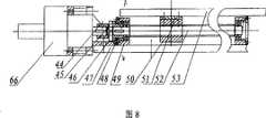
所述垂直方向位置调整机构中第六电机固定在垂直支架上,所述垂直支架固定于垂直底板上,所述第六电机通过垂直连轴器、垂直滑块与垂直传动丝杠相连接,所述垂直传动丝杠两端部套装有轴承并穿过垂直轴承座,所述垂直轴承座固定于垂直底板上,所述垂直轴承座端部固定有垂直轴承盖,所述垂直底板通过导轨滑块及导轨与垂直导轨板相连接,垂直传动螺母通过垂直调整垫固定于垂直导轨板上,垂直传动丝杠通过垂直传动螺母,其垂直运动通过安装于垂直导轨板上的垂直传动螺母与垂直传动丝杠之间的螺纹传动来实现;The sixth motor in the vertical direction position adjustment mechanism is fixed on the vertical support, and the vertical support is fixed on the vertical bottom plate. The sixth motor is connected with the vertical transmission lead screw through a vertical coupling and a vertical slider. Both ends of the vertical transmission screw are fitted with bearings and pass through the vertical bearing seat, the vertical bearing seat is fixed on the vertical bottom plate, the vertical bearing seat end is fixed with a vertical bearing cover, and the vertical bottom plate passes through the guide rail And the guide rail is connected with the vertical guide rail plate. The vertical transmission nut is fixed on the vertical guide rail plate through the vertical adjustment pad. The thread transmission between the bars is realized;
所述同步齿型带轮机构由第一齿型带轮、第二齿型带轮、第三齿型带轮和第四齿型带轮及张紧轮组成,所述第一齿型带轮设置在第一臂后转轴上,所述第四齿型带轮设置在第四电机输出轴上,所述第二齿型带轮设置在第二臂后转轴上,所述第三齿型带轮设置在第五电机输出轴上,所述大臂下部设置有底板,所述底板设置有沟槽,所述张紧轮通过其内的小轴固定于底板沟槽内。The synchronous toothed pulley mechanism is composed of a first toothed pulley, a second toothed pulley, a third toothed pulley, a fourth toothed pulley and a tensioning pulley. The first toothed pulley It is arranged on the rear rotating shaft of the first arm, the fourth toothed pulley is arranged on the output shaft of the fourth motor, the second toothed pulley is arranged on the rear rotating shaft of the second arm, and the third toothed belt The wheel is arranged on the output shaft of the fifth motor, and a base plate is provided at the bottom of the boom, and a groove is arranged on the base plate, and the tension wheel is fixed in the groove of the base plate through a small shaft inside it.
所述第一电机或第二电机或第三电机或第七电机或第八电机为步进式电机,所述第四电机或第五电机或第六电机为伺服电机。所述底板上沟槽的长度为30mm-50mm。所述第一臂前转轴或第一臂后转轴或第二臂前转轴或第二臂后转轴通过轴承、转轴盖和轴用弹性挡圈轴向固定。所述第三齿型带轮或第四齿型带轮与电机输出轴键连接。所述第三齿型带轮或第四齿型带轮与电机输出轴销连接。所述小轴上设置有轴承和套筒,所述小轴末端设置有螺母。所述定位盘通过骑缝螺丝与大臂相连接。The first motor or the second motor or the third motor or the seventh motor or the eighth motor is a stepping motor, and the fourth motor or the fifth motor or the sixth motor is a servo motor. The length of the groove on the bottom plate is 30mm-50mm. The front rotating shaft of the first arm or the rear rotating shaft of the first arm or the front rotating shaft of the second arm or the rear rotating shaft of the second arm are axially fixed by a bearing, a rotating shaft cover and an elastic circlip for the shaft. The third toothed pulley or the fourth toothed pulley is keyed to the output shaft of the motor. The third toothed pulley or the fourth toothed pulley is pin-connected with the output shaft of the motor. A bearing and a sleeve are arranged on the small shaft, and a nut is arranged at the end of the small shaft. The positioning plate is connected with the big arm through a seam screw.
本发明的手指,包括由外套筒和内套筒构成的本体、设置在本体内套筒尾端内的第七电机、设置在本体外套筒尾端的第八电机,以及设置在本体外套筒上的第一限位器,所述第八电机输出端设置有由依次设置的第二主动法兰、传动块、固定在本体内套筒尾端外侧的内挡环,以及锁定在本体内套筒前端外侧的外挡环、密布在内挡环与本体外套筒之间的第二钢珠和密布在外挡环与本体外套筒之间的第三钢珠所构成的器械旋转机构;所述本体内套筒内设置有凸台,卡住由内套筒前端伸出的支撑管;所述第七电机的输出端设置有由在支撑管内依次设置的第一主动法兰、扭转弹簧、第一钢珠、从动管、螺杆、第二销轴、套接在第二销轴上的支撑块,以及第一销轴、外套固定于支撑管上内套固定于从动管上的轴承和内螺纹套所构成的器械开合机构;所述第七电机的尾端设置有间隔套;所述内螺纹套设置有沟槽,第一销轴与第二销轴穿过沟槽固定于支撑管上;所述支撑管前端设置有传动锷结构的器械快换机构,它由依次设置的抵在支撑块上的压缩弹簧、支撑柱、指端更换工具构成,所述指端更换工具设置有两条连通的互成有60~120度的沟槽;所述第二主动法兰上设置有第二限位器,所述指端更换工具为针持、或手术刀、或手术镊子、或手术剪刀。The finger of the present invention comprises a body composed of an outer sleeve and an inner sleeve, a seventh motor arranged in the tail end of the inner sleeve of the body, an eighth motor arranged at the tail end of the outer sleeve of the body, and an eighth motor arranged on the outer sleeve of the body The first limiter, the output end of the eighth motor is provided with the second active flange, the transmission block, the inner stop ring fixed on the outside of the tail end of the inner sleeve of the body, and the inner sleeve locked in the body The instrument rotation mechanism composed of the outer retaining ring on the outside of the front end, the second steel balls densely distributed between the inner retaining ring and the outer sleeve of the body, and the third steel balls densely distributed between the outer retaining ring and the outer sleeve of the body; The sleeve is provided with a boss, which clamps the support tube protruding from the front end of the inner sleeve; the output end of the seventh motor is provided with a first active flange, a torsion spring, and a first steel ball sequentially arranged in the support tube. , a driven tube, a screw, a second pin shaft, a support block sleeved on the second pin shaft, and a first pin shaft, an outer sleeve fixed on the support tube, an inner sleeve fixed on the driven tube, and a bearing and an internal thread sleeve The opening and closing mechanism of the instrument is formed; the tail end of the seventh motor is provided with a spacer sleeve; the internal thread sleeve is provided with a groove, and the first pin shaft and the second pin shaft pass through the groove and are fixed on the support tube; The front end of the support tube is provided with an instrument quick-change mechanism with a transmission collar structure, which is composed of a compression spring, a support column, and a finger-tip replacement tool arranged in sequence against the support block. The finger-tip replacement tool is provided with two communicating There are grooves of 60-120 degrees between each other; the second active flange is provided with a second limiter, and the fingertip replacement tool is a needle holder, or a scalpel, or surgical tweezers, or surgical scissors.
本发明的外科手术机器人从操作手与现有技术相比具有以下有益效果:Compared with the prior art, the surgical robot of the present invention has the following beneficial effects from the operating hand:
1.该机构为关节式坐标结构,具有8+1个自由度,可以完成各种手术操作,操作轻便灵活;1. The mechanism is an articulated coordinate structure with 8+1 degrees of freedom, which can complete various surgical operations, and the operation is light and flexible;
2.双四连杆机构的应用,使得机器人的工作点位置变化时姿态保持不变,从而实现了位置和姿态的机械结构解偶;2. The application of the double four-bar linkage mechanism keeps the posture of the robot unchanged when the position of the working point changes, thus realizing the mechanical structure decoupling of the position and posture;
3.采用两级丝传动结构,即减少了机构空间的体积,又减轻了机构的重量;3. The two-stage wire transmission structure is adopted, which not only reduces the volume of the mechanism space, but also reduces the weight of the mechanism;
4.采用了双臂长度近似相等的结构,使得操作空间的得到优化;4. The structure with approximately equal length of both arms is adopted to optimize the operating space;
5.张紧机构和钢丝轮的巧妙设计,解决了丝传动经常出现的压线与张紧问题;5. The ingenious design of the tensioning mechanism and wire wheel solves the problems of crimping and tensioning that often occur in wire transmission;
6.主动关节同步齿型带传动的应用,使得电机后置,即减轻系统末端所受的力矩,又能保证关节运动控制的精度;6. The application of active joint synchronous toothed belt transmission makes the motor rear, which not only reduces the torque on the end of the system, but also ensures the accuracy of joint motion control;
7.采用角度可调的斜导轨结构,使得机器人更接近手术医生工作姿态;7. The angle-adjustable inclined rail structure is adopted to make the robot closer to the working posture of the surgeon;
8.粗调和精调相分离,通过手动粗调可以进行快速定位;精调机构使系统具有进行显微手术的操作精度;8. Coarse adjustment and fine adjustment are separated, and rapid positioning can be performed through manual coarse adjustment; the fine adjustment mechanism makes the system have the operating accuracy for microsurgery;
9.采用六维力传感器来真实的反映手指的尖端的真实力和力矩信息,从而能够帮助医生感受所接触到的组织或器官的真实情况;9. The six-dimensional force sensor is used to truly reflect the real force and torque information of the tip of the finger, which can help doctors feel the real situation of the tissue or organ they touch;
10.系列末端工具的设计如手术刀、手术剪子、手术镊子等使从手可以完成切开、剪断、分离、止血、打结、缝合等手术基本操作。10. The series of terminal tools are designed such as scalpel, surgical scissors, surgical tweezers, etc., so that slave hands can complete basic operations such as incision, cutting, separation, hemostasis, knotting, and suturing.
附图说明Description of drawings
图1是本发明的外科手术机器人从操作手的结构示意图;Fig. 1 is the structural representation of the operating hand of the surgical robot of the present invention;
图2是本发明的丝传动机构示意图;Fig. 2 is a schematic diagram of a wire transmission mechanism of the present invention;
图3是本发明的姿态调整部分结构示意图;Fig. 3 is a schematic diagram of the structure of the attitude adjustment part of the present invention;
图4是本发明的弧形导轨的局部放大图;Fig. 4 is the partially enlarged view of arc guide rail of the present invention;
图5是本发明的姿态调整部分A-A剖面图;Fig. 5 is a sectional view of the attitude adjustment part A-A of the present invention;
图6是本发明的水平位置调整部分过渡架的局部放大图;Fig. 6 is a partially enlarged view of the transition frame of the horizontal position adjustment part of the present invention;
图7是本发明的水平位置调整部分结构示意图;Fig. 7 is a structural schematic diagram of the horizontal position adjustment part of the present invention;
图8是本发明的垂直位置调整部分结构示意图;Fig. 8 is a schematic structural diagram of the vertical position adjustment part of the present invention;
图9是本发明的垂直位置调整部分B-B剖面图;Fig. 9 is a B-B sectional view of the vertical position adjustment part of the present invention;
图10是本发明的手指的结构示意图;Fig. 10 is a structural schematic diagram of a finger of the present invention;
图11a是本发明的手指指端更换工具之一手术剪刀的结构示意图;Fig. 11a is a structural schematic diagram of surgical scissors, one of the finger tip replacement tools of the present invention;
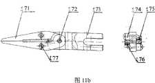
图11b是本发明的手指指端更换工具之一手术镊子的结构示意图;Fig. 11b is a structural schematic diagram of surgical tweezers, one of the finger tip replacement tools of the present invention;
图11c是本发明的手指指端更换工具之一手术刀的结构示意图。Fig. 11c is a structural schematic diagram of a scalpel, one of the fingertip replacement tools of the present invention.
附图标记:Reference signs:
1-紧箍 2-第一支撑板 3-弧形导轨 4-弧形导轨支架1-Hoop 2-First support plate 3-Arc guide rail 4-Arc guide rail bracket
5-齿扇 6-第一电机 7-小齿轮 8-力传感器5-tooth fan 6-first motor 7-pinion 8-force sensor
9-自转传动轴 10-自转轴承盖 11-自转轴承座 12-隔套9-Autorotation transmission shaft 10-Autorotation bearing cover 11-Autorotation bearing seat 12-Spacer sleeve
13-自转联轴器 14-自转联轴器滑块 15-自转电机支架 16-第二电机13-Autorotation coupling 14-Autorotation coupling slider 15-Autorotation motor bracket 16-Second motor
17-斜滑台 18-第三电机 19-斜滑台支架 20-钢丝轮17-Slanted table 18-Third motor 19-Slanted table bracket 20-Wire wheel
21-前转轴盖 22-第一臂前转轴 23-第一小臂 24-后转轴盖21-Front shaft cover 22-First arm front shaft 23-First arm 24-Rear shaft cover
25-第二臂前转轴 26-第二小臂 27-过渡架 28-第一臂后转轴25-Second arm front shaft 26-Second arm 27-Transition frame 28-First arm rear shaft
29-第一齿型带轮 30-带轮挡圈 31-第二臂后转轴 32-转轴盖29-The first toothed belt pulley 30-Belt wheel retaining ring 31-Second arm rear shaft 32-Rotation shaft cover
33-第二齿型带轮 34-第三齿型带轮 35-大臂 36-定位盘33-Second toothed pulley 34-Third toothed pulley 35-Boom 36-Positioning plate
37-大臂后转轴 38-大臂支架 39-底板 40-张紧轮37-Boom Rear Shaft 38-Boom Bracket 39-Bottom 40-Tension Wheel
41-小轴 42-第二支撑板 43-简支板 44-垂直连轴器41-Small shaft 42-Second support plate 43-Simply supported plate 44-Vertical coupling
45-垂直滑块 46-垂直支架 47-垂直底板 48-垂直轴承盖45-Vertical slider 46-Vertical bracket 47-Vertical bottom plate 48-Vertical bearing cover
49-垂直轴承座 50-垂直传动螺母 51-垂直调整垫 52-垂直传动丝杠49-Vertical bearing seat 50-Vertical drive nut 51-Vertical adjustment pad 52-Vertical drive screw
53-垂直导轨板 60-手指 61-第四齿型带轮 64-第四电机53-Vertical guide rail plate 60-Finger 61-The fourth toothed belt wheel 64-The fourth motor
65-第五电机 66-第六电机 71-第一关节 72-第二关节65-Fifth motor 66-Sixth motor 71-First joint 72-Second joint
73-第三关节 74-第四关节 75-第五关节 101-指端更换工具73-The third joint 74-The fourth joint 75-The fifth joint 101-Fingertip replacement tool
102-内螺纹套 103-第一销轴 104-支撑柱 105-压缩弹簧102-Internal thread sleeve 103-First pin shaft 104-Support column 105-Compression spring
106-支撑块 107-螺杆 108-支撑管 109-从动管106-support block 107-screw 108-support tube 109-driven tube
110-扭转弹簧 111-第一主动法兰 112-圆螺母 113-外挡环110-torsion spring 111-first driving flange 112-round nut 113-outer retaining ring
114-外套筒 115-内套筒 116-间隔套 117-内挡环114-outer sleeve 115-inner sleeve 116-spacer sleeve 117-inner retaining ring
118-传动块 119-第二主动法兰 120-过渡法兰 121-弹簧118-Transmission block 119-Second driving flange 120-Transition flange 121-Spring
122-弹簧套 132-轴承 135-第七电机 138-第八电机122-Spring sleeve 132-Bearing 135-Seventh motor 138-Eighth motor
133-第一钢珠 136-第二钢珠 145-第二销轴 142-第一限位器133-The first steel ball 136-The second steel ball 145-The second pin shaft 142-The first limiter
143-第二限位器 146-第三钢珠 131、134、137、139、140、141、144-螺钉143-Second limiter 146-
161-手术剪刀 162-剪刀销轴 163-剪刀快换卡头 164-剪刀垫圈161-Surgical scissors 162-Scissors pin 163-Scissors quick change chuck 164-Scissors washer
165-剪刀弹簧片 166、167-剪刀螺钉 171-手术镊子 172-镊子销轴165-
173-镊子快换卡头 174-镊子垫圈 175-镊子弹簧片 176、177-镊子螺钉173-Tweezers Quick Change Chuck 174-Tweezers Washer 175-Tweezers Spring 176、177-Tweezers Screws
181-手术刀 182-手术刀铆钉 183-手术刀快换卡头181-Scalpel 182-Scalpel Rivet 183-Scalpel Quick Change Chuck
具体实施方式 Detailed ways
下面结合附图和具体实施例对本发明的外科手术机器人从操作手作进一步详细地描述。The surgical robot of the present invention will be further described in detail from the operator side with reference to the accompanying drawings and specific embodiments.
在图1、2中,双四连杆机构是由丝传动实现的。所述双四连杆机构包括连接大臂和第二小臂的第一关节71、连接第二小臂和过渡架的第二关节72、连接第四电机64与过渡架的第三关节73、连接过渡架和第一小臂的第四关节74、连接第一小臂和斜滑台支架的第五关节75。In Figures 1 and 2, the double four-bar linkage mechanism is realized by wire transmission. The double four-bar linkage mechanism includes a first joint 71 connecting the boom and the second forearm, a second joint 72 connecting the second forearm and the transition frame, a third joint 73 connecting the
在图3、4、5中,姿态调整部分的手指圆弧运动关节机构,是一个主动关节,关节的运动是由电压型的步进式驱动弧形导轨的第一电机6提供,通过齿轮齿条机构实现的。第一电机6与夹持手指的紧箍1安装在支撑板2上,支撑板2与弧形导轨3的滑块固定在一起,并可以在弧形导轨上自由滑动;弧形导轨3的导轨通过齿扇5与弧形导轨支架4固定;第一电机6固定在支撑板2上,小齿轮7装于第一电机6轴上,可以在齿扇5上自由滚动。圆弧运动是第一电机6的轴通过小齿轮7和齿扇5带动支撑板2在弧形导轨3上运动,从而实现手指圆弧的运动。In Figures 3, 4, and 5, the finger arc movement joint mechanism of the attitude adjustment part is an active joint, and the joint movement is provided by the
姿态调整部分的弧形导轨旋转关节机构,是一个主动关节,关节的运动是由步进式第二电机16提供,通过轴承机构来实现的。第二电机16通过自转电机支架15与自转轴承座11连接,自转轴承座11固定在斜滑台17上;轴承装在自转轴承座11内,轴承内部由自转传动轴9支撑,轴承的轴向定位是由隔套12、自转轴承盖10限制;自转传动轴9通过力传感器8与弧形导轨支架4连接固定;自转轴承盖10固定在自转轴承座11上,隔套12置于自转轴承座11内的两个轴承之间;自转传动轴9通过自转连轴器13和自转连轴器滑块14与第二电机16的轴连接。旋转运动的传递是通过两个自转连轴器13和自转连轴器滑块14将电机轴的旋转运动传给自转传动轴9,自转传动轴9与弧形导轨支架4连接,带动整个前端部件进行旋转运动。The arc-shaped guide rail rotary joint mechanism of the attitude adjustment part is an active joint, and the motion of the joint is provided by the
姿态调整部分的斜导轨直线运动关节机构,是一个主动关节,关节的运动是由步进式第三电机18提供,通过斜滑台17自带的滚珠丝杠机构实现的。实现该关节运动的主要是由第三电机18驱动斜滑台17,由于其自带的丝杠和滑块的高精度运动实现动滑台的精确运动,从而带动整个前面两个关节实现直线运动。The inclined guide rail linear motion joint mechanism of the attitude adjustment part is an active joint, and the motion of the joint is provided by the
力传感器8固定安装在弧形导轨支架4和自转传动轴9之间,可以检测到三个方向的力和三个方向的力矩。The
在图6、7中,水平位置调整部分是由各个臂部的转动关节来实现的。其中,大臂35旋转关节机构,是一个手动调节关节,通过轴承机构实现的。大臂后转轴37与大臂35由销钉固连,通过轴承机构装配在大臂支架38上,使得整个前端部分灵活的转动,便于手动调节;此关节的锁紧机构是通过可插拔的定位销实现的,定位盘36用骑缝螺丝与大臂35固连,由于定位盘36上有均匀分布的销孔,当手臂走到工作位置时,将销钉插入定位盘36的销孔里从而实现了简易的手动初步定位功能。In Figures 6 and 7, the horizontal position adjustment part is realized by the rotating joints of each arm. Wherein, the swivel joint mechanism of the
第二小臂26的旋转关节机构,是一个主动关节,关节的运动是由第五伺服电机65提供,由带传动传递动力,通过轴承机构实现。其结构与大臂35旋转机构类似,第二小臂26也是通过销连接与第二臂后转轴31相连接,使第二小臂26在大臂35轴承座内旋转,通过轴承、转轴盖32和轴用弹性挡圈实现轴向定位。第二小臂26与通过穿过第一小臂23二者的第二臂前转轴25和过渡架27连接,通过轴承、转轴盖和轴用弹性挡圈实现轴向固定。The rotary joint mechanism of the
同步齿型带轮机构由两个齿型带轮、张紧轮及同步齿形带组成。同步齿型带轮机构中第一齿型带轮29装在第一臂后转轴28上,通过带轮挡圈30固定,第四齿型带轮61装在第四电机64输出轴上;第二齿型带轮33装在第二臂后转轴31上,第三齿型带轮34装在第五电机65输出轴上。第三齿型带轮34通过键与电机输出轴相连,将动力沿着同步齿型带的紧边传递给第二齿型带轮33,第二齿型带轮33固定在第二臂后转轴31上,第二臂后转轴31与第二小臂26销连接,从而实现带动第二小臂26转动;齿型带的张紧机构是在底板39上沿垂直齿型带方向开了一个长槽,长槽的长度为30mm-50mm,通常为48mm,使张紧轮40的小轴41能够在底板39的槽内运动,小轴41上装有轴承和套筒,用滚动摩擦代替滑动摩擦减小阻力,其末端是螺纹,当用螺母锁紧小轴41后可以使张紧轮40停在长槽的任意位置,从而达到了任意调节带轮张紧度的目的。第二小臂26上丝传动的两个钢丝轮中,后面的钢丝轮用骑缝螺丝固定在转轴盖32上,转轴盖32固定在大臂35上,使其与大臂35的相对位置不变;前面的钢丝轮以同样的方式固定在过渡架27上,这样当第二小臂26相对于大臂35转动时,钢丝绳就会带动过渡架27向相反的方向转动,通过这一组钢丝轮机构就可以对第二小臂26的旋转关节转动量进行补偿,实现第二小臂26后端运动而不改变前端姿态;第一小臂23上的一组钢丝轮结构与第二小臂26相同,后面的钢丝轮固定在过渡架27上,前面的钢丝轮20与斜滑台支架19固定,这组钢丝轮可以对第一小臂23的旋转关节量进行补偿,实现第一小臂23后端运动而不改变前端姿态。通过两组四连杆机构就实现了机械手工作点的位置与姿态控制的解偶。The synchronous toothed pulley mechanism is composed of two toothed pulleys, a tension pulley and a synchronous toothed belt. In the synchronous toothed pulley mechanism, the first
钢丝轮的张紧机构,在每个钢丝轮内部都开有孔,这样在绕线的时候,钢丝的一头可以通过孔绕过第二支撑板42和简支板43,第二支撑板42固定在钢丝轮上,简支板43可以自由移动,简支板43上有螺纹,装上长的螺栓,螺栓的顶部顶在第二支撑板42上,这样就实现了钢丝的张紧功能。The tensioning mechanism of the steel wire wheel has a hole inside each steel wire wheel, so that when winding, one end of the steel wire can bypass the
第一小臂23的旋转关节机构,是一个主动关节,关节的运动是由第四伺服电机64提供,由带传动传递动力,通过轴承机构实现。其结构与第二小臂26相同,斜滑台支架19与第一小臂23通过穿过二者的第一臂前转轴22连接,通过轴承、前转轴盖21和轴用弹性挡圈实现轴向固定。第一小臂23与第二小臂26通过穿过二者的第一臂后转轴28和过渡架27连接,通过轴承、后转轴盖24和轴用弹性挡圈实现轴向固定。The rotary joint mechanism of the
在图8、9中,垂直位置调整部分的垂直运动关节机构的运动是由第六伺服电机66提供,通过丝杠螺母机构实现。第六电机66及减速器固定在垂直支架46上,垂直支架46固定在垂直底板47上,第六电机66通过垂直连轴器44、垂直滑块45将动力传给垂直传动丝杠52;垂直传动丝杠52与垂直底板47由轴承机构连接,垂直轴承座49固定在垂直底板47上,垂直轴承盖48固定在垂直轴承座49上,轴承置于轴承座内,垂直传动丝杠52通过轴承可以自由转动。垂直导轨板53通过导轨滑块及导轨与垂直底板47连接,垂直传动螺母50通过垂直调整垫51固定于垂直导轨板53上,垂直传动丝杠52通过垂直传动螺母50,其垂直运动的实现是通过安装于垂直导轨板53上的垂直传动螺母50与垂直传动丝杠52之间的螺纹传动来实现。In FIGS. 8 and 9 , the movement of the vertical movement joint mechanism of the vertical position adjustment part is provided by the
本发明的手指可以使用专利申请号03100038所公开的手指,也可以使用以下所述手指。在图10中,包括由外套筒114和内套筒115构成的本体、设置在本体内套筒115尾端内的第七电机135、由过渡法兰120固定在本体外套筒114尾端的第八电机138,以及位于本体外套筒上的第一限位器142;所述第八电机138输出端设置有由依次设置的第二主动法兰119、传动块118、固定在本体内套筒尾端外侧的内挡环117,以及由圆螺母112锁定在本体内套筒115前端外侧的外挡环113、密布在内挡环117与本体外套筒114之间的第二钢珠136和密布在外挡环113与本体外套筒114之间的第三钢珠146所构成的器械旋转机构;所述本体内套筒115内设置有凸台,卡住由内套筒前端伸出的支撑管108;所述第七电机135的输出端设置有由在支撑管108内依次设置的第一主动法兰111、扭转弹簧110、第一钢珠133、从动管109、螺杆107、第二销轴145、套接在第二销轴145上的支撑块16,以及第一销轴103、外套固定于支撑管上内套固定于从动管上的轴承132和内螺纹套102所构成的器械开合机构;所述第七电机135尾端设有间隔套,间隔套为塑料圆柱套筒;所述内螺纹套102设置有长15mm~25mm沟槽,通常为20mm;第一销轴103与第二销轴145穿过沟槽固定于支撑管108上;所述支撑管108前端设置有传动锷结构的器械快换机构,由依次设置的抵在支撑块106上的压缩弹簧105、支撑柱104、指端更换工具101构成;所述第二主动法兰119上设置有第二限位器143,可以采用螺钉或挡块,所述第一限位器可采用螺钉。所述步进电机可以选用为1524系列,其驱动电路采用与所述电机配套的驱动器,例如AD-VL-M或AD-VM-M或AD-CM-M。The fingers of the present invention can use the fingers disclosed in Patent Application No. 03100038, and can also use the fingers described below. In FIG. 10 , it includes a body composed of an
本发明的手指指端更换工具柄上设置有两条连通的互成有90度的沟槽,所述指端更换工具有以下两种状态:所述指端更换工具插入内螺纹套102中,经过顺时针旋转90度后,被支撑柱104和压缩弹簧105将指端更换工具101顶紧固定;或将所述指端更换工具顶入内螺纹套102后,逆时针旋转90度,指端更换工具退出。所述指端更换工具101为针持,也可以使用手术剪刀161、手术刀181或手术镊子171。图11a为手术剪刀结构示意图,包括剪刀销轴162、剪刀快换卡头163、剪刀垫圈164、剪刀弹簧片165和剪刀螺钉166,167;图11b为手术镊子结构示意图,包括镊子销轴1172、镊子快换卡头73、镊子垫圈174、镊子弹簧片175和镊子螺钉176,177;图11c为手术刀结构示意图,包括手术刀铆钉182、手术刀快换卡头183。The handle of the fingertip replacement tool of the present invention is provided with two connected grooves forming 90 degrees to each other. The fingertip replacement tool has the following two states: the fingertip replacement tool is inserted into the internal thread sleeve 102, After clockwise rotation of 90 degrees, the fingertip replacement tool 101 is fastened and fixed by the
本发明第一限位器142位于本体外套筒上,第二限位器143位于第二主动法兰119上,所述第二主动法兰119在第八电机138驱动下旋转,带动所述第二限位器143一同旋转,由于所述本体外套筒上的第一限位器142与所述第二主动法兰119上第二限位器143的相互位置,所述第二主动法兰旋转不超过360度,从而限制指端工具旋转的角度不超过360度,防止第七电机在旋转过程中线路缠绕的问题。In the present invention, the
现在以手指指端更换工具是针持为实施例进一步说明本发明的手指结构。The finger structure of the present invention is further described with the example that the finger tip replacement tool is a needle holder.
针持上面有相互连通的开槽和封闭槽,固定在支撑管108上的第一销轴103可以从开槽进入针持内,并通过旋转90度角运动到封闭槽内,针持的底部与支撑柱1044连接,一起被压缩弹簧105顶紧固定,压缩弹簧105的另一端顶在支撑块106上,上述部分均安装在器械开合机构的内螺纹套102中;第七电机135与器械开合机构的第一主动法兰111连接,第一主动法兰111与从动管109轴向连接是由第一钢珠133实现,此机构在轴向固定从动管109的同时又保证其自由转动,第一主动法兰111与从动管109转动连接,通过扭转弹簧110实现刚性的传动机构的分离,使夹持动作具有柔性特征,上述部分通过轴承机构132安装于支撑管108中;第八电机138与器械旋转机构的第二主动法兰119连接,第二主动法兰119通过传动块118驱动内挡环117旋转,内挡环117与外挡环113将第七电机135固定在支撑管108内,其中外挡环113被圆螺母112锁紧,上述部分通过密封的第二钢珠136和第三钢珠146在本体外套筒114中转动。There are slots and closed slots connected to each other on the needle holder. The first pin shaft 103 fixed on the support tube 108 can enter the needle holder from the slot and move into the closed slot by rotating 90 degrees. The bottom of the needle holder It is connected with the support column 1044, and is tightly fixed by the
下面以实施例进一步说明本发明的外科手术机器人从操作手的动作实现的过程。The following examples further illustrate the process of the surgical robot of the present invention from the actions of the operating hand.
该系统可以实现6轴连动,包括前端绕X、Y、Z三个方向的转动(用以实现姿态调整)、后端X、Y、Z三个方向的移动(用以实现位置调整)。The system can realize 6-axis linkage, including the rotation of the front end in the three directions of X, Y, and Z (for attitude adjustment), and the movement of the rear end in the three directions of X, Y, and Z (for position adjustment).
前端绕X、Y、Z三个方向的转动,用以实现姿态调整。其中,手指的圆弧运动是驱动弧形导轨第一电机6的轴通过小齿轮7和齿扇5带动第一支撑板2在弧形导轨3上运动,从而实现手指圆弧的运动。旋转运动的实现是通过两个自转连轴器13和自转连轴器滑块14将第二电机16轴的旋转运动传给自转传动轴9,自转传动轴9与弧形导轨支架4连接,带动整个前端部件进行旋转运动。实现斜导轨的直线的运动主要是由第三电机18驱动斜滑台17,由于其自带的丝杠和滑块的高精度运动实现动滑台的精确运动,从而带动整个前端部件作直线运动。The front end rotates around the three directions of X, Y, and Z to realize attitude adjustment. Wherein, the arc motion of the finger is to drive the shaft of the
后端X、Y、Z三个方向的移动,用以实现位置调整。其中,水平方向的位置调整是由各个臂部的转动关节来实现的。大臂35的转动是手动调节实现的,驱动大臂35,通过装配在大臂支架38上的轴承机构带动整个前端部分灵活的转动;此关节的锁紧机构是通过可插拔的定位销实现的,定位盘36用骑缝螺丝与大臂35固连,由于定位盘36上有均匀分布的销孔,当手臂走到工作位置时,将销钉插入定位盘36的销孔里从而实现了简易的手动初步定位功能。The movement of the rear end in X, Y, and Z directions is used to realize position adjustment. Wherein, the position adjustment in the horizontal direction is realized by the rotating joints of each arm. The rotation of the
第二小臂26的旋转是由第五伺服电机65驱动实现的。置于大臂35内的第五电机65驱动第二小臂26转动,使第二小臂26在大臂35轴承座内旋转;第五电机65驱动齿型带轮34,将动力沿着同步齿型带的紧边传递给齿型带轮33,第二齿型带轮33固定在第二臂后转轴31上,第二臂后转轴31与第二小臂26销连接,从而实现带动第二小臂26转动;齿型带的张紧机构是在底板39上沿垂直齿型带方向开了一个长槽,使张紧轮40的小轴41能够在底板39的槽内运动,小轴41上装有轴承和套筒,用滚动摩擦代替滑动摩擦减小阻力,其末端是螺纹,当用螺母锁紧小轴41后可以使张紧轮40停在长槽的任意位置,从而达到了任意调节带轮张紧度的目的。The rotation of the second
第一小臂23的旋转是由第四伺服电机64驱动实现的,由带传动传递动力,通过轴承机构实现。其方式与第二小臂26相同,斜滑台支架19与第一小臂23通过穿过二者的第一臂前转轴22连接,通过轴承、前转轴盖21和轴用弹性挡圈实现轴向固定,并可以实现斜滑台支架19与第一小臂23之间的相互转动。第一小臂23与第二小臂26通过穿过二者的第一臂后转轴28和过渡架27连接,通过轴承、后转轴盖24和轴用弹性挡圈实现轴向固定,并可以实现第一小臂23与第二小臂26之间的相互转动。The rotation of the first
双四连杆机构的运动是由丝传动实现的。当第二小臂26相对于大臂35转动时,固定在过渡架27上的钢丝轮通过钢丝绳就会带动过渡架27向相反的方向转动;通过第二小臂26上丝传动的两个钢丝轮机构,就可以对第二小臂26的旋转关节转动量进行补偿,实现第二小臂26后端运动而不改变前端姿态;第一小臂23上的一组钢丝轮结构与第二小臂26相同,后面的钢丝轮固定在过渡架27上,前面的钢丝轮20与斜滑台支架19固定,这组钢丝轮可以对第一小臂23的旋转关节量进行补偿,实现第一小臂23后端运动而不改变前端姿态。通过两组四连杆机构就实现了机械手工作点的位置与姿态控制的解偶。The movement of the double four-bar linkage mechanism is realized by wire drive. When the second
钢丝轮的张紧机构,在每个钢丝轮内部都开有孔,这样在绕线的时候,钢丝的一头可以通过孔绕过第二支撑板42和简支板43,第二支撑板42固定在钢丝轮上,简支板43可以自由移动,简支板43上有螺纹,装上长的螺栓,螺栓的顶部顶在第二支撑板42上,这样就实现了钢丝的张紧功能。The tensioning mechanism of the steel wire wheel has a hole inside each steel wire wheel, so that when winding, one end of the steel wire can bypass the
垂直方向的运动的实现是由安装在垂直传动丝杠52上的垂直传动螺母50将垂直传动丝杠52的转动转变为垂直导轨板53的垂直方向的运动。The realization of the motion in the vertical direction is that the vertical drive nut 50 installed on the vertical drive screw 52 converts the rotation of the vertical drive screw 52 into the vertical motion of the vertical guide rail plate 53 .
下面仍以指端更换工具是针持为实施例进一步说明本发明的手指动作实现的过程。In the following, the fingertip replacement tool is still held as an example to further illustrate the process of realizing the finger movement of the present invention.
本发明的手指本身的动作主要指端更换工具绕自身轴线的旋转和手术更换工具的开合以符合手术中对指端工具的要求。The action of the finger itself of the present invention is mainly the rotation of the fingertip replacement tool around its own axis and the opening and closing of the surgical replacement tool to meet the requirements for the fingertip tool in the operation.
手指指端部件围绕自身轴线的旋转是由第八电机138通过限位器带动第二主动法兰119,第二主动法兰119上有开槽,通过开槽中固定在内挡环117上的传动块118从而带动内挡环117转动,内挡环117和外挡环113与本体外套筒114之间通过密封第二钢珠136与第三钢珠146连接在一起,并能够在本体外套筒114内转动,从而实现了手指末端绕自身轴线的旋转功能。The rotation of the fingertip part around its own axis is driven by the
另外,器械的开合动作由第七电机135驱动,第七电机135通过紧固螺钉134带动第一主动法兰111转动,第一主动法兰111通过扭转弹簧110驱动从动管109转动,从动管109与螺杆107连接,螺杆107将旋转运动转化为内螺纹套102的直线运动,由于针持位于内螺纹套102内部,通过内螺纹套102的向前直线运动就可以实现针持的闭合动作;针持带有弹簧121和弹簧套122,当内螺纹套102向后直线运动时,由于其自身弹性实现张开动作。In addition, the opening and closing action of the instrument is driven by the seventh motor 135, the seventh motor 135 drives the
本发明的外科手术机器人从操作手主要应用于微创外科、眼科、骨科等手术,尤其在显微外科手术中进行血管缝合等工作中,本发明的外科手术机器人从操作手能够替代主刀医生完成血管剥离、缝合、剪断等复杂的手术操作。The surgical robot slave operator of the present invention is mainly used in minimally invasive surgery, ophthalmology, orthopedics and other operations, especially in microsurgery for blood vessel suturing and other work, the surgical robot slave operator of the present invention can replace the chief surgeon to complete Complicated surgical operations such as vascular stripping, suturing, and cutting.
以上对本发明及其实施方式的描述是示意性的,没有限制性。所以,如果本领域的普通技术人员受其启示,在不脱离本发明创造宗旨的情况下,做出其它实施例,均应属于本发明的保护范围。The above description of the present invention and its embodiments is illustrative, not restrictive. Therefore, if a person of ordinary skill in the art is inspired by it and makes other embodiments without departing from the inventive concept of the present invention, all of them shall belong to the protection scope of the present invention.
Claims (10)
Translated fromChinesePriority Applications (1)
| Application Number | Priority Date | Filing Date | Title |
|---|---|---|---|
| CNB2005100131719ACN100336640C (en) | 2005-02-01 | 2005-02-01 | Secondary manipulator of surgery operation robot |
Applications Claiming Priority (1)
| Application Number | Priority Date | Filing Date | Title |
|---|---|---|---|
| CNB2005100131719ACN100336640C (en) | 2005-02-01 | 2005-02-01 | Secondary manipulator of surgery operation robot |
Publications (2)
| Publication Number | Publication Date |
|---|---|
| CN1654174A CN1654174A (en) | 2005-08-17 |
| CN100336640Ctrue CN100336640C (en) | 2007-09-12 |
Family
ID=34894202
Family Applications (1)
| Application Number | Title | Priority Date | Filing Date |
|---|---|---|---|
| CNB2005100131719AExpired - Fee RelatedCN100336640C (en) | 2005-02-01 | 2005-02-01 | Secondary manipulator of surgery operation robot |
Country Status (1)
| Country | Link |
|---|---|
| CN (1) | CN100336640C (en) |
Families Citing this family (27)
| Publication number | Priority date | Publication date | Assignee | Title |
|---|---|---|---|---|
| JP4539618B2 (en)* | 2006-07-31 | 2010-09-08 | トヨタ自動車株式会社 | Legged robot |
| US9096033B2 (en)* | 2007-06-13 | 2015-08-04 | Intuitive Surgical Operations, Inc. | Surgical system instrument sterile adapter |
| CN101390763B (en)* | 2008-10-31 | 2010-06-02 | 天津大学 | Robot body system for assisting minimally invasive surgery |
| CN101411632B (en)* | 2008-12-03 | 2010-06-16 | 天津大学 | A robotic active stent for assisting minimally invasive surgery |
| CN101744656B (en)* | 2008-12-11 | 2014-04-16 | 张春霖 | Minimally invasive spine surgical robot against nerve injuries |
| ES2388029B1 (en)* | 2009-05-22 | 2013-08-13 | Universitat Politècnica De Catalunya | ROBOTIC SYSTEM FOR LAPAROSCOPIC SURGERY. |
| CN101700656B (en)* | 2009-10-21 | 2011-06-08 | 昆山市工业技术研究院有限责任公司 | Surgical mechanical arm joint hydraulic locking power generator |
| CN102059187A (en)* | 2009-11-17 | 2011-05-18 | 赵德志 | Small-size spraying robot |
| CN101889900B (en)* | 2010-07-12 | 2012-04-11 | 天津大学 | Master-slave integrated mechanical arm for assisting minimally invasive surgery |
| JP5835906B2 (en)* | 2010-09-30 | 2015-12-24 | オリンパス株式会社 | Bending joint mechanism, surgical instrument having the bending joint mechanism, and manipulator having the bending joint mechanism |
| CN102488554B (en)* | 2011-11-14 | 2013-06-05 | 天津大学 | Micro instrument terminal based on module joint and used for minimally invasive surgery robot |
| CN102764158B (en)* | 2012-04-13 | 2015-03-11 | 中国科学院深圳先进技术研究院 | Surgical robot |
| CN103341856B (en)* | 2013-07-11 | 2016-08-10 | 东莞市亚世工业设备有限公司 | Improved bidirectional unfolding taking and placing device |
| JP5996492B2 (en)* | 2013-07-25 | 2016-09-21 | オリンパス株式会社 | Joint mechanisms and medical devices |
| CN104626163B (en)* | 2013-11-14 | 2016-08-31 | 沈阳新松机器人自动化股份有限公司 | The overall system control of orthopaedics manipulator |
| CN103600356A (en)* | 2013-11-26 | 2014-02-26 | 苏州晓炎自动化设备有限公司 | Robot wrist drive mechanism |
| CN104758052B (en)* | 2014-01-02 | 2017-02-08 | 中国科学院沈阳自动化研究所 | Position and posture adjusting passive manipulator for digestive endoscopy conveying robot |
| CN103932790B (en)* | 2014-03-11 | 2016-01-27 | 哈尔滨工程大学 | There is the surgical operation robot Two-Degree-of-Freedom mechanism of rapid replacing interface function |
| CN104224325B (en)* | 2014-10-11 | 2016-08-24 | 天津工业大学 | A kind of wire rope gearing linear telescopic mechanism for micro-wound operation robot |
| CN105033738B (en)* | 2015-06-30 | 2018-02-06 | 佛山市新恒萃材料科技有限公司 | A kind of multi-purpose robot with arc orbit |
| CN105286989B (en)* | 2015-10-15 | 2017-08-15 | 天津大学 | A kind of micro-wound operation robot bipolar energy instrument |
| ITUB20155057A1 (en)* | 2015-10-16 | 2017-04-16 | Medical Microinstruments S R L | Robotic surgery set |
| CN105196284B (en)* | 2015-11-02 | 2017-01-11 | 哈尔滨工业大学 | Three-degree-of-freedom tandem type self-gravity-balance passive mechanical arm |
| WO2017205481A1 (en)* | 2016-05-26 | 2017-11-30 | Covidien Lp | Robotic surgical assemblies and instrument drive units thereof |
| CN106377319B (en)* | 2016-11-22 | 2019-01-18 | 哈尔滨工业大学 | A kind of minimally invasive spine surgical robot end direction sleeve |
| CN110403700B (en)* | 2019-08-30 | 2024-05-03 | 山东威高手术机器人有限公司 | Doctor operation table |
| CN111544198B (en)* | 2020-05-14 | 2021-04-20 | 西安交通大学 | A flexible operation drive system for an ophthalmic surgical robot |
Citations (6)
| Publication number | Priority date | Publication date | Assignee | Title |
|---|---|---|---|---|
| CN88212752U (en)* | 1988-02-02 | 1988-11-30 | 陈长江 | Multifunctional device for abdominal operation |
| US5382885A (en)* | 1993-08-09 | 1995-01-17 | The University Of British Columbia | Motion scaling tele-operating system with force feedback suitable for microsurgery |
| US5820623A (en)* | 1995-06-20 | 1998-10-13 | Ng; Wan Sing | Articulated arm for medical procedures |
| CN1100516C (en)* | 1997-08-27 | 2003-02-05 | 北京航空航天大学 | Cerebrosurgical operation equipment system with robot and its implement method |
| US6620174B2 (en)* | 1995-06-07 | 2003-09-16 | Sri International | Surgical manipulator for a telerobotic system |
| CN2614044Y (en)* | 2003-05-06 | 2004-05-05 | 马增山 | Mechanical arm for medical use |
- 2005
- 2005-02-01CNCNB2005100131719Apatent/CN100336640C/ennot_activeExpired - Fee Related
Patent Citations (6)
| Publication number | Priority date | Publication date | Assignee | Title |
|---|---|---|---|---|
| CN88212752U (en)* | 1988-02-02 | 1988-11-30 | 陈长江 | Multifunctional device for abdominal operation |
| US5382885A (en)* | 1993-08-09 | 1995-01-17 | The University Of British Columbia | Motion scaling tele-operating system with force feedback suitable for microsurgery |
| US6620174B2 (en)* | 1995-06-07 | 2003-09-16 | Sri International | Surgical manipulator for a telerobotic system |
| US5820623A (en)* | 1995-06-20 | 1998-10-13 | Ng; Wan Sing | Articulated arm for medical procedures |
| CN1100516C (en)* | 1997-08-27 | 2003-02-05 | 北京航空航天大学 | Cerebrosurgical operation equipment system with robot and its implement method |
| CN2614044Y (en)* | 2003-05-06 | 2004-05-05 | 马增山 | Mechanical arm for medical use |
Also Published As
| Publication number | Publication date |
|---|---|
| CN1654174A (en) | 2005-08-17 |
Similar Documents
| Publication | Publication Date | Title |
|---|---|---|
| CN100336640C (en) | Secondary manipulator of surgery operation robot | |
| CN101548904B (en) | A surgical robot arm | |
| JP5715304B2 (en) | Mechanical remote control device for remote control | |
| CN113749777B (en) | Surgical instrument platform, instrument assembly and surgical instrument | |
| US9027431B2 (en) | Remote centre of motion positioner | |
| US6406472B1 (en) | Remote center positioner | |
| US5817084A (en) | Remote center positioning device with flexible drive | |
| WO2021184791A1 (en) | Serpentine surgical robot applied to minimally invasive surgery | |
| CN110123457B (en) | Variable-stiffness robot for minimally invasive surgery and working method | |
| CN201135461Y (en) | Micro-wound operation robot based on endoscopic | |
| CN107320910A (en) | A kind of submissive rehabilitation ectoskeleton of upper limbs | |
| CN101045015A (en) | Ultrasonic surgical system and method | |
| CN111643188B (en) | A puncture surgery robot device | |
| CN1634685A (en) | Master Operator with Gripping Feel | |
| CN210354897U (en) | A minimally invasive surgical robotic arm with parallelogram structure | |
| CN110236677A (en) | A parallelogram structure minimally invasive surgical robotic arm | |
| CN200945194Y (en) | Medical device | |
| CN109091232A (en) | A kind of robot system for hysteroscope Minimally Invasive Surgery | |
| CN117813036A (en) | Soft endoscope system, soft endoscope auxiliary device and operation method | |
| CN1730245A (en) | Throat surgery robot from the operator's hand | |
| CN101357075A (en) | Micro-wound operation robot based on endoscopic | |
| CN101474090A (en) | Six-freedom degree wearing type auxiliary bone-knitting parallel-connected robot | |
| CN113729969A (en) | Force feedback integrated minimally invasive surgery robot | |
| CN221671972U (en) | Laparoscopic minimally invasive robotic surgical arm | |
| CN114795476A (en) | Surgical execution device and surgical robot |
Legal Events
| Date | Code | Title | Description |
|---|---|---|---|
| C06 | Publication | ||
| PB01 | Publication | ||
| C10 | Entry into substantive examination | ||
| SE01 | Entry into force of request for substantive examination | ||
| C14 | Grant of patent or utility model | ||
| GR01 | Patent grant | ||
| CF01 | Termination of patent right due to non-payment of annual fee | ||
| CF01 | Termination of patent right due to non-payment of annual fee | Granted publication date:20070912 |