CN100334418C - Method for measuring roller shaft levelness in roller space position detection - Google Patents
Method for measuring roller shaft levelness in roller space position detectionDownload PDFInfo
- Publication number
- CN100334418C CN100334418CCNB2004100931245ACN200410093124ACN100334418CCN 100334418 CCN100334418 CCN 100334418CCN B2004100931245 ACNB2004100931245 ACN B2004100931245ACN 200410093124 ACN200410093124 ACN 200410093124ACN 100334418 CCN100334418 CCN 100334418C
- Authority
- CN
- China
- Prior art keywords
- point
- coordinates
- total station
- measurement point
- centerline
- Prior art date
- Legal status (The legal status is an assumption and is not a legal conclusion. Google has not performed a legal analysis and makes no representation as to the accuracy of the status listed.)
- Expired - Lifetime
Links
- 238000000034methodMethods0.000titleclaimsabstractdescription36
- 238000001514detection methodMethods0.000titleclaimsabstractdescription14
- 238000005259measurementMethods0.000claimsabstractdescription113
- 238000000691measurement methodMethods0.000claimsdescription9
- XLYOFNOQVPJJNP-UHFFFAOYSA-NwaterSubstancesOXLYOFNOQVPJJNP-UHFFFAOYSA-N0.000claimsdescription7
- 238000006243chemical reactionMethods0.000description6
- 238000010586diagramMethods0.000description6
- 238000004519manufacturing processMethods0.000description5
- 238000005516engineering processMethods0.000description3
- 238000005096rolling processMethods0.000description3
- 229910000831SteelInorganic materials0.000description2
- 238000004364calculation methodMethods0.000description2
- 239000010960cold rolled steelSubstances0.000description2
- 238000009434installationMethods0.000description2
- 239000010959steelSubstances0.000description2
- 238000010998test methodMethods0.000description2
- 238000012360testing methodMethods0.000description2
- 230000009466transformationEffects0.000description2
- 230000008901benefitEffects0.000description1
- 230000005540biological transmissionEffects0.000description1
- 239000011248coating agentSubstances0.000description1
- 238000000576coating methodMethods0.000description1
- 238000005260corrosionMethods0.000description1
- 230000007797corrosionEffects0.000description1
- 238000011161developmentMethods0.000description1
- 238000010438heat treatmentMethods0.000description1
- 230000006872improvementEffects0.000description1
- 239000007788liquidSubstances0.000description1
- 238000012423maintenanceMethods0.000description1
- 238000005554picklingMethods0.000description1
- 230000008569processEffects0.000description1
- 238000012545processingMethods0.000description1
- 238000010008shearingMethods0.000description1
Images

Landscapes
- Length Measuring Devices With Unspecified Measuring Means (AREA)
Abstract
Translated fromChinese
Description
Translated fromChinese技术领域technical field
本发明涉及测量技术,具体地说,涉及一种辊系空间位置检测中的辊轴水平度的测量方法。The invention relates to measurement technology, in particular to a method for measuring the levelness of a roller shaft in the detection of the spatial position of a roller system.
背景技术Background technique
在现代大型冶金企业中,一方面随着生产自动水平的提高,生产效率、产品质量都有了突破性的进展。在此同时,生设备的维护、检测、检修水平也要求有质的飞跃。In modern large-scale metallurgical enterprises, on the one hand, with the improvement of production automation level, breakthroughs have been made in production efficiency and product quality. At the same time, the level of maintenance, testing and overhaul of production equipment also requires a qualitative leap.
辊系空间位置状态检测技术的应用,主要集中在对轧制设备辊系状态的检测方面。冷轧板卷的生产通常要经过以下几个过程:酸洗,对热轧卷进行初步处理;轧制,使热轧带经过一定程度的变形获得厚度很薄、尺寸精确、表面光洁和板型平直冷硬状态钢带;热处理和精整,使带钢具有良好的力学性能或优良的电磁性能;镀层处理,可使带备良好的抗腐蚀性能。上述这些处理都是在由大量辊轴构成的流水线上完成的。The application of roll system spatial position state detection technology mainly focuses on the detection of rolling equipment roll state. The production of cold-rolled coils usually goes through the following processes: pickling, preliminary treatment of hot-rolled coils; rolling, making the hot-rolled strips undergo a certain degree of deformation to obtain very thin thickness, accurate dimensions, smooth surface and plate shape Straight and cold steel strip; heat treatment and finishing, so that the strip has good mechanical properties or excellent electromagnetic properties; coating treatment, can make the strip have good corrosion resistance. The above-mentioned processing is all completed on an assembly line composed of a large number of rollers.
为满足市场一需求,大量冷轧钢卷要求厚度在0.2mm-0.4mm之间,甚至更薄。为提高产品质量和数量,带钢运行速度即要求精确,又要求快速。而冷轧钢卷的轧制、运行、剪切及卷取等都需要通过大量辊轴的运行来完成。所以,对设备生产线辊轴的安装要求极高垂直度和水平度一般要求在±0.1mm/m至±0.1mm/m之间。因此需要有一种能达到这一精度要求的检测方法。In order to meet the needs of the market, a large number of cold-rolled steel coils require a thickness between 0.2mm-0.4mm, or even thinner. In order to improve product quality and quantity, the running speed of strip steel requires both precision and speed. The rolling, running, shearing and coiling of cold-rolled steel coils all need to be completed by the operation of a large number of rollers. Therefore, the installation of the roller shaft of the equipment production line requires extremely high verticality and horizontality, generally between ±0.1mm/m and ±0.1mm/m. Therefore, there is a need for a detection method that can meet this precision requirement.
传统的检测方法通常采用框式气泡水平仪,这种水平仪内部装有液体,且含有一气泡,在水平仪上标示有刻度,通过气泡在刻度上的位置来测量被测物的水平度。因此,利用这种气泡水平仪测量辊轴的水平度时,需要把水平仪放置于辊轴上,然而放置的方式和位置因人而异,因此,这种测量方式受人为因素的影响比较大,且要提高测量精度,要求测量人员有相当的经验。The traditional detection method usually uses a frame-type bubble level, which is filled with liquid and contains a bubble. There is a scale marked on the level, and the level of the measured object is measured by the position of the bubble on the scale. Therefore, when using this bubble level to measure the levelness of the roller shaft, it is necessary to place the level on the roller shaft, but the way and position of placement vary from person to person, so this measurement method is greatly affected by human factors, and To improve the measurement accuracy, the measurement personnel are required to have considerable experience.
显然,这种传统的测量方法与目前的技术发展要求不相适应,业界迫切要求一种高精度的测量方法的出现。Obviously, this traditional measurement method is not suitable for the current technical development requirements, and the industry urgently requires the emergence of a high-precision measurement method.
发明内容Contents of the invention
缘此,本发明的目的在于一种测试方便、精度高的辊系空间位置检测中的辊轴水平度的测量方法。Therefore, the object of the present invention is a method for measuring the levelness of the roller shaft in the detection of the spatial position of the roller system, which is convenient for testing and has high precision.
根据本发明的上述目的,本发明提供的辊系空间位置检测中的辊轴水平度测量方法,所述辊系包括有第一中心线点和第二中心线点以及位于该两中心线点之间的辊轴,所述方法包括如下步骤:According to the above purpose of the present invention, the present invention provides a method for measuring the levelness of the roller shaft in the detection of the spatial position of the roller system. The roller system includes a first centerline point and a second centerline point and a The roller shaft between, described method comprises the steps:
(1)将全站仪架设于该两中心线点之间;(1) Set up the total station between the two centerline points;
(2)将一标杆固定于被测辊轴上;(2) Fix a benchmark on the roller shaft to be tested;
(3)通过该全站仪测量所述第一中心线点和所述第二中心线点的空间坐标,该空间坐标的原点为该全站仪的位置;(3) measuring the spatial coordinates of the first centerline point and the second centerline point by the total station, the origin of the spatial coordinates being the position of the total station;
(4)转动所述被测辊轴,通过该全站仪测量所述被测辊轴三个不同旋转位置时,所述标杆上的反射标志的空间坐标,分别定义为第一旋转位置测量点坐标、第二旋转位置测量点坐标和第三旋转位置测量点坐标,该空间坐标的原点为该全站仪的位置;(4) Rotate the measured roller shaft, when the three different rotational positions of the measured roller shaft are measured by the total station, the spatial coordinates of the reflective marks on the benchmark are respectively defined as the first rotational position measurement point coordinates, the coordinates of the second rotation position measurement point and the third rotation position measurement point coordinates, the origin of the space coordinates is the position of the total station;
(5)将上述第一旋转位置测量点、第二旋转位置测量点和第三旋转位置测量点的坐标转换成以所述第一中心线点或第二中心线点为原点,以所述第一中心线点与第二中心线点之间的连线为X轴的坐标系的坐标值;其中A1(X1,Y1,Z1)表示第一旋转位置测量点坐标;A2(X2,Y2,Z2)表示第二旋转位置测量点坐标;A3(X3,Y3,Z3)表示第三旋转位置测量点坐标;(5) Transform the coordinates of the above-mentioned first rotation position measurement point, second rotation position measurement point and third rotation position measurement point into the first centerline point or the second centerline point as the origin, and the first rotation position measurement point The connection line between a center line point and the second center line point is the coordinate value of the coordinate system of the X axis; wherein A1 (X1, Y1, Z1) represents the first rotation position measurement point coordinates; A2 (X2, Y2 , Z2) represents the coordinates of the measurement point of the second rotation position; A3 (X3, Y3, Z3) represents the coordinates of the measurement point of the third rotation position;
(6)通过下列公式即可得到该被测辊轴的水平度A水平度:(6) The levelness Alevelness of the measured roller shaft can be obtained by the following formula:
式中,为所述第二旋转位置测量点至所述第一旋转位置测量点的矢量线;

Xr=(Y2-Y1)(Z2-Z3)-(Z2-Z1)(Y2-Y3)Xr=(Y2-Y1)(Z2-Z3)-(Z2-Z1)(Y2-Y3)
Yr=(Z2-Z1)(X2-X3)-(X2-X1)(Z2-Z3)Yr=(Z2-Z1)(X2-X3)-(X2-X1)(Z2-Z3)
Zr=(X2-X1)(Y2-Y3)-(Y2-Y1)(X2-X3)Zr=(X2-X1)(Y2-Y3)-(Y2-Y1)(X2-X3)
上式中,


A水平度=Zr/S水Alevelness = Zr /Swater

本发明还提供另一种辊系空间位置检测中的辊轴水平度测量方法,所述辊系包括有第一中心线点和第二中心线点以及位于该两中心线点之间的辊轴,所述方法包括如下步骤:The present invention also provides another method for measuring the levelness of the roller shaft in the detection of the spatial position of the roller system. , the method includes the steps of:
(1)将两台全站仪架设于该两中心线点之间或者将一台全站仪分两次架设于该两中心线点之间,并使其中第一全站仪能观察到第一中心线点;第二全站仪能观察到第二中心线点和被测辊轴;(1) Set up two total stations between the two centerline points or set up one total station twice between the two centerline points, and make the first total station observe the first total station. One centerline point; the second total station can observe the second centerline point and the measured roller;
(2)在辊系外设置两个公共控制点,该两公共控制点位置的选取保证两所述全站仪都能观察到;(2) Two public control points are set outside the roller system, and the selection of the two public control point positions ensures that the two total stations can be observed;
(3)将一标杆固定于被测辊轴上;(3) Fix a benchmark on the roller shaft to be tested;
(4)通过该第一全站仪测量所述第一中心线点和所述两公共控制点的空间坐标,该空间坐标的原点为该第一全站仪的位置;(4) measuring the spatial coordinates of the first central line point and the two common control points by the first total station, the origin of the spatial coordinates being the position of the first total station;
(5)通过该第二全站仪测量所述第二中心线点与所述两公共控制点的空间坐标,该空间坐标的原点为该第二全站仪的位置;(5) measuring the spatial coordinates of the second center line point and the two common control points by the second total station, the origin of the spatial coordinates being the position of the second total station;
(6)转动所述被测辊轴,通过该第二全站仪测量所述被测辊轴三个不同旋转位置时,所述标杆上的反射标志的空间坐标,分别定义为第一旋转位置测量点坐标、第二旋转位置测量点坐标和第三旋转位置测量点坐标,该空间坐标的原点为该第二全站仪的位置;(6) Rotate the measured roller shaft, and when the second total station measures three different rotational positions of the measured roller shaft, the spatial coordinates of the reflective marks on the pole are respectively defined as the first rotational position The coordinates of the measurement point, the coordinates of the measurement point of the second rotation position and the coordinates of the measurement point of the third rotation position, the origin of the space coordinates is the position of the second total station;
(6)将通过所述第一全站仪测得的第一中心点的空间坐标转换成以所述两公共控制点之一为原点,以两公共控制点的连线为X轴的坐标系上;(6) Transform the spatial coordinates of the first central point measured by the first total station into a coordinate system with one of the two public control points as the origin and the line connecting the two public control points as the X-axis superior;
(7)将通过所述第二全站仪测得的第二中心点的空间坐标、上述第一旋转位置测量点、第二旋转位置测量点和第三旋转位置测量点的坐标转换成以所述两公共控制点之一为原点,以两公共控制点的连线为X轴的坐标系上;(7) the space coordinates of the second central point measured by the second total station, the coordinates of the above-mentioned first rotation position measurement point, the second rotation position measurement point and the third rotation position measurement point are converted into One of the two public control points is the origin, and the line connecting the two public control points is the coordinate system of the X axis;
(8)将以所述两公共控制点之一为原点,以两公共控制点的连线为X轴的坐标系上的所述第一中心点坐标、第二中心点坐标和上述第一旋转位置测量点、第二旋转位置测量点、第三旋转位置测量点的坐标转换成以所述第一中心线点或第二中心线点之一为原点,以所述第一中心线点与第二中心线点之间的连线为X轴的坐标系的坐标值;其中A1(X1,Y1,Z1)表示第一旋转位置测量点坐标;A2(X2,Y2,Z2)表示第二旋转位置测量点坐标;A3(X3,Y3,Z3)表示第三旋转位置测量点坐标;(8) The coordinates of the first center point, the second center point and the above-mentioned first rotation on the coordinate system with one of the two public control points as the origin and the line connecting the two public control points as the X-axis The coordinates of the position measurement point, the second rotation position measurement point, and the third rotation position measurement point are transformed into one of the first centerline point or the second centerline point as the origin, and the first centerline point and the second centerline point The connecting line between the two centerline points is the coordinate value of the coordinate system of the X axis; where A1 (X1, Y1, Z1) represents the coordinates of the first rotation position measurement point; A2 (X2, Y2, Z2) represents the second Rotation position measurement point coordinates; A3 (X3, Y3, Z3) represents the third rotation position measurement point coordinates;
(9)通过下列公式即可得到该被测辊轴的水平度A水平度:(9) The levelness Alevelness of the measured roller shaft can be obtained by the following formula:
式中,为所述第二旋转位置测量点至所述第一旋转位置测量点的矢量线;为所述第二旋转位置测量点至所述第三旋转位置测量点的矢量线;In the formula, is a vector line from the second rotational position measurement point to the first rotational position measurement point; is a vector line from the second rotational position measurement point to the third rotational position measurement point;

Xr=(Y2-Y1)(Z2-Z3)-(Z2-Z1)(Y2-Y3)Xr=(Y2-Y1)(Z2-Z3)-(Z2-Z1)(Y2-Y3)
Yr=(Z2-Z1)(X2-X3)-(X2-X1)(Z2-Z3)Yr=(Z2-Z1)(X2-X3)-(X2-X1)(Z2-Z3)
Zr=(X2-X1)(Y2-Y3)-(Y2-Y1)(X2-X3)Zr=(X2-X1)(Y2-Y3)-(Y2-Y1)(X2-X3)
上式中,


A水平度=Zr/S水Alevelness = Zr /Swater

本发明再提供了一种辊系空间位置检测中的辊轴水平度的测量方法,所述辊系包括有第一中心线点和第二中心线点以及位于该两中心线点之间的辊轴,所述方法包括如下步骤:The present invention further provides a method for measuring the levelness of the roller axis in the detection of the spatial position of the roller system, the roller system includes a first centerline point and a second centerline point and a roller located between the two centerline points axis, the method includes the steps of:
(1)将三台全站仪架设于该两中心线点之间或者将一台全站仪分三次架设于该两中心线点之间,并使其中第一全站仪能观察到第一中心线点,第二全站仪能观察到被测辊轴,第三全站仪能观察到第二中心线点;(1) Set up three total stations between the two centerline points or install one total station between the two centerline points three times, and make the first total station observe the first The center line point, the second total station can observe the measured roller axis, and the third total station can observe the second center line point;
(2)在辊系外设置两个公共控制点,该两公共控制点位置的选取保证三个所述全站仪都能观察到;(2) two public control points are set outside the roller system, and the selection of the two public control point positions ensures that three total stations can be observed;
(3)将一标杆固定于被测辊轴上;(3) Fix a benchmark on the roller shaft to be tested;
(4)通过该第一全站仪测量所述第一中心线点和所述两公共控制点的空间坐标,该空间坐标的原点为该第一全站仪的位置;(4) measuring the spatial coordinates of the first central line point and the two common control points by the first total station, the origin of the spatial coordinates being the position of the first total station;
(5)通过该第三全站仪测量所述第二中心线点与所述两公共控制点的空间坐标,该空间坐标的原点为该第三全站仪的位置;(5) measuring the spatial coordinates of the second centerline point and the two common control points by the third total station, the origin of the spatial coordinates being the position of the third total station;
(6)转动所述被测辊轴,通过该第三全站仪测量所述被测辊轴三个不同旋转位置时,所述标杆上的反射标志的空间坐标,分别定义为第一旋转位置测量点坐标、第二旋转位置测量点坐标和第三旋转位置测量点坐标,该空间坐标的原点为该第三全站仪的位置;(6) Rotate the measured roller shaft, when measuring three different rotational positions of the measured roller shaft by the third total station, the spatial coordinates of the reflective marks on the pole are respectively defined as the first rotational position The coordinates of the measurement point, the coordinates of the measurement point of the second rotation position and the coordinates of the measurement point of the third rotation position, the origin of the space coordinates is the position of the third total station;
(6)将通过所述第一全站仪测得的第一中心点的空间坐标转换成以所述两公共控制点之一为原点,以两公共控制点的连线为X轴的坐标系上;(6) Transform the spatial coordinates of the first central point measured by the first total station into a coordinate system with one of the two public control points as the origin and the line connecting the two public control points as the X-axis superior;
(7)将通过所述第二全站仪测得的上述第一旋转位置测量点、第二旋转位置测量点和第三旋转位置测量点的坐标转换成以所述两公共控制点之一为原点,以两公共控制点的连线为X轴的坐标系上;(7) Convert the coordinates of the above-mentioned first rotational position measurement point, the second rotational position measurement point and the third rotational position measurement point measured by the second total station into one of the two common control points as The origin is on the coordinate system with the line connecting the two common control points as the X-axis;
(8)将通过所述第三全站仪测得的第二中心点的空间坐标转换成以所述两公共控制点之一为原点,以两公共控制点的连线为X轴的坐标系上;(8) converting the spatial coordinates of the second central point measured by the third total station into a coordinate system with one of the two public control points as the origin and the line connecting the two public control points as the X-axis superior;
(9)将以所述两公共控制点之一为原点,以两公共控制点的连线为X轴的坐标系上的所述第一中心点坐标、第二中心点坐标和上述第一旋转位置测量点、第二旋转位置测量点、第三旋转位置测量点的坐标转换成以所述第一中心线点或第二中心线点之一为原点,以所述第一中心线点与第二中心线点之间的连线为X轴的坐标系的坐标值;其中A1(X1,Y1,Z1)表示第一旋转位置测量点坐标;A2(X2,Y2,Z2)表示第二旋转位置测量点坐标;A3(X3,Y3,Z3)表示第三旋转位置测量点坐标;(9) The coordinates of the first central point, the second central point, and the above-mentioned first rotation on the coordinate system with one of the two common control points as the origin and the line connecting the two common control points as the X-axis The coordinates of the position measurement point, the second rotation position measurement point, and the third rotation position measurement point are transformed into one of the first centerline point or the second centerline point as the origin, and the first centerline point and the second centerline point The connecting line between the two centerline points is the coordinate value of the coordinate system of the X axis; where A1 (X1, Y1, Z1) represents the coordinates of the first rotation position measurement point; A2 (X2, Y2, Z2) represents the second Rotation position measurement point coordinates; A3 (X3, Y3, Z3) represents the third rotation position measurement point coordinates;
(10)通过下列公式即可得到该被测辊轴的水平度A水平度:(10) The levelness Alevelness of the measured roller shaft can be obtained by the following formula:
式中,

Xr=(Y2-Y1)(Z2-Z3)-(Z2-Z1)(Y2-Y3)Xr=(Y2-Y1)(Z2-Z3)-(Z2-Z1)(Y2-Y3)
Yr=(Z2-Z1)(X2-X3)-(X2-X1)(Z2-Z3)Yr=(Z2-Z1)(X2-X3)-(X2-X1)(Z2-Z3)
Zr=(X2-X1)(Y2-Y3)-(Y2-Y1)(X2-X3)Zr=(X2-X1)(Y2-Y3)-(Y2-Y1)(X2-X3)
上式中,


A水平度=Zr/S水Alevelness = Zr /Swater
在上述的测量方法中,所述全站仪测量一点的坐标的方法包括如下步骤:In the above-mentioned measuring method, the method for measuring the coordinates of a point with the total station comprises the steps:
测量所述被测点到所述全站仪距离Sa;Measuring the distance Sa from the measured point to the total station;
测量所述被测点的垂直角Va;Measuring the vertical angle Va of the measured point;
测量所述被测点的水平角Ra;Measuring the horizontal angle Ra of the measured point;
通过如下的公式计算得到该被测点的坐标值:The coordinate value of the measured point is calculated by the following formula:
Ax=Sa×sinVa×sinRa;Ax =Sa×sinVa×sinRa;
Ay=Sa×sinVa×cosRa;Ay =Sa×sinVa×cosRa;
Az=Sa×sinVa。Az =Sa×sinVa.
在上述的测量方法中,所述被测辊轴在三个不同旋转位置之间的旋转角度大于等于30度,小于等于120度。In the above measuring method, the rotation angle of the measured roller shaft between three different rotation positions is greater than or equal to 30 degrees and less than or equal to 120 degrees.
附图说明Description of drawings
图1是本发明的测量方法的示意图;Fig. 1 is the schematic diagram of measuring method of the present invention;
图2是本发明的测量方法的示意图;Fig. 2 is the schematic diagram of measurement method of the present invention;
图3是标杆旋转示意图;Fig. 3 is a schematic diagram of benchmark pole rotation;
图4是本发明的测量方法的另一个实施例的示意图;Fig. 4 is the schematic diagram of another embodiment of measuring method of the present invention;
图5是本发明的测量方法的再一个实施例的示意图。Fig. 5 is a schematic diagram of another embodiment of the measuring method of the present invention.
具体实施方式Detailed ways
下面将通过一些实例来详细描述本发明。The present invention will be described in detail below through some examples.
在本发明的测量方法中,主要利用了一种称为全站仪的已有设备,该设备是一种兼具自动测角、测距、计算和数据自动记录及传输功能的自动化、数字化的三维坐标测量定位系统。该仪器的优点在于,架设好以后,通过对目标点的测量,可以直接获得以该全站仪为原点的水平角、垂直角、中心至目标点照准中心的空间距离等信息。In the measurement method of the present invention, an existing device called a total station is mainly used, which is an automatic and digital instrument with functions of automatic angle measurement, distance measurement, calculation and automatic data recording and transmission. Three-dimensional coordinate measurement and positioning system. The advantage of this instrument is that after it is set up, by measuring the target point, information such as the horizontal angle, vertical angle, and space distance from the center to the aiming center of the target point can be directly obtained with the total station as the origin.
首先简单介绍一下通过全站仪来测量一目标点的坐标的方法。First, briefly introduce the method of measuring the coordinates of a target point through a total station.
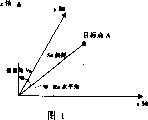
请参见图1,图1以一坐标系来显示目标点A的坐标测量方法。坐标系的原点0是全站仪的架设位置,全站仪可以测得该目标点A的三个数据值,即:目标点A到全站仪距离Sa;目标点A和原点O的连线与X轴之间的夹角,水平角Ra;目标点A与原点的连线与Z轴之间的夹角,垂直角Va。Please refer to FIG. 1 . FIG. 1 shows a coordinate measurement method of a target point A in a coordinate system. The origin 0 of the coordinate system is the erection position of the total station, and the total station can measure three data values of the target point A, namely: the distance Sa from the target point A to the total station; the connection line between the target point A and the origin O The angle between it and the X axis is the horizontal angle Ra; the angle between the line connecting the target point A and the origin and the Z axis is the vertical angle Va.
然后通过如下的公式计算得到该被测点的坐标值:Then calculate the coordinate value of the measured point by the following formula:
Ax=Sa×sinVa×sinRa;Ax =Sa×sinVa×sinRa;
Ay=Sa×sinVa×cosRa;Ay =Sa×sinVa×cosRa;
Az=Sa×sinVa。Az =Sa×sinVa.
在介绍了利用全站仪来测量目标点的坐标值之后,结合图2和图3来描述本发明的测量方法。After introducing the use of the total station to measure the coordinates of the target point, the measurement method of the present invention will be described in conjunction with FIG. 2 and FIG. 3 .
图2示意性地示出了一个辊轴系统。通常在安装辊轴系统时,为了保证安装的水平度,在整个系统的外侧会设置两个中心点,R01和R02(可分别称为第一中心点R01和第三中心点R02),该两中心点R01和R02之间的连线即为整个系统的中心线,要求所有的辊轴A、B、C都与该中心线垂直。Figure 2 schematically shows a roller system. Usually, when installing the roller shaft system, in order to ensure the levelness of the installation, two center points, R01 and R02 (respectively referred to as the first center point R01 and the third center point R02), will be set on the outside of the entire system. The connecting line between the center points R01 and R02 is the center line of the whole system, and all roller axes A, B, and C are required to be perpendicular to the center line.
在本例中,假设先测量辊轴A的水平度。首先,将全站仪31架设在两中心线点R1与R2之间,使全站仪31能观察到该两中心点R01和R02。然后,在被测的辊轴A上固定一标秆32。标杆可以采用传统的标杆,在标杆32的自由端(即远离与辊轴固定的一端)上设置有反射标志,全站仪后续就是测量该反射标志的坐标值。In this example, it is assumed that the levelness of roll A is measured first. Firstly, the total station 31 is erected between the two centerline points R1 and R2, so that the total station 31 can observe the two center points R01 and R02. Then, a mark stalk 32 is fixed on the roll axis A to be tested. The benchmark can be a traditional benchmark, and a reflective mark is provided on the free end of the mark 32 (that is, the end away from the fixed end of the roller), and the total station is to measure the coordinate value of the reflective mark subsequently.
在完成这些架设和固定动作之后,即可以开始测量了。通常可以先测量第一中心线点R01和第二中心线点R02的坐标值。此时测得的坐标值是以全站仪31的架设位置为原点的坐标系中的坐标值。然后再测量被测辊轴A三个不同旋转位置时,标杆上的反射标志的空间坐标。After completing these erection and fixing actions, the measurement can be started. Usually, the coordinate values of the first centerline point R01 and the second centerline point R02 can be measured first. The coordinate values measured at this time are coordinate values in a coordinate system whose origin is the erection position of the total station 31 . Then measure the spatial coordinates of the reflective marks on the pole at three different rotational positions of the measured roller axis A.
请参见图3,转动被测辊轴A,并在如图所示的三个点1#、2#、3#上测量辊轴A三个不同旋转位置时,标杆上的反射标志的坐标值。下表是这些点的坐标值的一个实际例子:Please refer to Figure 3, rotate the measured roller axis A, and measure the coordinate values of the reflective marks on the pole when measuring the three different rotational positions of the roller axis A at the three points 1#, 2#, and 3# as shown in the figure . The following table is a practical example of the coordinate values of these points:
当然,从全站仪获得的直接参数是距离Sa、水平角Ra和垂直角Va。通过上述的公式就可以转换成相应的坐标值。目前也有一些全站仪已能将这些公式转换包含在设备之中,根据用户的要求可以直接输出上述坐标值,而不再需要用户转换。Of course, the direct parameters obtained from the total station are the distance Sa, the horizontal angle Ra and the vertical angle Va. The above formula can be converted into the corresponding coordinate value. At present, there are also some total stations that can include these formula conversions in the equipment, and can directly output the above coordinate values according to the user's requirements, without the need for user conversion.
由于上述的坐标值是以全站仪31为原点O的坐标系中的,因此,还需要作一坐标的转换,转换到以辊轴系统的中心线为基准的设备坐标系统中。即转换到以中心线点R01或R02之一为原点,以中心线为X轴的坐标系中。坐标系的转换对于本领域的技术人员来说,属于公知技术,因此,在实施例中不再作详细的描述,下表是经过坐标转换后的数据值,新坐标是以中心线点R01为原点,中心线为X轴:Since the above-mentioned coordinate values are in the coordinate system with the total station 31 as the origin O, it is also necessary to perform a coordinate transformation to convert to the equipment coordinate system based on the center line of the roller system. That is, it is transformed into a coordinate system with the centerline point R01 or R02 as the origin and the centerline as the X axis. The conversion of the coordinate system belongs to the known technology for those skilled in the art, therefore, no more detailed description in the embodiment, the following table is the data value after the coordinate conversion, and the new coordinate is based on the central line point R01 The origin, the centerline is the X axis:
对于标杆的转动角度,三个测量点之间的角度值越大,则测量的精度越高。通常最好能大于等于30度,小于等于120度;最佳地,该角度值为90度。For the rotation angle of the benchmark, the greater the angle value between the three measurement points, the higher the measurement accuracy. Usually, it is better to be greater than or equal to 30 degrees and less than or equal to 120 degrees; optimally, the angle value is 90 degrees.
在获得上述这些点在新坐标,即以中心线点之一为原点,以中心线为X轴的坐标系下的坐标值之后,就可以通过如下的公开运算获得该辊轴A的水平度。After obtaining the coordinate values of the above-mentioned points in the new coordinates, that is, taking one of the centerline points as the origin and taking the centerline as the X-axis coordinate value, the levelness of the roller axis A can be obtained through the following public calculation.
假设辊轴A的水平度为A水平度。Assume that the levelness of the roller axis A is Alevelness .
先计算第二旋转位置测量点2#至第一旋转位置测量点1#的矢量线
然后计算矢量线与

Xr=(Y2-Y1)(Z2-Z3)-(Z2-Z1)(Y2-Y3)Xr=(Y2-Y1)(Z2-Z3)-(Z2-Z1)(Y2-Y3)
Yr=(Z2-Z1)(X2-X3)-(X2-X1)(Z2-Z3)Yr=(Z2-Z1)(X2-X3)-(X2-X1)(Z2-Z3)
Zr=(X2-X1)(Y2-Y3)-(Y2-Y1)(X2-X3)Zr=(X2-X1)(Y2-Y3)-(Y2-Y1)(X2-X3)
最后通过下列公式即可得到该被测辊轴的水平度A水平度:Finally, the levelness Alevelness of the measured roller shaft can be obtained by the following formula:
A水平度=Zr/S水Alevelness = Zr /Swater

根据上述公式,经运算可得本实施例的水平度为-1.46mm/M。According to the above formula, the levelness of this embodiment can be calculated as -1.46mm/M.
虽然仅描述了在一个辊轴系统中对其中一个辊轴的水平度的测量方法,可以理解,对于系统中的其它辊轴可以采用同样的步骤进行测量。Although only the method for measuring the levelness of one roller in a roller system is described, it can be understood that the same steps can be used for other rollers in the system to measure.
上面实施例是以架设一台全站仪的情况下的测试方法。对于有些较大的辊轴系统,由于流水线的横向跨度大,通过一个测站的全站仪不能完全所在目标点的测量,这时需要先后或同时在不同位置架设多台全站仪。图4是一个在不同位置架设了三台全站仪的实施例,应当注意,虽然在本实施例中,以同时架设三台全站仪作为例子,但使用一台全站仪分三次架设测量也是一个可选的例子。The above embodiment is a test method in the case of setting up a total station. For some larger roller shaft systems, due to the large horizontal span of the assembly line, the total station through one measuring station cannot completely measure the target point. At this time, it is necessary to set up multiple total stations in different positions successively or at the same time. Fig. 4 is an embodiment in which three total stations are set up in different positions. It should be noted that although in this embodiment, three total stations are set up at the same time as an example, a total station is used to set up three total stations for measurement Also an optional example.
如图4所示,第一全站仪51架设在靠近第一中心线点R01的附近;第二全站仪52架设在靠近被测辊轴A的附近;第三全站仪架53设在靠近第二中心点R01的附近。然后,一个关键的步骤是在辊轴系统的外侧设置两个公共基准点XP和YP。该两公共基准点XP和YP位置的选取以该三台全站仪全部能够观察到为准。As shown in Figure 4, the first
然后由第一全站仪51测量第一中心点R01和公共基准点XP和YP的坐标值,这些坐标值是在以第一全站仪51的位置为原点的坐标系中的;由第二全站仪52测量被测辊轴A三个不同旋转位置时,标杆上的反射标志的空间坐标,以及和公共基准点XP和YP的坐标值,这些坐标值是在以第二全站仪52的位置为原点的坐标系中的;由第三全站仪53测量第二中心点R02和公共基准点XP和YP的坐标值,该坐标值是在以第三全站仪53的位置为原点的坐标系中的。Then measure the coordinate values of the first central point R01 and public reference points XP and YP by the first
由于选用了三台全站仪,且三台全站仪选用的坐标系是不同的,因此,与图2实施例不同的是需要增加一个坐标系转换的步骤。即先分别把第一全站仪51测得的第一中心点的空间坐标转换成以两公共控制点之一为原点,以两公共控制点的连线为X轴的坐标系上;把第二全站仪52测得的第一旋转位置测量点、第二旋转位置测量点和第三旋转位置测量点的坐标转换成以两公共控制点之一为原点,以两公共控制点的连线为X轴的坐标系上;把第三全站仪53测得的第二中心点的空间坐标转换成以两公共控制点之一为原点,以两公共控制点的连线为X轴的坐标系上。Since three total stations are selected, and the coordinate systems selected by the three total stations are different, the difference from the embodiment in Fig. 2 is that a step of coordinate system transformation needs to be added. Promptly transform the space coordinates of the first central point measured by the first
在进行了上述的坐标转换到公共坐标系之后,再把这些坐标转换到以第一中心线点R01或第二中心线点R02之一为原点,以第一中心线点R01与第二中心线点R02之间的连线为X轴的坐标系的坐标值,即:将以两公共控制点之一为原点,以两公共控制点的连线为X轴的坐标系上的第一中心点坐标、第二中心点坐标和第一旋转位置测量点、第二旋转位置测量点、第三旋转位置测量点的坐标转换成以第一中心线点或第二中心线点之一为原点,以所述第一中心线点与第二中心线点之间的连线为X轴的坐标系的坐标值。这样的转换完成之后,即可根据上述的方法计算了该辊轴的水平度。After the above-mentioned coordinates are transformed into the common coordinate system, these coordinates are transformed to take one of the first centerline point R01 or the second centerline point R02 as the origin, and take the first centerline point R01 and the second centerline point R01 as the origin. The connection line between points R02 is the coordinate value of the X-axis coordinate system, that is, one of the two public control points is taken as the origin, and the connection line between the two public control points is the first center point on the X-axis coordinate system Coordinates, the coordinates of the second central point and the coordinates of the first rotational position measurement point, the second rotational position measurement point, and the third rotational position measurement point are transformed into one of the first central line point or the second central line point as the origin, with The line connecting the first centerline point and the second centerline point is the coordinate value of the X-axis coordinate system. After such conversion is completed, the levelness of the roller shaft can be calculated according to the above-mentioned method.
对于一些稍小一些的辊轴系统,可以采用两台全站仪,图5示出了使用两台全站仪的测试方法示意图。其测量方法基本上与上述相同,在此不再赘述。For some smaller roller systems, two total stations can be used. Figure 5 shows a schematic diagram of the test method using two total stations. Its measurement method is basically the same as above, and will not be repeated here.
Claims (9)
Translated fromChinese


Priority Applications (1)
| Application Number | Priority Date | Filing Date | Title |
|---|---|---|---|
| CNB2004100931245ACN100334418C (en) | 2004-12-16 | 2004-12-16 | Method for measuring roller shaft levelness in roller space position detection |
Applications Claiming Priority (1)
| Application Number | Priority Date | Filing Date | Title |
|---|---|---|---|
| CNB2004100931245ACN100334418C (en) | 2004-12-16 | 2004-12-16 | Method for measuring roller shaft levelness in roller space position detection |
Publications (2)
| Publication Number | Publication Date |
|---|---|
| CN1789899A CN1789899A (en) | 2006-06-21 |
| CN100334418Ctrue CN100334418C (en) | 2007-08-29 |
Family
ID=36787916
Family Applications (1)
| Application Number | Title | Priority Date | Filing Date |
|---|---|---|---|
| CNB2004100931245AExpired - LifetimeCN100334418C (en) | 2004-12-16 | 2004-12-16 | Method for measuring roller shaft levelness in roller space position detection |
Country Status (1)
| Country | Link |
|---|---|
| CN (1) | CN100334418C (en) |
Families Citing this family (12)
| Publication number | Priority date | Publication date | Assignee | Title |
|---|---|---|---|---|
| CN101210812B (en)* | 2006-12-28 | 2012-06-06 | 上海宝钢工业检测公司 | Hoist-transportation machine trajectory space relationship automated detection method |
| CN101398284B (en)* | 2007-09-28 | 2012-01-04 | 中国二十冶集团有限公司 | Measurement method for squareness and depth of parallelism of roll table |
| CN103673976A (en)* | 2013-12-03 | 2014-03-26 | 上海卫星装备研究所 | Method and system for converting and unifying composite type precision measuring coordinate system |
| CN104101314B (en)* | 2014-08-06 | 2017-08-25 | 中国十九冶集团有限公司 | One-time positioning method for center line of multi-layer belt conveyor |
| CN106238506A (en)* | 2016-09-18 | 2016-12-21 | 舞阳钢铁有限责任公司 | A kind of method of quick measurement Double-side-shearing pinch roll |
| CN108687164B (en)* | 2018-05-15 | 2019-12-06 | 中冶宝钢技术服务有限公司 | Method for adjusting levelness of winding drum of coiler |
| CN109059844A (en)* | 2018-09-28 | 2018-12-21 | 上海宝冶建筑工程有限公司 | A kind of measurement method of long range rail linearity degree and flatness |
| KR101914942B1 (en)* | 2018-10-08 | 2018-11-06 | 정홍석 | Apparatus and method for measuring alignment state of the roll |
| CN109352019B (en)* | 2018-11-19 | 2019-09-24 | 青岛海西重机有限责任公司 | A kind of crane walking equalizer bar axis hole processing method |
| CN109855611B (en)* | 2019-03-27 | 2022-03-15 | 中南大学 | A rapid measurement and calibration method of PC wall based on total station |
| CN112033364A (en)* | 2020-09-02 | 2020-12-04 | 本溪钢铁(集团)机电安装工程有限公司 | Roller system levelness and verticality detection process |
| CN113532342B (en)* | 2021-06-29 | 2023-02-10 | 中石化宁波工程有限公司 | Method for determining central points of upper and lower seal head pipe connecting holes of mixing drum of large-scale mixing equipment |
Citations (3)
| Publication number | Priority date | Publication date | Assignee | Title |
|---|---|---|---|---|
| US5068971A (en)* | 1990-03-23 | 1991-12-03 | Simco Industries, Inc. | Adjustable portable coordinate measuring machine |
| US5253429A (en)* | 1991-03-07 | 1993-10-19 | Mitutoyo Corporation | Levelling method and apparatus |
| CN2390181Y (en)* | 1998-11-03 | 2000-08-02 | 王建雷 | Perpendicularity and levelness measurer |
- 2004
- 2004-12-16CNCNB2004100931245Apatent/CN100334418C/ennot_activeExpired - Lifetime
Patent Citations (3)
| Publication number | Priority date | Publication date | Assignee | Title |
|---|---|---|---|---|
| US5068971A (en)* | 1990-03-23 | 1991-12-03 | Simco Industries, Inc. | Adjustable portable coordinate measuring machine |
| US5253429A (en)* | 1991-03-07 | 1993-10-19 | Mitutoyo Corporation | Levelling method and apparatus |
| CN2390181Y (en)* | 1998-11-03 | 2000-08-02 | 王建雷 | Perpendicularity and levelness measurer |
Also Published As
| Publication number | Publication date |
|---|---|
| CN1789899A (en) | 2006-06-21 |
Similar Documents
| Publication | Publication Date | Title |
|---|---|---|
| CN100334418C (en) | Method for measuring roller shaft levelness in roller space position detection | |
| KR102431799B1 (en) | Method and system for measuring coating thickness of steel plate | |
| CN106540968B (en) | The compensation method of cold rolled sheet shape measured value and device | |
| CN103167606B (en) | Based on the WLAN indoor orientation method of rarefaction representation | |
| CN110068794B (en) | AOA positioning optimization compensation method | |
| CN111780772B (en) | Map blind area vehicle positioning and correcting method | |
| CN110516350B (en) | ERS point error correction method based on anisotropic weighting | |
| CN111922096B (en) | A portable roll shape measuring instrument | |
| CN104483891A (en) | Method for improving machine tool space movement precision | |
| CN100334419C (en) | Method for measuring roller shaft verticality in roller space position detection | |
| CN114740425A (en) | Bluetooth positioning method and system fusing path planning information | |
| CN108225721A (en) | A kind of wind tunnel experiment surveys the method with reference to wind speed | |
| CN117739868A (en) | Stator core verticality online measurement method and device | |
| CN116502424A (en) | Online error estimation method for intelligent electric energy meter | |
| CN109780987A (en) | Strain gauge adhesion localization method in a kind of oil-gas pipeline depressed deformation strain field measurement | |
| CN110360937B (en) | An Automatic Measurement Method of Paper Roll Width Based on Laser Rangefinder | |
| JP2001280600A (en) | Thinning management system | |
| CN107796492B (en) | Online calibration method for ultrasonic gas meter | |
| CN206959954U (en) | A kind of online contrastive test device of ultrasonic flow and flow quantity detecting system | |
| CN106556338B (en) | A special device and method for measuring large radius of curvature | |
| CN108672502A (en) | Strip width control method, device and terminal device | |
| CN115574706B (en) | A high-precision monitoring method for earth-rock dam surface deformation based on GNSS | |
| CN104777526B (en) | A Correction Method of Wind Velocity Retrieval by ASCAT | |
| CN112698375B (en) | Circuit drawing method for eliminating multi-domain double positioning errors | |
| CN115453442B (en) | A method for calculating the accuracy inaccuracy of electric energy meters in centralized meter boxes |
Legal Events
| Date | Code | Title | Description |
|---|---|---|---|
| C06 | Publication | ||
| PB01 | Publication | ||
| C10 | Entry into substantive examination | ||
| SE01 | Entry into force of request for substantive examination | ||
| C14 | Grant of patent or utility model | ||
| GR01 | Patent grant | ||
| CX01 | Expiry of patent term | ||
| CX01 | Expiry of patent term | Granted publication date:20070829 |