BRPI0515999B1 - Syringe device and method for using the same - Google Patents
Syringe device and method for using the sameDownload PDFInfo
- Publication number
- BRPI0515999B1 BRPI0515999B1BRPI0515999-7ABRPI0515999ABRPI0515999B1BR PI0515999 B1BRPI0515999 B1BR PI0515999B1BR PI0515999 ABRPI0515999 ABR PI0515999ABR PI0515999 B1BRPI0515999 B1BR PI0515999B1
- Authority
- BR
- Brazil
- Prior art keywords
- piston
- vial
- syringe
- valve
- housing
- Prior art date
Links
- 238000000034methodMethods0.000titleclaimsabstractdescription33
- 230000006641stabilisationEffects0.000claimsdescription6
- 238000011105stabilizationMethods0.000claimsdescription6
- 230000000087stabilizing effectEffects0.000claimsdescription3
- 239000012530fluidSubstances0.000abstractdescription91
- 238000002156mixingMethods0.000abstractdescription81
- 239000003814drugSubstances0.000abstractdescription57
- 229940079593drugDrugs0.000abstractdescription46
- 239000003795chemical substances by applicationSubstances0.000abstractdescription24
- 239000000463materialSubstances0.000description72
- 238000004806packaging method and processMethods0.000description39
- 238000012546transferMethods0.000description31
- 239000000203mixtureSubstances0.000description23
- 238000002360preparation methodMethods0.000description19
- 238000003780insertionMethods0.000description18
- 230000037431insertionEffects0.000description18
- 229920003023plasticPolymers0.000description17
- 239000004033plasticSubstances0.000description17
- 230000004888barrier functionEffects0.000description10
- 238000004891communicationMethods0.000description10
- -1polyethylenesPolymers0.000description10
- 238000005553drillingMethods0.000description9
- 238000005520cutting processMethods0.000description7
- 239000007788liquidSubstances0.000description7
- 238000002372labellingMethods0.000description6
- 239000004743PolypropyleneSubstances0.000description5
- 238000011109contaminationMethods0.000description5
- 229920001577copolymerPolymers0.000description5
- 238000000605extractionMethods0.000description5
- 238000005304joiningMethods0.000description5
- 230000036961partial effectEffects0.000description5
- 229920001155polypropylenePolymers0.000description5
- 239000004814polyurethaneSubstances0.000description5
- 229920002635polyurethanePolymers0.000description5
- 238000005086pumpingMethods0.000description5
- 230000002441reversible effectEffects0.000description5
- 239000002131composite materialSubstances0.000description4
- 230000014759maintenance of locationEffects0.000description4
- 238000004519manufacturing processMethods0.000description4
- 230000000717retained effectEffects0.000description4
- 229920002943EPDM rubberPolymers0.000description3
- 239000004952PolyamideSubstances0.000description3
- 239000004698PolyethyleneSubstances0.000description3
- 230000000903blocking effectEffects0.000description3
- 238000005259measurementMethods0.000description3
- 239000005022packaging materialSubstances0.000description3
- 229920000058polyacrylatePolymers0.000description3
- 229920002647polyamidePolymers0.000description3
- 239000004417polycarbonateSubstances0.000description3
- 229920000515polycarbonatePolymers0.000description3
- 229920000573polyethylenePolymers0.000description3
- 229920001296polysiloxanePolymers0.000description3
- 238000003860storageMethods0.000description3
- 238000003466weldingMethods0.000description3
- 206010067484Adverse reactionDiseases0.000description2
- 230000006978adaptationEffects0.000description2
- 230000006838adverse reactionEffects0.000description2
- 125000001931aliphatic groupChemical group0.000description2
- 238000004458analytical methodMethods0.000description2
- 125000003118aryl groupChemical group0.000description2
- 230000015572biosynthetic processEffects0.000description2
- 125000000484butyl groupChemical group[H]C([*])([H])C([H])([H])C([H])([H])C([H])([H])[H]0.000description2
- 239000003085diluting agentSubstances0.000description2
- 239000011521glassSubstances0.000description2
- 238000000465mouldingMethods0.000description2
- 229920003050poly-cycloolefinPolymers0.000description2
- 229920000728polyesterPolymers0.000description2
- 239000004800polyvinyl chlorideSubstances0.000description2
- 239000000126substanceSubstances0.000description2
- 230000000007visual effectEffects0.000description2
- 241001049165CariaSpecies0.000description1
- 239000004593EpoxySubstances0.000description1
- 244000043261Hevea brasiliensisSpecies0.000description1
- RRHGJUQNOFWUDK-UHFFFAOYSA-NIsopreneChemical classCC(=C)C=CRRHGJUQNOFWUDK-UHFFFAOYSA-N0.000description1
- 229920000459Nitrile rubberPolymers0.000description1
- 208000027418Wounds and injuryDiseases0.000description1
- 230000004308accommodationEffects0.000description1
- 239000000853adhesiveSubstances0.000description1
- 238000004026adhesive bondingMethods0.000description1
- 230000001070adhesive effectEffects0.000description1
- 230000000712assemblyEffects0.000description1
- 238000000429assemblyMethods0.000description1
- 230000002457bidirectional effectEffects0.000description1
- 238000010276constructionMethods0.000description1
- 230000006378damageEffects0.000description1
- 230000007547defectEffects0.000description1
- 238000013461designMethods0.000description1
- 238000001035dryingMethods0.000description1
- 229920001971elastomerPolymers0.000description1
- 239000013536elastomeric materialSubstances0.000description1
- 125000003700epoxy groupChemical group0.000description1
- 238000004108freeze dryingMethods0.000description1
- 238000004817gas chromatographyMethods0.000description1
- 230000036512infertilityEffects0.000description1
- 230000000977initiatory effectEffects0.000description1
- 238000002347injectionMethods0.000description1
- 239000007924injectionSubstances0.000description1
- 238000001746injection mouldingMethods0.000description1
- 208000014674injuryDiseases0.000description1
- 238000010255intramuscular injectionMethods0.000description1
- 239000007927intramuscular injectionSubstances0.000description1
- 230000000670limiting effectEffects0.000description1
- 239000011344liquid materialSubstances0.000description1
- 238000004949mass spectrometryMethods0.000description1
- 238000002483medicationMethods0.000description1
- 229910052751metalInorganic materials0.000description1
- 239000002184metalSubstances0.000description1
- 150000002739metalsChemical class0.000description1
- 238000012986modificationMethods0.000description1
- 230000004048modificationEffects0.000description1
- 239000000178monomerSubstances0.000description1
- 229920003052natural elastomerPolymers0.000description1
- 229920001194natural rubberPolymers0.000description1
- NJPPVKZQTLUDBO-UHFFFAOYSA-NnovaluronChemical compoundC1=C(Cl)C(OC(F)(F)C(OC(F)(F)F)F)=CC=C1NC(=O)NC(=O)C1=C(F)C=CC=C1FNJPPVKZQTLUDBO-UHFFFAOYSA-N0.000description1
- 244000144985peepSpecies0.000description1
- 229920001084poly(chloroprene)Polymers0.000description1
- 229920002492poly(sulfone)Polymers0.000description1
- 229920000647polyepoxidePolymers0.000description1
- 229920001601polyetherimidePolymers0.000description1
- 230000001681protective effectEffects0.000description1
- 230000001105regulatory effectEffects0.000description1
- 239000005060rubberSubstances0.000description1
- 238000007789sealingMethods0.000description1
- 150000004756silanesChemical class0.000description1
- 239000007779soft materialSubstances0.000description1
- 238000005476solderingMethods0.000description1
- 239000007787solidSubstances0.000description1
- 239000000243solutionSubstances0.000description1
- 229910001220stainless steelInorganic materials0.000description1
- 239000010935stainless steelSubstances0.000description1
- 239000010421standard materialSubstances0.000description1
- 238000003756stirringMethods0.000description1
- 239000000725suspensionSubstances0.000description1
- 229920001169thermoplasticPolymers0.000description1
- 229920001187thermosetting polymerPolymers0.000description1
- 239000004416thermosoftening plasticSubstances0.000description1
- 238000011179visual inspectionMethods0.000description1
- 238000005493welding typeMethods0.000description1
Images


Classifications
- A—HUMAN NECESSITIES
- A61—MEDICAL OR VETERINARY SCIENCE; HYGIENE
- A61J—CONTAINERS SPECIALLY ADAPTED FOR MEDICAL OR PHARMACEUTICAL PURPOSES; DEVICES OR METHODS SPECIALLY ADAPTED FOR BRINGING PHARMACEUTICAL PRODUCTS INTO PARTICULAR PHYSICAL OR ADMINISTERING FORMS; DEVICES FOR ADMINISTERING FOOD OR MEDICINES ORALLY; BABY COMFORTERS; DEVICES FOR RECEIVING SPITTLE
- A61J1/00—Containers specially adapted for medical or pharmaceutical purposes
- A61J1/14—Details; Accessories therefor
- A61J1/20—Arrangements for transferring or mixing fluids, e.g. from vial to syringe
- A61J1/2096—Combination of a vial and a syringe for transferring or mixing their contents
- A—HUMAN NECESSITIES
- A61—MEDICAL OR VETERINARY SCIENCE; HYGIENE
- A61M—DEVICES FOR INTRODUCING MEDIA INTO, OR ONTO, THE BODY; DEVICES FOR TRANSDUCING BODY MEDIA OR FOR TAKING MEDIA FROM THE BODY; DEVICES FOR PRODUCING OR ENDING SLEEP OR STUPOR
- A61M5/00—Devices for bringing media into the body in a subcutaneous, intra-vascular or intramuscular way; Accessories therefor, e.g. filling or cleaning devices, arm-rests
- A61M5/002—Packages specially adapted therefor, e.g. for syringes or needles, kits for diabetics
- A—HUMAN NECESSITIES
- A61—MEDICAL OR VETERINARY SCIENCE; HYGIENE
- A61M—DEVICES FOR INTRODUCING MEDIA INTO, OR ONTO, THE BODY; DEVICES FOR TRANSDUCING BODY MEDIA OR FOR TAKING MEDIA FROM THE BODY; DEVICES FOR PRODUCING OR ENDING SLEEP OR STUPOR
- A61M5/00—Devices for bringing media into the body in a subcutaneous, intra-vascular or intramuscular way; Accessories therefor, e.g. filling or cleaning devices, arm-rests
- A61M5/178—Syringes
- A61M5/20—Automatic syringes, e.g. with automatically actuated piston rod, with automatic needle injection, filling automatically
- A61M5/204—Automatic syringes, e.g. with automatically actuated piston rod, with automatic needle injection, filling automatically connected to external reservoirs for multiple refilling
- A—HUMAN NECESSITIES
- A61—MEDICAL OR VETERINARY SCIENCE; HYGIENE
- A61M—DEVICES FOR INTRODUCING MEDIA INTO, OR ONTO, THE BODY; DEVICES FOR TRANSDUCING BODY MEDIA OR FOR TAKING MEDIA FROM THE BODY; DEVICES FOR PRODUCING OR ENDING SLEEP OR STUPOR
- A61M5/00—Devices for bringing media into the body in a subcutaneous, intra-vascular or intramuscular way; Accessories therefor, e.g. filling or cleaning devices, arm-rests
- A61M5/178—Syringes
- A61M5/28—Syringe ampoules or carpules, i.e. ampoules or carpules provided with a needle
- A61M5/284—Syringe ampoules or carpules, i.e. ampoules or carpules provided with a needle comprising means for injection of two or more media, e.g. by mixing
- A—HUMAN NECESSITIES
- A61—MEDICAL OR VETERINARY SCIENCE; HYGIENE
- A61M—DEVICES FOR INTRODUCING MEDIA INTO, OR ONTO, THE BODY; DEVICES FOR TRANSDUCING BODY MEDIA OR FOR TAKING MEDIA FROM THE BODY; DEVICES FOR PRODUCING OR ENDING SLEEP OR STUPOR
- A61M5/00—Devices for bringing media into the body in a subcutaneous, intra-vascular or intramuscular way; Accessories therefor, e.g. filling or cleaning devices, arm-rests
- A61M5/178—Syringes
- A61M5/31—Details
- A61M5/315—Pistons; Piston-rods; Guiding, blocking or restricting the movement of the rod or piston; Appliances on the rod for facilitating dosing ; Dosing mechanisms
- A61M5/31596—Pistons; Piston-rods; Guiding, blocking or restricting the movement of the rod or piston; Appliances on the rod for facilitating dosing ; Dosing mechanisms comprising means for injection of two or more media, e.g. by mixing
- A—HUMAN NECESSITIES
- A61—MEDICAL OR VETERINARY SCIENCE; HYGIENE
- A61J—CONTAINERS SPECIALLY ADAPTED FOR MEDICAL OR PHARMACEUTICAL PURPOSES; DEVICES OR METHODS SPECIALLY ADAPTED FOR BRINGING PHARMACEUTICAL PRODUCTS INTO PARTICULAR PHYSICAL OR ADMINISTERING FORMS; DEVICES FOR ADMINISTERING FOOD OR MEDICINES ORALLY; BABY COMFORTERS; DEVICES FOR RECEIVING SPITTLE
- A61J1/00—Containers specially adapted for medical or pharmaceutical purposes
- A61J1/14—Details; Accessories therefor
- A61J1/20—Arrangements for transferring or mixing fluids, e.g. from vial to syringe
- A61J1/2003—Accessories used in combination with means for transfer or mixing of fluids, e.g. for activating fluid flow, separating fluids, filtering fluid or venting
- A61J1/2006—Piercing means
- A61J1/201—Piercing means having one piercing end
- A—HUMAN NECESSITIES
- A61—MEDICAL OR VETERINARY SCIENCE; HYGIENE
- A61J—CONTAINERS SPECIALLY ADAPTED FOR MEDICAL OR PHARMACEUTICAL PURPOSES; DEVICES OR METHODS SPECIALLY ADAPTED FOR BRINGING PHARMACEUTICAL PRODUCTS INTO PARTICULAR PHYSICAL OR ADMINISTERING FORMS; DEVICES FOR ADMINISTERING FOOD OR MEDICINES ORALLY; BABY COMFORTERS; DEVICES FOR RECEIVING SPITTLE
- A61J1/00—Containers specially adapted for medical or pharmaceutical purposes
- A61J1/14—Details; Accessories therefor
- A61J1/20—Arrangements for transferring or mixing fluids, e.g. from vial to syringe
- A61J1/2003—Accessories used in combination with means for transfer or mixing of fluids, e.g. for activating fluid flow, separating fluids, filtering fluid or venting
- A61J1/2048—Connecting means
- A61J1/2058—Connecting means having multiple connecting ports
- A61J1/2062—Connecting means having multiple connecting ports with directional valves
- A—HUMAN NECESSITIES
- A61—MEDICAL OR VETERINARY SCIENCE; HYGIENE
- A61J—CONTAINERS SPECIALLY ADAPTED FOR MEDICAL OR PHARMACEUTICAL PURPOSES; DEVICES OR METHODS SPECIALLY ADAPTED FOR BRINGING PHARMACEUTICAL PRODUCTS INTO PARTICULAR PHYSICAL OR ADMINISTERING FORMS; DEVICES FOR ADMINISTERING FOOD OR MEDICINES ORALLY; BABY COMFORTERS; DEVICES FOR RECEIVING SPITTLE
- A61J1/00—Containers specially adapted for medical or pharmaceutical purposes
- A61J1/14—Details; Accessories therefor
- A61J1/20—Arrangements for transferring or mixing fluids, e.g. from vial to syringe
- A61J1/2003—Accessories used in combination with means for transfer or mixing of fluids, e.g. for activating fluid flow, separating fluids, filtering fluid or venting
- A61J1/2048—Connecting means
- A61J1/2065—Connecting means having aligning and guiding means
- A—HUMAN NECESSITIES
- A61—MEDICAL OR VETERINARY SCIENCE; HYGIENE
- A61J—CONTAINERS SPECIALLY ADAPTED FOR MEDICAL OR PHARMACEUTICAL PURPOSES; DEVICES OR METHODS SPECIALLY ADAPTED FOR BRINGING PHARMACEUTICAL PRODUCTS INTO PARTICULAR PHYSICAL OR ADMINISTERING FORMS; DEVICES FOR ADMINISTERING FOOD OR MEDICINES ORALLY; BABY COMFORTERS; DEVICES FOR RECEIVING SPITTLE
- A61J1/00—Containers specially adapted for medical or pharmaceutical purposes
- A61J1/14—Details; Accessories therefor
- A61J1/20—Arrangements for transferring or mixing fluids, e.g. from vial to syringe
- A61J1/2003—Accessories used in combination with means for transfer or mixing of fluids, e.g. for activating fluid flow, separating fluids, filtering fluid or venting
- A61J1/2079—Filtering means
- A61J1/2086—Filtering means for fluid filtration
- A—HUMAN NECESSITIES
- A61—MEDICAL OR VETERINARY SCIENCE; HYGIENE
- A61M—DEVICES FOR INTRODUCING MEDIA INTO, OR ONTO, THE BODY; DEVICES FOR TRANSDUCING BODY MEDIA OR FOR TAKING MEDIA FROM THE BODY; DEVICES FOR PRODUCING OR ENDING SLEEP OR STUPOR
- A61M5/00—Devices for bringing media into the body in a subcutaneous, intra-vascular or intramuscular way; Accessories therefor, e.g. filling or cleaning devices, arm-rests
- A61M5/178—Syringes
- A61M5/31—Details
- A61M2005/3117—Means preventing contamination of the medicament compartment of a syringe
- A—HUMAN NECESSITIES
- A61—MEDICAL OR VETERINARY SCIENCE; HYGIENE
- A61M—DEVICES FOR INTRODUCING MEDIA INTO, OR ONTO, THE BODY; DEVICES FOR TRANSDUCING BODY MEDIA OR FOR TAKING MEDIA FROM THE BODY; DEVICES FOR PRODUCING OR ENDING SLEEP OR STUPOR
- A61M5/00—Devices for bringing media into the body in a subcutaneous, intra-vascular or intramuscular way; Accessories therefor, e.g. filling or cleaning devices, arm-rests
- A61M5/178—Syringes
- A61M5/31—Details
- A61M2005/3128—Incorporating one-way valves, e.g. pressure-relief or non-return valves
- A—HUMAN NECESSITIES
- A61—MEDICAL OR VETERINARY SCIENCE; HYGIENE
- A61M—DEVICES FOR INTRODUCING MEDIA INTO, OR ONTO, THE BODY; DEVICES FOR TRANSDUCING BODY MEDIA OR FOR TAKING MEDIA FROM THE BODY; DEVICES FOR PRODUCING OR ENDING SLEEP OR STUPOR
- A61M2205/00—General characteristics of the apparatus
- A61M2205/58—Means for facilitating use, e.g. by people with impaired vision
- A61M2205/582—Means for facilitating use, e.g. by people with impaired vision by tactile feedback
- A—HUMAN NECESSITIES
- A61—MEDICAL OR VETERINARY SCIENCE; HYGIENE
- A61M—DEVICES FOR INTRODUCING MEDIA INTO, OR ONTO, THE BODY; DEVICES FOR TRANSDUCING BODY MEDIA OR FOR TAKING MEDIA FROM THE BODY; DEVICES FOR PRODUCING OR ENDING SLEEP OR STUPOR
- A61M2205/00—General characteristics of the apparatus
- A61M2205/58—Means for facilitating use, e.g. by people with impaired vision
- A61M2205/583—Means for facilitating use, e.g. by people with impaired vision by visual feedback
Landscapes
- Health & Medical Sciences (AREA)
- Veterinary Medicine (AREA)
- Life Sciences & Earth Sciences (AREA)
- Animal Behavior & Ethology (AREA)
- General Health & Medical Sciences (AREA)
- Public Health (AREA)
- Engineering & Computer Science (AREA)
- Vascular Medicine (AREA)
- Anesthesiology (AREA)
- Biomedical Technology (AREA)
- Heart & Thoracic Surgery (AREA)
- Hematology (AREA)
- Pharmacology & Pharmacy (AREA)
- Diabetes (AREA)
- Infusion, Injection, And Reservoir Apparatuses (AREA)
- Medical Preparation Storing Or Oral Administration Devices (AREA)
Abstract
Translated fromPortugueseDescription
Translated fromPortugueseO método pertence a dispositivos de seringa, es-truturas de perfuração, sistemas de preparação de agente de medicação, sistemas de mistura e administração, métodos de mistura de componentes e métodos de preparação de um agente de medicação para administração em um indivíduo.The method pertains to syringe devices, piercing structures, medication agent preparation systems, mixing and delivery systems, component mixing methods, and methods of preparing a medication agent for administration to a subject.
A preparação de medicamento ou agentes de medica-ção e a administração de tais agentes em um indivíduo fre- qüentemente envolvem a mistura de dois ou mais componentes para formar o agente e a aplicação subseqüente do medicamen-to misturado no indivíduo. A mistura dos componentes pode envolver tipicamente a extração de um componente na forma fluida de um frasco ou outro recipiente e a transferência de tais componentes para um recipiente separado que mantém um outro componente. Em casos particulares, somente uma porção dos conteúdos de um frasco ou recipiente é para ser utiliza-da para a preparação de uma mistura antes da administração. Dessa maneira, a extração e a transferência podem envolver a medição precisa de um ou mais componentes a serem mistura-dos.The preparation of medication or medication agents and the administration of such agents to a subject often involves mixing two or more components to form the agent and subsequently applying the mixed medication to the subject. Mixing the components can typically involve extracting one component in fluid form from a vial or other container and transferring such components to a separate container that holds another component. In particular cases, only a portion of the contents of a vial or container is to be used for preparing a mixture prior to administration. In this way, extraction and transfer may involve the precise measurement of one or more components to be mixed.
Uma variedade de problemas pode ocorrer quando utilizando metodologia e dispositivos convencionais para a mistura e/ou a administração de medicamentos em um indiví-duo. Por exemplo, onde múltiplos componentes devem ser mis-turados, a extração e a transferência de um componente e a " introdução de tal componente em um outro componente pode ex por potencialmente um ou ambos os componentes a um ambiente não estéril ou contaminado levando à contaminação do medicamento resultante. Adicionalmente, a extração incompleta ou a 5 medição imprópria de um ou mais componentes pode resultar na preparação e/ou na administração de uma dosagem imprópria. Em casos particulares, depois que o medicamento é misturado, a mistura deve novamente ser extraída de um frasco ou recipiente para dentro de uma seringa antes da administração em 10 um indivíduo. Tal transferência adicional pode levar a oportunidades adicionais de contaminação, extração incompleta dos conteúdos e/ou medição imprecisa de um componente do medicamento resultante. Na prática, existe disponibilidade li- mitada de ambientes estéreis para manter a esterilidade du- W 15 rante a transferência e/ou mistura de componentes, ou preparação e transferência de medicamentos. Erros adicionais podem resultar do uso do diluente errado para reconstituir a medicação. Finalmente, a preparação dos medicamentos utilizando múltiplos componentes pode ser tediosa e longa devido .20 a fatores tal como a necessidade de acessar itens individualmente embalados tal como frascos separados e/ou dispositivos de transferência, ou medir um ou mais componentes a serem combinados para formar o medicamento.A variety of problems can occur when using conventional methodology and devices for mixing and/or administering medications to an individual. For example, where multiple components must be mixed, the extraction and transfer of one component and the "introduction of such a component into another component can potentially expose one or both components to a non-sterile or contaminated environment leading to contamination." of the resulting drug. Additionally, incomplete extraction or improper measurement of one or more components may result in the preparation and/or administration of an improper dosage. In particular cases, after the drug is mixed, the mixture must be extracted again from a vial or container into a syringe prior to administration to an individual. Such additional transfer may lead to additional opportunities for contamination, incomplete extraction of contents, and/or inaccurate measurement of a component of the resulting drug. In practice, there is availability limited use of sterile environments to maintain sterility during
Seria desejável desenvolver metodologia e sistemas 25 alternativos para a preparação e a administração de medicamentos.It would be desirable to develop alternative methodology and systems 25 for the preparation and administration of drugs.
Em um aspecto, a invenção abrange um dispositivo * de seringa. 0 dispositivo inclui um corpo de seringa tendo um alojamento cilíndrico e uma câmara dentro do alojamento. 0 dispositivo adicionalmente inclui um pistão tendo uma haste, uma primeira extremidade e uma segunda extremidade opos- 5 ta à primeira extremidade. A primeira extremidade é externa à câmara compreendida pelo corpo da seringa. Uma passagem de fluido se estende através da primeira extremidade através da haste e através da segunda extremidade do pistão. 0 dispositivo de seringa também inclui uma válvula que está associada 10 com a passagem de fluido através do pistão tal que a válvula controla a passagem seletiva de fluido através, do pistão. Uma tampa pode ser presa de modo reversível no corpo da seringa para prover uma vedação ao fluido. Em um aspecto, a invenção abrange uma estrutura de perfuração tendo um segmento de cabeça compreendendo uma ponta disposta em uma primeira extremidade da estrutura. A cabeça tem uma superfície frontal e uma superfície posterior oposta. A estrutura de perfuração adicionalmente inclui uma porção de corpo compreendendo uma superfície de base dispos- 20 ta em uma segunda extremidade oposta à primeira extremidade da estrutura. Uma passagem de fluido passa através da segunda extremidade da estrutura através da porção de corpo e a- través de pelo menos uma da superfície frontal e da superfície traseira da cabeça sem passar através da ponta. Em um aspecto, a invenção abrange um sistema de preparação do agente de medicação. 0 sistema compreende uma seringa tendo um tubo com uma câmara interna, e um pistão tendo uma primeira extremidade, uma segunda extremidade e uma passagem de fluido passando longitudinalmente através do pistão. Pelo menos uma porção do pistão compreendendo a primeira extremidade é inserida na câmara. Uma estrutura de perfuração tendo um canal de fluido está associada com a se- gunda extremidade do pistão. Um frasco é disposto próximo e móvel em relação à ponta da estrutura de perfuração. Um pri-meiro componente de um agente de medicação é disposto dentro da câmara interna do tubo da seringa e o segundo componente do agente de medicação é disposto dentro do frasco. Uma vál- 10 vula está associada com a passagem de fluido que passa através do pistão.In one aspect, the invention encompasses a syringe device *. The device includes a syringe barrel having a cylindrical housing and a chamber within the housing. The device further includes a piston having a rod, a first end and a second end opposite the first end. The first end is external to the chamber comprised by the syringe body. A fluid passageway extends through the first end through the rod and through the second end of the piston. The syringe device also includes a valve which is associated with the passage of fluid through the piston such that the valve controls the selective passage of fluid through the piston. A cap may be reversibly secured to the syringe barrel to provide a seal to the fluid. In one aspect, the invention encompasses a perforation frame having a head segment comprising a spike disposed at a first end of the frame. The head has a front surface and an opposite back surface. The drill frame further includes a body portion comprising a base surface arranged at a second end opposite the first end of the frame. A fluid passage passes through the second end of the frame through the body portion and through at least one of the front surface and rear surface of the head without passing through the tip. In one aspect, the invention encompasses a medication agent preparation system. The system comprises a syringe having a tube with an internal chamber, and a piston having a first end, a second end and a fluid passage passing longitudinally through the piston. At least a portion of the piston comprising the first end is inserted into the chamber. A drilling structure having a fluid channel is associated with the second end of the piston. A vial is arranged close and movable with respect to the tip of the perforation frame. A first medication agent component is disposed within the inner chamber of the syringe tube and the second medication agent component is disposed within the vial. A valve is associated with the passage of fluid passing through the piston.
Em um outro aspecto, a invenção abrange um método de preparação de um agente de medicação para a administração 1 em um indivíduo. O método inclui prover uma seringa tendo um s r tubo de seringa e um pistão disposto em uma posição inicial em relação ao tubo de seringa. Um primeiro componente é pro-vido dentro do tubo de seringa e um segundo componente é provido dentro de um frasco. Uma válvula está associada com uma passagem de fluido entre o frasco e o tubo da seringa ,20 com a válvula inicialmente sendo disposta em uma posição fe-chada, bloqueando a passagem de fluido através da passagem. O método inclui reposicionar a válvula para permitir a passagem do fluido entre o frasco e o tubo da seringa. Depois de reposicionar a válvula, o pistão é deslizado em uma pri- meira direção para unir o primeiro componente com o segundo componente. O primeiro e o segundo componentes são misturados para produzir o agente de medicação. A mistura pode ser facilitada pela agitação, inversão do dispositivo e/ou des lizamento repetido do pistão em direções opostas. 0 método também inclui puxar o agente de medicação para dentro do tubo da seringa.In another aspect, the invention encompasses a method of preparing a medication agent for administration to a subject. The method includes providing a syringe having a syringe tube and a piston disposed at an initial position with respect to the syringe tube. A first component is provided within the syringe tube and a second component is provided within a vial. A valve is associated with a fluid passageway between the vial and the syringe tube, 20 with the valve initially being arranged in a closed position, blocking the passage of fluid through the passageway. The method includes repositioning the valve to allow fluid to pass between the vial and the syringe tube. After repositioning the valve, the piston is slid in a first direction to join the first component with the second component. The first and second components are mixed to produce the medication agent. Mixing can be facilitated by shaking, inverting the device and/or repeatedly sliding the piston in opposite directions. The method also includes drawing the medication agent into the syringe tube.
Em um aspecto adicional, a invenção inclui um mé- 5 todo de preparação de uma composição. Um material de embalagem é provido contendo um dispositivo de mistura no qual o dispositivo de mistura inclui um alojamento tendo uma câmara nele contendo um primeiro material. 0 dispositivo também inclui um pistão deslizável dentro da câmara com o pistão ten- 10 do um comprimento que é maior do que o comprimento da câmara. O dispositivo de mistura também inclui um recipiente mantendo um segundo material. Uma passagem de fluido é disposta longitudinalmente através do pistão com uma válvula ! sendo associada com a passagem de fluido. Sem expor o dispo- f sitivo a um ambiente externo ao material de embalagem, a válvula é reposicionada de uma posição fechada para uma posição aberta. Com a válvula na posição aberta o pistão é deslizado em uma primeira direção a partir de uma primeira posição dentro da câmara para uma segunda posição dentro da 20 câmara. 0 deslizamento do pistão move üm do primeiro é "segundo componentes através do pistão. O primeiro e o segundo materiais são então misturados para formar uma mistura onde a mistura compreende deslizar o pistão em uma segunda direção e subsequentemente retornar o pistão na primeira dire- ção. A mistura é então puxada para dentro da câmara através do pistão.In a further aspect, the invention includes a method of preparing a composition. A packaging material is provided containing a mixing device in which the mixing device includes a housing having a chamber therein containing a first material. The device also includes a piston slidable within the chamber with the piston having a length that is greater than the length of the chamber. The mixing device also includes a container holding a second material. A fluid passage is arranged longitudinally through the piston with a valve ! being associated with the passage of fluid. Without exposing the device to an environment external to the packaging material, the valve is repositioned from a closed to an open position. With the valve in the open position the piston is slid in a first direction from a first position within the chamber to a second position within the chamber. The sliding of the piston moves one of the first and second components through the piston. The first and second materials are then mixed to form a mixture where mixing comprises sliding the piston in a second direction and subsequently returning the piston in the first direction. The mixture is then drawn into the chamber through the piston.
Em um aspecto, a invenção abrange um dispositivo de preparação de medicamento. 0 dispositivo inclui um tubo de seringa que tem uma primeira extremidade, uma segunda extremidade e um eixo geométrico longitudinal entre eles. Um pistão pode ser inserido com o tubo de seringa através da segunda extremidade com o pistão sendo deslizável dentro do 5 tubo. 0 dispositivo também inclui um frasco contendo um ma-terial e um componente adaptador. 0 componente adaptador in-clui uma porção de alojamento do frasco configurada para re-ceber um frasco de maneira reversivel. 0 adaptador também tem um encaixe configurado para prender na seringa na pri- 10 meira extremidade. Uma primeira passagem de fluido se estende através do encaixe para uma válvula, e uma segunda passagem de fluido se estende da válvula para o alojamento do frasco. O dispositivo de preparação do medicamento adicionalmente inclui a embalagem que é configurada para permitir 15 a manipulação da válvula e o deslizamento do pistão sem a abertura do pacote.In one aspect, the invention encompasses a drug preparation device. The device includes a syringe tube having a first end, a second end and a longitudinal axis therebetween. A piston can be inserted with the syringe tube through the second end with the piston being slidable into the tube. The device also includes a vial containing a material and an adapter component. The adapter component includes a vial housing portion configured to reversibly receive a vial. The adapter also has a socket configured to attach to the syringe at the first end. A first fluid passageway extends through the fitting to a valve, and a second fluid passageway extends from the valve to the vial housing. The medication preparation device additionally includes the package which is configured to allow manipulation of the valve and sliding of the piston without opening the package.
Em um aspecto geral, a invenção inclui um dispositivo compreendendo um alojamento ao redor de uma câmara, um pistão tendo uma primeira extremidade, uma segunda extremi- 20 dade e uma passagem de fluido entre a primeira e a segunda extremidades com o pistão podendo ser inserido na câmara. O dispositivo também inclui uma válvula associada com a passagem de fluido tal que o fluxo através da passagem de fluido é seletivamente regulado pela válvula.In a general aspect, the invention includes a device comprising a housing around a chamber, a piston having a first end, a second end and a fluid passageway between the first and second ends with the piston insertable. in the camera. The device also includes a valve associated with the fluid passage such that the flow through the fluid passage is selectively regulated by the valve.
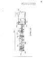
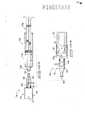
Modalidades preferidas da invenção são descritas abaixo com referência aos desenhos acompanhantes seguintes. A Fig. 1 é uma vista lateral e vista transversal parcial de um conjunto de mistura de acordo com um aspecto da invenção. A Fig. 2 é uma vista lateral explodida do conjunto mostrado na Fig. 1. A Fig. 3 é uma vista lateral de uma porção de um dispositivo de seringa de acordo com um aspecto da invenção.Preferred embodiments of the invention are described below with reference to the accompanying drawings. Fig. 1 is a side view and partial cross-sectional view of a mixing assembly in accordance with an aspect of the invention. Fig. 2 is an exploded side view of the assembly shown in Fig. 1. Fig. 3 is a side view of a portion of a syringe device in accordance with an aspect of the invention.
A Fig. 4 é uma vista lateral de um pistão de se-ringa de acordo com um aspecto da invenção. A Fig. 5 é uma vista em perspectiva de uma válvula exemplar de acordo com um aspecto da invenção. A Fig. 6 é uma vista em perspectiva fragmentada de um pistão de seringa de acordo com um aspecto da invenção. A Fig. 7 é uma vista em perspectiva de um disposi tivo de perfuração de acordo com um aspecto da invenção.Fig. 4 is a side view of a syringe piston in accordance with an aspect of the invention. Fig. 5 is a perspective view of an exemplary valve in accordance with an aspect of the invention. Fig. 6 is a fragmentary perspective view of a syringe piston in accordance with an aspect of the invention. Fig. 7 is a perspective view of a piercing device in accordance with an aspect of the invention.
A Fig. 8 é uma vista lateral de um recipiente que pode ser utilizado em um aspecto da invenção. A Fig. 9 é uma vista lateral fragmentar e vista transversal parcial de uma porção de um conjunto de mistura como ilustrado na Fig. 1.Fig. 8 is a side view of a container that may be used in one aspect of the invention. Fig. 9 is a fragmentary side view and partial cross-sectional view of a portion of a mixing assembly as illustrated in Fig. 1.
A Fig. 10 é uma vista em perspectiva fragmentar' de uma porção do conjunto de mistura ilustrado na Fig. 1. A Fig. 11 é uma vista em perspectiva explodida de um conjunto de mistura de acordo com um aspecto alternado da presente invenção. A Fig. 12 é uma vista lateral e vista parcialmente transversal de uma porção de um conjunto de mistura de acordo com um outro aspecto alternado da invenção. A Fig. 13 é uma vista em perspectiva explodida de um conjunto de mistura alternado de acordo com um outro aspecto da invenção.Fig. 10 is a fragmentary perspective view of a portion of the mixing assembly illustrated in Fig. 1. Fig. 11 is an exploded perspective view of a mixing assembly in accordance with an alternate aspect of the present invention. Fig. 12 is a side view and partially cross-sectional view of a portion of a mixing assembly in accordance with another alternate aspect of the invention. Fig. 13 is an exploded perspective view of an alternate mixing assembly in accordance with another aspect of the invention.
A Fig. 14 ilustra um alojamento de extensão de uma vista em perspectiva (painel A) e uma vista de extremidade (painel B) de acordo com o aspecto mostrado na Fig. 13. A Fig. 15A é uma vista lateral de uma modalidade alternada de um pistão de acordo com um aspecto da invenção.Fig. 14 illustrates an extension housing in perspective view (panel A) and end view (panel B) as shown in Fig. 13. Fig. 15A is a side view of an alternate embodiment of a piston in accordance with an aspect of the invention.
A Fig. 15B é uma vista explodida da estrutura de pistão mostrada na Fig. 15A. A Fig. 15C é uma vista fragmentar transversal ex-plodida da estrutura de pistão mostrada na Fig. 15A.Fig. 15B is an exploded view of the piston structure shown in Fig. 15A. Fig. 15C is an exploded, fragmentary cross-sectional view of the piston structure shown in Fig. 15A.
A Fig. 15D é uma vista lateral fragmentar trans-versal da estrutura de pistão mostrada na Fig. 15A. A Fig. 16A é uma vista lateral e vista transversal parcial de um conjunto de mistura de acordo com um aspecto alternativo da invenção. A Fig. 16B é uma vista lateral e parcialmente transversal de uma porção adaptadora do conjunto mostrado na Fig. 16A mostrado em associação com um frasco exemplar.Fig. 15D is a fragmentary, cross-sectional side view of the piston structure shown in Fig. 15A. Fig. 16A is a side view and partial cross-sectional view of a mixing assembly in accordance with an alternative aspect of the invention. Fig. 16B is a side and partially cross-sectional view of an adapter portion of the assembly shown in Fig. 16A shown in association with an exemplary vial.
A Fig. 17 é uma vista lateral de um conjunto de mistura alternado de acordo com um aspecto da invenção. A Fig. 18A é uma vista explodida de uma outra mo-dalidade alternada de um dispositivo de acordo com a invenção . A Fig. 18B é uma vista parcialmente transversal fragmentar explodida do dispositivo mostrado na Fig. 18A. A Fig. 18C é uma vista fragmentar parcialmente transversal do dispositivo mostrado na Fig. 18A.Fig. 17 is a side view of an alternate mixing assembly in accordance with an aspect of the invention. Fig. 18A is an exploded view of another alternate embodiment of a device in accordance with the invention. Fig. 18B is an exploded, fragmentary, partially cross-sectional view of the device shown in Fig. 18A. Fig. 18C is a fragmentary, partially cross-sectional view of the device shown in Fig. 18A.
A Fig. 19 é uma vista em perspectiva de um conjunto de mistura e embalagem exemplar de acordo com um aspecto da invenção. A Fig. 20 mostra aspectos adicionais de embalagem e etiquetagem de acordo com a invenção. A Fig. 21 mostra um dispositivo e embalagem de a- cordo com um aspecto alternado da invenção. A Fig. 22 mostra uma configuração de embalagem para um aspecto particular da invenção.Fig. 19 is a perspective view of an exemplary mixing and packaging assembly in accordance with one aspect of the invention. Fig. 20 shows additional packaging and labeling aspects in accordance with the invention. Fig. 21 shows a device and package in accordance with an alternate aspect of the invention. Fig. 22 shows a package configuration for a particular aspect of the invention.
Em geral, a invenção provê metodologia para combinar e misturar para produzir uma mistura e abrange configurações de dispositivo para permitir a combinação e a mistura dos componentes. Em particular, a metodologia da invenção envolve combinar e misturar componentes para produzir um a- gente pronto para administração tal como um medicamento e, em aspectos particulares, inclui administrar tal agente em um individuo. Dessa maneira, configurações do dispositivo da invenção permitem a combinação de componentes separados tal que os componentes combinados e misturados ficam prontos para a administração. Em aspectos particulares, os dispositivos abrangidos são adicionalmente configurados para uso du-rante a administração do agente pronto para administração. Os conceitos gerais e os dispositivos exemplares de acordo com a invenção são ilustrados nas figuras acompanhantes 1- 22. Onde os dispositivos de acordo com a invenção são usados para a preparação de um medicamento, os dispositivos são preferivelmente conjuntos de mistura com sistema fecha-do. Um conjunto de mistura exemplar 10 de acordo com a invenção é ilustrado na Fig. 1. Os vários componentes do conjunto de mistura 10 são descritos de maneira geral com refe- 5 rência à Fig. 1 e serão descritos em maiores detalhes com referência às figuras subsequentes. É para ser entendido que os aspectos gerais descritos com referência à Fig. 1 são e- xemplares e a invenção abrange modificações, modalidades alternadas e adaptações incluindo mas não limitadas a essas especificamente ilustradas nos desenhos subsequentes.In general, the invention provides methodology for blending and mixing to produce a blend and encompasses device configurations to allow blending and mixing of the components. In particular, the methodology of the invention involves combining and mixing components to produce an agent ready for administration such as a drug and, in particular aspects, includes administering such an agent to an individual. In this way, device configurations of the invention allow the combination of separate components such that the combined and mixed components are ready for administration. In particular, the covered devices are additionally configured for use during administration of the administration-ready agent. General concepts and exemplary devices according to the invention are illustrated in the accompanying figures 1-22. Where devices according to the invention are used for the preparation of a medicament, the devices are preferably closed-system mixing sets. . An
O conjunto de mistura 10 pode compreender um reci-piente tal como um corpo de seringa (ou tubo) 100 e um pis-tão 200 que tem uma passagem de fluido que passa inteiramen-te através do comprimento do pistão (discutido mais abaixo).The mixing
Em alguns casos, uma tampa presa de modo reversível (não mostrada) pode estar presente provendo uma vedação de fluido em uma extremidade dianteira do corpo da seringa. Uma válvu-la 300 pode ser associada com o pistão 200 e pode ser prefe-rivelmente configurada para permitir a passagem seletiva de fluido através da passagem do pistão. O conjunto de mistura pode ter uma extensão 600 que pode compreender um alojamento cilíndrico ou altemativamente formado configurado para receber um frasco 500 ou segundo recipiente alternativo dentro de uma câmara ou abertura dentro da extensão. O conjunto 10 25 pode também compreender um dispositivo de perfuração 400 associado com o pistão 200. Embora a Fig. 1 e as figuras subsequent es representem conjuntos como compreendendo seringas e a descrição apresente a metodologia primariamente em ter- mos de preparação de um medicamentof é para ser entendido que a invenção abrange formas de recipiente alternativas e adaptação de dispositivos para uso na mistura dos componen-tes para formar misturas ou agentes diferentes de medicamen-tos .In some cases, a reversibly secured cap (not shown) may be present providing a fluid seal at a forward end of the syringe body. A
Como ilustrado na Fig. 1, um frasco 500 que pode ser, por exemplo, um frasco do tipo de medicamento padrão, pode ser utilizado e o alojamento da extensão 600 pode ser preferivelmente configurado tal que o frasco 500 pode ser inserido de modo deslizável dentro da área interna do aloja-mento 600.As illustrated in Fig. 1, a
Um sistema de mistura e administração compreendendo o conjunto de mistura 10 como ilustrado na Fig. 1 pode ser descrito como sendo um sistema fechado no qual componentes separados de um agente podem ser combinados e misturados sem expor os componentes a um ambiente externo ao conjunto de mistura. Por exemplo, um primeiro componente pode ser provido dentro do frasco 500 e um segundo componente pode ser provido dentro da seringa 100. A seringa 100 pode ser tampada para reter o segundo componente, com tal tampa sendo presa de modo reversivel para permitir a remoção quando a- propriado (descrito abaixo).A mixing and administration system comprising mixing
Como descrito em mais detalhes abaixo, a passagem de fluido através do pistão 200 preferivelmente se estende na longitudinal e mais preferivelmente ao longo do eixo geo-métrico longitudinal de uma primeira extremidade da haste do pistão através do pistão e para fora de uma segunda extremi-dade tal que a comunicação de fluido pode ser estabelecida entre o frasco 500 e a câmara da seringa 100. Dessa maneira, quando a válvula 300 é posicionada em uma "configuração a- berta", o fluxo de fluido bidirecional através da passagem do pistão é estabelecido permitindo a comunicação de fluido 5 entre o tubo da seringa (preferivelmente tampado) e o frasco 500.As described in more detail below, the fluid passage through the
Com referência à Fig. 2, tal mostra uma vista ex-plodida dos vários componentes gerais do conjunto de mistura 10. Tal vista ilustra a relação geral dos vários componen- 10 tes, cada um dos quais é descrito independentemente nas figuras subseqüentes. Primariamente, é observado com referência à Fig. 2 que o pistão 200 pode compreender uma porção de entrave ou vedação independentemente fabricada 208 e que cada uma entre a válvula 300 e a estrutura de perfuração 400 15 pode ser fabricada independentemente da porção de vareta ou haste do pistão. Entretanto, é para ser observado que a invenção considera aspectos alternativos onde um ou mais do entrave 208, válvula 300 e estrutura de perfuração 400 são integrais com a porção de haste do pistão. É para ser adi- .20 ciohãlmente observado que a extensão 600 como representada na Fig. 2 tendo uma extremidade aberta para receber o frasco 500 pode ser fabricada para ser independente do pistão 200 como ilustrado, ou pode ser fabricada para ser integral com a porção da haste do pistão (não mostrada).With reference to Fig. 2, this shows an exploded view of the various general components of the mixing
Com referência à Fig. 3, o corpo da seringa 100 pode compreender um alojamento cilíndrico 102 tendo uma re-gião interior ou câmara 104 dentro do alojamento. A câmara pode ser descrita como tendo um eixo geométrico longitudinal se estendendo de uma primeira extremidade 105 do corpo da seringa. Uma segunda extremidade 106 do corpo da seringa é disposta oposta à primeira extremidade 105. Em casos parti-culares, a seringa pode compreender um encaixe do tipo LUER- 5 LOK® (Becton, Dickinson and Company, Corp., Franklin Lakes, NJ) 108 disposto proximo à segunda extremidade como ilustrado na Fig. 3. Embora um conector Luer-Lok seja ilustrado, é para ser entendido que a invenção considera configurações alternativas de conector/encaixe. De preferência, o conector 10 108 é capaz de receber e preferivelmente receber de maneira reversivel uma agulha, cânula alternativa, tubulação e/ou adaptadores que podem ser utilizados, por exemplo, durante a administração de um medicamento de dentro da câmara 104 para um indo viduo ou em casos particulares, para a transferência 15 para dentro de um recipiente distinto (não mostrado). Em a- plicações particulares, pode ser preferível que o corpo da seringa 100 compreenda um encaixe do tipo Luer-Lok macho para permitir a conexão e preferivelmente a conexão reversível . ,com um encaixe Luer-Lok fêmea compreendido por uma agulha de 20 administração.With reference to Fig. 3,
O alojamento da seringa 102 pode ter marcações de volume tal como essas ilustradas, ou pode ter indicadores de volume alternativos para auxiliar na medição ou verificação do volume. Embora não especificamente ilustrado na Fig. 3, 25 uma tampa pode ser provida para vedar a segunda extremidade 106 (ver Fig. 19). A tampa pode impedir a passagem do fluido de dentro do tubo da seringa durante o armazenamento, transporte, mistura, etc., e pode impedir a exposição dos compo- nentes do medicamento a um ambiente externo ao dispositivo da seringa. A tampa pode ser configurada para ser presa de modo reversivel pelo Luer-Lok ou outro mecanismo de encaixe, para permitir a remoção e a substituição por uma fixação de administração ou transferência apropriada.
O corpo da seringa 100 pode ser um tubo de seringa do tipo convencional ou pode ser fabricado para uma aplica-ção particular de acordo com a invenção. O aloj amento pode ser fabricado para compreender, por exemplo, materiais de vidro ou plástico aprovados/de qualidade médica. Materiais exemplares que podem ser utilizados para a formação do alo-jamento da seringa incluem mas não são limitados a polieti- lenos, polipropilenos, policicloolefinas, cloreto de polivi- nila (PVC), poliamidas (incluindo variações alifáticas e a- romáticas), poliésteres, policarbonatos, materiais de copo- limero incluindo mas não limitado a esses contendo um monô- mero de etileno-dieno-propileno (EPDM), poliacrilatos, poli-uretanos, compósitos, misturas ou combinações de tais mate-riais, ou materiais compósitos alternativos.
O volume da seringa (ou recipiente alternado) não é limitado a um valor particular e o corpo da seringa pode ser configurado para conter um volume máximo, por exemplo, de 1 mL a mais do que 10 mL. De preferência, o volume da seringa será menor do que ou igual a 10 mL. Para finalidades da presente descrição, o volume da seringa se refere ao volume do liquido que o alojamento da seringa é configurado para reter e não o volume geral dentro da região interna 104.The volume of the syringe (or alternate container) is not limited to a particular value and the syringe barrel can be configured to contain a maximum volume, for example from 1 mL to more than 10 mL. Preferably, the volume of the syringe will be less than or equal to 10 ml. For purposes of the present description, syringe volume refers to the volume of liquid that the syringe housing is configured to hold and not the overall volume within the
Com referência a seguir à Fig. 4, um pistão exem-plar 200 é ilustrado tendo uma porção de haste 201, uma pri-meira extremidade 204 e uma segunda extremidade 202. 0 pis-tão pode ser descrito como tendo um comprimento representado por di se estendendo da primeira extremidade 204 para a se-gunda extremidade 202. 0 comprimento di não é limitado a um valor particular e pode ser preferivelmente um valor maior do que o comprimento do eixo geométrico longitudinal da câ-mara da seringa interna 104.With reference below to Fig. 4, an
Uma passagem de fluido 206 atravessa o comprimento do pistão como ilustrado pelas linhas tracejadas. O diâmetro da passagem de fluido 206 é representado na Fig. 4 por "d2". Em alguns casos, a passagem 206 pode ter um diâmetro não u- niforme, entretanto d2 como usado aqui, indica o diâmetro mínimo da passagem. Embora di e d2 não sejam limitados a va-lores particulares, pode ser preferível em alguns casos que a razão de di para d2 seja pelo menos cerca de 10:1. A ação capilar pode ser estimulada pela maximização da relação de aspectos do comprimento da passagem em relação ao diâmetro. Tal ação capilar pode auxiliar na criação de um fecho de ar dentro da passagem quando uma válvula associada fica em uma posição fechada, dessa maneira evitando o contato de um com-ponente líquido/diluente, com a válvula antes da abertura da válvula na iniciação de um evento de mistura (discutido a- baixo). Entretanto, relações menores podem permitir vantajo-samente que toda a haste do pistão seja fabricada como uma peça única, por exemplo, por técnicas de moldagem a injeção.A
Dessa maneira, a invenção considera relações alternadas de di para d2 (isto é, menores do que cerca de 10:1). Como ilustrado na Fig. 4, uma porção de entrave 208 pode ser provida para ser recebida sobre a segunda ex-tremidade 202 do pistão 201. Em contraste com êmbolos de se-ringa convencionais, a porção de entrave 208 pode ser confi-gurada para ter uma abertura ou canal 210 passando inteira-mente através do entrave permitindo a passagem de fluido de dentro da passagem 206 através do entrave 208. Embora um ú- nico canal 210 seja representado, a invenção considera con-figurações de entrave tendo uma pluralidade de canais pro-vendo passagem de fluido através do entrave para/da passagem através da haste do pistão. Como representado na Fig. 1, o pistão 200 é configurado tal que a segunda extremidade 202 pode ser recebida dentro da câmara da seringa tal que a co-municação de fluido pode ser estabelecida entre a câmara da seringa e a passagem do pistão 206 através do entrave 208 via as abertura(s) 210 como ilustrado na Fig. 4.Thus, the invention considers alternating ratios of di to d2 (ie, less than about 10:1). As illustrated in Fig. 4, a
Onde o entrave 208 é formado como uma estrutura independente em relação à haste do pistão, o entrave pode preferivelmente compreender um material relativamente macio (com relação ao pistão, discutido abaixo). Materiais exem-plares que podem ser apropriados para a fabricação do entrave com base na capacidade de fabricação, biocompatibilidade e/ou compatibilidade quimica, e capacidade de produzir uma vedação de fluido incluem materiais elastoméricos tais como borracha, butila, silicones, silanos, polipropileno, poli- propileno-EPDM, poliuretanas e outros plásticos apropriados, bem como vários copolimeros, misturas e combinações desses.Where the
Com referência novamente à Fig. 4, o pistão 210 pode compreender adicionalmente vários anéis de sustentação 212, 216 e 217. É para ser entendido que tais anéis são um aspecto opcional e que a porção de haste 201 pode ser fabri- 5 cada para compreender menos anéis do que esses representados, compreender nenhum dos anéis representados ou compreender anéis adicionais em relação a esses representados. As estruturas de anel podem ser adicionalmente posicionadas alternadamente ao longo da haste do pistão em relação ao posi- 10 cionamento mostrado. Nas modalidades onde o entrave 208 é uma estrutura independentemente formada, pelo menos dois dos anéis 212 são providos para montagem, posicionamento e retenção do entrave sobre o pistão. Estruturas de anel 212, 216 e 217 podem ser vantajosas, por exemplo, para estabele- 15 cer e/ou manobrar o pistão 200 e ajudar na redução ou impedimento da contaminação das superficies internas do corpo da seringa durante a manipulação da seringa, especialmente para modalidades onde a embalagem é removida antes da manipulação do conjunto de mistura (discutido abaixo).With reference again to Fig. 4, the
Como adicionalmente ilustrado na Fig. 4, o pistão 200 pode compreender uma abertura 214 que se estende através da haste do pistão 201. Tal abertura pode preferivelmente interceptar na ortogonal a passagem de fluido 206. Tal abertura pode ser configurada para permitir a inserção de uma 25 válvula tal como a válvula exemplar representada na Fig. 5.As further illustrated in Fig. 4, the
O posicionamento representado da abertura 214 ao longo do comprimento da haste do pistão 201 da Fig. 4 é exemplar. O posicionamento da abertura de válvula 214 não é limitado a qualquer localização particular e pode ser em qualquer lugar ao longo do comprimento da trajetória de fluido 206. Pode ser preferível em alguns casos que a abertura de inserção da válvula 214 seja posicionada no ponto intermediário ao longo da distância di, ou alternadamente fique mais próxima da ex-tremidade 204 do que da extremidade 202. Esse posicionamento pode vantajosamente permitir a facilidade de manipulação da válvula associada.The depicted placement of opening 214 along the length of
Como representado na Fig. 1, o conjunto 10 pode ser configurado tal que a válvula 300 possa ser, quando disposta em associação com a abertura 214, pelo menos parcialmente inserida dentro do alojamento da seringa 100. Entretanto, a invenção considera o posicionamento da válvula 300 mais próximo da extremidade 204 do que essa representada, especialmente para seringas de pequeno volume onde uma vál-vula tal como a válvula exemplar 300 mostrada é muito grande para se ajustar de maneira a poder ser inserida dentro do alojamento da seringa. É para ser entendido que tipos de válvula alternativos podem ser utilizados que podem permitir a inserção õú inserção parcial da válvula dentro do aloja-mento da seringa mesmo para seringas de volume muito pequeno.As represented in Fig. 1,
A válvula exemplar 300 é mostrada em maiores deta-lhes na Fig. 5. Como ilustrado, a válvula 300 tem uma porção de corpo 302 e uma porção de cabeça 304. A porção de cabeça 304 pode ser configurada para ter abas de extensão ou protu-berância 307 e 308. Embora a Fig. 5 represente duas abas de extensão, é para ser entendido que menos ou mais do que duas abas de extensão podem ser utilizadas. As abas de extensão 307 e 308 podem auxiliar vantajosamente o posicionamento e o alinhamento apropriados de uma passagem de fluido 306 que passa através da porção de haste 302 da válvula 300. A in- 5 venção adicionalmente considera formas alternativas para a porção de cabeça 304 em relação à configuração arredondada representada. Por exemplo, a porção de cabeça pode ser em formato de seta para permitir a indicação visual e/ou tátil da posição da válvula. A porção de cabeça 304 pode também 10 ser configurada para ter indicadores visuais e/ou táteis alternativos ou adicionais.The
O corpo de válvula 302 é preferivelmente configurado para permitir a inserção de tal porção dentro, e em casos particulares inteiramente através da abertura 214 do 15 pistão 200 como ilustrado na Fig. 4. Dessa maneira, e como ilustrado na Fig. 5, uma ou mais vedações ou anéis em o 310 podem ser providos para prover uma vedação de fluido dentro da abertura 214. Altemativamente, uma vedação pode ser formada como uma parte integral do corpo de válvula 302 (não 20 mostrado). Embora a abertura 214 e a válvula associada 300 sejam ilustradas como sendo configuradas tal que a válvula passa inteiramente através da haste do pistão 201, é para ser entendido que a invenção considera configurações alternativas onde a abertura 214 e uma válvula associada, atra- 25 vessam menos do que a integridade da seção transversal da haste do pistão 201 (não mostrado). Adicionalmente, embora a Fig. 5 mostre uma válvula do tipo reguladora de duas vias (ligada/desligada), a invenção considera tipos de válvula alternativos e configurações de abertura apropriadas. Por exemplo, ao invés da abertura de válvula cilíndrica de diâmetro uniforme representada, a abertura 214 pode ser configurada para ser cônica, retangular ou outra forma. Em tais 5 casos, o corpo de válvula 302 pode ser apropriadamente formado para ser recebido dentro da abertura. Tipos de válvula alternativos tal como válvulas de parada bidirecionais, válvulas do tipo corrediça, válvulas de bola, válvulas de pressão ou válvulas de comporta podem ser utilizadas e podem ser 10 apropriadamente configuradas com base nas dimensões da abertura 214.
Além da haste de pistão de peça única 201 ilustra-da na Fig. 4, a invenção considera a utilização de hastes de pistão de múltiplas partes. Com referência à Fig. 6, uma 15 haste de pistão de duas partes exemplar 201 é ilustrada tendo uma primeira porção 230 e uma segunda porção 232. Na haste de pistão de duas partes exemplar ilustrada, as partes 230 e 232 fazem interface na posição longitudinal da abertura 214 ao longo do eixo geométrico do pistão. As partes 230 20 e 23'2 podem ser unidas, por exemplo, pela soldagem térmica, soldagem ultra-sônica, soldagem por radiofrequência, união adesiva ou outras técnicas de união apropriadas. Alternativamente, as duas porções podem ser configuradas para encaixar juntas ou podem ser presas por várias estruturas de uni- 25 ão tal como pinos, forquilhas, roscas ou técnicas de fixação mecânica alternativas conhecidas na técnica ou ainda a ser desenvolvidas.In addition to the one-
Embora a haste de pistão de duas partes ilustrada represente uma interface entre as duas partes coincidindo com a posição da abertura de recepção da válvula 214, é para ser entendido que o posicionamento da interface não é limitado a qualquer localização particular e pode ser, por exem- 5 pio, em qualquer lugar ao longo do comprimento longitudinal da haste do pistão. 0 posicionamento apropriado da interface e o comprimento dos segmentos resultantes podem ser adaptados como apropriados com base na facilidade de fabricação de uma válvula apropriada e segmentos de pistão. A invenção a- 10 dicionalmente considera hastes de pistão de múltiplas partes tendo mais do que dois segmentos independentemente fabricados (não mostrados).Although the illustrated two-part piston rod represents an interface between the two parts coinciding with the position of the
O pistão e as porções do alojamento da seringa dos dispositivos da invenção podem tipicamente compreender mate- 15 riais padrões utilizados para formação convencional de seringa e pistão/êmbolo. Tipicamente, o pistão, exclusivo do entrave, será de um plástico relativamente duro. Nas modalidades onde o entrave é integral com o pistão, a peça integrada pode ser formada de um material plástico comum. Plás- '""2 CT ti cos exemplares que ’podemTser^uti 1 izãdõs para a Tõfmação do pistão incluem mas não são limitados a polietilenos, poli- propilenos, policicloolefinas, cloreto de polivinila (PVC), poliamidas (incluindo variações alifáticas e aromáticas), poliésteres, policarbonatos, poliacrilatos, poliuretanas, 25 copolímeros, misturas, compósitos e combinações desses.The piston and syringe housing portions of the devices of the invention may typically comprise standard materials used for conventional syringe and piston/plunger formation. Typically, the piston, exclusive to the hamper, will be a relatively hard plastic. In embodiments where the stop is integral with the piston, the integral part can be formed from a common plastic material. Exemplary plastics that may be used for piston formation include but are not limited to polyethylenes, polypropylenes, polycycloolefins, polyvinyl chloride (PVC), polyamides (including aliphatic and aromatic variations ), polyesters, polycarbonates, polyacrylates, polyurethanes, 25 copolymers, blends, composites and combinations thereof.
A válvula 300 também não é limitada a um material particular e pode preferivelmente compreender plástico e/ou materiais elastoméricos. Em aplicações particulares pode ser preferível que a porção do corpo de válvula 302 (como ilus-trado na Fig. 5) compreenda um material elastomérico para permitir um melhor ajuste e/ou vedação dentro da abertura 214 da haste do pistão 201, especialmente onde o pistão 200 compreende um material plástico duro. Materiais elastoméri- cos exemplares que podem ser utilizados para a porção de corpo 302 incluem mas não são limitados a poliuretanas, po- lipropileno-EPDM, outros polipropilenos, polisiloxano e/ou materiais de silicone, materiais de butila, isoprenos, neo-prenes, polietilenos e vários copolímeros, compósitos, mis-turas ou outros combinações de tais materiais. Materiais a- propriados adicionais podem incluir borrachas naturais, bor-rachas de nitrila e combinações desses. A válvula 300, ex-clusivamente o anel em o 310, pode ser construída como uma peça única e, portanto, pode ser formada de um material par-ticular ou tipo de material. Alternadamente, a porção de ca-beça 304 pode ser formada independentemente e compreender um material que difere da porção de corpo 302. Por exemplo, em casos particulares a porção de cabeça 304 pode ser formada de um plástico duro tal como qualquer um desses listados a- cima e a porção de corpo 302 pode compreender ou um material plástico duro distinto ou qualquer um dos materiais elasto- méricos listados acima.
Com referência à Fig. 7, tal mostra uma estrutura de perfuração exemplar 400 de acordo com a invenção. A es-trutura de perfuração 400 pode ser descrita como tendo um segmento de cabeça 401 compreendendo uma ponta 402 disposta em uma primeira extremidade. A estrutura de perfuração 400 adicionalmente tem uma porção de haste/corpo 403 que se es-tende da porção de cabeça 401 para uma superfície de base 404 disposta em uma segunda extremidade da estrutura oposta à primeira extremidade. Um canal 406 ou outra passagem de 5 fluido se estende através da superfície de base e preferivelmente através da integridade da porção de corpo 403.With reference to Fig. 7 , this shows an
A estrutura de perfuração 400 mostrada em 4 06 i- lustra uma forma exemplar e forma de segmento de cabeça 401. Como ilustrado, a porção de cabeça 401 pode ter uma superfí- 10 cie externa compreendendo uma superfície frontal 414 (ou superfície superior como ilustrada) e uma superfície posterior oposta 415. Em um aspecto preferido da invenção, o canal 406 se estende por menos do que a integridade do comprimento interno do segmento de cabeça 401, tal que o canal não passa 15 através da ponta 402. Ao contrário, um ou mais furos de a- cesso 408 são providos, por exemplo, através de uma ou ambas as superfícies 414 e 415. Tal configuração onde o canal não passa através da ponta pode minimizar vantajosamente ou impedir a retirada central do material do septo ou o entupi- 20 ““‘merito“do“caria 1”“dúrárife” â' õperação de pèrfurãção".The
Furos de acesso 108 podem ser dispostos ortogonais em relação ao eixo geométrico longitudinal do canal 406 como representado na Fig. 7 ou podem interceptar o canal 406 em um ângulo diferente de 90° (não mostrado). Adicionalmente, a 25 colocação dos furos 4 08 ao longo do segmento de cabeça 401 não é limitada à posição mostrada. Pode ser vantajoso que os furos 408 sejam dispostos próximos à porção de corpo do dispositivo de perfuração para permitir que tais furos se situ- em logo dentro de um frasco com a perfuração. Tal pode minimizar o acesso de fluido permitindo extração eficiente e completa dos conteúdos do frasco sem reposicionamento da estrutura de perfuração depois da perfuração do septo ou outro material de barreira.Access holes 108 may be arranged orthogonal to the longitudinal axis of
Para auxiliar na perfuração e passagem do segmento de cabeça 401 através de um material perfurado tal como, por exemplo, um septo, a porção de cabeça 401 pode ser configurada para ter uma ou mais bordas 410 e 412 como bordas de corte, onde o termo "borda de corte" se refere a uma borda tendo um gume suficiente para cortar o material sendo perfurado durante a operação de perfuração. Como ilustrado na Fig. 7, bordas de corte 410 e 412 podem ser preferivelmente dispostas nas bordas da porção de cabeça 401 onde as superfícies 414 e 415 se encontram. Embora a figura ilustre duas bordas de corte, é para ser entendido que a invenção considera configurações de porções de cabeça 401 que não tenham bordas de corte, tenham uma borda de corte ou mais do que duas bordas de corte. Como também ilustrado, uma ou ambas as superficies 414 é 415 podem ser chanfradas. Tal chanfrò de superfície pode adicionalmente auxiliar na passagem do segmento de cabeça 401 através de um material perfurado.To assist in perforating and passing the
A porção de corpo 403 da estrutura de perfuração 400 pode ser, por exemplo, cilíndrica como ilustrado na Fig. 7. A porção de corpo 403 pode ter uma circunferência uniforme por todo o seu comprimento (não mostrado) ou pode ter segmentos que variam na circunferência em relação um com o outro. Por exemplo, como ilustrado na Fig. 7, a porção de corpo 403 pode ter um segmento de tubo 416 e um segmento de base 418 onde o segmento de base 418 se estende da superficie de base 404 para o segmento de tubo 416. Os comprimentos dos segmentos 418 e 416 não são limitados a quaisquer valores particulares. Nem a relação dos comprimentos de segmento é limitada a um valor particular. De preferência, onde a porção de base 418 será assentada dentro de um outro componente de um conjunto de mistura de acordo com a invenção (tal como pistão 200), o comprimento do segmento 418 pode ser tal para permitir a estabilização e/ou a retenção da estrutura de perfuração 400 na posição assentada.The
A porção de base 418 é preferivelmente de comprimento suficiente e forma apropriada para ser assentada de maneira segura dentro de uma abertura de assentamento compreendida pelo pistão (ver abaixo) . Um anel em o ou porção elevada da base 418 (não mostrada) pode ser provida para permitir um ajuste firme. Dessa maneira, um entalhe apropriado ou ranhura (não mostrado) pode ser provida dentro da a- bertura de assento do pistão. Em casos particulares, um a- juste por pressão ou ajuste por atrito será utilizado para prpver retenção suficiente da estrutura de perfuração. A u- nião segura pode opcionalmente ser utilizada utilizando por exemplo, um adesivo, soldagem ou outra técnica de união a- propriada.The
Com relação ao segmento 416, tal pode ser preferi-velmente de comprimento suficiente para passar inteiramente através de um material perfurado para permitir a passagem de fluido através do material perfurado via o furo de acesso 408 e através da passagem 406. Dessa maneira, um comprimento apropriado do segmento 416 pode ser determinado pela espessura do septo ou outra barreira a ser perfurada, enquanto posicionando o furo de acesso 408 tão próximo do material perfurado quanto possível para permitir máximo acesso de fluido (discutido acima). Além disso, embora o dispositivo de perfuração não seja limitado a uma forma particular, a configuração de forma de "cabeça de seta" representada na Fig. 7, onde o segmento de cabeça 401 tem superficies de crista 409 que se estendem lateralmente para fora em relação ao segmento do tubo 416, pode ajudar na estabilização e retenção do dispositivo de perfuração através do septo depois que a perfuração ocorreu. A retenção do dispositivo de perfuração através do septo pode evitar o contato inadvertido do dispositivo por um indivíduo, o que poderia causar ferimento e/ou contaminação do meio do medicamento.With respect to the
Numerosos materiais apropriados estão disponíveis para fabricação do dispositivo de perfuração 400. Tais materiais incluem mas não são limitados a metais, tais como aço inoxidável, e vários plásticos tais como poliamidas, polia- crilatos, policarbonatos, epóxis, poliuretanas, polissulfonas, poliéterimidas, polipropilenos, copolímeros, etc., em quaisquer variedades termoplásticas ou de termocura.Numerous suitable materials are available for manufacturing the piercing
Além da estrutura de perfuração representada na Fig. 7, e variações de tal configuração, a invenção considera a utilização de estruturas alternadas para perfurar uma barreira do recipiente. O pistão 200 pode ser adaptado dessa maneira. Estruturas alternadas podem incluir, por exemplo, uma agulha ou uma estrutura de perfuração sem retirada central de forma alternativa em relação ao desenho de cabeça de seta representado. Tais configurações alternativas podem ser especialmente úteis onde múltiplos frascos devem ser acessados seqüencialmente (isto é, durante a preparação de um medicamento compreendendo três ou mais componentes).In addition to the perforation structure shown in Fig. 7, and variations of such a configuration, the invention contemplates the use of alternating structures to pierce a container barrier.
Um frasco exemplar 500 que pode ser utilizado como parte de um conjunto de mistura de acordo com a invenção é ilustrado na Fig. 8. Para finalidades da invenção, o termo "frasco" não é limitado a uma estrutura de recipiente particular e pode ser usado para se referir a vários recipientes incluindo recipientes utilizados para materiais parenterais bem como não parenterais. 0 frasco 500 pode ser, por exemplo, uma garrafa tal como ilustrado na Fig. 8 tendo uma porção de tampa 504 e uma superficie superior 502. 0 frasco 500 pode ser uma garrafa de vidro ou altemativamente ser um recipiente plástico ou outro material utilizado convencional- mente ou ainda a ser desenvolvido para reter e/ou acessar um medicamento ou componente do mesmo.An
Com referência à Fig. 9, tal mostra uma configuração de engate exemplar da estrutura de perfuração 400 e frasco 500. Na ilustração de engate, o dispositivo 400 é i- lustrado como passando através do septo 506 dentro da porção de tampa 504 do frasco 500. Dessa maneira, o acesso de fluido é provido de dentro do frasco 500 através do furo de a- cesso 408 para dentro e através da passagem de fluido 406.With reference to Fig. 9, this shows an exemplary engagement configuration of the piercing
Uma associação exemplar do dispositivo de perfuração 400 e um pistão 200 de acordo com a invenção é mostrada na Fig. 10. Como ilustrado, a porção de base 418 (mostrada na Fig. 9) do dispositivo de perfuração é assentada dentro de uma porção terminal da passagem 206 da haste do pistão 201. Tal porção terminal pode ser, de preferência, diametralmente ampliada em relação a outras porções da passagem 206 para permitir o assentamento da estrutura de perfuração. A Fig. 10 adicionalmente ilustra um encaixe exemplar 203 e a crista 205 presentes na primeira extremidade 204 da estrutura de pistão. Como ilustrado, o encaixe 203 pode ter uma á- rea interior 207 tendo uma superfície de base 213 com dispositivo de perfuração 400 passando através de tal área interior e a superfície de base. Embora a superfície de base 213 seja ilustrada como sendo plana, a invenção considera confi-gurações de assentamento onde uma porção central da superfície de base 213 é elevada dentro da área 207 para formar um pedestal ou ressalto (não mostrado), onde uma abertura central dentro da porção elevada é uma extensão da passagem de fluido através do pistão e é configurada para assentar o dispositivo de perfuração. Pode ser vantajoso prover uma porção" elevada para prover um espaço entre a superfície “ de base 213 e o topo do frasco 500. A configuração de ressalto elevada pode ser ajustada para permitir o encaixe apropriado e/ou o posicionamento de um frasco particular dentro do alojamento de recepção e a associação com o dispositivo de perfuração.An exemplary association of the piercing
A área interior 207 pode ser de tamanho suficiente para permitir que uma porção de um frasco ou recipiente, tal como a porção de tampa 504 ilustrada nas Figs. 8 e 9 seja pelo menos parcialmente capaz de ser inserida dentro do encaixe 203. Adicionalmente, o encaixe 203 pode ter um diâmetro externo de um tamanho apropriado para permitir a inserção do encaixe 203 dentro de uma estrutura de extensão (tal 5 como a estrutura de extensão do alojamento cilíndrico mostrada nas Figs. 1 e 2). Onde o encaixe 203 é configurado para inserção dentro de uma estrutura de extensão, a crista 205 pode ser preferivelmente configurada para fazer interface com a estrutura de extensão para permitir um posiciona- 10 mento apropriado da estrutura de extensão em relação ao pistão 200 como ilustrado na Fig. 1, por exemplo.The
Com referência novamente à Fig. 1, uma metodologia geral de acordo com a invenção para a modalidade ilustrada pode compreender misturar um primeiro componente provido 15 dentro do frasco 500 com um segundo componente provido dentro do tubo da seringa 100. Em um estado inicial antes da combinação dos dois componentes, cada componente fica isolado do outro. O pistão 200 é provido preferivelmente em uma posição inicial em relação ao tubo da seringa com a válvula 20“ 30’0“sendo” Tniciálméhte disposta’ ”em uma-posição "desligada", bloqueando a passagem de fluido através do pistão.With reference again to Fig. 1, a general methodology according to the invention for the illustrated embodiment may comprise mixing a first component provided 15 within the
No estado inicial, a seringa 100 está preferivelmente tampada ou de outra forma vedada (não mostrado) para proibir a passagem do material para dentro ou para fora do 25 tubo da seringa 100 através da segunda extremidade da seringa. O pistão 200 é inicialmente disposto em uma posição inserida através da primeira extremidade do tubo de seringa 100 e posicionado para permitir a contenção do segundo com- ponente dentro do tubo da seringa. O entrave 208 (ilustrado na Fig. 2) preferivelmente proibe a passagem do componente de dentro do tubo da seringa entre as superficies internas do alojamento e do entrave.In the initial state, the
Enquanto a válvula 300 está na posição desligada, o frasco 500 é posicionado pela inserção parcial dentro do alojamento de extensão 600. É para ser observado que tal inserção pode ser executada, em aspectos alternados, por um usuário final do conjunto de mistura ou pode ser executada antes da embalagem do conjunto (discutido abaixo). A despeito disso, a tampa do frasco/septo é inicialmente provida para ficar intacta e preferivelmente para estar espaçada do dispositivo de perfuração 400 tal que a ponta do dispositivo de perfuração não fique em contato físico com qualquer porção do frasco 500 como inicialmente provido.While
Uma vez que a combinação e a mistura dos componentes separados é desejada, o frasco 500 pode ser reposiciona- do, por exemplo, deslizando o frasco 500 mais para longe dentro da extensão 600 para permitir que o dispositivo 400 perfure e seja parcialmente inserido através do septo ou porção de barreira alternada do frasco.Once the combination and mixing of the separate components is desired, the
Depois que a perfuração ocorreu, a válvula 300 pode ser girada ou de alguma outra maneira reposicionada dentro da posição aberta permitindo a passagem de fluido através do pistão. Tal reposicionamento estabelece a comunicação de fluido entre o interior do frasco 500 e o interior do tubo de seringa 100 sem expor qualquer um dos dois componentes a um ambiente externo ao conjunto de mistura. Um ou ambos o primeiro componente e o segundo componente podem estar pre-ferivelmente na forma liquida. Tipicamente, pelo menos o componente dentro do tubo da seringa estará na forma liquida . Frequentemente, o componente dentro do frasco 500 estará em uma forma seca, pulverizada ou liofilizada, mas pode ser alternativamente na forma de um líquido, solução, suspensão ou outra mistura.After drilling has occurred,
Onde o frasco 500 contém um componente não fluido, um componente líquido contido dentro da seringa 100 pode ser introduzido no frasco 500 e pode ser combinado com o componente dentro do frasco 500, por exemplo, deslizando o pistão 200 de uma posição inicial para uma segunda posição tal que o entrave 208 fica reposicionado para ficar mais próximo da segunda extremidade do corpo da seringa 100. Tal movimento deslizante permite que o fluido flua de dentro da câmara de seringa através do pistão 200 e para dentro do frasco 500 através da válvula 300. Durante a passagem o fluido adicionalmente passa através do dispositivo de perfuração 400.Where
A mistura dos componentes combinados pode ser exe-cutada, por exemplo, por um movimento deslizante para frente é reverso do pistão 200 em relação ao tubo da seringa em um movimento do tipo de "bombeamento". O movimento de bombea- mento é conduzido com a válvula 300 na posição aberta permitindo a comunicação de fluido entre o tubo da seringa e o frasco 500, tipicamente com o frasco ficando em uma posição invertida. Alternativamente, a mistura pode ser conduzida sacudindo ou agitando o frasco 500 e/ou todo o conjunto de mistura, ou por uma combinação da ação de bombeamento e sa cudidela, agitação, etc. Depois que os componentes foram misturados, o conjunto pode ser preparado para a transferência do agente misturado ou, onde a mistura é um agente pronto para a administração, o dispositivo pode ser preparado para administrar o agente em um indivíduo. Alternativamente, se componentes adicionais devem ser combinados com a mistura, tal pode ser introduzido, por exemplo, fluindo para dentro da seringa através da segunda extremidade, e misturando como descrito acima.Mixing of the combined components can be accomplished, for example, by a forward and reverse sliding motion of the
De modo a preparar para a transferência e/ou a ad-ministração do agente, a mistura pode ser puxada para dentro do corpo da seringa 100, por exemplo, pelo deslizamento do pistão 200 em um movimento para trás, tipicamente com o frasco em uma posição invertida. Em outras palavras, o pistão 200 é parcialmente extraído movendo o entrave 208 para a primeira extremidade do alojamento da seringa. Com a retirada de toda ou uma quantidade medida apropriada da mistura para dentro do tubo da seringa, a válvula 300 pode ser girada ou de outra forma reposicionada na posição fechada bloqueando a passagem do fluido do tubo da seringa através do pistão. O tubo da seringa pode então ser destampado, por e- xemplo, pela remoção de uma tampa tal como o encaixe de tampa Luer-lok. É para ser entendido que a invenção também considera executar a mistura/preparação do medicamento com uma agulha adaptada no encaixe Luer-lok durante o estágio de preparação. Entretanto, a agulha fica preferivelmente tampada e vedada durante tal operação ou de outra forma impedida de permitir a passagem ou a exposição do material do tubo da seringa para um ambiente externo ao conjunto.In order to prepare for transfer and/or administration of the agent, the mixture may be drawn into the
Onde a tampa é removida na preparação para a transferência ou a administração do agente, um dispositivo de transferência apropriado tal como uma agulha, cânula, tubo de transferência e/ou outro encaixe apropriado pode ser preso na conexão Luer-lok e a transferência/administração pode ocorrer deslizando para frente do pistão dentro do tubo, dessa maneira expelindo os conteúdos do tubo através da agulha ou estrutura de transferência alternada na extremidade Luer-lok da seringa. Tal transferência é executada com a válvula 3 permanecendo na posição fechada por toda ela. Alternativamente, a transferência pode ser realizada provendo o conjunto 10 em uma bomba de seringa apropriada, como será entendido por aqueles versados na técnica.Where the cap is removed in preparation for transfer or agent administration, an appropriate transfer device such as a needle, cannula, transfer tube and/or other appropriate fitting can be attached to the Luer-lok connection and transfer/administration may occur by sliding the piston forward into the tube, thereby expelling the contents of the tube through the needle or alternating transfer structure at the Luer-lok end of the syringe. Such transfer is performed with
Com referência a seguir à Fig. 11, tal mostra aspectos alternados da invenção tendo variação em relação ao conjunto de mistura mostrado nas Figs. 1-10. Os componentes que variam em relação a esses ilustrados nas figuras anteriores são fornecidos com identificadores numéricos tendo um apêndice "a" ou um identificador único em relação a esses usados previamente. Na modalidade mostrada na Fig. 11, a porção do pistão 200a é mostrada como tendo estruturas de nervura lateral 220a se estendendo longitudinalmente ao longo da porção de haste 201a. Tais aspectos de nervura podem ser similares ou idênticos a esses presentes nos dispositivos de êmbolo de seringa convencionais. A presença das nervuras 220a pode prover suporte adicional e dessa maneira fortalecer o pistão. Como ilustrado, as estruturas de anel 212a, 216a estão presentes em várias posições ao longo do comprimento da porção de haste. É para ser entendido que a invenção considera a colocação alternada e/ou números alternados de ambas as estruturas de anel e as nervuras em relação à configuração exemplar representada na Fig. 11.With reference below to Fig. 11, this shows alternate aspects of the invention having variation from the mixing assembly shown in Figs. 1-10. Components that vary from those illustrated in the preceding figures are provided with numerical identifiers having an appendix "a" or an identifier unique to those previously used. In the mode shown in Fig. 11, piston portion 200a is shown to have lateral rib structures 220a extending longitudinally along rod portion 201a. Such rib features may be similar or identical to those present in conventional syringe plunger devices. The presence of the ribs 220a can provide additional support and thereby strengthen the piston. As illustrated, the ring structures 212a, 216a are present at various positions along the length of the stem portion. It is to be understood that the invention envisages the alternating placement and/or alternating numbers of both the ring structures and the ribs with respect to the exemplary configuration depicted in Fig. 11.
Como mostrado na Fig. 11, uma ou mais das estruturas de nervura 220a podem ser providas para serem formadas com brecha na região da abertura de recepção da válvula 214a. A largura da brecha pode ser configurada para permitir espaço suficiente para a inserção da válvula e para permitir o posicionamento da porção de cabeça da válvula dentro da brecha. É observado que as abas de extensão presentes na cabeça da válvula podem ser especificamente configuradas para entrar em contato com uma nervura com a rotação da cabeça de válvula. Tal pode vantajosamente permitir o posicionamento aberto/fechado apropriado da válvula e o alinhamento da passagem de fluido através da válvula e haste de pistão 201a.As shown in Fig. 11, one or more of the rib structures 220a may be provided to be formed with a gap in the region of the receiving opening of the valve 214a. The gap width can be configured to allow sufficient space for valve insertion and to allow positioning of the valve head portion within the gap. It is noted that the extension tabs present on the valve head can be specifically configured to contact a rib with the rotation of the valve head. This may advantageously allow for proper open/closed positioning of the valve and alignment of the fluid passage through the valve and piston rod 201a.
O conjunto de mistura 10a como mostrado na Fig. 11 utiliza uma porção de extensão 600 tendo uma ranhura 602 que se estende parcialmente ao longo do comprimento do alojamento da extensão. A porção de extensão 600 pode compreender duas ranhuras como ilustrado ou pode compreender menos ou mais números de ranhuras. Tais ranhuras podem permitir uma expansão ligeira na circunferência interior do alojamento da extensão. Esse aspecto pode permitir que um ajuste firme porém reversivel seja estabelecido entre o alojamento da extensão 600 e o frasco 500. Por exemplo, onde a área interna 604 da extensão tem uma circunferência que é ligeiramente menor do que ou igual à circunferência máxima do frasco 500, ranhuras 602 podem permitir uma leve expansão do alojamento para permitir a inserção do frasco 500. Tal configuração pode permitir adicionalmente a retenção do frasco 500 dentro 5 da região interna 604 até que força seja aplicada para extrair o frasco.The mixing assembly 10a as shown in Fig. 11 uses an
O comprimento da(s) ranhura(s) 602 pode ser configurado para permitir o posicionamento e a estabilização do frasco 500 dentro do alojamento em uma posição que dispõe o 10 septo ou tampa do frasco 500 em uma relação espaçada em relação ao dispositivo de perfuração 400 (discutido abaixo). A relação espaçada pode permitir a embalagem e/ou transporte de um conjunto como um dispositivo linearmente montado onde a tampa do frasco 500 permanece intacta antes da remoção de 15 algum ou todos os materiais de embalagem e/ou engate intencional . Dessa maneira, o comprimento das ranhuras 602 e o èomprimento relativo das ranhuras e o comprimento geral do alojamento 600 podem variar com comprimentos apropriados e razões de comprimento dependendo do comprimento relativo e 20 do posicionamento do dispositivo 400 dentro de tal alojamento e do tamanho relativo do frasco 500.The length of the slot(s) 602 may be configured to allow positioning and stabilization of the
Um aspecto alternativo adicional da invenção é descrito com referência às Figs. 12-13. Com referência inicialmente à Fig. 12, tal mostra a variação dos componentes 25 do conjunto de mistura 10b em relação aos conjuntos de mistura descritos nas figuras prévias. Componentes que variam em relação a esses ilustrados nas figuras anteriores são fornecidos com um identificador numérico tendo um apêndice "b", ou um identificador único em relação a esses previamen- te usados. Na modalidade representada na Fig. 12, a porção do pistão 200b é mostrada como tendo uma configuração de encaixe alternativo 203b. Tal configuração pode permitir que 5 uma porção do alojamento de extensão 600b seja recebida dentro de uma área interna do encaixe 203b. Como ilustrado pela vista explodida, o dispositivo de perfuração 400 pode ser acomodado dentro do pistão 200b em uma maneira similar a essa descrita acima com relação às modalidades anteriores. A- 10 dicionalmente os vários anéis e barbatanas representados na Fig. 12 em associação com o pistão 200b podem ser como ilus-trados ou podem ter qualquer uma das configurações alterna-tivas descritas acima. A válvula 300b como representada na Fig. 12 pode 15 compreender um ou mais marcadores de alinhamento 312 prefe-rivelmente em uma superfície superior da cabeça de válvula 304 para permitir o alinhamento visível e/ou tátil da válvula com a inserção dentro da abertura 214b do pistão 200b. Embora representado como setas moldadas, é para ser entendi- 20 do quê ~a invenção considera marcadores de alinhamento"'alter natives.A further alternative aspect of the invention is described with reference to Figs. 12-13. With reference initially to Fig. 12, this shows the variation of the components 25 of the mixing
A extensão 600b mostrada na Fig. 12 ilustra aspec-tos da invenção onde o alojamento da extensão tem uma cir-cunferência externa não uniforme. Como mostrado, o alojamen- 25 to de extensão 600b pode compreender uma primeira porção 605b tendo uma circunferência menor do que uma segunda porção 606b. Tal configuração pode permitir a inserção e o as sentamento da porção 605b dentro da configuração de encaixe do pistão 203b como ilustrado.
Os aspectos da extensão 600b são descritos e mais totalmente ilustrados com referência às Figs. 13A e B. Como mostrado na Fig. 13A, o alojamento da extensão 600b tem uma 5 área interna 604b configurada para receber um frasco tal como um frasco padrão ou um recipiente alternativo como des- crito acima. Uma ou mais fendas 602b podem se estender lon- gitudinálmente da extremidade de recepção do alojamento de extensão para permitir a leve expansão do alojamento. Em al- 10 guns casos, a extremidade de recepção/abertura do alojamento 600b pode ter um diâmetro interno igual à ou ligeiramente menor do que o diâmetro de um frasco antes da inserção do frasco. A inserção do frasco pode expandir o alojamento devido à presença das fendas 602b. Tal configuração pode per- 15 mitir um ajuste perfeito e a estabilização do frasco inserido. Em combinação com aspectos de embalagem particulares (discutidos abaixo), as fendas 602b podem adicionalmente permitir a estabilização do posicionamento do frasco durante o armazenamento e/ou transporte.Aspects of
Com referência à Fig. 13B, pelo menos uma porção de um comprimento da área interior pode compreender nervuras interiores 607b. De preferência, pelo menos um comprimento interior associado com o segmento 605b contém as nervuras 607b que podem auxiliar no posicionamento e retenção do 25 frasco 500 (mostrado na Fig. 12) dentro do alojamento da extensão. Tais nervuras podem adicionalmente prover o suporte para o frasco dentro do alojamento com a perfuração do septo ou material de barreira alternativo.With reference to Fig. 13B, at least a portion of a length of the interior area may comprise
Embora a Fig. 13 represente a extensão 600b como tendo nervuras 607 ao longo de somente uma porção das paredes laterais interiores da abertura 604b, é para ser entendido que a invenção considera aspectos alternativos onde as nervuras são providas ao longo de uma porção ou a integridade da superficie interior do segmento 606b. As paredes laterais interiores e/ou porções de nervura dentro do alojamento 600b podem ser contornadas para corresponder com uma forma externa do frasco 500 se o frasco é da forma convencional ilustrada ou tem uma forma alternativa de frasco ou recipiente.Although Fig. 13 depicts
Embora as configurações de alojamento tendo seg-mentos de circunferência não equivalente sejam ilustradas na Fig. 12 como sendo utilizadas com uma haste de pistão de peça única, é para ser entendido que a invenção considera a utilização de tal configuração de alojamento com qualquer uma das configurações de pistão alternativas descritas aqui.Although housing configurations having non-equivalent circumference segments are illustrated in Fig. 12 as being used with a one-piece piston rod, it is to be understood that the invention contemplates the use of such a housing configuration with any of the alternative piston configurations described herein.
Além das modalidades descritas acima onde o frasco 500 é provido independentemente da porção do pistão do con-junto, a invenção adicionalmente abrange configurações onde um recipiente é integral com a porção do pistão como exem-plificado na Fig. 14. O pistão exemplar 200c tem aspectos tendo identificadores numéricos com um apêndice "c" para distinguir de modalidades anteriores. É para ser observado, entretanto, que os conceitos gerais e as variações das moda lidades anteriores podem se aplicar igualmente à modalidade representada na Fig. 14. É para ser adicionalmente observado que no pistão 200c, a porção de entrave pode ser provida co- mo um componente independente ou pode ser uma parte integral do pistão 200c. Dessa maneira, o entrave 208c pode compreen-der um material que difere da haste do pistão ou pode ser formado de um material idêntico ao material utilizado para a formação da haste do pistão 201c.In addition to the embodiments described above where the
Os aspectos alternados da invenção representados na Fig. 14 incluem a variação da porção de extensão para formar um recipiente 650c tendo uma superfície de base 652c que se opõe à primeira extremidade 204c do pistão formando um compartimento fechado. O recipiente 650c pode ser formado para ser integral com o pistão durante um evento de fabrica-ção comum (tal como moldagem), ou pela fixação de uma estru-tura de recipiente independentemente formada na porção de encaixe 203c do pistão. Alternativamente, a porção do reci-piente 650c pode ser presa de modo a poder ser reversível no pistão. A fixação (quer permanente ou reversível) de um re-cipiente independentemente formado na segunda extremidade 204c pode compreender a inserção da porção de encaixe 203c similar à fixação da porção de extensão 600 descrita acima. A união e a fixação da porção do recipiente no pistão podem compreender, por exemplo, uma junta do tipo de encaixe ou soldagem.The alternate aspects of the invention depicted in Fig. 14 include varying the extension portion to form a container 650c having a
Configurações alternativas de frasco-pistão inte-grais consideradas pela invenção incluem, por exemplo, prover uma abertura através da porção do frasco, por exemplo através da superfície de base 652c (não mostrada), que pode ser utilizada durante o provimento de um componente de medi-camento para dentro do frasco e/ou durante a secagem ou lio- filização do componente. Tal abertura pode ser subsequentemente tampada ou de alguma forma vedada.Alternative integral piston vial configurations envisaged by the invention include, for example, providing an opening through the vial portion, for example through the
O material utilizado para a construção do recipiente 650c não é limitado a um particular ou classe de mate- 5 riais. O recipiente 650c pode, em casos particulares, ser formado de um material plástico que pode ser um material rígido ou um material desmontável.The material used for the construction of the 650c container is not limited to any particular or class of materials. The container 650c may, in particular cases, be formed of a plastic material which may be a rigid material or a collapsible material.
Um componente de um medicamento ou outra mistura a ser formada pode ser provido dentro do recipiente 650c e po- 10 de ser isolado de um tubo de seringa associado (não mostrado) provendo uma válvula dentro da abertura de recepção de válvula 214c. Uma válvula apropriada pode ser, por exemplo, qualquer uma das válvulas descritas acima. O componente provido no recipiente 650c pode ser provido dentro do recipien- 15 te antes da fixação do recipiente ou alternativamente pode ser provido no recipiente integral ou preso via a passagem de fluido 206 através da abertura do pistão e entrave 210c. A válvula associada pode então ser fechada para impedir que o componente contido flua para fora através do pistão.A component of a drug or other mixture to be formed may be provided within the container 650c and may be isolated from an associated syringe tube (not shown) by providing a valve within the valve receiving opening 214c. A suitable valve may be, for example, any of the valves described above. The component provided in the container 650c may be provided within the
Onde o recipiente 650c é formado independéntemente e é preso no pistão de maneira reversível ou permanente, um anel em o 230c pode ser provido em associação com o encaixe 203c para prover uma vedação de fluido entre o pistão e as superfícies internas do recipiente 650c. Alternativamente, 25 outras técnicas de vedação apropriadas podem ser utilizadas.Where the container 650c is independently formed and is reversibly or permanently secured to the piston, an o-ring 230c may be provided in association with the
É observado que o pistão 200c carece de uma estrutura de perfuração associada. Dessa maneira, a primeira extremidade 204c do pistão pode ser modificada das configurações discu- tidas anteriores para carecer de aspectos de acomodação para o dispositivo de perfuração. Além do que, a fixação ilustrada do recipiente 650c no pistão 200c é uma configuração e- xemplar e formas e métodos de fixação alternativos são con-siderados .It is observed that the piston 200c lacks an associated perforation structure. In this way, the
Embora a estrutura integral de recipiente/pistão ilustrada seja mostrada como tendo anéis e nervuras 220c, é para ser entendido que as nervuras e os anéis são opcionais como é o número de tais nervuras e/ou anéis, como apresentado acima com relação aos aspectos descritos anteriores. Adicionalmente, a haste do pistão 201c, que é mostrada-Como uma peça única, pode compreender alternativamente múltiplos segmentos como descrito acima (e/ou a configuração do tipo de válvula rotacional descrita abaixo).Although the integral container/piston structure illustrated is shown to have rings and
Uma outra configuração de pistão alternada envolvendo um pistão do tipo de válvula rotacional é exemplificada e descrita com referência às Figs. 15A-D. Com referência inicialmente à Fig. 15A, um pistão 200d é representado o qual pode ser utilizado em conjunto com componentes de conjunto de mistura adicionais discutidos acima. O pistão 200d pode compreender uma haste de pistão de duas partes 201d que pode opcionalmente incluir nervuras 220d e/ou anéis 212d. A haste 201d compreende uma primeira porção 230d e uma segunda porção 232d. Os comprimentos do primeiro segmento 230d e do segundo segmento 232d podem ser idênticos ou podem diferir. 0 comprimento de cada segmento e seus comprimentos relativos podem ser determinados pela capacidade de fabricação e comprimento geral do pistão. O pistão 200d é mostrado como ten- do um entrave independentemente formado 208d. Entretanto, é para ser entendido que tal entrave pode ser integral com a primeira porção 230d do pistão 200d. Uma porção de extensão exemplar 60Od é ilustrada que pode ser configurada para receber um frasco como descrito acima. Como ilustrado na Fig. 15, a porção de extensão 600d pode ser integral com a segunda porção 232d. Tal configuração integral de pistão/extensão pode ser adaptada para uso com qualquer um dos aspectos alternativos de haste de pistão de parte única descrita.Another alternate piston configuration involving a rotary valve type piston is exemplified and described with reference to Figs. 15A-D. With reference initially to Fig. 15A, a
Com referência a seguir à Fig. 15B, tal figura mostra um dispositivo de perfuração exemplar 400d que pode ser disposto dentro de uma região interna da extensão 600d e que pode ser posicionado para permitir a comunicação entre um frasco associado e trajeto de fluido 206d que atravessa o comprimento da haste do pistão 2Old. O primeiro segmento 230d e o segundo segmento 232d podem ser configurados para interagir para prover a ação de válvula. Como ilustrado, o primeiro segmento 230d pode compreender uma protuberância tronco-cônica 226 tendo um par de aberturas 228 que passam intéiramente através da protuberância tronco-cônica. A segunda porção 232d pode ser configurada para ter uma região de câmara interior tronco-cônica correspondente 227 configurada para receber a protuberância 226. Embora uma forma tronco-cônica seja ilustrada, a invenção considera formas de protuberância e formas de câmara de recepção correspondentes diferentes da forma tronco-cônica exemplar.With reference below to Fig. 15B, that figure shows an
A passagem de fluido 206d é mostrada como se estendendo parcialmente através da protuberância tronco-cônica 226 em uma maneira descontinua tal que a passagem de fluido longitudinal direta é impedida. A passagem de fluido 206d retoma o seu progresso longitudinal em um lado oposto de um bloco sólido de material 223. Uma ou mais ranhuras 229 podem ser dispostas dentro de uma parede lateral interior do segundo segmento 232d que, quando alinhado com as aberturas 228 pode permitir a passagem de fluido da passagem de fluido 20 6d da primeira porção 230d para dentro da porção de tal passagem de fluido que passa através da segunda porção 232d. O alinhamento das aberturas 228 com as ranhuras 229 pode ser realizado pela rotação oposta da porção 230d em relação à porção 232d. Tal configuração de válvula/pistão é também descrita com referência à figura 15C. Como ilustrado, a protuberância 226 pode compreender um ou mais anéis em o 222 para permitir que a vedação de fluido seja formada com a inserção da protuberância dentro da câmara de recepção 227.The
Com referência ao segundo segmento 232d do pistão 200d, um par de ranhuras 229 é ilustrado como sendo ranhuras em formato de arco formadas no material da parede lateral do pistão. É para ser entendido que ranhuras em formato alternativo são consideradas e as ranhuras em formato de arco são apenas uma configuração exemplar. Com referência a seguir à Fig. 15D, com a inserção da protuberância dentro da câmara de recepção do segundo segmento 232d, a rotação da parte 230d e 232d em relação uma a outra pode ser executada para alinhar as aberturas de acesso de fluido 228 com as ranhuras 229 para permitir a conexão da passagem 206 via aberturas de acesso 228 permitindo a passagem de fluido entre os segmen- tos 230d e 232d. A rotação adicional ou a rotação inversa pode ser utilizada para desalinhar as aberturas de acesso 228 e a ranhura 229 para novamente fechar o acesso de fluido entre as duas partes de pistão.With reference to the
Embora as aberturas de acesso de fluido 228 sejam mostradas como se estendendo inteiramente através da protu-berância 226 (ver Fig. 15C) é para ser entendido que tais aberturas podem se estender por menos do que a integridade da largura de tal protuberância. Altemativamente, as aberturas de acesso 228 podem ser providas em um único lado de tal protuberância. Em uma outra alternativa, aberturas de acesso adicionais podem ser providas parcial ou inteiramente através da protuberância 226. Similarmente, um menor ou maior número do que as duas ranhuras de conexão ilustradas pode ser provido dentro do segundo segmento 232d.Although the
Além dos aspectos mostrados e descritos acima, em casos particulares, um ou mais filtros podem ser utilizados para a remoção de particulados antes da administração. Filtro (s) apropriados podem ser incorporados dentro de qualquer um dos dispositivos acima, por "exemplo, dentro'"da passagem de fluido através do pistão. Adicional ou altemativamente, um ou mais filtros podem ser providos em associação com a saida da seringa, tanto interna quanto externamente ao tubo da seringa.In addition to the aspects shown and described above, in particular cases, one or more filters may be used to remove particulates prior to administration. Appropriate filter(s) may be incorporated within any of the above devices, eg "inside" the fluid passage through the piston. Additionally or alternatively, one or more filters may be provided in association with the syringe outlet, either internally or externally to the syringe tube.
A metodologia para misturar os componentes para preparar uma mistura utilizando a configuração de válvula do tipo de pistão rotacional ilustrada nas Figs. 13A-D pode ser conduzida em uma maneira similar à metodologia descrita com referência à Fig. 1. Usando o dispositivo do tipo de pistão rotacionai, ao invés de girar ou reposicionar o componente de válvula independente 300 ilustrado na Fig. 1, o primeiro e o segundo segmentos do pistão seriam opostamente girados 5 para abrir ou fechar a passagem de fluido através do pistão no estágio apropriado do procedimento de mistura.The methodology for mixing the components to prepare a mixture using the rotational piston type valve configuration illustrated in Figs. 13A-D can be conducted in a manner similar to the methodology described with reference to Fig. 1. Using the rotary piston type device, instead of rotating or repositioning the
Uma outra modalidade alternada de um dispositivo de mistura de acordo com a invenção é descrita com referência às Figs. 16A-B. Com referência à Fig. 16A, um sistema de 10 mistura 10e pode compreender uma seringa 100 e um adaptador 700 que pode ser preso de modo reversível na seringa 100, por exemplo, pelo provimento de um encaixe Luer-lok fêmea ou alternativo 708 em uma primeira extremidade do adaptador 700. A seringa 100 pode ser, preferivelmente, uma seringa 15 convencional utilizando um pistão/êmbolo do tipo convencional 200e. O adaptador 700 pode ser provido para ter uma primeira passagem de fluido 706 (representada com linhas tracejadas) que passa através do encaixe Luer-lok fêmea 708 e a- través de um segmento do alojamento do adaptador 704 para 20 " ümã~vãTvulã' 800, e um segundo segmento dê'passagem dê fluido 707 (representado com linhas tracejadas) que passa da válvula 800 para uma área interior 703 de um alojamento do frasco 702. Embora representado como passagens em linha, a invenção considera passagens 706 e 707 sendo inclinadas ou ortogonais 25 em relação uma a outra.Another alternate embodiment of a mixing device according to the invention is described with reference to Figs. 16A-B. With reference to Fig. 16A, a
Como ilustrado na Fig. 16B, a câmara interna 703 pode ser configurada para receber um frasco 500 tal como, por exemplo, um frasco padrão. Tipos alternativos de frascos c ou recipientes podem ser utilizados como descrito acima. 0 * alojamento do frasco 702 pode ser configurado adicionalmente para conter um dispositivo de perfuração associado 400e que pode ser similar à ou idêntico aos dispositivos de perfura- 5 ção descritos acima. A inserção do frasco 500 no alojamento 702 pode ser como descrita acima com relação ao alojamento de extensão 600 com referência às Figs. 1-10.As illustrated in Fig. 16B, the
O adaptador 700 pode ser formado de qualquer material apropriado e em casos particulares compreenderá um ma- 10 terial plástico tal como qualquer um dos materiais plásticos discutidos acima com relação aos alojamentos de seringa e pistões. A válvula 800 pode ser qualquer um dos tipos de t válvula discutidos acima com relação à válvula exemplar 300 e pode, dessa maneira, compreender qualquer um dos materiais ■» descritos com referência à tal válvula exemplar. Alternativamente, o adaptador 700 pode ser configurado para ter um sistema de válvula do tipo rotativo como discutido com referência às Figs. 15A-D.
A metodologia para misturar componentes indepen- 20 dentes para preparar uma mistura ou agente pronto para administração utilizando o conjunto ilustrado nas Figs. 16A-B pode compreender prover um primeiro componente em um frasco independente 500 e prover um segundo componente a ser combi-nado e misturado com o primeiro componente dentro da seringa 25 100. A seringa 100 e o frasco 500 são então, cada um, presos b no adaptador 700. A fixação e a perfuração do frasco 500 podem ser executadas como descrito acima com relação às modalidades anteriores tendo o dispositivo de perfuração 400. A ordem de fixação do frasco 500 e seringa 100 não é limitada a uma seqüência particular. De preferência, a válvula 800 fica em uma posição fechada durante as fixações do frasco e da seringa.The methodology for mixing independent components to prepare a mixture or agent ready for administration using the kit illustrated in Figs. 16A-B may comprise providing a first component in a
Com a montagem, a válvula 800 pode ser girada ou de alguma outra forma reposicionada em uma posição aberta para estabelecer a comunicação de fluido entre o primeiro segmento da passagem 702 e o segundo segmento da passagem 707 permitindo a passagem de fluido através do adaptador.With the assembly, the
Dessa maneira, a comunicação de fluido é estabelecida entre o frasco 500 e a seringa 100. A combinação do primeiro e do segundo componentes pode compreender puxar o primeiro componente do frasco 500 para dentro da seringa (tipicamente com o frasco em uma po- 15 sição invertida), ou pode compreender expelir o segundo componente da seringa para dentro do frasco 500. A mistura dos componentes pode compreender uma ação de bombeamento como descrito acima com as modalidades anteriores independentemente ou em combinação com a sacudidela ou de outra forma 20 agitação dos componentes combinados. A mistura resultante pode ser puxada internamente dentro do alojamento da seringa 102e tipicamente enquanto o frasco é invertido, e a válvula 800 pode ser fechada. Onde a mistura é para ser subsequentemente transferida ou administrada em um individuo, o adapta- 25 dor 700 pode ser removido da fixação no encaixe Luer-lok 108e e um dispositivo de transferência tais como uma agulha, cânula, tubo de transferência ou outra estrutura de transferência pode ser preso no dispositivo Luer-lok 108e. A trans- ferência ou a administração da mistura pode então ser reali-zada expelindo a mistura da câmara interna dentro do aloja-mento da seringa 102e.In this manner, fluid communication is established between the
Uma configuração alternativa de um adaptador com- 5 preendido por um conjunto é ilustrada na Fig. 17. 0 conjunto 10e' compreende uma configuração de adaptador alternativa 700e' em relação a essa representada nas Figs. 16A e 16B. O adaptador ilustrado é um adaptador de "três vias" tendo um primeiro segmento 710e' que se estende de uma válvula de 10 três vias 800er para um primeiro orifício 711e' tendo um encaixe (por exemplo um encaixe do tipo Luer-lok) para conexão com a seringa 100e'. O adaptador 700e' adicionalmente inclui um segundo segmento 712e' que se estende da posição da válvula 800e' para um segundo orifício 713e'. O adaptador adi- 15 cionalmente tem um terceiro segmento 714e' que se estende da posição da válvula 800e' para um terceiro orifício 715e' que pode compreender um encaixe configurado para inserção ou outra associação com a extensão do alojamento 600e' como ilustrado. 0 orifício 715e' pode ser adicionalmente configurado 20 para incluir uma estrutura de perfuração (não mostrada) tal como os vários dispositivos de perfuração descritos acima. A porção de extensão 600e' pode ter qualquer uma das configurações descritas acima para receber, estabilizar e/ou reter o frasco 500 que é mostrado em uma posição parcialmente in- 25 serida dentro da extensão 600e'. A seringa 100e' pode ser uma seringa convencional padrão com um pistão do tipo padrão associado 200e' como ilustrado, ou pode ser uma configuração de seringa alternativa, incluindo mas não limitado a essas descritas acima.An alternative configuration of an adapter comprising an assembly is illustrated in Fig. 17.
A configuração do adaptador de orificio triplo i- lustrada na Fig. 17 pode permitir vantajosamente a introdu-ção e/ou remoção do material para ou do sistema sem a disso-ciação da seringa e/ou frasco 500. Por exemplo, depois da mistura ou preparação de um medicamento utilizando metodolo-gia análoga a essa descrita acima, o medicamento preparado pode ser transferido ou de outra forma removido do disposi-tivo de montagem 10e' através do orifício 713e'. Tal trans-ferência ou remoção pode ser realizada, por exemplo, pela fixação de um frasco apropriado, tubulação de transferência ou outro aparelho de transferência no orifício 713e'. Como ilustrado, o orifício 713e' tem um encaixe do tipo geral. Entretanto, um encaixe Luer-lok ou outro alternativo pode ser utilizado quando apropriado para a fixação em um recipi-ente ou aparelho de transferência desejado.The triple-hole adapter configuration illustrated in Fig. 17 may advantageously allow the introduction and/or removal of material into or from the system without dissociating the syringe and/or
A transferência do material do conjunto através do orifício 713 pode ser útil para aplicações tal como adminis-tração IV. Administração alternativa tal como injeção intra-muscular, pode utilizar a seringa 100e' independentemente depois da remoção do conjunto. Em qualquer caso, a dep»ressão do pistão durante a injeção pode ser executada manualmente ou utilizando uma bomba de seringa.Transferring material from the assembly through orifice 713 can be useful for applications such as IV administration. Alternative administration such as intra-muscular injection may use
Onde um material tal como um material líquido por exemplo é para ser introduzido no conjunto 10e', tal intro-dução pode ser realizada pela passagem através do orifício 713 e segmento do adaptador 712e'. 0 fluido introduzido pode ser direcionado para dentro do frasco 500 ou para dentro da seringa lOOe' quando apropriado, pela manipulação e posicio-namento da válvula 800e'. A introdução de um fluido no conjunto pode ser apropriada, por exemplo, onde cada um dos primeiro e segundo componentes (dentro do frasco e seringa 5 respectivamente) é provido em uma forma seca ou concentrada.Where a material such as a liquid material for example is to be introduced into
A configuração do adaptador 700e' ilustrada na Fig. 17 pode permitir o alinhamento linear do alojamento da seringa 102e' e frasco 500. É para ser entendido que a invenção adicionalmente considera configurações tendo as posi- 10 ções dos segmentos 714e' e 718e' trocadas tal que o frasco 500 e o corpo da seringa 102e' ficam posicionados em uma disposição ortogonal. Além disso, o adaptador 700e' pode ser alternativamente configurado para prover os segmentos 710e',712e' e 714e' em ângulos alternativos em relação um ao 15 outro quando comparado com a disposição ortogonal mostrada. 0 adaptador 700e' pode opcionalmente ter segmentos adicionais e orifícios e pode compreender uma válvula de ordem superior relativa a válvula de três vias representada.The
Uma configuração de dispositivo alternativo adi- 20 cional de acordo com a invenção é descrita com referência às Figs. 18A-18C. Com referência à Fig. 18A, o conjunto 10f inclui um pistão 200f tendo uma porção de válvula do tipo ro- tacional disposta na segunda extremidade 204f. A porção de válvula 226f é funcional e estruturalmente análoga à porção 25 de válvula 226 como mostrada na Fig. 15B e como descrita a- cima. Entretanto, ao invés de ser disposta em uma junção entre duas porções de uma haste de pistão como ilustrado na Fig. 15B, a porção de válvula 226f é disposta na extremidade do pistão e pode ser inserida dentro de uma abertura 557 de uma tampa de frasco 550 de acordo com a invenção. A tampa de frasco 550 pode ser configurada para utilização em conjunto com um frasco tal como o frasco exemplar 500f representado na Fig. 18A. 0 frasco 500f pode ser, por exemplo, um frasco de medicamento padrão ou recipiente alternativo. A tampa de frasco 550 pode compreender uma porção de base 552 e uma porção elevada cilíndrica ou alternativamente formada 554 tendo uma abertura 557 configurada para receber a porção de válvula 226f da estrutura do pistão.A further
Com a inserção da porção de válvula 226f do pistão na abertura de recepção 557 da tampa 550, a combinação de tampa/pistão pode funcionar como uma válvula rotacional como descrito acima com relação à válvula rotacional representada na Fig. 15.By inserting the
Com referência a seguir à Fig. 18B, ranhuras 559 providas dentro das paredes laterais interiores da abertura 557 podem ser alinhadas com as passagens de fluido 228f da porção de válvula 226f. O alinhamento pode prover passagem dê"fluido entre a passagem 206f através do pistão 200f e uma passagem de fluido correspondente 560 que passa da abertura 557 através da porção de base 552 da tampa 550, dessa manei-ra permitindo a passagem de fluido entre um tubo de seringa associado com o pistão 200f e um frasco ou recipiente asso-ciado com a tampa 552. O alinhamento do fluido e a passagem contígua resultante são representados na Fig. 18C. A comuni-cação seletiva de fluido pode ser descontinuada pela rotação oposta do pistão 200f em relação à tampa do frasco 550. Na configuração representada na Fig. 18A-C, o acesso de fluido é provido diretamente entre o pistão 200f e um frasco tal que a tampa 550 pode ser utilizada na ausência de qualquer estrutura de perfuração tal como a estrutura de perfuração exemplar descrita acima.With reference below to Fig. 18B,
A invenção também considera a utilização de aspec-tos do dispositivo mostrado na Fig. 18 em combinação com um ou mais aspectos descritos nas modalidades alternadas acima. Em aplicações particulares pode ser preferível prover múlti-plas barreiras de fluido entre um tubo de seringa e um fras-co . Dessa maneira, a configuração da válvula rotacional re-presentada na Fig. 18 pode ser utilizada em combinação com uma segunda válvula rotacional tal como representada na Fig. 15 ou uma válvula alternativa tal como descrito acima com referência às figuras anteriores. Tais múltiplas configura-ções de válvula podem vantajosamente prover uma proteção a- dicional contra o contato ou mistura inadvertida de compo-nentes separados alojados dentro de um tubo de seringa e o frasco do medicamento. Filtros, tal como esses descritos a- cima, podem ser adicionalmente utilizados com o dispositivo da Fig. 18 e suas variações.The invention also considers using aspects of the device shown in Fig. 18 in combination with one or more aspects described in the alternate embodiments above. In particular applications it may be preferable to provide multiple fluid barriers between a syringe tube and a vial. In this way, the rotational valve configuration shown in Fig. 18 can be used in combination with a second rotational valve as shown in Fig. 15 or an alternative valve as described above with reference to the preceding figures. Such multiple valve configurations can advantageously provide additional protection against contact or inadvertent mixing of separate components housed within a syringe tube and the medication vial. Filters such as those described above can be additionally used with the device of Fig. 18 and its variations.
A metodologia para a utilização da configuração do conjunto representado nas Figs. 18A-C é análoga à metodolo-gia descrita acima (na ausência de etapas de execução para a perfuração de uma tampa de frasco). Onde múltiplas válvulas são providas, a comunicação de fluido pode ser estabelecida entre o tubo da seringa e o frasco do medicamento colocando cada uma das válvulas na posição aberta. A mistura pode ser realizada, por exemplo, pela agitação e/ou utilização de uma ação de bombeamento de pistão. Uma ou ambas as válvulas po-dem ser utilizadas para descontinuar a passagem de fluido, permitindo a transferência e/ou administração do medicamento 5 preparado.The methodology for using the configuration of the assembly shown in Figs. 18A-C is analogous to the methodology described above (in the absence of execution steps for perforating a vial cap). Where multiple valves are provided, fluid communication can be established between the syringe tube and the medication vial by placing each of the valves in the open position. Mixing can be carried out, for example, by stirring and/or using a piston pumping action. One or both valves can be used to discontinue the fluid passage, allowing the transfer and/or administration of the prepared medicament.
Embora vários dispositivos da invenção sejam des-critos como utilizando um frasco único 500, é para ser en-tendido que a invenção abrange aspectos onde múltiplos frascos são utilizados. Em tais casos, um primeiro frasco pode 10 ser removido do conjunto depois da retirada de toda ou uma porção desejada do conteúdo do frasco original, e pode ser substituído por um segundo frasco compreendendo material a- dicional ou diferente. Dessa maneira, os sistemas de mistura da invenção podem ser utilizados para a preparação de medi- camentos que são compostos de três ou mais componentes. A mistura do componente adicional pode ser realizada em uma maneira análoga à metodologia de mistura discutido acima para uma configuração de conjunto correspondente.While various devices of the invention are described as utilizing a
Conjuntos de mistura/administração de acordo com a "' 20 invenção podem ser~despachados como umã" ühidãdé sIngulàr’in cluindo uma disposição linear do dispositivo de seringa e frasco. Onde um conjunto utiliza um frasco independente, o frasco pode ser provido dentro ou fora de alinhamento com relação ao dispositivo de mistura/administração. Alternati- 25 vamente, onde um frasco é independente, tal pode ser embalado separadamente do dispositivo de mistura. Embalagem exemplar de acordo com a invenção que pode ser utilizada para uma combinação de dispositivo de mistura e frasco linearmen- te alinhado é descrita com referência às Figs. 19 e 20.Mixing/administration kits in accordance with the invention may be shipped as a single unit including a linear arrangement of the syringe and vial device. Where an assembly utilizes an independent vial, the vial may be provided in or out of alignment with respect to the mixing/delivery device. Alternatively, where a vial is self contained, it may be packaged separately from the mixing device. Exemplary packaging according to the invention which can be used for a mixing device and linearly aligned vial combination is described with reference to Figs. 19 and 20.
Como ilustrado na Fig. 19, um sistema de preparação de medicamento 20 de acordo com a invenção pode compreender um componente de embalagem 900 configurado para rece- 5 ber o conjunto 10 em alinhamento linear com um frasco 500. O componente de embalagem 900 pode ser um componente do tipo de bandeja como ilustrado tendo uma cavidade de múltiplas partes 901,902,903. A porção de cavidade 901 pode ser confi-gurada para se aproximar da forma da seringa 100 e tampa as- 10 sociada 50. A porção de cavidade 902 pode ser formada para se aproximar da forma da porção do pistão 200. A porção de cavidade 903 pode ser formada para corresponder com a forma da porção de extensão combinada (incluindo o encaixe no pistão 200 na modalidade ilustrada) e um frasco associado 500 15 que pode ser parcialmente inserido dentro do alojamento 600.As illustrated in Fig. 19, a
Na maior parte das circunstâncias pode ser preferível que o frasco 500 seja somente parcialmente inserido com o alojamento 600. Em casos particulares, pode ser alta-mente preferido evitar o contato entre a estrutura de perfu- 20 ração compreendida pelo conjunto e a tampa ou septo compre-endido pelo frasco 500. Dessa maneira, uma projeção 904 pode ser provida dentro da porção de cavidade 903 que pode ser capaz de inserção dentro da ranhura 602 do alojamento de ex-tensão 600. A projeção 904 pode ser posicionada dentro da 25 ranhura para estabilizar uma relação espaçada entre o frasco 500 e o dispositivo de perfuração para evitar o contato com a estrutura de perfuração antes da remoção do conjunto da cavidade de embalagem.In most circumstances it may be preferable that the
As cavidades 901, 902, 903 podem ser configuradas para ser formadas rigorosamente com a forma do conjunto para prover estabilidade para o conjunto, de preferência estabilizando a posição do pistão em relação ao tubo da seringa.
Embora as cavidades representadas na Fig. 19 reflitam a for-ma geral do conjunto, é para ser entendido que a cavidade pode ser altemativamente formada para prover colocação de posição e estabilidade.Although the cavities shown in Fig. 19 reflect the general shape of the assembly, it is to be understood that the cavity may be alternatively formed to provide position placement and stability.
O componente de embalagem 900 pode ser formado, 10 por exemplo, por moldagem. Materiais apropriados para o componente de embalagem 900 incluem materiais plásticos, de preferência plásticos que têm resistência adequada para prover o posicionamento e estabilidade do conjunto embalado. Uma cobertura 905 pode ser opcionalmente provida 15 que pode estar associada com o componente de embalagem 900. A cobertura 905 pode ser provida para cobrir pelo menos a porção superior/abertura da bandeja para proteger o conjunto dentro da embalagem. Em casos particulares, a cobertura 900 pode ser utilizada para vedar a embalagem e pode permitir 20 "“qüe‘ um ambiente estéril seja criado é mantido dentro dá’ em balagem. A cobertura pode compreender um material translúcido ou opaco. Pode ser preferivel que pelo menos uma porção da cobertura sej a transparente para permitir a inspeção visual dos conteúdos (dispositivo e/ou etiquetas).The
Como representado, a cobertura 905 é uma folha de material que pode ser afixada no componente 900. Alternativamente, a cobertura pode ser uma cobertura do tipo de tampa que pode ser configurada para se ajustar de modo a poder ser inserida dentro da abertura da bandeja ou ter pelo menos uma porção superior da bandeja ajustada de modo a poder ser inserida em uma cavidade da tampa (não mostrada).As shown,
Como ilustrado na Fig. 19, uma ou mais etiquetas 910,912 podem ser providas em associação com o conjunto 10. Uma primeira etiqueta 910 pode ser utilizada em associação com a porção da seringa do dispositivo e pode prover informação quanto aos conteúdos da seringa. Uma segunda etiqueta 912 pode ser provida associada com o frasco 500 e pode ser utilizada para identificar ou prover informação quanto ao componente dentro do frasco. Onde o medicamento está sendo provido para um indivíduo particular, uma ou mais das etiquetas 910 e 912 podem conter indícios do paciente. Embora a Fig. 19 represente duas etiquetas, um número alternativo de etiquetas pode ser provido. O conteúdo da informação provida na etiqueta também não é limitado a qualquer conteúdo particular e pode prover informação adicional tal como, por exemplo, instruções, avisos, etc. Adicional ou alternativamente, a etiquetagem pode ser provida em associação com o componen-te de embalagem 900 e/ou 905 (não mostrado).As illustrated in Fig. 19, one or more tags 910,912 may be provided in association with
O tipo de etiqueta(s) utilizada em associação com o dispositivo de mistura 10 e/ou frasco associado 500 não é limitado a um tipo de etiqueta particular. Etiquetas exemplares podem incluir códigos de barras como ilustrado. Alternativa ou adicionalmente, uma ou ambas as etiquetas 910 e 912 podem ser uma etiqueta de identificação por radiofrequência (RFID) (não mostrada). Código de barra apropriado e/ou etiquetagem com RFID pode ser particularmente útil para identificar e acompanhar lotes, para finalidades de manutenção de registro com relação aos medicamentos e/ou informação especifica do paciente. Tal etiquetagem pode prover uma medida de segurança adicional. Por exemplo, na eventualidade de uma reação adversa com a administração do medicamento preparado, a informação provida na etiqueta pode ser utilizada para identificar a fonte, o número de lote, etc., que pode ser utilizado, por sua vez, para acompanhar outros dispositivos do conjunto ou material contendo o componente do dispositivo do lote identificado. Tal etiquetagem pode ser adicionalmente utilizada para identificar outros que podem estar em risco e/ou prover informação quanto à reação particular, etc.The type of label(s) used in association with the mixing
Na eventualidade de reação adversa ou identifica-ção de defeito, a análise de qualquer material retido dentro do dispositivo depois da administração pode ser analisada, por exemplo, por técnicas de análise incluindo mas não limitadas a espectrometria de massa e/ou cromatografia de gás- liquido. Relatório apropriado para o EDA pode então ser executado.In the event of an adverse reaction or defect identification, analysis of any material retained within the device after administration may be analyzed, for example, by analytical techniques including but not limited to mass spectrometry and/or gas chromatography. liquid. Appropriate reporting to the EDA can then be run.
Com referência à Fig. 20, tal mostra um aspecto de embalagem adicional da invenção. O dispositivo do conjunto 10 pode ser provido dentro de um segundo componente de embalagem 920 que pode ser um componente do tipo de bolsa vedada como ilustrado. 0 componente de embalagem 920 pode preferivelmente prover um ambiente fechado ao redor do dispositivo 10 que protege o dispositivo e os componentes da exposição a um ambiente externo ao componente de embalagem 920. Em casos particulares, pode ser preferível que o ambiente interno seja estéril, especialmente onde os componentes do medicamento e/ou os componentes do sistema 10 são estéreis e devem ser mantidos na condição estéril antes da administração. componente de embalagem 920 pode ser preferivel mente translúcido e pode ser formado de um material plástico translúcido apropriado. O material particular utilizado pode ser preferivelmente selecionado para prover flexibilidade para permitir a manipulação do conjunto 10 sem a abertura do 10 componente de embalagem 920. Em particular, pode ser preferível que o componente 920 seja provido para ter volume interno suficiente e flexibilidade de material para permitir que o frasco seja manipulado para engate e perfuração da tampa/septo. 0 componente 920 pode também ser preferivelmen- 15 te retido na condição vedada enquanto manipulando a válvula e o pistão durante a combinação e a mistura dos componentes do medicamento (descrito acima). A capacidade de preparar o medicamento para administração sem a abertura do componente de embalagem 920 pode minimizar ou impedir a contaminação .20 evitando a exposição a um ambiente externo ao componente de embalagem. Com a preparação de um medicamento pronto para administração, o componente de embalagem 920 pode ser aberto, a tampa protetora sobre a extremidade dianteira da seringa pode ser removida e a transferência e/ou a administra- 25 ção pode ser executada utilizando métodos descritos acima.With reference to Fig. 20, this shows a further packaging aspect of the invention. The
Embora cada um possa ser utilizado independentemente, os componentes de embalagem 920 e 900 representados nas Figs. 20 e 19 respectivamente, são configurados para permitir a utilização de ambos os componentes para um dado dispositivo. Por exemplo, um dispositivo de mistura pode ser fechado dentro do componente de embalagem 920 e o componente 920 e seu dispositivo fechado podem ser inseridos na cavidade do componente 900. Dessa maneira, o componente 900 pode ser utilizado para prover o posicionamento e a estabilização durante o transporte e armazenamento. 0 sistema de mistura pode ser removido do componente de embalagem 900 enquanto sendo retido dentro do componente 920. O componente de bolsa 920 pode ser retido em uma condição vedada durante a combinação e a mistura dos componentes independentes para preparar um medicamento pronto para administração. Onde cada um dos componentes 920 e 900 é utilizado, a cobertura 905 pode ser opcionalmente provida.While each can be used independently,
Embora as Figs. 19 e 20 representem uma configuração de sistema de mistura particular, é para ser entendido que conceitos de embalagem similares podem ser utilizados e adaptados para qualquer um dos sistemas de mistura alternativos descritos aqui.Although Figs. 19 and 20 depict a particular blending system configuration, it is to be understood that similar packaging concepts may be used and adapted for any of the alternative blending systems described herein.
Cada uma das Figs. 19 e 20 representa etiquetas associadas somente com componentes do dispositivo. Etiquetas adicionais (não mostradas) podem ser associadas com a embalagem pela inclusão dentro da embalagem ou pela fixação externamente aos componente(s) da embalagem. A etiquetagem a- dicional pode ser, por exemplo, qualquer um dos tipos de e- tiqueta discutidos acima ou etiquetas alternativas conhecidas para aqueles versados na técnica.Each of Figs. 19 and 20 represent labels associated with device components only. Additional labels (not shown) may be associated with the package by including within the package or by attaching externally to the package component(s). The additional labeling can be, for example, any of the types of label discussed above or alternative labels known to those skilled in the art.
Um aspecto de embalagem adicional de acordo com a invenção é ilustrado na Fig. 21. O conjunto 10 como ilustrado corresponde com a configuração ilustrada na Fig. 17 e descrita com referência a ela. O componente de embalagem 920 corresponde com o componente de embalagem 920 discutido aci- 5 ma com referência à Fig. 20. Como a Fig. 21 ilustra, o com-ponente 920 pode ser configurado para prover acesso ao con-junto 10 por uma tira de rasgar 921 ou abertura alternativa-mente vedada. A configuração de embalagem ilustrada pode permitir a mistura e a preparação de um medicamento em um 10 ambiente vedado seguido pela abertura do pacote ao longo da tira de rasgar 921. Onde apropriado, o medicamento preparado pode ser transferido do conjunto 10, por exemplo, pela fixação de um aparelho de transferência apropriado no orifício disponível (orifício 713 como descrito e ilustrado na Fig. 15 17) . Tal fixação e transferência podem ser conduzidas en quanto todo ou uma porção do conjunto 10 permanece dentro do invólucro do pacote.A further packaging aspect according to the invention is illustrated in Fig. 21. The
Onde a preparação de um medicamento envolve a adição de material no conjunto 10 (descrito acima), tal materi- 20 ãT pode ser adicionado, por exemplo, pela abertura da tira de rasgar 921 e conexão de um dispositivo de transferência apropriado no orifício disponível (não ocupado) e posicionamento da válvula para permitir a introdução do material na seringa ou frasco como apropriado. As etapas adicionais de 25 mistura e preparação podem ser executadas como descrito acima com ou sem a remoção do conjunto 10 da embalagem 920. A transferência ou a administração de um medicamento preparado do conjunto pode compreender a colocação de todo o conjunto em uma bomba de seringa, pode compreender a remoção do frasco e/ou do adaptador do conjunto antes da colocação da seringa em uma bomba de seringa ou pode compreender a manipulação manual do pistão da seringa.Where the preparation of a drug involves the addition of material to the assembly 10 (described above),
Um componente alternativo de embalagem do tipo de bandeja 900a é ilustrado na Fig. 22. Como ilustrado, uma cavidade única 913 pode ser provida tendo porções elevadas 914, 915, 916 e 917. As porções elevadas 914-917 podem ser estruturas do tipo de plataforma tendo forma apropriada e 10 posicionamento para estabilizar um conjunto de mistura inse-rido . Números e posicionamento alternativos de porções ele-vadas são considerados em relação à configuração particular mostrada na Fig. 22. A embalagem 900a pode adicionalmente incluir uma protuberância elevada (não mostrada) similar em 15 forma e função à protuberância 904 representada na Fig. 19 e descrita acima. Tal protuberância pode ser configurada para inserir em uma fenda presente no alojamento da extensão como descrito acima para reter o frasco 500 em uma posição não engatada em relação à estrutura de perfuração. Embora o com- "2'0 "pohente'-de^embalagem 900á ■sè'jã~“feprêsentadõ“"cómo sendo con figurado para o dispositivo ilustrado na Fig. 17, tal pode ser adaptado para qualquer uma das modalidades alternativas descritas acima. Adicionalmente, o componente de embalagem 920 tal como ilustrado na Fig. 21 pode ser utilizado simul- 25 taneamente com o componente 900a, por exemplo, provendo um conjunto dentro do componente de embalagem 920 antes da inserção do conjunto no componente do tipo de bandeja da embalagem.An alternative tray-type packaging component 900a is illustrated in Fig. 22. As illustrated, a
O componente de embalagem 900a pode compreender uma porção de tampa 905a análoga a essa mostrada e descrita com referência à Fig. 19. Etiquetagem apropriada dos compo-nentes do conjunto (isto é, frasco e/ou seringa) pode ser 5 utilizada independentemente ou além da etiquetagem de um ou mais dos componentes de embalagem como descrito previamente. Onde um material adicional é para ser adicionado no conjunto exemplar representado na Fig. 22, a tampa 905a, ou uma porção da mesma, pode ser removida do componente de 10 embalagem 900a seguido pela abertura de uma tira de rasgar 921 tal como essa representada na Fig. 21. Um dispositivo de transferência apropriado pode ser conectado no orifício não ocupado antes da extração do conj unto da bandej a do pacote. A introdução do material pode ser realizada pela manipulação 15 da válvula e pistão sem a remoção adicional do conj unto do componente de embalagem 920. Tal acessibilidade à válvula e orifício pode permitir a introdução de materiais adicionais no conjunto enquanto limitando a exposição do conjunto e componentes nele a um ambiente externo.The packaging member 900a may comprise a lid portion 905a analogous to that shown and described with reference to Fig. 19. Appropriate labeling of kit components (i.e., vial and/or syringe) may be used independently or in addition to labeling one or more of the packaging components as described previously. Where additional material is to be added to the exemplary set represented in Fig. 22, the lid 905a, or a portion thereof, may be removed from the packaging member 900a followed by the opening of a
Claims (11)
Translated fromPortugueseApplications Claiming Priority (7)
| Application Number | Priority Date | Filing Date | Title |
|---|---|---|---|
| US61863904P | 2004-10-13 | 2004-10-13 | |
| US60/618.639 | 2004-10-13 | ||
| US67041305P | 2005-04-11 | 2005-04-11 | |
| US60/670.413 | 2005-04-11 | ||
| US11/238,880US7731678B2 (en) | 2004-10-13 | 2005-09-28 | Syringe devices and methods for mixing and administering medication |
| US11/238.880 | 2005-09-28 | ||
| PCT/US2005/036071WO2006044236A2 (en) | 2004-10-13 | 2005-10-07 | Syringe devices and methods for mixing and administering medication |
Publications (2)
| Publication Number | Publication Date |
|---|---|
| BRPI0515999A BRPI0515999A (en) | 2008-08-19 |
| BRPI0515999B1true BRPI0515999B1 (en) | 2022-05-17 |
Family
ID=36146325
Family Applications (1)
| Application Number | Title | Priority Date | Filing Date |
|---|---|---|---|
| BRPI0515999-7ABRPI0515999B1 (en) | 2004-10-13 | 2005-10-07 | Syringe device and method for using the same |
Country Status (12)
| Country | Link |
|---|---|
| US (10) | US7731678B2 (en) |
| EP (2) | EP1799285B1 (en) |
| JP (1) | JP5052347B2 (en) |
| CN (1) | CN101068585B (en) |
| AU (1) | AU2005296001B2 (en) |
| BR (1) | BRPI0515999B1 (en) |
| CA (1) | CA2583601C (en) |
| ES (2) | ES2561805T3 (en) |
| MX (1) | MX2007004018A (en) |
| SG (1) | SG156642A1 (en) |
| TW (1) | TWI469806B (en) |
| WO (1) | WO2006044236A2 (en) |
Families Citing this family (316)
| Publication number | Priority date | Publication date | Assignee | Title |
|---|---|---|---|---|
| IL114960A0 (en) | 1995-03-20 | 1995-12-08 | Medimop Medical Projects Ltd | Flow control device |
| US8177762B2 (en) | 1998-12-07 | 2012-05-15 | C. R. Bard, Inc. | Septum including at least one identifiable feature, access ports including same, and related methods |
| HK1077154A2 (en) | 2003-12-30 | 2006-02-03 | Icu Medical, Inc. | Valve assembly |
| IL161660A0 (en) | 2004-04-29 | 2004-09-27 | Medimop Medical Projects Ltd | Liquid drug delivery device |
| US7998106B2 (en)* | 2004-05-03 | 2011-08-16 | Thorne Jr Gale H | Safety dispensing system for hazardous substances |
| US6997910B2 (en)* | 2004-05-03 | 2006-02-14 | Infusive Technologies, Llc | Multi-chamber, sequential dose dispensing syringe |
| GB2414399B (en)* | 2004-05-28 | 2008-12-31 | Cilag Ag Int | Injection device |
| GB2414401B (en) | 2004-05-28 | 2009-06-17 | Cilag Ag Int | Injection device |
| GB2414775B (en)* | 2004-05-28 | 2008-05-21 | Cilag Ag Int | Releasable coupling and injection device |
| GB2414406B (en)* | 2004-05-28 | 2009-03-18 | Cilag Ag Int | Injection device |
| GB2414409B (en) | 2004-05-28 | 2009-11-18 | Cilag Ag Int | Injection device |
| GB2414400B (en) | 2004-05-28 | 2009-01-14 | Cilag Ag Int | Injection device |
| GB2414403B (en) | 2004-05-28 | 2009-01-07 | Cilag Ag Int | Injection device |
| GB2414402B (en) | 2004-05-28 | 2009-04-22 | Cilag Ag Int | Injection device |
| US7731678B2 (en) | 2004-10-13 | 2010-06-08 | Hyprotek, Inc. | Syringe devices and methods for mixing and administering medication |
| US7682378B2 (en)* | 2004-11-10 | 2010-03-23 | Dfine, Inc. | Bone treatment systems and methods for introducing an abrading structure to abrade bone |
| US8029482B2 (en) | 2005-03-04 | 2011-10-04 | C. R. Bard, Inc. | Systems and methods for radiographically identifying an access port |
| JP5484674B2 (en) | 2005-03-04 | 2014-05-07 | シー・アール・バード・インコーポレーテッド | Access port and identification method |
| US9474888B2 (en) | 2005-03-04 | 2016-10-25 | C. R. Bard, Inc. | Implantable access port including a sandwiched radiopaque insert |
| US7947022B2 (en) | 2005-03-04 | 2011-05-24 | C. R. Bard, Inc. | Access port identification systems and methods |
| GB2424838B (en)* | 2005-04-06 | 2011-02-23 | Cilag Ag Int | Injection device (adaptable drive) |
| GB2424836B (en) | 2005-04-06 | 2010-09-22 | Cilag Ag Int | Injection device (bayonet cap removal) |
| GB2424837B (en)* | 2005-04-06 | 2010-10-06 | Cilag Ag Int | Injection device |
| GB2427826B (en) | 2005-04-06 | 2010-08-25 | Cilag Ag Int | Injection device comprising a locking mechanism associated with integrally formed biasing means |
| GB2425062B (en)* | 2005-04-06 | 2010-07-21 | Cilag Ag Int | Injection device |
| GB2424835B (en)* | 2005-04-06 | 2010-06-09 | Cilag Ag Int | Injection device (modified trigger) |
| EP1874393B1 (en) | 2005-04-27 | 2017-09-06 | C.R.Bard, Inc. | Infusion apparatuses |
| US10307581B2 (en) | 2005-04-27 | 2019-06-04 | C. R. Bard, Inc. | Reinforced septum for an implantable medical device |
| EP3884989B1 (en) | 2005-04-27 | 2022-07-13 | C. R. Bard, Inc. | Vascular access port |
| US8936577B2 (en) | 2005-05-02 | 2015-01-20 | Shi Zi Technology, Ltd. | Methods and devices for autoflush syringes |
| US8529517B2 (en) | 2005-05-02 | 2013-09-10 | Shi Zi Technology, Ltd. | Autoflush syringe |
| US8075533B2 (en) | 2005-05-02 | 2011-12-13 | Preventiv, Inc. | Autoflush syringe |
| US20070088293A1 (en) | 2005-07-06 | 2007-04-19 | Fangrow Thomas F Jr | Medical connector with closeable male luer |
| US7998134B2 (en) | 2007-05-16 | 2011-08-16 | Icu Medical, Inc. | Medical connector |
| US8070739B2 (en) | 2005-08-11 | 2011-12-06 | Medimop Medical Projects Ltd. | Liquid drug transfer devices for failsafe correct snap fitting onto medicinal vials |
| US8540723B2 (en)* | 2009-04-14 | 2013-09-24 | Dfine, Inc. | Medical system and method of use |
| US8562620B2 (en)* | 2008-04-21 | 2013-10-22 | Dfine, Inc. | Bone treatment systems |
| US8777479B2 (en) | 2008-10-13 | 2014-07-15 | Dfine, Inc. | System for use in bone cement preparation and delivery |
| PL1759729T3 (en)* | 2005-08-30 | 2010-09-30 | Cilag Gmbh Int | Needle assembly for a prefilled syringe system |
| US20110098656A1 (en) | 2005-09-27 | 2011-04-28 | Burnell Rosie L | Auto-injection device with needle protecting cap having outer and inner sleeves |
| WO2007053799A2 (en)* | 2005-10-19 | 2007-05-10 | Cd Solutions, Llc | Apparatus and method for mixing and transferring medications |
| JP2009519047A (en) | 2005-11-09 | 2009-05-14 | ハイプロテック、 インク. | Syringe device, syringe device component, and method of forming component and syringe device |
| US20130211375A1 (en)* | 2005-11-09 | 2013-08-15 | Hyprotek, Inc. | Syringe Devices, Components of Syringe Devices, and Methods of Forming Components and Syringe Devices |
| WO2007093307A1 (en)* | 2006-02-14 | 2007-08-23 | Arzneimittel Gmbh | Syringe |
| US7547300B2 (en) | 2006-04-12 | 2009-06-16 | Icu Medical, Inc. | Vial adaptor for regulating pressure |
| US8608712B2 (en)* | 2006-05-22 | 2013-12-17 | Medical Components, Inc. | Septum for venous access port assembly |
| CA2652206C (en) | 2006-05-25 | 2014-02-11 | Bayer Healthcare Llc | Reconstitution device |
| GB2438591B (en) | 2006-06-01 | 2011-07-13 | Cilag Gmbh Int | Injection device |
| GB2438593B (en) | 2006-06-01 | 2011-03-30 | Cilag Gmbh Int | Injection device (cap removal feature) |
| GB2438590B (en) | 2006-06-01 | 2011-02-09 | Cilag Gmbh Int | Injection device |
| US8167847B2 (en) | 2006-06-22 | 2012-05-01 | Excelsior Medical Corporation | Antiseptic cap and antiseptic cap equipped plunger and syringe barrel assembly |
| US11229746B2 (en) | 2006-06-22 | 2022-01-25 | Excelsior Medical Corporation | Antiseptic cap |
| US9700710B2 (en) | 2006-06-22 | 2017-07-11 | Excelsior Medical Corporation | Antiseptic cap equipped syringe |
| US9259535B2 (en) | 2006-06-22 | 2016-02-16 | Excelsior Medical Corporation | Antiseptic cap equipped syringe |
| USD561348S1 (en) | 2006-08-17 | 2008-02-05 | Medimop Medical Projects Ltd. | Vial adapter |
| USD582032S1 (en)* | 2006-09-28 | 2008-12-02 | Medical Components, Inc. | Venous access port septum with tactile locating feature |
| US9265912B2 (en) | 2006-11-08 | 2016-02-23 | C. R. Bard, Inc. | Indicia informative of characteristics of insertable medical devices |
| US9642986B2 (en) | 2006-11-08 | 2017-05-09 | C. R. Bard, Inc. | Resource information key for an insertable medical device |
| GB0705388D0 (en)* | 2007-03-21 | 2007-04-25 | Medical House Plc The | Improved autoinjector |
| US8313458B2 (en)* | 2007-03-30 | 2012-11-20 | Wenjie Liu | Barrel type plunger for use with a needle-retractable safety syringe and the syringe using the same |
| US8034033B2 (en) | 2007-04-13 | 2011-10-11 | Yair Grinberg | Hypodermic syringe with vial attachment |
| IL182605A0 (en)* | 2007-04-17 | 2007-07-24 | Medimop Medical Projects Ltd | Fluid control device with manually depressed actuator |
| WO2008137428A2 (en) | 2007-04-30 | 2008-11-13 | Dfine, Inc. | Bone treatment systems and methods |
| US7963954B2 (en)* | 2007-04-30 | 2011-06-21 | Medtronic Minimed, Inc. | Automated filling systems and methods |
| US20080294148A1 (en)* | 2007-05-22 | 2008-11-27 | Albert Gardner | System and method for refilling an implanted delivery device |
| MX2009013811A (en)* | 2007-06-22 | 2010-01-27 | Medical Components Inc | Low profile venous access port assembly. |
| EP2190518B1 (en) | 2007-09-18 | 2016-01-27 | Medimop Medical Projects Ltd. | Medicament mixing and injection apparatus |
| IL186290A0 (en) | 2007-09-25 | 2008-01-20 | Medimop Medical Projects Ltd | Liquid drug delivery devices for use with syringe having widened distal tip |
| US9522097B2 (en) | 2007-10-04 | 2016-12-20 | Hyprotek, Inc. | Mixing/administration syringe devices, protective packaging and methods of protecting syringe handlers |
| US8002737B2 (en)* | 2007-10-04 | 2011-08-23 | Hyprotek, Inc. | Mixing/administration syringe devices, protective packaging and methods of protecting syringe handlers |
| US9579496B2 (en) | 2007-11-07 | 2017-02-28 | C. R. Bard, Inc. | Radiopaque and septum-based indicators for a multi-lumen implantable port |
| AU2009203557B2 (en)* | 2008-01-09 | 2014-02-20 | Novartis Ag | Unitary withdrawal spike unit suitable for factory fitting |
| DK2240222T3 (en)* | 2008-01-11 | 2018-06-25 | Ucb Biopharma Sprl | SYSTEMS FOR THE ADMINISTRATION OF PHARMACEUTICALS FOR PATIENTS WITH RHEUMATOID ARTHRITIS |
| PT2259837E (en)* | 2008-02-29 | 2012-10-11 | Medical Components Inc | Venous access port assembly with push surfaces |
| US9107668B2 (en)* | 2008-03-25 | 2015-08-18 | Cook Medical Technologies Llc | Embolic particle mixing syringe |
| ES2675849T3 (en)* | 2008-03-28 | 2018-07-13 | Orion Diagnostica Oy | Sampling and dispensing method |
| US9180416B2 (en) | 2008-04-21 | 2015-11-10 | Dfine, Inc. | System for use in bone cement preparation and delivery |
| GB2461086B (en)* | 2008-06-19 | 2012-12-05 | Cilag Gmbh Int | Injection device |
| GB2461087B (en) | 2008-06-19 | 2012-09-26 | Cilag Gmbh Int | Injection device |
| GB2461089B (en) | 2008-06-19 | 2012-09-19 | Cilag Gmbh Int | Injection device |
| GB2461085B (en) | 2008-06-19 | 2012-08-29 | Cilag Gmbh Int | Injection device |
| GB2461084B (en)* | 2008-06-19 | 2012-09-26 | Cilag Gmbh Int | Fluid transfer assembly |
| WO2010022095A1 (en) | 2008-08-20 | 2010-02-25 | Icu Medical, Inc. | Anti-reflux vial adaptors |
| US8162875B2 (en)* | 2008-09-30 | 2012-04-24 | Tyco Healthcare Group Ip | Diluent/medication mixing syringe assembly |
| US9078992B2 (en) | 2008-10-27 | 2015-07-14 | Pursuit Vascular, Inc. | Medical device for applying antimicrobial to proximal end of catheter |
| US11890443B2 (en) | 2008-11-13 | 2024-02-06 | C. R. Bard, Inc. | Implantable medical devices including septum-based indicators |
| US8932271B2 (en) | 2008-11-13 | 2015-01-13 | C. R. Bard, Inc. | Implantable medical devices including septum-based indicators |
| US20100152676A1 (en)* | 2008-12-16 | 2010-06-17 | Alcon Research, Ltd. | Drug Loading Through Plunger |
| US9168366B2 (en) | 2008-12-19 | 2015-10-27 | Icu Medical, Inc. | Medical connector with closeable luer connector |
| USD641080S1 (en)* | 2009-03-31 | 2011-07-05 | Medimop Medical Projects Ltd. | Medical device having syringe port with locking mechanism |
| USD616984S1 (en) | 2009-07-02 | 2010-06-01 | Medimop Medical Projects Ltd. | Vial adapter having side windows |
| JP5431051B2 (en)* | 2009-07-17 | 2014-03-05 | 株式会社大協精工 | A small-capacity piston for a syringe and a plunger to which the piston is attached |
| ES3004613T3 (en) | 2009-07-29 | 2025-03-12 | Icu Medical Inc | Fluid transfer devices |
| USD630732S1 (en) | 2009-09-29 | 2011-01-11 | Medimop Medical Projects Ltd. | Vial adapter with female connector |
| IL201323A0 (en) | 2009-10-01 | 2010-05-31 | Medimop Medical Projects Ltd | Fluid transfer device for assembling a vial with pre-attached female connector |
| US8945066B2 (en) | 2009-11-06 | 2015-02-03 | Crisi Medical Systems, Inc. | Medication injection site and data collection system |
| US10350364B2 (en) | 2009-11-11 | 2019-07-16 | Windgap Medical, Inc. | Portable Drug Mixing and Delivery Device and Associated Methods |
| IL202069A0 (en) | 2009-11-12 | 2010-06-16 | Medimop Medical Projects Ltd | Fluid transfer device with sealing arrangement |
| IL202070A0 (en) | 2009-11-12 | 2010-06-16 | Medimop Medical Projects Ltd | Inline liquid drug medical device |
| ES2695907T3 (en) | 2009-11-17 | 2019-01-11 | Bard Inc C R | Overmolded access port that includes anchoring and identification features |
| WO2011082367A2 (en)* | 2009-12-30 | 2011-07-07 | Caliber Therapeutics,Inc. | Ballon catheter systems for delivery of dry drug delivery vesicles to a vessel in the body |
| DK2512398T3 (en) | 2010-02-24 | 2014-10-13 | Medimop Medical Projects Ltd | Liquid drug transfer device with vented ampoule adapter |
| DK2512399T3 (en) | 2010-02-24 | 2015-06-22 | Medimop Medical Projects Ltd | Fluid transfer device with vent arrangement |
| CA2790050C (en)* | 2010-03-23 | 2021-04-20 | Hyperbranch Medical Technology, Inc. | Disposable syringe applicators for multi-component formulations, and methods of use thereof |
| WO2011133672A2 (en)* | 2010-04-20 | 2011-10-27 | West Pharmaceutical Services, Inc. | Automatic injection syringe assembly with integrated, fillable medicine container and method of filling an injection syringe assembly |
| US9101534B2 (en) | 2010-04-27 | 2015-08-11 | Crisi Medical Systems, Inc. | Medication and identification information transfer apparatus |
| US9315858B2 (en)* | 2010-05-25 | 2016-04-19 | Lawrence Livermore National Security, Llc | Apparatus for point-of-care detection of nucleic acid in a sample |
| US9514131B1 (en) | 2010-05-30 | 2016-12-06 | Crisi Medical Systems, Inc. | Medication container encoding, verification, and identification |
| US10492991B2 (en) | 2010-05-30 | 2019-12-03 | Crisi Medical Systems, Inc. | Medication container encoding, verification, and identification |
| AU2011267879A1 (en)* | 2010-06-14 | 2012-12-06 | David R. Duncan | Medication infusion kit |
| AU2011276396B2 (en) | 2010-06-29 | 2014-05-08 | Biolyph, Llc | Reagent preparation assembly |
| US8734420B2 (en)* | 2010-08-25 | 2014-05-27 | Baxter International Inc. | Packaging assembly to prevent premature activation |
| USD669980S1 (en) | 2010-10-15 | 2012-10-30 | Medimop Medical Projects Ltd. | Vented vial adapter |
| IL209290A0 (en) | 2010-11-14 | 2011-01-31 | Medimop Medical Projects Ltd | Inline liquid drug medical device having rotary flow control member |
| DK3147032T3 (en) | 2010-11-18 | 2024-09-16 | Biolyph Llc | DEVICE FOR REAGENT MANUFACTURE AND DISTRIBUTION |
| US9139316B2 (en)* | 2010-12-29 | 2015-09-22 | Cardinal Health 414, Llc | Closed vial fill system for aseptic dispensing |
| USD676955S1 (en) | 2010-12-30 | 2013-02-26 | C. R. Bard, Inc. | Implantable access port |
| USD682416S1 (en) | 2010-12-30 | 2013-05-14 | C. R. Bard, Inc. | Implantable access port |
| WO2012099898A2 (en)* | 2011-01-17 | 2012-07-26 | Aktivpak, Inc. | Aseptic cartridge and dispenser arrangement |
| JP5934335B2 (en) | 2011-03-28 | 2016-06-15 | ベクトン・ディキンソン・アンド・カンパニーBecton, Dickinson And Company | Plastic stopper |
| US20120265150A1 (en)* | 2011-04-14 | 2012-10-18 | Plas-Pak Industries, Inc. | Injector device for administering multiple doses in a single delivery, and methods of manufacture |
| IL212420A0 (en) | 2011-04-17 | 2011-06-30 | Medimop Medical Projects Ltd | Liquid drug transfer assembly |
| WO2012162259A2 (en) | 2011-05-20 | 2012-11-29 | Excelsior Medical Corporation | Caps for cannula access devices |
| US10166381B2 (en) | 2011-05-23 | 2019-01-01 | Excelsior Medical Corporation | Antiseptic cap |
| US9867975B2 (en) | 2011-05-23 | 2018-01-16 | Excelsior Medical Corporation | Antiseptic line cap |
| CA2742555A1 (en)* | 2011-06-10 | 2012-12-10 | Duoject Medical Systems Inc. | Injection device |
| US9078809B2 (en) | 2011-06-16 | 2015-07-14 | Crisi Medical Systems, Inc. | Medication dose preparation and transfer system |
| US9744298B2 (en) | 2011-06-22 | 2017-08-29 | Crisi Medical Systems, Inc. | Selectively controlling fluid flow through a fluid pathway |
| US10293107B2 (en) | 2011-06-22 | 2019-05-21 | Crisi Medical Systems, Inc. | Selectively Controlling fluid flow through a fluid pathway |
| WO2013009998A2 (en) | 2011-07-12 | 2013-01-17 | Pursuit Vascular, Inc. | Device for delivery of antimicrobial agent into trans-dermal catheter |
| US20130102772A1 (en) | 2011-07-15 | 2013-04-25 | Cardinal Health 414, Llc | Systems, methods and devices for producing, manufacturing and control of radiopharmaceuticals-full |
| CA3176437A1 (en) | 2011-08-18 | 2013-02-21 | Icu Medical, Inc. | Pressure-regulating vial adaptors |
| TWI583373B (en)* | 2011-08-31 | 2017-05-21 | En大塚製藥股份有限公司 | Three-way direction cock unit, check valve and fluid delivery device |
| ES2664517T3 (en) | 2011-09-09 | 2018-04-19 | Icu Medical, Inc. | Medical connectors with fluid resistant coupling interfaces |
| EP2762185A4 (en)* | 2011-09-26 | 2015-05-13 | Terumo Corp | Liquid injection instrument |
| IL215699A0 (en) | 2011-10-11 | 2011-12-29 | Medimop Medical Projects Ltd | Liquid drug reconstitution assemblage for use with iv bag and drug vial |
| KR102145639B1 (en) | 2011-12-22 | 2020-08-19 | 아이씨유 메디칼 인코퍼레이티드 | Fluid transfer devices and methods of use |
| DK2802377T3 (en) | 2012-01-13 | 2017-03-20 | Icu Medical Inc | Pressure regulating bottle adapter and method |
| US9937317B2 (en)* | 2012-01-30 | 2018-04-10 | Ipsumpro, S.L. | Modified medical syringe with a flow regulator for the administration of local anaesthetic |
| SG11201404436XA (en)* | 2012-02-02 | 2014-08-28 | Becton Dickinson Holdings Pte Ltd | Adaptor for coupling with a medical container |
| SG192310A1 (en)* | 2012-02-02 | 2013-08-30 | Becton Dickinson Holdings Pte Ltd | Adaptor for coupling to a medical container |
| USD674088S1 (en) | 2012-02-13 | 2013-01-08 | Medimop Medical Projects Ltd. | Vial adapter |
| USD720451S1 (en) | 2012-02-13 | 2014-12-30 | Medimop Medical Projects Ltd. | Liquid drug transfer assembly |
| USD737436S1 (en) | 2012-02-13 | 2015-08-25 | Medimop Medical Projects Ltd. | Liquid drug reconstitution assembly |
| AU2013204180B2 (en) | 2012-03-22 | 2016-07-21 | Icu Medical, Inc. | Pressure-regulating vial adaptors |
| IL219065A0 (en) | 2012-04-05 | 2012-07-31 | Medimop Medical Projects Ltd | Fluid transfer device with manual operated cartridge release arrangement |
| CN204379913U (en)* | 2012-04-09 | 2015-06-10 | 贝克顿·迪金森公司 | Medicine bottle dosing mechanism and molectron |
| US20130269826A1 (en)* | 2012-04-13 | 2013-10-17 | Kyphon Sarl | Bone Cement Component Injection System With Reduced Fume Exposure And Method |
| KR20140138336A (en) | 2012-05-30 | 2014-12-03 | 미쓰이 가가쿠 가부시키가이샤 | Three-component mixing apparatus and three-component mixing adhesive kit |
| CN108420598B (en)* | 2012-06-12 | 2021-03-09 | 爱尔康公司 | Hand-held gas mixer and injector assembly, hand-held gas injector device and method of mixing gas |
| US9731076B2 (en) | 2012-06-29 | 2017-08-15 | Ethicon, Inc. | Multi-compartment pre-filled mixing syringes with bypass |
| CA2877972C (en) | 2012-07-03 | 2019-04-23 | Biogen Idec Ma Inc. | Device container |
| CA2878847C (en)* | 2012-07-12 | 2018-05-01 | Antares Pharma, Inc. | Liquid-transfer adapter beveled spike |
| CA2785130A1 (en)* | 2012-08-09 | 2014-02-09 | Duoject Medical Systems Inc. | Reconstitution device |
| IL221634A0 (en) | 2012-08-26 | 2012-12-31 | Medimop Medical Projects Ltd | Universal drug vial adapter |
| IL221635A0 (en) | 2012-08-26 | 2012-12-31 | Medimop Medical Projects Ltd | Drug vial mixing and transfer device for use with iv bag and drug vial |
| DK2872100T3 (en) | 2012-09-13 | 2017-07-10 | Medimop Medical Projects Ltd | Telescopic female adapter for drug ampoule |
| EP2908892A1 (en)* | 2012-10-22 | 2015-08-26 | Michael A. Creaturo | Apparatus and method for mixing a medicament and supplying it to an intravenous fluid |
| JP1628116S (en)* | 2012-10-24 | 2019-04-01 | ||
| US20140322706A1 (en) | 2012-10-24 | 2014-10-30 | Jon Faiz Kayyem | Integrated multipelx target analysis |
| USD734868S1 (en) | 2012-11-27 | 2015-07-21 | Medimop Medical Projects Ltd. | Drug vial adapter with downwardly depending stopper |
| AR094117A1 (en)* | 2012-12-20 | 2015-07-08 | Sanofi Aventis Deutschland | PACKAGING ASSEMBLY FOR DRUG ADMINISTRATION DEVICES |
| WO2014099846A1 (en)* | 2012-12-20 | 2014-06-26 | Merck Sharp & Dohme Corp. | Dual chamber mixing syringes and methods of using same |
| ES2739291T3 (en) | 2013-01-23 | 2020-01-30 | Icu Medical Inc | Pressure regulation vial adapters |
| US9089475B2 (en) | 2013-01-23 | 2015-07-28 | Icu Medical, Inc. | Pressure-regulating vial adaptors |
| CN103505366A (en)* | 2013-10-10 | 2014-01-15 | 丁一玲 | Back pressure type medical bottle and composite element of dispensing device and injection device thereof |
| US20140257204A1 (en)* | 2013-03-05 | 2014-09-11 | Stuart Robert Lessin | Apparatus for reconstituting and dispensing drugs for topical application |
| US9604184B2 (en) | 2013-03-06 | 2017-03-28 | Orthovita, Inc. | Mixing system and valve assembly |
| US10143830B2 (en) | 2013-03-13 | 2018-12-04 | Crisi Medical Systems, Inc. | Injection site information cap |
| US9533101B2 (en)* | 2013-03-14 | 2017-01-03 | Leonard Allen Massey, JR. | Multi-cycle and auto-disable syringe and method of use thereof |
| US9414990B2 (en) | 2013-03-15 | 2016-08-16 | Becton Dickinson and Company Ltd. | Seal system for cannula |
| JP5897203B2 (en)* | 2013-03-15 | 2016-03-30 | テルモ株式会社 | Syringe assembly, assembling method and assembling apparatus thereof, prefilled syringe using the same, and assembling method thereof |
| CN107866286A (en) | 2013-03-15 | 2018-04-03 | 金马克诊断股份有限公司 | Systems, methods, and apparatus for manipulating deformable fluid containers |
| US10391262B2 (en) | 2014-03-18 | 2019-08-27 | Windgap Medical, Inc. | Removable actuating cap for use with an auto-injector assembly |
| US9907910B2 (en) | 2013-03-15 | 2018-03-06 | Windgap Medical, Inc. | Portable drug mixing and delivery device and associated methods |
| US9597260B2 (en) | 2013-03-15 | 2017-03-21 | Becton Dickinson and Company Ltd. | System for closed transfer of fluids |
| US10569017B2 (en) | 2013-03-15 | 2020-02-25 | Windgap Medical, Inc. | Portable drug mixing and delivery device and associated methods |
| JP6560187B2 (en) | 2013-03-15 | 2019-08-14 | ウインドギャップ メディカル インコーポレイテッド | Portable drug mixing and delivery system and method |
| IL225734A0 (en) | 2013-04-14 | 2013-09-30 | Medimop Medical Projects Ltd | Ready-to-use drug vial assemblages including drug vial and drug vial closure having fluid transfer member, and drug vial closure therefor |
| CN105228676B (en) | 2013-05-10 | 2018-01-05 | 麦迪麦珀医疗工程有限公司 | Include the medical treatment device of the vial adapter with inline dry kit |
| US9539402B2 (en)* | 2013-06-10 | 2017-01-10 | Guidance Airway Solutions, Llc | Combined laryngo-tracheal anesthetic and stylet device |
| GB2515038A (en) | 2013-06-11 | 2014-12-17 | Cilag Gmbh Int | Injection device |
| GB2517896B (en) | 2013-06-11 | 2015-07-08 | Cilag Gmbh Int | Injection device |
| GB2515032A (en) | 2013-06-11 | 2014-12-17 | Cilag Gmbh Int | Guide for an injection device |
| GB2515039B (en) | 2013-06-11 | 2015-05-27 | Cilag Gmbh Int | Injection Device |
| CA2912932A1 (en) | 2013-07-17 | 2015-01-22 | Bayer Medical Care Inc. | Cartridge-based in-bore infuser |
| CA3179530A1 (en) | 2013-07-19 | 2015-01-22 | Icu Medical, Inc. | Pressure-regulating fluid transfer systems and methods |
| DE212014000169U1 (en) | 2013-08-07 | 2016-03-14 | Medimop Medical Projects Ltd. | Fluid transfer devices for use with infusion fluid containers |
| USD765837S1 (en) | 2013-08-07 | 2016-09-06 | Medimop Medical Projects Ltd. | Liquid transfer device with integral vial adapter |
| USD767124S1 (en) | 2013-08-07 | 2016-09-20 | Medimop Medical Projects Ltd. | Liquid transfer device with integral vial adapter |
| USD771807S1 (en)* | 2013-08-26 | 2016-11-15 | Erik M. Zalewski | Injectable medication cooperating color encoded syringe |
| US10428374B2 (en)* | 2013-10-04 | 2019-10-01 | Kimantech, Llc | Liquid dispensing device |
| US20150096646A1 (en)* | 2013-10-08 | 2015-04-09 | Stephanie Davidson | Needle-less vial assembly for use with needle-free system |
| US9498778B2 (en) | 2014-11-11 | 2016-11-22 | Genmark Diagnostics, Inc. | Instrument for processing cartridge for performing assays in a closed sample preparation and reaction system |
| USD881409S1 (en) | 2013-10-24 | 2020-04-14 | Genmark Diagnostics, Inc. | Biochip cartridge |
| CA2929476C (en) | 2013-11-06 | 2019-01-22 | Becton Dickinson and Company Limited | System for closed transfer of fluids with a locking member |
| ES2780857T3 (en) | 2013-11-06 | 2020-08-27 | Becton Dickinson & Co Ltd | Connection device for a medical device |
| ES2780856T3 (en) | 2013-11-06 | 2020-08-27 | Becton Dickinson & Co Ltd | Medical connector having locking coupling |
| EP3065694B1 (en) | 2013-11-06 | 2020-04-29 | Becton Dickinson and Company Limited | System for closed transfer of fluids having connector |
| ES2805051T3 (en) | 2013-11-25 | 2021-02-10 | Icu Medical Inc | Procedures and system for filling I.V. bags with therapeutic liquid |
| USD741703S1 (en) | 2014-01-08 | 2015-10-27 | Biogen Ma Inc. | Package |
| TWI495492B (en)* | 2014-03-27 | 2015-08-11 | Taiwan Biomaterial Co Ltd | Syringe |
| WO2015153828A1 (en) | 2014-04-04 | 2015-10-08 | Hyperbranch Medical Technology, Inc. | Extended tip spray applicator for two-component surgical selant, and methods of use thereof |
| CN106232082B (en) | 2014-04-16 | 2019-03-12 | 贝克顿迪金森有限公司 | Fluid delivery device with axially and rotatably movable parts |
| CN110353993B (en) | 2014-04-21 | 2022-04-12 | 贝克顿迪金森有限公司 | Bottle stabilizer base with attachable bottle adapter |
| EP3398583A1 (en) | 2014-04-21 | 2018-11-07 | Becton Dickinson and Company Limited | System with adapter for closed transfer of fluids |
| BR112016024680B8 (en) | 2014-04-21 | 2021-11-09 | Becton Dickinson & Co Ltd | Syringe adapter |
| EP4091597A1 (en) | 2014-04-21 | 2022-11-23 | Becton Dickinson and Company Limited | Syringe adapter with disconnection feedback mechanism |
| EP3134057B1 (en) | 2014-04-21 | 2018-06-27 | Becton Dickinson and Company Limited | Syringe adapter with compound motion disengagement |
| EP3134058B1 (en) | 2014-04-21 | 2020-03-18 | Becton Dickinson and Company Limited | Fluid transfer device and packaging therefor |
| AU2015249915B2 (en) | 2014-04-21 | 2017-11-30 | Becton Dickinson and Company Limited | System for closed transfer of fluids |
| ES2792512T3 (en) | 2014-04-21 | 2020-11-11 | Becton Dickinson & Co Ltd | Fluid transfer device and packaging for it |
| EP3137122B1 (en) | 2014-05-02 | 2019-09-04 | Excelsior Medical Corporation | Strip package for antiseptic cap |
| WO2015195844A1 (en) | 2014-06-20 | 2015-12-23 | Icu Medical, Inc. | Pressure-regulating vial adaptors |
| US10583257B2 (en)* | 2014-06-30 | 2020-03-10 | BreezzAngel, LLC | Method and apparatus for controlling the discharge rate of a syringe |
| RU2017121580A (en)* | 2014-07-11 | 2018-12-21 | Джей-Ник Пти Лтд. | SYRINGE |
| CA2994803C (en)* | 2014-08-18 | 2023-09-12 | Windgap Medical, Inc. | Portable drug mixing and delivery device and associated methods |
| US11116903B2 (en) | 2014-08-18 | 2021-09-14 | Windgap Medical, Inc | Compression seal for use with a liquid component storage vial of an auto-injector |
| USD757933S1 (en) | 2014-09-11 | 2016-05-31 | Medimop Medical Projects Ltd. | Dual vial adapter assemblage |
| WO2016057751A1 (en) | 2014-10-10 | 2016-04-14 | Becton, Dickinson And Company | Syringe labeling device |
| BR112017006984B1 (en) | 2014-10-10 | 2022-10-11 | Becton, Dickinson And Company | VOLTAGE CONTROL DEVICE AND LABELING SYSTEM |
| US10005080B2 (en) | 2014-11-11 | 2018-06-26 | Genmark Diagnostics, Inc. | Instrument and cartridge for performing assays in a closed sample preparation and reaction system employing electrowetting fluid manipulation |
| US9598722B2 (en) | 2014-11-11 | 2017-03-21 | Genmark Diagnostics, Inc. | Cartridge for performing assays in a closed sample preparation and reaction system |
| US20200147313A1 (en)* | 2014-11-21 | 2020-05-14 | Jay-Nik Pty Ltd (Acn 620 076 253) | Syringe |
| JP6358724B2 (en) | 2015-01-05 | 2018-07-18 | ウエスト・ファーマ.サービシーズ・イスラエル,リミテッド | Dual vial adapter assembly with easy removable pill adapter to ensure accurate use |
| WO2016118336A1 (en)* | 2015-01-20 | 2016-07-28 | Paw Bioscience Products, Inc. | Pre-sterilized syringe system and method of use |
| US10500344B2 (en)* | 2015-03-27 | 2019-12-10 | Hyprotek, Inc. | Injection systems with storage compartments |
| FR3035080B1 (en)* | 2015-04-17 | 2019-08-09 | Centre Hospitalier Universitaire D'amiens-Picardie | CLOSURE DEVICE FOR PERMITTING A SAMPLE OF A PACKAGING ASSEMBLY COMPOSITION COMPRISING SUCH A CLOGGING DEVICE, METHODS FOR COLLECTING AND PACKAGING |
| DK3294404T3 (en) | 2015-05-08 | 2025-09-08 | Icu Medical Inc | MEDICAL CONNECTORS CONFIGURED TO RECEIVE EMISSIONS OF THERAPEUTIC AGENTS |
| EP3100710A1 (en)* | 2015-06-03 | 2016-12-07 | Medical Biobank Swiss Institute SA/AG (MBSI) | Syringe for cell isolation |
| WO2017009822A1 (en) | 2015-07-16 | 2017-01-19 | Medimop Medical Projects Ltd | Liquid drug transfer devices for secure telescopic snap fit on injection vials |
| US20170035971A1 (en) | 2015-08-04 | 2017-02-09 | S-Vial Ltd. | Syringe for Direct Use with Medical Ampoules and Vials |
| CA2994300C (en) | 2015-08-13 | 2023-12-05 | Windgap Medical, Inc. | Mixing and injection device with sterility features |
| US9456956B1 (en)* | 2015-09-29 | 2016-10-04 | Siemens Medical Solutions Usa, Inc. | Aseptic assembling of pharmaceutical containers |
| US9815680B2 (en)* | 2015-10-13 | 2017-11-14 | Harald George Tomesch | Wine dispenser that preserves wine quality by reducing oxidation of contained wine when the dispenser is partially full |
| USD801522S1 (en) | 2015-11-09 | 2017-10-31 | Medimop Medical Projects Ltd. | Fluid transfer assembly |
| CN115721558A (en) | 2015-11-25 | 2023-03-03 | 西部制药服务以色列有限公司 | Dual vial adapter assembly comprising a drug vial adapter having a self-sealing inlet valve |
| CN112870064B (en)* | 2015-12-04 | 2024-09-20 | 康尔福盛303公司 | Pump drive for an automatic drug dispenser |
| EP4534065A3 (en) | 2015-12-04 | 2025-06-04 | ICU Medical, Inc. | Systems methods and components for transferring medical fluids |
| IL243108B (en)* | 2015-12-22 | 2018-08-30 | Kriheli Marino | Connector section |
| US10918790B2 (en)* | 2015-12-22 | 2021-02-16 | Guangzhou Bioseal Biotech Co., Ltd. | Dual syringe with funnel feeding kit |
| AU2017210140B2 (en) | 2016-01-19 | 2021-06-24 | Biogen Ma Inc. | Medical metering device |
| EP3397231B1 (en) | 2016-01-29 | 2022-03-02 | ICU Medical, Inc. | Pressure-regulating vial adaptors |
| IL245800A0 (en) | 2016-05-24 | 2016-08-31 | West Pharma Services Il Ltd | Dual vial adapter assemblages including identical twin vial adapters |
| IL245803A0 (en) | 2016-05-24 | 2016-08-31 | West Pharma Services Il Ltd | Dual vial adapter assemblages including vented drug vial adapter and vented liquid vial adapter |
| IL246073A0 (en) | 2016-06-06 | 2016-08-31 | West Pharma Services Il Ltd | Fluid transfer devices for use with drug pump cartridge having slidable driving plunger |
| USD851745S1 (en) | 2016-07-19 | 2019-06-18 | Icu Medical, Inc. | Medical fluid transfer system |
| EP3487468B1 (en) | 2016-07-25 | 2025-10-01 | ICU Medical, Inc. | Systems and components for trapping air bubbles in medical fluid transfer modules and systems |
| IL247376A0 (en) | 2016-08-21 | 2016-12-29 | Medimop Medical Projects Ltd | Syringe assembly |
| CN109640920B (en)* | 2016-08-22 | 2022-06-07 | 伊莱利利公司 | Safe drug transfer system |
| CA3037577A1 (en) | 2016-09-30 | 2018-04-05 | Icu Medical, Inc. | Pressure-regulating vial access devices and methods |
| PT3525865T (en) | 2016-10-14 | 2022-11-17 | Icu Medical Inc | Sanitizing caps for medical connectors |
| USD832430S1 (en) | 2016-11-15 | 2018-10-30 | West Pharma. Services IL, Ltd. | Dual vial adapter assemblage |
| IL249408A0 (en) | 2016-12-06 | 2017-03-30 | Medimop Medical Projects Ltd | Liquid transfer device for use with infusion liquid container and pincers-like hand tool for use therewith for releasing intact drug vial therefrom |
| NZ754878A (en)* | 2016-12-08 | 2025-06-27 | Blackswan Vascular Inc | Devices, systems, and methods for the embolization of body lumens |
| IL251458A0 (en) | 2017-03-29 | 2017-06-29 | Medimop Medical Projects Ltd | User actuated liquid drug transfer devices for use in ready-to-use (rtu) liquid drug transfer assemblages |
| WO2018204206A2 (en) | 2017-05-01 | 2018-11-08 | Icu Medical, Inc. | Medical fluid connectors and methods for providing additives in medical fluid lines |
| JP7237013B2 (en)* | 2017-05-05 | 2023-03-10 | エフ・ホフマン-ラ・ロシュ・アクチェンゲゼルシャフト | Drug preparation kit and process of preparing drugs |
| EP3400983B1 (en)* | 2017-05-09 | 2019-11-27 | Miltenyi Biotec B.V. & Co. KG | Refillable column system |
| WO2018232171A1 (en)* | 2017-06-15 | 2018-12-20 | Enable Injections, Inc. | Hand-held fluid transfer device and system |
| CA3064056A1 (en)* | 2017-06-29 | 2019-01-03 | Steen Jensen | Auto injector with reconstitution handling support |
| EP3654913A1 (en)* | 2017-07-20 | 2020-05-27 | Janssen Biotech, Inc. | Drug mixing device |
| US11116696B2 (en)* | 2017-08-10 | 2021-09-14 | Baxter International Inc. | Reconstitution device, system, and method to administer a drug in a moderate bolus |
| JP6954361B2 (en)* | 2017-09-19 | 2021-10-27 | 株式会社村田製作所 | Filtration device and filtration method |
| WO2019058865A1 (en) | 2017-09-25 | 2019-03-28 | 株式会社村田製作所 | Filtration device |
| IL254802A0 (en) | 2017-09-29 | 2017-12-31 | Medimop Medical Projects Ltd | Dual vial adapter assemblages with twin vented female vial adapters |
| WO2019086589A1 (en)* | 2017-11-02 | 2019-05-09 | F. Hoffmann-La Roche Ag | Container adapter, delivery assembly and method of delivering a liquid to a patient |
| US11478407B2 (en) | 2018-06-15 | 2022-10-25 | Indivior Uk Limited | Syringe system |
| WO2019152823A1 (en)* | 2018-02-01 | 2019-08-08 | Cook Regentec Llc | Closed system syringe loading |
| US11446209B2 (en)* | 2018-04-13 | 2022-09-20 | Fresenius Kabi Ab | Arrangement and method for providing a formulation for parenteral nutrition |
| CN108704169A (en)* | 2018-06-12 | 2018-10-26 | 邬波 | Osteomyelitis therapeutic equipment and its application |
| JP1630477S (en) | 2018-07-06 | 2019-05-07 | ||
| US11160919B2 (en) | 2018-07-10 | 2021-11-02 | Hyprotek, Inc. | Mixing/administration system for vaccines and medicaments |
| EP3593840A1 (en)* | 2018-07-12 | 2020-01-15 | Becton Dickinson France | Glass made luer tip with marking means and method for manufacturing the same |
| US10632261B2 (en) | 2018-08-22 | 2020-04-28 | Aurim, LLC | Self-admixing disposable hypodermic needle |
| CN109481786B (en)* | 2018-10-19 | 2021-04-23 | 青岛市第五人民医院 | A syringe for rapid premixing of amino acid powder and glucose |
| US11224537B2 (en) | 2018-10-19 | 2022-01-18 | Alcon Inc. | Intraocular gas injector |
| US11541221B2 (en) | 2018-11-07 | 2023-01-03 | Icu Medical, Inc. | Tubing set with antimicrobial properties |
| US11534595B2 (en) | 2018-11-07 | 2022-12-27 | Icu Medical, Inc. | Device for delivering an antimicrobial composition into an infusion device |
| US11517732B2 (en) | 2018-11-07 | 2022-12-06 | Icu Medical, Inc. | Syringe with antimicrobial properties |
| US11400195B2 (en) | 2018-11-07 | 2022-08-02 | Icu Medical, Inc. | Peritoneal dialysis transfer set with antimicrobial properties |
| US11541220B2 (en) | 2018-11-07 | 2023-01-03 | Icu Medical, Inc. | Needleless connector with antimicrobial properties |
| EP3883638A1 (en) | 2018-11-21 | 2021-09-29 | ICU Medical, Inc. | Antimicrobial device comprising a cap with ring and insert |
| USD923812S1 (en) | 2019-01-16 | 2021-06-29 | West Pharma. Services IL, Ltd. | Medication mixing apparatus |
| JP1648075S (en) | 2019-01-17 | 2019-12-16 | ||
| JP7209849B2 (en) | 2019-01-18 | 2023-01-20 | ウェスト・ファーマ・サービシーズ・アイエル・リミテッド | Liquid transfer device for use with IV bottles |
| US11918542B2 (en) | 2019-01-31 | 2024-03-05 | West Pharma. Services IL, Ltd. | Liquid transfer device |
| US11266779B2 (en)* | 2019-03-04 | 2022-03-08 | Carefusion 303, Inc. | IV set spike with enhanced removal force |
| KR102157612B1 (en)* | 2019-03-05 | 2020-09-18 | 김용현 | Syringe, drug mixing device, drug mixing kit comprising the same and method for manufacturing the same |
| JP7174953B2 (en)* | 2019-03-28 | 2022-11-18 | 大成化工株式会社 | Preparation aid for syringes |
| JP7284289B2 (en) | 2019-04-09 | 2023-05-30 | ウェスト ファーマ サービシーズ イスラエル リミテッド | Infusion device with integrated syringe |
| KR20240122586A (en) | 2019-04-30 | 2024-08-12 | 웨스트 파마. 서비시즈 일, 리미티드 | Liquid transfer device with dual lumen iv spike |
| DE102019121915A1 (en)* | 2019-05-29 | 2020-12-03 | Rpc Formatec Gmbh | Transfer cannula |
| CN110302407B (en)* | 2019-06-26 | 2023-11-28 | 温州维科生物实验设备有限公司 | Portable space degerming device |
| CA3146706A1 (en)* | 2019-07-19 | 2021-01-28 | Septodont Ou Septodont Sas Ou Specialites Septodont | Cartridge for dispensing a material |
| CA3149489A1 (en)* | 2019-08-06 | 2021-02-11 | Microvention, Inc. | Syringe |
| US11590057B2 (en) | 2020-04-03 | 2023-02-28 | Icu Medical, Inc. | Systems, methods, and components for transferring medical fluids |
| USD956958S1 (en) | 2020-07-13 | 2022-07-05 | West Pharma. Services IL, Ltd. | Liquid transfer device |
| EP3964189A1 (en)* | 2020-09-03 | 2022-03-09 | Teva Pharmaceuticals International GmbH | Vial adaptor with valve |
| JP2023546374A (en) | 2020-10-09 | 2023-11-02 | アイシーユー・メディカル・インコーポレーテッド | Fluid transfer device and method of use therefor |
| JP7476763B2 (en)* | 2020-11-06 | 2024-05-01 | ニプロ株式会社 | Drug emulsification equipment |
| CA3204371A1 (en) | 2020-12-07 | 2022-06-16 | Icu Medical, Inc. | Peritoneal dialysis caps, systems and methods |
| AU2021400746A1 (en)* | 2020-12-17 | 2023-07-06 | Mobius Therapeutics, Llc | Injection apparatus and method of use |
| GEP20257764B (en) | 2020-12-23 | 2025-05-13 | Tolmar International Ltd | Systems and methods for mixing syringe valve assemblies |
| WO2022182693A1 (en)* | 2021-02-23 | 2022-09-01 | Baylous Kyle | Device for addressing needlestick related injuries in injection practices |
| EP4112035B1 (en)* | 2021-06-29 | 2024-10-23 | Kairish Innotech Private Ltd. | Tray for positioning a medical vial together with a vial adapter in a fixed positional relationship relative to each other and packaging unit comprising the same |
| HUE065035T2 (en)* | 2021-07-26 | 2024-04-28 | Kairish Innotech Private Ltd | Component mixing apparatus and system including a cannula for fluid transfer |
| WO2023025662A1 (en)* | 2021-08-24 | 2023-03-02 | Shl Medical Ag | Storage container for a medicament delivery device |
| WO2023081145A1 (en)* | 2021-11-03 | 2023-05-11 | Merck Sharp & Dohme Llc | Vial-to-syringe converter and methods of making and using same |
| US12114843B2 (en) | 2022-03-31 | 2024-10-15 | Ethicon, Inc. | Sealant applicators having mixing and spraying assemblies with malleable sections and spray tips having reduced dimensions |
| US12220118B2 (en)* | 2022-03-31 | 2025-02-11 | Ethicon, Inc. | Systems, devices and methods for reconstituting therapeutic powders, mixing precursor solutions, and expressing sealants for controlling bleeding and sealing fluid and air leaks |
| USD1029245S1 (en) | 2022-06-22 | 2024-05-28 | Tolmar International Limited | Syringe connector |
| CN115957402B (en)* | 2022-12-02 | 2025-04-04 | 北京快舒尔医疗技术有限公司 | Injection assembly and injection system comprising the same |
| US20240269042A1 (en)* | 2023-02-15 | 2024-08-15 | Hyprotek, Inc. | Closed sterile medication mixing and/or administration system with disinfection options |
| WO2024173302A1 (en)* | 2023-02-15 | 2024-08-22 | Hyprotek, Inc. | Closed sterile medication mixing and/or administration system with disinfection options |
| EP4458343B1 (en)* | 2023-05-04 | 2025-04-09 | Heraeus Medical GmbH | Device for preparing and dispensing an antiseptic wound rinsing solution |
Family Cites Families (264)
| Publication number | Priority date | Publication date | Assignee | Title |
|---|---|---|---|---|
| US1465793A (en) | 1923-08-21 | Detachable spout fob containkbs | ||
| US730054A (en)* | 1903-03-11 | 1903-06-02 | John H Sheets | Syringe. |
| US984037A (en)* | 1909-05-11 | 1911-02-14 | John H Sheets | Syringe. |
| US1100799A (en)* | 1912-09-28 | 1914-06-23 | John Harrison Wedig | Hypodermic syringe. |
| US1696018A (en)* | 1926-07-10 | 1928-12-18 | Schellberg Oscar Boto | Colonic theraphy apparatus |
| US1707880A (en)* | 1927-07-22 | 1929-04-02 | John H Sheets | Syringe |
| US2453590A (en)* | 1946-11-04 | 1948-11-09 | Noel J Poux | Hypodermic syringe |
| US2456590A (en) | 1947-12-26 | 1948-12-14 | Commercial Solvents Corp | 4-amino-4-methylvaleroalkylamides and method for preparing them |
| US2540461A (en)* | 1948-03-01 | 1951-02-06 | Arthur E Smith | Combination ampoule syringe |
| US2555878A (en)* | 1949-06-06 | 1951-06-05 | Drabicki Anthony | Hypodermic syringe |
| US2661740A (en)* | 1952-02-07 | 1953-12-08 | Bishop & Co Platinum Works J | Disposable syringe |
| US2693188A (en) | 1952-04-25 | 1954-11-02 | Davol Rubber Co | Nipple construction |
| US2677372A (en)* | 1952-06-13 | 1954-05-04 | Jr Andrew William Barnish | Bottle holder |
| US2693186A (en) | 1953-05-18 | 1954-11-02 | William M Riker | Disposable hypodermic injection syringe |
| US2818999A (en)* | 1954-05-17 | 1958-01-07 | Paul H Miller | Gas-operated caulking gun |
| US2842124A (en)* | 1956-12-10 | 1958-07-08 | Joseph M James | Blood transfusion system |
| US2869544A (en)* | 1957-10-30 | 1959-01-20 | Iowa Cooperative Ass | Injector |
| US3052239A (en)* | 1959-01-29 | 1962-09-04 | Silver | Disposable hypodermic syringe |
| US3052240A (en)* | 1959-01-29 | 1962-09-04 | Silver | Disposable hypodermic syringe |
| US3164303A (en) | 1961-12-04 | 1965-01-05 | Semco Res Inc | Storage and mixing cartridge |
| US3342180A (en)* | 1964-04-24 | 1967-09-19 | American Cyanamid Co | Disposable liquid-powder package and hypodermic syringe |
| US3348546A (en)* | 1964-12-01 | 1967-10-24 | Ralph R Roberts | Intermixing syringe |
| DE1278703B (en) | 1967-01-21 | 1968-09-26 | Penicillin Ges Dauelsberg & Co | Two-chamber syringe |
| US3473646A (en)* | 1968-04-12 | 1969-10-21 | Burron Medical Prod Inc | Syringe assembly |
| US3642123A (en) | 1969-05-20 | 1972-02-15 | Knox Lab Inc | Guard enclosed hypodermic needle and syringe receptacle |
| US3645268A (en) | 1969-12-10 | 1972-02-29 | Dagoberto Capote | Disposable, presterilized, self-locating and piercing evacuator with ejector tube |
| US3818999A (en)* | 1970-05-19 | 1974-06-25 | Smith International | Wall contacting tool |
| US3648704A (en) | 1970-07-17 | 1972-03-14 | Frederick E Jackson | Disposable catheter apparatus |
| CH532396A (en)* | 1970-12-15 | 1973-01-15 | Bracco Ind Chimica Spa | New X-ray contrast media |
| US3659602A (en)* | 1970-12-30 | 1972-05-02 | Nosco Plastics | Two component syringe |
| US3841329A (en)* | 1972-09-11 | 1974-10-15 | Upjohn Co | Compact syringe |
| US3844318A (en)* | 1973-04-18 | 1974-10-29 | D Raia | Syringe loading guide |
| US3946732A (en) | 1973-08-08 | 1976-03-30 | Ampoules, Inc. | Two-chamber mixing syringe |
| US3938520A (en) | 1974-06-10 | 1976-02-17 | Abbott Laboratories | Transfer unit having a dual channel transfer member |
| US4153057A (en) | 1975-07-24 | 1979-05-08 | Merck Patent Gesellschaft Mit Beschrankter Haftung | Stopper for two-chamber mixing syringe |
| US4014330A (en) | 1975-10-28 | 1977-03-29 | Abbott Laboratories | Disposable two-compartment syringe |
| US4044757A (en)* | 1976-01-14 | 1977-08-30 | The Kendall Company | Cholangiography device and method |
| GB1574128A (en) | 1976-01-20 | 1980-09-03 | Lucas Industries Ltd | Fuel pump injector |
| US4142633A (en) | 1976-08-11 | 1979-03-06 | Mpl, Inc. | Packaging system for syringe dispensers |
| US4191225A (en)* | 1976-10-20 | 1980-03-04 | Ims Limited | Pharmaceutical cocktail package |
| US4116240A (en)* | 1977-03-11 | 1978-09-26 | Guiney Aeneas C | Mixing syringe |
| US4166265A (en) | 1978-02-03 | 1979-08-28 | Amp Incorporated | Coil bobbins and termination of coil windings |
| US4166533A (en) | 1978-02-07 | 1979-09-04 | Masti-Kure Products Company, Inc. | Biostable self-contained package of a plurality of veterinarian syringes |
| US4303069A (en)* | 1978-10-30 | 1981-12-01 | Cohen Milton J | Hypodermic syringe with needle guide |
| US4244364A (en)* | 1979-02-23 | 1981-01-13 | Harold Grushkin | Combination intra-veinous flow-meter and low level fluid mechanism |
| US4328802A (en)* | 1980-05-14 | 1982-05-11 | Survival Technology, Inc. | Wet dry syringe package |
| US4427015A (en) | 1980-06-06 | 1984-01-24 | Redeaux Jr Ralph | Syringe for use in the withdrawal of arterial blood |
| US4405317A (en) | 1981-09-30 | 1983-09-20 | The West Company | Syringe assembly |
| US4424057A (en)* | 1982-04-01 | 1984-01-03 | House Hugh A | Wet-dry syringe |
| US4458733A (en) | 1982-04-06 | 1984-07-10 | Baxter Travenol Laboratories, Inc. | Mixing apparatus |
| US4464174A (en) | 1982-09-27 | 1984-08-07 | Silver Industries, Inc. | Two compartment mixing syringe seal |
| US4518386A (en) | 1983-08-31 | 1985-05-21 | Tartaglia John A | Medicine container having lyophilized powder and diluent stored in separate sealed chambers |
| US4589879A (en)* | 1983-11-04 | 1986-05-20 | Baxter Travenol Laboratories, Inc. | Cannula assembly having closed, pressure-removable piercing tip |
| US4585446A (en)* | 1984-03-16 | 1986-04-29 | Joseph Kempf | Dialysis needle |
| US4624667A (en)* | 1984-06-11 | 1986-11-25 | Abbott Laboratories | Additive transfer device |
| US4599082A (en) | 1984-08-13 | 1986-07-08 | Becton, Dickinson And Company | Two-component syringe assembly |
| US4861335A (en)* | 1985-07-26 | 1989-08-29 | Duoject Medical Systems Inc. | Syringe |
| US4591357A (en)* | 1985-09-27 | 1986-05-27 | Sneider Vincent R | Container for drug isolation, storage and subsequent mixing |
| US4657534A (en)* | 1985-11-04 | 1987-04-14 | Alcon Laboratories, Inc. | Dual compartment, disposable, mixing and dispensing container |
| US4660569A (en)* | 1986-02-10 | 1987-04-28 | Sealsyringe Corporation | Venting, automatic-stopping, aspirating plungers for syringes |
| US4722733A (en) | 1986-02-26 | 1988-02-02 | Intelligent Medicine, Inc. | Drug handling apparatus and method |
| US4685596A (en)* | 1986-04-23 | 1987-08-11 | Risdon Corporation | Fluid dispenser |
| US4735608A (en) | 1986-05-14 | 1988-04-05 | Del F. Kahan | Apparatus for storing and reconstituting antibiotics with intravenous fluids |
| US4781701A (en) | 1986-07-11 | 1988-11-01 | Arzneimittel Gmbh Apotheker Vetter & Co. Ravensburg | Syringe for medical purposes |
| US4700872A (en)* | 1986-08-19 | 1987-10-20 | Keyes Paul H | Dispensing pump for syringe |
| US5417332A (en)* | 1986-12-18 | 1995-05-23 | G & G Intellectual Properties, Inc. | Adjustable vehicle-carrying frame |
| US4759750A (en)* | 1986-12-22 | 1988-07-26 | Dlp Inc. | Pressure sensing syringe |
| US4874361A (en)* | 1986-12-29 | 1989-10-17 | Obagi Zein E | Method for healing damaged skin |
| US5147329A (en) | 1987-02-11 | 1992-09-15 | Brannon James K | Intravenous access devices |
| US4886495A (en) | 1987-07-08 | 1989-12-12 | Duoject Medical Systems Inc. | Vial-based prefilled syringe system for one or two component medicaments |
| US4758231A (en)* | 1987-04-27 | 1988-07-19 | Habley Medical Technology Corporation | Shielded safety syringe |
| US5364369A (en)* | 1987-07-08 | 1994-11-15 | Reynolds David L | Syringe |
| US4838855A (en)* | 1987-07-31 | 1989-06-13 | Lynn Lawrence A | Blood aspiration assembly and method |
| US5178607A (en)* | 1987-07-31 | 1993-01-12 | Lynn Lawrence A | Blood aspiration assembly septum and blunt needle aspirator |
| US5211638A (en)* | 1988-01-25 | 1993-05-18 | Baxter International Inc. | Pre-slit injection site |
| US5411499A (en)* | 1988-01-25 | 1995-05-02 | Baxter International Inc. | Needleless vial access device |
| EP0328699B1 (en) | 1988-02-16 | 1991-09-18 | Arzneimittel GmbH Apotheker Vetter & Co. Ravensburg | Syringe for medical use |
| US4898209A (en) | 1988-09-27 | 1990-02-06 | Baxter International Inc. | Sliding reconstitution device with seal |
| CA2006582A1 (en) | 1988-12-27 | 1990-06-27 | Gabriel Meyer | Storage and transfer bottle for storing two components of a medicinal substance |
| US4969883A (en)* | 1989-01-03 | 1990-11-13 | Gilbert Michael D | Medicament vial end cap membrane piercing device |
| US4915701A (en) | 1989-02-21 | 1990-04-10 | Halkyard Douglas R | Protective device and syringe |
| EP0397951B1 (en) | 1989-05-17 | 1994-07-20 | Arzneimittel GmbH Apotheker Vetter & Co. Ravensburg | Syringe for medical purposes |
| DE3916101A1 (en) | 1989-05-17 | 1990-11-22 | Vetter & Co Apotheker | SYRINGE FOR MEDICAL PURPOSES |
| US5085643A (en) | 1989-06-02 | 1992-02-04 | Abbott Laboratories | Syringe, adaptor, and check valve combination for parenteral infuser |
| JPH039662A (en) | 1989-06-06 | 1991-01-17 | Mitsubishi Electric Corp | OCR reader |
| DE3924830A1 (en) | 1989-07-27 | 1991-02-07 | Vetter & Co Apotheker | SYRINGE CYLINDER FOR MEDICAL PURPOSES |
| US4994029A (en)* | 1989-09-12 | 1991-02-19 | David Bull Laboratories Pty. Ltd. | Syringe mixer and injector device |
| US4997420A (en) | 1989-12-28 | 1991-03-05 | Lefevre Robert J | Portable drug delivery device including pump with tapered barrel |
| DK0440846T3 (en) | 1990-02-07 | 1993-07-12 | Vetter & Co Apotheker | Double chamber syringe and application method |
| US5098402A (en) | 1990-05-23 | 1992-03-24 | Davis Lynn E | Retractable hypodermic syringe |
| US5372590A (en)* | 1990-07-27 | 1994-12-13 | Habley Medical Technology Corporation | Multi-celled safety package, needle guard and safety disposal module with sleeve for prefilled medication cartridges |
| US5067948A (en)* | 1990-09-27 | 1991-11-26 | Habley Medical Technology Corporation | Safety, packaging, injection and disposal system for pre-filled pharmaceutical vials |
| WO1992008504A1 (en) | 1990-11-17 | 1992-05-29 | Santen Seiyaku Kabushiki Kaisha | Double-chamber type syringe barrel |
| US5171214A (en) | 1990-12-26 | 1992-12-15 | Abbott Laboratories | Drug storage and delivery system |
| US5176642A (en)* | 1991-03-11 | 1993-01-05 | Mectra Labs, Inc. | Vacuum powdered syringe |
| US5181909A (en)* | 1991-05-15 | 1993-01-26 | Mcfarlane Richard H | Ampule-container medical syringe and methods |
| US5776125A (en)* | 1991-07-30 | 1998-07-07 | Baxter International Inc. | Needleless vial access device |
| DE4127650C1 (en) | 1991-08-21 | 1993-02-25 | Arzneimittel Gmbh Apotheker Vetter & Co Ravensburg, 7980 Ravensburg, De | |
| US5356380A (en)* | 1991-10-23 | 1994-10-18 | Baxter International Inc. | Drug delivery system |
| US5247972A (en)* | 1991-12-17 | 1993-09-28 | Whittier Medical, Inc. | Alignment guide for hypodermic syringe |
| CA2124822C (en) | 1991-12-18 | 2007-07-03 | George A. Lopez | Medical valve |
| JP2895298B2 (en) | 1991-12-27 | 1999-05-24 | 株式会社ユニエ | Active oxygen scavenging / removal agent |
| US5423791A (en) | 1992-03-31 | 1995-06-13 | Bartlett; J. Mark | Valve device for medical fluid transfer |
| US5356375A (en)* | 1992-04-06 | 1994-10-18 | Namic U.S.A. Corporation | Positive pressure fluid delivery and waste removal system |
| JP2605345Y2 (en) | 1992-05-01 | 2000-07-10 | 株式会社大塚製薬工場 | Drug container |
| JP3254648B2 (en)* | 1992-06-18 | 2002-02-12 | ブラザー工業株式会社 | Automatic tool changer for machine tools |
| US5226900A (en)* | 1992-08-03 | 1993-07-13 | Baxter International Inc. | Cannula for use in drug delivery systems and systems including same |
| US5531683A (en) | 1992-08-13 | 1996-07-02 | Science Incorporated | Mixing and delivery syringe assembly |
| US5807323A (en) | 1992-08-13 | 1998-09-15 | Science Incorporated | Mixing and delivery syringe assembly |
| US5330426A (en)* | 1992-08-13 | 1994-07-19 | Science Incorporated | Mixing and delivery syringe assembly |
| US5334163A (en) | 1992-09-16 | 1994-08-02 | Sinnett Kevin B | Apparatus for preparing and administering a dose of a fluid mixture for injection into body tissue |
| WO1994006690A1 (en)* | 1992-09-21 | 1994-03-31 | Habley Medical Technology Corporation | Device and method for containing an ampule and transferring liquid within the ampule to a container |
| US5484406A (en)* | 1992-11-19 | 1996-01-16 | Baxter International Inc. | In-line drug delivery device for use with a standard IV administration set and a method for delivery |
| US5376073A (en)* | 1992-11-23 | 1994-12-27 | Becton, Dickinson And Company | Locking safety needle assembly |
| JP3172005B2 (en) | 1992-11-27 | 2001-06-04 | 株式会社大協精工 | Syringe and container |
| DE69317650T2 (en)* | 1992-12-15 | 1998-10-08 | Sanofi Sa | DEVICE FOR PREPARING A SOLUTION, SUSPENSION OR EMULSION OF A MEDICAL SOLUTION |
| JPH06239352A (en)* | 1993-02-05 | 1994-08-30 | Nissho Corp | Solution injection set |
| US5332092A (en) | 1993-02-16 | 1994-07-26 | Ultradent Products, Inc. | Protective syringe sheath and method of use |
| US5423751A (en)* | 1993-02-18 | 1995-06-13 | Harrison; Samuel W. | Contrast media dispensing apparatus |
| ZA941881B (en)* | 1993-04-02 | 1995-09-18 | Lilly Co Eli | Manifold medication injection apparatus and method |
| US5312336A (en)* | 1993-04-14 | 1994-05-17 | Habley Medical Technology Corporation | Component mixing syringe |
| US5372128A (en) | 1993-04-14 | 1994-12-13 | Habley Medical Technology Corporation | Fluidizing powder inhaler |
| US5472403A (en)* | 1993-05-11 | 1995-12-05 | The Regents Of The University Of California | Device for automatic injection of radionuclide |
| EP0703793B1 (en) | 1993-06-17 | 1998-11-25 | Farco-Pharma Gesellschaft Mit Beschränkter Haftung Pharmazeutische Präparate | Process for producing sterile packings of ready-for-use articles and container for such packings |
| CA2124970A1 (en)* | 1993-06-29 | 1994-12-30 | R. Hayes Helgren | Pointed adapter for blunt entry device |
| US5407070A (en) | 1993-08-18 | 1995-04-18 | Bascos; Christine M. | One-time resealable package for needled medical devices |
| RU2141306C1 (en) | 1993-09-07 | 1999-11-20 | Дебиотек С.А. | Syringe device for mixing of two components |
| US5372586A (en) | 1993-10-20 | 1994-12-13 | Habley Medical Technology Corp. | Telescoping pharmaceutical storage and mixing syringe |
| JPH07116224A (en) | 1993-10-28 | 1995-05-09 | Arute:Kk | Syringe |
| IS4223A (en) | 1993-11-03 | 1995-05-04 | Astra Ab | Apparatus for mixing pharmaceutical composition with another substance |
| DE4338553A1 (en) | 1993-11-08 | 1995-05-18 | Ferring Arzneimittel Gmbh | Injection syringe for mixing and applying injection substances |
| US5489266A (en) | 1994-01-25 | 1996-02-06 | Becton, Dickinson And Company | Syringe assembly and method for lyophilizing and reconstituting injectable medication |
| US5795337A (en) | 1994-02-14 | 1998-08-18 | Becton Dickinson And Company | Syringe assembly and syringe stopper |
| US5522804A (en)* | 1994-02-15 | 1996-06-04 | Lynn; Lawrence A. | Aspiration, mixing, and injection syringe |
| US5466220A (en)* | 1994-03-08 | 1995-11-14 | Bioject, Inc. | Drug vial mixing and transfer device |
| US5411488A (en) | 1994-05-06 | 1995-05-02 | Sterling Winthrop Inc. | Pre-filled syringe and pre-filled cartridge having an improved plunger and plunger rod for reducing syringing force |
| US5411489A (en)* | 1994-05-06 | 1995-05-02 | Sterling Winthrop Inc. | Pre-filled syringe and pre-filled cartridge having actuating cylinder/plunger rod combination for reducing syringing force |
| US5474546A (en)* | 1994-05-09 | 1995-12-12 | Abbott Laboratories | Dripless cannula system usable with a sampling container for fluid sampling and operable to minimize fluid loss at a fluid sampling site |
| DE69528063T2 (en)* | 1994-06-24 | 2003-06-05 | Icu Medical, Inc. | DEVICE FOR TRANSMITTING A LIQUID AND METHOD FOR APPLICATION |
| JP3009662U (en) | 1994-07-11 | 1995-04-11 | 稔正 川島 | Half-volume cartridge for large amount of overfilled drug solution and infection-preventing small syringe corresponding to the half-volume cartridge |
| FR2726768A1 (en) | 1994-11-14 | 1996-05-15 | Debiotech Sa | SYRINGE DEVICE ATTACHABLE TO A VIAL |
| US5478314A (en)* | 1994-12-27 | 1995-12-26 | Malenchek; Robert | Non-reusable syringe |
| US5653686A (en) | 1995-01-13 | 1997-08-05 | Coulter Corporation | Closed vial transfer method and system |
| US5647845A (en) | 1995-02-01 | 1997-07-15 | Habley Medical Technology Corporation | Generic intravenous infusion system |
| US5674195A (en)* | 1995-02-06 | 1997-10-07 | Truthan; Charles Edwin | Syringe apparatus and method of mixing liquid medicants within a syringe |
| US5584819A (en)* | 1995-03-13 | 1996-12-17 | Kopfer; Rudolph J. | Nested blunt/sharp injection assembly |
| IL114960A0 (en)* | 1995-03-20 | 1995-12-08 | Medimop Medical Projects Ltd | Flow control device |
| US5569193A (en)* | 1995-03-22 | 1996-10-29 | Abbott Laboratories | Syringe system accommodating separately storable prefilled containers for two constituents |
| US5566729A (en) | 1995-04-06 | 1996-10-22 | Abbott Laboratories | Drug reconstitution and administration system |
| US5518005A (en)* | 1995-04-24 | 1996-05-21 | Brannon; James K. | Syringe apparatus for separating blood and method for using same |
| US5618268A (en)* | 1995-06-06 | 1997-04-08 | B. Braun Medical Inc. | Medical infusion devices and medicine delivery systems employing the same |
| CA2185346C (en)* | 1995-06-06 | 2005-11-29 | Osamu Tsukada | Portable analgesic system |
| US5766147A (en) | 1995-06-07 | 1998-06-16 | Winfield Medical | Vial adaptor for a liquid delivery device |
| US5722950A (en)* | 1995-06-07 | 1998-03-03 | Atrix Laboratories, Inc. | Method for remote delivery of an aerosolized liquid |
| US5529189A (en) | 1995-08-02 | 1996-06-25 | Daxor Corporation | Syringe assembly for quantitative measurement of radioactive injectate and kit having same |
| FR2738550B1 (en)* | 1995-09-11 | 1997-11-07 | Biodome | DEVICE FOR SEALING A CONTAINER ITSELF CLOSED, ASSEMBLY FOR PROVIDING A PRODUCT COMPRISING SUCH A CONTAINER AND SUCH A SEALING DEVICE |
| DK0928182T3 (en) | 1996-01-11 | 2002-08-26 | Duoject Inc | Delivery system for medicines packed in pharmaceutical bottles |
| GB9611562D0 (en) | 1996-06-03 | 1996-08-07 | Applied Research Systems | Device |
| FR2749169B1 (en) | 1996-06-04 | 1998-08-21 | Delab | PROCESS FOR CONSTITUTING AN INJECTABLE PREPARATION AND DEVICE FOR CARRYING OUT SAID METHOD |
| US5738655A (en)* | 1996-07-15 | 1998-04-14 | Vallelunga; Anthony J. | Nonrefillable syringe |
| US5785701A (en) | 1996-09-17 | 1998-07-28 | Becton Dickinson And Company | Sterile vial connector assembly for efficient transfer of liquid |
| DE19638940C2 (en) | 1996-09-23 | 1999-01-07 | Vetter & Co Apotheker | Prefilled syringe for medical purposes |
| US5997811A (en) | 1997-07-02 | 1999-12-07 | Cohesion Technologies, Inc. | Method for sterile syringe packaging and handling |
| FR2757069A1 (en) | 1996-12-18 | 1998-06-19 | Debiotech Sa | MEDICAL LIQUID INJECTION DEVICE |
| DE19652708C2 (en) | 1996-12-18 | 1999-08-12 | Schott Glas | Process for producing a filled plastic syringe body for medical purposes |
| US6391014B1 (en)* | 1996-12-20 | 2002-05-21 | David G. Silverman | Strong diaphragm/safe needle/converting device combinations and their individual components |
| US6013037A (en)* | 1997-02-07 | 2000-01-11 | Vascular Logics, Inc. | Syringe with conduit |
| JP4006779B2 (en)* | 1997-06-11 | 2007-11-14 | 株式会社カネカ | Method for producing polyimide film |
| US5928215A (en)* | 1997-08-14 | 1999-07-27 | Becton, Dickinson And Acompany | Syringe filling and delivery device |
| US5976115A (en)* | 1997-10-09 | 1999-11-02 | B. Braun Medical, Inc. | Blunt cannula spike adapter assembly |
| CN1143814C (en)* | 1997-10-20 | 2004-03-31 | Prc-迪索托国际公司 | Multi-Component Manual Dispensing Syringes |
| DE19751219A1 (en) | 1997-11-19 | 1999-05-27 | Vetter & Co Apotheker | Syringe, especially prefilled syringe, or carpule |
| US5951160A (en) | 1997-11-20 | 1999-09-14 | Biomet, Inc. | Method and apparatus for packaging, mixing and delivering bone cement |
| US5989237A (en) | 1997-12-04 | 1999-11-23 | Baxter International Inc. | Sliding reconstitution device with seal |
| US6478808B2 (en)* | 1997-12-17 | 2002-11-12 | Closys Corporation | Clotting cascade initiating apparatus and methods of use and methods of closing wounds |
| CA2318624A1 (en) | 1998-01-23 | 1999-07-29 | Reprogenesis, Inc. | Method and apparatus for aseptically packaging and dispensing live material |
| US6681946B1 (en) | 1998-02-26 | 2004-01-27 | Becton, Dickinson And Company | Resealable medical transfer set |
| JP3009662B2 (en) | 1998-02-27 | 2000-02-14 | 三菱電機株式会社 | Simultaneous broadcasting system, broadcasting transmitter and broadcasting receiver |
| WO1999045851A1 (en) | 1998-03-11 | 1999-09-16 | Harvest Technologies Corporation | Apparatus for the sterile transfer of fluids |
| JP2951938B1 (en) | 1998-03-19 | 1999-09-20 | 日本ケミカルリサーチ株式会社 | Syringe with built-in drug dissolution mechanism |
| US6378714B1 (en) | 1998-04-20 | 2002-04-30 | Becton Dickinson And Company | Transferset for vials and other medical containers |
| US6267154B1 (en) | 1998-06-05 | 2001-07-31 | Abbott Laboratories | System for storing mixing and administering a drug |
| US6358236B1 (en) | 1998-08-06 | 2002-03-19 | Baxter International Inc. | Device for reconstituting medicaments for injection |
| AU5639099A (en)* | 1998-09-04 | 2000-03-27 | Owen Mumford Limited | Improvements relating to fluid tranfer assemblies |
| US7074216B2 (en)* | 1998-09-15 | 2006-07-11 | Baxter International Inc. | Sliding reconstitution device for a diluent container |
| US6364866B1 (en)* | 1999-01-22 | 2002-04-02 | Douglas Furr | Syringe loading aid |
| FR2789369B1 (en)* | 1999-02-10 | 2001-04-27 | Biodome | CONNECTION DEVICE BETWEEN A CONTAINER AND A CONTAINER AND READY-TO-USE ASSEMBLY COMPRISING SUCH A DEVICE |
| EP1033143B1 (en) | 1999-02-26 | 2007-01-10 | F. Hoffmann-La Roche Ag | Device for administering a medication |
| DE19909824A1 (en) | 1999-03-05 | 2000-09-07 | Vetter & Co Apotheker | Syringe for medical purposes and assembly method |
| GB9905326D0 (en)* | 1999-03-10 | 1999-04-28 | Glaxo Group Ltd | Syringe device |
| US6099511A (en)* | 1999-03-19 | 2000-08-08 | Merit Medical Systems, Inc. | Manifold with check valve positioned within manifold body |
| EP1044697A1 (en) | 1999-04-15 | 2000-10-18 | Mac Clay, Fernando, Horacio | Disposable syringe |
| US6527738B1 (en) | 1999-04-30 | 2003-03-04 | Prismedical Corporation | Drug delivery pack |
| DE19927201A1 (en)* | 1999-06-15 | 2001-01-25 | Schott Glas | Syringe for medical purposes |
| US20020061281A1 (en) | 1999-07-06 | 2002-05-23 | Osbakken Robert S. | Aerosolized anti-infectives, anti-inflammatories, and decongestants for the treatment of sinusitis |
| US6576224B1 (en) | 1999-07-06 | 2003-06-10 | Sinuspharma, Inc. | Aerosolized anti-infectives, anti-inflammatories, and decongestants for the treatment of sinusitis |
| JP4399752B2 (en) | 1999-07-06 | 2010-01-20 | 日本ケミカルリサーチ株式会社 | Syringe with drug dissolution mechanism |
| US6716187B1 (en)* | 1999-07-08 | 2004-04-06 | Implant Innovations, Inc. | Platelet concentration syringe kit |
| US20040122345A1 (en) | 1999-08-02 | 2004-06-24 | Hans Muller | Body fluid aspiration and injection syringe |
| JP4293689B2 (en)* | 1999-10-05 | 2009-07-08 | 株式会社根本杏林堂 | Contrast medium injection device |
| US6802826B1 (en)* | 1999-10-11 | 2004-10-12 | Felton International, Inc. | Universal anti-infectious protector for needleless injectors |
| JP2001112867A (en) | 1999-10-18 | 2001-04-24 | Terumo Corp | Syringe containing drug |
| US6453956B2 (en)* | 1999-11-05 | 2002-09-24 | Medtronic Minimed, Inc. | Needle safe transfer guard |
| US6253804B1 (en)* | 1999-11-05 | 2001-07-03 | Minimed Inc. | Needle safe transfer guard |
| US20030069545A1 (en)* | 1999-12-06 | 2003-04-10 | Arm Douglas M. | Graft delivery syringe |
| EP1237492A4 (en) | 1999-12-07 | 2003-01-22 | Cohesion Tech Inc | Sterile syringe package |
| AU2607701A (en) | 1999-12-29 | 2001-07-09 | Regeneration Technologies, Inc. | System for reconstituting pastes and methods of using same |
| DE10018827A1 (en) | 2000-04-15 | 2001-10-25 | Vetter & Co Apotheker | Syringe used in medicine comprises cylinder with thin tube at one end, movable plunger with piston rod, and protective sleeve. |
| CA2410306C (en) | 2000-05-25 | 2009-12-15 | Westonbridge International Limited | Micromachined fluidic device and method for making same |
| DE20016945U1 (en) | 2000-09-30 | 2002-02-14 | B. Braun Melsungen Ag, 34212 Melsungen | withdrawal spike |
| JP2002177392A (en) | 2000-11-08 | 2002-06-25 | West Pharmaceutical Services Inc | Safety device of syringe |
| AR026723A1 (en) | 2000-12-05 | 2003-02-26 | Szames Leonardo | ELASTIC AND SLIDING VALVE ASSEMBLY SUITABLE TO ACT INSIDE PRELLENED SYRINGES. |
| US20020087118A1 (en)* | 2000-12-29 | 2002-07-04 | Duoject Medical Systems Inc. | Pharmaceutical delivery system |
| US6656433B2 (en)* | 2001-03-07 | 2003-12-02 | Churchill Medical Systems, Inc. | Vial access device for use with various size drug vials |
| US6685692B2 (en) | 2001-03-08 | 2004-02-03 | Abbott Laboratories | Drug delivery system |
| US7470258B2 (en)* | 2001-03-13 | 2008-12-30 | Mdc Investment Holdings, Inc. | Pre-filled safety vial injector |
| US6547432B2 (en)* | 2001-07-16 | 2003-04-15 | Stryker Instruments | Bone cement mixing and delivery device for injection and method thereof |
| DE10140704A1 (en) | 2001-08-18 | 2003-03-06 | Vetter & Co Apotheker | Process for mixing a poorly soluble pharmaceutical substance with a solvent and syringe to apply the process |
| US6808511B2 (en)* | 2001-10-11 | 2004-10-26 | Gary J. Pond | Disposable aspirating safety syringe |
| US6715520B2 (en)* | 2001-10-11 | 2004-04-06 | Carmel Pharma Ab | Method and assembly for fluid transfer |
| AU2002348148B2 (en) | 2001-11-02 | 2008-07-10 | Meridian Medical Technologies, Inc. | A medicament container, a medicament dispensing kit for administering medication and a method for packaging the same |
| JP2003135563A (en) | 2001-11-02 | 2003-05-13 | Nipro Corp | Small bag-shaped medicine container |
| US6802828B2 (en) | 2001-11-23 | 2004-10-12 | Duoject Medical Systems, Inc. | System for filling and assembling pharmaceutical delivery devices |
| US7134974B2 (en) | 2001-12-04 | 2006-11-14 | Callaway Golf Company | Golf ball |
| GB0130140D0 (en) | 2001-12-18 | 2002-02-06 | Dca Design Int Ltd | Improvements in and relating to medicament delivery service |
| US7867215B2 (en)* | 2002-04-17 | 2011-01-11 | Carmel Pharma Ab | Method and device for fluid transfer in an infusion system |
| WO2003090683A2 (en) | 2002-04-26 | 2003-11-06 | Surgical Sealants, Inc. | Mixing device for surgical sealants, and method thereof |
| USD472316S1 (en)* | 2002-04-30 | 2003-03-25 | Sterling Medivations, Inc. | Pen needle catheter connector |
| TW583004B (en)* | 2002-05-17 | 2004-04-11 | Chang-Ming Yang | Syringe |
| US20060278588A1 (en)* | 2002-05-24 | 2006-12-14 | Woodell-May Jennifer E | Apparatus and method for separating and concentrating fluids containing multiple components |
| AU2003256821A1 (en)* | 2002-07-26 | 2004-02-16 | Millipore Corporation | Sterile connector |
| DE10235542A1 (en) | 2002-08-03 | 2004-07-22 | Arzneimittel Gmbh Apotheker Vetter & Co. Ravensburg | Method for continuous measurement, detection and control of the support pressure and device for carrying out the method |
| US7081109B2 (en) | 2002-08-22 | 2006-07-25 | Baxa Corporation | Sterile docking apparatus and method |
| WO2004064706A2 (en)* | 2003-01-22 | 2004-08-05 | Duoject Medical Systems Inc. | Pharmaceutical delivery systems and methods for using same |
| DE10306400A1 (en) | 2003-02-15 | 2004-09-02 | Arzneimittel Gmbh Apotheker Vetter & Co. Ravensburg | Method for identifying and / or monitoring medical syringes, in particular prefilled pre-filled syringes |
| DK1454609T3 (en)* | 2003-03-05 | 2013-02-11 | Csl Behring Gmbh | Transmission facility |
| WO2004091688A2 (en) | 2003-04-08 | 2004-10-28 | Medrad, Inc. | Fluid delivery systems, devices and methods for delivery of hazardous fluids |
| DE10316127A1 (en) | 2003-04-09 | 2004-11-04 | Arzneimittel Gmbh Apotheker Vetter & Co. Ravensburg | Pre-filled syringe or cartridge for medical purposes |
| DE10319874B3 (en) | 2003-05-03 | 2004-08-19 | Arzneimittelgesellschaft mit beschränkter Haftung Apotheker Vetter & Co. Ravensburg | Dispenser for fluid solutions has flexible bag with outlet mounted in outer pressure chamber with nitrogen supply to force contents out of bag |
| WO2004101016A1 (en) | 2003-05-19 | 2004-11-25 | De Villiers, Malan | Preparation of an osteoinductive agent |
| US7824373B2 (en)* | 2003-05-28 | 2010-11-02 | Ducksoo Kim | Self-contained power-assisted syringe |
| US7221408B2 (en) | 2003-08-15 | 2007-05-22 | Samsung Electronics Co., Ltd. | Adaptive contrast enhancement method for video signals based on time-varying nonlinear transforms |
| DE10350422A1 (en) | 2003-10-29 | 2005-06-16 | Arzneimittel Gmbh Apotheker Vetter & Co. Ravensburg | Method for identifying and / or testing and / or releasing in particular pre-filled medical syringes prior to their use, and test device for carrying out the method |
| WO2005049166A1 (en) | 2003-11-21 | 2005-06-02 | Zhongshan Botai Pharmaceutic Instruments Co., Ltd. | A syringe for powder medicament premixing |
| NL1025647C2 (en) | 2004-03-05 | 2005-09-07 | Dutch Ophthalmic Res Ct B V | Device for applying fluid to the eye. |
| US6997910B2 (en) | 2004-05-03 | 2006-02-14 | Infusive Technologies, Llc | Multi-chamber, sequential dose dispensing syringe |
| US20060060745A1 (en) | 2004-09-20 | 2006-03-23 | Nichols Dennis C | Car crutch |
| US7731678B2 (en) | 2004-10-13 | 2010-06-08 | Hyprotek, Inc. | Syringe devices and methods for mixing and administering medication |
| FR2878737B1 (en)* | 2004-12-07 | 2007-03-16 | Maptech Soc Par Actions Simpli | SAFETY DEVICE FOR A BOTTLE FOR MEDICAL USE |
| MX2007006974A (en)* | 2004-12-09 | 2007-10-11 | West Pharm Serv Inc | Automatic injection and retraction syringe. |
| US20060184103A1 (en) | 2005-02-17 | 2006-08-17 | West Pharmaceutical Services, Inc. | Syringe safety device |
| JP2009519047A (en) | 2005-11-09 | 2009-05-14 | ハイプロテック、 インク. | Syringe device, syringe device component, and method of forming component and syringe device |
| US7874102B2 (en) | 2006-09-28 | 2011-01-25 | Stuart Hilbert | Decorative surround for plants |
| US7963951B2 (en) | 2007-02-09 | 2011-06-21 | Tyco Healthcare Group Lp | Medical valve device |
| CN201091743Y (en) | 2007-08-17 | 2008-07-30 | 朱锡才 | Water-spreading bag liquid valve |
| US8002737B2 (en)* | 2007-10-04 | 2011-08-23 | Hyprotek, Inc. | Mixing/administration syringe devices, protective packaging and methods of protecting syringe handlers |
| US9522097B2 (en) | 2007-10-04 | 2016-12-20 | Hyprotek, Inc. | Mixing/administration syringe devices, protective packaging and methods of protecting syringe handlers |
| US7753203B2 (en) | 2008-08-29 | 2010-07-13 | Merit Medical Systems, Inc. | Sharps handling devices |
| US20100114067A1 (en) | 2008-10-31 | 2010-05-06 | Warsaw Orthopedic, Inc. | Multi-Chamber Mixing System |
| US9399095B2 (en) | 2009-05-27 | 2016-07-26 | David R. Duncan | Compact non-electric medicament infuser |
| CN202191517U (en) | 2011-07-21 | 2012-04-18 | 江苏康进医疗器材有限公司 | Drainage bag with through hole cross valve |
| WO2013040597A1 (en) | 2011-09-16 | 2013-03-21 | Altarock Energy, Inc. | Method and system for providing temporary formation sealant |
| US20130075069A1 (en) | 2011-09-26 | 2013-03-28 | Trane International Inc. | Brazed microchannel heat exchanger with thermal expansion compensation |
| JP5903966B2 (en)* | 2012-03-21 | 2016-04-13 | 株式会社リコー | Image inspection apparatus, image forming apparatus, and control method for image inspection apparatus |
- 2005
- 2005-09-28USUS11/238,880patent/US7731678B2/enactiveActive
- 2005-10-07ESES05807323.0Tpatent/ES2561805T3/ennot_activeExpired - Lifetime
- 2005-10-07CNCN2005800412439Apatent/CN101068585B/ennot_activeExpired - Fee Related
- 2005-10-07JPJP2007536743Apatent/JP5052347B2/ennot_activeExpired - Fee Related
- 2005-10-07CACA2583601Apatent/CA2583601C/ennot_activeExpired - Fee Related
- 2005-10-07SGSG200906834-7Apatent/SG156642A1/enunknown
- 2005-10-07AUAU2005296001Apatent/AU2005296001B2/ennot_activeCeased
- 2005-10-07MXMX2007004018Apatent/MX2007004018A/enactiveIP Right Grant
- 2005-10-07EPEP05807323.0Apatent/EP1799285B1/ennot_activeExpired - Lifetime
- 2005-10-07EPEP13182659.6Apatent/EP2671563B1/ennot_activeExpired - Lifetime
- 2005-10-07ESES13182659.6Tpatent/ES2575163T3/ennot_activeExpired - Lifetime
- 2005-10-07BRBRPI0515999-7Apatent/BRPI0515999B1/enactiveIP Right Grant
- 2005-10-07WOPCT/US2005/036071patent/WO2006044236A2/enactiveApplication Filing
- 2005-10-13TWTW94135759Apatent/TWI469806B/ennot_activeIP Right Cessation
- 2007
- 2007-05-21USUS11/751,431patent/US7776011B2/enactiveActive
- 2007-05-21USUS11/751,410patent/US8231567B2/enactiveActive
- 2007-05-21USUS11/751,422patent/US7635344B2/enactiveActive
- 2007-05-21USUS11/751,418patent/US7731679B2/enactiveActive
- 2007-05-21USUS11/751,438patent/US7749189B2/enactiveActive
- 2007-05-21USUS11/751,434patent/US7753891B2/ennot_activeExpired - Lifetime
- 2007-05-21USUS11/751,426patent/US7985211B2/ennot_activeExpired - Lifetime
- 2012
- 2012-07-13USUS13/549,380patent/US9861555B2/ennot_activeExpired - Lifetime
- 2018
- 2018-01-04USUS15/862,572patent/US11376195B2/enactiveActive
Also Published As
Similar Documents
| Publication | Publication Date | Title |
|---|---|---|
| BRPI0515999B1 (en) | Syringe device and method for using the same | |
| CA2626864C (en) | Syringe devices, components of syringe devices, and methods of forming components and syringe devices | |
| CA2933685A1 (en) | Syringe devices, components of syringe devices, and methods of forming components and syringe devices | |
| TWI574707B (en) | Syringe devices and syringe piston | |
| HK1192444B (en) | Syringe devices & method for mixing and administering medication | |
| HK1104488B (en) | Syringe devices and methods for mixing and administering medication |
Legal Events
| Date | Code | Title | Description |
|---|---|---|---|
| B07A | Application suspended after technical examination (opinion) [chapter 7.1 patent gazette] | ||
| B09B | Patent application refused [chapter 9.2 patent gazette] | ||
| B12B | Appeal against refusal [chapter 12.2 patent gazette] | ||
| B16A | Patent or certificate of addition of invention granted [chapter 16.1 patent gazette] | Free format text:PRAZO DE VALIDADE: 20 (VINTE) ANOS CONTADOS A PARTIR DE 07/10/2005, OBSERVADAS AS CONDICOES LEGAIS. PATENTE CONCEDIDA CONFORME ADI 5.529/DF, QUE DETERMINA A ALTERACAO DO PRAZO DE CONCESSAO. |