BR122019018574B1 - IMPLEMENT TO TREAT SURFACE - Google Patents
IMPLEMENT TO TREAT SURFACEDownload PDFInfo
- Publication number
- BR122019018574B1 BR122019018574B1BR122019018574-3ABR122019018574ABR122019018574B1BR 122019018574 B1BR122019018574 B1BR 122019018574B1BR 122019018574 ABR122019018574 ABR 122019018574ABR 122019018574 B1BR122019018574 B1BR 122019018574B1
- Authority
- BR
- Brazil
- Prior art keywords
- container
- implement
- fact
- latch
- bayonet
- Prior art date
Links
- 239000012530fluidSubstances0.000claimsabstractdescription34
- 239000000203mixtureSubstances0.000claimsabstractdescription19
- 230000004913activationEffects0.000claimsabstractdescription13
- 238000004381surface treatmentMethods0.000claimsabstract2
- 238000004140cleaningMethods0.000claimsdescription15
- 239000004744fabricSubstances0.000claimsdescription7
- 239000000463materialSubstances0.000claimsdescription5
- 238000011144upstream manufacturingMethods0.000claimsdescription3
- 239000004753textileSubstances0.000claimsdescription2
- 239000000443aerosolSubstances0.000description18
- 230000007246mechanismEffects0.000description17
- 230000035515penetrationEffects0.000description6
- 230000001680brushing effectEffects0.000description5
- 238000009472formulationMethods0.000description4
- 239000006260foamSubstances0.000description3
- 239000013543active substanceSubstances0.000description2
- 230000000295complement effectEffects0.000description2
- 239000000835fiberSubstances0.000description2
- -1for exampleSubstances0.000description2
- 238000003780insertionMethods0.000description2
- 230000037431insertionEffects0.000description2
- 239000004033plasticSubstances0.000description2
- 239000004743PolypropyleneSubstances0.000description1
- XAGFODPZIPBFFR-UHFFFAOYSA-NaluminiumChemical compound[Al]XAGFODPZIPBFFR-UHFFFAOYSA-N0.000description1
- 229910052782aluminiumInorganic materials0.000description1
- 230000009286beneficial effectEffects0.000description1
- 230000015572biosynthetic processEffects0.000description1
- 230000008878couplingEffects0.000description1
- 238000010168coupling processMethods0.000description1
- 238000005859coupling reactionMethods0.000description1
- 230000003111delayed effectEffects0.000description1
- 238000011010flushing procedureMethods0.000description1
- 230000005484gravityEffects0.000description1
- 230000002401inhibitory effectEffects0.000description1
- 239000007769metal materialSubstances0.000description1
- 229920001155polypropylenePolymers0.000description1
- 239000007787solidSubstances0.000description1
- 239000000126substanceSubstances0.000description1
- 230000001960triggered effectEffects0.000description1
Images


Classifications
- A—HUMAN NECESSITIES
- A47—FURNITURE; DOMESTIC ARTICLES OR APPLIANCES; COFFEE MILLS; SPICE MILLS; SUCTION CLEANERS IN GENERAL
- A47L—DOMESTIC WASHING OR CLEANING; SUCTION CLEANERS IN GENERAL
- A47L13/00—Implements for cleaning floors, carpets, furniture, walls, or wall coverings
- A47L13/10—Scrubbing; Scouring; Cleaning; Polishing
- A47L13/12—Implements with several different treating devices
- B—PERFORMING OPERATIONS; TRANSPORTING
- B65—CONVEYING; PACKING; STORING; HANDLING THIN OR FILAMENTARY MATERIAL
- B65D—CONTAINERS FOR STORAGE OR TRANSPORT OF ARTICLES OR MATERIALS, e.g. BAGS, BARRELS, BOTTLES, BOXES, CANS, CARTONS, CRATES, DRUMS, JARS, TANKS, HOPPERS, FORWARDING CONTAINERS; ACCESSORIES, CLOSURES, OR FITTINGS THEREFOR; PACKAGING ELEMENTS; PACKAGES
- B65D83/00—Containers or packages with special means for dispensing contents
- B65D83/14—Containers for dispensing liquid or semi-liquid contents by internal gaseous pressure, i.e. aerosol containers comprising propellant
- B65D83/16—Actuating means
Landscapes
- Containers And Packaging Bodies Having A Special Means To Remove Contents (AREA)
- Nozzles (AREA)
- Coating Apparatus (AREA)
Abstract
Translated fromPortugueseDescription
Translated fromPortuguese[0001] A presente invenção se refere a um implemento para limpeza de superficies.[0001] The present invention relates to an implement for cleaning surfaces.
[0002] Os implementos para limpeza de superficies são extremamente comuns. Para as operações de limpeza da superficie dos pisos estes geralmente tomam a forma de dispositivos compreendendo uma ou mais escovas, sistemas para liberação de fluido, motores a vácuo e combinações destes elementos.[0002] Implements for cleaning surfaces are extremely common. For floor surface cleaning operations these generally take the form of devices comprising one or more brushes, fluid release systems, vacuum motors and combinations of these elements.
[0003] Nos ambientes domésticos, as superficies a serem limpas geralmente incluem áreas cobertas com tecido, tais como, áreas cobertas por tapetes ou carpetes. Para estas áreas, os implementos para limpeza da superficie geralmente incluem um elemento de escova e um reservatório para liberação de fluido. O fluido é colocado em contato com a superficie do tecido, frequentemente permitindo a secagem/revestimento da superficie do tecido e então o mesmo é removido.[0003] In domestic environments, surfaces to be cleaned usually include areas covered with fabric, such as areas covered by rugs or carpets. For these areas, implements for cleaning the surface usually include a brush element and a reservoir for fluid release. The fluid is placed in contact with the fabric surface, often allowing the fabric surface to dry / coat and then it is removed.
[0004] O reservatório de fluido pode ser acionado por gravidade e assim pode ser simplesmente enchido por um usuário. Mais frequentemente, contudo, o reservatório de fluido compreende um sistema comprimido e é assim melhor dispensado por uma lata em aerossol substituível. Tais latas permitem a liberação das formulações de limpeza sob pressão assim auxiliando na formação da espuma que pode ser benéfica e/ou penetração na fibra do carpete.[0004] The fluid reservoir can be activated by gravity and thus can be simply filled by a user. More often, however, the fluid reservoir comprises a compressed system and is thus best dispensed by a replaceable aerosol can. Such cans allow the release of cleaning formulations under pressure thus assisting in the formation of foam that can be beneficial and / or penetrate the carpet fiber.
[0005] É um objetivo da presente invenção prover um implemento aperfeiçoado para limpeza de superficies.[0005] It is an objective of the present invention to provide an improved implement for cleaning surfaces.
[0006] De acordo com um primeiro aspecto da invenção é provido um implemento para tratar superficies, compreendendo um corpo incluindo: um receptor de recipiente; uma montagem de bocal compreendendo um conduto de fluido conectado de forma fluida ao receptor de fluido; um recipiente montado ao receptor de recipiente, contendo uma quantidade predeterminada de uma composição para tratamento e apresentando uma abertura para dispensa em comunicação fluida com o conduto de fluido; em que o corpo está associado a uma alça que inclui pelo menos uma porção de um dispositivo de ativação para o implemento, caracterizado pelo fato de que o conduto de fluido inclui uma válvula, onde a válvula é operável por um elemento do recipiente anexado e/ou se estende do recipiente, adjacente à abertura para dispensa.[0006] In accordance with a first aspect of the invention, an implement for treating surfaces is provided, comprising a body including: a container receiver; a nozzle assembly comprising a fluid conduit fluidly connected to the fluid receiver; a container mounted to the container receiver, containing a predetermined amount of a treatment composition and having an opening for dispensing in fluid communication with the fluid conduit; wherein the body is associated with a handle that includes at least a portion of an activation device for the implement, characterized by the fact that the fluid conduit includes a valve, where the valve is operable by an element of the attached container and / or extends from the container, adjacent to the dispensing opening.
[0007] Foi verificado que o implemento para limpeza de superficies possui excelentes propriedades. Estas incluem a prevenção/inibição de ajuste de um recipiente incorreto no dispositivo. Desta forma são reduzidos os danos às superficies sendo tratadas e/ou exposição potencialmente perigosa do usuário ao dispositivo às substâncias que não aquelas destinadas a serem utilizadas com o dispositivo. Adicionalmente, quando se tem um agarre forte e positivo no recipiente o dispositivo da invenção assegura que a desconexão do recipiente do dispositivo seja evitada quando se trata de uma superficie.[0007] It was found that the implement for cleaning surfaces has excellent properties. These include preventing / inhibiting the adjustment of an incorrect container in the device. This reduces the damage to the surfaces being treated and / or the user's potentially dangerous exposure to the device to substances other than those intended for use with the device. In addition, when a strong and positive grip is placed on the container, the device of the invention ensures that disconnection of the container from the device is avoided when it comes to a surface.
[0008] Preferivelmente o recipiente compreende uma lata de aerossol. Geralmente, a mesma é inserida no receptor de recipiente em uma posição invertida com sua abertura de dispensa voltada a jusante quando em uma orientação operacional.[0008] Preferably the container comprises an aerosol can. Generally, it is inserted into the container receiver in an inverted position with its dispensing opening facing downstream when in an operational orientation.
[0009] De modo geral, o elemento do recipiente compreende uma projeção em forma de baioneta. O elemento do recipiente é disposto, preferivelmente, adjacente ao colar da lata em aerossol.[0009] In general, the container element comprises a bayonet-shaped projection. The container element is preferably arranged adjacent to the aerosol can collar.
[00010] Preferivelmente a válvula compreende uma válvula de rotação. A válvula de rotação é operada, de modo geral, (primeiramente) pela inserção do elemento do recipiente no interior de um orificio de recepção ou por localização do elemento do recipiente adjacente a um elemento de válvula. Então, a rotação da lata de aerossol por cooperação do elemento do recipiente com o orificio de recepção/elemento de válvula causa a rotação de uma porção da válvula de rotação. A porção girável da válvula de rotação inclui, preferivelmente, uma porção do conduto de fluido. Assim a rotação da porção girável da válvula de rotação permite que o conduto de fluido (a partir da abertura de dispensa para a montagem de bocal) seja completo, tal que, a composição de tratamento possa ser dispensada.[00010] Preferably the valve comprises a rotation valve. The rotation valve is generally operated (primarily) by inserting the container element into a receiving orifice or by locating the container element adjacent to a valve element. Then, rotation of the aerosol can by cooperation of the container element with the receiving port / valve element causes a portion of the rotation valve to rotate. The rotatable portion of the rotation valve preferably includes a portion of the fluid conduit. Thus the rotation of the rotatable portion of the rotation valve allows the fluid conduit (from the dispensing opening for the nozzle assembly) to be complete, such that the treatment composition can be dispensed with.
[00011] (A remoção do elemento do recipiente compreende uma operação semelhante inversa).[00011] (Removing the element from the container comprises a similar reverse operation).
[00012] A rotação em excesso do recipiente pode ser impedida pela provisão de um batente contra o qual o elemento do recipiente pode encostar quando rotação suficiente tiver ocorrido. O batente pode tomar a forma de uma placa de proteção disposta acima/adjacente à válvula. A placa de proteção possui, preferivelmente, uma ou mais aberturas para permitir a inserção do elemento do recipiente, tal que, o mesmo possa cooperar com a válvula enquanto ao mesmo tempo permitindo apenas um determinado grau de rotação do elemento do recipiente. 0 grau de rotação pode ser controlado pelo tamanho das aberturas na placa de proteção e/ou pelo projeto (complementar) do elemento do recipiente.[00012] Excessive rotation of the container can be prevented by the provision of a stop against which the container element can touch when sufficient rotation has occurred. The stop may take the form of a protection plate arranged above / adjacent to the valve. The guard plate preferably has one or more openings to allow insertion of the container element, such that it can cooperate with the valve while at the same time allowing only a certain degree of rotation of the container element. The degree of rotation can be controlled by the size of the openings in the protection plate and / or the (complementary) design of the container element.
[00013] Em uma concretização do dispositivo, a articulação está associada a um dispositivo de trava.[00013] In one embodiment of the device, the joint is associated with a locking device.
[00014] De acordo com um segundo aspecto da invenção é provido um implemento para tratar superficie, compreendendo um corpo incluindo: um receptor de recipiente; uma montagem de bocal compreendendo um conduto de fluido conectado de forma fluida ao receptor de fluido; um recipiente montado ao receptor de recipiente, contendo uma quantidade predeterminada de uma composição para tratamento e apresentando uma abertura para dispensa em comunicação fluida com o conduto de fluido; em que o corpo está associado a uma alça que inclui pelo menos uma porção de um dispositivo de ativação para o implemento, caracterizado pelo fato de que o conduto de fluido inclui um dispositivo de trava, onde o dispositivo de trava é ativado/desativado por um elemento do recipiente anexado e/ou se estendendo do recipiente, adjacente à abertura para dispensa.[00014] In accordance with a second aspect of the invention there is provided an implement for treating the surface, comprising a body including: a container receiver; a nozzle assembly comprising a fluid conduit fluidly connected to the fluid receiver; a container mounted to the container receiver, containing a predetermined amount of a treatment composition and having an opening for dispensing in fluid communication with the fluid conduit; where the body is associated with a handle that includes at least a portion of an activation device for the implement, characterized by the fact that the fluid conduit includes a locking device, where the locking device is activated / deactivated by a container element attached and / or extending from the container, adjacent to the dispensing opening.
[00015] Preferivelmente o recipiente compreende uma lata de aerossol. De modo geral, a mesma é inserida no interior do receptor de recipiente em uma posição invertida com sua abertura de dispensa voltada a jusante quando em uma orientação de operação.[00015] Preferably the container comprises an aerosol can. In general, it is inserted into the container receiver in an inverted position with its dispensing opening facing downstream when in an operating orientation.
[00016] Preferivelmente, o dispositivo de trava é inclinado para a posição de travamento, por exemplo, por uma mola.[00016] Preferably, the locking device is inclined to the locking position, for example, by a spring.
[00017] O dispositivo de trava pode compreender um cilindro dentro do qual um trinco penetra, quando em uma posição de travamento. Uma extremidade do cilindro se destina a receber a extremidade da lata da articulação operacional. Deste modo (quando o trinco penetra no cilindro de trava) a trava impede os movimentos da extremidade da lata de aerossol da articulação a montante na direção da lata de aerossol. Nesta concretização o movimento de engate/desengate do trinco é preferivelmente linear.[00017] The locking device may comprise a cylinder into which a latch penetrates when in a locking position. One end of the cylinder is intended to receive the can end of the operating joint. In this way (when the latch penetrates the lock cylinder) the lock prevents movements of the end of the aerosol can of the upstream joint in the direction of the aerosol can. In this embodiment the engagement / disengagement movement of the latch is preferably linear.
[00018] Preferivelmente, o elemento do recipiente é capaz de empurrar o trinco para fora do engate de penetração com o cilindro, tal que, a articulação é capaz de mover para dentro do cilindro, suficientemente, de modo a ativar o aerossol. Em uma concretização preferida, o elemento do recipiente compreende uma projeção em forma de baioneta e o trinco compreende uma haste. A extremidade da haste que se pretende que encontre com a projeção em forma de baioneta é preferivelmente angulada, tal que, o movimento aumentado da projeção em forma de baioneta contra a haste causa um movimento da haste para fora da projeção em forma de baioneta. Preferivelmente, o movimento da projeção em forma de baioneta contra a haste é realizado de forma circular. Alternativamente, o movimento da projeção em forma de baioneta contra a haste é realizado na forma axial/linear. 0 movimento da projeção em forma de baioneta pode se encontrar dentro do cilindro do dispositivo de trava. Mais preferivelmente, o dispositivo de trava apresenta uma passagem piloto que se associa a uma porção da projeção em forma de baioneta para guiar o movimento da projeção em forma de baioneta dentro do cilindro. A passagem piloto pode ser disposta dentro do cilindro ou pode ser adjacente ao mesmo. A passagem piloto pode estar na forma de uma placa aberta que coopera com a projeção em forma de baioneta, permitindo apenas que a projeção em forma de baioneta passe através da mesma quando a projeção em forma de baioneta é orientada em um determinado modo reativo em relação à placa. A abertura da placa e a projeção em forma de baioneta podem apresentar formas complementares para alcançar este objetivo. Alternativamente, a passagem piloto pode estar na forma de um canal que coopera com um botão disposto sobre ou adjacente à projeção em forma de baioneta. Preferivelmente, o canal é disposto de modo helicoidal, tal que, conforme o elemento do recipiente é empurrado para o interior do cilindro ele é girado adicionalmente com um grau maior de penetração. Preferivelmente o canal termina, tal que, na penetração máxima permitida, o elemento do recipiente e o trinco são completamente engajados e o mecanismo de trava é completamente desengajado. (Vários botões/canais associados podem estar presentes. Quando este for o caso, os botões são espaçados de forma igual ao redor da projeção em forma de baioneta).[00018] Preferably, the container element is able to push the latch out of the penetration coupling with the cylinder, such that the joint is able to move into the cylinder sufficiently in order to activate the aerosol. In a preferred embodiment, the container element comprises a bayonet-shaped projection and the latch comprises a rod. The end of the rod intended to meet the bayonet projection is preferably angled, such that the increased movement of the bayonet projection against the rod causes the rod to move out of the bayonet projection. Preferably, the movement of the bayonet-shaped projection against the rod is performed in a circular manner. Alternatively, the movement of the bayonet-shaped projection against the rod is performed in axial / linear form. The movement of the bayonet projection can be found inside the cylinder of the locking device. More preferably, the locking device has a pilot passage that associates with a portion of the bayonet-shaped projection to guide the movement of the bayonet-shaped projection within the cylinder. The pilot passage can be arranged inside the cylinder or it can be adjacent to it. The pilot passage can be in the form of an open plate that cooperates with the bayonet-shaped projection, allowing only the bayonet-shaped projection to pass through it when the bayonet-shaped projection is oriented in a certain reactive mode in relation to the sign. The opening of the plate and the bayonet-shaped projection can have complementary shapes to achieve this goal. Alternatively, the pilot passage may be in the form of a channel that cooperates with a button arranged on or adjacent to the bayonet-shaped projection. Preferably, the channel is helically arranged, such that as the container element is pushed into the cylinder it is further rotated with a greater degree of penetration. Preferably the channel ends, such that, at the maximum permissible penetration, the container element and the latch are completely engaged and the locking mechanism is completely disengaged. (Several associated buttons / channels may be present. When this is the case, the buttons are evenly spaced around the bayonet-shaped projection).
[00019] O trinco pode ser disposto adjacente à passagem piloto. Em uma posição de travamento (quando o trinco engaja/encosta contra o sistema de operação articulada) o movimento da extremidade da lata de aerossol da articulação (a montante na direção da lata de aerossol) é impedido. Nesta concretização, o movimento de engate/desengate do trinco é preferivelmente rotacional. 0 sistema de operação articulado pode apresentar um ressalto que é projetado para cooperar com o trinco.[00019] The latch can be arranged adjacent to the pilot passage. In a locking position (when the latch engages / abuts against the hinged operation system) movement of the end of the aerosol can of the joint (upstream in the direction of the aerosol can) is prevented. In this embodiment, the latch engaging / disengaging movement is preferably rotational. The articulated operating system may have a shoulder which is designed to cooperate with the latch.
[00020] Preferivelmente, o implemento pode ser ativado por um usuário quando desejado. A ativação geralmente ocorre através de um dispositivo de ativação que compreende, preferivelmente, um botão operacional que pode ser apertado manualmente (por exemplo, usando um dedo) por um usuário. O botão operacional é preferivelmente disposto sobre a alça que é conectada ao corpo. O mecanismo de ativação inclui, preferivelmente, uma articulação montada no corpo e/ou alça que pode ser articulada para causar aperto de uma válvula operacional na lata de aerossol e consequente liberação da substância ativa. Preferivelmente, a articulação é inclinada para dentro de sua posição não ativada, por exemplo, por uma mola.[00020] Preferably, the implement can be activated by a user when desired. Activation generally takes place via an activation device that preferably comprises an operational button that can be pressed manually (for example, using a finger) by a user. The operating button is preferably arranged on the handle that is connected to the body. The activation mechanism preferably includes a joint mounted on the body and / or handle that can be articulated to tighten an operational valve in the aerosol can and consequent release of the active substance. Preferably, the joint is tilted into its non-activated position, for example, by a spring.
[00021] O mecanismo de ativação é preferivelmente de natureza mecânica. Exemplos do mecanismo de ativação podem incluir um fio e/ou haste sólida dispostos entre o botão operacional e a articulação. A ativação do mecanismo do botão operacional causa o movimento/tensionamento da haste/fio que por sua vez causa o movimento da articulação. Preferivelmente, a haste e/ou o fio são dispostos dentro da alça (entre o botão operacional e a articulação) de modo que não podem ser danificados/perturbados por um usuário, especificamente não podem ser operados inadvertidamente por escovação contra a alça.[00021] The activation mechanism is preferably of a mechanical nature. Examples of the activation mechanism may include a wire and / or solid rod disposed between the operating button and the joint. Activation of the operating button mechanism causes the rod / wire to move / tension, which in turn causes the joint to move. Preferably, the rod and / or the wire are disposed within the handle (between the operating button and the joint) so that they cannot be damaged / disturbed by a user, specifically they cannot be operated inadvertently by brushing against the handle.
[00022] Foi verificado que a operação manual do dispositivo é vantajosa, pelo fato de que permite um usuário a ter um grau maior de controle do dispositivo, decidindo quando e onde o conteúdo do recipiente deve ser descarregado. Isto é especialmente importante/relevante quando comparado aos mecanismos operacionais acionados por contato do dispositivo com a superficie sendo limpa. Com estes dispositivos, o usuário precisa exercitar um grau maior de cuidado quando aplica o dispositivo à superficie.[00022] It was found that the manual operation of the device is advantageous, in that it allows a user to have a greater degree of control of the device, deciding when and where the contents of the container should be unloaded. This is especially important / relevant when compared to the operating mechanisms triggered by contact of the device with the surface being cleaned. With these devices, the user needs to exercise a greater degree of care when applying the device to the surface.
[00023] Preferivelmente o corpo compreende um material plástico, por exemplo, polipropileno. Preferivelmente a alça compreende um material plástico ou um material metálico, por exemplo, alumínio.[00023] Preferably the body comprises a plastic material, for example, polypropylene. Preferably the handle comprises a plastic material or a metallic material, for example, aluminum.
[00024] Preferivelmente o implemento se destina ao tratamento de um tecido/material têxtil ou um carpete. Geralmente, a substância ativa compreende uma formulação para limpeza de carpete. Mais preferivelmente, a formulação para limpeza de carpete é liberada do implemento na forma de espuma. Preferivelmente o corpo do implemento inclui um dispositivo para escovação. A escova pode ser usada para ajudar na dispersão da formulação para limpeza do carpete para as fibras do carpete que está sendo limpo. A descarga do conteúdo do recipiente sobre a superficie do carpete pode ser simultânea com a escovação do conteúdo do recipiente dentro/sobre a superficie do carpete. Alternativamente, a operação de escovação pode ser retardada em relação à operação de descarga. Com o emprego do mecanismo de ativação operado por alça a escovação simultânea/separada e a descarga são facilitadas quando comparadas aos sistemas de ativação com base em cabeçote com escova.[00024] Preferably the implement is intended for the treatment of a fabric / textile material or a carpet. Generally, the active substance comprises a carpet cleaning formulation. More preferably, the carpet cleaning formulation is released from the implement in the form of foam. Preferably the implement body includes a brushing device. The brush can be used to assist in dispersing the carpet cleaning formulation to the fibers of the carpet being cleaned. The discharge of the contents of the container onto the carpet surface can be simultaneous with the brushing of the contents of the container inside / on the carpet surface. Alternatively, the brushing operation can be delayed in relation to the flushing operation. With the use of the handle-operated activation mechanism, simultaneous / separate brushing and unloading are facilitated when compared to activation systems based on a brush head.
[00025] De acordo com um terceiro aspecto da invenção é provida uma operação de limpeza para uma superficie de tecido que compreende a operação de um implemento de acordo com o primeiro ou segundo aspecto da invenção sobre ou próximo a superficie de um tecido.[00025] According to a third aspect of the invention, a cleaning operation is provided for a fabric surface which comprises the operation of an implement according to the first or second aspect of the invention on or near the surface of a fabric.
[00026] A operação de limpeza pode incluir várias etapas. Uma forma preferida de uma operação de limpeza pode compreender as etapas que se seguem: a) aplicação da composição a uma mancha, b) deixar que a composição absorva a mancha, e c) remoção da composição.[00026] The cleaning operation can include several steps. A preferred form of a cleaning operation can comprise the following steps: a) applying the composition to a stain, b) letting the composition absorb the stain, and c) removing the composition.
[00027] Uma operação de limpeza é geralmente suficiente para tratar a maioria das manchas. Em casos extremos, usos múltiplos/repetidos podem ser necessários.[00027] A cleaning operation is usually sufficient to treat most stains. In extreme cases, multiple / repeated uses may be necessary.
[00028] De modo geral, a composição é aplicada sobre toda a superficie da mancha. Para segurança adicional, a composição pode ser aplicada de modo que a área coberta seja ligeiramente maior que a mancha sendo tratada e exista uma sobreposição da área aplicada da composição para tratamento sobre algum material limpo.[00028] In general, the composition is applied over the entire surface of the stain. For added security, the composition can be applied so that the covered area is slightly larger than the stain being treated and there is an overlap of the applied area of the composition for treatment over some clean material.
[00029] De modo geral o uso é direcionado a um carpete/capacho. No presente documento a aplicação encontra mais utilidade uma vez que os carpetes sofrem notoriamente mais com manchas de alimentos e ao mesmo tempo são difíceis de serem limpos em razão de seu tamanho e (em muitos casos) de serem fixos no lugar.[00029] In general the use is directed to a carpet / doormat. In this document, the application finds more use since carpets suffer notably more from food stains and at the same time are difficult to be cleaned due to their size and (in many cases) to be fixed in place.
[00030] Preferivelmente a remoção é realizada com um aspirador de pó doméstico.[00030] Preferably the removal is carried out with a household vacuum cleaner.
[00031] A invenção será descrita com referência às seguintes figuras não limitadas onde:[00031] The invention will be described with reference to the following unrestricted figures where:
[00032] A figura 1 e a figura 10 são uma vista explodida de uma primeira concretização da invenção;[00032] Figure 1 and Figure 10 are an exploded view of a first embodiment of the invention;
[00033] A figura 2 é uma vista explodida de uma primeira concretização da invenção;[00033] Figure 2 is an exploded view of a first embodiment of the invention;
[00034] A figura 3 é uma vista explodida de uma segunda concretização da invenção;[00034] Figure 3 is an exploded view of a second embodiment of the invention;
[00035] A figura 4 é uma vista explodida de uma segunda concretização da invenção; e[00035] Figure 4 is an exploded view of a second embodiment of the invention; and
[00036] A figura 5 é um corte em seção transversal de uma segunda concretização da invenção;[00036] Figure 5 is a cross sectional view of a second embodiment of the invention;
[00037] A figura 6 é uma vista explodida de uma terceira concretização da invenção;[00037] Figure 6 is an exploded view of a third embodiment of the invention;
[00038] A figura 7a é uma vista do corte em seção transversal de uma terceira concretização da invenção;[00038] Figure 7a is a cross-sectional view of a third embodiment of the invention;
[00039] A figura 7b é uma vista do corte em seção transversal de uma terceira concretização da invenção;[00039] Figure 7b is a cross-sectional view of a third embodiment of the invention;
[00040] A figura 8 é uma vista explodida de uma quarta concretização da invenção;[00040] Figure 8 is an exploded view of a fourth embodiment of the invention;
[00041] A figura 9a é uma vista de uma quarta concretização da invenção;[00041] Figure 9a is a view of a fourth embodiment of the invention;
[00042] A figura 9b é uma vista de uma quarta concretização da invenção.[00042] Figure 9b is a view of a fourth embodiment of the invention.
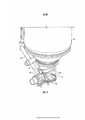
[00043] Com referência às figuras 1, 2 e 10, pode ser visto que o dispositivo (1) da invenção compreende um corpo (2) de duas partes. O corpo (2) inclui um receptor de recipiente cilíndrico (3) e uma montagem de bocal (a).[00043] With reference to figures 1, 2 and 10, it can be seen that the device (1) of the invention comprises a body (2) of two parts. The body (2) includes a cylindrical container receiver (3) and a nozzle assembly (a).
[00044] A montagem de bocal (a) compreende um conduto de fluido (4) conectado de forma fluida ao receptor de recipiente. A montagem de bocal compreende, adicionalmente, uma montagem de tubulação (b) que inclui um núcleo de espuma (c) . A montagem de tubulação (b) está disposta na direção frontal do corpo (2).[00044] The nozzle assembly (a) comprises a fluid conduit (4) fluidly connected to the container receiver. The nozzle assembly additionally comprises a pipe assembly (b) that includes a foam core (c). The piping assembly (b) is arranged in the front direction of the body (2).
[00045] O corpo (2) apresenta uma seção de escova associada (d) montada sobre o mesmo.[00045] The body (2) has an associated brush section (d) mounted on it.
[00046] O corpo apresenta uma alça (não mostrada) que pode ser acomodada por uma abertura de recepção da alça (5).[00046] The body has a handle (not shown) that can be accommodated by a handle receiving opening (5).
[00047] Na montagem do recipiente (6) (uma lata de aerossol invertida) é montada ao receptor da lata (3) . O recipiente (6) contém uma quantidade predeterminada de uma composição para tratamento e apresenta uma abertura para dispensa (não mostrada) em comunicação fluida com o conduto de fluido (4).[00047] When assembling the container (6) (an inverted aerosol can), it is mounted to the can receiver (3). The container (6) contains a predetermined amount of a treatment composition and has a dispensing opening (not shown) in fluid communication with the fluid conduit (4).
[00048] O conduto de fluido (4) inclui uma válvula de rotação (7). A válvula de rotação está disposta sob a placa de revestimento (8). A válvula de rotação (7) é operável por um elemento do recipiente (9) anexado e estendendo-se do recipiente (6), adjacente à abertura para dispensa. O elemento do recipiente está na forma de um par de cornetas (10) se estendendo de uma base cilíndrica (11). As cornetas (10) apresentam uma incisão (12) adjacente à base (11).[00048] The fluid conduit (4) includes a rotation valve (7). The rotation valve is arranged under the cover plate (8). The rotation valve (7) is operable by a container element (9) attached and extending from the container (6), adjacent to the dispensing opening. The container element is in the form of a pair of horns (10) extending from a cylindrical base (11). The horns (10) have an incision (12) adjacent to the base (11).
[00049] A válvula de rotação (7) é operada por inserção das cornetas de elemento do recipiente (10) dentro das aberturas de recepção (13) na placa de revestimento (8). A inserção adicional ocorre até as cornetas (10) encostarem contra os elementos operacionais da válvula (14).[00049] The rotation valve (7) is operated by inserting the container horns (10) into the receiving openings (13) in the cover plate (8). The additional insertion occurs until the horns (10) touch against the operational elements of the valve (14).
[00050] Então por rotação do recipiente (6), ocorre a rotação das cornetas (10) do elemento do recipiente (9), o que por sua vez causa rotação dos elementos operacionais da válvula (14) . Isto abre o conduto de fluido (4) . A rotação em excesso do recipiente (6) é impedida quando a incisão (12) das cornetas (10) encosta contra a placa de revestimento (8) .[00050] Then by rotation of the container (6), the horns (10) of the container element (9) rotate, which in turn causes rotation of the operational elements of the valve (14). This opens the fluid conduit (4). Excessive rotation of the container (6) is prevented when the incision (12) of the horns (10) touches the cover plate (8).
[00051] Nesta posição a operação do recipiente (6) pode ocorrer causando a dispensa do conteúdo do recipiente (6) através do conduto de fluido (4). (O mecanismo de operação completo não é mostrado. Contudo, é mostrada uma articulação (15) que compreende uma porção do mecanismo operacional).[00051] In this position the operation of the container (6) can occur causing the contents of the container (6) to be dispensed through the fluid conduit (4). (The complete operating mechanism is not shown. However, a hinge (15) is shown which comprises a portion of the operating mechanism).
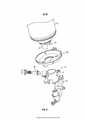
[00052] Com referência às figuras 3 a 5 pode ser visto que o dispositivo (1) da invenção compreende um dispositivo de trava (16).[00052] With reference to figures 3 to 5, it can be seen that the device (1) of the invention comprises a locking device (16).
[00053] O dispositivo de trava compreende um cilindro (17) dentro do qual penetra um trinco conformado em haste (18), quando em uma posição de travamento. Uma extremidade do cilindro (17) se destina a receber a extremidade da lata de uma articulação operacional (15). Desta forma (quando o trinco (18) penetra no cilindro (17) de travamento) a trava impede o movimento da extremidade da lata de aerossol da articulação (15) na direção da lata de aerossol (6).[00053] The locking device comprises a cylinder (17) into which a rod shaped rod (18) penetrates when in a locking position. One end of the cylinder (17) is intended to receive the can end of an operating joint (15). In this way (when the latch (18) penetrates the locking cylinder (17)) the lock prevents movement of the end of the aerosol can of the joint (15) in the direction of the aerosol can (6).
[00054] O elemento do recipiente (9) compreende uma projeção em forma de baioneta (19). A extremidade do trinco (18) que se destina a encontrar a projeção em forma de baioneta (19) é angulada de modo que o movimento da projeção em forma de baioneta (19) contra o trinco (18) causa movimento do trinco (18) para fora da projeção em forma de baioneta (19). 0 movimento da projeção em forma de baioneta (19) contra o trinco (18) se encontra em forma circular dentro do cilindro (17) do dispositivo de trava (16) . Para obter isto, o cilindro (17) do dispositivo de trava (16) apresenta uma passagem piloto (20) na forma de um canal com incisão, que se associa a um botão (21) disposto ou adjacente à projeção em forma de baioneta (19). A passagem piloto (20) é disposta em um modo helicoidal, tal que, conforme o elemento do recipiente (9) é fracionado para dentro do cilindro (17) ele é girado adicionalmente com um grau maior de penetração. A passagem piloto (20) termina, tal que, na penetração máxima permitida, o elemento do recipiente (9) e o trinco (18) são completamente engajados e o mecanismo de trava (16) é completamente desengajado.[00054] The container element (9) comprises a bayonet-shaped projection (19). The end of the latch (18) intended to meet the bayonet-shaped projection (19) is angled so that the movement of the bayonet-shaped projection (19) against the latch (18) causes movement of the latch (18) out of the bayonet-shaped projection (19). The movement of the bayonet-shaped projection (19) against the latch (18) is circular in the cylinder (17) of the locking device (16). To achieve this, the cylinder (17) of the locking device (16) has a pilot passage (20) in the form of an incised channel, which is associated with a button (21) arranged or adjacent to the bayonet-shaped projection ( 19). The pilot passage (20) is arranged in a helical manner, such that, as the container element (9) is fractionated into the cylinder (17) it is further rotated with a greater degree of penetration. The pilot passage (20) ends, such that, at the maximum permissible penetration, the container element (9) and the latch (18) are completely engaged and the locking mechanism (16) is completely disengaged.
[00055] Nesta posição a operação do recipiente (6) pode ocorrer para causar dispensa do conteúdo do recipiente (6) através do conduto de fluido (4). (O mecanismo de operação plena não é mostrado. Contudo, uma articulação (15) que compreende uma porção do mecanismo operacional é mostrada. )[00055] In this position the operation of the container (6) can occur to cause dispensing of the contents of the container (6) through the fluid conduit (4). (The full operating mechanism is not shown. However, a hinge (15) comprising a portion of the operating mechanism is shown.)
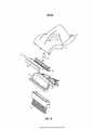
[00056] Com referência às figuras 6, 7a e 7b pode ser visto que o dispositivo (1) da invenção compreende um dispositivo de travamento (16).[00056] With reference to figures 6, 7a and 7b it can be seen that the device (1) of the invention comprises a locking device (16).
[00057] O dispositivo de travamento compreende um cilindro (17) dentro do qual um trinco conformado em haste (17) penetra, quando em uma posição de travamento (se inclina nesta posição por uma mola). Uma extremidade do cilindro (17) se destina a receber a extremidade da lata de uma articulação operacional (15) . Desta forma (quando o trinco (18) penetra no cilindro de trava (17) a trava impede movimento da extremidade da lata de aerossol da articulação (15) na direção da lata de aerossol (6) . Um ressalto da articulação (15) encosta contra o trinco (18).[00057] The locking device comprises a cylinder (17) into which a rod shaped rod (17) penetrates, when in a locking position (it is bent in this position by a spring). One end of the cylinder (17) is intended to receive the can end of an operating joint (15). This way (when the latch (18) penetrates the lock cylinder (17) the lock prevents movement of the end of the aerosol can of the joint (15) in the direction of the aerosol can (6). against the latch (18).
[00058] O elemento de recipiente (9) compreende uma projeção em forma de baioneta (19). A extremidade do trinco (18) que se destina a encontrar com a projeção em forma de baioneta (19) é angulada, tal que, o movimento da projeção em forma de baioneta (19) contra o trinco (18) causa um movimento do trinco (18) para fora da projeção em forma de baioneta (19) . O movimento da projeção em forma de baioneta (19) contra o trinco (18) está em um modo linear/axial dentro do cilindro (17) do dispositivo de trava (16) . Para obter isto, o cilindro (17) do dispositivo de trava (16) apresenta uma passagem piloto (20), na forma de uma placa conformada/com orificios que se associa à projeção em forma de baioneta (19), tal que, a projeção em forma de baioneta pode ser introduzida dentro da passagem piloto (20) quando em uma determinada orientação. A passagem piloto (20) é disposta, tal que, conforme o elemento do recipiente (9) é fracionado para dentro do cilindro (17) em penetração máxima permitida, o elemento do recipiente (9) e o trinco (18) são completamente engajados e o mecanismo de trava (16) é completamente desengajado.[00058] The container element (9) comprises a bayonet-shaped projection (19). The end of the latch (18) intended to meet the bayonet-shaped projection (19) is angled, such that the movement of the bayonet-shaped projection (19) against the latch (18) causes the latch to move (18) out of the bayonet-shaped projection (19). The movement of the bayonet-shaped projection (19) against the latch (18) is in a linear / axial mode inside the cylinder (17) of the locking device (16). To achieve this, the cylinder (17) of the locking device (16) has a pilot passage (20), in the form of a shaped plate / with holes that are associated with the bayonet-shaped projection (19), such that the bayonet projection can be inserted into the pilot passage (20) when in a certain orientation. The pilot passage (20) is arranged such that, as the container element (9) is fractionated into the cylinder (17) at maximum permissible penetration, the container element (9) and the latch (18) are completely engaged and the locking mechanism (16) is completely disengaged.
[00059] Nesta posição, o receptor do recipiente cilíndrico (3) apresenta uma tampa (22) que retém o recipiente (6) (por exemplo, por prender resilientemente um aro do mesmo).[00059] In this position, the receiver of the cylindrical container (3) has a lid (22) that holds the container (6) (for example, by resiliently attaching a rim of it).
[00060] Nesta posição a operação do recipiente (6) pode ocorrer para causar a dispensa do conteúdo do recipiente (6) através do conduto de fluido (4) . (O mecanismo de operação completo não é mostrado. Contudo uma articulação (15) que compreende uma porção do mecanismo de operação é mostrada).[00060] In this position the operation of the container (6) can occur to cause the dispensing of the contents of the container (6) through the fluid conduit (4). (The complete operating mechanism is not shown. However, a hinge (15) comprising a portion of the operating mechanism is shown).
[00061] Com referência às figuras 8, 9a e 9b pode ser visto que o dispositivo (1) da invenção compreende um dispositivo de trava (16).[00061] With reference to figures 8, 9a and 9b it can be seen that the device (1) of the invention comprises a locking device (16).
[00062] O dispositivo de trava compreende um trinco conformado em haste (18) . O trinco (18) é montado giravelmente (inclinado dentro da posição de trava por uma mola) . Desta forma, o trinco (18) impede o movimento da extremidade de lata em aerossol da articulação (15) na direção da lata de aerossol (6). Um ressalto da articulação (15) encosta contra o trinco (18).[00062] The locking device comprises a rod shaped latch (18). The latch (18) is pivotally mounted (inclined into the locking position by a spring). In this way, the latch (18) prevents movement of the aerosol can end of the joint (15) in the direction of the aerosol can (6). A shoulder of the joint (15) abuts against the latch (18).
[00063] O elemento do recipiente (9) compreende uma projeção em forma de baioneta (19).[00063] The container element (9) comprises a bayonet-shaped projection (19).
[00064] O dispositivo de trava (16) apresenta uma passagem piloto (20), na forma de uma placa conformada ou com orifícios, que se associa a um botão (21) disposto em ou adjacente à projeção em forma de baioneta (19), tal que, a projeção em forma de baioneta (19) pode ser introduzida apenas na passagem piloto (20) quando em uma determinada orientação. A projeção em forma de baioneta (19) pode ser fracionada para dentro da passagem piloto (20), tal que o botão (21) na projeção em forma de baioneta (19) torna-se disposto sobre o lado oposto da passagem piloto (20) da lata (6) .[00064] The locking device (16) has a pilot passage (20), in the form of a shaped plate or with holes, which is associated with a button (21) arranged in or adjacent to the bayonet-shaped projection (19) , such that the bayonet-shaped projection (19) can be introduced only in the pilot passage (20) when in a certain orientation. The bayonet-shaped projection (19) can be split into the pilot passage (20), such that the button (21) in the bayonet-shaped projection (19) becomes arranged on the opposite side of the pilot passage (20 ) of the can (6).
[00065] Uma vez nesta posição, a lata (6) pode ser girada, tal que, o botão (21) da projeção em forma de baioneta (19) encosta contra o trinco. O movimento continuo causa o desengate do trinco (18) do engajamento com o ressalto da articulação (15).[00065] Once in this position, the can (6) can be rotated, such that the button (21) of the bayonet-shaped projection (19) touches the latch. The continuous movement causes the latch (18) to disengage from the engagement with the joint shoulder (15).
[00066] Nesta posição a operação do recipiente (6) pode ocorrer, causando a dispensa do conteúdo do recipiente (6) através do conduto de fluido (4) . (O mecanismo de operação completo não é mostrado. Contudo, é mostrada uma articulação (15) que compreende uma porção do mecanismo operacional).[00066] In this position the operation of the container (6) can occur, causing the contents of the container (6) to be dispensed through the fluid conduit (4). (The complete operating mechanism is not shown. However, a hinge (15) is shown which comprises a portion of the operating mechanism).
Claims (7)
Translated fromPortugueseApplications Claiming Priority (4)
| Application Number | Priority Date | Filing Date | Title |
|---|---|---|---|
| GBGB0913488.3AGB0913488D0 (en) | 2009-08-01 | 2009-08-01 | Product |
| GB0913488.3 | 2009-08-01 | ||
| BR112012002269ABR112012002269B1 (en) | 2009-08-01 | 2010-08-02 | surface treatment implement |
| PCT/GB2010/001464WO2011015812A2 (en) | 2009-08-01 | 2010-08-02 | Product |
Publications (1)
| Publication Number | Publication Date |
|---|---|
| BR122019018574B1true BR122019018574B1 (en) | 2020-10-06 |
Family
ID=41129529
Family Applications (2)
| Application Number | Title | Priority Date | Filing Date |
|---|---|---|---|
| BR122019018574-3ABR122019018574B1 (en) | 2009-08-01 | 2010-08-02 | IMPLEMENT TO TREAT SURFACE |
| BR112012002269ABR112012002269B1 (en) | 2009-08-01 | 2010-08-02 | surface treatment implement |
Family Applications After (1)
| Application Number | Title | Priority Date | Filing Date |
|---|---|---|---|
| BR112012002269ABR112012002269B1 (en) | 2009-08-01 | 2010-08-02 | surface treatment implement |
Country Status (11)
| Country | Link |
|---|---|
| US (1) | US8657516B2 (en) |
| EP (2) | EP2459047B1 (en) |
| CN (2) | CN103735225A (en) |
| AU (1) | AU2010280517B2 (en) |
| BR (2) | BR122019018574B1 (en) |
| CA (1) | CA2769261C (en) |
| GB (1) | GB0913488D0 (en) |
| PL (2) | PL2534993T3 (en) |
| RU (1) | RU2546461C2 (en) |
| WO (1) | WO2011015812A2 (en) |
| ZA (1) | ZA201200968B (en) |
Families Citing this family (23)
| Publication number | Priority date | Publication date | Assignee | Title |
|---|---|---|---|---|
| US8684619B2 (en) | 2010-10-26 | 2014-04-01 | The Procter & Gamble Company | Cleaning device having plural and customizable cleaning surfaces |
| US9044852B2 (en) | 2010-10-26 | 2015-06-02 | Procter & Gamble | Cleaning device having onboard replaceable cleaning pad and onboard replaceable cleaning solution |
| GB201101006D0 (en)* | 2011-01-21 | 2011-03-09 | Reckitt Benckiser Nv | Product |
| AU2012261594A1 (en)* | 2012-01-18 | 2013-08-01 | Bissell Homecare, Inc. | Method of cleaning a carpet segment |
| GB2513006B (en) | 2013-03-15 | 2016-01-27 | Bissell Homecare Inc | Container and cap assembly |
| GB2525251A (en) | 2014-04-18 | 2015-10-21 | Mic Ag | Optical fibre sensor system |
| US10143350B2 (en) | 2015-09-09 | 2018-12-04 | Bissell Homecare, Inc. | Cap and receiver for coupling a container to a surface cleaning device |
| US10239185B2 (en) | 2017-08-23 | 2019-03-26 | Aeroetch Holdings, Inc. | Self-powered pressurized granular particle ejector tool with remote operation |
| US12434350B2 (en) | 2021-03-08 | 2025-10-07 | Aeroetch Holdings, Inc. | Atmospheric pressure venturi intermix regulator cartridge and emission conduit |
| US11647860B1 (en) | 2022-05-13 | 2023-05-16 | Sharkninja Operating Llc | Flavored beverage carbonation system |
| US11751585B1 (en) | 2022-05-13 | 2023-09-12 | Sharkninja Operating Llc | Flavored beverage carbonation system |
| US12213617B2 (en) | 2022-05-13 | 2025-02-04 | Sharkninja Operating Llc | Flavored beverage carbonation process |
| US12096880B2 (en) | 2022-05-13 | 2024-09-24 | Sharkninja Operating Llc | Flavorant for beverage carbonation system |
| US12084334B2 (en) | 2022-11-17 | 2024-09-10 | Sharkninja Operating Llc | Ingredient container |
| US11634314B1 (en) | 2022-11-17 | 2023-04-25 | Sharkninja Operating Llc | Dosing accuracy |
| US11738988B1 (en) | 2022-11-17 | 2023-08-29 | Sharkninja Operating Llc | Ingredient container valve control |
| US11745996B1 (en) | 2022-11-17 | 2023-09-05 | Sharkninja Operating Llc | Ingredient containers for use with beverage dispensers |
| US12103840B2 (en) | 2022-11-17 | 2024-10-01 | Sharkninja Operating Llc | Ingredient container with sealing valve |
| USD1092208S1 (en) | 2022-12-23 | 2025-09-09 | Sharkninja Operating Llc | Cap of ingredient container |
| USD1091308S1 (en) | 2022-12-23 | 2025-09-02 | Sharkninja Operating Llc | Ingredient container |
| US11871867B1 (en) | 2023-03-22 | 2024-01-16 | Sharkninja Operating Llc | Additive container with bottom cover |
| US11925287B1 (en) | 2023-03-22 | 2024-03-12 | Sharkninja Operating Llc | Additive container with inlet tube |
| US12116257B1 (en) | 2023-03-22 | 2024-10-15 | Sharkninja Operating Llc | Adapter for beverage dispenser |
Family Cites Families (81)
| Publication number | Priority date | Publication date | Assignee | Title |
|---|---|---|---|---|
| US2649331A (en)* | 1950-08-09 | 1953-08-18 | Bridgeport Brass Co | Device for intermittently discharging fluid under pressure |
| NL254551A (en)* | 1959-08-05 | |||
| US5110011A (en)* | 1990-06-29 | 1992-05-05 | Minnesota Mining And Manufacturing Company | Non-releasable spray head and dip tube assembly |
| US3303970A (en)* | 1964-07-14 | 1967-02-14 | Jerome Marrow | Device for simultaneously dispensing from plural sources |
| US3575319A (en)* | 1968-07-11 | 1971-04-20 | Upjohn Co | Portable dispenser for polymer foams |
| US3592364A (en)* | 1969-08-27 | 1971-07-13 | Geigy Chem Corp | Retaining ring incorporating a cutting edge for use in an aerosol dispenser valve assembly |
| US3659791A (en)* | 1969-11-17 | 1972-05-02 | William O Clark | Spray gun adaptor for aerosal cans |
| DE2153445A1 (en)* | 1970-11-02 | 1972-05-10 | Precision Valve Corp., Yonkers, N.Y. (V.St.A.) | Actuator for controlling the delivery of material from a pressure vessel |
| US3738536A (en)* | 1971-06-28 | 1973-06-12 | Sunbeam Plastics Corp | Child proof protective overcap for an aerosol can |
| US3848778A (en)* | 1972-08-14 | 1974-11-19 | P Meshberg | Childproof actuator assembly |
| US3765573A (en)* | 1972-11-01 | 1973-10-16 | I Landsman | Actuating cap for an aerosol device |
| US4171758A (en)* | 1977-04-11 | 1979-10-23 | S. C. Johnson & Son, Inc. | Child-safe actuator for pressurized container |
| JPS5442855A (en) | 1978-07-18 | 1979-04-05 | Matsushita Electric Ind Co Ltd | Nozzle of washing carpet |
| FR2482242B1 (en)* | 1980-05-06 | 1986-02-07 | Normos Norbert | SAFETY VALVE, ESPECIALLY FOR CONTAINERS CONTAINING A PRESSURIZED FLUID |
| EP0062609A1 (en)* | 1981-03-27 | 1982-10-13 | Plastics Consultency Office AG | Multi-component dispensing container with a valve |
| GB2112462B (en)* | 1981-12-03 | 1985-06-19 | Oreal | A dispenser cap for a pressurised container and a corresponding unit |
| JPS63267463A (en)* | 1986-12-19 | 1988-11-04 | Araki Rubber:Kk | Aerial spray - working aids |
| DE3707409A1 (en)* | 1987-03-07 | 1988-09-15 | Henkel Kgaa | METHOD FOR REMOVING TEXTILES |
| US4815637A (en)* | 1988-04-21 | 1989-03-28 | Nellis Russell L | Cap assembly for use with canned aerosol lubricant |
| DE3879951T2 (en)* | 1988-12-22 | 1993-09-16 | Artebel Sa | OPERATING DEVICE FOR APPLYING A LIQUID. |
| US5180109A (en)* | 1991-06-05 | 1993-01-19 | Minnesota Mining And Manufacturing Company | Single use spray dispensing assembly |
| US5514026A (en)* | 1993-10-20 | 1996-05-07 | Sandair Nevada, Inc. | Unitary, hand-held, portable, self-powered refillable mixed-media ejector tool |
| US5368202A (en)* | 1993-11-19 | 1994-11-29 | Smrt; Thomas J. | Handle for holding and remotely actuating an aerosol container |
| CN1045058C (en)* | 1994-01-14 | 1999-09-15 | 胡佛公司 | Liquid recovery tank for a convertible upright carpet extractor |
| US5534167A (en)* | 1994-06-13 | 1996-07-09 | S. C. Johnson & Son, Inc. | Carpet cleaning and restoring composition |
| US6030465A (en)* | 1996-06-26 | 2000-02-29 | Matsushita Electric Corporation Of America | Extractor with twin, counterrotating agitators |
| US5769279A (en)* | 1996-07-19 | 1998-06-23 | Smrt; Thomas J. | Aerosol container discharging apparatus with flag staking capability |
| US5826795A (en)* | 1996-08-19 | 1998-10-27 | Minnesota Mining And Manufacturing Company | Spray assembly |
| US6082588A (en)* | 1997-01-10 | 2000-07-04 | Lever Brothers Company, Division Of Conopco, Inc. | Dual compartment package and pumps |
| US7204041B1 (en)* | 1997-08-14 | 2007-04-17 | Promdx Technology, Inc. | Ergonomic systems and methods providing intelligent adaptive surfaces |
| JP3865485B2 (en)* | 1997-11-07 | 2007-01-10 | 東洋エアゾール工業株式会社 | Flow control device for aerosol containers |
| US5924599A (en)* | 1998-01-16 | 1999-07-20 | Flexible Products Company | Dispensing system with unique container attachment |
| US6056213A (en)* | 1998-01-30 | 2000-05-02 | 3M Innovative Properties Company | Modular system for atomizing a liquid |
| US6053373A (en)* | 1998-10-16 | 2000-04-25 | S.C. Johnson Commercial Markets, Inc. | Fluid dispensing device |
| US6579023B2 (en)* | 1998-12-01 | 2003-06-17 | The Procter & Gamble Company | Cleaning implements |
| US20030126710A1 (en)* | 1998-11-09 | 2003-07-10 | Policicchio Nicola John | Cleaning composition, pad, wipe, implement, and system and method of use thereof |
| US7048458B2 (en)* | 2000-03-24 | 2006-05-23 | The Clorox Company | Fluid valve and actuator for inverted fluid reservoir |
| US6976802B2 (en)* | 2000-10-11 | 2005-12-20 | The Clorox Company | Fluid distribution nozzle and stream pattern |
| ES2544951T3 (en)* | 2000-07-24 | 2015-09-07 | Clinical Designs Limited | Dispenser |
| JP4832661B2 (en)* | 2000-10-17 | 2011-12-07 | 株式会社ダイゾー | Rotating aerosol products |
| EP1229107A1 (en)* | 2001-02-05 | 2002-08-07 | The Procter & Gamble Company | Process of cleaning carpets with a composition comprising a fluorinated compound |
| CN2498978Y (en)* | 2001-07-17 | 2002-07-10 | 王冬雷 | Water absorption drying type vacuum cleaner |
| US6663307B2 (en)* | 2001-09-14 | 2003-12-16 | S. C. Johnson & Son, Inc. | Apparatus for spraying a remote target or area |
| US6866165B2 (en)* | 2001-09-14 | 2005-03-15 | S.C. Johnson & Son, Inc. | Spray canister |
| US6551001B2 (en)* | 2001-09-14 | 2003-04-22 | S. C. Johnson & Son, Inc. | Cleaning device with a trigger-actuated spray canister |
| US6497525B1 (en)* | 2002-04-05 | 2002-12-24 | Chiu-Yun Huang | Mop with a liquid spraying device |
| US7232262B2 (en)* | 2002-07-18 | 2007-06-19 | Westover Scientific, Inc. | Fiber-optic endface cleaning apparatus and method |
| US7906473B2 (en)* | 2002-09-13 | 2011-03-15 | Bissell Homecare, Inc. | Manual spray cleaner |
| US7007338B2 (en)* | 2003-01-16 | 2006-03-07 | Garabedian Jr Aram | Advanced aerosol cleaning system |
| US6868989B2 (en)* | 2003-03-10 | 2005-03-22 | S.C. Johnson & Son, Inc. | Cleaner with adjustable aerosol canister retainer |
| US6889917B2 (en)* | 2003-03-10 | 2005-05-10 | S.C. Johnson & Son, Inc. | Cleaning device with universal motion quick disconnect head |
| US8267607B2 (en)* | 2003-06-26 | 2012-09-18 | Harris Research, Inc. | Surface working apparatus |
| US20050112022A1 (en)* | 2003-11-26 | 2005-05-26 | Morgan David M. | Room sanitizing method and apparatus |
| EP1750540A1 (en)* | 2004-05-22 | 2007-02-14 | Ball Burnishing Machine Tools Limited | Multi-function surface treatment tool |
| CA2471837C (en)* | 2004-06-17 | 2008-05-13 | The Clorox Company | Advanced aerosol cleaning system |
| US8061562B2 (en)* | 2004-10-12 | 2011-11-22 | S.C. Johnson & Son, Inc. | Compact spray device |
| DE202004019888U1 (en) | 2004-12-20 | 2005-02-24 | Avet Ag | Cleaning device with cleaning liquid supply container, e.g. mop, has protruding part of container inserted into cavity in end of container holder |
| US20060201970A1 (en)* | 2005-03-11 | 2006-09-14 | Jasek Sidney J | Safety nozzle for aerosol can |
| JP4734124B2 (en)* | 2005-04-05 | 2011-07-27 | ユニ・チャーム株式会社 | Cleaning tool |
| US20090249533A1 (en)* | 2005-12-20 | 2009-10-08 | Sawalski Michael M | Toilet Bowl Cleaning and/or Deodorizing Device |
| US7922041B2 (en)* | 2005-12-29 | 2011-04-12 | The Procter & Gamble Company | Spray dispensers |
| US7631783B1 (en)* | 2006-06-12 | 2009-12-15 | Rodney Laible | Docking station for a liquid container |
| CN1923115A (en)* | 2006-09-08 | 2007-03-07 | 泰怡凯电器(苏州)有限公司 | Wet-type cleaning device |
| GB0620676D0 (en)* | 2006-10-18 | 2006-11-29 | Reckitt Benckiser Uk Ltd | A cleaning device |
| WO2008090498A1 (en)* | 2007-01-22 | 2008-07-31 | The Procter & Gamble Company | Method of cleaning carpet comprising melamine foam |
| US9186028B2 (en)* | 2007-03-05 | 2015-11-17 | Bissell Homecare, Inc. | Accessory tool for a vacuum cleaner |
| US7337989B1 (en)* | 2007-03-26 | 2008-03-04 | S.C. Johnson & Son, Inc. | Automated sprayer with manually-adjustable nozzle |
| GB0725198D0 (en)* | 2007-12-24 | 2008-01-30 | Reckitt Benckiser Uk Ltd | Cleaning device |
| USD613918S1 (en)* | 2008-01-11 | 2010-04-13 | Bissell Homecare, Inc. | Cleaning fluid dispenser |
| US8016167B2 (en)* | 2008-09-09 | 2011-09-13 | The Clorox Company | Aerosol sprayer |
| US9061817B2 (en)* | 2008-11-12 | 2015-06-23 | Meadwestvaco Calmar, Inc. | Spray devices and methods for using the same |
| US8475070B1 (en)* | 2009-02-11 | 2013-07-02 | Bissell Homecare, Inc. | Hard surface cleaning tool |
| GB2469476B (en)* | 2009-04-15 | 2013-05-15 | Akzo Nobel Coatings Int Bv | A decking coating composition applicator |
| JP2012530567A (en)* | 2009-06-25 | 2012-12-06 | ベーリンガー インゲルハイム フェトメディカ ゲゼルシャフト ミット ベシュレンクテル ハフツング | Inhaler |
| US8276832B2 (en)* | 2009-07-22 | 2012-10-02 | S.C. Johnson & Son, Inc. | Multiple spray actuator overcap |
| AU2010249272C1 (en)* | 2009-12-18 | 2014-07-17 | Bissell Inc. | Dry vacuum cleaner with spot cleaning |
| US20120217243A1 (en)* | 2010-05-21 | 2012-08-30 | Erica Eden Cohen | Shroud and Dispensing System for a Handheld Container |
| IT1400715B1 (en)* | 2010-07-06 | 2013-06-28 | Capsol S P A | DOUBLE CAP OF OPERATION AND DELIVERY COUPLED WITH AN AEROSOL BOTTLE. |
| GB201101006D0 (en)* | 2011-01-21 | 2011-03-09 | Reckitt Benckiser Nv | Product |
| US20120192894A1 (en)* | 2011-01-27 | 2012-08-02 | 3M Innovative Properties Company | Cleaning and sealing solution applicator tool for surfaces such as stone, porous tile, or grout |
| USD686383S1 (en)* | 2011-04-19 | 2013-07-16 | Reckitt Benckiser N. V. | Sweeper |
- 2009
- 2009-08-01GBGBGB0913488.3Apatent/GB0913488D0/ennot_activeCeased
- 2010
- 2010-07-26USUS12/804,614patent/US8657516B2/enactiveActive
- 2010-08-02PLPL12183829Tpatent/PL2534993T3/enunknown
- 2010-08-02BRBR122019018574-3Apatent/BR122019018574B1/enactiveIP Right Grant
- 2010-08-02BRBR112012002269Apatent/BR112012002269B1/ennot_activeIP Right Cessation
- 2010-08-02RURU2012107524/12Apatent/RU2546461C2/enactive
- 2010-08-02EPEP10748115.2Apatent/EP2459047B1/ennot_activeNot-in-force
- 2010-08-02CACA2769261Apatent/CA2769261C/ennot_activeExpired - Fee Related
- 2010-08-02WOPCT/GB2010/001464patent/WO2011015812A2/enactiveApplication Filing
- 2010-08-02AUAU2010280517Apatent/AU2010280517B2/ennot_activeCeased
- 2010-08-02CNCN201410046658.6Apatent/CN103735225A/enactivePending
- 2010-08-02EPEP12183829.6Apatent/EP2534993B1/ennot_activeNot-in-force
- 2010-08-02CNCN201080034201.3Apatent/CN102573592B/ennot_activeExpired - Fee Related
- 2010-08-02PLPL10748115Tpatent/PL2459047T3/enunknown
- 2012
- 2012-02-09ZAZA2012/00968Apatent/ZA201200968B/enunknown
Also Published As
| Publication number | Publication date |
|---|---|
| EP2459047B1 (en) | 2014-05-14 |
| PL2459047T3 (en) | 2014-09-30 |
| CN102573592A (en) | 2012-07-11 |
| GB0913488D0 (en) | 2009-09-16 |
| RU2546461C2 (en) | 2015-04-10 |
| WO2011015812A2 (en) | 2011-02-10 |
| EP2534993B1 (en) | 2013-10-23 |
| US8657516B2 (en) | 2014-02-25 |
| BR112012002269A2 (en) | 2016-06-14 |
| CA2769261C (en) | 2017-03-28 |
| US20110107545A1 (en) | 2011-05-12 |
| AU2010280517A1 (en) | 2012-03-15 |
| PL2534993T3 (en) | 2014-03-31 |
| EP2534993A1 (en) | 2012-12-19 |
| EP2459047A2 (en) | 2012-06-06 |
| CN103735225A (en) | 2014-04-23 |
| WO2011015812A8 (en) | 2012-03-08 |
| WO2011015812A3 (en) | 2011-06-23 |
| ZA201200968B (en) | 2013-05-29 |
| CN102573592B (en) | 2014-07-09 |
| AU2010280517B2 (en) | 2014-02-06 |
| BR112012002269B1 (en) | 2019-12-10 |
| RU2012107524A (en) | 2013-09-10 |
| CA2769261A1 (en) | 2011-02-10 |
Similar Documents
| Publication | Publication Date | Title |
|---|---|---|
| BR122019018574B1 (en) | IMPLEMENT TO TREAT SURFACE | |
| JP3917423B2 (en) | Dispensing device comprising a container and attachment means with protective perforation means | |
| BR112013018588B1 (en) | PRODUCT | |
| EP2494904B1 (en) | Surface cleaning apparatus with pivoting manifold | |
| US7048458B2 (en) | Fluid valve and actuator for inverted fluid reservoir | |
| US7004658B2 (en) | Fluid valve and actuator for inverted fluid reservoir | |
| US9538895B1 (en) | Whisk broom with squeegee | |
| US20150089757A1 (en) | Floor mop with removable base plate | |
| US7260865B2 (en) | Twist mop | |
| EP4274462B1 (en) | Rinse bucket for floor mop | |
| KR20170010804A (en) | A fluid dispensing cleaning tool | |
| US10299654B2 (en) | Fluid suction device | |
| US5819365A (en) | Window washing accessory cleaning tool for use with water extraction cleaning machine | |
| US20230020472A1 (en) | Spray mop with handle locking mechanism | |
| DE20280404U1 (en) | Household cleaner | |
| KR102322862B1 (en) | Double-sided cleaning pole | |
| EP3082545B1 (en) | Steam cleaner for cleaning domestic and industrial surfaces | |
| JP3774147B2 (en) | Reservoir used for cleaning tools | |
| KR100856463B1 (en) | Affected area | |
| EP2873358B1 (en) | Pivoting handle for a surface cleaning device | |
| EP2557978B1 (en) | A cleaning device with cleaning pad | |
| RU2575432C2 (en) | Device for surface treatment (versions) and its use | |
| KR20130004812U (en) | Shower head | |
| ITMO20010255A1 (en) | BRUSH ACCESSORY FOR HOUSEHOLD APPLIANCES, IN PARTICULAR VACUUM CLEANERS, ELECTRIC PURPOSES AND SIMILAR EQUIPPED WITH SUCTION HOSE |
Legal Events
| Date | Code | Title | Description |
|---|---|---|---|
| B06A | Patent application procedure suspended [chapter 6.1 patent gazette] | ||
| B09A | Decision: intention to grant [chapter 9.1 patent gazette] | ||
| B16A | Patent or certificate of addition of invention granted [chapter 16.1 patent gazette] | Free format text:PRAZO DE VALIDADE: 10 (DEZ) ANOS CONTADOS A PARTIR DE 06/10/2020, OBSERVADAS AS CONDICOES LEGAIS. |