BR122014016104A2 - CARTRIDGE - Google Patents
CARTRIDGEDownload PDFInfo
- Publication number
- BR122014016104A2 BR122014016104A2BR122014016104-2ABR122014016104ABR122014016104A2BR 122014016104 A2BR122014016104 A2BR 122014016104A2BR 122014016104 ABR122014016104 ABR 122014016104ABR 122014016104 A2BR122014016104 A2BR 122014016104A2
- Authority
- BR
- Brazil
- Prior art keywords
- cartridge
- lock
- guide
- track
- fluid
- Prior art date
Links
- 238000003780insertionMethods0.000claimsdescription22
- 230000037431insertionEffects0.000claimsdescription22
- 239000012858resilient materialSubstances0.000claimsdescription2
- 239000012530fluidSubstances0.000abstractdescription128
- 230000000903blocking effectEffects0.000description8
- 238000000034methodMethods0.000description7
- 239000003570airSubstances0.000description6
- 238000010586diagramMethods0.000description6
- 239000002991molded plasticSubstances0.000description4
- 230000000717retained effectEffects0.000description4
- 238000009434installationMethods0.000description3
- 230000032258transportEffects0.000description3
- 230000006870functionEffects0.000description2
- 238000002347injectionMethods0.000description2
- 239000007924injectionSubstances0.000description2
- 239000007788liquidSubstances0.000description2
- 239000000463materialSubstances0.000description2
- 230000007246mechanismEffects0.000description2
- 239000012080ambient airSubstances0.000description1
- 239000003086colorantSubstances0.000description1
- 239000013536elastomeric materialSubstances0.000description1
- 238000004519manufacturing processMethods0.000description1
- 239000004033plasticSubstances0.000description1
- 238000009827uniform distributionMethods0.000description1
Images


Classifications
- B—PERFORMING OPERATIONS; TRANSPORTING
- B41—PRINTING; LINING MACHINES; TYPEWRITERS; STAMPS
- B41J—TYPEWRITERS; SELECTIVE PRINTING MECHANISMS, i.e. MECHANISMS PRINTING OTHERWISE THAN FROM A FORME; CORRECTION OF TYPOGRAPHICAL ERRORS
- B41J2/00—Typewriters or selective printing mechanisms characterised by the printing or marking process for which they are designed
- B41J2/005—Typewriters or selective printing mechanisms characterised by the printing or marking process for which they are designed characterised by bringing liquid or particles selectively into contact with a printing material
- B41J2/01—Ink jet
- B41J2/17—Ink jet characterised by ink handling
- B41J2/175—Ink supply systems ; Circuit parts therefor
- B41J2/17503—Ink cartridges
- B41J2/17526—Electrical contacts to the cartridge
- B—PERFORMING OPERATIONS; TRANSPORTING
- B41—PRINTING; LINING MACHINES; TYPEWRITERS; STAMPS
- B41L—APPARATUS OR DEVICES FOR MANIFOLDING, DUPLICATING OR PRINTING FOR OFFICE OR OTHER COMMERCIAL PURPOSES; ADDRESSING MACHINES OR LIKE SERIES-PRINTING MACHINES
- B41L27/00—Inking arrangements or devices
- B—PERFORMING OPERATIONS; TRANSPORTING
- B41—PRINTING; LINING MACHINES; TYPEWRITERS; STAMPS
- B41J—TYPEWRITERS; SELECTIVE PRINTING MECHANISMS, i.e. MECHANISMS PRINTING OTHERWISE THAN FROM A FORME; CORRECTION OF TYPOGRAPHICAL ERRORS
- B41J2/00—Typewriters or selective printing mechanisms characterised by the printing or marking process for which they are designed
- B41J2/005—Typewriters or selective printing mechanisms characterised by the printing or marking process for which they are designed characterised by bringing liquid or particles selectively into contact with a printing material
- B41J2/01—Ink jet
- B41J2/17—Ink jet characterised by ink handling
- B41J2/175—Ink supply systems ; Circuit parts therefor
- B41J2/17503—Ink cartridges
- B41J2/17513—Inner structure
- B—PERFORMING OPERATIONS; TRANSPORTING
- B41—PRINTING; LINING MACHINES; TYPEWRITERS; STAMPS
- B41J—TYPEWRITERS; SELECTIVE PRINTING MECHANISMS, i.e. MECHANISMS PRINTING OTHERWISE THAN FROM A FORME; CORRECTION OF TYPOGRAPHICAL ERRORS
- B41J2/00—Typewriters or selective printing mechanisms characterised by the printing or marking process for which they are designed
- B41J2/005—Typewriters or selective printing mechanisms characterised by the printing or marking process for which they are designed characterised by bringing liquid or particles selectively into contact with a printing material
- B41J2/01—Ink jet
- B41J2/17—Ink jet characterised by ink handling
- B41J2/175—Ink supply systems ; Circuit parts therefor
- B41J2/17503—Ink cartridges
- B41J2/1752—Mounting within the printer
- B—PERFORMING OPERATIONS; TRANSPORTING
- B41—PRINTING; LINING MACHINES; TYPEWRITERS; STAMPS
- B41J—TYPEWRITERS; SELECTIVE PRINTING MECHANISMS, i.e. MECHANISMS PRINTING OTHERWISE THAN FROM A FORME; CORRECTION OF TYPOGRAPHICAL ERRORS
- B41J2/00—Typewriters or selective printing mechanisms characterised by the printing or marking process for which they are designed
- B41J2/005—Typewriters or selective printing mechanisms characterised by the printing or marking process for which they are designed characterised by bringing liquid or particles selectively into contact with a printing material
- B41J2/01—Ink jet
- B41J2/17—Ink jet characterised by ink handling
- B41J2/175—Ink supply systems ; Circuit parts therefor
- B41J2/17503—Ink cartridges
- B41J2/17543—Cartridge presence detection or type identification
- B41J2/1755—Cartridge presence detection or type identification mechanically
- B—PERFORMING OPERATIONS; TRANSPORTING
- B41—PRINTING; LINING MACHINES; TYPEWRITERS; STAMPS
- B41J—TYPEWRITERS; SELECTIVE PRINTING MECHANISMS, i.e. MECHANISMS PRINTING OTHERWISE THAN FROM A FORME; CORRECTION OF TYPOGRAPHICAL ERRORS
- B41J2/00—Typewriters or selective printing mechanisms characterised by the printing or marking process for which they are designed
- B41J2/005—Typewriters or selective printing mechanisms characterised by the printing or marking process for which they are designed characterised by bringing liquid or particles selectively into contact with a printing material
- B41J2/01—Ink jet
- B41J2/17—Ink jet characterised by ink handling
- B41J2/175—Ink supply systems ; Circuit parts therefor
- B41J2/17503—Ink cartridges
- B41J2/17553—Outer structure
Landscapes
- Ink Jet (AREA)
- Infusion, Injection, And Reservoir Apparatuses (AREA)
- Containers And Packaging Bodies Having A Special Means To Remove Contents (AREA)
- Quick-Acting Or Multi-Walled Pipe Joints (AREA)
Abstract
Translated fromPortugueseDescription
Translated fromPortuguese[0001] Cartuchos de fluido são subconjuntos para serem trocados com um correspondente conjunto de ejeção de fluido. Um cartucho de fluido comum é um cartucho de tinta. Um conjunto de ejeção de fluido comum é uma impressora. Em geral, dois tipos de cartuchos de tinta podem ser distinguidos. Um primeiro tipo consiste de um cartucho de cabeçote de impressão integrado, onde o cartucho compreende um cabeçote de impressão. Um segundo tipo consiste de um recipiente de tinta individual. Um cartucho de tinta é conectado a uma estrutura de recepção de uma impressora. A estrutura de recepção e os cartuchos de tinta são providos com as interfaces corretas para guiar tinta a partir do cartucho até o cabeçote de impressão para impressão. Em adição à interface de tinta, uma interface de ar, uma interface de enchavetamento, uma interface elétrica e uma interface de alinhamento podem ser providas no cartucho de tinta e sua estrutura de recepção. A interface de ar transporta ar para e a partir do cartucho, principalmente para controle de pressão dentro do cartucho. A interface de enchavetamento garante que o respectivo cartucho seja assentado na correta estrutura de recepção de cartucho de tinta. A interface de alinhamento garante que as interfaces estejam bem alinhadas para conexão. A interface elétrica envia sinais elétricos entre um circuito de controle de impressora e o cartucho de tinta. Os sinais podem se relacionar com características de cartucho de tinta.[0001] Fluid cartridges are subassemblies to be exchanged with a corresponding fluid ejection set. A common fluid cartridge is an ink cartridge. A common fluid ejection assembly is a printer. In general, two types of ink cartridges can be distinguished. A first type consists of an integrated printhead cartridge, where the cartridge comprises a printhead. A second type consists of an individual ink container. An ink cartridge is connected to a printer receiving frame. The receiving frame and ink cartridges are provided with the correct interfaces to guide ink from the cartridge to the print head for printing. In addition to the ink interface, an air interface, a locking interface, an electrical interface and an alignment interface can be provided in the ink cartridge and its receiving structure. The air interface transports air to and from the cartridge, primarily for pressure control inside the cartridge. The latching interface ensures that the respective cartridge is seated in the correct ink cartridge receiving structure. The alignment interface ensures that the interfaces are well aligned for connection. The electrical interface sends electrical signals between a printer control circuit and the ink cartridge. The signals may relate to ink cartridge characteristics.
[0002] Uma trava extra e usualmente provida para manter conexões substancialmente à prova de ar e liquido entre o cartucho e a estrutura de recepção. A trava extra deve também manter a conexão elétrica. Uma técnica de travamento conhecida envolve o uso de um anel para manter o cartucho selado com a baia de recepção. Uma outra técnica de travamento conhecida usa uma lingueta de encaixe deformável que engata um entalhe para manter o cartucho selado.[0002] An extra lock is usually provided to maintain substantially air and liquid proof connections between the cartridge and the receiving frame. The extra lock must also maintain the electrical connection. A known locking technique involves using a ring to keep the cartridge sealed with the receiving bay. Another known locking technique uses a deformable locking tongue that engages a notch to keep the cartridge sealed.
[0003] Os mecanismos de trava conhecidos tendem a consumir uma quantidade relativamente grande de espaço dentro da impressora. Em adição, força significativa pode ser necessária para estabelecer a trava. Em alguns casos, o cartucho é inserido em uma orientação inclinada, após o que ele é girado de volta para a posição normal para produzir o contato de interfaces. Isto usualmente envolve a deflexão de elementos de contato tal que conexões incorretas de interfaces, vazamento, e desgaste ou dano de material são prováveis de ocorrer.[0003] Known locking mechanisms tend to consume a relatively large amount of space inside the printer. In addition, significant force may be required to establish the lock. In some cases, the cartridge is inserted in an inclined orientation, after which it is rotated back to the normal position to produce the interface contact. This usually involves the deflection of contact elements such that incorrect interface connections, leakage, and material wear or damage are likely to occur.
[0004] Para o propósito de ilustração, certas configurações da presente invenção serão agora descritas com referência aos desenhos diagramáticos anexos nos quais:[0004] For the purpose of illustration, certain configurations of the present invention will now be described with reference to the accompanying diagrammatic drawings in which:
[0005] A figura 1 ilustra um diagrama de uma configuração de um sistema de ejeção de fluido, em vista frontal;[0005] Figure 1 illustrates a diagram of a configuration of a fluid ejection system, in front view;
[0006] A figura 2 ilustra um diagrama da configuração do sistema de ejeção de fluido da figura 1, em vista lateral;[0006] Figure 2 shows a diagram of the configuration of the fluid ejection system of figure 1, in side view;
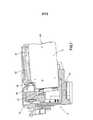
[0007] A figura 3 ilustra uma vista lateral de corte transversal de parte de uma configuração do sistema de ejeção de fluido com um cartucho de fluido em estado não conectado;[0007] Figure 3 illustrates a side cross-sectional view of part of a fluid ejection system configuration with a fluid cartridge in an unconnected state;
[0008] A figura 4 ilustra uma configuração de um detalhe de uma estrutura de recepção para um cartucho de fluido, em vista frontal;[0008] Figure 4 shows a configuration of a detail of a receiving structure for a fluid cartridge, in front view;
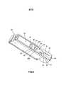
[0009] A figura 5 ilustra uma vista em perspectiva de uma configuração de um cartucho de fluido;[0009] Figure 5 illustrates a perspective view of a fluid cartridge configuration;
[0010] A figura 6 ilustra uma outra vista em perspectiva de uma configuração do cartucho de fluido da figura 5, mostrando claramente uma pista guia e uma pista de trava;[0010] Figure 6 illustrates another perspective view of a configuration of the fluid cartridge of Figure 5, clearly showing a guide track and a locking track;
[0011] A figura 7 ilustra uma vista lateral de corte transversal da configuração da parte do sistema de ejeção de fluido da figura 3 onde o cartucho de fluido está conectado à estrutura de recepção de cartucho;[0011] Figure 7 illustrates a side cross-sectional view of the configuration of the part of the fluid ejection system of Figure 3 where the fluid cartridge is connected to the cartridge receiving structure;
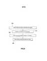
[0012] A figura 8 ilustra um diagrama de fluxo de uma configuração de um método para conectar um cartucho de fluido a uma estrutura de recepção;[0012] Figure 8 illustrates a flow diagram of a configuration of a method for connecting a fluid cartridge to a receiving structure;
[0013] A figura 9 ilustra um diagrama de fluxo de uma configuração adicional de um método para conectar e desconectar um cartucho de fluido com relação a uma estrutura de recepção;[0013] Figure 9 illustrates a flow diagram of an additional configuration of a method for connecting and disconnecting a fluid cartridge with respect to a receiving structure;
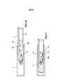
[0014] A figura 10 ilustra uma vista inferior diagramática de corte transversal de uma configuração de um cartucho de fluido e uma estrutura de recepção de cartucho, em um primeiro estágio de conexão do cartucho de fluido, onde o arranjo de trava é produzido semitransparente por razões de ilustração;[0014] Figure 10 illustrates a diagrammatic bottom cross-sectional view of a configuration of a fluid cartridge and a cartridge receiving structure, in a first connection stage of the fluid cartridge, where the locking arrangement is produced semitransparently by illustration reasons;
[0015] A figura 11 ilustra uma vista inferior diagramática de corte transversal da configuração do cartucho de fluido e da estrutura de recepção de cartucho da figura 10, em um segundo estágio de conexão do cartucho de fluido, onde o arranjo de trava é produzido semitransparente por razões de ilustração;[0015] Figure 11 illustrates a diagrammatic bottom cross-sectional view of the configuration of the fluid cartridge and the cartridge receiving structure of figure 10, in a second connection stage of the fluid cartridge, where the locking arrangement is produced semitransparent for illustration reasons;
[0016] A figura 12 ilustra uma vista inferior diagramática de corte transversal da configuração do cartucho de fluido e da estrutura de recepção de cartucho da figura 10 e 11, em urn terceiro estágio de conexão do cartucho de fluido, onde o arranjo de trava é produzido semitransparente por razões de ilustração;[0016] Figure 12 illustrates a diagrammatic bottom cross-sectional view of the configuration of the fluid cartridge and the cartridge receiving structure of figures 10 and 11, in a third connection stage of the fluid cartridge, where the locking arrangement is produced semitransparent for the sake of illustration;
[0017] A figura 13 ilustra uma vista inferior diagramática de corte transversal da configuração do cartucho de fluido e da estrutura de recepção de cartucho das figs. 10-12, em um estágio final de conexão do cartucho de fluido, onde o arranjo de trava é produzido semitransparente por razões de ilustração;[0017] Figure 13 shows a diagrammatic cross-sectional bottom view of the fluid cartridge configuration and the cartridge receiving structure of Figs. 10-12, in a final connection stage of the fluid cartridge, where the locking arrangement is produced semitransparent for the sake of illustration;
[0018] A figura 14 ilustra uma vista inferior diagramática de corte transversal da configuração do cartucho de fluido e da estrutura de recepção de cartucho das figs. 10-13, em um primeiro estágio de desconexão do cartucho de fluido, onde o arranjo de trava é produzido semitransparente por razões de ilustração; e[0018] Figure 14 illustrates a diagrammatic cross-sectional bottom view of the fluid cartridge configuration and the cartridge receiving structure of figs. 10-13, in a first stage of disconnecting the fluid cartridge, where the locking arrangement is produced semitransparent for the sake of illustration; and
[0019] A figura 15 ilustra uma vista inferior diagramática de corte transversal da configuração do cartucho de fluido e da estrutura de recepção de cartucho das figs. 10-14, em um segundo estágio de desconexão do cartucho de fluido, onde o arranjo de trava é produzido semitransparente por razões de ilustração.[0019] Figure 15 shows a diagrammatic cross-sectional bottom view of the configuration of the fluid cartridge and the cartridge receiving structure of Figs. 10-14, in a second stage of disconnecting the fluid cartridge, where the locking arrangement is produced semitransparent for the sake of illustration.
[0020] Na descrição detalhada seguinte, referência é feita aos desenhos anexos. As configurações na descrição e desenhos devem ser consideradas ilustrativas e não devem ser consideradas como limitadas à especifica configuração ou elemento descrita. Adicionalmente, pode ser entendido que outras configurações e elementos que não são divulgados literalmente podem ser derivadas da descrição e desenhos por uma pessoa experiente na técnica.[0020] In the following detailed description, reference is made to the attached drawings. The configurations in the description and drawings should be considered illustrative and should not be considered as limited to the specific configuration or element described. Additionally, it can be understood that other configurations and elements that are not literally disclosed can be derived from the description and drawings by a person skilled in the art.
[0021] Nesta descrição, referência pode ser feita a um espaço tridimensional compreendendo um eixo geométrico X, Y e Z. A direção de inserção e injeção unidimensional do cartucho 3 é paralela ao eixo geométrico Y. O eixo geométrico Y também é referido com uma linha reta Y.[0021] In this description, reference can be made to a three-dimensional space comprising a geometric axis X, Y and Z. The direction of insertion and one-dimensional injection of the
[0022] As figs. 1 e 2 mostram um sistema de ejeção de fluido 1. O sistema de ejeção de fluido 1 compreende um dispositivo de ejeção de fluido 2 e cartuchos de fluido 3. O dispositivo de ejeção de fluido 2 pode compreender uma impressora. A impressora pode ser uma impressora a jato de tinta, por exemplo uma impressora a jato de tinta térmica, ou uma impressora a jato de tinta continua. O dispositivo de ejeção 2 compreende uma ou mais estruturas de recepção 4 para receber e trocar um ou mais correspondentes cartuchos de fluido 3. Cada cartucho 3 do mesmo dispositivo de ejeção de fluido 2 pode compreender um fluido diferente. Se o dispositivo de ejeção de fluido 2 for uma impressora, o fluido em cada cartucho 3 pode compreender tinta de uma cor especifica, por exemplo, ciano, magenta, amarela, preta e/ou cinza. Os cartuchos 3 são arranjados para serem trocados com relação à respectiva estrutura de recepção 4.[0022] Figs. 1 and 2 show a fluid ejection system 1. The fluid ejection system 1 comprises a
[0023] As estruturas de recepção 4 são arranjadas para conectar o cartucho 3 ao cabeçote de impressão 4. Um suprimento de fluido 6 é provido para receber fluido a partir dos respectivos cartuchos 3, e fornecer o fluido para o cabeçote de impressão 5. Na configuração mostrada, as estruturas de recepção 4 e os cartuchos 3, quando instalados, são arranjados fora de eixo geométrico. O cabeçote de impressão 5 pode compreender um cabeçote de impressão de arranjo de largura de página (PWA) ou um cabeçote de impressão de varredura. A estrutura de recepção 4 é arranjada para estabelecer uma interface fluidica entre o cartucho 3 e o cabeçote de impressão 5, através do suprimento de fluido 6. Durante a impressão um meio de impressão 7 se estende sob o cabeçote de impressão 5. Em outras configurações (não mostradas), as estruturas de recepção 4 e os cartuchos 3, quando instalados, são arranjados em um eixo geométrico de varredura. Em configurações adicionais, o cartucho 3 compreende um cabeçote de impressão integrado, sendo que o volume de fluido e o cabeçote de impressão são integrados em um suprimento de cartucho a ser conectado à estrutura de recepção.[0023] Receiving frames 4 are arranged to connect
[0024] O dispositivo de ejeção de fluido 2 é provido com um circuito de controle 8 e uma memória 9. O cartucho de fluido 3 é provido com um circuito elétrico de cartucho 10, por exemplo incluindo uma memória de cartucho 11. O circuito de controle 8 é arranjado para recuperar dados a partir do circuito elétrico de cartucho 10. Os dados compreendem certas características de cartucho, por exemplo características de produto, características de tipo de fluido e/ou características de quantidade de fluido.[0024] The
[0025] A figura 3 mostra uma estrutura de recepção 4 e um cartucho de fluido 3 em uma posição logo antes ou após a instalação. Na instalação (figura 7), todas as interfaces da estrutura de recepção 4 e do cartucho de fluido 3 são interconectadas. A estrutura de recepção 4 pode compreender uma abertura com formato de fenda dentro da qual o cartucho 3 é inserido. Uma parte da estrutura de recepção 4 pode ser arranjada para guiar o cartucho 3 em conexão com a guia 17 para movimento ao longo da linha reta Y. A seta A indica um movimento de inserção do cartucho 3, ao longo da linha reta unidimensional Y, representada pelo eixo geométrico Y. Uma vez que o cartucho de fluido 3 contata a guia 17, seu movimento de inserção é substancialmente confinado a movimento ao longo da linha reta Y. Em principio, não existe movimento ao longo de um eixo geométrico Z e X e não existe substancialmente movimento rotacional do cartucho 3, durante a inserção e ejeção ao longo da guia 17. Entretanto, a pessoa experiente entenderá que uma certa quantidade de jogo, margem ou tolerância nos materiais interfaceados do cartucho 3 e estrutura de recepção 4, tal como a guia 17, pode ser permitida. Em uma configuração, a margem de desvio é aproximadamente 3 milimetros ou menos, em uma direção perpendicular à linha reta Y, e aproximadamente 3o ou menos ao redor da linha reta Y, ou do eixo geométrico Z ou eixo geométrico X. Estas margens podem ainda permitir a conexão correta do cartucho 3 à estrutura de recepção 4.[0025] Figure 3 shows a receiving structure 4 and a
[0026] A estrutura de recepção 4 compreende duas interfaces fluidicas. As interfaces fluidicas incluem uma primeira caneta de fluido 12 e uma segunda caneta de fluido 13. O primeiro fluido pode ser um fluido de impressão tal como tinta. O segundo fluido pode ser um gás tal como ar. As canetas 12, 13 são arranjadas para estabelecer uma conexão fluidica com correspondentes primeira e segunda interfaces fluidicas de cartucho. A primeira e segunda interfaces fluidicas de cartucho podem compreender um primeiro e segundo soquete 14, 15, respectivamente. As canetas 12, 13 têm eixos geométricos centrais Cl, C2, respectivamente, que são paralelos ao eixo geométrico Y. Em uma configuração (não mostrada), a estrutura de recepção 4 tem somente uma interface fluidica, por exemplo uma caneta. Em uma outra configuração (não mostrada), a estrutura de recepção 4 tem mais que duas tais interfaces fluidicas.[0026] The receiving structure 4 comprises two fluidic interfaces. Fluid interfaces include a first
[0027] Em uma configuração, a primeira caneta de fluido 12 compreende uma caneta de tinta. A primeira caneta de fluido 12 tem um diâmetro relativamente pequeno em sua boca 16. A primeira caneta de fluido 12 tem um formato longitudinal. A primeira caneta de fluido 12 tem um formato cônico, truncado. A primeira caneta de fluido 12 pode ser feita de plástico moldado. A estrutura de recepção 4 compreende uma guia 17 para guiar o cartucho 3 ao longo da direção unidimensional Y na inserção e ejeção. A guia 17 pode ser mais longa que a primeira caneta de fluido 12, ou ter pelo menos aproximadamente o mesmo comprimento, para a inserção correta da caneta 12 no correspondente soquete 14, e para impedir romper ou flexionar a caneta 12 na inserção ou ejeção. Isto permite a caneta 12 ser feita de plástico moldado relativamente barato.[0027] In one configuration, the first
[0028] Em uma configuração, a segunda caneta de fluido 13 compreende uma interface de gás para controlar a pressão no volume interno do cartucho de fluido 3. 0 gás pode compreender ar ambiente. Em uma configuração adicional, a segunda caneta de fluido 13 é arranjada para se conectar à segunda interface fluidica com formato de soquete 15, que por sua vez pode se conectar a uma bolsa de pressão no volume interno do cartucho. A segunda caneta 13 tem um formato cônico, truncado. A segunda caneta de fluido 13 pode ser feita de plástico moldado. A guia 17 pode ser mais longa que a segunda caneta de fluido 13, ou ter pelo menos aproximadamente o mesmo comprimento, para inserção correta da segunda caneta de fluido 13 na correspondente segunda interface fluidica 15, e para evitar romper ou flexionar a segunda caneta de fluido 13 na inserção ou ejeção. Isto permite a caneta 13 ser produzida de plástico moldado relativamente barato.[0028] In one configuration, the
[0029] A guia 17 e/ou a correspondente interface guia é que confinam o movimento de inserção e ejeção do cartucho 3 a uma dimensão. Isto permite interfaces relativamente longas e profundas 12, 13 e 14, 15, respectivamente. A respectiva caneta 12, 14 pode ter um comprimento de pelo menos 5 milimetros, ou pelo menos 10 milimetros. O correspondente soquete 14, 15 pode ter uma profundidade de pelo menos aproximadamente 3 milimetros, ou pelo menos aproximadamente 5 milimetros, ou aproximadamente 10 milimetros.[0029] The
[0030] Em uma configuração, a estrutura de recepção 4 compreende um circuito conector 18 para interconectar o circuito de controle 8 do dispositivo de ejeção de fluido 2 com o circuito elétrico de cartucho 19. Na figura 3, o lado de trás do circuito conector 18 é mostrado. Na figura 4, uma configuração de um circuito conector 18 é mostrada em um plano formado pelos eixos geométricos X e Z. O circuito conector 18 compreende eletrodos de conector 20. Os eletrodos 20 podem se estender ao longo de uma linha P aproximadamente paralela ao eixo geométrico Z, perpendicular à linha reta Y. Quando o cartucho 3 é inserido ou ejetado ao longo da linha reta Y, o circuito elétrico de cartucho 19 se move ao longo dos eletrodos 20 até que eles estejam conectados. O circuito conector 18 é arranjado para conectar de lado com o circuito elétrico de cartucho 19, em uma direção B transversal com relação à linha reta Y. Nos desenhos, a direção transversal B é paralela ao eixo geométrico X. Em uma condição instalada do cartucho 3, o circuito conector 18 e o circuito elétrico de cartucho 19 se estendem próximos entre si como visto a partir da direção de movimento ao longo da linha reta Y. Na configuração mostrada, os eletrodos 20 compreendem pinos. Os eletrodos de conector 20 são arranjados para serem movidos na direção transversal B. Os eletrodos 20 podem compreender membros resilientes que são forçados contra o circuito elétrico de cartucho 19, para conexão elétrica. Os eletrodos 20 são empurrados para trás pelo circuito elétrico de cartucho 19 durante a inserção do cartucho 3. Durante a inserção, os eletrodos de conector 20 podem deslizar sobre o circuito elétrico de cartucho 19 até que o cartucho 3 fique travado na estrutura de recepção 4 e os eletrodos 20 estabeleçam contato correto com o correspondente circuito elétrico de cartucho 19. Ao mesmo tempo, os membros resilientes empurram os eletrodos 20 contra o circuito elétrico 19 para melhor conexão elétrica. Quando o cartucho 3 é novamente ejetado para fora, os eletrodos 20 se movem para fora devido à força resiliente.[0030] In one configuration, the receiving structure 4 comprises a
[0031] O dispositivo de ejeção de fluido 2 pode compreender pelo menos duas diferentes interfaces de enchavetamento de recepção 22. Em uma configuração, cada estrutura de recepção 4 é provida com uma interface de enchavetamento de recepção especifica 22 que é diferente das outras interfaces de enchavetamento de recepção 22 das outras estruturas de recepção 4. A interface de enchavetamento de recepção 22 corresponde a uma particular cor de tinta, por exemplo ciano, magenta, amarela ou preta. Em uma configuração, o dispositivo de ejeção de fluido 2 compreende uma interface de enchavetamento de recepção especifica 22 para cada particular cartucho de fluido 3. Em uma configuração, o dispositivo de ejeção de fluido 2 compreende quatro estruturas de recepção 2 com quatro respectivas interfaces de enchavetamento de recepção 22, cada uma correspondendo a um cartucho de fluido 3 de uma cor especifica tendo uma correspondente interface de enchavetamento de cartucho 24.[0031] The
[0032] O dispositivo de ejeção de fluido 2 compreende estruturas de recepção 4 tendo interfaces de enchavetamento de recepção 22 arranjadas para permitir a conexão com um cartucho 3 com interfaces de enchavetamento combinando 24, e impedir a conexão com cartuchos de fluido 3 que são arranjados com interfaces de enchavetamento de cartucho não combinando 24. Por exemplo, uma primeira interface de enchavetamento de recepção 22 compreende um primeiro entalhe 23 ou recorte. Uma primeira interface de enchavetamento de cartucho combinando 24 de um correspondente cartucho 3 compreende um correspondente entalhe ou recorte invertido 25 que durante a inserção não é bloqueado pela primeira interface de enchavetamento de recepção 22, mas é bloqueado quando inserido em outras estruturas de recepção com outras interfaces de enchavetamento de recepção 22. Do mesmo modo, os outros cartuchos 3 têm uma segunda, terceira, quarta, e/ou adicional interfaces de enchavetamento de cartucho 24 que não combinam com a primeira interface de enchavetamento de recepção 22. A outra segunda, terceira, quarta e/ou adicional interfaces de enchavetamento de recepção não combinam com a primeira interface de enchavetamento de cartucho 24. As interfaces de enchavetamento 22, 24 impedem que cores de tinta do respectivo cartucho 3 e estruturas de recepção 4 não combinem.[0032] The
[0033] A interface de enchavetamento 22 da estrutura de recepção 4 pode ser arranjada próxima ao circuito conector 18. A correspondente interface de enchavetamento 24 do cartucho 3 pode ser arranjada próxima ao circuito elétrico de cartucho 19. Se as interfaces de enchavetamento 22, 24 combinarem, elas podem se contatar de lado tal que os circuitos 18, 19 posam ser prensados em contato. Se as interfaces de enchavetamento 22, 24 não combinarem, nenhum contato elétrico pode ser estabelecido. Por outro lado, nenhum contato elétrico é produzido entre o circuito conector 18 e o circuito elétrico de cartucho 19 se as interfaces de enchavetamento não combinarem. Por outro lado, um contato correto entre os circuitos de interconexão 18, 19 é ajudado pelas respectivas interfaces de enchavetamento 22, 24 da estrutura de recepção 4 e do cartucho 3, respectivamente.[0033] The interlocking
[0034] A guia 17 é arranjada para guiar o correspondente cartucho de fluido 3 ao longo da linha reta Y. A guia 17 é arranjada para contatar uma correspondente interface de guia do cartucho 3, por exemplo uma pista guia 21. A guia 17 compreende um trilho que se estende paralelo ao eixo geométrico Y. A guia 17 é mais longa que cada uma das canetas 13, para garantir o alinhamento correto das canetas 12, 13 com os respectivos soquetes 14, 15. Isto pode ser provido para uma boa interconexão sem vazamentos e pode impedir a deformação das canetas 12, 13. A guia 17 pode compreender um trilho T para contatar a correspondente pista guia 21 do cartucho 3. Um trilho T impede a rotação do cartucho 3 ao redor da linha reta do movimento Y, bem como ao redor dos outros eixos geométricos X, Z.[0034] The
[0035] A estrutura de recepção 4 compreende um arranjo de trava 26 para travar o cartucho 3. Na configuração mostrada, o arranjo de trava 26 compreende uma trava 27, arranjada para ser guiada por uma correspondente pista de trava 28 do cartucho 3, entre uma posição travada e uma destravada. A trava 27 pode ser arranjada no fundo da estrutura de recepção 4 para contatar o fundo 35 do cartucho 3. O arranjo de trava 2 6 pode compreender um pivô de trava 2 9 e um braço de pivô 29B, para permitir o movimento da trava 27 entre uma posição travada e uma destravada, pivotando ao redor de um eixo geométrico de articulação L. No desenho, o eixo geométrico de articulação L é perpendicular à linha reta Y, paralelo ao eixo geométrico Z. Em uma configuração, a trava 27 é forçada ao redor do eixo geométrico de articulação L, como um retorno para uma posição inicial após a ejeção do cartucho 3, e de modo a contatar respectivas paredes de pista de trava.[0035] The receiving structure 4 comprises a
[0036] Em uma configuração, a trava 27 compreende um pino. Em uma posição travada, a trava 27 contata um correspondente batente de trava 30 do cartucho 3. Em uma posição destravada, a trava 27 está desengatada a partir do batente de trava 30, tal que o cartucho 3 possa ser liberado da estrutura de recepção 4. A trava 27 pode se estender sobre o topo do braço de pivô 29B. Em uma condição instalada do cartucho 3, a trava 27 se estende na pista de trava 28 enquanto o pivô 29 e braço de pivô 29B se estendem por baixo do fundo 34 do cartucho 3. Na configuração mostrada, o arranjo de trava 26 compreende limites de trava 29C para limitar o movimento da trava 27. Em uma configuração, os limites de trava 29C são arranjados para contatar e limitar o movimento do braço de pivô de trava 29B. Em uma condição inserida do cartucho 3 os limites de trava 29C se estendem sob o cartucho 3.[0036] In one configuration, latch 27 comprises a pin. In a locked position, lock 27 contacts a corresponding lock stop 30 of
[0037] A estrutura de recepção de cartucho 4 compreende um ejetor 31. A figura 3 mostra o ejetor 31 em um estado descomprimido, após a ejeção ou antes da inserção do cartucho 3. Cada estrutura de recepção 4 compreende um ejetor 31. O ejetor 31 é forçado em uma direção paralela à linha reta Y. 0 ejetor 31 pode compreender uma mola, ou um outro elemento resiliente, por exemplo um elemento elastomérico. A mola pode compreender uma mola helicoidal. Quando o cartucho de fluido 3 é inserido e travado, a extremidade guia 44 do ejetor 31 contata a face frontal 33 do cartucho 3. Na configuração mostrada, o eixo geométrico central C2 da mola é igual ao eixo geométrico central C2 da segunda caneta de fluido 13. A segunda caneta de fluido 13 se estende dentro da mola. A mola helicoidal é ligada a uma base 32 da segunda caneta de fluido 13. O tamanho da mola ejetora é tal que em uma condição descomprimida da mola helicoidal (figura 3) , o cartucho 3 pode ser removido à mão.[0037] The cartridge receiving structure 4 comprises an
[0038] O ejetor 31 é arranjado para empurrar o cartucho 3 para fora da estrutura de recepção 4. Em uma condição instalada e travada, o cartucho 3 fica retido na estrutura de recepção 4 pela trava 27, enquanto comprimindo o ejetor 31. A trava 2 7 pode ser dirigida de uma posição travada para uma destravada empurrando adicionalmente o cartucho 3 contra a força do ejetor comprimido 31 ao longo da linha reta Y, como será explicado adicionalmente abaixo. Em uma posição destravada, a trava 27 libera o cartucho 3, e o ejetor 31 se descomprime de modo a ejetar o cartucho 3 em uma direção para fora da estrutura de recepção 4 ao longo da linha reta Y.[0038] The
[0039] As figs. 5 e 6 ilustram uma configuração de um cartucho de fluido 3 em vista em perspectiva. A figura 5 representa claramente a face frontal 33, enquanto a figura 6 representa mais claramente a face inferior 35. Nas configurações mostradas, as interfaces fluidica, elétrica e de enchavetamento são arranjadas sobre a face frontal 33. A interface de guia, pista de trava 28 e batente de trava 30 são arranjados sobre a face inferior 35.[0039] Figs. 5 and 6 illustrate a
[0040] As interfaces fluidicas do cartucho 3 compreendem uma primeira interface fluidica de cartucho para um primeiro fluido e uma segunda interface fluidica de cartucho para um segundo fluido. Em uma configuração, o primeiro fluido compreende um fluido ou liquido de impressão tal como tinta, e o segundo fluido compreende um gás tal como ar. Na configuração mostrada, a primeira e segunda interfaces fluidicas de cartucho compreendem um primeiro e um segundo soquete 14, 15, respectivamente, arranjados para receber e transportar fluido de e/ou para respectivas canetas 12, 13, respectivamente. O primeiro soquete 14 pode ser conectado a um volume interno do cartucho 3. O segundo soquete 15 pode ser conectado a uma bolsa de pressão no volume interno do cartucho 3.[0040] The fluid interfaces of the
[0041] A profundidade do respectivo soquete 14, 15 é aproximadamente a mesma que ou mais curta que um comprimento da guia 17 ou pista guia 21, para receber a respectiva caneta 12, 13 após contato do cartucho 3 com a guia 17, para garantir o alinhamento correto com a respectiva caneta 12, 13. Os eixos geométricos centrais Cl, C2 dos soquetes 14, 15 são paralelos à linha reta Y. Em uma condição instalada do cartucho 3, os eixos geométricos centrais Cl, C2 dos soquetes 14, 15 são aproximadamente iguais aos eixos geométricos centrais Cl, C2 das respectivas interfaces fluidicas de recepção 12, 13.[0041] The depth of the
[0042] O cartucho 3 pode compreender uma interface de alinhamento de ejetor 36 sobre a face frontal 33. Em uma configuração, a interface de alinhamento de ejetor 36 é arranjada próxima e/ou ao redor das interfaces fluidicas de cartucho, que na configuração mostrada são arranjadas como soquetes 14, 15. Na configuração mostrada, a interface de alinhamento de ejetor 36 é arranjada ao redor do segundo soquete 15, tendo o mesmo eixo geométrico central C2 com o segundo soquete 15, e em uma condição inserida do cartucho 3, o mesmo eixo geométrico central C2 que a segunda caneta 13. No exemplo mostrado, a interface de alinhamento de ejetor 36 compreende um anel, por exemplo no formato de uma aresta ou flange ao redor do segundo soquete 15, para contatar a circunferência interna da extremidade guia 44 do ejetor com formato de mola 31, para alinhar e manter o ejetor 31 em posição quando contatando o cartucho 3.[0042] The
[0043] O primeiro soquete 14 compreende o anel de selo 37 para receber a primeira caneta 12. O anel de selo 37 compreende material resiliente, por exemplo material elastomérico, para pelo menos substancialmente encerrar à prova de fluido a primeira caneta fluidica 12, em uma condição conectada da primeira caneta 12. Com será explicado adicionalmente abaixo, em um estágio de inserção e estágio de ejeção, a caneta 12 é inserida adicionalmente para dentro do primeiro soquete 14, se comparada com uma posição onde a caneta 12 está conectada para impressão. Portanto o anel de selo 37 é arranjado para permitir deformação adicional, para permitir tal inserção adicional da primeira caneta 12. 0 diâmetro interno do anel de selo 37 é tal que ele encerra à prova de fluido a primeira caneta 12 a partir de uma porção estreita do formato cônico da caneta 12 até uma porção mais larga. Por exemplo, a caneta 12 pode ter um diâmetro menor de aproximadamente 2,0 e um diâmetro maior de aproximadamente 2,3 milimetros ao longo do formato de cone. Em outras configurações a caneta 12 pode ter um diâmetro menor de pelo menos aproximadamente 1,5 e/ou um diâmetro maior de aproximadamente 3,5 milimetros ou menor ao longo do formato de cone da caneta 12. Novamente configurações adicionais podem ter diâmetros menores e/ou maiores, respectivamente.[0043] The
[0044] O anel de selo 37 é arranjado para encerrar à prova de fluido a primeira caneta 12 ao longo de uma parte substancial do comprimento da primeira caneta 12. Em uma configuração, o diâmetro interno do anel de selo 37 é aproximadamente 1,2 milimetro. Dependendo do diâmetro da caneta 12, em outras configurações o diâmetro interno do anel de selo 37 pode ser entre aproximadamente 0,6 e aproximadamente 3,0 milimetros. O diâmetro interno do anel de selo 37 pode se esticar enquanto mantendo suas características de encerramento da caneta à prova de fluido quando a caneta 12 desliza através do anel de selo 37, por exemplo, pelo menos aproximadamente 0,3 milimetro, ou em uma outra configuração pelo menos aproximadamente 0,6 milimetro, ou em uma outra configuração pelo menos aproximadamente 1,6 milimetro. Na configuração mostrada, o anel de selo 37 compreende uma boca de recepção afunilada 37B para alinhar a primeira caneta 12 na inserção. Na configuração mostrada, o anel de selo 37 gruda contra uma superfície de contato oposta, por exemplo na inserção na estrutura de recepção e/ou na fabricação.[0044]
[0045] O cartucho 3 compreende um circuito elétrico 19 (figura 3). Na configuração mostrada, o circuito elétrico 19 fica afundado com relação à face frontal 33, tal que contato elétrico com o circuito conector 18 seja feito somente após as outras interfaces estarem conectadas. Em uma configuração, isto pode evitar que uma impressora receba sinais elétricos antes que as interfaces fluidicas 12, 14, 13, 15 estejam conectadas. Tais sinais elétricos algumas vezes disparam uma impressora para atuar um cabeçote de impressão 5 e/ou cartucho 3, o que pode ser evitado por certas configurações desta divulgação.[0045] The
[0046] O circuito elétrico de cartucho 19 é arranjado para se conectar de lado, quando inserido na estrutura de recepção 4. Na condição conectada, o circuito conector 18 se estende pelo menos parcialmente dentro do cartucho 3. Por exemplo, o circuito elétrico de cartucho 19 compreende eletrodos 38 se estendendo em um plano, aproximadamente perpendicular à face frontal 33 do cartucho 3, e paralelo à direção de inserção, e/ou um plano formado pelos eixo geométrico Z e eixo geométrico Y. Em uma configuração, os eletrodos 38 do circuito elétrico de cartucho 18 se estendem ao longo de uma linha PP que é aproximadamente paralela ao eixo geométrico Z e/ou à face frontal 33, em uma posição de instalação do cartucho 3. A linha PP se estende por trás da face frontal 33. Os eletrodos 38 do circuito elétrico de cartucho 19 são arranjados para se conectar aos correspondentes eletrodos 20 do circuito conector 18. A linha PP que se estende através dos eletrodos 38 do cartucho 3 é paralela à linha P (figura 4) que se estende através dos eletrodos 20 do circuito conector 18, em uma condição instalada do cartucho 3. Em uma condição instalada, o circuito conector 38 se estende pelo menos parcialmente através ou por trás da face frontal 33 do cartucho 3, para conexão com o circuito elétrico de cartucho 18.[0046] The electrical circuit of
[0047] Em uma configuração, o cartucho 3 compreende uma interface de enchavetamento de cartucho 24 para evitar a conexão com uma estrutura de recepção 4 que está arranjada com uma interface de enchavetamento não combinando 22. Na configuração mostrada a interface de enchavetamento de cartucho 24 compreende um recorte 25. Em outras configurações, a interface de enchavetamento 24 pode compreender uma saliência, e em novamente outras configurações ela pode compreender ambos. A interface de enchavetamento de cartucho 24 é arranjada para bloquear a inserção adicional do cartucho 3 se a interface de enchavetamento não combinar. A interface de enchavetamento de cartucho 24 é arranjada para bloquear a inserção do circuito conector 18 dentro do cartucho 3 se a interface de enchavetamento de recepção 22 não combinar, tal que conexão elétrica com o circuito elétrico de cartucho 19 falhará.[0047] In one configuration, the
[0048] As interfaces de enchavetamento 22, 24 podem ser arranjadas para prover o alinhamento adicional do cartucho 3 com relação à estrutura de recepção 4, em adição à guia 17, por exemplo impedindo a rotação ao redor da linha reta de movimento Y. Adicionalmente, se as interfaces de enchavetamento 22, 24 da estrutura de recepção 4 e do cartucho 3 combinarem, as interfaces de enchavetamento 22, 23 podem se engatar devido a seu formato correspondendo, tal que os circuitos 18, 19 sejam interconectados corretamente.[0048] The blocking interfaces 22, 24 can be arranged to provide additional alignment of the
[0049] Em algumas configurações, os cartuchos 3 não são providos com uma interface de enchavetamento 2 4 tal que os cartuchos 3 possam combinar com qualquer das estruturas de recepção 4 do dispositivo de ejeção de fluido 1, e os circuitos 18, 19 se interconectem, independente da interface de enchavetamento de recepção 24.[0049] In some configurations, the
[0050] O cartucho 3 compreende uma interface guia para cooperação com a guia 17 da estrutura de recepção 4. Na configuração mostrada, a interface guia compreende uma pista guia 21. A interface guia é arranjada para guiar o cartucho 3 ao longo de uma linha reta Y para conectar as interfaces. A interface guia pode ter uma superficie de contato guia que se estende paralela à citada linha reta Y.[0050] The
[0051] A pista guia 21 é arranjada para contatar a guia 17. A pista guia 21 pode ser arranjada para guiar uma correspondente guia de trilho T 17. Na configuração mostrada, a pista guia 21 compreende um recorte com formato de T. A pista guia 21 compreende flanges 39 para engatar sob as asas 17B (figura 3) da guia de trilho T 17. A pista guia 21 pode compreender uma abertura afunilada 40 para facilitar a fácil recepção da guia de trilho T 17. Os flanges 39 podem ser afunilados próximos da abertura 40. A pista guia 21 pode compreender adicionalmente um batente guia 45.[0051]
[0052] O fundo 35 do cartucho 3 compreende adicionalmente uma pista de trava 28. A guia de trava 21 e a pista de trava 28 podem compreender um recorte integral no fundo 35 do cartucho 3. O fundo 35 pode compreender um formato plástico moldado integralmente.[0052] The bottom 35 of the
[0053] O cartucho 3 compreende uma pista de trava 28 e um batente de trava 30. A pista de trava 28 é arranjada para mover a trava 27 com relação ao batente de trava 30. Uma vez que a trava 2 7 contata o batente de trava 30, o cartucho 3 fica retido. A posição do batente de trava 30 pode determinar a localização das interfaces de cartucho com relação às interfaces da estrutura de recepção, ao longo da linha reta Y.[0053]
[0054] A pista de trava 21 compreende uma pista de travamento 2 8A e uma pista de destravamento 2 8B. A pista de travamento 28A pode ser totalmente ou parcialmente diferente da pista de destravamento 28B. O batente de trava 30 é arranjado entre a pista de travamento 28A e a pista de destravamento 2 8B, tal que a trava 2 7 seja guiada sobre um lado 28A do batente de trava 30 durante a inserção, e em um lado oposto 28B na injeção. Na inserção, a trava 27 é guiada pela pista de travamento 28A. A pista de travamento 28A pode compreender uma superfície guia de trava 26 do batente de trava 30, para guiar a trava 2 7 sobre o lado correto do batente de trava 30. A pista de travamento 28A pode adicionalmente compreender uma parede de guia de trava 47, na extremidade da pista de travamento 28A. A parede guia de trava 4 7 é arranjada para receber a trava 2 7 na extremidade da pista de travamento 28A, e direcionar a trava 27 para o batente de trava 30. O batente de trava 30 compreende uma parede batente de trava 49 e um encosto de trava 50. A parede guia de trava 4 7 é arranjada para guiar a trava 2 7 para uma posição travada de engate com a parede batente de trava 49 (figura 13) . O encosto 50 compreende uma saliência na parede de batente 49 para impedir a trava 27 de deslizar para fora da parede batente de trava 49. Na posição travada, a trava 27 engata o encosto 50. Na posição travada, o ejetor 31 é comprimido e empurra o cartucho 3 tal que o batente de trava 30 seja empurrado contra a trava 27.[0054] The
[0055] Adicionalmente, a pista de destravamento 28B compreende uma parede de redirecionamento de trava 48. A parede de redirecionamento de trava 48 é arranjada para receber a trava 27 quando o batente de trava 30 e a pista de trava 28A são empurrados para dentro, e para guiar a trava 27 para dentro da pista de destravamento 28B para ejeção, para fora da posição de engate de batente de trava. Na ejeção, a trava 27 passa para o lado oposto do batente de trava 30, com relação à inserção. A parede de redirecionamento de trava 48 pode ser arranjada na extremidade da pista de trava 28. Uma vez que a trava 27 está em uma posição destravada, o ejetor 31 ejeta o cartucho 3 tal que ele possa ser removido manualmente.[0055] Additionally, the unlocking
[0056] Em uma configuração, a pista de trava 28 compreende membros de feedback audiveis e/ou táteis. A trava 27 pode ser forçada ao redor de seu eixo geométrico de articulação L. A trava 27 pode deslizar contra as paredes de pista de trava enquanto a trava 27 viaja pela pista de trava 28. Por exemplo, uma ou mais paredes de pista de trava podem compreender um ou mais membros de feedback tais como frisos para prover feedback audivel e/ou tátil enquanto a trava 27 viaja na pista de trava 28. Os membros de feedback podem ser providos próximos à parede guia de trava 47, a partir de onde a trava 27 se moverá para uma posição travada se o cartucho 3 for liberado. Quando recebendo feedback audivel e/ou tátil, um usuário pode saber que o cartucho pode ser liberado e que ele está travado na estrutura de recepção 4. Um outro membro de feedback pode ser provido próximo à parede de redirecionamento de trava 48 para indicar um destravamento do cartucho 3.[0056] In one configuration,
[0057] A figura 7 mostra uma seção transversal do sistema de ejeção de fluido 1, onde o cartucho de fluido 3 e a estrutura de recepção 4 estão conectados. O ejetor 31 está comprimido e empurra o batente de trava de cartucho 30 contra a trava 27. O cartucho 3 é adicionalmente mantido no lugar pela guia 17. As canetas 12, 13 se estendem grandemente dentro dos respectivos soquetes 14, 15 para transportar os respectivos fluidos entre o cartucho 3 e o dispositivo de ejeção de fluido 2.[0057] Figure 7 shows a cross section of the fluid ejection system 1, where the
[0058] Os eletrodos 20, 38 do circuito conector 18 e do circuito elétrico de cartucho 19, respectivamente, se interconectam de lado. Por exemplo, os eletrodos 20, 38 se interconectam ao longo de uma linha P ou PP que é paralela ao eixo geométrico Z, e/ou em um plano que é paralelo ao plano formado pelo eixo geométrico Y e o eixo geométrico Z. Uma vez que o circuito elétrico de cartucho 19 fica afundado com relação à face frontal 33 do cartucho 3, o circuito conector 18 e o circuito elétrico de cartucho 19 se interconectam dentro da circunferência externa do cartucho 3, por trás da face frontal 33. Em uma condição instalada, o circuito conector 18 se estende pelo menos parcialmente dentro do cartucho 3. Em uma configuração, a conexão entre o circuito conector 18 e o circuito elétrico de cartucho 19 é estabelecida por trás e/ou próxima a uma interface de enchavetamento de cartucho 24, dentro do cartucho 3.[0058] The
[0059] Em uma configuração, o cartucho 3 compreende pelo menos uma superfície de engate de lingueta 51 para facilitar e indicar o manuseio manual do cartucho 3, por exemplo quando inserindo ou removendo o cartucho 3. A superfície de engate de lingueta 51 pode compreender uma ou uma combinação de uma curva para dentro, uma ou mais nervuras, um recorte, etc. A superfície de engate de lingueta 51 pode ser arranjada sobre a face superior 53 do cartucho 3, e próxima à face de trás 34. Como ilustrado na configuração mostrada, em uma condição instalada do cartucho 3, a estrutura de recepção 4 cobre grandemente a superfície de engate de lingueta 51. Após a ejeção, a superfície de engate de lingueta 51 fica visível e livre para ser engatada para remover o cartucho 3.[0059] In one configuration,
[0060] Em uma configuração, o cartucho 3 compreende uma superfície de empurrar lingueta 52 para indicar que o cartucho 3 necessita ser empurrado para dentro da estrutura de recepção 4, para tanto travamento quanto destravamento do cartucho 3. A superfície de empurrar lingueta 52 pode compreender uma ou uma combinação de uma curva para dentro, uma ou mais nervuras, um recorte, etc. A superfície de empurrar lingueta 52 é arranjada na face traseira 34. Em uma condição instalada do cartucho 3, a face traseira 34 e a superfície de empurrar lingueta 52 são visíveis fora da estrutura de recepção 4. Embora a superfície de empurrar lingueta 52 possa ter uma localização pré-determinada sobre a face traseira 34, um aspecto de certas configurações desta divulgação é que o cartucho 3 pode ser empurrado sobre qualquer localização da face traseira 34 para conexão correta das interfaces, porque a guia 17 pode guiar o cartucho 3 ao longo da linha reta Y, independente de uma específica localização ou inclinação de empurramento.[0060] In one configuration, the
[0061] A figura 8 mostra uma configuração de um método para conectar um cartucho de fluido 3 a uma estrutura de recepção 4 em um diagrama de fluxo. Em um primeiro estágio 800 de tal método, um cartucho de fluido 3 é inserido em uma estrutura de recepção 4. 0 movimento é confinado a uma dimensão, isto é, o cartucho 3 é movido ao longo da linha reta Y, como indicado pelo estágio 810. No fim do movimento unidirecional, uma conexão fluidica é estabelecida entre o cartucho 3 e o dispositivo de ejeção de fluido 2. Em um estágio 820, a trava 27 é guiada para a posição travada pelo movimento ao longo da linha reta Y. A trava 27 mantém a conexão fluidica. Os estágios 810 e 820 podem ocorrer simultaneamente. Em um estágio 830, fluido pode escoar pelas interfaces fluidicas conectadas, por exemplo para ejeção de fluido.[0061] Figure 8 shows a configuration of a method for connecting a
[0062] A figura 9 mostra uma configuração adicional de um método para conectar um cartucho de fluido 3 a uma estrutura de recepção 4 em um diagrama de fluxo. As figs. 10-15 ilustram posições sequenciais do cartucho 3 com relação ao arranjo de trava 26, correspondendo a alguns dos estágios 900-914 da figura 9.[0062] Figure 9 shows an additional configuration of a method for connecting a
[0063] Em um estágio 900, o cartucho 3 é inserido manualmente dentro da estrutura de recepção 4. A figura 10 corresponde a um estágio 900, onde as posições do cartucho 3 com relação à estrutura de recepção 4 e ao arranjo de trava 26 estão ilustradas. Em um próximo estágio 901, a pista guia 21 contata a guia 17. Empurrando adicionalmente o cartucho 3 para dentro da estrutura de recepção 4, a guia 17 guia o cartucho 3 ao longo da linha reta Y, na direção do ejetor 31. Em um estágio 902, a trava 27 contata a pista de trava 28. A trava 2 7 é guiada ao longo da pista de travamento 2 8A, como ilustrado pela figura 11. O braço de pivô 29B pivota sobre o eixo de pivô L (figura 3) , para permitir a trava 27 ser guiada pelas paredes da pista de trava 28A. No estágio 903, o ejetor 31 contata a face frontal 33 do cartucho e é comprimido. O ejetor 31 pode contatar o anel 36 que é provido ao redor de um segundo soquete de recepção de caneta 15. Os citados estágios 901-903 podem ocorrer simultaneamente.[0063] In a 900 stage, the
[0064] Na configuração mostrada nas figs. 9-15, o cartucho 3 e a estrutura de recepção 4 têm interfaces de enchavetamento combinando 22, 24. Em um estágio 904, as interfaces fluidicas 12, 13, 14, 15 são interconectadas e as interfaces de enchavetamento 22, 24 da estrutura de recepção 4 e do cartucho 3 combinam. As interfaces de enchavetamento combinando 22, 24 permitem o circuito elétrico de cartucho 19 e o circuito conector 18 se interconectarem. Após a chaveta combinar, no estágio 905, a conexão elétrica entre os circuitos 18, 19 é estabelecida. A conexão elétrica estabelecida implica que as conexões fluidicas também estão estabelecidas.[0064] In the configuration shown in figs. 9-15, the
[0065] Em um estágio 906, o usuário empurra o cartucho 3 para dentro até receber um feedback tátil e/ou audivel. Por exemplo, a trava 27 engata a extremidade 47 da pista de trava 2 8 e/ou os batentes guia 45 engatam uma extremidade da guia 17 e/ou o ejetor 33 não pode ser comprimido adicionalmente. Na correspondente figura 12 é mostrado que a trava 27 engata a extremidade da pista de trava 28, nesta configuração a trava 2 7 engata a parede guia de trava 4 7 para direcionar a trava 2 7 em uma posição travada quando liberada. Em um estágio 907, o usuário liberará manualmente o cartucho 3. Em um estágio 908, o ejetor 31 se descomprime empurrando o cartucho 3 para trás até que a trava 27 contate o batente de trava 30. Como pode ser visto a partir da correspondente figura 13, a trava 27 retém o cartucho 3 contatando a parede batente de trava 49. A trava 2 7 é mantida em posição pelo encosto 50. Os estágios 904 e 905 da combinação de chaveta e conexão elétrica, e os estágios 906-908 do travamento de trava ocorrem aproximadamente simultaneamente.[0065] In a 906 stage, the user pushes
[0066] Se o cartucho 3 não for empurrado corretamente, as interfaces fluidicas e/ou outras podem não ter sido conectadas corretamente. Em tal caso, a trava 27 pode não alcançar a parede guia de trava 47 e não alcançar a posição travada. Então, o cartucho 3 automaticamente será empurrado para fora pelo ejetor 31, antes que qualquer conexão elétrica e/ou fluidica seja feita.[0066] If the
[0067] Em um estágio 909, o sistema de ejeção de fluido 1 imprime recuperando o primeiro fluido a partir do cartucho 3, através das primeiras interfaces fluidicas 12, 14. Após a impressão, por exemplo quando o cartucho 3 está substancialmente vazio, o cartucho 3 pode ser ejetado para substituição. Em um estágio 910, um usuário empurra o cartucho 3 na direção do ejetor 31. Empurrando o cartucho 3, a trava 27 pode contatar a parede de redirecionamento de trava 48. Em um próximo estágio 911, a trava 27 é guiada para uma posição destravada, por exemplo pela parede de redirecionamento de trava 48 (figura 14) . Na posição destravada, o cartucho 3 não mais fica retido pela trava 27. Em um estágio 912, um usuário pode liberar manualmente o cartucho 3. Em um estágio 913, o ejetor 31 se descomprime, ejetando o cartucho 3 (figura 15). A ejeção é tornada possível uma vez que o cartucho 3 não mais está retido (figura 15) . No estágio 914, o usuário remove o cartucho 3 para fora da estrutura de recepção 4.[0067] In a
[0068] Como descrito, o cartucho 3 pode compreender uma primeira interface fluidica 12, uma segunda interface fluidica 13, uma interface elétrica 19, uma interface de alinhamento de ejetor 36, e/ou uma interface de enchavetamento 24, que são arranjadas na face frontal 33. A interface guia é arranjada na face inferior 35 tendo uma abertura de recepção 40 próxima à face frontal 33. Logo, as interfaces são arranjadas para se contatar próximas à superfície frontal 33 do cartucho 3. Na configuração mostrada, a interface de enchavetamento 24 e a interface elétrica 19 são arranjadas próximas à superfície superior 53, a segunda interface fluidica 15 e a interface de alinhamento de ejetor 36 são arranjadas próximas ao meio da superfície frontal 33, e a primeira interface fluidica 14 e a abertura de recepção de guia 40 são arranjadas próximas à face inferior 35. As interfaces são distribuídas relativamente uniformemente sobre a face frontal 33, provendo uma distribuição relativamente uniforme das forças de conexão das respectivas interfaces, e força de conexão total relativamente baixa, por exemplo ao redor de 14 Newtons ou menor. Nos mecanismos de trava e guia do sistema de ejeção 1, nenhuma deformação de trava ou de partes guias é necessária. Um empurrão relativamente leve e simples é suficiente para estabelecer uma trava segura. Adicionalmente, a guia 17 permite um usuário empurrar sobre qualquer local da face traseira 34 do cartucho 3 para estabelecer todas as conexões em uma direção Y.[0068] As described, the
[0069] O cartucho 3 e estrutura de recepção 4 podem ser relativamente finos, consumindo só um pequeno volume da impressora. Uma pista de movimento de cartucho também consome relativamente pouco espaço porque ela compreende uma linha reta Y. Além disso, o cartucho 3 pode ser liberado usando o mesmo movimento de empurrar na mesma direção Y. Se o cartucho 3 não for conectado corretamente, por exemplo fluidicamente e/ou eletricamente, o cartucho 3 é automaticamente empurrado para fora pelo ejetor 31.[0069] The
[0070] A descrição acima não é intencionada a ser exaustiva ou a limitar a invenção às configurações divulgadas. Outras variações para as configurações divulgadas podem ser entendidas e efetuadas por aqueles experientes na técnica ao praticar a invenção reivindicada, a partir de um estudo dos desenhos, da divulgação, e das reivindicações anexas. Em algumas configurações, inversões mecânicas podem ser aplicadas com relação às configurações mostradas. Por exemplo, a pista de trava 28 pode ser provida sobre a estrutura de recepção 4, enquanto o arranjo de trava 26 pode ser provido no cartucho 3. A primeira e segunda interfaces fluidicas do cartucho 3 podem compreender canetas, enquanto as correspondentes primeira e segunda interfaces fluidicas da estrutura de recepção 4 podem compreender soquetes.[0070] The description above is not intended to be exhaustive or to limit the invention to the disclosed configurations. Other variations to the disclosed configurations can be understood and made by those skilled in the art when practicing the claimed invention, from a study of the drawings, the disclosure, and the attached claims. In some configurations, mechanical inversions can be applied with respect to the configurations shown. For example, the
[0071] O artigo indefinido "um" ou "uma" não exclui uma pluralidade, enquanto uma referência a um certo número de elementos não exclui a possibilidade de ter mais elementos. Uma única unidade pode atender as funções de vários itens citados na divulgação, e vice-versa vários itens podem atender a função de uma unidade.[0071] The indefinite article "one" or "one" does not exclude a plurality, while a reference to a certain number of elements does not exclude the possibility of having more elements. A single unit can serve the functions of several items mentioned in the disclosure, and vice versa several items can serve the function of a unit.
Claims (16)
Translated fromPortugueseApplications Claiming Priority (1)
| Application Number | Priority Date | Filing Date | Title |
|---|---|---|---|
| PCT/US2010/053692WO2012054050A1 (en) | 2010-10-22 | 2010-10-22 | Fluid cartridge |
Publications (2)
| Publication Number | Publication Date |
|---|---|
| BR122014016104A2true BR122014016104A2 (en) | 2020-07-14 |
| BR122014016104B1 BR122014016104B1 (en) | 2024-05-28 |
Family
ID=
Also Published As
Similar Documents
| Publication | Publication Date | Title |
|---|---|---|
| BR112013009626B1 (en) | INK CARTRIDGE FOR AN INK JET PRINTER | |
| US9738080B1 (en) | Fluid cartridge | |
| US8979251B2 (en) | Fluid cartridge | |
| BR122014016104B1 (en) | CARTRIDGE | |
| AU2019203283B2 (en) | Fluid cartridge | |
| AU2014203182B2 (en) | Fluid cartridge |
Legal Events
| Date | Code | Title | Description |
|---|---|---|---|
| B03A | Publication of a patent application or of a certificate of addition of invention [chapter 3.1 patent gazette] | ||
| B06F | Objections, documents and/or translations needed after an examination request according [chapter 6.6 patent gazette] | ||
| B06U | Preliminary requirement: requests with searches performed by other patent offices: procedure suspended [chapter 6.21 patent gazette] | ||
| B06A | Patent application procedure suspended [chapter 6.1 patent gazette] | ||
| B25G | Requested change of headquarter approved | Owner name:HEWLETT-PACKARD DEVELOPMENT COMPANY, L.P. (US) | |
| B07A | Application suspended after technical examination (opinion) [chapter 7.1 patent gazette] | ||
| B09B | Patent application refused [chapter 9.2 patent gazette] | ||
| B12B | Appeal against refusal [chapter 12.2 patent gazette] | ||
| B16A | Patent or certificate of addition of invention granted [chapter 16.1 patent gazette] | Free format text:PRAZO DE VALIDADE: 20 (VINTE) ANOS CONTADOS A PARTIR DE 22/10/2010, OBSERVADAS AS CONDICOES LEGAIS. PATENTE CONCEDIDA CONFORME ADI 5.529/DF, QUE DETERMINA A ALTERACAO DO PRAZO DE CONCESSAO. |