BR112019025239B1 - SINGLE UNIT BASE FOR ATTACHING A SUPERSTRUCTURE TO A DENTAL BONE IMPLANT - Google Patents
SINGLE UNIT BASE FOR ATTACHING A SUPERSTRUCTURE TO A DENTAL BONE IMPLANTDownload PDFInfo
- Publication number
- BR112019025239B1 BR112019025239B1BR112019025239-8ABR112019025239ABR112019025239B1BR 112019025239 B1BR112019025239 B1BR 112019025239B1BR 112019025239 ABR112019025239 ABR 112019025239ABR 112019025239 B1BR112019025239 B1BR 112019025239B1
- Authority
- BR
- Brazil
- Prior art keywords
- base
- implant
- superstructure
- wall
- cavity
- Prior art date
Links
- 239000007943implantSubstances0.000titleclaimsabstractdescription231
- 210000000988bone and boneAnatomy0.000titleclaimsdescription46
- 239000004053dental implantSubstances0.000claimsabstractdescription14
- 238000003780insertionMethods0.000claimsdescription7
- 230000037431insertionEffects0.000claimsdescription7
- 230000000717retained effectEffects0.000abstract1
- 238000000034methodMethods0.000description20
- 208000006389Peri-ImplantitisDiseases0.000description16
- 238000013461designMethods0.000description10
- 239000000463materialSubstances0.000description8
- 210000001519tissueAnatomy0.000description6
- 230000008901benefitEffects0.000description4
- 210000004195gingivaAnatomy0.000description4
- 238000002513implantationMethods0.000description4
- 210000001847jawAnatomy0.000description4
- 230000014759maintenance of locationEffects0.000description4
- 230000009467reductionEffects0.000description4
- 238000007789sealingMethods0.000description4
- 238000005452bendingMethods0.000description3
- 230000008878couplingEffects0.000description3
- 238000010168coupling processMethods0.000description3
- 238000005859coupling reactionMethods0.000description3
- 230000000694effectsEffects0.000description3
- 230000035515penetrationEffects0.000description3
- 230000002093peripheral effectEffects0.000description3
- 208000006386Bone ResorptionDiseases0.000description2
- 230000024279bone resorptionEffects0.000description2
- 230000008859changeEffects0.000description2
- 230000010485copingEffects0.000description2
- 238000005553drillingMethods0.000description2
- 239000003292glueSubstances0.000description2
- 239000004615ingredientSubstances0.000description2
- 230000013011matingEffects0.000description2
- 239000000203mixtureSubstances0.000description2
- 238000012986modificationMethods0.000description2
- 230000004048modificationEffects0.000description2
- 238000010883osseointegrationMethods0.000description2
- 208000035143Bacterial infectionDiseases0.000description1
- 206010006326Breath odourDiseases0.000description1
- 206010061218InflammationDiseases0.000description1
- 229910001069Ti alloyInorganic materials0.000description1
- RTAQQCXQSZGOHL-UHFFFAOYSA-NTitaniumChemical compound[Ti]RTAQQCXQSZGOHL-UHFFFAOYSA-N0.000description1
- 241001105097TroxSpecies0.000description1
- 239000000853adhesiveSubstances0.000description1
- 230000001070adhesive effectEffects0.000description1
- 210000003484anatomyAnatomy0.000description1
- 238000004873anchoringMethods0.000description1
- 208000022362bacterial infectious diseaseDiseases0.000description1
- 230000015572biosynthetic processEffects0.000description1
- 230000021615conjugationEffects0.000description1
- 238000010276constructionMethods0.000description1
- 230000007423decreaseEffects0.000description1
- 239000013013elastic materialSubstances0.000description1
- 238000005516engineering processMethods0.000description1
- 230000012010growthEffects0.000description1
- 230000035876healingEffects0.000description1
- 230000036541healthEffects0.000description1
- 238000003384imaging methodMethods0.000description1
- 230000004054inflammatory processEffects0.000description1
- 210000004373mandibleAnatomy0.000description1
- 238000005259measurementMethods0.000description1
- 230000002250progressing effectEffects0.000description1
- 206010037844rashDiseases0.000description1
- 230000004044responseEffects0.000description1
- 238000000926separation methodMethods0.000description1
- 230000000087stabilizing effectEffects0.000description1
- 230000003746surface roughnessEffects0.000description1
- 238000012360testing methodMethods0.000description1
- 230000008467tissue growthEffects0.000description1
- 229910052719titaniumInorganic materials0.000description1
- 239000010936titaniumSubstances0.000description1
- 230000001960triggered effectEffects0.000description1
Images


Classifications
- A—HUMAN NECESSITIES
- A61—MEDICAL OR VETERINARY SCIENCE; HYGIENE
- A61C—DENTISTRY; APPARATUS OR METHODS FOR ORAL OR DENTAL HYGIENE
- A61C8/00—Means to be fixed to the jaw-bone for consolidating natural teeth or for fixing dental prostheses thereon; Dental implants; Implanting tools
- A—HUMAN NECESSITIES
- A61—MEDICAL OR VETERINARY SCIENCE; HYGIENE
- A61C—DENTISTRY; APPARATUS OR METHODS FOR ORAL OR DENTAL HYGIENE
- A61C13/00—Dental prostheses; Making same
- A—HUMAN NECESSITIES
- A61—MEDICAL OR VETERINARY SCIENCE; HYGIENE
- A61C—DENTISTRY; APPARATUS OR METHODS FOR ORAL OR DENTAL HYGIENE
- A61C8/00—Means to be fixed to the jaw-bone for consolidating natural teeth or for fixing dental prostheses thereon; Dental implants; Implanting tools
- A61C8/0048—Connecting the upper structure to the implant, e.g. bridging bars
- A61C8/005—Connecting devices for joining an upper structure with an implant member, e.g. spacers
- A61C8/006—Connecting devices for joining an upper structure with an implant member, e.g. spacers with polygonal positional means, e.g. hexagonal or octagonal
- A—HUMAN NECESSITIES
- A61—MEDICAL OR VETERINARY SCIENCE; HYGIENE
- A61C—DENTISTRY; APPARATUS OR METHODS FOR ORAL OR DENTAL HYGIENE
- A61C8/00—Means to be fixed to the jaw-bone for consolidating natural teeth or for fixing dental prostheses thereon; Dental implants; Implanting tools
- A61C8/0048—Connecting the upper structure to the implant, e.g. bridging bars
- A61C8/005—Connecting devices for joining an upper structure with an implant member, e.g. spacers
- A61C8/0066—Connecting devices for joining an upper structure with an implant member, e.g. spacers with positioning means
- A—HUMAN NECESSITIES
- A61—MEDICAL OR VETERINARY SCIENCE; HYGIENE
- A61C—DENTISTRY; APPARATUS OR METHODS FOR ORAL OR DENTAL HYGIENE
- A61C8/00—Means to be fixed to the jaw-bone for consolidating natural teeth or for fixing dental prostheses thereon; Dental implants; Implanting tools
- A61C8/0048—Connecting the upper structure to the implant, e.g. bridging bars
- A61C8/005—Connecting devices for joining an upper structure with an implant member, e.g. spacers
- A61C8/0069—Connecting devices for joining an upper structure with an implant member, e.g. spacers tapered or conical connection
- A—HUMAN NECESSITIES
- A61—MEDICAL OR VETERINARY SCIENCE; HYGIENE
- A61C—DENTISTRY; APPARATUS OR METHODS FOR ORAL OR DENTAL HYGIENE
- A61C8/00—Means to be fixed to the jaw-bone for consolidating natural teeth or for fixing dental prostheses thereon; Dental implants; Implanting tools
- A61C8/0048—Connecting the upper structure to the implant, e.g. bridging bars
- A61C8/005—Connecting devices for joining an upper structure with an implant member, e.g. spacers
- A61C8/0074—Connecting devices for joining an upper structure with an implant member, e.g. spacers with external threads
- A—HUMAN NECESSITIES
- A61—MEDICAL OR VETERINARY SCIENCE; HYGIENE
- A61C—DENTISTRY; APPARATUS OR METHODS FOR ORAL OR DENTAL HYGIENE
- A61C8/00—Means to be fixed to the jaw-bone for consolidating natural teeth or for fixing dental prostheses thereon; Dental implants; Implanting tools
- A61C8/0048—Connecting the upper structure to the implant, e.g. bridging bars
- A61C8/005—Connecting devices for joining an upper structure with an implant member, e.g. spacers
- A61C8/0068—Connecting devices for joining an upper structure with an implant member, e.g. spacers with an additional screw
- A—HUMAN NECESSITIES
- A61—MEDICAL OR VETERINARY SCIENCE; HYGIENE
- A61C—DENTISTRY; APPARATUS OR METHODS FOR ORAL OR DENTAL HYGIENE
- A61C8/00—Means to be fixed to the jaw-bone for consolidating natural teeth or for fixing dental prostheses thereon; Dental implants; Implanting tools
- A61C8/0048—Connecting the upper structure to the implant, e.g. bridging bars
- A61C8/0075—Implant heads specially designed for receiving an upper structure
Landscapes
- Health & Medical Sciences (AREA)
- Oral & Maxillofacial Surgery (AREA)
- Dentistry (AREA)
- Epidemiology (AREA)
- Life Sciences & Earth Sciences (AREA)
- Animal Behavior & Ethology (AREA)
- General Health & Medical Sciences (AREA)
- Public Health (AREA)
- Veterinary Medicine (AREA)
- Orthopedic Medicine & Surgery (AREA)
- Dental Prosthetics (AREA)
- Prostheses (AREA)
Abstract
Translated fromPortugueseDescription
Translated fromPortuguese[001] O presente pedido reivindica prioridade do Pedido de Patente Provisório dos Estados Unidos N° 62/512.119, depositado em 29 de maio de 2017. Os conteúdos são incorporados por referência como se estivessem totalmente descritos na íntegra neste documento.[001] This application claims priority from United States Provisional Patent Application No. 62/512,119, filed on May 29, 2017. The contents are incorporated by reference as if they were fully described in this document.
[002] A presente invenção, em algumas modalidades da mesma, refere-se a um sistema de superestrutura de múltiplas partes dentárias e, mais particularmente, mas não exclusivamente, a uma base ou uma base e implante para uso em ou com este sistema, por exemplo, para uso em humanos adultos.[002] The present invention, in some embodiments thereof, relates to a superstructure system of multiple dental parts and, more particularly, but not exclusively, to a base or a base and implant for use in or with this system, for example, for use in adult humans.
[003] Os sistemas de implantes dentários multiunidades são conhecidos na técnica para uso como membros de ancoragem para próteses dentárias. Um sistema multiunidades (abreviado neste documento como “sistema de implantes dentários multiunidades” ou “sistema dentário multiunidades”) pode incluir um implante dentário, tendo uma parte roscada normalmente roscada em um furo, que é perfurado na mandíbula ou maxilas do paciente; e um sistema de suporte de múltiplas partes que pode incluir uma base para montagem no implante, uma superestrutura montada na base e uma restauração montada na superestrutura. É fornecido também um parafuso separado para prender a superestrutura à base do implante. Um sistema multiunidades específico e o sistema de superestrutura de múltiplas partes que faz parte do sistema multiunidades podem ser compostos para se adaptar a um paciente específico, usando peças selecionadas de uma respectiva série para ajustar-se perfeitamente à anatomia do paciente e outras especificidades do procedimento odontológico realizado.[003] Multi-unit dental implant systems are known in the art for use as anchoring members for dental prostheses. A multi-unit system (abbreviated herein as "multi-unit dental implant system" or "multi-unit dental system") may include a dental implant, having a threaded portion normally threaded into a hole, which is drilled into the patient's jaw or jaws; and a multipart support system which may include an implant-mounted base, a base-mounted superstructure, and a superstructure-mounted restoration. A separate screw is also provided to secure the superstructure to the implant base. A specific multi-unit system and the multi-part superstructure system that is part of the multi-unit system can be composed to fit a specific patient, using parts selected from a respective series to perfectly fit the patient's anatomy and other procedure specifics. dental performed.
[004] A publicação do pedido de patente US número 2009/0298013 divulga um dispositivo de montagem de suporte que compreende uma superestrutura para suportar uma prótese dentária.[004] US patent application publication number 2009/0298013 discloses a support mounting device comprising a superstructure for supporting a dental prosthesis.
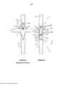
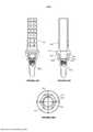
[005] A Fig. 1 representa esquematicamente um implante 20 e uma base 30 da técnica anterior. A base 30 inclui um flange saliente 36 na forma de uma seção cônica, configurada para receber uma prótese ou uma superestrutura nela, e um furo roscado 38 que se estende na seção cônica. Uma superestrutura ou uma prótese (não mostrada) configurada para fixar sobre a superestrutura pode incluir uma cavidade fruto-cônica ou afunilada para receber a parte cônica 36 da base 30 nela, de modo que a superestrutura se acopla intimamente com a parte cônica 36.[005] Fig. 1 schematically represents a
[006] Técnicas antecedentes adicionais incluem a Patente U.S. N° 5344457, a Patente U.S. N° 5829977, a Patente U.S. N° 6030219, a Publicação de Pedido de Patente U.S. N° 2006/0183078 e a Publicação de Pedido de Patente U.S. N° 2014/0011160.[006] Additional prior art includes the U.S. Patent No. 5,344,457, U.S. Patent No. 5829977, U.S. Patent No. 6030219, U.S. Patent Application Publication No. No. 2006/0183078 and U.S. Patent Application Publication No. No. 2014/0011160.
[007] Algumas modalidades da invenção são ilustradas pelos exemplos abaixo, observando que os recursos mostrados em um exemplo podem ser combinados com os recursos mostrados em outro exemplo, a menos que tecnicamente proibido.[007] Some embodiments of the invention are illustrated by the examples below, noting that the features shown in one example may be combined with the features shown in another example, unless technically prohibited.
[008] Exemplo 1. Uma base para prender uma superestrutura a um implante ósseo dentário, compreendendo a referida base: - um topo representando uma parte mais larga da base; - uma ponta inferior da base; - uma parede externa que se estende para baixo a partir do topo; - uma superfície interna da parede externa que se estende para baixo a partir do topo, de modo a definir uma cavidade dentro da referida base, a superfície interna tendo uma parte roscada internamente; e - uma parede externa mais baixa que a parede externa e incluindo uma parte roscada externamente configurada para acasalar com um implante ósseo, - um fundo da cavidade que se estende mais de 40% de uma distância do topo para uma parte superior da parte roscada externamente, medida ao longo de uma altura da base.[008] Example 1. A base for attaching a superstructure to a dental bone implant, said base comprising: - a top representing a wider part of the base; - a lower tip of the base; - an outer wall extending downwards from the top; - an inner surface of the outer wall extending downwards from the top so as to define a cavity within said base, the inner surface having an internally threaded portion; and - an outer wall lower than the outer wall and including an externally threaded portion configured to mate with a bone implant, - a bottom of the cavity extending more than 40% of a distance from the top to an upper portion of the externally threaded portion , measured along a height of the base.
[011] Exemplo 2. A base do exemplo 1, em que a maior parte da parte roscada internamente está abaixo de uma altura da superfície interna que corresponde a uma altura do topo do implante.[011] Example 2. The base of example 1, in which most of the internally threaded part is below a height of the internal surface that corresponds to a height of the top of the implant.
[012] Exemplo 3. A base de qualquer um dos exemplos s 1-2, em que pelo menos parte da parte roscada internamente se estende abaixo de um quarto de uma altura do topo da ponta inferior.[012] Example 3. The base of any of the examples s 1-2, in which at least part of the internally threaded portion extends below a quarter of a height from the top of the lower tip.
[013] Exemplo 4. A base de qualquer um dos exemplos s 1-3, em que a altura do fundo da cavidade é adjacente à altura da parte superior da parte roscada externamente.[013] Example 4. The base of any of examples s 1-3, where the height of the bottom of the cavity is adjacent to the height of the top of the externally threaded part.
[014] Exemplo 5. A base de qualquer um dos exemplos 14, compreendendo uma parede externa intermediária, intermediária entre a referida parede externa e a referida parede externa inferior, a qual é afunilada para dentro para coincidir com uma parede de uma cavidade no referido implante.[014] Example 5. The base of any one of Examples 14, comprising an intermediate outer wall, intermediate between said outer wall and said lower outer wall, which is tapered inwardly to match a wall of a cavity in said implant.
[015] Exemplo 6. A base de qualquer um dos exemplos 15, em que a roscagem da parte roscada internamente e a roscagem da parte roscada externamente podem coincidir com uma mesma geometria do parafuso.[015] Example 6. The basis of any of examples 15, in which the threading of the internally threaded part and the threading of the externally threaded part can coincide with the same screw geometry.
[016] Exemplo 7. A base de qualquer um dos exemplos 16, em que a superfície interna da parede externa é afunilada para dentro, de modo que pelo menos um topo da cavidade seja afunilado para dentro.[016] Example 7. The base of any one of Examples 16, wherein the inner surface of the outer wall is tapered inward, so that at least one top of the cavity is tapered inward.
[017] Exemplo 8. A base de qualquer um dos exemplos 17, em que a superfície interna da parede externa tem uma configuração antirrotação não circular moldada para receber uma parte inferior de uma superestrutura.[017] Example 8. The base of any one of Examples 17, in which the inner surface of the outer wall has a non-circular anti-rotation configuration molded to receive a lower part of a superstructure.
[018] Exemplo 9. A base de qualquer um dos exemplos 18, em que a referida cavidade inclui uma parte não roscada de pelo menos 20% em comprimento da referida cavidade e maior em diâmetro do que a de uma parte roscada da mesma, definindo assim uma seção da cavidade receptora da superestrutura, de modo que uma extensão da referida superestrutura através da qual um parafuso de fixação, que se encaixa nessa rosca, pode encaixar nele.[018] Example 9. The basis of any one of examples 18, wherein said cavity includes an unthreaded portion of at least 20% in length of said cavity and greater in diameter than that of a threaded portion thereof, defining thus a section of the receiving cavity of the superstructure, so that an extension of said superstructure through which a set screw, which fits into this thread, can fit into it.
[019] Exemplo 10. A base do exemplo 9, em que a referida seção de cavidade receptora da superestrutura é de pelo menos 30% em comprimento da referida cavidade.[019] Example 10. The basis of example 9, wherein said receiving cavity section of the superstructure is at least 30% in length of said cavity.
[020] Exemplo 11. A base do exemplo 9, em que a referida seção de cavidade receptora da superestrutura está entre 40% e 60% em comprimento da referida cavidade.[020] Example 11. The basis of example 9, in which said receiving cavity section of the superstructure is between 40% and 60% in length of said cavity.
[021] Exemplo 12. A base de qualquer um dos exemplos 9-11, em que a referida seção de cavidade receptora da superestrutura tem um comprimento de pelo menos 2 mm.[021] Example 12. The base of any one of Examples 9-11, wherein said receiving cavity section of the superstructure has a length of at least 2 mm.
[022] Exemplo 13. A base de qualquer um dos exemplos 912, em que uma razão de um comprimento da referida seção de retenção da superestrutura para um diâmetro externo d do topo é de pelo menos 1:2.[022] Example 13. The basis of any of the examples 912, wherein a ratio of a length of said superstructure retaining section to an outer diameter d of the top is at least 1:2.
[023] Exemplo 14. A base do exemplo 13, em que a referida razão é pelo menos 3:4.[023] Example 14. The basis of example 13, wherein said ratio is at least 3:4.
[024] Exemplo 15. A base de qualquer um dos exemplos 19, em que o topo largo é uma parte mais larga da base e o topo largo não é superior a 4 mm.[024] Example 15. The base of any one of Examples 19, where the wide top is a wider part of the base and the wide top is not more than 4 mm.
[025] Exemplo 16. A base de qualquer um dos exemplos 1 15, em que a parede externa se estende para baixo a partir do topo até pelo menos 7 mm de profundidade.[025] Example 16. The base of any one of Examples 1 to 15, wherein the outer wall extends downwards from the top to at least 7 mm in depth.
[026] Exemplo 17. A base de qualquer um dos exemplos 116, em que cavidade tem uma profundidade de pelo menos 5 mm.[026] Example 17. The base of any of the examples 116, wherein the cavity has a depth of at least 5 mm.
[027] Exemplo 18. A base de qualquer um dos exemplos 117, em que a parede externa tem uma espessura de cerca de 0,5 mm sobre pelo menos 50% de uma parte extra-implante e uma parte mais grossa em uma parte adjacente onde a base é projetada para sair de um implante.[027] Example 18. The basis of any one of examples 117, in which the outer wall has a thickness of about 0.5 mm over at least 50% of an extra-implant part and a thicker part in an adjacent part where the base is designed to come out of an implant.
[028] Exemplo 19. A base de qualquer um dos exemplos 117, em que a parede externa tem uma espessura mínima de no máximo 2 mm.[028] Example 19. The base of any of the examples 117, in which the outer wall has a minimum thickness of at most 2 mm.
[029] Exemplo 20. A base de qualquer um dos exemplos 119, em que uma altura da parede externa excede um diâmetro externo d do topo.[029] Example 20. The base of any of the examples 119, in which an outer wall height exceeds an outer diameter d of the top.
[030] Exemplo 21. A base de qualquer um dos exemplos 120, em que um diâmetro externo do topo da base não excede 4,5 mm.[030] Example 21. The base of any of the examples 120, wherein an outer diameter of the top of the base does not exceed 4.5 mm.
[031] Exemplo 22. A base de qualquer um dos exemplos 121, em que um diâmetro externo do topo da base não excede 3,5 mm.[031] Example 22. The base of any of the examples 121, in which an external diameter of the top of the base does not exceed 3.5 mm.
[032] Exemplo 23. A base de qualquer um dos exemplos 122, em que a parte roscada internamente é de pelo menos 1,5 mm de comprimento.[032] Example 23. The base of any of the examples 122, in which the internally threaded part is at least 1.5 mm long.
[033] Exemplo 24. A base de qualquer um dos exemplos 123, em que a superfície interna da parede externa tem um canal periférico definido nela.[033] Example 24. The base of any one of Examples 123, wherein the inner surface of the outer wall has a peripheral channel defined therein.
[034] Exemplo 25. Uma combinação da base de qualquer um dos exemplos 1-24 com uma superestrutura, em que a superestrutura e compreendendo um parafuso que aparafusa na parte roscada internamente, em que o parafuso tem pelo menos 5 mm de comprimento.[034] Example 25. A combination of the base of any one of examples 1-24 with a superstructure, wherein the superstructure is comprising a screw that screws into the internally threaded portion, wherein the screw is at least 5 mm long.
[035] Exemplo 26. A base de qualquer um dos exemplos 125, em que a parede externa se estreita entre uma parte superior da parede externa e uma parte mais inferior da parede externa.[035] Example 26. The basis of any one of examples 125, in which the outer wall narrows between an upper part of the outer wall and a lower part of the outer wall.
[036] Exemplo 27. Um sistema de suporte que compreende uma base de acordo com qualquer um dos exemplos anteriores e uma superestrutura tendo uma extensão dimensionada para caber na referida cavidade na referida base.[036] Example 27. A support system comprising a base according to any one of the preceding examples and a superstructure having an extension sized to fit in said cavity in said base.
[037] Exemplo 28. Um sistema de acordo com o exemplo 27, em que a referida extensão é de pelo menos 20% em comprimento da referida superestrutura.[037] Example 28. A system according to example 27, wherein said extension is at least 20% in length of said superstructure.
[038] Exemplo 29. Um sistema de acordo com o exemplo 27, em que a referida extensão é de pelo menos 10% em comprimento da referida superestrutura.[038] Example 29. A system according to example 27, wherein said extension is at least 10% in length of said superstructure.
[039] Exemplo 30. Um sistema de acordo com qualquer um dos exemplos 27-29, em que a referida extensão inclui uma geometria antirrotação configurada para intertravar com uma indexação hexagonal e não hexagonal de uma cavidade da referida base.[039] Example 30. A system according to any one of Examples 27-29, wherein said extension includes an anti-rotation geometry configured to interlock with a hexagonal and non-hexagonal indexing of a cavity of said base.
[040] Exemplo 31. Um sistema de implante, compreendendo: - um implante com uma parede interna de implante que inclui uma parte da parede do implante roscada internamente; - uma base, compreendendo: - um topo; - uma parede externa da base que se estende para baixo a partir do topo e inclui uma parte roscada externamente configurada para coincidir com a parte da parede do implante roscada internamente; - uma superfície interna da parede externa que se estende para baixo a partir do topo, de modo a definir uma cavidade dentro da base, a superfície interna tendo uma parte roscada internamente, - pelo menos parte da parte roscada internamente está abaixo de uma altura da superfície interna que corresponde a uma altura do topo do implante.[040] Example 31. An implant system, comprising: - an implant with an internal implant wall including an internally threaded portion of the implant wall; - a base, comprising: - a top; - an outer wall of the base extending downwardly from the top and including an externally threaded portion configured to mate with the internally threaded portion of the wall of the implant; - an inner surface of the outer wall extending downwardly from the top so as to define a cavity within the base, the inner surface having an internally threaded portion, - at least part of the internally threaded portion is below a height of the inner surface that corresponds to a height from the top of the implant.
[041] Exemplo 32. O sistema de implante do exemplo 31, em que um fundo da cavidade que se estende mais da metade de uma distância do topo para uma parte mais superior da parte roscada externamente, medida ao longo de uma altura da base.[041] Example 32. The implant system of Example 31, in which a bottom of the cavity extending more than half a distance from the top to an uppermost part of the externally threaded part, measured along a height of the base.
[042] Exemplo 33. O sistema de implante de qualquer um dos exemplos 31-32, em que a maior parte da parte roscada internamente está abaixo da altura da superfície interna que corresponde à altura do topo.[042] Example 33. The implant system of any of examples 31-32, in which most of the internally threaded part is below the height of the internal surface that corresponds to the height of the top.
[043] Exemplo 34. O sistema de implante, de acordo com qualquer um dos exemplos 31-33, em que uma seção inclinada mais baixa da parede externa da base corresponde a uma parte inferior da parede interna do implante.[043] Example 34. The implant system according to any one of examples 31-33, in which a lower inclined section of the outer wall of the base corresponds to a lower part of the inner wall of the implant.
[044] Exemplo 35. O sistema de implante de qualquer um dos exemplos 31-34, em que a base é mais estreita que o implante a uma altura logo acima do implante.[044] Example 35. The implant system of any of examples 31-34, in which the base is narrower than the implant at a height just above the implant.
[045] Exemplo 36. O sistema de implante de qualquer um dos exemplos 31-35, compreendendo uma superestrutura e em que a referida cavidade na referida base inclui uma seção dimensionada e configurada para receber uma extensão da referida superestrutura.[045] Example 36. The implant system of any one of Examples 31-35, comprising a superstructure and wherein said cavity in said base includes a section sized and configured to receive an extension of said superstructure.
[046] Exemplo 37. Um método para usar uma base como implante de nível ósseo para minimizar a peri-implantite, compreendendo: a) fornecer ao paciente um implante inserido abaixo do nível ósseo; b) fixar uma base ao implante, de modo que pelo menos parte de uma superfície externa da base esteja abaixo do nível ósseo e em que a referida base seja menor em seção transversal em um aspecto externo do que o referido implante; e c) remover a base do osso após suspeita de peri-implantite.[046] Example 37. A method for using a base as a bone-level implant to minimize peri-implantitis, comprising: a) providing the patient with an implant inserted below bone level; b) attaching a base to the implant such that at least part of an external surface of the base is below bone level and wherein said base is smaller in cross-section in an external aspect than said implant; and c) removing the bone base after suspected peri-implantitis.
[047] Exemplo 38. O método do exemplo 37, compreendendo ainda a substituição da base por uma segunda base.[047] Example 38. The method of Example 37, further comprising replacing the base with a second base.
[048] Exemplo 39. Método para usar uma base e proteger uma superestrutura, compreendendo: - inserir um implante em um osso, o implante tendo uma parede interna do implante que inclui uma parte da parede do implante roscada internamente e uma roscagem externa do implante; - inserir uma base no implante, incluindo a referida base uma cavidade com uma seção roscada internamente para receber um parafuso; e - inserir um parafuso através de uma superestrutura e na base, - em que a cavidade é profunda o suficiente para que pelo menos parte do parafuso dentro da base seja cercada e suportada pela base e parte do implante que circunda a base.[048] Example 39. Method for using a base and protecting a superstructure, comprising: - inserting an implant into a bone, the implant having an internal implant wall that includes an internally threaded part of the implant wall and an external implant thread ; - inserting a base into the implant, said base including a cavity with an internally threaded section to receive a screw; and - inserting a screw through a superstructure and into the base, - where the cavity is deep enough that at least part of the screw within the base is surrounded and supported by the base and part of the implant surrounding the base.
[049] Exemplo 40. Método para usar uma base e proteger uma superestrutura, compreendendo: - inserir um implante em um osso, o implante tendo uma parede interna do implante que inclui uma parte da parede do implante roscada internamente e uma roscagem externa do implante; - inserir uma base no implante, incluindo a referida base uma cavidade; e - inserir uma superestrutura na referida cavidade; - em que a cavidade é profunda o suficiente para que pelo menos parte da superestrutura esteja pelo menos 1 mm abaixo de um topo da referida base e/ou no máximo 1 mm acima de um topo do referido implante.[049] Example 40. Method for using a base and protecting a superstructure, comprising: - inserting an implant into a bone, the implant having an internal implant wall that includes an internally threaded part of the implant wall and an external implant thread ; - inserting a base into the implant, said base including a cavity; and - inserting a superstructure into said cavity; - wherein the cavity is deep enough so that at least part of the superstructure is at least 1 mm below a top of said base and/or at most 1 mm above a top of said implant.
[050] Exemplo 41. Uma superestrutura dimensionada e configurada para um sistema de implante dentário, em que: - um corpo com um primeiro diâmetro e adaptado para montar uma restauração dentária no mesmo; e - uma extensão abaixo do referido corpo e com um diâmetro menor que o referido corpo, - em que a referida extensão se estende pelo menos 5% de um comprimento do referido corpo.[050] Example 41. A superstructure dimensioned and configured for a dental implant system, in which: - a body with a first diameter and adapted to mount a dental restoration in it; and - an extension below said body and with a smaller diameter than said body, - wherein said extension extends at least 5% of a length of said body.
[051] Exemplo 42. Uma superestrutura de acordo com o exemplo 41, em que a referida extensão se prolonga em pelo menos 20% de um comprimento do referido corpo.[051] Example 42. A superstructure according to example 41, wherein said extension extends by at least 20% of a length of said body.
[052] Exemplo 43. Uma superestrutura de acordo com o exemplo 41 ou exemplo 42, compreendendo um flange que se estende radialmente para longe do referido corpo.[052] Example 43. A superstructure according to example 41 or example 42, comprising a flange extending radially away from said body.
[053] Exemplo 44. Uma superestrutura de acordo com qualquer um dos exemplos 41-43, em que a referida extensão afunila para dentro quando se estende para fora do referido corpo, por pelo menos uma primeira distância.[053] Example 44. A superstructure according to any one of Examples 41-43, wherein said extension tapers inwardly when extending outward from said body, for at least a first distance.
[054] Exemplo 45. Uma superestrutura de acordo com qualquer um dos exemplos 41-44, em que a referida extensão é geralmente cilíndrica.[054] Example 45. A superstructure according to any one of examples 41-44, wherein said extension is generally cylindrical.
[055] Exemplo 46. Uma superestrutura de acordo com qualquer um dos exemplos 41-45, em que a referida extensão define o canal de recebimento de parafusos ao longo do mesmo.[055] Example 46. A superstructure according to any one of examples 41-45, in which said extension defines the channel for receiving screws along it.
[056] Exemplo 47. Uma superestrutura de acordo com qualquer um dos exemplos 41-46, em que a referida extensão define uma geometria antirrotação.[056] Example 47. A superstructure according to any one of examples 41-46, wherein said extension defines an anti-rotation geometry.
[057] Exemplo 48. Uma superestrutura de acordo com o exemplo 47, em que a referida geometria antirrotação corresponde à indexação hexagonal lateral igual e indexação hexagonal lateral não igual.[057] Example 48. A superstructure according to example 47, wherein said anti-rotation geometry corresponds to equal lateral hexagonal indexing and non-equal lateral hexagonal indexing.
[058] Exemplo 49. Uma superestrutura de acordo com o exemplo 48, em que a referida geometria antirrotação compreende uma seção transversal hexagonal com ângulos internos iguais e com três lados longos alternando com três lados mais curtos.[058] Example 49. A superstructure according to example 48, wherein said anti-rotation geometry comprises a hexagonal cross section with equal internal angles and with three long sides alternating with three shorter sides.
[059] De acordo com um aspecto de algumas modalidades da presente divulgação, é fornecida uma base para fixar uma superestrutura a um implante ósseo dentário, compreendendo a referida base: - um topo representando uma parte mais larga da base; - uma ponta inferior da base; - uma parede externa que se estende para baixo a partir do topo; - uma superfície interna da parede externa que se estende para baixo a partir do topo, de modo a definir uma cavidade dentro da referida base, a superfície interna tendo uma parte roscada internamente; - em que a maior parte da parte roscada internamente está abaixo de uma altura da superfície interna que corresponde a uma altura do topo do implante; - uma parede externa mais baixa que a parede externa e incluindo uma parte roscada externamente configurada para acasalar com um implante ósseo; e - um fundo da cavidade que se estende mais de 40% de uma distância do topo para uma parte superior da parte roscada externamente, medida ao longo de uma altura da base.[059] According to one aspect of some embodiments of the present disclosure, a base is provided for attaching a superstructure to a dental bone implant, said base comprising: - a top representing a wider part of the base; - a lower tip of the base; - an outer wall extending downwards from the top; - an inner surface of the outer wall extending downwards from the top so as to define a cavity within said base, the inner surface having an internally threaded portion; - in which the major part of the internally threaded part is below a height of the internal surface that corresponds to a height of the top of the implant; - an outer wall lower than the outer wall and including an externally threaded portion configured to mate with a bone implant; and - a bottom of the cavity that extends more than 40% of a distance from the top to an upper part of the externally threaded part, measured along a height of the base.
[060] De acordo com algumas modalidades, pelo menos parte da parte roscada internamente se estende abaixo de um quarto de uma altura do topo da ponta inferior.[060] According to some embodiments, at least part of the internally threaded part extends below a quarter of a height from the top of the lower tip.
[061] De acordo com algumas modalidades, a altura do fundo da cavidade é adjacente à altura da parte superior da parte roscada externamente.[061] According to some embodiments, the height of the bottom of the cavity is adjacent to the height of the upper part of the externally threaded part.
[062] De acordo com algumas modalidades, a base compreendendo uma parede externa intermediária, intermediária entre a referida parede externa e a referida parede externa inferior, a qual é afunilada para dentro para coincidir com uma parede de uma cavidade no referido implante.[062] According to some embodiments, the base comprising an intermediate outer wall, intermediate between said outer wall and said lower outer wall, which is tapered inwardly to match a wall of a cavity in said implant.
[063] De acordo com algumas modalidades, a roscagem da parte roscada internamente e a roscagem da parte roscada externamente podem coincidir com uma mesma geometria do parafuso.[063] According to some embodiments, the threading of the internally threaded part and the threading of the externally threaded part can coincide with the same screw geometry.
[064] De acordo com algumas modalidades, a superfície interna da parede externa é afunilada para dentro, de modo que pelo menos um topo da cavidade seja afunilado para dentro.[064] According to some embodiments, the inner surface of the outer wall is tapered inward, so that at least one top of the cavity is tapered inward.
[065] De acordo com algumas modalidades, a superfície interna da parede externa tem uma configuração anti-rotação não circular moldada para receber uma parte inferior de uma superestrutura.[065] According to some embodiments, the inner surface of the outer wall has a non-circular anti-rotation configuration molded to receive a lower part of a superstructure.
[066] De acordo com algumas modalidades, a referida cavidade inclui uma parte não roscada de pelo menos 20% em comprimento da referida cavidade e maior em diâmetro do que a de uma parte roscada da mesma, definindo assim uma seção de cavidade receptora da superestrutura de modo que uma extensão da referida superestrutura possa caber na referida seção da cavidade receptora da superestrutura; e um parafuso de fixação pode passar através da referida extensão da referida superestrutura, o referido parafuso encaixando a referida parte roscada.[066] According to some embodiments, said cavity includes an unthreaded part of at least 20% in length of said cavity and greater in diameter than that of a threaded part thereof, thus defining a receiving cavity section of the superstructure such that an extension of said superstructure can fit in said superstructure receiving cavity section; and a set screw may pass through said extension of said superstructure, said screw engaging said threaded portion.
[067] De acordo com algumas modalidades, a referida seção de cavidade receptora da superestrutura é de pelo menos 30% em comprimento da referida cavidade.[067] According to some embodiments, said receiving cavity section of the superstructure is at least 30% in length of said cavity.
[068] De acordo com algumas modalidades, a referida seção de cavidade receptora da superestrutura está entre 40% e 60% em comprimento da referida cavidade.[068] According to some embodiments, said receiving cavity section of the superstructure is between 40% and 60% in length of said cavity.
[069] De acordo com algumas modalidades, a referida seção de cavidade receptora da superestrutura tem um comprimento de pelo menos 2 mm.[069] According to some embodiments, said receiving cavity section of the superstructure has a length of at least 2 mm.
[070] De acordo com algumas modalidades, uma razão de um comprimento da referida seção de retenção da superestrutura para um diâmetro externo d do topo é de pelo menos 1:2.[070] According to some embodiments, a ratio of a length of said superstructure retaining section to an outer diameter d of the top is at least 1:2.
[071] De acordo com algumas modalidades, a referida razão é de pelo menos 3:4.[071] According to some embodiments, said ratio is at least 3:4.
[072] De acordo com algumas modalidades, o topo largo é uma parte mais larga da base e o topo largo não é superior a 4 mm.[072] According to some embodiments, the wide top is a wider part of the base, and the wide top is not more than 4 mm.
[073] De acordo com algumas modalidades, a parede externa se estende para baixo a partir do topo até pelo menos 7 mm de profundidade.[073] According to some embodiments, the outer wall extends downwards from the top to at least 7 mm in depth.
[074] De acordo com algumas modalidades, a cavidade tem um comprimento de pelo menos 5 mm.[074] According to some embodiments, the cavity has a length of at least 5 mm.
[075] De acordo com algumas modalidades, a parede externa tem uma espessura de cerca de 0,5 mm sobre pelo menos 50% de uma parte extra-implante e uma parte mais grossa em uma parte adjacente onde a base é projetada para sair de um implante.[075] According to some embodiments, the outer wall has a thickness of about 0.5 mm over at least 50% of an extra-implant part and a thicker part in an adjacent part where the base is designed to come out of an implant.
[076] De acordo com algumas modalidades, a parede externa tem uma espessura mínima de no máximo 2 mm.[076] According to some embodiments, the outer wall has a minimum thickness of a maximum of 2 mm.
[077] De acordo com algumas modalidades, a altura da parede externa excede um diâmetro externo d do topo.[077] According to some embodiments, the height of the outer wall exceeds an outer diameter d of the top.
[078] De acordo com algumas modalidades, um diâmetro externo do topo da base não excede 4,5 mm.[078] According to some embodiments, an outer diameter of the top of the base does not exceed 4.5 mm.
[079] De acordo com algumas modalidades, um diâmetro externo do topo da base não excede 3,5 mm.[079] According to some embodiments, an outer diameter of the top of the base does not exceed 3.5 mm.
[080] De acordo com algumas modalidades, a parte roscada internamente tem pelo menos 1,5 mm de comprimento.[080] According to some embodiments, the internally threaded part is at least 1.5 mm long.
[081] De acordo com algumas modalidades, a superfície interna da parede externa possui um canal periférico definido nela.[081] According to some embodiments, the inner surface of the outer wall has a peripheral channel defined therein.
[082] De acordo com algumas modalidades, a base com uma superestrutura, em que a superestrutura e compreendendo um parafuso que aparafusa na parte roscada internamente, em que o parafuso tem pelo menos 5 mm de comprimento.[082] According to some embodiments, the base with a superstructure, wherein the superstructure is comprising a screw that screws into the internally threaded portion, wherein the screw is at least 5 mm long.
[083] De acordo com algumas modalidades, a parede externa se estreita entre uma parte superior da parede externa e uma parte mais inferior da parede externa.[083] According to some embodiments, the outer wall narrows between an upper part of the outer wall and a lower part of the outer wall.
[084] De acordo com um aspecto de algumas modalidades da presente divulgação, é fornecido um sistema de suporte que compreende uma base e uma superestrutura com uma extensão dimensionada para caber na referida cavidade na referida base.[084] According to an aspect of some embodiments of the present disclosure, there is provided a support system comprising a base and a superstructure with an extension sized to fit said cavity in said base.
[085] De acordo com algumas modalidades, a referida extensão é de pelo menos 20% em comprimento da referida superestrutura.[085] According to some embodiments, said extension is at least 20% in length of said superstructure.
[086] De acordo com algumas modalidades, a referida extensão é de pelo menos 10% em comprimento da referida superestrutura.[086] According to some embodiments, said extension is at least 10% in length of said superstructure.
[087] De acordo com algumas modalidades, a referida extensão inclui uma geometria antirrotação configurada para intertravar com uma indexação hexagonal e não hexagonal de uma cavidade da referida base.[087] According to some embodiments, said extension includes an anti-rotation geometry configured to interlock with a hexagonal and non-hexagonal indexing of a cavity in said base.
[088] De acordo com algumas modalidades, o sistema de implante, compreendendo: - um implante com uma parede interna de implante que inclui uma parte da parede do implante roscada internamente; - uma base, compreendendo: - um topo; - uma parede externa da base que se estende para baixo a partir do topo e inclui uma parte roscada externamente configurada para coincidir com a parte da parede do implante roscada internamente; - em que a maior parte da parte roscada internamente está abaixo da altura da superfície interna que corresponde à altura do topo - uma superfície interna da parede externa que se estende para baixo a partir do topo, de modo a definir uma cavidade dentro da base, a superfície interna tendo uma parte roscada internamente, - pelo menos parte da parte roscada internamente está abaixo de uma altura da superfície interna que corresponde a uma altura do topo do implante.[088] According to some embodiments, the implant system, comprising: - an implant with an internal implant wall that includes an internally threaded portion of the implant wall; - a base, comprising: - a top; - an outer wall of the base extending downwardly from the top and including an externally threaded portion configured to mate with the internally threaded portion of the wall of the implant; - wherein most of the internally threaded portion is below the height of the inner surface which corresponds to the height of the top - an inner surface of the outer wall which extends downwards from the top so as to define a cavity within the base, the internal surface having an internally threaded part, - at least part of the internally threaded part is below a height of the internal surface which corresponds to a height of the top of the implant.
[089] De acordo com algumas modalidades, um fundo da cavidade que se estende mais da metade de uma distância do topo para uma parte mais superior da parte roscada externamente, medida ao longo de uma altura da base.[089] According to some embodiments, a bottom of the cavity that extends more than half a distance from the top to an uppermost part of the externally threaded part, measured along a height of the base.
[090] De acordo com algumas modalidades, uma seção inclinada mais baixa da parede externa da base corresponde a uma parte inferior da parede interna do implante.[090] According to some embodiments, a lower inclined section of the outer wall of the base corresponds to a lower part of the inner wall of the implant.
[091] De acordo com algumas modalidades, a base é mais estreita que o implante a uma altura logo acima do implante.[091] According to some embodiments, the base is narrower than the implant at a height just above the implant.
[092] De acordo com algumas modalidades, a base compreendendo uma superestrutura e em que a referida cavidade na referida base inclui uma seção dimensionada e configurada para receber uma extensão da referida superestrutura.[092] According to some embodiments, the base comprising a superstructure and wherein said cavity in said base includes a section dimensioned and configured to receive an extension of said superstructure.
[093] De acordo com um aspecto de algumas modalidades da presente divulgação, é fornecido um método de usar uma base como um implante de nível ósseo para minimizar a peri-implantite, compreendendo: a) fornecer ao paciente um implante inserido abaixo do nível ósseo; b) fixar uma base ao implante, de modo que pelo menos parte de uma superfície externa da base esteja abaixo do nível ósseo e em que a referida base seja menor em seção transversal em um aspecto externo do que o referido implante; e c) remover a base do osso após suspeita de peri-implantite.[093] According to one aspect of some embodiments of the present disclosure, there is provided a method of using a base as a bone-level implant to minimize peri-implantitis, comprising: a) providing the patient with an implant inserted below bone level ; b) attaching a base to the implant such that at least part of an external surface of the base is below bone level and wherein said base is smaller in cross-section in an external aspect than said implant; and c) removing the bone base after suspected peri-implantitis.
[094] De acordo com algumas modalidades, o método compreende ainda a substituição da base por uma segunda base.[094] According to some embodiments, the method further comprises replacing the base with a second base.
[095] De acordo com um aspecto de algumas modalidades da presente divulgação, é fornecido um método de usar uma base e prender uma superestrutura, compreendendo: - inserir um implante em um osso, o implante tendo uma parede interna do implante que inclui uma parte da parede do implante roscada internamente e uma roscagem externa do implante; - inserir uma base no implante, incluindo a referida base uma cavidade com uma seção roscada internamente para receber um parafuso; e - inserir um parafuso através de uma superestrutura e na base, - em que a cavidade é profunda o suficiente para que pelo menos parte do parafuso dentro da base seja cercada e suportada pela base e parte do implante que circunda a base.[095] According to one aspect of some embodiments of the present disclosure, there is provided a method of using a base and securing a superstructure, comprising: - inserting an implant into a bone, the implant having an inner wall of the implant that includes a portion of the internally threaded implant wall and an external implant thread; - inserting a base into the implant, said base including a cavity with an internally threaded section to receive a screw; and - inserting a screw through a superstructure and into the base, - where the cavity is deep enough that at least part of the screw within the base is surrounded and supported by the base and part of the implant surrounding the base.
[096] De acordo com um aspecto de algumas modalidades da presente divulgação, é fornecido um método de usar uma base e prender uma superestrutura, compreendendo: - inserir um implante em um osso, o implante tendo uma parede interna do implante que inclui uma parte da parede do implante roscada internamente e uma roscagem externa do implante; - inserir uma base no implante, incluindo a referida base uma cavidade; e - inserir uma superestrutura na referida cavidade; - em que a cavidade é profunda o suficiente para que pelo menos parte da superestrutura esteja pelo menos 1 mm abaixo de um topo da referida base e/ou no máximo 1 mm acima de um topo do referido implante.[096] According to one aspect of some embodiments of the present disclosure, there is provided a method of using a base and securing a superstructure, comprising: - inserting an implant into a bone, the implant having an inner wall of the implant that includes a portion of the internally threaded implant wall and an external implant thread; - inserting a base into the implant, said base including a cavity; and - inserting a superstructure into said cavity; - wherein the cavity is deep enough so that at least part of the superstructure is at least 1 mm below a top of said base and/or at most 1 mm above a top of said implant.
[097] De acordo com um aspecto de algumas modalidades da presente divulgação, é fornecida uma superestrutura dimensionada e configurada para um sistema de implante dentário, compreendendo: - um corpo com um primeiro diâmetro e adaptado para montar uma restauração dentária no mesmo; e - uma extensão abaixo do referido corpo e com um diâmetro menor que o referido corpo, - em que a referida extensão se estende pelo menos 5% de um comprimento do referido corpo.[097] According to one aspect of some embodiments of the present disclosure, there is provided a sized and configured superstructure for a dental implant system, comprising: - a body having a first diameter and adapted to mount a dental restoration thereon; and - an extension below said body and with a smaller diameter than said body, - wherein said extension extends at least 5% of a length of said body.
[098] De acordo com algumas modalidades, a referida extensão se estende em pelo menos 20% de um comprimento do referido corpo.[098] According to some embodiments, said extension extends to at least 20% of a length of said body.
[099] De acordo com algumas modalidades, a superestrutura compreendendo um flange que se estende radialmente para longe do referido corpo.[099] According to some embodiments, the superstructure comprising a flange extending radially away from said body.
[100] De acordo com algumas modalidades, em que a referida extensão afunila para dentro quando se estende para fora do referido corpo, por pelo menos uma primeira distância.[100] According to some embodiments, wherein said extension tapers inwardly when extending outward from said body, for at least a first distance.
[101] De acordo com algumas modalidades, a referida extensão é geralmente cilíndrica.[101] According to some embodiments, said extension is generally cylindrical.
[102] De acordo com algumas modalidades, a referida extensão define o canal receptor de parafusos ao longo do mesmo.[102] According to some embodiments, said extension defines the screw receiving channel along it.
[103] De acordo com algumas modalidades, a referida extensão define uma geometria antirrotação.[103] According to some embodiments, said extension defines an anti-rotation geometry.
[104] De acordo com algumas modalidades, a referida geometria antirrotação corresponde à indexação hexagonal lateral igual e indexação hexagonal lateral não igual.[104] According to some embodiments, said anti-rotational geometry corresponds to equal lateral hexagonal indexing and non-equal lateral hexagonal indexing.
[105] De acordo com algumas modalidades, a referida geometria antirrotação compreende uma seção transversal hexagonal com ângulos internos iguais e com três lados longos alternando com três lados mais curtos.[105] According to some embodiments, said anti-rotation geometry comprises a hexagonal cross section with equal internal angles and with three long sides alternating with three shorter sides.
[106] A menos que definidos de outra maneira, todos os termos técnicos e/ou científicos usados neste documento têm o mesmo significado que compreendido geralmente por alguém versado na técnica a qual esta invenção pertence. Embora métodos e materiais similares ou equivalentes àqueles descritos neste documento possam ser usados na prática ou teste das modalidades da invenção, os métodos e/ou materiais exemplificativos são descritos abaixo. Em caso de conflito, o relatório descritivo da patente, incluindo definições, prevalecerão. Além disso, os materiais, métodos e exemplos são apenas ilustrativos e não devem ser necessariamente limitativos.[106] Unless otherwise defined, all technical and/or scientific terms used in this document have the same meaning as commonly understood by one of ordinary skill in the art to which this invention pertains. While methods and materials similar or equivalent to those described herein may be used in practicing or testing embodiments of the invention, exemplary methods and/or materials are described below. In case of conflict, the patent specification, including definitions, will prevail. Furthermore, the materials, methods, and examples are illustrative only and are not necessarily intended to be limiting.
[107] Algumas modalidades da invenção estão descritas abaixo, a título de exemplo somente, tendo como referência os desenhos anexos. Com referência específica agora aos desenhos em detalhes, é enfatizado que os dados mostrados são a título de exemplo e para fins de discussão ilustrativa das modalidades da invenção. Neste respeito, a descrição feita com os desenhos torna aparente para os versados na técnica como as modalidades da invenção podem ser praticadas.[107] Some embodiments of the invention are described below, by way of example only, with reference to the attached drawings. With specific reference now to the detailed drawings, it is emphasized that the data shown is by way of example and for purposes of discussion illustrating embodiments of the invention. In this regard, the description given with the drawings makes it apparent to those skilled in the art how embodiments of the invention can be practiced.
[108] Nos desenhos: - A Fig. 1 é uma vista esquemática de um implante dentário e uma superestrutura da técnica anterior; - A Fig. 2 é uma vista em corte vertical de um implante dentário, base, superestrutura e parafuso da técnica anterior; - A Fig. 3A é uma vista em corte vertical de um implante dentário, base, superestrutura e parafuso, de acordo com uma modalidade exemplar da invenção; - A Fig. 3B é uma vista em corte parcial de uma base e implante, de acordo com algumas modalidades da invenção; - A Fig. 4A é uma vista esquemática de um sistema de implante de suporte, de acordo com algumas modalidades da invenção; - A Fig. 4A1 é uma vista lateral esquemática de uma base, de acordo com algumas modalidades da invenção; - As Figs. 4B-4D mostram várias vistas de uma base, de acordo com algumas modalidades da invenção; - As Figs. 4E-4G mostram várias vistas de uma base, de acordo com algumas modalidades da invenção; - As Figs. 4H1-4H3 mostram várias vistas de uma base, de acordo com algumas modalidades da invenção; - As Figs. 4I1-4I2 mostram várias vistas de uma base, de acordo com algumas modalidades da invenção; - As Figs. 4J1-4J3 mostram uma vista lateral, transversal e detalhada de uma base, de acordo com algumas modalidades da invenção; - As Figs. 4K1-4K3 mostram uma vista lateral e transversal de uma base, de acordo com algumas modalidades da invenção; - As Figs. 4L1, 4L2 e Fig. 4M mostram uma vista lateral e transversal de uma base, de acordo com algumas modalidades da invenção; - As Figs. 4N1-4N2 mostram uma vista lateral e transversal de uma base, de acordo com algumas modalidades da invenção; - As Figs. 4O1-4O3 mostram várias vistas de uma base, de acordo com algumas modalidades da invenção; - As Figs. 4P1-4P3 mostram várias vistas de uma superestrutura ligável a uma base, de acordo com algumas modalidades da invenção; - A Fig. 4Q é um fluxograma de um método de implantação, de acordo com algumas modalidades da invenção; - As Figs. 4R1-4R3 mostram várias vistas de um sistema de suporte montado, de acordo com algumas modalidades da invenção; - As Figs. 4S1-4S3 mostram várias vistas de um sistema de suporte montado, de acordo com algumas modalidades da invenção; - A Fig. 5A é uma vista lateral de um implante implantado abaixo do nível ósseo de uma maneira adequada para o tratamento da peri- implantite, de acordo com algumas modalidades da invenção; e - A Fig. 5B é um fluxograma mostrando um método de tratar a peri-implantite, de acordo com algumas modalidades da invenção.[108] In the drawings: - Fig. 1 is a schematic view of a prior art dental implant and superstructure; - Fig. 2 is a vertical cross-sectional view of a prior art dental implant, base, superstructure, and screw; - Fig. 3A is a vertical cross-sectional view of a dental implant, base, superstructure and screw, in accordance with an exemplary embodiment of the invention; - Fig. 3B is a partial cross-sectional view of a base and implant, in accordance with some embodiments of the invention; - Fig. 4A is a schematic view of an implant support system, in accordance with some embodiments of the invention; - Fig. 4A1 is a schematic side view of a base, in accordance with some embodiments of the invention; - Figs. 4B-4D show various views of a base, in accordance with some embodiments of the invention; - Figs. 4E-4G show various views of a base, in accordance with some embodiments of the invention; - Figs. 4H1-4H3 show various views of a base, in accordance with some embodiments of the invention; - Figs. 4I1-4I2 show various views of a base, in accordance with some embodiments of the invention; - Figs. 4J1-4J3 show a side, cross-sectional and detailed view of a base, according to some embodiments of the invention; - Figs. 4K1-4K3 show a side and cross-sectional view of a base, in accordance with some embodiments of the invention; - Figs. 4L1, 4L2 and Fig. 4M show a side and cross-sectional view of a base, according to some embodiments of the invention; - Figs. 4N1-4N2 show a side and cross-sectional view of a base, according to some embodiments of the invention; - Figs. 401-403 show various views of a base, in accordance with some embodiments of the invention; - Figs. 4P1-4P3 show various views of a superstructure attachable to a base, in accordance with some embodiments of the invention; - Fig. 4Q is a flowchart of an implantation method, in accordance with some embodiments of the invention; - Figs. 4R1-4R3 show various views of an assembled support system, in accordance with some embodiments of the invention; - Figs. 4S1-4S3 show various views of an assembled support system, in accordance with some embodiments of the invention; - Fig. 5A is a side view of an implant implanted below bone level in a manner suitable for the treatment of peri-implantitis, in accordance with some embodiments of the invention; and - Fig. 5B is a flow chart showing a method of treating peri-implantitis in accordance with some embodiments of the invention.
[109] A presente invenção, em algumas modalidades da mesma, refere-se a um sistema de superestrutura de múltiplas partes dentárias e, mais particularmente, mas não exclusivamente, a uma base ou uma base e implante para uso em ou com este sistema.[109] The present invention, in some embodiments thereof, relates to a multipart tooth superstructure system, and more particularly, but not exclusively, to a base or a base and implant for use in or with this system.
[110] Algumas modalidades da invenção geralmente fornecem uma base que se encaixa em um implante dentário (tipicamente com uma parte roscada) e que é implantada na mandíbula ou nos ossos do maxilar do paciente. A base faz parte de um sistema de suporte com várias partes que também inclui a superestrutura e uma restauração. A base é presa ao implante e uma superestrutura é montada nele. Uma restauração pode ser montada na superestrutura ou ser anexada separadamente. Opcionalmente, um parafuso é usado para fixar a superestrutura na base.[110] Some embodiments of the invention generally provide a base that fits a dental implant (typically with a threaded portion) and that is implanted in the mandible or jaw bones of the patient. The base forms part of a multi-part support system that also includes the superstructure and a restoration. The base is attached to the implant and a superstructure is mounted on it. A restoration can be mounted on the superstructure or attached separately. Optionally, a bolt is used to secure the superstructure to the base.
[111] Um aspecto de algumas modalidades da invenção refere-se a uma base com uma cavidade interna para receber um parafuso e/ou uma extensão da superestrutura e na qual a cavidade é profunda o suficiente para que o parafuso fique pelo menos parcialmente abaixo do topo do implante. Opcionalmente, isso permite que o parafuso seja apoiado radialmente pelo implante e também pela base. Opcional ou alternativamente, isso permite que a base seja mais estreita, o que pode ter uma vantagem estética. Como usado neste documento, o topo é a direção afastada do osso.[111] One aspect of some embodiments of the invention relates to a base with an internal cavity to receive a screw and/or an extension of the superstructure and in which the cavity is deep enough for the screw to be at least partially below the top of the implant. Optionally, this allows the screw to be radially supported by the implant as well as the base. Optionally or alternatively, this allows the base to be narrower, which can have an aesthetic advantage. As used in this document, the top is the direction away from the bone.
[112] Em algumas modalidades exemplares da invenção, a cavidade inclui uma rosca interna para uma fixação por parafuso. Opcionalmente, a rosca está abaixo de uma parte mais larga da base. Opcionalmente, pelo menos 50%, 70%, 90% ou percentuais intermediários ou menores da rosca interna são projetados para ficar abaixo de um topo do implante. Opcionalmente, a parte mais larga é selecionada como a parte mais larga a 1 mm da parte superior.[112] In some exemplary embodiments of the invention, the cavity includes an internal thread for a screw attachment. Optionally, the thread is below a wider part of the base. Optionally, at least 50%, 70%, 90% or intermediate or lesser percentages of the internal thread are designed to be below a top of the implant. Optionally, the widest part is selected as the widest part 1 mm from the top.
[113] É uma característica particular de algumas modalidades da invenção que o comprimento da cavidade interna permita que uma base de menor diâmetro seja usada. Em alguns casos, uma redução no diâmetro deve-se ao uso de uma parede mais fina. Em algumas modalidades, é devido uma redução no diâmetro, pelo menos em parte, para suportar pelo implante e não apenas pela base. Em algumas modalidades exemplares da invenção, o diâmetro menor é devido, pelo menos em parte, ao suporte da superestrutura sendo axial (por exemplo, ao longo de um comprimento) e não principalmente lateral (pelo tamanho da seção transversal do topo da base). Possivelmente, o próprio implante suporta parte das forças não axiais aplicadas pela restauração (por exemplo, através do parafuso). Outra possibilidade é que o comprimento da cavidade forneça mais suporte e, portanto, divida as tensões na parede base ao longo de uma área maior, possivelmente permitindo que as paredes sejam mais fracas.[113] It is a particular feature of some embodiments of the invention that the length of the internal cavity allows a smaller diameter base to be used. In some cases, a reduction in diameter is due to the use of a thinner wall. In some embodiments, a reduction in diameter is due, at least in part, to support by the implant and not just the base. In some exemplary embodiments of the invention, the smaller diameter is due, at least in part, to the support of the superstructure being axial (eg, along a length) rather than primarily lateral (by the cross-sectional size of the top of the base). Possibly, the implant itself supports part of the non-axial forces applied by the restoration (for example, through the screw). Another possibility is that the length of the cavity provides more support and therefore spreads stresses in the base wall over a larger area, possibly allowing the walls to be weaker.
[114] Em algumas modalidades exemplares da invenção, o suporte lateral é reduzido fornecendo um implante com um pequeno diâmetro superior e/ou reduzindo uma quantidade de contato na face superior.[114] In some exemplary embodiments of the invention, lateral support is reduced by providing an implant with a small upper diameter and/or reducing an amount of contact on the upper surface.
[115] É uma característica particular de algumas modalidades da invenção que uma cavidade interna longa seja estimulada usando uma parte incorporada com roscagem externa em vez de um parafuso separado. Em algumas modalidades exemplares da invenção, a cavidade é longa o suficiente para fornecer suporte à superestrutura. Opcionalmente ou alternativamente, a cavidade é longa o suficiente para ficar dentro do nível do implante e o implante pode suportar a base.[115] It is a particular feature of some embodiments of the invention that a long internal cavity is stimulated using an externally threaded embedded part rather than a separate screw. In some exemplary embodiments of the invention, the cavity is long enough to provide support for the superstructure. Optionally or alternatively, the cavity is long enough to be within the level of the implant and the implant can support the base.
[116] Em algumas modalidades exemplares da invenção, a cavidade é tornada estreita, de modo que a base é estreita. Opcionalmente, a cavidade é moldada para receber uma parte da superestrutura que está dentro de 1 mm de diâmetro externo e/ou 10% de diâmetro do parafuso usado para prender a superestrutura à base. Em algumas modalidades exemplares da invenção, não há parte da base ou outra estrutura mecânica pré-formada entre o parafuso e a parte da superestrutura inserida na base.[116] In some exemplary embodiments of the invention, the cavity is made narrow so that the base is narrow. Optionally, the cavity is shaped to receive a portion of the superstructure that is within 1 mm outside diameter and/or 10% diameter of the bolt used to secure the superstructure to the base. In some exemplary embodiments of the invention, there is no base part or other preformed mechanical structure between the screw and the superstructure part inserted into the base.
[117] Em algumas modalidades exemplares da invenção, as partes da superestrutura inseridas na base, todas, ou pelo menos 50% em comprimento, ficam acima do ponto de fixação do parafuso que acopla a superestrutura à base.[117] In some exemplary embodiments of the invention, the parts of the superstructure inserted into the base, all, or at least 50% in length, are above the point of attachment of the screw that couples the superstructure to the base.
[118] É uma característica particular de algumas modalidades da invenção que a base esteja na forma de uma única unidade (por exemplo, integralmente fundida e/ou usinada e/ou formada de outra forma, sem conectores) incluindo suporte da superestrutura e conexão ao implante. Opcionalmente, isso aumenta a estabilidade e/ou permite que uma base de perfil mais fina seja usada.[118] It is a particular feature of some embodiments of the invention that the base is in the form of a single unit (e.g., integrally cast and/or machined and/or otherwise formed, without connectors) including superstructure support and connection to the implant. Optionally, this increases stability and/or allows a thinner profile base to be used.
[119] Como observado, uma base mais estreita pode ser mais estética. Em algumas modalidades exemplares da invenção, a largura da base é menor que a do implante, ou dentro de 20% sobre o mesmo. Em algumas modalidades, a parte mais larga da base é substancialmente a mesma que a largura do implante. Em algumas modalidades exemplares da invenção, o topo da base serve para suportar uma superestrutura montada nela.[119] As noted, a narrower base can be more aesthetic. In some exemplary embodiments of the invention, the width of the base is less than that of the implant, or within 20% of it. In some embodiments, the widest part of the base is substantially the same as the width of the implant. In some exemplary embodiments of the invention, the top of the base serves to support a superstructure mounted thereon.
[120] Em algumas modalidades exemplares da invenção, a parte superior da base é mais larga para permitir que ela tenha um afunilamento interno (e opcionalmente um afunilamento externo para corresponder, devido à espessura da parede), cujo afunilamento pode ser usado para permitir a inserção de parafusos e/ou superestruturas em ângulo com o eixo. Em algumas modalidades exemplares da invenção, esse cone é reduzido ou eliminado. Por exemplo, para situações de implante único, em que um implante diferente não restringe a orientação, a inserção pode ser diretamente axial e evitar a necessidade de afunilamento.[120] In some exemplary embodiments of the invention, the top of the base is wider to allow it to have an internal taper (and optionally an external taper to match, due to wall thickness), which taper can be used to allow for insertion of screws and/or superstructures at an angle to the axis. In some exemplary embodiments of the invention, this cone is reduced or eliminated. For example, for single-implant situations, where a different implant does not restrict orientation, insertion can be directly axial and avoid the need for tapering.
[121] Em algumas modalidades exemplares da invenção, para um único implante, uma espessura de parede pode ser reduzida, pois pode haver momentos de flexão reduzidos. Opcionalmente, a redução é de até 0,45 ou 0,4 mm de espessura.[121] In some exemplary embodiments of the invention, for a single implant, a wall thickness can be reduced as there can be reduced bending moments. Optionally, the reduction is up to 0.45 or 0.4 mm thick.
[122] Em algumas modalidades exemplares da invenção, para implantes únicos ou não únicos, a espessura da parede pode ser aumentada, por exemplo, em 10%, 15%, 20%, 30%, 40% ou percentuais intermediárias ou menores ou maiores (por exemplo, até uma espessura média da parede de partes que não são a base superior), em uma área acima de onde a base sai do implante. Essa é a área em que alguns momentos de flexão podem ser sentidos em alguns modelos.[122] In some exemplary embodiments of the invention, for single or non-single implants, the wall thickness can be increased, for example, by 10%, 15%, 20%, 30%, 40% or intermediate or lesser or greater percentages (for example, up to a medium wall thickness of parts other than the upper base), in an area above where the base exits the implant. This is the area where some bending moments can be felt on some models.
[123] Opcionalmente ou alternativamente, o material próximo ao topo da base é tratado ou formado de um material que é elástico o suficiente para permitir tal inserção fora do eixo. Em algumas modalidades exemplares da invenção, o afunilamento, se fornecido, está entre 0-15, 15-30 ou 30-45 graus ou ângulos intermediários. Opcionalmente, é usado um afunilamento abaixo de 15 graus, se a inserção fora do eixo não for desejada. Opcionalmente, evita-se um afunilamento maior para manter um diâmetro menor do topo da base (por exemplo, por razões estéticas).[123] Optionally or alternatively, the material near the top of the base is treated or formed from a material that is elastic enough to allow such off-axis insertion. In some exemplary embodiments of the invention, the taper, if provided, is between 0-15, 15-30 or 30-45 degrees or intermediate angles. Optionally, a taper below 15 degrees is used if off-axis insertion is not desired. Optionally, a larger taper is avoided to maintain a smaller diameter of the top of the base (for example, for aesthetic reasons).
[124] É uma característica particular de algumas modalidades da invenção que a base inclua uma cavidade receptora da superestrutura. Opcionalmente, essa cavidade se estende além do afunilamento interno. Opcionalmente, essa cavidade faz parte da cavidade receptora do parafuso da base. Em algumas modalidades exemplares da invenção, a cavidade é profunda o suficiente para que pelo menos 10%, 15%, 20% ou percentuais intermediários ou maiores de comprimento da superestrutura estejam dentro da base. Opcionalmente ou alternativamente, a parte dentro da conexão tem um comprimento que é pelo menos 50%, 75%, 100%, 150%, 200% ou percentuais intermediários da largura do corpo da superestrutura (por exemplo, largura média dos 50% do topo da superestrutura). Opcionalmente, a porção inserida atinge o nível do implante, por exemplo, 1 mm ou mais abaixo dela, ou fica próxima a ela, por exemplo, dentro de 1 ou 2 mm a partir de um topo do implante.[124] It is a particular feature of some embodiments of the invention that the base includes a superstructure receiving cavity. Optionally, this cavity extends beyond the internal funnel. Optionally, this cavity forms part of the base screw receiving cavity. In some exemplary embodiments of the invention, the cavity is deep enough that at least 10%, 15%, 20% or intermediate or greater percentages of the superstructure length are within the base. Optionally or alternatively, the portion within the connection has a length that is at least 50%, 75%, 100%, 150%, 200% or intermediate percentages of the width of the superstructure body (e.g. average width of the top 50% of the superstructure). Optionally, the inserted portion reaches the level of the implant, for example, 1 mm or more below it, or is close to it, for example, within 1 or 2 mm from a top of the implant.
[125] Embora algumas modalidades da invenção tenham um afunilamento externo geralmente monotônico e opcionalmente uniforme nas partes da base projetadas para estar fora do implante, isso não é fornecido em todas as modalidades. Por exemplo, o afunilamento pode incluir uma ou mais alterações na direção do afunilamento (por exemplo, definir uma protuberância e/ou um recesso) e/ou pode incluir uma ou mais seções não afuniladas.[125] Although some embodiments of the invention have a generally monotonic and optionally uniform external taper in the base portions designed to be outside the implant, this is not provided in all embodiments. For example, the taper can include one or more changes in the direction of the taper (for example, defining a bulge and/or a recess) and/or can include one or more non-tapered sections.
[126] Em algumas modalidades exemplares da invenção, o topo da base tem um diâmetro entre 3 e 5 mm, por exemplo, cerca de 3, entre 3 e 4 ou cerca de 4 mm. Note-se que o topo da base é opcionalmente projetado para estar no nível gengival, onde pode ser perceptível, então menor é geralmente melhor. Opcionalmente, o topo da base é a sua porção mais larga. Note-se que, em algumas modalidades exemplares da invenção, a rosca interna da base está toda abaixo da porção mais larga da mesma, a menos que essa porção mais larga seja projetada para ficar a 1 mm do implante. Opcionalmente, devido à conexão externa de algumas modalidades, há um ressalto em que a base encontra o implante de modo que o implante seja mais largo em seu topo do que a base no nível logo acima. Uma vantagem potencial é que alguns distúrbios mecânicos entre o implante e a base ocorrem afastados do tecido ósseo, reduzindo a probabilidade de reabsorção óssea. Opcionalmente, a base não encosta axialmente à superfície superior do implante. Alternativamente, uma superfície adjacente pode ser fornecida, por exemplo, para vedação. Opcionalmente ou alternativamente, é fornecida uma superfície de suporte (por exemplo, com uma extensão radial superior a 0,1 mm). Em algumas modalidades, é fornecida uma superfície inclinada, com um comprimento, por exemplo, entre 0,1 e 3 mm. Opcionalmente, essa superfície engata o implante por atrito, sendo usada para impedir a rotação da superestrutura em relação ao implante.[126] In some exemplary embodiments of the invention, the top of the base has a diameter of between 3 and 5 mm, for example about 3, between 3 and 4 or about 4 mm. Note that the top of the base is optionally designed to be at gingival level where it may be noticeable, so smaller is usually better. Optionally, the top of the base is its widest portion. Note that, in some exemplary embodiments of the invention, the internal thread of the base is all below the widest portion of the same, unless this widest portion is designed to be 1 mm from the implant. Optionally, due to the external connection of some modalities, there is a shoulder where the base meets the implant so that the implant is wider at its top than the base just above. A potential advantage is that some mechanical disturbances between the implant and the base occur away from the bone tissue, reducing the likelihood of bone resorption. Optionally, the base does not axially abut the upper surface of the implant. Alternatively, an adjacent surface can be provided, for example for sealing. Optionally or alternatively, a support surface (eg with a radial extension greater than 0.1 mm) is provided. In some embodiments, an inclined surface is provided, with a length, for example, between 0.1 and 3 mm. Optionally, this surface frictionally engages the implant and is used to prevent rotation of the superstructure relative to the implant.
[127] Em algumas modalidades exemplares da invenção, a superfície externa da base, em regiões projetadas para ficar abaixo da parte superior do implante, são compatíveis com a superfície interna do implante. Isso pode ajudar a fornecer suporte mecânico do implante à base, parafuso e/ou superestrutura. Em algumas modalidades exemplares da invenção, a cavidade do implante e a superfície externa da base são afuniladas de maneira correspondente.[127] In some exemplary embodiments of the invention, the outer surface of the base, in regions designed to lie below the top of the implant, are compatible with the inner surface of the implant. This can help provide mechanical support from the implant to the base, screw and/or superstructure. In some exemplary embodiments of the invention, the implant cavity and the outer surface of the base are correspondingly tapered.
[128] Em algumas modalidades exemplares da invenção, a correspondência entre os afunilamentos não é perfeita. Por exemplo, a base, pelo menos em partes projetadas para ficar próximas ao topo do implante, é mais larga que a cavidade do implante, por exemplo, pelo afunilamento da conexão sendo maior que o da cavidade. Isso pode permitir encaixe por pressão, vedação e/ou atrito entre a base e o implante, o que pode, por exemplo, evitar infecção bacteriana, crescimento de tecidos e/ou rotação traseira. Opcionalmente, é fornecido material elástico ou tratamento de superfície ou volume nos locais onde a vedação é desejada. Em algumas modalidades exemplares da invenção, a correspondência entre os ângulos de afunilamento é entre 0,1 e 5 graus, por exemplo, entre 0,5 e 2 graus, por exemplo, cerca de 1 grau (por exemplo, a base tendo um cone maior ou menor).[128] In some exemplary embodiments of the invention, the correspondence between the bottlenecks is not perfect. For example, the base, at least in parts designed to be close to the top of the implant, is wider than the implant well, eg by the taper of the connection being greater than that of the well. This can allow for pressure fit, sealing and/or friction between the base and the implant, which can, for example, prevent bacterial infection, tissue growth and/or back rotation. Optionally, elastic material or surface or volume treatment is provided where sealing is desired. In some exemplary embodiments of the invention, the correspondence between the taper angles is between 0.1 and 5 degrees, for example, between 0.5 and 2 degrees, for example, about 1 degree (for example, the base having a cone bigger or smaller).
[129] Em algumas modalidades exemplares da invenção, a base inclui uma rosca externa para combinar com uma rosca interna de um implante. Em algumas modalidades exemplares da invenção, a rosca interna da base corresponde à rosca interna do implante em relação a uma ou mais de largura, forma da rosca, altura e/ou passo da rosca. Opcionalmente, isso permite que os mesmos parafusos sejam usados para um implante e para a base. Em algumas modalidades, um parafuso mais estreito é usado para conectar a superestrutura à base, por exemplo, um implante de plataforma larga teria uma base de plataforma larga, mas a superestrutura seria conectada com um parafuso de plataforma estreito.[129] In some exemplary embodiments of the invention, the base includes an external thread to match an internal thread of an implant. In some exemplary embodiments of the invention, the internal thread of the base corresponds to the internal thread of the implant with respect to one or more of the width, thread shape, height and/or thread pitch. Optionally, this allows the same screws to be used for an implant and the base. In some embodiments a narrower screw is used to connect the superstructure to the base, for example a wide platform implant would have a wide platform base but the superstructure would be connected with a narrow platform screw.
[130] Em algumas modalidades exemplares da invenção, a base inclui uma indexação interna (por exemplo, um hexágono), opcionalmente formada na cavidade interna da base, opcionalmente dentro de uma seção afunilada, que combina opcionalmente com o modelo da indexação fornecida no implante. Opcional ou alternativamente, uma indexação adicional ou alternativa, por exemplo, com uma resolução angular mais alta, é fornecida na base, por exemplo, perto de uma superfície superior da base. Como alternativa, não é fornecida nenhuma indexação, mas uma geometria assimétrica para impedir a rotação.[130] In some exemplary embodiments of the invention, the base includes an internal index (e.g., a hexagon), optionally formed in the internal cavity of the base, optionally within a tapered section, which optionally matches the pattern of the index provided on the implant . Optionally or alternatively, additional or alternative indexing, eg with a higher angular resolution, is provided on the base, eg near an upper surface of the base. Alternatively, no indexing is provided, but an asymmetric geometry to prevent rotation.
[131] Em algumas modalidades exemplares da invenção, o topo da cavidade da base inclui um design de rebaixo ou outro tipo de interferência, opcionalmente para conexão rápida a uma superestrutura e/ou ferramenta correspondente (por exemplo, para impedir que ela caia da ferramenta durante a implantação ou outra manipulação por um usuário).[131] In some exemplary embodiments of the invention, the top of the base cavity includes a recessed or other interference design, optionally for quick connection to a superstructure and/or corresponding tool (e.g., to prevent it from falling out of the tool). during deployment or other manipulation by a user).
[132] Em algumas modalidades exemplares da invenção, o tipo de conexão da base corresponde ao do implante (por exemplo, hexagonal ou cônico), isso pode facilitar a manipulação pelo usuário.[132] In some exemplary embodiments of the invention, the base connection type corresponds to that of the implant (for example, hexagonal or conical), this can facilitate manipulation by the user.
[133] Em algumas modalidades exemplares da invenção, a base tem uma parede externa que se estende para baixo a partir de um topo da base. Opcionalmente, a parede externa é estreita e longa, de modo que a base possui um diâmetro estreito no topo e uma cavidade profunda que permite a penetração profunda de um parafuso ou outra parte da superestrutura na base. A parede externa se estreita em algumas modalidades à medida que se move para baixo em direção a uma ponta da base. O estreitamento é opcional como resultado de ser afunilado para dentro. A base inclui opcionalmente uma parede externa inferior (por exemplo, projetada para ficar abaixo da parte superior do implante) inferior à parede externa que inclui a parte roscada externamente configurada para combinar com o implante ósseo.[133] In some exemplary embodiments of the invention, the base has an outer wall that extends downwardly from a top of the base. Optionally, the outer wall is narrow and long, so the base has a narrow diameter at the top and a deep cavity that allows a screw or other part of the superstructure to penetrate deep into the base. The outer wall narrows in some embodiments as it moves downward toward a tip of the base. The narrowing is optional as a result of being tapered inward. The base optionally includes a lower external wall (eg, designed to be below the top of the implant) inferior to the external wall that includes the externally threaded portion configured to match the bone implant.
[134] Em algumas modalidades exemplares da invenção, a base é compatível com uma conexão cônica ou uma conexão hexagonal interna. Opcionalmente, a indexação interna da base é idêntica à indexação interna do implante - para permitir que as mesma unidade de implante seja anexada ao implante e à base.[134] In some exemplary embodiments of the invention, the base is compatible with a conical connection or an internal hexagonal connection. Optionally, the base's internal indexing is identical to the implant's internal indexing - to allow the same implant unit to be attached to the implant and the base.
[135] Em algumas modalidades exemplares da invenção, uma superfície interna da parede externa que se estende para baixo a partir do topo, de modo a definir a cavidade dentro da referida base, tem uma parte roscada internamente que se estende profundamente na base e, em algumas modalidades, se estende o suficiente para ser adjacente em altura a uma altura de uma parte roscada externamente da base usada para encaixar a base no implante. O fundo da cavidade se estende opcionalmente mais da metade de uma distância do topo para uma parte mais superior da parte roscada externamente, medida ao longo de uma altura da base. Em algumas modalidades exemplares da invenção, a cavidade se estende até 1 ou 2 mm ou mesmo abaixo de um nível de uma parte roscada externamente da base.[135] In some exemplary embodiments of the invention, an inner surface of the outer wall extending downwardly from the top so as to define the cavity within said base has an internally threaded portion extending deep into the base and, in some embodiments, it extends far enough to be adjacent in height to a height of an externally threaded portion of the base used to engage the base with the implant. The bottom of the cavity optionally extends more than half a distance from the top to the top most part of the externally threaded portion, measured along a height from the base. In some exemplary embodiments of the invention, the cavity extends to 1 or 2 mm or even below a level of an externally threaded portion of the base.
[136] Em algumas modalidades exemplares da invenção, a superestrutura e/ou parafuso são colocados bem no nível do osso e podem ser circundados não apenas pela base, mas indiretamente pelo implante e/ou osso.[136] In some exemplary embodiments of the invention, the superstructure and/or screw are placed quite flush with the bone and may be surrounded not only by the base, but indirectly by the implant and/or bone.
[137] Em algumas modalidades exemplares da invenção, é fornecido um sistema de implante que inclui a base e um implante com uma parede interna do implante que inclui uma parte da parede do implante roscada internamente que se encaixa na parte roscada externamente da base. Em algumas modalidades exemplares da invenção, a parte roscada internamente da base está suficientemente abaixo da altura da superfície interna correspondente à altura do topo que está à altura do implante no osso. Em algumas modalidades, uma seção inclinada mais baixa da parede externa da base combina e é projetada para acoplar e, opcionalmente, vedar a uma parede de uma cavidade no implante.[137] In some exemplary embodiments of the invention, an implant system is provided that includes the base and an implant having an internal implant wall that includes an internally threaded portion of the implant wall that engages the externally threaded portion of the base. In some exemplary embodiments of the invention, the internally threaded portion of the base is sufficiently below the height of the internal surface corresponding to the height of the top that is the height of the implant in the bone. In some embodiments, a lower sloped section of the outer wall of the base combines and is designed to mate and, optionally, seal to a wall of a cavity in the implant.
[138] Em algumas modalidades exemplares da invenção, a base é usada para restauração de dente único. Opcionalmente, isso permite um diâmetro superior ainda mais estreito para a base, pois não é necessário um afunilamento interno menor ou nenhum afunilamento na entrada.[138] In some exemplary embodiments of the invention, the base is used for single tooth restoration. This optionally allows for an even narrower top diameter for the base as no minor internal taper or no entry taper is required.
[139] Um aspecto de algumas modalidades da invenção refere-se ao bloqueio de uma base em um implante. Em algumas modalidades exemplares da invenção, a base tem um fundo rotacionalmente simétrico (exceto a roscagem).[139] One aspect of some embodiments of the invention relates to locking a base to an implant. In some exemplary embodiments of the invention, the base has a rotationally symmetric bottom (except the thread).
[140] Em algumas modalidades exemplares da invenção, a base define uma seção cônica que combina (opcionalmente com uma ligeira incompatibilidade) um afunilamento de uma cavidade no implante.[140] In some exemplary embodiments of the invention, the base defines a tapered section that matches (optionally with a slight mismatch) a taper of a cavity in the implant.
[141] Em algumas modalidades exemplares da invenção, a combinação é selecionada de modo que quando a base é firmemente parafusada no implante, o atrito entre a base e o implante é suficiente para impedir a rotação entre elas. Opcionalmente, o aperto está entre 15 e 40 Ncm.[141] In some exemplary embodiments of the invention, the combination is selected such that when the base is firmly screwed onto the implant, the friction between the base and the implant is sufficient to prevent rotation between them. Optionally, tightening is between 15 and 40 Ncm.
[142] Um aspecto de algumas modalidades da invenção refere-se a uma base projetada e usada com uma superestrutura que pode caber nela. Opcionalmente, a base e a superestrutura são fornecidas como um kit. Em algumas modalidades exemplares da invenção, a base inclui um corpo, um flange e uma extensão do corpo abaixo do flange. Opcionalmente, o flange é suportado pela parte superior da base, enquanto a extensão entra na base. Opcionalmente, a extensão atinge abaixo em pelo menos 15% do comprimento do corpo. Opcional ou alternativamente, a extensão é maior ou igual a metade da largura do corpo acima do flange. Em algumas modalidades exemplares da invenção, a extensão inclui uma geometria que intertrava com a geometria da base. Opcionalmente, a geometria é configurada para intertravar com uma geometria do tipo hexagonal ou triangular da base.[142] One aspect of some embodiments of the invention relates to a designed and used base with a superstructure that can fit thereon. Optionally, the base and superstructure are supplied as a kit. In some exemplary embodiments of the invention, the base includes a body, a flange and an extension of the body below the flange. Optionally, the flange is supported by the top of the base while the extension goes into the base. Optionally, the extension reaches down to at least 15% of the body length. Optionally or alternatively, the span is greater than or equal to half the body width above the flange. In some exemplary embodiments of the invention, the extension includes geometry that interlocks with the base geometry. Optionally, the geometry is configured to interlock with a base hex or triangle type geometry.
[143] Em algumas modalidades exemplares da invenção, o flange inclui em uma parte inferior do mesmo uma geometria que intertrava com uma geometria de indexação da base. Opcionalmente, a extensão não possui uma geometria de intertravamento.[143] In some exemplary embodiments of the invention, the flange includes in a lower part thereof a geometry that interlocks with a base indexing geometry. Optionally, the extension does not have an interlocking geometry.
[144] Em algumas modalidades exemplares da invenção, o afunilamento é projetado para que não haja rebaixo ao remover a superestrutura da base, em um ângulo.[144] In some exemplary embodiments of the invention, the taper is designed so that there is no undercut when removing the superstructure from the base, at an angle.
[145] Em algumas modalidades exemplares da invenção, por exemplo, para restauração fora do eixo, a extensão é no máximo em torno, contanto que a seção cônica, por exemplo, entre 2 e 10%, por exemplo, cerca de 5% do comprimento do corpo . Em algumas modalidades exemplares da invenção, uma extensão mais curta não tem indexação nela. Em algumas modalidades exemplares da invenção, o contato entre a base e a superestrutura fornece atrito suficiente para impedir a rotação relativa entre as mesmas.[145] In some exemplary embodiments of the invention, for example for off-axis restoration, the extension is at most around the lathe, provided that the conical section, for example, between 2 and 10%, for example about 5% of the body length . In some exemplary embodiments of the invention, a shorter extension has no indexing on it. In some exemplary embodiments of the invention, the contact between the base and the superstructure provides sufficient friction to prevent relative rotation therebetween.
[146] Em algumas modalidades exemplares da invenção, a extensão (comprimento inserido) está entre 0,5 e 7 mm, por exemplo, entre 1 e 5 mm, por exemplo, cerca de 2 mm de comprimento.[146] In some exemplary embodiments of the invention, the length (insert length) is between 0.5 and 7 mm, for example between 1 and 5 mm, for example about 2 mm in length.
[147] Um aspecto de algumas modalidades da invenção refere-se a uma superestrutura com uma extensão “macho” inferior compatível com conectores hexagonais e tipo torx. Em algumas modalidades exemplares da invenção, a extensão inferior é de seis lados, com comprimentos e ângulos que se encaixam dentro de uma conexão hexagonal. No entanto, apenas três dos seis lados têm um comprimento correspondente à conexão hexagonal. Cada lado alternado é reduzido para que a extensão também se encaixe dentro de uma conexão tipo torx. Em algumas modalidades exemplares da invenção, os ângulos são todos iguais.[147] One aspect of some embodiments of the invention relates to a superstructure with a lower "male" extension compatible with hexagonal and torx-type connectors. In some exemplary embodiments of the invention, the lower extension is six-sided, with lengths and angles that fit within a hexagonal connection. However, only three of the six sides have a length corresponding to the hexagonal connection. Each alternate side is shortened so the extension also fits inside a torx connection. In some exemplary embodiments of the invention, the angles are all equal.
[148] Em algumas modalidades exemplares da invenção, isso fornece três lados que repousam contra as paredes de uma conexão hexagonal (fêmea) e seis lados que repousam contra as paredes de conexão tipo torx.[148] In some exemplary embodiments of the invention, this provides three sides that rest against the walls of a hexagonal (female) connection and six sides that rest against the walls of a torx connection.
[149] Um aspecto de algumas modalidades da invenção refere-se a peri-implantite. Em algumas modalidades exemplares da invenção, uma base usada para anexar uma restauração também é usada no nível ósseo onde é esperada a peri-implantite. Em algumas modalidades exemplares da invenção, o implante dentário é implantado abaixo do nível ósseo e a base é implantada no nível ósseo ou acima. Em algumas modalidades exemplares da invenção, a base tem uma cavidade interna que atinge abaixo do nível do implante, de modo que o implante possa suportar radialmente a reconstrução anexada à base.[149] One aspect of some embodiments of the invention relates to peri-implantitis. In some exemplary embodiments of the invention, a base used to attach a restoration is also used at the bone level where peri-implantitis is expected. In some exemplary embodiments of the invention, the dental implant is implanted below bone level and the base is implanted at or above bone level. In some exemplary embodiments of the invention, the base has an internal cavity that reaches below the level of the implant, so that the implant can radially support the reconstruction attached to the base.
[150] Em algumas modalidades da invenção, a base, que em alguns casos tem aproximadamente a largura do implante, sofre opcionalmente um tratamento ósseo de integração óssea (por exemplo, como normalmente aplicado a um implante) e, em seguida, a base é opcionalmente implantada no osso de modo que o topo da base fique sobre ou abaixo de uma interface entre o osso e um tecido gengival do paciente acima do osso.[150] In some embodiments of the invention, the base, which in some cases is approximately the width of the implant, optionally undergoes an osseointegration treatment (e.g., as normally applied to an implant) and then the base is optionally implanted in bone such that the top of the base is over or below an interface between the bone and a patient's gingival tissue above the bone.
[151] Mais tarde, se houver suspeita de peri-implantite, a base é removida opcionalmente do osso. O tecido pode ser tratado e uma nova base inserida com a mesma restauração e no local correto.[151] Later, if peri-implantitis is suspected, the base is optionally removed from the bone. The tissue can be treated and a new base inserted with the same restoration and in the correct place.
[152] Em algumas modalidades exemplares da invenção, a base é mais estreita na sua parte mais exposta do fundo do que o implante. Opcionalmente ou alternativamente, a base também pode ser usada para fixar uma superestrutura nela.[152] In some exemplary embodiments of the invention, the base is narrower at its bottom most exposed part than the implant. Optionally or alternatively, the base can also be used to fix a superstructure on it.
[153] Em algumas modalidades exemplares da invenção, a base tem um afunilamento de entrada. Opcionalmente, esse cone está entre 1% e 20%, por exemplo, entre 3 e 7%, por exemplo, cerca de 5% de um comprimento da superestrutura.[153] In some exemplary embodiments of the invention, the base has an inlet funnel. Optionally this cone is between 1% and 20%, for example between 3 and 7%, for example about 5% of a superstructure length.
[154] Antes de explicar pelo menos uma modalidade da invenção em detalhes, deve-se entender que a invenção não está necessariamente limitada em sua aplicação aos detalhes de construção e disposição dos componentes e/ou métodos estabelecidos na descrição a seguir e/ou ilustrados nos desenhos e/ou nos exemplos, se houver. A invenção é capaz de outras modalidades ou de ser praticada ou realizada de várias maneiras.[154] Before explaining at least one embodiment of the invention in detail, it should be understood that the invention is not necessarily limited in its application to the details of construction and arrangement of components and/or methods set forth in the description below and/or illustrated in the drawings and/or in the examples, if any. The invention is capable of other embodiments or of being practiced or carried out in various ways.
[155] Com referência agora à Fig. 3A e Fig. 3B, um sistema de suporte de múltiplas partes 95 é conectado a um implante 202 que juntos são um sistema multiunidades 90. A base 100 do sistema de superestrutura de múltiplas partes 95 é engatada de maneira roscada no implante 202 nesta modalidade. Um parafuso 300 também está engatado de forma roscada na base 100 nesta modalidade. A Fig. 3A também mostra uma superestrutura 200 em interface com o encaixe dentro da base 100 e em interface com (e acoplada à base 100 pelo) o parafuso 300. Em algumas modalidades, adesivo ou cola ou um material de fixação é usado em vez de ou além de um parafuso, e a roscagem interna na base pode ser omitida ou substituída por uma estrutura de retenção de cola, como rugosidade da superfície. Observa-se que tanto as forças axiais descendentes quanto as forças de flexão são carregadas opcionalmente pela base, de modo que a cola é opcionalmente usada principalmente para impedir a retração axial e/ou preencher os espaços entre os componentes para melhorar a estabilidade. Opcionalmente, uma geometria antirrotação também é usada para evitar forças de torção.[155] With reference now to Fig. 3A and Fig. 3B, a
[156] Especificamente, a Fig. 3A mostra a base 100 como compreendendo um topo largo 110 que opcionalmente representa uma porção mais larga da base 100 e que opcionalmente engata a porção mais externa 211 de uma base 210 da superestrutura 200. Como observado neste documento, mesmo este topo “largo” não é muito largo (embora seja opcionalmente a parte mais larga da base 100) e pode servir uma função de estabilização reduzida em comparação com outras partes da base.[156] Specifically, Fig. 3A shows the base 100 as comprising a broad top 110 that optionally represents a wider portion of the
[157] Em algumas modalidades exemplares da invenção, a parte superior larga não tem mais de 5 mm de diâmetro máximo, em outras modalidades não mais de 4 mm e em outras modalidades ainda não mais de 3 mm, permitindo potencialmente uma restauração relativamente estreita e/ou menor visibilidade da base, por exemplo, conforme discutido abaixo. Partes mais situadas no interior 212 da base 210 da superestrutura 200 se encaixam opcionalmente dentro da base 100, por exemplo, como mostrado na Fig. 3A, e em particular dentro de uma cavidade 130 da base 100.[157] In some exemplary embodiments of the invention, the wide top is no more than 5 mm in maximum diameter, in other embodiments no more than 4 mm, and in still other embodiments no more than 3 mm, potentially allowing for a relatively narrow restoration and /or lower base visibility, for example, as discussed below.
[158] A Fig. 3A mostra que o topo 110 é opcionalmente e substancialmente plano, mas o topo 100 pode ter outras formas em outras modalidades. Em particular, o topo 110 pode ser projetado para acasalar e/ou apoiar axialmente a base 210. Por exemplo, o topo 110 pode incluir uma crista anular (ou outra saliência e/ou recesso ou conjunto dos mesmos) que corresponde a uma ranhura anular na superestrutura.[158] Fig. 3A shows that the top 110 is optionally substantially flat, but the top 100 may have other shapes in other embodiments. In particular, top 110 may be designed to mate and/or
[159] A base 100, por exemplo, como mostrado na Fig. 3A, opcionalmente inclui uma ponta inferior 150. A base 100 também inclui uma parede externa 120 que se estende para baixo a partir do topo 110. Nas Figs. 3A e 3B, uma superfície interna 125 da parede externa 120 se estende para baixo a partir do topo 110, de modo a definir uma cavidade 130 (melhor vista na Fig. 3B) dentro da base 100. A superfície interna 125 opcionalmente tem uma porção roscada internamente 126.[159] The
[160] A base 100 possui opcionalmente uma parede externa inferior 140 inferior à parede externa 120 que opcionalmente inclui uma parte roscada externamente 145 opcionalmente configurada para acasalar com o implante ósseo 202. Um fundo 133 da cavidade 130 se estende profundamente para a base 100 na modalidade mostrada na Fig. 3A. A parte inferior 133 da cavidade 130 em uma opção estende mais de meia distância (e em outras opções estende mais de 3/5 de distância, em outras opções ainda estende mais de 2/3 de distância e em outras opções estende mais de 3/4 ou em outras opções mais de 9/10 da distância e/ou frações intermediárias da mesma) do topo 110 da base 100 para uma parte mais superior 146 da porção roscada externamente 145, medida ao longo de uma altura da base. O eixo da altura é indicado na Figura 3A como “H”. Também deve ser notada a linha grossa 127 denotando o topo do osso, a linha grossa 128 denotando a parte superior da linha gengival e a linha tracejada 129 indicando o nível da gengiva no local do implante.[160] The
[161] Em algumas modalidades, como mostrado nas Figs. 3A-3B, o fundo 133 da cavidade 130 se estende de modo que a altura do fundo da cavidade 130 seja adjacente (ou em outras modalidades dentro de 0,5 mm ou dentro de 1 mm ou dentro de 1,5 mm ou dentro de 2 mm ou dentro de 2,5 mm) do altura da porção mais superior da porção roscada externamente 145.[161] In some embodiments, as shown in Figs. 3A-3B, the
[162] Opcionalmente, a maioria da (ou em outras opções um quarto de, um terço de, dois terços de ou três quartos de ou facções intermediárias de) da parte roscada internamente 126 está abaixo de uma altura da superfície interna 125 que corresponde ao nível do topo 110.[162] Optionally, the majority of (or in other options one-quarter of, one-third of, two-thirds of or three-quarters of or intermediate fractions of) the internally threaded
[163] Na Fig. 3A, toda a parte roscada internamente 126 está abaixo da altura da superfície interna 125 que corresponde ao nível do topo 110. Em outras modalidades, pelo menos 20%, 40%, 60%, 70%, 90% ou percentuais intermediárias estão abaixo. Em algumas modalidades, a parte roscada internamente tem pelo menos 2 mm de comprimento. Em outras modalidades, a parte roscada internamente tem pelo menos 2,5 mm de comprimento ou pelo menos 3 mm de comprimento, pelo menos 3 mm de comprimento, pelo menos 3,5 mm de comprimento, pelo menos 4 mm de comprimento ou pelo menos 4,5 mm de comprimento. Em algumas modalidades exemplares da invenção, a rosca inclui entre 3 e 5 roscas, por exemplo, 4 com etapas de, por exemplo, entre 0,2 e 0,43 mm, por exemplo, cerca de 0,35 mm.[163] In Fig. 3A, the entire internally threaded
[164] Em algumas modalidades exemplares da invenção, as partes mais notadas acima da base 212 se encaixam entre 0,2 e 4 mm abaixo do topo 110, por exemplo, entre 1 e 3 mm, por exemplo, entre 1,7 e 3 mm.[164] In some exemplary embodiments of the invention, the most noticeable parts above the base 212 fit between 0.2 and 4 mm below the top 110, for example, between 1 and 3 mm, for example, between 1.7 and 3 mm.
[165] Como mostrado por exemplo na Fig. 3A, em uma opção, a parede externa 120 se estreita entre uma parte mais superior 122 da parede externa 120 e uma parte mais inferior 124 da parede externa 120. Por exemplo, a parede externa 120 se estreita gradualmente sendo afunilada para dentro em pelo menos uma seção da parede externa 120. Em algumas opções, a parede externa 120 é afunilada para dentro, sem nenhuma parte não sendo afunilada para dentro. Em uma opção específica, pelo menos parte da parede externa 120 se estreita passo a passo quando se move em uma direção a partir do topo 110 em direção à ponta 150.[165] As shown for example in Fig. 3A, in one option, the
[166] Opcionalmente, pelo menos parte da parte roscada internamente 126 se estende abaixo de um quarto (em outras opções abaixo de pelo menos um terço ou abaixo de pelo menos dois terços ou frações intermediárias) de uma altura do topo 110 à ponta inferior 150. Na Fig. 3A, por exemplo, pelo menos parte da parte roscada internamente 126 se estende abaixo de um meio de uma altura do topo da ponta inferior.[166] Optionally, at least part of the internally threaded
[167] A superfície interna 125 da parede externa 120 se estreita em algumas modalidades, de modo que pelo menos um topo da cavidade 130 se estreita. Opcionalmente, a cavidade 130 se estreita sendo afunilada para dentro. Em algumas modalidades, a cavidade 130 e a superfície interna 125 são afuniladas para dentro do topo 110 para pelo menos um quarto (ou pelo menos um terço, ou em outras modalidades para pelo menos metade) de uma altura da cavidade 130.[167] The
[168] Como visto, por exemplo, na Fig. 3A, em algumas modalidades, a parede externa 120 se estende para baixo a partir do topo 110 para, por exemplo, pelo menos 2 mm de profundidade e em outras modalidades para pelo menos 3 mm ou pelo menos 4 mm ou a pelo menos 5 mm ou 6 mm de profundidade ou profundidades intermediárias. Em algumas modalidades, a parede externa 120 se estende para baixo entre 2 mm e 5 mm, ou em outras opções entre 3 mm e 5 mm ou entre 2 mm e 4 mm, ou entre 2 mm e 6 mm e/ou valores menores ou maiores.[168] As seen, for example, in Fig. 3A, in some embodiments, the
[169] Em algumas modalidades exemplares da invenção, a parede externa está entre 0,2 e 0,9 mm de espessura, por exemplo, cerca de 0,5 mm de espessura. Em algumas modalidades exemplares da invenção, a espessura da parede é a espessura mínima que fornece uma resistência mecânica e/ou estabilidade necessárias.[169] In some exemplary embodiments of the invention, the outer wall is between 0.2 and 0.9 mm thick, for example about 0.5 mm thick. In some exemplary embodiments of the invention, the wall thickness is the minimum thickness that provides the necessary mechanical strength and/or stability.
[170] Opcionalmente, a parede externa 120 tem uma espessura máxima que não excede 1 mm (ou em outras modalidades não excede 0,2 mm ou 0,3 mm ou 0,4 mm ou 0,5 mm ou 0,7 mm ou 0,8 mm ou 0,9 mm ou valores intermediários ou maiores). Esta minimização da espessura da parede externa 120 pode permitir que o diâmetro, d, no topo 110 seja menor do que o contrário, o que pode reduzir a visibilidade da base. Por exemplo, em uma modalidade, um diâmetro externo d do topo 110 da base 100 não excede 4 mm, em outras modalidades o diâmetro externo d no topo 110 não excede 3,5 mm e em outras modalidades o diâmetro externo d não excede 3 mm.[170] Optionally, the
[171] Opcionalmente, uma razão de uma altura da parede externa 120 para um diâmetro externo (máximo) d do topo 110 é de pelo menos 1:2. Em outras modalidades, esta razão é de pelo menos 3:4. Em ainda outras modalidades, esta razão é tal que uma altura da parede externa 120 excede um diâmetro externo d do topo.[171] Optionally, a ratio of an
[172] Em algumas modalidades exemplares da invenção, uma razão entre a profundidade da cavidade 130 e a profundidade de uma porção receptora da superestrutura está entre 1,1:1 e 4:1, por exemplo, entre 1,5:1 e 2:1.[172] In some exemplary embodiments of the invention, a ratio between the depth of
[173] Em algumas modalidades, a roscagem da parte roscada internamente 126 e a roscagem da parte roscada externamente 145 possuem o mesmo passo, ângulo e forma. Isso permite a opção de usar o mesmo parafuso para o implante e para a base.[173] In some embodiments, the thread of the internally threaded
[174] Opcionalmente, por exemplo, como mostrado na Fig. 3B, a superfície interna da parede externa é opcionalmente configurada para receber uma parte inferior de uma restauração ou superestrutura. Opcionalmente, esta superfície tem uma configuração antirrotação não circular 343. Opcionalmente, por exemplo, como mostrado na Fig. 3B, a superfície interna 125 da parede externa 120 tem um canal periférico 333 definido na mesma. Isso permite a retenção da base 100 em uma unidade de implante, como por uma conexão de encaixe rápido, que opcionalmente é a mesma ferramenta usada para reter o implante 202.[174] Optionally, for example as shown in Fig. 3B, the inner surface of the outer wall is optionally configured to receive an underside of a restoration or superstructure. Optionally, this surface has a
[175] A Fig. 3B também mostra uma correspondência entre a base 100 e o implante 202, de acordo com algumas modalidades da invenção. Opcionalmente, a combinação é feita pelas seções afuniladas 408 (no implante) e 410 (na base). Opcionalmente, o uso de afunilamento fornece um atrito maior à medida que a base 100 é aparafusada com mais força. Opcionalmente, o afunilamento não corresponde exatamente, por exemplo, ao afunilamento 410 sendo maior, por exemplo, pelo menos nos 30% superiores. Opcionalmente, isso permite um ajuste mais confortável. Opcionalmente, a diferença é a redução gradual entre 0,2 e 3%, por exemplo, cerca de 1%. Opcional ou alternativamente, o diâmetro externo de uma parte da seção 410 é maior entre 0,01 mm e 0,1 mm que o diâmetro interno da seção 408.[175] Fig. 3B also shows a correspondence between the base 100 and the
[176] Pode ser ilustrativo comparar a Fig. 3A com a técnica anterior da Fig. 2.[176] It may be illustrative to compare Fig. 3A with the prior art of Fig. two.
[177] Em particular, note-se que o parafuso 38, na sua porção mais baixa, fica bem acima da parte superior do implante 20. Além disso, é de notar que uma superestrutura 40 tem uma aba larga 42 para encaixar na seção de cone 36. Isso pode aumentar a visibilidade e/ou enfraquecer a restauração onde foi moldada ou presa à aba 42 (por exemplo, porque ela precisará ser mais fina). Além disso, note-se que o corpo do parafuso 38 não entra em contato com a superestrutura 40 por um comprimento significativo, enquanto na Fig. 3A faz um comprimento considerável, por exemplo, entre 0,2 e 5 mm, por exemplo, entre 2 e 4 mm, por exemplo, cerca de 3 mm. Isso pode ajudar a fornecer um sistema mais restrito.[177] In particular, it is noted that the
[178] Finalmente, note-se que o diâmetro do conector 30 (por exemplo, geralmente a parte mais larga do sistema de implante, ou pelo menos das áreas ósseas acima) é maior que o da base 100, para um implante do mesmo tamanho, que se espera aumentar a visibilidade do conector 30 após a reconstrução dentária estar concluída. Opcionalmente ou alternativamente, para considerações estéticas, é possível que o uso de uma base mais estreita permita melhor cicatrização e/ou saúde para a gengiva.[178] Finally, note that the diameter of connector 30 (eg, usually the widest part of the implant system, or at least the bony areas above) is larger than that of
[179] Em geral, note-se que, para um determinado implante, há uma quantidade fixa de altura entre a parte superior do implante e a parte superior do dente restaurado. Em algumas modalidades exemplares da invenção, mais desta altura está disponível para um diâmetro estreito em algumas modalidades da invenção, do que na técnica.[179] In general, it should be noted that for a given implant, there is a fixed amount of height between the top of the implant and the top of the restored tooth. In some exemplary embodiments of the invention, more of this height is available for a narrow diameter in some embodiments of the invention than in the art.
[180] Em algumas modalidades, em uma combinação da base 100 em qualquer uma das opções indicadas acima, juntamente com uma superestrutura, é fornecido um parafuso 300 que aparafusa na parte roscada internamente 126. Opcionalmente, o parafuso 300 está entre 2 e 7 mm, por exemplo, cerca de 5 mm[180] In some embodiments, in a combination of the base 100 in any of the options noted above, along with a superstructure, a
[181] A Fig. 4A é uma exibição esquemática de um sistema de implante 500, de acordo com algumas modalidades da invenção, incluindo um implante 202, uma base 100 (por exemplo, de qualquer um dos projetos específicos mostrados neste documento), uma superestrutura 200 e um parafuso 300 e uma altura geral e/ou outras relações entre eles. Também é mostrada uma restauração 402, opcionalmente formada na superestrutura 200 ou de outra forma conectada a ela. Números de referência semelhantes são usados para ajudar na comparação entre os exemplos específicos e este desenho mais generalizado.[181] Fig. 4A is a schematic view of an
[182] Como mostrado, o implante 202 pode incluir uma cavidade 404, que possui uma rosca 204 nela.[182] As shown, the
[183] A Fig. 4A mostra uma relação exemplar, na qual pode ser visto que a superestrutura 206 está montada sobre e também na base 200, um parafuso 300 que acopla a superestrutura 206 à base 100 se estende abaixo de um nível ósseo (por exemplo, parte superior do implante 202) e a base 100 é opcionalmente mais larga no fundo de uma cavidade 130 do que na parte mais baixa da mesma, para fornecer uma parede para envolver e apoiar o parafuso 300. Opcionalmente, em uma direção ascendente, o diâmetro da base permanece tão estreito quanto na conexão ao implante até e se os problemas de resistência mecânica forçarem o diâmetro a crescer. Observa-se que, embora o termo “diâmetro” seja usado, em algumas modalidades, a base não é circular em seção transversal rotacionalmente simétrica, por exemplo, tendo uma seção transversal elíptica ou poligonal, opcionalmente retangular ou triangular. O diâmetro nesses casos refere-se à maior extensão no plano de seção transversal.[183] Fig. 4A shows an exemplary relationship, in which it can be seen that the
[184] Também ilustrado esquematicamente é o acoplamento entre várias partes, que é opcional por excesso de encaixe (por exemplo, pequena incompatibilidade de afunilamento ou geometria), de modo a fornecer um bom acoplamento mecânico, vedação e/ou atrito para evitar a desmontagem do dispositivo.[184] Also illustrated schematically is the coupling between multiple parts, which is optional for overfitting (e.g., minor taper or geometry mismatch) so as to provide good mechanical coupling, sealing, and/or friction to prevent disassembly of the device.
[185] Por exemplo, em uma opção, a base 100 compreende uma parede externa 520. A parede externa 520 é opcionalmente igual à parede externa 120 ou em outra opção é uma parede externa completa 520 que inclui a parede externa 120 e a parede externa inferior 140. Por exemplo, a parede externa 520 se estende para baixo a partir do topo 110 e, opcionalmente, inclui uma parte roscada externamente 145 configurada para acoplar-se à porção da parede do implante roscada internamente 204 e, assim, encaixar a base 100 no implante 202. Além disso, opcionalmente, uma superfície interna 125 da parede externa 520 se estende opcionalmente para baixo a partir do topo 110, de modo a definir uma cavidade 130 dentro da base 100. A superfície interna 125 pode ter uma parte roscada internamente 126. Opcionalmente, pelo menos parte da parte roscada internamente 126 está abaixo da altura da superfície interna 125 que corresponde a uma altura do topo do implante 202.[185] For example, in one option, the
[186] A base 100 do sistema de implante 500 opcionalmente é estruturada de acordo com qualquer uma das opções e modalidades possíveis descritas em conexão com a base 100 acima. Por exemplo, um fundo 133 da cavidade 130 se estende mais da metade de uma distância do topo 110 para uma parte mais superior da parte roscada externamente 145, medida ao longo de uma altura da base 100 do sistema de implante 500 em uma versão. Opcionalmente ou alternativamente, a maior parte da parte roscada internamente 126 está abaixo da altura da superfície interna 125 que corresponde à altura do topo 110.[186] The
[187] Em algumas modalidades da invenção, uma seção inclinada mais baixa 525 da parede externa 520 da base 100 (opcionalmente com uma seção roscada abaixo dela) corresponde a uma porção correspondente 204a da parede interna do implante 204 do implante 202. Opcionalmente, a parte 204a não é inclinada e é dimensionada para passar e opcionalmente engatar confortavelmente uma parte de indexação da cavidade do implante. Em algumas modalidades, a base 100 é mais estreita que o implante 202 a uma altura logo acima do implante 202.[187] In some embodiments of the invention, a lower
[188] Em algumas modalidades, a base 100 é usada para restauração de um dente individual. Opcionalmente, a estreiteza da base auxilia na obtenção de um efeito estético. Opcionalmente, ao restaurar um único dente, não há necessidade de inserção fora do eixo, portanto, um afunilamento de entrada na cavidade 130 pode ser de 5 graus ou menos. VANTAGENS POTENCIAIS DE CERTAS MODALIDADES DA INVENÇÃO[188] In some embodiments, the
[189] Em consequência da profundidade de penetração da cavidade 130 dentro da base 100 e da profundidade de penetração da parte roscada internamente 126 dentro da base 100, um parafuso 300 mantido dentro da cavidade 130 da base 100 (enquanto a base 100 está dentro do implante 202) potencialmente adicionou suporte mecânico, uma vez que o parafuso 300 é indiretamente suportado e circundado pelo implante 202, além de ser diretamente circundado e suportado pela base 100.[189] As a result of the depth of penetration of the
[190] Em algumas modalidades exemplares da invenção, a penetração aprofundada da porção roscada internamente 126 e da cavidade 130 dentro da base 100 também permite que a parede externa 120 seja consideravelmente alongada. Uma vez que a resistência da conexão, por exemplo, suporte mecânico, fornecido pela parede externa 120 entre a base 100 e um parafuso 300 ou restauração da seção de superestrutura 212 pode estar relacionada ao comprimento e espessura da parede externa 120, o comprimento adicional da parede externa 120 da base 100 fornecida em algumas modalidades permite um estreitamento da parede externa 120 sem reduzir a força total dessa conexão.[190] In some exemplary embodiments of the invention, the deep penetration of the internally threaded
[191] Em algumas modalidades da invenção, o comprimento da seção 212 (por exemplo, na cavidade 130) fornece essa resistência mecânica e/ou estabilidade.[191] In some embodiments of the invention, the length of section 212 (eg, in cavity 130) provides such mechanical strength and/or stability.
[192] Em algumas modalidades da invenção, a cavidade 130 é modelada para ser longa o suficiente acima da sua parte roscada, para receber um comprimento significativo de extensão 212. Opcionalmente, a parte da cavidade 130 correspondente a 212 inclui uma seção de indexação ou antirrotação, por exemplo, na forma hexagonal.[192] In some embodiments of the invention, the
[193] Esse estreitamento do diâmetro mais amplo da base 100 potencialmente proporciona uma importante vantagem estética para um usuário que usa uma restauração ou outra superestrutura mantida pela base 100. Quanto mais estreito o Topo da base, menor a visibilidade da unidade de conexão no tecido gengival, uma vantagem que muitos pacientes que precisam de restaurações procuram. Logo acima do implante, por exemplo, a base é mais estreita que o implante (por exemplo, entre 10 e 30%) em certas modalidades.[193] This narrowing of the wider diameter of
[194] A Fig. 4A1 é uma vista lateral esquemática de uma base 440z, de acordo com algumas modalidades da invenção. Destaca-se uma porção superior 442 cuja largura é opcionalmente definida por um afunilamento desejado em uma cavidade, uma superfície correspondente ao implante 452 cuja geometria é opcionalmente selecionada para corresponder à cavidade do implante (por exemplo, comprimento e/ou diâmetro e/ou afunilamento) , uma seção de passagem de indexação 458 opcionalmente dimensionada e modelada para caber em uma porção de indexação do implante (opcionalmente contatando, mas não resistindo à rotação) e uma seção roscada 460 opcionalmente dimensionada e configurada para engatar uma seção roscada interna do implante.[194] Fig. 4A1 is a schematic side view of a
[195] Uma seção 450 fica entre a parte superior 442 e a superfície correspondente 452. Em várias das modalidades abaixo, a seção 450 é modificada para, por exemplo, fins estéticos, para coincidir com diâmetros, para corresponder a vários tamanhos de implante e/ou formas de cavidade, para controlar um tamanho e forma de um entalhe acima do implante, para fornecer alturas diferentes dos implantes (por exemplo, para coincidir com a espessura gengival e/ou profundidade do implante), para fornecer separações axiais diferentes entre o fundo da cavidade 130 e a parte superior do implante e/ou aumentar a estabilidade ou força da conexão entre a superestrutura e base 440z. Isso pode resultar em uma seção 450 que inclui peças que são afuniladas, estriadas, ranhuradas, cilíndricas e/ou com outras geometrias.[195]
[196] As Figs. 4B-4O3 mostram várias designs de dispositivos de base 100, de acordo com algumas modalidades da invenção. Números iguais ou semelhantes serão usados para partes iguais ou similares desses projetos de base. Essas figuras são fornecidas para ilustrar os recursos e os designs completos. Note-se que um ou mais recursos de uma base podem ser combinados com um ou mais recursos de outra base para fornecer uma base de acordo com algumas modalidades da invenção. Além disso, estas figuras mostram alguns exemplos de posições relativas de partes da base e/ou formas de superfícies externas e/ou internas.[196] Figs. 4B-403 show various designs of
[197] As Figs. 4B-4D mostram um design de primeira base, 440, em vista em perspectiva, vista lateral e vista superior, respectivamente, de acordo com uma modalidade exemplar da invenção.[197] Figs. 4B-4D show a first base design, 440, in perspective view, side view, and top view, respectively, in accordance with an exemplary embodiment of the invention.
[198] A base 440 tem um topo 442 tendo uma superfície interna 444, que é opcionalmente indexada para travamento em múltiplas posições rotacionais (por exemplo, com uma superestrutura adequada). Opcionalmente, a indexação é de aproximadamente 7,5 graus, por exemplo, entre 7 e 20 graus. Uma indexação adicional 448 pode ser fornecida para impedir a rotação da superestrutura, uma vez inserida. Opcionalmente, a indexação interna 448 é usada para engatar com a unidade de implante, e a indexação superior 444 é para orientar a superestrutura. Em algumas modalidades exemplares da invenção, a indexação 444 é usada com superestruturas com seções mais curtas que se encaixam na base 100 e/ou para superestruturas em que a parte que corresponde à indexação 448 está livre para girar em relação à indexação 448.[198] The
[199] Em algumas modalidades exemplares da invenção, o topo 442 é dimensionado de acordo com o tipo de restauração, por exemplo, pode ser maior em diâmetro para suportar alguns tipos de restauração dentária.[199] In some exemplary embodiments of the invention, the top 442 is sized according to the type of restoration, for example, it may be larger in diameter to support some types of dental restoration.
[200] A base 440 define uma cavidade interna 446 que pode ser roscada internamente em uma parte inferior da mesma.[200] The
[201] Progredindo para baixo a partir do topo 442, é mostrada uma seção afunilada para dentro 450 que tem uma seção menos afunilada (ou cilíndrica) 452 abaixo dela que é opcionalmente configurada para caber dentro do implante e encaixar contra uma parede de uma cavidade interna do implante. Em algumas modalidades da invenção, a seção 452 destina-se a estar dentro do implante, sendo projetada para ser compatível com a cavidade do implante. Opcional ou alternativamente, a seção 450 deve estar em contato com a gengiva, sendo projetada em resposta a considerações da gengiva, por exemplo, a altura da gengiva, a largura no lado bucal e a direção e forma em que as erupções de base formam a gengiva.[201] Progressing down from the top 442, there is shown an inwardly tapered
[202] Um estreitamento opcional 454 define uma parte mais baixa da base que engata de maneira cônica no implante e uma superfície 456 abaixo dela é opcionalmente usinada para não interferir com a borda superior da indexação 448 para coincidir com uma borda de abertura de um implante.[202] An
[203] Abaixo, está uma seção 458, opcionalmente cônica para dentro, que engata uma parte inferior da cavidade interna do implante. Mais abaixo está uma seção roscada 460 que engata uma seção roscada correspondente do implante. Uma ponta inferior 462 se encaixa opcionalmente, e confortavelmente, no fundo da cavidade do implante.[203] Below is a
[204] As Figs. 4E-4G são uma vista lateral, vista em seção transversal lateral e vista em seção transversal axial de uma base 440a, que pode ser igual à base 440, exceto por uma falta opcional de indexação 444.[204] Figs. 4E-4G are a side view, side cross-sectional view, and axial cross-sectional view of a
[205] Referindo-se especificamente à Fig. 4F, opcionalmente é fornecido um afunilamento interno 464 (por exemplo, com um ângulo entre 35 e 45 graus) para auxiliar na inserção não axial dos pilares através dos mesmos. Um rebaixo 466 é opcionalmente fornecido para bloquear com uma ferramenta de retenção (não mostrada). Opcionalmente, a geometria deste rebaixo (ou outro design de encaixe rápido) é semelhante o suficiente para a encontrada em um implante dentário, de modo que uma mesma ferramenta pode ser usada para segurar os dois.[205] Referring specifically to Fig. 4F, an
[206] A seção de cavidade 446 opcionalmente tem duas partes principais, de cima para baixo: uma seção de retenção da superestrutura 445 incluindo uma seção de afunilamento e de indexação e uma seção de rosca interna 447 para prender um parafuso. Opcionalmente, a seção de retenção da superestrutura 445 (normalmente terminando na parte inferior da indexação 448), é longa o suficiente para engatar, por exemplo, entre 15% e 30% de uma altura total da superestrutura. Opcionalmente, a seção de retenção do parafuso 447 é dimensionada para segurar o parafuso. Como observado neste documento, uma parte significativa da seção de retenção do parafuso e possivelmente parte da seção de retenção da superestrutura estão no nível do implante ou abaixo.[206]
[207] A Fig. 4G é uma vista em corte transversal axial mostrando a indexação 448.[207] Fig. 4G is an axial cross-sectional
[208] As Figs. 4H1-4H3 são vistas em corte transversal lateral e axial de uma base de variante exemplar, 440b, ilustrando várias opções, por exemplo, um design no qual não há rebaixo 466, no qual a seção de indexação 448 é hexagonal e/ou mais, na qual a seção afunilada 464 é mais longa, na qual a seção 452 tem um maior afunilamento e/ou na qual a seção 450 é recortada.[208] Figs. 4H1-4H3 are side and axial cross-sectional views of an exemplary variant base, 440b, illustrating various options, for example, a design in which there is no
[209] As Figs. 4I1-4I2 mostram vistas laterais e vistas transversais lateral de uma base, de acordo com algumas modalidades da invenção. A parte roscada interna 447 e a parte roscada externa 460 são mostradas antes da formação da rosca. Como pode ser visto, parte da parte de indexação 448 pode ficar abaixo do nível do implante (por exemplo, abaixo do topo da seção 452), o que significa que parte da superestrutura pode ser cercada pelo implante. Também é mostrada a opção da seção 450 sendo significativamente menor em diâmetro do que a seção 452. Pode ser que a seção 452 seja ampliada para corresponder à geometria do implante, mas a espessura da parede não é necessária na seção 450 por razões de resistência. Também deve ser observado um maior comprimento de afunilamento 464 (por exemplo, em comparação com a base 440a).[209] Figs. 4I1-4I2 show side views and side cross-sectional views of a base, in accordance with some embodiments of the invention. Internal threaded
[210] As Figs. 4J1-4J3 mostram vistas laterais, vistas transversais lateral e vistas detalhadas de uma base 440d, de acordo com algumas modalidades da invenção. Em particular, quando comparada à base 440a, a seção 450 é mais longa, portanto, o afunilamento dessa seção pode ser mais gradual. Opcional ou alternativamente, a seção 458 é mais longa para corresponder a um design de implante diferente. Além disso, isso permite que a cavidade de retenção do parafuso 447 seja mais alta acima da seção 460.[210] Figs. 4J1-4J3 show side views, side cross-sectional views, and detailed views of a
[211] As Figs. 4K1-4K3 mostram vistas laterais, vistas transversais laterais e vistas detalhadas de uma base 440e, de acordo com algumas modalidades da invenção. Em particular, quando comparada à base 440d, a seção 450 é estendida, por exemplo, para corresponder a uma situação em que a gengiva é mais espessa e/ou em que o implante é implantado mais baixo (por exemplo, abaixo do osso, por exemplo, conforme descrito em relação a peri-implantite).[211] Figs. 4K1-4K3 show side views, side cross-sectional views, and detail views of a
[212] As Figs. 4L1-4L2 e Fig. 4M mostram vistas laterais, vistas transversais laterais e vistas detalhadas de uma base 440f, de acordo com algumas modalidades da invenção. Em particular, por exemplo, devido ao uso com um implante tendo uma cavidade de diâmetro maior, a seção 52 tem um diâmetro maior. A seção 450 pode então ter um diâmetro reduzido, que se apresenta como um recesso (mostrado neste documento como uma mudança gradual de diâmetro e na Fig. 4I1 como uma mudança repentina de diâmetro) entre as seções 452 e 442. Esse recesso pode reduzir a visibilidade da base 440f quando implantada.[212] Figs. 4L1-4L2 and Fig. 4M show side views, side cross-sectional views, and detail views of a
[213] As Figs. 4N1-4N2 mostram vistas laterais e vistas transversais laterais de uma base 440g, de acordo com algumas modalidades da invenção. Em particular, quando comparada à base 440a, a seção 450 é alongada, o que pode aumentar a distância entre a seção 447 e a seção 460.[213] Figs. 4N1-4N2 show side views and side cross-sectional views of a
[214] As Figs. 4O1-4O3 mostram vistas laterais, vistas transversais laterais e vistas detalhadas de uma base 440h, de acordo com algumas modalidades da invenção. Em particular, quando comparada à base 440f, a seção 450 é feita mais longa e/ou a cavidade 447 é distanciada da seção 460. Como mostrado, a seção 450 diminui gradualmente do diâmetro da seção 452 (que é feita para corresponder ao implante). No entanto, também pode ter uma etapa, para que a seção 450 seja mais fina o tempo todo. Opcionalmente, a seção 450 é cilíndrica ou afunilada (por exemplo, de tal etapa).[214] Figs. 401-403 show side views, side cross-sectional views and detail views of a
[215] As Figs. 4P1-P3 mostram várias vistas de uma superestrutura 480 ligável a uma base 100, de acordo com algumas modalidades da invenção. Referindo-se especificamente à Fig. 4P3, uma vista em seção transversal lateral. A superestrutura 480 inclui um corpo 482 tendo uma ou mais irregularidades opcionalmente 484 no mesmo, por exemplo, para acasalar ou montar nele um dente de restauração. Uma extremidade inferior da superestrutura 480 inclui um inserto opcional 486 que se encaixa na cavidade 130 da base 100.[215] Figs. 4P1-P3 show various views of a
[216] Em algumas modalidades exemplares da invenção, o inserto 486 é indexado para rotação. Um exemplo pode ser visto na Fig. 4P2. Em algumas modalidades exemplares da invenção, a indexação é hexagonal com dois comprimentos de lados. Isso pode permitir que a superestrutura se encaixe em dois (ou mais) tipos de base, aqueles que possuem uma conexão hexagonal interna e aqueles que possuem uma conexão cônica interna. Veja também abaixo com referência às Figs. 4R1-4R3 e 4S1-4S3.[216] In some exemplary embodiments of the invention, the
[217] Uma face 490 se encaixa opcionalmente no topo 110 da base 100. Opcionalmente, a face 490 se projeta 492 e define um diâmetro maior que o do corpo 482 e uma aba ou uma etapa 494 fornece continuidade entre os diferentes diâmetros. Como observado neste documento, em algumas modalidades exemplares da invenção, esta aba é curta.[217] A
[218] Um canal de parafuso 496 é opcionalmente definido para o parafuso 300 para ligar a superestrutura 480 à base 100. Opcionalmente, o canal 496 é mais estreito do que um canal 499 no corpo 480, e uma etapa ou outra interface 498 entre os mesmos serve para apoiar a cabeça do parafuso 300. Opcionalmente, a roscagem interna é fornecido no canal 496 e/ou canal 499.[218] A
[219] A Fig. 4Q é um fluxograma de um método de uso de uma base 100, de acordo com algumas modalidades da invenção.[219] Fig. 4Q is a flowchart of a method of using a
[220] Em 420, opcionalmente após atividades de planejamento adequadas, um implante é implantado no osso da mandíbula.[220] At 420, optionally after appropriate planning activities, an implant is implanted in the jaw bone.
[221] Em 422, uma base é selecionada, por exemplo, com base no tamanho do implante (combinando a base com a cavidade do implante) e na altura gengival.[221] In 422, a base is selected, for example, based on the size of the implant (matching the base to the implant well) and the gingival height.
[222] Em 424, a base é conectada ao implante, por exemplo, parafusando-o. Opcionalmente, essa conexão fornece correspondência entre uma superfície interna de uma cavidade do implante e uma superfície externa da base, para que haja um bom acoplamento mecânico.[222] In 424, the base is connected to the implant, for example by screwing it in. Optionally, this connection provides matching between an inner surface of an implant well and an outer surface of the base so that there is good mechanical coupling.
[223] Em 426, uma superestrutura é selecionada e ligada à base.[223] At 426, a superstructure is selected and attached to the base.
[224] Em algumas modalidades exemplares da invenção, a superestrutura é multidirecional (por exemplo, existe um ângulo entre os eixos do corpo 482 e o inserto 486). A superestrutura pode ser girada (428) até orientada como desejado. Como observado, alguns projetos de base permitem rotação em etapas de 60 graus e alguns têm uma resolução melhor, como menos de 30, menos de 10 ou, por exemplo, 7,5 graus.[224] In some exemplary embodiments of the invention, the superstructure is multidirectional (eg, there is an angle between the axes of
[225] 430-434 representam um exemplo de atividade pós- implantação. Isso pode variar dependendo do tipo de restauração dentária e do fluxo de trabalho específico do profissional.[225] 430-434 represent an example of post-implantation activity. This can vary depending on the type of dental restoration and the practitioner's specific workflow.
[226] Em 430, por exemplo, se a restauração ainda não estiver montada na superestrutura, a restauração será montada e, opcionalmente, verificada.[226] At 430, for example, if the restoration is not already mounted on the superstructure, the restoration will be mounted and optionally verified.
[227] Em 432, a superestrutura é fixada na base, opcionalmente abaixo do nível do osso, por exemplo, usando o parafuso 300.[227] At 432, the superstructure is attached to the base, optionally below bone level, for
[228] Em 434, a restauração é opcionalmente vedada (por exemplo, se o parafuso 300 foi inserido através dela) e o procedimento é opcionalmente concluído.[228] At 434, the restoration is optionally sealed (eg, if
[229] As Figs. 4R1-R3 mostram a superestrutura 480 montada na base 440a, de acordo com algumas modalidades da invenção e as Figs. 4S1-S3 mostram a superestrutura 480 montada na base 440b, de acordo com algumas modalidades da invenção. Como pode ser visto, um mesmo tipo de superestrutura pode caber nos dois tipos de indexação de bases 440.[229] Figs. 4R1-
[230] Com referência às Figs. 4R1-R2 e 4S1-S2, o flange 492 é mostrado encostado ao topo da base 440. Uma parte afunilada opcional 488 corresponde ao afunilamento 464 (se presente) e, opcionalmente, fornece uma trava de fricção entre as mesmas. A extensão 486 é mostrada ajustada contra a indexação 448a ou 448b e na cavidade 445. Isso opcionalmente fornece estabilidade (por exemplo, uma vez que um parafuso 300 prende a base 440 à superestrutura 480).[230] With reference to Figs. 4R1-R2 and 4S1-S2,
[231] Com referência especificamente às Figs. 4R3 e 4S3, é mostrada a correspondência entre a extensão 486 e dois tipos de indexação. A Fig. 4R3 mostra a extensão 486 ajustada em uma indexação do tipo trox 448a. A extensão 486 tem lados longos 483 e lados curtos 485. Os lados 447 estão contra os lados longos 447 da indexação 448a e os lados 485 opcionalmente não atingem os lados curtos 449 da indexação 448a. Como pode ser visto, no entanto, há um ajuste confortável e estável entre a extensão 486 e a indexação 448a, pelo menos em três lados.[231] With specific reference to Figs. 4R3 and 4S3, the correspondence between
[232] A Fig. 4S3 mostra a extensão 486 ajustada em uma indexação hexagonal 448b. Os lados 485 estão contra três dos lados 443 da indexação 448b e os lados 483 opcionalmente não atingem seus três lados correspondentes 443. Como pode ser visto, no entanto, há um ajuste confortável e estável entre a extensão 486 e a indexação 448b, pelo menos em três lados.[232] Fig. 4S3 shows
[233] Referindo-se também às Figs. 4S1 e 4R1, a forma da extensão 486 e sua relação com a cavidade 445 podem ser vistas. Em particular, a extensão 486 opcionalmente tem um pequeno diâmetro externo, por exemplo, menor ou próximo ao do corpo 482. Opcional ou alternativamente, a extensão 486 tem um canal de parafuso interno que encaixa confortavelmente um parafuso 300 quando inserido no mesmo para fixação à base 440. Opcional ou alternativamente, as extensões 486 se estendem na e/ou abaixo da seção cônica interna 464. Opcionalmente, esse afunilamento e posição da extensão sopram um topo substancialmente plano da base 440, que opcionalmente define seu ponto mais largo. Em algumas modalidades exemplares da invenção, a superestrutura 480 não inclui nenhuma parte que circunda uma parte da base 440. Em algumas modalidades exemplares da invenção, a extensão 486 é geralmente cilíndrica e/ou frusto-cônica, acima, por exemplo, de pelo menos 50% de seu comprimento.[233] Referring also to Figs. 4S1 and 4R1, the shape of
[234] Embora não necessariamente limitado a qualquer material em particular, como qualquer material compatível com a odontologia pode ser usado, em algumas modalidades exemplares da invenção, a base 440 e/ou a superestrutura 480 são formadas de titânio ou uma liga de titânio.[234] While not necessarily limited to any particular material, as any material compatible with dentistry may be used, in some exemplary embodiments of the invention,
[235] A Fig. 5A mostra uma base 100 usada com um implante 202 para tratamento potencial da peri-implantite, de acordo com algumas modalidades da invenção.[235] Fig. 5A shows a base 100 used with an
[236] A peri-implantite (418) ocorre frequentemente em uma interface osso-implante, geralmente iniciando em uma interface osso- gengiva 416. O tratamento é tradicionalmente removendo o implante. No entanto, reaplicar um novo implante para que a restauração ainda esteja alinhada corretamente pode ser muito difícil e/ou desagradável para o paciente.[236] Peri-implantitis (418) often occurs at a bone-implant interface, usually starting at a bone-
[237] Como mostrado na Fig. 5A, a base 100 é opcionalmente usada como parte do implante, onde é esperada a peri-implantite. Como mostrado, um topo 110 da base 100 está abaixo do nível ósseo 127. Em algumas modalidades, o topo 110 está acima do nível do osso, opcionalmente tão alto quanto a camada gengival 128, mas um topo 412 do implante 414 está abaixo do nível do osso, por exemplo, 1 mm, 2 mm, 3 mm ou distâncias intermediárias ou maiores. Uma superestrutura, por exemplo, como descrita neste documento, pode ser montada na base 100.[237] As shown in Fig. 5A, the
[238] Opcionalmente, uma parte inferior da base 100, indicada como 414, que está acima do implante, mas ainda dentro do osso é tratada para ser adequada à integração óssea. Opcional ou alternativamente, a parte 414 é feita mais larga do que a mostrada na Fig. 3A, por exemplo, para fornecer melhor contato com o osso circundante.[238] Optionally, a lower part of the
[239] Em algumas modalidades exemplares da invenção, a base não fornece uma continuação geométrica da forma do implante 202, por exemplo, tendo uma textura diferente, geometria da superfície e/ou diâmetro que o implante. Opcionalmente, a base 100 não inclui rosca ou anéis externos na parte 414, mas pode ter uma superfície não lisa.[239] In some exemplary embodiments of the invention, the base does not provide a geometric continuation of the shape of the
[240] A Fig. 5B é um fluxograma de um método de tal implante e tratamento, de acordo com algumas modalidades da invenção.[240] Fig. 5B is a flowchart of one method of such implantation and treatment, in accordance with some embodiments of the invention.
[241] Em 550, um profissional seleciona uma profundidade abaixo do osso para o topo 412 do implante 202.[241] At 550, a practitioner selects a depth below the bone for the top 412 of the
[242] Em 552, um tamanho de implante adequado é escolhido, por exemplo, para evitar perfurar além de uma profundidade de segurança.[242] In 552, an appropriate implant size is chosen, for example, to avoid drilling beyond a safe depth.
[243] Em 554, o implante é implantado (por exemplo, com qualquer perfuração, conforme necessário), de modo que o topo 412 esteja abaixo do nível ósseo 127.[243] At 554, the implant is implanted (e.g., with any drilling as needed) so that the top 412 is below
[244] Em 556, uma base com uma altura adequada acima do implante é selecionada.[244] In 556, a base with a suitable height above the implant is selected.
[245] Em 558, a base é anexada ao implante, com pelo menos uma parte 414 de uma superfície externa do implante abaixo do nível ósseo 127.[245] At 558, the base is attached to the implant, with at least a
[246] Em 560, a restauração é concluída (por exemplo, e ligada à base). Em algumas modalidades, isso é feito mais tarde (por exemplo, para permitir a cicatrização do tecido) e a base 100 pode ser tapada e a ferida de implantação deixada em recuperação.[246] At 560, the restoration is complete (eg, and connected to the base). In some embodiments, this is done later (for example, to allow tissue to heal) and the base 100 can be capped and the implantation wound left to heal.
[247] Em 562, pode-se suspeitar de peri-implantite, por exemplo, devido ao mau hálito, dor, secreção, instabilidade do implante, geração de imagens e/ou inflamação visível. Opcional ou alternativamente à peri- implantite, o tratamento com implante/local pode ser desencadeado por reabsorção óssea ou falta de crescimento.[247] In 562, peri-implantitis may be suspected, for example, due to bad breath, pain, discharge, implant instability, imaging, and/or visible inflammation. Optionally or alternatively to peri-implantitis, implant/site treatment may be triggered by bone resorption or lack of growth.
[248] Em 564, a restauração e a base 100 são removidas, expondo (esperançosamente) qualquer tecido doente.[248] In 564, the restoration and
[249] Em 566, esse tecido doente é tratado.[249] In 566, this diseased tissue is treated.
[250] Em 568, uma nova base é opcionalmente ligada ao implante, opcionalmente semelhante ou à mesma base, re-esterilizada.[250] At 568, a new base is optionally attached to the implant, optionally similar or the same base, resterilized.
[251] Em 570, a restauração antiga pode ser anexada e espera-se que esteja alinhada corretamente, opcionalmente devido ao alinhamento sendo definido pelo implante (que não seja a rotação da superestrutura), que não se move.[251] At 570, the old restoration can be attached and expected to be correctly aligned, optionally due to the alignment being set by the implant (other than rotation of the superstructure), which does not move.
[252] Espera-se que, durante a vida de uma patente que amadurece a partir deste pedido, muitos pilares, copings, restaurações e implantes dentários relevantes sejam desenvolvidos. Por exemplo, a forma e a maneira de inserção e/ou fixação de um parafuso em uma base ou a maneira de fazer a interface de uma superestrutura com uma base podem diferir no futuro. O escopo dos termos pilares, copings, restaurações e implantes dentários visa incluir todas essas novas tecnologias a priori.[252] It is expected that, during the life of a patent maturing from this application, many relevant dental abutments, copings, restorations, and implants will be developed. For example, the way and manner of inserting and/or securing a bolt into a foundation or the manner of interfacing a superstructure with a foundation may differ in the future. The scope of the terms abutments, copings, restorations and dental implants aims to include all these new technologies a priori.
[253] O termo “cerca de” significa “dentro de 10% maior ou menor que”, a menos que seja claro de modo contrário ao contexto.[253] The term “about” means “within 10% greater or less than”, unless otherwise clear from the context.
[254] Os termos “compreende”, “compreendendo”, “inclui”, “incluindo”, “tem”, “tendo” e seus conjugados significam “incluindo, mas não se limitando a”.[254] The terms “comprises”, “comprising”, “includes”, “including”, “has”, “having” and their conjugations mean “including, but not limited to”.
[255] O termo “consistindo em” significa “incluindo e limitado a”.[255] The term “consisting of” means “including and limited to”.
[256] O termo “consistindo essencialmente em” significa que a composição, método ou estrutura pode incluir ingredientes, etapas e/ou partes adicionais, mas apenas se os ingredientes, etapas e/ou partes adicionais não alterarem materialmente as características básicas e novas da composição, método ou estrutura reivindicada.[256] The term "consisting essentially of" means that the composition, method or structure may include additional ingredients, steps and/or parts, but only if the additional ingredients, steps and/or parts do not materially alter the basic and novel characteristics of the claimed composition, method or structure.
[257] Ao longo deste pedido, as modalidades desta invenção podem ser apresentadas com referência a um formato de intervalo. Deve ser entendido que a descrição no formato de intervalo é meramente por conveniência e brevidade e não deve ser interpretada como uma limitação inflexível no escopo da invenção. Por conseguinte, a descrição de um intervalo deve ser considerada como tendo divulgado especificamente todas as subintervalos possíveis, bem como valores numéricos individuais dentro desse intervalo. Por exemplo, a descrição de um intervalo como “de 1 a 6” deve ser considerada como tendo subintervalos especificamente divulgados, como “de 1 a 3”, “de 1 a 4”, “de 1 a 5”, “de 2 a 4”, “de 2 a 6”, “de 3 a 6”, etc.; bem como números individuais dentro desse intervalo, por exemplo, 1, 2, 3, 4, 5 e 6. Isso se aplica independentemente da amplitude do intervalo.[257] Throughout this application, embodiments of this invention may be presented with reference to an interval format. It is to be understood that the description in range format is merely for convenience and brevity and should not be construed as an inflexible limitation on the scope of the invention. Therefore, the description of an interval should be considered as having specifically disclosed all possible subintervals, as well as individual numerical values within that interval. For example, a range description such as “1 to 6” should be considered to have specifically disclosed subranges such as “1 to 3”, “1 to 4”, “1 to 5”, “2 to 4”, “from 2 to 6”, “from 3 to 6”, etc.; as well as individual numbers within that range, for example, 1, 2, 3, 4, 5, and 6. This applies regardless of how wide the range is.
[258] Sempre que um intervalo numérico for indicado neste documento (por exemplo, “10-15”, “10 a 15” ou qualquer par de números vinculados por esses outros indicadores), deve-se incluir qualquer número (fracionário ou integral) dentro do limites de intervalo indicados, incluindo os limites de intervalo, a menos que o contexto indique claramente o contrário. As frases “variando/varia entre” um primeiro número indica e um segundo número indica e “variando/varia de” um primeiro número indica “a”, “até” ou “através” (ou outro tal termo indicador de intervalo), um segundo número indicador é usado neste documento de forma intercambiável e pretende incluir o primeiro e o segundo números indicados e todos os números fracionários e integrais entre eles.[258] Whenever a numerical range is indicated in this document (for example, “10-15”, “10 to 15”, or any pair of numbers linked by these other indicators), any number (fractional or integral) must be included. within the indicated range limits, including the range limits, unless the context clearly indicates otherwise. The phrases "ranging/varies between" a first number indicates and a second number indicates and "ranging/varies from" a first number indicates "to", "until" or "through" (or other such range-indicating term), a second indicator number is used interchangeably in this document and is intended to include the first and second number indicated and all fractional and integral numbers between them.
[259] Salvo indicação em contrário, os números utilizados neste documento e quaisquer intervalos de números com base neles são aproximações dentro da precisão de erros razoáveis de medição e arredondamento, como entendido pelos versados na técnica.[259] Unless otherwise noted, the numbers used in this document and any ranges of numbers based on them are approximations within the accuracy of reasonable measurement and rounding errors, as understood by those skilled in the art.
[260] Entende-se que certas características da invenção, que são, para maior clareza, descritas no contexto de modalidades separadas, também podem ser fornecidas em combinação em uma única modalidade. Inversamente, várias características da invenção, que são, por uma questão de brevidade, descritas no contexto de uma única modalidade, também podem ser fornecidas separadamente ou em qualquer subcombinação adequada ou como adequadas em qualquer outra modalidade descrita da invenção. Certas características descritas no contexto de várias modalidades não devem ser consideradas características essenciais dessas modalidades, a menos que a modalidade seja inoperante sem esses elementos.[260] It is understood that certain features of the invention, which are, for clarity, described in the context of separate embodiments, may also be provided in combination in a single embodiment. Conversely, various features of the invention, which are, for the sake of brevity, described in the context of a single embodiment, may also be provided separately or in any suitable subcombination or as suitable in any other described embodiment of the invention. Certain features described in the context of various modalities should not be considered essential features of those modalities unless the modality is inoperative without those elements.
[261] Embora a invenção tenha sido descrita em conjunto com modalidades específicas da mesma, é evidente que muitas alternativas, modificações e variações serão evidentes para os versados na técnica. Consequentemente, pretende-se abranger todas essas alternativas, modificações e variações que se enquadram no espírito e no amplo escopo das reivindicações anexas.[261] Although the invention has been described in conjunction with specific embodiments thereof, it is apparent that many alternatives, modifications, and variations will be apparent to those skilled in the art. Accordingly, it is intended to cover all such alternatives, modifications and variations that fall within the spirit and broad scope of the appended claims.
[262] Todas as publicações, patentes e pedidos de patente mencionados neste relatório descritivo são incorporados neste documento na sua totalidade por referência no relatório descritivo, na mesma extensão como se cada publicação, patente ou pedido de patente individual fosse específico e individualmente indicado para ser incorporado neste documento por referência. Além disso, a citação ou identificação de qualquer referência neste pedido não deve ser interpretada como uma admissão de que essa referência está disponível como técnica anterior à presente invenção. Na medida em que os títulos das seções são usados, eles não devem ser interpretados como necessariamente limitativos.[262] All publications, patents and patent applications mentioned in this specification are hereby incorporated in their entirety by reference in the specification, to the same extent as if each individual publication, patent or patent application were specifically and individually indicated to be incorporated herein by reference. Furthermore, citation or identification of any reference in this application should not be construed as an admission that such reference is available as prior art to the present invention. To the extent that section titles are used, they should not be construed as necessarily limiting.
Claims (15)
Translated fromPortugueseApplications Claiming Priority (3)
| Application Number | Priority Date | Filing Date | Title |
|---|---|---|---|
| US201762512119P | 2017-05-29 | 2017-05-29 | |
| US62/512,119 | 2017-05-29 | ||
| PCT/IL2018/050502WO2018220612A1 (en) | 2017-05-29 | 2018-05-08 | Dental connection system |
Publications (2)
| Publication Number | Publication Date |
|---|---|
| BR112019025239A2 BR112019025239A2 (en) | 2020-06-09 |
| BR112019025239B1true BR112019025239B1 (en) | 2022-12-20 |
Family
ID=62599658
Family Applications (1)
| Application Number | Title | Priority Date | Filing Date |
|---|---|---|---|
| BR112019025239-8ABR112019025239B1 (en) | 2017-05-29 | 2018-05-08 | SINGLE UNIT BASE FOR ATTACHING A SUPERSTRUCTURE TO A DENTAL BONE IMPLANT |
Country Status (10)
| Country | Link |
|---|---|
| US (1) | US10813723B2 (en) |
| EP (1) | EP3629997B1 (en) |
| KR (1) | KR102562065B1 (en) |
| CN (1) | CN110944598B (en) |
| BR (1) | BR112019025239B1 (en) |
| ES (1) | ES2828087T3 (en) |
| IL (1) | IL270997B (en) |
| PL (1) | PL3629997T3 (en) |
| RU (1) | RU2757708C2 (en) |
| WO (1) | WO2018220612A1 (en) |
Families Citing this family (11)
| Publication number | Priority date | Publication date | Assignee | Title |
|---|---|---|---|---|
| IL242816B (en) | 2015-11-26 | 2020-06-30 | Mis Implants Tech Ltd | Abutment, coping and method of connecting thereof in a dental multi-unit system |
| BR112019025239B1 (en) | 2017-05-29 | 2022-12-20 | Mis Implants Technologies Ltd | SINGLE UNIT BASE FOR ATTACHING A SUPERSTRUCTURE TO A DENTAL BONE IMPLANT |
| US20210220095A1 (en)* | 2018-05-16 | 2021-07-22 | Valoc Ag | Gingiva former, bite support and dental healing system |
| ES1220239Y (en)* | 2018-10-01 | 2019-02-07 | Terrats Medical S L | Cap piece for dental scanning |
| LU101149B1 (en)* | 2019-03-11 | 2020-09-18 | Jade Finance S A R L | Tool assembly for mounting of a dental prosthesis an method of mounting |
| KR102464000B1 (en)* | 2020-09-22 | 2022-11-04 | 김정환 | Abutment assembly for implant |
| BR102020022937A2 (en)* | 2020-11-10 | 2022-05-24 | Jjgc Indústria E Comércio De Materiais Dentários S.A. | System of components and dental implants containing geometric configurations that only allow assembly between corresponding parts |
| US20220202539A1 (en)* | 2020-12-30 | 2022-06-30 | Industrial Technology Research Institute | Dental implant |
| WO2024055089A1 (en)* | 2022-09-12 | 2024-03-21 | M3 Health Indústria E Comércio De Produtos Médicos, Odontológicos E Correlatos S.A. | Base, screw and interchangeable intermediary piece for securing a dental prosthesis to a dental implant and prosthetic component for securing a dental prosthesis to a dental implant |
| EP4431054A1 (en)* | 2023-03-15 | 2024-09-18 | Talladium España, S.L. | Internal transepthelial abutment |
| BR102023012620A2 (en)* | 2023-06-22 | 2023-11-14 | D Alvia Salvoni Alexander | INTERCHANGEABLE SYSTEM INCORPORATED IN ZYGOMATIC IMPLANT |
Family Cites Families (47)
| Publication number | Priority date | Publication date | Assignee | Title |
|---|---|---|---|---|
| US5344457A (en) | 1986-05-19 | 1994-09-06 | The University Of Toronto Innovations Foundation | Porous surfaced implant |
| SE455371C (en) | 1987-04-22 | 1990-03-26 | Astra Meditec Ab | DEVICE FOR FIXING A DENTAL PROTEIN |
| JP3001300B2 (en)* | 1990-09-08 | 2000-01-24 | イー・エム・ツエツト・フエルテイグングス−ウント・フエアトリープスゲゼルシヤフト・フエーア・デンタール・テヒノロギー・エムベーハー | Single tooth implant for attachment to bone |
| US5316477A (en)* | 1993-05-25 | 1994-05-31 | Calderon Luis O | Universal implant abutment |
| IL113726A (en)* | 1994-06-03 | 1998-04-05 | Straumann Inst Ag | Device for forming a dental prosthesis and method for its manufacture |
| USD414556S (en) | 1995-01-12 | 1999-09-28 | Astra Aktiebolag | Healing abutment for a dental implant |
| US5829977A (en) | 1995-05-25 | 1998-11-03 | Implant Innovations, Inc. | Two-piece dental abutment |
| CN2273176Y (en)* | 1996-12-10 | 1998-01-28 | 欧亚 | Upper structure for artificial implanted tooth |
| SE9702981D0 (en)* | 1997-08-19 | 1997-08-19 | Astra Ab | Dental implant systems |
| US6030219A (en) | 1998-10-13 | 2000-02-29 | Zest Anchors, Inc. | Dental attachment assembly |
| US6663388B1 (en)* | 1998-12-28 | 2003-12-16 | Institut Straumann Ag | Connection between a dental implant and an abutment |
| WO2004054464A2 (en)* | 2002-12-13 | 2004-07-01 | Stefan Neumeyer | Abutment for a dental implant, dental implant comprising such an abutment, and method for the production of dentures by means of said dental implant |
| ZAA200500076S (en) | 2004-07-30 | 2005-08-18 | Robert Bottcher | Prosthetic article |
| USD507650S1 (en) | 2004-09-17 | 2005-07-19 | Thomas J. Teich | Dental implant with internal passageway |
| CN101146490A (en)* | 2005-02-08 | 2008-03-19 | 生物技术研究所I+D有限公司 | Narrow dental implants and related components |
| US7699613B2 (en) | 2005-02-11 | 2010-04-20 | Niznick Gerald A | One-piece, screw-receiving, externally-threaded endosseous dental implants and related transfer components, comfort caps and abutments |
| JP2008223937A (en)* | 2007-03-14 | 2008-09-25 | Aoyama Seisakusho Co Ltd | Fastener |
| WO2008138852A1 (en)* | 2007-05-11 | 2008-11-20 | Biomain Ab | Implant arrangement |
| US8562344B2 (en)* | 2008-03-04 | 2013-10-22 | Grant Dental Technology Corporation | Dental platform assembly and methods |
| USD604413S1 (en) | 2008-03-26 | 2009-11-17 | Gc Corporation | Impression coping |
| USD606196S1 (en) | 2008-04-21 | 2009-12-15 | Gc Corporation | Dental implant fixture mount |
| US20090298013A1 (en) | 2008-05-27 | 2009-12-03 | Daniel Baruc | Inclined dental abutment assembly device |
| CN201244094Y (en) | 2008-07-14 | 2009-05-27 | 张正宜 | Simple artificial tooth root implantation carrying cap |
| CN101889904B (en)* | 2009-05-21 | 2012-12-12 | 兴达生技有限公司 | Dental implant |
| CN101581333A (en)* | 2009-06-01 | 2009-11-18 | 宁波东港紧固件制造有限公司 | Full thread screw structure with mother hole at end |
| EP2347729A1 (en)* | 2010-01-21 | 2011-07-27 | Camlog Biotechnologies AG | Dental implant, abutment for a dental implant, combination of the same and an implantation set |
| DE202010017227U1 (en)* | 2010-04-29 | 2011-04-21 | Nt-Trading Gmbh & Co. Kg | Abutment for dental implant |
| US9308059B2 (en) | 2011-02-09 | 2016-04-12 | Osstem Implant Co., Ltd. | Implant bite registration jig and bite impression fabrication method using the jig |
| USD663032S1 (en) | 2011-02-25 | 2012-07-03 | Gc Corporation | Dental abutment |
| USD663419S1 (en) | 2011-02-25 | 2012-07-10 | Gc Corporation | Dental abutment |
| USD721809S1 (en) | 2011-05-13 | 2015-01-27 | Astra Tech Ab | Dental implant |
| DE112012001947T8 (en)* | 2011-05-25 | 2014-04-03 | Hitachi Metals, Ltd. | Anchor for an implant and an assembly containing it, as well as methods for attaching the anchor |
| WO2013025017A2 (en)* | 2011-08-12 | 2013-02-21 | Wang Je-Won | Abutment capable of accommodating core crowns manufactured at various angles and functioning as a healing abutment having a cap attached thereto, method for manufacturing dental implant prostheses using the abutment, and method for implant surgery using the abutment |
| GB201212125D0 (en)* | 2012-07-09 | 2012-08-22 | Nobel Biocare Services Ag | Abutment system and dental methods |
| US9452029B2 (en)* | 2012-12-11 | 2016-09-27 | Zest Ip Holdings Llc | Fixed hybrid dental attachment device and methods of using same |
| US9861455B2 (en)* | 2013-07-30 | 2018-01-09 | TI Intellectual Property Inc. | Dental implant system |
| US10470851B2 (en)* | 2013-12-24 | 2019-11-12 | Straumann Holding Ag | Self-retaining dental screw |
| USD752756S1 (en) | 2014-03-17 | 2016-03-29 | Implant Direct Sybron International L.L.C. | Dental prosthesis |
| TWM499896U (en)* | 2014-08-18 | 2015-05-01 | jian-zhou Lin | Artificial tooth implants assembly |
| US10004570B2 (en) | 2015-03-17 | 2018-06-26 | Anthogyr | Assembly comprising a component and an axial limit stop device intended to be placed in a bore of said component |
| IL242816B (en) | 2015-11-26 | 2020-06-30 | Mis Implants Tech Ltd | Abutment, coping and method of connecting thereof in a dental multi-unit system |
| USD785179S1 (en) | 2016-02-05 | 2017-04-25 | Silvio Franco Emanuelli | Post part for a dental implant |
| USD783823S1 (en) | 2016-02-05 | 2017-04-11 | Silvio Franco Emanuelli | Post part for a dental implant |
| USD783825S1 (en) | 2016-02-05 | 2017-04-11 | Silvio Franco Emanuelli | Post part for a dental implant |
| USD808016S1 (en) | 2016-06-02 | 2018-01-16 | Truabutment Korea, Inc. | Healing scan body for dental implant |
| US10258435B2 (en)* | 2016-10-28 | 2019-04-16 | Rodo Medical, Inc. | Removable and adjustable abutment devices and methods of operation thereof |
| BR112019025239B1 (en) | 2017-05-29 | 2022-12-20 | Mis Implants Technologies Ltd | SINGLE UNIT BASE FOR ATTACHING A SUPERSTRUCTURE TO A DENTAL BONE IMPLANT |
- 2018
- 2018-05-08BRBR112019025239-8Apatent/BR112019025239B1/enactiveIP Right Grant
- 2018-05-08RURU2019144447Apatent/RU2757708C2/enactive
- 2018-05-08ESES18731193Tpatent/ES2828087T3/enactiveActive
- 2018-05-08CNCN201880049075.5Apatent/CN110944598B/enactiveActive
- 2018-05-08PLPL18731193Tpatent/PL3629997T3/enunknown
- 2018-05-08KRKR1020197038674Apatent/KR102562065B1/enactiveActive
- 2018-05-08EPEP18731193.1Apatent/EP3629997B1/enactiveActive
- 2018-05-08WOPCT/IL2018/050502patent/WO2018220612A1/ennot_activeCeased
- 2018-05-14USUS15/978,237patent/US10813723B2/enactiveActive
- 2019
- 2019-11-27ILIL270997Apatent/IL270997B/enactiveIP Right Grant
Also Published As
| Publication number | Publication date |
|---|---|
| KR20200012951A (en) | 2020-02-05 |
| CN110944598B (en) | 2023-03-24 |
| BR112019025239A2 (en) | 2020-06-09 |
| RU2757708C2 (en) | 2021-10-20 |
| US20180338818A1 (en) | 2018-11-29 |
| EP3629997B1 (en) | 2020-08-12 |
| RU2019144447A (en) | 2021-07-02 |
| US10813723B2 (en) | 2020-10-27 |
| IL270997A (en) | 2020-01-30 |
| RU2019144447A3 (en) | 2021-08-13 |
| WO2018220612A1 (en) | 2018-12-06 |
| KR102562065B1 (en) | 2023-08-02 |
| CN110944598A (en) | 2020-03-31 |
| PL3629997T3 (en) | 2021-01-25 |
| IL270997B (en) | 2021-05-31 |
| EP3629997A1 (en) | 2020-04-08 |
| ES2828087T3 (en) | 2021-05-25 |
Similar Documents
| Publication | Publication Date | Title |
|---|---|---|
| BR112019025239B1 (en) | SINGLE UNIT BASE FOR ATTACHING A SUPERSTRUCTURE TO A DENTAL BONE IMPLANT | |
| JP6259822B2 (en) | Abutment system and dental method | |
| US8734155B2 (en) | Dental implant system and method | |
| JP7021103B2 (en) | Angled dental implant | |
| KR102462085B1 (en) | Dental implants of asymmetric cheekbones with partial micro-threads/grooves | |
| ES2302833T5 (en) | Bone implant | |
| ES2447941T3 (en) | Dental implant set | |
| EP2629695B1 (en) | A dental component, a dental fixture and a dental implant assembly | |
| BRPI0810555B1 (en) | DENTAL IMPLANT | |
| BRPI0916805A2 (en) | compact tooth implant | |
| US20140199658A1 (en) | Dental implant with multiple thread patterns | |
| ES3013112T3 (en) | Multi-unit dental assembly with off-axis feature | |
| RU2637612C2 (en) | Dental implant kit | |
| US20160045290A1 (en) | Dental implant system comprising means for preventing rotation of the superstructures and methods of forming and installing | |
| BR112019017287B1 (en) | DENTAL IMPLANT SYSTEM | |
| ES2541027T3 (en) | Dental implant | |
| JP2013078428A (en) | Dental implant | |
| CN222426272U (en) | Internal transepithelial abutment | |
| KR200378567Y1 (en) | The temporary abutment for the locking-taper type dental implant | |
| KR20150067630A (en) | Dental implants |
Legal Events
| Date | Code | Title | Description |
|---|---|---|---|
| B350 | Update of information on the portal [chapter 15.35 patent gazette] | ||
| B06W | Patent application suspended after preliminary examination (for patents with searches from other patent authorities) chapter 6.23 patent gazette] | ||
| B09A | Decision: intention to grant [chapter 9.1 patent gazette] | ||
| B16A | Patent or certificate of addition of invention granted [chapter 16.1 patent gazette] | Free format text:PRAZO DE VALIDADE: 20 (VINTE) ANOS CONTADOS A PARTIR DE 08/05/2018, OBSERVADAS AS CONDICOES LEGAIS |