BR112018077494B1 - ULTRASONIC SURGICAL INSTRUMENT WITH GRIP ARM DEFLECTION FEATURE - Google Patents
ULTRASONIC SURGICAL INSTRUMENT WITH GRIP ARM DEFLECTION FEATUREDownload PDFInfo
- Publication number
- BR112018077494B1 BR112018077494B1BR112018077494-4ABR112018077494ABR112018077494B1BR 112018077494 B1BR112018077494 B1BR 112018077494B1BR 112018077494 ABR112018077494 ABR 112018077494ABR 112018077494 B1BR112018077494 B1BR 112018077494B1
- Authority
- BR
- Brazil
- Prior art keywords
- tube
- clamping arm
- distally projecting
- projecting tongue
- distally
- Prior art date
Links
- 239000004744fabricSubstances0.000claimsabstractdescription24
- 230000004044responseEffects0.000claimsabstractdescription20
- 210000002105tongueAnatomy0.000description57
- 239000000463materialSubstances0.000description15
- 238000005516engineering processMethods0.000description11
- 238000000034methodMethods0.000description11
- 230000008901benefitEffects0.000description6
- 230000014509gene expressionEffects0.000description6
- 238000005452bendingMethods0.000description4
- 230000004048modificationEffects0.000description4
- 238000012986modificationMethods0.000description4
- 230000005855radiationEffects0.000description4
- 230000000284resting effectEffects0.000description4
- 238000004140cleaningMethods0.000description3
- 230000009467reductionEffects0.000description3
- 239000012858resilient materialSubstances0.000description3
- 238000001356surgical procedureMethods0.000description3
- 239000011324beadSubstances0.000description2
- 230000001112coagulating effectEffects0.000description2
- 230000007423decreaseEffects0.000description2
- 238000002224dissectionMethods0.000description2
- 230000003028elevating effectEffects0.000description2
- 238000002955isolationMethods0.000description2
- 230000007246mechanismEffects0.000description2
- 230000010355oscillationEffects0.000description2
- 230000008569processEffects0.000description2
- 102000004169proteins and genesHuman genes0.000description2
- 108090000623proteins and genesProteins0.000description2
- 238000011282treatmentMethods0.000description2
- 238000002604ultrasonographyMethods0.000description2
- 241000894006BacteriaSpecies0.000description1
- IAYPIBMASNFSPL-UHFFFAOYSA-NEthylene oxideChemical compoundC1CO1IAYPIBMASNFSPL-UHFFFAOYSA-N0.000description1
- 239000004775TyvekSubstances0.000description1
- 229920000690TyvekPolymers0.000description1
- 230000009471actionEffects0.000description1
- 230000004913activationEffects0.000description1
- 230000006978adaptationEffects0.000description1
- 230000015572biosynthetic processEffects0.000description1
- 210000004204blood vesselAnatomy0.000description1
- 239000000701coagulantSubstances0.000description1
- 230000015271coagulationEffects0.000description1
- 238000005345coagulationMethods0.000description1
- 238000009792diffusion processMethods0.000description1
- 230000000694effectsEffects0.000description1
- 238000007373indentationMethods0.000description1
- 230000010358mechanical oscillationEffects0.000description1
- 238000012978minimally invasive surgical procedureMethods0.000description1
- 238000013001point bendingMethods0.000description1
- 230000001737promoting effectEffects0.000description1
- 230000001954sterilising effectEffects0.000description1
- 238000004659sterilization and disinfectionMethods0.000description1
- 230000007704transitionEffects0.000description1
- XLYOFNOQVPJJNP-UHFFFAOYSA-NwaterChemical compoundOXLYOFNOQVPJJNP-UHFFFAOYSA-N0.000description1
Images


Classifications
- A—HUMAN NECESSITIES
- A61—MEDICAL OR VETERINARY SCIENCE; HYGIENE
- A61B—DIAGNOSIS; SURGERY; IDENTIFICATION
- A61B17/00—Surgical instruments, devices or methods
- A61B17/32—Surgical cutting instruments
- A61B17/320068—Surgical cutting instruments using mechanical vibrations, e.g. ultrasonic
- A61B17/320092—Surgical cutting instruments using mechanical vibrations, e.g. ultrasonic with additional movable means for clamping or cutting tissue, e.g. with a pivoting jaw
- A—HUMAN NECESSITIES
- A61—MEDICAL OR VETERINARY SCIENCE; HYGIENE
- A61B—DIAGNOSIS; SURGERY; IDENTIFICATION
- A61B17/00—Surgical instruments, devices or methods
- A61B17/28—Surgical forceps
- A61B17/29—Forceps for use in minimally invasive surgery
- A61B2017/2901—Details of shaft
- A61B2017/2902—Details of shaft characterized by features of the actuating rod
- A—HUMAN NECESSITIES
- A61—MEDICAL OR VETERINARY SCIENCE; HYGIENE
- A61B—DIAGNOSIS; SURGERY; IDENTIFICATION
- A61B17/00—Surgical instruments, devices or methods
- A61B17/28—Surgical forceps
- A61B17/29—Forceps for use in minimally invasive surgery
- A61B2017/2926—Details of heads or jaws
- A61B2017/2932—Transmission of forces to jaw members
- A61B2017/2933—Transmission of forces to jaw members camming or guiding means
- A61B2017/2937—Transmission of forces to jaw members camming or guiding means with flexible part
- A—HUMAN NECESSITIES
- A61—MEDICAL OR VETERINARY SCIENCE; HYGIENE
- A61B—DIAGNOSIS; SURGERY; IDENTIFICATION
- A61B17/00—Surgical instruments, devices or methods
- A61B17/28—Surgical forceps
- A61B17/29—Forceps for use in minimally invasive surgery
- A61B2017/2926—Details of heads or jaws
- A61B2017/2932—Transmission of forces to jaw members
- A61B2017/2939—Details of linkages or pivot points
- A—HUMAN NECESSITIES
- A61—MEDICAL OR VETERINARY SCIENCE; HYGIENE
- A61B—DIAGNOSIS; SURGERY; IDENTIFICATION
- A61B17/00—Surgical instruments, devices or methods
- A61B17/28—Surgical forceps
- A61B17/29—Forceps for use in minimally invasive surgery
- A61B2017/2926—Details of heads or jaws
- A61B2017/2945—Curved jaws
- A—HUMAN NECESSITIES
- A61—MEDICAL OR VETERINARY SCIENCE; HYGIENE
- A61B—DIAGNOSIS; SURGERY; IDENTIFICATION
- A61B17/00—Surgical instruments, devices or methods
- A61B17/32—Surgical cutting instruments
- A61B17/320068—Surgical cutting instruments using mechanical vibrations, e.g. ultrasonic
- A61B17/320092—Surgical cutting instruments using mechanical vibrations, e.g. ultrasonic with additional movable means for clamping or cutting tissue, e.g. with a pivoting jaw
- A61B2017/320094—Surgical cutting instruments using mechanical vibrations, e.g. ultrasonic with additional movable means for clamping or cutting tissue, e.g. with a pivoting jaw additional movable means performing clamping operation
- A—HUMAN NECESSITIES
- A61—MEDICAL OR VETERINARY SCIENCE; HYGIENE
- A61B—DIAGNOSIS; SURGERY; IDENTIFICATION
- A61B17/00—Surgical instruments, devices or methods
- A61B17/32—Surgical cutting instruments
- A61B17/320068—Surgical cutting instruments using mechanical vibrations, e.g. ultrasonic
- A61B17/320092—Surgical cutting instruments using mechanical vibrations, e.g. ultrasonic with additional movable means for clamping or cutting tissue, e.g. with a pivoting jaw
- A61B2017/320095—Surgical cutting instruments using mechanical vibrations, e.g. ultrasonic with additional movable means for clamping or cutting tissue, e.g. with a pivoting jaw with sealing or cauterizing means
Landscapes
- Health & Medical Sciences (AREA)
- Surgery (AREA)
- Engineering & Computer Science (AREA)
- Life Sciences & Earth Sciences (AREA)
- Heart & Thoracic Surgery (AREA)
- Nuclear Medicine, Radiotherapy & Molecular Imaging (AREA)
- Mechanical Engineering (AREA)
- Biomedical Technology (AREA)
- Dentistry (AREA)
- Medical Informatics (AREA)
- Molecular Biology (AREA)
- Animal Behavior & Ethology (AREA)
- General Health & Medical Sciences (AREA)
- Public Health (AREA)
- Veterinary Medicine (AREA)
- Surgical Instruments (AREA)
Abstract
Translated fromPortugueseDescription
Translated fromPortuguese[0001] A presente invenção refere-se a uma variedade de instrumentos cirúrgicos que inclui um atuador de extremidade que tem um elemento de lâmina que vibra em frequências ultrassônicas para cortar e/ou vedar tecidos (por exemplo, através da desnaturação de proteínas nas células do tecido). Esses instrumentos incluem elementos piezoelétricos que convertem energia elétrica em vibrações ultrassônicas que, por sua vez, são transmitidas ao longo de um guia de ondas acústicas para o elemento de lâmina. A precisão do corte e da coagulação pode ser controlada pela técnica do cirurgião e através do ajuste do nível de energia, do gume da lâmina, da tração do tecido e da pressão da lâmina.[0001] The present invention relates to a variety of surgical instruments that include an end actuator that has a blade element that vibrates at ultrasonic frequencies to cut and/or seal tissue (for example, by denaturing proteins in cells of the fabric). These instruments include piezoelectric elements that convert electrical energy into ultrasonic vibrations which, in turn, are transmitted along an acoustic waveguide to the blade element. The accuracy of cutting and coagulation can be controlled by the surgeon's technique and by adjusting the energy level, blade edge, tissue pull and blade pressure.
[0002] Exemplos de instrumentos cirúrgicos ultrassônicos incluem as cisalhadoras ultrassônicas HARMONIC ACE®, as cisalhadoras ultrassônicas HARMONIC WAVE®, as cisalhadoras ultrassônicas HARMONIC FOCUS® e as lâminas ultrassônicas HARMONIC SYNERGY®, todas produzidas pela Ethicon Endo-Surgery, Inc. de Cincinnati, Ohio, EUA. Outros exemplos de tais dispositivos e conceitos relacionados são divulgados na patente US N° 5.322.055, intitulada "Clamp Coagulator/Cutting System for Ultrasonic Surgical Instruments", concedida em 21 de junho de 1994, cuja divulgação está aqui incorporada a título de referência; na patente US N° 5.873.873, intitulada "Ultrasonic Clamp Coagulator Apparatus Having Improved Clamp Mechanism", concedida em 23 de fevereiro de 1999, cuja divulgação está aqui incorporada a título de referência; na patente US N° 5.980.510, intitulada "Ultrasonic Clamp Coagulator Apparatus Having Improved Clamp Arm Pivot Mount", depositada em 10 de outubro de 1997, cuja divulgação está aqui incorporada a título de referência; na patente US N° 6.325.811, intitulada "Blades with Functional Balance Asymmetries for use with Ultrasonic Surgical Instruments", concedida em 4 de dezembro de 2001, cuja divulgação está aqui incorporada a título de referência; na patente US N° 6.773.444, intitulada "Blades with Functional Balance Asymmetries for Use with Ultrasonic Surgical Instruments", concedida em 10 de agosto de 2004, cuja divulgação está aqui incorporada a título de referência; na patente US N° 6.783.524, intitulada "Robotic Surgical Tool with Ultrasound Cauterizing and Cutting Instrument", concedida em 31 de agosto de 2004, cuja descrição está aqui incorporada a título de referência; na patente US N° 8.461.744, intitulada "Rotating Transducer Mount for Ultrasonic Surgical Instruments", concedida em 11 de junho de 2013, cuja descrição está aqui incorporada a título de referência; na patente US N° 8.591.536, intitulada "Ultrasonic Surgical Instrument Blades", concedida em 26 de novembro de 2013, cuja divulgação está aqui incorporada a título de referência; e na patente US N° 8.623.027, intitulada "Ergonomic Surgical Instruments", concedida em 7 de janeiro de 2014, cuja divulgação está aqui incorporada a título de referência.[0002] Examples of ultrasonic surgical instruments include the HARMONIC ACE® ultrasonic shears, the HARMONIC WAVE® ultrasonic shears, the HARMONIC FOCUS® ultrasonic shears and the HARMONIC SYNERGY® ultrasonic blades, all produced by Ethicon Endo-Surgery, Inc. from Cincinnati, Ohio, USA. Other examples of such devices and related concepts are disclosed in US Patent No. 5,322,055 entitled "Clamp Coagulator/Cutting System for Ultrasonic Surgical Instruments", issued June 21, 1994, the disclosure of which is incorporated herein by reference; in US Patent No. 5,873,873 entitled "Ultrasonic Clamp Coagulator Apparatus Having Improved Clamp Mechanism", issued February 23, 1999, the disclosure of which is incorporated herein by reference; in US Patent No. 5,980,510, entitled "Ultrasonic Clamp Coagulator Apparatus Having Improved Clamp Arm Pivot Mount", filed October 10, 1997, the disclosure of which is incorporated herein by reference; in US Patent No. 6,325,811 entitled "Blades with Functional Balance Asymmetries for use with Ultrasonic Surgical Instruments", issued December 4, 2001, the disclosure of which is incorporated herein by reference; in US Patent No. 6,773,444 entitled "Blades with Functional Balance Asymmetries for Use with Ultrasonic Surgical Instruments", issued August 10, 2004, the disclosure of which is incorporated herein by reference; in US Patent No. 6,783,524 entitled "Robotic Surgical Tool with Ultrasound Cauterizing and Cutting Instrument", issued August 31, 2004, the disclosure of which is incorporated herein by reference; in US Patent No. 8,461,744, entitled "Rotating Transducer Mount for Ultrasonic Surgical Instruments", issued June 11, 2013, the description of which is incorporated herein by reference; in US Patent No. 8,591,536, entitled "Ultrasonic Surgical Instrument Blades", issued November 26, 2013, the disclosure of which is incorporated herein by reference; and US Patent No. 8,623,027 entitled "Ergonomic Surgical Instruments", issued January 7, 2014, the disclosure of which is incorporated herein by reference.
[0003] Exemplos adicionais de instrumentos cirúrgicos ultrassônicos são divulgados na publicação US N° 2006/0079874, intitulada "Tissue Pad for Use with an Ultrasonic Surgical Instrument", publicada em 13 de abril de 2006, cuja divulgação está aqui incorporada a título de referência; na publicação US N° 2007/0191713, intitulada "Ultrasonic Device for Cutting and Coagulating", publicada em 16 de agosto de 2007, cuja divulgação está aqui incorporada a título de referência; na publicação US N° 2007/0282333, intitulada "Ultrasonic Waveguide and Blade", publicada em 6 de dezembro de 2007, cuja divulgação está aqui incorporada a título de referência; na publicação US N° 2008/0200940, intitulada "Ultrasonic Device for Cutting and Coagulating", publicada em 21 de agosto de 2008, cuja descrição está aqui incorporada a título de referência; e na publicação US N° 2010/0069940, intitulada "Ultrasonic Device for Fingertip Control", publicada em 18 de março de 2010, cuja descrição está aqui incorporada a título de referência.[0003] Additional examples of ultrasonic surgical instruments are disclosed in US publication No. 2006/0079874, entitled "Tissue Pad for Use with an Ultrasonic Surgical Instrument", published on April 13, 2006, which disclosure is incorporated herein by reference ; in US Publication No. 2007/0191713 entitled "Ultrasonic Device for Cutting and Coagulating", published August 16, 2007, the disclosure of which is incorporated herein by reference; in US Publication No. 2007/0282333 entitled "Ultrasonic Waveguide and Blade", published December 6, 2007, the disclosure of which is incorporated herein by reference; in US Publication No. 2008/0200940, entitled "Ultrasonic Device for Cutting and Coagulating", published on August 21, 2008, the description of which is incorporated herein by reference; and in US Publication No. 2010/0069940 entitled "Ultrasonic Device for Fingertip Control", published March 18, 2010, the disclosure of which is incorporated herein by reference.
[0004] Alguns instrumentos cirúrgicos ultrassônicos podem incluir um transdutor sem fio como aquele divulgado na publicação US N° 2012/0112687, intitulada "Recharge System for Medical Devices", publicada em 10 de maio de 2012, cuja descrição está aqui incorporada a título de referência; na publicação US N° 2012/0116265, intitulada "Surgical Instrument With Charging Devices", publicada em 10 de maio de 2012, cuja descrição está aqui incorporada a título de referência; e/ou do pedido de patente US N° 61/410.603, depositado em 5 de novembro de 2010, intitulado "Energy-Based Surgical Instruments", cuja descrição está aqui incorporada a título de referência.[0004] Some ultrasonic surgical instruments may include a wireless transducer such as that disclosed in US Publication No. 2012/0112687, entitled "Recharge System for Medical Devices", published on May 10, 2012, the description of which is incorporated herein by way of reference; in US Publication No. 2012/0116265 entitled "Surgical Instrument With Charging Devices", published May 10, 2012, the description of which is incorporated herein by reference; and/or US Patent Application No. 61/410,603, filed November 5, 2010, entitled "Energy-Based Surgical Instruments", the description of which is incorporated herein by reference.
[0005] Adicionalmente, alguns instrumentos cirúrgicos ultrassônicos podem incluir uma seção de eixo de acionamento articulada. Exemplos destes instrumentos cirúrgicos ultrassônicos são divulgados na publicação de patente US N° 2014/0005701, publicada em 2 de janeiro de 2014, intitulada "Surgical Instruments with Articulating Shafts", cuja divulgação está aqui incorporada a título de referência; e na publicação US N° 2014/0114334, publicada em 24 de abril de 2014, intitulada "Flexible Harmonic Waveguides/Blades for Surgical Instruments", cuja divulgação está aqui incorporada a título de referência.[0005] Additionally, some ultrasonic surgical instruments may include a hinged drive shaft section. Examples of these ultrasonic surgical instruments are disclosed in US Patent Publication No. 2014/0005701, published January 2, 2014, entitled "Surgical Instruments with Articulating Shafts", the disclosure of which is incorporated herein by reference; and in US Publication No. 2014/0114334, published April 24, 2014, entitled "Flexible Harmonic Waveguides/Blades for Surgical Instruments", the disclosure of which is incorporated herein by reference.
[0006] Embora uma variedade de instrumentos e sistemas cirúrgicos tenha sido desenvolvida e usada, acredita-se que ninguém antes dos inventores tenha desenvolvido ou usado a invenção descrita nas concretizações.[0006] Although a variety of surgical instruments and systems have been developed and used, it is believed that no one prior to the inventors has developed or used the invention described in the embodiments.
[0007] Embora o relatório descritivo conclua com concretizações que especificamente indicam e distintamente reivindicam esta tecnologia, acredita-se que esta tecnologia será mais bem compreendida a partir da descrição a seguir de certos exemplos, tomada em conjunto com os desenhos anexos, nos quais números de referência iguais identificam elementos iguais, e na qual:[0007] Although the specification concludes with embodiments that specifically indicate and distinctly claim this technology, it is believed that this technology will be better understood from the following description of certain examples, taken in conjunction with the accompanying drawings, in which numbers like reference marks identify like elements, and in which:
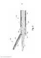
[0008] A Figura 1 representa uma vista em elevação lateral de um instrumento cirúrgico ultrassônico exemplificador;[0008] Figure 1 represents a side elevation view of an exemplary ultrasonic surgical instrument;
[0009] A Figura 2 representa uma vista em perspectiva de um atuador de extremidade e um conjunto de eixo de acionamento do instrumento da Figura 1, em que o atuador de extremidade está em uma configuração aberta;[0009] Figure 2 represents a perspective view of an end actuator and an instrument drive shaft assembly of Figure 1, in which the end actuator is in an open configuration;
[0010] A Figura 3 representa uma vista parcialmente explodida do atuador de extremidade e do conjunto de eixo de acionamento da Figura 2;[0010] Figure 3 represents a partially exploded view of the end actuator and the drive shaft assembly of Figure 2;
[0011] A Figura 4A representa uma vista em elevação lateral do atuador de extremidade e do conjunto de eixo de acionamento da Figura 2, em que o atuador de extremidade está na configuração aberta;[0011] Figure 4A represents a side elevation view of the end actuator and the drive shaft assembly of Figure 2, in which the end actuator is in the open configuration;
[0012] A Figura 4B representa uma vista em elevação lateral do atuador de extremidade e do conjunto de eixo de acionamento da Figura 2, em que o atuador de extremidade está em uma configuração fechada;[0012] Figure 4B represents a side elevation view of the end actuator and the drive shaft assembly of Figure 2, in which the end actuator is in a closed configuration;
[0013] A Figura 5 representa uma vista em seção transversal lateral do atuador de extremidade e do conjunto de eixo de acionamento da Figura 2, em que o atuador de extremidade está na configuração aberta;[0013] Figure 5 represents a side cross-sectional view of the end actuator and the drive shaft assembly of Figure 2, in which the end actuator is in the open configuration;
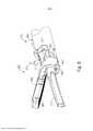
[0014] A Figura 6 representa uma vista em perspectiva de um atuador de extremidade alternativo e um conjunto de eixo de acionamento alternativo que podem ser prontamente incorporados ao instrumento da Figura 1;[0014] Figure 6 represents a perspective view of an alternative end actuator and an alternative drive shaft assembly that can be readily incorporated into the instrument of Figure 1;
[0015] A Figura 7 representa uma vista parcialmente explodida do atuador de extremidade e do conjunto de eixo de acionamento da Figura 6;[0015] Figure 7 represents a partially exploded view of the end actuator and the drive shaft assembly of Figure 6;
[0016] A Figura 8 representa uma vista em perspectiva de um tubo interno do conjunto de eixo de acionamento da Figura 6;[0016] Figure 8 represents a perspective view of an inner tube of the drive shaft assembly of Figure 6;
[0017] A Figura 9 representa uma vista em elevação lateral do tubo interno da Figura 8;[0017] Figure 9 represents a side elevation view of the inner tube of Figure 8;
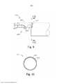
[0018] A Figura 10 representa uma vista frontal em seção transversal do tubo interno da Figura 8, tomada ao longo da linha 10-10 da Figura 9;[0018] Figure 10 represents a front view in cross section of the inner tube of Figure 8, taken along line 10-10 of Figure 9;
[0019] A Figura 11A representa uma vista em elevação lateral do atuador de extremidade e do conjunto de eixo de acionamento da Figura 6, em que o atuador de extremidade está na configuração aberta com o tecido posicionado em um local proximal do atuador de extremidade;[0019] Figure 11A represents a side elevation view of the end actuator and the drive shaft assembly of Figure 6, in which the end actuator is in the open configuration with the tissue positioned at a proximal location of the end actuator;
[0020] A Figura 11B representa uma vista em elevação lateral do atuador de extremidade e do conjunto de eixo de acionamento da Figura 6, em que o atuador de extremidade está em uma configuração fechada e está segurando o tecido em um local proximal do atuador de extremidade;[0020] Figure 11B represents a side elevation view of the end actuator and the drive shaft assembly of Figure 6, in which the end actuator is in a closed configuration and is holding the tissue at a proximal location of the end actuator far end;
[0021] A Figura 12A representa uma vista em elevação lateral do atuador de extremidade e do conjunto de eixo de acionamento da Figura 6, em que o atuador de extremidade está na configuração aberta com o tecido posicionado em um local distal do atuador de extremidade;[0021] Figure 12A represents a side elevation view of the end actuator and the drive shaft assembly of Figure 6, in which the end actuator is in the open configuration with the tissue positioned at a distal location of the end actuator;
[0022] A Figura 12B representa uma vista em elevação lateral do atuador de extremidade e do conjunto de eixo de acionamento da Figura 6, em que o atuador de extremidade está na configuração fechada e está segurando o tecido em um local distal do atuador de extremidade;[0022] Figure 12B represents a side elevation view of the end actuator and the drive shaft assembly of Figure 6, in which the end actuator is in the closed configuration and is holding the tissue at a distal location of the end actuator ;
[0023] A Figura 13 representa uma vista em perspectiva de um tubo interno alternativo que pode ser prontamente incorporado no conjunto de eixo de acionamento da Figura 2 ou da Figura 6;[0023] Figure 13 represents a perspective view of an alternative inner tube that can be readily incorporated into the drive shaft assembly of Figure 2 or Figure 6;
[0024] A Figura 14 representa uma vista em perspectiva de outro tubo interno alternativo que pode ser prontamente incorporado no conjunto de eixo de acionamento da Figura 2 ou da Figura 6; e[0024] Figure 14 represents a perspective view of another alternative inner tube that can be readily incorporated into the drive shaft assembly of Figure 2 or Figure 6; and
[0025] A Figura 15 representa uma vista em elevação lateral do tubo interno da Figura 14.[0025] Figure 15 represents a side elevation view of the inner tube of Figure 14.
[0026] Os desenhos não pretendem ser limitadores de modo algum e contempla-se que várias modalidades da tecnologia podem ser executadas em uma variedade de outras maneiras, incluindo aquelas não necessariamente representadas nos desenhos. Os desenhos incorporados em anexo e formando uma parte do relatório descritivo ilustram vários aspectos da presente tecnologia e, em conjunto com a descrição, servem para explicar os princípios da tecnologia; entende- se, entretanto, que esta tecnologia não se limita precisamente às disposições mostradas.[0026] The drawings are not intended to be limiting in any way and it is contemplated that various embodiments of the technology may be performed in a variety of other ways, including those not necessarily represented in the drawings. The drawings incorporated in the annex and forming a part of the specification illustrate various aspects of the present technology and, together with the description, serve to explain the principles of the technology; it is understood, however, that this technology is not limited precisely to the arrangements shown.
[0027] A descrição a seguir de certos exemplos da tecnologia não deve ser usada para limitar o seu escopo. Outros exemplos, recursos, aspectos, modalidades e vantagens da tecnologia se tornarão evidentes aos versados na técnica a partir da descrição a seguir, que se dá por meio de ilustração, um dos melhores modos contemplados para executar a tecnologia. Conforme será compreendido, a tecnologia aqui descrita é capaz de outros aspectos diferentes e óbvios, todos sem desconsiderar a tecnologia. Consequentemente, os desenhos e as descrições devem ser considerados como de natureza ilustrativa e não restritiva.[0027] The following description of certain examples of the technology should not be used to limit its scope. Other examples, resources, aspects, modalities and advantages of the technology will become evident to those skilled in the art from the following description, which is given by way of illustration, one of the best contemplated ways to execute the technology. As will be understood, the technology described here is capable of other different and obvious aspects, all without disregarding the technology. Consequently, the drawings and descriptions are to be considered as illustrative and not restrictive in nature.
[0028] É entendido adicionalmente que qualquer um ou mais dentre os ensinamentos, expressões, modalidades, exemplos etc. aqui descritos podem ser combinados com qualquer um ou mais dentre os outros ensinamentos, expressões, modalidades, exemplos etc. que são descritos na presente invenção. Os ensinamentos, expressões, modalidades, exemplos etc. descritos a seguir não devem ser vistos isoladamente um em relação ao outro. Várias maneiras adequadas, pelas quais os ensinamentos da presente invenção podem ser combinados, se tornarão prontamente evidentes aos versados na técnica tendo em vista dos ensinamentos da presente invenção. Essas modificações e variações são destinadas a serem incluídas no escopo das concretizações.[0028] It is further understood that any one or more of the teachings, expressions, modalities, examples, etc. described herein may be combined with any one or more of the other teachings, expressions, embodiments, examples, etc. which are described in the present invention. The teachings, expressions, modalities, examples, etc. described below should not be viewed in isolation from one another. Various suitable ways in which the teachings of the present invention may be combined will become readily apparent to those skilled in the art in view of the teachings of the present invention. These modifications and variations are intended to be included within the scope of the embodiments.
[0029] Para maior clareza da divulgação, os termos "proximal" e "distal" são aqui definidos em relação a um operador humano ou robótico do instrumento cirúrgico. O termo "proximal" se refere à posição de um elemento mais próximo ao operador humano ou robótico do instrumento cirúrgico e mais afastado do atuador de extremidade cirúrgico do instrumento cirúrgico. O termo "distal" se refere à posição de um elemento mais próximo ao atuador de extremidade cirúrgico do instrumento cirúrgico e mais afastado do operador humano ou robótico do instrumento cirúrgico.[0029] For clarity of disclosure, the terms "proximal" and "distal" are defined herein in relation to a human or robotic operator of the surgical instrument. The term "proximal" refers to the position of an element closest to the human or robotic operator of the surgical instrument and furthest away from the surgical end actuator of the surgical instrument. The term "distal" refers to the position of an element closest to the surgical end actuator of the surgical instrument and furthest away from the human or robotic operator of the surgical instrument.
[0030] A Figura 1 mostra um instrumento cirúrgico ultrassônico (10) exemplificador que é configurado para ser usado em procedimentos cirúrgicos minimamente invasivos (por exemplo, através de um trocarte ou outra porta de acesso de diâmetro pequeno, etc.). Conforme será descrito em mais detalhes a seguir, o instrumento (10) funciona de modo a cortar o tecido e vedar ou soldar tecido (por exemplo, um vaso sanguíneo etc.) de modo substancialmente simultâneo. O instrumento (10) desse exemplo compreende um conjunto descartável (100) e um conjunto reutilizável (200). A porção distal do conjunto reutilizável (200) é configurada para receber de modo removível a porção proximal do conjunto descartável (100) para formar o instrumento (10). Entretanto, deve-se compreender que o conjunto reutilizável (200) e o conjunto descartável (100) podem, alternativamente, ser conectados unitariamente.[0030] Figure 1 shows an exemplary ultrasonic surgical instrument (10) that is configured to be used in minimally invasive surgical procedures (eg, through a trocar or other small-diameter access port, etc.). As will be described in more detail below, the instrument (10) operates to cut tissue and seal or weld tissue (e.g., a blood vessel, etc.) substantially simultaneously. The instrument (10) of this example comprises a disposable set (100) and a reusable set (200). The distal portion of the reusable assembly (200) is configured to releasably receive the proximal portion of the disposable assembly (100) to form the instrument (10). However, it should be understood that the reusable assembly (200) and the disposable assembly (100) may alternatively be connected unitarily.
[0031] O conjunto descartável (100) do presente exemplo compreende uma porção de corpo (110), um conjunto de eixo de acionamento (150) que se estende distalmente a partir da porção de corpo (110) e um atuador de extremidade (180) localizado na extremidade distal do conjunto de eixo de acionamento (150). Conforme se pode observar melhor nas Figuras 2 a 4, o atuador de extremidade (180) desse exemplo compreende um braço de aperto (182) e uma lâmina ultrassônica (190). O braço de aperto (182) inclui uma almofada de aperto (184) voltada para a lâmina (190). Conforme mostrado nas Figuras 3A e 3B e conforme será descrito em mais detalhes a seguir, o braço de aperto (182) é giratório em direção à lâmina (190), e na direção contrária à mesma, para comprimir seletivamente o tecido entre a almofada de aperto (184) e a lâmina (190). Conforme visto na Figura 4, a lâmina (190) é um recurso integral da extremidade distal de um guia de ondas acústicas (192), que se estende coaxialmente através dos tubos (152, 170) e que é configurado para transmitir vibrações ultrassônicas para a lâmina (190), conforme será descrito em mais detalhes a seguir.[0031] The disposable assembly (100) of the present example comprises a body portion (110), a drive shaft assembly (150) extending distally from the body portion (110) and an end actuator (180) ) located at the distal end of the drive shaft assembly (150). As best seen in Figures 2 to 4, the end actuator (180) in this example comprises a clamping arm (182) and an ultrasonic blade (190). The clamping arm (182) includes a clamping pad (184) facing the blade (190). As shown in Figures 3A and 3B and as will be described in more detail below, the clamping arm (182) is pivotable towards and away from the blade (190) to selectively compress tissue between the grip (184) and blade (190). As seen in Figure 4, the blade (190) is an integral feature of the distal end of an acoustic waveguide (192), which extends coaxially through the tubes (152, 170) and which is configured to transmit ultrasonic vibrations to the blade (190), as will be described in more detail below.
[0032] O conjunto de eixo de acionamento (150) compreende um tubo externo (152) e um tubo interno (170). O tubo externo (152) tem por finalidade transladar longitudinalmente em relação ao tubo interno (170) para girar seletivamente o braço de aperto (182) em direção à lâmina (190), e na direção contrária à mesma. A fim de conseguir isso, e conforme é melhor visto nas Figuras 3 e 5, os recursos de pinos integrantes (186) do braço de aperto (182) prendem de modo pivotante uma primeira porção do braço de aperto (182) a uma lingueta que se projeta distalmente (154) do tubo externo (152); ao mesmo tempo que um pino inserido (188) prende de forma articulada uma segunda porção do braço de aperto (182) a uma lingueta distalmente protuberante (172) do tubo interno (170). Desse modo, conforme pode ser visto na transição da Figura 4A para a Figura 4B, os tubos (152, 170) cooperam para girar o braço de aperto (182) em direção à lâmina (190) quando o tubo externo (152) é retraído proximalmente em relação ao tubo interno (170). Deve- se entender que o braço de aperto (182) pode ser girado na direção contrária à lâmina (190) (por exemplo, da posição mostrada na Figura 4B para a posição mostrada na Figura 4A) transladando-se o tubo externo (152) distalmente em relação ao tubo interno (170), de modo oposto à operação mostrada nas Figuras 4A a 4B. Em um uso exemplificador, o braço de aperto (182) pode ser girado em direção à lâmina (190) para segurar, comprimir, vedar e cortar o tecido capturado entre a almofada de aperto (184) e a lâmina (190). O braço de aperto (182) pode ser girado na direção contrária à lâmina (190) para soltar o tecido entre a almofada de aperto (184) e a lâmina (190); e/ou realizar uma dissecção brusca do tecido que engata as superfícies externas opostas do braço de aperto (182) e da lâmina (190).[0032] The drive shaft assembly (150) comprises an outer tube (152) and an inner tube (170). The outer tube (152) has the purpose of translating longitudinally in relation to the inner tube (170) to selectively rotate the clamping arm (182) towards the blade (190) and away from it. In order to accomplish this, and as best seen in Figures 3 and 5, integral pin features (186) of the clamping arm (182) pivotally secure a first portion of the clamping arm (182) to a tongue that projects distally (154) from the outer tube (152); while an inserted pin (188) pivotally secures a second portion of the clamping arm (182) to a distally protruding tongue (172) of the inner tube (170). Thus, as can be seen in the transition from Figure 4A to Figure 4B, the tubes (152, 170) cooperate to rotate the clamping arm (182) towards the blade (190) when the outer tube (152) is retracted. proximally to the inner tube (170). It should be understood that the clamping arm (182) can be rotated away from the blade (190) (for example, from the position shown in Figure 4B to the position shown in Figure 4A) by translating the outer tube (152) distally of the inner tube (170), opposite to the operation shown in Figures 4A to 4B. In an exemplary use, the clamping arm (182) can be pivoted toward the blade (190) to grip, compress, seal, and cut tissue captured between the clamping pad (184) and the blade (190). The clamping arm (182) can be rotated away from the blade (190) to loosen the fabric between the clamping pad (184) and the blade (190); and/or perform a blunt dissection of the tissue engaging the opposing outer surfaces of the clamp arm (182) and blade (190).
[0033] O conjunto reutilizável (200) inclui uma empunhadura de pistola (204) neste exemplo, embora deva ser entendido que qualquer outro tipo adequado de empunhadura pode ser usado. Um gatilho (120) do conjunto reutilizável (200) é configurado para pivotar em direção à e na direção oposta à empunhadura tipo pistola (204) para, assim, transladar o tubo externo (152) para, assim, pivotear o braço de aperto (182). Os botões (126, 220) do conjunto reutilizável (200) são operáveis para ativar a lâmina (190) para fazer com que a lâmina (190) vibre a frequências ultrassônicas. Em algumas versões, pelo menos um botão (126, 220) também tem por finalidade ativar o atuador de extremidade (180) para fornecer energia eletrocirúrgica de RF ao tecido.[0033] The reusable assembly (200) includes a pistol grip (204) in this example, although it should be understood that any other suitable type of grip can be used. A trigger (120) of the reusable assembly (200) is configured to pivot towards and away from the pistol grip (204) to thereby translate the outer tube (152) to thereby pivot the clamping arm ( 182). The buttons (126, 220) of the reusable assembly (200) are operable to activate the blade (190) to cause the blade (190) to vibrate at ultrasonic frequencies. In some versions, at least one button (126, 220) is also intended to activate the tip actuator (180) to deliver RF electrosurgical energy to tissue.
[0034] O conjunto reutilizável (200) compreende vários recursos que funcionam de modo a ativar a lâmina (190), incluindo uma bateria e um transdutor ultrassônico. O conjunto reutilizável (200) inclui adicionalmente recursos que funcionam de modo a acoplar o transdutor ultrassônico ao guia de ondas (192) para, desse modo, acoplar o transdutor ultrassônico à lâmina (190). Em algumas variações, o conjunto reutilizável (200) é acoplado a uma fonte de energia externa que fornece energia elétrica ao transdutor ultrassônico. Somente a título de exemplo, tal fonte de energia externa pode compreender um GEN 300 vendido pela Ethicon Endo-Surgery, Inc., de Cincinnati, Ohio, EUA. Adicional ou alternativamente, a fonte de energia externa pode compreender um gerador que é construído de acordo com ao menos alguns dos ensinamentos da publicação US N° 2011/0087212, intitulada "Surgical Generator for Ultrasonic And Electrosurgical Devices", publicada em 14 de abril de 2011, cuja descrição está aqui incorporada a título de referência.[0034] The reusable assembly (200) comprises various resources that function to activate the blade (190), including a battery and an ultrasonic transducer. The reusable assembly (200) further includes features that function to couple the ultrasonic transducer to the waveguide (192) to thereby couple the ultrasonic transducer to the blade (190). In some variations, the reusable assembly (200) is coupled to an external power source that supplies electrical power to the ultrasonic transducer. By way of example only, such an external power source may comprise a GEN 300 sold by Ethicon Endo-Surgery, Inc., of Cincinnati, Ohio, USA. Additionally or alternatively, the external power source may comprise a generator that is constructed in accordance with at least some of the teachings of US Publication No. 2011/0087212, entitled "Surgical Generator for Ultrasonic And Electrosurgical Devices", published on April 14, 2011, the description of which is incorporated herein by reference.
[0035] No presente exemplo, a extremidade distal da lâmina (190) está situada em uma posição que corresponde a um antinó associado às vibrações ultrassônicas ressonantes comunicadas através do guia de ondas (192), a fim de sintonizar o conjunto acústico em uma frequência ressonante preferencial fo quando o conjunto acústico não é carregado por tecido. Quando o conjunto de transdutor está energizado, a extremidade distal da lâmina (190) é configurada para se mover longitudinalmente na faixa de, por exemplo, aproximadamente 10 a 500 mícrons pico a pico, e em alguns exemplos, na faixa de cerca de 20 a cerca de 200 mícrons em uma frequência vibratória predeterminada fo de, por exemplo, 55,5 kHz. Quando o conjunto de transdutor do presente exemplo é ativado, essas oscilações mecânicas são transmitidas através do guia de ondas (192) para alcançar a lâmina (190), fornecendo assim a oscilação da lâmina (190) na frequência ultrassônica ressonante. Desse modo, quando o tecido estiver preso entre a lâmina (190) e a almofada de aperto (184), a oscilação ultrassônica da lâmina (190) poderá cortar simultaneamente o tecido e desnaturar as proteínas em células de tecido adjacentes, fornecendo assim um efeito coagulante com relativamente pouca difusão térmica.[0035] In the present example, the distal end of the blade (190) is located in a position that corresponds to an antinode associated with the resonant ultrasonic vibrations communicated through the waveguide (192), in order to tune the acoustic assembly to a frequency preferred resonant fo when the acoustic array is not loaded by tissue. When the transducer assembly is energized, the distal end of the blade (190) is configured to move longitudinally in the range of, for example, approximately 10 to 500 microns peak to peak, and in some examples, in the range of about 20 to 500 microns. about 200 microns at a predetermined vibratory frequency of, for example, 55.5 kHz. When the transducer assembly of the present example is activated, these mechanical oscillations are transmitted through the waveguide (192) to reach the blade (190), thereby providing oscillation of the blade (190) at the resonant ultrasonic frequency. Thus, when tissue is trapped between the blade (190) and the pinch pad (184), the ultrasonic oscillation of the blade (190) can simultaneously cut tissue and denature proteins in adjacent tissue cells, thereby providing an effect coagulant with relatively little thermal diffusion.
[0036] Em algumas versões, o atuador de extremidade (180) é operável para aplicar energia eletrocirúrgica de radiofrequência (RF) ao tecido além de aplicar energia ultrassônica ao tecido. Somente a título de exemplo, o atuador de extremidade (180) pode ser configurado e operado de acordo com ao menos alguns dos ensinamentos da publicação de patente US N° 2015/0141981, intitulada "Ultrasonic Surgical Instrument with Electrosurgical Feature", publicada em 21 de maio de 2015, cuja descrição está aqui incorporada a título de referência; e/ou da patente US N° 8.663.220, intitulada "Ultrasonic Surgical Instrument Blades", concedida em 4 de março de 2014, cuja divulgação está aqui incorporada a título de referência.[0036] In some versions, the end actuator (180) is operable to apply radiofrequency (RF) electrosurgical energy to tissue in addition to applying ultrasonic energy to tissue. By way of example only, the end actuator (180) can be configured and operated in accordance with at least some of the teachings of US Patent Publication No. 2015/0141981, entitled "Ultrasonic Surgical Instrument with Electrosurgical Feature", published on 21 May 2015, the description of which is incorporated herein by reference; and/or US Patent No. 8,663,220, entitled "Ultrasonic Surgical Instrument Blades", issued March 4, 2014, the disclosure of which is incorporated herein by reference.
[0037] No presente exemplo, o braço de aperto (182) é atuado pela translação do tubo externo (152) enquanto o tubo interno (170) permanece estacionário. Entretanto, deve-se compreender que o braço de aperto (182) pode, em vez disso, ser atuado pela translação do tubo interno (170) enquanto o tubo externo (152) permanece estacionário. Exemplos meramente ilustrativos de tais formas alternativas de atuação serão descritos com mais detalhes abaixo. Várias formas adequadas nas quais o gatilho (120) pode ser acoplado ao tubo externo (152) ou ao tubo interno (170), para fornecer translação do tubo externo (152) ou do tubo interno (170) em resposta à rotação do gatilho (120) em relação à empunhadura de pistola (204), serão evidentes para os versados na técnica em vista dos ensinamentos da presente invenção.[0037] In the present example, the clamping arm (182) is actuated by the translation of the outer tube (152) while the inner tube (170) remains stationary. However, it should be understood that the clamping arm (182) may instead be actuated by translation of the inner tube (170) while the outer tube (152) remains stationary. Merely illustrative examples of such alternative forms of action will be described in more detail below. Various suitable ways in which the trigger (120) can be coupled to the outer tube (152) or inner tube (170) to provide translation of the outer tube (152) or inner tube (170) in response to rotation of the trigger ( 120) in relation to the pistol grip (204), will be apparent to those skilled in the art in view of the teachings of the present invention.
[0038] Em adição ao supracitado, o conjunto descartável (100) e/ou o conjunto reutilizável (200) pode ser construído e operável de acordo com ao menos alguns dos ensinamentos da publicação US N° 2015/0245850, intitulado "Ultrasonic Surgical Instrument With Removable Handle Assembly", publicada em 3 de setembro de 2015, cuja descrição está aqui incorporada a título de referência. Adicional ou alternativamente, o conjunto descartável (100) e/ou o conjunto reutilizável (200) podem ser construídos e operáveis de acordo com ao menos alguns dos ensinamentos do pedido de patente US N° 14/868.574, intitulado "Ultrasonic Surgical Instrument with Removable Handle Assembly", depositado em 29 de setembro de 2015, cuja divulgação está aqui incorporada a título de referência. Outros componentes, recursos e operabilidades adequados que podem ser incorporados no conjunto descartável (100) e/ou no conjunto reutilizável (200), bem como variações dos mesmos, ficarão evidentes aos versados na técnica, tendo em vista os ensinamentos do presente documento.[0038] In addition to the foregoing, the disposable set (100) and/or the reusable set (200) can be constructed and operable in accordance with at least some of the teachings of US publication No. 2015/0245850, entitled "Ultrasonic Surgical Instrument With Removable Handle Assembly", published September 3, 2015, the description of which is incorporated herein by reference. Additionally or alternatively, the disposable assembly (100) and/or the reusable assembly (200) may be constructed and operable in accordance with at least some of the teachings of US Patent Application No. 14/868,574, entitled "Ultrasonic Surgical Instrument with Removable Handle Assembly", filed on September 29, 2015, the disclosure of which is incorporated herein by reference. Other suitable components, features, and operabilities that can be incorporated into the disposable assembly (100) and/or the reusable assembly (200), as well as variations thereof, will be apparent to those skilled in the art in view of the teachings herein.
[0039] Conforme discutido acima, o braço de aperto (182) do atuador de extremidade (180) se move de maneira articulada em direção à lâmina ultrassônica (190) e na direção oposta à mesma. Em alguns casos, esse movimento pivotante do braço de aperto (182) pode não permitir uma distribuição adequada de força a ser aplicada ao tecido prensado entre o braço de aperto (182) e a lâmina ultrassônica (190). Por exemplo, quando o braço de aperto (182) se articula em direção à lâmina ultrassônica (190), uma porção proximal do braço de aperto (182) pode entrar em contato com o tecido entre o braço de aperto (182) e a lâmina ultrassônica (190) antes de uma porção distal do braço de aperto (182) entrar em contato com o tecido. Essa distribuição inadequada de força pode permitir que se formem "etiquetas" de tecido (por exemplo, regiões planas, porém não cortadas de tecido), particularmente em uma extremidade distal e/ou extremidade proximal de atuador de extremidade (180). Dessa forma, em algumas versões do instrumento (10), pode ser desejável fornecer um mecanismo que fornece distribuição melhorada de força a ser aplicada ao tecido prensado entre o braço de aperto (182) e a lâmina ultrassônica (190) para reduzir a ocorrência de etiquetas de tecido e/ou para fornecer o corte de etiquetas de tecido.[0039] As discussed above, the clamping arm (182) of the end actuator (180) pivotally moves towards the ultrasonic blade (190) and in the opposite direction to it. In some cases, this pivotal movement of the clamping arm (182) may not allow for proper distribution of force to be applied to the pressed tissue between the clamping arm (182) and the ultrasonic blade (190). For example, as the clamp arm (182) pivots toward the ultrasonic blade (190), a proximal portion of the clamp arm (182) can contact the tissue between the clamp arm (182) and the blade. (190) before a distal portion of the clamping arm (182) comes into contact with tissue. This improper distribution of force can allow tissue "tags" (eg, flat but uncut regions of tissue) to form, particularly at a distal end and/or proximal end of an end actuator (180). Thus, in some versions of the instrument (10), it may be desirable to provide a mechanism that provides improved distribution of force to be applied to the pressed tissue between the clamping arm (182) and the ultrasonic blade (190) to reduce the occurrence of fabric labels and/or to provide fabric label cutting.
[0040] As Figuras 6 a 7 mostram um conjunto de eixo de acionamento alternativo (350) e uma atuador de extremidade (380) que podem ser prontamente incorporados ao instrumento (10) descrito acima. Conforme será descrito com mais detalhes abaixo, o conjunto de eixo de acionamento (350) inclui recursos que podem otimizar a distribuição de força a ser aplicada ao tecido prensado entre o atuador de extremidade (380). O atuador de extremidade (380) inclui um braço de aperto (382) e uma lâmina ultrassônica (390) que são substancialmente similares ao braço de aperto (182) e à lâmina ultrassônica (190) descritos acima, com as diferenças descritas abaixo.[0040] Figures 6 to 7 show an alternative drive shaft assembly (350) and an end actuator (380) that can be readily incorporated into the instrument (10) described above. As will be described in more detail below, the drive shaft assembly (350) includes features that can optimize the distribution of force to be applied to the pressed tissue between the end actuator (380). The end actuator (380) includes a clamping arm (382) and ultrasonic blade (390) that are substantially similar to the clamping arm (182) and ultrasonic blade (190) described above, with the differences described below.
[0041] O braço de aperto (382) inclui uma almofada de aperto (384) e um par de recursos de pino integrais (386), substancialmente similar à almofada de aperto (184) e recursos de pino integrais (186) descritos acima, respectivamente. Portanto, o bloco de aperto (384) é voltado para a lâmina (390). O braço de aperto (382) inclui também um outro par de pinos integrais (388), que servem para o mesmo propósito que o pino inserido (188) descrito acima. Alternativamente, os recursos de pino integrais (388) podem também ser um único pino, inserível em relação ao restante do braço de aperto (382), se desejado. Adicionalmente, conforme será descrito em mais detalhes a seguir, o braço de aperto (384) é giratório em direção à lâmina (390), e na direção oposta à mesma, para comprimir seletivamente o tecido entre a almofada de aperto (384) e a lâmina (390). A lâmina (390) é um recurso integral da extremidade distal do guia de ondas acústicas (392), que é substancialmente similar ao guia de ondas acústicas (192) descrito acima. Portanto, o guia de ondas acústicas (392) se estende coaxialmente através dos tubos (352, 370), e é configurado para comunicar vibrações ultrassônicas à lâmina (390).[0041] The grip arm (382) includes a grip pad (384) and a pair of integral pin features (386), substantially similar to the grip pad (184) and integral pin features (186) described above, respectively. Therefore, the clamping block (384) faces the blade (390). The clamping arm (382) also includes another pair of integral pins (388), which serve the same purpose as the inserted pin (188) described above. Alternatively, the integral pin features (388) may also be a single pin, insertable with respect to the remainder of the clamping arm (382), if desired. Additionally, as will be described in more detail below, the pinch arm (384) is pivotable towards the blade (390), and away from it, to selectively compress tissue between the pinch pad (384) and the blade (384). blade (390). The blade (390) is an integral feature of the distal end of the acoustic waveguide (392), which is substantially similar to the acoustic waveguide (192) described above. Therefore, the acoustic waveguide (392) extends coaxially through the tubes (352, 370), and is configured to communicate ultrasonic vibrations to the blade (390).
[0042] O conjunto de eixo de acionamento (350) compreende um tubo externo (352) e um tubo interno (370), que são substancialmente similares ao tubo externo (152) e ao tubo interno (170) descritos acima, respectivamente, com as diferenças descritas abaixo. Portanto, o tubo externo (352) é operável para transladar longitudinalmente em relação ao tubo interno (370) para girar seletivamente o braço de aperto (382) em direção à lâmina (390) e na direção oposta à mesma. Alternativamente, o tubo externo (370) pode ser transladado longitudinalmente em relação ao tubo interno (352) para girar seletivamente o braço de aperto (382) em direção à lâmina (390) e na direção oposta à mesma.[0042] The drive shaft assembly (350) comprises an outer tube (352) and an inner tube (370), which are substantially similar to the outer tube (152) and the inner tube (170) described above, respectively, with the differences described below. Therefore, the outer tube (352) is operable to translate longitudinally relative to the inner tube (370) to selectively rotate the clamping arm (382) toward and away from the blade (390). Alternatively, the outer tube (370) can be translated longitudinally with respect to the inner tube (352) to selectively rotate the clamping arm (382) towards and away from the blade (390).
[0043] O tubo interno (370) inclui uma lingueta que se projeta distalmente (372) que é substancialmente similar à lingueta que se projeta distalmente (172) descrita acima, com as diferenças descritas abaixo. A lingueta que se projeta distalmente (372) contém vários recursos para promover a flexibilidade elástica da lingueta que se projeta distalmente (372) em relação ao restante do tubo interno (370). Conforme será descrito com mais detalhes abaixo, essa flexibilidade elástica pode proporcionar melhor distribuição da força aplicada ao tecido preso entre o braço (382) e a lâmina ultrassônica (390).[0043] The inner tube (370) includes a distally projecting tongue (372) that is substantially similar to the distally projecting tongue (172) described above, with the differences described below. The distally projecting tongue (372) contains various features to promote the elastic flexibility of the distally projecting tongue (372) relative to the remainder of the inner tube (370). As will be described in more detail below, this elastic flexibility can provide better distribution of the force applied to tissue trapped between the arm (382) and the ultrasonic blade (390).
[0044] O tubo externo (350) inclui uma lingueta que se projeta distalmente (354) que define um par de fendas de pino verticalmente alongadas (356). Os recursos de pino integrais (386) do braço de aperto (382) acoplam de modo pivotante uma primeira porção do braço de aperto (382) à lingueta que se projeta distalmente (354) do tubo externo (352) através das fendas de pino verticalmente alongadas (356). Os recursos de pino integrais (386) podem girar e transladar verticalmente dentro das fendas de pino verticalmente alongadas (356).[0044] The outer tube (350) includes a distally projecting tongue (354) that defines a pair of vertically elongated pin slots (356). The integral pin features (386) of the clamping arm (382) pivotally couple a first portion of the clamping arm (382) to the distally projecting tongue (354) of the outer tube (352) through the vertically extending pin slots. elongated (356). The integral pin features (386) can vertically rotate and translate within the vertically elongated pin slots (356).
[0045] A lingueta que se projeta distalmente (372) inclui um par de pontas que se projetam distalmente (371), cada uma definindo um respectivo orifício de pino (374). Os recursos de pino integrais (388) do braço de aperto (382) prendem de forma articulada uma segunda porção do braço de aperto (382) à lingueta que se projeta distalmente (372) do tubo interno (370). Desse modo, conforme será descrito em mais detalhes abaixo, os tubos (352, 370) cooperam para girar o braço de aperto (382) em direção à lâmina (390) quando o tubo externo (352) é retraído proximalmente em relação ao tubo interno (370); e na direção oposta à lâmina (390) quando o tubo externo (353) é avançado distalmente em relação ao tubo interno (370). De modo similar ao braço de aperto (182) e à lâmina (190), o braço de aperto (382) pode ser girado em direção à lâmina (390) para segurar, comprimir, vedar e cortar o tecido capturado entre a almofada de aperto (384) e a lâmina (390). O braço de aperto (382) pode ser girado na direção oposta à lâmina (390) para soltar o tecido entre a almofada de aperto (384) e a lâmina (390); e/ou realizar uma dissecção brusca do tecido que engata as superfícies externas opostas do braço de aperto (382) e da lâmina (390).[0045] The distally projecting tongue (372) includes a pair of distally projecting prongs (371), each defining a respective pin hole (374). Integral pin features (388) of the clamping arm (382) pivotally secure a second portion of the clamping arm (382) to the distally projecting tongue (372) of the inner tube (370). Thus, as will be described in more detail below, the tubes (352, 370) cooperate to pivot the clamp arm (382) toward the blade (390) when the outer tube (352) is retracted proximally with respect to the inner tube. (370); and away from the blade (390) as the outer tube (353) is advanced distally relative to the inner tube (370). Similar to the clamping arm (182) and blade (190), the clamping arm (382) can be pivoted toward the blade (390) to grip, compress, seal, and cut tissue captured between the clamping pad. (384) and the blade (390). The clamping arm (382) can be rotated away from the blade (390) to loosen the fabric between the clamping pad (384) and the blade (390); and/or perform a blunt dissection of the tissue engaging the opposing outer surfaces of the clamp arm (382) and blade (390).
[0046] As pontas que se projetam distalmente (371) podem ser produzidas a partir de um material suficientemente resiliente de modo que as pontas (371) possam se flexionar elasticamente em relação ao restante do tubo interno (370) em resposta a uma força externa que tem um componente orientado transversalmente. Adicionalmente, as pontas que se projetam distalmente (371) podem se flexionar de volta para uma posição de repouso em relação ao restante do tubo interno (370) (conforme mostrado nas Figuras 6 a 9) uma vez que a força externa é removida. Deve-se compreender que as pontas (371) podem se flexionar elasticamente a partir da posição de repouso em diferentes magnitudes dependendo da magnitude do componente longitudinalmente orientado da força externa.[0046] The distally projecting tips (371) can be produced from a sufficiently resilient material so that the tips (371) can elastically flex relative to the remainder of the inner tube (370) in response to an external force which has a transversely oriented component. Additionally, the distally projecting tips (371) can flex back into a resting position relative to the remainder of the inner tube (370) (as shown in Figures 6 to 9) once the external force is removed. It should be understood that the tips (371) can flex elastically from the rest position by different magnitudes depending on the magnitude of the longitudinally oriented component of the external force.
[0047] As pontas que se projetam distalmente (371) definem em conjunto um canal que se estende longitudinalmente (375). O canal que se estende longitudinalmente (375) é aberto em uma extremidade distal e fechado em uma extremidade proximal. O canal que se estende longitudinalmente (375) pode reduzir a quantidade de material usado para formar a lingueta que se projeta distalmente (372). A redução no material ao longo do comprimento da lingueta que se projeta distalmente (372) pode permitir que a porção das pontas (371) conectadas ao restante do tubo interno (370) flexionem mais facilmente em relação ao restante do tubo interno (370) quando as pontas (371) são expostas a uma força externa em comparação com a lingueta que se projeta distalmente (172) descrita acima. Adicionalmente, as pontas (371) podem se flexionar mais facilmente em relação ao restante do tubo interno (370) em diferentes magnitudes/ângulos dependendo da distribuição lateral de forças ou outros fatores. Em outras palavras, as pontas (371) podem se flexionar mais facilmente uma em relação à outra. Embora no presente exemplo, o canal que se estende longitudinalmente (375) tenha uma geometria exclusiva definida pelas pontas (371), qualquer outra geometria adequada pode ser utilizada, como ficaria evidente aos versados na técnica em vista dos ensinamentos da presente invenção.[0047] The distally projecting spikes (371) together define a longitudinally extending channel (375). The longitudinally extending channel (375) is open at a distal end and closed at a proximal end. The longitudinally extending channel (375) can reduce the amount of material used to form the distally projecting tongue (372). The reduction in material along the length of the distally projecting tongue (372) may allow the portion of the prongs (371) connected to the remainder of the inner tube (370) to flex more easily relative to the remainder of the inner tube (370) when the prongs (371) are exposed to an external force compared to the distally projecting tongue (172) described above. Additionally, the tips (371) can flex more easily relative to the rest of the inner tube (370) by different magnitudes/angles depending on the lateral distribution of forces or other factors. In other words, the prongs (371) can flex more easily relative to each other. Although in the present example, the longitudinally extending channel (375) has a unique geometry defined by the prongs (371), any other suitable geometry may be used, as would be apparent to those skilled in the art in view of the teachings of the present invention.
[0048] Conforme se pode observar melhor nas Figuras 8 a 9, cada ponta que se projeta distalmente (371) também define um recorte circunferencial (378) situado próximo à extremidade proximal das pontas que se projetam distalmente (371). De modo similar ao canal que se estende longitudinalmente (375), os recortes circunferenciais (378) podem também reduzir a quantidade de material usado para formar a lingueta que se projeta distalmente (372). Adicionalmente, recortes circunferenciais (378) reduzem a quantidade de material usado para conectar as pontas que se projetam distalmente (371) ao restante do tubo interno (370). Portanto, a redução no material que conecta as pontas (371) ao restante do tubo interno (370) pode permitir que as pontas (371) flexionem mais facilmente em relação ao restante do tubo interno (370) quando as pontas (371) são expostas a uma força externa. Deve-se compreender que a quantidade de material que conecta as pontas que se projetam distalmente (371) ao restante do tubo interno (370) ainda é suficiente para que as pontas (371) flexionem de volta para a posição de repouso quando uma força externa não estiver mais presente. Embora no atual exemplo, o recorte circunferencial (378) tenha uma geometria semirretangular, qualquer outra geometria adequada pode ser usada como seria evidente a uma pessoa versada na técnica em vista dos ensinamentos da presente invenção, como uma geometria triangular.[0048] As best seen in Figures 8 to 9, each distally projecting tip (371) also defines a circumferential cutout (378) located near the proximal end of the distally projecting tips (371). Similar to the longitudinally extending channel (375), the circumferential cutouts (378) can also reduce the amount of material used to form the distally projecting tongue (372). Additionally, circumferential cutouts (378) reduce the amount of material used to connect the distally projecting tips (371) to the remainder of the inner tube (370). Therefore, the reduction in the material connecting the tips (371) to the rest of the inner tube (370) can allow the tips (371) to flex more easily relative to the rest of the inner tube (370) when the tips (371) are exposed. to an external force. It should be understood that the amount of material connecting the distally projecting tips (371) to the remainder of the inner tube (370) is still sufficient for the tips (371) to flex back into the resting position when an external force is no longer present. Although in the present example, the circumferential cutout (378) has a semi-rectangular geometry, any other suitable geometry can be used as would be apparent to a person skilled in the art in view of the teachings of the present invention, such as a triangular geometry.
[0049] Adicionalmente, a lingueta que se projeta distalmente (372) contém uma superfície externa cunhada ou estampada (376) que se estende ao longo da superfície externa das pontas (371) e que termina proximalmente em um rebordo parcialmente circunferencial (377). Conforme se pode observar melhor na Figura 10, a superfície externa estampada (376) diminui a área em seção transversal das porções estampadas, como a lingueta que se projeta distalmente (372). Em particular, a superfície externa estampada (376) é definida por um raio que é menor que o raio que define a superfície externa do restante do tubo interno (370). Essa diminuição no raio ou área da seção transversal pode ajudar a promover a flexibilidade elástica da lingueta que se projeta distalmente (372). Embora no exemplo atual, a redução na área em seção transversal da lingueta que se projeta distalmente (372) seja formada por um processo de cunhagem ou estampagem, qualquer outro processo adequado pode ser usado como seria evidente a uma pessoa versada na técnica em vista dos ensinamentos da presente invenção, como moagem, etc.[0049] Additionally, the distally projecting tongue (372) contains a stamped or stamped outer surface (376) which extends along the outer surface of the prongs (371) and which terminates proximally in a partially circumferential rim (377). As best seen in Figure 10, the stamped outer surface (376) decreases the cross-sectional area of the stamped portions, such as the distally projecting tongue (372). In particular, the stamped outer surface (376) is defined by a radius that is less than the radius defining the outer surface of the remainder of the inner tube (370). This decrease in radius or cross-sectional area may help promote the elastic flexibility of the distally projecting tongue (372). Although in the present example, the reduction in cross-sectional area of the distally projecting tongue (372) is formed by a coining or stamping process, any other suitable process can be used as would be apparent to a person skilled in the art in view of the teachings of the present invention, such as grinding, etc.
[0050] As Figuras 11A a 11B mostram o conjunto de eixo de acionamento (350) e o atuador de extremidade (380) sendo utilizados para segurar o tecido (T) ao longo de um local proximal entre a almofada de aperto (384) e a lâmina (390). A Figura 11A mostra o braço de aperto (382) girado para uma posição imediatamente antes de entrar em contato com o tecido (T). Portanto, como o tecido (T) não está em contato com a almofada de aperto (382), o tecido (T) não está conferindo uma força externa ao braço de aperto (382). Deve-se compreender que logo após o braço de aperto (382) ser girado além da posição mostrada na Figura 11A em direção à posição mostrada na Figura 11B, o grampo de aperto (384) começa a entrar em contato com o tecido (T).[0050] Figures 11A to 11B show the drive shaft assembly (350) and the end actuator (380) being used to hold the tissue (T) along a proximal location between the grip pad (384) and the blade (390). Figure 11A shows the clamp arm (382) rotated to a position just before contacting the tissue (T). Therefore, as the fabric (T) is not in contact with the grip pad (382), the fabric (T) is not imparting an external force to the grip arm (382). It should be understood that shortly after the clamp arm (382) is rotated past the position shown in Figure 11A towards the position shown in Figure 11B, the clamp clamp (384) begins to come into contact with the tissue (T) .
[0051] A Figura 11B mostra o braço de aperto (382) girado em direção à lâmina (390) e contra o tecido (T) devido à retração proximal do tubo externo (354) em relação ao tubo interno (370), conforme descrito acima. Quanto mais braço de aperto adicional (382) gira a partir da posição mostrada na Figura 11A em direção à posição mostrada na Figura 11B, maior será a força externa que o tecido (T) confere sobre o braço de aperto (382). Deve-se compreender que a força conferida pelo tecido (T) sobre o braço de aperto (382) tem um componente que é transversal ao eixo geométrico longitudinal do conjunto de eixo de acionamento (350).[0051] Figure 11B shows the clamping arm (382) rotated towards the blade (390) and against the tissue (T) due to the proximal retraction of the outer tube (354) in relation to the inner tube (370), as described above. The more additional clamping arm (382) rotates from the position shown in Figure 11A towards the position shown in Figure 11B, the greater the external force that the fabric (T) imparts on the clamping arm (382). It should be understood that the force imparted by the fabric (T) on the clamping arm (382) has a component that is transverse to the longitudinal axis of the driveshaft assembly (350).
[0052] A força externa fornecida pelo tecido (T) que entra em contato com o braço de aperto (382) é transferida para pontas que se projetam distalmente (371) através de recursos de pino integrais (388) e orifícios de pino (374). Portanto, a força externa fornecida pelo tecido (T) faz com que as pontas (371) se flexionem elasticamente em relação ao restante do tubo interno (370), na direção oposta ao eixo geométrico longitudinal do conjunto de eixo de acionamento (350). Os recursos de pino integrais (388) são acoplados aos orifícios de pino (374) de modo que os recursos de pino integrais (388) se desloquem com orifícios de pino (374) à medida que as pontas (371) se flexionam. Portanto, à medida que os orifícios de pino (374) se movem para cima em relação ao restante do tubo interno (370) através da flexão dos pinos (371), recursos de pino integrais (388) e o braço de aperto (382) também se elevam para cima dentro dos orifícios de furo (374). Em resposta, o braço de aperto (382) levanta-se, fazendo com que os recursos de pino integrais (386) transladem verticalmente dentro das fendas de pino verticais (356).[0052] The external force provided by tissue (T) contacting the clamp arm (382) is transferred to distally projecting tips (371) through integral pin features (388) and pin holes (374) ). Therefore, the external force provided by the fabric (T) causes the tips (371) to elastically flex in relation to the rest of the inner tube (370), in the opposite direction to the longitudinal axis of the drive shaft assembly (350). The integral pin features (388) are coupled to the pin holes (374) such that the integral pin features (388) travel with the pin holes (374) as the prongs (371) flex. Therefore, as the pin holes (374) move upward relative to the rest of the inner tube (370) through bending the pins (371), integral pin features (388) and the clamping arm (382) also rise upwards within the bore holes (374). In response, the clamping arm (382) lifts, causing the integral pin features (386) to translate vertically within the vertical pin slots (356).
[0053] A elevação de ambos os recursos de pino integrais (386, 388) pode levar o braço de aperto (382) a girar adicionalmente para otimizar a uniformidade longitudinal da almofada de aperto (384) em relação à lâmina (390). A uniformidade longitudinal aprimorada da almofada de aperto (384) em relação à lâmina (390) pode melhorar a distribuição da força aplicada ao tecido (T) preso entre o braço de aperto (382) e a lâmina ultrassônica (390). Em outras palavras, a pressão aplicada ao tecido (T) pelo braço de aperto (382) e a lâmina ultrassônica (390) pode ser mais uniforme ao longo do comprimento do tecido comprimido (T) do que seria de outro modo fornecido na ausência de flexão por pontas (371). Em particular, se as pontas (371) forem rígidas em vez de flexíveis, a porção proximal do tecido comprimido (T) pode receber pressão substancialmente maior do que a porção distal do tecido comprimido (T). Tal distribuição desigual de pressão pode resultar em uma etiqueta de tecido na porção distal do tecido comprimido (T). Dessa forma, ao fornecer maior uniformidade na distribuição de pressão ao longo do comprimento do tecido (T) que é comprimido entre o braço de aperto (382) e a lâmina ultrassônica (390), pontas flexíveis (371) podem reduzir a ocorrência de etiquetas de tecido.[0053] Elevating both integral pin features (386, 388) can cause the clamping arm (382) to rotate further to optimize the longitudinal uniformity of the clamping pad (384) relative to the blade (390). The improved longitudinal uniformity of the grip pad (384) relative to the blade (390) can improve the distribution of force applied to tissue (T) trapped between the grip arm (382) and the ultrasonic blade (390). In other words, the pressure applied to the tissue (T) by the clamp arm (382) and the ultrasonic blade (390) can be more uniform along the length of the compressed tissue (T) than would otherwise be provided in the absence of point bending (371). In particular, if the tips (371) are rigid rather than flexible, the proximal portion of the compressed tissue (T) can receive substantially greater pressure than the distal portion of the compressed tissue (T). Such uneven pressure distribution can result in a tissue tag in the distal portion of the compressed tissue (T). Thus, by providing greater uniformity in pressure distribution along the length of tissue (T) that is compressed between the grip arm (382) and the ultrasonic blade (390), flexible tips (371) can reduce the occurrence of tags of fabric.
[0054] Deve-se compreender que quando o braço de aperto (382) gira da posição mostrada na Figura 11B de volta para a posição mostrada na Figura 11A, o tecido (T) não confere mais uma força externa ao braço de aperto (382). Devido à natureza resiliente da lingueta apresentada distalmente (372), as pontas (371) flexionam de volta para a posição de repouso mostrada na Figura 11A.[0054] It should be understood that when the clamping arm (382) rotates from the position shown in Figure 11B back to the position shown in Figure 11A, the fabric (T) no longer imparts an external force to the clamping arm (382) ). Due to the resilient nature of the distally presented tongue (372), the prongs (371) flex back into the resting position shown in Figure 11A.
[0055] As Figuras 12A a 12B mostram o conjunto de eixo de acionamento (350) e o atuador de extremidade (380) sendo utilizados para segurar o tecido (T) ao longo de um local mais distal entre o bloco de aperto (384) e a lâmina (390). A Figura 12A mostra o braço de aperto (382) girado para uma posição similar à posição mostrada na Figura 11A. Entretanto, como o tecido (T) está situado ao longo de um local mais distal entre a almofada de aperto (384) e a lâmina (390), o braço de aperto (382) precisará ser adicionalmente girado em direção à lâmina (390) até que a almofada de aperto (384) entre em contato com o tecido (T). Portanto, como o tecido (T) não está em contato com o bloco de aperto (382), o tecido (T) ainda não está conferindo uma força externa ao braço de aperto (382) no estágio mostrado na Figura 12A.[0055] Figures 12A to 12B show the drive shaft assembly (350) and the end actuator (380) being used to hold the tissue (T) along a more distal location between the clamping block (384) and the blade (390). Figure 12A shows the clamping arm (382) rotated to a position similar to the position shown in Figure 11A. However, as the tissue (T) is situated along a more distal location between the grip pad (384) and the blade (390), the grip arm (382) will need to be additionally rotated towards the blade (390) until the pinch pad (384) contacts the fabric (T). Therefore, as the fabric (T) is not in contact with the clamping block (382), the fabric (T) is not yet imparting an external force to the clamping arm (382) at the stage shown in Figure 12A.
[0056] A Figura 12B mostra o braço de aperto (382) girado em direção à lâmina (390) e contra o tecido (T) devido à retração proximal do tubo externo (354) em relação ao tubo interno (370), conforme descrito acima. Conforme mencionado acima, o braço de aperto adicional (382) gira enquanto entra em contato com o tecido (T), quanto mais força externa o tecido (T) confere ao braço de aperto (382). Como o braço de aperto (382) entra contato com o tecido (T) durante uma menor faixa de rotação quando o tecido (T) está situado distalmente entre a almofada de aperto (384) e a lâmina (390) em comparação a quando o tecido (T) é proximalmente localizado entre a almofada de aperto (384) e a lâmina (390), a força externa que o tecido (T) confere ao braço de aperto (382) também é menor. Em outras palavras, o tecido distalmente posicionado (T) das Figuras 12A a 12B fornece um fulcro que confere uma força menos transversalmente direcionada sobre as pontas (371) do que a força conferida pelo fulcro fornecido pelo tecido proximalmente posicionado (T) das Figuras 11A a 11B.[0056] Figure 12B shows the clamping arm (382) rotated towards the blade (390) and against the tissue (T) due to the proximal retraction of the outer tube (354) in relation to the inner tube (370), as described above. As mentioned above, the additional clamping arm (382) rotates while contacting the fabric (T), the more external force the fabric (T) imparts to the clamping arm (382). As the gripping arm (382) contacts the tissue (T) during a smaller range of rotation when the tissue (T) is located distally between the gripping pad (384) and the blade (390) compared to when the fabric (T) is located proximally between the gripping pad (384) and the blade (390), the external force that the fabric (T) imparts to the gripping arm (382) is also less. In other words, the distally positioned tissue (T) of Figures 12A through 12B provides a fulcrum that imparts a less transversely directed force on the tips (371) than the force imparted by the fulcrum provided by the proximally positioned tissue (T) of Figures 11A to 11B.
[0057] No estágio mostrado na Figura 12A, o componente transversalmente orientado da força externa fornecida pelo tecido (T) que entra em contato com o braço de aperto (382) transfere para pontas que se projetam distalmente (371) através de recursos de pinos integrais (388) e orifícios de pino (374). Portanto, a força externa fornecida pelo tecido (T) faz com que as pontas (371) se flexionem elasticamente em relação ao restante do tubo interno (370). Deve-se compreender que, como a força externa que o tecido (T) confere ao braço de aperto (382) é menor na série mostrada nas Figuras 12A a 12B, em comparação com a série mostrada nas Figuras 11A a 11B, as pontas (371) se flexionam elasticamente em um ângulo menor em relação ao restante do tubo interno (370).[0057] In the stage shown in Figure 12A, the transversely oriented component of the external force provided by the tissue (T) that comes into contact with the clamping arm (382) transfers to distally projecting tips (371) through pin features integrals (388) and pin holes (374). Therefore, the external force provided by the fabric (T) causes the ends (371) to flex elastically relative to the remainder of the inner tube (370). It should be understood that since the external force that the fabric (T) imparts to the clamping arm (382) is less in the series shown in Figures 12A to 12B compared to the series shown in Figures 11A to 11B, the spikes ( 371) elastically flex at a lesser angle relative to the rest of the inner tube (370).
[0058] Os recursos de pino integrais (388) são acoplados aos orifícios de pino (374) de modo que os recursos de pino integrais (388) se desloquem com orifícios de pino (374) à medida que as pontas (371) se flexionam. Portanto, à medida que os orifícios de pino (374) se movem para cima em relação ao restante do tubo interno (370) através da flexão dos pinos (371), recursos de pino integrais (388) e o braço de aperto (382) também se elevam para cima com os orifícios de furo (374). Em resposta, o braço de aperto (382) levanta-se, fazendo com que os recursos de pino integrais (386) transladem verticalmente dentro das fendas de pino verticais (356). A elevação de ambos os recursos de pino integrais (386, 388) pode levar o braço de aperto (382) a girar adicionalmente para otimizar a uniformidade longitudinal da almofada de aperto (384) em relação à lâmina (390). Melhor uniformidade longitudinal do bloco de aperto (384) em relação à lâmina (390) pode melhorar a distribuição da força aplicada ao tecido (T) preso entre o braço (382) e a lâmina ultrassônica (390), o que pode ajudar a evitar a formação de tecido "etiquetas" durante a ativação da lâmina ultrassônica (390).[0058] The integral pin features (388) are coupled to the pin holes (374) so that the integral pin features (388) move with the pin holes (374) as the prongs (371) flex . Therefore, as the pin holes (374) move upward relative to the rest of the inner tube (370) through bending the pins (371), integral pin features (388) and the clamping arm (382) also rise upwards with the bore holes (374). In response, the clamping arm (382) lifts, causing the integral pin features (386) to translate vertically within the vertical pin slots (356). Elevating both integral pin features (386, 388) can cause the clamping arm (382) to rotate further to optimize the longitudinal uniformity of the clamping pad (384) relative to the blade (390). Better longitudinal uniformity of the clamping block (384) relative to the blade (390) can improve the distribution of force applied to the tissue (T) trapped between the arm (382) and the ultrasonic blade (390), which can help to avoid the formation of tissue "tags" during activation of the ultrasonic blade (390).
[0059] Deve-se compreender que quando o braço de aperto (382) gira da posição mostrada na Figura 12B de volta para a posição mostrada na Figura 12A, o tecido (T) não confere mais uma força externa ao braço de aperto (382). Devido à natureza resiliente da lingueta apresentada distalmente (372), as pontas (371) flexionam de volta para a posição de repouso mostrada na Figura 11A.[0059] It should be understood that when the clamping arm (382) rotates from the position shown in Figure 12B back to the position shown in Figure 12A, the fabric (T) no longer imparts an external force to the clamping arm (382) ). Due to the resilient nature of the distally presented tongue (372), the prongs (371) flex back into the resting position shown in Figure 11A.
[0060] A Figura 13 mostra um tubo interno alternativo exemplificador (470) que pode ser prontamente incorporado ao conjunto de eixo de acionamento (150, 350). O tubo interno (470) inclui uma lingueta distalmente protuberante (472) que é substancialmente similar à lingueta que se projeta distalmente (372) descrita acima, com as diferenças descritas abaixo. Portanto, a lingueta que se projeta distalmente (472) contém vários recursos para promover a flexibilidade elástica da lingueta que se projeta distalmente (472) em relação ao restante do tubo interno (470).[0060] Figure 13 shows an exemplary alternative inner tube (470) that can be readily incorporated into the drive shaft assembly (150, 350). The inner tube (470) includes a distally protruding tongue (472) that is substantially similar to the distally projecting tongue (372) described above, with the differences described below. Therefore, the distally projecting tongue (472) contains several features to promote the elastic flexibility of the distally projecting tongue (472) relative to the remainder of the inner tube (470).
[0061] A lingueta que se projeta distalmente (472) inclui um par de pontas que se projetam distalmente (471), cada uma definindo um respectivo orifício de pino (474), que pode se acoplar de modo pivotante aos recursos de pino integrais (388) do braço de aperto (382) ou pino (188) do braço de aperto (182). As pontas que se projetam distalmente (471) podem ser produzidas a partir de um material suficientemente resiliente, similar às pontas (371) descritas acima, de modo que as pontas (471) possam se flexionar elasticamente em relação ao restante do tubo interno (470) em resposta a uma força externa que tem um componente orientado transversalmente.[0061] The distally projecting tongue (472) includes a pair of distally projecting prongs (471), each defining a respective pin hole (474) that can pivotally engage the integral pin features ( 388) of the clamping arm (382) or pin (188) of the clamping arm (182). The distally projecting prongs (471) can be produced from a sufficiently resilient material, similar to the prongs (371) described above, so that the prongs (471) can flex elastically relative to the remainder of the inner tube (470) ) in response to an external force that has a transversely oriented component.
[0062] As pontas que se projetam distalmente (471) definem em conjunto um canal que se estende longitudinalmente (475) similar ao canal que se estende longitudinalmente (375) descrito acima. O canal que se estende longitudinalmente (475) pode fornecer as mesmas vantagens que o canal que se estende longitudinalmente (375) descrito acima. Embora no presente exemplo, o canal que se estende longitudinalmente (475) tenha uma geometria exclusiva definida pelas pontas (471), qualquer outra geometria adequada pode ser utilizada, como ficaria evidente aos versados na técnica em vista dos ensinamentos da presente invenção.[0062] The distally projecting spikes (471) together define a longitudinally extending channel (475) similar to the longitudinally extending channel (375) described above. The longitudinally extending channel (475) can provide the same advantages as the longitudinally extending channel (375) described above. Although in the present example, the longitudinally extending channel (475) has a unique geometry defined by the prongs (471), any other suitable geometry may be used, as would be apparent to those skilled in the art in view of the teachings of the present invention.
[0063] Cada ponta que se projeta distalmente (471) também define um recorte circunferencial (478) situado próximo à extremidade proximal das pontas que se projetam distalmente (471), similar ao recorte circunferencial (378) descrito acima. Portanto, o recorte circunferencial (478) pode proporcionar as mesmas vantagens que o recorte circunferencial (378) descrito acima. Embora no atual exemplo, o recorte circunferencial (478) tenha uma geometria semirretangular, qualquer outra geometria adequada (por exemplo, geometria triangular, etc) pode ser usada como seria evidente a uma pessoa versada na técnica em vista dos ensinamentos da presente invenção.[0063] Each distally projecting spike (471) also defines a circumferential cutout (478) located near the proximal end of the distally projecting spikes (471), similar to the circumferential cutout (378) described above. Therefore, the circumferential cutout (478) can provide the same advantages as the circumferential cutout (378) described above. Although in the current example, the circumferential cutout (478) has a semi-rectangular geometry, any other suitable geometry (eg, triangular geometry, etc.) may be used as would be apparent to a person skilled in the art in view of the teachings of the present invention.
[0064] A lingueta que se projeta distalmente (472) é diferente da lingueta que se projeta distalmente (372) descrita acima, pelo fato de que a lingueta que se projeta distalmente (472) não tem qualquer tipo de superfície externa cunhada ou estampada. Embora no exemplo atual, a lingueta que se projeta distalmente (472) não inclua uma superfície externa cunhada ou estampada, a lingueta que se projeta distalmente (472) poderia incluir uma superfície externa cunhada ou estampada e em vez disso omitir um recorte circunferencial (378). Portanto, deve-se compreender que qualquer número de recursos selecionados da lingueta que se projeta distalmente (370) pode ser combinado com os recursos da lingueta (472) a fim de promover a flexibilidade da extremidade distal do tubo interno (470), conforme seria evidente para o versado na técnica em vista dos ensinamentos da presente invenção.[0064] The distally projecting tongue (472) is different from the distally projecting tongue (372) described above, in that the distally projecting tongue (472) does not have any type of stamped or stamped external surface. Although in the current example, the distally projecting tongue (472) does not include a stamped or stamped outer surface, the distally projecting tongue (472) could include a stamped or stamped outer surface and instead omit a circumferential cutout (378) ). Therefore, it should be understood that any number of selected features of the distally projecting tongue (370) can be combined with the tongue features (472) to promote flexibility of the distal end of the inner tube (470) as would be evident to the person skilled in the art in view of the teachings of the present invention.
[0065] As Figuras 14 a 15 mostram outro tubo interno alternativo exemplificador (570) que pode ser prontamente incorporado ao conjunto de eixo de acionamento (150, 350). O tubo interno (570) inclui uma lingueta que se projeta distal (572) que é substancialmente similar à lingueta que se projeta distalmente (372, 472) descrita acima, com as diferenças descritas abaixo. Portanto, a lingueta que se projeta distalmente (572) contém vários recursos para promover a flexibilidade elástica da lingueta que se projeta distalmente (572) em relação ao restante do tubo interno (570).[0065] Figures 14 to 15 show another exemplary alternative inner tube (570) that can be readily incorporated into the drive shaft assembly (150, 350). The inner tube (570) includes a distally projecting tongue (572) that is substantially similar to the distally projecting tongue (372, 472) described above, with the differences described below. Therefore, the distally projecting tongue (572) contains several features to promote the elastic flexibility of the distally projecting tongue (572) relative to the remainder of the inner tube (570).
[0066] A lingueta que se projeta distalmente (572) inclui um par de pontas que se projetam distalmente (571), cada uma definindo um respectivo orifício de pino (574), que pode se acoplar de modo pivotante aos recursos de pino integrais (388) do braço de aperto (382) ou pino (188) do braço de aperto (182). As pontas que se projetam distalmente (571) podem ser produzidas a partir de um material suficientemente resiliente, similar às pontas (371, 471) descritas acima, de modo que as pontas (571) possam se flexionar elasticamente em relação ao restante do tubo interno (570) em resposta a uma força externa.[0066] The distally projecting tongue (572) includes a pair of distally projecting prongs (571), each defining a respective pin hole (574) that can pivotally engage the integral pin features ( 388) of the clamping arm (382) or pin (188) of the clamping arm (182). The distally projecting prongs (571) can be produced from a sufficiently resilient material, similar to the prongs (371, 471) described above, so that the prongs (571) can flex elastically relative to the remainder of the inner tube. (570) in response to an external force.
[0067] As pontas que se projetam distalmente (571) definem em conjunto um canal que se estende longitudinalmente (575) que é similar ao canal que se estende longitudinalmente (375, 475) descrito acima. O canal que se estende longitudinalmente (575) pode fornecer as mesmas vantagens que o canal que se estende longitudinalmente (375, 475) descrito acima. Embora no presente exemplo, o canal que se estende longitudinalmente (575) tenha uma geometria exclusiva definida pelas pontas (571), qualquer outra geometria adequada pode ser utilizada, como ficaria evidente aos versados na técnica em vista dos ensinamentos da presente invenção.[0067] The distally projecting prongs (571) together define a longitudinally extending channel (575) that is similar to the longitudinally extending channel (375, 475) described above. The longitudinally extending channel (575) can provide the same advantages as the longitudinally extending channel (375, 475) described above. Although in the present example, the longitudinally extending channel (575) has a unique geometry defined by the prongs (571), any other suitable geometry may be used, as would be apparent to those skilled in the art in view of the teachings of the present invention.
[0068] Cada ponta que se projeta distalmente (571) também define um recorte circunferencial (578) situado próximo à extremidade proximal das pontas que se projetam distalmente (571), similar ao recorte circunferencial (378, 478) descrito acima. Portanto, o corte circunferencial (578) pode proporcionar as mesmas vantagens que o recorte circunferencial (378, 478) descrito acima. Embora no atual exemplo, o recorte circunferencial (578) tenha uma geometria semirretangular, qualquer outra geometria adequada (por exemplo, uma geometria triangular, etc) pode ser usada como seria evidente a uma pessoa versada na técnica em vista dos ensinamentos da presente invenção.[0068] Each distally projecting spike (571) also defines a circumferential cutout (578) located near the proximal end of the distally projecting spikes (571), similar to the circumferential cutout (378, 478) described above. Therefore, the circumferential cut (578) can provide the same advantages as the circumferential cut (378, 478) described above. Although in the current example, the circumferential cutout (578) has a semi-rectangular geometry, any other suitable geometry (eg, a triangular geometry, etc.) can be used as would be apparent to a person skilled in the art in view of the teachings of the present invention.
[0069] A lingueta que se projeta distalmente (572) contém uma superfície externa cunhada ou estampada (576) que se estende ao longo da superfície externa das pontas (571) e que termina proximalmente em um rebordo circunferencial (577). Ao contrário do rebordo circunferencial (377) e da superfície externa estampada (376), o rebordo circunferencial (577) e a superfície externa estampada (576) se estendem ao redor da circunferência completa do tubo interno (570). A superfície externa estampada (576) pode proporcionar funcionalidade e/ou benefícios similares como a superfície externa estampada (376) descrita acima.[0069] The distally projecting tongue (572) contains a stamped or stamped outer surface (576) that extends along the outer surface of the prongs (571) and ends proximally in a circumferential rim (577). Unlike the circumferential bead (377) and stamped outer surface (376), the circumferential bead (577) and stamped outer surface (576) extend around the full circumference of the inner tube (570). The stamped outer surface (576) can provide similar functionality and/or benefits as the stamped outer surface (376) described above.
[0070] Embora as linguetas de flexão (372, 472, 572) sejam aqui descritas como fazendo parte dos tubos internos (370, 470, 570), deve- se compreender que a lingueta (154, 354) do tubo externo (152, 352) pode ter os mesmos recursos de flexão das linguetas (372, 472, 572) conforme descrito acima. Em algumas versões em que a lingueta (154, 354) é configurada para se flexionar conforme descrito aqui, o tubo interno (170) pode ter uma lingueta não flexionada (172). Em algumas outras versões em que a lingueta (154, 354) é configurada para flexionar conforme descrito aqui, o tubo interno (370, 470, 570) pode ter uma lingueta de flexão (372, 472, 572).[0070] Although the bending fingers (372, 472, 572) are described herein as being part of the inner tubes (370, 470, 570), it should be understood that the tongue (154, 354) of the outer tube (152, 352) may have the same bending capabilities as the tongues (372, 472, 572) as described above. In some versions where the tongue (154, 354) is configured to flex as described herein, the inner tube (170) may have an unflexed tongue (172). In certain other versions where the tongue (154, 354) is configured to flex as described herein, the inner tube (370, 470, 570) may have a flexing tongue (372, 472, 572).
[0071] Os exemplos a seguir se referem a várias formas não exaustivas nas quais os ensinamentos da presente invenção podem ser combinados ou aplicados. Deve-se compreender que os exemplos a seguir não se destinam a restringir a cobertura de quaisquer concretizações que possam ser apresentadas a qualquer momento neste pedido ou em depósitos subsequentes a este pedido. Não se pretende fazer nenhuma renúncia de direitos. Os exemplos a seguir são fornecidos apenas para propósitos meramente ilustrativos. Contempla- se que os vários ensinamentos da presente invenção podem ser dispostos e aplicados de várias outras formas. Contempla-se também que algumas variações podem omitir certos recursos referidos nos exemplos abaixo. Portanto, nenhum dos aspectos ou recursos referidos abaixo devem ser considerados críticos, salvo indicação explícita em contrário em uma data posterior feita pelos inventores ou por um sucessor de interesse dos inventores. Se quaisquer concretizações forem apresentadas no presente pedido ou em depósitos subsequentes relacionados a este pedido que incluam recursos adicionais além dos referidos abaixo, não se presume que esses recursos adicionais tenham sido adicionados por qualquer motivo relacionado à patenteabilidade.[0071] The following examples refer to various non-exhaustive ways in which the teachings of the present invention can be combined or applied. It is to be understood that the examples below are not intended to restrict the coverage of any embodiments that may be presented at any time in this application or in subsequent filings to this application. No waiver of rights is intended. The following examples are provided for illustrative purposes only. It is contemplated that the various teachings of the present invention may be arranged and applied in various other ways. It is also contemplated that some variations may omit certain features referred to in the examples below. Therefore, none of the aspects or features referred to below should be considered critical, unless explicitly stated otherwise at a later date by the inventors or a successor of interest to the inventors. If any embodiments are presented in the present application or in subsequent filings relating to this application that include additional features in addition to those referenced below, it is not presumed that those additional features have been added for any reason related to patentability.
[0072] Um aparelho que compreende: (a) um conjunto de eixo de acionamento que compreende: (i) um primeiro tubo, (ii) um segundo tubo disposto coaxialmente dentro do primeiro tubo, sendo que um dentre o primeiro tubo ou o segundo tubo é configurado para transladar em relação ao outro dentre o primeiro tubo ou o segundo tubo, e (iii) uma lingueta que se projeta distalmente fixada ao primeiro tubo ou ao segundo tubo; e (b) um atuador de extremidade que compreende: (i) uma lâmina ultrassônica estendendo-se a partir do conjunto de eixo de acionamento, e (ii) um braço de aperto acoplado de modo pivotante à lingueta que se projeta distalmente do conjunto de eixo de acionamento, em que o braço de aperto é configurado para pivotar em direção à lâmina ultrassônica e na direção oposta à mesma em resposta à translação relativa entre o primeiro e o segundo tubos, sendo que a lingueta que se projeta distalmente é configurada para flexionar em relação ao primeiro tubo e ao segundo tubo em resposta ao braço de aperto que segura o tecido[0072] An apparatus comprising: (a) a drive shaft assembly comprising: (i) a first tube, (ii) a second tube coaxially disposed within the first tube, one of the first tube or the second tube tube is configured to translate relative to one another either the first tube or the second tube, and (iii) a distally projecting tongue attached to the first tube or the second tube; and (b) an end actuator comprising: (i) an ultrasonic blade extending from the drive shaft assembly, and (ii) a clamping arm pivotally coupled to the pawl projecting distally from the drive shaft assembly. drive shaft, wherein the clamping arm is configured to pivot toward and away from the ultrasonic blade in response to relative translation between the first and second tubes, the distally projecting pawl being configured to flex in relation to the first tube and the second tube in response to the clamp arm that holds the tissue
[0073] O aparelho, de acordo com o Exemplo 1, em que a lingueta que se projeta distalmente compreende adicionalmente um par de pontas configuradas para se acoplarem de modo pivotante ao braço de aperto.[0073] The apparatus according to Example 1, wherein the distally projecting tongue further comprises a pair of prongs configured to pivotally engage the clamping arm.
[0074] O aparelho, de acordo com o Exemplo 2, em que o par de pontas define um canal que se estende longitudinalmente.[0074] The apparatus according to Example 2, wherein the pair of spikes define a longitudinally extending channel.
[0075] O aparelho, de acordo com qualquer um ou mais dentre os Exemplos de 1 a 3, em que a lingueta que se projeta distalmente define uma pluralidade de recortes circunferenciais.[0075] The apparatus according to any one or more of Examples 1 to 3, wherein the distally projecting tongue defines a plurality of circumferential cutouts.
[0076] O aparelho, de acordo com o Exemplo 4, em que os recortes circunferenciais são localizados adjacentes a uma extremidade distal do primeiro tubo ou do segundo tubo.[0076] The apparatus according to Example 4, wherein the circumferential cutouts are located adjacent a distal end of the first tube or the second tube.
[0077] O aparelho, de acordo com um ou mais dos Exemplos 1 a 5, em que a lingueta que se projeta distalmente tem uma superfície externa definida por um primeiro raio, sendo que o primeiro tubo ou o segundo tubo fixado à lingueta que se projeta distalmente tem uma superfície externa definida por um segundo raio, sendo que o primeiro raio é menor que o segundo raio.[0077] The apparatus according to one or more of Examples 1 to 5, wherein the distally projecting tongue has an outer surface defined by a first radius, the first tube or the second tube being attached to the projecting tongue projects distally has an outer surface defined by a second ray, the first ray being smaller than the second ray.
[0078] O aparelho, de acordo com o Exemplo 6, em que a lingueta que se projeta distalmente tem uma superfície externa cunhada.[0078] The apparatus according to Example 6, wherein the distally projecting tongue has a wedged outer surface.
[0079] O aparelho, de acordo com o Exemplo 7, em que a superfície externa cunhada termina em um rebordo, sendo que o rebordo faz transição da primeira área em seção transversal para a segunda área em seção transversal.[0079] The apparatus according to Example 7, in which the outer surface dies ends in a ridge, the ridge transitioning from the first area in cross-section to the second area in cross-section.
[0080] O aparelho, de acordo com o Exemplo 8, em que o rebordo se estende ao longo apenas de uma porção da circunferência do primeiro tubo ou do segundo tubo fixado à lingueta que se projeta distalmente.[0080] The apparatus according to Example 8, wherein the rim extends along only a portion of the circumference of the first tube or the second tube attached to the distally projecting tongue.
[0081] O aparelho, de acordo com um ou mais dentre os Exemplos 8 a 9, em que o rebordo se estende ao longo da circunferência completa do primeiro tubo ou segundo tubo fixado à lingueta que se projeta distalmente.[0081] The apparatus according to one or more of Examples 8 to 9, wherein the rim extends along the complete circumference of the first tube or second tube attached to the distally projecting tongue.
[0082] O aparelho, de acordo com um ou mais dentre os Exemplos 1 a 10, em que o braço de aperto compreende adicionalmente um primeiro par de pinos integrais e um segundo par de pinos integrais, sendo que o primeiro par de pinos integrais é configurado para acoplar de modo pivotante o braço de aperto às protuberâncias da lingueta que se projeta distalmente.[0082] The apparatus according to one or more of Examples 1 to 10, wherein the clamping arm further comprises a first pair of integral pins and a second pair of integral pins, the first pair of integral pins being configured to pivotally engage the clamping arm with the distally projecting lug protuberances.
[0083] O aparelho, de acordo com um ou mais dentre os Exemplos 1 a 11, em que o braço de aperto compreende adicionalmente uma almofada de aperto, em que a almofada de aperto é posicionada voltada para a lâmina ultrassônica.[0083] The apparatus according to one or more of Examples 1 to 11, wherein the gripping arm further comprises a gripping pad, wherein the gripping pad is positioned facing the ultrasonic blade.
[0084] O aparelho, de acordo com um ou mais dentre os Exemplos 1 a 12, em que o primeiro tubo compreende um par de fendas verticalmente alongadas configuradas para se acoplar ao braço de aperto.[0084] The apparatus according to one or more of Examples 1 to 12, wherein the first tube comprises a pair of vertically elongated slots configured to engage the clamping arm.
[0085] O aparelho, de acordo com o Exemplo 13, em que o braço de aperto compreende um par de pinos integrais, sendo que os pinos integrais são configurados para pivotar dentro das fendas verticalmente alongadas, sendo que os pinos integrais são configurados para trasladar dentro das fendas verticalmente alongadas.[0085] The apparatus according to Example 13, wherein the clamping arm comprises a pair of integral pins, the integral pins being configured to pivot within the vertically elongated slots, the integral pins being configured to translate inside the vertically elongated slits.
[0086] O aparelho, de acordo com um ou mais dentre os Exemplos 13 a 14, em que os pinos integrais são configurados para trasladar dentro das fendas verticalmente alongadas em resposta à flexão da lingueta que se projeta distalmente em relação ao primeiro tubo e ao segundo tubo.[0086] The apparatus according to one or more of Examples 13 to 14, wherein the integral pins are configured to translate within the vertically elongated slots in response to flexion of the tongue projecting distally with respect to the first tube and the second tube.
[0087] Um aparelho que compreende: (a) um conjunto de atuação de braço de aperto; (b) um conjunto de eixo de acionamento que compreende: (i) um primeiro eixo de acionamento, (ii) um segundo eixo de acionamento, sendo que o primeiro eixo de acionamento é disposto de maneira deslizante dentro do segundo eixo de acionamento, sendo que um dentre o primeiro eixo de acionamento ou o segundo eixo de acionamento é configurado para transladar em relação ao outro dentre o primeiro eixo de acionamento ou o segundo eixo de acionamento em resposta à atuação do conjunto de atuação do braço de aperto, e (iii) uma lingueta que se projeta distalmente a partir do segundo eixo de acionamento; e (c) um atuador de extremidade que compreende: (i) uma lâmina ultrassônica estendendo-se a partir do conjunto de eixo de acionamento, e (ii) um braço de aperto acoplado de modo pivotante à lingueta, sendo que o braço de aperto é configurado para pivotar em direção à lâmina ultrassônica e na direção oposta à mesma em resposta à atuação do conjunto de atuação do braço de aperto, sendo que a lingueta é configurada para flexionar em relação ao segundo eixo de acionamento em resposta ao braço de aperto que comprime o tecido contra a lâmina ultrassônica.[0087] An apparatus comprising: (a) a clamping arm actuation assembly; (b) a driveshaft assembly comprising: (i) a first driveshaft, (ii) a second driveshaft, the first driveshaft being slidably disposed within the second driveshaft, being that one of the first drive shaft or the second drive shaft is configured to translate relative to the other of the first drive shaft or the second drive shaft in response to actuation of the clamping arm actuation assembly, and (iii ) a pawl projecting distally from the second drive shaft; and (c) an end actuator comprising: (i) an ultrasonic blade extending from the drive shaft assembly, and (ii) a clamping arm pivotally coupled to the pawl, the clamping arm is configured to pivot toward and away from the ultrasonic blade in response to actuation of the clamping arm actuation assembly, the pawl being configured to flex relative to the second drive axis in response to the clamping arm that presses the tissue against the ultrasonic blade.
[0088] O aparelho, de acordo com o Exemplo 16, em que a lingueta que se projeta distalmente compreende adicionalmente uma primeira ponta e uma segunda ponta, sendo que a primeira ponta define um primeiro recorte circunferencial, sendo que a segunda ponta define um segundo recorte circunferencial.[0088] The apparatus according to Example 16, wherein the distally projecting tongue further comprises a first spike and a second spike, the first spike defining a first circumferential indentation, the second spike defining a second circumferential cut.
[0089] O aparelho, de acordo com o Exemplo 17, em que o primeiro recorte circunferencial e o segundo recorte circunferencial são adjacentes ao segundo eixo de acionamento.[0089] The apparatus according to Example 17, wherein the first circumferential cutout and the second circumferential cutout are adjacent to the second drive shaft.
[0090] O aparelho, de acordo com um ou mais dentre os Exemplos 16 a 18, em que a lingueta que se projeta distalmente compreende uma superfície externa cunhada.[0090] The apparatus according to one or more of Examples 16 to 18, wherein the distally projecting tongue comprises a wedged outer surface.
[0091] Um aparelho que compreende: (a) um conjunto de atuação de braço de aperto; (b) um conjunto de eixo de acionamento que compreende: (i) um primeiro eixo de acionamento, (ii) um segundo eixo de acionamento, sendo que o primeiro eixo de acionamento é disposto de maneira deslizante dentro do segundo eixo de acionamento, sendo que um dentre o primeiro eixo de acionamento ou o segundo eixo de acionamento é configurado para transladar em relação ao outro dentre o primeiro eixo de acionamento ou o segundo eixo de acionamento em resposta à atuação do conjunto de atuação do braço de aperto, e (iii) uma lingueta que se projeta distalmente a partir do segundo eixo de acionamento, sendo que a lingueta compreende: (A) uma primeira ponta, (B) uma segunda ponta, sendo que a primeira ponta e a segunda ponta definem um canal longitudinal, e (C) uma superfície externa cunhada que se estende ao longo da primeira ponta e da segunda ponta; e (c) um atuador de extremidade que compreende: (i) uma lâmina ultrassônica estendendo-se a partir do conjunto de eixo de acionamento, e (ii) um braço de aperto acoplado de modo pivotante à lingueta, sendo que o braço de aperto é configurado para pivotar em direção à lâmina ultrassônica e na direção oposta à mesma em resposta à atuação do conjunto de atuação do braço de aperto, sendo que a lingueta é configurada para flexionar em relação ao segundo eixo de acionamento em resposta ao braço de aperto que comprime o tecido contra a lâmina ultrassônica.[0091] An apparatus comprising: (a) a clamping arm actuation assembly; (b) a driveshaft assembly comprising: (i) a first driveshaft, (ii) a second driveshaft, the first driveshaft being slidably disposed within the second driveshaft, being that one of the first drive shaft or the second drive shaft is configured to translate relative to the other of the first drive shaft or the second drive shaft in response to actuation of the clamping arm actuation assembly, and (iii ) a tongue projecting distally from the second drive shaft, the tongue comprising: (A) a first spike, (B) a second spike, the first spike and the second spike defining a longitudinal channel, and (C) a wedged outer surface extending along the first prong and the second prong; and (c) an end actuator comprising: (i) an ultrasonic blade extending from the drive shaft assembly, and (ii) a clamping arm pivotally coupled to the pawl, the clamping arm is configured to pivot toward and away from the ultrasonic blade in response to actuation of the clamping arm actuation assembly, the pawl being configured to flex relative to the second drive axis in response to the clamping arm that presses the tissue against the ultrasonic blade.
[0092] Deve-se compreender que qualquer um ou mais dos ensinamentos, expressões, modalidades, exemplos, etc. aqui descritos podem ser combinados com qualquer um ou mais dos outros ensinamentos, expressões, modalidades, exemplos, etc. que são descritos na presente invenção. Os ensinamentos, expressões, modalidades, exemplos, etc. descritos acima não devem, portanto, ser vistos isolados uns dos outros. Várias maneiras adequadas, pelas quais os ensinamentos da presente invenção podem ser combinados, se tornarão prontamente evidentes aos versados na técnica tendo em vista dos ensinamentos da presente invenção. Essas modificações e variações são destinadas a serem incluídas no escopo das concretizações.[0092] It should be understood that any one or more of the teachings, expressions, modalities, examples, etc. described herein may be combined with any one or more of the other teachings, expressions, embodiments, examples, etc. which are described in the present invention. The teachings, expressions, modalities, examples, etc. described above should therefore not be seen in isolation from each other. Various suitable ways in which the teachings of the present invention may be combined will become readily apparent to those skilled in the art in view of the teachings of the present invention. These modifications and variations are intended to be included within the scope of the embodiments.
[0093] Deve-se compreender que qualquer patente, publicação, ou outro material de divulgação tidos como incorporados à presente invenção a título de referência, total ou parcialmente, estão incorporados à presente invenção somente na medida em que o material incorporado não entrar em conflito com as definições, declarações ou outro material divulgado apresentados nesta divulgação. Desse modo, e na medida em que for necessário, a divulgação como explicitamente aqui apresentada substitui qualquer material conflitante incorporado à presente invenção a título de referência. Qualquer material, ou porção do mesmo, tido como aqui incorporado a título de referência, mas que entre em conflito com as definições, declarações, ou outros materiais de divulgação existentes aqui apresentados estará aqui incorporado apenas na medida em que não haja conflito entre o material incorporado e o material de divulgação existente.[0093] It should be understood that any patent, publication, or other disclosure material incorporated into the present invention by way of reference, in whole or in part, are incorporated into the present invention only to the extent that the incorporated material does not conflict with the definitions, statements or other disclosure material set forth in this disclosure. Accordingly, and to the extent necessary, the disclosure as explicitly set forth herein supersedes any conflicting material incorporated by reference into the present invention. Any material, or portion thereof, incorporated herein by reference but which conflicts with existing definitions, statements, or other disclosure materials presented herein, is incorporated herein only to the extent that there is no conflict between the material incorporated and existing promotional material.
[0094] Versões dos dispositivos descritos acima podem ter aplicação em tratamentos médicos convencionais e procedimentos conduzidos por um profissional médico, bem como aplicação em tratamentos e procedimentos médicos assistidos por robótica. Somente a título de exemplo, vários ensinamentos da presente invenção podem ser prontamente incorporados a um sistema cirúrgico robótico como o sistema DAVINCI™ pelo Intuitive Surgical, Inc., de Sunnyvale, Califórnia, EUA. De modo similar, as pessoas versadas na técnica reconhecerão que vários ensinamentos da presente invenção podem ser facilmente combinados com vários ensinamentos da patente US N° 6.783.524, intitulada "Robotic Surgical Tool With Ultrasound Cauterizing And Cutting Instrument", publicada em 31 de agosto de 2004, cuja divulgação está aqui incorporada a título de referência.[0094] Versions of the devices described above may have application in conventional medical treatments and procedures conducted by a medical professional, as well as application in robotic-assisted medical treatments and procedures. By way of example only, various teachings of the present invention can be readily incorporated into a robotic surgical system such as the DAVINCI™ system by Intuitive Surgical, Inc., of Sunnyvale, California, USA. Similarly, those skilled in the art will recognize that various teachings of the present invention can be easily combined with various teachings of US Patent No. 6,783,524, entitled "Robotic Surgical Tool With Ultrasound Cauterizing And Cutting Instrument", issued Aug. 2004, whose disclosure is incorporated herein by way of reference.
[0095] Versões do que foi descrito acima podem ser projetadas para serem descartadas após um único uso, ou as mesmas podem ser projetadas para serem usadas múltiplas vezes. As versões podem, em qualquer um ou em ambos os casos, ser recondicionadas para reutilização após ao menos uma utilização. O recondicionamento pode incluir qualquer combinação das etapas de desmontagem do dispositivo, seguida de limpeza ou substituição de peças específicas e a subsequente remontagem. Especificamente, algumas versões do dispositivo podem ser desmontadas em qualquer número de peças particulares ou partes do dispositivo podem ser seletivamente substituídas ou removidas em qualquer combinação. Com a limpeza e/ou substituição de partes específicas, algumas versões do dispositivo podem ser remontadas para uso subsequente em uma instalação de recondicionamento ou por um operador imediatamente antes de um procedimento cirúrgico. Os versados na técnica compreenderão que o recondicionamento de um dispositivo pode usar uma variedade de técnicas de desmontagem, limpeza/substituição e remontagem. O uso dessas técnicas, bem como o resultante dispositivo recondicionado, estão todos dentro do escopo do presente pedido.[0095] Versions of the above may be designed to be discarded after a single use, or they may be designed to be used multiple times. Versions may, in either or both cases, be reconditioned for reuse after at least one use. Reconditioning can include any combination of the steps of disassembling the device, followed by cleaning or replacing specific parts, and subsequent reassembly. Specifically, some versions of the device can be disassembled into any number of particular parts, or device parts can be selectively replaced or removed in any combination. By cleaning and/or replacing specific parts, some versions of the device can be reassembled for subsequent use in an overhaul facility or by an operator immediately prior to a surgical procedure. Those skilled in the art will understand that refurbishing a device can use a variety of disassembly, cleaning/replacement, and reassembly techniques. The use of these techniques, as well as the resulting refurbished device, are all within the scope of this application.
[0096] Apenas a título de exemplo, as versões aqui descritas podem ser esterilizadas antes e/ou depois de um procedimento. Em uma técnica de esterilização, o dispositivo é colocado em um recipiente fechado e vedado, como um saco plástico ou de TYVEK. O recipiente e o dispositivo podem então ser colocados em um campo de radiação, como radiação gama, raios X ou elétrons de alta energia, que pode penetrar no recipiente. A radiação pode exterminar bactérias no dispositivo e no recipiente. O dispositivo esterilizado pode, então, ser guardado em um recipiente estéril para uso posterior. O dispositivo pode também ser esterilizado com o uso de qualquer outra técnica conhecida, incluindo, mas não se limitando a, radiação beta ou gama, óxido de etileno ou vapor d'água.[0096] Just as an example, the versions described here can be sterilized before and/or after a procedure. In a sterilization technique, the device is placed in a closed, sealed container, such as a plastic or TYVEK bag. The container and device can then be placed in a field of radiation, such as gamma radiation, X-rays or high-energy electrons, which can penetrate the container. Radiation can kill bacteria in the device and container. The sterilized device can then be stored in a sterile container for later use. The device may also be sterilized using any other known technique, including, but not limited to, beta or gamma radiation, ethylene oxide or water vapor.
[0097] Tendo mostrado e descrito várias modalidades da presente invenção, outras adaptações dos métodos e sistemas descritos na presente invenção podem ser realizadas por meio de modificações adequadas por uma pessoa versada na técnica sem se afastar do escopo da presente invenção. Várias dessas possíveis modificações foram mencionadas, e outras ficarão evidentes aos versados na técnica. Por exemplo, os exemplos, modalidades, geometria, materiais, dimensões, proporções, etapas e similares discutidos acima são ilustrativos e não são obrigatórios. Consequentemente, o escopo da presente invenção deve ser considerado de acordo com os termos das concretizações e entende-se que o mesmo não está limitado aos detalhes da estrutura e operação mostrados e descritos no relatório descritivo e nos desenhos.[0097] Having shown and described various embodiments of the present invention, further adaptations of the methods and systems described in the present invention can be carried out through suitable modifications by a person skilled in the art without departing from the scope of the present invention. Several such possible modifications have been mentioned, and others will be apparent to those skilled in the art. For example, the examples, modalities, geometry, materials, dimensions, proportions, steps and the like discussed above are illustrative and are not binding. Consequently, the scope of the present invention is to be considered in accordance with the terms of the embodiments and it is understood that the same is not limited to the details of structure and operation shown and described in the specification and drawings.
Claims (14)
Translated fromPortugueseApplications Claiming Priority (3)
| Application Number | Priority Date | Filing Date | Title |
|---|---|---|---|
| US15/200,333 | 2016-07-01 | ||
| US15/200,333US10543014B2 (en) | 2016-07-01 | 2016-07-01 | Ultrasonic surgical instrument with clamp arm deflection feature |
| PCT/US2017/039485WO2018005478A1 (en) | 2016-07-01 | 2017-06-27 | Ultrasonic surgical instrument with clamp arm deflection feature |
Publications (2)
| Publication Number | Publication Date |
|---|---|
| BR112018077494A2 BR112018077494A2 (en) | 2019-04-09 |
| BR112018077494B1true BR112018077494B1 (en) | 2022-12-27 |
Family
ID=59285398
Family Applications (1)
| Application Number | Title | Priority Date | Filing Date |
|---|---|---|---|
| BR112018077494-4ABR112018077494B1 (en) | 2016-07-01 | 2017-06-27 | ULTRASONIC SURGICAL INSTRUMENT WITH GRIP ARM DEFLECTION FEATURE |
Country Status (7)
| Country | Link |
|---|---|
| US (2) | US10543014B2 (en) |
| EP (2) | EP3478191B1 (en) |
| JP (1) | JP6965288B2 (en) |
| CN (1) | CN109414276B (en) |
| BR (1) | BR112018077494B1 (en) |
| PL (1) | PL3478191T3 (en) |
| WO (1) | WO2018005478A1 (en) |
Families Citing this family (5)
| Publication number | Priority date | Publication date | Assignee | Title |
|---|---|---|---|---|
| US10543014B2 (en) | 2016-07-01 | 2020-01-28 | Ethicon Llc | Ultrasonic surgical instrument with clamp arm deflection feature |
| CN110051410B (en)* | 2019-05-15 | 2022-02-22 | 成都五义医疗科技有限公司 | Slender shaft assembly capable of being detached, washed and reused and surgical instrument thereof |
| US11478268B2 (en)* | 2019-08-16 | 2022-10-25 | Covidien Lp | Jaw members for surgical instruments and surgical instruments incorporating the same |
| WO2021152753A1 (en) | 2020-01-29 | 2021-08-05 | オリンパス株式会社 | Treatment instrument, and method for manufacturing treatment instrument |
| WO2025114881A1 (en)* | 2023-12-01 | 2025-06-05 | Covidien Lp | Surgical instruments and systems including jaw actuation mechanisms |
Family Cites Families (31)
| Publication number | Priority date | Publication date | Assignee | Title |
|---|---|---|---|---|
| JP3532565B2 (en)* | 1991-12-31 | 2004-05-31 | ミネソタ マイニング アンド マニュファクチャリング カンパニー | Removable low melt viscosity acrylic pressure sensitive adhesive |
| US5322055B1 (en) | 1993-01-27 | 1997-10-14 | Ultracision Inc | Clamp coagulator/cutting system for ultrasonic surgical instruments |
| US6024750A (en) | 1997-08-14 | 2000-02-15 | United States Surgical | Ultrasonic curved blade |
| US5980510A (en) | 1997-10-10 | 1999-11-09 | Ethicon Endo-Surgery, Inc. | Ultrasonic clamp coagulator apparatus having improved clamp arm pivot mount |
| US5873873A (en) | 1997-10-10 | 1999-02-23 | Ethicon Endo-Surgery, Inc. | Ultrasonic clamp coagulator apparatus having improved clamp mechanism |
| US6325811B1 (en) | 1999-10-05 | 2001-12-04 | Ethicon Endo-Surgery, Inc. | Blades with functional balance asymmetries for use with ultrasonic surgical instruments |
| US6783524B2 (en) | 2001-04-19 | 2004-08-31 | Intuitive Surgical, Inc. | Robotic surgical tool with ultrasound cauterizing and cutting instrument |
| JP4300169B2 (en)* | 2004-09-10 | 2009-07-22 | アロカ株式会社 | Ultrasound surgical device |
| US20060079879A1 (en)* | 2004-10-08 | 2006-04-13 | Faller Craig N | Actuation mechanism for use with an ultrasonic surgical instrument |
| US20070191713A1 (en) | 2005-10-14 | 2007-08-16 | Eichmann Stephen E | Ultrasonic device for cutting and coagulating |
| US7336533B2 (en) | 2006-01-23 | 2008-02-26 | Freescale Semiconductor, Inc. | Electronic device and method for operating a memory circuit |
| US8366727B2 (en) | 2006-06-01 | 2013-02-05 | Ethicon Endo-Surgery, Inc. | Tissue pad ultrasonic surgical instrument |
| JP5165696B2 (en) | 2007-01-16 | 2013-03-21 | エシコン・エンド−サージェリィ・インコーポレイテッド | Ultrasonic device for cutting and coagulation |
| US8057498B2 (en) | 2007-11-30 | 2011-11-15 | Ethicon Endo-Surgery, Inc. | Ultrasonic surgical instrument blades |
| EP2217157A2 (en) | 2007-10-05 | 2010-08-18 | Ethicon Endo-Surgery, Inc. | Ergonomic surgical instruments |
| WO2010030850A2 (en) | 2008-09-12 | 2010-03-18 | Ethicon Endo-Surgery, Inc. | Ultrasonic device for fingertip control |
| US8461744B2 (en) | 2009-07-15 | 2013-06-11 | Ethicon Endo-Surgery, Inc. | Rotating transducer mount for ultrasonic surgical instruments |
| US8663220B2 (en) | 2009-07-15 | 2014-03-04 | Ethicon Endo-Surgery, Inc. | Ultrasonic surgical instruments |
| US9050093B2 (en) | 2009-10-09 | 2015-06-09 | Ethicon Endo-Surgery, Inc. | Surgical generator for ultrasonic and electrosurgical devices |
| US8531064B2 (en)* | 2010-02-11 | 2013-09-10 | Ethicon Endo-Surgery, Inc. | Ultrasonically powered surgical instruments with rotating cutting implement |
| US20120116265A1 (en) | 2010-11-05 | 2012-05-10 | Houser Kevin L | Surgical instrument with charging devices |
| US9381058B2 (en) | 2010-11-05 | 2016-07-05 | Ethicon Endo-Surgery, Llc | Recharge system for medical devices |
| US9393037B2 (en) | 2012-06-29 | 2016-07-19 | Ethicon Endo-Surgery, Llc | Surgical instruments with articulating shafts |
| US9408622B2 (en)* | 2012-06-29 | 2016-08-09 | Ethicon Endo-Surgery, Llc | Surgical instruments with articulating shafts |
| US9095367B2 (en) | 2012-10-22 | 2015-08-04 | Ethicon Endo-Surgery, Inc. | Flexible harmonic waveguides/blades for surgical instruments |
| US20140330298A1 (en)* | 2013-05-03 | 2014-11-06 | Ethicon Endo-Surgery, Inc. | Clamp arm features for ultrasonic surgical instrument |
| US9949785B2 (en) | 2013-11-21 | 2018-04-24 | Ethicon Llc | Ultrasonic surgical instrument with electrosurgical feature |
| US10349967B2 (en) | 2014-02-28 | 2019-07-16 | Ethicon Llc | Ultrasonic surgical instrument with removable handle assembly |
| US10010340B2 (en) | 2014-02-28 | 2018-07-03 | Ethicon Llc | Ultrasonic surgical instrument with removable handle assembly |
| US10285724B2 (en) | 2014-07-31 | 2019-05-14 | Ethicon Llc | Actuation mechanisms and load adjustment assemblies for surgical instruments |
| US10543014B2 (en) | 2016-07-01 | 2020-01-28 | Ethicon Llc | Ultrasonic surgical instrument with clamp arm deflection feature |
- 2016
- 2016-07-01USUS15/200,333patent/US10543014B2/enactiveActive
- 2017
- 2017-06-27WOPCT/US2017/039485patent/WO2018005478A1/ennot_activeCeased
- 2017-06-27CNCN201780041286.XApatent/CN109414276B/enactiveActive
- 2017-06-27JPJP2018568754Apatent/JP6965288B2/enactiveActive
- 2017-06-27PLPL17735758Tpatent/PL3478191T3/enunknown
- 2017-06-27BRBR112018077494-4Apatent/BR112018077494B1/enactiveIP Right Grant
- 2017-06-27EPEP17735758.9Apatent/EP3478191B1/enactiveActive
- 2017-06-27EPEP20190437.2Apatent/EP3753506B1/enactiveActive
- 2019
- 2019-11-26USUS16/696,315patent/US11439427B2/enactiveActive
Also Published As
| Publication number | Publication date |
|---|---|
| CN109414276A (en) | 2019-03-01 |
| US20180000506A1 (en) | 2018-01-04 |
| EP3478191A1 (en) | 2019-05-08 |
| JP2019520913A (en) | 2019-07-25 |
| EP3753506C0 (en) | 2024-07-31 |
| BR112018077494A2 (en) | 2019-04-09 |
| US20200179000A1 (en) | 2020-06-11 |
| JP6965288B2 (en) | 2021-11-10 |
| US11439427B2 (en) | 2022-09-13 |
| WO2018005478A1 (en) | 2018-01-04 |
| EP3478191B1 (en) | 2020-08-12 |
| CN109414276B (en) | 2022-04-08 |
| EP3753506A1 (en) | 2020-12-23 |
| PL3478191T3 (en) | 2020-12-28 |
| EP3753506B1 (en) | 2024-07-31 |
| US10543014B2 (en) | 2020-01-28 |
Similar Documents
| Publication | Publication Date | Title |
|---|---|---|
| US20250255637A1 (en) | Handpiece and blade configurations for ultrasonic surgical instrument | |
| EP3747378B1 (en) | Ultrasonic surgical instrument with removable shaft assembly portion | |
| US11439427B2 (en) | Ultrasonic surgical instrument with clamp arm deflection feature | |
| BR112018007724B1 (en) | SURGICAL INSTRUMENT | |
| BR112016010807B1 (en) | DEVICE | |
| BR112016010518B1 (en) | SURGICAL INSTRUMENT | |
| BR112016013817B1 (en) | APPLIANCE TO OPERATE ON FABRIC | |
| BR112016011728B1 (en) | DEVICE | |
| BR112016021794B1 (en) | SURGICAL INSTRUMENT | |
| BR112016005855B1 (en) | ULTRASONIC INSTRUMENT | |
| BR112016011466B1 (en) | SURGICAL KIT | |
| US11179177B2 (en) | Ultrasonic blade and clamp arm matching design | |
| US11744607B2 (en) | Ultrasonic surgical instrument with blade replacement features | |
| BR112017005480B1 (en) | Ultrasonic surgical instrument with a removable grip arm | |
| EP3871618A1 (en) | Ultrasonic surgical instrument with integral torque wrench and transverse engagement | |
| US11123095B2 (en) | Blade grounding mechanisms and alternative pin designs | |
| BR112018012535B1 (en) | ULTRASONIC SURGICAL INSTRUMENT WITH TUBULAR SEGMENT OF ACOUSTIC WAVE GUIDE | |
| US11653944B2 (en) | Passive dissection features for ultrasonic surgical instrument | |
| BR112019024341B1 (en) | COMBINED ELECTROSURGICAL AND ULTRASONIC SYSTEM HAVING A GENERATOR FILTER CIRCUIT | |
| BR112017022170B1 (en) | DEVICE | |
| BR112019024331B1 (en) | SURGICAL SYSTEM HAVING EEPROM COMPONENTS |
Legal Events
| Date | Code | Title | Description |
|---|---|---|---|
| B350 | Update of information on the portal [chapter 15.35 patent gazette] | ||
| B06W | Patent application suspended after preliminary examination (for patents with searches from other patent authorities) chapter 6.23 patent gazette] | ||
| B09A | Decision: intention to grant [chapter 9.1 patent gazette] | ||
| B16A | Patent or certificate of addition of invention granted [chapter 16.1 patent gazette] | Free format text:PRAZO DE VALIDADE: 20 (VINTE) ANOS CONTADOS A PARTIR DE 27/06/2017, OBSERVADAS AS CONDICOES LEGAIS |