BR112018071296B1 - METHOD OF COMPENSATING FOR A BATTERY PACK FAILURE IN A POWERED SURGICAL INSTRUMENT - Google Patents
METHOD OF COMPENSATING FOR A BATTERY PACK FAILURE IN A POWERED SURGICAL INSTRUMENTDownload PDFInfo
- Publication number
- BR112018071296B1 BR112018071296B1BR112018071296-5ABR112018071296ABR112018071296B1BR 112018071296 B1BR112018071296 B1BR 112018071296B1BR 112018071296 ABR112018071296 ABR 112018071296ABR 112018071296 B1BR112018071296 B1BR 112018071296B1
- Authority
- BR
- Brazil
- Prior art keywords
- surgical instrument
- cartridge
- processor
- drive
- patent application
- Prior art date
Links
- 238000000034methodMethods0.000titleclaimsabstractdescription65
- 238000010304firingMethods0.000claimsabstractdescription354
- 230000033001locomotionEffects0.000claimsabstractdescription53
- 230000004044responseEffects0.000claimsabstractdescription40
- 230000015654memoryEffects0.000claimsdescription101
- 230000036541healthEffects0.000claimsdescription16
- 230000001010compromised effectEffects0.000claimsdescription15
- 238000004140cleaningMethods0.000claimsdescription5
- 230000002950deficientEffects0.000claimsdescription4
- 230000001965increasing effectEffects0.000claimsdescription4
- 239000007943implantSubstances0.000claimsdescription3
- 238000005259measurementMethods0.000claimsdescription3
- 230000001154acute effectEffects0.000abstractdescription33
- 230000003213activating effectEffects0.000abstractdescription9
- 238000011068loading methodMethods0.000description99
- 230000007246mechanismEffects0.000description68
- 238000005520cutting processMethods0.000description55
- 210000000078clawAnatomy0.000description52
- 230000036961partial effectEffects0.000description51
- 238000004891communicationMethods0.000description41
- 238000010586diagramMethods0.000description36
- 230000006870functionEffects0.000description36
- 230000005291magnetic effectEffects0.000description36
- 238000001514detection methodMethods0.000description32
- 239000004020conductorSubstances0.000description27
- 238000004422calculation algorithmMethods0.000description24
- 239000000463materialSubstances0.000description19
- 230000005540biological transmissionEffects0.000description18
- 238000006073displacement reactionMethods0.000description17
- 238000012544monitoring processMethods0.000description17
- 230000000903blocking effectEffects0.000description15
- 239000012636effectorSubstances0.000description15
- 230000001960triggered effectEffects0.000description15
- 230000004048modificationEffects0.000description13
- 238000012986modificationMethods0.000description13
- 238000013016dampingMethods0.000description12
- 230000008878couplingEffects0.000description11
- 238000010168coupling processMethods0.000description11
- 238000005859coupling reactionMethods0.000description11
- PXHVJJICTQNCMI-UHFFFAOYSA-NNickelChemical compound[Ni]PXHVJJICTQNCMI-UHFFFAOYSA-N0.000description10
- 230000004913activationEffects0.000description10
- 230000006835compressionEffects0.000description10
- 238000007906compressionMethods0.000description10
- 230000014759maintenance of locationEffects0.000description10
- 230000008569processEffects0.000description10
- 238000012545processingMethods0.000description10
- 238000000418atomic force spectrumMethods0.000description9
- 230000008859changeEffects0.000description9
- 230000000007visual effectEffects0.000description9
- 230000000712assemblyEffects0.000description8
- 238000000429assemblyMethods0.000description8
- 230000001186cumulative effectEffects0.000description8
- 239000012530fluidSubstances0.000description7
- 230000009467reductionEffects0.000description7
- 230000002829reductive effectEffects0.000description7
- 238000004364calculation methodMethods0.000description6
- 238000004590computer programMethods0.000description6
- 230000001976improved effectEffects0.000description6
- 238000009434installationMethods0.000description6
- 238000002955isolationMethods0.000description6
- 230000002159abnormal effectEffects0.000description5
- 230000001133accelerationEffects0.000description5
- 230000015572biosynthetic processEffects0.000description5
- 230000001276controlling effectEffects0.000description5
- 235000019800disodium phosphateNutrition0.000description5
- 230000000670limiting effectEffects0.000description5
- 239000002184metalSubstances0.000description5
- 229910052751metalInorganic materials0.000description5
- 229910052759nickelInorganic materials0.000description5
- 239000004033plasticSubstances0.000description5
- 229920003023plasticPolymers0.000description5
- 230000001954sterilising effectEffects0.000description5
- HBBGRARXTFLTSG-UHFFFAOYSA-NLithium ionChemical compound[Li+]HBBGRARXTFLTSG-UHFFFAOYSA-N0.000description4
- 230000009471actionEffects0.000description4
- 239000003990capacitorSubstances0.000description4
- 238000010276constructionMethods0.000description4
- 230000009977dual effectEffects0.000description4
- 230000005669field effectEffects0.000description4
- 230000014509gene expressionEffects0.000description4
- 229910001416lithium ionInorganic materials0.000description4
- 238000004549pulsed laser depositionMethods0.000description4
- 238000011084recoveryMethods0.000description4
- 230000000284resting effectEffects0.000description4
- 230000000717retained effectEffects0.000description4
- 239000004065semiconductorSubstances0.000description4
- 239000007787solidSubstances0.000description4
- 239000000758substrateSubstances0.000description4
- 238000001356surgical procedureMethods0.000description4
- 230000001360synchronised effectEffects0.000description4
- 230000004075alterationEffects0.000description3
- 230000007423decreaseEffects0.000description3
- 238000011156evaluationMethods0.000description3
- 239000004744fabricSubstances0.000description3
- 230000003862health statusEffects0.000description3
- 230000002452interceptive effectEffects0.000description3
- 238000012423maintenanceMethods0.000description3
- 238000007726management methodMethods0.000description3
- 238000007789sealingMethods0.000description3
- 238000004659sterilization and disinfectionMethods0.000description3
- 230000001052transient effectEffects0.000description3
- XEEYBQQBJWHFJM-UHFFFAOYSA-NIronChemical compound[Fe]XEEYBQQBJWHFJM-UHFFFAOYSA-N0.000description2
- 230000003321amplificationEffects0.000description2
- 238000003491arrayMethods0.000description2
- 230000015556catabolic processEffects0.000description2
- 238000006243chemical reactionMethods0.000description2
- 238000006731degradation reactionMethods0.000description2
- 238000005516engineering processMethods0.000description2
- 230000006872improvementEffects0.000description2
- 238000007373indentationMethods0.000description2
- 230000000977initiatory effectEffects0.000description2
- 238000007689inspectionMethods0.000description2
- 238000009413insulationMethods0.000description2
- PWPJGUXAGUPAHP-UHFFFAOYSA-NlufenuronChemical compoundC1=C(Cl)C(OC(F)(F)C(C(F)(F)F)F)=CC(Cl)=C1NC(=O)NC(=O)C1=C(F)C=CC=C1FPWPJGUXAGUPAHP-UHFFFAOYSA-N0.000description2
- 238000003199nucleic acid amplification methodMethods0.000description2
- 238000002355open surgical procedureMethods0.000description2
- 230000001105regulatory effectEffects0.000description2
- 230000008054signal transmissionEffects0.000description2
- 238000001228spectrumMethods0.000description2
- 238000012414sterilization procedureMethods0.000description2
- 238000006467substitution reactionMethods0.000description2
- 238000012546transferMethods0.000description2
- 238000013519translationMethods0.000description2
- 238000002604ultrasonographyMethods0.000description2
- 238000012795verificationMethods0.000description2
- 206010011906DeathDiseases0.000description1
- 230000005355Hall effectEffects0.000description1
- 239000004734Polyphenylene sulfideSubstances0.000description1
- 229920000491PolyphenylsulfonePolymers0.000description1
- 239000004954PolyphthalamideSubstances0.000description1
- 230000006978adaptationEffects0.000description1
- 230000003044adaptive effectEffects0.000description1
- 239000000654additiveSubstances0.000description1
- 238000004458analytical methodMethods0.000description1
- 238000013459approachMethods0.000description1
- 230000009118appropriate responseEffects0.000description1
- 238000005452bendingMethods0.000description1
- 230000008901benefitEffects0.000description1
- 230000001684chronic effectEffects0.000description1
- 238000000576coating methodMethods0.000description1
- 239000003086colorantSubstances0.000description1
- 239000002131composite materialSubstances0.000description1
- 230000001143conditioned effectEffects0.000description1
- 238000005260corrosionMethods0.000description1
- 230000007797corrosionEffects0.000description1
- 230000003247decreasing effectEffects0.000description1
- 238000013461designMethods0.000description1
- 238000009826distributionMethods0.000description1
- 230000000694effectsEffects0.000description1
- 230000008030eliminationEffects0.000description1
- 238000003379elimination reactionMethods0.000description1
- 238000001839endoscopyMethods0.000description1
- 230000003628erosive effectEffects0.000description1
- 230000005294ferromagnetic effectEffects0.000description1
- 239000000835fiberSubstances0.000description1
- 238000001914filtrationMethods0.000description1
- 238000007667floatingMethods0.000description1
- 239000007789gasSubstances0.000description1
- 230000002439hemostatic effectEffects0.000description1
- 238000005286illuminationMethods0.000description1
- 238000002513implantationMethods0.000description1
- 230000001939inductive effectEffects0.000description1
- 238000003780insertionMethods0.000description1
- 229910052742ironInorganic materials0.000description1
- 238000002357laparoscopic surgeryMethods0.000description1
- 238000012830laparoscopic surgical procedureMethods0.000description1
- 239000007788liquidSubstances0.000description1
- 239000004973liquid crystal related substanceSubstances0.000description1
- 239000000314lubricantSubstances0.000description1
- 238000004519manufacturing processMethods0.000description1
- 230000013011matingEffects0.000description1
- 238000012978minimally invasive surgical procedureMethods0.000description1
- 239000003607modifierSubstances0.000description1
- 238000012806monitoring deviceMethods0.000description1
- 238000000465mouldingMethods0.000description1
- 230000003287optical effectEffects0.000description1
- 230000008520organizationEffects0.000description1
- 230000037361pathwayEffects0.000description1
- 230000000737periodic effectEffects0.000description1
- 229920001643poly(ether ketone)Polymers0.000description1
- 229920000768polyaminePolymers0.000description1
- 229920000069polyphenylene sulfidePolymers0.000description1
- 229920006375polyphtalamidePolymers0.000description1
- 229920001343polytetrafluoroethylenePolymers0.000description1
- -1polytetrafluoroethylenesPolymers0.000description1
- 230000001141propulsive effectEffects0.000description1
- 238000004353relayed correlation spectroscopyMethods0.000description1
- 238000002271resectionMethods0.000description1
- 230000002441reversible effectEffects0.000description1
- 150000003839saltsChemical class0.000description1
- 238000000926separation methodMethods0.000description1
- 230000006641stabilisationEffects0.000description1
- 238000011105stabilizationMethods0.000description1
- 229910001220stainless steelInorganic materials0.000description1
- 239000010935stainless steelSubstances0.000description1
- 238000003860storageMethods0.000description1
- 239000000126substanceSubstances0.000description1
- 230000036962time dependentEffects0.000description1
- 230000007704transitionEffects0.000description1
- 239000012780transparent materialSubstances0.000description1
- XLYOFNOQVPJJNP-UHFFFAOYSA-NwaterSubstancesOXLYOFNOQVPJJNP-UHFFFAOYSA-N0.000description1
- 238000003466weldingMethods0.000description1
Images


Classifications
- H—ELECTRICITY
- H02—GENERATION; CONVERSION OR DISTRIBUTION OF ELECTRIC POWER
- H02J—CIRCUIT ARRANGEMENTS OR SYSTEMS FOR SUPPLYING OR DISTRIBUTING ELECTRIC POWER; SYSTEMS FOR STORING ELECTRIC ENERGY
- H02J7/00—Circuit arrangements for charging or depolarising batteries or for supplying loads from batteries
- H02J7/007—Regulation of charging or discharging current or voltage
- A—HUMAN NECESSITIES
- A61—MEDICAL OR VETERINARY SCIENCE; HYGIENE
- A61B—DIAGNOSIS; SURGERY; IDENTIFICATION
- A61B17/00—Surgical instruments, devices or methods
- A61B17/068—Surgical staplers, e.g. containing multiple staples or clamps
- A—HUMAN NECESSITIES
- A61—MEDICAL OR VETERINARY SCIENCE; HYGIENE
- A61B—DIAGNOSIS; SURGERY; IDENTIFICATION
- A61B17/00—Surgical instruments, devices or methods
- A61B17/068—Surgical staplers, e.g. containing multiple staples or clamps
- A61B17/072—Surgical staplers, e.g. containing multiple staples or clamps for applying a row of staples in a single action, e.g. the staples being applied simultaneously
- A61B17/07207—Surgical staplers, e.g. containing multiple staples or clamps for applying a row of staples in a single action, e.g. the staples being applied simultaneously the staples being applied sequentially
- H—ELECTRICITY
- H02—GENERATION; CONVERSION OR DISTRIBUTION OF ELECTRIC POWER
- H02J—CIRCUIT ARRANGEMENTS OR SYSTEMS FOR SUPPLYING OR DISTRIBUTING ELECTRIC POWER; SYSTEMS FOR STORING ELECTRIC ENERGY
- H02J7/00—Circuit arrangements for charging or depolarising batteries or for supplying loads from batteries
- H02J7/0029—Circuit arrangements for charging or depolarising batteries or for supplying loads from batteries with safety or protection devices or circuits
- H—ELECTRICITY
- H02—GENERATION; CONVERSION OR DISTRIBUTION OF ELECTRIC POWER
- H02J—CIRCUIT ARRANGEMENTS OR SYSTEMS FOR SUPPLYING OR DISTRIBUTING ELECTRIC POWER; SYSTEMS FOR STORING ELECTRIC ENERGY
- H02J7/00—Circuit arrangements for charging or depolarising batteries or for supplying loads from batteries
- H02J7/0063—Circuit arrangements for charging or depolarising batteries or for supplying loads from batteries with circuits adapted for supplying loads from the battery
- A—HUMAN NECESSITIES
- A61—MEDICAL OR VETERINARY SCIENCE; HYGIENE
- A61B—DIAGNOSIS; SURGERY; IDENTIFICATION
- A61B17/00—Surgical instruments, devices or methods
- A61B2017/00017—Electrical control of surgical instruments
- A—HUMAN NECESSITIES
- A61—MEDICAL OR VETERINARY SCIENCE; HYGIENE
- A61B—DIAGNOSIS; SURGERY; IDENTIFICATION
- A61B17/00—Surgical instruments, devices or methods
- A61B2017/00017—Electrical control of surgical instruments
- A61B2017/00022—Sensing or detecting at the treatment site
- A61B2017/00026—Conductivity or impedance, e.g. of tissue
- A61B2017/0003—Conductivity or impedance, e.g. of tissue of parts of the instruments
- A—HUMAN NECESSITIES
- A61—MEDICAL OR VETERINARY SCIENCE; HYGIENE
- A61B—DIAGNOSIS; SURGERY; IDENTIFICATION
- A61B17/00—Surgical instruments, devices or methods
- A61B2017/00017—Electrical control of surgical instruments
- A61B2017/00022—Sensing or detecting at the treatment site
- A61B2017/00075—Motion
- A—HUMAN NECESSITIES
- A61—MEDICAL OR VETERINARY SCIENCE; HYGIENE
- A61B—DIAGNOSIS; SURGERY; IDENTIFICATION
- A61B17/00—Surgical instruments, devices or methods
- A61B2017/00017—Electrical control of surgical instruments
- A61B2017/00115—Electrical control of surgical instruments with audible or visual output
- A61B2017/00119—Electrical control of surgical instruments with audible or visual output alarm; indicating an abnormal situation
- A—HUMAN NECESSITIES
- A61—MEDICAL OR VETERINARY SCIENCE; HYGIENE
- A61B—DIAGNOSIS; SURGERY; IDENTIFICATION
- A61B17/00—Surgical instruments, devices or methods
- A61B2017/00017—Electrical control of surgical instruments
- A61B2017/00137—Details of operation mode
- A61B2017/00154—Details of operation mode pulsed
- A—HUMAN NECESSITIES
- A61—MEDICAL OR VETERINARY SCIENCE; HYGIENE
- A61B—DIAGNOSIS; SURGERY; IDENTIFICATION
- A61B17/00—Surgical instruments, devices or methods
- A61B17/00234—Surgical instruments, devices or methods for minimally invasive surgery
- A61B2017/00292—Surgical instruments, devices or methods for minimally invasive surgery mounted on or guided by flexible, e.g. catheter-like, means
- A61B2017/003—Steerable
- A—HUMAN NECESSITIES
- A61—MEDICAL OR VETERINARY SCIENCE; HYGIENE
- A61B—DIAGNOSIS; SURGERY; IDENTIFICATION
- A61B17/00—Surgical instruments, devices or methods
- A61B2017/00367—Details of actuation of instruments, e.g. relations between pushing buttons, or the like, and activation of the tool, working tip, or the like
- A61B2017/00398—Details of actuation of instruments, e.g. relations between pushing buttons, or the like, and activation of the tool, working tip, or the like using powered actuators, e.g. stepper motors, solenoids
- A—HUMAN NECESSITIES
- A61—MEDICAL OR VETERINARY SCIENCE; HYGIENE
- A61B—DIAGNOSIS; SURGERY; IDENTIFICATION
- A61B17/00—Surgical instruments, devices or methods
- A61B2017/0046—Surgical instruments, devices or methods with a releasable handle; with handle and operating part separable
- A—HUMAN NECESSITIES
- A61—MEDICAL OR VETERINARY SCIENCE; HYGIENE
- A61B—DIAGNOSIS; SURGERY; IDENTIFICATION
- A61B17/00—Surgical instruments, devices or methods
- A61B2017/0046—Surgical instruments, devices or methods with a releasable handle; with handle and operating part separable
- A61B2017/00473—Distal part, e.g. tip or head
- A—HUMAN NECESSITIES
- A61—MEDICAL OR VETERINARY SCIENCE; HYGIENE
- A61B—DIAGNOSIS; SURGERY; IDENTIFICATION
- A61B17/00—Surgical instruments, devices or methods
- A61B2017/00477—Coupling
- A—HUMAN NECESSITIES
- A61—MEDICAL OR VETERINARY SCIENCE; HYGIENE
- A61B—DIAGNOSIS; SURGERY; IDENTIFICATION
- A61B17/00—Surgical instruments, devices or methods
- A61B2017/00681—Aspects not otherwise provided for
- A61B2017/00734—Aspects not otherwise provided for battery operated
- A—HUMAN NECESSITIES
- A61—MEDICAL OR VETERINARY SCIENCE; HYGIENE
- A61B—DIAGNOSIS; SURGERY; IDENTIFICATION
- A61B17/00—Surgical instruments, devices or methods
- A61B2017/00831—Material properties
- A61B2017/00876—Material properties magnetic
- A—HUMAN NECESSITIES
- A61—MEDICAL OR VETERINARY SCIENCE; HYGIENE
- A61B—DIAGNOSIS; SURGERY; IDENTIFICATION
- A61B17/00—Surgical instruments, devices or methods
- A61B17/068—Surgical staplers, e.g. containing multiple staples or clamps
- A61B17/072—Surgical staplers, e.g. containing multiple staples or clamps for applying a row of staples in a single action, e.g. the staples being applied simultaneously
- A61B2017/07214—Stapler heads
- A61B2017/07257—Stapler heads characterised by its anvil
- A—HUMAN NECESSITIES
- A61—MEDICAL OR VETERINARY SCIENCE; HYGIENE
- A61B—DIAGNOSIS; SURGERY; IDENTIFICATION
- A61B17/00—Surgical instruments, devices or methods
- A61B17/068—Surgical staplers, e.g. containing multiple staples or clamps
- A61B17/072—Surgical staplers, e.g. containing multiple staples or clamps for applying a row of staples in a single action, e.g. the staples being applied simultaneously
- A61B2017/07214—Stapler heads
- A61B2017/07271—Stapler heads characterised by its cartridge
- A—HUMAN NECESSITIES
- A61—MEDICAL OR VETERINARY SCIENCE; HYGIENE
- A61B—DIAGNOSIS; SURGERY; IDENTIFICATION
- A61B17/00—Surgical instruments, devices or methods
- A61B17/068—Surgical staplers, e.g. containing multiple staples or clamps
- A61B17/072—Surgical staplers, e.g. containing multiple staples or clamps for applying a row of staples in a single action, e.g. the staples being applied simultaneously
- A61B2017/07214—Stapler heads
- A61B2017/07278—Stapler heads characterised by its sled or its staple holder
- A—HUMAN NECESSITIES
- A61—MEDICAL OR VETERINARY SCIENCE; HYGIENE
- A61B—DIAGNOSIS; SURGERY; IDENTIFICATION
- A61B17/00—Surgical instruments, devices or methods
- A61B17/068—Surgical staplers, e.g. containing multiple staples or clamps
- A61B17/072—Surgical staplers, e.g. containing multiple staples or clamps for applying a row of staples in a single action, e.g. the staples being applied simultaneously
- A61B2017/07214—Stapler heads
- A61B2017/07285—Stapler heads characterised by its cutter
- A—HUMAN NECESSITIES
- A61—MEDICAL OR VETERINARY SCIENCE; HYGIENE
- A61B—DIAGNOSIS; SURGERY; IDENTIFICATION
- A61B17/00—Surgical instruments, devices or methods
- A61B17/28—Surgical forceps
- A61B17/29—Forceps for use in minimally invasive surgery
- A61B2017/2926—Details of heads or jaws
- A61B2017/2927—Details of heads or jaws the angular position of the head being adjustable with respect to the shaft
- A—HUMAN NECESSITIES
- A61—MEDICAL OR VETERINARY SCIENCE; HYGIENE
- A61B—DIAGNOSIS; SURGERY; IDENTIFICATION
- A61B17/00—Surgical instruments, devices or methods
- A61B17/28—Surgical forceps
- A61B17/29—Forceps for use in minimally invasive surgery
- A61B2017/2926—Details of heads or jaws
- A61B2017/2931—Details of heads or jaws with releasable head
- A—HUMAN NECESSITIES
- A61—MEDICAL OR VETERINARY SCIENCE; HYGIENE
- A61B—DIAGNOSIS; SURGERY; IDENTIFICATION
- A61B17/00—Surgical instruments, devices or methods
- A61B17/28—Surgical forceps
- A61B17/29—Forceps for use in minimally invasive surgery
- A61B2017/2926—Details of heads or jaws
- A61B2017/2932—Transmission of forces to jaw members
- A61B2017/2943—Toothed members, e.g. rack and pinion
- A—HUMAN NECESSITIES
- A61—MEDICAL OR VETERINARY SCIENCE; HYGIENE
- A61B—DIAGNOSIS; SURGERY; IDENTIFICATION
- A61B90/00—Instruments, implements or accessories specially adapted for surgery or diagnosis and not covered by any of the groups A61B1/00 - A61B50/00, e.g. for luxation treatment or for protecting wound edges
- A61B90/03—Automatic limiting or abutting means, e.g. for safety
- A61B2090/033—Abutting means, stops, e.g. abutting on tissue or skin
- A61B2090/034—Abutting means, stops, e.g. abutting on tissue or skin abutting on parts of the device itself
- A—HUMAN NECESSITIES
- A61—MEDICAL OR VETERINARY SCIENCE; HYGIENE
- A61B—DIAGNOSIS; SURGERY; IDENTIFICATION
- A61B90/00—Instruments, implements or accessories specially adapted for surgery or diagnosis and not covered by any of the groups A61B1/00 - A61B50/00, e.g. for luxation treatment or for protecting wound edges
- A61B90/08—Accessories or related features not otherwise provided for
- A61B2090/0807—Indication means
- A61B2090/0808—Indication means for indicating correct assembly of components, e.g. of the surgical apparatus
- A—HUMAN NECESSITIES
- A61—MEDICAL OR VETERINARY SCIENCE; HYGIENE
- A61B—DIAGNOSIS; SURGERY; IDENTIFICATION
- A61B90/00—Instruments, implements or accessories specially adapted for surgery or diagnosis and not covered by any of the groups A61B1/00 - A61B50/00, e.g. for luxation treatment or for protecting wound edges
- A61B90/08—Accessories or related features not otherwise provided for
- A61B2090/0807—Indication means
- A61B2090/0809—Indication of cracks or breakages
- A—HUMAN NECESSITIES
- A61—MEDICAL OR VETERINARY SCIENCE; HYGIENE
- A61B—DIAGNOSIS; SURGERY; IDENTIFICATION
- A61B90/00—Instruments, implements or accessories specially adapted for surgery or diagnosis and not covered by any of the groups A61B1/00 - A61B50/00, e.g. for luxation treatment or for protecting wound edges
- A61B90/08—Accessories or related features not otherwise provided for
- A61B2090/0814—Preventing re-use
- A—HUMAN NECESSITIES
- A61—MEDICAL OR VETERINARY SCIENCE; HYGIENE
- A61B—DIAGNOSIS; SURGERY; IDENTIFICATION
- A61B90/00—Instruments, implements or accessories specially adapted for surgery or diagnosis and not covered by any of the groups A61B1/00 - A61B50/00, e.g. for luxation treatment or for protecting wound edges
- A61B90/90—Identification means for patients or instruments, e.g. tags
- A61B90/98—Identification means for patients or instruments, e.g. tags using electromagnetic means, e.g. transponders
- H—ELECTRICITY
- H02—GENERATION; CONVERSION OR DISTRIBUTION OF ELECTRIC POWER
- H02J—CIRCUIT ARRANGEMENTS OR SYSTEMS FOR SUPPLYING OR DISTRIBUTING ELECTRIC POWER; SYSTEMS FOR STORING ELECTRIC ENERGY
- H02J2310/00—The network for supplying or distributing electric power characterised by its spatial reach or by the load
- H02J2310/10—The network having a local or delimited stationary reach
- H02J2310/20—The network being internal to a load
- H02J2310/23—The load being a medical device, a medical implant, or a life supporting device
- H—ELECTRICITY
- H02—GENERATION; CONVERSION OR DISTRIBUTION OF ELECTRIC POWER
- H02J—CIRCUIT ARRANGEMENTS OR SYSTEMS FOR SUPPLYING OR DISTRIBUTING ELECTRIC POWER; SYSTEMS FOR STORING ELECTRIC ENERGY
- H02J7/00—Circuit arrangements for charging or depolarising batteries or for supplying loads from batteries
- H02J7/007—Regulation of charging or discharging current or voltage
- H02J7/00712—Regulation of charging or discharging current or voltage the cycle being controlled or terminated in response to electric parameters
- H02J7/00714—Regulation of charging or discharging current or voltage the cycle being controlled or terminated in response to electric parameters in response to battery charging or discharging current
- H—ELECTRICITY
- H02—GENERATION; CONVERSION OR DISTRIBUTION OF ELECTRIC POWER
- H02J—CIRCUIT ARRANGEMENTS OR SYSTEMS FOR SUPPLYING OR DISTRIBUTING ELECTRIC POWER; SYSTEMS FOR STORING ELECTRIC ENERGY
- H02J7/00—Circuit arrangements for charging or depolarising batteries or for supplying loads from batteries
- H02J7/007—Regulation of charging or discharging current or voltage
- H02J7/00712—Regulation of charging or discharging current or voltage the cycle being controlled or terminated in response to electric parameters
- H02J7/007182—Regulation of charging or discharging current or voltage the cycle being controlled or terminated in response to electric parameters in response to battery voltage
- H—ELECTRICITY
- H02—GENERATION; CONVERSION OR DISTRIBUTION OF ELECTRIC POWER
- H02J—CIRCUIT ARRANGEMENTS OR SYSTEMS FOR SUPPLYING OR DISTRIBUTING ELECTRIC POWER; SYSTEMS FOR STORING ELECTRIC ENERGY
- H02J7/00—Circuit arrangements for charging or depolarising batteries or for supplying loads from batteries
- H02J7/007—Regulation of charging or discharging current or voltage
- H02J7/007188—Regulation of charging or discharging current or voltage the charge cycle being controlled or terminated in response to non-electric parameters
- H02J7/007192—Regulation of charging or discharging current or voltage the charge cycle being controlled or terminated in response to non-electric parameters in response to temperature
- H02J7/007194—Regulation of charging or discharging current or voltage the charge cycle being controlled or terminated in response to non-electric parameters in response to temperature of the battery
Landscapes
- Health & Medical Sciences (AREA)
- Engineering & Computer Science (AREA)
- Life Sciences & Earth Sciences (AREA)
- Surgery (AREA)
- Power Engineering (AREA)
- Medical Informatics (AREA)
- Biomedical Technology (AREA)
- Heart & Thoracic Surgery (AREA)
- Nuclear Medicine, Radiotherapy & Molecular Imaging (AREA)
- Molecular Biology (AREA)
- Animal Behavior & Ethology (AREA)
- General Health & Medical Sciences (AREA)
- Public Health (AREA)
- Veterinary Medicine (AREA)
- Surgical Instruments (AREA)
- Charge And Discharge Circuits For Batteries Or The Like (AREA)
- Protection Of Static Devices (AREA)
- Secondary Cells (AREA)
Abstract
Translated fromPortugueseDescription
Translated fromPortuguese[001] A presente invenção se refere a instrumentos cirúrgicos e, em várias disposições, a instrumentos cirúrgicos para grampeamento e corte, e a cartuchos de grampos para uso com os mesmos, que são projetados para grampear e cortar tecido.[001] The present invention relates to surgical instruments and, in various arrangements, surgical instruments for stapling and cutting, and staple cartridges for use therewith, which are designed for stapling and cutting tissue.
[002] Os recursos dos vários aspectos são apresentados com particularidade nas concretizações em anexo. Entretanto, os vários aspectos no que se refere tanto à organização quanto aos métodos de operação, juntamente com as vantagens dos mesmos, podem ser melhor compreendidos por referência à descrição apresentada a seguir, considerada em conjunto com os desenhos em anexo, da seguinte forma:[002] The features of the various aspects are presented with particularity in the attached embodiments. However, the various aspects with regard to both organization and methods of operation, together with the advantages thereof, may be better understood by reference to the following description, taken in conjunction with the accompanying drawings, as follows:
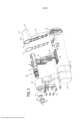
[003] A Figura 1 é uma vista desmontada em perspectiva de um sistema cirúrgico eletromecânico incluindo um instrumento cirúrgico, um adaptador e um atuador de extremidade, de acordo com a presente descrição;[003] Figure 1 is a disassembled perspective view of an electromechanical surgical system including a surgical instrument, an adapter and an end actuator, in accordance with the present description;
[004] A Figura 2 é uma vista em perspectiva do instrumento cirúrgico da Figura 1, de acordo com ao menos um aspecto da presente descrição;[004] Figure 2 is a perspective view of the surgical instrument of Figure 1, in accordance with at least one aspect of the present description;
[005] A Figura 3 é uma vista explodida em perspectiva do instrumento cirúrgico da Figura 1, de acordo com ao menos um aspecto da presente descrição;[005] Figure 3 is an exploded perspective view of the surgical instrument of Figure 1, in accordance with at least one aspect of the present description;
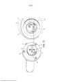
[006] A Figura 4 é uma vista em perspectiva de uma bateria do instrumento cirúrgico da Figura 1, de acordo com ao menos um aspecto da presente descrição;[006] Figure 4 is a perspective view of a battery of the surgical instrument of Figure 1, in accordance with at least one aspect of the present description;
[007] A Figura 5 é uma vista superior parcialmente desmontada do instrumento cirúrgico da Figura 1, de acordo com ao menos um aspecto da presente descrição;[007] Figure 5 is a partially disassembled top view of the surgical instrument of Figure 1, in accordance with at least one aspect of the present disclosure;
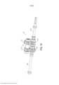
[008] A Figura 6 é uma vista frontal em perspectiva do instrumento cirúrgico da Figura 1 com o adaptador separado do mesmo, de acordo com ao menos um aspecto da presente descrição;[008] Figure 6 is a perspective front view of the surgical instrument of Figure 1 with the adapter separated therefrom, in accordance with at least one aspect of the present description;
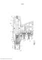
[009] A Figura 7 é uma vista lateral em seção transversal do instrumento cirúrgico da Figura 1, tomada de 7 a 7 da Figura 2, de acordo com ao menos um aspecto da presente descrição;[009] Figure 7 is a side view in cross section of the surgical instrument of Figure 1, taken from 7 to 7 of Figure 2, in accordance with at least one aspect of the present description;
[0010] A Figura 8 é uma vista superior em seção transversal do instrumento cirúrgico da Figura 1, tomada de 8 a 8 da Figura 2, de acordo com ao menos um aspecto da presente descrição;[0010] Figure 8 is a top view in cross section of the surgical instrument of Figure 1, taken at 8 to 8 of Figure 2, in accordance with at least one aspect of the present description;
[0011] A Figura 9 é uma vista explodida em perspectiva de um atuador de extremidade da Figura 1, de acordo com ao menos um aspecto da presente descrição;[0011] Figure 9 is an exploded perspective view of an end actuator of Figure 1, in accordance with at least one aspect of the present description;
[0012] A Figura 10A é uma vista superior de um membro de travamento, de acordo com ao menos um aspecto da presente descrição;[0012] Figure 10A is a top view of a locking member in accordance with at least one aspect of the present disclosure;
[0013] A Figura 10B é uma vista em perspectiva do membro de travamento da Figura 10A, de acordo com ao menos um aspecto da presente descrição;[0013] Figure 10B is a perspective view of the locking member of Figure 10A, in accordance with at least one aspect of the present description;
[0014] A Figura 11 é um diagrama esquemático do instrumento cirúrgico da Figura 1, de acordo com ao menos um aspecto da presente descrição;[0014] Figure 11 is a schematic diagram of the surgical instrument of Figure 1, in accordance with at least one aspect of the present description;
[0015] A Figura 12 é uma vista em perspectiva, com peças separadas, de um sistema cirúrgico eletromecânico, de acordo com ao menos um aspecto da presente descrição;[0015] Figure 12 is a perspective view, with separate parts, of an electromechanical surgical system, in accordance with at least one aspect of the present description;
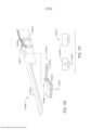
[0016] A Figura 13 é uma vista traseira em perspectiva de um conjunto de eixo de acionamento e um instrumento cirúrgico equipado com motor, do sistema cirúrgico eletromecânico da Figura 12, ilustrando uma conexão entre os mesmos, de acordo com ao menos um aspecto da presente descrição;[0016] Figure 13 is a perspective rear view of a drive shaft assembly and a surgical instrument equipped with a motor, of the electromechanical surgical system of Figure 12, illustrating a connection between them, according to at least one aspect of the present description;
[0017] A Figura 14 é uma vista em perspectiva, com peças separadas, do conjunto de eixo de acionamento da Figura 13, de acordo com ao menos um aspecto da presente descrição;[0017] Figure 14 is a perspective view, with parts broken away, of the drive shaft assembly of Figure 13, in accordance with at least one aspect of the present description;
[0018] A Figura 15 é uma vista em perspectiva, com peças separadas, de uma caixa de transmissão do conjunto de eixo de acionamento da Figura 13, de acordo com ao menos um aspecto da presente descrição;[0018] Figure 15 is a perspective view, with separate parts, of a gearbox of the drive shaft assembly of Figure 13, in accordance with at least one aspect of the present description;
[0019] A Figura 16 é uma vista em perspectiva de um primeiro sistema de trem de engrenagem que é apoiado na caixa de transmissão da Figura 15, de acordo com ao menos um aspecto da presente descrição;[0019] Figure 16 is a perspective view of a first gear train system that is supported on the gearbox of Figure 15, in accordance with at least one aspect of the present description;
[0020] A Figura 17 é uma vista em perspectiva de um segundo sistema de trem de engrenagem que é apoiado na caixa de transmissão da Figura 15, de acordo com ao menos um aspecto da presente descrição;[0020] Figure 17 is a perspective view of a second gear train system that is supported on the gearbox of Figure 15, in accordance with at least one aspect of the present description;
[0021] A Figura 18 é uma vista em perspectiva de um terceiro eixo de acionamento que é apoiado na caixa de transmissão da Figura 15, de acordo com ao menos um aspecto da presente descrição;[0021] Figure 18 is a perspective view of a third drive shaft that is supported in the gearbox of Figure 15, in accordance with at least one aspect of the present description;
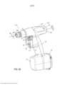
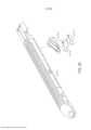
[0022] A Figura 19 é uma vista em perspectiva de um instrumento cirúrgico, de acordo com ao menos um aspecto da presente descrição;[0022] Figure 19 is a perspective view of a surgical instrument, in accordance with at least one aspect of the present description;
[0023] A Figura 19A é uma vista superior do instrumento cirúrgico da Figura 19, de acordo com ao menos um aspecto da presente descrição;[0023] Figure 19A is a top view of the surgical instrument of Figure 19, in accordance with at least one aspect of the present description;
[0024] A Figura 20 é um diagrama de circuito de vários componentes do instrumento cirúrgico da Figura 20, de acordo com ao menos um aspecto da presente descrição;[0024] Figure 20 is a circuit diagram of various components of the surgical instrument of Figure 20, in accordance with at least one aspect of the present description;
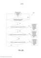
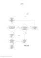
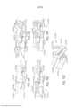
[0025] A Figura 21 é um diagrama lógico que inclui etapas para responder a falhas no trem de acionamento do instrumento cirúrgico da Figura 19, de acordo com ao menos um aspecto da presente descrição;[0025] Figure 21 is a logic diagram that includes steps to respond to failures in the drive train of the surgical instrument of Figure 19, in accordance with at least one aspect of the present description;
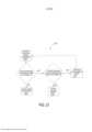
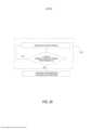
[0026] A Figura 22 é um diagrama lógico de um modo de segurança do instrumento cirúrgico da Figura 19, de acordo com ao menos um aspecto da presente descrição;[0026] Figure 22 is a logic diagram of a security mode of the surgical instrument of Figure 19, in accordance with at least one aspect of the present description;
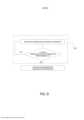
[0027] A Figura 22A é um diagrama lógico que inclui etapas para responder a falhas no trem de acionamento do instrumento cirúrgico da Figura 19, de acordo com ao menos um aspecto da presente descrição;[0027] Figure 22A is a logic diagram that includes steps to respond to failures in the drive train of the surgical instrument of Figure 19, in accordance with at least one aspect of the present description;
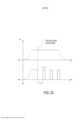
[0028] A Figura 23 é um gráfico que contorna uma modulação do motor no modo de segurança da Figura 22, de acordo com ao menos um aspecto da presente descrição;[0028] Figure 23 is a graph contouring a motor modulation in the safe mode of Figure 22, in accordance with at least one aspect of the present description;
[0029] A Figura 23A é um gráfico que contorna uma modulação do motor no modo de segurança da Figura 22, de acordo com ao menos um aspecto da presente descrição;[0029] Figure 23A is a graph contouring a motor modulation in the safe mode of Figure 22, in accordance with at least one aspect of the present description;
[0030] A Figura 24 é um diagrama lógico que inclui etapas para responder a falhas no trem de acionamento do instrumento cirúrgico da Figura 19, de acordo com ao menos um aspecto da presente descrição;[0030] Figure 24 is a logic diagram that includes steps to respond to failures in the drive train of the surgical instrument of Figure 19, in accordance with at least one aspect of the present description;
[0031] A Figura 25 é um diagrama lógico de um modo de resgate do instrumento cirúrgico da Figura 19, de acordo com ao menos um aspecto da presente descrição;[0031] Figure 25 is a logic diagram of a mode of rescue of the surgical instrument of Figure 19, in accordance with at least one aspect of the present description;
[0032] A Figura 26A é uma vista em perspectiva parcial de um instrumento cirúrgico, de acordo com ao menos um aspecto da presente descrição;[0032] Figure 26A is a partial perspective view of a surgical instrument, in accordance with at least one aspect of the present description;
[0033] A Figura 26B é uma vista em perspectiva de uma unidade de alimentação do instrumento cirúrgico da Figura 26A, de acordo com ao menos um aspecto da presente descrição;[0033] Figure 26B is a perspective view of a supply unit of the surgical instrument of Figure 26A, in accordance with at least one aspect of the present description;
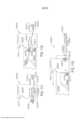
[0034] A Figura 27 é um diagrama lógico que ilustra um método para avaliar a integridade da unidade de alimentação da Figura 26B e responder a uma queda detectada na integridade da unidade de alimentação, de acordo com ao menos um aspecto da presente descrição;[0034] Figure 27 is a logic diagram illustrating a method for evaluating the integrity of the power supply unit of Figure 26B and responding to a detected drop in power unit integrity, in accordance with at least one aspect of the present description;
[0035] A Figura 28 é um diagrama lógico de um módulo do instrumento cirúrgico da Figura 26A, de acordo com ao menos um aspecto da presente descrição;[0035] Figure 28 is a logic diagram of a module of the surgical instrument of Figure 26A, in accordance with at least one aspect of the present disclosure;
[0036] A Figura 29 é um diagrama lógico das etapas do método da Figura 27, de acordo com ao menos um aspecto da presente descrição;[0036] Figure 29 is a logic diagram of the steps of the method of Figure 27, in accordance with at least one aspect of the present description;
[0037] A Figura 30 é um diagrama lógico das etapas do método da Figura 27, de acordo com ao menos um aspecto da presente descrição;[0037] Figure 30 is a logic diagram of the steps of the method of Figure 27, in accordance with at least one aspect of the present description;
[0038] A Figura 31 é um diagrama lógico das etapas do método da Figura 27, de acordo com ao menos um aspecto da presente descrição;[0038] Figure 31 is a logic diagram of the steps of the method of Figure 27, in accordance with at least one aspect of the present description;
[0039] A Figura 32 é um diagrama de circuito de um módulo do instrumento cirúrgico da Figura 26A, de acordo com ao menos um aspecto da presente descrição;[0039] Figure 32 is a circuit diagram of a module of the surgical instrument of Figure 26A, in accordance with at least one aspect of the present description;
[0040] A Figura 33 é um circuito de ponte de Wheatstone, de acordo com ao menos um aspecto da presente descrição;[0040] Figure 33 is a Wheatstone bridge circuit, in accordance with at least one aspect of the present description;
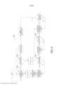
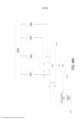
[0041] A Figura 34 é um circuito de controle eletrônico acoplado a uma pluralidade de células de bateria dispostas em série, de acordo com ao menos um aspecto da presente descrição;[0041] Figure 34 is an electronic control circuit coupled to a plurality of battery cells arranged in series, in accordance with at least one aspect of the present description;
[0042] A Figura 35 é um diagrama lógico para avaliar o estado de integridade de uma unidade de alimentação com base nas leituras de sensor, de acordo com ao menos um aspecto da presente descrição;[0042] Figure 35 is a logic diagram for evaluating the health status of a power supply unit based on sensor readings, in accordance with at least one aspect of the present description;
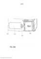
[0043] A Figura 36 é uma vista em perspectiva de um instrumento cirúrgico, de acordo com ao menos um aspecto da presente descrição;[0043] Figure 36 is a perspective view of a surgical instrument, in accordance with at least one aspect of the present description;
[0044] A Figura 36A é uma vista superior do instrumento cirúrgico da Figura 36, de acordo com ao menos um aspecto da presente descrição;[0044] Figure 36A is a top view of the surgical instrument of Figure 36, in accordance with at least one aspect of the present description;
[0045] A Figura 36B é uma vista explodida parcial do instrumento cirúrgico da Figura 36, de acordo com ao menos um aspecto da presente descrição;[0045] Figure 36B is a partial exploded view of the surgical instrument of Figure 36, in accordance with at least one aspect of the present disclosure;
[0046] A Figura 37 é uma vista em perspectiva de um cartucho do motor, de acordo com ao menos um aspecto da presente descrição;[0046] Figure 37 is a perspective view of an engine cartridge, in accordance with at least one aspect of the present description;
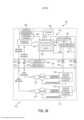
[0047] A Figura 38 é um diagrama de circuito de vários componentes do instrumento cirúrgico da Figura 37, de acordo com ao menos um aspecto da presente descrição;[0047] Figure 38 is a circuit diagram of various components of the surgical instrument of Figure 37, in accordance with at least one aspect of the present description;
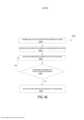
[0048] A Figura 39 é um diagrama lógico que define um método para monitoramento da integridade de um cartucho de motor, de acordo com ao menos um aspecto da presente descrição;[0048] Figure 39 is a logic diagram that defines a method for monitoring the integrity of an engine cartridge, according to at least one aspect of the present description;
[0049] A Figura 40 é um diagrama lógico que define um método que emprega um sensor de corrente para monitorar a integridade de um cartucho de motor, de acordo com ao menos um aspecto da presente descrição;[0049] Figure 40 is a logic diagram defining a method that employs a current sensor to monitor the integrity of an engine cartridge, in accordance with at least one aspect of the present description;
[0050] A Figura 41 é um diagrama lógico que define um módulo do instrumento cirúrgico da Figura 37, de acordo com ao menos um aspecto da presente descrição;[0050] Figure 41 is a logic diagram defining a module of the surgical instrument of Figure 37, in accordance with at least one aspect of the present description;
[0051] A Figura 42 é um diagrama lógico que define um módulo do instrumento cirúrgico da Figura 37, de acordo com ao menos um aspecto da presente descrição;[0051] Figure 42 is a logic diagram defining a module of the surgical instrument of Figure 37, in accordance with at least one aspect of the present description;
[0052] A Figura 43 é uma vista em perspectiva de um instrumento cirúrgico, de acordo com ao menos um aspecto da presente descrição;[0052] Figure 43 is a perspective view of a surgical instrument, in accordance with at least one aspect of the present disclosure;
[0053] A Figura 44 é um diagrama de circuito de vários componentes do instrumento cirúrgico da Figura 43, de acordo com ao menos um aspecto da presente descrição;[0053] Figure 44 is a circuit diagram of various components of the surgical instrument of Figure 43, in accordance with at least one aspect of the present disclosure;
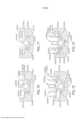
[0054] A Figura 45 é um diagrama de circuito que inclui um microfone em comunicação com uma pluralidade de filtros acoplados a uma pluralidade de portas lógicas de acordo com ao menos um aspecto da presente descrição;[0054] Figure 45 is a circuit diagram including a microphone in communication with a plurality of filters coupled to a plurality of logic gates in accordance with at least one aspect of the present description;
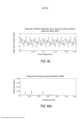
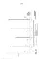
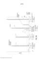
[0055] A Figura 46 é um gráfico de saída de um microfone em volts versus tempo em segundos, sendo que o gráfico representa uma resposta vibratória de um instrumento cirúrgico da Figura 43, que funciona adequadamente, registrado pelo microfone durante a operação do instrumento cirúrgico, de acordo com ao menos um aspecto da presente descrição;[0055] Figure 46 is a graph of output of a microphone in volts versus time in seconds, and the graph represents a vibratory response of a surgical instrument in Figure 43, which works properly, recorded by the microphone during the operation of the surgical instrument , in accordance with at least one aspect of the present description;
[0056] A Figura 46A é um sinal filtrado da saída do microfone da Figura 46, de acordo com ao menos um aspecto da presente descrição;[0056] Figure 46A is a filtered output signal from the microphone of Figure 46, in accordance with at least one aspect of the present description;
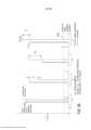
[0057] A Figura 47 é um gráfico de saída de um microfone em volts versus tempo em segundos, o gráfico representando uma resposta vibratória de um instrumento cirúrgico com defeito da Figura 43, registrado pelo microfone durante a operação do instrumento cirúrgico, de acordo com ao menos um aspecto da presente descrição;[0057] Figure 47 is a graph of output of a microphone in volts versus time in seconds, the graph representing a vibratory response of a defective surgical instrument in Figure 43, recorded by the microphone during the operation of the surgical instrument, according to at least one aspect of the present disclosure;
[0058] A Figura 47A é um sinal filtrado da saída do microfone da Figura 47, de acordo com ao menos um aspecto da presente descrição;[0058] Figure 47A is a filtered output signal from the microphone of Figure 47, in accordance with at least one aspect of the present description;
[0059] A Figura 48 é um diagrama de circuito que inclui um sensor do instrumento cirúrgico da Figura 43 acoplado a uma pluralidade de filtros em comunicação com um microcontrolador por meio de um multiplexador e um conversor analógico-digital, de acordo com ao menos um aspecto da presente descrição;[0059] Figure 48 is a circuit diagram that includes a sensor of the surgical instrument of Figure 43 coupled to a plurality of filters in communication with a microcontroller through a multiplexer and an analog-to-digital converter, according to at least one aspect of the present description;
[0060] A Figura 48A é um diagrama de circuito que inclui um sensor do instrumento cirúrgico da Figura 43 acoplado a uma pluralidade de filtros em comunicação com um microcontrolador por meio de um multiplexador e um conversor analógico-digital, de acordo com ao menos um aspecto da presente descrição;[0060] Figure 48A is a circuit diagram that includes a sensor of the surgical instrument of Figure 43 coupled to a plurality of filters in communication with a microcontroller through a multiplexer and an analog-to-digital converter, according to at least one aspect of the present description;
[0061] As Figuras de 48B a 48D ilustram características estruturais e operacionais de um filtro de passagem de banda do instrumento cirúrgico da Figura 43, de acordo com ao menos um aspecto da presente descrição;[0061] Figures 48B to 48D illustrate structural and operational features of a bandpass filter of the surgical instrument of Figure 43, in accordance with at least one aspect of the present description;
[0062] A Figura 49 é um gráfico que representa um sinal filtrado de uma saída de sensor do instrumento cirúrgico da Figura 43, de acordo com ao menos um aspecto da presente descrição;[0062] Figure 49 is a graph representing a filtered signal from a sensor output of the surgical instrument of Figure 43, in accordance with at least one aspect of the present description;
[0063] A Figura 50 é um gráfico que representa um sinal processado de uma saída de sensor do instrumento cirúrgico da Figura 43, de acordo com ao menos um aspecto da presente descrição;[0063] Figure 50 is a graph representing a processed signal from a sensor output of the surgical instrument of Figure 43, in accordance with at least one aspect of the present description;
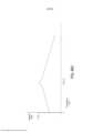
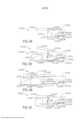
[0064] A Figura 51 é um gráfico que representa a força necessária para disparar (FTF) o instrumento cirúrgico da Figura 43 em relação a uma posição de deslocamento de um conjunto de acionamento do instrumento cirúrgico a partir de uma posição inicial, de acordo com ao menos um aspecto da presente descrição;[0064] Figure 51 is a graph representing the force required to trigger (FTF) the surgical instrument of Figure 43 in relation to a displacement position of a surgical instrument trigger assembly from an initial position, according to at least one aspect of the present description;
[0065] A Figura 52 é um gráfico que representa a velocidade de um conjunto de acionamento do instrumento cirúrgico da Figura 43, durante um curso de disparo, em relação à posição de deslocamento do conjunto de acionamento a partir de uma posição inicial, de acordo com ao menos um aspecto da presente descrição;[0065] Figure 52 is a graph representing the speed of a drive assembly of the surgical instrument in Figure 43, during a firing stroke, in relation to the displacement position of the drive assembly from an initial position, according to with at least one aspect of the present disclosure;
[0066] A Figura 53 é um gráfico que representa uma modificação de limite aceitável com base na zona de localização do curso durante um curso de disparo do instrumento cirúrgico da Figura 43, de acordo com ao menos um aspecto da presente descrição;[0066] Figure 53 is a graph representing an acceptable threshold modification based on the stroke location zone during a firing stroke of the surgical instrument of Figure 43, in accordance with at least one aspect of the present description;
[0067] A Figura 54 é um gráfico que representa um sinal processado da saída de um sensor do instrumento cirúrgico da Figura 43 mostrando um deslocamento na resposta de frequência do sinal processado devido a alterações de carga e velocidade experimentadas por um conjunto de acionamento durante um curso de disparo, de acordo com ao menos um aspecto da presente descrição;[0067] Figure 54 is a graph representing a processed signal from the output of a sensor of the surgical instrument of Figure 43 showing a shift in the frequency response of the processed signal due to changes in load and speed experienced by a drive assembly during a firing stroke, in accordance with at least one aspect of the present disclosure;
[0068] A Figura 55 é um gráfico que representa um sinal processado de vibrações capturadas por um sensor do instrumento cirúrgico da Figura 43 durante uma zona de operação, sendo que o gráfico ilustra um limite aceitável, limite marginal e limite crítico para a zona de operação, de acordo com ao menos um aspecto da presente descrição;[0068] Figure 55 is a graph representing a processed signal of vibrations captured by a sensor of the surgical instrument of Figure 43 during an operation zone, and the graph illustrates an acceptable limit, marginal limit and critical limit for the zone of operation operation, in accordance with at least one aspect of the present disclosure;
[0069] A Figura 56 é um diagrama lógico do instrumento cirúrgico da Figura 43, de acordo com ao menos um aspecto da presente descrição;[0069] Figure 56 is a logic diagram of the surgical instrument of Figure 43, in accordance with at least one aspect of the present description;
[0070] A Figura 57 é um gráfico que representa um sinal processado de vibrações capturadas por um sensor do instrumento cirúrgico da Figura 43, de acordo com ao menos um aspecto da presente descrição;[0070] Figure 57 is a graph representing a processed signal of vibrations captured by a sensor of the surgical instrument of Figure 43, in accordance with at least one aspect of the present description;
[0071] A Figura 58 é um gráfico que representa um sinal processado de vibrações capturadas por um sensor do instrumento cirúrgico da Figura 43, de acordo com ao menos um aspecto da presente descrição;[0071] Figure 58 is a graph representing a processed signal of vibrations captured by a sensor of the surgical instrument of Figure 43, in accordance with at least one aspect of the present description;
[0072] A Figura 59 é um gráfico que representa um sinal processado de vibrações capturadas por um sensor do instrumento cirúrgico da Figura 43, de acordo com ao menos um aspecto da presente descrição;[0072] Figure 59 is a graph representing a processed signal of vibrations captured by a sensor of the surgical instrument of Figure 43, in accordance with at least one aspect of the present description;
[0073] A Figura 60 é uma vista em perspectiva de um sistema de instrumento cirúrgico de acordo com ao menos uma modalidade;[0073] Figure 60 is a perspective view of a surgical instrument system according to at least one embodiment;
[0074] A Figura 61 é uma vista em perspectiva de uma porção de um conjunto de disparo acionado por rotação e de um deslizador de um cartucho de grampos cirúrgicos no qual o deslizador está em uma posição inicial e o conjunto de disparo está em uma primeira posição "destravada" de acordo com pelo menos uma modalidade;[0074] Figure 61 is a perspective view of a portion of a firing assembly driven by rotation and a slider of a surgical staple cartridge in which the slider is in a starting position and the firing set is in a first "unlocked" position according to at least one embodiment;
[0075] A Figura 62 é outra vista em perspectiva da porção da modalidade de conjunto de disparo acionado por rotação da Figura 61 em uma segunda posição "travada", sendo que o deslizador não está na posição inicial;[0075] Figure 62 is another perspective view of the portion of the rotation-actuated firing assembly embodiment of Figure 61 in a second "locked" position, the slider not being in the initial position;
[0076] A Figura 63 é uma vista em elevação lateral de um cartucho de grampos cirúrgicos que é inicialmente instalado em um atuador de extremidade cirúrgico que é configurado para cortar e grampear tecido de acordo com pelo menos uma modalidade;[0076] Figure 63 is a side elevation view of a surgical staple cartridge that is initially installed in a surgical end actuator that is configured to cut and staple tissue according to at least one embodiment;
[0077] A Figura 64 é outra vista em elevação lateral do cartucho de grampos cirúrgicos assentado no canal do atuador de extremidade cirúrgico da Figura 63, sendo que o deslizador do cartucho de grampos cirúrgicos está em uma posição inicial e em engate com o elemento de disparo do instrumento cirúrgico;[0077] Figure 64 is another side elevation view of the surgical staple cartridge seated in the channel of the surgical end actuator of Figure 63, with the slider of the surgical staple cartridge being in an initial position and in engagement with the element of firing of the surgical instrument;
[0078] A Figura 65 é outra vista em elevação lateral de um cartucho de grampos cirúrgicos parcialmente usado, assentado no canal do atuador de extremidade cirúrgico da Figura 63, sendo que o deslizador do cartucho de grampos cirúrgicos não está em uma posição inicial;[0078] Figure 65 is another side elevation view of a partially used surgical staple cartridge, seated in the surgical end actuator channel of Figure 63, with the surgical staple cartridge slider not in a home position;
[0079] A Figura 66 é uma vista em perspectiva de uma porção de um conjunto de disparo acionado por rotação e canal de um atuador de extremidade de corte e grampeamento cirúrgico, sendo que o conjunto de disparo está em uma posição "travada" de acordo com ao menos uma modalidade;[0079] Figure 66 is a perspective view of a portion of a rotation-actuated trigger assembly and channel of a surgical cutting and stapling end actuator, the trigger assembly being in a "locked" position in accordance with with at least one modality;
[0080] A Figura 67 é outra vista em perspectiva de uma porção do conjunto de disparo acionado por rotação da Figura 66 e um deslizador de um cartucho de grampos cirúrgicos, sendo que o deslizador está em uma posição inicial e o conjunto de disparo está em uma posição "destravada";[0080] Figure 67 is another perspective view of a portion of the trigger assembly triggered by rotation of Figure 66 and a slider of a surgical staple cartridge, the slider being in a home position and the trigger assembly being in an "unlocked" position;
[0081] A Figura 68 é uma vista em perspectiva de uma porção de porca rosqueada, de acordo com ao menos uma modalidade;[0081] Figure 68 is a perspective view of a threaded nut portion, according to at least one embodiment;
[0082] A Figura 69 é uma vista em perspectiva da porção de porca rosqueada da Figura 68 sendo instalado em uma modalidade de canal correspondente mostrada em seção transversal;[0082] Figure 69 is a perspective view of the threaded nut portion of Figure 68 being installed in a corresponding channel embodiment shown in cross section;
[0083] A Figura 70 é uma vista em elevação em seção transversal de um canal e porção de porca rosqueada da Figura 69 com a porção de porca rosqueada em uma posição travada;[0083] Figure 70 is an elevation view in cross section of a channel and threaded nut portion of Figure 69 with the threaded nut portion in a locked position;
[0084] A Figura 71 é outra vista em elevação em seção transversal da porção de canal e porca rosqueada das Figuras 69 e 70 com a porção de porca em uma posição destravada;[0084] Figure 71 is another cross-sectional elevation view of the channel and threaded nut portion of Figures 69 and 70 with the nut portion in an unlocked position;
[0085] A Figura 72 é outra vista em elevação em seção transversal da porção de canal e porca rosqueada das Figuras de 69 a 71 com a porção de porca rosqueada em uma posição travada e ilustrando a instalação inicial de um deslizador de um cartucho de grampos cirúrgicos no canal com o corpo do cartucho omitido para maior clareza;[0085] Figure 72 is another cross-sectional elevation view of the channel and threaded nut portion of Figures 69 to 71 with the threaded nut portion in a locked position and illustrating the initial installation of a staple cartridge slider surgical in-channel with cartridge body omitted for clarity;
[0086] A Figura 73 é outra vista em elevação em seção transversal do canal, porção de porca rosqueada e do deslizador da Figura 72, com o deslizador instalado de modo a mover a porção de porca para a posição destravada;[0086] Figure 73 is another elevation view in cross section of the channel, threaded nut portion and the slider of Figure 72, with the slider installed in order to move the nut portion to the unlocked position;
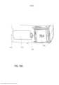
[0087] A Figura 74 é uma vista em elevação lateral em seção transversal de um atuador de extremidade de corte e grampeamento cirúrgico, de acordo com ao menos uma modalidade;[0087] Figure 74 is a side elevation view in cross section of a surgical cutting and stapling end actuator, according to at least one embodiment;
[0088] A Figura 75 é uma vista de conjunto em perspectiva explodida de um conjunto de bigorna do atuador de extremidade cirúrgico da Figura 74;[0088] Figure 75 is an exploded perspective assembly view of an anvil assembly of the surgical end actuator of Figure 74;
[0089] A Figura 76 é uma vista em seção transversal do conjunto de bigorna da Figura 75;[0089] Figure 76 is a cross-sectional view of the anvil assembly of Figure 75;
[0090] A Figura 77 é uma vista em seção transversal do atuador de extremidade cirúrgico da Figura 74 com um conjunto de elemento de disparo do mesmo em uma posição travada;[0090] Figure 77 is a cross-sectional view of the surgical end actuator of Figure 74 with a trigger assembly thereof in a locked position;
[0091] A Figura 78 é outra vista em seção transversal do atuador de extremidade cirúrgico da Figura 77 tomada em uma extremidade proximal do mesmo com o conjunto do elemento de disparo em uma posição destravada;[0091] Figure 78 is another cross-sectional view of the surgical end actuator of Figure 77 taken at a proximal end thereof with the trigger assembly in an unlocked position;
[0092] A Figura 79 é outra vista em seção transversal do atuador de extremidade cirúrgico da Figura 77 tomada em uma posição que é distal à vista da Figura 78;[0092] Figure 79 is another cross-sectional view of the surgical end actuator of Figure 77 taken in a position that is distal to the view of Figure 78;
[0093] A Figura 80 é uma vista em perspectiva de um instrumento de grampeamento cirúrgico que compreende um cabo e uma unidade de carregamento substituível, de acordo com ao menos uma modalidade;[0093] Figure 80 is a perspective view of a surgical stapling instrument comprising a handle and a replaceable loading unit, according to at least one embodiment;
[0094] A Figura 81 é uma vista em perspectiva da unidade de carregamento da Figura 80 ilustrada com uma garra de cartucho de grampos separada da unidade de carregamento;[0094] Figure 81 is a perspective view of the loading unit of Figure 80 illustrated with a staple cartridge gripper separate from the loading unit;
[0095] A Figura 82 é uma vista em perspectiva de um instrumento de grampeamento cirúrgico que inclui um cabo e uma unidade de carregamento substituível, de acordo com ao menos uma modalidade;[0095] Figure 82 is a perspective view of a surgical stapling instrument including a handle and a replaceable loading unit, according to at least one embodiment;
[0096] A Figura 83 é uma vista em perspectiva da unidade de carregamento da Figura 82;[0096] Figure 83 is a perspective view of the charging unit of Figure 82;
[0097] A Figura 84 ilustra as porções de conexão do cabo e da unidade de carregamento da Figura 82;[0097] Figure 84 illustrates the connection portions of the cable and the charging unit of Figure 82;
[0098] A Figura 85 é uma vista em seção transversal de um atuador de extremidade da unidade de carregamento da Figura 80;[0098] Figure 85 is a cross-sectional view of an end actuator of the loading unit of Figure 80;
[0099] A Figura 86 é uma vista detalhada da fixação entre a garra do cartucho de grampos e uma estrutura da unidade de carregamento de grampos da Figura 80;[0099] Figure 86 is a detailed view of the attachment between the staple cartridge claw and a structure of the staple loading unit of Figure 80;
[00100] A Figura 87 é uma vista em seção transversal de um atuador de extremidade de uma unidade de carregamento de acordo com pelo menos uma modalidade;[00100] Figure 87 is a cross-sectional view of an end actuator of a loading unit according to at least one embodiment;
[00101] A Figura 88 é uma vista detalhada da fixação entre um cartucho de grampos e uma estrutura de garra da unidade de carregamento da Figura 87;[00101] Figure 88 is a detailed view of the attachment between a staple cartridge and a claw structure of the loading unit of Figure 87;
[00102] A Figura 89 é uma vista em perspectiva da estrutura da unidade de carregamento da Figura 87;[00102] Figure 89 is a perspective view of the structure of the charging unit of Figure 87;
[00103] A Figura 90 é uma vista detalhada da extremidade proximal da garra do cartucho de grampos da Figura 87;[00103] Figure 90 is a detailed view of the proximal end of the staple cartridge claw of Figure 87;
[00104] A Figura 91 é uma vista detalhada que ilustra a conexão entre a estrutura e a garra do cartucho de grampos da Figura 87;[00104] Figure 91 is a detailed view illustrating the connection between the structure and the staple cartridge claw of Figure 87;
[00105] A Figura 92 é uma vista explodida de uma garra do cartucho de grampos, de acordo com ao menos uma modalidade;[00105] Figure 92 is an exploded view of a staple cartridge claw, according to at least one embodiment;
[00106] A Figura 93 é uma vista em perspectiva parcial de uma unidade de carregamento, de acordo com ao menos uma modalidade;[00106] Figure 93 is a partial perspective view of a charging unit, according to at least one embodiment;
[00107] A Figura 94 é uma vista em elevação parcial de uma estrutura de uma unidade de carregamento de acordo com ao menos uma modalidade ilustrada sem uma garra do cartucho de grampos fixada à mesma;[00107] Figure 94 is a partial elevation view of a structure of a loading unit according to at least one illustrated embodiment without a staple cartridge claw attached to it;
[00108] A Figura 95 é uma vista em elevação parcial de uma garra do cartucho de grampos fixada à estrutura da unidade de carregamento da Figura 94;[00108] Figure 95 is a partial elevation view of a staple cartridge claw attached to the loading unit structure of Figure 94;
[00109] A Figura 96 é uma vista em elevação parcial da unidade de carregamento da Figura 94 ilustrada em uma configuração presa;[00109] Figure 96 is a partial elevation view of the loading unit of Figure 94 illustrated in a trapped configuration;
[00110] A Figura 97 é uma vista em elevação parcial da unidade de carregamento da Figura 94 ilustrada em uma configuração parcialmente disparada;[00110] Figure 97 is a partial elevation view of the charging unit of Figure 94 illustrated in a partially fired configuration;
[00111] A Figura 98 é uma vista em elevação parcial de uma estrutura de uma unidade de carregamento de acordo com ao menos uma modalidade ilustrada sem uma garra do cartucho de grampos fixada à mesma;[00111] Figure 98 is a partial elevation view of a structure of a loading unit according to at least one illustrated embodiment without a staple cartridge claw attached to it;
[00112] A Figura 99 é uma vista em elevação parcial de uma garra do cartucho de grampos fixada à estrutura da unidade de carregamento da Figura 98;[00112] Figure 99 is a partial elevation view of a staple cartridge claw attached to the loading unit structure of Figure 98;
[00113] A Figura 100 é uma vista em elevação parcial da unidade de carregamento da Figura 98 ilustrada em uma configuração presa;[00113] Figure 100 is a partial elevation view of the loading unit of Figure 98 illustrated in a trapped configuration;
[00114] A Figura 101 é uma vista em elevação parcial da unidade de carregamento da Figura 98 ilustrada em uma configuração parcialmente disparada;[00114] Figure 101 is a partial elevation view of the charging unit of Figure 98 illustrated in a partially fired configuration;
[00115] A Figura 102 é uma vista em perspectiva parcial da unidade de carregamento da Figura 98 ilustrada com uma garra do cartucho de grampos fixada à estrutura;[00115] Figure 102 is a partial perspective view of the loading unit of Figure 98 illustrated with a staple cartridge claw attached to the structure;
[00116] A Figura 103 é uma vista em perspectiva parcial de uma garra do cartucho de grampos fixada a uma estrutura de uma unidade de carregamento, de acordo com ao menos uma modalidade;[00116] Figure 103 is a partial perspective view of a staple cartridge gripper attached to a frame of a loading unit, according to at least one embodiment;
[00117] A Figura 104 é uma vista em elevação parcial de uma tentativa de fixar a garra do cartucho de grampos da Figura 103 a uma unidade de carregamento configurada para receber uma garra do cartucho de grampos diferente;[00117] Figure 104 is a partial elevation view of an attempt to attach the staple cartridge grip of Figure 103 to a loading unit configured to receive a different staple cartridge grip;
[00118] A Figura 105 é uma vista em elevação parcial da garra do cartucho de grampos da Figura 103 fixada à estrutura da unidade de carregamento da Figura 103;[00118] Figure 105 is a partial elevation view of the claw of the staple cartridge of Figure 103 attached to the structure of the loading unit of Figure 103;
[00119] A Figura 106 é uma vista em elevação parcial de uma conexão entre uma garra do cartucho de grampos e uma estrutura de uma unidade de carregamento, de acordo com pelo menos uma modalidade;[00119] Figure 106 is a partial elevation view of a connection between a claw of the staple cartridge and a structure of a loading unit, according to at least one embodiment;
[00120] A Figura 107 é uma vista em elevação parcial da unidade de carregamento da Figura 106;[00120] Figure 107 is a partial elevation view of the loading unit of Figure 106;
[00121] A Figura 108 é uma vista em elevação parcial de uma garra do cartucho de grampos configurada para ser usada com uma unidade de carregamento diferente além da unidade de carregamento da Figura 106 fixada à unidade de carregamento da Figura 106;[00121] Figure 108 is a partial elevation view of a staple cartridge gripper configured to be used with a different loading unit in addition to the loading unit of Figure 106 attached to the loading unit of Figure 106;
[00122] A Figura 109 é uma vista em elevação parcial de um sistema de instrumento cirúrgico que compreende uma disposição de travamento defletível ilustrada em uma configuração travada;[00122] Figure 109 is a partial elevation view of a surgical instrument system comprising a deflectable locking arrangement illustrated in a locked configuration;
[00123] A Figura 110 é uma vista em elevação parcial do sistema de instrumento cirúrgico da Figura 109, sendo que a disposição de travamento é ilustrada em uma configuração destravada;[00123] Figure 110 is a partial elevation view of the surgical instrument system of Figure 109, with the locking arrangement illustrated in an unlocked configuration;
[00124] A Figura 111 é uma vista em elevação parcial de um sistema de instrumento cirúrgico que compreende uma disposição de bloqueio magnética ilustrada em uma configuração travada;[00124] Figure 111 is a partial elevation view of a surgical instrument system comprising a magnetic locking arrangement illustrated in a locked configuration;
[00125] A Figura 112 é uma vista em elevação parcial do sistema de instrumento cirúrgico da Figura 111, sendo que a disposição de bloqueio magnética é ilustrada em uma configuração destravada;[00125] Figure 112 is a partial elevation view of the surgical instrument system of Figure 111, with the magnetic locking arrangement illustrated in an unlocked configuration;
[00126] A Figura 113 é uma vista em elevação parcial do sistema de instrumento cirúrgico da Figura 111 ilustrado em uma configuração parcialmente disparada;[00126] Figure 113 is a partial elevation view of the surgical instrument system of Figure 111 illustrated in a partially fired configuration;
[00127] A Figura 114 é uma vista em perspectiva parcial de um cartucho de grampos para um sistema de instrumento cirúrgico, sendo que o cartucho de grampos compreende um acionador configurado para controlar uma disposição de bloqueio do sistema de instrumento cirúrgico;[00127] Figure 114 is a partial perspective view of a staple cartridge for a surgical instrument system, the staple cartridge comprising an actuator configured to control a locking arrangement of the surgical instrument system;
[00128] A Figura 115 é uma vista em perspectiva de um deslizador para uso com o cartucho da Figura 114;[00128] Figure 115 is a perspective view of a slider for use with the cartridge of Figure 114;
[00129] A Figura 116 é uma vista em perspectiva do acionador falso do cartucho de grampos da Figura 114;[00129] Figure 116 is a perspective view of the false trigger of the staple cartridge of Figure 114;
[00130] A Figura 117 é uma vista em elevação parcial do sistema de instrumento cirúrgico que utiliza o cartucho de grampos da Figura 114, sendo que o sistema de instrumento cirúrgico compreende uma disposição de bloqueio configurada para limitar o movimento de um elemento de disparo até que um cartucho de grampos seja carregado no sistema de instrumento cirúrgico;[00130] Figure 117 is a partial elevation view of the surgical instrument system that uses the staple cartridge of Figure 114, the surgical instrument system comprising a locking arrangement configured to limit the movement of a trigger element up to that a staple cartridge is loaded into the surgical instrument system;
[00131] A Figura 118 é uma vista em elevação parcial do sistema de instrumento cirúrgico da Figura 117, sendo que a disposição de bloqueio é ilustrada em uma configuração destravada;[00131] Figure 118 is a partial elevation view of the surgical instrument system of Figure 117, with the locking arrangement illustrated in an unlocked configuration;
[00132] A Figura 119 é uma vista em elevação parcial do sistema de instrumento cirúrgico da Figura 117 ilustrado em uma configuração parcialmente disparada;[00132] Figure 119 is a partial elevation view of the surgical instrument system of Figure 117 illustrated in a partially fired configuration;
[00133] A Figura 120 é uma vista em perspectiva parcial de um cartucho de grampos para uso com um sistema de instrumento cirúrgico, sendo que o sistema de instrumento cirúrgico compreende um circuito de bloqueio que compreende um elemento separável;[00133] Figure 120 is a partial perspective view of a staple cartridge for use with a surgical instrument system, the surgical instrument system comprising a lock circuit comprising a separable member;
[00134] A Figura 121 é uma vista plana em seção transversal do sistema de instrumento cirúrgico da Figura 120, sendo que o sistema de instrumento cirúrgico compreende adicionalmente um membro de bloqueio, sendo que o membro de bloqueio é ilustrado em uma posição destravada, e sendo que o circuito de bloqueio está em uma configuração fechada;[00134] Figure 121 is a plan view in cross section of the surgical instrument system of Figure 120, the surgical instrument system further comprising a locking member, the locking member being illustrated in an unlocked position, and wherein the blocking circuit is in a closed configuration;
[00135] A Figura 122 é uma vista plana em seção transversal do sistema de instrumento cirúrgico da Figura 120, sendo que o elemento de bloqueio é ilustrado em uma posição travada, e sendo que o circuito de bloqueio está em uma configuração aberta;[00135] Figure 122 is a plan view in cross-section of the surgical instrument system of Figure 120, in which the locking element is illustrated in a locked position, and in which the locking circuit is in an open configuration;
[00136] A Figura 123 é uma vista em perspectiva de um sistema de instrumento cirúrgico, sendo que o sistema de instrumento cirúrgico compreende uma disposição de bloqueio de circuito que compreende contatos elétricos posicionados em um deslizador para uso com um cartucho de grampos;[00136] Figure 123 is a perspective view of a surgical instrument system, the surgical instrument system comprising a circuit-locking arrangement comprising electrical contacts positioned on a slider for use with a staple cartridge;
[00137] A Figura 124 é uma vista em elevação parcial do sistema de instrumento cirúrgico da Figura 123;[00137] Figure 124 is a partial elevation view of the surgical instrument system of Figure 123;
[00138] A Figura 125 é uma vista em seção transversal parcial de um bloqueio do elemento de disparo ilustrando o bloqueio do elemento de disparo em uma configuração travada;[00138] Figure 125 is a partial cross-sectional view of a trigger lock illustrating the trigger lock in a locked configuration;
[00139] A Figura 126 é uma vista em seção transversal do bloqueio de elemento de disparo da Figura 125, tomada ao longo da linha 126-126 na Figura 125;[00139] Figure 126 is a cross-sectional view of the trigger lock of Figure 125, taken along line 126-126 in Figure 125;
[00140] A Figura 127 é uma vista em seção transversal parcial do bloqueio de elemento de disparo da Figura 125 que ilustra o bloqueio do elemento de disparo em uma configuração destravada;[00140] Figure 127 is a partial cross-sectional view of the trigger lock of Figure 125 illustrating the trigger lock in an unlocked configuration;
[00141] A Figura 128 é uma vista em seção transversal do bloqueio do elemento de disparo da Figura 125, tomada ao longo da linha 128-128 na Figura 127;[00141] Figure 128 is a cross-sectional view of the trigger lock of Figure 125, taken along line 128-128 in Figure 127;
[00142] A Figura 129 é uma vista plana em seção transversal do bloqueio do elemento de disparo da Figura 125, tomada ao longo da linha 129-129 na Figura 127;[00142] Figure 129 is a plan view in cross-section of the trigger lock of Figure 125, taken along line 129-129 in Figure 127;
[00143] A Figura 130 é uma vista em elevação parcial de um conjunto de grampeamento que compreende um cartucho de grampos não gastos, de acordo com ao menos uma modalidade;[00143] Figure 130 is a partial elevation view of a stapling assembly comprising an unused staple cartridge, according to at least one embodiment;
[00144] A Figura 131 é uma vista plana parcial do conjunto de grampeamento da Figura 130;[00144] Figure 131 is a partial plan view of the stapling assembly of Figure 130;
[00145] A Figura 132 é uma vista em elevação parcial do conjunto de grampeamento da Figura 130 ilustrado em uma condição gasta;[00145] Figure 132 is a partial elevation view of the stapling assembly of Figure 130 illustrated in a worn condition;
[00146] A Figura 133 é uma vista plana parcial do conjunto de grampeamento da Figura 130 ilustrado na condição da Figura 132;[00146] Figure 133 is a partial plan view of the clipping assembly of Figure 130 illustrated in the condition of Figure 132;
[00147] A Figura 134 é uma vista em perspectiva parcial de um conjunto grampeamento que compreende um acartucho de grampos não gastos, de acordo com ao menos uma modalidade;[00147] Figure 134 is a partial perspective view of a stapling assembly comprising an unused staple cartridge, according to at least one embodiment;
[00148] A Figura 135 é uma vista em perspectiva parcial do conjunto de grampeamento da Figura 134 ilustrada em sua condição gasta;[00148] Figure 135 is a partial perspective view of the stapling assembly of Figure 134 illustrated in its worn condition;
[00149] A Figura 136 é uma vista em perspectiva parcial de um conjunto de grampeamento ilustrado com componentes removidos com o propósito de ilustração;[00149] Figure 136 is a partial perspective view of a stapling assembly illustrated with components removed for the purpose of illustration;
[00150] A Figura 137 ilustra um pino do conjunto de grampeamento da Figura 136 configurado para afetar um circuito de detecção do conjunto de grampeamento;[00150] Figure 137 illustrates a pin of the clipping assembly of Figure 136 configured to affect a detection circuit of the clipping assembly;
[00151] A Figura 138 é uma vista em perspectiva parcial de certos componentes do conjunto de grampeamento da Figura 136;[00151] Figure 138 is a partial perspective view of certain components of the clipping assembly of Figure 136;
[00152] A Figura 139 é uma vista em perspectiva parcial de um compartimento de eixo de acionamento do conjunto de grampeamento da Figura 136;[00152] Figure 139 is a partial perspective view of a drive shaft housing of the clipping assembly of Figure 136;
[00153] A Figura 140 é uma vista plana parcial de um cartucho de grampos de acordo com ao menos uma modalidade;[00153] Figure 140 is a partial plan view of a staple cartridge according to at least one embodiment;
[00154] A Figura 140A ilustra um perfil de força de disparo que é experimentada ao disparar um cartucho de grampos em pelo menos uma modalidade;[00154] Figure 140A illustrates a firing force profile that is experienced when firing a staple cartridge in at least one embodiment;
[00155] A Figura 141 é uma vista em seção transversal parcial de um conjunto grampeamento que compreende um bloqueio, de acordo com ao menos uma modalidade;[00155] Figure 141 is a partial cross-sectional view of a clipping assembly comprising a lock, according to at least one embodiment;
[00156] A Figura 142 é uma vista em seção transversal parcial do conjunto de grampeamento da Figura 141 ilustrado em uma configuração bloqueada;[00156] Figure 142 is a partial cross-sectional view of the stapling assembly of Figure 141 illustrated in a locked configuration;
[00157] A Figura 143 é uma vista em seção transversal parcial de um conjunto de grampeamento que compreende um bloqueio, de acordo com ao menos uma modalidade;[00157] Figure 143 is a partial cross-sectional view of a stapling assembly comprising a lock, according to at least one embodiment;
[00158] A Figura 144 é uma vista em seção transversal parcial de um conjunto de grampeamento que compreende um bloqueio, de acordo com ao menos uma modalidade;[00158] Figure 144 is a partial cross-sectional view of a stapling assembly comprising a lock, according to at least one embodiment;
[00159] A Figura 145 é uma vista em seção transversal parcial de um conjunto de grampeamento que compreende um freio, de acordo com ao menos uma modalidade;[00159] Figure 145 is a partial cross-sectional view of a clipping assembly comprising a brake, according to at least one embodiment;
[00160] A Figura 146 é uma vista em seção transversal parcial de um conjunto de grampeamento que compreende um sistema de amortecimento, de acordo com ao menos uma modalidade;[00160] Figure 146 is a partial cross-sectional view of a stapling assembly comprising a damping system, according to at least one embodiment;
[00161] A Figura 147 é uma vista esquemática que ilustra um conjunto de grampeamento que compreende um freio eletromagnético, de acordo com ao menos uma modalidade;[00161] Figure 147 is a schematic view illustrating a clipping assembly comprising an electromagnetic brake, according to at least one embodiment;
[00162] A Figura 148 é uma vista em seção transversal parcial de um conjunto de grampeamento que compreende um sistema de amortecimento, de acordo com ao menos uma modalidade;[00162] Figure 148 is a partial cross-sectional view of a stapling assembly comprising a damping system, according to at least one embodiment;
[00163] A Figura 149 é um circuito elétrico configurado para detectar a posição e a progressão de um elemento de disparo de grampos ilustrando o elemento de disparo de grampos em uma posição completamente disparada;[00163] Figure 149 is an electrical circuit configured to detect the position and progression of a staple trigger illustrating the staple trigger in a fully fired position;
[00164] A Figura 150 ilustra o elemento de disparo de grampos da Figura 149 em uma posição completamente disparada;[00164] Figure 150 illustrates the staple firing element of Figure 149 in a fully fired position;
[00165] A Figura 151 é uma vista em seção transversal de um conjunto de grampeamento que compreende um bloqueio de acordo com ao menos uma modalidade ilustrada em uma configuração destravada;[00165] Figure 151 is a cross-sectional view of a stapling assembly comprising a lock according to at least one illustrated embodiment in an unlocked configuration;
[00166] A Figura 152 é uma vista de extremidade em seção transversal do conjunto de grampeamento da Figura 151 ilustrado em sua configuração destravada;[00166] Figure 152 is an end view in cross section of the stapling assembly of Figure 151 illustrated in its unlocked configuration;
[00167] A Figura 153 é uma vista em seção transversal do conjunto de grampeamento da Figura 151 ilustrado em uma configuração travada; e[00167] Figure 153 is a cross-sectional view of the stapling assembly of Figure 151 illustrated in a locked configuration; It is
[00168] A Figura 154 é uma vista de extremidade em seção transversal do conjunto de grampeamento da Figura 151 ilustrado em sua configuração travada.[00168] Figure 154 is an end view in cross section of the stapling assembly of Figure 151 illustrated in its locked configuration.
[00169] O requerente do presente pedido detém os seguintes pedidos de patente US, que foram depositados na mesma data do presente pedido e que estão, cada um, aqui incorporados por referência em suas respectivas totalidades: - pedido de patente US n° de série , intitulado SURGICAL INSTRUMENT COMPRISING A LOCKOUT; n° do documento do procurador END7828USNP/150542; - pedido de patente US n° de série , intitulado SURGICAL INSTRUMENT COMPRISING A PRIMARY FIRING LOCKOUT AND A SECONDARY FIRING LOCKOUT; n° do documento do procurador END7787USNP/150522; - pedido de patente US n° de série , intitulado SURGICAL INSTRUMENT SYSTEM COMPRISING A MAGNETIC LOCKOUT; n° do documento do procurador END7789USNP/150503; - pedido de patente US n° de série , intitulado SURGICAL INSTRUMENT COMPRISING A REPLACEABLE CARTRIDGE JAW; n° do documento do procurador END7790USNP/150504; e - pedido de patente US n° de série , intitulado CARTRIDGE LOCKOUT ARRANGEMENTS FOR ROTARY POWERED SURGICAL CUTTING AND STAPLING INSTRUMENTS; n° do documento do procurador END7791USNP/150505.[00169] The applicant for this application holds the following US patent applications, which were filed on the same date as the present application and which are each incorporated herein by reference in their respective entireties: - US patent application serial no. , entitled SURGICAL INSTRUMENT COMPRISING A LOCKOUT; attorney document no. END7828USNP/150542; - US patent application serial number, entitled SURGICAL INSTRUMENT COMPRISING A PRIMARY FIRING LOCKOUT AND A SECONDARY FIRING LOCKOUT; attorney document no. END7787USNP/150522; - US patent application Serial No. entitled SURGICAL INSTRUMENT SYSTEM COMPRISING A MAGNETIC LOCKOUT; attorney document no. END7789USNP/150503; - US Patent Application Serial No. entitled SURGICAL INSTRUMENT COMPRISING A REPLACEABLE CARTRIDGE JAW; attorney document no. END7790USNP/150504; and - US Patent Application Serial No. entitled CARTRIDGE LOCKOUT ARRANGEMENTS FOR ROTARY POWERED SURGICAL CUTTING AND STAPLING INSTRUMENTS; attorney document no. END7791USNP/150505.
[00170] O requerente do presente pedido detém os seguintes pedidos de patente que foram depositados em 15 de abril de 2016 e que estão, cada um, aqui incorporados por referência em suas respectivas totalidades: - pedido de patente US n° de série 15/130.575, intitulado STAPLE FORMATION DETECTION MECHANISMS; - pedido de patente US n° de série 15/130.582, intitulado SURGICAL INSTRUMENT WITH DETECTION SENSORS; - pedido de patente US n° de série 15/130.588, intitulado SURGICAL INSTRUMENT WITH IMPROVED STOP/START CONTROL DURING A FIRING MOTION; - pedido de patente US n° de série 15/130.595, intitulado SURGICAL INSTRUMENT WITH ADJUSTABLE STOP/START CONTROL DURING A FIRING MOTION; - pedido de patente US n° de série 15/130.566, intitulado SURGICAL INSTRUMENT WITH MULTIPLE PROGRAM RESPONSES DURING A FIRING MOTION; - pedido de patente US n° de série 15/130.571, intitulado SURGICAL INSTRUMENT WITH MULTIPLE PROGRAM RESPONSES DURING A FIRING MOTION; - pedido de patente US n° de série 15/130.581, intitulado MODULAR SURGICAL INSTRUMENT WITH CONFIGURABLE OPERATING MODE; - pedido de patente US n° de série 15/130.590, intitulado SYSTEMS AND METHODS FOR CONTROLLING A SURGICAL STAPLING AND CUTTING INSTRUMENT; e - pedido de patente US n° de série 15/130.596, intitulado SYSTEMS AND METHODS FOR CONTROLLING A SURGICAL STAPLING AND CUTTING INSTRUMENT.[00170] The applicant for this application holds the following patent applications that were filed on April 15, 2016 and which are each hereby incorporated by reference in their respective entireties: - US patent application Serial No. 15/ 130,575 entitled STAPLE FORMATION DETECTION MECHANISMS; - US Patent Application Serial No. 15/130,582 entitled SURGICAL INSTRUMENT WITH DETECTION SENSORS; - US patent application serial number 15/130,588, entitled SURGICAL INSTRUMENT WITH IMPROVED STOP/START CONTROL DURING A FIRING MOTION; - US patent application serial number 15/130,595, entitled SURGICAL INSTRUMENT WITH ADJUSTABLE STOP/START CONTROL DURING A FIRING MOTION; - US Patent Application Serial No. 15/130,566 entitled SURGICAL INSTRUMENT WITH MULTIPLE PROGRAM RESPONSES DURING A FIRING MOTION; - US Patent Application Serial No. 15/130,571 entitled SURGICAL INSTRUMENT WITH MULTIPLE PROGRAM RESPONSES DURING A FIRING MOTION; - US Patent Application Serial No. 15/130,581 entitled MODULAR SURGICAL INSTRUMENT WITH CONFIGURABLE OPERATING MODE; - US patent application serial number 15/130,590, entitled SYSTEMS AND METHODS FOR CONTROLLING A SURGICAL STAPLING AND CUTTING INSTRUMENT; and - US Patent Application Serial No. 15/130,596 entitled SYSTEMS AND METHODS FOR CONTROLLING A SURGICAL STAPLING AND CUTTING INSTRUMENT.
[00171] O requerente do presente pedido detém os seguintes pedidos de patente US que foram depositados em 1 de abril de 2016 e que estão, cada um, aqui incorporados por referência em suas respectivas totalidades: - pedido de patente US n° de série 15/089.325, intitulado METHOD FOR OPERATING A SURGICAL STAPLING SYSTEM; - pedido de patente US n° de série 15/089.321, intitulado MODULAR SURGICAL STAPLING SYSTEM COMPRISING A DISPLAY; - pedido de patente US n° de série 15/089.326, intitulado SURGICAL STAPLING SYSTEM COMPRISING A DISPLAY INCLUDING A RE-ORIENTABLE DISPLAY FIELD; - pedido de patente US n° de série 15/089.263, intitulado SURGICAL INSTRUMENT HANDLE ASSEMBLY WITH RECONFIGURABLE GRIP PORTION; - pedido de patente US n° de série 15/089.262, intitulado ROTARY POWERED SURGICAL INSTRUMENT WITH MANUALLY ACTUATABLE BAILOUT SYSTEM; - pedido de patente US n° de série 15/089.277, intitulado SURGICAL CUTTING AND STAPLING END EFFECTOR WITH ANVIL CONCENTRIC DRIVE MEMBER; pedido de patente US n° de série 15/089.283, intitulado CLOSURE SYSTEM ARRANGEMENTS FOR SURGICAL CUTTING AND STAPLING DEVICES WITH SEPARATE AND DISTINCT FIRING SHAFTS; pedido de patente US n° de série 15/089.296, intitulado INTERCHANGEABLE SURGICAL TOOL ASSEMBLY WITH A SURGICAL END EFFECTOR THAT IS SELECTIVELY ROTATABLE ABOUT A SHAFT AXIS; - pedido de patente US n° de série 15/089.258, intitulado SURGICAL STAPLING SYSTEM COMPRISING A SHIFTABLE TRANSMISSION; - pedido de patente US n° de série 15/089.278, intitulado SURGICAL STAPLING SYSTEM CONFIGURED TO PROVIDE SELECTIVE CUTTING OF TISSUE; - pedido de patente US n° de série 15/089.284, intitulado SURGICAL STAPLING SYSTEM COMPRISING A CONTOURABLE SHAFT; - pedido de patente US n° de série 15/089.295, intitulado SURGICAL STAPLING SYSTEM COMPRISING A TISSUE COMPRESSION LOCKOUT; - pedido de patente US n° de série 15/089.300, intitulado SURGICAL STAPLING SYSTEM COMPRISING AN UNCLAMPING LOCKOUT; - pedido de patente US n° de série 15/089.196 intitulado SURGICAL STAPLING SYSTEM COMPRISING A JAW CLOSURE LOCKOUT; - pedido de patente US n° de série 15/089.203, intitulado SURGICAL STAPLING SYSTEM COMPRISING A JAW ATTACHMENT LOCKOUT; - pedido de patente US n° de série 15/089.210, intitulado SURGICAL STAPLING SYSTEM COMPRISING A SPENT CARTRIDGE LOCKOUT; - pedido de patente US n° de série 15/089.324, intitulado SURGICAL INSTRUMENT COMPRISING A SHIFTING MECHANISM; - pedido de patente US n° de série 15/089.335, intitulado SURGICAL STAPLING INSTRUMENT COMPRISING MULTIPLE LOCKOUTS; - pedido de patente US n° de série 15/089.339, intitulado SURGICAL STAPLING INSTRUMENT; pedido de patente US n° de série 15/089.253, intitulado SURGICAL STAPLING SYSTEM CONFIGURED TO APPLY ANNULAR ROWS OF STAPLES HAVING DIFFERENT HEIGHTS; - pedido de patente US n° de série 15/089.304, intitulado SURGICAL STAPLING SYSTEM COMPRISING A GROOVED FORMING POCKET; - pedido de patente US n° de série 15/089.331, intitulado ANVIL MODIFICATION MEMBERS FOR SURGICAL STAPLERS; - pedido de patente US n° de série 15/089.336, intitulado STAPLE CARTRIDGES WITH ATRAUMATIC FEATURES; - pedido de patente US n° de série 15/089.312, intitulado CIRCULAR STAPLING SYSTEM COMPRISING AN INCISABLE TISSUE SUPPORT; - pedido de patente US n° de série 15/089.309, intitulado CIRCULAR STAPLING SYSTEM COMPRISING ROTARY FIRING SYSTEM; e - pedido de patente US n° de série 15/089.349, intitulado CIRCULAR STAPLING SYSTEM COMPRISING LOAD CONTROL.[00171] The applicant for this application owns the following US patent applications that were filed on April 1, 2016 and which are each incorporated herein by reference in their respective entireties: - US patent application Serial No. 15 /089.325, entitled METHOD FOR OPERATING A SURGICAL STAPLING SYSTEM; - US Patent Application Serial No. 15/089,321 entitled MODULAR SURGICAL STAPLING SYSTEM COMPRISING A DISPLAY; - US Patent Application Serial No. 15/089,326 entitled SURGICAL STAPLING SYSTEM COMPRISING A DISPLAY INCLUDING A RE-ORIENTABLE DISPLAY FIELD; - US Patent Application Serial No. 15/089,263 entitled SURGICAL INSTRUMENT HANDLE ASSEMBLY WITH RECONFIGURABLE GRIP PORTION; - US Patent Application Serial No. 15/089,262 entitled ROTARY POWERED SURGICAL INSTRUMENT WITH MANUALLY ACTUATABLE BAILOUT SYSTEM; - US Patent Application Serial No. 15/089,277 entitled SURGICAL CUTTING AND STAPLING END EFFECTOR WITH ANVIL CONCENTRIC DRIVE MEMBER; US Patent Application Serial No. 15/089,283 entitled CLOSURE SYSTEM ARRANGEMENTS FOR SURGICAL CUTTING AND STAPLING DEVICES WITH SEPARATE AND DISTINCT FIRING SHAFTS; US Patent Application Serial No. 15/089,296 entitled INTERCHANGEABLE SURGICAL TOOL ASSEMBLY WITH A SURGICAL END EFFECTOR THAT IS SELECTIVELY ROTATABLE ABOUT A SHAFT AXIS; - US Patent Application Serial No. 15/089,258 entitled SURGICAL STAPLING SYSTEM COMPRISING A SHIFTABLE TRANSMISSION; - US Patent Application Serial No. 15/089,278 entitled SURGICAL STAPLING SYSTEM CONFIGURED TO PROVIDE SELECTIVE CUTTING OF TISSUE; - US Patent Application Serial No. 15/089,284 entitled SURGICAL STAPLING SYSTEM COMPRISING A CONTOURABLE SHAFT; - US Patent Application Serial No. 15/089,295 entitled SURGICAL STAPLING SYSTEM COMPRISING A TISSUE COMPRESSION LOCKOUT; - US Patent Application Serial No. 15/089,300 entitled SURGICAL STAPLING SYSTEM COMPRISING AN UNCLAMPING LOCKOUT; - US Patent Application Serial No. 15/089,196 entitled SURGICAL STAPLING SYSTEM COMPRISING A JAW CLOSURE LOCKOUT; - US Patent Application Serial No. 15/089,203 entitled SURGICAL STAPLING SYSTEM COMPRISING A JAW ATTACHMENT LOCKOUT; - US Patent Application Serial No. 15/089,210 entitled SURGICAL STAPLING SYSTEM COMPRISING A SPENT CARTRIDGE LOCKOUT; - US Patent Application Serial No. 15/089,324 entitled SURGICAL INSTRUMENT COMPRISING A SHIFTING MECHANISM; - US Patent Application Serial No. 15/089,335 entitled SURGICAL STAPLING INSTRUMENT COMPRISING MULTIPLE LOCKOUTS; - US Patent Application Serial No. 15/089,339 entitled SURGICAL STAPLING INSTRUMENT; US Patent Application Serial No. 15/089,253 entitled SURGICAL STAPLING SYSTEM CONFIGURED TO APPLY ANNULAR ROWS OF STAPLES HAVING DIFFERENT HEIGHTS; - US Patent Application Serial No. 15/089,304 entitled SURGICAL STAPLING SYSTEM COMPRISING A GROOVED FORMING POCKET; - US Patent Application Serial No. 15/089,331 entitled ANVIL MODIFICATION MEMBERS FOR SURGICAL STAPLERS; - US Patent Application Serial No. 15/089,336 entitled STAPLE CARTRIDGES WITH ATRAUMATIC FEATURES; - US Patent Application Serial No. 15/089,312 entitled CIRCULAR STAPLING SYSTEM COMPRISING AN INCISABLE TISSUE SUPPORT; - US Patent Application Serial No. 15/089,309 entitled CIRCULAR STAPLING SYSTEM COMPRISING ROTARY FIRING SYSTEM; and - US Patent Application Serial No. 15/089,349 entitled CIRCULAR STAPLING SYSTEM COMPRISING LOAD CONTROL.
[00172] O requerente do presente pedido também detém os pedidos de patente US identificados abaixo, os quais foram depositados em 31 de dezembro de 2015, os quais estão, cada um, incorporados no presente documento a título de referência em sua totalidade, respectivamente: - pedido de patente US n° de série 14/984.488, intitulado MECHANISMS FOR COMPENSATING FOR BATTERY PACK FAILURE IN POWERED SURGICAL INSTRUMENTS; - pedido de patente US n° de série 14/984.525, intitulado MECHANISMS FOR COMPENSATING FOR DRIVETRAIN FAILURE IN POWERED SURGICAL INSTRUMENTS; e - pedido de patente US n° de série 14/984.552, intitulado SURGICAL INSTRUMENTS WITH SEPARABLE MOTORS AND MOTOR CONTROL CIRCUITS.[00172] The applicant for this application also holds the US patent applications identified below, which were filed on December 31, 2015, which are each incorporated herein by reference in their entirety, respectively: - US Patent Application Serial No. 14/984,488 entitled MECHANISMS FOR COMPENSATING FOR BATTERY PACK FAILURE IN POWERED SURGICAL INSTRUMENTS; - US patent application serial number 14/984,525, entitled MECHANISMS FOR COMPENSATING FOR DRIVETRAIN FAILURE IN POWERED SURGICAL INSTRUMENTS; and - US Patent Application Serial No. 14/984,552 entitled SURGICAL INSTRUMENTS WITH SEPARABLE MOTORS AND MOTOR CONTROL CIRCUITS.
[00173] O requerente do presente pedido também detém os pedidos de patente US identificados abaixo, os quais foram depositados em 9 de fevereiro de 2016, os quais estão, cada um, incorporados no presente documento a título de referência em sua totalidade, respectivamente: - pedido de patente US n° de série 15/019.220, intitulado SURGICAL INSTRUMENT WITH ARTICULATING AND AXIALLY TRANSLATABLE END EFFECTOR; - pedido de patente US n° de série 15/019.228, intitulado SURGICAL INSTRUMENTS WITH MULTIPLE LINK ARTICULATION ARRANGEMENTS; pedido de patente US n° de série 15/019.196, intitulado SURGICAL INSTRUMENT ARTICULATION MECHANISM WITH SLOTTED SECONDARY CONSTRAINT; pedido de patente US n° de série 15/019.206, intitulado SURGICAL INSTRUMENTS WITH AN END EFFECTOR THAT IS HIGHLY ARTICULATABLE RELATIVE TO AN ELONGATE SHAFT ASSEMBLY; - pedido de patente US n° de série 15/019.215, intitulado SURGICAL INSTRUMENTS WITH NON-SYMMETRICAL ARTICULATION ARRANGEMENTS; - pedido de patente US n° de série 15/019.227, intitulado ARTICULATABLE SURGICAL INSTRUMENTS WITH SINGLE ARTICULATION LINK ARRANGEMENTS; - pedido de patente US n° de série 15/019.235, intitulado SURGICAL INSTRUMENTS WITH TENSIONING ARRANGEMENTS FOR CABLE DRIVEN ARTICULATION SYSTEMS; - pedido de patente US n° de série 15/019.230, intitulado ARTICULATABLE SURGICAL INSTRUMENTS WITH OFF-AXIS FIRING BEAM ARRANGEMENTS; e - pedido de patente US n° de série 15/019.245, intitulado SURGICAL INSTRUMENTS WITH CLOSURE STROKE REDUCTION ARRANGEMENTS.[00173] The applicant for this application also holds the US patent applications identified below, which were filed on February 9, 2016, which are each incorporated herein by reference in their entirety, respectively: - US patent application serial number 15/019,220, entitled SURGICAL INSTRUMENT WITH ARTICULATING AND AXIALLY TRANSLATABLE END EFFECTOR; - US Patent Application Serial No. 15/019,228 entitled SURGICAL INSTRUMENTS WITH MULTIPLE LINK ARTICULATION ARRANGEMENTS; US Patent Application Serial No. 15/019,196 entitled SURGICAL INSTRUMENT ARTICULATION MECHANISM WITH SLOTTED SECONDARY CONSTRAINT; US Patent Application Serial No. 15/019,206 entitled SURGICAL INSTRUMENTS WITH AN END EFFECTOR THAT IS HIGHLY ARTICULATABLE RELATIVE TO AN ELONGATE SHAFT ASSEMBLY; - US Patent Application Serial No. 15/019,215 entitled SURGICAL INSTRUMENTS WITH NON-SYMMETRICAL ARTICULATION ARRANGEMENTS; - US Patent Application Serial No. 15/019,227 entitled ARTICULATABLE SURGICAL INSTRUMENTS WITH SINGLE ARTICULATION LINK ARRANGEMENTS; - US patent application serial number 15/019,235, entitled SURGICAL INSTRUMENTS WITH TENSIONING ARRANGEMENTS FOR CABLE DRIVEN ARTICULATION SYSTEMS; - US Patent Application Serial No. 15/019,230 entitled ARTICULATABLE SURGICAL INSTRUMENTS WITH OFF-AXIS FIRING BEAM ARRANGEMENTS; and - US Patent Application Serial No. 15/019,245 entitled SURGICAL INSTRUMENTS WITH CLOSURE STROKE REDUCTION ARRANGEMENTS.
[00174] O requerente do presente pedido também detém os pedidos de patente US identificados abaixo, os quais foram depositados em 12 de fevereiro de 2016, os quais estão, cada um, incorporados no presente documento a título de referência em sua totalidade, respectivamente: - pedido de patente US n° de série 15/043.254, intitulado MECHANISMS FOR COMPENSATING FOR DRIVETRAIN FAILURE IN POWERED SURGICAL INSTRUMENTS; - pedido de patente US n° de série 15/043.259, intitulado MECHANISMS FOR COMPENSATING FOR DRIVETRAIN FAILURE IN POWERED SURGICAL INSTRUMENTS; - pedido de patente US n° de série 15/043.275, intitulado MECHANISMS FOR COMPENSATING FOR DRIVETRAIN FAILURE IN POWERED SURGICAL INSTRUMENTS; e - pedido de patente US n° de série 15/043.289, intitulado MECHANISMS FOR COMPENSATING FOR DRIVETRAIN FAILURE IN POWERED SURGICAL INSTRUMENTS.[00174] The applicant for this application also holds the US patent applications identified below, which were filed on February 12, 2016, which are each incorporated herein by reference in their entirety, respectively: - US patent application serial number 15/043,254, entitled MECHANISMS FOR COMPENSATING FOR DRIVETRAIN FAILURE IN POWERED SURGICAL INSTRUMENTS; - US patent application serial number 15/043,259, entitled MECHANISMS FOR COMPENSATING FOR DRIVETRAIN FAILURE IN POWERED SURGICAL INSTRUMENTS; - US patent application serial number 15/043,275, entitled MECHANISMS FOR COMPENSATING FOR DRIVETRAIN FAILURE IN POWERED SURGICAL INSTRUMENTS; and - US Patent Application Serial No. 15/043,289 entitled MECHANISMS FOR COMPENSATING FOR DRIVETRAIN FAILURE IN POWERED SURGICAL INSTRUMENTS.
[00175] O requerente do presente pedido detém os seguintes pedidos de patente que foram depositados em 18 de junho de 2015 e que estão, cada um, aqui incorporados por referência em suas respectivas totalidades: - pedido de patente US n° de série 14/742.925, intitulado "SURGICAL END EFFECTORS WITH POSITIVE JAW OPENING ARRANGEMENTS"; - pedido de patente US n° de série 14/742.941, intitulado "SURGICAL END EFFECTORS WITH DUAL CAM ACTUATED JAW CLOSING FEATURES"; - pedido de patente US n° de série 14/742.914, intitulado "MOVABLE FIRING BEAM SUPPORT ARRANGEMENTS FOR ARTICULATABLE SURGICAL INSTRUMENTS"; - pedido de patente US n° de série 14/742.900, intitulado "ARTICULATABLE SURGICAL INSTRUMENTS WITH COMPOSITE FIRING BEAM STRUCTURES WITH CENTER FIRING SUPPORT MEMBER FOR ARTICULATION SUPPORT"; - pedido de patente US n° de série 14/742.885, intitulado DUAL ARTICULATION DRIVE SYSTEM ARRANGEMENTS FOR ARTICULATABLE SURGICAL INSTRUMENTS; e - pedido de patente US n° de série 14/742.876, intitulado "PUSH/PULL ARTICULATION DRIVE SYSTEMS FOR[00175] The applicant for this application owns the following patent applications that were filed on June 18, 2015 and which are each incorporated herein by reference in their respective entireties: - US patent application Serial No. 14/ 742,925, entitled "SURGICAL END EFFECTORS WITH POSITIVE JAW OPENING ARRANGEMENTS"; - US Patent Application Serial No. 14/742,941 entitled "SURGICAL END EFFECTORS WITH DUAL CAM ACTUATED JAW CLOSING FEATURES"; - US Patent Application Serial No. 14/742,914 entitled "MOVABLE FIRING BEAM SUPPORT ARRANGEMENTS FOR ARTICULATABLE SURGICAL INSTRUMENTS"; - US Patent Application Serial No. 14/742,900 entitled "ARTICULATABLE SURGICAL INSTRUMENTS WITH COMPOSITE FIRING BEAM STRUCTURES WITH CENTER FIRING SUPPORT MEMBER FOR ARTICULATION SUPPORT"; - US patent application serial number 14/742,885 entitled DUAL ARTICULATION DRIVE SYSTEM ARRANGEMENTS FOR ARTICULATABLE SURGICAL INSTRUMENTS; and - US Patent Application Serial No. 14/742,876 entitled "PUSH/PULL ARTICULATION DRIVE SYSTEMS FOR
[00176] O requerente do presente pedido detém os seguintes pedidos de patente que foram depositados em 6 de março de 2015 e que estão, cada um, aqui incorporados por referência em suas respectivas totalidades: - pedido de patente US n° de série 14/640.746, intitulado "POWERED SURGICAL INSTRUMENT"; pedido de patente US n° de série 14/640.795, intitulado "MULTIPLE LEVEL THRESHOLDS TO MODIFY OPERATION OF POWERED SURGICAL INSTRUMENTS"; - pedido de patente US n° de série 14/640.832, intitulado "ADAPTIVE TISSUE COMPRESSION TECHNIQUES TO ADJUST CLOSURE RATES FOR MULTIPLE TISSUE TYPES"; n° do documento do procurador END7557USNP/140482; - pedido de patente US n° de série 14/640.935, intitulado "OVERLAID MULTI SENSOR RADIO FREQUENCY (RF) ELECTRODE SYSTEM TO MEASURE TISSUE COMPRESSION"; - pedido de patente US n° de série 14/640.831, intitulado "MONITORING SPEED CONTROL AND PRECISION INCREMENTING OF MOTOR FOR POWERED SURGICAL INSTRUMENTS"; pedido de patente US n° de série 14/640.859, intitulado "TIME DEPENDENT EVALUATION OF SENSOR DATA TO DETERMINE STABILITY, CREEP, AND VISCOELASTIC ELEMENTS OF MEASURES"; - pedido de patente US n° de série 14/640.817, intitulado "INTERACTIVE FEEDBACK SYSTEM FOR POWERED SURGICAL INSTRUMENTS"; pedido de patente US n° de série 14/640.844, intitulado CONTROL TECHNIQUES AND SUB-PROCESSOR CONTAINED WITHIN MODULAR SHAFT WITH SELECT CONTROL PROCESSING FROM HANDLE; - pedido de patente US n° de série 14/640.837, intitulado "SMART SENSORS WITH LOCAL SIGNAL PROCESSING"; - pedido de patente US n° de série 14/640.765, intitulado "SYSTEM FOR DETECTING THE MIS-INSERTION OF A STAPLE CARTRIDGE INTO A SURGICAL STAPLER"; - pedido de patente US n° de série 14/640.799, intitulado SIGNAL AND POWER COMMUNICATION SYSTEM POSITIONED ON A ROTATABLE SHAFT; e - pedido de patente US n° de série 14/640.780, intitulado "SURGICAL INSTRUMENT COMPRISING A LOCKABLE BATTERY HOUSING".[00176] The applicant for this application owns the following patent applications that were filed on March 6, 2015 and which are each incorporated herein by reference in their respective entireties: - US patent application Serial No. 14/ 640,746, entitled "POWERED SURGICAL INSTRUMENT"; US Patent Application Serial No. 14/640,795 entitled "MULTIPLE LEVEL THRESHOLDS TO MODIFY OPERATION OF POWERED SURGICAL INSTRUMENTS"; - US Patent Application Serial No. 14/640,832 entitled "ADAPTIVE TISSUE COMPRESSION TECHNIQUES TO ADJUST CLOSURE RATES FOR MULTIPLE TISSUE TYPES"; attorney document no. END7557USNP/140482; - US Patent Application Serial No. 14/640,935 entitled "OVERLAID MULTI SENSOR RADIO FREQUENCY (RF) ELECTRODE SYSTEM TO MEASURE TISSUE COMPRESSION"; - US patent application serial number 14/640,831, entitled "MONITORING SPEED CONTROL AND PRECISION INCREMENTING OF MOTOR FOR POWERED SURGICAL INSTRUMENTS"; US Patent Application Serial No. 14/640,859 entitled "TIME DEPENDENT EVALUATION OF SENSOR DATA TO DETERMINE STABILITY, CREEP, AND VISCOELASTIC ELEMENTS OF MEASURES"; - US Patent Application Serial No. 14/640,817 entitled "INTERACTIVE FEEDBACK SYSTEM FOR POWERED SURGICAL INSTRUMENTS"; US Patent Application Serial No. 14/640,844 entitled CONTROL TECHNIQUES AND SUB-PROCESSOR CONTAINED WITHIN MODULAR SHAFT WITH SELECT CONTROL PROCESSING FROM HANDLE; - US Patent Application Serial No. 14/640,837 entitled "SMART SENSORS WITH LOCAL SIGNAL PROCESSING"; - US Patent Application Serial No. 14/640,765 entitled "SYSTEM FOR DETECTING THE MIS-INSERTION OF A STAPLE CARTRIDGE INTO A SURGICAL STAPLER"; - US Patent Application Serial No. 14/640,799 entitled SIGNAL AND POWER COMMUNICATION SYSTEM POSITIONED ON A ROTATABLE SHAFT; and - US Patent Application Serial No. 14/640,780 entitled "SURGICAL INSTRUMENT COMPRISING A LOCKABLE BATTERY HOUSING".
[00177] O requerente do presente pedido detém os seguintes pedidos de patente que foram depositados em 27 de fevereiro de 2015 e que estão, cada um, aqui incorporados por referência em suas respectivas totalidades: - pedido de patente US n° de série 14/633.576, intitulado "SURGICAL INSTRUMENT SYSTEM COMPRISING AN INSPECTION STATION"; pedido de patente US n° de série 14/633.546, intitulado "SURGICAL APPARATUS CONFIGURED TO ASSESS WHETHER A PERFORMANCE PARAMETER OF THE SURGICAL APPARATUS IS WITHIN AN ACCEPTABLE PERFORMANCE BAND"; pedido de patente US n° de série 14/633.576, intitulado "SURGICAL CHARGING SYSTEM THAT CHARGES AND/OR CONDITIONS ONE OR MORE BATTERIES"; pedido de patente US n° de série 14/633.566, intitulado "CHARGING SYSTEM THAT ENABLES EMERGENCY RESOLUTIONS FOR CHARGING A BATTERY"; pedido de patente US n° de série 14/633.555, intitulado "SYSTEM FOR MONITORING WHETHER A SURGICAL INSTRUMENT NEEDS TO BE SERVICED"; pedido de patente US n° de série 14/633.542, intitulado "REINFORCED BATTERY FOR A SURGICAL INSTRUMENT"; - pedido de patente US n° de série 14/633.548, intitulado "POWER ADAPTER FOR A SURGICAL INSTRUMENT"; - pedido de patente US n° de série 14/633.526, intitulado "ADAPTABLE SURGICAL INSTRUMENT HANDLE"; - pedido de patente US n° de série 14/633.541, intitulado "MODULAR STAPLING ASSEMBLY"; e - pedido de patente US n° de série 14/633.562, intitulado "SURGICAL APPARATUS CONFIGURED TO TRACK AN END-OF-LIFE PARAMETER".[00177] The applicant for this application owns the following patent applications that were filed on February 27, 2015 and which are each incorporated herein by reference in their respective entireties: - US patent application Serial No. 14/ 633,576, titled "SURGICAL INSTRUMENT SYSTEM COMPRISING AN INSPECTION STATION"; US Patent Application Serial No. 14/633,546 entitled "SURGICAL APPARATUS CONFIGURED TO ASSESS WHETHER A PERFORMANCE PARAMETER OF THE SURGICAL APPARATUS IS WITHIN AN ACCEPTABLE PERFORMANCE BAND"; US Patent Application Serial No. 14/633,576 entitled "SURGICAL CHARGING SYSTEM THAT CHARGES AND/OR CONDITIONS ONE OR MORE BATTERIES"; US Patent Application Serial No. 14/633,566 entitled "CHARGING SYSTEM THAT ENABLES EMERGENCY RESOLUTIONS FOR CHARGING A BATTERY"; US Patent Application Serial No. 14/633,555 entitled "SYSTEM FOR MONITORING WHETHER A SURGICAL INSTRUMENT NEEDS TO BE SERVICED"; US Patent Application Serial No. 14/633,542 entitled "REINFORCED BATTERY FOR A SURGICAL INSTRUMENT"; - US Patent Application Serial No. 14/633,548 entitled "POWER ADAPTER FOR A SURGICAL INSTRUMENT"; - US Patent Application Serial No. 14/633,526 entitled "ADAPTABLE SURGICAL INSTRUMENT HANDLE"; - US Patent Application Serial No. 14/633,541 entitled "MODULAR STAPLING ASSEMBLY"; and - US Patent Application Serial No. 14/633,562 entitled "SURGICAL APPARATUS CONFIGURED TO TRACK AN END-OF-LIFE PARAMETER".
[00178] O requerente do presente pedido detém os seguintes pedidos de patente que foram depositados em 18 de dezembro de 2014 e que estão, cada um, aqui incorporados por referência em suas respectivas totalidades: pedido de patente US n° de série 14/574.478, intitulado "SURGICAL INSTRUMENT SYSTEMS COMPRISING AN ARTICULATABLE END EFFECTOR AND MEANS FOR ADJUSTING THE FIRING STROKE OF A FIRING"; - pedido de patente US n° de série 14/574.483, intitulado "SURGICAL INSTRUMENT ASSEMBLY COMPRISING LOCKABLE SYSTEMS"; - pedido de patente US n° de série 14/575.139, intitulado "DRIVE ARRANGEMENTS FOR ARTICULATABLE SURGICAL INSTRUMENTS"; - pedido de patente US n° de série 14/575.148, intitulado LOCKING ARRANGEMENTS FOR DETACHABLE SHAFT ASSEMBLIES WITH ARTICULATABLE SURGICAL END EFFECTORS; - pedido de patente US n° de série 14/575.130, intitulado "SURGICAL INSTRUMENT WITH AN ANVIL THAT IS SELECTIVELY MOVABLE ABOUT A DISCRETE NON-MOVABLE AXIS RELATIVE TO A STAPLE CARTRIDGE"; - pedido de patente US n° de série 14/575.143, intitulado "SURGICAL INSTRUMENTS WITH IMPROVED CLOSURE ARRANGEMENTS"; pedido de patente US n° de série 14/575.117, intitulado "SURGICAL INSTRUMENTS WITH ARTICULATABLE END EFFECTORS AND MOVABLE FIRING BEAM SUPPORT ARRANGEMENTS"; pedido de patente US n° de série 14/575.154, intitulado "SURGICAL INSTRUMENTS WITH ARTICULATABLE END EFFECTORS AND IMPROVED FIRING BEAM SUPPORT ARRANGEMENTS"; - pedido de patente US n° de série 14/574.493, intitulado "SURGICAL INSTRUMENT ASSEMBLY COMPRISING A FLEXIBLE ARTICULATION SYSTEM"; e - pedido de patente US n° de série 14/574.500, intitulado "SURGICAL INSTRUMENT ASSEMBLY COMPRISING A LOCKABLE ARTICULATION SYSTEM".[00178] The applicant for this application owns the following patent applications that were filed on December 18, 2014 and which are each incorporated herein by reference in their respective entireties: US Patent Application Serial No. 14/574,478 , entitled "SURGICAL INSTRUMENT SYSTEMS COMPRISING AN ARTICULATABLE END EFFECTOR AND MEANS FOR ADJUSTING THE FIRING STROKE OF A FIRING"; - US Patent Application Serial No. 14/574,483 entitled "SURGICAL INSTRUMENT ASSEMBLY COMPRISING LOCKABLE SYSTEMS"; - US Patent Application Serial No. 14/575,139 entitled "DRIVE ARRANGEMENTS FOR ARTICULATABLE SURGICAL INSTRUMENTS"; - US Patent Application Serial No. 14/575,148 entitled LOCKING ARRANGEMENTS FOR DETACHABLE SHAFT ASSEMBLIES WITH ARTICULATABLE SURGICAL END EFFECTORS; - US Patent Application Serial No. 14/575,130, entitled "SURGICAL INSTRUMENT WITH AN ANVIL THAT IS SELECTIVELY MOVABLE ABOUT A DISCRETE NON-MOVABLE AXIS RELATIVE TO A STAPLE CARTRIDGE"; - US Patent Application Serial No. 14/575,143 entitled "SURGICAL INSTRUMENTS WITH IMPROVED CLOSURE ARRANGEMENTS"; US Patent Application Serial No. 14/575,117 entitled "SURGICAL INSTRUMENTS WITH ARTICULATABLE END EFFECTORS AND MOVABLE FIRING BEAM SUPPORT ARRANGEMENTS"; US Patent Application Serial No. 14/575,154 entitled "SURGICAL INSTRUMENTS WITH ARTICULATABLE END EFFECTORS AND IMPROVED FIRING BEAM SUPPORT ARRANGEMENTS"; - US patent application serial number 14/574,493, entitled "SURGICAL INSTRUMENT ASSEMBLY COMPRISING A FLEXIBLE ARTICULATION SYSTEM"; and - US Patent Application Serial No. 14/574,500 entitled "SURGICAL INSTRUMENT ASSEMBLY COMPRISING A LOCKABLE ARTICULATION SYSTEM".
[00179] O requerente do presente pedido detém os seguintes pedidos de patente que foram depositados em 1 de março de 2013 e que estão, cada um, aqui incorporados por referência em suas respectivas totalidades: - pedido de patente US n° de série 13/782.295, intitulado "ARTICULATABLE SURGICAL INSTRUMENTS WITH CONDUCTIVE PATHWAYS FOR SIGNAL COMMUNICATION", agora publicação de pedido de patente US n° 2014/0246471; - pedido de patente US n° de série 13/782.323, intitulado "ROTARY POWERED ARTICULATION JOINTS FOR SURGICAL INSTRUMENTS", agora publicação de pedido de patente US n° 2014/0246472; - pedido de patente US n° de série 13/782.338, intitulado "THUMBWHEEL SWITCH ARRANGEMENTS FOR SURGICAL INSTRUMENTS", agora publicação de pedido de patente US n° 2014/0249557; - pedido de patente US n° de série 13/782.499, intitulado "ELECTROMECHANICAL SURGICAL DEVICE WITH SIGNAL RELAY ARRANGEMENT", agora publicação de pedido de patente US n° 2014/0246474; - pedido de patente US n° de série 13/782.460, intitulado "MULTIPLE PROCESSOR MOTOR CONTROL FOR MODULAR SURGICAL INSTRUMENTS", agora publicação de pedido de patente US n° 2014/0246478; - pedido de patente US n° de série 13/782.358, intitulado "JOYSTICK SWITCH ASSEMBLIES FOR SURGICAL INSTRUMENTS", agora publicação de pedido de patente US n° 2014/0246477; - pedido de patente US n° de série 13/782.481, intitulado "SENSOR STRAIGHTENED END EFFECTOR DURING REMOVAL THROUGH TROCAR", agora publicação de pedido de patente US n° 2014/0246479; - pedido de patente US n° de série 13/782.518, intitulado "CONTROL METHODS FOR SURGICAL INSTRUMENTS WITH REMOVABLE IMPLEMENT PORTIONS", agora publicação de pedido de patente US n° 2014/0246475; - pedido de patente US n° de série 13/782.375, intitulado "ROTARY POWERED SURGICAL INSTRUMENTS WITH MULTIPLE DEGREES OF FREEDOM", agora publicação de pedido de patente US n° 2014/0246473; e - pedido de patente US n° de série 13/782.536, intitulado "SURGICAL INSTRUMENT SOFT STOP", agora publicação de pedido de patente n° 2014/0246476.[00179] The applicant for this application owns the following patent applications that were filed on March 1, 2013 and which are each incorporated herein by reference in their respective entireties: - US patent application Serial No. 13/ 782,295 entitled "ARTICULATABLE SURGICAL INSTRUMENTS WITH CONDUCTIVE PATHWAYS FOR SIGNAL COMMUNICATION", now US Patent Application Publication No. 2014/0246471; - US Patent Application Serial No. 13/782,323 entitled "ROTARY POWERED ARTICULATION JOINTS FOR SURGICAL INSTRUMENTS", now US Patent Application Publication No. 2014/0246472; - US Patent Application Serial No. 13/782,338 entitled "THUMBWHEEL SWITCH ARRANGEMENTS FOR SURGICAL INSTRUMENTS", now US Patent Application Publication No. 2014/0249557; - US Patent Application Serial No. 13/782,499 entitled "ELECTROMECHANICAL SURGICAL DEVICE WITH SIGNAL RELAY ARRANGEMENT", now US Patent Application Publication No. 2014/0246474; - US Patent Application Serial No. 13/782,460 entitled "MULTIPLE PROCESSOR MOTOR CONTROL FOR MODULAR SURGICAL INSTRUMENTS", now US Patent Application Publication No. 2014/0246478; - US Patent Application Serial No. 13/782,358 entitled "JOYSTICK SWITCH ASSEMBLIES FOR SURGICAL INSTRUMENTS", now US Patent Application Publication No. 2014/0246477; - US Patent Application Serial No. 13/782,481 entitled "SENSOR STRAIGHTENED END EFFECTOR DURING REMOVAL THROUGH TROCAR", now US Patent Application Publication No. 2014/0246479; - US Patent Application Serial No. 13/782,518 entitled "CONTROL METHODS FOR SURGICAL INSTRUMENTS WITH REMOVABLE IMPLEMENT PORTIONS", now US Patent Application Publication No. 2014/0246475; - US Patent Application Serial No. 13/782,375 entitled "ROTARY POWERED SURGICAL INSTRUMENTS WITH MULTIPLE DEGREES OF FREEDOM", now US Patent Application Publication No. 2014/0246473; and - US Patent Application Serial No. 13/782,536 entitled "SURGICAL INSTRUMENT SOFT STOP", now Patent Application Publication No. 2014/0246476.
[00180] O requerente do presente pedido detém também os seguintes pedidos de patente que foram depositados em 14 de março de 2013 e que estão, cada um, aqui incorporados por referência em suas respectivas totalidades: - pedido de patente US n° de série 13/803.097, intitulado "ARTICULATABLE SURGICAL INSTRUMENT COMPRISING A FIRING DRIVE", agora publicação de pedido de patente US n° 2014/0263542; - pedido de patente US n° de série 13/803.193, intitulado "CONTROL ARRANGEMENTS FOR A DRIVE MEMBER OF A SURGICAL INSTRUMENT", agora publicação de pedido de patente n° 2014/0263537; - pedido de patente US n° de série 13/803.053, intitulado INTERCHANGEABLE SHAFT ASSEMBLIES FOR USE WITH A SURGICAL INSTRUMENT, agora publicação de pedido de patente US n° 2014/0263564; - pedido de patente US n° de série 13/803.086, intitulado "ARTICULATABLE SURGICAL INSTRUMENT COMPRISING AN ARTICULATION LOCK", agora publicação de pedido de patente US n° 2014/0263541; - pedido de patente US n° de série 13/803.210, intitulado "SENSOR ARRANGEMENTS FOR ABSOLUTE POSITIONING SYSTEM FOR SURGICAL INSTRUMENTS", agora publicação de pedido de patente US n° 2014/0263538; - pedido de patente US n° de série 13/803.148, intitulado "MULTI-FUNCTION MOTOR FOR A SURGICAL INSTRUMENT", agora publicação de pedido de patente US n° 2014/0263554; - pedido de patente US n° de série 13/803.066, intitulado "DRIVE SYSTEM LOCKOUT ARRANGEMENTS FOR MODULAR SURGICAL INSTRUMENTS", agora publicação de pedido de patente US n° 2014/0263565; - pedido de patente US n° de série 13/803.117, intitulado "ARTICULATION CONTROL SYSTEM FOR ARTICULATABLE SURGICAL INSTRUMENTS", agora publicação de pedido de patente US n° 2014/0263553; - pedido de patente US n° de série 13/803.130, intitulado "DRIVE TRAIN CONTROL ARRANGEMENTS FOR MODULAR SURGICAL INSTRUMENTS", agora publicação de pedido de patente US n° 2014/0263543; e - pedido de patente US n° de série 13/803.159, intitulado "METHOD AND SYSTEM FOR OPERATING A SURGICAL INSTRUMENT", agora publicação de pedido de patente US n° 2014/0277017.[00180] The applicant for this application also owns the following patent applications that were filed on March 14, 2013 and which are each incorporated herein by reference in their respective entireties: - US patent application Serial No. 13 /803,097, entitled "ARTICULATABLE SURGICAL INSTRUMENT COMPRISING A FIRING DRIVE", now US Patent Application Publication No. 2014/0263542; - US Patent Application Serial No. 13/803,193, entitled "CONTROL ARRANGEMENTS FOR A DRIVE MEMBER OF A SURGICAL INSTRUMENT", now Patent Application Publication No. 2014/0263537; - US Patent Application Serial No. 13/803,053 entitled INTERCHANGEABLE SHAFT ASSEMBLIES FOR USE WITH A SURGICAL INSTRUMENT, now US Patent Application Publication No. 2014/0263564; - US Patent Application Serial No. 13/803,086 entitled "ARTICULATABLE SURGICAL INSTRUMENT COMPRISING AN ARTICULATION LOCK", now US Patent Application Publication No. 2014/0263541; - US Patent Application Serial No. 13/803,210, entitled "SENSOR ARRANGEMENTS FOR ABSOLUTE POSITIONING SYSTEM FOR SURGICAL INSTRUMENTS", now US Patent Application Publication No. 2014/0263538; - US Patent Application Serial No. 13/803,148 entitled "MULTI-FUNCTION MOTOR FOR A SURGICAL INSTRUMENT", now US Patent Application Publication No. 2014/0263554; - US Patent Application Serial No. 13/803,066 entitled "DRIVE SYSTEM LOCKOUT ARRANGEMENTS FOR MODULAR SURGICAL INSTRUMENTS", now US Patent Application Publication No. 2014/0263565; - US Patent Application Serial No. 13/803,117, entitled "ARTICULATION CONTROL SYSTEM FOR ARTICULATABLE SURGICAL INSTRUMENTS", now US Patent Application Publication No. 2014/0263553; - US Patent Application Serial No. 13/803,130, entitled "DRIVE TRAIN CONTROL ARRANGEMENTS FOR MODULAR SURGICAL INSTRUMENTS", now US Patent Application Publication No. 2014/0263543; and - US Patent Application Serial No. 13/803,159, entitled "METHOD AND SYSTEM FOR OPERATING A SURGICAL INSTRUMENT", now US Patent Application Publication No. 2014/0277017.
[00181] O requerente do presente pedido também detém o seguinte pedido de patente que foi depositado em 7 de março de 2014 e está aqui incorporado por referência em sua totalidade: - pedido de patente US n° de série 14/200.111, intitulado "CONTROL SYSTEMS FOR SURGICAL INSTRUMENTS", agora publicação de pedido de patente US n° 2014/0263539.[00181] The applicant for this application also holds the following patent application which was filed on March 7, 2014 and is hereby incorporated by reference in its entirety: - US patent application Serial No. 14/200,111, entitled "CONTROL SYSTEMS FOR SURGICAL INSTRUMENTS", now US Patent Application Publication No. 2014/0263539.
[00182] O requerente do presente pedido detém também os seguintes pedidos de patente que foram depositados em 26 de março de 2014 e que estão, cada um, aqui incorporados por referência em suas respectivas totalidades: - pedido de patente US n° de série 14/226.106, intitulado "POWER MANAGEMENT CONTROL SYSTEMS FOR SURGICAL INSTRUMENTS", agora publicação de pedido de patente US n° 2015/0272582; - pedido de patente US n° de série 14/226.099, intitulado "STERILIZATION VERIFICATION CIRCUIT", agora publicação de pedido de patente US n° 2015/0272581; - pedido de patente US n° de série 14/226.094, intitulado "VERIFICATION OF NUMBER OF BATTERY EXCHANGES/PROCEDURE COUNT", agora publicação de pedido de patente US n° 2015/0272580; - pedido de patente US n° de série 14/226.117, intitulado "POWER MANAGEMENT THROUGH SLEEP OPTIONS OF SEGMENTED CIRCUIT AND WAKE UP CONTROL", agora publicação de pedido de patente US n° 2015/0272574; - pedido de patente US n° de série 14/226.075, intitulado MODULAR POWERED SURGICAL INSTRUMENT WITH DETACHABLE SHAFT ASSEMBLIES, agora publicação de pedido de patente US n° 2015/0272579; - pedido de patente US n° de série 14/226.093, intitulado "FEEDBACK ALGORITHMS FOR MANUAL BAILOUT SYSTEMS FOR SURGICAL INSTRUMENTS", agora publicação de pedido de patente US n° 2015/0272569; - pedido de patente US n° de série 14/226.116, intitulado "SURGICAL INSTRUMENT UTILIZING SENSOR ADAPTATION", agora publicação de pedido de patente US n° 2015/0272571; - pedido de patente US n° de série 14/226.071, intitulado "SURGICAL INSTRUMENT CONTROL CIRCUIT HAVING A SAFETY PROCESSOR", agora publicação de pedido de patente US n° 2015/0272578; - pedido de patente US n° de série 14/226.097, intitulado "SURGICAL INSTRUMENT COMPRISING INTERACTIVE SYSTEMS", agora publicação de pedido de patente US n° 2015/0272570; - pedido de patente US n° de série 14/226.126, intitulado "INTERFACE SYSTEMS FOR USE WITH SURGICAL INSTRUMENTS", agora publicação de pedido de patente US n° 2015/0272572; - pedido de patente US n° de série 14/226.133, intitulado "MODULAR SURGICAL INSTRUMENT SYSTEM", agora publicação de pedido de patente US n° 2015/0272557; - pedido de patente US n° de série 14/226.081, intitulado "SYSTEMS AND METHODS FOR CONTROLLING A SEGMENTED CIRCUIT", agora publicação de pedido de patente US n° 2015/0277471; - pedido de patente US n° de série 14/226.076, intitulado "POWER MANAGEMENT THROUGH SEGMENTED CIRCUIT AND VARIABLE VOLTAGE PROTECTION", agora publicação de pedido de patente US n° 2015/0280424; - pedido de patente US n° de série 14/226.111, intitulado "SURGICAL STAPLING INSTRUMENT SYSTEM", agora publicação de pedido de patente US n° 2015/0272583; e - pedido de patente US n° de série 14/226.125, intitulado SURGICAL INSTRUMENT COMPRISING A ROTATABLE SHAFT, agora publicação de pedido de patente US n° 2015/0280384.[00182] The applicant for this application also owns the following patent applications that were filed on March 26, 2014 and which are each incorporated herein by reference in their respective entireties: - US patent application Serial No. 14 /226,106, titled "POWER MANAGEMENT CONTROL SYSTEMS FOR SURGICAL INSTRUMENTS", now US Patent Application Publication No. 2015/0272582; - US Patent Application Serial No. 14/226,099 entitled "STERILIZATION VERIFICATION CIRCUIT", now US Patent Application Publication No. 2015/0272581; - US Patent Application Serial No. 14/226,094, entitled "VERIFICATION OF NUMBER OF BATTERY EXCHANGES/PROCEDURE COUNT", now US Patent Application Publication No. 2015/0272580; - US Patent Application Serial No. 14/226,117 entitled "POWER MANAGEMENT THROUGH SLEEP OPTIONS OF SEGMENTED CIRCUIT AND WAKE UP CONTROL", now US Patent Application Publication No. 2015/0272574; - US Patent Application Serial No. 14/226,075 entitled MODULAR POWERED SURGICAL INSTRUMENT WITH DETACHABLE SHAFT ASSEMBLIES, now US Patent Application Publication No. 2015/0272579; - US Patent Application Serial No. 14/226,093, entitled "FEEDBACK ALGORITHMS FOR MANUAL BAILOUT SYSTEMS FOR SURGICAL INSTRUMENTS", now US Patent Application Publication No. 2015/0272569; - US Patent Application Serial No. 14/226,116 entitled "SURGICAL INSTRUMENT UTILIZING SENSOR ADAPTATION", now US Patent Application Publication No. 2015/0272571; - US Patent Application Serial No. 14/226,071, entitled "SURGICAL INSTRUMENT CONTROL CIRCUIT HAVING A SAFETY PROCESSOR", now US Patent Application Publication No. 2015/0272578; - US Patent Application Serial No. 14/226,097 entitled "SURGICAL INSTRUMENT COMPRISING INTERACTIVE SYSTEMS", now US Patent Application Publication No. 2015/0272570; - US Patent Application Serial No. 14/226,126, entitled "INTERFACE SYSTEMS FOR USE WITH SURGICAL INSTRUMENTS", now US Patent Application Publication No. 2015/0272572; - US Patent Application Serial No. 14/226,133 entitled "MODULAR SURGICAL INSTRUMENT SYSTEM", now US Patent Application Publication No. 2015/0272557; - US Patent Application Serial No. 14/226,081, entitled "SYSTEMS AND METHODS FOR CONTROLLING A SEGMENTED CIRCUIT", now US Patent Application Publication No. 2015/0277471; - US Patent Application Serial No. 14/226,076 entitled "POWER MANAGEMENT THROUGH SEGMENTED CIRCUIT AND VARIABLE VOLTAGE PROTECTION", now US Patent Application Publication No. 2015/0280424; - US Patent Application Serial No. 14/226,111 entitled "SURGICAL STAPLING INSTRUMENT SYSTEM", now US Patent Application Publication No. 2015/0272583; and - US Patent Application Serial No. 14/226,125 entitled SURGICAL INSTRUMENT COMPRISING A ROTATABLE SHAFT, now US Patent Application Publication No. 2015/0280384.
[00183] O requerente do presente pedido detém também os seguintes pedidos de patente que foram depositados em 5 de setembro de 2014 e que estão, cada um, aqui incorporados por referência em suas respectivas totalidades: - pedido de patente US n° de série 14/479.103, intitulado CIRCUITRY AND SENSORS FOR POWERED MEDICAL DEVICE, agora publicação de pedido de patente US n° 2016/0066912; - pedido de patente US n° de série 14/479.119, intitulado ADJUNCT WITH INTEGRATED SENSORS TO QUANTIFY TISSUE COMPRESSION, agora publicação de pedido de patente US n° 2016/0066914; - pedido de patente US n° de série 14/478.908, intitulado MONITORING DEVICE DEGRADATION BASED ON COMPONENT EVALUATION, agora publicação de pedido de patente US n° 2016/0066910; - pedido de patente US n° de série 14/478.895, intitulado MULTIPLE SENSORS WITH ONE SENSOR AFFECTING A SECOND SENSOR'S OUTPUT OR INTERPRETATION, agora publicação de pedido de patente US n° 2016/0066909; - pedido de patente US n° de série 14/479.110, intitulado USE OF POLARITY OF HALL MAGNET DETECTION TO DETECT MISLOADED CARTRIDGE, agora publicação de pedido de patente US n° 2016/0066915; - pedido de patente US n° de série 14/479.098, intitulado SMART CARTRIDGE WAKE UP OPERATION AND DATA RETENTION, agora publicação de pedido de patente US n° 2016/0066911; - pedido de patente US n° de série 14/479.115, intitulado MULTIPLE MOTOR CONTROL FOR POWERED MEDICAL DEVICE, agora publicação de pedido de patente US n° 2016/0066916; e - pedido de patente US n° de série 14/479.108, intitulado LOCAL DISPLAY OF TISSUE PARAMETER STABILIZATION, agora publicação de pedido de patente US n° 2016/0066913.[00183] The applicant for this application also owns the following patent applications that were filed on September 5, 2014 and which are each incorporated herein by reference in their respective entireties: - US patent application Serial No. 14 /479,103 entitled CIRCUITRY AND SENSORS FOR POWERED MEDICAL DEVICE, now US Patent Application Publication No. 2016/0066912; - US Patent Application Serial No. 14/479,119 entitled ADJUNCT WITH INTEGRATED SENSORS TO QUANTIFY TISSUE COMPRESSION, now US Patent Application Publication No. 2016/0066914; - US Patent Application Serial No. 14/478,908 entitled MONITORING DEVICE DEGRADATION BASED ON COMPONENT EVALUATION, now US Patent Application Publication No. 2016/0066910; - US Patent Application Serial No. 14/478,895 entitled MULTIPLE SENSORS WITH ONE SENSOR AFFECTING A SECOND SENSOR'S OUTPUT OR INTERPRETATION, now US Patent Application Publication No. 2016/0066909; - US Patent Application Serial No. 14/479,110 entitled USE OF POLARITY OF HALL MAGNET DETECTION TO DETECT MISLOADED CARTRIDGE, now US Patent Application Publication No. 2016/0066915; - US Patent Application Serial No. 14/479,098 entitled SMART CARTRIDGE WAKE UP OPERATION AND DATA RETENTION, now US Patent Application Publication No. 2016/0066911; - US Patent Application Serial No. 14/479,115 entitled MULTIPLE MOTOR CONTROL FOR POWERED MEDICAL DEVICE, now US Patent Application Publication No. 2016/0066916; and - US Patent Application Serial No. 14/479,108 entitled LOCAL DISPLAY OF TISSUE PARAMETER STABILIZATION, now US Patent Application Publication No. 2016/0066913.
[00184] O requerente do presente pedido detém também os seguintes pedidos de patente que foram depositados em 9 de abril de 2014 e que estão, cada um, aqui incorporados por referência em suas respectivas totalidades: - pedido de patente US n° de série 14/248.590, intitulado MOTOR DRIVEN SURGICAL INSTRUMENTS WITH LOCKABLE DUAL DRIVE SHAFTS, agora publicação de pedido de patente US n° 2014/0305987; - pedido de patente US n° de série 14/248.581, intitulado "SURGICAL INSTRUMENT COMPRISING A CLOSING DRIVE AND A FIRING DRIVE OPERATED FROM THE SAME ROTATABLE OUTPUT", agora publicação de pedido de patente n° 2014/0305989; - pedido de patente US n° de série 14/248.595, intitulado SURGICAL INSTRUMENT SHAFT INCLUDING SWITCHES FOR CONTROLLING THE OPERATION OF THE SURGICAL INSTRUMENT, agora publicação de pedido de patente US n° 2014/0305988; - pedido de patente US n° de série 14/248.588, intitulado "POWERED LINEAR SURGICAL STAPLER", agora publicação de pedido de patente US n° 2014/0309666; - pedido de patente US n° de série 14/248.591, intitulado "TRANSMISSION ARRANGEMENT FOR A SURGICAL INSTRUMENT", agora publicação de pedido de patente US n° 2014/0305991; - pedido de patente US n° de série 14/248.584, intitulado MODULAR MOTOR DRIVEN SURGICAL INSTRUMENTS WITH ALIGNMENT FEATURES FOR ALIGNING ROTARY DRIVE SHAFTS WITH SURGICAL END EFFECTOR SHAFTS, agora publicação de pedido de patente US n° 2014/0305994; - pedido de patente US n° de série 14/248.587, intitulado "POWERED SURGICAL STAPLER", agora publicação de pedido de patente US n° 2014/0309665; - pedido de patente US n° de série 14/248.586, intitulado "DRIVE SYSTEM DECOUPLING ARRANGEMENT FOR A SURGICAL INSTRUMENT", agora publicação de pedido de patente n° 2014/0305990; e - pedido de patente US n° de série 14/248.607, intitulado "MODULAR MOTOR DRIVEN SURGICAL INSTRUMENTS WITH STATUS INDICATION ARRANGEMENTS", agora publicação de pedido de patente US n° 2014/0305992.[00184] The applicant for this application also owns the following patent applications that were filed on April 9, 2014 and which are each incorporated herein by reference in their respective entireties: - US patent application Serial No. 14 /248,590, titled MOTOR DRIVEN SURGICAL INSTRUMENTS WITH LOCKABLE DUAL DRIVE SHAFTS, now US Patent Application Publication No. 2014/0305987; - US Patent Application Serial No. 14/248,581, entitled "SURGICAL INSTRUMENT COMPRISING A CLOSING DRIVE AND A FIRING DRIVE OPERATED FROM THE SAME ROTATABLE OUTPUT", now Patent Application Publication No. 2014/0305989; - US Patent Application Serial No. 14/248,595, entitled SURGICAL INSTRUMENT SHAFT INCLUDING SWITCHES FOR CONTROLLING THE OPERATION OF THE SURGICAL INSTRUMENT, now US Patent Application Publication No. 2014/0305988; - US Patent Application Serial No. 14/248,588 entitled "POWERED LINEAR SURGICAL STAPLER", now US Patent Application Publication No. 2014/0309666; - US Patent Application Serial No. 14/248,591 entitled "TRANSMISSION ARRANGEMENT FOR A SURGICAL INSTRUMENT", now US Patent Application Publication No. 2014/0305991; - US Patent Application Serial No. 14/248,584 entitled MODULAR MOTOR DRIVEN SURGICAL INSTRUMENTS WITH ALIGNMENT FEATURES FOR ALIGNING ROTARY DRIVE SHAFTS WITH SURGICAL END EFFECTOR SHAFTS, now US Patent Application Publication No. 2014/0305994; - US Patent Application Serial No. 14/248,587 entitled "POWERED SURGICAL STAPLER", now US Patent Application Publication No. 2014/0309665; - US Patent Application Serial No. 14/248,586, entitled "DRIVE SYSTEM DECOUPLING ARRANGEMENT FOR A SURGICAL INSTRUMENT", now Patent Application Publication No. 2014/0305990; and - US Patent Application Serial No. 14/248,607 entitled "MODULAR MOTOR DRIVEN SURGICAL INSTRUMENTS WITH STATUS INDICATION ARRANGEMENTS", now US Patent Application Publication No. 2014/0305992.
[00185] O requerente do presente pedido detém também os seguintes pedidos de patente que foram depositados em 16 de abril de 2013 e que estão, cada um, aqui incorporados por referência em suas respectivas totalidades: - pedido de patente provisório US n° de série 61/812.365, intitulado "SURGICAL INSTRUMENT WITH MULTIPLE FUNCTIONS PERFORMED BY A SINGLE MOTOR"; - pedido de patente provisório US n° de série 61/812.376, intitulado "LINEAR CUTTER WITH POWER"; - pedido de patente provisório US n° de série 61/812.382, intitulado "LINEAR CUTTER WITH MOTOR AND PISTOL GRIP"; - pedido de patente provisório US n° de série 61/812.385, intitulado "SURGICAL INSTRUMENT HANDLE WITH MULTIPLE ACTUATION MOTORS AND MOTOR CONTROL"; e - pedido de patente provisório US n° de série 61/812.372, intitulado "SURGICAL INSTRUMENT WITH MULTIPLE FUNCTIONS PERFORMED BY A SINGLE MOTOR".[00185] The applicant for this application also holds the following patent applications that were filed on April 16, 2013 and which are each incorporated herein by reference in their respective entireties: - US provisional patent application serial no. 61/812,365, entitled "SURGICAL INSTRUMENT WITH MULTIPLE FUNCTIONS PERFORMED BY A SINGLE MOTOR"; - US Provisional Patent Application Serial No. 61/812,376 entitled "LINEAR CUTTER WITH POWER"; - US Provisional Patent Application Serial No. 61/812,382 entitled "LINEAR CUTTER WITH MOTOR AND PISTOL GRIP"; - US provisional patent application Serial No. 61/812,385 entitled "SURGICAL INSTRUMENT HANDLE WITH MULTIPLE ACTUATION MOTORS AND MOTOR CONTROL"; and - US provisional patent application serial number 61/812,372 entitled "SURGICAL INSTRUMENT WITH MULTIPLE FUNCTIONS PERFORMED BY A SINGLE MOTOR".
[00186] Numerosos detalhes específicos são apresentados para fornecer um completo entendimento da estrutura, da função, da fabricação e do uso geral das modalidades descritas no relatório descritivo e ilustradas nos desenhos anexos. Operações, componentes e elementos bem conhecidos não foram descritos com detalhes, de modo a não obscurecer as modalidades descritas no relatório descritivo. O leitor entenderá que as modalidades descritas e ilustradas na presente invenção são exemplos não limitadores e, portanto, pode-se entender que os detalhes estruturais e funcionais específicos revelados na presente invenção podem ser representativos e ilustrativos. Podem ser feitas variações e alterações a isso, sem se desviar do escopo das concretizações.[00186] Numerous specific details are presented to provide a complete understanding of the structure, function, fabrication and general use of the modalities described in the descriptive report and illustrated in the attached drawings. Well-known operations, components and elements have not been described in detail, so as not to obscure the modalities described in the specification. The reader will understand that the embodiments described and illustrated in the present invention are non-limiting examples and, therefore, it is to be understood that the specific structural and functional details disclosed in the present invention may be representative and illustrative. Variations and alterations may be made thereto without deviating from the scope of the embodiments.
[00187] Os termos "compreende" (e qualquer forma de compreende, como "compreende" e "que compreende"), "tem" (e qualquer forma de tem, como "tem" e "que tem"), "inclui" (e qualquer forma de inclui, como "inclui" e "que inclui") e "contém" (e qualquer forma de contém, como "contém" e "que contém") são verbos de ligação irrestritos. Como um resultado, um sistema, dispositivo ou aparelho cirúrgico que "compreende", "tem", "inclui" ou "contém" um ou mais elementos possui aqueles um ou mais elementos, mas não é limitado a possuir somente aqueles um ou mais elementos. Da mesma forma, um elemento de um sistema, dispositivo ou aparelho cirúrgico que "compreende", "tem", "inclui" ou "contém" um ou mais recursos possui aqueles um ou mais recurso, mas não é limitado a possuir somente aqueles um ou mais recursos.[00187] The terms "comprises" (and any form of comprises, such as "comprises" and "which comprises"), "has" (and any form of has, such as "has" and "which has"), "includes" (and any form of includes, such as "includes" and "which includes") and "contains" (and any form of contains, such as "contains" and "which contains") are unrestricted linking verbs. As a result, a surgical system, device or apparatus that "comprises", "has", "includes" or "contains" one or more elements has those one or more elements, but is not limited to having only those one or more elements . Similarly, an element of a system, device or surgical apparatus that "comprises", "has", "includes" or "contains" one or more features has those one or more features, but is not limited to having only those one or more features. or more features.
[00188] Os termos "proximal" e "distal" são usados na presente invenção com referência a um médico que manipula a porção de cabo do instrumento cirúrgico. O termo "proximal" refere-se à porção mais próxima ao médico, e o termo "distal" refere-se à porção situada na direção oposta ao médico. Também será entendido que, por uma questão de conveniência e clareza, termos espaciais como "vertical", "horizontal", "para cima" e "para baixo" podem ser usados na presente invenção com relação aos desenhos. Entretanto, instrumentos cirúrgicos podem ser usados em muitas orientações e posições, e esses termos não se destinam a ser limitadores e/ou absolutos.[00188] The terms "proximal" and "distal" are used in the present invention with reference to a physician manipulating the handle portion of the surgical instrument. The term "proximal" refers to the portion closest to the practitioner, and the term "distal" refers to the portion located away from the practitioner. It will also be understood that, for the sake of convenience and clarity, spatial terms such as "vertical", "horizontal", "up" and "down" may be used in the present invention in connection with the drawings. However, surgical instruments can be used in many orientations and positions, and these terms are not intended to be limiting and/or absolute.
[00189] São fornecidos vários dispositivos e métodos exemplificadores para a realização de procedimentos cirúrgicos laparoscópicos e minimamente invasivos. Entretanto, o leitor entenderá prontamente que os vários métodos e dispositivos revelados na presente invenção podem ser usados em inúmeros procedimentos e aplicações cirúrgicas, inclusive, por exemplo, em relação a procedimentos cirúrgicos abertos. Com o avanço da presente Descrição Detalhada, o leitor entenderá ainda que os vários instrumentos aqui revelados podem ser inseridos em um corpo de qualquer maneira, como através de um orifício natural, através de uma incisão ou perfuração formada em tecido, etc. As porções funcionais ou porções do atuador de extremidade dos instrumentos podem ser inseridas diretamente no corpo de um paciente ou podem ser inseridas por meio de um dispositivo de acesso que tenha um canal de trabalho através da qual o atuador de extremidade e o eixo de acionamento alongado de um instrumento cirúrgico podem ser avançados.[00189] Several exemplary devices and methods are provided for performing laparoscopic and minimally invasive surgical procedures. However, the reader will readily understand that the various methods and devices disclosed in the present invention can be used in a number of surgical procedures and applications, including, for example, in connection with open surgical procedures. As this Detailed Description advances, the reader will further understand that the various instruments disclosed herein may be inserted into a body in any manner, such as through a natural orifice, through an incision or perforation formed in tissue, etc. The functional portions or end actuator portions of the instruments may be inserted directly into a patient's body or may be inserted through an access device that has a working channel through which the end actuator and elongated drive shaft of a surgical instrument can be advanced.
[00190] O sistema de grampeamento cirúrgico pode compreender um eixo de acionamento e um atuador de extremidade que se estende a partir do eixo de acionamento. O atuador de extremidade compreende uma primeira garra e uma segunda garra. A primeira garra compreende um cartucho de grampos. O cartucho de grampos é inserível na, e removível da, primeira garra; entretanto, são previstas outras modalidades nas quais um cartucho de grampos não é removível, ou ao menos prontamente substituível, da primeira garra. A segunda garra compreende uma bigorna configurada para deformar os grampos ejetados a partir do cartucho de grampos. A segunda garra é pivotante em relação à primeira garra ao redor de um eixo geométrico da tampa; entretanto, outras modalidades são previstas nas quais a primeira garra é pivotante em relação à segunda garra. O sistema de grampeamento cirúrgico compreende, adicionalmente, uma junta de articulação configurada para permitir que o atuador de extremidade seja girado ou articulado em relação ao eixo de acionamento. O atuador de extremidade é giratório em torno de um eixo geométrico de articulação que se estende através da junta de articulação. Outras modalidades são previstas que não incluem uma junta de articulação.[00190] The surgical stapling system may comprise a drive shaft and an end actuator that extends from the drive shaft. The end actuator comprises a first jaw and a second jaw. The first gripper comprises a staple cartridge. The staple cartridge is insertable into and removable from the first jaw; however, other embodiments are envisaged in which a staple cartridge is not removable, or at least readily replaceable, from the first jaw. The second gripper comprises an anvil configured to deform staples ejected from the staple cartridge. The second claw pivots with respect to the first claw around a geometric axis of the cover; however, other embodiments are envisaged in which the first claw is pivotal with respect to the second claw. The surgical stapling system further comprises a pivot joint configured to allow the end actuator to be pivoted or pivoted relative to the drive shaft. The end actuator is rotatable about a pivot axis that extends through the pivot joint. Other embodiments are envisaged which do not include a pivot joint.
[00191] O cartucho de grampos compreende um corpo do cartucho. O corpo de cartucho inclui uma extremidade proximal, uma extremidade distal, e uma plataforma que se estende entre a extremidade proximal e a extremidade distal. Em uso, o cartucho de grampos é posicionado em um primeiro lado do tecido a ser grampeado e a bigorna é posicionada em um segundo lado do tecido. A bigorna é movida em direção ao cartucho de grampos para comprimir e pinçar o tecido contra a plataforma. Depois disso, os grampos armazenados de modo removível no corpo do cartucho podem ser implantados no tecido. O corpo do cartucho inclui cavidades de grampo definidas no mesmo, sendo que os grampos são armazenados de modo removível nas cavidades de grampo. As cavidades de grampo são dispostas em seis fileiras longitudinais. Três fileiras de cavidades de grampo são posicionadas em um primeiro lado de uma fenda longitudinal e três fileiras de cavidades de grampos são posicionadas em um segundo lado da fenda longitudinal. Outras disposições de cavidades de grampo e grampos podem ser possíveis.[00191] The staple cartridge comprises a cartridge body. The cartridge body includes a proximal end, a distal end, and a platform extending between the proximal end and the distal end. In use, the staple cartridge is positioned on a first side of the tissue to be stapled and the anvil is positioned on a second side of the tissue. The anvil is moved towards the staple cartridge to compress and clamp the tissue against the platform. Thereafter, staples removablely stored in the cartridge body can be implanted into the tissue. The cartridge body includes clip cavities defined therein, the clips being removablely stored in the clip cavities. The staple cavities are arranged in six longitudinal rows. Three rows of staple cavities are positioned on a first side of a longitudinal slot and three rows of staple pockets are positioned on a second side of the longitudinal slot. Other arrangements of staple cavities and staples may be possible.
[00192] Os grampos são sustentados por acionadores de grampos no corpo de cartucho. Os acionadores são móveis entre uma primeira posição, ou posição não disparada, e uma segunda posição, ou posição disparada, para ejetar os grampos das cavidades de grampo. Os acionadores são retidos no corpo de cartucho por um retentor que se estende em torno do fundo do corpo de cartucho e inclui membros resilientes configurados para prender o corpo de cartucho e reter o retentor no corpo de cartucho. Os acionadores são móveis entre suas posições não disparadas e suas posições disparadas por um deslizador. O deslizador é móvel entre uma posição proximal adjacente à extremidade proximal e uma posição distal adjacente à extremidade distal. O deslizador compreende uma pluralidade de superfícies inclinadas configuradas para deslizar sob os acionadores e levantar os acionadores, e os grampos sustentados no mesmo, em direção à bigorna.[00192] The staples are supported by staple drivers in the cartridge body. The actuators are movable between a first position, or unfired position, and a second position, or fired position, for ejecting staples from the staple cavities. The actuators are retained in the cartridge body by a retainer that extends around the bottom of the cartridge body and includes resilient members configured to grip the cartridge body and retain the retainer in the cartridge body. Triggers are movable between their non-triggered positions and their positions triggered by a slider. The slider is movable between a proximal position adjacent to the proximal end and a distal position adjacent to the distal end. The slider comprises a plurality of inclined surfaces configured to slide under the drivers and lift the drivers, and the clamps supported thereon, towards the anvil.
[00193] Adicionalmente ao exposto acima, o deslizador é movido distalmente por um membro de disparo. O membro de disparo é configurado para estar em contato com o deslizador e empurrar o deslizador em direção à extremidade distal. A fenda longitudinal definida no corpo de cartucho é configurada para receber o membro de disparo. A bigorna inclui, também, uma fenda configurada para receber o membro de disparo. O membro de disparo compreende, ainda, um primeiro came que se engata à primeira garra e um segundo came que se engata à segunda garra. Conforme o membro de disparo é avançado distalmente, o primeiro came e o segundo came podem controlar a distância, ou vão de tecido, entre a plataforma do cartucho de grampos e a bigorna. O membro de disparo compreende, também, uma faca configurada para fazer uma incisão no tecido capturado entre a bigorna e o cartucho de grampos. É desejável que a faca seja posicionada ao menos parcialmente proximal às superfícies inclinadas, de modo que os grampos sejam ejetados à frente da faca.[00193] In addition to the above, the slider is moved distally by a trigger member. The trigger member is configured to contact the slider and push the slider towards the distal end. The longitudinal slot defined in the cartridge body is configured to receive the firing member. The anvil also includes a slot configured to receive the firing member. The trigger member further comprises a first cam that engages the first jaw and a second cam that engages the second claw. As the trigger member is advanced distally, the first cam and second cam can control the distance, or tissue gap, between the staple cartridge platform and the anvil. The trigger member also comprises a knife configured to make an incision in tissue captured between the anvil and the staple cartridge. It is desirable that the knife be positioned at least partially proximal to the inclined surfaces so that the staples are ejected ahead of the knife.
[00194] Antes de explicar com detalhes as várias formas de mecanismos para compensar as falhas no trem de acionamento em instrumentos cirúrgicos equipados com motor, deve-se notar que as formas ilustrativas não se limitam, em termos de aplicação ou uso, aos detalhes de construção e disposição das peças ilustradas nos desenhos e na descrição em anexo. As formas ilustrativas podem ser implementadas ou incorporadas a outras formas, variações e modificações, e podem ser praticadas ou executadas de várias formas. Além disso, exceto onde indicado em contrário, os termos e expressões usados na presente invenção foram escolhidos com o propósito de descrever as formas ilustrativas para a conveniência do leitor e não para o propósito de limitar a mesma.[00194] Before explaining in detail the various forms of mechanisms to compensate for failures in the drive train in surgical instruments equipped with a motor, it should be noted that the illustrative forms are not limited, in terms of application or use, to the details of construction and arrangement of the parts illustrated in the drawings and in the attached description. The illustrative forms may be implemented or incorporated into other forms, variations and modifications, and may be practiced or performed in a variety of ways. Furthermore, except where otherwise indicated, terms and expressions used in the present invention have been chosen for the purpose of describing the illustrative forms for the reader's convenience and not for the purpose of limiting the same.
[00195] Além disso, deve-se entender que um ou mais dentre as formas, as expressões de formas e os exemplos descritos a seguir podem ser combinados com qualquer um ou mais dentre as outras formas, as outras expressões de formas e os outros exemplos descritos a seguir.[00195] Furthermore, it should be understood that one or more of the forms, expressions of forms and examples described below may be combined with any one or more of the other forms, the other expressions of forms and the other examples described below.
[00196] Várias formas são direcionadas a mecanismos para compensar falhas no trem de acionamento em instrumentos cirúrgicos equipados com motor. Em uma forma, os mecanismos para compensar as falhas no trem de acionamento de instrumentos cirúrgicos equipados com motor podem ser configurados para uso em procedimentos cirúrgicos abertos, mas têm aplicações em outros tipos de cirurgia, como laparoscopia, endoscopia e procedimentos auxiliados por robôs.[00196] Various forms are directed at mechanisms to compensate for failures in the drive train in surgical instruments equipped with a motor. In one form, mechanisms to compensate for failures in the drive train of motor-equipped surgical instruments can be configured for use in open surgical procedures, but have applications in other types of surgery such as laparoscopy, endoscopy, and robot-assisted procedures.
[00197] As Figuras de 1 a 18 representam vários aspectos de um sistema cirúrgico que é, de modo geral, designado como 10, e está sob a forma de um instrumento eletromecânico portátil equipado com motor, configurado para a fixação seletiva ao mesmo de uma pluralidade de diferentes atuadores de extremidade que são, cada um, configurados para atuação e manipulação pelo instrumento cirúrgico eletromecânico portátil equipado com motor. Os aspectos das Figuras de 1 a 18 são revelados na publicação de pedido de patente US n° 2014/0110453, depositada em 23 de outubro de 2012 e intitulada "SURGICAL INSTRUMENT WITH RAPID POST EVENT DETECTION", publicação de pedido de patente US n° 2013/0282052, depositada em 19 de junho de 2013 e intitulada "APPARATUS FOR ENDOSCOPIC PROCEDURES", e publicação de pedido de patente US n° 2013/0274722, depositada em 10 de maio de 2013 e intitulada "APPARATUS FOR ENDOSCOPIC PROCEDURES".[00197] Figures 1 to 18 represent various aspects of a surgical system that is generally designated as 10, and is in the form of a portable electromechanical instrument equipped with a motor, configured for selective fixation to it of a a plurality of different end actuators that are each configured for actuation and manipulation by the motor-equipped portable electromechanical surgical instrument. Aspects of Figures 1 to 18 are disclosed in US Patent Application Publication No. 2014/0110453, filed on October 23, 2012 and entitled "SURGICAL INSTRUMENT WITH RAPID POST EVENT DETECTION", US Patent Application Publication No. 2013/0282052, filed on June 19, 2013 and entitled "APPARATUS FOR ENDOSCOPIC PROCEDURES", and US Patent Application Publication No. 2013/0274722, filed on May 10, 2013 and entitled "APPARATUS FOR ENDOSCOPIC PROCEDURES".
[00198] Com referência às Figuras de 1 a 3, um instrumento cirúrgico 100 é configurado para conexão seletiva com um adaptador 200 e, por sua vez, o adaptador 200 é configurado para conexão seletiva com um atuador de extremidade ou unidade de carregamento de uso único ou de recarga 300. Conforme ilustrado nas Figuras de 1 a 3, o instrumento cirúrgico 100 inclui um compartimento do cabo 102 que tem uma porção inferior do compartimento 104, uma porção intermediária do compartimento 106 que se estende a partir de e/ou é apoiada na porção inferior do compartimento 104 e uma porção superior do compartimento 108 que se estende a partir de e/ou é apoiada na porção intermediária do compartimento 106. A porção intermediária do compartimento 106 e a porção superior do compartimento 108 são separadas em uma meia seção distal 110a que é formada integralmente com, e estendendo-se a partir de, a porção inferior 104, e uma meia seção proximal 110b conectável à meia seção distal 110a por uma pluralidade de prendedores. Quando unidas, as meias seções distal e proximal 110a, 110b definem um compartimento do cabo 102 que tem uma cavidade 102a no seu interior na qual uma placa de circuito 150 e um mecanismo de acionamento 160 estão situados.[00198] With reference to Figures 1 to 3, a
[00199] As meias seções distal e proximal 110a e 110b, são divididas ao longo de um plano que atravessa um eixo geométrico longitudinal "X" da porção superior de compartimento 108, conforme visto nas Figuras 2 e 3. O compartimento do cabo 102 inclui uma guarnição 112 que se estende completamente ao redor de uma borda da meia seção distal e/ou da meia seção proximal 110a e 110b e é interposto entre a meia seção distal 110a e a meia seção proximal 110b. A guarnição 112 veda o perímetro da meia seção distal 110a e da meia seção proximal 110b. A guarnição 112 funciona para estabelecer uma vedação hermética entre a meia seção distal 110a e a meia seção proximal 110b, de modo que a placa de circuito 150 e o mecanismo de acionamento 160 sejam protegidos contra procedimentos de esterilização e/ou de limpeza.[00199] The distal and
[00200] Dessa maneira, a cavidade 102a do compartimento do cabo 102 é vedada ao longo do perímetro da meia seção distal 110a e da meia seção proximal 110b e, ainda assim, é configurada para possibilitar uma montagem mais fácil e mais eficiente da placa de circuito 150 e um mecanismo de acionamento 160 no compartimento do cabo 102.[00200] In this way, the cavity 102a of the
[00201] A porção intermediária do compartimento 106 do compartimento do cabo 102 fornece um compartimento no qual a placa de circuito 150 está situada. A placa de circuito 150 é configurada para controlar as várias operações do instrumento cirúrgico 100.[00201] The middle portion of the
[00202] A porção inferior do compartimento 104 do instrumento cirúrgico 100 define uma abertura (não mostrada) formada em uma superfície superior da mesma e que está situada abaixo ou dentro da porção intermediária do compartimento 106. A abertura da porção inferior do compartimento 104 fornece uma passagem através da qual os fios 152 passam para interconectar eletricamente os componentes elétricos (uma bateria 156, conforme ilustrado na Figura 4, uma placa de circuito 154, conforme ilustrado na Figura 3, etc.) situados na porção inferior do compartimento 104 com componentes elétricos (placa de circuito 150, mecanismo de acionamento 160, etc.) situados na porção intermediária do compartimento 106 e/ou na porção superior do compartimento 108.[00202] The lower portion of the
[00203] O compartimento do cabo 102 inclui uma guarnição 103 disposta dentro da abertura da porção inferior do compartimento 104 (não mostrada) plugando ou vedando, assim, a abertura da porção inferior do compartimento 104 enquanto permite que os fios 152 passem através do mesmo. A guarnição 103 serve para estabelecer uma vedação hermética entre a porção inferior do compartimento 106 e a porção intermediária do compartimento 108 de modo que a placa de circuito 150 e o mecanismo de acionamento 160 sejam protegidos contra procedimentos de esterilização e/ou de limpeza.[00203] The
[00204] Conforme mostrado, a porção inferior do compartimento 104 do compartimento do cabo 102 fornece um compartimento no qual uma bateria recarregável 156 está situada de modo removível. A bateria 156 é configurada para fornecer energia a qualquer um dos componentes elétricos do instrumento cirúrgico 100. A porção inferior do compartimento 104 define uma cavidade (não mostrada) na qual a bateria 156 é inserida. A porção inferior do compartimento 104 inclui uma porta 105 conectada de maneira articulada à mesma para fechar a cavidade da porção inferior do compartimento 104 e manter a bateria 156 na mesma.[00204] As shown, the lower portion of the
[00205] Com referência às Figuras 3 e 5, a meia seção distal 110a da porção superior do compartimento 108 define um nariz ou porção de conexão 108a. Um cone de nariz 114 é apoiado na porção do nariz 108a da porção superior do compartimento 108. O cone de nariz 114 é fabricado a partir de um material transparente. Um indicador de retroinformação como, por exemplo, um elemento de iluminação 116, está disposto no interior do cone de nariz 114 de modo que o elemento de iluminação 116 seja visível através do mesmo. O elemento de iluminação 116 pode ser uma placa de circuito impresso de diodo emissor de luz (PCB LED). O elemento de iluminação 116 é configurado para iluminar múltiplas cores com um padrão de cores específico sendo associado a um evento isolado exclusivo.[00205] With reference to Figures 3 and 5, the
[00206] A porção superior do compartimento 108 do compartimento do cabo 102 fornece um compartimento no qual está situado o mecanismo de acionamento 160. Conforme ilustrado na Figura 5, o mecanismo de acionamento 160 é configurado para acionar eixos de acionamento e/ou componentes de engrenagem para executar as várias operações do instrumento cirúrgico 100. Em particular, o mecanismo de acionamento 160 é configurado para acionar eixos de acionamento e/ou componentes de engrenagem para mover seletivamente o conjunto de ferramenta 304 do atuador de extremidade 300 (consulte as Figuras 1 e 9) em relação à porção de corpo proximal 302 do atuador de extremidade 300, para girar o atuador de extremidade 300 em torno de um eixo geométrico longitudinal "X" (consulte Figura 2) em relação ao compartimento do cabo 102, a fim de mover o conjunto de bigorna 306 em relação ao conjunto de cartucho 308 do atuador de extremidade 300, e/ou para disparar um cartucho de grampeamento e corte dentro do conjunto de cartucho 308 do atuador de extremidade 300.[00206] The upper portion of the
[00207] O mecanismo de acionamento 160 inclui um conjunto de caixa de câmbio com seletor 162 que está situado imediatamente proximal em relação ao adaptador 200. Proximal ao conjunto de caixa de câmbio com seletor 162 está um módulo de seleção de função 163 que tem um primeiro motor 164 que funciona para mover seletivamente os elementos de engrenagem dentro do conjunto de caixa de câmbio com seletor 162 para engate a um componente de acionamento de entrada 165 que tem um segundo motor 166.[00207] The
[00208] Conforme ilustrado nas Figuras de 1 a 4, e conforme mencionado acima, a meia seção distal 110a da porção superior do compartimento 108 define uma porção de conexão 108a configurada para aceitar um conjunto de acoplamento de acionamento correspondente 210 do adaptador 200.[00208] As illustrated in Figures 1 to 4, and as mentioned above, the
[00209] Conforme ilustrado nas Figuras de 6 a 8, a porção de conexão 108a do instrumento cirúrgico 100 tem uma reentrância cilíndrica 108b que recebe um conjunto de acoplamento de acionamento 210 do adaptador 200 quando o adaptador 200 é acoplado ao instrumento cirúrgico 100. A porção de conexão 108a abriga três conectores de acionamento giratórios 118, 120 e 122.[00209] As illustrated in Figures 6 to 8, the
[00210] Quando o adaptador 200 é acoplado ao instrumento cirúrgico 100, cada um dos conectores de acionamento giratórios 118, 120 e 122 do instrumento cirúrgico 100 se acopla a uma luva do conector giratório correspondente 218, 220 e 222 do adaptador 200, conforme mostrado na Figura 6. Nesse sentido, a interface entre o primeiro conector de acionamento 118 e a primeira luva do conector correspondente 218, a interface entre o segundo conector de acionamento 120 e a segunda luva do conector 220 correspondente, e a interface entre o terceiro conector de acionamento 122 e a terceira luva do conector 222 correspondente são encaixadas de modo que a rotação de cada um dos conectores de acionamento 118, 120 e 122 do instrumento cirúrgico 100 causa uma rotação correspondente da luva do conector correspondente 218, 220 e 222 do adaptador 200.[00210] When the
[00211] O acoplamento dos conectores de acionamento 118, 120 e 122 do instrumento cirúrgico 100 com as luvas do conector 218, 220 e 222 do adaptador 200 permite que forças rotacionais sejam transmitidas independentemente através de cada uma das três respectivas interfaces de conector. Os conectores de acionamento 118, 120 e 122 do instrumento cirúrgico 100 são configurados para serem girados independentemente pelo mecanismo de acionamento 160. Nesse sentido, o módulo de seleção de função 163 do mecanismo de acionamento 160 seleciona qual ou quais conectores de acionamento 118, 120 ou 122 do instrumento cirúrgico 100 devem ser acionados pelo componente de acionamento de entrada 165 do mecanismo de acionamento 160.[00211] The coupling of the
[00212] Como cada um dos conectores de acionamento 118, 120 e 122 do instrumento cirúrgico 100 tem uma interface encaixada, e/ou substancialmente não giratória, nas respectivas luvas do conector 218, 220 e 222 do adaptador 200, quando o adaptador 200 é acoplado ao instrumento cirúrgico 100, as uma ou mais forças rotacionais são seletivamente transferidas do mecanismo de acionamento 160 do instrumento cirúrgico 100 para o adaptador 200.[00212] As each of the
[00213] A rotação seletiva dos um ou mais conectores de acionamento 118, 120 e/ou 122 do instrumento cirúrgico 100 permite que o instrumento cirúrgico 100 acione seletivamente diferentes funções do atuador de extremidade 300. A rotação seletiva e independente do primeiro conector de acionamento 118 do instrumento cirúrgico 100 corresponde à abertura e ao fechamento seletivos e independentes do conjunto de ferramentas 304 do atuador de extremidade 300 e ao acionamento de um componente de grampeamento/corte do conjunto de ferramentas 304 do atuador de extremidade 300. Além disso, a rotação seletiva e independente do segundo conector de acionamento 120 do instrumento cirúrgico 100 corresponde à articulação seletiva e independente do conjunto de ferramentas 304 do atuador de extremidade 300 transversal ao eixo geométrico longitudinal "X" (veja a Figura 2). Adicionalmente, a rotação seletiva e independente do terceiro conector de acionamento 122 do instrumento cirúrgico 100 corresponde à rotação seletiva e independente do atuador de extremidade 300 em torno do eixo geométrico longitudinal "X" (veja a Figura 2) em relação ao compartimento do cabo 102 do instrumento cirúrgico 100.[00213] The selective rotation of one or
[00214] Conforme mencionado acima e conforme ilustrado nas Figuras 5 e 8, o mecanismo de acionamento 160 inclui um conjunto de caixa de câmbio com seletor 162; e um módulo de seleção de função 163, localizado próximo ao conjunto de caixa de câmbio com seletor 162, que funciona para mover seletivamente os elementos de engrenagem dentro do conjunto de caixa de câmbio com seletor 162 para engate no segundo motor 166. Dessa forma, o mecanismo de acionamento 160 aciona seletivamente um dos conectores de acionamento 118, 120 e 122 do instrumento cirúrgico 100 em um dado momento.[00214] As mentioned above and as illustrated in Figures 5 and 8, the
[00215] Conforme ilustrado nas Figuras de 1 a 3, o compartimento do cabo 102 sustenta um conjunto de controle 107 em uma superfície distal ou ao lateral da porção intermediária do compartimento 108. O conjunto de controle 107 é um subconjunto mecânico completamente funcional que pode ser montado e testado separadamente do restante do instrumento 100 antes do acoplamento ao mesmo.[00215] As illustrated in Figures 1 to 3, the
[00216] O conjunto de controle 107, em cooperação com a porção intermediária do compartimento 108, sustenta um par de botões de controle acionados através dos dedos 124 e 126 e um par de dispositivos osciladores 128 e 130 dentro de um compartimento 107a. Os botões de controle 124, 126 são acoplados aos eixos de acionamento de extensão 125, 127, respectivamente. Em particular, o conjunto de controle 107 define uma abertura superior 124a, para receber de modo deslizante o eixo de acionamento de extensão 125, e uma abertura inferior 126a para receber de modo deslizante o eixo de acionamento de extensão 127.[00216] The
[00217] O conjunto de controle 107 e seus componentes (por exemplo, os botões de controle 124 e 126 e os dispositivos oscilantes 128 e 130) podem ser feitos de plásticos ou materiais ou revestimentos de baixo atrito, autolubrificantes e escorregadios, que cobrem os componentes móveis para reduzir as forças de atuação e o desgaste dos principais componentes, para a eliminação de atrito, acionamento suave e consistente, melhor confiabilidade do componente e do conjunto e redução nas folgas para um encaixe mais justo e uma sensação tátil consistente. Isso inclui o uso de materiais plásticos nos coxins, moentes oscilantes, coxins de êmbolo, bolsos de mola, anéis de retenção e componentes deslizantes. A moldagem dos componentes em plástico também fornece componentes em formato de rede ou formato de malha com todos esses atributos de desempenho. Os componentes plásticos eliminam a corrosão e as reações anódicas de bimetal sob condições eletrolíticas, como autoclavagem, esterilizações a vapor e limpeza. Os encaixes por pressão com plásticos e materiais escorregadios também eliminam folgas, minimizando a tensão ou as penalidades funcionais nos componentes quando comparadas aos componentes similares de metal.[00217] The
[00218] Os materiais adequados para a formação dos componentes do conjunto de controle 107 incluem, mas não se limitam a, poliaminas, sulfetos de polifenileno, poliftalamidas, polifenilsulfonas, cetonas de poliéter, politetrafluoroetilenos e combinações dos mesmos. Esses componentes podem ser usados na presença ou ausência de lubrificantes e podem também incluir aditivos para reduzir o desgaste e forças de atrito.[00218] Suitable materials for forming the components of the control set 107 include, but are not limited to, polyamines, polyphenylene sulfides, polyphthalamides, polyphenylsulfones, polyether ketones, polytetrafluoroethylenes and combinations thereof. These components can be used in the presence or absence of lubricants and can also include additives to reduce wear and frictional forces.
[00219] Pode ser feita referência a um pedido de patente US n° de série 13/331.047, agora patente US n° 8.968.276, estando a totalidade de seu conteúdo aqui incorporada, a título de referência, para uma discussão detalhada sobre a construção e operação do instrumento cirúrgico 100.[00219] Reference may be made to US Patent Application Serial No. 13/331,047, now US Patent No. 8,968,276, the entirety of its content being incorporated herein, by way of reference, for a detailed discussion of the construction and operation of the
[00220] O instrumento cirúrgico 100 inclui um conjunto de disparo configurado para implantar ou ejetar uma pluralidade de grampos no tecido capturado pelo atuador de extremidade 300. O conjunto de disparo compreende um conjunto de acionamento 360, conforme ilustrado na Figura 9. O conjunto de acionamento 360 inclui uma viga de acionamento flexível 364 que tem uma extremidade distal que é presa a um membro de preensão dinâmico 365 e uma seção de engate proximal 368. A seção de engate 368 inclui uma porção com degraus definindo um ombro 370. Uma extremidade proximal da seção de engate 368 inclui dedos diametralmente opostos que se estendem para dentro 372. Os dedos 372 se engatam a um membro de acionamento oco 374 para prender por fixação o membro de acionamento 374 à extremidade proximal da viga 364. O membro de acionamento 374 define um orifício proximal 376a que recebe um membro de conexão do tubo de acionamento 246 (Figura 1) do adaptador 200 quando o atuador de extremidade 300 é fixado ao acoplamento distal 230 do adaptador 200.[00220] The
[00221] Quando o conjunto de acionamento 360 é avançado distalmente dentro do conjunto de ferramentas 304, uma viga superior 365a do membro de fixação 365 se move dentro de um canal definido entre a placa da bigorna 312 e a tampa da bigorna 310, e uma viga inferior 365b se move sobre a superfície exterior do suporte 316 para fechar o conjunto de ferramentas 304 e disparar grampos a partir do mesmo.[00221] When the drive assembly 360 is advanced distally within the tool assembly 304, an upper beam 365a of the attachment member 365 moves within a channel defined between the
[00222] A porção proximal do corpo 302 do atuador de extremidade 300 inclui uma bainha ou tubo externo 301 que circunda uma porção superior do compartimento 301a e uma porção inferior do compartimento 301b. As porções do compartimento 301a e 301b encerram um elo de articulação 366 que tem uma extremidade proximal em forma de gancho 366a que se estende a partir de uma extremidade proximal do atuador de extremidade 300. A extremidade proximal em forma de gancho 366a do elo de articulação 366 engata um gancho de acoplamento (não mostrado) do adaptador 200 quando o atuador de extremidade 300 é preso ao compartimento distal 232 do adaptador 200. Quando a barra de acionamento 258 do adaptador 200 é avançada ou retraída, conforme descrito acima, o elo de articulação 366 do atuador de extremidade 300 é avançado ou retraído no interior do atuador de extremidade 300 para girar o conjunto de ferramentas 304 em relação a uma extremidade distal da porção proximal do corpo 302.[00222] The proximal portion of the
[00223] Conforme ilustrado na Figura 9, acima, o conjunto de cartucho 308 do conjunto de ferramentas 304 inclui um cartucho de grampos 305 apoiado no suporte 316. O cartucho pode ser permanentemente instalado no atuador de extremidade 300 ou pode ser disposto de modo a ser removido ou substituído. O cartucho de grampos 305 define uma fenda longitudinal central 305a e três fileiras lineares de fendas de retenção de grampo 305b posicionadas em cada lado da fenda longitudinal 305a. Cada uma das fendas de retenção de grampo 305b recebe um único grampo 307 e uma porção de um propulsor de grampos 309. Durante o funcionamento do instrumento 100, o conjunto de acionamento 360 está em contiguidade com um deslizador de atuação e empurra o deslizador de atuação através do cartucho 305. À medida que o deslizador de atuação se move através do cartucho 305, as cunhas de came do deslizador de atuação engatam sequencialmente os empurradores de grampo 309 para mover os empurradores de grampo 309 verticalmente dentro das fendas de retenção de grampo 305b e ejetam sequencialmente os grampos 307 a partir dos mesmos para a formação contra a placa da bigorna 312.[00223] As shown in Figure 9, above, the cartridge set 308 of the tool set 304 includes a staple cartridge 305 resting on the support 316. The cartridge can be permanently installed in the
[00224] O elemento de acionamento oco 374 inclui um mecanismo de travamento 373 que impede um disparo dos atuadores de extremidade previamente disparados 300. O mecanismo de travamento 373 inclui um membro de travamento 371 acoplado de modo pivotante dentro de um orifício distal 376b através de um pino 377, de modo que o membro de travamento 371 seja pivotante em torno do pino 377 em relação ao membro de acionamento 374.[00224] The hollow actuating element 374 includes a locking mechanism 373 that prevents a firing of the previously fired
[00225] Com referência às Figuras 10A e 10B, o membro de travamento 371 define um canal 379 formado entre os deslizadores alongados 381 e 383. A manta 385 une uma porção das superfícies superiores dos deslizadores 381 e 383. A manta 385 está configurada e dimensionada para encaixar-se no interior do orifício 376b do elemento de acionamento 374. As saliências horizontais 389 e 391 se estendem a partir de deslizadores 381 e 383, respectivamente. Conforme é melhor mostrado na Figura 9, uma mola 393 está disposta no interior do membro de acionamento 374 e engata a saliência horizontal 389 e/ou a saliência horizontal 391 para inclinar o membro de travamento 371 para baixo.[00225] With reference to Figures 10A and 10B, the locking member 371 defines a channel 379 formed between the elongated sliders 381 and 383. The mat 385 joins a portion of the upper surfaces of the sliders 381 and 383. The mat 385 is configured and sized to fit inside hole 376b of drive member 374. Horizontal projections 389 and 391 extend from sliders 381 and 383, respectively. As best shown in Figure 9, a spring 393 is disposed within the actuating member 374 and engages the horizontal projection 389 and/or the horizontal projection 391 to bias the locking member 371 downwardly.
[00226] Em funcionamento, o membro de travamento 371 é inicialmente disposto em sua posição pré-disparo na extremidade proximal das porções de compartimento 301a e 301b com a saliência horizontal 389 e 391 repousando no topo das projeções 303a e 303b formadas nas paredes laterais da porção de compartimento 301b. Nessa posição, o membro de travamento 371 é mantido para cima e para fora do alinhamento com uma projeção 303c formada na superfície de fundo da porção de compartimento 301b, distal da projeção 303a e 303b, e a manta 385 está em justaposição longitudinal com o ombro 370 definido na viga de acionamento 364. Essa configuração permite que a bigorna 306 seja aberta e reposicionada sobre o tecido a ser grampeado até que o cirurgião esteja satisfeito com a posição sem ativar o membro de travamento 371 para desabilitar o atuador de extremidade descartável 300.[00226] In operation, the locking member 371 is initially disposed in its pre-firing position at the proximal end of the compartment portions 301a and 301b with the horizontal projection 389 and 391 resting on top of the projections 303a and 303b formed on the side walls of the compartment portion 301b. In this position, the locking member 371 is held up and out of alignment with a projection 303c formed on the bottom surface of the compartment portion 301b, distal to the projections 303a and 303b, and the mat 385 is in longitudinal juxtaposition with the shoulder. 370 set on drive beam 364. This configuration allows anvil 306 to be opened and repositioned over the tissue to be stapled until the surgeon is satisfied with the position without activating locking member 371 to disable
[00227] Mediante o movimento distal da viga de acionamento 364 pelo tubo de acionamento 246, o membro de travamento 371 se desloca para fora das projeções 303a e 303b e é inclinado para ser engatado na porção de compartimento 301b pela mola 393, distal da projeção 303c. O membro de travamento 371 permanece nessa configuração durante o disparo do aparelho.[00227] Upon distal movement of the drive beam 364 by the drive tube 246, the locking member 371 moves out of the projections 303a and 303b and is inclined to be engaged in the compartment portion 301b by the spring 393, distal of the projection 303c. Locking member 371 remains in this configuration during firing of the apparatus.
[00228] Mediante a retração da viga de acionamento 364, após ao menos um disparo parcial, o membro de travamento 371 passa sob as projeções 303a e 303b e se desloca sobre a projeção 303c da porção de compartimento 301b, até que a porção mais distal do membro de travamento 371 seja proximal à projeção 303c. A mola 393 inclina o membro de travamento 371 em alinhamento justaposto com a projeção 303c, desabilitando efetivamente o atuador de extremidade descartável. Se uma tentativa é feita para reativar o aparelho, carregado com o atuador de extremidade existente 300, o membro de travamento 371 entra em contiguidade com a projeção 303c da porção de compartimento 301b e inibe o movimento distal da trava de acionamento 364.[00228] Upon retraction of the drive beam 364, after at least one partial shot, the locking member 371 passes under the projections 303a and 303b and moves over the projection 303c of the compartment portion 301b, until the most distal portion of locking member 371 is proximal to projection 303c. Spring 393 biases locking member 371 into juxtaposed alignment with projection 303c, effectively disabling the expendable end actuator. If an attempt is made to reactivate the apparatus loaded with the existing
[00229] Outra modalidade do instrumento 100 é mostrada na Figura 11. O instrumento 100 inclui o motor 164. O motor 164 pode ser qualquer motor elétrico configurado para atuar uma ou mais unidades (por exemplo, conectores de acionamento giratórios 118, 120 e 122 da Figura 6). O motor 164 é acoplado à bateria 156, que pode ser uma bateria CC, corrente direta, (por exemplo, uma bateria recarregável à base de chumbo, à base de níquel, à base de íons de lítio, bateria, etc.), um transformador CA/CC ou qualquer outra fonte de alimentação adequada para fornecer energia elétrica ao motor 164.[00229] Another embodiment of the
[00230] A bateria 156 e o motor 164 são acoplados a um circuito acionador de motor 404 disposto na placa de circuito 154 que controla a operação do motor 164 incluindo o fluxo de energia elétrica da bateria 156 para o motor 164. O circuito acionador 404 inclui uma pluralidade de sensores 408a e 408b... 408n configurados para medir os estados operacionais do motor 164 e da bateria 156. Os sensores 408a a 408n podem incluir sensores de tensão, sensores de corrente, sensores de temperatura, sensores de pressão, sensores de telemetria, sensores ópticos e combinações dos mesmos. Os sensores 408a a 408n podem medir tensão, corrente e outras propriedades elétricas da energia elétrica fornecida pela bateria 156. Os sensores 408a a 408n podem também medir a velocidade de rotação como revoluções por minuto (RPM), torque, temperatura, drenagem de corrente e outras propriedades operacionais do motor 164. RPM pode ser determinada mediante a medição da rotação do motor 164. A posição de vários eixos de acionamento (por exemplo, conectores de acionamento giratórios 118, 120, 122 da Figura 6) pode ser determinada pelo uso de vários sensores lineares dispostos dentro ou próximos aos eixos de acionamento ou extrapolados a partir das medições de RPM. Em aspectos, o torque pode ser calculado com base na drenagem de corrente regulada do motor 164 a uma RPM constante. Em aspectos adicionais, o circuito acionador 404 e/ou o controlador 406 podem medir o tempo e processar os valores descritos acima como uma função do mesmo, incluindo a integração e/ou a diferenciação, por exemplo, para determinar a taxa de alteração dos valores medidos e similares.[00230] The
[00231] O circuito acionador 404 também é acoplado a um controlador 406, que pode ser qualquer circuito de controle lógico adequado adaptado para executar os cálculos e/ou operar de acordo com um conjunto de instruções. O controlador 406 pode incluir uma unidade de processamento central operacionalmente conectada a uma memória que pode incluir memória do tipo transitório (por exemplo, RAM) e/ou memória do tipo não transitório (por exemplo, mídia flash, mídia de disco, etc.). O controlador 406 inclui uma pluralidade de entradas e saídas para fazer interface com o circuito acionador 404. Em particular, o controlador 406 recebe sinais de sensor medidos a partir do circuito acionador 404 em relação ao estado operacional do motor 164 e à bateria 156 e, por sua vez, emite sinais de controle para o circuito acionador 404 para controlar a operação do motor 164 com base nas leituras de sensor e instruções de algoritmo específicas. O controlador 406 é também configurado para aceitar uma pluralidade de entradas de usuário a partir de uma interface de usuário (por exemplo, chaves, botões, tela sensível ao toque etc., do conjunto de controle 107 acoplado ao controlador 406). Um cartão ou de memória removível ou chip pode ser fornecido ou os dados podem ser baixados sem fio.[00231] The driver circuit 404 is also coupled to a
[00232] Com referência às Figuras de 12 a 18, um sistema cirúrgico 10’ é mostrado. O sistema cirúrgico 10’ é similar, em muitos aspectos, ao instrumento cirúrgico 10. Por exemplo, o sistema cirúrgico 10’ inclui o instrumento cirúrgico 100. A porção superior do compartimento 108 do compartimento do instrumento 102 define um nariz ou porção de conexão 108a configurada para aceitar um conjunto de acoplamento do eixo de acionamento correspondente 514 de um compartimento de transmissão 512 de um conjunto de eixo de acionamento 500 que é similar em muitos aspectos ao conjunto de eixo de acionamento 200.[00232] With reference to Figures 12 to 18, a surgical system 10' is shown. The surgical system 10' is similar in many respects to the surgical instrument 10. For example, the surgical system 10' includes the
[00233] O conjunto de eixo de acionamento 500 tem um conjunto transmissor de força para interconectar o ao menos um membro de acionamento do instrumento cirúrgico a ao menos um membro de recepção de rotação do atuador de extremidade. O conjunto de transmissão de força tem uma primeira extremidade que é conectável a ao menos um membro de acionamento giratório e uma segunda extremidade que é conectável a ao menos um membro de recepção de rotação do atuador de extremidade. Quando o conjunto de eixo de acionamento 500 é acoplado ao instrumento cirúrgico 100, cada um dos membros de acionamento giratórios ou conectores 118, 120 e 122 do instrumento cirúrgico 100 se acopla a uma luva do conector giratório correspondente 518, 520 e 522 do conjunto de eixo de acionamento 500 (vide Figuras 13 e 15). Nesse sentido, a interface entre o primeiro membro de acionamento ou conector 118 e a primeira luva de conector 518 correspondente, a interface entre o segundo membro de acionamento ou conector 120 e a segunda luva de conector 520 correspondente e a interface entre o terceiro membro de acionamento ou conector 122 e a terceira luva de conector 522 correspondente são encaixadas de modo que a rotação de cada um dos membros de acionamento ou conectores 118, 120 e 122 do instrumento cirúrgico 100 cause uma rotação correspondente da luva do conector correspondente 518, 520 e 522 do conjunto de eixo de acionamento 500.[00233] The
[00234] A rotação seletiva dos um ou mais membros de acionamento ou conectores 118, 120 e/ou 122 do instrumento cirúrgico 100 possibilita que o instrumento cirúrgico 100 acione seletivamente diferentes funções de um atuador de extremidade 400.[00234] The selective rotation of one or more actuating members or
[00235] Com referência às Figuras 12 e 14, o conjunto de eixo de acionamento 500 inclui um corpo tubular externo alongado, substancialmente rígido 510 que tem uma extremidade proximal 510a e uma extremidade distal 510b e uma caixa de transmissão 212 conectada à extremidade proximal 210a do corpo tubular 510 e é configurado para conexão seletiva ao instrumento cirúrgico 100. Além disso, o conjunto de eixo de acionamento 500 inclui, ainda, um conjunto de pescoço de articulação 530 conectado à extremidade distal 510b da porção de corpo alongado 510.[00235] With reference to Figures 12 and 14, the
[00236] A caixa de transmissão 512 é configurada para alojar um par de sistemas de trem engrenagem em seu interior para variar uma velocidade/força de rotação (por exemplo, aumentar ou diminuir) do primeiro, segundo e/ou terceiro membros de acionamento giratórios ou conectores 118, 120 e/ou 122 do instrumento cirúrgico 100, antes da transmissão dessa velocidade/força rotacional para o atuador de extremidade 501. Conforme visto na Figura 15, a caixa de transmissão 512 e o conjunto de acoplamento do eixo de acionamento 514 giratoriamente apoiam um primeiro eixo de acionamento proximal ou de entrada 524a, um segundo eixo de acionamento proximal ou de entrada 526a e um terceiro eixo de acionamento 528.[00236] The transmission box 512 is configured to house a pair of gear train systems inside it to vary a rotational speed/force (for example, increase or decrease) of the first, second and/or third rotary drive members or
[00237] O conjunto de acoplamento de acionamento do eixo de acionamento 514 inclui um primeiro, um segundo e um terceiro elementos de inclinação 518a, 520a e 522a dispostos distalmente das respectivas primeira, segunda e terceira luvas do conector 518, 520 e 522. Cada um dos elementos de inclinação 518a, 520a e 522a está disposto em torno do respectivo primeiro eixo de acionamento proximal 524a, do segundo eixo de acionamento proximal 526a e do terceiro eixo de acionamento 228. Os elementos de inclinação 518a, 520a e 522a agem sobre as respectivas luvas do conector 518, 520 e 522 para ajudar a manter as luvas do conector 218, 220 e 222 engatadas à extremidade distal dos respectivos membros de acionamento giratórios ou conectores 118, 120 e 122 do instrumento cirúrgico 100 quando o conjunto de eixo de acionamento 500 está conectado ao instrumento cirúrgico 100.[00237] The drive shaft drive coupling assembly 514 includes a first, a second and a third tilting element 518a, 520a and 522a distally disposed of the respective first, second and third sleeves of the connector 518, 520 and 522. one of the tilting elements 518a, 520a and 522a is arranged around the respective first
[00238] O conjunto de eixo de acionamento 500 inclui um primeiro e um segundo sistemas de trem de engrenagem 540, 550, respectivamente, dispostos dentro da caixa de transmissão 512 e do corpo tubular 510 e do conjunto de acoplamento adjacente 514. Conforme mencionado acima, cada sistema de trem de engrenagem 540 e 550 é configurado e adaptado para variar uma velocidade/força de rotação (por exemplo, aumentar ou diminuir) do primeiro e do segundo conectores de acionamento giratórios 118 e 120 do instrumento cirúrgico 100 antes da transmissão dessa velocidade/força rotacional para o atuador de extremidade 501.[00238] The
[00239] Conforme ilustrado nas Figuras 15 e 16, o primeiro sistema de trem de engrenagem 540 inclui um primeiro eixo de acionamento de entrada 524a e uma primeira roda dentada do eixo de acionamento de entrada 542a encaixada no primeiro eixo de acionamento de entrada 524a. O primeiro sistema de trem de engrenagem 540 inclui também um primeiro eixo de transmissão 544 giratoriamente apoiado na caixa de transmissão 512, uma primeira roda dentada de transmissão de entrada 544a encaixada no primeiro eixo de transmissão 544 e engatada na primeira roda dentada do eixo de acionamento de entrada 542a e uma primeira roda dentada de transmissão de saída 544b encaixada no primeiro eixo de transmissão 544. O primeiro sistema de trem de engrenagem 540 inclui, ainda, um primeiro eixo de acionamento de saída 546a giratoriamente apoiado na caixa de transmissão 512 e no corpo tubular 510, e uma primeira roda dentada do eixo de acionamento de saída 546b encaixada no primeiro eixo de acionamento de saída 546a e engatada na primeira roda dentada de transmissão de saída 544b.[00239] As illustrated in Figures 15 and 16, the first gear train system 540 includes a first
[00240] Em ao menos um exemplo, a primeira roda dentada do eixo de acionamento de entrada 542a inclui 10 dentes; a primeira roda dentada de transmissão de entrada 544a inclui 18 dentes; a primeira roda dentada de transmissão de saída 544b inclui 13 dentes; e a primeira roda dentada do eixo de acionamento de saída 546b inclui 15 dentes. De acordo com a configuração, uma rotação de entrada do primeiro eixo de acionamento de entrada 524a é convertida em uma rotação de saída do primeiro eixo de acionamento de saída 546a em uma razão de 1:2,08.[00240] In at least one example, the first sprocket of the
[00241] Em funcionamento, à medida que a primeira roda dentada do eixo de acionamento de entrada 542a é girada, devido a uma rotação da primeira luva do conector 558 e do primeiro eixo de acionamento de entrada 524a, como resultado da rotação do primeiro respectivo conector de acionamento 118 do instrumento cirúrgico 100, a primeira roda dentada do eixo de acionamento de entrada 542a engata na primeira roda dentada de transmissão de entrada 544a, fazendo girar a primeira roda dentada de transmissão de entrada 544a. À medida que a primeira roda dentada de transmissão de entrada 544a gira, o primeiro eixo de transmissão 544 é girado e, dessa forma, faz girar a primeira roda dentada do eixo de acionamento de saída 546b, que está encaixada no primeiro eixo de transmissão 544. À medida que a primeira roda dentada do eixo de acionamento de saída 546b gira, uma vez que a primeira roda dentada do eixo de acionamento de saída 546b é engatada na mesma, a primeira roda dentada do eixo de acionamento de saída 546b também gira. À medida que a primeira roda dentada do eixo de acionamento de saída 546b gira, uma vez que a primeira roda dentada do eixo de acionamento de saída 546b é encaixada no primeiro eixo de acionamento de saída 546a, o primeiro eixo de acionamento de saída 546a gira.[00241] In operation, as the first sprocket of the
[00242] O conjunto de eixo de acionamento 500, incluindo o primeiro sistema de engrenagem 540, funciona para transmitir forças operacionais do instrumento cirúrgico 100 para o atuador de extremidade 501 de modo a operar, acionar e/ou disparar o atuador de extremidade 501.[00242] The
[00243] Conforme ilustrado nas Figuras 15 e 17, o segundo sistema de trem de engrenagem 550 inclui um segundo eixo de acionamento de entrada 526a e uma segunda roda dentada do eixo de acionamento de entrada 552a, encaixada no segundo eixo de acionamento de entrada 526a. O segundo sistema de trem de engrenagens 550 inclui, também, um primeiro eixo de transmissão 554, giratoriamente apoiado na caixa de transmissão 512, uma primeira roda dentada de transmissão de entrada 554a que é encaixada no primeiro de eixo de transmissão 554 e engatada na segunda roda dentada do eixo de acionamento de entrada 552a, e uma primeira roda dentada de transmissão de saída 554b é encaixada no primeiro eixo de transmissão 554.[00243] As illustrated in Figures 15 and 17, the second gear train system 550 includes a second input drive shaft 526a and a second input drive shaft sprocket 552a, fitted to the second input drive shaft 526a . The second gear train system 550 also includes a first driveshaft 554 pivotally supported in the driveshaft 512, a first input drive sprocket 554a that is engaged with the first driveshaft 554 and engaged with the second driveshaft 554. input drive shaft sprocket 552a, and a first output drive sprocket 554b is fitted to the first drive shaft 554.
[00244] O segundo sistema de trem de engrenagens 550 inclui, também, um segundo eixo de transmissão 556 giratoriamente apoiado na caixa de transmissão 512, uma segunda roda dentada de transmissão de entrada 556a encaixada ao segundo eixo de transmissão 556 e engatada à primeira roda dentada de transmissão de saída 554b que é encaixada no primeiro de eixo de transmissão 554, e uma segunda roda dentada de transmissão de saída 556b encaixada no segundo eixo de transmissão 556.[00244] The second gear train system 550 also includes a second transmission shaft 556 rotatably supported in the transmission box 512, a second input transmission sprocket 556a fitted to the second transmission shaft 556 and engaged with the first wheel output drive sprocket 554b that is fitted to the first drive shaft 554, and a second output drive sprocket 556b fitted to the second drive shaft 556.
[00245] O segundo sistema de trem de engrenagem 550 inclui adicionalmente um segundo eixo de acionamento de saída 558a giratoriamente apoiado na caixa de transmissão 512 e no corpo tubular 510, e uma segunda roda dentada do eixo de acionamento de saída 558b encaixada no segundo eixo de acionamento de saída 558a e engatada na segunda roda dentada de transmissão de saída 556b.[00245] The second gear train system 550 additionally includes a second output drive shaft 558a rotatably supported by the gearbox 512 and the tubular body 510, and a second output drive shaft sprocket 558b fitted to the second shaft output drive sprocket 558a and engaged with second output drive sprocket 556b.
[00246] Em ao menos um exemplo, a segunda roda dentada do eixo de acionamento de entrada 552a inclui 10 dentes; a primeira roda dentada de transmissão de entrada 554a inclui 20 dentes; a primeira roda dentada de transmissão de saída 554b inclui 10 dentes; a segunda roda dentada de transmissão de entrada 556a inclui 20 dentes; a segunda roda dentada de transmissão de saída 556b inclui 10 dentes; e a segunda roda dentada do eixo de acionamento de saída 558b inclui 15 dentes. Conforme configurado, uma rotação de entrada do segundo eixo de acionamento de entrada 526a é convertida em uma rotação de saída do segundo eixo de acionamento de saída 558a em uma razão de 1:6.[00246] In at least one example, the second sprocket of the input drive shaft 552a includes 10 teeth; first input drive sprocket 554a includes 20 teeth; first output drive sprocket 554b includes 10 teeth; second input drive sprocket 556a includes 20 teeth; second output drive sprocket 556b includes 10 teeth; and the second output drive shaft sprocket 558b includes 15 teeth. As configured, an input rotation of the second input drive shaft 526a is converted to an output rotation of the second output drive shaft 558a at a ratio of 1:6.
[00247] Em funcionamento, à medida que a segunda roda dentada do eixo de acionamento de entrada 552a é girada, devido a uma rotação da segunda luva do conector 560 e do segundo eixo de acionamento de entrada 526a, como resultado da rotação do segundo respectivo conector de acionamento 120 do instrumento cirúrgico 100, a segunda roda dentada do eixo de acionamento de entrada 552a engata na primeira roda dentada de transmissão de entrada 554a fazendo com que a primeira roda dentada de transmissão de entrada 554a gire. À medida que a primeira roda dentada de transmissão de entrada 554a gira, o primeiro eixo de transmissão 554 é girado e, dessa forma, faz girar a primeira roda dentada de transmissão de saída 554b, que está encaixada no primeiro eixo de transmissão 554. À medida que a primeira roda dentada de transmissão de saída 554b gira, uma vez que a segunda roda dentada de transmissão de entrada 556a é engatada na mesma, a segunda roda dentada de transmissão de entrada 556a também é girada. À medida que a segunda roda dentada de transmissão de entrada 556a gira, o segundo eixo de transmissão 256 é girado e, dessa forma, faz girar a segunda roda dentada de transmissão de saída 256b, que está encaixada no segundo eixo de transmissão 556. À medida que a segunda roda dentada de transmissão de saída 556b gira, uma vez que a segunda roda dentada do eixo de acionamento de saída 558b é engatada na mesma, uma segunda roda dentada do eixo de acionamento de saída 558b é girada. À medida que a segunda roda dentada do eixo de acionamento de saída 558b gira, uma vez que a segunda roda dentada do eixo de acionamento de saída 558b é encaixada no segundo eixo de acionamento de saída 558a, o segundo eixo de acionamento de saída 558a é girado.[00247] In operation, as the second sprocket of the input drive shaft 552a is rotated, due to a rotation of the second connector sleeve 560 and the second input drive shaft 526a, as a result of the rotation of the second respective With the
[00248] O conjunto de eixo de acionamento 500, incluindo o segundo sistema de trem de engrenagem 550, funciona para transmitir forças operacionais do instrumento cirúrgico 100 para o atuador de extremidade 501 de modo a girar o conjunto de eixo de acionamento 500 e/ou o atuador de extremidade 501 em relação ao instrumento cirúrgico 100.[00248] The
[00249] Conforme ilustrado nas Figuras 15 e 18, a caixa de transmissão 512 e o conjunto de acoplamento do eixo de acionamento 514 giratoriamente apoiam um terceiro eixo de acionamento 528. O terceiro eixo de acionamento 528 inclui uma extremidade proximal 528a configurada para apoiar a terceira luva do conector 522 e uma extremidade distal 528b que se estende para, e operacionalmente conectada a, um conjunto de articulação 570.[00249] As illustrated in Figures 15 and 18, the gearbox 512 and the drive shaft coupling assembly 514 rotatably support a third drive shaft 528. The third drive shaft 528 includes a proximal end 528a configured to support the third connector sleeve 522 and a distal end 528b extending into, and operatively connected to, a
[00250] Conforme ilustrado na Figura 14, o corpo tubular externo alongado 510 do conjunto de eixo de acionamento 500 inclui uma primeira meia seção 511a e uma segunda meia seção 511b definindo, ao menos, três canais que se estendem longitudinalmente através do corpo tubular externo 510 quando as meias seções 511a e 511b são encaixadas uma na outra. Os canais são configurados e dimensionados para receber e apoiar, de modo giratório, o primeiro eixo de acionamento de saída 546a, o segundo eixo de acionamento de saída 558a e o terceiro eixo de acionamento 528, à medida que o primeiro eixo de acionamento de saída 546a, o segundo eixo de acionamento de saída 558a e o terceiro eixo de acionamento 528 se estendem a partir da caixa de transmissão 512 para o conjunto de pescoço de articulação 530. Cada um dentre o primeiro eixo de acionamento de saída 546a, o segundo eixo de acionamento de saída 558a e o terceiro eixo de acionamento 528 são alongados e suficientemente rígidos para transmitir forças rotacionais da caixa de transmissão 520 para o conjunto de pescoço de articulação 530.[00250] As shown in Figure 14, the elongated outer tubular body 510 of the
[00251] Com referência à Figura 14, o conjunto de eixo de acionamento 500 inclui, ainda, um conjunto de pescoço de articulação 530. O conjunto de pescoço de articulação 530 inclui uma carcaça de pescoço proximal 532, uma pluralidade de elos 534 conectados e estendendo-se, em série, a partir da carcaça de pescoço proximal 532; e uma carcaça de pescoço distal 536 conectada, e se estendendo, a partir de um elo mais distal da pluralidade de elos 534. Considera-se que, em qualquer um dos aspectos aqui revelados, o conjunto de eixo de acionamento pode ter um único elo ou elemento de pivô para possibilitar a articulação do atuador de extremidade. Considera-se que, em qualquer um dos aspectos apresentados na presente invenção, a carcaça de pescoço distal pode ser incorporada ao elo mais distal.[00251] With reference to Figure 14, the
[00252] A totalidade das descrições de: publicação de pedido de patente US n° 2014/0110453, depositada em 23 de outubro de 2012 e intitulada "SURGICAL INSTRUMENT WITH RAPID POST EVENT DETECTION"; publicação de pedido de patente US n° 2013/0282052, depositada em 19 de junho de 2013 e intitulada "APPARATUS FOR ENDOSCOPIC PROCEDURES"; e publicação de pedido de patente US n° 2013/0274722, depositada em 10 de maio de 2013 e intitulada "APPARATUS FOR ENDOSCOPIC PROCEDURES", estão aqui incorporadas, por referência.[00252] All descriptions of: publication of US patent application No. 2014/0110453, filed on October 23, 2012 and entitled "SURGICAL INSTRUMENT WITH RAPID POST EVENT DETECTION"; US Patent Application Publication No. 2013/0282052, filed on June 19, 2013 and entitled "APPARATUS FOR ENDOSCOPIC PROCEDURES"; and US Patent Application Publication No. 2013/0274722, filed May 10, 2013 and entitled "APPARATUS FOR ENDOSCOPIC PROCEDURES", are incorporated herein by reference.
[00253] Com referência às Figuras 19 e 20, um instrumento cirúrgico 1010 é mostrado. O instrumento cirúrgico 1010 é similar, em muitos aspectos, ao instrumento cirúrgico 100. Por exemplo, o instrumento cirúrgico 1010 é configurado para conexão seletiva com o atuador de extremidade ou a unidade de carregamento de uso único ou recarregável 300 através do adaptador 200. Além disso, o instrumento cirúrgico 1010 inclui um compartimento do cabo 102 que inclui uma porção inferior do compartimento 104, uma porção intermediária do compartimento 106 e uma porção superior do compartimento 108.[00253] With reference to Figures 19 and 20, a
[00254] Como o instrumento cirúrgico 100, o instrumento cirúrgico 1010 inclui um mecanismo de acionamento 160 que é configurado para acionar eixos de acionamento e/ou componentes de engrenagem para executar as várias operações do instrumento cirúrgico 1010. Em ao menos um caso, o mecanismo de acionamento 160 inclui um trem de acionamento de rotação 1012 (vide Figura 20) configurado para girar o atuador de extremidade 300 em torno de um eixo geométrico longitudinal "X" (vide Figura 2) em relação ao compartimento do cabo 102. O mecanismo de acionamento 160 inclui adicionalmente um trem de acionamento de fechamento 1014 (vide Figura 20) configurado para mover o conjunto de bigorna 306 em relação ao conjunto de cartucho 308 do atuador de extremidade 300 para capturar tecido entre os mesmos. Além disso, o mecanismo de acionamento 160 inclui um trem de acionamento de disparo 1016 (vide Figura 20) configurado para disparar um cartucho de grampeamento e corte no interior do conjunto de cartucho 308 do atuador de extremidade 300.[00254] Like the
[00255] Conforme descrito acima, referindo-se principalmente às Figuras 7, 8 e 20, o mecanismo de acionamento 160 inclui um conjunto de caixa de câmbio com seletor 162 que pode estar situado imediatamente proximal em relação ao adaptador 200. Próximo ao conjunto de caixa de câmbio com seletor 162 está o módulo de seleção de função 163 que inclui o primeiro motor 164 que funciona para mover seletivamente os elementos de engrenagem dentro do conjunto de caixa de câmbio com seletor 162 para posicionar seletivamente um dos trens de acionamento 1012, 1014 e 1016 para engatar no componente de acionamento de entrada 165 do segundo motor 166.[00255] As described above, referring mainly to Figures 7, 8 and 20, the
[00256] Com referência à Figura 20, os motores 164 e 166 são acoplados aos circuitos de controle de motor 1018 e 1018', respectivamente, que são configurados para controlar a operação dos motores 164 e 166, incluindo o fluxo de energia elétrica de uma fonte de alimentação 156 para os motores 164 e 166. A fonte de alimentação 156 pode ser uma bateria de CC (por exemplo, uma bateria recarregável à base de chumbo, à base de níquel, à base de íons de lítio, bateria, etc.), um transformador de CA/CC ou qualquer outra fonte de alimentação adequada para fornecer energia elétrica ao instrumento cirúrgico 1010.[00256] With reference to Figure 20,
[00257] O instrumento cirúrgico 1010 inclui adicionalmente um microcontrolador 1020 ("controlador"). Em certos exemplos, o controlador 1020 pode incluir um microprocessador 1036 ("processador") e um ou mais meios legíveis por computador ou unidades de memória 1038 ("memória"). Em certos exemplos, a memória 1038 pode armazenar várias instruções de programa que, quando executadas, podem fazer com que o processador 1036 execute uma pluralidade de funções e/ou cálculos aqui descritos. Uma fonte de alimentação 156 pode ser configurada para fornecer energia ao controlador 1020, por exemplo.[00257] The
[00258] O processador 1036 pode estar em comunicação com o circuito de controle do motor 1018. Além disso, a memória 1038 pode armazenar instruções de programa que, quando executadas pelo processador 1036 em resposta a uma entrada de usuário 1034, podem fazer com que o circuito de controle do motor 1018 induza o motor 164 a gerar ao menos um movimento giratório para mover seletivamente os elementos de engrenagem dentro do conjunto de caixa de câmbio com seletor 162 para posicionar seletivamente um dos trens de acionamento 1012, 1014 e 1016 para engatar no componente de acionamento de entrada 165 do segundo motor 166. Além disso, o processador 1036 pode estar em comunicação com o circuito de controle do motor 1018'. A memória 1038 pode também armazenar instruções de programa que, quando executadas pelo processador 1036 em resposta a uma entrada de usuário 1034, podem fazer com que o circuito de controle do motor 1018' induza o motor 166 a gerar ao menos um movimento giratório para acionar o trem de acionamento engatado no componente de acionamento de entrada 165 do segundo motor 166, por exemplo.[00258] The
[00259] O controlador 1020 e/ou os outros controladores da presente descrição podem ser implementados usando-se elementos de hardware integrados e/ou distintos, elementos de software e/ou uma combinação de ambos. Exemplos de elementos de hardware integrados podem incluir processadores, microprocessadores, microcontroladores, circuitos integrados, ASICs, PLDs, DSPs, FPGAs, portas lógicas, registros, dispositivos de semicondutor, circuitos integrados, microcircuitos, chipsets, microcontroladores, SoC e/ou SiP. Exemplos de elementos de hardware distintos podem incluir circuitos e/ou elementos de circuito, como portas lógicas, transistores de efeito de campo, transistores bipolares, resistores, capacitores, indutores e/ou relés. Em certas modalidades, o controlador 1020 pode incluir um circuito híbrido que compreende elementos ou componentes de circuitos integrados e isolados em um ou mais substratos, por exemplo.[00259] The
[00260] Em certos exemplos, o controlador 1020 e/ou os outros controladores da presente descrição podem ser um LM 4F230H5QR, disponível junto à Texas Instruments, por exemplo. Em certas instâncias, o LM4F230H5QR da Texas Instruments é um núcleo processador ARM Cortex-M4F que compreende uma memória integrada do tipo flash de ciclo único de 256 KB, ou outra memória não volátil, até 40 MHz, um buffer de pré-busca para otimizar o desempenho acima de 40 MHz, uma SRAM de ciclo único de 32 KB, ROM interna carregada com o software StellarisWare®, EEPROM de 2 KB, um ou mais módulos de PWM, um ou mais análogos de QEI, um ou mais ADCs de 12 bits com 12 canais de entrada analógicos, dentre outros recursos que são prontamente disponíveis. Outros microcontroladores podem ser prontamente substituídos para uso com a presente descrição. Consequentemente, a presente descrição não deve ser limitada nesse contexto.[00260] In certain examples, the
[00261] Em vários exemplos, uma ou mais das várias etapas aqui descritas podem ser executadas por uma máquina de estados finitos que compreende um circuito lógico combinacional ou um circuito lógico sequencial, onde o circuito lógico combinacional ou o circuito lógico sequencial é acoplado, ao menos, a um circuito de memória. O pelo menos um circuito de memória armazena um estado atual da máquina de estados finitos. O circuito lógico combinacional ou sequencial é configurado para fazer com que a máquina de estados finitos execute as etapas. O circuito lógico sequencial pode ser síncrono ou assíncrono. Em outros exemplos, uma ou mais das várias etapas aqui descritas podem ser executadas por um circuito que inclui uma combinação do processador 1036 e da máquina de estados finitos, por exemplo.[00261] In various examples, one or more of the various steps described herein can be performed by a finite state machine comprising a combinational logic circuit or a sequential logic circuit, where the combinational logic circuit or the sequential logic circuit is coupled, to the least to a memory circuit. The at least one memory circuit stores a current state of the finite state machine. The combinational or sequential logic circuit is configured to make the finite state machine perform the steps. The sequential logic circuit can be synchronous or asynchronous. In other examples, one or more of the various steps described herein may be performed by a circuit that includes a combination of
[00262] Novamente com referência à Figura 20, o instrumento cirúrgico 1010 inclui adicionalmente um módulo de detecção de falha no trem de acionamento 1040. O processador 1036 pode estar em comunicação com ou, de outro modo, controlar o módulo 1040. O módulo 1040 pode ser incorporado como vários meios, como circuitos, hardware, um produto de programa de computador que compreende uma mídia legível por computador (por exemplo, a memória 1038) que armazena instruções de programa legíveis por computador que são executáveis por um dispositivo de processamento (por exemplo, o processador 1036), ou alguma combinação dos mesmos. Em alguns casos, o processador 1036 pode incluir ou, de outro modo, controlar o módulo 1040.[00262] With reference again to Figure 20, the
[00263] Com referência à Figura 20, o módulo 1040 pode incluir um ou mais sensores (não mostrados) que podem ser configurados para detectar uma falha aguda no trem de acionamento em um ou mais dos trens de acionamento 1012, 1014 e 1016.[00263] With reference to Figure 20, the
[00264] Com referência à Figura 20, o módulo 1040 pode ser configurado para detectar uma falha aguda em um trem de acionamento ativo do instrumento cirúrgico 1010. O termo "ativo", como usado aqui em conexão com os trens de acionamento 1012, 1014 e 1016, refere-se a um trem de acionamento selecionado que é engatado no componente de acionamento de entrada 165 e é acionado pelo segundo motor 166. O termo "falha aguda", como usado aqui, refere-se a uma falha que pode fazer com que um ou mais dos trens de acionamento 1012, 1014 e 1016, por exemplo, operem em níveis de desempenho abaixo do ideal. Um exemplo de uma falha aguda no trem de acionamento pode envolver um dano aos dentes de uma ou mais das engrenagens de um trem de acionamento ativo e/ou uma inclinação excessiva no trem de acionamento ativo.[00264] Referring to Figure 20,
[00265] No caso de uma falha aguda no trem de acionamento, o trem de acionamento ativo pode ainda ser operado para completar uma etapa cirúrgica ou para reinicializar o instrumento cirúrgico 1010; entretanto, certas etapas de precaução e/ou de segurança podem ser executadas, conforme descrito com mais detalhes abaixo, para evitar ou minimizar danos adicionais ao trem de acionamento ativo e/ou a outros componentes do instrumento cirúrgico 1010. Alternativamente, no caso de uma falha catastrófica, o trem de acionamento ativo se torna inoperável, e certas etapas de recuperação são executadas para assegurar, entre outras coisas, uma remoção segura do instrumento cirúrgico 1010 do tecido sob tratamento.[00265] In the event of an acute drive train failure, the active drive train can still be operated to complete a surgical step or to reset the
[00266] Novamente com referência à Figura 21, um diagrama lógico 21 representa possíveis operações que podem ser implementadas pelo instrumento cirúrgico 1010 em resposta às falhas no trem de acionamento ativo. A memória 1038 pode incluir instruções de programa que, quando executadas pelo processador 1036, podem fazer com que o processador 1036 use o módulo 1040 para detectar continuamente 1023 falhas no trem de acionamento ativo. A memória 1038 pode incluir instruções de programa que, quando executadas pelo processador 1036, podem fazer com que o processador 1036 responda a uma falha aguda detectada no trem de acionamento mediante a ativação de um modo de segurança de operação 1022, por exemplo. Além disso, a memória 1038 pode incluir instruções de programa que, quando executadas pelo processador 1036, podem fazer com que o processador 1036 responda a uma falha catastrófica no trem de acionamento detectada através da ativação de um modo de recuperação ou resgate 1022. Se nenhuma falha no trem de acionamento for detectada, o processador 1036 pode permitir que o instrumento cirúrgico 1010 continue 1027 com operações normais até que uma falha no trem de acionamento ativo seja detectada.[00266] Again referring to Figure 21, a logic diagram 21 represents possible operations that can be implemented by the
[00267] Com referência à Figura 22, o modo de segurança 22 pode incluir uma ou mais etapas como, por exemplo, uma etapa de modulação do motor 1026 que pode ser empregada pelo processador 1036 para limitar a velocidade de um trem de acionamento ativo. Por exemplo, se o trem de acionamento de disparo 1016 estiver sendo acionado ativamente pelo motor 166 durante uma sequência de disparo, uma detecção de uma falha aguda no trem de acionamento pelo módulo 1040 pode fazer com que o processador 1036 comunique instruções ao circuito de acionamento do motor 1018' para fazer com que a saída mecânica do motor 166 seja reduzida. Uma redução na saída mecânica do motor 166 reduz a velocidade do trem de acionamento ativo 1016 que garante a conclusão segura da sequência de disparo e/ou reconfiguração do trem de acionamento 1016 para uma posição original ou inicial.[00267] With reference to Figure 22, the safety mode 22 may include one or more steps, such as, for example, a
[00268] Da mesma forma, se o trem de acionamento de fechamento 1014 estiver sendo ativamente acionado pelo motor 166 durante um movimento de fechamento para capturar tecido pelo atuador de extremidade 300, uma detecção de uma falha aguda no trem de acionamento pelo módulo 1040 pode fazer com que o processador 1036 comunique instruções ao circuito de acionamento do motor 1018' para fazer com que a saída mecânica do motor 166 seja reduzida. Uma redução na saída mecânica do motor 166 reduz a velocidade do trem de acionamento ativo 1014 que garante a conclusão segura do movimento de fechamento e/ou reconfiguração do trem de acionamento ativo 1014 para uma posição original ou inicial. Por exemplo, se o trem de acionamento de rotação 1012 estiver sendo acionado ativamente pelo motor 166, uma detecção de uma falha aguda no trem de acionamento pelo módulo 1040 pode fazer com que o processador 1036 comunique instruções ao circuito de acionamento do motor 1018' para fazer com que a saída mecânica do motor 166 seja reduzida. Uma redução na saída mecânica do motor 166 reduz a velocidade do trem de acionamento ativo 1012 que garante a conclusão segura da rotação e/ou reconfiguração do trem de acionamento ativo 1012 para uma posição original ou inicial.[00268] Likewise, if closing
[00269] Com referência à Figura 23, a etapa de modulação do motor 1026 pode ser implementada por instruções de programa armazenadas na memória 1038 que, quando executadas pelo processador 1036, podem fazer com que o processador 1036 se comunique com o circuito de acionamento do motor 1018', por exemplo, para modular uma tensão de entrada do motor (Vm) 166, por exemplo, para reduzir uma velocidade de um trem de acionamento ativo operacionalmente acoplado ao motor 166. Em ao menos um caso, conforme ilustrado na Figura 23, a modulação do motor 1026 pode compreender a liberação da tensão de entrada do motor (Vm) em pulsos que são espaçados um em relação ao outro por períodos de tempo (t1) com nenhuma ou zero tensão de entrada do motor (Vm). Alternativamente, conforme ilustrado na Figura 23A, a modulação do motor 1026 pode compreender uma redução na tensão de entrada do motor (Vm) a partir de uma primeira tensão (V1) para uma segunda tensão (V2). A liberação comedida da tensão de entrada do motor (Vm) faz com que a saída mecânica do motor 166 seja reduzida, o que, por sua vez, reduz ou limita a velocidade do trem de acionamento ativo. A redução da velocidade do trem de acionamento ativo, conforme descrito acima, pode retardar a rotação do trem de acionamento ao redor da seção danificada e/ou limitar a força de engate com um dente que segue um dente danificado ou ausente.[00269] With reference to Figure 23, the
[00270] Os pulsos de tensão de entrada do motor (Vm) podem compreender, cada um, um período de tempo (t2). Em ao menos um caso, uma razão entre um período de tempo (t2) e um período de tempo (t1) pode ser qualquer valor selecionado dentre uma faixa de cerca de 1/100 a cerca de 1, por exemplo. Em ao menos um caso, a razão entre um período de tempo (t2) e um período de tempo (t1) pode ser qualquer valor selecionado dentre uma faixa de cerca de 1/20 a cerca de 1/80, por exemplo. Em ao menos um caso, a razão entre um período de tempo (t2) e um período de tempo (t1) pode ser qualquer valor selecionado dentre uma faixa de cerca de 1/30 a cerca de 1/60, por exemplo. Outros valores da razão entre um período de tempo (t2) e um período de tempo (t1) são contemplados pela presente descrição.[00270] The motor input voltage pulses (Vm) may comprise, each one, a period of time (t2). In at least one case, a ratio between a period of time (t2) and a period of time (t1) can be any value selected from a range of about 1/100 to about 1, for example. In at least one case, the ratio of a period of time (t2) to a period of time (t1) can be any value selected from a range from about 1/20 to about 1/80, for example. In at least one case, the ratio of a period of time (t2) to a period of time (t1) can be any value selected from a range from about 1/30 to about 1/60, for example. Other values of the ratio between a period of time (t2) and a period of time (t1) are contemplated by the present description.
[00271] Com referência à Figura 22A, em certos casos, uma modulação de motor diferente ou dedicada 1026 pode ser implementada para cada uma das transmissões 1012, 1014 e/ou 1016. Um diagrama lógico 1041 representa possíveis operações que podem ser implementadas pelo instrumento cirúrgico 1010 em tais casos. Conforme descrito acima, a memória 1038 pode incluir instruções de programa que, quando executadas pelo processador 1036, podem fazer com que o processador 1036 empregue o módulo 1040 para detectar 1023 continuamente falhas ativas no trem de acionamento. A memória 1038 pode também incluir instruções de programa que, quando executadas pelo processador 1036, podem fazer com que o processador 1036 responda a uma falha aguda detectada 1027 no trem de acionamento por meio da implementação de um algoritmo de modulação do trem de acionamento de disparo 1043, um algoritmo de modulação do trem de acionamento de fechamento 1045 e um algoritmo de modulação do trem de acionamento de rotação 1049 dependendo do tipo ou da natureza do trem de acionamento ativo quando é detectada a falha aguda. O algoritmo de modulação do trem de acionamento de disparo 1043, o algoritmo de modulação do trem de acionamento de fechamento 1045 e/ou o algoritmo de modulação do trem de acionamento de rotação 1049 podem ser armazenados na memória 1038, por exemplo.[00271] With reference to Figure 22A, in certain cases, a different or
[00272] Novamente com referência à Figura 22, o modo de segurança 22 pode também incluir uma etapa de desvio do sensor 1028. O instrumento cirúrgico 1010 pode incluir uma variedade de sensores como, por exemplo, sensores de circuito fechado que são configurados para fornecer vários dados ao processador 1036 em relação à operação do instrumento cirúrgico 1010. No caso de uma falha aguda no trem de acionamento, os dados fornecidos por tais sensores podem não ser precisos. Em resposta, a memória 1038 pode incluir instruções de programa que, quando executadas pelo processador 1036, podem fazer com que o processador 1036 responda a uma falha aguda detectada no trem de acionamento ignorando a entrada desses sensores e/ou desativando ou pausando funções que são ativadas em resposta à entrada desses sensores.[00272] Again referring to Figure 22, the security mode 22 may also include a
[00273] A memória 1038 pode incluir uma base de dados de desvio do sensor de um subconjunto de sensores que devem ser desativados ou ignorados no caso de uma falha aguda no trem de acionamento. Em ao menos um caso, o processador 1036 pode usar a base de dados de desvio do sensor para implementar a etapa de desvio do sensor no caso de uma falha aguda no trem de acionamento.[00273] Memory 1038 may include a sensor drift database of a subset of sensors that must be disabled or ignored in the event of an acute failure in the drive train. In at least one case,
[00274] O modo de segurança 1022 pode também incluir uma etapa 1029 para alertar um usuário do instrumento cirúrgico 1010 de que foi detectada uma falha aguda no trem de acionamento e que o instrumento cirúrgico 1010 continuará a rodar no modo de segurança 1022, o que pode limitar ou reduzir as funções disponíveis para o usuário, por exemplo. O processador 1036 pode empregar um sistema de retroinformação 1035 para emitir tais alertas para o usuário do instrumento cirúrgico 1010. O sistema de retroinformação 1035 pode incluir um ou mais elementos de retroinformação 1034 e/ou um ou mais elementos de entrada de usuário 1037, por exemplo. Em certos casos, o sistema de retroinformação 1035 pode compreender um ou mais elementos de retroinformação visual, incluindo telas de exibição, de retroiluminação e/ou de LED, por exemplo. Em certos casos, o sistema de retroinformação 1035 pode compreender um ou mais sistemas de retroinformação de áudio, como alto-falantes e/ou campainhas, por exemplo. Em certos casos, o sistema de retroinformação 1035 pode compreender um ou mais sistemas de retroinformação tátil, por exemplo. Em certos casos, o sistema de retroinformação 1035 pode compreender combinações de sistemas de retroinformação visual, auditiva e/ou tátil, por exemplo.[00274] The
[00275] Com referência à Figura 24, um diagrama lógico 1021', que é similar em muitos aspectos ao diagrama lógico 1021, representa possíveis operações que podem ser implementadas pelo instrumento cirúrgico 1010 em resposta a falhas no trem de acionamento ativo. Em ao menos um caso, conforme ilustrado na Figura 24, a operação do instrumento cirúrgico 1010 no modo de segurança 1022 pode ser condicionada à obtenção de uma aprovação de um usuário do instrumento cirúrgico 1010, conforme ilustrado na Figura 24. O motor 166, por exemplo, pode ser suspenso 1033 após uma falha aguda no trem de acionamento ser detectada. A memória 1038 pode incluir instruções de programa que, quando executadas pelo processador 1036, podem fazer com que o processador 1036 suspenda a operação de um trem de acionamento ativo, em resposta a uma falha aguda no trem de acionamento, suspendendo a operação do motor 166, por exemplo. O motor 166 pode ser parado e/ou desativado desconectando-se a fonte de alimentação 156 do motor 166, por exemplo. Em vários casos, um circuito de cancelamento do motor pode ser empregado pelo processador 1036 para interromper o fornecimento de energia ao motor 166, por exemplo.[00275] With reference to Figure 24, a logic diagram 1021', which is similar in many respects to the logic diagram 1021, represents possible operations that can be implemented by the
[00276] Após desabilitar o motor 166, o processador 1036 pode solicitar uma aprovação do usuário para prosseguir no modo de segurança 1022 através de um ou mais dos elementos de retroinformação 1037. A decisão do operador pode ser comunicada ao processador 1036 através da entrada de usuário 1034. Se o operador optar por prosseguir no modo de segurança 1022, o processador 1036 pode reativar o trem de acionamento danificado, mediante a reativação da transmissão de energia para o motor 166, e prosseguir no modo de segurança 1022. Alternativamente, se o operador optar por não prosseguir no modo de segurança 1022, o processador 1036 pode ativar o modo de resgate 1024.[00276] After disabling the
[00277] Novamente com referência à Figura 22, o modo de segurança 22 pode também incluir uma etapa de solicitação de serviço 1042 para iniciar uma solicitação de serviço em caso de falha aguda em um trem de acionamento ativo. A memória 1038 pode incluir instruções de programa que, quando executadas pelo processador 1036, podem fazer com que o processador 1036 responda a uma falha aguda detectada no trem de acionamento mediante o início de uma solicitação de serviço. A solicitação pode ser comunicada, através de qualquer modo de comunicação adequado, a uma unidade de manutenção que pode ser sob a forma de um servidor externo, por exemplo.[00277] Again referring to Figure 22, the safe mode 22 may also include a service request step 1042 to initiate a service request in the event of an acute failure in an active drive train. Memory 1038 can include program instructions that, when executed by
[00278] Em ao menos um caso, um modo de comunicação sem fio pode ser empregado para iniciar a solicitação de serviço. O modo de comunicação sem fio pode incluir um ou mais dentre os seguintes: comunicação dedicada de curto alcance (DSRC), Bluetooth, WiFi, ZigBee, identificação por radiofrequência (RFID) e comunicação de campo próximo (NFC).[00278] In at least one case, a wireless communication mode can be used to initiate the service request. The wireless communication mode can include one or more of the following: Dedicated Short Range Communication (DSRC), Bluetooth, WiFi, ZigBee, Radio Frequency Identification (RFID), and Near Field Communication (NFC).
[00279] A comunicação de solicitação de serviço pode incluir também quaisquer dados salvos em conexão com a falha detectada no trem de acionamento como, por exemplo, o tempo e a data da falha, o tipo de trem de acionamento ativo e/ou a etapa cirúrgica durante a qual ocorreu a falha. Além disso, o sistema de retroinformação 1035 pode incluir um ou mais elementos de retroinformação visual como, por exemplo, a tela 1046 que pode ser empregada para fornecer uma inspeção interativa de opções de manutenção e/ou etapas de reconstrução, por exemplo.[00279] The service request communication may also include any data saved in connection with the fault detected in the drive train, such as, for example, the time and date of the fault, the type of active drive train and/or the step surgery during which the failure occurred. Additionally,
[00280] Novamente com referência à Figura 22, o modo de segurança 22 pode também incluir uma etapa de funcionalidade limitada 1044. A memória 1038 pode incluir instruções de programa que, quando executadas pelo processador 1036, podem fazer com que o processador 1036 responda a uma falha aguda detectada no trem de acionamento mediante a limitação das funções do instrumento cirúrgico 1010 que estão disponíveis para o usuário. Em ao menos um caso, o processador 1036 pode limitar as funções disponíveis àquelas que reiniciam ou retornam o instrumento cirúrgico 10 a uma posição original ou inicial. Por exemplo, no caso de uma falha aguda ser detectada no trem de acionamento de disparo 1016, o processador 1036 pode ser configurado para suspender o avanço adicional do trem de acionamento de disparo 1016 e permitir apenas a retração do trem de acionamento de disparo 1016 para uma posição original ou inicial. Da mesma forma, no caso de uma falha aguda ser detectada no trem de acionamento de fechamento 1014 durante um movimento de fechamento do atuador de extremidade 300, o processador 1036 pode ser configurado para suspender o avanço adicional do trem de acionamento de fechamento 1014 e permitir apenas a retração do trem de acionamento de fechamento 1014 para uma posição original ou inicial, liberando, assim, qualquer tecido capturado. Caso contrário, as funções que não são afetadas pela falha detectada ainda podem permanecer disponíveis.[00280] Referring again to Figure 22, safe mode 22 may also include a
[00281] No caso de uma falha catastrófica ser detectada no trem de acionamento, em vez de uma falha aguda no trem de acionamento, um modo de resgate 1024 pode ser ativado. A memória 1038 pode incluir instruções de programa que, quando executadas pelo processador 1036, podem fazer com que o processador 1036 responda a uma falha aguda no trem de acionamento por meio da ativação do modo de resgate 1024. Em ao menos um caso, como ilustrado na Figura 25, o modo de resgate 1024 pode incluir uma etapa de resgate mecânico 1046. No caso de uma falha catastrófica de um trem de acionamento ativo como, por exemplo, o trem de acionamento de disparo 1016, o processador 1036 pode suspender o trem de acionamento de disparo 1016 mediante a interrupção do motor 166. Além disso, o processador 1036 pode empregar um ou mais dos elementos de retroinformação 1037 para alertar 1029 o usuário sobre a falha detectada e fornecer instruções ao usuário do instrumento cirúrgico 1010 para completar mecanicamente a sequência de disparo e/ou reinicializar o trem de acionamento de disparo 1016.[00281] In the event that a catastrophic failure is detected in the drive train, instead of an acute failure in the drive train, a
[00282] No caso de uma falha catastrófica do trem de acionamento de fechamento ativo 1014, o processador 1036 pode suspender o trem de acionamento de fechamento 1014 mediante a interrupção do motor 166. Além disso, o processador 1036 pode empregar um ou mais dos elementos de retroinformação 1037 para fornecer instruções ao usuário do instrumento cirúrgico 1010 para completar mecanicamente o movimento de fechamento e/ou reinicializar o trem de acionamento de fechamento 1014.[00282] In the event of a catastrophic failure of the active
[00283] Com referência à Figura 19, o instrumento cirúrgico 1010 pode incluir uma porta de resgate 1013 que pode ser aberta com o uso de um cabo de resgate 1047. A porta de resgate 1013 pode ser aberta por um usuário do instrumento cirúrgico 1010 para acessar um conjunto de resgate que pode ser empregado para completar mecanicamente uma sequência de disparo, por exemplo, e/ou reinicializar um trem de acionamento de disparo 1016 do instrumento cirúrgico 1010. O pedido de patente US n° de série 14/226.142, intitulado "SURGICAL INSTRUMENT COMPRISING A SENSOR SYSTEM" e depositado em 26 de março de 2014, agora publicação de pedido de patente US n° 2015/0272575, e a publicação de pedido de patente US n° 2010/0089970 revelam disposições de resgate e outros componentes, disposições e sistemas que podem também ser empregados com os vários instrumentos aqui revelados. O pedido de patente US n° de série 14/226.142, intitulado "SURGICAL INSTRUMENT COMPRISING A SENSOR SYSTEM" e depositado em 26 de março de 2014, agora publicação de pedido de patente US n° 2015/0272575, está aqui incorporado, a título de referência, em sua totalidade. Adicionalmente, o pedido de patente US n° de série 12/249.117, intitulado "POWERED SURGICAL CUTTING AND STAPLING APPARATUS WITH MANUALLY RETRACTABLE FIRING SYSTEM", agora publicação de pedido de patente US n° 2010/0089970, está aqui incorporado, a título de referência, em sua totalidade.[00283] Referring to Figure 19, the
[00284] Novamente com referência à Figura 25, o modo de resgate 1024 pode incluir, ainda, uma ou mais das etapas descritas acima em conjunto com o modo de segurança 1022. Por exemplo, o modo de resgate 1024 pode incluir uma etapa de desvio do sensor 1028. A memória 1038 pode incluir instruções de programa que, quando executadas pelo processador 1036, podem fazer com que o processador 1036 responda a uma falha catastrófica no trem de acionamento, ignorando a entrada fornecida por vários sensores e/ou desativando ou pausando funções que são acionadas em resposta à entrada fornecida por esses sensores.[00284] Again referring to Figure 25,
[00285] A memória 1038 pode incluir uma base de dados de desvio do sensor de um subconjunto de sensores que devem ser desativados ou ignorados em caso de falha catastrófica no trem de acionamento. Em ao menos um caso, o processador 1036 pode utilizar a base de dados de desvio do sensor para implementar a etapa de desvio do sensor no caso de uma falha catastrófica no trem de acionamento. O modo de resgate 1024 pode também incluir uma etapa de solicitação de serviço 1042 para iniciar uma solicitação de serviço em caso de falha catastrófica de um trem de acionamento ativo.[00285] Memory 1038 may include a sensor drift database of a subset of sensors that are to be disabled or ignored in the event of catastrophic failure in the drive train. In at least one case,
[00286] Com referência à Figura 26A, um instrumento cirúrgico 2010 é mostrado. O instrumento cirúrgico 2010 é similar, em muitos aspectos, ao instrumento cirúrgico 100. Por exemplo, o instrumento cirúrgico 2010 é configurado para conexão seletiva com o atuador de extremidade ou a unidade de carregamento de uso único ou recarregável 300 através do adaptador 200. Além disso, o instrumento cirúrgico 2010 inclui um compartimento do cabo 102 que inclui uma porção inferior do compartimento 104, uma porção intermediária do compartimento 106 e uma porção superior do compartimento 108. Além disso, o instrumento cirúrgico 2010 inclui uma unidade de alimentação 2012 mantida na porção inferior do compartimento 104. Como a bateria 156, a unidade de alimentação 2012 é acoplável de maneira separável ao instrumento cirúrgico 2010. Um ou mais conectores 2019 podem ser configurados para acoplar eletricamente a unidade de alimentação 2012 ao instrumento cirúrgico 2010, conforme ilustrado na Figura 28, quando a unidade de alimentação 2012 é fixada ao instrumento cirúrgico 2010. Os conectores 2019 facilitam a comunicação e a troca de energia entre a unidade de alimentação 2012 e o instrumento cirúrgico 2010.[00286] With reference to Figure 26A, a
[00287] Conforme ilustrado na Figura 26B, a porção inferior do compartimento 104 compreende elementos resilientes 2017 e 2018 que são configurados para fornecer um engate de encaixe por pressão na porção intermediária do compartimento 106. Outros mecanismos para fixar a porção inferior do compartimento 104 à porção intermediária do compartimento 106 são contemplados na presente descrição. No aspecto ilustrado na Figura 26A, a unidade de alimentação 2012 pode ser separada do instrumento cirúrgico 2010 pela retração ou puxamento da porção inferior do compartimento 104 em uma direção contrária à porção intermediária do compartimento 106.[00287] As illustrated in Figure 26B, the lower portion of the
[00288] Com referência às Figuras 26B e 28, a unidade de alimentação 2012 inclui uma pluralidade de células de bateria (B1...Bn) 2014 e um circuito de controle eletrônico 2016. As células de bateria 2014 são dispostas em série e são eletricamente acopladas ao circuito de controle eletrônico 2016. Outras disposições das células de bateria 2014 são contempladas pela presente descrição. No aspecto ilustrado na Figura 26B, a unidade de alimentação 2012 inclui quatro células de bateria (B1- B4). Em outros aspectos, conforme ilustrado na Figura 28, a unidade de alimentação 2012 pode incluir mais ou menos que quatro células de bateria. Em vários casos, as células de bateria 2014 são substituíveis e/ou recarregáveis.[00288] With reference to Figures 26B and 28, the
[00289] Com referência à Figura 27, um método 2009 de monitoramento da integridade da unidade de alimentação 2012 durante uma sequência de disparo do instrumento cirúrgico 2010 é mostrado. O método 2009 inclui etapas para responder a uma queda detectada na integridade da unidade de alimentação 2012 abaixo de um limite predeterminado. O método 2009 compreende uma etapa 2011 de detectar a ativação da sequência de disparo. O método 2009 compreende adicionalmente uma etapa 2013 de monitorar a integridade da unidade de alimentação após a detecção da ativação da sequência de disparo. A etapa de monitorar a integridade da unidade de alimentação 2012 pode incluir o monitoramento de um ou mais parâmetros associados à unidade de alimentação 2012 como, por exemplo, temperatura, corrente de saída e/ou tensão de saída. Caso seja detectado que a integridade da unidade de alimentação 2012 está parcialmente comprometida, o método 2009 compreende adicionalmente ao menos uma medição de segurança e/ou operação pós-detecção. Por exemplo, o método 2009 compreende adicionalmente alertar um usuário do instrumento cirúrgico 2010 e/ou registrar um estado danificado da unidade de alimentação 2012 comprometida.[00289] With reference to Figure 27, a
[00290] Em ao menos um caso, o método 2009 compreende adicionalmente determinar se a sequência de disparo pode ser concluída. Caso seja determinado que a sequência de disparo não pode ser concluída, o método 2009 compreende adicionalmente alertar o usuário do instrumento cirúrgico 2010 e/ou reinicializar a sequência de disparo. A etapa de reinicializar a sequência de disparo pode incluir, entre outras coisas, a retração do conjunto de acionamento 360 para uma posição original ou inicial. Caso seja determinado que a sequência de disparo pode ser concluída, o método 2009 compreende adicionalmente alertar o usuário do instrumento cirúrgico 2010 para continuar a sequência de disparo. Além disso, o método 2009 pode compreender adicionalmente aumentar e/ou priorizar uma saída de energia da unidade de alimentação 2012 para facilitar a conclusão da sequência de disparo. Após a conclusão da sequência de disparo, o método 9 pode compreender adicionalmente uma etapa de desativação do instrumento cirúrgico 2010.[00290] In at least one case, the
[00291] As medidas de segurança e/ou operacionais do método 2009 podem ser empregadas na abordagem de uma situação na qual a sequência de disparo foi iniciada, mas foi apenas parcialmente concluída devido a uma falha na unidade de alimentação 2012. Essa situação, de modo geral, produz uma região de tecido que é apenas parcialmente grampeada e/ou ressecada. O método 2009 permite a conclusão do grampeamento e/ou da resseção da região de tecido caso a falha da unidade de alimentação 2012 seja uma falha parcial.[00291] The safety and/or operational measures of the 2009 method can be employed in addressing a situation in which the firing sequence was initiated, but was only partially completed due to a failure in the 2012 power supply unit. it generally produces a region of tissue that is only partially stapled and/or resected. The 2009 method allows completion of the stapling and/or resection of the tissue region if the 2012 power pack failure is a partial failure.
[00292] Com referência à Figura 28, a unidade de alimentação 2012 pode empregar o circuito de controle eletrônico 2016 para monitorar a integridade da unidade de alimentação 2012 durante uma sequência de disparo do instrumento cirúrgico 2010 e responder a uma queda detectada na integridade da unidade de alimentação 2012 abaixo de um limite predeterminado. O circuito de controle eletrônico 2016 pode incluir um ou mais sensores (S1...Sn) 2015 para monitorar a integridade da unidade de alimentação 2012. No aspecto ilustrado na Figura 34, o circuito de controle eletrônico 2016 inclui um sensor de tensão 2022, um sensor de temperatura 2024 e um sensor de corrente 2026 que cooperam para monitorar o estado de integridade da unidade de alimentação 2012, conforme descrito com mais detalhes abaixo. Outros sensores podem também ser empregados pelo circuito de controle eletrônico 2016 para monitorar a integridade da unidade de alimentação 2012.[00292] With reference to Figure 28, the
[00293] Além do exposto acima, o circuito de controle eletrônico 2016 inclui um microcontrolador 2028 ("controlador") que é operacionalmente acoplado aos sensores 2015, conforme ilustrado na Figura 28. Em certos exemplos, o controlador 2028 pode incluir um microprocessador 2030 ("processador") e um ou mais meios legíveis por computador ou unidades de memória 2032 ("memória"). Em certos casos, a memória 2032 pode armazenar várias instruções de programa que, quando executadas, podem fazer com que o processador 2030 execute uma pluralidade de funções e/ou cálculos aqui descritos, como, por exemplo, uma ou mais das etapas do método 2009 representado na Figura 27. Em certos casos, a memória 2032 pode ser acoplada ao processador 2030, por exemplo. As células de bateria 2014 podem ser configuradas para fornecer energia ao controlador 2028, aos sensores 2015 e/ou a outros componentes do circuito de controle eletrônico 2016, por exemplo. Além disso, o controlador 2028 pode estar em comunicação com um controlador principal 2029 no instrumento cirúrgico 2010, conforme ilustrado na Figura 28, que pode também ser alimentado pelas células de bateria 2014 através dos conectores 2019.[00293] In addition to the above, the
[00294] O controlador 2028 e/ou os outros controladores da presente descrição podem ser implementados usando-se elementos de hardware integrados e/ou distintos, elementos de software e/ou uma combinação de ambos. Exemplos de elementos de hardware integrados podem incluir processadores, microprocessadores, microcontroladores, circuitos integrados, ASICs, PLDs, DSPs, FPGAs, portas lógicas, registros, dispositivos de semicondutor, circuitos integrados, microcircuitos, chipsets, microcontroladores, SoC e/ou SiP. Exemplos de elementos de hardware distintos podem incluir circuitos e/ou elementos de circuito, como portas lógicas, transistores de efeito de campo, transistores bipolares, resistores, capacitores, indutores e/ou relés. Em certas modalidades, o controlador 2028 pode incluir um circuito híbrido que compreende elementos ou componentes de circuitos integrados e isolados em um ou mais substratos, por exemplo.[00294] The
[00295] Em certos exemplos, o controlador 2028 e/ou os outros controladores da presente descrição podem ser um LM 4F230H5QR, disponível junto à Texas Instruments, por exemplo. Em certas instâncias, o LM4F230H5QR da Texas Instruments é um núcleo processador ARM Cortex-M4F que compreende uma memória integrada do tipo flash de ciclo único de 256 KB, ou outra memória não volátil, até 40 MHz, um buffer de pré-busca para otimizar o desempenho acima de 40 MHz, uma SRAM de ciclo único de 32 KB, ROM interna carregada com o software StellarisWare®, EEPROM de 2 KB, um ou mais módulos de PWM, um ou mais análogos de QEI, um ou mais ADCs de 12 bits com 12 canais de entrada analógicos, dentre outros recursos que são prontamente disponíveis. Outros microcontroladores podem ser prontamente substituídos para uso com a presente descrição. Consequentemente, a presente descrição não deve ser limitada nesse contexto.[00295] In certain examples, the 2028 controller and/or the other controllers of the present description may be an LM 4F230H5QR, available from Texas Instruments, for example. In certain instances, the Texas Instruments LM4F230H5QR is an ARM Cortex-M4F processor core comprising 256 KB single-cycle flash memory onboard, or other non-volatile memory, up to 40 MHz, a prefetch buffer to optimize performance above 40 MHz, a 32 KB single-cycle SRAM, internal ROM loaded with StellarisWare® software, 2 KB EEPROM, one or more PWM modules, one or more QEI analogues, one or more 12-bit ADCs bits with 12 analog input channels, among other features that are readily available. Other microcontrollers can be readily substituted for use with the present disclosure. Consequently, the present disclosure should not be limited in that context.
[00296] Em vários exemplos, uma ou mais das várias etapas aqui descritas podem ser executadas por uma máquina de estados finitos que compreende um circuito lógico combinacional ou um circuito lógico sequencial, onde o circuito lógico combinacional ou o circuito lógico sequencial é acoplado, ao menos, a um circuito de memória. O pelo menos um circuito de memória armazena um estado atual da máquina de estados finitos. O circuito lógico combinacional ou sequencial é configurado para fazer com que a máquina de estados finitos execute as etapas. O circuito lógico sequencial pode ser síncrono ou assíncrono. Em outros exemplos, uma ou mais das várias etapas aqui descritas podem ser executadas por um circuito que inclui uma combinação do processador 2030 e da máquina de estados finitos, por exemplo.[00296] In various examples, one or more of the various steps described herein can be performed by a finite state machine comprising a combinational logic circuit or a sequential logic circuit, where the combinational logic circuit or the sequential logic circuit is coupled, to the least to a memory circuit. The at least one memory circuit stores a current state of the finite state machine. The combinational or sequential logic circuit is configured to make the finite state machine perform the steps. The sequential logic circuit can be synchronous or asynchronous. In other examples, one or more of the various steps described herein may be performed by a circuit that includes a combination of
[00297] Com referência à Figura 28, o circuito de controle eletrônico 2016 pode incluir, também, um conversor de amplificação 2036. Conforme ilustrado na Figura 28, as células de bateria 2014 são acopladas ao conversor de tensão ou a um conversor de amplificação 2036. O processador 2030 pode ser configurado para empregar o conversor de amplificação 2036 para fornecer uma tensão amplificada ou aumentar a tensão para manter uma tensão mínima suficiente para concluir uma sequência de disparo caso seja determinado que uma ou mais das células de bateria 2014 foram danificadas ou comprometidas durante o funcionamento do instrumento cirúrgico 2010.[00297] With reference to Figure 28, the
[00298] Em ao menos um caso, conforme ilustrado na Figura 28, o processador 2030 pode ser configurado para responder a uma determinação de que uma ou mais das células de bateria 2014 estão comprometidas pela utilização de um sistema de retroinformação 2034 para emitir um alerta a um usuário do instrumento cirúrgico 100. Em certos casos, o sistema de retroinformação 2034 pode compreender um ou mais sistemas de retroinformação visuais, como telas de exibição, luzes de fundo e/ou LEDs, por exemplo. Em certos casos, o sistema de retroinformação 2034 pode compreender um ou mais sistemas de retroinformação de áudio, como alto-falantes e/ou campainhas, por exemplo. Em certos casos, o sistema de retroinformação 2034 pode compreender um ou mais sistemas de retroinformação tátil, por exemplo. Em certos casos, o sistema de retroinformação 2034 pode compreender combinações de sistemas de retroinformação visual, auditiva e/ou tátil, por exemplo.[00298] In at least one case, as illustrated in Figure 28, the
[00299] Em ao menos um caso, o processador 2030 é configurado para responder a uma determinação de que uma ou mais das células de bateria 2014 estão comprometidas ao armazenar ou registrar um estado danificado da unidade de alimentação 2012 na memória 2032. Um estado danificado da unidade de alimentação 2012 pode também ser armazenado em uma memória 2054 de um controlador principal 2029 dentro do instrumento cirúrgico 2040. O processador 2030 do controlador 2028 da unidade de alimentação 2012 pode estar em comunicação com o processador 2052 do controlador principal 2029 para informar o controlador principal 2029 do estado danificado da unidade de alimentação 2012. Em resposta a uma determinação de que uma ou mais das células de bateria 2014 estão comprometidas, o processador 2052 do controlador principal 2029 pode ser configurado para reinicializar a sequência de disparo, fazendo com que o conjunto de acionamento 360 retorne a uma posição original ou inicial, por exemplo. Alternativamente, em certos casos, o processador 2052 pode ser configurado para redirecionar a energia de sistemas não essenciais do instrumento cirúrgico 2040 para assegurar a conclusão da sequência de disparo em caso de uma determinação de que uma ou mais das células de bateria 2014 estão comprometidas durante a sequência de disparo. Exemplos de sistemas não essenciais podem incluir telas de cristal líquido retroiluminadas (LCDs, "Liquid Crystal Displays") e/ou indicadores de diodo emissor de luz (LED, "Light-Emitting Diode"). Após o término da sequência de disparo, o processador 2052 do controlador principal 2029 pode ser configurado para fazer com que o instrumento cirúrgico 2040 seja desativado até que a unidade de alimentação danificada 2012 seja substituída por uma unidade de alimentação não danificada, por exemplo.[00299] In at least one instance, the
[00300] Com referência à Figura 29, a etapa 2013 de monitorar a integridade da unidade de alimentação 2012 pode incluir o monitoramento de uma tensão de saída das células de bateria 2014. Em tais casos, os sensores 2015 podem incluir um sensor de tensão que pode ser disposto em paralelo com as células de bateria 2014. O sensor de tensão pode ser configurado para obter amostras de tensão de saída das células de bateria 2014 durante a sequência de disparo do instrumento cirúrgico 2010. Leituras adicionais de tensão podem ser obtidas antes da ativação da sequência de disparo e/ou após a conclusão da sequência de disparo. O processador 2030 pode ser configurado para receber as leituras de tensão do sensor de tensão e comparar as leituras a um limite predeterminado de tensão (Vt) que pode ser armazenado na memória 2032. No caso de uma leitura de tensão, ou uma média de uma pluralidade de leituras de tensão, que atinge e/ou cai abaixo do limite predeterminado de tensão (Vt), o processador 2030 pode concluir que uma ou mais das células de bateria 2014 estão comprometidas ou danificadas. Em resposta, o processador 2030 pode ser configurado para ativar uma ou mais das medidas de segurança e/ou operacionais descritas acima.[00300] With reference to Figure 29, the
[00301] Com referência à Figura 30, a etapa 2013 de monitorar a integridade da unidade de alimentação 2012 pode incluir o monitoramento da corrente drenada das células de bateria 2014. Em tais casos, os sensores 2015 podem incluir um sensor de corrente que pode ser disposto em série com as células de bateria 2014. O sensor de corrente pode ser configurado para obter amostras de corrente drenada das células de bateria 2014 durante a sequência de disparo do instrumento cirúrgico 2010. Leituras adicionais de corrente podem ser obtidas antes da ativação da sequência de disparo e/ou após a conclusão da sequência de disparo. O processador 2030 pode ser configurado para receber as leituras de corrente do sensor de corrente e comparar as leituras a um limite predeterminado de corrente (lt) que pode ser armazenado na memória 2032. No caso de uma leitura de corrente, ou uma média de uma pluralidade de leituras de corrente, que atinge e/ou cai abaixo do limite predeterminado de corrente (lt), o processador 2030 pode concluir que uma ou mais das células de bateria 2014 estão comprometidas ou danificadas. Em resposta, o processador 2030 pode ser configurado para ativar uma ou mais das medidas de segurança e/ou operacionais descritas acima.[00301] With reference to Figure 30, the
[00302] Com referência à Figura 31, a etapa 2013 de monitorar a integridade da unidade de alimentação 2012 pode incluir o monitoramento de uma temperatura das células de bateria 2014. Em tais casos, os sensores 2015 podem incluir um ou mais sensores de temperatura que podem ser posicionados dentro da unidade de alimentação 2012 em estreita proximidade com as células de bateria 2014. Os sensores de tensão podem ser configurados para obter amostras da temperatura das células de bateria 2014 durante a sequência de disparo do instrumento cirúrgico 100. Leituras adicionais de temperatura podem ser obtidas antes da ativação da sequência de disparo e/ou após a conclusão da sequência de disparo. O processador 2030 pode ser configurado para receber as leituras de temperatura do sensor de corrente e comparar as leituras a um limite predeterminado de temperatura (Tt) que pode ser armazenado na memória 2032. No caso de uma leitura de temperatura, ou uma média de uma pluralidade de leituras de temperatura, que atinge e/ou cai abaixo do limite predeterminado de temperatura (Tt), o processador 2030 pode concluir que uma ou mais das células de bateria 2014 estão comprometidas ou danificadas. Em resposta, o processador 2030 pode ser configurado para ativar uma ou mais das medidas de segurança e/ou operacionais descritas acima.[00302] With reference to Figure 31, the
[00303] Com referência à Figura 32, um instrumento cirúrgico 2040 é similar em muitos aspectos aos instrumentos cirúrgicos 2010 e 100. O instrumento cirúrgico 2040 inclui uma unidade de alimentação 2042 que é similar em muitos aspectos à unidade de alimentação 2012. Além disso, a unidade de alimentação 2042 inclui uma câmara de isolamento 2044 que abriga as células de bateria 2014. A câmara de isolamento 2044 inclui uma parede de isolamento 2046 que é configurada para resistir à transferência de calor entre o interior e o exterior da câmara de isolamento 2044. A câmara de isolamento 2044 também abriga um ou mais sensores de temperatura 2024 que são configurados para obter amostras de uma temperatura interna dentro da câmara de isolamento 2044 durante a sequência de disparo do instrumento cirúrgico 2040. Sensores de temperatura adicionais 2024' são posicionados fora da câmara de isolamento 2044 para obter amostras de uma temperatura externa fora da câmara de isolamento 2044 durante a sequência de disparo do instrumento cirúrgico 2040.[00303] With reference to Figure 32, a
[00304] O processador 2030 é configurado para receber as leituras de temperatura externa e interna dos sensores de temperatura 2024' e 2024, respectivamente. Além disso, o processador 30 é configurado para aplicar um algoritmo, que pode ser armazenado na memória 2032, para comparar quantitativamente as leituras de temperatura interna e externa recebidas. Caso uma leitura de temperatura interna, ou uma média de uma pluralidade de leituras de temperatura interna, exceda uma leitura de temperatura externa obtida simultaneamente, ou uma média de uma pluralidade de leituras de temperatura externa, em um limite predeterminado de temperatura (Tt), que pode ser armazenado na memória 2032, o processador 2030 pode concluir que uma ou mais das células de bateria 2014 estão comprometidas ou danificadas. Em resposta, o processador 2030 pode ser configurado para ativar uma ou mais das medidas de segurança e/ou operacionais descritas acima.[00304]
[00305] Em certos casos, os sensores de temperatura interna 2024 e os sensores de temperatura externa 2024' do instrumento cirúrgico 2040 podem ser dispostos em um circuito de ponte de Wheatstone 2048, conforme ilustrado na Figura 33. Um sensor de tensão 2022 pode ser empregado para medir a tensão através do circuito de ponte de Wheatstone 2048. O processador 2030 pode ser configurado para receber as leituras de tensão do sensor de tensão 2022. No caso de uma leitura de tensão, ou uma média de uma pluralidade de leituras de tensão, que atinge e/ou excede um limite predeterminado de tensão (Vt), o processador 2030 pode concluir que uma ou mais das células de bateria 2014 estão comprometidas ou danificadas. Em resposta, o processador 2030 pode ser configurado para ativar uma ou mais das medidas de segurança e/ou operacionais descritas acima.[00305] In certain cases, the
[00306] No aspecto ilustrado na Figura 34, o circuito de controle eletrônico 2016 inclui um sensor de tensão 2022, um sensor de temperatura 2024 e um sensor de corrente 2026 que cooperam para monitorar o estado de integridade da unidade de alimentação 2012. O sensor de tensão 2022 pode ser configurado para monitorar uma tensão de saída das células de bateria 2014 enquanto o sensor de corrente 2026 e o sensor de temperatura 2024 medem simultaneamente uma corrente drenada das células de bateria 2014 e uma temperatura das células de bateria 2014, respectivamente. Em ao menos um caso, o processador 30 é configurado para receber leituras do sensor de tensão 2022, do sensor de temperatura 2024 e do sensor de corrente 2026 durante a sequência de disparo do instrumento cirúrgico 2010. Leituras adicionais podem ser obtidas antes da ativação da sequência de disparo e/ou após a conclusão da sequência de disparo.[00306] In the aspect illustrated in Figure 34, the
[00307] A Figura 35 é um diagrama lógico para avaliar o estado de integridade de uma unidade de alimentação com base nas leituras de sensor, de acordo com ao menos um aspecto da presente descrição. Com referência à Figura 35, além do exposto acima, o processador 2030 é configurado para aplicar um algoritmo 2050, que pode ser armazenado na memória 2032, para avaliar o estado de integridade da unidade de alimentação 2012 com base nas leituras obtidas a partir do sensor de tensão 2022, do sensor de temperatura 2024 e do sensor de corrente 2026. Primeiro, o processador 2030 é configurado para determinar se a leitura de tensão recebida do sensor de tensão 2022 atinge ou cai abaixo de um limite predeterminado de tensão (Vt) armazenado na memória 2032. Segundo, se o processador 2030 determinar que a leitura de tensão atinge ou cai abaixo do limite predeterminado de tensão (Vt), o processador 2030 é configurado para determinar adicionalmente se a leitura de corrente recebida do sensor de corrente 2026 atinge ou cai abaixo do limite predeterminado de corrente (It) armazenado na memória 2032. Terceiro, se o processador 2030 determinar que a leitura de corrente atinge ou cai abaixo do limite predeterminado de corrente (It), o processador 2030 é adicionalmente configurado para determinar se a leitura de temperatura recebida do sensor de temperatura 2024 atinge ou excede o limite predeterminado de temperatura (Tt) armazenado na memória 2032. Se alguma das três condições não for satisfeita, o processador 2030 pode continuar a monitorar a integridade da unidade de alimentação 2012. Entretanto, se todas as três condições forem satisfeitas, o processador 2030 pode concluir que uma ou mais das células de bateria 2014 estão comprometidas ou danificadas. Em resposta, o processador 2030 pode ser configurado para ativar uma ou mais das medidas de segurança e/ou operacionais descritas acima. Em ao menos um caso, se duas das três condições forem satisfeitas, o processador 2030 pode concluir que uma ou mais das células de bateria 2014 estão comprometidas ou danificadas.[00307] Figure 35 is a logic diagram for evaluating the health status of a power supply unit based on sensor readings, according to at least one aspect of the present description. Referring to Figure 35, in addition to the foregoing,
[00308] Com referência às Figuras de 36 a 36B, um instrumento cirúrgico 3010 é mostrado. O instrumento cirúrgico 3010 é similar, em muitos aspectos, ao instrumento cirúrgico 100. Por exemplo, o instrumento cirúrgico 3010 é configurado para conexão seletiva com o atuador de extremidade ou a unidade de carregamento de uso único ou recarregável 300 através do adaptador 200. Além disso, o instrumento cirúrgico 3010 inclui o compartimento do cabo 102 que inclui uma porção inferior do compartimento 104, uma porção intermediária do compartimento 106 e uma porção superior do compartimento 108. Além disso, o instrumento cirúrgico 3010 inclui adicionalmente um cartucho de motor substituível 3012, conforme ilustrado na Figura 37. O cartucho de motor 3012 é acoplável de maneira separável ao instrumento cirúrgico 3010. Uma porta de acesso do motor 3013 (Figura 36) pode ser aberta para se obter acesso ao cartucho de motor 3012. Uma vez aberta a porta de acesso do motor 3013, o cartucho de motor 3012 pode ser removido e substituído por outro cartucho de motor.[00308] With reference to Figures 36 to 36B, a
[00309] Conforme descrito com mais detalhes abaixo, o instrumento cirúrgico 3010 é configurado para detectar um cartucho de motor danificado 3012 e, em certos exemplos, instruir um operador do instrumento cirúrgico 10 a substituir o cartucho de motor danificado 3012 por um cartucho de motor não danificado 3012. A capacidade de substituir um cartucho de motor 3012 é bastante útil pelo menos porque possibilita uma capacidade de reparo aprimorada, uma vez que um cartucho de motor danificado 3012 pode ser prontamente substituído por um cartucho de motor não danificado 3012. Na ausência da capacidade de substituir um cartucho de motor danificado 3012, o instrumento cirúrgico 3010 pode ser tornado inoperante mesmo que a maioria dos componentes do instrumento cirúrgico 3010 esteja em boas condições de operação. A capacidade de substituir um cartucho de motor 3012 também é útil para possibilitar a modularidade em novos designs de produto e simplificar a instalação de atualizações de hardware como parte das melhorias no ciclo de vida. Por exemplo, um cartucho de motor de primeira geração pode ser prontamente substituído por um cartucho de motor de segunda geração atualizado. Os cartuchos de motor também podem ser trocados entre instrumentos cirúrgicos que usam o mesmo tipo de cartucho de motor, por exemplo.[00309] As described in more detail below, the
[00310] O cartucho de motor 3012 compreende uma carcaça 3014 que inclui componentes de alta corrente do instrumento cirúrgico 3010 como, por exemplo, pelo menos um motor 3016 e pelo menos uma placa de circuito de motor 3018. Como os componentes de alta corrente do instrumento cirúrgico 3010 são mais suscetíveis a danos que os componentes de baixa corrente, como uma placa de circuito de controle principal 3019 e vários sistemas de retroinformação, é desejável poder substituir prontamente os componentes de alta corrente substituindo-se o cartucho de motor 3012.[00310] The
[00311] Conforme ilustrado na Figura 38, o cartucho de motor 3012 é acoplado de modo liberável ao instrumento cirúrgico 3010. Uma interface 3021 entre o cartucho de motor 3012 e o instrumento cirúrgico 3010 compreende um componente mecânico representado pelos conectores mecânicos 3022, 3023, 3024 e 3025, e um componente de transmissão de energia/comunicação representado pelos conectores elétricos 3026, 3028, 3030 e 3032. Em ao menos um exemplo, a placa de circuito de controle principal 3019 compreende um receptor 3053 que pode estar sob a forma de um soquete, conforme ilustrado na Figura 36B. O receptor 3053 pode ser configurado para receber os conectores 3028 e 3032, por exemplo, para acoplar eletricamente a placa de circuito de controle principal 3019 às placas de circuito 3018 e 3018’. Em certos exemplos, a interface 3021 pode compreender uma ou mais chaves que podem ser ativadas após o engate de acoplamento do cartucho de motor 3012 e do instrumento cirúrgico 3010. Vários conectores adequados são descritos na publicação de pedido de patente US n° 2014/0305990, depositada em 16 de abril de 2013 e intitulada "DRIVE SYSTEM DECOUPLING ARRANGEMENT FOR A SURGICAL INSTRUMENT", que está aqui incorporada a título de referência, em sua totalidade.[00311] As shown in Figure 38, the
[00312] No aspecto ilustrado na Figura 38, o cartucho de motor 3012 inclui dois motores 3016 e 3016’ que são controlados por placas de circuito de controle de motor separadas 3018 e 3018’. Alternativamente, os motores 3016 e 3016’ podem ser controlados por uma placa de circuito de controle de motor. Em certos exemplos, dois ou mais cartuchos de motor separados podem ser usados com o instrumento cirúrgico 3010, sendo que cada cartucho de motor inclui pelo menos um motor e pelo menos uma placa de circuito de controle de motor para controlar o pelo menos um motor, por exemplo. Por uma questão de brevidade, a discussão a seguir se concentrará no motor 3016 e na placa de circuito de controle 3018; entretanto, a discussão a seguir também se aplica ao motor 3016’ e à placa de circuito de controle 3018’.[00312] In the aspect illustrated in Figure 38, the
[00313] O motor 3016 pode ser qualquer motor elétrico configurado para atuar uma ou mais unidades (por exemplo, o conector de acionamento giratório 3024 da Figura 36B). O motor 3016 é alimentado por uma fonte de alimentação 3034 no instrumento cirúrgico 3010. A energia elétrica é transmitida ao motor 3016 por meio da interface 3021. A fonte de alimentação 3034 pode ser uma bateria de CC (por exemplo, uma bateria recarregável à base de chumbo, à base de níquel, à base de íons de lítio, bateria, etc.), um transformador de CA/CC ou qualquer outra fonte de alimentação adequada para fornecer energia elétrica ao motor 3016. Quando o cartucho de motor 3012 é acoplado ao instrumento cirúrgico 3010, a fonte de alimentação 3034 e o motor 3016 são acoplados ao circuito de controle do motor 3018 que controla a operação do motor 3016, incluindo o fluxo de energia elétrica da fonte de alimentação 3034 para o motor 3016.[00313]
[00314] Com referência à Figura 38, a placa de circuito de controle principal 3019 inclui um microcontrolador 3020 ("controlador"). Em certos exemplos, o controlador 3020 pode incluir um microprocessador 3036 ("processador") e um ou mais meios legíveis por computador ou unidades de memória 3038 ("memória"). Em certos exemplos, a memória 3038 pode armazenar várias instruções de programa que, quando executadas, podem fazer com que o processador 3036 execute uma pluralidade de funções e/ou cálculos aqui descritos. A fonte de alimentação 3034 pode ser configurada para fornecer energia ao controlador 3020 e/ou outros componentes da placa de circuito de controle principal 3019, por exemplo.[00314] Referring to Figure 38, the main
[00315] O controlador 3020 e/ou os outros controladores da presente descrição podem ser implementados usando-se elementos de hardware integrados e/ou distintos, elementos de software e/ou uma combinação de ambos. Exemplos de elementos de hardware integrados podem incluir processadores, microprocessadores, microcontroladores, circuitos integrados, ASICs, PLDs, DSPs, FPGAs, portas lógicas, registros, dispositivos de semicondutor, circuitos integrados, microcircuitos, chipsets, microcontroladores, SoC e/ou SiP. Exemplos de elementos de hardware distintos podem incluir circuitos e/ou elementos de circuito, como portas lógicas, transistores de efeito de campo, transistores bipolares, resistores, capacitores, indutores e/ou relés. Em certas modalidades, o controlador 3020 pode incluir um circuito híbrido que compreende elementos ou componentes de circuitos integrados e isolados em um ou mais substratos, por exemplo.[00315] The
[00316] Em certos exemplos, o controlador 3020 e/ou os outros controladores da presente descrição podem ser um LM 4F230H5QR, disponível junto à Texas Instruments, por exemplo. Em certas instâncias, o LM4F230H5QR da Texas Instruments é um núcleo processador ARM Cortex-M4F que compreende uma memória integrada do tipo flash de ciclo único de 256 KB, ou outra memória não volátil, até 40 MHz, um buffer de pré-busca para otimizar o desempenho acima de 40 MHz, uma SRAM de ciclo único de 32 KB, ROM interna carregada com o software StellarisWare®, EEPROM de 2 KB, um ou mais módulos de PWM, um ou mais análogos de QEI, um ou mais ADCs de 12 bits com 12 canais de entrada analógicos, dentre outros recursos que são prontamente disponíveis. Outros microcontroladores podem ser prontamente substituídos para uso com a presente descrição. Consequentemente, a presente descrição não deve ser limitada nesse contexto.[00316] In certain examples, the
[00317] Em vários exemplos, uma ou mais das várias etapas aqui descritas podem ser executadas por uma máquina de estados finitos que compreende um circuito lógico combinacional ou um circuito lógico sequencial, onde o circuito lógico combinacional ou o circuito lógico sequencial é acoplado, ao menos, a um circuito de memória. O pelo menos um circuito de memória armazena um estado atual da máquina de estados finitos. O circuito lógico combinacional ou sequencial é configurado para fazer com que a máquina de estados finitos execute as etapas. O circuito lógico sequencial pode ser síncrono ou assíncrono. Em outros exemplos, uma ou mais das várias etapas aqui descritas podem ser executadas por um circuito que inclui uma combinação do processador 3036 e da máquina de estados finitos, por exemplo.[00317] In various examples, one or more of the various steps described herein can be performed by a finite state machine comprising a combinational logic circuit or a sequential logic circuit, where the combinational logic circuit or the sequential logic circuit is coupled, to the least to a memory circuit. The at least one memory circuit stores a current state of the finite state machine. The combinational or sequential logic circuit is configured to make the finite state machine perform the steps. The sequential logic circuit can be synchronous or asynchronous. In other examples, one or more of the various steps described herein may be performed by a circuit that includes a combination of
[00318] A Figura 39 descreve um diagrama lógico 3070 representativo de possíveis operações que podem ser implementadas pelo instrumento cirúrgico 3010, por exemplo, para monitorar a saúde de um cartucho de motor 3012 e responder a uma falha detectada no cartucho de motor. Um sinal de ativação do motor pode ser recebido 3072 pelo processador 3036, a partir de um atuador 3042 do instrumento cirúrgico 3010. O atuador 3042 pode ser uma chave que é configurada para fechar ou abrir um circuito mediante o acionamento do atuador 3042. O fechamento ou a abertura do circuito pode sinalizar ao processador 3036 que o atuador 3042 foi acionado. Em ao menos um exemplo, o atuador 3042 pode estar sob a forma de um gatilho de disparo que pode ser acionado por um operador para ativar uma sequência de disparo do instrumento cirúrgico 3010, por exemplo. Em outro exemplo, o atuador 3042 pode estar sob a forma de um gatilho de fechamento que pode ser acionado por um operador para fechar um atuador de extremidade 300 do instrumento cirúrgico 3010, por exemplo. Em outro exemplo, o atuador 3042 pode estar sob a forma de um gatilho de rotação que pode ser acionado por um operador para fechar um atuador de extremidade 300 do instrumento cirúrgico 3010, por exemplo.[00318] Figure 39 depicts a logic diagram 3070 representative of possible operations that can be implemented by the
[00319] Ao receber o sinal de ativação, o processador 3036 pode sinalizar 3074 à placa de circuito de controle do motor 3018 para ativar o motor 3016. A saúde do cartucho de motor 3012 pode ser continuamente monitorada 3076 enquanto o atuador 3042 é acionado. Sob condições de operação normais, conforme ilustrado na Figura 21, o motor 3016 drena corrente da fonte de alimentação 3034 e gera um ou mais movimentos giratórios que são transmitidos através da interface 21 para o mecanismo de acionamento 160 em resposta ao acionamento do atuador 3042. Se, entretanto, uma falha no cartucho de motor 3012 for detectada 3078, uma ou mais medidas de segurança e/ou operacionais podem ser ativadas 3079, conforme descrito com mais detalhes abaixo. De outro modo, a saúde do cartucho de motor é monitorada continuamente 3076 enquanto o atuador 3042 é acionado, até que uma falha seja detectada 3078.[00319] Upon receiving the activation signal, the
[00320] A Figura 40 descreve um diagrama lógico 3080 representativo de possíveis operações que podem ser implementadas pelo instrumento cirúrgico 3010, por exemplo, para monitorar a saúde de um cartucho de motor 3012 e responder a uma falha detectada no cartucho de motor. Um sinal de ativação do motor pode ser recebido 3082 pelo processador 3036, a partir de um atuador 3042 do instrumento cirúrgico 3010. Ao receber o sinal de ativação, o processador 3036 pode sinalizar 3084 à placa de circuito de controle do motor 3018 para ativar o motor 3016. Em 3086, a saúde do cartucho de motor 3012 pode ser monitorada continuamente, enquanto o atuador 3042 é acionado, por meio do monitoramento da drenagem de corrente do cartucho de motor 3012. Conforme ilustrado na Figura 38, a drenagem de corrente do cartucho de motor 3012 pode ser monitorada por um ou mais sensores de corrente 3040. As leituras de corrente detectadas podem ser comunicadas ao processador 3036 pelo sensor de corrente 3040. Em 3088, se a drenagem de corrente do cartucho de motor 3012, enquanto o atuador 3042 é acionado, fica fora de um valor ou faixa predeterminada, o processador 3036 pode concluir que uma falha no cartucho de motor 3012 é detectada 3088. Se uma falha no cartucho de motor 3012 for detectada 3088, uma ou mais medidas de segurança e/ou operacionais podem ser ativadas 3089, conforme descrito com mais detalhes abaixo. De outro modo, a saúde do cartucho de motor é monitorada continuamente 3086 enquanto o atuador 3042 é acionado, até que uma falha seja detectada 3088.[00320] Figure 40 depicts a logic diagram 3080 representative of possible operations that can be implemented by the
[00321] O valor ou faixa predeterminado pode ser armazenado na memória 3038, por exemplo. No caso de uma faixa predeterminada ser armazenada na memória 3038, o processador 3036 pode acessar a memória 3038 para comparar uma leitura de corrente, ou uma média de uma pluralidade de leituras de corrente, do sensor de corrente 3040 para a faixa predeterminada. Se a leitura de corrente for maior ou igual a um valor máximo da faixa predeterminada, o processador 3036 pode concluir que uma falha no cartucho de motor 3012 é detectada 3088. Além disso, se a leitura de corrente for menor ou igual a um valor mínimo da faixa predeterminada, o processador 3036 pode concluir que uma falha no cartucho de motor 3012 é detectada 3088.[00321] The predetermined value or range can be stored in
[00322] De modo semelhante, caso um valor armazenado seja armazenado na memória 3038, o processador 3036 pode acessar a memória 3038 para comparar uma leitura de corrente, ou uma média de uma pluralidade de leituras de corrente, do sensor de corrente 3040 para a faixa predeterminada. Se a leitura de corrente for maior ou igual ao valor predeterminado, por exemplo, ou menor ou igual ao valor predeterminado, por exemplo, o processador 3036 pode concluir que uma falha no cartucho de motor 3012 é detectada 3088.[00322] Similarly, if a stored value is stored in
[00323] Em ao menos um exemplo, o processador 3036 pode concluir que é detectada uma falha no cartucho de motor 3012 se a drenagem de corrente do cartucho de motor 3012, enquanto o atuador 4302 está ativado, for menor ou igual a 10% do valor predeterminado. Em ao menos um exemplo, o processador 3036 pode concluir que é detectada uma falha no cartucho de motor 3012 se a drenagem de corrente do cartucho de motor 3012, enquanto o atuador 3042 está ativado, for menor ou igual a 20% do valor predeterminado. Em ao menos um exemplo, o processador 3036 pode concluir que é detectada uma falha no cartucho de motor 3012 se a drenagem de corrente do cartucho de motor 3012, enquanto o atuador 3042 está ativado, for maior ou igual a 150% do valor predeterminado. Em ao menos um exemplo, o processador 3036 pode concluir que é detectada uma falha no cartucho de motor 3012 se a drenagem de corrente do cartucho de motor 3012, enquanto o atuador 3042 está ativado, for maior ou igual a 200% do valor predeterminado.[00323] In at least one example, the
[00324] Conforme indicado acima, o processador 3036 pode ser configurado para responder a uma falha detectada do cartucho de motor 3012 mediante a ativação (79 e 89) de uma ou mais medidas de segurança e/ou operacionais. Por exemplo, o processador 3036 pode usar um ou mais elementos de retroinformação 3044 para emitir um alerta a um operador do instrumento cirúrgico 3010. Em certas instâncias, os elementos de retroinformação 3044 podem compreender um ou mais sistemas de retroinformação visuais, como telas de exibição, luzes de fundo e/ou LEDs, por exemplo. Em certas instâncias, os elementos de retroinformação 3044 podem compreender um ou mais sistemas de retroinformação de áudio, como alto-falantes e/ou campainhas, por exemplo. Em certas instâncias, os elementos de retroinformação 3044 podem compreender um ou mais sistemas de retroinformação tátil, por exemplo. Em certas instâncias, os elementos de retroinformação 3044 podem compreender combinações de sistemas de retroinformação visual, de áudio e/ou tátil, por exemplo.[00324] As noted above, the 3036 processor may be configured to respond to a detected failure of the 3012 engine cartridge upon activation (79 and 89) of one or more safety and/or operational measures. For example,
[00325] Além do exposto acima, o processador 3036 pode usar uma tela de retroinformação 3046 (Figura 36B) do instrumento cirúrgico 3010 para fornecer instruções a um operador de como substituir o cartucho de motor 3012, por exemplo. Além disso, o processador 3036 pode responder a uma falha detectada no cartucho de motor 3012 ao armazenar ou registrar um estado danificado do cartucho de motor 3012 na memória 3038.[00325] In addition to the above, the
[00326] Em ao menos um exemplo, o processador 3036 pode desabilitar o instrumento cirúrgico 3010 até que o cartucho de motor danificado 3012 seja substituído por um cartucho de motor não danificado. Por exemplo, a memória 3038 pode incluir instruções de programa que, quando executadas pelo processador 3036 em resposta a uma falha detectada no cartucho de motor 3012, podem fazer com que o processador 3036 ignore a entrada do atuador 3042 até que o cartucho de motor danificado 3012 seja substituído. Um elemento de retroinformação de substituição do cartucho de motor 3058 pode ser usado para alertar o processador 3036 quando o cartucho de motor 3012 for substituído, conforme descrito com mais detalhes abaixo.[00326] In at least one example, the
[00327] Referindo-se principalmente às Figuras 36A e 38, o instrumento cirúrgico 3010 pode incluir uma porta de acesso do motor 3013. A porta de acesso do motor 3013 pode ser travada de modo liberável no compartimento do cabo 102 para controlar o acesso ao cartucho de motor 3012. Conforme ilustrado na Figura 36A, a porta de acesso do motor 3013 pode incluir um mecanismo de travamento como, por exemplo, um mecanismo de travamento do tipo encaixe por pressão 3047 para engate de travamento com o compartimento do cabo 102. Outros mecanismos de travamento para travar a porta de acesso do motor 3013 no compartimento do cabo 102 são contemplados na presente descrição. Em uso, o médico pode obter acesso ao cartucho de motor 3012 destravando o mecanismo de travamento 3047 e abrindo a porta de acesso do motor 3013. Em ao menos um exemplo, a porta de acesso do motor 3013 pode ser acoplada, de modo separável, ao compartimento do cabo 102 e pode ser destacada do compartimento do cabo 102 para permitir o acesso à porta de acesso do motor 3013, por exemplo. Em outro exemplo, a porta de acesso do motor 3013 pode ser acoplada, de modo pivotante, ao compartimento do cabo 102 através de dobradiças (não mostradas) e pode ser girada em relação ao compartimento do cabo 102 para permitir o acesso à porta de acesso do motor 3013, por exemplo. Em ainda outro exemplo, a porta de acesso do motor 3013 pode ser uma porta deslizante que pode ser móvel de maneira deslizante em relação ao compartimento do cabo 102 para possibilitar o acesso à porta de acesso do motor 3013.[00327] Referring primarily to Figures 36A and 38, the
[00328] Novamente com referência à Figura 38, em certos exemplos, um elemento de retroinformação da porta do motor 3048 pode ser configurado para alertar o processador 3036 de que o mecanismo de travamento 3047 está destravado. Em ao menos um exemplo, o elemento de retroinformação da porta do motor 3048 pode compreender um circuito de chave (não mostrado) acoplado, de modo operável, ao processador 3036; o circuito de chave pode ser configurado para ser transicionado para uma configuração aberta, quando o mecanismo de travamento 3047 é destravado por um médico, e/ou transicionado para uma configuração fechada, quando o mecanismo de travamento 3047 é travado pelo médico, por exemplo. Em ao menos um exemplo, o elemento de retroinformação de porta do motor 3048 pode compreender ao menos um sensor (não mostrado) acoplado, de modo operável, ao processador 3036; o sensor pode ser configurado para ser reativado quando o mecanismo de travamento 3047 é transicionado para as configurações destravada e/ou travada pelo médico, por exemplo. O elemento de retroinformação da porta do motor 3048 pode incluir outros meios para detectar o travamento e/ou destravamento do mecanismo de travamento 3047 pelo médico.[00328] Again referring to Figure 38, in certain examples, a motor
[00329] Com referência às Figuras 38 e 41, o controlador 3020 pode compreender uma ou mais aplicações incorporadas e implementadas, como firmware, software, hardware ou qualquer combinação dos mesmos. Em certas modalidades, o controlador 3020 pode compreender vários módulos executáveis, como software, programas, dados, unidades e/ou interfaces de programação de aplicativos (API, de "application program interfaces"), por exemplo. A Figura 41 representa um exemplo de módulo 3050 que pode ser armazenado na memória 3038, por exemplo. O módulo 3050 pode ser executado pelo processador 3036, por exemplo, para alertar, guiar e/ou fornecer retroinformação a um usuário do instrumento cirúrgico 3010 sobre a substituição de um cartucho de motor 3012.[00329] With reference to Figures 38 and 41, the
[00330] Conforme ilustrado na Figura 41, o módulo 3050 é executado pelo processador 3036 para fornecer ao usuário instruções sobre como substituir o cartucho de motor 3012, por exemplo. Em vários exemplos, o módulo 3050 pode compreender uma ou mais etapas de tomada de decisão como, por exemplo, uma etapa de tomada de decisão 3052 relacionada à detecção de um ou mais erros que exigem a substituição do cartucho de motor 3012. Em ao menos um exemplo, conforme descrito acima com mais detalhes, o processador 3036 é configurado para detectar um erro que exige a substituição do cartucho de motor 3012 quando a drenagem de corrente do cartucho de motor 3012, enquanto o atuador 3042 é acionado, está fora de uma faixa predeterminada, por exemplo.[00330] As illustrated in Figure 41, the 3050 module is executed by the 3036 processor to provide the user with instructions on how to replace the 3012 engine cartridge, for example. In various examples, the
[00331] Quando o processador 3036 detecta um erro na etapa de tomada de decisão 52, o processador 3036 pode responder parando e/ou desativando o motor 3016, por exemplo. Além disso, em certos exemplos, o processador 3036 pode também armazenar na memória 3038 um estado danificado do cartucho de motor 3012, após detectar o erro do cartucho de motor, conforme ilustrado na Figura 42. Conforme descrito acima, a memória 3038 pode ser uma memória não volátil que pode preservar a condição armazenada quando o instrumento cirúrgico 3010 é reinicializado pelo usuário, por exemplo. Em vários exemplos, o motor 3016 pode ser parado e/ou desativado desconectando-se a bateria 3034 do motor 3016, por exemplo. Em vários exemplos, a placa de circuito de controle principal 3019 pode incluir um circuito de cancelamento de motor que pode ser usado pelo processador 3036 para interromper o fornecimento de energia ao cartucho de motor 3012, por exemplo. A etapa de parar o motor 3016 e/ou interromper o fornecimento de energia ao cartucho de motor 3012 pode ser vantajosa para evitar, ou pelo menos reduzir, a possibilidade de danos adicionais ao instrumento cirúrgico 3010, por exemplo.[00331] When the
[00332] Além do descrito acima, ainda com referência à Figura 41, o módulo 3050 pode incluir uma etapa de tomada de decisão 3054 para detectar se a porta de acesso do motor 3013 foi removida. Como descrito acima, o processador 3036 pode ser acoplado, de modo operacional, ao elemento de retroinformação da porta do motor 3048 que pode ser configurado para alertar o processador 3036 se a porta de acesso do motor 3013 foi ou não removida. Em certos exemplos, o processador 3036 pode ser programado para detectar que a porta de acesso do motor 3013 foi removida quando o elemento de retroinformação da porta do motor 3048 relatar que o mecanismo de travamento 3047 está destravado, por exemplo. Em certos exemplos, o processador 3036 pode ser programado para detectar que a porta de acesso do motor 3013 foi removida quando o elemento de retroinformação da porta do motor 3048 relatar que a porta de acesso do motor 3013 está aberta, por exemplo. Em certos exemplos, o processador 3036 pode ser programado para detectar que a porta de acesso do motor 3013 foi removida quando o elemento de retroinformação da porta do motor 3048 relatar que o mecanismo de travamento 3047 está destravado e que a porta de acesso do motor 3013 está aberta, por exemplo.[00332] In addition to what is described above, still referring to Figure 41, the
[00333] Ainda com referência à Figura 41, quando o processador 3036 não detecta um erro de cartucho de motor na etapa de tomada de decisão 3052 e não detecta que a porta de acesso do motor 3013 foi removida na etapa de tomada de decisão 3054, o processador 3036 pode não interromper a operação normal do instrumento cirúrgico 3010 e pode prosseguir com vários algoritmos clínicos. Entretanto, o processador 3036 pode continuar a detectar erros que exijam a substituição do cartucho de motor 3012.[00333] Still referring to Figure 41, when the
[00334] Em certos exemplos, quando o processador 3036 não detecta um erro de cartucho de motor na etapa de tomada de decisão 3052, mas detecta que a porta de acesso do motor 3013 foi removida na etapa de tomada de decisão 3054, o processador 3036 pode responder parando e/ou desativando o motor 3016, conforme descrito acima. Além disso, o processador 3036 pode, também, fornecer ao usuário instruções para reinstalar a porta de acesso do motor 3013. Em certos exemplos, quando o processador 3036 detecta que a porta de acesso do motor 3013 está reinstalada, embora nenhum erro no cartucho de motor seja detectado, o processador 3036 pode ser configurado para reconectar a energia ao motor 3016 e permitir que o usuário continue com algoritmos clínicos, conforme ilustrado na Figura 41.[00334] In certain examples, when
[00335] Além do exposto acima, quando o processador 3036 detecta um erro de cartucho de motor e detecta adicionalmente a remoção da porta de acesso do motor 3013, o processador 3036 pode sinalizar ao usuário para que substitua o cartucho de motor 3012 mediante o fornecimento, ao usuário, de uma retroinformação visual, de áudio e/ou tátil, por exemplo. Em certos casos, o processador 3036 pode sinalizar ao usuário do instrumento cirúrgico 3010 para que substitua o cartucho de motor 3012, mediante o piscar de uma luz de fundo da tela de retroinformação 3046. Em todo caso, o processador 3036 pode fornecer ao usuário instruções para substituir o cartucho de motor 3012, conforme ilustrado na Figura 41.[00335] In addition to the above, when the
[00336] Novamente com referência à Figura 41, em vários exemplos, as instruções fornecidas pelo processador 3036 ao usuário para que remova a porta de acesso do motor 3013 e/ou substitua o cartucho de motor 3012 podem compreender uma ou mais etapas; as etapas podem ser apresentadas ao usuário em ordem cronológica. As etapas podem compreender ações a serem executadas pelo usuário. Em tais exemplos, o usuário pode proceder com as etapas por meio da execução das ações apresentadas em cada uma das etapas. Em certos exemplos, as ações necessárias em uma ou mais das etapas podem ser apresentadas ao usuário na forma de imagens animadas exibidas na tela de retroinformação 3046 (Figura 36B), por exemplo. Em certos exemplos, uma ou mais etapas podem ser apresentadas ao usuário na forma de mensagens que podem incluir palavras, símbolos e/ou imagens.[00336] Again referring to Figure 41, in several examples, the instructions provided by the
[00337] Além do descrito acima, ainda com referência à Figura 41, o módulo 3050 pode incluir uma etapa de tomada de decisão 3056 para detectar se o cartucho de motor 3012 foi removido. Em ao menos um exemplo, o usuário do instrumento cirúrgico 3010 é solicitado a alertar o processador 3036 quando o cartucho de motor 3012 tiver sido substituído com o uso de um ou mais dos elementos de retroinformação de usuário 3044, por exemplo. Alternativamente, conforme ilustrado na Figura 38, o processador 3036 pode ser operacionalmente acoplado a um elemento de retroinformação de substituição do cartucho de motor 3058 que pode ser configurado para alertar o processador 3036 quando o cartucho de motor 3012 é substituído. Em ao menos um exemplo, o elemento de retroinformação de substituição do cartucho de motor 3058 inclui um ou mais sensores e/ou chaves que podem ser acionados quando o cartucho de motor 3012 for removido e/ou substituído para alertar o processador 36 quando o cartucho de motor 3012 foi removido e/ou substituído.[00337] In addition to what is described above, still referring to Figure 41, the
[00338] Em ao menos um exemplo, o elemento de retroinformação de substituição do cartucho de motor 3058 inclui um sensor de pressão posicionado na interface 3021 entre o instrumento cirúrgico 3010 e o cartucho de motor 3012. O processador 3036 pode ser configurado para usar o sensor de pressão do elemento de retroinformação de substituição do cartucho de motor 3058 para detectar quando o cartucho de motor 3012 foi removido e/ou substituído. Em ao menos um exemplo, o processador 3036 pode ser configurado para usar o sensor de pressão do elemento de retroinformação de substituição do cartucho de motor 3058 para detectar uma leitura de pressão com definição de limiar quando o cartucho de motor 3012 é instalado com o instrumento cirúrgico 3010. A leitura de pressão com definição de limiar pode ser usada para definir um limiar predeterminado que pode ser armazenado na memória 3038. Alternativamente, o limiar predeterminado pode ser calculado e armazenado na memória 3036 independentemente de quaisquer leituras obtidas pelo sensor de pressão.[00338] In at least one example, the motor cartridge replacement feedback element 3058 includes a pressure sensor positioned at the
[00339] Além do exposto acima, o processador 3036 pode ser configurado para concluir que um cartucho de motor 3012 instalado foi removido quando uma ou mais leituras de pressão detectadas pelo sensor de pressão do elemento de retroinformação de substituição do cartucho de motor 3058 forem menores ou iguais ao limiar predeterminado. O processador 3036 pode também ser configurado para concluir que um cartucho de motor de substituição 3012 foi instalado quando as leituras de pressão subsequentes detectadas pelo sensor de pressão do elemento de retroinformação de substituição do cartucho de motor 3058 se tornam maiores ou iguais ao limiar predeterminado, por exemplo.[00339] In addition to the above, the 3036 processor can be configured to conclude that an installed 3012 engine cartridge has been removed when one or more pressure readings detected by the 3058 engine cartridge replacement feedback element pressure sensor are less or equal to the predetermined threshold.
[00340] Além do exposto acima, ainda com referência à Figura 41, uma vez que é determinado que o cartucho de motor 3012 foi substituído, o processador 3036 pode ser configurado para instruir o usuário a reinstalar a porta de acesso do motor 3013. Após a subsequente detecção de que a porta de acesso do motor 3013 foi instalada, o processador 3036 pode ser configurado para permitir a transmissão de energia ao cartucho de motor de substituição 3012 instalado. Em certos exemplos, o processador 3036 é adicionalmente configurado para usar um ou mais dos elementos de retroinformação de usuário 3044 para alertar o uso da instalação bem- sucedida do cartucho de motor de substituição 3012 e/ou que o instrumento cirúrgico 3010 agora está pronto para continuar com vários algoritmos clínicos.[00340] In addition to the above, still referring to Figure 41, once it is determined that the 3012 motor cartridge has been replaced, the 3036 processor can be configured to instruct the user to reinstall the 3013 motor access door. Upon subsequent detection that the 3013 motor access port has been installed, the 3036 processor can be configured to allow power to be transmitted to the 3012 installed replacement motor cartridge. In certain examples, the
[00341] Em vários exemplos, a porta de acesso do motor 3013 pode ser substituída por um elemento de acesso do motor ou um elemento de fixação do motor configurado para prender o cartucho de motor 3012 no compartimento do cabo 102. Alternativamente, a porta de acesso do motor 3013 pode ser removida completamente ou ser integrada ao compartimento 3014 do cartucho de motor 3012, de modo que o cartucho de motor 3012 possa ser prontamente removido ou separado do instrumento cirúrgico 3010, puxando ou retraindo o cartucho de motor 3012 para longe do compartimento do cabo 102, por exemplo. Em ao menos um exemplo, na ausência de uma porta de acesso do motor, uma parede externa 3059 (Figura 37) do compartimento 3014 do cartucho de motor 3012 pode ser configurada para formar uma porção de uma parede externa do compartimento do cabo 102 do instrumento cirúrgico 3010 quando o cartucho de motor 3012 é instalado com o instrumento cirúrgico 3010. Em tais exemplos, a parede externa 3059 pode incluir uma porção de fixação (não mostrada) que pode ser agarrada por um usuário do instrumento cirúrgico e puxada para facilitar a separação do cartucho de motor 3012 do compartimento do cabo 102, por exemplo.[00341] In several examples, the
[00342] A Figura 42 representa um módulo exemplificador 3060 que pode ser armazenado na memória 38, por exemplo. O módulo 3060 é similar em muitos aspectos ao módulo 3050. Por exemplo, o módulo 3060 pode também ser executado pelo processador 3036, por exemplo, para alertar, guiar e/ou fornecer retroinformação a um usuário do instrumento cirúrgico 3010 em relação à substituição de um cartucho de motor 3012; entretanto, o módulo 3060 é implementado quando o recurso de porta de acesso do motor não é usado.[00342] Figure 42 represents an
[00343] Conforme ilustrado na Figura 41, o módulo 3050 é executado pelo processador 3036 para fornecer ao usuário instruções sobre como substituir o cartucho de motor 3012, por exemplo. Em vários exemplos, o módulo 3050 pode compreender uma ou mais etapas de tomada de decisão como, por exemplo, uma etapa de tomada de decisão 3052 relacionada à detecção de um ou mais erros que exigem a substituição do cartucho de motor 3012. Em ao menos um exemplo, conforme descrito acima com mais detalhes, o processador 3036 é configurado para detectar um erro que exige a substituição do cartucho de motor 3012 quando a drenagem de corrente do cartucho de motor 3012, enquanto o atuador 3042 é acionado, está fora de uma faixa predeterminada, por exemplo.[00343] As illustrated in Figure 41, the 3050 module is executed by the 3036 processor to provide the user with instructions on how to replace the 3012 engine cartridge, for example. In various examples, the
[00344] Como o módulo 3050, o módulo 3060 também inclui uma ou mais etapas de tomada de decisão como, por exemplo, uma etapa de tomada de decisão 3052 relacionada com a detecção de um ou mais erros que exigem a substituição do cartucho de motor 3012. Quando o processador 3036 detecta um erro na etapa de tomada de decisão 3052, o processador 3036 pode responder parando e/ou desativando o motor 3016, por exemplo. Além disso, em certos exemplos, o processador 3036 pode também armazenar na memória 3038 um estado danificado do cartucho de motor 3012, após detectar o erro do cartucho de motor, conforme ilustrado na Figura 42.[00344] Like the 3050 module, the 3060 module also includes one or more decision-making steps, such as, for example, a decision-
[00345] Além do exposto acima, quando o processador 3036 detecta um erro de cartucho de motor, o processador 3036 pode sinalizar ao usuário para substituir o cartucho de motor 3012, fornecendo ao usuário retroinformação visual, de áudio e/ou tátil, por exemplo. Em certos casos, o processador 3036 pode sinalizar ao usuário do instrumento cirúrgico 3010 para que substitua o cartucho de motor 3012, mediante o piscar de uma luz de fundo da tela de retroinformação 3046. Em todo caso, o processador 36 pode fornecer ao usuário instruções para substituir o cartucho de motor 3012, conforme ilustrado na Figura 42. Além disso, o módulo 3060 inclui a etapa de tomada de decisão 3056 para detectar se o cartucho de motor 3012 foi substituído, conforme descrito acima em mais detalhes. Além disso, uma vez que seja determinado que o cartucho de motor 3012 foi substituído, o processador 3036 pode ser configurado para permitir a transmissão de energia ao cartucho de motor de substituição 3012 instalado. O processador 3036 pode ser adicionalmente configurado para usar um ou mais dos elementos de retroinformação ao usuário 3044 para alertar o usuário sobre a instalação bem-sucedida do cartucho de motor de substituição 3012.[00345] In addition to the above, when the
[00346] Com referência às Figuras 43 e 44, um instrumento cirúrgico 4010 é mostrado. O instrumento cirúrgico 4010 é similar, em muitos aspectos, ao instrumento cirúrgico 100. Por exemplo, o instrumento cirúrgico 4010 é configurado para conexão seletiva com o atuador de extremidade ou a unidade de carregamento de uso único ou recarregável 300 através do adaptador 200. Além disso, o instrumento cirúrgico 4010 inclui um compartimento do cabo 102 que inclui uma porção inferior do compartimento 104, uma porção intermediária do compartimento 106 e uma porção superior do compartimento 108.[00346] With reference to Figures 43 and 44, a
[00347] Como o instrumento cirúrgico 100, o instrumento cirúrgico 4010 inclui um mecanismo de acionamento 160 que é configurado para acionar eixos e/ou componentes de engrenagem para executar as várias operações do instrumento cirúrgico 4010. Em ao menos um caso, o mecanismo de acionamento 160 inclui um trem de acionamento de rotação 4012 (vide Figura 44) configurado para girar o atuador de extremidade 300 em torno de um eixo geométrico longitudinal "X" (vide Figura 2) em relação ao compartimento do cabo 102. O mecanismo de acionamento 160 inclui adicionalmente um trem de acionamento de fechamento 4014 (vide Figura 44) configurado para mover o conjunto de bigorna 306 em relação ao conjunto de cartucho 308 do atuador de extremidade 300 para capturar tecido entre o mesmo. Além disso, o mecanismo de acionamento 160 inclui um trem de acionamento de disparo 4016 (vide Figura 44) configurado para disparar um cartucho de grampeamento e corte no interior do conjunto de cartucho 308 do atuador de extremidade 300.[00347] Like the
[00348] Conforme descrito acima, referindo-se principalmente às Figuras 7, 8 e 44, o mecanismo de acionamento 160 inclui um conjunto de caixa de câmbio com seletor 162 que pode estar situado imediatamente proximal em relação ao adaptador 200. Próximo ao conjunto de caixa de câmbio com seletor 162 está o módulo de seleção de função 163 que inclui o primeiro motor 164 que funciona para mover seletivamente os elementos de engrenagem dentro do conjunto de caixa de câmbio com seletor 162 para posicionar seletivamente um dos trens de acionamento 4012, 4014 e 4016 para engatar no componente de acionamento de entrada 165 do segundo motor 166.[00348] As described above, referring mainly to Figures 7, 8 and 44, the
[00349] Com referência à Figura 44, os motores 164 e 166 são acoplados aos circuitos de controle de motor 4018 e 4018', respectivamente, que são configurados para controlar a operação dos motores 164 e 166, incluindo o fluxo de energia elétrica de uma fonte de alimentação 156 para os motores 164 e 166. A fonte de alimentação 156 pode ser uma bateria de CC (por exemplo, uma bateria recarregável à base de chumbo, à base de níquel, à base de íons de lítio, bateria, etc.), um transformador de CA/CC ou qualquer outra fonte de alimentação adequada para fornecer energia elétrica ao instrumento cirúrgico 4010.[00349] With reference to Figure 44,
[00350] O instrumento cirúrgico 4010 inclui adicionalmente um microcontrolador 4020 ("controlador"). Em certos exemplos, o controlador 4020 pode incluir um microprocessador 4036 ("processador") e um ou mais meios legíveis por computador ou unidades de memória 4038 ("memória"). Em certos exemplos, a memória 4038 pode armazenar várias instruções de programa que, quando executadas, podem fazer com que o processador 4036 execute uma pluralidade de funções e/ou cálculos aqui descritos. Uma fonte de alimentação 156 pode ser configurada para fornecer energia ao controlador 4020, por exemplo.[00350] The
[00351] O processador 4036 pode estar em comunicação com o circuito de controle do motor 4018. Além disso, a memória 4038 pode armazenar instruções de programa que, quando executadas pelo processador 4036 em resposta a uma entrada de usuário 4034, podem fazer com que o circuito de controle do motor 4018 induza o motor 164 a gerar ao menos um movimento giratório para mover seletivamente os elementos de engrenagem dentro do conjunto de caixa de câmbio com seletor 162 para posicionar seletivamente um dos trens de acionamento 4012, 4014 e 4016 para engatar no componente de acionamento de entrada 165 do segundo motor 166. Além disso, o processador 4036 pode estar em comunicação com o circuito de controle do motor 4018'. A memória 4038 pode também armazenar instruções de programa que, quando executadas pelo processador 4036 em resposta a uma entrada de usuário 4034, podem fazer com que o circuito de controle do motor 4018' induza o motor 166 a gerar ao menos um movimento giratório para acionar o trem de acionamento engatado no componente de acionamento de entrada 165 do segundo motor 166, por exemplo.[00351] The
[00352] O controlador 4020 e/ou os outros controladores da presente descrição podem ser implementados usando-se elementos de hardware integrados e/ou distintos, elementos de software e/ou uma combinação de ambos. Exemplos de elementos de hardware integrados podem incluir processadores, microprocessadores, microcontroladores, circuitos integrados, ASICs, PLDs, DSPs, FPGAs, portas lógicas, registros, dispositivos de semicondutor, circuitos integrados, microcircuitos, chipsets, microcontroladores, SoC e/ou SiP. Exemplos de elementos de hardware distintos podem incluir circuitos e/ou elementos de circuito, como portas lógicas, transistores de efeito de campo, transistores bipolares, resistores, capacitores, indutores e/ou relés. Em certas modalidades, o controlador 4020 pode incluir um circuito híbrido que compreende elementos ou componentes de circuitos integrados e distintos em um ou mais substratos, por exemplo.[00352] The
[00353] Em certos exemplos, o controlador 4020 e/ou os outros controladores da presente descrição podem ser um LM 4F230H5QR, disponível junto à Texas Instruments, por exemplo. Em certas instâncias, o LM4F230H5QR da Texas Instruments é um núcleo processador ARM Cortex-M4F que compreende uma memória integrada do tipo flash de ciclo único de 256 KB, ou outra memória não volátil, até 40 MHz, um buffer de pré-busca para otimizar o desempenho acima de 40 MHz, uma SRAM de ciclo único de 32 KB, ROM interna carregada com o software StellarisWare®, EEPROM de 2 KB, um ou mais módulos de PWM, um ou mais análogos de QEI, um ou mais ADCs de 12 bits com 12 canais de entrada analógicos, dentre outros recursos que são prontamente disponíveis. Outros microcontroladores podem ser prontamente substituídos para uso com a presente descrição. Consequentemente, a presente descrição não deve ser limitada nesse contexto.[00353] In certain examples, the 4020 controller and/or the other controllers of the present description may be an LM 4F230H5QR, available from Texas Instruments, for example. In certain instances, the Texas Instruments LM4F230H5QR is an ARM Cortex-M4F processor core comprising 256 KB single-cycle flash memory onboard, or other non-volatile memory, up to 40 MHz, a prefetch buffer to optimize performance above 40 MHz, a 32 KB single-cycle SRAM, internal ROM loaded with StellarisWare® software, 2 KB EEPROM, one or more PWM modules, one or more QEI analogues, one or more 12-bit ADCs bits with 12 analog input channels, among other features that are readily available. Other microcontrollers can be readily substituted for use with the present description. Consequently, the present disclosure should not be limited in that context.
[00354] Em vários exemplos, uma ou mais das várias etapas aqui descritas podem ser executadas por uma máquina de estados finitos que compreende um circuito lógico combinacional ou um circuito lógico sequencial, onde o circuito lógico combinacional ou o circuito lógico sequencial é acoplado, ao menos, a um circuito de memória. O pelo menos um circuito de memória armazena um estado atual da máquina de estados finitos. O circuito lógico combinacional ou sequencial é configurado para fazer com que a máquina de estados finitos execute as etapas. O circuito lógico sequencial pode ser síncrono ou assíncrono. Em outros exemplos, uma ou mais das várias etapas aqui descritas podem ser executadas por um circuito que inclui uma combinação do processador 4036 e da máquina de estados finitos, por exemplo.[00354] In various examples, one or more of the various steps described herein can be performed by a finite state machine comprising a combinational logic circuit or a sequential logic circuit, where the combinational logic circuit or the sequential logic circuit is coupled, to the least to a memory circuit. The at least one memory circuit stores a current state of the finite state machine. The combinational or sequential logic circuit is configured to make the finite state machine perform the steps. The sequential logic circuit can be synchronous or asynchronous. In other examples, one or more of the various steps described herein may be performed by a circuit that includes a combination of
[00355] Em vários casos, pode ser vantajoso ser capaz de avaliar o estado da funcionalidade de um instrumento cirúrgico para assegurar sua função adequada. É possível, por exemplo, que o mecanismo de acionamento, conforme explicado acima, que é configurado para incluir vários motores, trens de acionamento e/ou componentes de engrenagem para executar as várias operações do instrumento cirúrgico 4010, se desgaste ao longo do tempo. Isso pode ocorrer através do uso normal e, em alguns casos, o mecanismo de acionamento pode se desgastar mais rapidamente devido a condições de uso abusivo. Em certos casos, um instrumento cirúrgico 4010 pode ser configurado para executar autoavaliações para determinar o estado, por exemplo, a integridade do mecanismo de acionamento e de seus vários componentes.[00355] In many cases, it may be advantageous to be able to assess the state of functionality of a surgical instrument to ensure its proper function. It is possible, for example, for the drive mechanism, as explained above, which is configured to include various motors, drive trains, and/or gear components to perform the various operations of the 4010 surgical instrument, to wear out over time. This can occur through normal use, and in some cases the drive mechanism can wear out more quickly due to conditions of abuse. In certain cases, a
[00356] Por exemplo, a autoavaliação pode ser usada para determinar quando o instrumento cirúrgico 4010 é capaz de realizar sua função antes de uma reesterilização ou quando alguns dos componentes devem ser substituídos e/ou reparados. A avaliação do mecanismo de acionamento e de seus componentes, incluindo, mas não se limitando ao trem de acionamento de rotação 4012, o trem de acionamento do sistema de fechamento 4014 e/ou o trem de acionamento de disparo 4016, pode ser realizada de diversas formas. A magnitude do desvio de um desempenho previsto pode ser utilizada para determinar a probabilidade de uma falha detectada e da gravidade dessa falha. Várias métricas podem ser utilizadas, incluindo: Análise periódica de eventos repetidamente previsíveis, aumentos ou quedas que excedem um limiar esperado e a extensão da falha.[00356] For example, the self-assessment can be used to determine when the 4010 surgical instrument is capable of performing its function before a resterilization or when some of the components must be replaced and/or repaired. Evaluation of the drive mechanism and its components, including, but not limited to, the
[00357] Em diversos casos, uma forma de onda de assinatura de um mecanismo de acionamento operando adequadamente ou um ou mais de seus componentes pode ser empregada para avaliar o estado do mecanismo de acionamento ou de um ou mais de seus componentes. Um ou mais sensores de vibração podem estar dispostos em relação a um mecanismo de acionamento operando adequadamente ou um ou mais de seus componentes para registrar diversas vibrações que ocorrem durante a operação do mecanismo de acionamento operando adequadamente ou de um ou mais de seus componentes. As vibrações registradas podem ser empregadas para criar a forma de onda de assinatura. As futuras formas de ondas podem ser comparadas à forma de onda de assinatura para avaliar o estado do mecanismo de acionamento e seus componentes.[00357] In several cases, a waveform signature of a properly operating drive mechanism or one or more of its components can be used to assess the state of the drive mechanism or one or more of its components. One or more vibration sensors may be arranged relative to a properly operating drive mechanism or one or more of its components to record various vibrations that occur during operation of the properly operating drive mechanism or one or more of its components. The recorded vibrations can be used to create the signature waveform. Future waveforms can be compared to the signature waveform to assess the state of the drive mechanism and its components.
[00358] Em ao menos um aspecto, os princípios da acústica podem ser empregados para avaliar o estado do mecanismo de acionamento e seus componentes. Para uso na presente invenção, o termo acústica refere-se, em geral, a todas as ondas mecânicas em gases, líquidos e sólidos, incluindo vibração, som, ultrassom (ondas sonoras com frequências superiores ao limite audível superior da audição humana), e infrassom (som de baixa frequência, menor em frequência do que 20 Hz [Hertz] ou ciclos por segundo, portanto, inferior ao limite "normal" da audição humana). Consequentemente, as emissões acústicas do mecanismo de acionamento e seus componentes podem ser detectadas com sensores acústicos incluindo sensores de vibração, som, ultrassom e infrassom. Em um aspecto, a assinatura de frequência vibratória de um mecanismo de acionamento 160 pode ser analisada para determinar o estado de um ou mais dos trens de acionamento 4012, 4014 e/ou 4016. Um ou mais sensores de vibração podem ser acoplados a um ou mais dos trens de acionamento 4012, 4014 e/ou 4016, a fim de registrar a saída acústica dos trens de acionamento quando em uso.[00358] In at least one aspect, the principles of acoustics can be employed to assess the state of the drive mechanism and its components. For use in the present invention, the term acoustic generally refers to all mechanical waves in gases, liquids and solids, including vibration, sound, ultrasound (sound waves with frequencies greater than the upper audible limit of human hearing), and infrasound (low-frequency sound, lower in frequency than 20 Hz [Hertz] or cycles per second, therefore below the "normal" range of human hearing). Consequently, acoustic emissions from the drive mechanism and its components can be detected with acoustic sensors including vibration, sound, ultrasound and infrasound sensors. In one aspect, the vibrational frequency signature of a
[00359] Novamente com referência à Figura 44, o instrumento cirúrgico 4010 inclui um módulo de detecção de falha de trem de acionamento 4040 configurado para registrar e analisar uma ou mais saídas acústicas de um ou mais dos trens de acionamento 4012, 4014 e/ou 4016. O processador 4036 pode estar em comunicação com ou, de outro modo, controlar o módulo 4040. Conforme descrito com mais detalhes abaixo, o módulo 4040 pode ser incorporado como vários meios, como circuitos, hardware, um produto de programa de computador que compreende uma mídia legível por computador (por exemplo, a memória 4038) que armazena instruções de programa legíveis por computador que são executáveis por um dispositivo de processamento (por exemplo, o processador 4036), ou alguma combinação dos mesmos. Em alguns casos, o processador 4036 pode incluir ou, de outro modo, controlar o módulo 4040.[00359] Again with reference to Figure 44, the
[00360] O módulo 4040 pode incluir um ou mais sensores 4042 que podem ser empregados pelo módulo 4040 para detectar falhas do trem de acionamento do instrumento cirúrgico 4010. Em ao menos um caso, conforme ilustrado na Figura 45, os sensores 4042 podem compreender um ou mais sensores acústicos ou microfones acústicos, por exemplo. Em ao menos um caso, conforme ilustrado na Figura 48, os sensores 4042 podem compreender um ou mais acelerômetros.[00360] The
[00361] Vários tipos de filtros e transformadas podem ser usados na saída de um sensor 4042 para gerar uma forma de onda que representa o estado operacional de um trem de acionamento, por exemplo, do instrumento cirúrgico 4010. Conforme ilustrado na Figura 45, uma pluralidade de filtros de passagem de banda pode ser configurada para se comunicar com um sensor 4042 para processar uma saída do mesmo. No exemplo mostrado na Figura 45, há quatro filtros de passagem de banda, BPF1, BPF2, BPF3 e BPF4, usados para filtrar a saída do sensor 4042. Esses filtros são usados para determinar os vários limiares usados para avaliar a integridade de um instrumento cirúrgico 4010, incluindo limites aceitáveis, limites marginais e limites críticos, por exemplo. Em um exemplo, uma série de filtros passa-baixa, conforme ilustrado na Figura 48, podem ser usados na saída do sensor 4042.[00361] Various types of filters and transforms can be used at the output of a
[00362] Em um aspecto, conforme ilustrado na Figura 45, portas lógicas podem ser empregadas com os filtros para processar a saída dos sensores 4042. Alternativamente, um processador como, por exemplo, o processador 4036 pode ser empregado com os filtros para processar a saída dos sensores 4042, conforme ilustrado nas Figuras 48 e 48A. As Figuras 48B, 48C e 48D representam uma estrutura exemplificadora e detalhes operacionais de um filtro de passagem de banda usado para filtrar a saída do sensor 4042. Em ao menos um caso, um ou mais dos filtros empregados na filtragem da saída do sensor 4042 é um amplificador operacional de propósito geral de entrada JFET duplo de baixo ruído.[00362] In one aspect, as illustrated in Figure 45, logic gates can be employed with the filters to process the output of
[00363] Embora várias frequências possam ser usadas, as frequências exemplificadoras dos filtros mostrados na Figura 45 são 5 kHz, 1 kHz, 200 Hz e 50 Hz. A saída de cada filtro é mostrada na Figura 49, que ilustra a amplitude de tensão na frequência de cada filtro. A amplitude de pico da saída de cada filtro é mostrada na Figura 50. Esses valores podem ser usados para determinar a integridade do instrumento cirúrgico 4010 por comparação com valores-limite armazenados na memória 4038, por exemplo. Conforme ilustrado na Figura 48, um multiplexador 4044 e um conversor analógico para digital 4046 podem ser empregados para comunicar a saída dos filtros ao processador 4036.[00363] Although several frequencies can be used, the sample frequencies of the filters shown in Figure 45 are 5 kHz, 1 kHz, 200 Hz and 50 Hz. The output of each filter is shown in Figure 49, which illustrates the voltage amplitude at each filter's frequency. The peak amplitude of each filter's output is shown in Figure 50. These values can be used to determine the health of
[00364] Em ao menos um caso, uma saída de um sensor 4042 pode ser registrada quando um motor está em funcionamento durante uma função conhecida que tem movimento repetível. Por exemplo, a saída pode ser registrada quando o motor 166 está em funcionamento para retrair ou reinicializar um trem de acionamento como, por exemplo, o trem de acionamento de disparo 4016 para uma posição original ou inicial. A saída registrada do sensor 4042 pode ser usada para desenvolver uma forma de onda de assinatura desse movimento. Em um exemplo, a saída registrada do sensor 4402 é executada através de uma transformada rápida de Fourier para desenvolver a forma de onda de assinatura.[00364] In at least one case, an output from a 4042 sensor may be registered when a motor is running during a known function that has repeatable motion. For example, the output can be recorded when
[00365] Além do exposto acima, a amplitude das regiões chave da forma de onda de assinatura resultante pode ser comparada a valores predeterminados armazenados na memória 4038, por exemplo. Em ao menos um caso, a memória 4038 pode incluir instruções de programa que, quando executadas pelo processador 4036, podem fazer com que o processador 4036 compare as amplitudes das regiões chave com os valores predeterminados armazenados na memória 4038. Quando as amplitudes excedem esses valores armazenados, o processador 4036 determina que um ou mais componentes do instrumento cirúrgico 4010 não estão mais funcionando adequadamente e/ou que o instrumento cirúrgico 4010 atingiu o final de sua vida útil.[00365] In addition to the above, the amplitude of key regions of the resulting signature waveform can be compared to predetermined values stored in
[00366] A Figura 46 ilustra uma resposta vibratória de um trem de acionamento que está funcionando adequadamente. A saída em volts de um microfone que é posicionada sobre ou em estreita proximidade com o trem de acionamento é registrada ao longo do tempo. A resposta de frequência dessa saída é determinada com o uso de uma transformada rápida de Fourier, conforme mostrado na Figura 46A, para desenvolver uma forma de onda de assinatura para um trem de acionamento que funciona adequadamente. A forma de onda de assinatura do trem de acionamento que funciona adequadamente pode ser usada para detectar qualquer falha no mesmo trem de acionamento ou outros similares. Por exemplo, a Figura 47 ilustra uma resposta vibratória de um trem de acionamento que não está funcionando adequadamente. A saída do microfone é usada para determinar a resposta de frequência do trem de acionamento avariado, conforme ilustrado na Figura 47A. O desvio da resposta de frequência do dispositivo de transmissão avariado a partir da forma de onda de assinatura do dispositivo de transmissão que funciona corretamente indica uma anomalia no trem de acionamento.[00366] Figure 46 illustrates a vibration response of a drive train that is working properly. The output in volts of a microphone that is positioned on or in close proximity to the drive train is recorded over time. The frequency response of this output is determined using a fast Fourier transform, as shown in Figure 46A, to develop a signature waveform for a properly functioning drive train. The signature waveform of the properly functioning drive train can be used to detect any faults in the same or similar drive trains. For example, Figure 47 illustrates a vibratory response from a drive train that is not working properly. The microphone output is used to determine the frequency response of the failed drive train, as illustrated in Figure 47A. Deviation of the frequency response of the failing transmission device from the signature waveform of the properly functioning transmission device indicates an anomaly in the drive train.
[00367] Em ao menos um caso, valores armazenados de regiões chave de uma resposta de frequência de um trem de acionamento em funcionamento adequado, conforme mostrado na Figura 47A, são comparados aos valores registrados de regiões correspondentes de uma resposta de frequência de um trem de acionamento examinado, conforme mostrado na Figura 48A. No caso de os valores armazenados serem excedidos pelos valores registados, pode concluir-se que é detectada uma anomalia no trem de acionamento examinado. Em resposta, várias medidas de segurança e corretivas podem ser tomadas como descrito em mais detalhes no pedido de patente US número de série 14/984.525, intitulado "MECHANISMS FOR COMPENSATING FOR DRIVETRAIN FAILURE IN POWERED SURGICAL INSTRUMENTS" e depositado em 30 de dezembro de 2015, que está aqui incorporado por referência em sua totalidade.[00367] In at least one case, stored values of key regions of a frequency response of a properly functioning drive train, as shown in Figure 47A, are compared to recorded values of corresponding regions of a frequency response of a train examined drive, as shown in Figure 48A. In case the stored values are exceeded by the recorded values, it can be concluded that an anomaly is detected in the examined drive train. In response, various safety and corrective measures can be taken as described in more detail in US patent application serial number 14/984,525, entitled "MECHANISMS FOR COMPENSATING FOR DRIVETRAIN FAILURE IN POWERED SURGICAL INSTRUMENTS" and filed on December 30, 2015 , which is incorporated herein by reference in its entirety.
[00368] Pode haver vários estágios de operação do instrumento cirúrgico 4010 à medida que os componentes são movidos para efetuar uma função em um atuador de extremidade do instrumento cirúrgico 4010 como, por exemplo, capturar tecido, disparar grampos no tecido capturado e/ou cortar o tecido capturado. As vibrações geradas pelo mecanismo de acionamento 160 do instrumento cirúrgico 4010 podem variar dependendo do estágio de operação do instrumento cirúrgico 4010. Certas vibrações podem ser associadas de modo exclusivo a certos estágios de operação do instrumento cirúrgico 4010. Consequentemente, levar em consideração o estágio ou zona de operação do instrumento cirúrgico 4010 permite analisar seletivamente as vibrações que estão associadas àquele estágio ou zona de operação, ignorando outras vibrações que não são relevantes para aquele estágio ou zona de operação. Vários sensores como, por exemplo, sensores de posição podem ser empregados pelo processador 4036 para determinar o estágio de operação do instrumento cirúrgico 4010.[00368] There may be several stages of operation of the 4010 surgical instrument as components are moved to perform a function on an end actuator of the 4010 surgical instrument, such as capturing tissue, firing staples into captured tissue, and/or cutting the captured tissue. The vibrations generated by the
[00369] Em um exemplo, vários estágios de operação do instrumento 4010 são representados no gráfico da Figura 51, que ilustra a força necessária para disparar (FTF) o instrumento cirúrgico 4010 em relação a uma posição de deslocamento do conjunto de acionamento 360 a partir de uma posição inicial ou original durante uma sequência de disparo ou curso do instrumento cirúrgico 4010. Na zona 1, um atuador de extremidade 300 do instrumento cirúrgico 4010 foi preso ao tecido, conforme descrito acima, mas não afetou o tecido. Na zona 2, uma carga é aplicada para mover um deslizador de atuação do instrumento cirúrgico 4010 para permitir que o atuador de extremidade 300 afete o tecido, por exemplo, corte e grampeamento do tecido. Na zona 3, o tecido foi cortado e grampeado pelo atuador de extremidade 300 do instrumento cirúrgico 4010. Dependendo de em qual zona o instrumento cirúrgico 4010 está durante a captura e o processamento das vibrações produzidas pelos vários trens de acionamento, as vibrações podem ser comparadas a valores-limite de frequência ou podem ser desprezadas ou não consideradas. Para vibrações capturadas por um sensor 4042 no bloco 4048 e no bloco 4050 da Figura 51, certas porções das vibrações capturadas podem ser desprezadas ou não consideradas para fins de determinação da integridade do instrumento cirúrgico 4010.[00369] In an example, various stages of operation of the
[00370] Em ao menos um caso, quaisquer vibrações capturadas abaixo da linha-limite 4052 podem ser desprezadas ou não consideradas. Em ao menos um caso, a razão entre o limiar mínimo 4052 e um FTF máximo durante uma sequência de disparo ou curso do instrumento cirúrgico 4010 é qualquer valor selecionado dentre uma faixa de cerca de 0,001 a cerca de 0,30, por exemplo. Em ao menos um caso, a razão é qualquer valor selecionado de uma faixa de cerca de 0,01 a cerca de 0,20, por exemplo. Em ao menos um caso, a razão é qualquer valor selecionado de uma faixa de cerca de 0,01 a cerca de 0,10, por exemplo.[00370] In at least one case, any vibrations captured below the
[00371] Além disso, quaisquer vibrações capturadas dentro do bloco 4048 e do bloco 4050 também podem ser desprezadas ou não consideradas enquanto os eventos dentro desses blocos não são um evento catastrófico. No caso de uma falha catastrófica, um mecanismo de acionamento 160 se torna inoperável, e certas etapas de recuperação são executadas para assegurar, entre outras coisas, uma remoção segura do instrumento cirúrgico 4010 do tecido sob tratamento. Alternativamente, no caso de uma falha aguda no trem de acionamento, o trem de acionamento pode ainda ser operado para completar uma etapa cirúrgica ou para reinicializar o instrumento cirúrgico 4010; entretanto, certas etapas de precaução e/ou de segurança podem ser executadas para evitar ou minimizar danos adicionais ao trem de acionamento e/ou a outros componentes do instrumento cirúrgico 4010.[00371] Furthermore, any vibrations captured within the 4048 block and the 4050 block may also be neglected or not considered as long as events within these blocks are not a catastrophic event. In the event of a catastrophic failure, a
[00372] Novamente com referência à Figura 51, em ao menos um caso, as vibrações detectadas no início e/ou no final do curso de disparo do instrumento cirúrgico 4010 são desprezadas ou não consideradas para os propósitos de avaliar um estado de dano/função do instrumento cirúrgico 4010. Em um exemplo, apenas as vibrações detectadas em um segmento central do curso de disparo do instrumento cirúrgico 4010 são consideradas para os propósitos de avaliar um estado de dano/função do instrumento cirúrgico 4010. Em ao menos um caso, as vibrações detectadas no início da zona 1 e/ou no final da zona 2 do curso de disparo do instrumento cirúrgico 4010, conforme ilustrado na Figura 51, são desprezadas ou não consideradas para fins de avaliação de um estado de dano/função do instrumento cirúrgico 4010.[00372] Again with reference to Figure 51, in at least one case, the vibrations detected at the beginning and/or at the end of the firing stroke of the
[00373] Um aumento limitado do ruído poderia indicar maior desgaste ou uma falha não catastrófica de partes das engrenagens, por exemplo. Um aumento significativo da magnitude do ruído de maneira crônica poderia indicar erosão contínua da transmissão, mas poderia ser usado para predizer a vida útil do instrumento 4010 e a degradação de desempenho permitindo a conclusão de certos trabalhos, por exemplo. Um aumento dramático agudo da magnitude ou número de picos poderia indicar uma falha substancial ou catastrófica fazendo com que o instrumento inicie opções de reação mais imediatas e finais, por exemplo.[00373] A limited increase in noise could indicate increased wear or a non-catastrophic failure of gear parts, for example. A significant increase in noise magnitude on a chronic basis could indicate ongoing erosion of the transmission, but could be used to predict 4010 instrument life and performance degradation allowing completion of certain jobs, for example. A sharp dramatic increase in the magnitude or number of spikes could indicate a substantial or catastrophic failure causing the instrument to initiate more immediate and final reaction options, for example.
[00374] A Figura 52 ilustra a velocidade do conjunto de acionamento 360 do instrumento cirúrgico 4010 em relação a uma posição de deslocamento do conjunto de acionamento 360 a partir de uma posição inicial ou original. O ponto A, mostrado nas Figuras 51 e 52, representa um contato inicial com o tecido, aumentando a força para avançar o conjunto de acionamento 360 do instrumento cirúrgico 4010, conforme mostrado na Figura 51, e diminuindo a velocidade do conjunto de acionamento 360, conforme mostrado na Figura 52. O ponto B, também mostrado nas Figuras 51 e 52, representa um contato com a porção mais espessa do tecido durante o grampeamento e corte. Consequentemente, o FTF no ponto B está no máximo, conforme mostrado na Figura 51, e a velocidade no ponto B está em seu ponto mais baixo, conforme mostrado na Figura 52. Um ou mais sensores como, por exemplo, sensores de força, podem ser configurados para medir o FTF conforme o conjunto de acionamento 360 é avançado. Além disso, um ou mais sensores de posição podem ser configurados para detectar a posição do conjunto de acionamento 360 durante uma sequência de disparo do instrumento cirúrgico 4010.[00374] Figure 52 illustrates the speed of the drive assembly 360 of the
[00375] Em ao menos um caso, a memória 4038 inclui instruções de programa que, quando executadas pelo processador 4036, fazem com que o processador 4036 empregue um ou mais sensores 4042 posicionados próximos de um ou mais componentes do mecanismo de acionamento 160 do instrumento cirúrgico 4010, para capturar ou registrar seletivamente vibrações geradas pelo um ou mais componentes do mecanismo de acionamento 160 durante uma seção predeterminada da sequência de disparo. Em ao menos um caso, os sensores 4042 são ativados pelo processador 4036 em um ponto de partida da seção predeterminada e desativados em um ponto final da seção predeterminada da sequência ou curso de disparo de modo que os sensores 4042 podem apenas capturar ou registrar vibrações geradas durante a seção predeterminada.[00375] In at least one case, the
[00376] A seção predeterminada pode ter um ponto de partida após a sequência de disparo ser iniciada e um ponto final antes de a sequência de disparo ser concluída. Dito de outra forma, o processador 4036 é configurado para fazer com que os sensores 4042 apenas registrem vibrações em uma seção central da sequência de disparo. Conforme ilustrado na Figura 52, o processador 4036 pode ser configurado para fazer com que os sensores 4042 comecem a capturar ou registrar vibrações durante um coeficiente angular descendente da velocidade do conjunto de acionamento 360, e parem de registrar vibrações durante um coeficiente angular ascendente da velocidade do conjunto de acionamento 360. Alternativamente, os sensores 4042 podem estar ativos durante toda a sequência de disparo do instrumento cirúrgico 4010, enquanto o processador 4036 ignora ou exclui vibrações registradas fora da seção predeterminada da sequência ou curso de disparo.[00376] The predetermined section can have a starting point after the trigger sequence starts and an end point before the trigger sequence completes. Stated another way, the 4036 processor is configured to cause the 4042 sensors to only register vibrations in a central section of the firing sequence. As illustrated in Figure 52,
[00377] A Figura 53 ilustra modificações de limite aceitáveis com base na zona do local do curso. Os perfis de limite para ambas as zonas 1 e zona 2 são mostrados. Os valores-limite para a zona 2 são maiores que a zona 1 devido à carga do tecido no instrumento cirúrgico 4010. Conforme a velocidade do instrumento diminui, conforme o instrumento se move da zona 1 para a zona 2, o espectro de potência irá se deslocar para baixo em frequência. Conforme mostrado na Figura 54, que representa a amplitude de tensão versus a frequência em várias larguras de banda representadas pelos filtros mostrados na Figura 48 para os pontos A e B das Figuras 51 e 52, as linhas de frequência associadas ao ponto B para cada largura de banda do filtro são menores que as linhas de frequência associadas ao ponto A devido à carga no instrumento 10 a partir do tecido no ponto B e a alteração de velocidade devido à zona de curso.[00377] Figure 53 illustrates acceptable limit modifications based on course location zone. Boundary profiles for both
[00378] Dessa forma, esses limites podem ser usados para avaliar os danos potenciais ao instrumento cirúrgico 4010. Com o uso das vibrações capturadas a partir dos vários trens de acionamento do instrumento cirúrgico 4010, as vibrações podem ser processadas usando-se o processador 4036 mostrado na Figura 45 para determinar quando a frequência das vibrações está acima de certos valores-limite armazenados na memória 4038 associados ao processador 4036, enquanto leva em consideração a zona de operação do instrumento cirúrgico 4010 durante o tempo da captura das vibrações. Quando o instrumento cirúrgico 4010 é determinado como defeituoso de alguma forma, o instrumento 4010 pode ser reparado ou substituído antes da esterilização ou seu uso subsequente. Várias outras medidas de segurança e/ou correção também podem ser tomadas.[00378] In this way, these limits can be used to assess the potential damage to the
[00379] Em outro aspecto, a magnitude do ruído produzido pelo instrumento cirúrgico 4010 pode ser comparada a harmônicas de sistema predefinidas para avaliar os danos potenciais ao instrumento cirúrgico 4010, e a gravidade desse dano. Conforme mostrado na Figura 55, a saída do sensor 4042 de um ou mais trens de acionamento do instrumento cirúrgico 4010 é apresentada como um sinal de tensão para a zona 1, por exemplo. Cada frequência, conforme capturada durante o processamento do sinal através dos filtros, como aqueles mostrados na Figura 48, pode ter seu próprio perfil-limite.[00379] In another aspect, the magnitude of noise produced by the 4010 surgical instrument can be compared to predefined system harmonics to assess the potential damage to the 4010 surgical instrument, and the severity of that damage. As shown in Figure 55, the output of
[00380] Por exemplo, conforme mostrado na Figura 55, cada frequência pode ter seu próprio limite aceitável 4054, limite marginal 4056 e limite crítico 4058 para cada zona de operação do instrumento cirúrgico 4010. Com base no exemplo mostrado na Figura 55, todas as frequências são aceitáveis e representam um instrumento cirúrgico 4010 que funciona adequadamente, exceto pela frequência representada por A'. Em ao menos um caso, isso faz com que um processador, como o processador 4036 mostrado na Figura 48, conclua que ocorreu uma falha aguda, mas não catastrófica, do trem de acionamento.[00380] For example, as shown in Figure 55, each frequency can have its own
[00381] Além do exposto acima, em ao menos um caso, o processador 4036 é configurado para concluir que ocorreu uma falha catastrófica do trem de acionamento, quando qualquer uma frequência é igual ou excede o limite crítico 4058. Alternativamente, o processador 4036 pode ser configurado para concluir que uma falha catastrófica do trem de acionamento ocorreu somente quando uma pluralidade de frequências é igual ou excede o limite crítico 4058, por exemplo. Alternativamente, o processador 4036 pode ser configurado para concluir que uma falha catastrófica do trem de acionamento ocorreu somente quando todas as frequências, conforme capturadas durante o processamento do sinal através dos filtros, são iguais ou excedem o limite crítico 4058, por exemplo.[00381] In addition to the above, in at least one case, the
[00382] Além do exposto acima, em ao menos um caso, o processador 4036 é configurado para concluir que uma falha de trem de acionamento aguda ocorreu quando qualquer uma frequência é igual ou excede o limite marginal 4056, mas está abaixo do limite crítico 4058, conforme ilustrado na Figura 55. Alternativamente, o processador 4036 pode ser configurado para concluir que uma falha de trem de acionamento aguda ocorreu somente quando uma pluralidade de frequências é igual ou excede o limite marginal 4056, mas abaixo do limite crítico 4058, por exemplo. Alternativamente, o processador 4036 pode ser configurado para concluir que uma falha de trem de acionamento aguda ocorreu somente quando todas as frequências, conforme capturadas durante o processamento do sinal através dos filtros, são iguais ou excedem o limite marginal 4056, mas abaixo do limite crítico 4058, por exemplo.[00382] In addition to the above, in at least one case, the
[00383] Com referência à Figura 56, um diagrama lógico 4021 representa possíveis operações que podem ser implementadas pelo instrumento cirúrgico 4010 em resposta às falhas detectadas no trem de acionamento. A memória 4038 pode incluir instruções de programa que, quando executadas pelo processador 4036, podem fazer com que o processador 4036 avalie a gravidade de uma falha do trem de acionamento com base na entrada dos sensores 4042 e ative as respostas adequadas dependendo da gravidade determinada. A memória 4038 pode incluir instruções de programa que, quando executadas pelo processador 4036, podem fazer com que o processador 4036 responda a uma falha aguda detectada 4023 no trem de acionamento mediante a ativação de um modo de segurança 4022 de operação, por exemplo. Além disso, a memória 4038 pode incluir instruções de programa que, quando executadas pelo processador 4036, podem fazer com que o processador 4036 responda a uma falha catastrófica no trem de acionamento detectada através da ativação de um modo de recuperação ou resgate 4022. Quando não é detectada nenhuma falha no trem de acionamento, o processador 4036 pode permitir que o instrumento cirúrgico 4010 continue 4027 com operações normais até que uma falha no trem de acionamento seja detectada.[00383] With reference to Figure 56, a logic diagram 4021 represents possible operations that can be implemented by the
[00384] Novamente com referência à Figura 56, o modo de segurança 4022 pode compreender uma ou mais etapas como, por exemplo, uma etapa de modulação do motor que pode ser empregada pelo processador 4036 para limitar a velocidade de um trem de acionamento ativo. Por exemplo, quando o trem de acionamento de disparo 4016 estiver sendo acionado ativamente pelo motor 166 durante uma sequência de disparo, uma detecção de uma falha aguda no trem de acionamento pelo módulo 4040 pode fazer com que o processador 4036 comunique instruções ao circuito de acionamento do motor 4018' (Figura 44) para fazer com que a saída mecânica do motor 166 seja reduzida. Uma redução na saída mecânica do motor 166 reduz a velocidade do trem de acionamento ativo 4016 que garante a conclusão segura da sequência de disparo e/ou reconfiguração do trem de acionamento 4016 para uma posição original ou inicial.[00384] Again referring to Figure 56, the safety mode 4022 may comprise one or more steps such as, for example, a motor modulation step that may be employed by the
[00385] Em outro aspecto, uma comparação de frequência de uma magnitude de ruído cumulativa em relação a um limiar mínimo e/ou máximo predeterminado é usada para avaliar os danos potenciais ao instrumento cirúrgico 4010. Em ao menos um caso, um limiar mínimo define um limite aceitável 4054. Uma magnitude de ruído cumulativa que está abaixo do limiar mínimo é interpretada pelo processador 4036 como um limite aceitável 4054. Além disso, um limiar máximo pode ser empregado para definir um limite crítico 4058. Uma magnitude de ruído cumulativa que está acima do limiar mínimo é interpretada pelo processador 4036 como um limite crítico 4058. Um limite marginal 4056 pode ser definido pelos limiares mínimo e máximo. Em um exemplo, uma magnitude de ruído cumulativa que está acima do limiar mínimo, mas abaixo do limiar máximo, é interpretada pelo processador 4036 como um limite marginal 4056.[00385] In another aspect, a frequency comparison of a cumulative noise magnitude against a predetermined minimum and/or maximum threshold is used to assess potential damage to the 4010 surgical instrument. In at least one case, a minimum threshold defines an
[00386] A Figura 57 é uma representação de um sinal processado da saída de um sensor 4042 que foi filtrado por quatro filtros de passagem de banda, BPF1, BPF2, BPF3 e BPF4. O sinal processado é representado dentro de larguras de banda de frequência a1, a2, a3, e a4 que correspondem às larguras de banda dos quatro filtros de passagem de banda, BPF1, BPF2, BPF3 e BPF4.[00386] Figure 57 is a representation of a processed signal from the output of a 4042 sensor that was filtered by four bandpass filters, BPF1, BPF2, BPF3 and BPF4. The processed signal is represented within frequency bandwidths a1, a2, a3, and a4 that correspond to the bandwidths of the four bandpass filters, BPF1, BPF2, BPF3, and BPF4.
[00387] A Figura 57 ilustra um gráfico da amplitude de tensão versus frequência do sinal processado. As amplitudes de tensão de peal do sinal processado nas frequências centrais dos filtros de passagem de banda, BPF1, BPF2, BPF3 e BPF4 são representadas por linhas verticais sólidas A, A', A" e A"', respectivamente. Além disso, um valor- limite de linha de base 4060 é usado para permitir que uma quantidade previsível de ruído seja desprezada ou não considerada. O ruído adicional pode ser levado em consideração ou desprezado, dependendo de onde ele se enquadra no espectro de frequências.[00387] Figure 57 illustrates a graph of voltage amplitude versus frequency of the processed signal. Peal voltage amplitudes of the processed signal at the center frequencies of the bandpass filters, BPF1, BPF2, BPF3 and BPF4 are represented by solid vertical lines A, A', A" and A"', respectively. Additionally, a 4060 baseline threshold value is used to allow a predictable amount of noise to be ignored or ignored. Additional noise can be taken into account or ignored depending on where it falls on the frequency spectrum.
[00388] No exemplo ilustrado na Figura 57, a amplitude da tensão Z2 é descontada conforme está abaixo do valor-limite de linha de base 4060 que representou um nível aceitável de ruído, e Z4 é descontado conforme não se enquadra nas larguras de banda predeterminadas a1, a2, a3, e a4. Conforme Z, Z1 e Z3 se situam acima do valor-limite de linha de base 4060 e estão dentro das larguras de banda predeterminadas a1, a2, a3 e a4, essas amplitudes de tensão são consideradas com um, um A, A', A" e A"' na definição da magnitude de ruído cumulativa e, por sua vez, determinando os possíveis danos ao instrumento 4010.[00388] In the example illustrated in Figure 57, the voltage amplitude Z2 is discounted as it falls below the
[00389] Em ao menos um caso, os valores de amplitude de tensão nas frequências centrais A, A', A" e A"' são somados para gerar a magnitude de ruído cumulativa, conforme representada pela amplitude de tensão, que é então empregada para avaliar se ocorreu uma falha e, caso positivo, a gravidade dessa falha. Em outro caso, os valores de amplitude de tensão nas frequências centrais A, A', A" e A"' e qualquer amplitude de tensão dentro das larguras de banda predeterminadas a1, a2, a3 e a4 são somados para gerar a magnitude de ruído cumulativa, conforme representada pela amplitude de tensão, que é então empregada para avaliar se ocorreu uma falha e, caso positivo, a gravidade dessa falha. Em outro caso, os valores de amplitude de tensão nas frequências centrais A, A', A'' e A"' e quaisquer valores de amplitude de tensão maiores que o valor-limite de linha de base 4060 e dentro das larguras de banda predeterminadas a1, a2, a3 e a4 são somados para gerar a magnitude de ruído cumulativa, conforme representada pela amplitude de tensão, que é então empregada para avaliar se ocorreu uma falha e, caso positivo, a gravidade dessa falha.[00389] In at least one case, the voltage amplitude values at the central frequencies A, A', A" and A"' are summed to generate the cumulative noise magnitude, as represented by the voltage amplitude, which is then used to assess whether a failure has occurred and, if so, the severity of the failure. In another case, the voltage amplitude values at the center frequencies A, A', A" and A"' and any voltage amplitude within the predetermined bandwidths a1, a2, a3 and a4 are summed to generate the noise magnitude cumulative value, as represented by the voltage amplitude, which is then used to assess whether a failure has occurred and, if so, the severity of that failure. Otherwise, the voltage amplitude values at the center frequencies A, A', A'' and A"' and any voltage amplitude values greater than the
[00390] Em vários casos, uma comparação entre um sinal de ruído atual e um sinal de ruído anteriormente registrado, que pode estar armazenado na memória 4038, pode ser empregada pelo processador 4036 para determinar um estado de dano/função do instrumento cirúrgico 4010. Um sinal de ruído que é registrado pelo sensor 4042 durante uma operação normal do instrumento cirúrgico 4010 pode ser filtrado e processado pelo processador 4036 para gerar um sinal processado normal que é armazenado na memória 4038. Qualquer sinal de ruído novo registrado pelo sensor 4042 pode ser filtrado e processado da mesma maneira que o sinal de ruído normal para gerar um sinal processado atual que pode ser comparado ao sinal processado normal armazenado na memória 4038.[00390] In various cases, a comparison between a current noise signal and a previously recorded noise signal, which may be stored in
[00391] Um desvio entre a assinatura processada atual e o sinal processado normal além de um limiar predeterminado pode ser interpretado como um dano potencial ao instrumento cirúrgico 4010. O sinal processado normal pode ser ajustado na primeira vez em que o instrumento é usado, por exemplo. Alternativamente, um sinal processado atual torna-se o sinal processado normal contra o próximo sinal processado atual.[00391] A deviation between the current processed signature and the normal processed signal beyond a predetermined threshold can be interpreted as potential damage to the 4010 surgical instrument. The normal processed signal can be adjusted the first time the instrument is used, for example example. Alternatively, a current processed signal becomes the normal processed signal against the next current processed signal.
[00392] A Figura 58 é uma representação de dois sinais processados da saída de um sensor 4042 que foram filtrados por quatro filtros de passagem de banda, BPF1, BPF2, BPF3 e BPF4. Os sinais processados são representados em larguras de banda de frequência a1, a2, a3, e a4 que correspondem às larguras de banda dos quatro filtros de passagem de banda, BPF1, BPF2, BPF3, e BPF4. A Figura 58 ilustra um gráfico da amplitude de tensão versus frequência do sinal processado.[00392] Figure 58 is a representation of two processed signals from the output of a 4042 sensor that were filtered by four bandpass filters, BPF1, BPF2, BPF3 and BPF4. The processed signals are represented in frequency bandwidths a1, a2, a3, and a4 that correspond to the bandwidths of the four bandpass filters, BPF1, BPF2, BPF3, and BPF4. Figure 58 illustrates a plot of voltage amplitude versus frequency of the processed signal.
[00393] As amplitudes de tensão dos sinais processados normal e atual são representadas por linhas verticais sólidas. O sinal processado normal está nas linhas sólidas enquanto o sinal processado atual está nas linhas tracejadas representando um sinal processado atual/presente, conforme descrito acima. Há um valor-limite de linha de base 4060 que é usado para permitir que uma quantidade previsível de ruído seja desprezada, similar ao limiar de linha de base 4060 da Figura 57. A diferença entre as duas iterações é calculada e mostrada como δ1, δ2, e δ3 na Figura 58. Há vários valores-limite que são comparados aos vários valores de δ para determinar os danos ao instrumento cirúrgico 4010, indicando um δ aceitável, um δ marginal ou um δ crítico, que indicaria a necessidade de substituir ou reparar o instrumento 4010.[00393] The voltage amplitudes of the normal and current processed signals are represented by solid vertical lines. The normal processed signal is in the solid lines while the current processed signal is in the dashed lines representing a current/present processed signal as described above. There is a
[00394] Em ao menos um caso, uma ou mais amplitudes de tensão são comparadas com as amplitudes de tensão correspondentes em um padrão de ruído previamente registrado para avaliar quaisquer danos ao instrumento cirúrgico 4010. A diferença entre uma amplitude de tensão presente e uma amplitude de tensão armazenada anteriormente pode ser comparada com um ou mais limiares predeterminados, que podem ser armazenados na memória 4038, para selecionar uma saída de um estado aceitável, marginal ou crítico.[00394] In at least one case, one or more voltage amplitudes are compared with the corresponding voltage amplitudes in a previously recorded noise pattern to assess any damage to the
[00395] Em ao menos um caso, as diferenças entre as amplitudes de tensão presentes e as amplitudes de tensão anteriormente armazenadas são somadas e comparadas a um ou mais limiares predeterminados armazenados na memória 4038, por exemplo, para selecionar uma saída de um estado aceitável, marginal ou crítico. A magnitude do desvio poderia ser comparada com a faixa para indicar alteração de cisalhamento em um evento local.[00395] In at least one case, the differences between the present voltage amplitudes and the previously stored voltage amplitudes are summed and compared to one or more predetermined thresholds stored in
[00396] Em vários casos, um ou mais algoritmos, que podem ser armazenados na memória 4038, podem ser empregados pelo processador 4036 para determinar um estado de dano/função do instrumento cirúrgico 4010, com base no sinal processado da saída do sensor 4042. Diferentes sinais de ruído que são registrados pelo sensor 4042 podem ser interpretados como representando diferentes situações de dano/função do instrumento cirúrgico 4010. Durante a operação normal, um sinal de ruído normal ou esperado é registrado pelo sensor 4042. Quando um sinal de ruído anormal é registrado pelo sensor 4042, ele pode ser adicionalmente avaliado pelo processador 4036, com o uso de um ou mais dos algoritmos armazenados na memória 4038, para determinar um estado de dano/função do instrumento cirúrgico 4010. O sinal anormal pode compreender características exclusivas que podem ser usadas para avaliar a natureza dos danos ao instrumento cirúrgico 4010. Por exemplo, as características exclusivas do sinal anormal podem ser indicativas de danos a um componente particular do instrumento cirúrgico 4010, que pode ser prontamente substituído.[00396] In various cases, one or more algorithms, which can be stored in the
[00397] Em certos casos, um ou mais algoritmos são configurados para avaliar o desgaste normal de um ou mais componentes do instrumento cirúrgico 4010, com base no sinal processado da saída do sensor 4042. O desgaste normal pode ser detectado mediante a identificação de um sinal de ruído indicativo de detritos potenciais, por exemplo. Quando os detritos, conforme medidos pelos seus sinais de ruído registrados, atingem ou excedem um limiar predeterminado armazenado na memória 4038, por exemplo, o processador 4036 pode ser configurado para emitir um alerta de que o instrumento cirúrgico 4010 está próximo do final de sua vida útil ou exige manutenção, por exemplo.[00397] In certain cases, one or more algorithms are configured to evaluate the normal wear of one or more components of the
[00398] Além disso, um ou mais algoritmos podem ser configurados para determinar danos potenciais a um ou mais mecanismos de engrenagem como, por exemplo, um mecanismo de engrenagem planetária dentro do mecanismo de acionamento 160, com base no sinal processado da saída de um sensor 4042. Durante o funcionamento normal, a engrenagem planetária pode produzir um sinal de ruído normal, conforme registrado pelo sensor 4042. Quando a engrenagem planetária está danificada devido a um dente quebrado, por exemplo, um sinal de ruído anormal é registrado pelo sensor 4042. O sinal anormal pode compreender características exclusivas indicativas de uma engrenagem planetária danificada, por exemplo.[00398] In addition, one or more algorithms can be configured to determine potential damage to one or more gear mechanisms, for example, a planetary gear mechanism within the
[00399] A Figura 59 é uma representação de um sinal processado da saída de um sensor 4042 que foi filtrado por quatro filtros de passagem de banda, BPF1, BPF2, BPF3 e BPF4. O sinal processado é representado dentro de larguras de banda de frequência a1, a2, a3, e a4 que correspondem às larguras de banda dos quatro filtros de passagem de banda, BPF1, BPF2, BPF3 e BPF4. Vários algoritmos, conforme descrito acima, podem ser aplicados ao sinal processado da Figura 59 para determinar um estado de dano/função do instrumento cirúrgico 4010.[00399] Figure 59 is a representation of a processed signal from the output of a 4042 sensor that was filtered by four bandpass filters, BPF1, BPF2, BPF3 and BPF4. The processed signal is represented within frequency bandwidths a1, a2, a3, and a4 that correspond to the bandwidths of the four bandpass filters, BPF1, BPF2, BPF3, and BPF4. Various algorithms as described above can be applied to the processed signal of Figure 59 to determine a damage/function status of the
[00400] Como a Figura 57, a Figura 59 ilustra um gráfico de amplitude de tensão versus frequência do sinal processado. As amplitudes de tensão do sinal processado são representadas por linhas verticais sólidas. Em cada uma das larguras de banda a1, a2, a3, e a4, o sinal processado é avaliado dentro de uma faixa esperada definida por um limiar de amplitude e um limiar de sub-banda. Espera- se que as faixas de E1, E2, E3, e E4 correspondam às larguras de banda de a1, a2, a3 e a4, respectivamente.[00400] Like Figure 57, Figure 59 illustrates a plot of voltage amplitude versus frequency of the processed signal. The voltage amplitudes of the processed signal are represented by solid vertical lines. At each of the bandwidths a1, a2, a3, and a4, the processed signal is evaluated within an expected range defined by an amplitude threshold and a subband threshold. The bands of E1, E2, E3, and E4 are expected to correspond to the bandwidths of a1, a2, a3, and a4, respectively.
[00401] No exemplo ilustrado na Figura 59, um primeiro evento indicativo de dano potencial à planetária é observado. O primeiro evento observado inclui um sinal processado que compreende duas leituras de amplitude de tensão que são indicativas de possíveis danos à planetária. As duas leituras de amplitude de tensão são uma primeira leitura de amplitude de tensão que excede a faixa esperada E1 na frequência central da largura de banda a1, e uma segunda leitura de amplitude de tensão em uma frequência que esteja situada entre, mas fora das larguras de banda a1 e a2. Um primeiro algoritmo pode ser configurado para reconhecer o evento observado como indicativo de possíveis danos à engrenagem planetária. O processador 4036 pode empregar o primeiro algoritmo para concluir que potenciais danos à planetária são detectados.[00401] In the example illustrated in Figure 59, a first event indicative of potential damage to the planetary is observed. The first observed event includes a processed signal comprising two voltage amplitude readings that are indicative of possible planetary damage. The two voltage amplitude readings are a first voltage amplitude reading that exceeds the expected E1 range at the center frequency of the a1 bandwidth, and a second voltage amplitude reading at a frequency that lies between, but outside the a1 bandwidths. of band a1 and a2. A first algorithm can be configured to recognize the observed event as indicative of possible damage to the planetary gear. The 4036 processor can employ the first algorithm to conclude that potential planetary damage is detected.
[00402] Também, no exemplo ilustrado na Figura 59, um segundo evento indicativo de um único dano potencial em conexão com uma parte central do instrumento cirúrgico 4010 é observado. O segundo evento inclui um sinal processado que compreende uma leitura de amplitude de tensão que se situa abaixo do limiar de amplitude de tensão esperado na frequência central da largura de banda a2. Além disso, o sinal processado compreende as leituras de amplitude de tensão Z1 e Z2 que excedem o valor-limite de linha de base 4060 e estão dentro da largura de banda a2, mas estão fora do limiar de sub-banda da faixa esperada E2. Um segundo algoritmo pode ser configurado para reconhecer o segundo evento observado como indicativo de um único dano potencial. O processador 4036 pode empregar o segundo algoritmo para concluir que é detectado um dano potencial em conexão com uma parte central do instrumento cirúrgico 4010.[00402] Also, in the example illustrated in Figure 59, a second event indicative of a single potential damage in connection with a central part of the
[00403] Também, no exemplo ilustrado na Figura 59, um terceiro evento indicativo de detritos potenciais indicativos de desgaste associado a um ou mais componentes do instrumento cirúrgico 4010 é observado. O terceiro evento inclui um sinal processado que compreende uma leitura de amplitude de tensão que excede o limiar de amplitude de tensão esperado na frequência central da largura de banda a4. Um terceiro algoritmo pode ser configurado para reconhecer o terceiro evento observado como indicativo de detritos potenciais. O processador 4036 pode empregar o terceiro algoritmo para avaliar a gravidade dos detritos potenciais com base na diferença entre a amplitude de tensão observada e o limiar de amplitude de tensão esperado, por exemplo.[00403] Also, in the example illustrated in Figure 59, a third event indicative of potential debris indicative of wear associated with one or more components of the
[00404] Certos atuadores de extremidade de corte e grampeamento cirúrgico aqui descritos incluem um canal alongada configurada para receber de modo removível um cartucho de grampos que tem grampos cirúrgicos nele armazenados. O cartucho de grampos inclui ejetores ou acionadores sustentados de modo móvel dentro de um corpo de cartucho do cartucho de grampos que são, cada um, configurados para sustentar um ou mais grampos nos mesmos. Os acionadores de suporte de grampo são dispostos em fileiras longitudinais dentro do corpo de cartucho localizado em cada lado de uma fenda que se estende longitudinalmente definida no corpo do cartucho. A fenda é configurada para acomodar de maneira móvel um elemento de disparo que pode ter um gume cortante de tecido no mesmo que serve para cortar o tecido que foi grampeado entre a bigorna e o cartucho de grampos. Os acionadores são impulsionados para cima no corpo do cartucho, isto é, em direção a uma plataforma do corpo do cartucho, quando eles são colocados em contato por um deslizador que é configurado para ser acionado longitudinalmente através do corpo de cartucho pelo elemento de disparo. O deslizador é sustentado de modo móvel no cartucho e inclui uma pluralidade de cames em forma de cunha ou em ângulo que correspondem às linhas de acionadores de grampo dentro do corpo de cartucho. Em um cartucho de grampos não disparado ou "novo", o deslizador é posicionado em uma posição inicial que é próxima ao primeiro ou mais próxima aos acionadores de grampos em cada linha. O deslizador é avançado distalmente pelo elemento de disparo durante um curso de disparo para ejetar os grampos do corpo do cartucho. Uma vez que o cartucho de grampos tenha sido ao menos parcialmente disparado, isto é, ejetado do corpo de cartucho, o elemento de disparo é retraído de volta para uma posição inicial ou não disparada e o deslizador permanece em uma extremidade distal do cartucho de grampos agora gasto. Uma vez que o elemento de disparo tenha retornado à posição inicial ou não disparada, o cartucho de grampos gasto pode ser removido do canal do atuador de extremidade.[00404] Certain surgical clipping and cutting edge actuators described herein include an elongated channel configured to removably receive a staple cartridge having surgical staples stored therein. The staple cartridge includes movably supported ejectors or drivers within a staple cartridge cartridge body that are each configured to hold one or more staples thereon. The clip support drivers are disposed in longitudinal rows within the cartridge body located on each side of a longitudinally extending slot defined in the cartridge body. The slit is configured to movably accommodate a trigger which may have a tissue cutting edge therein which serves to cut tissue which has been stapled between the anvil and the staple cartridge. The actuators are urged upwards on the cartridge body, i.e. towards a platform of the cartridge body, when they are brought into contact by a slider which is configured to be driven longitudinally through the cartridge body by the firing element. The slider is movably supported on the cartridge and includes a plurality of wedge-shaped or angled cams that correspond to rows of clip drivers within the cartridge body. On an unfired or "new" staple cartridge, the slider is positioned at a starting position that is next to the first or closest to the staple drivers in each row. The slider is advanced distally by the firing element during a firing stroke to eject the clips from the cartridge body. Once the staple cartridge has been at least partially fired, i.e., ejected from the cartridge body, the firing member is retracted back to an initial or non-fired position and the slider remains at a distal end of the staple cartridge. now spent. Once the trigger has returned home or not fired, the spent staple cartridge can be removed from the end actuator channel.
[00405] Adicionalmente ao mencionado acima, um sistema de instrumento cirúrgico 19010 é ilustrado na Figura 60. O sistema de instrumento cirúrgico 19010 compreende um cabo 19014 e um conjunto de eixo de acionamento 19200 que é fixado de modo removível ao cabo 19014. O conjunto de eixo de acionamento 19200 compreende um atuador de extremidade 19300 incluindo um canal de cartucho 19302 e uma bigorna 19306 móvel em relação ao canal de cartucho 19302. Um cartucho de grampos 19304 é posicionado de modo removível no canal do cartucho 19302.[00405] In addition to the above, a
[00406] Tais atuadores de extremidade de corte e grampeamento são montados em uma extremidade distal de um conjunto de eixo de acionamento alongado que suporta operacionalmente vários eixos de acionamento e componentes configurados para aplicar vários movimentos de controle ao atuador de extremidade. Em vários casos, um conjunto de eixo de acionamento pode incluir uma junta articulada ou pode ser configurado de outro modo para facilitar a articulação do atuador de extremidade em relação a uma porção do eixo de acionamento alongado quando os movimentos de articulação são aplicados ao atuador de extremidade. O conjunto de eixo de acionamento é acoplado a um compartimento que suporta vários sistemas de acionamento que fazem interface operacionalmente com vários componentes no conjunto de eixo de acionamento alongado. Em certas disposições, o compartimento pode compreender um compartimento portátil ou cabo. Em outras disposições, o compartimento pode compreender uma porção de um sistema cirúrgico robótico ou automatizado. Os vários sistemas de acionamento do compartimento podem ser configurados para aplicar movimentos de acionamento axial, movimentos de acionamento giratório e/ou combinações de movimentos de acionamento axial e giratório ao conjunto de eixo de acionamento alongado. Em disposições portáteis, os movimentos axiais podem ser gerados por uma ou mais manivelas manualmente acionadas e/ou gerados por um ou mais motores elétricos. O sistema robótico pode empregar motores elétricos e/ou outras disposições de acionamento automatizadas que são configuradas para gerar e aplicar os movimentos de controle necessários ao conjunto de eixo de acionamento alongado e, em alguns casos, finalmente ao elemento de disparo no atuador de extremidade.[00406] Such cutting and stapling end actuators are mounted at a distal end of an elongated drive shaft assembly that operationally supports multiple drive shafts and components configured to apply various control movements to the end actuator. In various cases, a driveshaft assembly may include a pivot joint or may be otherwise configured to facilitate pivoting of the end actuator relative to a portion of the elongated driveshaft when pivotal motions are applied to the driveshaft actuator. far end. The driveshaft assembly is mated to a housing that supports various drive systems that operationally interface with various components on the elongated driveshaft assembly. In certain arrangements, the compartment may comprise a portable compartment or cable. In other arrangements, the housing may comprise a portion of a robotic or automated surgical system. The housing's various drive systems can be configured to apply axial drive motions, rotary drive motions, and/or combinations of axial and rotary drive motions to the elongated drive shaft assembly. In portable arrangements, axial motions may be generated by one or more hand cranks and/or generated by one or more electric motors. The robotic system may employ electric motors and/or other automated drive arrangements that are configured to generate and apply the necessary control motions to the elongated drive shaft assembly and, in some cases, ultimately to the trigger element on the end actuator.
[00407] Para atuadores de extremidade cirúrgicos que exigem movimentos de controle giratórios, o conjunto de eixo de acionamento alongado pode incluir uma porção de eixo de acionamento giratória "proximal" que é girada por um motor correspondente ou outra fonte de movimento giratório que é suportada no compartimento. O eixo de acionamento giratório proximal é configurado para aplicar o movimento giratório de controle a um atuador de extremidade de acionamento que é suportado no atuador de extremidade. Em tais disposições, o elemento de disparo faz interface com o eixo de acionamento do atuador de extremidade, de modo que o elemento de disparo possa ser longitudinalmente avançado através do atuador de extremidade e, então, retornado à posição não disparada.[00407] For surgical end actuators that require rotary control movements, the elongated drive shaft assembly may include a "proximal" rotatable drive shaft portion that is rotated by a matching motor or other source of rotary motion that is supported in the compartment. The proximal rotary drive shaft is configured to apply control rotary motion to a drive end actuator that is supported on the end actuator. In such arrangements, the trigger element interfaces with the drive shaft of the end actuator so that the trigger element can be longitudinally advanced through the end actuator and then returned to the non-fired position.
[00408] Ao usar instrumentos cirúrgicos que são configurados para cortar e grampear tecido, devem ser tomadas medidas para assegurar que um cartucho de grampos cirúrgicos não gasto seja adequadamente instalado no atuador de extremidade do instrumento cirúrgico antes de atuar o sistema de acionamento de disparo do instrumento cirúrgico. Se um médico puder atuar inadvertidamente um elemento de corte de tecido do sistema de acionamento de disparo sem primeiro ter instalado um cartucho de grampos não gasto no atuador de extremidade, por exemplo, o elemento de corte de tecido pode cortar o tecido sem grampeamento do mesmo. Problemas similares também poderiam surgir se o médico pudesse instalar involuntariamente um cartucho de grampos parcialmente gasto no atuador de extremidade. Um cartucho de grampos parcialmente gasto pode ser criado quando um cartucho de grampos é usado em um procedimento anterior, ou uma etapa anterior em um procedimento, e então removido do atuador de extremidade antes de todos os grampos terem sido ejetados da mesma. Se tal cartucho parcialmente gasto fosse reutilizado no instrumento cirúrgico, o elemento de corte de tecido pode criar uma incisão no tecido que é mais longa que as linhas de grampos que são aplicadas ao tecido. Dessa forma, quando se usa atuadores de extremidade cirúrgicos que são configurados para cortar e grampear tecido, é desejável que o atuador de extremidade cirúrgico seja configurado para impedir a atuação do elemento de corte de tecido, a menos que um cartucho de grampos "novo" não gasto tenha sido adequadamente instalado no atuador de extremidade.[00408] When using surgical instruments that are configured to cut and staple tissue, measures must be taken to ensure that an unused surgical staple cartridge is properly installed in the end actuator of the surgical instrument before actuating the trigger trigger system of the surgical instrument. If a clinician can inadvertently actuate a tissue cutting element of the trigger drive system without first having installed an unused staple cartridge in the end actuator, for example, the tissue cutting element can cut tissue without stapling it. . Similar problems could also arise if the clinician could unintentionally install a partially spent staple cartridge in the end actuator. A partially spent staple cartridge can be created when a staple cartridge is used in a previous procedure, or a previous step in a procedure, and then removed from the End Actuator before all staples have been ejected from the End Actuator. If such a partially spent cartridge were reused in the surgical instrument, the tissue cutting element could create an incision in the tissue that is longer than the staple lines that are applied to the tissue. Thus, when using surgical tip actuators that are configured to cut and staple tissue, it is desirable that the surgical tip actuator be configured to prevent actuation of the tissue cutting element unless a "new" staple cartridge is used. not worn has been properly installed in the end actuator.
[00409] As Figuras 61 e 62 representam porções de um atuador de extremidade cirúrgico de corte e grampeamento 20000 que pode resolver tais questões. Conforme pode ser visto nas Figuras 61 e 62, o atuador de extremidade 20000 inclui um eixo de acionamento de atuador de extremidade giratório 20010. Embora não mostrado, o eixo de acionamento do atuador de extremidade giratório 20010 é suportado de modo giratório dentro de um canal alongado que é configurado para sustentar de modo removível um cartucho de grampos cirúrgicos no mesmo. O eixo de acionamento de atuador de extremidade giratório 20010 é configurado para receber movimentos de acionamento giratórios a partir de um eixo de acionamento giratório proximal que é fixado ao canal ou, de outro modo, faz interface operacionalmente com o eixo de acionamento de atuador de extremidade giratório 20010. Os movimentos de controle giratórios podem ser aplicados ao eixo de acionamento giratório proximal através de uma disposição de acionamento correspondente que pode compreender um motor ou motores que são manualmente atuados ou controlados por um sistema de controle robótico ou outra (s) fonte (s) de movimentos giratórios de controle. Em disposições alternativas, os movimentos de controle giratórios podem ser gerados manualmente. Ainda com referência às Figuras 61 e 62, o atuador de extremidade cirúrgico 20000 compreende um conjunto de disparo 20020 que é configurado para deslocamento longitudinal dentro do canal. Na modalidade ilustrada, o conjunto de disparo 20020 compreende um corpo de disparo superior 20022 que tem um pino de disparo distal 20024 e um pino de disparo proximal 20026. O pino de disparo distal 20024 tem um orifício não rosqueado (não mostrado) no mesmo que é configurado para receber o eixo de acionamento de atuador de extremidade giratório 20010 através do mesmo. O pino de disparo proximal 20026 é separado em relação ao pino de disparo distal 20024 para definir uma cavidade de porca 20028 entre os mesmos. O pino de disparo proximal 20026 tem um orifício através do mesmo que é desprovido de rosca 20027 configurado para receber o eixo de acionamento de atuador de extremidade giratório 20010 através do mesmo.[00409] Figures 61 and 62 represent portions of a cutting and stapling
[00410] Conforme pode ser visto nas Figuras 61 e 62, o eixo de acionamento de atuador de extremidade giratório 20010 é rosqueado. O conjunto de disparo 20020 compreende uma porca de deslocamento 20030 que é assentada de maneira rosqueável no eixo de acionamento do atuador de extremidade giratório 20010 e está situada na cavidade de porca 20028 entre o pino de disparo distal 20026 e o pino de disparo proximal 20027. A porca de deslocamento 20040 é móvel dentro da cavidade de porca 20028 entre uma primeira posição (Figura 61) e uma segunda posição (Figura 62). A porca de deslocamento 20040 inclui uma porção entalhada superior 20042 que tem uma aba de retenção que se estende distalmente 20044 que se projeta da mesma. Quando a porca de deslocamento 20040 está na primeira posição, a porção superior entalhada 20042 está em alinhamento vertical com o corpo de disparo superior 20022 do conjunto de disparo 20020. Conforme pode ser visto adicionalmente nas Figuras 61 e 62, o pino de disparo distal 20024 pode incluir um par de aletas distais que se projetam lateralmente 20025 (apenas uma pode ser vista nas Figuras) e o pino de disparo proximal 20026 pode incluir um par de aletas proximais que se projetam lateralmente 20027. Da mesma forma, a porca de deslocamento 20040 pode incluir um par de aletas de porca 20046 que são configuradas para se alinhar com as aletas distais 20025 e as aletas proximais 20027 quando a porca de deslocamento 20040 está na primeira posição. Consulte a Figura 61. Quando naquela posição alinhada, as aletas 20025, 20027 e 20046 são livres para passar dentro de um canal fornecido no corpo do cartucho de grampos. Também na disposição ilustrada, a porção de corpo superior 20022 do conjunto de disparo 20020 inclui um par de aletas superiores que se projetam lateralmente 20030 que são configuradas para serem recebidas de maneira deslizante em canais correspondentes na bigorna ou, de outro modo, engatar de maneira deslizante a bigorna à medida que o conjunto de disparo é acionado distalmente através do atuador de extremidade. Dessa forma, as aletas 20025, 20027, 20046 e as aletas superiores 20030 servem para reter a bigorna em uma distância desejada a partir do cartucho de grampos durante o processo de disparo. O conjunto de disparo 20020 inclui também uma superfície de corte de tecido ou lâmina de corte de tecido 20032 para cortar o tecido que foi preso entre a bigorna e o cartucho de grampos.[00410] As can be seen in Figures 61 and 62, the 20010 rotary end actuator drive shaft is threaded.
[00411] O canal do atuador de extremidade cirúrgico 20000 é configurado para sustentar de modo removível e operacional um cartucho de grampos cirúrgicos no mesmo que inclui um deslizador 20050. O deslizador 20050 é móvel a partir de uma posição inicial localizada na extremidade proximal do cartucho de grampos para uma posição final dentro do cartucho. O deslizador 20050 inclui um corpo de deslizador central 20052 que tem uma coleção de cunhas de came 20054 formadas no mesmo. No exemplo ilustrado, o deslizador 20050 inclui quatro cunhas de came 20054 com duas cunhas de came 20054 estando localizadas em cada lado do corpo central do deslizador 20052. Cada cunha de came 20054 corresponderia a uma linha de acionadores de suporte de grampo localizados no corpo do cartucho. Conforme o deslizador 20050 é acionado distalmente através do corpo de cartucho, as cunhas de came 20054 acionariam sequencialmente os acionadores de grampos na linha correspondente para cima dentro do corpo de cartucho para, assim, acionar os grampos em contato de formação com o lado inferior da bigorna.[00411] The channel of the
[00412] No exemplo ilustrado, o deslizador 20050 inclui uma cavidade de retenção 20056 que é formada no corpo do suporte deslizante central 20052 que é configurado para engatar de forma retentora a aba de retenção que se estende distalmente 20040 na porca de deslocamento 20040 quando a porca de deslocamento está na primeira posição e o deslizador 20050 está na posição inicial (pré-disparo). Consulte a Figura 61. Em certas disposições, um ou mais elementos de inclinação 20060 podem ser fornecidos no conjunto de disparo 20020 para inclinar a porca de deslocamento 20040 para a primeira posição. Por exemplo, uma mola de torção pode ser suportada em um ou ambos dentre o pino de disparo proximal 20024 e o pino de disparo distal 20026 para inclinar a porca de deslocamento 20040 para a primeira posição (direção D1) quando o eixo de acionamento de atuador de extremidade rosqueado 20020 é não atuado. Entretanto, quando o eixo de acionamento do atuador de extremidade rosqueado 20020 é girado na direção de disparo (D2), o eixo de acionamento giratório 20020 supera a inclinação do (s) elemento (s) de inclinação 20060 e irá mover a porca de deslocamento 20030 para a segunda posição mostrada na Figura 62. Quando a porca de deslocamento 20030 está na segunda posição, a aba de retenção 20044 está fora de alinhamento com a fenda no corpo do cartucho que acomoda de maneira deslizante o corpo do deslizador central 20052 e as aletas de porca 20046 estão fora de alinhamento com os canais no corpo do cartucho. Dessa forma, a rotação adicional do eixo de acionamento de acionamento do atuador de extremidade giratório 20010 não irá acionar o conjunto de disparo 20020 distalmente devido a esse desalinhamento da aba 20044 e das aletas 20046 com as porções correspondentes do corpo de cartucho. Entretanto, se o cartucho não for gasto (nunca ter sido disparado), o cartucho terá um deslizador 20050 na posição inicial. Quando o cartucho é adequadamente assentado no canal do atuador de extremidade, a aba de retenção 20044 será recebida na cavidade de retenção 20056 no deslizador 20050 que irá reter a porca de deslocamento 20030 na primeira posição quando o eixo de acionamento de atuador de extremidade giratório 20010 é girado na direção de disparo. Dessa forma, tal disposição evitará que o médico avance involuntariamente o conjunto de disparo 20020 (e a superfície de corte de tecido 20044) quando um cartucho não gasto não foi adequadamente assentado no canal. Se um cartucho gasto ou mesmo parcialmente gasto estiver assentado no canal, o deslizador não estará na posição inicial e o médico não será capaz de disparar o conjunto de disparo. Se um cartucho não gasto estiver presente no canal, mas não tiver assentado adequadamente no mesmo, de modo que a aba de retenção seja recebida dentro da cavidade de retenção no deslizador, o médico não será capaz de avançar o conjunto de disparo.[00412] In the illustrated example, the
[00413] Voltando a seguir às Figuras de 63 a 65, são mostradas porções de outro atuador de extremidade cirúrgico de grampeamento e corte 20100. O atuador de extremidade 20100 inclui um canal 20110 que é configurado para receber de modo removível no mesmo um cartucho de grampos cirúrgicos 20200. Em pelo menos uma modalidade, o atuador de extremidade 20100 inclui um eixo de acionamento do atuador de extremidade giratório 20120 que é seletivamente móvel ou defletível entre uma primeira posição "travada" e uma segunda posição de "acionamento". O eixo de acionamento de atuador de extremidade giratório 20120 é configurado para receber movimentos de acionamento giratórios a partir de um eixo de acionamento giratório proximal (não mostrado). Os movimentos de controle giratórios podem ser aplicados ao eixo de acionamento giratório proximal através de uma disposição de acionamento correspondente que pode compreender um motor ou motores que são acionados manualmente ou controlados por um sistema de controle robótico. Em disposições alternativas, os movimentos de controle giratórios podem ser gerados manualmente. O eixo de acionamento do atuador de extremidade giratório 20120 pode ser suportado de modo giratório em suas extremidades proximal e distal por disposições ou berços de mancal giratórios correspondentes que facilitam a rotação operacional do eixo de acionamento do atuador de extremidade giratório 20120, ainda permitindo que uma porção do eixo de acionamento de atuador de extremidade giratório seja defletida entre a primeira e a segunda posições enquanto permanece em engate operacional giratório com o eixo de acionamento giratória proximal ou outra fonte de movimento giratório.[00413] Returning after Figures 63 to 65, portions of another surgical stapling and cutting
[00414] Conforme pode ser visto nas Figuras de 63 a 67, o atuador de extremidade cirúrgico 20100 compreende um conjunto de disparo 20130 que é configurado para deslocamento longitudinal dentro do canal 20110. Na modalidade ilustrada, o conjunto de disparo 20130 compreende um corpo de disparo 20132 que é assentado de maneira rosqueável no eixo de acionamento do atuador de extremidade giratório 20120. O corpo de disparo 20132 inclui um par de aletas que se projetam lateralmente 20134 que são configuradas para passar dentro de uma passagem 20112 no canal 20110. A passagem 20112 pode ser definida por duas abas de canal espaçadas que se estendem para dentro 20114 (apenas uma aba pode ser vista nas Figuras 66 e 67) que têm uma fenda 20116 entre as mesmas para acomodar o eixo de acionamento do atuador de extremidade giratório 20120 bem como a passagem do corpo de disparo 20132 entre as mesmas. Consulte as Figuras 66 e 67. Também na disposição ilustrada, uma porção de corpo superior 20136 do conjunto de disparo 20130 inclui um par de aletas superiores lateralmente projetadas 20138 que são configuradas para serem recebidas de maneira deslizante em canais correspondentes 20152 em uma bigorna 20150 conforme o conjunto de disparo 20130 é acionado distalmente através do atuador de extremidade 20100. Dessa forma, as aletas 20134 e 20138 servem para reter a bigorna 20150 em uma distância desejada a partir do cartucho de grampos 20200 durante o processo de disparo. O conjunto de disparo 20130 inclui também uma superfície de corte de tecido ou lâmina de corte de tecido 20139 que é configurada para cortar o tecido que foi preso entre a bigorna e o cartucho de grampos.[00414] As can be seen in Figures 63 to 67, the
[00415] A Figura 63 ilustra a instalação de um cartucho de grampos não gasto 20200 no atuador de extremidade cirúrgico 20100. Conforme pode ser visto na Figura 63, o cartucho de grampos não gasto 20200 inclui um deslizador 20210 que está situado em uma posição inicial. O deslizador 20210 é móvel a partir da posição inicial localizada na extremidade proximal do cartucho de grampos 20200 até uma posição final dentro do cartucho 20200. Conforme pode ser visto na Figura 67, o deslizador 20210 inclui um corpo de deslizador central 20212 que tem uma coleção de cunhas de came 20214 formadas no mesmo. No exemplo ilustrado, o deslizador 20210 inclui quatro cunhas de came 20214 com duas cunhas de came 20214 estando localizadas em cada lado do corpo central do deslizador 20212. Cada cunha de came 20214 corresponde a uma linha de acionadores de suporte de grampos que são suportados no cartucho 20200. Conforme o deslizador 20210 é acionado distalmente através do cartucho 20200, as cunhas de came 20214 acionariam sequencialmente os acionadores de grampos na linha correspondente para cima dentro do cartucho 20200 para, assim, acionar os grampos em contato de formação com o lado inferior da bigorna 2015. Antes do assentamento do cartucho de grampos não gasto 20200 no canal 20110, o eixo de acionamento giratório 20120 está situado na primeira posição ou posição de cima (representada pela seta "U"). A Figura 66 ilustra a posição do eixo de acionamento giratório 20120 e do conjunto de disparo 20130 em uma posição travada antes da instalação de um cartucho de grampos dentro do atuador de extremidade. Conforme pode ser visto na Figura 66, as aletas 20134 são alinhadas com as abas de canal 20144 do canal 20110, de modo que se o médico pudesse atuar o eixo de acionamento giratório 20120 em um esforço para acionar o conjunto de disparo distalmente através do canal 20110, o conjunto de disparo 20130 seria impedido de se mover distalmente devido ao contato entre as aletas 20134 e as abas de canal 20114. A distância que o eixo de acionamento giratório 20120 bem como o conjunto de disparo 20130 pode defletir para baixo é representada como a distância Df na Figura 66.[00415] Figure 63 illustrates the installation of an
[00416] No exemplo ilustrado, um entalhe de engate do conjunto de disparo 20216 é fornecido no corpo de deslizador 20212 que é configurado para engatar um entalhe de engate correspondente 20137 na porção de corpo superior 20136 do conjunto de disparo 20130. Conforme o entalhe de engate do conjunto de disparo 20216 do deslizador 20210 engata inicialmente o entalhe de engate 20137 na porção de corpo superior 20136 do conjunto de disparo 20130, o deslizador 20120 inclina ou deflete o conjunto de disparo 20130 e o eixo de acionamento giratório do atuador de extremidade 20120 para baixo para dentro do canal 20110 (representado pelas setas "D" na Figura 67). Tal movimento alinha as aletas 20134 do conjunto de disparo 20130 com a passagem 20112 no canal 20110. O cartucho de grampos cirúrgicos 20220 pode ser configurado para ser encaixado no canal 20100 e retido no mesmo em uma orientação adequadamente instalada. As Figuras 64 e 67 ilustram o eixo de acionamento giratório 20120 na "posição de acionamento" ou "segunda posição", sendo que o conjunto de disparo 20130 é alinhado verticalmente com o canal 20110 de modo a permitir que o conjunto de disparo 20130 seja acionado distalmente através do cartucho de grampos 20200 quando o eixo de acionamento giratório 20120 é girado em uma direção de disparo.[00416] In the illustrated example, a firing
[00417] A Figura 65 ilustra a instalação de um cartucho de grampos gasto ou parcialmente gasto 20200’ para dentro do atuador de extremidade cirúrgico 20100. Conforme pode ser visto na Figura 65, o deslizador 20210 foi movido distalmente da posição inicial dentro do cartucho de grampos 20200’. Dessa forma, quando o cartucho de grampos 20200’ está adequadamente instalado dentro do canal 20110, o deslizador 20210 e, mais particularmente, o entalhe de engate do conjunto de disparo 20126 no deslizador 20210 está fora de engate com o entalhe de engate 20137 no conjunto de disparo 20130. Dessa forma, o conjunto de disparo 20130 permanece na primeira posição ou na posição travada. Dessa forma, se o médico pudesse atuar de forma involuntária o eixo de acionamento do atuador de extremidade giratório 20120, o conjunto de disparo 20130 não seria avançado distalmente no cartucho 20200’.[00417] Figure 65 illustrates the installation of a spent or partially spent staple cartridge 20200' into the
[00418] As Figuras de 68 a 73 ilustram porções de outro conjunto de disparo travável 20300 que é impedido de ser avançado distalmente a menos que um cartucho de grampos cirúrgicos não gasto tiver sido adequadamente assentado dentro do atuador de extremidade canal 20400. A Figura 68 ilustra a porção de porca rosqueada 20302 do conjunto de disparo 20300 que é assentada de maneira rosqueável em um eixo de acionamento de atuador de extremidade giratório da maneira aqui descrita. O eixo de acionamento do atuador de extremidade giratório foi omitido para maior clareza nas Figuras de 68 a 73. Na modalidade ilustrada, um pino de travamento 20304 e um pino atuador 20306 se projetam lateralmente da porção de porca rosqueada 20302. Embora não mostrado, o conjunto de disparo 20300 inclui um corpo de disparo superior com um gume cortante de tecido que pode ser similar àquele apresentado na presente invenção. As Figuras de 69 a 73 ilustram a porção de porca rosqueada 20302 em conexão com o canal 20400. Deve-se compreender que o canal 20400 é configurado para suportar operacionalmente e de modo removível um cartucho de grampos cirúrgicos no mesmo. Voltando-se primeiramente para a Figura 69, o canal 20400 inclui uma fenda longitudinal disposta centralmente 20402 que é configurada para suportar operacionalmente o eixo de acionamento do atuador de extremidade giratório, bem como para permitir o deslocamento longitudinal da porca rosqueada 20302 através do canal 20400. Além disso, uma primeira saliência longitudinal 20404 e uma segunda saliência longitudinal 20406 são formadas em cada lado da fenda longitudinal 20402. As saliências 20404, 20406 servem para definir uma passagem longitudinal 20408 que permite a passagem dos pinos 20304 e 20306 nas mesmas quando o conjunto de disparo 20300 é distalmente disparado através do canal 20400. Além disso, o canal 20400 inclui uma cavidade longitudinal 20410 para receber o corpo de cartucho no mesmo. Deve- se compreender que o corpo do cartucho pode ser configurado para ser retido por pressão e retido de modo removível no interior da cavidade 20410.[00418] Figures 68 to 73 illustrate portions of another
[00419] Na modalidade ilustrada, um entalhe de travamento 20412 é fornecido na saliência 20404. O entalhe de travamento 20412 é dimensionado para receber pelo menos uma porção do pino de travamento 20304 no mesmo quando o conjunto de disparo 20300 está em uma primeira posição ou posição inicial antes do disparo. Uma mola de trava ou elemento de inclinação 20414 é fornecido na saliência 20406 e é configurado para engatar e inclinar o pino do atuador 20306 na direção de travamento "L". Tal rotação do pino do atuador 20306 faz com que o pino de travamento 20304 entre no entalhe de travamento 20412. Quando nessa posição, o conjunto de disparo 20300 não pode ser avançado distalmente quando o eixo de acionamento do atuador de extremidade giratório é girado em uma direção de disparo.[00419] In the illustrated embodiment, a locking
[00420] A Figura 71 ilustra a posição da porção de porca rosqueada 20302 do conjunto de disparo 20300 quando o conjunto de disparo foi movido para uma segunda posição ou posição destravada. A Figura 72 ilustra o que acontece quando um cartucho de grampos cirúrgicos é inicialmente introduzido no canal 20400. Nas Figuras 72 e 73, o corpo do cartucho foi omitido para maior clareza. Entretanto, deve-se compreender que o cartucho de grampos cirúrgicos inclui um deslizador 20500. O deslizador 20500 é móvel a partir da posição inicial localizada na extremidade proximal do cartucho de grampos até uma posição final dentro do cartucho. Conforme pode ser visto nas Figuras 72 e 73, o deslizador 20500 inclui um corpo de deslizador central 20502 que tem uma coleção de cunhas de came 20504 formadas no mesmo. No exemplo ilustrado, o deslizador 20500 inclui quatro cunhas de came 20504 com duas cunhas de came 20504 estando localizadas em cada lado do corpo central do deslizador 20502. Cada cunha de came 20504 corresponde a uma linha de acionadores de suporte de grampos localizados no cartucho 20500. Conforme o deslizador 20500 é acionado distalmente através do cartucho, as cunhas de came 20504 acionam sequencialmente os acionadores de grampos na linha correspondente para cima dentro do cartucho para, assim, ejetar os grampos em contato de formação com o lado inferior da bigorna.[00420] Figure 71 illustrates the position of the threaded
[00421] Ainda com referência à Figura 72, o deslizador 20500 é configurado para entrar em contato com o pino do atuador 20306 quando o cartucho está adequadamente instalado dentro do canal 20400 e o deslizador está na posição inicial. Na modalidade ilustrada, por exemplo, um elemento atuador que se estende para baixo 20506 é formado sobre ou, de outro modo, fixado ao deslizador 20500. Quando o cartucho é instalado no canal 20400, o elemento atuador 20506 no deslizador 20500 entra em contato com o pino do atuador 20306 e inclina o conjunto de disparo na direção de destravamento "UL" (Figura 72) para a posição mostrada na Figura 73. Conforme pode ser visto na Figura 73, o pino de travamento 20304 está fora do entalhe de travamento 20412 e o conjunto de disparo 20300 pode agora ser longitudinalmente avançado através do canal e do cartucho de grampos. Dessa forma, tal disposição evitará que o médico avance involuntariamente o conjunto de disparo, a menos que um cartucho com um deslizador na posição inicial tenha sido adequadamente instalado no canal. Como usado neste contexto, o termo "adequadamente instalado" significa que o cartucho de grampos foi retido de forma retentora no canal da maneira pretendida, de modo a permitir que o deslizador e outras porções do mesmo interajam com o conjunto de disparo nas maneiras aqui descritas.[00421] Still referring to Figure 72, the
[00422] As Figuras de 74 a 76 ilustram porções de um atuador de extremidade 20500 que é configurado para cortar e grampear o tecido. O atuador de extremidade 20500 inclui um canal alongado 20510 que é configurado para operacionalmente suportar um cartucho de grampos cirúrgicos 20600 em seu interior. O atuador de extremidade inclui um conjunto de bigorna 20700 que sustenta operacionalmente um elemento de acionamento concêntrico de bigorna 20710 para acionar operacionalmente um elemento de disparo 20720 através do atuador de extremidade 20500. O elemento de acionamento concêntrico de bigorna 20710 pode, por exemplo, ser disposto centralmente dentro da estrutura de bigorna 20712 e substancialmente se estender pelo comprimento da mesma. O elemento de acionamento concêntrico de bigorna 20710 na modalidade ilustrada compreende um eixo de acionamento de bigorna 20714 e um pino de mancal proximal 20716. O pino de mancal distal 20714 é alojado de modo giratório em um compartimento de mancal distal 20718 que é suportado em um bolso de mancal na estrutura de bigorna 20712. O pino de mancal proximal 20716 é suportado de modo giratório no conjunto de bigorna 20700 por um compartimento de mancal flutuante 20720 que é suportado de modo móvel em um bolso de mancal 20722 que é formado na porção de bigorna proximal 20724. Consulte a Figura 75. As disposições de compartimento de mancal proximal e distal podem servir para evitar ou pelo menos minimizar uma ocorrência de forças de compressão sobre o eixo de acionamento de bigorna 20710, o que poderia, de outro modo, fazer com que o eixo de acionamento de bigorna 20710 se empenhe sob condições de alta força. O eixo de acionamento de bigorna 20710 inclui adicionalmente uma engrenagem de disparo acionada 20726, uma seção proximal rosqueada ou de hélice 20728 e uma seção de rosca ou hélice distal 20730. Na disposição ilustrada, a seção rosqueada proximal 20728 tem um primeiro comprimento e a seção rosqueada distal 20730 tem um comprimento distal que é maior que o primeiro comprimento. Na disposição ilustrada, o passo da seção rosqueada distal 20730 é maior que o passo da seção rosqueada proximal 20728. Em outras palavras, o avanço da seção rosqueada distal 20730 é maior que o avanço da seção rosqueada proximal 20728. Em uma disposição, o avanço da seção rosqueada distal 20730 pode ser aproximadamente duas vezes tão grande quanto o avanço da seção rosqueada proximal 20728. Além disso, um espaço morto 20731 pode ser fornecido entre a seção rosqueada proximal 20728 e a seção rosqueada distal 20730. Em ao menos um exemplo, o eixo de acionamento de bigorna 20710 pode ser fabricado em uma peça de estoque de engrenagem extrudada.[00422] Figures 74 to 76 illustrate portions of an
[00423] Para facilitar a montagem dos vários componentes de bigorna, o conjunto de bigorna 20700 inclui uma tampa da bigorna 20740 que pode ser fixada à estrutura de bigorna 20712 por soldagem, recursos de encaixe por pressão, etc. Além disso, o conjunto de bigorna 20700 inclui um par de placas de bigorna ou placas formadoras de grampos 20742 que podem conter vários padrões de bolsos formadores de grampos nas superfícies de fundo das mesmas que correspondem às disposições de grampo no cartucho de grampos cirúrgicos 20600 que é suportado no canal alongado 20510. As placas formadoras de grampos 20742 podem ser produzidas a partir de um metal ou material similar e ser soldadas ou, de outro modo, fixadas à estrutura de bigorna 20712. Em outras disposições, uma única placa de bigorna que tem uma fenda em seu interior para acomodar um elemento de disparo pode também ser empregada. Tal placa de bigorna ou combinação de placas pode servir para otimizar a rigidez geral do conjunto de bigorna. A (s) placa (s) de bigorna pode ser plana e tem os bolsos formadores de grampos "cunhados" em seu interior, por exemplo.[00423] To facilitate assembly of the various anvil components, the 20700 anvil assembly includes a 20740 anvil cover that can be attached to the 20712 anvil frame by welding, press fit features, etc. Additionally,
[00424] Conforme pode ser visto nas Figuras 74 e de 77 a 79, o atuador de extremidade cirúrgico 20500 inclui um elemento de disparo 20800 que tem uma porção de corpo 20802 que tem uma porção de porca de faca 20804 formada sobre a mesma ou, de outro modo, fixada à mesma. A porção de porca de faca 20804 é configurada para ser recebida no eixo de acionamento de bigorna 20710. Um nódulo de rosca distal 20806 e um nódulo de rosca proximal 20808 que são configurados para engatar a seção rosqueada proximal 20728 e a seção rosqueada distal 20730 são formados na porção de porca de faca 20804. O nódulo de rosca distal 20806 é espaçado em relação ao nódulo de rosca proximal 20808 em relação ao comprimento do espaço morto 20731, de modo que quando a porção de porca de faca 20804 se estende através do espaço morto 20731, o nódulo de rosca distal 20806 está em engate rosqueado com a seção rosqueada distal 20730 e o nódulo de rosca proximal 20808 está em engate rosqueado com a seção rosqueada proximal 20728. Além disso, as abas de engate da bigorna 20810 se projetam lateralmente a partir de porções laterais opostas da porca de faca 20804 e são, cada uma, orientadas para engatar as placas formadoras de grampo 20742 correspondentes que são fixadas à estrutura de bigorna 20712. O elemento de disparo 20800 inclui adicionalmente uma aba de engate de canal 20820 que se projeta de cada lado lateral da porção de corpo 20800. O elemento de disparo 20800 inclui também uma superfície de corte de tecido 20822.[00424] As can be seen in Figures 74 and 77 to 79, the
[00425] A rotação do eixo de acionamento de bigorna 20710 em uma primeira direção giratória resultará no movimento axial do elemento de disparo 20800 de uma primeira posição para uma segunda posição. De modo similar, a rotação do eixo de acionamento de bigorna 20710 em uma segunda direção giratória resultará na retração axial do elemento de disparo 20800 da segunda posição de volta para a primeira posição. O eixo de acionamento de bigorna 20710 por fim obtém o movimento giratório de um eixo de acionamento proximal (não mostrado) que operacionalmente faz interface com um eixo de potência distal 20830. Na disposição ilustrada, o eixo de potência distal 20830 tem uma engrenagem de acionamento distal 20832 que é configurada para engate engrenado com a engrenagem de disparo acionada 20726 no eixo de acionamento de bigorna 20710 quando o conjunto de bigorna 20710 está na posição fechada. Diz-se que o eixo de acionamento de bigorna 20710 é "separado e distinto" do eixo de potência distal 20830. Ou seja, pelo menos na disposição ilustrada por exemplo, o eixo de acionamento de bigorna 20710 não é alinhado coaxialmente com o eixo de potência distal 20830 e não forma uma parte do eixo de potência distal 20830. Além disso, o eixo de acionamento de bigorna 20710 é móvel em relação ao eixo de potência distal 20830, por exemplo, quando o conjunto de bigorna 20700 é movido entre as posições aberta e fechada. O eixo de acionamento proximal pode, por fim, ser girado por um motor suportado em um compartimento que é fixado a um conjunto de eixo de acionamento acoplado ao atuador de extremidade cirúrgico 20500. O compartimento pode compreender um conjunto portátil ou uma porção de um sistema roboticamente controlado.[00425] Rotation of the
[00426] Na disposição ilustrada, o conjunto de bigorna 20700 é fechado por avanço distal de um tubo de fechamento 20900. Conforme pode ser visto na Figura 74, o tubo de fechamento 20900 inclui uma porca de fechamento rosqueada internamente 20902 que é configurada para engate rosqueado com um segmento de rosca de fechamento 20834 que é formado no eixo de potência distal 20830. A rotação inicial do eixo de potência distal 20830 irá acionar o tubo de fechamento 20900 distalmente para girar o conjunto de bigorna 20700 para a posição fechada. A rotação do eixo de potência distal 20830 em uma direção oposta irá acionar o tubo de fechamento 20900 na direção proximal para permitir que o conjunto de bigorna 20700 se mova para uma posição aberta.[00426] In the illustrated arrangement, the
[00427] Voltando às Figuras de 77 a 79, o canal inclui um par de abas de retenção longitudinal estendendo-se para dentro 20512 que têm um espaço de fenda 20514 entre as mesmas para acomodar o movimento longitudinal do elemento de disparo 20800. Além disso, o canal 20510 inclui uma cavidade de travamento proximal 20516 que é proximal às abas de retenção 20512. A cavidade de travamento 20516 muda para uma cavidade de disparo distal que é coextensiva com as abas 20512 e o espaço 20514 entre as mesmas. A cavidade de travamento 20516 é maior que a cavidade de disparo distal para permitir que o elemento de disparo 20800 gire para a posição mostrada na Figura 77. Quando nessa posição, o corpo do elemento de disparo 20802 está fora de alinhamento com o espaço de fenda e as abas 20820 estão fora de alinhamento com a cavidade de disparo distal 20518. Quando naquela posição, uma das abas 20820 que se projetam do elemento de disparo 20800 está em alinhamento com uma das abas de retenção 20512 e, dessa forma, o elemento de disparo 20800 é impedido de ser longitudinalmente avançado através do canal 20510. O elemento de disparo 20800 girará para aquela posição "travada" quando o eixo de acionamento de bigorna 20710 for girado inicialmente e um cartucho de grampos cirúrgicos com um deslizador em uma posição inicial não foi instalado no canal 20510. Entretanto, quando um cartucho que tem um deslizador em uma posição inicial tiver sido instalado no canal 20510, o deslizador irá servir para entrar em contato ou, de outro modo, fazer interface com o elemento de disparo 20800 para posicionar e reter o elemento de disparo 20800 em alinhamento com o espaço 20514 entre as abas de retenção 20512. Consulte a Figura 78. Dessa forma, a rotação continuada do eixo de acionamento de bigorna 20710 conduz o elemento de disparo 20800 distalmente através do canal 20510, conforme mostrado na Figura 79. Tal disposição irá, portanto, evitar que o médico ative inadvertidamente o eixo de acionamento de bigorna 20710 para acionar o elemento de disparo 20800 distalmente através do canal 20510, a menos que um cartucho de grampos cirúrgicos não gasto que tenha um deslizador em uma posição inicial tenha sido instalado no canal.[00427] Returning to Figures 77 to 79, the channel includes a pair of inwardly extending longitudinal retention flaps 20512 having a slit
[00428] Em ainda outras disposições, a detecção do deslizador no local correto dentro de um cartucho de grampos não gasto que foi adequadamente assentado no canal de um atuador de extremidade de grampeamento e corte cirúrgico pode ser determinada eletricamente. Por exemplo, isso pode ser realizado com contatos no deslizador que completam um circuito quando o deslizador está em uma posição inicial em um cartucho que foi adequadamente assentado no canal. Após o disparo, o circuito é aberto e o disparo adicional não é permitido até que o circuito seja fechado novamente.[00428] In still other arrangements, detection of the slider in the correct location within an unused staple cartridge that has been properly seated in the channel of a surgical cutting and stapling end actuator can be determined electrically. For example, this could be accomplished with contacts on the slider that complete a circuit when the slider is in a home position on a cartridge that has been properly seated in the groove. After tripping, the circuit is opened and further tripping is not allowed until the circuit is closed again.
[00429] Conforme mencionado acima, os conjuntos de grampeamento para primeiramente agarrar, travar, grampear e/ou cortar o tecido são bem conhecidos na técnica. Os conjuntos de grampeamento anteriores, como aqueles apresentados na patente US n° 5.865.361, por exemplo, compreendiam uma unidade de carregamento que está conectada de maneira funcional a um conjunto de cabo. A descrição da patente US n° 5.865.361, intitulada SURGICAL STAPLING APPARATUS, que foi concedida em 2 de fevereiro de 1999, está aqui incorporada, por referência, em sua totalidade. Embora os conjuntos de cabo desses conjuntos de grampeamento anteriores tenham sido configurados para múltiplos usos, as unidades de carregamento são configuradas para um único uso. Após cada unidade de carregamento ter sido gasta, ou pelo menos parcialmente gasta, a unidade de carregamento foi removida do conjunto de cabo e então substituída por uma unidade de carregamento nova ou não gasta, se desejado. A configuração dessas unidades de carregamento anteriores não permitiu que uma porção de cartucho da unidade de carregamento fosse substituída, de modo que uma unidade de carregamento gasta pudesse ser usada novamente.[00429] As mentioned above, stapling assemblies for first grasping, locking, stapling and/or cutting tissue are well known in the art. Earlier clipping assemblies, such as those shown in US Patent No. 5,865,361, for example, comprised a charging unit that is operatively connected to a cable assembly. Description of US Patent No. 5,865,361 entitled SURGICAL STAPLING APPARATUS, which was issued February 2, 1999, is incorporated herein by reference in its entirety. While the cable assemblies in these previous clip assemblies were configured for multiple uses, the charging units are configured for single use. After each charging unit was spent, or at least partially spent, the charging unit was removed from the cable assembly and then replaced with a new or unused charging unit, if desired. The configuration of these earlier charging units did not allow for a cartridge portion of the charging unit to be replaced so that a spent charging unit could be used again.
[00430] A publicação de pedido de patente US n° 2012/0286021 revela um conjunto de grampeamento alternativo que compreende uma primeira garra que inclui uma bigorna e uma segunda garra que inclui um cartucho de grampos. Toda a descrição do pedido de patente US n° de série 2012/0286021, intitulado REPLACEABLE STAPLE CARTRIDGE, depositado em 15 de novembro de 2012, está aqui incorporada a título de referência. Ao contrário das unidades de carregamento anteriores, a segunda garra desses conjuntos de grampeamento pode ser completamente removida da unidade de carregamento e, então, substituída por outra segunda garra, presumivelmente após a segunda garra anterior ter sido gasta. Notavelmente, toda a segunda garra desses conjuntos de grampeamento é substituída - não apenas uma porção da segunda garra conforme apresentado na patente US n° 6.988.649, intitulada SURGICAL STAPLING INSTRUMENT HAVING A SPENT CARTRIDGE LOCKOUT, que foi concedida em 24 janeiro 2006, sendo que a descrição completa do mesmo está aqui incorporada por referência.[00430] US Patent Application Publication No. 2012/0286021 discloses an alternative stapling assembly comprising a first claw including an anvil and a second claw including a staple cartridge. The entire disclosure of US Patent Application Serial No. 2012/0286021 entitled REPLACEABLE STAPLE CARTRIDGE, filed November 15, 2012, is incorporated herein by reference. Unlike previous loading units, the second jaw on these stapling sets can be completely removed from the loading unit and then replaced with another second jaw, presumably after the previous second jaw has worn out. Notably, the entire second claw on these stapling assemblies is replaced - not just a portion of the second claw as shown in US Patent No. 6,988,649 entitled SURGICAL STAPLING INSTRUMENT HAVING A SPENT CARTRIDGE LOCKOUT, which was issued on January 24, 2006, being that the full disclosure thereof is incorporated herein by reference.
[00431] O conjunto de grampeamento revelado na publicação de pedido de patente US n° 2012/0286021, entretanto, é defeituoso. Por exemplo, o conjunto de grampeamento apresentado na publicação de pedido de patente US n° 2012/0286021 inclui um elemento de corte que pode ser avançado distalmente mesmo que uma segunda garra não seja fixada ao conjunto de grampeamento. Como resultado, o elemento de corte pode ser não intencionalmente exposto ao tecido de um paciente. Várias melhorias para esses conjuntos de grampeamento, dentre outras, são discutidas adicionalmente abaixo.[00431] The stapling assembly disclosed in US Patent Application Publication No. 2012/0286021, however, is defective. For example, the stapling assembly disclosed in US Patent Application Publication No. 2012/0286021 includes a cutting element that can be advanced distally even if a second claw is not attached to the stapling assembly. As a result, the cutting element may be unintentionally exposed to a patient's tissue. Various improvements to these stapling sets, among others, are discussed further below.
[00432] Com referência agora à Figura 80, um sistema de instrumento cirúrgico 21000 compreende um cabo 21010 e um conjunto de grampeamento, ou unidade de carregamento, 21030 fixado a um eixo de acionamento 21020 do cabo 21010. Com referência principalmente à Figura 81, a unidade de carregamento 21030 compreende uma extremidade proximal, ou conector de baioneta, 21032 configurado para fixar de modo liberável a unidade de carregamento 21030 ao eixo de acionamento 21020. Similar ao conjunto de grampeamento apresentado na publicação de pedido de patente US n° 2012/0286021, a unidade de carregamento 21030 compreende uma bigorna 21040 e uma garra de cartucho fixável 21050. A garra do cartucho 21050, uma vez fixada à unidade de carregamento 21030, é articulável entre uma posição aberta (Figura 80) e uma posição fechada, ou presa.[00432] With reference now to Figure 80, a
[00433] O cabo 21010 compreende um atuador ou gatilho 21014 que é giratório em direção a uma pega de pistola 21012 do cabo 21010 para acionar uma barra de disparo da unidade de carregamento 21030 distalmente. Durante um primeiro curso do gatilho 21014, a barra de disparo se engata à garra do cartucho 21050 e move a garra do cartucho 21050 para a sua posição fechada. Durante um ou mais cursos subsequentes do gatilho 21014, a barra de disparo é avançada através da garra do cartucho 21050. A garra do cartucho 21050 compreende uma pluralidade de grampos armazenados de modo removível no mesmo que são ejetados da garra do cartucho 21050, conforme a barra de disparo é avançada distalmente através da garra do cartucho 21050. Mais particularmente, conforme discutido com mais detalhes em outro local da presente invenção, a barra de disparo entra na garra do cartucho 21050 e empurra um deslizador armazenado na garra do cartucho 21060 distalmente o que, por sua vez, aciona os grampos para fora da garra do cartucho 21050.[00433] The
[00434] Com referência principalmente à Figura 81, a unidade de carregamento 21030 compreende adicionalmente uma junta de articulação 21036 sobre o qual a bigorna 21040 e a garra do cartucho 21050 podem ser articulados. A unidade de carregamento 21030 compreende um acionador de articulação configurado para articular a bigorna 21040 e a garra do cartucho 21050 em torno da junta de articulação 21036. O acionador de articulação é operacionalmente acoplado a um atuador de articulação 21016 que é giratório para empurrar ou puxar o acionador de articulação, dependendo da direção na qual o atuador de articulação 21016 é girado.[00434] Referring mainly to Figure 81, the
[00435] Um sistema de instrumento cirúrgico alternativo 21100 é ilustrado nas Figuras 82 e 83. O instrumento 21100 compreende um cabo 21110 e uma unidade de carregamento fixável 21130. De modo similar ao exposto acima, a unidade de carregamento 21130 compreende uma garra de bigorna 21040 e uma garra do cartucho fixada de modo removível 21050. A unidade de carregamento 21130 compreende adicionalmente uma junta de articulação 21138 e uma junta flexível 21136 que são configuradas para permitir que o atuador de extremidade articule em relação a uma porção do eixo de acionamento 21120 da unidade de carregamento 21130. A porção do eixo de acionamento 21120 compreende um conector proximal 21122 configurado para fixar a unidade de carregamento 21130 ao cabo 21110. Com referência principalmente à Figura 84, o conector proximal 21122 compreende entradas giratórias 21128 que são engatáveis operacionalmente com as saídas giratórias 21118 do cabo 21110. Cada entrada giratória 21128 faz parte de um sistema de acionamento que articula a unidade de carregamento 21130 ao redor da junta flexível 21136 e/ou da junta de articulação 21128, fecha a garra do cartucho 21050 e/ou dispara os grampos a partir da garra do cartucho 21050, por exemplo. O cabo 21110 compreende controles 21114 e 21116 que podem ser utilizados para operar os sistemas de acionamento da unidade de carregamento 21130. A descrição da publicação do pedido de patente US n° 2013/0282052, intitulada APPARATUS FOR ENDOSCOPIC PROCEDURES, que foi depositada em 24 de outubro de 2013, está aqui incorporada na íntegra a título de referência.[00435] An alternative
[00436] Além do exposto acima, a garra do cartucho de grampos 21050 é fixada de modo removível à garra de bigorna 21040 da unidade de carregamento 21030. Com referência principalmente às Figuras 85 e 86, a extremidade proximal da garra de bigorna 21040 compreende projeções de fixação 21042 estendendo-se de lados opostos da mesma. A extremidade proximal da garra do cartucho de grampos 21050 compreende reentrâncias 21052 definidas na mesma que são configuradas para receber as projeções de fixação 21042. A garra de bigorna 21040 é fixada de modo fixo à estrutura da unidade de carregamento 21030 e as projeções de fixação 21042 se estendem fixamente a partir da garra de bigorna 21040. Em ao menos um caso, a garra de bigorna 21040 e/ou as projeções de fixação 21042 são integralmente formadas com a estrutura da porção de bigorna 21030.[00436] In addition to the above, the
[00437] A garra de cartucho de grampos 21050 compreende adicionalmente grampos 21056 configurados para engatar e segurar as projeções de fixação 21042. Cada prendedor 21056 é posicionado no interior de uma fenda 21055 definida na garra do cartucho 21050. Quando a garra do cartucho 21050 é fixada à unidade de carregamento 21030, os prendedores 21056 se flexionam ao redor das projeções de fixação 21042. Quando a garra do cartucho 21050 está completamente fixada à unidade de carregamento 21030, os prendedores 21056 se encaixam resilientemente ou voltam em direção à sua configuração não flexionada e mantêm as projeções de fixação 21042 nas reentrâncias 21052.[00437] The
[00438] Além do exposto acima, a garra do cartucho 21050 está adequadamente fixada à unidade de carregamento 21030 quando os prendedores 21056 são engatados às projeções de fixação 21042 e as projeções de fixação 21042 são completamente assentadas nas reentrâncias 21052. Dito isto, a unidade de carregamento 21030 não inclui um sistema de detecção configurado para detectar se a garra do cartucho 21050 está ou não adequadamente fixada à unidade de carregamento 21030. Voltando agora às Figuras de 87 a 91, uma unidade de carregamento 21130 compreende um sistema configurado para detectar se uma garra de cartucho de grampos 21150 está ou não adequadamente fixada a uma garra de bigorna 21140 da unidade de carregamento 21130, conforme descrito com mais detalhes abaixo.[00438] In addition to the above, the
[00439] A unidade de carregamento 21130 compreende um circuito elétrico que é completado ou fechado, quando a garra do cartucho de grampos 21150 está adequadamente fixada à unidade de carregamento 21130. O circuito elétrico está em comunicação com um microprocessador ou controlador do sistema de instrumento cirúrgico. O controlador está no cabo do sistema de instrumento cirúrgico; entretanto, o controlador pode estar em qualquer parte adequada do sistema de instrumento cirúrgico, como a unidade de carregamento 21130, por exemplo. Alternativamente, o controlador pode estar em um compartimento de um conjunto de instrumento cirúrgico que é fixado a um sistema cirúrgico robótico e/ou no próprio sistema cirúrgico robótico. Em qualquer caso, o controlador está em comunicação com um motor elétrico que aciona o sistema de disparo de grampos do sistema de instrumento cirúrgico.[00439] The
[00440] Quando o controlador detecta que um cartucho de grampos não está adequadamente fixado à unidade de carregamento 21130, além do exposto acima, o controlador pode evitar que o motor elétrico acione o sistema de disparo de grampos através de um curso de disparo de grampos. Em ao menos um desses casos, o controlador pode abrir uma chave entre uma fonte de alimentação, como uma bateria, por exemplo, e o motor elétrico para evitar que a energia elétrica seja fornecida ao motor elétrico. Quando o controlador detecta que um cartucho de grampos 21150 está adequadamente fixado à unidade de carregamento 21130, o controlador pode permitir que o motor elétrico receba energia da bateria e acione o sistema de disparo de grampos através de um curso de disparo de grampos quando acionado pelo usuário do sistema de instrumento cirúrgico. Em ao menos uma tal ocorrência, o microprocessador pode fechar a chave entre a bateria e o motor elétrico, por exemplo.[00440] When the controller detects that a staple cartridge is not properly attached to the 21130 loading unit, in addition to the above, the controller can prevent the electric motor from triggering the staple firing system through a staple firing stroke . In at least one of these cases, the controller may open a switch between a power source, such as a battery, for example, and the electric motor to prevent electrical power from being supplied to the electric motor. When the controller detects that a
[00441] O circuito elétrico da unidade de carregamento 21130 compreende condutores 21147 (Figuras 89 e 91) que se estendem através de uma porção do eixo de acionamento da unidade de carregamento 21130 e, além disso, um contato 21146 posicionado ao redor de cada uma das projeções de fixação 21142. Cada um dos condutores 21147 está eletricamente acoplado ao microprocessador e a um contato 21146. O cartucho de grampos 21150 compreende uma porção do circuito elétrico que completa o circuito elétrico quando o cartucho de grampos 21150 é completamente engatado com as projeções de fixação 21142. A porção do circuito elétrico no cartucho de grampos 21150, com referência à Figura 90, compreende um contato 21159 posicionado em cada uma das reentrâncias 21052 e um condutor, ou traço, 21157 estendendo-se entre e eletricamente acoplado aos contatos 21159. Os prendedores 21056 são configurados para manter os contatos 21159 da garra de cartucho de grampos 21150 contra os contatos 21146 que se estendem em torno das porções de fixação 21142. Em ao menos um caso, os prendedores 21056 são compreendidos de um material condutor e estão em comunicação com o traço 21157. Em tais casos, os prendedores 21056 são parte do circuito elétrico no cartucho de grampos 21150. Em qualquer caso, quando a garra do cartucho de grampos 21150 é separada da unidade de carregamento 21130, o circuito elétrico é rompido, ou aberto, e o microprocessador pode detectar que uma garra de cartucho de grampos 21150 não está mais fixada à unidade de carregamento 21130.[00441] The electrical circuit of the charging
[00442] Além do exposto acima, o controlador pode determinar que uma garra de cartucho de grampos 21150 é fixada de maneira inadequada à unidade de carregamento 21130 se apenas um dos contatos 21159 estiver engatado com seu respectivo contato 21146. Em tais casos, o circuito elétrico estaria em uma condição aberta e, como resultado, o microprocessador trataria uma garra de cartucho de grampos 21150 montada incorretamente como uma garra de cartucho ausente 21150 e evitaria que o motor elétrico fosse atuado para realizar o curso de disparo de grampos. Em vários casos, o sistema de instrumento cirúrgico pode incluir uma luz indicadora e/ou sistema de retroalimentação que comunica ao usuário do sistema de instrumento cirúrgico que o circuito de detecção de garra do cartucho de grampos não foi fechado. Em resposta a isso, o usuário pode investigar a condição e apropriadamente assentar a garra do cartucho de grampos 21150 para fechar o circuito de detecção.[00442] In addition to the above, the controller may determine that a 21150 staple cartridge gripper is improperly attached to the 21130 loading unit if only one of the 21159 contacts is engaged with its respective 21146 contact. would be in an open condition and as a result, the microprocessor would treat an improperly mounted
[00443] Conforme ilustrado na Figura 90, o condutor 21157 se estende lateralmente através da garra do cartucho 21150. Quando um elemento de disparo é avançado distalmente através da garra do cartucho 21150, o elemento de disparo pode transeccionar e/ou romper o condutor 21157 e abrir o circuito de detecção de garra. Nesse ponto, o controlador pode permitir que o motor elétrico seja operado para avançar o elemento de disparo distalmente até que o elemento de disparo seja retraído de volta para sua posição não disparada. Após o elemento de disparo ter sido retraído para sua posição não disparada, o controlador pode, então, evitar a reoperação do motor elétrico até que uma garra de cartucho não gasto 21150 seja adequadamente fixada à unidade de carregamento 21130. Como resultado, o circuito elétrico da unidade de carregamento 21130 pode servir como um bloqueio de cartucho faltante, um bloqueio de cartucho incorretamente fixado e um bloqueio de cartucho gasto.[00443] As shown in Figure 90, the
[00444] Adicionalmente a ou em lugar do exposto acima, o deslizador 21170 pode compreender uma porção condutiva que conecta eletricamente os contatos de garra lateral 21159 e/ou os prendedores eletricamente condutivos 21056 quando o deslizador 21170 está em sua posição não disparada. Em ao menos um caso, o deslizador 21170 compreende um condutor e/ou traço que se estende de um lado lateral do deslizador 21170 para o outro. Quando o deslizador 21170 é avançado distalmente, a porção condutiva do deslizador 21170 já não está em comunicação elétrica com os contatos 21159 e/ou prendedores 21056 e o circuito de detecção de garra é aberto. Até o ponto em que o conjunto de garra compreende também o condutor 21157, o condutor 21157 pode ser cortado ou rompido para abrir o circuito de detecção de garra conforme descrito acima. Em vários casos, o deslizador 21170 pode ser deslocado do circuito de detecção de garra ao mesmo tempo em que o condutor 21157 é cortado ou rompido, por exemplo. Em todo caso, o deslizador condutivo 21170 pode fornecer um bloqueio de cartucho gasto.[00444] In addition to or in place of the foregoing, the
[00445] Em várias modalidades alternativas, o bloqueio do circuito elétrico da unidade de carregamento não é transeccionado quando o elemento de disparo é avançado distalmente. Com referência agora à Figura 93, uma garra de cartucho de grampos 21250 de uma unidade de carregamento 21230 compreende um corpo de cartucho 21251, uma pluralidade de cavidades de grampo 21258 definidas no corpo de cartucho 21251 e uma fenda longitudinal 21259 definida no corpo de cartucho 21251 que é configurada para receber uma porção do elemento de disparo. Similar à garra do cartucho de grampos 21150, a garra do cartucho de grampos 21250 compreende uma porção do circuito elétrico da unidade de carregamento. A porção do circuito elétrico na garra do cartucho de grampos 21250 compreende contatos elétricos, como contatos 21159, por exemplo, definidos nas reentrâncias 21052 e contatos elétricos maleáveis 21257 dispostos em lados opostos da fenda longitudinal 21251. Cada contato maleável 21257 está em comunicação elétrica com um contato 21052 através de um condutor, ou traço, por exemplo, estendendo-se através do corpo de cartucho 21251.[00445] In several alternative embodiments, the blocking of the electrical circuit of the charging unit is not transected when the trigger element is advanced distally. Referring now to Figure 93, a
[00446] Os contatos maleáveis 21257 são configurados para engatar uma garra de bigorna 21240 da unidade de carregamento 21230 quando a garra do cartucho de grampos 21250 é montada na unidade de carregamento 21250. Mais especificamente, os contatos maleáveis 21257 engatam uma rota condutiva 21247 definida na garra de bigorna 21240 que conecta eletricamente os contatos maleáveis 21257 e, nesse ponto, o circuito elétrico foi fechado. Os contatos maleáveis 21257 permanecem constantemente engatados à rota condutiva 21247, isto é, quando a garra do cartucho 21250 está em uma posição aberta, quando a garra do cartucho 21250 está em uma posição fechada e quando a garra do cartucho 21250 é movida entre suas posições aberta e fechada. Quando o elemento de disparo é avançado distalmente, o elemento de disparo passa através de um vão definido entre os contatos 21257 e, como resultado, o circuito elétrico de detecção de garra não é cortado transversalmente. Tal disposição pode fornecer um bloqueio de garra de cartucho faltante e/ou um bloqueio de garra de cartucho inadequadamente fixado.[00446] The
[00447] Além do exposto acima, os contatos maleáveis 21257 podem compreender molas configuradas para inclinar a garra do cartucho de grampos 21250 para uma posição aberta. Quando a garra do cartucho de grampos 21250 é movida para sua posição fechada, os contatos maleáveis 21257 são comprimidos entre a garra do cartucho de grampos 21250 e a bigorna 21240. Os contatos maleáveis 21257, juntamente com as outras porções do circuito elétrico de detecção de garra, são eletricamente isolados das porções de metal ou condutivas, do conjunto de grampeamento, de modo a manter a integridade do circuito de detecção da garra e impedir que o circuito de detecção da garra entre em curto-circuito.[00447] In addition to the above, the
[00448] Adicionalmente a ou em lugar de um bloqueio elétrico ou eletrônico como o travamento descrito acima, por exemplo, uma unidade de carregamento pode incluir um bloqueio mecânico que evita que o sistema de disparo realize um curso de disparo de grampos se uma garra de cartucho de grampos não estiver adequadamente fixada à unidade de carregamento. Com referência agora à Figura 92, a garra do cartucho de grampos 21150 compreende um deslizador 21170 que é empurrado distalmente pelo elemento de disparo 21160 (Figura 89) quando o elemento de disparo 21160 é avançado distalmente durante um curso de disparo de grampos. A garra do cartucho de grampos 21150 compreende adicionalmente elementos de bloqueio 21172 que são engatados de modo pivotante ao corpo de cartucho 21151 da garra do cartucho 21150. Conforme descrito na publicação de pedido de patente US n° 2012/0286021, os elementos de bloqueio 21172 são inclinados para dentro em uma posição bloqueada após o deslizador 21170 ter sido ao menos parcialmente avançado distalmente durante um curso de disparo que evita que a garra do cartucho 21150 seja novamente disparada.[00448] In addition to or instead of an electrical or electronic lock such as the lock described above, for example, a loading unit may include a mechanical lock that prevents the trigger system from performing a staple firing course if a clip staple cartridge is not properly attached to the loading unit. Referring now to Figure 92, the
[00449] Embora os elementos de bloqueio 21172 possam bloquear o avanço distal do elemento de disparo 21160, conforme discutido acima, o elemento de disparo 21160 pode ter capacidade de empurrar e deslizar entre os elementos de bloqueio 21172 em certos casos. Como um aprimoramento, um ou ambos os elementos de bloqueio 21172 podem compreender uma trava ou gancho que se estende para dentro em direção ao elemento de disparo 21160. Quando os elementos de bloqueio 21172 são inclinados para dentro após o deslizador 21170 ter sido avançado distalmente, as travas ou ganchos podem engatar as aberturas definidas no elemento de disparo 21160 quando o elemento de disparo 21160 é retraído de volta para sua posição não disparada. Uma vez que as travas ou ganchos são posicionados nas aberturas do elemento de disparo, eles podem evitar que o elemento de disparo 21160 seja avançado distalmente através do cartucho já gasto. Em tal ponto, o cartucho de grampos teria que ser substituído para destravar o elemento de disparo 21160.[00449] Although the locking
[00450] Conforme descrito acima, uma garra de cartucho de grampos fixável pode ser movida entre as posições aberta e fechada para prender o tecido entre as mesmas. Outras modalidades são previstas nas quais a garra do cartucho de grampos é fixável de modo removível a um instrumento de grampeamento, mas a garra de bigorna é móvel entre as posições aberta e fechada. Voltando agora às Figuras de 94 a 97, um conjunto de grampeamento 21530 compreende uma garra do cartucho de grampos fixável 21550 incluindo um corpo de cartucho 21551 e, além disso, uma garra de bigorna articulável 21540. O conjunto de grampeamento 21530 compreende adicionalmente um elemento de disparo, como o elemento de disparo 21160, por exemplo, que é móvel distalmente para engatar a garra de bigorna 21540 e mover a garra de bigorna 21540 para uma posição fechada. Mais especificamente, o elemento de disparo 21160 compreende um primeiro elemento de came 21162 configurado para engatar a garra do cartucho 21550 e um segundo elemento de came 21164 configurado para engatar a garra da bigorna 21540 e mover a garra da bigorna 21540 em direção à garra do cartucho 21550.[00450] As described above, an attachable staple cartridge gripper can be moved between open and closed positions to clamp tissue between them. Other embodiments are envisaged in which the staple cartridge jaw is removablely attachable to a stapling instrument, but the anvil jaw is movable between open and closed positions. Turning now to Figures 94-97, a stapling
[00451] O conjunto de grampeamento 21530 compreende adicionalmente um bloqueio mecânico 21572. O bloqueio 21572 é montado em uma estrutura do conjunto de grampeamento 21530 em um pivô da estrutura 21232. O bloqueio 21572 se estende distalmente e é suportado por um pino de estrutura 21533. O bloqueio 21572 compreende um fio metálico; entretanto, o bloqueio 21572 pode ser composto por qualquer material adequado. O bloqueio 21572 compreende adicionalmente um trilho de reentrância alongado 21576 definido no mesmo que é configurado para receber um pino de bloqueio 21166 que se estende a partir do elemento de disparo 21160. Com referência principalmente à Figura 94, o trilho de reentrância alongado 21276 restringe ou limita o deslocamento longitudinal do elemento de disparo 21160 quando o bloqueio 21572 está em sua posição travada. Mais especificamente, o trilho de reentrância 21576 é configurado para permitir que o elemento de disparo 21160 seja avançado distalmente para mover a garra de bigorna 21540 entre suas posições aberta e fechada, mas evita que o elemento de disparo 21160 seja avançado distalmente para executar um curso de disparo, a menos que o bloqueio 21572 seja movido para sua posição destravada, conforme discutido abaixo.[00451] The stapling set 21530 further comprises a
[00452] Quando a garra do cartucho de grampos 21550 é fixada ao conjunto de grampeamento 21530, conforme ilustrado na Figura 95, o deslizador 21270 da garra do cartucho 21550 entra em contato com um braço distal 21574 do bloqueio 21572 e deflete o bloqueio 21572 para baixo em sua posição destravada. Em tal ponto, o bloqueio 21572 foi deslocado abaixo do pino de bloqueio 21166 do elemento de disparo 21160 e, como resultado, o elemento de disparo 21160 pode ser avançado distalmente para executar um curso de disparo de grampos, conforme ilustrado na Figura 96. Durante o curso de disparo de grampos, o elemento de disparo 21160 empurra o deslizador 21270 distalmente para fora do braço de bloqueio 21574 e o bloqueio 21572 pode retornar para sua configuração não flexionada, ou travada. Quando o elemento de disparo 21160 é retraído, conforme ilustrado na Figura 97, o pino de bloqueio 21166 pode engatar o bloqueio 21572 e flexionar o bloqueio 21572 para baixo para permitir que o elemento de disparo 21160 para retornar para sua posição não disparada. Notavelmente, o deslizador 21270 não é retraído com o elemento de disparo 21160 e, como resultado, não pode destravar o bloqueio 21572 mesmo que o elemento de disparo 21160 tenha sido retraído. Como resultado do exposto acima, o bloqueio 21572 pode servir como um bloqueio de cartucho faltante e um bloqueio de cartucho gasto.[00452] When the
[00453] Voltando agora às Figuras de 98 a 102, um conjunto de grampeamento 21330 compreende uma garra de cartucho de grampos fixável 21350 incluindo um corpo de cartucho 21351 e, além disso, uma garra de bigorna 21340. O conjunto de grampeamento 21330 compreende adicionalmente um elemento de disparo, como o elemento de disparo 21160, por exemplo, que é móvel distalmente para engatar a garra de bigorna 21340 e a garra do cartucho 21350. Mais especificamente, o elemento de disparo 21160 compreende um primeiro elemento de came 21162 configurado para engatar a garra de cartucho 21350 e um segundo elemento de came 21164 configurado para engatar a garra de bigorna 21340 que fecha as garras 21340 e 21350 quando o elemento de disparo 21160 é avançado distalmente.[00453] Turning now to Figures 98 to 102, a stapling
[00454] O conjunto de grampeamento 21330 compreende adicionalmente um bloqueio mecânico 21372. O bloqueio 21372 é montado em uma estrutura do conjunto de grampeamento 21330 em um pivô da estrutura 21232. O bloqueio 21372 se estende distalmente e é constrito por um pino de estrutura 21333. O bloqueio 21372 compreende um fio metálico; entretanto, o bloqueio 21372 pode ser composto por qualquer material adequado. O bloqueio 21372 compreende adicionalmente um trilho de reentrância alongado 21376 definido no mesmo que é configurado para receber um pino de bloqueio 21166 que se estende a partir do elemento de disparo 21160. Com referência principalmente à Figura 98, o trilho de reentrância alongado 21376 restringe ou limita o deslocamento longitudinal do elemento de disparo 21160 quando o bloqueio 21372 está em sua posição travada. Mais especificamente, o trilho de reentrância 21376 é configurado para permitir que o elemento de disparo 21160 seja avançado distalmente para fechar o conjunto de grampeamento 21330, mas evita que o elemento de disparo 21160 seja avançado distalmente para executar um curso de disparo.[00454] The
[00455] Quando a garra do cartucho de grampos 21550 é fixada ao conjunto de grampeamento 21530, conforme ilustrado na Figura 99, o deslizador 21370 do cartucho garra 21350 entra em contato com braços distais 21374 do bloqueio 21372 e deflete o boqueio 21372 para cima em uma posição destravada. Em tal ponto, o bloqueio 21372 foi deslocado acima do pino de bloqueio 21166 do elemento de disparo 21160 e, como resultado, o elemento de disparo 21160 pode ser avançado distalmente para executar um curso de disparo de grampos, conforme ilustrado na Figura 100. Durante o curso de disparo de grampos, o elemento de disparo 21160 empurra o deslizador 21370 distalmente para fora por baixo dos braços de bloqueio 21374 e o bloqueio 21372 pode retornar para sua configuração não flexionada ou travada. Quando o elemento de disparo 21160 é retraído, conforme ilustrado na Figura 101, o pino de bloqueio 21166 pode engatar o bloqueio 21372 e flexionar o bloqueio 21372 para cima para permitir que o elemento de disparo 21160 para retornar para sua posição não disparada. Notavelmente, o deslizador 21370 não retorna com o elemento de disparo 21160. Como resultado do exposto acima, o bloqueio 21372 pode servir como um bloqueio de cartucho faltante e um bloqueio de cartucho gasto.[00455] When the
[00456] Com referência à Figura 102, os braços 21374 do bloqueio 21372 são lateralmente espaçados em lados opostos da fenda longitudinal 21359, de modo que o elemento de disparo 21160 possa deslizar entre os braços 21374. Em tais casos, os braços não são transeccionados pelo elemento de disparo 21160.[00456] With reference to Figure 102, the
[00457] Durante um procedimento cirúrgico, várias unidades de carregamento podem ser usadas com um cabo de um sistema de grampeamento cirúrgico. Em ao menos um caso, uma primeira unidade de carregamento pode ser usada, que é configurada para aplicar uma linha de grampos de 30 mm, uma segunda unidade de carregamento pode ser usada que é configurada para aplicar uma linha de grampos de 45 mm, e uma terceira unidade de carregamento pode ser usada, que é configurada para aplicar uma linha de grampos de 60 mm, por exemplo. Caso cada uma destas unidades de carregamento compreenda uma garra de cartucho substituível, é possível que a garra de cartucho de grampos errada possa ser fixada a uma unidade de carregamento. Por exemplo, um médico pode tentar fixar uma garra de cartucho de grampos de 60 mm a uma unidade de carregamento configurada para aplicar uma linha de grampos de 30 mm. Como resultado, é possível que alguns dos grampos ejetados da garra de cartucho de grampos de 60 mm possam não ser deformados pela bigorna e/ou que a linha de incisão do tecido possa ser mais longa que as linhas de grampos. Os conjuntos de grampeamento e/ou unidades de carregamento aqui revelados podem incluir meios para evitar que a garra de cartucho de grampos incorreta seja fixada à mesma, conforme discutido com mais detalhes abaixo.[00457] During a surgical procedure, multiple loading units can be used with one handle of a surgical stapling system. In at least one case, a first loading unit may be used which is configured to apply a 30 mm row of staples, a second loading unit may be used which is configured to apply a 45 mm row of staples, and a third loading unit can be used which is configured to apply a 60 mm staple line, for example. If each of these loading units comprises a replaceable cartridge gripper, it is possible that the wrong staple cartridge gripper could be attached to a loading unit. For example, a clinician might attempt to attach a 60mm staple cartridge gripper to a loading unit configured to deliver a 30mm staple line. As a result, it is possible that some of the staples ejected from the 60 mm staple cartridge gripper may not be deformed by the anvil and/or that the tissue incision line may be longer than the staple lines. The stapling assemblies and/or loading units disclosed herein may include means to prevent the incorrect staple cartridge claw from being attached thereto, as discussed in more detail below.
[00458] Com referência às Figuras 103 e 105, além do exposto acima, as reentrâncias 21052 definidas na garra de cartucho 21250 são configuradas para receber intimamente as projeções de fixação 21142 da unidade de carregamento 21130, de modo que haja um ajuste apertado entre as mesmas. As projeções de fixação 21242’ (Figura 104) de uma segunda unidade de carregamento 21130’, em ao menos uma instância, são menores que as projeções de fixação 21142 e, de modo correspondente, as reentrâncias de uma segunda garra de cartucho para uso com a segunda unidade de carregamento 21130’ são menores que as reentrâncias 21052. Para fornecer uma forma de prova de erro, as reentrâncias da segunda garra do cartucho são muito pequenas para receber as projeções de fixação 21142 da unidade de carregamento 21130 e, como resultado, a segunda garra do cartucho não pode ser fixada à unidade de carregamento 21130. De modo similar, com referência agora à Figura 104, as reentrâncias 21052 da garra do cartucho 21250 são maiores que as projeções de fixação 21242’ da segunda unidade de carregamento 21130’, de modo que os prendedores 21056 da garra do cartucho 21250 não possam manter as projeções de fixação 21242’ nas reentrâncias 21052 e, como resultado, não podem manter a garra do cartucho 21250 na unidade de carregamento 21130’. Em tais casos, a interconexão entre a garra do cartucho 21250 e a unidade de carregamento 21130’ seria muito frouxa para a garra do cartucho 21250 para ser usada com a unidade de carregamento 21130’.[00458] With reference to Figures 103 and 105, in addition to the above, the
[00459] Nos casos descritos acima, as projeções de fixação de uma unidade de carregamento, as reentrâncias de uma garra de cartucho de grampos, e os prendedores de mola que mantêm a garra do cartucho de grampos na unidade de carregamento têm a mesma configuração em ambos os lados do conjunto de grampeamento. Em outros casos, a projeção de fixação, a reentrância e/ou o prendedor de mola em um lado do conjunto de grampeamento é diferente da projeção de fixação, da reentrância e/ou do prendedor de mola no outro lado do conjunto de grampeamento. Por exemplo, uma grande projeção de fixação, reentrância e prendedor de mola são dispostos em um lado do conjunto de grampeamento enquanto uma projeção de fixação menor, reentrância e prendedor de mola estão dispostos no outro lado. Tais disposições podem aumentar as permutações disponíveis para evitar que uma garra de cartucho de grampos incorreta seja fixada a uma unidade de carregamento.[00459] In the cases described above, the fixing projections of a loading unit, the recesses of a staple cartridge gripper, and the spring fasteners that hold the staple cartridge gripper in the loading unit have the same configuration in both sides of the stapling assembly. In other cases, the locking projection, recess, and/or spring clip on one side of the stapling assembly is different than the locking projection, recess, and/or spring clip on the other side of the stapling assembly. For example, a large clamping projection, recess, and spring clip are arranged on one side of the stapling assembly while a smaller clamping projection, recess, and spring clip are arranged on the other side. Such arrangements can increase the permutations available to prevent an incorrect staple cartridge gripper from being attached to a loading unit.
[00460] Nos casos descritos acima, as projeções de fixação de uma unidade de carregamento, as reentrâncias de uma garra de cartucho de grampos e os prendedores de mola são alinhados em relação a um eixo geométrico lateral comum. Em outros casos, a projeção de fixação, a reentrância e/ou o prendedor de mola em um lado do conjunto de grampeamento não estão alinhados com a projeção de fixação, a reentrância e/ou o prendedor de mola no outro lado. Dito de outra forma, um lado está deslocado do outro. Tais disposições podem também aumentar as permutações disponíveis para evitar que uma garra de cartucho de grampos incorreta seja fixada a uma unidade de carregamento.[00460] In the cases described above, the fixing projections of a loading unit, the recesses of a staple cartridge gripper and the spring fasteners are aligned with respect to a common lateral axis. In other cases, the locking projection, recess, and/or spring clip on one side of the stapling assembly is not aligned with the locking projection, recess, and/or spring clip on the other side. In other words, one side is displaced from the other. Such arrangements can also increase the permutations available to prevent an incorrect staple cartridge gripper from being attached to a loading unit.
[00461] Além do exposto acima, considera-se que pode ser fornecido um kit de unidades de carregamento, sendo que cada unidade de carregamento do kit pode ser configurada de modo que apenas uma garra de cartucho destinada a ser usada com a unidade de carregamento possa ser adequadamente fixada à unidade de carregamento.[00461] In addition to the above, it is considered that a kit of loading units can be supplied, and each loading unit in the kit can be configured so that only one cartridge grip intended to be used with the loading unit can be properly attached to the charging unit.
[00462] Voltando agora às Figuras 106 e 107, a garra do cartucho de grampos 21050 compreende um ombro proximal 21058 que é posicionado em estreita proximidade com a estrutura da unidade de carregamento 21030 quando a garra do cartucho 21050 é fixada à unidade de carregamento 21030. Devido ao ajuste apertado entre as projeções 21042, as reentrâncias 21052 e os prendedores 21056, a garra do cartucho 21050 é mantida em posição, de modo que o ombro 21058 da garra do cartucho 21050 não interfira com a progressão distal do elemento de disparo 21160, por exemplo. Mais particularmente, o ombro 21058 não interfere com o primeiro elemento de came 21162 do elemento de disparo 21160. Caso um cartucho de grampos incorreto tenha sido fixado à garra do cartucho 21050, em certos casos, o ombro proximal da garra de cartucho incorreta pode interferir com a progressão distal do primeiro elemento de came e, como resultado, evitar que o elemento de disparo 21160 execute um curso de disparo com o cartucho de grampos incorreto. Com referência agora à Figura 108, uma garra de cartucho de grampos 21450 é uma garra de cartucho de grampos incorreta para uso com a unidade de carregamento 21030. Mesmo que a garra de cartucho de grampos 21450 tenha sido fixada à unidade de carregamento 21030, o ombro proximal 21458 evita que o elemento de disparo 21060 seja avançado distalmente.[00462] Returning now to Figures 106 and 107, the
[00463] Além do exposto acima, o ombro proximal de uma garra de cartucho de grampos pode compreender um canto agudo ou abrupto. Em ao menos um desses casos, o ombro proximal não compreende uma chanfradura ou chumbo, por exemplo.[00463] In addition to the above, the proximal shoulder of a staple cartridge gripper may comprise a sharp or blunt corner. In at least one of these cases, the proximal shoulder does not comprise a chamfer or lead, for example.
[00464] Em vários casos, um ombro proximal de uma garra de cartucho de grampos pode ser configurado para bloquear o avanço distal de um elemento de disparo de grampos se o tecido preso entre a garra do cartucho de grampos e uma garra de bigorna oposta for muito espesso. Em tais casos, a garra do cartucho de grampos não se fecharia completamente e o ombro proximal da garra do cartucho de grampos seria posicionado na frente do elemento de disparo de grampos. Tal disposição compreenderia um bloqueio de espessura de tecido; entretanto, tal disposição poderia também servir como um bloqueio de travamento de tecido no caso de a garra do cartucho de grampos ainda não ter sido movida para sua posição presa.[00464] In many cases, a proximal shoulder of a staple cartridge gripper can be configured to block the distal advancement of a staple firing element if the tissue trapped between the staple cartridge gripper and an opposing anvil grip is very thick. In such cases, the staple cartridge jaw would not fully close and the proximal shoulder of the staple cartridge jaw would be positioned in front of the staple firing element. Such an arrangement would comprise a fabric thickness block; however, such an arrangement could also serve as a tissue locking interlock in the event that the staple cartridge jaw has not yet been moved to its locked position.
[00465] Adicionalmente a ou no lugar do exposto acima, um bloqueio eletrônico ou de software de um sistema de instrumento cirúrgico pode ser utilizado para evitar que um acionador de disparo realize um curso de disparo de grampos no caso de uma garra de cartucho de grampos incorreta ser fixada ao sistema de instrumento cirúrgico. Em vários casos, conforme discutido acima, uma porção de um circuito de detecção de garra pode se estender através de uma garra do cartucho de grampos e, em ao menos um caso, um controlador do sistema de instrumento cirúrgico pode ser configurado para avaliar a porção do circuito de detecção de garra que se estende através da garra do cartucho de grampos para determinar se o cartucho de grampos fixado à garra do sistema de instrumento cirúrgico é uma garra de cartucho de grampos adequada para uso com o sistema de instrumento cirúrgico. Em ao menos um caso, os prendedores 21056 de uma primeira garra de cartucho de grampos têm propriedades elétricas detectavelmente diferentes, como resistência ou impedância, por exemplo, que os prendedores 21056 de uma segunda garra de cartucho de grampos.[00465] In addition to or in place of the above, an electronic or software lock of a surgical instrument system can be used to prevent a trigger trigger from performing a staple firing course in the case of a staple cartridge gripper incorrectly attached to the surgical instrument system. In several cases, as discussed above, a portion of a gripper detection circuit may extend through a clip cartridge gripper and, in at least one case, a surgical instrument system controller may be configured to evaluate the portion of the gripper detection circuit that extends through the staple cartridge gripper to determine whether the staple cartridge attached to the surgical instrument system gripper is a staple cartridge gripper suitable for use with the surgical instrument system. In at least one instance, the
[00466] Com referência novamente às Figuras 81, 85 e 87, uma ferramenta de remoção de garra de cartucho 21090 pode ser usada para separar uma garra de cartucho de uma unidade de carregamento. A publicação de pedido de patente US n° 2012/0286021 discute uma ferramenta de remoção de cartucho com mais detalhes.[00466] Referring again to Figures 81, 85 and 87, a 21090 Cartridge Jaw Removal Tool can be used to detach a cartridge jaw from a loading unit. US Patent Application Publication No. 2012/0286021 discusses a cartridge removal tool in more detail.
[00467] É desejável empregar sistemas de bloqueio com instrumentos de grampeamento cirúrgico tendo conjuntos de cartucho de grampos substituível. Por exemplo, caso um usuário se esqueça de instalar um cartucho de grampos em um instrumento sem tal sistema de bloqueio, o elemento de disparo do instrumento cirúrgico poderia ser usado para cortar o tecido de um paciente sem grampeamento do mesmo. Tais circunstâncias são indesejáveis. Em ainda outro exemplo, caso um usuário instale um cartucho de grampos gasto ou parcialmente gasto em um instrumento e sem um sistema de bloqueio, o elemento de disparo do instrumento cirúrgico poderia, de modo similar, cortar mas não grampear, ou apenas parcialmente grampear, o tecido de um paciente. Tais circunstâncias também são indesejáveis. Como resultado, são desejáveis instrumentos cirúrgicos que podem bloquear automaticamente o elemento de disparo para evitar que o elemento de disparo seja avançado dentro de um atuador de extremidade.[00467] It is desirable to employ locking systems with surgical stapling instruments having replaceable staple cartridge assemblies. For example, if a user forgets to install a staple cartridge in an instrument without such a locking system, the surgical instrument's firing element could be used to cut a patient's tissue without stapling the tissue. Such circumstances are undesirable. In yet another example, if a user installs a spent or partially spent staple cartridge into an instrument and without a locking system, the surgical instrument trigger element could similarly cut but not staple, or only partially staple, a patient's tissue. Such circumstances are also undesirable. As a result, surgical instruments that can automatically lock the trigger to prevent the trigger from being advanced within an end actuator are desirable.
[00468] Voltando agora às Figuras 109 e 110, um sistema de instrumento cirúrgico 25100 que compreende um cartucho faltante e sistema de bloqueio de cartucho gasto é representado. O sistema 25100 compreende um elemento de disparo 25110, um conjunto de cartucho de grampos 25120 e uma garra de bigorna 25130. O elemento de disparo 25110 compreende uma porção de corte distalmente apresentada 25111 configurada para cortar tecido quando avançada através de uma porção do atuador de extremidade do sistema de instrumento cirúrgico 25100. O elemento de disparo 25110 é configurado para posicionar uma pluralidade de grampos do conjunto de cartucho de grampos 25120 em direção à garra de bigorna 25130 avançando um deslizador 25121 longitudinalmente através do conjunto de cartucho de grampos 25120. O deslizador 25121 é móvel a partir de uma posição não disparada proximal para uma posição distal completamente disparada durante um curso de disparo de grampos. Após o curso de disparo de grampos ter sido completado, o elemento de disparo 25110 é retraído. O deslizador 25121 não se retrai com o elemento de disparo 25110. Entretanto, modalidades são previstas nas quais o deslizador 25121 é pelo menos parcialmente retraído.[00468] Turning now to Figures 109 and 110, a
[00469] O sistema de instrumento cirúrgico 25100 compreende adicionalmente um elemento de bloqueio 25140. O elemento de bloqueio 25140 é configurado para evitar que o elemento de disparo 25110 seja avançado através do curso de disparo de grampos quando um cartucho não está presente no sistema de instrumento cirúrgico 25100 ou um cartucho gasto, ou parcialmente gasto, está presente no sistema de instrumento cirúrgico 25100. O elemento de bloqueio 25140 compreende uma porção proximal 25141 montada de modo articulado a um pino de espinha 25101 de uma porção de armação do sistema 25100. O elemento de bloqueio 25140 compreende adicionalmente uma face de trava ou ombro 25142 configurado para prender o elemento de disparo 25110 e uma porção defletível 25143. O elemento de bloqueio 25140 é móvel ou defletível entre uma posição travada (Figura 109) e uma posição destravada (Figura 110) quando um conjunto de cartucho de grampos é instalado dentro do sistema 25100. O elemento de bloqueio 25140 é ativado por mola na posição travada quando um conjunto de cartucho de grampos não está instalado dentro do sistema 25100, conforme discutido com mais detalhes abaixo. O elemento de bloqueio 25140 também é ativado por mola para a posição travada quando um conjunto de cartucho de grampos gasto ou parcialmente gasto é instalado no interior do sistema 25100, como também discutido com mais detalhes abaixo.[00469] The
[00470] Quando o elemento de bloqueio 25140 está em sua posição travada conforme ilustrado na Figura 109, um elemento de disparo pino 25113 montado sobre o elemento de disparo 25110 é configurado para encontrar a face de trava 25142 25140 do elemento de bloqueio que impede que o elemento de disparo 25110 seja deslocado em posição distal. Para mover o elemento de bloqueio 25140 da posição travada para a posição destravada, um conjunto de cartucho de grampos não gasto pronto para disparar precisa ser adequadamente instalado no interior do sistema 25100. Mais especificamente, o deslizador 25121 de um conjunto de cartucho de grampos não gasto pronto para disparar está em sua posição não disparada proximal e, quando tal conjunto de cartucho de grampos é instalado no sistema 25100, o deslizador 25121 deflete ou flexiona a porção defletível 25143 para baixo em sua posição destravada. Quando o elemento de bloqueio 25140 está em sua posição destravada com referência à Figura 110, o pino do elemento de disparo 25113 é transparente para avançar além da face de trava 25142, permitindo assim que o elemento de disparo 25110 seja avançado distalmente para posicionar os grampos e cortar o tecido durante um curso de disparo.[00470] When the
[00471] Conforme pode ser visto nas Figuras 109 e 110, algum movimento longitudinal do elemento de disparo 25110 é permitido quando o elemento de bloqueio 25140 está em sua posição travada. Essa liberdade de movimento longitudinal quando o elemento de bloqueio 25140 está em sua posição travada permite que o elemento de disparo 25110 seja avançado distalmente para fechar as garras do sistema 25100 e movido proximalmente para evitar que as garras sejam reabertas. Manipular as garras do Sistema 25100 pode ser necessário para carregar e/ou descarregar cartuchos de grampos, por exemplo.[00471] As can be seen in Figures 109 and 110, some longitudinal movement of the
[00472] Conforme mencionado acima, o deslizador 25121 não retorna com o elemento de disparo 25110 quando o elemento de disparo 25110 é retraído após o curso de disparo. Quando o elemento de disparo 25110 é retraído, o pino do elemento de disparo 25113 deflete ou flexiona a porção defletível 25143 para sua posição destravada permitindo que o pino 25113 passe a face de trava 25142 e retorne para uma posição inicial. Uma vez que o pino 25113 é retraído além da face de trava 25142, o elemento de bloqueio 25140 salta pra trás ou retorna para sua posição travada para evitar um disparo de repetição com um cartucho de grampos gasto instalado dentro do sistema 25100. O elemento de disparo pode ser retraído 25110 ainda mais, de modo que as garras do sistema 25100 possam então ser soltas do tecido grampeado.[00472] As mentioned above, the
[00473] Com referência agora às Figuras de 111 a 113, outro sistema de instrumento cirúrgico 25200 é mostrado. O sistema 25200 compreende outro tipo de um cartucho faltante e uma disposição de bloqueio de cartucho gasto. O sistema 25200 compreende um elemento de disparo 25210 e um conjunto de cartucho de grampos 25220. O elemento de disparo 25210 compreende uma porção de corte distalmente apresentada 25211 configurada para cortar tecido quando avançada através do sistema 25200. O elemento de disparo é configurado para posicionar uma pluralidade de grampos do conjunto de cartucho de grampos 25220 avançando um deslizador 25221 longitudinalmente através do conjunto de cartucho de grampos 25220. O deslizador 25221 é móvel a partir de uma posição não disparada proximal para uma posição distal completamente disparada durante um curso de disparo de grampos. O deslizador 25221 não se retrai com o elemento de disparo 25210; entretanto, modalidades são previstas nas quais o deslizador 25221 é pelo menos parcialmente retraído.[00473] Referring now to Figures 111 to 113, another
[00474] O sistema de instrumento cirúrgico 25200 compreende adicionalmente um elemento de bloqueio 25240. O elemento de bloqueio 25240 é configurado para evitar que o elemento de disparo 25210 seja avançado através de seu curso de disparo de grampos quando um cartucho não está presente no sistema 25200 ou um cartucho gasto, ou parcialmente gasto, está presente no sistema 25200. O elemento de bloqueio 25240 compreende uma primeira porção proximal 25241 montada de forma giratória a um primeiro pino de espinha 25201 do sistema 25200. O pino de espinha 2 5201 pode se estender a partir de uma armação de eixo ou espinha do sistema 25200, por exemplo. O elemento de bloqueio 25240 compreende adicionalmente uma segunda porção 25242, uma terceira porção ou porção de captura 25243 e uma quarta porção ou porção distal 25245. O elemento de bloqueio 25240 é móvel entre uma posição travada (Figuras 111 e 113) e uma posição destravada (Figura 112). O elemento de bloqueio 25240 é ativado por mola na posição travada quando um conjunto de cartucho de grampos não está adequadamente instalado dentro do sistema 25200. O elemento de bloqueio 25240 é também forçado para a posição travada quando um conjunto de cartucho de grampos gasto ou parcialmente gasto é instalado no interior do sistema 25200.[00474] The
[00475] Quando o elemento de bloqueio 25240 está em sua posição travada conforme ilustrado na Figura 111, um pino do elemento de disparo 25213 montado no elemento de disparo 25210 é configurado para estar em posição limítrofe com uma face de trava ou ombro 25244 do elemento de bloqueio 25240. Como resultado da face de trava 25244, o avanço distal do elemento de disparo 25210 é bloqueado para além dessa posição. Para mover o elemento de bloqueio 25240 de sua posição travada para sua posição destravada, um conjunto de cartucho de grampos não gasto e pronto para disparar precisa ser instalado dentro do sistema 25200. Um conjunto de cartucho de grampos não gasto, pronto para disparar compreende um deslizador 25221 em uma posição não disparada proximal.[00475] When the locking element 25240 is in its locked position as shown in Figure 111, a pin of the
[00476] O deslizador 25221 compreende um ímã 25226 orientado com um de seus polos "P1" voltado para a porção distal 25245 do elemento de bloqueio 25240 e outro polo "P2" voltado para o lado oposto da porção distal 25245 do elemento de bloqueio 25240. A porção distal 25245 do elemento de bloqueio 25240 compreende um ímã 25246 disposto sobre a mesma. O ímã 25246 está orientado com um polo "P1" voltado para o polo similar "P1" similares do ímã do deslizador 25226 e outro polo "P2" voltado para o lado oposto do ímã do deslizador 25226. O polo P1 do ímã 25226 e o polo P1 do ímã 25246 repelem um ao outro. Essa relação cria um efeito levitacional quando o deslizador 25221 está em sua posição não disparada proximal (Figura 112) que força, ou repele, o elemento de bloqueio 25240 para cima em sua posição destravada, levantando a face de trava 25213 do elemento de disparo 25210 para permitir que o pino 25213 avance para além da face de trava 25142. O elemento de disparo 25210 pode, então, ser avançado distalmente para posicionar os grampos e cortar o tecido durante um curso de disparo.[00476] The
[00477] Quando o elemento de disparo 25210 é retraído após seu curso de disparo, o pino 25213 é configurado para entrar em contato com uma face angulada da porção distal 25245 para empurrar a porção distal 25245 e, dessa forma, o elemento de bloqueio 25240 em direção à sua posição destravada, permitindo que o pino 25213 passe a face de trava 25244 quando retornar para uma posição inicial. Uma vez que o pino 25213 passa a face de trava 25244, o elemento de bloqueio 25240 salta de volta ou retorna para sua posição travada para evitar que o curso de disparo seja repetido com um cartucho de grampos gasto ou parcialmente gasto instalado no sistema 25100.[00477] When the
[00478] Similar ao sistema 25100 ilustrado nas Figuras 109 e 110, o elemento de bloqueio 25240 é configurado para permitir que o elemento de disparo 25210 se mova dentro de uma distância "y" para permitir o travamento e destravamento das garras quando o elemento de disparo 25210 é confiável para as funções de travamento e destravamento. O pino 25213 e, dessa forma, o elemento de disparo 25210 podem ser movidos proximalmente e distalmente dentro da porção de captura 25243 do elemento de bloqueio 25240, mesmo que um cartucho de grampos esteja ausente de e/ou um cartucho de grampos gasto esteja posicionado no interior do sistema 25100.[00478] Similar to the 25100 system illustrated in Figures 109 and 110, the locking element 25240 is configured to allow the
[00479] Outro sistema de instrumento cirúrgico 25300 é ilustrado nas Figuras de 114 a 119. O sistema 25300 compreende outro tipo de disposição de bloqueio onde o sistema 25300 é configurado para ser travado quando um cartucho não está instalado no sistema 25300. O sistema é adicionalmente configurado para ser travado quando um cartucho gasto ou parcialmente gasto é instalado dentro do sistema 25300. O sistema 25300 compreende um elemento de disparo 25310 e um conjunto de cartucho de grampos 25320. O elemento de disparo 25310 compreende uma porção de corte distalmente apresentada 25311 configurada para cortar tecido quando avançada através do sistema 25300. O elemento de disparo 25310 é configurado para posicionar uma pluralidade de grampos do conjunto de cartucho de grampos 25320 avançando um deslizador 25330 (Figura 115) longitudinalmente através do conjunto de cartucho de grampos 25320. O deslizador 25330 é móvel entre uma posição não disparada proximal para uma posição distal completamente disparada durante um curso de disparo. Em vários casos, o deslizador 25230 não se retrai com o elemento de disparo 25310; entretanto, modalidades são previstas nas quais o deslizador 25230 é pelo menos parcialmente retraído.[00479] Another
[00480] O sistema de instrumento cirúrgico 25300 compreende adicionalmente um elemento de bloqueio 25340. O elemento de bloqueio 25340 é configurado para evitar que o elemento de disparo 25310 seja avançado através de um curso de disparo de grampos quando um cartucho não está presente no sistema 25300 ou um cartucho gasto, ou parcialmente gasto, está presente no sistema 25300. O elemento de bloqueio 25340 é similar aos elementos de bloqueio 25140, 25240 em muitos aspectos. Com referência às Figuras de 117 a 119, o elemento de bloqueio 25340 compreende uma primeira porção proximal ou porção proximal 25341 montada de modo giratório a um primeiro pino de espinha 25301 do sistema 25300. Alternativamente, a porção proximal 25341 pode ser montada de modo fixo ao pino de espinha 25301 do sistema 25300. O elemento de bloqueio 25340 compreende adicionalmente uma segunda porção 25342, uma terceira porção ou porção de captura 25343 e uma quarta porção ou porção distal 25345. O elemento de bloqueio 25340 é móvel entre uma posição travada (Figuras 117 e 119) e uma posição destravada (Figura 118). O elemento de bloqueio 25340 é ativado por mola em sua posição travada quando um conjunto de cartucho de grampos não está instalado dentro do sistema 25300. O elemento de bloqueio 25340 é também forçado para sua posição travada quando um conjunto de cartucho de grampos gasto ou parcialmente gasto é instalado no interior do sistema 25300.[00480] The
[00481] O conjunto de cartucho de grampos 25320 compreende um deslizador 25330 e pluralidade de acionadores 25328 configurados para ejetar um grampo a ser acionado pelas rampas 25330A, 25330B, 25330C e 25330D do deslizador 25330 durante um curso de disparo de grampos. O conjunto de cartucho de grampos 25320 compreende adicionalmente um elemento de controle móvel entre uma posição não gasta e uma posição gasta pelo deslizador 25330 quando o deslizador 25330 é avançado distalmente durante seu curso de disparo de grampos. O elemento de controle está em sua posição não gasta quando um cartucho de grampos 25320 é carregado no sistema de instrumento cirúrgico 25300 e é configurado para mover o elemento de bloqueio 25340 de sua posição travada para sua posição destravada quando o conjunto de cartucho de grampos não gasto 25320 é carregado no sistema de instrumento cirúrgico 25300. Uma primeira configuração de um acionador proximal 25325 é ilustrada nas Figuras 114 e 116. O acionador proximal 25325 compreende uma porção em cunha de acionador 25326 e uma porção magnética 25327. Quando o acionador proximal 25325 está em sua posição não usada e o deslizador 25330 está em sua posição não disparada (Figura 118), a porção em cunha do acionador 25326 é posicionada dentro de um entalhe do deslizador 25331 e a porção magnética 25327 está em proximidade suficientemente estreita com a porção distal 25327 para atrair a porção distal 25327 para mover ou erguer o elemento de bloqueio 25340 para sua posição destravada.[00481] The
[00482] Uma configuração de acionador proximal similar é representada nas Figuras 118 e 119. Um acionador proximal 25325’ compreende uma porção em cunha do acionador 25326’ e uma porção magnética 25327’. A porção em cunha 25326’ do acionador proximal 25325’ é posicionada no lado do acionador proximal 25325’. Quando o acionador proximal 25325’ está em sua posição não usada e o deslizador 25330 está em sua posição não disparada (Figura 118), a porção em cunha do acionador 25326’ é posicionada dentro do entalhe do deslizador 25331 e a porção magnética 25327’ está em proximidade suficientemente estreita com a porção distal 25327’ para atrair a porção distal 25327’ para mover o elemento de bloqueio 25340 para sua posição destravada. Quando a porção em cunha do acionador 25326’ é posicionada dentro do entalhe do deslizador 25331, a porção magnética 25327’ é configurada para reter o elemento de bloqueio 25340 em sua posição destravada. Quando o deslizador 25330 é avançado distalmente a partir de sua posição não disparada, o deslizador 25330 aciona o acionador proximal 25325’, de modo que a porção em cunha do acionador 25326’ seja acionada fora do entalhe do deslizador 25331. Como resultado, a porção magnética 25327’ não está mais em estreita proximidade com o elemento de bloqueio 25340 para prender o elemento de bloqueio em sua posição destravada e, portanto, o elemento de bloqueio é ativado por mola em sua posição travada (Figura 119). Um dado "D" é definido como uma superfície de topo do deslizador 25330 e, quando o fundo da porção em cunha 25326’ é alinhado com ou acima do dado D, a relação magnética entre a porção distal 25345 e a porção magnética 25327’ é insuficiente para manter o elemento de bloqueio 25340 em sua posição destravada, liberando assim o elemento de bloqueio 25340.[00482] A similar proximal actuator configuration is shown in Figures 118 and 119. A proximal actuator 25325' comprises a wedge portion of the actuator 25326' and a magnetic portion 25327'. The wedge portion 25326' of the proximal driver 25325' is positioned on the side of the proximal driver 25325'. When proximal driver 25325' is in its unused position and
[00483] Uma vez que o elemento de bloqueio 25340 foi liberado para sua posição travada (Figura 119) e o conjunto de cartucho instalado 25320 foi ao menos parcialmente gasto (Figura 119), o sistema 25300 é impedido de recarregar o mesmo conjunto de cartucho 25320. Quando o elemento de disparo 25310 é retraído, o pino de bloqueio 25312 se desloca debaixo da porção distal para mover o elemento de bloqueio 25340 temporariamente para fora do caminho até que o pino de bloqueio 25312 alcança a porção de captura 25343. Quando o pino de bloqueio 25312 atinge a porção de captura 25343, o elemento de bloqueio 25340 volta ou retorna para sua posição travada. Quando em sua posição gasta, a porção magnética 25327’ não puxa o elemento de bloqueio 25340 para sua posição destravada. Em vários casos, o acionador proximal 25325’ pode engatar o conjunto de cartucho de grampos 25320 em um modo de encaixe por pressão, quando o acionador proximal 25325’ é movido para sua posição gasta pelo deslizador 25330 para impedir que o acionador proximal 25325’ caia em direção a sua posição não gasta. Tal disposição pode evitar que o elemento de bloqueio 25340 seja falsamente destravado. Além de um conjunto de cartucho gasto, o fato de não ter um cartucho instalado dentro do sistema 25300 impulsiona o elemento de bloqueio para sua posição travada. A mera ausência de um acionador proximal impede que o membro de bloqueio 25340 se mova para sua posição destravada.[00483] Once the locking
[00484] Os elementos de controle 25325, 25325’ são acionados pelo deslizador 25330 e podem ser chamados de acionadores; entretanto, eles não acionam os grampos. Dessa maneira, os elementos de controle 25325, 25325’ compreendem acionadores "falsos". Dito isto, considera-se que o acionador de grampos mais proximal de um conjunto de cartucho de grampos poderia ser usado como um elemento de controle.[00484] The
[00485] Outro sistema de instrumento cirúrgico é representado nas Figuras de 120 a 122. O sistema 25400 compreende um conjunto de cartucho de grampos 25410, um sistema de circuito de bloqueio 25420 e um elemento de bloqueio 25430. O elemento de bloqueio 25440 é preso fixamente a uma porção de espinha 25401 do sistema 25400. O elemento de bloqueio 25430 compreende adicionalmente um elemento de mola, por exemplo, e é inclinado em direção a sua posição travada (Figura 122). Quando o elemento de bloqueio 25430 está em sua posição travada, uma porção de gancho 25431 do elemento de bloqueio 25430 é configurada para prender um elemento de disparo no caso de o instrumento cirúrgico ou médico tentar avançar o elemento de disparo além do elemento de bloqueio 25440 sem um conjunto de cartucho de grampos não gasto instalado no sistema 25400.[00485] Another surgical instrument system is shown in Figures 120 to 122. The
[00486] Para mover o elemento de bloqueio 25440 para sua posição destravada de modo que um elemento de disparo possa ser avançado através do conjunto de cartucho de grampos 25410 durante um curso de disparo de grampos, um eletroímã 25421 é empregado. O eletroímã 25421 está disposto na porção de espinha 25401 do sistema 25400, mas pode ser disposto em qualquer local adequado dentro do sistema 25400. Os condutores são posicionados no interior do sistema 25400 ao longo da porção de espinha 25401, por exemplo, para alimentar o eletroímã 25421. O sistema de circuito de bloqueio 25420 que abrange o eletroímã 25421 e sua fonte de alimentação se estende através do conjunto de cartucho de grampos 25410. Conforme discutido abaixo, quando o circuito 25420 estiver completo ou fechado, o eletroímã 25421 é alimentado. Quando o circuito não está completo ou aberto, o eletroímã 25421 não é energizado. Como também discutido abaixo, a presença de um cartucho gasto ou parcialmente gasto no sistema 25400 é um cenário no qual o circuito 25420 está aberto. A ausência de um cartucho no sistema 25400 é outro cenário onde o circuito 25420 está aberto.[00486] To move the locking element 25440 to its unlocked position so that a trigger element can be advanced through the
[00487] O sistema de circuito de bloqueio 25420 compreende condutores 25422 estendendo-se a partir do eletroímã 25421 para um par de contatos elétricos 25423 posicionados no interior do sistema 25400. Os contatos elétricos 25423 estão posicionados no interior de uma garra do sistema 25400 como uma porção de canal que recebe o conjunto de cartucho de grampos 25410, por exemplo. O conjunto de cartucho de grampos 25410 compreende adicionalmente as pernas de condutor 25425 configuradas para engatar os contatos 25423 quando o conjunto de cartucho de grampos 25410 está completamente assentado na porção de canal da garra. As pernas de condutor 25425 são parte de um traço elétrico 25424 definido dentro do conjunto de cartucho de grampos 25410. As pernas de condutor 25425 são dispostas sobre uma face proximal 25412 do conjunto de cartucho 25410. Também disposta sobre a face proximal 25412 encontra-se uma porção separável 25426 do traço elétrico 25424 que se estende através de uma fenda 25411 do conjunto de cartucho de grampos 25410. Um gume cortante de um elemento de disparo é configurado para cortar ou incisar a porção separável 25426 durante um curso de disparo de grampos do elemento de disparo.[00487] The
[00488] Quando um conjunto de cartucho é instalado e não é gasto, além do exposto acima, a porção separável 25426 não é cortada e o circuito de bloqueio 25420 é completo ou fechado. Quando o circuito de bloqueio 25420 está completo (Figura 121), o eletroímã 25421 recebe energia impulsionando o elemento de bloqueio 25430 para sua posição destravada permitindo que o elemento de disparo passe pelo mesmo. Depois que a porção separável 25426 é separada ou cortada durante um curso de disparo do elemento de disparo, o instrumento cirúrgico detecta um circuito incompleto. Um circuito incompleto ou aberto indica que o conjunto de cartucho de grampos 25410 está em uma configuração falsa. Isto pode ser devido ao fato de terem um cartucho gasto ou parcialmente gasto instalado ou não terem um cartucho instalado dentro do sistema 25400. Quando o circuito 25420 está incompleto (Figura 122), por exemplo, em uma configuração falsa, o eletroímã 25421 perde energia e libera o elemento de bloqueio 25430 para sua posição travada (Figura 122).[00488] When a cartridge assembly is installed and is not spent, in addition to the above, the
[00489] Quando o conjunto de cartucho de grampos gasto 25410 é removido do sistema de instrumento cirúrgico 25400, o circuito de bloqueio 25420 permanece em um estado aberto e o eletroímã 25421 permanece sem alimentação. Quando um conjunto de cartucho de grampos não gasto 25410 está completamente assentado no sistema 25400, o circuito de bloqueio 25420 é novamente fechado e o eletroímã 25421 é reenergizado para destravar o elemento de bloqueio 25430. Notavelmente, se um conjunto de cartucho de grampos 25410 não estiver completamente assentado no sistema 25400, as pernas 25425 não serão engatadas aos contatos 25423 e o circuito de bloqueio 25420 permanecerá em um estado aberto e não energizado.[00489] When the spent
[00490] Outro sistema de instrumento cirúrgico 25500 é ilustrado nas Figuras 123 e 124. O sistema 25500 compreende um cartucho de grampos 25501 que compreende um deslizador 25510 móvel entre uma posição não disparada e uma posição disparada. Um elemento de disparo 25503 é configurado para mover o deslizador 25510 de sua posição não disparada para sua posição disparada para posicionar uma pluralidade de grampos (não mostrados) armazenados no cartucho 25501 através de rampas 25511. O sistema 25500 compreende adicionalmente um circuito 25520 configurado para indicar ao instrumento cirúrgico e/ou ao usuário do sistema 25500 se o cartucho instalado no sistema 25500 é gasto, ou parcialmente gasto, ou se o cartucho instalado no sistema 25500 não é gasto e pronto para disparar. Quando o deslizador 25510 está em sua posição não disparada, o deslizador 25510 completa o circuito 25520 e quando o deslizador 25510 está em sua posição disparada, ou parcialmente disparada, o deslizador 25510 não completa o circuito 25520 e o circuito 25520 está aberto.[00490] Another
[00491] O circuito de bloqueio 25520 compreende um par de condutores 25521 em comunicação elétrica com um cabo de instrumento cirúrgico, por exemplo, e um par de contatos elétricos 25522 posicionados dentro de uma porção de garra do sistema de instrumento cirúrgico 25500 configurado para sustentar o cartucho de grampos 25501. Os contatos elétricos 25522 são posicionados de modo que blocos correspondentes, ou contatos, 25523 dispostos sobre uma face proximal 25512 do deslizador 25510 entrem em contato com os contatos elétricos 25522 quando o cartucho de grampos 25501 está completamente assentado no sistema 25500 e o deslizador 25510 está em sua posição não disparada (Figura 124). Uma porção de cabo, ou condutor, 25524 se conecta, ou se acopla eletricamente, aos contatos 25523 e é fixada a uma face central proximal 25513 do deslizador 25510. Os contatos 25522 se estendem até uma face de fundo do deslizador em adição à face proximal 25512. Quando o deslizador 25510 está em sua posição não disparada, os contatos 25523 são engatados com o circuito de bloqueio e o circuito de bloqueio 25520 está completo indicando um cartucho de grampos não disparado, pronto para disparar. Quando o circuito de bloqueio 25520 está incompleto, o instrumento cirúrgico pode ser travado com o uso de software e/ou um recurso mecânico como aqueles apresentados na presente invenção, por exemplo. Em ao menos um caso, o circuito de bloqueio 25520 está em comunicação de sinal com um controlador do sistema de instrumento cirúrgico 255500 que fornece energia a um motor elétrico do acionador de disparo quando o circuito de bloqueio 25520 está em um estado fechado e evita que a energia seja fornecida ao motor elétrico quando o circuito de bloqueio 25520 está aberto.[00491] The
[00492] Uma disposição de bloqueio do elemento de disparo de um sistema 25600 é mostrada nas Figuras de 125 a 129. O sistema 25600 compreende um elemento de disparo 25610, um bloqueio 25620 e uma espinha do eixo de acionamento 25601. A espinha do eixo de acionamento 25601 abriga o bloqueio 25620 e o elemento de disparo 25610. O elemento de disparo 25610 compreende um gume cortante distalmente apresentado 25611 configurado para cortar o tecido durante um curso de disparo de grampos do elemento de disparo 25610. O bloqueio 25620 é configurado para prender o elemento de disparo 25610 quando o bloqueio 25620 é ativado e permite que o elemento de disparo 25610 passe pelo mesmo. Além do exposto acima, o bloqueio 25620 pode ser ativado por um controlador do sistema 25600 quando um cartucho de grampos não gasto não está posicionado no sistema 25600.[00492] A locking arrangement of the trigger element of a
[00493] O bloqueio 25620 compreende uma solenoide 25621 e uma ligação mecânica que compreende um primeiro elo 25623 e um segundo elo 25624. As ligações 25623, 25624 são fixadas em um pivô 25622. A solenoide 25621 é posicionada dentro da espinha 25601, de modo que a solenoide 25621 possa aplicar uma força à ligação próxima ao pivô 25622. O bloqueio 25620 é ilustrado em sua posição travada e inclinada nas Figuras 125 e 126. O bloqueio 25620 compreende adicionalmente um corpo da trava ou placa do came 25625 articuladamente acoplada com uma extremidade do segundo elo 25624. A placa do came 25625 é forçada para uma janela de banda de faca 25612 para prender o elemento de disparo 25610 quando a solenóide está em sua configuração não atuada 25621 conforme ilustrado nas Figuras 125 e 126.[00493] The
[00494] Em vários casos, múltiplas janelas são fornecidas no elemento de disparo 25610. Outra janela, como a janela 25614, pode compreender outra superfície proximal. A janela 2 5614 pode atuar como um bloqueio intermediário para travar o elemento de disparo 25610 no meio de uma operação. Um evento como a ligação de faca, por exemplo, pode acionar a solenoide 25621 para liberar o bloqueio 25620 para sua posição travada para evitar o acionamento adicional do elemento de disparo 25610. Em vários casos, as superfícies distais das janelas no elemento de disparo 25610 podem ser configuradas de modo que quando o elemento de disparo 25610 é retraído proximalmente, a placa de came 25625 possa deslizar sobre as superfícies distais para evitar o travamento do elemento de disparo 25610 quando o elemento de disparo 25610 é movido proximalmente. Em outros casos, é desejável o travamento do elemento de disparo 25610 à medida que ele se move proximalmente.[00494] In various cases, multiple windows are provided in the
[00495] Em alguns casos, um travamento pode ser configurado para permitir o movimento em uma direção, mas evitar o movimento em outra direção. Por exemplo, uma leve retração do elemento de disparo 2510 pode ser desejável quando o movimento distal do elemento de disparo 25610 foi travado. Quando retraído proximalmente em tais casos, o tecido na área que fez com que o membro de disparo 25610 se ligasse pode descomprimir naturalmente e, após um período de tempo definido de espera para o tecido descomprimir, a solenoide 25621 pode ser ativada para mover o bloqueio 25620 na sua posição desbloqueada (FIG. 127 e 128) permitindo assim que o elemento de disparo 25610 seja avançado distalmente de novo.[00495] In some cases, a lock can be configured to allow movement in one direction, but prevent movement in another direction. For example, a slight retraction of trigger 2510 may be desirable when distal movement of
[00496] As Figuras de 127 a 129 ilustram o bloqueio 25620 em sua posição destravada. Ao comparar as Figuras 125 e 126 às Figuras de 127 a 129, pode-se notar que, quando acionada, a solenoide 25621 move a ligação mecânica em uma configuração colinear para deslizar ou impelir a placa de came 25625 para fora da janela 25612 para destravar o elemento de disparo 25610. Suportes deslizantes 25603 são fornecidos dentro da espinha 25601 para guiar a placa de came 25625 conforme a solenoide 25621 move a ligação mecânica. Os suportes de elemento deslizante 25603, em ao menos um caso, controlam o movimento da placa de came 25625 para uma trajetória linear, por exemplo.[00496] Figures 127 to 129 illustrate
[00497] Várias modalidades são reveladas na presente invenção que compreendem um bloqueio configurado para evitar que um elemento de disparo seja avançado distalmente em certas instâncias. Em muitos casos, o bloqueio é mais do que adequado para bloquear o avanço distal do elemento de disparo. Em alguns casos, pode ser desejável ter mais de um bloqueio configurado para bloquear o avanço distal do elemento de disparo. Em tais casos, um bloqueio primário e um bloqueio secundário podem bloquear o avanço distal do elemento de disparo. Conforme descrito com mais detalhes abaixo, o bloqueio secundário pode ser acionado como um resultado do bloqueio primário sendo atuado. Por exemplo, o bloqueio primário pode bloquear o avanço distal do elemento de disparo porque uma garra está ausente de cartucho de grampos da unidade de carregamento, a garra do cartucho de grampos é inadequadamente fixada à unidade de carregamento, e/ou a garra do cartucho de grampos tem sido previamente pelo menos parcialmente disparada e, quando o deslocamento distal do elemento de disparo é impedido pelo bloqueio primário, o bloqueio secundário pode ser atuado para auxiliar o bloqueio primário no bloqueio do avanço distal do elemento de disparo.[00497] Various embodiments are disclosed in the present invention that comprise a lock configured to prevent a trigger element from being advanced distally in certain instances. In many cases, blocking is more than adequate to block distal advancement of the trigger. In some cases, it may be desirable to have more than one lock configured to block distal advancement of the trigger. In such cases, a primary block and a secondary block can block distal advancement of the trigger. As described in more detail below, the secondary interlock can be triggered as a result of the primary interlock being actuated. For example, the primary blockage may block distal advancement of the trigger because a claw is missing from the loading unit's staple cartridge, the staple cartridge's claw is improperly attached to the loading unit, and/or the cartridge's claw of staples has previously been at least partially triggered, and when distal displacement of the trigger is prevented by the primary lock, the secondary lock can be actuated to assist the primary lock in blocking distal advancement of the trigger.
[00498] Voltando agora às Figuras 141 e 142, uma unidade de carregamento compreende um eixo de acionamento 21730 e um sistema de elemento de disparo estendendo-se através do eixo de acionamento 21730. O sistema de elemento de disparo compreende um primeiro elemento de disparo ou elemento de disparo proximal 21760 e um segundo elemento de disparo ou elemento de disparo distal 21762. Durante um curso de disparo de grampos do sistema de elemento de disparo, o elemento de disparo proximal 21760 é empurrado distalmente por um motor elétrico e/ou manivela manual, por exemplo. Da mesma forma, o elemento de disparo distal 21762 é empurrado distalmente pelo elemento de disparo proximal 21760. O sistema de elemento de disparo compreende adicionalmente um bloqueio 21780 posicionado entre o elemento de disparo proximal 21760 e o elemento de disparo distal 21762. O bloqueio 21780 é configurado para transmitir uma força de disparo do elemento de disparo proximal 21760 para o elemento de disparo distal 21762 durante um curso de disparo de grampos. Caso a força transmitida através do bloqueio 21780 exceda a força de disparo esperada durante o curso de disparo de grampos, e/ou exceda uma força limite predeterminada, o bloqueio 21780 se move para uma configuração travada conforme ilustrado na Figura 142 e conforme descrito com mais detalhes abaixo.[00498] Returning now to Figures 141 and 142, a loading unit comprises a
[00499] O bloqueio 21780 compreende braços de trava 21782 montados de modo pivotante ao elemento de disparo proximal 21760 em um pivô 21784. Os braços de trava 21782 são configurados para estar em posição limítrofe com as superfícies de acionamento 21768 definidas na extremidade proximal do elemento de disparo 21762 e empurrar o elemento de disparo 21762 distalmente. Em ao menos um caso, as superfícies de acionamento 21768 formam uma superfície cônica, por exemplo. O bloqueio 21780 compreende adicionalmente um elemento de inclinação ou mola 21785 configurado para inclinar os braços de trava 21782 para dentro em direção a uma configuração destravada, conforme ilustrado na Figura 141, contra as superfícies de acionamento 21768. Cada braço de trava 21782 compreende um pino 21783 que se estende a partir do mesmo que é configurado para montar uma extremidade da mola 21785 no mesmo. Quando o bloqueio 21780 se move para uma configuração travada, além do exposto acima, os braços de trava 21782 deslizam em relação às superfícies de acionamento 21768 e se expandem ou giram para fora em engate com o eixo de acionamento 21730. O eixo de acionamento 21730 compreende uma cremalheira ou cremalheiras de dentes 21781 definidos no mesmo que são engatados pelos braços de trava 21782 e evitam que o elemento de disparo proximal 21760 seja avançado distalmente.[00499] The
[00500] Além do exposto acima, a mola 21785 é estirada resilientemente quando os braços de trava 21782 são deslocados para fora. A rigidez da mola 21785 é selecionada, de modo que a mola 21785 possa reter os braços de trava 21782 em sua configuração destravada contra as superfícies de acionamento 21760 quando a força transmitida do elemento de disparo proximal 21760 para o elemento de disparo distal 21760 está abaixo da força limite, permitindo ainda que os braços de trava 21782 se desloquem para fora quando a força transmitida do elemento de disparo proximal 21760 para o elemento de disparo distal 21762 exceder a força limite. A força transmitida entre o elemento de disparo proximal 21760 e o elemento de disparo distal 21762 está abaixo da força limite quando o sistema de disparo está disparando os grampos de um cartucho de grampos e acima da força limite quando o elemento de disparo distal 21760 é bloqueado por um cartucho em falta e/ou travamento de cartucho gasto, por exemplo. Em tais casos, o bloqueio 21780 é posicionado em resposta a outro bloqueio bloqueando o avanço do sistema de disparo de grampos. Em outras palavras, o bloqueio 21780 pode compreender um bloqueio secundário que coopera com um bloqueio primário para bloquear o avanço do sistema de disparo de grampos.[00500] In addition to the above, the
[00501] Em vários casos, além do exposto acima, o bloqueio 21780 pode fornecer proteção contra sobrecarga ao sistema de disparo de grampos. Por exemplo, o sistema de disparo de grampos pode ficar obstruído durante um curso de disparo e o bloqueio 21780 pode ser implantado para interromper o curso de disparo de grampos. Em tais casos, o bloqueio 21780 pode transferir a força de disparo, ou ao menos uma porção da força de disparo, ao eixo de acionamento 21730 em vez do cartucho de grampos. Como resultado, o bloqueio 21780 pode evitar que o sistema de disparo e/ou cartucho de grampos seja danificado, ou pelo menos mais danificado. Em tais casos, o bloqueio 21780 é posicionado em resposta a uma condição do conjunto de grampeamento diferente de um bloqueio predefinido. Com referência novamente às Figuras 141 e 142, as cremalheiras de dentes 21781 têm o mesmo comprimento ou são mais compridas que o curso de disparo do sistema de disparo de grampos, de modo que o bloqueio 21780 possa engatar as cremalheiras de dentes 21781 em qualquer ponto durante o curso de disparo.[00501] In many cases, in addition to the above, the 21780 lock can provide overload protection to the staple firing system. For example, the staple firing system can become obstructed during a firing stroke and the 21780 interlock can be deployed to stop the staple firing stroke. In such cases,
[00502] Quando a força sendo transmitida do elemento de disparo proximal 21760 para o elemento de disparo distal 21762 cai abaixo do limite da força, a mola 21785 pode retornar resilientemente os braços de trava 21782 para sua configuração destravada e em engate com as superfícies de acionamento 21768 do elemento de disparo distal 21762. Nesse ponto, o curso de disparo pode ser completado se a condição que causou o segundo bloqueio 21780 for acionada. De outro modo, o elemento de disparo proximal 21760 pode ser retraído.[00502] When the force being transmitted from the
[00503] Voltando agora às Figuras de 151 a 154, uma unidade de carregamento compreende um eixo de acionamento 24530 e um sistema de disparo de grampos estendendo-se através do eixo de acionamento 24530. O sistema de disparo de grampos compreende um elemento de disparo proximal 24560 e um elemento de disparo distal 24562. Durante um curso de disparo de grampos do sistema de disparo de grampos, o elemento de disparo proximal 24560 é empurrado distalmente por um motor elétrico e/ou manivela manual, por exemplo. Da mesma forma, o elemento de disparo distal 24562 é empurrado distalmente pelo elemento de disparo proximal 24560. O sistema de disparo de grampos compreende adicionalmente um bloqueio 24580 posicionado entre o elemento de disparo proximal 24560 e o elemento de disparo distal 24562. O bloqueio 24580 é configurado para transmitir uma força de disparo do elemento de disparo proximal 24560 para o elemento de disparo distal 24562 durante um curso de disparo de grampos. Caso a força transmitida através do bloqueio 24580 exceda a força de disparo esperada durante o curso de disparo de grampos, e/ou exceda uma força limite predeterminada, o bloqueio 24580 se move para uma configuração travada conforme ilustrado nas Figuras 153 e 154.[00503] Returning now to Figures 151 to 154, a loading unit comprises a
[00504] Com referência principalmente às Figuras 152 e 154, o bloqueio 24580 compreende uma configuração substancialmente um formato de C, por exemplo, que se estende em torno de uma porção do elemento de disparo distal 24562. O bloqueio 24580 compreende braços de trava 24584 que prendem o elemento de disparo distal 24562 quando o bloqueio 24580 está em sua configuração não atuada, ou destravada, conforme ilustrado nas Figuras 151 e 152. O bloqueio 24580 compreende adicionalmente uma aba de acionamento 24582 que é colocada em contato pelo elemento de disparo proximal 24560 quando o elemento de disparo proximal 24560 é acionado distalmente durante um curso de disparo de grampos do sistema de disparo de grampos. Quando o bloqueio 24580 é empurrado distalmente pelo elemento de disparo proximal 24560, o bloqueio 24580 está em contiguidade com uma superfície de acionamento 24564 definida no elemento de disparo distal 24562 e empurra distalmente o elemento de disparo distal 24562. Como resultado, o bloqueio 24580 transmite uma força de compressão do elemento de disparo proximal 24560, através dos braços de trava 24584 e para dentro da superfície de acionamento 24564.[00504] Referring primarily to Figures 152 and 154, the
[00505] Com referência principalmente à Figura 151, a aba de acionamento 24582 não é coplanar com os braços de trava 24584; em vez disso, a aba de acionamento 24582 se estende lateralmente a partir de um plano definido pelos braços de trava 24584. Mais particularmente, a aba de acionamento 24582 compreende uma porção elevada que é virada a partir dos braços de trava 24584, pelo menos quando o bloqueio 24580 está em sua configuração não acionada. O bloqueio 24580 é configurado para permanecer em sua configuração não atuada de modo que a força de compressão que é transmitida através do bloqueio 24580 esteja abaixo de uma força limite. A força de compressão necessária para completar o curso de disparo está abaixo dessa força limite. Quando a força de compressão transmitida através do bloqueio 24580 excede a força limite, o bloqueio 24580 se retrai para sua configuração atuada, conforme ilustrado nas Figuras 153 e 154. A força de compressão pode exceder a força limite quando o elemento de disparo distal 24562 está em contiguidade com um cartucho faltante e/ou bloqueio de cartucho gasto no cartucho de grampos, por exemplo.[00505] Referring primarily to Figure 151, the
[00506] Com referência novamente às Figuras 153 e 154, os braços de trava 24584 se alargam radialmente para fora para engatar o eixo de acionamento 24530 quando o bloqueio 24580 se move para sua configuração atuada. Em ao menos um caso, o eixo de acionamento 24530 pode compreender uma reentrância 24534 definida na mesma que é configurada para receber os braços de trava 24584. A reentrância 24534 é definida no eixo de acionamento 24530, de modo que os braços de trava 24584 sejam alinhados com a reentrância 24534 quando o avanço distal do sistema de descarga for bloqueado por um cartucho faltante e/ou bloqueio de cartucho gasto. Quando os braços de trava 24584 estão na reentrância 24534, o bloqueio 24580 pode também bloquear o avanço distal do sistema de disparo. Em vários casos, a reentrância 24534 é posicionada e disposta para parar o elemento de disparo 24560 antes de um elemento de corte do acionamento de disparo incisar o tecido. Quando o elemento de disparo proximal 24560 é retraído e a carga de propulsão que é aplicada ao bloqueio 24580 cai abaixo da força limite, o bloqueio 24580 pode retornar resilientemente de volta para sua configuração não atuada. Em tal ponto, um cartucho não gasto pode ser colocado na unidade de carregamento para derrotar o cartucho em falta e/ou o bloqueio do cartucho gasto, de modo que o sistema de disparo possa ser avançado distalmente através de seu curso de disparo de grampos. Em qualquer ponto, entretanto, o elemento de disparo proximal 24560 pode ser retraído para retrair o elemento de disparo distal 24562.[00506] Referring again to Figures 153 and 154, lock
[00507] A força limite dos bloqueios descritos acima pode ser atuada se o sistema de disparo de grampos for acelerado muito rapidamente. Em outras palavras, um pico de aceleração em um sistema de disparo de grampos pode causar um pico de força que excede uma força limite do bloqueio que faz com que o bloqueio pare o sistema de disparo de grampos. Tais casos podem surgir quando um gatilho de disparo acoplado mecanicamente ao sistema de disparo de grampos é apertado muito rapidamente e ou uma fonte de alimentação é repentinamente aplicada a um motor elétrico do sistema de disparo de grampos, por exemplo. Em pelo menos um caso, um pico de aceleração pode ocorrer quando a potência aplicada ao motor elétrico é modulada e/ou inadequadamente quando uma falha de software ocorreu no controlador de motor, por exemplo. Tais picos de aceleração e picos de força são tipicamente transitórios e o curso de disparo pode ser completado quando a força sendo transmitida através do sistema de disparo de grampos cai de volta abaixo da força limite.[00507] The limit strength of the locks described above can be actuated if the staple firing system is accelerated too quickly. In other words, an acceleration spike in a staple firing system can cause a force spike that exceeds a lockout force threshold that causes the lock to stop the staple firing system. Such cases may arise when a trigger trigger mechanically coupled to the staple trigger system is squeezed too quickly and or a power supply is suddenly applied to an electric motor of the staple trigger system, for example. In at least one case, an acceleration spike can occur when the power applied to the electric motor is modulated inappropriately and/or when a software failure has occurred in the motor controller, for example. Such acceleration spikes and force spikes are typically transient and the firing stroke may be completed when the force being transmitted through the clamp firing system drops back below the threshold force.
[00508] Com referência agora à Figura 143, um conjunto de grampeamento compreende um eixo de acionamento 21830 e um elemento de disparo 21860 estendendo-se através do mesmo. O conjunto de grampeamento compreende adicionalmente um sistema de bloqueio 21880. O sistema de bloqueio 21880 compreende braços de trava 21882 montados de forma giratória ao elemento de disparo de grampos 21860 em torno de pivôs 21884. Cada braço de trava 21882 é giratório entre uma posição não atuada, que é mostrada em linhas sólidas na Figura 143, e uma posição atuada, que é mostrada em linhas imaginárias na Figura 143. O sistema de bloqueio 21880 compreende adicionalmente molas em cantiléver 21885 montadas no elemento de disparo de grampos 21860 configuradas para inclinar os braços de trava 21882 para suas posições não atuadas. O conjunto de grampeamento compreende adicionalmente um atuador 21862 montado no elemento de disparo 21860 que é configurado para deslizar ou arrastar contra o compartimento do eixo de acionamento 21830 quando o elemento de disparo 21860 é movido distalmente. Quando o elemento de disparo 21860 é acelerado muito rápido, ou acima de um nível limite, a força de arrasto entre o atuador 21862 e o eixo de acionamento 21830 irá desacelerar ou prender o atuador 21862 e permitir que o elemento de disparo 21860 deslize em relação ao atuador 21862. Em tais casos, o movimento relativo entre o atuador 21862 e o elemento de disparo 21860 aciona os braços de trava 21882 para fora em engate com as cremalheiras de dentes 21881 definidas no eixo de acionamento 21830 para parar, impedir ou retardar a progressão distal do sistema de disparo de grampos.[00508] Referring now to Figure 143, a clipping assembly comprises a
[00509] Com referência agora à Figura 144, um conjunto de grampeamento compreende um eixo de acionamento 21930 e um elemento de disparo 21960 configurado para ser transladado dentro do eixo de acionamento 21930. O conjunto de grampeamento compreende adicionalmente um sistema de bloqueio 21980 que inclui um braço de trava 21982 montado de forma giratória ao elemento de disparo de grampos 21960 em torno de um pivô 21984. O braço de trava 21982 é giratório entre uma posição não atuada, que é mostrada em linhas sólidas na Figura 144, e uma posição atuada, que é mostrada em linhas imaginárias na Figura 144. O sistema de bloqueio 21980 compreende adicionalmente uma mola em espiral 21985 montada no elemento de disparo de grampos 21960 e o braço de trava 21982 que é configurado para inclinar o braço de trava 21982 para sua posição não acionada. O sistema de bloqueio 21980 compreende adicionalmente um atuador ou peso 21989 montado no braço de trava 21982 que é configurado para girar por inércia o braço de trava 21982 quando o elemento de disparo 21960 é acelerado distalmente. Quando o elemento de disparo 21960 é acelerado muito rápido, ou acima de um nível limite, a força de inércia gerada pelo peso 21989 é suficiente para superar a força de inclinação da mola 21985 e girar o braço de trava 21982 em engate com uma cremalheira de dentes 21981 definida no eixo de acionamento 21930. Em tais casos, o sistema de bloqueio 21890 irá parar, impedir ou retardar a progressão distal do sistema de disparo de grampos até a aceleração do elemento de disparo 21960 cair abaixo do limiar e a mola 21985 pode puxar o braço de trava 21982 fora de engate com a cremalheira de dentes 21981.[00509] Referring now to Figure 144, a clipping assembly comprises a
[00510] Adicionalmente a ou em lugar do exposto acima, um conjunto de grampeamento pode compreender meios para regular a velocidade de um sistema de disparo de grampos que pode, em vários casos, reduzir ou suavizar picos de aceleração gerados dentro do sistema de disparo de grampos. Com referência agora à Figura 155, um conjunto de grampeamento pode compreender um eixo de acionamento 22030 e um elemento de disparo de grampos 22060 configurado para ser transladado dentro do eixo de acionamento 22030. O conjunto de grampeamento compreende adicionalmente um sistema de amortecimento 22080 incluindo um elemento de amortecimento ou amortecedor 22081 configurado para retardar a translação distal e/ou a translação proximal do elemento de disparo de grampos 22060. O elemento de amortecimento 22081 compreende um material maleável e/ou elastomérico, como borracha, por exemplo, que é configurado para gerar uma força de amortecimento oposta à força de compressão que é aplicada ao elemento de disparo 22060 quando o elemento de disparo 22060 entra em contato com o elemento de amortecimento 22081. O elemento de disparo 22060 se estende através de uma abertura definida no elemento de amortecimento 22081 e compreende uma crista anular 22082 configurada para engatar o elemento de amortecimento 22081. Embora apenas um elemento de amortecimento 22081 e uma crista de eixo de acionamento 22082 sejam ilustrados na Figura 155, o conjunto de grampeamento pode compreender qualquer número adequado de elementos de amortecimento 22081 e/ou cristas de eixo de acionamento 22082, por exemplo.[00510] In addition to or in place of the foregoing, a clipping assembly may comprise means for regulating the speed of a clipping system that can, in various cases, reduce or smooth acceleration peaks generated within the clipping system Bobby pins. Referring now to Figure 155, a stapling assembly may comprise a
[00511] Além do exposto acima, o batente 22081 é posicionado dentro do eixo de acionamento 22030, de modo que a crista 22082 entre em contato com o batente 22081 logo antes de o elemento de disparo 22060 atingir um cartucho faltante e/ou bloqueio de cartucho gasto. Em tais casos, o sistema de amortecimento 22080 pode reduzir a velocidade do elemento de disparo 22060 antes que o elemento de disparo 22060 atinja um bloqueio e, como resultado, reduzir a possibilidade de que o elemento de disparo 22060 colida, ou anule involuntariamente, o bloqueio.[00511] In addition to the above, the
[00512] Com referência agora à Figura 156, um conjunto de grampeamento pode compreender um eixo de acionamento 22130 e um elemento de disparo de grampos 22160 configurado para ser transladado dentro do eixo de acionamento 22130. O conjunto de grampeamento compreende adicionalmente um sistema de amortecimento hidráulico 22180 que inclui um conjunto de cilindro configurado para retardar o elemento de disparo 22160 durante seu curso de disparo de grampos. O conjunto de cilindro compreende um pistão de entrada 22181 posicionado de maneira deslizante em uma câmara 22183 que é engatada de maneira vedante às paredes laterais da câmara 22183. O conjunto de cilindro compreende adicionalmente um pistão de saída 22184 posicionado de maneira deslizante em uma câmara 22185 que é engatada de maneira vedante às paredes laterais da câmara 22185. Conforme ilustrado na Figura 156, uma porção da câmara 22183 está em comunicação fluida com uma porção da câmara 22185 através de um orifício restrito 22189. Um fluido incompressível ou substancialmente incompressível, 22182 está contido nas câmaras 22183 e 22185 entre o pistão de entrada 22181 e o pistão de saída 22184. Em ao menos um caso, o fluido 22182 compreende fluido hidráulico, por exemplo. Em certos casos, o fluido 22182 compreende água salgada, por exemplo. Quando o elemento de disparo 22160 é avançado distalmente, o elemento de disparo 22160 ou um ombro definido no elemento de disparo 22160, entra em contato com um came ou superfície angulada definida no pistão de entrada 22181 e aciona o pistão de entrada para baixo para dentro da câmara 22183. Em tais casos, o pistão de entrada 22181 desloca o fluido 22182 para dentro da câmara 22185 que, por sua vez, desloca o pistão de saída 22184 dentro da câmara 22185. O movimento do pistão de saída 22184, do fluido 22182 e do pistão de entrada 22181 é resistido por uma mola 22186 posicionada na câmara 22185. Como resultado do exposto acima, o sistema de amortecimento 22180 aplica uma força de arrasto ao elemento de disparo 22160 que aumenta proporcionalmente com um aumento na velocidade do elemento de disparo 22160 e pode limitar a velocidade máxima do elemento de disparo 22160. De modo similar ao exposto acima, o sistema de amortecimento 22180 pode ser posicionado no eixo de acionamento 22130, de modo que o elemento de disparo 22160 entre em contato com o sistema de amortecimento 22180 imediatamente antes, ou pelo menos antes, de o elemento de disparo 22160 atingir um bloqueio.[00512] Referring now to Figure 156, a stapling assembly may comprise a
[00513] Com referência agora à Figura 158, um conjunto de grampeamento pode compreender um eixo de acionamento 22330 e um elemento de disparo 22360 deslizável no interior do eixo de acionamento 22330. O conjunto de grampeamento compreende adicionalmente uma disposição de pistão pneumático 22380 configurada para aplicar uma força de arrasto ao elemento de disparo 22360. O elemento de disparo 22360 compreende uma haste cilíndrica, ou pelo menos substancialmente cilíndrica, estendendo-se através de um suporte definido no eixo de acionamento 22330 e um pistão integralmente formado 22362 posicionado de maneira deslizante em um cilindro 22383 definido no eixo de acionamento 22330. A disposição de pistão 22380 compreende uma ou mais vedações de pistão 22382 assentadas dentro de sulcos de vedação estendendo-se ao redor do pistão 22362. As vedações de pistão 22382 são encaixadas de maneira vedante com o pistão 22362 e uma parede cilíndrica 22381 do cilindro 22383. A disposição de pistão 22380 compreende adicionalmente uma ou mais vedações 22361 assentadas em sulcos de vedação definidos no suporte do eixo de acionamento, que são engatados de maneira vedante ao eixo de acionamento 22330 e ao elemento de disparo 22360. Em vários casos, as vedações 22361 e 22383 compreendem anéis em O maleáveis, por exemplo. Em qualquer caso, o deslocamento distal do elemento de disparo 22360 comprime o ar no cilindro 22383 e força o ar comprimido através de um respiro 22363 definido no eixo de acionamento 22330. Essa disposição aplica uma força de arrasto ao elemento de disparo 22360 que aumenta proporcionalmente com a velocidade do elemento de disparo 22360.[00513] Referring now to Figure 158, a clipping assembly may comprise a
[00514] Além do exposto acima, o diâmetro e/ou comprimento do respiro 22363 podem ser selecionados para limitar a velocidade do elemento de disparo 22360 de uma maneira desejada. Além disso, as vedações 22382 são engatadas de maneira vedante ao eixo de acionamento 22330 quando o elemento de disparo 22360 é avançado distalmente e retraído proximalmente e, como resultado, a disposição de pistão 22380 aplica uma força de arrasto ao elemento de disparo 22360 quando o elemento de disparo 22360 é avançado distalmente e retraído proximalmente. Em pelo menos uma modalidade, uma válvula, como uma válvula unidirecional, por exemplo, pode ser posicionada e disposta em relação ao respiro 22363. A válvula pode fornecer um orifício que tem um diâmetro menor quando o elemento de disparo 22360 está sendo avançado distalmente e um orifício tendo um diâmetro maior quando o elemento de disparo 22360 é retraído proximalmente. Em tais casos, o respiro pode aplicar uma força de arrasto maior ao elemento de disparo 22360 quando o elemento de disparo 22360 está sendo avançado distalmente em comparação com quando o elemento de disparo 22360 está sendo retraído proximalmente para uma dada velocidade. Como resultado, a válvula pode fornecer diferentes limites de velocidade direcional.[00514] In addition to the above, the diameter and/or length of the vent 22363 can be selected to limit the speed of the
[00515] Com referência agora à Figura 147, um conjunto de grampeamento pode compreender um eixo de acionamento de disparo de grampos 22060 que é deslocado distalmente para ejetar grampos de um cartucho de grampos. O conjunto de grampeamento compreende adicionalmente meios para aplicar uma força de arrasto eletromagnético e/ou força de arrasto magnético ao eixo de acionamento de disparo de grampos 22260. Em ao menos um caso, o conjunto de grampeamento compreende uma bobina condutora enrolada 22280 que é energizada por uma fonte de alimentação, como uma bateria, por exemplo, de modo que uma corrente flua através da bobina 22280. A bobina condutora enrolada 22280, uma vez energizada, cria um campo magnético que interage com os elementos magnéticos 22282 definidos em e/ou fixados ao eixo de acionamento 22260. Em ao menos um exemplo, os elementos magnéticos 22282 compreendem ímãs permanentes, por exemplo. A polaridade da fonte de alimentação é aplicada à bobina 22280, de modo que a bobina 22280 gere um campo magnético que aplica uma força de repulsão aos elementos ferromagnéticos 22282 conforme o elemento de disparo 22260 se aproxima da bobina 22280 e, como resultado, aplica uma força de arrasto ao elemento de disparo 22360 durante o curso de disparo de grampo. A intensidade ou força do campo magnético criado pela bobina 22280 é mais forte perto da bobina 22280 e, como resultado, a força de arrasto aplicada ao elemento de disparo 22360 será maior perto da bobina 22280.[00515] Referring now to Figure 147, a stapling assembly may comprise a staple
[00516] Em vista do exposto acima, a bobina 22280, quando energizada, pode atuar como um freio e, em certos casos, parar, ou pelo menos auxiliar na interrupção, do movimento longitudinal do elemento de disparo 22360 no final do curso de disparo de grampos, por exemplo. Em certos casos, a polaridade de tensão aplicada à bobina 22280 pode ser revertida para reverter o fluxo de corrente através da bobina 22280 durante o curso de retração do elemento de disparo 22360. Em tais casos, a bobina 22280 pode aplicar uma força de frenagem ao elemento de disparo 22360 conforme o elemento de disparo 22360 é retraído para longe da bobina 22280. Embora apenas uma bobina 22280 seja ilustrada na Figura 147, um conjunto de grampeamento pode compreender qualquer número adequado de bobinas energizáveis. Adicionalmente a ou em lugar do exposto acima, um conjunto de grampeamento pode compreender um ou mais ímãs permanentes montados no eixo de acionamento do conjunto de grampeamento, o que pode aplicar uma força de frenagem magnética ao elemento de disparo de grampos.[00516] In view of the above, the
[00517] Em pelo menos uma modalidade, novamente com referência à Figura 147, uma fonte de alimentação não é aplicada à bobina 22280 e a bobina 22280 pode agir como freio elétrico/indutivo. Em tais modalidades, o movimento dos elementos magnéticos 22282 através da bobina 22280 gera uma corrente na bobina 22280 que, por sua vez, gera um campo magnético que se opõe ao movimento dos elementos magnéticos 22282. Quando os elementos magnéticos 22282 são movidos lentamente em relação à bobina 22280, o campo magnético oposto exerce uma força de frenagem desprezível no elemento de disparo 22260. Quando os elementos magnéticos 22282 são movidos rapidamente em relação à bobina 22280, o campo magnético oposto é muito mais forte e aplica uma força de frenagem muito mais forte ao elemento de disparo 22260. A bobina 22280 e os elementos magnéticos 22282 podem ser posicionados e dispostos de modo que a força de frenagem seja aplicada ao elemento de disparo 22260 imediatamente antes, ou pelo menos antes, de o elemento de disparo 22260 alcançar um cartucho faltante e/ou bloqueio de cartucho gasto.[00517] In at least one embodiment, again referring to Figure 147, a power supply is not applied to
[00518] Conforme discutido acima, o elemento de disparo de um sistema de disparo de grampos pode ser acionado por um motor elétrico. Um controlador de motor, que pode incluir um processador, e que pode ser implementado como um microcontrolador, pode ser utilizado para controlar a tensão fornecida ao motor elétrico e, como resultado, controlar a velocidade do elemento de disparo de grampos. Em certos casos, o controlador do motor pode utilizar modulação de largura de pulso (PWM - pulse width modulation) e/ou modulação de frequência (FM - frequency modulation), por exemplo, para controlar a velocidade do motor elétrico. Em outros casos, o controlador do motor pode não modular a energia fornecida ao motor elétrico. Em qualquer caso, um conjunto de grampeamento pode compreender um sistema de sensor em comunicação com o controlador de motor que é configurado para detectar se um cartucho de grampos não gasto, ou uma garra de cartucho de grampos não gasto, foi fixado ao conjunto de grampeamento. Caso o sistema de sensor detecte que um cartucho de grampos não gasto é fixado ao conjunto de grampeamento, o controlador do motor pode reconhecer um sinal do sistema de sensor indicando a presença de um cartucho de grampos não gasto e operar o motor elétrico do sistema de disparo de grampos quando o usuário do conjunto de grampeamento aciona o sistema de disparo de grampos. Caso o sistema de sensor não detecte um cartucho de grampos não gasto fixado ao conjunto de grampeamento, o controlador de motor recebe um sinal do sistema de sensor indicando que um cartucho não gasto não é fixado ao conjunto de grampeamento e evita que o motor elétrico opere o sistema de disparo de grampos. Tal disposição pode compreender um bloqueio eletrônico ou de software.[00518] As discussed above, the trigger element of a staple trigger system can be driven by an electric motor. A motor controller, which may include a processor, and which may be implemented as a microcontroller, may be used to control the voltage supplied to the electric motor and, as a result, control the speed of the staple trigger. In certain cases, the motor controller may use pulse width modulation (PWM) and/or frequency modulation (FM) for example to control the speed of the electric motor. In other cases, the engine controller may not modulate the power supplied to the electric motor. In any case, a stapling assembly may comprise a sensor system in communication with the motor controller that is configured to detect whether an unworn staple cartridge, or an unused staple cartridge gripper, has been attached to the stapling assembly. . In the event that the sensing system detects that an unused staple cartridge is attached to the stapling assembly, the motor controller can recognize a signal from the sensing system indicating the presence of an unused staple cartridge and operate the electric motor of the stapling system. staple firing when the user of the stapling assembly triggers the staple firing system. If the sensor system does not detect an unused staple cartridge attached to the stapling assembly, the motor controller receives a signal from the sensor system indicating that an unused cartridge is not attached to the staple assembly and prevents the electric motor from operating. the staple firing system. Such an arrangement may comprise an electronic or software lock.
[00519] Adicionalmente a ou em lugar do exposto acima, um sistema de grampeamento pode compreender um sistema de sensor configurado para rastrear o deslocamento de um elemento de disparo de grampos. Com referência à Figura 149, um elemento de disparo de grampos 22460 de um conjunto de grampeamento 22400 é móvel entre uma posição não disparada proximal e uma posição disparada distal ao longo de uma trajetória de disparo de grampos 22463. Um elemento magnético detectável 22461, por exemplo, é montado no elemento de disparo de grampos 22460 que se move ao longo ou ao menos substancialmente ao longo da trajetória de disparo de grampos 22463. Em ao menos um caso, o elemento magnético 22461 é um ímã permanente, por exemplo, que compreende ferro, níquel e/ou qualquer outro material adequado. O sistema de sensor compreende um primeiro sensor ou sensor proximal 22401’ e um segundo sensor ou sensor distal 22401 que são configurados para detectar o elemento magnético 22461 quando ele se move ao longo da trajetória de disparo de grampos 22463 com o elemento transladável 22460. O primeiro sensor 22401’ e o segundo sensor 22401 compreendem, cada um, um sensor de efeito Hall; entretanto, os sensores 22401’ e 22401 podem compreender qualquer sensor adequado. Os sensores 22401’ e 22401 emitem uma tensão que varia dependendo de suas respectivas distâncias do elemento magnético 22461 (uma tensão mais alta é emitida quando a distância é pequena e uma tensão menor é emitida quando a distância é grande).[00519] In addition to or in lieu of the above, a stapling system may comprise a sensor system configured to track the displacement of a staple trigger. Referring to Figure 149, a
[00520] Além do exposto acima, o sistema de sensor compreende um circuito de sensor que inclui, entre outras coisas, uma fonte de tensão 22403, por exemplo, em comunicação com os sensores 22401’ e 22401 que fornece energia aos sensores 22401’ e 22401. O circuito de sensor compreende adicionalmente uma primeira chave 22405’ em comunicação com o primeiro sensor 22401’ e uma segunda chave 22405 em comunicação com o segundo sensor 22401. Em ao menos um caso, as chaves 22401’ e 22401 compreendem, cada uma, um transistor, como um FET, por exemplo. As saídas dos sensores 22401’, 22401 são conectadas ao terminal central (porta) das chaves 22405’, 22405, respectivamente. Antes do curso de disparo do elemento de disparo de grampos 22460, as tensões de saída dos sensores 22401’, 22401 são altas, de modo que a primeira chave 22405’ e a segunda chave 22405 estejam em condições fechadas.[00520] In addition to the above, the sensor system comprises a sensor circuit that includes, among other things, a
[00521] Quando o elemento magnético 22461 passa pelo primeiro sensor 22401’, a saída de tensão do primeiro sensor 22401’ é suficiente para alterar a primeira chave entre uma condição fechada e uma condição aberta. De modo similar, a saída de tensão do segundo sensor 22401 é suficiente para alterar a segunda chave 22405 entre uma condição fechada e uma condição aberta quando o elemento magnético 22461 passa pelo segundo sensor 22401. Quando ambas as chaves 22405’ e 22405 estão em uma condição aberta, um potencial de aterramento é aplicado a um circuito amplificador operacional 22406. O circuito amplificador operacional 22406 está em comunicação de sinal com um canal de entrada de um microcontrolador 22490 do controlador de motor e, quando um potencial de aterramento for aplicado ao circuito amplificador operacional 22406, o microcontrolador 22490 recebe um sinal de aterramento do circuito 22406.[00521] When the
[00522] Quando o microcontrolador 22490 recebe um sinal de aterramento do circuito 22406, o microcontrolador 22490 pode determinar que o curso de disparo de grampos foi concluído e que o cartucho de grampos posicionado no conjunto de grampeamento 22400 foi completamente gasto. Outras modalidades são previstas nas quais o sistema de sensor é configurado para detectar um curso de disparo parcial do elemento de disparo de grampos 22460 e fornecer um sinal ao microcontrolador 22490 que indica que o cartucho de grampos foi ao menos parcialmente gasto. Em qualquer caso, o controlador do motor pode ser configurado para evitar que o elemento de disparo 22460 execute outro curso de disparo até que o cartucho de grampos tenha sido substituído por um cartucho não gasto. Em ao menos um caso, além do exposto acima, o sistema de sensor compreende um sensor configurado para detectar se o cartucho gasto foi separado do conjunto de grampeamento e/ou se um cartucho não gasto foi montado no conjunto de grampeamento.[00522] When the
[00523] Além do exposto acima, o sistema de sensor pode ser configurado para detectar se o elemento de disparo 22460 foi retraído ao longo de uma trajetória de retração 22462. Em ao menos um caso, o elemento magnético 22461 pode ser detectado pelo sensor 22401 conforme o elemento magnético 22461 é retraído ao longo da trajetória 22462 e altera a segunda chave 22405 de volta para uma condição fechada. De modo similar, o elemento magnético 22461 pode ser detectado pelo sensor 22401’, conforme o elemento magnético 22461 é retraído ao longo da trajetória 22463, e altera a primeira chave 22405’ de volta para uma condição fechada. Ao fechar as chaves 22405 e 22405’, a polaridade de tensão da bateria 22403 é aplicada ao circuito 22406 e, como resultado, o microprocessador 22490 recebe um sinal de Vcc do circuito 22406 em seu canal de entrada. Em vários casos, o controlador do motor pode ser configurado para evitar que o motor elétrico seja operado para executar outro curso de disparo de grampos até que o elemento de disparo 22460 tenha sido completamente retraído.[00523] In addition to the above, the sensor system can be configured to detect whether the
[00524] Um conjunto de grampeamento 25700 que compreende um cartucho de grampos 25730, um elemento de disparo 25760 e um bloqueio 25780 é ilustrado nas Figuras de 130 a 133. O cartucho de grampos 25730 compreende um deslizador 25770 que é empurrado distalmente pelo elemento de disparo 25760 durante um curso de disparo de grampos do elemento de disparo 25760. Durante o curso de disparo de grampos, o elemento de disparo 25760 empurra o deslizador 25770 distalmente a partir de uma posição não disparada proximal (Figuras 130 e 131) em direção a uma posição disparada distal (Figuras 132 e 133). O deslizador 25770 é configurado para deslizar sob os grampos armazenados de modo removível nas cavidades de grampo definidas no cartucho de grampos 25730 e ejetar os grampos das cavidades de grampos. Em vários casos, o cartucho de grampos 25730 compreende acionadores de grampos que, um, suportam os grampos no cartucho de grampos e, dois, são acionados pelo deslizador 25770 para ejetar os grampos das cavidades de grampos. Após o curso de disparo de grampos do elemento de disparo 25760 ter sido completado, o elemento de disparo 25760 é retraído proximalmente. Notavelmente, o deslizador 25770 não é retraído proximalmente com o elemento de disparo 25760.[00524] A
[00525] Além do exposto acima, o bloqueio 25780 compreende braços de trava 25782. Cada braço de trava 25782 compreende um feixe em cantiléver incluindo uma primeira extremidade montada em um eixo de acionamento do conjunto de grampeamento 25700 e uma segunda extremidade móvel configurada para engatar o elemento de disparo 25760. O elemento de disparo 25760 compreende aberturas de trava 25762 definidas no mesmo que são configuradas para receber as segundas extremidades dos braços de trava 25782. Quando o deslizador 25770 está em sua posição não disparada proximal (Figuras 130 e 131), entretanto, o deslizador 25770 deflete os braços de trava 25782 lateralmente para longe do elemento de disparo 25760 e mantém os braços de trava 25782 fora das aberturas de travamento 25762. Como resultado, o bloqueio 25780 não impede que o elemento de disparo 25760 exerça um curso de disparo de grampos quando um cartucho de grampos 25730 está posicionado no conjunto de grampeamento 25700 e o deslizador 25770 do cartucho de grampos 25730 está em sua posição não disparada. Quando o elemento de disparo 25760 é avançado distalmente durante seu curso de disparo de grampos, as aberturas de trava 25762 definidas no elemento de disparo 25760 não estão mais alinhadas com os braços de trava 25782 e, como resultado, os braços de trava 25782 não interferem com o curso de disparo de grampeamento uma vez iniciado. Após o curso de disparo de grampos do elemento de disparo 25760, o elemento de disparo 25760 é retraído proximalmente para sua posição não disparada, conforme ilustrado nas Figuras 132 e 133. Em tal ponto, as aberturas de trava 25762 são novamente alinhadas com os braços de trava 25782 e, à medida que o deslizador 25770 não foi retornado para sua posição não disparada, os braços de trava 25782 podem entrar nas aberturas de trava 25762 e bloquear o elemento de disparo 25760.[00525] In addition to the above,
[00526] Como resultado do exposto acima, o bloqueio 25780 compreende um bloqueio de cartucho faltante e um bloqueio de cartucho gasto. São previstas modalidades alternativas nas quais o cartucho de grampos 25730 não é removível do conjunto de grampeamento 25700. Em tais modalidades, o bloqueio 25780 pode compreender um bloqueio de cartucho gasto.[00526] As a result of the above,
[00527] Com referência às Figuras 134 e 135, um conjunto de grampeamento 25800 compreende um cartucho de grampos 25830 que inclui um corpo de cartucho 25831, um deslizador 25870 móvel distalmente dentro do corpo de cartucho 25831, e acionadores de grampo 25880. O corpo do cartucho compreende cavidades de grampo 25832 definidas no mesmo, sendo que grampos são armazenados de modo removível nas cavidades de grampo 25832. O deslizador 25870 é transladável distalmente entre uma posição não disparada proximal (Figura 134) e uma posição disparada distal durante um curso de disparo de grampos. Durante o curso de disparo de grampos, o deslizador 25870 entra em contato com os acionadores de grampos 25880 e aciona os acionadores de grampo 25880 para cima dentro das cavidades de grampos 25832, conforme ilustrado na Figura 135. Notavelmente, o corpo de cartucho 25831 compreende várias fileiras longitudinais de cavidades de grampo 25832 definidas no mesmo e os acionadores de grampos 25880 estão dispostos em fileiras longitudinais que são alinhadas com as fileiras longitudinais das cavidades de grampo 25832. Durante o curso de disparo de grampos do deslizador 25870, os acionadores de grampos 25880 e os grampos são acionados sequencialmente conforme o deslizador 25870 é avançado distalmente. Dito de outra forma, os acionadores de grampos mais proximais 25880 e os grampos são disparados antes que os acionadores mais distais 25880 e os grampos sejam disparados. Em vários casos, o disparo dos acionadores de grampo mais proximais 25880 marca o início do curso de disparo de grampos.[00527] With reference to Figures 134 and 135, a stapling
[00528] Com referência novamente às Figuras 134 e 135, o cartucho de grampos 25830 compreende um circuito de bloqueio configurado para detectar quando o cartucho de grampos 25830 foi ao menos parcialmente disparado. Uma porção do circuito de bloqueio se estende através do corpo de cartucho 25831 e inclui contatos elétricos 25834. Outra porção do circuito de bloqueio se estende através do acionador de grampo mais proximal 25880 e inclui contatos elétricos 25884 que são alinhados com os contatos elétricos 25834. Quando o cartucho de grampos está em sua condição não disparada 25830 (Figura 134), os contatos do acionador 25884 ficam em contiguidade com os contatos do corpo do cartucho 25834 e, como resultado, o circuito de bloqueio está em uma condição fechada. Quando o acionador de grampo mais proximal 25880 é levantado para cima pelo deslizador 25870, os contatos do acionador 25884 são desengatados do corpo do cartucho e o circuito de bloqueio de contatos 25834 é aberto. O circuito de bloqueio está em comunicação de sinal com um controlador do conjunto de grampeamento 25800 que é configurado para interpretar que a abertura do circuito de bloqueio 25800 foi ao menos parcialmente disparada e que o sistema de disparo de grampos não deve ser operado por um segundo tempo ou tempo adicional sem que o cartucho de grampos 25830 seja substituído por um cartucho de grampos não gasto 25830. Uma vez que um cartucho de grampos não gasto 25830 tenha sido posicionado no conjunto de grampeamento 25800 e o circuito de bloqueio é fechado pelo cartucho de grampos não gasto 25830, o controlador pode permitir que o sistema de disparo de grampos seja operado novamente.[00528] Referring again to Figures 134 and 135, the
[00529] Em vários casos, novamente com referência à Figura 135, o acionador de grampos mais proximal 25880 está em um leve engate de encaixe por atrito com as paredes laterais de uma cavidade de grampo 25832. Como resultado, o acionador de grampos mais proximal 25880 permanece em sua posição disparada após ele ter sido levantado para cima pelo deslizador 25870 e, dessa forma, os contatos do acionador 25884 são mantidos fora de contato com os contatos do corpo de cartucho 25834 uma vez que o circuito de bloqueio é aberto e a possibilidade do bloqueio do circuito de bloqueio ser reduzida.[00529] In several instances, again referring to Figure 135, the most proximal
[00530] Conforme descrito acima, o curso de disparo de grampos do cartucho de grampos 25830 abre o circuito de bloqueio. Em modalidades alternativas, o curso de disparo de grampos de um cartucho de grampos pode fechar um circuito de bloqueio. Em tais modalidades, o controlador do conjunto de grampeamento pode interpretar que o fechamento do circuito de bloqueio significa que o cartucho de grampos foi ao menos parcialmente disparado e que o sistema de disparo de grampos não deve ser operado por um segundo tempo ou tempo adicional, sem que o cartucho de grampos seja substituído por um cartucho de grampos não gasto.[00530] As described above, the staple firing stroke of the
[00531] Adicionalmente a ou no lugar do exposto acima, um conjunto de grampeamento pode incluir um circuito de detecção configurado para detectar quando o acionador de grampo mais distal 25880 e grampos foram disparados. Em ao menos um desses casos, o acionador de grampos mais distal 25880 pode ter a disposição de contato descrita acima, e/ou qualquer outra disposição adequada, que altera a condição do circuito de detecção. O controlador do conjunto de grampeamento pode interpretar que a alteração na condição do circuito de detecção significa que o cartucho de grampos foi completamente disparado e que o sistema de disparo de grampos deve ser retraído, por exemplo.[00531] In addition to or in lieu of the above, a stapling assembly may include a detection circuit configured to detect when the most distal 25880 staple driver and staples have fired. In at least one of these cases, the most
[00532] Voltando agora às Figuras 136 e 137, um conjunto de grampeamento 25900 compreende um eixo de acionamento 25910, uma garra de bigorna 25920 e uma garra do cartucho de grampos que é fixável de modo removível a uma estrutura do eixo de acionamento 25910. O conjunto de grampeamento 25900 compreende adicionalmente uma junta de articulação 25940 configurada para permitir que a garra da bigorna 25920 e a garra do cartucho de grampos se articulem em relação ao eixo de acionamento 25910. Similar às modalidades aqui descritas, a garra do cartucho de grampos é móvel entre uma posição aberta e uma posição fechada para prender o tecido de um paciente contra a garra de bigorna 25920.[00532] Returning now to Figures 136 and 137, a stapling
[00533] O conjunto de grampeamento 25900 compreende adicionalmente um circuito de bloqueio 25980 configurado para detectar quando a garra do cartucho de grampos está em sua posição fechada. O circuito de bloqueio 25980 compreende condutores 25984 estendendo-se através do eixo de acionamento 25910 e um bloco de eletrodo 25982 posicionado na garra de bigorna 25920. Os condutores 25984 colocam o bloco de eletrodo 25982 em comunicação com um controlador do conjunto de grampeamento 25900 e, em vários casos, o controlador pode aplicar um potencial de tensão através dos condutores 25984 para criar uma corrente de monitoramento no circuito de bloqueio 25980. Conforme descrito com mais detalhes abaixo, o controlador é configurado para avaliar a impedância e/ou resistividade do circuito de bloqueio 25980 e monitorar para alterações na impedância e/ou resistividade do circuito de bloqueio 25980 através da corrente de monitoramento.[00533] The
[00534] Além do exposto acima, com referência principalmente à Figura 137, a garra do cartucho de grampos compreende um pino 25932 configurado para perfurar e/ou deformar o bloco de eletrodo 25982 quando a garra do cartucho de grampos é movida para sua posição fechada. O pino 25932 é compreendido de aço inoxidável, por exemplo, e interrompe a impedância e/ou resistividade do circuito de bloqueio 25980 que é detectado pelo controlador. Tal ruptura pode informar ao controlador que, um, uma garra de cartucho de grampos foi fixada ao conjunto de grampeamento 25900 e, dois, a garra do cartucho de grampos foi fechada. Em tal ponto, o controlador pode destravar eletronicamente o sistema de disparo de grampos e permitir que o sistema de disparo de grampos realize seu curso de disparo de grampos. Em ao menos um desses casos, o sistema de disparo de grampos compreende um motor elétrico e uma bateria, sendo que o controlador compreende um bloqueio eletrônico ou de software que impede que a bateria forneça potência suficiente ao motor elétrico para executar o curso de disparo de grampos até que o controlador detecte que uma alteração suficiente em um parâmetro do circuito de bloqueio 25980 ocorreu. Como resultado, o sistema de disparo de grampos do conjunto de grampeamento 25900 não pode ser operado até que a garra do cartucho de grampos tenha sido fechada.[00534] In addition to the above, with reference mainly to Figure 137, the staple cartridge claw comprises a
[00535] Novamente com referência à Figura 136, o circuito de bloqueio 25980 se estende através do eixo de acionamento 25910 e da garra de bigorna 25920, mas não da garra do cartucho de grampos. Enquanto o pino 25932 da garra do cartucho de grampos interrompe o circuito de bloqueio 25980, conforme descrito acima, o pino 25932 é eletricamente isolado na garra do cartucho de grampos e não fecha ou abre o circuito de bloqueio 25980.[00535] Again referring to Figure 136, the blocking
[00536] Alternativamente, com referência novamente às Figuras 136 e 137, o pino 25932 faz parte do circuito de bloqueio 25980 e o bloco de eletrodo 25982 compreende um contato que é perfurado pelo pino 25932. Em tais modalidades, o pino 25932 fecha o circuito de bloqueio quando o pino 25932 engata o bloco de eletrodo 25982, de modo que uma corrente de detecção possa fluir entre o pino 25932 e o bloco de eletrodo 25982. Em ao menos um caso, o bloco de eletrodo 25982 pode ser compreendido de um material de autocura, como um gel condutivo, por exemplo. Em vários casos, o pino 2 5932 pode perfurar o tecido antes de entrar no bloco de eletrodo 25982. Novamente com referência à Figura 136, a placa de eletrodo 25982 pode compreender uma almofada de limpeza 25983 configurada para pelo menos parcialmente limpar o pino 25932 antes de o pino 25932 entrar no interior da placa de eletrodo 25982.[00536] Alternatively, referring again to Figures 136 and 137, the
[00537] Com referência às Figuras 138 e 139, o eixo de acionamento 25910 compreende um compartimento externo 25911 incluindo uma fenda longitudinal 25912 definida no mesmo que é configurado para receber de maneira deslizante um elemento de disparo 25960. A fenda longitudinal 25912 se estende através da junta de articulação 25940 e para dentro da garra de bigorna 25920 e da garra do cartucho de grampos. Quando a garra da bigorna 25920 e a garra do cartucho de grampos estão em uma orientação não articulada, a fenda longitudinal 25912 é reta, ou não inclui uma mudança de direção. Quando a garra de bigorna 25920 e a garra do cartucho de grampos estão em uma orientação articulada, a fenda longitudinal 25912 compreende uma mudança de direção. Como resultado, o elemento de disparo 25960 precisa ser suficientemente flexível para passar através da junta de articulação 25940. Tal flexibilidade do elemento de disparo 25960, entretanto, pode fazer com que o elemento de disparo 25960 se deforme durante o curso de disparo de grampos. Para evitar ou reduzir tal deformação, o conjunto de grampeamento 25900 compreende adicionalmente anti-empenamento ou antirrompimento de placas 25944 posicionadas em lados opostos do elemento de disparo 25960 que são configuradas para sustentar o elemento de disparo 25960 dentro e/ou adjacente à junta de articulação 25940. Em ao menos um caso, as placas de anti- empenamento 25944 são posicionadas no eixo de acionamento 25910 proximalmente em relação à junta de articulação 25940.[00537] With reference to Figures 138 and 139, the
[00538] Além do exposto acima, o eixo de acionamento 25910 e a junta de articulação 25940 incluem canais de rota definidos nos mesmos configurados para receber os condutores 25984 do circuito de bloqueio 25980. Por exemplo, o eixo de acionamento 25910 compreende canais 25915 definidos no compartimento externo 25911 do eixo de acionamento 25910. Em ao menos um desses casos, um primeiro condutor 25984 se estende através de um primeiro canal 25915 e um segundo condutor 25984 se estende através de um segundo canal 25915. Além disso, cada placa anti-empenamento 25984 compreende um canal 25945 definido na mesma configurado para receber um condutor 25984. Os canais 25945 são alinhados, ou ao menos substancialmente alinhados, com os canais 25915.[00538] In addition to the above, the
[00539] Com referência à Figura 140, um cartucho de grampos 26230 compreende uma fenda longitudinal 26231 e fileiras longitudinais de cavidades de grampo 26232 definidas na mesma. Durante um curso de disparo de grampos, um elemento de disparo, como o elemento de disparo 25960, por exemplo, é configurado para deslizar dentro da fenda longitudinal 26231 para empurrar um deslizador, como o deslizador 25770, por exemplo, distalmente para ejetar grampos a partir das cavidades de grampo 26232. De modo similar ao exposto acima, o elemento de disparo 25960 e o deslizador 25770 ejetam sequencialmente os grampos das cavidades de grampos 26232 e, como resultado, deformam sequencialmente os grampos contra uma bigorna, como a bigorna 25920, por exemplo. A força de compressão transmitida através do elemento de disparo 25960 para deformar sequencialmente os grampos é raramente, se alguma vez, constante. Em vez disso, a força de compressão inclui, tipicamente, uma série de picos que são coincidentes com os grampos sendo deformados contra a bigorna. A Figura 141A ilustra tais picos de força. Mais particularmente, a Figura 141A ilustra um típico perfil de força 26260 da força de compressão (F) experimentada pelo elemento de disparo 25960 ao longo do comprimento (L) do curso de disparo de grampos. O perfil de força 26260 compreende picos 26261 e vales 26262 entre os picos 26261.[00539] With reference to Figure 140, a
[00540] Em vários casos, além do exposto acima, o controlador de um conjunto de grampeamento pode ser configurado para monitorar a força de compressão que é aplicada ao elemento de disparo 25960. Em ao menos um caso, o sistema de disparo de grampos compreende um motor elétrico configurado para acionar o elemento de disparo 25960 e, em tais casos, a corrente drenada pelo motor elétrico durante o curso de disparo de grampos pode ser monitorada como um substituto para a força de compressão que é aplicada ao elemento de disparo 25960. De fato, um gráfico comparando a corrente drenada pelo motor elétrico sobre o curso de disparo de grampos pode parecer muito similar ao perfil de força 26260 ilustrado na Figura 140A. Em certas modalidades, um transdutor de força pode ser utilizado para monitorar a força de compressão. Em qualquer caso, o controlador pode contar os picos 26261 do perfil de força 26260 durante o curso de disparo e parar o curso de disparo de grampos após um limite de contagem predeterminado ter sido atingido. Em ao menos um desses casos, um cartucho de grampos pode compreender 100 grampos armazenados de modo removível no mesmo e, após o controlador ter contado 100 picos de força e/ou de corrente, o controlador pode interromper a energia ao motor elétrico, por exemplo, visto que pode ser presumido que o curso de disparo de grampos foi concluído.[00540] In several cases, in addition to the above, the controller of a clipping assembly can be configured to monitor the compression force that is applied to the
[00541] Em vários casos, além do exposto acima, um conjunto de grampeamento pode ser configurado para uso com cartuchos de grampos que têm diferentes comprimentos e/ou diferentes quantidades de grampos armazenados no mesmo. Por exemplo, o conjunto de grampeamento pode ser utilizável com um primeiro cartucho de grampos configurado para aplicar uma linha de grampos de aproximadamente 45 mm e um segundo cartucho de grampos configurado para aplicar uma linha de grampos de aproximadamente 60 mm. O primeiro cartucho de grampos compreende uma primeira quantidade de grampos nele armazenados de modo removível e o segundo cartucho de grampos compreende uma segunda quantidade de grampos nele armazenados de modo removível que é maior que a primeira quantidade. Quando o primeiro cartucho de grampos está sendo usado com o conjunto de grampeamento, o controlador é configurado para interromper o curso de disparo de grampos depois que o controlador identifica um primeiro número de picos de força e, de modo similar, o controlador é configurado para interromper o curso de disparo de grampos depois que o controlador identifica um segundo número de picos de força quando o segundo cartucho de grampos está sendo usado com o conjunto de grampeamento. Dito de outra forma, o controlador pode ser configurado para avaliar o perfil de força do primeiro cartucho, como o perfil de força 26260, por exemplo, e o perfil de força do segundo cartucho, como o perfil de força 26260’, por exemplo. Além disso, o controlador pode ser configurado para monitorar os perfis de força de qualquer número adequado de cartuchos de grampos.[00541] In several cases, in addition to the above, a stapling set can be configured for use with staple cartridges that have different lengths and/or different amounts of staples stored in it. For example, the stapling assembly may be usable with a first staple cartridge configured to deliver a row of staples of approximately 45 mm and a second cartridge of staples configured to deliver a row of staples of approximately 60 mm. The first staple cartridge comprises a first quantity of staples removablely stored therein and the second staple cartridge comprises a second quantity of staples removablely stored therein which is greater than the first quantity. When the first staple cartridge is being used with the stapling assembly, the controller is configured to stop the staple firing stroke after the controller identifies a first number of spikes in force, and similarly, the controller is configured to interrupt the staple firing stroke after the controller sees a second number of power spikes when the second staple cartridge is being used with the stapling assembly. In other words, the controller can be configured to evaluate the force profile of the first cartridge, such as
[00542] Além do exposto acima, os cartuchos de grampos que podem ser usados com um conjunto de grampeamento podem compreender identificadores únicos que podem auxiliar o controlador do conjunto de grampeamento na identificação do tipo de cartucho de grampos que é fixado ao conjunto de grampeamento. Em ao menos um caso, os cartuchos de grampos têm etiquetas de RFID únicas que podem se comunicar com o controlador do conjunto de grampeamento, por exemplo. Em certos casos, os cartuchos de grampos têm códigos de barras nos mesmos que podem ser varridos antes de serem usados com o conjunto de grampeamento, por exemplo. Uma vez que o controlador identifica o tipo de cartucho de grampos fixado ao conjunto de grampeamento, o controlador pode determinar o comprimento adequado do curso de disparo de grampos. Em ao menos um caso, as informações referentes ao comprimento de curso de disparo adequado para um cartucho de grampos podem ser armazenadas em um dispositivo de memória, por exemplo, em comunicação com um microprocessador do controlador.[00542] In addition to the above, staple cartridges that can be used with a stapling assembly may comprise unique identifiers that can assist the stapling assembly controller in identifying the type of staple cartridge that is attached to the stapling assembly. In at least one case, the staple cartridges have unique RFID tags that can communicate with the stapling assembly controller, for example. In certain cases, the staple cartridges have barcodes on them that can be scanned before being used with the stapling kit, for example. Once the controller identifies the type of staple cartridge attached to the stapling assembly, the controller can determine the proper length of staple firing stroke. In at least one case, information regarding the proper firing stroke length for a staple cartridge may be stored in a memory device, for example, in communication with a controller microprocessor.
[00543] Adicionalmente a ou em lugar do exposto acima, um cartucho de grampos, como o cartucho de grampos 26230, por exemplo, pode ser configurado para criar picos de força detectáveis na força de compressão e/ou picos de corrente sendo drenados pelo motor elétrico no final do curso de disparo de grampos. Com referência à Figura 140, o cartucho de grampos 26230 compreende uma ou mais pontes 26233 estendendo- se através da fenda longitudinal 26231 próxima à extremidade distal da fenda longitudinal 26231, isto é, próxima à extremidade distal do curso de disparo de grampos. Conforme o elemento de disparo 26260 é avançado distalmente, o elemento de disparo 26260 entra em contato com as pontes 26233 e rompe e/ou incisa as pontes 26233, o que cria picos na força de compressão e/ou corrente de suprimento que são diferentes dos picos criados quando os grampos são deformados. Em ao menos um caso, os picos criados ao derrotar as pontes 26233 são muito maiores que os picos criados pela deformação dos grampos e o controlador é configurado para discernir a diferença em tais picos. Uma vez que o controlador identifica que certos picos foram criados pelas pontes, o controlador pode interromper o curso de disparo de grampos. Como o leitor deve apreciar, tal disposição permitiria que o controlador parasse o sistema de disparo de grampos no momento adequado, independentemente do comprimento do cartucho de grampos fixado ao conjunto de grampeamento e/ou independentemente do número de grampos armazenados no cartucho de grampos, por exemplo.[00543] In addition to or in place of the above, a staple cartridge, such as the 26230 staple cartridge, for example, can be configured to create detectable force spikes in the compression force and/or current spikes being drained by the motor electric at the end of the staple firing stroke. Referring to Figure 140,
[00544] Embora vários detalhes tenham sido apresentados na descrição acima, será reconhecido que os vários aspectos dos mecanismos de compensação das falhas no trem de acionamento em instrumentos cirúrgicos equipados com motor podem ser praticados sem esses detalhes específicos. Por exemplo, por concisão e clareza, aspectos selecionados foram mostrados em diagramas de blocos em vez de em detalhes. Algumas porções das descrições detalhadas fornecidas na presente invenção podem ser apresentadas em termos de instruções que operam com base em dados armazenados em uma memória de computador. Essas descrições e representações são usadas pelos versados na técnica para descrever e transmitir a substância de seu trabalho a outros versados na técnica. Em geral, um algoritmo refere-se à sequência autoconsistente de etapas que levam ao resultado desejado, sendo que uma "etapa" refere-se à manipulação de quantidades físicas que podem, embora não necessariamente precisem, assumir a forma de sinais elétricos ou magnéticos que possam ser armazenados, transferidos, combinados, comparados e manipulados de qualquer outra forma. É uso comum chamar esses sinais de bits, valores, elementos, símbolos, caracteres, termos, números ou congêneres. Esses termos e termos semelhantes podem ser associados às grandezas físicas apropriadas e são identificações meramente convenientes aplicadas a essas grandezas.[00544] While various details have been presented in the above description, it will be recognized that the various aspects of compensation mechanisms for drive train failures in motor-equipped surgical instruments can be practiced without these specific details. For example, for brevity and clarity, selected aspects have been shown in block diagrams rather than in detail. Some portions of the detailed description provided in the present invention can be presented in terms of instructions that operate based on data stored in a computer's memory. These descriptions and representations are used by those skilled in the art to describe and convey the substance of their work to others skilled in the art. In general, an algorithm refers to the self-consistent sequence of steps that lead to the desired result, where a "step" refers to the manipulation of physical quantities that can, though need not necessarily, take the form of electrical or magnetic signals that can be stored, transferred, combined, compared and manipulated in any other way. It is common usage to call these signals bits, values, elements, symbols, characters, terms, numbers, or the like. These terms and similar terms can be associated with the appropriate physical quantities and are merely convenient identifications applied to these quantities.
[00545] Salvo afirmação expressa em contrário, como fica patente com a discussão precedente, é entendido que, ao longo da descrição precedente, as discussões que usam termos como "processamento", ou "computação", ou "cálculo", ou "determinação", ou "exibição", ou similares, referem-se à ação e aos processos de um computador, ou dispositivo de computação eletrônica semelhante, que manipule e transforme os dados representados na forma de grandezas físicas (eletrônicas) nos registros e nas memórias do computador em outros dados representados de modo semelhante sob a forma de grandezas físicas nas memórias ou nos registros do computador, ou em outros dispositivos similares de armazenamento, transmissão ou exibição de informações.[00545] Unless expressly stated otherwise, as is evident from the preceding discussion, it is understood that throughout the preceding description, discussions using terms such as "processing", or "computation", or "calculation", or "determination ", or "display", or similar, refers to the action and processes of a computer, or similar electronic computing device, which manipulates and transforms the data represented in the form of physical (electronic) quantities in the registers and memories of the computer into other data similarly represented as physical quantities in computer memories or registers, or other similar information storage, transmission, or display devices.
[00546] Vale notar que qualquer referência a "aspecto" ou "um aspecto", significa que um determinado recurso, estrutura ou característica descrito em conexão com o aspecto está incluído em ao menos um aspecto. Dessa forma, ocorrências das frases "em um aspecto" ou "no aspecto" em vários locais ao longo deste relatório descritivo não se referem todas necessariamente ao mesmo aspecto. Além disso, os recursos, estruturas ou características específicos podem ser combinados de qualquer maneira adequada em um ou mais aspectos.[00546] It is worth noting that any reference to "aspect" or "an aspect" means that a particular feature, structure or characteristic described in connection with the aspect is included in at least one aspect. Accordingly, occurrences of the phrases "in one aspect" or "in aspect" in various places throughout this specification do not all necessarily refer to the same aspect. In addition, specific features, structures or characteristics may be combined in any suitable manner in one or more aspects.
[00547] Embora vários aspectos tenham sido aqui descritos, muitas modificações, variações, substituições, alterações e equivalentes àqueles aspectos podem ser implementadas e ocorrerão aos versados na técnica. Além disso, onde forem revelados materiais para certos componentes, outros materiais podem ser usados. Deve-se compreender, portanto, que a descrição precedente e as concretizações em anexo se destinam a cobrir todas essas modificações e variações como estando dentro do escopo dos aspectos revelados. As concretizações a seguir se destinam a cobrir todas essas modificações e variações.[00547] Although various aspects have been described herein, many modifications, variations, substitutions, alterations and equivalents to those aspects can be implemented and will occur to those skilled in the art. In addition, where materials are disclosed for certain components, other materials may be used. It is to be understood, therefore, that the foregoing description and the appended embodiments are intended to cover all such modifications and variations as being within the scope of the disclosed aspects. The following embodiments are intended to cover all such modifications and variations.
[00548] Alguns ou todos os aspectos aqui descritos podem, de modo geral, compreender tecnologias com mecanismos para compensar falhas no trem de acionamento em instrumentos cirúrgicos equipados com motor ou, caso contrário, de acordo com as tecnologias aqui descritas. Em um sentido geral, os versados na técnica reconhecerão que os vários aspectos aqui descritos, os quais podem ser implementados, individual e/ou coletivamente, por meio de uma ampla gama de hardware, software, firmware, ou qualquer combinação destes, podem ser vistos como sendo compostos por vários tipos de "circuitos elétricos". Consequentemente, como usado na presente invenção, "circuito elétrico" inclui, mas não se limita aos, circuitos elétricos que tenham pelo menos um circuito elétrico discreto, circuitos elétricos que tenham pelo menos um circuito integrado, circuitos elétricos que tenham pelo menos um circuito integrado para aplicação específica, circuitos elétricos que formem um dispositivo de computação para finalidades gerais configurado por um programa de computador (por exemplo, um computador para finalidades gerais configurado por um programa de computador que pelo menos parcialmente execute processos e/ou dispositivos aqui descritos, ou um microprocessador configurado por um programa de computador que pelo menos parcialmente execute os processos e/ou dispositivos aqui descritos), circuitos elétricos que formem um dispositivo de memória (por exemplo, formas de memória de acesso aleatório), e/ou circuitos elétricos que formem um dispositivo de comunicações (por exemplo, um modem, roteadores ou equipamento óptico-elétrico). Os versados na técnica reconhecerão que o assunto aqui descrito pode ser implementado de modo analógico ou digital, ou em alguma combinação destes.[00548] Some or all of the aspects described here may, in general, comprise technologies with mechanisms to compensate for failures in the drive train in surgical instruments equipped with a motor or, otherwise, according to the technologies described here. In a general sense, those skilled in the art will recognize that the various aspects described herein, which can be implemented, individually and/or collectively, through a wide range of hardware, software, firmware, or any combination thereof, can be seen as being composed of various types of "electrical circuits". Accordingly, as used in the present invention, "electrical circuit" includes, but is not limited to, electrical circuits having at least one discrete electrical circuit, electrical circuits having at least one integrated circuit, electrical circuits having at least one integrated circuit for specific application, electrical circuits that form a general purpose computing device configured by a computer program (e.g., a general purpose computer configured by a computer program that at least partially executes processes and/or devices described herein, or a microprocessor configured by a computer program that at least partially executes the processes and/or devices described herein), electrical circuits that form a memory device (e.g., forms of random access memory), and/or electrical circuits that form a communications device (for example, a modem, routers, or optical-electrical equipment). Those skilled in the art will recognize that the subject matter described herein can be implemented analog or digital, or some combination thereof.
[00549] A descrição detalhada supracitada apresentou vários aspectos dos dispositivos e/ou processos por meio do uso de diagramas de blocos, fluxogramas e/ou exemplos. Embora esses diagramas de bloco, fluxogramas e/ou exemplos contenham uma ou mais funções e/ou operações, será compreendido pelos versados na técnica que cada função e/ou operação dentro desses diagramas de bloco, fluxogramas ou exemplos pode ser implementada, individual e/ou coletivamente, por meio de uma ampla gama de hardware, software, firmware ou praticamente qualquer combinação destes. Em um aspecto, várias porções do assunto descrito na presente invenção podem ser implementadas por meio de circuitos integrados de aplicação específica (ASICs, de "Application Specific Integrated Circuits"), arranjos de portas programáveis em campo (FPGAs, de "Field Programmable Gate Arrays"), processadores de sinal digital (DSPs, de "Digital Signal Processors") ou outros formatos integrados. Os versados na técnica reconhecerão, contudo, que alguns aspectos dos aspectos aqui revelados, no todo ou em parte, podem ser implementados de modo equivalente em circuitos integrados, como um ou mais programas de computador executados em um ou mais computadores (por exemplo, como um ou mais programas executados em um ou mais sistemas de computador), como um ou mais programas executados em um ou mais processadores (por exemplo, como um ou mais programas executados em um ou mais microprocessadores), como firmware, ou virtualmente como qualquer combinação dos mesmos, e que projetar o conjunto de circuitos e/ou escrever o código para o software e firmware estaria dentro do âmbito de prática do versado na técnica, à luz desta descrição. Além disso, os versados na técnica entenderão que os mecanismos do assunto aqui descrito podem ser distribuídos como um produto de programa em uma variedade de formas, e que um aspecto ilustrativo do assunto aqui descrito é aplicável independentemente do tipo específico de meio de transmissão de sinais usado para efetivamente executar a distribuição. Exemplos de um meio de transmissão de sinais incluem, mas não se limitam aos seguintes: um meio do tipo gravável como um disquete, uma unidade de disco rígido, um disco compacto (CD), um disco de vídeo digital (DVD), uma fita digital, uma memória de computador, etc.; e uma mídia do tipo de transmissão, como uma mídia de comunicação digital e/ou analógica (por exemplo, um cabo de fibra óptica, um guia de onda, um enlace de comunicação com fio, um enlace de comunicação sem fio (por exemplo, transmissor, receptor, lógica de transmissão, lógica de recepção, etc.), etc.).[00549] The aforementioned detailed description presented various aspects of the devices and/or processes through the use of block diagrams, flowcharts and/or examples. Although these block diagrams, flowcharts and/or examples contain one or more functions and/or operations, it will be understood by those skilled in the art that each function and/or operation within these block diagrams, flowcharts or examples can be implemented, individually and/or or collectively, through a wide range of hardware, software, firmware, or virtually any combination thereof. In one aspect, various portions of the subject matter described in the present invention can be implemented by means of application specific integrated circuits (ASICs, for "Application Specific Integrated Circuits"), field programmable gate arrays (FPGAs, for "Field Programmable Gate Arrays") "), digital signal processors (DSPs, for "Digital Signal Processors") or other embedded formats. Those skilled in the art will recognize, however, that some aspects of the aspects disclosed herein, in whole or in part, can be equivalently implemented on integrated circuits, as one or more computer programs executed on one or more computers (e.g., as one or more programs running on one or more computer systems), as one or more programs running on one or more processors (for example, as one or more programs running on one or more microprocessors), as firmware, or virtually any combination thereof, and that designing the circuitry and/or writing the code for the software and firmware would be within the scope of practice of one skilled in the art, in light of this description. Furthermore, those skilled in the art will understand that the mechanisms of the subject matter described herein can be distributed as a program product in a variety of ways, and that an illustrative aspect of the subject matter described herein is applicable regardless of the specific type of signal transmission medium. used to actually perform the distribution. Examples of a signal transmission medium include, but are not limited to, the following: a recordable type medium such as a floppy disk, a hard disk drive, a compact disc (CD), a digital video disc (DVD), a tape digital, a computer memory, etc.; and a transmission-type media, such as digital and/or analogue communication media (e.g., a fiber optic cable, a waveguide, a wired communication link, a wireless communication link (e.g., sender, receiver, transmit logic, receive logic, etc.), etc.).
[00550] Muitos dos sistemas de instrumento cirúrgico aqui descritos são acionados por um motor elétrico; entretanto, os sistemas de instrumento cirúrgico aqui descritos podem ser induzidos de qualquer maneira adequada. Em vários exemplos, os sistemas de instrumento cirúrgico aqui descritos podem ser induzidos, por exemplo, por um gatilho manualmente operado. Em certos casos, os motores revelados no presente documento podem compreender uma porção ou porções de um sistema roboticamente controlado. Além disso, qualquer um dos atuadores de extremidade e/ou conjuntos de ferramenta apresentados na presente invenção pode ser utilizado com um sistema de instrumento cirúrgico robótico. O pedido de patente US n° de série 13/118.241, intitulado SURGICAL STAPLING INSTRUMENTS WITH ROTATABLE STAPLE DEPLOYMENT ARRANGEMENTS, agora patente US n° 9.072.535, por exemplo, revela vários exemplos de um sistema de instrumento cirúrgico robótico com mais detalhes. Toda a descrição do pedido de patente US n° de série 13/118.241, intitulado SURGICAL STAPLING INSTRUMENTS WITH ROTATABLE STAPLE DEPLOYMENT ARRANGEMENTS, agora patente US n° 9.072.535, está aqui incorporada a título de referência.[00550] Many of the surgical instrument systems described here are powered by an electric motor; however, the surgical instrument systems described herein may be induced in any suitable manner. In various examples, the surgical instrument systems described herein can be triggered, for example, by a manually operated trigger. In certain instances, the motors disclosed herein may comprise a portion or portions of a robotically controlled system. Furthermore, any of the end actuators and/or tool assemblies disclosed in the present invention can be used with a robotic surgical instrument system. US Patent Application Serial No. 13/118,241 entitled SURGICAL STAPLING INSTRUMENTS WITH ROTATABLE STAPLE DEPLOYMENT ARRANGEMENTS, now US Patent No. 9,072,535, for example, discloses several examples of a robotic surgical instrument system in more detail. The entire description of US Patent Application Serial No. 13/118,241 entitled SURGICAL STAPLING INSTRUMENTS WITH ROTATABLE STAPLE DEPLOYMENT ARRANGEMENTS, now US Patent No. 9,072,535, is incorporated herein by reference.
[00551] A totalidade das descrições de:[00551] All descriptions of:
[00552] Pedido de patente europeu n° EP 795298, intitulado LINEAR STAPLER WITH IMPROVED FIRING STROKE, o qual foi depositado em 12 de março de 1997;[00552] European patent application No. EP 795298, entitled LINEAR STAPLER WITH IMPROVED FIRING STROKE, which was filed on March 12, 1997;
[00553] Patente US n° 5.605.272, intitulada TRIGGER MECHANISM FOR SURGICAL INSTRUMENTS, que foi concedida em 25 de fevereiro de 1997;[00553] US Patent No. 5,605,272, entitled TRIGGER MECHANISM FOR SURGICAL INSTRUMENTS, which was granted on February 25, 1997;
[00554] Patente US n° 5.697.543, intitulada LINEAR STAPLER WITH IMPROVED FIRING STROKE, que foi concedida em 16 de dezembro de 1997;[00554] US Patent No. 5,697,543, entitled LINEAR STAPLER WITH IMPROVED FIRING STROKE, which was granted on December 16, 1997;
[00555] Publicação de pedido de patente US n° 2005/0246881, intitulada METHOD FOR MAKING A SURGICAL STAPLER, que foi publicada em 10 de novembro de 2005;[00555] US Patent Application Publication No. 2005/0246881, entitled METHOD FOR MAKING A SURGICAL STAPLER, which was published on November 10, 2005;
[00556] Publicação de pedido de patente US n° 2007/0208359, intitulada METHOD FOR STAPLING TISSUE, que foi publicada em 6 de setembro de 2007;[00556] US Patent Application Publication No. 2007/0208359 entitled METHOD FOR STAPLING TISSUE, which was published on September 6, 2007;
[00557] Patente US n° 4.527.724, intitulada DISPOSABLE LINEAR SURGICAL STAPLING INSTRUMENT, que foi concedida em 9 de julho de 1985;[00557] US Patent No. 4,527,724, entitled DISPOSABLE LINEAR SURGICAL STAPLING INSTRUMENT, which was granted on July 9, 1985;
[00558] Patente US n° 5.137.198, intitulada FAST CLOSURE DEVICE FOR LINEAR SURGICAL STAPLING INSTRUMENT, concedida em 11 de agosto de 1992;[00558] US Patent No. 5,137,198, entitled FAST CLOSURE DEVICE FOR LINEAR SURGICAL STAPLING INSTRUMENT, granted on August 11, 1992;
[00559] Patente US n° 5.405.073, intitulada FLEXIBLE SUPPORT SHAFT ASSEMBLY, que foi concedida em 11 de abril de 1995;[00559] US Patent No. 5,405,073, entitled FLEXIBLE SUPPORT SHAFT ASSEMBLY, which was granted on April 11, 1995;
[00560] Patente US n° 8.360.297, intitulada SURGICAL CUTTING AND STAPLING INSTRUMENT WITH SELF ADJUSTING ANVIL, que foi concedida em 29 de janeiro de 2013;[00560] US Patent No. 8,360,297, entitled SURGICAL CUTTING AND STAPLING INSTRUMENT WITH SELF ADJUSTING ANVIL, which was granted on January 29, 2013;
[00561] Pedido de patente US n° de série 14/813.242, intitulado SURGICAL INSTRUMENT COMPRISING SYSTEMS FOR ASSURING THE PROPER SEQUENTIAL OPERATION OF THE SURGICAL INSTRUMENT, que foi depositado em 30 de julho de 2015;[00561] US patent application serial number 14/813,242, entitled SURGICAL INSTRUMENT COMPRISING SYSTEMS FOR ASSURING THE PROPER SEQUENTIAL OPERATION OF THE SURGICAL INSTRUMENT, which was filed on July 30, 2015;
[00562] Pedido de patente US n° de série 14/813.259, intitulado SURGICAL INSTRUMENT COMPRISING SEPARATE TISSUE SECURING AND TISSUE CUTTING SYSTEMS, que foi depositado em 30 de julho de 2015;[00562] US patent application serial number 14/813,259, entitled SURGICAL INSTRUMENT COMPRISING SEPARATE TISSUE SECURING AND TISSUE CUTTING SYSTEMS, which was filed on July 30, 2015;
[00563] Pedido de patente US n° de série 14/813.266, intitulado SURGICAL INSTRUMENT COMPRISING SYSTEMS FOR PERMITTING THE OPTIONAL TRANSECTION OF TISSUE, que foi depositado em 30 de julho de 2015;[00563] US patent application serial number 14/813,266, entitled SURGICAL INSTRUMENT COMPRISING SYSTEMS FOR PERMITTING THE OPTIONAL TRANSECTION OF TISSUE, which was filed on July 30, 2015;
[00564] Pedido de patente US n° de série 14/813.274, intitulado SURGICAL INSTRUMENT COMPRISING A SYSTEM FOR BYPASSING AN OPERATIONAL STEP OF THE SURGICAL INSTRUMENT; que foi depositado em 30 julho de 2015;[00564] US Patent Application Serial No. 14/813,274, entitled SURGICAL INSTRUMENT COMPRISING A SYSTEM FOR BYPASSING AN OPERATIONAL STEP OF THE SURGICAL INSTRUMENT; which was filed on July 30, 2015;
[00565] patente US n° 5.403.312, intitulada "ELECTROSURGICAL HEMOSTATIC DEVICE", que foi concedida em 4 de abril de 1995;[00565] US Patent No. 5,403,312, entitled "ELECTROSURGICAL HEMOSTATIC DEVICE", which was issued on April 4, 1995;
[00566] patente US n° 7.000.818, intitulada "SURGICAL STAPLING INSTRUMENT HAVING SEPARATE DISTINCT CLOSING AND FIRING SYSTEMS", que foi concedida em 21 de fevereiro de 2006;[00566] US Patent No. 7,000,818, entitled "SURGICAL STAPLING INSTRUMENT HAVING SEPARATE DISTINCT CLOSING AND FIRING SYSTEMS", which was granted on February 21, 2006;
[00567] patente US n° 7.422.139, intitulada "MOTOR-DRIVEN SURGICAL CUTTING AND FASTENING INSTRUMENT WITH TACTILE POSITION FEEDBACK", que foi concedida em 9 de setembro de 2008;[00567] US Patent No. 7,422,139, entitled "MOTOR-DRIVEN SURGICAL CUTTING AND FASTENING INSTRUMENT WITH TACTILE POSITION FEEDBACK", which was granted on September 9, 2008;
[00568] patente US n° 7.464.849, intitulada "ELECTROMECHANICAL SURGICAL INSTRUMENT WITH CLOSURE SYSTEM AND ANVIL ALIGNMENT COMPONENTS", que foi concedida em 16 de dezembro de 2008;[00568] US Patent No. 7,464,849, entitled "ELECTROMECHANICAL SURGICAL INSTRUMENT WITH CLOSURE SYSTEM AND ANVIL ALIGNMENT COMPONENTS", which was granted on December 16, 2008;
[00569] patente US n° 7.670.334, intitulada "SURGICAL INSTRUMENT HAVING AN ARTICULATING END EFFECTOR", que foi concedida em 2 de março de 2010;[00569] US Patent No. 7,670,334, entitled "SURGICAL INSTRUMENT HAVING AN ARTICULATING END EFFECTOR", which was granted on March 2, 2010;
[00570] patente US n° 7.753.245, intitulada "SURGICAL STAPLING INSTRUMENTS", que foi concedida em 13 de julho de 2010;[00570] US Patent No. 7,753,245, entitled "SURGICAL STAPLING INSTRUMENTS", which was issued on July 13, 2010;
[00571] patente US n° 8.393.514, intitulada "SELECTIVELY ORIENTABLE IMPLANTABLE FASTENER CARTRIDGE", que foi concedida em 12 de março de 2013;[00571] US Patent No. 8,393,514, entitled "SELECTIVELY ORIENTABLE IMPLANTABLE FASTENER CARTRIDGE", which was issued on March 12, 2013;
[00572] Pedido de patente US n° de série 11/343.803, intitulado SURGICAL INSTRUMENT HAVING RECORDING CAPABILITIES; agora patente US n° 7.845.537;[00572] US Patent Application Serial No. 11/343,803 entitled SURGICAL INSTRUMENT HAVING RECORDING CAPABILITIES; now US Patent No. 7,845,537;
[00573] pedido de patente US n° de série 12/031.573, intitulado "SURGICAL CUTTING AND FASTENING INSTRUMENT HAVING RF ELECTRODES", depositado em 14 de fevereiro de 2008;[00573] US Patent Application Serial No. 12/031,573, entitled "SURGICAL CUTTING AND FASTENING INSTRUMENT HAVING RF ELECTRODES", filed on February 14, 2008;
[00574] Pedido de patente US n° de série 12/031.873, intitulado END EFFECTORS FOR A SURGICAL CUTTING AND STAPLING INSTRUMENT, depositado em 15 de fevereiro de 2008, agora patente US n° 7.980.443;[00574] US Patent Application Serial No. 12/031,873, entitled END EFFECTORS FOR A SURGICAL CUTTING AND STAPLING INSTRUMENT, filed on February 15, 2008, now US Patent No. 7,980,443;
[00575] pedido de patente US n° de série 12/235.782, intitulado "MOTOR-DRIVEN SURGICAL CUTTING INSTRUMENT", agora patente US n° 8.210.411;[00575] US Patent Application Serial No. 12/235,782 entitled "MOTOR-DRIVEN SURGICAL CUTTING INSTRUMENT", now US Patent No. 8,210,411;
[00576] pedido de patente US n° de série 12/249.117, intitulado "POWERED SURGICAL CUTTING AND STAPLING APPARATUS WITH MANUALLY RETRACTABLE FIRING SYSTEM", agora patente US n° 8.608.045;[00576] US Patent Application Serial No. 12/249,117, entitled "POWERED SURGICAL CUTTING AND STAPLING APPARATUS WITH MANUALLY RETRACTABLE FIRING SYSTEM", now US Patent No. 8,608,045;
[00577] Pedido de patente n° de série US 12/647.100, intitulado MOTOR-DRIVEN SURGICAL CUTTING INSTRUMENT WITH ELECTRIC ACTUATOR DIRECTIONAL CONTROL ASSEMBLY, depositado em 24 de dezembro de 2009; agora patente US n° 8.220.688;[00577] Patent Application Serial No. US 12/647,100, entitled MOTOR-DRIVEN SURGICAL CUTTING INSTRUMENT WITH ELECTRIC ACTUATOR DIRECTIONAL CONTROL ASSEMBLY, filed on December 24, 2009; now US Patent No. 8,220,688;
[00578] Pedido de patente US n° de série 12/893.461, intitulado STAPLE CARTRIDGE, depositado em 29 de setembro de 2012, agora patente US n° 8.733.613;[00578] US Patent Application Serial No. 12/893,461, entitled STAPLE CARTRIDGE, filed on September 29, 2012, now US Patent No. 8,733,613;
[00579] Pedido de patente US n° de série 13/036.647, intitulado SURGICAL STAPLING INSTRUMENT, depositado em 28 de fevereiro de 2011, agora patente US n° 8.561.870;[00579] US Patent Application Serial No. 13/036,647, entitled SURGICAL STAPLING INSTRUMENT, filed on February 28, 2011, now US Patent No. 8,561,870;
[00580] pedido de patente US n° de série 13/118.241, intitulado "SURGICAL STAPLING INSTRUMENTS WITH ROTATABLE STAPLE DEPLOYMENT ARRANGEMENTS", agora patente US n° 2012/9.072.535;[00580] US Patent Application Serial No. 13/118,241 entitled "SURGICAL STAPLING INSTRUMENTS WITH ROTATABLE STAPLE DEPLOYMENT ARRANGEMENTS", now US Patent No. 2012/9,072,535;
[00581] Pedido de patente n° de série US 13/524.049, intitulado ARTICULATABLE SURGICAL INSTRUMENT COMPRISING A FIRING DRIVE, depositado em 15 de junho de 2012; agora patente US n° 9.101.358;[00581] Patent application serial number US 13/524,049, entitled ARTICULATABLE SURGICAL INSTRUMENT COMPRISING A FIRING DRIVE, filed on June 15, 2012; now US Patent No. 9,101,358;
[00582] pedido de patente US n° de série 13/800.025, intitulado "STAPLE CARTRIDGE TISSUE THICKNESS SENSOR SYSTEM", depositado em 13 de março de 2013, agora publicação de pedido de patente US n° 2014/0263551;[00582] US Patent Application Serial No. 13/800,025 entitled "STAPLE CARTRIDGE TISSUE THICKNESS SENSOR SYSTEM", filed on March 13, 2013, now Publication US Patent Application No. 2014/0263551;
[00583] pedido de patente US n° de série 13/800.067, intitulado STAPLE CARTRIDGE TISSUE THICKNESS SENSOR SYSTEM, depositado em 13 de março de 2013, agora publicação de pedido de patente US n° 2014/0263552;[00583] US Patent Application Serial No. 13/800,067 entitled STAPLE CARTRIDGE TISSUE THICKNESS SENSOR SYSTEM, filed March 13, 2013, now US Patent Application Publication No. 2014/0263552;
[00584] publicação de pedido de patente US n° 2007/0175955, intitulada "SURGICAL CUTTING AND FASTENING INSTRUMENT WITH CLOSURE TRIGGER LOCKING MECHANISM", depositada em 31 de janeiro de 2006; e[00584] publication of US patent application No. 2007/0175955, entitled "SURGICAL CUTTING AND FASTENING INSTRUMENT WITH CLOSURE TRIGGER LOCKING MECHANISM", filed on January 31, 2006; It is
[00585] publicação de pedido de patente US n° 2010/0264194, intitulada "SURGICAL STAPLING INSTRUMENT WITH AN ARTICULATABLE END EFFECTOR", depositada em 22 de abril de 2010, agora patente US n° 8.308.040, estão aqui incorporadas por referência.[00585] US Patent Application Publication No. 2010/0264194, entitled "SURGICAL STAPLING INSTRUMENT WITH AN ARTICULATABLE END EFFECTOR", filed April 22, 2010, now US Patent No. 8,308,040, are incorporated herein by reference.
[00586] Os sistemas de instrumento cirúrgico aqui descritos foram descritos em conexão com a implantação e a deformação dos grampos; entretanto, as modalidades descritas na presente invenção não são limitadas dessa forma. Várias modalidades são previstas, as quais implantam prendedores além de grampos, como garras ou tachas, por exemplo. Além disso, várias modalidades são contempladas, as quais utilizam quaisquer meios adequados para selar o tecido. Por exemplo, um atuador de extremidade, de acordo com várias modalidades, pode compreender eletrodos configurados para aquecer e vedar o tecido. Da mesma forma, por exemplo, um atuador de extremidade de acordo com certas modalidades, pode aplicar energia vibracional para selar o tecido.[00586] The surgical instrument systems described herein were described in connection with implantation and deformation of staples; however, the embodiments described in the present invention are not so limited. Several modalities are foreseen, which implant fasteners in addition to staples, such as claws or tacks, for example. Furthermore, various embodiments are contemplated which utilize any suitable means to seal the tissue. For example, an end actuator, in accordance with various embodiments, may comprise electrodes configured to heat and seal tissue. Also, for example, an end actuator according to certain embodiments, can apply vibrational energy to seal the tissue.
[00587] Todas as patentes US, publicações de pedido de patente US, pedidos de patente US, patentes estrangeiras, pedidos de patentes estrangeiros e publicações de não patentes supracitados neste relatório descritivo e/ou listados em qualquer Folha de Dados de Pedido (ADS, de "Application Data Sheet"), ou qualquer outro material de descrição estão aqui incorporados, por referência, na medida em que não forem inconsistentes com o conteúdo da presente descrição. Desse modo, e na medida em que for necessário, a descrição como explicitamente aqui apresentada substitui qualquer material conflitante incorporado à presente invenção a título de referência. Qualquer material, ou porção do mesmo, tido como aqui incorporado a título de referência, mas que entre em conflito com as definições, declarações, ou outros materiais de descrição existentes aqui apresentados estará aqui incorporado apenas na medida em que não haja conflito entre o material incorporado e o material de descrição existente.[00587] All US patents, US patent application publications, US patent applications, foreign patents, foreign patent applications and non-patent publications cited in this specification and/or listed in any Application Data Sheet (ADS, "Application Data Sheet"), or any other descriptive material are incorporated herein by reference to the extent not inconsistent with the contents of this description. Accordingly, and to the extent necessary, the description as explicitly set forth herein supersedes any conflicting material incorporated into the present invention by way of reference. Any material, or portion thereof, incorporated herein by reference but which conflicts with existing definitions, statements, or other descriptive materials presented herein, is incorporated herein only to the extent that there is no conflict between the material incorporated and existing descriptive material.
[00588] Os versados na técnica reconhecerão que os componentes (por exemplo, operações), dispositivos e objetivos descritos na presente invenção, e a discussão que os acompanha, são usados como exemplos tendo em vista a clareza conceitual, e que são contempladas várias modificações de configuração. Consequentemente, como usado na presente invenção, os exemplares específicos apresentados e a discussão que os acompanha pretendem ser representativos de suas classes mais gerais. Em geral, o uso de qualquer exemplar específico pretende ser representativo de sua classe, e a não inclusão de componentes (por exemplo, operações), dispositivos e objetos específicos não deve ser considerada limitadora.[00588] Those skilled in the art will recognize that the components (e.g., operations), devices, and purposes described in the present invention, and the accompanying discussion, are used as examples for conceptual clarity, and that various modifications are contemplated configuration. Accordingly, as used in the present invention, the specific exemplars shown and the accompanying discussion are intended to be representative of their more general classes. In general, the use of any specific instance is intended to be representative of its class, and the failure to include specific components (eg, operations), devices, and objects should not be considered limiting.
[00589] Com respeito ao uso de substancialmente quaisquer termos plurais e/ou singulares na presente invenção, os versados na técnica podem mudar do plural para o singular e/ou do singular para o plural conforme seja adequado ao contexto e/ou aplicação. As várias permutações singular/plural não são expressamente aqui apresentadas por fins de clareza.[00589] With respect to the use of substantially any plural and/or singular terms in the present invention, those skilled in the art may switch from plural to singular and/or from singular to plural as appropriate to the context and/or application. The various singular/plural permutations are not expressly given here for the sake of clarity.
[00590] O assunto descrito na presente invenção ilustra por vezes componentes distintos contidos em outros componentes distintos, ou a eles relacionados. É necessário compreender que essas arquiteturas representadas são meramente exemplificadoras, e que, de fato, podem ser implementadas muitas outras arquiteturas que alcancem a mesma funcionalidade. No sentido conceitual, qualquer disposição de componentes para alcançar a mesma funcionalidade está efetivamente "associada" se a funcionalidade desejada for alcançada. Assim, quaisquer dois componentes mencionados na presente invenção que sejam combinados para alcançar uma funcionalidade específica podem ser vistos como "associados" um ao outro se a funcionalidade desejada é alcançada, independentemente das arquiteturas ou dos componentes intermediários. De modo semelhante, quaisquer desses dois componentes assim associados também podem ser vistos como estando "conectados de modo operável" ou "acoplados de modo operável" um ao outro para alcançar a funcionalidade desejada, e quaisquer desses dois componentes capazes de serem associados dessa forma podem ser vistos como sendo "acopláveis de modo operável" um ao outro para alcançar a funcionalidade desejada. Exemplos específicos de componentes operacionalmente acopláveis incluem, mas não se limitam a, componentes fisicamente encaixáveis e/ou em interação física, e/ou os que podem interagir por conexão sem fio, e/ou que interajam por lógica, e/ou podem interagir por lógica.[00590] The subject described in the present invention sometimes illustrates distinct components contained in other distinct components, or related to them. It is necessary to understand that these represented architectures are merely exemplary, and that, in fact, many other architectures that achieve the same functionality can be implemented. In a conceptual sense, any arrangement of components to achieve the same functionality is effectively "associated" if the desired functionality is achieved. Thus, any two components mentioned in the present invention that are combined to achieve a specific functionality can be seen as "associated" with each other if the desired functionality is achieved, regardless of architectures or intermediate components. Similarly, any of these two components so associated can also be viewed as being "operably connected" or "operably coupled" to one another to achieve the desired functionality, and any of these two components capable of being associated in this way can be viewed as being "operably coupleable" to one another to achieve the desired functionality. Specific examples of operationally attachable components include, but are not limited to, components that are physically pluggable and/or physically interacting, and/or those that can interact wirelessly, and/or that interact logically, and/or can interact via logic.
[00591] Alguns aspectos podem ser descritos com o uso da expressão "acoplado" e "conectado" juntamente com seus derivados. Deve-se compreender que esses termos não são concebidos para serem sinônimos uns dos outros. Por exemplo, alguns aspectos podem ser descritos com o uso do termo "conectado" para indicar que dois ou mais elementos estão em contato físico direto ou em contato elétrico uns com os outros. Em outro exemplo, alguns aspectos podem ser descritos com o uso do termo "acoplado" para indicar que dois ou mais elementos estão em contato físico direto ou em contato elétrico. O termo "acoplado", entretanto, também pode significar que dois ou mais elementos não estão em contato direto um com o outro, mas ainda assim cooperam ou interagem entre si.[00591] Some aspects can be described using the expression "coupled" and "connected" together with their derivatives. It should be understood that these terms are not intended to be synonymous with one another. For example, some aspects may be described using the term "connected" to indicate that two or more elements are in direct physical contact or electrical contact with each other. In another example, some aspects can be described using the term "coupled" to indicate that two or more elements are in direct physical contact or in electrical contact. The term "coupled", however, can also mean that two or more elements are not in direct contact with each other, but still cooperate or interact with each other.
[00592] Em alguns casos, um ou mais componentes podem ser chamados na presente invenção de "configurado para", "configurável para", "operável/operacional para", "adaptado/adaptável para", "capaz de", "conformável/conformado para", etc. Os versados na técnica reconhecerão que "configurado para" pode, de modo geral, abranger componentes em estado ativo, e/ou componentes em estado inativo, e/ou componentes em estado de espera, exceto quando o contexto determinar o contrário.[00592] In some cases, one or more components may be called in the present invention "configured to", "configurable to", "operable/operational to", "adapted/adaptable to", "capable of", "conformable/ conformed to", etc. Those skilled in the art will recognize that "configured to" can generally encompass components in an active state, and/or components in an inactive state, and/or components in a standby state, unless the context dictates otherwise.
[00593] Embora aspectos específicos do assunto aqui descrito tenham sido mostrados e descritos, ficará evidente aos versados na técnica que, com base nos ensinamentos na presente invenção, podem ser feitas mudanças e modificações sem se afastar do assunto aqui descrito e de seus aspectos mais amplos e, portanto, as concretizações em anexo se destinam a abranger em seu escopo todas essas alterações e modificações, já que estão dentro do verdadeiro espírito e escopo do assunto aqui descrito. Será compreendido pelos versados na técnica que, em geral, os termos usados aqui, e principalmente nas concretizações em anexo (por exemplo, corpos das concretizações em anexo) destinam-se geralmente como termos "abertos" (por exemplo, o termo "incluindo" deve ser interpretado como "incluindo mas não se limitando a", o termo "tendo" deve ser interpretado como "tendo, ao menos", o termo "inclui" deve ser interpretado como "inclui, mas não se limita a", etc.). Será ainda entendido pelos versados na técnica que, quando um número específico de uma menção de concretização introduzida for pretendido, tal intenção será expressamente mencionada na concretização e, na ausência de tal menção, nenhuma intenção estará presente. Por exemplo, como uma ajuda para a compreensão, as seguintes concretizações em anexo podem conter o uso das frases introdutórias "ao menos um" e "um ou mais" para introduzir menções de concretização. Entretanto, o uso de tais frases não deve ser interpretado como implicando que a introdução de uma menção da concretização pelos artigos indefinidos "um, uns" ou "uma, umas" limita qualquer concretização específica contendo a menção da concretização introduzida a concretizações que contêm apenas uma tal menção, mesmo quando a mesma concretização inclui as frases introdutórias "um ou mais" ou "ao menos um" e artigos indefinidos, como "um, uns" ou "uma, umas" (por exemplo, "um, uns" e/ou "uma, umas" deve tipicamente ser interpretado como significando "ao menos um" ou "um ou mais"); o mesmo vale para o uso de artigos definidos usados para introduzir as menções de concretização.[00593] Although specific aspects of the subject described herein have been shown and described, it will be apparent to those skilled in the art that, based on the teachings in the present invention, changes and modifications can be made without departing from the subject described herein and its more broad and, therefore, the appended embodiments are intended to encompass in their scope all such changes and modifications, as they are within the true spirit and scope of the subject described herein. It will be understood by those skilled in the art that, in general, terms used herein, and particularly in the appended embodiments (e.g., bodies of the appended embodiments) are generally intended as "open-ended" terms (e.g., the term "including" shall be construed as "including but not limited to", the term "having" shall be construed as "having at least", the term "includes" shall be construed as "includes but is not limited to", etc. ). It will be further understood by those skilled in the art that where a specific number of inserted embodiment mentions are intended, such intention will be expressly mentioned in the embodiment and, in the absence of such mention, no intention will be present. For example, as an aid to understanding, the following appended embodiments may contain the use of the introductory phrases "at least one" and "one or more" to introduce embodiment statements. However, the use of such phrases should not be interpreted to imply that the introduction of an embodiment mention by the indefinite articles "an, ones" or "an, ones" limits any specific embodiment containing the introduced embodiment mention to embodiments that contain only such mention, even when the same embodiment includes the introductory phrases "one or more" or "at least one" and indefinite articles such as "one, ones" or "one, ones" (e.g., "one, ones" and /or "one, one" should typically be interpreted to mean "at least one" or "one or more"); the same goes for the use of definite articles used to introduce the concretion statements.
[00594] Além disso, mesmo se um número específico de uma menção de concretização introduzida for explicitamente mencionado, os versados na técnica reconhecerão que essa menção precisa ser tipicamente interpretada como significando ao menos o número mencionado (por exemplo, a mera menção de "duas menções", sem outros modificadores, tipicamente significa ao menos duas menções, ou duas ou mais menções). Além disso, em casos onde é usada uma convenção análoga a "pelo menos um dentre A, B e C, etc.", em geral essa construção se destina a ter o sentido no qual a convenção seria entendida por (por exemplo, "um sistema que tem ao menos um dentre A, B e C" incluiria, mas não se limitaria a, sistemas que têm A sozinho, B sozinho, C sozinho, A e B juntos, A e C juntos, B e C juntos, e/ou A, B e C juntos, etc.). Em casos nos quais é usada uma convenção análoga a "pelo menos um dentre A, B ou C, etc.", em geral essa construção se destina a ter o sentido no qual a convenção seria entendida por (por exemplo, "um sistema que tem ao menos um dentre A, B e C" incluiria, mas não se limitaria a, sistemas que têm A sozinho, B sozinho, C sozinho, A e B juntos, A e C juntos, B e C juntos, e/ou A, B e C juntos, etc.). Será adicionalmente entendido pelos versados na técnica que tipicamente uma palavra e/ou uma frase disjuntiva apresentando dois ou mais termos alternativos, quer na descrição, nas concretizações ou nos desenhos, deve ser entendida como contemplando a possibilidade de incluir um dos termos, qualquer um dos termos ou ambos os termos, exceto quando o contexto determinar indicar algo diferente. Por exemplo, a frase "A ou B" será tipicamente entendida como incluindo as possibilidades de "A" ou "B" ou "A e B".[00594] Furthermore, even if a specific number of an introduced embodiment statement is explicitly mentioned, those skilled in the art will recognize that such statement typically needs to be interpreted as meaning at least the number mentioned (e.g., the mere mention of "two mentions", without other modifiers, typically means at least two mentions, or two or more mentions). Furthermore, in cases where a convention analogous to "at least one of A, B, and C, etc." is used, this construction is usually intended to have the sense in which the convention would be understood by (e.g., "a system that has at least one of A, B, and C" would include, but not be limited to, systems that have A alone, B alone, C alone, A and B together, A and C together, B and C together, and/ or A, B and C together, etc.). In cases where a convention analogous to "at least one of A, B, or C, etc." is used, this construction is usually intended to have the sense in which the convention would be understood by (e.g., "a system that has at least one of A, B, and C" would include, but not be limited to, systems that have A alone, B alone, C alone, A and B together, A and C together, B and C together, and/or A , B and C together, etc.). It will further be understood by those skilled in the art that typically a disjunctive word and/or phrase featuring two or more alternative terms, whether in the description, embodiments or drawings, is to be understood as contemplating the possibility of including one of the terms, any one of the terms or both terms, unless the context indicates otherwise. For example, the phrase "A or B" will typically be understood to include the possibilities of "A" or "B" or "A and B".
[00595] Com respeito às concretizações em anexo, os versados na técnica entenderão que as operações mencionadas nas mesmas podem, de modo geral, ser executadas em qualquer ordem. Além disso, embora vários fluxos operacionais sejam apresentados em uma ou mais sequências, deve-se compreender que as várias operações podem ser executadas em outras ordens diferentes daquelas que estão ilustradas, ou podem ser executadas simultaneamente. Exemplos dessas ordenações alternativas podem incluir ordenações sobrepostas, intercaladas, interrompidas, reordenadas, incrementais, preparatórias, suplementares, simultâneas, inversas ou outras ordenações variantes, exceto quando o contexto determinar em contrário. Ademais, termos como "responsivo a", "relacionado a" ou outros particípios adjetivos não pretendem de modo geral excluir essas variantes, exceto quando o contexto determinar em contrário.[00595] With respect to the attached embodiments, those skilled in the art will understand that the operations mentioned therein can, in general, be performed in any order. Furthermore, although various operational flows are presented in one or more sequences, it should be understood that the various operations may be performed in orders other than those illustrated, or may be performed concurrently. Examples of these alternate orderings may include overlapping, interleaved, interrupted, reordered, incremental, preparatory, supplementary, simultaneous, inverse, or other variant orderings, unless the context dictates otherwise. Furthermore, terms such as "responsive to", "relating to" or other adjectival participles are not generally intended to exclude these variants, except where the context dictates otherwise.
[00596] Em certos casos, o uso de um sistema ou método pode ocorrer mesmo se os componentes em um território estão localizados fora do território. Por exemplo, em um contexto de computação distribuída, o uso de um sistema de computação distribuída pode ocorrer em uma região ainda que partes do sistema possam ser localizados fora do território (por exemplo, relé, servidor, processador, sinal contendo meio, transmissão de computador, computador, etc., localizado fora do território).[00596] In certain cases, the use of a system or method may occur even if the components in a territory are located outside the territory. For example, in a distributed computing context, the use of a distributed computing system may occur in a region even though parts of the system may be located outside the territory (e.g., relay, server, processor, signal containing medium, transmission of computer, computer, etc., located outside the territory).
[00597] Uma venda de um sistema ou método pode, da mesma forma, ocorrer em um território mesmo se os componentes do sistema e/ou método estiverem situados e/ou forem usados fora do território. Adicionalmente, a implementação de pelo menos parte de um sistema para executar um método em um território não impede o uso do sistema em outro território.[00597] A sale of a system or method may likewise take place in a territory even if the components of the system and/or method are located and/or used outside the territory. Additionally, the implementation of at least part of a system to perform a method in one territory does not preclude the use of the system in another territory.
[00598] Embora vários aspectos tenham sido aqui descritos, muitas modificações, variações, substituições, alterações e equivalentes àqueles aspectos podem ser implementadas e ocorrerão aos versados na técnica. Além disso, onde forem revelados materiais para certos componentes, outros materiais podem ser usados. Deve-se compreender, portanto, que a descrição precedente e as concretizações em anexo se destinam a cobrir todas essas modificações e variações como estando dentro do escopo dos aspectos revelados. As concretizações a seguir se destinam a cobrir todas essas modificações e variações.[00598] Although various aspects have been described herein, many modifications, variations, substitutions, alterations and equivalents to those aspects can be implemented and will occur to those skilled in the art. In addition, where materials are disclosed for certain components, other materials may be used. It is to be understood, therefore, that the foregoing description and the appended embodiments are intended to cover all such modifications and variations as being within the scope of the disclosed aspects. The following embodiments are intended to cover all such modifications and variations.
Claims (4)
Translated fromPortugueseApplications Claiming Priority (3)
| Application Number | Priority Date | Filing Date | Title |
|---|---|---|---|
| US15/131,963US20170296173A1 (en) | 2016-04-18 | 2016-04-18 | Method for operating a surgical instrument |
| US15/131,963 | 2016-04-18 | ||
| PCT/US2017/027929WO2017184505A2 (en) | 2016-04-18 | 2017-04-17 | Method for operating a surgical instrument |
Publications (2)
| Publication Number | Publication Date |
|---|---|
| BR112018071296A2 BR112018071296A2 (en) | 2019-02-05 |
| BR112018071296B1true BR112018071296B1 (en) | 2023-03-07 |
Family
ID=58549096
Family Applications (1)
| Application Number | Title | Priority Date | Filing Date |
|---|---|---|---|
| BR112018071296-5ABR112018071296B1 (en) | 2016-04-18 | 2017-04-17 | METHOD OF COMPENSATING FOR A BATTERY PACK FAILURE IN A POWERED SURGICAL INSTRUMENT |
Country Status (6)
| Country | Link |
|---|---|
| US (4) | US20170296173A1 (en) |
| EP (1) | EP3235446B1 (en) |
| JP (1) | JP6968869B2 (en) |
| CN (1) | CN109310427B (en) |
| BR (1) | BR112018071296B1 (en) |
| WO (1) | WO2017184505A2 (en) |
Families Citing this family (609)
| Publication number | Priority date | Publication date | Assignee | Title |
|---|---|---|---|---|
| US20070084897A1 (en) | 2003-05-20 | 2007-04-19 | Shelton Frederick E Iv | Articulating surgical stapling instrument incorporating a two-piece e-beam firing mechanism |
| US9060770B2 (en) | 2003-05-20 | 2015-06-23 | Ethicon Endo-Surgery, Inc. | Robotically-driven surgical instrument with E-beam driver |
| US9072535B2 (en) | 2011-05-27 | 2015-07-07 | Ethicon Endo-Surgery, Inc. | Surgical stapling instruments with rotatable staple deployment arrangements |
| US8215531B2 (en) | 2004-07-28 | 2012-07-10 | Ethicon Endo-Surgery, Inc. | Surgical stapling instrument having a medical substance dispenser |
| US11890012B2 (en) | 2004-07-28 | 2024-02-06 | Cilag Gmbh International | Staple cartridge comprising cartridge body and attached support |
| US11998198B2 (en) | 2004-07-28 | 2024-06-04 | Cilag Gmbh International | Surgical stapling instrument incorporating a two-piece E-beam firing mechanism |
| US11246590B2 (en) | 2005-08-31 | 2022-02-15 | Cilag Gmbh International | Staple cartridge including staple drivers having different unfired heights |
| US7669746B2 (en) | 2005-08-31 | 2010-03-02 | Ethicon Endo-Surgery, Inc. | Staple cartridges for forming staples having differing formed staple heights |
| US7934630B2 (en) | 2005-08-31 | 2011-05-03 | Ethicon Endo-Surgery, Inc. | Staple cartridges for forming staples having differing formed staple heights |
| US10159482B2 (en) | 2005-08-31 | 2018-12-25 | Ethicon Llc | Fastener cartridge assembly comprising a fixed anvil and different staple heights |
| US11484312B2 (en) | 2005-08-31 | 2022-11-01 | Cilag Gmbh International | Staple cartridge comprising a staple driver arrangement |
| US9237891B2 (en) | 2005-08-31 | 2016-01-19 | Ethicon Endo-Surgery, Inc. | Robotically-controlled surgical stapling devices that produce formed staples having different lengths |
| US20070106317A1 (en) | 2005-11-09 | 2007-05-10 | Shelton Frederick E Iv | Hydraulically and electrically actuated articulation joints for surgical instruments |
| US8186555B2 (en) | 2006-01-31 | 2012-05-29 | Ethicon Endo-Surgery, Inc. | Motor-driven surgical cutting and fastening instrument with mechanical closure system |
| US20110024477A1 (en) | 2009-02-06 | 2011-02-03 | Hall Steven G | Driven Surgical Stapler Improvements |
| US20120292367A1 (en) | 2006-01-31 | 2012-11-22 | Ethicon Endo-Surgery, Inc. | Robotically-controlled end effector |
| US7845537B2 (en) | 2006-01-31 | 2010-12-07 | Ethicon Endo-Surgery, Inc. | Surgical instrument having recording capabilities |
| US8820603B2 (en) | 2006-01-31 | 2014-09-02 | Ethicon Endo-Surgery, Inc. | Accessing data stored in a memory of a surgical instrument |
| US8708213B2 (en) | 2006-01-31 | 2014-04-29 | Ethicon Endo-Surgery, Inc. | Surgical instrument having a feedback system |
| US7753904B2 (en) | 2006-01-31 | 2010-07-13 | Ethicon Endo-Surgery, Inc. | Endoscopic surgical instrument with a handle that can articulate with respect to the shaft |
| US11278279B2 (en) | 2006-01-31 | 2022-03-22 | Cilag Gmbh International | Surgical instrument assembly |
| US20110295295A1 (en) | 2006-01-31 | 2011-12-01 | Ethicon Endo-Surgery, Inc. | Robotically-controlled surgical instrument having recording capabilities |
| US11793518B2 (en) | 2006-01-31 | 2023-10-24 | Cilag Gmbh International | Powered surgical instruments with firing system lockout arrangements |
| US11224427B2 (en) | 2006-01-31 | 2022-01-18 | Cilag Gmbh International | Surgical stapling system including a console and retraction assembly |
| US8992422B2 (en) | 2006-03-23 | 2015-03-31 | Ethicon Endo-Surgery, Inc. | Robotically-controlled endoscopic accessory channel |
| US8322455B2 (en) | 2006-06-27 | 2012-12-04 | Ethicon Endo-Surgery, Inc. | Manually driven surgical cutting and fastening instrument |
| US10568652B2 (en) | 2006-09-29 | 2020-02-25 | Ethicon Llc | Surgical staples having attached drivers of different heights and stapling instruments for deploying the same |
| US7506791B2 (en) | 2006-09-29 | 2009-03-24 | Ethicon Endo-Surgery, Inc. | Surgical stapling instrument with mechanical mechanism for limiting maximum tissue compression |
| US11980366B2 (en) | 2006-10-03 | 2024-05-14 | Cilag Gmbh International | Surgical instrument |
| US8652120B2 (en) | 2007-01-10 | 2014-02-18 | Ethicon Endo-Surgery, Inc. | Surgical instrument with wireless communication between control unit and sensor transponders |
| US8632535B2 (en) | 2007-01-10 | 2014-01-21 | Ethicon Endo-Surgery, Inc. | Interlock and surgical instrument including same |
| US11291441B2 (en) | 2007-01-10 | 2022-04-05 | Cilag Gmbh International | Surgical instrument with wireless communication between control unit and remote sensor |
| US8684253B2 (en) | 2007-01-10 | 2014-04-01 | Ethicon Endo-Surgery, Inc. | Surgical instrument with wireless communication between a control unit of a robotic system and remote sensor |
| US20080169333A1 (en) | 2007-01-11 | 2008-07-17 | Shelton Frederick E | Surgical stapler end effector with tapered distal end |
| US11039836B2 (en) | 2007-01-11 | 2021-06-22 | Cilag Gmbh International | Staple cartridge for use with a surgical stapling instrument |
| US7673782B2 (en) | 2007-03-15 | 2010-03-09 | Ethicon Endo-Surgery, Inc. | Surgical stapling instrument having a releasable buttress material |
| US8893946B2 (en) | 2007-03-28 | 2014-11-25 | Ethicon Endo-Surgery, Inc. | Laparoscopic tissue thickness and clamp load measuring devices |
| US8931682B2 (en) | 2007-06-04 | 2015-01-13 | Ethicon Endo-Surgery, Inc. | Robotically-controlled shaft based rotary drive systems for surgical instruments |
| US11564682B2 (en) | 2007-06-04 | 2023-01-31 | Cilag Gmbh International | Surgical stapler device |
| US7753245B2 (en) | 2007-06-22 | 2010-07-13 | Ethicon Endo-Surgery, Inc. | Surgical stapling instruments |
| US11849941B2 (en) | 2007-06-29 | 2023-12-26 | Cilag Gmbh International | Staple cartridge having staple cavities extending at a transverse angle relative to a longitudinal cartridge axis |
| US7819298B2 (en) | 2008-02-14 | 2010-10-26 | Ethicon Endo-Surgery, Inc. | Surgical stapling apparatus with control features operable with one hand |
| US8636736B2 (en) | 2008-02-14 | 2014-01-28 | Ethicon Endo-Surgery, Inc. | Motorized surgical cutting and fastening instrument |
| JP5410110B2 (en) | 2008-02-14 | 2014-02-05 | エシコン・エンド−サージェリィ・インコーポレイテッド | Surgical cutting / fixing instrument with RF electrode |
| US8573465B2 (en) | 2008-02-14 | 2013-11-05 | Ethicon Endo-Surgery, Inc. | Robotically-controlled surgical end effector system with rotary actuated closure systems |
| US7866527B2 (en) | 2008-02-14 | 2011-01-11 | Ethicon Endo-Surgery, Inc. | Surgical stapling apparatus with interlockable firing system |
| US9179912B2 (en) | 2008-02-14 | 2015-11-10 | Ethicon Endo-Surgery, Inc. | Robotically-controlled motorized surgical cutting and fastening instrument |
| US11986183B2 (en) | 2008-02-14 | 2024-05-21 | Cilag Gmbh International | Surgical cutting and fastening instrument comprising a plurality of sensors to measure an electrical parameter |
| US8758391B2 (en) | 2008-02-14 | 2014-06-24 | Ethicon Endo-Surgery, Inc. | Interchangeable tools for surgical instruments |
| US9585657B2 (en) | 2008-02-15 | 2017-03-07 | Ethicon Endo-Surgery, Llc | Actuator for releasing a layer of material from a surgical end effector |
| US11272927B2 (en) | 2008-02-15 | 2022-03-15 | Cilag Gmbh International | Layer arrangements for surgical staple cartridges |
| US9386983B2 (en) | 2008-09-23 | 2016-07-12 | Ethicon Endo-Surgery, Llc | Robotically-controlled motorized surgical instrument |
| US9005230B2 (en) | 2008-09-23 | 2015-04-14 | Ethicon Endo-Surgery, Inc. | Motorized surgical instrument |
| US8210411B2 (en) | 2008-09-23 | 2012-07-03 | Ethicon Endo-Surgery, Inc. | Motor-driven surgical cutting instrument |
| US11648005B2 (en) | 2008-09-23 | 2023-05-16 | Cilag Gmbh International | Robotically-controlled motorized surgical instrument with an end effector |
| US8608045B2 (en) | 2008-10-10 | 2013-12-17 | Ethicon Endo-Sugery, Inc. | Powered surgical cutting and stapling apparatus with manually retractable firing system |
| US8517239B2 (en) | 2009-02-05 | 2013-08-27 | Ethicon Endo-Surgery, Inc. | Surgical stapling instrument comprising a magnetic element driver |
| US8444036B2 (en) | 2009-02-06 | 2013-05-21 | Ethicon Endo-Surgery, Inc. | Motor driven surgical fastener device with mechanisms for adjusting a tissue gap within the end effector |
| RU2525225C2 (en) | 2009-02-06 | 2014-08-10 | Этикон Эндо-Серджери, Инк. | Improvement of drive surgical suturing instrument |
| US8220688B2 (en) | 2009-12-24 | 2012-07-17 | Ethicon Endo-Surgery, Inc. | Motor-driven surgical cutting instrument with electric actuator directional control assembly |
| US8851354B2 (en) | 2009-12-24 | 2014-10-07 | Ethicon Endo-Surgery, Inc. | Surgical cutting instrument that analyzes tissue thickness |
| US8783543B2 (en) | 2010-07-30 | 2014-07-22 | Ethicon Endo-Surgery, Inc. | Tissue acquisition arrangements and methods for surgical stapling devices |
| US12213666B2 (en) | 2010-09-30 | 2025-02-04 | Cilag Gmbh International | Tissue thickness compensator comprising layers |
| US9788834B2 (en) | 2010-09-30 | 2017-10-17 | Ethicon Llc | Layer comprising deployable attachment members |
| US9232941B2 (en) | 2010-09-30 | 2016-01-12 | Ethicon Endo-Surgery, Inc. | Tissue thickness compensator comprising a reservoir |
| US11812965B2 (en) | 2010-09-30 | 2023-11-14 | Cilag Gmbh International | Layer of material for a surgical end effector |
| US10945731B2 (en) | 2010-09-30 | 2021-03-16 | Ethicon Llc | Tissue thickness compensator comprising controlled release and expansion |
| US9016542B2 (en) | 2010-09-30 | 2015-04-28 | Ethicon Endo-Surgery, Inc. | Staple cartridge comprising compressible distortion resistant components |
| US11925354B2 (en) | 2010-09-30 | 2024-03-12 | Cilag Gmbh International | Staple cartridge comprising staples positioned within a compressible portion thereof |
| US9351730B2 (en) | 2011-04-29 | 2016-05-31 | Ethicon Endo-Surgery, Llc | Tissue thickness compensator comprising channels |
| US9386988B2 (en) | 2010-09-30 | 2016-07-12 | Ethicon End-Surgery, LLC | Retainer assembly including a tissue thickness compensator |
| US9629814B2 (en) | 2010-09-30 | 2017-04-25 | Ethicon Endo-Surgery, Llc | Tissue thickness compensator configured to redistribute compressive forces |
| US9364233B2 (en) | 2010-09-30 | 2016-06-14 | Ethicon Endo-Surgery, Llc | Tissue thickness compensators for circular surgical staplers |
| US11298125B2 (en) | 2010-09-30 | 2022-04-12 | Cilag Gmbh International | Tissue stapler having a thickness compensator |
| US8695866B2 (en) | 2010-10-01 | 2014-04-15 | Ethicon Endo-Surgery, Inc. | Surgical instrument having a power control circuit |
| AU2012250197B2 (en) | 2011-04-29 | 2017-08-10 | Ethicon Endo-Surgery, Inc. | Staple cartridge comprising staples positioned within a compressible portion thereof |
| US11207064B2 (en) | 2011-05-27 | 2021-12-28 | Cilag Gmbh International | Automated end effector component reloading system for use with a robotic system |
| US9044230B2 (en) | 2012-02-13 | 2015-06-02 | Ethicon Endo-Surgery, Inc. | Surgical cutting and fastening instrument with apparatus for determining cartridge and firing motion status |
| BR112014024098B1 (en) | 2012-03-28 | 2021-05-25 | Ethicon Endo-Surgery, Inc. | staple cartridge |
| JP6224070B2 (en) | 2012-03-28 | 2017-11-01 | エシコン・エンド−サージェリィ・インコーポレイテッドEthicon Endo−Surgery,Inc. | Retainer assembly including tissue thickness compensator |
| MX358135B (en) | 2012-03-28 | 2018-08-06 | Ethicon Endo Surgery Inc | Tissue thickness compensator comprising a plurality of layers. |
| US11871901B2 (en) | 2012-05-20 | 2024-01-16 | Cilag Gmbh International | Method for situational awareness for surgical network or surgical network connected device capable of adjusting function based on a sensed situation or usage |
| US9101358B2 (en) | 2012-06-15 | 2015-08-11 | Ethicon Endo-Surgery, Inc. | Articulatable surgical instrument comprising a firing drive |
| BR112014032776B1 (en) | 2012-06-28 | 2021-09-08 | Ethicon Endo-Surgery, Inc | SURGICAL INSTRUMENT SYSTEM AND SURGICAL KIT FOR USE WITH A SURGICAL INSTRUMENT SYSTEM |
| US9289256B2 (en) | 2012-06-28 | 2016-03-22 | Ethicon Endo-Surgery, Llc | Surgical end effectors having angled tissue-contacting surfaces |
| US12383267B2 (en) | 2012-06-28 | 2025-08-12 | Cilag Gmbh International | Robotically powered surgical device with manually-actuatable reversing system |
| US9282974B2 (en) | 2012-06-28 | 2016-03-15 | Ethicon Endo-Surgery, Llc | Empty clip cartridge lockout |
| US9408606B2 (en) | 2012-06-28 | 2016-08-09 | Ethicon Endo-Surgery, Llc | Robotically powered surgical device with manually-actuatable reversing system |
| US11278284B2 (en) | 2012-06-28 | 2022-03-22 | Cilag Gmbh International | Rotary drive arrangements for surgical instruments |
| US20140005718A1 (en) | 2012-06-28 | 2014-01-02 | Ethicon Endo-Surgery, Inc. | Multi-functional powered surgical device with external dissection features |
| JP6290201B2 (en) | 2012-06-28 | 2018-03-07 | エシコン・エンド−サージェリィ・インコーポレイテッドEthicon Endo−Surgery,Inc. | Lockout for empty clip cartridge |
| US20140001231A1 (en) | 2012-06-28 | 2014-01-02 | Ethicon Endo-Surgery, Inc. | Firing system lockout arrangements for surgical instruments |
| RU2672520C2 (en) | 2013-03-01 | 2018-11-15 | Этикон Эндо-Серджери, Инк. | Hingedly turnable surgical instruments with conducting ways for signal transfer |
| BR112015021082B1 (en) | 2013-03-01 | 2022-05-10 | Ethicon Endo-Surgery, Inc | surgical instrument |
| US9629629B2 (en) | 2013-03-14 | 2017-04-25 | Ethicon Endo-Surgey, LLC | Control systems for surgical instruments |
| US9808244B2 (en) | 2013-03-14 | 2017-11-07 | Ethicon Llc | Sensor arrangements for absolute positioning system for surgical instruments |
| BR112015026109B1 (en) | 2013-04-16 | 2022-02-22 | Ethicon Endo-Surgery, Inc | surgical instrument |
| US9826976B2 (en) | 2013-04-16 | 2017-11-28 | Ethicon Llc | Motor driven surgical instruments with lockable dual drive shafts |
| US10117654B2 (en)* | 2013-06-18 | 2018-11-06 | Covidien Lp | Method of emergency retraction for electro-mechanical surgical devices and systems |
| US9889066B2 (en) | 2013-07-01 | 2018-02-13 | Good Fortune 5, Llc | Massaging device having a heat sink |
| MX369362B (en) | 2013-08-23 | 2019-11-06 | Ethicon Endo Surgery Llc | Firing member retraction devices for powered surgical instruments. |
| US9775609B2 (en) | 2013-08-23 | 2017-10-03 | Ethicon Llc | Tamper proof circuit for surgical instrument battery pack |
| US9962161B2 (en) | 2014-02-12 | 2018-05-08 | Ethicon Llc | Deliverable surgical instrument |
| JP6462004B2 (en) | 2014-02-24 | 2019-01-30 | エシコン エルエルシー | Fastening system with launcher lockout |
| BR112016021943B1 (en) | 2014-03-26 | 2022-06-14 | Ethicon Endo-Surgery, Llc | SURGICAL INSTRUMENT FOR USE BY AN OPERATOR IN A SURGICAL PROCEDURE |
| US12232723B2 (en) | 2014-03-26 | 2025-02-25 | Cilag Gmbh International | Systems and methods for controlling a segmented circuit |
| US10013049B2 (en) | 2014-03-26 | 2018-07-03 | Ethicon Llc | Power management through sleep options of segmented circuit and wake up control |
| US10004497B2 (en) | 2014-03-26 | 2018-06-26 | Ethicon Llc | Interface systems for use with surgical instruments |
| US20150272580A1 (en) | 2014-03-26 | 2015-10-01 | Ethicon Endo-Surgery, Inc. | Verification of number of battery exchanges/procedure count |
| US10327764B2 (en) | 2014-09-26 | 2019-06-25 | Ethicon Llc | Method for creating a flexible staple line |
| CN106456176B (en) | 2014-04-16 | 2019-06-28 | 伊西康内外科有限责任公司 | Fastener Cartridge Including Extensions With Different Configurations |
| US20150297225A1 (en) | 2014-04-16 | 2015-10-22 | Ethicon Endo-Surgery, Inc. | Fastener cartridges including extensions having different configurations |
| US10470768B2 (en) | 2014-04-16 | 2019-11-12 | Ethicon Llc | Fastener cartridge including a layer attached thereto |
| BR112016023825B1 (en) | 2014-04-16 | 2022-08-02 | Ethicon Endo-Surgery, Llc | STAPLE CARTRIDGE FOR USE WITH A SURGICAL STAPLER AND STAPLE CARTRIDGE FOR USE WITH A SURGICAL INSTRUMENT |
| CN106456159B (en) | 2014-04-16 | 2019-03-08 | 伊西康内外科有限责任公司 | Fastener Cartridge Assembly and Nail Retainer Cover Arrangement |
| US11311294B2 (en) | 2014-09-05 | 2022-04-26 | Cilag Gmbh International | Powered medical device including measurement of closure state of jaws |
| US10135242B2 (en) | 2014-09-05 | 2018-11-20 | Ethicon Llc | Smart cartridge wake up operation and data retention |
| BR112017004361B1 (en) | 2014-09-05 | 2023-04-11 | Ethicon Llc | ELECTRONIC SYSTEM FOR A SURGICAL INSTRUMENT |
| US10105142B2 (en) | 2014-09-18 | 2018-10-23 | Ethicon Llc | Surgical stapler with plurality of cutting elements |
| CN107427300B (en) | 2014-09-26 | 2020-12-04 | 伊西康有限责任公司 | Surgical suture buttresses and auxiliary materials |
| US11523821B2 (en) | 2014-09-26 | 2022-12-13 | Cilag Gmbh International | Method for creating a flexible staple line |
| US10076325B2 (en) | 2014-10-13 | 2018-09-18 | Ethicon Llc | Surgical stapling apparatus comprising a tissue stop |
| US9924944B2 (en) | 2014-10-16 | 2018-03-27 | Ethicon Llc | Staple cartridge comprising an adjunct material |
| US11141153B2 (en) | 2014-10-29 | 2021-10-12 | Cilag Gmbh International | Staple cartridges comprising driver arrangements |
| US10517594B2 (en) | 2014-10-29 | 2019-12-31 | Ethicon Llc | Cartridge assemblies for surgical staplers |
| US11504192B2 (en) | 2014-10-30 | 2022-11-22 | Cilag Gmbh International | Method of hub communication with surgical instrument systems |
| US9844376B2 (en) | 2014-11-06 | 2017-12-19 | Ethicon Llc | Staple cartridge comprising a releasable adjunct material |
| US10736636B2 (en) | 2014-12-10 | 2020-08-11 | Ethicon Llc | Articulatable surgical instrument system |
| US9844374B2 (en) | 2014-12-18 | 2017-12-19 | Ethicon Llc | Surgical instrument systems comprising an articulatable end effector and means for adjusting the firing stroke of a firing member |
| US9943309B2 (en) | 2014-12-18 | 2018-04-17 | Ethicon Llc | Surgical instruments with articulatable end effectors and movable firing beam support arrangements |
| US9844375B2 (en) | 2014-12-18 | 2017-12-19 | Ethicon Llc | Drive arrangements for articulatable surgical instruments |
| MX389118B (en) | 2014-12-18 | 2025-03-20 | Ethicon Llc | SURGICAL INSTRUMENT WITH AN ANVIL THAT CAN BE SELECTIVELY MOVED ON A DISCRETE, NON-MOBILE AXIS RELATIVE TO A STAPLE CARTRIDGE. |
| US9987000B2 (en) | 2014-12-18 | 2018-06-05 | Ethicon Llc | Surgical instrument assembly comprising a flexible articulation system |
| US10188385B2 (en) | 2014-12-18 | 2019-01-29 | Ethicon Llc | Surgical instrument system comprising lockable systems |
| US10085748B2 (en) | 2014-12-18 | 2018-10-02 | Ethicon Llc | Locking arrangements for detachable shaft assemblies with articulatable surgical end effectors |
| US11154301B2 (en) | 2015-02-27 | 2021-10-26 | Cilag Gmbh International | Modular stapling assembly |
| US10180463B2 (en) | 2015-02-27 | 2019-01-15 | Ethicon Llc | Surgical apparatus configured to assess whether a performance parameter of the surgical apparatus is within an acceptable performance band |
| US10159483B2 (en) | 2015-02-27 | 2018-12-25 | Ethicon Llc | Surgical apparatus configured to track an end-of-life parameter |
| US9808246B2 (en) | 2015-03-06 | 2017-11-07 | Ethicon Endo-Surgery, Llc | Method of operating a powered surgical instrument |
| US9924961B2 (en) | 2015-03-06 | 2018-03-27 | Ethicon Endo-Surgery, Llc | Interactive feedback system for powered surgical instruments |
| JP2020121162A (en) | 2015-03-06 | 2020-08-13 | エシコン エルエルシーEthicon LLC | Time dependent evaluation of sensor data to determine stability element, creep element and viscoelastic element of measurement |
| US10617412B2 (en) | 2015-03-06 | 2020-04-14 | Ethicon Llc | System for detecting the mis-insertion of a staple cartridge into a surgical stapler |
| US9901342B2 (en) | 2015-03-06 | 2018-02-27 | Ethicon Endo-Surgery, Llc | Signal and power communication system positioned on a rotatable shaft |
| US10548504B2 (en) | 2015-03-06 | 2020-02-04 | Ethicon Llc | Overlaid multi sensor radio frequency (RF) electrode system to measure tissue compression |
| US10245033B2 (en) | 2015-03-06 | 2019-04-02 | Ethicon Llc | Surgical instrument comprising a lockable battery housing |
| US10687806B2 (en) | 2015-03-06 | 2020-06-23 | Ethicon Llc | Adaptive tissue compression techniques to adjust closure rates for multiple tissue types |
| US9993248B2 (en) | 2015-03-06 | 2018-06-12 | Ethicon Endo-Surgery, Llc | Smart sensors with local signal processing |
| US10441279B2 (en) | 2015-03-06 | 2019-10-15 | Ethicon Llc | Multiple level thresholds to modify operation of powered surgical instruments |
| US10433844B2 (en) | 2015-03-31 | 2019-10-08 | Ethicon Llc | Surgical instrument with selectively disengageable threaded drive systems |
| US10835249B2 (en) | 2015-08-17 | 2020-11-17 | Ethicon Llc | Implantable layers for a surgical instrument |
| US10363036B2 (en) | 2015-09-23 | 2019-07-30 | Ethicon Llc | Surgical stapler having force-based motor control |
| US10238386B2 (en) | 2015-09-23 | 2019-03-26 | Ethicon Llc | Surgical stapler having motor control based on an electrical parameter related to a motor current |
| US10105139B2 (en) | 2015-09-23 | 2018-10-23 | Ethicon Llc | Surgical stapler having downstream current-based motor control |
| US10327769B2 (en) | 2015-09-23 | 2019-06-25 | Ethicon Llc | Surgical stapler having motor control based on a drive system component |
| US10299878B2 (en) | 2015-09-25 | 2019-05-28 | Ethicon Llc | Implantable adjunct systems for determining adjunct skew |
| US11890015B2 (en) | 2015-09-30 | 2024-02-06 | Cilag Gmbh International | Compressible adjunct with crossing spacer fibers |
| US10478188B2 (en) | 2015-09-30 | 2019-11-19 | Ethicon Llc | Implantable layer comprising a constricted configuration |
| US10980539B2 (en) | 2015-09-30 | 2021-04-20 | Ethicon Llc | Implantable adjunct comprising bonded layers |
| US10433846B2 (en) | 2015-09-30 | 2019-10-08 | Ethicon Llc | Compressible adjunct with crossing spacer fibers |
| US10973517B2 (en) | 2015-11-13 | 2021-04-13 | Intuitive Surgical Operations, Inc. | Stapler with composite cardan and screw drive |
| US10292704B2 (en) | 2015-12-30 | 2019-05-21 | Ethicon Llc | Mechanisms for compensating for battery pack failure in powered surgical instruments |
| US10265068B2 (en) | 2015-12-30 | 2019-04-23 | Ethicon Llc | Surgical instruments with separable motors and motor control circuits |
| US10368865B2 (en) | 2015-12-30 | 2019-08-06 | Ethicon Llc | Mechanisms for compensating for drivetrain failure in powered surgical instruments |
| US10413291B2 (en) | 2016-02-09 | 2019-09-17 | Ethicon Llc | Surgical instrument articulation mechanism with slotted secondary constraint |
| BR112018016098B1 (en) | 2016-02-09 | 2023-02-23 | Ethicon Llc | SURGICAL INSTRUMENT |
| US11213293B2 (en) | 2016-02-09 | 2022-01-04 | Cilag Gmbh International | Articulatable surgical instruments with single articulation link arrangements |
| US10448948B2 (en) | 2016-02-12 | 2019-10-22 | Ethicon Llc | Mechanisms for compensating for drivetrain failure in powered surgical instruments |
| US11224426B2 (en) | 2016-02-12 | 2022-01-18 | Cilag Gmbh International | Mechanisms for compensating for drivetrain failure in powered surgical instruments |
| US10258331B2 (en) | 2016-02-12 | 2019-04-16 | Ethicon Llc | Mechanisms for compensating for drivetrain failure in powered surgical instruments |
| US10617413B2 (en) | 2016-04-01 | 2020-04-14 | Ethicon Llc | Closure system arrangements for surgical cutting and stapling devices with separate and distinct firing shafts |
| US10413297B2 (en) | 2016-04-01 | 2019-09-17 | Ethicon Llc | Surgical stapling system configured to apply annular rows of staples having different heights |
| US10357247B2 (en) | 2016-04-15 | 2019-07-23 | Ethicon Llc | Surgical instrument with multiple program responses during a firing motion |
| US10335145B2 (en) | 2016-04-15 | 2019-07-02 | Ethicon Llc | Modular surgical instrument with configurable operating mode |
| US11607239B2 (en) | 2016-04-15 | 2023-03-21 | Cilag Gmbh International | Systems and methods for controlling a surgical stapling and cutting instrument |
| US10426467B2 (en) | 2016-04-15 | 2019-10-01 | Ethicon Llc | Surgical instrument with detection sensors |
| US10492783B2 (en) | 2016-04-15 | 2019-12-03 | Ethicon, Llc | Surgical instrument with improved stop/start control during a firing motion |
| US10405859B2 (en) | 2016-04-15 | 2019-09-10 | Ethicon Llc | Surgical instrument with adjustable stop/start control during a firing motion |
| US11179150B2 (en) | 2016-04-15 | 2021-11-23 | Cilag Gmbh International | Systems and methods for controlling a surgical stapling and cutting instrument |
| US10828028B2 (en) | 2016-04-15 | 2020-11-10 | Ethicon Llc | Surgical instrument with multiple program responses during a firing motion |
| US10456137B2 (en) | 2016-04-15 | 2019-10-29 | Ethicon Llc | Staple formation detection mechanisms |
| US10363037B2 (en) | 2016-04-18 | 2019-07-30 | Ethicon Llc | Surgical instrument system comprising a magnetic lockout |
| US20170296173A1 (en) | 2016-04-18 | 2017-10-19 | Ethicon Endo-Surgery, Llc | Method for operating a surgical instrument |
| US11317917B2 (en) | 2016-04-18 | 2022-05-03 | Cilag Gmbh International | Surgical stapling system comprising a lockable firing assembly |
| US10799239B2 (en)* | 2016-05-09 | 2020-10-13 | Covidien Lp | Adapter assembly with pulley system and worm gear drive for interconnecting electromechanical surgical devices and surgical end effectors |
| US10959731B2 (en)* | 2016-06-14 | 2021-03-30 | Covidien Lp | Buttress attachment for surgical stapling instrument |
| US10413373B2 (en) | 2016-08-16 | 2019-09-17 | Ethicon, Llc | Robotic visualization and collision avoidance |
| US10687904B2 (en) | 2016-08-16 | 2020-06-23 | Ethicon Llc | Robotics tool exchange |
| US10398517B2 (en) | 2016-08-16 | 2019-09-03 | Ethicon Llc | Surgical tool positioning based on sensed parameters |
| US10500000B2 (en) | 2016-08-16 | 2019-12-10 | Ethicon Llc | Surgical tool with manual control of end effector jaws |
| FR3056096B1 (en)* | 2016-09-16 | 2024-07-12 | Intech Medical | DEVICE FOR SURGICAL INSTRUMENT, HAVING SENSORS FOR STORING INFORMATION |
| CN106546778B (en)* | 2016-11-09 | 2019-08-02 | 京东方科技集团股份有限公司 | A kind of crimping jig and electron product checking device |
| US10542982B2 (en) | 2016-12-21 | 2020-01-28 | Ethicon Llc | Shaft assembly comprising first and second articulation lockouts |
| CN110087565A (en) | 2016-12-21 | 2019-08-02 | 爱惜康有限责任公司 | Surgical stapling system |
| US10973516B2 (en) | 2016-12-21 | 2021-04-13 | Ethicon Llc | Surgical end effectors and adaptable firing members therefor |
| US11090048B2 (en) | 2016-12-21 | 2021-08-17 | Cilag Gmbh International | Method for resetting a fuse of a surgical instrument shaft |
| US10582928B2 (en) | 2016-12-21 | 2020-03-10 | Ethicon Llc | Articulation lock arrangements for locking an end effector in an articulated position in response to actuation of a jaw closure system |
| US10695055B2 (en) | 2016-12-21 | 2020-06-30 | Ethicon Llc | Firing assembly comprising a lockout |
| US10485543B2 (en) | 2016-12-21 | 2019-11-26 | Ethicon Llc | Anvil having a knife slot width |
| US10980536B2 (en) | 2016-12-21 | 2021-04-20 | Ethicon Llc | No-cartridge and spent cartridge lockout arrangements for surgical staplers |
| US10813638B2 (en) | 2016-12-21 | 2020-10-27 | Ethicon Llc | Surgical end effectors with expandable tissue stop arrangements |
| US10426471B2 (en) | 2016-12-21 | 2019-10-01 | Ethicon Llc | Surgical instrument with multiple failure response modes |
| US11419606B2 (en) | 2016-12-21 | 2022-08-23 | Cilag Gmbh International | Shaft assembly comprising a clutch configured to adapt the output of a rotary firing member to two different systems |
| JP7010957B2 (en) | 2016-12-21 | 2022-01-26 | エシコン エルエルシー | Shaft assembly with lockout |
| MX2019007295A (en) | 2016-12-21 | 2019-10-15 | Ethicon Llc | Surgical instrument system comprising an end effector lockout and a firing assembly lockout. |
| JP2020501815A (en) | 2016-12-21 | 2020-01-23 | エシコン エルエルシーEthicon LLC | Surgical stapling system |
| US20180168615A1 (en) | 2016-12-21 | 2018-06-21 | Ethicon Endo-Surgery, Llc | Method of deforming staples from two different types of staple cartridges with the same surgical stapling instrument |
| US11134942B2 (en) | 2016-12-21 | 2021-10-05 | Cilag Gmbh International | Surgical stapling instruments and staple-forming anvils |
| JP7010956B2 (en) | 2016-12-21 | 2022-01-26 | エシコン エルエルシー | How to staple tissue |
| US20180168625A1 (en) | 2016-12-21 | 2018-06-21 | Ethicon Endo-Surgery, Llc | Surgical stapling instruments with smart staple cartridges |
| US10758229B2 (en) | 2016-12-21 | 2020-09-01 | Ethicon Llc | Surgical instrument comprising improved jaw control |
| US10898186B2 (en) | 2016-12-21 | 2021-01-26 | Ethicon Llc | Staple forming pocket arrangements comprising primary sidewalls and pocket sidewalls |
| JP6983893B2 (en) | 2016-12-21 | 2021-12-17 | エシコン エルエルシーEthicon LLC | Lockout configuration for surgical end effectors and replaceable tool assemblies |
| US10568625B2 (en) | 2016-12-21 | 2020-02-25 | Ethicon Llc | Staple cartridges and arrangements of staples and staple cavities therein |
| USD879809S1 (en) | 2017-06-20 | 2020-03-31 | Ethicon Llc | Display panel with changeable graphical user interface |
| US11653914B2 (en) | 2017-06-20 | 2023-05-23 | Cilag Gmbh International | Systems and methods for controlling motor velocity of a surgical stapling and cutting instrument according to articulation angle of end effector |
| US10307170B2 (en) | 2017-06-20 | 2019-06-04 | Ethicon Llc | Method for closed loop control of motor velocity of a surgical stapling and cutting instrument |
| USD879808S1 (en) | 2017-06-20 | 2020-03-31 | Ethicon Llc | Display panel with graphical user interface |
| US10390841B2 (en) | 2017-06-20 | 2019-08-27 | Ethicon Llc | Control of motor velocity of a surgical stapling and cutting instrument based on angle of articulation |
| US10881399B2 (en) | 2017-06-20 | 2021-01-05 | Ethicon Llc | Techniques for adaptive control of motor velocity of a surgical stapling and cutting instrument |
| US10779820B2 (en) | 2017-06-20 | 2020-09-22 | Ethicon Llc | Systems and methods for controlling motor speed according to user input for a surgical instrument |
| US11517325B2 (en) | 2017-06-20 | 2022-12-06 | Cilag Gmbh International | Closed loop feedback control of motor velocity of a surgical stapling and cutting instrument based on measured displacement distance traveled over a specified time interval |
| US10646220B2 (en) | 2017-06-20 | 2020-05-12 | Ethicon Llc | Systems and methods for controlling displacement member velocity for a surgical instrument |
| US10327767B2 (en) | 2017-06-20 | 2019-06-25 | Ethicon Llc | Control of motor velocity of a surgical stapling and cutting instrument based on angle of articulation |
| USD890784S1 (en) | 2017-06-20 | 2020-07-21 | Ethicon Llc | Display panel with changeable graphical user interface |
| US10881396B2 (en) | 2017-06-20 | 2021-01-05 | Ethicon Llc | Surgical instrument with variable duration trigger arrangement |
| US10888321B2 (en) | 2017-06-20 | 2021-01-12 | Ethicon Llc | Systems and methods for controlling velocity of a displacement member of a surgical stapling and cutting instrument |
| US10813639B2 (en) | 2017-06-20 | 2020-10-27 | Ethicon Llc | Closed loop feedback control of motor velocity of a surgical stapling and cutting instrument based on system conditions |
| US10980537B2 (en) | 2017-06-20 | 2021-04-20 | Ethicon Llc | Closed loop feedback control of motor velocity of a surgical stapling and cutting instrument based on measured time over a specified number of shaft rotations |
| US11071554B2 (en) | 2017-06-20 | 2021-07-27 | Cilag Gmbh International | Closed loop feedback control of motor velocity of a surgical stapling and cutting instrument based on magnitude of velocity error measurements |
| US10624633B2 (en) | 2017-06-20 | 2020-04-21 | Ethicon Llc | Systems and methods for controlling motor velocity of a surgical stapling and cutting instrument |
| US11090046B2 (en) | 2017-06-20 | 2021-08-17 | Cilag Gmbh International | Systems and methods for controlling displacement member motion of a surgical stapling and cutting instrument |
| US11382638B2 (en) | 2017-06-20 | 2022-07-12 | Cilag Gmbh International | Closed loop feedback control of motor velocity of a surgical stapling and cutting instrument based on measured time over a specified displacement distance |
| US10368864B2 (en) | 2017-06-20 | 2019-08-06 | Ethicon Llc | Systems and methods for controlling displaying motor velocity for a surgical instrument |
| US11266405B2 (en) | 2017-06-27 | 2022-03-08 | Cilag Gmbh International | Surgical anvil manufacturing methods |
| US10772629B2 (en) | 2017-06-27 | 2020-09-15 | Ethicon Llc | Surgical anvil arrangements |
| US11324503B2 (en) | 2017-06-27 | 2022-05-10 | Cilag Gmbh International | Surgical firing member arrangements |
| US11090049B2 (en) | 2017-06-27 | 2021-08-17 | Cilag Gmbh International | Staple forming pocket arrangements |
| US10993716B2 (en) | 2017-06-27 | 2021-05-04 | Ethicon Llc | Surgical anvil arrangements |
| US10856869B2 (en) | 2017-06-27 | 2020-12-08 | Ethicon Llc | Surgical anvil arrangements |
| US10765427B2 (en) | 2017-06-28 | 2020-09-08 | Ethicon Llc | Method for articulating a surgical instrument |
| USD854151S1 (en) | 2017-06-28 | 2019-07-16 | Ethicon Llc | Surgical instrument shaft |
| US11246592B2 (en) | 2017-06-28 | 2022-02-15 | Cilag Gmbh International | Surgical instrument comprising an articulation system lockable to a frame |
| USD851762S1 (en) | 2017-06-28 | 2019-06-18 | Ethicon Llc | Anvil |
| US10758232B2 (en) | 2017-06-28 | 2020-09-01 | Ethicon Llc | Surgical instrument with positive jaw opening features |
| US10211586B2 (en) | 2017-06-28 | 2019-02-19 | Ethicon Llc | Surgical shaft assemblies with watertight housings |
| USD869655S1 (en) | 2017-06-28 | 2019-12-10 | Ethicon Llc | Surgical fastener cartridge |
| USD906355S1 (en) | 2017-06-28 | 2020-12-29 | Ethicon Llc | Display screen or portion thereof with a graphical user interface for a surgical instrument |
| EP3420947B1 (en) | 2017-06-28 | 2022-05-25 | Cilag GmbH International | Surgical instrument comprising selectively actuatable rotatable couplers |
| US10903685B2 (en) | 2017-06-28 | 2021-01-26 | Ethicon Llc | Surgical shaft assemblies with slip ring assemblies forming capacitive channels |
| US10716614B2 (en) | 2017-06-28 | 2020-07-21 | Ethicon Llc | Surgical shaft assemblies with slip ring assemblies with increased contact pressure |
| US11564686B2 (en) | 2017-06-28 | 2023-01-31 | Cilag Gmbh International | Surgical shaft assemblies with flexible interfaces |
| US11484310B2 (en) | 2017-06-28 | 2022-11-01 | Cilag Gmbh International | Surgical instrument comprising a shaft including a closure tube profile |
| US11259805B2 (en) | 2017-06-28 | 2022-03-01 | Cilag Gmbh International | Surgical instrument comprising firing member supports |
| US11007022B2 (en) | 2017-06-29 | 2021-05-18 | Ethicon Llc | Closed loop velocity control techniques based on sensed tissue parameters for robotic surgical instrument |
| US10898183B2 (en) | 2017-06-29 | 2021-01-26 | Ethicon Llc | Robotic surgical instrument with closed loop feedback techniques for advancement of closure member during firing |
| US10258418B2 (en) | 2017-06-29 | 2019-04-16 | Ethicon Llc | System for controlling articulation forces |
| US10932772B2 (en) | 2017-06-29 | 2021-03-02 | Ethicon Llc | Methods for closed loop velocity control for robotic surgical instrument |
| US10398434B2 (en) | 2017-06-29 | 2019-09-03 | Ethicon Llc | Closed loop velocity control of closure member for robotic surgical instrument |
| US10191482B1 (en)* | 2017-07-19 | 2019-01-29 | Regal Beloit America, Inc. | Motor controller and methods of monitoring motor status |
| US11944300B2 (en) | 2017-08-03 | 2024-04-02 | Cilag Gmbh International | Method for operating a surgical system bailout |
| US11974742B2 (en) | 2017-08-03 | 2024-05-07 | Cilag Gmbh International | Surgical system comprising an articulation bailout |
| US11304695B2 (en) | 2017-08-03 | 2022-04-19 | Cilag Gmbh International | Surgical system shaft interconnection |
| US11471155B2 (en) | 2017-08-03 | 2022-10-18 | Cilag Gmbh International | Surgical system bailout |
| US10548601B2 (en) | 2017-08-29 | 2020-02-04 | Ethicon Llc | Control system for clip applier |
| US10485527B2 (en)* | 2017-08-29 | 2019-11-26 | Ethicon Llc | Control system for clip applier |
| US11504126B2 (en) | 2017-08-29 | 2022-11-22 | Cilag Gmbh International | Control system for clip applier |
| USD907647S1 (en) | 2017-09-29 | 2021-01-12 | Ethicon Llc | Display screen or portion thereof with animated graphical user interface |
| US10743872B2 (en) | 2017-09-29 | 2020-08-18 | Ethicon Llc | System and methods for controlling a display of a surgical instrument |
| USD917500S1 (en) | 2017-09-29 | 2021-04-27 | Ethicon Llc | Display screen or portion thereof with graphical user interface |
| US10765429B2 (en) | 2017-09-29 | 2020-09-08 | Ethicon Llc | Systems and methods for providing alerts according to the operational state of a surgical instrument |
| USD907648S1 (en) | 2017-09-29 | 2021-01-12 | Ethicon Llc | Display screen or portion thereof with animated graphical user interface |
| US10729501B2 (en) | 2017-09-29 | 2020-08-04 | Ethicon Llc | Systems and methods for language selection of a surgical instrument |
| US11399829B2 (en) | 2017-09-29 | 2022-08-02 | Cilag Gmbh International | Systems and methods of initiating a power shutdown mode for a surgical instrument |
| US10796471B2 (en) | 2017-09-29 | 2020-10-06 | Ethicon Llc | Systems and methods of displaying a knife position for a surgical instrument |
| US11311342B2 (en) | 2017-10-30 | 2022-04-26 | Cilag Gmbh International | Method for communicating with surgical instrument systems |
| US11510741B2 (en) | 2017-10-30 | 2022-11-29 | Cilag Gmbh International | Method for producing a surgical instrument comprising a smart electrical system |
| US11229436B2 (en) | 2017-10-30 | 2022-01-25 | Cilag Gmbh International | Surgical system comprising a surgical tool and a surgical hub |
| US11911045B2 (en) | 2017-10-30 | 2024-02-27 | Cllag GmbH International | Method for operating a powered articulating multi-clip applier |
| US11801098B2 (en) | 2017-10-30 | 2023-10-31 | Cilag Gmbh International | Method of hub communication with surgical instrument systems |
| US11317919B2 (en) | 2017-10-30 | 2022-05-03 | Cilag Gmbh International | Clip applier comprising a clip crimping system |
| US11291510B2 (en) | 2017-10-30 | 2022-04-05 | Cilag Gmbh International | Method of hub communication with surgical instrument systems |
| US11134944B2 (en) | 2017-10-30 | 2021-10-05 | Cilag Gmbh International | Surgical stapler knife motion controls |
| US11026687B2 (en) | 2017-10-30 | 2021-06-08 | Cilag Gmbh International | Clip applier comprising clip advancing systems |
| US11564756B2 (en) | 2017-10-30 | 2023-01-31 | Cilag Gmbh International | Method of hub communication with surgical instrument systems |
| US11925373B2 (en) | 2017-10-30 | 2024-03-12 | Cilag Gmbh International | Surgical suturing instrument comprising a non-circular needle |
| US11090075B2 (en) | 2017-10-30 | 2021-08-17 | Cilag Gmbh International | Articulation features for surgical end effector |
| US10842490B2 (en) | 2017-10-31 | 2020-11-24 | Ethicon Llc | Cartridge body design with force reduction based on firing completion |
| US10779903B2 (en) | 2017-10-31 | 2020-09-22 | Ethicon Llc | Positive shaft rotation lock activated by jaw closure |
| US10863988B2 (en) | 2017-11-29 | 2020-12-15 | Intuitive Surgical Operations, Inc. | Surgical instrument with lockout mechanism |
| US10779825B2 (en) | 2017-12-15 | 2020-09-22 | Ethicon Llc | Adapters with end effector position sensing and control arrangements for use in connection with electromechanical surgical instruments |
| US11071543B2 (en) | 2017-12-15 | 2021-07-27 | Cilag Gmbh International | Surgical end effectors with clamping assemblies configured to increase jaw aperture ranges |
| US11033267B2 (en) | 2017-12-15 | 2021-06-15 | Ethicon Llc | Systems and methods of controlling a clamping member firing rate of a surgical instrument |
| US10966718B2 (en) | 2017-12-15 | 2021-04-06 | Ethicon Llc | Dynamic clamping assemblies with improved wear characteristics for use in connection with electromechanical surgical instruments |
| US11197670B2 (en) | 2017-12-15 | 2021-12-14 | Cilag Gmbh International | Surgical end effectors with pivotal jaws configured to touch at their respective distal ends when fully closed |
| US10687813B2 (en) | 2017-12-15 | 2020-06-23 | Ethicon Llc | Adapters with firing stroke sensing arrangements for use in connection with electromechanical surgical instruments |
| US10779826B2 (en) | 2017-12-15 | 2020-09-22 | Ethicon Llc | Methods of operating surgical end effectors |
| US11006955B2 (en) | 2017-12-15 | 2021-05-18 | Ethicon Llc | End effectors with positive jaw opening features for use with adapters for electromechanical surgical instruments |
| US10743875B2 (en) | 2017-12-15 | 2020-08-18 | Ethicon Llc | Surgical end effectors with jaw stiffener arrangements configured to permit monitoring of firing member |
| US10828033B2 (en) | 2017-12-15 | 2020-11-10 | Ethicon Llc | Handheld electromechanical surgical instruments with improved motor control arrangements for positioning components of an adapter coupled thereto |
| US10743874B2 (en) | 2017-12-15 | 2020-08-18 | Ethicon Llc | Sealed adapters for use with electromechanical surgical instruments |
| US10869666B2 (en) | 2017-12-15 | 2020-12-22 | Ethicon Llc | Adapters with control systems for controlling multiple motors of an electromechanical surgical instrument |
| US11045270B2 (en) | 2017-12-19 | 2021-06-29 | Cilag Gmbh International | Robotic attachment comprising exterior drive actuator |
| US10716565B2 (en) | 2017-12-19 | 2020-07-21 | Ethicon Llc | Surgical instruments with dual articulation drivers |
| US11020112B2 (en) | 2017-12-19 | 2021-06-01 | Ethicon Llc | Surgical tools configured for interchangeable use with different controller interfaces |
| US10729509B2 (en) | 2017-12-19 | 2020-08-04 | Ethicon Llc | Surgical instrument comprising closure and firing locking mechanism |
| USD910847S1 (en) | 2017-12-19 | 2021-02-16 | Ethicon Llc | Surgical instrument assembly |
| US10835330B2 (en) | 2017-12-19 | 2020-11-17 | Ethicon Llc | Method for determining the position of a rotatable jaw of a surgical instrument attachment assembly |
| US12336705B2 (en) | 2017-12-21 | 2025-06-24 | Cilag Gmbh International | Continuous use self-propelled stapling instrument |
| US11129680B2 (en) | 2017-12-21 | 2021-09-28 | Cilag Gmbh International | Surgical instrument comprising a projector |
| US11179151B2 (en) | 2017-12-21 | 2021-11-23 | Cilag Gmbh International | Surgical instrument comprising a display |
| US11076853B2 (en) | 2017-12-21 | 2021-08-03 | Cilag Gmbh International | Systems and methods of displaying a knife position during transection for a surgical instrument |
| US11311290B2 (en) | 2017-12-21 | 2022-04-26 | Cilag Gmbh International | Surgical instrument comprising an end effector dampener |
| US11311306B2 (en) | 2017-12-28 | 2022-04-26 | Cilag Gmbh International | Surgical systems for detecting end effector tissue distribution irregularities |
| US11559308B2 (en) | 2017-12-28 | 2023-01-24 | Cilag Gmbh International | Method for smart energy device infrastructure |
| US10943454B2 (en) | 2017-12-28 | 2021-03-09 | Ethicon Llc | Detection and escalation of security responses of surgical instruments to increasing severity threats |
| US12062442B2 (en) | 2017-12-28 | 2024-08-13 | Cilag Gmbh International | Method for operating surgical instrument systems |
| US10758310B2 (en) | 2017-12-28 | 2020-09-01 | Ethicon Llc | Wireless pairing of a surgical device with another device within a sterile surgical field based on the usage and situational awareness of devices |
| US11896322B2 (en) | 2017-12-28 | 2024-02-13 | Cilag Gmbh International | Sensing the patient position and contact utilizing the mono-polar return pad electrode to provide situational awareness to the hub |
| US11304763B2 (en) | 2017-12-28 | 2022-04-19 | Cilag Gmbh International | Image capturing of the areas outside the abdomen to improve placement and control of a surgical device in use |
| US11786245B2 (en) | 2017-12-28 | 2023-10-17 | Cilag Gmbh International | Surgical systems with prioritized data transmission capabilities |
| US20190201142A1 (en) | 2017-12-28 | 2019-07-04 | Ethicon Llc | Automatic tool adjustments for robot-assisted surgical platforms |
| US12376855B2 (en) | 2017-12-28 | 2025-08-05 | Cilag Gmbh International | Safety systems for smart powered surgical stapling |
| US11234756B2 (en) | 2017-12-28 | 2022-02-01 | Cilag Gmbh International | Powered surgical tool with predefined adjustable control algorithm for controlling end effector parameter |
| US11864728B2 (en) | 2017-12-28 | 2024-01-09 | Cilag Gmbh International | Characterization of tissue irregularities through the use of mono-chromatic light refractivity |
| US10892899B2 (en) | 2017-12-28 | 2021-01-12 | Ethicon Llc | Self describing data packets generated at an issuing instrument |
| US11419630B2 (en) | 2017-12-28 | 2022-08-23 | Cilag Gmbh International | Surgical system distributed processing |
| US12127729B2 (en) | 2017-12-28 | 2024-10-29 | Cilag Gmbh International | Method for smoke evacuation for surgical hub |
| US11666331B2 (en) | 2017-12-28 | 2023-06-06 | Cilag Gmbh International | Systems for detecting proximity of surgical end effector to cancerous tissue |
| US11069012B2 (en) | 2017-12-28 | 2021-07-20 | Cilag Gmbh International | Interactive surgical systems with condition handling of devices and data capabilities |
| US11696760B2 (en) | 2017-12-28 | 2023-07-11 | Cilag Gmbh International | Safety systems for smart powered surgical stapling |
| US11266468B2 (en) | 2017-12-28 | 2022-03-08 | Cilag Gmbh International | Cooperative utilization of data derived from secondary sources by intelligent surgical hubs |
| CN111787865B (en) | 2017-12-28 | 2024-12-03 | 爱惜康有限责任公司 | Surgical instrument including push button circuit |
| US10849697B2 (en) | 2017-12-28 | 2020-12-01 | Ethicon Llc | Cloud interface for coupled surgical devices |
| US11832840B2 (en) | 2017-12-28 | 2023-12-05 | Cilag Gmbh International | Surgical instrument having a flexible circuit |
| US10892995B2 (en) | 2017-12-28 | 2021-01-12 | Ethicon Llc | Surgical network determination of prioritization of communication, interaction, or processing based on system or device needs |
| US11284936B2 (en) | 2017-12-28 | 2022-03-29 | Cilag Gmbh International | Surgical instrument having a flexible electrode |
| US11304745B2 (en) | 2017-12-28 | 2022-04-19 | Cilag Gmbh International | Surgical evacuation sensing and display |
| US11376002B2 (en) | 2017-12-28 | 2022-07-05 | Cilag Gmbh International | Surgical instrument cartridge sensor assemblies |
| US12396806B2 (en) | 2017-12-28 | 2025-08-26 | Cilag Gmbh International | Adjustment of a surgical device function based on situational awareness |
| US11179175B2 (en) | 2017-12-28 | 2021-11-23 | Cilag Gmbh International | Controlling an ultrasonic surgical instrument according to tissue location |
| US11432885B2 (en) | 2017-12-28 | 2022-09-06 | Cilag Gmbh International | Sensing arrangements for robot-assisted surgical platforms |
| US11202570B2 (en) | 2017-12-28 | 2021-12-21 | Cilag Gmbh International | Communication hub and storage device for storing parameters and status of a surgical device to be shared with cloud based analytics systems |
| US12096916B2 (en) | 2017-12-28 | 2024-09-24 | Cilag Gmbh International | Method of sensing particulate from smoke evacuated from a patient, adjusting the pump speed based on the sensed information, and communicating the functional parameters of the system to the hub |
| US11424027B2 (en) | 2017-12-28 | 2022-08-23 | Cilag Gmbh International | Method for operating surgical instrument systems |
| US10987178B2 (en) | 2017-12-28 | 2021-04-27 | Ethicon Llc | Surgical hub control arrangements |
| US11937769B2 (en) | 2017-12-28 | 2024-03-26 | Cilag Gmbh International | Method of hub communication, processing, storage and display |
| US11969142B2 (en) | 2017-12-28 | 2024-04-30 | Cilag Gmbh International | Method of compressing tissue within a stapling device and simultaneously displaying the location of the tissue within the jaws |
| US11179208B2 (en) | 2017-12-28 | 2021-11-23 | Cilag Gmbh International | Cloud-based medical analytics for security and authentication trends and reactive measures |
| US11540855B2 (en) | 2017-12-28 | 2023-01-03 | Cilag Gmbh International | Controlling activation of an ultrasonic surgical instrument according to the presence of tissue |
| US11109866B2 (en) | 2017-12-28 | 2021-09-07 | Cilag Gmbh International | Method for circular stapler control algorithm adjustment based on situational awareness |
| US11832899B2 (en) | 2017-12-28 | 2023-12-05 | Cilag Gmbh International | Surgical systems with autonomously adjustable control programs |
| US11410259B2 (en) | 2017-12-28 | 2022-08-09 | Cilag Gmbh International | Adaptive control program updates for surgical devices |
| US11304720B2 (en) | 2017-12-28 | 2022-04-19 | Cilag Gmbh International | Activation of energy devices |
| US11602393B2 (en) | 2017-12-28 | 2023-03-14 | Cilag Gmbh International | Surgical evacuation sensing and generator control |
| US11257589B2 (en) | 2017-12-28 | 2022-02-22 | Cilag Gmbh International | Real-time analysis of comprehensive cost of all instrumentation used in surgery utilizing data fluidity to track instruments through stocking and in-house processes |
| US11253315B2 (en) | 2017-12-28 | 2022-02-22 | Cilag Gmbh International | Increasing radio frequency to create pad-less monopolar loop |
| US11446052B2 (en) | 2017-12-28 | 2022-09-20 | Cilag Gmbh International | Variation of radio frequency and ultrasonic power level in cooperation with varying clamp arm pressure to achieve predefined heat flux or power applied to tissue |
| US11273001B2 (en) | 2017-12-28 | 2022-03-15 | Cilag Gmbh International | Surgical hub and modular device response adjustment based on situational awareness |
| US11998193B2 (en) | 2017-12-28 | 2024-06-04 | Cilag Gmbh International | Method for usage of the shroud as an aspect of sensing or controlling a powered surgical device, and a control algorithm to adjust its default operation |
| US11160605B2 (en) | 2017-12-28 | 2021-11-02 | Cilag Gmbh International | Surgical evacuation sensing and motor control |
| US11818052B2 (en) | 2017-12-28 | 2023-11-14 | Cilag Gmbh International | Surgical network determination of prioritization of communication, interaction, or processing based on system or device needs |
| US11308075B2 (en) | 2017-12-28 | 2022-04-19 | Cilag Gmbh International | Surgical network, instrument, and cloud responses based on validation of received dataset and authentication of its source and integrity |
| US11056244B2 (en) | 2017-12-28 | 2021-07-06 | Cilag Gmbh International | Automated data scaling, alignment, and organizing based on predefined parameters within surgical networks |
| US11529187B2 (en) | 2017-12-28 | 2022-12-20 | Cilag Gmbh International | Surgical evacuation sensor arrangements |
| US11969216B2 (en) | 2017-12-28 | 2024-04-30 | Cilag Gmbh International | Surgical network recommendations from real time analysis of procedure variables against a baseline highlighting differences from the optimal solution |
| US11013563B2 (en) | 2017-12-28 | 2021-05-25 | Ethicon Llc | Drive arrangements for robot-assisted surgical platforms |
| US11419667B2 (en) | 2017-12-28 | 2022-08-23 | Cilag Gmbh International | Ultrasonic energy device which varies pressure applied by clamp arm to provide threshold control pressure at a cut progression location |
| US11559307B2 (en) | 2017-12-28 | 2023-01-24 | Cilag Gmbh International | Method of robotic hub communication, detection, and control |
| US10695081B2 (en) | 2017-12-28 | 2020-06-30 | Ethicon Llc | Controlling a surgical instrument according to sensed closure parameters |
| US11076921B2 (en) | 2017-12-28 | 2021-08-03 | Cilag Gmbh International | Adaptive control program updates for surgical hubs |
| US11147607B2 (en) | 2017-12-28 | 2021-10-19 | Cilag Gmbh International | Bipolar combination device that automatically adjusts pressure based on energy modality |
| US11026751B2 (en) | 2017-12-28 | 2021-06-08 | Cilag Gmbh International | Display of alignment of staple cartridge to prior linear staple line |
| US11903601B2 (en) | 2017-12-28 | 2024-02-20 | Cilag Gmbh International | Surgical instrument comprising a plurality of drive systems |
| US11304699B2 (en) | 2017-12-28 | 2022-04-19 | Cilag Gmbh International | Method for adaptive control schemes for surgical network control and interaction |
| US10966791B2 (en) | 2017-12-28 | 2021-04-06 | Ethicon Llc | Cloud-based medical analytics for medical facility segmented individualization of instrument function |
| US20190206569A1 (en) | 2017-12-28 | 2019-07-04 | Ethicon Llc | Method of cloud based data analytics for use with the hub |
| US11464535B2 (en) | 2017-12-28 | 2022-10-11 | Cilag Gmbh International | Detection of end effector emersion in liquid |
| US11464559B2 (en) | 2017-12-28 | 2022-10-11 | Cilag Gmbh International | Estimating state of ultrasonic end effector and control system therefor |
| US11051876B2 (en) | 2017-12-28 | 2021-07-06 | Cilag Gmbh International | Surgical evacuation flow paths |
| US10898622B2 (en) | 2017-12-28 | 2021-01-26 | Ethicon Llc | Surgical evacuation system with a communication circuit for communication between a filter and a smoke evacuation device |
| US11389164B2 (en) | 2017-12-28 | 2022-07-19 | Cilag Gmbh International | Method of using reinforced flexible circuits with multiple sensors to optimize performance of radio frequency devices |
| US11659023B2 (en) | 2017-12-28 | 2023-05-23 | Cilag Gmbh International | Method of hub communication |
| US10932872B2 (en) | 2017-12-28 | 2021-03-02 | Ethicon Llc | Cloud-based medical analytics for linking of local usage trends with the resource acquisition behaviors of larger data set |
| US11857152B2 (en) | 2017-12-28 | 2024-01-02 | Cilag Gmbh International | Surgical hub spatial awareness to determine devices in operating theater |
| US11576677B2 (en) | 2017-12-28 | 2023-02-14 | Cilag Gmbh International | Method of hub communication, processing, display, and cloud analytics |
| US11096693B2 (en) | 2017-12-28 | 2021-08-24 | Cilag Gmbh International | Adjustment of staple height of at least one row of staples based on the sensed tissue thickness or force in closing |
| US11612444B2 (en) | 2017-12-28 | 2023-03-28 | Cilag Gmbh International | Adjustment of a surgical device function based on situational awareness |
| US20190201027A1 (en) | 2017-12-28 | 2019-07-04 | Ethicon Llc | Surgical instrument with acoustic-based motor control |
| US11132462B2 (en) | 2017-12-28 | 2021-09-28 | Cilag Gmbh International | Data stripping method to interrogate patient records and create anonymized record |
| US11364075B2 (en) | 2017-12-28 | 2022-06-21 | Cilag Gmbh International | Radio frequency energy device for delivering combined electrical signals |
| US11278281B2 (en) | 2017-12-28 | 2022-03-22 | Cilag Gmbh International | Interactive surgical system |
| US11317937B2 (en) | 2018-03-08 | 2022-05-03 | Cilag Gmbh International | Determining the state of an ultrasonic end effector |
| US11100631B2 (en) | 2017-12-28 | 2021-08-24 | Cilag Gmbh International | Use of laser light and red-green-blue coloration to determine properties of back scattered light |
| US11896443B2 (en) | 2017-12-28 | 2024-02-13 | Cilag Gmbh International | Control of a surgical system through a surgical barrier |
| US20190201039A1 (en) | 2017-12-28 | 2019-07-04 | Ethicon Llc | Situational awareness of electrosurgical systems |
| US11786251B2 (en) | 2017-12-28 | 2023-10-17 | Cilag Gmbh International | Method for adaptive control schemes for surgical network control and interaction |
| US11423007B2 (en) | 2017-12-28 | 2022-08-23 | Cilag Gmbh International | Adjustment of device control programs based on stratified contextual data in addition to the data |
| US11744604B2 (en) | 2017-12-28 | 2023-09-05 | Cilag Gmbh International | Surgical instrument with a hardware-only control circuit |
| US20190201090A1 (en) | 2017-12-28 | 2019-07-04 | Ethicon Llc | Capacitive coupled return path pad with separable array elements |
| US11589888B2 (en) | 2017-12-28 | 2023-02-28 | Cilag Gmbh International | Method for controlling smart energy devices |
| US11291495B2 (en) | 2017-12-28 | 2022-04-05 | Cilag Gmbh International | Interruption of energy due to inadvertent capacitive coupling |
| US11324557B2 (en) | 2017-12-28 | 2022-05-10 | Cilag Gmbh International | Surgical instrument with a sensing array |
| US10755813B2 (en) | 2017-12-28 | 2020-08-25 | Ethicon Llc | Communication of smoke evacuation system parameters to hub or cloud in smoke evacuation module for interactive surgical platform |
| US11166772B2 (en) | 2017-12-28 | 2021-11-09 | Cilag Gmbh International | Surgical hub coordination of control and communication of operating room devices |
| US11678881B2 (en) | 2017-12-28 | 2023-06-20 | Cilag Gmbh International | Spatial awareness of surgical hubs in operating rooms |
| US10944728B2 (en) | 2017-12-28 | 2021-03-09 | Ethicon Llc | Interactive surgical systems with encrypted communication capabilities |
| US20190201112A1 (en) | 2017-12-28 | 2019-07-04 | Ethicon Llc | Computer implemented interactive surgical systems |
| US11571234B2 (en) | 2017-12-28 | 2023-02-07 | Cilag Gmbh International | Temperature control of ultrasonic end effector and control system therefor |
| US11633237B2 (en) | 2017-12-28 | 2023-04-25 | Cilag Gmbh International | Usage and technique analysis of surgeon / staff performance against a baseline to optimize device utilization and performance for both current and future procedures |
| WO2019133144A1 (en)* | 2017-12-28 | 2019-07-04 | Ethicon Llc | Detection and escalation of security responses of surgical instruments to increasing severity threats |
| US10918310B2 (en) | 2018-01-03 | 2021-02-16 | Biosense Webster (Israel) Ltd. | Fast anatomical mapping (FAM) using volume filling |
| CN111989051B (en) | 2018-02-12 | 2024-09-24 | 直观外科手术操作公司 | Surgical instruments with locking mechanism |
| US10695140B2 (en)* | 2018-02-15 | 2020-06-30 | Ethicon Llc | Near field communication between a surgical instrument and a robotic surgical system |
| US11439390B2 (en)* | 2018-02-26 | 2022-09-13 | Intuitive Surgical Operations, Inc. | Surgical instrument with lockout mechanism |
| US11986233B2 (en) | 2018-03-08 | 2024-05-21 | Cilag Gmbh International | Adjustment of complex impedance to compensate for lost power in an articulating ultrasonic device |
| US12303159B2 (en) | 2018-03-08 | 2025-05-20 | Cilag Gmbh International | Methods for estimating and controlling state of ultrasonic end effector |
| US11259830B2 (en) | 2018-03-08 | 2022-03-01 | Cilag Gmbh International | Methods for controlling temperature in ultrasonic device |
| US11534196B2 (en) | 2018-03-08 | 2022-12-27 | Cilag Gmbh International | Using spectroscopy to determine device use state in combo instrument |
| US10973520B2 (en) | 2018-03-28 | 2021-04-13 | Ethicon Llc | Surgical staple cartridge with firing member driven camming assembly that has an onboard tissue cutting feature |
| US11213294B2 (en)* | 2018-03-28 | 2022-01-04 | Cilag Gmbh International | Surgical instrument comprising co-operating lockout features |
| US11278280B2 (en) | 2018-03-28 | 2022-03-22 | Cilag Gmbh International | Surgical instrument comprising a jaw closure lockout |
| US11471156B2 (en) | 2018-03-28 | 2022-10-18 | Cilag Gmbh International | Surgical stapling devices with improved rotary driven closure systems |
| US11207067B2 (en) | 2018-03-28 | 2021-12-28 | Cilag Gmbh International | Surgical stapling device with separate rotary driven closure and firing systems and firing member that engages both jaws while firing |
| US11219453B2 (en) | 2018-03-28 | 2022-01-11 | Cilag Gmbh International | Surgical stapling devices with cartridge compatible closure and firing lockout arrangements |
| US11090047B2 (en) | 2018-03-28 | 2021-08-17 | Cilag Gmbh International | Surgical instrument comprising an adaptive control system |
| US11096688B2 (en) | 2018-03-28 | 2021-08-24 | Cilag Gmbh International | Rotary driven firing members with different anvil and channel engagement features |
| US11589865B2 (en) | 2018-03-28 | 2023-02-28 | Cilag Gmbh International | Methods for controlling a powered surgical stapler that has separate rotary closure and firing systems |
| US11193858B2 (en) | 2018-05-01 | 2021-12-07 | Community Blood Center | Tissue planing assemblies and methods |
| US12029473B2 (en) | 2018-05-31 | 2024-07-09 | Intuitive Surgical Operations, Inc. | Surgical instruments having a jaw locking mechanism |
| CN112384155B (en) | 2018-07-12 | 2024-08-23 | 达沃有限公司 | Surgical instrument with fastener preload lockout |
| US10779821B2 (en) | 2018-08-20 | 2020-09-22 | Ethicon Llc | Surgical stapler anvils with tissue stop features configured to avoid tissue pinch |
| US11083458B2 (en) | 2018-08-20 | 2021-08-10 | Cilag Gmbh International | Powered surgical instruments with clutching arrangements to convert linear drive motions to rotary drive motions |
| US11324501B2 (en) | 2018-08-20 | 2022-05-10 | Cilag Gmbh International | Surgical stapling devices with improved closure members |
| US20200054321A1 (en) | 2018-08-20 | 2020-02-20 | Ethicon Llc | Surgical instruments with progressive jaw closure arrangements |
| US11045192B2 (en) | 2018-08-20 | 2021-06-29 | Cilag Gmbh International | Fabricating techniques for surgical stapler anvils |
| US11291440B2 (en) | 2018-08-20 | 2022-04-05 | Cilag Gmbh International | Method for operating a powered articulatable surgical instrument |
| US10842492B2 (en) | 2018-08-20 | 2020-11-24 | Ethicon Llc | Powered articulatable surgical instruments with clutching and locking arrangements for linking an articulation drive system to a firing drive system |
| US11039834B2 (en) | 2018-08-20 | 2021-06-22 | Cilag Gmbh International | Surgical stapler anvils with staple directing protrusions and tissue stability features |
| US10912559B2 (en) | 2018-08-20 | 2021-02-09 | Ethicon Llc | Reinforced deformable anvil tip for surgical stapler anvil |
| US11207065B2 (en)* | 2018-08-20 | 2021-12-28 | Cilag Gmbh International | Method for fabricating surgical stapler anvils |
| US10856870B2 (en) | 2018-08-20 | 2020-12-08 | Ethicon Llc | Switching arrangements for motor powered articulatable surgical instruments |
| USD914878S1 (en) | 2018-08-20 | 2021-03-30 | Ethicon Llc | Surgical instrument anvil |
| US11253256B2 (en) | 2018-08-20 | 2022-02-22 | Cilag Gmbh International | Articulatable motor powered surgical instruments with dedicated articulation motor arrangements |
| CN118750062A (en) | 2018-10-19 | 2024-10-11 | 直观外科手术操作公司 | Endoscopic purse-line suture surgical device |
| JP7241178B2 (en) | 2018-12-21 | 2023-03-16 | インテュイティブ サージカル オペレーションズ, インコーポレイテッド | Surgical instrument with reinforced staple cartridge |
| WO2020131692A1 (en) | 2018-12-21 | 2020-06-25 | Intuitive Surgical Operations, Inc. | Surgical instruments having mechanisms for identifying and/or deactivating stapler cartridges |
| US11857188B2 (en) | 2018-12-21 | 2024-01-02 | Intuitive Surgical Operations, Inc. | Articulation assemblies for surgical instruments |
| EP3897405A4 (en) | 2018-12-21 | 2022-09-14 | Intuitive Surgical Operations, Inc. | ACTUATION MECHANISMS FOR SURGICAL INSTRUMENTS |
| US11357503B2 (en) | 2019-02-19 | 2022-06-14 | Cilag Gmbh International | Staple cartridge retainers with frangible retention features and methods of using same |
| US11464511B2 (en)* | 2019-02-19 | 2022-10-11 | Cilag Gmbh International | Surgical staple cartridges with movable authentication key arrangements |
| US11331100B2 (en) | 2019-02-19 | 2022-05-17 | Cilag Gmbh International | Staple cartridge retainer system with authentication keys |
| US11317915B2 (en) | 2019-02-19 | 2022-05-03 | Cilag Gmbh International | Universal cartridge based key feature that unlocks multiple lockout arrangements in different surgical staplers |
| US11369377B2 (en) | 2019-02-19 | 2022-06-28 | Cilag Gmbh International | Surgical stapling assembly with cartridge based retainer configured to unlock a firing lockout |
| US11147551B2 (en) | 2019-03-25 | 2021-10-19 | Cilag Gmbh International | Firing drive arrangements for surgical systems |
| US11147553B2 (en) | 2019-03-25 | 2021-10-19 | Cilag Gmbh International | Firing drive arrangements for surgical systems |
| US11172929B2 (en) | 2019-03-25 | 2021-11-16 | Cilag Gmbh International | Articulation drive arrangements for surgical systems |
| US11696761B2 (en) | 2019-03-25 | 2023-07-11 | Cilag Gmbh International | Firing drive arrangements for surgical systems |
| US11944302B2 (en) | 2019-04-15 | 2024-04-02 | Intuitive Surgical Operations, Inc. | Staple cartridge for a surgical instrument |
| US11701136B2 (en)* | 2019-04-16 | 2023-07-18 | Cilag Gmbh International | Unclamp lockout mechanism for a surgical tool |
| WO2020214397A1 (en) | 2019-04-17 | 2020-10-22 | Intuitive Surgical Operations, Inc. | Surgical stapling instrument |
| US12029416B2 (en) | 2019-04-17 | 2024-07-09 | Davol Inc. | Surgical instrument with fastener preload lock-out |
| US11648009B2 (en) | 2019-04-30 | 2023-05-16 | Cilag Gmbh International | Rotatable jaw tip for a surgical instrument |
| US20200345359A1 (en) | 2019-04-30 | 2020-11-05 | Ethicon Llc | Tissue stop for a surgical instrument |
| US11426251B2 (en) | 2019-04-30 | 2022-08-30 | Cilag Gmbh International | Articulation directional lights on a surgical instrument |
| US11471157B2 (en) | 2019-04-30 | 2022-10-18 | Cilag Gmbh International | Articulation control mapping for a surgical instrument |
| US11903581B2 (en) | 2019-04-30 | 2024-02-20 | Cilag Gmbh International | Methods for stapling tissue using a surgical instrument |
| US11253254B2 (en) | 2019-04-30 | 2022-02-22 | Cilag Gmbh International | Shaft rotation actuator on a surgical instrument |
| US11452528B2 (en) | 2019-04-30 | 2022-09-27 | Cilag Gmbh International | Articulation actuators for a surgical instrument |
| US11432816B2 (en) | 2019-04-30 | 2022-09-06 | Cilag Gmbh International | Articulation pin for a surgical instrument |
| CN113905675B (en) | 2019-05-31 | 2025-01-14 | 直观外科手术操作公司 | Staple cartridge for surgical instruments |
| USD952144S1 (en) | 2019-06-25 | 2022-05-17 | Cilag Gmbh International | Surgical staple cartridge retainer with firing system authentication key |
| USD964564S1 (en) | 2019-06-25 | 2022-09-20 | Cilag Gmbh International | Surgical staple cartridge retainer with a closure system authentication key |
| USD950728S1 (en) | 2019-06-25 | 2022-05-03 | Cilag Gmbh International | Surgical staple cartridge |
| US11684434B2 (en) | 2019-06-28 | 2023-06-27 | Cilag Gmbh International | Surgical RFID assemblies for instrument operational setting control |
| US11638587B2 (en) | 2019-06-28 | 2023-05-02 | Cilag Gmbh International | RFID identification systems for surgical instruments |
| US11219455B2 (en) | 2019-06-28 | 2022-01-11 | Cilag Gmbh International | Surgical instrument including a lockout key |
| US11376098B2 (en) | 2019-06-28 | 2022-07-05 | Cilag Gmbh International | Surgical instrument system comprising an RFID system |
| US11399837B2 (en) | 2019-06-28 | 2022-08-02 | Cilag Gmbh International | Mechanisms for motor control adjustments of a motorized surgical instrument |
| US11241235B2 (en)* | 2019-06-28 | 2022-02-08 | Cilag Gmbh International | Method of using multiple RFID chips with a surgical assembly |
| US11298127B2 (en)* | 2019-06-28 | 2022-04-12 | Cilag GmbH Interational | Surgical stapling system having a lockout mechanism for an incompatible cartridge |
| US11291451B2 (en) | 2019-06-28 | 2022-04-05 | Cilag Gmbh International | Surgical instrument with battery compatibility verification functionality |
| US11246678B2 (en)* | 2019-06-28 | 2022-02-15 | Cilag Gmbh International | Surgical stapling system having a frangible RFID tag |
| US11497492B2 (en) | 2019-06-28 | 2022-11-15 | Cilag Gmbh International | Surgical instrument including an articulation lock |
| US11224497B2 (en)* | 2019-06-28 | 2022-01-18 | Cilag Gmbh International | Surgical systems with multiple RFID tags |
| US11553971B2 (en) | 2019-06-28 | 2023-01-17 | Cilag Gmbh International | Surgical RFID assemblies for display and communication |
| US11660163B2 (en) | 2019-06-28 | 2023-05-30 | Cilag Gmbh International | Surgical system with RFID tags for updating motor assembly parameters |
| US11523822B2 (en) | 2019-06-28 | 2022-12-13 | Cilag Gmbh International | Battery pack including a circuit interrupter |
| US11298132B2 (en) | 2019-06-28 | 2022-04-12 | Cilag GmbH Inlernational | Staple cartridge including a honeycomb extension |
| US11478241B2 (en) | 2019-06-28 | 2022-10-25 | Cilag Gmbh International | Staple cartridge including projections |
| US11853835B2 (en)* | 2019-06-28 | 2023-12-26 | Cilag Gmbh International | RFID identification systems for surgical instruments |
| US11426167B2 (en) | 2019-06-28 | 2022-08-30 | Cilag Gmbh International | Mechanisms for proper anvil attachment surgical stapling head assembly |
| US11771419B2 (en) | 2019-06-28 | 2023-10-03 | Cilag Gmbh International | Packaging for a replaceable component of a surgical stapling system |
| US11259803B2 (en) | 2019-06-28 | 2022-03-01 | Cilag Gmbh International | Surgical stapling system having an information encryption protocol |
| US11051807B2 (en) | 2019-06-28 | 2021-07-06 | Cilag Gmbh International | Packaging assembly including a particulate trap |
| US11464601B2 (en) | 2019-06-28 | 2022-10-11 | Cilag Gmbh International | Surgical instrument comprising an RFID system for tracking a movable component |
| US11627959B2 (en) | 2019-06-28 | 2023-04-18 | Cilag Gmbh International | Surgical instruments including manual and powered system lockouts |
| US12004740B2 (en) | 2019-06-28 | 2024-06-11 | Cilag Gmbh International | Surgical stapling system having an information decryption protocol |
| CN112438767B (en)* | 2019-08-29 | 2025-02-11 | 天臣国际医疗科技股份有限公司 | Closed driving mechanism and medical stapler including the same |
| CA3151254A1 (en) | 2019-08-29 | 2021-03-04 | Touchstone International Medical Science Co., Ltd. | Closure driving mechanism and medical stapler including the same |
| CN112438766B (en)* | 2019-08-29 | 2025-02-11 | 天臣国际医疗科技股份有限公司 | Closed driving mechanism and medical stapler including the same |
| CN114502083A (en) | 2019-10-18 | 2022-05-13 | 直观外科手术操作公司 | Surgical instrument with adjustable jaws |
| US11607219B2 (en) | 2019-12-19 | 2023-03-21 | Cilag Gmbh International | Staple cartridge comprising a detachable tissue cutting knife |
| US11931033B2 (en)* | 2019-12-19 | 2024-03-19 | Cilag Gmbh International | Staple cartridge comprising a latch lockout |
| US11911032B2 (en) | 2019-12-19 | 2024-02-27 | Cilag Gmbh International | Staple cartridge comprising a seating cam |
| US11446029B2 (en) | 2019-12-19 | 2022-09-20 | Cilag Gmbh International | Staple cartridge comprising projections extending from a curved deck surface |
| US11304696B2 (en) | 2019-12-19 | 2022-04-19 | Cilag Gmbh International | Surgical instrument comprising a powered articulation system |
| US11701111B2 (en) | 2019-12-19 | 2023-07-18 | Cilag Gmbh International | Method for operating a surgical stapling instrument |
| US11291447B2 (en) | 2019-12-19 | 2022-04-05 | Cilag Gmbh International | Stapling instrument comprising independent jaw closing and staple firing systems |
| US11504122B2 (en) | 2019-12-19 | 2022-11-22 | Cilag Gmbh International | Surgical instrument comprising a nested firing member |
| US11234698B2 (en)* | 2019-12-19 | 2022-02-01 | Cilag Gmbh International | Stapling system comprising a clamp lockout and a firing lockout |
| US11529137B2 (en)* | 2019-12-19 | 2022-12-20 | Cilag Gmbh International | Staple cartridge comprising driver retention members |
| US11844520B2 (en) | 2019-12-19 | 2023-12-19 | Cilag Gmbh International | Staple cartridge comprising driver retention members |
| US12035913B2 (en) | 2019-12-19 | 2024-07-16 | Cilag Gmbh International | Staple cartridge comprising a deployable knife |
| US11529139B2 (en) | 2019-12-19 | 2022-12-20 | Cilag Gmbh International | Motor driven surgical instrument |
| US11559304B2 (en) | 2019-12-19 | 2023-01-24 | Cilag Gmbh International | Surgical instrument comprising a rapid closure mechanism |
| US11464512B2 (en) | 2019-12-19 | 2022-10-11 | Cilag Gmbh International | Staple cartridge comprising a curved deck surface |
| US11576672B2 (en) | 2019-12-19 | 2023-02-14 | Cilag Gmbh International | Surgical instrument comprising a closure system including a closure member and an opening member driven by a drive screw |
| WO2021141971A1 (en) | 2020-01-07 | 2021-07-15 | Intuitive Surgical Operations, Inc. | Surgical instruments for applying multiple clips |
| US11642129B2 (en) | 2020-01-15 | 2023-05-09 | Intuitive Surgical Operations, Inc. | Staple cartridge and drive member for surgical instrument |
| US11937794B2 (en)* | 2020-05-11 | 2024-03-26 | Covidien Lp | Powered handle assembly for surgical devices |
| US11690694B2 (en)* | 2020-05-19 | 2023-07-04 | Covidien Lp | Powered surgical instruments and methods of identifying tissue types therewith |
| USD974560S1 (en) | 2020-06-02 | 2023-01-03 | Cilag Gmbh International | Staple cartridge |
| USD967421S1 (en) | 2020-06-02 | 2022-10-18 | Cilag Gmbh International | Staple cartridge |
| USD976401S1 (en) | 2020-06-02 | 2023-01-24 | Cilag Gmbh International | Staple cartridge |
| USD966512S1 (en) | 2020-06-02 | 2022-10-11 | Cilag Gmbh International | Staple cartridge |
| USD975851S1 (en) | 2020-06-02 | 2023-01-17 | Cilag Gmbh International | Staple cartridge |
| USD975278S1 (en) | 2020-06-02 | 2023-01-10 | Cilag Gmbh International | Staple cartridge |
| USD975850S1 (en) | 2020-06-02 | 2023-01-17 | Cilag Gmbh International | Staple cartridge |
| US11871925B2 (en) | 2020-07-28 | 2024-01-16 | Cilag Gmbh International | Surgical instruments with dual spherical articulation joint arrangements |
| US11701117B2 (en)* | 2020-09-29 | 2023-07-18 | Cilag Gmbh International | Manual drive functions for surgical tool |
| US11931025B2 (en) | 2020-10-29 | 2024-03-19 | Cilag Gmbh International | Surgical instrument comprising a releasable closure drive lock |
| US11896217B2 (en) | 2020-10-29 | 2024-02-13 | Cilag Gmbh International | Surgical instrument comprising an articulation lock |
| US11534259B2 (en) | 2020-10-29 | 2022-12-27 | Cilag Gmbh International | Surgical instrument comprising an articulation indicator |
| US11452526B2 (en) | 2020-10-29 | 2022-09-27 | Cilag Gmbh International | Surgical instrument comprising a staged voltage regulation start-up system |
| US11717289B2 (en) | 2020-10-29 | 2023-08-08 | Cilag Gmbh International | Surgical instrument comprising an indicator which indicates that an articulation drive is actuatable |
| US11779330B2 (en) | 2020-10-29 | 2023-10-10 | Cilag Gmbh International | Surgical instrument comprising a jaw alignment system |
| US11517390B2 (en) | 2020-10-29 | 2022-12-06 | Cilag Gmbh International | Surgical instrument comprising a limited travel switch |
| US11617577B2 (en) | 2020-10-29 | 2023-04-04 | Cilag Gmbh International | Surgical instrument comprising a sensor configured to sense whether an articulation drive of the surgical instrument is actuatable |
| US12053175B2 (en) | 2020-10-29 | 2024-08-06 | Cilag Gmbh International | Surgical instrument comprising a stowed closure actuator stop |
| US11844518B2 (en) | 2020-10-29 | 2023-12-19 | Cilag Gmbh International | Method for operating a surgical instrument |
| USD1013170S1 (en) | 2020-10-29 | 2024-01-30 | Cilag Gmbh International | Surgical instrument assembly |
| USD980425S1 (en) | 2020-10-29 | 2023-03-07 | Cilag Gmbh International | Surgical instrument assembly |
| US11944296B2 (en) | 2020-12-02 | 2024-04-02 | Cilag Gmbh International | Powered surgical instruments with external connectors |
| US11744581B2 (en) | 2020-12-02 | 2023-09-05 | Cilag Gmbh International | Powered surgical instruments with multi-phase tissue treatment |
| US11737751B2 (en) | 2020-12-02 | 2023-08-29 | Cilag Gmbh International | Devices and methods of managing energy dissipated within sterile barriers of surgical instrument housings |
| US11890010B2 (en) | 2020-12-02 | 2024-02-06 | Cllag GmbH International | Dual-sided reinforced reload for surgical instruments |
| US11849943B2 (en) | 2020-12-02 | 2023-12-26 | Cilag Gmbh International | Surgical instrument with cartridge release mechanisms |
| US11627960B2 (en) | 2020-12-02 | 2023-04-18 | Cilag Gmbh International | Powered surgical instruments with smart reload with separately attachable exteriorly mounted wiring connections |
| US11653915B2 (en) | 2020-12-02 | 2023-05-23 | Cilag Gmbh International | Surgical instruments with sled location detection and adjustment features |
| US11653920B2 (en) | 2020-12-02 | 2023-05-23 | Cilag Gmbh International | Powered surgical instruments with communication interfaces through sterile barrier |
| JP2023551919A (en)* | 2020-12-02 | 2023-12-13 | シラグ・ゲーエムベーハー・インターナショナル | Surgical instrument with thread position detection and adjustment function |
| US11678882B2 (en) | 2020-12-02 | 2023-06-20 | Cilag Gmbh International | Surgical instruments with interactive features to remedy incidental sled movements |
| US12402883B2 (en) | 2021-01-08 | 2025-09-02 | Intuitive Surgical Operations, Inc. | Surgical instrument with linear and purse string suture staples |
| US11812964B2 (en) | 2021-02-26 | 2023-11-14 | Cilag Gmbh International | Staple cartridge comprising a power management circuit |
| US11723657B2 (en) | 2021-02-26 | 2023-08-15 | Cilag Gmbh International | Adjustable communication based on available bandwidth and power capacity |
| US11730473B2 (en) | 2021-02-26 | 2023-08-22 | Cilag Gmbh International | Monitoring of manufacturing life-cycle |
| US11696757B2 (en) | 2021-02-26 | 2023-07-11 | Cilag Gmbh International | Monitoring of internal systems to detect and track cartridge motion status |
| US11950777B2 (en) | 2021-02-26 | 2024-04-09 | Cilag Gmbh International | Staple cartridge comprising an information access control system |
| US12108951B2 (en) | 2021-02-26 | 2024-10-08 | Cilag Gmbh International | Staple cartridge comprising a sensing array and a temperature control system |
| US11925349B2 (en) | 2021-02-26 | 2024-03-12 | Cilag Gmbh International | Adjustment to transfer parameters to improve available power |
| US11980362B2 (en) | 2021-02-26 | 2024-05-14 | Cilag Gmbh International | Surgical instrument system comprising a power transfer coil |
| US11744583B2 (en) | 2021-02-26 | 2023-09-05 | Cilag Gmbh International | Distal communication array to tune frequency of RF systems |
| US11701113B2 (en) | 2021-02-26 | 2023-07-18 | Cilag Gmbh International | Stapling instrument comprising a separate power antenna and a data transfer antenna |
| US11751869B2 (en) | 2021-02-26 | 2023-09-12 | Cilag Gmbh International | Monitoring of multiple sensors over time to detect moving characteristics of tissue |
| US11950779B2 (en) | 2021-02-26 | 2024-04-09 | Cilag Gmbh International | Method of powering and communicating with a staple cartridge |
| US11749877B2 (en) | 2021-02-26 | 2023-09-05 | Cilag Gmbh International | Stapling instrument comprising a signal antenna |
| US12324580B2 (en) | 2021-02-26 | 2025-06-10 | Cilag Gmbh International | Method of powering and communicating with a staple cartridge |
| US11793514B2 (en)* | 2021-02-26 | 2023-10-24 | Cilag Gmbh International | Staple cartridge comprising sensor array which may be embedded in cartridge body |
| US11723658B2 (en) | 2021-03-22 | 2023-08-15 | Cilag Gmbh International | Staple cartridge comprising a firing lockout |
| US11826042B2 (en) | 2021-03-22 | 2023-11-28 | Cilag Gmbh International | Surgical instrument comprising a firing drive including a selectable leverage mechanism |
| US11806011B2 (en) | 2021-03-22 | 2023-11-07 | Cilag Gmbh International | Stapling instrument comprising tissue compression systems |
| US11759202B2 (en) | 2021-03-22 | 2023-09-19 | Cilag Gmbh International | Staple cartridge comprising an implantable layer |
| US11717291B2 (en) | 2021-03-22 | 2023-08-08 | Cilag Gmbh International | Staple cartridge comprising staples configured to apply different tissue compression |
| US11826012B2 (en) | 2021-03-22 | 2023-11-28 | Cilag Gmbh International | Stapling instrument comprising a pulsed motor-driven firing rack |
| US11737749B2 (en) | 2021-03-22 | 2023-08-29 | Cilag Gmbh International | Surgical stapling instrument comprising a retraction system |
| US11832816B2 (en) | 2021-03-24 | 2023-12-05 | Cilag Gmbh International | Surgical stapling assembly comprising nonplanar staples and planar staples |
| US11896219B2 (en) | 2021-03-24 | 2024-02-13 | Cilag Gmbh International | Mating features between drivers and underside of a cartridge deck |
| US11903582B2 (en) | 2021-03-24 | 2024-02-20 | Cilag Gmbh International | Leveraging surfaces for cartridge installation |
| US11786239B2 (en) | 2021-03-24 | 2023-10-17 | Cilag Gmbh International | Surgical instrument articulation joint arrangements comprising multiple moving linkage features |
| US11786243B2 (en) | 2021-03-24 | 2023-10-17 | Cilag Gmbh International | Firing members having flexible portions for adapting to a load during a surgical firing stroke |
| US11849944B2 (en) | 2021-03-24 | 2023-12-26 | Cilag Gmbh International | Drivers for fastener cartridge assemblies having rotary drive screws |
| US11849945B2 (en) | 2021-03-24 | 2023-12-26 | Cilag Gmbh International | Rotary-driven surgical stapling assembly comprising eccentrically driven firing member |
| US11857183B2 (en) | 2021-03-24 | 2024-01-02 | Cilag Gmbh International | Stapling assembly components having metal substrates and plastic bodies |
| US11896218B2 (en) | 2021-03-24 | 2024-02-13 | Cilag Gmbh International | Method of using a powered stapling device |
| US11944336B2 (en) | 2021-03-24 | 2024-04-02 | Cilag Gmbh International | Joint arrangements for multi-planar alignment and support of operational drive shafts in articulatable surgical instruments |
| US12102323B2 (en) | 2021-03-24 | 2024-10-01 | Cilag Gmbh International | Rotary-driven surgical stapling assembly comprising a floatable component |
| US11793516B2 (en) | 2021-03-24 | 2023-10-24 | Cilag Gmbh International | Surgical staple cartridge comprising longitudinal support beam |
| US11744603B2 (en) | 2021-03-24 | 2023-09-05 | Cilag Gmbh International | Multi-axis pivot joints for surgical instruments and methods for manufacturing same |
| US11826047B2 (en) | 2021-05-28 | 2023-11-28 | Cilag Gmbh International | Stapling instrument comprising jaw mounts |
| EP4373429A4 (en) | 2021-07-20 | 2025-09-03 | Intech Medical Sas | SYSTEMS, METHODS AND DEVICES FOR TRACKING SURGICAL INSTRUMENTS AND DEVICES |
| US12343302B2 (en) | 2021-08-13 | 2025-07-01 | Hyperice Ip Subco, Llc | Combination applicator and adapter for percussive massage device |
| US11986182B2 (en)* | 2021-08-16 | 2024-05-21 | Cilag Gmbh International | Multi-position restraining member for sled movement |
| US20230101109A1 (en)* | 2021-09-29 | 2023-03-30 | Covidien Lp | Stapling device having actuation sled with knife guard |
| US11849949B2 (en)* | 2021-09-30 | 2023-12-26 | Covidien Lp | Surgical stapling device with firing lockout member |
| US11877745B2 (en) | 2021-10-18 | 2024-01-23 | Cilag Gmbh International | Surgical stapling assembly having longitudinally-repeating staple leg clusters |
| US11980363B2 (en) | 2021-10-18 | 2024-05-14 | Cilag Gmbh International | Row-to-row staple array variations |
| US12239317B2 (en) | 2021-10-18 | 2025-03-04 | Cilag Gmbh International | Anvil comprising an arrangement of forming pockets proximal to tissue stop |
| US11957337B2 (en) | 2021-10-18 | 2024-04-16 | Cilag Gmbh International | Surgical stapling assembly with offset ramped drive surfaces |
| US11937816B2 (en) | 2021-10-28 | 2024-03-26 | Cilag Gmbh International | Electrical lead arrangements for surgical instruments |
| US20230135811A1 (en)* | 2021-10-28 | 2023-05-04 | Cilag Gmbh International | Surgical instrument cartridge with unique resistor for surgical instrument identification |
| US12432790B2 (en) | 2021-10-28 | 2025-09-30 | Cilag Gmbh International | Method and device for transmitting UART communications over a security short range wireless communication |
| US12089841B2 (en) | 2021-10-28 | 2024-09-17 | Cilag CmbH International | Staple cartridge identification systems |
| EP4444193A1 (en)* | 2021-12-07 | 2024-10-16 | Covidien LP | Retraction torque monitoring of surgical stapler |
| US12239319B2 (en) | 2022-09-29 | 2025-03-04 | Cilag Gmbh International | Adjustment of a motor control command signal to adapt to system changes |
| CN120265218A (en)* | 2022-09-29 | 2025-07-04 | 西拉格国际有限公司 | Utilizing local firing parameters to enable motor control regulation in surgical systems |
| TWI860691B (en)* | 2023-04-21 | 2024-11-01 | 彪騰虎興業有限公司 | Power tools with motor directly connected to tool head |
| CN116231814B (en)* | 2023-05-09 | 2023-07-21 | 西安交通大学医学院第一附属医院 | A battery pack safety control method, system and electric stapler thereof |
| CZ2023384A3 (en)* | 2023-10-10 | 2025-04-23 | Robotwin S.R.O. | Method of generating instructions for a stationary robot and system for implementing this method |
| WO2025122972A1 (en)* | 2023-12-06 | 2025-06-12 | Ergosurgical Group Corp. | Articulating surgical instrument |
Family Cites Families (6526)
| Publication number | Priority date | Publication date | Assignee | Title |
|---|---|---|---|---|
| DE273689C (en) | 1913-08-07 | 1914-05-08 | ||
| US1306107A (en) | 1919-06-10 | Assigotob to amebxcak | ||
| US2120951A (en) | 1938-06-14 | Steering repeater compass | ||
| US1314601A (en) | 1919-09-02 | Flexible shaft | ||
| US66052A (en) | 1867-06-25 | smith | ||
| US662587A (en) | 1900-05-18 | 1900-11-27 | Charles Chandler Blake | Insulated support for electric conductors. |
| US670748A (en) | 1900-10-25 | 1901-03-26 | Paul Weddeler | Flexible shafting. |
| US719487A (en) | 1901-09-16 | 1903-02-03 | William E Minor | Dilator. |
| US804229A (en) | 1904-07-27 | 1905-11-14 | Thomas C Hutchinson | Forceps and the like. |
| US903739A (en) | 1908-07-30 | 1908-11-10 | William Lesemann | Gearing. |
| US951393A (en) | 1909-04-06 | 1910-03-08 | John N Hahn | Staple. |
| FR459743A (en) | 1912-09-14 | 1913-11-12 | Bariquant Et Marre Des Atel | Flexible transmission |
| US1082105A (en) | 1912-10-17 | 1913-12-23 | George A Anderson | Releasable driving mechanism. |
| US1075556A (en) | 1913-05-12 | 1913-10-14 | American Carbon & Battery Company | Battery. |
| US1188721A (en) | 1915-05-05 | 1916-06-27 | Frank Bittner | Pipe-wrench. |
| US1466128A (en) | 1921-11-28 | 1923-08-28 | Baker Bros | Drill-press control |
| US1677337A (en) | 1924-09-27 | 1928-07-17 | Thomas E Grove | Antrum drill |
| US1849427A (en) | 1927-10-17 | 1932-03-15 | Westminster Tool And Electric | Handle of tools driven by flexible shafts |
| US1794907A (en) | 1929-07-19 | 1931-03-03 | Joseph N Kelly | Worm and gear |
| US1944116A (en) | 1930-05-26 | 1934-01-16 | Edward A Stratman | Lever locking device |
| US1954048A (en) | 1931-01-06 | 1934-04-10 | Jeffrey Mfg Co | Tool holder |
| US1912783A (en) | 1931-04-20 | 1933-06-06 | Meyer Josephine | Sanitary pad holder |
| US2028635A (en) | 1933-09-11 | 1936-01-21 | Wappler Frederick Charles | Forcipated surgical instrument |
| US2037727A (en) | 1934-12-27 | 1936-04-21 | United Shoe Machinery Corp | Fastening |
| US2132295A (en) | 1937-05-05 | 1938-10-04 | Hawkins Earl | Stapling device |
| US2211117A (en) | 1937-09-06 | 1940-08-13 | Rieter Joh Jacob & Cie Ag | Device for drawing rovings in speeders and spinning machines |
| US2256295A (en) | 1937-11-26 | 1941-09-16 | H A Douglas Mfg Co | Electric switch |
| US2161632A (en) | 1937-12-20 | 1939-06-06 | Martin L Nattenheimer | Fastening device |
| US2214870A (en) | 1938-08-10 | 1940-09-17 | William J West | Siding cutter |
| US2224108A (en) | 1939-04-15 | 1940-12-03 | Ingersoll Milling Machine Co | Machine tool |
| US2224882A (en) | 1939-08-01 | 1940-12-17 | Herbert G Peck | Umbrella |
| US2329440A (en) | 1941-04-02 | 1943-09-14 | Bocjl Corp | Fastener |
| US2318379A (en) | 1941-04-17 | 1943-05-04 | Walter S Davis | Suture package |
| US2406389A (en) | 1942-11-30 | 1946-08-27 | Lee Engineering Res Corp | Electric motor |
| US2420552A (en) | 1942-12-05 | 1947-05-13 | Gen Electric | Driving mechanism |
| US2377581A (en) | 1944-03-09 | 1945-06-05 | Matthew J Shaffrey | Divided nut construction |
| US2441096A (en) | 1944-09-04 | 1948-05-04 | Singer Mfg Co | Control means for portable electric tools |
| US2448741A (en) | 1945-04-25 | 1948-09-07 | American Cystoscope Makers Inc | Endoscopic surgical instrument |
| US2578686A (en) | 1945-04-27 | 1951-12-18 | Tubing Appliance Co Inc | Open-sided-socket ratchet wrench |
| US2450527A (en) | 1945-10-27 | 1948-10-05 | P & V Quicklocking Co | Semiautomatic coupling |
| US2507872A (en) | 1946-01-18 | 1950-05-16 | Unsinger Ap Corp | Implement or toolholder |
| US2491872A (en) | 1946-06-15 | 1949-12-20 | Int Resistance Co | Liquid cooled resistor |
| US2526902A (en) | 1947-07-31 | 1950-10-24 | Norman C Rublee | Insulating staple |
| US2527256A (en) | 1947-11-07 | 1950-10-24 | Earle R Jackson | Connector for brushes, brooms, and the like |
| FR999646A (en) | 1949-11-16 | 1952-02-04 | Cable clamp device | |
| US2742955A (en) | 1951-01-13 | 1956-04-24 | Richard A Dominguez | Collapsible seat structure |
| US2638901A (en) | 1951-07-30 | 1953-05-19 | Everett D Sugarbaker | Surgical clamp |
| US2701489A (en) | 1951-09-12 | 1955-02-08 | Leonard C Osborn | Cam-actuated slidable jaw wrench |
| US2674149A (en) | 1952-03-01 | 1954-04-06 | Jerry S Benson | Multiple pronged fastener device with spreading means |
| US2711461A (en) | 1953-12-24 | 1955-06-21 | Singer Mfg Co | Portable electric tool handle assemblies |
| US2724289A (en) | 1954-04-27 | 1955-11-22 | Janette Electric Mfg Co | Coupling apparatus |
| US2804848A (en) | 1954-09-30 | 1957-09-03 | Chicago Pneumatic Tool Co | Drilling apparatus |
| FR1112936A (en) | 1954-10-20 | 1956-03-20 | Electric motor and three-speed control enclosed in a sheath | |
| US2887004A (en) | 1954-11-04 | 1959-05-19 | William H Stewart | Staple having flat depressed head with reinforcing ridge |
| US2825178A (en) | 1955-10-07 | 1958-03-04 | Havilah S Hawkins | Articulated toy set of building blocks |
| US2808482A (en) | 1956-04-12 | 1957-10-01 | Miniature Switch Corp | Toggle switch construction |
| US2853074A (en) | 1956-06-15 | 1958-09-23 | Edward A Olson | Stapling instrument for surgical purposes |
| US2856192A (en) | 1956-10-29 | 1958-10-14 | Hi Shear Rivet Tool Company | Collet with spring jaws |
| US3060972A (en) | 1957-08-22 | 1962-10-30 | Bausch & Lomb | Flexible tube structures |
| US3972734A (en) | 1957-12-27 | 1976-08-03 | Catalyst Research Corporation | Thermal deferred action battery |
| US2959974A (en) | 1958-05-28 | 1960-11-15 | Melvin H Emrick | Forward and reverse friction drive tapping attachment |
| US2957353A (en) | 1958-08-26 | 1960-10-25 | Teleflex Inc | Connector |
| US3032769A (en) | 1959-08-18 | 1962-05-08 | John R Palmer | Method of making a bracket |
| US3078465A (en) | 1959-09-09 | 1963-02-26 | Bobrov Boris Sergueevitch | Instrument for stitching gastric stump |
| US3080564A (en) | 1959-09-10 | 1963-03-12 | Strekopitov Alexey Alexeevich | Instrument for stitching hollow organs |
| GB939929A (en) | 1959-10-30 | 1963-10-16 | Vasilii Fedotovich Goodov | Instrument for stitching blood vessels, intestines, bronchi and other soft tissues |
| US3079606A (en) | 1960-01-04 | 1963-03-05 | Bobrov Boris Sergeevich | Instrument for placing lateral gastrointestinal anastomoses |
| US3035256A (en) | 1960-02-02 | 1962-05-15 | Thompson Ramo Wooldridge Inc | Remote frequency indicator |
| US3075062A (en) | 1960-02-02 | 1963-01-22 | J B T Instr Inc | Toggle switch |
| US4034143A (en) | 1960-02-24 | 1977-07-05 | Catalyst Research Corporation | Thermal deferred action battery with interconnecting, foldable electrodes |
| SU143738A1 (en) | 1960-06-15 | 1960-11-30 | А.А. Стрекопытов | Method of suturing lung tissue by double-sided immersion sutures |
| US3026744A (en) | 1960-07-14 | 1962-03-27 | Cutler Hammer Inc | Motor operated and overriding manual drive for rotatable shaft operated devices |
| US3204731A (en) | 1961-05-26 | 1965-09-07 | Gardner Denver Co | Positive engaging jaw clutch or brake |
| US3157308A (en) | 1961-09-05 | 1964-11-17 | Clark Mfg Co J L | Canister type container and method of making the same |
| US3196869A (en) | 1962-06-13 | 1965-07-27 | William M Scholl | Buttress pad and method of making the same |
| US3166072A (en) | 1962-10-22 | 1965-01-19 | Jr John T Sullivan | Barbed clips |
| US3180236A (en) | 1962-12-20 | 1965-04-27 | Beckett Harcum Co | Fluid motor construction |
| US3252643A (en) | 1962-12-24 | 1966-05-24 | Strekopytov Alexey Alexcevich | Instrument for suturing living tissue |
| US3266494A (en) | 1963-08-26 | 1966-08-16 | Possis Machine Corp | Powered forceps |
| US3317105A (en) | 1964-03-25 | 1967-05-02 | Niiex Khirurgicheskoi Apparatu | Instrument for placing lateral intestinal anastomoses |
| US3269630A (en) | 1964-04-30 | 1966-08-30 | Fleischer Harry | Stapling instrument |
| US3269631A (en) | 1964-06-19 | 1966-08-30 | Takaro Timothy | Surgical stapler |
| US3359978A (en) | 1964-10-26 | 1967-12-26 | Jr Raymond M Smith | Guide needle for flexible catheters |
| US3317103A (en) | 1965-05-03 | 1967-05-02 | Cullen | Apparatus for handling hose or similar elongate members |
| US3275211A (en) | 1965-05-10 | 1966-09-27 | United States Surgical Corp | Surgical stapler with replaceable cartridge |
| US3357296A (en) | 1965-05-14 | 1967-12-12 | Keuneth W Lefever | Staple fastener |
| US3315863A (en) | 1965-07-06 | 1967-04-25 | United States Surgical Corp | Medical instrument |
| US3726755A (en) | 1966-09-29 | 1973-04-10 | Owens Corning Fiberglass Corp | High-strength foam material |
| US3509629A (en) | 1966-10-01 | 1970-05-05 | Mitsubishi Electric Corp | Portable and adjustable contra-angle dental instrument |
| GB1210522A (en) | 1966-10-10 | 1970-10-28 | United States Surgical Corp | Instrument for placing lateral gastro-intestinal anastomoses |
| US3494533A (en) | 1966-10-10 | 1970-02-10 | United States Surgical Corp | Surgical stapler for stitching body organs |
| US3490675A (en) | 1966-10-10 | 1970-01-20 | United States Surgical Corp | Instrument for placing lateral gastrointestinal anastomoses |
| US3377893A (en) | 1967-03-06 | 1968-04-16 | John A. Shorb | Wrench having pivoted jaws adjustable by a lockable exterior camming sleeve |
| US3499591A (en) | 1967-06-23 | 1970-03-10 | United States Surgical Corp | Instrument for placing lateral gastro-intestinal anastomoses |
| NL6710441A (en) | 1967-07-28 | 1969-01-30 | ||
| US3480193A (en) | 1967-09-15 | 1969-11-25 | Robert E Ralston | Power-operable fastener applying device |
| DE1791114B1 (en) | 1967-09-19 | 1971-12-02 | Vnii Chirurgitscheskoj Apparat | Surgical device for stapling tissues |
| US3503396A (en) | 1967-09-21 | 1970-03-31 | American Hospital Supply Corp | Atraumatic surgical clamp |
| GB1217159A (en) | 1967-12-05 | 1970-12-31 | Coventry Gauge & Tool Co Ltd | Torque limiting device |
| US3583393A (en) | 1967-12-26 | 1971-06-08 | Olympus Optical Co | Bendable tube assembly |
| JPS4711908Y1 (en) | 1968-01-18 | 1972-05-02 | ||
| DE1775926A1 (en) | 1968-08-28 | 1972-01-27 | Ver Deutsche Metallwerke Ag | Verfaerkungen for plastic Bowden cable guide hoses without wire reinforcement |
| US3568675A (en) | 1968-08-30 | 1971-03-09 | Clyde B Harvey | Fistula and penetrating wound dressing |
| US3551987A (en) | 1968-09-12 | 1971-01-05 | Jack E Wilkinson | Stapling clamp for gastrointestinal surgery |
| US4369013A (en) | 1969-02-13 | 1983-01-18 | Velo-Bind, Inc. | Bookbinding strips |
| US3640317A (en) | 1969-03-21 | 1972-02-08 | Jack Panfili | Clip for closing fragile stuffed casings |
| US3661339A (en) | 1969-03-27 | 1972-05-09 | Nippon Kogaku Kk | Film rewinding mechanism for cameras |
| US3797494A (en) | 1969-04-01 | 1974-03-19 | Alza Corp | Bandage for the administration of drug by controlled metering through microporous materials |
| US3572159A (en) | 1969-06-12 | 1971-03-23 | Teleflex Inc | Motion transmitting remote control assembly |
| US3635394A (en) | 1969-07-30 | 1972-01-18 | Rohe Scientific Corp | Automated clinical laboratory |
| US3604561A (en) | 1969-08-07 | 1971-09-14 | Codman & Shurtleff | Multiple stapler cartridge |
| US3643851A (en) | 1969-08-25 | 1972-02-22 | United States Surgical Corp | Skin stapler |
| US3688966A (en) | 1969-11-10 | 1972-09-05 | Spotnails | Magazine and feed assembly for a fastener-driving tool |
| US3709221A (en) | 1969-11-21 | 1973-01-09 | Pall Corp | Microporous nonadherent surgical dressing |
| US3598943A (en) | 1969-12-01 | 1971-08-10 | Illinois Tool Works | Actuator assembly for toggle switch |
| US3744495A (en) | 1970-01-02 | 1973-07-10 | M Johnson | Method of securing prolapsed vagina in cattle |
| US3608549A (en) | 1970-01-15 | 1971-09-28 | Merrill Edward Wilson | Method of administering drugs and capsule therefor |
| US3662939A (en) | 1970-02-26 | 1972-05-16 | United States Surgical Corp | Surgical stapler for skin and fascia |
| FR2084475A5 (en) | 1970-03-16 | 1971-12-17 | Brumlik George | |
| US3618842A (en) | 1970-03-20 | 1971-11-09 | United States Surgical Corp | Surgical stapling cartridge with cylindrical driving cams |
| US3902247A (en) | 1970-05-15 | 1975-09-02 | Siemens Ag | Device for operating dental hand pieces |
| US3638652A (en) | 1970-06-01 | 1972-02-01 | James L Kelley | Surgical instrument for intraluminal anastomosis |
| US3695646A (en) | 1970-06-18 | 1972-10-03 | Metal Matic Inc | Ball and socket pipe joint with clip spring |
| US3685250A (en) | 1970-07-09 | 1972-08-22 | Woodman Co | Cam interrupted sealing jaws for product stripping |
| US3661666A (en) | 1970-08-06 | 1972-05-09 | Philip Morris Inc | Method for making swab applicators |
| US3650453A (en) | 1970-08-13 | 1972-03-21 | United States Surgical Corp | Staple cartridge with drive belt |
| US3740994A (en) | 1970-10-13 | 1973-06-26 | Surgical Corp | Three stage medical instrument |
| BE758685A (en) | 1970-10-14 | 1971-05-10 | Vnii Khirurgicheskoi Apparatur | SURGICAL APPARATUS FOR TISSUE SUTURE WITH STAPLES |
| US3717294A (en) | 1970-12-14 | 1973-02-20 | Surgical Corp | Cartridge and powering instrument for stapling skin and fascia |
| US3837555A (en) | 1970-12-14 | 1974-09-24 | Surgical Corp | Powering instrument for stapling skin and fascia |
| US3799151A (en) | 1970-12-21 | 1974-03-26 | Olympus Optical Co | Controllably bendable tube of an endoscope |
| US3727904A (en) | 1971-03-12 | 1973-04-17 | E Gabbey | Concentricity coil for screw threads |
| US3746002A (en) | 1971-04-29 | 1973-07-17 | J Haller | Atraumatic surgical clamp |
| US3724237A (en) | 1971-06-07 | 1973-04-03 | Black & Decker Mfg Co | Attachment coupling for power tool |
| US3836171A (en) | 1971-07-07 | 1974-09-17 | Tokai Rika Co Ltd | Safety belt locking device |
| CA960189A (en) | 1971-07-12 | 1974-12-31 | Hilti Aktiengesellschaft | Nail holder assembly |
| US3752161A (en) | 1971-08-02 | 1973-08-14 | Minnesota Mining & Mfg | Fluid operated surgical tool |
| US3747692A (en) | 1971-08-30 | 1973-07-24 | Parrott Bell Seltzer Park & Gi | Stonesetter{40 s hand tool |
| US3851196A (en) | 1971-09-08 | 1974-11-26 | Xynetics Inc | Plural axis linear motor structure |
| US3747603A (en) | 1971-11-03 | 1973-07-24 | B Adler | Cervical dilators |
| US3883624A (en) | 1971-11-18 | 1975-05-13 | Grandview Ind Limited | Recovery and utilization of scrap in production of foamed thermoplastic polymeric products |
| US3734207A (en) | 1971-12-27 | 1973-05-22 | M Fishbein | Battery powered orthopedic cutting tool |
| US3825007A (en) | 1972-01-07 | 1974-07-23 | R Rand | Pledgets |
| US3940844A (en) | 1972-02-22 | 1976-03-02 | Pci Group, Inc. | Method of installing an insulating sleeve on a staple |
| US3751902A (en) | 1972-02-22 | 1973-08-14 | Emhart Corp | Apparatus for installing insulation on a staple |
| US4198734A (en) | 1972-04-04 | 1980-04-22 | Brumlik George C | Self-gripping devices with flexible self-gripping means and method |
| GB1339394A (en) | 1972-04-06 | 1973-12-05 | Vnii Khirurgicheskoi Apparatur | Dies for surgical stapling instruments |
| US3819100A (en) | 1972-09-29 | 1974-06-25 | United States Surgical Corp | Surgical stapling instrument |
| USRE28932E (en) | 1972-09-29 | 1976-08-17 | United States Surgical Corporation | Surgical stapling instrument |
| US3892228A (en) | 1972-10-06 | 1975-07-01 | Olympus Optical Co | Apparatus for adjusting the flexing of the bending section of an endoscope |
| US3821919A (en) | 1972-11-10 | 1974-07-02 | Illinois Tool Works | Staple |
| US3887393A (en) | 1972-12-15 | 1975-06-03 | Bell & Howell Co | Battery holder assembly |
| US3822818A (en) | 1973-02-20 | 1974-07-09 | A Strekopytov | Surgical instrument for joining osseous tissues by staples |
| US3959879A (en) | 1973-02-26 | 1976-06-01 | Rockwell International Corporation | Electrically powered grass trimmer |
| US3944163A (en) | 1973-03-24 | 1976-03-16 | Kabushiki Kaisha Tokai Rika Denki Seisakusho | Seat belt retractor |
| US3826978A (en) | 1973-04-03 | 1974-07-30 | Dynalysis Of Princeton | Waveguide refractometer |
| US3863940A (en) | 1973-04-04 | 1975-02-04 | Philip T Cummings | Wide opening collet |
| US3808452A (en) | 1973-06-04 | 1974-04-30 | Gte Automatic Electric Lab Inc | Power supply system having redundant d. c. power supplies |
| SU511939A1 (en) | 1973-07-13 | 1976-04-30 | Центральная Научно-Исследовательская Лаборатория При 4-М Главном Управлении | Apparatus for imposing arcuate suture on the greater curvature of the stomach |
| JPS5033988U (en) | 1973-07-21 | 1975-04-11 | ||
| US3885491A (en) | 1973-12-21 | 1975-05-27 | Illinois Tool Works | Locking staple |
| US3899829A (en) | 1974-02-07 | 1975-08-19 | Fred Storm Ind Designs Inc | Holder and actuator means for surgical instruments |
| JPS552966Y2 (en) | 1974-02-08 | 1980-01-24 | ||
| JPS543B2 (en) | 1974-02-28 | 1979-01-05 | ||
| US3952747A (en) | 1974-03-28 | 1976-04-27 | Kimmell Jr Garman O | Filter and filter insertion instrument |
| US3863639A (en) | 1974-04-04 | 1975-02-04 | Richard N Kleaveland | Disposable visceral retainer |
| CA1015829A (en) | 1974-05-23 | 1977-08-16 | Kurt Pokrandt | Current sensing circuitry |
| US4169990A (en) | 1974-06-24 | 1979-10-02 | General Electric Company | Electronically commutated motor |
| US4459519A (en) | 1974-06-24 | 1984-07-10 | General Electric Company | Electronically commutated motor systems and control therefor |
| US3894174A (en) | 1974-07-03 | 1975-07-08 | Emhart Corp | Insulated staple and method of making the same |
| US3973179A (en) | 1974-08-23 | 1976-08-03 | The Black And Decker Manufacturing Company | Modular cordless tools |
| US3993072A (en) | 1974-08-28 | 1976-11-23 | Alza Corporation | Microporous drug delivery device |
| DE2442260A1 (en) | 1974-09-04 | 1976-03-18 | Bosch Gmbh Robert | CRAFT MACHINE |
| US3955581A (en) | 1974-10-18 | 1976-05-11 | United States Surgical Corporation | Three-stage surgical instrument |
| DE2530261C2 (en) | 1974-10-22 | 1986-10-23 | Asea S.p.A., Mailand/Milano | Programming device for a manipulator |
| US4129059A (en) | 1974-11-07 | 1978-12-12 | Eck William F Van | Staple-type fastener |
| US3950686A (en) | 1974-12-11 | 1976-04-13 | Trw Inc. | Series redundant drive system |
| US3999110A (en) | 1975-02-06 | 1976-12-21 | The Black And Decker Manufacturing Company | Battery pack and latch |
| GB1491083A (en) | 1975-03-19 | 1977-11-09 | Newage Kitchens Ltd | Joint assemblies |
| US4108211A (en) | 1975-04-28 | 1978-08-22 | Fuji Photo Optical Co., Ltd. | Articulated, four-way bendable tube structure |
| SU566574A1 (en) | 1975-05-04 | 1977-07-30 | Всесоюзный научно-исследовательский и испытательный институт медицинской техники | Apparatus for applying linear agraffe suture on organs and tissue |
| US4185701A (en) | 1975-05-19 | 1980-01-29 | Sps Technologies, Inc. | Tightening apparatus |
| US4060089A (en) | 1975-09-03 | 1977-11-29 | United States Surgical Corporation | Surgical fastening method and device therefor |
| US4027746A (en) | 1975-09-05 | 1977-06-07 | Shimano Industrial Company, Limited | Center-pull type caliper brake for a bicycle |
| US4085337A (en) | 1975-10-07 | 1978-04-18 | Moeller Wolfgang W | Electric drill multi-functional apparatus |
| US4047654A (en) | 1976-06-23 | 1977-09-13 | Alfredo Alvarado | Surgical stapler |
| DE2628508A1 (en) | 1976-06-25 | 1977-12-29 | Hilti Ag | SWIVEL NUT WITH TWO U-SHAPED DISCS |
| US4054108A (en) | 1976-08-02 | 1977-10-18 | General Motors Corporation | Internal combustion engine |
| US4100820A (en) | 1976-09-13 | 1978-07-18 | Joel Evett | Shift lever and integral handbrake apparatus |
| US4127227A (en) | 1976-10-08 | 1978-11-28 | United States Surgical Corporation | Wide fascia staple cartridge |
| US4226242A (en) | 1977-09-13 | 1980-10-07 | United States Surgical Corporation | Repeating hemostatic clip applying instruments and multi-clip cartridges therefor |
| AU518664B2 (en) | 1976-10-08 | 1981-10-15 | K. Jarvik Robert | Surgical' clip applicator |
| DE2649052C2 (en) | 1976-10-28 | 1979-01-25 | Roland Offsetmaschinenfabrik Faber & Schleicher Ag, 6050 Offenbach | Device for switching off the bearing play on printing cylinders of printing machines, in particular rotary offset printing machines |
| SU674747A1 (en) | 1976-11-24 | 1979-07-25 | Всесоюзный научно-исследовательский и испытательный институт медицинской техники | Apparatus for mechanical suturing of tissues |
| FR2446509A1 (en) | 1977-04-29 | 1980-08-08 | Garret Roger | PROGRAMMER |
| SU728848A1 (en) | 1977-05-24 | 1980-04-25 | Всесоюзный научно-исследовательский и испытательный институт медицинской техники | Surgical suturing arrangement |
| US4304236A (en) | 1977-05-26 | 1981-12-08 | United States Surgical Corporation | Stapling instrument having an anvil-carrying part of particular geometric shape |
| US4573468A (en) | 1977-05-26 | 1986-03-04 | United States Surgical Corporation | Hollow body organ stapling instrument and disposable cartridge employing relief vents |
| US4135517A (en) | 1977-07-21 | 1979-01-23 | Minnesota Mining And Manufacturing Company | Femoral prosthesis trial fitting device |
| US4452376A (en) | 1977-08-05 | 1984-06-05 | Charles H. Klieman | Hemostatic clip applicator |
| CA1124605A (en) | 1977-08-05 | 1982-06-01 | Charles H. Klieman | Surgical stapler |
| US4169476A (en) | 1977-08-12 | 1979-10-02 | Wolf Medical Instruments Corporation | Applicator for surgical clip |
| USD261356S (en) | 1977-09-07 | 1981-10-20 | Ofrex Group Limited | Strip of insulated cable clips |
| US6264617B1 (en) | 1977-09-12 | 2001-07-24 | Symbiosis Corporation | Radial jaw biopsy forceps |
| US5133727A (en) | 1990-05-10 | 1992-07-28 | Symbiosis Corporation | Radial jaw biopsy forceps |
| US4154122A (en) | 1977-09-16 | 1979-05-15 | Severin Hubert J | Hand-powered tool |
| US4106620A (en) | 1977-10-03 | 1978-08-15 | Brimmer Frances M | Surgical blade dispenser |
| JPS6060024B2 (en) | 1977-10-19 | 1985-12-27 | 株式会社日立製作所 | Engine control method |
| US4203444A (en) | 1977-11-07 | 1980-05-20 | Dyonics, Inc. | Surgical instrument suitable for closed surgery such as of the knee |
| US4241861A (en) | 1977-12-20 | 1980-12-30 | Fleischer Harry N | Scissor-type surgical stapler |
| US4160857A (en) | 1978-02-16 | 1979-07-10 | Codman & Shurtleff, Inc. | Canister and removable battery pack unit therefor |
| US4900303A (en) | 1978-03-10 | 1990-02-13 | Lemelson Jerome H | Dispensing catheter and method |
| US4190042A (en) | 1978-03-16 | 1980-02-26 | Manfred Sinnreich | Surgical retractor for endoscopes |
| US4321002A (en) | 1978-03-27 | 1982-03-23 | Minnesota Mining And Manufacturing Company | Medical stapling device |
| US4207898A (en) | 1978-03-27 | 1980-06-17 | Senco Products, Inc. | Intralumenal anastomosis surgical stapling instrument |
| US4274304A (en) | 1978-03-29 | 1981-06-23 | Cooper Industries, Inc. | In-line reversing mechanism |
| SU1036324A1 (en) | 1978-03-31 | 1983-08-23 | Всесоюзный научно-исследовательский и испытательный институт медицинской техники | Surgical suturing device |
| US4198982A (en) | 1978-03-31 | 1980-04-22 | Memorial Hospital For Cancer And Allied Diseases | Surgical stapling instrument and method |
| US4191377A (en) | 1978-04-03 | 1980-03-04 | Bally Manufacturing Corporation | Indexing means for rotating drums of amusement apparatus |
| DE2815486C2 (en) | 1978-04-10 | 1986-10-30 | Thermo Murg KG Apparatebau, 7886 Murg | Burner furnace |
| GB2024012B (en) | 1978-04-10 | 1982-07-28 | Johnson & Johnson | Oxygen-generating surgical dressing |
| US4180285A (en) | 1978-05-11 | 1979-12-25 | Reneau Bobby J | Articulated ball connector for use with pipeline |
| DE2839990C2 (en) | 1978-09-14 | 1980-05-14 | Audi Nsu Auto Union Ag, 7107 Neckarsulm | Method for remelt hardening the surface of a workpiece rotating about its axis of rotation, which surface is at a different distance from the axis of rotation |
| US4321746A (en) | 1978-11-01 | 1982-03-30 | White Consolidated Industries, Inc. | Tool changer for vertical boring machine |
| SU886897A1 (en) | 1978-12-25 | 1981-12-07 | Всесоюзный Научно-Исследовательский Институт Медицинской Техники | Surgical apparatus for applying side gastroenterostomy |
| SE419421B (en) | 1979-03-16 | 1981-08-03 | Ove Larson | RESIDENTIAL ARM IN SPECIAL ROBOT ARM |
| SU886900A1 (en) | 1979-03-26 | 1981-12-07 | Всесоюзный научно-исследовательский и испытательный институт медицинской техники | Surgical apparatus for applying line sutures |
| US4340331A (en) | 1979-03-26 | 1982-07-20 | Savino Dominick J | Staple and anviless stapling apparatus therefor |
| JPS55138634A (en) | 1979-04-16 | 1980-10-29 | Kansai Electric Power Co Inc:The | Fault diagnosis apparatus of apparatus |
| US4512038A (en) | 1979-04-27 | 1985-04-23 | University Of Medicine And Dentistry Of New Jersey | Bio-absorbable composite tissue scaffold |
| US4261244A (en) | 1979-05-14 | 1981-04-14 | Senco Products, Inc. | Surgical staple |
| US4274398A (en) | 1979-05-14 | 1981-06-23 | Scott Jr Frank B | Surgical retractor utilizing elastic tubes frictionally held in spaced notches |
| US4289131A (en) | 1979-05-17 | 1981-09-15 | Ergo Instruments, Inc. | Surgical power tool |
| US4272662A (en) | 1979-05-21 | 1981-06-09 | C & K Components, Inc. | Toggle switch with shaped wire spring contact |
| US4275813A (en) | 1979-06-04 | 1981-06-30 | United States Surgical Corporation | Coherent surgical staple array |
| US4272002A (en) | 1979-07-23 | 1981-06-09 | Lawrence M. Smith | Internal surgical stapler |
| US4296654A (en) | 1979-08-20 | 1981-10-27 | Mercer Albert E | Adjustable angled socket wrench extension |
| US4250436A (en) | 1979-09-24 | 1981-02-10 | The Singer Company | Motor braking arrangement and method |
| SU942719A1 (en) | 1979-11-23 | 1982-07-15 | Всесоюзный научно-исследовательский и испытательный институт медицинской техники | Surgical suturing apparatus for application of linear sutures |
| US4357940A (en) | 1979-12-13 | 1982-11-09 | Detroit Neurosurgical Foundation | Tissue pneumatic separator structure |
| SU1022703A1 (en) | 1979-12-20 | 1983-06-15 | Всесоюзный научно-исследовательский и испытательный институт медицинской техники | Device for correcting and fixing vertebral column of patients ill with scoliosis surgical apparatus for applying compression sutures |
| CA1205525A (en) | 1980-02-01 | 1986-06-03 | Russell H. Taggart | Current detector |
| US4278091A (en) | 1980-02-01 | 1981-07-14 | Howmedica, Inc. | Soft tissue retainer for use with bone implants, especially bone staples |
| US4429695A (en) | 1980-02-05 | 1984-02-07 | United States Surgical Corporation | Surgical instruments |
| AU534210B2 (en) | 1980-02-05 | 1984-01-12 | United States Surgical Corporation | Surgical staples |
| US4376380A (en) | 1980-02-05 | 1983-03-15 | John D. Brush & Co., Inc. | Combination lock |
| JPS56112235A (en) | 1980-02-07 | 1981-09-04 | Vnii Ispytatel Med Tech | Surgical suturing implement for suturing staple |
| SU1042742A1 (en) | 1980-02-08 | 1983-09-23 | Всесоюзный Научно-Исследовательский Институт Клинической И Экспериментальной Хирургии | Surgical suturing apparatus for application of linear suture |
| US4368731A (en) | 1980-02-12 | 1983-01-18 | Schramm Heinrich W | Pistol-type syringe |
| US4396139A (en) | 1980-02-15 | 1983-08-02 | Technalytics, Inc. | Surgical stapling system, apparatus and staple |
| US4317451A (en) | 1980-02-19 | 1982-03-02 | Ethicon, Inc. | Plastic surgical staple |
| US4319576A (en) | 1980-02-26 | 1982-03-16 | Senco Products, Inc. | Intralumenal anastomosis surgical stapling instrument |
| US4312363A (en) | 1980-02-26 | 1982-01-26 | Senco Products, Inc. | Surgical tissue thickness measuring instrument |
| US4289133A (en) | 1980-02-28 | 1981-09-15 | Senco Products, Inc. | Cut-through backup washer for the scalpel of an intraluminal surgical stapling instrument |
| US4361057A (en) | 1980-02-28 | 1982-11-30 | John Sigan | Handlebar adjusting device |
| US4296881A (en) | 1980-04-03 | 1981-10-27 | Sukoo Lee | Surgical stapler using cartridge |
| US4428376A (en) | 1980-05-02 | 1984-01-31 | Ethicon Inc. | Plastic surgical staple |
| US4331277A (en) | 1980-05-23 | 1982-05-25 | United States Surgical Corporation | Self-contained gas powered surgical stapler |
| US5445604A (en) | 1980-05-22 | 1995-08-29 | Smith & Nephew Associated Companies, Ltd. | Wound dressing with conformable elastomeric wound contact layer |
| US4293604A (en) | 1980-07-11 | 1981-10-06 | Minnesota Mining And Manufacturing Company | Flocked three-dimensional network mat |
| US4380312A (en) | 1980-07-17 | 1983-04-19 | Minnesota Mining And Manufacturing Company | Stapling tool |
| US4606343A (en) | 1980-08-18 | 1986-08-19 | United States Surgical Corporation | Self-powered surgical fastening instrument |
| US4328839A (en) | 1980-09-19 | 1982-05-11 | Drilling Development, Inc. | Flexible drill pipe |
| US4353371A (en) | 1980-09-24 | 1982-10-12 | Cosman Eric R | Longitudinally, side-biting, bipolar coagulating, surgical instrument |
| DE3036217C2 (en) | 1980-09-25 | 1986-12-18 | Siemens AG, 1000 Berlin und 8000 München | Remote-controlled medical device |
| US4349028A (en) | 1980-10-03 | 1982-09-14 | United States Surgical Corporation | Surgical stapling apparatus having self-contained pneumatic system for completing manually initiated motion sequence |
| AU542936B2 (en) | 1980-10-17 | 1985-03-28 | United States Surgical Corporation | Self centering staple |
| JPS5778844A (en) | 1980-11-04 | 1982-05-17 | Kogyo Gijutsuin | Lasre knife |
| US4430997A (en) | 1980-11-19 | 1984-02-14 | Ethicon, Inc. | Multiple clip applier |
| US4500024A (en) | 1980-11-19 | 1985-02-19 | Ethicon, Inc. | Multiple clip applier |
| US4347450A (en) | 1980-12-10 | 1982-08-31 | Colligan Wallace M | Portable power tool |
| US4451743A (en) | 1980-12-29 | 1984-05-29 | Citizen Watch Company Limited | DC-to-DC Voltage converter |
| SU1235495A1 (en) | 1980-12-29 | 1986-06-07 | Всесоюзный научно-исследовательский и испытательный институт медицинской техники | Apparatus for placing compression anastomoses |
| US4409057A (en) | 1981-01-19 | 1983-10-11 | Minnesota Mining & Manufacturing Company | Staple supporting and removing strip |
| US4394613A (en) | 1981-01-19 | 1983-07-19 | California Institute Of Technology | Full-charge indicator for battery chargers |
| US4382326A (en) | 1981-01-19 | 1983-05-10 | Minnesota Mining & Manufacturing Company | Staple supporting and staple removing strip |
| US4348603A (en) | 1981-01-29 | 1982-09-07 | Black & Decker Inc. | Printed-circuit board and trigger-switch arrangement for a portable electric tool |
| FR2499395A1 (en) | 1981-02-10 | 1982-08-13 | Amphoux Andre | DEFORMABLE CONDUIT SUCH AS GAS FLUID SUCTION ARM |
| FR2499782A1 (en) | 1981-02-11 | 1982-08-13 | Faiveley Sa | METHOD FOR ADJUSTING THE POWER SUPPLY OF A DC MOTOR AND DEVICE FOR IMPLEMENTING SAID METHOD |
| US4379457A (en) | 1981-02-17 | 1983-04-12 | United States Surgical Corporation | Indicator for surgical stapler |
| US4350151A (en) | 1981-03-12 | 1982-09-21 | Lone Star Medical Products, Inc. | Expanding dilator |
| SU1009439A1 (en) | 1981-03-24 | 1983-04-07 | Предприятие П/Я Р-6094 | Surgical suturing device for application of anastomosis on digestive tract |
| US4389963A (en) | 1981-03-26 | 1983-06-28 | Pearson Richard W | Apparatus and method for monitoring periodic dispensation of pills |
| US4526174A (en) | 1981-03-27 | 1985-07-02 | Minnesota Mining And Manufacturing Company | Staple and cartridge for use in a tissue stapling device and a tissue closing method |
| SU982676A1 (en) | 1981-04-07 | 1982-12-23 | Всесоюзный научно-исследовательский и испытательный институт медицинской техники | Surgical cramp |
| DE3115192C2 (en) | 1981-04-15 | 1983-05-19 | Christian Prof. Dr.med. 2400 Lübeck Krüger | Medical instrument |
| US4406621A (en) | 1981-05-04 | 1983-09-27 | Young Dental Manufacturing Company, Inc. | Coupling ensemble for dental handpiece |
| US4383634A (en) | 1981-05-26 | 1983-05-17 | United States Surgical Corporation | Surgical stapler apparatus with pivotally mounted actuator assemblies |
| JPS57211361A (en) | 1981-06-23 | 1982-12-25 | Terumo Corp | Liquid injecting apparatus |
| US4485816A (en) | 1981-06-25 | 1984-12-04 | Alchemia | Shape-memory surgical staple apparatus and method for use in surgical suturing |
| US4421264A (en) | 1981-06-26 | 1983-12-20 | International Business Machines Corporation | Variable thickness set compensation for stapler |
| FR2509490B1 (en) | 1981-07-09 | 1985-02-22 | Tractel Sa | RELEASE MECHANISM FOR TRACTION EQUIPMENT ACTING ON A CABLE THROUGH IT |
| US4486928A (en) | 1981-07-09 | 1984-12-11 | Magnavox Government And Industrial Electronics Company | Apparatus for tool storage and selection |
| US4373147A (en) | 1981-07-23 | 1983-02-08 | General Signal Corporation | Torque compensated electric motor |
| US4475679A (en) | 1981-08-07 | 1984-10-09 | Fleury Jr George J | Multi-staple cartridge for surgical staplers |
| US4632290A (en) | 1981-08-17 | 1986-12-30 | United States Surgical Corporation | Surgical stapler apparatus |
| US4417890A (en) | 1981-08-17 | 1983-11-29 | Baxter Travenol Laboratories, Inc. | Antibacterial closure |
| US4576167A (en) | 1981-09-03 | 1986-03-18 | United States Surgical Corporation | Surgical stapler apparatus with curved shaft |
| US4461305A (en) | 1981-09-04 | 1984-07-24 | Cibley Leonard J | Automated biopsy device |
| JPS5844033A (en) | 1981-09-11 | 1983-03-14 | 富士写真光機株式会社 | Adaptor type treating tool introducing apparatus for endoscope |
| US4402445A (en) | 1981-10-09 | 1983-09-06 | United States Surgical Corporation | Surgical fastener and means for applying same |
| JPS5861747A (en) | 1981-10-08 | 1983-04-12 | 馬渕 健一 | Beauty tool |
| EP0077526B1 (en) | 1981-10-15 | 1987-09-16 | Olympus Optical Co., Ltd. | Endoscope system with an electric bending mechanism |
| US4483562A (en) | 1981-10-16 | 1984-11-20 | Arnold Schoolman | Locking flexible shaft device with live distal end attachment |
| US4809695A (en) | 1981-10-21 | 1989-03-07 | Owen M. Gwathmey | Suturing assembly and method |
| US4416276A (en) | 1981-10-26 | 1983-11-22 | Valleylab, Inc. | Adaptive, return electrode monitoring system |
| US4415112A (en) | 1981-10-27 | 1983-11-15 | United States Surgical Corporation | Surgical stapling assembly having resiliently mounted anvil |
| JPS5878639A (en) | 1981-11-04 | 1983-05-12 | オリンパス光学工業株式会社 | Endoscope |
| US4423456A (en) | 1981-11-13 | 1983-12-27 | Medtronic, Inc. | Battery reversal protection |
| JPS5887494U (en) | 1981-12-05 | 1983-06-14 | 株式会社モリタ製作所 | Speed control device for small medical motors |
| US4442964A (en) | 1981-12-07 | 1984-04-17 | Senco Products, Inc. | Pressure sensitive and working-gap controlled surgical stapling instrument |
| US4586502A (en) | 1982-02-03 | 1986-05-06 | Ethicon, Inc. | Surgical instrument actuator with non-collinear hydraulic pistons |
| US4448194A (en) | 1982-02-03 | 1984-05-15 | Ethicon, Inc. | Full stroke compelling mechanism for surgical instrument with drum drive |
| US4724840A (en) | 1982-02-03 | 1988-02-16 | Ethicon, Inc. | Surgical fastener applier with rotatable front housing and laterally extending curved needle for guiding a flexible pusher |
| US4471781A (en) | 1982-02-03 | 1984-09-18 | Ethicon, Inc. | Surgical instrument with rotatable front housing and latch mechanism |
| US4478220A (en) | 1982-02-05 | 1984-10-23 | Ethicon, Inc. | Ligating clip cartridge |
| US4471780A (en) | 1982-02-05 | 1984-09-18 | Ethicon, Inc. | Multiple ligating clip applier instrument |
| US4480641A (en) | 1982-02-05 | 1984-11-06 | Ethicon, Inc. | Tip configuration for a ligating clip applier |
| DE3204532C2 (en) | 1982-02-10 | 1983-12-08 | B. Braun Melsungen Ag, 3508 Melsungen | Surgical skin staple |
| SU1114405A1 (en) | 1982-02-23 | 1984-09-23 | Всесоюзный научно-исследовательский и испытательный институт медицинской техники | Surgical suturing apparatus for placing compression anastomoses on the organs of digestive tract |
| US4425915A (en) | 1982-02-26 | 1984-01-17 | Ethicon, Inc. | Surgical clip applier with in-line cartridge and interruptable biased feeder |
| DE3210466A1 (en) | 1982-03-22 | 1983-09-29 | Peter Dipl.-Kfm. Dr. 6230 Frankfurt Gschaider | Method and device for carrying out handling processes |
| USD278081S (en) | 1982-04-02 | 1985-03-19 | United States Surgical Corporation | Linear anastomosis surgical staple cartridge |
| US4408692A (en) | 1982-04-12 | 1983-10-11 | The Kendall Company | Sterile cover for instrument |
| US4664305A (en) | 1982-05-04 | 1987-05-12 | Blake Joseph W Iii | Surgical stapler |
| US4523707A (en) | 1982-05-04 | 1985-06-18 | Blake Joseph W Iii | Surgical stapler |
| US4485817A (en) | 1982-05-28 | 1984-12-04 | United States Surgical Corporation | Surgical stapler apparatus with flexible shaft |
| US4473077A (en) | 1982-05-28 | 1984-09-25 | United States Surgical Corporation | Surgical stapler apparatus with flexible shaft |
| US4467805A (en) | 1982-08-25 | 1984-08-28 | Mamoru Fukuda | Skin closure stapling device for surgical procedures |
| US4488523A (en) | 1982-09-24 | 1984-12-18 | United States Surgical Corporation | Flexible, hydraulically actuated device for applying surgical fasteners |
| JPS5949356U (en) | 1982-09-25 | 1984-04-02 | 新正工業株式会社 | Cassette type battery case |
| US4476864A (en) | 1982-09-29 | 1984-10-16 | Jirayr Tezel | Combined multiple punch and single punch hair transplant cutting device |
| FR2534801A1 (en) | 1982-10-21 | 1984-04-27 | Claracq Michel | DEVICE FOR PARTIALLY OCCLUDING A VESSEL, PARTICULARLY OF THE CAUDAL CAVE VEIN, AND CONSTITUENT PART THEREOF |
| US4604786A (en) | 1982-11-05 | 1986-08-12 | The Grigoleit Company | Method of making a composite article including a body having a decorative metal plate attached thereto |
| US4790225A (en) | 1982-11-24 | 1988-12-13 | Panduit Corp. | Dispenser of discrete cable ties provided on a continuous ribbon of cable ties |
| US4676245A (en) | 1983-02-09 | 1987-06-30 | Mamoru Fukuda | Interlocking surgical staple assembly |
| JPS59163608A (en) | 1983-03-08 | 1984-09-14 | Hitachi Koki Co Ltd | jigsaw |
| JPS59168848A (en) | 1983-03-11 | 1984-09-22 | エチコン・インコ−ポレ−テツド | Antiseptic surgical apparatus made of nonmetal having affinity to organism |
| US4652820A (en) | 1983-03-23 | 1987-03-24 | North American Philips Corporation | Combined position sensor and magnetic motor or bearing |
| US4569346A (en) | 1983-03-30 | 1986-02-11 | United States Surgical Corporation | Safety apparatus for surgical occluding and cutting device |
| US4556058A (en) | 1983-08-17 | 1985-12-03 | United States Surgical Corporation | Apparatus for ligation and division with fixed jaws |
| US4506671A (en) | 1983-03-30 | 1985-03-26 | United States Surgical Corporation | Apparatus for applying two-part surgical fasteners |
| US4481458A (en) | 1983-04-11 | 1984-11-06 | Levitt-Safety Limited | Miners lamp power pack |
| US4530357A (en) | 1983-04-18 | 1985-07-23 | Pawloski James A | Fluid actuated orthopedic tool |
| GB2138298B (en) | 1983-04-21 | 1986-11-05 | Hundon Forge Ltd | Pellet implanter |
| US4522327A (en) | 1983-05-18 | 1985-06-11 | United States Surgical Corporation | Surgical fastener applying apparatus |
| US4527724A (en) | 1983-06-10 | 1985-07-09 | Senmed, Inc. | Disposable linear surgical stapling instrument |
| GR81919B (en) | 1983-06-20 | 1984-12-12 | Ethicon Inc | |
| US4548202A (en) | 1983-06-20 | 1985-10-22 | Ethicon, Inc. | Mesh tissue fasteners |
| US4573469A (en) | 1983-06-20 | 1986-03-04 | Ethicon, Inc. | Two-piece tissue fastener with coinable leg staple and retaining receiver and method and instrument for applying same |
| US4693248A (en) | 1983-06-20 | 1987-09-15 | Ethicon, Inc. | Two-piece tissue fastener with deformable retaining receiver |
| US4531522A (en) | 1983-06-20 | 1985-07-30 | Ethicon, Inc. | Two-piece tissue fastener with locking top and method for applying same |
| US4532927A (en) | 1983-06-20 | 1985-08-06 | Ethicon, Inc. | Two-piece tissue fastener with non-reentry bent leg staple and retaining receiver |
| DE3325282C2 (en) | 1983-07-13 | 1986-09-25 | Howmedica International, Inc., 2301 Schönkirchen | Procedure for charging an accumulator |
| SU1175891A1 (en) | 1983-08-16 | 1985-08-30 | Предприятие П/Я А-7840 | Device for moulding articles |
| US4944443A (en) | 1988-04-22 | 1990-07-31 | Innovative Surgical Devices, Inc. | Surgical suturing instrument and method |
| US4669647A (en) | 1983-08-26 | 1987-06-02 | Technalytics, Inc. | Surgical stapler |
| US4667674A (en) | 1983-10-04 | 1987-05-26 | United States Surgical Corporation | Surgical fastener exhibiting improved hemostasis |
| US4589416A (en) | 1983-10-04 | 1986-05-20 | United States Surgical Corporation | Surgical fastener retainer member assembly |
| US4530453A (en) | 1983-10-04 | 1985-07-23 | United States Surgical Corporation | Surgical fastener applying apparatus |
| US4505414A (en) | 1983-10-12 | 1985-03-19 | Filipi Charles J | Expandable anvil surgical stapler |
| US4610383A (en) | 1983-10-14 | 1986-09-09 | Senmed, Inc. | Disposable linear surgical stapler |
| US4571213A (en) | 1983-11-17 | 1986-02-18 | Nikko Co., Ltd. | Direction-converting device for a toy car |
| JPS60113007A (en) | 1983-11-24 | 1985-06-19 | Nissan Motor Co Ltd | Internal combustion engine intake/exhaust valve control device |
| US4565109A (en) | 1983-12-27 | 1986-01-21 | Tsay Chi Chour | Instantaneous direction changing rotation mechanism |
| US4576165A (en) | 1984-01-23 | 1986-03-18 | United States Surgical Corporation | Surgical ligation and cutting device with safety means |
| US4635638A (en) | 1984-02-07 | 1987-01-13 | Galil Advanced Technologies Ltd. | Power-driven gripping tool particularly useful as a suturing device |
| USD287278S (en) | 1984-02-21 | 1986-12-16 | Senmed, Inc. | Flexible surgical stapler |
| US4589870A (en) | 1984-02-21 | 1986-05-20 | Indicon, Inc. | Incremental actuator for syringe |
| JPS60137406U (en) | 1984-02-24 | 1985-09-11 | シ−アイ化成株式会社 | magnetic sheet |
| US4600037A (en) | 1984-03-19 | 1986-07-15 | Texas Eastern Drilling Systems, Inc. | Flexible drill pipe |
| US4612933A (en) | 1984-03-30 | 1986-09-23 | Senmed, Inc. | Multiple-load cartridge assembly for a linear surgical stapling instrument |
| US4608980A (en) | 1984-04-13 | 1986-09-02 | Osada Electric Co., Ltd. | Laser hand piece |
| US4619391A (en) | 1984-04-18 | 1986-10-28 | Acme United Corporation | Surgical stapling instrument |
| US4607638A (en) | 1984-04-20 | 1986-08-26 | Design Standards Corporation | Surgical staples |
| JPS60232124A (en) | 1984-05-04 | 1985-11-18 | 旭光学工業株式会社 | Endoscope bending device |
| US4894051A (en) | 1984-05-14 | 1990-01-16 | Surgical Systems & Instruments, Inc. | Atherectomy system with a biasing sleeve and method of using the same |
| US5002553A (en) | 1984-05-14 | 1991-03-26 | Surgical Systems & Instruments, Inc. | Atherectomy system with a clutch |
| US4628636A (en) | 1984-05-18 | 1986-12-16 | Holmes-Hally Industries, Inc. | Garage door operator mechanism |
| DE3419477C1 (en) | 1984-05-24 | 1985-11-28 | Hörmann KG Antriebs- und Steuerungstechnik, 4834 Harsewinkel | Gearbox for converting a rotary into a translatory movement |
| US5464013A (en) | 1984-05-25 | 1995-11-07 | Lemelson; Jerome H. | Medical scanning and treatment system and method |
| US4781186A (en) | 1984-05-30 | 1988-11-01 | Devices For Vascular Intervention, Inc. | Atherectomy device having a flexible housing |
| GB8417562D0 (en) | 1984-07-10 | 1984-08-15 | Surgical Design Services | Fasteners |
| US4607636A (en) | 1984-07-16 | 1986-08-26 | Ethicon, Inc. | Surgical instrument for applying fasteners having tissue locking means for maintaining the tissue in the instrument while applying the fasteners (case I) |
| US4605004A (en) | 1984-07-16 | 1986-08-12 | Ethicon, Inc. | Surgical instrument for applying fasteners said instrument including force supporting means (case IV) |
| DE3426173A1 (en) | 1984-07-16 | 1986-01-23 | Hilti Ag, Schaan | DRIVING DEVICE FOR FASTENING ELEMENTS, LIKE NAILS, CLIPS AND THE LIKE |
| US4591085A (en) | 1984-07-16 | 1986-05-27 | Ethicon, Inc. | Surgical instrument for applying fasteners, said instrument having an improved trigger interlocking mechanism (Case VI) |
| IN165375B (en) | 1984-07-16 | 1989-10-07 | Ethicon Inc | |
| US4741336A (en) | 1984-07-16 | 1988-05-03 | Ethicon, Inc. | Shaped staples and slotted receivers (case VII) |
| US4585153A (en) | 1984-07-16 | 1986-04-29 | Ethicon, Inc. | Surgical instrument for applying two-piece fasteners comprising frictionally held U-shaped staples and receivers (Case III) |
| DE3427329A1 (en) | 1984-07-25 | 1986-01-30 | Mannesmann Kienzle GmbH, 7730 Villingen-Schwenningen | METHOD FOR POSITIONING A SWITCH ASSOCIATED WITH A SPEED LIMITER |
| US4655222A (en) | 1984-07-30 | 1987-04-07 | Ethicon, Inc. | Coated surgical staple |
| US4671445A (en) | 1984-08-09 | 1987-06-09 | Baxter Travenol Laboratories, Inc. | Flexible surgical stapler assembly |
| US4754909A (en) | 1984-08-09 | 1988-07-05 | Barker John M | Flexible stapler |
| US4589582A (en) | 1984-08-23 | 1986-05-20 | Senmed, Inc. | Cartridge and driver assembly for a surgical stapling instrument |
| US4560915A (en) | 1984-08-23 | 1985-12-24 | Wen Products, Inc. | Electronic charging circuit for battery operated appliances |
| IL73079A (en) | 1984-09-26 | 1989-01-31 | Porat Michael | Gripper means for medical instruments |
| USD286180S (en) | 1984-10-16 | 1986-10-14 | United States Surgical Corporation | Surgical fastener |
| US4633861A (en) | 1984-10-19 | 1987-01-06 | Senmed, Inc. | Surgical stapling instrument with jaw clamping mechanism |
| US4633874A (en) | 1984-10-19 | 1987-01-06 | Senmed, Inc. | Surgical stapling instrument with jaw latching mechanism and disposable staple cartridge |
| US4605001A (en) | 1984-10-19 | 1986-08-12 | Senmed, Inc. | Surgical stapling instrument with dual staple height mechanism |
| US4566620A (en) | 1984-10-19 | 1986-01-28 | United States Surgical Corporation | Articulated surgical fastener applying apparatus |
| US4580712A (en) | 1984-10-19 | 1986-04-08 | United States Surgical Corporation | Surgical fastener applying apparatus with progressive application of fastener |
| US4767044A (en) | 1984-10-19 | 1988-08-30 | United States Surgical Corporation | Surgical fastener applying apparatus |
| US4608981A (en) | 1984-10-19 | 1986-09-02 | Senmed, Inc. | Surgical stapling instrument with staple height adjusting mechanism |
| US4573622A (en) | 1984-10-19 | 1986-03-04 | United States Surgical Corporation | Surgical fastener applying apparatus with variable fastener arrays |
| IT1180106B (en) | 1984-11-05 | 1987-09-23 | Olivetti & Co Spa | CIRCUIT FOR PILOTING ELECTRIC MOTORS OF TABULATION SELECTION AND INTERLINE OF A ELECTRONIC WRITING MACHINE |
| US4787387A (en) | 1984-11-08 | 1988-11-29 | American Cyanamid Company | Surgical closure element |
| US4949707A (en) | 1984-11-08 | 1990-08-21 | Minnesota Scientific, Inc. | Retractor apparatus |
| DE3543096A1 (en) | 1984-12-05 | 1986-06-05 | Olympus Optical Co., Ltd., Tokio/Tokyo | DEVICE FOR THE CRUSHING OF STONES, LIKE KIDNEY AND GALLET STONES OR THE LIKE |
| US4646722A (en) | 1984-12-10 | 1987-03-03 | Opielab, Inc. | Protective endoscope sheath and method of installing same |
| US4828542A (en) | 1986-08-29 | 1989-05-09 | Twin Rivers Engineering | Foam substrate and micropackaged active ingredient particle composite dispensing materials |
| SU1271497A1 (en) | 1985-01-07 | 1986-11-23 | Научно-производственное объединение "Мединструмент" | Apparatus for bringing together the wound edges |
| US4671278A (en) | 1985-01-14 | 1987-06-09 | Thomas J. Fogarty | Scalp hemostatic clip and dispenser therefor |
| US4705038A (en) | 1985-01-23 | 1987-11-10 | Dyonics, Inc. | Surgical system for powered instruments |
| US4641076A (en) | 1985-01-23 | 1987-02-03 | Hall Surgical-Division Of Zimmer, Inc. | Method and apparatus for sterilizing and charging batteries |
| US4643173A (en) | 1985-01-29 | 1987-02-17 | Bell John H | Heated traction belt |
| JPS61129692U (en) | 1985-02-02 | 1986-08-14 | ||
| US4651734A (en) | 1985-02-08 | 1987-03-24 | The United States Of America As Represented By The United States Department Of Energy | Electrosurgical device for both mechanical cutting and coagulation of bleeding |
| JPH0663165B2 (en) | 1985-11-20 | 1994-08-17 | ユニ・チヤ−ム株式会社 | Nonwoven fabric manufacturing method and apparatus |
| US4569469A (en) | 1985-02-15 | 1986-02-11 | Minnesota Mining And Manufacturing Company | Bone stapler cartridge |
| IL74405A0 (en) | 1985-02-21 | 1985-05-31 | Moshe Meller | Illuminated dental drill |
| US4617935A (en) | 1985-03-12 | 1986-10-21 | Ndm Corporation | Medical electrode |
| JPS61209647A (en) | 1985-03-14 | 1986-09-17 | 須广 久善 | Incision opening retractor for connecting blood vessel |
| JPS635697Y2 (en) | 1985-04-04 | 1988-02-17 | ||
| JPS61235446A (en) | 1985-04-11 | 1986-10-20 | Karupu Kogyo Kk | Jacket tube for industrial robot |
| SU1377052A1 (en) | 1985-04-17 | 1988-02-28 | Всесоюзный онкологический научный центр | Arrangement for connecting hollow organs |
| US4833937A (en) | 1985-04-22 | 1989-05-30 | Shimano Industrial Company Limited | Adjusting device for a control cable for a bicycle |
| US4807628A (en) | 1985-04-26 | 1989-02-28 | Edward Weck & Company, Inc. | Method and apparatus for storing, dispensing, and applying surgical staples |
| DE3515659C1 (en) | 1985-05-02 | 1986-08-28 | Goetze Ag, 5093 Burscheid | Piston ring |
| US4671280A (en) | 1985-05-13 | 1987-06-09 | Ethicon, Inc. | Surgical fastening device and method for manufacture |
| US5012411A (en) | 1985-07-23 | 1991-04-30 | Charles J. Policastro | Apparatus for monitoring, storing and transmitting detected physiological information |
| US4642618A (en) | 1985-07-23 | 1987-02-10 | Ibm Corporation | Tool failure detector |
| US4665916A (en) | 1985-08-09 | 1987-05-19 | United States Surgical Corporation | Surgical stapler apparatus |
| US4643731A (en) | 1985-08-16 | 1987-02-17 | Alza Corporation | Means for providing instant agent from agent dispensing system |
| US4750902A (en) | 1985-08-28 | 1988-06-14 | Sonomed Technology, Inc. | Endoscopic ultrasonic aspirators |
| US4750488A (en) | 1986-05-19 | 1988-06-14 | Sonomed Technology, Inc. | Vibration apparatus preferably for endoscopic ultrasonic aspirator |
| US4728020A (en) | 1985-08-30 | 1988-03-01 | United States Surgical Corporation | Articulated surgical fastener applying apparatus |
| CH670753A5 (en) | 1985-09-10 | 1989-07-14 | Vnii Ispytatel Med Tech | |
| SU1377053A1 (en) | 1985-10-02 | 1988-02-28 | В. Г. Сахаутдинов, Р. А. Талипов, Р. М. Халиков и 3. X. Гарифуллин | Surgical suturing apparatus |
| US4610250A (en) | 1985-10-08 | 1986-09-09 | United States Surgical Corporation | Two-part surgical fastener for fascia wound approximation |
| US4715520A (en) | 1985-10-10 | 1987-12-29 | United States Surgical Corporation | Surgical fastener applying apparatus with tissue edge control |
| US4721099A (en) | 1985-10-30 | 1988-01-26 | Kabushiki Kaisha Machida Seisakusho | Operating mechanism for bendable section of endoscope |
| US4729260A (en) | 1985-12-06 | 1988-03-08 | Desoutter Limited | Two speed gearbox |
| SU1333319A2 (en) | 1985-12-10 | 1987-08-30 | Петрозаводский государственный университет им.О.В.Куусинена | Suture appliance for hollow organs |
| US4634419A (en) | 1985-12-13 | 1987-01-06 | Cooper Lasersonics, Inc. | Angulated ultrasonic surgical handpieces and method for their production |
| USD297764S (en) | 1985-12-18 | 1988-09-20 | Ethicon, Inc. | Surgical staple cartridge |
| US4679719A (en) | 1985-12-27 | 1987-07-14 | Senco Products, Inc. | Electronic control for a pneumatic fastener driving tool |
| USD286442S (en) | 1985-12-31 | 1986-10-28 | United States Surgical Corporation | Surgical fastener |
| US4763669A (en) | 1986-01-09 | 1988-08-16 | Jaeger John C | Surgical instrument with adjustable angle of operation |
| DE3603121A1 (en) | 1986-02-01 | 1987-10-29 | Hoermann Kg Antrieb Steuertec | DEVICE FOR CONVERTING A ROTATORY STRETCHABLE TO A TRANSLATORY MOVEMENT BY MEANS OF TWO STORAGE DRUMS |
| US4728876A (en) | 1986-02-19 | 1988-03-01 | Minnesota Mining And Manufacturing Company | Orthopedic drive assembly |
| US4672964A (en) | 1986-02-21 | 1987-06-16 | Dee Robert N | Scalpel with universally adjustable blade |
| US4662555A (en) | 1986-03-11 | 1987-05-05 | Edward Weck & Company, Inc. | Surgical stapler |
| US4675944A (en) | 1986-03-17 | 1987-06-30 | Wells Daryl F | Pneumatic meat saw |
| JPS62221897A (en) | 1986-03-24 | 1987-09-29 | Mitsubishi Electric Corp | Motor control apparatus |
| US4700703A (en) | 1986-03-27 | 1987-10-20 | Semion Resnick | Cartridge assembly for a surgical stapling instrument |
| US4903697A (en) | 1986-03-27 | 1990-02-27 | Semion Resnick | Cartridge assembly for a surgical stapling instrument |
| US4909789A (en) | 1986-03-28 | 1990-03-20 | Olympus Optical Co., Ltd. | Observation assisting forceps |
| US4827911A (en) | 1986-04-02 | 1989-05-09 | Cooper Lasersonics, Inc. | Method and apparatus for ultrasonic surgical fragmentation and removal of tissue |
| US4747820A (en) | 1986-04-09 | 1988-05-31 | Cooper Lasersonics, Inc. | Irrigation/aspiration manifold and fittings for ultrasonic surgical aspiration system |
| US4988334A (en) | 1986-04-09 | 1991-01-29 | Valleylab, Inc. | Ultrasonic surgical system with aspiration tubulation connector |
| JPS62170011U (en) | 1986-04-16 | 1987-10-28 | ||
| US4817847A (en) | 1986-04-21 | 1989-04-04 | Finanzaktiengesellschaft Globe Control | Instrument and a procedure for performing an anastomosis |
| SU1561964A1 (en) | 1986-04-24 | 1990-05-07 | Благовещенский государственный медицинский институт | Surgical suturing apparatus |
| US4688555A (en) | 1986-04-25 | 1987-08-25 | Circon Corporation | Endoscope with cable compensating mechanism |
| US4691703A (en) | 1986-04-25 | 1987-09-08 | Board Of Regents, University Of Washington | Thermal cautery system |
| EP0251444A1 (en) | 1986-04-30 | 1988-01-07 | Minnesota Mining And Manufacturing Company | Anvil assembly |
| FR2598905B1 (en) | 1986-05-22 | 1993-08-13 | Chevalier Jean Michel | DEVICE FOR INTERRUPTING THE CIRCULATION OF A FLUID IN A FLEXIBLE WALL CONDUIT, IN PARTICULAR A HOLLOW VISCERE AND CLIP ASSEMBLY COMPRISING THIS DEVICE |
| US4709120A (en) | 1986-06-06 | 1987-11-24 | Pearson Dean C | Underground utility equipment vault |
| USD298967S (en) | 1986-06-09 | 1988-12-13 | Ethicon, Inc. | Surgical staple cartridge |
| US5190544A (en) | 1986-06-23 | 1993-03-02 | Pfizer Hospital Products Group, Inc. | Modular femoral fixation system |
| US4744363A (en) | 1986-07-07 | 1988-05-17 | Hasson Harrith M | Intra-abdominal organ stabilizer, retractor and tissue manipulator |
| DE8620714U1 (en) | 1986-08-01 | 1986-11-20 | C. & E. Fein GmbH & Co KG, 70176 Stuttgart | Sterilizable battery |
| US4727308A (en) | 1986-08-28 | 1988-02-23 | International Business Machines Corporation | FET power converter with reduced switching loss |
| US4743214A (en) | 1986-09-03 | 1988-05-10 | Tai Cheng Yang | Steering control for toy electric vehicles |
| US4875486A (en) | 1986-09-04 | 1989-10-24 | Advanced Techtronics, Inc. | Instrument and method for non-invasive in vivo testing for body fluid constituents |
| US4890613A (en) | 1986-09-19 | 1990-01-02 | Ethicon, Inc. | Two piece internal organ fastener |
| US4893622A (en) | 1986-10-17 | 1990-01-16 | United States Surgical Corporation | Method of stapling tubular body organs |
| US4752024A (en) | 1986-10-17 | 1988-06-21 | Green David T | Surgical fastener and surgical stapling apparatus |
| CH674058A5 (en) | 1986-10-22 | 1990-04-30 | Festo Kg | |
| US4933843A (en) | 1986-11-06 | 1990-06-12 | Storz Instrument Company | Control system for ophthalmic surgical instruments |
| US4970656A (en) | 1986-11-07 | 1990-11-13 | Alcon Laboratories, Inc. | Analog drive for ultrasonic probe with tunable phase angle |
| US4954960A (en) | 1986-11-07 | 1990-09-04 | Alcon Laboratories | Linear power control for ultrasonic probe with tuned reactance |
| JPH0418209Y2 (en) | 1986-11-14 | 1992-04-23 | ||
| JPH0755222B2 (en) | 1986-12-12 | 1995-06-14 | オリンパス光学工業株式会社 | Treatment tool |
| SE457680B (en) | 1987-01-15 | 1989-01-16 | Toecksfors Verkstads Ab | ELECTRONIC SWITCH INCLUDING ONE IN A MUCH MOVABLE MANUAL |
| US4832158A (en) | 1987-01-20 | 1989-05-23 | Delaware Capital Formation, Inc. | Elevator system having microprocessor-based door operator |
| US4865030A (en) | 1987-01-21 | 1989-09-12 | American Medical Systems, Inc. | Apparatus for removal of objects from body passages |
| CA1322314C (en) | 1987-02-10 | 1993-09-21 | Paul Mulhauser | Venous cuff applicator |
| US4873977A (en) | 1987-02-11 | 1989-10-17 | Odis L. Avant | Stapling method and apparatus for vesicle-urethral re-anastomosis following retropubic prostatectomy and other tubular anastomosis |
| US4719917A (en) | 1987-02-17 | 1988-01-19 | Minnesota Mining And Manufacturing Company | Surgical staple |
| US5217478A (en) | 1987-02-18 | 1993-06-08 | Linvatec Corporation | Arthroscopic surgical instrument drive system |
| GB8704265D0 (en) | 1987-02-24 | 1987-04-01 | Yang T H | Manual electric tools(1) |
| US4950268A (en) | 1987-02-27 | 1990-08-21 | Xintec Corporation | Laser driver and control circuit |
| DE3807004A1 (en) | 1987-03-02 | 1988-09-15 | Olympus Optical Co | ULTRASONIC TREATMENT DEVICE |
| DE3709067A1 (en) | 1987-03-19 | 1988-09-29 | Ewald Hensler | Medical, especially surgical, instrument |
| US5001649A (en) | 1987-04-06 | 1991-03-19 | Alcon Laboratories, Inc. | Linear power control for ultrasonic probe with tuned reactance |
| US4777780A (en) | 1987-04-21 | 1988-10-18 | United States Surgical Corporation | Method for forming a sealed sterile package |
| US4730726A (en) | 1987-04-21 | 1988-03-15 | United States Surgical Corporation | Sealed sterile package |
| SU1443874A1 (en) | 1987-04-23 | 1988-12-15 | Всесоюзный научно-исследовательский и испытательный институт медицинской техники | Surgical apparatus for applying compression anastomoses |
| JPS63270040A (en) | 1987-04-28 | 1988-11-08 | Haruo Takase | Suturing method and device in surgical operation |
| US4941623A (en) | 1987-05-12 | 1990-07-17 | United States Surgical Corporation | Stapling process and device for use on the mesentery of the abdomen |
| US5542949A (en) | 1987-05-14 | 1996-08-06 | Yoon; Inbae | Multifunctional clip applier instrument |
| US4928699A (en) | 1987-05-18 | 1990-05-29 | Olympus Optical Co., Ltd. | Ultrasonic diagnosis device |
| US4838859A (en) | 1987-05-19 | 1989-06-13 | Steve Strassmann | Steerable catheter |
| US5158222A (en) | 1987-05-26 | 1992-10-27 | United States Surgical Corp. | Surgical stapler apparatus |
| US5285944A (en) | 1987-05-26 | 1994-02-15 | United States Surgical Corporation | Surgical stapler apparatus |
| USD309350S (en) | 1987-06-01 | 1990-07-17 | Pfizer Hospital Products Group, Inc. | Surgical sternotomy band tightening instrument |
| US4844068A (en) | 1987-06-05 | 1989-07-04 | Ethicon, Inc. | Bariatric surgical instrument |
| US4761326A (en) | 1987-06-09 | 1988-08-02 | Precision Fabrics Group, Inc. | Foam coated CSR/surgical instrument wrap fabric |
| SU1475611A1 (en) | 1987-06-10 | 1989-04-30 | Предприятие П/Я А-3697 | Device for joining tubular organs |
| US4848637A (en) | 1987-06-11 | 1989-07-18 | Pruitt J Crayton | Staple device for use on the mesenteries of the abdomen |
| US4930503A (en) | 1987-06-11 | 1990-06-05 | Pruitt J Crayton | Stapling process and device for use on the mesenteries of the abdomen |
| US5027834A (en) | 1987-06-11 | 1991-07-02 | United States Surgical Corporation | Stapling process for use on the mesenteries of the abdomen |
| US4773420A (en) | 1987-06-22 | 1988-09-27 | U.S. Surgical Corporation | Purse string applicator |
| JPS63318824A (en) | 1987-06-22 | 1988-12-27 | Oki Electric Ind Co Ltd | Capacity coupled rotary coupler |
| DE3723310A1 (en) | 1987-07-15 | 1989-01-26 | John Urquhart | PHARMACEUTICAL PREPARATION AND METHOD FOR THE PRODUCTION THEREOF |
| US4817643A (en) | 1987-07-30 | 1989-04-04 | Olson Mary Lou C | Chinese finger cuff dental floss |
| US5158567A (en) | 1987-09-02 | 1992-10-27 | United States Surgical Corporation | One-piece surgical staple |
| US4821939A (en) | 1987-09-02 | 1989-04-18 | United States Surgical Corporation | Staple cartridge and an anvilless surgical stapler |
| SU1509051A1 (en) | 1987-09-14 | 1989-09-23 | Институт прикладной физики АН СССР | Appliance for suturing organs |
| GB2209673B (en) | 1987-09-15 | 1991-06-12 | Wallace Ltd H G | Catheter and cannula assembly |
| US5025559A (en) | 1987-09-29 | 1991-06-25 | Food Industry Equipment International, Inc. | Pneumatic control system for meat trimming knife |
| US4931047A (en) | 1987-09-30 | 1990-06-05 | Cavitron, Inc. | Method and apparatus for providing enhanced tissue fragmentation and/or hemostasis |
| US5015227A (en) | 1987-09-30 | 1991-05-14 | Valleylab Inc. | Apparatus for providing enhanced tissue fragmentation and/or hemostasis |
| US4921479A (en) | 1987-10-02 | 1990-05-01 | Joseph Grayzel | Catheter sheath with longitudinal seam |
| US4834096A (en) | 1987-10-26 | 1989-05-30 | Edward Weck Incorporated | Plastic ligating clips |
| US4805617A (en) | 1987-11-05 | 1989-02-21 | Ethicon, Inc. | Surgical fastening systems made from polymeric materials |
| US4830855A (en) | 1987-11-13 | 1989-05-16 | Landec Labs, Inc. | Temperature-controlled active agent dispenser |
| FR2622429A1 (en) | 1987-11-16 | 1989-05-05 | Blagoveschensky G | SURGICAL SUTURE APPARATUS |
| GB2212433B (en) | 1987-11-16 | 1992-07-29 | Canon Kk | A sheet stapler |
| US5106627A (en) | 1987-11-17 | 1992-04-21 | Brown University Research Foundation | Neurological therapy devices |
| US5018515A (en) | 1987-12-14 | 1991-05-28 | The Kendall Company | See through absorbent dressing |
| US5062491A (en) | 1987-12-23 | 1991-11-05 | Honda Giken Kogyo Kabushiki Kaisha | Apparatus for controlling nut runner |
| US4834720A (en) | 1987-12-24 | 1989-05-30 | Becton, Dickinson And Company | Implantable port septum |
| US4951860A (en) | 1987-12-28 | 1990-08-28 | Edward Weck & Co. | Method and apparatus for storing, dispensing and applying surgical staples |
| US4819853A (en) | 1987-12-31 | 1989-04-11 | United States Surgical Corporation | Surgical fastener cartridge |
| US5100420A (en) | 1989-07-18 | 1992-03-31 | United States Surgical Corporation | Apparatus and method for applying surgical clips in laparoscopic or endoscopic procedures |
| US5030226A (en) | 1988-01-15 | 1991-07-09 | United States Surgical Corporation | Surgical clip applicator |
| US5383881A (en) | 1989-07-18 | 1995-01-24 | United States Surgical Corporation | Safety device for use with endoscopic instrumentation |
| US5197970A (en) | 1988-01-15 | 1993-03-30 | United States Surgical Corporation | Surgical clip applicator |
| GB8800909D0 (en) | 1988-01-15 | 1988-02-17 | Ethicon Inc | Gas powered surgical stapler |
| US5084057A (en) | 1989-07-18 | 1992-01-28 | United States Surgical Corporation | Apparatus and method for applying surgical clips in laparoscopic or endoscopic procedures |
| JPH01182196A (en) | 1988-01-18 | 1989-07-20 | Sanshin Ind Co Ltd | Auxiliary shift device |
| DE3805179A1 (en) | 1988-02-19 | 1989-08-31 | Wolf Gmbh Richard | DEVICE WITH A ROTATING DRIVEN SURGICAL INSTRUMENT |
| US5060658A (en) | 1988-02-23 | 1991-10-29 | Vance Products Incorporated | Fine-needle aspiration cell sampling apparatus |
| US4860644A (en) | 1988-02-29 | 1989-08-29 | Donaldson Company, Inc. | Articulatable fume exhauster trunk |
| FR2628488B1 (en) | 1988-03-14 | 1990-12-28 | Ecia Equip Composants Ind Auto | QUICK ATTACHMENT OF THE IMPROVED BAYONET TYPE |
| US4862891A (en) | 1988-03-14 | 1989-09-05 | Canyon Medical Products | Device for sequential percutaneous dilation |
| US4827552A (en) | 1988-03-14 | 1989-05-09 | Better Health Concepts, Inc. | Rotary electric toothbrush |
| US4790314A (en) | 1988-03-16 | 1988-12-13 | Kenneth Weaver | Orifice dilator |
| US4805823A (en) | 1988-03-18 | 1989-02-21 | Ethicon, Inc. | Pocket configuration for internal organ staplers |
| US4856078A (en) | 1988-03-23 | 1989-08-08 | Zenith Electronics Corporation | DC fan speed control |
| FR2631396B1 (en) | 1988-05-11 | 1991-01-04 | Marot Jacques | ASSEMBLY DEVICE FOR REMOVABLE OR MODULAR ELEMENTS |
| US4933800A (en) | 1988-06-03 | 1990-06-12 | Yang Tai Her | Motor overload detection with predetermined rotation reversal |
| US4880015A (en) | 1988-06-03 | 1989-11-14 | Nierman David M | Biopsy forceps |
| GB2220919B (en) | 1988-06-10 | 1992-04-08 | Seikosha Kk | Automatic feeder |
| JPH01313783A (en) | 1988-06-14 | 1989-12-19 | Philips Kk | Measuring circuit for capacity of battery |
| US5193731A (en) | 1988-07-01 | 1993-03-16 | United States Surgical Corporation | Anastomosis surgical stapling instrument |
| KR920001244Y1 (en) | 1988-07-06 | 1992-02-20 | 이재희 | Stapler |
| US4919039A (en) | 1988-07-25 | 1990-04-24 | General Electric Company | Hydraulic turning gear |
| US5185717A (en) | 1988-08-05 | 1993-02-09 | Ryoichi Mori | Tamper resistant module having logical elements arranged in multiple layers on the outer surface of a substrate to protect stored information |
| US5444113A (en) | 1988-08-08 | 1995-08-22 | Ecopol, Llc | End use applications of biodegradable polymers |
| ES2011110A6 (en) | 1988-09-02 | 1989-12-16 | Lopez Hervas Pedro | Hydraulic device with flexible body for surgical anastomosts |
| CA1327424C (en) | 1988-09-16 | 1994-03-08 | James C. Armour | Compact tampon applicator |
| DE3831607A1 (en) | 1988-09-17 | 1990-03-22 | Haubold Kihlberg Gmbh | STRIKE DEVICE OPERATED BY COMPRESSED AIR WITH BLEEDING VALVE FOR THE MAIN VALVE |
| US5024671A (en) | 1988-09-19 | 1991-06-18 | Baxter International Inc. | Microporous vascular graft |
| US5071052A (en) | 1988-09-22 | 1991-12-10 | United States Surgical Corporation | Surgical fastening apparatus with activation lockout |
| US5024652A (en) | 1988-09-23 | 1991-06-18 | Dumenek Vladimir A | Ophthalmological device |
| DE3832528C1 (en) | 1988-09-24 | 1989-11-16 | Fresenius Ag, 6380 Bad Homburg, De | |
| US4869415A (en) | 1988-09-26 | 1989-09-26 | Ethicon, Inc. | Energy storage means for a surgical stapler |
| US4948327A (en) | 1988-09-28 | 1990-08-14 | Crupi Jr Theodore P | Towing apparatus for coupling to towed vehicle undercarriage |
| CA1308782C (en) | 1988-10-13 | 1992-10-13 | Gyrus Medical Limited | Screening and monitoring instrument |
| JP2625176B2 (en) | 1988-10-14 | 1997-07-02 | 株式会社テック | Rechargeable electric razor |
| US4892244A (en) | 1988-11-07 | 1990-01-09 | Ethicon, Inc. | Surgical stapler cartridge lockout device |
| US4962681A (en) | 1988-11-09 | 1990-10-16 | Yang Tai Her | Modular manual electric appliance |
| DE68924692T2 (en) | 1988-11-11 | 1996-04-25 | United States Surgical Corp | Surgical instrument. |
| US5197648A (en) | 1988-11-29 | 1993-03-30 | Gingold Bruce S | Surgical stapling apparatus |
| US4915100A (en) | 1988-12-19 | 1990-04-10 | United States Surgical Corporation | Surgical stapler apparatus with tissue shield |
| US4986808A (en) | 1988-12-20 | 1991-01-22 | Valleylab, Inc. | Magnetostrictive transducer |
| US4978333A (en) | 1988-12-20 | 1990-12-18 | Valleylab, Inc. | Resonator for surgical handpiece |
| US5098360A (en) | 1988-12-26 | 1992-03-24 | Tochigifujisangyo Kabushiki Kaisha | Differential gear with limited slip and locking mechanism |
| US5108368A (en) | 1990-01-04 | 1992-04-28 | Pilot Cardiovascular System, Inc. | Steerable medical device |
| US5111987A (en) | 1989-01-23 | 1992-05-12 | Moeinzadeh Manssour H | Semi-disposable surgical stapler |
| US5089606A (en) | 1989-01-24 | 1992-02-18 | Minnesota Mining And Manufacturing Company | Water-insoluble polysaccharide hydrogel foam for medical applications |
| US4919679A (en) | 1989-01-31 | 1990-04-24 | Osteonics Corp. | Femoral stem surgical instrument system |
| US5077506A (en) | 1989-02-03 | 1991-12-31 | Dyonics, Inc. | Microprocessor controlled arthroscopic surgical system |
| US5061269A (en) | 1989-02-07 | 1991-10-29 | Joseph J. Berke | Surgical rongeur power grip structure and method |
| EP0389102B1 (en) | 1989-02-22 | 1995-05-10 | United States Surgical Corporation | Skin fastener |
| US4930674A (en) | 1989-02-24 | 1990-06-05 | Abiomed, Inc. | Surgical stapler |
| US5186711A (en) | 1989-03-07 | 1993-02-16 | Albert Einstein College Of Medicine Of Yeshiva University | Hemostasis apparatus and method |
| IT1234756B (en) | 1989-03-17 | 1992-05-26 | Orthofix Srl | EXTERNAL FIXER PARTICULARLY SUITABLE TO BE APPLIED ON THE BASINS. |
| US5522817A (en) | 1989-03-31 | 1996-06-04 | United States Surgical Corporation | Absorbable surgical fastener with bone penetrating elements |
| US5062563A (en) | 1989-04-10 | 1991-11-05 | United States Surgical Corporation | Fascia stapler |
| US5104397A (en) | 1989-04-14 | 1992-04-14 | Codman & Shurtleff, Inc. | Multi-position latching mechanism for forceps |
| US5038247A (en) | 1989-04-17 | 1991-08-06 | Delco Electronics Corporation | Method and apparatus for inductive load control with current simulation |
| US5119009A (en) | 1989-04-20 | 1992-06-02 | Motorola, Inc. | Lithium battery deactivator |
| US5164652A (en) | 1989-04-21 | 1992-11-17 | Motorola, Inc. | Method and apparatus for determining battery type and modifying operating characteristics |
| US5009661A (en) | 1989-04-24 | 1991-04-23 | Michelson Gary K | Protective mechanism for surgical rongeurs |
| US6200320B1 (en) | 1989-04-24 | 2001-03-13 | Gary Karlin Michelson | Surgical rongeur |
| JP2722132B2 (en) | 1989-05-03 | 1998-03-04 | 日機装株式会社 | Device and method for alleviating stenosis from the lumen |
| US5222976A (en) | 1989-05-16 | 1993-06-29 | Inbae Yoon | Suture devices particularly useful in endoscopic surgery |
| SU1708312A1 (en) | 1989-05-16 | 1992-01-30 | Всесоюзный научно-исследовательский и испытательный институт медицинской техники | Surgical apparatus for suturing bone tissue |
| US5413268A (en) | 1989-05-26 | 1995-05-09 | United States Surgical Corporation | Apparatus and method for placing stables in laparoscopic or endoscopic procedures |
| US4978049A (en) | 1989-05-26 | 1990-12-18 | United States Surgical Corporation | Three staple drive member |
| US5031814A (en) | 1989-05-26 | 1991-07-16 | United States Surgical Corporation | Locking mechanism for surgical fastening apparatus |
| US5100422A (en) | 1989-05-26 | 1992-03-31 | Impra, Inc. | Blood vessel patch |
| US5505363A (en) | 1989-05-26 | 1996-04-09 | United States Surgical Corporation | Surgical staples with plated anvils |
| US5040715B1 (en) | 1989-05-26 | 1994-04-05 | United States Surgical Corp | Apparatus and method for placing staples in laparoscopic or endoscopic procedures |
| US5104400A (en) | 1989-05-26 | 1992-04-14 | Impra, Inc. | Blood vessel patch |
| US4955959A (en) | 1989-05-26 | 1990-09-11 | United States Surgical Corporation | Locking mechanism for a surgical fastening apparatus |
| US5106008A (en) | 1989-05-26 | 1992-04-21 | United States Surgical Corporation | Locking mechanism for a surgical fastening apparatus |
| US5318221A (en) | 1989-05-26 | 1994-06-07 | United States Surgical Corporation | Apparatus and method for placing staples in laparoscopic or endoscopic procedures |
| US5035040A (en) | 1989-05-30 | 1991-07-30 | Duo-Fast Corporation | Hog ring fastener, tool and methods |
| FR2647683B1 (en) | 1989-05-31 | 1993-02-12 | Kyocera Corp | BLOOD WATERPROOFING / COAGULATION DEVICE OUTSIDE BLOOD VESSELS |
| JPH034831A (en) | 1989-06-01 | 1991-01-10 | Toshiba Corp | endoscope equipment |
| US4946067A (en) | 1989-06-07 | 1990-08-07 | Wickes Manufacturing Company | Inflation valve with actuating lever interlock |
| US4987049A (en) | 1989-07-21 | 1991-01-22 | Konica Corporation | Image-receiving element for heat transfer type dye image |
| US5009222A (en) | 1989-07-24 | 1991-04-23 | Her Ming Long | Diving case massager |
| USD327323S (en) | 1989-08-02 | 1992-06-23 | Ethicon,Inc. | Combination skin stapler and rotating head |
| US6004330A (en) | 1989-08-16 | 1999-12-21 | Medtronic, Inc. | Device or apparatus for manipulating matter |
| US4932960A (en) | 1989-09-01 | 1990-06-12 | United States Surgical Corporation | Absorbable surgical fastener |
| DE3929575A1 (en) | 1989-09-06 | 1991-03-07 | Vascomed Kathetertech | DILATATION CATHETER FOR EXTENDING BLOOD VESSELS WITH MOTOR DRIVE |
| US5155941A (en) | 1989-09-18 | 1992-10-20 | Olympus Optical Co., Ltd. | Industrial endoscope system having a rotary treatment member |
| US4965709A (en) | 1989-09-25 | 1990-10-23 | General Electric Company | Switching converter with pseudo-resonant DC link |
| US4984564A (en) | 1989-09-27 | 1991-01-15 | Frank Yuen | Surgical retractor device |
| CH677728A5 (en) | 1989-10-17 | 1991-06-28 | Bieffe Medital Sa | |
| US4949927A (en) | 1989-10-17 | 1990-08-21 | John Madocks | Articulable column |
| US5264218A (en) | 1989-10-25 | 1993-11-23 | C. R. Bard, Inc. | Modifiable, semi-permeable, wound dressing |
| GB8924806D0 (en) | 1989-11-03 | 1989-12-20 | Neoligaments Ltd | Prosthectic ligament system |
| US5239981A (en) | 1989-11-16 | 1993-08-31 | Effner Biomet Gmbh | Film covering to protect a surgical instrument and an endoscope to be used with the film covering |
| US5188126A (en) | 1989-11-16 | 1993-02-23 | Fabian Carl E | Surgical implement detector utilizing capacitive coupling |
| US5176677A (en) | 1989-11-17 | 1993-01-05 | Sonokinetics Group | Endoscopic ultrasonic rotary electro-cauterizing aspirator |
| JPH0737603Y2 (en) | 1989-11-30 | 1995-08-30 | 晴夫 高瀬 | Surgical suture instrument |
| US5922001A (en) | 1989-12-05 | 1999-07-13 | Yoon; Inbae | Surgical instrument with jaws and a movable internal blade member and method for use thereof |
| US5893863A (en) | 1989-12-05 | 1999-04-13 | Yoon; Inbae | Surgical instrument with jaws and movable internal hook member for use thereof |
| JPH0527929Y2 (en) | 1989-12-19 | 1993-07-16 | ||
| US5098004A (en) | 1989-12-19 | 1992-03-24 | Duo-Fast Corporation | Fastener driving tool |
| US5156609A (en) | 1989-12-26 | 1992-10-20 | Nakao Naomi L | Endoscopic stapling device and method |
| US5109722A (en) | 1990-01-12 | 1992-05-05 | The Toro Company | Self-detenting transmission shift key |
| JP3021571B2 (en) | 1990-07-31 | 2000-03-15 | オリンパス光学工業株式会社 | Ultrasound surgical handpiece |
| US5195968A (en) | 1990-02-02 | 1993-03-23 | Ingemar Lundquist | Catheter steering mechanism |
| US6033378A (en) | 1990-02-02 | 2000-03-07 | Ep Technologies, Inc. | Catheter steering mechanism |
| AU7082091A (en) | 1990-02-13 | 1991-08-15 | Ethicon Inc. | Rotating head skin stapler |
| US5100042A (en) | 1990-03-05 | 1992-03-31 | United States Surgical Corporation | Surgical fastener apparatus |
| US5217457A (en) | 1990-03-15 | 1993-06-08 | Valleylab Inc. | Enhanced electrosurgical apparatus |
| US5244462A (en) | 1990-03-15 | 1993-09-14 | Valleylab Inc. | Electrosurgical apparatus |
| US5088997A (en) | 1990-03-15 | 1992-02-18 | Valleylab, Inc. | Gas coagulation device |
| US5014899A (en) | 1990-03-30 | 1991-05-14 | United States Surgical Corporation | Surgical stapling apparatus |
| SU1722476A1 (en) | 1990-04-02 | 1992-03-30 | Свердловский Филиал Научно-Производственного Объединения "Фтизиопульмонология" | Appliance for temporary occlusion of tubular organs |
| US5005754A (en) | 1990-04-04 | 1991-04-09 | Ethicon, Inc. | Bladder and mandrel for use with surgical stapler |
| US5002543A (en) | 1990-04-09 | 1991-03-26 | Bradshaw Anthony J | Steerable intramedullary fracture reduction device |
| US5343391A (en) | 1990-04-10 | 1994-08-30 | Mushabac David R | Device for obtaining three dimensional contour data and for operating on a patient and related method |
| US5124990A (en) | 1990-05-08 | 1992-06-23 | Caterpillar Inc. | Diagnostic hardware for serial datalink |
| US5613499A (en) | 1990-05-10 | 1997-03-25 | Symbiosis Corporation | Endoscopic biopsy forceps jaws and instruments incorporating same |
| US5331971A (en) | 1990-05-10 | 1994-07-26 | Symbiosis Corporation | Endoscopic surgical instruments |
| US5454378A (en) | 1993-02-11 | 1995-10-03 | Symbiosis Corporation | Biopsy forceps having a detachable proximal handle and distal jaws |
| US5431645A (en) | 1990-05-10 | 1995-07-11 | Symbiosis Corporation | Remotely activated endoscopic tools such as endoscopic biopsy forceps |
| US5086401A (en) | 1990-05-11 | 1992-02-04 | International Business Machines Corporation | Image-directed robotic system for precise robotic surgery including redundant consistency checking |
| CA2042006C (en) | 1990-05-11 | 1995-08-29 | Morito Idemoto | Surgical ultrasonic horn |
| US5290271A (en) | 1990-05-14 | 1994-03-01 | Jernberg Gary R | Surgical implant and method for controlled release of chemotherapeutic agents |
| US5116349A (en) | 1990-05-23 | 1992-05-26 | United States Surgical Corporation | Surgical fastener apparatus |
| US5396635A (en) | 1990-06-01 | 1995-03-07 | Vadem Corporation | Power conservation apparatus having multiple power reduction levels dependent upon the activity of the computer system |
| US5074454A (en) | 1990-06-04 | 1991-12-24 | Peters Ronald L | Surgical stapler |
| US5342395A (en) | 1990-07-06 | 1994-08-30 | American Cyanamid Co. | Absorbable surgical repair devices |
| NL9001564A (en) | 1990-07-09 | 1992-02-03 | Optische Ind De Oude Delft Nv | BODY CONTAINABLE TUBE EQUIPPED WITH A MANIPULATOR. |
| SU1752361A1 (en) | 1990-07-10 | 1992-08-07 | Производственное Объединение "Челябинский Тракторный Завод Им.В.И.Ленина" | Surgical sutural material |
| RU2008830C1 (en) | 1990-07-13 | 1994-03-15 | Константин Алексеевич Додонов | Electrosurgical apparatus |
| US5163598A (en) | 1990-07-23 | 1992-11-17 | Rudolph Peters | Sternum stapling apparatus |
| US5033552A (en) | 1990-07-24 | 1991-07-23 | Hu Cheng Te | Multi-function electric tool |
| US5234447A (en) | 1990-08-28 | 1993-08-10 | Robert L. Kaster | Side-to-end vascular anastomotic staple apparatus |
| US5094247A (en) | 1990-08-31 | 1992-03-10 | Cordis Corporation | Biopsy forceps with handle having a flexible coupling |
| US5389102A (en) | 1990-09-13 | 1995-02-14 | United States Surgical Corporation | Apparatus and method for subcuticular stapling of body tissue |
| US5156614A (en) | 1990-09-17 | 1992-10-20 | United States Surgical Corporation | Apparatus for applying two-part surgical fasteners |
| US5156315A (en) | 1990-09-17 | 1992-10-20 | United States Surgical Corporation | Arcuate apparatus for applying two-part surgical fasteners |
| US5253793A (en) | 1990-09-17 | 1993-10-19 | United States Surgical Corporation | Apparatus for applying two-part surgical fasteners |
| US5653373A (en) | 1990-09-17 | 1997-08-05 | United States Surgical Corporation | Arcuate apparatus for applying two-part surgical fasteners |
| US5104025A (en) | 1990-09-28 | 1992-04-14 | Ethicon, Inc. | Intraluminal anastomotic surgical stapler with detached anvil |
| US5080556A (en) | 1990-09-28 | 1992-01-14 | General Electric Company | Thermal seal for a gas turbine spacer disc |
| EP0484677B2 (en) | 1990-10-05 | 2000-07-05 | United States Surgical Corporation | Apparatus for placing staples in laparoscopic or endoscopic procedures |
| US5088979A (en) | 1990-10-11 | 1992-02-18 | Wilson-Cook Medical Inc. | Method for esophageal invagination and devices useful therein |
| US5042707A (en) | 1990-10-16 | 1991-08-27 | Taheri Syde A | Intravascular stapler, and method of operating same |
| USD330699S (en) | 1990-10-19 | 1992-11-03 | W. W. Cross, Inc. | Insulated staple |
| FR2668361A1 (en) | 1990-10-30 | 1992-04-30 | Mai Christian | OSTEOSYNTHESIS CLIP AND PLATE WITH SELF-RETENTIVE DYNAMIC COMPRESSION. |
| US5344454A (en) | 1991-07-24 | 1994-09-06 | Baxter International Inc. | Closed porous chambers for implanting tissue in a host |
| US5658307A (en) | 1990-11-07 | 1997-08-19 | Exconde; Primo D. | Method of using a surgical dissector instrument |
| GB9025131D0 (en) | 1990-11-19 | 1991-01-02 | Ofrex Group Holdings Plc | Improvements in or relating to a stapling machine |
| US5129570A (en) | 1990-11-30 | 1992-07-14 | Ethicon, Inc. | Surgical stapler |
| CA2055943C (en) | 1990-12-06 | 2003-09-23 | Daniel P. Rodak | Surgical fastening apparatus with locking mechanism |
| US5470009A (en) | 1990-12-06 | 1995-11-28 | United States Surgical Corporation | Surgical fastening apparatus with locking mechanism |
| USRE36720E (en) | 1990-12-13 | 2000-05-30 | United States Surgical Corporation | Apparatus and method for applying latchless surgical clips |
| US5209747A (en) | 1990-12-13 | 1993-05-11 | Knoepfler Dennis J | Adjustable angle medical forceps |
| US5122156A (en) | 1990-12-14 | 1992-06-16 | United States Surgical Corporation | Apparatus for securement and attachment of body organs |
| US7384417B2 (en) | 1990-12-14 | 2008-06-10 | Cucin Robert L | Air-powered tissue-aspiration instrument system employing curved bipolar-type electro-cauterizing dual cannula assembly |
| US5083695A (en) | 1990-12-18 | 1992-01-28 | Minnesota Mining And Manufacturing Company | Stapler and firing device |
| US5141144A (en) | 1990-12-18 | 1992-08-25 | Minnesota Mining And Manufacturing Company | Stapler and firing device |
| BR9107241A (en) | 1990-12-18 | 1994-02-16 | Minnesota Mining & Mfg | CLAMP CARTRIDGE SET ADAPTED FOR USE IN A SURGICAL STAPLER |
| CA2055985A1 (en) | 1990-12-20 | 1992-06-21 | Daniel Shichman | Fascia clip |
| US5195505A (en) | 1990-12-27 | 1993-03-23 | United States Surgical Corporation | Surgical retractor |
| US5354303A (en) | 1991-01-09 | 1994-10-11 | Endomedix Corporation | Devices for enclosing, manipulating, debulking and removing tissue through minimal incisions |
| EP0566694A1 (en) | 1991-01-09 | 1993-10-27 | EndoMedix Corporation | Method and device for intracorporeal liquidization of tissue and/or intracorporeal fragmentation of calculi during endoscopic surgical procedures |
| US5222963A (en) | 1991-01-17 | 1993-06-29 | Ethicon, Inc. | Pull-through circular anastomosic intraluminal stapler with absorbable fastener means |
| US5188111A (en) | 1991-01-18 | 1993-02-23 | Catheter Research, Inc. | Device for seeking an area of interest within a body |
| US5425355A (en) | 1991-01-28 | 1995-06-20 | Laserscope | Energy discharging surgical probe and surgical process having distal energy application without concomitant proximal movement |
| US5342385A (en) | 1991-02-05 | 1994-08-30 | Norelli Robert A | Fluid-expandable surgical retractor |
| CA2060635A1 (en) | 1991-02-12 | 1992-08-13 | Keith D'alessio | Bioabsorbable medical implants |
| US5690675A (en) | 1991-02-13 | 1997-11-25 | Fusion Medical Technologies, Inc. | Methods for sealing of staples and other fasteners in tissue |
| US5168605A (en) | 1991-02-15 | 1992-12-08 | Russell Bartlett | Method and apparatus for securing a tarp |
| US5156151A (en) | 1991-02-15 | 1992-10-20 | Cardiac Pathways Corporation | Endocardial mapping and ablation system and catheter probe |
| DE4104755A1 (en) | 1991-02-15 | 1992-08-20 | Heidmueller Harald | SURGICAL INSTRUMENT |
| US5329923A (en) | 1991-02-15 | 1994-07-19 | Lundquist Ingemar H | Torquable catheter |
| AU1102192A (en) | 1991-02-19 | 1992-08-27 | Ethicon Inc. | Surgical staple for insertion into tissue |
| US5571285A (en) | 1991-02-19 | 1996-11-05 | Ethicon, Inc. | Surgical staple for insertion into tissue |
| US5324489A (en) | 1991-03-04 | 1994-06-28 | Johnson & Johnson Medical, Inc. | Medical instrument sterilization container with a contaminant plug |
| US5219111A (en) | 1991-03-11 | 1993-06-15 | Ethicon, Inc. | Pneumatically actuated linear stapling device |
| JPH0747031B2 (en) | 1991-03-12 | 1995-05-24 | 株式会社江川 | Equipment for preparing restorations for crown restoration |
| US5445155A (en) | 1991-03-13 | 1995-08-29 | Scimed Life Systems Incorporated | Intravascular imaging apparatus and methods for use and manufacture |
| US5438997A (en) | 1991-03-13 | 1995-08-08 | Sieben; Wayne | Intravascular imaging apparatus and methods for use and manufacture |
| US5353798A (en) | 1991-03-13 | 1994-10-11 | Scimed Life Systems, Incorporated | Intravascular imaging apparatus and methods for use and manufacture |
| CA2061885A1 (en) | 1991-03-14 | 1992-09-15 | David T. Green | Approximating apparatus for surgical jaw structure |
| US5336232A (en) | 1991-03-14 | 1994-08-09 | United States Surgical Corporation | Approximating apparatus for surgical jaw structure and method of using the same |
| JP2760666B2 (en) | 1991-03-15 | 1998-06-04 | 株式会社東芝 | Method and apparatus for controlling PWM converter |
| US5170925A (en) | 1991-03-18 | 1992-12-15 | Ethicon, Inc. | Laparoscopic stapler with knife means |
| US5217453A (en) | 1991-03-18 | 1993-06-08 | Wilk Peter J | Automated surgical system and apparatus |
| SU1814161A1 (en) | 1991-03-19 | 1993-05-07 | Penzen Nii Elektronno Mekh Pri | Electric motor |
| USD338729S (en) | 1991-03-22 | 1993-08-24 | Ethicon, Inc. | Linear surgical stapler |
| US5171253A (en) | 1991-03-22 | 1992-12-15 | Klieman Charles H | Velcro-like closure system with absorbable suture materials for absorbable hemostatic clips and surgical strips |
| US5300087A (en) | 1991-03-22 | 1994-04-05 | Knoepfler Dennis J | Multiple purpose forceps |
| US5065929A (en) | 1991-04-01 | 1991-11-19 | Ethicon, Inc. | Surgical stapler with locking means |
| US5171249A (en) | 1991-04-04 | 1992-12-15 | Ethicon, Inc. | Endoscopic multiple ligating clip applier |
| US5359993A (en) | 1992-12-31 | 1994-11-01 | Symbiosis Corporation | Apparatus for counting the number of times a medical instrument has been used |
| US5470010A (en) | 1991-04-04 | 1995-11-28 | Ethicon, Inc. | Multiple fire endoscopic stapling mechanism |
| US5171247A (en) | 1991-04-04 | 1992-12-15 | Ethicon, Inc. | Endoscopic multiple ligating clip applier with rotating shaft |
| US5246156A (en) | 1991-09-12 | 1993-09-21 | Ethicon, Inc. | Multiple fire endoscopic stapling mechanism |
| JPH05226945A (en) | 1991-04-09 | 1993-09-03 | Olympus Optical Co Ltd | Voltage current conversion circuit and differential amplifier circuit having same circuit |
| JPH05208014A (en) | 1991-04-10 | 1993-08-20 | Olympus Optical Co Ltd | Treating tool |
| US5297714A (en) | 1991-04-17 | 1994-03-29 | Ethicon, Inc. | Surgical staple with modified "B" shaped configuration |
| US5339799A (en) | 1991-04-23 | 1994-08-23 | Olympus Optical Co., Ltd. | Medical system for reproducing a state of contact of the treatment section in the operation unit |
| US5338317A (en) | 1991-05-03 | 1994-08-16 | Vance Products Incorporated | Rotational surgical instrument handle |
| US5257713A (en) | 1991-05-07 | 1993-11-02 | United States Surgical Corporation | Surgical fastening device |
| US5413267A (en) | 1991-05-14 | 1995-05-09 | United States Surgical Corporation | Surgical stapler with spent cartridge sensing and lockout means |
| AU671685B2 (en) | 1991-05-14 | 1996-09-05 | United States Surgical Corporation | Surgical stapler with spent cartridge sensing and lockout means |
| US5137198A (en) | 1991-05-16 | 1992-08-11 | Ethicon, Inc. | Fast closure device for linear surgical stapling instrument |
| DE4116343A1 (en) | 1991-05-18 | 1992-11-19 | Bosch Gmbh Robert | HAND-MADE ELECTRIC TOOL, ESPECIALLY DRILLING MACHINE |
| US5181514A (en) | 1991-05-21 | 1993-01-26 | Hewlett-Packard Company | Transducer positioning system |
| FI93607C (en) | 1991-05-24 | 1995-05-10 | John Koivukangas | Cutting Remedy |
| JP2581082Y2 (en) | 1991-05-24 | 1998-09-17 | 三洋電機株式会社 | Battery device |
| FR2677167B1 (en) | 1991-05-29 | 1994-07-08 | Dav | ELECTRIC SWITCH, PARTICULARLY FOR THE CONTROL OF AUTOMOTIVE EQUIPMENT AND ACCESSORIES. |
| US5361752A (en) | 1991-05-29 | 1994-11-08 | Origin Medsystems, Inc. | Retraction apparatus and methods for endoscopic surgery |
| US5370134A (en) | 1991-05-29 | 1994-12-06 | Orgin Medsystems, Inc. | Method and apparatus for body structure manipulation and dissection |
| US5527264A (en) | 1991-05-29 | 1996-06-18 | Origin Medsystem, Inc. | Methods of using endoscopic inflatable retraction devices |
| US5258010A (en) | 1991-05-30 | 1993-11-02 | United States Surgical Corporation | Anvilless surgical apparatus for applying surgical fasteners |
| US5190517A (en) | 1991-06-06 | 1993-03-02 | Valleylab Inc. | Electrosurgical and ultrasonic surgical system |
| US5221036A (en) | 1991-06-11 | 1993-06-22 | Haruo Takase | Surgical stapler |
| US5190560A (en) | 1991-06-20 | 1993-03-02 | Woods John B | Instrument for ligation and castration |
| US5262678A (en) | 1991-06-21 | 1993-11-16 | Lutron Electronics Co., Inc. | Wallbox-mountable switch and dimmer |
| US5207697A (en) | 1991-06-27 | 1993-05-04 | Stryker Corporation | Battery powered surgical handpiece |
| US5268622A (en) | 1991-06-27 | 1993-12-07 | Stryker Corporation | DC powered surgical handpiece having a motor control circuit |
| US5735290A (en) | 1993-02-22 | 1998-04-07 | Heartport, Inc. | Methods and systems for performing thoracoscopic coronary bypass and other procedures |
| US5176688A (en) | 1991-07-17 | 1993-01-05 | Perinchery Narayan | Stone extractor and method |
| US5261877A (en) | 1991-07-22 | 1993-11-16 | Dow Corning Wright | Method of performing a thrombectomy procedure |
| US5135483A (en) | 1991-07-22 | 1992-08-04 | Dow Corning Wright Corporation | Atherectomy device with a removable drive system |
| US5190657A (en) | 1991-07-22 | 1993-03-02 | Lydall, Inc. | Blood filter and method of filtration |
| US5173133A (en) | 1991-07-23 | 1992-12-22 | United States Surgical Corporation | Method for annealing stapler anvils |
| US6773458B1 (en) | 1991-07-24 | 2004-08-10 | Baxter International Inc. | Angiogenic tissue implant systems and methods |
| US5187422A (en) | 1991-07-31 | 1993-02-16 | Stryker Corporation | Charger for batteries of different type |
| US5251801A (en) | 1991-08-05 | 1993-10-12 | Edward Weck Incorporated | Surgical stapler |
| US5490819A (en) | 1991-08-05 | 1996-02-13 | United States Surgical Corporation | Articulating endoscopic surgical apparatus |
| US5391180A (en) | 1991-08-05 | 1995-02-21 | United States Surgical Corporation | Articulating endoscopic surgical apparatus |
| US5383888A (en) | 1992-02-12 | 1995-01-24 | United States Surgical Corporation | Articulating endoscopic surgical apparatus |
| AU2063592A (en) | 1991-08-09 | 1993-02-11 | Emerson Electric Co. | Cordless power tool |
| US5282829A (en) | 1991-08-15 | 1994-02-01 | United States Surgical Corporation | Hollow body implants |
| US5302148A (en) | 1991-08-16 | 1994-04-12 | Ted Heinz | Rotatable demountable blocks of several shapes on a central elastic anchor |
| US5350104A (en) | 1991-08-23 | 1994-09-27 | Ethicon, Inc. | Sealing means for endoscopic surgical anastomosis stapling instrument |
| GR920100358A (en) | 1991-08-23 | 1993-06-07 | Ethicon Inc | Surgical anastomosis stapling instrument. |
| US5333773A (en) | 1991-08-23 | 1994-08-02 | Ethicon, Inc. | Sealing means for endoscopic surgical anastomosis stapling instrument |
| US5259835A (en) | 1991-08-29 | 1993-11-09 | Tri-Point Medical L.P. | Wound closure means and method using flowable adhesive |
| US5263973A (en) | 1991-08-30 | 1993-11-23 | Cook Melvin S | Surgical stapling method |
| US5142932A (en) | 1991-09-04 | 1992-09-01 | The United States Of America As Represented By The Administrator Of The National Aeronautics And Space Administration | Flexible robotic arm |
| US5200280A (en) | 1991-09-05 | 1993-04-06 | Black & Decker Inc. | Terminal cover for a battery pack |
| IT1251206B (en) | 1991-09-18 | 1995-05-04 | Magneti Marelli Spa | ELECTRICAL SYSTEM OF A MOTOR VEHICLE, INCLUDING AT LEAST A SUPER CAPACITOR. |
| US5476479A (en) | 1991-09-26 | 1995-12-19 | United States Surgical Corporation | Handle for endoscopic surgical instruments and jaw structure |
| CA2075319C (en) | 1991-09-26 | 1998-06-30 | Ernie Aranyi | Handle for surgical instruments |
| US5431654A (en) | 1991-09-30 | 1995-07-11 | Stryker Corporation | Bone cement injector |
| US5369565A (en) | 1991-10-04 | 1994-11-29 | Innova Electronics Corp. | Modular power supply system |
| US5220269A (en) | 1991-10-04 | 1993-06-15 | Innova Electronics Corporation | Power supply unit |
| JP2817749B2 (en) | 1991-10-07 | 1998-10-30 | 三菱電機株式会社 | Laser processing equipment |
| US5697909A (en) | 1992-01-07 | 1997-12-16 | Arthrocare Corporation | Methods and apparatus for surgical cutting |
| USD347474S (en) | 1991-10-11 | 1994-05-31 | Ethicon, Inc. | Endoscopic stapler |
| USD348930S (en) | 1991-10-11 | 1994-07-19 | Ethicon, Inc. | Endoscopic stapler |
| US5275608A (en) | 1991-10-16 | 1994-01-04 | Implemed, Inc. | Generic endoscopic instrument |
| CA2075141C (en) | 1991-10-17 | 1998-06-30 | Donald A. Morin | Anvil for surgical staplers |
| US5711472A (en) | 1991-10-18 | 1998-01-27 | United States Surgical Corporation | Self contained gas powered surgical apparatus |
| US5307976A (en) | 1991-10-18 | 1994-05-03 | Ethicon, Inc. | Linear stapling mechanism with cutting means |
| US5497933A (en) | 1991-10-18 | 1996-03-12 | United States Surgical Corporation | Apparatus and method for applying surgical staples to attach an object to body tissue |
| US5308576A (en) | 1991-10-18 | 1994-05-03 | United States Surgical Corporation | Injection molded anvils |
| CA2075227C (en) | 1991-10-18 | 2004-02-10 | Robert J. Geiste | Surgical fastening apparatus with shipping interlock |
| US5478003A (en) | 1991-10-18 | 1995-12-26 | United States Surgical Corporation | Surgical apparatus |
| US5356064A (en) | 1991-10-18 | 1994-10-18 | United States Surgical Corporation | Apparatus and method for applying surgical staples to attach an object to body tissue |
| US5443198A (en) | 1991-10-18 | 1995-08-22 | United States Surgical Corporation | Surgical fastener applying apparatus |
| AU657364B2 (en) | 1991-10-18 | 1995-03-09 | United States Surgical Corporation | Self contained gas powered surgical apparatus |
| US5312023A (en) | 1991-10-18 | 1994-05-17 | United States Surgical Corporation | Self contained gas powered surgical apparatus |
| US5431322A (en) | 1991-10-18 | 1995-07-11 | United States Surgical Corporation | Self contained gas powered surgical apparatus |
| US5579978A (en) | 1991-10-18 | 1996-12-03 | United States Surgical Corporation | Apparatus for applying surgical fasteners |
| CA2079756A1 (en) | 1991-10-18 | 1993-04-19 | David T. Green | Apparatus for applying surgical fasteners |
| US5395312A (en) | 1991-10-18 | 1995-03-07 | Desai; Ashvin | Surgical tool |
| AU660712B2 (en) | 1991-10-18 | 1995-07-06 | United States Surgical Corporation | Apparatus for applying surgical fasteners |
| US5366134A (en) | 1991-10-18 | 1994-11-22 | United States Surgical Corporation | Surgical fastening apparatus |
| US5332142A (en) | 1991-10-18 | 1994-07-26 | Ethicon, Inc. | Linear stapling mechanism with cutting means |
| US6250532B1 (en) | 1991-10-18 | 2001-06-26 | United States Surgical Corporation | Surgical stapling apparatus |
| CA2078794C (en) | 1991-10-18 | 1998-10-06 | Frank J. Viola | Locking device for an apparatus for applying surgical fasteners |
| US5474223A (en) | 1991-10-18 | 1995-12-12 | United States Surgical Corporation | Surgical fastener applying apparatus |
| US5289963A (en) | 1991-10-18 | 1994-03-01 | United States Surgical Corporation | Apparatus and method for applying surgical staples to attach an object to body tissue |
| US5364001A (en) | 1991-10-18 | 1994-11-15 | United States Surgical Corporation | Self contained gas powered surgical apparatus |
| US5397046A (en) | 1991-10-18 | 1995-03-14 | United States Surgical Corporation | Lockout mechanism for surgical apparatus |
| US5326013A (en) | 1991-10-18 | 1994-07-05 | United States Surgical Corporation | Self contained gas powered surgical apparatus |
| US5197649A (en) | 1991-10-29 | 1993-03-30 | The Trustees Of Columbia University In The City Of New York | Gastrointestinal endoscoptic stapler |
| EP0540461A1 (en) | 1991-10-29 | 1993-05-05 | SULZER Medizinaltechnik AG | Sterile puncturing apparatus for blood vessels with non-sterile ultrasound probe and device for preparing the apparatus |
| US5350400A (en) | 1991-10-30 | 1994-09-27 | American Cyanamid Company | Malleable, bioabsorbable, plastic staple; and method and apparatus for deforming such staple |
| US5240163A (en) | 1991-10-30 | 1993-08-31 | American Cyanamid Company | Linear surgical stapling instrument |
| EP0541950B1 (en) | 1991-10-30 | 2004-03-10 | Sherwood Services AG | Stapling device comprising malleable, bioabsorbable, plastic staples |
| US5290310A (en) | 1991-10-30 | 1994-03-01 | Howmedica, Inc. | Hemostatic implant introducer |
| WO1993008754A1 (en) | 1991-11-01 | 1993-05-13 | Medical Scientific, Inc. | Electrosurgical cutting tool |
| US5665085A (en) | 1991-11-01 | 1997-09-09 | Medical Scientific, Inc. | Electrosurgical cutting tool |
| US5713896A (en) | 1991-11-01 | 1998-02-03 | Medical Scientific, Inc. | Impedance feedback electrosurgical system |
| US5531744A (en) | 1991-11-01 | 1996-07-02 | Medical Scientific, Inc. | Alternative current pathways for bipolar surgical cutting tool |
| JPH05123325A (en) | 1991-11-01 | 1993-05-21 | Olympus Optical Co Ltd | Treating tool |
| US5741271A (en) | 1991-11-05 | 1998-04-21 | Nakao; Naomi L. | Surgical retrieval assembly and associated method |
| US5395034A (en) | 1991-11-07 | 1995-03-07 | American Cyanamid Co. | Linear surgical stapling instrument |
| US5383874A (en) | 1991-11-08 | 1995-01-24 | Ep Technologies, Inc. | Systems for identifying catheters and monitoring their use |
| CA2106410C (en) | 1991-11-08 | 2004-07-06 | Stuart D. Edwards | Ablation electrode with insulated temperature sensing elements |
| WO1993009843A1 (en) | 1991-11-15 | 1993-05-27 | Schoendorf Erhard | Electrotherapy apparatus |
| RU2069981C1 (en) | 1991-11-15 | 1996-12-10 | Ялмар Яковлевич Татти | Surgical suture appliance |
| US5236629A (en) | 1991-11-15 | 1993-08-17 | Xerox Corporation | Conductive composite particles and processes for the preparation thereof |
| US5242456A (en) | 1991-11-21 | 1993-09-07 | Kensey Nash Corporation | Apparatus and methods for clamping tissue and reflecting the same |
| US5173053A (en) | 1991-11-26 | 1992-12-22 | Caterpillar Inc. | Electrical connector for an electromechanical device |
| US5439467A (en) | 1991-12-03 | 1995-08-08 | Vesica Medical, Inc. | Suture passer |
| US5458579A (en) | 1991-12-31 | 1995-10-17 | Technalytics, Inc. | Mechanical trocar insertion apparatus |
| WO1993013704A1 (en) | 1992-01-09 | 1993-07-22 | Endomedix Corporation | Bi-directional miniscope |
| US5383880A (en) | 1992-01-17 | 1995-01-24 | Ethicon, Inc. | Endoscopic surgical system with sensing means |
| US5433721A (en) | 1992-01-17 | 1995-07-18 | Ethicon, Inc. | Endoscopic instrument having a torsionally stiff drive shaft for applying fasteners to tissue |
| US6963792B1 (en) | 1992-01-21 | 2005-11-08 | Sri International | Surgical method |
| DE9290164U1 (en) | 1992-01-21 | 1994-09-15 | Valleylab, Inc., Boulder, Col. | Electrosurgical control for a trocar |
| US5631973A (en) | 1994-05-05 | 1997-05-20 | Sri International | Method for telemanipulation with telepresence |
| CA2128606C (en) | 1992-01-21 | 2008-07-22 | Philip S. Green | Teleoperator system and method with telepresence |
| US5284128A (en) | 1992-01-24 | 1994-02-08 | Applied Medical Resources Corporation | Surgical manipulator |
| WO1993015648A1 (en) | 1992-02-07 | 1993-08-19 | Wilk Peter J | Endoscope with disposable insertion member |
| US5271543A (en) | 1992-02-07 | 1993-12-21 | Ethicon, Inc. | Surgical anastomosis stapling instrument with flexible support shaft and anvil adjusting mechanism |
| DE9290173U1 (en) | 1992-02-07 | 1994-10-27 | Valleylab, Inc., Boulder, Col. | Ultrasonic surgical device |
| US5348259A (en) | 1992-02-10 | 1994-09-20 | Massachusetts Institute Of Technology | Flexible, articulable column |
| US5514157A (en) | 1992-02-12 | 1996-05-07 | United States Surgical Corporation | Articulating endoscopic surgical apparatus |
| US5626595A (en) | 1992-02-14 | 1997-05-06 | Automated Medical Instruments, Inc. | Automated surgical instrument |
| US5350355A (en) | 1992-02-14 | 1994-09-27 | Automated Medical Instruments, Inc. | Automated surgical instrument |
| AU667877B2 (en) | 1992-02-14 | 1996-04-18 | Board Of Regents, The University Of Texas System | Multi-phase bioerodible implant/carrier and method of manufacturing and using same |
| US5261922A (en) | 1992-02-20 | 1993-11-16 | Hood Larry L | Improved ultrasonic knife |
| US5282806A (en) | 1992-08-21 | 1994-02-01 | Habley Medical Technology Corporation | Endoscopic surgical instrument having a removable, rotatable, end effector assembly |
| JP3512435B2 (en) | 1992-02-24 | 2004-03-29 | スィロン エンジニアリング アンド マニュファクチュアリング コーポレイション | Ball coupling link |
| CA2089999A1 (en) | 1992-02-24 | 1993-08-25 | H. Jonathan Tovey | Resilient arm mesh deployer |
| US5658238A (en) | 1992-02-25 | 1997-08-19 | Olympus Optical Co., Ltd. | Endoscope apparatus capable of being switched to a mode in which a curvature operating lever is returned and to a mode in which the curvature operating lever is not returned |
| US5282826A (en) | 1992-03-05 | 1994-02-01 | Quadtello Corporation | Dissector for endoscopic and laparoscopic use |
| US5352235A (en) | 1992-03-16 | 1994-10-04 | Tibor Koros | Laparoscopic grasper and cutter |
| GR1002537B (en) | 1992-03-30 | 1997-01-27 | Ethicon Inc. | Surgical staple for insertion into tissue. |
| US5484095A (en) | 1992-03-31 | 1996-01-16 | United States Surgical Corporation | Apparatus for endoscopically applying staples individually to body tissue |
| US5281216A (en) | 1992-03-31 | 1994-01-25 | Valleylab, Inc. | Electrosurgical bipolar treating apparatus |
| US5478308A (en) | 1992-04-02 | 1995-12-26 | New Dimensions In Medicine, Inc. | Wound packing and package therefor |
| US5223675A (en) | 1992-04-02 | 1993-06-29 | Taft Anthony W | Cable fastener |
| DE4211230C2 (en) | 1992-04-03 | 1997-06-26 | Ivoclar Ag | Rechargeable light curing device |
| US5314424A (en) | 1992-04-06 | 1994-05-24 | United States Surgical Corporation | Surgical instrument locking mechanism |
| US5411481A (en) | 1992-04-08 | 1995-05-02 | American Cyanamid Co. | Surgical purse string suturing instrument and method |
| US5314466A (en) | 1992-04-13 | 1994-05-24 | Ep Technologies, Inc. | Articulated unidirectional microwave antenna systems for cardiac ablation |
| US5672945A (en) | 1992-04-13 | 1997-09-30 | Smith & Nephew Endoscopy, Inc. | Motor controlled surgical system and method having self clearing motor control |
| US5602449A (en) | 1992-04-13 | 1997-02-11 | Smith & Nephew Endoscopy, Inc. | Motor controlled surgical system and method having positional control |
| FR2689749B1 (en) | 1992-04-13 | 1994-07-22 | Toledano Haviv | FLEXIBLE SURGICAL STAPLING INSTRUMENT FOR CIRCULAR ANASTOMOSES. |
| US5563481A (en) | 1992-04-13 | 1996-10-08 | Smith & Nephew Endoscopy, Inc. | Brushless motor |
| WO1993020886A1 (en) | 1992-04-13 | 1993-10-28 | Ep Technologies, Inc. | Articulated systems for cardiac ablation |
| US5236440A (en) | 1992-04-14 | 1993-08-17 | American Cyanamid Company | Surgical fastener |
| US5620459A (en) | 1992-04-15 | 1997-04-15 | Microsurge, Inc. | Surgical instrument |
| DK50592A (en) | 1992-04-15 | 1993-10-16 | Jane Noeglebaek Christensen | BACENTIAL TRAINING APPARATUS |
| US5318589A (en) | 1992-04-15 | 1994-06-07 | Microsurge, Inc. | Surgical instrument for endoscopic surgery |
| US5355897A (en) | 1992-04-16 | 1994-10-18 | Ethicon, Inc. | Method of performing a pyloroplasty/pylorectomy using a stapler having a shield |
| US5603318A (en) | 1992-04-21 | 1997-02-18 | University Of Utah Research Foundation | Apparatus and method for photogrammetric surgical localization |
| US5417203A (en) | 1992-04-23 | 1995-05-23 | United States Surgical Corporation | Articulating endoscopic surgical apparatus |
| US5443463A (en) | 1992-05-01 | 1995-08-22 | Vesta Medical, Inc. | Coagulating forceps |
| US5261135A (en) | 1992-05-01 | 1993-11-16 | Mitchell Brent R | Screw gun router for drywall installation |
| GR1002336B (en) | 1992-05-06 | 1996-05-21 | Ethicon Inc. | Endoscopic surgical apparatus capable of ligation and division. |
| US5242457A (en) | 1992-05-08 | 1993-09-07 | Ethicon, Inc. | Surgical instrument and staples for applying purse string sutures |
| US5211655A (en) | 1992-05-08 | 1993-05-18 | Hasson Harrith M | Multiple use forceps for endoscopy |
| US5484451A (en) | 1992-05-08 | 1996-01-16 | Ethicon, Inc. | Endoscopic surgical instrument and staples for applying purse string sutures |
| US5258007A (en) | 1992-05-14 | 1993-11-02 | Robert F. Spetzler | Powered surgical instrument |
| US5344059A (en) | 1992-05-19 | 1994-09-06 | United States Surgical Corporation | Surgical apparatus and anvil delivery system therefor |
| JPH0630945A (en) | 1992-05-19 | 1994-02-08 | Olympus Optical Co Ltd | Suturing apparatus |
| US5389098A (en) | 1992-05-19 | 1995-02-14 | Olympus Optical Co., Ltd. | Surgical device for stapling and/or fastening body tissues |
| US5405378A (en) | 1992-05-20 | 1995-04-11 | Strecker; Ernst P. | Device with a prosthesis implantable in the body of a patient |
| US5197966A (en) | 1992-05-22 | 1993-03-30 | Sommerkamp T Greg | Radiodorsal buttress blade plate implant for repairing distal radius fractures |
| US5192288A (en) | 1992-05-26 | 1993-03-09 | Origin Medsystems, Inc. | Surgical clip applier |
| US5658300A (en) | 1992-06-04 | 1997-08-19 | Olympus Optical Co., Ltd. | Tissue fixing surgical instrument, tissue-fixing device, and method of fixing tissues |
| JPH0647050A (en) | 1992-06-04 | 1994-02-22 | Olympus Optical Co Ltd | Tissue suture and ligature device |
| US5906625A (en) | 1992-06-04 | 1999-05-25 | Olympus Optical Co., Ltd. | Tissue-fixing surgical instrument, tissue-fixing device, and method of fixing tissue |
| JP3442423B2 (en) | 1992-06-05 | 2003-09-02 | 積水化学工業株式会社 | Simple corset and simple corset stuck body |
| US5281218A (en) | 1992-06-05 | 1994-01-25 | Cardiac Pathways Corporation | Catheter having needle electrode for radiofrequency ablation |
| US5361902A (en) | 1992-06-05 | 1994-11-08 | Leonard Bloom | Surgical blade dispenser and disposal system for use during an operating procedure and method thereof |
| US5236424A (en) | 1992-06-05 | 1993-08-17 | Cardiac Pathways Corporation | Catheter with retractable cannula for delivering a plurality of chemicals |
| US5279416A (en) | 1992-06-05 | 1994-01-18 | Edward Weck Incorporated | Ligating device cartridge with separable retainer |
| US5389072A (en) | 1992-06-05 | 1995-02-14 | Mircor Biomedical, Inc. | Mechanism for manipulating a tool and flexible elongate device using the same |
| US7928281B2 (en) | 1992-06-19 | 2011-04-19 | Arizant Technologies Llc | Wound covering |
| US5263629A (en) | 1992-06-29 | 1993-11-23 | Ethicon, Inc. | Method and apparatus for achieving hemostasis along a staple line |
| US5221281A (en) | 1992-06-30 | 1993-06-22 | Valleylab Inc. | Electrosurgical tubular trocar |
| US5258012A (en) | 1992-06-30 | 1993-11-02 | Ethicon, Inc. | Surgical fasteners |
| US5258009A (en) | 1992-06-30 | 1993-11-02 | American Cyanamid Company | Malleable, bioabsorbable,plastic staple having a knotted configuration; and method and apparatus for deforming such staple |
| US5341807A (en) | 1992-06-30 | 1994-08-30 | American Cardiac Ablation Co., Inc. | Ablation catheter positioning system |
| US5368606A (en) | 1992-07-02 | 1994-11-29 | Marlow Surgical Technologies, Inc. | Endoscopic instrument system |
| US5222975A (en) | 1992-07-13 | 1993-06-29 | Lawrence Crainich | Surgical staples |
| JPH0636757A (en) | 1992-07-21 | 1994-02-10 | Ricoh Co Ltd | Battery pack device |
| US5360428A (en) | 1992-07-22 | 1994-11-01 | Hutchinson Jr William B | Laparoscopic instrument with electrical cutting wires |
| US5313967A (en) | 1992-07-24 | 1994-05-24 | Medtronic, Inc. | Helical guidewire |
| US5258008A (en) | 1992-07-29 | 1993-11-02 | Wilk Peter J | Surgical stapling device and associated method |
| US5330486A (en) | 1992-07-29 | 1994-07-19 | Wilk Peter J | Laparoscopic or endoscopic anastomosis technique and associated instruments |
| US5511564A (en) | 1992-07-29 | 1996-04-30 | Valleylab Inc. | Laparoscopic stretching instrument and associated method |
| US5524180A (en) | 1992-08-10 | 1996-06-04 | Computer Motion, Inc. | Automated endoscope system for optimal positioning |
| US5762458A (en) | 1996-02-20 | 1998-06-09 | Computer Motion, Inc. | Method and apparatus for performing minimally invasive cardiac procedures |
| US5657429A (en) | 1992-08-10 | 1997-08-12 | Computer Motion, Inc. | Automated endoscope system optimal positioning |
| AU675077B2 (en) | 1992-08-14 | 1997-01-23 | British Telecommunications Public Limited Company | Position location system |
| US5375588A (en) | 1992-08-17 | 1994-12-27 | Yoon; Inbae | Method and apparatus for use in endoscopic procedures |
| US5291133A (en) | 1992-08-24 | 1994-03-01 | General Motors Corporation | Multi-bit encoder signal conditioning circuit having common mode disturbance compensation |
| US5308358A (en) | 1992-08-25 | 1994-05-03 | Bond Albert L | Rigid-shaft surgical instruments that can be disassembled for improved cleaning |
| DE4228909C2 (en) | 1992-08-28 | 1994-06-09 | Ethicon Gmbh | Endoscopic instrument for the application of ligature binders and ligature binders |
| US5308353A (en) | 1992-08-31 | 1994-05-03 | Merrimac Industries, Inc. | Surgical suturing device |
| US5630782A (en) | 1992-09-01 | 1997-05-20 | Adair; Edwin L. | Sterilizable endoscope with separable auxiliary assembly |
| JP3421038B2 (en) | 1992-09-01 | 2003-06-30 | エドウィン エル アデアー, | Sterilizable endoscope having a detachable disposable tube assembly |
| CA2104345A1 (en) | 1992-09-02 | 1994-03-03 | David T. Green | Surgical clamp apparatus |
| US5368215A (en) | 1992-09-08 | 1994-11-29 | United States Surgical Corporation | Surgical apparatus and detachable anvil rod therefor |
| US5285381A (en) | 1992-09-09 | 1994-02-08 | Vanderbilt University | Multiple control-point control system and method of use |
| US5772597A (en) | 1992-09-14 | 1998-06-30 | Sextant Medical Corporation | Surgical tool end effector |
| CA2100532C (en) | 1992-09-21 | 2004-04-20 | David T. Green | Device for applying a meniscal staple |
| US5485952A (en) | 1992-09-23 | 1996-01-23 | United States Surgical Corporation | Apparatus for applying surgical fasteners |
| US5465819A (en) | 1992-09-29 | 1995-11-14 | Borg-Warner Automotive, Inc. | Power transmitting assembly |
| US5281400A (en) | 1992-09-30 | 1994-01-25 | Carr Metal Products | Plastic autoclave tray and lid combination |
| US5423471A (en) | 1992-10-02 | 1995-06-13 | United States Surgical Corporation | Apparatus for applying two-part surgical fasteners in laparoscopic or endoscopic procedures |
| US5573169A (en) | 1992-10-02 | 1996-11-12 | United States Surgical Corporation | Apparatus for applying two-part surgical fasteners in laparoscopic or endoscopic procedures |
| US5383460A (en) | 1992-10-05 | 1995-01-24 | Cardiovascular Imaging Systems, Inc. | Method and apparatus for ultrasound imaging and atherectomy |
| US5569161A (en) | 1992-10-08 | 1996-10-29 | Wendell V. Ebling | Endoscope with sterile sleeve |
| US5368599A (en) | 1992-10-08 | 1994-11-29 | United States Surgical Corporation | Surgical fastening apparatus with suture array |
| US5431323A (en) | 1992-10-09 | 1995-07-11 | Ethicon, Inc. | Endoscopic surgical instrument with pivotable and rotatable staple cartridge |
| US5662662A (en) | 1992-10-09 | 1997-09-02 | Ethicon Endo-Surgery, Inc. | Surgical instrument and method |
| US5601224A (en) | 1992-10-09 | 1997-02-11 | Ethicon, Inc. | Surgical instrument |
| US5330502A (en) | 1992-10-09 | 1994-07-19 | Ethicon, Inc. | Rotational endoscopic mechanism with jointed drive mechanism |
| US5381943A (en) | 1992-10-09 | 1995-01-17 | Ethicon, Inc. | Endoscopic surgical stapling instrument with pivotable and rotatable staple cartridge |
| US5374277A (en) | 1992-10-09 | 1994-12-20 | Ethicon, Inc. | Surgical instrument |
| US5454824A (en) | 1992-10-09 | 1995-10-03 | United States Surgical Corporation | Fragmentable ring applier |
| US5286253A (en) | 1992-10-09 | 1994-02-15 | Linvatec Corporation | Angled rotating surgical instrument |
| US5626587A (en) | 1992-10-09 | 1997-05-06 | Ethicon Endo-Surgery, Inc. | Method for operating a surgical instrument |
| US5222945A (en) | 1992-10-13 | 1993-06-29 | Basnight Robert W | Hypodermic syringe with protective shield |
| US5350391A (en) | 1992-10-19 | 1994-09-27 | Benedetto Iacovelli | Laparoscopic instruments |
| US5718548A (en) | 1992-10-20 | 1998-02-17 | Clipmaster Corporation Pty Ltd | Staple assembly |
| CA2108605A1 (en) | 1992-10-21 | 1994-04-22 | Nagabhushanam Totakura | Bioabsorbable foam pledget |
| US5309927A (en) | 1992-10-22 | 1994-05-10 | Ethicon, Inc. | Circular stapler tissue retention spring method |
| US5578052A (en) | 1992-10-27 | 1996-11-26 | Koros; Tibor | Insulated laparoscopic grasper with removable shaft |
| US5259366A (en) | 1992-11-03 | 1993-11-09 | Boris Reydel | Method of using a catheter-sleeve assembly for an endoscope |
| US5409498A (en) | 1992-11-05 | 1995-04-25 | Ethicon, Inc. | Rotatable articulating endoscopic fastening instrument |
| GB2272159A (en) | 1992-11-10 | 1994-05-11 | Andreas G Constantinides | Surgical/diagnostic aid |
| IL103737A (en) | 1992-11-13 | 1997-02-18 | Technion Res & Dev Foundation | Stapler device particularly useful in medical suturing |
| US5441483A (en) | 1992-11-16 | 1995-08-15 | Avitall; Boaz | Catheter deflection control |
| US5389104A (en) | 1992-11-18 | 1995-02-14 | Symbiosis Corporation | Arthroscopic surgical instruments |
| US5346504A (en) | 1992-11-19 | 1994-09-13 | Ethicon, Inc. | Intraluminal manipulator with a head having articulating links |
| US5372602A (en) | 1992-11-30 | 1994-12-13 | Device For Vascular Intervention, Inc. | Method of removing plaque using catheter cutter with torque control |
| AU672227B2 (en) | 1992-11-30 | 1996-09-26 | Sherwood Services Ag | An ultrasonic surgical handpiece and an energy initiator to maintain the vibration and linear dynamics |
| US5769640A (en) | 1992-12-02 | 1998-06-23 | Cybernet Systems Corporation | Method and system for simulating medical procedures including virtual reality and control method and system for use therein |
| US5333422A (en) | 1992-12-02 | 1994-08-02 | The United States Of America As Represented By The United States Department Of Energy | Lightweight extendable and retractable pole |
| US5400267A (en) | 1992-12-08 | 1995-03-21 | Hemostatix Corporation | Local in-device memory feature for electrically powered medical equipment |
| US5356006A (en) | 1992-12-16 | 1994-10-18 | Ethicon, Inc. | Sterile package for surgical devices |
| US5330487A (en) | 1992-12-17 | 1994-07-19 | Tfi Acquistion Corp. | Drive mechanism for surgical instruments |
| JP3042816B2 (en) | 1992-12-18 | 2000-05-22 | 矢崎総業株式会社 | Power supply connector |
| US5558671A (en) | 1993-07-22 | 1996-09-24 | Yates; David C. | Impedance feedback monitor for electrosurgical instrument |
| US5403312A (en) | 1993-07-22 | 1995-04-04 | Ethicon, Inc. | Electrosurgical hemostatic device |
| US5807393A (en) | 1992-12-22 | 1998-09-15 | Ethicon Endo-Surgery, Inc. | Surgical tissue treating device with locking mechanism |
| FR2699806B1 (en) | 1992-12-30 | 1995-03-24 | Duthoit Francois | Instrument, intended in particular to allow the extraction of pathological venous sections such as varicose veins. |
| US5313935A (en) | 1992-12-31 | 1994-05-24 | Symbiosis Corporation | Apparatus for counting the number of times a surgical instrument has been used |
| EP0604789A1 (en) | 1992-12-31 | 1994-07-06 | K. Widmann Ag | Surgical clamping element for making a purse string |
| US5236269A (en) | 1993-01-14 | 1993-08-17 | Mattel, Inc. | Battery-powered dispenser for hot melt adhesive |
| US5468253A (en) | 1993-01-21 | 1995-11-21 | Ethicon, Inc. | Elastomeric medical device |
| US5358510A (en) | 1993-01-26 | 1994-10-25 | Ethicon, Inc. | Two part surgical fastener |
| JP2857555B2 (en) | 1993-01-27 | 1999-02-17 | 三菱電機株式会社 | Electric power steering device |
| CA2114282A1 (en) | 1993-01-28 | 1994-07-29 | Lothar Schilder | Multi-layered implant |
| CA2114330A1 (en) | 1993-01-29 | 1994-07-30 | Smith & Nephew Endoscopy, Inc. | Rotatable curved instrument |
| US5304204A (en) | 1993-02-09 | 1994-04-19 | Ethicon, Inc. | Receiverless surgical fasteners |
| US5336229A (en) | 1993-02-09 | 1994-08-09 | Laparomed Corporation | Dual ligating and dividing apparatus |
| US5383895A (en) | 1993-02-10 | 1995-01-24 | Unisurge, Inc. | Endoscopic surgical grasper and method |
| US5553624A (en) | 1993-02-11 | 1996-09-10 | Symbiosis Corporation | Endoscopic biopsy forceps jaws and instruments incorporating same |
| US5263937A (en) | 1993-02-11 | 1993-11-23 | Shipp John I | Trocar with profile to reduce insertion force |
| US5342381A (en) | 1993-02-11 | 1994-08-30 | Everest Medical Corporation | Combination bipolar scissors and forceps instrument |
| JPH06237937A (en) | 1993-02-12 | 1994-08-30 | Olympus Optical Co Ltd | Suturing device for surgery |
| US5403276A (en) | 1993-02-16 | 1995-04-04 | Danek Medical, Inc. | Apparatus for minimally invasive tissue removal |
| DE4304571A1 (en) | 1993-02-16 | 1994-08-18 | Mdc Med Diagnostic Computing | Procedures for planning and controlling a surgical procedure |
| JPH08502438A (en) | 1993-02-22 | 1996-03-19 | ヴァリーラブ・インコーポレーテッド | Laparoscopic distraction tension retractor device and method |
| US5613937A (en) | 1993-02-22 | 1997-03-25 | Heartport, Inc. | Method of retracting heart tissue in closed-chest heart surgery using endo-scopic retraction |
| US5749968A (en) | 1993-03-01 | 1998-05-12 | Focal, Inc. | Device for priming for improved adherence of gels to substrates |
| US5643294A (en) | 1993-03-01 | 1997-07-01 | United States Surgical Corporation | Surgical apparatus having an increased range of operability |
| JP2672713B2 (en) | 1993-03-02 | 1997-11-05 | ホロビーム インコーポレイティド | Surgical equipment |
| US5342396A (en) | 1993-03-02 | 1994-08-30 | Cook Melvin S | Staples |
| US5336130A (en) | 1993-03-04 | 1994-08-09 | Metal-Fab, Inc. | Adjustable exhauster arm assembly |
| DE4306786C1 (en) | 1993-03-04 | 1994-02-10 | Wolfgang Daum | Hand-type surgical manipulator for areas hard to reach - has distal components actuated by fingers via Bowden cables |
| US5431676A (en) | 1993-03-05 | 1995-07-11 | Innerdyne Medical, Inc. | Trocar system having expandable port |
| US5397324A (en) | 1993-03-10 | 1995-03-14 | Carroll; Brendan J. | Surgical stapler instrument and method for vascular hemostasis |
| DE4308454A1 (en) | 1993-03-17 | 1994-09-22 | Ferdinand Dr Koeckerling | Surgical suture clip, in particular tobacco pouch suture clip |
| US5360305A (en) | 1993-03-19 | 1994-11-01 | Duo-Fast Corporation | Clinch staples and method of manufacturing and applying clinch staples |
| US5343382A (en) | 1993-04-05 | 1994-08-30 | Delco Electronics Corp. | Adaptive current control |
| US5312329A (en) | 1993-04-07 | 1994-05-17 | Valleylab Inc. | Piezo ultrasonic and electrosurgical handpiece |
| US5456917A (en) | 1993-04-12 | 1995-10-10 | Cambridge Scientific, Inc. | Method for making a bioerodible material for the sustained release of a medicament and the material made from the method |
| US5303606A (en) | 1993-04-15 | 1994-04-19 | Kokinda Mark A | Anti-backlash nut having a free floating insert for applying an axial force to a lead screw |
| USD352780S (en) | 1993-04-19 | 1994-11-22 | Valleylab Inc. | Combined suction, irrigation and electrosurgical handle |
| US5370645A (en) | 1993-04-19 | 1994-12-06 | Valleylab Inc. | Electrosurgical processor and method of use |
| US5540375A (en) | 1993-04-20 | 1996-07-30 | United States Surgical Corporation | Endoscopic stapler |
| DE69406845T2 (en) | 1993-04-20 | 1998-04-09 | United States Surgical Corp | Surgical stapling instrument |
| CA2121861A1 (en) | 1993-04-23 | 1994-10-24 | William D. Fox | Mechanical morcellator |
| JPH06304176A (en) | 1993-04-27 | 1994-11-01 | Olympus Optical Co Ltd | Suturing and ligating device |
| DE69403271T2 (en) | 1993-04-27 | 1997-09-18 | American Cyanamid Co | Automatic laparoscopic applicator for ligation clips |
| US5467911A (en) | 1993-04-27 | 1995-11-21 | Olympus Optical Co., Ltd. | Surgical device for stapling and fastening body tissues |
| US5464300A (en) | 1993-04-29 | 1995-11-07 | Crainich; Lawrence | Medical instrument and coupling apparatus for same |
| US5407293A (en) | 1993-04-29 | 1995-04-18 | Crainich; Lawrence | Coupling apparatus for medical instrument |
| US5431668A (en) | 1993-04-29 | 1995-07-11 | Ethicon, Inc. | Ligating clip applier |
| US5447265A (en) | 1993-04-30 | 1995-09-05 | Minnesota Mining And Manufacturing Company | Laparoscopic surgical instrument with a mechanism for preventing its entry into the abdominal cavity once it is depleted and removed from the abdominal cavity |
| US6716232B1 (en) | 1993-04-30 | 2004-04-06 | United States Surgical Corporation | Surgical instrument having an articulated jaw structure and a detachable knife |
| ES2122282T3 (en) | 1993-04-30 | 1998-12-16 | United States Surgical Corp | SURGICAL INSTRUMENT THAT HAS AN ARTICULATED JAW STRUCTURE. |
| GB9309142D0 (en) | 1993-05-04 | 1993-06-16 | Gyrus Medical Ltd | Laparoscopic instrument |
| GB9309151D0 (en) | 1993-05-04 | 1993-06-16 | Zeneca Ltd | Syringes and syringe pumps |
| US5364003A (en) | 1993-05-05 | 1994-11-15 | Ethicon Endo-Surgery | Staple cartridge for a surgical stapler |
| US5415334A (en) | 1993-05-05 | 1995-05-16 | Ethicon Endo-Surgery | Surgical stapler and staple cartridge |
| US5509918A (en) | 1993-05-11 | 1996-04-23 | David Romano | Method and apparatus for drilling a curved bore in an object |
| US5352229A (en) | 1993-05-12 | 1994-10-04 | Marlowe Goble E | Arbor press staple and washer and method for its use |
| US5449370A (en) | 1993-05-12 | 1995-09-12 | Ethicon, Inc. | Blunt tipped ultrasonic trocar |
| US5388748A (en) | 1993-05-13 | 1995-02-14 | Avery Dennison Corp. | Electric powered apparatus for dispensing individual plastic fasteners from fastener stock |
| US6406472B1 (en) | 1993-05-14 | 2002-06-18 | Sri International, Inc. | Remote center positioner |
| US5549621A (en) | 1993-05-14 | 1996-08-27 | Byron C. Sutherland | Apparatus and method for performing vertical banded gastroplasty |
| EP0699053B1 (en) | 1993-05-14 | 1999-03-17 | Sri International | Surgical apparatus |
| US5791231A (en) | 1993-05-17 | 1998-08-11 | Endorobotics Corporation | Surgical robotic system and hydraulic actuator therefor |
| JPH06327684A (en) | 1993-05-19 | 1994-11-29 | Olympus Optical Co Ltd | Surgical suture instrument |
| CA2124109A1 (en) | 1993-05-24 | 1994-11-25 | Mark T. Byrne | Endoscopic surgical instrument with electromagnetic sensor |
| JP3172977B2 (en) | 1993-05-26 | 2001-06-04 | 富士重工業株式会社 | In-vehicle battery capacity meter |
| US5601604A (en) | 1993-05-27 | 1997-02-11 | Inamed Development Co. | Universal gastric band |
| US5489290A (en) | 1993-05-28 | 1996-02-06 | Snowden-Pencer, Inc. | Flush port for endoscopic surgical instruments |
| US5404870A (en) | 1993-05-28 | 1995-04-11 | Ethicon, Inc. | Method of using a transanal inserter |
| US5381649A (en) | 1993-06-04 | 1995-01-17 | Webb; Stephen A. | Medical staple forming die and punch |
| US5443197A (en) | 1993-06-16 | 1995-08-22 | United States Surgical Corporation | Locking mechanism for a skin stapler cartridge |
| RU2066128C1 (en) | 1993-06-21 | 1996-09-10 | Иван Александрович Корольков | Surgical suture appliance |
| US5409703A (en) | 1993-06-24 | 1995-04-25 | Carrington Laboratories, Inc. | Dried hydrogel from hydrophilic-hygroscopic polymer |
| US5354215A (en) | 1993-06-24 | 1994-10-11 | Viracola Joseph R | Circuit interconnect for a power tool |
| US5341724A (en) | 1993-06-28 | 1994-08-30 | Bronislav Vatel | Pneumatic telescoping cylinder and method |
| US6063025A (en) | 1993-07-09 | 2000-05-16 | Bioenterics Corporation | Apparatus for holding intestines out of an operative field |
| US5651762A (en) | 1993-07-09 | 1997-07-29 | Bridges; Doye R. | Apparatus for holding intestines out of an operative field |
| GB9314391D0 (en) | 1993-07-12 | 1993-08-25 | Gyrus Medical Ltd | A radio frequency oscillator and an electrosurgical generator incorporating such an oscillator |
| US5478354A (en) | 1993-07-14 | 1995-12-26 | United States Surgical Corporation | Wound closing apparatus and method |
| DE4323585A1 (en) | 1993-07-14 | 1995-01-19 | Delma Elektro Med App | Bipolar high-frequency surgical instrument |
| US5501654A (en) | 1993-07-15 | 1996-03-26 | Ethicon, Inc. | Endoscopic instrument having articulating element |
| DE4323815C2 (en) | 1993-07-15 | 1997-09-25 | Siemens Ag | Method and device for the hygienic preparation of medical, in particular dental, instruments |
| DE9310601U1 (en) | 1993-07-15 | 1993-09-02 | Siemens AG, 80333 München | Cassette for holding medical, in particular dental, instruments |
| US5805140A (en) | 1993-07-16 | 1998-09-08 | Immersion Corporation | High bandwidth force feedback interface using voice coils and flexures |
| CA2124505C (en) | 1993-07-21 | 2000-01-04 | William A. S. Buxton | User interface having simultaneously movable tools and cursor |
| ATE209875T1 (en) | 1993-07-21 | 2001-12-15 | Charles H Klieman | SURGICAL INSTRUMENT FOR ENDOSCOPIC AND GENERAL OPERATIONS |
| US5792165A (en) | 1993-07-21 | 1998-08-11 | Charles H. Klieman | Endoscopic instrument with detachable end effector |
| US5827323A (en) | 1993-07-21 | 1998-10-27 | Charles H. Klieman | Surgical instrument for endoscopic and general surgery |
| US5582617A (en) | 1993-07-21 | 1996-12-10 | Charles H. Klieman | Surgical instrument for endoscopic and general surgery |
| US5688270A (en) | 1993-07-22 | 1997-11-18 | Ethicon Endo-Surgery,Inc. | Electrosurgical hemostatic device with recessed and/or offset electrodes |
| US5693051A (en) | 1993-07-22 | 1997-12-02 | Ethicon Endo-Surgery, Inc. | Electrosurgical hemostatic device with adaptive electrodes |
| GR940100335A (en) | 1993-07-22 | 1996-05-22 | Ethicon Inc. | Electrosurgical device for placing staples. |
| US5709680A (en) | 1993-07-22 | 1998-01-20 | Ethicon Endo-Surgery, Inc. | Electrosurgical hemostatic device |
| US5810811A (en) | 1993-07-22 | 1998-09-22 | Ethicon Endo-Surgery, Inc. | Electrosurgical hemostatic device |
| US5817093A (en) | 1993-07-22 | 1998-10-06 | Ethicon Endo-Surgery, Inc. | Impedance feedback monitor with query electrode for electrosurgical instrument |
| US5372596A (en) | 1993-07-27 | 1994-12-13 | Valleylab Inc. | Apparatus for leakage control and method for its use |
| JPH079622U (en) | 1993-07-27 | 1995-02-10 | 和光化成工業株式会社 | Vehicle sun visor holder structure |
| US5441494A (en) | 1993-07-29 | 1995-08-15 | Ethicon, Inc. | Manipulable hand for laparoscopy |
| US5503320A (en) | 1993-08-19 | 1996-04-02 | United States Surgical Corporation | Surgical apparatus with indicator |
| US5447417A (en) | 1993-08-31 | 1995-09-05 | Valleylab Inc. | Self-adjusting pump head and safety manifold cartridge for a peristaltic pump |
| USD357981S (en) | 1993-09-01 | 1995-05-02 | United States Surgical Corporation | Surgical stapler |
| CH689906A5 (en) | 1993-09-16 | 2000-01-14 | Whitaker Corp | Module-like electrical contact arrangement. |
| US5441193A (en) | 1993-09-23 | 1995-08-15 | United States Surgical Corporation | Surgical fastener applying apparatus with resilient film |
| WO1995008354A1 (en) | 1993-09-24 | 1995-03-30 | Takiron Co., Ltd. | Implantation material |
| US5419766A (en) | 1993-09-28 | 1995-05-30 | Critikon, Inc. | Catheter with stick protection |
| US5405344A (en) | 1993-09-30 | 1995-04-11 | Ethicon, Inc. | Articulable socket joint assembly for an endoscopic instrument for surgical fastner track therefor |
| CA2133159A1 (en) | 1993-09-30 | 1995-03-31 | Eric J. Butterfield | Surgical instrument having improved manipulating means |
| DE4333983A1 (en) | 1993-10-05 | 1995-04-06 | Delma Elektro Med App | High frequency electrosurgical instrument |
| US5542594A (en) | 1993-10-06 | 1996-08-06 | United States Surgical Corporation | Surgical stapling apparatus with biocompatible surgical fabric |
| US6210403B1 (en) | 1993-10-07 | 2001-04-03 | Sherwood Services Ag | Automatic control for energy from an electrosurgical generator |
| US5496312A (en) | 1993-10-07 | 1996-03-05 | Valleylab Inc. | Impedance and temperature generator control |
| US5439155A (en) | 1993-10-07 | 1995-08-08 | United States Surgical Corporation | Cartridge for surgical fastener applying apparatus |
| CA2132917C (en) | 1993-10-07 | 2004-12-14 | John Charles Robertson | Circular anastomosis device |
| US5725554A (en) | 1993-10-08 | 1998-03-10 | Richard-Allan Medical Industries, Inc. | Surgical staple and stapler |
| US5562682A (en) | 1993-10-08 | 1996-10-08 | Richard-Allan Medical Industries, Inc. | Surgical Instrument with adjustable arms |
| US5487499A (en) | 1993-10-08 | 1996-01-30 | United States Surgical Corporation | Surgical apparatus for applying surgical fasteners including a counter |
| US5560532A (en) | 1993-10-08 | 1996-10-01 | United States Surgical Corporation | Apparatus and method for applying surgical staples to body tissue |
| US5607436A (en) | 1993-10-08 | 1997-03-04 | United States Surgical Corporation | Apparatus for applying surgical clips |
| RU2098025C1 (en) | 1993-10-11 | 1997-12-10 | Аркадий Вениаминович Дубровский | Rotary device |
| US5556416A (en) | 1993-10-12 | 1996-09-17 | Valleylab, Inc. | Endoscopic instrument |
| US5724025A (en) | 1993-10-21 | 1998-03-03 | Tavori; Itzchak | Portable vital signs monitor |
| US5427298A (en) | 1993-10-28 | 1995-06-27 | Tegtmeier; C. Allen | Method and apparatus for indicating quantity of fasteners in a fastening device |
| US5571100B1 (en) | 1993-11-01 | 1998-01-06 | Gyrus Medical Ltd | Electrosurgical apparatus |
| GB9322464D0 (en) | 1993-11-01 | 1993-12-22 | Gyrus Medical Ltd | Electrosurgical apparatus |
| JP3414455B2 (en) | 1993-11-02 | 2003-06-09 | オリンパス光学工業株式会社 | Suture device |
| US5376095A (en) | 1993-11-04 | 1994-12-27 | Ethicon Endo-Surgery | Endoscopic multi-fire flat stapler with low profile |
| US5487377A (en) | 1993-11-05 | 1996-01-30 | Clinical Innovation Associates, Inc. | Uterine manipulator and manipulator tip assembly |
| US5531305A (en) | 1993-11-05 | 1996-07-02 | Borg-Warner Automotive, Inc. | Synchronizer clutch assembly for multiple ratio gearing |
| US5658298A (en) | 1993-11-09 | 1997-08-19 | Inamed Development Company | Laparoscopic tool |
| US5503635A (en) | 1993-11-12 | 1996-04-02 | United States Surgical Corporation | Apparatus and method for performing compressional anastomoses |
| US5562690A (en) | 1993-11-12 | 1996-10-08 | United States Surgical Corporation | Apparatus and method for performing compressional anastomoses |
| US5449355A (en) | 1993-11-24 | 1995-09-12 | Valleylab Inc. | Retrograde tissue splitter and method |
| US5633374A (en) | 1993-11-26 | 1997-05-27 | The Upjohn Company | Pyrimidine, cyanoguanidines as K-channel blockers |
| DE4340707C2 (en) | 1993-11-30 | 1997-03-27 | Wolf Gmbh Richard | manipulator |
| US5514129A (en) | 1993-12-03 | 1996-05-07 | Valleylab Inc. | Automatic bipolar control for an electrosurgical generator |
| US5465894A (en) | 1993-12-06 | 1995-11-14 | Ethicon, Inc. | Surgical stapling instrument with articulated stapling head assembly on rotatable and flexible support shaft |
| US5405073A (en) | 1993-12-06 | 1995-04-11 | Ethicon, Inc. | Flexible support shaft assembly |
| US5543695A (en) | 1993-12-15 | 1996-08-06 | Stryker Corporation | Medical instrument with programmable torque control |
| US5743456A (en) | 1993-12-16 | 1998-04-28 | Stryker Corporation | Hand actuable surgical handpiece |
| US5470008A (en) | 1993-12-20 | 1995-11-28 | United States Surgical Corporation | Apparatus for applying surgical fasteners |
| US5422567A (en) | 1993-12-27 | 1995-06-06 | Valleylab Inc. | High frequency power measurement |
| US5643293A (en) | 1993-12-29 | 1997-07-01 | Olympus Optical Co., Ltd. | Suturing instrument |
| US5564658A (en) | 1993-12-29 | 1996-10-15 | B-Line Systems, Inc. | Support system for data transmission lines |
| WO1995017855A1 (en) | 1993-12-30 | 1995-07-06 | Valleylab, Inc. | Bipolar ultrasonic surgery |
| US5441191A (en) | 1993-12-30 | 1995-08-15 | Linden; Gerald E. | Indicating "staples low" in a paper stapler |
| US5782397A (en) | 1994-01-04 | 1998-07-21 | Alpha Surgical Technologies, Inc. | Stapling device |
| US5437681A (en) | 1994-01-13 | 1995-08-01 | Suturtek Inc. | Suturing instrument with thread management |
| US5452837A (en) | 1994-01-21 | 1995-09-26 | Ethicon Endo-Surgery, Inc. | Surgical stapler with tissue gripping ridge |
| US5382247A (en) | 1994-01-21 | 1995-01-17 | Valleylab Inc. | Technique for electrosurgical tips and method of manufacture and use |
| JP2925036B2 (en) | 1994-01-31 | 1999-07-26 | ヴァリーラブ・インコーポレーテッド | Telescopic telescopic bipolar electrode for non-invasive therapy |
| US5597107A (en) | 1994-02-03 | 1997-01-28 | Ethicon Endo-Surgery, Inc. | Surgical stapler instrument |
| US5465895A (en) | 1994-02-03 | 1995-11-14 | Ethicon Endo-Surgery, Inc. | Surgical stapler instrument |
| US5487500A (en) | 1994-02-03 | 1996-01-30 | Ethicon Endo-Surgery, Inc. | Surgical stapler instrument |
| US5452836A (en) | 1994-02-07 | 1995-09-26 | Ethicon Endo-Surgery, Inc. | Surgical stapling instrument with improved jaw closure and staple firing actuator mechanism |
| US5503638A (en) | 1994-02-10 | 1996-04-02 | Bio-Vascular, Inc. | Soft tissue stapling buttress |
| US5527320A (en) | 1994-02-10 | 1996-06-18 | Pilling Weck Inc. | Surgical clip applying instrument |
| US5413107A (en) | 1994-02-16 | 1995-05-09 | Tetrad Corporation | Ultrasonic probe having articulated structure and rotatable transducer head |
| US5507773A (en) | 1994-02-18 | 1996-04-16 | Ethicon Endo-Surgery | Cable-actuated jaw assembly for surgical instruments |
| US5431666A (en) | 1994-02-24 | 1995-07-11 | Lasersurge, Inc. | Surgical suture instrument |
| JPH0833642A (en) | 1994-02-25 | 1996-02-06 | Ethicon Endo Surgery Inc | Improved anvil receiving port for surgical stapler |
| WO1995023557A1 (en) | 1994-03-01 | 1995-09-08 | United States Surgical Corporation | Surgical stapler with anvil sensor and lockout |
| CA2143560C (en) | 1994-03-02 | 2007-01-16 | Mark Fogelberg | Sterile occlusion fasteners and instrument and method for their placement |
| US5445142A (en) | 1994-03-15 | 1995-08-29 | Ethicon Endo-Surgery, Inc. | Surgical trocars having optical tips defining one or more viewing ports |
| CA2144211C (en) | 1994-03-16 | 2005-05-24 | David T. Green | Surgical instruments useful for endoscopic spinal procedures |
| DE9404459U1 (en) | 1994-03-16 | 1994-07-14 | Chr. Renz GmbH & Co, 73540 Heubach | Device for packaging binding elements |
| JP3421117B2 (en) | 1994-03-17 | 2003-06-30 | テルモ株式会社 | Surgical instruments |
| US5484398A (en) | 1994-03-17 | 1996-01-16 | Valleylab Inc. | Methods of making and using ultrasonic handpiece |
| RU2052979C1 (en) | 1994-03-22 | 1996-01-27 | Товарищество с ограниченной ответственностью "Дипы" ЛТД | Apparatus for application of clamping clips and magazine for suturing staples or clamping clips |
| US5561881A (en) | 1994-03-22 | 1996-10-08 | U.S. Philips Corporation | Electric toothbrush |
| US5472442A (en) | 1994-03-23 | 1995-12-05 | Valleylab Inc. | Moveable switchable electrosurgical handpiece |
| US5860581A (en) | 1994-03-24 | 1999-01-19 | United States Surgical Corporation | Anvil for circular stapler |
| US5541376A (en) | 1994-03-28 | 1996-07-30 | Valleylab Inc | Switch and connector |
| CA2145723A1 (en) | 1994-03-30 | 1995-10-01 | Steven W. Hamblin | Surgical stapling instrument with remotely articulated stapling head assembly on rotatable support shaft |
| US5695524A (en) | 1994-04-05 | 1997-12-09 | Tracor Aerospace, Inc. | Constant width, adjustable grip, staple apparatus and method |
| US5715987A (en) | 1994-04-05 | 1998-02-10 | Tracor Incorporated | Constant width, adjustable grip, staple apparatus and method |
| CA2144818C (en) | 1994-04-07 | 2006-07-11 | Henry Bolanos | Graduated anvil for surgical stapling instruments |
| US5415335A (en) | 1994-04-07 | 1995-05-16 | Ethicon Endo-Surgery | Surgical stapler cartridge containing lockout mechanism |
| US5626979A (en) | 1994-04-08 | 1997-05-06 | Sony Corporation | Battery device and electronic equipment employing the battery device as power source |
| US5653677A (en) | 1994-04-12 | 1997-08-05 | Fuji Photo Optical Co. Ltd | Electronic endoscope apparatus with imaging unit separable therefrom |
| JPH07285089A (en) | 1994-04-14 | 1995-10-31 | Mitsubishi Heavy Ind Ltd | Pentadactylic hand arm mechanism |
| US5529235A (en) | 1994-04-28 | 1996-06-25 | Ethicon Endo-Surgery, Inc. | Identification device for surgical instrument |
| US5470007A (en) | 1994-05-02 | 1995-11-28 | Minnesota Mining And Manufacturing Company | Laparoscopic stapler with overload sensor and interlock |
| US5489058A (en) | 1994-05-02 | 1996-02-06 | Minnesota Mining And Manufacturing Company | Surgical stapler with mechanisms for reducing the firing force |
| CA2148667A1 (en) | 1994-05-05 | 1995-11-06 | Carlo A. Mililli | Self-contained powered surgical apparatus |
| US5628446A (en) | 1994-05-05 | 1997-05-13 | United States Surgical Corporation | Self-contained powered surgical apparatus |
| US5474566A (en) | 1994-05-05 | 1995-12-12 | United States Surgical Corporation | Self-contained powered surgical apparatus |
| US5498164A (en) | 1994-05-09 | 1996-03-12 | Ward; Mark C. | Automotive steering column electrical connector |
| US5843021A (en) | 1994-05-09 | 1998-12-01 | Somnus Medical Technologies, Inc. | Cell necrosis apparatus |
| US5480409A (en) | 1994-05-10 | 1996-01-02 | Riza; Erol D. | Laparoscopic surgical instrument |
| US5782749A (en) | 1994-05-10 | 1998-07-21 | Riza; Erol D. | Laparoscopic surgical instrument with adjustable grip |
| US6704210B1 (en) | 1994-05-20 | 2004-03-09 | Medtronic, Inc. | Bioprothesis film strip for surgical stapler and method of attaching the same |
| USRE38335E1 (en) | 1994-05-24 | 2003-11-25 | Endius Incorporated | Surgical instrument |
| US5510138A (en) | 1994-05-24 | 1996-04-23 | Delco Electronics Corporation | Hot melt conformal coating materials |
| US5454827A (en) | 1994-05-24 | 1995-10-03 | Aust; Gilbert M. | Surgical instrument |
| ES2135012T3 (en) | 1994-05-30 | 1999-10-16 | Canon Kk | RECHARGEABLE BATTERIES. |
| US5814057A (en) | 1994-06-03 | 1998-09-29 | Gunze Limited | Supporting element for staple region |
| GB9411429D0 (en) | 1994-06-08 | 1994-07-27 | Seton Healthcare Group Plc | Wound dressings |
| US5553675A (en) | 1994-06-10 | 1996-09-10 | Minnesota Mining And Manufacturing Company | Orthopedic surgical device |
| US5522831A (en) | 1994-06-13 | 1996-06-04 | Dennis R. Sleister | Incising trocar and cannula assembly |
| US5473204A (en) | 1994-06-16 | 1995-12-05 | Temple; Thomas D. | Time delay switch |
| US5732872A (en) | 1994-06-17 | 1998-03-31 | Heartport, Inc. | Surgical stapling instrument |
| WO1995035065A1 (en) | 1994-06-17 | 1995-12-28 | Heartport, Inc. | Surgical stapling instrument and method thereof |
| US5881943A (en) | 1994-06-17 | 1999-03-16 | Heartport, Inc. | Surgical anastomosis apparatus and method thereof |
| US5746224A (en) | 1994-06-24 | 1998-05-05 | Somnus Medical Technologies, Inc. | Method for ablating turbinates |
| US5807376A (en) | 1994-06-24 | 1998-09-15 | United States Surgical Corporation | Apparatus and method for performing surgical tasks during laparoscopic procedures |
| US5558665A (en) | 1994-06-24 | 1996-09-24 | Archimedes Surgical, Inc. | Surgical instrument and method for intraluminal retraction of an anatomic structure |
| DE19523332C2 (en) | 1994-06-27 | 1998-05-28 | Ricoh Kk | Battery disposal and collection device |
| DE4422621C1 (en) | 1994-06-28 | 1995-08-31 | Aesculap Ag | Surgical instrument for gripping, transporting or fixing objects |
| GB9413070D0 (en) | 1994-06-29 | 1994-08-17 | Gyrus Medical Ltd | Electrosurgical apparatus |
| US5551622A (en) | 1994-07-13 | 1996-09-03 | Yoon; Inbae | Surgical stapler |
| US5833695A (en) | 1994-07-13 | 1998-11-10 | Yoon; Inbae | Surgical stapling system and method of applying staples from multiple staple cartridges |
| US5623582A (en) | 1994-07-14 | 1997-04-22 | Immersion Human Interface Corporation | Computer interface or control input device for laparoscopic surgical instrument and other elongated mechanical objects |
| US5533521A (en) | 1994-07-15 | 1996-07-09 | United States Surgical Corporation | Interchangeable tissue measuring device |
| US5629577A (en) | 1994-07-15 | 1997-05-13 | Micro Medical Devices | Miniature linear motion actuator |
| US5712460A (en) | 1994-07-19 | 1998-01-27 | Linvatec Corporation | Multi-function surgical device control system |
| US5544802A (en) | 1994-07-27 | 1996-08-13 | Crainich; Lawrence | Surgical staple and stapler device therefor |
| US5583114A (en) | 1994-07-27 | 1996-12-10 | Minnesota Mining And Manufacturing Company | Adhesive sealant composition |
| DE9412228U1 (en) | 1994-07-28 | 1994-09-22 | Loctite Europa E.E.I.G. (E.W.I.V.), 85748 Garching | Peristaltic pump for precise dosing of small amounts of liquid |
| US5582907A (en) | 1994-07-28 | 1996-12-10 | Pall Corporation | Melt-blown fibrous web |
| AU694225B2 (en) | 1994-08-02 | 1998-07-16 | Ethicon Endo-Surgery, Inc. | Ultrasonic hemostatic and cutting instrument |
| US5607303A (en) | 1994-08-03 | 1997-03-04 | Nakamura; Shoukou | Accessory apparatus of dentistry drills for putting oral cavity organs out of way |
| RU2104671C1 (en) | 1994-08-03 | 1998-02-20 | Виктор Алексеевич Липатов | Surgical suturing device |
| EP0699418A1 (en) | 1994-08-05 | 1996-03-06 | United States Surgical Corporation | Self-contained powered surgical apparatus |
| US5779130A (en) | 1994-08-05 | 1998-07-14 | United States Surgical Corporation | Self-contained powered surgical apparatus |
| US5507426A (en) | 1994-08-05 | 1996-04-16 | United States Surgical Corporation | Apparatus for applying surgical fasteners |
| US5509916A (en) | 1994-08-12 | 1996-04-23 | Valleylab Inc. | Laser-assisted electrosurgery system |
| US5480089A (en) | 1994-08-19 | 1996-01-02 | United States Surgical Corporation | Surgical stapler apparatus with improved staple pockets |
| CA2146508C (en) | 1994-08-25 | 2006-11-14 | Robert H. Schnut | Anvil for circular stapler |
| US6120433A (en) | 1994-09-01 | 2000-09-19 | Olympus Optical Co., Ltd. | Surgical manipulator system |
| JPH08136626A (en) | 1994-09-16 | 1996-05-31 | Seiko Epson Corp | Battery remaining capacity meter and method for calculating battery remaining capacity |
| US5609601A (en) | 1994-09-23 | 1997-03-11 | United States Surgical Corporation | Endoscopic surgical apparatus with rotation lock |
| US5569284A (en) | 1994-09-23 | 1996-10-29 | United States Surgical Corporation | Morcellator |
| US5916225A (en) | 1994-09-29 | 1999-06-29 | Surgical Sense, Inc. | Hernia mesh patch |
| DE4434864C2 (en) | 1994-09-29 | 1997-06-19 | United States Surgical Corp | Surgical staple applicator with interchangeable staple magazine |
| US5571116A (en) | 1994-10-02 | 1996-11-05 | United States Surgical Corporation | Non-invasive treatment of gastroesophageal reflux disease |
| US5685474A (en) | 1994-10-04 | 1997-11-11 | United States Surgical Corporation | Tactile indicator for surgical instrument |
| US5797538A (en) | 1994-10-05 | 1998-08-25 | United States Surgical Corporation | Articulating apparatus for applying surgical fasteners to body tissue |
| US5901895A (en) | 1994-10-05 | 1999-05-11 | United States Surgical Corporation | Articulating apparatus for applying surgical fasteners to body tissue |
| US5540374A (en) | 1994-10-06 | 1996-07-30 | Minnesota Mining And Manufacturing Company | Bone stapler cartridge |
| US5575805A (en) | 1994-10-07 | 1996-11-19 | Li Medical Technologies, Inc. | Variable tip-pressure surgical grasper |
| CA2157744C (en) | 1994-10-07 | 2005-08-23 | Charles R. Sherts | Endoscopic vascular suturing apparatus |
| US5571090A (en) | 1994-10-07 | 1996-11-05 | United States Surgical Corporation | Vascular suturing apparatus |
| EP0705571A1 (en) | 1994-10-07 | 1996-04-10 | United States Surgical Corporation | Self-contained powered surgical apparatus |
| CN1163558A (en) | 1994-10-11 | 1997-10-29 | 查尔斯·H·克利曼 | Endoscopic instrument with detachable end effector |
| US5718714A (en) | 1994-10-11 | 1998-02-17 | Circon Corporation | Surgical instrument with removable shaft assembly |
| US5562694A (en) | 1994-10-11 | 1996-10-08 | Lasersurge, Inc. | Morcellator |
| US5591170A (en) | 1994-10-14 | 1997-01-07 | Genesis Orthopedics | Intramedullary bone cutting saw |
| US5549627A (en) | 1994-10-21 | 1996-08-27 | Kieturakis; Maciej J. | Surgical instruments and method for applying progressive intracorporeal traction |
| US5599852A (en) | 1994-10-18 | 1997-02-04 | Ethicon, Inc. | Injectable microdispersions for soft tissue repair and augmentation |
| US5752973A (en) | 1994-10-18 | 1998-05-19 | Archimedes Surgical, Inc. | Endoscopic surgical gripping instrument with universal joint jaw coupler |
| AU706434B2 (en) | 1994-10-18 | 1999-06-17 | Ethicon Inc. | Injectable liquid copolymers for soft tissue repair and augmentation |
| USD381077S (en) | 1994-10-25 | 1997-07-15 | Ethicon Endo-Surgery | Multifunctional surgical stapling instrument |
| US5620454A (en) | 1994-10-25 | 1997-04-15 | Becton, Dickinson And Company | Guarded surgical scalpel |
| US5575789A (en) | 1994-10-27 | 1996-11-19 | Valleylab Inc. | Energizable surgical tool safety device and method |
| US5549637A (en) | 1994-11-10 | 1996-08-27 | Crainich; Lawrence | Articulated medical instrument |
| JPH08136628A (en) | 1994-11-11 | 1996-05-31 | Fujitsu Ltd | Battery capacity monitor |
| US5989244A (en) | 1994-11-15 | 1999-11-23 | Gregory; Kenton W. | Method of use of a sheet of elastin or elastin-based material |
| US5891558A (en) | 1994-11-22 | 1999-04-06 | Tissue Engineering, Inc. | Biopolymer foams for use in tissue repair and reconstruction |
| US5709934A (en) | 1994-11-22 | 1998-01-20 | Tissue Engineering, Inc. | Bipolymer foams having extracellular matrix particulates |
| US6206897B1 (en) | 1994-12-02 | 2001-03-27 | Ethicon, Inc. | Enhanced visualization of the latching mechanism of latching surgical devices |
| US7235089B1 (en) | 1994-12-07 | 2007-06-26 | Boston Scientific Corporation | Surgical apparatus and method |
| US5868760A (en) | 1994-12-07 | 1999-02-09 | Mcguckin, Jr.; James F. | Method and apparatus for endolumenally resectioning tissue |
| JPH08164141A (en) | 1994-12-13 | 1996-06-25 | Olympus Optical Co Ltd | Treating tool |
| US5569270A (en) | 1994-12-13 | 1996-10-29 | Weng; Edward E. | Laparoscopic surgical instrument |
| US5636779A (en) | 1994-12-13 | 1997-06-10 | United States Surgical Corporation | Apparatus for applying surgical fasteners |
| US5988479A (en) | 1994-12-13 | 1999-11-23 | United States Surgical Corporation | Apparatus for applying surgical fasteners |
| US5541489A (en) | 1994-12-15 | 1996-07-30 | Intel Corporation | Smart battery power availability feature based on battery-specific characteristics |
| US5713505A (en) | 1996-05-13 | 1998-02-03 | Ethicon Endo-Surgery, Inc. | Articulation transmission mechanism for surgical instruments |
| US5704534A (en) | 1994-12-19 | 1998-01-06 | Ethicon Endo-Surgery, Inc. | Articulation assembly for surgical instruments |
| US5632432A (en) | 1994-12-19 | 1997-05-27 | Ethicon Endo-Surgery, Inc. | Surgical instrument |
| US5492671A (en) | 1994-12-20 | 1996-02-20 | Zimmer, Inc. | Sterilization case and method of sterilization |
| US5628743A (en) | 1994-12-21 | 1997-05-13 | Valleylab Inc. | Dual mode ultrasonic surgical apparatus |
| GB9425781D0 (en) | 1994-12-21 | 1995-02-22 | Gyrus Medical Ltd | Electrosurgical instrument |
| US5613966A (en) | 1994-12-21 | 1997-03-25 | Valleylab Inc | System and method for accessory rate control |
| US5695494A (en) | 1994-12-22 | 1997-12-09 | Valleylab Inc | Rem output stage topology |
| US5620452A (en) | 1994-12-22 | 1997-04-15 | Yoon; Inbae | Surgical clip with ductile tissue penetrating members |
| AU701320B2 (en) | 1994-12-22 | 1999-01-28 | Ethicon Endo-Surgery, Inc. | Impedance feedback monitor with query electrode for electrosurgical instrument |
| US5713895A (en) | 1994-12-30 | 1998-02-03 | Valleylab Inc | Partially coated electrodes |
| US5466020A (en) | 1994-12-30 | 1995-11-14 | Valleylab Inc. | Bayonet connector for surgical handpiece |
| US6430298B1 (en) | 1995-01-13 | 2002-08-06 | Lonnie Joe Kettl | Microphone mounting structure for a sound amplifying respirator and/or bubble suit |
| US5637110A (en) | 1995-01-31 | 1997-06-10 | Stryker Corporation | Electrocautery surgical tool with relatively pivoted tissue engaging jaws |
| CA2168404C (en) | 1995-02-01 | 2007-07-10 | Dale Schulze | Surgical instrument with expandable cutting element |
| USD372086S (en) | 1995-02-03 | 1996-07-23 | Valleylab Inc. | Aspirator attachment for a surgical device |
| CA2210517A1 (en) | 1995-02-03 | 1996-08-08 | Valleylab, Inc. | Electrosurgical aspirator combined with a pencil |
| AU4763296A (en) | 1995-02-03 | 1996-08-21 | Inbae Yoon | Cannula with distal end valve |
| EP0726632B1 (en) | 1995-02-10 | 2000-10-25 | The Raymond Corporation | Lift truck with internal temperature monitor and system |
| US5669907A (en) | 1995-02-10 | 1997-09-23 | Valleylab Inc. | Plasma enhanced bipolar electrosurgical system |
| US6409722B1 (en) | 1998-07-07 | 2002-06-25 | Medtronic, Inc. | Apparatus and method for creating, maintaining, and controlling a virtual electrode used for the ablation of tissue |
| US6110187A (en) | 1995-02-24 | 2000-08-29 | Heartport, Inc. | Device and method for minimizing heart displacements during a beating heart surgical procedure |
| US5695504A (en) | 1995-02-24 | 1997-12-09 | Heartport, Inc. | Devices and methods for performing a vascular anastomosis |
| US6213999B1 (en) | 1995-03-07 | 2001-04-10 | Sherwood Services Ag | Surgical gas plasma ignition apparatus and method |
| US5735445A (en) | 1995-03-07 | 1998-04-07 | United States Surgical Corporation | Surgical stapler |
| US5669904A (en) | 1995-03-07 | 1997-09-23 | Valleylab Inc. | Surgical gas plasma ignition apparatus and method |
| US5681341A (en) | 1995-03-14 | 1997-10-28 | Origin Medsystems, Inc. | Flexible lifting apparatus |
| DE19509116C2 (en) | 1995-03-16 | 2000-01-05 | Deutsch Zentr Luft & Raumfahrt | Flexible structure |
| DE19509115C2 (en) | 1995-03-16 | 1997-11-27 | Deutsche Forsch Luft Raumfahrt | Surgical device for preparing an anastomosis using minimally invasive surgical techniques |
| US5575799A (en) | 1995-03-30 | 1996-11-19 | United States Surgical Corporation | Articulating surgical apparatus |
| WO1996030666A1 (en) | 1995-03-31 | 1996-10-03 | Rockwell International Corporation | Yoke connections for universal joints |
| US5618307A (en) | 1995-04-03 | 1997-04-08 | Heartport, Inc. | Clamp assembly and method of use |
| US5599350A (en) | 1995-04-03 | 1997-02-04 | Ethicon Endo-Surgery, Inc. | Electrosurgical clamping device with coagulation feedback |
| US5619992A (en) | 1995-04-06 | 1997-04-15 | Guthrie; Robert B. | Methods and apparatus for inhibiting contamination of reusable pulse oximetry sensors |
| US6669690B1 (en) | 1995-04-06 | 2003-12-30 | Olympus Optical Co., Ltd. | Ultrasound treatment system |
| US6056735A (en) | 1996-04-04 | 2000-05-02 | Olympus Optical Co., Ltd. | Ultrasound treatment system |
| US5624452A (en) | 1995-04-07 | 1997-04-29 | Ethicon Endo-Surgery, Inc. | Hemostatic surgical cutting or stapling instrument |
| JPH10513390A (en) | 1995-04-21 | 1998-12-22 | ダブリュ.エル.ゴア アンド アソシエイツ,インコーポレイティド | Surgical pledget dispensing and feeding system |
| JPH08289895A (en) | 1995-04-21 | 1996-11-05 | Olympus Optical Co Ltd | Suture device |
| US5553765A (en) | 1995-04-28 | 1996-09-10 | Ethicon Endo-Surgery, Inc. | Surgical stapler with improved operating lever mounting arrangement |
| US5773991A (en) | 1995-05-02 | 1998-06-30 | Texas Instruments Incorporated | Motor current sense circuit using H bridge circuits |
| US5657417A (en) | 1995-05-02 | 1997-08-12 | Burndy Corporation | Control for battery powered tool |
| US6575969B1 (en) | 1995-05-04 | 2003-06-10 | Sherwood Services Ag | Cool-tip radiofrequency thermosurgery electrode system for tumor ablation |
| JP3526487B2 (en) | 1995-05-08 | 2004-05-17 | 株式会社伊垣医療設計 | Medical sutures |
| JP3795100B2 (en) | 1995-05-08 | 2006-07-12 | 株式会社伊垣医療設計 | Medical suture material |
| AU5741296A (en) | 1995-05-12 | 1996-11-29 | Rodney C. Perkins | Translumenal circumferential injector |
| US5540705A (en) | 1995-05-19 | 1996-07-30 | Suturtek, Inc. | Suturing instrument with thread management |
| CA2176047C (en) | 1995-05-22 | 2000-04-11 | Mohi Sobhani | Spring loaded rotary connector |
| US6123241A (en) | 1995-05-23 | 2000-09-26 | Applied Tool Development Corporation | Internal combustion powered tool |
| US5678748A (en) | 1995-05-24 | 1997-10-21 | Vir Engineering | Surgical stapler with improved safety mechanism |
| US5630540A (en) | 1995-05-24 | 1997-05-20 | United States Surgical Corporation | Surgical staple and staple drive member |
| US5628745A (en) | 1995-06-06 | 1997-05-13 | Bek; Robin B. | Exit spark control for an electrosurgical generator |
| US5599344A (en) | 1995-06-06 | 1997-02-04 | Valleylab Inc. | Control apparatus for electrosurgical generator power output |
| JPH10506564A (en) | 1995-06-06 | 1998-06-30 | ヴァリーラブ・インコーポレーテッド | Digital waveform generation for electrosurgical generators |
| WO1996039086A1 (en) | 1995-06-06 | 1996-12-12 | Valleylab Inc. | Power control for an electrosurgical generator |
| US5720744A (en) | 1995-06-06 | 1998-02-24 | Valleylab Inc | Control system for neurosurgery |
| US5667864A (en) | 1995-06-07 | 1997-09-16 | Landoll; Leo M. | Absorbant laminates and method of making same |
| US5649956A (en) | 1995-06-07 | 1997-07-22 | Sri International | System and method for releasably holding a surgical instrument |
| US5814038A (en) | 1995-06-07 | 1998-09-29 | Sri International | Surgical manipulator for a telerobotic system |
| US5614887A (en) | 1995-06-07 | 1997-03-25 | Buchbinder; Dale | Patient monitoring system and method thereof |
| US5620326A (en) | 1995-06-09 | 1997-04-15 | Simulab Corporation | Anatomical simulator for videoendoscopic surgical training |
| DE19521257C2 (en) | 1995-06-10 | 1999-01-28 | Winter & Ibe Olympus | Surgical forceps |
| FR2735350B1 (en) | 1995-06-15 | 1997-12-26 | Maurice Lanzoni | DEVICE FOR DEVELOPING EFFORTS OF A CUTTER |
| US5849011A (en) | 1995-06-19 | 1998-12-15 | Vidamed, Inc. | Medical device with trigger actuation assembly |
| GB9604770D0 (en) | 1995-06-23 | 1996-05-08 | Gyrus Medical Ltd | An electrosurgical generator and system |
| EP1025807B1 (en) | 1995-06-23 | 2004-12-08 | Gyrus Medical Limited | An electrosurgical instrument |
| KR19990028365A (en) | 1995-06-23 | 1999-04-15 | 니겔 마크 고블 | Electrosurgical surgical instruments |
| US6015406A (en) | 1996-01-09 | 2000-01-18 | Gyrus Medical Limited | Electrosurgical instrument |
| US6780180B1 (en) | 1995-06-23 | 2004-08-24 | Gyrus Medical Limited | Electrosurgical instrument |
| GB9526627D0 (en) | 1995-12-29 | 1996-02-28 | Gyrus Medical Ltd | An electrosurgical instrument and an electrosurgical electrode assembly |
| GB9600377D0 (en) | 1996-01-09 | 1996-03-13 | Gyrus Medical Ltd | Electrosurgical instrument |
| US6293942B1 (en) | 1995-06-23 | 2001-09-25 | Gyrus Medical Limited | Electrosurgical generator method |
| US6185356B1 (en) | 1995-06-27 | 2001-02-06 | Lumitex, Inc. | Protective cover for a lighting device |
| US6077280A (en) | 1995-06-29 | 2000-06-20 | Thomas Jefferson University | Surgical clamp |
| US5902312A (en) | 1995-07-03 | 1999-05-11 | Frater; Dirk A. | System for mounting bolster material on tissue staplers |
| US5878607A (en) | 1995-07-06 | 1999-03-09 | Johnson & Johnson Professional, Inc. | Surgical cast cutter |
| USRE38708E1 (en) | 1995-07-11 | 2005-03-01 | United States Surgical Corporation | Disposable loading unit for surgical stapler |
| US5752644A (en) | 1995-07-11 | 1998-05-19 | United States Surgical Corporation | Disposable loading unit for surgical stapler |
| US5591187A (en) | 1995-07-14 | 1997-01-07 | Dekel; Moshe | Laparoscopic tissue retrieval device and method |
| US5706998A (en) | 1995-07-17 | 1998-01-13 | United States Surgical Corporation | Surgical stapler with alignment pin locking mechanism |
| US6447518B1 (en) | 1995-07-18 | 2002-09-10 | William R. Krause | Flexible shaft components |
| AU6499596A (en) | 1995-07-18 | 1997-02-18 | Edwards, Garland U. | Flexible shaft |
| US5749896A (en) | 1995-07-18 | 1998-05-12 | Cook; Melvin S. | Staple overlap |
| US5810855A (en) | 1995-07-21 | 1998-09-22 | Gore Enterprise Holdings, Inc. | Endoscopic device and method for reinforcing surgical staples |
| US5556020A (en) | 1995-07-21 | 1996-09-17 | Hou; Chang F. | Power staple gun |
| US5702409A (en) | 1995-07-21 | 1997-12-30 | W. L. Gore & Associates, Inc. | Device and method for reinforcing surgical staples |
| JP3264607B2 (en)* | 1995-07-28 | 2002-03-11 | 株式会社モリタ製作所 | Motor control device for dental handpiece |
| US6023638A (en) | 1995-07-28 | 2000-02-08 | Scimed Life Systems, Inc. | System and method for conducting electrophysiological testing using high-voltage energy pulses to stun tissue |
| RU2110965C1 (en) | 1995-08-03 | 1998-05-20 | Ярослав Петрович Кулик | Apparatus for laparoscopic interventions |
| US5810846A (en) | 1995-08-03 | 1998-09-22 | United States Surgical Corporation | Vascular hole closure |
| US5549583A (en) | 1995-08-04 | 1996-08-27 | Adam Spence Corporation | Surgical connector |
| JP3359472B2 (en) | 1995-08-07 | 2002-12-24 | 京セラ株式会社 | Battery pack |
| US5611709A (en) | 1995-08-10 | 1997-03-18 | Valleylab Inc | Method and assembly of member and terminal |
| US5715988A (en) | 1995-08-14 | 1998-02-10 | United States Surgical Corporation | Surgical stapler with lockout mechanism |
| US5718359A (en) | 1995-08-14 | 1998-02-17 | United States Of America Surgical Corporation | Surgical stapler with lockout mechanism |
| US5839639A (en) | 1995-08-17 | 1998-11-24 | Lasersurge, Inc. | Collapsible anvil assembly and applicator instrument |
| US5931853A (en) | 1995-08-25 | 1999-08-03 | Mcewen; James A. | Physiologic tourniquet with safety circuit |
| US6032849A (en) | 1995-08-28 | 2000-03-07 | United States Surgical | Surgical stapler |
| US5782396A (en) | 1995-08-28 | 1998-07-21 | United States Surgical Corporation | Surgical stapler |
| US5762256A (en) | 1995-08-28 | 1998-06-09 | United States Surgical Corporation | Surgical stapler |
| US5574431A (en) | 1995-08-29 | 1996-11-12 | Checkpoint Systems, Inc. | Deactivateable security tag |
| US5664404A (en) | 1995-08-31 | 1997-09-09 | Ethicon, Inc. | Automatic zipper package winding and packaging machine |
| US5891094A (en) | 1995-09-07 | 1999-04-06 | Innerdyne, Inc. | System for direct heating of fluid solution in a hollow body organ and methods |
| US5667526A (en) | 1995-09-07 | 1997-09-16 | Levin; John M. | Tissue retaining clamp |
| US6075441A (en) | 1996-09-05 | 2000-06-13 | Key-Trak, Inc. | Inventoriable-object control and tracking system |
| DE19534112A1 (en) | 1995-09-14 | 1997-03-20 | Wolf Gmbh Richard | Endoscopic instrument with steerable distal end |
| DE19534043A1 (en) | 1995-09-14 | 1997-03-20 | Carisius Christensen Gmbh Dr | Surgical machine with inductively stored electric energy driven electric motor |
| US5814055A (en) | 1995-09-19 | 1998-09-29 | Ethicon Endo-Surgery, Inc. | Surgical clamping mechanism |
| US5827271A (en) | 1995-09-19 | 1998-10-27 | Valleylab | Energy delivery system for vessel sealing |
| US5662667A (en) | 1995-09-19 | 1997-09-02 | Ethicon Endo-Surgery, Inc. | Surgical clamping mechanism |
| US5704087A (en) | 1995-09-19 | 1998-01-06 | Strub; Richard | Dental care apparatus and technique |
| US5776130A (en) | 1995-09-19 | 1998-07-07 | Valleylab, Inc. | Vascular tissue sealing pressure control |
| US5797959A (en) | 1995-09-21 | 1998-08-25 | United States Surgical Corporation | Surgical apparatus with articulating jaw structure |
| US5797927A (en) | 1995-09-22 | 1998-08-25 | Yoon; Inbae | Combined tissue clamping and suturing instrument |
| DE19535179A1 (en) | 1995-09-22 | 1997-03-27 | Wolf Gmbh Richard | Angled pipe and process for its manufacture |
| US5772659A (en) | 1995-09-26 | 1998-06-30 | Valleylab Inc. | Electrosurgical generator power control circuit and method |
| US5702387A (en) | 1995-09-27 | 1997-12-30 | Valleylab Inc | Coated electrosurgical electrode |
| US5732821A (en) | 1995-09-28 | 1998-03-31 | Biomet, Inc. | System for sterilizing medical devices |
| US5707392A (en) | 1995-09-29 | 1998-01-13 | Symbiosis Corporation | Hermaphroditic stamped forceps jaw for disposable endoscopic biopsy forceps and method of making the same |
| US5796188A (en) | 1995-10-05 | 1998-08-18 | Xomed Surgical Products, Inc. | Battery-powered medical instrument with power booster |
| US5804726A (en) | 1995-10-16 | 1998-09-08 | Mtd Products Inc. | Acoustic signature analysis for a noisy enviroment |
| US5653721A (en) | 1995-10-19 | 1997-08-05 | Ethicon Endo-Surgery, Inc. | Override mechanism for an actuator on a surgical instrument |
| US5809441A (en) | 1995-10-19 | 1998-09-15 | Case Corporation | Apparatus and method of neutral start control of a power transmission |
| US5697542A (en) | 1995-10-19 | 1997-12-16 | Ethicon Endo-Surgery, Inc. | Endoscopic surgical stapler with compact profile |
| US5997552A (en) | 1995-10-20 | 1999-12-07 | United States Surgical Corporation | Meniscal fastener applying device |
| US5700270A (en) | 1995-10-20 | 1997-12-23 | United States Surgical Corporation | Surgical clip applier |
| US5839369A (en) | 1995-10-20 | 1998-11-24 | Eastman Kodak Company | Method of controlled laser imaging of zirconia alloy ceramic lithographic member to provide localized melting in exposed areas |
| GB9521772D0 (en) | 1995-10-24 | 1996-01-03 | Gyrus Medical Ltd | An electrosurgical instrument |
| CA2188738A1 (en) | 1995-10-27 | 1997-04-28 | Lisa W. Heaton | Surgical stapler having interchangeable loading units |
| US5651491A (en) | 1995-10-27 | 1997-07-29 | United States Surgical Corporation | Surgical stapler having interchangeable loading units |
| US5941442A (en) | 1995-10-27 | 1999-08-24 | United States Surgical | Surgical stapler |
| US5804936A (en) | 1995-10-31 | 1998-09-08 | Smith & Nephew, Inc. | Motor controlled surgical system |
| US5827298A (en) | 1995-11-17 | 1998-10-27 | Innovasive Devices, Inc. | Surgical fastening system and method for using the same |
| US5860953A (en) | 1995-11-21 | 1999-01-19 | Catheter Imaging Systems, Inc. | Steerable catheter having disposable module and sterilizable handle and method of connecting same |
| US5746770A (en) | 1995-11-22 | 1998-05-05 | Zeitels; Jerrold Roy | Endoscopic retriever |
| JPH09149941A (en) | 1995-12-01 | 1997-06-10 | Tokai Rika Co Ltd | Sensor for intra-corporeal medical instrument |
| US5658281A (en) | 1995-12-04 | 1997-08-19 | Valleylab Inc | Bipolar electrosurgical scissors and method of manufacture |
| US5656917A (en) | 1995-12-14 | 1997-08-12 | Motorola, Inc. | Battery identification apparatus and associated method |
| US5638582A (en) | 1995-12-20 | 1997-06-17 | Flexible Steel Lacing Company | Belt fastener with pre-set staples |
| US5865638A (en) | 1995-12-21 | 1999-02-02 | Alcoa Fujikura Ltd. | Electrical connector |
| US5971916A (en) | 1995-12-27 | 1999-10-26 | Koren; Arie | Video camera cover |
| BR9612395A (en) | 1995-12-29 | 1999-07-13 | Gyrus Medical Ltd | Electrosurgical instrument and an electrosurgical electrode set |
| US6013076A (en) | 1996-01-09 | 2000-01-11 | Gyrus Medical Limited | Electrosurgical instrument |
| US6090106A (en) | 1996-01-09 | 2000-07-18 | Gyrus Medical Limited | Electrosurgical instrument |
| GB9600354D0 (en) | 1996-01-09 | 1996-03-13 | Gyrus Medical Ltd | Electrosurgical instrument |
| US5683432A (en) | 1996-01-11 | 1997-11-04 | Medtronic, Inc. | Adaptive, performance-optimizing communication system for communicating with an implanted medical device |
| US5755717A (en) | 1996-01-16 | 1998-05-26 | Ethicon Endo-Surgery, Inc. | Electrosurgical clamping device with improved coagulation feedback |
| US5738648A (en) | 1996-01-23 | 1998-04-14 | Valleylab Inc | Method and apparatus for a valve and irrigator |
| US6015417A (en) | 1996-01-25 | 2000-01-18 | Reynolds, Jr.; Walker | Surgical fastener |
| DE19603889C2 (en) | 1996-02-03 | 1999-05-06 | Aesculap Ag & Co Kg | Surgical application device |
| US7166117B2 (en) | 1996-02-07 | 2007-01-23 | Hellenkamp Johann F | Automatic surgical device and control assembly for cutting a cornea |
| US20070244496A1 (en) | 1996-02-07 | 2007-10-18 | Hellenkamp Johann F | Automatic surgical device and control assembly for cutting a cornea |
| US5624398A (en) | 1996-02-08 | 1997-04-29 | Symbiosis Corporation | Endoscopic robotic surgical tools and methods |
| GB9602580D0 (en) | 1996-02-08 | 1996-04-10 | Dual Voltage Ltd | Plastics flexible core |
| US5620289A (en) | 1996-02-09 | 1997-04-15 | Curry; Rinda M. | Colored staples |
| US5749889A (en) | 1996-02-13 | 1998-05-12 | Imagyn Medical, Inc. | Method and apparatus for performing biopsy |
| WO1997029680A1 (en) | 1996-02-13 | 1997-08-21 | Imagyn Medical, Inc. | Surgical access device and method of constructing same |
| US5713128A (en) | 1996-02-16 | 1998-02-03 | Valleylab Inc | Electrosurgical pad apparatus and method of manufacture |
| US6436107B1 (en) | 1996-02-20 | 2002-08-20 | Computer Motion, Inc. | Method and apparatus for performing minimally invasive surgical procedures |
| US5797537A (en) | 1996-02-20 | 1998-08-25 | Richard-Allan Medical Industries, Inc. | Articulated surgical instrument with improved firing mechanism |
| US6063095A (en) | 1996-02-20 | 2000-05-16 | Computer Motion, Inc. | Method and apparatus for performing minimally invasive surgical procedures |
| US6010054A (en) | 1996-02-20 | 2000-01-04 | Imagyn Medical Technologies | Linear stapling instrument with improved staple cartridge |
| US5725536A (en) | 1996-02-20 | 1998-03-10 | Richard-Allen Medical Industries, Inc. | Articulated surgical instrument with improved articulation control mechanism |
| CA2197614C (en) | 1996-02-20 | 2002-07-02 | Charles S. Taylor | Surgical instruments and procedures for stabilizing the beating heart during coronary artery bypass graft surgery |
| US6699177B1 (en) | 1996-02-20 | 2004-03-02 | Computer Motion, Inc. | Method and apparatus for performing minimally invasive surgical procedures |
| US5762255A (en) | 1996-02-20 | 1998-06-09 | Richard-Allan Medical Industries, Inc. | Surgical instrument with improvement safety lockout mechanisms |
| US5855583A (en) | 1996-02-20 | 1999-01-05 | Computer Motion, Inc. | Method and apparatus for performing minimally invasive cardiac procedures |
| US5820009A (en) | 1996-02-20 | 1998-10-13 | Richard-Allan Medical Industries, Inc. | Articulated surgical instrument with improved jaw closure mechanism |
| US5894843A (en) | 1996-02-20 | 1999-04-20 | Cardiothoracic Systems, Inc. | Surgical method for stabilizing the beating heart during coronary artery bypass graft surgery |
| US5891160A (en) | 1996-02-23 | 1999-04-06 | Cardiovascular Technologies, Llc | Fastener delivery and deployment mechanism and method for placing the fastener in minimally invasive surgery |
| US5716370A (en) | 1996-02-23 | 1998-02-10 | Williamson, Iv; Warren | Means for replacing a heart valve in a minimally invasive manner |
| US6402780B2 (en) | 1996-02-23 | 2002-06-11 | Cardiovascular Technologies, L.L.C. | Means and method of replacing a heart valve in a minimally invasive manner |
| US5868664A (en) | 1996-02-23 | 1999-02-09 | Envision Medical Corporation | Electrically isolated sterilizable endoscopic video camera head |
| US5800379A (en) | 1996-02-23 | 1998-09-01 | Sommus Medical Technologies, Inc. | Method for ablating interior sections of the tongue |
| DE19607123C2 (en) | 1996-02-26 | 1998-07-16 | Aesculap Ag & Co Kg | Drilling machine for surgical purposes |
| US6099537A (en) | 1996-02-26 | 2000-08-08 | Olympus Optical Co., Ltd. | Medical treatment instrument |
| US5951575A (en) | 1996-03-01 | 1999-09-14 | Heartport, Inc. | Apparatus and methods for rotationally deploying needles |
| US5810721A (en) | 1996-03-04 | 1998-09-22 | Heartport, Inc. | Soft tissue retractor and method for providing surgical access |
| US5673842A (en) | 1996-03-05 | 1997-10-07 | Ethicon Endo-Surgery | Surgical stapler with locking mechanism |
| US5697543A (en) | 1996-03-12 | 1997-12-16 | Ethicon Endo-Surgery, Inc. | Linear stapler with improved firing stroke |
| US5605272A (en) | 1996-03-12 | 1997-02-25 | Ethicon Endo-Surgery, Inc. | Trigger mechanism for surgical instruments |
| US5810240A (en) | 1996-03-15 | 1998-09-22 | United States Surgical Corporation | Surgical fastener applying device |
| IL117607A0 (en) | 1996-03-21 | 1996-07-23 | Dev Of Advanced Medical Produc | Surgical stapler and method of surgical fastening |
| WO1997035533A1 (en) | 1996-03-25 | 1997-10-02 | Enrico Nicolo | Surgical mesh prosthetic material and methods of use |
| US5747953A (en) | 1996-03-29 | 1998-05-05 | Stryker Corporation | Cordless, battery operated surical tool |
| US5772099A (en) | 1996-04-01 | 1998-06-30 | United States Surgical Corporation | Surgical fastening apparatus with alignment pin |
| USD416089S (en) | 1996-04-08 | 1999-11-02 | Richard-Allan Medical Industries, Inc. | Endoscopic linear stapling and dividing surgical instrument |
| US5728121A (en) | 1996-04-17 | 1998-03-17 | Teleflex Medical, Inc. | Surgical grasper devices |
| US5785232A (en) | 1996-04-17 | 1998-07-28 | Vir Engineering | Surgical stapler |
| US6149660A (en) | 1996-04-22 | 2000-11-21 | Vnus Medical Technologies, Inc. | Method and apparatus for delivery of an appliance in a vessel |
| US5836503A (en) | 1996-04-22 | 1998-11-17 | United States Surgical Corporation | Insertion device for surgical apparatus |
| US6050472A (en) | 1996-04-26 | 2000-04-18 | Olympus Optical Co., Ltd. | Surgical anastomosis stapler |
| JP3791856B2 (en) | 1996-04-26 | 2006-06-28 | オリンパス株式会社 | Medical suture device |
| US5880733A (en) | 1996-04-30 | 1999-03-09 | Microsoft Corporation | Display system and method for displaying windows of an operating system to provide a three-dimensional workspace for a computer system |
| US6221007B1 (en) | 1996-05-03 | 2001-04-24 | Philip S. Green | System and method for endoscopic imaging and endosurgery |
| US5928137A (en) | 1996-05-03 | 1999-07-27 | Green; Philip S. | System and method for endoscopic imaging and endosurgery |
| US5741305A (en) | 1996-05-06 | 1998-04-21 | Physio-Control Corporation | Keyed self-latching battery pack for a portable defibrillator |
| DE19618291A1 (en) | 1996-05-07 | 1998-01-29 | Storz Karl Gmbh & Co | Instrument with a bendable handle |
| US5823066A (en) | 1996-05-13 | 1998-10-20 | Ethicon Endo-Surgery, Inc. | Articulation transmission mechanism for surgical instruments |
| US5792135A (en) | 1996-05-20 | 1998-08-11 | Intuitive Surgical, Inc. | Articulated surgical instrument for performing minimally invasive surgery with enhanced dexterity and sensitivity |
| US5797900A (en) | 1996-05-20 | 1998-08-25 | Intuitive Surgical, Inc. | Wrist mechanism for surgical instrument for performing minimally invasive surgery with enhanced dexterity and sensitivity |
| US5772379A (en) | 1996-05-24 | 1998-06-30 | Evensen; Kenneth | Self-filling staple fastener |
| JPH09323068A (en) | 1996-06-07 | 1997-12-16 | Chowa Kogyo Kk | Method for controlling phase difference of eccentric weight for excitation and mechanism for controlling the same phase |
| US6119913A (en) | 1996-06-14 | 2000-09-19 | Boston Scientific Corporation | Endoscopic stapler |
| GB2314274A (en) | 1996-06-20 | 1997-12-24 | Gyrus Medical Ltd | Electrode construction for an electrosurgical instrument |
| US5735874A (en) | 1996-06-21 | 1998-04-07 | Ethicon Endo-Surgery, Inc. | Variable position handle locking mechanism |
| US6911916B1 (en) | 1996-06-24 | 2005-06-28 | The Cleveland Clinic Foundation | Method and apparatus for accessing medical data over a network |
| US5736271A (en) | 1996-06-28 | 1998-04-07 | Telxon Corporation | Battery pack for portable electronic device |
| US5853366A (en) | 1996-07-08 | 1998-12-29 | Kelsey, Inc. | Marker element for interstitial treatment and localizing device and method using same |
| US5782748A (en) | 1996-07-10 | 1998-07-21 | Symbiosis Corporation | Endoscopic surgical instruments having detachable proximal and distal portions |
| US5957831A (en) | 1996-07-12 | 1999-09-28 | Adair; Edwin L. | Sterile encapsulated endoscopic video monitor |
| US5732712A (en) | 1996-07-12 | 1998-03-31 | Adair; Edwin L. | Sterile encapsulated operating room video monitor and video monitor support device |
| US5812188A (en) | 1996-07-12 | 1998-09-22 | Adair; Edwin L. | Sterile encapsulated endoscopic video monitor |
| US5765565A (en) | 1996-07-12 | 1998-06-16 | Adair; Edwin L. | Sterile encapsulated operating room video monitor and video monitor support device |
| US5702408A (en) | 1996-07-17 | 1997-12-30 | Ethicon Endo-Surgery, Inc. | Articulating surgical instrument |
| US6440146B2 (en) | 1996-07-23 | 2002-08-27 | United States Surgical Corporation | Anastomosis instrument and method |
| US6024748A (en) | 1996-07-23 | 2000-02-15 | United States Surgical Corporation | Singleshot anastomosis instrument with detachable loading unit and method |
| US6083234A (en) | 1996-07-23 | 2000-07-04 | Surgical Dynamics, Inc. | Anastomosis instrument and method |
| US5785647A (en) | 1996-07-31 | 1998-07-28 | United States Surgical Corporation | Surgical instruments useful for spinal surgery |
| US6054142A (en) | 1996-08-01 | 2000-04-25 | Cyto Therapeutics, Inc. | Biocompatible devices with foam scaffolds |
| JP3752737B2 (en) | 1996-08-12 | 2006-03-08 | トヨタ自動車株式会社 | Angular velocity detector |
| US5830598A (en) | 1996-08-15 | 1998-11-03 | Ericsson Inc. | Battery pack incorporating battery pack contact assembly and method |
| US6017354A (en) | 1996-08-15 | 2000-01-25 | Stryker Corporation | Integrated system for powered surgical tools |
| USD393067S (en) | 1996-08-27 | 1998-03-31 | Valleylab Inc. | Electrosurgical pencil |
| US5873885A (en) | 1996-08-29 | 1999-02-23 | Storz Instrument Company | Surgical handpiece |
| US5997528A (en) | 1996-08-29 | 1999-12-07 | Bausch & Lomb Surgical, Inc. | Surgical system providing automatic reconfiguration |
| US6065679A (en) | 1996-09-06 | 2000-05-23 | Ivi Checkmate Inc. | Modular transaction terminal |
| US6364888B1 (en) | 1996-09-09 | 2002-04-02 | Intuitive Surgical, Inc. | Alignment of master and slave in a minimally invasive surgical apparatus |
| US5730758A (en) | 1996-09-12 | 1998-03-24 | Allgeyer; Dean O. | Staple and staple applicator for use in skin fixation of catheters |
| US20050143769A1 (en) | 2002-08-19 | 2005-06-30 | White Jeffrey S. | Ultrasonic dissector |
| US5833696A (en) | 1996-10-03 | 1998-11-10 | United States Surgical Corporation | Apparatus for applying surgical clips |
| US6036667A (en) | 1996-10-04 | 2000-03-14 | United States Surgical Corporation | Ultrasonic dissection and coagulation system |
| US6109500A (en) | 1996-10-04 | 2000-08-29 | United States Surgical Corporation | Lockout mechanism for a surgical stapler |
| US5843132A (en) | 1996-10-07 | 1998-12-01 | Ilvento; Joseph P. | Self-contained, self-powered temporary intravenous pacing catheter assembly |
| US5904647A (en) | 1996-10-08 | 1999-05-18 | Asahi Kogyo Kabushiki Kaisha | Treatment accessories for an endoscope |
| US5851179A (en) | 1996-10-10 | 1998-12-22 | Nellcor Puritan Bennett Incorporated | Pulse oximeter sensor with articulating head |
| JP3091420B2 (en) | 1996-10-18 | 2000-09-25 | 株式会社貝印刃物開発センター | Endoscope treatment tool |
| US5752965A (en) | 1996-10-21 | 1998-05-19 | Bio-Vascular, Inc. | Apparatus and method for producing a reinforced surgical fastener suture line |
| US5769892A (en) | 1996-10-22 | 1998-06-23 | Mitroflow International Inc. | Surgical stapler sleeve for reinforcing staple lines |
| US6043626A (en) | 1996-10-29 | 2000-03-28 | Ericsson Inc. | Auxiliary battery holder with multicharger functionality |
| US6162537A (en) | 1996-11-12 | 2000-12-19 | Solutia Inc. | Implantable fibers and medical articles |
| HU223059B1 (en) | 1996-11-15 | 2004-03-01 | Michael Stuart Gardner | Ear tag applicator |
| US6033105A (en) | 1996-11-15 | 2000-03-07 | Barker; Donald | Integrated bone cement mixing and dispensing system |
| US6165184A (en) | 1996-11-18 | 2000-12-26 | Smith & Nephew, Inc. | Systems methods and instruments for minimally invasive surgery |
| BR9714740A (en) | 1996-11-18 | 2002-01-02 | Univ Massachusetts | Systems, methods and instruments for minimized penetration surgery |
| US6159224A (en) | 1996-11-27 | 2000-12-12 | Yoon; Inbae | Multiple needle suturing instrument and method |
| US5993466A (en) | 1997-06-17 | 1999-11-30 | Yoon; Inbae | Suturing instrument with multiple rotatably mounted spreadable needle holders |
| FR2756574B1 (en) | 1996-11-29 | 1999-01-08 | Staubli Lyon | SELECTION DEVICE, THREE POSITION WEAPON MECHANICS AND WEAVING MACHINE EQUIPPED WITH SUCH WEAPON MECHANICS |
| US6165188A (en) | 1996-12-02 | 2000-12-26 | Angiotrax, Inc. | Apparatus for percutaneously performing myocardial revascularization having controlled cutting depth and methods of use |
| US6102926A (en) | 1996-12-02 | 2000-08-15 | Angiotrax, Inc. | Apparatus for percutaneously performing myocardial revascularization having means for sensing tissue parameters and methods of use |
| US5899915A (en) | 1996-12-02 | 1999-05-04 | Angiotrax, Inc. | Apparatus and method for intraoperatively performing surgery |
| US5766186A (en) | 1996-12-03 | 1998-06-16 | Simon Fraser University | Suturing device |
| US6162211A (en) | 1996-12-05 | 2000-12-19 | Thermolase Corporation | Skin enhancement using laser light |
| CA2224366C (en) | 1996-12-11 | 2006-10-31 | Ethicon, Inc. | Meniscal repair device |
| US8206406B2 (en) | 1996-12-12 | 2012-06-26 | Intuitive Surgical Operations, Inc. | Disposable sterile surgical adaptor |
| US9050119B2 (en) | 2005-12-20 | 2015-06-09 | Intuitive Surgical Operations, Inc. | Cable tensioning in a robotic surgical system |
| US6331181B1 (en) | 1998-12-08 | 2001-12-18 | Intuitive Surgical, Inc. | Surgical robotic tools, data architecture, and use |
| US6132368A (en) | 1996-12-12 | 2000-10-17 | Intuitive Surgical, Inc. | Multi-component telepresence system and method |
| US6019780A (en) | 1996-12-17 | 2000-02-01 | Tnco, Inc. | Dual pin and groove pivot for micro-instrument |
| GB9626512D0 (en) | 1996-12-20 | 1997-02-05 | Gyrus Medical Ltd | An improved electrosurgical generator and system |
| US5966126A (en) | 1996-12-23 | 1999-10-12 | Szabo; Andrew J. | Graphic user interface for database system |
| IL119883A0 (en) | 1996-12-23 | 1997-03-18 | Dev Of Advanced Medical Produc | Connector of rod posts in surgical stapler apparatus |
| US6063098A (en) | 1996-12-23 | 2000-05-16 | Houser; Kevin | Articulable ultrasonic surgical apparatus |
| US5849023A (en) | 1996-12-27 | 1998-12-15 | Mericle; Robert William | Disposable remote flexible drive cutting apparatus |
| US6007521A (en) | 1997-01-07 | 1999-12-28 | Bidwell; Robert E. | Drainage catheter system |
| DE19700402C2 (en) | 1997-01-08 | 1999-12-30 | Ferdinand Peer | Instrument to compensate for hand tremors when manipulating fine structures |
| US5931847A (en) | 1997-01-09 | 1999-08-03 | Ethicon Endo-Surgery, Inc. | Surgical cutting instrument with improved cutting edge |
| US6074401A (en) | 1997-01-09 | 2000-06-13 | Coalescent Surgical, Inc. | Pinned retainer surgical fasteners, instruments and methods for minimally invasive vascular and endoscopic surgery |
| JPH10200699A (en) | 1997-01-16 | 1998-07-31 | Ricoh Co Ltd | Servo control device in scanner of image forming apparatus |
| US5769748A (en) | 1997-01-16 | 1998-06-23 | Hughes Electronics Corporation | Gimbal employing differential combination of offset drives |
| GB2323744B (en) | 1997-01-17 | 1999-03-24 | Connell Anne O | Method of supporting unknown addresses in an interface for data transmission in an asynchronous transfer mode |
| US6485667B1 (en) | 1997-01-17 | 2002-11-26 | Rayonier Products And Financial Services Company | Process for making a soft, strong, absorbent material for use in absorbent articles |
| US5784934A (en) | 1997-01-30 | 1998-07-28 | Shinano Pneumatic Industries, Inc. | Ratchet wrench with pivotable head |
| US5908402A (en) | 1997-02-03 | 1999-06-01 | Valleylab | Method and apparatus for detecting tube occlusion in argon electrosurgery system |
| US6376971B1 (en) | 1997-02-07 | 2002-04-23 | Sri International | Electroactive polymer electrodes |
| US6545384B1 (en) | 1997-02-07 | 2003-04-08 | Sri International | Electroactive polymer devices |
| US5899824A (en) | 1997-02-12 | 1999-05-04 | Accudart Corporation | Snap-fit dart and adapter |
| US5797637A (en) | 1997-02-21 | 1998-08-25 | Ervin; Scott P. | Roll mover and method of using |
| DE19707373C1 (en) | 1997-02-25 | 1998-02-05 | Storz Karl Gmbh & Co | Releasable connection of two tube shaft instruments or instrument parts |
| US5907211A (en) | 1997-02-28 | 1999-05-25 | Massachusetts Institute Of Technology | High-efficiency, large stroke electromechanical actuator |
| IT1291164B1 (en) | 1997-03-04 | 1998-12-29 | Coral Spa | UNIVERSAL DUCT FOR THE CONVEYANCE OF HARMFUL SMOKES OR GAS FROM A WORKING PLACE. |
| US6626901B1 (en) | 1997-03-05 | 2003-09-30 | The Trustees Of Columbia University In The City Of New York | Electrothermal instrument for sealing and joining or cutting tissue |
| CA2283392C (en) | 1997-03-05 | 2009-06-30 | The Trustees Of Columbia University In The City Of New York | Electrothermal device for sealing and joining or cutting tissue |
| US5908149A (en) | 1997-03-12 | 1999-06-01 | Ethicon Endo-Surgery, Inc. | Skin stapler with multi-directional release mechanism |
| US5810821A (en) | 1997-03-28 | 1998-09-22 | Biomet Inc. | Bone fixation screw system |
| WO1998043543A1 (en) | 1997-03-31 | 1998-10-08 | Kabushikikaisha Igaki Iryo Sekkei | Suture retaining member for use in medical treatment |
| US6050172A (en) | 1997-04-04 | 2000-04-18 | Emhart Glass S.A. | Pneumatically operated mechanism |
| US5843169A (en) | 1997-04-08 | 1998-12-01 | Taheri; Syde A. | Apparatus and method for stapling graft material to a blood vessel wall while preserving the patency of orifices |
| US5846254A (en) | 1997-04-08 | 1998-12-08 | Ethicon Endo-Surgery, Inc. | Surgical instrument for forming a knot |
| US6033399A (en) | 1997-04-09 | 2000-03-07 | Valleylab, Inc. | Electrosurgical generator with adaptive power control |
| US6270916B1 (en) | 1997-04-10 | 2001-08-07 | Alcatel | Complete discharge device for lithium battery |
| RU2144791C1 (en) | 1997-04-14 | 2000-01-27 | Дубровский Аркадий Вениаминович | Gently sloping turning device |
| USD462758S1 (en) | 1997-04-14 | 2002-09-10 | Baxter International Inc. | Pistol grip manually operable irrigation surgical instrument |
| TW473600B (en) | 1997-04-15 | 2002-01-21 | Swagelok Co | Tube fitting, rear ferrule for a two ferrule tube fitting and ferrule for a tube fitting and a non-flared tube fitting |
| US5919198A (en) | 1997-04-17 | 1999-07-06 | Ethicon Endo-Surgery, Inc. | Disposable cartridge with drivers |
| DE29720616U1 (en) | 1997-04-18 | 1998-08-20 | Kaltenbach & Voigt Gmbh & Co, 88400 Biberach | Handpiece for medical purposes, in particular for a medical or dental treatment facility, preferably for machining a tooth root canal |
| US5893855A (en) | 1997-04-18 | 1999-04-13 | Jacobs; Robert A. | Surgical stapler |
| GB9708268D0 (en) | 1997-04-24 | 1997-06-18 | Gyrus Medical Ltd | An electrosurgical instrument |
| US5893878A (en) | 1997-04-24 | 1999-04-13 | Pierce; Javin | Micro traumatic tissue manipulator apparatus |
| JPH10296660A (en) | 1997-04-25 | 1998-11-10 | Hitachi Koki Co Ltd | Battery-powered portable tools |
| US6157169A (en) | 1997-04-30 | 2000-12-05 | Samsung Electronics Co., Ltd. | Monitoring technique for accurately determining residual capacity of a battery |
| US5906577A (en) | 1997-04-30 | 1999-05-25 | University Of Massachusetts | Device, surgical access port, and method of retracting an incision into an opening and providing a channel through the incision |
| US6037724A (en) | 1997-05-01 | 2000-03-14 | Osteomed Corporation | Electronic controlled surgical power tool |
| US6017358A (en) | 1997-05-01 | 2000-01-25 | Inbae Yoon | Surgical instrument with multiple rotatably mounted offset end effectors |
| WO1998049953A1 (en) | 1997-05-09 | 1998-11-12 | Xomed Surgical Products, Inc. | Angled rotary tissue cutting instrument |
| US6867248B1 (en) | 1997-05-12 | 2005-03-15 | Metabolix, Inc. | Polyhydroxyalkanoate compositions having controlled degradation rates |
| USH1904H (en) | 1997-05-14 | 2000-10-03 | Ethicon Endo-Surgery, Inc. | Electrosurgical hemostatic method and device |
| USH2037H1 (en) | 1997-05-14 | 2002-07-02 | David C. Yates | Electrosurgical hemostatic device including an anvil |
| US7048716B1 (en) | 1997-05-15 | 2006-05-23 | Stanford University | MR-compatible devices |
| US5817091A (en) | 1997-05-20 | 1998-10-06 | Medical Scientific, Inc. | Electrosurgical device having a visible indicator |
| DE19721076A1 (en) | 1997-05-20 | 1998-11-26 | Trw Repa Gmbh | Method for producing a rope section with a fastening element for a vehicle occupant restraint system, and rope section produced with this method |
| US5997952A (en) | 1997-05-23 | 1999-12-07 | The Dow Chemical Company | Fast-setting latex coating and formulations |
| US5851212A (en) | 1997-06-11 | 1998-12-22 | Endius Incorporated | Surgical instrument |
| US5899914A (en) | 1997-06-11 | 1999-05-04 | Endius Incorporated | Surgical instrument |
| US6231565B1 (en) | 1997-06-18 | 2001-05-15 | United States Surgical Corporation | Robotic arm DLUs for performing surgical tasks |
| US5947996A (en) | 1997-06-23 | 1999-09-07 | Medicor Corporation | Yoke for surgical instrument |
| US5849020A (en) | 1997-06-30 | 1998-12-15 | Ethicon Endo-Surgery, Inc. | Inductively coupled electrosurgical instrument |
| US5951552A (en) | 1997-06-30 | 1999-09-14 | Ethicon Endo-Surgery, Inc. | Capacitively coupled cordless electrosurgical instrument |
| US7021878B1 (en) | 1997-07-03 | 2006-04-04 | Trackers Company | Categorizing fasteners and construction connectors using visual identifiers |
| US6049145A (en) | 1997-07-07 | 2000-04-11 | Motorola, Inc. | Tamper proof safety circuit |
| FR2765794B1 (en) | 1997-07-11 | 1999-09-03 | Joel Bardeau | DRAINAGE DEVICE, PARTICULARLY FOR COVERING |
| US6338737B1 (en) | 1997-07-17 | 2002-01-15 | Haviv Toledano | Flexible annular stapler for closed surgery of hollow organs |
| GB2327352A (en) | 1997-07-18 | 1999-01-27 | Gyrus Medical Ltd | Electrosurgical instrument |
| US6923803B2 (en) | 1999-01-15 | 2005-08-02 | Gyrus Medical Limited | Electrosurgical system and method |
| US5937951A (en) | 1997-07-18 | 1999-08-17 | Ethicon Endo-Surgery, Inc. | Skin stapler with rack and pinion staple feed mechanism |
| AU731398B2 (en) | 1997-07-18 | 2001-03-29 | Gyrus Medical Limited | An electrosurgical instrument |
| WO1999003409A1 (en) | 1997-07-18 | 1999-01-28 | Gyrus Medical Limited | An electrosurgical instrument |
| GB9900964D0 (en) | 1999-01-15 | 1999-03-10 | Gyrus Medical Ltd | An electrosurgical system |
| DE19731021A1 (en) | 1997-07-18 | 1999-01-21 | Meyer Joerg | In vivo degradable metallic implant |
| US7278994B2 (en) | 1997-07-18 | 2007-10-09 | Gyrus Medical Limited | Electrosurgical instrument |
| WO1999003408A1 (en) | 1997-07-18 | 1999-01-28 | Gyrus Medical Limited | An electrosurgical instrument |
| CA2297122A1 (en) | 1997-07-24 | 1999-02-04 | James F. Mcguckin, Jr. | Stationary central tunnel dialysis catheter with optional separable sheath |
| AU8586298A (en) | 1997-07-25 | 1999-02-16 | University Of Massachusetts | Designed protein pores as components for biosensors |
| US6532958B1 (en) | 1997-07-25 | 2003-03-18 | Minnesota Innovative Technologies & Instruments Corporation | Automated control and conservation of supplemental respiratory oxygen |
| US6371114B1 (en) | 1998-07-24 | 2002-04-16 | Minnesota Innovative Technologies & Instruments Corporation | Control device for supplying supplemental respiratory oxygen |
| US5948030A (en) | 1997-07-25 | 1999-09-07 | General Motors Corporation | Steering angle determaination method and apparatus |
| ES2242289T3 (en) | 1997-07-25 | 2005-11-01 | MINNESOTA INNOVATIVE TECHNOLOGIES & INSTRUMENTS CORPORATION (MITI) | CONTROL DEVICE TO SUPPLY SUPPLEMENTARY OXYGEN FOR BREATHING. |
| DE69824545T2 (en) | 1997-07-29 | 2005-06-16 | Thomas & Betts International, Inc., Wilmington | DEVICE FOR DISTRIBUTING CABLE TIES |
| JP3811291B2 (en) | 1998-07-02 | 2006-08-16 | オリンパス株式会社 | Endoscope system |
| US5878938A (en) | 1997-08-11 | 1999-03-09 | Ethicon Endo-Surgery, Inc. | Surgical stapler with improved locking mechanism |
| US6024750A (en) | 1997-08-14 | 2000-02-15 | United States Surgical | Ultrasonic curved blade |
| US5904702A (en) | 1997-08-14 | 1999-05-18 | University Of Massachusetts | Instrument for thoracic surgical procedures |
| US6024764A (en) | 1997-08-19 | 2000-02-15 | Intermedics, Inc. | Apparatus for imparting physician-determined shapes to implantable tubular devices |
| US6211626B1 (en) | 1997-08-26 | 2001-04-03 | Color Kinetics, Incorporated | Illumination components |
| US6083223A (en) | 1997-08-28 | 2000-07-04 | Baker; James A. | Methods and apparatus for welding blood vessels |
| AUPO889497A0 (en) | 1997-09-01 | 1997-09-25 | N.J. Phillips Pty. Limited | An applicator |
| US6731976B2 (en) | 1997-09-03 | 2004-05-04 | Medtronic, Inc. | Device and method to measure and communicate body parameters |
| US6267761B1 (en) | 1997-09-09 | 2001-07-31 | Sherwood Services Ag | Apparatus and method for sealing and cutting tissue |
| WO1999012488A1 (en) | 1997-09-10 | 1999-03-18 | Sherwood Services Ag | Bipolar instrument for vessel fusion |
| AU9478498A (en) | 1997-09-11 | 1999-03-29 | Genzyme Corporation | Articulating endoscopic implant rotator surgical apparatus and method for using same |
| EP2362286B1 (en) | 1997-09-19 | 2015-09-02 | Massachusetts Institute Of Technology | Robotic apparatus |
| US5980569A (en) | 1997-09-19 | 1999-11-09 | United States Surgical Corp. | Prosthetic valve holder and method of use |
| US6214001B1 (en) | 1997-09-19 | 2001-04-10 | Oratec Interventions, Inc. | Electrocauterizing tool for orthopedic shave devices |
| US6017356A (en) | 1997-09-19 | 2000-01-25 | Ethicon Endo-Surgery Inc. | Method for using a trocar for penetration and skin incision |
| US20040236352A1 (en) | 1997-09-22 | 2004-11-25 | Yulun Wang | Method and apparatus for performing minimally invasive cardiac procedures |
| US5865361A (en) | 1997-09-23 | 1999-02-02 | United States Surgical Corporation | Surgical stapling apparatus |
| US5921956A (en) | 1997-09-24 | 1999-07-13 | Smith & Nephew, Inc. | Surgical instrument |
| CA2305375C (en) | 1997-09-29 | 2007-10-09 | Scimed Life Systems, Inc. | Intravascular imaging guidewire |
| US6173074B1 (en) | 1997-09-30 | 2001-01-09 | Lucent Technologies, Inc. | Acoustic signature recognition and identification |
| US6174318B1 (en) | 1998-04-23 | 2001-01-16 | Scimed Life Systems, Inc. | Basket with one or more moveable legs |
| CA2304663C (en) | 1997-10-02 | 2005-08-09 | Boston Scientific Limited | Device and method for delivering fiber into a body |
| GB2329840C (en) | 1997-10-03 | 2007-10-05 | Johnson & Johnson Medical | Biopolymer sponge tubes |
| US5984949A (en) | 1997-10-06 | 1999-11-16 | Levin; John M. | Tissue hooks and tools for applying same |
| US6293941B1 (en) | 1997-10-06 | 2001-09-25 | Somnus Medical Technologies, Inc. | Method and apparatus for impedance measurement in a multi-channel electro-surgical generator |
| US5944172A (en) | 1997-10-06 | 1999-08-31 | Allen-Bradley Company, Llc | Biasing assembly for a switching device |
| US7030904B2 (en) | 1997-10-06 | 2006-04-18 | Micro-Medical Devices, Inc. | Reduced area imaging device incorporated within wireless endoscopic devices |
| US6206894B1 (en) | 1997-10-09 | 2001-03-27 | Ethicon Endo-Surgery, Inc. | Electrically powered needle holder to assist in suturing |
| EP1674044B1 (en) | 1997-10-09 | 2015-08-19 | Aesculap AG | Systems for organ resection |
| US5893835A (en) | 1997-10-10 | 1999-04-13 | Ethicon Endo-Surgery, Inc. | Ultrasonic clamp coagulator apparatus having dual rotational positioning |
| US5947984A (en) | 1997-10-10 | 1999-09-07 | Ethicon Endo-Surger, Inc. | Ultrasonic clamp coagulator apparatus having force limiting clamping mechanism |
| US6171316B1 (en) | 1997-10-10 | 2001-01-09 | Origin Medsystems, Inc. | Endoscopic surgical instrument for rotational manipulation |
| US6241723B1 (en) | 1997-10-15 | 2001-06-05 | Team Medical Llc | Electrosurgical system |
| US6511468B1 (en) | 1997-10-17 | 2003-01-28 | Micro Therapeutics, Inc. | Device and method for controlling injection of liquid embolic composition |
| US6117148A (en) | 1997-10-17 | 2000-09-12 | Ravo; Biagio | Intraluminal anastomotic device |
| US6224617B1 (en) | 1997-10-17 | 2001-05-01 | Angiotrax, Inc. | Methods and apparatus for defibrillating a heart refractory to electrical stimuli |
| US6142149A (en) | 1997-10-23 | 2000-11-07 | Steen; Scot Kenneth | Oximetry device, open oxygen delivery system oximetry device and method of controlling oxygen saturation |
| US5903117A (en) | 1997-10-28 | 1999-05-11 | Xomed Surgical Products, Inc. | Method and adaptor for connecting a powered surgical instrument to a medical console |
| JP4121615B2 (en) | 1997-10-31 | 2008-07-23 | オリンパス株式会社 | Endoscope |
| US6086600A (en) | 1997-11-03 | 2000-07-11 | Symbiosis Corporation | Flexible endoscopic surgical instrument for invagination and fundoplication |
| US6050996A (en) | 1997-11-12 | 2000-04-18 | Sherwood Services Ag | Bipolar electrosurgical instrument with replaceable electrodes |
| US6187003B1 (en) | 1997-11-12 | 2001-02-13 | Sherwood Services Ag | Bipolar electrosurgical instrument for sealing vessels |
| US7435249B2 (en) | 1997-11-12 | 2008-10-14 | Covidien Ag | Electrosurgical instruments which reduces collateral damage to adjacent tissue |
| US5946978A (en) | 1997-11-13 | 1999-09-07 | Shimano Inc. | Cable adjustment device |
| US6228083B1 (en) | 1997-11-14 | 2001-05-08 | Sherwood Services Ag | Laparoscopic bipolar electrosurgical instrument |
| FR2771145B1 (en) | 1997-11-19 | 2000-02-25 | Car X | FLEXIBLE SHEATH WITH BELLOWS FOR ARTICULATED JOINT AND TOOLS FOR PLACING THIS SHEATH |
| US6010513A (en) | 1997-11-26 | 2000-01-04 | Bionx Implants Oy | Device for installing a tissue fastener |
| US6273876B1 (en) | 1997-12-05 | 2001-08-14 | Intratherapeutics, Inc. | Catheter segments having circumferential supports with axial projection |
| US6254642B1 (en) | 1997-12-09 | 2001-07-03 | Thomas V. Taylor | Perorally insertable gastroesophageal anti-reflux valve prosthesis and tool for implantation thereof |
| US6068627A (en) | 1997-12-10 | 2000-05-30 | Valleylab, Inc. | Smart recognition apparatus and method |
| US6171330B1 (en) | 1997-12-15 | 2001-01-09 | Sofradim Production | Pneumatic surgical instrument for the distribution and placement of connecting or fastening means |
| ES2227877T3 (en) | 1997-12-16 | 2005-04-01 | B. Braun Celsa | MEDICAL SET FOR THE TREATMENT OF AN ANATOMICAL CONDUCT AFFECTION. |
| US6472784B2 (en) | 1997-12-16 | 2002-10-29 | Fred N. Miekka | Methods and apparatus for increasing power of permanent magnet motors |
| US6055062A (en) | 1997-12-19 | 2000-04-25 | Hewlett-Packard Company | Electronic printer having wireless power and communications connections to accessory units |
| US6228089B1 (en) | 1997-12-19 | 2001-05-08 | Depuy International Limited | Device for positioning and guiding a surgical instrument during orthopaedic interventions |
| EP0923907A1 (en) | 1997-12-19 | 1999-06-23 | Gyrus Medical Limited | An electrosurgical instrument |
| JPH11178833A (en) | 1997-12-24 | 1999-07-06 | Olympus Optical Co Ltd | Ultrasonic treatment implement |
| US6033427A (en) | 1998-01-07 | 2000-03-07 | Lee; Benjamin I. | Method and device for percutaneous sealing of internal puncture sites |
| US6156056A (en) | 1998-01-09 | 2000-12-05 | Ethicon, Inc. | Suture buttress |
| US6245081B1 (en) | 1998-01-09 | 2001-06-12 | Steven M. Bowman | Suture buttress |
| US6620166B1 (en) | 1998-01-09 | 2003-09-16 | Ethicon, Inc. | Suture buttress system |
| GB2336214A (en) | 1998-01-16 | 1999-10-13 | David William Taylor | Preventionof multiple use of limited use devices |
| US6148979A (en) | 1998-01-20 | 2000-11-21 | Brigham Young University | Compliant overrunning clutch with centrifugal throw-out |
| US6200311B1 (en) | 1998-01-20 | 2001-03-13 | Eclipse Surgical Technologies, Inc. | Minimally invasive TMR device |
| US6072299A (en) | 1998-01-26 | 2000-06-06 | Medtronic Physio-Control Manufacturing Corp. | Smart battery with maintenance and testing functions |
| US6096074A (en) | 1998-01-27 | 2000-08-01 | United States Surgical | Stapling apparatus and method for heart valve replacement |
| US6228454B1 (en) | 1998-02-02 | 2001-05-08 | Fort James Corporation | Sheet material having weakness zones and a system for dispensing the material |
| US6165175A (en) | 1999-02-02 | 2000-12-26 | Ethicon Endo-Surgery, Inc. | RF bipolar mesentery takedown device including improved bipolar end effector |
| US6296640B1 (en) | 1998-02-06 | 2001-10-02 | Ethicon Endo-Surgery, Inc. | RF bipolar end effector for use in electrosurgical instruments |
| US6457625B1 (en) | 1998-02-17 | 2002-10-01 | Bionx Implants, Oy | Device for installing a tissue fastener |
| US7052499B2 (en) | 1998-02-18 | 2006-05-30 | Walter Lorenz Surgical, Inc. | Method and apparatus for bone fracture fixation |
| US6645201B1 (en) | 1998-02-19 | 2003-11-11 | Curon Medical, Inc. | Systems and methods for treating dysfunctions in the intestines and rectum |
| US6554844B2 (en) | 1998-02-24 | 2003-04-29 | Endovia Medical, Inc. | Surgical instrument |
| US7090683B2 (en) | 1998-02-24 | 2006-08-15 | Hansen Medical, Inc. | Flexible instrument |
| US20020128661A1 (en) | 1998-02-24 | 2002-09-12 | Brock David L. | Surgical instrument |
| US7775972B2 (en) | 1998-02-24 | 2010-08-17 | Hansen Medical, Inc. | Flexible instrument |
| US8414598B2 (en) | 1998-02-24 | 2013-04-09 | Hansen Medical, Inc. | Flexible instrument |
| US20020087048A1 (en) | 1998-02-24 | 2002-07-04 | Brock David L. | Flexible instrument |
| US7789875B2 (en) | 1998-02-24 | 2010-09-07 | Hansen Medical, Inc. | Surgical instruments |
| US7713190B2 (en) | 1998-02-24 | 2010-05-11 | Hansen Medical, Inc. | Flexible instrument |
| US6949106B2 (en) | 1998-02-24 | 2005-09-27 | Endovia Medical, Inc. | Surgical instrument |
| US20020095175A1 (en) | 1998-02-24 | 2002-07-18 | Brock David L. | Flexible instrument |
| US6183442B1 (en) | 1998-03-02 | 2001-02-06 | Board Of Regents Of The University Of Texas System | Tissue penetrating device and methods for using same |
| US5909062A (en) | 1998-03-10 | 1999-06-01 | Krietzman; Mark Howard | Secondary power supply for use with handheld illumination devices |
| RU2141279C1 (en) | 1998-03-11 | 1999-11-20 | Кондратюк Георгий Константинович | Multipurpose attachment |
| US6099551A (en) | 1998-03-12 | 2000-08-08 | Shelhigh, Inc. | Pericardial strip and stapler assembly for dividing and sealing visceral tissues and method of use thereof |
| US7491232B2 (en) | 1998-09-18 | 2009-02-17 | Aptus Endosystems, Inc. | Catheter-based fastener implantation apparatus and methods with implantation force resolution |
| US6042601A (en) | 1998-03-18 | 2000-03-28 | United States Surgical Corporation | Apparatus for vascular hole closure |
| US6592538B1 (en) | 1998-03-20 | 2003-07-15 | New York Society For The Ruptured And Crippled Maintaining The Hospital For Special Surgery | Dynamic orthopedic braces |
| US20020025921A1 (en) | 1999-07-26 | 2002-02-28 | Petito George D. | Composition and method for growing, protecting, and healing tissues and cells |
| AU3157599A (en) | 1998-03-26 | 1999-10-18 | Gyrus Medical Limited | An electrosurgical instrument |
| GB9807303D0 (en) | 1998-04-03 | 1998-06-03 | Gyrus Medical Ltd | An electrode assembly for an electrosurgical instrument |
| US6626938B1 (en) | 2000-11-16 | 2003-09-30 | Cordis Corporation | Stent graft having a pleated graft member |
| GB2335858A (en) | 1998-04-03 | 1999-10-06 | Gyrus Medical Ltd | Resectoscope having pivoting electrode assembly |
| US6347241B2 (en) | 1999-02-02 | 2002-02-12 | Senorx, Inc. | Ultrasonic and x-ray detectable biopsy site marker and apparatus for applying it |
| US6482217B1 (en) | 1998-04-10 | 2002-11-19 | Endicor Medical, Inc. | Neuro thrombectomy catheter |
| US6001112A (en) | 1998-04-10 | 1999-12-14 | Endicor Medical, Inc. | Rotational atherectomy device |
| US6249076B1 (en) | 1998-04-14 | 2001-06-19 | Massachusetts Institute Of Technology | Conducting polymer actuator |
| US6047861A (en) | 1998-04-15 | 2000-04-11 | Vir Engineering, Inc. | Two component fluid dispenser |
| FR2777443B1 (en) | 1998-04-21 | 2000-06-30 | Tornier Sa | ANCILLARY FOR THE PLACEMENT AND REMOVAL OF AN IMPLANT AND MORE PARTICULARLY A SUTURE ANCHOR |
| US6450989B2 (en) | 1998-04-27 | 2002-09-17 | Artemis Medical, Inc. | Dilating and support apparatus with disease inhibitors and methods for use |
| US6023641A (en) | 1998-04-29 | 2000-02-08 | Medtronic, Inc. | Power consumption reduction in medical devices employing multiple digital signal processors |
| US6003517A (en) | 1998-04-30 | 1999-12-21 | Ethicon Endo-Surgery, Inc. | Method for using an electrosurgical device on lung tissue |
| US6514252B2 (en) | 1998-05-01 | 2003-02-04 | Perfect Surgical Techniques, Inc. | Bipolar surgical instruments having focused electrical fields |
| US6030384A (en) | 1998-05-01 | 2000-02-29 | Nezhat; Camran | Bipolar surgical instruments having focused electrical fields |
| US6010520A (en) | 1998-05-01 | 2000-01-04 | Pattison; C. Phillip | Double tapered esophageal dilator |
| US6171305B1 (en) | 1998-05-05 | 2001-01-09 | Cardiac Pacemakers, Inc. | RF ablation apparatus and method having high output impedance drivers |
| US6558378B2 (en) | 1998-05-05 | 2003-05-06 | Cardiac Pacemakers, Inc. | RF ablation system and method having automatic temperature control |
| US6517566B1 (en) | 1998-05-11 | 2003-02-11 | Surgical Connections, Inc. | Devices and methods for treating e.g. urinary stress incontinence |
| US6062360A (en) | 1998-05-13 | 2000-05-16 | Brunswick Corporation | Synchronizer for a gear shift mechanism for a marine propulsion system |
| US6039126A (en) | 1998-05-15 | 2000-03-21 | Hsieh; An-Fu | Multi-usage electric tool with angle-changeable grip |
| US6165929A (en) | 1998-05-18 | 2000-12-26 | Phillips Petroleum Company | Compositions that can produce polymers |
| US6261679B1 (en) | 1998-05-22 | 2001-07-17 | Kimberly-Clark Worldwide, Inc. | Fibrous absorbent material and methods of making the same |
| US20050283188A1 (en) | 1998-05-29 | 2005-12-22 | By-Pass, Inc. | Vascular closure device |
| KR20010052459A (en) | 1998-05-29 | 2001-06-25 | 바이-패스, 인크. | Methods and devices for vascular surgery |
| US6309403B1 (en) | 1998-06-01 | 2001-10-30 | Board Of Trustees Operating Michigan State University | Dexterous articulated linkage for surgical applications |
| US6599302B2 (en) | 1998-06-10 | 2003-07-29 | Converge Medical, Inc. | Aortic aneurysm treatment systems |
| JP3331172B2 (en) | 1998-06-12 | 2002-10-07 | 旭光学工業株式会社 | Endoscope foreign matter collection tool |
| JP2000002228A (en) | 1998-06-12 | 2000-01-07 | Chuo Spring Co Ltd | End structure of pull cable |
| US6629630B2 (en) | 1998-06-19 | 2003-10-07 | Scimed Life Systems, Inc. | Non-circular resection device and endoscope |
| US6478210B2 (en) | 2000-10-25 | 2002-11-12 | Scimed Life Systems, Inc. | Method and device for full thickness resectioning of an organ |
| US6601749B2 (en) | 1998-06-19 | 2003-08-05 | Scimed Life Systems, Inc. | Multi fire full thickness resectioning device |
| US6126058A (en) | 1998-06-19 | 2000-10-03 | Scimed Life Systems, Inc. | Method and device for full thickness resectioning of an organ |
| US6585144B2 (en) | 1998-06-19 | 2003-07-01 | Acimed Life Systems, Inc. | Integrated surgical staple retainer for a full thickness resectioning device |
| US6018227A (en) | 1998-06-22 | 2000-01-25 | Stryker Corporation | Battery charger especially useful with sterilizable, rechargeable battery packs |
| US5941890A (en) | 1998-06-26 | 1999-08-24 | Ethicon Endo-Surgery, Inc. | Implantable surgical marker |
| CA2276316C (en) | 1998-06-29 | 2008-02-12 | Ethicon Endo-Surgery, Inc. | Method of balancing asymmetric ultrasonic surgical blades |
| CA2276313C (en) | 1998-06-29 | 2008-01-29 | Ethicon Endo-Surgery, Inc. | Balanced ultrasonic blade including a plurality of balance asymmetries |
| US6309400B2 (en) | 1998-06-29 | 2001-10-30 | Ethicon Endo-Surgery, Inc. | Curved ultrasonic blade having a trapezoidal cross section |
| US6066132A (en) | 1998-06-30 | 2000-05-23 | Ethicon, Inc. | Articulating endometrial ablation device |
| US6228098B1 (en) | 1998-07-10 | 2001-05-08 | General Surgical Innovations, Inc. | Apparatus and method for surgical fastening |
| JP3806518B2 (en) | 1998-07-17 | 2006-08-09 | オリンパス株式会社 | Endoscopic treatment device |
| US6352503B1 (en) | 1998-07-17 | 2002-03-05 | Olympus Optical Co., Ltd. | Endoscopic surgery apparatus |
| US5977746A (en) | 1998-07-21 | 1999-11-02 | Stryker Corporation | Rechargeable battery pack and method for manufacturing same |
| US6157303A (en) | 1998-07-24 | 2000-12-05 | Terrapin Communications Inc. | Water safety portable transmitter and receiver |
| JP2000055752A (en) | 1998-08-03 | 2000-02-25 | Kayaba Ind Co Ltd | Torque detector |
| WO2000007503A1 (en) | 1998-08-04 | 2000-02-17 | Intuitive Surgical, Inc. | Manipulator positioning linkage for robotic surgery |
| WO2000009179A2 (en) | 1998-08-14 | 2000-02-24 | Verigen Transplantation Service International (Vtsi) Ag | Methods, instruments and materials for chondrocyte cell transplantation |
| US6818018B1 (en) | 1998-08-14 | 2004-11-16 | Incept Llc | In situ polymerizable hydrogels |
| DE19836950B4 (en) | 1998-08-17 | 2004-09-02 | Deutsches Zentrum für Luft- und Raumfahrt e.V. | Surgical instrument in the form of a suturing device |
| DE19837258A1 (en) | 1998-08-17 | 2000-03-02 | Deutsch Zentr Luft & Raumfahrt | Device for operating a surgical instrument for anastomosis of hollow organs |
| US6554798B1 (en) | 1998-08-18 | 2003-04-29 | Medtronic Minimed, Inc. | External infusion device with remote programming, bolus estimator and/or vibration alarm capabilities |
| US6050989A (en) | 1998-08-24 | 2000-04-18 | Linvatec Corporation | Angularly adjustable powered surgical handpiece |
| US6458147B1 (en) | 1998-11-06 | 2002-10-01 | Neomend, Inc. | Compositions, systems, and methods for arresting or controlling bleeding or fluid leakage in body tissue |
| USH2086H1 (en) | 1998-08-31 | 2003-10-07 | Kimberly-Clark Worldwide | Fine particle liquid filtration media |
| US6726651B1 (en) | 1999-08-04 | 2004-04-27 | Cardeon Corporation | Method and apparatus for differentially perfusing a patient during cardiopulmonary bypass |
| US6131790A (en) | 1998-09-02 | 2000-10-17 | Piraka; Hadi A. | Surgical stapler and cartridge |
| DE19840163A1 (en) | 1998-09-03 | 2000-03-16 | Webasto Karosseriesysteme | Drive device and method for adjusting a vehicle part |
| US6924781B1 (en) | 1998-09-11 | 2005-08-02 | Visible Tech-Knowledgy, Inc. | Smart electronic label employing electronic ink |
| BR9913759A (en) | 1998-09-15 | 2001-06-12 | Medtronic Inc | System to temporarily immobilize an area of tissue, and system to stabilize tissue |
| FR2783429B1 (en) | 1998-09-18 | 2002-04-12 | Imedex Biomateriaux | BICOMPOSITE COLLAGENIC MATERIAL, ITS OBTAINING PROCESS AND ITS THERAPEUTIC APPLICATIONS |
| US6402748B1 (en) | 1998-09-23 | 2002-06-11 | Sherwood Services Ag | Electrosurgical device having a dielectrical seal |
| US6445530B1 (en) | 1998-09-25 | 2002-09-03 | Seagate Technology Llc | Class AB H-bridge using current sensing MOSFETs |
| JP3766552B2 (en) | 1998-10-01 | 2006-04-12 | 富士写真フイルム株式会社 | Film unit with lens with data imprinting device |
| US6262216B1 (en) | 1998-10-13 | 2001-07-17 | Affymetrix, Inc. | Functionalized silicon compounds and methods for their synthesis and use |
| US6245084B1 (en) | 1998-10-20 | 2001-06-12 | Promex, Inc. | System for controlling a motor driven surgical cutting instrument |
| AU756626B2 (en) | 1998-10-23 | 2003-01-16 | Covidien Ag | Open vessel sealing forceps with disposable electrodes |
| JP4463424B2 (en) | 1998-10-23 | 2010-05-19 | ボストン サイエンティフィック リミテッド | Improved system and method for intraluminal imaging processing |
| US7137980B2 (en) | 1998-10-23 | 2006-11-21 | Sherwood Services Ag | Method and system for controlling output of RF medical generator |
| WO2000024322A1 (en) | 1998-10-23 | 2000-05-04 | Applied Medical Resources Corporation | Surgical grasper with inserts and method of using same |
| JP4164235B2 (en) | 1998-10-23 | 2008-10-15 | コビディエン アクチェンゲゼルシャフト | Endoscopic bipolar electrosurgical forceps |
| US5951574A (en) | 1998-10-23 | 1999-09-14 | Ethicon Endo-Surgery, Inc. | Multiple clip applier having a split feeding mechanism |
| US7267677B2 (en) | 1998-10-23 | 2007-09-11 | Sherwood Services Ag | Vessel sealing instrument |
| US6398779B1 (en) | 1998-10-23 | 2002-06-04 | Sherwood Services Ag | Vessel sealing system |
| US6270508B1 (en) | 1998-10-26 | 2001-08-07 | Charles H. Klieman | End effector and instrument for endoscopic and general surgery needle control |
| JP2000210299A (en) | 1999-01-20 | 2000-08-02 | Olympus Optical Co Ltd | Surgical operation instrument |
| DE19851291A1 (en) | 1998-11-06 | 2000-01-05 | Siemens Ag | Data input unit suitable for use in operating theatre |
| JP3034508B1 (en) | 1998-11-12 | 2000-04-17 | 本田技研工業株式会社 | Motor drive |
| US6249105B1 (en) | 1998-11-13 | 2001-06-19 | Neal Andrews | System and method for detecting performance components of a battery pack |
| US6887710B2 (en) | 1998-11-13 | 2005-05-03 | Mesosystems Technology, Inc. | Robust system for screening mail for biological agents |
| US6659939B2 (en) | 1998-11-20 | 2003-12-09 | Intuitive Surgical, Inc. | Cooperative minimally invasive telesurgical system |
| US6398726B1 (en) | 1998-11-20 | 2002-06-04 | Intuitive Surgical, Inc. | Stabilizer for robotic beating-heart surgery |
| US6459926B1 (en) | 1998-11-20 | 2002-10-01 | Intuitive Surgical, Inc. | Repositioning and reorientation of master/slave relationship in minimally invasive telesurgery |
| JP4542710B2 (en) | 1998-11-23 | 2010-09-15 | マイクロデクステラティー・システムズ・インコーポレーテッド | Surgical manipulator |
| US6142933A (en) | 1998-11-23 | 2000-11-07 | Ethicon Endo-Surgery, Inc. | Anoscope for hemorrhoidal surgery |
| US6200330B1 (en) | 1998-11-23 | 2001-03-13 | Theodore V. Benderev | Systems for securing sutures, grafts and soft tissue to bone and periosteum |
| US6102271A (en) | 1998-11-23 | 2000-08-15 | Ethicon Endo-Surgery, Inc. | Circular stapler for hemorrhoidal surgery |
| US6167185A (en) | 1998-11-24 | 2000-12-26 | Jds Fitel Inc. | Adjustable optical attenuator |
| US6254534B1 (en) | 1999-10-14 | 2001-07-03 | Atropos Limited | Retractor |
| US7537564B2 (en) | 1998-12-01 | 2009-05-26 | Atropos Limited | Wound retractor device |
| US6309397B1 (en) | 1999-12-02 | 2001-10-30 | Sri International | Accessories for minimally invasive robotic surgery and methods |
| US6620173B2 (en) | 1998-12-08 | 2003-09-16 | Intuitive Surgical, Inc. | Method for introducing an end effector to a surgical site in minimally invasive surgery |
| JP2000171730A (en) | 1998-12-08 | 2000-06-23 | Olympus Optical Co Ltd | Battery type portable endoscopic device |
| US7125403B2 (en) | 1998-12-08 | 2006-10-24 | Intuitive Surgical | In vivo accessories for minimally invasive robotic surgery |
| US6522906B1 (en) | 1998-12-08 | 2003-02-18 | Intuitive Surgical, Inc. | Devices and methods for presenting and regulating auxiliary information on an image display of a telesurgical system to assist an operator in performing a surgical procedure |
| JP4233656B2 (en) | 1998-12-11 | 2009-03-04 | ジョンソン・エンド・ジョンソン株式会社 | Automatic anastomosis instrument and guide balloon attachable to the anastomosis instrument |
| US6828902B2 (en) | 1998-12-14 | 2004-12-07 | Soundcraft, Inc. | Wireless data input to RFID reader |
| EP1142054A1 (en) | 1998-12-15 | 2001-10-10 | Electric Fuel Limited | Battery pack design for metal-air battery cells |
| US6887244B1 (en) | 1998-12-16 | 2005-05-03 | Medtronic, Inc. | Cordless surgical handpiece with disposable battery; and method |
| US6126670A (en) | 1998-12-16 | 2000-10-03 | Medtronic, Inc. | Cordless surgical handpiece with disposable battery; and method |
| DE19858512C1 (en) | 1998-12-18 | 2000-05-25 | Storz Karl Gmbh & Co Kg | Bipolar medical instrument for minimally invasive surgery for endoscopic operations; has mutually insulated leads passing through tubular shaft to conductor elements on linked jaw parts |
| DE19860444C2 (en) | 1998-12-28 | 2001-03-29 | Storz Karl Gmbh & Co Kg | Handle for a medical tubular shaft instrument |
| DE19860611C1 (en) | 1998-12-29 | 2000-03-23 | Fraunhofer Ges Forschung | Particulate polymer foam product molding process for impact resisting cushions, models, prototypes, involving shaping and microwave fusing of foam particles in evacuated bag |
| US6806867B1 (en) | 1998-12-31 | 2004-10-19 | A.T.X. International, Inc. | Palm pad system |
| US6147135A (en) | 1998-12-31 | 2000-11-14 | Ethicon, Inc. | Fabrication of biocompatible polymeric composites |
| US6113618A (en) | 1999-01-13 | 2000-09-05 | Stryker Corporation | Surgical saw with spring-loaded, low-noise cutting blade |
| US7001380B2 (en) | 1999-01-15 | 2006-02-21 | Gyrus Medical Limited | Electrosurgical system and method |
| US20040030333A1 (en) | 1999-01-15 | 2004-02-12 | Gyrus Medical Ltd. | Electrosurgical system and method |
| US6554861B2 (en) | 1999-01-19 | 2003-04-29 | Gyrus Ent L.L.C. | Otologic prosthesis |
| US6273252B1 (en) | 1999-01-20 | 2001-08-14 | Burke H. Mitchell | Protective covering for a hand-held device |
| ES2153313B1 (en) | 1999-01-21 | 2001-11-16 | Biomed S A | APPARATUS FOR THE GUIDED APPLICATION OF A RETRACTABLE CLAMP FOR THE PRECUTE CLOSURE OF ORIFICES, INCISIONS OR LACERATIONS IN VESSELS, DUCTS OR ANATOMICAL STRUCTURES, HUMAN RETRACTABLE AND PROCEDURE FOR APPLICATION. |
| US6394998B1 (en) | 1999-01-22 | 2002-05-28 | Intuitive Surgical, Inc. | Surgical tools for use in minimally invasive telesurgical applications |
| US8529588B2 (en) | 1999-01-25 | 2013-09-10 | Applied Medical Resources Corporation | Multiple clip applier apparatus and method |
| DE19905085A1 (en) | 1999-01-29 | 2000-08-03 | Black & Decker Inc N D Ges D S | Battery operated, hand-held power tool |
| US6387113B1 (en) | 1999-02-02 | 2002-05-14 | Biomet, Inc. | Method and apparatus for repairing a torn meniscus |
| US6174309B1 (en) | 1999-02-11 | 2001-01-16 | Medical Scientific, Inc. | Seal & cut electrosurgical instrument |
| DE19906191A1 (en) | 1999-02-15 | 2000-08-17 | Ingo F Herrmann | Mouldable endoscope for transmitting light and images with supplementary device has non-round cross section along longitudinal section for inserting in human or animal body opening |
| US6295888B1 (en) | 1999-02-16 | 2001-10-02 | Shimano Inc. | Gear indicator for a bicycle |
| US6083242A (en) | 1999-02-17 | 2000-07-04 | Holobeam, Inc. | Surgical staples with deformation zones of non-uniform cross section |
| US6065919A (en) | 1999-02-18 | 2000-05-23 | Peck; Philip D. | Self-tapping screw with an improved thread design |
| USD429252S (en) | 1999-02-22 | 2000-08-08 | 3Com Corporation | Computer icon for a display screen |
| US6806808B1 (en) | 1999-02-26 | 2004-10-19 | Sri International | Wireless event-recording device with identification codes |
| US6398781B1 (en) | 1999-03-05 | 2002-06-04 | Gyrus Medical Limited | Electrosurgery system |
| GB9905209D0 (en) | 1999-03-05 | 1999-04-28 | Gyrus Medical Ltd | Electrosurgery system |
| US20020022836A1 (en) | 1999-03-05 | 2002-02-21 | Gyrus Medical Limited | Electrosurgery system |
| GB9905211D0 (en) | 1999-03-05 | 1999-04-28 | Gyrus Medical Ltd | Electrosurgery system and instrument |
| GB9905210D0 (en) | 1999-03-05 | 1999-04-28 | Gyrus Medical Ltd | Electrosurgical system |
| US6582427B1 (en) | 1999-03-05 | 2003-06-24 | Gyrus Medical Limited | Electrosurgery system |
| US6666875B1 (en) | 1999-03-05 | 2003-12-23 | Olympus Optical Co., Ltd. | Surgical apparatus permitting recharge of battery-driven surgical instrument in noncontact state |
| US6190386B1 (en) | 1999-03-09 | 2001-02-20 | Everest Medical Corporation | Electrosurgical forceps with needle electrodes |
| US6179776B1 (en) | 1999-03-12 | 2001-01-30 | Scimed Life Systems, Inc. | Controllable endoscopic sheath apparatus and related method of use |
| US6159146A (en) | 1999-03-12 | 2000-12-12 | El Gazayerli; Mohamed Mounir | Method and apparatus for minimally-invasive fundoplication |
| US6512360B1 (en) | 1999-03-15 | 2003-01-28 | Amiteq Co., Ltd | Self-induction-type stroke sensor |
| DE19912038C1 (en) | 1999-03-17 | 2001-01-25 | Storz Karl Gmbh & Co Kg | Handle for a medical instrument |
| JP2000271141A (en) | 1999-03-23 | 2000-10-03 | Olympus Optical Co Ltd | Operation device |
| CA2368470C (en) | 1999-03-25 | 2011-05-17 | Metabolix, Inc. | Medical devices and applications of polyhydroxyalkanoate polymers |
| US6186957B1 (en) | 1999-03-30 | 2001-02-13 | Michael W. Milam | Stethoscope cover |
| US6416486B1 (en) | 1999-03-31 | 2002-07-09 | Ethicon Endo-Surgery, Inc. | Ultrasonic surgical device having an embedding surface and a coagulating surface |
| US6086544A (en) | 1999-03-31 | 2000-07-11 | Ethicon Endo-Surgery, Inc. | Control apparatus for an automated surgical biopsy device |
| US6120462A (en) | 1999-03-31 | 2000-09-19 | Ethicon Endo-Surgery, Inc. | Control method for an automated surgical biopsy device |
| AU4187800A (en) | 1999-03-31 | 2000-10-16 | Peter L. Rosenblatt | Systems and methods for soft tissue reconstruction |
| JP2000287987A (en) | 1999-04-01 | 2000-10-17 | Olympus Optical Co Ltd | Chargeable battery type medical treatment apparatus |
| DE19915291A1 (en) | 1999-04-03 | 2000-10-05 | Gardena Kress & Kastner Gmbh | Pipe connector comprises two connecting sections and locking sleeve which can be slid back to undo joint, sleeve and one part of the coupling having stops which fit into sockets on other part to lock connector together |
| US6228084B1 (en) | 1999-04-06 | 2001-05-08 | Kirwan Surgical Products, Inc. | Electro-surgical forceps having recessed irrigation channel |
| US6594552B1 (en) | 1999-04-07 | 2003-07-15 | Intuitive Surgical, Inc. | Grip strength with tactile feedback for robotic surgery |
| US6424885B1 (en) | 1999-04-07 | 2002-07-23 | Intuitive Surgical, Inc. | Camera referenced control in a minimally invasive surgical apparatus |
| US6565554B1 (en) | 1999-04-07 | 2003-05-20 | Intuitive Surgical, Inc. | Friction compensation in a minimally invasive surgical apparatus |
| US10327743B2 (en) | 1999-04-09 | 2019-06-25 | Evalve, Inc. | Device and methods for endoscopic annuloplasty |
| US7226467B2 (en) | 1999-04-09 | 2007-06-05 | Evalve, Inc. | Fixation device delivery catheter, systems and methods of use |
| AU770243B2 (en) | 1999-04-09 | 2004-02-19 | Evalve, Inc. | Methods and apparatus for cardiac valve repair |
| US6182673B1 (en) | 1999-04-12 | 2001-02-06 | Mike Kindermann Marketing/Vertriebs Gmbh | Dump facility for cassette sewage tanks |
| US6308089B1 (en) | 1999-04-14 | 2001-10-23 | O.B. Scientific, Inc. | Limited use medical probe |
| US7160311B2 (en) | 1999-04-16 | 2007-01-09 | Integrated Vascular Interventional Technologies, L.C. (Ivit Lc) | Locking compression plate anastomosis apparatus |
| US6689153B1 (en) | 1999-04-16 | 2004-02-10 | Orthopaedic Biosystems Ltd, Inc. | Methods and apparatus for a coated anchoring device and/or suture |
| US6569173B1 (en) | 1999-12-14 | 2003-05-27 | Integrated Vascular Interventional Technologies, L.C. | Compression plate anastomosis apparatus |
| US6248117B1 (en) | 1999-04-16 | 2001-06-19 | Vital Access Corp | Anastomosis apparatus for use in intraluminally directed vascular anastomosis |
| JP2000304153A (en) | 1999-04-19 | 2000-11-02 | Honda Motor Co Ltd | Electromagnetic actuator drive |
| US6319510B1 (en) | 1999-04-20 | 2001-11-20 | Alayne Yates | Gum pad for delivery of medication to mucosal tissues |
| US6325805B1 (en) | 1999-04-23 | 2001-12-04 | Sdgi Holdings, Inc. | Shape memory alloy staple |
| US20050222665A1 (en) | 1999-04-23 | 2005-10-06 | Ernest Aranyi | Endovascular fastener applicator |
| TNSN00088A1 (en) | 1999-04-26 | 2002-05-30 | Int Paper Co | VARIABLE MOTION SYSTEM AND METHOD |
| US6181105B1 (en) | 1999-04-26 | 2001-01-30 | Exonix Corporation | Self contained transportable power source maintenance and charge |
| DE59900101D1 (en) | 1999-04-29 | 2001-06-28 | Storz Karl Gmbh & Co Kg | Medical instrument for tissue preparation |
| US6383201B1 (en) | 1999-05-14 | 2002-05-07 | Tennison S. Dong | Surgical prosthesis for repairing a hernia |
| JP4503725B2 (en) | 1999-05-17 | 2010-07-14 | オリンパス株式会社 | Endoscopic treatment device |
| AU5150600A (en) | 1999-05-18 | 2000-12-05 | Vascular Innovations, Inc. | Tissue punch |
| US6921412B1 (en) | 1999-05-18 | 2005-07-26 | Cryolife, Inc. | Self-supporting, shaped, three-dimensional biopolymeric materials and methods |
| US6762339B1 (en) | 1999-05-21 | 2004-07-13 | 3M Innovative Properties Company | Hydrophilic polypropylene fibers having antimicrobial activity |
| US6547786B1 (en) | 1999-05-21 | 2003-04-15 | Gyrus Medical | Electrosurgery system and instrument |
| US6063020A (en) | 1999-05-21 | 2000-05-16 | Datex-Ohmeda, Inc. | Heater door safety interlock for infant warming apparatus |
| GB9911954D0 (en) | 1999-05-21 | 1999-07-21 | Gyrus Medical Ltd | Electrosurgery system and instrument |
| GB9911956D0 (en) | 1999-05-21 | 1999-07-21 | Gyrus Medical Ltd | Electrosurgery system and method |
| US6454781B1 (en) | 1999-05-26 | 2002-09-24 | Ethicon Endo-Surgery, Inc. | Feedback control in an ultrasonic surgical instrument for improved tissue effects |
| DE19924311A1 (en) | 1999-05-27 | 2000-11-30 | Walter A Rau | Clip cutting device to cut body tissue and place staple on at least one side of cut line; has clamp head with staples and pressure plate part, with collagen and fibrin fleece underlay covering staples |
| GB9912627D0 (en) | 1999-05-28 | 1999-07-28 | Gyrus Medical Ltd | An electrosurgical instrument |
| US6409724B1 (en) | 1999-05-28 | 2002-06-25 | Gyrus Medical Limited | Electrosurgical instrument |
| GB9912625D0 (en) | 1999-05-28 | 1999-07-28 | Gyrus Medical Ltd | An electrosurgical generator and system |
| US8229549B2 (en) | 2004-07-09 | 2012-07-24 | Tyco Healthcare Group Lp | Surgical imaging device |
| US6315184B1 (en) | 1999-06-02 | 2001-11-13 | Powermed, Inc. | Stapling device for use with an electromechanical driver device for use with anastomosing, stapling, and resecting instruments |
| US7032798B2 (en) | 1999-06-02 | 2006-04-25 | Power Medical Interventions, Inc. | Electro-mechanical surgical device |
| US8025199B2 (en) | 2004-02-23 | 2011-09-27 | Tyco Healthcare Group Lp | Surgical cutting and stapling device |
| US8241322B2 (en) | 2005-07-27 | 2012-08-14 | Tyco Healthcare Group Lp | Surgical device |
| US6793652B1 (en) | 1999-06-02 | 2004-09-21 | Power Medical Interventions, Inc. | Electro-mechanical surgical device |
| US6264087B1 (en) | 1999-07-12 | 2001-07-24 | Powermed, Inc. | Expanding parallel jaw device for use with an electromechanical driver device |
| US6716233B1 (en) | 1999-06-02 | 2004-04-06 | Power Medical Interventions, Inc. | Electromechanical driver and remote surgical instrument attachment having computer assisted control capabilities |
| US6981941B2 (en) | 1999-06-02 | 2006-01-03 | Power Medical Interventions | Electro-mechanical surgical device |
| US6443973B1 (en) | 1999-06-02 | 2002-09-03 | Power Medical Interventions, Inc. | Electromechanical driver device for use with anastomosing, stapling, and resecting instruments |
| US6517565B1 (en) | 1999-06-02 | 2003-02-11 | Power Medical Interventions, Inc. | Carriage assembly for controlling a steering wire steering mechanism within a flexible shaft |
| US7951071B2 (en) | 1999-06-02 | 2011-05-31 | Tyco Healthcare Group Lp | Moisture-detecting shaft for use with an electro-mechanical surgical device |
| US7695485B2 (en) | 2001-11-30 | 2010-04-13 | Power Medical Interventions, Llc | Surgical device |
| US6491201B1 (en) | 2000-02-22 | 2002-12-10 | Power Medical Interventions, Inc. | Fluid delivery mechanism for use with anastomosing, stapling, and resecting instruments |
| US6223833B1 (en) | 1999-06-03 | 2001-05-01 | One World Technologies, Inc. | Spindle lock and chipping mechanism for hammer drill |
| EP1058177A1 (en) | 1999-06-04 | 2000-12-06 | Alps Electric Co., Ltd. | Input device for game machine |
| GB9913652D0 (en) | 1999-06-11 | 1999-08-11 | Gyrus Medical Ltd | An electrosurgical generator |
| US6273902B1 (en) | 1999-06-18 | 2001-08-14 | Novare Surgical Systems, Inc. | Surgical clamp having replaceable pad |
| SE519023C2 (en) | 1999-06-21 | 2002-12-23 | Micromuscle Ab | Catheter-borne microsurgical tool kit |
| US6494888B1 (en) | 1999-06-22 | 2002-12-17 | Ndo Surgical, Inc. | Tissue reconfiguration |
| FR2795301B1 (en) | 1999-06-25 | 2001-08-31 | Prec | ENDOSCOPIC SURGERY INSTRUMENT |
| US7637905B2 (en) | 2003-01-15 | 2009-12-29 | Usgi Medical, Inc. | Endoluminal tool deployment system |
| US6257351B1 (en) | 1999-06-29 | 2001-07-10 | Microaire Surgical Instruments, Inc. | Powered surgical instrument having locking systems and a clutch mechanism |
| US6325810B1 (en) | 1999-06-30 | 2001-12-04 | Ethicon, Inc. | Foam buttress for stapling apparatus |
| US6333029B1 (en) | 1999-06-30 | 2001-12-25 | Ethicon, Inc. | Porous tissue scaffoldings for the repair of regeneration of tissue |
| US6306424B1 (en) | 1999-06-30 | 2001-10-23 | Ethicon, Inc. | Foam composite for the repair or regeneration of tissue |
| US6488196B1 (en) | 1999-06-30 | 2002-12-03 | Axya Medical, Inc. | Surgical stapler and method of applying plastic staples to body tissue |
| US6355699B1 (en) | 1999-06-30 | 2002-03-12 | Ethicon, Inc. | Process for manufacturing biomedical foams |
| US6175290B1 (en) | 1999-06-30 | 2001-01-16 | Gt Development Corporation | Contactless stalk mounted control switch |
| US6104304A (en) | 1999-07-06 | 2000-08-15 | Conexant Systems, Inc. | Self-test and status reporting system for microcontroller-controlled devices |
| JP3293802B2 (en) | 1999-07-07 | 2002-06-17 | エスエムシー株式会社 | Chuck with position detection function |
| US6117158A (en) | 1999-07-07 | 2000-09-12 | Ethicon Endo-Surgery, Inc. | Ratchet release mechanism for hand held instruments |
| US6168605B1 (en) | 1999-07-08 | 2001-01-02 | Ethicon Endo-Surgery, Inc. | Curved laparoscopic scissor having arcs of curvature |
| JP2001035827A (en) | 1999-07-16 | 2001-02-09 | Memc Kk | High concentration ozone water, preparation method thereof and cleaning method using the same |
| RU2161450C1 (en) | 1999-07-22 | 2001-01-10 | Каншин Николай Николаевич | Surgical suturing device |
| US6402766B2 (en) | 1999-07-23 | 2002-06-11 | Ethicon, Inc. | Graft fixation device combination |
| US6436110B2 (en) | 1999-07-23 | 2002-08-20 | Ethicon, Inc. | Method of securing a graft using a graft fixation device |
| US7682368B1 (en) | 1999-07-28 | 2010-03-23 | Cardica, Inc. | Anastomosis tool actuated with stored energy |
| US6391038B2 (en) | 1999-07-28 | 2002-05-21 | Cardica, Inc. | Anastomosis system and method for controlling a tissue site |
| US7303570B2 (en) | 1999-07-28 | 2007-12-04 | Cardica, Inc. | Anastomosis tool having a connector holder |
| US7766924B1 (en) | 1999-07-28 | 2010-08-03 | Cardica, Inc. | System for performing anastomosis |
| US7285131B1 (en) | 1999-07-28 | 2007-10-23 | Cardica, Inc. | System for performing anastomosis |
| US7063712B2 (en) | 2001-04-27 | 2006-06-20 | Cardica, Inc. | Anastomosis method |
| DE19935725C2 (en) | 1999-07-29 | 2003-11-13 | Wolf Gmbh Richard | Medical instrument, especially a rectoscope |
| DE19935904C1 (en) | 1999-07-30 | 2001-07-12 | Karlsruhe Forschzent | Applicator tip of a surgical applicator for placing clips / clips for the connection of tissue |
| US6927315B1 (en) | 1999-07-30 | 2005-08-09 | 3M Innovative Properties Company | Adhesive composite having distinct phases |
| US20020116063A1 (en) | 1999-08-02 | 2002-08-22 | Bruno Giannetti | Kit for chondrocyte cell transplantation |
| US6527785B2 (en) | 1999-08-03 | 2003-03-04 | Onux Medical, Inc. | Surgical suturing instrument and method of use |
| US6788018B1 (en) | 1999-08-03 | 2004-09-07 | Intuitive Surgical, Inc. | Ceiling and floor mounted surgical robot set-up arms |
| CA2380111A1 (en) | 1999-08-03 | 2001-02-08 | Smith & Nephew, Inc. | Controlled release implantable devices |
| IT1307263B1 (en) | 1999-08-05 | 2001-10-30 | Sorin Biomedica Cardio Spa | ANGIOPLASTIC STENT WITH RESTENOSIS ANTAGONIST ACTION, RELATED KIT AND COMPONENTS. |
| AU6519100A (en) | 1999-08-05 | 2001-03-05 | Biocardia, Inc. | A system and method for delivering thermally sensitive and reverse-thermal gelation matrials |
| EP1206254A1 (en) | 1999-08-06 | 2002-05-22 | The Board Of Regents, The University Of Texas System | Drug releasing biodegradable fiber implant |
| US6358197B1 (en) | 1999-08-13 | 2002-03-19 | Enteric Medical Technologies, Inc. | Apparatus for forming implants in gastrointestinal tract and kit for use therewith |
| US6666860B1 (en) | 1999-08-24 | 2003-12-23 | Olympus Optical Co., Ltd. | Electric treatment system |
| JP2001069758A (en) | 1999-08-26 | 2001-03-16 | Asahi Optical Co Ltd | Power supply for endoscope |
| US6338738B1 (en) | 1999-08-31 | 2002-01-15 | Edwards Lifesciences Corp. | Device and method for stabilizing cardiac tissue |
| DE19941859C2 (en) | 1999-09-02 | 2002-06-13 | Siemens Audiologische Technik | Digital hearing aid |
| US6237604B1 (en) | 1999-09-07 | 2001-05-29 | Scimed Life Systems, Inc. | Systems and methods for preventing automatic identification of re-used single use devices |
| US6387092B1 (en) | 1999-09-07 | 2002-05-14 | Scimed Life Systems, Inc. | Systems and methods to identify and disable re-used single use devices based on time elapsed from first therapeutic use |
| US6611793B1 (en) | 1999-09-07 | 2003-08-26 | Scimed Life Systems, Inc. | Systems and methods to identify and disable re-use single use devices based on detecting environmental changes |
| DE50014373D1 (en) | 1999-09-09 | 2007-07-12 | Tuebingen Scient Medical Gmbh | SURGICAL INSTRUMENT FOR MINIMALLY INVASIVE INTERVENTIONS |
| US6077290A (en) | 1999-09-10 | 2000-06-20 | Tnco, Incorporated | Endoscopic instrument with removable front end |
| US6104162A (en) | 1999-09-11 | 2000-08-15 | Sainsbury; Simon R. | Method and apparatus for multi-power source for power tools |
| US7267679B2 (en) | 1999-09-13 | 2007-09-11 | Rex Medical, L.P | Vascular hole closure device |
| US7662161B2 (en) | 1999-09-13 | 2010-02-16 | Rex Medical, L.P | Vascular hole closure device |
| US6317616B1 (en) | 1999-09-15 | 2001-11-13 | Neil David Glossop | Method and system to facilitate image guided surgery |
| US6636412B2 (en) | 1999-09-17 | 2003-10-21 | Taser International, Inc. | Hand-held stun gun for incapacitating a human target |
| US7075770B1 (en) | 1999-09-17 | 2006-07-11 | Taser International, Inc. | Less lethal weapons and methods for halting locomotion |
| US6358224B1 (en) | 1999-09-24 | 2002-03-19 | Tyco Healthcare Group Lp | Irrigation system for endoscopic surgery |
| US6356072B1 (en) | 1999-09-24 | 2002-03-12 | Jacob Chass | Hall effect sensor of displacement of magnetic core |
| JP2001087272A (en) | 1999-09-24 | 2001-04-03 | Motoko Iwabuchi | Automatic suturing unit for excising living body tissue |
| US6458142B1 (en) | 1999-10-05 | 2002-10-01 | Ethicon Endo-Surgery, Inc. | Force limiting mechanism for an ultrasonic surgical instrument |
| US6325811B1 (en) | 1999-10-05 | 2001-12-04 | Ethicon Endo-Surgery, Inc. | Blades with functional balance asymmetries for use with ultrasonic surgical instruments |
| JP4233742B2 (en) | 1999-10-05 | 2009-03-04 | エシコン・エンド−サージェリィ・インコーポレイテッド | Connecting curved clamp arms and tissue pads used with ultrasonic surgical instruments |
| CA2322061A1 (en) | 1999-10-05 | 2001-04-05 | Anil K. Nalagatla | Stapling instrument having two staple forming surfaces |
| US6312435B1 (en) | 1999-10-08 | 2001-11-06 | Intuitive Surgical, Inc. | Surgical instrument with extended reach for use in minimally invasive surgery |
| US6206903B1 (en) | 1999-10-08 | 2001-03-27 | Intuitive Surgical, Inc. | Surgical tool with mechanical advantage |
| EP1092487A3 (en) | 1999-10-15 | 2004-08-25 | Gustav Klauke GmbH | Pressing tool with pressure jaws |
| US7887535B2 (en) | 1999-10-18 | 2011-02-15 | Covidien Ag | Vessel sealing wave jaw |
| US6320123B1 (en) | 1999-10-20 | 2001-11-20 | Steven S. Reimers | System and method for shielding electrical components from electromagnetic waves |
| US6780151B2 (en) | 1999-10-26 | 2004-08-24 | Acmi Corporation | Flexible ureteropyeloscope |
| US6749560B1 (en) | 1999-10-26 | 2004-06-15 | Circon Corporation | Endoscope shaft with slotted tube |
| EP1095627A1 (en) | 1999-10-27 | 2001-05-02 | Everest Medical Corporation | Electrosurgical probe for surface treatment |
| US6471659B2 (en) | 1999-12-27 | 2002-10-29 | Neothermia Corporation | Minimally invasive intact recovery of tissue |
| DE19951940C2 (en) | 1999-10-28 | 2001-11-29 | Karlsruhe Forschzent | Clamping device that can be used endoscopically |
| US6716215B1 (en) | 1999-10-29 | 2004-04-06 | Image-Guided Neurologics | Cranial drill with sterile barrier |
| SE515391C2 (en) | 1999-11-08 | 2001-07-23 | Tagmaster Ab | Identification tag and reader with interference protection |
| DE19954497C1 (en) | 1999-11-11 | 2001-04-19 | Norbert Lemke | Electrical apparatus operating device for use in sterile area uses magnetic field device within sterile device cooperating with magnetic field sensor outside sterile area |
| US6666846B1 (en) | 1999-11-12 | 2003-12-23 | Edwards Lifesciences Corporation | Medical device introducer and obturator and methods of use |
| US6482063B1 (en) | 1999-11-18 | 2002-11-19 | Charles Raymond Frigard | Articulating blocks toy |
| GB9927338D0 (en) | 1999-11-18 | 2000-01-12 | Gyrus Medical Ltd | Electrosurgical system |
| DE19955412A1 (en) | 1999-11-18 | 2001-05-23 | Hilti Ag | Drilling and chiseling device |
| US6592572B1 (en) | 1999-11-22 | 2003-07-15 | Olympus Optical Co., Ltd. | Surgical operation apparatus |
| US6324339B1 (en) | 1999-11-29 | 2001-11-27 | Eveready Battery Company, Inc. | Battery pack including input and output waveform modification capability |
| US6494896B1 (en) | 1999-11-30 | 2002-12-17 | Closure Medical Corporation | Applicator for laparoscopic or endoscopic surgery |
| US20020022810A1 (en) | 1999-12-07 | 2002-02-21 | Alex Urich | Non-linear flow restrictor for a medical aspiration system |
| US6184655B1 (en) | 1999-12-10 | 2001-02-06 | Stryker Corporation | Battery charging system with internal power manager |
| US6352532B1 (en) | 1999-12-14 | 2002-03-05 | Ethicon Endo-Surgery, Inc. | Active load control of ultrasonic surgical instruments |
| US6736825B2 (en) | 1999-12-14 | 2004-05-18 | Integrated Vascular Interventional Technologies, L C (Ivit Lc) | Paired expandable anastomosis devices and related methods |
| US6432065B1 (en) | 1999-12-17 | 2002-08-13 | Ethicon Endo-Surgery, Inc. | Method for using a surgical biopsy system with remote control for selecting and operational mode |
| US6428487B1 (en) | 1999-12-17 | 2002-08-06 | Ethicon Endo-Surgery, Inc. | Surgical biopsy system with remote control for selecting an operational mode |
| TW429637B (en) | 1999-12-17 | 2001-04-11 | Synergy Scientech Corp | Electrical energy storage device |
| USD535657S1 (en) | 1999-12-20 | 2007-01-23 | Apple Computer, Inc. | User interface for computer display |
| US6254619B1 (en) | 1999-12-28 | 2001-07-03 | Antoine Garabet | Microkeratome |
| US6942674B2 (en) | 2000-01-05 | 2005-09-13 | Integrated Vascular Systems, Inc. | Apparatus and methods for delivering a closure device |
| US6197042B1 (en) | 2000-01-05 | 2001-03-06 | Medical Technology Group, Inc. | Vascular sheath with puncture site closure apparatus and methods of use |
| US6364828B1 (en) | 2000-01-06 | 2002-04-02 | Hubert K. Yeung | Elongated flexible inspection neck |
| RU2181566C2 (en) | 2000-01-10 | 2002-04-27 | Дубровский Аркадий Вениаминович | Controllable pivoting mechanism |
| US6361546B1 (en) | 2000-01-13 | 2002-03-26 | Endotex Interventional Systems, Inc. | Deployable recoverable vascular filter and methods for use |
| US6770078B2 (en) | 2000-01-14 | 2004-08-03 | Peter M. Bonutti | Movable knee implant and methods therefor |
| US6699214B2 (en) | 2000-01-19 | 2004-03-02 | Scimed Life Systems, Inc. | Shear-sensitive injectable delivery system |
| US8221402B2 (en) | 2000-01-19 | 2012-07-17 | Medtronic, Inc. | Method for guiding a medical device |
| US20030205029A1 (en) | 2000-01-20 | 2003-11-06 | Chapolini Robert J. | Method and apparatus for introducing a non-sterile component into a sterile device |
| US6193129B1 (en) | 2000-01-24 | 2001-02-27 | Ethicon Endo-Surgery, Inc. | Cutting blade for a surgical anastomosis stapling instrument |
| HU225908B1 (en) | 2000-01-24 | 2007-12-28 | Ethicon Endo Surgery Europe | Surgical circular stapling head |
| DE10003020C2 (en) | 2000-01-25 | 2001-12-06 | Aesculap Ag & Co Kg | Bipolar barrel instrument |
| US6377011B1 (en) | 2000-01-26 | 2002-04-23 | Massachusetts Institute Of Technology | Force feedback user interface for minimally invasive surgical simulator and teleoperator and other similar apparatus |
| US20010034530A1 (en) | 2000-01-27 | 2001-10-25 | Malackowski Donald W. | Surgery system |
| US6429611B1 (en) | 2000-01-28 | 2002-08-06 | Hui Li | Rotary and linear motor |
| JP2001208655A (en) | 2000-01-28 | 2001-08-03 | Rion Co Ltd | Failure diagnosis method and device |
| DE10004264C2 (en) | 2000-02-01 | 2002-06-13 | Storz Karl Gmbh & Co Kg | Device for the intracorporeal, minimally invasive treatment of a patient |
| KR20020081295A (en) | 2000-02-04 | 2002-10-26 | 이매진 메디칼 테크놀로지즈 캘리포니아, 인코포레이티드. | Surgical clip applier |
| US20040181219A1 (en) | 2000-02-08 | 2004-09-16 | Gyrus Medical Limited | Electrosurgical instrument and an electrosugery system including such an instrument |
| GB0223348D0 (en) | 2002-10-08 | 2002-11-13 | Gyrus Medical Ltd | A surgical instrument |
| US20040068307A1 (en) | 2000-02-08 | 2004-04-08 | Gyrus Medical Limited | Surgical instrument |
| US6758846B2 (en) | 2000-02-08 | 2004-07-06 | Gyrus Medical Limited | Electrosurgical instrument and an electrosurgery system including such an instrument |
| GB0002849D0 (en) | 2000-02-08 | 2000-03-29 | Gyrus Medical Ltd | An electrosurgical instrument and an electosurgery system including such an instrument |
| US6756705B2 (en) | 2000-02-10 | 2004-06-29 | Tri-Tech., Inc | Linear stepper motor |
| US7963964B2 (en) | 2000-02-10 | 2011-06-21 | Santilli Albert N | Surgical clamp assembly with electrodes |
| US6911033B2 (en) | 2001-08-21 | 2005-06-28 | Microline Pentax Inc. | Medical clip applying device |
| US6569171B2 (en) | 2001-02-28 | 2003-05-27 | Microline, Inc. | Safety locking mechanism for a medical clip device |
| US6306149B1 (en) | 2000-02-15 | 2001-10-23 | Microline, Inc. | Medical clip device with cyclical pusher mechanism |
| US6589164B1 (en) | 2000-02-15 | 2003-07-08 | Transvascular, Inc. | Sterility barriers for insertion of non-sterile apparatus into catheters or other medical devices |
| DE10007919C2 (en) | 2000-02-21 | 2003-07-17 | Wolf Gmbh Richard | Forceps for free preparation of tissue in a body cavity |
| US6629974B2 (en) | 2000-02-22 | 2003-10-07 | Gyrus Medical Limited | Tissue treatment method |
| US7770773B2 (en) | 2005-07-27 | 2010-08-10 | Power Medical Interventions, Llc | Surgical device |
| US6723091B2 (en) | 2000-02-22 | 2004-04-20 | Gyrus Medical Limited | Tissue resurfacing |
| US8016855B2 (en) | 2002-01-08 | 2011-09-13 | Tyco Healthcare Group Lp | Surgical device |
| JP4447196B2 (en) | 2000-02-22 | 2010-04-07 | パワー メディカル インターベンションズ, エルエルシー | Telesurgical instrument attachment with electromechanical driver and computer control capability |
| US6488197B1 (en) | 2000-02-22 | 2002-12-03 | Power Medical Interventions, Inc. | Fluid delivery device for use with anastomosing resecting and stapling instruments |
| US7335199B2 (en) | 2000-02-22 | 2008-02-26 | Rhytec Limited | Tissue resurfacing |
| US6533157B1 (en) | 2000-02-22 | 2003-03-18 | Power Medical Interventions, Inc. | Tissue stapling attachment for use with an electromechanical driver device |
| US6348061B1 (en) | 2000-02-22 | 2002-02-19 | Powermed, Inc. | Vessel and lumen expander attachment for use with an electromechanical driver device |
| GB0004179D0 (en) | 2000-02-22 | 2000-04-12 | Gyrus Medical Ltd | Tissue resurfacing |
| US6603050B2 (en) | 2000-02-23 | 2003-08-05 | Uxb International, Inc. | Destruction of energetic materials |
| US6582441B1 (en) | 2000-02-24 | 2003-06-24 | Advanced Bionics Corporation | Surgical insertion tool |
| US20010025183A1 (en) | 2000-02-25 | 2001-09-27 | Ramin Shahidi | Methods and apparatuses for maintaining a trajectory in sterotaxi for tracking a target inside a body |
| US6463824B1 (en) | 2000-02-29 | 2002-10-15 | S-B Power Tool Company | Right angle attachment for power hand tool |
| US6273897B1 (en) | 2000-02-29 | 2001-08-14 | Ethicon, Inc. | Surgical bettress and surgical stapling apparatus |
| US20030070683A1 (en) | 2000-03-04 | 2003-04-17 | Deem Mark E. | Methods and devices for use in performing pulmonary procedures |
| US6953461B2 (en) | 2002-05-16 | 2005-10-11 | Tissuelink Medical, Inc. | Fluid-assisted medical devices, systems and methods |
| DE60136862D1 (en) | 2000-03-06 | 2009-01-15 | Tyco Healthcare | DEVICE FOR IMPLEMENTING A BYPASS IN THE DIGESTING SYSTEM |
| US6763307B2 (en) | 2000-03-06 | 2004-07-13 | Bioseek, Inc. | Patient classification |
| US6423079B1 (en) | 2000-03-07 | 2002-07-23 | Blake, Iii Joseph W | Repeating multi-clip applier |
| USD455758S1 (en) | 2000-03-08 | 2002-04-16 | Ethicon Endo-Surgery, Inc. | Operational mode icon for a display screen of a control unit for a surgical device |
| GB0005897D0 (en) | 2000-03-10 | 2000-05-03 | Black & Decker Inc | Power tool |
| US6663623B1 (en) | 2000-03-13 | 2003-12-16 | Olympus Optical Co., Ltd. | Electric surgical operation apparatus |
| US6525499B2 (en) | 2000-03-15 | 2003-02-25 | Keihin Corporation | System for controlling vehicle power sliding door |
| IL138632A (en) | 2000-09-21 | 2008-06-05 | Minelu Zonnenschein | Multiple view endoscopes |
| US7819799B2 (en) | 2000-03-16 | 2010-10-26 | Immersion Medical, Inc. | System and method for controlling force applied to and manipulation of medical instruments |
| IL139788A (en) | 2000-11-20 | 2006-10-05 | Minelu Zonnenschein | Stapler for endoscopes |
| US6510854B2 (en) | 2000-03-16 | 2003-01-28 | Gyrus Medical Limited | Method of treatment of prostatic adenoma |
| JP4477280B2 (en) | 2000-03-16 | 2010-06-09 | メディガス リミテッド | Gastric fistula wall forming device |
| US6770070B1 (en) | 2000-03-17 | 2004-08-03 | Rita Medical Systems, Inc. | Lung treatment apparatus and method |
| US9314339B2 (en) | 2000-03-27 | 2016-04-19 | Formae, Inc. | Implants for replacing cartilage, with negatively-charged hydrogel surfaces and flexible matrix reinforcement |
| DE10015398A1 (en) | 2000-03-28 | 2001-10-11 | Bosch Gmbh Robert | Electrical device, especially hand-held tool, has connection point for transfer of information via information link for evaluation in power supply unit |
| JP2001276091A (en) | 2000-03-29 | 2001-10-09 | Toshiba Corp | Medical manipulator |
| US6778846B1 (en) | 2000-03-30 | 2004-08-17 | Medtronic, Inc. | Method of guiding a medical device and system regarding same |
| US6802822B1 (en) | 2000-03-31 | 2004-10-12 | 3M Innovative Properties Company | Dispenser for an adhesive tissue sealant having a flexible link |
| JP2001275941A (en) | 2000-03-31 | 2001-10-09 | Olympus Optical Co Ltd | Motor-driven bending endoscopic apparatus |
| JP4723156B2 (en) | 2000-03-31 | 2011-07-13 | アンジオ ダイナミクス インコーポレイテッド | Tissue biopsy and treatment equipment |
| US6858005B2 (en) | 2000-04-03 | 2005-02-22 | Neo Guide Systems, Inc. | Tendon-driven endoscope and methods of insertion |
| US6837846B2 (en) | 2000-04-03 | 2005-01-04 | Neo Guide Systems, Inc. | Endoscope having a guide tube |
| US6984203B2 (en) | 2000-04-03 | 2006-01-10 | Neoguide Systems, Inc. | Endoscope with adjacently positioned guiding apparatus |
| US8888688B2 (en) | 2000-04-03 | 2014-11-18 | Intuitive Surgical Operations, Inc. | Connector device for a controllable instrument |
| WO2005018428A2 (en) | 2000-04-03 | 2005-03-03 | Neoguide Systems, Inc. | Activated polymer articulated instruments and methods of insertion |
| IL135571A0 (en) | 2000-04-10 | 2001-05-20 | Doron Adler | Minimal invasive surgery imaging system |
| US6517528B1 (en) | 2000-04-13 | 2003-02-11 | Scimed Life Systems, Inc. | Magnetic catheter drive shaft clutch |
| JP4716594B2 (en) | 2000-04-17 | 2011-07-06 | オリンパス株式会社 | Endoscope |
| USD445745S1 (en) | 2000-04-18 | 2001-07-31 | Honda Giken Kogyo Kabushiki Kaisha | Indicator icon for a vehicle display screen |
| US6415542B1 (en) | 2000-04-19 | 2002-07-09 | International Business Machines Corporation | Location-based firearm discharge prevention |
| DE60111517T2 (en) | 2000-04-27 | 2006-05-11 | Medtronic, Inc., Minneapolis | VIBRATION-SENSITIVE ABLATION DEVICE |
| US6905498B2 (en) | 2000-04-27 | 2005-06-14 | Atricure Inc. | Transmural ablation device with EKG sensor and pacing electrode |
| RU2187249C2 (en) | 2000-04-27 | 2002-08-20 | Общество с ограниченной ответственностью "ЭНДОМЕДИУМ+" | Surgical instrument |
| US6387114B2 (en) | 2000-04-28 | 2002-05-14 | Scimed Life Systems, Inc. | Gastrointestinal compression clips |
| US6412639B1 (en) | 2000-04-28 | 2002-07-02 | Closure Medical Corporation | Medical procedure kit having medical adhesive |
| DE10058796A1 (en) | 2000-05-09 | 2001-11-15 | Heidelberger Druckmasch Ag | Saddle stitcher with separate drives |
| FR2808674B1 (en) | 2000-05-12 | 2002-08-02 | Cie Euro Etude Rech Paroscopie | GASTROPLASTY RING WITH GRIPPED LEGS |
| US6305891B1 (en) | 2000-05-15 | 2001-10-23 | Mark S. Burlingame | Fastening device and a spacer, and a method of using the same |
| US6361542B1 (en) | 2000-05-17 | 2002-03-26 | Prism Enterprises, Inc. | Obstetrical vacuum extractor cup with force measuring capabilities |
| US6485503B2 (en) | 2000-05-19 | 2002-11-26 | Coapt Systems, Inc. | Multi-point tissue tension distribution device, a brow and face lift variation, and a method of tissue approximation using the device |
| US7510566B2 (en) | 2000-05-19 | 2009-03-31 | Coapt Systems, Inc. | Multi-point tissue tension distribution device and method, a chin lift variation |
| US7172615B2 (en) | 2000-05-19 | 2007-02-06 | Coapt Systems, Inc. | Remotely anchored tissue fixation device |
| US6419695B1 (en) | 2000-05-22 | 2002-07-16 | Shlomo Gabbay | Cardiac prosthesis for helping improve operation of a heart valve |
| DE10026683C2 (en) | 2000-05-30 | 2003-07-10 | Ethicon Endo Surgery Europe | Surgical stapling device |
| US6805273B2 (en) | 2002-11-04 | 2004-10-19 | Federico Bilotti | Surgical stapling instrument |
| US20020023126A1 (en) | 2000-06-01 | 2002-02-21 | Flavin James D. | Systems and methods for application service provision |
| US6602262B2 (en) | 2000-06-02 | 2003-08-05 | Scimed Life Systems, Inc. | Medical device having linear to rotation control |
| US6306423B1 (en) | 2000-06-02 | 2001-10-23 | Allergan Sales, Inc. | Neurotoxin implant |
| US6883199B1 (en) | 2000-06-06 | 2005-04-26 | Koninklijke Philips Electronics, N.V. | Short-life power toothbrush for trial use |
| AU2001275511A1 (en) | 2000-06-07 | 2001-12-17 | Stereotaxis, Inc. | Guide for medical devices |
| GB0014059D0 (en) | 2000-06-09 | 2000-08-02 | Chumas Paul D | Method and apparatus |
| GB0014120D0 (en) | 2000-06-10 | 2000-08-02 | Sinton Richard T | Hand instrument |
| US6492785B1 (en) | 2000-06-27 | 2002-12-10 | Deere & Company | Variable current limit control for vehicle electric drive system |
| DE10031436A1 (en) | 2000-06-28 | 2002-01-10 | Alexander Von Fuchs | Anti-slip protection for a housing head of medical instruments |
| US6863694B1 (en) | 2000-07-03 | 2005-03-08 | Osteotech, Inc. | Osteogenic implants derived from bone |
| JP3789733B2 (en) | 2000-07-06 | 2006-06-28 | アルプス電気株式会社 | Compound operation switch |
| DE10033344B4 (en) | 2000-07-08 | 2011-04-07 | Robert Bosch Gmbh | Method and device for evaluating a sensor signal |
| US6660008B1 (en) | 2001-06-07 | 2003-12-09 | Opus Medical, Inc. | Method and apparatus for attaching connective tissues to bone using a suture anchoring device |
| JP3897962B2 (en) | 2000-07-19 | 2007-03-28 | 株式会社モリタ製作所 | Identification-type instrument body, identification-type adapter, identification-type tube, and medical device using these |
| US20100241137A1 (en) | 2000-07-20 | 2010-09-23 | Mark Doyle | Hand-actuated articulating surgical tool |
| EP2005914B1 (en) | 2000-07-20 | 2012-04-04 | CareFusion 2200, Inc. | Hand-actuated articulating surgical tool |
| EP1303222A1 (en) | 2000-07-21 | 2003-04-23 | Atropos Limited | A cannula |
| US6447799B1 (en) | 2000-07-24 | 2002-09-10 | Joseph M. Ullman | Thromboplastic system |
| JP2004520865A (en) | 2000-07-25 | 2004-07-15 | リタ メディカル システムズ インコーポレイテッド | Apparatus for tumor detection and treatment using localized impedance measurements |
| US6494882B1 (en) | 2000-07-25 | 2002-12-17 | Verimetra, Inc. | Cutting instrument having integrated sensors |
| US6392854B1 (en) | 2000-07-27 | 2002-05-21 | Motorola, Inc. | Method and system for testing continuity of a motor and associated drive circuitry |
| US6746443B1 (en) | 2000-07-27 | 2004-06-08 | Intuitive Surgical Inc. | Roll-pitch-roll surgical tool |
| US6902560B1 (en) | 2000-07-27 | 2005-06-07 | Intuitive Surgical, Inc. | Roll-pitch-roll surgical tool |
| US6585664B2 (en) | 2000-08-02 | 2003-07-01 | Ethicon Endo-Surgery, Inc. | Calibration method for an automated surgical biopsy device |
| US8366787B2 (en) | 2000-08-04 | 2013-02-05 | Depuy Products, Inc. | Hybrid biologic-synthetic bioabsorbable scaffolds |
| JP5162782B2 (en) | 2000-08-07 | 2013-03-13 | 株式会社小松製作所 | Work machine display |
| JP2002054903A (en) | 2000-08-10 | 2002-02-20 | Nippon Densan Corp | Displacement detecting device |
| JP2002051974A (en) | 2000-08-14 | 2002-02-19 | Fuji Photo Optical Co Ltd | Endoscope manipulator |
| US6572629B2 (en) | 2000-08-17 | 2003-06-03 | Johns Hopkins University | Gastric reduction endoscopy |
| GB0020461D0 (en) | 2000-08-18 | 2000-10-11 | Oliver Crispin Consulting Ltd | Improvements in and relating to the robotic positioning of a work tool to a sensor |
| US6533723B1 (en) | 2000-08-25 | 2003-03-18 | Ge Marquette Medical Systems, Inc. | Multiple-link cable management apparatus |
| AU2001288462A1 (en) | 2000-08-30 | 2002-03-13 | Cerebral Vascular Applications Inc. | Medical instrument |
| US6876850B2 (en) | 2000-08-30 | 2005-04-05 | Sony Corporation | Communication apparatus and communication method |
| JP2002074322A (en) | 2000-08-31 | 2002-03-15 | Sony Corp | Information processor, method for processing information and data recording medium |
| US20040093024A1 (en) | 2000-09-01 | 2004-05-13 | James Lousararian | Advanced wound site management systems and methods |
| US6767356B2 (en) | 2000-09-01 | 2004-07-27 | Angiolink Corporation | Advanced wound site management systems and methods |
| GB0021799D0 (en) | 2000-09-05 | 2000-10-18 | Gyrus Medical Ltd | Electrosurgery system |
| AU2001288945A1 (en) | 2000-09-07 | 2002-03-22 | Eva Arkin | Fluorescent surgical device |
| DE60144328D1 (en) | 2000-09-08 | 2011-05-12 | Abbott Vascular Inc | Surgical clamp |
| JP2002078674A (en) | 2000-09-08 | 2002-03-19 | Fuji Photo Optical Co Ltd | Curved surface structure of endoscope |
| US6712773B1 (en) | 2000-09-11 | 2004-03-30 | Tyco Healthcare Group Lp | Biopsy system |
| JP4297603B2 (en) | 2000-09-19 | 2009-07-15 | 株式会社トップ | Surgical stapler |
| ATE369800T1 (en) | 2000-09-24 | 2007-09-15 | Medtronic Inc | MOTOR CONTROL SYSTEM FOR A SURGICAL HANDPIECE |
| WO2002026143A1 (en) | 2000-09-27 | 2002-04-04 | Applied Medical Resources | Surgical apparatus with detachable handle assembly |
| JP4014792B2 (en) | 2000-09-29 | 2007-11-28 | 株式会社東芝 | manipulator |
| US6755843B2 (en) | 2000-09-29 | 2004-06-29 | Olympus Optical Co., Ltd. | Endoscopic suturing device |
| BR0017336B1 (en) | 2000-10-04 | 2008-11-18 | device for supplying electric power to an electric pen, electric pen for use with such a device as well as device with such an electric pen. | |
| US7007176B2 (en) | 2000-10-10 | 2006-02-28 | Primarion, Inc. | System and method for highly phased power regulation using adaptive compensation control |
| US6817508B1 (en) | 2000-10-13 | 2004-11-16 | Tyco Healthcare Group, Lp | Surgical stapling device |
| US7055730B2 (en) | 2000-10-13 | 2006-06-06 | Tyco Healthcare Group Lp | Surgical fastener applying apparatus |
| WO2003079909A2 (en) | 2002-03-19 | 2003-10-02 | Tyco Healthcare Group, Lp | Surgical fastener applying apparatus |
| US7407076B2 (en) | 2000-10-13 | 2008-08-05 | Tyco Healthcare Group Lp | Surgical stapling device |
| US7334717B2 (en) | 2001-10-05 | 2008-02-26 | Tyco Healthcare Group Lp | Surgical fastener applying apparatus |
| US6551333B2 (en) | 2000-10-19 | 2003-04-22 | Ethicon Endo-Surgery, Inc. | Method for attaching hernia mesh |
| US7485124B2 (en) | 2000-10-19 | 2009-02-03 | Ethicon Endo-Surgery, Inc. | Surgical instrument having a fastener delivery mechanism |
| JP5190169B2 (en) | 2000-10-19 | 2013-04-24 | アプライド メディカル リソーシーズ コーポレイション | Surgical access instruments and methods |
| US6773438B1 (en) | 2000-10-19 | 2004-08-10 | Ethicon Endo-Surgery | Surgical instrument having a rotary lockout mechanism |
| US7273483B2 (en) | 2000-10-20 | 2007-09-25 | Ethicon Endo-Surgery, Inc. | Apparatus and method for alerting generator functions in an ultrasonic surgical system |
| AU2002234140A1 (en) | 2000-10-20 | 2002-05-06 | Onux Medical, Inc. | Surgical suturing instrument and method of use |
| US6945981B2 (en) | 2000-10-20 | 2005-09-20 | Ethicon-Endo Surgery, Inc. | Finger operated switch for controlling a surgical handpiece |
| US20040267310A1 (en) | 2000-10-20 | 2004-12-30 | Racenet David C | Directionally biased staple and anvil assembly for forming the staple |
| US6908472B2 (en) | 2000-10-20 | 2005-06-21 | Ethicon Endo-Surgery, Inc. | Apparatus and method for altering generator functions in an ultrasonic surgical system |
| US6500176B1 (en) | 2000-10-23 | 2002-12-31 | Csaba Truckai | Electrosurgical systems and techniques for sealing tissue |
| US6913608B2 (en) | 2000-10-23 | 2005-07-05 | Viacor, Inc. | Automated annular plication for mitral valve repair |
| US7665995B2 (en) | 2000-10-23 | 2010-02-23 | Toly Christopher C | Medical training simulator including contact-less sensors |
| US6656177B2 (en) | 2000-10-23 | 2003-12-02 | Csaba Truckai | Electrosurgical systems and techniques for sealing tissue |
| US20020188287A1 (en) | 2001-05-21 | 2002-12-12 | Roni Zvuloni | Apparatus and method for cryosurgery within a body cavity |
| US6605090B1 (en) | 2000-10-25 | 2003-08-12 | Sdgi Holdings, Inc. | Non-metallic implant devices and intra-operative methods for assembly and fixation |
| US6793661B2 (en) | 2000-10-30 | 2004-09-21 | Vision Sciences, Inc. | Endoscopic sheath assemblies having longitudinal expansion inhibiting mechanisms |
| FR2815842B1 (en) | 2000-10-31 | 2003-05-09 | Assist Publ Hopitaux De Paris | MECHANICAL STAPLER FOR RECTUM SURGERY |
| US6893435B2 (en) | 2000-10-31 | 2005-05-17 | Gyrus Medical Limited | Electrosurgical system |
| US6843789B2 (en) | 2000-10-31 | 2005-01-18 | Gyrus Medical Limited | Electrosurgical system |
| US20030139741A1 (en) | 2000-10-31 | 2003-07-24 | Gyrus Medical Limited | Surgical instrument |
| GB0026586D0 (en) | 2000-10-31 | 2000-12-13 | Gyrus Medical Ltd | An electrosurgical system |
| JP2002149860A (en) | 2000-11-07 | 2002-05-24 | Japan Institute Of Plant Maintenance | Maintenance management method and maintenance management support system for equipment in manufacturing operations |
| JP2002143078A (en) | 2000-11-08 | 2002-05-21 | Olympus Optical Co Ltd | Outside tube for endoscope |
| US6506197B1 (en) | 2000-11-15 | 2003-01-14 | Ethicon, Inc. | Surgical method for affixing a valve to a heart using a looped suture combination |
| US6749600B1 (en) | 2000-11-15 | 2004-06-15 | Impulse Dynamics N.V. | Braided splittable catheter sheath |
| JP3822433B2 (en) | 2000-11-16 | 2006-09-20 | オリンパス株式会社 | TREATMENT TOOL, TREATMENT TOOL CONTROL DEVICE AND MEDICAL TREATMENT SYSTEM |
| US6498480B1 (en) | 2000-11-22 | 2002-12-24 | Wabash Technologies, Inc. | Magnetic non-contacting rotary transducer |
| US6821282B2 (en) | 2000-11-27 | 2004-11-23 | Scimed Life Systems, Inc. | Full thickness resection device control handle |
| US8286845B2 (en) | 2000-11-27 | 2012-10-16 | Boston Scientific Scimed, Inc. | Full thickness resection device control handle |
| US6520971B1 (en) | 2000-11-27 | 2003-02-18 | Scimed Life Systems, Inc. | Full thickness resection device control handle |
| WO2002043569A2 (en) | 2000-11-28 | 2002-06-06 | Intuitive Surgical, Inc. | Endoscopic beating-heart stabilizer and vessel occlusion fastener |
| JP2002159500A (en) | 2000-11-28 | 2002-06-04 | Koseki Ika Kk | Ligament fixing system |
| US6899915B2 (en) | 2000-11-29 | 2005-05-31 | President And Fellows Of Harvard College | Methods and compositions for culturing a biological tooth |
| US7081114B2 (en) | 2000-11-29 | 2006-07-25 | St. Jude Medical, Atrial Fibrillation Division, Inc. | Electrophysiology/ablation catheter having lariat configuration of variable radius |
| US6398795B1 (en) | 2000-11-30 | 2002-06-04 | Scimed Life Systems, Inc. | Stapling and cutting in resectioning for full thickness resection devices |
| JP2002170622A (en) | 2000-11-30 | 2002-06-14 | Sumitomo Wiring Syst Ltd | Connector |
| US6439446B1 (en) | 2000-12-01 | 2002-08-27 | Stephen J. Perry | Safety lockout for actuator shaft |
| US6569085B2 (en) | 2001-08-16 | 2003-05-27 | Syntheon, Llc | Methods and apparatus for delivering a medical instrument over an endoscope while the endoscope is in a body lumen |
| US20020138086A1 (en) | 2000-12-06 | 2002-09-26 | Robert Sixto | Surgical clips particularly useful in the endoluminal treatment of gastroesophageal reflux disease (GERD) |
| US6588931B2 (en) | 2000-12-07 | 2003-07-08 | Delphi Technologies, Inc. | Temperature sensor with flexible circuit substrate |
| ES2326467T3 (en) | 2000-12-08 | 2009-10-13 | Osteotech, Inc. | IMPLANT FOR ORTHOPEDIC APPLICATIONS. |
| US6852330B2 (en) | 2000-12-21 | 2005-02-08 | Depuy Mitek, Inc. | Reinforced foam implants with enhanced integrity for soft tissue repair and regeneration |
| CA2365376C (en) | 2000-12-21 | 2006-03-28 | Ethicon, Inc. | Use of reinforced foam implants with enhanced integrity for soft tissue repair and regeneration |
| US6599323B2 (en) | 2000-12-21 | 2003-07-29 | Ethicon, Inc. | Reinforced tissue implants and methods of manufacture and use |
| US6406440B1 (en) | 2000-12-21 | 2002-06-18 | Ethicon Endo-Surgery, Inc. | Specimen retrieval bag |
| US20020127265A1 (en) | 2000-12-21 | 2002-09-12 | Bowman Steven M. | Use of reinforced foam implants with enhanced integrity for soft tissue repair and regeneration |
| US20020185514A1 (en) | 2000-12-22 | 2002-12-12 | Shane Adams | Control module for flywheel operated hand tool |
| US6503259B2 (en) | 2000-12-27 | 2003-01-07 | Ethicon, Inc. | Expandable anastomotic device |
| KR100498302B1 (en) | 2000-12-27 | 2005-07-01 | 엘지전자 주식회사 | Copacity variable motor for linear compressor |
| US6840938B1 (en) | 2000-12-29 | 2005-01-11 | Intuitive Surgical, Inc. | Bipolar cauterizing instrument |
| US7041868B2 (en) | 2000-12-29 | 2006-05-09 | Kimberly-Clark Worldwide, Inc. | Bioabsorbable wound dressing |
| US6482200B2 (en) | 2001-01-03 | 2002-11-19 | Ronald D. Shippert | Cautery apparatus and method |
| DE60218814T2 (en) | 2001-01-03 | 2007-12-06 | Santa Fe Science and Technology, Inc., Santa Fe | STABLE, CONJUGATED POLYMER-CONTAINING ELECTROCHROMIC DEVICES WITH IONIC LIQUIDS |
| AU2002251732A1 (en) | 2001-01-04 | 2002-08-28 | Becomm Corporation | Universal media bar for controlling different types of media |
| US20020151770A1 (en) | 2001-01-04 | 2002-10-17 | Noll Austin F. | Implantable medical device with sensor |
| US20020133131A1 (en) | 2001-01-09 | 2002-09-19 | Krishnakumar Rangachari | Absorbent material incorporating synthetic fibers and process for making the material |
| US7037314B2 (en) | 2001-01-09 | 2006-05-02 | Armstrong David N | Multiple band ligator and anoscope system and method for using same |
| IL156876A0 (en) | 2001-01-11 | 2004-02-08 | Given Imaging Ltd | Device and system for in-vivo procedures |
| US6439439B1 (en) | 2001-01-12 | 2002-08-27 | Telios Orthopedic Systems, Inc. | Bone cement delivery apparatus and hand-held fluent material dispensing apparatus |
| US6494885B1 (en) | 2001-01-17 | 2002-12-17 | Avtar S. Dhindsa | Endoscopic stone extraction device with rotatable basket |
| JP4121730B2 (en) | 2001-01-19 | 2008-07-23 | 富士通コンポーネント株式会社 | Pointing device and portable information device |
| US6695774B2 (en) | 2001-01-19 | 2004-02-24 | Endactive, Inc. | Apparatus and method for controlling endoscopic instruments |
| US6620161B2 (en) | 2001-01-24 | 2003-09-16 | Ethicon, Inc. | Electrosurgical instrument with an operational sequencing element |
| US6554829B2 (en) | 2001-01-24 | 2003-04-29 | Ethicon, Inc. | Electrosurgical instrument with minimally invasive jaws |
| EP1357844B1 (en) | 2001-01-24 | 2008-06-25 | Tyco Healthcare Group Lp | Anastomosis instrument and method for performing same |
| US6626834B2 (en) | 2001-01-25 | 2003-09-30 | Shane Dunne | Spiral scanner with electronic control |
| US20020111624A1 (en) | 2001-01-26 | 2002-08-15 | Witt David A. | Coagulating electrosurgical instrument with tissue dam |
| US20020134811A1 (en) | 2001-01-29 | 2002-09-26 | Senco Products, Inc. | Multi-mode power tool utilizing attachment |
| ES2304430T3 (en) | 2001-01-29 | 2008-10-16 | The Acrobot Company Limited | ROBOTS WITH ACTIVE LIMITATION. |
| US6835199B2 (en) | 2001-01-31 | 2004-12-28 | Rex Medical, L.P. | Apparatus and method for resectioning gastro-esophageal tissue |
| US20020103494A1 (en) | 2001-01-31 | 2002-08-01 | Pacey John Allen | Percutaneous cannula delvery system for hernia patch |
| US6997931B2 (en) | 2001-02-02 | 2006-02-14 | Lsi Solutions, Inc. | System for endoscopic suturing |
| US8313496B2 (en) | 2001-02-02 | 2012-11-20 | Lsi Solutions, Inc. | System for endoscopic suturing |
| US9050192B2 (en) | 2001-02-05 | 2015-06-09 | Formae, Inc. | Cartilage repair implant with soft bearing surface and flexible anchoring device |
| JP3939158B2 (en) | 2001-02-06 | 2007-07-04 | オリンパス株式会社 | Endoscope device |
| US6723109B2 (en) | 2001-02-07 | 2004-04-20 | Karl Storz Endoscopy-America, Inc. | Deployable surgical clamp with delivery/retrieval device and actuator |
| US20080214967A1 (en) | 2004-02-17 | 2008-09-04 | Ernest Aranyi | Ultrasonic surgical instrument |
| US6302743B1 (en) | 2001-02-09 | 2001-10-16 | Pen-Li Chiu | Electric outlet assembly with rotary receptacles |
| US20030135204A1 (en) | 2001-02-15 | 2003-07-17 | Endo Via Medical, Inc. | Robotically controlled medical instrument with a flexible section |
| AU2002251958A1 (en) | 2001-02-15 | 2002-09-04 | Brock Rogers Surgical, Inc. | Surgical master/slave system |
| US7766894B2 (en) | 2001-02-15 | 2010-08-03 | Hansen Medical, Inc. | Coaxial catheter system |
| EP2298220B1 (en) | 2001-02-15 | 2016-06-08 | Hansen Medical, Inc. | Flexible instrument |
| US7699835B2 (en) | 2001-02-15 | 2010-04-20 | Hansen Medical, Inc. | Robotically controlled surgical instruments |
| US7008433B2 (en) | 2001-02-15 | 2006-03-07 | Depuy Acromed, Inc. | Vertebroplasty injection device |
| DE10108732A1 (en) | 2001-02-23 | 2002-09-05 | Philips Corp Intellectual Pty | Device with a magnetic position sensor |
| US6533784B2 (en) | 2001-02-24 | 2003-03-18 | Csaba Truckai | Electrosurgical working end for transecting and sealing tissue |
| EP1234587B1 (en) | 2001-02-26 | 2005-11-23 | Ethicon, Inc. | Biocompatible foam composite |
| WO2002067798A1 (en) | 2001-02-26 | 2002-09-06 | Ntero Surgical, Inc. | System and method for reducing post-surgical complications |
| USD454951S1 (en) | 2001-02-27 | 2002-03-26 | Visionary Biomedical, Inc. | Steerable catheter |
| DE60224990T2 (en) | 2001-02-27 | 2009-02-05 | Tyco Healthcare Group Lp, Norwalk | EXTERNAL MIXING ARRANGEMENT |
| US7139016B2 (en) | 2001-02-28 | 2006-11-21 | Eastman Kodak Company | Intra-oral camera system with chair-mounted display |
| US6682527B2 (en) | 2001-03-13 | 2004-01-27 | Perfect Surgical Techniques, Inc. | Method and system for heating tissue with a bipolar instrument |
| US6551356B2 (en) | 2001-03-19 | 2003-04-22 | Ethicon, Inc. | Pocketed hernia repair |
| US6582387B2 (en) | 2001-03-20 | 2003-06-24 | Therox, Inc. | System for enriching a bodily fluid with a gas |
| US20020135474A1 (en) | 2001-03-21 | 2002-09-26 | Sylliassen Douglas G. | Method and device for sensor-based power management of a consumer electronic device |
| US6802844B2 (en) | 2001-03-26 | 2004-10-12 | Nuvasive, Inc | Spinal alignment apparatus and methods |
| US7605826B2 (en) | 2001-03-27 | 2009-10-20 | Siemens Corporate Research, Inc. | Augmented reality guided instrument positioning with depth determining graphics |
| JP2002282269A (en) | 2001-03-28 | 2002-10-02 | Gc Corp | Pin for fixing dental tissue regenerated membrane |
| US7097644B2 (en) | 2001-03-30 | 2006-08-29 | Ethicon Endo-Surgery, Inc. | Medical device with improved wall construction |
| US20030181900A1 (en) | 2002-03-25 | 2003-09-25 | Long Gary L. | Endoscopic ablation system with a plurality of electrodes |
| US6861954B2 (en) | 2001-03-30 | 2005-03-01 | Bruce H. Levin | Tracking medical products with integrated circuits |
| US6769590B2 (en) | 2001-04-02 | 2004-08-03 | Susan E. Vresh | Luminal anastomotic device and method |
| US6605669B2 (en) | 2001-04-03 | 2003-08-12 | E. I. Du Pont De Nemours And Company | Radiation-curable coating compounds |
| EP2397080B1 (en) | 2001-04-03 | 2018-08-01 | Covidien LP | Surgical stapling device |
| JP2004525707A (en) | 2001-04-05 | 2004-08-26 | ヒースレイ、ジョン、マーティン | General field isolation rubber dam |
| ES2262639T3 (en) | 2001-04-06 | 2006-12-01 | Sherwood Services Ag | SHUTTER AND DIVIDER OF GLASSES WITH BUMPER MEMBERS N OCONDUCTIVES. |
| US7101371B2 (en) | 2001-04-06 | 2006-09-05 | Dycus Sean T | Vessel sealer and divider |
| US7101372B2 (en) | 2001-04-06 | 2006-09-05 | Sherwood Sevices Ag | Vessel sealer and divider |
| US7090673B2 (en) | 2001-04-06 | 2006-08-15 | Sherwood Services Ag | Vessel sealer and divider |
| DE10117597C1 (en) | 2001-04-07 | 2002-11-28 | Itt Mfg Enterprises Inc | Switch |
| US6638285B2 (en) | 2001-04-16 | 2003-10-28 | Shlomo Gabbay | Biological tissue strip and system and method to seal tissue |
| JP2002314298A (en) | 2001-04-18 | 2002-10-25 | Matsushita Electric Ind Co Ltd | Electronic component mounting equipment |
| EP1250891B1 (en) | 2001-04-18 | 2007-02-21 | Olympus Corporation | Surgical instrument |
| US7824401B2 (en) | 2004-10-08 | 2010-11-02 | Intuitive Surgical Operations, Inc. | Robotic tool with wristed monopolar electrosurgical end effectors |
| US6783524B2 (en) | 2001-04-19 | 2004-08-31 | Intuitive Surgical, Inc. | Robotic surgical tool with ultrasound cauterizing and cutting instrument |
| US6994708B2 (en) | 2001-04-19 | 2006-02-07 | Intuitive Surgical | Robotic tool with monopolar electro-surgical scissors |
| US7367973B2 (en) | 2003-06-30 | 2008-05-06 | Intuitive Surgical, Inc. | Electro-surgical instrument with replaceable end-effectors and inhibited surface conduction |
| US20040110439A1 (en) | 2001-04-20 | 2004-06-10 | Chaikof Elliot L | Native protein mimetic fibers, fiber networks and fabrics for medical use |
| US6620111B2 (en) | 2001-04-20 | 2003-09-16 | Ethicon Endo-Surgery, Inc. | Surgical biopsy device having automatic rotation of the probe for taking multiple samples |
| ATE551955T1 (en) | 2001-04-20 | 2012-04-15 | Tyco Healthcare | SURGICAL DEVICE HAVING BIPOLAR OR ULTRASONIC FEATURES |
| WO2002085254A1 (en) | 2001-04-20 | 2002-10-31 | The Research Foundation Of State University Of Newyork | Apparatus and method for fixation of vascular grafts |
| JP4617059B2 (en) | 2001-04-20 | 2011-01-19 | パワー メディカル インターベンションズ, エルエルシー | Imaging device |
| IL158527A0 (en) | 2001-04-26 | 2004-05-12 | Control Delivery Sys Inc | Sustained release drug delivery system containing codrugs |
| US20020188170A1 (en) | 2001-04-27 | 2002-12-12 | Santamore William P. | Prevention of myocardial infarction induced ventricular expansion and remodeling |
| US20020158593A1 (en) | 2001-04-27 | 2002-10-31 | Henderson Jeffery L. | Circuit for controlling dynamic braking of a motor shaft in a power tool |
| US7225959B2 (en) | 2001-04-30 | 2007-06-05 | Black & Decker, Inc. | Portable, battery-powered air compressor for a pneumatic tool system |
| US6586898B2 (en) | 2001-05-01 | 2003-07-01 | Magnon Engineering, Inc. | Systems and methods of electric motor control |
| US6913579B2 (en) | 2001-05-01 | 2005-07-05 | Surgrx, Inc. | Electrosurgical working end and method for obtaining tissue samples for biopsy |
| NZ511444A (en) | 2001-05-01 | 2004-01-30 | Deep Video Imaging Ltd | Information display |
| US6535764B2 (en) | 2001-05-01 | 2003-03-18 | Intrapace, Inc. | Gastric treatment and diagnosis device and method |
| DE10121305A1 (en) | 2001-05-02 | 2002-12-12 | Ethicon Endo Surgery Europe | Surgical instrument |
| US6349868B1 (en) | 2001-05-03 | 2002-02-26 | Chris A. Mattingly | Multipurpose stapler |
| DK1389958T3 (en) | 2001-05-06 | 2009-01-12 | Stereotaxis Inc | Catheter delivery system |
| US6656193B2 (en) | 2001-05-07 | 2003-12-02 | Ethicon Endo-Surgery, Inc. | Device for attachment of buttress material to a surgical fastening device |
| US6503257B2 (en) | 2001-05-07 | 2003-01-07 | Ethicon Endo-Surgery, Inc. | Method for releasing buttress material attached to a surgical fastening device |
| US6827725B2 (en) | 2001-05-10 | 2004-12-07 | Gyrus Medical Limited | Surgical instrument |
| US7160296B2 (en) | 2001-05-10 | 2007-01-09 | Rita Medical Systems, Inc. | Tissue ablation apparatus and method |
| US6588277B2 (en) | 2001-05-21 | 2003-07-08 | Ethicon Endo-Surgery | Method for detecting transverse mode vibrations in an ultrasonic hand piece/blade |
| US6630047B2 (en) | 2001-05-21 | 2003-10-07 | 3M Innovative Properties Company | Fluoropolymer bonding composition and method |
| US20050010158A1 (en) | 2001-05-24 | 2005-01-13 | Brugger James M. | Drop-in blood treatment cartridge with filter |
| US20020177848A1 (en) | 2001-05-24 | 2002-11-28 | Csaba Truckai | Electrosurgical working end for sealing tissue |
| US6766957B2 (en) | 2001-05-25 | 2004-07-27 | Sony Corporation | Optical device for bar-code reading, method for manufacturing an optical device, and light projection/receiving package |
| US6558400B2 (en) | 2001-05-30 | 2003-05-06 | Satiety, Inc. | Obesity treatment tools and methods |
| US8740987B2 (en) | 2001-06-04 | 2014-06-03 | Warsaw Orthopedic, Inc. | Tissue-derived mesh for orthopedic regeneration |
| IES20010547A2 (en) | 2001-06-07 | 2002-12-11 | Christy Cummins | Surgical Staple |
| DE50214070D1 (en) | 2001-06-07 | 2010-01-21 | Kaltenbach & Voigt | MEDICAL OR DENTAL MEDICINE INSTRUMENT AND / OR SUPPLY APPARATUS AND / OR CARE INSTRUMENT FOR THE MEDICAL OR DENTAL MEDICINE INSTRUMENT |
| US7041068B2 (en) | 2001-06-12 | 2006-05-09 | Pelikan Technologies, Inc. | Sampling module device and method |
| US7371403B2 (en) | 2002-06-14 | 2008-05-13 | Providence Health System-Oregon | Wound dressing and method for controlling severe, life-threatening bleeding |
| EP2308391B1 (en) | 2001-06-14 | 2016-08-31 | Endoevolution, Llc | Apparatus for surgical suturing with thread management |
| US20030040670A1 (en) | 2001-06-15 | 2003-02-27 | Assaf Govari | Method for measuring temperature and of adjusting for temperature sensitivity with a medical device having a position sensor |
| DE20121753U1 (en) | 2001-06-15 | 2003-04-17 | BEMA GmbH + Co. KG Endochirurgische Instrumente, 78576 Emmingen-Liptingen | Handle for a surgical instrument comprises a locking device having a sliding element attached to one handle part and axially moving in a clamping housing attached to the other handle part |
| USD465226S1 (en) | 2001-06-18 | 2002-11-05 | Bellsouth Intellecutal Property Corporation | Display screen with a user interface icon |
| AU2002315397A1 (en) | 2001-06-20 | 2003-01-08 | Power Medical Interventions, Inc. | A method and system for integrated medical tracking |
| US7000911B2 (en) | 2001-06-22 | 2006-02-21 | Delaware Capital Formation, Inc. | Motor pack for automated machinery |
| CA2814279C (en) | 2001-06-22 | 2015-12-29 | Tyco Healthcare Group Lp | Electro-mechanical surgical device with data memory unit |
| US6726706B2 (en) | 2001-06-26 | 2004-04-27 | Steven Dominguez | Suture tape and method for use |
| US20060178556A1 (en) | 2001-06-29 | 2006-08-10 | Intuitive Surgical, Inc. | Articulate and swapable endoscope for a surgical robot |
| AU2002322374B2 (en) | 2001-06-29 | 2006-10-26 | Intuitive Surgical, Inc. | Platform link wrist mechanism |
| US20050182298A1 (en) | 2002-12-06 | 2005-08-18 | Intuitive Surgical Inc. | Cardiac tissue ablation instrument with flexible wrist |
| US20060199999A1 (en) | 2001-06-29 | 2006-09-07 | Intuitive Surgical Inc. | Cardiac tissue ablation instrument with flexible wrist |
| US6817974B2 (en) | 2001-06-29 | 2004-11-16 | Intuitive Surgical, Inc. | Surgical tool having positively positionable tendon-actuated multi-disk wrist joint |
| US20040243147A1 (en) | 2001-07-03 | 2004-12-02 | Lipow Kenneth I. | Surgical robot and robotic controller |
| US7607189B2 (en) | 2004-07-14 | 2009-10-27 | Colgate-Palmolive | Oral care implement |
| JP3646162B2 (en) | 2001-07-04 | 2005-05-11 | 独立行政法人産業技術総合研究所 | Transplant for cartilage tissue regeneration |
| CN2488482Y (en) | 2001-07-05 | 2002-05-01 | 天津市华志计算机应用有限公司 | Joint locking mechanism for mechanical arm |
| CA2451102C (en) | 2001-07-09 | 2009-09-15 | Tyco Healthcare Group Lp | Right angle clip applier apparatus and method |
| US6696814B2 (en) | 2001-07-09 | 2004-02-24 | Tyco Electronics Corporation | Microprocessor for controlling the speed and frequency of a motor shaft in a power tool |
| US7137949B2 (en) | 2001-07-13 | 2006-11-21 | United States Surgical Corporation | Surgical instrument |
| AU2002313694B2 (en) | 2001-07-16 | 2007-08-30 | Depuy Products, Inc. | Cartilage repair apparatus and method |
| US7056123B2 (en) | 2001-07-16 | 2006-06-06 | Immersion Corporation | Interface apparatus with cable-driven force feedback and grounded actuators |
| US8025896B2 (en) | 2001-07-16 | 2011-09-27 | Depuy Products, Inc. | Porous extracellular matrix scaffold and method |
| US20050027307A1 (en) | 2001-07-16 | 2005-02-03 | Schwartz Herbert Eugene | Unitary surgical device and method |
| IL144446A0 (en) | 2001-07-19 | 2002-05-23 | Prochon Biotech Ltd | Plasma protein matrices and methods for their preparation |
| DE50109817D1 (en) | 2001-07-19 | 2006-06-22 | Hilti Ag | Bolt setting tool with setting depth control |
| US7510534B2 (en) | 2001-07-20 | 2009-03-31 | Ethicon Endo-Surgery, Inc. | Method for operating biopsy device |
| US7011668B2 (en) | 2001-07-23 | 2006-03-14 | Dvl Acquistion Sub, Inc. | Surgical suturing instrument and method of use |
| US6755854B2 (en) | 2001-07-31 | 2004-06-29 | Advanced Cardiovascular Systems, Inc. | Control device and mechanism for deploying a self-expanding medical device |
| JP3646163B2 (en) | 2001-07-31 | 2005-05-11 | 国立大学法人 東京大学 | Active forceps |
| DE20112837U1 (en) | 2001-08-02 | 2001-10-04 | Aesculap AG & Co. KG, 78532 Tuttlingen | Forceps or tweezers shaped surgical instrument |
| WO2003013374A1 (en) | 2001-08-06 | 2003-02-20 | Penn State Research Foundation | Multifunctional tool and method for minimally invasive surgery |
| JP4235105B2 (en) | 2001-08-07 | 2009-03-11 | 並木精密宝石株式会社 | Magnetic microencoder and micromotor |
| DE60216676T2 (en) | 2001-08-07 | 2007-10-04 | Universitair Medisch Centrum Utrecht | Device for connecting a surgical device with a stable base |
| EP2314233B1 (en) | 2001-08-08 | 2013-06-12 | Stryker Corporation | A surgical tool system with an intermediate attachment located between the handpiece and an accessory or an implant, the attachment able to transmit energy from the handpiece to the accessory or the implant and the transmission of data signals from the accessory or implant to the handpiece |
| US6592608B2 (en) | 2001-12-07 | 2003-07-15 | Biopsy Sciences, Llc | Bioabsorbable sealant |
| DE10139153A1 (en) | 2001-08-09 | 2003-02-27 | Ingo F Herrmann | Disposable endoscope sheath |
| IES20010748A2 (en) | 2001-08-09 | 2003-02-19 | Christy Cummins | Surgical Stapling Device and Method |
| JP3926119B2 (en) | 2001-08-10 | 2007-06-06 | 株式会社東芝 | Medical manipulator |
| ATE333094T1 (en) | 2001-08-10 | 2006-08-15 | Hoffmann La Roche | METHOD FOR PRODUCING PROTEIN-LOADED MICROPARTICLES |
| WO2004052595A1 (en) | 2002-03-07 | 2004-06-24 | Tricord Solutions, Inc. | Enhanced electrical motor driven nail gun |
| US6705503B1 (en) | 2001-08-20 | 2004-03-16 | Tricord Solutions, Inc. | Electrical motor driven nail gun |
| US6692507B2 (en) | 2001-08-23 | 2004-02-17 | Scimed Life Systems, Inc. | Impermanent biocompatible fastener |
| US7563862B2 (en) | 2001-08-24 | 2009-07-21 | Neuren Pharmaceuticals Limited | Neural regeneration peptides and methods for their use in treatment of brain damage |
| US7344532B2 (en) | 2001-08-27 | 2008-03-18 | Gyrus Medical Limited | Electrosurgical generator and system |
| US7282048B2 (en) | 2001-08-27 | 2007-10-16 | Gyrus Medical Limited | Electrosurgical generator and system |
| US6929641B2 (en) | 2001-08-27 | 2005-08-16 | Gyrus Medical Limited | Electrosurgical system |
| US6808525B2 (en) | 2001-08-27 | 2004-10-26 | Gyrus Medical, Inc. | Bipolar electrosurgical hook probe for cutting and coagulating tissue |
| GB0425051D0 (en) | 2004-11-12 | 2004-12-15 | Gyrus Medical Ltd | Electrosurgical generator and system |
| EP1287788B1 (en) | 2001-08-27 | 2011-04-20 | Gyrus Medical Limited | Electrosurgical system |
| US6966907B2 (en) | 2001-08-27 | 2005-11-22 | Gyrus Medical Limited | Electrosurgical generator and system |
| WO2004078051A2 (en) | 2001-08-27 | 2004-09-16 | Gyrus Medial Limited | Electrosurgical system |
| US6629988B2 (en) | 2001-08-28 | 2003-10-07 | Ethicon, Inc. | Composite staple for completing an anastomosis |
| US6755338B2 (en) | 2001-08-29 | 2004-06-29 | Cerebral Vascular Applications, Inc. | Medical instrument |
| US20030045835A1 (en) | 2001-08-30 | 2003-03-06 | Vascular Solutions, Inc. | Method and apparatus for coagulation and closure of pseudoaneurysms |
| NL1018874C2 (en) | 2001-09-03 | 2003-03-05 | Michel Petronella Hub Vleugels | Surgical instrument. |
| US6747121B2 (en) | 2001-09-05 | 2004-06-08 | Synthes (Usa) | Poly(L-lactide-co-glycolide) copolymers, methods for making and using same, and devices containing same |
| JP2003070804A (en) | 2001-09-05 | 2003-03-11 | Olympus Optical Co Ltd | Remote medical support system |
| JP4857504B2 (en) | 2001-09-10 | 2012-01-18 | マックス株式会社 | Electric stapler staple detection mechanism |
| KR100431690B1 (en) | 2001-09-12 | 2004-05-17 | 김중한 | Apparatus for binding wire |
| US6802843B2 (en) | 2001-09-13 | 2004-10-12 | Csaba Truckai | Electrosurgical working end with resistive gradient electrodes |
| US6799669B2 (en) | 2001-09-13 | 2004-10-05 | Siemens Vdo Automotive Corporation | Dynamic clutch control |
| US6773409B2 (en) | 2001-09-19 | 2004-08-10 | Surgrx Llc | Surgical system for applying ultrasonic energy to tissue |
| GB2379878B (en) | 2001-09-21 | 2004-11-10 | Gyrus Medical Ltd | Electrosurgical system and method |
| US6955864B1 (en) | 2001-09-21 | 2005-10-18 | Defibtech, Llc | Medical device battery pack with active status indication |
| DE10147145C2 (en) | 2001-09-25 | 2003-12-18 | Kunz Reiner | Multi-function instrument for micro-invasive surgery |
| US6587750B2 (en) | 2001-09-25 | 2003-07-01 | Intuitive Surgical, Inc. | Removable infinite roll master grip handle and touch sensor for robotic surgery |
| US6578751B2 (en) | 2001-09-26 | 2003-06-17 | Scimed Life Systems, Inc. | Method of sequentially firing staples using springs and a rotary or linear shutter |
| JP3557186B2 (en) | 2001-09-26 | 2004-08-25 | 三洋電機株式会社 | DC-DC converter |
| US7108701B2 (en) | 2001-09-28 | 2006-09-19 | Ethicon, Inc. | Drug releasing anastomosis devices and methods for treating anastomotic sites |
| JP4450622B2 (en) | 2001-09-28 | 2010-04-14 | アンジオ ダイナミクス インコーポレイテッド | Impedance-controlled tissue peeling device and method |
| SE523684C2 (en) | 2001-10-04 | 2004-05-11 | Isaberg Rapid Ab | Control device for a drive motor in a stapler |
| JP4245480B2 (en) | 2001-10-05 | 2009-03-25 | タイコ ヘルスケア グループ エルピー | Surgical stapling apparatus and method |
| CA2462536C (en) | 2001-10-05 | 2010-03-30 | Tyco Healthcare Group Lp | Tilt top anvil for a surgical fastener device |
| EP1432358B1 (en) | 2001-10-05 | 2015-08-12 | Covidien LP | Surgical stapling device |
| US6770027B2 (en) | 2001-10-05 | 2004-08-03 | Scimed Life Systems, Inc. | Robotic endoscope with wireless interface |
| EP1434571B1 (en) | 2001-10-05 | 2005-05-11 | SurModics, Inc. | Particle immobilized coatings and uses thereof |
| US6835173B2 (en) | 2001-10-05 | 2004-12-28 | Scimed Life Systems, Inc. | Robotic endoscope |
| US7070597B2 (en) | 2001-10-18 | 2006-07-04 | Surgrx, Inc. | Electrosurgical working end for controlled energy delivery |
| US20050267464A1 (en) | 2001-10-18 | 2005-12-01 | Surgrx, Inc. | Electrosurgical instrument and method of use |
| US6929644B2 (en) | 2001-10-22 | 2005-08-16 | Surgrx Inc. | Electrosurgical jaw structure for controlled energy delivery |
| US7052454B2 (en) | 2001-10-20 | 2006-05-30 | Applied Medical Resources Corporation | Sealed surgical access device |
| US10285694B2 (en)* | 2001-10-20 | 2019-05-14 | Covidien Lp | Surgical stapler with timer and feedback display |
| US7464847B2 (en) | 2005-06-03 | 2008-12-16 | Tyco Healthcare Group Lp | Surgical stapler with timer and feedback display |
| US6926716B2 (en) | 2001-11-09 | 2005-08-09 | Surgrx Inc. | Electrosurgical instrument |
| US7083619B2 (en) | 2001-10-22 | 2006-08-01 | Surgrx, Inc. | Electrosurgical instrument and method of use |
| US7311709B2 (en) | 2001-10-22 | 2007-12-25 | Surgrx, Inc. | Electrosurgical instrument and method of use |
| US6770072B1 (en) | 2001-10-22 | 2004-08-03 | Surgrx, Inc. | Electrosurgical jaw structure for controlled energy delivery |
| US7041102B2 (en) | 2001-10-22 | 2006-05-09 | Surgrx, Inc. | Electrosurgical working end with replaceable cartridges |
| US7354440B2 (en) | 2001-10-22 | 2008-04-08 | Surgrx, Inc. | Electrosurgical instrument and method of use |
| US6905497B2 (en) | 2001-10-22 | 2005-06-14 | Surgrx, Inc. | Jaw structure for electrosurgical instrument |
| US7011657B2 (en) | 2001-10-22 | 2006-03-14 | Surgrx, Inc. | Jaw structure for electrosurgical instrument and method of use |
| US7125409B2 (en) | 2001-10-22 | 2006-10-24 | Surgrx, Inc. | Electrosurgical working end for controlled energy delivery |
| US20030216732A1 (en) | 2002-05-20 | 2003-11-20 | Csaba Truckai | Medical instrument with thermochromic or piezochromic surface indicators |
| US6677687B2 (en) | 2001-10-23 | 2004-01-13 | Sun Microsystems, Inc. | System for distributing power in CPCI computer architecture |
| US20060020336A1 (en) | 2001-10-23 | 2006-01-26 | Liddicoat John R | Automated annular plication for mitral valve repair |
| WO2003054849A1 (en) | 2001-10-23 | 2003-07-03 | Immersion Corporation | Method of using tactile feedback to deliver silent status information to a user of an electronic device |
| FR2831417B1 (en) | 2001-10-30 | 2004-08-06 | Eurosurgical | SURGICAL INSTRUMENT |
| JP2003135473A (en) | 2001-11-01 | 2003-05-13 | Mizuho Co Ltd | Active forceps for endoscopic surgery |
| AUPR865901A0 (en) | 2001-11-02 | 2002-01-24 | Poly Systems Pty Ltd | Projectile firing device |
| US6716223B2 (en) | 2001-11-09 | 2004-04-06 | Micrus Corporation | Reloadable sheath for catheter system for deploying vasoocclusive devices |
| US7061292B2 (en) | 2001-11-09 | 2006-06-13 | The Regents Of The University Of Colorado | Adaptive voltage regulator for powered digital devices |
| US8089509B2 (en) | 2001-11-09 | 2012-01-03 | Karl Storz Imaging, Inc. | Programmable camera control unit with updatable program |
| FR2832262A1 (en) | 2001-11-09 | 2003-05-16 | France Telecom | METHOD AND DEVICE FOR SUPPLYING ELECTRICAL ENERGY TO AN APPARATUS |
| US6471106B1 (en) | 2001-11-15 | 2002-10-29 | Intellectual Property Llc | Apparatus and method for restricting the discharge of fasteners from a tool |
| US6997935B2 (en) | 2001-11-20 | 2006-02-14 | Advanced Medical Optics, Inc. | Resonant converter tuning for maintaining substantially constant phaco handpiece power under increased load |
| US6993200B2 (en) | 2001-11-20 | 2006-01-31 | Sony Corporation | System and method for effectively rendering high dynamic range images |
| GB2382226A (en) | 2001-11-20 | 2003-05-21 | Black & Decker Inc | Switch mechanism for a power tool |
| JP2003164066A (en) | 2001-11-21 | 2003-06-06 | Hitachi Koki Co Ltd | Battery pack |
| US6605078B2 (en) | 2001-11-26 | 2003-08-12 | Scimed Life Systems, Inc. | Full thickness resection device |
| US20070073389A1 (en) | 2001-11-28 | 2007-03-29 | Aptus Endosystems, Inc. | Endovascular aneurysm devices, systems, and methods |
| DE10158246C1 (en) | 2001-11-28 | 2003-08-21 | Ethicon Endo Surgery Europe | Surgical stapling instrument |
| US6671185B2 (en) | 2001-11-28 | 2003-12-30 | Landon Duval | Intelligent fasteners |
| US9320503B2 (en) | 2001-11-28 | 2016-04-26 | Medtronic Vascular, Inc. | Devices, system, and methods for guiding an operative tool into an interior body region |
| DE60238362D1 (en) | 2001-11-29 | 2010-12-30 | Max Co Ltd | Electric stapler |
| JP2003170381A (en) | 2001-11-30 | 2003-06-17 | Seiko Epson Corp | Operation device |
| US7591818B2 (en) | 2001-12-04 | 2009-09-22 | Endoscopic Technologies, Inc. | Cardiac ablation devices and methods |
| EP1453432B1 (en) | 2001-12-04 | 2012-08-01 | Tyco Healthcare Group LP | System and method for calibrating a surgical instrument |
| US7542807B2 (en) | 2001-12-04 | 2009-06-02 | Endoscopic Technologies, Inc. | Conduction block verification probe and method of use |
| US10098640B2 (en) | 2001-12-04 | 2018-10-16 | Atricure, Inc. | Left atrial appendage devices and methods |
| US7331968B2 (en) | 2004-06-14 | 2008-02-19 | Ethicon Endo-Surgery, Inc. | Endoscopic clip applier with threaded clip |
| US7918867B2 (en) | 2001-12-07 | 2011-04-05 | Abbott Laboratories | Suture trimmer |
| US20030121586A1 (en) | 2001-12-11 | 2003-07-03 | 3M Innovative Properties Company | Tack-on-pressure films for temporary surface protection and surface modification |
| US20030114851A1 (en) | 2001-12-13 | 2003-06-19 | Csaba Truckai | Electrosurgical jaws for controlled application of clamping pressure |
| GB2383006A (en) | 2001-12-13 | 2003-06-18 | Black & Decker Inc | Mechanism for use in a power tool and a power tool including such a mechanism |
| US6723087B2 (en) | 2001-12-14 | 2004-04-20 | Medtronic, Inc. | Apparatus and method for performing surgery on a patient |
| US6974462B2 (en) | 2001-12-19 | 2005-12-13 | Boston Scientific Scimed, Inc. | Surgical anchor implantation device |
| US7122028B2 (en) | 2001-12-19 | 2006-10-17 | Allegiance Corporation | Reconfiguration surgical apparatus |
| US6939358B2 (en) | 2001-12-20 | 2005-09-06 | Gore Enterprise Holdings, Inc. | Apparatus and method for applying reinforcement material to a surgical stapler |
| US7729742B2 (en) | 2001-12-21 | 2010-06-01 | Biosense, Inc. | Wireless position sensor |
| EP1465555B1 (en) | 2001-12-21 | 2015-05-06 | QuickRing Medical Technologies Ltd. | Implantation system for annuloplasty rings |
| DE10163106A1 (en) | 2001-12-24 | 2003-07-10 | Univ Hannover | Medical implants, prostheses, prosthesis parts, medical instruments, devices and aids made of a halide-modified magnesium material |
| RU2225170C2 (en) | 2001-12-25 | 2004-03-10 | Дубровский Аркадий Вениаминович | Instrument having rotation device |
| US20060264929A1 (en) | 2001-12-27 | 2006-11-23 | Gyrus Group Plc | Surgical system |
| JP4313205B2 (en) | 2001-12-27 | 2009-08-12 | ジラス メディカル リミティド | Surgical instruments |
| GB0130975D0 (en) | 2001-12-27 | 2002-02-13 | Gyrus Group Plc | A surgical instrument |
| US6942662B2 (en) | 2001-12-27 | 2005-09-13 | Gyrus Group Plc | Surgical Instrument |
| GB0425842D0 (en) | 2004-11-24 | 2004-12-29 | Gyrus Group Plc | An electrosurgical instrument |
| US6729119B2 (en) | 2001-12-28 | 2004-05-04 | The Schnipke Family Limited Liability Company | Robotic loader for surgical stapling cartridge |
| US6913594B2 (en) | 2001-12-31 | 2005-07-05 | Biosense Webster, Inc. | Dual-function catheter handle |
| US6602252B2 (en) | 2002-01-03 | 2003-08-05 | Starion Instruments Corporation | Combined dissecting, cauterizing, and stapling device |
| US6740030B2 (en) | 2002-01-04 | 2004-05-25 | Vision Sciences, Inc. | Endoscope assemblies having working channels with reduced bending and stretching resistance |
| CA2472207A1 (en) | 2002-01-09 | 2003-07-24 | Neoguide Systems, Inc. | Apparatus and method for endoscopic colectomy |
| US6985870B2 (en) | 2002-01-11 | 2006-01-10 | Baxter International Inc. | Medication delivery system |
| DE60335080D1 (en) | 2002-01-16 | 2011-01-05 | Toyota Motor Co Ltd | TESTING PROCEDURE, STORAGE MEDIUM, PROGRAM, DRIVE |
| AU2003205148A1 (en) | 2002-01-16 | 2003-09-02 | Eva Corporation | Catheter hand-piece apparatus and method of using the same |
| US6869435B2 (en) | 2002-01-17 | 2005-03-22 | Blake, Iii John W | Repeating multi-clip applier |
| US6999821B2 (en) | 2002-01-18 | 2006-02-14 | Pacesetter, Inc. | Body implantable lead including one or more conductive polymer electrodes and methods for fabricating same |
| AU2003205316A1 (en) | 2002-01-22 | 2003-09-02 | Sciogen Llc | Electrosurgical instrument and method of use |
| US7091412B2 (en) | 2002-03-04 | 2006-08-15 | Nanoset, Llc | Magnetically shielded assembly |
| US6676660B2 (en) | 2002-01-23 | 2004-01-13 | Ethicon Endo-Surgery, Inc. | Feedback light apparatus and method for use with an electrosurgical instrument |
| DE10203282A1 (en) | 2002-01-29 | 2003-08-21 | Behrens Ag Friedrich Joh | Fasteners and process for its manufacture |
| US7530985B2 (en) | 2002-01-30 | 2009-05-12 | Olympus Corporation | Endoscopic suturing system |
| EP1478263B1 (en) | 2002-01-30 | 2011-03-09 | Tyco Healthcare Group LP | Surgical imaging device |
| US7501198B2 (en) | 2002-02-07 | 2009-03-10 | Linvatec Corporation | Sterile transfer battery container |
| US20030149406A1 (en) | 2002-02-07 | 2003-08-07 | Lucie Martineau | Multi-layer dressing as medical drug delivery system |
| JP2005516714A (en) | 2002-02-13 | 2005-06-09 | アプライド メディカル リソーシーズ コーポレイション | Tissue melting / welding apparatus and method |
| EP1336392A1 (en) | 2002-02-14 | 2003-08-20 | John S. Geis | Body vessel support and catheter system |
| US7494499B2 (en) | 2002-02-15 | 2009-02-24 | Olympus Corporation | Surgical therapeutic instrument |
| US6524180B1 (en) | 2002-02-19 | 2003-02-25 | Maury Simms | Adjustable duct assembly for fume and dust removal |
| US7427607B2 (en) | 2002-02-20 | 2008-09-23 | Next21 K.K. | Drug administration method |
| US7400752B2 (en) | 2002-02-21 | 2008-07-15 | Alcon Manufacturing, Ltd. | Video overlay system for surgical apparatus |
| US6646307B1 (en) | 2002-02-21 | 2003-11-11 | Advanced Micro Devices, Inc. | MOSFET having a double gate |
| US20050120836A1 (en) | 2003-03-04 | 2005-06-09 | Anderson Steven P. | Hinged socket wrench speed handle |
| US7197965B1 (en) | 2002-02-25 | 2007-04-03 | Anderson Steven P | Hinged socket wrench speed handle |
| US6847190B2 (en) | 2002-02-26 | 2005-01-25 | Linvatec Corporation | Method and apparatus for charging sterilizable rechargeable batteries |
| US6747300B2 (en) | 2002-03-04 | 2004-06-08 | Ternational Rectifier Corporation | H-bridge drive utilizing a pair of high and low side MOSFETs in a common insulation housing |
| TW200304608A (en) | 2002-03-06 | 2003-10-01 | Z Kat Inc | System and method for using a haptic device in combination with a computer-assisted surgery system |
| US8010180B2 (en) | 2002-03-06 | 2011-08-30 | Mako Surgical Corp. | Haptic guidance system and method |
| US7831292B2 (en) | 2002-03-06 | 2010-11-09 | Mako Surgical Corp. | Guidance system and method for surgical procedures with improved feedback |
| USD473239S1 (en) | 2002-03-08 | 2003-04-15 | Dca Design International Limited | Portion of a display panel with a computer icon image |
| US7289139B2 (en) | 2002-03-12 | 2007-10-30 | Karl Storz Imaging, Inc. | Endoscope reader |
| GB0206208D0 (en) | 2002-03-15 | 2002-05-01 | Gyrus Medical Ltd | A surgical instrument |
| US20040049172A1 (en) | 2002-03-18 | 2004-03-11 | Root Thomas V. | Reusable instruments and related systems and methods |
| US7660988B2 (en) | 2002-03-18 | 2010-02-09 | Cognomina, Inc. | Electronic notary |
| US9155544B2 (en) | 2002-03-20 | 2015-10-13 | P Tech, Llc | Robotic systems and methods |
| USD478986S1 (en) | 2002-03-22 | 2003-08-26 | Gyrus Ent L.L.C. | Surgical tool |
| USD484977S1 (en) | 2002-03-22 | 2004-01-06 | Gyrus Ent L.L.C. | Surgical tool blade holder |
| USD484595S1 (en) | 2002-03-22 | 2003-12-30 | Gyrus Ent L.L.C. | Surgical tool blade holder |
| USD484243S1 (en) | 2002-03-22 | 2003-12-23 | Gyrus Ent L.L.C. | Surgical tool blade holder |
| US7247161B2 (en) | 2002-03-22 | 2007-07-24 | Gyrus Ent L.L.C. | Powered surgical apparatus, method of manufacturing powered surgical apparatus, and method of using powered surgical apparatus |
| USD484596S1 (en) | 2002-03-22 | 2003-12-30 | Gyrus Ent L.L.C. | Surgical tool blade holder |
| USD478665S1 (en) | 2002-03-22 | 2003-08-19 | Gyrus Ent L.L.C. | Disposable trigger |
| US6991146B2 (en) | 2002-03-25 | 2006-01-31 | Design Circle, Inc. | Stapler having detached base |
| JP4071642B2 (en) | 2002-03-25 | 2008-04-02 | 株式会社リコー | Paper processing apparatus and image forming system |
| US7137981B2 (en) | 2002-03-25 | 2006-11-21 | Ethicon Endo-Surgery, Inc. | Endoscopic ablation system with a distally mounted image sensor |
| US7128748B2 (en) | 2002-03-26 | 2006-10-31 | Synovis Life Technologies, Inc. | Circular stapler buttress combination |
| WO2003087303A2 (en) | 2002-04-04 | 2003-10-23 | W.R. Grace & Company | Tissue composites and uses thereof |
| JP4347705B2 (en) | 2002-04-09 | 2009-10-21 | ファン キム,ジェ | Medical intestinal tract manager for stool bypass of patients with bowel surgery |
| JP2003300416A (en) | 2002-04-10 | 2003-10-21 | Kyowa Sangyo Kk | Sun visor for vehicles |
| US7070083B2 (en) | 2002-04-11 | 2006-07-04 | Tyco Healthcare Group Lp | Surgical stapling apparatus including an anvil and cartridge each having cooperating mating surfaces |
| CA2479765C (en) | 2002-04-15 | 2009-01-27 | Cook Biotech Incorporated | Apparatus and method for producing a reinforced surgical staple line |
| WO2003088854A1 (en) | 2002-04-15 | 2003-10-30 | Tyco Healthcare Group, Lp | Instrument introducer |
| EP2298187B1 (en) | 2002-04-16 | 2017-06-07 | Covidien LP | Surgical stapler and method |
| US7547287B2 (en) | 2002-04-19 | 2009-06-16 | Pelikan Technologies, Inc. | Method and apparatus for penetrating tissue |
| JP4347216B2 (en) | 2002-04-22 | 2009-10-21 | マルシオ マルク アブリュー | Biological parameter measuring device |
| US6846811B2 (en) | 2002-04-22 | 2005-01-25 | Wisconsin Alumni Research Foundation | (20S) 1α-hydroxy-2α-methyl and 2β-methyl-19-nor-vitamin D3 and their uses |
| US7141055B2 (en) | 2002-04-24 | 2006-11-28 | Surgical Connections, Inc. | Resection and anastomosis devices and methods |
| US8241308B2 (en) | 2002-04-24 | 2012-08-14 | Boston Scientific Scimed, Inc. | Tissue fastening devices and processes that promote tissue adhesion |
| AU2003234088A1 (en) | 2002-04-25 | 2003-11-10 | Terumo Kabushiki Kaisha | Organism tissue suturing apparatus |
| WO2003090630A2 (en) | 2002-04-25 | 2003-11-06 | Tyco Healthcare Group, Lp | Surgical instruments including micro-electromechanical systems (mems) |
| US7161580B2 (en) | 2002-04-25 | 2007-01-09 | Immersion Corporation | Haptic feedback using rotary harmonic moving mass |
| US6692692B2 (en) | 2002-04-29 | 2004-02-17 | Eric J. Stetzel | Dental drill sterilization through application of high amperage current |
| US6969385B2 (en) | 2002-05-01 | 2005-11-29 | Manuel Ricardo Moreyra | Wrist with decoupled motion transmission |
| US7101394B2 (en) | 2002-05-02 | 2006-09-05 | Boston Scientific Scimed, Inc. | Energetically-controlled delivery of biologically active material from an implanted medical device |
| US7674270B2 (en) | 2002-05-02 | 2010-03-09 | Laparocision, Inc | Apparatus for positioning a medical instrument |
| AU2003224567A1 (en) | 2002-05-08 | 2003-11-11 | Radi Medical Systems Ab | Dissolvable medical sealing device |
| CN1457139A (en) | 2002-05-08 | 2003-11-19 | 精工爱普生株式会社 | Stabilized voltage swtich supply with overpressure output protective circuit and electronic device |
| US7044350B2 (en) | 2002-05-09 | 2006-05-16 | Toshiyuki Kameyama | Cartridge for stapler and stapler |
| JP4316491B2 (en) | 2002-05-10 | 2009-08-19 | タイコ ヘルスケア グループ エルピー | Wound closure material applicator and stapler |
| US6736854B2 (en) | 2002-05-10 | 2004-05-18 | C. R. Bard, Inc. | Prosthetic repair fabric with erosion resistant edge |
| AU2003230359B2 (en) | 2002-05-10 | 2008-11-13 | Covidien Lp | Electrosurgical stapling apparatus |
| EP2292151B1 (en) | 2002-05-10 | 2014-08-27 | Covidien LP | Surgical stapling apparatus having a wound closure material applicator assembly |
| AU2003234551A1 (en) | 2002-05-13 | 2003-11-11 | Tyco Healthcare Group, Lp | Surgical stapler and disposable loading unit having different size staples |
| TWI237916B (en) | 2002-05-13 | 2005-08-11 | Sun Bridge Corp | Cordless device system |
| US20040158261A1 (en) | 2002-05-15 | 2004-08-12 | Vu Dinh Q. | Endoscopic device for spill-proof laparoscopic ovarian cystectomy |
| US20040254455A1 (en) | 2002-05-15 | 2004-12-16 | Iddan Gavriel J. | Magneic switch for use in a system that includes an in-vivo device, and method of use thereof |
| WO2003097111A2 (en) | 2002-05-16 | 2003-11-27 | Scott Laboratories, Inc. | System and method for permitting sterile operation of a sedation and analgesia system |
| US7968569B2 (en) | 2002-05-17 | 2011-06-28 | Celgene Corporation | Methods for treatment of multiple myeloma using 3-(4-amino-1-oxo-1,3-dihydro-isoindol-2-yl)-piperidine-2,6-dione |
| JP2005525862A (en) | 2002-05-17 | 2005-09-02 | オーナックス・メディカル・インコーポレーテッド | Surgical suture instrument and method of use thereof |
| US7967839B2 (en) | 2002-05-20 | 2011-06-28 | Rocky Mountain Biosystems, Inc. | Electromagnetic treatment of tissues and cells |
| US8147421B2 (en) | 2003-01-15 | 2012-04-03 | Nuvasive, Inc. | System and methods for determining nerve direction to a surgical instrument |
| US7075412B1 (en) | 2002-05-30 | 2006-07-11 | Thingmagic L.L.C. | Methods and apparatus for operating a radio device |
| US6638297B1 (en) | 2002-05-30 | 2003-10-28 | Ethicon Endo-Surgery, Inc. | Surgical staple |
| US20030225439A1 (en) | 2002-05-31 | 2003-12-04 | Cook Alonzo D. | Implantable product with improved aqueous interface characteristics and method for making and using same |
| US7004174B2 (en) | 2002-05-31 | 2006-02-28 | Neothermia Corporation | Electrosurgery with infiltration anesthesia |
| US6543456B1 (en) | 2002-05-31 | 2003-04-08 | Ethicon Endo-Surgery, Inc. | Method for minimally invasive surgery in the digestive system |
| US6769594B2 (en) | 2002-05-31 | 2004-08-03 | Tyco Healthcare Group, Lp | End-to-end anastomosis instrument and method for performing same |
| US7056330B2 (en) | 2002-05-31 | 2006-06-06 | Ethicon Endo-Surgery, Inc. | Method for applying tissue fastener |
| US6989034B2 (en) | 2002-05-31 | 2006-01-24 | Ethicon, Inc. | Attachment of absorbable tissue scaffolds to fixation devices |
| US6861142B1 (en) | 2002-06-06 | 2005-03-01 | Hills, Inc. | Controlling the dissolution of dissolvable polymer components in plural component fibers |
| ATE392998T1 (en) | 2002-06-07 | 2008-05-15 | Black & Decker Inc | POWER-DRIVEN TOOL WITH LOCKING DEVICE |
| JP3738843B2 (en) | 2002-06-11 | 2006-01-25 | ソニー株式会社 | Image detection apparatus, image detection method, and image detection program |
| US7166133B2 (en) | 2002-06-13 | 2007-01-23 | Kensey Nash Corporation | Devices and methods for treating defects in the tissue of a living being |
| US6790173B2 (en) | 2002-06-13 | 2004-09-14 | Usgi Medical, Inc. | Shape lockable apparatus and method for advancing an instrument through unsupported anatomy |
| US20050137454A1 (en) | 2002-06-13 | 2005-06-23 | Usgi Medical Corp. | Shape lockable apparatus and method for advancing an instrument through unsupported anatomy |
| CA2489727C (en) | 2002-06-14 | 2011-04-26 | Power Medical Interventions, Inc. | Surgical device |
| US7717873B2 (en) | 2002-06-14 | 2010-05-18 | Mcneil-Ppc, Inc. | Applicator device for suppositories and the like |
| EP1719461B1 (en) | 2002-06-17 | 2009-06-03 | Tyco Healthcare Group Lp | Annular support structures |
| EP1515645B1 (en) | 2002-06-17 | 2006-08-16 | Tyco Healthcare Group Lp | Annular support structures |
| US20030234194A1 (en) | 2002-06-21 | 2003-12-25 | Clark Dan Warren | Protective shield for a patient control unit |
| US7063671B2 (en) | 2002-06-21 | 2006-06-20 | Boston Scientific Scimed, Inc. | Electronically activated capture device |
| US6635838B1 (en) | 2002-06-24 | 2003-10-21 | Brent A. Kornelson | Switch actuating device and method of mounting same |
| RU2284160C2 (en) | 2002-06-24 | 2006-09-27 | Аркадий Вениаминович Дубровский | Device for rotating remote control instrument |
| US7112214B2 (en) | 2002-06-25 | 2006-09-26 | Incisive Surgical, Inc. | Dynamic bioabsorbable fastener for use in wound closure |
| US6726705B2 (en) | 2002-06-25 | 2004-04-27 | Incisive Surgical, Inc. | Mechanical method and apparatus for bilateral tissue fastening |
| US7220260B2 (en) | 2002-06-27 | 2007-05-22 | Gyrus Medical Limited | Electrosurgical system |
| US9126317B2 (en) | 2002-06-27 | 2015-09-08 | Snap-On Incorporated | Tool apparatus system and method of use |
| US7699856B2 (en) | 2002-06-27 | 2010-04-20 | Van Wyk Robert A | Method, apparatus, and kit for thermal suture cutting |
| GB2390024B (en) | 2002-06-27 | 2005-09-21 | Gyrus Medical Ltd | Electrosurgical system |
| AUPS322702A0 (en) | 2002-06-28 | 2002-07-18 | Cochlear Limited | Cochlear implant electrode array |
| US8287561B2 (en) | 2002-06-28 | 2012-10-16 | Boston Scientific Scimed, Inc. | Balloon-type actuator for surgical applications |
| US7033356B2 (en) | 2002-07-02 | 2006-04-25 | Gyrus Medical, Inc. | Bipolar electrosurgical instrument for cutting desiccating and sealing tissue |
| US20040006340A1 (en) | 2002-07-02 | 2004-01-08 | Gyrus Medical, Inc. | Bipolar electrosurgical instrument for cutting, desiccating and sealing tissue |
| US6932218B2 (en) | 2002-07-03 | 2005-08-23 | Monica Rich Kosann Photography Llc | Folding photo case |
| EP1646320B1 (en) | 2002-07-03 | 2009-02-25 | Abbott Vascular Inc | Surgical stapling device |
| US20040006335A1 (en) | 2002-07-08 | 2004-01-08 | Garrison Lawrence L. | Cauterizing surgical saw |
| US7029439B2 (en) | 2002-07-09 | 2006-04-18 | Welch Allyn, Inc. | Medical diagnostic instrument |
| US20060089535A1 (en) | 2002-07-11 | 2006-04-27 | Dan Raz | Piston-actuated endoscopic steering system |
| US7035762B2 (en) | 2002-07-11 | 2006-04-25 | Alcatel Canada Inc. | System and method for tracking utilization data for an electronic device |
| US20040006860A1 (en) | 2002-07-15 | 2004-01-15 | Haytayan Harry M. | Method and apparatus for attaching structural components with fasteners |
| US20040166169A1 (en) | 2002-07-15 | 2004-08-26 | Prasanna Malaviya | Porous extracellular matrix scaffold and method |
| US7769427B2 (en) | 2002-07-16 | 2010-08-03 | Magnetics, Inc. | Apparatus and method for catheter guidance control and imaging |
| US7054696B2 (en) | 2002-07-18 | 2006-05-30 | Black & Decker Inc. | System and method for data retrieval in AC power tools via an AC line cord |
| US7074880B2 (en) | 2002-07-22 | 2006-07-11 | Aspen Aerogels, Inc. | Polyimide aerogels, carbon aerogels, and metal carbide aerogels and methods of making same |
| IL150853A0 (en) | 2002-07-22 | 2003-02-12 | Niti Medical Technologies Ltd | Imppoved intussusception and anastomosis apparatus |
| JP4046569B2 (en) | 2002-07-30 | 2008-02-13 | オリンパス株式会社 | Surgical instrument |
| WO2004011037A2 (en) | 2002-07-31 | 2004-02-05 | Tyco Heathcare Group, Lp | Tool member cover and cover deployment device |
| US8016881B2 (en) | 2002-07-31 | 2011-09-13 | Icon Interventional Systems, Inc. | Sutures and surgical staples for anastamoses, wound closures, and surgical closures |
| JP4063166B2 (en) | 2002-07-31 | 2008-03-19 | 日産自動車株式会社 | Electric motor control device |
| US7179223B2 (en) | 2002-08-06 | 2007-02-20 | Olympus Optical Co., Ltd. | Endoscope apparatus having an internal channel |
| JP4142369B2 (en) | 2002-08-07 | 2008-09-03 | オリンパス株式会社 | Endoscopic treatment system |
| US6969395B2 (en) | 2002-08-07 | 2005-11-29 | Boston Scientific Scimed, Inc. | Electroactive polymer actuated medical devices |
| US9271753B2 (en) | 2002-08-08 | 2016-03-01 | Atropos Limited | Surgical device |
| US6720734B2 (en) | 2002-08-08 | 2004-04-13 | Datex-Ohmeda, Inc. | Oximeter with nulled op-amp current feedback |
| AU2003257309A1 (en) | 2002-08-13 | 2004-02-25 | Microbotics Corporation | Microsurgical robot system |
| US6863668B2 (en) | 2002-08-16 | 2005-03-08 | Edwards Lifesciences Corporation | Articulation mechanism for medical devices |
| US20040044295A1 (en) | 2002-08-19 | 2004-03-04 | Orthosoft Inc. | Graphical user interface for computer-assisted surgery |
| US7494460B2 (en) | 2002-08-21 | 2009-02-24 | Medtronic, Inc. | Methods and apparatus providing suction-assisted tissue engagement through a minimally invasive incision |
| AU2002332597A1 (en) | 2002-08-21 | 2004-03-11 | Neothermia Corporation | Device and method for minimally invasive and intact recovery of tissue |
| EP1531750B1 (en) | 2002-08-28 | 2014-08-27 | Heribert Schmid | Dental treatment system |
| US20040044364A1 (en) | 2002-08-29 | 2004-03-04 | Devries Robert | Tissue fasteners and related deployment systems and methods |
| US6784775B2 (en) | 2002-08-29 | 2004-08-31 | Ljm Associates, Inc. | Proximity safety switch suitable for use in a hair dryer for disabling operation |
| US6981978B2 (en) | 2002-08-30 | 2006-01-03 | Satiety, Inc. | Methods and devices for maintaining a space occupying device in a relatively fixed location within a stomach |
| DE10240719B4 (en) | 2002-09-04 | 2006-01-19 | Hilti Ag | Electric hand tool with soft start |
| US7174636B2 (en) | 2002-09-04 | 2007-02-13 | Scimed Life Systems, Inc. | Method of making an embolic filter |
| US20040049121A1 (en) | 2002-09-06 | 2004-03-11 | Uri Yaron | Positioning system for neurological procedures in the brain |
| US7223230B2 (en) | 2002-09-06 | 2007-05-29 | C. R. Bard, Inc. | External endoscopic accessory control system |
| AU2003270549A1 (en) | 2002-09-09 | 2004-03-29 | Brian Kelleher | Device and method for endoluminal therapy |
| US6925849B2 (en) | 2002-09-10 | 2005-08-09 | Acco Brands, Inc. | Stapler anvil |
| US8298161B2 (en) | 2002-09-12 | 2012-10-30 | Intuitive Surgical Operations, Inc. | Shape-transferring cannula system and method of use |
| US6895176B2 (en) | 2002-09-12 | 2005-05-17 | General Electric Company | Method and apparatus for controlling electronically commutated motor operating characteristics |
| US7096972B2 (en) | 2002-09-17 | 2006-08-29 | Orozco Jr Efrem | Hammer drill attachment |
| KR100450086B1 (en) | 2002-09-18 | 2004-09-30 | 삼성테크윈 주식회사 | Means for containing batteries |
| GB0221707D0 (en) | 2002-09-18 | 2002-10-30 | Gyrus Medical Ltd | Electrical system |
| JP3680050B2 (en) | 2002-09-18 | 2005-08-10 | 株式会社東芝 | Medical manipulator and control method thereof |
| US7033378B2 (en) | 2002-09-20 | 2006-04-25 | Id, Llc | Surgical fastener, particularly for the endoluminal treatment of gastroesophageal reflux disease (GERD) |
| US8454628B2 (en) | 2002-09-20 | 2013-06-04 | Syntheon, Llc | Surgical fastener aligning instrument particularly for transoral treatment of gastroesophageal reflux disease |
| US7001408B2 (en) | 2002-09-20 | 2006-02-21 | Ethicon Endo-Surgery,Inc. | Surgical device with expandable member |
| US7256695B2 (en) | 2002-09-23 | 2007-08-14 | Microstrain, Inc. | Remotely powered and remotely interrogated wireless digital sensor telemetry system |
| US6814154B2 (en) | 2002-09-23 | 2004-11-09 | Wen San Chou | Power tool having automatically selective driving direction |
| WO2004028402A2 (en) | 2002-09-26 | 2004-04-08 | Bioaccess, Inc. | Orthopedic medical device with unitary components |
| WO2006047598A1 (en) | 2002-09-27 | 2006-05-04 | Surgifile, Inc. | Surgical file system |
| AU2002368279A1 (en) | 2002-09-27 | 2004-05-04 | Aesculap Ag And Co. Kg | Set of instruments for performing a surgical operation |
| WO2004028585A2 (en) | 2002-09-30 | 2004-04-08 | Sightline Technologies Ltd. | Piston-actuated endoscopic tool |
| US7326203B2 (en) | 2002-09-30 | 2008-02-05 | Depuy Acromed, Inc. | Device for advancing a functional element through tissue |
| US7087054B2 (en) | 2002-10-01 | 2006-08-08 | Surgrx, Inc. | Electrosurgical instrument and method of use |
| US20040068224A1 (en) | 2002-10-02 | 2004-04-08 | Couvillon Lucien Alfred | Electroactive polymer actuated medication infusion pumps |
| JP4049217B2 (en) | 2002-10-02 | 2008-02-20 | イーメックス株式会社 | Conductive polymer molded article and apparatus using laminate |
| JP3912251B2 (en) | 2002-10-02 | 2007-05-09 | 株式会社日立製作所 | manipulator |
| US20040068161A1 (en) | 2002-10-02 | 2004-04-08 | Couvillon Lucien Alfred | Thrombolysis catheter |
| US6836611B2 (en) | 2002-10-03 | 2004-12-28 | J. W. Speaker Corporation | Light guide and lateral illuminator |
| US7083626B2 (en) | 2002-10-04 | 2006-08-01 | Applied Medical Resources Corporation | Surgical access device with pendent valve |
| CA2500785C (en) | 2002-10-04 | 2011-04-26 | Philip C. Roy | Pneumatic powered surgical stapling device |
| ES2289334T3 (en) | 2002-10-04 | 2008-02-01 | Tyco Healthcare Group Lp | TOOL ASSEMBLY FOR SURGICAL STAPLING DEVICE. |
| JP4422027B2 (en) | 2002-10-04 | 2010-02-24 | タイコ ヘルスケア グループ エルピー | Surgical stapling device |
| US7276068B2 (en) | 2002-10-04 | 2007-10-02 | Sherwood Services Ag | Vessel sealing instrument with electrical cutting mechanism |
| ES2730694T3 (en) | 2002-10-04 | 2019-11-12 | Covidien Lp | Surgical stapler with universal joint and prior tissue support |
| AU2012268848B2 (en) | 2002-10-04 | 2016-01-28 | Covidien Lp | Surgical stapler with universal articulation and tissue pre-clamp |
| US7135027B2 (en) | 2002-10-04 | 2006-11-14 | Baxter International, Inc. | Devices and methods for mixing and extruding medically useful compositions |
| AU2003279854B2 (en) | 2002-10-04 | 2008-12-18 | Covidien Lp | Tool assembly for a surgical stapling device |
| US20040070369A1 (en) | 2002-10-11 | 2004-04-15 | Makita Corporation | Adapters for battery chargers |
| US7041088B2 (en) | 2002-10-11 | 2006-05-09 | Ethicon, Inc. | Medical devices having durable and lubricious polymeric coating |
| US6958035B2 (en) | 2002-10-15 | 2005-10-25 | Dusa Pharmaceuticals, Inc | Medical device sheath apparatus and method of making and using same |
| US7023159B2 (en) | 2002-10-18 | 2006-04-04 | Black & Decker Inc. | Method and device for braking a motor |
| US8100872B2 (en) | 2002-10-23 | 2012-01-24 | Tyco Healthcare Group Lp | Medical dressing containing antimicrobial agent |
| US20040092992A1 (en) | 2002-10-23 | 2004-05-13 | Kenneth Adams | Disposable battery powered rotary tissue cutting instruments and methods therefor |
| AU2003287204B2 (en) | 2002-10-28 | 2008-12-11 | Covidien Lp | Fast curing compositions |
| JP4086621B2 (en) | 2002-10-28 | 2008-05-14 | 株式会社トップ | Surgical instrument handle structure |
| US6923093B2 (en) | 2002-10-29 | 2005-08-02 | Rizwan Ullah | Tool drive system |
| US7083620B2 (en) | 2002-10-30 | 2006-08-01 | Medtronic, Inc. | Electrosurgical hemostat |
| US20040085180A1 (en) | 2002-10-30 | 2004-05-06 | Cyntec Co., Ltd. | Current sensor, its production substrate, and its production process |
| US20090149871A9 (en) | 2002-11-01 | 2009-06-11 | Jonathan Kagan | Devices and methods for treating morbid obesity |
| US8070743B2 (en) | 2002-11-01 | 2011-12-06 | Valentx, Inc. | Devices and methods for attaching an endolumenal gastrointestinal implant |
| US7037344B2 (en) | 2002-11-01 | 2006-05-02 | Valentx, Inc. | Apparatus and methods for treatment of morbid obesity |
| US8142515B2 (en) | 2002-11-04 | 2012-03-27 | Sofradim Production | Prosthesis for reinforcement of tissue structures |
| US20040218451A1 (en) | 2002-11-05 | 2004-11-04 | Said Joe P. | Accessible user interface and navigation system and method |
| US6884392B2 (en) | 2002-11-12 | 2005-04-26 | Minntech Corporation | Apparatus and method for steam reprocessing flexible endoscopes |
| US6951562B2 (en) | 2002-11-13 | 2005-10-04 | Ralph Fritz Zwirnmann | Adjustable length tap and method for drilling and tapping a bore in bone |
| CA2505743A1 (en) | 2002-11-14 | 2004-06-03 | Ethicon Endo-Surgery, Inc. | Methods and devices for detecting tissue cells |
| DE10253572A1 (en) | 2002-11-15 | 2004-07-29 | Vega Grieshaber Kg | Wireless communication |
| US20050256452A1 (en) | 2002-11-15 | 2005-11-17 | Demarchi Thomas | Steerable vascular sheath |
| US7211092B2 (en) | 2002-11-19 | 2007-05-01 | Pilling Weck Incorporated | Automated-feed surgical clip applier and related methods |
| US7896897B2 (en) | 2002-11-22 | 2011-03-01 | Tyco Healthcare Group Lp | Sheath introduction apparatus and method |
| CN1486667A (en) | 2002-11-22 | 2004-04-07 | Endoscope system with disposable sheath | |
| DE10257760A1 (en) | 2002-11-26 | 2004-06-17 | Stefan Koscher | Surgical instrument |
| US20040101822A1 (en) | 2002-11-26 | 2004-05-27 | Ulrich Wiesner | Fluorescent silica-based nanoparticles |
| US6801009B2 (en) | 2002-11-27 | 2004-10-05 | Siemens Vdo Automotive Inc. | Current limitation process of brush and brushless DC motors during severe voltage changes |
| US20040102783A1 (en) | 2002-11-27 | 2004-05-27 | Sutterlin Chester E. | Powered Kerrison-like Rongeur system |
| CA2507803C (en) | 2002-11-29 | 2012-12-04 | John R. Liddicoat | Apparatus and method for manipulating tissue |
| EP1572259A2 (en) | 2002-12-05 | 2005-09-14 | Cardio Incorporated | Layered bioresorbable implant |
| US7386365B2 (en) | 2004-05-04 | 2008-06-10 | Intuitive Surgical, Inc. | Tool grip calibration for robotic surgery |
| KR100486596B1 (en) | 2002-12-06 | 2005-05-03 | 엘지전자 주식회사 | Apparatus and control method for driving of reciprocating compressor |
| JP3686947B2 (en) | 2002-12-09 | 2005-08-24 | 国立大学法人 東京大学 | High-rigid forceps tip structure for active forceps and active forceps including the same |
| CA2508800A1 (en) | 2002-12-11 | 2004-06-24 | Proteus Biomedical, Inc. | Method and system for monitoring and treating hemodynamic parameters |
| KR100803798B1 (en) | 2002-12-16 | 2008-02-14 | 군제 가부시키가이샤 | Medical film |
| EP1572009A2 (en) | 2002-12-17 | 2005-09-14 | Applied Medical Resources Corporation | Surgical staple-clip and applier |
| US20040122419A1 (en) | 2002-12-18 | 2004-06-24 | Ceramoptec Industries, Inc. | Medical device recognition system with write-back feature |
| US7119534B2 (en) | 2002-12-18 | 2006-10-10 | Koninklijke Philips Electronics N.V. | Magnetic position sensor |
| US7348763B1 (en) | 2002-12-20 | 2008-03-25 | Linvatec Corporation | Method for utilizing temperature to determine a battery state |
| US20040147909A1 (en) | 2002-12-20 | 2004-07-29 | Gyrus Ent L.L.C. | Surgical instrument |
| US7682686B2 (en) | 2002-12-20 | 2010-03-23 | The Procter & Gamble Company | Tufted fibrous web |
| US7343920B2 (en) | 2002-12-20 | 2008-03-18 | Toby E Bruce | Connective tissue repair system |
| US7249267B2 (en) | 2002-12-21 | 2007-07-24 | Power-One, Inc. | Method and system for communicating filter compensation coefficients for a digital power control system |
| US6863924B2 (en) | 2002-12-23 | 2005-03-08 | Kimberly-Clark Worldwide, Inc. | Method of making an absorbent composite |
| US6931830B2 (en) | 2002-12-23 | 2005-08-23 | Chase Liao | Method of forming a wire package |
| US7131445B2 (en) | 2002-12-23 | 2006-11-07 | Gyrus Medical Limited | Electrosurgical method and apparatus |
| GB0230055D0 (en) | 2002-12-23 | 2003-01-29 | Gyrus Medical Ltd | Electrosurgical method and apparatus |
| US20040119185A1 (en) | 2002-12-23 | 2004-06-24 | Chen Ching Hsi | Method for manufacturing opened-cell plastic foams |
| US20040186349A1 (en) | 2002-12-24 | 2004-09-23 | Usgi Medical Corp. | Apparatus and methods for achieving endoluminal access |
| JP4160381B2 (en) | 2002-12-27 | 2008-10-01 | ローム株式会社 | Electronic device having audio output device |
| JP2004208922A (en) | 2002-12-27 | 2004-07-29 | Olympus Corp | Medical apparatus, medical manipulator and control process for medical apparatus |
| US7455687B2 (en) | 2002-12-30 | 2008-11-25 | Advanced Cardiovascular Systems, Inc. | Polymer link hybrid stent |
| US7914561B2 (en) | 2002-12-31 | 2011-03-29 | Depuy Spine, Inc. | Resilient bone plate and screw system allowing bi-directional assembly |
| JP2004209042A (en) | 2003-01-06 | 2004-07-29 | Olympus Corp | Ultrasonic treatment apparatus |
| CN1323649C (en) | 2003-01-09 | 2007-07-04 | 盖拉斯医疗有限公司 | electrosurgical generator |
| GB0426648D0 (en) | 2004-12-03 | 2005-01-05 | Gyrus Medical Ltd | An electrosurgical generator |
| US7195627B2 (en) | 2003-01-09 | 2007-03-27 | Gyrus Medical Limited | Electrosurgical generator |
| US7287682B1 (en) | 2003-01-20 | 2007-10-30 | Hazem Ezzat | Surgical device and method |
| US20040143297A1 (en) | 2003-01-21 | 2004-07-22 | Maynard Ramsey | Advanced automatic external defibrillator powered by alternative and optionally multiple electrical power sources and a new business method for single use AED distribution and refurbishment |
| TWI225129B (en) | 2003-01-21 | 2004-12-11 | Honda Motor Co Ltd | Transmission |
| US6960220B2 (en) | 2003-01-22 | 2005-11-01 | Cardia, Inc. | Hoop design for occlusion device |
| US6821284B2 (en) | 2003-01-22 | 2004-11-23 | Novare Surgical Systems, Inc. | Surgical clamp inserts with micro-tractive surfaces |
| US6852122B2 (en) | 2003-01-23 | 2005-02-08 | Cordis Corporation | Coated endovascular AAA device |
| US20040225186A1 (en) | 2003-01-29 | 2004-11-11 | Horne Guy E. | Composite flexible endoscope insertion shaft with tubular substructure |
| US7341591B2 (en) | 2003-01-30 | 2008-03-11 | Depuy Spine, Inc. | Anterior buttress staple |
| JP2004229976A (en) | 2003-01-31 | 2004-08-19 | Nippon Zeon Co Ltd | Forceps type electric treatment instrument |
| EP1442720A1 (en) | 2003-01-31 | 2004-08-04 | Tre Esse Progettazione Biomedica S.r.l | Apparatus for the maneuvering of flexible catheters in the human cardiovascular system |
| EP2263833B1 (en) | 2003-02-05 | 2012-01-18 | Makita Corporation | Power tool with a torque limiter using only rotational angle detecting means |
| US7041196B2 (en) | 2003-02-06 | 2006-05-09 | The Procter & Gamble Company | Process for making a fibrous structure comprising cellulosic and synthetic fibers |
| US7067038B2 (en) | 2003-02-06 | 2006-06-27 | The Procter & Gamble Company | Process for making unitary fibrous structure comprising randomly distributed cellulosic fibers and non-randomly distributed synthetic fibers |
| US20090318557A1 (en) | 2003-12-22 | 2009-12-24 | Stockel Richard F | Dermatological compositions |
| EP2196288B1 (en) | 2003-02-07 | 2011-11-23 | MAX Kabushiki Kaisha | Staple Refill, Stapler |
| DE602004015729D1 (en) | 2003-02-11 | 2008-09-25 | Olympus Corp | ABOUT TUBE |
| US7169146B2 (en) | 2003-02-14 | 2007-01-30 | Surgrx, Inc. | Electrosurgical probe and method of use |
| CN100442622C (en) | 2003-02-18 | 2008-12-10 | 美商波特-凯博公司 | Over current protective amperage control for battery of electric tool |
| US20040167572A1 (en) | 2003-02-20 | 2004-08-26 | Roth Noah M. | Coated medical devices |
| AU2004212990B2 (en) | 2003-02-20 | 2009-12-10 | Covidien Ag | Motion detector for controlling electrosurgical output |
| US7083615B2 (en) | 2003-02-24 | 2006-08-01 | Intuitive Surgical Inc | Surgical tool having electrocautery energy supply conductor with inhibited current leakage |
| EP2604216B1 (en) | 2003-02-25 | 2018-08-22 | Tria Beauty, Inc. | Self-contained, diode-laser-based dermatologic treatment apparatus |
| JP4754474B2 (en) | 2003-02-25 | 2011-08-24 | エシコン・エンド−サージェリィ・インコーポレイテッド | Biopsy device with variable speed cutter |
| ES2570987T3 (en) | 2003-02-25 | 2016-05-23 | Tria Beauty Inc | Dermatological treatment device, based on diode laser and autonomous |
| JP4231707B2 (en) | 2003-02-25 | 2009-03-04 | オリンパス株式会社 | Capsule medical device |
| CA2877504C (en) | 2003-02-25 | 2017-07-25 | Bennie Thompson | Biopsy device with variable speed cutter advance |
| US7476237B2 (en) | 2003-02-27 | 2009-01-13 | Olympus Corporation | Surgical instrument |
| WO2004078236A2 (en) | 2003-03-04 | 2004-09-16 | Norton Healthcare Limited | Medicament dispensing device with a display indicative of the state of an internal medicament reservoir |
| AU2004216886B9 (en) | 2003-03-05 | 2010-02-25 | Gyrus Medical Limited | Electrosurgical generator and system |
| US8197837B2 (en) | 2003-03-07 | 2012-06-12 | Depuy Mitek, Inc. | Method of preparation of bioabsorbable porous reinforced tissue implants and implants thereof |
| US7368124B2 (en) | 2003-03-07 | 2008-05-06 | Depuy Mitek, Inc. | Method of preparation of bioabsorbable porous reinforced tissue implants and implants thereof |
| IL154814A0 (en) | 2003-03-09 | 2003-10-31 | Edward G Shifrin | Sternal closure system, method and apparatus therefor |
| US7126879B2 (en) | 2003-03-10 | 2006-10-24 | Healthtrac Systems, Inc. | Medication package and method |
| FR2852226B1 (en) | 2003-03-10 | 2005-07-15 | Univ Grenoble 1 | LOCALIZED MEDICAL INSTRUMENT WITH ORIENTABLE SCREEN |
| US20060064086A1 (en) | 2003-03-13 | 2006-03-23 | Darren Odom | Bipolar forceps with multiple electrode array end effector assembly |
| EP1603452B1 (en) | 2003-03-17 | 2017-05-17 | Covidien LP | Endoscopic tissue removal apparatus |
| CA2433205A1 (en) | 2003-03-18 | 2004-09-18 | James Alexander Keenan | Drug delivery, bodily fluid drainage, and biopsy device with enhanced ultrasonic visibility |
| US6928902B1 (en) | 2003-03-20 | 2005-08-16 | Luis P. Eyssallenne | Air powered wrench device with pivotable head and method of using |
| US20040193189A1 (en) | 2003-03-25 | 2004-09-30 | Kortenbach Juergen A. | Passive surgical clip |
| US20060041188A1 (en) | 2003-03-25 | 2006-02-23 | Dirusso Carlo A | Flexible endoscope |
| US7559449B2 (en) | 2003-03-26 | 2009-07-14 | Tyco Healthcare Group Lp | Energy stored in spring with controlled release |
| DE10314072B4 (en) | 2003-03-28 | 2009-01-15 | Aesculap Ag | Surgical instrument |
| US7014640B2 (en) | 2003-03-28 | 2006-03-21 | Depuy Products, Inc. | Bone graft delivery device and method of use |
| US7572298B2 (en) | 2003-03-28 | 2009-08-11 | Ethicon, Inc. | Implantable medical devices and methods for making same |
| US7295893B2 (en) | 2003-03-31 | 2007-11-13 | Kabushiki Kaisha Toshiba | Manipulator and its control apparatus and method |
| US7527632B2 (en) | 2003-03-31 | 2009-05-05 | Cordis Corporation | Modified delivery device for coated medical devices |
| JP3944108B2 (en) | 2003-03-31 | 2007-07-11 | 株式会社東芝 | Power transmission mechanism and manipulator for medical manipulator |
| JP3752494B2 (en) | 2003-03-31 | 2006-03-08 | 株式会社東芝 | Master-slave manipulator, control device and control method thereof |
| DE10330604A1 (en) | 2003-04-01 | 2004-10-28 | Tuebingen Scientific Surgical Products Gmbh | Surgical instrument |
| DE10324844A1 (en) | 2003-04-01 | 2004-12-23 | Tuebingen Scientific Surgical Products Gmbh | Surgical instrument with instrument handle and zero point adjustment |
| US7591783B2 (en) | 2003-04-01 | 2009-09-22 | Boston Scientific Scimed, Inc. | Articulation joint for video endoscope |
| DE10314827B3 (en) | 2003-04-01 | 2004-04-22 | Tuebingen Scientific Surgical Products Gmbh | Surgical instrument used in minimal invasive surgery comprises an effector-operating gear train having a push bar displaceably arranged in a tubular shaft and lying in contact with a push bolt interacting with an engaging element |
| US20040197375A1 (en) | 2003-04-02 | 2004-10-07 | Alireza Rezania | Composite scaffolds seeded with mammalian cells |
| US20040243163A1 (en) | 2003-04-02 | 2004-12-02 | Gyrus Ent L.L.C | Surgical instrument |
| US20040199181A1 (en) | 2003-04-02 | 2004-10-07 | Knodel Bryan D. | Surgical device for anastomosis |
| US20070010702A1 (en) | 2003-04-08 | 2007-01-11 | Xingwu Wang | Medical device with low magnetic susceptibility |
| US20040204735A1 (en) | 2003-04-11 | 2004-10-14 | Shiroff Jason Alan | Subcutaneous dissection tool incorporating pharmacological agent delivery |
| US6754959B1 (en) | 2003-04-15 | 2004-06-29 | Guiette, Iii William E. | Hand-held, cartridge-actuated cutter |
| US20050116673A1 (en) | 2003-04-18 | 2005-06-02 | Rensselaer Polytechnic Institute | Methods and systems for controlling the operation of a tool |
| CN100515381C (en) | 2003-04-23 | 2009-07-22 | 株式会社大塚制药工厂 | Plastic ampoule filled with medicinal liquid and its manufacturing method |
| US8377029B2 (en) | 2003-04-23 | 2013-02-19 | Otsuka Pharmaceutical Factory, Inc. | Drug solution filling plastic ampoule and process for producing the same |
| CA2523270A1 (en) | 2003-04-25 | 2004-11-11 | Applied Medical Resources Corporation | Steerable kink-resistant sheath |
| TWI231076B (en) | 2003-04-29 | 2005-04-11 | Univ Nat Chiao Tung | Evanescent-field optical amplifiers and lasers |
| US20040243151A1 (en) | 2003-04-29 | 2004-12-02 | Demmy Todd L. | Surgical stapling device with dissecting tip |
| US9597078B2 (en) | 2003-04-29 | 2017-03-21 | Covidien Lp | Surgical stapling device with dissecting tip |
| US8714429B2 (en) | 2003-04-29 | 2014-05-06 | Covidien Lp | Dissecting tip for surgical stapler |
| RU32984U1 (en) | 2003-04-30 | 2003-10-10 | Институт экспериментальной ветеринарии Сибири и Дальнего Востока СО РАСХН | CUTIMETER |
| US8128624B2 (en) | 2003-05-01 | 2012-03-06 | Covidien Ag | Electrosurgical instrument that directs energy delivery and protects adjacent tissue |
| US7160299B2 (en) | 2003-05-01 | 2007-01-09 | Sherwood Services Ag | Method of fusing biomaterials with radiofrequency energy |
| CA2523675C (en) | 2003-05-01 | 2016-04-26 | Sherwood Services Ag | Electrosurgical instrument which reduces thermal damage to adjacent tissue |
| CA2777958C (en) | 2003-05-06 | 2015-01-20 | Enpath Medical, Inc. | Rotatable lead introducer |
| JP4391762B2 (en) | 2003-05-08 | 2009-12-24 | オリンパス株式会社 | Surgical instrument |
| US6722550B1 (en) | 2003-05-09 | 2004-04-20 | Illinois Tool Works Inc. | Fuel level indicator for combustion tools |
| AU2003243219B2 (en) | 2003-05-09 | 2009-10-29 | Covidien Lp | Anastomotic staple with fluid dispensing capillary |
| US7404449B2 (en) | 2003-05-12 | 2008-07-29 | Bermingham Construction Limited | Pile driving control apparatus and pile driving system |
| US7025775B2 (en) | 2003-05-15 | 2006-04-11 | Applied Medical Resources Corporation | Surgical instrument with removable shaft apparatus and method |
| US7431694B2 (en) | 2003-05-16 | 2008-10-07 | Ethicon Endo-Surgery, Inc. | Method of guiding medical devices |
| US7615003B2 (en) | 2005-05-13 | 2009-11-10 | Ethicon Endo-Surgery, Inc. | Track for medical devices |
| US7815565B2 (en) | 2003-05-16 | 2010-10-19 | Ethicon Endo-Surgery, Inc. | Endcap for use with an endoscope |
| WO2004102824A1 (en) | 2003-05-19 | 2004-11-25 | Telefonaktiebolaget L M Ericsson (Publ) | Determination of a channel estimate of a transmission channel |
| US9060770B2 (en) | 2003-05-20 | 2015-06-23 | Ethicon Endo-Surgery, Inc. | Robotically-driven surgical instrument with E-beam driver |
| US7143923B2 (en) | 2003-05-20 | 2006-12-05 | Ethicon Endo-Surgery, Inc. | Surgical stapling instrument having a firing lockout for an unclosed anvil |
| US7286850B2 (en) | 2003-05-20 | 2007-10-23 | Agere Systems Inc. | Wireless communication module system and method for performing a wireless communication |
| US7380696B2 (en) | 2003-05-20 | 2008-06-03 | Ethicon Endo-Surgery, Inc. | Articulating surgical stapling instrument incorporating a two-piece E-beam firing mechanism |
| US7380695B2 (en) | 2003-05-20 | 2008-06-03 | Ethicon Endo-Surgery, Inc. | Surgical stapling instrument having a single lockout mechanism for prevention of firing |
| US20070084897A1 (en) | 2003-05-20 | 2007-04-19 | Shelton Frederick E Iv | Articulating surgical stapling instrument incorporating a two-piece e-beam firing mechanism |
| US7044352B2 (en) | 2003-05-20 | 2006-05-16 | Ethicon Endo-Surgery, Inc. | Surgical stapling instrument having a single lockout mechanism for prevention of firing |
| US6978921B2 (en) | 2003-05-20 | 2005-12-27 | Ethicon Endo-Surgery, Inc. | Surgical stapling instrument incorporating an E-beam firing mechanism |
| US7140528B2 (en) | 2003-05-20 | 2006-11-28 | Ethicon Endo-Surgery, Inc. | Surgical stapling instrument having an electroactive polymer actuated single lockout mechanism for prevention of firing |
| US20070010838A1 (en) | 2003-05-20 | 2007-01-11 | Shelton Frederick E Iv | Surgical stapling instrument having a firing lockout for an unclosed anvil |
| US6988649B2 (en) | 2003-05-20 | 2006-01-24 | Ethicon Endo-Surgery, Inc. | Surgical stapling instrument having a spent cartridge lockout |
| USD502994S1 (en) | 2003-05-21 | 2005-03-15 | Blake, Iii Joseph W | Repeating multi-clip applier |
| US8100824B2 (en) | 2003-05-23 | 2012-01-24 | Intuitive Surgical Operations, Inc. | Tool with articulation lock |
| US7410483B2 (en) | 2003-05-23 | 2008-08-12 | Novare Surgical Systems, Inc. | Hand-actuated device for remote manipulation of a grasping tool |
| US7090637B2 (en) | 2003-05-23 | 2006-08-15 | Novare Surgical Systems, Inc. | Articulating mechanism for remote manipulation of a surgical or diagnostic tool |
| NL1023532C2 (en) | 2003-05-26 | 2004-11-29 | Innosource B V | Speed control for a brushless DC motor. |
| US7583063B2 (en) | 2003-05-27 | 2009-09-01 | Pratt & Whitney Canada Corp. | Architecture for electric machine |
| US6965183B2 (en) | 2003-05-27 | 2005-11-15 | Pratt & Whitney Canada Corp. | Architecture for electric machine |
| US7413563B2 (en) | 2003-05-27 | 2008-08-19 | Cardia, Inc. | Flexible medical device |
| US6921397B2 (en) | 2003-05-27 | 2005-07-26 | Cardia, Inc. | Flexible delivery device |
| US7430772B2 (en) | 2003-05-28 | 2008-10-07 | Koninklijke Philips Electronics N.V. | Device including moveable support for examining persons |
| DE10325393B3 (en) | 2003-05-28 | 2005-01-05 | Karl Storz Gmbh & Co. Kg | retractor |
| JP3521910B1 (en) | 2003-05-29 | 2004-04-26 | 清輝 司馬 | External forceps channel device for endoscope |
| US6796921B1 (en) | 2003-05-30 | 2004-09-28 | One World Technologies Limited | Three speed rotary power tool |
| US7346344B2 (en) | 2003-05-30 | 2008-03-18 | Aol Llc, A Delaware Limited Liability Company | Identity-based wireless device configuration |
| US20040247415A1 (en) | 2003-06-04 | 2004-12-09 | Mangone Peter G. | Slotted fastener and fastening method |
| US8007511B2 (en) | 2003-06-06 | 2011-08-30 | Hansen Medical, Inc. | Surgical instrument design |
| US7043852B2 (en) | 2003-06-09 | 2006-05-16 | Mitutoyo Corporation | Measuring instrument |
| WO2004110553A1 (en) | 2003-06-09 | 2004-12-23 | The University Of Cincinnati | Actuation mechanisms for a heart actuation device |
| WO2005006939A2 (en) | 2003-06-11 | 2005-01-27 | Pelikan Technologies, Inc. | Method and apparatus for body fluid sampling and analyte sensing |
| US7156846B2 (en) | 2003-06-13 | 2007-01-02 | Sherwood Services Ag | Vessel sealer and divider for use with small trocars and cannulas |
| DE10326677A1 (en) | 2003-06-13 | 2005-01-20 | Zf Friedrichshafen Ag | planetary gear |
| US7597693B2 (en) | 2003-06-13 | 2009-10-06 | Covidien Ag | Vessel sealer and divider for use with small trocars and cannulas |
| US20040254590A1 (en) | 2003-06-16 | 2004-12-16 | Hoffman Gary H. | Method and instrument for the performance of stapled anastamoses |
| US7905902B2 (en) | 2003-06-16 | 2011-03-15 | Ethicon Endo-Surgery, Inc. | Surgical implant with preferential corrosion zone |
| US20060052824A1 (en) | 2003-06-16 | 2006-03-09 | Ransick Mark H | Surgical implant |
| US7862546B2 (en) | 2003-06-16 | 2011-01-04 | Ethicon Endo-Surgery, Inc. | Subcutaneous self attaching injection port with integral moveable retention members |
| US20060052825A1 (en) | 2003-06-16 | 2006-03-09 | Ransick Mark H | Surgical implant alloy |
| EP2474272B1 (en) | 2003-06-17 | 2020-11-04 | Covidien LP | Surgical stapling device |
| US7494039B2 (en) | 2003-06-17 | 2009-02-24 | Tyco Healthcare Group Lp | Surgical stapling device |
| US20040260315A1 (en) | 2003-06-17 | 2004-12-23 | Dell Jeffrey R. | Expandable tissue support member and method of forming the support member |
| AU2012200594B2 (en) | 2003-06-17 | 2014-03-27 | Covidien Lp | Surgical stapling device |
| US7038421B2 (en) | 2003-06-17 | 2006-05-02 | International Business Machines Corporation | Method and system for multiple servo motor control |
| EP1635712B1 (en) | 2003-06-20 | 2015-09-30 | Covidien LP | Surgical stapling device |
| JP4665432B2 (en) | 2003-06-20 | 2011-04-06 | 日立工機株式会社 | Combustion power tool |
| WO2004112652A2 (en) | 2003-06-20 | 2004-12-29 | Medtronic Vascular, Inc. | Device, system, and method for contracting tissue in a mammalian body |
| US20060154546A1 (en) | 2003-06-25 | 2006-07-13 | Andover Coated Products, Inc. | Air permeable pressure-sensitive adhesive tapes |
| SE526852C2 (en) | 2003-06-26 | 2005-11-08 | Kongsberg Automotive Ab | Method and arrangement for controlling DC motor |
| GB0314863D0 (en) | 2003-06-26 | 2003-07-30 | Univ Dundee | Medical apparatus and method |
| JP2005013573A (en) | 2003-06-27 | 2005-01-20 | Olympus Corp | Electronic endoscope system |
| DE10328934B4 (en) | 2003-06-27 | 2005-06-02 | Christoph Zepf | Motor drive for surgical instruments |
| US8226715B2 (en) | 2003-06-30 | 2012-07-24 | Depuy Mitek, Inc. | Scaffold for connective tissue repair |
| US6998816B2 (en) | 2003-06-30 | 2006-02-14 | Sony Electronics Inc. | System and method for reducing external battery capacity requirement for a wireless card |
| DE102004063606B4 (en)* | 2004-02-20 | 2015-10-22 | Carl Zeiss Meditec Ag | Holding device, in particular for a medical-optical instrument, with a device for active vibration damping |
| US9002518B2 (en) | 2003-06-30 | 2015-04-07 | Intuitive Surgical Operations, Inc. | Maximum torque driving of robotic surgical tools in robotic surgical systems |
| US7042184B2 (en) | 2003-07-08 | 2006-05-09 | Board Of Regents Of The University Of Nebraska | Microrobot for surgical applications |
| US7147648B2 (en) | 2003-07-08 | 2006-12-12 | Board Of Supervisors Of Louisiana State University And Agricultural And Mechanical College | Device for cutting and holding a cornea during a transplant procedure |
| US20050010213A1 (en) | 2003-07-08 | 2005-01-13 | Depuy Spine, Inc. | Attachment mechanism for surgical instrument |
| US7126303B2 (en) | 2003-07-08 | 2006-10-24 | Board Of Regents Of The University Of Nebraska | Robot for surgical applications |
| US7213736B2 (en) | 2003-07-09 | 2007-05-08 | Ethicon Endo-Surgery, Inc. | Surgical stapling instrument incorporating an electroactive polymer actuated firing bar track through an articulation joint |
| US6786382B1 (en) | 2003-07-09 | 2004-09-07 | Ethicon Endo-Surgery, Inc. | Surgical stapling instrument incorporating an articulation joint for a firing bar track |
| US7111769B2 (en) | 2003-07-09 | 2006-09-26 | Ethicon Endo-Surgery, Inc. | Surgical instrument incorporating an articulation mechanism having rotation about the longitudinal axis |
| US7055731B2 (en) | 2003-07-09 | 2006-06-06 | Ethicon Endo-Surgery Inc. | Surgical stapling instrument incorporating a tapered firing bar for increased flexibility around the articulation joint |
| US6964363B2 (en) | 2003-07-09 | 2005-11-15 | Ethicon Endo-Surgery, Inc. | Surgical stapling instrument having articulation joint support plates for supporting a firing bar |
| US6981628B2 (en) | 2003-07-09 | 2006-01-03 | Ethicon Endo-Surgery, Inc. | Surgical instrument with a lateral-moving articulation control |
| US7066879B2 (en) | 2003-07-15 | 2006-06-27 | The Trustees Of Columbia University In The City Of New York | Insertable device and system for minimal access procedure |
| US7931695B2 (en) | 2003-07-15 | 2011-04-26 | Kensey Nash Corporation | Compliant osteosynthesis fixation plate |
| EP1498077B8 (en) | 2003-07-15 | 2005-12-28 | University Of Dundee | Medical gripping and/or cutting instrument |
| CA2531909C (en) | 2003-07-16 | 2011-02-15 | Tyco Healthcare Group Lp | Surgical stapling device with tissue tensioner |
| WO2005008769A1 (en) | 2003-07-16 | 2005-01-27 | Tokyo Electron Limited | Transportation apparatus and drive mechanism |
| ATE482656T1 (en) | 2003-07-17 | 2010-10-15 | Gunze Kk | SEAM REINFORCEMENT MATERIAL FOR AN AUTOMATIC SEWING DEVICE |
| US7183737B2 (en) | 2003-07-17 | 2007-02-27 | Asmo Co., Ltd. | Motor control device and motor control method |
| DE102004034444A1 (en) | 2003-07-18 | 2005-02-03 | Pentax Corp. | Endoscope capsule for digestive tract investigations has power coupling coils at different angles to provide stable output and orientation information |
| JP4124041B2 (en) | 2003-07-18 | 2008-07-23 | 日立工機株式会社 | DC power supply with charging function |
| US7712182B2 (en) | 2003-07-25 | 2010-05-11 | Milwaukee Electric Tool Corporation | Air flow-producing device, such as a vacuum cleaner or a blower |
| US6949196B2 (en) | 2003-07-28 | 2005-09-27 | Fkos, Llc | Methods and systems for improved dosing of a chemical treatment, such as chlorine dioxide, into a fluid stream, such as a wastewater stream |
| US7121773B2 (en) | 2003-08-01 | 2006-10-17 | Nitto Kohki Co., Ltd. | Electric drill apparatus |
| JP4472395B2 (en) | 2003-08-07 | 2010-06-02 | オリンパス株式会社 | Ultrasonic surgery system |
| US20050032511A1 (en) | 2003-08-07 | 2005-02-10 | Cardiac Pacemakers, Inc. | Wireless firmware download to an external device |
| FI120333B (en) | 2003-08-20 | 2009-09-30 | Bioretec Oy | Porous medical agent and process for its manufacture |
| JP3853807B2 (en) | 2003-08-28 | 2006-12-06 | 本田技研工業株式会社 | Sound vibration analysis apparatus, sound vibration analysis method, computer-readable recording medium recording sound vibration analysis program, and program for sound vibration analysis |
| US7313430B2 (en) | 2003-08-28 | 2007-12-25 | Medtronic Navigation, Inc. | Method and apparatus for performing stereotactic surgery |
| US7686201B2 (en) | 2003-09-01 | 2010-03-30 | Tyco Healthcare Group Lp | Circular stapler for hemorrhoid operations |
| CA2439536A1 (en) | 2003-09-04 | 2005-03-04 | Jacek Krzyzanowski | Variations of biopsy jaw and clevis and method of manufacture |
| JP4190983B2 (en) | 2003-09-04 | 2008-12-03 | ジョンソン・エンド・ジョンソン株式会社 | Staple device |
| US7205959B2 (en) | 2003-09-09 | 2007-04-17 | Sony Ericsson Mobile Communications Ab | Multi-layered displays providing different focal lengths with optically shiftable viewing formats and terminals incorporating the same |
| JP4722849B2 (en) | 2003-09-12 | 2011-07-13 | マイルストーン サイアンティフィック インク | Drug injection device that identifies tissue using pressure sensing |
| JP4722850B2 (en) | 2003-09-15 | 2011-07-13 | アラーガン、インコーポレイテッド | Implantable device clamping system and method of use |
| US7901381B2 (en) | 2003-09-15 | 2011-03-08 | Allergan, Inc. | Implantable device fastening system and methods of use |
| US20050058890A1 (en) | 2003-09-15 | 2005-03-17 | Kenneth Brazell | Removable battery pack for a portable electric power tool |
| US20050059997A1 (en) | 2003-09-17 | 2005-03-17 | Bauman Ann M. | Circular stapler buttress |
| US7547312B2 (en) | 2003-09-17 | 2009-06-16 | Gore Enterprise Holdings, Inc. | Circular stapler buttress |
| US20090325859A1 (en) | 2003-09-19 | 2009-12-31 | Northwestern University | Citric acid polymers |
| JP4533695B2 (en) | 2003-09-23 | 2010-09-01 | オリンパス株式会社 | Treatment endoscope |
| US7364061B2 (en) | 2003-09-29 | 2008-04-29 | Ethicon Endo-Surgery, Inc. | Surgical stapling instrument incorporating a multistroke firing position indicator and retraction mechanism |
| US7303108B2 (en) | 2003-09-29 | 2007-12-04 | Ethicon Endo-Surgery, Inc. | Surgical stapling instrument incorporating a multi-stroke firing mechanism with a flexible rack |
| US6959852B2 (en) | 2003-09-29 | 2005-11-01 | Ethicon Endo-Surgery, Inc. | Surgical stapling instrument with multistroke firing incorporating an anti-backup mechanism |
| DE20321118U1 (en) | 2003-09-29 | 2005-12-22 | Robert Bosch Gmbh | Cordless drill/driver, comprising spring supported switch extending across full front of handle |
| US6905057B2 (en) | 2003-09-29 | 2005-06-14 | Ethicon Endo-Surgery, Inc. | Surgical stapling instrument incorporating a firing mechanism having a linked rack transmission |
| US7094202B2 (en) | 2003-09-29 | 2006-08-22 | Ethicon Endo-Surgery, Inc. | Method of operating an endoscopic device with one hand |
| US7000819B2 (en) | 2003-09-29 | 2006-02-21 | Ethicon Endo-Surgery, Inc. | Surgical stapling instrument having multistroke firing incorporating a traction-biased ratcheting mechanism |
| US7434715B2 (en) | 2003-09-29 | 2008-10-14 | Ethicon Endo-Surgery, Inc. | Surgical stapling instrument having multistroke firing with opening lockout |
| US7083075B2 (en) | 2003-09-29 | 2006-08-01 | Ethicon Endo-Surgery, Inc. | Multi-stroke mechanism with automatic end of stroke retraction |
| US20050070929A1 (en) | 2003-09-30 | 2005-03-31 | Dalessandro David A. | Apparatus and method for attaching a surgical buttress to a stapling apparatus |
| JP4296894B2 (en) | 2003-09-30 | 2009-07-15 | 東海ゴム工業株式会社 | Fluid transfer tube bracket |
| US20050075561A1 (en) | 2003-10-01 | 2005-04-07 | Lucent Medical Systems, Inc. | Method and apparatus for indicating an encountered obstacle during insertion of a medical device |
| US7202576B1 (en) | 2003-10-03 | 2007-04-10 | American Power Conversion Corporation | Uninterruptible power supply systems and enclosures |
| US7556647B2 (en) | 2003-10-08 | 2009-07-07 | Arbor Surgical Technologies, Inc. | Attachment device and methods of using the same |
| US7097650B2 (en) | 2003-10-14 | 2006-08-29 | Satiety, Inc. | System for tissue approximation and fixation |
| US7914543B2 (en) | 2003-10-14 | 2011-03-29 | Satiety, Inc. | Single fold device for tissue fixation |
| US7533906B2 (en) | 2003-10-14 | 2009-05-19 | Water Pik, Inc. | Rotatable and pivotable connector |
| US20060161050A1 (en) | 2003-10-15 | 2006-07-20 | John Butler | A surgical sealing device |
| US7029435B2 (en) | 2003-10-16 | 2006-04-18 | Granit Medical Innovation, Llc | Endoscope having multiple working segments |
| US10041822B2 (en) | 2007-10-05 | 2018-08-07 | Covidien Lp | Methods to shorten calibration times for powered devices |
| US8806973B2 (en) | 2009-12-02 | 2014-08-19 | Covidien Lp | Adapters for use between surgical handle assembly and surgical end effector |
| US10022123B2 (en) | 2012-07-09 | 2018-07-17 | Covidien Lp | Surgical adapter assemblies for use between surgical handle assembly and surgical end effectors |
| EP1680028B1 (en) | 2003-10-17 | 2012-01-25 | Tyco Healthcare Group LP | Surgical stapling device |
| US10588629B2 (en) | 2009-11-20 | 2020-03-17 | Covidien Lp | Surgical console and hand-held surgical device |
| USD509297S1 (en) | 2003-10-17 | 2005-09-06 | Tyco Healthcare Group, Lp | Surgical instrument |
| USD509589S1 (en) | 2003-10-17 | 2005-09-13 | Tyco Healthcare Group, Lp | Handle for surgical instrument |
| US8968276B2 (en) | 2007-09-21 | 2015-03-03 | Covidien Lp | Hand held surgical handle assembly, surgical adapters for use between surgical handle assembly and surgical end effectors, and methods of use |
| US20090090763A1 (en) | 2007-10-05 | 2009-04-09 | Tyco Healthcare Group Lp | Powered surgical stapling device |
| US9055943B2 (en) | 2007-09-21 | 2015-06-16 | Covidien Lp | Hand held surgical handle assembly, surgical adapters for use between surgical handle assembly and surgical end effectors, and methods of use |
| US7296722B2 (en) | 2003-10-17 | 2007-11-20 | Tyco Healthcare Group Lp | Surgical fastener applying apparatus with controlled beam deflection |
| US8770459B2 (en) | 2003-10-17 | 2014-07-08 | Covidien Lp | Surgical stapling device with independent tip rotation |
| US10105140B2 (en) | 2009-11-20 | 2018-10-23 | Covidien Lp | Surgical console and hand-held surgical device |
| US9113880B2 (en) | 2007-10-05 | 2015-08-25 | Covidien Lp | Internal backbone structural chassis for a surgical device |
| US7840253B2 (en) | 2003-10-17 | 2010-11-23 | Medtronic Navigation, Inc. | Method and apparatus for surgical navigation |
| US20050090817A1 (en) | 2003-10-22 | 2005-04-28 | Scimed Life Systems, Inc. | Bendable endoscopic bipolar device |
| US20050214318A1 (en) | 2003-10-23 | 2005-09-29 | Nmk Research, Llc | Immunogenic composition and method of developing a vaccine based on fusion protein |
| CA2542849C (en) | 2003-10-23 | 2013-08-20 | Sherwood Services Ag | Redundant temperature monitoring in electrosurgical systems for safety mitigation |
| WO2005039835A1 (en) | 2003-10-24 | 2005-05-06 | The University Of Western Ontario | Force reflective robotic control system and minimally invasive surgical device |
| US7190147B2 (en) | 2003-10-24 | 2007-03-13 | Eagle-Picher Technologies, Llc | Battery with complete discharge device |
| EP1682297A4 (en) | 2003-10-28 | 2009-11-11 | Ibex Ind Ltd | Powered hand tool |
| US7686826B2 (en) | 2003-10-30 | 2010-03-30 | Cambridge Endoscopic Devices, Inc. | Surgical instrument |
| US7338513B2 (en) | 2003-10-30 | 2008-03-04 | Cambridge Endoscopic Devices, Inc. | Surgical instrument |
| US7842028B2 (en) | 2005-04-14 | 2010-11-30 | Cambridge Endoscopic Devices, Inc. | Surgical instrument guide device |
| DE602004015134D1 (en) | 2003-10-30 | 2008-08-28 | Mcneil Ppc Inc | VACUUM ARTICLES WITH METAL-LOADED NANOTEILES |
| US7147650B2 (en) | 2003-10-30 | 2006-12-12 | Woojin Lee | Surgical instrument |
| JP2005131164A (en) | 2003-10-31 | 2005-05-26 | Olympus Corp | External channel for endoscope |
| JP2005131163A (en) | 2003-10-31 | 2005-05-26 | Olympus Corp | External channel for endoscope |
| JP2005131173A (en) | 2003-10-31 | 2005-05-26 | Olympus Corp | Externally mounted channel for endoscope |
| JP2005131212A (en) | 2003-10-31 | 2005-05-26 | Olympus Corp | External channel for endoscope and endoscope device |
| JP2005131211A (en) | 2003-10-31 | 2005-05-26 | Olympus Corp | Externally mounted channel for endoscope |
| US20050096683A1 (en) | 2003-11-01 | 2005-05-05 | Medtronic, Inc. | Using thinner laminations to reduce operating temperature in a high speed hand-held surgical power tool |
| JP2005137423A (en) | 2003-11-04 | 2005-06-02 | Olympus Corp | External channel for endoscope and branch member for external channel |
| US7397364B2 (en) | 2003-11-11 | 2008-07-08 | Biosense Webster, Inc. | Digital wireless position sensor |
| JP4614965B2 (en) | 2003-11-12 | 2011-01-19 | アプライド メディカル リソーシーズ コーポレイション | Overmold gripping jaw |
| US8122128B2 (en) | 2003-11-18 | 2012-02-21 | Burke Ii Robert M | System for regulating access to and distributing content in a network |
| DE10353846A1 (en) | 2003-11-18 | 2005-06-16 | Maquet Gmbh & Co. Kg | Method of preparation of equipment intended for the performance of medical or surgical procedures |
| US6899593B1 (en) | 2003-11-18 | 2005-05-31 | Dieter Moeller | Grinding apparatus for blending defects on turbine blades and associated method of use |
| JP4594612B2 (en) | 2003-11-27 | 2010-12-08 | オリンパス株式会社 | Insertion aid |
| GB0327904D0 (en) | 2003-12-02 | 2004-01-07 | Qinetiq Ltd | Gear change mechanism |
| US8133500B2 (en) | 2003-12-04 | 2012-03-13 | Kensey Nash Bvf Technology, Llc | Compressed high density fibrous polymers suitable for implant |
| US8389588B2 (en) | 2003-12-04 | 2013-03-05 | Kensey Nash Corporation | Bi-phasic compressed porous reinforcement materials suitable for implant |
| US8257393B2 (en) | 2003-12-04 | 2012-09-04 | Ethicon, Inc. | Active suture for the delivery of therapeutic fluids |
| GB2408936B (en) | 2003-12-09 | 2007-07-18 | Gyrus Group Plc | A surgical instrument |
| US7439354B2 (en) | 2003-12-11 | 2008-10-21 | E.I. Du Pont De Nemours And Company | Process for preparing amide acetals |
| MXPA06006362A (en) | 2003-12-12 | 2006-08-23 | Automated Merchandising System | Adjustable storage rack for a vending machine. |
| US7375493B2 (en) | 2003-12-12 | 2008-05-20 | Microsoft Corporation | Inductive battery charger |
| US7317955B2 (en) | 2003-12-12 | 2008-01-08 | Conmed Corporation | Virtual operating room integration |
| US7378817B2 (en) | 2003-12-12 | 2008-05-27 | Microsoft Corporation | Inductive power adapter |
| US7604118B2 (en) | 2003-12-15 | 2009-10-20 | Panasonic Corporation | Puncture needle cartridge and lancet for blood collection |
| JP4460890B2 (en) | 2003-12-15 | 2010-05-12 | 衛 光石 | Multi-DOF manipulator |
| US20050131457A1 (en) | 2003-12-15 | 2005-06-16 | Ethicon, Inc. | Variable stiffness shaft |
| US7091191B2 (en) | 2003-12-19 | 2006-08-15 | Ethicon, Inc. | Modified hyaluronic acid for use in musculoskeletal tissue repair |
| US8221424B2 (en) | 2004-12-20 | 2012-07-17 | Spinascope, Inc. | Surgical instrument for orthopedic surgery |
| US7742036B2 (en) | 2003-12-22 | 2010-06-22 | Immersion Corporation | System and method for controlling haptic devices having multiple operational modes |
| JP4552435B2 (en) | 2003-12-22 | 2010-09-29 | 住友化学株式会社 | Oxime production method |
| US8590764B2 (en) | 2003-12-24 | 2013-11-26 | Boston Scientific Scimed, Inc. | Circumferential full thickness resectioning device |
| JP4398716B2 (en) | 2003-12-24 | 2010-01-13 | 呉羽テック株式会社 | Highly stretchable nonwoven fabric provided with a clear embossed pattern and method for producing the same |
| DE10361942A1 (en) | 2003-12-24 | 2005-07-21 | Restate Patent Ag | Radioopaque marker for medical implants |
| CN1634601A (en) | 2003-12-26 | 2005-07-06 | 吉林省中立实业有限公司 | Method for sterilizing medical appliance |
| US7618427B2 (en) | 2003-12-29 | 2009-11-17 | Ethicon Endo-Surgery, Inc. | Device and method for intralumenal anastomosis |
| US20050139636A1 (en) | 2003-12-30 | 2005-06-30 | Schwemberger Richard F. | Replaceable cartridge module for a surgical stapling and cutting instrument |
| US7549563B2 (en) | 2003-12-30 | 2009-06-23 | Ethicon Endo-Surgery, Inc. | Rotating curved cutter stapler |
| US6988650B2 (en) | 2003-12-30 | 2006-01-24 | Ethicon Endo-Surgery, Inc. | Retaining pin lever advancement mechanism for a curved cutter stapler |
| US7207472B2 (en) | 2003-12-30 | 2007-04-24 | Ethicon Endo-Surgery, Inc. | Cartridge with locking knife for a curved cutter stapler |
| US7147139B2 (en) | 2003-12-30 | 2006-12-12 | Ethicon Endo-Surgery, Inc | Closure plate lockout for a curved cutter stapler |
| US20050143759A1 (en) | 2003-12-30 | 2005-06-30 | Kelly William D. | Curved cutter stapler shaped for male pelvis |
| US7134587B2 (en) | 2003-12-30 | 2006-11-14 | Ethicon Endo-Surgery, Inc. | Knife retraction arm for a curved cutter stapler |
| US7766207B2 (en) | 2003-12-30 | 2010-08-03 | Ethicon Endo-Surgery, Inc. | Articulating curved cutter stapler |
| US7204404B2 (en) | 2003-12-30 | 2007-04-17 | Ethicon Endo-Surgery, Inc. | Slotted pins guiding knife in a curved cutter stapler |
| US20050145672A1 (en) | 2003-12-30 | 2005-07-07 | Schwemberger Richard F. | Curved cutter stapler with aligned tissue retention feature |
| US7147140B2 (en) | 2003-12-30 | 2006-12-12 | Ethicon Endo - Surgery, Inc. | Cartridge retainer for a curved cutter stapler |
| US20050191936A1 (en) | 2004-01-07 | 2005-09-01 | Marine Jon C. | Doll |
| US6995729B2 (en) | 2004-01-09 | 2006-02-07 | Biosense Webster, Inc. | Transponder with overlapping coil antennas on a common core |
| TWI228850B (en) | 2004-01-14 | 2005-03-01 | Asia Optical Co Inc | Laser driver circuit for burst mode and making method thereof |
| US7146191B2 (en) | 2004-01-16 | 2006-12-05 | United States Thermoelectric Consortium | Wireless communications apparatus and method |
| US20050197859A1 (en) | 2004-01-16 | 2005-09-08 | Wilson James C. | Portable electronic data storage and retreival system for group data |
| GB2410161B (en) | 2004-01-16 | 2008-09-03 | Btg Int Ltd | Method and system for calculating and verifying the integrity of data in data transmission system |
| US7219980B2 (en) | 2004-01-21 | 2007-05-22 | Silverbrook Research Pty Ltd | Printhead assembly with removable cover |
| JP2005211455A (en) | 2004-01-30 | 2005-08-11 | Olympus Corp | Surgical excision apparatus |
| US20050171522A1 (en) | 2004-01-30 | 2005-08-04 | Christopherson Mark A. | Transurethral needle ablation system with needle position indicator |
| US7204835B2 (en) | 2004-02-02 | 2007-04-17 | Gyrus Medical, Inc. | Surgical instrument |
| US20050177176A1 (en) | 2004-02-05 | 2005-08-11 | Craig Gerbi | Single-fold system for tissue approximation and fixation |
| DE102004005709A1 (en) | 2004-02-05 | 2005-08-25 | Polydiagnost Gmbh | Endoscope with a flexible probe |
| JP4845382B2 (en) | 2004-02-06 | 2011-12-28 | キヤノン株式会社 | Image processing apparatus, control method therefor, computer program, and computer-readable storage medium |
| DE102004029611A1 (en) | 2004-02-06 | 2005-08-25 | Restate Patent Ag | Implant for e.g. releasing active substances into a vessel through which body fluids flow, comprises a base consisting of a biodegradable material as the carrier of the active substances |
| US11395865B2 (en) | 2004-02-09 | 2022-07-26 | DePuy Synthes Products, Inc. | Scaffolds with viable tissue |
| KR100855957B1 (en) | 2004-02-09 | 2008-09-02 | 삼성전자주식회사 | Solid-state image sensor and its driving method for compensating the brightness of the periphery of the screen |
| AU2005212341B2 (en) | 2004-02-10 | 2011-11-24 | Synecor, Llc. | Intravascular delivery system for therapeutic agents |
| US7979137B2 (en) | 2004-02-11 | 2011-07-12 | Ethicon, Inc. | System and method for nerve stimulation |
| GB0403020D0 (en) | 2004-02-11 | 2004-03-17 | Pa Consulting Services | Portable charging device |
| ATE520440T1 (en) | 2004-02-12 | 2011-09-15 | Ndi Medical Llc | WEARABLE ARRANGEMENTS AND SYSTEMS FOR FUNCTIONAL OR THERAPEUTIC NEUROMUSCULAR STIMULATION |
| ES2285587T3 (en) | 2004-02-17 | 2007-11-16 | Tyco Healthcare Group Lp | SURGICAL ENGRAVING DEVICE WITH LOCKING MECHANISM. |
| DE602005001328T2 (en) | 2004-02-17 | 2008-02-14 | Tyco Healthcare Group Lp, Norwalk | Surgical stapler |
| ES2285586T3 (en) | 2004-02-17 | 2007-11-16 | Tyco Healthcare Group Lp | SURGICAL ENGRAVING DEVICE WITH LOCKING MECHANISM. |
| US7886952B2 (en) | 2004-02-17 | 2011-02-15 | Tyco Healthcare Group Lp | Surgical stapling apparatus with locking mechanism |
| US7097089B2 (en) | 2004-02-17 | 2006-08-29 | Tyco Healthcare Group Lp | Surgical stapling apparatus with locking mechanism |
| US20100191292A1 (en) | 2004-02-17 | 2010-07-29 | Demeo Joseph | Oriented polymer implantable device and process for making same |
| GB2429651C (en) | 2004-02-17 | 2009-03-25 | Cook Biotech Inc | Medical devices and methods useful for applying bolster material |
| US6953138B1 (en) | 2004-02-18 | 2005-10-11 | Frank W. Dworak | Surgical stapler anvil with nested staple forming pockets |
| US20050182443A1 (en) | 2004-02-18 | 2005-08-18 | Closure Medical Corporation | Adhesive-containing wound closure device and method |
| US7086267B2 (en) | 2004-02-18 | 2006-08-08 | Frank W. Dworak | Metal-forming die and method for manufacturing same |
| US20050187545A1 (en) | 2004-02-20 | 2005-08-25 | Hooven Michael D. | Magnetic catheter ablation device and method |
| US20050186240A1 (en) | 2004-02-23 | 2005-08-25 | Ringeisen Timothy A. | Gel suitable for implantation and delivery system |
| US8046049B2 (en) | 2004-02-23 | 2011-10-25 | Biosense Webster, Inc. | Robotically guided catheter |
| GB2411527B (en) | 2004-02-26 | 2006-06-28 | Itt Mfg Enterprises Inc | Electrical connector |
| JP2005279253A (en) | 2004-03-02 | 2005-10-13 | Olympus Corp | Endoscope |
| US7780662B2 (en) | 2004-03-02 | 2010-08-24 | Covidien Ag | Vessel sealing system using capacitive RF dielectric heating |
| US20050209614A1 (en) | 2004-03-04 | 2005-09-22 | Fenter Felix W | Anastomosis apparatus and methods with computer-aided, automated features |
| US8052636B2 (en) | 2004-03-05 | 2011-11-08 | Hansen Medical, Inc. | Robotic catheter system and methods |
| WO2005087128A1 (en) | 2004-03-05 | 2005-09-22 | Hansen Medical, Inc. | Robotic catheter system |
| US20060100610A1 (en) | 2004-03-05 | 2006-05-11 | Wallace Daniel T | Methods using a robotic catheter system |
| US9028511B2 (en) | 2004-03-09 | 2015-05-12 | Ethicon Endo-Surgery, Inc. | Devices and methods for placement of partitions within a hollow body organ |
| US8252009B2 (en) | 2004-03-09 | 2012-08-28 | Ethicon Endo-Surgery, Inc. | Devices and methods for placement of partitions within a hollow body organ |
| US8449560B2 (en) | 2004-03-09 | 2013-05-28 | Satiety, Inc. | Devices and methods for placement of partitions within a hollow body organ |
| US20080269596A1 (en) | 2004-03-10 | 2008-10-30 | Ian Revie | Orthpaedic Monitoring Systems, Methods, Implants and Instruments |
| JP4610934B2 (en) | 2004-06-03 | 2011-01-12 | オリンパス株式会社 | Surgical instrument |
| WO2005084556A1 (en) | 2004-03-10 | 2005-09-15 | Olympus Corporation | Treatment tool for surgery |
| US7066944B2 (en) | 2004-03-11 | 2006-06-27 | Laufer Michael D | Surgical fastening system |
| GB2412232A (en) | 2004-03-15 | 2005-09-21 | Ims Nanofabrication Gmbh | Particle-optical projection system |
| US7118528B1 (en) | 2004-03-16 | 2006-10-10 | Gregory Piskun | Hemorrhoids treatment method and associated instrument assembly including anoscope and cofunctioning tissue occlusion device |
| MXPA06010653A (en) | 2004-03-18 | 2007-03-26 | Contipi Ltd | Apparatus for the prevention of urinary incontinence in females. |
| FI20040415A7 (en) | 2004-03-18 | 2005-09-19 | Stora Enso Oyj | Food packaging and its manufacturing method |
| US8181840B2 (en) | 2004-03-19 | 2012-05-22 | Tyco Healthcare Group Lp | Tissue tensioner assembly and approximation mechanism for surgical stapling device |
| ES2400050T3 (en) | 2004-03-19 | 2013-04-05 | Covidien Lp | Anvil set with improved cutting ring |
| US7093492B2 (en) | 2004-03-19 | 2006-08-22 | Mechworks Systems Inc. | Configurable vibration sensor |
| WO2005092177A1 (en) | 2004-03-22 | 2005-10-06 | Bodymedia, Inc. | Non-invasive temperature monitoring device |
| US7625388B2 (en) | 2004-03-22 | 2009-12-01 | Alcon, Inc. | Method of controlling a surgical system based on a load on the cutting tip of a handpiece |
| JP4727158B2 (en) | 2004-03-23 | 2011-07-20 | オリンパス株式会社 | Endoscope system |
| DE102004014011A1 (en) | 2004-03-23 | 2005-10-20 | Airtec Pneumatic Gmbh | Multifunctional therapy device for shock wave or massage therapy comprises a module with a housing containing a rear and a front cylinder head and a cylinder tube, a piston, a control unit, a piston rod, and an adaptable treatment head |
| TWI234339B (en) | 2004-03-25 | 2005-06-11 | Richtek Techohnology Corp | High-efficiency voltage transformer |
| EP1584300A3 (en) | 2004-03-30 | 2006-07-05 | Kabushiki Kaisha Toshiba | Manipulator apparatus |
| DE102004015667B3 (en) | 2004-03-31 | 2006-01-19 | Sutter Medizintechnik Gmbh | Bipolar double jointed instrument |
| EP1591208A1 (en) | 2004-04-02 | 2005-11-02 | BLACK & DECKER INC. | Electronic fastening tool |
| US7331403B2 (en) | 2004-04-02 | 2008-02-19 | Black & Decker Inc. | Lock-out for activation arm mechanism in a power tool |
| US7036680B1 (en) | 2004-04-07 | 2006-05-02 | Avery Dennison Corporation | Device for dispensing plastic fasteners |
| JP2005296412A (en) | 2004-04-13 | 2005-10-27 | Olympus Corp | Endoscopic treatment apparatus |
| WO2006033671A2 (en) | 2004-04-15 | 2006-03-30 | Wilson-Cook Medical Inc. | Endoscopic surgical access devices and methods of articulating an external accessory channel |
| US6960107B1 (en) | 2004-04-16 | 2005-11-01 | Brunswick Corporation | Marine transmission with a cone clutch used for direct transfer of torque |
| WO2005102193A2 (en) | 2004-04-19 | 2005-11-03 | Acumed, Llc | Placement of fasteners into bone |
| US7361168B2 (en) | 2004-04-21 | 2008-04-22 | Acclarent, Inc. | Implantable device and methods for delivering drugs and other substances to treat sinusitis and other disorders |
| US7758612B2 (en) | 2004-04-27 | 2010-07-20 | Tyco Healthcare Group Lp | Surgery delivery device and mesh anchor |
| US7377918B2 (en) | 2004-04-28 | 2008-05-27 | Gyrus Medical Limited | Electrosurgical method and apparatus |
| US7948381B2 (en) | 2004-04-30 | 2011-05-24 | Binforma Group Limited Liability Company | Reversibly deactivating a radio frequency identification data tag |
| US7336183B2 (en) | 2004-04-30 | 2008-02-26 | Kimberly-Clark Worldwide, Inc. | Decommissioning an electronic data tag |
| US7151455B2 (en) | 2004-04-30 | 2006-12-19 | Kimberly-Clark Worldwide, Inc. | Activating a data tag by load or orientation or user control |
| US7098794B2 (en) | 2004-04-30 | 2006-08-29 | Kimberly-Clark Worldwide, Inc. | Deactivating a data tag for user privacy or tamper-evident packaging |
| CA2562096A1 (en) | 2004-05-03 | 2005-11-24 | Ams Research Corporation | Surgical implants and related methods |
| US7348875B2 (en) | 2004-05-04 | 2008-03-25 | Battelle Memorial Institute | Semi-passive radio frequency identification (RFID) tag with active beacon |
| CA2563426C (en) | 2004-05-05 | 2013-12-24 | Direct Flow Medical, Inc. | Unstented heart valve with formed in place support structure |
| US20050251063A1 (en) | 2004-05-07 | 2005-11-10 | Raghuveer Basude | Safety device for sampling tissue |
| US7736374B2 (en) | 2004-05-07 | 2010-06-15 | Usgi Medical, Inc. | Tissue manipulation and securement system |
| US8333764B2 (en) | 2004-05-12 | 2012-12-18 | Medtronic, Inc. | Device and method for determining tissue thickness and creating cardiac ablation lesions |
| US20050267529A1 (en) | 2004-05-13 | 2005-12-01 | Heber Crockett | Devices, systems and methods for tissue repair |
| US8251891B2 (en) | 2004-05-14 | 2012-08-28 | Nathan Moskowitz | Totally wireless electronically embedded action-ended endoscope utilizing differential directional illumination with digitally controlled mirrors and/or prisms |
| JP2005328882A (en) | 2004-05-18 | 2005-12-02 | Olympus Corp | Treatment instrument for endoscope, and endoscopic system |
| GB2414185A (en) | 2004-05-20 | 2005-11-23 | Gyrus Medical Ltd | Morcellating device using cutting electrodes on end-face of tube |
| US7158032B2 (en) | 2004-05-20 | 2007-01-02 | Xerox Corporation | Diagnosis of programmable modules |
| US7260431B2 (en) | 2004-05-20 | 2007-08-21 | Cardiac Pacemakers, Inc. | Combined remodeling control therapy and anti-remodeling therapy by implantable cardiac device |
| JP2005335432A (en) | 2004-05-24 | 2005-12-08 | Nissan Motor Co Ltd | Rear wheel steering control device |
| IES20040368A2 (en) | 2004-05-25 | 2005-11-30 | James E Coleman | Surgical stapler |
| IL162187A (en) | 2004-05-27 | 2010-05-31 | Elazar Sonnenschein | Stapling device |
| US7450991B2 (en) | 2004-05-28 | 2008-11-11 | Advanced Neuromodulation Systems, Inc. | Systems and methods used to reserve a constant battery capacity |
| US7828808B2 (en) | 2004-06-07 | 2010-11-09 | Novare Surgical Systems, Inc. | Link systems and articulation mechanisms for remote manipulation of surgical or diagnostic tools |
| DE102004027850A1 (en) | 2004-06-08 | 2006-01-05 | Henke-Sass Wolf Gmbh | Bendable section of an introducer tube of an endoscope and method for its manufacture |
| US7695493B2 (en) | 2004-06-09 | 2010-04-13 | Usgi Medical, Inc. | System for optimizing anchoring force |
| US7446131B1 (en) | 2004-06-10 | 2008-11-04 | The United States Of America As Represented By The Secretary Of Agriculture | Porous polymeric matrices made of natural polymers and synthetic polymers and optionally at least one cation and methods of making |
| US8663245B2 (en) | 2004-06-18 | 2014-03-04 | Medtronic, Inc. | Device for occlusion of a left atrial appendage |
| GB2415140A (en) | 2004-06-18 | 2005-12-21 | Gyrus Medical Ltd | A surgical instrument |
| US20050283226A1 (en) | 2004-06-18 | 2005-12-22 | Scimed Life Systems, Inc. | Medical devices |
| US7331406B2 (en) | 2004-06-21 | 2008-02-19 | Duraspin Products Llc | Apparatus for controlling a fastener driving tool, with user-adjustable torque limiting control |
| USD530339S1 (en) | 2004-06-23 | 2006-10-17 | Cellco Partnership | Animated icon for a cellularly communicative electronic device |
| KR20070039065A (en) | 2004-06-24 | 2007-04-11 | 필립 엘. 길덴버그 | Anti-robot sealing device |
| USD511525S1 (en) | 2004-06-24 | 2005-11-15 | Verizon Wireless | Icon for the display screen of a cellulary communicative electronic device |
| US20060020167A1 (en) | 2004-06-30 | 2006-01-26 | James Sitzmann | Medical devices for minimally invasive surgeries and other internal procedures |
| US7059508B2 (en) | 2004-06-30 | 2006-06-13 | Ethicon Endo-Surgery, Inc. | Surgical stapling instrument incorporating an uneven multistroke firing mechanism having a rotary transmission |
| US7367485B2 (en) | 2004-06-30 | 2008-05-06 | Ethicon Endo-Surgery, Inc. | Surgical stapling instrument incorporating a multistroke firing mechanism having a rotary transmission |
| US7229408B2 (en) | 2004-06-30 | 2007-06-12 | Ethicon, Inc. | Low profile surgical retractor |
| EP1614394A3 (en) | 2004-07-02 | 2006-11-02 | Discus Dental Impressions Inc. | Support system for dentistry |
| US7443547B2 (en) | 2004-07-03 | 2008-10-28 | Science Forge, Inc. | Portable electronic faxing, scanning, copying, and printing device |
| US7966236B2 (en) | 2004-07-07 | 2011-06-21 | Ubs Financial Services Inc. | Method and system for real time margin calculation |
| US7472624B2 (en) | 2004-07-07 | 2009-01-06 | Ventra Group Inc. | Push to release brake actuating assembly for a vehicle |
| JP4257270B2 (en) | 2004-07-14 | 2009-04-22 | オリンパス株式会社 | Biological tissue suturing method and biological tissue suturing device |
| US7485133B2 (en) | 2004-07-14 | 2009-02-03 | Warsaw Orthopedic, Inc. | Force diffusion spinal hook |
| US20060020258A1 (en) | 2004-07-20 | 2006-01-26 | Medtronic, Inc. | Surgical apparatus with a manually actuatable assembly and a method of operating same |
| JP4596844B2 (en) | 2004-07-23 | 2010-12-15 | テルモ株式会社 | Medical article and ordering system for medical article |
| US20090078736A1 (en) | 2004-07-26 | 2009-03-26 | Van Lue Stephen J | Surgical stapler with magnetically secured components |
| RU42750U1 (en) | 2004-07-26 | 2004-12-20 | Альбертин Сергей Викторович | DEVICE FOR DOSED SUBMISSION OF SUBSTANCES |
| US8075476B2 (en) | 2004-07-27 | 2011-12-13 | Intuitive Surgical Operations, Inc. | Cannula system and method of use |
| US7354447B2 (en) | 2005-11-10 | 2008-04-08 | Ethicon Endo-Surgery, Inc. | Disposable loading unit and surgical instruments including same |
| US8905977B2 (en) | 2004-07-28 | 2014-12-09 | Ethicon Endo-Surgery, Inc. | Surgical stapling instrument having an electroactive polymer actuated medical substance dispenser |
| US7879070B2 (en) | 2004-07-28 | 2011-02-01 | Ethicon Endo-Surgery, Inc. | Electroactive polymer-based actuation mechanism for grasper |
| US7407074B2 (en) | 2004-07-28 | 2008-08-05 | Ethicon Endo-Surgery, Inc. | Electroactive polymer-based actuation mechanism for multi-fire surgical fastening instrument |
| US7487899B2 (en) | 2004-07-28 | 2009-02-10 | Ethicon Endo-Surgery, Inc. | Surgical instrument incorporating EAP complete firing system lockout mechanism |
| US7513408B2 (en) | 2004-07-28 | 2009-04-07 | Ethicon Endo-Surgery, Inc. | Multiple firing stroke surgical instrument incorporating electroactive polymer anti-backup mechanism |
| US8057508B2 (en) | 2004-07-28 | 2011-11-15 | Ethicon Endo-Surgery, Inc. | Surgical instrument incorporating an electrically actuated articulation locking mechanism |
| US7147138B2 (en) | 2004-07-28 | 2006-12-12 | Ethicon Endo-Surgery, Inc. | Surgical stapling instrument having an electroactive polymer actuated buttress deployment mechanism |
| US11890012B2 (en) | 2004-07-28 | 2024-02-06 | Cilag Gmbh International | Staple cartridge comprising cartridge body and attached support |
| US7143926B2 (en) | 2005-02-07 | 2006-12-05 | Ethicon Endo-Surgery, Inc. | Surgical stapling instrument incorporating a multi-stroke firing mechanism with return spring rotary manual retraction system |
| US11998198B2 (en) | 2004-07-28 | 2024-06-04 | Cilag Gmbh International | Surgical stapling instrument incorporating a two-piece E-beam firing mechanism |
| US7506790B2 (en) | 2004-07-28 | 2009-03-24 | Ethicon Endo-Surgery, Inc. | Surgical instrument incorporating an electrically actuated articulation mechanism |
| US7857183B2 (en) | 2004-07-28 | 2010-12-28 | Ethicon Endo-Surgery, Inc. | Surgical instrument incorporating an electrically actuated articulation mechanism |
| US20060025812A1 (en) | 2004-07-28 | 2006-02-02 | Ethicon Endo-Surgery, Inc. | Surgical instrument incorporating an electrically actuated pivoting articulation mechanism |
| US7407077B2 (en) | 2004-07-28 | 2008-08-05 | Ethicon Endo-Surgery, Inc. | Electroactive polymer-based actuation mechanism for linear surgical stapler |
| CA2512948C (en) | 2004-07-28 | 2013-10-01 | Ethicon Endo-Surgery, Inc. | Surgical stapling instrument having an electroactive polymer actuated medical substance dispenser |
| US7143925B2 (en) | 2004-07-28 | 2006-12-05 | Ethicon Endo-Surgery, Inc. | Surgical instrument incorporating EAP blocking lockout mechanism |
| US8215531B2 (en) | 2004-07-28 | 2012-07-10 | Ethicon Endo-Surgery, Inc. | Surgical stapling instrument having a medical substance dispenser |
| US7410086B2 (en) | 2004-07-28 | 2008-08-12 | Ethicon Endo-Surgery, Inc. | Electroactive polymer-based actuation mechanism for circular stapler |
| US9072535B2 (en) | 2011-05-27 | 2015-07-07 | Ethicon Endo-Surgery, Inc. | Surgical stapling instruments with rotatable staple deployment arrangements |
| DE102004038415A1 (en) | 2004-07-30 | 2006-03-23 | Aesculap Ag & Co. Kg | Surgical machine and method for controlling and / or regulating a surgical machine |
| DE102004038414A1 (en) | 2004-07-30 | 2006-03-23 | Aesculap Ag & Co. Kg | Surgical machine and method for operating a surgical machine |
| US7210609B2 (en) | 2004-07-30 | 2007-05-01 | Tools For Surgery, Llc | Stapling apparatus having a curved anvil and driver |
| DE202004012389U1 (en) | 2004-07-30 | 2004-09-30 | Aesculap Ag & Co. Kg | Surgical machine has brushless electric motor with space vector pulse width modulation control using rotor position sensing by reverse EMF during coil disconnection |
| EP1774037B1 (en) | 2004-08-06 | 2011-05-11 | Genentech, Inc. | Assays and methods using biomarkers |
| CN2716900Y (en) | 2004-08-09 | 2005-08-10 | 陈永 | Novel feeling mouse |
| US7779737B2 (en) | 2004-08-12 | 2010-08-24 | The Chisel Works, LLC. | Multi-axis panel saw |
| AU2005277448B2 (en) | 2004-08-17 | 2011-04-21 | Covidien Lp | Stapling support structures |
| US7395116B2 (en) | 2004-08-19 | 2008-07-01 | Medtronic, Inc. | Lead body-to-connector transition zone |
| EP1778752B1 (en) | 2004-08-19 | 2012-02-15 | Tyco Healthcare Group LP | Water-swellable copolymers and articles and coating made therefrom |
| US7644016B2 (en) | 2004-08-25 | 2010-01-05 | Warsaw Orthopedic, Inc. | Automated pass-through surgical instrument tray reader |
| US7182239B1 (en) | 2004-08-27 | 2007-02-27 | Myers Stephan R | Segmented introducer device for a circular surgical stapler |
| DE102004041871B4 (en) | 2004-08-27 | 2014-01-30 | W.O.M. World Of Medicine Ag | Method for producing an autoclavable remote control and autoclavable remote control |
| US8657808B2 (en) | 2004-08-31 | 2014-02-25 | Medtronic, Inc. | Surgical apparatus including a hand-activated, cable assembly and method of using same |
| WO2006026520A2 (en) | 2004-08-31 | 2006-03-09 | Surgical Solutions Llc | Medical device with articulating shaft |
| US8157839B2 (en) | 2004-08-31 | 2012-04-17 | Wadsworth Medical Technologies, Inc. | Systems and methods for closing a tissue opening |
| DE102004042886A1 (en) | 2004-09-04 | 2006-03-30 | Roche Diagnostics Gmbh | Lancet device for creating a puncture wound |
| US8066158B2 (en) | 2004-09-05 | 2011-11-29 | Gateway Plastics, Inc. | Closure for a container |
| US7128254B2 (en) | 2004-09-07 | 2006-10-31 | Ethicon Endo-Surgery, Inc. | Surgical stapling instrument incorporating a multistroke firing mechanism having a rotary slip-clutch transmission |
| CA2579606C (en) | 2004-09-10 | 2012-04-17 | Ethicon Endo-Surgery, Inc. | Surgical stapling instrument |
| KR100646762B1 (en) | 2004-09-10 | 2006-11-23 | 인하대학교 산학협력단 | Surgical staples and surgical anastomosis device having the same |
| US7162758B2 (en) | 2004-09-14 | 2007-01-16 | Skinner Lyle J | Multipurpose gripping tool |
| US7726171B2 (en) | 2004-09-15 | 2010-06-01 | Ao Technology Ag | Device and process for calibrating geometrical measurements of surgical tools and orienting the same in space |
| US7391164B2 (en) | 2004-09-15 | 2008-06-24 | Research In Motion Limited | Visual notification methods for candy-bar type cellphones |
| JP2006081687A (en) | 2004-09-15 | 2006-03-30 | Max Co Ltd | Medical stapler |
| US8123764B2 (en) | 2004-09-20 | 2012-02-28 | Endoevolution, Llc | Apparatus and method for minimally invasive suturing |
| GB0519252D0 (en) | 2005-09-21 | 2005-10-26 | Dezac Ltd | Laser hair removal device |
| US7540872B2 (en) | 2004-09-21 | 2009-06-02 | Covidien Ag | Articulating bipolar electrosurgical instrument |
| US20070055305A1 (en) | 2004-09-23 | 2007-03-08 | Guido Schnyder | Biodegradable and/or bioabsorbable member for vascular sealing |
| US7336184B2 (en) | 2004-09-24 | 2008-02-26 | Intel Corporation | Inertially controlled switch and RFID tag |
| US20070016272A1 (en) | 2004-09-27 | 2007-01-18 | Thompson Russell B | Systems and methods for treating a hollow anatomical structure |
| US7422582B2 (en) | 2004-09-29 | 2008-09-09 | Stryker Corporation | Control console to which powered surgical handpieces are connected, the console configured to simultaneously energize more than one and less than all of the handpieces |
| US10646292B2 (en) | 2004-09-30 | 2020-05-12 | Intuitive Surgical Operations, Inc. | Electro-mechanical strap stack in robotic arms |
| US9261172B2 (en) | 2004-09-30 | 2016-02-16 | Intuitive Surgical Operations, Inc. | Multi-ply strap drive trains for surgical robotic arms |
| JP5047797B2 (en) | 2004-09-30 | 2012-10-10 | コヴァロン・テクノロジーズ・インコーポレーテッド | Non-adhesive elastic gelatin matrix |
| US20070187857A1 (en) | 2004-09-30 | 2007-08-16 | Riley Susan L | Methods for making and using composites, polymer scaffolds, and composite scaffolds |
| BRPI0419120B8 (en) | 2004-09-30 | 2021-06-22 | Ethicon Endo Surgery Inc | surgical stapling instrument |
| FR2876020B1 (en) | 2004-10-06 | 2007-03-09 | Sofradim Production Sa | APPARATUS FOR STORAGE, DISTRIBUTION AND INSTALLATION OF SURGICAL ATTACHES |
| US20120016239A1 (en) | 2004-10-06 | 2012-01-19 | Guided Therapy Systems, Llc | Systems for cosmetic treatment |
| USD541418S1 (en) | 2004-10-06 | 2007-04-24 | Sherwood Services Ag | Lung sealing device |
| CA2809110A1 (en) | 2004-10-08 | 2006-04-20 | Tyco Healthcare Group Lp | Apparatus for applying surgical clips |
| US20060079879A1 (en) | 2004-10-08 | 2006-04-13 | Faller Craig N | Actuation mechanism for use with an ultrasonic surgical instrument |
| US7819886B2 (en) | 2004-10-08 | 2010-10-26 | Tyco Healthcare Group Lp | Endoscopic surgical clip applier |
| US9763668B2 (en) | 2004-10-08 | 2017-09-19 | Covidien Lp | Endoscopic surgical clip applier |
| US8409222B2 (en) | 2004-10-08 | 2013-04-02 | Covidien Lp | Endoscopic surgical clip applier |
| EP2641548B1 (en) | 2004-10-08 | 2015-08-19 | Covidien LP | Endoscopic surgical clip applier |
| WO2006044581A2 (en) | 2004-10-13 | 2006-04-27 | Medtronic, Inc. | Single-use transurethral needle ablation device |
| US7857813B2 (en) | 2006-08-29 | 2010-12-28 | Baxano, Inc. | Tissue access guidewire system and method |
| US20100331883A1 (en) | 2004-10-15 | 2010-12-30 | Schmitz Gregory P | Access and tissue modification systems and methods |
| US8372094B2 (en) | 2004-10-15 | 2013-02-12 | Covidien Lp | Seal element for anastomosis |
| US8257356B2 (en) | 2004-10-15 | 2012-09-04 | Baxano, Inc. | Guidewire exchange systems to treat spinal stenosis |
| US7922743B2 (en) | 2004-10-18 | 2011-04-12 | Tyco Healthcare Group Lp | Structure for applying sprayable wound treatment material |
| US7845536B2 (en) | 2004-10-18 | 2010-12-07 | Tyco Healthcare Group Lp | Annular adhesive structure |
| US7455682B2 (en) | 2004-10-18 | 2008-11-25 | Tyco Healthcare Group Lp | Structure containing wound treatment material |
| ES2748926T3 (en) | 2004-10-18 | 2020-03-18 | Covidien Lp | Surgical fixings coated with wound treatment materials |
| CN201515238U (en) | 2004-10-18 | 2010-06-23 | 布莱克和戴克公司 | Cordless power tool system and battery pack for cordless power tool system |
| CA2583800C (en) | 2004-10-18 | 2013-12-10 | Tyco Healthcare Group Lp | Apparatus for applying wound treatment material using tissue-penetrating needles |
| US7717313B2 (en) | 2004-10-18 | 2010-05-18 | Tyco Healthcare Group Lp | Surgical apparatus and structure for applying sprayable wound treatment material |
| US7938307B2 (en) | 2004-10-18 | 2011-05-10 | Tyco Healthcare Group Lp | Support structures and methods of using the same |
| WO2006044799A2 (en) | 2004-10-18 | 2006-04-27 | Tyco Healthcare Group, Lp | Extraluminal sealant applicator and method |
| US7823592B2 (en) | 2004-10-18 | 2010-11-02 | Tyco Healthcare Group Lp | Annular adhesive structure |
| US9070068B2 (en) | 2004-10-19 | 2015-06-30 | Michael E. Coveley | Passive tamper-resistant seal and applications therefor |
| DE102004052204A1 (en) | 2004-10-19 | 2006-05-04 | Karl Storz Gmbh & Co. Kg | Deflectible endoscopic instrument |
| US7582086B2 (en) | 2004-10-20 | 2009-09-01 | Atricure, Inc. | Surgical clamp |
| US8128662B2 (en) | 2004-10-20 | 2012-03-06 | Vertiflex, Inc. | Minimally invasive tooling for delivery of interspinous spacer |
| CN101137402B (en) | 2004-10-20 | 2012-01-11 | 伊西康公司 | Reinforced absorbable multilayered fabric for use in medical devices and its preparation thereof |
| US20060087746A1 (en) | 2004-10-22 | 2006-04-27 | Kenneth Lipow | Remote augmented motor-sensory interface for surgery |
| US9463012B2 (en) | 2004-10-26 | 2016-10-11 | P Tech, Llc | Apparatus for guiding and positioning an implant |
| US20060086032A1 (en) | 2004-10-27 | 2006-04-27 | Joseph Valencic | Weapon and input device to record information |
| ATE479387T1 (en) | 2004-11-02 | 2010-09-15 | Medtronic Inc | TECHNIQUES FOR USER-ACTIVATED DATA RETENTION IN AN IMPLANTABLE MEDICAL DEVICE |
| US20060097699A1 (en) | 2004-11-05 | 2006-05-11 | Mathews Associates, Inc. | State of charge indicator for battery |
| US20060106369A1 (en) | 2004-11-12 | 2006-05-18 | Desai Jaydev P | Haptic interface for force reflection in manipulation tasks |
| KR20060046933A (en) | 2004-11-12 | 2006-05-18 | 노틸러스효성 주식회사 | Pinpad module protector |
| CN2738962Y (en) | 2004-11-15 | 2005-11-09 | 胡建坤 | Electric shaver and electric shaver with charger |
| US20060226957A1 (en) | 2004-11-15 | 2006-10-12 | Miller Ronald H | Health care operating system with radio frequency information transfer |
| US7641671B2 (en) | 2004-11-22 | 2010-01-05 | Design Standards Corporation | Closing assemblies for clamping device |
| US7492261B2 (en) | 2004-11-22 | 2009-02-17 | Warsaw Orthopedic, Inc. | Control system for an RFID-based system for assembling and verifying outbound surgical equipment corresponding to a particular surgery |
| US7182763B2 (en) | 2004-11-23 | 2007-02-27 | Instrasurgical, Llc | Wound closure device |
| US9700334B2 (en) | 2004-11-23 | 2017-07-11 | Intuitive Surgical Operations, Inc. | Articulating mechanisms and link systems with torque transmission in remote manipulation of instruments and tools |
| EP1838223A2 (en) | 2004-11-23 | 2007-10-03 | Novare Surgical Systems, Inc. | Articulating mechanisms and link systems with torque transmission in remote manipulation of instruments and tools |
| GB0425843D0 (en) | 2004-11-24 | 2004-12-29 | Gyrus Group Plc | An electrosurgical instrument |
| US7255012B2 (en) | 2004-12-01 | 2007-08-14 | Rosemount Inc. | Process fluid flow device with variable orifice |
| CA2526541C (en) | 2004-12-01 | 2013-09-03 | Tyco Healthcare Group Lp | Novel biomaterial drug delivery and surface modification compositions |
| US20060189440A1 (en) | 2004-12-02 | 2006-08-24 | Baylor University | Exercise circuit system and method |
| JP2006158525A (en) | 2004-12-03 | 2006-06-22 | Olympus Medical Systems Corp | Ultrasonic surgical apparatus and driving method of ultrasonic treatment instrument |
| EP1833390B1 (en) | 2004-12-09 | 2010-05-12 | Stryker Corporation | Wireless system for providing instrument and implant data to a surgical navigation unit |
| US7328829B2 (en) | 2004-12-13 | 2008-02-12 | Niti Medical Technologies Ltd. | Palm size surgical stapler for single hand operation |
| US7121446B2 (en) | 2004-12-13 | 2006-10-17 | Niti Medical Technologies Ltd. | Palm-size surgical stapler for single hand operation |
| US7568619B2 (en) | 2004-12-15 | 2009-08-04 | Alcon, Inc. | System and method for identifying and controlling ophthalmic surgical devices and components |
| US7384403B2 (en) | 2004-12-17 | 2008-06-10 | Depuy Products, Inc. | Wireless communication system for transmitting information from a medical device |
| US7678121B1 (en) | 2004-12-23 | 2010-03-16 | Cardica, Inc. | Surgical stapling tool |
| US20060142772A1 (en) | 2004-12-29 | 2006-06-29 | Ralph James D | Surgical fasteners and related implant devices having bioabsorbable components |
| US7896869B2 (en) | 2004-12-29 | 2011-03-01 | Depuy Products, Inc. | System and method for ensuring proper medical instrument use in an operating room |
| US7611474B2 (en) | 2004-12-29 | 2009-11-03 | Ethicon Endo-Surgery, Inc. | Core sampling biopsy device with short coupled MRI-compatible driver |
| US7419321B2 (en) | 2005-01-05 | 2008-09-02 | Misha Tereschouk | Hand applicator of encapsulated liquids |
| US7118020B2 (en) | 2005-01-05 | 2006-10-10 | Chung-Heng Lee | Stapler |
| US8182422B2 (en) | 2005-12-13 | 2012-05-22 | Avantis Medical Systems, Inc. | Endoscope having detachable imaging device and method of using |
| US7713542B2 (en) | 2005-01-14 | 2010-05-11 | Ada Foundation | Three dimensional cell protector/pore architecture formation for bone and tissue constructs |
| US7686804B2 (en) | 2005-01-14 | 2010-03-30 | Covidien Ag | Vessel sealer and divider with rotating sealer and cutter |
| JP4681961B2 (en) | 2005-01-14 | 2011-05-11 | オリンパスメディカルシステムズ株式会社 | Surgical instrument |
| US20060161185A1 (en) | 2005-01-14 | 2006-07-20 | Usgi Medical Inc. | Methods and apparatus for transmitting force to an end effector over an elongate member |
| EP1847225B1 (en) | 2005-01-26 | 2011-12-21 | Suzhou Touchstone International Medical Science Co., Ltd. | Surgical stapler having a stapling head with a rotatable cutter |
| US20060167471A1 (en) | 2005-01-27 | 2006-07-27 | Vector Surgical | Surgical marker |
| US20060173470A1 (en) | 2005-01-31 | 2006-08-03 | Oray B N | Surgical fastener buttress material |
| US20060176031A1 (en) | 2005-02-04 | 2006-08-10 | Ess Technology, Inc. | Dual output switching regulator and method of operation |
| WO2006086223A2 (en) | 2005-02-08 | 2006-08-17 | Blue Belt Technologies, Inc. | Augmented reality device and method |
| US8007440B2 (en) | 2005-02-08 | 2011-08-30 | Volcano Corporation | Apparatus and methods for low-cost intravascular ultrasound imaging and for crossing severe vascular occlusions |
| WO2006085389A1 (en) | 2005-02-09 | 2006-08-17 | Johnson & Johnson Kabushiki Kaisha | Stapling instrument |
| EP1690638A1 (en) | 2005-02-09 | 2006-08-16 | BLACK & DECKER INC. | Power tool gear-train and torque overload clutch therefor |
| US7706853B2 (en) | 2005-02-10 | 2010-04-27 | Terumo Cardiovascular Systems Corporation | Near infrared spectroscopy device with reusable portion |
| JP2006218129A (en) | 2005-02-10 | 2006-08-24 | Olympus Corp | Surgery supporting system |
| GB2423199B (en) | 2005-02-11 | 2009-05-13 | Pa Consulting Services | Power supply systems for electrical devices |
| CA2597621C (en) | 2005-02-11 | 2012-04-17 | Radatec, Inc. | Microstrip patch antenna for high temperature environments |
| JP2006218228A (en) | 2005-02-14 | 2006-08-24 | Olympus Corp | Battery unit, battery device having the same, medical instrument and endoscope |
| US20060180633A1 (en) | 2005-02-17 | 2006-08-17 | Tyco Healthcare Group, Lp | Surgical staple |
| US7559452B2 (en) | 2005-02-18 | 2009-07-14 | Ethicon Endo-Surgery, Inc. | Surgical instrument having fluid actuated opposing jaws |
| US7784662B2 (en) | 2005-02-18 | 2010-08-31 | Ethicon Endo-Surgery, Inc. | Surgical instrument with articulating shaft with single pivot closure and double pivot frame ground |
| US7780054B2 (en) | 2005-02-18 | 2010-08-24 | Ethicon Endo-Surgery, Inc. | Surgical instrument with laterally moved shaft actuator coupled to pivoting articulation joint |
| US7559450B2 (en) | 2005-02-18 | 2009-07-14 | Ethicon Endo-Surgery, Inc. | Surgical instrument incorporating a fluid transfer controlled articulation mechanism |
| US20060289602A1 (en) | 2005-06-23 | 2006-12-28 | Ethicon Endo-Surgery, Inc. | Surgical instrument with articulating shaft with double pivot closure and single pivot frame ground |
| US7654431B2 (en) | 2005-02-18 | 2010-02-02 | Ethicon Endo-Surgery, Inc. | Surgical instrument with guided laterally moving articulation member |
| US7572285B2 (en) | 2005-02-18 | 2009-08-11 | Smiths Medical Asd, Inc. | System for providing actuated optimal inflation to multiple temperature regulated blankets and method therefor |
| US7878981B2 (en) | 2005-03-01 | 2011-02-01 | Checkpoint Surgical, Llc | Systems and methods for intra-operative stimulation |
| GB2423931B (en) | 2005-03-03 | 2009-08-26 | Michael John Radley Young | Ultrasonic cutting tool |
| JP5484674B2 (en) | 2005-03-04 | 2014-05-07 | シー・アール・バード・インコーポレーテッド | Access port and identification method |
| US7699846B2 (en) | 2005-03-04 | 2010-04-20 | Gyrus Ent L.L.C. | Surgical instrument and method |
| US7674263B2 (en) | 2005-03-04 | 2010-03-09 | Gyrus Ent, L.L.C. | Surgical instrument and method |
| US20060206100A1 (en) | 2005-03-09 | 2006-09-14 | Brasseler Usa Medical Llc | Surgical apparatus and power module for same, and a method of preparing a surgical apparatus |
| US20060217729A1 (en) | 2005-03-09 | 2006-09-28 | Brasseler Usa Medical Llc | Surgical apparatus and tools for same |
| US20060201989A1 (en) | 2005-03-11 | 2006-09-14 | Ojeda Herminio F | Surgical anvil and system for deploying the same |
| US7064509B1 (en) | 2005-03-14 | 2006-06-20 | Visteon Global Technologies, Inc. | Apparatus for DC motor position detection with capacitive ripple current extraction |
| US20070203510A1 (en) | 2006-02-28 | 2007-08-30 | Bettuchi Michael J | Annular disk for reduction of anastomotic tension and methods of using the same |
| AU2012200178B2 (en) | 2005-03-15 | 2013-07-11 | Covidien Lp | Anastomosis composite gasket |
| US9364229B2 (en) | 2005-03-15 | 2016-06-14 | Covidien Lp | Circular anastomosis structures |
| US7942890B2 (en) | 2005-03-15 | 2011-05-17 | Tyco Healthcare Group Lp | Anastomosis composite gasket |
| US7431230B2 (en) | 2005-03-16 | 2008-10-07 | Medtronic Ps Medical, Inc. | Apparatus and method for bone morselization for surgical grafting |
| CN2785249Y (en) | 2005-03-16 | 2006-05-31 | 刘文辉 | H bridge power module bypassing circuit in H bridge series connection voltage type inverter |
| US9504521B2 (en) | 2005-03-17 | 2016-11-29 | Stryker Corporation | Surgical tool arrangement |
| US7784663B2 (en) | 2005-03-17 | 2010-08-31 | Ethicon Endo-Surgery, Inc. | Surgical stapling instrument having load sensing control circuitry |
| JP4887838B2 (en) | 2005-03-18 | 2012-02-29 | 株式会社ジェイ・エム・エス | Method for producing porous body and porous body using the same |
| CN2796654Y (en) | 2005-03-21 | 2006-07-19 | 强生(上海)医疗器材有限公司 | Linear cutting and suturing instrument |
| US7116100B1 (en) | 2005-03-21 | 2006-10-03 | Hr Textron, Inc. | Position sensing for moveable mechanical systems and associated methods and apparatus |
| WO2006100658A2 (en) | 2005-03-22 | 2006-09-28 | Atropos Limited | A surgical instrument |
| US20060252993A1 (en) | 2005-03-23 | 2006-11-09 | Freed David I | Medical devices and systems |
| US7918848B2 (en) | 2005-03-25 | 2011-04-05 | Maquet Cardiovascular, Llc | Tissue welding and cutting apparatus and method |
| US7670337B2 (en) | 2005-03-25 | 2010-03-02 | Boston Scientific Scimed, Inc. | Ablation probe having a plurality of arrays of electrodes |
| JP2006271697A (en) | 2005-03-29 | 2006-10-12 | Fujinon Corp | Electronic endoscope |
| ATE543455T1 (en) | 2005-03-29 | 2012-02-15 | Toshiba Kk | MANIPULATOR |
| US9138226B2 (en) | 2005-03-30 | 2015-09-22 | Covidien Lp | Cartridge assembly for a surgical stapling device |
| US8945095B2 (en) | 2005-03-30 | 2015-02-03 | Intuitive Surgical Operations, Inc. | Force and torque sensing for surgical instruments |
| JP4857585B2 (en) | 2005-04-04 | 2012-01-18 | 日立工機株式会社 | Cordless power tool |
| US7780055B2 (en) | 2005-04-06 | 2010-08-24 | Tyco Healthcare Group Lp | Loading unit having drive assembly locking mechanism |
| US7408310B2 (en) | 2005-04-08 | 2008-08-05 | Lg Electronics Inc. | Apparatus for controlling driving of reciprocating compressor and method thereof |
| US20060241691A1 (en) | 2005-04-12 | 2006-10-26 | Wilk Patent, Llc | Medical treatment method and device utilizing magnetic elements |
| US7211979B2 (en) | 2005-04-13 | 2007-05-01 | The Broad Of Trustees Of The Leland Stanford Junior University | Torque-position transformer for task control of position controlled robots |
| US7297149B2 (en) | 2005-04-14 | 2007-11-20 | Ethicon Endo-Surgery, Inc. | Surgical clip applier methods |
| US8038686B2 (en) | 2005-04-14 | 2011-10-18 | Ethicon Endo-Surgery, Inc. | Clip applier configured to prevent clip fallout |
| US7731724B2 (en) | 2005-04-14 | 2010-06-08 | Ethicon Endo-Surgery, Inc. | Surgical clip advancement and alignment mechanism |
| US8523882B2 (en) | 2005-04-14 | 2013-09-03 | Ethicon Endo-Surgery, Inc. | Clip advancer mechanism with alignment features |
| US7699860B2 (en) | 2005-04-14 | 2010-04-20 | Ethicon Endo-Surgery, Inc. | Surgical clip |
| US9204830B2 (en) | 2005-04-15 | 2015-12-08 | Surgisense Corporation | Surgical instruments with sensors for detecting tissue properties, and system using such instruments |
| JP4892546B2 (en) | 2005-04-16 | 2012-03-07 | アエスキュラップ アーゲー | Surgical machine and method for controlling and / or adjusting surgical machine |
| EP1874211B1 (en) | 2005-04-21 | 2017-05-31 | Boston Scientific Scimed, Inc. | Control devices for energy delivery |
| US20080206186A1 (en) | 2005-04-26 | 2008-08-28 | Rimon Therapeutics Ltd. | Pro-Angiogenic Polymer Scaffolds |
| WO2006116392A2 (en) | 2005-04-27 | 2006-11-02 | The Regents Of The University Of Michigan | Particle-containing complex porous materials |
| US7837694B2 (en) | 2005-04-28 | 2010-11-23 | Warsaw Orthopedic, Inc. | Method and apparatus for surgical instrument identification |
| US20060244460A1 (en) | 2005-04-29 | 2006-11-02 | Weaver Jeffrey S | System and method for battery management |
| DE102005020377B4 (en) | 2005-05-02 | 2021-08-12 | Robert Bosch Gmbh | Method for operating an electric machine tool |
| US8084001B2 (en) | 2005-05-02 | 2011-12-27 | Cornell Research Foundation, Inc. | Photoluminescent silica-based sensors and methods of use |
| US20100016888A1 (en) | 2005-05-05 | 2010-01-21 | Allison Calabrese | Surgical Gasket |
| US20090177226A1 (en) | 2005-05-05 | 2009-07-09 | Jon Reinprecht | Bioabsorbable Surgical Compositions |
| US20100012703A1 (en) | 2005-05-05 | 2010-01-21 | Allison Calabrese | Surgical Gasket |
| US20100100124A1 (en) | 2005-05-05 | 2010-04-22 | Tyco Healthcare Group Lp | Bioabsorbable surgical composition |
| US7418078B2 (en) | 2005-05-06 | 2008-08-26 | Siemens Medical Solutions Usa, Inc. | Spot-size effect reduction |
| US20060252990A1 (en) | 2005-05-06 | 2006-11-09 | Melissa Kubach | Systems and methods for endoscope integrity testing |
| US7806871B2 (en) | 2005-05-09 | 2010-10-05 | Boston Scientific Scimed, Inc. | Method and device for tissue removal and for delivery of a therapeutic agent or bulking agent |
| WO2006122167A2 (en) | 2005-05-10 | 2006-11-16 | Cardinal Health 303, Inc | Medication safety system featuring a multiplexed rfid interrogator panel |
| US8287535B2 (en) | 2005-05-11 | 2012-10-16 | Mayo Foundation For Medical Education And Research | Apparatus and methods for internal surgical procedures |
| JP4339275B2 (en) | 2005-05-12 | 2009-10-07 | 株式会社エスティック | Method and apparatus for controlling impact type screw fastening device |
| US20060258904A1 (en) | 2005-05-13 | 2006-11-16 | David Stefanchik | Feeding tube and track |
| US7648457B2 (en) | 2005-05-13 | 2010-01-19 | Ethicon Endo-Surgery, Inc. | Method of positioning a device on an endoscope |
| US8108072B2 (en) | 2007-09-30 | 2012-01-31 | Intuitive Surgical Operations, Inc. | Methods and systems for robotic instrument tool tracking with adaptive fusion of kinematics information and image information |
| DE102006023187B4 (en) | 2005-05-17 | 2020-02-27 | Milwaukee Electric Tool Corp. | Method for operating a battery charger and a combination comprising a battery and a battery charger |
| SG127831A1 (en) | 2005-05-17 | 2006-12-29 | Ethicon Endo Surgery Inc | Surgical stapler having a plastic closure plate |
| US7415827B2 (en) | 2005-05-18 | 2008-08-26 | United Technologies Corporation | Arrangement for controlling fluid jets injected into a fluid stream |
| DE102005000062A1 (en) | 2005-05-18 | 2006-11-23 | Hilti Ag | Electrically operated tacker |
| US20060263444A1 (en) | 2005-05-19 | 2006-11-23 | Xintian Ming | Antimicrobial composition |
| US8840876B2 (en) | 2005-05-19 | 2014-09-23 | Ethicon, Inc. | Antimicrobial polymer compositions and the use thereof |
| US7682561B2 (en) | 2005-05-19 | 2010-03-23 | Sage Products, Inc. | Needleless hub disinfection device and method |
| US7758594B2 (en) | 2005-05-20 | 2010-07-20 | Neotract, Inc. | Devices, systems and methods for treating benign prostatic hyperplasia and other conditions |
| US8157815B2 (en) | 2005-05-20 | 2012-04-17 | Neotract, Inc. | Integrated handle assembly for anchor delivery system |
| US20060265031A1 (en) | 2005-05-20 | 2006-11-23 | Medtronic, Inc. | Operation indicator for a portable therapy delivery device |
| US20060261763A1 (en) | 2005-05-23 | 2006-11-23 | Masco Corporation | Brushed motor position control based upon back current detection |
| CA2508161C (en) | 2005-05-24 | 2010-03-30 | Lawrence Wayne Vereschagin | Automatic banding device and method |
| EP1883358B1 (en) | 2005-05-25 | 2009-12-02 | Gyrus Medical, Inc. | A surgical instrument |
| US20060271042A1 (en) | 2005-05-26 | 2006-11-30 | Gyrus Medical, Inc. | Cutting and coagulating electrosurgical forceps having cam controlled jaw closure |
| DE202005009061U1 (en) | 2005-05-31 | 2006-10-12 | Karl Storz Gmbh & Co. Kg | Clip and clip setter for closing blood vessels |
| JP2006334029A (en) | 2005-05-31 | 2006-12-14 | Olympus Medical Systems Corp | Surgical surgical device |
| US20060291981A1 (en) | 2005-06-02 | 2006-12-28 | Viola Frank J | Expandable backspan staple |
| CA2549209C (en) | 2005-06-02 | 2014-03-25 | Tyco Healthcare Group Lp | Multiple coil staple and staple applier |
| US7909191B2 (en) | 2005-06-03 | 2011-03-22 | Greatbatch Ltd. | Connectable instrument trays for creating a modular case |
| AU2006344427B2 (en) | 2005-06-03 | 2012-03-01 | Covidien Lp | Surgical stapler with timer and feedback display |
| US11291443B2 (en) | 2005-06-03 | 2022-04-05 | Covidien Lp | Surgical stapler with timer and feedback display |
| US20060276726A1 (en) | 2005-06-03 | 2006-12-07 | Holsten Henry E | Tissue tension detection system |
| AU2012203035B2 (en) | 2005-06-03 | 2014-10-23 | Covidien Lp | Surgical stapler with timer and feedback display |
| US7717312B2 (en) | 2005-06-03 | 2010-05-18 | Tyco Healthcare Group Lp | Surgical instruments employing sensors |
| CA2609970C (en) | 2005-06-03 | 2014-08-12 | Tyco Healthcare Group Lp | Battery powered surgical instrument |
| MX2007015387A (en) | 2005-06-06 | 2008-02-19 | Lutron Electronics Co | Method and apparatus for quiet variable motor speed control. |
| US7824579B2 (en) | 2005-06-07 | 2010-11-02 | E. I. Du Pont De Nemours And Company | Aluminum thick film composition(s), electrode(s), semiconductor device(s) and methods of making thereof |
| TW200642841A (en) | 2005-06-08 | 2006-12-16 | Nanoforce Technologies Corp | After glow lighting film having UV filtering and explosion-proof |
| US7265374B2 (en) | 2005-06-10 | 2007-09-04 | Arima Computer Corporation | Light emitting semiconductor device |
| US7295907B2 (en) | 2005-06-14 | 2007-11-13 | Trw Automotive U.S. Llc | Recovery of calibrated center steering position after loss of battery power |
| EP1736112B1 (en) | 2005-06-20 | 2011-08-17 | Heribert Schmid | Medical device |
| US7655003B2 (en) | 2005-06-22 | 2010-02-02 | Smith & Nephew, Inc. | Electrosurgical power control |
| EP2241270B1 (en) | 2005-06-28 | 2012-10-10 | Stryker Corporation | Control assembly for a motorized surgical tool that contains a sensor that monitors the state of the motor rotor |
| US7898198B2 (en) | 2005-06-29 | 2011-03-01 | Drs Test & Energy Management, Llc | Torque controller in an electric motor |
| KR100846472B1 (en) | 2005-06-29 | 2008-07-17 | 엘지전자 주식회사 | Linear motor |
| US20070005002A1 (en) | 2005-06-30 | 2007-01-04 | Intuitive Surgical Inc. | Robotic surgical instruments for irrigation, aspiration, and blowing |
| EP1901884B1 (en) | 2005-06-30 | 2019-02-13 | Intuitive Surgical Operations Inc. | Indicator for tool state communication in multi-arm telesurgery |
| US9597063B2 (en) | 2006-06-28 | 2017-03-21 | Abbott Laboratories | Expandable introducer sheath to preserve guidewire access |
| US7709136B2 (en) | 2005-07-01 | 2010-05-04 | Perimeter Technologies Incorporated | Battery pack assembly |
| USD605201S1 (en) | 2005-07-01 | 2009-12-01 | Roche Diagnostics Operations, Inc. | Image for a risk evaluation system for a portion of a computer screen |
| US20080312686A1 (en) | 2005-07-01 | 2008-12-18 | Abbott Laboratories | Antimicrobial closure element and closure element applier |
| KR100751733B1 (en) | 2005-07-07 | 2007-08-24 | 한국과학기술연구원 | Method of preparing porous polymer scaffold for tissue engineering using gel spinning technique |
| JP4879645B2 (en) | 2005-07-12 | 2012-02-22 | ローム株式会社 | Motor drive device and electric apparatus using the same |
| US7837685B2 (en) | 2005-07-13 | 2010-11-23 | Covidien Ag | Switch mechanisms for safe activation of energy on an electrosurgical instrument |
| US8409175B2 (en) | 2005-07-20 | 2013-04-02 | Woojin Lee | Surgical instrument guide device |
| US7871416B2 (en) | 2005-07-22 | 2011-01-18 | Phillips Edward H | Clamp device to plicate the stomach |
| WO2007014215A2 (en) | 2005-07-22 | 2007-02-01 | Berg Howard K | Ultrasonic scalpel device |
| JP4756943B2 (en) | 2005-07-22 | 2011-08-24 | オリンパス株式会社 | Endoscopic suturing device |
| US7597699B2 (en) | 2005-07-25 | 2009-10-06 | Rogers William G | Motorized surgical handpiece |
| US7554343B2 (en) | 2005-07-25 | 2009-06-30 | Piezoinnovations | Ultrasonic transducer control method and system |
| US8579176B2 (en) | 2005-07-26 | 2013-11-12 | Ethicon Endo-Surgery, Inc. | Surgical stapling and cutting device and method for using the device |
| US8627995B2 (en) | 2006-05-19 | 2014-01-14 | Ethicon Endo-Sugery, Inc. | Electrically self-powered surgical instrument with cryptographic identification of interchangeable part |
| US7959050B2 (en) | 2005-07-26 | 2011-06-14 | Ethicon Endo-Surgery, Inc | Electrically self-powered surgical instrument with manual release |
| US9554803B2 (en) | 2005-07-26 | 2017-01-31 | Ethicon Endo-Surgery, Llc | Electrically self-powered surgical instrument with manual release |
| US8627993B2 (en) | 2007-02-12 | 2014-01-14 | Ethicon Endo-Surgery, Inc. | Active braking electrical surgical instrument and method for braking such an instrument |
| US8679154B2 (en) | 2007-01-12 | 2014-03-25 | Ethicon Endo-Surgery, Inc. | Adjustable compression staple and method for stapling with adjustable compression |
| US7479608B2 (en) | 2006-05-19 | 2009-01-20 | Ethicon Endo-Surgery, Inc. | Force switch |
| US10314583B2 (en) | 2005-07-26 | 2019-06-11 | Ethicon Llc | Electrically self-powered surgical instrument with manual release |
| US8573462B2 (en) | 2006-05-19 | 2013-11-05 | Ethicon Endo-Surgery, Inc. | Electrical surgical instrument with optimized power supply and drive |
| US8123523B2 (en) | 2005-07-26 | 2012-02-28 | Angstrom Manufacturing, Inc. | Prophy angle and adapter |
| US9662116B2 (en) | 2006-05-19 | 2017-05-30 | Ethicon, Llc | Electrically self-powered surgical instrument with cryptographic identification of interchangeable part |
| JP4336386B2 (en) | 2005-07-26 | 2009-09-30 | エシコン エンド−サージェリー,インク. | Surgical stapling and cutting device and method of using the device |
| CN101495046B (en) | 2005-07-27 | 2012-12-12 | Tyco医疗健康集团 | e.g. shafts for electromechanical surgical equipment |
| WO2007014354A2 (en) | 2005-07-27 | 2007-02-01 | Power Medical Interventions, Inc. | Staple pocket arrangement for surgical stapler |
| CA2617120C (en) | 2005-07-27 | 2014-10-07 | Power Medical Interventions, Inc. | System and method for forming staple pockets of a surgical stapler |
| US7655288B2 (en) | 2005-07-29 | 2010-02-02 | Gore Enterprise Holdings, Inc. | Composite self-cohered web materials |
| US20070026039A1 (en) | 2005-07-29 | 2007-02-01 | Drumheller Paul D | Composite self-cohered web materials |
| US20070026040A1 (en) | 2005-07-29 | 2007-02-01 | Crawley Jerald M | Composite self-cohered web materials |
| US7604668B2 (en) | 2005-07-29 | 2009-10-20 | Gore Enterprise Holdings, Inc. | Composite self-cohered web materials |
| US20070155010A1 (en) | 2005-07-29 | 2007-07-05 | Farnsworth Ted R | Highly porous self-cohered fibrous tissue engineering scaffold |
| US8048503B2 (en) | 2005-07-29 | 2011-11-01 | Gore Enterprise Holdings, Inc. | Highly porous self-cohered web materials |
| US20070027551A1 (en) | 2005-07-29 | 2007-02-01 | Farnsworth Ted R | Composite self-cohered web materials |
| CA2616886C (en) | 2005-07-29 | 2011-11-08 | Gore Enterprise Holdings, Inc. | Highly porous self-cohered web materials having haemostatic properties |
| US7655584B2 (en) | 2005-07-29 | 2010-02-02 | Gore Enterprise Holdings, Inc. | Highly porous self-cohered web materials |
| KR20080045165A (en) | 2005-07-29 | 2008-05-22 | 알콘, 인코퍼레이티드 | Method and system for configuring a surgical device and entering data |
| US20070027468A1 (en) | 2005-08-01 | 2007-02-01 | Wales Kenneth S | Surgical instrument with an articulating shaft locking mechanism |
| BRPI0520473A2 (en) | 2005-08-01 | 2009-05-12 | Miret Lab | preservative systems comprising cationic surfactants |
| JP4675709B2 (en) | 2005-08-03 | 2011-04-27 | 株式会社リコー | Optical scanning apparatus and image forming apparatus |
| US7641092B2 (en) | 2005-08-05 | 2010-01-05 | Ethicon Endo - Surgery, Inc. | Swing gate for device lockout in a curved cutter stapler |
| US7559937B2 (en) | 2005-08-09 | 2009-07-14 | Towertech Research Group | Surgical fastener apparatus and reinforcing material |
| US7101187B1 (en) | 2005-08-11 | 2006-09-05 | Protex International Corp. | Rotatable electrical connector |
| US7407075B2 (en) | 2005-08-15 | 2008-08-05 | Tyco Healthcare Group Lp | Staple cartridge having multiple staple sizes for a surgical stapling instrument |
| US8579178B2 (en) | 2005-08-15 | 2013-11-12 | Covidien Lp | Surgical stapling instruments including a cartridge having multiple staples sizes |
| US7398908B2 (en) | 2005-08-15 | 2008-07-15 | Tyco Healthcare Group Lp | Surgical stapling instruments including a cartridge having multiple staple sizes |
| US7401721B2 (en) | 2005-08-15 | 2008-07-22 | Tyco Healthcare Group Lp | Surgical stapling instruments including a cartridge having multiple staple sizes |
| US7388484B2 (en) | 2005-08-16 | 2008-06-17 | Honeywell International Inc. | Conductive tamper switch for security devices |
| DE102005038919A1 (en) | 2005-08-17 | 2007-03-15 | BSH Bosch und Siemens Hausgeräte GmbH | Electric motor kitchen appliance with electrical or electronic interlock |
| US7771440B2 (en) | 2005-08-18 | 2010-08-10 | Ethicon Endo-Surgery, Inc. | Method and apparatus for endoscopically performing gastric reduction surgery in a single pass |
| JP4402629B2 (en) | 2005-08-19 | 2010-01-20 | オリンパスメディカルシステムズ株式会社 | Ultrasonic coagulation and incision device |
| US8657814B2 (en) | 2005-08-22 | 2014-02-25 | Medtronic Ablation Frontiers Llc | User interface for tissue ablation system |
| CA2620196A1 (en) | 2005-08-24 | 2007-03-01 | Traxtal Inc. | System, method and devices for navigated flexible endoscopy |
| US7828794B2 (en) | 2005-08-25 | 2010-11-09 | Covidien Ag | Handheld electrosurgical apparatus for controlling operating room equipment |
| US20070049950A1 (en) | 2005-08-25 | 2007-03-01 | Microline Pentax Inc. | Medical clip applying device |
| US20080177392A1 (en) | 2005-08-30 | 2008-07-24 | Williams Michael S | Closed system artificial intervertebral disc |
| US7669746B2 (en) | 2005-08-31 | 2010-03-02 | Ethicon Endo-Surgery, Inc. | Staple cartridges for forming staples having differing formed staple heights |
| US9237891B2 (en) | 2005-08-31 | 2016-01-19 | Ethicon Endo-Surgery, Inc. | Robotically-controlled surgical stapling devices that produce formed staples having different lengths |
| US8800838B2 (en) | 2005-08-31 | 2014-08-12 | Ethicon Endo-Surgery, Inc. | Robotically-controlled cable-based surgical end effectors |
| US10159482B2 (en) | 2005-08-31 | 2018-12-25 | Ethicon Llc | Fastener cartridge assembly comprising a fixed anvil and different staple heights |
| US11246590B2 (en) | 2005-08-31 | 2022-02-15 | Cilag Gmbh International | Staple cartridge including staple drivers having different unfired heights |
| US7500979B2 (en) | 2005-08-31 | 2009-03-10 | Ethicon Endo-Surgery, Inc. | Surgical stapling device with multiple stacked actuator wedge cams for driving staple drivers |
| US11484312B2 (en) | 2005-08-31 | 2022-11-01 | Cilag Gmbh International | Staple cartridge comprising a staple driver arrangement |
| US7673781B2 (en) | 2005-08-31 | 2010-03-09 | Ethicon Endo-Surgery, Inc. | Surgical stapling device with staple driver that supports multiple wire diameter staples |
| US7934630B2 (en) | 2005-08-31 | 2011-05-03 | Ethicon Endo-Surgery, Inc. | Staple cartridges for forming staples having differing formed staple heights |
| CN2815700Y (en) | 2005-09-01 | 2006-09-13 | 煜日升电子(深圳)有限公司 | Electric book binding machine |
| US20070051375A1 (en) | 2005-09-06 | 2007-03-08 | Milliman Keith L | Instrument introducer |
| US7778004B2 (en) | 2005-09-13 | 2010-08-17 | Taser International, Inc. | Systems and methods for modular electronic weaponry |
| JP2009507617A (en) | 2005-09-14 | 2009-02-26 | ネオガイド システムズ, インコーポレイテッド | Method and apparatus for performing transluminal and other operations |
| US7467740B2 (en) | 2005-09-21 | 2008-12-23 | Ethicon Endo-Surgery, Inc. | Surgical stapling instruments having flexible channel and anvil features for adjustable staple heights |
| CA2520413C (en) | 2005-09-21 | 2016-10-11 | Sherwood Services Ag | Bipolar forceps with multiple electrode array end effector assembly |
| US7407078B2 (en) | 2005-09-21 | 2008-08-05 | Ehthicon Endo-Surgery, Inc. | Surgical stapling instrument having force controlled spacing end effector |
| US20090204126A1 (en) | 2005-09-21 | 2009-08-13 | Andrew Le | Cutting Instrument |
| US7772725B2 (en) | 2005-09-22 | 2010-08-10 | Eastman Kodak Company | Apparatus and method for current control in H-Bridge load drivers |
| EP1767163A1 (en) | 2005-09-22 | 2007-03-28 | Sherwood Services AG | Bipolar forceps with multiple electrode array end effector assembly |
| US7691106B2 (en) | 2005-09-23 | 2010-04-06 | Synvasive Technology, Inc. | Transverse acting surgical saw blade |
| JP4190530B2 (en) | 2005-09-26 | 2008-12-03 | オリンパスメディカルシステムズ株式会社 | Ultrasonic diagnostic equipment |
| US7451904B2 (en) | 2005-09-26 | 2008-11-18 | Ethicon Endo-Surgery, Inc. | Surgical stapling instrument having end effector gripping surfaces |
| JP2007097252A (en) | 2005-09-27 | 2007-04-12 | Nayuta:Kk | Power unit and its bidirectional step-up/step-down converter |
| JP4927371B2 (en) | 2005-09-28 | 2012-05-09 | 興和株式会社 | Intraocular lens |
| KR100699467B1 (en) | 2005-09-28 | 2007-03-26 | 삼성전자주식회사 | RF-ID tag, RF-ID privacy system and method |
| US7357287B2 (en) | 2005-09-29 | 2008-04-15 | Ethicon Endo-Surgery, Inc. | Surgical stapling instrument having preloaded firing assistance mechanism |
| US8079950B2 (en) | 2005-09-29 | 2011-12-20 | Intuitive Surgical Operations, Inc. | Autofocus and/or autoscaling in telesurgery |
| DE102005047320A1 (en) | 2005-09-30 | 2007-04-05 | Biotronik Crm Patent Ag | Detector for atrial flicker and flutter |
| ES2381560T3 (en) | 2005-09-30 | 2012-05-29 | Covidien Ag | Insulating sleeve for electrosurgical forceps |
| AU2006222753B2 (en) | 2005-09-30 | 2012-09-27 | Ethicon Endo-Surgery, Inc. | Electroactive polymer-based actuation mechanism for linear surgical stapler |
| US7722607B2 (en) | 2005-09-30 | 2010-05-25 | Covidien Ag | In-line vessel sealer and divider |
| US9055942B2 (en) | 2005-10-03 | 2015-06-16 | Boston Scienctific Scimed, Inc. | Endoscopic plication devices and methods |
| US20070078484A1 (en) | 2005-10-03 | 2007-04-05 | Joseph Talarico | Gentle touch surgical instrument and method of using same |
| US20080190989A1 (en) | 2005-10-03 | 2008-08-14 | Crews Samuel T | Endoscopic plication device and method |
| US7635074B2 (en) | 2005-10-04 | 2009-12-22 | Tyco Healthcare Group Lp | Staple drive assembly |
| US7641091B2 (en) | 2005-10-04 | 2010-01-05 | Tyco Healthcare Group Lp | Staple drive assembly |
| CA2625359A1 (en) | 2005-10-11 | 2007-04-19 | Blake Podaima | Smart medical compliance method and system |
| US8096459B2 (en) | 2005-10-11 | 2012-01-17 | Ethicon Endo-Surgery, Inc. | Surgical stapler with an end effector support |
| AU2006304141B2 (en) | 2005-10-14 | 2012-07-05 | Applied Medical Resources Corporation | Gel cap for wound retractor |
| AU2006228045B2 (en) | 2005-10-14 | 2011-11-24 | Covidien Lp | Apparatus for laparoscopic or endoscopic procedures |
| CA2563147C (en) | 2005-10-14 | 2014-09-23 | Tyco Healthcare Group Lp | Surgical stapling device |
| US8266232B2 (en) | 2005-10-15 | 2012-09-11 | International Business Machines Corporation | Hardware processing of commands within virtual client computing environment |
| US20070173870A2 (en)* | 2005-10-18 | 2007-07-26 | Jaime Zacharias | Precision Surgical System |
| US7966269B2 (en) | 2005-10-20 | 2011-06-21 | Bauer James D | Intelligent human-machine interface |
| DE602006018510D1 (en) | 2005-10-21 | 2011-01-05 | Stryker Corp | SYSTEM AND METHOD FOR RECHARGING A HARSH ENVIRONMENT EXPOSED BATTERY |
| US20070244471A1 (en) | 2005-10-21 | 2007-10-18 | Don Malackowski | System and method for managing the operation of a battery powered surgical tool and the battery used to power the tool |
| US20070103437A1 (en) | 2005-10-26 | 2007-05-10 | Outland Research, Llc | Haptic metering for minimally invasive medical procedures |
| US8080004B2 (en) | 2005-10-26 | 2011-12-20 | Earl Downey | Laparoscopic surgical instrument |
| US7850623B2 (en) | 2005-10-27 | 2010-12-14 | Boston Scientific Scimed, Inc. | Elongate medical device with continuous reinforcement member |
| EP1780867B1 (en) | 2005-10-28 | 2016-11-30 | Black & Decker Inc. | Battery pack for cordless power tools |
| US7656131B2 (en) | 2005-10-31 | 2010-02-02 | Black & Decker Inc. | Methods of charging battery packs for cordless power tool systems |
| EP2919295B1 (en) | 2005-10-31 | 2018-08-29 | Black & Decker, Inc. | Method of arranging the components of a battery pack |
| CN101030709A (en) | 2005-11-01 | 2007-09-05 | 布莱克和戴克公司 | Recharging battery group and operation system |
| US20070102472A1 (en) | 2005-11-04 | 2007-05-10 | Ethicon Endo-Surgery, Inc. | Electrosurgical stapling instrument with disposable severing / stapling unit |
| US7607557B2 (en) | 2005-11-04 | 2009-10-27 | Ethicon Endo-Surgery, Inc. | Surgical stapling instruments structured for pump-assisted delivery of medical agents |
| US7328828B2 (en) | 2005-11-04 | 2008-02-12 | Ethicon Endo-Surgery, Inc, | Lockout mechanisms and surgical instruments including same |
| US7673783B2 (en) | 2005-11-04 | 2010-03-09 | Ethicon Endo-Surgery, Inc. | Surgical stapling instruments structured for delivery of medical agents |
| US8182444B2 (en) | 2005-11-04 | 2012-05-22 | Medrad, Inc. | Delivery of agents such as cells to tissue |
| US20070106113A1 (en) | 2005-11-07 | 2007-05-10 | Biagio Ravo | Combination endoscopic operative delivery system |
| US20070106317A1 (en) | 2005-11-09 | 2007-05-10 | Shelton Frederick E Iv | Hydraulically and electrically actuated articulation joints for surgical instruments |
| US7673780B2 (en) | 2005-11-09 | 2010-03-09 | Ethicon Endo-Surgery, Inc. | Articulation joint with improved moment arm extension for articulating an end effector of a surgical instrument |
| US7799039B2 (en) | 2005-11-09 | 2010-09-21 | Ethicon Endo-Surgery, Inc. | Surgical instrument having a hydraulically actuated end effector |
| CN2868212Y (en) | 2005-11-11 | 2007-02-14 | 钟李宽 | Random-replaceable laparoscope surgical forceps |
| CN101351236B (en) | 2005-11-15 | 2013-05-29 | 约翰霍普金斯大学 | An active sleeve for biosensing and surgery |
| EP1785703B1 (en) | 2005-11-15 | 2011-12-21 | Mettler-Toledo AG | Method for monitoring and/or determining the condition of a force measuring device and force measuring device |
| US7272002B2 (en) | 2005-11-16 | 2007-09-18 | Adc Dsl Systems, Inc. | Auxiliary cooling methods and systems for electrical device housings |
| WO2007061890A2 (en) | 2005-11-17 | 2007-05-31 | Calypso Medical Technologies, Inc. | Apparatus and methods for using an electromagnetic transponder in orthopedic procedures |
| US20070118115A1 (en) | 2005-11-22 | 2007-05-24 | Sherwood Services Ag | Bipolar electrosurgical sealing instrument having an improved tissue gripping device |
| US7896895B2 (en) | 2005-11-23 | 2011-03-01 | Ethicon Endo-Surgery, Inc. | Surgical clip and applier device and method of use |
| US7651017B2 (en) | 2005-11-23 | 2010-01-26 | Ethicon Endo-Surgery, Inc. | Surgical stapler with a bendable end effector |
| DE102005058107A1 (en) | 2005-12-05 | 2007-07-26 | Müller, Erich Johann, Dr. med. | Surgical processing tool |
| US7246734B2 (en) | 2005-12-05 | 2007-07-24 | Ethicon Endo-Surgery, Inc. | Rotary hydraulic pump actuated multi-stroke surgical instrument |
| CN101336315B (en) | 2005-12-07 | 2012-12-19 | 特拉维夫大学拉莫特有限公司 | Drug-delivering composite structures |
| US8190238B2 (en) | 2005-12-09 | 2012-05-29 | Hansen Medical, Inc. | Robotic catheter system and methods |
| US8498691B2 (en) | 2005-12-09 | 2013-07-30 | Hansen Medical, Inc. | Robotic catheter system and methods |
| US20070135686A1 (en) | 2005-12-14 | 2007-06-14 | Pruitt John C Jr | Tools and methods for epicardial access |
| CN2868208Y (en) | 2005-12-14 | 2007-02-14 | 苏州天臣国际医疗科技有限公司 | Round Tube Binding Instrument with Automatic Safety Mechanism |
| KR101337278B1 (en) | 2005-12-20 | 2013-12-09 | 인튜어티브 서지컬 인코포레이티드 | Instrument interface of a robotic surgical system |
| US8672922B2 (en) | 2005-12-20 | 2014-03-18 | Intuitive Surgical Operations, Inc. | Wireless communication in a robotic surgical system |
| US7464845B2 (en) | 2005-12-22 | 2008-12-16 | Welcome Co., Ltd. | Hand-held staple gun having a safety device |
| RU61114U1 (en) | 2005-12-23 | 2007-02-27 | Мирзакарим Санакулович Норбеков | DEVICE FOR THE DEVELOPMENT OF BRAIN ACTIVITY |
| WO2007074647A1 (en) | 2005-12-26 | 2007-07-05 | Nitto Kohki Co., Ltd. | Portable drilling machine |
| US20100145146A1 (en) | 2005-12-28 | 2010-06-10 | Envisionier Medical Technologies, Inc. | Endoscopic digital recording system with removable screen and storage device |
| WO2007074430A1 (en) | 2005-12-28 | 2007-07-05 | Given Imaging Ltd. | Device, system and method for activation of an in vivo device |
| US8628518B2 (en) | 2005-12-30 | 2014-01-14 | Intuitive Surgical Operations, Inc. | Wireless force sensor on a distal portion of a surgical instrument and method |
| US7553173B2 (en) | 2005-12-30 | 2009-06-30 | Click, Inc. | Vehicle connector lockout apparatus and method of using same |
| TWI288526B (en) | 2005-12-30 | 2007-10-11 | Yen Sun Technology Corp | Speed transmission control circuit of a brushless DC motor |
| US7481824B2 (en) | 2005-12-30 | 2009-01-27 | Ethicon Endo-Surgery, Inc. | Surgical instrument with bending articulation controlled articulation pivot joint |
| US7930065B2 (en) | 2005-12-30 | 2011-04-19 | Intuitive Surgical Operations, Inc. | Robotic surgery system including position sensors using fiber bragg gratings |
| USD552623S1 (en) | 2006-01-04 | 2007-10-09 | Microsoft Corporation | User interface for a portion of a display screen |
| US7835823B2 (en) | 2006-01-05 | 2010-11-16 | Intuitive Surgical Operations, Inc. | Method for tracking and reporting usage events to determine when preventive maintenance is due for a medical robotic system |
| JP4597871B2 (en) | 2006-01-05 | 2010-12-15 | 富士フイルム株式会社 | Digital camera |
| US7955257B2 (en) | 2006-01-05 | 2011-06-07 | Depuy Spine, Inc. | Non-rigid surgical retractor |
| US8202535B2 (en) | 2006-01-06 | 2012-06-19 | Acelrx Pharmaceuticals, Inc. | Small-volume oral transmucosal dosage forms |
| US7670334B2 (en) | 2006-01-10 | 2010-03-02 | Ethicon Endo-Surgery, Inc. | Surgical instrument having an articulating end effector |
| KR100752548B1 (en) | 2006-01-10 | 2007-08-29 | (주)이앤아이 | Control device of hybrid electric motor and control method thereof |
| DE102006001677B3 (en) | 2006-01-12 | 2007-05-03 | Gebr. Brasseler Gmbh & Co. Kg | Surgical connection device e.g. for removable connection of hand piece to surgical instrument, has recess in which coupling part of instrument can be inserted and at wall on inside of recess resting recess is provided |
| WO2007080783A1 (en)* | 2006-01-13 | 2007-07-19 | Olympus Medical Systems Corp. | Rotary self-running endoscope system, program, and method of driving rotary self-running endoscope system |
| US20120064483A1 (en) | 2010-09-13 | 2012-03-15 | Kevin Lint | Hard-wired and wireless system with footswitch for operating a dental or medical treatment apparatus |
| US20070173872A1 (en) | 2006-01-23 | 2007-07-26 | Ethicon Endo-Surgery, Inc. | Surgical instrument for cutting and coagulating patient tissue |
| US20070173813A1 (en) | 2006-01-24 | 2007-07-26 | Sherwood Services Ag | System and method for tissue sealing |
| CA2574934C (en) | 2006-01-24 | 2015-12-29 | Sherwood Services Ag | System and method for closed loop monitoring of monopolar electrosurgical apparatus |
| US8147485B2 (en) | 2006-01-24 | 2012-04-03 | Covidien Ag | System and method for tissue sealing |
| US8248232B2 (en) | 2006-01-25 | 2012-08-21 | Greatbatch Ltd. | Hermetically sealed RFID microelectronic chip connected to a biocompatible RFID antenna |
| CA2854625C (en) | 2006-01-27 | 2017-01-24 | Suturtek Incorporated | Apparatus and method for tissue closure |
| US20070198039A1 (en) | 2006-01-27 | 2007-08-23 | Wilson-Cook Medical, Inc. | Intragastric device for treating obesity |
| US7705559B2 (en) | 2006-01-27 | 2010-04-27 | Stryker Corporation | Aseptic battery with a removal cell cluster, the cell cluster configured for charging in a socket that receives a sterilizable battery |
| US20110024477A1 (en) | 2009-02-06 | 2011-02-03 | Hall Steven G | Driven Surgical Stapler Improvements |
| US11224427B2 (en) | 2006-01-31 | 2022-01-18 | Cilag Gmbh International | Surgical stapling system including a console and retraction assembly |
| US7845537B2 (en) | 2006-01-31 | 2010-12-07 | Ethicon Endo-Surgery, Inc. | Surgical instrument having recording capabilities |
| US7575144B2 (en) | 2006-01-31 | 2009-08-18 | Ethicon Endo-Surgery, Inc. | Surgical fastener and cutter with single cable actuator |
| US20070175950A1 (en) | 2006-01-31 | 2007-08-02 | Shelton Frederick E Iv | Disposable staple cartridge having an anvil with tissue locator for use with a surgical cutting and fastening instrument and modular end effector system therefor |
| US7753904B2 (en) | 2006-01-31 | 2010-07-13 | Ethicon Endo-Surgery, Inc. | Endoscopic surgical instrument with a handle that can articulate with respect to the shaft |
| US8763879B2 (en) | 2006-01-31 | 2014-07-01 | Ethicon Endo-Surgery, Inc. | Accessing data stored in a memory of surgical instrument |
| US7464846B2 (en) | 2006-01-31 | 2008-12-16 | Ethicon Endo-Surgery, Inc. | Surgical instrument having a removable battery |
| US7464849B2 (en) | 2006-01-31 | 2008-12-16 | Ethicon Endo-Surgery, Inc. | Electro-mechanical surgical instrument with closure system and anvil alignment components |
| US7416101B2 (en) | 2006-01-31 | 2008-08-26 | Ethicon Endo-Surgery, Inc. | Motor-driven surgical cutting and fastening instrument with loading force feedback |
| US7891531B1 (en) | 2006-01-31 | 2011-02-22 | Ward Gary L | Sub-miniature surgical staple cartridge |
| US8186555B2 (en) | 2006-01-31 | 2012-05-29 | Ethicon Endo-Surgery, Inc. | Motor-driven surgical cutting and fastening instrument with mechanical closure system |
| US8708213B2 (en) | 2006-01-31 | 2014-04-29 | Ethicon Endo-Surgery, Inc. | Surgical instrument having a feedback system |
| US20070175951A1 (en) | 2006-01-31 | 2007-08-02 | Shelton Frederick E Iv | Gearing selector for a powered surgical cutting and fastening instrument |
| US7766210B2 (en) | 2006-01-31 | 2010-08-03 | Ethicon Endo-Surgery, Inc. | Motor-driven surgical cutting and fastening instrument with user feedback system |
| US7770775B2 (en) | 2006-01-31 | 2010-08-10 | Ethicon Endo-Surgery, Inc. | Motor-driven surgical cutting and fastening instrument with adaptive user feedback |
| US9861359B2 (en) | 2006-01-31 | 2018-01-09 | Ethicon Llc | Powered surgical instruments with firing system lockout arrangements |
| US11278279B2 (en) | 2006-01-31 | 2022-03-22 | Cilag Gmbh International | Surgical instrument assembly |
| US8161977B2 (en) | 2006-01-31 | 2012-04-24 | Ethicon Endo-Surgery, Inc. | Accessing data stored in a memory of a surgical instrument |
| US20110295295A1 (en) | 2006-01-31 | 2011-12-01 | Ethicon Endo-Surgery, Inc. | Robotically-controlled surgical instrument having recording capabilities |
| US20120292367A1 (en) | 2006-01-31 | 2012-11-22 | Ethicon Endo-Surgery, Inc. | Robotically-controlled end effector |
| US20070175955A1 (en) | 2006-01-31 | 2007-08-02 | Shelton Frederick E Iv | Surgical cutting and fastening instrument with closure trigger locking mechanism |
| US7568603B2 (en) | 2006-01-31 | 2009-08-04 | Ethicon Endo-Surgery, Inc. | Motor-driven surgical cutting and fastening instrument with articulatable end effector |
| US11793518B2 (en) | 2006-01-31 | 2023-10-24 | Cilag Gmbh International | Powered surgical instruments with firing system lockout arrangements |
| GB2435214B (en) | 2006-01-31 | 2010-01-20 | Michael John Radley Young | Ultrasonic Cutting Tool |
| US8820603B2 (en) | 2006-01-31 | 2014-09-02 | Ethicon Endo-Surgery, Inc. | Accessing data stored in a memory of a surgical instrument |
| US7422139B2 (en) | 2006-01-31 | 2008-09-09 | Ethicon Endo-Surgery, Inc. | Motor-driven surgical cutting fastening instrument with tactile position feedback |
| US7644848B2 (en) | 2006-01-31 | 2010-01-12 | Ethicon Endo-Surgery, Inc. | Electronic lockouts and surgical instrument including same |
| US7595642B2 (en) | 2006-02-01 | 2009-09-29 | Qualcomm Incorporated | Battery management system for determining battery charge sufficiency for a task |
| US7422138B2 (en) | 2006-02-01 | 2008-09-09 | Ethicon Endo-Surgery, Inc. | Elliptical intraluminal surgical stapler for anastomosis |
| US9629626B2 (en) | 2006-02-02 | 2017-04-25 | Covidien Lp | Mechanically tuned buttress material to assist with proper formation of surgical element in diseased tissue |
| US8062236B2 (en) | 2006-02-02 | 2011-11-22 | Tyco Healthcare Group, Lp | Method and system to determine an optimal tissue compression time to implant a surgical element |
| EP1837041A1 (en) | 2006-03-20 | 2007-09-26 | Tissuemed Limited | Tissue-adhesive materials |
| GB0602192D0 (en) | 2006-02-03 | 2006-03-15 | Tissuemed Ltd | Tissue-adhesive materials |
| EP1815950A1 (en) | 2006-02-03 | 2007-08-08 | The European Atomic Energy Community (EURATOM), represented by the European Commission | Robotic surgical system for performing minimally invasive medical procedures |
| WO2007092852A2 (en) | 2006-02-06 | 2007-08-16 | Mynosys Cellular Devices, Inc. | Microsurgical cutting instruments |
| US20070185545A1 (en) | 2006-02-06 | 2007-08-09 | Medtronic Emergency Response Systems, Inc. | Post-download patient data protection in a medical device |
| DE102006005998B4 (en) | 2006-02-08 | 2008-05-08 | Schnier, Dietmar, Dr. | Nut with at least two parts |
| WO2007095005A1 (en) | 2006-02-10 | 2007-08-23 | Z-Medica Corporation | Agents and devices for providing blood clotting functions to wounds |
| US7854735B2 (en) | 2006-02-16 | 2010-12-21 | Ethicon Endo-Surgery, Inc. | Energy-based medical treatment system and method |
| CN201263101Y (en) | 2006-02-20 | 2009-06-24 | 布莱克和戴克公司 | DC motor with double commutator strip set and selectable series/parallel connection adjacent coil |
| US20070208375A1 (en) | 2006-02-23 | 2007-09-06 | Kouji Nishizawa | Surgical device |
| JP4910423B2 (en) | 2006-02-27 | 2012-04-04 | ソニー株式会社 | Battery pack, electronic device, and battery remaining amount detection method |
| US8500628B2 (en) | 2006-02-28 | 2013-08-06 | Olympus Endo Technology America, Inc. | Rotate-to-advance catheterization system |
| US20070208359A1 (en) | 2006-03-01 | 2007-09-06 | Hoffman Douglas B | Method for stapling tissue |
| US20070207010A1 (en) | 2006-03-03 | 2007-09-06 | Roni Caspi | Split nut with magnetic coupling |
| US8706316B1 (en) | 2006-03-14 | 2014-04-22 | Snap-On Incorporated | Method and system for enhanced scanner user interface |
| US7955380B2 (en) | 2006-03-17 | 2011-06-07 | Medtronic Vascular, Inc. | Prosthesis fixation apparatus and methods |
| US7771396B2 (en) | 2006-03-22 | 2010-08-10 | Ethicon Endo-Surgery, Inc. | Intubation device for enteral feeding |
| US8992422B2 (en) | 2006-03-23 | 2015-03-31 | Ethicon Endo-Surgery, Inc. | Robotically-controlled endoscopic accessory channel |
| US8721630B2 (en) | 2006-03-23 | 2014-05-13 | Ethicon Endo-Surgery, Inc. | Methods and devices for controlling articulation |
| US20110163146A1 (en) | 2006-03-23 | 2011-07-07 | Ortiz Mark S | Surgical Stapling And Cuttting Device |
| US8348959B2 (en) | 2006-03-23 | 2013-01-08 | Symmetry Medical Manufacturing, Inc. | Angled surgical driver |
| US8236010B2 (en) | 2006-03-23 | 2012-08-07 | Ethicon Endo-Surgery, Inc. | Surgical fastener and cutter with mimicking end effector |
| JP4689511B2 (en) | 2006-03-24 | 2011-05-25 | 株式会社エヌ・ティ・ティ・ドコモ | Portable base station equipment |
| US9675375B2 (en) | 2006-03-29 | 2017-06-13 | Ethicon Llc | Ultrasonic surgical system and method |
| US20070270660A1 (en) | 2006-03-29 | 2007-11-22 | Caylor Edward J Iii | System and method for determining a location of an orthopaedic medical device |
| US7836400B2 (en) | 2006-03-31 | 2010-11-16 | Research In Motion Limited | Snooze support for event reminders |
| EP2007466A4 (en) | 2006-03-31 | 2012-01-18 | Automated Medical Instr Inc | System and method for advancing, orienting, and immobilizing on internal body tissue a catheter or other therapeutic device |
| US20090020958A1 (en) | 2006-03-31 | 2009-01-22 | Soul David F | Methods and apparatus for operating an internal combustion engine |
| US7635922B2 (en) | 2006-04-03 | 2009-12-22 | C.E. Niehoff & Co. | Power control system and method |
| JP4102409B2 (en) | 2006-04-03 | 2008-06-18 | オリンパス株式会社 | Suture and ligature applier |
| US8915842B2 (en) | 2008-07-14 | 2014-12-23 | Ethicon Endo-Surgery, Inc. | Methods and devices for maintaining visibility and providing irrigation and/or suction during surgical procedures |
| US8485970B2 (en) | 2008-09-30 | 2013-07-16 | Ethicon Endo-Surgery, Inc. | Surgical access device |
| US8926506B2 (en) | 2009-03-06 | 2015-01-06 | Ethicon Endo-Surgery, Inc. | Methods and devices for providing access into a body cavity |
| US20100081883A1 (en) | 2008-09-30 | 2010-04-01 | Ethicon Endo-Surgery, Inc. | Methods and devices for performing gastroplasties using a multiple port access device |
| CA2648283A1 (en) | 2006-04-07 | 2007-10-18 | Societe De Commercialisation Des Produits De La Recherche Appliquee Socp Ra Sciences Et Genie S.E.C. | Integrated cement delivery system for bone augmentation procedures and methods |
| MX2008012555A (en) | 2006-04-11 | 2008-10-14 | Tyco Healthcare | Wound dressings with anti-microbial and zinc-containing agents. |
| EP2006185B1 (en) | 2006-04-11 | 2016-07-20 | NSK Ltd. | Electric power steering device and method of assembling the same |
| US7741273B2 (en) | 2006-04-13 | 2010-06-22 | Warsaw Orthopedic, Inc. | Drug depot implant designs |
| KR100739165B1 (en) | 2006-04-13 | 2007-07-13 | 엘지전자 주식회사 | Operation control device and method of linear compressor |
| US20070243227A1 (en) | 2006-04-14 | 2007-10-18 | Michael Gertner | Coatings for surgical staplers |
| US7450010B1 (en) | 2006-04-17 | 2008-11-11 | Tc License Ltd. | RFID mutual authentication verification session |
| US8267849B2 (en) | 2006-04-18 | 2012-09-18 | Wazer David E | Radioactive therapeutic fastening instrument |
| AU2007250136B2 (en) | 2006-04-20 | 2011-05-26 | Illinois Tool Works Inc. | Fastener-driving tool having trigger control mechanism for alternatively permitting bump firing and sequential firing modes of operation |
| US20070246505A1 (en) | 2006-04-24 | 2007-10-25 | Medical Ventures Inc. | Surgical buttress assemblies and methods of uses thereof |
| US8518024B2 (en) | 2006-04-24 | 2013-08-27 | Transenterix, Inc. | System and method for multi-instrument surgical access using a single access port |
| US7650185B2 (en) | 2006-04-25 | 2010-01-19 | Cardiac Pacemakers, Inc. | System and method for walking an implantable medical device from a sleep state |
| US7278563B1 (en) | 2006-04-25 | 2007-10-09 | Green David T | Surgical instrument for progressively stapling and incising tissue |
| JP4566943B2 (en) | 2006-04-26 | 2010-10-20 | 株式会社マキタ | Charger |
| CN101484599A (en) | 2006-04-28 | 2009-07-15 | 生物镁系统有限公司 | Biodegradable magnesium alloys and uses thereof |
| JP2009535161A (en) | 2006-04-29 | 2009-10-01 | ボード・オブ・リージエンツ,ザ・ユニバーシテイ・オブ・テキサス・システム | Device for use in transmural and intraluminal surgery |
| EP2015681B1 (en) | 2006-05-03 | 2018-03-28 | Datascope Corp. | Tissue closure device |
| US20070260132A1 (en) | 2006-05-04 | 2007-11-08 | Sterling Bernhard B | Method and apparatus for processing signals reflecting physiological characteristics from multiple sensors |
| US20070262592A1 (en) | 2006-05-08 | 2007-11-15 | Shih-Ming Hwang | Mounting plate for lock and lock therewith |
| WO2007129121A1 (en) | 2006-05-08 | 2007-11-15 | Tayside Health Board | Device and method for improved surgical suturing |
| JP2007306710A (en) | 2006-05-11 | 2007-11-22 | Mitsubishi Electric Corp | Electric power steering device |
| JP4829005B2 (en) | 2006-05-12 | 2011-11-30 | テルモ株式会社 | manipulator |
| JP4584186B2 (en) | 2006-05-15 | 2010-11-17 | トヨタ自動車株式会社 | Failure diagnosis method and failure diagnosis apparatus |
| JP2007312515A (en) | 2006-05-18 | 2007-11-29 | Sony Corp | Switching power supply device, electronic apparatus, and method for controlling switching power circuit |
| EP3181063B1 (en) | 2006-05-19 | 2019-09-11 | Ethicon Endo-Surgery, Inc. | Surgical device |
| WO2007136769A2 (en) | 2006-05-19 | 2007-11-29 | Mako Surgical Corp. | Method and apparatus for controlling a haptic device |
| BRPI0722407B8 (en) | 2006-05-19 | 2021-06-22 | Ethicon Endo Surgery Inc | surgical instrument with optimized power and operating period |
| EP2486862B1 (en) | 2006-05-19 | 2019-03-27 | Ethicon Endo-Surgery, Inc. | Electrical surgical instrument |
| EP2018248B1 (en) | 2006-05-19 | 2015-11-04 | Applied Medical Resources Corporation | Surgical stapler |
| US8105350B2 (en) | 2006-05-23 | 2012-01-31 | Cambridge Endoscopic Devices, Inc. | Surgical instrument |
| US7586289B2 (en) | 2006-05-23 | 2009-09-08 | Ultralife Corporation | Complete discharge device |
| US20070275035A1 (en) | 2006-05-24 | 2007-11-29 | Microchips, Inc. | Minimally Invasive Medical Implant Devices for Controlled Drug Delivery |
| US20070276409A1 (en) | 2006-05-25 | 2007-11-29 | Ethicon Endo-Surgery, Inc. | Endoscopic gastric restriction methods and devices |
| US20080039746A1 (en) | 2006-05-25 | 2008-02-14 | Medtronic, Inc. | Methods of using high intensity focused ultrasound to form an ablated tissue area containing a plurality of lesions |
| WO2007138571A2 (en) | 2006-06-01 | 2007-12-06 | Mor Research Applications Ltd. | Membrane augmentation, such as of for treatment of cardiac valves, and fastening devices for membrane augmentation |
| US7615067B2 (en) | 2006-06-05 | 2009-11-10 | Cambridge Endoscopic Devices, Inc. | Surgical instrument |
| US7530984B2 (en) | 2006-06-05 | 2009-05-12 | Medigus Ltd. | Transgastric method for carrying out a partial fundoplication |
| IL176133A0 (en) | 2006-06-05 | 2006-10-05 | Medigus Ltd | Stapler |
| US7862554B2 (en) | 2007-04-16 | 2011-01-04 | Intuitive Surgical Operations, Inc. | Articulating tool with improved tension member system |
| US8551076B2 (en) | 2006-06-13 | 2013-10-08 | Intuitive Surgical Operations, Inc. | Retrograde instrument |
| KR101477133B1 (en) | 2006-06-13 | 2014-12-29 | 인튜어티브 서지컬 인코포레이티드 | Minimally invasive surgical system |
| WO2007146984A2 (en) | 2006-06-13 | 2007-12-21 | Intuitive Surgical, Inc. | Control system configured to compensate for non-ideal actuator-to-joint linkage characteristics in a medical robotic system |
| US20070286892A1 (en) | 2006-06-13 | 2007-12-13 | Uri Herzberg | Compositions and methods for preventing or reducing postoperative ileus and gastric stasis in mammals |
| DE202007003114U1 (en) | 2006-06-13 | 2007-06-21 | Olympus Winter & Ibe Gmbh | Medical forceps has a removable tool that fits into a retaining sleeve that has a snap action element that prevents rotation |
| US9561045B2 (en) | 2006-06-13 | 2017-02-07 | Intuitive Surgical Operations, Inc. | Tool with rotation lock |
| EP2040635A1 (en) | 2006-06-14 | 2009-04-01 | MacDonald Dettwiler & Associates Inc. | Surgical manipulator with right-angle pulley drive mechanisms |
| WO2007147058A2 (en) | 2006-06-14 | 2007-12-21 | Cornova, Inc. | Method and apparatus for identifying and treating myocardial infarction |
| US8560047B2 (en) | 2006-06-16 | 2013-10-15 | Board Of Regents Of The University Of Nebraska | Method and apparatus for computer aided surgery |
| EP2035723A4 (en) | 2006-06-20 | 2011-11-30 | Aortx Inc | Torque shaft and torque drive |
| DE502006006482C5 (en) | 2006-06-21 | 2017-08-17 | Steffpa Gmbh | DEVICE FOR INTRODUCING AND POSITIONING SURGICAL INSTRUMENTS |
| US9579088B2 (en) | 2007-02-20 | 2017-02-28 | Board Of Regents Of The University Of Nebraska | Methods, systems, and devices for surgical visualization and device manipulation |
| US8322455B2 (en) | 2006-06-27 | 2012-12-04 | Ethicon Endo-Surgery, Inc. | Manually driven surgical cutting and fastening instrument |
| US8974542B2 (en) | 2006-06-27 | 2015-03-10 | University of Pittsburgh—of the Commonwealth System of Higher Education | Biodegradable elastomeric patch for treating cardiac or cardiovascular conditions |
| US9718190B2 (en) | 2006-06-29 | 2017-08-01 | Intuitive Surgical Operations, Inc. | Tool position and identification indicator displayed in a boundary area of a computer display screen |
| EP1872729B1 (en) | 2006-06-29 | 2009-10-21 | The University of Dundee | Medical instrument for grasping on object, in particular needle holder |
| US9492192B2 (en) | 2006-06-30 | 2016-11-15 | Atheromed, Inc. | Atherectomy devices, systems, and methods |
| US7391173B2 (en) | 2006-06-30 | 2008-06-24 | Intuitive Surgical, Inc | Mechanically decoupled capstan drive |
| US20080003196A1 (en) | 2006-06-30 | 2008-01-03 | Jonn Jerry Y | Absorbable cyanoacrylate compositions |
| US20080200835A1 (en) | 2006-06-30 | 2008-08-21 | Monson Gavin M | Energy Biopsy Device for Tissue Penetration and Hemostasis |
| CN101500630B (en) | 2006-07-03 | 2012-05-30 | 诺沃-诺迪斯克有限公司 | Coupling for an injection device |
| JP4157574B2 (en) | 2006-07-04 | 2008-10-01 | オリンパスメディカルシステムズ株式会社 | Surgical instrument |
| WO2008004548A1 (en) | 2006-07-06 | 2008-01-10 | Nippon Oil Corporation | Refrigerator oil, compressor oil composition, hydraulic fluid composition, metalworking fluid composition, heat treatment oil composition, lubricant composition for machine tool and lubricant composition |
| DE602006017990D1 (en) | 2006-07-07 | 2010-12-16 | Ethicon Endo Surgery Inc | Surgical stapling applicator and stapling cartridge and staple for such a device |
| DE602006010845D1 (en) | 2006-07-07 | 2010-01-14 | Ethicon Endo Surgery Inc | Surgical stapling device |
| US7776037B2 (en) | 2006-07-07 | 2010-08-17 | Covidien Ag | System and method for controlling electrode gap during tissue sealing |
| US7993360B2 (en) | 2006-07-11 | 2011-08-09 | Arthrex, Inc. | Rotary shaver with improved connection between flexible and rigid rotatable tubes |
| DE102006031971A1 (en) | 2006-07-11 | 2008-01-17 | Karl Storz Gmbh & Co. Kg | Medical instrument |
| CA2592221C (en) | 2006-07-11 | 2014-10-07 | Tyco Healthcare Group Lp | Skin staples with thermal properties |
| FR2903696B1 (en) | 2006-07-12 | 2011-02-11 | Provence Technologies | PROCESS FOR PURIFYING DIAMINOPHENOTHIAZIUM COMPOUNDS |
| RU61122U1 (en) | 2006-07-14 | 2007-02-27 | Нина Васильевна Гайгерова | SURGICAL STAPER |
| IL176889A0 (en) | 2006-07-16 | 2006-10-31 | Medigus Ltd | Devices and methods for treating morbid obesity |
| DE102007020583B4 (en) | 2006-07-19 | 2012-10-11 | Erbe Elektromedizin Gmbh | Electrode device with an impedance measuring device and method for producing such an electrode device |
| WO2008011351A2 (en) | 2006-07-19 | 2008-01-24 | Boston Scientific Scimed, Inc. | Apparatus for tissue resection |
| US7748632B2 (en) | 2006-07-25 | 2010-07-06 | Hand Held Products, Inc. | Portable data terminal and battery therefor |
| WO2008013863A2 (en) | 2006-07-26 | 2008-01-31 | Cytori Therapeutics, Inc. | Generation of adipose tissue and adipocytes |
| US7740159B2 (en) | 2006-08-02 | 2010-06-22 | Ethicon Endo-Surgery, Inc. | Pneumatically powered surgical cutting and fastening instrument with a variable control of the actuating rate of firing with mechanical power assist |
| US7431189B2 (en) | 2006-08-02 | 2008-10-07 | Ethicon Endo-Surgery, Inc. | Pneumatically powered surgical cutting and fastening instrument with mechanical linkage coupling end effector and trigger motion |
| US20080029574A1 (en) | 2006-08-02 | 2008-02-07 | Shelton Frederick E | Pneumatically powered surgical cutting and fastening instrument with actuator at distal end |
| US20080030170A1 (en) | 2006-08-03 | 2008-02-07 | Bruno Dacquay | Safety charging system for surgical hand piece |
| JP4755047B2 (en) | 2006-08-08 | 2011-08-24 | テルモ株式会社 | Working mechanism and manipulator |
| WO2008021969A2 (en) | 2006-08-09 | 2008-02-21 | Coherex Medical, Inc. | Methods, systems and devices for reducing the size of an internal tissue opening |
| US20080042861A1 (en) | 2006-08-16 | 2008-02-21 | Bruno Dacquay | Safety battery meter system for surgical hand piece |
| US7708758B2 (en) | 2006-08-16 | 2010-05-04 | Cambridge Endoscopic Devices, Inc. | Surgical instrument |
| DE102006038515A1 (en) | 2006-08-17 | 2008-02-21 | Karl Storz Gmbh & Co. Kg | Medical tubular shaft instrument |
| CN200942099Y (en) | 2006-08-17 | 2007-09-05 | 苏州天臣国际医疗科技有限公司 | Stapler Insurance Agency |
| US7674253B2 (en) | 2006-08-18 | 2010-03-09 | Kensey Nash Corporation | Catheter for conducting a procedure within a lumen, duct or organ of a living being |
| US20080051833A1 (en) | 2006-08-25 | 2008-02-28 | Vincent Gramuglia | Suture passer and method of passing suture material |
| US20080196253A1 (en) | 2006-08-28 | 2008-08-21 | Richard Simon Ezra | Precision knife and blade dispenser for the same |
| US20080125749A1 (en) | 2006-08-29 | 2008-05-29 | Boston Scientific Scimed, Inc. | Self-powered medical devices |
| DE102006041951B4 (en) | 2006-08-30 | 2022-05-05 | Deltatech Controls Usa, Llc | Switch |
| WO2008026319A1 (en) | 2006-08-30 | 2008-03-06 | Rohm Co., Ltd. | Motor drive circuit, drive method, and motor unit and electronic device using the motor unit |
| US8323789B2 (en) | 2006-08-31 | 2012-12-04 | Cambridge Enterprise Limited | Nanomaterial polymer compositions and uses thereof |
| US20080071328A1 (en) | 2006-09-06 | 2008-03-20 | Medtronic, Inc. | Initiating medical system communications |
| US8230235B2 (en) | 2006-09-07 | 2012-07-24 | International Business Machines Corporation | Selective encryption of data stored on removable media in an automated data storage library |
| US8982195B2 (en) | 2006-09-07 | 2015-03-17 | Abbott Medical Optics Inc. | Digital video capture system and method with customizable graphical overlay |
| US20080065153A1 (en) | 2006-09-08 | 2008-03-13 | Warsaw Orthopedic, Inc. | Surgical staple |
| US8403196B2 (en) | 2006-09-08 | 2013-03-26 | Covidien Lp | Dissection tip and introducer for surgical instrument |
| ATE440549T1 (en) | 2006-09-08 | 2009-09-15 | Ethicon Endo Surgery Inc | SURGICAL INSTRUMENT AND ACTUATING DEVICE FOR TRANSMITTING MOTION THEREFOR |
| US8136711B2 (en) | 2006-09-08 | 2012-03-20 | Tyco Healthcare Group Lp | Dissection tip and introducer for surgical instrument |
| US20080064920A1 (en) | 2006-09-08 | 2008-03-13 | Ethicon Endo-Surgery, Inc. | Medical drive system for providing motion to at least a portion of a medical apparatus |
| US8794496B2 (en) | 2006-09-11 | 2014-08-05 | Covidien Lp | Rotating knob locking mechanism for surgical stapling device |
| CN100464715C (en) | 2006-09-11 | 2009-03-04 | 苏州天臣国际医疗科技有限公司 | Surgical binding instrument binding mechanism |
| JP5148092B2 (en) | 2006-09-11 | 2013-02-20 | オリンパスメディカルシステムズ株式会社 | Energy surgical device |
| US8944069B2 (en) | 2006-09-12 | 2015-02-03 | Vidacare Corporation | Assemblies for coupling intraosseous (IO) devices to powered drivers |
| EP2068743B1 (en) | 2006-09-12 | 2017-03-15 | Vidacare LLC | Medical procedures trays, kits and related methods |
| US7648519B2 (en) | 2006-09-13 | 2010-01-19 | Cambridge Endoscopic Devices, Inc. | Surgical instrument |
| DE502006007177D1 (en) | 2006-09-15 | 2010-07-22 | Brainlab Ag | Apparatus and method for measuring geometric properties of medical treatment devices, in particular for the automatic verification, calibration and measurement of instruments for computer-assisted surgery |
| US7887755B2 (en) | 2006-09-20 | 2011-02-15 | Binforma Group Limited Liability Company | Packaging closures integrated with disposable RFID devices |
| US7780663B2 (en) | 2006-09-22 | 2010-08-24 | Ethicon Endo-Surgery, Inc. | End effector coatings for electrosurgical instruments |
| US8015506B2 (en) | 2006-09-22 | 2011-09-06 | Microsoft Corporation | Customizing a menu in a discovery interface |
| US20080082114A1 (en) | 2006-09-29 | 2008-04-03 | Mckenna Robert H | Adhesive Mechanical Fastener for Lumen Creation Utilizing Tissue Necrosing Means |
| US20200038018A1 (en) | 2006-09-29 | 2020-02-06 | Ethicon Llc | End effector for use with a surgical fastening instrument |
| US10130359B2 (en) | 2006-09-29 | 2018-11-20 | Ethicon Llc | Method for forming a staple |
| US7506791B2 (en) | 2006-09-29 | 2009-03-24 | Ethicon Endo-Surgery, Inc. | Surgical stapling instrument with mechanical mechanism for limiting maximum tissue compression |
| US20100133317A1 (en) | 2006-09-29 | 2010-06-03 | Shelton Iv Frederick E | Motor-Driven Surgical Cutting And Fastening Instrument with Tactile Position Feedback |
| US10568652B2 (en) | 2006-09-29 | 2020-02-25 | Ethicon Llc | Surgical staples having attached drivers of different heights and stapling instruments for deploying the same |
| US20110087276A1 (en) | 2009-10-09 | 2011-04-14 | Ethicon Endo-Surgery, Inc. | Method for forming a staple |
| US20190269402A1 (en) | 2006-09-29 | 2019-09-05 | Ethicon Llc | Surgical staple having a deformable member with a non-circular cross-sectional geometry |
| US20080081948A1 (en) | 2006-10-03 | 2008-04-03 | Ethicon Endo-Surgery, Inc. | Apparatus for cleaning a distal scope end of a medical viewing scope |
| US11980366B2 (en) | 2006-10-03 | 2024-05-14 | Cilag Gmbh International | Surgical instrument |
| US8226667B2 (en) | 2006-10-05 | 2012-07-24 | Tyco Healthcare Group Lp | Axial stitching device |
| US7952464B2 (en) | 2006-10-05 | 2011-05-31 | Intermec Ip Corp. | Configurable RFID tag with protocol and band selection |
| DE102006047204B4 (en) | 2006-10-05 | 2015-04-23 | Erbe Elektromedizin Gmbh | Tubular shaft instrument |
| US8708210B2 (en) | 2006-10-05 | 2014-04-29 | Covidien Lp | Method and force-limiting handle mechanism for a surgical instrument |
| JP5481194B2 (en) | 2006-10-05 | 2014-04-23 | コヴィディエン リミテッド パートナーシップ | Flexible endoscopic suturing device |
| US8475453B2 (en) | 2006-10-06 | 2013-07-02 | Covidien Lp | Endoscopic vessel sealer and divider having a flexible articulating shaft |
| US20080086078A1 (en) | 2006-10-06 | 2008-04-10 | Powell Darrel M | Devices for reduction of post operative ileus |
| US8584921B2 (en) | 2006-10-06 | 2013-11-19 | Covidien Lp | Surgical instrument with articulating tool assembly |
| JP5225996B2 (en) | 2006-10-06 | 2013-07-03 | タイコ ヘルスケア グループ リミテッド パートナーシップ | Endoscopic vessel sealer and divider with flexible articulation shaft |
| US8807414B2 (en) | 2006-10-06 | 2014-08-19 | Covidien Lp | System and method for non-contact electronic articulation sensing |
| US7866525B2 (en) | 2006-10-06 | 2011-01-11 | Tyco Healthcare Group Lp | Surgical instrument having a plastic surface |
| US7481348B2 (en) | 2006-10-06 | 2009-01-27 | Tyco Healthcare Group Lp | Surgical instrument with articulating tool assembly |
| US20080085296A1 (en) | 2006-10-06 | 2008-04-10 | Powell Darrel M | Methods for reduction of post operative ileus. |
| CN101273908A (en) | 2006-10-06 | 2008-10-01 | 伊西康内外科公司 | Devices for reduction of post operative ileus |
| US7967178B2 (en) | 2006-10-06 | 2011-06-28 | Tyco Healthcare Group Lp | Grasping jaw mechanism |
| US8733614B2 (en) | 2006-10-06 | 2014-05-27 | Covidien Lp | End effector identification by mechanical features |
| EP1908422B1 (en) | 2006-10-06 | 2009-07-08 | Ethicon Endo-Surgery, Inc. | Improvements relating to an anastomotic ring applier |
| DE102006047882B3 (en) | 2006-10-10 | 2007-08-02 | Rasmussen Gmbh | Pluggable connection arrangement for hose and pipe or tube, uses leaf-spring ring for latching into annular groove |
| US7736254B2 (en) | 2006-10-12 | 2010-06-15 | Intuitive Surgical Operations, Inc. | Compact cable tension tender device |
| US20080094228A1 (en) | 2006-10-12 | 2008-04-24 | Welch James P | Patient monitor using radio frequency identification tags |
| ATE470399T1 (en) | 2006-10-13 | 2010-06-15 | Terumo Corp | MANIPULATOR |
| CA2605135C (en) | 2006-10-17 | 2014-12-30 | Tyco Healthcare Group Lp | Apparatus for applying surgical clips |
| US7862502B2 (en) | 2006-10-20 | 2011-01-04 | Ellipse Technologies, Inc. | Method and apparatus for adjusting a gastrointestinal restriction device |
| US8226635B2 (en) | 2006-10-23 | 2012-07-24 | Boston Scientific Scimed, Inc. | Device for circulating heated fluid |
| EP1915963A1 (en) | 2006-10-25 | 2008-04-30 | The European Atomic Energy Community (EURATOM), represented by the European Commission | Force estimation for a minimally invasive robotic surgery system |
| US8157793B2 (en) | 2006-10-25 | 2012-04-17 | Terumo Kabushiki Kaisha | Manipulator for medical use |
| JP5085996B2 (en) | 2006-10-25 | 2012-11-28 | テルモ株式会社 | Manipulator system |
| JP5198014B2 (en) | 2006-10-25 | 2013-05-15 | テルモ株式会社 | Medical manipulator |
| US7845533B2 (en) | 2007-06-22 | 2010-12-07 | Tyco Healthcare Group Lp | Detachable buttress material retention systems for use with a surgical stapling device |
| US8028883B2 (en) | 2006-10-26 | 2011-10-04 | Tyco Healthcare Group Lp | Methods of using shape memory alloys for buttress attachment |
| US7828854B2 (en) | 2006-10-31 | 2010-11-09 | Ethicon, Inc. | Implantable repair device |
| EP2091463B1 (en) | 2006-11-03 | 2018-03-07 | Koninklijke Philips N.V. | System for maintaining performance of battery-operated toothbrushes |
| US20080129253A1 (en) | 2006-11-03 | 2008-06-05 | Advanced Desalination Inc. | Battery energy reclamation apparatus and method thereby |
| US8822934B2 (en) | 2006-11-03 | 2014-09-02 | Accuray Incorporated | Collimator changer |
| JP2008114339A (en) | 2006-11-06 | 2008-05-22 | Terumo Corp | manipulator |
| SE0602364L (en) | 2006-11-08 | 2008-04-15 | Atlas Copco Tools Ab | Power tool with interchangeable gear unit |
| US7946453B2 (en) | 2006-11-09 | 2011-05-24 | Ethicon Endo-Surgery, Inc. | Surgical band fluid media dispenser |
| US7780685B2 (en) | 2006-11-09 | 2010-08-24 | Ethicon Endo-Surgery, Inc. | Adhesive and mechanical fastener |
| US7708180B2 (en) | 2006-11-09 | 2010-05-04 | Ethicon Endo-Surgery, Inc. | Surgical fastening device with initiator impregnation of a matrix or buttress to improve adhesive application |
| US8834498B2 (en) | 2006-11-10 | 2014-09-16 | Ethicon Endo-Surgery, Inc. | Method and device for effecting anastomosis of hollow organ structures using adhesive and fasteners |
| US7721930B2 (en) | 2006-11-10 | 2010-05-25 | Thicon Endo-Surgery, Inc. | Disposable cartridge with adhesive for use with a stapling device |
| US20080114250A1 (en) | 2006-11-10 | 2008-05-15 | Penrith Corporation | Transducer array imaging system |
| US7935130B2 (en) | 2006-11-16 | 2011-05-03 | Intuitive Surgical Operations, Inc. | Two-piece end-effectors for robotic surgical tools |
| US9011439B2 (en) | 2006-11-20 | 2015-04-21 | Poly-Med, Inc. | Selectively absorbable/biodegradable, fibrous composite constructs and applications thereof |
| WO2008061566A1 (en) | 2006-11-23 | 2008-05-29 | Tte Germany Gmbh | Power failure detection circuit |
| CN200984209Y (en) | 2006-11-24 | 2007-12-05 | 苏州天臣国际医疗科技有限公司 | Nail anvil molding groove of the chirurgery binding instrument |
| US20080140159A1 (en) | 2006-12-06 | 2008-06-12 | Transoma Medical, Inc. | Implantable device for monitoring biological signals |
| US8114100B2 (en) | 2006-12-06 | 2012-02-14 | Ethicon Endo-Surgery, Inc. | Safety fastener for tissue apposition |
| WO2008073362A2 (en) | 2006-12-08 | 2008-06-19 | Bovie Medical | Forceps for performing endoscopic surgery |
| US7871440B2 (en) | 2006-12-11 | 2011-01-18 | Depuy Products, Inc. | Unitary surgical device and method |
| US20080308504A1 (en) | 2006-12-12 | 2008-12-18 | Hallan Matthew J | Element loading mechanism and method |
| US8062306B2 (en) | 2006-12-14 | 2011-11-22 | Ethicon Endo-Surgery, Inc. | Manually articulating devices |
| CN200991269Y (en) | 2006-12-20 | 2007-12-19 | 张红 | Reload-unit structure of alimentary tract stapler |
| PL2094173T3 (en) | 2006-12-21 | 2016-09-30 | Disposable vitrectomy handpiece | |
| US7434716B2 (en) | 2006-12-21 | 2008-10-14 | Tyco Healthcare Group Lp | Staple driver for articulating surgical stapler |
| WO2008078879A1 (en) | 2006-12-22 | 2008-07-03 | Hyun Duk Uhm | Structure of staple magazine having permanent magnet |
| US8292801B2 (en) | 2006-12-22 | 2012-10-23 | Olympus Medical Systems Corp. | Surgical treatment apparatus |
| JP2008154804A (en) | 2006-12-25 | 2008-07-10 | Cyber Firm Inc | Device for discriminating living body condition, and laser blood flowmeter |
| CN201001747Y (en) | 2006-12-25 | 2008-01-09 | 苏州天臣国际医疗科技有限公司 | Illuminated round tube surgical stapler |
| ES1070456Y (en) | 2007-01-02 | 2009-11-25 | La Torre Martinez Ruben De | CLAMP CLAMP WITH SECURITY AND IDENTIFICATION SYSTEM |
| CN201029899Y (en) | 2007-01-05 | 2008-03-05 | 苏州天臣国际医疗科技有限公司 | Minimally Invasive Surgery Side-to-Side Binding Instruments |
| US20110174861A1 (en) | 2007-01-10 | 2011-07-21 | Shelton Iv Frederick E | Surgical Instrument With Wireless Communication Between Control Unit and Remote Sensor |
| US7954682B2 (en) | 2007-01-10 | 2011-06-07 | Ethicon Endo-Surgery, Inc. | Surgical instrument with elements to communicate between control unit and end effector |
| US7721931B2 (en) | 2007-01-10 | 2010-05-25 | Ethicon Endo-Surgery, Inc. | Prevention of cartridge reuse in a surgical instrument |
| US7738971B2 (en) | 2007-01-10 | 2010-06-15 | Ethicon Endo-Surgery, Inc. | Post-sterilization programming of surgical instruments |
| US8684253B2 (en) | 2007-01-10 | 2014-04-01 | Ethicon Endo-Surgery, Inc. | Surgical instrument with wireless communication between a control unit of a robotic system and remote sensor |
| US8652120B2 (en) | 2007-01-10 | 2014-02-18 | Ethicon Endo-Surgery, Inc. | Surgical instrument with wireless communication between control unit and sensor transponders |
| US7721936B2 (en) | 2007-01-10 | 2010-05-25 | Ethicon Endo-Surgery, Inc. | Interlock and surgical instrument including same |
| US8632535B2 (en) | 2007-01-10 | 2014-01-21 | Ethicon Endo-Surgery, Inc. | Interlock and surgical instrument including same |
| US11291441B2 (en) | 2007-01-10 | 2022-04-05 | Cilag Gmbh International | Surgical instrument with wireless communication between control unit and remote sensor |
| US7900805B2 (en) | 2007-01-10 | 2011-03-08 | Ethicon Endo-Surgery, Inc. | Surgical instrument with enhanced battery performance |
| US8459520B2 (en) | 2007-01-10 | 2013-06-11 | Ethicon Endo-Surgery, Inc. | Surgical instrument with wireless communication between control unit and remote sensor |
| US20080169328A1 (en) | 2007-01-11 | 2008-07-17 | Shelton Frederick E | Buttress material for use with a surgical stapler |
| US11039836B2 (en) | 2007-01-11 | 2021-06-22 | Cilag Gmbh International | Staple cartridge for use with a surgical stapling instrument |
| US20220061862A1 (en) | 2007-01-11 | 2022-03-03 | Cilag Gmbh International | Surgical stapling device with a curved end effector |
| US20080169333A1 (en) | 2007-01-11 | 2008-07-17 | Shelton Frederick E | Surgical stapler end effector with tapered distal end |
| AU2011218702B2 (en) | 2007-01-12 | 2013-06-06 | Ethicon Endo-Surgery, Inc | Adjustable compression staple and method for stapling with adjustable compression |
| WO2008089404A2 (en) | 2007-01-19 | 2008-07-24 | Synovis Life Technologies, Inc. | Circular stapler anvil introducer |
| WO2008092056A1 (en) | 2007-01-25 | 2008-07-31 | Eveready Battery Company, Inc. | Portable power supply |
| US7753246B2 (en) | 2007-01-31 | 2010-07-13 | Tyco Healthcare Group Lp | Surgical instrument with replaceable loading unit |
| US7950562B2 (en) | 2007-01-31 | 2011-05-31 | Tyco Healthcare Group Lp | Surgical instrument with replaceable loading unit |
| US20110125149A1 (en) | 2007-02-06 | 2011-05-26 | Rizk El-Galley | Universal surgical function control system |
| US7789883B2 (en) | 2007-02-14 | 2010-09-07 | Olympus Medical Systems Corp. | Curative treatment system, curative treatment device, and treatment method for living tissue using energy |
| US20080249536A1 (en) | 2007-02-15 | 2008-10-09 | Hansen Medical, Inc. | Interface assembly for controlling orientation of robotically controlled medical instrument |
| US20080200933A1 (en) | 2007-02-15 | 2008-08-21 | Bakos Gregory J | Surgical devices and methods for forming an anastomosis between organs by gaining access thereto through a natural orifice in the body |
| US20080200934A1 (en) | 2007-02-15 | 2008-08-21 | Fox William D | Surgical devices and methods using magnetic force to form an anastomosis |
| US20080200911A1 (en) | 2007-02-15 | 2008-08-21 | Long Gary L | Electrical ablation apparatus, system, and method |
| US7655004B2 (en) | 2007-02-15 | 2010-02-02 | Ethicon Endo-Surgery, Inc. | Electroporation ablation apparatus, system, and method |
| US20080200755A1 (en) | 2007-02-15 | 2008-08-21 | Bakos Gregory J | Method and device for retrieving suture tags |
| US20080200762A1 (en) | 2007-02-16 | 2008-08-21 | Stokes Michael J | Flexible endoscope shapelock |
| US7430675B2 (en) | 2007-02-16 | 2008-09-30 | Apple Inc. | Anticipatory power management for battery-powered electronic device |
| CA2621045A1 (en) | 2007-02-16 | 2008-08-16 | Serge Dube | Build-up monitoring system for refrigerated enclosures |
| EP1961433A1 (en) | 2007-02-20 | 2008-08-27 | National University of Ireland Galway | Porous substrates for implantation |
| US7681725B2 (en) | 2007-02-23 | 2010-03-23 | The Procter And Gamble Company | Container with ability to transfer a material to container content |
| US9265559B2 (en) | 2007-02-25 | 2016-02-23 | Avent, Inc. | Electrosurgical method |
| US7682367B2 (en) | 2007-02-28 | 2010-03-23 | Tyco Healthcare Group Lp | Surgical stapling apparatus |
| JP5096020B2 (en) | 2007-03-02 | 2012-12-12 | オリエンタルモーター株式会社 | Inductance load control device |
| EP1983312B1 (en) | 2007-03-05 | 2018-02-28 | LG Electronics Inc. | Automatic Liquid Dispenser And Refrigerator With The Same |
| EP3087929B1 (en) | 2007-03-06 | 2020-04-29 | Covidien LP | Surgical stapling apparatus |
| US9888924B2 (en) | 2007-03-06 | 2018-02-13 | Covidien Lp | Wound closure material |
| US8011550B2 (en) | 2009-03-31 | 2011-09-06 | Tyco Healthcare Group Lp | Surgical stapling apparatus |
| US20100076489A1 (en) | 2007-03-06 | 2010-03-25 | Joshua Stopek | Wound closure material |
| US8011555B2 (en) | 2007-03-06 | 2011-09-06 | Tyco Healthcare Group Lp | Surgical stapling apparatus |
| CA2678889A1 (en) | 2007-03-06 | 2008-09-12 | Tyco Healthcare Group Lp | Wound closure material |
| US7533790B1 (en) | 2007-03-08 | 2009-05-19 | Cardica, Inc. | Surgical stapler |
| US7815662B2 (en) | 2007-03-08 | 2010-10-19 | Ethicon Endo-Surgery, Inc. | Surgical suture anchors and deployment device |
| US7473258B2 (en) | 2007-03-08 | 2009-01-06 | Cardica, Inc. | Surgical stapler |
| US20080216704A1 (en) | 2007-03-09 | 2008-09-11 | Fisher Controls International Llc | Conformal Coating |
| US8500777B2 (en) | 2007-03-13 | 2013-08-06 | Longevity Surgical, Inc. | Methods for approximation and fastening of soft tissue |
| US20100318085A1 (en) | 2007-03-13 | 2010-12-16 | Smith & Nephew, Inc. | Internal fixation devices |
| US20110016960A1 (en) | 2007-03-13 | 2011-01-27 | Franck Debrailly | Device For Detecting Angular Position, Electric Motor, Steering Column And Reduction Gear |
| US20150127021A1 (en) | 2007-03-13 | 2015-05-07 | Longevity Surgical, Inc. | Devices for reconfiguring a portion of the gastrointestinal tract |
| EP2338325B1 (en) | 2007-03-14 | 2018-05-16 | Robert Bosch GmbH | Cutting tools |
| US7422136B1 (en) | 2007-03-15 | 2008-09-09 | Tyco Healthcare Group Lp | Powered surgical stapling device |
| US7673782B2 (en) | 2007-03-15 | 2010-03-09 | Ethicon Endo-Surgery, Inc. | Surgical stapling instrument having a releasable buttress material |
| US7431188B1 (en) | 2007-03-15 | 2008-10-07 | Tyco Healthcare Group Lp | Surgical stapling apparatus with powered articulation |
| US20110052660A1 (en) | 2007-03-16 | 2011-03-03 | Board Of Regents Of The University Of Texas System | Ceramic scaffolds for bone repair |
| US7776065B2 (en) | 2007-03-20 | 2010-08-17 | Symmetry Medical New Bedford Inc | End effector mechanism for a surgical instrument |
| JP4916011B2 (en) | 2007-03-20 | 2012-04-11 | 株式会社日立製作所 | Master / slave manipulator system |
| US8308725B2 (en) | 2007-03-20 | 2012-11-13 | Minos Medical | Reverse sealing and dissection instrument |
| US8911460B2 (en) | 2007-03-22 | 2014-12-16 | Ethicon Endo-Surgery, Inc. | Ultrasonic surgical instruments |
| US8226675B2 (en) | 2007-03-22 | 2012-07-24 | Ethicon Endo-Surgery, Inc. | Surgical instruments |
| US8142461B2 (en) | 2007-03-22 | 2012-03-27 | Ethicon Endo-Surgery, Inc. | Surgical instruments |
| CA2681186C (en) | 2007-03-22 | 2015-07-21 | Tyco Healthcare Group Lp | Apparatus for forming variable height surgical fasteners |
| US20080234709A1 (en) | 2007-03-22 | 2008-09-25 | Houser Kevin L | Ultrasonic surgical instrument and cartilage and bone shaping blades therefor |
| ES2369417T3 (en) | 2007-03-23 | 2011-11-30 | Stryker Trauma Gmbh | DEVICE FOR IMPLEMENTATION, PROCEDURE FOR PRODUCTION AND FOR THE APPLICATION OF THE SAME. |
| EP2157920B1 (en) | 2007-03-26 | 2017-09-27 | Covidien LP | Endoscopic surgical clip applier |
| US8608745B2 (en) | 2007-03-26 | 2013-12-17 | DePuy Synthes Products, LLC | System, apparatus, and method for cutting bone during an orthopaedic surgical procedure |
| US8142200B2 (en) | 2007-03-26 | 2012-03-27 | Liposonix, Inc. | Slip ring spacer and method for its use |
| US20080243088A1 (en) | 2007-03-28 | 2008-10-02 | Docusys, Inc. | Radio frequency identification drug delivery device and monitoring system |
| US8893946B2 (en) | 2007-03-28 | 2014-11-25 | Ethicon Endo-Surgery, Inc. | Laparoscopic tissue thickness and clamp load measuring devices |
| US8056787B2 (en) | 2007-03-28 | 2011-11-15 | Ethicon Endo-Surgery, Inc. | Surgical stapling and cutting instrument with travel-indicating retraction member |
| US7490749B2 (en) | 2007-03-28 | 2009-02-17 | Ethicon Endo-Surgery, Inc. | Surgical stapling and cutting instrument with manually retractable firing member |
| US8496153B2 (en) | 2007-03-29 | 2013-07-30 | Covidien Lp | Anvil-mounted dissecting tip for surgical stapling device |
| US8377044B2 (en) | 2007-03-30 | 2013-02-19 | Ethicon Endo-Surgery, Inc. | Detachable end effectors |
| US7630841B2 (en) | 2007-03-30 | 2009-12-08 | Texas Instruments Incorporated | Supervising and sequencing commonly driven power supplies with digital information |
| AU2008233166B2 (en) | 2007-03-30 | 2013-05-16 | Covidien Lp | Laparoscopic port assembly |
| US7923144B2 (en) | 2007-03-31 | 2011-04-12 | Tesla Motors, Inc. | Tunable frangible battery pack system |
| USD570868S1 (en) | 2007-04-02 | 2008-06-10 | Tokyo Electron Limited | Computer generated image for a display panel or screen |
| US20080242939A1 (en) | 2007-04-02 | 2008-10-02 | William Johnston | Retractor system for internal in-situ assembly during laparoscopic surgery |
| JP5006093B2 (en) | 2007-04-03 | 2012-08-22 | テルモ株式会社 | Manipulator system and control device |
| JP5090045B2 (en) | 2007-04-03 | 2012-12-05 | テルモ株式会社 | Manipulator and control method thereof |
| US20080249608A1 (en) | 2007-04-04 | 2008-10-09 | Vipul Dave | Bioabsorbable Polymer, Bioabsorbable Composite Stents |
| JP4728996B2 (en) | 2007-04-04 | 2011-07-20 | 三菱電機株式会社 | Particle beam therapy apparatus and particle beam irradiation dose calculation method |
| FR2914554B1 (en) | 2007-04-05 | 2009-07-17 | Germitec Soc Par Actions Simpl | METHOD OF MONITORING THE USE OF A MEDICAL DEVICE. |
| US8951274B2 (en) | 2007-04-06 | 2015-02-10 | Hologic, Inc. | Methods of high rate, low profile tissue removal |
| US8006885B2 (en) | 2007-04-09 | 2011-08-30 | Tyco Healthcare Group Lp | Surgical stapling apparatus with powered retraction |
| EP2144660A4 (en) | 2007-04-09 | 2016-05-04 | Creative Surgical Llc | FRAME DEVICE |
| US20080255420A1 (en) | 2007-04-10 | 2008-10-16 | Cambridge Endoscopic Devices, Inc. | Surgical instrument |
| CN102327136B (en) | 2007-04-11 | 2014-04-23 | 柯惠Lp公司 | Surgical clip applier |
| US20080255413A1 (en) | 2007-04-13 | 2008-10-16 | Michael Zemlok | Powered surgical instrument |
| USD582934S1 (en) | 2007-04-13 | 2008-12-16 | Samsung Electronics Co., Ltd. | Transitional video image display for portable phone |
| US8800837B2 (en) | 2007-04-13 | 2014-08-12 | Covidien Lp | Powered surgical instrument |
| US20080255663A1 (en) | 2007-04-13 | 2008-10-16 | Akpek Esen K | Artificial Cornea and Method of Making Same |
| US7950560B2 (en) | 2007-04-13 | 2011-05-31 | Tyco Healthcare Group Lp | Powered surgical instrument |
| US9050123B2 (en) | 2007-04-16 | 2015-06-09 | Smith & Nephew, Inc. | Powered surgical system |
| US7708182B2 (en) | 2007-04-17 | 2010-05-04 | Tyco Healthcare Group Lp | Flexible endoluminal surgical instrument |
| US7839109B2 (en) | 2007-04-17 | 2010-11-23 | Lutron Electronics Co., Inc. | Method of controlling a motorized window treatment |
| US8323271B2 (en) | 2007-04-20 | 2012-12-04 | Doheny Eye Institute | Sterile surgical tray |
| CN101765414B (en) | 2007-04-20 | 2013-09-25 | 多汉尼眼科研究所 | Independent surgical center |
| DE102007019409B3 (en) | 2007-04-23 | 2008-11-13 | Lösomat Schraubtechnik Neef Gmbh | power wrench |
| JP4668946B2 (en) | 2007-04-25 | 2011-04-13 | 株式会社デンソー | On-vehicle air conditioner operation unit and on-vehicle air conditioner control apparatus using the same |
| EP1986123A1 (en) | 2007-04-27 | 2008-10-29 | Italdata Ingegneria Dell'Idea S.p.A. | Data survey device, integrated with an anti-tamper system |
| US8028882B2 (en) | 2007-05-01 | 2011-10-04 | Tyco Healthcare Group | Anvil position detector for a surgical stapler |
| US7823760B2 (en) | 2007-05-01 | 2010-11-02 | Tyco Healthcare Group Lp | Powered surgical stapling device platform |
| US8486047B2 (en) | 2007-05-03 | 2013-07-16 | Covidien Lp | Packaged medical device |
| US20080281332A1 (en) | 2007-05-07 | 2008-11-13 | Warsaw Orthopedic, Inc. | Surgical screwdriver |
| US9636111B2 (en) | 2007-05-07 | 2017-05-02 | Covidien Lp | Method of stapling tissues with a staple assembly |
| JP2007289715A (en) | 2007-05-07 | 2007-11-08 | Olympus Corp | Ultrasonic diagnostic and therapeutic system |
| US20080281171A1 (en) | 2007-05-08 | 2008-11-13 | Abbott Diabetes Care, Inc. | Analyte monitoring system and methods |
| US7931660B2 (en) | 2007-05-10 | 2011-04-26 | Tyco Healthcare Group Lp | Powered tacker instrument |
| JP4348714B2 (en) | 2007-05-10 | 2009-10-21 | シャープ株式会社 | Data transmission system and data transmission method |
| CA2691269C (en) | 2007-05-12 | 2016-04-12 | Barosense, Inc. | Devices and methods for stomach partitioning |
| DE102007023585B4 (en) | 2007-05-16 | 2009-08-20 | Esab Cutting Systems Gmbh | Device and method for calibrating swivel units, in particular on cutting machines |
| US7832611B2 (en) | 2007-05-16 | 2010-11-16 | The Invention Science Fund I, Llc | Steerable surgical stapler |
| US7823761B2 (en) | 2007-05-16 | 2010-11-02 | The Invention Science Fund I, Llc | Maneuverable surgical stapler |
| US7810691B2 (en) | 2007-05-16 | 2010-10-12 | The Invention Science Fund I, Llc | Gentle touch surgical stapler |
| US9545258B2 (en) | 2007-05-17 | 2017-01-17 | Boston Scientific Scimed, Inc. | Tissue aperture securing and sealing apparatuses and related methods of use |
| US8910846B2 (en) | 2007-05-17 | 2014-12-16 | Covidien Lp | Gear driven knife drive mechanism |
| US7981102B2 (en) | 2007-05-21 | 2011-07-19 | Asante Solutions, Inc. | Removable controller for an infusion pump |
| US20080293910A1 (en) | 2007-05-24 | 2008-11-27 | Tyco Healthcare Group Lp | Adhesive formulatiions |
| US8409234B2 (en) | 2007-05-25 | 2013-04-02 | Hansen Medical, Inc. | Rotational apparatus system and method for a robotic instrument system |
| US8038045B2 (en) | 2007-05-25 | 2011-10-18 | Tyco Healthcare Group Lp | Staple buttress retention system |
| US7549564B2 (en) | 2007-06-22 | 2009-06-23 | Ethicon Endo-Surgery, Inc. | Surgical stapling instrument with an articulating end effector |
| US7810693B2 (en) | 2007-05-30 | 2010-10-12 | Ethicon Endo-Surgery, Inc. | Surgical stapling and cutting instrument with articulatable end effector |
| US7798386B2 (en) | 2007-05-30 | 2010-09-21 | Ethicon Endo-Surgery, Inc. | Surgical instrument articulation joint cover |
| US20080297287A1 (en) | 2007-05-30 | 2008-12-04 | Magnetecs, Inc. | Magnetic linear actuator for deployable catheter tools |
| US7971414B1 (en) | 2007-05-30 | 2011-07-05 | Walgreen Co. | Multi-dose filling machine |
| US20080296346A1 (en) | 2007-05-31 | 2008-12-04 | Shelton Iv Frederick E | Pneumatically powered surgical cutting and fastening instrument with electrical control and recording mechanisms |
| US8157145B2 (en) | 2007-05-31 | 2012-04-17 | Ethicon Endo-Surgery, Inc. | Pneumatically powered surgical cutting and fastening instrument with electrical feedback |
| US7939152B2 (en) | 2007-06-01 | 2011-05-10 | M-Tech Corporation | Heat-shrinkable anti-fomitic device |
| US8931682B2 (en) | 2007-06-04 | 2015-01-13 | Ethicon Endo-Surgery, Inc. | Robotically-controlled shaft based rotary drive systems for surgical instruments |
| KR101349639B1 (en) | 2007-06-04 | 2014-01-09 | 타이코 일렉트로닉스 저팬 지.케이. | A memory card and a SIM card mounting socket having a sensing switch |
| US7819299B2 (en) | 2007-06-04 | 2010-10-26 | Ethicon Endo-Surgery, Inc. | Surgical instrument having a common trigger for actuating an end effector closing system and a staple firing system |
| US8534528B2 (en) | 2007-06-04 | 2013-09-17 | Ethicon Endo-Surgery, Inc. | Surgical instrument having a multiple rate directional switching mechanism |
| US20080298784A1 (en) | 2007-06-04 | 2008-12-04 | Mark Allen Kastner | Method of Sensing Speed of Electric Motors and Generators |
| US7832408B2 (en) | 2007-06-04 | 2010-11-16 | Ethicon Endo-Surgery, Inc. | Surgical instrument having a directional switching mechanism |
| US7905380B2 (en) | 2007-06-04 | 2011-03-15 | Ethicon Endo-Surgery, Inc. | Surgical instrument having a multiple rate directional switching mechanism |
| US11564682B2 (en) | 2007-06-04 | 2023-01-31 | Cilag Gmbh International | Surgical stapler device |
| US7780309B2 (en) | 2007-06-05 | 2010-08-24 | Eveready Battery Company, Inc. | Preparedness flashlight |
| US8016841B2 (en) | 2007-06-11 | 2011-09-13 | Novus Scientific Pte. Ltd. | Mesh implant with an interlocking knitted structure |
| US8899460B2 (en) | 2007-06-12 | 2014-12-02 | Black & Decker Inc. | Magazine assembly for nailer |
| JP2008307383A (en) | 2007-06-12 | 2008-12-25 | Tyco Healthcare Group Lp | Surgical fastener |
| US9096033B2 (en) | 2007-06-13 | 2015-08-04 | Intuitive Surgical Operations, Inc. | Surgical system instrument sterile adapter |
| US8620473B2 (en) | 2007-06-13 | 2013-12-31 | Intuitive Surgical Operations, Inc. | Medical robotic system with coupled control modes |
| JP5331389B2 (en) | 2007-06-15 | 2013-10-30 | 株式会社半導体エネルギー研究所 | Method for manufacturing display device |
| US7731072B2 (en) | 2007-06-18 | 2010-06-08 | Ethicon Endo-Surgery, Inc. | Surgical stapling and cutting instrument with improved anvil opening features |
| US7665646B2 (en) | 2007-06-18 | 2010-02-23 | Tyco Healthcare Group Lp | Interlocking buttress material retention system |
| US7950561B2 (en) | 2007-06-18 | 2011-05-31 | Tyco Healthcare Group Lp | Structure for attachment of buttress material to anvils and cartridges of surgical staplers |
| USD578644S1 (en) | 2007-06-20 | 2008-10-14 | Abbott Laboratories | Medical device delivery handle |
| ES2677323T3 (en) | 2007-06-22 | 2018-08-01 | Medical Components, Inc. | Bushing for removable sheath assembly with hemostatic valve |
| US7441685B1 (en) | 2007-06-22 | 2008-10-28 | Ethicon Endo-Surgery, Inc. | Surgical stapling instrument with a return mechanism |
| US7604150B2 (en) | 2007-06-22 | 2009-10-20 | Ethicon Endo-Surgery, Inc. | Surgical stapling instrument with an anti-back up mechanism |
| US8408439B2 (en) | 2007-06-22 | 2013-04-02 | Ethicon Endo-Surgery, Inc. | Surgical stapling instrument with an articulatable end effector |
| US7753245B2 (en) | 2007-06-22 | 2010-07-13 | Ethicon Endo-Surgery, Inc. | Surgical stapling instruments |
| US7597229B2 (en) | 2007-06-22 | 2009-10-06 | Ethicon Endo-Surgery, Inc. | End effector closure system for a surgical stapling instrument |
| US7658311B2 (en) | 2007-06-22 | 2010-02-09 | Ethicon Endo-Surgery, Inc. | Surgical stapling instrument with a geared return mechanism |
| US8062330B2 (en) | 2007-06-27 | 2011-11-22 | Tyco Healthcare Group Lp | Buttress and surgical stapling apparatus |
| US20090004455A1 (en) | 2007-06-27 | 2009-01-01 | Philippe Gravagna | Reinforced composite implant |
| US20090007014A1 (en) | 2007-06-27 | 2009-01-01 | Microsoft Corporation | Center locked lists |
| CN101873834B (en) | 2007-06-29 | 2012-12-05 | 伊西康内外科公司 | Washer for use with a surgical stapling instrument |
| US11849941B2 (en) | 2007-06-29 | 2023-12-26 | Cilag Gmbh International | Staple cartridge having staple cavities extending at a transverse angle relative to a longitudinal cartridge axis |
| US10219832B2 (en) | 2007-06-29 | 2019-03-05 | Actuated Medical, Inc. | Device and method for less forceful tissue puncture |
| CA2698728C (en) | 2007-06-29 | 2016-08-02 | Ethicon Endo-Surgery, Inc. | Washer for use with a surgical stapling instrument |
| US8093572B2 (en) | 2007-06-29 | 2012-01-10 | Accuray Incorporated | Integrated variable-aperture collimator and fixed-aperture collimator |
| DE102007031008A1 (en) | 2007-07-04 | 2009-01-08 | Braun Gmbh | Device with electrical device and charging station |
| US7600663B2 (en) | 2007-07-05 | 2009-10-13 | Green David T | Apparatus for stapling and incising tissue |
| US8758366B2 (en) | 2007-07-09 | 2014-06-24 | Neotract, Inc. | Multi-actuating trigger anchor delivery system |
| US9492278B2 (en) | 2007-07-10 | 2016-11-15 | Warsaw Orthopedic, Inc. | Delivery system |
| US8348972B2 (en) | 2007-07-11 | 2013-01-08 | Covidien Lp | Surgical staple with augmented compression area |
| US7823076B2 (en) | 2007-07-13 | 2010-10-26 | Adobe Systems Incorporated | Simplified user interface navigation |
| US7967791B2 (en) | 2007-07-23 | 2011-06-28 | Ethicon Endo-Surgery, Inc. | Surgical access device |
| JP2009028157A (en) | 2007-07-25 | 2009-02-12 | Terumo Corp | Medical manipulator system |
| US9539061B2 (en) | 2007-07-25 | 2017-01-10 | Karl Storz Gmbh & Co. Kg | Medical manipulator and welding method |
| KR101540920B1 (en) | 2007-07-26 | 2015-08-03 | 사노피 파스퇴르 리미티드 | Antigen-adjuvant compositions and methods |
| US8808319B2 (en) | 2007-07-27 | 2014-08-19 | Ethicon Endo-Surgery, Inc. | Surgical instruments |
| JP5042738B2 (en) | 2007-07-30 | 2012-10-03 | テルモ株式会社 | Working mechanism and cleaning method of medical manipulator |
| US8430898B2 (en) | 2007-07-31 | 2013-04-30 | Ethicon Endo-Surgery, Inc. | Ultrasonic surgical instruments |
| US9044261B2 (en) | 2007-07-31 | 2015-06-02 | Ethicon Endo-Surgery, Inc. | Temperature controlled ultrasonic surgical instruments |
| US7829416B2 (en) | 2007-08-07 | 2010-11-09 | Panasonic Corporation | Silicon carbide semiconductor device and method for producing the same |
| US7747146B2 (en) | 2007-08-08 | 2010-06-29 | Allegro Microsystems, Inc. | Motor controller having a multifunction port |
| US7787256B2 (en) | 2007-08-10 | 2010-08-31 | Gore Enterprise Holdings, Inc. | Tamper respondent system |
| WO2009023745A1 (en) | 2007-08-14 | 2009-02-19 | The Regents Of The University Of California | Mesocellular oxide foams as hemostatic compositions and methods of use |
| EP2626030A3 (en) | 2007-08-14 | 2017-03-08 | Koninklijke Philips N.V. | Robotic instrument systems and methods utilizing optical fiber sensors |
| US20090048589A1 (en) | 2007-08-14 | 2009-02-19 | Tomoyuki Takashino | Treatment device and treatment method for living tissue |
| CA2695619C (en) | 2007-08-15 | 2015-11-24 | Board Of Regents Of The University Of Nebraska | Modular and cooperative medical devices and related systems and methods |
| US7556185B2 (en) | 2007-08-15 | 2009-07-07 | Tyco Healthcare Group Lp | Surgical instrument with flexible drive mechanism |
| US7714334B2 (en) | 2007-08-16 | 2010-05-11 | Lin Peter P W | Polarless surface mounting light emitting diode |
| US8165663B2 (en) | 2007-10-03 | 2012-04-24 | The Invention Science Fund I, Llc | Vasculature and lymphatic system imaging and ablation |
| US20090053288A1 (en) | 2007-08-20 | 2009-02-26 | Eskridge Jr E Stan | Hemostatic woven fabric |
| US9005238B2 (en) | 2007-08-23 | 2015-04-14 | Covidien Lp | Endoscopic surgical devices |
| JP2009050288A (en) | 2007-08-23 | 2009-03-12 | Terumo Corp | Work mechanism of medical manipulator |
| US8465515B2 (en) | 2007-08-29 | 2013-06-18 | Ethicon Endo-Surgery, Inc. | Tissue retractors |
| US7967181B2 (en) | 2007-08-29 | 2011-06-28 | Tyco Healthcare Group Lp | Rotary knife cutting systems |
| KR101387404B1 (en) | 2007-08-30 | 2014-04-21 | 삼성전자주식회사 | Apparatus of controlling digital image processing apparatus and method thereof |
| USD580942S1 (en) | 2007-08-30 | 2008-11-18 | Microsoft Corporation | Graphical user interface for a portion of a display screen |
| US8579897B2 (en) | 2007-11-21 | 2013-11-12 | Ethicon Endo-Surgery, Inc. | Bipolar forceps |
| US8061576B2 (en) | 2007-08-31 | 2011-11-22 | Tyco Healthcare Group Lp | Surgical instrument |
| JP2009056164A (en) | 2007-08-31 | 2009-03-19 | Terumo Corp | Medical manipulator system |
| US7624902B2 (en) | 2007-08-31 | 2009-12-01 | Tyco Healthcare Group Lp | Surgical stapling apparatus |
| US8262655B2 (en) | 2007-11-21 | 2012-09-11 | Ethicon Endo-Surgery, Inc. | Bipolar forceps |
| FR2920683B1 (en) | 2007-09-06 | 2010-02-12 | Pellenc Sa | MULTIPURPOSE ELECTROPORTATIVE DEVICES. |
| US7988026B2 (en) | 2007-09-06 | 2011-08-02 | Cardica, Inc. | Endocutter with staple feed |
| US9168039B1 (en) | 2007-09-06 | 2015-10-27 | Cardica, Inc. | Surgical stapler with staples of different sizes |
| US7772726B1 (en) | 2007-09-11 | 2010-08-10 | Hunter Industries, Inc. | Irrigation controller with processor power down upon module unlocking |
| US8257386B2 (en) | 2007-09-11 | 2012-09-04 | Cambridge Endoscopic Devices, Inc. | Surgical instrument |
| GB2452720A (en) | 2007-09-11 | 2009-03-18 | Ethicon Inc | Wound dressing with an antimicrobial absorbent layer and an apertured cover sheet |
| US8556151B2 (en) | 2007-09-11 | 2013-10-15 | Covidien Lp | Articulating joint for surgical instruments |
| US8317790B2 (en) | 2007-09-14 | 2012-11-27 | W. L. Gore & Associates, Inc. | Surgical staple line reinforcements |
| EP2039302A3 (en) | 2007-09-18 | 2009-06-10 | Ethicon Endo-Surgery, Inc. | Devices for reduction of post operative ileus |
| US20090076506A1 (en) | 2007-09-18 | 2009-03-19 | Surgrx, Inc. | Electrosurgical instrument and method |
| US7513407B1 (en) | 2007-09-20 | 2009-04-07 | Acuman Power Tools Corp. | Counterforce-counteracting device for a nailer |
| CN102793571B (en) | 2007-09-21 | 2014-12-17 | 柯惠Lp公司 | Surgical device |
| AU2008302043B2 (en) | 2007-09-21 | 2013-06-27 | Covidien Lp | Surgical device |
| US9023014B2 (en) | 2007-09-21 | 2015-05-05 | Covidien Lp | Quick connect assembly for use between surgical handle assembly and surgical accessories |
| US8678263B2 (en) | 2007-09-24 | 2014-03-25 | Covidien Lp | Materials delivery system for stapling device |
| US9597080B2 (en) | 2007-09-24 | 2017-03-21 | Covidien Lp | Insertion shroud for surgical instrument |
| US8721666B2 (en) | 2007-09-26 | 2014-05-13 | Ethicon, Inc. | Method of facial reconstructive surgery using a self-anchoring tissue lifting device |
| US20090088659A1 (en) | 2007-09-27 | 2009-04-02 | Immersion Corporation | Biological Sensing With Haptic Feedback |
| US20090132400A1 (en) | 2007-09-28 | 2009-05-21 | Verizon Services Organization Inc. | Data metering |
| US7703653B2 (en) | 2007-09-28 | 2010-04-27 | Tyco Healthcare Group Lp | Articulation mechanism for surgical instrument |
| US9050120B2 (en) | 2007-09-30 | 2015-06-09 | Intuitive Surgical Operations, Inc. | Apparatus and method of user interface with alternate tool mode for robotic surgical tools |
| US8084969B2 (en) | 2007-10-01 | 2011-12-27 | Allegro Microsystems, Inc. | Hall-effect based linear motor controller |
| US9707003B2 (en) | 2007-10-02 | 2017-07-18 | Covidien Lp | Articulating surgical instrument |
| US8285367B2 (en) | 2007-10-05 | 2012-10-09 | The Invention Science Fund I, Llc | Vasculature and lymphatic system imaging and ablation associated with a reservoir |
| US7945798B2 (en) | 2007-10-03 | 2011-05-17 | Lenovo (Singapore) Pte. Ltd. | Battery pack for portable computer |
| US10271844B2 (en) | 2009-04-27 | 2019-04-30 | Covidien Lp | Surgical stapling apparatus employing a predictive stapling algorithm |
| US20110022032A1 (en) | 2007-10-05 | 2011-01-27 | Tyco Healthcare Group Lp | Battery ejection design for a surgical device |
| US8960520B2 (en) | 2007-10-05 | 2015-02-24 | Covidien Lp | Method and apparatus for determining parameters of linear motion in a surgical instrument |
| US8517241B2 (en) | 2010-04-16 | 2013-08-27 | Covidien Lp | Hand-held surgical devices |
| US10498269B2 (en) | 2007-10-05 | 2019-12-03 | Covidien Lp | Powered surgical stapling device |
| US8763874B2 (en) | 2007-10-05 | 2014-07-01 | Senco Brands, Inc. | Gas spring fastener driving tool with improved lifter and latch mechanisms |
| US8012170B2 (en) | 2009-04-27 | 2011-09-06 | Tyco Healthcare Group Lp | Device and method for controlling compression of tissue |
| US8967443B2 (en) | 2007-10-05 | 2015-03-03 | Covidien Lp | Method and apparatus for determining parameters of linear motion in a surgical instrument |
| US10779818B2 (en) | 2007-10-05 | 2020-09-22 | Covidien Lp | Powered surgical stapling device |
| EP2044888B1 (en) | 2007-10-05 | 2016-12-07 | Covidien LP | Articulation mechanism for a surgical instrument |
| US20130214025A1 (en) | 2007-10-05 | 2013-08-22 | Covidien Lp | Powered surgical stapling device |
| US10500309B2 (en) | 2007-10-05 | 2019-12-10 | Cook Biotech Incorporated | Absorbable adhesives and their formulation for use in medical applications |
| AU2008311321B2 (en) | 2007-10-08 | 2012-11-08 | W. L. Gore & Associates, Inc. | Apparatus for supplying surgical staple line reinforcement |
| US20120289979A1 (en) | 2007-10-08 | 2012-11-15 | Sherif Eskaros | Apparatus for Supplying Surgical Staple Line Reinforcement |
| WO2009047664A1 (en) | 2007-10-09 | 2009-04-16 | St Wireless Sa | Non-recursive adaptive filter for predicting the mean processing performance of a complex system´s processing core |
| US8044536B2 (en) | 2007-10-10 | 2011-10-25 | Ams Research Corporation | Powering devices having low and high voltage circuits |
| US8992409B2 (en) | 2007-10-11 | 2015-03-31 | Peter Forsell | Method for controlling flow in a bodily organ |
| US20090099579A1 (en) | 2007-10-16 | 2009-04-16 | Tyco Healthcare Group Lp | Self-adherent implants and methods of preparation |
| EP2995276B1 (en) | 2007-10-17 | 2017-07-05 | Davol, Inc. | Fixating means between a mesh and mesh deployment means especially useful for hernia repair surgeries |
| US7945792B2 (en) | 2007-10-17 | 2011-05-17 | Spansion Llc | Tamper reactive memory device to secure data from tamper attacks |
| CN101188900B (en) | 2007-10-17 | 2011-07-20 | 廖云峰 | Medical diagnosis X ray high-frequency and high-voltage generator based on dual-bed and dual-tube |
| EP2052678A1 (en) | 2007-10-24 | 2009-04-29 | F. Hoffmann-Roche AG | Medical system with monitoring of consumables |
| US8142425B2 (en) | 2007-10-30 | 2012-03-27 | Hemostatix Medical Techs, LLC | Hemostatic surgical blade, system and method of blade manufacture |
| CN101203085B (en) | 2007-10-30 | 2011-08-10 | 杨扬 | X ray high frequency high voltage generator for medical use diagnose |
| JP5011067B2 (en) | 2007-10-31 | 2012-08-29 | 株式会社東芝 | Manipulator system |
| US7922063B2 (en) | 2007-10-31 | 2011-04-12 | Tyco Healthcare Group, Lp | Powered surgical instrument |
| AU2008318560B2 (en) | 2007-10-31 | 2014-12-04 | Cardinal Health 529, Llc | Method of making a vascular closure device |
| JP5364255B2 (en) | 2007-10-31 | 2013-12-11 | テルモ株式会社 | Medical manipulator |
| US20090112234A1 (en) | 2007-10-31 | 2009-04-30 | Lawrence Crainich | Reloadable laparoscopic fastener deploying device for use in a gastric volume reduction procedure |
| US20090118762A1 (en) | 2007-10-31 | 2009-05-07 | Lawrence Crainch | Disposable cartridge for use in a gastric volume reduction procedure |
| KR100877721B1 (en) | 2007-11-05 | 2009-01-07 | (주)건양트루넷 | Riveting device |
| US7954687B2 (en) | 2007-11-06 | 2011-06-07 | Tyco Healthcare Group Lp | Coated surgical staples and an illuminated staple cartridge for a surgical stapling instrument |
| US7954685B2 (en) | 2007-11-06 | 2011-06-07 | Tyco Healthcare Group Lp | Articulation and firing force mechanisms |
| JP2009115640A (en) | 2007-11-07 | 2009-05-28 | Honda Motor Co Ltd | Navigation device |
| RU2010123052A (en) | 2007-11-08 | 2011-12-20 | Сеапро Инк. (Ca) | AVENANTRAMID COMPOSITIONS |
| US8425600B2 (en) | 2007-11-14 | 2013-04-23 | G. Patrick Maxwell | Interfaced medical implant assembly |
| US8125168B2 (en) | 2007-11-19 | 2012-02-28 | Honeywell International Inc. | Motor having controllable torque |
| KR100947442B1 (en) | 2007-11-20 | 2010-03-12 | 삼성모바일디스플레이주식회사 | Vertical deposition mask manufacturing apparatus and manufacturing method of vertical deposition mask using same |
| US20090131819A1 (en) | 2007-11-20 | 2009-05-21 | Ritchie Paul G | User Interface On Biopsy Device |
| ES2715605T3 (en) | 2007-11-21 | 2019-06-05 | Smith & Nephew | Wound dressing |
| WO2009067649A2 (en) | 2007-11-21 | 2009-05-28 | Ethicon Endo-Surgery, Inc. | Bipolar forceps having a cutting element |
| EP2214612B1 (en) | 2007-11-21 | 2019-05-01 | Smith & Nephew PLC | Wound dressing |
| GB0722820D0 (en) | 2007-11-21 | 2008-01-02 | Smith & Nephew | Vacuum assisted wound dressing |
| US8457757B2 (en) | 2007-11-26 | 2013-06-04 | Micro Transponder, Inc. | Implantable transponder systems and methods |
| US7791009B2 (en) | 2007-11-27 | 2010-09-07 | University Of Washington | Eliminating illumination crosstalk while using multiple imaging devices with plural scanning devices, each coupled to an optical fiber |
| DE102007057033A1 (en) | 2007-11-27 | 2009-05-28 | Robert Bosch Gmbh | Electrically drivable hand tool machine |
| US8377059B2 (en) | 2007-11-28 | 2013-02-19 | Covidien Ag | Cordless medical cauterization and cutting device |
| US9050098B2 (en) | 2007-11-28 | 2015-06-09 | Covidien Ag | Cordless medical cauterization and cutting device |
| JP5283209B2 (en) | 2007-11-29 | 2013-09-04 | マニー株式会社 | Medical staples |
| WO2009073577A2 (en) | 2007-11-29 | 2009-06-11 | Surgiquest, Inc. | Surgical instruments with improved dexterity for use in minimally invasive surgical procedures |
| US20090143855A1 (en) | 2007-11-29 | 2009-06-04 | Boston Scientific Scimed, Inc. | Medical Device Including Drug-Loaded Fibers |
| JP5377944B2 (en) | 2007-11-30 | 2013-12-25 | 住友ベークライト株式会社 | Gastrostomy sheath, sheathed dilator, gastrostomy sheath with insertion aid, gastrostomy catheter kit |
| US8061014B2 (en) | 2007-12-03 | 2011-11-22 | Covidien Ag | Method of assembling a cordless hand-held ultrasonic cautery cutting device |
| US8425545B2 (en) | 2007-12-03 | 2013-04-23 | Covidien Ag | Cordless hand-held ultrasonic cautery cutting device and method |
| US8663262B2 (en) | 2007-12-03 | 2014-03-04 | Covidien Ag | Battery assembly for battery-powered surgical instruments |
| US20090143800A1 (en) | 2007-12-03 | 2009-06-04 | Derek Dee Deville | Cordless Hand-Held Ultrasonic Cautery Cutting Device |
| US8334468B2 (en) | 2008-11-06 | 2012-12-18 | Covidien Ag | Method of switching a cordless hand-held ultrasonic cautery cutting device |
| US9017355B2 (en) | 2007-12-03 | 2015-04-28 | Covidien Ag | Battery-powered hand-held ultrasonic surgical cautery cutting device |
| US7772720B2 (en) | 2007-12-03 | 2010-08-10 | Spx Corporation | Supercapacitor and charger for secondary power |
| US9314261B2 (en) | 2007-12-03 | 2016-04-19 | Covidien Ag | Battery-powered hand-held ultrasonic surgical cautery cutting device |
| US9107690B2 (en) | 2007-12-03 | 2015-08-18 | Covidien Ag | Battery-powered hand-held ultrasonic surgical cautery cutting device |
| WO2009073815A1 (en) | 2007-12-06 | 2009-06-11 | Cpair, Inc. | Cpr system with feed back instruction |
| JP5235394B2 (en) | 2007-12-06 | 2013-07-10 | 株式会社ハーモニック・エイディ | Switchable rotary drive |
| US8319002B2 (en) | 2007-12-06 | 2012-11-27 | Nanosys, Inc. | Nanostructure-enhanced platelet binding and hemostatic structures |
| US8180458B2 (en) | 2007-12-17 | 2012-05-15 | Thermage, Inc. | Method and apparatus for digital signal processing for radio frequency surgery measurements |
| US8561473B2 (en) | 2007-12-18 | 2013-10-22 | Intuitive Surgical Operations, Inc. | Force sensor temperature compensation |
| US8352004B2 (en) | 2007-12-21 | 2013-01-08 | Covidien Lp | Medical sensor and technique for using the same |
| AU2008345557B2 (en) | 2007-12-21 | 2014-11-27 | Smith & Nephew, Inc. | Surgical drilling aimer |
| JP5071103B2 (en) | 2007-12-29 | 2012-11-14 | ブラザー工業株式会社 | Display body and display body structure |
| US20090171147A1 (en) | 2007-12-31 | 2009-07-02 | Woojin Lee | Surgical instrument |
| TWI348086B (en) | 2008-01-02 | 2011-09-01 | Mstar Semiconductor Inc | Dc power converter and mode-switching method |
| US8727199B2 (en) | 2008-01-03 | 2014-05-20 | Covidien Lp | Surgical stapler |
| US9192376B2 (en) | 2008-01-04 | 2015-11-24 | Luis Jose Almodovar | Rotational driver |
| JP5116490B2 (en) | 2008-01-08 | 2013-01-09 | 株式会社マキタ | Motor control device and electric tool using the same |
| US8647258B2 (en) | 2008-01-10 | 2014-02-11 | Covidien Lp | Apparatus for endoscopic procedures |
| EP2240083B8 (en) | 2008-01-10 | 2015-08-19 | Covidien LP | Imaging system for a surgical device |
| US20090181290A1 (en) | 2008-01-14 | 2009-07-16 | Travis Baldwin | System and Method for an Automated Battery Arrangement |
| US8031069B2 (en) | 2008-01-14 | 2011-10-04 | Oded Yair Cohn | Electronic security seal and system |
| US8490851B2 (en) | 2008-01-15 | 2013-07-23 | Covidien Lp | Surgical stapling apparatus |
| JP5146734B2 (en) | 2008-01-15 | 2013-02-20 | 日立工機株式会社 | Fastener driving machine |
| WO2009091497A2 (en) | 2008-01-16 | 2009-07-23 | John Hyoung Kim | Minimally invasive surgical instrument |
| US20110287082A1 (en) | 2008-01-25 | 2011-11-24 | Jennifer Margaret Smith | Multilayer Scaffold |
| US8192350B2 (en) | 2008-01-28 | 2012-06-05 | Ethicon Endo-Surgery, Inc. | Methods and devices for measuring impedance in a gastric restriction system |
| US8814836B2 (en) | 2008-01-29 | 2014-08-26 | Edge Systems Llc | Devices, systems and methods for treating the skin using time-release substances |
| MX2010008003A (en) | 2008-01-29 | 2010-09-24 | Milux Holding Sa | Apparatus for treating obesity. |
| US20090192534A1 (en) | 2008-01-29 | 2009-07-30 | Ethicon Endo-Surgery, Inc. | Sensor trigger |
| WO2009097468A2 (en) | 2008-01-29 | 2009-08-06 | Kliman Gilbert H | Drug delivery devices, kits and methods therefor |
| US8006365B2 (en) | 2008-01-30 | 2011-08-30 | Easylap Ltd. | Device and method for applying rotary tacks |
| JP4672031B2 (en) | 2008-01-31 | 2011-04-20 | オリンパスメディカルシステムズ株式会社 | Medical instruments |
| CN101219648B (en) | 2008-01-31 | 2010-12-08 | 北京经纬恒润科技有限公司 | Car lamp steering driving mechanism |
| US20100249947A1 (en) | 2009-03-27 | 2010-09-30 | Evera Medical, Inc. | Porous implant with effective extensibility and methods of forming an implant |
| US20090198272A1 (en) | 2008-02-06 | 2009-08-06 | Lawrence Kerver | Method and apparatus for articulating the wrist of a laparoscopic grasping instrument |
| US8870867B2 (en) | 2008-02-06 | 2014-10-28 | Aesculap Ag | Articulable electrosurgical instrument with a stabilizable articulation actuator |
| US8114345B2 (en) | 2008-02-08 | 2012-02-14 | Ethicon Endo-Surgery, Inc. | System and method of sterilizing an implantable medical device |
| US20090204925A1 (en) | 2008-02-08 | 2009-08-13 | Sony Ericsson Mobile Communications Ab | Active Desktop with Changeable Desktop Panels |
| US7766209B2 (en) | 2008-02-13 | 2010-08-03 | Ethicon Endo-Surgery, Inc. | Surgical stapling instrument with improved firing trigger arrangement |
| US8453908B2 (en) | 2008-02-13 | 2013-06-04 | Ethicon Endo-Surgery, Inc. | Surgical stapling instrument with improved firing trigger arrangement |
| US8540133B2 (en) | 2008-09-19 | 2013-09-24 | Ethicon Endo-Surgery, Inc. | Staple cartridge |
| US8561870B2 (en) | 2008-02-13 | 2013-10-22 | Ethicon Endo-Surgery, Inc. | Surgical stapling instrument |
| US7913891B2 (en) | 2008-02-14 | 2011-03-29 | Ethicon Endo-Surgery, Inc. | Disposable loading unit with user feedback features and surgical instrument for use therewith |
| US7819298B2 (en) | 2008-02-14 | 2010-10-26 | Ethicon Endo-Surgery, Inc. | Surgical stapling apparatus with control features operable with one hand |
| US7861906B2 (en) | 2008-02-14 | 2011-01-04 | Ethicon Endo-Surgery, Inc. | Surgical stapling apparatus with articulatable components |
| US7819296B2 (en) | 2008-02-14 | 2010-10-26 | Ethicon Endo-Surgery, Inc. | Surgical stapling apparatus with retractable firing systems |
| US7857185B2 (en) | 2008-02-14 | 2010-12-28 | Ethicon Endo-Surgery, Inc. | Disposable loading unit for surgical stapling apparatus |
| JP5496520B2 (en) | 2008-02-14 | 2014-05-21 | エシコン・エンド−サージェリィ・インコーポレイテッド | Motorized cutting and fastening device with control circuit to optimize battery use |
| US11986183B2 (en) | 2008-02-14 | 2024-05-21 | Cilag Gmbh International | Surgical cutting and fastening instrument comprising a plurality of sensors to measure an electrical parameter |
| US8657174B2 (en) | 2008-02-14 | 2014-02-25 | Ethicon Endo-Surgery, Inc. | Motorized surgical cutting and fastening instrument having handle based power source |
| US7819297B2 (en) | 2008-02-14 | 2010-10-26 | Ethicon Endo-Surgery, Inc. | Surgical stapling apparatus with reprocessible handle assembly |
| US7866527B2 (en) | 2008-02-14 | 2011-01-11 | Ethicon Endo-Surgery, Inc. | Surgical stapling apparatus with interlockable firing system |
| US8459525B2 (en) | 2008-02-14 | 2013-06-11 | Ethicon Endo-Sugery, Inc. | Motorized surgical cutting and fastening instrument having a magnetic drive train torque limiting device |
| US9179912B2 (en) | 2008-02-14 | 2015-11-10 | Ethicon Endo-Surgery, Inc. | Robotically-controlled motorized surgical cutting and fastening instrument |
| US7793812B2 (en) | 2008-02-14 | 2010-09-14 | Ethicon Endo-Surgery, Inc. | Disposable motor-driven loading unit for use with a surgical cutting and stapling apparatus |
| US8758391B2 (en) | 2008-02-14 | 2014-06-24 | Ethicon Endo-Surgery, Inc. | Interchangeable tools for surgical instruments |
| JP5410110B2 (en) | 2008-02-14 | 2014-02-05 | エシコン・エンド−サージェリィ・インコーポレイテッド | Surgical cutting / fixing instrument with RF electrode |
| US20090206133A1 (en) | 2008-02-14 | 2009-08-20 | Ethicon Endo-Surgery, Inc. | Articulatable loading units for surgical stapling and cutting instruments |
| US8622274B2 (en) | 2008-02-14 | 2014-01-07 | Ethicon Endo-Surgery, Inc. | Motorized cutting and fastening instrument having control circuit for optimizing battery usage |
| US8636736B2 (en) | 2008-02-14 | 2014-01-28 | Ethicon Endo-Surgery, Inc. | Motorized surgical cutting and fastening instrument |
| US8752749B2 (en) | 2008-02-14 | 2014-06-17 | Ethicon Endo-Surgery, Inc. | Robotically-controlled disposable motor-driven loading unit |
| US7810692B2 (en) | 2008-02-14 | 2010-10-12 | Ethicon Endo-Surgery, Inc. | Disposable loading unit with firing indicator |
| US8584919B2 (en) | 2008-02-14 | 2013-11-19 | Ethicon Endo-Sugery, Inc. | Surgical stapling apparatus with load-sensitive firing mechanism |
| US8573465B2 (en) | 2008-02-14 | 2013-11-05 | Ethicon Endo-Surgery, Inc. | Robotically-controlled surgical end effector system with rotary actuated closure systems |
| US11272927B2 (en) | 2008-02-15 | 2022-03-15 | Cilag Gmbh International | Layer arrangements for surgical staple cartridges |
| US20090206141A1 (en) | 2008-02-15 | 2009-08-20 | Ethicon Endo-Surgery, Inc. | Buttress material having an activatable adhesive |
| US8398673B2 (en) | 2008-02-15 | 2013-03-19 | Surgical Innovations V.O.F. | Surgical instrument for grasping and cutting tissue |
| JP5507093B2 (en) | 2008-02-15 | 2014-05-28 | エシコン・エンド−サージェリィ・インコーポレイテッド | Surgical end effector with support retention feature |
| US20220175372A1 (en) | 2008-02-15 | 2022-06-09 | Cilag Gmbh International | Releasable layer of material and surgical end effector having the same |
| US8047100B2 (en) | 2008-02-15 | 2011-11-01 | Black & Decker Inc. | Tool assembly having telescoping fastener support |
| US7959051B2 (en) | 2008-02-15 | 2011-06-14 | Ethicon Endo-Surgery, Inc. | Closure systems for a surgical cutting and stapling instrument |
| US20090206131A1 (en) | 2008-02-15 | 2009-08-20 | Ethicon Endo-Surgery, Inc. | End effector coupling arrangements for a surgical cutting and stapling instrument |
| US7980443B2 (en) | 2008-02-15 | 2011-07-19 | Ethicon Endo-Surgery, Inc. | End effectors for a surgical cutting and stapling instrument |
| US20090206137A1 (en) | 2008-02-15 | 2009-08-20 | Ethicon Endo-Surgery, Inc. | Disposable loading units for a surgical cutting and stapling instrument |
| US8608044B2 (en) | 2008-02-15 | 2013-12-17 | Ethicon Endo-Surgery, Inc. | Feedback and lockout mechanism for surgical instrument |
| US9585657B2 (en) | 2008-02-15 | 2017-03-07 | Ethicon Endo-Surgery, Llc | Actuator for releasing a layer of material from a surgical end effector |
| EP2252222B1 (en) | 2008-02-18 | 2014-03-26 | Texas Scottish Rite Hospital For Children | Tool for external fixation strut adjustment |
| JP5377991B2 (en) | 2008-02-26 | 2013-12-25 | テルモ株式会社 | manipulator |
| JP2009207260A (en) | 2008-02-27 | 2009-09-10 | Denso Corp | Motor controller |
| US8733611B2 (en) | 2008-03-12 | 2014-05-27 | Covidien Lp | Ratcheting mechanism for surgical stapling device |
| US8870049B2 (en) | 2008-03-14 | 2014-10-28 | Transenterix, Inc. | Hernia stapler |
| US8118206B2 (en) | 2008-03-15 | 2012-02-21 | Surgisense Corporation | Sensing adjunct for surgical staplers |
| US20090234273A1 (en) | 2008-03-17 | 2009-09-17 | Alfred Intoccia | Surgical trocar with feedback |
| US8020741B2 (en) | 2008-03-18 | 2011-09-20 | Barosense, Inc. | Endoscopic stapling devices and methods |
| US8491581B2 (en) | 2008-03-19 | 2013-07-23 | Covidien Ag | Method for powering a surgical instrument |
| US8328802B2 (en) | 2008-03-19 | 2012-12-11 | Covidien Ag | Cordless medical cauterization and cutting device |
| US8197501B2 (en) | 2008-03-20 | 2012-06-12 | Medtronic Xomed, Inc. | Control for a powered surgical instrument |
| JP2009226028A (en) | 2008-03-24 | 2009-10-08 | Terumo Corp | Manipulator |
| US8639936B2 (en) | 2008-03-25 | 2014-01-28 | Alcatel Lucent | Methods and entities using IPSec ESP to support security functionality for UDP-based traffic |
| US8136713B2 (en) | 2008-03-25 | 2012-03-20 | Tyco Healthcare Group Lp | Surgical stapling instrument having transducer effecting vibrations |
| US20090247901A1 (en) | 2008-03-25 | 2009-10-01 | Brian Zimmer | Latching side removal spacer |
| US20090242610A1 (en) | 2008-03-26 | 2009-10-01 | Shelton Iv Frederick E | Disposable loading unit and surgical instruments including same |
| US8317744B2 (en) | 2008-03-27 | 2012-11-27 | St. Jude Medical, Atrial Fibrillation Division, Inc. | Robotic catheter manipulator assembly |
| US8684962B2 (en) | 2008-03-27 | 2014-04-01 | St. Jude Medical, Atrial Fibrillation Division, Inc. | Robotic catheter device cartridge |
| US20090248100A1 (en) | 2008-03-28 | 2009-10-01 | Defibtech, Llc | System and Method for Conditioning a Lithium Battery in an Automatic External Defibrillator |
| US8808164B2 (en) | 2008-03-28 | 2014-08-19 | Intuitive Surgical Operations, Inc. | Controlling a robotic surgical tool with a display monitor |
| JP2009240605A (en) | 2008-03-31 | 2009-10-22 | Gc Corp | Cell engineering support and its manufacturing method |
| US9895813B2 (en) | 2008-03-31 | 2018-02-20 | Intuitive Surgical Operations, Inc. | Force and torque sensing in a surgical robot setup arm |
| US20090247368A1 (en) | 2008-03-31 | 2009-10-01 | Boson Technology Co., Ltd. | Sports health care apparatus with physiological monitoring function |
| US7886743B2 (en) | 2008-03-31 | 2011-02-15 | Intuitive Surgical Operations, Inc. | Sterile drape interface for robotic surgical instrument |
| ES2442241T3 (en) | 2008-03-31 | 2014-02-10 | Applied Medical Resources Corporation | Electrosurgical system with a switching mechanism |
| US10368838B2 (en) | 2008-03-31 | 2019-08-06 | Intuitive Surgical Operations, Inc. | Surgical tools for laser marking and laser cutting |
| US7843158B2 (en) | 2008-03-31 | 2010-11-30 | Intuitive Surgical Operations, Inc. | Medical robotic system adapted to inhibit motions resulting in excessive end effector forces |
| WO2009146089A2 (en) | 2008-04-01 | 2009-12-03 | Cardiomems, Inc. | System and apparatus for in-vivo assessment of relative position of an implant |
| FR2929544B1 (en) | 2008-04-02 | 2010-09-03 | Facom | AUTONOMOUS PORTABLE ELECTRICAL APPARATUS WITH ELECTRIC POWER SUPPLY BLOCK LOCKING. |
| US8534527B2 (en) | 2008-04-03 | 2013-09-17 | Black & Decker Inc. | Cordless framing nailer |
| JP5301867B2 (en) | 2008-04-07 | 2013-09-25 | オリンパスメディカルシステムズ株式会社 | Medical manipulator system |
| JP5145103B2 (en) | 2008-04-08 | 2013-02-13 | ローム株式会社 | Inverter, control circuit thereof, control method, and liquid crystal display device using the same |
| DE102008018158A1 (en) | 2008-04-10 | 2009-10-15 | Aesculap Ag | Ligature clip magazine and bearing body for use in this |
| US20090255974A1 (en) | 2008-04-14 | 2009-10-15 | Tyco Healthcare Group Lp | Single loop surgical fastener apparatus for applying variable compression |
| US8100310B2 (en) | 2008-04-14 | 2012-01-24 | Tyco Healthcare Group Lp | Variable compression surgical fastener apparatus |
| US8231040B2 (en) | 2008-04-14 | 2012-07-31 | Tyco Healthcare Group Lp | Variable compression surgical fastener cartridge |
| US7926691B2 (en) | 2008-04-14 | 2011-04-19 | Tyco Healthcare Group, L.P. | Variable compression surgical fastener cartridge |
| US8170241B2 (en) | 2008-04-17 | 2012-05-01 | Intouch Technologies, Inc. | Mobile tele-presence system with a microphone system |
| US9078671B2 (en) | 2008-04-17 | 2015-07-14 | Warsaw Orthopedic, Inc. | Surgical tool |
| US20090261141A1 (en) | 2008-04-18 | 2009-10-22 | Stratton Lawrence D | Ergonomic stapler and method for setting staples |
| US8021375B2 (en) | 2008-04-21 | 2011-09-20 | Conmed Corporation | Surgical clip applicator |
| US20090262078A1 (en) | 2008-04-21 | 2009-10-22 | David Pizzi | Cellular phone with special sensor functions |
| US8357158B2 (en) | 2008-04-22 | 2013-01-22 | Covidien Lp | Jaw closure detection system |
| US8028884B2 (en) | 2008-04-22 | 2011-10-04 | Tyco Healthcare Group Lp | Cartridge for applying varying amounts of tissue compression |
| US8640940B2 (en) | 2008-04-30 | 2014-02-04 | Educational Foundation Jichi Medical University | Surgical system and surgical method for natural orifice transluminal endoscopic surgery (NOTES) |
| US7997468B2 (en) | 2008-05-05 | 2011-08-16 | Tyco Healthcare Group Lp | Surgical instrument with clamp |
| EP2502595B1 (en) | 2008-05-05 | 2014-10-01 | Stryker Corporation | Control console for a surgical tool, the console capable of reading data from a memory integral with the tool from the console terminals over which power is sourced to the tool |
| CA2665017A1 (en) | 2008-05-05 | 2009-11-05 | Tyco Healthcare Group Lp | Surgical instrument with sequential clamping and cutting |
| WO2009137410A1 (en) | 2008-05-06 | 2009-11-12 | Corindus Ltd. | Catheter system |
| DE102008001664B4 (en) | 2008-05-08 | 2015-07-30 | Deutsches Zentrum für Luft- und Raumfahrt e.V. | Medical robot and method for meeting the performance requirement of a medical robot |
| US8967446B2 (en) | 2008-05-09 | 2015-03-03 | Covidien Lp | Variable compression surgical fastener cartridge |
| US8091756B2 (en) | 2008-05-09 | 2012-01-10 | Tyco Healthcare Group Lp | Varying tissue compression using take-up component |
| US8464922B2 (en) | 2008-05-09 | 2013-06-18 | Covidien Lp | Variable compression surgical fastener cartridge |
| US8308659B2 (en) | 2008-05-09 | 2012-11-13 | Greatbatch Ltd. | Bi-directional sheath deflection mechanism |
| US8795308B2 (en) | 2008-05-09 | 2014-08-05 | Elmer Valin | Laparoscopic gastric and intestinal trocar |
| US8006577B2 (en) | 2008-05-09 | 2011-08-30 | The Schnipke Family, LLC | Method and apparatus for testing for the presence of excess drivers in a surgical cartridge |
| JP5145113B2 (en) | 2008-05-09 | 2013-02-13 | Hoya株式会社 | Endoscope operation part |
| US8186556B2 (en) | 2008-05-09 | 2012-05-29 | Tyco Healthcare Group Lp | Variable compression surgical fastener apparatus |
| US9016541B2 (en) | 2008-05-09 | 2015-04-28 | Covidien Lp | Varying tissue compression with an anvil configuration |
| DE102008024438A1 (en) | 2008-05-14 | 2009-11-19 | Aesculap Ag | Surgical drive unit, surgical instrument and surgical drive system |
| US8409079B2 (en) | 2008-05-14 | 2013-04-02 | Olympus Medical Systems Corp. | Electric bending operation device and medical treatment system including electric bending operation device |
| US7430849B1 (en) | 2008-05-16 | 2008-10-07 | Practical Inventions, Llc | Conveyor chain pin remover |
| US8273404B2 (en) | 2008-05-19 | 2012-09-25 | Cordis Corporation | Extraction of solvents from drug containing polymer reservoirs |
| US20090290016A1 (en) | 2008-05-20 | 2009-11-26 | Hoya Corporation | Endoscope system |
| DE112009001239T5 (en) | 2008-05-21 | 2011-04-07 | Cook Biotech, Inc., West Lafayette | Apparatus and methods for attaching reinforcing materials to surgical fasteners |
| US7922061B2 (en) | 2008-05-21 | 2011-04-12 | Ethicon Endo-Surgery, Inc. | Surgical instrument with automatically reconfigurable articulating end effector |
| US8179705B2 (en) | 2008-05-27 | 2012-05-15 | Power-One, Inc. | Apparatus and method of optimizing power system efficiency using a power loss model |
| US9402679B2 (en) | 2008-05-27 | 2016-08-02 | Maquet Cardiovascular Llc | Surgical instrument and method |
| US8771260B2 (en) | 2008-05-30 | 2014-07-08 | Ethicon Endo-Surgery, Inc. | Actuating and articulating surgical device |
| MX2010012963A (en) | 2008-05-30 | 2011-04-05 | Xbiotech Inc | Il-1î± abs and methods of use. |
| US8016176B2 (en) | 2008-06-04 | 2011-09-13 | Tyco Healthcare Group, Lp | Surgical stapling instrument with independent sequential firing |
| US8403926B2 (en) | 2008-06-05 | 2013-03-26 | Ethicon Endo-Surgery, Inc. | Manually articulating devices |
| US7789283B2 (en) | 2008-06-06 | 2010-09-07 | Tyco Healthcare Group Lp | Knife/firing rod connection for surgical instrument |
| US8701959B2 (en) | 2008-06-06 | 2014-04-22 | Covidien Lp | Mechanically pivoting cartridge channel for surgical instrument |
| US7942303B2 (en) | 2008-06-06 | 2011-05-17 | Tyco Healthcare Group Lp | Knife lockout mechanisms for surgical instrument |
| US20090306639A1 (en) | 2008-06-06 | 2009-12-10 | Galil Medical Ltd. | Cryoprobe incorporating electronic module, and system utilizing same |
| WO2009151064A1 (en) | 2008-06-10 | 2009-12-17 | 株式会社マキタ | Circular saw |
| BRPI0915375B8 (en) | 2008-06-12 | 2021-06-22 | Ethicon Endo Surgery Inc | surgical stapler for installing staples in fabrics |
| US8267951B2 (en) | 2008-06-12 | 2012-09-18 | Ncontact Surgical, Inc. | Dissecting cannula and methods of use thereof |
| EP2303353B1 (en) | 2008-06-12 | 2018-01-10 | Ramot at Tel-Aviv University Ltd. | Drug-eluting medical devices |
| US8007513B2 (en) | 2008-06-12 | 2011-08-30 | Ethicon Endo-Surgery, Inc. | Partially reusable surgical stapler |
| US8628545B2 (en) | 2008-06-13 | 2014-01-14 | Covidien Lp | Endoscopic stitching devices |
| US9396669B2 (en) | 2008-06-16 | 2016-07-19 | Microsoft Technology Licensing, Llc | Surgical procedure capture, modelling, and editing interactive playback |
| US9486126B2 (en) | 2008-06-17 | 2016-11-08 | Apollo Endosurgery, Inc. | Endoscopic helix tissue grasping device |
| US20140100558A1 (en) | 2012-10-05 | 2014-04-10 | Gregory P. Schmitz | Micro-articulated surgical instruments using micro gear actuation |
| US7543730B1 (en) | 2008-06-24 | 2009-06-09 | Tyco Healthcare Group Lp | Segmented drive member for surgical instruments |
| DE102008002641A1 (en) | 2008-06-25 | 2009-12-31 | Biotronik Vi Patent Ag | Fiber strand and implantable support body with a fiber strand |
| US8414469B2 (en) | 2008-06-27 | 2013-04-09 | Intuitive Surgical Operations, Inc. | Medical robotic system having entry guide controller with instrument tip velocity limiting |
| US9179832B2 (en) | 2008-06-27 | 2015-11-10 | Intuitive Surgical Operations, Inc. | Medical robotic system with image referenced camera control using partitionable orientational and translational modes |
| US8704849B2 (en) | 2008-07-01 | 2014-04-22 | Canon Kabushiki Kaisha | Display control apparatus and display control method |
| US8011551B2 (en) | 2008-07-01 | 2011-09-06 | Tyco Healthcare Group Lp | Retraction mechanism with clutch-less drive for use with a surgical apparatus |
| US20100005035A1 (en) | 2008-07-02 | 2010-01-07 | Cake Financial Corporation | Systems and Methods for a Cross-Linked Investment Trading Platform |
| DE102008040061A1 (en) | 2008-07-02 | 2010-01-07 | Robert Bosch Gmbh | Power tool |
| US8206482B2 (en) | 2008-07-04 | 2012-06-26 | Emerson Electric Co. | Vacuum appliance filter assemblies and associated vacuum systems |
| JP2011527611A (en) | 2008-07-08 | 2011-11-04 | パワー メディカル インターベンションズ, エルエルシー | Surgical attachment for use with robotic surgical systems |
| CN104539027A (en) | 2008-07-09 | 2015-04-22 | 捷通国际有限公司 | Wireless charging system |
| DE102008040341A1 (en) | 2008-07-11 | 2010-01-14 | Robert Bosch Gmbh | Accumulator with several accumulator cells |
| US8888792B2 (en) | 2008-07-14 | 2014-11-18 | Ethicon Endo-Surgery, Inc. | Tissue apposition clip application devices and methods |
| US8834465B2 (en) | 2008-07-15 | 2014-09-16 | Immersion Corporation | Modular tool with signal feedback |
| US8487487B2 (en) | 2008-07-15 | 2013-07-16 | Ethicon Endo-Surgery, Inc. | Magnetostrictive actuator of a medical ultrasound transducer assembly, and a medical ultrasound handpiece and a medical ultrasound system having such actuator |
| US9186221B2 (en) | 2008-07-16 | 2015-11-17 | Intuitive Surgical Operations Inc. | Backend mechanism for four-cable wrist |
| US8771270B2 (en) | 2008-07-16 | 2014-07-08 | Intuitive Surgical Operations, Inc. | Bipolar cautery instrument |
| US9204923B2 (en) | 2008-07-16 | 2015-12-08 | Intuitive Surgical Operations, Inc. | Medical instrument electronically energized using drive cables |
| US8074858B2 (en) | 2008-07-17 | 2011-12-13 | Tyco Healthcare Group Lp | Surgical retraction mechanism |
| WO2010011661A1 (en) | 2008-07-21 | 2010-01-28 | Atricure, Inc. | Apparatus and methods for occluding an anatomical structure |
| US20110101794A1 (en) | 2008-07-21 | 2011-05-05 | Kirk Schroeder | Portable Power Supply Device |
| US20100022824A1 (en) | 2008-07-22 | 2010-01-28 | Cybulski James S | Tissue modification devices and methods of using the same |
| US9061392B2 (en) | 2008-07-25 | 2015-06-23 | Sylvain Forgues | Controlled electro-pneumatic power tools and interactive consumable |
| US20110088921A1 (en) | 2008-07-25 | 2011-04-21 | Sylvain Forgues | Pneumatic hand tool rotational speed control method and portable apparatus |
| US20100023024A1 (en) | 2008-07-25 | 2010-01-28 | Zeiner Mark S | Reloadable laparoscopic fastener deploying device with disposable cartridge for use in a gastric volume reduction procedure |
| US8317437B2 (en) | 2008-08-01 | 2012-11-27 | The Boeing Company | Adaptive positive feed drilling system |
| US8968355B2 (en) | 2008-08-04 | 2015-03-03 | Covidien Lp | Articulating surgical device |
| US8801752B2 (en) | 2008-08-04 | 2014-08-12 | Covidien Lp | Articulating surgical device |
| US8058771B2 (en) | 2008-08-06 | 2011-11-15 | Ethicon Endo-Surgery, Inc. | Ultrasonic device for cutting and coagulating with stepped output |
| US9089360B2 (en) | 2008-08-06 | 2015-07-28 | Ethicon Endo-Surgery, Inc. | Devices and techniques for cutting and coagulating tissue |
| US20100036370A1 (en) | 2008-08-07 | 2010-02-11 | Al Mirel | Electrosurgical instrument jaw structure with cutting tip |
| US8109426B2 (en) | 2008-08-12 | 2012-02-07 | Tyco Healthcare Group Lp | Surgical tilt anvil assembly |
| DE102008038911A1 (en) | 2008-08-13 | 2010-02-18 | Technische Universität Darmstadt | Manipulation device for a surgical instrument |
| US8413661B2 (en) | 2008-08-14 | 2013-04-09 | Ethicon, Inc. | Methods and devices for treatment of obstructive sleep apnea |
| US8211125B2 (en) | 2008-08-15 | 2012-07-03 | Ethicon Endo-Surgery, Inc. | Sterile appliance delivery device for endoscopic procedures |
| US8465475B2 (en) | 2008-08-18 | 2013-06-18 | Intuitive Surgical Operations, Inc. | Instrument with multiple articulation locks |
| US7954688B2 (en) | 2008-08-22 | 2011-06-07 | Medtronic, Inc. | Endovascular stapling apparatus and methods of use |
| WO2010022329A1 (en) | 2008-08-22 | 2010-02-25 | Zevex, Inc. | Removable adapter for phacoemulsification handpiece having irrigation and aspiration fluid paths |
| US8532747B2 (en) | 2008-08-22 | 2013-09-10 | Devicor Medical Products, Inc. | Biopsy marker delivery device |
| US8465502B2 (en) | 2008-08-25 | 2013-06-18 | Covidien Lp | Surgical clip applier and method of assembly |
| JP2010054718A (en) | 2008-08-27 | 2010-03-11 | Sony Corp | Display device |
| US9358015B2 (en) | 2008-08-29 | 2016-06-07 | Covidien Lp | Endoscopic surgical clip applier with wedge plate |
| US8409223B2 (en) | 2008-08-29 | 2013-04-02 | Covidien Lp | Endoscopic surgical clip applier with clip retention |
| US8834353B2 (en) | 2008-09-02 | 2014-09-16 | Olympus Medical Systems Corp. | Medical manipulator, treatment system, and treatment method |
| US20100057118A1 (en) | 2008-09-03 | 2010-03-04 | Dietz Timothy G | Ultrasonic surgical blade |
| US20100051668A1 (en) | 2008-09-03 | 2010-03-04 | Milliman Keith L | Surgical instrument with indicator |
| US8113405B2 (en) | 2008-09-03 | 2012-02-14 | Tyco Healthcare Group, Lp | Surgical instrument with indicator |
| WO2010028332A2 (en) | 2008-09-08 | 2010-03-11 | Mayo Foundation For Medical Education And Research | Devices, kits and methods for surgical fastening |
| US8808294B2 (en) | 2008-09-09 | 2014-08-19 | William Casey Fox | Method and apparatus for a multiple transition temperature implant |
| WO2010028701A1 (en) | 2008-09-09 | 2010-03-18 | , Olympus Winter & Ibe Gmbh | Laparoscope having adjustable shaft |
| JP5089537B2 (en) | 2008-09-10 | 2012-12-05 | 三菱電機株式会社 | Failure diagnosis device for electric blower and electric device equipped with the same |
| CN101669833A (en) | 2008-09-11 | 2010-03-17 | 苏州天臣国际医疗科技有限公司 | Automatic purse-string device |
| WO2010030850A2 (en) | 2008-09-12 | 2010-03-18 | Ethicon Endo-Surgery, Inc. | Ultrasonic device for fingertip control |
| US8047236B2 (en) | 2008-09-12 | 2011-11-01 | Boston Scientific Scimed, Inc. | Flexible conduit with locking element |
| US9107688B2 (en) | 2008-09-12 | 2015-08-18 | Ethicon Endo-Surgery, Inc. | Activation feature for surgical instrument with pencil grip |
| EP2163209A1 (en) | 2008-09-15 | 2010-03-17 | Zhiqiang Weng | Lockout mechanism for a surgical stapler |
| US20100069942A1 (en) | 2008-09-18 | 2010-03-18 | Ethicon Endo-Surgery, Inc. | Surgical instrument with apparatus for measuring elapsed time between actions |
| US8290883B2 (en) | 2008-09-18 | 2012-10-16 | Honda Motor Co., Ltd. | Learning system and learning method comprising an event list database |
| US7837080B2 (en) | 2008-09-18 | 2010-11-23 | Ethicon Endo-Surgery, Inc. | Surgical stapling instrument with device for indicating when the instrument has cut through tissue |
| US8083120B2 (en) | 2008-09-18 | 2011-12-27 | Ethicon Endo-Surgery, Inc. | End effector for use with a surgical cutting and stapling instrument |
| US7954686B2 (en) | 2008-09-19 | 2011-06-07 | Ethicon Endo-Surgery, Inc. | Surgical stapler with apparatus for adjusting staple height |
| BRPI0903919B8 (en) | 2008-09-19 | 2021-06-22 | Ethicon Endo Surgery Inc | staple cartridge and surgical stapler |
| BRPI0904975B1 (en) | 2008-09-19 | 2019-09-10 | Ethicon Endo Surgery Inc | surgical stapler |
| US8628544B2 (en) | 2008-09-23 | 2014-01-14 | Covidien Lp | Knife bar for surgical instrument |
| US9327061B2 (en) | 2008-09-23 | 2016-05-03 | Senorx, Inc. | Porous bioabsorbable implant |
| US9386983B2 (en) | 2008-09-23 | 2016-07-12 | Ethicon Endo-Surgery, Llc | Robotically-controlled motorized surgical instrument |
| US9050083B2 (en) | 2008-09-23 | 2015-06-09 | Ethicon Endo-Surgery, Inc. | Motorized surgical instrument |
| US7988028B2 (en) | 2008-09-23 | 2011-08-02 | Tyco Healthcare Group Lp | Surgical instrument having an asymmetric dynamic clamping member |
| US8215532B2 (en) | 2008-09-23 | 2012-07-10 | Tyco Healthcare Group Lp | Tissue stop for surgical instrument |
| US7896214B2 (en) | 2008-09-23 | 2011-03-01 | Tyco Healthcare Group Lp | Tissue stop for surgical instrument |
| US9005230B2 (en) | 2008-09-23 | 2015-04-14 | Ethicon Endo-Surgery, Inc. | Motorized surgical instrument |
| US8210411B2 (en) | 2008-09-23 | 2012-07-03 | Ethicon Endo-Surgery, Inc. | Motor-driven surgical cutting instrument |
| US8360298B2 (en) | 2008-09-23 | 2013-01-29 | Covidien Lp | Surgical instrument and loading unit for use therewith |
| US11648005B2 (en) | 2008-09-23 | 2023-05-16 | Cilag Gmbh International | Robotically-controlled motorized surgical instrument with an end effector |
| JP2010075242A (en) | 2008-09-24 | 2010-04-08 | Terumo Corp | Medical manipulator |
| US8937408B2 (en) | 2008-09-27 | 2015-01-20 | Witricity Corporation | Wireless energy transfer for medical applications |
| US20120256494A1 (en) | 2008-09-27 | 2012-10-11 | Kesler Morris P | Tunable wireless energy transfer for medical applications |
| US9339342B2 (en) | 2008-09-30 | 2016-05-17 | Intuitive Surgical Operations, Inc. | Instrument interface |
| US9259274B2 (en) | 2008-09-30 | 2016-02-16 | Intuitive Surgical Operations, Inc. | Passive preload and capstan drive for surgical instruments |
| JP5475262B2 (en) | 2008-10-01 | 2014-04-16 | テルモ株式会社 | Medical manipulator |
| US8608045B2 (en) | 2008-10-10 | 2013-12-17 | Ethicon Endo-Sugery, Inc. | Powered surgical cutting and stapling apparatus with manually retractable firing system |
| US8808308B2 (en) | 2008-10-13 | 2014-08-19 | Alcon Research, Ltd. | Automated intraocular lens injector device |
| US8020743B2 (en) | 2008-10-15 | 2011-09-20 | Ethicon Endo-Surgery, Inc. | Powered articulatable surgical cutting and fastening instrument with flexible drive member |
| US8287487B2 (en) | 2008-10-15 | 2012-10-16 | Asante Solutions, Inc. | Infusion pump system and methods |
| US20100094340A1 (en) | 2008-10-15 | 2010-04-15 | Tyco Healthcare Group Lp | Coating compositions |
| US7918377B2 (en) | 2008-10-16 | 2011-04-05 | Ethicon Endo-Surgery, Inc. | Surgical stapling instrument with apparatus for providing anvil position feedback |
| JP2010098844A (en) | 2008-10-16 | 2010-04-30 | Toyota Motor Corp | Power supply system of vehicle |
| US20100100123A1 (en) | 2008-10-17 | 2010-04-22 | Confluent Surgical, Inc. | Hemostatic implant |
| US9889230B2 (en) | 2008-10-17 | 2018-02-13 | Covidien Lp | Hemostatic implant |
| US8063619B2 (en) | 2008-10-20 | 2011-11-22 | Dell Products L.P. | System and method for powering an information handling system in multiple power states |
| US8996165B2 (en) | 2008-10-21 | 2015-03-31 | Intouch Technologies, Inc. | Telepresence robot with a camera boom |
| US9211125B2 (en) | 2008-10-23 | 2015-12-15 | Microline Surgical, Inc. | Flexible clip applier |
| US9370341B2 (en) | 2008-10-23 | 2016-06-21 | Covidien Lp | Surgical retrieval apparatus |
| CN101721236A (en) | 2008-10-29 | 2010-06-09 | 苏州天臣国际医疗科技有限公司 | Surgical cutting and binding apparatus |
| US8561617B2 (en) | 2008-10-30 | 2013-10-22 | Ethicon, Inc. | Implant systems and methods for treating obstructive sleep apnea |
| MX2011004313A (en) | 2008-10-31 | 2011-06-16 | Dsm Ip Assets Bv | Improved composition for making a dairy product. |
| KR101075363B1 (en) | 2008-10-31 | 2011-10-19 | 정창욱 | Surgical Robot System Having Tool for Minimally Invasive Surgery |
| US8231042B2 (en) | 2008-11-06 | 2012-07-31 | Tyco Healthcare Group Lp | Surgical stapler |
| US9119898B2 (en) | 2008-11-07 | 2015-09-01 | Sofradim Production | Medical implant including a 3D mesh of oxidized cellulose and a collagen sponge |
| US7934631B2 (en) | 2008-11-10 | 2011-05-03 | Barosense, Inc. | Multi-fire stapling systems and methods for delivering arrays of staples |
| US20110009694A1 (en) | 2009-07-10 | 2011-01-13 | Schultz Eric E | Hand-held minimally dimensioned diagnostic device having integrated distal end visualization |
| US9782217B2 (en) | 2008-11-13 | 2017-10-10 | Covidien Ag | Radio frequency generator and method for a cordless medical cauterization and cutting device |
| US8657821B2 (en) | 2008-11-14 | 2014-02-25 | Revascular Therapeutics Inc. | Method and system for reversibly controlled drilling of luminal occlusions |
| EP2355720A4 (en) | 2008-11-14 | 2015-11-11 | Cole Isolation Tech Llc | Follicular dissection device and method |
| AU2009313687B2 (en) | 2008-11-17 | 2015-11-26 | Vytronus, Inc. | Systems and methods for ablating body tissue |
| JP4752900B2 (en) | 2008-11-19 | 2011-08-17 | ソニー株式会社 | Image processing apparatus, image display method, and image display program |
| US7886951B2 (en) | 2008-11-24 | 2011-02-15 | Tyco Healthcare Group Lp | Pouch used to deliver medication when ruptured |
| TWI414713B (en) | 2008-11-24 | 2013-11-11 | Everlight Electronics Co Ltd | Led lamp device manufacturing method |
| US8157834B2 (en) | 2008-11-25 | 2012-04-17 | Ethicon Endo-Surgery, Inc. | Rotational coupling device for surgical instrument with flexible actuators |
| CN101756727A (en) | 2008-11-27 | 2010-06-30 | 苏州天臣国际医疗科技有限公司 | Nail barn of linear type cutting closer |
| US8539866B2 (en) | 2008-12-01 | 2013-09-24 | Castrax, L.L.C. | Method and apparatus to remove cast from an individual |
| USD600712S1 (en) | 2008-12-02 | 2009-09-22 | Microsoft Corporation | Icon for a display screen |
| GB0822110D0 (en) | 2008-12-03 | 2009-01-07 | Angiomed Ag | Catheter sheath for implant delivery |
| GB2466180B (en) | 2008-12-05 | 2013-07-10 | Surgical Innovations Ltd | Surgical instrument, handle for a surgical instrument and surgical instrument system |
| US8348837B2 (en) | 2008-12-09 | 2013-01-08 | Covidien Lp | Anoscope |
| US8034363B2 (en) | 2008-12-11 | 2011-10-11 | Advanced Technologies And Regenerative Medicine, Llc. | Sustained release systems of ascorbic acid phosphate |
| US20100331856A1 (en) | 2008-12-12 | 2010-12-30 | Hansen Medical Inc. | Multiple flexible and steerable elongate instruments for minimally invasive operations |
| USD607010S1 (en) | 2008-12-12 | 2009-12-29 | Microsoft Corporation | Icon for a portion of a display screen |
| US8060250B2 (en) | 2008-12-15 | 2011-11-15 | GM Global Technology Operations LLC | Joint-space impedance control for tendon-driven manipulators |
| US20100147921A1 (en) | 2008-12-16 | 2010-06-17 | Lee Olson | Surgical Apparatus Including Surgical Buttress |
| US8245594B2 (en) | 2008-12-23 | 2012-08-21 | Intuitive Surgical Operations, Inc. | Roll joint and method for a surgical apparatus |
| US8770460B2 (en) | 2008-12-23 | 2014-07-08 | George E. Belzer | Shield for surgical stapler and method of use |
| US20100168741A1 (en) | 2008-12-29 | 2010-07-01 | Hideo Sanai | Surgical operation apparatus |
| US8374723B2 (en) | 2008-12-31 | 2013-02-12 | Intuitive Surgical Operations, Inc. | Obtaining force information in a minimally invasive surgical procedure |
| US9477649B1 (en) | 2009-01-05 | 2016-10-25 | Perceptive Pixel, Inc. | Multi-layer telestration on a multi-touch display device |
| US8632539B2 (en) | 2009-01-14 | 2014-01-21 | Covidien Lp | Vessel sealer and divider |
| US8281974B2 (en) | 2009-01-14 | 2012-10-09 | Tyco Healthcare, Group LP | Surgical stapler with suture locator |
| WO2010083110A1 (en) | 2009-01-16 | 2010-07-22 | Rhaphis Medical, Inc. | Surgical suturing latch |
| US20130268062A1 (en) | 2012-04-05 | 2013-10-10 | Zeus Industrial Products, Inc. | Composite prosthetic devices |
| US20100180711A1 (en) | 2009-01-19 | 2010-07-22 | Comau, Inc. | Robotic end effector system and method |
| US8833219B2 (en) | 2009-01-26 | 2014-09-16 | Illinois Tool Works Inc. | Wire saw |
| US20100187285A1 (en) | 2009-01-26 | 2010-07-29 | Harris Jason L | Surgical stapler for applying a large staple though a small delivery port and a method of using the stapler to secure a tissue fold |
| US20120330329A1 (en) | 2011-06-21 | 2012-12-27 | Harris Jason L | Methods of forming a laparoscopic greater curvature plication using a surgical stapler |
| US9713468B2 (en) | 2009-01-26 | 2017-07-25 | Ethicon Endo-Surgery, Inc. | Surgical stapler for applying a large staple through a small delivery port and a method of using the stapler to secure a tissue fold |
| US20100191262A1 (en) | 2009-01-26 | 2010-07-29 | Harris Jason L | Surgical stapler for applying a large staple through small delivery port and a method of using the stapler to secure a tissue fold |
| US20100191255A1 (en) | 2009-01-26 | 2010-07-29 | Lawrence Crainich | Method for Applying A Surgical Staple |
| HRP20211671T1 (en) | 2009-01-29 | 2022-03-04 | Implantica Patent Ltd. | Obesity treatment |
| US20110278343A1 (en) | 2009-01-29 | 2011-11-17 | Cardica, Inc. | Clamping of Hybrid Surgical Instrument |
| US8228048B2 (en) | 2009-01-30 | 2012-07-24 | Hewlett-Packard Development Company, L.P. | Method and system of regulating voltages |
| US8037591B2 (en) | 2009-02-02 | 2011-10-18 | Ethicon Endo-Surgery, Inc. | Surgical scissors |
| US8523900B2 (en) | 2009-02-03 | 2013-09-03 | Terumo Kabushiki Kaisha | Medical manipulator |
| US8397971B2 (en) | 2009-02-05 | 2013-03-19 | Ethicon Endo-Surgery, Inc. | Sterilizable surgical instrument |
| US8517239B2 (en) | 2009-02-05 | 2013-08-27 | Ethicon Endo-Surgery, Inc. | Surgical stapling instrument comprising a magnetic element driver |
| US8485413B2 (en) | 2009-02-05 | 2013-07-16 | Ethicon Endo-Surgery, Inc. | Surgical stapling instrument comprising an articulation joint |
| US20100193566A1 (en) | 2009-02-05 | 2010-08-05 | Ethicon Endo-Surgery, Inc. | Surgical stapling instrument |
| US8414577B2 (en) | 2009-02-05 | 2013-04-09 | Ethicon Endo-Surgery, Inc. | Surgical instruments and components for use in sterile environments |
| US20110024478A1 (en) | 2009-02-06 | 2011-02-03 | Shelton Iv Frederick E | Driven Surgical Stapler Improvements |
| US20120007442A1 (en) | 2009-02-06 | 2012-01-12 | Mark Rhodes | Rotary data and power transfer system |
| US8245899B2 (en) | 2009-02-06 | 2012-08-21 | Ethicon Endo-Surgery, Inc. | Driven surgical stapler improvements |
| RU2525225C2 (en) | 2009-02-06 | 2014-08-10 | Этикон Эндо-Серджери, Инк. | Improvement of drive surgical suturing instrument |
| US8453907B2 (en) | 2009-02-06 | 2013-06-04 | Ethicon Endo-Surgery, Inc. | Motor driven surgical fastener device with cutting member reversing mechanism |
| US8444036B2 (en) | 2009-02-06 | 2013-05-21 | Ethicon Endo-Surgery, Inc. | Motor driven surgical fastener device with mechanisms for adjusting a tissue gap within the end effector |
| USD622286S1 (en) | 2009-02-11 | 2010-08-24 | Ricoh Company, Ltd. | Portion of liquid crystal panel with icon image |
| EP2395941B1 (en) | 2009-02-11 | 2017-01-11 | Nanyang Technological University | Multi-layered surgical prosthesis |
| US8708211B2 (en) | 2009-02-12 | 2014-04-29 | Covidien Lp | Powered surgical instrument with secondary circuit board |
| US20100204717A1 (en) | 2009-02-12 | 2010-08-12 | Cardica, Inc. | Surgical Device for Multiple Clip Application |
| WO2010093955A1 (en) | 2009-02-12 | 2010-08-19 | Osteotech,Inc. | Segmented delivery system |
| US8690776B2 (en) | 2009-02-17 | 2014-04-08 | Inneroptic Technology, Inc. | Systems, methods, apparatuses, and computer-readable media for image guided surgery |
| US8349987B2 (en) | 2009-02-19 | 2013-01-08 | Covidien Lp | Adhesive formulations |
| US20100298636A1 (en) | 2009-02-19 | 2010-11-25 | Salvatore Castro | Flexible rigidizing instruments |
| JP2010193994A (en) | 2009-02-24 | 2010-09-09 | Fujifilm Corp | Clip package, multiple clip system, and mechanism for preventing mismatch of the multiple clip system |
| US8393516B2 (en) | 2009-02-26 | 2013-03-12 | Covidien Lp | Surgical stapling apparatus with curved cartridge and anvil assemblies |
| US20130066304A1 (en) | 2009-02-27 | 2013-03-14 | Modular Surgical, Inc. | Apparatus and methods for hybrid endoscopic and laparoscopic surgery |
| DE102009012175A1 (en) | 2009-02-27 | 2010-09-02 | Andreas Stihl Ag & Co. Kg | Electrical appliance with a battery pack |
| US9030169B2 (en) | 2009-03-03 | 2015-05-12 | Robert Bosch Gmbh | Battery system and method for system state of charge determination |
| JP5431749B2 (en) | 2009-03-04 | 2014-03-05 | テルモ株式会社 | Medical manipulator |
| US20100228250A1 (en) | 2009-03-05 | 2010-09-09 | Intuitive Surgical Operations, Inc. | Cut and seal instrument |
| US8858547B2 (en) | 2009-03-05 | 2014-10-14 | Intuitive Surgical Operations, Inc. | Cut and seal instrument |
| US8317071B1 (en) | 2009-03-09 | 2012-11-27 | Cardica, Inc. | Endocutter with auto-feed buttress |
| US8418073B2 (en) | 2009-03-09 | 2013-04-09 | Intuitive Surgical Operations, Inc. | User interfaces for electrosurgical tools in robotic surgical systems |
| US8120301B2 (en) | 2009-03-09 | 2012-02-21 | Intuitive Surgical Operations, Inc. | Ergonomic surgeon control console in robotic surgical systems |
| US8397973B1 (en) | 2009-03-09 | 2013-03-19 | Cardica, Inc. | Wide handle for true multi-fire surgical stapler |
| US7918376B1 (en) | 2009-03-09 | 2011-04-05 | Cardica, Inc. | Articulated surgical instrument |
| US8356740B1 (en) | 2009-03-09 | 2013-01-22 | Cardica, Inc. | Controlling compression applied to tissue by surgical tool |
| US8423182B2 (en) | 2009-03-09 | 2013-04-16 | Intuitive Surgical Operations, Inc. | Adaptable integrated energy control system for electrosurgical tools in robotic surgical systems |
| US8007370B2 (en) | 2009-03-10 | 2011-08-30 | Cobra Golf, Inc. | Metal injection molded putter |
| JP5177683B2 (en) | 2009-03-12 | 2013-04-03 | 株式会社リコー | Image reading apparatus and copying machine |
| JP4875117B2 (en) | 2009-03-13 | 2012-02-15 | 株式会社東芝 | Image processing device |
| DE102009013034B4 (en) | 2009-03-16 | 2015-11-19 | Olympus Winter & Ibe Gmbh | Autoclavable charging device for an energy store of a surgical instrument and method for charging a rechargeable energy store in an autoclaved surgical instrument or for an autoclaved surgical instrument |
| US8597287B2 (en) | 2009-03-17 | 2013-12-03 | Stryker Corporation | Method and system for varying output intensity of energy applied to an electrosurgical probe |
| US8366719B2 (en) | 2009-03-18 | 2013-02-05 | Integrated Spinal Concepts, Inc. | Image-guided minimal-step placement of screw into bone |
| US8066167B2 (en) | 2009-03-23 | 2011-11-29 | Ethicon Endo-Surgery, Inc. | Circular surgical stapling instrument with anvil locking system |
| JP5292155B2 (en) | 2009-03-27 | 2013-09-18 | Tdkラムダ株式会社 | Power supply control device, power supply device, and power supply control method |
| CN102421384B (en) | 2009-03-27 | 2014-11-12 | 内球外科股份有限公司 | Cannula with integrated camera and illumination |
| US20100249497A1 (en) | 2009-03-30 | 2010-09-30 | Peine William J | Surgical instrument |
| US8092443B2 (en) | 2009-03-30 | 2012-01-10 | Medtronic, Inc. | Element for implantation with medical device |
| US8110208B1 (en) | 2009-03-30 | 2012-02-07 | Biolife, L.L.C. | Hemostatic compositions for arresting blood flow from an open wound or surgical site |
| US20100249520A1 (en) | 2009-03-31 | 2010-09-30 | Shelton Iv Frederick E | Method Of Surgical Access |
| US7967179B2 (en) | 2009-03-31 | 2011-06-28 | Tyco Healthcare Group Lp | Center cinch and release of buttress material |
| JP2010239817A (en) | 2009-03-31 | 2010-10-21 | Brother Ind Ltd | Information display device |
| US8016178B2 (en) | 2009-03-31 | 2011-09-13 | Tyco Healthcare Group Lp | Surgical stapling apparatus |
| US7988027B2 (en) | 2009-03-31 | 2011-08-02 | Tyco Healthcare Group Lp | Crimp and release of suture holding buttress material |
| US8348126B2 (en) | 2009-03-31 | 2013-01-08 | Covidien Lp | Crimp and release of suture holding buttress material |
| US9486215B2 (en) | 2009-03-31 | 2016-11-08 | Covidien Lp | Surgical stapling apparatus |
| US8365972B2 (en) | 2009-03-31 | 2013-02-05 | Covidien Lp | Surgical stapling apparatus |
| US9277969B2 (en) | 2009-04-01 | 2016-03-08 | Covidien Lp | Microwave ablation system with user-controlled ablation size and method of use |
| US8945163B2 (en) | 2009-04-01 | 2015-02-03 | Ethicon Endo-Surgery, Inc. | Methods and devices for cutting and fastening tissue |
| KR101132659B1 (en) | 2009-04-02 | 2012-04-02 | 한국과학기술원 | A Laparoscopic Surgical Instrument with 4 Degree of Freedom |
| EP2413838A4 (en) | 2009-04-03 | 2012-09-19 | Biomerix Corp | At least partially resorbable reticulated elastomeric matrix elements and methods of making same |
| FR2943906B1 (en) | 2009-04-03 | 2013-03-22 | Univ Pierre Et Marie Curie Paris 6 | SURGICAL INSTRUMENT. |
| US20100256675A1 (en) | 2009-04-03 | 2010-10-07 | Romans Matthew L | Absorbable surgical staple |
| AU2010232921B2 (en) | 2009-04-03 | 2016-04-28 | The Board Of Trustees Of The Leland Stanford Junior University | Surgical device and method |
| US9050176B2 (en) | 2009-04-03 | 2015-06-09 | Biomerix Corporation | At least partially resorbable reticulated elastomeric matrix elements and methods of making same |
| US8257251B2 (en) | 2009-04-08 | 2012-09-04 | Ethicon Endo-Surgery, Inc. | Methods and devices for providing access into a body cavity |
| US8419635B2 (en) | 2009-04-08 | 2013-04-16 | Ethicon Endo-Surgery, Inc. | Surgical access device having removable and replaceable components |
| US8444549B2 (en) | 2009-04-16 | 2013-05-21 | Covidien Lp | Self-steering endoscopic device |
| US20100267525A1 (en) | 2009-04-16 | 2010-10-21 | Mark Tanner | Athletic Training Aid and Method |
| US9131977B2 (en) | 2009-04-17 | 2015-09-15 | Domain Surgical, Inc. | Layered ferromagnetic coated conductor thermal surgical tool |
| US9730749B2 (en) | 2009-04-17 | 2017-08-15 | Domain Surgical, Inc. | Surgical scalpel with inductively heated regions |
| US20100274160A1 (en) | 2009-04-22 | 2010-10-28 | Chie Yachi | Switching structure and surgical equipment |
| WO2010121356A1 (en) | 2009-04-24 | 2010-10-28 | Storefront.Com Online Inc. | Automated battery and data delivery system |
| EP2424448A4 (en) | 2009-04-27 | 2015-03-04 | Intersect Ent Inc | Devices and methods for treating pain associated with tonsillectomies |
| PL2424458T3 (en) | 2009-04-29 | 2019-09-30 | Erbe Elektromedizin Gmbh | Hf surgery generator and method for operating an hf surgery generator |
| JP5886043B2 (en) | 2009-04-30 | 2016-03-16 | カール シュトルツ ゲゼルシャフト ミット ベシュレンクテル ハフツング ウント コンパニー コマンディートゲゼルシャフト | Medical manipulator |
| US9192430B2 (en) | 2009-05-01 | 2015-11-24 | Covidien Lp | Electrosurgical instrument with time limit circuit |
| US8631992B1 (en) | 2009-05-03 | 2014-01-21 | Cardica, Inc. | Feeder belt with padded staples for true multi-fire surgical stapler |
| US8167898B1 (en) | 2009-05-05 | 2012-05-01 | Cardica, Inc. | Flexible cutter for surgical stapler |
| US8365975B1 (en) | 2009-05-05 | 2013-02-05 | Cardica, Inc. | Cam-controlled knife for surgical instrument |
| US9038881B1 (en) | 2009-05-05 | 2015-05-26 | Cardica, Inc. | Feeder belt actuation mechanism for true multi-fire surgical stapler |
| US8328064B2 (en) | 2009-05-06 | 2012-12-11 | Covidien Lp | Pin locking mechanism for a surgical instrument |
| US8523881B2 (en) | 2010-07-26 | 2013-09-03 | Valtech Cardio, Ltd. | Multiple anchor delivery tool |
| US8127976B2 (en) | 2009-05-08 | 2012-03-06 | Tyco Healthcare Group Lp | Stapler cartridge and channel interlock |
| JP2010260139A (en) | 2009-05-08 | 2010-11-18 | Ntn Corp | Remote-controlled work robot |
| US8324585B2 (en) | 2009-05-11 | 2012-12-04 | General Electric Company | Digital image detector |
| US20100292540A1 (en) | 2009-05-12 | 2010-11-18 | Hess Christopher J | Surgical retractor and method |
| US8728099B2 (en) | 2009-05-12 | 2014-05-20 | Ethicon, Inc. | Surgical fasteners, applicator instruments, and methods for deploying surgical fasteners |
| JP5428515B2 (en) | 2009-05-15 | 2014-02-26 | マックス株式会社 | Electric stapler and motor driving method of electric stapler |
| US9023069B2 (en) | 2009-05-18 | 2015-05-05 | Covidien Lp | Attachable clamp for use with surgical instruments |
| US8308043B2 (en) | 2009-05-19 | 2012-11-13 | Covidien Lp | Recognition of interchangeable component of a device |
| WO2010134913A1 (en) | 2009-05-20 | 2010-11-25 | California Institute Of Technology | Endoscope and system and method of operation thereof |
| CN102448389B (en) | 2009-05-26 | 2014-10-15 | 捷迈公司 | Handheld tool for driving a bone pin into a fractured bone |
| US9004339B1 (en) | 2009-05-26 | 2015-04-14 | Cardica, Inc. | Cartridgizable feeder belt for surgical stapler |
| DE202009012796U1 (en) | 2009-05-29 | 2009-11-26 | Aesculap Ag | Surgical instrument |
| US8070034B1 (en) | 2009-05-29 | 2011-12-06 | Cardica, Inc. | Surgical stapler with angled staple bays |
| SG176213A1 (en) | 2009-05-29 | 2011-12-29 | Univ Nanyang Tech | Robotic system for flexible endoscopy |
| US8418909B2 (en) | 2009-06-02 | 2013-04-16 | Covidien Lp | Surgical instrument and method for performing a resection |
| US9383881B2 (en) | 2009-06-03 | 2016-07-05 | Synaptics Incorporated | Input device and method with pressure-sensitive layer |
| US8056789B1 (en) | 2009-06-03 | 2011-11-15 | Cardica, Inc. | Staple and feeder belt configurations for surgical stapler |
| US9086875B2 (en) | 2009-06-05 | 2015-07-21 | Qualcomm Incorporated | Controlling power consumption of a mobile device based on gesture recognition |
| US8132706B2 (en) | 2009-06-05 | 2012-03-13 | Tyco Healthcare Group Lp | Surgical stapling apparatus having articulation mechanism |
| US20100310623A1 (en) | 2009-06-05 | 2010-12-09 | Laurencin Cato T | Synergetic functionalized spiral-in-tubular bone scaffolds |
| US8821514B2 (en) | 2009-06-08 | 2014-09-02 | Covidien Lp | Powered tack applier |
| CH701320B1 (en) | 2009-06-16 | 2013-10-15 | Frii S A | A device for resection treatments / endoscopic tissue removal. |
| US8827134B2 (en) | 2009-06-19 | 2014-09-09 | Covidien Lp | Flexible surgical stapler with motor in the head |
| WO2010148167A2 (en) | 2009-06-19 | 2010-12-23 | Google Inc. | User interface visualizations |
| US8087562B1 (en) | 2009-06-22 | 2012-01-03 | Cardica, Inc. | Anvil for surgical instrument |
| US8701960B1 (en) | 2009-06-22 | 2014-04-22 | Cardica, Inc. | Surgical stapler with reduced clamp gap for insertion |
| USD604325S1 (en) | 2009-06-26 | 2009-11-17 | Microsoft Corporation | Animated image for a portion of a display screen |
| US9463260B2 (en) | 2009-06-29 | 2016-10-11 | Covidien Lp | Self-sealing compositions |
| US8784404B2 (en) | 2009-06-29 | 2014-07-22 | Carefusion 2200, Inc. | Flexible wrist-type element and methods of manufacture and use thereof |
| US9030166B2 (en) | 2009-07-03 | 2015-05-12 | Nikon Corporation | Electronic device, and method controlling electronic power supply |
| CN101940844A (en) | 2009-07-03 | 2011-01-12 | 林翠琼 | Analog dog tail oscillator |
| KR101180665B1 (en) | 2009-07-03 | 2012-09-07 | 주식회사 이턴 | Hybrid surgical robot system and control method thereof |
| US20110009863A1 (en) | 2009-07-10 | 2011-01-13 | Tyco Healthcare Group Lp | Shaft Constructions for Medical Devices with an Articulating Tip |
| US8276802B2 (en) | 2009-07-11 | 2012-10-02 | Tyco Healthcare Group Lp | Surgical instrument with double cartridge and anvil assemblies |
| US8146790B2 (en) | 2009-07-11 | 2012-04-03 | Tyco Healthcare Group Lp | Surgical instrument with safety mechanism |
| CN102497827B (en) | 2009-07-15 | 2016-06-01 | 伊西康内外科公司 | Electrosurgical generator for ultrasonic surgical instrument |
| US8343150B2 (en) | 2009-07-15 | 2013-01-01 | Covidien Lp | Mechanical cycling of seal pressure coupled with energy for tissue fusion |
| US20110011916A1 (en) | 2009-07-16 | 2011-01-20 | New York University | Anastomosis device |
| US8328062B2 (en) | 2009-07-21 | 2012-12-11 | Covidien Lp | Surgical instrument with curvilinear tissue-contacting surfaces |
| USD606992S1 (en) | 2009-07-21 | 2009-12-29 | Micro-Star Int'l Co., Ltd. | Laptop computer |
| US8143520B2 (en) | 2009-07-22 | 2012-03-27 | Paul Cutler | Universal wall plate thermometer |
| US8205779B2 (en) | 2009-07-23 | 2012-06-26 | Tyco Healthcare Group Lp | Surgical stapler with tactile feedback system |
| US20110021871A1 (en) | 2009-07-27 | 2011-01-27 | Gerry Berkelaar | Laparoscopic surgical instrument |
| MX2012001210A (en) | 2009-07-29 | 2012-03-26 | Hitachi Koki Kk | Impact tool. |
| US9592108B2 (en) | 2009-07-29 | 2017-03-14 | Covidien Lp | System and method of laparoscopic use of hemostatic patch |
| US20110025311A1 (en) | 2009-07-29 | 2011-02-03 | Logitech Europe S.A. | Magnetic rotary system for input devices |
| JP5440766B2 (en) | 2009-07-29 | 2014-03-12 | 日立工機株式会社 | Impact tools |
| FR2948594B1 (en) | 2009-07-31 | 2012-07-20 | Dexterite Surgical | ERGONOMIC AND SEMI-AUTOMATIC MANIPULATOR AND INSTRUMENT APPLICATIONS FOR MINI-INVASIVE SURGERY |
| EP2281506B1 (en) | 2009-08-03 | 2013-01-16 | Fico Mirrors, S.A. | Method and system for determining an individual's state of attention |
| US8172004B2 (en) | 2009-08-05 | 2012-05-08 | Techtronic Power Tools Technology Limited | Automatic transmission for a power tool |
| US8968358B2 (en) | 2009-08-05 | 2015-03-03 | Covidien Lp | Blunt tissue dissection surgical instrument jaw designs |
| US10383629B2 (en) | 2009-08-10 | 2019-08-20 | Covidien Lp | System and method for preventing reprocessing of a powered surgical instrument |
| US8360299B2 (en) | 2009-08-11 | 2013-01-29 | Covidien Lp | Surgical stapling apparatus |
| US20110036891A1 (en) | 2009-08-11 | 2011-02-17 | Tyco Healthcare Group Lp | Surgical stapler with visual positional indicator |
| US8276801B2 (en) | 2011-02-01 | 2012-10-02 | Tyco Healthcare Group Lp | Surgical stapling apparatus |
| DE202009011312U1 (en) | 2009-08-11 | 2010-12-23 | C. & E. Fein Gmbh | Hand tool with an oscillation drive |
| US8955732B2 (en) | 2009-08-11 | 2015-02-17 | Covidien Lp | Surgical stapling apparatus |
| CA2770743C (en) | 2009-08-14 | 2018-05-01 | Ethicon Endo-Surgery, Inc. | Ultrasonic surgical apparatus and silicon waveguide and methods for use thereof |
| US8459524B2 (en) | 2009-08-14 | 2013-06-11 | Covidien Lp | Tissue fastening system for a medical device |
| US20110046667A1 (en) | 2009-08-17 | 2011-02-24 | Patrick John Culligan | Apparatus for housing a plurality of needles and method of use therefor |
| US8733612B2 (en) | 2009-08-17 | 2014-05-27 | Covidien Lp | Safety method for powered surgical instruments |
| US8342378B2 (en) | 2009-08-17 | 2013-01-01 | Covidien Lp | One handed stapler |
| US9271718B2 (en) | 2009-08-18 | 2016-03-01 | Karl Storz Gmbh & Co. Kg | Suturing and ligating method |
| US9265500B2 (en) | 2009-08-19 | 2016-02-23 | Covidien Lp | Surgical staple |
| US8387848B2 (en) | 2009-08-20 | 2013-03-05 | Covidien Lp | Surgical staple |
| US8162965B2 (en) | 2009-09-09 | 2012-04-24 | Tyco Healthcare Group Lp | Low profile cutting assembly with a return spring |
| JP2011079510A (en) | 2009-09-10 | 2011-04-21 | Makita Corp | Electric vehicle |
| US8258745B2 (en) | 2009-09-10 | 2012-09-04 | Syntheon, Llc | Surgical sterilizer with integrated battery charging device |
| TWI394362B (en) | 2009-09-11 | 2013-04-21 | Anpec Electronics Corp | Method of driving dc motor and related circuit for avoiding reverse current |
| US20110066156A1 (en) | 2009-09-14 | 2011-03-17 | Warsaw Orthopedic, Inc. | Surgical Tool |
| US8974932B2 (en) | 2009-09-14 | 2015-03-10 | Warsaw Orthopedic, Inc. | Battery powered surgical tool with guide wire |
| US9168144B2 (en) | 2009-09-14 | 2015-10-27 | Evgeny Rivin | Prosthesis for replacement of cartilage |
| EP2296350B1 (en) | 2009-09-14 | 2018-11-07 | Alcatel Lucent | Management of application server-related user data |
| DE102009041329A1 (en) | 2009-09-15 | 2011-03-24 | Celon Ag Medical Instruments | Combined Ultrasonic and HF Surgical System |
| DE102009042411A1 (en) | 2009-09-21 | 2011-03-31 | Richard Wolf Gmbh | Medical instrument |
| US8623028B2 (en) | 2009-09-23 | 2014-01-07 | Intuitive Surgical Operations, Inc. | Surgical port feature |
| EP2485079B1 (en) | 2009-09-29 | 2016-12-21 | Olympus Corporation | Endoscope system |
| JP2011072574A (en) | 2009-09-30 | 2011-04-14 | Terumo Corp | Medical manipulator |
| WO2011041488A2 (en) | 2009-09-30 | 2011-04-07 | Mayo Foundation For Medical Education And Research | Tissue capture and occlusion systems and methods |
| US8470355B2 (en) | 2009-10-01 | 2013-06-25 | Covidien Lp | Mesh implant |
| WO2011041571A2 (en) | 2009-10-01 | 2011-04-07 | Kardium Inc. | Medical device, kit and method for constricting tissue or a bodily orifice, for example, a mitral valve |
| US8970507B2 (en) | 2009-10-02 | 2015-03-03 | Blackberry Limited | Method of waking up and a portable electronic device configured to perform the same |
| US8430892B2 (en) | 2009-10-06 | 2013-04-30 | Covidien Lp | Surgical clip applier having a wireless clip counter |
| US8257634B2 (en) | 2009-10-06 | 2012-09-04 | Tyco Healthcare Group Lp | Actuation sled having a curved guide member and method |
| US8236011B2 (en) | 2009-10-06 | 2012-08-07 | Ethicon Endo-Surgery, Inc. | Method for deploying fasteners for use in a gastric volume reduction procedure |
| US10194904B2 (en) | 2009-10-08 | 2019-02-05 | Covidien Lp | Surgical staple and method of use |
| US9474540B2 (en) | 2009-10-08 | 2016-10-25 | Ethicon-Endo-Surgery, Inc. | Laparoscopic device with compound angulation |
| US8496154B2 (en) | 2009-10-08 | 2013-07-30 | Covidien Lp | Pair of double staple pusher in triple row stapler |
| WO2011044343A2 (en) | 2009-10-09 | 2011-04-14 | Ethicon Endo-Surgery, Inc. | Surgical instrument |
| US10441345B2 (en) | 2009-10-09 | 2019-10-15 | Ethicon Llc | Surgical generator for ultrasonic and electrosurgical devices |
| US9168054B2 (en) | 2009-10-09 | 2015-10-27 | Ethicon Endo-Surgery, Inc. | Surgical generator for ultrasonic and electrosurgical devices |
| US9050093B2 (en) | 2009-10-09 | 2015-06-09 | Ethicon Endo-Surgery, Inc. | Surgical generator for ultrasonic and electrosurgical devices |
| US10172669B2 (en) | 2009-10-09 | 2019-01-08 | Ethicon Llc | Surgical instrument comprising an energy trigger lockout |
| US8152041B2 (en) | 2009-10-14 | 2012-04-10 | Tyco Healthcare Group Lp | Varying tissue compression aided by elastic members |
| US20150231409A1 (en) | 2009-10-15 | 2015-08-20 | Covidien Lp | Buttress brachytherapy and integrated staple line markers for margin identification |
| US8157151B2 (en) | 2009-10-15 | 2012-04-17 | Tyco Healthcare Group Lp | Staple line reinforcement for anvil and cartridge |
| US9693772B2 (en) | 2009-10-15 | 2017-07-04 | Covidien Lp | Staple line reinforcement for anvil and cartridge |
| US10293553B2 (en) | 2009-10-15 | 2019-05-21 | Covidien Lp | Buttress brachytherapy and integrated staple line markers for margin identification |
| US9610080B2 (en) | 2009-10-15 | 2017-04-04 | Covidien Lp | Staple line reinforcement for anvil and cartridge |
| US8038693B2 (en) | 2009-10-21 | 2011-10-18 | Tyco Healthcare Group Ip | Methods for ultrasonic tissue sensing and feedback |
| US8523042B2 (en) | 2009-10-21 | 2013-09-03 | The General Hospital Corporation | Apparatus and method for preserving a tissue margin |
| US20110095064A1 (en) | 2009-10-22 | 2011-04-28 | Taylor Walter J | Fuel level monitoring system for combustion-powered tools |
| ES2388867B1 (en) | 2009-10-27 | 2013-09-18 | Universitat Politècnica De Catalunya | MINIMALLY INVASIVE LAPAROSCOPIC SURGERY CLAMPS. |
| US8322590B2 (en) | 2009-10-28 | 2012-12-04 | Covidien Lp | Surgical stapling instrument |
| JP4704520B1 (en) | 2009-10-28 | 2011-06-15 | オリンパスメディカルシステムズ株式会社 | High-frequency surgical apparatus and medical device operating method |
| US8430292B2 (en) | 2009-10-28 | 2013-04-30 | Covidien Lp | Surgical fastening apparatus |
| JPWO2011052391A1 (en) | 2009-10-28 | 2013-03-21 | オリンパスメディカルシステムズ株式会社 | Medical device |
| US8413872B2 (en) | 2009-10-28 | 2013-04-09 | Covidien Lp | Surgical fastening apparatus |
| US8657175B2 (en) | 2009-10-29 | 2014-02-25 | Medigus Ltd. | Medical device comprising alignment systems for bringing two portions into alignment |
| MX2012004919A (en) | 2009-10-29 | 2012-08-15 | Prosidyan Inc | Bone graft material. |
| US8357161B2 (en) | 2009-10-30 | 2013-01-22 | Covidien Lp | Coaxial drive |
| US8398633B2 (en) | 2009-10-30 | 2013-03-19 | Covidien Lp | Jaw roll joint |
| US8225979B2 (en) | 2009-10-30 | 2012-07-24 | Tyco Healthcare Group Lp | Locking shipping wedge |
| WO2011055244A1 (en) | 2009-11-04 | 2011-05-12 | Koninklijke Philips Electronics N.V. | Disposable tip with sheath |
| US8418907B2 (en) | 2009-11-05 | 2013-04-16 | Covidien Lp | Surgical stapler having cartridge with adjustable cam mechanism |
| US20110112530A1 (en) | 2009-11-06 | 2011-05-12 | Keller Craig A | Battery Powered Electrosurgery |
| US20110112517A1 (en) | 2009-11-06 | 2011-05-12 | Peine Willliam J | Surgical instrument |
| US8162138B2 (en) | 2009-11-09 | 2012-04-24 | Containmed, Inc. | Universal surgical fastener sterilization caddy |
| US8186558B2 (en) | 2009-11-10 | 2012-05-29 | Tyco Healthcare Group Lp | Locking mechanism for use with loading units |
| KR102152042B1 (en) | 2009-11-13 | 2020-09-04 | 인튜어티브 서지컬 오퍼레이션즈 인코포레이티드 | Surgical tool with a compact wrist |
| US20110118708A1 (en) | 2009-11-13 | 2011-05-19 | Intuitive Surgical Operations, Inc. | Double universal joint |
| EP2498710B1 (en) | 2009-11-13 | 2018-05-16 | Intuitive Surgical Operations, Inc. | Motor interface for parallel drive shafts within an independently rotating member |
| EP2467065B1 (en) | 2009-11-13 | 2020-01-08 | Intuitive Surgical Operations, Inc. | End effector with redundant closing mechanisms |
| US20110114697A1 (en) | 2009-11-19 | 2011-05-19 | Ethicon Endo-Surgery, Inc. | Circular stapler introducer with multi-lumen sheath |
| US8235272B2 (en) | 2009-11-20 | 2012-08-07 | Tyco Healthcare Group Lp | Surgical stapling device with captive anvil |
| US9226686B2 (en) | 2009-11-23 | 2016-01-05 | Rf Surgical Systems, Inc. | Method and apparatus to account for transponder tagged objects used during medical procedures |
| JP5211022B2 (en) | 2009-11-30 | 2013-06-12 | 株式会社日立製作所 | Lithium ion secondary battery |
| JP5073733B2 (en) | 2009-11-30 | 2012-11-14 | シャープ株式会社 | Storage battery forced discharge mechanism and safety switch device |
| US8167622B2 (en) | 2009-12-02 | 2012-05-01 | Mig Technology Inc. | Power plug with a freely rotatable delivery point |
| DE102009060987A1 (en) | 2009-12-07 | 2011-06-09 | Deutsches Zentrum für Luft- und Raumfahrt e.V. | Surgical manipulation instrument |
| US8136712B2 (en) | 2009-12-10 | 2012-03-20 | Ethicon Endo-Surgery, Inc. | Surgical stapler with discrete staple height adjustment and tactile feedback |
| FR2953752B1 (en) | 2009-12-11 | 2012-01-20 | Prospection & Inventions | INTERNAL COMBUSTION ENGINE FIXING TOOL WITH SINGLE CHAMBER OPENING AND CLOSING |
| CN101716090A (en) | 2009-12-15 | 2010-06-02 | 李东瑞 | Nut cap of tubular anastomat |
| DE102009059196A1 (en) | 2009-12-17 | 2011-06-22 | Aesculap AG, 78532 | Surgical system for connecting body tissue |
| GB2476461A (en) | 2009-12-22 | 2011-06-29 | Neosurgical Ltd | Laparoscopic surgical device with jaws biased closed |
| DE102009060495A1 (en) | 2009-12-23 | 2011-06-30 | Karl Storz GmbH & Co. KG, 78532 | Holding device for medical instruments |
| US8220688B2 (en) | 2009-12-24 | 2012-07-17 | Ethicon Endo-Surgery, Inc. | Motor-driven surgical cutting instrument with electric actuator directional control assembly |
| US8851354B2 (en) | 2009-12-24 | 2014-10-07 | Ethicon Endo-Surgery, Inc. | Surgical cutting instrument that analyzes tissue thickness |
| US8267300B2 (en) | 2009-12-30 | 2012-09-18 | Ethicon Endo-Surgery, Inc. | Dampening device for endoscopic surgical stapler |
| US8561871B2 (en) | 2009-12-31 | 2013-10-22 | Covidien Lp | Indicators for surgical staplers |
| US8714430B2 (en) | 2009-12-31 | 2014-05-06 | Covidien Lp | Indicator for surgical stapler |
| US8261958B1 (en) | 2010-01-06 | 2012-09-11 | Cardica, Inc. | Stapler cartridge with staples frangibly affixed thereto |
| CN102753782B (en) | 2010-01-07 | 2015-09-30 | 布莱克和戴克公司 | There is the electric screw driver rotating input control |
| US9475180B2 (en) | 2010-01-07 | 2016-10-25 | Black & Decker Inc. | Power tool having rotary input control |
| US8608046B2 (en) | 2010-01-07 | 2013-12-17 | Ethicon Endo-Surgery, Inc. | Test device for a surgical tool |
| US8313509B2 (en) | 2010-01-19 | 2012-11-20 | Covidien Lp | Suture and retainer assembly and SULU |
| AU2011341678B2 (en) | 2010-01-21 | 2014-12-11 | OrthAlign, Inc. | Systems and methods for joint replacement |
| US8469254B2 (en) | 2010-01-22 | 2013-06-25 | Covidien Lp | Surgical instrument having a drive assembly |
| US10911515B2 (en) | 2012-05-24 | 2021-02-02 | Deka Products Limited Partnership | System, method, and apparatus for electronic patient care |
| CN102811675B (en) | 2010-01-22 | 2016-01-20 | 奥林巴斯株式会社 | Treatment instrument for treatment, treatment device for treatment, and treatment method for treatment |
| ES2662543T3 (en) | 2010-01-26 | 2018-04-06 | Artack Medical (2013) Ltd. | Articulated medical instrument |
| US8322901B2 (en) | 2010-01-28 | 2012-12-04 | Michelotti William M | Illuminated vehicle wheel with bearing seal slip ring assembly |
| US9510925B2 (en) | 2010-02-02 | 2016-12-06 | Covidien Lp | Surgical meshes |
| US8328061B2 (en) | 2010-02-02 | 2012-12-11 | Covidien Lp | Surgical instrument for joining tissue |
| DE102010006845B4 (en) | 2010-02-03 | 2019-05-16 | Leica Microsystems (Schweiz) Ag | Medical device with wireless foot switch |
| US8381834B2 (en) | 2010-02-04 | 2013-02-26 | Robert Bosch Gmbh | Drive system for interconnecting attachment devices and handheld rotary power tools |
| WO2011097634A1 (en) | 2010-02-08 | 2011-08-11 | On Demand Therapeutics, Inc. | Low-permeability, laser-activated drug delivery device |
| JP5461221B2 (en) | 2010-02-12 | 2014-04-02 | 株式会社マキタ | Electric tool powered by multiple battery packs |
| JP5432761B2 (en) | 2010-02-12 | 2014-03-05 | 株式会社マキタ | Electric tool powered by multiple battery packs |
| US20110199225A1 (en) | 2010-02-15 | 2011-08-18 | Honeywell International Inc. | Use of token switch to indicate unauthorized manipulation of a protected device |
| US8403945B2 (en) | 2010-02-25 | 2013-03-26 | Covidien Lp | Articulating endoscopic surgical clip applier |
| US8672209B2 (en) | 2010-02-25 | 2014-03-18 | Design Standards Corporation | Laproscopic stapler |
| CN101779977B (en) | 2010-02-25 | 2011-12-14 | 上海创亿医疗器械技术有限公司 | Nail bin for surgical linear cut stapler |
| US8403832B2 (en) | 2010-02-26 | 2013-03-26 | Covidien Lp | Drive mechanism for articulation of a surgical instrument |
| EP2538841A2 (en) | 2010-02-26 | 2013-01-02 | Myskin, Inc. | Analytic methods of tissue evaluation |
| US9610412B2 (en) | 2010-03-02 | 2017-04-04 | Covidien Lp | Internally pressurized medical devices |
| US20110295299A1 (en) | 2010-03-03 | 2011-12-01 | Gavin Braithwaite | Gastric volume filling construct |
| US20110218400A1 (en) | 2010-03-05 | 2011-09-08 | Tyco Healthcare Group Lp | Surgical instrument with integrated wireless camera |
| US20110218550A1 (en) | 2010-03-08 | 2011-09-08 | Tyco Healthcare Group Lp | System and method for determining and adjusting positioning and orientation of a surgical device |
| DE102010002702A1 (en) | 2010-03-09 | 2011-09-15 | Robert Bosch Gmbh | Electrical appliance, in particular electric hand tool |
| US8623004B2 (en) | 2010-03-10 | 2014-01-07 | Covidien Lp | Method for determining proximity relative to a critical structure |
| US8864761B2 (en) | 2010-03-10 | 2014-10-21 | Covidien Lp | System and method for determining proximity relative to a critical structure |
| AU2011200961B2 (en) | 2010-03-12 | 2014-05-29 | Covidien Lp | Method and apparatus for determining parameters of linear motion in a surgical instrument |
| JP5875973B2 (en) | 2010-03-15 | 2016-03-02 | カール シュトルツ ゲゼルシャフト ミット ベシュレンクテル ハフツング ウント コンパニー コマンディートゲゼルシャフト | Medical manipulator |
| US8288984B2 (en) | 2010-03-17 | 2012-10-16 | Tai-Her Yang | DC brushless motor drive circuit with speed variable-voltage |
| US8575880B2 (en) | 2010-03-17 | 2013-11-05 | Alan Lyndon Grantz | Direct current motor with independently driven and switchable stators |
| US20110172495A1 (en) | 2010-03-26 | 2011-07-14 | Armstrong David N | Surgical retractor |
| US8696665B2 (en) | 2010-03-26 | 2014-04-15 | Ethicon Endo-Surgery, Inc. | Surgical cutting and sealing instrument with reduced firing force |
| DE102010003339B4 (en) | 2010-03-26 | 2012-02-02 | Leica Microsystems (Schweiz) Ag | Sterile control unit with touch screen |
| DE102010013150A1 (en) | 2010-03-27 | 2011-09-29 | Volkswagen Ag | Device for thermal insulation of e.g. lead acid battery utilized in engine component of hybrid car, has battery arranged at distance from inner surfaces of base part, side panel and upper part of housing |
| US20110241597A1 (en) | 2010-03-30 | 2011-10-06 | Lin Engineering | H-bridge drive circuit for step motor control |
| CN102834064B (en) | 2010-03-30 | 2016-01-27 | 卡尔·施托尔茨两合公司 | Medical manipulator system |
| US8894654B2 (en) | 2010-03-31 | 2014-11-25 | Smart Medical Devices, Inc. | Depth controllable and measurable medical driver devices and methods of use |
| US8074859B2 (en) | 2010-03-31 | 2011-12-13 | Tyco Healthcare Group Lp | Surgical instrument |
| CN201719298U (en) | 2010-04-01 | 2011-01-26 | 江苏瑞安贝医疗器械有限公司 | Free handle anti-dropping mechanism for straight line cutting anastomat |
| USD667018S1 (en) | 2010-04-02 | 2012-09-11 | Kewaunee Scientific Corporation | Display screen of a biological safety cabinet with graphical user interface |
| US20120265220A1 (en) | 2010-04-06 | 2012-10-18 | Pavel Menn | Articulating Steerable Clip Applier for Laparoscopic Procedures |
| US9722334B2 (en) | 2010-04-07 | 2017-08-01 | Black & Decker Inc. | Power tool with light unit |
| US8348127B2 (en) | 2010-04-07 | 2013-01-08 | Covidien Lp | Surgical fastener applying apparatus |
| US8662370B2 (en) | 2010-04-08 | 2014-03-04 | Hidehisa Thomas Takei | Introducer system and assembly for surgical staplers |
| US8961504B2 (en) | 2010-04-09 | 2015-02-24 | Covidien Lp | Optical hydrology arrays and system and method for monitoring water displacement during treatment of patient tissue |
| US8834518B2 (en) | 2010-04-12 | 2014-09-16 | Ethicon Endo-Surgery, Inc. | Electrosurgical cutting and sealing instruments with cam-actuated jaws |
| US8597295B2 (en) | 2010-04-12 | 2013-12-03 | Covidien Lp | Surgical instrument with non-contact electrical coupling |
| EP2377477B1 (en) | 2010-04-14 | 2012-05-30 | Tuebingen Scientific Medical GmbH | Surgical instrument with elastically moveable instrument head |
| US8734831B2 (en) | 2010-04-16 | 2014-05-27 | Snu R&Db Foundation | Method for manufacturing a porous ceramic scaffold having an organic/inorganic hybrid coating layer containing a bioactive factor |
| IT1399603B1 (en) | 2010-04-26 | 2013-04-26 | Scuola Superiore Di Studi Universitari E Di Perfez | ROBOTIC SYSTEM FOR MINIMUM INVASIVE SURGERY INTERVENTIONS |
| US9451938B2 (en) | 2010-04-27 | 2016-09-27 | DePuy Synthes Products, Inc. | Insertion instrument for anchor assembly |
| CA2797582C (en) | 2010-04-29 | 2018-04-10 | Ethicon, Llc | High-density self-retaining sutures, manufacturing equipment and methods |
| US20110271186A1 (en) | 2010-04-30 | 2011-11-03 | John Colin Owens | Visual audio mixing system and method thereof |
| US9226760B2 (en) | 2010-05-07 | 2016-01-05 | Ethicon Endo-Surgery, Inc. | Laparoscopic devices with flexible actuation mechanisms |
| US8562592B2 (en) | 2010-05-07 | 2013-10-22 | Ethicon Endo-Surgery, Inc. | Compound angle laparoscopic methods and devices |
| US20110276083A1 (en) | 2010-05-07 | 2011-11-10 | Ethicon Endo-Surgery, Inc. | Bendable shaft for handle positioning |
| US20110275901A1 (en) | 2010-05-07 | 2011-11-10 | Ethicon Endo-Surgery, Inc. | Laparoscopic devices with articulating end effectors |
| US8646674B2 (en) | 2010-05-11 | 2014-02-11 | Ethicon Endo-Surgery, Inc. | Methods and apparatus for delivering tissue treatment compositions to stapled tissue |
| US8464925B2 (en) | 2010-05-11 | 2013-06-18 | Ethicon Endo-Surgery, Inc. | Methods and apparatus for delivering tissue treatment compositions to stapled tissue |
| US8689901B2 (en) | 2010-05-12 | 2014-04-08 | X'pole Precision Tools Inc. | Electric power tool |
| CN101828940A (en) | 2010-05-12 | 2010-09-15 | 苏州天臣国际医疗科技有限公司 | Flexural linear closed cutter |
| US8603077B2 (en) | 2010-05-14 | 2013-12-10 | Intuitive Surgical Operations, Inc. | Force transmission for robotic surgical instrument |
| US8958860B2 (en) | 2010-05-17 | 2015-02-17 | Covidien Lp | Optical sensors for intraoperative procedures |
| US8685020B2 (en) | 2010-05-17 | 2014-04-01 | Ethicon Endo-Surgery, Inc. | Surgical instruments and end effectors therefor |
| JP5085684B2 (en) | 2010-05-19 | 2012-11-28 | オリンパスメディカルシステムズ株式会社 | Treatment instrument system and manipulator system |
| JP5534327B2 (en) | 2010-05-19 | 2014-06-25 | 日立工機株式会社 | Electric tool |
| DE102010029100A1 (en) | 2010-05-19 | 2011-11-24 | Osram Gesellschaft mit beschränkter Haftung | Circuit arrangement for operating at least one discharge lamp and at least one LED |
| US20110285507A1 (en) | 2010-05-21 | 2011-11-24 | Nelson Erik T | Tamper Detection RFID Tape |
| US20110293690A1 (en) | 2010-05-27 | 2011-12-01 | Tyco Healthcare Group Lp | Biodegradable Polymer Encapsulated Microsphere Particulate Film and Method of Making Thereof |
| US9091588B2 (en) | 2010-05-28 | 2015-07-28 | Prognost Systems Gmbh | System and method of mechanical fault detection based on signature detection |
| US20110292258A1 (en) | 2010-05-28 | 2011-12-01 | C2Cure, Inc. | Two sensor imaging systems |
| US8491624B2 (en) | 2010-06-02 | 2013-07-23 | Covidien Lp | Apparatus for performing an electrosurgical procedure |
| USD666209S1 (en) | 2010-06-05 | 2012-08-28 | Apple Inc. | Display screen or portion thereof with graphical user interface |
| US9144455B2 (en) | 2010-06-07 | 2015-09-29 | Just Right Surgical, Llc | Low power tissue sealing device and method |
| CN101856250B (en) | 2010-06-07 | 2011-08-31 | 常州威克医疗器械有限公司 | Disposable automatic safety circular anastomat |
| KR101095099B1 (en) | 2010-06-07 | 2011-12-16 | 삼성전기주식회사 | Flat vibration motor |
| FR2961087B1 (en) | 2010-06-09 | 2013-06-28 | Allflex Europ | TOOL FOR SAMPLING AN ANIMAL TISSUE SAMPLE. |
| US8795276B2 (en) | 2010-06-09 | 2014-08-05 | Ethicon Endo-Surgery, Inc. | Electrosurgical instrument employing a plurality of electrodes |
| WO2011156776A2 (en) | 2010-06-10 | 2011-12-15 | The Regents Of The University Of California | Smart electric vehicle (ev) charging and grid integration apparatus and methods |
| US8825164B2 (en) | 2010-06-11 | 2014-09-02 | Enteromedics Inc. | Neural modulation devices and methods |
| US20120130217A1 (en) | 2010-11-23 | 2012-05-24 | Kauphusman James V | Medical devices having electrodes mounted thereon and methods of manufacturing therefor |
| US8596515B2 (en) | 2010-06-18 | 2013-12-03 | Covidien Lp | Staple position sensor system |
| US20110313894A1 (en) | 2010-06-18 | 2011-12-22 | Dye Alan W | System and Method for Surgical Pack Manufacture, Monitoring, and Tracking |
| KR20110139127A (en) | 2010-06-21 | 2011-12-28 | 엔비전 에너지 (덴마크) 에이피에스 | Wind turbines and shafts for wind turbines |
| US8302323B2 (en) | 2010-06-21 | 2012-11-06 | Confluent Surgical, Inc. | Hemostatic patch |
| US9226799B2 (en) | 2010-06-23 | 2016-01-05 | Mako Surgical Corp. | Inertially tracked objects |
| US8366559B2 (en) | 2010-06-23 | 2013-02-05 | Lenkbar, Llc | Cannulated flexible drive shaft |
| US9028495B2 (en) | 2010-06-23 | 2015-05-12 | Covidien Lp | Surgical instrument with a separable coaxial joint |
| US20110315413A1 (en) | 2010-06-25 | 2011-12-29 | Mako Surgical Corp. | Kit-Of Parts for Multi-Functional Tool, Drive Unit, and Operating Members |
| USD650789S1 (en) | 2010-06-25 | 2011-12-20 | Microsoft Corporation | Display screen with in-process indicator |
| KR101143469B1 (en) | 2010-07-02 | 2012-05-08 | 에스케이하이닉스 주식회사 | Output enable signal generation circuit of semiconductor memory |
| US20120004636A1 (en) | 2010-07-02 | 2012-01-05 | Denny Lo | Hemostatic fibrous material |
| US20120008880A1 (en) | 2010-07-06 | 2012-01-12 | Landy Toth | Isolation system for a mobile computing device |
| EP2405439B1 (en) | 2010-07-07 | 2013-01-23 | Crocus Technology S.A. | Magnetic device with optimized heat confinement |
| US9149324B2 (en) | 2010-07-08 | 2015-10-06 | Ethicon Endo-Surgery, Inc. | Surgical instrument comprising an articulatable end effector |
| WO2012006306A2 (en) | 2010-07-08 | 2012-01-12 | Ethicon Endo-Surgery, Inc. | Surgical instrument comprising an articulatable end effector |
| US8834466B2 (en) | 2010-07-08 | 2014-09-16 | Ethicon Endo-Surgery, Inc. | Surgical instrument comprising an articulatable end effector |
| US10737398B2 (en) | 2010-07-08 | 2020-08-11 | Vanderbilt University | Continuum devices and control methods thereof |
| WO2012149480A2 (en) | 2011-04-29 | 2012-11-01 | University Of Southern California | Systems and methods for in vitro and in vivo imaging of cells on a substrate |
| US20120016413A1 (en) | 2010-07-14 | 2012-01-19 | Ethicon Endo-Surgery, Inc. | Surgical fastening devices comprising rivets |
| JP2012023847A (en) | 2010-07-14 | 2012-02-02 | Panasonic Electric Works Co Ltd | Rechargeable electrical apparatus |
| US8453906B2 (en) | 2010-07-14 | 2013-06-04 | Ethicon Endo-Surgery, Inc. | Surgical instruments with electrodes |
| US8439246B1 (en) | 2010-07-20 | 2013-05-14 | Cardica, Inc. | Surgical stapler with cartridge-adjustable clamp gap |
| US8840609B2 (en) | 2010-07-23 | 2014-09-23 | Conmed Corporation | Tissue fusion system and method of performing a functional verification test |
| US9011437B2 (en) | 2010-07-23 | 2015-04-21 | Ethicon Endo-Surgery, Inc. | Electrosurgical cutting and sealing instrument |
| US8979843B2 (en) | 2010-07-23 | 2015-03-17 | Ethicon Endo-Surgery, Inc. | Electrosurgical cutting and sealing instrument |
| US8663270B2 (en) | 2010-07-23 | 2014-03-04 | Conmed Corporation | Jaw movement mechanism and method for a surgical tool |
| WO2012013577A1 (en) | 2010-07-26 | 2012-02-02 | Laboratorios Miret, S.A. | Composition for coating medical devices containing lae and a polycationic amphoteric polymer |
| US8968337B2 (en) | 2010-07-28 | 2015-03-03 | Covidien Lp | Articulating clip applier |
| US8403946B2 (en) | 2010-07-28 | 2013-03-26 | Covidien Lp | Articulating clip applier cartridge |
| US8801734B2 (en) | 2010-07-30 | 2014-08-12 | Ethicon Endo-Surgery, Inc. | Circular stapling instruments with secondary cutting arrangements and methods of using same |
| JP5686236B2 (en) | 2010-07-30 | 2015-03-18 | 日立工機株式会社 | Electric tools and electric tools for screw tightening |
| US8783543B2 (en) | 2010-07-30 | 2014-07-22 | Ethicon Endo-Surgery, Inc. | Tissue acquisition arrangements and methods for surgical stapling devices |
| US8789740B2 (en) | 2010-07-30 | 2014-07-29 | Ethicon Endo-Surgery, Inc. | Linear cutting and stapling device with selectively disengageable cutting member |
| US8900267B2 (en) | 2010-08-05 | 2014-12-02 | Microline Surgical, Inc. | Articulable surgical instrument |
| CN103140226B (en) | 2010-08-06 | 2015-07-08 | 大日本住友制药株式会社 | Preparation for treatment of spinal cord injury |
| US8852199B2 (en) | 2010-08-06 | 2014-10-07 | Abyrx, Inc. | Method and device for handling bone adhesives |
| CN102378503A (en) | 2010-08-06 | 2012-03-14 | 鸿富锦精密工业(深圳)有限公司 | Electronic device combination |
| US8675820B2 (en) | 2010-08-10 | 2014-03-18 | Varian Medical Systems, Inc. | Electronic conical collimator verification |
| EP2417925B1 (en) | 2010-08-12 | 2016-12-07 | Immersion Corporation | Electrosurgical tool having tactile feedback |
| CN101912284B (en) | 2010-08-13 | 2012-07-18 | 李东瑞 | Arc-shaped cutting anastomat |
| US8298233B2 (en) | 2010-08-20 | 2012-10-30 | Tyco Healthcare Group Lp | Surgical instrument configured for use with interchangeable hand grips |
| JP2013126430A (en) | 2010-08-25 | 2013-06-27 | Kevin W Smith | Battery-powered hand-held ultrasonic surgical cautery cutting device |
| WO2012033860A1 (en) | 2010-09-07 | 2012-03-15 | Boston Scientific Scimed, Inc. | Self-powered ablation catheter for renal denervation |
| US8360296B2 (en) | 2010-09-09 | 2013-01-29 | Ethicon Endo-Surgery, Inc. | Surgical stapling head assembly with firing lockout for a surgical stapler |
| ES2887194T3 (en) | 2010-09-09 | 2021-12-22 | Queen Mary & Westfield College Univ Of London | Device for trephine formation and stoma anastomosis |
| US9289212B2 (en) | 2010-09-17 | 2016-03-22 | Ethicon Endo-Surgery, Inc. | Surgical instruments and batteries for surgical instruments |
| US8632525B2 (en) | 2010-09-17 | 2014-01-21 | Ethicon Endo-Surgery, Inc. | Power control arrangements for surgical instruments and batteries |
| WO2012036296A1 (en) | 2010-09-17 | 2012-03-22 | ユニバーサル・バイオ・リサーチ株式会社 | Cartridge and automatic analysis device |
| US20120078244A1 (en) | 2010-09-24 | 2012-03-29 | Worrell Barry C | Control features for articulating surgical device |
| US9220559B2 (en) | 2010-09-24 | 2015-12-29 | Ethicon Endo-Surgery, Inc. | Articulation joint features for articulating surgical device |
| US9545253B2 (en) | 2010-09-24 | 2017-01-17 | Ethicon Endo-Surgery, Llc | Surgical instrument with contained dual helix actuator assembly |
| US20130131651A1 (en) | 2010-09-24 | 2013-05-23 | Ethicon Endo-Surgery, Inc. | Features providing linear actuation through articulation joint in surgical instrument |
| DK2621339T3 (en) | 2010-09-29 | 2020-02-24 | Dexcom Inc | ADVANCED SYSTEM FOR CONTINUOUS ANALYTICAL MONITORING |
| US8733613B2 (en) | 2010-09-29 | 2014-05-27 | Ethicon Endo-Surgery, Inc. | Staple cartridge |
| US9016542B2 (en) | 2010-09-30 | 2015-04-28 | Ethicon Endo-Surgery, Inc. | Staple cartridge comprising compressible distortion resistant components |
| US11298125B2 (en) | 2010-09-30 | 2022-04-12 | Cilag Gmbh International | Tissue stapler having a thickness compensator |
| US8893949B2 (en) | 2010-09-30 | 2014-11-25 | Ethicon Endo-Surgery, Inc. | Surgical stapler with floating anvil |
| US9314246B2 (en) | 2010-09-30 | 2016-04-19 | Ethicon Endo-Surgery, Llc | Tissue stapler having a thickness compensator incorporating an anti-inflammatory agent |
| US12213666B2 (en) | 2010-09-30 | 2025-02-04 | Cilag Gmbh International | Tissue thickness compensator comprising layers |
| US9232941B2 (en) | 2010-09-30 | 2016-01-12 | Ethicon Endo-Surgery, Inc. | Tissue thickness compensator comprising a reservoir |
| US9220501B2 (en) | 2010-09-30 | 2015-12-29 | Ethicon Endo-Surgery, Inc. | Tissue thickness compensators |
| CN102440813B (en) | 2010-09-30 | 2013-05-08 | 上海创亿医疗器械技术有限公司 | Endoscopic surgical cutting anastomat with chain joints |
| US9301752B2 (en) | 2010-09-30 | 2016-04-05 | Ethicon Endo-Surgery, Llc | Tissue thickness compensator comprising a plurality of capsules |
| US9351730B2 (en) | 2011-04-29 | 2016-05-31 | Ethicon Endo-Surgery, Llc | Tissue thickness compensator comprising channels |
| US9055941B2 (en) | 2011-09-23 | 2015-06-16 | Ethicon Endo-Surgery, Inc. | Staple cartridge including collapsible deck |
| CN103458808B (en) | 2010-09-30 | 2016-10-05 | 伊西康内外科公司 | There is the surgery suturing appliance of compact articulation control arrangement |
| US9307989B2 (en) | 2012-03-28 | 2016-04-12 | Ethicon Endo-Surgery, Llc | Tissue stapler having a thickness compensator incorportating a hydrophobic agent |
| US9301753B2 (en) | 2010-09-30 | 2016-04-05 | Ethicon Endo-Surgery, Llc | Expandable tissue thickness compensator |
| EP3120781B1 (en) | 2010-09-30 | 2018-03-21 | Ethicon LLC | Surgical stapling instrument with interchangeable staple cartridge arrangements |
| US9386988B2 (en) | 2010-09-30 | 2016-07-12 | Ethicon End-Surgery, LLC | Retainer assembly including a tissue thickness compensator |
| US10945731B2 (en) | 2010-09-30 | 2021-03-16 | Ethicon Llc | Tissue thickness compensator comprising controlled release and expansion |
| BR112013007624B1 (en) | 2010-09-30 | 2020-09-08 | Ethicon Endo-Surgery, Inc. | CUTTING AND FIXING SURGICAL INSTRUMENTS WITH SEPARATE SYSTEMS AND DIFFERENT CUTTING AND TISSUE CUTTING SYSTEMS |
| US9629814B2 (en) | 2010-09-30 | 2017-04-25 | Ethicon Endo-Surgery, Llc | Tissue thickness compensator configured to redistribute compressive forces |
| US9277919B2 (en) | 2010-09-30 | 2016-03-08 | Ethicon Endo-Surgery, Llc | Tissue thickness compensator comprising fibers to produce a resilient load |
| US20220175370A1 (en) | 2010-09-30 | 2022-06-09 | Cilag Gmbh International | Tissue thickness compensator comprising at least one medicament |
| US11812965B2 (en) | 2010-09-30 | 2023-11-14 | Cilag Gmbh International | Layer of material for a surgical end effector |
| US20120248169A1 (en) | 2010-09-30 | 2012-10-04 | Ethicon Endo-Surgery, Inc. | Methods for forming tissue thickness compensator arrangements for surgical staplers |
| US11925354B2 (en) | 2010-09-30 | 2024-03-12 | Cilag Gmbh International | Staple cartridge comprising staples positioned within a compressible portion thereof |
| RU2586246C2 (en) | 2010-09-30 | 2016-06-10 | Этикон Эндо-Серджери, Инк. | Compressible fastener cartridge |
| US9364233B2 (en) | 2010-09-30 | 2016-06-14 | Ethicon Endo-Surgery, Llc | Tissue thickness compensators for circular surgical staplers |
| US9113862B2 (en) | 2010-09-30 | 2015-08-25 | Ethicon Endo-Surgery, Inc. | Surgical stapling instrument with a variable staple forming system |
| US9788834B2 (en) | 2010-09-30 | 2017-10-17 | Ethicon Llc | Layer comprising deployable attachment members |
| JP5902177B2 (en) | 2010-09-30 | 2016-04-13 | エシコン・エンド−サージェリィ・インコーポレイテッドEthicon Endo−Surgery,Inc. | Implantable fastener cartridge including support retainer |
| RU2013119928A (en) | 2010-09-30 | 2014-11-10 | Этикон Эндо-Серджери, Инк. | A STAPLING SYSTEM CONTAINING A RETAINING MATRIX AND A LEVELING MATRIX |
| US9332974B2 (en) | 2010-09-30 | 2016-05-10 | Ethicon Endo-Surgery, Llc | Layered tissue thickness compensator |
| US8695866B2 (en) | 2010-10-01 | 2014-04-15 | Ethicon Endo-Surgery, Inc. | Surgical instrument having a power control circuit |
| US8979890B2 (en) | 2010-10-01 | 2015-03-17 | Ethicon Endo-Surgery, Inc. | Surgical instrument with jaw member |
| US9750502B2 (en) | 2010-10-01 | 2017-09-05 | Covidien Lp | Surgical stapling device for performing circular anastomosis and surgical staples for use therewith |
| US8998061B2 (en) | 2010-10-01 | 2015-04-07 | Covidien Lp | Surgical fastener applying apparatus |
| US8899461B2 (en) | 2010-10-01 | 2014-12-02 | Covidien Lp | Tissue stop for surgical instrument |
| EP2621390A2 (en) | 2010-10-01 | 2013-08-07 | Ethicon Endo-Surgery, Inc. | Surgical instrument with jaw member |
| US8888809B2 (en) | 2010-10-01 | 2014-11-18 | Ethicon Endo-Surgery, Inc. | Surgical instrument with jaw member |
| USD650074S1 (en) | 2010-10-01 | 2011-12-06 | Ethicon Endo-Surgery, Inc. | Surgical instrument |
| JP5636247B2 (en) | 2010-10-06 | 2014-12-03 | Hoya株式会社 | Electronic endoscope processor and electronic endoscope apparatus |
| EP2627278B1 (en) | 2010-10-11 | 2015-03-25 | Ecole Polytechnique Fédérale de Lausanne (EPFL) | Mechanical manipulator for surgical instruments |
| GB2500478A (en) | 2010-10-12 | 2013-09-25 | Hewlett Packard Development Co | Supplying power to an electronic device using multiple power sources |
| US8828046B2 (en) | 2010-10-14 | 2014-09-09 | Ethicon Endo-Surgery, Inc. | Laparoscopic device with distal handle |
| US20110225105A1 (en) | 2010-10-21 | 2011-09-15 | Ford Global Technologies, Llc | Method and system for monitoring an energy storage system for a vehicle for trip planning |
| US9039694B2 (en) | 2010-10-22 | 2015-05-26 | Just Right Surgical, Llc | RF generator system for surgical vessel sealing |
| US8628529B2 (en) | 2010-10-26 | 2014-01-14 | Ethicon Endo-Surgery, Inc. | Surgical instrument with magnetic clamping force |
| CN102452074A (en) | 2010-10-27 | 2012-05-16 | 鸿富锦精密工业(深圳)有限公司 | Parallel robot |
| US20120109186A1 (en) | 2010-10-29 | 2012-05-03 | Parrott David A | Articulating laparoscopic surgical instruments |
| US8568425B2 (en) | 2010-11-01 | 2013-10-29 | Covidien Lp | Wire spool for passing of wire through a rotational coupling |
| US8292150B2 (en) | 2010-11-02 | 2012-10-23 | Tyco Healthcare Group Lp | Adapter for powered surgical devices |
| US9597143B2 (en) | 2010-11-05 | 2017-03-21 | Ethicon Endo-Surgery, Llc | Sterile medical instrument charging device |
| US9161803B2 (en) | 2010-11-05 | 2015-10-20 | Ethicon Endo-Surgery, Inc. | Motor driven electrosurgical device with mechanical and electrical feedback |
| US9039720B2 (en) | 2010-11-05 | 2015-05-26 | Ethicon Endo-Surgery, Inc. | Surgical instrument with ratcheting rotatable shaft |
| US20120116261A1 (en) | 2010-11-05 | 2012-05-10 | Mumaw Daniel J | Surgical instrument with slip ring assembly to power ultrasonic transducer |
| US9089338B2 (en) | 2010-11-05 | 2015-07-28 | Ethicon Endo-Surgery, Inc. | Medical device packaging with window for insertion of reusable component |
| US9072523B2 (en) | 2010-11-05 | 2015-07-07 | Ethicon Endo-Surgery, Inc. | Medical device with feature for sterile acceptance of non-sterile reusable component |
| US9421062B2 (en) | 2010-11-05 | 2016-08-23 | Ethicon Endo-Surgery, Llc | Surgical instrument shaft with resiliently biased coupling to handpiece |
| US9510895B2 (en) | 2010-11-05 | 2016-12-06 | Ethicon Endo-Surgery, Llc | Surgical instrument with modular shaft and end effector |
| US9375255B2 (en) | 2010-11-05 | 2016-06-28 | Ethicon Endo-Surgery, Llc | Surgical instrument handpiece with resiliently biased coupling to modular shaft and end effector |
| US9017851B2 (en) | 2010-11-05 | 2015-04-28 | Ethicon Endo-Surgery, Inc. | Sterile housing for non-sterile medical device component |
| US9011471B2 (en) | 2010-11-05 | 2015-04-21 | Ethicon Endo-Surgery, Inc. | Surgical instrument with pivoting coupling to modular shaft and end effector |
| US9782214B2 (en) | 2010-11-05 | 2017-10-10 | Ethicon Llc | Surgical instrument with sensor and powered control |
| US9017849B2 (en) | 2010-11-05 | 2015-04-28 | Ethicon Endo-Surgery, Inc. | Power source management for medical device |
| US20120116265A1 (en) | 2010-11-05 | 2012-05-10 | Houser Kevin L | Surgical instrument with charging devices |
| US9526921B2 (en) | 2010-11-05 | 2016-12-27 | Ethicon Endo-Surgery, Llc | User feedback through end effector of surgical instrument |
| US20120116381A1 (en) | 2010-11-05 | 2012-05-10 | Houser Kevin L | Surgical instrument with charging station and wireless communication |
| US9000720B2 (en) | 2010-11-05 | 2015-04-07 | Ethicon Endo-Surgery, Inc. | Medical device packaging with charging interface |
| US9381058B2 (en) | 2010-11-05 | 2016-07-05 | Ethicon Endo-Surgery, Llc | Recharge system for medical devices |
| US8308041B2 (en) | 2010-11-10 | 2012-11-13 | Tyco Healthcare Group Lp | Staple formed over the wire wound closure procedure |
| US20120123463A1 (en) | 2010-11-11 | 2012-05-17 | Moises Jacobs | Mechanically-guided transoral bougie |
| EP2640301B1 (en) | 2010-11-15 | 2016-03-30 | Intuitive Surgical Operations, Inc. | Decoupling instrument shaft roll and end effector actuation in a surgical instrument |
| US8480703B2 (en) | 2010-11-19 | 2013-07-09 | Covidien Lp | Surgical device |
| US20120175398A1 (en) | 2010-11-22 | 2012-07-12 | Mayo Foundation For Medical Education And Research | Stapling apparatus and methods of assembling or operating the same |
| US8679093B2 (en) | 2010-11-23 | 2014-03-25 | Microchips, Inc. | Multi-dose drug delivery device and method |
| KR20120059105A (en) | 2010-11-30 | 2012-06-08 | 현대자동차주식회사 | Water drain apparatus of mounting high voltage battery pack in vehicle |
| US20120132663A1 (en) | 2010-11-30 | 2012-05-31 | Tyco Healthcare Group Lp | Jaw Restraint |
| WO2012072133A1 (en) | 2010-12-01 | 2012-06-07 | Ethicon Endo-Surgery, Inc. | A surgical stapling device and a method for anchoring a liner to a hollow organ |
| WO2012074564A1 (en) | 2010-12-02 | 2012-06-07 | Freehand Endoscopic Devices, Inc. | Surgical tool |
| JP5530911B2 (en) | 2010-12-02 | 2014-06-25 | Hoya株式会社 | Zoom electronic endoscope |
| US9731410B2 (en) | 2010-12-02 | 2017-08-15 | Makita Corporation | Power tool |
| CN102038532A (en) | 2010-12-07 | 2011-05-04 | 苏州天臣国际医疗科技有限公司 | Nail bin assembly |
| US8523043B2 (en) | 2010-12-07 | 2013-09-03 | Immersion Corporation | Surgical stapler having haptic feedback |
| US8801710B2 (en) | 2010-12-07 | 2014-08-12 | Immersion Corporation | Electrosurgical sealing tool having haptic feedback |
| DE102010053811A1 (en) | 2010-12-08 | 2012-06-14 | Moog Gmbh | Fault-proof actuation system |
| US20130331826A1 (en) | 2010-12-09 | 2013-12-12 | Agile Endosurgery, Inc. | Surgical instrument |
| US20120239068A1 (en) | 2010-12-10 | 2012-09-20 | Morris James R | Surgical instrument |
| CN101991453B (en) | 2010-12-10 | 2012-07-18 | 苏州天臣国际医疗科技有限公司 | Linear type cutting seaming device |
| CN101991452B (en) | 2010-12-10 | 2012-07-04 | 苏州天臣国际医疗科技有限公司 | Linear type surgical stapling apparatus |
| US8348130B2 (en) | 2010-12-10 | 2013-01-08 | Covidien Lp | Surgical apparatus including surgical buttress |
| US8714352B2 (en) | 2010-12-10 | 2014-05-06 | Covidien Lp | Cartridge shipping aid |
| CN201949071U (en) | 2010-12-10 | 2011-08-31 | 苏州天臣国际医疗科技有限公司 | Linear type cutting suturing device |
| FR2968564B1 (en) | 2010-12-13 | 2013-06-21 | Perouse Medical | MEDICAL DEVICE FOR INPUT IN CONTACT WITH TISSUE OF A PATIENT AND ASSOCIATED MANUFACTURING METHOD. |
| CN102068290B (en) | 2010-12-16 | 2013-06-05 | 苏州天臣国际医疗科技有限公司 | Linear cutting stapler |
| US8540735B2 (en) | 2010-12-16 | 2013-09-24 | Apollo Endosurgery, Inc. | Endoscopic suture cinch system |
| US8736212B2 (en) | 2010-12-16 | 2014-05-27 | St. Jude Medical, Atrial Fibrillation Division, Inc. | System and method of automatic detection and prevention of motor runaway |
| CN106377294B (en) | 2010-12-21 | 2020-02-18 | 史赛克公司 | Control module for powered surgical tool including active seal |
| CN201879759U (en) | 2010-12-21 | 2011-06-29 | 南京迈迪欣医疗器械有限公司 | Cartridge device of disposable rotary cutting anastomat capable of controlling tissue thickness |
| WO2012083468A1 (en) | 2010-12-24 | 2012-06-28 | Ao Technology Ag | Surgical instrument |
| CN102228387B (en) | 2010-12-29 | 2012-11-07 | 北京中法派尔特医疗设备有限公司 | Numerically controlled surgical stapling apparatus |
| US9124097B2 (en) | 2010-12-29 | 2015-09-01 | International Safety And Development, Inc. | Polarity correcting device |
| US8936614B2 (en) | 2010-12-30 | 2015-01-20 | Covidien Lp | Combined unilateral/bilateral jaws on a surgical instrument |
| DE102011002404A1 (en) | 2011-01-03 | 2012-07-05 | Robert Bosch Gmbh | Hand machine tool power supply unit |
| JP2012143283A (en) | 2011-01-07 | 2012-08-02 | Tomato Inc:Kk | Optical beauty instrument and handpiece used for it |
| DE102012100086A1 (en) | 2011-01-07 | 2012-08-02 | Z-Medical Gmbh & Co. Kg | Surgical instrument |
| WO2012097342A1 (en) | 2011-01-14 | 2012-07-19 | Transenterix, Inc. | Surgical stapling device and method |
| US8603089B2 (en) | 2011-01-19 | 2013-12-10 | Covidien Lp | Surgical instrument including inductively coupled accessory |
| JPWO2012101728A1 (en) | 2011-01-25 | 2014-06-30 | パナソニック株式会社 | Battery module and assembled battery used therefor |
| US9084602B2 (en) | 2011-01-26 | 2015-07-21 | Covidien Lp | Buttress film with hemostatic action for surgical stapling apparatus |
| EP3964146B1 (en) | 2011-01-31 | 2023-10-18 | Boston Scientific Scimed Inc. | Medical devices having releasable coupling |
| US20120197239A1 (en) | 2011-01-31 | 2012-08-02 | Paul Smith | Endoscopic medical device with articulating joints |
| US9730717B2 (en) | 2011-02-03 | 2017-08-15 | Karl Storz Gmbh & Co. Kg | Medical manipulator system |
| US8336754B2 (en) | 2011-02-04 | 2012-12-25 | Covidien Lp | Locking articulation mechanism for surgical stapler |
| US8348124B2 (en) | 2011-02-08 | 2013-01-08 | Covidien Lp | Knife bar with geared overdrive |
| US8698885B2 (en) | 2011-02-14 | 2014-04-15 | Intuitive Surgical Operations, Inc. | Methods and apparatus for demosaicing images with highly correlated color channels |
| KR102143818B1 (en) | 2011-02-15 | 2020-08-13 | 인튜어티브 서지컬 오퍼레이션즈 인코포레이티드 | Indicator for knife location in a stapling or vessel sealing instrument |
| WO2012112251A1 (en) | 2011-02-15 | 2012-08-23 | Intuitive Surgical Operations, Inc. | Systems for indicating a clamping prediction |
| US9216062B2 (en) | 2011-02-15 | 2015-12-22 | Intuitive Surgical Operations, Inc. | Seals and sealing methods for a surgical instrument having an articulated end effector actuated by a drive shaft |
| US9393017B2 (en) | 2011-02-15 | 2016-07-19 | Intuitive Surgical Operations, Inc. | Methods and systems for detecting staple cartridge misfire or failure |
| WO2012110119A1 (en) | 2011-02-15 | 2012-08-23 | Zimmer Surgical Sa | Battery housing for powered surgical tool |
| KR102359695B1 (en) | 2011-02-15 | 2022-02-09 | 인튜어티브 서지컬 오퍼레이션즈 인코포레이티드 | Systems for detecting clamping or firing failure |
| DE102011011497A1 (en) | 2011-02-17 | 2012-08-23 | Kuka Roboter Gmbh | Surgical instrument |
| JP6518403B2 (en) | 2011-02-18 | 2019-05-22 | インテュイティブ サージカル オペレーションズ, インコーポレイテッド | Fusion and cutting surgical instruments and related methods |
| BR112013021042B1 (en) | 2011-02-18 | 2021-08-17 | DePuy Synthes Products, LLC | MANUAL TOOL |
| US20120211542A1 (en) | 2011-02-23 | 2012-08-23 | Tyco Healthcare Group I.P | Controlled tissue compression systems and methods |
| US8968340B2 (en) | 2011-02-23 | 2015-03-03 | Covidien Lp | Single actuating jaw flexible endolumenal stitching device |
| US9585672B2 (en) | 2011-02-25 | 2017-03-07 | Thd S.P.A. | Device for implanting a prosthesis in a tissue |
| US8479968B2 (en) | 2011-03-10 | 2013-07-09 | Covidien Lp | Surgical instrument buttress attachment |
| CN106217295B (en) | 2011-03-11 | 2019-07-12 | S·D·温纳德 | Hand-held drive device |
| US9211122B2 (en) | 2011-03-14 | 2015-12-15 | Ethicon Endo-Surgery, Inc. | Surgical access devices with anvil introduction and specimen retrieval structures |
| US8540131B2 (en) | 2011-03-15 | 2013-09-24 | Ethicon Endo-Surgery, Inc. | Surgical staple cartridges with tissue tethers for manipulating divided tissue and methods of using same |
| US8857693B2 (en) | 2011-03-15 | 2014-10-14 | Ethicon Endo-Surgery, Inc. | Surgical instruments with lockable articulating end effector |
| US8556935B1 (en) | 2011-03-15 | 2013-10-15 | Cardica, Inc. | Method of manufacturing surgical staples |
| US8926598B2 (en) | 2011-03-15 | 2015-01-06 | Ethicon Endo-Surgery, Inc. | Surgical instruments with articulatable and rotatable end effector |
| US20120234895A1 (en) | 2011-03-15 | 2012-09-20 | Ethicon Endo-Surgery, Inc. | Surgical staple cartridges and end effectors with vessel measurement arrangements |
| US9044229B2 (en) | 2011-03-15 | 2015-06-02 | Ethicon Endo-Surgery, Inc. | Surgical fastener instruments |
| US8800841B2 (en) | 2011-03-15 | 2014-08-12 | Ethicon Endo-Surgery, Inc. | Surgical staple cartridges |
| US8397972B2 (en) | 2011-03-18 | 2013-03-19 | Covidien Lp | Shipping wedge with lockout |
| WO2012127462A1 (en) | 2011-03-22 | 2012-09-27 | Human Extensions Ltd. | Motorized surgical instruments |
| US9949754B2 (en) | 2011-03-28 | 2018-04-24 | Avinger, Inc. | Occlusion-crossing devices |
| US8575895B2 (en) | 2011-03-29 | 2013-11-05 | Rally Manufacturing, Inc. | Method and device for voltage detection and charging of electric battery |
| US10729458B2 (en) | 2011-03-30 | 2020-08-04 | Covidien Lp | Ultrasonic surgical instruments |
| US20120253328A1 (en) | 2011-03-30 | 2012-10-04 | Tyco Healthcare Group Lp | Combined presentation unit for reposable battery operated surgical system |
| WO2012135721A1 (en) | 2011-03-30 | 2012-10-04 | Tyco Healthcare Group Lp | Ultrasonic surgical instruments |
| US20120251861A1 (en) | 2011-03-31 | 2012-10-04 | De Poan Pneumatic Corp. | Shock proof structure of battery pack for receiving battery cell |
| US20140330579A1 (en) | 2011-03-31 | 2014-11-06 | Healthspot, Inc. | Medical Kiosk and Method of Use |
| US9370362B2 (en) | 2011-04-07 | 2016-06-21 | Wake Forest University Health Sciences | Surgical staplers with tissue protection and related methods |
| US10146423B1 (en) | 2011-04-07 | 2018-12-04 | Wells Fargo Bank, N.A. | System and method for generating a position based user interface |
| CN103402414B (en) | 2011-04-08 | 2016-05-11 | 奥林巴斯株式会社 | Endoscope |
| DE102011007121A1 (en) | 2011-04-11 | 2012-10-11 | Karl Storz Gmbh & Co. Kg | Handling device for a micro-invasive-surgical instrument |
| WO2012141679A1 (en) | 2011-04-11 | 2012-10-18 | Hassan Chandra | Surgical technique(s) and/or device(s) |
| CA2774751C (en) | 2011-04-15 | 2018-11-06 | Covidien Ag | Battery powered hand-held ultrasonic surgical cautery cutting device |
| US9131950B2 (en) | 2011-04-15 | 2015-09-15 | Endoplus, Inc. | Laparoscopic instrument |
| JP5703497B2 (en) | 2011-04-18 | 2015-04-22 | ▲華▼▲為▼▲終▼端有限公司 | Battery, battery assembly, and user equipment |
| US8540646B2 (en) | 2011-04-18 | 2013-09-24 | Jose Arturo Mendez-Coll | Biopsy and sutureless device |
| US9655615B2 (en) | 2011-04-19 | 2017-05-23 | Dextera Surgical Inc. | Active wedge and I-beam for surgical stapler |
| US9021684B2 (en) | 2011-04-19 | 2015-05-05 | Tyco Electronics Corporation | Method of fabricating a slip ring component |
| CN102743201B (en) | 2011-04-20 | 2014-03-12 | 苏州天臣国际医疗科技有限公司 | Linear cutting suturing device |
| US20140039549A1 (en) | 2011-04-21 | 2014-02-06 | Novogate Medical Ltd | Tissue closure device and method of deliver and uses thereof |
| US8631990B1 (en) | 2011-04-25 | 2014-01-21 | Cardica, Inc. | Staple trap for surgical stapler |
| JP5839828B2 (en) | 2011-04-25 | 2016-01-06 | キヤノン株式会社 | Image forming apparatus, image forming apparatus control method, and program |
| US8789737B2 (en) | 2011-04-27 | 2014-07-29 | Covidien Lp | Circular stapler and staple line reinforcement material |
| US10603044B2 (en) | 2011-04-27 | 2020-03-31 | Covidien Lp | Surgical instruments for use with diagnostic scanning devices |
| US9337668B2 (en) | 2011-04-28 | 2016-05-10 | Zoll Circulation, Inc. | Viral distribution of battery management parameters |
| CN103797681B (en) | 2011-04-28 | 2018-05-11 | 佐尔循环公司 | The system and method for tracking and achieving battery performance |
| JP2014513512A (en) | 2011-04-28 | 2014-05-29 | ゾール サーキュレイション インコーポレイテッド | Battery management system for control of lithium power cell |
| AU2012250197B2 (en) | 2011-04-29 | 2017-08-10 | Ethicon Endo-Surgery, Inc. | Staple cartridge comprising staples positioned within a compressible portion thereof |
| RU2606316C2 (en) | 2011-04-29 | 2017-01-10 | Этикон Эндо-Серджери, Инк. | Staple cartridge with implanted compressed part and cap for introduction |
| CN102247182A (en) | 2011-04-29 | 2011-11-23 | 常州市康迪医用吻合器有限公司 | Electric anastomat for surgical department |
| CN103648410B (en) | 2011-04-29 | 2016-10-26 | 伊西康内外科公司 | Compressible cartridge assembly |
| AU2012201645B2 (en) | 2011-04-29 | 2015-04-16 | Covidien Lp | Surgical stapling apparatus |
| CA3182519A1 (en) | 2011-04-29 | 2012-11-01 | Selecta Biosciences, Inc. | Tolerogenic synthetic nanocarriers for antigen-specific deletion of t effector cells |
| US9901412B2 (en) | 2011-04-29 | 2018-02-27 | Vanderbilt University | Dexterous surgical manipulator and method of use |
| BR112013027777B1 (en) | 2011-04-29 | 2020-11-24 | Ethicon Endo-Surgery, Inc. | staple cartridge |
| CN102125450B (en) | 2011-04-29 | 2012-07-25 | 常州市康迪医用吻合器有限公司 | Cutter stapler for surgery |
| HK1198738A1 (en) | 2011-05-03 | 2015-06-05 | Endosee股份有限公司 | Method and apparatus for hysteroscopy and endometrial biopsy |
| JP5816457B2 (en) | 2011-05-12 | 2015-11-18 | オリンパス株式会社 | Surgical device |
| US9820741B2 (en) | 2011-05-12 | 2017-11-21 | Covidien Lp | Replaceable staple cartridge |
| US20120289811A1 (en) | 2011-05-13 | 2012-11-15 | Tyco Healthcare Group Lp | Mask on monitor hernia locator |
| FR2975534B1 (en) | 2011-05-19 | 2013-06-28 | Electricite De France | METAL-AIR ACCUMULATOR WITH PROTECTION DEVICE FOR THE AIR ELECTRODE |
| US8852185B2 (en) | 2011-05-19 | 2014-10-07 | Covidien Lp | Apparatus for performing an electrosurgical procedure |
| US8733615B2 (en) | 2011-05-19 | 2014-05-27 | Ethicon Endo-Surgery, Inc. | Circular stapler with frictional reducing member |
| JP5159918B2 (en) | 2011-05-20 | 2013-03-13 | 浩平 窪田 | Medical implantable staples |
| US20120296342A1 (en) | 2011-05-22 | 2012-11-22 | Kathleen Haglund Wendelschafer | Electric hand-held grooming tool |
| US9161807B2 (en) | 2011-05-23 | 2015-10-20 | Covidien Lp | Apparatus for performing an electrosurgical procedure |
| WO2012160163A1 (en) | 2011-05-25 | 2012-11-29 | Sanofi-Aventis Deutschland Gmbh | Medicament delivery device with cap |
| US10542978B2 (en) | 2011-05-27 | 2020-01-28 | Covidien Lp | Method of internally potting or sealing a handheld medical device |
| US11207064B2 (en) | 2011-05-27 | 2021-12-28 | Cilag Gmbh International | Automated end effector component reloading system for use with a robotic system |
| US9913694B2 (en) | 2011-05-31 | 2018-03-13 | Intuitive Surgical Operations, Inc. | Grip force control in a robotic surgical instrument |
| WO2012166817A2 (en) | 2011-05-31 | 2012-12-06 | Intuitive Surgical Operations, Inc. | Surgical instrument with single drive input for two end effector mechanisms |
| KR102109615B1 (en) | 2011-05-31 | 2020-05-12 | 인튜어티브 서지컬 오퍼레이션즈 인코포레이티드 | Positive control of robotic surgical instrument end effector |
| CN107951563B (en) | 2011-05-31 | 2021-03-16 | 直观外科手术操作公司 | Controlling a surgical instrument that detects a fault condition |
| US9050089B2 (en) | 2011-05-31 | 2015-06-09 | Covidien Lp | Electrosurgical apparatus with tissue site sensing and feedback control |
| US9358065B2 (en) | 2011-06-23 | 2016-06-07 | Covidien Lp | Shaped electrode bipolar resection apparatus, system and methods of use |
| US8523787B2 (en) | 2011-06-03 | 2013-09-03 | Biosense Webster (Israel), Ltd. | Detection of tenting |
| CN102217963A (en) | 2011-06-08 | 2011-10-19 | 刘忠臣 | Sandwiched stapler type alimentary tract anastomosis dissecting sealer |
| US9289209B2 (en) | 2011-06-09 | 2016-03-22 | Covidien Lp | Surgical fastener applying apparatus |
| WO2012171423A1 (en) | 2011-06-14 | 2012-12-20 | 常州市康迪医用吻合器有限公司 | Kidney-shaped surgical stapler nail and shaping groove therefor |
| US8715302B2 (en) | 2011-06-17 | 2014-05-06 | Estech, Inc. (Endoscopic Technologies, Inc.) | Left atrial appendage treatment systems and methods |
| CN102835977A (en) | 2011-06-21 | 2012-12-26 | 达华国际股份有限公司 | Minimally invasive medical device |
| US8963714B2 (en) | 2011-06-24 | 2015-02-24 | Abbvie Inc. | Tamper-evident packaging |
| CN103764061B (en) | 2011-06-27 | 2017-03-08 | 内布拉斯加大学评议会 | On Tool Tracking System and Computer Assisted Surgery Method |
| US9498231B2 (en) | 2011-06-27 | 2016-11-22 | Board Of Regents Of The University Of Nebraska | On-board tool tracking system and methods of computer assisted surgery |
| US9381010B2 (en) | 2011-06-27 | 2016-07-05 | Covidien Lp | Surgical instrument with adapter for facilitating multi-direction end effector articulation |
| CN102243850B (en) | 2011-06-27 | 2013-03-06 | 青岛海信电器股份有限公司 | Backlight source driving circuit, driving method thereof as well as liquid crystal television |
| US8763876B2 (en) | 2011-06-30 | 2014-07-01 | Covidien Lp | Surgical instrument and cartridge for use therewith |
| US9474513B2 (en) | 2011-06-30 | 2016-10-25 | Karl Storz Gmbh & Co. Kg | Medical manipulator |
| US20130012983A1 (en) | 2011-07-08 | 2013-01-10 | Tyco Healthcare Group Lp | Surgical Instrument with Flexible Shaft |
| WO2013009252A2 (en) | 2011-07-11 | 2013-01-17 | Medical Vision Research & Development Ab | Status control for electrically powered surgical tool systems |
| EP2734121A2 (en) | 2011-07-11 | 2014-05-28 | Agile Endosurgery, Inc. | Articulated surgical tool |
| CN103648414A (en) | 2011-07-11 | 2014-03-19 | 意昂外科手术有限公司 | Laparoscopic graspers |
| WO2013010107A2 (en) | 2011-07-13 | 2013-01-17 | Cook Medical Technologies Llc | Surgical retractor device |
| US8758235B2 (en) | 2011-07-13 | 2014-06-24 | Cook Medical Technologies Llc | Foldable surgical retractor |
| US8960521B2 (en) | 2011-07-15 | 2015-02-24 | Covidien Lp | Loose staples removal system |
| US9421682B2 (en) | 2011-07-18 | 2016-08-23 | Black & Decker Inc. | Multi-head power tool with reverse lock-out capability |
| ES2951258T3 (en) | 2011-07-20 | 2023-10-19 | Int Paper Co | Substrate for board joint tape and process for its manufacture |
| US8574263B2 (en) | 2011-07-20 | 2013-11-05 | Covidien Lp | Coaxial coil lock |
| US8603135B2 (en) | 2011-07-20 | 2013-12-10 | Covidien Lp | Articulating surgical apparatus |
| US20130023910A1 (en) | 2011-07-21 | 2013-01-24 | Solomon Clifford T | Tissue-identifying surgical instrument |
| US9259265B2 (en) | 2011-07-22 | 2016-02-16 | Ethicon Endo-Surgery, Llc | Surgical instruments for tensioning tissue |
| TWI485572B (en) | 2011-07-26 | 2015-05-21 | 睿能創意公司 | Apparatus, method and article for physical preservation of power storage devices in vehicles |
| CN103891089B (en) | 2011-07-26 | 2016-10-12 | 睿能创意公司 | Apparatus, method and article for authentication, security and control of electric power storage devices such as batteries |
| US10512459B2 (en) | 2011-07-27 | 2019-12-24 | William Casey Fox | Bone staple, instrument and method of use and manufacturing |
| US8998059B2 (en) | 2011-08-01 | 2015-04-07 | Ethicon Endo-Surgery, Inc. | Adjunct therapy device having driver with cavity for hemostatic agent |
| JP5841451B2 (en) | 2011-08-04 | 2016-01-13 | オリンパス株式会社 | Surgical instrument and control method thereof |
| US8931692B2 (en) | 2011-08-05 | 2015-01-13 | Murat Sancak | Multi-communication featured, touch-operated or keyboard cash register with contact and non-contact credit card reader |
| US9724095B2 (en) | 2011-08-08 | 2017-08-08 | Covidien Lp | Surgical fastener applying apparatus |
| US20130041292A1 (en) | 2011-08-09 | 2013-02-14 | Tyco Healthcare Group Lp | Customizable Haptic Assisted Robot Procedure System with Catalog of Specialized Diagnostic Tips |
| US9492170B2 (en) | 2011-08-10 | 2016-11-15 | Ethicon Endo-Surgery, Inc. | Device for applying adjunct in endoscopic procedure |
| KR20130017624A (en) | 2011-08-11 | 2013-02-20 | 주식회사 모바수 | Apparatus for holding articulative structure |
| WO2013027202A2 (en) | 2011-08-21 | 2013-02-28 | M.S.T. Medical Surgery Technologies Ltd. | Device and method for asissting laparoscopic surgery - rule based approach |
| JP5859650B2 (en) | 2011-08-25 | 2016-02-10 | アンドコントロルEndocontrol | Surgical instrument with disengageable handle |
| US9004799B1 (en) | 2011-08-31 | 2015-04-14 | Skylar Tibbits | Transformable linked self-assembly system |
| US8956342B1 (en) | 2011-09-01 | 2015-02-17 | Microaire Surgical Instruments Llc | Method and device for ergonomically and ambidextrously operable surgical device |
| US9707043B2 (en) | 2011-09-02 | 2017-07-18 | Stryker Corporation | Surgical instrument including housing, a cutting accessory that extends from the housing and actuators that establish the position of the cutting accessory relative to the housing |
| US8833632B2 (en) | 2011-09-06 | 2014-09-16 | Ethicon Endo-Surgery, Inc. | Firing member displacement system for a stapling instrument |
| JP5330627B2 (en) | 2011-09-08 | 2013-10-30 | オリンパスメディカルシステムズ株式会社 | Multi-DOF forceps |
| US9099863B2 (en) | 2011-09-09 | 2015-08-04 | Covidien Lp | Surgical generator and related method for mitigating overcurrent conditions |
| USD677273S1 (en) | 2011-09-12 | 2013-03-05 | Microsoft Corporation | Display screen with icon |
| CN104010773B (en) | 2011-09-13 | 2017-01-18 | 美的洛博迪克斯公司 | Highly Articulated Probes With Anti-Twist Link Arrangement, Methods Of Formation Thereof, And Methods Of Performing Medical Procedures |
| US9101359B2 (en) | 2011-09-13 | 2015-08-11 | Ethicon Endo-Surgery, Inc. | Surgical staple cartridge with self-dispensing staple buttress |
| US8679098B2 (en) | 2011-09-13 | 2014-03-25 | Covidien Lp | Rotation knobs for surgical instruments |
| EP2755549A1 (en) | 2011-09-13 | 2014-07-23 | Dose Medical Corporation | Intraocular physiological sensor |
| US8998060B2 (en) | 2011-09-13 | 2015-04-07 | Ethicon Endo-Surgery, Inc. | Resistive heated surgical staple cartridge with phase change sealant |
| US9999408B2 (en) | 2011-09-14 | 2018-06-19 | Ethicon Endo-Surgery, Inc. | Surgical instrument with fluid fillable buttress |
| DE102011113126B4 (en) | 2011-09-14 | 2015-05-13 | Olaf Storz | Power unit and medical hand-held device |
| DE102011113127B4 (en) | 2011-09-14 | 2015-05-13 | Olaf Storz | Medical handset and power unit |
| US20130068816A1 (en) | 2011-09-15 | 2013-03-21 | Venkataramanan Mandakolathur Vasudevan | Surgical instrument and buttress material |
| US8814025B2 (en) | 2011-09-15 | 2014-08-26 | Ethicon Endo-Surgery, Inc. | Fibrin pad matrix with suspended heat activated beads of adhesive |
| US20130069088A1 (en) | 2011-09-20 | 2013-03-21 | The Regents Of The University Of California | Light emitting diode with conformal surface electrical contacts with glass encapsulation |
| WO2013042118A1 (en) | 2011-09-20 | 2013-03-28 | A.A. Cash Technology Ltd | Methods and devices for occluding blood flow to an organ |
| US9198644B2 (en) | 2011-09-22 | 2015-12-01 | Ethicon Endo-Surgery, Inc. | Anvil cartridge for surgical fastening device |
| US9393018B2 (en) | 2011-09-22 | 2016-07-19 | Ethicon Endo-Surgery, Inc. | Surgical staple assembly with hemostatic feature |
| US20130075447A1 (en) | 2011-09-22 | 2013-03-28 | II William B. Weisenburgh | Adjunct therapy device for applying hemostatic agent |
| USD680646S1 (en) | 2011-09-23 | 2013-04-23 | Ethicon Endo-Surgery, Inc. | Circular stapler |
| US8985429B2 (en) | 2011-09-23 | 2015-03-24 | Ethicon Endo-Surgery, Inc. | Surgical stapling device with adjunct material application feature |
| US9050084B2 (en) | 2011-09-23 | 2015-06-09 | Ethicon Endo-Surgery, Inc. | Staple cartridge including collapsible deck arrangement |
| US8911448B2 (en) | 2011-09-23 | 2014-12-16 | Orthosensor, Inc | Device and method for enabling an orthopedic tool for parameter measurement |
| JP2014528796A (en) | 2011-09-30 | 2014-10-30 | コヴィディエン リミテッド パートナーシップ | Implantable device having a swellable gripping member |
| KR101609959B1 (en) | 2011-09-30 | 2016-04-06 | 히타치가세이가부시끼가이샤 | Rfid tag |
| CN104105957B (en) | 2011-09-30 | 2018-06-19 | 生命科技公司 | For the optical system and method for bioanalysis |
| US8899464B2 (en) | 2011-10-03 | 2014-12-02 | Ethicon Endo-Surgery, Inc. | Attachment of surgical staple buttress to cartridge |
| US9089326B2 (en) | 2011-10-07 | 2015-07-28 | Ethicon Endo-Surgery, Inc. | Dual staple cartridge for surgical stapler |
| US9629652B2 (en) | 2011-10-10 | 2017-04-25 | Ethicon Endo-Surgery, Llc | Surgical instrument with clutching slip ring assembly to power ultrasonic transducer |
| US8585721B2 (en) | 2011-10-12 | 2013-11-19 | Covidien Lp | Mesh fixation system |
| DE102011084499A1 (en) | 2011-10-14 | 2013-04-18 | Robert Bosch Gmbh | tool attachment |
| US9153994B2 (en) | 2011-10-14 | 2015-10-06 | Welch Allyn, Inc. | Motion sensitive and capacitor powered handheld device |
| US8931679B2 (en) | 2011-10-17 | 2015-01-13 | Covidien Lp | Surgical stapling apparatus |
| US9060794B2 (en) | 2011-10-18 | 2015-06-23 | Mako Surgical Corp. | System and method for robotic surgery |
| US8708212B2 (en) | 2011-10-18 | 2014-04-29 | Covidien Lp | Tilt top anvil with torsion spring |
| US20130096568A1 (en) | 2011-10-18 | 2013-04-18 | Warsaw Orthopedic, Inc. | Modular tool apparatus and method |
| EP2768418B1 (en) | 2011-10-19 | 2017-07-19 | Ethicon Endo-Surgery, Inc. | Clip applier adapted for use with a surgical robot |
| US8968308B2 (en) | 2011-10-20 | 2015-03-03 | Covidien Lp | Multi-circuit seal plates |
| US9333025B2 (en) | 2011-10-24 | 2016-05-10 | Ethicon Endo-Surgery, Llc | Battery initialization clip |
| US9161855B2 (en) | 2011-10-24 | 2015-10-20 | Ethicon, Inc. | Tissue supporting device and method |
| US8657177B2 (en) | 2011-10-25 | 2014-02-25 | Covidien Lp | Surgical apparatus and method for endoscopic surgery |
| US8672206B2 (en) | 2011-10-25 | 2014-03-18 | Covidien Lp | Apparatus for endoscopic procedures |
| US20130098970A1 (en) | 2011-10-25 | 2013-04-25 | David Racenet | Surgical Apparatus and Method for Endoluminal Surgery |
| US8899462B2 (en) | 2011-10-25 | 2014-12-02 | Covidien Lp | Apparatus for endoscopic procedures |
| US9480492B2 (en) | 2011-10-25 | 2016-11-01 | Covidien Lp | Apparatus for endoscopic procedures |
| US9016539B2 (en) | 2011-10-25 | 2015-04-28 | Covidien Lp | Multi-use loading unit |
| US11207089B2 (en) | 2011-10-25 | 2021-12-28 | Covidien Lp | Apparatus for endoscopic procedures |
| US9492146B2 (en) | 2011-10-25 | 2016-11-15 | Covidien Lp | Apparatus for endoscopic procedures |
| US8912746B2 (en) | 2011-10-26 | 2014-12-16 | Intuitive Surgical Operations, Inc. | Surgical instrument motor pack latch |
| EP2770937B1 (en) | 2011-10-26 | 2016-10-05 | Intuitive Surgical Operations, Inc. | Cartridge status and presence detection |
| KR102019754B1 (en) | 2011-10-26 | 2019-09-10 | 인튜어티브 서지컬 오퍼레이션즈 인코포레이티드 | Surgical instrument with integral knife blade |
| US9675351B2 (en) | 2011-10-26 | 2017-06-13 | Covidien Lp | Buttress release from surgical stapler by knife pushing |
| US8418908B1 (en) | 2011-10-26 | 2013-04-16 | Covidien Lp | Staple feeding and forming apparatus |
| US9364231B2 (en) | 2011-10-27 | 2016-06-14 | Covidien Lp | System and method of using simulation reload to optimize staple formation |
| JP2013099120A (en) | 2011-10-31 | 2013-05-20 | Sanyo Electric Co Ltd | Charger, battery pack attachment unit, and battery pack unit |
| US9393354B2 (en) | 2011-11-01 | 2016-07-19 | J&M Shuler Medical, Inc. | Mechanical wound therapy for sub-atmospheric wound care system |
| JP5855423B2 (en) | 2011-11-01 | 2016-02-09 | オリンパス株式会社 | Surgery support device |
| WO2013063674A1 (en) | 2011-11-04 | 2013-05-10 | Titan Medical Inc. | Apparatus and method for controlling an end-effector assembly |
| US8584920B2 (en) | 2011-11-04 | 2013-11-19 | Covidien Lp | Surgical stapling apparatus including releasable buttress |
| CN103083053A (en) | 2011-11-07 | 2013-05-08 | 苏州天臣国际医疗科技有限公司 | Nail head assembly of stitching device and sewing cutting device |
| CN202313537U (en) | 2011-11-07 | 2012-07-11 | 苏州天臣国际医疗科技有限公司 | Staple cartridge component for linear stapling and cutting device |
| US20130123816A1 (en) | 2011-11-10 | 2013-05-16 | Gerald Hodgkinson | Hydrophilic medical devices |
| US9486213B2 (en) | 2011-11-14 | 2016-11-08 | Thd Lap Ltd. | Drive mechanism for articulating tacker |
| US8992042B2 (en) | 2011-11-14 | 2015-03-31 | Halma Holdings, Inc. | Illumination devices using natural light LEDs |
| WO2013074694A1 (en) | 2011-11-15 | 2013-05-23 | Oneeros, Inc. | Pulse oximetry system |
| CN111281457B (en) | 2011-11-15 | 2023-10-20 | 直观外科手术操作公司 | Surgical instrument with retracting blade |
| EP2781195B1 (en) | 2011-11-16 | 2016-10-26 | Olympus Corporation | Medical instrument |
| US8968312B2 (en) | 2011-11-16 | 2015-03-03 | Covidien Lp | Surgical device with powered articulation wrist rotation |
| DE102011086826A1 (en) | 2011-11-22 | 2013-05-23 | Robert Bosch Gmbh | System with a hand tool battery and at least one hand tool battery charger |
| US9283334B2 (en) | 2011-11-23 | 2016-03-15 | Northgate Technologies Inc. | System for identifying the presence and correctness of a medical device accessory |
| JP5591213B2 (en) | 2011-11-25 | 2014-09-17 | 三菱電機株式会社 | Inverter device and air conditioner equipped with the same |
| WO2013137942A1 (en) | 2012-03-13 | 2013-09-19 | Eca Medical Instruments | Bidirectional ramped disposable torque limiting device |
| WO2013082310A1 (en) | 2011-12-02 | 2013-06-06 | Barosense, Inc. | Positioning device and articulation assembly for remote positioning of a tool |
| US9486186B2 (en) | 2011-12-05 | 2016-11-08 | Devicor Medical Products, Inc. | Biopsy device with slide-in probe |
| US9259268B2 (en) | 2011-12-06 | 2016-02-16 | Covidien Lp | Vessel sealing using microwave energy |
| US9125651B2 (en) | 2011-12-07 | 2015-09-08 | Ethicon Endo-Surgery, Inc. | Reusable linear stapler cartridge device for tissue thickness measurement |
| WO2013087092A1 (en) | 2011-12-13 | 2013-06-20 | Ethicon Endo-Surgery, Inc. | An applier and a method for anchoring a lining to a hollow organ |
| US9010608B2 (en) | 2011-12-14 | 2015-04-21 | Covidien Lp | Releasable buttress retention on a surgical stapler |
| US9237892B2 (en) | 2011-12-14 | 2016-01-19 | Covidien Lp | Buttress attachment to the cartridge surface |
| US8967448B2 (en) | 2011-12-14 | 2015-03-03 | Covidien Lp | Surgical stapling apparatus including buttress attachment via tabs |
| US9351732B2 (en) | 2011-12-14 | 2016-05-31 | Covidien Lp | Buttress attachment to degradable polymer zones |
| US9351731B2 (en) | 2011-12-14 | 2016-05-31 | Covidien Lp | Surgical stapling apparatus including releasable surgical buttress |
| US9113885B2 (en) | 2011-12-14 | 2015-08-25 | Covidien Lp | Buttress assembly for use with surgical stapling device |
| US9113868B2 (en) | 2011-12-15 | 2015-08-25 | Ethicon Endo-Surgery, Inc. | Devices and methods for endoluminal plication |
| US9173657B2 (en) | 2011-12-15 | 2015-11-03 | Ethicon Endo-Surgery, Inc. | Devices and methods for endoluminal plication |
| US9603599B2 (en) | 2011-12-16 | 2017-03-28 | Ethicon Endo-Surgery, Llc | Feature to reengage safety switch of tissue stapler |
| US9364239B2 (en) | 2011-12-19 | 2016-06-14 | Covidien Lp | Jaw closure mechanism for a surgical clip applier |
| CN103169493A (en) | 2011-12-20 | 2013-06-26 | 通用电气公司 | Device and method for guiding ultraphonic probe and ultraphonic system |
| CN202568350U (en) | 2011-12-21 | 2012-12-05 | 常州市康迪医用吻合器有限公司 | Clamping thickness adjustment mechanism for surgical linear cut stapler |
| CN202426586U (en) | 2011-12-22 | 2012-09-12 | 苏州天臣国际医疗科技有限公司 | Nail cabinet for surgical suture cutter |
| US8920368B2 (en) | 2011-12-22 | 2014-12-30 | St. Jude Medical, Atrial Fibrillation Division, Inc. | Multi-user touch-based control of a remote catheter guidance system (RCGS) |
| CA2796525A1 (en) | 2011-12-23 | 2013-06-23 | Covidien Lp | Apparatus for endoscopic procedures |
| USD701238S1 (en) | 2011-12-23 | 2014-03-18 | Citrix Systems, Inc. | Display screen with animated graphical user interface |
| JP5361983B2 (en) | 2011-12-27 | 2013-12-04 | 株式会社東芝 | Information processing apparatus and control method |
| US9220502B2 (en) | 2011-12-28 | 2015-12-29 | Covidien Lp | Staple formation recognition for a surgical device |
| CN202397539U (en) | 2011-12-29 | 2012-08-29 | 瑞奇外科器械(中国)有限公司 | Surgical suturing machine and suturing nail drive thereof |
| WO2013101485A1 (en) | 2011-12-29 | 2013-07-04 | Boston Scientific Scimed, Inc. | Device and methods for renal nerve modulation monitoring |
| US9402555B2 (en) | 2011-12-29 | 2016-08-02 | St. Jude Medical, Atrial Fibrillation Division, Inc. | Drive assembly for use in a robotic control and guidance system |
| CN202489990U (en) | 2011-12-30 | 2012-10-17 | 苏州天臣国际医疗科技有限公司 | Linear sewing and cutting device for surgery |
| US9186148B2 (en) | 2012-01-05 | 2015-11-17 | Ethicon Endo-Surgery, Inc. | Tissue stapler anvil feature to prevent premature jaw opening |
| US20130175315A1 (en) | 2012-01-11 | 2013-07-11 | Covidien Lp | Method and device for performing a surgical anastomosis |
| US9168042B2 (en) | 2012-01-12 | 2015-10-27 | Covidien Lp | Circular stapling instruments |
| US9636091B2 (en) | 2012-01-13 | 2017-05-02 | Covidien Lp | Hand-held electromechanical surgical system |
| US8894647B2 (en) | 2012-01-13 | 2014-11-25 | Covidien Lp | System and method for performing surgical procedures with a reusable instrument module |
| USD736792S1 (en) | 2012-01-13 | 2015-08-18 | Htc Corporation | Display screen with graphical user interface |
| EP2804541B1 (en) | 2012-01-18 | 2017-10-04 | Covidien LP | Surgical fastener applying apparatus |
| US8864010B2 (en) | 2012-01-20 | 2014-10-21 | Covidien Lp | Curved guide member for articulating instruments |
| US9326812B2 (en) | 2012-01-25 | 2016-05-03 | Covidien Lp | Portable surgical instrument |
| US20130211244A1 (en) | 2012-01-25 | 2013-08-15 | Surgix Ltd. | Methods, Devices, Systems, Circuits and Associated Computer Executable Code for Detecting and Predicting the Position, Orientation and Trajectory of Surgical Tools |
| US9098153B2 (en) | 2012-02-01 | 2015-08-04 | Qualcomm Technologies, Inc. | Touch panel excitation using a drive signal having time-varying characteristics |
| WO2013116869A1 (en) | 2012-02-02 | 2013-08-08 | Transenterix, Inc. | Mechanized multi-instrument surgical system |
| US9265510B2 (en) | 2012-02-06 | 2016-02-23 | Zimmer, Inc. | Cone lock quick connect mechanism |
| US9931116B2 (en) | 2012-02-10 | 2018-04-03 | Covidien Lp | Buttress composition |
| WO2013119545A1 (en) | 2012-02-10 | 2013-08-15 | Ethicon-Endo Surgery, Inc. | Robotically controlled surgical instrument |
| US9044230B2 (en) | 2012-02-13 | 2015-06-02 | Ethicon Endo-Surgery, Inc. | Surgical cutting and fastening instrument with apparatus for determining cartridge and firing motion status |
| JP5620932B2 (en) | 2012-02-14 | 2014-11-05 | 富士フイルム株式会社 | Endoscope system, processor device for endoscope system, and method for operating endoscope system |
| USD686244S1 (en) | 2012-02-23 | 2013-07-16 | JVC Kenwood Corporation | Display screen with an animated dial for a wireless communication device |
| US8820606B2 (en) | 2012-02-24 | 2014-09-02 | Covidien Lp | Buttress retention system for linear endostaplers |
| USD725674S1 (en) | 2012-02-24 | 2015-03-31 | Samsung Electronics Co., Ltd. | Display screen or portion thereof with transitional graphical user interface |
| US20130231661A1 (en) | 2012-03-01 | 2013-09-05 | Hasan M. Sh. Sh. Alshemari | Electrosurgical midline clamping scissors |
| KR101965892B1 (en) | 2012-03-05 | 2019-04-08 | 삼성디스플레이 주식회사 | DC-DC Converter and Organic Light Emitting Display Device Using the same |
| ES2422332B1 (en) | 2012-03-05 | 2014-07-01 | Iv�n Jes�s ARTEAGA GONZ�LEZ | Surgical device |
| US20150066000A1 (en) | 2012-03-06 | 2015-03-05 | Briteseed Llc | Surgical Tool With Integrated Sensor |
| US8752264B2 (en) | 2012-03-06 | 2014-06-17 | Covidien Lp | Surgical tissue sealer |
| JP2013188812A (en) | 2012-03-13 | 2013-09-26 | Hitachi Koki Co Ltd | Impact tool |
| EP2825105B1 (en) | 2012-03-13 | 2022-05-04 | Medtronic Xomed, Inc. | Surgical system including powered rotary-type handpiece |
| US9113881B2 (en) | 2012-03-16 | 2015-08-25 | Covidien Lp | Travel clip for surgical staple cartridge |
| US9364249B2 (en) | 2012-03-22 | 2016-06-14 | Ethicon Endo-Surgery, Llc | Method and apparatus for programming modular surgical instrument |
| MX368000B (en) | 2012-03-22 | 2019-09-13 | Trb Chemedica Int S A | Method for repair of ligament or tendon. |
| US20130253480A1 (en) | 2012-03-22 | 2013-09-26 | Cory G. Kimball | Surgical instrument usage data management |
| US8855822B2 (en) | 2012-03-23 | 2014-10-07 | Innovative Surgical Solutions, Llc | Robotic surgical system with mechanomyography feedback |
| US9078653B2 (en) | 2012-03-26 | 2015-07-14 | Ethicon Endo-Surgery, Inc. | Surgical stapling device with lockout system for preventing actuation in the absence of an installed staple cartridge |
| KR101400981B1 (en) | 2012-03-27 | 2014-05-30 | 주식회사 루트로닉 | Radio-frequency surgical electrode, radio-frequency surgical devices and method for controlling thereof |
| BR112014024098B1 (en) | 2012-03-28 | 2021-05-25 | Ethicon Endo-Surgery, Inc. | staple cartridge |
| US20130256373A1 (en) | 2012-03-28 | 2013-10-03 | Ethicon Endo-Surgery, Inc. | Devices and methods for attaching tissue thickness compensating materials to surgical stapling instruments |
| EP3275378B1 (en) | 2012-03-28 | 2019-07-17 | Ethicon LLC | Tissue thickness compensator comprising a plurality of capsules |
| JP6305977B2 (en) | 2012-03-28 | 2018-04-04 | エシコン・エンド−サージェリィ・インコーポレイテッドEthicon Endo−Surgery,Inc. | Tissue thickness compensator containing structures that generate elastic loads |
| MX358135B (en) | 2012-03-28 | 2018-08-06 | Ethicon Endo Surgery Inc | Tissue thickness compensator comprising a plurality of layers. |
| JP6224070B2 (en) | 2012-03-28 | 2017-11-01 | エシコン・エンド−サージェリィ・インコーポレイテッドEthicon Endo−Surgery,Inc. | Retainer assembly including tissue thickness compensator |
| BR112014024153B1 (en) | 2012-03-28 | 2021-09-14 | Ethicon Endo-Surgery, Inc | CLAMP ATTACHED TO AN ANGEL OF A HOLDING INSTRUMENT |
| MX373516B (en) | 2012-03-28 | 2020-04-30 | Ethicon Endo Surgery Inc | TISSUE THICKNESS COMPENSATOR COMPRISING CONTROLLED EXPANSION AND RELEASE. |
| JP6193351B2 (en) | 2012-03-28 | 2017-09-06 | エシコン・エンド−サージェリィ・インコーポレイテッドEthicon Endo−Surgery,Inc. | Tissue thickness compensator with at least one drug |
| US9198662B2 (en) | 2012-03-28 | 2015-12-01 | Ethicon Endo-Surgery, Inc. | Tissue thickness compensator having improved visibility |
| EP2833802A4 (en) | 2012-04-04 | 2015-11-18 | Cardica Inc | Surgical staple cartridge with bendable tip |
| US9526563B2 (en) | 2012-04-06 | 2016-12-27 | Covidien Lp | Spindle assembly with mechanical fuse for surgical instruments |
| US9241731B2 (en) | 2012-04-09 | 2016-01-26 | Ethicon Endo-Surgery, Inc. | Rotatable electrical connection for ultrasonic surgical instruments |
| US9237921B2 (en) | 2012-04-09 | 2016-01-19 | Ethicon Endo-Surgery, Inc. | Devices and techniques for cutting and coagulating tissue |
| US9724118B2 (en)* | 2012-04-09 | 2017-08-08 | Ethicon Endo-Surgery, Llc | Techniques for cutting and coagulating tissue for ultrasonic surgical instruments |
| EP2836123B1 (en) | 2012-04-09 | 2017-05-10 | Facet Technologies, LLC | Push-to-charge lancing device |
| US9144456B2 (en) | 2012-04-09 | 2015-09-29 | Intuitive Surgical Operations, Inc. | Surgical instrument control |
| CA2809613C (en) | 2012-04-09 | 2019-11-12 | Covidien Lp | Surgical fastener applying apparatus |
| US9439668B2 (en) | 2012-04-09 | 2016-09-13 | Ethicon Endo-Surgery, Llc | Switch arrangements for ultrasonic surgical instruments |
| WO2013152452A1 (en) | 2012-04-09 | 2013-10-17 | Intel Corporation | Parallel processing image data having top-left dependent pixels |
| US9113887B2 (en) | 2012-04-10 | 2015-08-25 | Covidien Lp | Electrosurgical generator |
| US9044238B2 (en) | 2012-04-10 | 2015-06-02 | Covidien Lp | Electrosurgical monopolar apparatus with arc energy vascular coagulation control |
| AU2013201994B2 (en) | 2012-04-11 | 2017-09-07 | Covidien Lp | Apparatus for endoscopic procedures |
| JP5883343B2 (en) | 2012-04-12 | 2016-03-15 | 株式会社スズキプレシオン | Medical manipulator |
| JP5997365B2 (en) | 2012-04-18 | 2016-09-28 | カーディカ インコーポレイテッド | Safety lockout for surgical staplers |
| US9788851B2 (en) | 2012-04-18 | 2017-10-17 | Ethicon Llc | Surgical instrument with tissue density sensing |
| WO2013156071A1 (en) | 2012-04-19 | 2013-10-24 | Deru Gmbh | Disassemblable surgical forceps |
| US9539726B2 (en) | 2012-04-20 | 2017-01-10 | Vanderbilt University | Systems and methods for safe compliant insertion and hybrid force/motion telemanipulation of continuum robots |
| US9507399B2 (en) | 2012-04-24 | 2016-11-29 | Analog Devices, Inc. | Accelerometer-controlled master power switch for electronic devices |
| US8818523B2 (en) | 2012-04-25 | 2014-08-26 | Medtronic, Inc. | Recharge of an implantable device in the presence of other conductive objects |
| US20130284792A1 (en) | 2012-04-26 | 2013-10-31 | Covidien Lp | Surgical Stapling Device Including A Camera |
| US9331721B2 (en) | 2012-04-30 | 2016-05-03 | The Trustees Of Columbia University In The City Of New York | Systems, devices, and methods for continuous time signal processing |
| KR101800189B1 (en) | 2012-04-30 | 2017-11-23 | 삼성전자주식회사 | Apparatus and method for controlling power of surgical robot |
| US9668807B2 (en) | 2012-05-01 | 2017-06-06 | Covidien Lp | Simplified spring load mechanism for delivering shaft force of a surgical instrument |
| US9204920B2 (en) | 2012-05-02 | 2015-12-08 | Covidien Lp | External reader for device management |
| EP2846710B1 (en) | 2012-05-09 | 2016-07-13 | Boston Scientific Scimed, Inc. | Bushing arm deformation mechanism |
| DE102012207707A1 (en) | 2012-05-09 | 2013-11-28 | Deutsches Zentrum für Luft- und Raumfahrt e.V. | Minimally invasive instrument for robotic surgery |
| CA2873076A1 (en) | 2012-05-10 | 2013-11-14 | The Trustees Of The Stevens Institute Of Technology | Biphasic osteochondral scaffold for reconstruction of articular cartilage |
| US9364228B2 (en) | 2012-05-11 | 2016-06-14 | Ethicon, Llc | Applicator instruments having distal end caps for facilitating the accurate placement of surgical fasteners during open repair procedures |
| US10575716B2 (en) | 2012-05-11 | 2020-03-03 | Ethicon Llc | Applicator instruments with imaging systems for dispensing surgical fasteners during open repair procedures |
| US11871901B2 (en) | 2012-05-20 | 2024-01-16 | Cilag Gmbh International | Method for situational awareness for surgical network or surgical network connected device capable of adjusting function based on a sensed situation or usage |
| WO2013177228A1 (en) | 2012-05-22 | 2013-11-28 | Loma Linda University | Generation of integration/transgene-free stem cells |
| EP2852336B1 (en) | 2012-05-23 | 2021-06-23 | Stryker Corporation | Battery and control module for a powered surgical tool, the module including a switch and sensors for both the surgical tool and the switch |
| US8973805B2 (en) | 2012-05-25 | 2015-03-10 | Covidien Lp | Surgical fastener applying apparatus including a knife guard |
| US9681884B2 (en) | 2012-05-31 | 2017-06-20 | Ethicon Endo-Surgery, Llc | Surgical instrument with stress sensor |
| US9572592B2 (en) | 2012-05-31 | 2017-02-21 | Ethicon Endo-Surgery, Llc | Surgical instrument with orientation sensing |
| AU2013203675B2 (en) | 2012-05-31 | 2014-11-27 | Covidien Lp | Hand held surgical handle assembly, surgical adapters for use between surgical handle assembly and surgical end effectors, and methods of use |
| US9597104B2 (en) | 2012-06-01 | 2017-03-21 | Covidien Lp | Handheld surgical handle assembly, surgical adapters for use between surgical handle assembly and surgical end effectors, and methods of use |
| US9868198B2 (en) | 2012-06-01 | 2018-01-16 | Covidien Lp | Hand held surgical handle assembly, surgical adapters for use between surgical handle assembly and surgical loading units, and methods of use |
| CA2789488C (en) | 2012-06-07 | 2014-01-28 | Jae E. Dauvin | Flexible transmission device for tool extensions and the like |
| US20130327552A1 (en) | 2012-06-08 | 2013-12-12 | Black & Decker Inc. | Power tool having multiple operating modes |
| US10039440B2 (en) | 2012-06-11 | 2018-08-07 | Intuitive Surgical Operations, Inc. | Systems and methods for cleaning a minimally invasive instrument |
| US20130334280A1 (en) | 2012-06-14 | 2013-12-19 | Covidien Lp | Sliding Anvil/Retracting Cartridge Reload |
| US9101358B2 (en) | 2012-06-15 | 2015-08-11 | Ethicon Endo-Surgery, Inc. | Articulatable surgical instrument comprising a firing drive |
| US9364220B2 (en) | 2012-06-19 | 2016-06-14 | Covidien Lp | Apparatus for endoscopic procedures |
| US11589771B2 (en) | 2012-06-21 | 2023-02-28 | Globus Medical Inc. | Method for recording probe movement and determining an extent of matter removed |
| USD692916S1 (en) | 2012-06-22 | 2013-11-05 | Mako Surgical Corp. | Display device or portion thereof with graphical user interface |
| US20140107697A1 (en) | 2012-06-25 | 2014-04-17 | Castle Surgical, Inc. | Clamping Forceps and Associated Methods |
| US9641122B2 (en) | 2012-06-26 | 2017-05-02 | Johnson Controls Technology Company | HVAC actuator with automatic end stop recalibration |
| US8747238B2 (en) | 2012-06-28 | 2014-06-10 | Ethicon Endo-Surgery, Inc. | Rotary drive shaft assemblies for surgical instruments with articulatable end effectors |
| US9561038B2 (en) | 2012-06-28 | 2017-02-07 | Ethicon Endo-Surgery, Llc | Interchangeable clip applier |
| BR112014032776B1 (en) | 2012-06-28 | 2021-09-08 | Ethicon Endo-Surgery, Inc | SURGICAL INSTRUMENT SYSTEM AND SURGICAL KIT FOR USE WITH A SURGICAL INSTRUMENT SYSTEM |
| JP6290201B2 (en) | 2012-06-28 | 2018-03-07 | エシコン・エンド−サージェリィ・インコーポレイテッドEthicon Endo−Surgery,Inc. | Lockout for empty clip cartridge |
| US9028494B2 (en) | 2012-06-28 | 2015-05-12 | Ethicon Endo-Surgery, Inc. | Interchangeable end effector coupling arrangement |
| US11278284B2 (en) | 2012-06-28 | 2022-03-22 | Cilag Gmbh International | Rotary drive arrangements for surgical instruments |
| US20140005640A1 (en) | 2012-06-28 | 2014-01-02 | Ethicon Endo-Surgery, Inc. | Surgical end effector jaw and electrode configurations |
| US9289256B2 (en) | 2012-06-28 | 2016-03-22 | Ethicon Endo-Surgery, Llc | Surgical end effectors having angled tissue-contacting surfaces |
| US9101385B2 (en) | 2012-06-28 | 2015-08-11 | Ethicon Endo-Surgery, Inc. | Electrode connections for rotary driven surgical tools |
| US9282974B2 (en) | 2012-06-28 | 2016-03-15 | Ethicon Endo-Surgery, Llc | Empty clip cartridge lockout |
| US20140001231A1 (en) | 2012-06-28 | 2014-01-02 | Ethicon Endo-Surgery, Inc. | Firing system lockout arrangements for surgical instruments |
| US9408606B2 (en) | 2012-06-28 | 2016-08-09 | Ethicon Endo-Surgery, Llc | Robotically powered surgical device with manually-actuatable reversing system |
| US9125662B2 (en) | 2012-06-28 | 2015-09-08 | Ethicon Endo-Surgery, Inc. | Multi-axis articulating and rotating surgical tools |
| US20140005718A1 (en) | 2012-06-28 | 2014-01-02 | Ethicon Endo-Surgery, Inc. | Multi-functional powered surgical device with external dissection features |
| US9119657B2 (en) | 2012-06-28 | 2015-09-01 | Ethicon Endo-Surgery, Inc. | Rotary actuatable closure arrangement for surgical end effector |
| US9072536B2 (en) | 2012-06-28 | 2015-07-07 | Ethicon Endo-Surgery, Inc. | Differential locking arrangements for rotary powered surgical instruments |
| RU2686954C2 (en) | 2012-06-28 | 2019-05-06 | Конинклейке Филипс Н.В. | Navigation by optical fiber sensor for visualization and monitoring of vessels |
| US20140005702A1 (en) | 2012-06-29 | 2014-01-02 | Ethicon Endo-Surgery, Inc. | Ultrasonic surgical instruments with distally positioned transducers |
| US9326788B2 (en) | 2012-06-29 | 2016-05-03 | Ethicon Endo-Surgery, Llc | Lockout mechanism for use with robotic electrosurgical device |
| US9408622B2 (en) | 2012-06-29 | 2016-08-09 | Ethicon Endo-Surgery, Llc | Surgical instruments with articulating shafts |
| JP2014011047A (en) | 2012-06-29 | 2014-01-20 | Canon Components Inc | Shielded cable, manufacturing method of the same, and wireless communication module |
| EP2693954B1 (en) | 2012-06-29 | 2022-03-02 | Gyrus ACMI, Inc. | Blade retention mechanism for surgical instrument |
| US9039691B2 (en) | 2012-06-29 | 2015-05-26 | Covidien Lp | Surgical forceps |
| US9820768B2 (en) | 2012-06-29 | 2017-11-21 | Ethicon Llc | Ultrasonic surgical instruments with control mechanisms |
| US9283045B2 (en) | 2012-06-29 | 2016-03-15 | Ethicon Endo-Surgery, Llc | Surgical instruments with fluid management system |
| US9226767B2 (en) | 2012-06-29 | 2016-01-05 | Ethicon Endo-Surgery, Inc. | Closed feedback control for electrosurgical device |
| US10881339B2 (en) | 2012-06-29 | 2021-01-05 | Dexcom, Inc. | Use of sensor redundancy to detect sensor failures |
| US9220570B2 (en) | 2012-06-29 | 2015-12-29 | Children's National Medical Center | Automated surgical and interventional procedures |
| CN103505240B (en) | 2012-06-29 | 2018-05-22 | 通用电气公司 | Supersonic imaging apparatus and the device and method for adjust automatically user interface layout |
| JP6235008B2 (en) | 2012-07-02 | 2017-11-22 | ボストン サイエンティフィック サイムド,インコーポレイテッドBoston Scientific Scimed,Inc. | Stapling apparatus and staple cartridge assembly |
| EP2883511B1 (en) | 2012-07-03 | 2018-08-22 | KUKA Deutschland GmbH | Surgical instrument arrangement |
| US9973021B2 (en) | 2012-07-06 | 2018-05-15 | Energous Corporation | Receivers for wireless power transmission |
| DE102012211886A1 (en) | 2012-07-06 | 2014-01-09 | Technische Universität Berlin | Medical instrument and method for pivoting such a medical instrument |
| US9839480B2 (en) | 2012-07-09 | 2017-12-12 | Covidien Lp | Surgical adapter assemblies for use between surgical handle assembly and surgical end effectors |
| US10492814B2 (en) | 2012-07-09 | 2019-12-03 | Covidien Lp | Apparatus for endoscopic procedures |
| US9955965B2 (en) | 2012-07-09 | 2018-05-01 | Covidien Lp | Switch block control assembly of a medical device |
| US9408605B1 (en) | 2012-07-12 | 2016-08-09 | Cardica, Inc. | Single-trigger clamping and firing of surgical stapler |
| WO2014010998A1 (en) | 2012-07-13 | 2014-01-16 | Samsung Electronics Co., Ltd. | Method for transmitting and receiving data between memo layer and application and electronic device using the same |
| WO2014014965A1 (en) | 2012-07-16 | 2014-01-23 | Mirabilis Medica, Inc. | Human interface and device for ultrasound guided treatment |
| US8939975B2 (en) | 2012-07-17 | 2015-01-27 | Covidien Lp | Gap control via overmold teeth and hard stops |
| US9554796B2 (en) | 2012-07-18 | 2017-01-31 | Covidien Lp | Multi-fire surgical stapling apparatus including safety lockout and visual indicator |
| US10194907B2 (en) | 2012-07-18 | 2019-02-05 | Covidien Lp | Multi-fire stapler with electronic counter, lockout, and visual indicator |
| US9572576B2 (en) | 2012-07-18 | 2017-02-21 | Covidien Lp | Surgical apparatus including surgical buttress |
| AU2013206807A1 (en) | 2012-07-18 | 2014-02-06 | Covidien Lp | Apparatus for endoscopic procedures |
| US20140022283A1 (en) | 2012-07-20 | 2014-01-23 | University Health Network | Augmented reality apparatus |
| US9402604B2 (en) | 2012-07-20 | 2016-08-02 | Covidien Lp | Apparatus for endoscopic procedures |
| EP2877100B1 (en) | 2012-07-24 | 2021-01-20 | Richard Wolf GmbH | Shaft for medical instruments, comprising movable sections |
| US10058317B2 (en) | 2012-07-26 | 2018-08-28 | Smith & Nephew, Inc. | Knotless anchor for instability repair |
| US9161769B2 (en) | 2012-07-30 | 2015-10-20 | Covidien Lp | Endoscopic instrument |
| DE102012213322A1 (en) | 2012-07-30 | 2014-01-30 | Siemens Aktiengesellschaft | Medical apparatus e.g. C-arm X-ray machine has control panel with holding device for releasable attachment of sterile cover, such that cover is clamped on and locked against displacement relative to display |
| US9572552B1 (en) | 2012-08-09 | 2017-02-21 | Integrated Medical Systems International, Inc. | Battery pack for power surgical hand piece with heat dissipating means |
| US9468447B2 (en) | 2012-08-14 | 2016-10-18 | Insurgical, LLC | Limited-use tool system and method of reprocessing |
| KR101359053B1 (en) | 2012-08-14 | 2014-02-06 | 정창욱 | Apparatus for holding articulative structure |
| KR102283182B1 (en) | 2012-08-15 | 2021-07-29 | 인튜어티브 서지컬 오퍼레이션즈 인코포레이티드 | User initiated break-away clutching of a surgical mounting platform |
| US9277957B2 (en) | 2012-08-15 | 2016-03-08 | Ethicon Endo-Surgery, Inc. | Electrosurgical devices and methods |
| AU2013206804B2 (en) | 2012-08-15 | 2017-12-07 | Covidien Lp | Buttress attachment to degradable polymer zones |
| CN102783741B (en) | 2012-08-16 | 2014-10-15 | 东华大学 | Multistage-spreading heat-dissipation fire-proof heat-insulation composite fabric, preparation method and application |
| US8690893B2 (en) | 2012-08-16 | 2014-04-08 | Coloplast A/S | Vaginal manipulator head with tissue index and head extender |
| US9154189B2 (en) | 2012-08-17 | 2015-10-06 | Qualcomm Incorporated | Wireless power system with capacitive proximity sensing |
| US20140048580A1 (en) | 2012-08-20 | 2014-02-20 | Covidien Lp | Buttress attachment features for surgical stapling apparatus |
| US9610068B2 (en) | 2012-08-29 | 2017-04-04 | Boston Scientific Scimed, Inc. | Articulation joint with bending member |
| US9131957B2 (en) | 2012-09-12 | 2015-09-15 | Gyrus Acmi, Inc. | Automatic tool marking |
| US9353917B2 (en) | 2012-09-14 | 2016-05-31 | Cree, Inc. | High efficiency lighting device including one or more solid state light emitters, and method of lighting |
| CN104640514B (en) | 2012-09-17 | 2019-05-07 | 直观外科手术操作公司 | Method and system for assigning input devices to teleoperated surgical instrument functionality |
| US9713474B2 (en) | 2012-09-17 | 2017-07-25 | The Cleveland Clinic Foundation | Endoscopic stapler |
| CN102885641B (en) | 2012-09-18 | 2015-04-01 | 上海逸思医疗科技有限公司 | Improved performer for surgical instruments |
| SG11201502034WA (en) | 2012-09-19 | 2015-05-28 | Univ Nanyang Tech | Flexible master - slave robotic endoscopy system |
| JP6082553B2 (en) | 2012-09-26 | 2017-02-15 | カール シュトルツ ゲゼルシャフト ミット ベシュレンクテル ハフツング ウント コンパニー コマンディートゲゼルシャフト | Brake release mechanism and medical manipulator having the same |
| JP2014069252A (en) | 2012-09-28 | 2014-04-21 | Hitachi Koki Co Ltd | Power tool |
| US20140094681A1 (en) | 2012-10-02 | 2014-04-03 | Covidien Lp | System for navigating surgical instruments adjacent tissue of interest |
| US9526564B2 (en) | 2012-10-08 | 2016-12-27 | Covidien Lp | Electric stapler device |
| US10842357B2 (en) | 2012-10-10 | 2020-11-24 | Moskowitz Family Llc | Endoscopic surgical system |
| US9161753B2 (en) | 2012-10-10 | 2015-10-20 | Covidien Lp | Buttress fixation for a circular stapler |
| US8906001B2 (en) | 2012-10-10 | 2014-12-09 | Covidien Lp | Electromechanical surgical apparatus including wire routing clock spring |
| US9386985B2 (en) | 2012-10-15 | 2016-07-12 | Ethicon Endo-Surgery, Llc | Surgical cutting instrument |
| US9364217B2 (en) | 2012-10-16 | 2016-06-14 | Covidien Lp | In-situ loaded stapler |
| US10478182B2 (en) | 2012-10-18 | 2019-11-19 | Covidien Lp | Surgical device identification |
| US9044281B2 (en) | 2012-10-18 | 2015-06-02 | Ellipse Technologies, Inc. | Intramedullary implants for replacing lost bone |
| US9421014B2 (en) | 2012-10-18 | 2016-08-23 | Covidien Lp | Loading unit velocity and position feedback |
| US20140115229A1 (en) | 2012-10-19 | 2014-04-24 | Lsi Corporation | Method and system to reduce system boot loader download time for spi based flash memories |
| US9095367B2 (en) | 2012-10-22 | 2015-08-04 | Ethicon Endo-Surgery, Inc. | Flexible harmonic waveguides/blades for surgical instruments |
| US10201365B2 (en) | 2012-10-22 | 2019-02-12 | Ethicon Llc | Surgeon feedback sensing and display methods |
| US9265585B2 (en)* | 2012-10-23 | 2016-02-23 | Covidien Lp | Surgical instrument with rapid post event detection |
| USD686240S1 (en) | 2012-10-25 | 2013-07-16 | Advanced Mediwatch Co., Ltd. | Display screen with graphical user interface for a sports device |
| JP6304661B2 (en) | 2012-10-26 | 2018-04-04 | 勝行 戸津 | Automatic screw tightening control method and apparatus |
| WO2014070831A1 (en)* | 2012-10-30 | 2014-05-08 | Board Of Trustees Of The University Of Alabama | Distributed battery power electronics architecture and control |
| JP5154710B1 (en) | 2012-11-01 | 2013-02-27 | 株式会社テクノプロジェクト | Medical image exchange system, image relay server, medical image transmission system, and medical image reception system |
| CN104755041B (en) | 2012-11-02 | 2018-11-13 | 直观外科手术操作公司 | Self-antagonistic drive for medical instruments |
| US20140131418A1 (en) | 2012-11-09 | 2014-05-15 | Covidien Lp | Surgical Stapling Apparatus Including Buttress Attachment |
| US9192384B2 (en) | 2012-11-09 | 2015-11-24 | Covidien Lp | Recessed groove for better suture retention |
| US9610397B2 (en) | 2012-11-20 | 2017-04-04 | Medimop Medical Projects Ltd. | System and method to distribute power to both an inertial device and a voltage sensitive device from a single current limited power source |
| WO2014080862A1 (en) | 2012-11-20 | 2014-05-30 | オリンパスメディカルシステムズ株式会社 | Tissue ablation apparatus |
| USD748668S1 (en) | 2012-11-23 | 2016-02-02 | Samsung Electronics Co., Ltd. | Display screen or portion thereof with transitional graphical user interface |
| CN103829981A (en) | 2012-11-26 | 2014-06-04 | 天津瑞贝精密机械技术研发有限公司 | Electric endoscope anastomat |
| CN103841802B (en) | 2012-11-27 | 2017-04-05 | 华硕电脑股份有限公司 | electronic device |
| US20140148803A1 (en) | 2012-11-28 | 2014-05-29 | Covidien Lp | External actuator for an electrosurgical instrument |
| US9289207B2 (en) | 2012-11-29 | 2016-03-22 | Ethicon Endo-Surgery, Llc | Surgical staple with integral pledget for tip deflection |
| US9295466B2 (en) | 2012-11-30 | 2016-03-29 | Covidien Lp | Surgical apparatus including surgical buttress |
| US9681936B2 (en) | 2012-11-30 | 2017-06-20 | Covidien Lp | Multi-layer porous film material |
| USD729274S1 (en) | 2012-11-30 | 2015-05-12 | Google Inc. | Portion of a display screen with icon |
| US9566062B2 (en) | 2012-12-03 | 2017-02-14 | Ethicon Endo-Surgery, Llc | Surgical instrument with secondary jaw closure feature |
| KR102076233B1 (en) | 2012-12-05 | 2020-02-11 | 가부시키가이샤 아이피솔루션즈 | Facility-management-system control interface |
| US20140158747A1 (en) | 2012-12-06 | 2014-06-12 | Ethicon Endo-Surgery, Inc. | Surgical stapler with varying staple widths along different circumferences |
| US9050100B2 (en) | 2012-12-10 | 2015-06-09 | Ethicon Endo-Surgery, Inc. | Surgical instrument with feedback at end effector |
| US9445808B2 (en) | 2012-12-11 | 2016-09-20 | Ethicon Endo-Surgery, Llc | Electrosurgical end effector with tissue tacking features |
| US8815594B2 (en) | 2012-12-12 | 2014-08-26 | Southwest Research Institute | Hybrid tissue scaffold for tissue engineering |
| US9398905B2 (en) | 2012-12-13 | 2016-07-26 | Ethicon Endo-Surgery, Llc | Circular needle applier with offset needle and carrier tracks |
| CN102973300B (en) | 2012-12-13 | 2014-10-15 | 常州市新能源吻合器总厂有限公司 | Tissue clamping piece of linear cutting anastomat and nail bin seat thereof |
| US9402627B2 (en) | 2012-12-13 | 2016-08-02 | Covidien Lp | Folded buttress for use with a surgical apparatus |
| KR101484208B1 (en) | 2012-12-14 | 2015-01-21 | 현대자동차 주식회사 | The motor velocity compensating device of the fuel cell vehicle and sensor, the motor velocity compensating method thereof |
| US9463022B2 (en) | 2012-12-17 | 2016-10-11 | Ethicon Endo-Surgery, Llc | Motor driven rotary input circular stapler with lockable flexible shaft |
| JP6154483B2 (en) | 2012-12-17 | 2017-06-28 | コーニンクレッカ フィリップス エヌ ヴェKoninklijke Philips N.V. | Apparatus and method for preparing extrudable food |
| US9445816B2 (en) | 2012-12-17 | 2016-09-20 | Ethicon Endo-Surgery, Llc | Circular stapler with selectable motorized and manual control |
| BR112015013795A2 (en) | 2012-12-17 | 2017-07-11 | Koninklijke Philips Nv | method for performing the self-test of a defibrillator, and defibrillator that has an automatic self-test protocol |
| USD741895S1 (en) | 2012-12-18 | 2015-10-27 | 2236008 Ontario Inc. | Display screen or portion thereof with graphical user interface |
| CN103860225B (en) | 2012-12-18 | 2016-03-09 | 苏州天臣国际医疗科技有限公司 | Linear seam cutting device |
| CN103860221B (en) | 2012-12-18 | 2016-08-17 | 苏州天臣国际医疗科技有限公司 | Linear stapling cutter nail-head component |
| AU2013266989A1 (en) | 2012-12-19 | 2014-07-03 | Covidien Lp | Buttress attachment to the cartridge surface |
| US9470297B2 (en) | 2012-12-19 | 2016-10-18 | Covidien Lp | Lower anterior resection 90 degree instrument |
| US9099922B2 (en) | 2012-12-21 | 2015-08-04 | Silicon Laboratories Inc. | System and method for adaptive current limit of a switching regulator |
| US9566065B2 (en) | 2012-12-21 | 2017-02-14 | Cardica, Inc. | Apparatus and methods for surgical stapler clamping and deployment |
| JP6024446B2 (en) | 2012-12-22 | 2016-11-16 | 日立工機株式会社 | Impact tools |
| DE102012025393A1 (en) | 2012-12-24 | 2014-06-26 | Festool Group Gmbh & Co. Kg | Electric device in the form of a hand-held machine tool or a suction device |
| US20140181710A1 (en) | 2012-12-26 | 2014-06-26 | Harman International Industries, Incorporated | Proximity location system |
| US9614258B2 (en) | 2012-12-28 | 2017-04-04 | Semiconductor Energy Laboratory Co., Ltd. | Power storage device and power storage system |
| CN103908313A (en) | 2012-12-29 | 2014-07-09 | 苏州天臣国际医疗科技有限公司 | Surgical operating instrument |
| JP6297060B2 (en) | 2012-12-31 | 2018-03-20 | インテュイティブ サージカル オペレーションズ, インコーポレイテッド | Surgical staple cartridge with enhanced knife clearance |
| GB2509523A (en) | 2013-01-07 | 2014-07-09 | Anish Kumar Mampetta | Surgical instrument with flexible members and a motor |
| USD750129S1 (en) | 2013-01-09 | 2016-02-23 | Samsung Electronics Co., Ltd. | Display screen or portion thereof with graphical user interface |
| US20140194874A1 (en) | 2013-01-10 | 2014-07-10 | Ethicon Endo-Surgery, Inc. | Electrosurgical end effector with independent closure feature and blade |
| US9204881B2 (en) | 2013-01-11 | 2015-12-08 | Covidien Lp | Buttress retainer for EEA anvil |
| US9675354B2 (en) | 2013-01-14 | 2017-06-13 | Intuitive Surgical Operations, Inc. | Torque compensation |
| US9522003B2 (en) | 2013-01-14 | 2016-12-20 | Intuitive Surgical Operations, Inc. | Clamping instrument |
| US10265090B2 (en)* | 2013-01-16 | 2019-04-23 | Covidien Lp | Hand held electromechanical surgical system including battery compartment diagnostic display |
| US9345480B2 (en) | 2013-01-18 | 2016-05-24 | Covidien Lp | Surgical instrument and cartridge members for use therewith |
| US9782187B2 (en) | 2013-01-18 | 2017-10-10 | Covidien Lp | Adapter load button lockout |
| PL2945549T3 (en) | 2013-01-18 | 2019-01-31 | Ethicon Llc | Motorized surgical instrument |
| US9433420B2 (en) | 2013-01-23 | 2016-09-06 | Covidien Lp | Surgical apparatus including surgical buttress |
| US20140207124A1 (en) | 2013-01-23 | 2014-07-24 | Ethicon Endo-Surgery, Inc. | Surgical instrument with selectable integral or external power source |
| US10918364B2 (en) | 2013-01-24 | 2021-02-16 | Covidien Lp | Intelligent adapter assembly for use with an electromechanical surgical system |
| EP2948274A1 (en) | 2013-01-24 | 2015-12-02 | Hitachi Koki Co., Ltd. | Power tool |
| US20140209658A1 (en) | 2013-01-25 | 2014-07-31 | Covidien Lp | Foam application to stapling device |
| US9241758B2 (en) | 2013-01-25 | 2016-01-26 | Ethicon Endo-Surgery, Inc. | Surgical instrument with blade compliant along vertical cutting edge plane |
| US9149325B2 (en) | 2013-01-25 | 2015-10-06 | Ethicon Endo-Surgery, Inc. | End effector with compliant clamping jaw |
| US10175739B2 (en) | 2013-01-29 | 2019-01-08 | Avago Technologies International Sales Pte. Limited | Wearable device-aware supervised power management for mobile platforms |
| US9610114B2 (en) | 2013-01-29 | 2017-04-04 | Ethicon Endo-Surgery, Llc | Bipolar electrosurgical hand shears |
| JP6033698B2 (en) | 2013-02-01 | 2016-11-30 | 株式会社マキタ | Electric tool |
| US9028510B2 (en) | 2013-02-01 | 2015-05-12 | Olympus Medical Systems Corp. | Tissue excision method |
| DE102013101158A1 (en) | 2013-02-06 | 2014-08-07 | Karl Storz Gmbh & Co. Kg | Medical device e.g. endoscope, for forming medical system to perform diagnostic or therapeutic surgeries for patient, has signaling device producing viewable, audible or instruction signal to medical elements with coupling mode |
| MX360430B (en) | 2013-02-08 | 2018-10-31 | Ethicon Endo Surgery Inc | Staple cartridge comprising a releasable cover. |
| US20140224857A1 (en) | 2013-02-08 | 2014-08-14 | Ethicon Endo-Surgery, Inc. | Staple cartridge comprising a compressible portion |
| BR112015018699B1 (en) | 2013-02-08 | 2022-01-11 | Ethicon Endo-Surgery, Inc | END ACTUATOR ASSEMBLY FOR USE WITH A SURGICAL INSTRUMENT |
| US9386984B2 (en) | 2013-02-08 | 2016-07-12 | Ethicon Endo-Surgery, Llc | Staple cartridge comprising a releasable cover |
| CN105120771B (en) | 2013-02-08 | 2018-07-24 | 伊西康内外科公司 | Multi-thickness for surgical stapling device can plant layer |
| JP5733332B2 (en) | 2013-02-13 | 2015-06-10 | 株式会社豊田自動織機 | Battery module |
| USD759063S1 (en) | 2013-02-14 | 2016-06-14 | Healthmate International, LLC | Display screen with graphical user interface for an electrotherapy device |
| US10231728B2 (en) | 2013-02-15 | 2019-03-19 | Surgimatix, Inc. | Medical fastening device |
| US9421003B2 (en) | 2013-02-18 | 2016-08-23 | Covidien Lp | Apparatus for endoscopic procedures |
| US9216013B2 (en) | 2013-02-18 | 2015-12-22 | Covidien Lp | Apparatus for endoscopic procedures |
| US9808248B2 (en) | 2013-02-28 | 2017-11-07 | Ethicon Llc | Installation features for surgical instrument end effector cartridge |
| US9839421B2 (en) | 2013-02-28 | 2017-12-12 | Ethicon Llc | Jaw closure feature for end effector of surgical instrument |
| US9517065B2 (en) | 2013-02-28 | 2016-12-13 | Ethicon Endo-Surgery, Llc | Integrated tissue positioning and jaw alignment features for surgical stapler |
| US20140239047A1 (en) | 2013-02-28 | 2014-08-28 | Covidien Lp | Adherence concepts for non-woven absorbable felt buttresses |
| US9186142B2 (en) | 2013-02-28 | 2015-11-17 | Ethicon Endo-Surgery, Inc. | Surgical instrument end effector articulation drive with pinion and opposing racks |
| US9622746B2 (en) | 2013-02-28 | 2017-04-18 | Ethicon Endo-Surgery, Llc | Distal tip features for end effector of surgical instrument |
| US9867615B2 (en) | 2013-02-28 | 2018-01-16 | Ethicon Llc | Surgical instrument with articulation lock having a detenting binary spring |
| US9795379B2 (en) | 2013-02-28 | 2017-10-24 | Ethicon Llc | Surgical instrument with multi-diameter shaft |
| US9717497B2 (en) | 2013-02-28 | 2017-08-01 | Ethicon Llc | Lockout feature for movable cutting member of surgical instrument |
| US10092292B2 (en) | 2013-02-28 | 2018-10-09 | Ethicon Llc | Staple forming features for surgical stapling instrument |
| RU2672520C2 (en) | 2013-03-01 | 2018-11-15 | Этикон Эндо-Серджери, Инк. | Hingedly turnable surgical instruments with conducting ways for signal transfer |
| MX373144B (en) | 2013-03-01 | 2020-05-26 | Ethicon Endo Surgery Inc | ROTATIONALLY FED SURGICAL INSTRUMENTS WITH MULTIPLE DEGREES OF FREEDOM. |
| JP2014194211A (en) | 2013-03-01 | 2014-10-09 | Aisan Ind Co Ltd | Electric vacuum pump |
| US9468438B2 (en) | 2013-03-01 | 2016-10-18 | Eticon Endo-Surgery, LLC | Sensor straightened end effector during removal through trocar |
| BR112015021082B1 (en) | 2013-03-01 | 2022-05-10 | Ethicon Endo-Surgery, Inc | surgical instrument |
| US9483095B2 (en) | 2013-03-04 | 2016-11-01 | Abbott Medical Optics Inc. | Apparatus and method for providing a modular power supply with multiple adjustable output voltages |
| US10561432B2 (en) | 2013-03-05 | 2020-02-18 | Covidien Lp | Pivoting screw for use with a pair of jaw members of a surgical instrument |
| US9839481B2 (en) | 2013-03-07 | 2017-12-12 | Intuitive Surgical Operations, Inc. | Hybrid manual and robotic interventional instruments and methods of use |
| AU2014200501B2 (en) | 2013-03-07 | 2017-08-24 | Covidien Lp | Powered surgical stapling device |
| US10080576B2 (en) | 2013-03-08 | 2018-09-25 | Auris Health, Inc. | Method, apparatus, and a system for facilitating bending of an instrument in a surgical or medical robotic environment |
| US9706993B2 (en) | 2013-03-08 | 2017-07-18 | Covidien Lp | Staple cartridge with shipping wedge |
| USD711905S1 (en) | 2013-03-12 | 2014-08-26 | Arthrocare Corporation | Display screen for electrosurgical controller with graphical user interface |
| CN104042267A (en) | 2013-03-12 | 2014-09-17 | 伊西康内外科公司 | Powered Surgical Instruments With Firing System Lockout Arrangements |
| US9936951B2 (en) | 2013-03-12 | 2018-04-10 | Covidien Lp | Interchangeable tip reload |
| US20140263535A1 (en) | 2013-03-12 | 2014-09-18 | Techtronic Power Tools Technology Limited | Direct current fastening device and related control methods |
| US9254170B2 (en) | 2013-03-13 | 2016-02-09 | Ethicon Endo-Surgery, Inc. | Electrosurgical device with disposable shaft having modular subassembly |
| US9345481B2 (en) | 2013-03-13 | 2016-05-24 | Ethicon Endo-Surgery, Llc | Staple cartridge tissue thickness sensor system |
| US9668729B2 (en) | 2013-03-13 | 2017-06-06 | Covidien Lp | Surgical stapling apparatus |
| US9814463B2 (en) | 2013-03-13 | 2017-11-14 | Covidien Lp | Surgical stapling apparatus |
| US9629628B2 (en) | 2013-03-13 | 2017-04-25 | Covidien Lp | Surgical stapling apparatus |
| US9492189B2 (en) | 2013-03-13 | 2016-11-15 | Covidien Lp | Apparatus for endoscopic procedures |
| US9717498B2 (en) | 2013-03-13 | 2017-08-01 | Covidien Lp | Surgical stapling apparatus |
| US9107685B2 (en) | 2013-03-13 | 2015-08-18 | Ethicon Endo-Surgery, Inc. | Electrosurgical device with disposable shaft having clamshell coupling |
| EP3135225B1 (en) | 2013-03-13 | 2019-08-14 | Covidien LP | Surgical stapling apparatus |
| US9402687B2 (en) | 2013-03-13 | 2016-08-02 | Ethicon Endo-Surgery, Llc | Robotic electrosurgical device with disposable shaft |
| US9592056B2 (en) | 2013-03-14 | 2017-03-14 | Covidien Lp | Powered stapling apparatus |
| US9352071B2 (en) | 2013-03-14 | 2016-05-31 | Ethicon, Inc. | Method of forming an implantable device |
| JP6114583B2 (en) | 2013-03-14 | 2017-04-12 | カール シュトルツ ゲゼルシャフト ミット ベシュレンクテル ハフツング ウント コンパニー コマンディートゲゼルシャフト | Medical manipulator |
| US9867620B2 (en) | 2013-03-14 | 2018-01-16 | Covidien Lp | Articulation joint for apparatus for endoscopic procedures |
| US9808244B2 (en) | 2013-03-14 | 2017-11-07 | Ethicon Llc | Sensor arrangements for absolute positioning system for surgical instruments |
| EP2967564B1 (en) | 2013-03-14 | 2018-09-12 | Applied Medical Resources Corporation | Surgical stapler with partial pockets |
| US9655613B2 (en) | 2013-03-14 | 2017-05-23 | Dextera Surgical Inc. | Beltless staple chain for cartridge and cartridgeless surgical staplers |
| US20140276730A1 (en) | 2013-03-14 | 2014-09-18 | Ethicon Endo-Surgery, Inc. | Surgical instrument with reinforced articulation section |
| US9629629B2 (en) | 2013-03-14 | 2017-04-25 | Ethicon Endo-Surgey, LLC | Control systems for surgical instruments |
| US10314559B2 (en) | 2013-03-14 | 2019-06-11 | Inneroptic Technology, Inc. | Medical device guidance |
| US10105149B2 (en) | 2013-03-15 | 2018-10-23 | Board Of Regents Of The University Of Nebraska | On-board tool tracking system and methods of computer assisted surgery |
| KR102526549B1 (en) | 2013-03-15 | 2023-04-27 | 어플라이드 메디컬 리소시스 코포레이션 | Surgical stapler having actuation mechanism with rotatable shaft |
| US8961191B2 (en) | 2013-03-15 | 2015-02-24 | Garmin Switzerland Gmbh | Electrical connector for pedal spindle |
| JP6396987B2 (en) | 2013-03-15 | 2018-09-26 | エスアールアイ インターナショナルSRI International | Super elaborate surgical system |
| CN105228443B (en) | 2013-03-15 | 2019-05-03 | 索迈克创新公司 | The equipment, system and method for microelectronics animal identification |
| US9615816B2 (en) | 2013-03-15 | 2017-04-11 | Vidacare LLC | Drivers and drive systems |
| US9722236B2 (en) | 2013-03-15 | 2017-08-01 | General Atomics | Apparatus and method for use in storing energy |
| US20140263558A1 (en) | 2013-03-15 | 2014-09-18 | Cardica, Inc. | Extended curved tip for surgical apparatus |
| AU2014228789A1 (en) | 2013-03-15 | 2015-10-29 | Board Of Regents Of The University Of Nebraska | On-board tool tracking system and methods of computer assisted surgery |
| US9283028B2 (en) | 2013-03-15 | 2016-03-15 | Covidien Lp | Crest-factor control of phase-shifted inverter |
| US10303851B2 (en) | 2013-03-15 | 2019-05-28 | Md24 Patent Technology, Llc | Physician-centric health care delivery platform |
| US9420967B2 (en) | 2013-03-19 | 2016-08-23 | Surgisense Corporation | Apparatus, systems and methods for determining tissue oxygenation |
| US9515366B2 (en) | 2013-03-19 | 2016-12-06 | Texas Instruments Incorporated | Printed circuit board dielectric waveguide core and metallic waveguide end |
| FR3003660B1 (en) | 2013-03-22 | 2016-06-24 | Schneider Electric Ind Sas | MAN-MACHINE DIALOGUE SYSTEM |
| US9510827B2 (en) | 2013-03-25 | 2016-12-06 | Covidien Lp | Micro surgical instrument and loading unit for use therewith |
| US9572577B2 (en) | 2013-03-27 | 2017-02-21 | Ethicon Endo-Surgery, Llc | Fastener cartridge comprising a tissue thickness compensator including openings therein |
| US20140291379A1 (en) | 2013-03-27 | 2014-10-02 | Ethicon Endo-Surgery, Inc. | Tissue thickness compensator comprising a cutting member path |
| US9795384B2 (en) | 2013-03-27 | 2017-10-24 | Ethicon Llc | Fastener cartridge comprising a tissue thickness compensator and a gap setting element |
| US9332984B2 (en) | 2013-03-27 | 2016-05-10 | Ethicon Endo-Surgery, Llc | Fastener cartridge assemblies |
| US20140303660A1 (en) | 2013-04-04 | 2014-10-09 | Elwha Llc | Active tremor control in surgical instruments |
| US9700318B2 (en) | 2013-04-09 | 2017-07-11 | Covidien Lp | Apparatus for endoscopic procedures |
| US9775610B2 (en) | 2013-04-09 | 2017-10-03 | Covidien Lp | Apparatus for endoscopic procedures |
| MX377739B (en) | 2013-04-16 | 2025-03-11 | Ethicon Endo Surgery Inc | SURGICAL INSTRUMENT COMPRISING A CLOSING DRIVE MECHANISM AND A FIRING DRIVE MECHANISM OPERATED FROM THE SAME ROTATING OUTLET. |
| US9826976B2 (en) | 2013-04-16 | 2017-11-28 | Ethicon Llc | Motor driven surgical instruments with lockable dual drive shafts |
| BR112015026109B1 (en) | 2013-04-16 | 2022-02-22 | Ethicon Endo-Surgery, Inc | surgical instrument |
| WO2014172589A1 (en) | 2013-04-17 | 2014-10-23 | Sp Surgical Inc. | Method and apparatus for passing suture |
| ITMI20130666A1 (en) | 2013-04-23 | 2014-10-24 | Valuebiotech S R L | ROBOT STRUCTURE, PARTICULARLY FOR MINI-INVASIVE SURGERY THROUGH SINGLE PARIETAL ENGRAVING OR NATURAL ORIFICE. |
| WO2014175894A1 (en) | 2013-04-25 | 2014-10-30 | Cardica, Inc. | Active wedge and i-beam for surgical stapler |
| US10542908B2 (en) | 2013-04-25 | 2020-01-28 | Intuitive Surgical Operations, Inc. | Surgical equipment control input visualization field |
| KR20140129702A (en) | 2013-04-30 | 2014-11-07 | 삼성전자주식회사 | Surgical robot system and method for controlling the same |
| USD741882S1 (en) | 2013-05-01 | 2015-10-27 | Viber Media S.A.R.L. | Display screen or a portion thereof with graphical user interface |
| US20140330298A1 (en) | 2013-05-03 | 2014-11-06 | Ethicon Endo-Surgery, Inc. | Clamp arm features for ultrasonic surgical instrument |
| US9956677B2 (en) | 2013-05-08 | 2018-05-01 | Black & Decker Inc. | Power tool with interchangeable power heads |
| US9687233B2 (en) | 2013-05-09 | 2017-06-27 | Dextera Surgical Inc. | Surgical stapling and cutting apparatus—deployment mechanisms, systems and methods |
| CN105473031B (en) | 2013-05-10 | 2018-11-02 | 竹斯柔公司 | Juicing system and method |
| US9237900B2 (en) | 2013-05-10 | 2016-01-19 | Ethicon Endo-Surgery, Inc. | Surgical instrument with split jaw |
| ES2799580T3 (en) | 2013-05-15 | 2020-12-18 | Aesculap Ag | Stapling and cutting surgical apparatus |
| US9574644B2 (en) | 2013-05-30 | 2017-02-21 | Ethicon Endo-Surgery, Llc | Power module for use with a surgical instrument |
| US11020016B2 (en) | 2013-05-30 | 2021-06-01 | Auris Health, Inc. | System and method for displaying anatomy and devices on a movable display |
| US9240740B2 (en) | 2013-05-30 | 2016-01-19 | The Boeing Company | Active voltage controller for an electric motor |
| US10722292B2 (en) | 2013-05-31 | 2020-07-28 | Covidien Lp | Surgical device with an end-effector assembly and system for monitoring of tissue during a surgical procedure |
| US9504520B2 (en) | 2013-06-06 | 2016-11-29 | Ethicon Endo-Surgery, Llc | Surgical instrument with modular motor |
| USD742893S1 (en) | 2013-06-09 | 2015-11-10 | Apple Inc. | Display screen or portion thereof with graphical user interface |
| USD740851S1 (en) | 2013-06-10 | 2015-10-13 | Apple Inc. | Display screen or portion thereof with icon |
| USD742894S1 (en) | 2013-06-10 | 2015-11-10 | Apple Inc. | Display screen or portion thereof with graphical user interface |
| US20140373003A1 (en) | 2013-06-13 | 2014-12-18 | L'oreal | Appliance-based firmware upgrade system |
| DE102013106277A1 (en) | 2013-06-17 | 2014-12-18 | Aesculap Ag | Surgical clip applicator |
| US10117654B2 (en) | 2013-06-18 | 2018-11-06 | Covidien Lp | Method of emergency retraction for electro-mechanical surgical devices and systems |
| US20140367445A1 (en) | 2013-06-18 | 2014-12-18 | Covidien Lp | Emergency retraction for electro-mechanical surgical devices and systems |
| TWM473838U (en) | 2013-06-19 | 2014-03-11 | Mouldex Co Ltd | Rotary medical connector |
| CN203328751U (en) | 2013-06-20 | 2013-12-11 | 瑞奇外科器械(中国)有限公司 | Surgical operating instrument and driving device thereof |
| CN104224254B (en) | 2013-06-20 | 2016-03-30 | 瑞奇外科器械(中国)有限公司 | Surgical operating instrument and driving device thereof |
| US9797486B2 (en) | 2013-06-20 | 2017-10-24 | Covidien Lp | Adapter direct drive with manual retraction, lockout and connection mechanisms |
| US9351728B2 (en) | 2013-06-28 | 2016-05-31 | Covidien Lp | Articulating apparatus for endoscopic procedures |
| US10085746B2 (en) | 2013-06-28 | 2018-10-02 | Covidien Lp | Surgical instrument including rotating end effector and rotation-limiting structure |
| US9358004B2 (en) | 2013-06-28 | 2016-06-07 | Covidien Lp | Articulating apparatus for endoscopic procedures |
| US9668730B2 (en) | 2013-06-28 | 2017-06-06 | Covidien Lp | Articulating apparatus for endoscopic procedures with timing system |
| EP3014394B1 (en) | 2013-07-05 | 2022-06-22 | Rubin, Jacob A. | Whole-body human-computer interface |
| US9757129B2 (en) | 2013-07-08 | 2017-09-12 | Covidien Lp | Coupling member configured for use with surgical devices |
| KR101550600B1 (en) | 2013-07-10 | 2015-09-07 | 현대자동차 주식회사 | Hydraulic circuit for automatic transmission |
| US9750503B2 (en) | 2013-07-11 | 2017-09-05 | Covidien Lp | Methods and devices for performing a surgical anastomosis |
| KR102113853B1 (en) | 2013-07-17 | 2020-06-03 | 삼성전자주식회사 | Method and aparatus of detecting coupling region |
| JP6157258B2 (en) | 2013-07-26 | 2017-07-05 | オリンパス株式会社 | Manipulator and manipulator system |
| US10285750B2 (en) | 2013-07-29 | 2019-05-14 | Covidien Lp | Systems and methods for operating an electrosurgical generator |
| USD757028S1 (en) | 2013-08-01 | 2016-05-24 | Palantir Technologies Inc. | Display screen or portion thereof with graphical user interface |
| US10828089B2 (en) | 2013-08-02 | 2020-11-10 | Biosense Webster (Israel) Ltd. | Catheter with improved irrigated tip electrode having two-piece construction, and method of manufacturing therefor |
| USD749623S1 (en) | 2013-08-07 | 2016-02-16 | Robert Bosch Gmbh | Display screen with an animated graphical user interface |
| CN104337556B (en) | 2013-08-09 | 2016-07-13 | 瑞奇外科器械(中国)有限公司 | Curved rotation control apparatus and surgical operating instrument |
| CN103391037B (en) | 2013-08-13 | 2016-01-20 | 山东大学 | Based on the chaos mixing control system that ARM single-chip microcomputer chaotic maps controls |
| US9597074B2 (en) | 2013-08-15 | 2017-03-21 | Ethicon Endo-Surgery, Llc | Endoluminal stapler with rotating wheel cam for multi-staple firing |
| US9561029B2 (en) | 2013-08-15 | 2017-02-07 | Ethicon Endo-Surgery, Llc | Surgical stapler with rolling anvil |
| US9636112B2 (en) | 2013-08-16 | 2017-05-02 | Covidien Lp | Chip assembly for reusable surgical instruments |
| JP6090576B2 (en) | 2013-08-19 | 2017-03-08 | 日立工機株式会社 | Electric tool |
| BR112016003674B1 (en) | 2013-08-23 | 2022-02-08 | Ethicon Endo-Surgery, Llc | SURGICAL INSTRUMENT |
| MX369362B (en) | 2013-08-23 | 2019-11-06 | Ethicon Endo Surgery Llc | Firing member retraction devices for powered surgical instruments. |
| WO2015025493A1 (en) | 2013-08-23 | 2015-02-26 | 日本電産コパル電子株式会社 | Damping mechanism |
| US9775609B2 (en) | 2013-08-23 | 2017-10-03 | Ethicon Llc | Tamper proof circuit for surgical instrument battery pack |
| BR112016003537B1 (en) | 2013-08-23 | 2023-01-17 | Ethicon Endo-Surgery, Llc | SURGICAL INSTRUMENT, EQUIPPED WITH A MOTOR, WITH SECONDARY BATTERY PROVISIONS |
| US9539006B2 (en) | 2013-08-27 | 2017-01-10 | Covidien Lp | Hand held electromechanical surgical handle assembly for use with surgical end effectors, and methods of use |
| US9295514B2 (en) | 2013-08-30 | 2016-03-29 | Ethicon Endo-Surgery, Llc | Surgical devices with close quarter articulation features |
| US9662108B2 (en) | 2013-08-30 | 2017-05-30 | Covidien Lp | Surgical stapling apparatus |
| USD740414S1 (en) | 2013-08-30 | 2015-10-06 | Karl Storz Gmbh & Co. Kg | Operation handle for medical manipulator system |
| WO2015032797A1 (en) | 2013-09-03 | 2015-03-12 | Frank Wenger | Intraluminal stapler |
| US20150067582A1 (en) | 2013-09-05 | 2015-03-05 | Storehouse Media, Inc. | Content navigation structure and transition mechanism |
| EP3041427B1 (en) | 2013-09-06 | 2024-11-06 | Brigham and Women's Hospital, Inc. | System for a tissue resection margin measurement device |
| US9220508B2 (en) | 2013-09-06 | 2015-12-29 | Ethicon Endo-Surgery, Inc. | Surgical clip applier with articulation section |
| CN104422849A (en) | 2013-09-09 | 2015-03-18 | 南京南瑞继保电气有限公司 | Short circuit simulation test circuit and test method thereof |
| US20140018832A1 (en) | 2013-09-13 | 2014-01-16 | Ethicon Endo-Surgery, Inc. | Method For Applying A Surgical Clip Having A Compliant Portion |
| USD751082S1 (en) | 2013-09-13 | 2016-03-08 | Airwatch Llc | Display screen with a graphical user interface for an email application |
| EP3043733A1 (en) | 2013-09-13 | 2016-07-20 | Boston Scientific Scimed, Inc. | Ablation balloon with vapor deposited cover layer |
| US20140014704A1 (en) | 2013-09-16 | 2014-01-16 | Ethicon Endo-Surgery, Inc. | Medical Device Having An Improved Coating |
| US20140014707A1 (en) | 2013-09-16 | 2014-01-16 | Ethicon Endo-Surgery, Inc. | Surgical Stapling Instrument Having An Improved Coating |
| US10172636B2 (en) | 2013-09-17 | 2019-01-08 | Ethicon Llc | Articulation features for ultrasonic surgical instrument |
| US9955966B2 (en) | 2013-09-17 | 2018-05-01 | Covidien Lp | Adapter direct drive with manual retraction, lockout, and connection mechanisms for improper use prevention |
| US20150076211A1 (en) | 2013-09-17 | 2015-03-19 | Covidien Lp | Surgical instrument controls with illuminated feedback |
| US9962157B2 (en) | 2013-09-18 | 2018-05-08 | Covidien Lp | Apparatus and method for differentiating between tissue and mechanical obstruction in a surgical instrument |
| CN103505264B (en) | 2013-09-18 | 2015-06-24 | 大连理工大学 | Minimally invasive surgical instrument for treating thoracolumbar spine burst fracture through vertebral pedicle tunnel |
| US9642642B2 (en) | 2013-09-20 | 2017-05-09 | Kok Hoo LIM | Guide tip introducer and method to create thereof |
| USD768152S1 (en) | 2013-09-20 | 2016-10-04 | ACCO Brands Corporation | Display screen including a graphical user interface |
| US20150088547A1 (en) | 2013-09-22 | 2015-03-26 | Ricoh Company, Ltd. | Mobile Information Gateway for Home Healthcare |
| US9936949B2 (en) | 2013-09-23 | 2018-04-10 | Ethicon Llc | Surgical stapling instrument with drive assembly having toggle features |
| US9907552B2 (en) | 2013-09-23 | 2018-03-06 | Ethicon Llc | Control features for motorized surgical stapling instrument |
| CN203564287U (en) | 2013-09-23 | 2014-04-30 | 瑞奇外科器械(中国)有限公司 | End effector, surgical operating instrument and purse-string forceps |
| CN203564285U (en) | 2013-09-23 | 2014-04-30 | 瑞奇外科器械(中国)有限公司 | End effector, surgical operating instrument and purse-string clamp |
| US20180132849A1 (en) | 2016-11-14 | 2018-05-17 | Ethicon Endo-Surgery, Llc | Staple forming pocket configurations for circular surgical stapler anvil |
| US10709452B2 (en) | 2013-09-23 | 2020-07-14 | Ethicon Llc | Methods and systems for performing circular stapling |
| US10478189B2 (en) | 2015-06-26 | 2019-11-19 | Ethicon Llc | Method of applying an annular array of staples to tissue |
| US20150087952A1 (en) | 2013-09-24 | 2015-03-26 | Alivecor, Inc. | Smartphone and ecg device microbial shield |
| US20150082624A1 (en) | 2013-09-24 | 2015-03-26 | Covidien Lp | Aseptic bag to encapsulate an energy source of a surgical instrument |
| US20150088127A1 (en) | 2013-09-24 | 2015-03-26 | Covidien Lp | Aseptic bag to encapsulate an energy source of a surgical instrument |
| US10695119B2 (en) | 2013-09-24 | 2020-06-30 | Covidien Lp | Power and bi directional data interface assembly and surgical system including the same |
| US9392885B2 (en) | 2013-09-24 | 2016-07-19 | Marketing Impact Limited | Modular manual lift dispenser security systems and methods for assembling, manufacturing and/or utilizing said security systems |
| CN110074755A (en) | 2013-09-25 | 2019-08-02 | 柯惠Lp公司 | Surgical instrument with magnetic sensor |
| WO2015046349A1 (en) | 2013-09-27 | 2015-04-02 | オリンパスメディカルシステムズ株式会社 | Treatment tool and treatment system |
| US20140175150A1 (en) | 2013-10-01 | 2014-06-26 | Ethicon Endo-Surgery, Inc. | Providing Near Real Time Feedback To A User of A Surgical Instrument |
| USD749128S1 (en) | 2013-10-04 | 2016-02-09 | Microsoft Corporation | Display screen with icon |
| CN104580654B (en) | 2013-10-09 | 2019-05-10 | 中兴通讯股份有限公司 | A kind of method of terminal and electronics waterproof |
| EP3441023B1 (en) | 2013-10-10 | 2021-04-07 | Gyrus ACMI, Inc. (D.B.A. Olympus Surgical Technologies America) | Laparoscopic forceps assembly |
| US9295565B2 (en) | 2013-10-18 | 2016-03-29 | Spine Wave, Inc. | Method of expanding an intradiscal space and providing an osteoconductive path during expansion |
| CN203597997U (en) | 2013-10-31 | 2014-05-21 | 山东威瑞外科医用制品有限公司 | Nail bin of anastomat and anastomat |
| US11504346B2 (en) | 2013-11-03 | 2022-11-22 | Arizona Board Of Regents On Behalf Of The University Of Arizona | Redox-activated pro-chelators |
| DE102013018499B3 (en) | 2013-11-04 | 2014-12-24 | Wagner GmbH Fabrik für medizinische Geräte | Ventilation valve arrangement for a vacuum sterilizing container |
| US9295522B2 (en) | 2013-11-08 | 2016-03-29 | Covidien Lp | Medical device adapter with wrist mechanism |
| US9936950B2 (en) | 2013-11-08 | 2018-04-10 | Ethicon Llc | Hybrid adjunct materials for use in surgical stapling |
| US20150134077A1 (en) | 2013-11-08 | 2015-05-14 | Ethicon Endo-Surgery, Inc. | Sealing materials for use in surgical stapling |
| USD746459S1 (en) | 2013-11-14 | 2015-12-29 | Karl Storz Gmbh & Co. Kg | Laparoscopic vacuum grasper |
| US9907600B2 (en) | 2013-11-15 | 2018-03-06 | Ethicon Llc | Ultrasonic anastomosis instrument with piezoelectric sealing head |
| US9901358B2 (en) | 2013-11-15 | 2018-02-27 | Ethicon Llc | Ultrasonic surgical instrument with integral blade cleaning feature |
| WO2015076780A1 (en) | 2013-11-19 | 2015-05-28 | Perfecseal, Inc | A vented rigid gas sterilization packaging tray |
| US10368892B2 (en) | 2013-11-22 | 2019-08-06 | Ethicon Llc | Features for coupling surgical instrument shaft assembly with instrument body |
| CN104682792B (en) | 2013-11-27 | 2020-01-31 | 德昌电机(深圳)有限公司 | Direct current motor control circuit |
| EP2878274A1 (en) | 2013-12-02 | 2015-06-03 | Ethicon Endo-Surgery, Inc. | Electrically self-powered surgical instrument with cryptographic identification of interchangeable part |
| USD746854S1 (en) | 2013-12-04 | 2016-01-05 | Medtronic, Inc. | Display screen or portion thereof with graphical user interface |
| MX2016007236A (en) | 2013-12-04 | 2016-08-04 | Obalon Therapeutics Inc | Systems and methods for locating and/or characterizing intragastric devices. |
| USD750122S1 (en) | 2013-12-04 | 2016-02-23 | Medtronic, Inc. | Display screen or portion thereof with graphical user interface |
| ES2755485T3 (en) | 2013-12-09 | 2020-04-22 | Covidien Lp | Adapter assembly for the interconnection of electromechanical surgical devices and surgical load units, and surgical systems thereof |
| CN105813582B (en) | 2013-12-11 | 2019-05-28 | 柯惠Lp公司 | Wrist and jaw assemblies for robotic surgical systems |
| US9782193B2 (en) | 2013-12-11 | 2017-10-10 | Medos International Sàrl | Tissue shaving device having a fluid removal path |
| CN110448377A (en) | 2013-12-12 | 2019-11-15 | 柯惠Lp公司 | Gear train for robotic surgical system |
| MX369672B (en) | 2013-12-17 | 2019-11-15 | Standard Bariatrics Inc | Resection line guide for a medical procedure and method of using same. |
| USD744528S1 (en) | 2013-12-18 | 2015-12-01 | Aliphcom | Display screen or portion thereof with animated graphical user interface |
| USD769930S1 (en) | 2013-12-18 | 2016-10-25 | Aliphcom | Display screen or portion thereof with animated graphical user interface |
| US9867613B2 (en) | 2013-12-19 | 2018-01-16 | Covidien Lp | Surgical staples and end effectors for deploying the same |
| US20150173749A1 (en) | 2013-12-23 | 2015-06-25 | Ethicon Endo-Surgery, Inc. | Surgical staples and staple cartridges |
| US9839428B2 (en) | 2013-12-23 | 2017-12-12 | Ethicon Llc | Surgical cutting and stapling instruments with independent jaw control features |
| USD775336S1 (en) | 2013-12-23 | 2016-12-27 | Ethicon Endo-Surgery, Llc | Surgical fastener |
| US20150173756A1 (en) | 2013-12-23 | 2015-06-25 | Ethicon Endo-Surgery, Inc. | Surgical cutting and stapling methods |
| US20150173789A1 (en) | 2013-12-23 | 2015-06-25 | Ethicon Endo-Surgery, Inc. | Surgical instruments with articulatable shaft arrangements |
| US9642620B2 (en) | 2013-12-23 | 2017-05-09 | Ethicon Endo-Surgery, Llc | Surgical cutting and stapling instruments with articulatable end effectors |
| US9681870B2 (en) | 2013-12-23 | 2017-06-20 | Ethicon Llc | Articulatable surgical instruments with separate and distinct closing and firing systems |
| US9724092B2 (en) | 2013-12-23 | 2017-08-08 | Ethicon Llc | Modular surgical instruments |
| EP3087928A4 (en) | 2013-12-27 | 2017-11-08 | Olympus Corporation | Treatment tool handle and treatment tool |
| WO2015096530A1 (en) | 2013-12-27 | 2015-07-02 | 瑞奇外科器械(中国)有限公司 | Flexible drive element, end effector and surgical instrument |
| CN203736251U (en) | 2013-12-30 | 2014-07-30 | 瑞奇外科器械(中国)有限公司 | Support of flexible driving element, end effector and surgical operating instrument |
| TWI548388B (en) | 2013-12-30 | 2016-09-11 | 國立臺灣大學 | A handheld robot for orthopedic surgery and a control method thereof |
| CN103750872B (en) | 2013-12-31 | 2016-05-11 | 苏州天臣国际医疗科技有限公司 | Straight line stitching instrument cutter sweep |
| CN103690212B (en) | 2013-12-31 | 2015-08-12 | 上海创亿医疗器械技术有限公司 | There is the surgical linear anastomat from changing cutter function |
| US20150201918A1 (en) | 2014-01-02 | 2015-07-23 | Osseodyne Surgical Solutions, Llc | Surgical Handpiece |
| CN203693685U (en) | 2014-01-09 | 2014-07-09 | 杨宗德 | High-speed automatic stop vertebral plate drill |
| US9655616B2 (en) | 2014-01-22 | 2017-05-23 | Covidien Lp | Apparatus for endoscopic procedures |
| US9700312B2 (en) | 2014-01-28 | 2017-07-11 | Covidien Lp | Surgical apparatus |
| US9629627B2 (en) | 2014-01-28 | 2017-04-25 | Coviden Lp | Surgical apparatus |
| US9801679B2 (en) | 2014-01-28 | 2017-10-31 | Ethicon Llc | Methods and devices for controlling motorized surgical devices |
| US9802033B2 (en) | 2014-01-28 | 2017-10-31 | Ethicon Llc | Surgical devices having controlled tissue cutting and sealing |
| CN203815517U (en) | 2014-01-29 | 2014-09-10 | 上海创亿医疗器械技术有限公司 | Surgical anastomotic nail forming groove with nail bending groove |
| US9936952B2 (en) | 2014-02-03 | 2018-04-10 | Covidien Lp | Introducer assembly for a surgical fastener applying apparatus |
| US9706674B2 (en) | 2014-02-04 | 2017-07-11 | Covidien Lp | Authentication system for reusable surgical instruments |
| US9795449B2 (en) | 2014-02-06 | 2017-10-24 | Faculty Physicians And Surgeons Of Loma Linda University School Of Medicine | Methods and devices for performing abdominal surgery |
| US10213266B2 (en) | 2014-02-07 | 2019-02-26 | Covidien Lp | Robotic surgical assemblies and adapter assemblies thereof |
| USD787548S1 (en) | 2014-02-10 | 2017-05-23 | What Watch Ag | Display screen or portion thereof with animated graphical user interface |
| US11090109B2 (en) | 2014-02-11 | 2021-08-17 | Covidien Lp | Temperature-sensing electrically-conductive tissue-contacting plate configured for use in an electrosurgical jaw member, electrosurgical system including same, and methods of controlling vessel sealing using same |
| USD758433S1 (en) | 2014-02-11 | 2016-06-07 | Samsung Electronics Co., Ltd. | Display screen or portion thereof with graphical user interface |
| US9962161B2 (en) | 2014-02-12 | 2018-05-08 | Ethicon Llc | Deliverable surgical instrument |
| US10420607B2 (en) | 2014-02-14 | 2019-09-24 | Arthrocare Corporation | Methods and systems related to an electrosurgical controller |
| US9974541B2 (en) | 2014-02-14 | 2018-05-22 | Covidien Lp | End stop detection |
| US9707005B2 (en) | 2014-02-14 | 2017-07-18 | Ethicon Llc | Lockout mechanisms for surgical devices |
| CA2939345C (en) | 2014-02-17 | 2022-05-31 | Children's National Medical Center | Method and system for providing recommendation for optimal execution of surgical procedures |
| JP6218634B2 (en) | 2014-02-20 | 2017-10-25 | オリンパス株式会社 | ENDOSCOPE SYSTEM AND ENDOSCOPE OPERATING METHOD |
| US9301691B2 (en) | 2014-02-21 | 2016-04-05 | Covidien Lp | Instrument for optically detecting tissue attributes |
| KR20230056068A (en) | 2014-02-21 | 2023-04-26 | 인튜어티브 서지컬 오퍼레이션즈 인코포레이티드 | Articulatable members having constrained motion, and related devices and methods |
| US11033182B2 (en) | 2014-02-21 | 2021-06-15 | 3Dintegrated Aps | Set comprising a surgical instrument |
| USD756373S1 (en) | 2014-02-21 | 2016-05-17 | Aliphcom | Display screen or portion thereof with graphical user interface |
| CN111938820B (en) | 2014-02-21 | 2024-12-10 | 直观外科手术操作公司 | Mechanical joints and related systems and methods |
| RU2703827C2 (en) | 2014-02-24 | 2019-10-22 | ЭТИКОН ЭНДО-СЕРДЖЕРИ, ЭлЭлСи. | Implantable layers containing compressed area |
| JP6462004B2 (en) | 2014-02-24 | 2019-01-30 | エシコン エルエルシー | Fastening system with launcher lockout |
| USD755196S1 (en) | 2014-02-24 | 2016-05-03 | Kennedy-Wilson, Inc. | Display screen or portion thereof with graphical user interface |
| US20140166724A1 (en) | 2014-02-24 | 2014-06-19 | Ethicon Endo-Surgery, Inc. | Staple cartridge including a barbed staple |
| US20150238118A1 (en) | 2014-02-27 | 2015-08-27 | Biorasis, Inc. | Detection of the spatial location of an implantable biosensing platform and method thereof |
| CN103829983A (en) | 2014-03-07 | 2014-06-04 | 常州威克医疗器械有限公司 | Anti-skid cartridge with different staple heights |
| WO2015134755A2 (en) | 2014-03-07 | 2015-09-11 | Ubiquiti Networks, Inc. | Devices and methods for networked living and work spaces |
| WO2015138760A1 (en) | 2014-03-12 | 2015-09-17 | Conextions, Inc. | Soft tissue repair devices, systems, and methods |
| US10342623B2 (en) | 2014-03-12 | 2019-07-09 | Proximed, Llc | Surgical guidance systems, devices, and methods |
| US9861261B2 (en) | 2014-03-14 | 2018-01-09 | Hrayr Karnig Shahinian | Endoscope system and method of operation thereof |
| WO2015137040A1 (en) | 2014-03-14 | 2015-09-17 | ソニー株式会社 | Robot arm device, robot arm control method and program |
| KR102553082B1 (en) | 2014-03-17 | 2023-07-10 | 인튜어티브 서지컬 오퍼레이션즈 인코포레이티드 | Surgical cannula mounts and related systems and methods |
| US10595836B2 (en) | 2014-03-17 | 2020-03-24 | Intuitive Surgical Operations, Inc. | Systems and methods for confirming disc engagement |
| JP6725424B2 (en) | 2014-03-17 | 2020-07-15 | インテュイティブ サージカル オペレーションズ, インコーポレイテッド | Guidance setup for teleoperated medical system |
| US9554854B2 (en) | 2014-03-18 | 2017-01-31 | Ethicon Endo-Surgery, Llc | Detecting short circuits in electrosurgical medical devices |
| JP2017508590A (en) | 2014-03-20 | 2017-03-30 | ステップワイズ エルティーディーStepwise Ltd | Convertible surgical tissue stapler and application method thereof |
| JP6204858B2 (en) | 2014-03-25 | 2017-09-27 | 富士フイルム株式会社 | Touch panel module and electronic device |
| US10013049B2 (en) | 2014-03-26 | 2018-07-03 | Ethicon Llc | Power management through sleep options of segmented circuit and wake up control |
| US9913642B2 (en)* | 2014-03-26 | 2018-03-13 | Ethicon Llc | Surgical instrument comprising a sensor system |
| BR112016021943B1 (en) | 2014-03-26 | 2022-06-14 | Ethicon Endo-Surgery, Llc | SURGICAL INSTRUMENT FOR USE BY AN OPERATOR IN A SURGICAL PROCEDURE |
| US20150272580A1 (en) | 2014-03-26 | 2015-10-01 | Ethicon Endo-Surgery, Inc. | Verification of number of battery exchanges/procedure count |
| US20180132850A1 (en) | 2014-03-26 | 2018-05-17 | Ethicon Llc | Surgical instrument comprising a sensor system |
| CN106413578B (en) | 2014-03-26 | 2019-09-06 | 伊西康内外科有限责任公司 | Surgery suturing appliance system |
| US10004497B2 (en) | 2014-03-26 | 2018-06-26 | Ethicon Llc | Interface systems for use with surgical instruments |
| US20220218344A1 (en) | 2014-03-26 | 2022-07-14 | Cilag Gmbh International | Surgical instrument comprising a sensor system |
| BR112016021815B1 (en) | 2014-03-26 | 2022-07-19 | Ethicon Endo-Surgery, Llc. | METHOD TO CONTROL A SURGICAL INSTRUMENT |
| BR112016021974B1 (en) | 2014-03-26 | 2022-07-12 | Ethicon Endo-Surgery, Llc | SURGICAL INSTRUMENT |
| US10130382B2 (en) | 2014-03-27 | 2018-11-20 | Medtronic Xomed, Inc. | Powered surgical handpiece having a surgical tool with an RFID tag |
| CN106456267B (en) | 2014-03-28 | 2020-04-03 | 直观外科手术操作公司 | Quantitative 3D visualization of instruments in the field of view |
| US9526518B2 (en) | 2014-03-28 | 2016-12-27 | Ethicon Endo-Surgery, Llc | Surgical cutting devices and methods that include a self-adjusting cutting blade |
| WO2015153324A1 (en) | 2014-03-29 | 2015-10-08 | Standard Bariatrics, Inc. | End effectors, surgical stapling devices, and methods of using same |
| AU2015241193B2 (en) | 2014-03-29 | 2020-01-02 | Standard Bariatrics, Inc. | End effectors surgical stapling devices, and methods of using same |
| US9549750B2 (en) | 2014-03-31 | 2017-01-24 | Ethicon Endo-Surgery, Llc | Surgical devices with articulating end effectors and methods of using surgical devices with articulating end effectors |
| US9757126B2 (en) | 2014-03-31 | 2017-09-12 | Covidien Lp | Surgical stapling apparatus with firing lockout mechanism |
| CN106163445B (en) | 2014-03-31 | 2019-11-29 | 直观外科手术操作公司 | Surgical instruments with switchable drives |
| US10420577B2 (en) | 2014-03-31 | 2019-09-24 | Covidien Lp | Apparatus and method for tissue thickness sensing |
| US11116383B2 (en) | 2014-04-02 | 2021-09-14 | Asensus Surgical Europe S.à.R.L. | Articulated structured light based-laparoscope |
| US10285763B2 (en) | 2014-04-02 | 2019-05-14 | Intuitive Surgical Operations, Inc. | Actuation element guide with twisting channels |
| JP6654623B2 (en) | 2014-04-08 | 2020-02-26 | アキュイティバイオ コーポレーション | Delivery system for placing and gluing a surgical mesh or surgical buttress over a resection edge |
| US9980769B2 (en) | 2014-04-08 | 2018-05-29 | Ethicon Llc | Methods and devices for controlling motorized surgical devices |
| US9675405B2 (en) | 2014-04-08 | 2017-06-13 | Ethicon Llc | Methods and devices for controlling motorized surgical devices |
| US9918730B2 (en) | 2014-04-08 | 2018-03-20 | Ethicon Llc | Methods and devices for controlling motorized surgical devices |
| US10105126B2 (en) | 2014-04-09 | 2018-10-23 | Lsi Solutions, Inc. | Self-articulating joint for a minimally invasive surgical apparatus |
| WO2015154188A1 (en) | 2014-04-09 | 2015-10-15 | The University Of British Columbia | Drill cover and chuck mechanism |
| CN106456159B (en) | 2014-04-16 | 2019-03-08 | 伊西康内外科有限责任公司 | Fastener Cartridge Assembly and Nail Retainer Cover Arrangement |
| US10327764B2 (en) | 2014-09-26 | 2019-06-25 | Ethicon Llc | Method for creating a flexible staple line |
| US10470768B2 (en) | 2014-04-16 | 2019-11-12 | Ethicon Llc | Fastener cartridge including a layer attached thereto |
| US10636104B2 (en) | 2014-04-16 | 2020-04-28 | Vios Medical, Inc. | Patient care and health information management systems and methods |
| BR112016023825B1 (en) | 2014-04-16 | 2022-08-02 | Ethicon Endo-Surgery, Llc | STAPLE CARTRIDGE FOR USE WITH A SURGICAL STAPLER AND STAPLE CARTRIDGE FOR USE WITH A SURGICAL INSTRUMENT |
| US20150297225A1 (en) | 2014-04-16 | 2015-10-22 | Ethicon Endo-Surgery, Inc. | Fastener cartridges including extensions having different configurations |
| CN106456176B (en) | 2014-04-16 | 2019-06-28 | 伊西康内外科有限责任公司 | Fastener Cartridge Including Extensions With Different Configurations |
| USD756377S1 (en) | 2014-04-17 | 2016-05-17 | Google Inc. | Portion of a display panel with an animated computer icon |
| US20150297200A1 (en) | 2014-04-17 | 2015-10-22 | Covidien Lp | End of life transmission system for surgical instruments |
| US10164466B2 (en)* | 2014-04-17 | 2018-12-25 | Covidien Lp | Non-contact surgical adapter electrical interface |
| DE102015201574A1 (en) | 2014-04-17 | 2015-10-22 | Robert Bosch Gmbh | battery device |
| US10080552B2 (en) | 2014-04-21 | 2018-09-25 | Covidien Lp | Adapter assembly with gimbal for interconnecting electromechanical surgical devices and surgical loading units, and surgical systems thereof |
| US9668733B2 (en) | 2014-04-21 | 2017-06-06 | Covidien Lp | Stapling device with features to prevent inadvertent firing of staples |
| US9855108B2 (en) | 2014-04-22 | 2018-01-02 | Bio-Medical Engineering (HK) Limited | Robotic devices and systems for performing single incision procedures and natural orifice translumenal endoscopic surgical procedures, and methods of configuring robotic devices and systems |
| US10258363B2 (en) | 2014-04-22 | 2019-04-16 | Ethicon Llc | Method of operating an articulating ultrasonic surgical instrument |
| CN105358072B (en) | 2014-04-22 | 2018-11-09 | 香港生物医学工程有限公司 | Single access channel surgical robotic devices and systems and methods of configuring single access channel surgical robotic devices and systems |
| US10133248B2 (en) | 2014-04-28 | 2018-11-20 | Covidien Lp | Systems and methods for determining an end of life state for surgical devices |
| US9844378B2 (en) | 2014-04-29 | 2017-12-19 | Covidien Lp | Surgical stapling apparatus and methods of adhering a surgical buttress thereto |
| CA2947530A1 (en) | 2014-04-30 | 2015-11-05 | Vanderbilt Universtiy | Surgical grasper |
| USD786280S1 (en) | 2014-05-01 | 2017-05-09 | Beijing Qihoo Technology Company Limited | Display screen with a graphical user interface |
| US9872722B2 (en) | 2014-05-05 | 2018-01-23 | Covidien Lp | Wake-up system and method for powered surgical instruments |
| US10175127B2 (en) | 2014-05-05 | 2019-01-08 | Covidien Lp | End-effector force measurement drive circuit |
| US9861366B2 (en) | 2014-05-06 | 2018-01-09 | Covidien Lp | Ejecting assembly for a surgical stapler |
| US20150324317A1 (en) | 2014-05-07 | 2015-11-12 | Covidien Lp | Authentication and information system for reusable surgical instruments |
| US9675368B2 (en) | 2014-05-07 | 2017-06-13 | Stmicroelectronics Asia Pacific Pte Ltd. | Touch panel scanning method, circuit and system |
| USD754679S1 (en) | 2014-05-08 | 2016-04-26 | Express Scripts, Inc. | Display screen with a graphical user interface |
| CN103981635B (en) | 2014-05-09 | 2017-01-11 | 浙江省纺织测试研究院 | Preparation method of porous fiber non-woven fabric |
| EP3142569B1 (en) | 2014-05-15 | 2023-12-27 | Covidien LP | Surgical fastener applying apparatus |
| JP2017518800A (en) | 2014-05-15 | 2017-07-13 | コヴィディエン リミテッド パートナーシップ | Surgical fastener application device |
| US9713466B2 (en) | 2014-05-16 | 2017-07-25 | Covidien Lp | Adaptor for surgical instrument for converting rotary input to linear output |
| US9668734B2 (en) | 2014-05-16 | 2017-06-06 | Covidien Lp | In-situ loaded stapler |
| US9901341B2 (en) | 2014-05-16 | 2018-02-27 | Covidien Lp | Surgical instrument |
| JP2015217112A (en) | 2014-05-16 | 2015-12-07 | キヤノン株式会社 | Mobile radiography apparatus and mobile radiation generation apparatus |
| JP1517663S (en) | 2014-05-30 | 2015-02-16 | ||
| US9751176B2 (en) | 2014-05-30 | 2017-09-05 | Black & Decker Inc. | Power tool accessory attachment system |
| USD771112S1 (en) | 2014-06-01 | 2016-11-08 | Apple Inc. | Display screen or portion thereof with graphical user interface |
| WO2015187107A1 (en) | 2014-06-05 | 2015-12-10 | Eae Elektri̇k Asansör Endüstri̇si̇ İnşaat Sanayi̇ Ve Ti̇caret Anoni̇m Şi̇rketi̇ | Rotary connection mechanism carrying cable in the wind turbines |
| CN104027145B (en) | 2014-06-06 | 2016-07-06 | 山东威瑞外科医用制品有限公司 | Anti-misoperation type Endo-GIA |
| US10251725B2 (en) | 2014-06-09 | 2019-04-09 | Covidien Lp | Authentication and information system for reusable surgical instruments |
| US9936954B2 (en) | 2014-06-10 | 2018-04-10 | Ethicon Llc | Devices and methods for sealing staples in tissue |
| US9848871B2 (en) | 2014-06-10 | 2017-12-26 | Ethicon Llc | Woven and fibrous materials for reinforcing a staple line |
| US10172611B2 (en) | 2014-06-10 | 2019-01-08 | Ethicon Llc | Adjunct materials and methods of using same in surgical methods for tissue sealing |
| ES2861258T3 (en) | 2014-06-11 | 2021-10-06 | Applied Med Resources | Circumferential Shot Surgical Stapler |
| US9918714B2 (en) | 2014-06-13 | 2018-03-20 | Cook Medical Technologies Llc | Stapling device and method |
| US10045781B2 (en) | 2014-06-13 | 2018-08-14 | Ethicon Llc | Closure lockout systems for surgical instruments |
| US9987099B2 (en) | 2014-06-18 | 2018-06-05 | Covidien Lp | Disposable housings for encasing handle assemblies |
| US20150366585A1 (en) | 2014-06-18 | 2015-12-24 | Matthieu Olivier Lemay | Tension-limiting temporary epicardial pacing wire extraction device |
| US9471969B2 (en) | 2014-06-23 | 2016-10-18 | Exxonmobil Upstream Research Company | Methods for differential image quality enhancement for a multiple detector system, systems and use thereof |
| US10314577B2 (en) | 2014-06-25 | 2019-06-11 | Ethicon Llc | Lockout engagement features for surgical stapler |
| JP2016007800A (en) | 2014-06-25 | 2016-01-18 | 株式会社リコー | Abnormality detection system, electronic apparatus, abnormality detection method, and program |
| US9693774B2 (en) | 2014-06-25 | 2017-07-04 | Ethicon Llc | Pivotable articulation joint unlocking feature for surgical stapler |
| US10456132B2 (en) | 2014-06-25 | 2019-10-29 | Ethicon Llc | Jaw opening feature for surgical stapler |
| US9999423B2 (en) | 2014-06-25 | 2018-06-19 | Ethicon Llc | Translatable articulation joint unlocking feature for surgical stapler |
| US10335147B2 (en) | 2014-06-25 | 2019-07-02 | Ethicon Llc | Method of using lockout features for surgical stapler cartridge |
| US10064620B2 (en) | 2014-06-25 | 2018-09-04 | Ethicon Llc | Method of unlocking articulation joint in surgical stapler |
| US20150374372A1 (en)* | 2014-06-26 | 2015-12-31 | Covidien Lp | Hand held surgical handle assembly, surgical adapters for use between surgical handle assembly and surgical end effectors, and methods of use |
| US10561418B2 (en) | 2014-06-26 | 2020-02-18 | Covidien Lp | Adapter assemblies for interconnecting surgical loading units and handle assemblies |
| US10163589B2 (en) | 2014-06-26 | 2018-12-25 | Covidien Lp | Adapter assemblies for interconnecting surgical loading units and handle assemblies |
| US9987095B2 (en) | 2014-06-26 | 2018-06-05 | Covidien Lp | Adapter assemblies for interconnecting electromechanical handle assemblies and surgical loading units |
| USD753167S1 (en) | 2014-06-27 | 2016-04-05 | Opower, Inc. | Display screen of a communications terminal with graphical user interface |
| US9629631B2 (en) | 2014-07-01 | 2017-04-25 | Covidien Lp | Composite drive beam for surgical stapling |
| DE102014009893B4 (en) | 2014-07-04 | 2016-04-28 | gomtec GmbH | End effector for an instrument |
| US10064649B2 (en) | 2014-07-07 | 2018-09-04 | Covidien Lp | Pleated seal for surgical hand or instrument access |
| CN112862775A (en) | 2014-07-25 | 2021-05-28 | 柯惠Lp公司 | Augmenting surgical reality environment |
| JP6265859B2 (en) | 2014-07-28 | 2018-01-24 | オリンパス株式会社 | Treatment instrument drive |
| US10717179B2 (en) | 2014-07-28 | 2020-07-21 | Black & Decker Inc. | Sound damping for power tools |
| US10285724B2 (en) | 2014-07-31 | 2019-05-14 | Ethicon Llc | Actuation mechanisms and load adjustment assemblies for surgical instruments |
| US10542976B2 (en) | 2014-07-31 | 2020-01-28 | Covidien Lp | Powered surgical instrument with pressure sensitive motor speed control |
| US10058395B2 (en)* | 2014-08-01 | 2018-08-28 | Intuitive Surgical Operations, Inc. | Active and semi-active damping in a telesurgical system |
| EP3178411B1 (en) | 2014-08-04 | 2023-12-20 | Olympus Corporation | Surgical instrument |
| US9759265B2 (en) | 2014-08-14 | 2017-09-12 | Steering Solutions Ip Holding Corporation | Centering mechanism for double cardan joints |
| US9913733B2 (en) | 2014-08-20 | 2018-03-13 | Synaptive Medical (Barbados) Inc. | Intra-operative determination of dimensions for fabrication of artificial bone flap |
| US9877776B2 (en) | 2014-08-25 | 2018-01-30 | Ethicon Llc | Simultaneous I-beam and spring driven cam jaw closure mechanism |
| US10194976B2 (en) | 2014-08-25 | 2019-02-05 | Ethicon Llc | Lockout disabling mechanism |
| US20160051316A1 (en) | 2014-08-25 | 2016-02-25 | Ethicon Endo-Surgery, Inc. | Electrosurgical electrode mechanism |
| CA2959162C (en) | 2014-08-28 | 2023-02-28 | Unitract Syringe Pty Ltd | Sensor systems for drug delivery devices |
| US9877722B2 (en) | 2014-09-02 | 2018-01-30 | Ethicon Llc | Devices and methods for guiding surgical fasteners |
| US9848877B2 (en) | 2014-09-02 | 2017-12-26 | Ethicon Llc | Methods and devices for adjusting a tissue gap of an end effector of a surgical device |
| US9795380B2 (en) | 2014-09-02 | 2017-10-24 | Ethicon Llc | Devices and methods for facilitating closing and clamping of an end effector of a surgical device |
| US10004500B2 (en) | 2014-09-02 | 2018-06-26 | Ethicon Llc | Devices and methods for manually retracting a drive shaft, drive beam, and associated components of a surgical fastening device |
| US9943312B2 (en) | 2014-09-02 | 2018-04-17 | Ethicon Llc | Methods and devices for locking a surgical device based on loading of a fastener cartridge in the surgical device |
| USD762659S1 (en) | 2014-09-02 | 2016-08-02 | Apple Inc. | Display screen or portion thereof with graphical user interface |
| US9788835B2 (en) | 2014-09-02 | 2017-10-17 | Ethicon Llc | Devices and methods for facilitating ejection of surgical fasteners from cartridges |
| US9700320B2 (en) | 2014-09-02 | 2017-07-11 | Ethicon Llc | Devices and methods for removably coupling a cartridge to an end effector of a surgical device |
| US9413128B2 (en) | 2014-09-04 | 2016-08-09 | Htc Corporation | Connector module having a rotating element disposed within and rotatable relative to a case |
| US11311294B2 (en) | 2014-09-05 | 2022-04-26 | Cilag Gmbh International | Powered medical device including measurement of closure state of jaws |
| BR112017004361B1 (en) | 2014-09-05 | 2023-04-11 | Ethicon Llc | ELECTRONIC SYSTEM FOR A SURGICAL INSTRUMENT |
| US10135242B2 (en) | 2014-09-05 | 2018-11-20 | Ethicon Llc | Smart cartridge wake up operation and data retention |
| CN204092074U (en) | 2014-09-05 | 2015-01-14 | 瑞奇外科器械(中国)有限公司 | The driving device of surgical operating instrument and surgical operating instrument |
| US20160069449A1 (en) | 2014-09-08 | 2016-03-10 | Nidec Copal Electronics Corporation | Thin-type gear motor and muscle force assisting device using thin-type gear motor |
| WO2016037529A1 (en) | 2014-09-12 | 2016-03-17 | 瑞奇外科器械(中国)有限公司 | End effector and staple magazine assembly thereof, and surgical operation instrument |
| KR102773368B1 (en) | 2014-09-15 | 2025-02-27 | 어플라이드 메디컬 리소시스 코포레이션 | Surgical stapler with self-adjusting staple height |
| US10820939B2 (en) | 2014-09-15 | 2020-11-03 | Covidien Lp | Vessel-sealing device including force-balance interface and electrosurgical system including same |
| US10105142B2 (en) | 2014-09-18 | 2018-10-23 | Ethicon Llc | Surgical stapler with plurality of cutting elements |
| US20160081678A1 (en) | 2014-09-22 | 2016-03-24 | Boston Scientific Scimed, Inc. | Hinged needle |
| CN107427300B (en) | 2014-09-26 | 2020-12-04 | 伊西康有限责任公司 | Surgical suture buttresses and auxiliary materials |
| CN204158440U (en) | 2014-09-26 | 2015-02-18 | 重庆康美唯外科器械有限公司 | Linear anastomat suturing nail chamber structure |
| US11523821B2 (en) | 2014-09-26 | 2022-12-13 | Cilag Gmbh International | Method for creating a flexible staple line |
| CN204158441U (en) | 2014-09-26 | 2015-02-18 | 重庆康美唯外科器械有限公司 | Pin chamber of straight anastomat structure |
| US10039564B2 (en) | 2014-09-30 | 2018-08-07 | Ethicon Llc | Surgical devices having power-assisted jaw closure and methods for compressing and sensing tissue |
| US9953193B2 (en) | 2014-09-30 | 2018-04-24 | Tego, Inc. | Operating systems for an RFID tag |
| US9924943B2 (en) | 2014-10-01 | 2018-03-27 | Covidien Lp | Method of manufacturing jaw members for surgical stapling instrument |
| US9901406B2 (en) | 2014-10-02 | 2018-02-27 | Inneroptic Technology, Inc. | Affected region display associated with a medical device |
| US10603128B2 (en) | 2014-10-07 | 2020-03-31 | Covidien Lp | Handheld electromechanical surgical system |
| USD766261S1 (en) | 2014-10-10 | 2016-09-13 | Salesforce.Com, Inc. | Display screen or portion thereof with animated graphical user interface |
| US10076325B2 (en) | 2014-10-13 | 2018-09-18 | Ethicon Llc | Surgical stapling apparatus comprising a tissue stop |
| US9974539B2 (en) | 2014-10-15 | 2018-05-22 | Ethicon Llc | Surgical instrument battery pack with voltage polling |
| GB2531994B (en) | 2014-10-15 | 2020-06-24 | Cmr Surgical Ltd | Surgical articulation |
| US9924944B2 (en) | 2014-10-16 | 2018-03-27 | Ethicon Llc | Staple cartridge comprising an adjunct material |
| USD780803S1 (en) | 2014-10-16 | 2017-03-07 | Orange Research, Inc. | Display panel portion with icon |
| USD761309S1 (en) | 2014-10-17 | 2016-07-12 | Samsung Electronics Co., Ltd. | Display screen or portion thereof with animated graphical user interface |
| JP5945653B1 (en) | 2014-10-20 | 2016-07-05 | オリンパス株式会社 | Solid-state imaging device and electronic endoscope provided with the solid-state imaging device |
| US10729443B2 (en) | 2014-10-21 | 2020-08-04 | Covidien Lp | Adapter, extension, and connector assemblies for surgical devices |
| US10085750B2 (en) | 2014-10-22 | 2018-10-02 | Covidien Lp | Adapter with fire rod J-hook lockout |
| US9991069B2 (en) | 2014-10-22 | 2018-06-05 | Covidien Lp | Surgical instruments and switch assemblies thereof |
| US10517594B2 (en) | 2014-10-29 | 2019-12-31 | Ethicon Llc | Cartridge assemblies for surgical staplers |
| US11141153B2 (en) | 2014-10-29 | 2021-10-12 | Cilag Gmbh International | Staple cartridges comprising driver arrangements |
| US11504192B2 (en) | 2014-10-30 | 2022-11-22 | Cilag Gmbh International | Method of hub communication with surgical instrument systems |
| US9844376B2 (en) | 2014-11-06 | 2017-12-19 | Ethicon Llc | Staple cartridge comprising a releasable adjunct material |
| ES2907269T3 (en) | 2014-11-07 | 2022-04-22 | Corium Inc | Medical device container. |
| WO2016076100A1 (en) | 2014-11-11 | 2016-05-19 | オリンパス株式会社 | Treatment instrument and treatment system |
| USD772905S1 (en) | 2014-11-14 | 2016-11-29 | Volvo Car Corporation | Display screen with graphical user interface |
| EP3220797A1 (en) | 2014-11-17 | 2017-09-27 | Lina Medical ApS | A device for use in hysteroscopy |
| EP3032443A1 (en) | 2014-12-08 | 2016-06-15 | Roche Diagnostics GmbH | Pairing of a medical apparatus with a control unit |
| US9651032B2 (en) | 2014-12-09 | 2017-05-16 | General Electric Company | Submersible power generators and method of operating thereof |
| EP3229703B1 (en) | 2014-12-10 | 2024-08-28 | Edwards Lifesciences AG | Multiple-firing securing device |
| US10736636B2 (en) | 2014-12-10 | 2020-08-11 | Ethicon Llc | Articulatable surgical instrument system |
| USD777773S1 (en) | 2014-12-11 | 2017-01-31 | Lenovo (Beijing) Co., Ltd. | Display screen or portion thereof with graphical user interface |
| WO2016100682A1 (en) | 2014-12-17 | 2016-06-23 | Maquet Cardiovascular Llc | Surgical device |
| JP6518766B2 (en) | 2014-12-17 | 2019-05-22 | コヴィディエン リミテッド パートナーシップ | Surgical stapling device with firing indicator |
| US10117649B2 (en) | 2014-12-18 | 2018-11-06 | Ethicon Llc | Surgical instrument assembly comprising a lockable articulation system |
| US9844374B2 (en) | 2014-12-18 | 2017-12-19 | Ethicon Llc | Surgical instrument systems comprising an articulatable end effector and means for adjusting the firing stroke of a firing member |
| US9844375B2 (en) | 2014-12-18 | 2017-12-19 | Ethicon Llc | Drive arrangements for articulatable surgical instruments |
| US9943309B2 (en) | 2014-12-18 | 2018-04-17 | Ethicon Llc | Surgical instruments with articulatable end effectors and movable firing beam support arrangements |
| US10188385B2 (en) | 2014-12-18 | 2019-01-29 | Ethicon Llc | Surgical instrument system comprising lockable systems |
| MX389118B (en) | 2014-12-18 | 2025-03-20 | Ethicon Llc | SURGICAL INSTRUMENT WITH AN ANVIL THAT CAN BE SELECTIVELY MOVED ON A DISCRETE, NON-MOBILE AXIS RELATIVE TO A STAPLE CARTRIDGE. |
| US10085748B2 (en) | 2014-12-18 | 2018-10-02 | Ethicon Llc | Locking arrangements for detachable shaft assemblies with articulatable surgical end effectors |
| US9987000B2 (en) | 2014-12-18 | 2018-06-05 | Ethicon Llc | Surgical instrument assembly comprising a flexible articulation system |
| US9993284B2 (en) | 2014-12-19 | 2018-06-12 | Ethicon Llc | Electrosurgical instrument with jaw cleaning mode |
| USD785794S1 (en) | 2014-12-23 | 2017-05-02 | Gyrus Acmi, Inc. | Adapter for a surgical device |
| ES2971142T3 (en) | 2014-12-30 | 2024-06-03 | Touchstone International Medical Science Co Ltd | Stapling head and suturing and cutting apparatus set for endoscopic surgery |
| CN104434250B (en) | 2014-12-30 | 2017-01-18 | 苏州天臣国际医疗科技有限公司 | Reload unit and medical stapler using same |
| WO2016107585A1 (en) | 2014-12-30 | 2016-07-07 | 苏州天臣国际医疗科技有限公司 | Nail head assembly and suturing and cutting apparatus for endoscopic surgery |
| CN104490440B (en) | 2014-12-30 | 2016-09-14 | 苏州天臣国际医疗科技有限公司 | Surgical Instruments |
| US10888323B2 (en) | 2014-12-31 | 2021-01-12 | Touchstone International Medical Science Co., Ltd. | Staple cartridge assembly and medical stapler using the staple cartridge assembly |
| US9775611B2 (en) | 2015-01-06 | 2017-10-03 | Covidien Lp | Clam shell surgical stapling loading unit |
| US20170106302A1 (en) | 2015-01-16 | 2017-04-20 | Kma Concepts Limited | Toy Figure with Articulating Limbs and Body |
| AU2016200084B2 (en) | 2015-01-16 | 2020-01-16 | Covidien Lp | Powered surgical stapling device |
| CN104586463A (en) | 2015-01-19 | 2015-05-06 | 鲁仁义 | Medical disposable electric motor saw |
| WO2016118616A1 (en) | 2015-01-20 | 2016-07-28 | Talon Medical, LLC | Tissue engagement devices, systems, and methods |
| US11026750B2 (en) | 2015-01-23 | 2021-06-08 | Queen's University At Kingston | Real-time surgical navigation |
| USD798319S1 (en) | 2015-02-02 | 2017-09-26 | Scanmaskin Sverige Ab | Portion of an electronic display panel with changeable computer-generated screens and icons |
| US9396369B1 (en) | 2015-02-03 | 2016-07-19 | Apple Inc. | Electronic tag transmissions corresponding to physical disturbance of tag |
| US10470767B2 (en) | 2015-02-10 | 2019-11-12 | Covidien Lp | Surgical stapling instrument having ultrasonic energy delivery |
| US10111658B2 (en) | 2015-02-12 | 2018-10-30 | Covidien Lp | Display screens for medical devices |
| CN204520822U (en) | 2015-02-15 | 2015-08-05 | 王超航 | A kind of interchangeable cartridge device for surgical stapling device |
| US10034668B2 (en) | 2015-02-19 | 2018-07-31 | Covidien Lp | Circular knife blade for linear staplers |
| US10111665B2 (en) | 2015-02-19 | 2018-10-30 | Covidien Lp | Electromechanical surgical systems |
| USD791784S1 (en) | 2015-02-20 | 2017-07-11 | Google Inc. | Portion of a display panel with a graphical user interface with icons |
| US10039545B2 (en) | 2015-02-23 | 2018-08-07 | Covidien Lp | Double fire stapling |
| USD767624S1 (en) | 2015-02-26 | 2016-09-27 | Samsung Electronics Co., Ltd. | Display screen or portion thereof with animated graphical user interface |
| WO2016138443A2 (en) | 2015-02-26 | 2016-09-01 | Stryker Corporation | Surgical instrument with articulation region |
| US10285698B2 (en) | 2015-02-26 | 2019-05-14 | Covidien Lp | Surgical apparatus |
| US10085749B2 (en) | 2015-02-26 | 2018-10-02 | Covidien Lp | Surgical apparatus with conductor strain relief |
| US11154301B2 (en) | 2015-02-27 | 2021-10-26 | Cilag Gmbh International | Modular stapling assembly |
| US10159483B2 (en) | 2015-02-27 | 2018-12-25 | Ethicon Llc | Surgical apparatus configured to track an end-of-life parameter |
| USD770515S1 (en) | 2015-02-27 | 2016-11-01 | Samsung Electronics Co., Ltd. | Display screen or portion thereof with graphical user interface |
| JP6762952B2 (en) | 2015-02-27 | 2020-09-30 | エシコン エルエルシーEthicon LLC | Surgical instrument system with inspection station |
| US10180463B2 (en) | 2015-02-27 | 2019-01-15 | Ethicon Llc | Surgical apparatus configured to assess whether a performance parameter of the surgical apparatus is within an acceptable performance band |
| US9993258B2 (en) | 2015-02-27 | 2018-06-12 | Ethicon Llc | Adaptable surgical instrument handle |
| US10064642B2 (en) | 2015-03-04 | 2018-09-04 | Covidien Lp | Surgical instrument for dissecting tissue |
| US9855040B2 (en) | 2015-03-04 | 2018-01-02 | Covidien Lp | Surgical stapling loading unit having articulating jaws |
| US20160256159A1 (en) | 2015-03-05 | 2016-09-08 | Covidien Lp | Jaw members and methods of manufacture |
| US20160256221A1 (en) | 2015-03-05 | 2016-09-08 | Donald L. Smith | Anesthesia cover system |
| US10441279B2 (en) | 2015-03-06 | 2019-10-15 | Ethicon Llc | Multiple level thresholds to modify operation of powered surgical instruments |
| US9895148B2 (en) | 2015-03-06 | 2018-02-20 | Ethicon Endo-Surgery, Llc | Monitoring speed control and precision incrementing of motor for powered surgical instruments |
| US10045776B2 (en) | 2015-03-06 | 2018-08-14 | Ethicon Llc | Control techniques and sub-processor contained within modular shaft with select control processing from handle |
| US10617412B2 (en) | 2015-03-06 | 2020-04-14 | Ethicon Llc | System for detecting the mis-insertion of a staple cartridge into a surgical stapler |
| JP2020121162A (en) | 2015-03-06 | 2020-08-13 | エシコン エルエルシーEthicon LLC | Time dependent evaluation of sensor data to determine stability element, creep element and viscoelastic element of measurement |
| US9808246B2 (en) | 2015-03-06 | 2017-11-07 | Ethicon Endo-Surgery, Llc | Method of operating a powered surgical instrument |
| US10548504B2 (en) | 2015-03-06 | 2020-02-04 | Ethicon Llc | Overlaid multi sensor radio frequency (RF) electrode system to measure tissue compression |
| US9924961B2 (en) | 2015-03-06 | 2018-03-27 | Ethicon Endo-Surgery, Llc | Interactive feedback system for powered surgical instruments |
| US9993248B2 (en) | 2015-03-06 | 2018-06-12 | Ethicon Endo-Surgery, Llc | Smart sensors with local signal processing |
| US10245033B2 (en) | 2015-03-06 | 2019-04-02 | Ethicon Llc | Surgical instrument comprising a lockable battery housing |
| US10687806B2 (en) | 2015-03-06 | 2020-06-23 | Ethicon Llc | Adaptive tissue compression techniques to adjust closure rates for multiple tissue types |
| US9901342B2 (en) | 2015-03-06 | 2018-02-27 | Ethicon Endo-Surgery, Llc | Signal and power communication system positioned on a rotatable shaft |
| US10190888B2 (en) | 2015-03-11 | 2019-01-29 | Covidien Lp | Surgical stapling instruments with linear position assembly |
| CN204636451U (en) | 2015-03-12 | 2015-09-16 | 葛益飞 | Arteriovenous is cut and stapling apparatus |
| US10159506B2 (en) | 2015-03-16 | 2018-12-25 | Ethicon Llc | Methods and devices for actuating surgical instruments |
| US10092290B2 (en) | 2015-03-17 | 2018-10-09 | Covidien Lp | Surgical instrument, loading unit for use therewith and related methods |
| US9918717B2 (en) | 2015-03-18 | 2018-03-20 | Covidien Lp | Pivot mechanism for surgical device |
| US10004552B1 (en) | 2015-03-19 | 2018-06-26 | Expandoheat, L.L.C. | End effector structure for stapling apparatus |
| US9883843B2 (en) | 2015-03-19 | 2018-02-06 | Medtronic Navigation, Inc. | Apparatus and method of counterbalancing axes and maintaining a user selected position of a X-Ray scanner gantry |
| US10595929B2 (en) | 2015-03-24 | 2020-03-24 | Ethicon Llc | Surgical instruments with firing system overload protection mechanisms |
| US10568621B2 (en) | 2015-03-25 | 2020-02-25 | Ethicon Llc | Surgical staple buttress with integral adhesive for releasably attaching to a surgical stapler |
| US10548593B2 (en) | 2015-03-25 | 2020-02-04 | Ethicon Llc | Flowable bioabsorbable polymer adhesive for releasably attaching a staple buttress to a surgical stapler |
| US10863984B2 (en) | 2015-03-25 | 2020-12-15 | Ethicon Llc | Low inherent viscosity bioabsorbable polymer adhesive for releasably attaching a staple buttress to a surgical stapler |
| US10478187B2 (en) | 2015-03-25 | 2019-11-19 | Ethicon Llc | Biologically derived extracellular matrix with infused viscous absorbable copolymer for releasably attaching a staple buttress to a surgical stapler |
| US10172618B2 (en) | 2015-03-25 | 2019-01-08 | Ethicon Llc | Low glass transition temperature bioabsorbable polymer adhesive for releasably attaching a staple buttress to a surgical stapler |
| US10136891B2 (en) | 2015-03-25 | 2018-11-27 | Ethicon Llc | Naturally derived bioabsorbable polymer gel adhesive for releasably attaching a staple buttress to a surgical stapler |
| US10172617B2 (en) | 2015-03-25 | 2019-01-08 | Ethicon Llc | Malleable bioabsorbable polymer adhesive for releasably attaching a staple buttress to a surgical stapler |
| US10349939B2 (en) | 2015-03-25 | 2019-07-16 | Ethicon Llc | Method of applying a buttress to a surgical stapler |
| USD832301S1 (en) | 2015-03-30 | 2018-10-30 | Creed Smith | Display screen or portion thereof with animated graphical user interface |
| US10433844B2 (en) | 2015-03-31 | 2019-10-08 | Ethicon Llc | Surgical instrument with selectively disengageable threaded drive systems |
| US20160287279A1 (en) | 2015-04-01 | 2016-10-06 | Auris Surgical Robotics, Inc. | Microsurgical tool for robotic applications |
| CA2980685A1 (en) | 2015-04-01 | 2016-10-06 | Artack Medical (2013) Ltd. | Articulating medical device |
| AU2016243992B2 (en) | 2015-04-03 | 2019-02-21 | Conmed Corporation | Autoclave tolerant battery powered motorized surgical hand piece tool and motor control method |
| US10016656B2 (en) | 2015-04-07 | 2018-07-10 | Ohio State Innovation Foundation | Automatically adjustable treadmill control system |
| USD768167S1 (en) | 2015-04-08 | 2016-10-04 | Anthony M Jones | Display screen with icon |
| US10226239B2 (en) | 2015-04-10 | 2019-03-12 | Covidien Lp | Adapter assembly with gimbal for interconnecting electromechanical surgical devices and surgical loading units, and surgical systems thereof |
| US10342567B2 (en) | 2015-04-16 | 2019-07-09 | Ethicon Llc | Ultrasonic surgical instrument with opposing thread drive for end effector articulation |
| US10111698B2 (en) | 2015-04-16 | 2018-10-30 | Ethicon Llc | Surgical instrument with rotatable shaft having plurality of locking positions |
| US10029125B2 (en) | 2015-04-16 | 2018-07-24 | Ethicon Llc | Ultrasonic surgical instrument with articulation joint having integral stiffening members |
| US10226274B2 (en) | 2015-04-16 | 2019-03-12 | Ethicon Llc | Ultrasonic surgical instrument with articulation joint having plurality of locking positions |
| JP6344674B2 (en) | 2015-04-20 | 2018-06-20 | メディ チューリップ カンパニー,リミテッド | Surgical linear stapling device |
| JP6109448B2 (en) | 2015-04-21 | 2017-04-05 | オリンパス株式会社 | Energy treatment tool |
| EP3741309A1 (en) | 2015-04-22 | 2020-11-25 | Covidien LP | Handheld electromechanical surgical system |
| US11278286B2 (en) | 2015-04-22 | 2022-03-22 | Covidien Lp | Handheld electromechanical surgical system |
| US20160314712A1 (en) | 2015-04-27 | 2016-10-27 | KindHeart, Inc. | Telerobotic surgery system for remote surgeon training using robotic surgery station and remote surgeon station and associated methods |
| US20160314717A1 (en) | 2015-04-27 | 2016-10-27 | KindHeart, Inc. | Telerobotic surgery system for remote surgeon training using robotic surgery station coupled to remote surgeon trainee and instructor stations and associated methods |
| US10117650B2 (en) | 2015-05-05 | 2018-11-06 | Covidien Lp | Adapter assembly and loading units for surgical stapling devices |
| US10299789B2 (en) | 2015-05-05 | 2019-05-28 | Covidie LP | Adapter assembly for surgical stapling devices |
| US10039532B2 (en) | 2015-05-06 | 2018-08-07 | Covidien Lp | Surgical instrument with articulation assembly |
| EP4245227A3 (en) | 2015-05-08 | 2024-01-17 | Bolder Surgical, LLC | Surgical stapler |
| CA3029355A1 (en) | 2015-05-22 | 2016-11-22 | Covidien Lp | Surgical instruments and methods for performing tonsillectomy, adenoidectomy, and other surgical procedures |
| CN107635481B (en) | 2015-05-25 | 2021-01-05 | 柯惠有限合伙公司 | Minor diameter surgical suturing device |
| US10022120B2 (en) | 2015-05-26 | 2018-07-17 | Ethicon Llc | Surgical needle with recessed features |
| US10349941B2 (en) | 2015-05-27 | 2019-07-16 | Covidien Lp | Multi-fire lead screw stapling device |
| US10172615B2 (en) | 2015-05-27 | 2019-01-08 | Covidien Lp | Multi-fire push rod stapling device |
| US10722293B2 (en) | 2015-05-29 | 2020-07-28 | Covidien Lp | Surgical device with an end effector assembly and system for monitoring of tissue before and after a surgical procedure |
| US10426555B2 (en) | 2015-06-03 | 2019-10-01 | Covidien Lp | Medical instrument with sensor for use in a system and method for electromagnetic navigation |
| USD772269S1 (en) | 2015-06-05 | 2016-11-22 | Apple Inc. | Display screen or portion thereof with graphical user interface |
| USD764498S1 (en) | 2015-06-07 | 2016-08-23 | Apple Inc. | Display screen or portion thereof with graphical user interface |
| EP3307197B1 (en) | 2015-06-10 | 2024-06-26 | Intuitive Surgical Operations, Inc. | System for patient-side instrument control |
| US10201381B2 (en) | 2015-06-11 | 2019-02-12 | Conmed Corporation | Hand instruments with shaped shafts for use in laparoscopic surgery |
| US9888914B2 (en) | 2015-06-16 | 2018-02-13 | Ethicon Endo-Surgery, Llc | Suturing instrument with motorized needle drive |
| KR101719208B1 (en) | 2015-06-17 | 2017-03-23 | 주식회사 하이딥 | Touch pressure detectable touch input device including display module |
| US10154841B2 (en) | 2015-06-18 | 2018-12-18 | Ethicon Llc | Surgical stapling instruments with lockout arrangements for preventing firing system actuation when a cartridge is spent or missing |
| US10194911B2 (en) | 2015-06-26 | 2019-02-05 | Ethicon Llc | Surgical stapler with ready state indicator |
| US10226276B2 (en) | 2015-06-26 | 2019-03-12 | Covidien Lp | Tissue-removing catheter including operational control mechanism |
| US10905415B2 (en) | 2015-06-26 | 2021-02-02 | Ethicon Llc | Surgical stapler with electromechanical lockout |
| US10271841B2 (en) | 2015-06-26 | 2019-04-30 | Ethicon Llc | Bailout assembly for surgical stapler |
| US9839470B2 (en) | 2015-06-30 | 2017-12-12 | Covidien Lp | Electrosurgical generator for minimizing neuromuscular stimulation |
| US11051873B2 (en) | 2015-06-30 | 2021-07-06 | Cilag Gmbh International | Surgical system with user adaptable techniques employing multiple energy modalities based on tissue parameters |
| CN104921730B (en) | 2015-06-30 | 2017-09-12 | 上海理工大学 | Measure the intelligent apparatus of tissue thickness |
| US10709894B2 (en) | 2015-07-01 | 2020-07-14 | Btl Medical Technologies S.R.O. | Aesthetic method of biological structure treatment by magnetic field |
| USD769315S1 (en) | 2015-07-09 | 2016-10-18 | Monthly Gift Inc. | Display screen or portion thereof with graphical user interface |
| CN108024806B (en) | 2015-07-21 | 2022-07-01 | 3D集成公司 | Cannula assembly kit, trocar assembly kit, sleeve assembly, minimally invasive surgical system and method thereof |
| GB201512964D0 (en) | 2015-07-22 | 2015-09-02 | Cambridge Medical Robotics Ltd | Communication paths for robot arms |
| GB2540757B (en) | 2015-07-22 | 2021-03-31 | Cmr Surgical Ltd | Torque sensors |
| US10314580B2 (en) | 2015-07-28 | 2019-06-11 | Ethicon Llc | Surgical staple cartridge with compression feature at knife slot |
| US10201348B2 (en) | 2015-07-28 | 2019-02-12 | Ethicon Llc | Surgical stapler cartridge with compression features at staple driver edges |
| US10194912B2 (en) | 2015-07-28 | 2019-02-05 | Ethicon Llc | Surgical staple cartridge with outer edge compression features |
| US10064622B2 (en) | 2015-07-29 | 2018-09-04 | Covidien Lp | Surgical stapling loading unit with stroke counter and lockout |
| US11154300B2 (en) | 2015-07-30 | 2021-10-26 | Cilag Gmbh International | Surgical instrument comprising separate tissue securing and tissue cutting systems |
| US10045782B2 (en) | 2015-07-30 | 2018-08-14 | Covidien Lp | Surgical stapling loading unit with stroke counter and lockout |
| US10194913B2 (en) | 2015-07-30 | 2019-02-05 | Ethicon Llc | Surgical instrument comprising systems for assuring the proper sequential operation of the surgical instrument |
| USD768709S1 (en) | 2015-07-31 | 2016-10-11 | Gen-Probe Incorporated | Display screen or portion thereof with animated graphical user interface |
| USD763277S1 (en) | 2015-08-06 | 2016-08-09 | Fore Support Services, Llc | Display screen with an insurance authorization/preauthorization dashboard graphical user interface |
| EP3331455B1 (en) | 2015-08-06 | 2019-10-09 | Applied Medical Resources Corporation | Surgical stapler having locking articulation joint |
| WO2017026141A1 (en) | 2015-08-07 | 2017-02-16 | オリンパス株式会社 | Treatment device |
| US10136949B2 (en) | 2015-08-17 | 2018-11-27 | Ethicon Llc | Gathering and analyzing data for robotic surgical systems |
| US10835249B2 (en) | 2015-08-17 | 2020-11-17 | Ethicon Llc | Implantable layers for a surgical instrument |
| US10166023B2 (en) | 2015-08-24 | 2019-01-01 | Ethicon Llc | Method of applying a buttress to a surgical stapler end effector |
| US11039832B2 (en) | 2015-08-24 | 2021-06-22 | Cilag Gmbh International | Surgical stapler buttress applicator with spent staple cartridge lockout |
| US10349940B2 (en) | 2015-08-24 | 2019-07-16 | Ethicon Llc | Surgical stapler buttress applicator with state indicator |
| US10342542B2 (en) | 2015-08-24 | 2019-07-09 | Ethicon Llc | Surgical stapler buttress applicator with end effector actuated release mechanism |
| US10980538B2 (en) | 2015-08-26 | 2021-04-20 | Ethicon Llc | Surgical stapling configurations for curved and circular stapling instruments |
| RU2725081C2 (en) | 2015-08-26 | 2020-06-29 | ЭТИКОН ЭлЭлСи | Strips with surgical staples allowing the presence of staples with variable properties and providing simple loading of the cartridge |
| USD803234S1 (en) | 2015-08-26 | 2017-11-21 | General Electric Company | Display screen or portion thereof with graphical user interface |
| USD770476S1 (en) | 2015-08-27 | 2016-11-01 | Google Inc. | Display screen with animated graphical user interface |
| US10569071B2 (en) | 2015-08-31 | 2020-02-25 | Ethicon Llc | Medicant eluting adjuncts and methods of using medicant eluting adjuncts |
| US10245034B2 (en) | 2015-08-31 | 2019-04-02 | Ethicon Llc | Inducing tissue adhesions using surgical adjuncts and medicants |
| US10130738B2 (en) | 2015-08-31 | 2018-11-20 | Ethicon Llc | Adjunct material to promote tissue growth |
| US9829698B2 (en) | 2015-08-31 | 2017-11-28 | Panasonic Corporation | Endoscope |
| US10188389B2 (en) | 2015-08-31 | 2019-01-29 | Ethicon Llc | Adjunct material for delivery to colon tissue |
| US10238390B2 (en) | 2015-09-02 | 2019-03-26 | Ethicon Llc | Surgical staple cartridges with driver arrangements for establishing herringbone staple patterns |
| MX2022006189A (en) | 2015-09-02 | 2022-06-16 | Ethicon Llc | Surgical staple configurations with camming surfaces located between portions supporting surgical staples. |
| CN108348264B (en) | 2015-09-03 | 2021-04-30 | 史赛克公司 | Powered surgical drill with integrated depth gauge including probe sliding on drill bit |
| US20170066054A1 (en) | 2015-09-08 | 2017-03-09 | Caterpillar Inc. | Powdered metal compacting |
| HRP20240478T1 (en) | 2015-09-15 | 2024-07-05 | Ilc Therapeutics Ltd | Compositions and methods relating to the treatment of diseases |
| US10363036B2 (en) | 2015-09-23 | 2019-07-30 | Ethicon Llc | Surgical stapler having force-based motor control |
| US20170079642A1 (en) | 2015-09-23 | 2017-03-23 | Ethicon Endo-Surgery, Llc | Surgical stapler having magnetic field-based motor control |
| US10076326B2 (en) | 2015-09-23 | 2018-09-18 | Ethicon Llc | Surgical stapler having current mirror-based motor control |
| US10238386B2 (en) | 2015-09-23 | 2019-03-26 | Ethicon Llc | Surgical stapler having motor control based on an electrical parameter related to a motor current |
| US10085751B2 (en) | 2015-09-23 | 2018-10-02 | Ethicon Llc | Surgical stapler having temperature-based motor control |
| US10105139B2 (en) | 2015-09-23 | 2018-10-23 | Ethicon Llc | Surgical stapler having downstream current-based motor control |
| US10327769B2 (en) | 2015-09-23 | 2019-06-25 | Ethicon Llc | Surgical stapler having motor control based on a drive system component |
| US10299878B2 (en) | 2015-09-25 | 2019-05-28 | Ethicon Llc | Implantable adjunct systems for determining adjunct skew |
| US10258419B2 (en) | 2015-09-25 | 2019-04-16 | Ethicon Llc | Methods for hybrid robotic laparoscopic surgery |
| US10642633B1 (en) | 2015-09-29 | 2020-05-05 | EMC IP Holding Company LLC | Intelligent backups with dynamic proxy in virtualized environment |
| US10182813B2 (en) | 2015-09-29 | 2019-01-22 | Ethicon Llc | Surgical stapling instrument with shaft release, powered firing, and powered articulation |
| US10314578B2 (en) | 2015-09-29 | 2019-06-11 | Ethicon Llc | Battery drain circuit for surgical instrument |
| US11890015B2 (en) | 2015-09-30 | 2024-02-06 | Cilag Gmbh International | Compressible adjunct with crossing spacer fibers |
| US10433846B2 (en) | 2015-09-30 | 2019-10-08 | Ethicon Llc | Compressible adjunct with crossing spacer fibers |
| US10980539B2 (en) | 2015-09-30 | 2021-04-20 | Ethicon Llc | Implantable adjunct comprising bonded layers |
| US10478188B2 (en) | 2015-09-30 | 2019-11-19 | Ethicon Llc | Implantable layer comprising a constricted configuration |
| US9987097B2 (en) | 2015-10-02 | 2018-06-05 | Elucent Medical, Inc. | Signal tag detection components, devices, and systems |
| US10052164B2 (en) | 2015-10-02 | 2018-08-21 | Ethicon Llc | System and method of converting user input into motion of a surgical instrument via a robotic surgical system |
| US10213204B2 (en) | 2015-10-02 | 2019-02-26 | Covidien Lp | Micro surgical instrument and loading unit for use therewith |
| WO2017062516A1 (en) | 2015-10-05 | 2017-04-13 | Flexdex, Inc. | Medical devices having smoothly articulating multi-cluster joints |
| US10404136B2 (en) | 2015-10-14 | 2019-09-03 | Black & Decker Inc. | Power tool with separate motor case compartment |
| US10265073B2 (en) | 2015-10-15 | 2019-04-23 | Ethicon Llc | Surgical stapler with terminal staple orientation crossing center line |
| US10499917B2 (en) | 2015-10-15 | 2019-12-10 | Ethicon Llc | Surgical stapler end effector with knife position indicators |
| US10342535B2 (en) | 2015-10-15 | 2019-07-09 | Ethicon Llc | Method of applying staples to liver and other organs |
| US10226251B2 (en) | 2015-10-15 | 2019-03-12 | Ethicon Llc | Surgical staple actuating sled with actuation stroke having minimized distance relative to distal staple |
| US11141159B2 (en) | 2015-10-15 | 2021-10-12 | Cilag Gmbh International | Surgical stapler end effector with multi-staple driver crossing center line |
| US20170105727A1 (en) | 2015-10-15 | 2017-04-20 | Ethicon Endo-Surgery, Llc | Surgical stapler with progressively driven asymmetric alternating staple drivers |
| USD788140S1 (en) | 2015-10-16 | 2017-05-30 | Nasdaq, Inc. | Display screen or portion thereof with animated graphical user interface |
| US10595930B2 (en) | 2015-10-16 | 2020-03-24 | Ethicon Llc | Electrode wiping surgical device |
| JP6938488B2 (en) | 2015-10-20 | 2021-09-22 | ルメンディ リミテッド | Medical equipment for minimally invasive procedures |
| USD788123S1 (en) | 2015-10-20 | 2017-05-30 | 23Andme, Inc. | Display screen or portion thereof with a graphical user interface for conveying genetic information |
| US10561412B2 (en) | 2015-10-21 | 2020-02-18 | Ethicon Llc | Suturing instrument with integrated cover needle release |
| USD788792S1 (en) | 2015-10-28 | 2017-06-06 | Technogym S.P.A. | Portion of a display screen with a graphical user interface |
| US10772632B2 (en) | 2015-10-28 | 2020-09-15 | Covidien Lp | Surgical stapling device with triple leg staples |
| US10251649B2 (en) | 2015-10-29 | 2019-04-09 | Ethicon Llc | Surgical stapler buttress applicator with data communication |
| US10441286B2 (en) | 2015-10-29 | 2019-10-15 | Ethicon Llc | Multi-layer surgical stapler buttress assembly |
| WO2017075541A1 (en) | 2015-10-29 | 2017-05-04 | Sharp Fluidics Llc | Systems and methods for data capture in an operating room |
| US10499918B2 (en) | 2015-10-29 | 2019-12-10 | Ethicon Llc | Surgical stapler buttress assembly with features to interact with movable end effector components |
| US10433839B2 (en) | 2015-10-29 | 2019-10-08 | Ethicon Llc | Surgical stapler buttress assembly with gel adhesive retainer |
| US10314588B2 (en) | 2015-10-29 | 2019-06-11 | Ethicon Llc | Fluid penetrable buttress assembly for a surgical stapler |
| US10357248B2 (en) | 2015-10-29 | 2019-07-23 | Ethicon Llc | Extensible buttress assembly for surgical stapler |
| US10517592B2 (en) | 2015-10-29 | 2019-12-31 | Ethicon Llc | Surgical stapler buttress assembly with adhesion to wet end effector |
| US10729435B2 (en) | 2015-11-06 | 2020-08-04 | Covidien Lp | Adapter assemblies for interconnecting surgical loading units and handle assemblies |
| WO2017079044A1 (en) | 2015-11-06 | 2017-05-11 | Intuitive Surgical Operations, Inc. | Knife with mechanical fuse |
| DE102015221998B4 (en) | 2015-11-09 | 2019-01-17 | Siemens Healthcare Gmbh | A method of assisting a finder in locating a target structure in a breast, apparatus and computer program |
| EP3373838B1 (en) | 2015-11-11 | 2020-10-28 | Intuitive Surgical Operations Inc. | Reconfigurable end effector architecture |
| US10772630B2 (en) | 2015-11-13 | 2020-09-15 | Intuitive Surgical Operations, Inc. | Staple pusher with lost motion between ramps |
| US10307204B2 (en) | 2015-11-13 | 2019-06-04 | Ethicon Llc | Integrated bailout for motorized RF device |
| US10143514B2 (en) | 2015-11-13 | 2018-12-04 | Ethicon Llc | Electronic bailout for motorized RF device |
| EP3373831B1 (en) | 2015-11-13 | 2024-01-03 | Intuitive Surgical Operations, Inc. | Push-pull stapler with two degree of freedom wrist |
| US10973517B2 (en) | 2015-11-13 | 2021-04-13 | Intuitive Surgical Operations, Inc. | Stapler with composite cardan and screw drive |
| WO2017083129A1 (en) | 2015-11-13 | 2017-05-18 | Intuitive Surgical Operations, Inc. | Stapler anvil with compliant tip |
| US10709495B2 (en) | 2015-11-13 | 2020-07-14 | Ethicon Llc | Dual step bailout for motorized RF device |
| WO2017083989A1 (en) | 2015-11-16 | 2017-05-26 | Ao Technology Ag | Surgical power drill including a measuring unit suitable for bone screw length determination |
| US10675080B2 (en) | 2015-11-25 | 2020-06-09 | Smith & Nephew, Inc. | System and methods of controlling temperature related to electrosurgical procedures |
| US10617411B2 (en) | 2015-12-01 | 2020-04-14 | Covidien Lp | Adapter assembly for surgical device |
| US10111660B2 (en) | 2015-12-03 | 2018-10-30 | Covidien Lp | Surgical stapler flexible distal tip |
| JP6682627B2 (en) | 2015-12-03 | 2020-04-15 | ボストン サイエンティフィック サイムド,インコーポレイテッドBoston Scientific Scimed,Inc. | Electrocautery hemostatic clip |
| USD803235S1 (en) | 2015-12-04 | 2017-11-21 | Capital One Services, Llc | Display screen with a graphical user interface |
| EP3388004B1 (en) | 2015-12-07 | 2022-02-02 | Olympus Corporation | Ultrasonic treatment instrument |
| USD789384S1 (en) | 2015-12-09 | 2017-06-13 | Facebook, Inc. | Display screen with animated graphical user interface |
| US10952726B2 (en) | 2015-12-10 | 2021-03-23 | Covidien Lp | Handheld electromechanical surgical instruments |
| GB201521812D0 (en) | 2015-12-10 | 2016-01-27 | Cambridge Medical Robotics Ltd | Driving a surgical instrument articulation |
| USD800766S1 (en) | 2015-12-11 | 2017-10-24 | Samsung Electronics Co., Ltd. | Display screen or portion thereof with graphical user interface |
| US10338259B2 (en) | 2015-12-14 | 2019-07-02 | Covidien Lp | Surgical adapter assemblies and wireless detection of surgical loading units |
| AU2016262637B2 (en) | 2015-12-17 | 2020-12-10 | Covidien Lp | Multi-fire stapler with electronic counter, lockout, and visual indicator |
| USD795919S1 (en) | 2015-12-17 | 2017-08-29 | The Procter & Gamble Company | Display screen with icon |
| US10624616B2 (en) | 2015-12-18 | 2020-04-21 | Covidien Lp | Surgical instruments including sensors |
| USD864388S1 (en) | 2015-12-21 | 2019-10-22 | avateramedical GmBH | Instrument unit |
| CN105411642B (en) | 2015-12-22 | 2018-09-11 | 苏州英途康医疗科技有限公司 | Electronic stapler and its closure, firing control method |
| US10420554B2 (en) | 2015-12-22 | 2019-09-24 | Covidien Lp | Personalization of powered surgical devices |
| DE102015122802A1 (en) | 2015-12-23 | 2017-06-29 | Karl Storz Gmbh & Co. Kg | Joint arrangement, guide device, manufacture and use of a joint arrangement |
| JP6180692B1 (en) | 2015-12-28 | 2017-08-16 | オリンパス株式会社 | Medical manipulator system |
| US10292704B2 (en) | 2015-12-30 | 2019-05-21 | Ethicon Llc | Mechanisms for compensating for battery pack failure in powered surgical instruments |
| US10368865B2 (en)* | 2015-12-30 | 2019-08-06 | Ethicon Llc | Mechanisms for compensating for drivetrain failure in powered surgical instruments |
| US10265068B2 (en) | 2015-12-30 | 2019-04-23 | Ethicon Llc | Surgical instruments with separable motors and motor control circuits |
| US10561474B2 (en) | 2015-12-31 | 2020-02-18 | Ethicon Llc | Surgical stapler with end of stroke indicator |
| US10314579B2 (en) | 2016-01-07 | 2019-06-11 | Covidien Lp | Adapter assemblies for interconnecting surgical loading units and handle assemblies |
| US10966717B2 (en) | 2016-01-07 | 2021-04-06 | Covidien Lp | Surgical fastener apparatus |
| CN108430350B (en) | 2016-01-11 | 2021-06-08 | 捷锐士阿希迈公司(以奥林巴斯美国外科技术名义) | Clamps with Tissue Stops |
| US10786248B2 (en) | 2016-01-11 | 2020-09-29 | Ethicon. Inc. | Intra dermal tissue fixation device |
| GB201600546D0 (en) | 2016-01-12 | 2016-02-24 | Gyrus Medical Ltd | Electrosurgical device |
| EP3192491B1 (en) | 2016-01-15 | 2020-01-08 | Evonik Operations GmbH | Composition comprising polyglycerol esters and hydroxy-alkyl modified guar |
| US11129670B2 (en) | 2016-01-15 | 2021-09-28 | Cilag Gmbh International | Modular battery powered handheld surgical instrument with selective application of energy based on button displacement, intensity, or local tissue characterization |
| US11051840B2 (en) | 2016-01-15 | 2021-07-06 | Ethicon Llc | Modular battery powered handheld surgical instrument with reusable asymmetric handle housing |
| US10508720B2 (en) | 2016-01-21 | 2019-12-17 | Covidien Lp | Adapter assembly with planetary gear drive for interconnecting electromechanical surgical devices and surgical loading units, and surgical systems thereof |
| US10695123B2 (en) | 2016-01-29 | 2020-06-30 | Covidien Lp | Surgical instrument with sensor |
| KR102760033B1 (en) | 2016-01-29 | 2025-02-03 | 인튜어티브 서지컬 오퍼레이션즈 인코포레이티드 | Systems and methods for variable speed surgical devices |
| USD782530S1 (en) | 2016-02-01 | 2017-03-28 | Microsoft Corporation | Display screen with animated graphical user interface |
| EP3410957B1 (en) | 2016-02-04 | 2020-06-03 | Covidien LP | Circular stapler with visual indicator mechanism |
| BR112018016098B1 (en) | 2016-02-09 | 2023-02-23 | Ethicon Llc | SURGICAL INSTRUMENT |
| US10413291B2 (en) | 2016-02-09 | 2019-09-17 | Ethicon Llc | Surgical instrument articulation mechanism with slotted secondary constraint |
| WO2017138905A1 (en) | 2016-02-09 | 2017-08-17 | Gnatenko Vitaliy I | Scissors |
| US11213293B2 (en) | 2016-02-09 | 2022-01-04 | Cilag Gmbh International | Articulatable surgical instruments with single articulation link arrangements |
| US10349937B2 (en) | 2016-02-10 | 2019-07-16 | Covidien Lp | Surgical stapler with articulation locking mechanism |
| US10420559B2 (en) | 2016-02-11 | 2019-09-24 | Covidien Lp | Surgical stapler with small diameter endoscopic portion |
| US11224426B2 (en) | 2016-02-12 | 2022-01-18 | Cilag Gmbh International | Mechanisms for compensating for drivetrain failure in powered surgical instruments |
| US20170231628A1 (en) | 2016-02-12 | 2017-08-17 | Ethicon Endo-Surgery, Llc | Mechanisms for compensating for drivetrain failure in powered surgical instruments |
| US10258331B2 (en) | 2016-02-12 | 2019-04-16 | Ethicon Llc | Mechanisms for compensating for drivetrain failure in powered surgical instruments |
| US10448948B2 (en) | 2016-02-12 | 2019-10-22 | Ethicon Llc | Mechanisms for compensating for drivetrain failure in powered surgical instruments |
| US10555769B2 (en) | 2016-02-22 | 2020-02-11 | Ethicon Llc | Flexible circuits for electrosurgical instrument |
| US20170242455A1 (en) | 2016-02-24 | 2017-08-24 | Shavena Dickens | Sterile Screen Protector |
| US9824251B2 (en) | 2016-03-04 | 2017-11-21 | Motorola Mobility Llc | Automating device testing using RFID |
| US11045626B2 (en) | 2016-03-06 | 2021-06-29 | Andrew N. Ellingson | Guide wire device and method |
| US10315566B2 (en) | 2016-03-07 | 2019-06-11 | Lg Electronics Inc. | Vehicle control device mounted on vehicle and method for controlling the vehicle |
| US10625062B2 (en) | 2016-03-08 | 2020-04-21 | Acclarent, Inc. | Dilation catheter assembly with rapid change components |
| USD800904S1 (en) | 2016-03-09 | 2017-10-24 | Ethicon Endo-Surgery, Llc | Surgical stapling instrument |
| US20170262110A1 (en) | 2016-03-10 | 2017-09-14 | Synaptics Incorporated | Hybrid force sensor |
| CN111329553B (en) | 2016-03-12 | 2021-05-04 | P·K·朗 | Devices and methods for surgery |
| US10631858B2 (en) | 2016-03-17 | 2020-04-28 | Intuitive Surgical Operations, Inc. | Stapler with cable-driven advanceable clamping element and distal pulley |
| US10350016B2 (en) | 2016-03-17 | 2019-07-16 | Intuitive Surgical Operations, Inc. | Stapler with cable-driven advanceable clamping element and dual distal pulleys |
| US10278703B2 (en) | 2016-03-21 | 2019-05-07 | Ethicon, Inc. | Temporary fixation tools for use with circular anastomotic staplers |
| USD800742S1 (en) | 2016-03-25 | 2017-10-24 | Illumina, Inc. | Display screen or portion thereof with graphical user interface |
| US20190110779A1 (en) | 2016-03-31 | 2019-04-18 | Snpshot Trustee Limited | Biological sampler, collector and storage container |
| US10413297B2 (en) | 2016-04-01 | 2019-09-17 | Ethicon Llc | Surgical stapling system configured to apply annular rows of staples having different heights |
| US10617413B2 (en) | 2016-04-01 | 2020-04-14 | Ethicon Llc | Closure system arrangements for surgical cutting and stapling devices with separate and distinct firing shafts |
| US10420552B2 (en) | 2016-04-01 | 2019-09-24 | Ethicon Llc | Surgical stapling system configured to provide selective cutting of tissue |
| US10531874B2 (en) | 2016-04-01 | 2020-01-14 | Ethicon Llc | Surgical cutting and stapling end effector with anvil concentric drive member |
| JP7010838B2 (en) | 2016-04-01 | 2022-01-26 | エシコン エルエルシー | Surgical staple fasteners |
| CN109219405B (en) | 2016-04-01 | 2022-05-24 | 伊西康有限责任公司 | Surgical Suture System |
| US11284890B2 (en) | 2016-04-01 | 2022-03-29 | Cilag Gmbh International | Circular stapling system comprising an incisable tissue support |
| US10743850B2 (en) | 2016-04-04 | 2020-08-18 | Ethicon Llc | Surgical instrument with locking articulation drive wheel |
| US10507034B2 (en) | 2016-04-04 | 2019-12-17 | Ethicon Llc | Surgical instrument with motorized articulation drive in shaft rotation knob |
| US10722233B2 (en) | 2016-04-07 | 2020-07-28 | Intuitive Surgical Operations, Inc. | Stapling cartridge |
| KR102388183B1 (en) | 2016-04-12 | 2022-04-19 | 어플라이드 메디컬 리소시스 코포레이션 | Reload Shaft Assembly for Surgical Stapler |
| AU2017250206B2 (en) | 2016-04-12 | 2022-03-24 | Applied Medical Resources Corporation | Surgical stapler having a powered handle |
| US20170297106A1 (en) | 2016-04-14 | 2017-10-19 | Desktop Metal, Inc. | System for fabricating an interface layer to separate binder jetted objects from support structures |
| US10357247B2 (en) | 2016-04-15 | 2019-07-23 | Ethicon Llc | Surgical instrument with multiple program responses during a firing motion |
| US10492783B2 (en) | 2016-04-15 | 2019-12-03 | Ethicon, Llc | Surgical instrument with improved stop/start control during a firing motion |
| US10456137B2 (en) | 2016-04-15 | 2019-10-29 | Ethicon Llc | Staple formation detection mechanisms |
| US11607239B2 (en) | 2016-04-15 | 2023-03-21 | Cilag Gmbh International | Systems and methods for controlling a surgical stapling and cutting instrument |
| US10335145B2 (en) | 2016-04-15 | 2019-07-02 | Ethicon Llc | Modular surgical instrument with configurable operating mode |
| US10426467B2 (en) | 2016-04-15 | 2019-10-01 | Ethicon Llc | Surgical instrument with detection sensors |
| US10405859B2 (en) | 2016-04-15 | 2019-09-10 | Ethicon Llc | Surgical instrument with adjustable stop/start control during a firing motion |
| US11179150B2 (en) | 2016-04-15 | 2021-11-23 | Cilag Gmbh International | Systems and methods for controlling a surgical stapling and cutting instrument |
| US10828028B2 (en) | 2016-04-15 | 2020-11-10 | Ethicon Llc | Surgical instrument with multiple program responses during a firing motion |
| US11317917B2 (en) | 2016-04-18 | 2022-05-03 | Cilag Gmbh International | Surgical stapling system comprising a lockable firing assembly |
| US20170296173A1 (en)* | 2016-04-18 | 2017-10-19 | Ethicon Endo-Surgery, Llc | Method for operating a surgical instrument |
| US10363037B2 (en) | 2016-04-18 | 2019-07-30 | Ethicon Llc | Surgical instrument system comprising a magnetic lockout |
| EP4104775A1 (en) | 2016-04-18 | 2022-12-21 | Ethicon LLC | Surgical instrument comprising a lockout |
| US10285700B2 (en) | 2016-04-20 | 2019-05-14 | Ethicon Llc | Surgical staple cartridge with hydraulic staple deployment |
| USD786896S1 (en) | 2016-04-29 | 2017-05-16 | Salesforce.Com, Inc. | Display screen or portion thereof with animated graphical user interface |
| US10561419B2 (en) | 2016-05-04 | 2020-02-18 | Covidien Lp | Powered end effector assembly with pivotable channel |
| CN114588435A (en) | 2016-05-19 | 2022-06-07 | 曼金德公司 | Devices, systems and methods for detecting and monitoring inhalation |
| US20170348042A1 (en) | 2016-06-01 | 2017-12-07 | Covidien Lp | Cutting mechanisms for surgical end effector assemblies, instruments, and systems |
| US11076908B2 (en) | 2016-06-02 | 2021-08-03 | Gyrus Acmi, Inc. | Two-stage electrosurgical device for vessel sealing |
| US20170348010A1 (en) | 2016-06-03 | 2017-12-07 | Orion Biotech Inc. | Surgical drill and method of controlling the automatic stop thereof |
| USD790575S1 (en) | 2016-06-12 | 2017-06-27 | Apple Inc. | Display screen or portion thereof with graphical user interface |
| US10959731B2 (en) | 2016-06-14 | 2021-03-30 | Covidien Lp | Buttress attachment for surgical stapling instrument |
| US10349963B2 (en) | 2016-06-14 | 2019-07-16 | Gyrus Acmi, Inc. | Surgical apparatus with jaw force limiter |
| US10251645B2 (en) | 2016-06-14 | 2019-04-09 | Covidien Lp | Surgical fastening with W-shaped surgical fasteners |
| US20170360441A1 (en) | 2016-06-15 | 2017-12-21 | Covidien Lp | Tool assembly for leak resistant tissue dissection |
| WO2017214928A1 (en) | 2016-06-16 | 2017-12-21 | 深圳市汇顶科技股份有限公司 | Touch sensor, touch detection apparatus and detection method, and touch control device |
| USD826405S1 (en) | 2016-06-24 | 2018-08-21 | Ethicon Llc | Surgical fastener |
| USD850617S1 (en) | 2016-06-24 | 2019-06-04 | Ethicon Llc | Surgical fastener cartridge |
| US10893863B2 (en) | 2016-06-24 | 2021-01-19 | Ethicon Llc | Staple cartridge comprising offset longitudinal staple rows |
| USD822206S1 (en) | 2016-06-24 | 2018-07-03 | Ethicon Llc | Surgical fastener |
| USD847989S1 (en) | 2016-06-24 | 2019-05-07 | Ethicon Llc | Surgical fastener cartridge |
| USD819682S1 (en) | 2016-06-29 | 2018-06-05 | Rockwell Collins, Inc. | Ground system display screen portion with transitional graphical user interface |
| CN105997173A (en) | 2016-06-30 | 2016-10-12 | 江苏风和医疗器材有限公司 | Nail cartridge for surgical instrument and surgical instrument |
| CN105919642A (en) | 2016-06-30 | 2016-09-07 | 江苏风和医疗器材有限公司 | Nail cabin for surgical instrument and surgical instrument |
| JP6602979B2 (en) | 2016-07-11 | 2019-11-06 | オリンパス株式会社 | Endoscope device |
| US10512464B2 (en) | 2016-07-11 | 2019-12-24 | Chul Hi Park | Surgical brace device for stapled tissue |
| WO2018011664A1 (en) | 2016-07-12 | 2018-01-18 | Stepwise Ltd | Asymmetric stapler heads and applications thereof |
| USD813899S1 (en) | 2016-07-20 | 2018-03-27 | Facebook, Inc. | Display screen with animated graphical user interface |
| US10682154B2 (en) | 2016-08-02 | 2020-06-16 | Covidien Lp | Cutting mechanisms for surgical end effector assemblies, instruments, and systems |
| US10856933B2 (en) | 2016-08-02 | 2020-12-08 | Covidien Lp | Surgical instrument housing incorporating a channel and methods of manufacturing the same |
| USD845342S1 (en) | 2016-08-02 | 2019-04-09 | Smule, Inc. | Display screen or portion thereof with graphical user interface |
| USD844667S1 (en) | 2016-08-02 | 2019-04-02 | Smule, Inc. | Display screen or portion thereof with graphical user interface |
| USD844666S1 (en) | 2016-08-02 | 2019-04-02 | Smule, Inc. | Display screen or portion thereof with graphical user interface |
| US10383631B2 (en) | 2016-08-04 | 2019-08-20 | Covidien Lp | Variable speed control of powered surgical device |
| CA2972840A1 (en) | 2016-08-11 | 2018-02-11 | Ronald Aho | Hammer drill adaptors and methods of use |
| US10595951B2 (en) | 2016-08-15 | 2020-03-24 | Covidien Lp | Force sensor for surgical devices |
| US10765428B2 (en) | 2016-08-15 | 2020-09-08 | Covidien Lp | Hermetic force sensors for surgical devices |
| US10993760B2 (en) | 2016-08-16 | 2021-05-04 | Ethicon, Llc | Modular surgical robotic tool |
| US10687904B2 (en) | 2016-08-16 | 2020-06-23 | Ethicon Llc | Robotics tool exchange |
| US10849698B2 (en) | 2016-08-16 | 2020-12-01 | Ethicon Llc | Robotics tool bailouts |
| US10413373B2 (en) | 2016-08-16 | 2019-09-17 | Ethicon, Llc | Robotic visualization and collision avoidance |
| US9943377B2 (en) | 2016-08-16 | 2018-04-17 | Ethicon Endo-Surgery, Llc | Methods, systems, and devices for causing end effector motion with a robotic surgical system |
| US10736702B2 (en) | 2016-08-16 | 2020-08-11 | Ethicon Llc | Activating and rotating surgical end effectors |
| US10500000B2 (en) | 2016-08-16 | 2019-12-10 | Ethicon Llc | Surgical tool with manual control of end effector jaws |
| US10952759B2 (en) | 2016-08-25 | 2021-03-23 | Ethicon Llc | Tissue loading of a surgical instrument |
| US10682137B2 (en) | 2016-08-29 | 2020-06-16 | Ethicon Llc | Surgical stapler |
| US10125586B2 (en) | 2016-09-02 | 2018-11-13 | Saudi Arabian Oil Company | Controlling hydrocarbon production |
| US10345165B2 (en) | 2016-09-08 | 2019-07-09 | Covidien Lp | Force sensor for surgical devices |
| JP7130627B2 (en) | 2016-09-09 | 2022-09-05 | インテュイティブ サージカル オペレーションズ, インコーポレイテッド | stapler beam structure |
| US11234700B2 (en) | 2016-09-09 | 2022-02-01 | Intuitive Surgical Operations, Inc. | Wrist architecture |
| KR102456430B1 (en) | 2016-09-09 | 2022-10-19 | 인튜어티브 서지컬 오퍼레이션즈 인코포레이티드 | Stapler reload detection and identification |
| EP3512435B1 (en) | 2016-09-14 | 2023-11-01 | Intuitive Surgical Operations, Inc. | Joint assemblies with cross-axis flexural pivots |
| CN106344091B (en) | 2016-09-23 | 2018-09-14 | 普瑞斯星(常州)医疗器械有限公司 | The nail bin groupware of disposable intracavitary cutting incisxal edge stapler |
| CN109996490B (en) | 2016-09-28 | 2023-01-10 | 项目莫里股份有限公司 | Base station, charging station and/or server for robotic catheter systems and other uses, and improved articulation apparatus and systems |
| US20180092710A1 (en) | 2016-09-30 | 2018-04-05 | Kerr Corporation | Electronic tool recognition system for dental devices |
| US10482292B2 (en) | 2016-10-03 | 2019-11-19 | Gary L. Sharpe | RFID scanning device |
| USD806108S1 (en) | 2016-10-07 | 2017-12-26 | General Electric Company | Display screen portion with graphical user interface for a healthcare command center computing system |
| KR20240129097A (en) | 2016-10-11 | 2024-08-27 | 인튜어티브 서지컬 오퍼레이션즈 인코포레이티드 | Stapler cartridge with an integral knife |
| CN107967874B (en) | 2016-10-19 | 2020-04-28 | 元太科技工业股份有限公司 | pixel structure |
| MY197572A (en) | 2016-10-26 | 2023-06-26 | Virginia Flavin Pribanic | System and method for synthetic interaction with user and devices |
| US10610236B2 (en) | 2016-11-01 | 2020-04-07 | Covidien Lp | Endoscopic reposable surgical clip applier |
| USD819684S1 (en) | 2016-11-04 | 2018-06-05 | Microsoft Corporation | Display screen with graphical user interface |
| US11642126B2 (en) | 2016-11-04 | 2023-05-09 | Covidien Lp | Surgical stapling apparatus with tissue pockets |
| US10631857B2 (en) | 2016-11-04 | 2020-04-28 | Covidien Lp | Loading unit for surgical instruments with low profile pushers |
| US11116594B2 (en) | 2016-11-08 | 2021-09-14 | Covidien Lp | Surgical systems including adapter assemblies for interconnecting electromechanical surgical devices and end effectors |
| ES2984481T3 (en) | 2016-11-10 | 2024-10-29 | Reach Surgical Inc | Surgical instrument with interlocking function |
| US10603041B2 (en) | 2016-11-14 | 2020-03-31 | Ethicon Llc | Circular surgical stapler with angularly asymmetric deck features |
| KR20180053811A (en) | 2016-11-14 | 2018-05-24 | 재단법인 오송첨단의료산업진흥재단 | Distance detecting system for real-time detection of tumor location and method for detecting tumor location using the same |
| USD833608S1 (en) | 2016-11-14 | 2018-11-13 | Ethicon Llc | Stapling head feature for surgical stapler |
| USD830550S1 (en) | 2016-11-14 | 2018-10-09 | Ethicon Llc | Surgical stapler |
| USD820307S1 (en) | 2016-11-16 | 2018-06-12 | Airbnb, Inc. | Display screen with graphical user interface for a video pagination indicator |
| US11602364B2 (en) | 2016-11-16 | 2023-03-14 | Cilag Gmbh International | Surgical instrument with removable end effector components |
| USD810099S1 (en) | 2016-11-17 | 2018-02-13 | Nasdaq, Inc. | Display screen or portion thereof with graphical user interface |
| US11382649B2 (en) | 2016-11-17 | 2022-07-12 | Covidien Lp | Rotation control systems for surgical instruments |
| US10337148B2 (en) | 2016-11-23 | 2019-07-02 | Kimberly-Clark Worldwide, Inc. | Hesperaloe tissue having improved cross-machine direction properties |
| US10463371B2 (en) | 2016-11-29 | 2019-11-05 | Covidien Lp | Reload assembly with spent reload indicator |
| US10251716B2 (en) | 2016-12-19 | 2019-04-09 | Ethicon Llc | Robotic surgical system with selective motion control decoupling |
| USD841667S1 (en) | 2016-12-19 | 2019-02-26 | Coren Intellect LLC | Display screen with employee survey graphical user interface |
| US10881446B2 (en) | 2016-12-19 | 2021-01-05 | Ethicon Llc | Visual displays of electrical pathways |
| US10398460B2 (en) | 2016-12-20 | 2019-09-03 | Ethicon Llc | Robotic endocutter drivetrain with bailout and manual opening |
| USD808989S1 (en) | 2016-12-20 | 2018-01-30 | Abbott Laboratories | Display screen with graphical user interface |
| USD831676S1 (en) | 2016-12-20 | 2018-10-23 | Hancom, Inc. | Display screen or portion thereof with icon |
| US10987177B2 (en) | 2016-12-20 | 2021-04-27 | Ethicon Llc | Robotic endocutter drivetrain with bailout and manual opening |
| CN110087565A (en) | 2016-12-21 | 2019-08-02 | 爱惜康有限责任公司 | Surgical stapling system |
| CN110099637B (en) | 2016-12-21 | 2022-07-29 | 爱惜康有限责任公司 | Surgical stapling instrument with smart staple cartridge |
| US10758229B2 (en) | 2016-12-21 | 2020-09-01 | Ethicon Llc | Surgical instrument comprising improved jaw control |
| US10993715B2 (en) | 2016-12-21 | 2021-05-04 | Ethicon Llc | Staple cartridge comprising staples with different clamping breadths |
| US10426471B2 (en) | 2016-12-21 | 2019-10-01 | Ethicon Llc | Surgical instrument with multiple failure response modes |
| US20180168615A1 (en) | 2016-12-21 | 2018-06-21 | Ethicon Endo-Surgery, Llc | Method of deforming staples from two different types of staple cartridges with the same surgical stapling instrument |
| US10898186B2 (en) | 2016-12-21 | 2021-01-26 | Ethicon Llc | Staple forming pocket arrangements comprising primary sidewalls and pocket sidewalls |
| US10485543B2 (en) | 2016-12-21 | 2019-11-26 | Ethicon Llc | Anvil having a knife slot width |
| JP2020501822A (en) | 2016-12-21 | 2020-01-23 | エシコン エルエルシーEthicon LLC | Surgical stapling system |
| US10582928B2 (en) | 2016-12-21 | 2020-03-10 | Ethicon Llc | Articulation lock arrangements for locking an end effector in an articulated position in response to actuation of a jaw closure system |
| US10568625B2 (en) | 2016-12-21 | 2020-02-25 | Ethicon Llc | Staple cartridges and arrangements of staples and staple cavities therein |
| US10471282B2 (en) | 2016-12-21 | 2019-11-12 | Ethicon Llc | Ultrasonic robotic tool actuation |
| US20180168625A1 (en) | 2016-12-21 | 2018-06-21 | Ethicon Endo-Surgery, Llc | Surgical stapling instruments with smart staple cartridges |
| US10687810B2 (en) | 2016-12-21 | 2020-06-23 | Ethicon Llc | Stepped staple cartridge with tissue retention and gap setting features |
| JP7010956B2 (en) | 2016-12-21 | 2022-01-26 | エシコン エルエルシー | How to staple tissue |
| US20180168648A1 (en) | 2016-12-21 | 2018-06-21 | Ethicon Endo-Surgery, Llc | Durability features for end effectors and firing assemblies of surgical stapling instruments |
| JP6983893B2 (en) | 2016-12-21 | 2021-12-17 | エシコン エルエルシーEthicon LLC | Lockout configuration for surgical end effectors and replaceable tool assemblies |
| US10542982B2 (en) | 2016-12-21 | 2020-01-28 | Ethicon Llc | Shaft assembly comprising first and second articulation lockouts |
| JP7010957B2 (en) | 2016-12-21 | 2022-01-26 | エシコン エルエルシー | Shaft assembly with lockout |
| US10695055B2 (en) | 2016-12-21 | 2020-06-30 | Ethicon Llc | Firing assembly comprising a lockout |
| MX2019007295A (en) | 2016-12-21 | 2019-10-15 | Ethicon Llc | Surgical instrument system comprising an end effector lockout and a firing assembly lockout. |
| US10945727B2 (en) | 2016-12-21 | 2021-03-16 | Ethicon Llc | Staple cartridge with deformable driver retention features |
| US10980536B2 (en) | 2016-12-21 | 2021-04-20 | Ethicon Llc | No-cartridge and spent cartridge lockout arrangements for surgical staplers |
| US11134942B2 (en) | 2016-12-21 | 2021-10-05 | Cilag Gmbh International | Surgical stapling instruments and staple-forming anvils |
| MX2019007299A (en) | 2016-12-21 | 2019-10-15 | Ethicon Llc | Method for attaching a shaft assembly to a surgical instrument and, alternatively, to a surgical robot. |
| US11090048B2 (en) | 2016-12-21 | 2021-08-17 | Cilag Gmbh International | Method for resetting a fuse of a surgical instrument shaft |
| US10973516B2 (en) | 2016-12-21 | 2021-04-13 | Ethicon Llc | Surgical end effectors and adaptable firing members therefor |
| US10813638B2 (en) | 2016-12-21 | 2020-10-27 | Ethicon Llc | Surgical end effectors with expandable tissue stop arrangements |
| US11419606B2 (en) | 2016-12-21 | 2022-08-23 | Cilag Gmbh International | Shaft assembly comprising a clutch configured to adapt the output of a rotary firing member to two different systems |
| JP2018107934A (en) | 2016-12-27 | 2018-07-05 | 日本電産株式会社 | Motor life estimation method, motor control system, blower system, and multicopter system |
| USD820867S1 (en) | 2016-12-30 | 2018-06-19 | Facebook, Inc. | Display screen with animated graphical user interface |
| US10758298B2 (en) | 2017-01-20 | 2020-09-01 | Ethicon Llc | Articulating electrosurgical tools |
| US10952767B2 (en) | 2017-02-06 | 2021-03-23 | Covidien Lp | Connector clip for securing an introducer to a surgical fastener applying apparatus |
| US10575787B2 (en) | 2017-02-13 | 2020-03-03 | Wright State University | Hydration sensor |
| US20180231111A1 (en) | 2017-02-14 | 2018-08-16 | Disney Enterprises, Inc. | Drive system using balls within a conduit for transmission of motive power |
| US10869663B2 (en) | 2017-02-17 | 2020-12-22 | Ethicon Llc | End effector configured to mate with adjunct materials |
| US10806451B2 (en) | 2017-02-17 | 2020-10-20 | Ethicon Llc | Surgical stapler with cooperating distal tip features on anvil and staple cartridge |
| US10716564B2 (en) | 2017-02-17 | 2020-07-21 | Ethicon Llc | Stapling adjunct attachment |
| US10729434B2 (en) | 2017-02-17 | 2020-08-04 | Ethicon Llc | Surgical stapler with insertable distal anvil tip |
| US10758231B2 (en) | 2017-02-17 | 2020-09-01 | Ethicon Llc | Surgical stapler with bent anvil tip, angled staple cartridge tip, and tissue gripping features |
| US11141150B2 (en) | 2017-02-17 | 2021-10-12 | Cilag Gmbh International | Buttress loader for surgical staplers |
| US10828031B2 (en) | 2017-02-17 | 2020-11-10 | Ethicon Llc | Surgical stapler with elastically deformable tip |
| US11564687B2 (en) | 2017-02-17 | 2023-01-31 | Cilag Gmbh International | Method of surgical stapling with end effector component having a curved tip |
| US11564684B2 (en) | 2017-02-17 | 2023-01-31 | Cilag Gmbh International | Surgical stapling end effector component with tip having varying bend angle |
| US20180235618A1 (en) | 2017-02-22 | 2018-08-23 | Covidien Lp | Loading unit for surgical instruments with low profile pushers |
| US10849621B2 (en) | 2017-02-23 | 2020-12-01 | Covidien Lp | Surgical stapler with small diameter endoscopic portion |
| WO2018156928A1 (en) | 2017-02-27 | 2018-08-30 | Applied Logic, Inc. | System and method for managing the use of surgical instruments |
| WO2018159338A1 (en) | 2017-02-28 | 2018-09-07 | ソニー株式会社 | Medical support arm system and control device |
| US20180242970A1 (en) | 2017-02-28 | 2018-08-30 | Covidien Lp | Reusable powered surgical devices having improved durability |
| US10813710B2 (en) | 2017-03-02 | 2020-10-27 | KindHeart, Inc. | Telerobotic surgery system using minimally invasive surgical tool with variable force scaling and feedback and relayed communications between remote surgeon and surgery station |
| US10299790B2 (en) | 2017-03-03 | 2019-05-28 | Covidien Lp | Adapter with centering mechanism for articulation joint |
| USD854032S1 (en) | 2017-03-03 | 2019-07-16 | Deere & Company | Display screen with a graphical user interface |
| US20180250002A1 (en) | 2017-03-03 | 2018-09-06 | Covidien Lp | Powered surgical devices having tissue sensing function |
| US20180271526A1 (en) | 2017-03-22 | 2018-09-27 | Covidien Lp | Endoscopic surgical clip applier |
| US10743899B2 (en) | 2017-03-24 | 2020-08-18 | Ethicon Llc | Surgical instrument with articulating and rotating end effector and flexible coaxial drive |
| US11078945B2 (en) | 2017-03-26 | 2021-08-03 | Verb Surgical Inc. | Coupler to attach robotic arm to surgical table |
| USD837244S1 (en) | 2017-03-27 | 2019-01-01 | Vudu, Inc. | Display screen or portion thereof with interactive graphical user interface |
| USD837245S1 (en) | 2017-03-27 | 2019-01-01 | Vudu, Inc. | Display screen or portion thereof with graphical user interface |
| EP3599977A4 (en) | 2017-03-30 | 2020-12-30 | Shifamed Holdings, LLC | Medical tool positioning devices, systems, and methods of use and manufacture |
| USD819072S1 (en) | 2017-03-30 | 2018-05-29 | Facebook, Inc. | Display panel of a programmed computer system with a graphical user interface |
| JP6557274B2 (en) | 2017-03-31 | 2019-08-07 | ファナック株式会社 | Component mounting position guidance device, component mounting position guidance system, and component mounting position guidance method |
| US10433842B2 (en) | 2017-04-07 | 2019-10-08 | Lexington Medical, Inc. | Surgical handle assembly |
| US10765442B2 (en) | 2017-04-14 | 2020-09-08 | Ethicon Llc | Surgical devices and methods for biasing an end effector to a closed configuration |
| US11497560B2 (en) | 2017-04-28 | 2022-11-15 | Biosense Webster (Israel) Ltd. | Wireless tool with accelerometer for selective power saving |
| US10524784B2 (en) | 2017-05-05 | 2020-01-07 | Covidien Lp | Surgical staples with expandable backspan |
| US11311295B2 (en) | 2017-05-15 | 2022-04-26 | Covidien Lp | Adaptive powered stapling algorithm with calibration factor |
| US10667408B2 (en) | 2017-05-18 | 2020-05-26 | Covidien Lp | Fully encapsulated electronics and printed circuit boards |
| US10588231B2 (en) | 2017-05-18 | 2020-03-10 | Covidien Lp | Hermetically sealed printed circuit boards |
| US10420551B2 (en) | 2017-05-30 | 2019-09-24 | Covidien Lp | Authentication and information system for reusable surgical instruments |
| JP1603246S (en) | 2017-05-31 | 2018-05-07 | ||
| AU2018202705B2 (en) | 2017-06-02 | 2023-11-16 | Covidien Lp | Handheld electromechanical surgical system |
| US10478185B2 (en) | 2017-06-02 | 2019-11-19 | Covidien Lp | Tool assembly with minimal dead space |
| JP1601498S (en) | 2017-06-05 | 2018-04-09 | ||
| CA3064576A1 (en) | 2017-06-09 | 2018-12-13 | Stryker Corporation | Surgical systems with twist-lock battery connection |
| US11045199B2 (en) | 2017-06-09 | 2021-06-29 | Covidien Lp | Handheld electromechanical surgical system |
| US11596400B2 (en) | 2017-06-09 | 2023-03-07 | Covidien Lp | Handheld electromechanical surgical system |
| US10932784B2 (en) | 2017-06-09 | 2021-03-02 | Covidien Lp | Handheld electromechanical surgical system |
| WO2018229889A1 (en) | 2017-06-14 | 2018-12-20 | オリンパス株式会社 | Manipulator |
| US10425894B2 (en) | 2017-06-16 | 2019-09-24 | Stryker Corporation | System and method for providing power from a battery to a medical device |
| USD836124S1 (en) | 2017-06-19 | 2018-12-18 | Abishkking Ltd. | Display screen or portion thereof with a graphical user interface |
| US10779820B2 (en) | 2017-06-20 | 2020-09-22 | Ethicon Llc | Systems and methods for controlling motor speed according to user input for a surgical instrument |
| US10888321B2 (en) | 2017-06-20 | 2021-01-12 | Ethicon Llc | Systems and methods for controlling velocity of a displacement member of a surgical stapling and cutting instrument |
| US10368864B2 (en) | 2017-06-20 | 2019-08-06 | Ethicon Llc | Systems and methods for controlling displaying motor velocity for a surgical instrument |
| US11517325B2 (en) | 2017-06-20 | 2022-12-06 | Cilag Gmbh International | Closed loop feedback control of motor velocity of a surgical stapling and cutting instrument based on measured displacement distance traveled over a specified time interval |
| USD879809S1 (en) | 2017-06-20 | 2020-03-31 | Ethicon Llc | Display panel with changeable graphical user interface |
| USD890784S1 (en) | 2017-06-20 | 2020-07-21 | Ethicon Llc | Display panel with changeable graphical user interface |
| US10307170B2 (en) | 2017-06-20 | 2019-06-04 | Ethicon Llc | Method for closed loop control of motor velocity of a surgical stapling and cutting instrument |
| US10624633B2 (en) | 2017-06-20 | 2020-04-21 | Ethicon Llc | Systems and methods for controlling motor velocity of a surgical stapling and cutting instrument |
| US11382638B2 (en) | 2017-06-20 | 2022-07-12 | Cilag Gmbh International | Closed loop feedback control of motor velocity of a surgical stapling and cutting instrument based on measured time over a specified displacement distance |
| US11071554B2 (en) | 2017-06-20 | 2021-07-27 | Cilag Gmbh International | Closed loop feedback control of motor velocity of a surgical stapling and cutting instrument based on magnitude of velocity error measurements |
| USD879808S1 (en) | 2017-06-20 | 2020-03-31 | Ethicon Llc | Display panel with graphical user interface |
| US10980537B2 (en) | 2017-06-20 | 2021-04-20 | Ethicon Llc | Closed loop feedback control of motor velocity of a surgical stapling and cutting instrument based on measured time over a specified number of shaft rotations |
| US20180360456A1 (en) | 2017-06-20 | 2018-12-20 | Ethicon Llc | Surgical instrument having controllable articulation velocity |
| US11090046B2 (en) | 2017-06-20 | 2021-08-17 | Cilag Gmbh International | Systems and methods for controlling displacement member motion of a surgical stapling and cutting instrument |
| US10327767B2 (en) | 2017-06-20 | 2019-06-25 | Ethicon Llc | Control of motor velocity of a surgical stapling and cutting instrument based on angle of articulation |
| US10881396B2 (en) | 2017-06-20 | 2021-01-05 | Ethicon Llc | Surgical instrument with variable duration trigger arrangement |
| US10390841B2 (en) | 2017-06-20 | 2019-08-27 | Ethicon Llc | Control of motor velocity of a surgical stapling and cutting instrument based on angle of articulation |
| US11653914B2 (en) | 2017-06-20 | 2023-05-23 | Cilag Gmbh International | Systems and methods for controlling motor velocity of a surgical stapling and cutting instrument according to articulation angle of end effector |
| US10881399B2 (en) | 2017-06-20 | 2021-01-05 | Ethicon Llc | Techniques for adaptive control of motor velocity of a surgical stapling and cutting instrument |
| US10646220B2 (en) | 2017-06-20 | 2020-05-12 | Ethicon Llc | Systems and methods for controlling displacement member velocity for a surgical instrument |
| US10813639B2 (en) | 2017-06-20 | 2020-10-27 | Ethicon Llc | Closed loop feedback control of motor velocity of a surgical stapling and cutting instrument based on system conditions |
| US10677853B2 (en) | 2017-06-22 | 2020-06-09 | Stryker Corporation | System and method for determining an amount of degradation of a medical device battery |
| EP3644875B1 (en) | 2017-06-26 | 2023-06-07 | Bolder Surgical, LLC | Anti-buckling actuator |
| US10639018B2 (en) | 2017-06-27 | 2020-05-05 | Ethicon Llc | Battery pack with integrated circuit providing sleep mode to battery pack and associated surgical instrument |
| US11090049B2 (en) | 2017-06-27 | 2021-08-17 | Cilag Gmbh International | Staple forming pocket arrangements |
| US11324503B2 (en) | 2017-06-27 | 2022-05-10 | Cilag Gmbh International | Surgical firing member arrangements |
| US10856869B2 (en) | 2017-06-27 | 2020-12-08 | Ethicon Llc | Surgical anvil arrangements |
| US10511065B2 (en) | 2017-06-27 | 2019-12-17 | Ethicon Llc | Battery powered surgical instrument with dual power utilization circuits for dual modes |
| US10828029B2 (en) | 2017-06-27 | 2020-11-10 | Ethicon Llc | Surgical stapler with independently actuated drivers to provide varying staple heights |
| US10993716B2 (en) | 2017-06-27 | 2021-05-04 | Ethicon Llc | Surgical anvil arrangements |
| US10772629B2 (en) | 2017-06-27 | 2020-09-15 | Ethicon Llc | Surgical anvil arrangements |
| US11266405B2 (en) | 2017-06-27 | 2022-03-08 | Cilag Gmbh International | Surgical anvil manufacturing methods |
| USD835785S1 (en) | 2017-06-27 | 2018-12-11 | Ethicon Llc | Handle for surgical stapler |
| USD865174S1 (en) | 2017-06-27 | 2019-10-29 | Ethicon Llc | Shaft assembly for surgical stapler |
| US10758232B2 (en) | 2017-06-28 | 2020-09-01 | Ethicon Llc | Surgical instrument with positive jaw opening features |
| US11564686B2 (en) | 2017-06-28 | 2023-01-31 | Cilag Gmbh International | Surgical shaft assemblies with flexible interfaces |
| US11129666B2 (en) | 2017-06-28 | 2021-09-28 | Cilag Gmbh International | Shaft module circuitry arrangements |
| US11013552B2 (en) | 2017-06-28 | 2021-05-25 | Cilag Gmbh International | Electrosurgical cartridge for use in thin profile surgical cutting and stapling instrument |
| US10765427B2 (en) | 2017-06-28 | 2020-09-08 | Ethicon Llc | Method for articulating a surgical instrument |
| USD865175S1 (en) | 2017-06-28 | 2019-10-29 | Ethicon Llc | Staple cartridge for surgical instrument |
| USD893717S1 (en) | 2017-06-28 | 2020-08-18 | Ethicon Llc | Staple cartridge for surgical instrument |
| US10813640B2 (en) | 2017-06-28 | 2020-10-27 | Ethicon Llc | Method of coating slip rings |
| US10716614B2 (en) | 2017-06-28 | 2020-07-21 | Ethicon Llc | Surgical shaft assemblies with slip ring assemblies with increased contact pressure |
| US11484310B2 (en) | 2017-06-28 | 2022-11-01 | Cilag Gmbh International | Surgical instrument comprising a shaft including a closure tube profile |
| US11298128B2 (en) | 2017-06-28 | 2022-04-12 | Cilag Gmbh International | Surgical system couplable with staple cartridge and radio frequency cartridge, and method of using same |
| US10211586B2 (en) | 2017-06-28 | 2019-02-19 | Ethicon Llc | Surgical shaft assemblies with watertight housings |
| US11246592B2 (en) | 2017-06-28 | 2022-02-15 | Cilag Gmbh International | Surgical instrument comprising an articulation system lockable to a frame |
| US10888369B2 (en) | 2017-06-28 | 2021-01-12 | Ethicon Llc | Systems and methods for controlling control circuits for independent energy delivery over segmented sections |
| BR112019027065B1 (en) | 2017-06-28 | 2023-12-26 | Ethicon Llc | SURGICAL INSTRUMENT AND SURGICAL SYSTEM |
| US11103301B2 (en) | 2017-06-28 | 2021-08-31 | Cilag Gmbh International | Surgical system coupleable with staple cartridge and radio frequency cartridge, and having a plurality of radio-frequency energy return paths |
| US11259805B2 (en) | 2017-06-28 | 2022-03-01 | Cilag Gmbh International | Surgical instrument comprising firing member supports |
| US10888325B2 (en) | 2017-06-28 | 2021-01-12 | Ethicon Llc | Cartridge arrangements for surgical cutting and fastening instruments with lockout disablement features |
| USD854151S1 (en) | 2017-06-28 | 2019-07-16 | Ethicon Llc | Surgical instrument shaft |
| US10265120B2 (en) | 2017-06-28 | 2019-04-23 | Ethicon Llc | Systems and methods for controlling control circuits for an independent energy delivery over segmented sections |
| USD869655S1 (en) | 2017-06-28 | 2019-12-10 | Ethicon Llc | Surgical fastener cartridge |
| EP3420947B1 (en) | 2017-06-28 | 2022-05-25 | Cilag GmbH International | Surgical instrument comprising selectively actuatable rotatable couplers |
| USD906355S1 (en) | 2017-06-28 | 2020-12-29 | Ethicon Llc | Display screen or portion thereof with a graphical user interface for a surgical instrument |
| US10603117B2 (en) | 2017-06-28 | 2020-03-31 | Ethicon Llc | Articulation state detection mechanisms |
| USD851762S1 (en) | 2017-06-28 | 2019-06-18 | Ethicon Llc | Anvil |
| US11065048B2 (en) | 2017-06-28 | 2021-07-20 | Cilag Gmbh International | Flexible circuit arrangement for surgical fastening instruments |
| US10903685B2 (en) | 2017-06-28 | 2021-01-26 | Ethicon Llc | Surgical shaft assemblies with slip ring assemblies forming capacitive channels |
| USD908216S1 (en) | 2017-06-28 | 2021-01-19 | Ethicon Llc | Surgical instrument |
| US10398434B2 (en) | 2017-06-29 | 2019-09-03 | Ethicon Llc | Closed loop velocity control of closure member for robotic surgical instrument |
| US10258418B2 (en) | 2017-06-29 | 2019-04-16 | Ethicon Llc | System for controlling articulation forces |
| US10932772B2 (en) | 2017-06-29 | 2021-03-02 | Ethicon Llc | Methods for closed loop velocity control for robotic surgical instrument |
| US11007022B2 (en) | 2017-06-29 | 2021-05-18 | Ethicon Llc | Closed loop velocity control techniques based on sensed tissue parameters for robotic surgical instrument |
| US10898183B2 (en) | 2017-06-29 | 2021-01-26 | Ethicon Llc | Robotic surgical instrument with closed loop feedback techniques for advancement of closure member during firing |
| US10927585B2 (en) | 2017-07-17 | 2021-02-23 | Magna Closures Inc. | System for electronic control unit wake-up on movement of a controlled member and protection from motor back electromotive force |
| USD865796S1 (en) | 2017-07-19 | 2019-11-05 | Lenovo (Beijing) Co., Ltd. | Smart glasses with graphical user interface |
| US11172580B2 (en) | 2017-07-24 | 2021-11-09 | Rosemount Aerospace Inc. | BGA component masking dam and a method of manufacturing with the BGA component masking dam |
| US11974742B2 (en) | 2017-08-03 | 2024-05-07 | Cilag Gmbh International | Surgical system comprising an articulation bailout |
| US11471155B2 (en) | 2017-08-03 | 2022-10-18 | Cilag Gmbh International | Surgical system bailout |
| US11944300B2 (en) | 2017-08-03 | 2024-04-02 | Cilag Gmbh International | Method for operating a surgical system bailout |
| US11304695B2 (en) | 2017-08-03 | 2022-04-19 | Cilag Gmbh International | Surgical system shaft interconnection |
| US10849625B2 (en) | 2017-08-07 | 2020-12-01 | Covidien Lp | Surgical buttress retention systems for surgical stapling apparatus |
| USD858767S1 (en) | 2017-08-10 | 2019-09-03 | Ethicon Llc | Surgical clip applier device |
| US10912562B2 (en) | 2017-08-14 | 2021-02-09 | Standard Bariatrics, Inc. | End effectors, surgical stapling devices, and methods of using same |
| US10163065B1 (en) | 2017-08-16 | 2018-12-25 | Nmetric, Llc | Systems and methods of ensuring and maintaining equipment viability for a task |
| USD855634S1 (en) | 2017-08-17 | 2019-08-06 | Samsung Electronics Co., Ltd. | Display screen or portion thereof with transitional graphical user interface |
| US10932846B2 (en) | 2017-08-25 | 2021-03-02 | Ethicon Llc | Articulation section for shaft assembly of surgical instrument |
| US20190059986A1 (en) | 2017-08-29 | 2019-02-28 | Ethicon Llc | Methods, systems, and devices for controlling electrosurgical tools |
| US10966720B2 (en) | 2017-09-01 | 2021-04-06 | RevMedica, Inc. | Surgical stapler with removable power pack |
| US10695060B2 (en) | 2017-09-01 | 2020-06-30 | RevMedica, Inc. | Loadable power pack for surgical instruments |
| USD831209S1 (en) | 2017-09-14 | 2018-10-16 | Ethicon Llc | Surgical stapler cartridge |
| AU2018342093B2 (en) | 2017-09-26 | 2023-09-07 | Stryker Corporation | System and method for wirelessly charging a medical device battery |
| USD863343S1 (en) | 2017-09-27 | 2019-10-15 | Bigfoot Biomedical, Inc. | Display screen or portion thereof with graphical user interface associated with insulin delivery |
| US10796471B2 (en) | 2017-09-29 | 2020-10-06 | Ethicon Llc | Systems and methods of displaying a knife position for a surgical instrument |
| US10765429B2 (en) | 2017-09-29 | 2020-09-08 | Ethicon Llc | Systems and methods for providing alerts according to the operational state of a surgical instrument |
| US11399829B2 (en) | 2017-09-29 | 2022-08-02 | Cilag Gmbh International | Systems and methods of initiating a power shutdown mode for a surgical instrument |
| USD907648S1 (en) | 2017-09-29 | 2021-01-12 | Ethicon Llc | Display screen or portion thereof with animated graphical user interface |
| US10729501B2 (en) | 2017-09-29 | 2020-08-04 | Ethicon Llc | Systems and methods for language selection of a surgical instrument |
| USD907647S1 (en) | 2017-09-29 | 2021-01-12 | Ethicon Llc | Display screen or portion thereof with animated graphical user interface |
| USD917500S1 (en) | 2017-09-29 | 2021-04-27 | Ethicon Llc | Display screen or portion thereof with graphical user interface |
| US10743872B2 (en) | 2017-09-29 | 2020-08-18 | Ethicon Llc | System and methods for controlling a display of a surgical instrument |
| NL2019672B1 (en) | 2017-10-05 | 2019-04-15 | N V Nederlandsche Apparatenfabriek Nedap | System of RFID reader units transmitting synchronized modulation using asynchronous carrier waves |
| USD847199S1 (en) | 2017-10-16 | 2019-04-30 | Caterpillar Inc. | Display screen with animated graphical user interface |
| US10993759B2 (en) | 2017-10-20 | 2021-05-04 | Ethicon, Inc. | Hypothermic linear surgical staplers and methods of use |
| US10888320B2 (en) | 2017-10-20 | 2021-01-12 | Ethicon, Inc. | Hypothermic circular surgical staplers and methods of use |
| US10624709B2 (en) | 2017-10-26 | 2020-04-21 | Ethicon Llc | Robotic surgical tool with manual release lever |
| US11090075B2 (en) | 2017-10-30 | 2021-08-17 | Cilag Gmbh International | Articulation features for surgical end effector |
| US11564756B2 (en) | 2017-10-30 | 2023-01-31 | Cilag Gmbh International | Method of hub communication with surgical instrument systems |
| US11134944B2 (en) | 2017-10-30 | 2021-10-05 | Cilag Gmbh International | Surgical stapler knife motion controls |
| US11911045B2 (en) | 2017-10-30 | 2024-02-27 | Cllag GmbH International | Method for operating a powered articulating multi-clip applier |
| EP3476339A3 (en) | 2017-10-30 | 2019-07-31 | Ethicon LLC | Surgical clip applier comprising an empty clip cartridge lockout |
| US11291510B2 (en) | 2017-10-30 | 2022-04-05 | Cilag Gmbh International | Method of hub communication with surgical instrument systems |
| US11510741B2 (en) | 2017-10-30 | 2022-11-29 | Cilag Gmbh International | Method for producing a surgical instrument comprising a smart electrical system |
| US11317919B2 (en) | 2017-10-30 | 2022-05-03 | Cilag Gmbh International | Clip applier comprising a clip crimping system |
| US11801098B2 (en) | 2017-10-30 | 2023-10-31 | Cilag Gmbh International | Method of hub communication with surgical instrument systems |
| US11026687B2 (en) | 2017-10-30 | 2021-06-08 | Cilag Gmbh International | Clip applier comprising clip advancing systems |
| US10987104B2 (en) | 2017-10-30 | 2021-04-27 | Covidien Lp | Apparatus for endoscopic procedures |
| US10932804B2 (en) | 2017-10-30 | 2021-03-02 | Ethicon Llc | Surgical instrument with sensor and/or control systems |
| US11311342B2 (en) | 2017-10-30 | 2022-04-26 | Cilag Gmbh International | Method for communicating with surgical instrument systems |
| US10736616B2 (en) | 2017-10-30 | 2020-08-11 | Ethicon Llc | Surgical instrument with remote release |
| US11229436B2 (en) | 2017-10-30 | 2022-01-25 | Cilag Gmbh International | Surgical system comprising a surgical tool and a surgical hub |
| US11925373B2 (en) | 2017-10-30 | 2024-03-12 | Cilag Gmbh International | Surgical suturing instrument comprising a non-circular needle |
| US11129634B2 (en) | 2017-10-30 | 2021-09-28 | Cilag Gmbh International | Surgical instrument with rotary drive selectively actuating multiple end effector functions |
| EP3476301A1 (en) | 2017-10-30 | 2019-05-01 | Ethicon LLC | Surgical suturing instrument |
| US10779903B2 (en) | 2017-10-31 | 2020-09-22 | Ethicon Llc | Positive shaft rotation lock activated by jaw closure |
| US10842490B2 (en) | 2017-10-31 | 2020-11-24 | Ethicon Llc | Cartridge body design with force reduction based on firing completion |
| USD848473S1 (en) | 2017-11-01 | 2019-05-14 | General Electric Company | Display screen with transitional graphical user interface |
| US11207068B2 (en) | 2017-11-03 | 2021-12-28 | Ethicon, Inc. | Anvil assembly for use with surgical stapling instruments |
| USD839900S1 (en) | 2017-11-06 | 2019-02-05 | Shenzhen Valuelink E-Commerce Co., Ltd. | Display screen with graphical user interface |
| JP1630005S (en) | 2017-11-21 | 2019-04-22 | ||
| AU201812807S (en) | 2017-11-24 | 2018-06-14 | Dyson Technology Ltd | Display screen with graphical user interface |
| US11071543B2 (en) | 2017-12-15 | 2021-07-27 | Cilag Gmbh International | Surgical end effectors with clamping assemblies configured to increase jaw aperture ranges |
| US10966718B2 (en) | 2017-12-15 | 2021-04-06 | Ethicon Llc | Dynamic clamping assemblies with improved wear characteristics for use in connection with electromechanical surgical instruments |
| US11006955B2 (en) | 2017-12-15 | 2021-05-18 | Ethicon Llc | End effectors with positive jaw opening features for use with adapters for electromechanical surgical instruments |
| US10828033B2 (en) | 2017-12-15 | 2020-11-10 | Ethicon Llc | Handheld electromechanical surgical instruments with improved motor control arrangements for positioning components of an adapter coupled thereto |
| US10687813B2 (en) | 2017-12-15 | 2020-06-23 | Ethicon Llc | Adapters with firing stroke sensing arrangements for use in connection with electromechanical surgical instruments |
| US11033267B2 (en) | 2017-12-15 | 2021-06-15 | Ethicon Llc | Systems and methods of controlling a clamping member firing rate of a surgical instrument |
| US10743874B2 (en) | 2017-12-15 | 2020-08-18 | Ethicon Llc | Sealed adapters for use with electromechanical surgical instruments |
| US20190183502A1 (en) | 2017-12-15 | 2019-06-20 | Ethicon Llc | Systems and methods of controlling a clamping member |
| US10779825B2 (en) | 2017-12-15 | 2020-09-22 | Ethicon Llc | Adapters with end effector position sensing and control arrangements for use in connection with electromechanical surgical instruments |
| US10779826B2 (en) | 2017-12-15 | 2020-09-22 | Ethicon Llc | Methods of operating surgical end effectors |
| US10869666B2 (en) | 2017-12-15 | 2020-12-22 | Ethicon Llc | Adapters with control systems for controlling multiple motors of an electromechanical surgical instrument |
| US10743875B2 (en) | 2017-12-15 | 2020-08-18 | Ethicon Llc | Surgical end effectors with jaw stiffener arrangements configured to permit monitoring of firing member |
| US11197670B2 (en) | 2017-12-15 | 2021-12-14 | Cilag Gmbh International | Surgical end effectors with pivotal jaws configured to touch at their respective distal ends when fully closed |
| USD910847S1 (en) | 2017-12-19 | 2021-02-16 | Ethicon Llc | Surgical instrument assembly |
| US10729509B2 (en) | 2017-12-19 | 2020-08-04 | Ethicon Llc | Surgical instrument comprising closure and firing locking mechanism |
| US10716565B2 (en) | 2017-12-19 | 2020-07-21 | Ethicon Llc | Surgical instruments with dual articulation drivers |
| US11045270B2 (en) | 2017-12-19 | 2021-06-29 | Cilag Gmbh International | Robotic attachment comprising exterior drive actuator |
| US10835330B2 (en) | 2017-12-19 | 2020-11-17 | Ethicon Llc | Method for determining the position of a rotatable jaw of a surgical instrument attachment assembly |
| US11020112B2 (en) | 2017-12-19 | 2021-06-01 | Ethicon Llc | Surgical tools configured for interchangeable use with different controller interfaces |
| US11076853B2 (en) | 2017-12-21 | 2021-08-03 | Cilag Gmbh International | Systems and methods of displaying a knife position during transection for a surgical instrument |
| US11311290B2 (en) | 2017-12-21 | 2022-04-26 | Cilag Gmbh International | Surgical instrument comprising an end effector dampener |
| US11129680B2 (en) | 2017-12-21 | 2021-09-28 | Cilag Gmbh International | Surgical instrument comprising a projector |
| US11179151B2 (en) | 2017-12-21 | 2021-11-23 | Cilag Gmbh International | Surgical instrument comprising a display |
| US10892899B2 (en) | 2017-12-28 | 2021-01-12 | Ethicon Llc | Self describing data packets generated at an issuing instrument |
| US20190206564A1 (en) | 2017-12-28 | 2019-07-04 | Ethicon Llc | Method for facility data collection and interpretation |
| US20190206561A1 (en) | 2017-12-28 | 2019-07-04 | Ethicon Llc | Data handling and prioritization in a cloud analytics network |
| US11284936B2 (en) | 2017-12-28 | 2022-03-29 | Cilag Gmbh International | Surgical instrument having a flexible electrode |
| EP3505095B1 (en) | 2017-12-28 | 2022-07-06 | Ethicon LLC | Mechanisms for controlling different electromechanical systems of an electrosurgical instrument |
| US12127729B2 (en) | 2017-12-28 | 2024-10-29 | Cilag Gmbh International | Method for smoke evacuation for surgical hub |
| US20190201140A1 (en) | 2017-12-28 | 2019-07-04 | Ethicon Llc | Surgical hub situational awareness |
| US11969142B2 (en) | 2017-12-28 | 2024-04-30 | Cilag Gmbh International | Method of compressing tissue within a stapling device and simultaneously displaying the location of the tissue within the jaws |
| US20190200987A1 (en) | 2017-12-28 | 2019-07-04 | Ethicon Llc | Variable output cartridge sensor assembly |
| US20190201115A1 (en) | 2017-12-28 | 2019-07-04 | Ethicon Llc | Aggregation and reporting of surgical hub data |
| US11576677B2 (en) | 2017-12-28 | 2023-02-14 | Cilag Gmbh International | Method of hub communication, processing, display, and cloud analytics |
| US11202570B2 (en) | 2017-12-28 | 2021-12-21 | Cilag Gmbh International | Communication hub and storage device for storing parameters and status of a surgical device to be shared with cloud based analytics systems |
| US11857152B2 (en) | 2017-12-28 | 2024-01-02 | Cilag Gmbh International | Surgical hub spatial awareness to determine devices in operating theater |
| US11559308B2 (en) | 2017-12-28 | 2023-01-24 | Cilag Gmbh International | Method for smart energy device infrastructure |
| US11324557B2 (en) | 2017-12-28 | 2022-05-10 | Cilag Gmbh International | Surgical instrument with a sensing array |
| US11559307B2 (en) | 2017-12-28 | 2023-01-24 | Cilag Gmbh International | Method of robotic hub communication, detection, and control |
| US11266468B2 (en) | 2017-12-28 | 2022-03-08 | Cilag Gmbh International | Cooperative utilization of data derived from secondary sources by intelligent surgical hubs |
| US11109866B2 (en) | 2017-12-28 | 2021-09-07 | Cilag Gmbh International | Method for circular stapler control algorithm adjustment based on situational awareness |
| US11678881B2 (en) | 2017-12-28 | 2023-06-20 | Cilag Gmbh International | Spatial awareness of surgical hubs in operating rooms |
| US11432885B2 (en) | 2017-12-28 | 2022-09-06 | Cilag Gmbh International | Sensing arrangements for robot-assisted surgical platforms |
| US10695081B2 (en) | 2017-12-28 | 2020-06-30 | Ethicon Llc | Controlling a surgical instrument according to sensed closure parameters |
| JP7263367B2 (en) | 2017-12-28 | 2023-04-24 | エシコン エルエルシー | surgical instrument cartridge sensor assembly |
| US20190205567A1 (en) | 2017-12-28 | 2019-07-04 | Ethicon Llc | Data pairing to interconnect a device measured parameter with an outcome |
| US11317937B2 (en) | 2018-03-08 | 2022-05-03 | Cilag Gmbh International | Determining the state of an ultrasonic end effector |
| US11937769B2 (en) | 2017-12-28 | 2024-03-26 | Cilag Gmbh International | Method of hub communication, processing, storage and display |
| US11069012B2 (en) | 2017-12-28 | 2021-07-20 | Cilag Gmbh International | Interactive surgical systems with condition handling of devices and data capabilities |
| US20190201034A1 (en) | 2017-12-28 | 2019-07-04 | Ethicon Llc | Powered stapling device configured to adjust force, advancement speed, and overall stroke of cutting member based on sensed parameter of firing or clamping |
| US10966791B2 (en) | 2017-12-28 | 2021-04-06 | Ethicon Llc | Cloud-based medical analytics for medical facility segmented individualization of instrument function |
| US20190201027A1 (en) | 2017-12-28 | 2019-07-04 | Ethicon Llc | Surgical instrument with acoustic-based motor control |
| US11179208B2 (en) | 2017-12-28 | 2021-11-23 | Cilag Gmbh International | Cloud-based medical analytics for security and authentication trends and reactive measures |
| US11659023B2 (en) | 2017-12-28 | 2023-05-23 | Cilag Gmbh International | Method of hub communication |
| US11589888B2 (en) | 2017-12-28 | 2023-02-28 | Cilag Gmbh International | Method for controlling smart energy devices |
| US20190201112A1 (en) | 2017-12-28 | 2019-07-04 | Ethicon Llc | Computer implemented interactive surgical systems |
| US11424027B2 (en) | 2017-12-28 | 2022-08-23 | Cilag Gmbh International | Method for operating surgical instrument systems |
| US11410259B2 (en) | 2017-12-28 | 2022-08-09 | Cilag Gmbh International | Adaptive control program updates for surgical devices |
| US11026751B2 (en) | 2017-12-28 | 2021-06-08 | Cilag Gmbh International | Display of alignment of staple cartridge to prior linear staple line |
| US11311306B2 (en) | 2017-12-28 | 2022-04-26 | Cilag Gmbh International | Surgical systems for detecting end effector tissue distribution irregularities |
| US11376002B2 (en) | 2017-12-28 | 2022-07-05 | Cilag Gmbh International | Surgical instrument cartridge sensor assemblies |
| US20190201142A1 (en) | 2017-12-28 | 2019-07-04 | Ethicon Llc | Automatic tool adjustments for robot-assisted surgical platforms |
| US11304699B2 (en) | 2017-12-28 | 2022-04-19 | Cilag Gmbh International | Method for adaptive control schemes for surgical network control and interaction |
| US11076921B2 (en) | 2017-12-28 | 2021-08-03 | Cilag Gmbh International | Adaptive control program updates for surgical hubs |
| US11419630B2 (en) | 2017-12-28 | 2022-08-23 | Cilag Gmbh International | Surgical system distributed processing |
| US20190200997A1 (en) | 2017-12-28 | 2019-07-04 | Ethicon Llc | Stapling device with both compulsory and discretionary lockouts based on sensed parameters |
| US10849697B2 (en) | 2017-12-28 | 2020-12-01 | Ethicon Llc | Cloud interface for coupled surgical devices |
| US11013563B2 (en) | 2017-12-28 | 2021-05-25 | Ethicon Llc | Drive arrangements for robot-assisted surgical platforms |
| US12096916B2 (en) | 2017-12-28 | 2024-09-24 | Cilag Gmbh International | Method of sensing particulate from smoke evacuated from a patient, adjusting the pump speed based on the sensed information, and communicating the functional parameters of the system to the hub |
| US20190206569A1 (en) | 2017-12-28 | 2019-07-04 | Ethicon Llc | Method of cloud based data analytics for use with the hub |
| US11166772B2 (en) | 2017-12-28 | 2021-11-09 | Cilag Gmbh International | Surgical hub coordination of control and communication of operating room devices |
| US11903601B2 (en) | 2017-12-28 | 2024-02-20 | Cilag Gmbh International | Surgical instrument comprising a plurality of drive systems |
| US11896443B2 (en) | 2017-12-28 | 2024-02-13 | Cilag Gmbh International | Control of a surgical system through a surgical barrier |
| US20190200906A1 (en) | 2017-12-28 | 2019-07-04 | Ethicon Llc | Dual cmos array imaging |
| US11786245B2 (en) | 2017-12-28 | 2023-10-17 | Cilag Gmbh International | Surgical systems with prioritized data transmission capabilities |
| US10932872B2 (en) | 2017-12-28 | 2021-03-02 | Ethicon Llc | Cloud-based medical analytics for linking of local usage trends with the resource acquisition behaviors of larger data set |
| CN208625784U (en) | 2017-12-28 | 2019-03-22 | 重庆西山科技股份有限公司 | Sealing structure of stapler power handle |
| US20190206555A1 (en) | 2017-12-28 | 2019-07-04 | Ethicon Llc | Cloud-based medical analytics for customization and recommendations to a user |
| US11696760B2 (en) | 2017-12-28 | 2023-07-11 | Cilag Gmbh International | Safety systems for smart powered surgical stapling |
| JP7225249B2 (en) | 2017-12-28 | 2023-02-20 | エシコン エルエルシー | Surgical system for detecting irregularities in end effector tissue distribution |
| US11744604B2 (en) | 2017-12-28 | 2023-09-05 | Cilag Gmbh International | Surgical instrument with a hardware-only control circuit |
| US10944728B2 (en) | 2017-12-28 | 2021-03-09 | Ethicon Llc | Interactive surgical systems with encrypted communication capabilities |
| US11100631B2 (en) | 2017-12-28 | 2021-08-24 | Cilag Gmbh International | Use of laser light and red-green-blue coloration to determine properties of back scattered light |
| US11389164B2 (en) | 2017-12-28 | 2022-07-19 | Cilag Gmbh International | Method of using reinforced flexible circuits with multiple sensors to optimize performance of radio frequency devices |
| US10987178B2 (en) | 2017-12-28 | 2021-04-27 | Ethicon Llc | Surgical hub control arrangements |
| US11864728B2 (en) | 2017-12-28 | 2024-01-09 | Cilag Gmbh International | Characterization of tissue irregularities through the use of mono-chromatic light refractivity |
| US11132462B2 (en) | 2017-12-28 | 2021-09-28 | Cilag Gmbh International | Data stripping method to interrogate patient records and create anonymized record |
| US11998193B2 (en) | 2017-12-28 | 2024-06-04 | Cilag Gmbh International | Method for usage of the shroud as an aspect of sensing or controlling a powered surgical device, and a control algorithm to adjust its default operation |
| WO2019136041A1 (en) | 2018-01-04 | 2019-07-11 | Covidien Lp | Robotic surgical instrument including high articulation wrist assembly with torque transmission and mechanical manipulation |
| US10614184B2 (en) | 2018-01-08 | 2020-04-07 | Atlazo, Inc. | Semiconductor process and performance sensor |
| USD870742S1 (en) | 2018-01-26 | 2019-12-24 | Facebook, Inc. | Display screen or portion thereof with animated user interface |
| US10667818B2 (en) | 2018-02-06 | 2020-06-02 | Ethicon Llc | Lockout assembly for linear surgical stapler |
| US10687819B2 (en) | 2018-02-06 | 2020-06-23 | Ethicon Llc | Clamping mechanism for linear surgical stapler |
| US10210244B1 (en) | 2018-02-12 | 2019-02-19 | Asapp, Inc. | Updating natural language interfaces by processing usage data |
| US10820910B2 (en) | 2018-02-15 | 2020-11-03 | Ethicon Llc | Surgical clip applier with articulating joint path for surgical clips |
| US11065000B2 (en) | 2018-02-22 | 2021-07-20 | Covidien Lp | Surgical buttresses for surgical stapling apparatus |
| CN111741721B (en) | 2018-02-23 | 2023-08-04 | 波士顿科学国际有限公司 | Attachment Mechanisms for Medical Implants |
| US11439390B2 (en) | 2018-02-26 | 2022-09-13 | Intuitive Surgical Operations, Inc. | Surgical instrument with lockout mechanism |
| US20190261982A1 (en) | 2018-02-27 | 2019-08-29 | Covidien Lp | Powered stapler having varying staple heights and sizes |
| US11134946B2 (en) | 2018-02-27 | 2021-10-05 | Bolder Surgical, Llc | Staple cartridge and methods for surgical staplers |
| KR20250038836A (en) | 2018-02-27 | 2025-03-19 | 어플라이드 메디컬 리소시스 코포레이션 | Surgical stapler having a powered handle |
| USD861035S1 (en) | 2018-03-01 | 2019-09-24 | Google Llc | Display screen with animated icon |
| US11160601B2 (en) | 2018-03-13 | 2021-11-02 | Cilag Gmbh International | Supplying electrical energy to electrosurgical instruments |
| US10631860B2 (en) | 2018-03-23 | 2020-04-28 | Ethicon Llc | Surgical instrument with electrical contact under membrane |
| US11090047B2 (en) | 2018-03-28 | 2021-08-17 | Cilag Gmbh International | Surgical instrument comprising an adaptive control system |
| JP7348199B2 (en) | 2018-03-28 | 2023-09-20 | データスコープ コーポレイション | Device for atrial appendage exclusion |
| US11589865B2 (en) | 2018-03-28 | 2023-02-28 | Cilag Gmbh International | Methods for controlling a powered surgical stapler that has separate rotary closure and firing systems |
| US11213294B2 (en) | 2018-03-28 | 2022-01-04 | Cilag Gmbh International | Surgical instrument comprising co-operating lockout features |
| US11096688B2 (en) | 2018-03-28 | 2021-08-24 | Cilag Gmbh International | Rotary driven firing members with different anvil and channel engagement features |
| US11278280B2 (en) | 2018-03-28 | 2022-03-22 | Cilag Gmbh International | Surgical instrument comprising a jaw closure lockout |
| US11207067B2 (en) | 2018-03-28 | 2021-12-28 | Cilag Gmbh International | Surgical stapling device with separate rotary driven closure and firing systems and firing member that engages both jaws while firing |
| US11471156B2 (en) | 2018-03-28 | 2022-10-18 | Cilag Gmbh International | Surgical stapling devices with improved rotary driven closure systems |
| US11219453B2 (en) | 2018-03-28 | 2022-01-11 | Cilag Gmbh International | Surgical stapling devices with cartridge compatible closure and firing lockout arrangements |
| US10973520B2 (en) | 2018-03-28 | 2021-04-13 | Ethicon Llc | Surgical staple cartridge with firing member driven camming assembly that has an onboard tissue cutting feature |
| US20190298353A1 (en) | 2018-03-28 | 2019-10-03 | Ethicon Llc | Surgical stapling devices with asymmetric closure features |
| US10912578B2 (en) | 2018-04-24 | 2021-02-09 | Covidien Lp | Clamping device with parallel jaw closure |
| WO2019208902A1 (en) | 2018-04-27 | 2019-10-31 | 삼성전자 주식회사 | Wireless power transmission device, and electronic device for wirelessly receiving power and operating method therefor |
| US11896230B2 (en) | 2018-05-07 | 2024-02-13 | Covidien Lp | Handheld electromechanical surgical device including load sensor having spherical ball pivots |
| USD856359S1 (en) | 2018-05-30 | 2019-08-13 | Mindtronic Ai Co., Ltd. | Vehicle display screen or portion thereof with an animated graphical user interface |
| US20210204941A1 (en) | 2018-06-01 | 2021-07-08 | Steerable Instruments nv | Controllable steerable fusing device |
| US20190388091A1 (en) | 2018-06-21 | 2019-12-26 | Covidien Lp | Powered surgical devices including strain gauges incorporated into flex circuits |
| US11272948B2 (en) | 2018-07-10 | 2022-03-15 | Covidien Lp | Hand-held surgical instruments |
| US10973515B2 (en) | 2018-07-16 | 2021-04-13 | Ethicon Llc | Permanent attachment means for curved tip of component of surgical stapling instrument |
| US10912561B2 (en) | 2018-07-16 | 2021-02-09 | Ethicon Llc | Buttress applier cartridge for surgical stapler having end effector with deflectable curved tip |
| US11324544B2 (en) | 2018-07-25 | 2022-05-10 | Gyrus Acmi, Inc. | Medical instrument |
| WO2020028148A1 (en) | 2018-08-03 | 2020-02-06 | Dexcom, Inc. | Systems and methods for communication with analyte sensor electronics |
| USD904613S1 (en) | 2018-08-13 | 2020-12-08 | Ethicon Llc | Cartridge for linear surgical stapler |
| USD904612S1 (en) | 2018-08-13 | 2020-12-08 | Ethicon Llc | Cartridge for linear surgical stapler |
| US10912559B2 (en) | 2018-08-20 | 2021-02-09 | Ethicon Llc | Reinforced deformable anvil tip for surgical stapler anvil |
| US11039834B2 (en) | 2018-08-20 | 2021-06-22 | Cilag Gmbh International | Surgical stapler anvils with staple directing protrusions and tissue stability features |
| US11045192B2 (en) | 2018-08-20 | 2021-06-29 | Cilag Gmbh International | Fabricating techniques for surgical stapler anvils |
| US11207065B2 (en) | 2018-08-20 | 2021-12-28 | Cilag Gmbh International | Method for fabricating surgical stapler anvils |
| US11291440B2 (en) | 2018-08-20 | 2022-04-05 | Cilag Gmbh International | Method for operating a powered articulatable surgical instrument |
| USD914878S1 (en) | 2018-08-20 | 2021-03-30 | Ethicon Llc | Surgical instrument anvil |
| US10779821B2 (en) | 2018-08-20 | 2020-09-22 | Ethicon Llc | Surgical stapler anvils with tissue stop features configured to avoid tissue pinch |
| US10842492B2 (en) | 2018-08-20 | 2020-11-24 | Ethicon Llc | Powered articulatable surgical instruments with clutching and locking arrangements for linking an articulation drive system to a firing drive system |
| US11253256B2 (en) | 2018-08-20 | 2022-02-22 | Cilag Gmbh International | Articulatable motor powered surgical instruments with dedicated articulation motor arrangements |
| US11324501B2 (en) | 2018-08-20 | 2022-05-10 | Cilag Gmbh International | Surgical stapling devices with improved closure members |
| JP7394117B2 (en) | 2018-08-20 | 2023-12-07 | ブライトシード・エルエルシー | A stimulation system used to detect or identify tissue or artifacts |
| US20200054321A1 (en) | 2018-08-20 | 2020-02-20 | Ethicon Llc | Surgical instruments with progressive jaw closure arrangements |
| US11083458B2 (en) | 2018-08-20 | 2021-08-10 | Cilag Gmbh International | Powered surgical instruments with clutching arrangements to convert linear drive motions to rotary drive motions |
| US10856870B2 (en) | 2018-08-20 | 2020-12-08 | Ethicon Llc | Switching arrangements for motor powered articulatable surgical instruments |
| US11304704B2 (en) | 2018-08-22 | 2022-04-19 | Covidien Lp | Surgical clip applier and ligation clips |
| US11510720B2 (en) | 2018-09-07 | 2022-11-29 | Cilag Gmbh International | Managing simultaneous monopolar outputs using duty cycle and synchronization |
| EP3852668B1 (en) | 2018-09-17 | 2023-12-13 | Covidien LP | Highly articulated laparoscopic joint including electrical signal transmission therethrough |
| US20200138507A1 (en) | 2018-11-02 | 2020-05-07 | Ethicon Llc | Distal closure mechanism for surgical instruments |
| CN111134754B (en) | 2018-11-02 | 2025-03-18 | 逸思(苏州)医疗科技有限公司 | A push rod adaptive structure |
| CN111134849B (en) | 2018-11-02 | 2024-05-31 | 威博外科公司 | Surgical robot system |
| US11406442B2 (en) | 2018-11-05 | 2022-08-09 | Cilag Gmbh International | Articulate wrist with flexible central member |
| US20200146166A1 (en) | 2018-11-07 | 2020-05-07 | Covidien Lp | Hermetically sealed printed circuit boards |
| EP3897405A4 (en) | 2018-12-21 | 2022-09-14 | Intuitive Surgical Operations, Inc. | ACTUATION MECHANISMS FOR SURGICAL INSTRUMENTS |
| US11701109B2 (en) | 2018-12-28 | 2023-07-18 | Cilag Gmbh International | Surgical stapler with sloped staple deck for varying tissue compression |
| US11202628B2 (en) | 2018-12-28 | 2021-12-21 | Cilag Gmbh International | Surgical stapler with tissue engagement features around tissue containment pin |
| US11116505B2 (en) | 2018-12-28 | 2021-09-14 | Cilag Gmbh International | Applicator for surgical stapler buttress |
| US11369373B2 (en) | 2019-01-23 | 2022-06-28 | Lexington Medical, Inc. | Surgical stapler |
| US11304697B2 (en) | 2019-01-30 | 2022-04-19 | Cilag Gmbh International | Surgical stapler with deflectable distal tip |
| US11439391B2 (en) | 2019-01-30 | 2022-09-13 | Cilag Gmbh International | Surgical stapler with toggling distal tip |
| US11317912B2 (en) | 2019-01-30 | 2022-05-03 | Cilag Gmbh International | Surgical stapler with rotatable distal tip |
| US12274419B2 (en) | 2019-02-19 | 2025-04-15 | Korea Institute Of Medical Microrobotics | Micro-robot control apparatus |
| US11331100B2 (en) | 2019-02-19 | 2022-05-17 | Cilag Gmbh International | Staple cartridge retainer system with authentication keys |
| US11317915B2 (en) | 2019-02-19 | 2022-05-03 | Cilag Gmbh International | Universal cartridge based key feature that unlocks multiple lockout arrangements in different surgical staplers |
| US11357503B2 (en) | 2019-02-19 | 2022-06-14 | Cilag Gmbh International | Staple cartridge retainers with frangible retention features and methods of using same |
| US11369377B2 (en) | 2019-02-19 | 2022-06-28 | Cilag Gmbh International | Surgical stapling assembly with cartridge based retainer configured to unlock a firing lockout |
| US11464511B2 (en) | 2019-02-19 | 2022-10-11 | Cilag Gmbh International | Surgical staple cartridges with movable authentication key arrangements |
| CN109730735B (en) | 2019-02-21 | 2024-04-12 | 上海逸思医疗科技股份有限公司 | Reduction mechanism, stapler and medical device |
| EP3930588B1 (en) | 2019-02-27 | 2025-09-03 | Applied Medical Resources Corporation | Surgical stapling instrument having a two-position lockout mechanism |
| US11376000B2 (en) | 2019-03-13 | 2022-07-05 | Covidien Lp | Surgical stapler anvil with directionally biased staple pockets |
| CN113573650B (en) | 2019-03-15 | 2024-05-28 | 后续医疗股份有限公司 | Silk device with flexible connector for treating vascular defects |
| US11317978B2 (en) | 2019-03-22 | 2022-05-03 | Globus Medical, Inc. | System for neuronavigation registration and robotic trajectory guidance, robotic surgery, and related methods and devices |
| US11696761B2 (en) | 2019-03-25 | 2023-07-11 | Cilag Gmbh International | Firing drive arrangements for surgical systems |
| US11172929B2 (en) | 2019-03-25 | 2021-11-16 | Cilag Gmbh International | Articulation drive arrangements for surgical systems |
| US11147553B2 (en) | 2019-03-25 | 2021-10-19 | Cilag Gmbh International | Firing drive arrangements for surgical systems |
| US11147551B2 (en) | 2019-03-25 | 2021-10-19 | Cilag Gmbh International | Firing drive arrangements for surgical systems |
| KR20210145248A (en) | 2019-03-29 | 2021-12-01 | 어플라이드 메디컬 리소시스 코포레이션 | Reload cover for surgical stapling system |
| US11534164B2 (en) | 2019-04-05 | 2022-12-27 | Covidien Lp | Strain gauge stabilization in a surgical device |
| WO2020214397A1 (en) | 2019-04-17 | 2020-10-22 | Intuitive Surgical Operations, Inc. | Surgical stapling instrument |
| US11076933B2 (en) | 2019-04-19 | 2021-08-03 | Elt Sight, Inc. | Authentication systems and methods for an excimer laser system |
| US11737813B2 (en) | 2019-04-25 | 2023-08-29 | M. I. Advanced Thermosurgery, Inc. | Anastomosis device and method |
| US11903581B2 (en) | 2019-04-30 | 2024-02-20 | Cilag Gmbh International | Methods for stapling tissue using a surgical instrument |
| US11471157B2 (en) | 2019-04-30 | 2022-10-18 | Cilag Gmbh International | Articulation control mapping for a surgical instrument |
| US11426251B2 (en) | 2019-04-30 | 2022-08-30 | Cilag Gmbh International | Articulation directional lights on a surgical instrument |
| US11432816B2 (en) | 2019-04-30 | 2022-09-06 | Cilag Gmbh International | Articulation pin for a surgical instrument |
| US11648009B2 (en) | 2019-04-30 | 2023-05-16 | Cilag Gmbh International | Rotatable jaw tip for a surgical instrument |
| US20200345356A1 (en) | 2019-04-30 | 2020-11-05 | Ethicon Llc | Intelligent firing associated with a surgical instrument |
| US20200345359A1 (en) | 2019-04-30 | 2020-11-05 | Ethicon Llc | Tissue stop for a surgical instrument |
| US20200345357A1 (en) | 2019-04-30 | 2020-11-05 | Ethicon Llc | Intelligent firing associated with a surgical instrument |
| US11452528B2 (en) | 2019-04-30 | 2022-09-27 | Cilag Gmbh International | Articulation actuators for a surgical instrument |
| US11253254B2 (en) | 2019-04-30 | 2022-02-22 | Cilag Gmbh International | Shaft rotation actuator on a surgical instrument |
| CN110336545B (en) | 2019-06-14 | 2020-08-04 | 东南大学 | A Bidirectional Adaptive Clock Circuit Supporting Wide Frequency Range |
| US11690624B2 (en) | 2019-06-21 | 2023-07-04 | Covidien Lp | Reload assembly injection molded strain gauge |
| USD952144S1 (en) | 2019-06-25 | 2022-05-17 | Cilag Gmbh International | Surgical staple cartridge retainer with firing system authentication key |
| USD950728S1 (en) | 2019-06-25 | 2022-05-03 | Cilag Gmbh International | Surgical staple cartridge |
| USD964564S1 (en) | 2019-06-25 | 2022-09-20 | Cilag Gmbh International | Surgical staple cartridge retainer with a closure system authentication key |
| US11547468B2 (en) | 2019-06-27 | 2023-01-10 | Cilag Gmbh International | Robotic surgical system with safety and cooperative sensing control |
| US11376082B2 (en) | 2019-06-27 | 2022-07-05 | Cilag Gmbh International | Robotic surgical system with local sensing of functional parameters based on measurements of multiple physical inputs |
| US12042894B2 (en) | 2019-06-27 | 2024-07-23 | Wham Bam Systems, LLC | Universal interchangeable plate system for tool head assemblies |
| US11413102B2 (en) | 2019-06-27 | 2022-08-16 | Cilag Gmbh International | Multi-access port for surgical robotic systems |
| US11369443B2 (en) | 2019-06-27 | 2022-06-28 | Cilag Gmbh International | Method of using a surgical modular robotic assembly |
| US11207146B2 (en) | 2019-06-27 | 2021-12-28 | Cilag Gmbh International | Surgical instrument drive systems with cable-tightening system |
| US11607278B2 (en) | 2019-06-27 | 2023-03-21 | Cilag Gmbh International | Cooperative robotic surgical systems |
| US11627959B2 (en) | 2019-06-28 | 2023-04-18 | Cilag Gmbh International | Surgical instruments including manual and powered system lockouts |
| US11376098B2 (en) | 2019-06-28 | 2022-07-05 | Cilag Gmbh International | Surgical instrument system comprising an RFID system |
| US11464601B2 (en) | 2019-06-28 | 2022-10-11 | Cilag Gmbh International | Surgical instrument comprising an RFID system for tracking a movable component |
| US20200405307A1 (en) | 2019-06-28 | 2020-12-31 | Ethicon Llc | Control circuit comprising a coating |
| US11361176B2 (en) | 2019-06-28 | 2022-06-14 | Cilag Gmbh International | Surgical RFID assemblies for compatibility detection |
| US11638587B2 (en) | 2019-06-28 | 2023-05-02 | Cilag Gmbh International | RFID identification systems for surgical instruments |
| US11523822B2 (en) | 2019-06-28 | 2022-12-13 | Cilag Gmbh International | Battery pack including a circuit interrupter |
| US11246678B2 (en) | 2019-06-28 | 2022-02-15 | Cilag Gmbh International | Surgical stapling system having a frangible RFID tag |
| US20200405308A1 (en) | 2019-06-28 | 2020-12-31 | Ethicon Llc | Surgical instrument including a firing lockout |
| US11853835B2 (en) | 2019-06-28 | 2023-12-26 | Cilag Gmbh International | RFID identification systems for surgical instruments |
| US12004740B2 (en) | 2019-06-28 | 2024-06-11 | Cilag Gmbh International | Surgical stapling system having an information decryption protocol |
| US11291451B2 (en) | 2019-06-28 | 2022-04-05 | Cilag Gmbh International | Surgical instrument with battery compatibility verification functionality |
| US11771419B2 (en) | 2019-06-28 | 2023-10-03 | Cilag Gmbh International | Packaging for a replaceable component of a surgical stapling system |
| US11241235B2 (en) | 2019-06-28 | 2022-02-08 | Cilag Gmbh International | Method of using multiple RFID chips with a surgical assembly |
| US11259803B2 (en) | 2019-06-28 | 2022-03-01 | Cilag Gmbh International | Surgical stapling system having an information encryption protocol |
| US11684434B2 (en) | 2019-06-28 | 2023-06-27 | Cilag Gmbh International | Surgical RFID assemblies for instrument operational setting control |
| US11051807B2 (en) | 2019-06-28 | 2021-07-06 | Cilag Gmbh International | Packaging assembly including a particulate trap |
| US11426167B2 (en) | 2019-06-28 | 2022-08-30 | Cilag Gmbh International | Mechanisms for proper anvil attachment surgical stapling head assembly |
| US20200405306A1 (en) | 2019-06-28 | 2020-12-31 | Ethicon Llc | Surgical instrument including a firing system bailout |
| US11660163B2 (en) | 2019-06-28 | 2023-05-30 | Cilag Gmbh International | Surgical system with RFID tags for updating motor assembly parameters |
| US11219455B2 (en) | 2019-06-28 | 2022-01-11 | Cilag Gmbh International | Surgical instrument including a lockout key |
| US11224497B2 (en) | 2019-06-28 | 2022-01-18 | Cilag Gmbh International | Surgical systems with multiple RFID tags |
| US11478241B2 (en) | 2019-06-28 | 2022-10-25 | Cilag Gmbh International | Staple cartridge including projections |
| US11298127B2 (en) | 2019-06-28 | 2022-04-12 | Cilag GmbH Interational | Surgical stapling system having a lockout mechanism for an incompatible cartridge |
| US11553971B2 (en) | 2019-06-28 | 2023-01-17 | Cilag Gmbh International | Surgical RFID assemblies for display and communication |
| US11399837B2 (en) | 2019-06-28 | 2022-08-02 | Cilag Gmbh International | Mechanisms for motor control adjustments of a motorized surgical instrument |
| US20200405292A1 (en) | 2019-06-28 | 2020-12-31 | Ethicon Llc | Surgical instrument including a battery unit |
| US11298132B2 (en) | 2019-06-28 | 2022-04-12 | Cilag GmbH Inlernational | Staple cartridge including a honeycomb extension |
| US11497492B2 (en) | 2019-06-28 | 2022-11-15 | Cilag Gmbh International | Surgical instrument including an articulation lock |
| CN212089645U (en) | 2019-07-31 | 2020-12-08 | 柯惠有限合伙公司 | Handle unit and electric hand-held surgical instrument |
| US11559149B2 (en) | 2020-08-14 | 2023-01-24 | Nabors Drilling Technologies Usa, Inc. | Method and apparatus for transitioning between rotary drilling and slide drilling while maintaining a bit of a bottom hole assembly on a wellbore bottom |
| EP3791810B1 (en) | 2019-09-16 | 2023-12-20 | Ethicon LLC | Compressible non-fibrous adjuncts |
| US11642130B2 (en) | 2019-09-16 | 2023-05-09 | Cilag Gmbh International | Compressible non-fibrous adjuncts |
| US11382155B2 (en) | 2019-09-18 | 2022-07-05 | Canon U.S.A., Inc. | System and method for out-of-band pairing of sterile device with non-sterile device |
| US11395653B2 (en) | 2019-11-26 | 2022-07-26 | Covidien Lp | Surgical stapling device with impedance sensor |
| US11523824B2 (en) | 2019-12-12 | 2022-12-13 | Covidien Lp | Anvil buttress loading for a surgical stapling apparatus |
| US12383260B2 (en) | 2019-12-13 | 2025-08-12 | Covidien Lp | Surgical stapler with universal tip reload |
| US11642185B2 (en) | 2019-12-16 | 2023-05-09 | Purdue Research Foundation | Systems and methods for performing a surgical procedure |
| US11911032B2 (en) | 2019-12-19 | 2024-02-27 | Cilag Gmbh International | Staple cartridge comprising a seating cam |
| US11607219B2 (en) | 2019-12-19 | 2023-03-21 | Cilag Gmbh International | Staple cartridge comprising a detachable tissue cutting knife |
| US11304696B2 (en) | 2019-12-19 | 2022-04-19 | Cilag Gmbh International | Surgical instrument comprising a powered articulation system |
| US11291447B2 (en) | 2019-12-19 | 2022-04-05 | Cilag Gmbh International | Stapling instrument comprising independent jaw closing and staple firing systems |
| US11576672B2 (en) | 2019-12-19 | 2023-02-14 | Cilag Gmbh International | Surgical instrument comprising a closure system including a closure member and an opening member driven by a drive screw |
| US11464512B2 (en) | 2019-12-19 | 2022-10-11 | Cilag Gmbh International | Staple cartridge comprising a curved deck surface |
| US11529139B2 (en) | 2019-12-19 | 2022-12-20 | Cilag Gmbh International | Motor driven surgical instrument |
| US11446029B2 (en) | 2019-12-19 | 2022-09-20 | Cilag Gmbh International | Staple cartridge comprising projections extending from a curved deck surface |
| US11844520B2 (en) | 2019-12-19 | 2023-12-19 | Cilag Gmbh International | Staple cartridge comprising driver retention members |
| US11504122B2 (en) | 2019-12-19 | 2022-11-22 | Cilag Gmbh International | Surgical instrument comprising a nested firing member |
| US11529137B2 (en) | 2019-12-19 | 2022-12-20 | Cilag Gmbh International | Staple cartridge comprising driver retention members |
| US11701111B2 (en) | 2019-12-19 | 2023-07-18 | Cilag Gmbh International | Method for operating a surgical stapling instrument |
| US11559304B2 (en) | 2019-12-19 | 2023-01-24 | Cilag Gmbh International | Surgical instrument comprising a rapid closure mechanism |
| US11234698B2 (en) | 2019-12-19 | 2022-02-01 | Cilag Gmbh International | Stapling system comprising a clamp lockout and a firing lockout |
| US11931033B2 (en) | 2019-12-19 | 2024-03-19 | Cilag Gmbh International | Staple cartridge comprising a latch lockout |
| US12035913B2 (en) | 2019-12-19 | 2024-07-16 | Cilag Gmbh International | Staple cartridge comprising a deployable knife |
| US12303217B2 (en) | 2019-12-20 | 2025-05-20 | Auris Health, Inc. | Functional indicators for robotic medical systems |
| US20210196270A1 (en) | 2019-12-30 | 2021-07-01 | Ethicon Llc | Surgical instrument comprising a flex circuit |
| US11452525B2 (en) | 2019-12-30 | 2022-09-27 | Cilag Gmbh International | Surgical instrument comprising an adjustment system |
| US12064109B2 (en) | 2019-12-30 | 2024-08-20 | Cilag Gmbh International | Surgical instrument comprising a feedback control circuit |
| US20210204951A1 (en) | 2020-01-08 | 2021-07-08 | Covidien Lp | Surgical apparatus |
| US20210212671A1 (en) | 2020-01-14 | 2021-07-15 | Covidien Lp | Handheld electromechanical surgical instruments |
| US11357597B2 (en) | 2020-02-17 | 2022-06-14 | Verb Surgical Inc. | Method and system for data exchange with robotic surgical tools using near field communication (NFC) |
| US11730551B2 (en) | 2020-02-24 | 2023-08-22 | Canon U.S.A., Inc. | Steerable medical device with strain relief elements |
| US11707278B2 (en) | 2020-03-06 | 2023-07-25 | Covidien Lp | Surgical stapler tool assembly to minimize bleeding |
| US12108953B2 (en) | 2020-03-24 | 2024-10-08 | Covidien Lp | Surgical stapling device with replaceable staple cartridge |
| US20210307744A1 (en) | 2020-04-07 | 2021-10-07 | Covidien Lp | Surgical stapling device with adjustable dissecting tip |
| US20210346082A1 (en) | 2020-05-08 | 2021-11-11 | Covidien Lp | Robotic surgical instruments and methods |
| US11219454B2 (en) | 2020-05-29 | 2022-01-11 | Cilag Gmbh International | Pin trap mechanism for surgical linear cutter |
| USD966512S1 (en) | 2020-06-02 | 2022-10-11 | Cilag Gmbh International | Staple cartridge |
| USD967421S1 (en) | 2020-06-02 | 2022-10-18 | Cilag Gmbh International | Staple cartridge |
| USD974560S1 (en) | 2020-06-02 | 2023-01-03 | Cilag Gmbh International | Staple cartridge |
| USD976401S1 (en) | 2020-06-02 | 2023-01-24 | Cilag Gmbh International | Staple cartridge |
| USD975278S1 (en) | 2020-06-02 | 2023-01-10 | Cilag Gmbh International | Staple cartridge |
| USD975850S1 (en) | 2020-06-02 | 2023-01-17 | Cilag Gmbh International | Staple cartridge |
| USD975851S1 (en) | 2020-06-02 | 2023-01-17 | Cilag Gmbh International | Staple cartridge |
| US12220186B2 (en) | 2020-06-29 | 2025-02-11 | Covidien Lp | Seal configurations for surgical instruments such as for use in robotic surgical systems |
| US12059195B2 (en) | 2020-06-29 | 2024-08-13 | Covidien Lp | Seal configurations for surgical instruments such as for use in robotic surgical systems |
| US20220015760A1 (en) | 2020-07-20 | 2022-01-20 | Covidien Lp | Surgical stapling device with tissue gap control and controlled staple formation |
| US11871925B2 (en) | 2020-07-28 | 2024-01-16 | Cilag Gmbh International | Surgical instruments with dual spherical articulation joint arrangements |
| US11564683B2 (en) | 2020-09-16 | 2023-01-31 | Cilag Gmbh International | Apparatus and method to apply buttress to end effector of surgical stapler via driven member |
| US20220104820A1 (en) | 2020-10-02 | 2022-04-07 | Ethicon Llc | Surgical instrument with adaptive motor control |
| US12239293B2 (en) | 2020-10-02 | 2025-03-04 | Verb Surgical Inc. | Endoscope for sensing trocars, compatible cannulas, instruments and accessories |
| US11672534B2 (en) | 2020-10-02 | 2023-06-13 | Cilag Gmbh International | Communication capability of a smart stapler |
| US11576674B2 (en) | 2020-10-06 | 2023-02-14 | Covidien Lp | Surgical stapling device with articulation lock assembly |
| US20220110673A1 (en) | 2020-10-13 | 2022-04-14 | Cilag Gmbh International | Structured tissue contact surface for energy-based surgical instrument |
| US11998228B2 (en) | 2020-10-22 | 2024-06-04 | Cilag Gmbh International | Ultrasonic surgical instrument with a carrier kart and reusable stage |
| US11452526B2 (en) | 2020-10-29 | 2022-09-27 | Cilag Gmbh International | Surgical instrument comprising a staged voltage regulation start-up system |
| US12053175B2 (en) | 2020-10-29 | 2024-08-06 | Cilag Gmbh International | Surgical instrument comprising a stowed closure actuator stop |
| US20220133303A1 (en) | 2020-10-29 | 2022-05-05 | Ethicon Llc | Surgical instrument comprising sealable interface |
| USD980425S1 (en) | 2020-10-29 | 2023-03-07 | Cilag Gmbh International | Surgical instrument assembly |
| US11779330B2 (en) | 2020-10-29 | 2023-10-10 | Cilag Gmbh International | Surgical instrument comprising a jaw alignment system |
| US11931025B2 (en) | 2020-10-29 | 2024-03-19 | Cilag Gmbh International | Surgical instrument comprising a releasable closure drive lock |
| US11844518B2 (en) | 2020-10-29 | 2023-12-19 | Cilag Gmbh International | Method for operating a surgical instrument |
| US11896217B2 (en) | 2020-10-29 | 2024-02-13 | Cilag Gmbh International | Surgical instrument comprising an articulation lock |
| US11730475B2 (en) | 2020-10-29 | 2023-08-22 | Applied Medical Resources Corporation | Surgical stapler having a powered handle |
| US11617577B2 (en) | 2020-10-29 | 2023-04-04 | Cilag Gmbh International | Surgical instrument comprising a sensor configured to sense whether an articulation drive of the surgical instrument is actuatable |
| US11534259B2 (en) | 2020-10-29 | 2022-12-27 | Cilag Gmbh International | Surgical instrument comprising an articulation indicator |
| US11517390B2 (en) | 2020-10-29 | 2022-12-06 | Cilag Gmbh International | Surgical instrument comprising a limited travel switch |
| US11717289B2 (en) | 2020-10-29 | 2023-08-08 | Cilag Gmbh International | Surgical instrument comprising an indicator which indicates that an articulation drive is actuatable |
| US11653915B2 (en) | 2020-12-02 | 2023-05-23 | Cilag Gmbh International | Surgical instruments with sled location detection and adjustment features |
| US11627960B2 (en) | 2020-12-02 | 2023-04-18 | Cilag Gmbh International | Powered surgical instruments with smart reload with separately attachable exteriorly mounted wiring connections |
| US11890010B2 (en) | 2020-12-02 | 2024-02-06 | Cllag GmbH International | Dual-sided reinforced reload for surgical instruments |
| US11944296B2 (en) | 2020-12-02 | 2024-04-02 | Cilag Gmbh International | Powered surgical instruments with external connectors |
| US11849943B2 (en) | 2020-12-02 | 2023-12-26 | Cilag Gmbh International | Surgical instrument with cartridge release mechanisms |
| US11737751B2 (en) | 2020-12-02 | 2023-08-29 | Cilag Gmbh International | Devices and methods of managing energy dissipated within sterile barriers of surgical instrument housings |
| US11678882B2 (en) | 2020-12-02 | 2023-06-20 | Cilag Gmbh International | Surgical instruments with interactive features to remedy incidental sled movements |
| US11744581B2 (en) | 2020-12-02 | 2023-09-05 | Cilag Gmbh International | Powered surgical instruments with multi-phase tissue treatment |
| US11653920B2 (en) | 2020-12-02 | 2023-05-23 | Cilag Gmbh International | Powered surgical instruments with communication interfaces through sterile barrier |
| US20220168038A1 (en) | 2020-12-02 | 2022-06-02 | Cilag Gmbh International | Method for tissue treatment by surgical instrument |
| US20220167973A1 (en) | 2020-12-02 | 2022-06-02 | Ethicon Llc | Surgical systems with detachable shaft reload detection |
| US20220167982A1 (en) | 2020-12-02 | 2022-06-02 | Ethicon Llc | Surgical instruments with electrical connectors for power transmission across sterile barrier |
| US20220202487A1 (en) | 2020-12-29 | 2022-06-30 | Ethicon Llc | Electrosurgical instrument with shaft voltage monitor |
| US11749877B2 (en) | 2021-02-26 | 2023-09-05 | Cilag Gmbh International | Stapling instrument comprising a signal antenna |
| US12108951B2 (en) | 2021-02-26 | 2024-10-08 | Cilag Gmbh International | Staple cartridge comprising a sensing array and a temperature control system |
| US11723657B2 (en) | 2021-02-26 | 2023-08-15 | Cilag Gmbh International | Adjustable communication based on available bandwidth and power capacity |
| US12324580B2 (en) | 2021-02-26 | 2025-06-10 | Cilag Gmbh International | Method of powering and communicating with a staple cartridge |
| US11812964B2 (en) | 2021-02-26 | 2023-11-14 | Cilag Gmbh International | Staple cartridge comprising a power management circuit |
| US11950777B2 (en) | 2021-02-26 | 2024-04-09 | Cilag Gmbh International | Staple cartridge comprising an information access control system |
| US11980362B2 (en) | 2021-02-26 | 2024-05-14 | Cilag Gmbh International | Surgical instrument system comprising a power transfer coil |
| US11950779B2 (en) | 2021-02-26 | 2024-04-09 | Cilag Gmbh International | Method of powering and communicating with a staple cartridge |
| US11744583B2 (en) | 2021-02-26 | 2023-09-05 | Cilag Gmbh International | Distal communication array to tune frequency of RF systems |
| US11730473B2 (en) | 2021-02-26 | 2023-08-22 | Cilag Gmbh International | Monitoring of manufacturing life-cycle |
| US11793514B2 (en) | 2021-02-26 | 2023-10-24 | Cilag Gmbh International | Staple cartridge comprising sensor array which may be embedded in cartridge body |
| US11751869B2 (en) | 2021-02-26 | 2023-09-12 | Cilag Gmbh International | Monitoring of multiple sensors over time to detect moving characteristics of tissue |
| US11701113B2 (en) | 2021-02-26 | 2023-07-18 | Cilag Gmbh International | Stapling instrument comprising a separate power antenna and a data transfer antenna |
| US11696757B2 (en) | 2021-02-26 | 2023-07-11 | Cilag Gmbh International | Monitoring of internal systems to detect and track cartridge motion status |
| US11925349B2 (en) | 2021-02-26 | 2024-03-12 | Cilag Gmbh International | Adjustment to transfer parameters to improve available power |
| US11806011B2 (en) | 2021-03-22 | 2023-11-07 | Cilag Gmbh International | Stapling instrument comprising tissue compression systems |
| US20220296230A1 (en) | 2021-03-22 | 2022-09-22 | Ethicon Llc | Method of shifting a surgical stapling instrument |
| US11717291B2 (en) | 2021-03-22 | 2023-08-08 | Cilag Gmbh International | Staple cartridge comprising staples configured to apply different tissue compression |
| US11826012B2 (en) | 2021-03-22 | 2023-11-28 | Cilag Gmbh International | Stapling instrument comprising a pulsed motor-driven firing rack |
| US11826042B2 (en) | 2021-03-22 | 2023-11-28 | Cilag Gmbh International | Surgical instrument comprising a firing drive including a selectable leverage mechanism |
| US11723658B2 (en) | 2021-03-22 | 2023-08-15 | Cilag Gmbh International | Staple cartridge comprising a firing lockout |
| US11759202B2 (en) | 2021-03-22 | 2023-09-19 | Cilag Gmbh International | Staple cartridge comprising an implantable layer |
| US11737749B2 (en) | 2021-03-22 | 2023-08-29 | Cilag Gmbh International | Surgical stapling instrument comprising a retraction system |
| US11832816B2 (en) | 2021-03-24 | 2023-12-05 | Cilag Gmbh International | Surgical stapling assembly comprising nonplanar staples and planar staples |
| US11793516B2 (en) | 2021-03-24 | 2023-10-24 | Cilag Gmbh International | Surgical staple cartridge comprising longitudinal support beam |
| US11744603B2 (en) | 2021-03-24 | 2023-09-05 | Cilag Gmbh International | Multi-axis pivot joints for surgical instruments and methods for manufacturing same |
| US11944336B2 (en) | 2021-03-24 | 2024-04-02 | Cilag Gmbh International | Joint arrangements for multi-planar alignment and support of operational drive shafts in articulatable surgical instruments |
| US11896218B2 (en) | 2021-03-24 | 2024-02-13 | Cilag Gmbh International | Method of using a powered stapling device |
| US11849944B2 (en) | 2021-03-24 | 2023-12-26 | Cilag Gmbh International | Drivers for fastener cartridge assemblies having rotary drive screws |
| US11849945B2 (en) | 2021-03-24 | 2023-12-26 | Cilag Gmbh International | Rotary-driven surgical stapling assembly comprising eccentrically driven firing member |
| US11786239B2 (en) | 2021-03-24 | 2023-10-17 | Cilag Gmbh International | Surgical instrument articulation joint arrangements comprising multiple moving linkage features |
| US11857183B2 (en) | 2021-03-24 | 2024-01-02 | Cilag Gmbh International | Stapling assembly components having metal substrates and plastic bodies |
| US20220304682A1 (en) | 2021-03-24 | 2022-09-29 | Ethicon Llc | Fastener cartridge with non-repeating fastener rows |
| US11786243B2 (en) | 2021-03-24 | 2023-10-17 | Cilag Gmbh International | Firing members having flexible portions for adapting to a load during a surgical firing stroke |
| US11903582B2 (en) | 2021-03-24 | 2024-02-20 | Cilag Gmbh International | Leveraging surfaces for cartridge installation |
| US11896219B2 (en) | 2021-03-24 | 2024-02-13 | Cilag Gmbh International | Mating features between drivers and underside of a cartridge deck |
| US12102323B2 (en) | 2021-03-24 | 2024-10-01 | Cilag Gmbh International | Rotary-driven surgical stapling assembly comprising a floatable component |
| US11857184B2 (en) | 2021-04-30 | 2024-01-02 | Cilag Gmbh International | Surgical instrument comprising a rotation-driven and translation-driven tissue cutting knife |
| US20220346781A1 (en) | 2021-04-30 | 2022-11-03 | Cilag Gmbh International | Staple cartridge comprising staple drivers and stability supports |
| US20220346785A1 (en) | 2021-04-30 | 2022-11-03 | Cilag Gmbh International | Surgical instrument comprising end effector with energy sensitive resistance elements |
| US11944295B2 (en) | 2021-04-30 | 2024-04-02 | Cilag Gmbh International | Surgical instrument comprising end effector with longitudinal sealing step |
| US11576670B2 (en) | 2021-05-06 | 2023-02-14 | Covidien Lp | Surgical stapling device with optimized drive assembly |
| US11510673B1 (en) | 2021-05-25 | 2022-11-29 | Covidien Lp | Powered stapling device with manual retraction |
| US11826047B2 (en) | 2021-05-28 | 2023-11-28 | Cilag Gmbh International | Stapling instrument comprising jaw mounts |
| WO2022249094A1 (en) | 2021-05-28 | 2022-12-01 | Cilag Gmbh International | Stapling instrument comprising a control system that controls a firiing stroke length |
| BR112023023286A2 (en) | 2021-05-28 | 2024-01-30 | Cilag Gmbh Int | CLIPPING INSTRUMENT COMPRISING A MOUNTED DRIVE AXIS ORIENTATION SENSOR |
| US11877745B2 (en) | 2021-10-18 | 2024-01-23 | Cilag Gmbh International | Surgical stapling assembly having longitudinally-repeating staple leg clusters |
| US11980363B2 (en) | 2021-10-18 | 2024-05-14 | Cilag Gmbh International | Row-to-row staple array variations |
| US11937816B2 (en) | 2021-10-28 | 2024-03-26 | Cilag Gmbh International | Electrical lead arrangements for surgical instruments |
| US20230138314A1 (en) | 2021-10-28 | 2023-05-04 | Cilag Gmbh International | Surgical device with internal communication that combines multiple signals per wire |
| US12089841B2 (en) | 2021-10-28 | 2024-09-17 | Cilag CmbH International | Staple cartridge identification systems |
| US20230134883A1 (en) | 2021-10-28 | 2023-05-04 | Cilag Gmbh International | Alternate means to establish resistive load force |
| US12432790B2 (en) | 2021-10-28 | 2025-09-30 | Cilag Gmbh International | Method and device for transmitting UART communications over a security short range wireless communication |
| US20230135811A1 (en) | 2021-10-28 | 2023-05-04 | Cilag Gmbh International | Surgical instrument cartridge with unique resistor for surgical instrument identification |
- 2016
- 2016-04-18USUS15/131,963patent/US20170296173A1/ennot_activeAbandoned
- 2017
- 2017-04-17BRBR112018071296-5Apatent/BR112018071296B1/enactiveIP Right Grant
- 2017-04-17CNCN201780036320.4Apatent/CN109310427B/enactiveActive
- 2017-04-17WOPCT/US2017/027929patent/WO2017184505A2/ennot_activeCeased
- 2017-04-17JPJP2019505337Apatent/JP6968869B2/enactiveActive
- 2017-04-18EPEP17166945.0Apatent/EP3235446B1/enactiveActive
- 2019
- 2019-06-05USUS16/432,319patent/US11350928B2/enactiveActive
- 2022
- 2022-03-30USUS17/708,064patent/US11811253B2/enactiveActive
- 2023
- 2023-11-07USUS18/503,623patent/US12261471B2/enactiveActive
Also Published As
| Publication number | Publication date |
|---|---|
| JP2019520181A (en) | 2019-07-18 |
| JP6968869B2 (en) | 2021-11-17 |
| BR112018071296A2 (en) | 2019-02-05 |
| EP3235446B1 (en) | 2020-12-02 |
| CN109310427A (en) | 2019-02-05 |
| EP3235446A2 (en) | 2017-10-25 |
| US12261471B2 (en) | 2025-03-25 |
| US11350928B2 (en) | 2022-06-07 |
| EP3235446A3 (en) | 2018-01-10 |
| US11811253B2 (en) | 2023-11-07 |
| WO2017184505A2 (en) | 2017-10-26 |
| US20170296173A1 (en) | 2017-10-19 |
| US20220218332A1 (en) | 2022-07-14 |
| US20190350582A1 (en) | 2019-11-21 |
| US20240072560A1 (en) | 2024-02-29 |
| WO2017184505A3 (en) | 2018-03-01 |
| CN109310427B (en) | 2021-11-19 |
Similar Documents
| Publication | Publication Date | Title |
|---|---|---|
| BR112018071296B1 (en) | METHOD OF COMPENSATING FOR A BATTERY PACK FAILURE IN A POWERED SURGICAL INSTRUMENT | |
| US10363037B2 (en) | Surgical instrument system comprising a magnetic lockout | |
| EP3189790A1 (en) | Surgical instruments with separable motors and motor control circuits | |
| JP2019513530A (en) | Surgical instrument with lockout | |
| BR112018069832B1 (en) | SURGICAL INSTRUMENT SET | |
| BR112018012957B1 (en) | SURGICAL INSTRUMENT EQUIPPED WITH A MOTOR WITH A MECHANISM TO COMPENSATE FAILURE IN THE DRIVE TRAIN | |
| BR112020013065A2 (en) | surgical instruments comprising button circuits | |
| BR112017020835B1 (en) | SURGICAL INSTRUMENT | |
| BR112018071317B1 (en) | SURGICAL INSTRUMENT COMPRISING A PRIMARY FIRE LOCK AND A SECONDARY FIRE LOCK | |
| BR112017004321B1 (en) | surgical instrument | |
| BR112017004338B1 (en) | SURGICAL INSTRUMENT | |
| JP2019513529A (en) | Cartridge lockout arrangement for rotational powered surgical cutting and stapling instruments | |
| BR112018071335B1 (en) | SURGICAL INSTRUMENT SYSTEM COMPRISING A LOCK | |
| BR112018071274B1 (en) | END ACTUATOR FOR SURGICAL CUTTING AND STAPING | |
| BR112019012220A2 (en) | staple deformation method from two different types of staple cartridges with the same surgical stapling instrument | |
| BR112019012230A2 (en) | surgical stapling instruments with smart staple cartridges | |
| BR112019012220B1 (en) | SURGICAL INSTRUMENT | |
| BR112019012426A2 (en) | SURGICAL INSTRUMENT WITH SECURITY AND PRIMARY PROCESSORS | |
| BR112018070059B1 (en) | SURGICAL STAPING SYSTEM | |
| BR112018070054B1 (en) | STAPLE SET FOR STAPING FABRIC | |
| BR112017004363B1 (en) | SURGICAL INSTRUMENT | |
| BR112018069882B1 (en) | STAPPING SET | |
| BR112018070053B1 (en) | END ACTUATOR OF A CIRCULAR STAPPING INSTRUMENT | |
| BR112018070102B1 (en) | END ACTUATOR FOR USE WITH A SURGICAL STAPLER | |
| BR112018070025B1 (en) | END ACTUATOR |
Legal Events
| Date | Code | Title | Description |
|---|---|---|---|
| B350 | Update of information on the portal [chapter 15.35 patent gazette] | ||
| B06W | Patent application suspended after preliminary examination (for patents with searches from other patent authorities) chapter 6.23 patent gazette] | ||
| B09A | Decision: intention to grant [chapter 9.1 patent gazette] | ||
| B16A | Patent or certificate of addition of invention granted [chapter 16.1 patent gazette] | Free format text:PRAZO DE VALIDADE: 20 (VINTE) ANOS CONTADOS A PARTIR DE 17/04/2017, OBSERVADAS AS CONDICOES LEGAIS |