BR112018009605B1 - SURGICAL DRILL INCLUDING A SUITABLE MEASURING UNIT FOR DETERMINING BONE SCREW LENGTH - Google Patents
SURGICAL DRILL INCLUDING A SUITABLE MEASURING UNIT FOR DETERMINING BONE SCREW LENGTHDownload PDFInfo
- Publication number
- BR112018009605B1 BR112018009605B1BR112018009605-9ABR112018009605ABR112018009605B1BR 112018009605 B1BR112018009605 B1BR 112018009605B1BR 112018009605 ABR112018009605 ABR 112018009605ABR 112018009605 B1BR112018009605 B1BR 112018009605B1
- Authority
- BR
- Brazil
- Prior art keywords
- processing unit
- bone
- drill
- respect
- measuring device
- Prior art date
Links
- 210000000988bone and boneAnatomy0.000titleclaimsabstractdescription99
- 238000012545processingMethods0.000claimsabstractdescription72
- 238000005553drillingMethods0.000claimsabstractdescription52
- 239000007943implantSubstances0.000claimsabstractdescription38
- 238000000034methodMethods0.000claimsabstractdescription37
- 230000008569processEffects0.000claimsabstractdescription22
- 238000006073displacement reactionMethods0.000claimsabstractdescription17
- 238000002604ultrasonographyMethods0.000claimsabstractdescription3
- 230000001133accelerationEffects0.000claimsdescription53
- 230000036461convulsionEffects0.000claimsdescription13
- 239000003826tabletSubstances0.000claimsdescription5
- 239000004984smart glassSubstances0.000claimsdescription4
- 230000005540biological transmissionEffects0.000claimsdescription3
- 238000005259measurementMethods0.000description13
- 230000008901benefitEffects0.000description11
- 230000033001locomotionEffects0.000description10
- 230000008859changeEffects0.000description7
- 230000006870functionEffects0.000description7
- 239000011796hollow space materialSubstances0.000description5
- 238000004891communicationMethods0.000description4
- 230000004069differentiationEffects0.000description4
- 238000003780insertionMethods0.000description4
- 230000037431insertionEffects0.000description4
- 210000004872soft tissueAnatomy0.000description4
- 238000001514detection methodMethods0.000description3
- 230000007423decreaseEffects0.000description2
- 238000011156evaluationMethods0.000description2
- 230000007246mechanismEffects0.000description2
- 238000012986modificationMethods0.000description2
- 230000004048modificationEffects0.000description2
- 238000001356surgical procedureMethods0.000description2
- 230000003750conditioning effectEffects0.000description1
- 238000011109contaminationMethods0.000description1
- 230000000694effectsEffects0.000description1
- 239000012634fragmentSubstances0.000description1
- 230000005484gravityEffects0.000description1
- 230000000977initiatory effectEffects0.000description1
- 208000014674injuryDiseases0.000description1
- 230000007794irritationEffects0.000description1
- 239000000463materialSubstances0.000description1
- 238000002844meltingMethods0.000description1
- 230000008018meltingEffects0.000description1
- 230000000399orthopedic effectEffects0.000description1
- 230000002035prolonged effectEffects0.000description1
- 238000004080punchingMethods0.000description1
- 230000004044responseEffects0.000description1
- 230000009897systematic effectEffects0.000description1
- 230000008733traumaEffects0.000description1
Images


Classifications
- A—HUMAN NECESSITIES
- A61—MEDICAL OR VETERINARY SCIENCE; HYGIENE
- A61B—DIAGNOSIS; SURGERY; IDENTIFICATION
- A61B17/00—Surgical instruments, devices or methods
- A61B17/16—Instruments for performing osteoclasis; Drills or chisels for bones; Trepans
- A61B17/1613—Component parts
- A61B17/1626—Control means; Display units
- A—HUMAN NECESSITIES
- A61—MEDICAL OR VETERINARY SCIENCE; HYGIENE
- A61B—DIAGNOSIS; SURGERY; IDENTIFICATION
- A61B17/00—Surgical instruments, devices or methods
- A61B17/16—Instruments for performing osteoclasis; Drills or chisels for bones; Trepans
- A61B17/1613—Component parts
- A61B17/1622—Drill handpieces
- A—HUMAN NECESSITIES
- A61—MEDICAL OR VETERINARY SCIENCE; HYGIENE
- A61B—DIAGNOSIS; SURGERY; IDENTIFICATION
- A61B17/00—Surgical instruments, devices or methods
- A61B17/16—Instruments for performing osteoclasis; Drills or chisels for bones; Trepans
- A61B17/1613—Component parts
- A61B17/1615—Drill bits, i.e. rotating tools extending from a handpiece to contact the worked material
- A—HUMAN NECESSITIES
- A61—MEDICAL OR VETERINARY SCIENCE; HYGIENE
- A61B—DIAGNOSIS; SURGERY; IDENTIFICATION
- A61B17/00—Surgical instruments, devices or methods
- A61B17/16—Instruments for performing osteoclasis; Drills or chisels for bones; Trepans
- A61B17/1613—Component parts
- A61B17/1633—Sleeves, i.e. non-rotating parts surrounding the bit shaft, e.g. the sleeve forming a single unit with the bit shaft
- A—HUMAN NECESSITIES
- A61—MEDICAL OR VETERINARY SCIENCE; HYGIENE
- A61B—DIAGNOSIS; SURGERY; IDENTIFICATION
- A61B90/00—Instruments, implements or accessories specially adapted for surgery or diagnosis and not covered by any of the groups A61B1/00 - A61B50/00, e.g. for luxation treatment or for protecting wound edges
- A61B90/06—Measuring instruments not otherwise provided for
- A61B2090/061—Measuring instruments not otherwise provided for for measuring dimensions, e.g. length
- A—HUMAN NECESSITIES
- A61—MEDICAL OR VETERINARY SCIENCE; HYGIENE
- A61B—DIAGNOSIS; SURGERY; IDENTIFICATION
- A61B90/00—Instruments, implements or accessories specially adapted for surgery or diagnosis and not covered by any of the groups A61B1/00 - A61B50/00, e.g. for luxation treatment or for protecting wound edges
- A61B90/06—Measuring instruments not otherwise provided for
- A61B2090/062—Measuring instruments not otherwise provided for penetration depth
Landscapes
- Health & Medical Sciences (AREA)
- Surgery (AREA)
- Life Sciences & Earth Sciences (AREA)
- Medical Informatics (AREA)
- Animal Behavior & Ethology (AREA)
- Orthopedic Medicine & Surgery (AREA)
- Oral & Maxillofacial Surgery (AREA)
- Engineering & Computer Science (AREA)
- Biomedical Technology (AREA)
- Heart & Thoracic Surgery (AREA)
- Veterinary Medicine (AREA)
- Molecular Biology (AREA)
- Nuclear Medicine, Radiotherapy & Molecular Imaging (AREA)
- General Health & Medical Sciences (AREA)
- Public Health (AREA)
- Dentistry (AREA)
- Surgical Instruments (AREA)
- Length Measuring Devices With Unspecified Measuring Means (AREA)
- Force Measurement Appropriate To Specific Purposes (AREA)
- Length Measuring Devices By Optical Means (AREA)
- Pathology (AREA)
Abstract
Translated fromPortugueseDescription
Translated fromPortuguese[0001] A invenção refere-se a uma furadeira cirúrgica que inclui uma unidade de medição adequada para a determinação de comprimento de parafuso para osso de acordo com o preâmbulo da reivindicação independente 1, a um dispositivo que inclui uma furadeira cirúrgica e uma unidade de medição adequada para a determinação de comprimento de parafuso para osso de acordo com o preâmbulo da reivindicação independente 2 e a um método para a estimativa de comprimento do parafuso para osso a partir de características de perfuração utilizando a furadeira cirúrgica de acordo com o preâmbulo da reivindicação 49.[0001] The invention relates to a surgical drill that includes a measuring unit suitable for determining bone screw length according to the preamble of
[0002] A partir de observações clínicas, um problema na cirurgia ortopédica e traumatismo é a determinação dos comprimentos dos parafusos necessários para, por exemplo, a colocação do parafuso bi-cortical antes da inserção de um parafuso em um fragmento de osso. Os medidores de profundidades mecânicos atuais são bastante imprecisos, não confiáveis e difíceis de lidar, resultando em: - tempo de cirurgia prolongado; - inserção de parafusos muito longos, resultando em irritação do tecido mole, dor e re- operação; - inserção de parafusos muito curtos, resultando em falha de osteossíntese, re-operação; - necessidade de troca de parafusos, resultando em sucata de parafuso, aumento dos custos de hardware.[0002] From clinical observations, a problem in orthopedic surgery and trauma is the determination of screw lengths required for, for example, bi-cortical screw placement prior to insertion of a screw into a bone fragment. Current mechanical depth gauges are quite inaccurate, unreliable and difficult to handle, resulting in: - prolonged surgery time; - insertion of screws that are too long, resulting in soft tissue irritation, pain and reoperation; - insertion of screws that are too short, resulting in osteosynthesis failure, re-operation; - need to change screws, resulting in screw scrap, increased hardware costs.
[0003] Uma furadeira cirúrgica tendo um dispositivo de medição de profundidade integrado é conhecida a partir de WO 2015/006296 XIE. Esta furadeira cirúrgica conhecida compreende uma haste telescópica com uma manga que desliza ao longo da broca durante a operação e a extremidade distal da qual se encosta na superfície proximal de um osso, um mecanismo de travagem adequado para parar o movimento da haste telescópica em relação à broca, e um atuador para engatar o mecanismo de travagem em resposta a um sinal de comando que indica quando a broca penetra através do osso. Um sensor mede a corrente elétrica consumida pelo motor do dispositivo de perfuração. Quando a broca fura através do lado distal do osso, a força de atrito gerada pela broca contra o osso diminui subitamente, resultando em uma diminuição rápida da corrente elétrica obtida por motor. A queda súbita na corrente obtida pelo motor ao longo de um período de tempo é medida ou detectada por um sensor e um processador, que está a executar um módulo de software de travagem, comparando a alteração nos dados de corrente elétricos recebidos a partir do sensor para uma mudança de limiar pré-determinada no nível de queda de corrente ou de corrente que é armazenado em valores limite de parâmetro de sensor. O comprimento da broca que se estende para além da extremidade distal da manga é medido por meio de um medidor de profundidade ou escala afixada à haste telescópica. Em alternativa, o comprimento da broca que se estende para além da extremidade distal da manga é medido por meio de um compasso de calibre digital. A desvantagem desta furadeira cirúrgica conhecida é que inclui dois dispositivos de medição diferentes, um primeiro para detecção quando a broca deixa um osso através da medição da corrente elétrica obtida pelo motor, e um segundo meio para determinar a profundidade de perfuração resultando em um sistema de medição mecânico e elétrico complexo.[0003] A surgical drill having an integrated depth measurement device is known from WO 2015/006296 XIE. This known surgical drill comprises a telescopic rod with a sleeve that slides along the drill during operation and the distal end of which abuts the proximal surface of a bone, a braking mechanism suitable for stopping the movement of the telescopic rod with respect to the bit, and an actuator for engaging the braking mechanism in response to a command signal that indicates when the bit penetrates through the bone. A sensor measures the electrical current consumed by the drilling device's motor. When the drill drills through the distal side of the bone, the friction force generated by the drill against the bone suddenly decreases, resulting in a rapid decrease in the electrical current obtained by the motor. The sudden drop in current obtained by the motor over a period of time is measured or detected by a sensor and a processor, which is running a braking software module, comparing the change in electrical current data received from the sensor. for a predetermined threshold change in current or current drop level that is stored in sensor parameter threshold values. The length of the bit that extends beyond the distal end of the sleeve is measured by means of a depth gauge or scale affixed to the telescopic rod. Alternatively, the length of the drill that extends beyond the distal end of the sleeve is measured using a digital caliper. The disadvantage of this known surgical drill is that it includes two different measuring devices, a first one for detecting when the drill leaves a bone by measuring the electrical current obtained by the motor, and a second means for determining the drilling depth resulting in a system of complex mechanical and electrical measurement.
[0004] Uma outra furadeira cirúrgica, incluindo um dispositivo de medição de profundidade integrado é conhecida a partir de US 2015/066030 MCGINGLEY ET AL. Esta furadeira cirúrgica conhecida compreende um dispositivo de medição configurado como uma transdutor de deslocamento diferencial linear variável (LVDT) fixado no compartimento, em que o dispositivo de medição está configurado para medir a distância x coberta pelo compartimento na direção do eixo longitudinal e em relação a uma superfície de um osso durante um processo de perfuração. O dispositivo de medição compreende uma unidade de processamento, incluindo uma ou mais diferenciais para determinar o primeiro e segundo derivativo de tempo da distância x coberto com relação ao tempo. Além disso, o dispositivo de medição inclui um sensor adicional para medir a força aplicada para a broca e a utilização de um terceiro sinal que indica o instante de tempo em que a broca sai de um córtex ósseo, em que o terceiro sinal é emitido quando a segunda derivada de tempo (aceleração) do primeiro sinal (deslocamento) é maior do que zero e a primeira derivada de tempo do segundo sinal (força aplicada à furadeira) é menor do que zero. Um inconveniente desta furadeira cirúrgica conhecida é que, devido à haste conectando a ponta deslocável para o sensor do dispositivo de medição, o dispositivo de medição tem uma configuração de difícil manejo, resultando em um tratamento incômodo para o cirurgião. Além disso, a haste impede a visão do cirurgião sobre o local da operação.[0004] Another surgical drill including an integrated depth measurement device is known from US 2015/066030 MCGINGLEY ET AL. This known surgical drill comprises a measuring device configured as a linear variable differential displacement transducer (LVDT) fixed to the housing, wherein the measurement device is configured to measure the distance x covered by the housing in the direction of the longitudinal axis and with respect to a surface of a bone during a drilling process. The measuring device comprises a processing unit including one or more differentials for determining the first and second time derivatives of the distance x covered with respect to time. In addition, the measuring device includes an additional sensor to measure the force applied to the drill and the use of a third signal that indicates the instant of time when the drill leaves a bone cortex, at which the third signal is emitted when the second time derivative (acceleration) of the first signal (displacement) is greater than zero and the first time derivative of the second signal (force applied to the drill) is less than zero. A drawback of this known surgical drill is that, due to the rod connecting the displaceable tip to the sensor of the measuring device, the measuring device has an unwieldy configuration, resulting in an uncomfortable treatment for the surgeon. In addition, the rod prevents the surgeon's view of the operation site.
[0005] M um objetivo da invenção proporcionar uma furadeira cirúrgica que compreende um dispositivo de medição que tem uma configuração simples e permite a estimativa do comprimento do parafuso para osso com base apenas em características de perfuração.[0005] It is an object of the invention to provide a surgical drill that comprises a measuring device that has a simple configuration and allows estimation of bone screw length based solely on drilling characteristics.
[0006] A invenção resolve o problema que se coloca com uma furadeira cirúrgica que inclui uma unidade de medição adequada para a determinação de comprimento de parafuso para osso, compreendendo as características da reivindicação 1, com um dispositivo, incluindo uma furadeira cirúrgica e uma unidade de medição adequada para a determinação de comprimento de parafuso para osso que compreende as características de acordo com a reivindicação 2 e com um método para a estimativa do comprimento do parafuso para osso a partir de características de perfuração utilizando a furadeira cirúrgica que compreende as características da reivindicação 49.[0006] The invention solves the problem that arises with a surgical drill that includes a measuring unit suitable for determining bone screw length, comprising the features of
[0007] As vantagens da furadeira cirúrgica podem ser essencialmente vistas, em que: - a configuração do dispositivo de medição com a utilização de um dispositivo de laser ou um sensor de posição ultrassons para a avaliação do deslocamento por meio de triangulação permite uma configuração simples do dispositivo de medição sem um braço mecânico entre o elemento deslocável e o sensor. Assim o campo de trabalho do cirurgião não é ocupado nem é o campo de visão obstruída. A medição de distância sem contato reduz o risco de contaminação do paciente e não influencia o processo de perfuração, em oposição à medição de contato mecânico. Além disso, uma faixa de medida significativamente maior é conseguido, por exemplo, 15 cm a 30 cm em comparação com 6,4 cm dos dispositivos conhecidos de modo que uma grande variedade de furadeiras e mangas de perfuração com comprimentos diferentes podem ser usados; - devido à utilização de um sensor de posição única e uma unidade de processamento que registra a distância x coberta pelo compartimento em relação à superfície de um osso ou de um implante em relação ao tempo durante um processo de perfuração e o uso de um ou mais diferenciadores e um detector de picos, a unidade de medição tem uma configuração simples e, por conseguinte, pode ser configurada como uma unidade separada que pode ser temporariamente ligada a uma máquina de perfuração cirúrgica padrão.[0007] The advantages of the surgical drill can essentially be seen, in that: - the configuration of the measuring device with the use of a laser device or an ultrasonic position sensor for the evaluation of displacement by means of triangulation allows a simple configuration of the measuring device without a mechanical arm between the movable element and the sensor. Thus the surgeon's field of work is not occupied nor is the field of vision obstructed. Non-contact distance measurement reduces the risk of patient contamination and does not influence the drilling process, as opposed to mechanical contact measurement. Furthermore, a significantly wider measurement range is achieved, for example 15 cm to 30 cm compared to 6.4 cm for known devices so that a wide variety of drills and drill sleeves of different lengths can be used; - due to the use of a single position sensor and a processing unit that records the distance x covered by the compartment in relation to the surface of a bone or an implant in relation to time during a drilling process and the use of one or more differentiators and a peak detector, the measuring unit has a simple configuration and therefore can be configured as a separate unit that can be temporarily connected to a standard surgical drilling machine.
[0008] Outras modalidades vantajosas da invenção podem ser comentadas como se segue:[0008] Other advantageous embodiments of the invention can be commented as follows:
[0009] Em uma modalidade especial, a unidade de processamento é uma de um computador com monitor, um computador tablet, um smartphone, um smartwatch ou um smartglass, em que a unidade de processamento está adequadamente programada para calcular a, pelo menos, primeira e segunda derivadas da distância x coberta com relação ao tempo de modo a formar, pelo menos, um primeiro e um segundo diferenciador, e em que a unidade de processamento está adequadamente programada para formar um detector de picos.[0009] In a special embodiment, the processing unit is one of a monitor computer, a tablet computer, a smartphone, a smartwatch or a smartglass, wherein the processing unit is suitably programmed to calculate the at least first and second derivatives of the distance x covered with respect to time so as to form at least a first and a second differentiator, and wherein the processing unit is suitably programmed to form a peak detector.
[0010] Em uma outra modalidade, o detector de pico é configurado para identificar um pico de aceleração quando o valor máximo da aceleração determinada excede um valor limiar pré-definido.[0010] In another embodiment, the peak detector is configured to identify an acceleration peak when the maximum value of the determined acceleration exceeds a pre-defined threshold value.
[0011] Com isto, a vantagem pode ser alcançada, em que o valor de limiar permite a detectar de forma fiável a posição x, em que a ponta de corte da broca sai do córtex de um osso. A unidade de processamento pode reportar dois valores para a posição em que o valor de pico da maior derivada excede o valor de limiar, que ocorre nas posições em que a ponta de corte da broca sai do córtex próximo, respectivamente, o córtex distante de um osso. O cirurgião pode então decidir se parafusos de osso unicorticais ou bicorticais estão a ser aplicados.[0011] With this, the advantage can be achieved, in that the threshold value allows to reliably detect the position x, in which the cutting tip of the drill leaves the cortex of a bone. The processing unit can report two values for the position where the peak value of the highest derivative exceeds the threshold value, which occurs at the positions where the cutting tip of the drill leaves the near cortex, respectively, the distant cortex of a bone. The surgeon can then decide whether unicortical or bicortical bone screws are to be applied.
[0012] Em mais uma modalidade adicional, a unidade de processamento compreende um terceiro diferenciador para determinar a terceira derivada da distância x coberta pelo compartimento na direção do eixo longitudinal e em relação a uma superfície de um implante ou um osso em relação ao tempo durante o processo de perfuração. A terceira derivada da posição x no que diz respeito ao tempo, respectivamente, a primeira derivada da aceleração versus o tempo ou a segunda derivada da velocidade versus o tempo é assim chamado de empurrão. Os picos de empurrão são mais distintos do que os picos de aceleração, de modo a que a importância da detecção do ponto em que a broca sai do córtex de um osso pode ser melhorado. Além disso, os picos de empurrão estão localizados mais perto dos pontos de saída do que os picos de aceleração.[0012] In yet another embodiment, the processing unit comprises a third differentiator for determining the third derivative of the distance x covered by the compartment in the direction of the longitudinal axis and with respect to a surface of an implant or a bone with respect to time during the drilling process. The third derivative of position x with respect to time, respectively, the first derivative of acceleration versus time or the second derivative of velocity versus time is so called a push. The thrust peaks are more distinct than the acceleration peaks, so the importance of detecting the point at which the drill leaves the cortex of a bone can be enhanced. Also, the thrust spikes are located closer to the exit points than the acceleration spikes.
[0013] Em outra modalidade, o detector de pico é configurado para identificar um pico de empurrão quando o valor máximo do empurrão determinado excede um valor de limiar pré- definido para o empurrão.[0013] In another embodiment, the peak detector is configured to identify a jerk peak when the maximum value of the determined jerk exceeds a pre-set threshold value for the jerk.
[0014] Em uma modalidade adicional, a unidade de processamento compreende um microprocessador ou uma unidade de processamento central que tem um registro do processador para registrar a distância x coberta pelo compartimento na direção do eixo longitudinal e em relação a uma superfície de um implante ou de um osso com relação ao tempo durante um processo de perfuração, em que o microprocessador ou a unidade central de processamento é adequadamente programado para calcular a, pelo menos, primeira e segunda derivadas da distância x coberta pelo compartimento na direção do eixo longitudinal e em relação a uma superfície de um implante ou um osso com relação ao tempo, de modo a formar, pelo menos, um primeiro e um segundo diferenciador, e em que o microprocessador ou a unidade de processamento central é adequadamente programado para formar um detector de picos. O pico ocorrendo quando a broca sai do córtex pode ser claramente distinguido a partir dos picos que ocorrem quando a furadeira entra no córtex de deslocamento da furadeira durante a perfuração.[0014] In an additional embodiment, the processing unit comprises a microprocessor or a central processing unit that has a processor register for recording the distance x covered by the compartment in the longitudinal axis direction and in relation to a surface of an implant or of a bone with respect to time during a drilling process, wherein the microprocessor or central processing unit is suitably programmed to calculate at least first and second derivatives of the distance x covered by the compartment in the longitudinal axis direction and in with respect to a surface of an implant or a bone with respect to time so as to form at least a first and a second differentiator, and wherein the microprocessor or central processing unit is suitably programmed to form a peak detector . The spike occurring when the drill exits the cortex can be clearly distinguished from the spikes that occur when the drill enters the drill displacement cortex during drilling.
[0015] Em uma outra modalidade, o registro de processador do microprocessador ou unidade central de processamento armazena temporariamente valores de picos de aceleração e/ou de empurrão determinados durante um processo de perfuração para definir os valores de limiar para a aceleração e/ou empurrão. Por este meio, a vantagem é alcançada, em que os valores de limiar podem ser retrospectivamente definidos em relação ao pico máximo registrado sob a suposição de que o número de picos esperados é conhecido (por exemplo, dois picos para o córtex próximo e distante).[0015] In another embodiment, the processor register of the microprocessor or central processing unit temporarily stores acceleration and/or thrust peak values determined during a drilling process to define threshold values for acceleration and/or thrust . By this means the advantage is achieved, that threshold values can be set retrospectively with respect to the maximum peak recorded under the assumption that the number of expected peaks is known (e.g. two peaks for near and far cortex) .
[0016] Em outra modalidade, o microprocessador ou a unidade de processamento central está programado para calcular as derivadas, para detectar os picos e para a saída da distância da corrente x e/ou a velocidade de corrente em tempo real.[0016] In another embodiment, the microprocessor or central processing unit is programmed to calculate derivatives, to detect peaks and to output current distance x and/or current velocity in real time.
[0017] Em ainda outra modalidade o dispositivo de medição compreende meios de fixação, de preferência, um adaptador, que é afixável de forma amovível ao compartimento da furadeira cirúrgica. Esta configuração permite a vantagem de que o dispositivo de medição pode ser configurado como uma unidade separada que pode ser temporariamente ligada a uma furadeira cirúrgica padrão.[0017] In yet another embodiment the measuring device comprises attachment means, preferably an adapter, which is detachably attachable to the housing of the surgical drill. This configuration allows the advantage that the measuring device can be configured as a separate unit that can be temporarily connected to a standard surgical drill.
[0018] Em uma outra modalidade o dispositivo de medição compreende grampos para fixar de forma liberável o dispositivo de medição ao compartimento.[0018] In another embodiment the measuring device comprises clamps to releasably secure the measuring device to the compartment.
[0019] Em outra modalidade o adaptador é configurado como um quadro fixo ao compartimento, de preferência, uma estrutura anular para ser fixada ao compartimento por meio de um encaixe de pressão ou por meio de um anel de aperto.[0019] In another embodiment the adapter is configured as a frame fixed to the compartment, preferably an annular structure to be fixed to the compartment by means of a snap fit or by means of a clamping ring.
[0020] Em outra modalidade o dispositivo de medição compreende um dispositivo de transmissão de dados sem fios, de preferência, um módulo Bluetooth com um condicionador de sinal. A informação derivada, ou seja, a posição medida x da ponta de corte da furadeira com relação ao tempo, bem como a velocidade computadorizada e aceleração com relação ao tempo e o empurrão computado com relação ao tempo pode ser transmitida sem fios para um dispositivo externo, tal como um computador com monitor, um computador tablet, um smartphone, um smartwatch ou um smartlass.[0020] In another embodiment the measuring device comprises a wireless data transmission device, preferably a Bluetooth module with a signal conditioner. Derived information, i.e. the measured position x of the drill bit with respect to time, as well as the computed speed and acceleration versus time and the computed thrust versus time, can be transmitted wirelessly to an external device. , such as a monitor computer, a tablet computer, a smartphone, a smartwatch or a smartlass.
[0021] Em outra modalidade, o dispositivo de medição compreende um compartimento para envolver a unidade de processamento e, preferencialmente, o dispositivo de comunicação sem fio.[0021] In another embodiment, the measurement device comprises a compartment to enclose the processing unit and, preferably, the wireless communication device.
[0022] De preferência, o compartimento que envolve a unidade de processamento é esterilizável.[0022] Preferably, the compartment surrounding the processing unit is sterilizable.
[0023] Em outra modalidade os dispositivos de medição compreendem uma fonte de alimentação, de preferência uma ou mais baterias recarregáveis ou não-recarregáveis dispostas no compartimento ou dispostas no compartimento para fornecer, adicionalmente, energia elétrica ao motor elétrico da furadeira cirúrgica.[0023] In another embodiment the measuring devices comprise a power supply, preferably one or more rechargeable or non-rechargeable batteries arranged in the compartment or arranged in the compartment to additionally supply electrical energy to the electric motor of the surgical drill.
[0024] Em mais uma modalidade adicional, o dispositivo de medição é constituído por: um primeiro elemento, o qual está em uma posição fixa em relação ao compartimento; e um segundo elemento longitudinal, o qual é deslocável essencialmente na direção do eixo longitudinal do fuso em relação ao primeiro elemento e que compreende uma extremidade frontal apropriada para encostar a uma superfície de um osso ou um implante.[0024] In yet another embodiment, the measuring device consists of: a first element, which is in a fixed position in relation to the compartment; and a second longitudinal element which is displaceable essentially in the direction of the longitudinal axis of the spindle with respect to the first element and which comprises a front end suitable for abutting a surface of a bone or an implant.
[0025] Em outra modalidade, o dispositivo a laser compreende um módulo de laser e, pelo menos, dois sensores de luz eletrônicos, de um modo preferido os dispositivos de carga acoplada (CCD) para efetuar a triangulação a laser para avaliação de deslocamento.[0025] In another embodiment, the laser device comprises a laser module and at least two electronic light sensors, preferably charge-coupled devices (CCD) to perform laser triangulation for displacement assessment.
[0026] Em ainda outra modalidade, o dispositivo a laser compreende um refletor que pode deslizar ao longo de uma furadeira e configurado para se encostar em um implante, um osso ou um instrumento.[0026] In yet another embodiment, the laser device comprises a reflector that can slide along a drill and configured to abut an implant, a bone or an instrument.
[0027] Em uma outra modalidade o segundo elemento deslocável do dispositivo de medição compreende uma ponta de detecção disposta na extremidade frontal do segundo elemento e configurada para se encostar em um implante, uma superfície de um osso ou um instrumento.[0027] In another embodiment, the second displaceable element of the measuring device comprises a detection tip disposed at the front end of the second element and configured to abut an implant, a surface of a bone or an instrument.
[0028] Em uma outra modalidade a unidade de processamento compreende uma memória de dados para armazenar os dados relacionados com comprimentos de parafuso para osso, de preferência incluindo uma margem de segurança, comprimento da cabeça de parafuso, comprimento da seção da ponta e incrementos de comprimento do parafuso.[0028] In another embodiment the processing unit comprises a data memory for storing data relating to bone screw lengths, preferably including a safety margin, screw head length, tip section length and increments of screw length.
[0029] Em mais uma modalidade adicional, o dispositivo de medição compreende, adicionalmente, um visor ou um alto-falante. A informação derivada pode ser fornecida em um visor ou alto-falante montado localmente para a máquina de perfuração, em que os principais parâmetros de saída são: - a posição atual X da ponta de corte da furadeira, que coincide com a distância medida x coberta pelo compartimento na direção do eixo longitudinal e em relação à superfície do implante, o instrumento ou o osso; - a velocidade atual da furadeira em movimento para a frente; e - a posição da ponta de corte da furadeira com o pico de empurrão e/ou de aceleração mais recente, de onde o comprimento do implante adequado pode ser derivado.[0029] In yet another additional embodiment, the measuring device additionally comprises a display or a loudspeaker. Derived information can be provided on a display or speaker mounted locally to the drilling machine, where the main output parameters are: - the current position X of the drill cutting tip, which coincides with the measured distance x covered through the compartment in the direction of the longitudinal axis and in relation to the surface of the implant, the instrument or the bone; - the current speed of the drill in forward motion; and - the position of the drill cutting tip with the most recent thrust and/or acceleration peak, from which the proper implant length can be derived.
[0030] Em outra modalidade, o dispositivo compreende adicionalmente um dispositivo de calibração.[0030] In another embodiment, the device additionally comprises a calibration device.
[0031] Em ainda outra modalidade o segundo elemento deslocável compreende uma manga de perfuração que se estende na direção do eixo longitudinal para a extremidade frontal do segundo elemento. Em uma outra modalidade o primeiro elemento do dispositivo de medição compreende um visor.[0031] In yet another embodiment the second displaceable element comprises a perforation sleeve that extends in the direction of the longitudinal axis towards the front end of the second element. In another embodiment the first element of the measuring device comprises a display.
[0032] Em outra modalidade o primeiro elemento do dispositivo de medição pode ser inserido dentro de um espaço oco disposto no compartimento da furadeira cirúrgica.[0032] In another embodiment the first element of the measuring device can be inserted into a hollow space arranged in the compartment of the surgical drill.
[0033] De um modo preferido, o primeiro elemento é parte de um módulo eletrônico que compreende adicionalmente uma fonte de alimentação e/ou um motor para acionamento da furadeira cirúrgica, em que a fonte de alimentação está configurada para fornecer o primeiro elemento e de preferência o motor com a energia elétrica.[0033] Preferably, the first element is part of an electronic module that additionally comprises a power supply and/or a motor for driving the surgical drill, in which the power supply is configured to supply the first element and of preferably the motor with electrical energy.
[0034] De preferência, o espaço oco é disposto em uma pega do compartimento e configurado para receber o módulo eletrônico.[0034] Preferably, the hollow space is arranged in a handle of the compartment and configured to receive the electronic module.
[0035] Em uma outra modalidade o compartimento compreende uma parte superior que inclui uma janela esterilizável para cobrir o visor.[0035] In another embodiment the compartment comprises an upper part that includes a sterilizable window to cover the display.
[0036] Em outra modalidade a parte de topo é integral com o compartimento e forma um invólucro para o visor.[0036] In another embodiment the top part is integral with the compartment and forms a housing for the display.
[0037] De preferência, o compartimento compreende pelo menos uma janela estéril para fornecer uma janela para o feixe de laser emitido pelo módulo de laser e um feixe refletido podendo ser recebido pelo sensor de luz eletrônico.[0037] Preferably, the housing comprises at least one sterile window to provide a window for the laser beam emitted by the laser module and a reflected beam capable of being received by the electronic light sensor.
[0038] Em outra modalidade a unidade de processamento está adequadamente programada para controlar a velocidade de rotação do fuso da furadeira cirúrgica.[0038] In another embodiment the processing unit is properly programmed to control the rotation speed of the surgical drill spindle.
[0039] Em outra modalidade, o primeiro elemento é parte de um módulo eletrônico que compreende adicionalmente uma fonte de alimentação para o fornecimento do primeiro elemento com energia elétrica.[0039] In another embodiment, the first element is part of an electronic module that additionally comprises a power supply for supplying the first element with electrical energy.
[0040] Em uma outra modalidade o invólucro pode ser fixo ao invólucro por meio de um adaptador e compreende uma cavidade configurada para receber o módulo eletrônico.[0040] In another embodiment, the housing can be fixed to the housing by means of an adapter and comprises a cavity configured to receive the electronic module.
[0041] De preferência, o invólucro compreende uma tampa disposta na extremidade traseira do invólucro e que inclui uma janela traseira esterilizável para cobrir o visor.[0041] Preferably, the housing comprises a cover disposed at the rear end of the housing and which includes a sterilizable rear window to cover the display.
[0042] De preferência, o invólucro compreende, pelo menos, uma janela frontal estéril para fornecer uma janela para o feixe de laser emitido pelo módulo de laser e um feixe refletido podendo ser recebido pelo sensor de luz eletrônico.[0042] Preferably, the housing comprises at least one sterile front window for providing a window for the laser beam emitted by the laser module and a reflected beam capable of being received by the electronic light sensor.
[0043] Em outra modalidade o dispositivo de medição está posicionado em relação ao invólucro, de modo que um feixe de laser emitido pelo módulo de laser é orientado segundo um ângulo de desvio em relação ao eixo longitudinal do fuso. Esta configuração permite a vantagem de que o diâmetro do segundo elemento deslocável pode ser reduzida.[0043] In another embodiment the measuring device is positioned with respect to the housing, so that a laser beam emitted by the laser module is oriented at an angle of deviation in relation to the longitudinal axis of the spindle. This configuration allows the advantage that the diameter of the second displaceable element can be reduced.
[0044] Em outra modalidade o primeiro elemento do dispositivo de medição é posicionado fora do centro em relação ao eixo longitudinal do fuso. Com isso a vantagem pode ser alcançada, em que os feixes de laser (emitido e refletido) não estão obstruídos pela furadeira. A vista do operador é menos obstruída.[0044] In another embodiment the first element of the measuring device is positioned off-center in relation to the longitudinal axis of the spindle. With this the advantage can be achieved, in which the laser beams (emitted and reflected) are not obstructed by the drill. Operator's view is less obstructed.
[0045] Em uma outra modalidade o dispositivo de medição compreende, pelo menos, um botão de pressão com uma tampa estéril, flexível.[0045] In another embodiment the measuring device comprises at least one push-button with a sterile, flexible cap.
[0046] Em uma outra modalidade o invólucro é transparente.[0046] In another embodiment the wrapper is transparent.
[0047] Em mais uma modalidade adicional o invólucro é configurado como um funil para facilitar a inserção do módulo eletrônico para dentro da cavidade.[0047] In yet another embodiment, the housing is configured as a funnel to facilitate the insertion of the electronic module into the cavity.
[0048] Em outra modalidade, o segundo elemento deslocável compreende uma porção de aperto para a fixação de estruturas cilíndricas com diâmetros variáveis.[0048] In another embodiment, the second displaceable element comprises a clamping portion for fixing cylindrical structures with variable diameters.
[0049] De preferência, a porção de aperto do segundo elemento deslocável é configurada para proporcionar um encaixe de fricção para uma furadeira. Por este meio, a vantagem pode ser alcançada, em que o refletor pode deslizar ao longo de uma furadeira, mas não se move devido à gravidade ou pequenos impactos. Desta forma, o refletor é empurrado de encontro a uma superfície de um instrumento ou implante sem a necessidade de ajustar com precisão a geometria do instrumento ou implante.[0049] Preferably, the gripping portion of the second displaceable member is configured to provide a friction fit for a drill. By this means, the advantage can be achieved, where the reflector can slide along a drill, but does not move due to gravity or small impacts. In this way, the reflector is pushed against a surface of an instrument or implant without the need to precisely adjust the geometry of the instrument or implant.
[0050] Em outra modalidade, o segundo elemento deslocável compreende um refletor, que tem uma superfície que reflete e uma borda ou ranhura configurada e dimensionada para proporcionar eventos de informação ou de gatilho para a unidade de processamento. Esta configuração permite a vantagem de que a profundidade ou a posição da borda ou ranhura pode ser utilizada para selecionar automaticamente, por exemplo, o módulo de parafuso ou desencadear um evento como o modo de determinação da tara, isto é, quando o ajuste da posição de referência.[0050] In another embodiment, the second displaceable element comprises a reflector, which has a reflecting surface and an edge or groove configured and sized to provide information or trigger events to the processing unit. This configuration allows the advantage that the depth or position of the edge or groove can be used to automatically select, for example, the screw module or trigger an event such as the tare mode, i.e. when the position adjustment of reference.
[0051] Em outra modalidade o segundo elemento deslocável é simétrico de rotação, de modo que o refletor possa rodar com a furadeira.[0051] In another embodiment, the second displaceable element is rotationally symmetrical, so that the reflector can rotate with the drill.
[0052] Em uma outra modalidade, o dispositivo compreende um dispositivo de calibração, que pode ser rompido após a utilização.[0052] In another embodiment, the device comprises a calibration device, which can be broken after use.
[0053] Em uma outra modalidade, o segundo elemento deslocável ou o dispositivo de calibração ou o invólucro são feitos de um material com uma temperatura de fusão abaixo de temperaturas de operação de autoclave típicas. Esta configuração impede a reutilização de refletores para melhorar a segurança.[0053] In another embodiment, the second displaceable element or calibration device or housing is made of a material with a melting temperature below typical autoclave operating temperatures. This setting prevents the reuse of reflectors to improve security.
[0054] Em outra modalidade, o dispositivo de medição compreende, pelo menos, um acelerômetro. Por isso significa que o dispositivo pode ser operado por meio de gestos em vez de botões. Exemplo: tara só é possível quando orientada na vertical (dentro de certos limites) apontando para baixo. Alternar para o modo de tara, orientando o apontamento vertical da furadeira para cima. Modo de suspensão e de wake-up pelo movimento do dispositivo para economizar energia.[0054] In another embodiment, the measuring device comprises at least one accelerometer. This means that the device can be operated using gestures instead of buttons. Example: tare is only possible when oriented vertically (within certain limits) pointing downwards. Switch to tare mode, orienting the drill vertical point upwards. Sleep and wake-up mode by device movement to save power.
[0055] Em mais uma modalidade adicional, o dispositivo de medição compreende, adicionalmente, pelo menos, um giroscópio e/ou, pelo menos, um magnetômetro. Esta configuração permite a vantagem de que a orientação absoluta da furadeira pode ser rastreada para controlar a direção da perfuração.[0055] In yet a further embodiment, the measuring device additionally comprises at least one gyroscope and/or at least one magnetometer. This configuration allows the advantage that the absolute orientation of the drill can be tracked to control the drilling direction.
[0056] Em uma modalidade especial o método compreende antes da etapa a) as seguintes etapas: posicionar a furadeira cirúrgica em relação a um osso de modo que a extremidade frontal do segundo elemento deslocável e a ponta de corte da furadeira encosta sobre uma superfície de um osso; e armazenar a posição relativa como ponto de partida (x = 0) para a medição da posição x da ponta de corte da furadeira em relação a uma superfície de um osso na direção de perfuração em relação ao tempo. Neste caso, o segundo elemento compreende uma manga de perfuração que se estende na direção do eixo longitudinal para a extremidade frontal do segundo elemento.[0056] In a special embodiment the method comprises, before step a) the following steps: positioning the surgical drill in relation to a bone so that the front end of the second displaceable element and the cutting tip of the drill abut on a surface of a bone; and storing the relative position as a starting point (x = 0) for measuring the x position of the drill cutting tip relative to a surface of a bone in the drilling direction with respect to time. In this case, the second element comprises a perforation sleeve that extends in the direction of the longitudinal axis towards the front end of the second element.
[0057] Em outra modalidade o modo compreende antes da etapa A), as seguintes etapas: posicionar a furadeira cirúrgica em relação a um osso de modo que a extremidade frontal do segundo elemento deslocável encosta em uma manga de furadeira inserida no tecido mole que cobre um osso a ser tratado; ajustar a ponta de corte da furadeira fixada no mandril da furadeira cirúrgica em relação ao segundo elemento deslocável, de modo que a ponta de corte da furadeira encosta em uma superfície de um osso; e armazenar a posição relativa como ponto de partida (x = 0) para a medição da posição x da ponta de corte da furadeira em relação a uma superfície de um osso ou de um implante na direção de perfuração em relação ao tempo. Neste caso, uma manga de perfuração em separado pode ser usada.[0057] In another embodiment, the method comprises, before step A), the following steps: positioning the surgical drill in relation to a bone so that the front end of the second displaceable element abuts a drill sleeve inserted into the soft tissue that covers a bone to be treated; adjusting the drill cutting tip fixed to the surgical drill chuck with respect to the second displaceable element so that the drill cutting tip abuts a surface of a bone; and storing the relative position as a starting point (x = 0) for measuring the x position of the drill cutting tip relative to a surface of a bone or an implant in the drilling direction with respect to time. In this case, a separate punching sleeve can be used.
[0058] Em uma outra modalidade o método compreende antes da etapa a) as seguintes etapas: posicionar a furadeira fixada no mandril em relação ao segundo elemento deslocável por meio de um dispositivo de calibração de modo que a extremidade frontal do segundos elemento entra em contato com uma superfície do dispositivo de calibração e a ponta de corte da furadeira encosta em uma parada sobressaindo a partir da superfície do dispositivo de calibração; armazenar a posição relativa como ponto de partida (x = 0) para a medição da posição x da ponta de corte da furadeira em relação a uma superfície de um osso ou de um implante na direção de perfuração em relação ao tempo; e posicionar a furadeira de potência cirúrgica em relação a um implante, de modo que a extremidade frontal do segundo elemento deslocável encosta em uma superfície do implante.[0058] In another embodiment, the method comprises, before step a) the following steps: positioning the drill fixed on the chuck in relation to the second displaceable element by means of a calibration device so that the front end of the second element comes into contact with a surface of the calibrating device and the cutting tip of the drill abutting to a stop protruding from the surface of the calibrating device; storing the relative position as a starting point (x = 0) for measuring the x position of the drill cutting tip in relation to a surface of a bone or an implant in the drilling direction with respect to time; and positioning the surgical power drill with respect to an implant so that the front end of the second displaceable element abuts a surface of the implant.
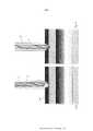
[0059] Várias modalidades da invenção serão descritas a seguir a título de exemplo e com referência aos desenhos anexos, nos quais: - A Fig. 1 ilustra uma vista em perspectiva de uma modalidade do dispositivo de acordo com a invenção; - A Fig. 2 ilustra uma vista em perspectiva de outra modalidade do dispositivo de acordo com a invenção; - A Fig. 3 ilustra uma vista em perspectiva de uma modalidade adicional do dispositivo de acordo com a invenção; - A Fig. 4 ilustra uma vista frontal explodida da modalidade da fig. 3; - A Fig. 5 ilustra um gráfico da aceleração de uma furadeira versus o deslocamento ao longo do eixo x como a linha ao longo da qual o movimento ocorre; - A Fig. 6 ilustra um gráfico do empurrão da furadeira contra o deslocamento, em que o empurrão é a derivada da aceleração mostrada na fig. 4 com relação ao tempo; - A Fig. 7 ilustra uma vista em perspectiva de um dispositivo de calibração para uso com o dispositivo de acordo com a invenção; - A Fig. 8 ilustra uma vista em perspectiva do dispositivo de calibração da fig. 7 em conjunto com uma furadeira e uma modalidade do segundo elemento deslocável do dispositivo de acordo com a invenção; - A Fig. 9 ilustra uma vista em corte esquemática de um implante posicionado sobre um osso em conjunto com uma furadeira e uma modalidade do elemento deslocável do dispositivo de acordo com a invenção, no ponto de início do processo de perfuração; - A Fig. 10 ilustra uma vista em corte esquemática de um implante posicionado sobre um osso em conjunto com uma furadeira e uma modalidade do elemento deslocável do dispositivo de acordo com a invenção, no ponto em que a furadeira está em contato com a superfície de um osso; - As Figs. 11a - 11e ilustram vistas em perspectiva de diferentes modalidades do segundo elemento deslocável do dispositivo de acordo com a invenção; - A Fig. 12 ilustra uma vista em perspectiva de outra modalidade do dispositivo de acordo com a invenção; - A Fig. 13 ilustra uma vista em perspectiva do primeiro elemento do dispositivo de medição da modalidade do dispositivo de acordo com a fig. 12; - A Fig. 14 ilustra uma outra vista em perspectiva do primeiro elemento do dispositivo de medição da modalidade do dispositivo de acordo com a fig. 12; - A Fig. 15 ilustra a vista em perspectiva de frente da modalidade do dispositivo de acordo com a fig. 12; - A Fig. 16 ilustra uma vista em perspectiva de um segundo elemento deslocável do dispositivo de medição de acordo com uma outra modalidade do dispositivo de acordo com a invenção; - A Fig. 17 ilustra uma vista em perspectiva de um conjunto que inclui o segundo elemento deslocável do dispositivo de medição de acordo com a fig. 16 em conjunto com uma manga de perfuração e um dispositivo de calibração; e - A Fig. 18 ilustra uma vista em perspectiva de um segundo elemento deslocável do dispositivo de medição de acordo com uma outra modalidade do dispositivo de acordo com a invenção.[0059] Various embodiments of the invention will be described below by way of example and with reference to the accompanying drawings, in which: - Fig. 1 illustrates a perspective view of an embodiment of the device according to the invention; - Fig. 2 illustrates a perspective view of another embodiment of the device according to the invention; - Fig. 3 illustrates a perspective view of an additional embodiment of the device according to the invention; - Fig. 4 illustrates an exploded front view of the embodiment of fig. 3; - Fig. 5 illustrates a graph of the acceleration of a drill versus displacement along the x-axis as the line along which the motion occurs; - Fig. 6 illustrates a graph of the thrust of the drill against displacement, where thrust is the derivative of the acceleration shown in fig. 4 with respect to time; - Fig. 7 illustrates a perspective view of a calibration device for use with the device according to the invention; - Fig. 8 illustrates a perspective view of the calibration device of fig. 7 together with a drill and an embodiment of the second displaceable element of the device according to the invention; - Fig. 9 illustrates a schematic sectional view of an implant positioned on a bone together with a drill and a displaceable element embodiment of the device according to the invention, at the point of initiation of the drilling process; - Fig. 10 illustrates a schematic sectional view of an implant positioned over a bone in conjunction with a drill and a displaceable element embodiment of the device according to the invention, at the point where the drill is in contact with a bone surface; - Figs. 11a - 11e illustrate perspective views of different embodiments of the second displaceable element of the device according to the invention; - Fig. 12 illustrates a perspective view of another embodiment of the device according to the invention; - Fig. 13 illustrates a perspective view of the first element of the measuring device of the device embodiment according to fig. 12; - Fig. 14 illustrates another perspective view of the first element of the measuring device of the device embodiment according to fig. 12; - Fig. 15 illustrates the front perspective view of the device embodiment according to fig. 12; - Fig. 16 illustrates a perspective view of a second displaceable element of the measuring device according to another embodiment of the device according to the invention; - Fig. 17 illustrates a perspective view of an assembly including the second displaceable element of the measuring device according to fig. 16 together with a drill sleeve and a calibration device; and - Fig. 18 illustrates a perspective view of a second displaceable element of the measuring device according to another embodiment of the device according to the invention.
[0060] As seguintes definições de termos e palavras usadas atualmente descrevem o significado exato dos mesmos como eles são usados ao longo do presente relatório descritivo:[0060] The following definitions of currently used terms and words describe their exact meaning as they are used throughout this descriptive report:
[0061] Durante um processo de perfuração a distância x coberta pelo compartimento 12, na direção do eixo longitudinal 7 da haste 13 e em relação a uma superfície de um osso ou de um implante 26 está relacionada com a posição x da ponta de corte 9 da broca 5 em relação a uma superfície de um osso ou de um implante 26 na direção de perfuração devido a broca 5 estar firmemente fixa no mandril 6 da furadeira cirúrgica 2 e posicionada no início do processo de perfuração, tal como descrito em detalhes abaixo.[0061] During a drilling process the distance x covered by the
[0062] A unidade de processamento 14 do dispositivo de acordo com a invenção pode ser configurada por meio da técnica digital ou por meio da técnica analógica.[0062] The
[0063] No caso em que a unidade de processamento 14 (figs. 1 a 4) é configurada como uma unidade de processamento digital, a unidade de processamento 14 compreende um microprocessador ou uma unidade central de processamento, que está adequadamente programada para realizar uma diferenciação numérica dos sinais digitalizados, ou seja, para calcular as, pelo menos, primeira e segunda derivadas da posição relativa x entre a ponta de corte 9 da broca 5 e a superfície de um osso ou de um implante 26 com respeito ao tempo durante o processo de perfuração (fig. 1).[0063] In the case where the processing unit 14 (figs. 1 to 4) is configured as a digital processing unit, the
[0064] A diferenciação numérica pode exemplarmente ser realizada pelo cálculo da inclinação média entre os dois pontos de dados adjacentes [x’i = (xi+1 - x)/Δt]. Alternativamente, um algoritmo utilizando três pontos de dados adjacentes chamado método de diferença central pode ser aplicado, em que [x’i = (xi+1 - xi-1)/2Δt]. O último método tem a vantagem de que ele não envolve uma mudança na posição do eixo t da derivada.[0064] Numerical differentiation can exemplarily be performed by calculating the average slope between the two adjacent data points [x'i = (xi+1 - x)/Δt]. Alternatively, an algorithm using three adjacent data points called the central difference method can be applied, where [x'i = (xi+1 - xi-1)/2Δt]. The latter method has the advantage that it does not involve a change in the position of the t-axis of the derivative.
[0065] O dispositivo de medição 1 pode compreender um condicionador de sinal para converter os sinais analógicos gerados por um sensor em sinais digitalizados. Além disso, a unidade de processamento 14 pode ser proporcionada com um temporizador ou um relógio para registrar a posição relativa x em relação ao tempo.[0065] The
[0066] Em alternativa, a unidade de processamento 14 pode ser configurada por meio da técnica analógica, por exemplo, circuitos eletrônicos, incluindo um ou mais circuitos eletrônicos que atuam como diferenciadores e um circuito eletrônico atuando como um detector de picos.[0066] Alternatively, the
[0067] A Fig.1 ilustra uma modalidade da furadeira cirúrgica 2 de acordo com a invenção, em que a furadeira cirúrgica 2 essencialmente inclui um compartimento 12 em que o motor e um fuso 13 acionados pelo motor são acomodados, um dispositivo de medição 1 preso ou fixo de forma destacável ao compartimento 12 e um adaptador 15 para prender o dispositivo de medição 1 ao compartimento 12. O fuso 13 tem um eixo longitudinal 7 e compreende um mandril 3 em uma extremidade frontal para prender a broca 5. O dispositivo de medição 1 compreende um primeiro elemento 3, que está em uma posição fixa relativa ao compartimento 12 e um segundo elemento longitudinal 4, que é exemplificativa, mas não limitante de forma passível de deslocamento paralela ou coaxial ao eixo longitudinal 7 do fuso 13 em relação ao primeiro elemento 3. Alternativamente, o dispositivo de medição 1 pode estar disposto no compartimento 12 de modo que o segundo elemento 4 pode é deslocável em um ângulo em relação ao eixo longitudinal 7 do fuso 13. O erro sistemático que ocorre devido a esta angulação (erro cosseno) pode ser facilmente compensado. Esta configuração tem a vantagem de que o refletor pode ser menor para que a ponta de medição possa estar disposta mais perto da broca 5.[0067] Fig. 1 illustrates an embodiment of the surgical drill 2 according to the invention, in which the surgical drill 2 essentially includes a
[0068] O segundo elemento deslocável 4 tem uma extremidade frontal 10, em que em uso a extremidade frontal 10 do segundo elemento deslocável 4 encosta na superfície do osso ou uma superfície de um implante 26, por exemplo, uma placa de osso ou uma manga de furadeira. A broca 5 pode ser apertada no mandril 6 e é fornecida com uma ponta de corte 9. Além disso, o segundo elemento deslocável 4 pode compreender uma manga de perfuração 23 que se estende na direção do eixo longitudinal 7 da extremidade frontal 10 do segundo elemento 4.[0068] The second
[0069] O dispositivo de medição 1 compreende um dispositivo de laser para a avaliação de deslocamento linear. Este dispositivo de laser compreende um módulo de laser 18 com um meio que emite luz de laser, um refletor 20 ligado a uma manga de furadeira 23 que forma o segundo elemento 4 que pode deslizar ao longo da broca 5 e, pelo menos, dois sensores de luz eletrônico 19, que são, exemplarmente, mas não limitando, configurados como dispositivos de carga acoplada (CCD) para efetuar a triangulação à laser para avaliação de deslocamento linear.[0069] The
[0070] Em outra modalidade alternativa a avaliação de deslocamento linear pode ser realizada por meio de sensores de posição de ultrassom.[0070] In another alternative modality the evaluation of linear displacement can be performed by means of ultrasound position sensors.
[0071] Para incorporar a determinação do comprimento do parafuso no processo de perfuração, de modo a eliminar a etapa de medição da profundidade, após a perfuração do furo no osso, a configuração do dispositivo de medição 1 se baseia no fato de que, durante a perfuração um pico de aceleração da broca 5 ocorre quando a ponta de corte 9 da broca 5 sai de um córtex ósseo conforme este é um atributo inevitável de perfuração à mão. Por conseguinte, o compartimento 12 da furadeira cirúrgica 2 em conjunto com o primeiro elemento 3 do dispositivo de medição 1 é submetido à mesma aceleração.[0071] In order to incorporate screw length determination into the drilling process, so as to eliminate the depth measurement step after drilling the hole in the bone, the configuration of the
[0072] Além disso, a unidade de processamento 14 compreende um ou mais diferenciadores para determinar, pelo menos, as primeira e segunda derivadas da posição x no que diz respeito ao tempo e um detector de picos. O detector de pico é aplicado para identificar uma aceleração e/ou um pico de empurrão quando a ponta de corte 9 da broca 5 sai do córtex de um osso. O gráfico de aceleração contra deslocamento, ou seja, a profundidade de perfuração é exemplarmente ilustrada na fig. 5. O valor de aceleração no ponto de entrada (A) da ponta de corte 9 da broca 5 é definido como zero. Um primeiro pico de aceleração ocorre quando a ponta de corte 9 da broca 5 sai do córtex próximo de um osso (B) e após um aumento da aceleração na entrada (C) da ponta de corte 9 da broca 5 para o córtex distante, um segundo pico de aceleração ocorre quando a ponta de corte 9 da broca 5 sai do córtex distante do osso (D). O primeiro e segundo pico são claramente identificáveis por um aumento distinto repentino e uma reversão subsequente da aceleração especificando uma descontinuidade clara e identificável no gráfico de aceleração versus deslocamento da broca 5.[0072] Furthermore, the
[0073] O dispositivo de medição 1 particularmente mede e grava o movimento relativo entre o segundo elemento deslocável 4 e o primeiro elemento 3, que está fixo em relação ao compartimento 12. Uma vez que a broca 5 está firmemente fixada no mandril 6, o movimento relativo entre o segundo elemento deslocável 4 e o primeiro elemento 3 coincide com o movimento relativo da ponta de corte 9 da broca 5 com respeito à extremidade anterior 10 do segundo elemento deslocável 4. Por conseguinte, o dispositivo de medição 1 mede e grava o movimento relativo da broca 5 na direção de perfuração em tempo real no que diz respeito à superfície do osso ou à superfície de um implante no qual a extremidade frontal 10 do segundo elemento deslocável 4 do dispositivo de medição 1 se encosta. O movimento da broca 5 em relação ao segundo elemento deslocável 4 do dispositivo de medição 1 é um movimento de translação de uma dimensão, e a posição x da ponta de corte 9 da broca 5 em relação à extremidade frontal 10 do segundo elemento deslocável 4 em qualquer momento é dada pela coordenada x da ponta de corte 9 ao longo do eixo x 8, que neste caso constitui a estrutura de referência. A posição x ou a coordenada x do corte da ponta 9 é definida como 0, no início do processo de perfuração, por exemplo, quando a ponta de corte 9 da broca 5 está nivelada com a extremidade da frente 10 do segundo elemento deslocável 4.[0073] The
[0074] A velocidade da broca 5 se movendo ao longo do eixo x 8 em qualquer instante é igual à taxa de alteração do gráfico de x versus tempo naquele instante e, por conseguinte, é determinada pela primeira derivada de x em relação ao tempo naquele instante. Além disso, a aceleração instantânea da broca 5, a qualquer momento, é a taxa de variação da velocidade versus a curva do tempo, naquele tempo e é determinada como a segunda derivada de x em relação ao tempo naquele instante. O pico de aceleração pode ocorrer muito tarde em relação ao ponto em que a ponta de corte 9 da broca 5 sai de, por exemplo, o córtex distante do osso. A maior variação em aceleração, isto é, o pico de empurrão ocorre mais perto do ponto em que a ponta de corte 9 da broca 5 sai de, por exemplo, o córtex distante do osso. Para permitir uma identificação mais significativa do ponto em que a ponta de corte 9 da broca 5 sai de, por exemplo, o córtex distante do osso, o empurrão da broca 5 é determinado. Além disso, o pico de empurrão permite aplicar um detector de pico simples. Tal como definido na física do empurrão está a taxa de variação de aceleração, que é a derivada da aceleração em função do tempo, ou seja, a segunda derivada da velocidade e a terceira derivada de x em relação ao tempo, em qualquer instante.[0074] The speed of
[0075] Para este efeito, a posição x ou a coordenada x da ponta de corte 9 da broca 5 em relação ao tempo é registrada pela unidade de processamento 14, que está integrada no primeiro elemento 3 do dispositivo de medição 1.[0075] For this purpose, the x position or the x coordinate of the
[0076] Exemplarmente, mas não limitante, a unidade de processamento 14 é configurada como uma unidade de processamento digital e compreende um microprocessador que tem um registro do processador para registrar a posição do segundo elemento 4 em relação ao primeiro elemento 3. Tal como descrito acima, a posição do segundo elemento 4 em relação ao primeiro elemento 3 coincide com a posição x ou coordenada x da ponta de corte 9 da broca 5 em relação à extremidade frontal 10 do segundo elemento deslocável 4. Além disso, o microprocessador é programado adequadamente para uma diferenciação numérica de sinais digitalizados, ou seja, para calcular a pelo menos primeira e segunda derivadas da posição x ou coordenada x com relação ao tempo e é ainda programado para detectar os picos de aceleração e/ou de empurrão em função da aceleração e/ou do empurrão atuando sobre a broca 5 e determinados através dos diferenciadores.[0076] Exemplary, but not limiting, the
[0077] Alternativamente, como mencionado acima, a unidade de processamento 14 pode ser configurada por meio da técnica analógica, por exemplo, circuitos eletrônicos, incluindo um ou mais circuitos eletrônicos que atuam como diferenciadores e um circuito eletrônico atuando como um detector de picos.[0077] Alternatively, as mentioned above, the
[0078] Por meio de um ou mais diferenciadores, a aceleração instantânea da broca 5, a qualquer momento é determinada como a segunda derivada de x em relação ao tempo naquele instante. Além disso, o empurrão como a derivada da aceleração em relação ao tempo, ou seja, a segunda derivada da velocidade e a terceira derivada de x em relação ao tempo, em qualquer instante é determinado.[0078] By means of one or more differentiators, the instantaneous acceleration of
[0079] Tal como ilustrado na fig. 5 a aceleração da broca 5 apresenta um primeiro pico, quando a ponta de corte 9 da broca 5 sai do córtex próximo de um osso (B), e um segundo pico da aceleração ocorre quando a ponta de corte 9 da broca 5 sai do córtex distante do osso (D). Além disso, um aumento repentino da aceleração da broca 5 ao longo do eixo x 8 ocorre quando a ponta de corte 9 da broca 5 entra no córtex distante do osso (C), o que, no entanto, não é seguido por uma regressão de modo que neste ponto não aparece nenhum pico de aceleração. A Fig. 6 ilustra o empurrão atuando sobre a broca 5 e sendo a derivada da aceleração em função do tempo. O primeiro pico do empurrão especifica a inclinação da tangente do gráfico da aceleração em função do tempo naquele instante, isto é, aproximadamente naquele ponto onde a ponta de corte 9 da broca 5 sai do córtex próximo (B), o segundo pico especifica a inclinação da tangente do gráfico da aceleração em função do tempo naquele instante, ou seja, naquele ponto onde a ponta de corte 9 da broca 5 entra no córtex distante (C) e o terceiro pico especifica a inclinação da tangente do gráfico da aceleração em função do tempo naquele instante, ou seja, aproximadamente naquele ponto onde a ponta de corte 9 da broca 5 sai do córtex distante (D).[0079] As illustrated in fig. 5 the acceleration of
[0080] O processamento de dados efetuado pelo detector de pico pode incluir uma determinação das suas posições, alturas e larguras. Além disso, o detector de pico pode usar um limiar de amplitude ou um limiar de inclinação para identificar com segurança um pico. Outros parâmetros podem ser a largura do pico ou a área coberta pelo pico.[0080] The data processing performed by the peak detector may include a determination of its positions, heights and widths. In addition, the peak detector can use an amplitude threshold or a slope threshold to reliably identify a peak. Other parameters can be the peak width or the area covered by the peak.
[0081] No caso, o detector de picos estar configurado para utilizar um limiar de amplitude, de modo a identificar um pico de aceleração quando o valor máximo da aceleração determinada excede um valor limiar pré-definido. Os valores de limiar particulares podem ser armazenados em uma memória de dados conectada de forma eletrônica ao microprocessador e/ou armazenada temporariamente no registro do processador do microprocessador.[0081] In this case, the peak detector is configured to use an amplitude threshold, in order to identify an acceleration peak when the maximum value of the determined acceleration exceeds a pre-defined threshold value. Particular threshold values may be stored in a data memory electronically connected to the microprocessor and/or temporarily stored in the microprocessor's processor register.
[0082] No caso do detector de picos estar configurado para utilizar um limiar de inclinação, isto é, o empurrão para identificação do pico, a unidade de processamento 14 compreende adicionalmente um terceiro diferenciador para determinar ou calcular a terceira derivada da posição x ou coordenada x da ponta de corte 9 da broca 5 em relação ao tempo, em qualquer instante, em que a posição x ou coordenada x coincide novamente com o deslocamento do segundo elemento 4 em relação ao primeiro elemento 3. O detector de pico é então configurado ou programado para identificar um pico de empurrão quando o valor máximo do empurrão determinado excede um valor limiar pré-definido para o empurrão.[0082] In case the peak detector is configured to use a slope threshold, i.e. the push for peak identification, the
[0083] A distância da broca para a saída a partir do segundo córtex, ou seja, a posição x ou coordenada x da ponta de corte 9 da broca 5, quando a ponta de corte 9 sai do córtex distante automaticamente é calculada com base nos picos de aceleração e/ou de empurrão. Com base nesta posição x ou coordenada x, o comprimento do parafuso requerida, de preferência incluindo uma margem de segurança pode ser estimado. Para este efeito, a unidade de processamento 14 pode compreender uma memória de dados para armazenar dados relacionados com comprimentos de parafuso para osso, de preferência, incluindo a margem de segurança.[0083] The distance from the bit to the output from the second cortex, i.e. the x position or x coordinate of cutting
[0084] O dispositivo de medição 1 e em particular os transdutores de deslocamento podem ser ou integrados no compartimento 12 ou podem ser temporariamente acopláveis ao mesmo. Em uma configuração temporariamente acoplável, o dispositivo de medição compreende um meio de fixação sob a forma de um adaptador 15 que é afixável de forma liberável ao compartimento 12 da furadeira cirúrgica 2. Este adaptador 15 é, exemplarmente, mas não se limitante configurado como uma estrutura anelar acoplável ao compartimento 12 por meio de um encaixe de pressão ou por meio de um anel de aperto. Em alternativa, o dispositivo de medição 1 pode compreender grampos para afixar de forma liberável o dispositivo de medição 1 para o compartimento 12.[0084] The
[0085] O dispositivo de medição 1 pode compreender um dispositivo de comunicação sem fio, exemplarmente configurado como um módulo de Bluetooth 17 com condicionador de sinal. Através do dispositivo de comunicação sem fio, os dados podem ser transmitidos de forma sem fio para um computador externo com monitor, um computador tablet, um smartphone, um smartwatch ou um smartglass para calcular ou indicar a informação derivada, ou seja, a posição medida da ponta de corte da furadeira com relação ao tempo, bem como a velocidade calculada em relação ao tempo, a aceleração computada com relação ao tempo, e o empurrão computado com relação ao tempo. Em alternativa, os dadas derivadas podem ser fornecidos a um visor ou alto-falante localmente montado para a furadeira cirúrgica 2.[0085] The
[0086] Além disso, o dispositivo de medição 1 compreende um invólucro esterilizável 16 para envolver a unidade de processamento 14, o dispositivo de comunicação sem fios e a fonte de alimentação 22 para o aparelho de medição 1, em que a fonte de alimentação 22 inclui uma ou mais baterias recarregáveis ou não-recarregáveis dispostas no invólucro 16.[0086] Furthermore, the measuring
[0087] Além disso, o dispositivo 25 pode, adicionalmente, compreender um dispositivo de calibração 27, tal como ilustrado nas figs. 7 e 8 e descritos em mais detalhe abaixo.[0087] Furthermore, the
[0088] Outra modalidade do dispositivo 25 de acordo com a invenção está ilustrada na fig. 2, em que o dispositivo 25 da fig. 2 difere da modalidade da fig. 1, apenas em que a unidade de processamento 14 é uma unidade externa, por exemplo, um computador com monitor, um computador tablet, um aparelho, um smartwatch ou um smartglass, e que o dispositivo de medição 1 compreende um dispositivo de transmissão de dados sem fios 17 e a unidade de processamento 14 inclui um dispositivo de recebimento de dados sem fios, de modo que a distância medida x coberta pelo compartimento 12, na direção do eixo longitudinal 7 e em relação a uma superfície de um implante 26 ou um osso pode ser transmitida a partir do dispositivo de medição 1 para a unidade de processamento externa 14 e registrada com relação ao tempo. A unidade de processamento externa 14 pode compreender um microprocessador semelhante ao da modalidade da fig. 1, ou pode compreender uma unidade de processamento central.[0088] Another embodiment of the
[0089] Uma modalidade adicional do dispositivo 25 de acordo com a invenção é ilustrada nas figs. 3 e 4, em que o dispositivo de medição 1 da modalidade das figs. 3 e 4 difere da modalidade da fig. 1, em que o primeiro elemento 3, incluindo o módulo de laser 18 para emissão de um feixe de laser e o receptor de triangulação, por exemplo, um sensor de luz eletrônico 19 na forma de um dispositivo de fotodiodo ou de carga acoplada (CCD) é configurado como uma parte de um módulo eletrônico 31. Este módulo eletrônico 31 é inserido em um espaço oco 32 formado na pega 33 do compartimento 12, em que o espaço oco 32 estende-se desde uma abertura 34 na parte inferior da pega 33 para a parte superior 35 do compartimento 12. A abertura 34 pode ser fechada por meio de uma tampa 36, que é acoplável para a parte inferior da pega 33.[0089] An additional embodiment of the
[0090] Além do primeiro elemento 3, o módulo eletrônico 31 compreende um visor 30, o qual está disposto em uma parte superior 37 do módulo eletrônico 31, em que esta parte superior 37 é configurada e dimensionada para encaixar-se em uma respectiva cavidade 38 configurada na parte superior 35 do compartimento 12. Além disso, o módulo eletrônico 31 tem uma parte inferior 40, incluindo o módulo de laser 18, o sensor de luz eletrônico 19, a unidade de processamento 14 e uma fonte de alimentação 22 para o acionamento do furadeira cirúrgica 2 e para o fornecimento do módulo de laser 18, o sensor de luz 19 e a unidade de processamento 14. Exemplarmente, a fonte de alimentação 22 pode ser uma bateria ou um acumulador. A parte inferior 40 do módulo eletrônico 31 é conformada e dimensionada para encaixar-se no espaço oco 32 na pega 33 do compartimento 12. Uma janela de laser 41 é disposta na frente da parte inferior 40 e imediatamente abaixo da parte superior 37 do módulo eletrônico 31, de modo a coincidir com o feixe de laser e o sensor de luz eletrônico 19 com as respectivas janelas 42, 43 (fig. 4) no compartimento 12.[0090] In addition to the
[0091] Uma primeira e uma segunda janela 42, 43 estéreis estão dispostas no compartimento 12 da furadeira cirúrgica 2 para proporcionar janelas para o feixe de laser emitido pelo módulo de laser 18 e o feixe refletido recebido pelo sensor de luz eletrônico 19. A primeira e segunda janelas estéreis 42, 43 são dispostas na frente do compartimento 12 e - quando vistas em uma vista frontal - abaixo do eixo longitudinal 7 do fuso 13 e localizadas em lados opostos de um plano médio 44 da furadeira cirúrgica 2 que contém o eixo longitudinal 7 e a uma distância a partir do plano médio 44, que permite que o feixe de laser e do feixe refletido passem ao lado do fuso 13 e o mandril 6 da furadeira cirúrgica 2.[0091] A first and a second
[0092] A parte superior 35 do compartimento 12 forma um invólucro 16 para o visor 30, no qual o invólucro 16 é, exemplarmente, mas não limitante, integral com o compartimento 12 da furadeira cirúrgica 2 e engloba a cavidade 38. Este invólucro 16 compreende uma terceira janela estéril 45 para cobrir o visor 30. Além disso, o invólucro 16 está disposto no compartimento 12 oposto à pega 33 da furadeira cirúrgica 2. A terceira janela estéril 45 é angulada em relação a um plano ortogonal ao eixo longitudinal 7 do fuso 13 e dirigida para a extremidade posterior do compartimento 12.[0092] The
[0093] Exemplarmente, mas não limitante, o dispositivo de medição 1 é adequadamente configurado para controlar a velocidade de rotação do fuso 13 da furadeira cirúrgica 2, de modo que a energia fornecida ao motor elétrico da furadeira de potência 2 pode ser desligada, quando um pico é detectado por meio do dispositivo de medição 1 para, assim, evitar o empurrão brusco da broca 5.[0093] Exemplary, but not limiting, the measuring
[0094] Novamente, outra modalidade do dispositivo 25 de acordo com a invenção é ilustrada nas figs. 12-15, em que o dispositivo de medição 1 da modalidade das figs. 12-15 difere da modalidade da fig. 1, em que o primeiro elemento 3 inclui um módulo eletrônico 31, que compreende além do módulo de laser 18 para emissão de um feixe de laser e o receptor de triangulação, por exemplo, um sensor de luz eletrônico 19 em forma de um dispositivo de fotodiodo ou de carga acoplada (CCD) um visor 30. Além disso, o módulo eletrônico 31 compreende a unidade de processamento 14 e a fonte de alimentação 22 para o aparelho de medição 1. O visor 30 é disposto no lado posterior 46 do módulo eletrônico 31. De modo semelhante à modalidade da fig. 1, o invólucro esterilizado 16 pode ser fixo à furadeira cirúrgica 2 e compreende uma cavidade 38 para receber o módulo eletrônico 31. A janela frontal estéril 47 é disposta na frente do invólucro para deixar passar através do feixe de luz emitido pelo módulo de laser 18, e o feixe refletido, refletido por meio do refletor 20 disposto no segundo elemento 4 do dispositivo de medição 1.[0094] Again, another embodiment of the
[0095] O módulo de laser 18 e a luz eletrônica do sensor 19, que recebe o feixe refletido para efetuar a triangulação são dispostos lateralmente espaçados uns dos outros no módulo eletrônico 31 de modo a que - quando visto numa vista frontal do primeiro elemento montado 3 - o feixe de laser e o feixe refletido passam por cima do eixo longitudinal 7 do fuso 13.[0095] The
[0096] O invólucro 16 compreende um adaptador 15 para fixar o primeiro elemento 3 do dispositivo de medição 1 para o compartimento 12, em que o adaptador 15 é afixável de forma liberável para o compartimento 12 da furadeira cirúrgica 2. Este adaptador 15 é, exemplarmente, mas não limitante, configurado como uma estrutura anelar fixa ao compartimento 12 por meio de um anel de aperto 48 que é fixável, por exemplo, à parte estacionária do fuso 13 por meio de um parafuso de aperto 49.[0096]
[0097] O anel de aperto 48 é posicionado no invólucro 16 lateralmente desviado em relação a um plano central longitudinal do invólucro 16 para permitir que o feixe de laser e o feixe refletido passem ao lado da broca 5. Além disso, por meio do adaptador 15, o invólucro 16 é ligado a furadeira cirúrgica 2 com um ângulo em relação ao eixo longitudinal 7, de modo que o feixe de laser é emitido em um ângulo para o eixo longitudinal 7 permitindo um tamanho reduzido do refletor 20 do segundo elemento 4 do dispositivo de medição 1.[0097] The
[0098] O invólucro 16 é esterilizável e configurado como uma peça separada disposta no topo do invólucro 10. A cavidade 38 tem uma abertura no lado de trás do invólucro 16 e pode ser fechada por meio de uma tampa 51 que pode rodar em torno de um eixo localizado no lado inferior do invólucro 16 e prolongando-se ortogonalmente ao eixo longitudinal. A tampa 51 compreende uma janela traseira estéril 52 para cobrir o visor 30, sendo que - quando a tampa 51 está fechada - a janela traseira 52 é inclinada em relação a um plano ortogonal ao eixo longitudinal 7 do fuso 13 e dirigida para a extremidade traseira do compartimento 12.[0098]
[0099] Exemplarmente, mas não limitante, um atuador 53 para um interruptor de energia do módulo eletrônico 31 pode ser disposto no interior da tampa 51 de modo que quando a tampa 51 é fechada, a energia é fornecida a partir da fonte de alimentação 22 para os componentes eletrônicos do dispositivo de medição 1. Para operar a unidade de processamento 14, o módulo de laser 18 e o sensor de luz eletrônica 19, um ou mais botões 54 podem ser posicionados no lado posterior do módulo eletrônico 31. A janela traseira estéril 52 pode ser proporcionada com recessos de modo a proporcionar áreas enfraquecidas na janela traseira 52 que permitem acionar o um ou mais botões 54, quando a tampa 51 está na sua posição fechada.[0099] Exemplary, but not limiting, an
[0100] A unidade de processamento 14 das modalidades das figs. 1 a 4 e 12 a 15 compreende um microprocessador ou uma unidade central de processamento que inclui um registro do processador para registrar a distância x coberta pelo compartimento 12, na direção do eixo longitudinal 7 e em relação a uma superfície de um implante 26 ou um osso com relação ao tempo durante um processo de perfuração. Além disso, o registro do processador do microprocessador ou da unidade central de processamento armazena temporariamente valores dos picos de aceleração e/ou de empurrão determinados durante um processo de perfuração para definir os valores de limiar para a aceleração e/ou empurrão. Por este meio, os limiares podem ser retrospectivamente definidos em relação ao pico máximo gravado sob a suposição de que o número de picos esperados é conhecido (por exemplo, dois picos para o córtex próximo e distante).[0100] The
[0101] Além disso, o microprocessador ou a unidade de processamento central da unidade de processamento 14 das modalidades das figs. 1 a 4 e 12 a 15 podem ser programados para calcular as derivadas, para detectar os picos e para a saída da distância atual x, a velocidade atual e a posição x da ponta de corte 9 da broca 5 no pico de empurrão mais recente em tempo real. Tal como descrito acima, a diferenciação numérica requer, pelo menos, dois ou três pontos de dados adjacentes xi-1 (ti-1), x (ti) e x+1 (ti+1). Por conseguinte, para o processamento em tempo real das derivadas e a detecção do pico, a unidade de processamento 14 armazena ou registra temporariamente pelo menos, dois ou mais pontos de dados adjacentes.[0101] Furthermore, the microprocessor or the central processing unit of the
[0102] Em alternativa, o microprocessador ou a unidade de processamento central da unidade de processamento 14 das modalidades das figs. 1 a 4 e 12 a 15 podem ser programados para o processamento de dados retrospectivo, de modo a primeiro registrar o conjunto completo de pontos de dados x em relação ao tempo durante todo o processo de perfuração e para calcular as derivadas e realizar a detecção do pico assim que o processo de perfuração tiver sido completado.[0102] Alternatively, the microprocessor or the central processing unit of the
[0103] M de se notar que o feedback em tempo real da profundidade de perfuração atual isolada pode ser de grande valor para o cirurgião. Outras informações valiosas são entregues pela velocidade de perfuração atual. Isto ajuda o cirurgião a controlar a sua velocidade de alimentação, para evitar danos mecânicos ou de calor do osso ou pode ser utilizado para estimar a qualidade do osso.[0103] It should be noted that real-time feedback of the isolated current drilling depth can be of great value to the surgeon. Other valuable information is delivered by the current drilling speed. This helps the surgeon to control his feeding rate to avoid mechanical or heat damage to the bone or can be used to estimate the quality of the bone.
[0104] A Fig. 16 ilustra uma outra modalidade do refletor 20, que não é parte integrante com ou fixada a uma manga de furadeira 23. O refletor 20 é apertável para a broca 5 de tal maneira que possa deslizar sobre a broca 5, de modo que o refletor 20 é independente da configuração da manga de furadeira 23. O refletor 20 tem uma porção em forma de disco 55 e adjacente ao mesmo de uma porção de aperto 56 compreendendo fendas longitudinais de modo a formar linguetas adequadas para exercer pressão radial para a broca 5.[0104] Fig. 16 illustrates another embodiment of the
[0105] A Fig. 18 ilustra outra modalidade mais uma vez do refletor 20, que difere da modalidade da fig. 16 apenas em que o refletor 20 tem uma superfície refletora 58 virada para fora da porção de aperto 56, em que a superfície refletora 58 inclui uma ranhura 57 que se estende ao longo da periferia da porção em forma de disco 55. Exemplarmente, o evento quando o ponto de laser produzido pelo feixe de laser sobre o lado posterior da porção em forma de disco 55 salta para a ranhura 57 pode ser utilizado como um interruptor ou desencadeador de ações, por exemplo, para parar a rotação do fuso 13 e a profundidade ou posição de ranhura 57 pode ser utilizada para selecionar, por exemplo, o módulo de parafuso, por exemplo, 5 mm ou 3,5 milímetros ou 2,4 mm.[0105] Fig. 18 illustrates yet another embodiment of
[0106] O método para a estimativa de comprimento do parafuso para osso a partir das características de perfuração essencialmente compreende as etapas: A) avançar a furadeira cirúrgica 2 coaxialmente em relação ao eixo longitudinal 7 do fuso 13 para perfurar um furo em um osso e registrando a posição x da ponta de corte 9 da broca 5 em relação ao tempo; B) determinar a primeira, segunda e terceira derivada de x em função de t, em qualquer instante; C) determinar o instante em que a ponta de corte 9 da broca 5 sai de um córtex de um osso, utilizando o detector de pico para identificar um pico de empurrão que ocorre nesse instante, em que os gráficos de velocidade, aceleração e de empurrão versus o tempo são derivados através das derivadas em qualquer instante determinado de acordo com a etapa B). As soluções falsas são excluídas por análise dos sinais dos sinais de velocidade e de aceleração naquele instante. A fim de determinar se o pico de empurrão identificado se refere à desaceleração (osso entrando) ou aceleração (osso saindo) o sinal da aceleração naquele instante é consultado. Por consultar adicionalmente o sinal da velocidade naquele instante, é assegurado ao considerar apenas os picos que ocorrem durante o avanço da furadeira ao invés de retirá-los; D) determinar a posição relativa entre o segundo elemento 4 e o primeiro elemento 3 no instante determinado de acordo com a etapa C); e E) selecionar um parafuso para o osso que tem um comprimento correspondente à posição relativa entre o segundo elemento 4 e o primeiro elemento 3 determinado de acordo com a etapa D), sob consideração de uma margem de segurança pré-definida.[0106] The method for estimating bone screw length from the drilling characteristics essentially comprises the steps: A) advancing the surgical drill 2 coaxially with respect to the
[0107] Tal como descrito acima, a posição x da ponta de corte 9 da broca 5 em relação a uma superfície de um osso ou de um implante 26 na direção de perfuração é ajustada para zero no início do processo de perfuração. No entanto, esta posição zero da ponta de corte 9 da broca 5 depende do fato de se: 1) o segundo elemento deslocável 4 compreende uma manga de perfuração 23 que se estende na direção do eixo longitudinal 7 para a extremidade frontal 10 do segundo elemento 4 como ilustrado nas figs. 3, 4 e 11a - 11e; ou se 2) a manga de furadeira é um elemento separado inserido previamente no tecido mole que cobre o osso a ser tratado; ou se 3) a posição zero da ponta de corte 9 é para ser definida com relação a um implante 26, por exemplo, uma placa de osso. No caso da broca 5 é guiada numa manga de perfuração 23, que durante a perfuração entra em contato de ou se une a uma placa para ossos e, consequentemente, não permite que a ponta de corte 9 da broca 5 se encoste à superfície superior da placa de osso (fig. 9), um dispositivo de calibração 27 proporcionando uma parada física 28 no interior da manga de furadeira 23 a uma altura que corresponde com a superfície superior da placa do osso pode ser utilizado para determinar o ponto de início da medição (Fig. 8). Alternativamente, se são conhecidos os comprimentos de broca 5 e a manga de furadeira 23, o ponto de partida pode ser calculado a partir destes dados.[0107] As described above, the position x of the
[0108] No caso da variante acima 1) o método compreende antes da etapa A) as seguintes etapas: posicionar a furadeira cirúrgica 2 em relação a um osso de modo que a extremidade frontal 10 do segundo elemento deslocável 4 e a ponta de corte 9 da broca 5 encostar a uma superfície de um osso; e armazenar a posição relativa como ponto de partida (x = 0) para a medição da posição x da ponta de corte 9 da broca 5 em relação a uma superfície de um osso na direção de perfuração em relação ao tempo.[0108] In the case of the above variant 1) the method comprises, before step A) the following steps: positioning the surgical drill 2 in relation to a bone so that the
[0109] No caso da variante acima 2) o método compreende antes da etapa a) as seguintes etapas: posicionar a furadeira cirúrgica 2 em relação a um osso de modo que a extremidade frontal 10 do segundo elemento deslocável 4 encosta em uma manga de furadeira 23 inserida no tecido mole que cobre um osso a ser tratado; e ajustar a ponta de corte 9 da broca 5 fixada no mandril 6 da furadeira cirúrgica 2 em relação ao segundo elemento deslocável 4, de modo que a ponta de corte 9 da broca 5 encosta em uma superfície de um osso; e armazenar a posição relativa como ponto de partida (x = 0) para a medição da posição x da ponta de corte 9 da broca 5 em relação a uma superfície de um osso na direção de perfuração em relação ao tempo.[0109] In the case of the above variant 2) the method comprises, before step a) the following steps: positioning the surgical drill 2 in relation to a bone so that the
[0110] No caso da variante acima 3) o método compreende antes da etapa a) as seguintes etapas (figs 9 e 10): posicionar a broca 5 fixada no mandril 6 em relação ao segundo elemento deslocável 4 pelo uso de um dispositivo de calibração 27 (figs. 7 e 8) de modo a que extremidade frontal 10 do segundo elemento 4 entra em contato com uma superfície 29 do dispositivo de calibração 27, e a ponta de corte 9 da broca 5 encosta em uma parada 28 protuberante a partir da superfície 29 do dispositivo de calibração 27; armazenar a posição relativa como ponto de partida (x = 0) para a medição da posição x da ponta de corte 9 da broca 5 em relação a uma superfície de um osso ou de um implante 26 na direção de perfuração em relação ao tempo; e posicionar a furadeira cirúrgica 2 em relação a um implante 26, por exemplo, uma placa de osso, de modo que a extremidade frontal 10 do segundo elemento deslocável 4 encosta em uma superfície do implante 26 (fig. 9).[0110] In the case of the above variant 3) the method comprises, before step a) the following steps (figs 9 and 10): positioning the
[0111] A Fig. 17 ilustra uma modalidade adicional do dispositivo de calibragem 27. O refletor 20, por exemplo, como ilustrado na fig. 16 ou 17, bem como o dispositivo de calibração 27, por exemplo, ilustrado nas figs. 7 e 8 podem ser feitos para uso individual. Em outras modalidades, a manga de furadeira 23 de acordo com uma das modalidades ilustradas nas figs. 11a - 11e, 16 e 17 pode ser configurada como um elemento descartável também e pode ser para este efeito ligada ao dispositivo de calibração 27, através de um ponto de ruptura predeterminado.[0111] Fig. 17 illustrates a further embodiment of the calibrating
[0112] Embora a invenção tenha sido descrita em conjunto com modalidades específicas da mesma, é evidente que muitas alternativas, modificações e variações serão evidentes para os técnicos especialistas no assunto. Por conseguinte, pretende-se englobar todas essas alternativas, modificações e variações que caem dentro do escopo das reivindicações anexas.[0112] While the invention has been described in conjunction with specific embodiments thereof, it is evident that many alternatives, modifications and variations will be apparent to those skilled in the art. Therefore, it is intended to encompass all such alternatives, modifications and variations that fall within the scope of the appended claims.
[0113] Aprecia-se que certas características da invenção, que são, para clareza, descritas no contexto de modalidades separadas, podem também ser fornecidas em combinação em uma única modalidade. Inversamente, várias características da invenção, que são, para brevidade, descritas no contexto de uma única modalidade, podem também ser proporcionadas separadamente ou em qualquer sub-combinação adequada ou como apropriado em qualquer outra modalidade descrita da invenção. Certas características descritas no contexto de várias modalidades não são para serem consideradas características essenciais dessas modalidades, a menos que a modalidade seja inoperativa sem estes elementos.[0113] It is appreciated that certain features of the invention, which are, for clarity, described in the context of separate embodiments, may also be provided in combination in a single embodiment. Conversely, various features of the invention, which are, for brevity, described in the context of a single embodiment, may also be provided separately or in any suitable sub-combination or as appropriate in any other described embodiment of the invention. Certain features described in the context of various modalities are not to be considered essential features of those modalities unless the modality is inoperative without these elements.
Claims (17)
Translated fromPortugueseApplications Claiming Priority (3)
| Application Number | Priority Date | Filing Date | Title |
|---|---|---|---|
| CHPCT/CH2015/000168 | 2015-11-16 | ||
| PCT/CH2015/000168WO2017083989A1 (en) | 2015-11-16 | 2015-11-16 | Surgical power drill including a measuring unit suitable for bone screw length determination |
| PCT/CH2016/000143WO2017083992A1 (en) | 2015-11-16 | 2016-11-11 | Surgical power drill including a measuring unit suitable for bone screw length determination |
Publications (3)
| Publication Number | Publication Date |
|---|---|
| BR112018009605A2 BR112018009605A2 (en) | 2018-11-06 |
| BR112018009605A8 BR112018009605A8 (en) | 2019-02-26 |
| BR112018009605B1true BR112018009605B1 (en) | 2022-07-05 |
Family
ID=54704942
Family Applications (1)
| Application Number | Title | Priority Date | Filing Date |
|---|---|---|---|
| BR112018009605-9ABR112018009605B1 (en) | 2015-11-16 | 2016-11-11 | SURGICAL DRILL INCLUDING A SUITABLE MEASURING UNIT FOR DETERMINING BONE SCREW LENGTH |
Country Status (8)
| Country | Link |
|---|---|
| US (4) | US10736644B2 (en) |
| EP (1) | EP3376971B1 (en) |
| JP (1) | JP7289654B2 (en) |
| CN (1) | CN108366801B (en) |
| AU (1) | AU2016356755B2 (en) |
| BR (1) | BR112018009605B1 (en) |
| CA (1) | CA3001738C (en) |
| WO (2) | WO2017083989A1 (en) |
Families Citing this family (430)
| Publication number | Priority date | Publication date | Assignee | Title |
|---|---|---|---|---|
| US9060770B2 (en) | 2003-05-20 | 2015-06-23 | Ethicon Endo-Surgery, Inc. | Robotically-driven surgical instrument with E-beam driver |
| US20070084897A1 (en) | 2003-05-20 | 2007-04-19 | Shelton Frederick E Iv | Articulating surgical stapling instrument incorporating a two-piece e-beam firing mechanism |
| US8215531B2 (en) | 2004-07-28 | 2012-07-10 | Ethicon Endo-Surgery, Inc. | Surgical stapling instrument having a medical substance dispenser |
| US11890012B2 (en) | 2004-07-28 | 2024-02-06 | Cilag Gmbh International | Staple cartridge comprising cartridge body and attached support |
| US11998198B2 (en) | 2004-07-28 | 2024-06-04 | Cilag Gmbh International | Surgical stapling instrument incorporating a two-piece E-beam firing mechanism |
| US9072535B2 (en) | 2011-05-27 | 2015-07-07 | Ethicon Endo-Surgery, Inc. | Surgical stapling instruments with rotatable staple deployment arrangements |
| US11246590B2 (en) | 2005-08-31 | 2022-02-15 | Cilag Gmbh International | Staple cartridge including staple drivers having different unfired heights |
| US7669746B2 (en) | 2005-08-31 | 2010-03-02 | Ethicon Endo-Surgery, Inc. | Staple cartridges for forming staples having differing formed staple heights |
| US9237891B2 (en) | 2005-08-31 | 2016-01-19 | Ethicon Endo-Surgery, Inc. | Robotically-controlled surgical stapling devices that produce formed staples having different lengths |
| US7934630B2 (en) | 2005-08-31 | 2011-05-03 | Ethicon Endo-Surgery, Inc. | Staple cartridges for forming staples having differing formed staple heights |
| US10159482B2 (en) | 2005-08-31 | 2018-12-25 | Ethicon Llc | Fastener cartridge assembly comprising a fixed anvil and different staple heights |
| US11484312B2 (en) | 2005-08-31 | 2022-11-01 | Cilag Gmbh International | Staple cartridge comprising a staple driver arrangement |
| US20070106317A1 (en) | 2005-11-09 | 2007-05-10 | Shelton Frederick E Iv | Hydraulically and electrically actuated articulation joints for surgical instruments |
| US8708213B2 (en) | 2006-01-31 | 2014-04-29 | Ethicon Endo-Surgery, Inc. | Surgical instrument having a feedback system |
| US20110024477A1 (en) | 2009-02-06 | 2011-02-03 | Hall Steven G | Driven Surgical Stapler Improvements |
| US7753904B2 (en) | 2006-01-31 | 2010-07-13 | Ethicon Endo-Surgery, Inc. | Endoscopic surgical instrument with a handle that can articulate with respect to the shaft |
| US20110295295A1 (en) | 2006-01-31 | 2011-12-01 | Ethicon Endo-Surgery, Inc. | Robotically-controlled surgical instrument having recording capabilities |
| US7845537B2 (en) | 2006-01-31 | 2010-12-07 | Ethicon Endo-Surgery, Inc. | Surgical instrument having recording capabilities |
| US11224427B2 (en) | 2006-01-31 | 2022-01-18 | Cilag Gmbh International | Surgical stapling system including a console and retraction assembly |
| US8186555B2 (en) | 2006-01-31 | 2012-05-29 | Ethicon Endo-Surgery, Inc. | Motor-driven surgical cutting and fastening instrument with mechanical closure system |
| US11793518B2 (en) | 2006-01-31 | 2023-10-24 | Cilag Gmbh International | Powered surgical instruments with firing system lockout arrangements |
| US11278279B2 (en) | 2006-01-31 | 2022-03-22 | Cilag Gmbh International | Surgical instrument assembly |
| US8820603B2 (en) | 2006-01-31 | 2014-09-02 | Ethicon Endo-Surgery, Inc. | Accessing data stored in a memory of a surgical instrument |
| US20120292367A1 (en) | 2006-01-31 | 2012-11-22 | Ethicon Endo-Surgery, Inc. | Robotically-controlled end effector |
| US8992422B2 (en) | 2006-03-23 | 2015-03-31 | Ethicon Endo-Surgery, Inc. | Robotically-controlled endoscopic accessory channel |
| US8322455B2 (en) | 2006-06-27 | 2012-12-04 | Ethicon Endo-Surgery, Inc. | Manually driven surgical cutting and fastening instrument |
| US10568652B2 (en) | 2006-09-29 | 2020-02-25 | Ethicon Llc | Surgical staples having attached drivers of different heights and stapling instruments for deploying the same |
| US11980366B2 (en) | 2006-10-03 | 2024-05-14 | Cilag Gmbh International | Surgical instrument |
| US8632535B2 (en) | 2007-01-10 | 2014-01-21 | Ethicon Endo-Surgery, Inc. | Interlock and surgical instrument including same |
| US8684253B2 (en) | 2007-01-10 | 2014-04-01 | Ethicon Endo-Surgery, Inc. | Surgical instrument with wireless communication between a control unit of a robotic system and remote sensor |
| US11291441B2 (en) | 2007-01-10 | 2022-04-05 | Cilag Gmbh International | Surgical instrument with wireless communication between control unit and remote sensor |
| US11039836B2 (en) | 2007-01-11 | 2021-06-22 | Cilag Gmbh International | Staple cartridge for use with a surgical stapling instrument |
| US20080169333A1 (en) | 2007-01-11 | 2008-07-17 | Shelton Frederick E | Surgical stapler end effector with tapered distal end |
| US7673782B2 (en) | 2007-03-15 | 2010-03-09 | Ethicon Endo-Surgery, Inc. | Surgical stapling instrument having a releasable buttress material |
| US11564682B2 (en) | 2007-06-04 | 2023-01-31 | Cilag Gmbh International | Surgical stapler device |
| US8931682B2 (en) | 2007-06-04 | 2015-01-13 | Ethicon Endo-Surgery, Inc. | Robotically-controlled shaft based rotary drive systems for surgical instruments |
| US7753245B2 (en) | 2007-06-22 | 2010-07-13 | Ethicon Endo-Surgery, Inc. | Surgical stapling instruments |
| US11849941B2 (en) | 2007-06-29 | 2023-12-26 | Cilag Gmbh International | Staple cartridge having staple cavities extending at a transverse angle relative to a longitudinal cartridge axis |
| US7866527B2 (en) | 2008-02-14 | 2011-01-11 | Ethicon Endo-Surgery, Inc. | Surgical stapling apparatus with interlockable firing system |
| US8758391B2 (en) | 2008-02-14 | 2014-06-24 | Ethicon Endo-Surgery, Inc. | Interchangeable tools for surgical instruments |
| US7819298B2 (en) | 2008-02-14 | 2010-10-26 | Ethicon Endo-Surgery, Inc. | Surgical stapling apparatus with control features operable with one hand |
| US8636736B2 (en) | 2008-02-14 | 2014-01-28 | Ethicon Endo-Surgery, Inc. | Motorized surgical cutting and fastening instrument |
| US9179912B2 (en) | 2008-02-14 | 2015-11-10 | Ethicon Endo-Surgery, Inc. | Robotically-controlled motorized surgical cutting and fastening instrument |
| US11986183B2 (en) | 2008-02-14 | 2024-05-21 | Cilag Gmbh International | Surgical cutting and fastening instrument comprising a plurality of sensors to measure an electrical parameter |
| US8573465B2 (en) | 2008-02-14 | 2013-11-05 | Ethicon Endo-Surgery, Inc. | Robotically-controlled surgical end effector system with rotary actuated closure systems |
| JP5410110B2 (en) | 2008-02-14 | 2014-02-05 | エシコン・エンド−サージェリィ・インコーポレイテッド | Surgical cutting / fixing instrument with RF electrode |
| US9585657B2 (en) | 2008-02-15 | 2017-03-07 | Ethicon Endo-Surgery, Llc | Actuator for releasing a layer of material from a surgical end effector |
| US9005230B2 (en) | 2008-09-23 | 2015-04-14 | Ethicon Endo-Surgery, Inc. | Motorized surgical instrument |
| US8210411B2 (en) | 2008-09-23 | 2012-07-03 | Ethicon Endo-Surgery, Inc. | Motor-driven surgical cutting instrument |
| US11648005B2 (en) | 2008-09-23 | 2023-05-16 | Cilag Gmbh International | Robotically-controlled motorized surgical instrument with an end effector |
| US9386983B2 (en) | 2008-09-23 | 2016-07-12 | Ethicon Endo-Surgery, Llc | Robotically-controlled motorized surgical instrument |
| US8608045B2 (en) | 2008-10-10 | 2013-12-17 | Ethicon Endo-Sugery, Inc. | Powered surgical cutting and stapling apparatus with manually retractable firing system |
| US8517239B2 (en) | 2009-02-05 | 2013-08-27 | Ethicon Endo-Surgery, Inc. | Surgical stapling instrument comprising a magnetic element driver |
| RU2525225C2 (en) | 2009-02-06 | 2014-08-10 | Этикон Эндо-Серджери, Инк. | Improvement of drive surgical suturing instrument |
| US8220688B2 (en) | 2009-12-24 | 2012-07-17 | Ethicon Endo-Surgery, Inc. | Motor-driven surgical cutting instrument with electric actuator directional control assembly |
| US8851354B2 (en) | 2009-12-24 | 2014-10-07 | Ethicon Endo-Surgery, Inc. | Surgical cutting instrument that analyzes tissue thickness |
| US8783543B2 (en) | 2010-07-30 | 2014-07-22 | Ethicon Endo-Surgery, Inc. | Tissue acquisition arrangements and methods for surgical stapling devices |
| US9629814B2 (en) | 2010-09-30 | 2017-04-25 | Ethicon Endo-Surgery, Llc | Tissue thickness compensator configured to redistribute compressive forces |
| US9788834B2 (en) | 2010-09-30 | 2017-10-17 | Ethicon Llc | Layer comprising deployable attachment members |
| US11298125B2 (en) | 2010-09-30 | 2022-04-12 | Cilag Gmbh International | Tissue stapler having a thickness compensator |
| US11812965B2 (en) | 2010-09-30 | 2023-11-14 | Cilag Gmbh International | Layer of material for a surgical end effector |
| US10945731B2 (en) | 2010-09-30 | 2021-03-16 | Ethicon Llc | Tissue thickness compensator comprising controlled release and expansion |
| US9016542B2 (en) | 2010-09-30 | 2015-04-28 | Ethicon Endo-Surgery, Inc. | Staple cartridge comprising compressible distortion resistant components |
| US9386988B2 (en) | 2010-09-30 | 2016-07-12 | Ethicon End-Surgery, LLC | Retainer assembly including a tissue thickness compensator |
| US9351730B2 (en) | 2011-04-29 | 2016-05-31 | Ethicon Endo-Surgery, Llc | Tissue thickness compensator comprising channels |
| US12213666B2 (en) | 2010-09-30 | 2025-02-04 | Cilag Gmbh International | Tissue thickness compensator comprising layers |
| US11925354B2 (en) | 2010-09-30 | 2024-03-12 | Cilag Gmbh International | Staple cartridge comprising staples positioned within a compressible portion thereof |
| US8695866B2 (en) | 2010-10-01 | 2014-04-15 | Ethicon Endo-Surgery, Inc. | Surgical instrument having a power control circuit |
| AU2012250197B2 (en) | 2011-04-29 | 2017-08-10 | Ethicon Endo-Surgery, Inc. | Staple cartridge comprising staples positioned within a compressible portion thereof |
| US11207064B2 (en) | 2011-05-27 | 2021-12-28 | Cilag Gmbh International | Automated end effector component reloading system for use with a robotic system |
| US9044230B2 (en) | 2012-02-13 | 2015-06-02 | Ethicon Endo-Surgery, Inc. | Surgical cutting and fastening instrument with apparatus for determining cartridge and firing motion status |
| JP6224070B2 (en) | 2012-03-28 | 2017-11-01 | エシコン・エンド−サージェリィ・インコーポレイテッドEthicon Endo−Surgery,Inc. | Retainer assembly including tissue thickness compensator |
| BR112014024098B1 (en) | 2012-03-28 | 2021-05-25 | Ethicon Endo-Surgery, Inc. | staple cartridge |
| MX358135B (en) | 2012-03-28 | 2018-08-06 | Ethicon Endo Surgery Inc | Tissue thickness compensator comprising a plurality of layers. |
| US9101358B2 (en) | 2012-06-15 | 2015-08-11 | Ethicon Endo-Surgery, Inc. | Articulatable surgical instrument comprising a firing drive |
| US11278284B2 (en) | 2012-06-28 | 2022-03-22 | Cilag Gmbh International | Rotary drive arrangements for surgical instruments |
| JP6290201B2 (en) | 2012-06-28 | 2018-03-07 | エシコン・エンド−サージェリィ・インコーポレイテッドEthicon Endo−Surgery,Inc. | Lockout for empty clip cartridge |
| US20140001231A1 (en) | 2012-06-28 | 2014-01-02 | Ethicon Endo-Surgery, Inc. | Firing system lockout arrangements for surgical instruments |
| US9289256B2 (en) | 2012-06-28 | 2016-03-22 | Ethicon Endo-Surgery, Llc | Surgical end effectors having angled tissue-contacting surfaces |
| US12383267B2 (en) | 2012-06-28 | 2025-08-12 | Cilag Gmbh International | Robotically powered surgical device with manually-actuatable reversing system |
| US9408606B2 (en) | 2012-06-28 | 2016-08-09 | Ethicon Endo-Surgery, Llc | Robotically powered surgical device with manually-actuatable reversing system |
| US9282974B2 (en) | 2012-06-28 | 2016-03-15 | Ethicon Endo-Surgery, Llc | Empty clip cartridge lockout |
| BR112014032776B1 (en) | 2012-06-28 | 2021-09-08 | Ethicon Endo-Surgery, Inc | SURGICAL INSTRUMENT SYSTEM AND SURGICAL KIT FOR USE WITH A SURGICAL INSTRUMENT SYSTEM |
| RU2672520C2 (en) | 2013-03-01 | 2018-11-15 | Этикон Эндо-Серджери, Инк. | Hingedly turnable surgical instruments with conducting ways for signal transfer |
| BR112015021082B1 (en) | 2013-03-01 | 2022-05-10 | Ethicon Endo-Surgery, Inc | surgical instrument |
| US9808244B2 (en) | 2013-03-14 | 2017-11-07 | Ethicon Llc | Sensor arrangements for absolute positioning system for surgical instruments |
| US9629629B2 (en) | 2013-03-14 | 2017-04-25 | Ethicon Endo-Surgey, LLC | Control systems for surgical instruments |
| BR112015026109B1 (en) | 2013-04-16 | 2022-02-22 | Ethicon Endo-Surgery, Inc | surgical instrument |
| US9826976B2 (en) | 2013-04-16 | 2017-11-28 | Ethicon Llc | Motor driven surgical instruments with lockable dual drive shafts |
| MX369362B (en) | 2013-08-23 | 2019-11-06 | Ethicon Endo Surgery Llc | Firing member retraction devices for powered surgical instruments. |
| US9775609B2 (en) | 2013-08-23 | 2017-10-03 | Ethicon Llc | Tamper proof circuit for surgical instrument battery pack |
| US9962161B2 (en) | 2014-02-12 | 2018-05-08 | Ethicon Llc | Deliverable surgical instrument |
| US12232723B2 (en) | 2014-03-26 | 2025-02-25 | Cilag Gmbh International | Systems and methods for controlling a segmented circuit |
| US10013049B2 (en) | 2014-03-26 | 2018-07-03 | Ethicon Llc | Power management through sleep options of segmented circuit and wake up control |
| US10004497B2 (en) | 2014-03-26 | 2018-06-26 | Ethicon Llc | Interface systems for use with surgical instruments |
| BR112016021943B1 (en) | 2014-03-26 | 2022-06-14 | Ethicon Endo-Surgery, Llc | SURGICAL INSTRUMENT FOR USE BY AN OPERATOR IN A SURGICAL PROCEDURE |
| US20150272580A1 (en) | 2014-03-26 | 2015-10-01 | Ethicon Endo-Surgery, Inc. | Verification of number of battery exchanges/procedure count |
| CN106456176B (en) | 2014-04-16 | 2019-06-28 | 伊西康内外科有限责任公司 | Fastener Cartridge Including Extensions With Different Configurations |
| CN106456159B (en) | 2014-04-16 | 2019-03-08 | 伊西康内外科有限责任公司 | Fastener Cartridge Assembly and Nail Retainer Cover Arrangement |
| US10470768B2 (en) | 2014-04-16 | 2019-11-12 | Ethicon Llc | Fastener cartridge including a layer attached thereto |
| BR112016023825B1 (en) | 2014-04-16 | 2022-08-02 | Ethicon Endo-Surgery, Llc | STAPLE CARTRIDGE FOR USE WITH A SURGICAL STAPLER AND STAPLE CARTRIDGE FOR USE WITH A SURGICAL INSTRUMENT |
| US10327764B2 (en) | 2014-09-26 | 2019-06-25 | Ethicon Llc | Method for creating a flexible staple line |
| US20150297225A1 (en) | 2014-04-16 | 2015-10-22 | Ethicon Endo-Surgery, Inc. | Fastener cartridges including extensions having different configurations |
| US10135242B2 (en) | 2014-09-05 | 2018-11-20 | Ethicon Llc | Smart cartridge wake up operation and data retention |
| BR112017004361B1 (en) | 2014-09-05 | 2023-04-11 | Ethicon Llc | ELECTRONIC SYSTEM FOR A SURGICAL INSTRUMENT |
| US11311294B2 (en) | 2014-09-05 | 2022-04-26 | Cilag Gmbh International | Powered medical device including measurement of closure state of jaws |
| US10105142B2 (en) | 2014-09-18 | 2018-10-23 | Ethicon Llc | Surgical stapler with plurality of cutting elements |
| US11523821B2 (en) | 2014-09-26 | 2022-12-13 | Cilag Gmbh International | Method for creating a flexible staple line |
| CN107427300B (en) | 2014-09-26 | 2020-12-04 | 伊西康有限责任公司 | Surgical suture buttresses and auxiliary materials |
| US10076325B2 (en) | 2014-10-13 | 2018-09-18 | Ethicon Llc | Surgical stapling apparatus comprising a tissue stop |
| US9924944B2 (en) | 2014-10-16 | 2018-03-27 | Ethicon Llc | Staple cartridge comprising an adjunct material |
| US11141153B2 (en) | 2014-10-29 | 2021-10-12 | Cilag Gmbh International | Staple cartridges comprising driver arrangements |
| US10517594B2 (en) | 2014-10-29 | 2019-12-31 | Ethicon Llc | Cartridge assemblies for surgical staplers |
| US9844376B2 (en) | 2014-11-06 | 2017-12-19 | Ethicon Llc | Staple cartridge comprising a releasable adjunct material |
| US10736636B2 (en) | 2014-12-10 | 2020-08-11 | Ethicon Llc | Articulatable surgical instrument system |
| US10085748B2 (en) | 2014-12-18 | 2018-10-02 | Ethicon Llc | Locking arrangements for detachable shaft assemblies with articulatable surgical end effectors |
| US9987000B2 (en) | 2014-12-18 | 2018-06-05 | Ethicon Llc | Surgical instrument assembly comprising a flexible articulation system |
| MX389118B (en) | 2014-12-18 | 2025-03-20 | Ethicon Llc | SURGICAL INSTRUMENT WITH AN ANVIL THAT CAN BE SELECTIVELY MOVED ON A DISCRETE, NON-MOBILE AXIS RELATIVE TO A STAPLE CARTRIDGE. |
| US9844374B2 (en) | 2014-12-18 | 2017-12-19 | Ethicon Llc | Surgical instrument systems comprising an articulatable end effector and means for adjusting the firing stroke of a firing member |
| US9943309B2 (en) | 2014-12-18 | 2018-04-17 | Ethicon Llc | Surgical instruments with articulatable end effectors and movable firing beam support arrangements |
| US9844375B2 (en) | 2014-12-18 | 2017-12-19 | Ethicon Llc | Drive arrangements for articulatable surgical instruments |
| US11154301B2 (en) | 2015-02-27 | 2021-10-26 | Cilag Gmbh International | Modular stapling assembly |
| US10441279B2 (en) | 2015-03-06 | 2019-10-15 | Ethicon Llc | Multiple level thresholds to modify operation of powered surgical instruments |
| US10617412B2 (en) | 2015-03-06 | 2020-04-14 | Ethicon Llc | System for detecting the mis-insertion of a staple cartridge into a surgical stapler |
| US10548504B2 (en) | 2015-03-06 | 2020-02-04 | Ethicon Llc | Overlaid multi sensor radio frequency (RF) electrode system to measure tissue compression |
| US10245033B2 (en) | 2015-03-06 | 2019-04-02 | Ethicon Llc | Surgical instrument comprising a lockable battery housing |
| JP2020121162A (en) | 2015-03-06 | 2020-08-13 | エシコン エルエルシーEthicon LLC | Time dependent evaluation of sensor data to determine stability element, creep element and viscoelastic element of measurement |
| US9901342B2 (en) | 2015-03-06 | 2018-02-27 | Ethicon Endo-Surgery, Llc | Signal and power communication system positioned on a rotatable shaft |
| US10687806B2 (en) | 2015-03-06 | 2020-06-23 | Ethicon Llc | Adaptive tissue compression techniques to adjust closure rates for multiple tissue types |
| US9993248B2 (en) | 2015-03-06 | 2018-06-12 | Ethicon Endo-Surgery, Llc | Smart sensors with local signal processing |
| US10433844B2 (en) | 2015-03-31 | 2019-10-08 | Ethicon Llc | Surgical instrument with selectively disengageable threaded drive systems |
| US10835249B2 (en) | 2015-08-17 | 2020-11-17 | Ethicon Llc | Implantable layers for a surgical instrument |
| CN108348264B (en) | 2015-09-03 | 2021-04-30 | 史赛克公司 | Powered surgical drill with integrated depth gauge including probe sliding on drill bit |
| US10238386B2 (en) | 2015-09-23 | 2019-03-26 | Ethicon Llc | Surgical stapler having motor control based on an electrical parameter related to a motor current |
| US10105139B2 (en) | 2015-09-23 | 2018-10-23 | Ethicon Llc | Surgical stapler having downstream current-based motor control |
| US10299878B2 (en) | 2015-09-25 | 2019-05-28 | Ethicon Llc | Implantable adjunct systems for determining adjunct skew |
| US11890015B2 (en) | 2015-09-30 | 2024-02-06 | Cilag Gmbh International | Compressible adjunct with crossing spacer fibers |
| US10433846B2 (en) | 2015-09-30 | 2019-10-08 | Ethicon Llc | Compressible adjunct with crossing spacer fibers |
| US10980539B2 (en) | 2015-09-30 | 2021-04-20 | Ethicon Llc | Implantable adjunct comprising bonded layers |
| US10478188B2 (en) | 2015-09-30 | 2019-11-19 | Ethicon Llc | Implantable layer comprising a constricted configuration |
| US10390869B2 (en)* | 2015-10-27 | 2019-08-27 | Mcginley Engineered Solutions, Llc | Techniques and instruments for placement of orthopedic implants relative to bone features |
| WO2017083989A1 (en)* | 2015-11-16 | 2017-05-26 | Ao Technology Ag | Surgical power drill including a measuring unit suitable for bone screw length determination |
| US10368865B2 (en) | 2015-12-30 | 2019-08-06 | Ethicon Llc | Mechanisms for compensating for drivetrain failure in powered surgical instruments |
| US10292704B2 (en) | 2015-12-30 | 2019-05-21 | Ethicon Llc | Mechanisms for compensating for battery pack failure in powered surgical instruments |
| US10265068B2 (en) | 2015-12-30 | 2019-04-23 | Ethicon Llc | Surgical instruments with separable motors and motor control circuits |
| BR112018016098B1 (en) | 2016-02-09 | 2023-02-23 | Ethicon Llc | SURGICAL INSTRUMENT |
| US11213293B2 (en) | 2016-02-09 | 2022-01-04 | Cilag Gmbh International | Articulatable surgical instruments with single articulation link arrangements |
| US11224426B2 (en) | 2016-02-12 | 2022-01-18 | Cilag Gmbh International | Mechanisms for compensating for drivetrain failure in powered surgical instruments |
| US10448948B2 (en) | 2016-02-12 | 2019-10-22 | Ethicon Llc | Mechanisms for compensating for drivetrain failure in powered surgical instruments |
| US10617413B2 (en) | 2016-04-01 | 2020-04-14 | Ethicon Llc | Closure system arrangements for surgical cutting and stapling devices with separate and distinct firing shafts |
| US11179150B2 (en) | 2016-04-15 | 2021-11-23 | Cilag Gmbh International | Systems and methods for controlling a surgical stapling and cutting instrument |
| US10492783B2 (en) | 2016-04-15 | 2019-12-03 | Ethicon, Llc | Surgical instrument with improved stop/start control during a firing motion |
| US10456137B2 (en) | 2016-04-15 | 2019-10-29 | Ethicon Llc | Staple formation detection mechanisms |
| US10426467B2 (en) | 2016-04-15 | 2019-10-01 | Ethicon Llc | Surgical instrument with detection sensors |
| US10828028B2 (en) | 2016-04-15 | 2020-11-10 | Ethicon Llc | Surgical instrument with multiple program responses during a firing motion |
| US10357247B2 (en) | 2016-04-15 | 2019-07-23 | Ethicon Llc | Surgical instrument with multiple program responses during a firing motion |
| US10335145B2 (en) | 2016-04-15 | 2019-07-02 | Ethicon Llc | Modular surgical instrument with configurable operating mode |
| US11607239B2 (en) | 2016-04-15 | 2023-03-21 | Cilag Gmbh International | Systems and methods for controlling a surgical stapling and cutting instrument |
| US11317917B2 (en) | 2016-04-18 | 2022-05-03 | Cilag Gmbh International | Surgical stapling system comprising a lockable firing assembly |
| US10363037B2 (en) | 2016-04-18 | 2019-07-30 | Ethicon Llc | Surgical instrument system comprising a magnetic lockout |
| US20170296173A1 (en) | 2016-04-18 | 2017-10-19 | Ethicon Endo-Surgery, Llc | Method for operating a surgical instrument |
| WO2017214194A1 (en) | 2016-06-07 | 2017-12-14 | Pro-Dex, Inc. | Torque-limiting screwdriver devices, systems, and methods |
| US10500000B2 (en) | 2016-08-16 | 2019-12-10 | Ethicon Llc | Surgical tool with manual control of end effector jaws |
| MX2019007295A (en) | 2016-12-21 | 2019-10-15 | Ethicon Llc | Surgical instrument system comprising an end effector lockout and a firing assembly lockout. |
| US10973516B2 (en) | 2016-12-21 | 2021-04-13 | Ethicon Llc | Surgical end effectors and adaptable firing members therefor |
| US10695055B2 (en) | 2016-12-21 | 2020-06-30 | Ethicon Llc | Firing assembly comprising a lockout |
| US10813638B2 (en) | 2016-12-21 | 2020-10-27 | Ethicon Llc | Surgical end effectors with expandable tissue stop arrangements |
| JP7010957B2 (en) | 2016-12-21 | 2022-01-26 | エシコン エルエルシー | Shaft assembly with lockout |
| US20180168625A1 (en) | 2016-12-21 | 2018-06-21 | Ethicon Endo-Surgery, Llc | Surgical stapling instruments with smart staple cartridges |
| US10758229B2 (en) | 2016-12-21 | 2020-09-01 | Ethicon Llc | Surgical instrument comprising improved jaw control |
| US10568625B2 (en) | 2016-12-21 | 2020-02-25 | Ethicon Llc | Staple cartridges and arrangements of staples and staple cavities therein |
| US10485543B2 (en) | 2016-12-21 | 2019-11-26 | Ethicon Llc | Anvil having a knife slot width |
| JP2020501815A (en) | 2016-12-21 | 2020-01-23 | エシコン エルエルシーEthicon LLC | Surgical stapling system |
| US10582928B2 (en) | 2016-12-21 | 2020-03-10 | Ethicon Llc | Articulation lock arrangements for locking an end effector in an articulated position in response to actuation of a jaw closure system |
| JP6983893B2 (en) | 2016-12-21 | 2021-12-17 | エシコン エルエルシーEthicon LLC | Lockout configuration for surgical end effectors and replaceable tool assemblies |
| JP7010956B2 (en) | 2016-12-21 | 2022-01-26 | エシコン エルエルシー | How to staple tissue |
| US11134942B2 (en) | 2016-12-21 | 2021-10-05 | Cilag Gmbh International | Surgical stapling instruments and staple-forming anvils |
| US10980536B2 (en) | 2016-12-21 | 2021-04-20 | Ethicon Llc | No-cartridge and spent cartridge lockout arrangements for surgical staplers |
| US10542982B2 (en) | 2016-12-21 | 2020-01-28 | Ethicon Llc | Shaft assembly comprising first and second articulation lockouts |
| US11419606B2 (en) | 2016-12-21 | 2022-08-23 | Cilag Gmbh International | Shaft assembly comprising a clutch configured to adapt the output of a rotary firing member to two different systems |
| US10898186B2 (en) | 2016-12-21 | 2021-01-26 | Ethicon Llc | Staple forming pocket arrangements comprising primary sidewalls and pocket sidewalls |
| CN110087565A (en) | 2016-12-21 | 2019-08-02 | 爱惜康有限责任公司 | Surgical stapling system |
| US11090048B2 (en) | 2016-12-21 | 2021-08-17 | Cilag Gmbh International | Method for resetting a fuse of a surgical instrument shaft |
| US20180168615A1 (en) | 2016-12-21 | 2018-06-21 | Ethicon Endo-Surgery, Llc | Method of deforming staples from two different types of staple cartridges with the same surgical stapling instrument |
| US10307170B2 (en) | 2017-06-20 | 2019-06-04 | Ethicon Llc | Method for closed loop control of motor velocity of a surgical stapling and cutting instrument |
| US11382638B2 (en) | 2017-06-20 | 2022-07-12 | Cilag Gmbh International | Closed loop feedback control of motor velocity of a surgical stapling and cutting instrument based on measured time over a specified displacement distance |
| USD879809S1 (en) | 2017-06-20 | 2020-03-31 | Ethicon Llc | Display panel with changeable graphical user interface |
| US11071554B2 (en) | 2017-06-20 | 2021-07-27 | Cilag Gmbh International | Closed loop feedback control of motor velocity of a surgical stapling and cutting instrument based on magnitude of velocity error measurements |
| US10646220B2 (en) | 2017-06-20 | 2020-05-12 | Ethicon Llc | Systems and methods for controlling displacement member velocity for a surgical instrument |
| US10881399B2 (en) | 2017-06-20 | 2021-01-05 | Ethicon Llc | Techniques for adaptive control of motor velocity of a surgical stapling and cutting instrument |
| US10813639B2 (en) | 2017-06-20 | 2020-10-27 | Ethicon Llc | Closed loop feedback control of motor velocity of a surgical stapling and cutting instrument based on system conditions |
| US11090046B2 (en) | 2017-06-20 | 2021-08-17 | Cilag Gmbh International | Systems and methods for controlling displacement member motion of a surgical stapling and cutting instrument |
| USD890784S1 (en) | 2017-06-20 | 2020-07-21 | Ethicon Llc | Display panel with changeable graphical user interface |
| US11653914B2 (en) | 2017-06-20 | 2023-05-23 | Cilag Gmbh International | Systems and methods for controlling motor velocity of a surgical stapling and cutting instrument according to articulation angle of end effector |
| USD879808S1 (en) | 2017-06-20 | 2020-03-31 | Ethicon Llc | Display panel with graphical user interface |
| US10980537B2 (en) | 2017-06-20 | 2021-04-20 | Ethicon Llc | Closed loop feedback control of motor velocity of a surgical stapling and cutting instrument based on measured time over a specified number of shaft rotations |
| US10624633B2 (en) | 2017-06-20 | 2020-04-21 | Ethicon Llc | Systems and methods for controlling motor velocity of a surgical stapling and cutting instrument |
| US11517325B2 (en) | 2017-06-20 | 2022-12-06 | Cilag Gmbh International | Closed loop feedback control of motor velocity of a surgical stapling and cutting instrument based on measured displacement distance traveled over a specified time interval |
| US10888321B2 (en) | 2017-06-20 | 2021-01-12 | Ethicon Llc | Systems and methods for controlling velocity of a displacement member of a surgical stapling and cutting instrument |
| US10779820B2 (en) | 2017-06-20 | 2020-09-22 | Ethicon Llc | Systems and methods for controlling motor speed according to user input for a surgical instrument |
| US10881396B2 (en) | 2017-06-20 | 2021-01-05 | Ethicon Llc | Surgical instrument with variable duration trigger arrangement |
| US11090049B2 (en) | 2017-06-27 | 2021-08-17 | Cilag Gmbh International | Staple forming pocket arrangements |
| US10772629B2 (en) | 2017-06-27 | 2020-09-15 | Ethicon Llc | Surgical anvil arrangements |
| US11324503B2 (en) | 2017-06-27 | 2022-05-10 | Cilag Gmbh International | Surgical firing member arrangements |
| US11266405B2 (en) | 2017-06-27 | 2022-03-08 | Cilag Gmbh International | Surgical anvil manufacturing methods |
| US10993716B2 (en) | 2017-06-27 | 2021-05-04 | Ethicon Llc | Surgical anvil arrangements |
| US10856869B2 (en) | 2017-06-27 | 2020-12-08 | Ethicon Llc | Surgical anvil arrangements |
| US10765427B2 (en) | 2017-06-28 | 2020-09-08 | Ethicon Llc | Method for articulating a surgical instrument |
| US11484310B2 (en) | 2017-06-28 | 2022-11-01 | Cilag Gmbh International | Surgical instrument comprising a shaft including a closure tube profile |
| US11246592B2 (en) | 2017-06-28 | 2022-02-15 | Cilag Gmbh International | Surgical instrument comprising an articulation system lockable to a frame |
| EP3420947B1 (en) | 2017-06-28 | 2022-05-25 | Cilag GmbH International | Surgical instrument comprising selectively actuatable rotatable couplers |
| US10716614B2 (en) | 2017-06-28 | 2020-07-21 | Ethicon Llc | Surgical shaft assemblies with slip ring assemblies with increased contact pressure |
| US11564686B2 (en) | 2017-06-28 | 2023-01-31 | Cilag Gmbh International | Surgical shaft assemblies with flexible interfaces |
| US10903685B2 (en) | 2017-06-28 | 2021-01-26 | Ethicon Llc | Surgical shaft assemblies with slip ring assemblies forming capacitive channels |
| US11259805B2 (en) | 2017-06-28 | 2022-03-01 | Cilag Gmbh International | Surgical instrument comprising firing member supports |
| US10758232B2 (en) | 2017-06-28 | 2020-09-01 | Ethicon Llc | Surgical instrument with positive jaw opening features |
| USD906355S1 (en) | 2017-06-28 | 2020-12-29 | Ethicon Llc | Display screen or portion thereof with a graphical user interface for a surgical instrument |
| US10932772B2 (en) | 2017-06-29 | 2021-03-02 | Ethicon Llc | Methods for closed loop velocity control for robotic surgical instrument |
| US10898183B2 (en) | 2017-06-29 | 2021-01-26 | Ethicon Llc | Robotic surgical instrument with closed loop feedback techniques for advancement of closure member during firing |
| US11007022B2 (en) | 2017-06-29 | 2021-05-18 | Ethicon Llc | Closed loop velocity control techniques based on sensed tissue parameters for robotic surgical instrument |
| US11944300B2 (en) | 2017-08-03 | 2024-04-02 | Cilag Gmbh International | Method for operating a surgical system bailout |
| US11304695B2 (en) | 2017-08-03 | 2022-04-19 | Cilag Gmbh International | Surgical system shaft interconnection |
| US11974742B2 (en) | 2017-08-03 | 2024-05-07 | Cilag Gmbh International | Surgical system comprising an articulation bailout |
| US11471155B2 (en) | 2017-08-03 | 2022-10-18 | Cilag Gmbh International | Surgical system bailout |
| CA3073178A1 (en)* | 2017-08-17 | 2019-02-21 | Stryker Corporation | Surgical handpiece for measuring depth of bore holes and related accessories |
| US11896239B2 (en) | 2017-08-17 | 2024-02-13 | Stryker Corporation | Surgical handpiece system for depth measurement and related accessories |
| AU2018321969B2 (en)* | 2017-08-25 | 2022-08-11 | Mcginley Engineered Solutions, Llc | Sensing of surgical instrument placement relative to anatomic structures |
| CN107343809B (en)* | 2017-08-30 | 2019-10-18 | 王兴铧 | A kind of skull drilling device of neurosurgery |
| US11166766B2 (en) | 2017-09-21 | 2021-11-09 | DePuy Synthes Products, Inc. | Surgical instrument mounted display system |
| USD907647S1 (en) | 2017-09-29 | 2021-01-12 | Ethicon Llc | Display screen or portion thereof with animated graphical user interface |
| US10765429B2 (en) | 2017-09-29 | 2020-09-08 | Ethicon Llc | Systems and methods for providing alerts according to the operational state of a surgical instrument |
| USD917500S1 (en) | 2017-09-29 | 2021-04-27 | Ethicon Llc | Display screen or portion thereof with graphical user interface |
| US10729501B2 (en) | 2017-09-29 | 2020-08-04 | Ethicon Llc | Systems and methods for language selection of a surgical instrument |
| US10743872B2 (en) | 2017-09-29 | 2020-08-18 | Ethicon Llc | System and methods for controlling a display of a surgical instrument |
| USD907648S1 (en) | 2017-09-29 | 2021-01-12 | Ethicon Llc | Display screen or portion thereof with animated graphical user interface |
| US11399829B2 (en) | 2017-09-29 | 2022-08-02 | Cilag Gmbh International | Systems and methods of initiating a power shutdown mode for a surgical instrument |
| US11134944B2 (en) | 2017-10-30 | 2021-10-05 | Cilag Gmbh International | Surgical stapler knife motion controls |
| US11090075B2 (en) | 2017-10-30 | 2021-08-17 | Cilag Gmbh International | Articulation features for surgical end effector |
| US10842490B2 (en) | 2017-10-31 | 2020-11-24 | Ethicon Llc | Cartridge body design with force reduction based on firing completion |
| US10779903B2 (en) | 2017-10-31 | 2020-09-22 | Ethicon Llc | Positive shaft rotation lock activated by jaw closure |
| US10966718B2 (en) | 2017-12-15 | 2021-04-06 | Ethicon Llc | Dynamic clamping assemblies with improved wear characteristics for use in connection with electromechanical surgical instruments |
| US10743875B2 (en) | 2017-12-15 | 2020-08-18 | Ethicon Llc | Surgical end effectors with jaw stiffener arrangements configured to permit monitoring of firing member |
| US10687813B2 (en) | 2017-12-15 | 2020-06-23 | Ethicon Llc | Adapters with firing stroke sensing arrangements for use in connection with electromechanical surgical instruments |
| US10743874B2 (en) | 2017-12-15 | 2020-08-18 | Ethicon Llc | Sealed adapters for use with electromechanical surgical instruments |
| US10779825B2 (en) | 2017-12-15 | 2020-09-22 | Ethicon Llc | Adapters with end effector position sensing and control arrangements for use in connection with electromechanical surgical instruments |
| US11197670B2 (en) | 2017-12-15 | 2021-12-14 | Cilag Gmbh International | Surgical end effectors with pivotal jaws configured to touch at their respective distal ends when fully closed |
| US10869666B2 (en) | 2017-12-15 | 2020-12-22 | Ethicon Llc | Adapters with control systems for controlling multiple motors of an electromechanical surgical instrument |
| US11033267B2 (en) | 2017-12-15 | 2021-06-15 | Ethicon Llc | Systems and methods of controlling a clamping member firing rate of a surgical instrument |
| US10779826B2 (en) | 2017-12-15 | 2020-09-22 | Ethicon Llc | Methods of operating surgical end effectors |
| US11006955B2 (en) | 2017-12-15 | 2021-05-18 | Ethicon Llc | End effectors with positive jaw opening features for use with adapters for electromechanical surgical instruments |
| US11071543B2 (en) | 2017-12-15 | 2021-07-27 | Cilag Gmbh International | Surgical end effectors with clamping assemblies configured to increase jaw aperture ranges |
| US10828033B2 (en) | 2017-12-15 | 2020-11-10 | Ethicon Llc | Handheld electromechanical surgical instruments with improved motor control arrangements for positioning components of an adapter coupled thereto |
| US11045270B2 (en) | 2017-12-19 | 2021-06-29 | Cilag Gmbh International | Robotic attachment comprising exterior drive actuator |
| USD910847S1 (en) | 2017-12-19 | 2021-02-16 | Ethicon Llc | Surgical instrument assembly |
| US10729509B2 (en) | 2017-12-19 | 2020-08-04 | Ethicon Llc | Surgical instrument comprising closure and firing locking mechanism |
| US11020112B2 (en) | 2017-12-19 | 2021-06-01 | Ethicon Llc | Surgical tools configured for interchangeable use with different controller interfaces |
| US10716565B2 (en) | 2017-12-19 | 2020-07-21 | Ethicon Llc | Surgical instruments with dual articulation drivers |
| US10835330B2 (en) | 2017-12-19 | 2020-11-17 | Ethicon Llc | Method for determining the position of a rotatable jaw of a surgical instrument attachment assembly |
| US11179151B2 (en) | 2017-12-21 | 2021-11-23 | Cilag Gmbh International | Surgical instrument comprising a display |
| US11076853B2 (en) | 2017-12-21 | 2021-08-03 | Cilag Gmbh International | Systems and methods of displaying a knife position during transection for a surgical instrument |
| US12336705B2 (en) | 2017-12-21 | 2025-06-24 | Cilag Gmbh International | Continuous use self-propelled stapling instrument |
| US11311290B2 (en) | 2017-12-21 | 2022-04-26 | Cilag Gmbh International | Surgical instrument comprising an end effector dampener |
| US11129680B2 (en) | 2017-12-21 | 2021-09-28 | Cilag Gmbh International | Surgical instrument comprising a projector |
| NL2020243B1 (en)* | 2018-01-08 | 2019-07-15 | Slam Ortho B V | A system and a drill bit for drilling a bore in a bone and measuring a depth of the bore during surgery |
| JP2021520247A (en) | 2018-04-03 | 2021-08-19 | コンバージェント デンタル, インコーポレイテッド | Laser system for surgical applications |
| US10820911B2 (en) | 2018-05-17 | 2020-11-03 | Peninsula Surgical Solutions, Llc | Self-propelling surgical device |
| US10849711B2 (en) | 2018-07-11 | 2020-12-01 | DePuy Synthes Products, Inc. | Surgical instrument mounted display system |
| CN113518593B (en)* | 2018-07-31 | 2025-04-15 | 新特斯有限责任公司 | Surgical instruments |
| US11291440B2 (en) | 2018-08-20 | 2022-04-05 | Cilag Gmbh International | Method for operating a powered articulatable surgical instrument |
| US11039834B2 (en) | 2018-08-20 | 2021-06-22 | Cilag Gmbh International | Surgical stapler anvils with staple directing protrusions and tissue stability features |
| US10779821B2 (en) | 2018-08-20 | 2020-09-22 | Ethicon Llc | Surgical stapler anvils with tissue stop features configured to avoid tissue pinch |
| US10842492B2 (en) | 2018-08-20 | 2020-11-24 | Ethicon Llc | Powered articulatable surgical instruments with clutching and locking arrangements for linking an articulation drive system to a firing drive system |
| US10856870B2 (en) | 2018-08-20 | 2020-12-08 | Ethicon Llc | Switching arrangements for motor powered articulatable surgical instruments |
| US10912559B2 (en) | 2018-08-20 | 2021-02-09 | Ethicon Llc | Reinforced deformable anvil tip for surgical stapler anvil |
| US11045192B2 (en) | 2018-08-20 | 2021-06-29 | Cilag Gmbh International | Fabricating techniques for surgical stapler anvils |
| US11083458B2 (en) | 2018-08-20 | 2021-08-10 | Cilag Gmbh International | Powered surgical instruments with clutching arrangements to convert linear drive motions to rotary drive motions |
| US11324501B2 (en) | 2018-08-20 | 2022-05-10 | Cilag Gmbh International | Surgical stapling devices with improved closure members |
| US11253256B2 (en) | 2018-08-20 | 2022-02-22 | Cilag Gmbh International | Articulatable motor powered surgical instruments with dedicated articulation motor arrangements |
| CN112566754B (en) | 2018-08-20 | 2023-04-18 | 普罗德克斯有限公司 | Torque limiting device, system and method |
| USD914878S1 (en) | 2018-08-20 | 2021-03-30 | Ethicon Llc | Surgical instrument anvil |
| US11207065B2 (en) | 2018-08-20 | 2021-12-28 | Cilag Gmbh International | Method for fabricating surgical stapler anvils |
| US20200054321A1 (en) | 2018-08-20 | 2020-02-20 | Ethicon Llc | Surgical instruments with progressive jaw closure arrangements |
| CA3118456A1 (en)* | 2018-11-02 | 2020-05-07 | Stryker Corporation | Calibration and adjustment determination of a surgical handpiece system |
| US11406472B2 (en) | 2018-12-13 | 2022-08-09 | DePuy Synthes Products, Inc. | Surgical instrument mounted display system |
| US11517326B1 (en) | 2019-02-07 | 2022-12-06 | Stryker Corporation | Methods and systems of determining drill breakthrough during surgical drilling |
| US11147553B2 (en) | 2019-03-25 | 2021-10-19 | Cilag Gmbh International | Firing drive arrangements for surgical systems |
| US11696761B2 (en) | 2019-03-25 | 2023-07-11 | Cilag Gmbh International | Firing drive arrangements for surgical systems |
| US11172929B2 (en) | 2019-03-25 | 2021-11-16 | Cilag Gmbh International | Articulation drive arrangements for surgical systems |
| US11147551B2 (en) | 2019-03-25 | 2021-10-19 | Cilag Gmbh International | Firing drive arrangements for surgical systems |
| EP3721826A1 (en) | 2019-04-12 | 2020-10-14 | Medivation AG | Surgical instrument system for tracking a relative position |
| US11471157B2 (en) | 2019-04-30 | 2022-10-18 | Cilag Gmbh International | Articulation control mapping for a surgical instrument |
| US11903581B2 (en) | 2019-04-30 | 2024-02-20 | Cilag Gmbh International | Methods for stapling tissue using a surgical instrument |
| US11426251B2 (en) | 2019-04-30 | 2022-08-30 | Cilag Gmbh International | Articulation directional lights on a surgical instrument |
| US11432816B2 (en) | 2019-04-30 | 2022-09-06 | Cilag Gmbh International | Articulation pin for a surgical instrument |
| US11253254B2 (en) | 2019-04-30 | 2022-02-22 | Cilag Gmbh International | Shaft rotation actuator on a surgical instrument |
| US11452528B2 (en) | 2019-04-30 | 2022-09-27 | Cilag Gmbh International | Articulation actuators for a surgical instrument |
| US11648009B2 (en) | 2019-04-30 | 2023-05-16 | Cilag Gmbh International | Rotatable jaw tip for a surgical instrument |
| JP7576047B2 (en) | 2019-05-15 | 2024-10-30 | ストライカー・コーポレイション | Electric surgical drilling device for identifying the rotating magnetic field of a bit |
| US11259803B2 (en) | 2019-06-28 | 2022-03-01 | Cilag Gmbh International | Surgical stapling system having an information encryption protocol |
| US11771419B2 (en) | 2019-06-28 | 2023-10-03 | Cilag Gmbh International | Packaging for a replaceable component of a surgical stapling system |
| US11051807B2 (en) | 2019-06-28 | 2021-07-06 | Cilag Gmbh International | Packaging assembly including a particulate trap |
| US11298127B2 (en) | 2019-06-28 | 2022-04-12 | Cilag GmbH Interational | Surgical stapling system having a lockout mechanism for an incompatible cartridge |
| US11478241B2 (en) | 2019-06-28 | 2022-10-25 | Cilag Gmbh International | Staple cartridge including projections |
| US11684434B2 (en) | 2019-06-28 | 2023-06-27 | Cilag Gmbh International | Surgical RFID assemblies for instrument operational setting control |
| US11553971B2 (en) | 2019-06-28 | 2023-01-17 | Cilag Gmbh International | Surgical RFID assemblies for display and communication |
| US11523822B2 (en) | 2019-06-28 | 2022-12-13 | Cilag Gmbh International | Battery pack including a circuit interrupter |
| US11224497B2 (en) | 2019-06-28 | 2022-01-18 | Cilag Gmbh International | Surgical systems with multiple RFID tags |
| US11399837B2 (en) | 2019-06-28 | 2022-08-02 | Cilag Gmbh International | Mechanisms for motor control adjustments of a motorized surgical instrument |
| US11497492B2 (en) | 2019-06-28 | 2022-11-15 | Cilag Gmbh International | Surgical instrument including an articulation lock |
| US11638587B2 (en) | 2019-06-28 | 2023-05-02 | Cilag Gmbh International | RFID identification systems for surgical instruments |
| US11241235B2 (en) | 2019-06-28 | 2022-02-08 | Cilag Gmbh International | Method of using multiple RFID chips with a surgical assembly |
| US11426167B2 (en) | 2019-06-28 | 2022-08-30 | Cilag Gmbh International | Mechanisms for proper anvil attachment surgical stapling head assembly |
| US12004740B2 (en) | 2019-06-28 | 2024-06-11 | Cilag Gmbh International | Surgical stapling system having an information decryption protocol |
| US11464601B2 (en) | 2019-06-28 | 2022-10-11 | Cilag Gmbh International | Surgical instrument comprising an RFID system for tracking a movable component |
| US11627959B2 (en) | 2019-06-28 | 2023-04-18 | Cilag Gmbh International | Surgical instruments including manual and powered system lockouts |
| US11219455B2 (en) | 2019-06-28 | 2022-01-11 | Cilag Gmbh International | Surgical instrument including a lockout key |
| US11376098B2 (en) | 2019-06-28 | 2022-07-05 | Cilag Gmbh International | Surgical instrument system comprising an RFID system |
| US11298132B2 (en) | 2019-06-28 | 2022-04-12 | Cilag GmbH Inlernational | Staple cartridge including a honeycomb extension |
| US11660163B2 (en) | 2019-06-28 | 2023-05-30 | Cilag Gmbh International | Surgical system with RFID tags for updating motor assembly parameters |
| US11246678B2 (en) | 2019-06-28 | 2022-02-15 | Cilag Gmbh International | Surgical stapling system having a frangible RFID tag |
| US11291451B2 (en) | 2019-06-28 | 2022-04-05 | Cilag Gmbh International | Surgical instrument with battery compatibility verification functionality |
| JP2022539024A (en)* | 2019-06-30 | 2022-09-07 | ヒューマン エクステンションズ リミテッド | Sterility barriers and sensor sets for medical devices |
| US11559359B2 (en) | 2019-08-09 | 2023-01-24 | DePuy Synthes Products, Inc. | Surgical instrument mounted display system |
| EP4400070A3 (en)* | 2019-10-11 | 2024-09-11 | Stryker Corporation | Systems for using the status of a motor during a surgical drilling procedure to improve efficiency of a breakthrough algorithm |
| US11951225B2 (en) | 2019-10-22 | 2024-04-09 | DePuy Synthes Products, Inc. | Medical instrument sterilization case tracking |
| US11234698B2 (en) | 2019-12-19 | 2022-02-01 | Cilag Gmbh International | Stapling system comprising a clamp lockout and a firing lockout |
| US11701111B2 (en) | 2019-12-19 | 2023-07-18 | Cilag Gmbh International | Method for operating a surgical stapling instrument |
| US11504122B2 (en) | 2019-12-19 | 2022-11-22 | Cilag Gmbh International | Surgical instrument comprising a nested firing member |
| US11291447B2 (en) | 2019-12-19 | 2022-04-05 | Cilag Gmbh International | Stapling instrument comprising independent jaw closing and staple firing systems |
| US11529137B2 (en) | 2019-12-19 | 2022-12-20 | Cilag Gmbh International | Staple cartridge comprising driver retention members |
| US11844520B2 (en) | 2019-12-19 | 2023-12-19 | Cilag Gmbh International | Staple cartridge comprising driver retention members |
| US11931033B2 (en) | 2019-12-19 | 2024-03-19 | Cilag Gmbh International | Staple cartridge comprising a latch lockout |
| US11529139B2 (en) | 2019-12-19 | 2022-12-20 | Cilag Gmbh International | Motor driven surgical instrument |
| US11576672B2 (en) | 2019-12-19 | 2023-02-14 | Cilag Gmbh International | Surgical instrument comprising a closure system including a closure member and an opening member driven by a drive screw |
| US11911032B2 (en) | 2019-12-19 | 2024-02-27 | Cilag Gmbh International | Staple cartridge comprising a seating cam |
| US11464512B2 (en) | 2019-12-19 | 2022-10-11 | Cilag Gmbh International | Staple cartridge comprising a curved deck surface |
| US11607219B2 (en) | 2019-12-19 | 2023-03-21 | Cilag Gmbh International | Staple cartridge comprising a detachable tissue cutting knife |
| US11304696B2 (en) | 2019-12-19 | 2022-04-19 | Cilag Gmbh International | Surgical instrument comprising a powered articulation system |
| US11559304B2 (en) | 2019-12-19 | 2023-01-24 | Cilag Gmbh International | Surgical instrument comprising a rapid closure mechanism |
| US11446029B2 (en) | 2019-12-19 | 2022-09-20 | Cilag Gmbh International | Staple cartridge comprising projections extending from a curved deck surface |
| US12035913B2 (en) | 2019-12-19 | 2024-07-16 | Cilag Gmbh International | Staple cartridge comprising a deployable knife |
| WO2021154622A1 (en)* | 2020-01-29 | 2021-08-05 | University Of Florida Research Foundation | Dental instrument pressure indication |
| CN111248976B (en)* | 2020-02-20 | 2022-06-21 | 京东方科技集团股份有限公司 | Grinding equipment |
| USD975278S1 (en) | 2020-06-02 | 2023-01-10 | Cilag Gmbh International | Staple cartridge |
| USD976401S1 (en) | 2020-06-02 | 2023-01-24 | Cilag Gmbh International | Staple cartridge |
| USD967421S1 (en) | 2020-06-02 | 2022-10-18 | Cilag Gmbh International | Staple cartridge |
| USD966512S1 (en) | 2020-06-02 | 2022-10-11 | Cilag Gmbh International | Staple cartridge |
| USD974560S1 (en) | 2020-06-02 | 2023-01-03 | Cilag Gmbh International | Staple cartridge |
| USD975850S1 (en) | 2020-06-02 | 2023-01-17 | Cilag Gmbh International | Staple cartridge |
| USD975851S1 (en) | 2020-06-02 | 2023-01-17 | Cilag Gmbh International | Staple cartridge |
| US20210405701A1 (en)* | 2020-06-30 | 2021-12-30 | Robbox Inc. | Dockable apparatus for automatically-initiated control of external devices |
| US11871925B2 (en) | 2020-07-28 | 2024-01-16 | Cilag Gmbh International | Surgical instruments with dual spherical articulation joint arrangements |
| US11529147B2 (en)* | 2020-08-07 | 2022-12-20 | Mighty Oak Medical, Inc. | Drilling depth and control apparatus and methods for using the same |
| US12426896B2 (en)* | 2020-08-07 | 2025-09-30 | Mighty Oak Medical, Inc. | Drilling depth and control apparatus and methods for using the same |
| CN111938744A (en)* | 2020-08-19 | 2020-11-17 | 黄丽娟 | Medical drilling equipment and method for setting same |
| KR102439447B1 (en)* | 2020-08-31 | 2022-09-02 | 사이언스메딕 주식회사 | Surgical handpiece with magazine-type electronic component module |
| US11452526B2 (en) | 2020-10-29 | 2022-09-27 | Cilag Gmbh International | Surgical instrument comprising a staged voltage regulation start-up system |
| US11844518B2 (en) | 2020-10-29 | 2023-12-19 | Cilag Gmbh International | Method for operating a surgical instrument |
| USD980425S1 (en) | 2020-10-29 | 2023-03-07 | Cilag Gmbh International | Surgical instrument assembly |
| US11779330B2 (en) | 2020-10-29 | 2023-10-10 | Cilag Gmbh International | Surgical instrument comprising a jaw alignment system |
| US11617577B2 (en) | 2020-10-29 | 2023-04-04 | Cilag Gmbh International | Surgical instrument comprising a sensor configured to sense whether an articulation drive of the surgical instrument is actuatable |
| US11517390B2 (en) | 2020-10-29 | 2022-12-06 | Cilag Gmbh International | Surgical instrument comprising a limited travel switch |
| US11717289B2 (en) | 2020-10-29 | 2023-08-08 | Cilag Gmbh International | Surgical instrument comprising an indicator which indicates that an articulation drive is actuatable |
| US11896217B2 (en) | 2020-10-29 | 2024-02-13 | Cilag Gmbh International | Surgical instrument comprising an articulation lock |
| USD1013170S1 (en) | 2020-10-29 | 2024-01-30 | Cilag Gmbh International | Surgical instrument assembly |
| US12053175B2 (en) | 2020-10-29 | 2024-08-06 | Cilag Gmbh International | Surgical instrument comprising a stowed closure actuator stop |
| US11534259B2 (en) | 2020-10-29 | 2022-12-27 | Cilag Gmbh International | Surgical instrument comprising an articulation indicator |
| US11931025B2 (en) | 2020-10-29 | 2024-03-19 | Cilag Gmbh International | Surgical instrument comprising a releasable closure drive lock |
| JP2023550408A (en)* | 2020-11-18 | 2023-12-01 | ストライカー・コーポレイション | Surgical system and method for determining penetration depth of a cutting tool |
| USD954950S1 (en) | 2020-11-18 | 2022-06-14 | Stryker Corporation | Measurement head for a surgical tool |
| US11627960B2 (en) | 2020-12-02 | 2023-04-18 | Cilag Gmbh International | Powered surgical instruments with smart reload with separately attachable exteriorly mounted wiring connections |
| US11653920B2 (en) | 2020-12-02 | 2023-05-23 | Cilag Gmbh International | Powered surgical instruments with communication interfaces through sterile barrier |
| US11944296B2 (en) | 2020-12-02 | 2024-04-02 | Cilag Gmbh International | Powered surgical instruments with external connectors |
| US11849943B2 (en) | 2020-12-02 | 2023-12-26 | Cilag Gmbh International | Surgical instrument with cartridge release mechanisms |
| US11678882B2 (en) | 2020-12-02 | 2023-06-20 | Cilag Gmbh International | Surgical instruments with interactive features to remedy incidental sled movements |
| US11737751B2 (en) | 2020-12-02 | 2023-08-29 | Cilag Gmbh International | Devices and methods of managing energy dissipated within sterile barriers of surgical instrument housings |
| US11890010B2 (en) | 2020-12-02 | 2024-02-06 | Cllag GmbH International | Dual-sided reinforced reload for surgical instruments |
| US11653915B2 (en) | 2020-12-02 | 2023-05-23 | Cilag Gmbh International | Surgical instruments with sled location detection and adjustment features |
| US11744581B2 (en) | 2020-12-02 | 2023-09-05 | Cilag Gmbh International | Powered surgical instruments with multi-phase tissue treatment |
| US12324580B2 (en) | 2021-02-26 | 2025-06-10 | Cilag Gmbh International | Method of powering and communicating with a staple cartridge |
| US11751869B2 (en) | 2021-02-26 | 2023-09-12 | Cilag Gmbh International | Monitoring of multiple sensors over time to detect moving characteristics of tissue |
| US11980362B2 (en) | 2021-02-26 | 2024-05-14 | Cilag Gmbh International | Surgical instrument system comprising a power transfer coil |
| US11925349B2 (en) | 2021-02-26 | 2024-03-12 | Cilag Gmbh International | Adjustment to transfer parameters to improve available power |
| US11696757B2 (en) | 2021-02-26 | 2023-07-11 | Cilag Gmbh International | Monitoring of internal systems to detect and track cartridge motion status |
| US11749877B2 (en) | 2021-02-26 | 2023-09-05 | Cilag Gmbh International | Stapling instrument comprising a signal antenna |
| US11701113B2 (en) | 2021-02-26 | 2023-07-18 | Cilag Gmbh International | Stapling instrument comprising a separate power antenna and a data transfer antenna |
| US11950779B2 (en) | 2021-02-26 | 2024-04-09 | Cilag Gmbh International | Method of powering and communicating with a staple cartridge |
| US12108951B2 (en) | 2021-02-26 | 2024-10-08 | Cilag Gmbh International | Staple cartridge comprising a sensing array and a temperature control system |
| US11950777B2 (en) | 2021-02-26 | 2024-04-09 | Cilag Gmbh International | Staple cartridge comprising an information access control system |
| US11812964B2 (en) | 2021-02-26 | 2023-11-14 | Cilag Gmbh International | Staple cartridge comprising a power management circuit |
| US11730473B2 (en) | 2021-02-26 | 2023-08-22 | Cilag Gmbh International | Monitoring of manufacturing life-cycle |
| US11793514B2 (en) | 2021-02-26 | 2023-10-24 | Cilag Gmbh International | Staple cartridge comprising sensor array which may be embedded in cartridge body |
| US11723657B2 (en) | 2021-02-26 | 2023-08-15 | Cilag Gmbh International | Adjustable communication based on available bandwidth and power capacity |
| US11744583B2 (en) | 2021-02-26 | 2023-09-05 | Cilag Gmbh International | Distal communication array to tune frequency of RF systems |
| US11723658B2 (en) | 2021-03-22 | 2023-08-15 | Cilag Gmbh International | Staple cartridge comprising a firing lockout |
| US11826042B2 (en) | 2021-03-22 | 2023-11-28 | Cilag Gmbh International | Surgical instrument comprising a firing drive including a selectable leverage mechanism |
| US11826012B2 (en) | 2021-03-22 | 2023-11-28 | Cilag Gmbh International | Stapling instrument comprising a pulsed motor-driven firing rack |
| US11717291B2 (en) | 2021-03-22 | 2023-08-08 | Cilag Gmbh International | Staple cartridge comprising staples configured to apply different tissue compression |
| US11806011B2 (en) | 2021-03-22 | 2023-11-07 | Cilag Gmbh International | Stapling instrument comprising tissue compression systems |
| US11737749B2 (en) | 2021-03-22 | 2023-08-29 | Cilag Gmbh International | Surgical stapling instrument comprising a retraction system |
| US11759202B2 (en) | 2021-03-22 | 2023-09-19 | Cilag Gmbh International | Staple cartridge comprising an implantable layer |
| US11832816B2 (en) | 2021-03-24 | 2023-12-05 | Cilag Gmbh International | Surgical stapling assembly comprising nonplanar staples and planar staples |
| US11857183B2 (en) | 2021-03-24 | 2024-01-02 | Cilag Gmbh International | Stapling assembly components having metal substrates and plastic bodies |
| US11786243B2 (en) | 2021-03-24 | 2023-10-17 | Cilag Gmbh International | Firing members having flexible portions for adapting to a load during a surgical firing stroke |
| US11896218B2 (en) | 2021-03-24 | 2024-02-13 | Cilag Gmbh International | Method of using a powered stapling device |
| US11849945B2 (en) | 2021-03-24 | 2023-12-26 | Cilag Gmbh International | Rotary-driven surgical stapling assembly comprising eccentrically driven firing member |
| US11944336B2 (en) | 2021-03-24 | 2024-04-02 | Cilag Gmbh International | Joint arrangements for multi-planar alignment and support of operational drive shafts in articulatable surgical instruments |
| US12102323B2 (en) | 2021-03-24 | 2024-10-01 | Cilag Gmbh International | Rotary-driven surgical stapling assembly comprising a floatable component |
| US11786239B2 (en) | 2021-03-24 | 2023-10-17 | Cilag Gmbh International | Surgical instrument articulation joint arrangements comprising multiple moving linkage features |
| US11793516B2 (en) | 2021-03-24 | 2023-10-24 | Cilag Gmbh International | Surgical staple cartridge comprising longitudinal support beam |
| US11744603B2 (en) | 2021-03-24 | 2023-09-05 | Cilag Gmbh International | Multi-axis pivot joints for surgical instruments and methods for manufacturing same |
| US11903582B2 (en) | 2021-03-24 | 2024-02-20 | Cilag Gmbh International | Leveraging surfaces for cartridge installation |
| US11896219B2 (en) | 2021-03-24 | 2024-02-13 | Cilag Gmbh International | Mating features between drivers and underside of a cartridge deck |
| US11849944B2 (en) | 2021-03-24 | 2023-12-26 | Cilag Gmbh International | Drivers for fastener cartridge assemblies having rotary drive screws |
| US11826047B2 (en) | 2021-05-28 | 2023-11-28 | Cilag Gmbh International | Stapling instrument comprising jaw mounts |
| US11980363B2 (en) | 2021-10-18 | 2024-05-14 | Cilag Gmbh International | Row-to-row staple array variations |
| US12239317B2 (en) | 2021-10-18 | 2025-03-04 | Cilag Gmbh International | Anvil comprising an arrangement of forming pockets proximal to tissue stop |
| US11957337B2 (en) | 2021-10-18 | 2024-04-16 | Cilag Gmbh International | Surgical stapling assembly with offset ramped drive surfaces |
| US11877745B2 (en) | 2021-10-18 | 2024-01-23 | Cilag Gmbh International | Surgical stapling assembly having longitudinally-repeating staple leg clusters |
| US12432790B2 (en) | 2021-10-28 | 2025-09-30 | Cilag Gmbh International | Method and device for transmitting UART communications over a security short range wireless communication |
| US11937816B2 (en) | 2021-10-28 | 2024-03-26 | Cilag Gmbh International | Electrical lead arrangements for surgical instruments |
| US12089841B2 (en) | 2021-10-28 | 2024-09-17 | Cilag CmbH International | Staple cartridge identification systems |
| WO2023135491A1 (en) | 2022-01-12 | 2023-07-20 | DePuy Synthes Products, Inc. | X-wing enhanced guidance system for distal targeting |
| US12201379B2 (en) | 2022-01-12 | 2025-01-21 | DePuy Synthes Products, Inc. | X-wing enhanced guidance system for distal targeting |
| US11779348B1 (en)* | 2022-03-16 | 2023-10-10 | Peninsula Surgical Solutions, Llc | Medical drill and implant device and method of using the same |
| NL2032484B1 (en)* | 2022-07-14 | 2024-01-25 | Slam Ortho B V | System for measuring a depth of a bore drilled in a bone |
| TWI841026B (en)* | 2022-10-31 | 2024-05-01 | 財團法人金屬工業研究發展中心 | Detection method for surgical drilling and end effector used therein |
| US20240173039A1 (en)* | 2022-11-29 | 2024-05-30 | Metal Industries Research & Development Centre | Detection method for surgical drilling and end effector used therein |
| US20250186127A1 (en)* | 2023-12-12 | 2025-06-12 | Depuy Ireland Unlimited Company | Navigated handpiece motor current signal and pose estimation based geofencing |
| WO2025126072A1 (en)* | 2023-12-14 | 2025-06-19 | Thomas Giesen | Surgical drill equipped with a measuring device to measure the length of a through-hole within a bone and measuring unit that can be coupled to a surgical drill |
Family Cites Families (68)
| Publication number | Priority date | Publication date | Assignee | Title |
|---|---|---|---|---|
| US1831813A (en)* | 1928-07-02 | 1931-11-17 | Independent Pneumatic Tool Co | Attachment for drills |
| US2883891A (en)* | 1955-09-29 | 1959-04-28 | Gardner Denver Co | Drill unit |
| US4157231A (en)* | 1977-09-27 | 1979-06-05 | The United States Of America As Represented By The Secretary Of The Air Force | Hydraulic drill unit |
| DE2907913C2 (en)* | 1979-03-01 | 1983-05-19 | Dornier Gmbh, 7990 Friedrichshafen | Pneumatic hand drill |
| DE2929073A1 (en)* | 1979-07-18 | 1981-02-05 | Hilti Ag | HAND DEVICE FOR DRIVING TOOLS OR FASTENING ELEMENTS IN WORKPIECES |
| US4310269A (en)* | 1980-02-19 | 1982-01-12 | Northrop Corporation | Drill break-through sensor |
| US4644335A (en)* | 1985-04-05 | 1987-02-17 | International Business Machines Corp. | Apparatus and method for monitoring drill bit condition and depth of drilling |
| US5014793A (en)* | 1989-04-10 | 1991-05-14 | Measurement Specialties, Inc. | Variable speed DC motor controller apparatus particularly adapted for control of portable-power tools |
| US5071293A (en)* | 1989-10-30 | 1991-12-10 | Mcdonnell Douglas Corporation | Feed rate regulator for a hand-held drill |
| CA2073266A1 (en)* | 1991-07-09 | 1993-01-10 | Mehmet Rona | Distal targeting system |
| DE69329553T2 (en)* | 1992-02-21 | 2001-02-08 | Cooper Industries, Inc. | Air pressure supply valve for a portable drill with intermittent advance |
| US5411503A (en)* | 1993-06-18 | 1995-05-02 | Hollstien; Steven B. | Instrumentation for distal targeting of locking screws in intramedullary nails |
| JP3363958B2 (en)* | 1993-07-13 | 2003-01-08 | ファナック株式会社 | Drilling method |
| US5538423A (en)* | 1993-11-26 | 1996-07-23 | Micro Motors, Inc. | Apparatus for controlling operational parameters of a surgical drill |
| FR2720308B1 (en)* | 1994-05-31 | 1996-08-09 | Recoules Fils Ets | Pneumatic machining machine. |
| JP3264607B2 (en)* | 1995-07-28 | 2002-03-11 | 株式会社モリタ製作所 | Motor control device for dental handpiece |
| AUPN741996A0 (en)* | 1996-01-04 | 1996-01-25 | Interfix Limited | A driver |
| IT1289301B1 (en)* | 1996-10-31 | 1998-10-02 | Scuola Superiore Di Studi Universitari E Di Perfezionamento Sant Anna | MANUAL DRILL FOR ORTHOPEDIC USE WITH INCIPIENT ADVANCE AND BREAK-OUT CONTROL |
| US5810828A (en)* | 1997-02-13 | 1998-09-22 | Mednext, Inc. | Adjustable depth drill guide |
| IT1290011B1 (en)* | 1997-03-03 | 1998-10-19 | Cembre Spa | DRILL FOR BORING CROSSBARS, PARTICULARLY FOR USE IN THE RAILWAY SECTOR |
| US6183442B1 (en)* | 1998-03-02 | 2001-02-06 | Board Of Regents Of The University Of Texas System | Tissue penetrating device and methods for using same |
| IT1313279B1 (en)* | 1999-07-30 | 2002-07-17 | Makita S P A | LIGHTING DEVICE FOR ELECTRIC MACHINE TOOLS AND MACHINE TOOL INCLUDING SUCH DEVICE. |
| US20010047219A1 (en)* | 2000-02-01 | 2001-11-29 | Erik Oden | Method of machining a multi-layer workpiece |
| DE10117952B4 (en)* | 2001-04-10 | 2004-07-08 | Hilti Ag | Hand tool with electronic depth stop |
| AUPR524901A0 (en)* | 2001-05-24 | 2001-06-21 | Hills Industries Limited | Guide mechanism for power drill |
| US6776562B2 (en)* | 2001-09-10 | 2004-08-17 | The Boeing Company | Power feed aline-a-drill attachment |
| JP2003211374A (en)* | 2002-01-21 | 2003-07-29 | Hitachi Koki Co Ltd | Electric tool |
| US20050131415A1 (en)* | 2002-04-24 | 2005-06-16 | Hearn Trevor C. | Adaptive apparatus for driving a threaded device into material such as a biological tissue |
| US6665948B1 (en)* | 2002-09-05 | 2003-12-23 | Scott Hal Kozin | Drill bit penetration measurement system and method |
| DE10243651A1 (en)* | 2002-09-19 | 2004-04-01 | Claas Fertigungstechnik Gmbh | Method and device for determining the penetration depth |
| CN100442622C (en)* | 2003-02-18 | 2008-12-10 | 美商波特-凯博公司 | Over current protective amperage control for battery of electric tool |
| US7073989B2 (en)* | 2003-03-31 | 2006-07-11 | The Boeing Company | Re-configurable bushing and drill incorporating same |
| US20050116673A1 (en)* | 2003-04-18 | 2005-06-02 | Rensselaer Polytechnic Institute | Methods and systems for controlling the operation of a tool |
| DE10318799A1 (en)* | 2003-04-25 | 2004-11-18 | Robert Bosch Gmbh | Automatic drilling depth measurement on hand machine tools |
| DE10341975A1 (en)* | 2003-09-11 | 2005-04-21 | Bosch Gmbh Robert | Torque limiting device for an electric motor |
| US20050169717A1 (en)* | 2004-02-03 | 2005-08-04 | Field Grant A. | Electronic drill depth indicator |
| DE102004024990A1 (en)* | 2004-05-21 | 2005-12-08 | Robert Bosch Gmbh | Eindringtiefenbestimmungsvorrichtung |
| EP1609560B1 (en)* | 2004-06-21 | 2009-05-20 | Straumann Holding AG | Method for manufacturing disposable rotary cutting tools and disposable rotary tool for dental or medical applications |
| US7552781B2 (en)* | 2004-10-20 | 2009-06-30 | Black & Decker Inc. | Power tool anti-kickback system with rotational rate sensor |
| US20110060242A1 (en)* | 2005-03-01 | 2011-03-10 | Checkpoint Surgical, Llc | Systems and methods for intra-operative stimulation within a surgical field |
| US7578642B2 (en)* | 2005-08-05 | 2009-08-25 | The Boeing Corporation | Flexible single rail drilling system |
| US20070030486A1 (en)* | 2005-08-08 | 2007-02-08 | Daniel Gelbart | Laser centering jig |
| DE102005038090A1 (en)* | 2005-08-11 | 2007-02-15 | Hilti Ag | Machine tool with penetration depth measurement for tools |
| GB0612452D0 (en)* | 2006-06-22 | 2006-08-02 | Univ Aston | Improvements in or relating to drilling apparatus and methods |
| US7607238B2 (en)* | 2006-11-07 | 2009-10-27 | Eidosmed Llc | Digital depth gauge |
| WO2009117836A1 (en)* | 2008-03-28 | 2009-10-01 | Quanser Consulting Inc. | Drill assembly and method to reduce drill bit plunge |
| US8167518B2 (en)* | 2008-04-11 | 2012-05-01 | The Boeing Company | Method and apparatus for a spindle with servo feed control |
| US7992311B2 (en)* | 2008-04-17 | 2011-08-09 | John Cerwin | Rotary boring tool alignment and depth indication system |
| US20090299439A1 (en)* | 2008-06-02 | 2009-12-03 | Warsaw Orthopedic, Inc. | Method, system and tool for surgical procedures |
| EP3649969A1 (en)* | 2008-06-26 | 2020-05-13 | Smart Medical Devices, Inc. | Depth controllable and measurable medical driver devices |
| US8317437B2 (en)* | 2008-08-01 | 2012-11-27 | The Boeing Company | Adaptive positive feed drilling system |
| US7946049B1 (en)* | 2009-12-17 | 2011-05-24 | Adam Wilton | Deck spacing tool |
| CN102844136B (en)* | 2010-03-24 | 2014-11-12 | 布莱恩·C·库克 | Ergonomic hand-held power tool and method of use |
| US8894654B2 (en)* | 2010-03-31 | 2014-11-25 | Smart Medical Devices, Inc. | Depth controllable and measurable medical driver devices and methods of use |
| US8734153B2 (en)* | 2010-04-15 | 2014-05-27 | Simon Fraser University | Intelligent dental handpiece control system |
| US8529567B2 (en)* | 2010-06-03 | 2013-09-10 | Biomet Microfixation, Llc | Surgical device with smart bit recognition collet assembly to set a desired application mode |
| JP5796816B2 (en)* | 2010-09-30 | 2015-10-21 | 日立工機株式会社 | Power tools |
| BR112013021042B1 (en) | 2011-02-18 | 2021-08-17 | DePuy Synthes Products, LLC | MANUAL TOOL |
| US9498231B2 (en)* | 2011-06-27 | 2016-11-22 | Board Of Regents Of The University Of Nebraska | On-board tool tracking system and methods of computer assisted surgery |
| US8925169B2 (en)* | 2011-09-21 | 2015-01-06 | The Boeing Company | Drill force indicator for hand-operated drills |
| US10194922B2 (en)* | 2012-05-11 | 2019-02-05 | Peter L. Bono | Rotary oscillating bone, cartilage, and disk removal tool assembly |
| US8970207B2 (en)* | 2012-05-16 | 2015-03-03 | DePuy Synthes Products, LLC | Device for measuring drill bit displacement |
| US9114494B1 (en)* | 2013-03-14 | 2015-08-25 | Kenneth Jack Mah | Electronic drill guide |
| WO2015006296A1 (en) | 2013-07-09 | 2015-01-15 | Stryker Corporation | Surgical drill having brake that, upon the drill bit penetrating through bone, prevents further insertion of the drill bit |
| US9370372B2 (en)* | 2013-09-04 | 2016-06-21 | Mcginley Engineered Solutions, Llc | Drill bit penetration measurement systems and methods |
| US20150165580A1 (en)* | 2013-12-13 | 2015-06-18 | James Holland | Power Drill Alignment and Depth Measurement Device |
| WO2015106304A1 (en)* | 2014-01-20 | 2015-07-23 | Jawhar Yousef | Arrangement for measuring the poise of a handheld tool |
| WO2017083989A1 (en)* | 2015-11-16 | 2017-05-26 | Ao Technology Ag | Surgical power drill including a measuring unit suitable for bone screw length determination |
- 2015
- 2015-11-16WOPCT/CH2015/000168patent/WO2017083989A1/ennot_activeCeased
- 2016
- 2016-11-11JPJP2018525459Apatent/JP7289654B2/enactiveActive
- 2016-11-11EPEP16800873.8Apatent/EP3376971B1/enactiveActive
- 2016-11-11WOPCT/CH2016/000143patent/WO2017083992A1/ennot_activeCeased
- 2016-11-11AUAU2016356755Apatent/AU2016356755B2/enactiveActive
- 2016-11-11BRBR112018009605-9Apatent/BR112018009605B1/ennot_activeIP Right Cessation
- 2016-11-11USUS15/774,798patent/US10736644B2/enactiveActive
- 2016-11-11CNCN201680067019.5Apatent/CN108366801B/enactiveActive
- 2016-11-11CACA3001738Apatent/CA3001738C/enactiveActive
- 2020
- 2020-07-01USUS16/918,337patent/US11478255B2/enactiveActive
- 2022
- 2022-10-21USUS18/048,806patent/US12004755B2/enactiveActive
- 2024
- 2024-05-17USUS18/667,393patent/US20240299044A1/enactivePending
Also Published As
| Publication number | Publication date |
|---|---|
| WO2017083992A1 (en) | 2017-05-26 |
| US12004755B2 (en) | 2024-06-11 |
| CA3001738A1 (en) | 2017-05-26 |
| US20200390450A1 (en) | 2020-12-17 |
| US20180325528A1 (en) | 2018-11-15 |
| JP2019503721A (en) | 2019-02-14 |
| BR112018009605A8 (en) | 2019-02-26 |
| US20240299044A1 (en) | 2024-09-12 |
| JP7289654B2 (en) | 2023-06-12 |
| BR112018009605A2 (en) | 2018-11-06 |
| AU2016356755B2 (en) | 2021-07-29 |
| CN108366801A (en) | 2018-08-03 |
| AU2016356755A1 (en) | 2018-06-14 |
| CA3001738C (en) | 2022-10-25 |
| US10736644B2 (en) | 2020-08-11 |
| CN108366801B (en) | 2021-11-23 |
| US20230113352A1 (en) | 2023-04-13 |
| EP3376971B1 (en) | 2024-08-28 |
| WO2017083989A1 (en) | 2017-05-26 |
| US11478255B2 (en) | 2022-10-25 |
| EP3376971A1 (en) | 2018-09-26 |
Similar Documents
| Publication | Publication Date | Title |
|---|---|---|
| US12004755B2 (en) | Surgical power drill including a measuring unit suitable for bone screw length determination | |
| US11517331B2 (en) | Instrument leading edge measurement system and method | |
| EP3829459B1 (en) | Surgical instrument | |
| EP3041419B1 (en) | Drill bit penetration measurement systems | |
| BR112013021042B1 (en) | MANUAL TOOL | |
| JP7754462B2 (en) | surgical instruments | |
| WO2025126072A1 (en) | Surgical drill equipped with a measuring device to measure the length of a through-hole within a bone and measuring unit that can be coupled to a surgical drill | |
| HK1226274B (en) | Drill bit penetration measurement systems |
Legal Events
| Date | Code | Title | Description |
|---|---|---|---|
| B06U | Preliminary requirement: requests with searches performed by other patent offices: procedure suspended [chapter 6.21 patent gazette] | ||
| B25C | Requirement related to requested transfer of rights | Owner name:AO TECHNOLOGY AG (CH) Free format text:A FIM DE ATENDER A TRANSFERENCIA, REQUERIDA ATRAVES DA PETICAO NO 870200147725 DE 23/11/2020, E NECESSARIO APRESENTAR O DOCUMENTO NOTARIZADO E COM APOSTILAMENTO OU LEGALIZACAO CONSULAR, TRADUCAO JURAMENTADA E A GUIA DE CUMPRIMENTO DE EXIGENCIA. | |
| B25A | Requested transfer of rights approved | Owner name:SYNTHES GMBH (CH) | |
| B25G | Requested change of headquarter approved | Owner name:SYNTHES GMBH (CH) | |
| B09A | Decision: intention to grant [chapter 9.1 patent gazette] | ||
| B16A | Patent or certificate of addition of invention granted [chapter 16.1 patent gazette] | Free format text:PRAZO DE VALIDADE: 20 (VINTE) ANOS CONTADOS A PARTIR DE 11/11/2016, OBSERVADAS AS CONDICOES LEGAIS | |
| B21F | Lapse acc. art. 78, item iv - on non-payment of the annual fees in time | Free format text:REFERENTE A 8A ANUIDADE. | |
| B24J | Lapse because of non-payment of annual fees (definitively: art 78 iv lpi, resolution 113/2013 art. 12) | Free format text:EM VIRTUDE DA EXTINCAO PUBLICADA NA RPI 2800 DE 03-09-2024 E CONSIDERANDO AUSENCIA DE MANIFESTACAO DENTRO DOS PRAZOS LEGAIS, INFORMO QUE CABE SER MANTIDA A EXTINCAO DA PATENTE E SEUS CERTIFICADOS, CONFORME O DISPOSTO NO ARTIGO 12, DA RESOLUCAO 113/2013. |