BR112018003693B1 - SURGICAL STAPLE CARTRIDGE FOR USE WITH A SURGICAL STAPPING INSTRUMENT - Google Patents
SURGICAL STAPLE CARTRIDGE FOR USE WITH A SURGICAL STAPPING INSTRUMENTDownload PDFInfo
- Publication number
- BR112018003693B1 BR112018003693B1BR112018003693-5ABR112018003693ABR112018003693B1BR 112018003693 B1BR112018003693 B1BR 112018003693B1BR 112018003693 ABR112018003693 ABR 112018003693ABR 112018003693 B1BR112018003693 B1BR 112018003693B1
- Authority
- BR
- Brazil
- Prior art keywords
- staple
- staples
- surgical
- clip
- cartridge
- Prior art date
Links
Images


Classifications
- A—HUMAN NECESSITIES
- A61—MEDICAL OR VETERINARY SCIENCE; HYGIENE
- A61B—DIAGNOSIS; SURGERY; IDENTIFICATION
- A61B17/00—Surgical instruments, devices or methods
- A61B17/10—Surgical instruments, devices or methods for applying or removing wound clamps, e.g. containing only one clamp or staple; Wound clamp magazines
- A61B17/105—Wound clamp magazines
- A—HUMAN NECESSITIES
- A61—MEDICAL OR VETERINARY SCIENCE; HYGIENE
- A61B—DIAGNOSIS; SURGERY; IDENTIFICATION
- A61B17/00—Surgical instruments, devices or methods
- A61B17/00491—Surgical glue applicators
- A—HUMAN NECESSITIES
- A61—MEDICAL OR VETERINARY SCIENCE; HYGIENE
- A61B—DIAGNOSIS; SURGERY; IDENTIFICATION
- A61B17/00—Surgical instruments, devices or methods
- A61B17/04—Surgical instruments, devices or methods for suturing wounds; Holders or packages for needles or suture materials
- A61B17/0469—Suturing instruments for use in minimally invasive surgery, e.g. endoscopic surgery
- A—HUMAN NECESSITIES
- A61—MEDICAL OR VETERINARY SCIENCE; HYGIENE
- A61B—DIAGNOSIS; SURGERY; IDENTIFICATION
- A61B17/00—Surgical instruments, devices or methods
- A61B17/064—Surgical staples, i.e. penetrating the tissue
- A—HUMAN NECESSITIES
- A61—MEDICAL OR VETERINARY SCIENCE; HYGIENE
- A61B—DIAGNOSIS; SURGERY; IDENTIFICATION
- A61B17/00—Surgical instruments, devices or methods
- A61B17/064—Surgical staples, i.e. penetrating the tissue
- A61B17/0644—Surgical staples, i.e. penetrating the tissue penetrating the tissue, deformable to closed position
- A—HUMAN NECESSITIES
- A61—MEDICAL OR VETERINARY SCIENCE; HYGIENE
- A61B—DIAGNOSIS; SURGERY; IDENTIFICATION
- A61B17/00—Surgical instruments, devices or methods
- A61B17/068—Surgical staplers, e.g. containing multiple staples or clamps
- A—HUMAN NECESSITIES
- A61—MEDICAL OR VETERINARY SCIENCE; HYGIENE
- A61B—DIAGNOSIS; SURGERY; IDENTIFICATION
- A61B17/00—Surgical instruments, devices or methods
- A61B17/068—Surgical staplers, e.g. containing multiple staples or clamps
- A61B17/072—Surgical staplers, e.g. containing multiple staples or clamps for applying a row of staples in a single action, e.g. the staples being applied simultaneously
- A61B17/07207—Surgical staplers, e.g. containing multiple staples or clamps for applying a row of staples in a single action, e.g. the staples being applied simultaneously the staples being applied sequentially
- A—HUMAN NECESSITIES
- A61—MEDICAL OR VETERINARY SCIENCE; HYGIENE
- A61B—DIAGNOSIS; SURGERY; IDENTIFICATION
- A61B17/00—Surgical instruments, devices or methods
- A61B17/068—Surgical staplers, e.g. containing multiple staples or clamps
- A61B17/072—Surgical staplers, e.g. containing multiple staples or clamps for applying a row of staples in a single action, e.g. the staples being applied simultaneously
- A61B17/07292—Reinforcements for staple line, e.g. pledgets
- A—HUMAN NECESSITIES
- A61—MEDICAL OR VETERINARY SCIENCE; HYGIENE
- A61B—DIAGNOSIS; SURGERY; IDENTIFICATION
- A61B17/00—Surgical instruments, devices or methods
- A61B17/11—Surgical instruments, devices or methods for performing anastomosis; Buttons for anastomosis
- A61B17/115—Staplers for performing anastomosis, e.g. in a single operation
- A61B17/1155—Circular staplers comprising a plurality of staples
- A—HUMAN NECESSITIES
- A61—MEDICAL OR VETERINARY SCIENCE; HYGIENE
- A61B—DIAGNOSIS; SURGERY; IDENTIFICATION
- A61B17/00—Surgical instruments, devices or methods
- A61B17/32—Surgical cutting instruments
- A—HUMAN NECESSITIES
- A61—MEDICAL OR VETERINARY SCIENCE; HYGIENE
- A61L—METHODS OR APPARATUS FOR STERILISING MATERIALS OR OBJECTS IN GENERAL; DISINFECTION, STERILISATION OR DEODORISATION OF AIR; CHEMICAL ASPECTS OF BANDAGES, DRESSINGS, ABSORBENT PADS OR SURGICAL ARTICLES; MATERIALS FOR BANDAGES, DRESSINGS, ABSORBENT PADS OR SURGICAL ARTICLES
- A61L31/00—Materials for other surgical articles, e.g. stents, stent-grafts, shunts, surgical drapes, guide wires, materials for adhesion prevention, occluding devices, surgical gloves, tissue fixation devices
- A61L31/02—Inorganic materials
- A61L31/022—Metals or alloys
- A—HUMAN NECESSITIES
- A61—MEDICAL OR VETERINARY SCIENCE; HYGIENE
- A61L—METHODS OR APPARATUS FOR STERILISING MATERIALS OR OBJECTS IN GENERAL; DISINFECTION, STERILISATION OR DEODORISATION OF AIR; CHEMICAL ASPECTS OF BANDAGES, DRESSINGS, ABSORBENT PADS OR SURGICAL ARTICLES; MATERIALS FOR BANDAGES, DRESSINGS, ABSORBENT PADS OR SURGICAL ARTICLES
- A61L31/00—Materials for other surgical articles, e.g. stents, stent-grafts, shunts, surgical drapes, guide wires, materials for adhesion prevention, occluding devices, surgical gloves, tissue fixation devices
- A61L31/08—Materials for coatings
- A61L31/10—Macromolecular materials
- A—HUMAN NECESSITIES
- A61—MEDICAL OR VETERINARY SCIENCE; HYGIENE
- A61L—METHODS OR APPARATUS FOR STERILISING MATERIALS OR OBJECTS IN GENERAL; DISINFECTION, STERILISATION OR DEODORISATION OF AIR; CHEMICAL ASPECTS OF BANDAGES, DRESSINGS, ABSORBENT PADS OR SURGICAL ARTICLES; MATERIALS FOR BANDAGES, DRESSINGS, ABSORBENT PADS OR SURGICAL ARTICLES
- A61L31/00—Materials for other surgical articles, e.g. stents, stent-grafts, shunts, surgical drapes, guide wires, materials for adhesion prevention, occluding devices, surgical gloves, tissue fixation devices
- A61L31/14—Materials characterised by their function or physical properties, e.g. injectable or lubricating compositions, shape-memory materials, surface modified materials
- A61L31/148—Materials at least partially resorbable by the body
- A—HUMAN NECESSITIES
- A61—MEDICAL OR VETERINARY SCIENCE; HYGIENE
- A61B—DIAGNOSIS; SURGERY; IDENTIFICATION
- A61B17/00—Surgical instruments, devices or methods
- A61B17/04—Surgical instruments, devices or methods for suturing wounds; Holders or packages for needles or suture materials
- A61B17/0401—Suture anchors, buttons or pledgets, i.e. means for attaching sutures to bone, cartilage or soft tissue; Instruments for applying or removing suture anchors
- A—HUMAN NECESSITIES
- A61—MEDICAL OR VETERINARY SCIENCE; HYGIENE
- A61B—DIAGNOSIS; SURGERY; IDENTIFICATION
- A61B17/00—Surgical instruments, devices or methods
- A61B2017/00004—(bio)absorbable, (bio)resorbable or resorptive
- A—HUMAN NECESSITIES
- A61—MEDICAL OR VETERINARY SCIENCE; HYGIENE
- A61B—DIAGNOSIS; SURGERY; IDENTIFICATION
- A61B17/00—Surgical instruments, devices or methods
- A61B2017/00367—Details of actuation of instruments, e.g. relations between pushing buttons, or the like, and activation of the tool, working tip, or the like
- A61B2017/00398—Details of actuation of instruments, e.g. relations between pushing buttons, or the like, and activation of the tool, working tip, or the like using powered actuators, e.g. stepper motors, solenoids
- A—HUMAN NECESSITIES
- A61—MEDICAL OR VETERINARY SCIENCE; HYGIENE
- A61B—DIAGNOSIS; SURGERY; IDENTIFICATION
- A61B17/00—Surgical instruments, devices or methods
- A61B2017/00526—Methods of manufacturing
- A—HUMAN NECESSITIES
- A61—MEDICAL OR VETERINARY SCIENCE; HYGIENE
- A61B—DIAGNOSIS; SURGERY; IDENTIFICATION
- A61B17/00—Surgical instruments, devices or methods
- A61B2017/00831—Material properties
- A—HUMAN NECESSITIES
- A61—MEDICAL OR VETERINARY SCIENCE; HYGIENE
- A61B—DIAGNOSIS; SURGERY; IDENTIFICATION
- A61B17/00—Surgical instruments, devices or methods
- A61B2017/00831—Material properties
- A61B2017/00889—Material properties antimicrobial, disinfectant
- A—HUMAN NECESSITIES
- A61—MEDICAL OR VETERINARY SCIENCE; HYGIENE
- A61B—DIAGNOSIS; SURGERY; IDENTIFICATION
- A61B17/00—Surgical instruments, devices or methods
- A61B2017/00831—Material properties
- A61B2017/00893—Material properties pharmaceutically effective
- A—HUMAN NECESSITIES
- A61—MEDICAL OR VETERINARY SCIENCE; HYGIENE
- A61B—DIAGNOSIS; SURGERY; IDENTIFICATION
- A61B17/00—Surgical instruments, devices or methods
- A61B2017/00831—Material properties
- A61B2017/00964—Material properties composite
- A—HUMAN NECESSITIES
- A61—MEDICAL OR VETERINARY SCIENCE; HYGIENE
- A61B—DIAGNOSIS; SURGERY; IDENTIFICATION
- A61B17/00—Surgical instruments, devices or methods
- A61B17/04—Surgical instruments, devices or methods for suturing wounds; Holders or packages for needles or suture materials
- A61B17/0401—Suture anchors, buttons or pledgets, i.e. means for attaching sutures to bone, cartilage or soft tissue; Instruments for applying or removing suture anchors
- A61B2017/0464—Suture anchors, buttons or pledgets, i.e. means for attaching sutures to bone, cartilage or soft tissue; Instruments for applying or removing suture anchors for soft tissue
- A—HUMAN NECESSITIES
- A61—MEDICAL OR VETERINARY SCIENCE; HYGIENE
- A61B—DIAGNOSIS; SURGERY; IDENTIFICATION
- A61B17/00—Surgical instruments, devices or methods
- A61B17/04—Surgical instruments, devices or methods for suturing wounds; Holders or packages for needles or suture materials
- A61B17/0469—Suturing instruments for use in minimally invasive surgery, e.g. endoscopic surgery
- A61B2017/0472—Multiple-needled, e.g. double-needled, instruments
- A—HUMAN NECESSITIES
- A61—MEDICAL OR VETERINARY SCIENCE; HYGIENE
- A61B—DIAGNOSIS; SURGERY; IDENTIFICATION
- A61B17/00—Surgical instruments, devices or methods
- A61B17/04—Surgical instruments, devices or methods for suturing wounds; Holders or packages for needles or suture materials
- A61B17/06—Needles ; Sutures; Needle-suture combinations; Holders or packages for needles or suture materials
- A61B17/06004—Means for attaching suture to needle
- A61B2017/06042—Means for attaching suture to needle located close to needle tip
- A—HUMAN NECESSITIES
- A61—MEDICAL OR VETERINARY SCIENCE; HYGIENE
- A61B—DIAGNOSIS; SURGERY; IDENTIFICATION
- A61B17/00—Surgical instruments, devices or methods
- A61B17/064—Surgical staples, i.e. penetrating the tissue
- A61B2017/0645—Surgical staples, i.e. penetrating the tissue being elastically deformed for insertion
- A—HUMAN NECESSITIES
- A61—MEDICAL OR VETERINARY SCIENCE; HYGIENE
- A61B—DIAGNOSIS; SURGERY; IDENTIFICATION
- A61B17/00—Surgical instruments, devices or methods
- A61B17/068—Surgical staplers, e.g. containing multiple staples or clamps
- A61B17/072—Surgical staplers, e.g. containing multiple staples or clamps for applying a row of staples in a single action, e.g. the staples being applied simultaneously
- A61B2017/07214—Stapler heads
- A61B2017/07221—Stapler heads curved
- A—HUMAN NECESSITIES
- A61—MEDICAL OR VETERINARY SCIENCE; HYGIENE
- A61B—DIAGNOSIS; SURGERY; IDENTIFICATION
- A61B17/00—Surgical instruments, devices or methods
- A61B17/068—Surgical staplers, e.g. containing multiple staples or clamps
- A61B17/072—Surgical staplers, e.g. containing multiple staples or clamps for applying a row of staples in a single action, e.g. the staples being applied simultaneously
- A61B2017/07214—Stapler heads
- A61B2017/07228—Arrangement of the staples
- A—HUMAN NECESSITIES
- A61—MEDICAL OR VETERINARY SCIENCE; HYGIENE
- A61B—DIAGNOSIS; SURGERY; IDENTIFICATION
- A61B17/00—Surgical instruments, devices or methods
- A61B17/068—Surgical staplers, e.g. containing multiple staples or clamps
- A61B17/072—Surgical staplers, e.g. containing multiple staples or clamps for applying a row of staples in a single action, e.g. the staples being applied simultaneously
- A61B2017/07214—Stapler heads
- A61B2017/07235—Stapler heads containing different staples, e.g. staples of different shapes, sizes or materials
- A—HUMAN NECESSITIES
- A61—MEDICAL OR VETERINARY SCIENCE; HYGIENE
- A61B—DIAGNOSIS; SURGERY; IDENTIFICATION
- A61B17/00—Surgical instruments, devices or methods
- A61B17/068—Surgical staplers, e.g. containing multiple staples or clamps
- A61B17/072—Surgical staplers, e.g. containing multiple staples or clamps for applying a row of staples in a single action, e.g. the staples being applied simultaneously
- A61B2017/07214—Stapler heads
- A61B2017/07242—Stapler heads achieving different staple heights during the same shot, e.g. using an anvil anvil having different heights or staples of different sizes
- A—HUMAN NECESSITIES
- A61—MEDICAL OR VETERINARY SCIENCE; HYGIENE
- A61B—DIAGNOSIS; SURGERY; IDENTIFICATION
- A61B17/00—Surgical instruments, devices or methods
- A61B17/068—Surgical staplers, e.g. containing multiple staples or clamps
- A61B17/072—Surgical staplers, e.g. containing multiple staples or clamps for applying a row of staples in a single action, e.g. the staples being applied simultaneously
- A61B2017/07214—Stapler heads
- A61B2017/07257—Stapler heads characterised by its anvil
- A61B2017/07264—Stapler heads characterised by its anvil characterised by its staple forming cavities, e.g. geometry or material
- A—HUMAN NECESSITIES
- A61—MEDICAL OR VETERINARY SCIENCE; HYGIENE
- A61B—DIAGNOSIS; SURGERY; IDENTIFICATION
- A61B17/00—Surgical instruments, devices or methods
- A61B17/068—Surgical staplers, e.g. containing multiple staples or clamps
- A61B17/072—Surgical staplers, e.g. containing multiple staples or clamps for applying a row of staples in a single action, e.g. the staples being applied simultaneously
- A61B2017/07214—Stapler heads
- A61B2017/07271—Stapler heads characterised by its cartridge
- A—HUMAN NECESSITIES
- A61—MEDICAL OR VETERINARY SCIENCE; HYGIENE
- A61B—DIAGNOSIS; SURGERY; IDENTIFICATION
- A61B17/00—Surgical instruments, devices or methods
- A61B17/068—Surgical staplers, e.g. containing multiple staples or clamps
- A61B17/072—Surgical staplers, e.g. containing multiple staples or clamps for applying a row of staples in a single action, e.g. the staples being applied simultaneously
- A61B2017/07214—Stapler heads
- A61B2017/07278—Stapler heads characterised by its sled or its staple holder
- A—HUMAN NECESSITIES
- A61—MEDICAL OR VETERINARY SCIENCE; HYGIENE
- A61B—DIAGNOSIS; SURGERY; IDENTIFICATION
- A61B17/00—Surgical instruments, devices or methods
- A61B17/11—Surgical instruments, devices or methods for performing anastomosis; Buttons for anastomosis
- A61B2017/1142—Purse-string sutures
- A—HUMAN NECESSITIES
- A61—MEDICAL OR VETERINARY SCIENCE; HYGIENE
- A61B—DIAGNOSIS; SURGERY; IDENTIFICATION
- A61B17/00—Surgical instruments, devices or methods
- A61B17/28—Surgical forceps
- A61B17/29—Forceps for use in minimally invasive surgery
- A61B2017/2926—Details of heads or jaws
- A61B2017/2927—Details of heads or jaws the angular position of the head being adjustable with respect to the shaft
- A61B2017/2929—Details of heads or jaws the angular position of the head being adjustable with respect to the shaft with a head rotatable about the longitudinal axis of the shaft
- A—HUMAN NECESSITIES
- A61—MEDICAL OR VETERINARY SCIENCE; HYGIENE
- A61B—DIAGNOSIS; SURGERY; IDENTIFICATION
- A61B17/00—Surgical instruments, devices or methods
- A61B17/32—Surgical cutting instruments
- A61B2017/320052—Guides for cutting instruments
- A—HUMAN NECESSITIES
- A61—MEDICAL OR VETERINARY SCIENCE; HYGIENE
- A61B—DIAGNOSIS; SURGERY; IDENTIFICATION
- A61B90/00—Instruments, implements or accessories specially adapted for surgery or diagnosis and not covered by any of the groups A61B1/00 - A61B50/00, e.g. for luxation treatment or for protecting wound edges
- A61B90/03—Automatic limiting or abutting means, e.g. for safety
- A61B2090/037—Automatic limiting or abutting means, e.g. for safety with a frangible part, e.g. by reduced diameter
- A—HUMAN NECESSITIES
- A61—MEDICAL OR VETERINARY SCIENCE; HYGIENE
- A61B—DIAGNOSIS; SURGERY; IDENTIFICATION
- A61B90/00—Instruments, implements or accessories specially adapted for surgery or diagnosis and not covered by any of the groups A61B1/00 - A61B50/00, e.g. for luxation treatment or for protecting wound edges
- A61B90/03—Automatic limiting or abutting means, e.g. for safety
- A61B2090/038—Automatic limiting or abutting means, e.g. for safety during shipment
- A—HUMAN NECESSITIES
- A61—MEDICAL OR VETERINARY SCIENCE; HYGIENE
- A61B—DIAGNOSIS; SURGERY; IDENTIFICATION
- A61B90/00—Instruments, implements or accessories specially adapted for surgery or diagnosis and not covered by any of the groups A61B1/00 - A61B50/00, e.g. for luxation treatment or for protecting wound edges
- A61B90/08—Accessories or related features not otherwise provided for
- A61B2090/0801—Prevention of accidental cutting or pricking
- A61B2090/08021—Prevention of accidental cutting or pricking of the patient or his organs
Landscapes
- Health & Medical Sciences (AREA)
- Surgery (AREA)
- Life Sciences & Earth Sciences (AREA)
- Public Health (AREA)
- Heart & Thoracic Surgery (AREA)
- Veterinary Medicine (AREA)
- Animal Behavior & Ethology (AREA)
- General Health & Medical Sciences (AREA)
- Nuclear Medicine, Radiotherapy & Molecular Imaging (AREA)
- Engineering & Computer Science (AREA)
- Biomedical Technology (AREA)
- Medical Informatics (AREA)
- Molecular Biology (AREA)
- Epidemiology (AREA)
- Vascular Medicine (AREA)
- Chemical & Material Sciences (AREA)
- Inorganic Chemistry (AREA)
- Rheumatology (AREA)
- Surgical Instruments (AREA)
Abstract
Translated fromPortugueseDescription
Translated fromPortuguese[001] A presente invenção refere-se a instrumentos cirúrgicos e, em várias modalidades, a instrumentos cirúrgicos de grampeamento e de corte e a cartuchos de grampos para uso com os mesmos.[001] The present invention relates to surgical instruments and, in various embodiments, surgical stapling and cutting instruments and staple cartridges for use therewith.
[002] Um instrumento de grampeamento pode incluir um par de membros de garra alongados cooperantes, sendo que cada membro de garra pode ser adaptado para ser inserido em um paciente e posicionado em relação ao tecido que será grampeado e/ou cortado. Em várias modalidades, um dos membros de garra pode sustentar um cartucho de grampos com ao menos duas fileiras de grampos espaçadas lateralmente e contidas no mesmo, e o outro membro de garra pode sustentar uma bigorna com receptáculos formadores de grampos alinhada com as fileiras de grampos no cartucho de grampos. Em geral, o instrumento de grampeamento pode incluir ainda uma barra propulsora e uma lâmina da faca que são deslizantes em relação ao membro de garra para ejetar sequencialmente os grampos do cartucho de grampos através de superfícies de came na barra propulsora e/ou superfícies de came sobre um trilho de cunha que é empurrado pela barra propulsora. Em ao menos uma modalidade, as superfícies de came podem ser configuradas para ativar uma pluralidade de acionadores de grampos carregados pelo cartucho e associados aos grampos a fim de empurrar os grampos contra a bigorna e formar fileiras espaçadas lateralmente de grampos deformados no tecido preso entre os membros de garra. Em ao menos uma modalidade, a lâmina da faca pode seguir as superfícies de came e cortar o tecido ao longo de uma linha entre as fileiras de grampo.[002] A stapling instrument can include a pair of cooperating elongated claw members, each claw member adaptable to be inserted into a patient and positioned relative to the tissue to be stapled and/or cut. In various embodiments, one of the claw members can support a staple cartridge with at least two rows of laterally spaced staples contained therein, and the other claw member can support an anvil with staple forming receptacles aligned with the rows of staples. in the staple cartridge. In general, the stapling apparatus may further include a pusher bar and knife blade that are slidable relative to the gripper member to sequentially eject staples from the staple cartridge through cam surfaces on the drive bar and/or cam surfaces. on a wedge rail that is pushed by the push bar. In at least one embodiment, the cam surfaces may be configured to activate a plurality of staple drivers carried by the cartridge and associated with the staples to push the staples against the anvil and form laterally spaced rows of deformed staples in the tissue trapped between the staples. claw limbs. In at least one embodiment, the knife blade can follow the cam surfaces and cut the fabric along a line between the staple rows.
[003] A discussão anteriormente mencionada se destina somente a ilustrar vários aspectos da técnica relacionada no campo da invenção no momento e não deve ser tomada como uma negação do escopo das reivindicações.[003] The foregoing discussion is intended only to illustrate various aspects of the related art in the field of the invention at present and should not be taken as a denial of the scope of the claims.
[004] Vários recursos das modalidades aqui descritas são de monstrados com particularidade nas reivindicações anexas. As várias modalidades, porém, no que se refere tanto à organização como aos métodos de operação, juntamente com vantagens dos mesmos, podem ser compreendidas de acordo com a descrição apresentada a seguir, considerada em conjunto com os desenhos anexos, da seguinte forma:[004] Several features of the embodiments described herein are shown with particularity in the appended claims. The various modalities, however, with regard to both the organization and the methods of operation, together with their advantages, can be understood according to the description presented below, considered together with the attached drawings, as follows:
[005] a Figura 1 é uma vista em perspectiva de um grampo para uso com um instrumento de grampeamento cirúrgico, de acordo com ao menos uma modalidade;[005] Figure 1 is a perspective view of a staple for use with a surgical stapling instrument, according to at least one embodiment;
[006] a Figura 2 é uma vista em elevação lateral do grampo da Figura 1;[006] Figure 2 is a side elevation view of the clamp of Figure 1;
[007] a Figura 3 é uma vista superior do grampo da Figura 1;[007] Figure 3 is a top view of the clip of Figure 1;
[008] a Figura 4 é uma vista em seção transversal do grampo da Figura 1, tomada ao longo da linha 4-4 na Figura 3;[008] Figure 4 is a cross-sectional view of the clamp of Figure 1, taken along line 4-4 in Figure 3;
[009] a Figura 5 é uma vista em perspectiva de um grampo para uso com um instrumento de grampeamento cirúrgico, de acordo com ao menos uma modalidade;[009] Figure 5 is a perspective view of a staple for use with a surgical stapling instrument, according to at least one embodiment;
[0010] a Figura 6 é uma vista em elevação lateral do grampo da Figura 5;[0010] Figure 6 is a side elevation view of the clamp of Figure 5;
[0011] a Figura 7 é uma vista em elevação lateral de um grampo para uso com um instrumento de grampeamento cirúrgico, de acordo com ao menos uma modalidade;[0011] Figure 7 is a side elevation view of a staple for use with a surgical stapling instrument, according to at least one embodiment;
[0012] a Figura 8 é uma vista em elevação lateral do grampo da Figura 7, em uma configuração formada;[0012] Figure 8 is a side elevation view of the clamp of Figure 7, in a formed configuration;
[0013] a Figura 9 é uma vista superior do grampo da Figura 7, na configuração formada da Figura 8;[0013] Figure 9 is a top view of the clip of Figure 7, in the formed configuration of Figure 8;
[0014] a Figura 10 é uma vista em elevação lateral do grampo da Figura 7 em uma configuração formada, e uma vista em seção transversal parcial de uma bigorna de um instrumento de grampeamento cirúrgico;[0014] Figure 10 is a side elevation view of the staple of Figure 7 in a formed configuration, and a partial cross-sectional view of an anvil of a surgical stapling instrument;
[0015] a Figura 11 é uma vista em perspectiva de um grampo para uso com um instrumento de grampeamento cirúrgico, de acordo com ao menos uma modalidade;[0015] Figure 11 is a perspective view of a staple for use with a surgical stapling instrument, according to at least one embodiment;
[0016] as Figuras 11A a 11C são seções transversais de porções do grampo da Figura 11;[0016] Figures 11A to 11C are cross sections of portions of the clip of Figure 11;
[0017] a Figura 12 é uma vista em perspectiva de um grampo para uso com um instrumento de grampeamento cirúrgico, de acordo com ao menos uma modalidade;[0017] Figure 12 is a perspective view of a staple for use with a surgical stapling instrument, according to at least one embodiment;
[0018] a Figura 13 é uma vista em elevação lateral de um grampo para uso com um instrumento de grampeamento cirúrgico, de acordo com ao menos uma modalidade;[0018] Figure 13 is a side elevation view of a staple for use with a surgical stapling instrument, according to at least one embodiment;
[0019] a Figura 14 é uma vista superior parcial de uma configura ção de grampo formada, compreendendo uma pluralidade de grampos, de acordo com ao menos uma modalidade;[0019] Figure 14 is a partial top view of a formed clip arrangement, comprising a plurality of clips, in accordance with at least one embodiment;
[0020] a Figura 15 é uma vista em perspectiva de um grampo para uso com um instrumento de grampeamento cirúrgico, de acordo com ao menos uma modalidade;[0020] Figure 15 is a perspective view of a staple for use with a surgical stapling instrument, according to at least one embodiment;
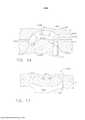
[0021] a Figura 16 é uma vista em seção transversal parcial de uma bigorna, ilustrando uma porção do grampo da Figura 15 sendo formado de uma configuração não formada para uma configuração formada;[0021] Figure 16 is a partial cross-sectional view of an anvil, illustrating a portion of the clamp of Figure 15 being formed from an unformed configuration to a formed configuration;
[0022] a Figura 17 é uma vista em elevação do grampo da Figura 15, em uma configuração formada;[0022] Figure 17 is an elevation view of the clamp of Figure 15, in a formed configuration;
[0023] a Figura 18 inclui vistas laterais de múltiplas pontas de grampo, de acordo com ao menos uma modalidade;[0023] Figure 18 includes side views of multiple clip tips, according to at least one embodiment;
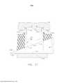
[0024] a Figura 19 é uma vista inferior de um grampo de acordo com ao menos uma modalidade, e receptáculos formadores em uma bigorna, de acordo com uma primeira disposição;[0024] Figure 19 is a bottom view of a clip according to at least one embodiment, and forming receptacles on an anvil, according to a first arrangement;
[0025] a Figura 20 é uma vista em seção transversal parcial de um receptáculo da bigorna da Figura 19, tomada ao longo da linha 20-20 na Figura 19;[0025] Figure 20 is a partial cross-sectional view of an anvil receptacle of Figure 19, taken along line 20-20 in Figure 19;
[0026] a Figura 21 é uma vista inferior do grampo e dos receptácu los formadores da Figura 19, de acordo com uma segunda disposição;[0026] Figure 21 is a bottom view of the clip and forming receptacles of Figure 19, according to a second arrangement;
[0027] a Figura 22 é uma vista inferior do grampo e dos receptácu los formadores da Figura 19, de acordo com uma terceira disposição;[0027] Figure 22 is a bottom view of the clip and forming receptacles of Figure 19, according to a third arrangement;
[0028] a Figura 23 é uma vista inferior do grampo da Figura 19 e dos receptáculos formadores, de acordo com ao menos uma modalidade;[0028] Figure 23 is a bottom view of the clip of Figure 19 and the forming receptacles, according to at least one embodiment;
[0029] a Figura 24 é uma vista em seção transversal parcial de um receptáculo da bigorna da Figura 23, tomada ao longo da linha 24-24 na Figura 23;[0029] Figure 24 is a partial cross-sectional view of an anvil receptacle of Figure 23, taken along line 24-24 in Figure 23;
[0030] a Figura 25 é uma vista inferior do grampo da Figura 19 e dos receptáculos formadores, de acordo com ao menos uma modalidade;[0030] Figure 25 is a bottom view of the clip of Figure 19 and the forming receptacles, according to at least one embodiment;
[0031] a Figura 26 é uma vista inferior do grampo da Figura 19 e dos receptáculos formadores, de acordo com ao menos uma modalidade;[0031] Figure 26 is a bottom view of the clip of Figure 19 and the forming receptacles, according to at least one embodiment;
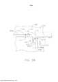
[0032] a Figura 27 é uma vista em perspectiva parcial de uma per na de grampo, de acordo com ao menos uma modalidade;[0032] Figure 27 is a partial perspective view of a clip leg, according to at least one embodiment;
[0033] a Figura 27A é uma vista de extremidade em seção trans versal parcial da perna de grampo da Figura 27;[0033] Figure 27A is an end view in partial cross-section of the clamp leg of Figure 27;
[0034] a Figura 27B é uma seção transversal longitudinal da perna de grampo da Figura 27;[0034] Figure 27B is a longitudinal cross-section of the clip leg of Figure 27;
[0035] a Figura 28 é uma vista em perspectiva de uma porção de uma tira de grampos fabricada mediante estampagem por matriz pro- gressiva;[0035] Figure 28 is a perspective view of a portion of a staple strip manufactured by progressive die stamping;
[0036] a Figura 28A é uma vista em seção transversal parcial da porção da tira de grampos da Figura 28, tomada ao longo da linha 28A-28A na Figura 28;[0036] Figure 28A is a partial cross-sectional view of the staple strip portion of Figure 28, taken along
[0037] a Figura 28B é uma vista em seção transversal parcial da porção da tira de grampos da Figura 28, tomada ao longo da linha 28B-28B na Figura 28;[0037] Figure 28B is a partial cross-sectional view of the staple strip portion of Figure 28, taken along
[0038] a Figura 28C é uma vista em perspectiva parcial de um deslizador configurado para engatar-se à tira de grampos da Figura 28;[0038] Figure 28C is a partial perspective view of a slider configured to engage the clip strip of Figure 28;
[0039] a Figura 29 é uma vista em perspectiva de uma porção de uma tira de grampos fabricada mediante estampagem por matriz pro-gressiva, de acordo com ao menos uma modalidade;[0039] Figure 29 is a perspective view of a portion of a staple strip manufactured by progressive die stamping, according to at least one embodiment;
[0040] a Figura 30 é uma vista em perspectiva inferior da tira de grampos da Figura 29;[0040] Figure 30 is a bottom perspective view of the staple strip of Figure 29;
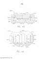
[0041] a Figura 31 é uma vista em seção transversal parcial de um cartucho de grampos e de grampos, de acordo com ao menos uma modalidade;[0041] Figure 31 is a partial cross-sectional view of a staple and staple cartridge, according to at least one embodiment;
[0042] a Figura 32 é uma vista em perspectiva de um conjunto de cartucho de grampos, de acordo com ao menos uma modalidade;[0042] Figure 32 is a perspective view of a staple cartridge assembly, according to at least one embodiment;
[0043] a Figura 33 é uma vista plana de topo do conjunto de cartu cho de grampos da Figura 32;[0043] Figure 33 is a top plan view of the staple cartridge assembly of Figure 32;
[0044] a Figura 34 é uma vista em detalhe de uma extremidade distal do conjunto de cartucho de grampos da Figura 32;[0044] Figure 34 is a detail view of a distal end of the staple cartridge assembly of Figure 32;
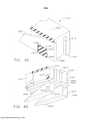
[0045] a Figura 35 é uma vista em perspectiva em seção transver sal parcial de um conjunto de cartucho de grampos, de acordo com ao menos uma modalidade, ilustrando grampos sendo ejetados do conjunto de cartucho de grampos por um membro de disparo;[0045] Figure 35 is a perspective view in partial cross-section of a staple cartridge assembly, according to at least one embodiment, illustrating staples being ejected from the staple cartridge assembly by a firing member;
[0046] a Figura 36 é uma vista explodida parcial do conjunto de cartucho de grampos da Figura 35;[0046] Figure 36 is a partial exploded view of the staple cartridge assembly of Figure 35;
[0047] a Figura 37 é uma vista em seção transversal parcial do conjunto de cartucho de grampos da Figura 35, que ilustra um grampo sendo deformado contra uma bigorna pelo membro de disparo;[0047] Figure 37 is a partial cross-sectional view of the staple cartridge assembly of Figure 35, illustrating a staple being biased against an anvil by the firing member;
[0048] a Figura 38 é uma vista em planta parcial de um grampo posicionado em uma cavidade para grampos do conjunto de cartucho de grampos da Figura 35;[0048] Figure 38 is a partial plan view of a staple positioned in a staple cavity of the staple cartridge assembly of Figure 35;
[0049] a Figura 39 é uma vista em perspectiva parcial de um grampo sendo erguido pelo membro de disparo do cartucho de grampos da Figura 35;[0049] Figure 39 is a partial perspective view of a staple being lifted by the firing member of the staple cartridge of Figure 35;
[0050] a Figura 40 é uma vista em perspectiva inferior do grampo da Figura 39;[0050] Figure 40 is a bottom perspective view of the clip of Figure 39;
[0051] a Figura 41 é um diagrama ilustrando o grampo da Figura 39 em uma posição nivelada;[0051] Figure 41 is a diagram illustrating the clamp of Figure 39 in a level position;
[0052] a Figura 42 é um diagrama ilustrando o grampo da Figura 39 em uma posição torta;[0052] Figure 42 is a diagram illustrating the clamp of Figure 39 in a crooked position;
[0053] a Figura 43 é uma vista em planta em seção transversal de uma cavidade para grampos, configurada para guiar um grampo, de acordo com ao menos uma modalidade;[0053] Figure 43 is a plan view in cross section of a cavity for staples, configured to guide a staple, according to at least one embodiment;
[0054] a Figura 44 é uma vista em perspectiva em seção transver sal de um conjunto de cartucho de grampos posicionado em uma garra de um instrumento de grampeamento cirúrgico, de acordo com ao menos uma modalidade, ilustrando um membro de disparo posicionado em um corpo de cartucho do conjunto de cartucho de grampos;[0054] Figure 44 is a perspective view in cross section of a staple cartridge assembly positioned in a gripper of a surgical stapling instrument, according to at least one embodiment, illustrating a trigger member positioned in a body staple cartridge assembly cartridge;
[0055] a Figura 45 é uma vista em perspectiva em seção transver sal parcial do conjunto de cartucho de grampos da Figura 44, ilustrando um recurso de retenção configurado para prender o membro de disparo no corpo do cartucho, quando o conjunto de cartucho de grampos não estiver posicionado na garra do instrumento de grampe- amento cirúrgico;[0055] Figure 45 is a perspective view in partial cross-section of the staple cartridge assembly of Figure 44, illustrating a retention feature configured to secure the trigger member in the cartridge body when the staple cartridge assembly it is not positioned in the jaw of the surgical stapling instrument;
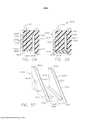
[0056] a Figura 46 é uma vista explodida em seção transversal parcial do conjunto de cartucho de grampos da Figura 44;[0056] Figure 46 is an exploded view in partial cross-section of the staple cartridge assembly of Figure 44;
[0057] a Figura 47 é uma vista de extremidade em seção transversal parcial do conjunto de cartucho de grampos da Figura 44;[0057] Figure 47 is an end view in partial cross-section of the staple cartridge assembly of Figure 44;
[0058] a Figura 48 é uma vista em perspectiva em seção transversal parcial do conjunto de cartucho de grampos da Figura 44, ilustran do um recurso de retenção configurado para prender de modo liberá- vel o conjunto de cartucho de grampos na garra do instrumento de grampeamento cirúrgico;[0058] Figure 48 is a perspective view in partial cross-section of the staple cartridge assembly of Figure 44, illustrating a retention feature configured to releasably secure the staple cartridge assembly in the clamping instrument grip. surgical stapling;
[0059] a Figura 49 é uma vista em planta parcial de um grampo posicionado em uma cavidade para grampos de um conjunto de cartucho de grampos, de acordo com ao menos uma modalidade;[0059] Figure 49 is a partial plan view of a clip positioned in a clip cavity of a clip cartridge assembly, according to at least one embodiment;
[0060] a Figura 50 é uma vista em detalhe de um recurso de re tenção configurado para prender o grampo de modo liberável no conjunto de cartucho de grampos da Figura 49;[0060] Figure 50 is a detail view of a retention feature configured to releasably secure the staple in the staple cartridge assembly of Figure 49;
[0061] a Figura 51 é uma vista em elevação em seção transversal parcial de um conjunto de cartucho de grampos, de acordo com ao menos uma modalidade;[0061] Figure 51 is an elevation view in partial cross-section of a staple cartridge assembly, according to at least one embodiment;
[0062] a Figura 52 é uma vista em perspectiva de um grampo, de acordo com ao menos uma modalidade;[0062] Figure 52 is a perspective view of a clip, according to at least one embodiment;
[0063] a Figura 53 é uma vista em perspectiva inferior do grampo da Figura 52;[0063] Figure 53 is a bottom perspective view of the clamp of Figure 52;
[0064] a Figura 54 é uma vista em elevação frontal do grampo da Figura 52;[0064] Figure 54 is a front elevation view of the clamp of Figure 52;
[0065] a Figura 55 é uma vista em elevação lateral do grampo da Figura 52;[0065] Figure 55 is a side elevation view of the clamp of Figure 52;
[0066] a Figura 56 é uma vista inferior do grampo da Figura 52;[0066] Figure 56 is a bottom view of the clamp of Figure 52;
[0067] a Figura 57 é uma vista em perspectiva de um membro de disparo de um conjunto de cartucho de grampos, de acordo com ao menos uma modalidade, compreendendo canaletas de alinhamento;[0067] Figure 57 is a perspective view of a firing member of a staple cartridge assembly, according to at least one embodiment, comprising alignment channels;
[0068] a Figura 58 é um diagrama ilustrando o membro de disparo da Figura 57 e um grampo posicionado em uma cavidade para grampos de um conjunto de cartucho de grampos;[0068] Figure 58 is a diagram illustrating the trigger member of Figure 57 and a clip positioned in a clip cavity of a clip cartridge assembly;
[0069] a Figura 59 é um diagrama ilustrando o membro de disparo da Figura 57 alinhando o grampo da Figura 58 dentro da cavidade para grampos da Figura 58;[0069] Figure 59 is a diagram illustrating the trigger member of Figure 57 aligning the clip of Figure 58 within the clip cavity of Figure 58;
[0070] a Figura 60 é uma vista em perspectiva do membro de dis paro da Figura 57 e de grampos dispostos em duas fileiras longitudinais;[0070] Figure 60 is a perspective view of the trigger member of Figure 57 and of clips arranged in two longitudinal rows;
[0071] a Figura 61 é uma vista em seção transversal parcial de uma canaleta de alinhamento do membro de disparo da Figura 57 e uma porção do grampo da Figura 58;[0071] Figure 61 is a partial cross-sectional view of a trigger member alignment groove of Figure 57 and a portion of the clip of Figure 58;
[0072] a Figura 62 é uma vista em perspectiva em seção transver sal parcial do conjunto de cartucho de grampos da Figura 58;[0072] Figure 62 is a perspective view in partial cross-section of the staple cartridge assembly of Figure 58;
[0073] a Figura 63 é uma vista explodida parcial do conjunto de cartucho de grampos da Figura 58;[0073] Figure 63 is a partial exploded view of the staple cartridge assembly of Figure 58;
[0074] a Figura 64 é uma vista em perspectiva em seção transver sal inferior parcial do conjunto de cartucho de grampos da Figura 58;[0074] Figure 64 is a perspective view in partial lower cross-section of the staple cartridge assembly of Figure 58;
[0075] a Figura 65 é uma vista em perspectiva parcial de proje ções que se estendem a partir de uma superfície de plataforma de um conjunto de cartucho de grampos, de acordo com ao menos uma mo-dalidade alternativa;[0075] Figure 65 is a partial perspective view of projections extending from a platform surface of a staple cartridge assembly, according to at least one alternative embodiment;
[0076] a Figura 66 é uma vista em perspectiva parcial de proje ções que se estendem a partir de uma superfície de plataforma de um conjunto de cartucho de grampos, de acordo com ao menos uma mo-dalidade alternativa;[0076] Figure 66 is a partial perspective view of projections extending from a platform surface of a staple cartridge assembly, according to at least one alternative embodiment;
[0077] a Figura 67 é uma vista em perspectiva inferior de um corpo de cartucho de um conjunto de cartucho de grampos;[0077] Figure 67 is a bottom perspective view of a cartridge body of a staple cartridge assembly;
[0078] a Figura 68 é uma vista inferior do corpo do cartucho da Figura 67;[0078] Figure 68 is a bottom view of the cartridge body of Figure 67;
[0079] a Figura 69 é uma vista em perspectiva inferior do corpo de cartucho do conjunto de cartucho de grampos da Figura 32;[0079] Figure 69 is a bottom perspective view of the cartridge body of the staple cartridge assembly of Figure 32;
[0080] a Figura 70 é uma vista inferior do corpo do cartucho da Figura 32;[0080] Figure 70 is a bottom view of the cartridge body of Figure 32;
[0081] a Figura 71 é um diagrama ilustrando o corpo do cartucho da Figura 67 para uma modalidade alternativa de um corpo de cartucho;[0081] Figure 71 is a diagram illustrating the cartridge body of Figure 67 for an alternative embodiment of a cartridge body;
[0082] a Figura 72 é uma vista em planta superior parcial de um conjunto de cartucho de grampos, de acordo com ao menos uma mo-dalidade;[0082] Figure 72 is a partial top plan view of a staple cartridge assembly, according to at least one embodiment;
[0083] a Figura 73 é uma vista em perspectiva parcial do cartucho de grampos da Figura 32;[0083] Figure 73 is a partial perspective view of the staple cartridge of Figure 32;
[0084] a Figura 74 é uma vista em seção transversal do cartucho de grampos da Figura 32 e da bigorna da Figura 37, ilustrando certos grampos em uma posição não disparada e certos grampos em uma posição disparada;[0084] Figure 74 is a cross-sectional view of the staple cartridge of Figure 32 and the anvil of Figure 37, illustrating certain staples in an unfired position and certain staples in a fired position;
[0085] a Figura 75 ilustra os grampos do cartucho de grampos da Figura 32 deformados em três alturas diferentes;[0085] Figure 75 illustrates the staple cartridge staples of Figure 32 deformed at three different heights;
[0086] a Figura 76 ilustra os grampos do cartucho de grampos da Figura 32 implantados no tecido de um paciente;[0086] Figure 76 illustrates the staples of the staple cartridge of Figure 32 implanted in a patient's tissue;
[0087] a Figura 77 ilustra um grampo do cartucho de grampos da Figura 32 sendo deformado;[0087] Figure 77 illustrates a staple of the staple cartridge of Figure 32 being deformed;
[0088] a Figura 78 é uma vista em perspectiva de um grampo, de acordo com ao menos uma modalidade;[0088] Figure 78 is a perspective view of a clip, according to at least one embodiment;
[0089] a Figura 79 é uma vista em seção transversal do grampo da Figura 78;[0089] Figure 79 is a cross-sectional view of the clamp of Figure 78;
[0090] a Figura 80 é uma vista em perspectiva de um conjunto de grampo, de acordo com ao menos uma modalidade;[0090] Figure 80 is a perspective view of a clamp assembly, according to at least one embodiment;
[0091] a Figura 81 é uma vista em elevação do conjunto de gram po da Figura 80;[0091] Figure 81 is an elevation view of the clamp assembly of Figure 80;
[0092] a Figura 82 é uma vista em perspectiva de um complemen- to de grampo implantável;[0092] Figure 82 is a perspective view of an implantable clip complement;
[0093] a Figura 83 é uma vista em seção transversal do comple mento de grampo da Figura 82;[0093] Figure 83 is a cross-sectional view of the clip complement of Figure 82;
[0094] a Figura 84 é uma vista em perspectiva parcial de um con junto de grampo, incluindo o complemento de grampo da Figura 82;[0094] Figure 84 is a partial perspective view of a clip assembly, including the clip complement of Figure 82;
[0095] a Figura 85 ilustra o conjunto de grampo da Figura 84 im plantado no tecido;[0095] Figure 85 illustrates the clip assembly of Figure 84 implanted in the tissue;
[0096] a Figura 86 é uma vista em perspectiva de um grampo, de acordo com ao menos uma modalidade, ilustrado em uma configuração deformada;[0096] Figure 86 is a perspective view of a clip, according to at least one embodiment, illustrated in a deformed configuration;
[0097] a Figura 87 é uma vista em planta de um corpo de cartucho circular, compreendendo uma pluralidade dos conjuntos de grampo da Figura 84, de acordo com ao menos uma modalidade;[0097] Figure 87 is a plan view of a circular cartridge body, comprising a plurality of the clip assemblies of Figure 84, according to at least one embodiment;
[0098] a Figura 88 ilustra o espaçamento dos grampos da Figura 35 em tecido não estirado;[0098] Figure 88 illustrates the spacing of the staples of Figure 35 in non-stretched fabric;
[0099] a Figura 89 ilustra o espaçamento dos grampos da Figura 35 em tecido estirado;[0099] Figure 89 illustrates the spacing of the staples of Figure 35 in stretched fabric;
[00100] a Figura 90 é uma vista em perspectiva de um grampo, de acordo com ao menos uma modalidade;[00100] Figure 90 is a perspective view of a clamp, according to at least one embodiment;
[00101] a Figura 91 ilustra o grampo da Figura 90 implantado no tecido;[00101] Figure 91 illustrates the staple of Figure 90 implanted in the tissue;
[00102] a Figura 92 ilustra o grampo da Figura 90 após ser parcialmente dissolvido;[00102] Figure 92 illustrates the staple of Figure 90 after being partially dissolved;
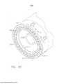
[00103] a Figura 93 é uma vista em perspectiva em seção transversal de uma porção de um grampeador cirúrgico circular, de acordo com ao menos uma modalidade;[00103] Figure 93 is a perspective view in cross section of a portion of a circular surgical stapler, according to at least one embodiment;
[00104] a Figura 94 é uma vista em perspectiva em seção transversal parcial do grampeador cirúrgico circular da Figura 93;[00104] Figure 94 is a perspective view in partial cross-section of the circular surgical stapler of Figure 93;
[00105] a Figura 95 é uma vista em perspectiva parcial do grampeador cirúrgico circular da Figura 93;[00105] Figure 95 is a partial perspective view of the circular surgical stapler of Figure 93;
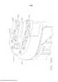
[00106] a Figura 96 é uma vista em perspectiva explodida parcial de um grampeador cirúrgico circular, de acordo com ao menos uma modalidade;[00106] Figure 96 is a partial exploded perspective view of a circular surgical stapler, according to at least one embodiment;
[00107] a Figura 97 é uma vista em perspectiva parcial do grampeador cirúrgico circular da Figura 96, ilustrando grampos em uma posição pré-carregada;[00107] Figure 97 is a partial perspective view of the circular surgical stapler of Figure 96, illustrating staples in a preloaded position;
[00108] a Figura 98 é uma vista em perspectiva parcial do grampeador cirúrgico circular da Figura 96;[00108] Figure 98 is a partial perspective view of the circular surgical stapler of Figure 96;
[00109] a Figura 99 é uma vista de extremidade de uma configuração de grampeamento cirúrgico circular, de acordo com ao menos uma modalidade;[00109] Figure 99 is an end view of a circular surgical stapling configuration, according to at least one embodiment;
[00110] a Figura 100 é uma vista de extremidade de uma configuração de grampeamento cirúrgico circular, de acordo com ao menos uma modalidade;[00110] Figure 100 is an end view of a circular surgical stapling configuration, according to at least one embodiment;
[00111] a Figura 101 é uma vista em seção transversal parcial de um cólon grampeado com um instrumento de grampeamento circular aqui descrito;[00111] Figure 101 is a partial cross-sectional view of a colon stapled with a circular stapling instrument described herein;
[00112] a Figura 102 é uma vista em perspectiva parcial de um grampeador curvo, de acordo com ao menos uma modalidade;[00112] Figure 102 is a partial perspective view of a curved stapler, according to at least one embodiment;
[00113] a Figura 103 é uma vista explodida parcial do grampeador curvo da Figura 102;[00113] Figure 103 is a partial exploded view of the curved stapler of Figure 102;
[00114] a Figura 104 é uma vista em perspectiva parcial do grampeador curvo da Figura 102;[00114] Figure 104 is a partial perspective view of the curved stapler of Figure 102;
[00115] a Figura 105 é uma vista em perspectiva parcial de um grampeador curvo, de acordo com ao menos uma modalidade; e[00115] Figure 105 is a partial perspective view of a curved stapler, according to at least one embodiment; and
[00116] a Figura 106 é uma vista em perspectiva parcial do grampeador curvo da Figura 105.[00116] Figure 106 is a partial perspective view of the curved stapler of Figure 105.
[00117] Os caracteres de referência correspondentes indicam as partes correspondentes através das várias vistas. As exemplificações aqui descritas ilustram várias modalidades da invenção, em uma for ma, e tais exemplificações não devem ser consideradas como limitadoras do escopo da invenção em qualquer modo.[00117] Matching reference characters indicate matching parts across the various views. The exemplifications described herein illustrate various embodiments of the invention, in one form, and such exemplifications are not to be considered as limiting the scope of the invention in any way.
[00118] O requerente do presente pedido detém os seguintes pedidos de Patente US que foram depositados na mesma data do presente pedido e que estão, cada um, aqui incorporados por referência em suas respectivas totalidades:[00118] The applicant for this application holds the following US Patent applications that were filed on the same date as this application and which are each incorporated herein by reference in their respective entireties:
[00119] - Pedido de Patente US n° de série , intitulado "SURGICAL STAPLES FOR MINIMIZING STAPLE ROLL"; n° do do-cumento do procurador END7687USNP/150127;[00119] - US Patent Application Serial No. entitled "SURGICAL STAPLES FOR MINIMIZING STAPLE ROLL"; attorney document no. END7687USNP/150127;
[00120] - Pedido de Patente US n° de série , intitulado "SURGICAL STAPLES COMPRISING FEATURES FOR IMPROVED FASTENING OF TISSUE"; n° do documento do procurador END7678USNP/150118;[00120] - US Patent Application Serial No., entitled "SURGICAL STAPLES COMPRISING FEATURES FOR IMPROVED FASTENING OF TISSUE"; attorney document no. END7678USNP/150118;
[00121] - Pedido de Patente US n° de série , intitulado "SURGICAL STAPLES COMPRISING HARDNESS VARIATIONS FOR IMPROVED FASTENING OF TISSUE"; n° do documento do procurador END7727USNP/150298;[00121] - US Patent Application Serial No., entitled "SURGICAL STAPLES COMPRISING HARDNESS VARIATIONS FOR IMPROVED FASTENING OF TISSUE"; attorney document no. END7727USNP/150298;
[00122] - Pedido de Patente US n° de série , intitulado "SURGICAL STAPLING CONFIGURATIONS FOR CURVED AND CIRCULAR STAPLING INSTRUMENTS"; n° do documento do procurador END7682USNP/150122;[00122] - US Patent Application Serial No. entitled "SURGICAL STAPLING CONFIGURATIONS FOR CURVED AND CIRCULAR STAPLING INSTRUMENTS"; attorney document no. END7682USNP/150122;
[00123] - Pedido de Patente US n° de série , intitulado "STAPLE CARTRIDGE ASSEMBLY WITHOUT A BOTTOM COVER"; n° do documento do procurador END7679USNP/150119;[00123] - US Patent Application Serial No., entitled "STAPLE CARTRIDGE ASSEMBLY WITHOUT A BOTTOM COVER"; attorney document no. END7679USNP/150119;
[00124] - Pedido de Patente US n° de série , intitulado "STAPLE CARTRIDGE ASSEMBLY COMPRISING STAPLE CAVITIES FOR PROVIDING BETTER STAPLE GUIDANCE"; n° do documento do procurador END7681USNP/150121;[00124] - US Patent Application Serial No., entitled "STAPLE CARTRIDGE ASSEMBLY COMPRISING STAPLE CAVITIES FOR PROVIDING BETTER STAPLE GUIDANCE"; attorney document no. END7681USNP/150121;
[00125] - Pedido de Patente US n° de série , intitulado "STAPLE CARTRIDGE ASSEMBLY INCLUDING STAPLE GUIDES"; n° do documento do procurador END7685USNP/150125;[00125] - US Patent Application Serial No. entitled "STAPLE CARTRIDGE ASSEMBLY INCLUDING STAPLE GUIDES"; attorney document no. END7685USNP/150125;
[00126] - Pedido de Patente US n° de série , intitulado "STAPLE CARTRIDGE ASSEMBLY COMPRISING STAPLE ALIGNMENT FEATURES ON A FIRING MEMBER"; n° do documento do procurador END7688USNP/150128;[00126] - US Patent Application Serial No., entitled "STAPLE CARTRIDGE ASSEMBLY COMPRISING STAPLE ALIGNMENT FEATURES ON A FIRING MEMBER"; attorney document no. END7688USNP/150128;
[00127] - Pedido de Patente US n° de série , intitulado "STAPLE CARTRIDGE ASSEMBLY COMPRISING VARIOUS TISSUE COMPRESSION GAPS AND STAPLE FORMING GAPS"; n° do documento do procurador END7684USNP/150124;[00127] - US Patent Application Serial No., entitled "STAPLE CARTRIDGE ASSEMBLY COMPRISING VARIOUS TISSUE COMPRESSION GAPS AND STAPLE FORMING GAPS"; attorney document no. END7684USNP/150124;
[00128] - Pedido de Patente US n° de série , intitulado "STAPLES CONFIGURED TO SUPPORT AN IMPLANTABLE ADJUNCT"; n° do documento do procurador END7686USNP/150126;[00128] - US Patent Application Serial No., entitled "STAPLES CONFIGURED TO SUPPORT AN IMPLANTABLE ADJUNCT"; attorney document no. END7686USNP/150126;
[00129] - Pedido de Patente US n° de série , intitulado "STAPLES COMPRISING A COVER"; n° do documento do procurador END7689USNP/150129; e[00129] - US Patent Application Serial No., entitled "STAPLES COMPRISING A COVER"; attorney document no. END7689USNP/150129; and
[00130] - Pedido de Patente US n° de série , intitulado " STAPLE CARTRIDGE ASSEMBLY INCLUDING FEATURES FOR CONTROLLING THE ROTATION OF STAPLES WHEN BEING EJECTED THEREFROM"; n° do documento do procurador END7683USNP/150123.[00130] - US Patent Application Serial No., entitled "STAPLE CARTRIDGE ASSEMBLY INCLUDING FEATURES FOR CONTROLLING THE ROTATION OF STAPLES WHEN BEING EJECTED THEREFROM"; attorney document no. END7683USNP/150123.
[00131] O requerente do presente pedido detém também os seguintes pedidos de patente, que foram depositados em 23 de dezembro de 2013 e que estão, cada um, aqui incorporados por referência em suas respectivas totalidades;[00131] The applicant for this application also holds the following patent applications, which were filed on December 23, 2013 and which are each incorporated herein by reference in their respective entireties;
[00132] - Pedido de Patente US n° de série 14/138.554, intitulado "SURGICAL INSTRUMENTS WITH ARTICULATABLE SHAFT AR-RANGEMENTS";[00132] - US Patent Application Serial No. 14/138,554, entitled "SURGICAL INSTRUMENTS WITH ARTICULATABLE SHAFT AR-RANGEMENTS";
[00133] - Pedido de Patente US n° de série 14/138.465, intitulado "SURGICAL STAPLES AND STAPLE CARTRIDGES";[00133] - US Patent Application Serial No. 14/138,465, entitled "SURGICAL STAPLES AND STAPLE CARTRIDGES";
[00134] - Pedido de Patente US n° de série 14/138.474, intitulado "ARTICULATABLE SURGICAL INSTRUMENTS WITH SEPARATE AND DISTINCT CLOSING AND FIRING SYSTEMS";[00134] - US Patent Application Serial No. 14/138,474, entitled "ARTICULATABLE SURGICAL INSTRUMENTS WITH SEPARATE AND DISTINCT CLOSING AND FIRING SYSTEMS";
[00135] - Pedido de Patente US n° de série 14/138.485, intitulado "SURGICAL CUTTING AND STAPLING INSTRUMENTS WITH INDE-PENDENT JAW CONTROL FEATURES";[00135] - US Patent Application Serial No. 14/138,485, entitled "SURGICAL CUTTING AND STAPLING INSTRUMENTS WITH INDE-PENDENT JAW CONTROL FEATURES";
[00136] - Pedido de Patente US n° de série 14/138.475, intitulado "SURGICAL STAPLES AND STAPLE CARTRIDGES";[00136] - US Patent Application Serial No. 14/138,475, entitled "SURGICAL STAPLES AND STAPLE CARTRIDGES";
[00137] - Pedido de Patente US n° de série 14/138.481, intitulado "SURGICAL STAPLES AND METHODS FOR MAKING THE SAME";[00137] - US Patent Application Serial No. 14/138,481, entitled "SURGICAL STAPLES AND METHODS FOR MAKING THE SAME";
[00138] - Pedido de Patente US n° de série 14/138.489, intitulado "SURGICAL STAPLES, STAPLE CARTRIDGES AND SURGICAL END EFFECTORS";[00138] - US Patent Application Serial No. 14/138,489, entitled "SURGICAL STAPLES, STAPLE CARTRIDGES AND SURGICAL END EFFECTORS";
[00139] - Pedido de Patente de Design US n° de série 29/477.488, intitulado "SURGICAL FASTENER";[00139] - US Design Patent Application Serial No. 29/477,488, entitled "SURGICAL FASTENER";
[00140] - Pedido de Patente US n° de série 14/138.505, intitulado "FASTENER CARTRIDGE COMPRISING AN EXTENDABLE FIRING MEMBER";[00140] - US Patent Application Serial No. 14/138,505, entitled "FASTENER CARTRIDGE COMPRISING AN EXTENDABLE FIRING MEMBER";
[00141] - Pedido de Patente US n° de série 14/138.518, intitulado "FASTENER CARTRIDGE COMPRISING A FIRING MEMBER CON-FIGURED TO DIRECTLY ENGAGE AND EJECT FASTENERS FROM THE FASTENER CARTRIDGE";[00141] - US Patent Application Serial No. 14/138,518, entitled "FASTENER CARTRIDGE COMPRISING A FIRING MEMBER CON-FIGURED TO DIRECTLY ENGAGE AND EJECT FASTENERS FROM THE FASTENER CARTRIDGE";
[00142] - Pedido de Patente US n° de série 14/138.530, intitulado "FASTENER CARTRIDGE COMPRISING A FIRING MEMBER IN-CLUDING FASTENER TRANSFER SURFACES";[00142] - US Patent Application Serial No. 14/138,530, entitled "FASTENER CARTRIDGE COMPRISING A FIRING MEMBER IN-CLUDING FASTENER TRANSFER SURFACES";
[00143] - Pedido de Patente US n° de série 14/138.507, intitulado "MODULAR SURGICAL INSTRUMENTS";[00143] - US Patent Application Serial No. 14/138,507, entitled "MODULAR SURGICAL INSTRUMENTS";
[00144] - Pedido de Patente US n° de série 14/138.497, intitulado "SURGICAL CUTTING AND STAPLING INSTRUMENTS WITH ARTI-CULATABLE END EFFECTORS"; e[00144] - US Patent Application Serial No. 14/138,497, entitled "SURGICAL CUTTING AND STAPLING INSTRUMENTS WITH ARTI-CULATABLE END EFFECTORS"; and
[00145] - Pedido de Patente US n° de série 14/138.516, intitulado "SURGICAL CUTTING AND STAPLING METHODS".[00145] - US Patent Application Serial No. 14/138,516, entitled "SURGICAL CUTTING AND STAPLING METHODS".
[00146] Numerosos detalhes específicos são apresentados para fornecer um completo entendimento da estrutura, função, fabricação e uso geral das modalidades conforme descrito no relatório descritivo e ilustrado nos desenhos anexos. Operações, componentes e elementos bem conhecidos foram descritos em detalhes de modo a não obscurecer as modalidades descritas no relatório descritivo. O leitor entenderá que as modalidades descritas e ilustradas na presente invenção são exemplos não limitadores e, portanto, pode-se entender que os detalhes estruturais e funcionais específicos descritos na presente invenção podem ser representativos e ilustrativos. Podem ser feitas variações e alterações a isso, sem se desviar do escopo das reivindicações.[00146] Numerous specific details are presented to provide a complete understanding of the structure, function, fabrication and general use of the modalities as described in the descriptive report and illustrated in the attached drawings. Well known operations, components and elements have been described in detail so as not to obscure the embodiments described in the specification. The reader will understand that the embodiments described and illustrated in the present invention are non-limiting examples and, therefore, it is to be understood that the specific structural and functional details described in the present invention may be representative and illustrative. Variations and alterations may be made thereto without deviating from the scope of the claims.
[00147] Os termos "compreende" (e qualquer forma de compreende, como "compreende" e "que compreende"), "tem" (e qualquer forma de tem, como "tem" e "que tem"), "inclui" (e qualquer forma de inclui, como "inclui" e "que inclui") e "contém" (e qualquer forma de contém, como "contém" e "que contém") são verbos de ligação irrestritos. Como um resultado, um sistema, dispositivo ou aparelho cirúrgico que "compreende", "tem", "inclui" ou "contém" um ou mais elementos possui aqueles um ou mais elementos, mas não é limitado a possuir somente aqueles um ou mais elementos. Da mesma forma, um elemento de um sistema, dispositivo ou aparelho cirúrgico que "compreende", "tem", "inclui" ou "contém" um ou mais recursos possui aqueles um ou mais recurso, mas não é limitado a possuir somente aqueles um ou mais recursos.[00147] The terms "comprises" (and any form of comprises, such as "comprises" and "which comprises"), "has" (and any form of has, such as "has" and "which has"), "includes" (and any form of includes, such as "includes" and "which includes") and "contains" (and any form of contains, such as "contains" and "which contains") are unrestricted linking verbs. As a result, a surgical system, device or apparatus that "comprises", "has", "includes" or "contains" one or more elements has those one or more elements, but is not limited to having only those one or more elements . Similarly, an element of a system, device or surgical apparatus that "comprises", "has", "includes" or "contains" one or more features has those one or more features, but is not limited to having only those one or more features. or more features.
[00148] Os termos "proximal" e "distal" são usados na presente invenção com referência a um médico que manipula a porção de cabo do instrumento cirúrgico. O termo "proximal" refere-se à porção mais próxima ao médico, e o termo "distal" refere-se à porção situada na direção oposta ao médico. Também será entendido que, por uma questão de conveniência e clareza, termos espaciais como "vertical", "horizontal", "para cima" e "para baixo" podem ser usados na presente invenção com relação aos desenhos. Entretanto, instrumentos cirúrgicos podem ser usados em muitas orientações e posições, e esses termos não se destinam a ser limitadores e/ou absolutos.[00148] The terms "proximal" and "distal" are used in the present invention with reference to a physician manipulating the handle portion of the surgical instrument. The term "proximal" refers to the portion closest to the practitioner, and the term "distal" refers to the portion located away from the practitioner. It will also be understood that, for the sake of convenience and clarity, spatial terms such as "vertical", "horizontal", "up" and "down" may be used in the present invention in connection with the drawings. However, surgical instruments can be used in many orientations and positions, and these terms are not intended to be limiting and/or absolute.
[00149] São fornecidos vários dispositivos e métodos exemplifica- dores para a realização de procedimentos cirúrgicos laparoscópicos e minimamente invasivos. Entretanto, o leitor entenderá prontamente que os vários métodos e dispositivos descritos na presente invenção podem ser usados em inúmeros procedimentos e aplicações cirúrgicas, inclusive, por exemplo, em relação a procedimentos cirúrgicos abertos. Conforme prossegue a presente Descrição Detalhada, o leitor entenderá ainda que os vários instrumentos aqui descritos podem ser inseridos em um corpo, de qualquer maneira, como através de um orifício natural, através de uma incisão ou perfuração formada em tecido, etc. As porções funcionais ou porções do atuador de extremidade dos instrumentos podem ser inseridas diretamente no corpo de um paciente, ou podem ser inseridas por meio de um dispositivo de acesso que tenha uma canaleta de trabalho através da qual podem ser avançados o atuador de extremidade e o eixo de acionamento alongado de um instrumento cirúrgico.[00149] Several exemplary devices and methods are provided for performing laparoscopic and minimally invasive surgical procedures. However, the reader will readily understand that the various methods and devices described in the present invention can be used in a number of surgical procedures and applications, including, for example, in relation to open surgical procedures. As this Detailed Description proceeds, the reader will further understand that the various instruments described herein may be inserted into a body in any manner, such as through a natural orifice, through an incision or perforation formed in tissue, etc. The functional portions or end actuator portions of the instruments may be inserted directly into a patient's body, or may be inserted through an access device that has a working channel through which the end actuator and the end actuator can be advanced. elongated drive shaft of a surgical instrument.
[00150] Um grampo, ou prendedor, aqui descrito é configurado para uso com um instrumento de grampeamento cirúrgico. Discutido com mais detalhes abaixo, o grampo é armazenado de modo removível em uma cavidade para grampos de um cartucho de grampos. O cartucho de grampos compreende um deslizador configurado para receber um acionamento de disparo proveniente do instrumento de grampeamento cirúrgico, o qual aplica uma força sobre o grampo para ejetá-lo da cavidade para grampos. Quando o grampo é ejetado, ou conduzido, para fora da cavidade para grampos pelo deslizador, o grampo é submetido a um processo de deformação, onde o grampo assume a forma de uma configuração disparada, a partir de uma configuração não disparada. O grampo assume a forma da configuração disparada quando o grampo entra em contato com os correspondentes receptáculos formadores de uma bigorna do instrumento de grampeamento cirúrgico.[00150] A clamp, or fastener, described herein is configured for use with a surgical stapling instrument. Discussed in more detail below, the staple is removable stored in a staple cavity of a staple cartridge. The staple cartridge comprises a slider configured to receive a trigger from the surgical stapling instrument which applies a force to the staple to eject it from the staple cavity. As the staple is ejected, or driven, out of the staple cavity by the slider, the staple is subjected to a deformation process where the staple takes the shape of a fired configuration from an unfired configuration. The staple takes the form of the configuration triggered when the staple comes into contact with the corresponding forming receptacles of an anvil of the surgical stapling instrument.
[00151] Vários grampos aqui descritos compreendem um grampo de formato plano, o qual pode ser cortado e/ou estampado a partir de uma folha de material, por exemplo. A folha de material pode ser metálica, e pode compreender aço inoxidável e/ou titânio, por exemplo. Em ao menos uma instância, os contornos podem ser traçados, gravados e/ou cortados na folha de material, sendo usinados e/ou cortados a laser para formar os grampos em um formato fabricado.[00151] Several clips described herein comprise a flat-shaped clip, which can be cut and/or stamped from a sheet of material, for example. The sheet of material may be metallic, and may comprise stainless steel and/or titanium, for example. In at least one instance, contours may be traced, engraved and/or cut into the sheet of material, machined and/or laser cut to form the staples into a manufactured shape.
[00152] Os grampos compreendem um par de pernas de grampo e uma porção de base do grampo, ou coroa, a partir da qual se estendem as pernas de grampo. Cada perna de grampo compreende uma ponta de grampo, a qual é configurada para perfurar o tecido e entrar em contato com um correspondente receptáculos formadores na bigorna do instrumento de grampeamento cirúrgico. As pernas de grampo são configuradas para mudar de formato a fim de se obter uma configuração formada para fixar o tecido. A porção de base do grampo define um primeiro plano e as pernas do grampo definem um segundo plano que é lateralmente deslocado, mas ao menos substancialmente paralelo, em relação ao primeiro plano. São previstas modalidades nas quais o primeiro e o segundo planos não são paralelos.[00152] The clips comprise a pair of clip legs and a clip base portion, or crown, from which the clip legs extend. Each staple leg comprises a staple tip which is configured to pierce tissue and contact a corresponding forming receptacle on the anvil of the surgical stapling instrument. The staple legs are configured to change shape to obtain a formed configuration for securing the fabric. The base portion of the clip defines a foreground and the legs of the clip define a second plane that is laterally offset from, but at least substantially parallel to, the foreground. Embodiments are envisaged in which the foreground and background are not parallel.
[00153] O grampo de formato plano 100, representado nas Figuras 1 a 4, compreende uma perna de grampo proximal 110, uma perna de grampo distal 120 e uma porção de base do grampo 130. O grampo 100 compreende ainda porções de transição vertical, ou flexões, 118, 128 e porções de transição lateral, ou flexões, 116, 126. As porções de transição verticais 118, 128 flexionam, ou estendem, as pernas 110, 120 verticalmente, ou para cima, a partir da porção de base do grampo 130. As porções de transição lateral 116, 126 estendem as pernas de grampo 110, 120 lateralmente para fora, ou ao menos em posição substancialmente perpendicular em relação à porção de base do grampo 130. As pernas de grampo 110, 120 definem um primeiro plano e a porção de base do grampo 130 define um segundo plano. Juntas, as porções de transição vertical 118, 128 e as porções de transição lateral 116, 126 permitem que as pernas de grampo 110, 120 sejam lateralmente deslocadas e paralelas em relação à porção de base do grampo 130. Dito de outro modo, o primeiro plano é deslocado, e ao menos substancialmente paralelo, em relação ao segundo plano. Nas Figuras 1 a 4, o primeiro plano é deslocado na direção Y negativa. Outros grampos podem ser usados em conjunto com uma pluralidade de grampos 100, onde os outros grampos compreendem um primeiro plano que é deslocado na direção Y positiva. O uso de ambos os tipos de grampos permite que fileiras de grampos sejam aninhadas, ou en-trelaçadas, onde as pernas de grampos de fileiras vizinhas podem estar ao menos substancialmente alinhadas e/ou compartilhar um eixo longitudinal comum. Em várias instâncias, as fileiras de grampos podem ser aninhadas para proporcionar fileiras de grampos mais densas.[00153] The flat-shaped
[00154] A perna de grampo proximal 110 e a perna de grampo distal 120 compreendem pontas de grampo 112, 122 e cantos 114, 124, respectivamente. As pontas 112, 122 são configuradas para perfurar tecido e entrar em contato com um correspondente receptáculo formador em uma bigorna de um instrumento de grampeamento cirúrgico. As pontas 112, 122 entram em contato com a bigorna quando o grampo 100 recebe uma força de acionamento para ejetar os grampos 100 a partir de uma correspondente cavidade para grampos no cartucho de grampos. As pontas 112, 122 e/ou as pernas 110, 120 do grampo 100 começarão, então, a formar-se de uma configuração não disparada para uma configuração disparada. A perna de grampo proximal 120 compreende ainda um pé de engate dianteiro 117, que compreende uma superfície chanfrada, ou borda, 119. Conforme o deslizador entra em contato com o grampo 100, durante a translação distal do desliza- dor, um recurso do deslizador pode engatar-se ao pé de engate dianteiro 117 para auxiliar na prevenção da rolagem, ou rotação, longitudinal do grampo, por exemplo. O pé de engate 117 pode compreender um ponto de pressão que é configurado para ser empurrado para diante a fim de carregar o grampo 100 em um cartucho de grampos.[00154] The
[00155] Como o grampo 100 é um grampo de formato plano, as pernas de grampo 110, 120, as pontas 112, 122 e/ou outras porções do grampo 100 podem ser ainda desenvolvidas, ou trabalhadas, após terem sido estampadas a partir de um material plano, ou ao menos substancialmente plano. O desenvolvimento adicional do grampo 100 pode fornecer propriedades específicas criando e/ou alterando planos de flexão preferenciais, robustez e/ou elasticidade, por exemplo. Os grampos tradicionais, formados por fio metálico, compreendem propriedades desejáveis que são vantajosas para a fixação cirúrgica e podem ser implementadas com o grampo 100. Os métodos para construir os cantos 114, 124 e/ou as pontas 112, 122, por exemplo, podem incluir qualquer processo adequado, inclusive trabalho a frio, por exemplo. Um processo específico pode incluir cunhagem mediante o trabalho dos cantos 114, 124 em um perfil arredondado, angular, oblíquo e/ou parabólico, por exemplo. As pontas de grampo 112, 122 também podem ser trabalhadas com o uso de métodos similares para fornecer uma ponta adequada configurada para perfurar tecido e formar- se contra um correspondente receptáculo formador na bigorna.[00155] As the
[00156] A porção de base do grampo 130 compreende uma superfície de acionamento inclinada 132, uma superfície de acionamento final 131 e uma parede distal 133. Em várias modalidades, o grampo 100 é suportado em um cartucho de grampos por uma bandeja, sendo que a superfície de acionamento final 131 é configurada para repousar sobre a bandeja. Em várias outras modalidades, nas quais um cartucho de grampos é desprovido de bandeja, a superfície de acionamento final não repousa sobre uma bandeja sendo que, ao invés disso, a superfície de acionamento final compreende uma posição inicial que reside acima de uma superfície de fundo do cartucho de grampos sem bandeja. Isso permitiria que uma superfície de fundo do deslizador e a superfície de fundo do cartucho de grampos sem bandeja ficassem ao menos substancialmente niveladas, conforme o deslizador translada através do cartucho. A superfície de acionamento 132 de cada porção de base do grampo 130 é configurada para receber a força de acionamento Fs proveniente do deslizador do instrumento de grampea- mento cirúrgico. Quando o carrinho translada distalmente através do cartucho de grampos, o deslizador entra em contato com a superfície de acionamento 132 para erguer o grampo 100 para fora do cartucho e, além disso, entrar em contato com a superfície de acionamento final 131 para formar o grampo 100 em sua configuração disparada.[00156] The base portion of the
[00157] A parede distal 133 atua como uma parede mais distal da porção de base do grampo 130 e fica em posição proximal à perna de grampo distal 120 resultando em uma falta de qualquer porção da porção de base do grampo 130 sob a perna de grampo distal 120. Ter uma quantidade maior de massa na porção de base 130 do grampo 100 aumenta a capacidade do grampo 100 para resistir ao movimento giratório causado pelo momento MS aplicado pelo deslizador. Aumentar o momento de inércia da porção de base do grampo 130 aumenta a capacidade de resistir ao movimento giratório. Como resultado, um torque mais alto, ou um momento maior, seria necessário para causar a rolagem longitudinal do grampo.[00157] The
[00158] A porção de base do grampo 130 compreende ainda uma superfície de topo, ou superfície de compressão, 136, compreendendo uma superfície proximal 139, uma superfície intermediária 138, e uma superfície distal 137. A superfície proximal 139 é angulada, ou inclinada, para cima, em direção à perna proximal 110. A superfície distal 137 é angulada, ou inclinada, para cima, em direção à perna distal 120. A superfície intermediária 138 é ao menos substancialmente paralela à superfície de acionamento final 131. Essa configuração similar a vale limita a concentração de esforço do tecido capturado junto às porções de transição 118, 128, 116, 126, onde as pernas 110, 120 se estendem a partir da porção de base do grampo 130. Em várias modalidades, essas superfícies 137, 138, 139 podem ser curvas, para criar uma superfície côncava. Em grampos tradicionais, quando formados, as conexões onde as pernas encontram a base do grampo produzem locais responsáveis por esforço altamente localizado do tecido. Isso é especialmente verdadeiro caso esse tipo de grampo tradicional se deforme, ou seja esmagado ou achatado, ao invés de formar-se em uma verdadeira configuração em "B".[00158] The base portion of the
[00159] Em várias modalidades, a dinâmica do grampo 100 é previsível quando este é ejetado de um cartucho de grampos. Conforme o grampo 100 é ejetado de sua correspondente cavidade para grampos, uma força de acionamento FS proveniente do deslizador gera um momento Ms. Uma medida preventiva para impedir a rolagem do grampo inclui aumentar o momento de inércia do grampo 100, discutido acima, que é configurado para impedir, conforme ilustrado na Figura 2, a rolagem, ou rotação, longitudinal do grampo. Caso o grampo 100 gire longitudinalmente na direção distal ou, em outras palavras, gire em sentido anti-horário ao redor do eixo Y, as superfícies externas longitudinais das pernas de grampo 115, 125 do grampo 100 entrarão em contato com as superfícies de guia, ou paredes laterais, do cartucho de gram- pos. Esse contato produz forças de reação FC1 e FC2 correspondentes. Mais particularmente, conforme o grampo 100 é conduzido para fora da cavidade para grampos e girado em torno do eixo Y, a parede 115 da perna de grampo proximal 110 entra em contato com uma parede lateral proximal do cartucho de grampos, produzindo uma força de reação FC2 que atua sobre a perna de grampo 110, abaixo do centro de massa. A parede 125 da perna de grampo distal 120 entra em contato com uma parede lateral distal do cartucho de grampos, produzindo uma força de reação FC1 que atua sobre a perna de grampo 120, acima do centro de massa. Ambas as forças de reação, FC1 e FC2, contribuem para que um momento reacional MRC neutralize, ou equilibre, o momento aplicado MS atuando sobre o grampo 100. As forças de reação aqui discutidas podem ser cargas distribuídas atuando sobre uma área superficial de cada uma das pernas de grampo 110, 120.[00159] In various embodiments, the dynamics of the
[00160] O momento de inércia do grampo 100 é também configurado para impedir, conforme ilustrado na Figura 4, a rolagem, ou rotação, lateral do grampo 100. A porção de base do grampo 130 compreende um entalhe 134 definido na superfície de topo 136, sobre um lado da porção de base do grampo 130 mais próximo das pernas 110, 120. O entalhe 134 contribui para a previsibilidade da dinâmica do grampo 100, antes da formação e durante a formação, quando ejetado do cartucho de grampos. Por exemplo, com referência principalmente à Figura 4, o entalhe 134 é configurado para induzir a rotação do grampo 100 em direção a uma determinada parede lateral da cavidade. Caso o grampo 100 gire lateralmente ou, em outras palavras, gire na direção do momento aplicado MS, as paredes externas laterais das pernas de grampo 111, 121 do grampo 100 entrarão em contato com as superfícies de guia, ou paredes laterais, do cartucho de grampos, produzindo as forças de reação FC1 e FC2 correspondentes. Por exemplo, conforme o grampo 100 é conduzido para fora da cavidade para grampos e girado na direção do momento aplicado MS, as paredes 111, 121 das pernas de grampo 110, 120 entram em contato com uma correspondente parede lateral do cartucho de grampos, produzindo uma força de reação FC1 que atua sobre as pernas de grampo 110, 120, acima do centro de massa. Uma parede lateral externa 135 da porção de base do grampo 130 entra em contato com uma outra parede lateral correspondente do cartucho de grampos, produzindo uma força de reação FC2 que atua sobre a porção de base do grampo 130, abaixo do centro de massa. As forças de reação, FC1 e FC2, produzem um momento reacional MRC para neutralizar, ou equilibrar, o momento aplicado MS que atua sobre o grampo 100, proveniente do deslizador. As forças de reação aqui discutidas podem ser cargas distribuídas atuando sobre uma área superficial de cada uma das pernas de grampo 110, 120 e da porção de base do grampo 130. Em várias modalidades, o grampo 100 é estimulado a rolar lateralmente na direção do momento aplicado MS para controlar com quais paredes da cavidade para grampos será feito contato para guiar o grampo, enquanto o grampo 100 é ejetado da cavidade para grampos correspondente do grampo 100.[00160] The moment of inertia of the
[00161] As Figuras 5 e 6 ilustram um grampo 200 formado por fio metálico, que compreende pernas de grampo 210 e uma porção de base do grampo 230. As pernas de grampo 210 são desviadas e fletidas em um ângulo de substancialmente noventa graus a partir da porção de base do grampo 230. As pernas de grampo 210 residem em um primeiro plano, que é ao menos substancialmente perpendicular a um segundo plano definido pela porção de base do grampo 230 e pelas porções fletidas 220 das pernas de grampo 210.[00161] Figures 5 and 6 illustrate a staple 200 formed of metal wire, comprising
[00162] As Figuras 7 a 10 ilustram um grampo 300 que compreende uma perna de grampo proximal 310, uma perna de grampo distal 320 e uma porção de base do grampo, ou coroa, 330, que tem uma super- fície de acionamento 332. As pernas de grampo 310, 320 se estendem a partir da porção de base do grampo 330, e cada perna de grampo 310, 320 compreende uma porção fletida lateralmente para fora e uma porção fletida para cima. As porções das pernas de grampo fletidas lateralmente para fora flexionam as pernas lateralmente para fora em relação à porção de base do grampo. As porções das pernas de grampo fletidas para cima flexionam as pernas verticalmente em relação à porção de base do grampo. O grampo 300 compreende uma primeira zona 331 compreendendo uma primeira dureza, segundas zonas 311, 321 compreendendo uma segunda dureza, e terceiras zonas 312, 322 compreendendo uma terceira dureza. São previstas modalidades nas quais o grampo 300 compreende mais ou menos zonas que o representado. A variação de certas propriedades, como a dure-za, de diferentes porções do grampo 300 pode fornecer maior controle e previsibilidade durante a formação do grampo contra os correspondentes receptáculos formadores, como os receptáculos formadores 341 na bigorna 340, por exemplo. A primeira dureza da primeira zona 331 pode ser maior que a segunda dureza das segundas zonas 311, 321. Em muitas instâncias, é desejável ter pernas de grampo dúteis 310, 320 capazes de mudar permanentemente de formato sem fraturas ou, em outras palavras, ter pernas de grampo 310, 320 com uma alta plasticidade, ao mesmo tempo em que se tem uma porção de base do grampo 330 que sustenta as pernas de grampo 310, 320 e compreende uma dureza maior que aquela das pernas de grampo 310, 320, por exemplo. Uma dureza maior aumentaria a capacidade da porção de base do grampo 330 para resistir à deformação quando da aplicação de uma força externa e/ou interna, como uma força proveniente das pernas de grampo ao serem comprimidas contra a bigorna, por exemplo.[00162] Figures 7 to 10 illustrate a
[00163] A metalurgia de diferentes porções dos grampos apresen- tados pode compreender várias vantagens. Uma dessas vantagens pode incluir a capacidade de evitar esmagamento, ou deformação, das pernas de grampo durante a formação e, em vez disso, estimular que as pernas de grampo se deformem em uma configuração desejada como resultado do contato com os receptáculos formadores correspondentes.[00163] The metallurgy of different portions of the presented staples can comprise several advantages. One of these advantages may include the ability to avoid crushing, or deforming, the staple legs during forming and instead encourage the staple legs to deform into a desired configuration as a result of contact with corresponding forming receptacles.
[00164] O grampo 300 pode ser formado em qualquer formação desejada. Em uma configuração não formada, as pernas de grampo 310, 320 definem um primeiro plano P1 e a porção de base do grampo 330 define um segundo plano P2. É mostrado nas Figuras 9 e 10 um exemplo de uma formação do grampo 300 no qual as pernas de grampo 310, 320 são formadas lateralmente em direção ao segundo plano P2. Variações na dureza de certas zonas e/ou porções do grampo 300 podem ser responsáveis por fornecer um estímulo direcional durante o contato com os receptáculos formadores 341. São previstas modalidades nas quais as pernas de grampo 310, 320 são formadas em uma direção que se afasta lateralmente do segundo plano P2.[00164] The
[00165] As Figuras 11 a 11C representam um grampo 400 que compreende pernas de grampo 410 e uma porção de base do grampo 430 formadas a partir de uma folha plana de material. A porção de base do grampo 430 compreende um perfil em seção transversal retangular 431 e as pernas de grampo compreendem um perfil em seção transversal circular 411. Ter pernas de grampo cilíndricas 410 que se estendem a partir de uma porção de base do grampo 430 com perfil em seção transversal retangular 431 pode fornecer uma porção de base do grampo e pernas de grampo sem planos de flexão preferenciais. O grampo 400 compreende porções de flexão 420 onde as pernas de grampo 410 se estendem a partir da porção de base do grampo 430. As porções de flexão 420 compreendem um perfil em seção transversal 421 substancialmente quadrado. O perfil quadrado 421 e o perfil retangular 431 das porções de flexão 420 e da porção de base do grampo 430, respectivamente, fornecem uma conexão e uma estrutura de suporte rígidas às pernas de grampo cilíndricas 410. As pernas de grampo cilíndricas 410 eliminam planos de flexão preferenciais que poderiam existir em pernas de grampo com seção transversal quadrada, retangular, ou de qualquer formato com vértices, ou de formato não uniforme.[00165] Figures 11 to 11C depict a
[00166] A Figura 12 representa um grampo 500, de acordo com ao menos uma modalidade, que compreende uma perna de grampo proximal 510, uma perna de grampo distal 520 e uma porção de base do grampo 530, a partir da qual se estendem as pernas de grampo 510, 520. A perna de grampo proximal 510 é fletida lateralmente para fora, a partir da porção de base do grampo 530, em uma primeira direção. A perna de grampo distal 520 é fletida lateralmente para fora, a partir da porção de base do grampo, em uma segunda direção. A primeira direção é oposta à segunda direção. A porção de base do grampo 530 define um primeiro plano, e as pernas de grampo 510, 520 definem um segundo plano que cruza o primeiro plano. Uma vantagem de ter as pernas de grampo 510, 520 fletidas em direções opostas é que isso pode ajudar a impedir a rolagem lateral mediante a neutralização do momento do deslizador aplicado sobre cada lado da porção de base do grampo 530. Isso resulta em uma configuração em formato de S e requer receptáculos formadores complementares.[00166] Figure 12 represents a
[00167] Na Figura 13 é representado um grampo 600 que compreende uma perna proximal 610, uma perna distal 620 e uma porção de base do grampo 630 tendo uma superfície de acionamento 632. A perna distal 620 é mais longa que a perna proximal 610, resultando em uma temporização deslocada do contato das pontas 611, 621 das pernas de grampo 610, 620 contra os receptáculos formadores na bigorna. Em várias modalidades, a perna distal pode compreender uma ponta que compreende uma configuração inicial pré-fletida para auxiliar no processo de formação, quando entrar inicialmente em contato com a bigorna. Essa ponta pré-formada 621 exigiria menos força de compressão que a ponta de grampo 611 para começar a deformação contra a bigorna. Fazer com que a perna de grampo mais longa, nesse caso a perna de grampo distal 620, entre em contato com a bigorna antes da perna de grampo mais curta, ou proximal, 610, pode exigir que a ponta de grampo 621 da perna mais longa 620 tenha, até um certo grau, uma ponta pré-formada antes que a ponta 611 seja deformada.[00167] In Figure 13, a
[00168] A Figura 14 ilustra uma disposição 700 de grampos formados 711, 721. Os grampos 711 estão dispostos em uma primeira fileira 710 e os grampos 721 estão dispostos em uma segunda fileira 720, que é adjacente à primeira fileira 710. Os grampos 711, 712 podem ser similares àqueles do grampo 600 ilustrado na Figura 13, discutido acima. Os grampos 711 compreendem pernas lateralmente opostas 713, 715. Os grampos 721 compreendem pernas lateralmente opostas 723, 725. Cada uma das pernas lateralmente opostas 713, 715 compreende pontas configuradas para entrar em contato com os receptáculos formadores em uma bigorna, nos pontos de contato 713c, 715c, respectivamente. Cada uma das pernas lateralmente opostas 723, 725 também compreende pontas configuradas para entrar em contato com os receptáculos formadores em uma bigorna, nos pontos de contato 723c, 725c, respectivamente. Cada uma das pernas lateralmente opostas 713, 715 se forma para dentro, em direção à porção de base do grampo a partir da qual elas se estendem. Cada uma das pernas lateralmente opostas 723, 725 também se forma para dentro, em direção à porção de base do grampo a partir da qual elas se estendem.[00168] Figure 14 illustrates an
[00169] As fileiras de grampos 710, 720 são entrelaçadas de modo que os pontos de contato 723c, 713c estejam em substancial alinha- mento. Essa disposição permite uma configuração de fileira de grampos mais densamente disposta em um cartucho de grampos e/ou uma configuração de receptáculo formador mais densamente disposta sobre uma bigorna. Além disso, planos de tração que se cruzam podem proporcionar uma tração com melhor qualidade e uma maior área de cobertura da tração no tecido. Os planos de tração que se cruzam podem assegurar que qualquer coisa capturada entre as fileiras de grampos e os receptáculos formadores fique adequadamente presa. Isso pode ajudar ao grampear vasos menores e/ou vasos não facilmente visíveis que, em disposições de grampo convencionais, podem navegar por separações na fileira de grampos, resultando em uma fixação menos que adequada.[00169] The rows of
[00170] As Figuras 15 a 17 representam um grampo 800 que compreende pernas de grampo 810, 820 e uma porção de base do grampo 830 que tem uma superfície de acionamento 832. As pernas de grampo 810, 820 compreendem pontas 842 configuradas para entrar em contato com os receptáculos formadores em uma bigorna, como o receptáculo formador 861 na bigorna 860, por exemplo. As pontas de grampo 842 compreendem uma ponta, ou porção, perfurante 842T, uma superfície de enrolamento 842S, e uma porção recortada côncava 842C. A ponta perfurante 842T é configurada para perfurar o tecido T durante a ejeção a partir do cartucho de grampos e, uma vez em contato com o receptáculo formador 861 da bigorna 860, deformar-se dentro do receptáculo formador 861. A deformação da ponta de grampo 842 é estimulada a assumir uma certa formação, mediante o uso da previsível deformabilidade da porção recortada côncava 842C. A superfície de enrolamento 842S da ponta de grampo 842 é configurada para enrolar-se, ou deformar-se, de uma posição perfurante 812A, para uma posição formada intermediária 812B, e para uma posição não perfurante 812C. Uma vez que a ponta de grampo 842 tenha se de- formado completamente, a ponta perfurante 842T é protegida, ou isolada, do tecido T pela superfície de enrolamento 842S. Isso impede a perfuração adicional do tecido T, após a ponta 842 ter perfurado o tecido durante a ejeção. Essa disposição também evita lesão adicional e/ou irritação indesejada que poderiam ser causadas por uma ponta perfurante que fique exposta após a perfuração inicial. Evitar perfuração adicional do tecido T após as pernas serem formadas também diminui a chance do grampo 800 ser puxado através do tecido T. A superfície de enrolamento 842S age como uma proteção configurada para isolar a ponta perfurante 842T do tecido T.[00170] Figures 15 to 17 represent a
[00171] A Figura 18 representa múltiplos exemplos de diferentes tipos de pontas de grampo 871, 872, 873, 874 e 875, que podem ser usadas com qualquer grampo cirúrgico adequado, como os grampos aqui descritos. A ponta de grampo 871 compreende um formato triangular com uma face ao menos substancialmente plana. A ponta de grampo 872 compreende uma face com um contorno variável. A ponta de grampo 873 compreende um formato similar a um foguete. A ponta de grampo 874 compreende um perfil similar a uma saliência. O perfil similar a saliência pode ser substancialmente embotado, por exemplo. A ponta de grampo 875 compreende um perfil afiado como um lápis.[00171] Figure 18 represents multiple examples of different types of
[00172] Em várias modalidades, as pontas de grampo aqui descritas podem compreender um material diferente daquele do grampo ao qual a ponta de grampo está conectada, de modo a tornar mais fácil a deformação na maneira desejada, mas o material da ponta de grampo pode ainda ser forte o suficiente para evitar o desdobramento da ponta de grampo após a fixação do tecido.[00172] In various embodiments, the staple ends described herein may comprise a different material than the staple to which the staple end is connected, in order to make it easier to deform in the desired way, but the material of the staple end may still be strong enough to prevent the staple tip from unfolding after tissue fixation.
[00173] Os grampos cirúrgicos podem ser estimulados a se formarem em uma configuração desejada mediante alteração do formato, do tamanho, da configuração e/ou de outros aspectos dos receptáculos formadores configurados para formar os grampos. A Figura 19 repre- senta os receptáculos formadores 911, 921 configurados para formar um grampo 900. O grampo 900 compreende pernas de grampo 901, 902, pontas de grampo 910, 920, e uma base de grampo 930, sendo que as pernas de grampo 901, 902 se estendem a partir da base do grampo 930. O grampo 900 é configurado para entrar em contato e se formar contra os correspondentes receptáculos formadores 911, 921. O receptáculo formador 911 compreende uma superfície de canaleta de formação 917 configurada para receber uma ponta 910 correspondente, e estimular a ponta 910 para que se forme em uma direção P1 Mostrado na Figura 20, o receptáculo formador 911 compreende superfícies similares a vale laterais 915 e superfícies similares a vale longitudinais 913, configuradas para conduzir, ou prender, a ponta 910 do grampo caso ocorra um pequeno desalinhamento durante o contato. O grampo 900, a perna de grampo 901 e/ou a ponta de grampo 910 podem ser conduzidos para fora do alvo em relação à superfície da canaleta de formação 917 ao serem ejetados do cartucho. As superfícies similares a vale permitem rotação longitudinal e lateral do grampo. Embora ilustradas como superfícies côncavas, as superfícies de vale podem ser convexas ou planas, por exemplo.[00173] Surgical staples can be encouraged to form in a desired configuration by changing the shape, size, configuration and/or other aspects of the forming receptacles configured to form the staples. Figure 19 depicts forming
[00174] O receptáculo formador 921 compreende uma superfície de canaleta de formação 927 configurada para receber uma ponta 920 correspondente do grampo 900, e estimular a ponta 920 para que se forme em uma direção D1 A direção D1 é oposta à direção P1 e, conforme mostrado na Figura 19, ilustra uma instância na qual as pernas de grampo são formadas uma em direção à outra e ao menos substancialmente paralelas à base de grampo 930. São previstas outras modalidades onde as direções D1, P1 direcionam as correspondentes pernas de grampo em direções opostas, mas para fora uma em relação à outra. O receptáculo formador 921 compreende ainda superfícies similares a vale laterais 925 e superfícies similares a vale longitu- dinais 923, configuradas para conduzir, ou prender, a ponta 920 do grampo 900 caso ocorra um pequeno desalinhamento durante o contato. O grampo 900, a perna de grampo 902 e/ou a ponta de grampo 920 podem ser conduzidos para fora do alvo em relação à superfície da canaleta de formação 927 ao serem ejetados do cartucho.[00174] The forming
[00175] Em várias modalidades, as superfícies similares a vale longitudinais podem compreender duas superfícies similares a vale separadas. As duas superfícies de vale separadas podem compreender uma superfície de vale inicial mais próxima do ponto de contato pretendido para a ponta de grampo correspondente. A superfície de vale inicial pode compreender uma faixa maior de proteção contra desali- nhamento, em comparação à outra dentre as superfícies de vale separadas. A superfície de vale inicial pode compreender largura e/ou altura maiores, em comparação com as outras superfícies de vale separadas, por exemplo.[00175] In various embodiments, the longitudinal valley-like surfaces may comprise two separate valley-like surfaces. The two separate valley surfaces may comprise an initial valley surface closest to the intended contact point for the corresponding staple tip. The initial valley surface may comprise a greater range of misalignment protection compared to one of the separate valley surfaces. The initial valley surface may comprise greater width and/or height compared to the other separate valley surfaces, for example.
[00176] A Figura 21 representa outra disposição dos receptáculos de grampo 911, 921, discutidos acima. Entretanto, os receptáculos de grampo 911, 921, na disposição ilustrada, são configurados para direcionar as pontas de grampo para dentro, em direção à base de grampo 130. A perna 901 e a ponta 910 são configuradas para serem formadas na direção P2. A perna 902 e a ponta 920 são configuradas para serem formadas na direção D2. As direções P2, D2 são transversais. São previstas outras modalidades onde as direções P2, D2 direcionam as correspondentes pernas e pontas de grampo na direção oposta à base do grampo, ou para fora.[00176] Figure 21 depicts another arrangement of
[00177] A Figura 22 representa ainda outra disposição dos receptáculos de grampo 911, 921 discutidos acima. Os receptáculos de grampo 911, 921 na disposição ilustrada são configurados para formar as correspondentes pernas de grampo 901, 902 e pontas 910, 920 em direções opostas, onde uma das pernas de grampo 902 é voltada em direção à base de grampo 930 e uma das pernas de grampo 901 é voltada na direção oposta à base de grampos 930. A perna 901 e a ponta 910 são configuradas para se formar na direção P3. A perna 902 e a ponta 920 são configuradas para se formar na direção D3. As direções P3, D3 são ao menos substancialmente paralelas. São previstas outras modalidades nas quais as direções P3, D3 não são paralelas.[00177] Figure 22 depicts yet another arrangement of the
[00178] As Figuras 23 e 24 representam uma outra modalidade de receptáculos formadores, compreendendo os receptáculos formadores 1011, 1021 configurados para deformar o grampo 900. Os receptáculos formadores 1011, 1021 compreendem um formato similar a aba que fornece receptáculos aninhados. Esse tipo de disposição pode economizar espaço na superfície de formação de grampo de uma bigorna, para acomodar mais receptáculos de grampos e, como resultado, mais grampos em um cartucho de grampos em uma menor quantidade de espaço. O receptáculo formador 1011 compreende uma superfície de canaleta de formação 1017 configurada para receber a ponta 910 correspondente, e estimular a ponta 910 para que se forme em uma direção curva P4. Mostrado na Figura 24, o receptáculo formador 1011 compreende uma primeira superfície curva similar a vale 1015A e uma segunda superfície curva similar a vale 1015B configurada para conduzir, ou prender, a ponta 910 do grampo, caso ocorra um pequeno desalinhamento durante o contato. O grampo 900, a perna de grampo 901 e/ou a ponta de grampo 910 podem ser conduzidos para fora do alvo em relação à superfície da canaleta de formação 917 ao serem ejetados de sua cavidade para grampos. As superfícies similares a vale permitem alguma rotação longitudinal e lateral do grampo. Embora ilustradas como superfícies côncavas, as superfícies de vale podem ser convexas ou planas, por exemplo.[00178] Figures 23 and 24 show another embodiment of forming receptacles, comprising forming
[00179] O receptáculo formador 1021 compreende uma superfície de canaleta de formação 1027 configurada para receber a ponta 920 correspondente do grampo 900, e estimular a ponta 920 para que se forme em uma direção D4 A Figura 23 ilustra uma instância em que as pernas de grampo 901, 902 são formadas uma em direção à outra, com uma perna de grampo 901 formada na direção contrária à base de grampo 930 e uma perna de grampo 902 formada em direção à base de grampo 930. São previstas outras modalidades onde as direções P4, D4 direcionam as correspondentes pernas de grampo 901, 902 em direções opostas, mas para fora uma em relação à outra. O receptáculo formador 1021 compreende uma primeira superfície curva similar a vale 1025A e uma segunda superfície curva similar a vale 1025B configurada para conduzir, ou prender, a ponta 920 do grampo 900, caso ocorra um pequeno desalinhamento antes do, e/ou durante o, contato.[00179] The forming
[00180] A Figura 25 mostra uma outra modalidade de receptáculos formadores, compreendendo os receptáculos formadores 1111, 1121 na bigorna, configurados para deformar as correspondentes pernas de grampo 901, 902 e pontas 910, 920 em direção à base do grampo 930. Os receptáculos formadores 1111, 1121 têm formato trapezoidal e podem ser aninhados com outros receptáculos formadores similares, usando menos espaço em uma superfície de formação de uma bigorna. Os receptáculos formadores 1111, 1121 são configurados para formar as pernas 901, 902 e pontas 910, 920 de grampo nas direções P5 e D5, respectivamente.[00180] Figure 25 shows another embodiment of forming receptacles, comprising the forming
[00181] A Figura 26 mostra uma outra modalidade de receptáculos formadores, compreendendo os receptáculos formadores 1211, 1221 na bigorna, configurados para deformar as correspondentes pernas de grampo 901, 902 e pontas 910, 920 nas direções P6 e D6, respectivamente. Os receptáculos formadores 1111, 1121 têm formato triangular e podem ser aninhados um ao outro, compreendendo uma disposição de receptáculos formadores ainda mais compacta sobre uma bigorna de um instrumento de grampeamento cirúrgico.[00181] Figure 26 shows another embodiment of forming receptacles, comprising the forming
[00182] Agora com referência às Figuras 27 a 27B, é representada uma perna de grampo 1300. A perna de grampo 1300 compreende uma ponta de grampo substancialmente redonda, com uma perna de grampo substancialmente quadrada e uma porção de corpo da perna de grampo 1301. A perna de grampo 1300 compreende cantos endurecidos formados mediante o uso de um processo de cunhagem, por exemplo, onde os cantos 1303A, 1303B, 1303C e 1303D foram arredondados a fim de criar planos de flexão preferenciais. Em outras palavras, a perna de grampo 1300 compreende um perfil em seção transversal configurado para estimular a perna de grampo 1300 a fletir em uma certa direção devido ao endurecimento do canto ao entrar em contato com uma bigorna. Os cantos 1303A, 1303B, 1303C e 1303D podem variar em termos de dureza de um canto para outro, ou podem compreender dois cantos com uma primeira dureza e os outros dois cantos com uma segunda dureza. Os cantos 1303A, 1303B, 1303C e 1303D podem ser cunhados para fornecer diferentes perfis radiais na mesma perna de grampo. Por exemplo, o canto 1303A compreende um perfil radial com um raio RA maior do que o raio RB do perfil radial do canto 1303B, mostrado na Figura 27B.[00182] With reference now to Figures 27 to 27B, a
[00183] Porções dos grampos aqui descritos podem ser endurecidas em vários momentos do processo de fabricação, por quaisquer meios adequados. Por exemplo, o processo de endurecimento pode incluir bronzeamento, deposição de vapores químicos, deposição física de vapor, tratamento da superfície por laser, oxidação térmica, ni- tretação de íons e/ou difusão de estado sólido, por exemplo. Outras porções dos grampos podem ser impedidas de serem endurecidas por esses processos. Outras porções dos grampos podem ser localmente temperadas, como as pontas de grampo, por exemplo. O aumento da dureza em certas áreas pode aumentar a força necessária para desformar os grampos, após os grampos terem assumido uma configura- ção disparada.[00183] Portions of the staples described herein may be hardened at various times in the manufacturing process, by any suitable means. For example, the hardening process may include tanning, chemical vapor deposition, physical vapor deposition, laser surface treatment, thermal oxidation, ion nitriding and/or solid state diffusion, for example. Other portions of the staples can be prevented from being hardened by these processes. Other portions of the staples can be locally tempered, like the staple tips, for example. Increasing the hardness in certain areas can increase the force required to deform the staples after the staples have assumed a fired configuration.
[00184] As Figuras 28 a 28C representam um grampo 1400 e um deslizador 1460, de acordo com ao menos uma modalidade. O grampo 1400 compreende pernas de grampo 1410, 1420, uma porção de base do grampo 1430 a partir da qual se estendem as pernas de grampo 1410, 1420, uma superfície de acionamento 1432 e uma superfície de fundo 1431. As pernas de grampo 1410, 1420 se estendem a partir da porção de base do grampo 1430 em um plano que é paralelo e deslocado em relação a um plano definido pela porção de base do grampo 1430. O grampo 1400 é feito mediante estampagem por matriz progressiva, usando uma tira de base 1450 e uma porção conectora 1451. Embora seja mostrado apenas um único grampo 1400, uma pluralidade de grampos 1400 é fixada à tira de base 1450. A porção co- nectora 1451 conecta o grampo 1400, especificamente a porção de base do grampo 1430, à tira de base 1450. A porção conectora 1451 compreende uma descontinuidade, ou entalhe, 1453, configurada para permitir que os grampos 1400 se separem da tira 1450. Em ao menos uma instância, o deslizador 1460 compreende porções de liberação, ou porções de impacto, 1461. As porções de liberação 1461 do desli- zador 1460 são configuradas para engatar-se às descontinuidades 1453, ou porções conectoras 1451, para separar, romper e/ou cisalhar, os grampos 1400 da tira de base 1450 e permitir que os grampos sejam ejetados de suas cavidades para grampos pelo deslizador 1460.[00184] Figures 28 to 28C represent a
[00185] São previstas modalidades onde a tira de base 1450 compreende recursos de alinhamento, como orifícios, por exemplo, os quais se engatam a recursos de alinhamento correspondentes em um cartucho de grampos. Esses recursos de alinhamento podem compreender protuberâncias, por exemplo, que se alinham com os recursos de alinhamento da tira de base 1450. Em várias instâncias, uma pessoa carregando os grampos no cartucho poderia alinhar os gram- pos com as cavidades para grampos, e/ou alinhar os recursos de ali-nhamento antes de empurrar os grampos para dentro das cavidades para grampos. São previstas certas modalidades nas quais o cartucho de grampos compreende recursos de engate configurados para engatar-se às descontinuidades 1453 quando os conjuntos de tira são carregados no cartucho de grampos. Os recursos de engate permitem que os grampos 1400 sejam separados da tira 1450 quando os grampos 1400 são carregados em um cartucho de grampos, em vez de quando os grampos 1400 são disparados. A fabricação de grampos mediante o uso de estampagem por matriz progressiva pode permitir que os grampos tenham diferentes tamanhos, formatos e/ou configurações de coroa, bem como tamanhos, formatos e/ou configurações de pernas de grampo. Uma outra vantagem do uso da tecnologia de estampagem por matriz progressiva pode incluir a capacidade de alterar o espaçamento das fileiras de grampos nas quais os grampos estão alinhados.[00185] Embodiments are envisaged where the
[00186] As Figuras 29 e 30 representam uma outra modalidade de uma tira 1500 de grampos 1501 produzida mediante estampagem por matriz progressiva. A tira 1500 de grampos 1501 compreende uma tira de base 1550, uma porção conectora 1551 e grampos 1501. Cada grampo 1501 compreende, um, uma porção de base do grampo 1530 que compreende uma superfície de fundo 1531 e, dois, pernas de grampo 1510 estendendo-se a partir da porção de base do grampo 1530. A porção conectora 1551 fixa a superfície de fundo 1531 da porção de base do grampo 1530 à tira de base 1550. As pernas de grampo são fletidas para cima a partir da porção de base do grampo 1530, de modo que as pernas 1510 residam em um plano que é deslocado e ao menos substancialmente paralelo em relação a um plano definido pela porção de base do grampo 1530. Na modalidade ilustrada, as pernas de grampo 1510 são fletidas em uma direção oposta àquela da porção conectora 1551. A flexão das pernas 1510 e das porções co- nectoras 1551 dessa maneira pode permitir uma disposição de fileiras de grampos mais densa. As porções conectoras 1551 podem compreender uma descontinuidade que permita que os grampos 1501 sejam liberados da tira de base 1550 mediante o carregamento dos grampos 1501 em um cartucho de grampos, e/ou mediante o disparo dos grampos 1501 a partir do cartucho de grampos conforme discutido na modalidade anterior.[00186] Figures 29 and 30 represent another embodiment of a
[00187] A Figura 31 representa uma pluralidade de grampos 1601 e uma vista em seção transversal de uma porção de um cartucho de grampos 1650, de acordo com ao menos uma modalidade. Os grampos 1601 são armazenados de modo removível no interior das correspondentes cavidades para grampos 1651 do cartucho de grampos 1650. O cartucho de grampos 1650 compreende uma superfície de plataforma 1653 e suportes para perna de grampo 1655. Os grampos 1601 compreendem, um, pernas de grampo 1610, sendo que cada uma compreende uma ponta de grampo 1611 e, dois, uma porção de base do grampo 1630, a partir da qual se estendem as pernas de grampo 1610. Cada grampo compreende uma configuração pré-carga 1601, uma configuração carregada e uma configuração disparada, na qual o grampo 1601 é ejetado do cartucho de grampos 1650 e formado contra os correspondentes receptáculos formadores em uma bigorna. As pernas de grampo 1610 são fletidas para fora em relação às porções de base do grampo 1630 na configuração pré-carga. As pernas de grampo 1610 são propendidas contra as paredes laterais da correspondente cavidade para grampos 1651 na configuração carregada, e definem uma primeira distância X entre as pontas 1611 das pernas de grampo 1610. Na configuração pré carga, a distância entre as pontas de grampo 1611 das pernas de grampo 1610 é maior que X. Essa força de propensão ajuda a sustentar os grampos 1601 no cartu- cho de grampos 1650.[00187] Figure 31 represents a plurality of
[00188] Um cartucho de grampos 2000 é ilustrado nas Figuras 32 a 34. O conjunto de cartucho de grampos 2800 compreende um corpo de cartucho 2010. O corpo de cartucho 2010 pode ser posicionado em, e removido de, uma garra de um instrumento de grampeamento cirúrgico. Como resultado, o cartucho de grampos 2000 é substituível; entretanto, são previstas outras modalidades nas quais o cartucho de grampos 2000 não é substituível. O corpo de cartucho 2010 compreende uma extremidade proximal 2011, uma extremidade distal 2012 e uma plataforma 2014 se estendendo entre a extremidade proximal 2011 e a extremidade distal 2012. A plataforma 2014 é configurada para apoiar o tecido de um paciente, quando o tecido é comprimido contra a plataforma 2014.[00188] A
[00189] O corpo de cartucho 2010 compreende ainda uma pluralidade de cavidades para grampos 2020 definidas no mesmo. As cavidades para grampos 2020 são dispostas em seis fileiras longitudinais que se estendem entre a extremidade proximal 2011 e a extremidade distal 2012; entretanto, pode ser usada qualquer disposição adequada de cavidades para grampos 2020. Um grampo, como o grampo 2130 (Figura 40), por exemplo, é armazenado de modo removível em cada cavidade para grampos 2020. Conforme discutido com mais detalhes abaixo, os grampos são ejetados das cavidades para grampos 2020 por um membro de disparo, quando o membro de disparo é movido da extremidade proximal 2011 do corpo de cartucho 2010 em direção à extremidade distal 2012.[00189] The
[00190] Ainda ao exposto acima, os grampos são movidos de uma posição não disparada para uma posição disparada pelo membro de disparo. O membro de disparo ergue os grampos em direção a uma bigorna, como a bigorna 2190 (Figura 37), por exemplo, para deformar os grampos entre uma configuração não disparada e não deformada, e uma configuração disparada e deformada. O corpo de cartucho 2010 compreende ainda uma fenda longitudinal 2013 definida no mesmo. A fenda 2013 é configurada para receber em seu interior o membro de disparo de grampo e/ou um membro de corte de tecido, quando os grampos são ejetados das cavidades para grampos 2020.[00190] Further to the above, the clips are moved from an unfired position to a position fired by the firing member. The firing member lifts the staples towards an anvil, such as anvil 2190 (Figure 37), for example, to deform the staples between an unfired and undeformed configuration and a fired and deformed configuration.
[00191] Ainda ao exposto acima, em várias modalidades os grampos não se projetam acima do suporte 2014 até que sejam movidos em direção à bigorna pelo membro de disparo. Essas modalidades podem frequentemente usar grampos pequenos. Em outras modalidades, as pernas dos grampos se projetam acima da plataforma 2014 quando os grampos estão em suas posições não disparadas. Em ao menos uma modalidade como essa, o corpo de cartucho 2010 compreende ainda projeções 2050 que se estendem a partir da plataforma 2014. As projeções 2050 estendem as cavidades para grampos 2020 acima da plataforma 2014 e orientam os grampos em direção à bigorna, quando os grampos estão sendo ejetados do cartucho de grampos 2000. Nessas modalidades, os grampos podem não se estender acima das projeções 2050 até que sejam movidos em direção à bigorna pelo membro de disparo.[00191] Further to the above, in several embodiments the clamps do not project above the
[00192] Referindo-se principalmente à Figura 34, as projeções 2050 não se estendem ao redor da totalidade das cavidades para grampos 2020. Uma primeira saliência 2050 é colocada em posição adjacente a uma primeira extremidade de cada cavidade 2020, e uma segunda saliência 2050 é colocada em posição adjacente a uma segunda extremidade de cada cavidade 2020. Cada primeira saliência 2050 se estende ao redor de uma primeira guia de perna de grampo 2022 de uma cavidade para grampos 2020, e cada segunda saliência 2050 se estende ao redor de uma segunda guia de perna de grampo 2023 da cavidade para grampos 2020. Cada primeira projeção 2050 fornece um bráquete proximal que pode controlar e guiar a perna proximal de um grampo, e cada segunda projeção 2050 fornece um bráquete distal que pode controlar e guiar a perna distal do grampo. A primeira saliência 2050 de cada cavidade para grampos 2020 não é simétrica em relação à primeira extremidade da cavidade para grampos 2020, e não se estende ao redor da totalidade da primeira extremidade da cavidade 2020. De modo similar, a segunda saliência 2050 de cada cavidade para grampos 2020 não é simétrica em relação à segunda extremidade da cavidade para grampos 2020, e não se estende ao redor da totalidade da segunda extremidade da cavidade 2020. A primeira saliência 2050 e a segunda saliência 2050 compreendem imagens espelhadas uma da outra, e estão simetricamente dispostas em relação ao centro de cada cavidade para grampos 2020; entretanto, poderia ser usada qualquer disposição adequada de projeções.[00192] Referring primarily to Figure 34, the
[00193] Conforme ilustrado nas Figuras 32 a 34, o corpo de cartucho 2010 compreende os degraus 2014’ e os degraus 2014", que se estendem para cima a partir da plataforma 2014. Mais especificamente, os degraus 2014’ se estendem para cima a partir da plataforma 2014 e os degraus 2014" se estendem para cima a partir dos degraus 2014’. Como resultado, os degraus 2014" podem aplicar ao tecido uma pressão compressiva maior que aquela dos degraus 2014’ e, de modo similar, os degraus 2014’ podem aplicar ao tecido uma pressão compressiva maior que aquela da plataforma 2014. Os degraus 2014’ e 2014" compreendem platôs longitudinais desalinhados; entretanto, os degraus 2014’ e 2014" podem compreender qualquer configuração adequada. Além disso, ainda ao exposto acima, as projeções 2050 estendendo-se a partir dos degraus 2014" se estendem acima das pro-jeções 2050 estendendo-se a partir dos degraus 2014’ e, de modo similar, as projeções 2050 estendendo-se a partir dos degraus 2014’ se estendem acima das projeções 2050 estendendo-se a partir da plataforma 2014. Dito de outro modo, as projeções 2050 que se estendem a partir da plataforma 2014, dos degraus 2014’ e dos degraus 2014" são desalinhadas.[00193] As illustrated in Figures 32 to 34, the
[00194] Um cartucho de grampos 2100 é ilustrado nas Figuras 35 a 38. O conjunto de cartucho de grampos 2100 compreende um corpo de cartucho 2110 e é, em muitos aspectos, similar ao conjunto de cartucho de grampos 2000 e/ou aos outros cartuchos de grampos aqui descritos. O corpo de cartucho 2110 compreende uma plataforma 2114, uma pluralidade de cavidades para grampos 2120a, e uma pluralidade de cavidades para grampos 2120b. As cavidades para grampos 2120a são, em muitos aspectos, similares às cavidades para grampos 2120b. Por exemplo, ambas as cavidades para grampos 2120a e 2120b compreendem uma fenda central 2121 que tem uma extremidade proximal e uma extremidade distal, sendo que uma guia de perna de grampo proximal 2122 se estende lateralmente a partir da extremidade proximal da fenda central 2121, e uma guia de perna de grampo distal 2123 se estende lateralmente a partir da extremidade distal da fenda central 2121. Dito isto, as cavidades para grampos 2120a e as cavidades para grampos 2120b são orientadas em direções diferentes. Mais particularmente, as guias de perna de grampo 2122, 2123 das cavidades para grampos 2120a se estendem em direção às cavidades para grampos 2120b e, de modo similar, as guias de perna de grampo 2122, 2123 das cavidades para grampos 2120b se estendem em direção às cavidades para grampos 2120a; entretanto, pode ser usada qualquer disposição adequada.[00194] A
[00195] Um grampo 2130a é posicionado em cada cavidade para grampos 2120a, e um grampo 2130b é posicionado em cada cavidade para grampos 2120b. Os grampos 2130a e os grampos 2130b são similares em muitos aspectos. Por exemplo, cada grampo 2130a compreende uma base, ou coroa, 2131, uma perna proximal 2132 se estendendo a partir de uma extremidade proximal da base 2131, e uma perna distal 2133 se estendendo a partir de uma extremidade distal da base 2131. Dito isto, os grampos 2130a, 2130b são adaptados de modo a se encaixar dentro das cavidades para grampos 2120a, 2120b, respectivamente. Por exemplo, quando os grampos 2130a estão posi-cionados nas cavidades para grampos 2120a e os grampos 2130b estão posicionados nas cavidades para grampos 2120b, as pernas 2132, 2133 dos grampos 2130a se estendem em direção aos grampos 2130b, e as pernas 2132, 2133 dos grampos 2130b se estendem em direção aos grampos 2130a; entretanto, outras disposições são possíveis.[00195] A
[00196] Ainda ao exposto acima, as pernas proximais 2132 dos grampos 2130a, 2130b são posicionadas no interior das guias de perna de grampo 2122, quando os grampos 2130a, 2130b estão armazenados nas cavidades para grampos 2120a e 2120b, respectivamente. De modo similar, as pernas distais 2133 dos grampos 2130a, 2130b são posicionadas dentro das guias de perna de grampo 2123, quando os grampos 2130a, 2130b estão armazenados nas cavidades para grampos 2120a e 2120b, respectivamente. Além disso, as bases 2131 dos grampos 2130a, 2130b são posicionadas nas fendas centrais 2121 das cavidades para grampos 2120, quando os grampos 2130a, 2130b estão armazenados nas cavidades para grampos 2120a e 2120b, respectivamente. Referindo-se principalmente à Figura 35, as pontas das pernas de grampo 2132, 2133 se estendem acima da plataforma 2114 do corpo de cartucho 2110, quando os grampos 2130a, 2130b estão em suas posições não disparadas. Dito isto, as pontas das pernas de grampo 2132 são ao menos parcialmente circundadas por projeções proximais 2152 se estendendo a partir da plataforma 2114, e as pontas das pernas de grampo 2133 são ao menos parcialmente circundadas por projeções distais 2153 se estendendo a partir da plataforma 2114. As projeções proximais 2152 se estendem em torno das guias de perna de grampo proximais 2122, mas não se estendem em torno das extremidades proximais das fendas centrais 2121. De modo similar, as projeções distais 2153 se estendem em torno das guias de perna de grampo distais 2123, mas não se estendem em torno das extremidades distais das fendas centrais 2121.[00196] Further to the above, the
[00197] Agora com referência à Figura 38, cada projeção proximal 2152 compreende uma primeira porção 2154 que se estende ao redor de um lado proximal da fenda de guia proximal 2122, e uma segunda porção 2155 que se estende ao redor de um lado lateral da fenda de guia proximal 2122. A projeção proximal 2152 não se estende em torno de um lado distal da fenda de guia proximal 2122; entretanto, é previsto que, em modalidades alternativas, a projeção proximal 2152 possa se estender em torno do lado distal da fenda de guia proximal. De modo similar, cada projeção distal 2153 compreende uma primeira porção que se estende ao redor de um lado distal da fenda de guia distal 2123, e uma segunda porção que se estende ao redor de um lado lateral da fenda de guia distal 2123. A projeção distal 2153 não se estende em torno de um lado proximal da fenda de guia distal 2123; entretanto, é previsto que, em modalidades alternativas, a projeção distal 2153 possa se estender em torno do lado proximal da fenda de guia distal. Em todo caso, a disposição representada na Figura 38 protege as pernas de grampo 2132, 2133, quando os grampos 2130a, 2130b estão em suas posições não disparadas e, além disso, guia os grampos 2130a, 2130b conforme os grampos estão sendo disparados. Esse tipo de disposição também controla adequadamente o fluxo de tecido em relação à plataforma 2114 do corpo de cartucho 2110.[00197] Now referring to Figure 38, each
[00198] Novamente com referência à Figura 38, as cavidades para grampos 2120a e os grampos 2130a são dimensionados e configurados de modo que sejam fornecidos vãos de folga entre os grampos 2130a e as cavidades para grampos 2120a. Por exemplo, um vão de folga 2156 está presente entre a perna proximal 2132 de um grampo 2130b e a parede lateral proximal da fenda de guia proximal 2122 e, de modo similar, um vão de folga 2158 está presente entre a perna proximal 2132 do grampo 2130b e a parede lateral distal da fenda de guia proximal 2122. Além disso, um vão de folga 2157 está presente entre o lado lateral da perna proximal 2132 e a parede lateral da fenda de guia proximal 2122. Vãos similares podem ser encontrados entre a perna distal 2133 e a fenda de guia distal 2123. Os vãos de folga laterais 2126, 2127 podem também estar dispostos entre a base 2131 do grampo 2130b e os lados laterais da fenda central 2121. Esses vãos de folga podem ser temporários e, ainda assim, o grampo pode entrar em contato com uma ou mais das paredes laterais.[00198] Referring again to Figure 38, the clamp cavities 2120a and the
[00199] Um cartucho de grampos 2200 é ilustrado na Figura 43. O cartucho de grampos 2200 é, em muitos aspectos, similar aos cartuchos de grampos 2000, 2100 e aos outros cartuchos de grampos aqui descritos. O cartucho de grampos 2200 compreende um corpo de cartucho 2210 que inclui cavidades para grampos 2220 definidas no mesmo. Cada uma das cavidades para grampos 2220 tem um grampo, como o grampo 2130 por exemplo, armazenado de modo removível em seu interior. Cada cavidade para grampos 2220 compreende uma primeira fenda de guia 2222 configurada para guiar a perna 2132 do grampo 2130, uma segunda fenda de guia 2223 configurada para orientar a perna 2133 do grampo 2130, e uma fenda central 2221. As fendas de guia 2222 e 2223 se estendem lateralmente a partir da fenda central 2221, e a fenda central 2221 inclui uma guia intermediária 2225 configurada para guiar a base 2131 do grampo 2130. A primeira fenda de guia 2222 é dimensionada e configurada de modo que a perna de grampo 2132 seja estreitamente recebida em um canto da primeira fenda de guia 2222. De modo similar, a segunda fenda de guia 2223 é dimensionada e configurada de modo que a perna de grampo 2133 seja estrei- tamente recebida em um canto da segunda fenda de guia 2223. A guia intermediária 2225 é dimensionada e configurada para limitar o movimento lateral do grampo 2130 dentro da cavidade para grampos 2220. Além disso, a guia intermediária 2225 é dimen-sionada e configurada para prender as pernas de grampo 2132 e 2133 nas fendas de guia para pernas de grampo 2222 e 2223, respectivamente.[00199] A
[00200] Conforme discutido acima, a guia intermediária 2225 é di-mensionada e configurada para prender as pernas de grampo 2132 e 2133 contra as paredes laterais das fendas de guia 2222 e 2223, res-pectivamente. Essa disposição cria forças de reação laterais, indicadas como vetores de força LT na Figura 43, entre as paredes laterais da cavidade 2220 e o grampo 2130. Essas forças de reação laterais geram forças de atrito entre as paredes laterais da cavidade 2220 e o grampo 2130, quando o grampo 2130 é ejetado da cavidade 2220. Deve-se compreender que as forças de atrito são uma função da área da superfície na qual elas são aplicadas e, assim sendo, a guia intermediária 2225 não se estende ao longo da totalidade do comprimento da fenda central 2221. Dito isto, a guia intermediária 2225 tem um comprimento longitudinal que é suficiente para controlar a orientação do grampo 2130 dentro da cavidade 2220. Além disso, a guia intermediária 2225 tem um comprimento vertical suficiente para controlar a orientação do grampo 2130 durante o curso de disparo do grampo 2130. Em ao menos uma instância, a guia 2225 se estende ao longo de toda a profundidade vertical da cavidade 2220.[00200] As discussed above, the
[00201] A guia intermediária 2225 é plana e está configurada para fazer interface com uma superfície plana definida no lado lateral da base 2131 do grampo 2130; entretanto, poderia ser usada qualquer disposição adequada. Em certas modalidades alternativas, a guia intermediária 2225 compreende um membro de propensão resiliente configurado para aplicar uma força de propensão lateral à base 2131 do grampo 2130, por exemplo. Em ao menos uma instância, o membro de propensão resiliente poderia compreender uma mola em cantiléver, por exemplo.[00201] The
[00202] A cavidade para grampos 2220 não inclui uma guia lateral posicionada em oposição à guia intermediária lateral 2225. De fato, um vão de folga 2229 está presente entre uma parede lateral 2228 e o grampo 2130.[00202] The cavity for
[00203] Ainda ao exposto acima, novamente com referência à Figura 43, o grampo 2130 não está posicionado nas extremidades da fenda central 2221. Mais particularmente, a fenda central 2221 da cavidade 2220 compreende uma extremidade proximal 2226 e uma extremidade distal 2227, e o grampo 2130 não se estende para dentro da extremidade proximal 2226 ou da extremidade distal 2227. Ao invés disso, vãos de folga estão presentes entre as extremidades 2226, 2227 e o grampo 2130. Esses vãos de folga se estendem entre as extremidades 2226, 2227 e a guia intermediária 2225. Como resultado, as extremidades 2226, 2227 da cavidade para grampos 2220 não controlam a posição longitudinal do grampo 2130. Em vez disso, as guias de perna de grampo 2222, 2223 controlam a posição longitudinal do grampo 2130. De fato, as pernas 2132 e 2133 do grampo 2130 podem ser propendidas para dentro pelas guias de perna de grampo 2222 e 2223, respectivamente. Esse tipo de disposição cria forças de reação longitudinais, indicadas como vetores de força LG na Figura 43.[00203] Further to the above, again with reference to Figure 43, the
[00204] Como resultado do exposto acima, a cavidade para grampos 2220 compreende três pontos, ou posições, de controle nos quais a cavidade para grampos 2220 controla a orientação do grampo 2130. Esses pontos de controle compreendem posições de controle distintas, com vãos de folga definidos entre si. Em outras palavras, as guias 2222, 2223 e 2225 triangulam o controle do grampo 2130. São previstas modalidades alternativas que compreendem mais de três pontos de controle. Em todo caso, os pontos de controle fornecidos pelas guias de perna de grampo 2222 e 2223 são definidos em um primeiro plano de controle. Um ponto de controle intermediário fornecido pela guia intermediária 2225 é definido em um segundo plano de controle. O primeiro plano de controle e o segundo plano de controle são paralelos; entretanto, são previstas modalidades alternativas nas quais o primeiro plano de controle e o segundo plano de controle não são paralelos. Além disso, o primeiro plano de controle é alinhado, ou adjacente, às pernas de grampo 2132 e 2133 do grampo 2130, e o segundo plano de controle é alinhado, ou adjacente, à base 2131 do grampo 2130.[00204] As a result of the above, the
[00205] Um cartucho de grampos 2700 é ilustrado na Figura 65. O cartucho de grampos 2700 compreende um corpo de cartucho 2710, o qual inclui uma plataforma 2714 e uma pluralidade de cavidades para grampos 2220 definidas na plataforma 2714. Similar ao corpo de cartucho 2110, o corpo de cartucho 2710 inclui as projeções 2752 e 2753, que se estendem acima da plataforma 2714. As projeções 2752 circundam ao menos parcialmente as guias de perna de grampo 2222 das cavidades para grampos 2220, e as projeções 2753 circundam ao menos parcialmente as guias de perna de grampo 2223 das cavidades para grampos 2220. Similares às projeções 2152, 2153, cada uma das projeções 2752, 2753 inclui uma porção externa 2754 e uma porção lateral 2755. As porções externas 2754 estão posicionadas longitudinalmente em relação às guias de perna de grampo 2222 e 2223, enquanto as porções laterais 2755 estão posicionadas lateralmente em relação às guias de perna de grampo 2222 e 2223. Ao contrário das projeções 2152, 2153, cada uma das projeções 2752, 2753 inclui uma porção interna 2756 que é posicionada longitudinalmente em relação às guias de perna de grampo 2222 e 2223. As porções internas 2756 são conectadas às porções laterais 2755, e as porções laterais 2755 são conectadas às porções externas 2754. Similar ao exposto acima, as projeções 2753 estendem as cavidades para grampos 2220 acima da plataforma 2714.[00205] A
[00206] Um cartucho de grampos 2800 é ilustrado na Figura 66. O cartucho de grampos 2800 compreende um corpo de cartucho 2810, o qual inclui uma plataforma 2814 e uma pluralidade de cavidades para grampos 2220 definidas na plataforma 2814. Similar ao corpo de cartucho 2110, o corpo de cartucho 2810 inclui as projeções 2152 e 2153, que se estendem acima da plataforma 2114. Conforme descrito acima, as projeções 2152 circundam ao menos parcialmente as guias de perna de grampo 2222 das cavidades para grampos 2220, e as projeções 2753 circundam ao menos parcialmente as guias de perna de grampo 2223 das cavidades para grampos 2220. Além disso, o corpo de cartucho 2810 inclui projeções internas 2856 que estão posicionadas longitudinalmente em relação às guias de perna de grampo 2222 e 2223. As projeções internas 2856 não estão conectadas às projeções 2152, 2153.[00206] A
[00207] Novamente com referência à Figura 35, os grampos 2130 são conduzidos entre posições não disparadas e posições disparadas por um membro de disparo, como o deslizador 2140, por exemplo. O deslizador 2140 compreende cunhas 2145 que são configuradas para interagir diretamente com os grampos 2130, e erguer os grampos 2130 em direção a uma bigorna, como a bigorna 2190, por exemplo, conforme ilustrado na Figura 37. O deslizador 2140 compreende uma cunha 2145 para cada fileira longitudinal de grampos 2130; entretanto, o deslizador 2140 pode ter qualquer número adequado de cunhas 2145. Cada cunha 2145 compreende uma superfície de acionamento em ângulo 2141, a qual desliza sob os grampos 2130 conforme o des- lizador 2140 é avançado da extremidade proximal do cartucho de grampos 2100 em direção à extremidade distal do cartucho de gram- pos 2100. A base 2131 de cada grampo 2130 compreende uma superfície de acionamento angulada 2135 que recebe contato direto de uma superfície de acionamento 2141. Em outras palavras, cada grampo 2130 compreende seu próprio acionador integralmente formado e tendo uma superfície de acionamento 2135. Os grampos 2130 são constituídos por metal e, como resultado, o acionador integralmente formado também é constituído por metal. Dito isto, os grampos aqui descritos podem ser constituídos por qualquer material adequado.[00207] Again referring to Figure 35, the
[00208] Ainda ao exposto acima, cada superfície de acionamento 2141 compreende uma porção inicial, ou distal, 2142, uma segunda porção, ou porção intermediária, 2143, e uma terceira porção, ou porção de ápice, 2144. A porção inicial 2142 se estende em um primeiro ângulo e fornece um ponto de contato inicial ao deslizador 2140 contra um grampo 2130, conforme o deslizador 2140 é movido distalmente. Conforme a porção inicial 2142 desliza sob o grampo 2130, o grampo 2130 é erguido no interior da cavidade para grampos 2120. Conforme o deslizador 2140 continua a se mover distalmente, a porção intermediária 2143 entra em contato com o grampo 2130. A porção intermediária 2143 se estende em um segundo ângulo, o qual é diferente do primeiro ângulo. O primeiro ângulo pode ser mais íngreme que o segundo ângulo, quando for desejável haver um rápido deslocamento ascendente inicial do grampo 2130, ao passo que o primeiro ângulo pode ser mais raso que o segundo ângulo, quando for desejável fornecer um gradual deslocamento ascendente inicial do grampo 2130. Em ambos os casos, o grampo 2130 entra em contato com a bigorna 2190 enquanto o grampo 2130 está sendo erguido pela porção intermediária 2143, conforme ilustrado na Figura 37; entretanto, são previstas moda-lidades alternativas nas quais o grampo 2130 entra em contato com a bigorna 2190 quando o grampo 2130 está sendo erguido pela porção inicial 2142. Em ambos os casos, a perna proximal 2132 do grampo 2130 entra em contato com um receptáculo formador proximal 2192 definido na bigorna 2190, e a perna distal 2133 entra em contato com um receptáculo formador distal 2193 definido na bigorna 2190. Os receptáculos formadores 2192 e 2193 são configurados para fletir as pernas 2132 e 2133 para dentro, a fim de deformar o grampo 2130 e capturar o tecido de um paciente no interior do grampo 2130. O ápice 2144 da superfície de acionamento 2141 desliza sob o grampo 2130 para finalizar o processo de formação. O ápice 2144 pode compreender um pico da superfície de acionamento 2141, uma superfície plana e/ou uma superfície que se estende em um terceiro ângulo, que é diferente do primeiro ângulo e/ou do segundo ângulo.[00208] Further to the above, each
[00209] Em várias instâncias, cada superfície de acionamento 2141 pode compreender uma porção que seja posterior, ou esteja em posição proximal, ao ápice 2144 da superfície de acionamento 2141. Essa porção posterior pode ser mais baixa que o ápice 2144, por exemplo. Além disso, essa porção posterior pode proporcionar uma diminuição gradual na pressão de formação nos grampos 2130, por exemplo.[00209] In various instances, each
[00210] Agora com referência à Figura 39, o grampo 2130 inclui ainda um pé 2134 que se estende para baixo a partir da perna proximal 2132. Quando o grampo 2130 está em sua orientação adequada em sua cavidade para grampos 2120, conforme ilustrado na Figura 41, o deslizador 2140 não entra em contato com o pé 2134. Nessas instâncias, um platô de alinhamento 2146 do deslizador 2140 passa por baixo do pé 2134. Quando o grampo 2130 não está em sua orientação adequada em sua cavidade para grampos 2120, conforme ilustrado na Figura 42, o deslizador 2140 pode entrar em contato com o grampo 2130 e reorientar 2130. Com o propósito de comparação, tanto um grampo 2130 inadequadamente orientado como um grampo 2130’ adequadamente orientado são ilustrados na Figura 42. O deslizador 2140 compreende uma rampa de alinhamento 2148 em ângulo, a qual é configurada para entrar em contato com o pé 2134 e girar o grampo 2130 até sua orientação adequada. Após a rampa de alinhamento 2148 ter orientado corretamente o grampo 2130, o platô de alinhamento 2146 pode deslizar por baixo do pé 2134. Conforme pode ser entendido a partir da Figura 39, a rampa de alinhamento 2148, o platô de alinhamento 2146 e o pé 2134 estão dispostos em um plano de alinhamento que está alinhado ao plano de formação das pernas 2132 e 2133 do grampo 2130. O plano de alinhamento é adjacente a um plano de levantamento, o qual inclui a superfície de formação 2141 do deslizador 2140 e a base 2131 do grampo 2130.[00210] Now referring to Figure 39, the
[00211] Um conjunto de cartucho de grampos 2300 é ilustrado nas Figuras 44 a 48. O conjunto de cartucho de grampos 2300 é, em muitos aspectos, similar ao cartucho de grampos 2000, 2100, 2200, e aos outros cartuchos de grampos aqui descritos. O cartucho de grampos 2300 compreende um corpo de cartucho 2310 e deslizadores 2340, os quais são configurados para ejetar grampos armazenados de modo removível no corpo de cartucho 2310. Similar ao deslizador 2140, os deslizadores 2340 compreendem rampas formadoras de grampo 2145. As rampas 2145 são posicionadas de maneira deslizante em fendas longitudinais 2115 definidas no corpo do cartucho 2110, as quais são alinhadas com as porções, ou planos, de levantamento dos grampos. Notavelmente, conforme discutido com mais detalhes abaixo, as fendas 2115 têm uma extremidade aberta definida no fundo 2316 do cor-po do cartucho 2310.[00211] A
[00212] Ainda ao exposto acima, o conjunto de cartucho de grampos 2300 não inclui uma tampa se estendendo ao redor do fundo 2316 do corpo de cartucho 2310. Referindo-se principalmente à Figura 48, o corpo de cartucho 2310 está diretamente posicionado contra a garra 2180 do instrumento de grampeamento. Em modalidades nas quais um cartucho de grampos não é prontamente removível da garra de um instrumento de grampeamento, e não é prontamente substituível por outro cartucho de grampos, a ausência de uma tampa de fundo não é necessariamente problemática, já que a garra 2180 pode impedir que os grampos caiam pelo fundo das cavidades para grampos 2120 e/ou os deslizadores 2340 caiam pelo fundo das fendas longitudinais 2115. O conjunto de cartucho de grampos 2300 é, porém, substituível e, embora não inclua uma tampa de fundo, o conjunto de cartucho de grampos 2300 inclui recursos que impedem que os grampos e os deslizado- res 2340 caiam pelo fundo 2316 do corpo de cartucho 2310, os quais são descritos com mais detalhes abaixo. Esses recursos podem ser adaptados a qualquer dos cartuchos de grampos aqui descritos.[00212] Further to the above, the
[00213] Com referência principalmente às Figuras 45 a 47, o corpo de cartucho 2310 inclui recursos de retenção configurados para reter os deslizadores 2340 em seu interior. Por exemplo, o corpo de cartucho 2310 inclui recursos de retenção proximais 2317 que são configurados para reter os deslizadores 2340 nas fendas longitudinais 2115, quando os deslizadores 2340 estão em suas posições proximais, ou não disparadas. Os deslizadores 2340 estão em sua posição não disparada quando o conjunto de cartucho de grampos 2300 é inserido, ou carregado, na garra 2180 e, como resultado, os recursos de retenção proximais 2317 retêm os deslizadores 2340 2310 no corpo de cartucho, quando o conjunto de cartucho 2300 está sendo manuseado por um médico. Cada recurso de retenção 2317 inclui uma superfície em ângulo 2318 e um anteparo 2319. Cada deslizador 2340 inclui uma reentrância 2348 correspondente configurada para receber uma superfície em ângulo 2318 e, além disso, um anteparo 2349 correspondente, o qual pode ser alinhado a, e/ou entrar em contato com, um anteparo 2319 do recurso de retenção 2317. Quando os deslizadores 2340 são inseridos nas fendas 2115, com referência à Figura 46, as rampas 2145 e/ou as paredes laterais do cartucho 2310 podem fletir-se para permitir que os deslizadores 2340 deslizem em relação às superfícies em ângulo e, então, se retraiam resilientemente de volta a suas posições originais, uma vez que os anteparos 2349 dos deslizadores 2340 tenham se alinhado aos anteparos 2319 do corpo de cartucho 2310, conforme ilustrado na Figura 45. Os recursos de retenção 2317 também são configurados para impedir que os deslizadores 2340 deslizem proximalmente para fora das fendas longitudinais 2115.[00213] Referring primarily to Figures 45 to 47, the
[00214] Como resultado do exposto acima, os recursos de retenção proximais 2317 impedem que os deslizadores 2340 caiam para fora do corpo de cartucho 2310, quando um clínico está manuseando o conjunto de cartucho de grampos 2300. Quando os deslizadores 2340 são distalmente avançados para disparar os grampos, os deslizadores 2340 já não estão alinhados aos recursos de retenção proximais 2317. Nesse ponto, porém, o conjunto de cartucho de grampos 2300 já está na garra 2180 e os recursos de retenção de deslizador já não são necessários. Dito isto, o corpo de cartucho 2310 pode incluir recursos de retenção adicionais, os quais podem reter os deslizadores 2340 no corpo de cartucho 2310, independentemente da posição dos desliza- dores 2340. Esses recursos de retenção podem ser configurados para manter os deslizadores 2340 no corpo de cartucho 2310 quando os deslizadores 2340 estão em suas posições distais, ou completamente disparadas, por exemplo.[00214] As a result of the above, the proximal retention features 2317 prevent the
[00215] Ainda ao exposto acima, os grampos dos cartuchos de grampos aqui descritos podem incluir um ou mais recursos configurados para prender os grampos nas cavidades para grampos do cartucho de grampos. Agora com referência às Figuras 49 e 50, um grampo 2330 inclui uma base 2331 e uma ou mais pernas de grampo 2332 se estendendo a partir da base 2331. O grampo 2330 é armazenado de modo removível em uma cavidade para grampos 2320 no corpo de cartucho 2310, por exemplo. A base 2331 compreende uma protube- rância 2338 que se estende a partir da mesma, e que é engatada a uma parede lateral da cavidade para grampos 2320. A interação entre a protuberância 2338 e a parede lateral da cavidade para grampos impede que o grampo 2330 caia pelo fundo 2316 do corpo de cartucho 2310. A interação entre a protuberância 2338 e a parede lateral da cavidade para grampos compreende um encaixe por interferência; entretanto, esse tipo de encaixe por interferência não impede que os desli- zadores 2340 ejetem os grampos 2330 a partir das cavidades para grampos 2320. A protuberância 2338 pode ser formada na base 2331 durante um processo de estampagem, por exemplo. O processo de estampagem pode formar a protuberância 2338 mediante a criação de uma indentação 2337 no lado oposto da base 2331. A cavidade para grampos 2320 inclui um sulco vertical 2328 que é alinhado à protuberância 2338. O sulco 2328 aumenta a área de contato entre a parede lateral da cavidade para grampos 2320 e a protuberância 2338. Além disso, o sulco 2328 pode controlar a orientação do grampo 2330 dentro da cavidade para grampos 2320. São previstas modalidades alternativas que não compreendem o sulco 2328.[00215] In addition to the above, the staple cartridge staples described herein may include one or more features configured to hold the staples in the staple cavities of the staple cartridge. 49 and 50, a
[00216] Em adição ao, ou em lugar do, exposto acima, os grampos armazenados nos cartuchos de grampos aqui descritos podem incluir pernas de grampo que são resilientemente engatadas às paredes laterais de suas cavidades para grampos. Agora com referência à Figura 51, um grampo 2430 pode incluir uma base 2431 e pernas de grampo 2432 e 2433 se estendendo a partir da base 2431. Os grampos 2430 são, em muitos aspectos, similares aos grampos 2130, 2330 e/ou aos outros grampos aqui descritos. Um corpo de cartucho de grampos 2410, por exemplo, pode incluir uma pluralidade de cavidades para grampos 2120 definida em seu interior, bem como um grampo 2430 posicionado em cada cavidade para grampos 2120. A Figura 51 mostra um grampo 2430 posicionado dentro de uma cavidade 2120 e um grampo 2430 posicionado fora de uma cavidade para grampos 2120 do corpo de cartucho 2430. Quando os grampos 2430 não estão posicionados nas cavidades para grampos 2120, as pernas de grampo 2432, 2433 não se estendem em direções paralelas; ao invés disso, elas se estendem para fora, afastando-se uma da outra. Quando os grampos 2430 estão posicionados nas cavidades para grampos 2120, eles são fletidos para dentro pelas paredes laterais das cavidades para grampos 2120. Dito de outro modo, as pernas de grampo 2432, 2433 são resilientemente propendidas contra as paredes laterais das cavidades para grampos e, devido a este engate propendido, evita-se que os grampos 2430 caiam pelo fundo 2436 do corpo de cartucho 2410. Conforme ilustrado na Figura 51, a distância entre as pernas de grampo 2432, 2433 é X quando os grampos 2130 estão posicionados nas cavidades para grampos 2120, enquanto a distância entre as pernas de grampo 2432, 2433 é maior que X quando os grampos 2130 não estão posicionados nas cavidades para grampos.[00216] In addition to, or in lieu of, the foregoing, the staples stored in the staple cartridges described herein may include staple legs that are resiliently engaged with the side walls of their staple cavities. Referring now to Figure 51, a
[00217] Em várias modalidades, um corpo de cartucho pode incluir um ou mais anteparos, os quais são configurados para impedir que os grampos armazenados em seu interior caiam pelo fundo do corpo do cartucho. Os anteparos podem se estender ao menos parcialmente por baixo dos grampos.[00217] In various embodiments, a cartridge body may include one or more shields, which are configured to prevent the staples stored therein from falling through the bottom of the cartridge body. The guards may extend at least partially under the clamps.
[00218] Em certas modalidades, o corpo de cartucho de um conjunto de cartucho de grampos pode consistir em plástico e pode ser formado durante um processo de moldagem por injeção, por exemplo. O molde para injeção pode incluir duas metades que podem mover-se de modo a se afastarem ou se aproximarem uma da outra. A interface entre as metades de molde para injeção é frequentemente chamada de linha divisória, sendo frequente que a formação de rebarbas, ou infiltração do plástico entre as metades do molde, possa ocorrer na linha divisória. Em ao menos uma modalidade, a linha divisória de um molde para injeção pode ser definida nas interfaces entre a plataforma do cartucho de grampos e as cavidades para grampos definidas na plataforma. Como resultado do acima, pode ocorrer formação de rebarbas de plástico ao redor do perímetro das cavidades para grampos. Essa formação de rebarbas pode prender os grampos de modo liberá- vel no cartucho de grampos.[00218] In certain embodiments, the cartridge body of a staple cartridge assembly may consist of plastic and may be formed during an injection molding process, for example. The injection mold can include two halves that can move towards or away from each other. The interface between injection mold halves is often referred to as the divider line, and often burr formation, or seepage of plastic between the mold halves, can occur at the divider line. In at least one embodiment, the dividing line of an injection mold may be defined at the interfaces between the staple cartridge platform and the staple cavities defined in the platform. As a result of the above, plastic burrs may form around the perimeter of the clip pockets. This burr formation can releasably trap staples in the staple cartridge.
[00219] Novamente com referência à Figura 48, o corpo de cartucho 2310 é configurado para engatar-se diretamente à garra 2180. A garra 2180 compreende um ou mais anteparos de retenção 2315 definidos em seu interior. O corpo de cartucho 2310 compreende anteparos de retenção 2187 correspondentes, os quais cooperam com os anteparos de retenção 2315 para reter de maneira liberável o corpo de cartucho 2310 na garra 2180. O corpo de cartucho 2310 e/ou a garra 2180 compreendem ainda superfícies de rampa 2314, as quais são configuradas para facilitar a inserção do corpo de cartucho 2310 na garra 2180. Como resultado do exposto acima, o corpo de cartucho 2310 pode ter uma relação de encaixe por pressão com a garra 2180. A relação de encaixe por pressão pode ser superada forçando-se o corpo de cartucho 2310 para fora da garra 2180, de modo que o conjunto de cartucho de grampos 2300 possa ser substituído.[00219] Again referring to Figure 48, the
[00220] Um grampo 2530 é ilustrado nas Figuras 52 a 56. O grampo 2530 é, em muitos aspectos, similar aos grampos 2130, 2330, 2340 e/ou aos outros grampos aqui descritos. O grampo 2530 compreende uma base 2531 e pernas 2532 e 2533 que se estendem a partir da base 2531. O grampo 2530 inclui também uma projeção 2538 que se estende para cima a partir da base 2531. A projeção 2538 está alinhada ao plano de acionamento de grampo, que inclui a base 2531 e que não está alinhado ao plano de captura de tecido incluindo as pernas de grampo 2532 e 2533. As projeções 2538 podem comprimir o tecido fora do plano de captura de grampos.[00220] A
[00221] Um conjunto de cartucho de grampos 2600 é ilustrado nas Figuras 57 a 64. O cartucho de grampos 2600 compreende um corpo de cartucho 2610 que inclui uma pluralidade de cavidades para grampos 2220 definidas no mesmo. O cartucho de grampos 2600 compreende ainda um grampo 2530 posicionado em cada cavidade para grampos 2220, e deslizadores 2640 configurados para ejetar os grampos 2530 a partir das cavidades para grampos 2220. Os deslizadores 2640 são, em muitos aspectos, similares aos deslizadores 2140. Cada deslizador 2640 compreende uma pluralidade de rampas 2645, sendo que cada rampa 2645 compreende uma superfície de acionamento 2641 configurada para deslizar sob os grampos 2530 e erguer os grampos 2530 no interior das cavidades para grampos 2220. Cada superfície de acionamento 2641 inclui uma superfície inclinada 2643 de-limitada por paredes laterais 2649, as quais definem uma canaleta de guia que alinha os grampos 2530 em relação às superfícies de acionamento 2641 e/ou às cavidades para grampos 2220. A canaleta de guia é configurada para receber as bases 2531 dos grampos 2530 entre as paredes laterais 2649, e orientar lateralmente os grampos 2530, conforme o deslizador 2640 é avançado distalmente. Esse realinha- mento lateral fica evidente mediante a comparação das Figuras 58 e 59. Novamente com referência às Figuras 52 a 56, cada grampo 2530 compreende um recurso de guia 2139 definido sobre as bases 2531 dos mesmos. O recurso de guia 2139 de cada grampo 2530 compreende uma extremidade curva, por exemplo, que é configurada para interagir com as paredes laterais 2649 das canaletas de guia, e para ajustar a posição lateral dos grampos 2530. Em várias outras modalidades, os recursos de guia 2139 podem compreender qualquer configuração adequada.[00221] A
[00222] Em adição ao, ou em lugar do, exposto acima, com referência principalmente à Figura 60, os deslizadores 2640 compreendem canaletas de guia 2646 que são configuradas para receber os pés 2134, pendentes para baixo, dos grampos 2530, e para orientar os grampos 2530 em relação às superfícies de acionamento 2641 e/ou às cavidades para grampos 2220. Cada canaleta de guia 2646 compreende uma porção de rampa 2648 e paredes laterais. As canaletas de guia 2646 são configuradas para receber as bases 2531 dos grampos 2530 entre as paredes laterais das canaletas 2646, e para orientar lateralmente os grampos 2530, conforme o deslizador 2640 é avançado distalmente. Referindo-se principalmente à Figura 61, cada pé 2134 compreende superfícies 2137 inclinadas, ou chanfradas, as quais são configuradas para interagir com as paredes laterais das canaletas 2646 para guiar os grampos 2530 para dentro das canaletas 2646. Dito isto, os pés 2134 podem compreender qualquer geometria adequada que facilite a entrada dos grampos 2530 nas canaletas 2646. O leitor precisa reconhecer que, conforme os grampos 2530 são conduzidos para cima, no interior das cavidades para grampos 2220, pelas superfícies de acionamento 2641, os pés 2134 dos grampos 2530 se erguem para fora das canaletas 2646. No momento em que os grampos 2530 estão sendo formados pelos ápices 2644 das superfícies de acionamento 2641, os pés 2134 já não estão posicionados nas canale- tas 2646.[00222] In addition to, or instead of, the above, with reference mainly to Figure 60, the
[00223] Com referência principalmente às Figuras 58, 59 e 64, as canaletas 2646 podem também alinhar os deslizadores 2640 em relação ao corpo de cartucho 2610. Mais particularmente, o corpo de cartucho 2610 compreende ainda trilhos longitudinais 2616 estendendo- se para baixo e para dentro das canaletas 2646. Os trilhos 2616 são estreitamente recebidos nas canaletas 2646 para limitar ou impedir o movimento lateral entre os deslizadores 2640 e o corpo de cartucho 2610, ao mesmo tempo em que permitem o movimento longitudinal dos deslizadores 2640, necessário para disparar os grampos 2530, conforme descrito acima. O pé 2134 de cada grampo 2530 é configurado para orientar adequadamente o grampo 2530 dentro de sua cavidade para grampos 2220, caso o grampo 2530 esteja mal orientado dentro da cavidade para grampos 2220.[00223] Referring mainly to Figures 58, 59 and 64, the
[00224] As disposições aqui descritas permitem que um cartucho de grampos seja mais compacto que os cartuchos de grampos anteriores. Entre outras coisas, os cartuchos de grampos aqui descritos que não usam acionadores de grampos entre o membro de disparo e os grampos, isto é, cartuchos de grampos sem acionador, permitem que os cartuchos de grampos tenham uma menor altura geral. De modo similar, os cartuchos de grampos que não incluem uma tampa de fundo permitem, também, que os cartuchos de grampos tenham uma menor altura total. Os cartuchos de grampos sem acionador podem também permitir que sejam usadas cavidades para grampos menores. Agora com referência às Figuras 67 e 68, um corpo de cartucho 2910 inclui cavidades para grampos 2920 e uma fenda longitudinal 2013 definida em seu interior. As Figuras 67 e 68 mostram o fundo 2916 do corpo de cartucho 2910 e as aberturas de fundo das cavidades para grampos 2920. O leitor precisa reconhecer que as cavidades para grampos 2920 são dimensionadas e configuradas para receber acionadores de grampos destinados a conduzir os grampos para fora do corpo de cartucho 2910. Agora com referência às Figuras 69 e 70, que retratam o fundo 2016 do corpo de cartucho 2010, as cavidades para grampos 2020 do corpo de cartucho 2010 são menores que as cavidades para grampos 2920. Conforme o leitor lembrará, os acionadores não estão posicionados nas cavidades para grampos 2020 e, como resultado, o tamanho das cavidades para grampos 2020 pode ser reduzido. A Figura 71 compara o fundo 2916 do corpo de cartucho 2910 ao fundo 3016 de uma modalidade alternativa de um corpo de cartucho 3010. Como pode ser visto na Figura 71, o corpo de cartucho 3010 inclui fileiras longitudinais de cavidades para grampos 3020, as quais são muito mais estreitas que as fileiras longitudinais de cavidades para grampos 2920. Em várias instâncias, essas cavidades para grampos mais estreitas podem permitir que as linhas centrais das fileiras longitudinais de cavidades para grampos fiquem mais próximas uma da outra. Agora com referência à Figura 72, um corpo de cartucho de grampos 3110 inclui fileiras longitudinais de cavidades para grampos 3120a, 3120b e 3120c definidas em uma plataforma 3114 do corpo de cartucho 3110, as quais são posicionadas mais próximo umas das outras do que seria permitido em modalidades que usam acionadores de grampos para erguer os grampos no interior do corpo do cartucho.[00224] The arrangements described here allow a staple cartridge to be more compact than previous staple cartridges. Among other things, the staple cartridges described herein which do not use staple drivers between the firing member and the staples, i.e., driverless staple cartridges, allow the staple cartridges to have a lower overall height. Similarly, staple cartridges that do not include a bottom cap also allow the staple cartridges to have a smaller overall height. Driverless staple cartridges may also allow smaller staple cavities to be used. Referring now to Figures 67 and 68, a
[00225] As várias modalidades dos conjuntos de cartucho de grampos aqui descritos podem ter qualquer número adequado de grampos e/ou qualquer tamanho adequado de grampos. Em certas instâncias, todos os grampos armazenados no conjunto de cartucho de grampos 2000 (Figura 73) têm tamanho igual, ou ao menos substancialmente igual. Com referência à Figura 77, cada grampo 2130 no cartucho de grampos 2000 compreende uma altura total H1 não formada, ou não disparada, definida entre o fundo da base 2131 e as pontas das pernas de grampo 2132, 2133. De modo similar, cada grampo 2130 compreende uma área de captura de tecido definida entre o topo da base 2131 e as pontas das pernas de grampo 2132, 2133, que tem a mesma altura H2 quando os grampos 2130 estão em sua altura não formada.[00225] The various embodiments of staple cartridge assemblies described herein may have any suitable number of staples and/or any suitable size of staples. In certain instances, all of the staples stored in the staple cartridge assembly 2000 (Figure 73) are equal, or at least substantially equal in size. Referring to Figure 77, each staple 2130 in the
[00226] Em contraste com o exposto acima, um primeiro grupo de grampos armazenado no cartucho de grampos 2000 pode ter uma primeira altura H1 não formada, e um segundo grupo de grampos pode ter uma segunda altura H1 não formada que é diferente da primeira altura H1 não formada. Também em contraste com o exposto acima, um primeiro grupo de grampos armazenado no cartucho de grampos 2000 pode ter uma primeira altura H2 de captura de tecido, e um segundo grupo de grampos pode ter uma segunda altura H2 de captura de tecido que é diferente da primeira altura H2 de captura de tecido.[00226] In contrast to the above, a first group of staples stored in the
[00227] O primeiro grupo de grampos pode estar posicionado em uma primeira fileira longitudinal de cavidades para grampos 2120, enquanto o segundo grupo de grampos pode estar posicionado em uma segunda fileira longitudinal de cavidades para grampos 2120. Em ao menos uma instância, a primeira fileira de cavidades para grampos 2120 pode ser adjacente à fenda de faca 2013 no degrau 2014" do corpo de cartucho 2010, enquanto a segunda fileira de cavidades para grampos 2120 pode ser adjacente à primeira fileira de cavidades para grampos 2120 no degrau 2014’ do corpo de cartucho 2010. Em ao menos uma dessas instâncias, a primeira altura não formada H1 é mais curta que a segunda altura não formada H1, por exemplo.[00227] The first group of staples can be positioned in a first longitudinal row of
[00228] Ainda ao exposto acima, um terceiro grupo de grampos ar-mazenados no cartucho de grampos 2000 pode ter uma terceira altura não formada H1, que é diferente da primeira altura não formada H1 e/ou a segunda altura não formada H1. O terceiro grupo de grampos pode ser posicionado em uma terceira fileira longitudinal de cavidades para grampos 2120. Em ao menos uma instância, a terceira fileira de cavidades para grampos 2120 pode ser adjacente à segunda fileira de cavidades para grampos 2120 na plataforma 2014 do corpo de cartucho 2010. Em ao menos uma dessas instâncias, a segunda altura não formada H1 é mais curta que a terceira altura não formada H1, por exemplo. Em adição ao, ou no lugar do, exposto acima, o terceiro grupo de grampos pode ter uma terceira altura H2 de captura de tecido, a qual é maior que a segunda altura H2 de captura de tecido.[00228] Further to the above, a third group of staples stored in the
[00229] Em várias modalidades, o primeiro grupo de grampos, o segundo grupo de grampos e/ou o terceiro grupo de grampos podem ser deformados até a mesma altura formada geral. Alternativamente, o primeiro grupo de grampos pode ser deformado até uma primeira altura formada, o segundo grupo de grampos pode ser deformado até uma segunda altura formada e/ou o terceiro grupo de grampos pode ser deformado até uma terceira altura formada. Nessas instâncias, o primeiro grupo de grampos pode aplicar ao tecido uma pressão maior que o segundo grupo de grampos e, de modo similar, o segundo grupo de grampos pode aplicar ao tecido uma pressão maior que o terceiro grupo de grampos.[00229] In various embodiments, the first group of staples, the second group of staples and/or the third group of staples can be deformed to the same general formed height. Alternatively, the first group of staples can be deformed to a first formed height, the second group of staples can be deformed to a second formed height, and/or the third group of staples can be deformed to a third formed height. In these instances, the first group of staples may apply greater pressure to tissue than the second group of staples, and similarly, the second group of staples may apply greater pressure to tissue than the third group of staples.
[00230] Agora com referência às Figuras 74 a 76, os grampos tendo a mesma altura não formada podem ser deformados em diferentes alturas formadas. Por exemplo, uma primeira fileira longitudinal de grampos, representada pelos grampos 2130", pode ser deformada até uma primeira altura formada, uma segunda fileira longitudinal de grampos, representada pelos grampos 2130’, pode ser deformada até uma segunda altura formada, e/ou uma terceira fileira de grampos, representada pelos grampos 2130, pode ser deformada até uma terceira altura formada. A primeira altura formada é menor que a segunda altura formada, e a segunda altura formada é menor que a terceira altura formada, por exemplo. Nessas instâncias, o primeiro grupo de grampos pode aplicar ao tecido uma pressão maior que o segundo grupo de grampos e, de modo similar, o segundo grupo de grampos pode aplicar uma pressão maior ao terceiro grupo de grampos.[00230] Now referring to Figures 74 to 76, the staples having the same unformed height can be deformed into different formed heights. For example, a first longitudinal row of staples, represented by staples 2130', can be deformed to a first formed height, a second longitudinal row of staples, represented by staples 2130', can be deformed to a second formed height, and/or a third row of staples, represented by
[00231] Um grampo 3230 é ilustrado nas Figuras 78 e 79. O grampo 3230 compreende uma base, ou coroa, 3231, uma primeira perna 3232 se estendendo a partir da base 3231, e uma segunda perna 3233 se estendendo a partir da base 3231. Similar à base 2131 do grampo 2130, a base 3231 do grampo 3230 inclui uma superfície de acionamento inclinada definida em um plano de acionamento. Ao contrário do grampo 2130, porém, a primeira perna 3232 e a segunda perna 3233 definem um plano de formação de grampos que é transversal, ou não paralelo, ao plano de acionamento.[00231] A
[00232] O grampo 3230 inclui ainda uma plataforma 3238 que se estende a partir da base 3231. A plataforma 3238 é integralmente formada com a base 3231, e foi dobrada de tal modo que a plataforma 3238 se estende lateralmente a partir da base 3231. A plataforma 3238 não está diretamente conectada às pernas 3232, 3233. Em vez disso, os vãos 3237 estão presentes entre a plataforma 3238 e as pernas 3232, 3233. Em várias outras modalidades, a plataforma 3238 está diretamente conectada à primeira perna 3232 e/ou à segunda perna 3233. A plataforma 3238 se estende em um plano, isto é, um plano de suporte, o qual é transversal ao plano de acionamento e ao plano de formação de grampos; entretanto, a plataforma 3238 pode se estender em qualquer direção adequada. A plataforma 3238 é plana, ou ao menos substancialmente plana; entretanto, a plataforma 3238 pode compreender qualquer formato adequado.[00232] The
[00233] Em certas modalidades, as plataformas 3238 dos grampos 3230 podem entrar em contato com o tecido sendo grampeado, quando os grampos 3230 são implantados no tecido. A plataforma mais larga 3238 pode reduzir a possibilidade de que os grampos 3230 rasguem o tecido.[00233] In certain embodiments, the
[00234] Em várias modalidades, um conjunto de cartucho de grampos compreende um corpo de cartucho que inclui uma plataforma e cavidades para grampos definidas na plataforma. O conjunto de cartucho de grampos compreende ainda grampos 3230 armazenados de modo removível nas cavidades para grampos e, além disso, uma camada implantável posicionada sobre a plataforma. A camada implan- tável pode compreender qualquer complemento adequado, como um compensador de espessura de tecido e/ou um material de reforço, por exemplo. Um compensador de espessura de tecido pode compensar variações na espessura do tecido sendo grampeado. A camada im- plantável pode ser constituída por um material tecido e/ou um material não tecido, por exemplo.[00234] In various embodiments, a staple cartridge assembly comprises a cartridge body that includes a platform and staple cavities defined in the platform. The staple cartridge assembly further comprises
[00235] Ainda ao exposto acima, as plataformas 3238 dos grampos 3230 podem estar em posição limítrofe com a camada, quando os grampos 3230 são implantados no tecido. Nessas instâncias, as plataformas 3238 suportam a camada. Similar ao exposto acima, as plataformas 3238 podem também reduzir a possibilidade de que os grampos 3230 rasguem a camada. As plataformas 3238 dos grampos 3230 e a camada podem formar um sistema cooperativo que distribui sobre uma área maior as forças, as tensões mecânicas e/ou os estiramentos sendo aplicados ao tecido.[00235] Further to the above, the
[00236] O grampo 3230 é formado a partir de uma folha plana de material, mediante o uso de um processo de estampagem. Durante o processo de estampagem, remove-se material da folha para criar o formato geral do grampo 3230. A primeira perna 3232 é fletida em uma primeira direção e a segunda perna 3233 é fletida em uma segunda direção; porém, tanto a primeira perna 3232 como a segunda perna 3233 podem ser fletidas em qualquer direção adequada por uma matriz usando uma única linha de ação. A plataforma 3238 é fletida na mesma direção que a primeira perna 3232, durante o processo de estampagem e/ou em um processo de estampagem diferente. Em certas instâncias, a plataforma 3238 pode ser criada mediante o uso da mesma linha única de ação que cria as pernas 3232 e 3233. Em outras instâncias, a plataforma 3238 pode ser criada mediante o uso de uma segunda linha de ação, a qual é transversal ou ortogonal à primeira linha de ação.[00236] The 3230 staple is formed from a flat sheet of material, using a stamping process. During the stamping process, material is removed from the sheet to create the overall shape of the
[00237] Agora com referência à Figura 86, um grampo 3630 compreende uma base, ou coroa, 3631, e pernas 3632 e 3633 se estendendo a partir da base 3631. Similar ao grampo 3230, o grampo 3630 compreende ainda uma plataforma 3638 que se estende a partir da base 3631. O leitor precisa reconhecer que a plataforma 3238 do grampo 3230 e a pla-taforma 3638 do grampo 3630 podem aumentar o momento de inércia, ou a rigidez, dos grampos. O grampo 3630 compreende, na base 3631, uma fenda de alívio, ou flexão, 3637, a qual diminui a rigidez do grampo 3630, por exemplo. Adicional ou alternativamente, uma fenda de alívio poderia ser disposta na plataforma 3638. Em todo caso, mais de uma fenda de alívio poderia ser usada para conferir ao grampo 3630 a rigidez desejada. Além disso, essas fendas de alívio poderiam ser adaptadas a qualquer dos grampos aqui descritos.[00237] Now referring to Figure 86, a
[00238] Em adição ao, ou em lugar do, exposto acima, agora com referência às Figuras 80 e 81, um conjunto de grampos 3330 compreende um grampo 3230 e um complemento implantável 3370 fixado ao grampo 3230. O complemento 3370 compreende uma primeira extremidade incluindo uma primeira abertura 3372, configurada para receber a primeira perna 3232 do grampo 3230, e uma segunda abertura 3373, configurada para receber a segunda perna 3233. Como resultado, o complemento 3370 é ancorado às pernas de grampo 3232, 3233, e o movimento do complemento 3370 em relação ao grampo 3230 é restrito.[00238] In addition to, or in place of, the above, now with reference to Figures 80 and 81, a
[00239] Ainda ao exposto acima, o complemento 3370 compreende uma porção resiliente 3371, a qual se estende sobre a plataforma 3238 do grampo 3230. Um vão 3377 está presente entre a porção resiliente 3371 do complemento 3370 e a plataforma 3238 do grampo 3230, quando o conjunto de grampo 3330 está armazenado em um cartucho de grampos. Quando o conjunto de grampos 3330 é ejetado do cartucho de grampos, as pernas de grampo 3232, 3233 dos grampos 3230 penetram no tecido que está sendo grampeado, e a porção resiliente 3371 do complemento 3370 entra em contato com o tecido. A porção resiliente 3371 é configurada para se fletir, defletir e/ou deslocar para baixo, em direção à plataforma 3238, quando o complemen- to 3370 entra em contato com o tecido. A porção resiliente 3371 pode aplicar uma força de propensão ao tecido, quando o tecido é capturado no interior do grampo 3230. O movimento da porção resiliente 3371 é ao menos parcialmente restrito pela plataforma 3238.[00239] Further to the above, the
[00240] Em adição ao, ou em lugar do, exposto acima, agora com referência à Figura 84, um conjunto de grampos 3430 compreende um grampo 3630 e um complemento implantável 3470 fixado ao grampo 3230. O complemento 3470 compreende uma primeira extremidade incluindo uma primeira abertura 3472, configurada para receber a primeira perna 3632 do grampo 3630, e uma segunda abertura 3473, configurada para receber a segunda perna 3633. Como resultado, o complemento 3470 é ancorado às pernas de grampo 3632, 3633, e o movimento do complemento 3470 em relação ao grampo 3630 é restrito.[00240] In addition to, or in lieu of, the foregoing, now with reference to Figure 84, a
[00241] Ainda ao exposto acima, o complemento 3470 compreende uma porção resiliente 3471, a qual se estende sobre a plataforma 3638 do grampo 3630. Pouco ou nenhum vão está presente entre a porção resiliente 3471 do complemento 3470 e a plataforma 3638 do grampo 3630, quando o conjunto de grampo 3430 está armazenado em um cartucho de grampos. Quando o conjunto de grampos 3430 é ejetado do cartucho de grampos, as pernas de grampo 3632, 3633 do grampo 3630 penetram no tecido que está sendo grampeado, e a porção resiliente 3471 do complemento 3470 entra em contato com o tecido. Com referência à Figura 85, a porção resiliente 3471 é configurada para se fletir, defletir e/ou deslocar para baixo, em direção à plataforma 3638, quando o complemento 3470 entra em contato com o tecido. A porção resiliente 3471 pode aplicar uma força de propensão ao tecido, quando o tecido é capturado no interior do grampo 3630. O movimento da porção resiliente 3471 é ao menos parcialmente restrito pela plataforma 3638.[00241] Further to the above, the
[00242] Referindo-se principalmente às Figuras 82 e 83, a porção resiliente 3471 do complemento 3470 compreende um invólucro. O invólucro é selado, e inclui ao menos um material em seu interior. Em várias instâncias, o material compreende um medicamento. O medicamento é liberado do invólucro quando o invólucro é rompido. O invólucro pode romper-se quando o conjunto de grampos 3430 é implantado no tecido, ou após um período de tempo. O complemento 3470 é constituído por qualquer material biocompatível adequado e, quando o material biocompatível compreende um material bioabsorvível, o com-plemento 3470 pode ser absorvido localmente. Após uma quantidade suficiente do complemento 3470 ter sido absorvida, o medicamento pode ser liberado a partir do complemento 3470. Em várias modalidades alternativas, um complemento compreende dois invólucros separados. Em ao menos uma dessas modalidades, um primeiro compartimento pode conter um primeiro medicamento, e um segundo compartimento pode conter um segundo medicamento. O primeiro medicamento pode misturar-se ao segundo medicamento quando os invólucros tiverem sido rompidos.[00242] Referring primarily to Figures 82 and 83, the
[00243] Ainda ao exposto acima, o material na câmara da porção resiliente 3471 pode ser selecionado por suas propriedades mecânicas, como sua elasticidade, por exemplo, e pode proporcionar à porção resiliente 3471 propriedades desejáveis para aplicar uma força de propensão suficiente ao tecido. Em ao menos uma instância, pode ser desejável que a porção resiliente 3471 tenha propriedades mecânicas que se parecem muito com aquelas do tecido do paciente. Em outras instâncias, pode ser desejável que a porção resiliente 3471 tenha uma rigidez menor que a rigidez do tecido do paciente, por exemplo. Essas modalidades podem proporcionar uma constrição adequada do fluxo sanguíneo no interior do tecido. Em algumas instâncias, pode ser desejável que a porção resiliente 3471 tenha uma rigidez que seja menor que a rigidez da base 3631, porém maior que a rigidez do tecido do paciente, por exemplo. Essas modalidades podem proporcionar alívio de esforço ao tecido.[00243] Further to the above, the material in the chamber of the
[00244] Os complementos 3370, 3470 podem ser constituídos por um material tecido e/ou um material não-tecido. Em ao menos uma instância, os complementos 3370, 3470 compreendem cápsulas que são constituídas por um material tecido e/ou um material não-tecido. Os complementos 3370, 3470 podem ser constituídos por PGA e/ou PLA, por exemplo. Em ao menos uma instância, os complementos 3370, 3470 compreendem cápsulas que são constituídas por PGA e/ou PLA, por exemplo.[00244]
[00245] Os complementos 3370, 3470 são configurados para serem fixados a um único grampo. Em outras palavras, cada complemento 3370, 3470 é fixado apenas a um grampo. Esses complementos podem ser chamados de compressas. São previstas modalidades alternativas nas quais dois ou mais grampos são conectados por um complemento.[00245]
[00246] Agora com referência às Figuras 88 e 89, os vários grampos aqui descritos, como os grampos 2130, por exemplo, podem ser implantados no tecido de um paciente em fileiras longitudinais. Duas fileiras longitudinais de grampos 2130 são representadas nas Figuras 88 e 89. Em várias instâncias, o tecido pode ser estirado em várias direções, como longitudinalmente, por exemplo. O estiramento longitudinal do tecido T é representado na Figura 89. Como pode ser visto na Figura 89, as fileiras de grampos 2130 podem se estender juntamente com o tecido T. Nessas instâncias, podem aumentar os vãos entre os grampos 2130. Esse aumento do vão fica prontamente evidente quando se compara a distância X1 de vão não estirado (Figura 88) à distância X2 de vão estirado (Figura 89). Os grampos 2130 em uma ter-ceira fileira longitudinal podem estar posicionados e dispostos de modo que estejam alinhados, ou coextensivos, aos vãos, estejam ou não os vãos estirados (X2) ou não estirados (X1). Esses conceitos poderiam ser prontamente adaptados para fileiras de grampos circulares e/ou curvas, por exemplo.[00246] With reference now to Figures 88 and 89, the various staples described herein, such as
[00247] Agora com referência à Figura 87, um corpo de cartucho circular 3510, por exemplo, pode usar os conjuntos de grampos 3430. O corpo de cartucho 3510 compreende uma pluralidade de cavidades para grampos 3520 dispostas em fileiras circulares concêntricas. Conforme ilustrado na Figura 87, cada cavidade para grampos inclui um conjunto de grampos 3430 posicionado em seu interior; entretanto, poderia ser usado qualquer grampo adequado.[00247] Referring now to Fig. 87, a
[00248] Os grampos aqui descritos podem ser constituídos por qualquer material adequado. Em várias instâncias, os grampos são constituídos por aço inoxidável e/ou titânio, por exemplo. Em certas instâncias, os grampos aqui descritos são constituídos por magnésio. A totalidade das descrições em "COMPARISON OF THE EFFECTS OF Mg-6Zn AND Ti-3Al-2.5V ALLOYS ON TGF-β/TNF-α/VEGF/b-FGF IN THE HEALING OF THE INTESTINAL TRACT IN VIVO", Biomed. Mater. 9 (2014) 025011, de Yan et al.; "COMPARISON OF THE EFFECTS OF Mg-6Zn AND TITANIUM ON INTESTINAL TRACT IN VIVO", J. Mater. Sci.: Mater. Med., de Yan et al., publicado online em 20 de março de 2013; "EVALUATION OF THE SOFT TISSUE BIOCOMPATIBILITY OF MgCa0.8 AND SURGICAL STEEL 316L IN VIVO: A COMPARATIVE STUDY IN RABBITS", Biomed. Eng. OnLine 2010 9:63, de Erdmann et al.; "INVESTIGATION OF THE MECHANICAL AND DEGRADATION PROPERTIES OF Mg-Sr AND Mg-Zn-Sr ALLOYS FOR USE AS POTENTIAL BIODEGRADABLE IMPLANT MATERIALS", J. Mech. Behavior of Biomed. Mat. 7 (2012) 87-95, de Brar et al.; "Mg-Zr-Sr ALLOYS AS BIODEGRADABLE IMPLANT MATERIALS", Acta Biomaterialia 8 (2012) 3177-3188, de Li et al.; "ON THE BIODEGRADABILITY, MECHANICAL BEHAVIOR, AND CYTOCOM- PATABILITY OF AMORPHOUS Mg72Zn23Ca5 AND CRYSTALLINE Mg70Zn23Ca5Pd2 ALLOYS AS TEMPORARY IMPLANT MATERIALS", Soc. Biomat., de Pellicer et al., publicado online em 28 de agosto de 2012, está aqui incorporada, por referência. Em ao menos uma instância, os grampos são constituídos por uma liga de magnésio incluindo zinco e/ou prata, por exemplo. Os grampos que incluem ligas de magnésio e zinco aumentam o desempenho de cicatrização do tecido. Os grampos que incluem prata fornecem benefícios antimicrobianos. Os grampos que incluem todas as três ligas fornecem uma dinâmica si- nérgica.[00248] The clips described herein may be made of any suitable material. In various instances, the clips are made of stainless steel and/or titanium, for example. In certain instances, the staples described herein are comprised of magnesium. All the descriptions in "COMPARISON OF THE EFFECTS OF Mg-6Zn AND Ti-3Al-2.5V ALLOYS ON TGF-β/TNF-α/VEGF/b-FGF IN THE HEALING OF THE INTESTINAL TRACT IN VIVO", Biomed. Mater. 9 (2014) 025011, to Yan et al.; "COMPARISON OF THE EFFECTS OF Mg-6Zn AND TITANIUM ON INTESTINAL TRACT IN VIVO", J. Mater. Sci.: Mater. Med., by Yan et al., published online March 20, 2013; "EVALUATION OF THE SOFT TISSUE BIOCOMPATIBILITY OF MgCa0.8 AND SURGICAL STEEL 316L IN VIVO: A COMPARATIVE STUDY IN RABBITS", Biomed. Eng. OnLine 2010 9:63, by Erdmann et al.; "INVESTIGATION OF THE MECHANICAL AND DEGRADATION PROPERTIES OF Mg-Sr AND Mg-Zn-Sr ALLOYS FOR USE AS POTENTIAL BIODEGRADABLE IMPLANT MATERIALS", J. Mech. Behavior of Biomed. Mat. 7 (2012) 87-95, by Brar et al.; "Mg-Zr-Sr ALLOYS AS BIODEGRADABLE IMPLANT MATERIALS", Acta Biomaterialia 8 (2012) 3177-3188, by Li et al.; "ON THE BIODEGRADABILITY, MECHANICAL BEHAVIOR, AND CYTOCOMPATABILITY OF AMORPHOUS Mg72Zn23Ca5 AND CRYSTALLINE Mg70Zn23Ca5Pd2 ALLOYS AS TEMPORARY IMPLANT MATERIALS", Soc. Biomat., by Pellicer et al., published online August 28, 2012, is incorporated herein by reference. In at least one instance, the staples are comprised of a magnesium alloy including zinc and/or silver, for example. Staples that include magnesium and zinc alloys enhance tissue healing performance. Staples that include silver provide antimicrobial benefits. Clamps that include all three alloys provide synergistic dynamics.
[00249] Os grampos que compreendem magnésio, inclusive aqueles que compreendem uma liga de magnésio, podem ser tratados para otimizar a dureza dos grampos. Em várias instâncias, um revestimento de nitreto de magnésio é aplicado aos grampos de magnésio. Em certas instâncias, o revestimento de nitreto de magnésio é aplicado na totalidade dos grampos de magnésio enquanto, em outras instâncias, o revestimento de nitreto de magnésio é aplicado apenas a porções dos grampos de magnésio. Por exemplo, pode ser desejável revestir com nitreto de magnésio somente as pernas de grampo e/ou as pontas das pernas de grampo, já que as pernas de grampo precisam ter dureza suficiente para penetrar no tecido. Em ao menos uma dessas instâncias, uma máscara pode ser aplicada ao restante do grampo de magnésio, quando o revestimento de nitreto de magnésio estiver sendo aplicado às pernas de grampo. O revestimento de nitreto de magnésio pode ser criado mediante a introdução dos grampos de magnésio em um ambiente rico em nitrogênio sob temperatura e/ou pressão elevadas, por exemplo.[00249] Staples comprising magnesium, including those comprising a magnesium alloy, can be treated to optimize the hardness of the staples. In several instances, a magnesium nitride coating is applied to the magnesium staples. In certain instances, the magnesium nitride coating is applied to the entirety of the magnesium clips while, in other instances, the magnesium nitride coating is applied to only portions of the magnesium clips. For example, it may be desirable to coat only the staple legs and/or the ends of the staple legs with magnesium nitride, as the staple legs need to be hard enough to penetrate tissue. In at least one of these instances, a mask may be applied to the remainder of the magnesium clip when the magnesium nitride coating is being applied to the clip legs. The magnesium nitride coating can be created by introducing the magnesium staples into a nitrogen-rich environment under elevated temperature and/or pressure, for example.
[00250] Em adição ao, ou em lugar do, exposto acima, uma ou mais superfícies dos grampos de magnésio podem incluir um revestimento que inclui carbono.[00250] In addition to, or in lieu of, the foregoing, one or more surfaces of the magnesium staples may include a coating that includes carbon.
[00251] Em adição ao, ou em lugar do, exposto acima, poderiam ser usadas outras técnicas de endurecimento de superfície. Por exemplo, os grampos de magnésio poderiam ser endurecidos mediante o uso de um processo de endurecimento por laser e/ou um processo de endurecimento por descarga de plasma. Em ao menos uma instância, um tratamento de superfície em cerâmica KERONITE, disponível junto à Keronite International, pode ser aplicado aos grampos.[00251] In addition to, or in place of, the above, other surface hardening techniques could be used. For example, magnesium staples could be hardened using a laser hardening process and/or a plasma discharge hardening process. In at least one instance, a KERONITE ceramic surface treatment, available from Keronite International, can be applied to the clasps.
[00252] Conforme discutido acima, certas porções dos grampos de magnésio podem ser submetidas a um processo de endurecimento, enquanto outras porções dos grampos de magnésio podem não ser submetidas a um processo de endurecimento. Em algumas instâncias, certas porções dos grampos de magnésio podem ser endurecidas até uma primeira dureza, enquanto outras porções dos grampos de magnésio podem ser endurecidas até uma segunda dureza, a qual é diferente da primeira dureza. As porções dos grampos de magnésio tendo uma dureza mais baixa eluirão íons de magnésio, zinco e/ou prata, por exemplo, mais rapidamente que as porções dos grampos de magnésio tendo uma dureza mais alta.[00252] As discussed above, certain portions of the magnesium staples may undergo a hardening process, while other portions of the magnesium staples may not undergo a hardening process. In some instances, certain portions of the magnesium staples may be hardened to a first hardness, while other portions of the magnesium staples may be hardened to a second hardness which is different from the first hardness. Portions of magnesium staples having a lower hardness will elute magnesium, zinc and/or silver ions, for example, more rapidly than portions of magnesium staples having a higher hardness.
[00253] Em adição ao, ou em lugar do, exposto acima, grampos de magnésio, inclusive aqueles compreendendo uma liga de magnésio, podem ser ao menos parcialmente cobertos por um revestimento que inclui prata. Em ao menos uma instância, o revestimento de prata pode incluir prata ionizada, por exemplo. Em certas instâncias, pode ser usado um processo de galvanoplastia para aplicar o revestimento de prata aos grampos de magnésio. Em várias instâncias, a totalidade dos grampos de magnésio é coberta por um revestimento de prata. Em ao menos uma instância, uma ou mais porções dos grampos de magnésio são mascaradas durante o processo de galvanoplastia, de modo que as porções mascaradas não sejam revestidas, ou ao menos substancialmente revestidas, por prata.[00253] In addition to, or in lieu of, the foregoing, magnesium staples, including those comprising a magnesium alloy, may be at least partially covered by a coating that includes silver. In at least one instance, the silver coating can include ionized silver, for example. In certain instances, an electroplating process may be used to apply the silver coating to the magnesium staples. In several instances, the entirety of the magnesium staples are covered in a silver coating. In at least one instance, one or more portions of the magnesium staples are masked during the electroplating process such that the masked portions are not coated, or at least substantially coated, with silver.
[00254] Em adição ao, ou em lugar do, exposto acima, os grampos aqui descritos podem ser revestidos, ou ao menos parcialmente revestidos, por um revestimento antimicrobiano. Esse revestimento pode compreender triclosan, por exemplo. Em ao menos uma instância, o triclosan é misturado a um revestimento polimérico absorvível. Em certas instâncias, o revestimento pode compreender LAE intermisturado com estearato de sódio, por exemplo. A totalidade da descrição de WO 2012013577 A1, intitulado "Composition for coating medical devices containing LAE and a polycationic amphoteric polymer", de Gaffar et al., está aqui incorporada a título de referência.[00254] In addition to, or in lieu of, the foregoing, the staples described herein may be coated, or at least partially coated, with an antimicrobial coating. Such a coating can comprise triclosan, for example. In at least one instance, triclosan is mixed with an absorbable polymeric coating. In certain instances, the coating can comprise LAE intermixed with sodium stearate, for example. The entire description of WO 2012013577 A1, entitled "Composition for coating medical devices containing LAE and a polycationic amphoteric polymer", by Gaffar et al., is incorporated herein by reference.
[00255] Agora com referência às Figuras 90 a 92., um grampo 3730 compreende uma armação de metal e um revestimento 3739 sobre menos que a totalidade da armação de metal. A armação de metal inclui o grampo 2130, e é constituída por magnésio e/ou uma liga de magnésio, por exemplo. O revestimento 3739 inclui um polímero bio- absorvível; entretanto, o revestimento 3739 pode compreender qualquer material adequado. O revestimento 3739 se estende em torno das pernas 2132, 2133 da armação de metal 2130. Mais especificamente, o revestimento 3739 forma uma espiral em torno de cada uma das pernas 2132, 2133; entretanto, poderia ser usada qualquer configuração adequada do revestimento 3739. O revestimento 3739 também cobre as transições, ou os cantos, entre as pernas 2132, 2133 e a base, ou coroa, 2131 da armação de metal 2130. O revestimento 3739 também poderia cobrir uma porção da base 2131. Em várias instâncias, o revestimento 3739 pode ser estrategicamente aplicado às áreas da armação de metal 2130 que são inerentemente suscetíveis a bioabsorção mais rápida, como as flexões, as bordas e/ou os cantos da armação de metal 2130, por exemplo. Em todo caso, uma porção da armação de metal 2130 fica coberta pelo revestimento 3739, enquanto uma porção da armação de metal 2130 fica exposta.[00255] Now referring to Figures 90 to 92., a
[00256] O magnésio, ou a liga de magnésio, da armação de metal 2130 é bioabsorvível. Com referência principalmente à Figura 91, as porções da armação de metal 2130 que não são cobertas pelo revestimento 3739 ficam diretamente expostas ao corpo quando implantadas e, dessa forma, são imediatamente submetidas ao processo de absorção natural do corpo. As porções da armação de metal 2130 que são cobertas pelo revestimento 3739 não ficam diretamente expostas ao corpo, ao menos não inicialmente, quando implantadas. O revestimento protege 3739, ou ao menos protege um pouco, as porções da armação de metal 2130 cobertas por ele, e retarda a bioabsorção dessas porções. Ao longo do tempo, referindo-se principalmente à Figura 92, as porções não protegidas da armação de metal 2130 serão bio- absorvidas, deixando para trás as porções da armação de metal 2130 que estão protegidas pelo revestimento 3739. O revestimento 3739 pode encapsular substancialmente as porções da armação de metal 2130 cobertas por ele, ao menos até que o próprio revestimento 3739 seja bioabsorvido, e/ou até que a armação de metal 2130 esteja suficientemente decomposta. Nesse ponto, as porções da armação de metal 2130 que o revestimento 3739 protegia ficam expostas, e podem ser bioabsorvidas pelo corpo.[00256] The magnesium, or magnesium alloy, of the
[00257] O polímero bioabsorvível do revestimento 3739 pode ser constituído por PGA e/ou PLA, por exemplo; entretanto, o revestimento 3739 pode ser constituído por qualquer material adequado incluindo, mas não se limitando a, polímeros bioabsorvíveis e polímeros não bio- absorvíveis. Em certas instâncias, o revestimento 3739 compreende um polímero não reticulado, por exemplo. Esse polímero pode fazer com que o revestimento 3739 se expanda e encapsule quaisquer bordas afiadas da armação de metal 2130 que sejam criadas quando a armação de metal 2130 se deteriora.[00257] The bioabsorbable polymer of the 3739 coating may consist of PGA and/or PLA, for example; however, the 3739 coating can be comprised of any suitable material including, but not limited to, bioabsorbable polymers and non-bioabsorbable polymers. In certain instances, the 3739 coating comprises an uncrosslinked polymer, for example. This polymer can cause the
[00258] Em várias modalidades, o revestimento 3739 pode ser dis- posto em uma disposição de grade, rede e/ou retícula sobre a armação de metal 2130. Nessa modalidade, a armação de metal 2130 pode ficar exposta nas aberturas na grade, o que pode permitir que a armação de metal 2130 seja bioabsorvida nessas aberturas. Conforme a armação de metal 2130 começa a se deteriorar, o revestimento reticulado 3739 pode agir como uma rede ou gaiola e manter juntos os fragmentos da armação de metal 2130, por exemplo, ao menos até que o revestimento seja bioabsorvido 3739.[00258] In various embodiments, the
[00259] O revestimento 3739 pode ser aplicado à armação de metal 2130 de qualquer maneira adequada. Em ao menos uma instância, o revestimento 3739 pode ser borrifado sobre a armação de metal 2130, de modo que o revestimento 3739 seja aplicado de um modo aleatório, que crie aberturas aleatórias através das quais a armação de metal 2130 possa ser bioabsorvida. Em certas outras instâncias, o revestimento 3739 pode ser aplicado à armação de metal 2130 em uma pa- dronagem. Em ao menos uma dessas instâncias, a padronagem pode incluir uma padronagem de matriz de pontos tendo ilhas de revestimento circundadas por porções expostas da armação de metal 2130.[00259]
[00260] Em certas modalidades alternativas, um grampo pode incluir dois ou mais revestimentos. Em ao menos uma dessas instâncias, um primeiro revestimento pode ser bioabsorvido a uma primeira velocidade e um segundo revestimento pode ser bioabsorvido a uma segunda velocidade, para expor diferentes porções da armação de metal 2130 em momentos diferentes durante o processo de cura, por exemplo. Esses grampos ainda podem ter porções descobertas; entretanto, contempla-se que todas as porções de um grampo possam ser cobertas por ao menos um ou mais revestimentos.[00260] In certain alternative embodiments, a staple can include two or more coatings. In at least one of these instances, a first coating can be bioabsorbed at a first rate and a second coating can be bioabsorbed at a second rate, to expose different portions of the
[00261] Os benefícios terapêuticos proporcionados pelos materiais aqui descritos são uma função da área superficial dos grampos que é exposta ao corpo do paciente. Grampos que têm uma área superficial maior podem proporcionar esses benefícios terapêuticos mais rápido que grampos que têm uma área superficial menor. Dito isso, grampos que têm uma área superficial menor podem proporcionar esses benefícios terapêuticos ao longo de um período de tempo mais longo. Entretanto, a área superficial dos grampos aqui descritos pode ser ampliada pela introdução de aberturas nos grampos. Por exemplo, pode- se criar uma ou mais aberturas, ou furos passantes, na base, ou coroa, 2131 do grampo 2130, por exemplo. Os furos passantes podem permitir crescimento do tecido através do grampo 2130 e aprimorar a assimilação do grampo 2130 no corpo.[00261] The therapeutic benefits provided by the materials described herein are a function of the surface area of the staples that is exposed to the patient's body. Staples that have a larger surface area can provide these therapeutic benefits faster than staples that have a smaller surface area. That said, staples that have a smaller surface area may provide these therapeutic benefits over a longer period of time. However, the surface area of the clips described herein can be enlarged by opening holes in the clips. For example, one or more openings, or through holes, can be created in the base, or crown, 2131 of
[00262] Em ao menos uma modalidade, além do mencionado acima, o revestimento 3739 não está posicionado nas aberturas, uma vez que o revestimento 3739 reduziria a área superficial de absorção disponível do grampo 2130. Entretanto, se for desejado atrasar a bioab- sorção destas porções de grampo, as aberturas no grampo 2130 poderiam ser preenchidas, ou ao menos parcialmente preenchidas, com o revestimento 3739. Conforme discutido acima, o revestimento 3739 pode ser configurado para atrasar a absorção da estrutura de metal subjacente; entretanto, poderia ser usado qualquer revestimento adequado. Por exemplo, um revestimento sobre a estrutura de metal poderia encorajar o crescimento do tecido para dentro da estrutura do grampo. Em ao menos uma dessas instâncias, o revestimento compreende pequenos micropilares que criam uma interação porosa e/ou espinhosa com o tecido.[00262] In at least one embodiment, in addition to that mentioned above, the
[00263] Em várias modalidades, além do mencionado acima, uma sutura, ou fio, pode se estender através das aberturas definidas nos grampos. Esse tipo de sutura pode amarrar os grampos uns aos outros. Em várias instâncias, a sutura é passada através das aberturas enquanto os grampos estão posicionados no cartucho de grampos. Em outras instâncias, a sutura é passada através das aberturas após os grampos terem sido implantados no tecido. Em ao menos uma mo-dalidade, a sutura está posicionada em um sulco definido na plataforma do cartucho de grampos, e cada um dos grampos compreende, definido no mesmo, uma fenda ou um gancho que é configurado para enganchar-se à sutura conforme os grampos estão sendo liberados. Em todo caso, a sutura pode ser puxada para franzir o tecido grampeado, como em uma técnica de sutura em bolsa, por exemplo.[00263] In various embodiments, in addition to the above, a suture, or thread, may extend through the openings defined in the staples. This type of suture can tie the staples together. In several instances, the suture is passed through the openings while the staples are positioned in the staple cartridge. In other instances, the suture is passed through the openings after the staples have been implanted in the tissue. In at least one embodiment, the suture is positioned in a defined groove in the staple cartridge platform, and each of the staples comprises, defined therein, a slit or a hook that is configured to hook the suture in accordance with the staples are being released. In any case, the suture can be pulled to pucker the stapled tissue, as in a purse-string suture technique, for example.
[00264] Em várias modalidades, os grampos aqui descritos podem compreender farpas. Em ao menos uma instância, as farpas são definidas na perna de grampo, de modo que as farpas se engatem a uma camada que é implantada com o tecido. Essas farpas podem reduzir o movimento relativo entre a camada e os grampos. Em certas modalidades, as farpas são definidas na base do grampo. Essas farpas podem prender uma camada de tecido posicionada adjacente aos grampos implantados.[00264] In various embodiments, the clips described herein may comprise barbs. In at least one instance, the barbs are defined on the staple leg such that the barbs engage a layer that is implanted with the tissue. These splinters can reduce the relative movement between the layer and the staples. In certain embodiments, the barbs are defined at the base of the clip. These barbs can trap a layer of tissue positioned adjacent to the implanted staples.
[00265] Um grampeador cirúrgico circular 5000 é representado nas Figuras de 93 a 95. O grampeador cirúrgico circular 5000 compreende um conjunto estrutural 5020 que compreende uma porção de fixação 5021 configurada para acoplar de maneira operacional uma bigorna ao grampeador cirúrgico circular 5000. O grampeador cirúrgico circular 5000 compreende ainda um membro de faca 5040 configurado para cortar o tecido capturado pelo grampeador cirúrgico circular 5000, um cartucho de grampos cirúrgicos 5010 que armazena de modo removível uma pluralidade de grampos 5051 no mesmo, e um conjunto de acionamento, ou acionador, 5030 configurado para ejetar os grampos 5051 para fora do cartucho de grampos 5010. O cartucho de grampos cirúrgicos 5010 compreende uma plataforma de cartucho 5013, e uma pluralidade de cavidades para grampos 5011 definidas na plataforma de cartucho 5013 que armazenam de modo removível os grampos 5051. Os grampos 5051 são similares aos grampos discutidos em maiores detalhes na presente invenção, entretanto, qualquer grampo adequado pode ser usado. Os grampos 5051 compreendem pernas de grampo em um plano que está deslocado em relação a um plano definido pela porção de base do grampo.[00265] A circular
[00266] Referindo-se principalmente à Figura 95, as cavidades para grampos 5011 do cartucho de grampos 5010 compreendem uma fileira interna de cavidades para grampos 5011A, uma fileira intermediária de cavidades para grampos 5011B, e uma fileira externa de cavidades para grampos 5011C. O espaçamento das fileiras de grampo pode incluir qualquer espaçamento adequado; entretanto, as fileiras aninhadas podem estar mais próximas umas das outras que as fileiras não aninhadas. A fileira intermediária das cavidades para grampos 5011B está posicionada radialmente para fora em relação à fileira interna das cavidades para grampos 5011A. A fileira externa das cavidades para grampos 5011C está posicionada radialmente para fora em relação à fileira intermediária das cavidades para grampos 5011B. As cavidades para grampos 5011A na fileira interna compreendem uma orientação que orienta as pernas de grampo dos grampos 5051 armazenados nas mesmas, de modo que as pernas de grampo se estendam radialmente para fora em relação à base do grampo. 'A fileira intermediária de cavidades para grampos 5011B e a fileira externa de cavidades para grampos 5011C compreendem uma orientação que orienta as pernas de grampo dos grampos 5051 armazenados na mesma, de modo que as pernas de grampo se estendam radialmente para dentro em relação às bases dos grampos.[00266] Referring primarily to Figure 95, the
[00267] As cavidades para grampos 5011A na fileira interna definem uma pluralidade de primeiros vãos entre si, que têm uma distância A. A fileira intermediária de cavidades para grampos 5011B define uma pluralidade de segundos vãos com uma distância B. A fileira externa de cavidades para grampos 5011C define uma pluralidade de terceiros vãos com uma distância C. A distância A é menor que as dis-tâncias B e C. A distância B é maior que a distância A, mas menor que a distância C. A distância C é maior que as distâncias A e B. As cavidades 5011 estão dispostas de modo que os primeiros vãos compreendam uma distância que é maior que as distâncias dos segundos vãos e/ou dos terceiros vãos. As cavidades 5011 estão dispostas de modo que os terceiros vãos compreendam uma distância que é menor que as distâncias dos primeiros vãos e/ou dos segundos vãos. São previstas modalidades onde não existem vãos associados a uma ou mais fileiras de cavidades para grampos.[00267] The
[00268] A fileira intermediária de cavidades para grampos 5011B está disposta de modo que as cavidades 5011B se sobreponham aos primeiros vãos definidos pela fileira interna de cavidades para grampos 5011A, a fim de compensar a falta de ligamento dos tecidos nos primeiros vãos. A fileira externa de cavidades para grampos 5011C está disposta de modo que as cavidades 5011C se sobreponham aos segundos vãos definidos pela fileira intermediária de cavidades para grampos 5011B, a fim de compensar a falta de ligação dos tecidos nos segundos vãos. Sobrepor esses vãos de fixação com esse tipo de disposição aumenta a capacidade de ligação do grampeador cirúrgico circular 5000. Esta disposição também permite que o tecido preso se flexione mediante fixação. Disposições convencionais usam maiores quantidades de grampos nas fileiras intermediária e/ou externa, a fim de se aumentar a eficiência da ligação; entretanto, essas disposições convencionais podem limitar a flexibilidade do tecido após a fixação.[00268] The intermediate row of cavities for staples 5011B is arranged so that the cavities 5011B overlap the first spans defined by the inner row of cavities for
[00269] As Figuras de 96 a 98 ilustram um grampeador cirúrgico circular 5100 de acordo com ao menos uma modalidade. O grampeador cirúrgico circular 5100 compreende um conjunto estrutural 5120 que compreende uma porção de fixação configurada para acoplar de maneira operacional uma bigorna ao grampeador cirúrgico circular 5100. O grampeador cirúrgico circular 5100 compreende ainda um membro de faca 5140 configurado para cortar o tecido capturado pelo grampeador cirúrgico circular 5100, um cartucho de grampos cirúrgicos 5110 que armazena de modo removível uma pluralidade de grampos 5151 no mesmo, e um conjunto de acionamento, ou acionador, 5130 configurado para ejetar os grampos 5151 para fora do cartucho de grampos 5110. O conjunto de acionamento 5130 compreende uma fileira interna de acionadores de grampo 5130A, uma fileira intermediária de acionadores de grampo 5130B, e uma fileira externa de aciona- dores de grampo 5130C. O cartucho de grampos cirúrgicos 5110 compreende uma plataforma de cartucho 5113, e uma pluralidade de cavidades para grampos 5111 definidas na plataforma de cartucho 5113 que armazenam de modo removível os grampos 5151 nas mesmas. O cartucho de grampos cirúrgicos 5110 compreende ainda uma pluralidade de recursos de plataforma, ou suportes de grampo, ou guias, 5115 configuradas para sustentar, orientar, e/ou controlar os grampos 5151 quando os grampos 5151 são ejetados do cartucho de grampos 5110. Os recursos de plataforma, ou extensores de cavidade, 5115 podem ter diversos propósitos, como auxiliar na preensão do tecido entre a bigorna e o cartucho de grampos 5110 e/ou prender, liberar, e fornecer um medicamento ao tecido capturado pelo grampeador 5100, por exemplo.[00269] Figures 96 to 98 illustrate a circular
[00270] As cavidades para grampos 5111 do cartucho de grampos 5110 são similares às cavidades para grampos 5011 em diversos aspectos. As cavidades para grampos 5111 compreendem uma fileira interna de cavidades para grampos 5111A, uma fileira intermediária de cavidades para grampos 5111B, e uma fileira externa de cavidades para grampos 5111C. Os recursos de plataforma 5115 compreendem uma pluralidade de primeiros recursos de plataforma 5115A, uma pluralidade de segundos recursos de plataforma 5115B, e uma pluralida- de de terceiros recursos de plataforma 5115C. Cada primeiro recurso de plataforma 5115A compreende uma porção intermediária 5116 e duas porções externas 5117 para definir uma configuração em T. A porção intermediária 5116 encontra-se entre duas cavidades para grampos 5111A e estende-se a partir da plataforma 5113 para orientar e/ou sustentar pernas de grampo adjacentes. As porções externas 5117 se ramificam a partir da porção intermediária 5116 em direções ao menos substancialmente opostas, e estendem-se a partir da plataforma 5113 para orientar e/ou sustentar uma porção de uma base de grampo. Combinar recursos de plataforma para mais de uma cavidade dessa maneira pode economizar espaço na plataforma de cartucho 5113.[00270] The
[00271] Cada segundo recurso de plataforma 5115B e cada terceiro recurso de plataforma 5115C compreende uma porção intermediária 5118 e duas porções externas 5119 para definir uma configuração que circunda uma cavidade. A porção intermediária 5118 estende-se a partir da plataforma 5113 para orientar e/ou sustentar as bases de grampo dos grampos armazenados de modo removível na fileira intermediária de cavidades para grampos 5111B e na fileira externa de cavidades para grampos 5111C. As duas porções externas 5119 se ramificam a partir da porção intermediária 5118 para sustentar as pernas de grampo que estendem-se a partir da base de grampo que a porção intermediária 5118 está orientando e/ou sustentando.[00271] Every
[00272] A Figura 99 ilustra uma configuração de grampeamento circular 5200 para uso com um grampeador cirúrgico circular, de acordo com ao menos uma modalidade. A configuração de grampeamento circular 5200 é uma disposição de grampos que pode ser usada com um cartucho de grampos circular. Um cartucho de grampos circular que emprega a configuração de grampeamento circular 5200 compreende cavidades para grampos correspondentes, a fim de armaze- nar de modo removível os grampos aqui discutidos. A configuração de grampeamento circular 5200 compreende uma pluralidade de grampos 5210 que compreendem uma fileira interna de grampos 5213, uma fileira intermediária de grampos 5215, e uma fileira externa de grampos 5217. Cada grampo 5213 é orientado de modo que suas pernas de grampo estejam voltadas para fora em direção à fileira externa de grampos 5217. Cada grampo 5215 é orientado de modo que suas pernas de grampo estejam voltadas para dentro em direção à fileira interna de grampos 5113. Cada grampo 5217 é orientado de modo que suas pernas de grampo estejam voltadas na direção oposta à fileira interna de grampos 5213 e à fileira intermediária de grampos 5215. Cada fileira de grampos pode estar a uma certa distância uma da outra e/ou do membro de corte, para melhor controlar o fluxo sanguíneo e/ou prever o comportamento do tecido em certos pontos no interior do tecido grampeado.[00272] Figure 99 illustrates a
[00273] A fileira externa de grampos 5217 compreende características diferentes daquelas da fileira interna e/ou intermediária de grampos 5213, 5215. Por exemplo, em várias instâncias, a fileira externa de grampos 5217 é formada em uma formação em "B" maior, resultando em um volume de captura maior e/ou maior altura de formação de grampo, para aliviar a alta compressão do tecido próximo à fileira externa de grampos 5217. Uma formação em B maior pode também aprimorar o fluxo sanguíneo em direção às fileiras internas. Em várias instâncias, a fileira externa de grampos 5217 compreende uma resistência maior ao desdobramento mediante o uso de uma coroa de grampo, larguras de pernas de grampo, e/ou espessuras de pernas de grampo maiores.[00273] The outer row of
[00274] A quantidade de grampos usada em cada fileira de grampos pode variar em um cartucho de grampos cirúrgicos circular e/ou linear. A fileira externa de grampos 5217 compreende uma primeira quantidade, a fileira intermediária de grampos 5215 compreende uma segunda quantidade, e a fileira interna de grampos 5213 compreende uma terceira quantidade. A Figura 99 ilustra um cenário onde a primeira quantidade é igual a segunda quantidade, mas, maior que a terceira quantidade. Em várias modalidades, a primeira quantidade, a segunda quantidade, e a terceira quantidade são diferentes. Em várias modalidades, a primeira quantidade é maior que a segunda quantidade, e a segunda quantidade é maior que a terceira quantidade.[00274] The number of staples used in each row of staples may vary in a circular and/or linear surgical staple cartridge. The outer row of
[00275] Larguras da coroa de grampo variadas entre as fileiras de grampos podem fornecer uma disposição de grampeamento eficaz e/ou eficiente. Por exemplo, cada grampo da fileira externa 5217 compreende uma coroa de grampo que tem uma largura que é maior que a largura de coroa de cada grampo da fileira interna 5213 e de cada grampo da fileira intermediária 5215. A coroa de grampo de cada grampo da fileira externa 5217 é dobrada lateralmente a fim de se obter um grampo com uma largura de coroa maior, ao mesmo tempo em que se mantém a disposição compacta de grampeamento circular. São previstas algumas modalidades onde a coroa de cada grampo da fileira externa 5217 é curva. Uma vantagem da flexão ou curvatura da coroa dos grampos da fileira externa 5217 pode incluir a capacidade de se aninhar os grampos da fileira externa 5217 mais próximo aos grampos da fileira intermediária 5215 e aos grampos da fileira interna 5213, por exemplo. Cada grampo da fileira externa 5217 abrange uma plura-lidade de vãos definidos entre os grampos da fileira interna 5213 e/ou os grampos da fileira intermediária 5215. Cada grampo da fileira intermediária 5215 abrange, se sobrepõe a, ou cobre cada vão definido entre os grampos da fileira interna 5213.[00275] Varying staple crown widths between rows of staples can provide an effective and/or efficient stapling arrangement. For example, each
[00276] Em várias modalidades, os vãos definidos pelos grampos da fileira interna 5213 podem variar com base na posição radial dos grampos da fileira interna. Por exemplo, uma fileira de grampos inter- nos que tem um diâmetro muito menor que o diâmetro do intestino sendo grampeado pode compreender vãos muito mais amplos entre os grampos da fileira interna para fornecer flexibilidade e/ou expansão radial. Uma fileira de grampos internos que tem um diâmetro menor que o, mas mais próximo ao diâmetro do intestino sendo grampeado pode compreender vãos menores entre os grampos da fileira interna pois, nesse caso, uma ampla expansão e/ou flexibilidade pode não ser necessária.[00276] In various embodiments, the gaps defined by the clamps of the
[00277] A Figura 100 ilustra uma configuração de grampeamento circular 5300 para uso com um grampeador cirúrgico circular, de acordo com ao menos uma modalidade. A configuração de grampeamento circular 5300 é uma disposição de grampos que pode ser usada com um cartucho de grampos circular. Um cartucho de grampos circular que emprega a configuração de grampeamento circular 5300 compreende cavidades para grampos correspondentes, a fim de armazenar de modo removível os grampos aqui discutidos. A configuração de grampeamento circular 5300 compreende uma pluralidade de grampos 5310 que compreendem grampos da fileira interna 5313A, 5313B, grampos da fileira intermediária 5315C, 5315D, e grampos da fileira externa 5317E, 5317F. Cada grampo 5313A, 5313B é orientado de modo que as pernas de grampo do mesmo estejam voltadas para fora em direção aos grampos da fileira externa 5317E, 5317F. Cada grampo 5315C, 5315D é orientado de modo que as pernas de grampo do mesmo estejam voltadas para dentro em direção aos grampos da fileira interna 5313A, 5313B. Cada grampo 5317E, 5317F é orientado de modo que as pernas de grampo do mesmo estejam voltadas para fora, na direção oposta aos grampos da fileira interna 5313A, 5313B e aos grampos da fileira intermediária 5315C, 5315D. São previstas modalidades onde vários grampos dentro da mesma fileira estão voltados para direções opostas. São previstas modalidades onde todos os grampos em todas as fileiras estão voltados para a mesma direção. São previstas modalidades onde os grampos da fileira interna estão voltados para dentro, os grampos da fileira intermediária estão voltados para fora, e os grampos da fileira externa estão voltados para dentro, por exemplo.[00277] Figure 100 illustrates a
[00278] Larguras da coroa de grampo que variam entre as fileiras de grampos e dentro das mesmas, também podem fornecer uma disposição de grampeamento eficaz e/ou eficiente. Por exemplo, cada um dos grampos da fileira interna 5313A, 5313B compreende uma largura de coroa diferente, cada um dos grampos da fileira intermediária 5315C, 5315D compreende uma largura de coroa diferente, e cada um dos grampos da fileira externa 5317E, 5317F compreende uma largura de coroa diferente. Em várias modalidades, as larguras de coroa de cada grampo 5313A, 5313B, 5315C, 5315D, 5317E, e 5317F são todas diferentes. São previstas modalidades onde as larguras de coroa de certos grampos em uma fileira são iguais às larguras de coroa de certos grampos em uma outra fileira. Os grampos da fileira interna definem uma zona de extensão identificado por SZ. A zona de extensão SZ pode compreender um vão definido entre os grampos 5313A, por exemplo. A zona de extensão SZ permite que o tecido grampeado se flexione.[00278] Staple crown widths that vary between and within rows of staples can also provide an effective and/or efficient stapling arrangement. For example, the inner row clips 5313A, 5313B each comprise a different crown width, the middle row clips 5315C, 5315D each comprise a different crown width, and the outer row clips 5317E, 5317F each comprise a different crown width. In various embodiments, the crown widths of each
[00279] Grampeadores cirúrgicos circulares, cartuchos de grampos circulares, e/ou configurações de grampeamento circular podem ser usados em um procedimento de colectomia, por exemplo. A Figura 101 ilustra um exemplo de uma parte de um procedimento de colecto- mia onde duas porções de intestino são unidas, fornecendo uma nova trajetória, ou passagem, 5400 ao sistema digestivo. Uma porção de intestino T1 compreende uma parede interna 5410, e uma segunda porção de intestino T2 compreende uma parede interna 5420. As porções de intestino T1 e T2 são grampeadas com grampos internos 5401, grampos intermediários 5403 e grampos externos 5405. As porções de intestino T1 e T2 são cortadas, criando uma nova passagem P-P para dar passagem ao material digestivo. A incisão cria porções de corte 5411 e 5421 das porções de intestino T1 e T2. A alteração no diâmetro entre as paredes internas 5410, 5420 das porções de intestino T1 e T2 e as porções de corte 5411, 5421 pode, em alguns casos, contrair, ou estreitar, a passagem P-P, tornando difícil a passagem do material digestivo. Pode ser desejável que a flexibilidade da porção de grampo comece nos grampos internos 5401. Um método para fornecer flexibilidade usa vãos nos grampos, definidos entre os grampos nas várias fileiras nas quais os grampos estão dispostos. Outro método para fornecer flexibilidade usa grampos de tamanho maior com coroas de grampo maiores. Em várias instâncias, os vãos entre os grampos e as fileiras de grampos permitem flexibilidade da porção grampeada, per-mitindo assim que o material digestivo passe mais facilmente. Em várias instâncias, grampos de tamanhos diferentes permitem flexibilidade do tecido.[00279] Circular surgical staplers, circular staple cartridges, and/or circular stapling configurations can be used in a colectomy procedure, for example. Figure 101 illustrates an example of a part of a colectomy procedure where two portions of intestine are joined together, providing a new path, or passage, 5400 to the digestive system. One intestine portion T1 comprises an
[00280] As Figuras de 102 a 104 representam um instrumento de grampeamento curvo 5500 de acordo com ao menos uma modalidade, configurado para capturar, cortar, e grampear um tecido. O instrumento de grampeamento curvo 5500 compreende um conjunto estrutural 5510, um cartucho de grampos 5520, e uma bigorna 5530. Ao receber uma primeira força de atuação, o cartucho de grampos 5520 é movido em direção à bigorna 5530 para capturar o tecido entre os mesmos. O instrumento de grampeamento curvo 5500 compreende ainda um conjunto de faca 5540 que compreende um membro de corte 5541 configurado para cortar o tecido capturado entre o cartucho de grampos 5520 e a bigorna 5530. O cartucho de grampos 5520 compreende uma plataforma 5527 que compreende uma fenda de corte 5521 configurada para receber o membro de corte 5541, uma pluralidade de cavida- des para grampos 5523A e 5523B, e uma pluralidade de grampos 5560 armazenados de modo removível dentro das cavidades para grampos 5523A, 5523B. O instrumento de grampeamento curvo 5500 compreende ainda um conjunto de acionamento 5550 que compreende uma pluralidade de acionadores de grampo 5551 configurados para mover os grampos 5560 em direção à bigorna 5530, mediante a aplicação de uma segunda força de atuação. A segunda força de atuação é responsável por levantar o conjunto de acionamento 5550 e o conjunto de faca 5540 verticalmente em relação ao instrumento de gram- peamento curvo 5500, de modo a cortar e grampear o tecido.[00280] Figures 102 to 104 represent a
[00281] O cartucho de grampos 5520 compreende ainda uma pluralidade de recursos de plataforma 5525 estendendo-se a partir da plataforma 5527. São previstas modalidades onde os recursos de plataforma 5525 são porções separadas configuradas para serem afixadas à plataforma 5527. Os recursos de plataforma 5525 podem ser extensões das cavidades para grampos 5523A, 5523B, de modo a sustentar, orientar, e/ou controlar os grampos 5560 durante o carregamento dos grampos 5560 no cartucho 5520, durante o armazenamento, ou sustentação, dos grampos 5560 antes da ejeção dos grampos 5560, e/ou durante a ejeção dos grampos 5560 a partir do cartucho 5520. Um único recurso de plataforma 5525 sustente duas pernas de gram-po diferentes de grampos adjacentes. Os recursos de plataforma 5525 podem compreender múltiplas paredes de suporte configuradas para sustentar um ou mais lados, faces, e/ou bordas de cada perna de grampo. São previstas modalidades onde os recursos de plataforma 5525 nas fileiras de grampo externas, mais distantes da fenda, se correlacionam apenas com cavidades para grampos alternadas em cada fileira externa. Os recursos de grampo podem aumentar em densidade quanto mais próximos da incisão eles estão posicionados.[00281] The
[00282] As Figuras 105 e 106 representam um instrumento de grampeamento curvo 5600 de acordo com ao menos uma modalidade, configurado para capturar, cortar, e grampear um tecido. O instrumento de grampeamento curvo 5600 compreende um conjunto estrutural 5610, um cartucho de grampos 5620, e uma bigorna 5630. Ao receber uma primeira força de atuação, o cartucho de grampos 5620 é movido em direção à bigorna 5630 para capturar o tecido entre os mesmos. O instrumento de grampeamento curvo 5600 compreende ainda um conjunto de faca que compreende um membro de corte configurado para cortar o tecido capturado entre o cartucho de grampos 5620 e a bigorna 5630. O cartucho de grampos 5620 compreende uma plataforma 5627 que compreende uma fenda de corte 5621 configurada para receber o membro de corte, uma pluralidade de cavidades para grampos 5623, e uma pluralidade de grampos 5660 armazenados de modo removível dentro das cavidades para grampos 5623. O instrumento de grampeamento curvo 5600 compreende ainda um conjunto de acionamento 5650 que compreende uma pluralidade de acionadores de grampo 5651 configurados para mover os grampos 5660 em direção à bigorna 5630, mediante a aplicação de uma segunda força de atuação. A segunda força de atuação é responsável por levantar o conjunto de acionamento 5650 e o conjunto de faca verticalmente em relação ao instrumento de grampeamento curvo 5600, de modo a cortar e grampear o tecido.[00282] Figures 105 and 106 represent a
[00283] O cartucho de grampos 5620 compreende ainda uma pluralidade de recursos de plataforma 5625 estendendo-se a partir da plataforma 5627. São previstas modalidades onde os recursos de plataforma 5625 são porções separadas configuradas para serem afixadas à plataforma 5627. Os recursos de plataforma 5625 podem ser extensões das cavidades para grampos 5623, de modo a sustentar, orientar, e/ou controlar os grampos 5660 durante o carregamento dos grampos 5660 no cartucho 5620, durante o armazenamento, ou sus- tentação, dos grampos 5660 antes da ejeção dos grampos 5660, e/ou durante a ejeção dos grampos 5660 a partir do cartucho 5620. Os recursos de plataforma 5625 podem compreender múltiplas paredes de suporte configuradas para sustentar um ou mais lados, faces, e/ou bordas de cada perna de grampo. Os recursos de plataforma 5625 se estendem a partir de ao menos uma dentre as paredes da perna de grampo e ao menos uma dentre as paredes da base de grampo das cavidades para grampos.[00283] The staple cartridge 5620 further comprises a plurality of
[00284] Os acionadores de grampo 5651 compreendem um perfil plano que é ao menos substancialmente igual ao perfil de fundo dos grampos 5660. Ter perfis similares, ou iguais, permite uma distribuição de força adequada pelos acionadores de grampo 5651 sobre as porções de base dos grampos 5660. Ao serem formados contra a bigorna 5630, os perfis similares entre os acionadores 5651 e os grampos 5660 evitam que os grampos 5660 fiquem desalinhados.[00284] The
[00285] Exemplo 1 - Um conjunto de cartucho de grampos para uso com um grampeador cirúrgico, sendo que o conjunto de cartucho de grampos compreende um corpo de cartucho que inclui uma extremidade proximal, uma extremidade distal, uma plataforma, uma fenda longitudinal definida na plataforma estendendo-se a partir da extremidade proximal em direção à extremidade distal, e cavidades para grampos, sendo que as cavidades para grampos estão dispostas nas fileiras longitudinais. Cada cavidade para grampos compreende uma abertura de topo definida na plataforma, uma abertura de fundo, uma extremidade proximal, uma extremidade distal, e uma parede lateral da cavidade para grampos estendendo-se entre a extremidade proximal e a extremidade distal. O conjunto de cartucho de grampos compreende ainda grampos armazenados de modo removível nas cavidades para grampos, sendo que cada grampo compreende uma perna proximal, uma perna distal, uma base estendendo-se entre a perna proximal e a perna distal, e uma projeção de retenção estendendo-se a partir da base, sendo que as projeções de retenção dos grampos se engatam às paredes laterais da cavidade para grampos para evitar que os grampos caiam pelas aberturas de fundo das cavidades para grampos.[00285] Example 1 - A staple cartridge assembly for use with a surgical stapler, the staple cartridge assembly comprising a cartridge body that includes a proximal end, a distal end, a platform, a longitudinal slit defined in the platform extending from the proximal end towards the distal end, and staple pockets, the staple pockets being arranged in the longitudinal rows. Each staple well comprises a top opening defined in the platform, a bottom opening, a proximal end, a distal end, and a side wall of the staple well extending between the proximal end and the distal end. The staple cartridge assembly further comprises staples removablely stored in the staple pockets, each staple comprising a proximal leg, a distal leg, a base extending between the proximal leg and the distal leg, and a retention projection. extending from the base, the staple retention projections engaging the side walls of the staple cavity to prevent the staples from falling through the bottom openings of the staple cavities.
[00286] Exemplo 2 - O conjunto de cartucho de grampos do Exemplo 1, que compreende ainda um deslizador móvel a partir da extremidade proximal em direção à extremidade distal para ejetar os grampos através das aberturas de topo das cavidades para grampos.[00286] Example 2 - The staple cartridge assembly of Example 1, further comprising a slider movable from the proximal end towards the distal end to eject the staples through the top openings of the staple cavities.
[00287] Exemplo 3 - O conjunto de cartucho de grampos do Exemplo 2, sendo que o corpo de cartucho compreende ainda uma superfície de fundo definida em oposição à plataforma, uma canaleta longitudinal definida na superfície de fundo, sendo que ao menos uma porção do deslizador é posicionada de maneira deslizante na canaleta longitudinal, e uma porção de retenção configurada para impedir que o des- lizador caia para fora da canaleta longitudinal através da superfície de fundo.[00287] Example 3 - The staple cartridge assembly of Example 2, the cartridge body further comprising a bottom surface defined opposite the platform, a longitudinal channel defined in the bottom surface, with at least a portion of the slider is slidably positioned in the longitudinal groove, and a retaining portion configured to prevent the slider from falling out of the longitudinal groove through the bottom surface.
[00288] Exemplo 4 - O conjunto de cartucho de grampos do Exemplo 3, sendo que o deslizador pode mover-se entre uma posição proximal e uma posição distal durante um golpe de disparo, sendo que a porção de retenção é engatada ao deslizador quando o deslizador está na posição proximal, e sendo que a porção de retenção não é engatada ao deslizador quando o deslizador está na posição distal.[00288] Example 4 - The staple cartridge assembly of Example 3, in which the slider can move between a proximal position and a distal position during a firing stroke, and the retention portion is engaged with the slider when the slider is in the proximal position, and provided that the retaining portion is not engaged with the slider when the slider is in the distal position.
[00289] Exemplo 5 - O conjunto de cartucho de grampos dos Exemplos 1, 2, 3, ou 4, sendo que o conjunto de cartucho de grampos não compreende uma tampa estendendo-se em torno da superfície de fundo do corpo de cartucho.[00289] Example 5 - The staple cartridge assembly of Examples 1, 2, 3, or 4, the staple cartridge assembly not comprising a cap extending around the bottom surface of the cartridge body.
[00290] Exemplo 6 - O conjunto de cartucho de grampos dos Exemplos 1, 2, 3, 4, ou 5, sendo que o corpo de cartucho compreende ao menos um recurso de encaixe por pressão configurado para se en- gatar diretamente ao grampeador cirúrgico.[00290] Example 6 - The staple cartridge assembly of Examples 1, 2, 3, 4, or 5, wherein the cartridge body comprises at least one snap fit feature configured to engage directly with the surgical stapler .
[00291] Exemplo 7 - O conjunto de cartucho de grampos dos Exemplos 3, 4, ou 5, sendo que o deslizador se engata diretamente aos grampos, e sendo que o conjunto de cartucho de grampos não compreende acionadores posicionados em uma posição intermediária entre o deslizador e os grampos.[00291] Example 7 - The staple cartridge assembly of Examples 3, 4, or 5, with the slider engaging directly with the staples, and the staple cartridge assembly not comprising actuators positioned in an intermediate position between the slider and clamps.
[00292] Exemplo 8 - O conjunto de cartucho de grampos dos Exemplos 1, 2, 3, 4, 5, 6, ou 7, sendo que cada grampo é estampado a partir de uma folha de material, sendo que a perna proximal, a perna distal e a base de cada um dos grampos são formadas em um plano de grampo, e sendo que a projeção de retenção estende-se lateralmente a partir do plano do grampo.[00292] Example 8 - The staple cartridge assembly of Examples 1, 2, 3, 4, 5, 6, or 7, each staple being stamped from a sheet of material, with the proximal leg, the The distal leg and base of each of the clasps are formed in a clasp plane, the retaining projection extending laterally from the clasp plane.
[00293] Exemplo 9 - Um conjunto de cartucho de grampos para uso com um grampeador cirúrgico, sendo que o conjunto de cartucho de grampos compreende um corpo de cartucho que inclui uma extremidade proximal, uma extremidade distal, uma plataforma, uma porção de fundo, uma fenda longitudinal definida na plataforma estendendo-se a partir da extremidade proximal em direção a extremidade distal, uma canaleta longitudinal definida na porção de fundo e cavidades para grampos, sendo que cada cavidade para grampos compreende uma abertura de topo definida na plataforma e uma abertura de fundo definida na porção de fundo. O conjunto de cartucho de grampos compreende ainda grampos armazenados de modo removível nas cavidades para grampos, um deslizador posicionado de maneira deslizante na canaleta longitudinal, sendo que o deslizador pode mover-se da extremidade proximal em direção à extremidade distal para ejetar os grampos através das aberturas de topo das cavidades para grampos, e uma porção de retenção configurada para evitar que o deslizador saia da canaleta longitudinal através da porção de fundo.[00293] Example 9 - A staple cartridge assembly for use with a surgical stapler, the staple cartridge assembly comprising a cartridge body including a proximal end, a distal end, a platform, a bottom portion, a longitudinal slit defined in the platform extending from the proximal end toward the distal end, a longitudinal groove defined in the bottom portion, and staple cavities, each staple cavity comprising a top opening defined in the platform and an opening background set in the background portion. The staple cartridge assembly further comprises staples removablely stored in the staple pockets, a slider slidably positioned in the longitudinal groove, the slider movable from the proximal end towards the distal end to eject the staples through the top openings of the staple cavities, and a retaining portion configured to prevent the slider from exiting the longitudinal groove through the bottom portion.
[00294] Exemplo 10 - O conjunto de cartucho de grampos do Exemplo 9, sendo que o deslizador pode mover-se entre uma posição proximal e uma posição distal durante um golpe de disparo, sendo que a porção de retenção é engatada ao deslizador quando o deslizador está na posição proximal, e sendo que a porção de retenção não é engatada ao deslizador quando o deslizador está na posição distal.[00294] Example 10 - The staple cartridge assembly of Example 9, in which the slider can move between a proximal position and a distal position during a firing stroke, and the retention portion is engaged with the slider when the slider is in the proximal position, and provided that the retaining portion is not engaged with the slider when the slider is in the distal position.
[00295] Exemplo 11 - O conjunto de cartucho de grampos dos Exemplos 9 ou 10, sendo que o conjunto de cartucho de grampos não compreende uma tampa estendendo-se em torno da porção de fundo do corpo de cartucho.[00295] Example 11 - The staple cartridge assembly of Examples 9 or 10, the staple cartridge assembly not comprising a cap extending around the bottom portion of the cartridge body.
[00296] Exemplo 12 - O conjunto de cartucho de grampos dos Exemplos 9, 10, ou 11, sendo que o deslizador se engata diretamente aos grampos, e sendo que o conjunto de cartucho de grampos não compreende acionadores posicionados em uma posição intermediária entre o deslizador e os grampos.[00296] Example 12 - The staple cartridge assembly of Examples 9, 10, or 11, with the slider engaging directly with the staples, and the staple cartridge assembly not comprising actuators positioned in an intermediate position between the slider and clamps.
[00297] Exemplo 13 - Um conjunto de cartucho de grampos para uso com um grampeador cirúrgico, sendo que o grampeador cirúrgico inclui uma garra configurada para receber o conjunto de cartucho de grampos, e sendo que o conjunto de cartucho de grampos compreende um corpo de cartucho que inclui uma extremidade proximal, uma extremidade distal, uma plataforma, uma porção de fundo, sendo que o conjunto de cartucho de grampos não compreende um invólucro estendendo-se em torno da porção de fundo, uma fenda longitudinal definida na plataforma estendendo-se a partir da extremidade proximal em direção à extremidade distal, uma canaleta longitudinal definida na porção de fundo, e cavidades para grampos, sendo que cada uma das cavidades para grampos compreende uma abertura de topo definida na plataforma e uma abertura de fundo definida na porção de fundo. O conjunto de cartucho de grampos compreende ainda grampos armazenados de modo removível nas cavidades para grampos, um desliza- dor posicionado de maneira deslizante na canaleta longitudinal, sendo que o deslizador pode mover-se da extremidade proximal em direção à extremidade distal para ejetar os grampos através das aberturas de topo das cavidades para grampos durante um golpe de disparo, e meios para evitar que o deslizador caia para fora da canaleta longitudinal através da porção de fundo.[00297] Example 13 - A staple cartridge assembly for use with a surgical stapler, wherein the surgical stapler includes a claw configured to receive the staple cartridge assembly, and wherein the staple cartridge assembly comprises a body of cartridge including a proximal end, a distal end, a platform, a bottom portion, the staple cartridge assembly not comprising a housing extending around the bottom portion, a longitudinal slit defined in the platform extending from the proximal end toward the distal end, a longitudinal groove defined in the bottom portion, and pockets for staples, each of the pockets for staples comprising a top opening defined in the platform and a bottom opening defined in the bottom portion. background. The staple cartridge assembly further comprises staples removablely stored in the staple pockets, a slider slidably positioned in the longitudinal groove, the slider movable from the proximal end toward the distal end to eject the staples. through the top openings of the clip cavities during a firing stroke, and means to prevent the slider from falling out of the longitudinal groove through the bottom portion.
[00298] Exemplo 14 - O conjunto de cartucho de grampos do Exemplo 13, sendo que o deslizador engata diretamente os grampos durante o golpe de disparo.[00298] Example 14 - The staple cartridge assembly of Example 13, with the slider directly engaging the staples during the firing stroke.
[00299] Exemplo 15 - O conjunto de cartucho de grampos dos Exemplos 13 ou 14, que compreende ainda meios para evitar que os grampos caiam para fora das cavidades para grampos através das aberturas de fundo.[00299] Example 15 - The staple cartridge assembly of Examples 13 or 14, further comprising means to prevent the staples from falling out of the staple cavities through the bottom openings.
[00300] Exemplo 16 - Um conjunto de cartucho de grampos para uso com um grampeador cirúrgico, sendo que o grampeador cirúrgico inclui uma garra configurada para receber o conjunto de cartucho de grampos, e sendo que o conjunto de cartucho de grampos compreende um corpo de cartucho que inclui uma extremidade proximal, uma extremidade distal, uma plataforma, uma porção de fundo, sendo que o conjunto de cartucho de grampos não compreende um invólucro estendendo-se em torno da porção de fundo, e cavidades para grampos, sendo que cada uma das cavidades para grampos compreende uma abertura de topo definida na plataforma e uma abertura de fundo definida na porção de fundo. O conjunto de cartucho de grampos compreende ainda grampos armazenados de modo removível nas cavidades para grampos, sendo que o corpo de cartucho inclui saliências formadas integralmente com o corpo de cartucho que evitam que os grampos caiam para fora das cavidades para grampos através das aberturas de fundo.[00300] Example 16 - A staple cartridge assembly for use with a surgical stapler, wherein the surgical stapler includes a claw configured to receive the staple cartridge assembly, and wherein the staple cartridge assembly comprises a body of cartridge including a proximal end, a distal end, a platform, a bottom portion, the staple cartridge assembly not comprising a housing extending around the bottom portion, and pockets for staples, each of the staple cavities comprises a top opening defined in the platform and a bottom opening defined in the bottom portion. The staple cartridge assembly further comprises staples removablely stored in the staple cavities, the cartridge body including projections formed integrally with the cartridge body that prevent staples from falling out of the staple cavities through the bottom openings. .
[00301] Exemplo 17 - Um conjunto de cartucho de grampos para uso com um grampeador cirúrgico, sendo que o conjunto de cartucho de grampos compreende um corpo de cartucho que inclui uma extremidade proximal, uma extremidade distal, uma plataforma, uma fenda longitudinal definida na plataforma estendendo-se a partir da extremidade proximal em direção à extremidade distal, e uma cavidade para grampos. A cavidade para grampos compreende uma abertura de topo definida na plataforma, uma abertura de fundo, uma guia proximal, uma guia distal, uma parede lateral estendendo-se entre a guia proximal e a guia distal, e uma guia intermediária estendendo-se para dentro a partir da parede lateral. O conjunto de cartucho de grampos compreende ainda um grampo armazenado de modo removível na cavidade para grampos, incluindo uma perna proximal posicionada dentro da guia proximal, uma perna distal posicionada dentro da guia distal, e uma base estendendo-se entre a perna proximal e a perna distal, sendo que a guia intermediária é posicionada para orientar a base e prender a perna proximal na guia proximal e a perna distal na guia distal.[00301] Example 17 - A staple cartridge assembly for use with a surgical stapler, the staple cartridge assembly comprising a cartridge body that includes a proximal end, a distal end, a platform, a longitudinal slit defined in the platform extending from the proximal end towards the distal end, and a cavity for staples. The staple cavity comprises a top opening defined in the platform, a bottom opening, a proximal guide, a distal guide, a sidewall extending between the proximal guide and the distal guide, and an intermediate guide extending inwardly. from the side wall. The staple cartridge assembly further comprises a staple removablely stored in the staple well, including a proximal leg positioned within the proximal guide, a distal leg positioned within the distal guide, and a base extending between the proximal leg and the distal guide. distal leg, with the intermediate guide positioned to guide the base and secure the proximal leg to the proximal guide and the distal leg to the distal guide.
[00302] Exemplo 18 - O conjunto de cartucho de grampos da Exemplo 17, sendo que a cavidade para grampos compreende ainda uma extremidade de cavidade proximal à guia proximal, e uma extremidade de cavidade distal à guia distal.[00302] Example 18 - The staple cartridge assembly of Example 17, wherein the staple cavity further comprises a cavity end proximal to the proximal guide, and a cavity end distal to the distal guide.
[00303] Exemplo 19 - O conjunto de cartucho de grampos do Exemplo 18, sendo que o grampo não é posicionado na extremidade de cavidade proximal e na extremidade de cavidade distal.[00303] Example 19 - The staple cartridge assembly of Example 18, in which the staple is not positioned at the end of the proximal cavity and at the end of the distal cavity.
[00304] Exemplo 20 - O conjunto de cartucho de grampos dos Exemplos 18 ou 19, sendo que um primeiro espaço livre está presente entre a base de grampo, a guia intermediária e a extremidade de cavidade distal, e sendo que um segundo espaço livre está presente entre a base de grampo, a guia intermediária e a extremidade de cavidade proximal.[00304] Example 20 - The staple cartridge assembly of Examples 18 or 19, in which a first free space is present between the staple base, the intermediate guide and the end of the distal cavity, and in which a second free space is present between the staple base, the intermediate guide and the end of the proximal cavity.
[00305] Exemplo 21 - O conjunto de cartucho de grampos dos Exemplos 17, 18, 19, ou 20, sendo que a base compreende uma su- perfície de guia plana relacionada à guia intermediária.[00305] Example 21 - The staple cartridge assembly of Examples 17, 18, 19, or 20, the base comprising a flat guide surface related to the intermediate guide.
[00306] Exemplo 22 - O conjunto de cartucho de grampos dos Exemplos 17, 18, 19, 20, ou 21, sendo que o corpo de cartucho compreende ainda uma pluralidade de cavidades para grampos, e sendo que o conjunto de cartucho de grampos compreende ainda uma pluralidade de grampos posicionados nas cavidades para grampos.[00306] Example 22 - The staple cartridge assembly of Examples 17, 18, 19, 20, or 21, wherein the cartridge body further comprises a plurality of cavities for staples, and wherein the staple cartridge assembly comprises further a plurality of staples positioned in the staple cavities.
[00307] Exemplo 23 - O conjunto de cartucho de grampos dos Exemplos 17, 18, 19, 20, 21, ou 22, sendo que a guia proximal, a guia distal, e a guia intermediária medem por triangulação o controle do grampo conforme o grampo é ejetado da cavidade para grampos.[00307] Example 23 - The staple cartridge assembly of Examples 17, 18, 19, 20, 21, or 22, with the proximal guide, the distal guide, and the intermediate guide measuring the control of the staple by triangulation according to the staple is ejected from the staple cavity.
[00308] Exemplo 24 - O conjunto de cartucho de grampos dos Exemplos 17, 18, 19, 20, 21, 22 ou 23, sendo que a guia proximal e a guia distal estendem-se acima da plataforma.[00308] Example 24 - The staple cartridge assembly of Examples 17, 18, 19, 20, 21, 22 or 23, with the proximal guide and the distal guide extending above the platform.
[00309] Exemplo 25 - O conjunto de cartucho de grampos dos Exemplos 17, 18, 19, 20, 21, 22, 23, ou 24, sendo que a guia intermediária estende-se acima da plataforma.[00309] Example 25 - The staple cartridge assembly of Examples 17, 18, 19, 20, 21, 22, 23, or 24, with the intermediate guide extending above the platform.
[00310] Exemplo 26 - O conjunto de cartucho de grampos dos Exemplos 17, 18, 19, 20, 21, 22, 23, 24, ou 25, sendo que a perna proximal e a perna distal do grampo definem um plano de pernas, sendo que a base compreende uma superfície de acionamento em um plano de acionamento, e sendo que o plano de acionamento está deslocado em relação ao plano de pernas.[00310] Example 26 - The staple cartridge assembly of Examples 17, 18, 19, 20, 21, 22, 23, 24, or 25, in which the proximal leg and the distal leg of the staple define a plane of legs, wherein the base comprises an actuating surface on an actuating plane, and wherein the actuating plane is offset with respect to the plane of legs.
[00311] Exemplo 27 - O conjunto de cartucho de grampos dos Exemplos 17, 18, 19, 20, 21, 22, 23, 24, 25, ou 26, sendo que a perna proximal e a perna distal são apertadas em direção uma a outra pela guia proximal e pela guia distal.[00311] Example 27 - The staple cartridge assembly of Examples 17, 18, 19, 20, 21, 22, 23, 24, 25, or 26, in which the proximal leg and the distal leg are tightened towards each other another through the proximal guide and the distal guide.
[00312] Exemplo 28 - O conjunto de cartucho de grampos dos Exemplos 17, 18, 19, 20, 21, 22, 23, 24, 25, 26, ou 27, sendo que a guia intermediária compreende um membro de propensão resiliente engatado com a base, configurado para empurrar a perna proximal para dentro da guia proximal e a perna distal para dentro da guia distal.[00312] Example 28 - The staple cartridge assembly of Examples 17, 18, 19, 20, 21, 22, 23, 24, 25, 26, or 27, the intermediate guide comprising a resilient bias member engaged with the base, configured to push the proximal leg into the proximal guide and the distal leg into the distal guide.
[00313] Exemplo 29 - O conjunto de cartucho de grampos dos Exemplos 17, 18, 19, 20, 21, 22, 23, 24, 25, 26, 27, ou 28, sendo que a guia intermediária está posicionada mais próximo da guia distal que da guia proximal.[00313] Example 29 - The staple cartridge assembly of Examples 17, 18, 19, 20, 21, 22, 23, 24, 25, 26, 27, or 28, with the intermediate guide positioned closer to the guide distal than the proximal guide.
[00314] Exemplo 30 - O conjunto de cartucho de grampos dos Exemplos 17, 18, 19, 20, 21, 22, 23, 24, 25, 26, 27, ou 28, sendo que a guia intermediária está posicionada equidistante entre a guia distal e a guia proximal.[00314] Example 30 - The staple cartridge assembly of Examples 17, 18, 19, 20, 21, 22, 23, 24, 25, 26, 27, or 28, with the intermediate guide positioned equidistant between the guide distal and the proximal guide.
[00315] Exemplo 31 - Um conjunto de cartucho de grampos para uso com um grampeador cirúrgico, sendo que o conjunto de cartucho de grampos compreende um corpo de cartucho que inclui uma extremidade proximal, uma extremidade distal, uma plataforma, uma fenda longitudinal definida na plataforma estendendo-se a partir da extremidade proximal em direção à extremidade distal, e uma cavidade para grampos. A cavidade para grampos compreende uma abertura de topo definida na plataforma, uma abertura de fundo, uma guia proximal, uma guia distal, e uma parede lateral estendendo-se entre a guia proximal e a guia distal. O conjunto de cartucho de grampos compreende ainda um grampo armazenado de modo removível na cavidade para grampos, incluindo uma perna proximal posicionada dentro da guia proximal, uma perna distal posicionada dentro da guia distal, sendo que a perna proximal e a perna distal definem um plano de pernas, e sendo que a perna proximal e a perna distal são apertadas em direção uma a outra pela guia proximal e a guia distal, e uma base estendendo-se entre a perna proximal e a perna distal, sendo que a base compreende uma superfície de acionamento em um plano de acionamento, e sendo que o plano de acionamento está deslocado em relação ao plano de pernas.[00315] Example 31 - A staple cartridge assembly for use with a surgical stapler, the staple cartridge assembly comprising a cartridge body that includes a proximal end, a distal end, a platform, a longitudinal slit defined in the platform extending from the proximal end towards the distal end, and a cavity for staples. The staple cavity comprises a top opening defined in the platform, a bottom opening, a proximal guide, a distal guide, and a sidewall extending between the proximal guide and the distal guide. The staple cartridge assembly further comprises a staple removablely stored in the staple well, including a proximal leg positioned within the proximal guide, a distal leg positioned within the distal guide, the proximal leg and the distal leg defining a plane of legs, and wherein the proximal leg and the distal leg are clamped towards each other by the proximal guide and the distal guide, and a base extending between the proximal leg and the distal leg, the base comprising a surface drive plane in a drive plane, and where the drive plane is offset relative to the legs plane.
[00316] Exemplo 32 - O conjunto de cartucho de grampos do Exemplo 31, sendo que o plano de pernas é paralelo ao plano de a-cionamento.[00316] Example 32 - The staple cartridge assembly of Example 31, where the leg plane is parallel to the drive plane.
[00317] Exemplo 33 - O conjunto de cartucho de grampos dos Exemplos 31 ou 32, sendo que o corpo de cartucho compreende ainda uma pluralidade de cavidades para grampos, e sendo que o conjunto de cartucho de grampos compreende ainda uma pluralidade de grampos posicionados nas cavidades para grampos.[00317] Example 33 - The staple cartridge assembly of Examples 31 or 32, the cartridge body further comprising a plurality of cavities for staples, and the staple cartridge assembly further comprising a plurality of staples positioned on the staple holes.
[00318] Exemplo 34 - Um conjunto de cartucho de grampos para uso com um grampeador cirúrgico, sendo que o conjunto de cartucho de grampos compreende um corpo de cartucho que inclui uma extremidade proximal, uma extremidade distal, uma plataforma, uma fenda longitudinal definida na plataforma estendendo-se a partir da extremidade proximal em direção à extremidade distal, e uma cavidade para grampos. A cavidade para grampos compreende uma abertura de topo definida na plataforma, uma abertura de fundo, uma guia proximal, uma guia distal, uma parede lateral estendendo-se entre a guia proximal e a guia distal, e uma guia intermediária estendendo-se para dentro a partir da parede lateral da cavidade para grampos. O conjunto de cartucho de grampos compreende ainda um grampo armazenado de modo removível na cavidade para grampos, incluindo uma perna proximal posicionada dentro da guia proximal, uma perna distal posicionada dentro da guia distal, e uma base estendendo-se entre a perna proximal e a perna distal, sendo que a guia proximal, a guia distal, e a guia intermediária medem por triangulação o controle do grampo conforme o grampo é ejetado da cavidade para grampos.[00318] Example 34 - A staple cartridge assembly for use with a surgical stapler, the staple cartridge assembly comprising a cartridge body that includes a proximal end, a distal end, a platform, a longitudinal slit defined in the platform extending from the proximal end towards the distal end, and a cavity for staples. The staple cavity comprises a top opening defined in the platform, a bottom opening, a proximal guide, a distal guide, a sidewall extending between the proximal guide and the distal guide, and an intermediate guide extending inwardly. from the side wall of the cavity for staples. The staple cartridge assembly further comprises a staple removablely stored in the staple well, including a proximal leg positioned within the proximal guide, a distal leg positioned within the distal guide, and a base extending between the proximal leg and the distal guide. distal leg, with the proximal guide, distal guide, and intermediate guide triangulating clamp control as the staple is ejected from the staple cavity.
[00319] Exemplo 35 - O conjunto de cartucho de grampos do Exemplo 34, sendo que o corpo de cartucho compreende ainda uma pluralidade de cavidades para grampos, e sendo que o conjunto de cartucho de grampos compreende ainda uma pluralidade de grampos posicionados nas cavidades para grampos.[00319] Example 35 - The staple cartridge assembly of Example 34, wherein the cartridge body further comprises a plurality of cavities for staples, and wherein the staple cartridge assembly further comprises a plurality of staples positioned in the cavities for Bobby pins.
[00320] Exemplo 36 - Um conjunto de cartucho de grampos para uso com um grampeador cirúrgico, sendo que o conjunto de cartucho de grampos compreende um corpo de cartucho que inclui uma extremidade de cartucho proximal, uma extremidade de cartucho distal, uma plataforma, uma fenda de corte longitudinal definida na plataforma estendendo-se a partir da extremidade de cartucho proximal em direção à extremidade de cartucho distal, e uma cavidade para grampos. A cavidade para grampos compreende uma abertura de topo definida na plataforma, uma extremidade de cavidade proximal, uma extremidade de cavidade distal, uma guia proximal, uma guia distal, sendo que a guia proximal e a guia distal estendem-se acima da plataforma, e uma fenda de cavidade estendendo-se entre a extremidade de cavidade proximal e a extremidade de cavidade distal, sendo que a guia proximal e a guia distal estendem-se lateralmente em relação à fenda da cavidade. O conjunto de cartucho de grampos compreende ainda um grampo armazenado de modo removível na cavidade para grampos, incluindo uma perna proximal posicionada dentro da guia proximal, uma perna distal posicionada dentro da guia distal, e uma base estendendo-se entre a perna proximal e a perna distal, sendo que a base está posicionada na fenda da cavidade.[00320] Example 36 - A staple cartridge assembly for use with a surgical stapler, the staple cartridge assembly comprising a cartridge body including a proximal cartridge end, a distal cartridge end, a platform, a longitudinally cut slit defined in the platform extending from the proximal cartridge end towards the distal cartridge end, and a cavity for staples. The staple pocket comprises a top opening defined in the platform, a proximal pocket end, a distal pocket end, a proximal guide, a distal guide, the proximal guide and the distal guide extending above the platform, and a socket slot extending between the proximal socket end and the distal socket end, the proximal guide and the distal guide extending laterally with respect to the socket gap. The staple cartridge assembly further comprises a staple removablely stored in the staple well, including a proximal leg positioned within the proximal guide, a distal leg positioned within the distal guide, and a base extending between the proximal leg and the distal guide. distal leg, with the base positioned in the cavity slit.
[00321] Exemplo 37 - O conjunto de cartucho de grampos do Exemplo 36, sendo que a guia proximal e a guia distal estendem-se em direção a fenda de corte.[00321] Example 37 - The staple cartridge assembly of Example 36, with the proximal guide and the distal guide extending towards the cutting slot.
[00322] Exemplo 38 - O conjunto de cartucho de grampos do Exemplo 36, sendo que a guia proximal e a guia distal estendem-se na direção oposta à fenda de corte.[00322] Example 38 - The staple cartridge assembly of Example 36, with the proximal guide and the distal guide extending in the opposite direction to the cutting slot.
[00323] Exemplo 39 - O conjunto de cartucho de grampos dos Exemplos 36, 37, ou 38, sendo que a guia proximal compreende um bráquete proximal.[00323] Example 39 - The staple cartridge assembly of Examples 36, 37, or 38, the proximal guide comprising a proximal bracket.
[00324] Exemplo 40 - O conjunto de cartucho de grampos do Exemplo 39, sendo que o bráquete proximal não se estende em torno da extremidade de cavidade proximal.[00324] Example 40 - The staple cartridge assembly of Example 39, with the proximal bracket not extending around the end of the proximal cavity.
[00325] Exemplo 41 - O conjunto de cartucho de grampos dos Exemplos 39 ou 40, sendo que a fenda da cavidade é definida por um eixo geométrico longitudinal, e sendo que o bráquete proximal não é alinhado com o eixo geométrico longitudinal.[00325] Example 41 - The staple cartridge assembly of Examples 39 or 40, in which the slot of the cavity is defined by a longitudinal axis, and in which the proximal bracket is not aligned with the longitudinal axis.
[00326] Exemplo 42 - O conjunto de cartucho de grampos dos Exemplos 36, 37, 38, 39, 40, ou 41, sendo que a guia distal compreende um bráquete distal.[00326] Example 42 - The staple cartridge assembly of Examples 36, 37, 38, 39, 40, or 41, the distal guide comprising a distal bracket.
[00327] Exemplo 43 - O conjunto de cartucho de grampos do Exemplo 42, sendo que o bráquete distal não se estende em torno da extremidade de cavidade distal.[00327] Example 43 - The staple cartridge assembly of Example 42, with the distal bracket not extending around the end of the distal socket.
[00328] Exemplo 44 - O conjunto de cartucho de grampos dos Exemplos 42 ou 43, sendo que a fenda da cavidade é definida por um eixo geométrico longitudinal, e sendo que o bráquete distal não é alinhado com o eixo geométrico longitudinal.[00328] Example 44 - The staple cartridge assembly of Examples 42 or 43, in which the slot of the cavity is defined by a longitudinal axis, and in which the distal bracket is not aligned with the longitudinal axis.
[00329] Exemplo 45 - O conjunto de cartucho de grampos dos Exemplos 36, 37, 38, 39, 40, 41, 42, 43, ou 44, sendo que a perna proximal e a perna distal definem um plano de pernas de grampo, sendo que a base compreende uma superfície de acionamento em um plano de acionamento deslocado a partir do plano de pernas de grampo, sendo que a guia proximal e a guia distal são alinhadas ao plano de grampo, e sendo que a guia proximal e a guia distal não são alinhadas ao plano de acionamento.[00329] Example 45 - The staple cartridge assembly of Examples 36, 37, 38, 39, 40, 41, 42, 43, or 44, in which the proximal leg and the distal leg define a plane of staple legs, wherein the base comprises an actuating surface in an actuating plane displaced from the plane of clamp legs, wherein the proximal guide and the distal guide are aligned with the plane of the clamp, and wherein the proximal guide and the distal guide are not aligned to the trigger plane.
[00330] Exemplo 46 - O conjunto de cartucho de grampos dos Exemplos 36, 37, 38, 39, 40, 41, 42, 43, ou 44, sendo que a perna proximal e a perna distal definem um plano de pernas de grampo, sendo que a base compreende uma superfície de acionamento em um plano de acionamento deslocado a partir do plano de pernas de grampo, e sendo que a guia proximal e a guia distal definem um plano de bráquete alinhado ao plano de pernas de grampo.[00330] Example 46 - The staple cartridge assembly of Examples 36, 37, 38, 39, 40, 41, 42, 43, or 44, in which the proximal leg and the distal leg define a plane of staple legs, wherein the base comprises a driving surface in a driving plane displaced from the plane of the clamp legs, and wherein the proximal guide and the distal guide define a bracket plane aligned with the plane of the clamp legs.
[00331] Exemplo 47 - O conjunto de cartucho de grampos dos Exemplos 36, 37, 38, 39, 40, 41, 42, 43, 44, 45, ou 46, sendo que o corpo de cartucho compreende ainda uma pluralidade de cavidades para grampos, e sendo que o conjunto de cartucho de grampos compreende ainda uma pluralidade de grampos posicionados nas cavidades para grampos.[00331] Example 47 - The staple cartridge assembly of Examples 36, 37, 38, 39, 40, 41, 42, 43, 44, 45, or 46, the cartridge body further comprising a plurality of cavities for staples, wherein the staple cartridge assembly further comprises a plurality of staples positioned in the staple cavities.
[00332] Exemplo 48 - O conjunto de cartucho de grampos dos Exemplos 36, 37, 38, 39, 40, 41, 42, 43, 44, 45, 46 ou 47, sendo que uma porção da guia proximal que se estende acima da plataforma compreende um extensor de cavidade para grampos, e sendo que uma porção da guia distal que se estende acima da plataforma compreende um extensor de cavidade para grampos.[00332] Example 48 - The staple cartridge assembly of Examples 36, 37, 38, 39, 40, 41, 42, 43, 44, 45, 46 or 47, with a portion of the proximal guide extending above the platform comprises a staple pocket extender, wherein a portion of the distal guide extending above the platform comprises a staple pocket extender.
[00333] Exemplo 49 - Um conjunto de cartucho de grampos para uso com um grampeador cirúrgico, sendo que o conjunto de cartucho de grampos compreende um corpo de cartucho que inclui uma extremidade de cartucho proximal, uma extremidade de cartucho distal, uma plataforma, e uma cavidade para grampos. A cavidade para grampos inclui uma extremidade de cavidade proximal, uma extremidade de cavidade distal, uma guia proximal estendendo-se acima e abaixo da plataforma, uma guia distal estendendo-se acima e abaixo da plataforma, e uma fenda de conexão estendendo-se entre a extremidade de cavidade proximal e a extremidade de cavidade distal, sendo que a guia proximal e a guia distal estendem-se lateralmente em relação à fenda de conexão. O conjunto de cartucho de grampos compreende ainda um grampo armazenado de modo removível na cavidade para grampos, compreendendo uma perna proximal posicionada dentro da guia proximal, uma perna distal posicionada dentro da guia distal, e uma base estendendo-se entre a perna proximal e a perna distal, sendo que a base está posicionada na fenda da cavidade.[00333] Example 49 - A staple cartridge assembly for use with a surgical stapler, the staple cartridge assembly comprising a cartridge body including a proximal cartridge end, a distal cartridge end, a platform, and a hole for staples. The staple pocket includes a proximal pocket end, a distal pocket end, a proximal guide extending above and below the platform, a distal guide extending above and below the platform, and a connecting slot extending between the proximal socket end and the distal socket end, with the proximal guide and the distal guide extending laterally with respect to the connecting slot. The staple cartridge assembly further comprises a staple removablely stored in the staple well, comprising a proximal leg positioned within the proximal guide, a distal leg positioned within the distal guide, and a base extending between the proximal leg and the distal guide. distal leg, with the base positioned in the cavity slit.
[00334] Exemplo 50 - O conjunto de cartucho de grampos do Exemplo 49, sendo que o corpo de cartucho compreende ainda uma pluralidade de cavidades para grampos, e sendo que o conjunto de cartucho de grampos compreende ainda uma pluralidade de grampos posicionados nas cavidades para grampos.[00334] Example 50 - The staple cartridge assembly of Example 49, wherein the cartridge body further comprises a plurality of cavities for staples, and wherein the staple cartridge assembly further comprises a plurality of staples positioned in the cavities for Bobby pins.
[00335] Exemplo 51 - O conjunto de cartucho de grampos dos Exemplos 49 ou 50, sendo que a porção da guia proximal que se estende acima da plataforma compreende um extensor de cavidade para grampos, e sendo que a porção da guia distal que se estende acima da plataforma compreende um extensor de cavidade para grampos.[00335] Example 51 - The staple cartridge assembly of Examples 49 or 50, in which the portion of the proximal guide that extends above the platform comprises a cavity extender for staples, and in which the portion of the distal guide that extends above the platform comprises a cavity extender for staples.
[00336] Exemplo 52 - Um conjunto de cartucho de prendedores para uso com um instrumento prendedor cirúrgico, sendo que o conjunto de cartucho de prendedores compreende um corpo de cartucho que compreende uma extremidade de cartucho proximal, uma extremidade de cartucho distal, uma plataforma, e um receptáculo de prendedores. O receptáculo para prendedores compreende uma extremidade de receptáculo proximal, uma extremidade de receptáculo distal, uma guia proximal, uma guia distal, um extensor de receptáculo proximal, sendo que o extensor de receptáculo proximal estende-se acima da plataforma, um extensor de receptáculo distal, sendo que o extensor de receptáculo distal estende-se acima da plataforma, e uma abertura de receptáculo estendendo-se entre a extremidade de receptáculo proximal e a extremidade de receptáculo distal, sendo que a guia proximal e a guia distal entendem-se lateralmente em relação à abertura do receptáculo. O conjunto de cartucho de prendedores compreende ainda um prendedor armazenado de modo removível no receptáculo para prendedores, compreendendo uma perna proximal posicionada dentro da guia proximal, uma perna distal posicionada dentro da guia distal, e uma base estendendo-se entre a perna proximal e a perna distal, sendo que a base está posicionada na abertura do receptáculo.[00336] Example 52 - A fastener cartridge assembly for use with a surgical fastener instrument, the fastener cartridge assembly comprising a cartridge body comprising a proximal cartridge end, a distal cartridge end, a platform, and a fastener receptacle. The fastener receptacle comprises a proximal receptacle end, a distal receptacle end, a proximal guide, a distal guide, a proximal receptacle extender, the proximal receptacle extender extending above the platform, a distal receptacle extender , the distal receptacle extender extending above the platform, and a receptacle opening extending between the proximal receptacle end and the distal receptacle end, the proximal guide and the distal guide extending laterally at relative to the opening of the receptacle. The fastener cartridge assembly further comprises a fastener removablely stored in the fastener receptacle, comprising a proximal leg positioned within the proximal guide, a distal leg positioned within the distal guide, and a base extending between the proximal leg and the distal guide. distal leg, with the base positioned at the opening of the receptacle.
[00337] Exemplo 53 - O conjunto de cartucho de prendedores do Exemplo 52, sendo que o corpo de cartucho compreende ainda uma pluralidade de receptáculos para prendedores, e sendo que o conjunto de cartucho de prendedores compreende uma pluralidade de prendedores posicionados nos receptáculos para prendedores.[00337] Example 53 - The fastener cartridge assembly of Example 52, wherein the cartridge body further comprises a plurality of receptacles for fasteners, and wherein the fastener cartridge assembly comprises a plurality of fasteners positioned in the receptacles for fasteners .
[00338] Exemplo 54 - Um conjunto de cartucho de grampos para uso com um instrumento cirúrgico, sendo que o conjunto de cartucho de grampos compreende um corpo de cartucho que inclui uma extremidade proximal, uma extremidade distal, uma plataforma, e cavidades para grampos definidas na plataforma. O conjunto de cartucho de grampos compreende ainda grampos posicionados de modo removível nas cavidades para grampos e um membro de disparo que compreende uma canaleta alinhada aos grampos, sendo que a canaleta compreende uma primeira parede lateral e uma segunda parede lateral, e sendo que a canaleta é configurada para receber os grampos entre a primeira parede lateral e a segunda parede lateral.[00338] Example 54 - A staple cartridge assembly for use with a surgical instrument, the staple cartridge assembly comprising a cartridge body that includes a proximal end, a distal end, a platform, and defined staple cavities on the platform. The staple cartridge assembly further comprises staples removablely positioned in the staple cavities and a trigger member comprising a groove aligned with the staples, the groove comprising a first side wall and a second side wall, and the groove is configured to receive the staples between the first sidewall and the second sidewall.
[00339] Exemplo 55 - O conjunto de cartucho de grampos do Exemplo 54, sendo que a canaleta é definida em uma superfície incli nada do membro de disparo.[00339] Example 55 - The staple cartridge assembly of Example 54, where the groove is defined in an inclined surface of the firing member.
[00340] Exemplo 56 - O conjunto de cartucho de grampos dos Exemplos 54 ou 55, sendo que a canaleta compreende uma porção de rampa configurada para erguer os grampos dentro das cavidades para grampos durante um golpe de disparo do membro de disparo, e uma porção de ápice configurada para formar os grampos contra uma bigorna do instrumento cirúrgico até uma altura formada final.[00340] Example 56 - The staple cartridge assembly of Examples 54 or 55, the channel comprising a ramp portion configured to lift the staples into the staple cavities during a firing stroke of the firing member, and a portion apex configured to form the staples against a surgical instrument anvil to a final formed height.
[00341] Exemplo 57 - O conjunto de cartucho de grampos do Exemplo 56, sendo que a canaleta compreende uma porção posterior posicionada de modo proximal em relação à porção de ápice, e sendo que a porção de ápice é posicionada acima da porção posterior.[00341] Example 57 - The staple cartridge assembly of Example 56, wherein the groove comprises a posterior portion positioned proximally to the apex portion, and wherein the apex portion is positioned above the posterior portion.
[00342] Exemplo 58 - O conjunto de cartucho de grampos dos Exemplos 54, 55, 56, ou 57, sendo que o membro de disparo compreende um deslizador que inclui uma pluralidade de cunhas, e sendo que a canaleta é definida em uma das cunhas.[00342] Example 58 - The staple cartridge assembly of Examples 54, 55, 56, or 57, wherein the trigger member comprises a slider that includes a plurality of wedges, and wherein the groove is defined in one of the wedges .
[00343] Exemplo 59 - O conjunto de cartucho de grampos dos Exemplos 54, 55, 56, 57, ou 58, sendo que o membro de disparo compreende ainda uma rampa configurada para inicialmente levantar os grampos dentro das cavidades para grampos e guiar os grampos para dentro da canaleta.[00343] Example 59 - The staple cartridge assembly of Examples 54, 55, 56, 57, or 58, the firing member further comprising a ramp configured to initially lift the staples into the staple cavities and guide the staples into the channel.
[00344] Exemplo 60 - O conjunto de cartucho de grampos dos Exemplos 54, 55, 56, 57, 58, ou 59, sendo que a canaleta compreende uma porção de boca e uma porção longitudinal, sendo que a porção de boca fornece uma área de entrada à porção longitudinal, e sendo que a porção de boca é mais larga que a porção longitudinal.[00344] Example 60 - The staple cartridge assembly of Examples 54, 55, 56, 57, 58, or 59, the channel comprising a mouth portion and a longitudinal portion, the mouth portion providing an area entrance to the longitudinal portion, and the mouth portion being wider than the longitudinal portion.
[00345] Exemplo 61 - O conjunto de cartucho de grampos dos Exemplos 54, 55, 56, 57, 58, 59, ou 60, sendo que os grampos são recebidos dentro da canaleta sem um acionador de grampo posicionado entre os grampos e a canaleta.[00345] Example 61 - The staple cartridge assembly of Examples 54, 55, 56, 57, 58, 59, or 60, in which the staples are received inside the groove without a staple driver positioned between the staples and the groove .
[00346] Exemplo 62 - O conjunto de cartucho de grampos dos Exemplos 54, 55, 56, 57, 58, 59, 60, ou 61, sendo que a primeira parede lateral é paralela à segunda parede lateral.[00346] Example 62 - The staple cartridge assembly of Examples 54, 55, 56, 57, 58, 59, 60, or 61, the first side wall being parallel to the second side wall.
[00347] Exemplo 63 - O conjunto de cartucho de grampos dos Exemplos 54, 55, 56, 57, 58, 59, 60, ou 61, sendo que a primeira parede lateral não é paralela à segunda parede lateral.[00347] Example 63 - The staple cartridge assembly of Examples 54, 55, 56, 57, 58, 59, 60, or 61, in which the first side wall is not parallel to the second side wall.
[00348] Exemplo 64 - O conjunto de cartucho de grampos dos Exemplos 54, 55, 56, 57, 58, 59, 60, ou 61, sendo que a primeira parede lateral e a segunda parede lateral estão em ângulo em relação uma a outra para criar uma área de entrada de grampo.[00348] Example 64 - The staple cartridge assembly of Examples 54, 55, 56, 57, 58, 59, 60, or 61, in which the first side wall and the second side wall are at an angle to each other to create a staple entry area.
[00349] Exemplo 65 - O conjunto de cartucho de grampos dos Exemplos 54, 55, 56, 57, 58, 59, 60, 61, 62, 63, ou 64, sendo que a canaleta compreende uma primeira canaleta, e sendo que o membro de disparo compreende ainda uma segunda canaleta configurada para receber os grampos.[00349] Example 65 - The staple cartridge assembly of Examples 54, 55, 56, 57, 58, 59, 60, 61, 62, 63, or 64, the channel comprising a first channel, and the the trigger member further comprises a second channel configured to receive the clips.
[00350] Exemplo 66 - O conjunto de cartucho de grampos do Exemplo 65, sendo que cada grampo compreende uma porção de acionamento configurada para entrar na primeira canaleta, e uma porção de formação configurada para entrar na segunda canaleta.[00350] Example 66 - The staple cartridge assembly of Example 65, each staple comprising a driving portion configured to enter the first groove, and a forming portion configured to enter the second groove.
[00351] Exemplo 67 - O conjunto de cartucho de grampos dos Exemplos 65 ou 66, sendo que a primeira canaleta estende-se em um ângulo em relação à segunda canaleta.[00351] Example 67 - The staple cartridge assembly of Examples 65 or 66, with the first groove extending at an angle to the second groove.
[00352] Exemplo 68 - O conjunto de cartucho de grampos dos Exemplos 65, 66, ou 67, sendo que a primeira canaleta e a segunda canaleta são paralelas uma à outra em uma primeira região, e não paralelas uma à outra em uma segunda região.[00352] Example 68 - The staple cartridge assembly of Examples 65, 66, or 67, in which the first groove and the second groove are parallel to each other in a first region, and not parallel to each other in a second region .
[00353] Exemplo 69 - O conjunto de cartucho de grampos dos Exemplos 65, 66, 67, ou 68, sendo que a segunda canaleta é configurada para receber os grampos antes da primeira canaleta, conforme o membro de disparo é avançado em direção à extremidade distal.[00353] Example 69 - The staple cartridge assembly of Examples 65, 66, 67, or 68, with the second groove configured to receive the staples before the first groove, as the firing member is advanced towards the end distal.
[00354] Exemplo 70 - Um conjunto de cartucho de grampos para uso com um instrumento cirúrgico, sendo que o conjunto de cartucho de grampos compreende um corpo de cartucho que compreende uma plataforma e cavidades para grampos definidas na plataforma, grampos posicionados de modo removível nas cavidades para grampos, e um membro de disparo que compreende uma rampa configurada para engatar diretamente os grampos, e um trilho estendendo-se a partir da rampa configurado para orientar os grampos em relação à rampa.[00354] Example 70 - A staple cartridge assembly for use with a surgical instrument, the staple cartridge assembly comprising a cartridge body comprising a platform and cavities for staples defined in the platform, staples removablely positioned on the cavities for clips, and a trigger member comprising a ramp configured to directly engage the clips, and a rail extending from the chute configured to orient the clips relative to the chute.
[00355] Exemplo 71 - O conjunto de cartucho de grampos do Exemplo 70, sendo que o trilho compreende um primeiro trilho, e sendo que o membro de disparo compreende ainda um segundo trilho que se estende a partir da rampa, configurado para orientar os grampos em relação à rampa.[00355] Example 71 - The staple cartridge assembly of Example 70, the rail comprising a first rail, and the firing member further comprising a second rail extending from the ramp, configured to guide the staples relative to the ramp.
[00356] Exemplo 72 - O conjunto de cartucho de grampos do Exemplo 71, sendo que o primeiro trilho é paralelo ao segundo trilho.[00356] Example 72 - The staple cartridge assembly of Example 71, where the first rail is parallel to the second rail.
[00357] Exemplo 73 - Um conjunto de cartucho de grampos para uso com um instrumento de grampeamento cirúrgico que inclui uma bigorna, sendo que a bigorna inclui a receptáculos formadores, e sendo que o conjunto de cartucho de grampos compreende um corpo de cartucho que compreende uma extremidade proximal, uma extremidade distal, uma plataforma, e cavidades para grampos definidas na plataforma. O conjunto de cartucho de grampos compreende grampos posicionados de modo removível nas cavidades para grampos, sendo que cada grampo compreende uma porção de acionamento de grampo e uma porção de formação de grampo, e um membro de disparo que compreende uma primeira canaleta de guia alinhada às porções de acionamento de grampo dos grampos, e uma segunda canaleta de guia alinhada às porções de formação de grampo dos grampos, sendo que a primeira canaleta de guia e a segunda canaleta de guia são configuradas para alinhar cooperativamente os grampos aos receptáculos formadores de grampo da bigorna quando o membro de disparo é movido em direção à extremidade distal.[00357] Example 73 - A staple cartridge assembly for use with a surgical stapling instrument that includes an anvil, the anvil including forming receptacles, and the staple cartridge assembly comprising a cartridge body comprising a proximal end, a distal end, a platform, and clip pockets defined in the platform. The clip cartridge assembly comprises clips removablely positioned in the clip wells, each clip comprising a clip driving portion and a clip forming portion, and a firing member comprising a first guide groove aligned with the clips. staple driving portions of the staples, and a second guide groove aligned with the staple forming portions of the staples, the first guide groove and the second guide groove being configured to cooperatively align the staples with the staple forming receptacles of the staple. anvil when the triggering limb is moved towards the distal end.
[00358] Exemplo 74 - Um conjunto de cartucho de grampos que compreende um corpo de cartucho que inclui uma plataforma, uma primeira fileira longitudinal de cavidades para grampos, e uma segunda fileira longitudinal de cavidades para grampos. O conjunto de cartucho de grampos compreende ainda uma pluralidade de primeiros grampos, sendo que cada primeiro grampo é armazenado de modo removível na primeira fileira longitudinal das cavidades para grampos, e sendo que cada primeiro grampo compreende uma estrutura unitária que inclui uma primeira base, incluindo uma primeira superfície de acionamento e uma primeira perna de grampo estendendo-se a partir da primeira base e incluindo uma primeira ponta, sendo que uma pri- meira distância irregular é definida entre a primeira superfície de acio-namento e a primeira ponta, uma pluralidade de segundos grampos, sendo que cada segundo grampo é armazenado de modo removível na segunda fileira longitudinal das cavidades para grampos, e sendo que cada segundo grampo compreende uma estrutura unitária que inclui uma segunda base, incluindo uma segunda superfície de acionamento e uma segunda perna de grampo estendendo-se a partir da segunda base e incluindo uma segunda ponta, sendo que a segunda superfície irregular é definida entre a segunda superfície de acionamento e a segunda ponta, que é diferente da primeira distância irregular, e um membro de disparo configurado para engatar diretamente os primeiros grampos e os segundos grampos.[00358] Example 74 - A staple cartridge assembly comprising a cartridge body including a platform, a first longitudinal row of staple cavities, and a second longitudinal row of staple cavities. The staple cartridge assembly further comprises a plurality of first staples, each first staple being removably stored in the first longitudinal row of staple cavities, and each first staple comprising a unitary structure including a first base including a first actuating surface and a first clamp leg extending from the first base and including a first spike, a first irregular distance defined between the first actuating surface and the first spike, a plurality of second staples, each second staple being removablely stored in the second longitudinal row of staple cavities, and each second staple comprising a unitary structure including a second base including a second drive surface and a second drive leg staple extending from second base and including a second spike, the second spike the jagged surface is defined between the second driving surface and the second prong, which is different from the first jagged distance, and a trigger member configured to directly engage the first clips and the second clips.
[00359] Exemplo 75 - O conjunto de cartucho de grampos do Exemplo 74, sendo que os primeiros grampos e os segundos grampos são formados a partir de uma folha de metal.[00359] Example 75 - The staple cartridge assembly of Example 74, in which the first staples and the second staples are formed from a metal sheet.
[00360] Exemplo 76 - O conjunto de cartucho de grampos dos Exemplos 74 ou 75, sendo que cada primeira base inclui uma primeira superfície de suporte de tecido, sendo que uma primeira distância de captura de tecido é definida entre a primeira superfície de suporte de tecido e a primeira ponta, sendo que cada segunda base inclui uma segunda superfície de suporte de tecido, sendo que uma segunda distância de captura de tecido é definida entre a segunda superfície de suporte de tecido e a segunda ponta, e sendo que a primeira distância de captura de tecido é diferente da segunda distância de captura de tecido.[00360] Example 76 - The staple cartridge assembly of Examples 74 or 75, each first base including a first tissue support surface, wherein a first tissue capture distance is defined between the first tissue support surface and the first end, wherein each second base includes a second tissue support surface, wherein a second tissue capturing distance is defined between the second tissue support surface and the second end, and wherein the first distance fabric capture distance is different from the second fabric capture distance.
[00361] Exemplo 77 - O conjunto de cartucho de grampos dos Exemplos 74, 75, ou 76, sendo que a plataforma compreende uma primeira altura de plataforma ao longo da primeira fileira longitudinal de cavidades para grampos, e uma segunda altura de plataforma ao longo da segunda fileira longitudinal de cavidades para grampos, que é diferente da primeira altura de plataforma.[00361] Example 77 - The staple cartridge assembly of Examples 74, 75, or 76, wherein the platform comprises a first platform height along the first longitudinal row of cavities for staples, and a second platform height along of the second longitudinal row of staple cavities, which is different from the first platform height.
[00362] Exemplo 78 - O conjunto de cartucho de grampos do Exemplo 77, sendo que o corpo de cartucho compreende ainda uma fenda longitudinal configurada para receber um membro de corte, sendo que a primeira fileira longitudinal de cavidades para grampos é adjacente à fenda longitudinal, sendo que a segunda fileira longitudinal de cavidades para grampos é adjacente à primeira fileira longitudinal de cavidades para grampos, e sendo que a segunda altura de plataforma é mais curta do que a primeira altura de plataforma.[00362] Example 78 - The staple cartridge assembly of Example 77, the cartridge body further comprising a longitudinal slot configured to receive a cutting member, the first longitudinal row of cavities for staples being adjacent to the longitudinal slot , wherein the second longitudinal row of staple cavities is adjacent to the first longitudinal row of staple cavities, and wherein the second platform height is shorter than the first platform height.
[00363] Exemplo 79 - O conjunto de cartucho de grampos dos Exemplos 74, 75, 76, 77, ou 78, sendo que o corpo de cartucho compreende ainda uma fenda longitudinal configurada para receber um membro de corte, sendo que a primeira fileira longitudinal de cavidades para grampos é adjacente à fenda longitudinal, e sendo que a segunda fileira longitudinal de cavidades para grampos é adjacente à primeira fileira longitudinal de cavidades para grampos.[00363] Example 79 - The staple cartridge assembly of Examples 74, 75, 76, 77, or 78, the cartridge body further comprising a longitudinal slit configured to receive a cutting member, the first longitudinal row of staple cavities is adjacent to the longitudinal slot, and the second longitudinal row of staple cavities is adjacent to the first longitudinal row of staple cavities.
[00364] Exemplo 80 - O conjunto de cartucho de grampos dos Exemplos 74, 75, 76, 77, 78, ou 79, sendo que a primeira distância irregular é mais curta que a segunda distância irregular.[00364] Example 80 - The staple cartridge assembly of Examples 74, 75, 76, 77, 78, or 79, where the first irregular distance is shorter than the second irregular distance.
[00365] Exemplo 81 - O conjunto de cartucho de grampos dos Exemplos 74, 75, 76,77, 78, 79, ou 80, que compreende ainda uma bigorna configurada para deformar os grampos.[00365] Example 81 - The staple cartridge assembly of Examples 74, 75, 76, 77, 78, 79, or 80, which further comprises an anvil configured to deform the staples.
[00366] Exemplo 82 - O conjunto de cartucho de grampos do Exemplo 81, sendo que a bigorna é configurada para deformar os primeiros grampos até uma primeira altura deformada e os segundos grampos até uma segunda altura deformada que é diferente da primeira altura deformada.[00366] Example 82 - The staple cartridge assembly of Example 81, where the anvil is configured to deform the first staples to a first deformed height and the second staples to a second deformed height that is different from the first deformed height.
[00367] Exemplo 83 - O conjunto de cartucho de grampos dos Exemplos 81 ou 82, sendo que o corpo de cartucho pode mover-se em direção à bigorna para prender o tecido entre a bigorna e a plataforma do corpo de cartucho.[00367] Example 83 - The staple cartridge assembly of Examples 81 or 82, in which the cartridge body can move towards the anvil to clamp the tissue between the anvil and the platform of the cartridge body.
[00368] Exemplo 84 - O conjunto de cartucho de grampos dos Exemplos 81, 82, ou 83, sendo que a bigorna pode mover-se em direção ao corpo de cartucho para prender o tecido entre a bigorna e a plataforma do corpo de cartucho.[00368] Example 84 - The staple cartridge assembly of Examples 81, 82, or 83, wherein the anvil can move toward the cartridge body to clamp tissue between the anvil and the platform of the cartridge body.
[00369] Exemplo 85 - O conjunto de cartucho de grampos dos Exemplos 74, 75, 76, 77, 78, 79, 80, 81, 82, 83, ou 84, que compreende ainda extensores de cavidade para grampos estendendo-se a partir da plataforma.[00369] Example 85 - The staple cartridge assembly of Examples 74, 75, 76, 77, 78, 79, 80, 81, 82, 83, or 84, which further comprises cavity extenders for staples extending from from the platform.
[00370] Exemplo 86 - O conjunto de cartucho de grampos dos Exemplos 74, 75, 76, 77, 78, 79, 80, 81, 82, 83, ou 85, que compreende ainda uma camada implantável posicionada sobre a plataforma.[00370] Example 86 - The staple cartridge assembly of Examples 74, 75, 76, 77, 78, 79, 80, 81, 82, 83, or 85, which further comprises an implantable layer positioned on the platform.
[00371] Exemplo 87 - Um conjunto de cartucho de grampos que compreende um corpo de cartucho que compreende uma plataforma, uma primeira fileira longitudinal de cavidades para grampos, e uma segunda fileira longitudinal de cavidades para grampos. O conjunto de cartucho de grampos compreende ainda uma pluralidade de primeiros grampos, sendo que cada primeiro grampo é armazenado de modo removível na primeira fileira longitudinal das cavidades para grampos, e sendo que cada primeiro grampo compreende uma estrutura unitária que inclui uma primeira base, incluindo uma primeira superfície de acionamento e uma primeira superfície de suporte de tecido e uma primeira perna de grampo estendendo-se a partir da primeira base e incluindo uma primeira ponta, sendo que uma primeira distância de captura de tecido é definida entre a primeira superfície de suporte de tecido e a primeira ponta, uma pluralidade de segundos grampos, sendo que cada segundo grampo é armazenado de modo removível na se-gunda fileira longitudinal das cavidades para grampos, e sendo que cada segundo grampo compreende uma estrutura unitária que inclui uma segunda base, incluindo uma segunda superfície de acionamento e uma segunda de suporte de tecido e uma segunda perna de grampo estendendo-se a partir da segunda base e incluindo uma segunda ponta, sendo que a segunda distância de captura de tecido é definida entre a segunda superfície de suporte de tecido e a segunda ponta, que é diferente da primeira distância de captura de tecido, e um membro de disparo configurado para engatar diretamente os primeiros grampos e os segundos grampos.[00371] Example 87 - A staple cartridge assembly comprising a cartridge body comprising a platform, a first longitudinal row of staple cavities, and a second longitudinal row of staple cavities. The staple cartridge assembly further comprises a plurality of first staples, each first staple being removably stored in the first longitudinal row of staple cavities, and each first staple comprising a unitary structure including a first base including a first drive surface and a first tissue support surface and a first staple leg extending from the first base and including a first spike, wherein a first tissue capturing distance is defined between the first support surface of fabric and the first spike, a plurality of second staples, each second staple being removablely stored in the second longitudinal row of staple cavities, and each second staple comprising a unitary frame including a second base, including a second driving surface and a second fabric support surface and a second d leg and clip extending from the second base and including a second tip, wherein the second tissue capture distance is defined between the second tissue support surface and the second tip, which is different from the first tissue capture distance , and a trigger member configured to directly engage the first clips and the second clips.
[00372] Exemplo 88 - O conjunto de cartucho de grampos do Exemplo 87, sendo que a plataforma compreende uma primeira altura de plataforma ao longo da primeira fileira longitudinal de cavidades para grampos, e uma segunda altura de plataforma ao longo da segunda fileira longitudinal de cavidades para grampos, que é diferente da primeira altura de plataforma.[00372] Example 88 - The staple cartridge assembly of Example 87, the platform comprising a first platform height along the first longitudinal row of staple cavities, and a second platform height along the second longitudinal row of staple cavities, which is different from the first platform height.
[00373] Exemplo 89 - O conjunto de cartucho de grampos do Exemplo 88, sendo que o corpo de cartucho compreende ainda uma fenda longitudinal configurada para receber um membro de corte, sendo que a primeira fileira longitudinal de cavidades para grampos é adjacente à fenda longitudinal, sendo que a segunda fileira longitudinal de cavidades para grampos é adjacente à primeira fileira longitudinal de cavidades para grampos, e sendo que a segunda altura de plataforma é mais curta do que a primeira altura de plataforma.[00373] Example 89 - The staple cartridge assembly of Example 88, the cartridge body further comprising a longitudinal slot configured to receive a cutting member, the first longitudinal row of cavities for staples being adjacent to the longitudinal slot , wherein the second longitudinal row of staple cavities is adjacent to the first longitudinal row of staple cavities, and wherein the second platform height is shorter than the first platform height.
[00374] Exemplo 90 - O conjunto de cartucho de grampos dos Exemplos 87, 88, ou 89, que compreende ainda uma bigorna configurada para deformar os grampos.[00374] Example 90 - The staple cartridge assembly of Examples 87, 88, or 89, further comprising an anvil configured to deform the staples.
[00375] Exemplo 91 - O conjunto de cartucho de grampos do Exemplo 90, sendo que a bigorna é configurada para deformar os primeiros grampos até uma primeira altura deformada e os segundos grampos até uma segunda altura deformada que é diferente da primeira altura deformada.[00375] Example 91 - The staple cartridge assembly of Example 90, where the anvil is configured to deform the first staples to a first deformed height and the second staples to a second deformed height that is different from the first deformed height.
[00376] Exemplo 92 - O conjunto de cartucho de grampos dos Exemplos 90 ou 91, sendo que o corpo de cartucho pode mover-se em direção à bigorna para prender o tecido entre a bigorna e a plataforma do corpo de cartucho.[00376] Example 92 - The staple cartridge assembly of Examples 90 or 91, in which the cartridge body can move towards the anvil to clamp the tissue between the anvil and the platform of the cartridge body.
[00377] Exemplo 93 - Um conjunto de cartucho de grampos que compreende um corpo de cartucho que compreende uma primeira fileira longitudinal de cavidades para grampos e uma segunda fileira longitudinal de cavidades para grampos, uma pluralidade de primeiros grampos armazenados de modo removível na primeira fileira longitudinal de cavidades para grampos, sendo que cada primeiro grampo compreende metal estampado e inclui um acionador de metal formado integralmente, uma pluralidade de segundos grampos armazenados de modo removível na segunda fileira longitudinal de cavidades para grampos, sendo que cada segundo grampo compreende metal estampado e inclui um acionador de metal formado integralmente, e meios para a formação dos primeiros grampos em uma primeira altura deformada e dos segundos grampos em uma segunda altura deformada, sendo que a primeira altura deformada é diferente da segunda altura deformada.[00377] Example 93 - A staple cartridge assembly comprising a cartridge body comprising a first longitudinal row of staple cavities and a second longitudinal row of staple cavities, a plurality of first staples removablely stored in the first row longitudinal row of staple cavities, each first staple comprising stamped metal and including an integrally formed metal driver, a plurality of second staples removablely stored in the second longitudinal row of staple pockets, each second staple comprising stamped metal and includes an integrally formed metal driver, and means for forming the first clips at a first deform height and the second clips at a second deform height, the first deform height being different from the second deform height.
[00378] Exemplo 94 - Um conjunto de cartucho de grampos que compreende um corpo de cartucho de grampos que inclui uma plataforma e cavidades para grampos definidas na plataforma, grampos armazenados de modo removível nas cavidades para grampos, sendo que cada grampo compreende uma base, uma perna estendendo-se a partir da base, e uma plataforma estendendo-se lateralmente a partir da base, e uma camada implantável posicionada sobre a plataforma, sendo que as plataformas dos grampos estão configuradas para estar em posição limítrofe quando os grampos são implantados no tecido de um paciente.[00378] Example 94 - A staple cartridge assembly comprising a staple cartridge body including a platform and staple cavities defined in the platform, staples removablely stored in the staple cavities, each staple comprising a base, a leg extending from the base, and a platform extending laterally from the base, and an deployable layer positioned over the platform, the staple platforms being configured to be in a boundary position when the staples are deployed in the base. patient tissue.
[00379] Exemplo 95 - O conjunto de cartucho de grampos do Exemplo 94, sendo que cada grampo é estampado a partir de uma fo- lha de material, sendo que a base define um plano de base, e sendo que a plataforma é dobrada para fora do plano de base.[00379] Example 95 - The staple cartridge assembly of Example 94, where each staple is stamped from a sheet of material, where the base defines a base plane, and where the platform is bent to outside the baseline.
[00380] Exemplo 96 - O conjunto de cartucho de grampos dos Exemplos 94 ou 95, sendo que a camada implantável compreende um material tecido.[00380] Example 96 - The staple cartridge assembly of Examples 94 or 95, the implantable layer comprising a woven material.
[00381] Exemplo 97 - O conjunto de cartucho de grampos dos Exemplos 94, 95, ou 96, sendo que a camada implantável compreende um material não-tecido.[00381] Example 97 - The staple cartridge assembly of Examples 94, 95, or 96, the implantable layer comprising a non-woven material.
[00382] Exemplo 98 - O conjunto de cartucho de grampos dos Exemplos 94, 95, 96, ou 97, que compreende ainda um membro de retenção estendendo-se a partir da perna adjacente à base, sendo que o membro de retenção é configurado para engatar a camada implantá- vel quando os grampos são implantados no tecido de um paciente.[00382] Example 98 - The staple cartridge assembly of Examples 94, 95, 96, or 97, further comprising a retaining member extending from the leg adjacent the base, the retaining member being configured to engage the implantable layer when the staples are implanted in a patient's tissue.
[00383] Exemplo 99 - O conjunto de cartucho de grampos dos Exemplos 94, 95, 96, 97, ou 98, sendo que a plataforma é plana.[00383] Example 99 - The staple cartridge assembly of Examples 94, 95, 96, 97, or 98, where the platform is flat.
[00384] Exemplo 100 - O conjunto de cartucho de grampos dos Exemplos 94, 95, 96, 97 98, ou 99, sendo que a plataforma não é dire-tamente fixada à perna.[00384] Example 100 - The staple cartridge assembly of Examples 94, 95, 96, 97, 98, or 99, where the platform is not directly attached to the leg.
[00385] Exemplo 101 - Um conjunto de cartucho de grampos que compreende um corpo de cartucho de grampos que inclui uma plataforma e cavidades para grampos definidas na plataforma, grampos armazenados de modo removível nas cavidades para grampos, sendo que cada grampo compreende uma coroa, uma primeira perna e uma segunda perna estendendo-se a partir da coroa, e uma plataforma estendendo-se lateralmente a partir da coroa, e uma camada implantável posicionada sobre a plataforma, sendo que as plataformas dos grampos estão configuradas para sustentar a camada quando os grampos são implantados no tecido de um paciente.[00385] Example 101 - A staple cartridge assembly comprising a staple cartridge body including a platform and staple cavities defined in the platform, staples removablely stored in the staple cavities, each staple comprising a crown, a first leg and a second leg extending from the crown, and a platform extending laterally from the crown, and an implantable layer positioned over the platform, the clip platforms being configured to support the layer when the staples are implanted into a patient's tissue.
[00386] Exemplo 102 - O conjunto de cartucho de grampos do Exemplo 101, sendo que cada grampo é estampado a partir de uma folha de material, sendo que a coroa define um plano de coroa, e sendo que a plataforma é dobrada para fora do plano de coroa.[00386] Example 102 - The staple cartridge assembly of Example 101, in which each staple is stamped from a sheet of material, in which the crown defines a crown plane, and in which the platform is bent out of the crown plan.
[00387] Exemplo 103 - O conjunto de cartucho de grampos dos Exemplos 101 ou 102, sendo que a camada implantável compreende um material tecido.[00387] Example 103 - The staple cartridge assembly of Examples 101 or 102, the implantable layer comprising a woven material.
[00388] Exemplo 104 - O conjunto de cartucho de grampos dos Exemplos 101, 102, ou 103, sendo que a camada implantável compre ende um material não-tecido.[00388] Example 104 - The staple cartridge assembly of Examples 101, 102, or 103, wherein the implantable layer comprises a non-woven material.
[00389] Exemplo 105 - O conjunto de cartucho de grampos dos Exemplos 101, 102, 103, ou 104, que compreende ainda um membro de retenção estendendo-se a partir da perna adjacente à coroa, sendo que o membro de retenção é configurado para engatar a camada im- plantável quando os grampos são implantados no tecido de um paciente.[00389] Example 105 - The staple cartridge assembly of Examples 101, 102, 103, or 104, which further comprises a retention member extending from the leg adjacent to the crown, the retention member being configured to engage the implantable layer when the staples are implanted in a patient's tissue.
[00390] Exemplo 106 - O conjunto de cartucho de grampos dos Exemplos 101, 102, 103, 104, ou 105, sendo que a plataforma é plana.[00390] Example 106 - The staple cartridge assembly of Examples 101, 102, 103, 104, or 105, with the platform being flat.
[00391] Exemplo 107 - O conjunto de cartucho de grampos dos Exemplos 101, 102, 103, 104, 105, ou 106, sendo que cada grampo compreende um complemento maleável posicionado adjacente à coroa.[00391] Example 107 - The staple cartridge assembly of Examples 101, 102, 103, 104, 105, or 106, each staple comprising a malleable complement positioned adjacent to the crown.
[00392] Exemplo 108 - O conjunto de cartucho de grampos do Exemplo 107, sendo que o complemento maleável estende-se entre a primeira perna e a segunda perna.[00392] Example 108 - The staple cartridge assembly of Example 107, with the malleable complement extending between the first leg and the second leg.
[00393] Exemplo 109 - O conjunto de cartucho de grampos do Exemplo 107 ou 108, sendo que o complemento maleável é afixado à primeira perna e à segunda perna.[00393] Example 109 - The staple cartridge assembly of Example 107 or 108, with the malleable complement attached to the first leg and second leg.
[00394] Exemplo 110 - O conjunto de cartucho de grampos dos Exemplos 107, 108, ou 109, sendo que o complemento maleável compreende uma primeira abertura e uma segunda abertura, sendo que a primeira perna estende-se através da primeira abertura, e sendo que a segunda perna estende-se através da segunda abertura.[00394] Example 110 - The staple cartridge assembly of Examples 107, 108, or 109, the malleable complement comprising a first opening and a second opening, the first leg extending through the first opening, and being that the second leg extends through the second opening.
[00395] Exemplo 111 - O conjunto de cartucho de grampos dos Exemplos 107, 108, 109, ou 110, sendo que o complemento maleável compreende uma cavidade e ao menos um medicamento posicionado na cavidade.[00395] Example 111 - The staple cartridge assembly of Examples 107, 108, 109, or 110, wherein the malleable complement comprises a cavity and at least one drug positioned in the cavity.
[00396] Exemplo 112 - O conjunto de cartucho de grampos dos Exemplos 107, 108, 109, 110, ou 111, sendo que o complemento maleável compreende um invólucro compressível.[00396] Example 112 - The staple cartridge assembly of Examples 107, 108, 109, 110, or 111, the malleable complement comprising a compressible casing.
[00397] Exemplo 113 - Um conjunto de cartucho de grampos que compreende um corpo de cartucho de grampos que inclui uma plataforma e cavidades para grampos definidas na plataforma, e grampos armazenados de modo removível nas cavidades para grampos, sendo que cada grampo compreende uma coroa, uma primeira perna e uma segunda perna estendendo-se a partir da coroa, uma plataforma estendendo-se lateralmente a partir da coroa, e um complemento maleável posicionado adjacente à coroa.[00397] Example 113 - A staple cartridge assembly comprising a staple cartridge body including a platform and staple cavities defined in the platform, and staples removablely stored in the staple cavities, each staple comprising a crown , a first leg and a second leg extending from the crown, a platform extending laterally from the crown, and a malleable insert positioned adjacent the crown.
[00398] Exemplo 114 - O conjunto de cartucho de grampos do Exemplo 113, sendo que o complemento maleável estende-se entre a primeira perna e a segunda perna.[00398] Example 114 - The staple cartridge assembly of Example 113, with the malleable complement extending between the first leg and the second leg.
[00399] Exemplo 115 - O conjunto de cartucho de grampos do Exemplo 113 ou 114, sendo que o complemento maleável é afixado à primeira perna e à segunda perna.[00399] Example 115 - The staple cartridge assembly of Example 113 or 114, with the malleable complement attached to the first leg and second leg.
[00400] Exemplo 116 - O conjunto de cartucho de grampos dos Exemplos 113, 114, ou 115, sendo que o complemento maleável compreende uma primeira abertura e uma segunda abertura, sendo que a primeira perna estende-se através da primeira abertura, e sendo que a segunda perna estende-se através da segunda abertura.[00400] Example 116 - The staple cartridge assembly of Examples 113, 114, or 115, the malleable complement comprising a first opening and a second opening, the first leg extending through the first opening, and being that the second leg extends through the second opening.
[00401] Exemplo 117 - O conjunto de cartucho de grampos dos Exemplos 113, 114, 115, ou 116, sendo que o complemento maleável compreende uma cavidade e ao menos um medicamento posicionado na cavidade.[00401] Example 117 - The staple cartridge assembly of Examples 113, 114, 115, or 116, wherein the malleable complement comprises a cavity and at least one drug positioned in the cavity.
[00402] Exemplo 118 - O conjunto de cartucho de grampos dos Exemplos 113, 114, 115, 116, ou 117, sendo que o complemento maleável compreende um invólucro compressível.[00402] Example 118 - The staple cartridge assembly of Examples 113, 114, 115, 116, or 117, the malleable complement comprising a compressible casing.
[00403] Exemplo 119 - Um conjunto de cartucho de grampos que compreende um corpo de cartucho que inclui uma plataforma e uma pluralidade de cavidades para grampos definidas na plataforma, e uma pluralidade de grampos armazenados nas cavidades para grampos, sendo que cada grampo compreende uma primeira porção que compreende uma liga incluindo zinco e magnésio, e uma segunda porção que compreende um polímero absorvível, sendo que a segunda porção está disposta sobre a primeira porção, e sendo que a segunda porção cobre menos que toda a primeira porção.[00403] Example 119 - A staple cartridge assembly comprising a cartridge body including a platform and a plurality of staple cavities defined in the platform, and a plurality of staples stored in the staple cavities, each staple comprising a first portion comprising an alloy including zinc and magnesium, and a second portion comprising an absorbable polymer, wherein the second portion is disposed over the first portion, and wherein the second portion covers less than the entire first portion.
[00404] Exemplo 120 - O conjunto de cartucho de grampos do Exemplo 119, sendo que a primeira porção compreende uma base e uma perna de grampo estendendo-se a partir da base, e sendo que a segunda porção se estende em torno de perna de grampo em um padrão espiral.[00404] Example 120 - The staple cartridge assembly of Example 119, the first portion comprising a base and a staple leg extending from the base, and the second portion extending around the leg of staple in a spiral pattern.
[00405] Exemplo 121 - O conjunto de cartucho de grampos dos Exemplos 119 ou 120, sendo que a segunda porção reveste a primeira porção em um padrão de matriz de pontos.[00405] Example 121 - The staple cartridge assembly of Examples 119 or 120, with the second portion coating the first portion in a dot matrix pattern.
[00406] Exemplo 122 - O conjunto de cartucho de grampos dos Exemplos 119, 120, ou 121, sendo que a primeira porção compreende uma base e uma perna de grampo estendendo-se a partir da base, sendo que um canto é definido entre a base e a perna de grampo, e sendo que a segunda porção cobre o canto.[00406] Example 122 - The staple cartridge assembly of Examples 119, 120, or 121, the first portion comprising a base and a staple leg extending from the base, a corner being defined between the base and the staple leg, and the second portion covers the corner.
[00407] Exemplo 123 - O conjunto de cartucho de grampos dos Exemplos 119, 120, 121, ou 122, sendo que o polímero absorvível compreende um polímero não reticulado.[00407] Example 123 - The staple cartridge assembly of Examples 119, 120, 121, or 122, wherein the absorbable polymer comprises a non-crosslinked polymer.
[00408] Exemplo 124 - O conjunto de cartucho de grampos dos Exemplos 119, 120, 121, 122, ou 123, sendo que a segunda porção reveste a primeira porção em um padrão de rede.[00408] Example 124 - The staple cartridge assembly of Examples 119, 120, 121, 122, or 123, with the second portion covering the first portion in a net pattern.
[00409] Exemplo 125 - O conjunto de cartucho de grampos dos Exemplos 119, 120, 121, 122, 123, ou 124, sendo que a primeira porção compreende uma base e uma perna de grampo estendendo-se a partir da base, sendo que a perna de grampo compreende uma ponta que penetra no tecido, e sendo que o grampo compreende ainda ni- treto de magnésio disposto na ponta.[00409] Example 125 - The staple cartridge assembly of Examples 119, 120, 121, 122, 123, or 124, the first portion comprising a base and a staple leg extending from the base, wherein the staple leg comprising a tissue-penetrating point, the staple further comprising magnesium nitride disposed on the point.
[00410] Exemplo 126 - O conjunto de cartucho de grampos dos Exemplos 119, 120, 121, 122, 123, 124, ou 125, sendo que o grampo compreende ainda um revestimento de prata ionizada sobre ao menos parte da primeira porção que não é revestida pela segunda porção.[00410] Example 126 - The staple cartridge assembly of Examples 119, 120, 121, 122, 123, 124, or 125, wherein the staple further comprises an ionized silver coating on at least part of the first portion that is not covered by the second portion.
[00411] Exemplo 127 - O conjunto de cartucho de grampos dos Exemplos 119, 120, 121, 122, 123, 124, 125, ou 126, que compreende ainda ao menos uma abertura na primeira porção.[00411] Example 127 - The staple cartridge assembly of Examples 119, 120, 121, 122, 123, 124, 125, or 126, which further comprises at least one opening in the first portion.
[00412] Exemplo 128 - Um conjunto de cartucho de grampos que compreende um corpo de cartucho que inclui uma plataforma e uma pluralidade de cavidades para grampos definidas na plataforma, e uma pluralidade de grampos armazenados nas cavidades para grampos, sendo que cada grampo compreende uma estrutura de metal que compreende uma liga de magnésio e um polímero absorvível revestindo a estrutura de metal, sendo que o polímero absorvível não cobre todas as porções da estrutura de metal.[00412] Example 128 - A staple cartridge assembly comprising a cartridge body including a platform and a plurality of staple cavities defined in the platform, and a plurality of staples stored in the staple cavities, each staple comprising a metal frame comprising a magnesium alloy and an absorbable polymer coating the metal frame, the absorbable polymer not covering all portions of the metal frame.
[00413] Exemplo 129 - Um conjunto de cartucho de grampos que compreende um corpo de cartucho que inclui uma plataforma e uma pluralidade de cavidades para grampos definidas na plataforma, e uma pluralidade de grampos armazenados nas cavidades para grampos, sendo que cada grampo compreende uma estrutura de metal que compreende uma liga de magnésio, sendo que a estrutura de metal compreende uma base e uma perna estendendo-se a partir da base, e sendo que a perna compreende uma ponta que penetra no tecido, e um nitreto de magnésio revestindo a ponta.[00413] Example 129 - A staple cartridge assembly comprising a cartridge body including a platform and a plurality of staple cavities defined in the platform, and a plurality of staples stored in the staple cavities, each staple comprising a metal frame comprising a magnesium alloy, the metal frame comprising a base and a leg extending from the base, and the leg comprising a tissue penetrating spike, and a magnesium nitride coating the base tip.
[00414] Exemplo 130 - O conjunto de cartucho de grampos do Exemplo 129, sendo que cada grampo compreende ainda um polímero absorvível aplicado sobre a estrutura de metal, e sendo que o polímero absorvível não cobre todas as porções da estrutura de metal.[00414] Example 130 - The staple cartridge assembly of Example 129, each staple further comprising an absorbable polymer applied over the metal framework, and wherein the absorbable polymer does not cover all portions of the metal framework.
[00415] Exemplo 131 - O conjunto de cartucho de grampos dos Exemplos 129 ou 130, sendo que cada grampo compreende ainda um revestimento que compreende prata sobre ao menos uma porção da estrutura de metal.[00415] Example 131 - The staple cartridge assembly of Examples 129 or 130, each staple further comprising a coating comprising silver over at least a portion of the metal structure.
[00416] Exemplo 132 - Um conjunto de cartucho de grampos que compreende um corpo de cartucho que inclui uma plataforma e uma pluralidade de cavidades para grampos definidas na plataforma, e uma pluralidade de grampos armazenados nas cavidades para grampos, sendo que cada grampo compreende uma estrutura de metal que compreende uma liga de magnésio, sendo que a estrutura de metal compreende uma base e uma perna estendendo-se a partir da base, e sendo que a perna compreende uma ponta que penetra no tecido, e um revestimento que compreende prata sobre ao menos uma porção da estrutura de metal.[00416] Example 132 - A staple cartridge assembly comprising a cartridge body including a platform and a plurality of staple cavities defined in the platform, and a plurality of staples stored in the staple cavities, each staple comprising a metal frame comprising a magnesium alloy, the metal frame comprising a base and a leg extending from the base, and the leg comprising a tissue-penetrating spike, and a coating comprising silver over at least a portion of the metal structure.
[00417] Exemplo 133 - O conjunto de cartucho de grampos do Exemplo 132, sendo que cada grampo compreende ainda um polímero absorvível aplicado sobre a estrutura de metal, e sendo que o polímero absorvível não cobre todas as porções da estrutura de metal.[00417] Example 133 - The staple cartridge assembly of Example 132, each staple further comprising an absorbable polymer applied over the metal framework, and wherein the absorbable polymer does not cover all portions of the metal framework.
[00418] Exemplo 134 - O conjunto de cartucho de grampos dos Exemplos 132 ou 133, que compreende ainda um nitreto de magnésio revestindo a ponta.[00418] Example 134 - The staple cartridge assembly of Examples 132 or 133, which further comprises a magnesium nitride coating the tip.
[00419] Exemplo 135 - Um conjunto de cartucho de grampos que compreende um corpo de cartucho que inclui uma plataforma e uma pluralidade de cavidades para grampos definidas na plataforma, e uma pluralidade de grampos armazenados nas cavidades para grampos, sendo que cada grampo compreende uma estrutura de metal que compreende uma liga de magnésio, sendo que a estrutura de metal compreende uma base e uma perna estendendo-se a partir da base, e sendo que a perna compreende uma ponta que penetra no tecido, e uma abertura definida na estrutura de metal.[00419] Example 135 - A staple cartridge assembly comprising a cartridge body including a platform and a plurality of staple cavities defined in the platform, and a plurality of staples stored in the staple cavities, each staple comprising a metal frame comprising a magnesium alloy, the metal frame comprising a base and a leg extending from the base, and the leg comprising a tissue penetrating spike, and an opening defined in the frame metal.
[00420] Exemplo 136 - O conjunto de cartucho de grampos do Exemplo 135, sendo que cada grampo compreende ainda um polímero absorvível aplicado sobre a estrutura de metal, e sendo que o polímero absorvível não cobre todas as porções da estrutura de metal.[00420] Example 136 - The staple cartridge assembly of Example 135, each staple further comprising an absorbable polymer applied over the metal framework, and wherein the absorbable polymer does not cover all portions of the metal framework.
[00421] Exemplo 137 - O conjunto de cartucho de grampos do Exemplo 135, sendo que cada grampo compreende ainda um polímero absorvível aplicado sobre a estrutura de metal, e sendo que o polímero absorvível não está posicionado na abertura.[00421] Example 137 - The staple cartridge assembly of Example 135, each staple further comprising an absorbable polymer applied over the metal structure, and wherein the absorbable polymer is not positioned in the aperture.
[00422] Exemplo 138 - O conjunto de cartucho de grampos do Exemplo 135, sendo que cada grampo compreende ainda um polímero absorvível aplicado sobre a estrutura de metal, e sendo que o polímero absorvível está posicionado na abertura.[00422] Example 138 - The staple cartridge assembly of Example 135, each staple further comprising an absorbable polymer applied over the metal structure, and wherein the absorbable polymer is positioned in the opening.
[00423] Exemplo 139 - O conjunto de cartucho de grampos do Exemplo 135, sendo que cada grampo compreende ainda um polímero absorvível aplicado sobre a estrutura de metal, e sendo que a abertura é preenchida com o polímero absorvível.[00423] Example 139 - The staple cartridge assembly of Example 135, each staple further comprising an absorbable polymer applied over the metal structure, and the aperture being filled with the absorbable polymer.
[00424] Exemplo 140 - Um conjunto de cartucho de grampos para grampeamento de tecido que compreende um corpo de cartucho que inclui uma extremidade proximal, uma extremidade distal, e uma pluralidade de cavidades para grampos, uma pluralidade de grampos posicionados nas cavidades para grampos, sendo que cada grampo compreende uma base e uma perna estendendo-se a partir da base, sendo que a perna compreende uma ponta configurada para penetrar no tecido, e um pé estendendo-se a partir da base, e um membro de disparo configurado para ejetar os grampos a partir das cavidades para grampos, sendo que o membro de disparo é configurado para entrar em contado com o pé de qualquer grampo que está desalinhado dentro da cavidade para grampos antes da ejeção do grampo desalinhado de sua cavidade para grampos.[00424] Example 140 - A tissue stapling staple cartridge assembly comprising a cartridge body including a proximal end, a distal end, and a plurality of staple cavities, a plurality of staples positioned in the staple cavities, each staple comprising a base and a leg extending from the base, the leg comprising a spike configured to penetrate tissue, and a foot extending from the base, and a trigger member configured to eject staples from the staple pockets, the trigger member being configured to make contact with the foot of any staple that is misaligned within the staple pocket prior to ejection of the misaligned staple from its staple pocket.
[00425] Exemplo 141 - O conjunto de cartucho de grampos do Exemplo 140, sendo que o membro de disparo compreende uma rampa de disparo configurada para entrar em contato com as bases dos grampos para guiar os grampos para fora das cavidades para grampos, e uma rampa de alinhamento configurada para entrar em contato com os pés dos grampos se os grampos estão desalinhados.[00425] Example 141 - The staple cartridge assembly of Example 140, the firing member comprising a firing ramp configured to contact the bases of the staples to guide the staples out of the staple cavities, and a alignment ramp configured to contact the feet of the staples if the staples are misaligned.
[00426] Exemplo 142 - O conjunto de cartucho de grampos dos Exemplos 140 ou 141, sendo que o membro de disparo compreende ainda uma canaleta de disparo alinhada à rampa de disparo, sendo que a canaleta de disparo é configurada para receber as bases dos grampos, e uma canaleta de alinhamento alinhada à rampa de alinhamento, sendo que a canaleta de alinhamento é configurada para receber os pés dos grampos, uma vez que os grampos estejam adequadamente orientados.[00426] Example 142 - The staple cartridge assembly of Examples 140 or 141, the firing member further comprising a firing groove aligned with the firing ramp, the firing groove being configured to receive the bases of the staples , and an alignment groove aligned with the alignment ramp, the alignment groove being configured to receive the feet of the staples, once the staples are properly oriented.
[00427] Exemplo 143 - O conjunto de cartucho de grampos do Exemplos 141 ou 142, sendo que a rampa de alinhamento estende-se distalmente em relação à rampa de disparo, de modo que a rampa de alinhamento possa entrar em contato com os pés dos grampos antes que a rampa de disparo entre em contato com as bases dos grampos.[00427] Example 143 - The staple cartridge assembly of Examples 141 or 142, with the alignment ramp extending distally in relation to the firing ramp, so that the alignment ramp can come into contact with the feet of the staples before the firing ramp makes contact with the staple bases.
[00428] Exemplo 144 - O conjunto de cartucho de grampos dos Exemplos 140, 141, 142, ou 143, sendo que o pé do grampo está posicionado proximalmente em relação à base do grampo.[00428] Example 144 - The staple cartridge assembly of Examples 140, 141, 142, or 143, in which the foot of the staple is positioned proximally in relation to the base of the staple.
[00429] Exemplo 145 - O conjunto de cartucho de grampos dos Exemplos 140, 141, 142, 143, ou 144, sendo que o membro de disparo não está configurado para entrar em contato com os pés dos grampos se os grampos estão adequadamente orientados dentro das cavidades para grampos.[00429] Example 145 - The staple cartridge assembly of Examples 140, 141, 142, 143, or 144, with the trigger member not configured to contact the feet of the staples if the staples are properly oriented inside of the staple cavities.
[00430] Exemplo 146 - Um conjunto de cartucho de grampos para grampeamento de tecido que compreende um corpo de cartucho que compreende uma extremidade proximal e uma extremidade distal, e uma pluralidade de cavidades para grampos, sendo que cada cavidade para grampos compreende uma abertura de topo, uma parede proximal, e uma parede distal. O conjunto de cartucho de grampos que compreende ainda um membro de disparo e uma pluralidade de grampos posicionados nas cavidades para grampos, sendo que cada grampo compreende uma base, uma perna proximal estendendo-se a partir da base, uma perna distal estendendo-se a partir da base, e um centro de massa definido na base, sendo que a parede distal fornece uma força de reação distal ao grampo acima do centro de massa, e a parede proximal fornece uma força de reação proximal ao grampo abaixo do centro de massa, sendo que o grampo é levantado em direção à abertura de topo pelo membro de disparo. O conjunto de cartucho de grampos que compreende ainda um membro de disparo configurado para ejetar os grampos das cavidades para grampos, sendo que o membro de disparo está configurado para entrar em contato com o pé de qualquer grampo que está desalinhado dentro de sua cavidade para grampos, antes da ejeção do grampo desalinhado de sua cavidade para grampos.[00430] Example 146 - A staple cartridge assembly for tissue stapling comprising a cartridge body comprising a proximal end and a distal end, and a plurality of staple cavities, each staple cavity comprising an opening for top, a proximal wall, and a distal wall. The staple cartridge assembly further comprising a trigger member and a plurality of staples positioned in the staple pockets, each staple comprising a base, a proximal leg extending from the base, a distal leg extending from the base, and a center of mass defined at the base, the distal wall providing a reaction force distal to the clamp above the center of mass, and the proximal wall providing a reaction force proximal to the clamp below the center of mass, the clip being lifted towards the top opening by the trigger member. The staple cartridge assembly further comprising a firing member configured to eject staples from the staple cavities, the firing member configured to contact the foot of any staple that is misaligned within its staple cavity , prior to ejecting the misaligned staple from its staple cavity.
[00431] Exemplo 147 - O conjunto de cartucho de grampos do Exemplo 146, sendo que a base define um plano de acionamento, e sendo que a perna proximal e a perna distal não estão no plano de acionamento.[00431] Example 147 - The staple cartridge assembly of Example 146, in which the base defines an actuation plane, and in which the proximal leg and the distal leg are not in the actuation plane.
[00432] Exemplo 148 - O conjunto de cartucho de grampos dos Exemplos 146 ou 147, sendo que a perna proximal e a perna distal estão deslocadas lateralmente do centro de massa do grampo.[00432] Example 148 - The staple cartridge assembly of Examples 146 or 147, in which the proximal leg and the distal leg are laterally displaced from the center of mass of the staple.
[00433] Exemplo 149 - O conjunto de cartucho de grampos dos Exemplos 146, 147, ou 148, sendo que a parede distal aplica a força de reação distal à perna distal, e a parede proximal aplica a força de reação proximal à perna proximal.[00433] Example 149 - The staple cartridge assembly of Examples 146, 147, or 148, where the distal wall applies the distal reaction force to the distal leg, and the proximal wall applies the proximal reaction force to the proximal leg.
[00434] Exemplo 150 - O conjunto de cartucho de grampos do Exemplo 147, sendo que a perna proximal estende-se até um primeiro lado do plano de acionamento, e a perna distal estende-se até um segundo lado do plano de acionamento.[00434] Example 150 - The staple cartridge assembly of Example 147, where the proximal leg extends to a first side of the drive plane, and the distal leg extends to a second side of the drive plane.
[00435] Exemplo 151 - O conjunto de cartucho de grampos dos Exemplos 146, 147, 148, 149, ou 150, sendo que a base compreende um entalhe definido na mesma e configurado para deslocar o centro de massa do grampo em direção a um lado da cavidade para grampos.[00435] Example 151 - The staple cartridge assembly of Examples 146, 147, 148, 149, or 150, the base comprising a notch defined therein and configured to shift the center of mass of the staple toward one side of the staple cavity.
[00436] Exemplo 152 - Um conjunto de cartucho de grampos para grampeamento de tecido que compreende um corpo de cartucho que inclui uma extremidade proximal, uma extremidade distal, e uma pluralidade de cavidades para grampos. O conjunto de cartucho de grampos compreende ainda uma pluralidade de grampos posicionados nas cavidades para grampos, sendo que cada grampo compreende uma base que define um plano de acionamento e uma perna estendendo- se a partir da base, sendo que a perna estende-se até um lado do plano de acionamento, um membro de disparo configurado para ejetar os grampos das cavidades para grampos, e meios para reduzir a rotação dos grampos dentro das cavidades para grampos quando o membro de disparo está movendo os grampos para fora das cavidades para grampos.[00436] Example 152 - A tissue stapling staple cartridge assembly comprising a cartridge body including a proximal end, a distal end, and a plurality of pockets for staples. The staple cartridge assembly further comprises a plurality of staples positioned in the staple pockets, each staple comprising a base defining an actuation plane and a leg extending from the base, the leg extending to one side of the drive plane, a firing member configured to eject the staples from the staple pockets, and means for reducing rotation of the staples within the staple pockets when the firing member is moving the staples out of the staple pockets.
[00437] Exemplo 153 - Um cartucho de grampos cirúrgicos para uso com um instrumento de grampeamento cirúrgico, sendo que o cartucho de grampos cirúrgicos compreende um corpo de cartucho, uma pluralidade de cavidades para grampos, e uma pluralidade de grampos armazenados de modo removível nas cavidades para grampos, sendo que cada grampo compreende uma porção de base de grampo que define um primeiro plano, um centro de massa situado dentro da porção de base de grampo, uma primeira perna de grampo estendendo- se a partir da porção de base de grampo, e uma segunda perna de grampo estendendo-se a partir da porção de base de grampo, sendo que a primeira perna de grampo e a segunda perna de grampo definem um segundo plano que é deslocado do e ao menos substancialmente paralelo ao primeiro plano.[00437] Example 153 - A surgical staple cartridge for use with a surgical stapling instrument, the surgical staple cartridge comprising a cartridge body, a plurality of staple cavities, and a plurality of staples removablely stored in the clip cavities, each clip comprising a clip base portion defining a foreground, a center of mass located within the clip base portion, a first clip leg extending from the clip base portion , and a second staple leg extending from the staple base portion, the first staple leg and the second staple leg defining a second plane that is offset from and at least substantially parallel to the first plane.
[00438] Exemplo 154 - O cartucho de grampos cirúrgicos do Exemplo 153, sendo que a primeira perna de grampo e a segunda perna de grampo são configuradas de modo a se formarem em direção à porção de base do grampo.[00438] Example 154 - The cartridge of surgical staples of Example 153, in which the first staple leg and the second staple leg are configured so as to form towards the base portion of the staple.
[00439] Exemplo 155 - O cartucho de grampos cirúrgicos dos Exemplos 153 ou 154, sendo que a porção de base do grampo compreende uma superfície de compressão que compreende um contorno configurado para limitar a compressão do tecido.[00439] Example 155 - The surgical staple cartridge of Examples 153 or 154, the base portion of the staple comprising a compression surface comprising a contour configured to limit tissue compression.
[00440] Exemplo 156 - O cartucho de grampos cirúrgicos dos Exemplos 153, 154, ou 155, sendo que a porção de base do grampo compreende uma superfície de fundo, e sendo que a primeira perna de grampo compreende ainda um pé de engate elevado acima da superfície de fundo.[00440] Example 156 - The cartridge of surgical staples of Examples 153, 154, or 155, wherein the base portion of the staple comprises a bottom surface, and wherein the first staple leg further comprises a hook foot raised above of the background surface.
[00441] Exemplo 157 - O cartucho de grampos cirúrgicos dos Exemplos 153, 154, 155, ou 156, sendo que a porção de base do grampo compreende uma parede interna e uma superfície de topo, sendo que a parede interna e a superfície de topo compreendem um recorte configurado para fazer com que a porção de base do grampo de incline em direção as pernas de grampo.[00441] Example 157 - The surgical staple cartridge of Examples 153, 154, 155, or 156, wherein the base portion of the staple comprises an inner wall and a top surface, the inner wall and top surface comprise a cutout configured to cause the base portion of the clip to slope towards the clip legs.
[00442] Exemplo 158 - O cartucho de grampos cirúrgicos dos Exemplos 153, 154, 155, 156, ou 157, sendo que a primeira perna de grampo estende-se mais para cima que a segunda perna de grampo.[00442] Example 158 - The surgical staple cartridge of Examples 153, 154, 155, 156, or 157, the first staple leg extending more upwards than the second staple leg.
[00443] Exemplo 159 - O cartucho de grampos cirúrgicos dos Exemplos 153, 154, 155, 156, 157, ou 158, sendo que a porção de base do grampo compreende um perfil em seção transversal retangular.[00443] Example 159 - The surgical staple cartridge of Examples 153, 154, 155, 156, 157, or 158, in which the base portion of the staple comprises a profile in rectangular cross-section.
[00444] Exemplo 160 - O cartucho de grampos cirúrgicos dos Exemplos 153, 154, 155, 156, 157, 158, ou 159, sendo que a primeira perna de grampo e a segunda perna de grampo compreendem um perfil em seção transversal substancialmente redondo.[00444] Example 160 - The surgical staple cartridge of Examples 153, 154, 155, 156, 157, 158, or 159, wherein the first staple leg and the second staple leg comprise a substantially round cross-sectional profile.
[00445] Exemplo 161 - O cartucho de grampos cirúrgicos dos Exemplos 153, 154, 155, 156, 157, 158, 159, ou 160, sendo que a primeira perna de grampo e a segunda perna de grampo compreendem cantos em cunha.[00445] Example 161 - The surgical staple cartridge of Examples 153, 154, 155, 156, 157, 158, 159, or 160, wherein the first staple leg and the second staple leg comprise wedge corners.
[00446] Exemplo 162 - O cartucho de grampos cirúrgicos dos Exemplos 153, 154, 155, 156, 157, 158, 159, 160, ou 161, sendo que a primeira perna de grampo é proximal à segunda perna de grampo, sendo que a porção de base do grampo compreende uma parede distal, e sendo que a parede distal é proximal à segunda perna de grampo.[00446] Example 162 - The surgical staple cartridge of Examples 153, 154, 155, 156, 157, 158, 159, 160, or 161, in which the first staple leg is proximal to the second staple leg, with the base portion of the clip comprises a distal wall, the distal wall being proximal to the second clip leg.
[00447] Exemplo 163 - O cartucho de grampos cirúrgicos dos Exemplos 153, 154, 155, 156, 157, 158, 159, 160, 161, ou 162, sendo que a primeira perna de grampo compreende uma primeira altura, e a segunda perna de grampo compreende uma segunda altura diferente da primeira altura.[00447] Example 163 - The surgical staple cartridge of Examples 153, 154, 155, 156, 157, 158, 159, 160, 161, or 162, wherein the first staple leg comprises a first height, and the second leg staple comprises a second height different from the first height.
[00448] Exemplo 164 - O cartucho de grampos cirúrgicos dos Exemplos 153, 154, 155, 156, 157, 158, 159, 160, 161, 162, ou 163, sendo que cada uma dentre a primeira perna de grampo e a segunda perna de grampo compreende uma ponta de grampo configurada para ser formada contra receptáculos formadores correspondentes de uma bigorna, sendo que os receptáculos formadores correspondentes compreendem um vale e uma superfície de formação, e sendo que o vale é configurado para afunilar as pontas de grampo em direção à superfície de formação.[00448] Example 164 - The surgical staple cartridge of Examples 153, 154, 155, 156, 157, 158, 159, 160, 161, 162, or 163, each of which of the first staple leg and the second leg The staple assembly comprises a staple tip configured to be formed against corresponding forming pockets of an anvil, the corresponding forming pockets comprising a valley and a forming surface, and the valley being configured to taper the staple tips towards the training surface.
[00449] Exemplo 165 - O cartucho de grampos cirúrgicos dos Exemplos 153, 154, 155, 156, 157, 158, 159, 160, 161, 162, 163, ou 164, sendo que a primeira perna de grampo e a segunda perna de grampo são configuradas para se formarem contra receptáculos formadores correspondentes, sendo que os receptáculos formadores correspondentes são configurados para formar a primeira perna de grampo em uma primeira direção e a segunda perna de grampo em uma segunda direção, e sendo que a primeira direção é oposta e ao menos substancialmente paralela à segunda direção.[00449] Example 165 - The surgical staple cartridge of Examples 153, 154, 155, 156, 157, 158, 159, 160, 161, 162, 163, or 164, with the first staple leg and the second staple leg clip are configured to form against corresponding forming receptacles, wherein the corresponding forming receptacles are configured to form the first clip leg in a first direction and the second clip leg in a second direction, and wherein the first direction is opposite and at least substantially parallel to the second direction.
[00450] Exemplo 166 - O cartucho de grampos cirúrgicos do Exemplo 165, sendo que a primeira direção aponta para fora a partir da porção de base do grampo, e sendo que a segunda direção aponta para a porção de base do grampo.[00450] Example 166 - The cartridge of surgical staples of Example 165, with the first direction pointing outwards from the base portion of the staple, and the second direction pointing towards the base portion of the staple.
[00451] Exemplo 167 - O cartucho de grampos cirúrgicos dos Exemplos 153, 154, 155, 156, 157, 158, 159, 160, 161, 162, 163, 164, 165, ou 166, sendo que a primeira perna de grampo e a segunda perna de grampo são configuradas para se formar contra receptáculos formadores correspondentes, sendo que os receptáculos formadores correspondentes são configurados para formar a primeira perna de grampo em uma primeira direção curva e a segunda perna de grampo em uma segunda direção curva.[00451] Example 167 - The surgical staple cartridge of Examples 153, 154, 155, 156, 157, 158, 159, 160, 161, 162, 163, 164, 165, or 166, with the first staple leg and the second clip leg are configured to form against corresponding forming receptacles, wherein the corresponding forming receptacles are configured to form the first clip leg in a first curved direction and the second clip leg in a second curved direction.
[00452] Exemplo 168 - Um grampeador cirúrgico que compreende uma porção de base de grampo que define um primeiro plano, uma primeira perna de grampo estendendo-se de modo ao menos substancialmente perpendicular a partir da porção de base do grampo, e uma segunda perna de grampo estendendo-se de modo ao menos substancialmente perpendicular a partir da porção de base do grampo, sendo que a primeira perna de grampo e a segunda perna de grampo definem um segundo plano, sendo que o primeiro plano e o segundo plano se cruzam.[00452] Example 168 - A surgical stapler comprising a staple base portion defining a first plane, a first staple leg extending at least substantially perpendicularly from the staple base portion, and a second leg extending at least substantially perpendicularly from the base portion of the staple, the first staple leg and the second staple leg defining a second plane, the first plane and the second plane intersecting.
[00453] Exemplo 169 - Um cartucho de grampos cirúrgicos que compreende uma pluralidade de grampos cirúrgicos dos Exemplos 152, 153, 154, 155, 156, 157, 158, 159, 160, 161, 162, 163, 164, 165, 166, 167, ou 168, sendo que os grampos cirúrgicos estão dispostos em uma pluralidade de fileiras tecidas.[00453] Example 169 - A surgical staple cartridge comprising a plurality of surgical staples of Examples 152, 153, 154, 155, 156, 157, 158, 159, 160, 161, 162, 163, 164, 165, 166, 167, or 168, the surgical staples being arranged in a plurality of woven rows.
[00454] Exemplo 170 - O grampo cirúrgico dos Exemplos 168 ou 169, sendo que o grampo é configurado para ser formado em uma configuração em forma de S.[00454] Example 170 - The surgical clip of Examples 168 or 169, in which the clip is configured to be formed in an S-shaped configuration.
[00455] Exemplo 171 - Um grampo cirúrgico que compreende uma porção de base de grampo que compreende uma superfície de fundo que define um plano de fundo, um centro de massa situado dentro da porção de base do grampo, e uma primeira perna de grampo e uma segunda perna de grampo estendendo-se a partir da porção de base do grampo e definindo um plano de perna de grampo que é deslocado da e ao menos substancialmente paralelo à porção de base do grampo, sendo que a primeira perna de grampo compreende um pé de engate elevado acima do plano de fundo.[00455] Example 171 - A surgical clip comprising a clip base portion comprising a bottom surface defining a background, a center of mass located within the clip base portion, and a first clip leg and a second clip leg extending from the clip base portion and defining a clip leg plane that is offset from and at least substantially parallel to the clip base portion, the first clip leg comprising a foot towbar raised above the background.
[00456] Exemplo 172 - O grampo cirúrgico do Exemplo 171, sendo que o pé de engate é deslocado lateralmente em relação à porção de base do grampo.[00456] Example 172 - The surgical clamp of Example 171, in which the coupling foot is laterally displaced in relation to the base portion of the clamp.
[00457] Exemplo 173 - Um cartucho de grampos cirúrgicos para uso com um grampeador cirúrgico que inclui uma bigorna para grampear um tecido, sendo que a bigorna compreende uma pluralidade de receptáculos formadores, sendo que o cartucho de grampos cirúrgicos compreende um corpo de cartucho, uma pluralidade de cavidades para grampos, e uma pluralidade de grampos armazenados de modo removível dentro das cavidades para grampos, sendo que cada grampo compreende uma base e uma perna de grampo estendendo-se a partir da base, sendo que a perna de grampo compreende uma ponta de grampo que compreende uma porção perfurante, sendo que a porção perfurante é configurada para perfurar o tecido e se deformar con tra o receptáculo formador da bigorna, e sendo que a porção perfuran- te é configurada para se deformar em uma configuração aninhada, de modo que a porção perfurante fique isolada do tecido.[00457] Example 173 - A surgical staple cartridge for use with a surgical stapler that includes an anvil for stapling tissue, the anvil comprising a plurality of forming receptacles, the surgical staple cartridge comprising a cartridge body, a plurality of staple pockets, and a plurality of staples removablely stored within the staple pockets, each staple comprising a base and a staple leg extending from the base, the staple leg comprising a A staple tip comprising a piercing portion, wherein the piercing portion is configured to pierce tissue and deform against the anvil-forming receptacle, and wherein the piercing portion is configured to deform in a nested configuration, so so that the piercing portion is isolated from the tissue.
[00458] Exemplo 174 - O cartucho de grampos cirúrgicos do Exemplo 173, sendo que a configuração aninhada compreende uma configuração de gancho configurada para evitar que o grampo cirúrgico seja puxado através do tecido.[00458] Example 174 - The surgical staple cartridge of Example 173, the nested configuration comprising a hook configuration configured to prevent the surgical staple from being pulled through the tissue.
[00459] Exemplo 175 - O cartucho de grampos cirúrgicos dos Exemplos 173 ou 174, sendo que a ponta de grampo compreende ainda uma porção recortada configurada para receber a porção perfuran- te quando a porção perfurante é deformada.[00459] Example 175 - The surgical staple cartridge of Examples 173 or 174, the staple point further comprising a cutout portion configured to receive the piercing portion when the piercing portion is deformed.
[00460] Exemplo 176 - O cartucho de grampos cirúrgicos do Exemplo 175, sendo que a porção recortada é côncava.[00460] Example 176 - The cartridge of surgical staples of Example 175, in which the cut portion is concave.
[00461] Exemplo 177 - O cartucho de grampos cirúrgicos dos Exemplos 175 ou 176, sendo que cada grampo compreende outra perna de grampo estendendo-se a partir da base, sendo que a outra perna de grampo compreende outra ponta de grampo que compreende outra porção recortada, e sendo que a porção recortada e a outra porção recortada estão de frente uma para a outra.[00461] Example 177 - The surgical staple cartridge of Examples 175 or 176, each staple comprising another staple leg extending from the base, the other staple leg comprising another staple tip comprising another portion scalloped, and wherein the scalloped portion and the other scalloped portion face each other.
[00462] Exemplo 178 - O cartucho de grampos cirúrgicos dos Exemplos 173, 174, 175, 176, ou 177, sendo que a ponta de grampo compreende ainda uma superfície de enrolamento configurada para ser conduzida contra um receptáculo formador correspondente da bigorna.[00462] Example 178 - The surgical staple cartridge of Examples 173, 174, 175, 176, or 177, the staple tip further comprising a winding surface configured to be driven against a corresponding anvil-forming receptacle.
[00463] Exemplo 179 - O cartucho de grampos cirúrgicos dos Exemplos 173, 174, 175, 176, 177, ou 178, sendo que cada grampo compreende outra perna de grampo, sendo que a perna de grampo e a outra perna de grampo definem um primeiro plano, sendo que a base do grampo define um segundo plano, e sendo que o primeiro plano e o segundo plano são deslocados lateralmente um do outro.[00463] Example 179 - The surgical staple cartridge of Examples 173, 174, 175, 176, 177, or 178, each staple comprising another staple leg, the staple leg and the other staple leg defining a foreground, wherein the base of the clamp defines a second plane, and wherein the foreground and background are laterally offset from each other.
[00464] Exemplo 180 - Um grampo cirúrgico para uso com um grampeador cirúrgico que inclui uma bigorna, sendo que a bigorna compreende um receptáculo formador, o grampo cirúrgico compreende uma porção de base de grampo e uma perna de grampo estendendo-se a partir da porção de base do grampo, sendo que a perna de grampo compreende uma ponta de grampo, e sendo que a ponta de grampo compreende uma ponta perfurante configurada para entrar em contato com o receptáculo formador para deformar a perna de grampo, e uma porção recortada, sendo que a ponta perfurante é configurada para se enrolar em direção à porção recortada mediante contato com o receptáculo formador, de modo que a ponta de grampo assuma uma configuração não perfurante.[00464] Example 180 - A surgical staple for use with a surgical stapler that includes an anvil, the anvil comprising a former receptacle, the surgical staple comprising a staple base portion and a staple leg extending from the base portion of the clip, the clip leg comprising a clip point, and the clip point comprising a piercing tip configured to contact the former receptacle to deform the clip leg, and a cutout portion, wherein the piercing tip is configured to curl towards the undercut portion upon contact with the former receptacle, so that the staple tip assumes a non-piercing configuration.
[00465] Exemplo 181 - O grampo cirúrgico do Exemplo 180, sendo que a configuração não perfurante compreende uma configuração de gancho configurada para evitar que o grampo cirúrgico seja puxado através do tecido.[00465] Example 181 - The surgical clip of Example 180, the non-piercing configuration comprising a hook configuration configured to prevent the surgical clip from being pulled through the tissue.
[00466] Exemplo 182 - O grampo cirúrgico dos Exemplos 180 ou 181, sendo que a porção recortada é configurada para receber a ponta perfurante quando a ponta de grampo é deformada.[00466] Example 182 - The surgical clip of Examples 180 or 181, in which the cut portion is configured to receive the piercing tip when the clip tip is deformed.
[00467] Exemplo 183 - O grampo cirúrgico dos Exemplos 180, 181, ou 182, sendo que a porção recortada é côncava.[00467] Example 183 - The surgical clip of Examples 180, 181, or 182, in which the cut portion is concave.
[00468] Exemplo 184 - O grampo cirúrgico dos Exemplos 180, 181, 182, ou 183, sendo que a ponta de grampo compreende ainda uma superfície deformável configurada para ser formada contra o receptáculo formador da bigorna.[00468] Example 184 - The surgical staple of Examples 180, 181, 182, or 183, wherein the staple tip further comprises a deformable surface configured to be formed against the anvil-forming receptacle.
[00469] Exemplo 185 - Um cartucho de grampos cirúrgicos para uso com um grampeador cirúrgico que inclui uma bigorna, sendo que o cartucho de grampos cirúrgicos compreende um corpo de cartucho, uma pluralidade de cavidades para grampos, e uma pluralidade de grampos formados de modo plano armazenados de modo removível dentro das cavidades para grampos, sendo que cada grampo compreende uma porção de base de grampo e uma perna de grampo estendendo-se a partir da porção de base, sendo que a perna de grampo compreende uma ponta de grampo que compreende um perfil arredondado e uma porção perfurante.[00469] Example 185 - A surgical staple cartridge for use with a surgical stapler that includes an anvil, the surgical staple cartridge comprising a cartridge body, a plurality of cavities for staples, and a plurality of staples formed in such a way flat removablely stored within the staple cavities, each staple comprising a staple base portion and a staple leg extending from the base portion, the staple leg comprising a staple tip comprising a rounded profile and a piercing portion.
[00470] Exemplo 186 - O cartucho de grampos cirúrgicos do Exemplo 185, sendo que o perfil arredondado é obtido por um processo de produção à frio.[00470] Example 186 - The cartridge of surgical staples of Example 185, in which the rounded profile is obtained by a cold production process.
[00471] Exemplo 187 - O cartucho de grampos cirúrgicos dos Exemplos 185 ou 186, sendo que a ponta de grampo compreende uma porção em cunha.[00471] Example 187 - The surgical staple cartridge of Examples 185 or 186, the staple tip comprising a wedge portion.
[00472] Exemplo 188 - O cartucho de grampos cirúrgicos dos Exemplos 185, 186, ou 187, sendo que a ponta de grampo compreende ainda uma superfície deformável configurada para ser formada contra um receptáculo formador da bigorna.[00472] Example 188 - The surgical staple cartridge of Examples 185, 186, or 187, the staple tip further comprising a deformable surface configured to be formed against an anvil-forming receptacle.
[00473] Exemplo 189 - O cartucho de grampos cirúrgicos dos Exemplos 185, 186, 187, ou 188, sendo que a ponta de grampo compreende uma primeira dureza, e sendo que a perna de grampo compreende uma segunda dureza diferente da primeira dureza.[00473] Example 189 - The surgical staple cartridge of Examples 185, 186, 187, or 188, wherein the staple tip comprises a first hardness, and wherein the staple leg comprises a second hardness different from the first hardness.
[00474] Exemplo 190 - O cartucho de grampos cirúrgicos do Exemplo 189, sendo que a primeira dureza é maior que a segunda dureza.[00474] Example 190 - The cartridge of surgical staples of Example 189, where the first hardness is greater than the second hardness.
[00475] Exemplo 191 - Um cartucho de grampos cirúrgicos para uso com um instrumento de grampeamento cirúrgico, sendo que o cartucho de grampos cirúrgicos compreende um corpo de cartucho, uma pluralidade de cavidades para grampos, e uma pluralidade de grampos armazenados de modo removível dentro das cavidades para grampos, sendo que cada grampo compreende uma base de grampo e um par de pernas de grampo estendendo-se a partir da base do grampo, sendo que cada perna de grampo compreende uma ponta de grampo, sendo que as pernas de grampo compreendem uma primeira zona que compreende uma primeira dureza, e sendo que as pontas de grampo compreendem uma segunda zona que compreende uma segunda dureza que é diferente da primeira dureza.[00475] Example 191 - A surgical staple cartridge for use with a surgical stapling instrument, the surgical staple cartridge comprising a cartridge body, a plurality of staple cavities, and a plurality of staples removablely stored inside of the staple cavities, each staple comprising a staple base and a pair of staple legs extending from the staple base, each staple leg comprising a staple tip, the staple legs comprising a first zone comprising a first hardness, and wherein the clip tips comprise a second zone comprising a second hardness which is different from the first hardness.
[00476] Exemplo 192 - O cartucho de grampos cirúrgicos do Exemplo 191, sendo que a segunda dureza é maior que a primeira dureza.[00476] Example 192 - The surgical staple cartridge of Example 191, where the second hardness is greater than the first hardness.
[00477] Exemplo 193 - O cartucho de grampos cirúrgicos do Exemplo 191, sendo que a segunda dureza é menor que a primeira dureza.[00477] Example 193 - The surgical staple cartridge of Example 191, where the second hardness is less than the first hardness.
[00478] Exemplo 194 - O cartucho de grampos cirúrgicos dos Exemplos 191, 192, ou 193, sendo que a base do grampo compreende uma terceira zona que compreende uma terceira dureza diferente da primeira dureza e da segunda dureza.[00478] Example 194 - The surgical staple cartridge of Examples 191, 192, or 193, wherein the base of the staple comprises a third zone comprising a third hardness different from the first hardness and the second hardness.
[00479] Exemplo 195 - O cartucho de grampos cirúrgicos dos Exemplos 191, 192, 193, ou 194, sendo que as pernas de grampo compreendem porções de canto que são em cunha até a primeira dureza.[00479] Example 195 - The surgical staple cartridge of Examples 191, 192, 193, or 194, the staple legs comprising corner portions that are wedged to the first hardness.
[00480] Exemplo 196 - O cartucho de grampos cirúrgicos do Exemplo 195, sendo que as porções em cunha fornecem um plano de flexão preferencial.[00480] Example 196 - The surgical staple cartridge of Example 195, with the wedge portions providing a preferred flexion plane.
[00481] Exemplo 197 - O cartucho de grampos cirúrgicos dos Exemplos 191, 192, 193, 194, 195, ou 196, sendo que a primeira zona compreende uma primeira ductilidade, e sendo que a segunda zona compreende uma segunda ductilidade que é menor que a primeira ductilidade.[00481] Example 197 - The surgical staple cartridge of Examples 191, 192, 193, 194, 195, or 196, the first zone comprising a first ductility, and the second zone comprising a second ductility that is less than the first ductility.
[00482] Exemplo 198 - Um cartucho de grampos cirúrgicos para uso com um instrumento de grampeamento cirúrgico, sendo que o cartucho de grampos cirúrgicos compreende um corpo de cartucho, uma pluralidade de cavidades para grampos, e[00482] Example 198 - A surgical staple cartridge for use with a surgical stapling instrument, the surgical staple cartridge comprising a cartridge body, a plurality of staple cavities, and
[00483] uma pluralidade de grampos armazenados de modo removível dentro das cavidades para grampos, sendo que cada grampo compreende uma base de grampo, um par de pernas de grampo es- tendendo-se a partir da base do grampo, uma primeira zona que com-preende uma primeira dureza, e uma segunda zona que compreende uma segunda dureza que é diferente da primeira dureza.[00483] a plurality of staples removablely stored within the staple cavities, each staple comprising a staple base, a pair of staple legs extending from the staple base, a first zone that with - comprises a first hardness, and a second zone comprising a second hardness that is different from the first hardness.
[00484] Exemplo 199 - O cartucho de grampos cirúrgicos do Exemplo 198, sendo que a primeira zona é endurecida com o uso de um primeiro método, e a segunda zona é endurecida com o uso de um segundo método diferente do primeiro método.[00484] Example 199 - The surgical staple cartridge of Example 198, in which the first zone is hardened using a first method, and the second zone is hardened using a second method different from the first method.
[00485] Exemplo 200 - O cartucho de grampos cirúrgicos do Exemplo 198, sendo que somente uma dentre a primeira zona e a segunda zona é endurecida por um método de endurecimento.[00485] Example 200 - The surgical staple cartridge of Example 198, only one of the first zone and the second zone being hardened by a hardening method.
[00486] Exemplo 201 - O cartucho de grampos cirúrgicos dos Exemplos 198, 199, ou 200, sendo que cada grampo compreende ainda porções de flexão intermediárias às pernas de grampo e à base do grampo, e sendo que as porções de flexão compreendem a primeira zona e a base do grampo compreende a segunda zona.[00486] Example 201 - The surgical staple cartridge of Examples 198, 199, or 200, each staple further comprising bending portions intermediate to the clip legs and the staple base, and wherein the bending portions comprise the first zone and the base of the clamp comprises the second zone.
[00487] Exemplo 202 - O cartucho de grampos cirúrgicos dos Exemplos 198, 199, 200, ou 201, sendo que a base do grampo compreende a primeira zona e a as pernas de grampo compreendem a segunda zona.[00487] Example 202 - The surgical staple cartridge of Examples 198, 199, 200, or 201, wherein the staple base comprises the first zone and the staple legs comprise the second zone.
[00488] Exemplo 203 - O cartucho de grampos cirúrgicos dos Exemplos 198, 199, 200, 201, ou 202, sendo que as pernas de grampo não são endurecidas, e a base do grampo é endurecida de modo que as pernas de grampo sejam encorajadas a assumir uma configuração formada e de modo que a base do grampo seja configurada para evitar deformação plástica.[00488] Example 203 - The surgical staple cartridge of Examples 198, 199, 200, 201, or 202, in which the staple legs are not hardened, and the staple base is hardened so that the staple legs are encouraged to assume a formed configuration and such that the base of the clip is shaped to avoid plastic deformation.
[00489] Exemplo 204 - O cartucho de grampos cirúrgicos dos Exemplos 198, 199, 200, 201, 202, ou 203, sendo que cada perna de grampo compreende uma porção de transição estendendo-se a partir da base do grampo, e uma primeira zona de perna vertical estendendo-se a partir da porção de transição, e sendo que a base do grampo compreende a primeira zona e a porção de perna vertical compreende a segunda zona.[00489] Example 204 - The surgical staple cartridge of Examples 198, 199, 200, 201, 202, or 203, each staple leg comprising a transitional portion extending from the base of the staple, and a first vertical leg portion extending from the transition portion, wherein the base of the clip comprises the first zone and the vertical leg portion comprises the second zone.
[00490] Exemplo 205 - Um grampo cirúrgico configurado para ser armazenado de modo removível dentro de um cartucho de grampos cirúrgicos em uma configuração não disparada, sendo que o grampo cirúrgico compreende um perfil de dureza não uniforme, sendo que o grampo compreende uma primeira zona que tem uma primeira dureza e uma segunda zona que tem uma segunda dureza, sendo que a primeira zona é endurecida até a primeira dureza quando o grampo está em uma configuração de pré-carga, e sendo que a segunda zona é endurecida até a segunda dureza quando o grampo está na configuração de pré-carga.[00490] Example 205 - A surgical staple configured to be removablely stored within a cartridge of surgical staples in an unfired configuration, the surgical staple comprising a non-uniform hardness profile, the staple comprising a first zone having a first hardness and a second zone having a second hardness, the first zone being hardened to the first hardness when the clamp is in a preload configuration, and the second zone being hardened to the second hardness when the clamp is in the preload setting.
[00491] Exemplo 206 - Um cartucho de grampos cirúrgicos para uso com um instrumento de grampeamento cirúrgico, sendo que o cartucho de grampos cirúrgicos compreende um corpo de cartucho, uma pluralidade de cavidades para grampos, e uma pluralidade de grampos armazenados de modo removível dentro das cavidades para grampos, sendo que cada grampo compreende uma base de grampo, sendo que a base de grampo define uma primeira zona que compreende uma primeira dureza, uma pluralidade de porções de flexão estendendo-se a partir da base do grampo, sendo que as porções de flexão definem uma segunda zona que compreende uma segunda dureza, e pernas de grampo estendendo-se a partir das porções de flexão, sendo que cada perna de grampo define uma terceira zona que compreende uma terceira dureza diferente da primeira dureza.[00491] Example 206 - A surgical staple cartridge for use with a surgical stapling instrument, the surgical staple cartridge comprising a cartridge body, a plurality of staple cavities, and a plurality of staples removablely stored inside of the clip cavities, each clip comprising a clip base, the clip base defining a first zone comprising a first hardness, a plurality of flexural portions extending from the clip base, the flexural portions define a second zone comprising a second hardness, and staple legs extending from the flexural portions, each staple leg defining a third zone comprising a third hardness different from the first hardness.
[00492] Exemplo 207 - O cartucho de grampos cirúrgicos do Exemplo 206, sendo que a primeira dureza é maior que a terceira dureza.[00492] Example 207 - The surgical staple cartridge of Example 206, where the first hardness is greater than the third hardness.
[00493] Exemplo 208 - O cartucho de grampos cirúrgicos do Exemplo 206, sendo que a primeira dureza é maior que a segunda dureza e a terceira dureza.[00493] Example 208 - The surgical staple cartridge of Example 206, where the first hardness is greater than the second hardness and the third hardness.
[00494] Exemplo 209 - O cartucho de grampos cirúrgicos dos Exemplos 206, 207, ou 208, sendo que cada perna de grampo compreende uma ponta de grampo que define uma quarta zona que compreende uma quarta dureza que é menor que a terceira dureza.[00494] Example 209 - The surgical staple cartridge of Examples 206, 207, or 208, each staple leg comprising a staple tip defining a fourth zone comprising a fourth hardness that is less than the third hardness.
[00495] Exemplo 210 - Um cartucho de grampos cirúrgicos para uso com um instrumento de grampeamento cirúrgico, sendo que o cartucho de grampos cirúrgicos compreende um deslizador, um corpo de cartucho, uma pluralidade de cavidades para grampos, e uma tira de grampos armazenados de modo removível nas cavidades para grampos, sendo que a tira de grampos compreende uma pluralidade de grampos, uma tira, e uma pluralidade de porções de conexão unindo os grampos à tira, sendo que as porções de conexão são configuradas para liberar os grampos da tira.[00495] Example 210 - A cartridge of surgical staples for use with a surgical stapling instrument, the cartridge of surgical staples comprising a slider, a cartridge body, a plurality of cavities for staples, and a strip of stored staples of removable manner in the clip pockets, the clip strip comprising a plurality of clips, a strip, and a plurality of connecting portions joining the clips to the strip, the connecting portions being configured to release the clips from the strip.
[00496] Exemplo 211 - O cartucho de grampos cirúrgicos do Exemplo 210, sendo que cada porção de conexão compreende uma descontinui- dade configurada para encorajar a separação dos grampos da tira.[00496] Example 211 - The surgical staple cartridge of Example 210, each connecting portion comprising a discontinuity configured to encourage separation of the staples from the strip.
[00497] Exemplo 212 - O cartucho de grampos cirúrgicos do Exemplo 210, sendo que cada porção de conexão compreende uma des- continuidade configurada para encorajar a separação do grampo da tira quando a tira de grampos é carregada no corpo de cartucho.[00497] Example 212 - The surgical staple cartridge of Example 210, each connecting portion comprising a discontinuity configured to encourage separation of the staple from the strip when the staple strip is loaded into the cartridge body.
[00498] Exemplo 213 - O cartucho de grampos cirúrgicos dos Exemplos 210 ou 211, sendo que o deslizador é configurado para separar a pluralidade de grampos da tira pelo rompimento das porções de conexão quando o deslizador é transladado através do cartucho de grampos.[00498] Example 213 - The surgical staple cartridge of Examples 210 or 211, the slider being configured to separate the plurality of staples from the strip by breaking the connecting portions when the slider is translated through the staple cartridge.
[00499] Exemplo 214 - O cartucho de grampos cirúrgicos dos Exemplos 210, 211, 212, ou 213, sendo que cada grampo compreende um par de pernas de grampo propendidas para fora, configurado para engatar o corpo de cartucho e prender a tira de grampos no cartucho de grampos cirúrgicos.[00499] Example 214 - The surgical staple cartridge of Examples 210, 211, 212, or 213, each staple comprising a pair of outwardly extending staple legs, configured to engage the cartridge body and hold the strip of staples in the surgical staple cartridge.
[00500] Exemplo 215 - O cartucho de grampos cirúrgicos dos Exemplos 210, 211, 212, 213, ou 214, sendo que o corpo de cartucho compreende um fundo, e sendo que a tira de grampos é configurada para ser carregada no fundo do corpo de cartucho.[00500] Example 215 - The surgical staple cartridge of Examples 210, 211, 212, 213, or 214, wherein the cartridge body comprises a bottom, and wherein the staple strip is configured to be loaded at the bottom of the body of cartridge.
[00501] Exemplo 216 - O cartucho de grampos cirúrgicos dos Exemplos 210, 211, 212, 213, 214, ou 215, sendo que a pluralidade de grampos está alinhada em uma primeira fileira e uma segunda fileira, e sendo que a tira é unida aos grampos na primeira fileira e na segunda fileira.[00501] Example 216 - The cartridge of surgical staples of Examples 210, 211, 212, 213, 214, or 215, in which the plurality of staples are aligned in a first row and a second row, and in which the strip is joined to staples in the first row and second row.
[00502] Exemplo 217 - O cartucho de grampos cirúrgicos dos Exemplos 210, 211, 212, 213, 214, 215, ou 216, sendo que a pluralidade de grampos compreende um primeiro grupo de grampos que tem uma primeira configuração, e um segundo grupo de grampos que tem uma segunda configuração diferente da primeira configuração.[00502] Example 217 - The cartridge of surgical staples of Examples 210, 211, 212, 213, 214, 215, or 216, wherein the plurality of staples comprises a first group of staples that have a first configuration, and a second group of staples that have a second configuration different from the first configuration.
[00503] Exemplo 218 - O cartucho de grampos cirúrgicos dos Exemplos 210, 211, 212, 213, 214, 215, 216, ou 217, sendo que a por ção de conexão compreende uma porção fendida.[00503] Example 218 - The surgical staple cartridge of Examples 210, 211, 212, 213, 214, 215, 216, or 217, the connection portion comprising a slotted portion.
[00504] Exemplo 219 - O cartucho de grampos cirúrgicos dos Exemplos 210, 211, 212, 213, 214, 215, 216, 217, ou 218, sendo que o deslizador compreende porções de golpeamento configuradas para romper as porções de conexão.[00504] Example 219 - The surgical staple cartridge of Examples 210, 211, 212, 213, 214, 215, 216, 217, or 218, the slider comprising striking portions configured to break the connection portions.
[00505] Exemplo 220 - O cartucho de grampos cirúrgicos dos Exemplos 210, 211, 212, 213, 214, 215, 216, 217, 218, ou 219, sendo que os grampos compreendem uma superfície chanfrada configurada para engatar o deslizador quando o deslizador é transladado através do corpo de cartucho.[00505] Example 220 - The surgical staple cartridge of Examples 210, 211, 212, 213, 214, 215, 216, 217, 218, or 219, the staples comprising a chamfered surface configured to engage the slider when the slider is translated through the cartridge body.
[00506] Exemplo 221 - O cartucho de grampos cirúrgicos dos Exemplos 210, 211, 212, 213, 214, 215, 216, 217, 218, 219, ou 220, sendo que a tira compreende recursos de alinhamento configurados para engatar recursos de alinhamento correspondentes no corpo de cartucho.[00506] Example 221 - The surgical staple cartridge of Examples 210, 211, 212, 213, 214, 215, 216, 217, 218, 219, or 220, the strip comprising alignment features configured to engage alignment features corresponding to the cartridge body.
[00507] Exemplo 222 - Um cartucho de grampos cirúrgicos para uso com um instrumento de grampeamento cirúrgico, sendo que o cartucho de grampos cirúrgicos compreende um corpo de cartucho, uma pluralidade de cavidades para grampos, e uma tira de grampos armazenada de modo removível na cavidades para grampos, sendo que a tira de grampos compreende uma pluralidade de grampos, uma tira, e uma pluralidade de porções de conexão unindo os grampos à tira, sendo que as porções de conexão são engatáveis para liberar os grampos da tira, e sendo que os grampos, a tira, e as porções de conexão são de metal.[00507] Example 222 - A surgical staple cartridge for use with a surgical stapling instrument, the surgical staple cartridge comprising a cartridge body, a plurality of staple cavities, and a strip of staples removablely stored in the cavities for clips, the clip strip comprising a plurality of clips, a strip, and a plurality of connecting portions joining the clips to the strip, the connecting portions being engageable to release the clips from the strip, and wherein the clips, strap, and connecting portions are of metal.
[00508] Exemplo 223 - O cartucho de grampos cirúrgicos do Exemplo 222, sendo que a pluralidade de grampos compreende uma primeira pluralidade de grampos compreendendo uma primeira largura de coroa, e uma segunda pluralidade de grampos compreendendo uma segunda largura de coroa que é diferente da primeira largura de coroa.[00508] Example 223 - The cartridge of surgical staples of Example 222, wherein the plurality of staples comprises a first plurality of staples comprising a first crown width, and a second plurality of staples comprising a second crown width that is different from the first crown width.
[00509] Exemplo 224 - O cartucho de grampos cirúrgicos dos Exemplos 222 ou 223, sendo que a pluralidade de grampos compreende um primeiro grupo de grampos compreendendo pernas de grampo que definem uma primeira altura, e um segundo grupo de grampos compreendendo pernas de grampo que definem uma segunda altura diferente da primeira altura.[00509] Example 224 - The surgical staple cartridge of Examples 222 or 223, wherein the plurality of staples comprises a first group of staples comprising staple legs defining a first height, and a second group of staples comprising staple legs that define define a second height different from the first height.
[00510] Exemplo 225 - O cartucho de grampos cirúrgicos do Exemplo 222, sendo que a tira de grampos compreende uma composição uniforme.[00510] Example 225 - The cartridge of surgical staples of Example 222, wherein the strip of staples comprises a uniform composition.
[00511] Exemplo 226 - O cartucho de grampos cirúrgicos dos Exemplos 222, 223, 224, ou 225, sendo que a tira compreende recursos de alinhamento configurados para engatar recursos de alinhamento correspondentes no corpo de cartucho.[00511] Example 226 - The surgical staple cartridge of Examples 222, 223, 224, or 225, the strip comprising alignment features configured to engage corresponding alignment features in the cartridge body.
[00512] Exemplo 227 - O cartucho de grampos cirúrgicos dos Exemplos 222, 223, 224, 225, ou 226, que compreende ainda uma segunda tira de grampos que compreende uma pluralidade de segundos grampos, uma segunda tira, e uma pluralidade de segundas porções de conexão unindo os segundos grampos à segunda tira, sendo que a pluralidade de grampos está disposta em uma pluralidade de fileiras que definem um primeiro espaçamento de fileira, sendo que a pluralidade de segundos grampos está disposta em uma pluralidade de segundas fileiras que definem um segundo espaçamento de fileira, e sendo que o primeiro espaçamento de fileira e o segundo espaçamento de fileira são diferentes.[00512] Example 227 - The surgical staple cartridge of Examples 222, 223, 224, 225, or 226, further comprising a second strip of staples comprising a plurality of second staples, a second strip, and a plurality of second portions connector joining the second clips to the second strip, the plurality of clips being disposed in a plurality of rows defining a first row spacing, the plurality of second clips being disposed in a plurality of second rows defining a second row spacing, and wherein the first row spacing and the second row spacing are different.
[00513] Exemplo 228 - Uma tira de metal de grampos cirúrgicos configurada para uso com um cartucho de grampos cirúrgicos, sendo que a tira de metal de grampos cirúrgicos compreende uma pluralidade de grampos, uma fita, e uma pluralidade de porções de conexão unindo os grampos à fita.[00513] Example 228 - A metal strip of surgical staples configured for use with a cartridge of surgical staples, wherein the metal strip of surgical staples comprises a plurality of staples, a tape, and a plurality of connecting portions joining the tape clips.
[00514] Exemplo 229 - A tira de metal dos grampos cirúrgicos do Exemplo 228, sendo que as porções de conexão compreendem um entalhe de descontinuidade.[00514] Example 229 - The metal strip of the surgical staples of Example 228, the connecting portions comprising a discontinuity notch.
[00515] Exemplo 230 - Um cartucho de grampos cirúrgicos para uso com um grampeador circular, sendo que o cartucho de grampos cirúrgicos compreende um corpo de cartucho, uma pluralidade de cavidades para grampos definidas no corpo de cartucho, e uma pluralidade de grampos armazenados de modo removível nas cavidades para grampos, sendo que a pluralidade de grampos compreende uma fileira interna de grampos que compreende uma quantidade de primeiros grampos, sendo que cada primeiro grampo compreende uma primeira coroa de grampo definindo uma primeira largura de coroa de grampo, uma fileira intermediária de grampos posicionada radialmente para fora em relação à fileira interna de grampos, sendo que a fileira intermediária de grampos compreende uma quantidade de segundos gram- pos, e sendo que cada segundo grampo compreende uma segunda coroa de grampo definindo uma segunda largura de coroa de grampo, e uma fileira externa de grampos posicionada radialmente para fora em relação à fileira intermediária de grampos, sendo que a fileira externa de grampos compreende uma quantidade de terceiros grampos, sendo que cada terceiro grampo compreende uma terceira coroa de grampo definindo uma terceira largura de coroa de grampo, e sendo que uma dentre a primeira largura de coroa de grampo, a segunda largura de coroa de grampo, e a terceira largura de coroa de grampo é diferente de outra dentre a primeira largura de coroa de grampo, a segunda largura de coroa de grampo, e a terceira largura de coroa de grampo.[00515] Example 230 - A surgical staple cartridge for use with a circular stapler, the surgical staple cartridge comprising a cartridge body, a plurality of staple cavities defined in the cartridge body, and a plurality of staples stored in a removable manner in the clip pockets, the plurality of clips comprising an inner row of clips comprising a number of first clips, each first clip comprising a first clip crown defining a first clip crown width, an intermediate row of staples positioned radially outward from the inner row of staples, the intermediate row of staples comprising a number of second staples, and each second staple comprising a second staple crown defining a second staple crown width , and an outer row of staples positioned radially outward from the entire row middle row of staples, the outer row of staples comprising a number of third staples, each third staple comprising a third staple crown defining a third staple crown width, and one of the first staple crown width , the second staple crown width, and the third staple crown width is different from one of the first staple crown width, the second staple crown width, and the third staple crown width.
[00516] Exemplo 231 - O cartucho de grampeamento cirúrgico do Exemplo 230, sendo que a fileira interna de grampos define uma pluralidade de primeiros vãos entre os primeiros grampos, e sendo que os segundos grampos da fileira intermediária de grampos se sobrepõem aos primeiros vãos.[00516] Example 231 - The surgical stapling cartridge of Example 230, in which the inner row of staples defines a plurality of first gaps between the first staples, and in which the second staples of the intermediate row of staples overlap the first gaps.
[00517] Exemplo 232 - O cartucho de grampeamento cirúrgico do Exemplo 231, sendo que a fileira intermediária de grampos define uma pluralidade de segundos vãos entre os segundos grampos, sendo que os segundos vãos são maiores que os primeiros vãos, e sendo que os terceiros grampos da fileira externa de grampos se sobrepõem aos segundos vãos.[00517] Example 232 - The surgical stapling cartridge of Example 231, in which the intermediate row of staples defines a plurality of second spans between the second staples, the second spans being greater than the first spans, and the third staples from the outer row of staples overlap the second spans.
[00518] Exemplo 233 - O cartucho de grampos cirúrgicos dos Exemplos 231 ou 232, sendo que os terceiros grampos da fileira externa de grampos também se sobrepõem aos primeiros vãos.[00518] Example 233 - The surgical staple cartridge of Examples 231 or 232, with the third staples of the outer row of staples also overlapping the first gaps.
[00519] Exemplo 234 - O cartucho de grampeamento cirúrgico do Exemplo 230, sendo que a fileira interna de grampos define uma pluralidade de primeiros vãos entre os primeiros grampos, sendo que a fileira intermediária de grampos define uma pluralidade de segundos vãos entre os segundos grampos, sendo que os segundos grampos se so-brepõem aos primeiros vãos, e sendo que os primeiros vãos e os segundos vãos são ao menos substancialmente iguais.[00519] Example 234 - The surgical stapling cartridge of Example 230, in which the inner row of staples defines a plurality of first gaps between the first staples, and the intermediate row of staples defines a plurality of second gaps between the second staples , the second spans overlapping the first spans, and the first spans and second spans being at least substantially equal.
[00520] Exemplo 235 - O cartucho de grampeamento cirúrgico do Exemplo 230, sendo que a fileira interna de grampos define uma pluralidade de primeiros vãos entre os primeiros grampos, sendo que a fileira intermediária de grampos define uma pluralidade de segundos vãos entre os segundos grampos, sendo que cada primeiro vão define uma primeira distância, e sendo que cada segundo vão define uma segunda distância que é menor que a primeira distância.[00520] Example 235 - The surgical stapling cartridge of Example 230, in which the inner row of staples defines a plurality of first gaps between the first staples, and the intermediate row of staples defines a plurality of second gaps between the second staples , where each first span defines a first distance, and where each second span defines a second distance that is less than the first distance.
[00521] Exemplo 236 - O cartucho de grampos cirúrgicos dos Exemplos 230, 231, 232, 233, 234, ou 235, sendo que a primeira largura de coroa de grampo é menor que a segunda largura de coroa de grampo.[00521] Example 236 - The surgical staple cartridge of Examples 230, 231, 232, 233, 234, or 235, where the first staple crown width is smaller than the second staple crown width.
[00522] Exemplo 237 - O cartucho de grampos cirúrgicos dos Exemplos 230, 231, 232, 233, 234, ou 235, sendo que a primeira largura de coroa de grampo é ao menos substancialmente igual à segunda largura de coroa de grampo.[00522] Example 237 - The surgical staple cartridge of Examples 230, 231, 232, 233, 234, or 235, wherein the first staple crown width is at least substantially equal to the second staple crown width.
[00523] Exemplo 238 - O cartucho de grampos cirúrgicos dos Exemplos 230, 231, 232, 233, 234, 235, 236, ou 237, sendo que a terceira largura de coroa de grampo é maior que a primeira largura de coroa de grampo e a segunda largura de coroa de grampo.[00523] Example 238 - The surgical staple cartridge of Examples 230, 231, 232, 233, 234, 235, 236, or 237, where the third staple crown width is greater than the first staple crown width and the second staple crown width.
[00524] Exemplo 239 - Um cartucho de grampos cirúrgicos para uso com um grampeador circular, sendo que o cartucho de grampos cirúrgicos compreende um corpo de cartucho, uma pluralidade de cavidades para grampos definidas no corpo de cartucho, e uma pluralidade de grampos armazenados de modo removível nas cavidades para grampos, sendo que a pluralidade de grampos compreende uma fileira interna de grampos que compreende uma primeira quantidade de primeiros grampos, sendo que cada primeiro grampo compreende uma primeira coroa de grampo definindo uma primeira largura de coroa de grampo, uma fileira intermediária de grampos posicionada radialmente para fora em relação à fileira interna de grampos, sendo que a fileira intermediária de grampos compreende uma segunda quantidade de segundos grampos, e sendo que cada segundo grampo compreende uma segunda coroa de grampo definindo uma segunda largura de coroa de grampo, e uma fileira externa de grampos posicionada radialmente para fora em relação à fileira intermediária de grampos, sendo que a fileira externa de grampos compreende uma terceira quantidade de terceiros grampos, sendo que cada terceiro grampo compreende uma terceira coroa de grampo definindo uma terceira largura de coroa de grampo, sendo que uma dentre a primeira largura de coroa de grampo, a segunda largura de coroa de grampo, e a terceira largura de coroa de grampo é diferente de outra dentre a primeira largura de coroa de grampo, a segunda largura de coroa de grampo, e a terceira largura de coroa de grampo, e sendo que uma dentre a primeira quantidade, a segunda quantidade, e a terceira quantidade é diferente de outra dentre a primeira quantidade, a segunda quantidade, e a terceira quantidade.[00524] Example 239 - A surgical staple cartridge for use with a circular stapler, the surgical staple cartridge comprising a cartridge body, a plurality of staple cavities defined in the cartridge body, and a plurality of staples stored in a removable manner in the clip pockets, the plurality of clips comprising an inner row of clips comprising a first number of first clips, each first clip comprising a first clip crown defining a first clip crown width, a row intermediate row of staples positioned radially outward from the inner row of staples, the intermediate row of staples comprising a second number of second staples, and each second staple comprising a second crown of staple defining a second crown width of staple , and an outer row of staples positioned radially outward relative to to the middle row of staples, the outer row of staples comprising a third number of third staples, each third staple comprising a third crown of staple defining a third crown width of staple, one of the first crown width staple crown, the second staple crown width, and the third staple crown width is different from one of the first staple crown width, second staple crown width, and third staple crown width, and wherein one of the first quantity, the second quantity, and the third quantity is different from another of the first quantity, the second quantity, and the third quantity.
[00525] Exemplo 240 - O cartucho de grampos cirúrgicos do Exemplo 239, sendo que a segunda quantidade é menor que a primeira quantidade.[00525] Example 240 - The cartridge of surgical staples from Example 239, where the second quantity is less than the first quantity.
[00526] Exemplo 241 - O cartucho de grampos cirúrgicos dos Exemplos 239 ou 240, sendo que a segunda quantidade é menor que a terceira quantidade.[00526] Example 241 - The surgical staple cartridge of Examples 239 or 240, where the second quantity is less than the third quantity.
[00527] Exemplo 242 - O cartucho de grampos cirúrgicos dos Exemplos 239, 240, ou 241, sendo que a pluralidade de cavidades para grampos compreende uma pluralidade de extensores de cavidade não uniformes.[00527] Example 242 - The surgical staple cartridge of Examples 239, 240, or 241, wherein the plurality of staple cavities comprises a plurality of non-uniform cavity stents.
[00528] Exemplo 243 - O cartucho de grampos cirúrgicos dos Exemplos 239, 240, 241, ou 242, sendo que cada primeiro grampo da fileira interna de grampos compreende um par de pernas de grampo estendendo-se radialmente para fora a partir de cada primeira coroa de grampo.[00528] Example 243 - The surgical staple cartridge of Examples 239, 240, 241, or 242, each first staple of the inner row of staples comprising a pair of staple legs extending radially outward from each first clip crown.
[00529] Exemplo 244 - O cartucho de grampos cirúrgicos dos Exemplos 239, 240, 241, 242, ou 243, sendo que cada segundo grampo da fileira intermediária de grampos compreende um par de pernas de grampo estendendo-se radialmente para dentro a partir de cada segunda coroa de grampo.[00529] Example 244 - The surgical staple cartridge of Examples 239, 240, 241, 242, or 243, each second staple of the intermediate row of staples comprising a pair of staple legs extending radially inward from every second staple crown.
[00530] Exemplo 245 - O cartucho de grampos cirúrgicos dos Exemplos 239, 240, 241, 242, 243, ou 244, sendo que cada terceiro grampo da fileira externa de grampos compreende um par de pernas de grampo estendendo-se radialmente para dentro a partir de cada terceira coroa de grampo.[00530] Example 245 - The cartridge of surgical staples of Examples 239, 240, 241, 242, 243, or 244, each third staple of the outer row of staples comprising a pair of staple legs extending radially inwards to from every third staple crown.
[00531] Exemplo 246 - Um cartucho de grampos cirúrgicos para uso com um grampeador cirúrgico, sendo que o cartucho de grampos cirúrgicos compreende um corpo de cartucho, uma pluralidade de cavidades para grampos definidas no corpo de cartucho, e uma pluralidade de grampos armazenados de modo removível nas cavidades para grampos, sendo que a pluralidade de grampos compreende uma fileira interna de grampos que compreende uma primeira quantidade de primeiros grampos, sendo que cada primeiro grampo compreende uma primeira coroa de grampo definindo uma primeira largura de coroa de grampo, uma fileira intermediária de grampos posicionada para fora em relação à fileira interna de grampos, sendo que a fileira intermediária de grampos compreende uma segunda quantidade de segundos grampos, e sendo que cada segundo grampo compreende uma segunda coroa de grampo definindo uma segunda largura de coroa de grampo, e uma fileira externa de grampos posicionada para fora em relação à fileira intermediária de grampos, sendo que a fileira externa de grampos compreende uma terceira quantidade de terceiros grampos, sendo que cada terceiro grampo compreende uma terceira coroa de grampo definindo uma terceira largura de coroa de grampo, e sendo que uma dentre a primeira largura de coroa de grampo, a segunda largura de coroa de grampo e a terceira largura de coroa de grampo é diferente de outra dentre a primeira largura de coroa de grampo, a segunda largura de coroa de grampo e a terceira largura de coroa de grampo.[00531] Example 246 - A surgical staple cartridge for use with a surgical stapler, the surgical staple cartridge comprising a cartridge body, a plurality of staple cavities defined in the cartridge body, and a plurality of staples stored in removable manner in the clip pockets, the plurality of clips comprising an inner row of clips comprising a first number of first clips, each first clip comprising a first clip crown defining a first clip crown width, a row intermediate row of staples positioned outwardly with respect to the inner row of staples, the intermediate row of staples comprising a second number of second staples, and each second staple comprising a second crown of staple defining a second crown width of staple, and an outer row of staples facing outward from the middle row. that of clips, the outer row of clips comprising a third number of third clips, each third clip comprising a third clip crown defining a third clip crown width, and one of the first clip crown width being staple, second staple crown width, and third staple crown width is different from one of the first staple crown width, second staple crown width, and third staple crown width.
[00532] Exemplo 247 - O cartucho de grampos cirúrgicos do Exemplo 246, sendo que uma dentre a primeira quantidade, a segunda quantidade e a terceira quantidade é diferente de outra dentre a primeira quantidade, a segunda quantidade e a terceira quantidade.[00532] Example 247 - The cartridge of surgical staples of Example 246, one of the first quantity, the second quantity and the third quantity being different from another among the first quantity, the second quantity and the third quantity.
[00533] Exemplo 248 - O cartucho de grampos cirúrgicos do Exemplo 246, sendo que a primeira quantidade e a segunda quantidade são iguais.[00533] Example 248 - The surgical staple cartridge of Example 246, where the first quantity and the second quantity are the same.
[00534] Exemplo 249 - O cartucho de grampeamento cirúrgico dos Exemplos 246, 247, ou 248, sendo que a fileira interna de grampos define uma pluralidade de primeiros vãos entre os primeiros grampos, sendo que a fileira intermediária de grampos define uma pluralidade de segundos vãos entre os segundos grampos, sendo que cada primeiro vão define uma primeira distância, e sendo que cada segundo vão define uma segunda distância que é menor que a primeira distância.[00534] Example 249 - The surgical stapling cartridge of Examples 246, 247, or 248, in which the inner row of staples defines a plurality of first gaps between the first staples, and the intermediate row of staples defines a plurality of seconds spans between the second clamps, each first span defining a first distance, and each second span defining a second distance that is less than the first distance.
[00535] A totalidade das descrições de:[00535] All descriptions of:
[00536] Patente US n° 5.403.312, intitulada "ELECTROSURGICAL HEMOSTATIC DEVICE", que foi concedida em 4 de abril de 1995;[00536] US Patent No. 5,403,312, entitled "ELECTROSURGICAL HEMOSTATIC DEVICE", which was granted on April 4, 1995;
[00537] Patente US n° 7.000.818, intitulada "SURGICAL STAPLING INSTRUMENT HAVING SEPARATE DISTINCT CLOSING AND FIRING SYSTEMS", que foi concedida em 21 de fevereiro de 2006;[00537] US Patent No. 7,000,818, entitled "SURGICAL STAPLING INSTRUMENT HAVING SEPARATE DISTINCT CLOSING AND FIRING SYSTEMS", which was granted on February 21, 2006;
[00538] Patente US n° 7.422.139, intitulada "MOTOR-DRIVEN SURGICAL CUTTING AND FASTENING INSTRUMENT WITH TACTI- LE POSITION FEEDBACK", que foi concedida em 9 de setembro de 2008;[00538] US Patent No. 7,422,139, entitled "MOTOR-DRIVEN SURGICAL CUTTING AND FASTENING INSTRUMENT WITH TACTI-LE POSITION FEEDBACK", which was granted on September 9, 2008;
[00539] Patente US n° 7.464.849, intitulada "ELECTROMECHANICAL SURGICAL INSTRUMENT WITH CLOSURE SYSTEM AND ANVIL ALIGNMENT COMPONENTS", que foi concedida em 16 de dezembro de 2008;[00539] US Patent No. 7,464,849, entitled "ELECTROMECHANICAL SURGICAL INSTRUMENT WITH CLOSURE SYSTEM AND ANVIL ALIGNMENT COMPONENTS", which was granted on December 16, 2008;
[00540] Patente US n° 7.670.334, intitulada "SURGICAL INSTRUMENT HAVING AN ARTICULATING END EFFECTOR", que foi concedida em 2 de março de 2010;[00540] US Patent No. 7,670,334, entitled "SURGICAL INSTRUMENT HAVING AN ARTICULATING END EFFECTOR", which was granted on March 2, 2010;
[00541] Patente US n° 7.753.245, intitulada "SURGICAL STAPLING INSTRUMENTS", que foi concedida em 13 de julho de 2010;[00541] US Patent No. 7,753,245, entitled "SURGICAL STAPLING INSTRUMENTS", which was granted on July 13, 2010;
[00542] Patente US n° 8.393.514, intitulada "SELECTIVELY ORIENTABLE IMPLANTABLE FASTENER CARTRIDGE", que foi concedida em 12 de março de 2013;[00542] US Patent No. 8,393,514, entitled "SELECTIVELY ORIENTABLE IMPLANTABLE FASTENER CARTRIDGE", which was granted on March 12, 2013;
[00543] Pedido de Patente US n° de série 11/343.803, intitulado "SURGICAL INSTRUMENT HAVING RECORDING CAPABILITIES", agora Patente US n° 7.845.537;[00543] US Patent Application Serial No. 11/343,803, entitled "SURGICAL INSTRUMENT HAVING RECORDING CAPABILITIES", now US Patent No. 7,845,537;
[00544] Pedido de Patente US n° de série 12/031.573, intitulado "SURGICAL CUTTING AND FASTENING INSTRUMENT HAVING RF ELECTRODES", depositado em 14 de fevereiro de 2008;[00544] US Patent Application Serial No. 12/031,573, entitled "SURGICAL CUTTING AND FASTENING INSTRUMENT HAVING RF ELECTRODES", filed on February 14, 2008;
[00545] Pedido de Patente n° de série US 12/031.873, intitulado "END EFFECTORS FOR A SURGICAL CUTTING AND STAPLING INSTRUMENT", depositado em 15 de fevereiro de 2008, agora Patente US n° 7.980.443;[00545] Patent Application Serial No. US 12/031,873, entitled "END EFFECTORS FOR A SURGICAL CUTTING AND STAPLING INSTRUMENT", filed on February 15, 2008, now US Patent No. 7,980,443;
[00546] Pedido de Patente US n° de série 12/235.782, intitulado "MOTOR-DRIVEN SURGICAL CUTTING INSTRUMENT", agora Patente US 8.210.411;[00546] US Patent Application Serial No. 12/235,782, entitled "MOTOR-DRIVEN SURGICAL CUTTING INSTRUMENT", now US Patent 8,210,411;
[00547] Pedido de Patente US n° de série 12/249.117, intitulado "POWERED SURGICAL CUTTING AND STAPLING APPARATUS WITH MANUALLY RETRACTABLE FIRING SYSTEM", agora Patente US n° 8.608.045;[00547] US Patent Application Serial No. 12/249,117, entitled "POWERED SURGICAL CUTTING AND STAPLING APPARATUS WITH MANUALLY RETRACTABLE FIRING SYSTEM", now US Patent No. 8,608,045;
[00548] Pedido de Patente n° de série US 12/647.100, intitulado "MOTOR-DRIVEN SURGICAL CUTTING INSTRUMENT WITH ELECTRIC ACTUATOR DIRECTIONAL CONTROL ASSEMBLY", depositado em 24 de dezembro de 2009, agora Patente US n° 8.220.688;[00548] Patent Application Serial No. US 12/647,100, entitled "MOTOR-DRIVEN SURGICAL CUTTING INSTRUMENT WITH ELECTRIC ACTUATOR DIRECTIONAL CONTROL ASSEMBLY", filed on December 24, 2009, now US Patent No. 8,220,688;
[00549] Pedido de Patente n° de série US 12/893.461, intitulado "STAPLE CARTRIDGE", depositado em 29 de setembro de 2012, agora Patente US n° 8.733.613;[00549] Patent Application Serial No. US 12/893,461, entitled "STAPLE CARTRIDGE", filed on September 29, 2012, now US Patent No. 8,733,613;
[00550] Pedido de Patente n° de série US 13/036.647, intitulado "SURGICAL STAPLING INSTRUMENT", depositado em 28 de fevereiro de 2011, agora Patente US n° 8.561.870;[00550] Patent Application Serial No. US 13/036,647, entitled "SURGICAL STAPLING INSTRUMENT", filed on February 28, 2011, now US Patent No. 8,561,870;
[00551] Pedido de Patente US n° de série 13/118.241, intitulado "SURGICAL STAPLING INSTRUMENTS WITH ROTATABLE STAPLE DEPLOYMENT ARRANGEMENTS", agora Patente US n° 9.072.535;[00551] US Patent Application Serial No. 13/118,241, entitled "SURGICAL STAPLING INSTRUMENTS WITH ROTATABLE STAPLE DEPLOYMENT ARRANGEMENTS", now US Patent No. 9,072,535;
[00552] Pedido de Patente n° de série US 13/524.049, intitulado "ARTICULATABLE SURGICAL INSTRUMENT COMPRISING A FIRING DRIVE", depositado em 15 de junho de 2012, agora Patente US n° 9.101.358;[00552] Patent Application Serial No. US 13/524,049, entitled "ARTICULATABLE SURGICAL INSTRUMENT COMPRISING A FIRING DRIVE", filed on June 15, 2012, now US Patent No. 9,101,358;
[00553] Pedido de Patente US n° de série 13/800.025, intitulado "STAPLE CARTRIDGE TISSUE THICKNESS SENSOR SYSTEM", depositado em 13 de março de 2013, agora Publicação de Pedido de Patente US n° 2014/0263551;[00553] US Patent Application Serial No. 13/800,025, entitled "STAPLE CARTRIDGE TISSUE THICKNESS SENSOR SYSTEM", filed on March 13, 2013, now US Patent Application Publication No. 2014/0263551;
[00554] Pedido de Patente US n° de série 13/800.067, intitulado "STAPLE CARTRIDGE TISSUE THICKNESS SENSOR SYSTEM", depositado em 13 de março de 2013, agora Publicação de Pedido de Patente US n° 2014/0263552;[00554] US Patent Application Serial No. 13/800,067, entitled "STAPLE CARTRIDGE TISSUE THICKNESS SENSOR SYSTEM", filed on March 13, 2013, now US Patent Application Publication No. 2014/0263552;
[00555] Publicação de Pedido de Patente n° US 2007/0175955, intitulada "SURGICAL CUTTING AND FASTENING INSTRUMENT WITH CLOSURE TRIGGER LOCKING MECHANISM", depositada em 31 de janeiro de 2006; e[00555] Patent Application Publication No. US 2007/0175955, entitled "SURGICAL CUTTING AND FASTENING INSTRUMENT WITH CLOSURE TRIGGER LOCKING MECHANISM", filed on January 31, 2006; and
[00556] Publicação de Pedido de Patente US n° 2010/0264194, intitulada "SURGICAL STAPLING INSTRUMENT WITH AN ARTICULATABLE END EFFECTOR", depositada em 22 de abril de 2010, agora Patente US n° 8.308.040, estão aqui incorporadas, por referência.[00556] US Patent Application Publication No. 2010/0264194, entitled "SURGICAL STAPLING INSTRUMENT WITH AN ARTICULATABLE END EFFECTOR", filed on April 22, 2010, now US Patent No. 8,308,040, are hereby incorporated by reference .
[00557] Embora várias modalidades dos dispositivos tenham sido aqui descritas em conexão com determinadas modalidades descritas, podem ser implementadas muitas modificações e variações dessas modalidades. Além disso, onde forem descritos materiais para certos componentes, outros materiais podem ser usados. Além disso, de acordo com várias modalidades, um único componente pode ser substituído por múltiplos componentes e múltiplos componentes podem ser substituídos por um único componente, para executar uma ou mais funções determinadas. A descrição mencionada anteriormente e as reivindicações seguintes são destinadas a abranger todas essas modificações e variações.[00557] Although various embodiments of the devices have been described herein in connection with certain described embodiments, many modifications and variations of these embodiments can be implemented. In addition, where materials are described for certain components, other materials may be used. Furthermore, according to various embodiments, a single component can be replaced by multiple components and multiple components can be replaced by a single component to perform one or more specified functions. The aforementioned description and the following claims are intended to cover all such modifications and variations.
[00558] Os dispositivos aqui descritos podem ser projetados para que eles sejam descartados após um único uso, ou podem ser projetados para que eles sejam usados múltiplas vezes. Em qualquer um dos casos, entretanto, o dispositivo pode ser recondicionado para reu- so após ao menos um uso. O recondicionamento pode incluir qualquer combinação das etapas de desmontagem do dispositivo, seguido de limpeza ou substituição de peças específicas e subsequente remonta- gem. Em particular, o dispositivo pode ser desmontado e qualquer número de peças ou partes específicas do dispositivo podem ser seletivamente substituídas ou removidas, em qualquer combinação. Mediante a limpeza e/ou substituição de partes específicas, o dispositivo pode ser remontado para uso subsequente na instalação de recondi- cionamento ou por uma equipe cirúrgica, imediatamente antes de um procedimento cirúrgico. Os versados na técnica entenderão que o re- condicionamento de um dispositivo pode usar uma variedade de técni- cas para desmontar, limpar/substituir e remontar. O uso dessas técnicas, bem como o resultante dispositivo recondicionado, estão dentro do escopo do presente pedido.[00558] The devices described here can be designed so that they are discarded after a single use, or can be designed so that they are used multiple times. In either case, however, the device can be refurbished for reuse after at least one use. Reconditioning can include any combination of the steps of disassembling the device, followed by cleaning or replacing specific parts and subsequent reassembly. In particular, the device can be disassembled and any number of parts or specific parts of the device can be selectively replaced or removed, in any combination. By cleaning and/or replacing specific parts, the device can be reassembled for subsequent use in the refurbishment facility or by a surgical team immediately prior to a surgical procedure. Those skilled in the art will understand that refurbishing a device can use a variety of techniques to disassemble, clean/replace, and reassemble. Use of these techniques, as well as the resulting refurbished device, are within the scope of this application.
[00559] Somente a título de exemplo, os aspectos aqui descritos podem ser processados antes da cirurgia. Primeiro, um instrumento novo ou usado pode ser obtido e, se necessário, limpo. O instrumento pode ser, então, esterilizado. Em uma técnica de esterilização, o instrumento é disposto em um recipiente fechado e vedado, como uma bolsa plástica ou de TYVEK. O recipiente e o instrumento podem, então, ser colocados em um campo de radiação que possa penetrar no recipiente, como radiação gama, raios X ou elétrons de alta energia. A radiação pode exterminar as bactérias no instrumento e no recipiente. O instrumento esterilizado pode, então, ser armazenado em um recipiente estéril. O recipiente vedado pode manter o instrumento estéril até que seja aberto na instalação médica. O dispositivo pode também ser esterilizado com o uso de qualquer outra técnica conhecida, incluindo, mas sem limitação, radiação beta ou gama, óxido de etileno, peróxido de plasma ou vapor d'água.[00559] As an example only, the aspects described here can be processed before surgery. First, a new or used instrument can be obtained and, if necessary, cleaned. The instrument can then be sterilized. In a sterilization technique, the instrument is placed in a closed, sealed container, such as a plastic bag or TYVEK. The container and instrument can then be placed in a field of radiation that can penetrate the container, such as gamma radiation, X-rays or high-energy electrons. Radiation can kill bacteria in the instrument and container. The sterilized instrument can then be stored in a sterile container. The sealed container can keep the instrument sterile until it is opened in the medical facility. The device may also be sterilized using any other known technique, including, but not limited to, beta or gamma radiation, ethylene oxide, plasma peroxide, or water vapor.
[00560] Embora esta invenção tenha sido descrita como tendo designs exemplificadores, a presente invenção pode ser ainda modificada dentro do espírito e do escopo da descrição. Pretende-se, portanto, que este pedido cubra quaisquer variações, usos ou adaptações da invenção com o uso de seus princípios gerais.[00560] Although this invention has been described as having exemplary designs, the present invention can be further modified within the spirit and scope of the description. It is therefore intended that this application cover any variations, uses or adaptations of the invention using its general principles.
[00561] Qualquer atente, publicação ou outro material de descrição, no todo ou em parte, que seja tido como incorporado a título de referência à presente invenção, é incorporado à presente invenção apenas até o ponto em que os materiais incorporados não entrem em conflito com definições, declarações ou outros materiais de descrição existentes apresentados nesta descrição. Desse modo, e na medida em que for necessário, a descrição como explicitamente aqui apresentada substitui qualquer material conflitante incorporado à presente invenção a título de referência. Qualquer material, ou porção do mesmo, tido como aqui incorporado a título de referência, mas que entre em conflito com as definições, declarações, ou outros materiais de descrição existentes aqui apresentados estará aqui incorporado apenas na medida em que não haja conflito entre o material incorporado e o material de descrição existente.[00561] Any notice, publication or other descriptive material, in whole or in part, which is incorporated by way of reference to the present invention, is incorporated into the present invention only to the extent that the incorporated materials do not conflict with existing definitions, statements or other description material presented in this description. Accordingly, and to the extent necessary, the description as explicitly set forth herein supersedes any conflicting material incorporated into the present invention by way of reference. Any material, or portion thereof, incorporated herein by reference but which conflicts with existing definitions, statements, or other descriptive materials presented herein, is incorporated herein only to the extent that there is no conflict between the material incorporated and existing descriptive material.
Claims (17)
Translated fromPortugueseApplications Claiming Priority (3)
| Application Number | Priority Date | Filing Date | Title |
|---|---|---|---|
| US14/836,058US10433845B2 (en) | 2015-08-26 | 2015-08-26 | Surgical staple strips for permitting varying staple properties and enabling easy cartridge loading |
| US14/836,058 | 2015-08-26 | ||
| PCT/US2016/046299WO2017034800A1 (en) | 2015-08-26 | 2016-08-10 | Surgical staple strips for permitting varying staple properties and enabling easy cartridge loading |
Publications (2)
| Publication Number | Publication Date |
|---|---|
| BR112018003693A2 BR112018003693A2 (en) | 2018-09-25 |
| BR112018003693B1true BR112018003693B1 (en) | 2022-11-22 |
Family
ID=62974838
Family Applications (1)
| Application Number | Title | Priority Date | Filing Date |
|---|---|---|---|
| BR112018003693-5ABR112018003693B1 (en) | 2015-08-26 | 2016-08-10 | SURGICAL STAPLE CARTRIDGE FOR USE WITH A SURGICAL STAPPING INSTRUMENT |
Country Status (6)
| Country | Link |
|---|---|
| US (1) | US11219456B2 (en) |
| JP (1) | JP6828018B2 (en) |
| CN (1) | CN108348233B (en) |
| BR (1) | BR112018003693B1 (en) |
| MX (1) | MX2018002388A (en) |
| RU (1) | RU2725081C2 (en) |
Families Citing this family (202)
| Publication number | Priority date | Publication date | Assignee | Title |
|---|---|---|---|---|
| US9060770B2 (en) | 2003-05-20 | 2015-06-23 | Ethicon Endo-Surgery, Inc. | Robotically-driven surgical instrument with E-beam driver |
| US20070084897A1 (en) | 2003-05-20 | 2007-04-19 | Shelton Frederick E Iv | Articulating surgical stapling instrument incorporating a two-piece e-beam firing mechanism |
| US11998198B2 (en) | 2004-07-28 | 2024-06-04 | Cilag Gmbh International | Surgical stapling instrument incorporating a two-piece E-beam firing mechanism |
| US9072535B2 (en) | 2011-05-27 | 2015-07-07 | Ethicon Endo-Surgery, Inc. | Surgical stapling instruments with rotatable staple deployment arrangements |
| US11896225B2 (en) | 2004-07-28 | 2024-02-13 | Cilag Gmbh International | Staple cartridge comprising a pan |
| US11246590B2 (en) | 2005-08-31 | 2022-02-15 | Cilag Gmbh International | Staple cartridge including staple drivers having different unfired heights |
| US10159482B2 (en) | 2005-08-31 | 2018-12-25 | Ethicon Llc | Fastener cartridge assembly comprising a fixed anvil and different staple heights |
| US7669746B2 (en) | 2005-08-31 | 2010-03-02 | Ethicon Endo-Surgery, Inc. | Staple cartridges for forming staples having differing formed staple heights |
| US8186555B2 (en) | 2006-01-31 | 2012-05-29 | Ethicon Endo-Surgery, Inc. | Motor-driven surgical cutting and fastening instrument with mechanical closure system |
| US20120292367A1 (en) | 2006-01-31 | 2012-11-22 | Ethicon Endo-Surgery, Inc. | Robotically-controlled end effector |
| US11793518B2 (en) | 2006-01-31 | 2023-10-24 | Cilag Gmbh International | Powered surgical instruments with firing system lockout arrangements |
| US7845537B2 (en) | 2006-01-31 | 2010-12-07 | Ethicon Endo-Surgery, Inc. | Surgical instrument having recording capabilities |
| US8708213B2 (en) | 2006-01-31 | 2014-04-29 | Ethicon Endo-Surgery, Inc. | Surgical instrument having a feedback system |
| US8992422B2 (en) | 2006-03-23 | 2015-03-31 | Ethicon Endo-Surgery, Inc. | Robotically-controlled endoscopic accessory channel |
| US11980366B2 (en) | 2006-10-03 | 2024-05-14 | Cilag Gmbh International | Surgical instrument |
| US8684253B2 (en) | 2007-01-10 | 2014-04-01 | Ethicon Endo-Surgery, Inc. | Surgical instrument with wireless communication between a control unit of a robotic system and remote sensor |
| US8632535B2 (en) | 2007-01-10 | 2014-01-21 | Ethicon Endo-Surgery, Inc. | Interlock and surgical instrument including same |
| US20080169333A1 (en) | 2007-01-11 | 2008-07-17 | Shelton Frederick E | Surgical stapler end effector with tapered distal end |
| US11564682B2 (en) | 2007-06-04 | 2023-01-31 | Cilag Gmbh International | Surgical stapler device |
| US8931682B2 (en) | 2007-06-04 | 2015-01-13 | Ethicon Endo-Surgery, Inc. | Robotically-controlled shaft based rotary drive systems for surgical instruments |
| US11849941B2 (en) | 2007-06-29 | 2023-12-26 | Cilag Gmbh International | Staple cartridge having staple cavities extending at a transverse angle relative to a longitudinal cartridge axis |
| US8573465B2 (en) | 2008-02-14 | 2013-11-05 | Ethicon Endo-Surgery, Inc. | Robotically-controlled surgical end effector system with rotary actuated closure systems |
| BRPI0901282A2 (en) | 2008-02-14 | 2009-11-17 | Ethicon Endo Surgery Inc | surgical cutting and fixation instrument with rf electrodes |
| US8636736B2 (en) | 2008-02-14 | 2014-01-28 | Ethicon Endo-Surgery, Inc. | Motorized surgical cutting and fastening instrument |
| US11986183B2 (en) | 2008-02-14 | 2024-05-21 | Cilag Gmbh International | Surgical cutting and fastening instrument comprising a plurality of sensors to measure an electrical parameter |
| US9585657B2 (en) | 2008-02-15 | 2017-03-07 | Ethicon Endo-Surgery, Llc | Actuator for releasing a layer of material from a surgical end effector |
| US9386983B2 (en) | 2008-09-23 | 2016-07-12 | Ethicon Endo-Surgery, Llc | Robotically-controlled motorized surgical instrument |
| US9005230B2 (en) | 2008-09-23 | 2015-04-14 | Ethicon Endo-Surgery, Inc. | Motorized surgical instrument |
| US8210411B2 (en) | 2008-09-23 | 2012-07-03 | Ethicon Endo-Surgery, Inc. | Motor-driven surgical cutting instrument |
| US8608045B2 (en) | 2008-10-10 | 2013-12-17 | Ethicon Endo-Sugery, Inc. | Powered surgical cutting and stapling apparatus with manually retractable firing system |
| US10945731B2 (en) | 2010-09-30 | 2021-03-16 | Ethicon Llc | Tissue thickness compensator comprising controlled release and expansion |
| US11925354B2 (en) | 2010-09-30 | 2024-03-12 | Cilag Gmbh International | Staple cartridge comprising staples positioned within a compressible portion thereof |
| US12213666B2 (en) | 2010-09-30 | 2025-02-04 | Cilag Gmbh International | Tissue thickness compensator comprising layers |
| US9320523B2 (en) | 2012-03-28 | 2016-04-26 | Ethicon Endo-Surgery, Llc | Tissue thickness compensator comprising tissue ingrowth features |
| US9629814B2 (en) | 2010-09-30 | 2017-04-25 | Ethicon Endo-Surgery, Llc | Tissue thickness compensator configured to redistribute compressive forces |
| US9566061B2 (en) | 2010-09-30 | 2017-02-14 | Ethicon Endo-Surgery, Llc | Fastener cartridge comprising a releasably attached tissue thickness compensator |
| US11812965B2 (en) | 2010-09-30 | 2023-11-14 | Cilag Gmbh International | Layer of material for a surgical end effector |
| RU2606493C2 (en) | 2011-04-29 | 2017-01-10 | Этикон Эндо-Серджери, Инк. | Staple cartridge, containing staples, located inside its compressible part |
| US11207064B2 (en) | 2011-05-27 | 2021-12-28 | Cilag Gmbh International | Automated end effector component reloading system for use with a robotic system |
| BR112014024098B1 (en) | 2012-03-28 | 2021-05-25 | Ethicon Endo-Surgery, Inc. | staple cartridge |
| CN104321024B (en) | 2012-03-28 | 2017-05-24 | 伊西康内外科公司 | Tissue thickness compensator comprising a plurality of layers |
| US9101358B2 (en) | 2012-06-15 | 2015-08-11 | Ethicon Endo-Surgery, Inc. | Articulatable surgical instrument comprising a firing drive |
| US20140001231A1 (en) | 2012-06-28 | 2014-01-02 | Ethicon Endo-Surgery, Inc. | Firing system lockout arrangements for surgical instruments |
| US12383267B2 (en) | 2012-06-28 | 2025-08-12 | Cilag Gmbh International | Robotically powered surgical device with manually-actuatable reversing system |
| US9289256B2 (en) | 2012-06-28 | 2016-03-22 | Ethicon Endo-Surgery, Llc | Surgical end effectors having angled tissue-contacting surfaces |
| JP6382235B2 (en) | 2013-03-01 | 2018-08-29 | エシコン・エンド−サージェリィ・インコーポレイテッドEthicon Endo−Surgery,Inc. | Articulatable surgical instrument with a conductive path for signal communication |
| BR112015021082B1 (en) | 2013-03-01 | 2022-05-10 | Ethicon Endo-Surgery, Inc | surgical instrument |
| US9629629B2 (en) | 2013-03-14 | 2017-04-25 | Ethicon Endo-Surgey, LLC | Control systems for surgical instruments |
| BR112015026109B1 (en) | 2013-04-16 | 2022-02-22 | Ethicon Endo-Surgery, Inc | surgical instrument |
| US9808249B2 (en) | 2013-08-23 | 2017-11-07 | Ethicon Llc | Attachment portions for surgical instrument assemblies |
| US9867613B2 (en)* | 2013-12-19 | 2018-01-16 | Covidien Lp | Surgical staples and end effectors for deploying the same |
| US20150173756A1 (en) | 2013-12-23 | 2015-06-25 | Ethicon Endo-Surgery, Inc. | Surgical cutting and stapling methods |
| US9839428B2 (en) | 2013-12-23 | 2017-12-12 | Ethicon Llc | Surgical cutting and stapling instruments with independent jaw control features |
| US9724092B2 (en) | 2013-12-23 | 2017-08-08 | Ethicon Llc | Modular surgical instruments |
| US12232723B2 (en) | 2014-03-26 | 2025-02-25 | Cilag Gmbh International | Systems and methods for controlling a segmented circuit |
| US10028761B2 (en) | 2014-03-26 | 2018-07-24 | Ethicon Llc | Feedback algorithms for manual bailout systems for surgical instruments |
| US9804618B2 (en) | 2014-03-26 | 2017-10-31 | Ethicon Llc | Systems and methods for controlling a segmented circuit |
| US10327764B2 (en) | 2014-09-26 | 2019-06-25 | Ethicon Llc | Method for creating a flexible staple line |
| JP6612256B2 (en) | 2014-04-16 | 2019-11-27 | エシコン エルエルシー | Fastener cartridge with non-uniform fastener |
| BR112016023807B1 (en) | 2014-04-16 | 2022-07-12 | Ethicon Endo-Surgery, Llc | CARTRIDGE SET OF FASTENERS FOR USE WITH A SURGICAL INSTRUMENT |
| CN106456176B (en) | 2014-04-16 | 2019-06-28 | 伊西康内外科有限责任公司 | Fastener Cartridge Including Extensions With Different Configurations |
| US20150297223A1 (en) | 2014-04-16 | 2015-10-22 | Ethicon Endo-Surgery, Inc. | Fastener cartridges including extensions having different configurations |
| US11311294B2 (en) | 2014-09-05 | 2022-04-26 | Cilag Gmbh International | Powered medical device including measurement of closure state of jaws |
| BR112017004361B1 (en) | 2014-09-05 | 2023-04-11 | Ethicon Llc | ELECTRONIC SYSTEM FOR A SURGICAL INSTRUMENT |
| US10105142B2 (en) | 2014-09-18 | 2018-10-23 | Ethicon Llc | Surgical stapler with plurality of cutting elements |
| US11523821B2 (en) | 2014-09-26 | 2022-12-13 | Cilag Gmbh International | Method for creating a flexible staple line |
| US9924944B2 (en) | 2014-10-16 | 2018-03-27 | Ethicon Llc | Staple cartridge comprising an adjunct material |
| US10517594B2 (en) | 2014-10-29 | 2019-12-31 | Ethicon Llc | Cartridge assemblies for surgical staplers |
| US10736636B2 (en) | 2014-12-10 | 2020-08-11 | Ethicon Llc | Articulatable surgical instrument system |
| US10085748B2 (en) | 2014-12-18 | 2018-10-02 | Ethicon Llc | Locking arrangements for detachable shaft assemblies with articulatable surgical end effectors |
| US9987000B2 (en) | 2014-12-18 | 2018-06-05 | Ethicon Llc | Surgical instrument assembly comprising a flexible articulation system |
| US11154301B2 (en) | 2015-02-27 | 2021-10-26 | Cilag Gmbh International | Modular stapling assembly |
| US10441279B2 (en) | 2015-03-06 | 2019-10-15 | Ethicon Llc | Multiple level thresholds to modify operation of powered surgical instruments |
| US10390825B2 (en) | 2015-03-31 | 2019-08-27 | Ethicon Llc | Surgical instrument with progressive rotary drive systems |
| US10517599B2 (en) | 2015-08-26 | 2019-12-31 | Ethicon Llc | Staple cartridge assembly comprising staple cavities for providing better staple guidance |
| CN108348239B (en) | 2015-08-26 | 2021-03-09 | 伊西康有限责任公司 | Staple cartridge assembly including various tissue compression gaps and staple forming gaps |
| MX2022009705A (en) | 2015-08-26 | 2022-11-07 | Ethicon Llc | Surgical staples comprising hardness variations for improved fastening of tissue. |
| MX2022006189A (en) | 2015-09-02 | 2022-06-16 | Ethicon Llc | Surgical staple configurations with camming surfaces located between portions supporting surgical staples. |
| US10238390B2 (en) | 2015-09-02 | 2019-03-26 | Ethicon Llc | Surgical staple cartridges with driver arrangements for establishing herringbone staple patterns |
| US10105139B2 (en) | 2015-09-23 | 2018-10-23 | Ethicon Llc | Surgical stapler having downstream current-based motor control |
| US10299878B2 (en) | 2015-09-25 | 2019-05-28 | Ethicon Llc | Implantable adjunct systems for determining adjunct skew |
| US10736633B2 (en) | 2015-09-30 | 2020-08-11 | Ethicon Llc | Compressible adjunct with looping members |
| US10327777B2 (en) | 2015-09-30 | 2019-06-25 | Ethicon Llc | Implantable layer comprising plastically deformed fibers |
| US11890015B2 (en) | 2015-09-30 | 2024-02-06 | Cilag Gmbh International | Compressible adjunct with crossing spacer fibers |
| US10265068B2 (en) | 2015-12-30 | 2019-04-23 | Ethicon Llc | Surgical instruments with separable motors and motor control circuits |
| US10292704B2 (en) | 2015-12-30 | 2019-05-21 | Ethicon Llc | Mechanisms for compensating for battery pack failure in powered surgical instruments |
| US11213293B2 (en) | 2016-02-09 | 2022-01-04 | Cilag Gmbh International | Articulatable surgical instruments with single articulation link arrangements |
| US10448948B2 (en) | 2016-02-12 | 2019-10-22 | Ethicon Llc | Mechanisms for compensating for drivetrain failure in powered surgical instruments |
| US10828028B2 (en) | 2016-04-15 | 2020-11-10 | Ethicon Llc | Surgical instrument with multiple program responses during a firing motion |
| US10357247B2 (en) | 2016-04-15 | 2019-07-23 | Ethicon Llc | Surgical instrument with multiple program responses during a firing motion |
| US20170296173A1 (en) | 2016-04-18 | 2017-10-19 | Ethicon Endo-Surgery, Llc | Method for operating a surgical instrument |
| US10542979B2 (en) | 2016-06-24 | 2020-01-28 | Ethicon Llc | Stamped staples and staple cartridges using the same |
| USD826405S1 (en)* | 2016-06-24 | 2018-08-21 | Ethicon Llc | Surgical fastener |
| JP6957532B2 (en) | 2016-06-24 | 2021-11-02 | エシコン エルエルシーEthicon LLC | Staple cartridges including wire staples and punched staples |
| CN109414263B (en) | 2016-06-24 | 2021-09-10 | 伊西康有限责任公司 | Suturing system for use with wire and punch staples |
| US10548673B2 (en) | 2016-08-16 | 2020-02-04 | Ethicon Llc | Surgical tool with a display |
| JP7010956B2 (en) | 2016-12-21 | 2022-01-26 | エシコン エルエルシー | How to staple tissue |
| US10639034B2 (en) | 2016-12-21 | 2020-05-05 | Ethicon Llc | Surgical instruments with lockout arrangements for preventing firing system actuation unless an unspent staple cartridge is present |
| JP7010957B2 (en) | 2016-12-21 | 2022-01-26 | エシコン エルエルシー | Shaft assembly with lockout |
| US10758230B2 (en) | 2016-12-21 | 2020-09-01 | Ethicon Llc | Surgical instrument with primary and safety processors |
| US20180168647A1 (en) | 2016-12-21 | 2018-06-21 | Ethicon Endo-Surgery, Llc | Surgical stapling instruments having end effectors with positive opening features |
| US10675026B2 (en) | 2016-12-21 | 2020-06-09 | Ethicon Llc | Methods of stapling tissue |
| US10588632B2 (en) | 2016-12-21 | 2020-03-17 | Ethicon Llc | Surgical end effectors and firing members thereof |
| US11684367B2 (en) | 2016-12-21 | 2023-06-27 | Cilag Gmbh International | Stepped assembly having and end-of-life indicator |
| US10945727B2 (en) | 2016-12-21 | 2021-03-16 | Ethicon Llc | Staple cartridge with deformable driver retention features |
| US10993715B2 (en) | 2016-12-21 | 2021-05-04 | Ethicon Llc | Staple cartridge comprising staples with different clamping breadths |
| US10779820B2 (en) | 2017-06-20 | 2020-09-22 | Ethicon Llc | Systems and methods for controlling motor speed according to user input for a surgical instrument |
| US10307170B2 (en) | 2017-06-20 | 2019-06-04 | Ethicon Llc | Method for closed loop control of motor velocity of a surgical stapling and cutting instrument |
| USD906355S1 (en) | 2017-06-28 | 2020-12-29 | Ethicon Llc | Display screen or portion thereof with a graphical user interface for a surgical instrument |
| EP4070740B1 (en) | 2017-06-28 | 2025-03-26 | Cilag GmbH International | Surgical instrument comprising selectively actuatable rotatable couplers |
| US10779824B2 (en) | 2017-06-28 | 2020-09-22 | Ethicon Llc | Surgical instrument comprising an articulation system lockable by a closure system |
| US11298128B2 (en) | 2017-06-28 | 2022-04-12 | Cilag Gmbh International | Surgical system couplable with staple cartridge and radio frequency cartridge, and method of using same |
| US10932772B2 (en) | 2017-06-29 | 2021-03-02 | Ethicon Llc | Methods for closed loop velocity control for robotic surgical instrument |
| US11974742B2 (en) | 2017-08-03 | 2024-05-07 | Cilag Gmbh International | Surgical system comprising an articulation bailout |
| US11944300B2 (en) | 2017-08-03 | 2024-04-02 | Cilag Gmbh International | Method for operating a surgical system bailout |
| US11134944B2 (en) | 2017-10-30 | 2021-10-05 | Cilag Gmbh International | Surgical stapler knife motion controls |
| US10842490B2 (en) | 2017-10-31 | 2020-11-24 | Ethicon Llc | Cartridge body design with force reduction based on firing completion |
| US10779826B2 (en) | 2017-12-15 | 2020-09-22 | Ethicon Llc | Methods of operating surgical end effectors |
| US10835330B2 (en) | 2017-12-19 | 2020-11-17 | Ethicon Llc | Method for determining the position of a rotatable jaw of a surgical instrument attachment assembly |
| US20190192151A1 (en) | 2017-12-21 | 2019-06-27 | Ethicon Llc | Surgical instrument having a display comprising image layers |
| US12336705B2 (en) | 2017-12-21 | 2025-06-24 | Cilag Gmbh International | Continuous use self-propelled stapling instrument |
| US11207065B2 (en) | 2018-08-20 | 2021-12-28 | Cilag Gmbh International | Method for fabricating surgical stapler anvils |
| US11291440B2 (en) | 2018-08-20 | 2022-04-05 | Cilag Gmbh International | Method for operating a powered articulatable surgical instrument |
| US20200054321A1 (en) | 2018-08-20 | 2020-02-20 | Ethicon Llc | Surgical instruments with progressive jaw closure arrangements |
| US11376000B2 (en)* | 2019-03-13 | 2022-07-05 | Covidien Lp | Surgical stapler anvil with directionally biased staple pockets |
| US11696761B2 (en) | 2019-03-25 | 2023-07-11 | Cilag Gmbh International | Firing drive arrangements for surgical systems |
| US11903581B2 (en) | 2019-04-30 | 2024-02-20 | Cilag Gmbh International | Methods for stapling tissue using a surgical instrument |
| US20200345359A1 (en) | 2019-04-30 | 2020-11-05 | Ethicon Llc | Tissue stop for a surgical instrument |
| US11684434B2 (en) | 2019-06-28 | 2023-06-27 | Cilag Gmbh International | Surgical RFID assemblies for instrument operational setting control |
| US11771419B2 (en) | 2019-06-28 | 2023-10-03 | Cilag Gmbh International | Packaging for a replaceable component of a surgical stapling system |
| US11241235B2 (en) | 2019-06-28 | 2022-02-08 | Cilag Gmbh International | Method of using multiple RFID chips with a surgical assembly |
| US11701111B2 (en) | 2019-12-19 | 2023-07-18 | Cilag Gmbh International | Method for operating a surgical stapling instrument |
| US12035913B2 (en) | 2019-12-19 | 2024-07-16 | Cilag Gmbh International | Staple cartridge comprising a deployable knife |
| US11534167B2 (en)* | 2020-05-28 | 2022-12-27 | Covidien Lp | Electrotaxis-conducive stapling |
| US12220126B2 (en) | 2020-07-28 | 2025-02-11 | Cilag Gmbh International | Surgical instruments with double pivot articulation joint arrangements |
| US11931025B2 (en) | 2020-10-29 | 2024-03-19 | Cilag Gmbh International | Surgical instrument comprising a releasable closure drive lock |
| US12053175B2 (en) | 2020-10-29 | 2024-08-06 | Cilag Gmbh International | Surgical instrument comprising a stowed closure actuator stop |
| US11896217B2 (en) | 2020-10-29 | 2024-02-13 | Cilag Gmbh International | Surgical instrument comprising an articulation lock |
| USD1013170S1 (en) | 2020-10-29 | 2024-01-30 | Cilag Gmbh International | Surgical instrument assembly |
| US11779330B2 (en) | 2020-10-29 | 2023-10-10 | Cilag Gmbh International | Surgical instrument comprising a jaw alignment system |
| US12064112B2 (en) | 2020-11-04 | 2024-08-20 | Cilag Gmbh International | Surgical stapler end effector sled having cartridge biasing feature |
| US11553912B2 (en) | 2020-11-04 | 2023-01-17 | Cilag Gmbh International | Surgical stapler end effector sled having multiple surface finishes |
| USD1072250S1 (en) | 2020-11-04 | 2025-04-22 | Cilag Gmbh International | Surgical stapler end effector sled |
| US11832814B2 (en)* | 2020-11-04 | 2023-12-05 | Cilag Gmbh International | Surgical stapler end effector sled having tapered distal end |
| US11540826B2 (en) | 2020-11-04 | 2023-01-03 | Cilag Gmbh International | Surgical stapler end effector sled having cartridge wall support feature |
| US11701112B2 (en) | 2020-11-04 | 2023-07-18 | Cilag Gmbh International | Surgical stapler end effector sled having staple driver support feature |
| USD1084333S1 (en) | 2020-11-04 | 2025-07-15 | Cilag Gmbh International | Surgical stapler end effector sled |
| US11737751B2 (en) | 2020-12-02 | 2023-08-29 | Cilag Gmbh International | Devices and methods of managing energy dissipated within sterile barriers of surgical instrument housings |
| US11849943B2 (en) | 2020-12-02 | 2023-12-26 | Cilag Gmbh International | Surgical instrument with cartridge release mechanisms |
| US11890010B2 (en) | 2020-12-02 | 2024-02-06 | Cllag GmbH International | Dual-sided reinforced reload for surgical instruments |
| US11744581B2 (en) | 2020-12-02 | 2023-09-05 | Cilag Gmbh International | Powered surgical instruments with multi-phase tissue treatment |
| US11944296B2 (en) | 2020-12-02 | 2024-04-02 | Cilag Gmbh International | Powered surgical instruments with external connectors |
| US11950777B2 (en) | 2021-02-26 | 2024-04-09 | Cilag Gmbh International | Staple cartridge comprising an information access control system |
| US11812964B2 (en) | 2021-02-26 | 2023-11-14 | Cilag Gmbh International | Staple cartridge comprising a power management circuit |
| US11980362B2 (en) | 2021-02-26 | 2024-05-14 | Cilag Gmbh International | Surgical instrument system comprising a power transfer coil |
| US12324580B2 (en) | 2021-02-26 | 2025-06-10 | Cilag Gmbh International | Method of powering and communicating with a staple cartridge |
| US11751869B2 (en) | 2021-02-26 | 2023-09-12 | Cilag Gmbh International | Monitoring of multiple sensors over time to detect moving characteristics of tissue |
| US11723657B2 (en) | 2021-02-26 | 2023-08-15 | Cilag Gmbh International | Adjustable communication based on available bandwidth and power capacity |
| US11730473B2 (en) | 2021-02-26 | 2023-08-22 | Cilag Gmbh International | Monitoring of manufacturing life-cycle |
| US11749877B2 (en) | 2021-02-26 | 2023-09-05 | Cilag Gmbh International | Stapling instrument comprising a signal antenna |
| US12108951B2 (en) | 2021-02-26 | 2024-10-08 | Cilag Gmbh International | Staple cartridge comprising a sensing array and a temperature control system |
| US11696757B2 (en) | 2021-02-26 | 2023-07-11 | Cilag Gmbh International | Monitoring of internal systems to detect and track cartridge motion status |
| US11701113B2 (en) | 2021-02-26 | 2023-07-18 | Cilag Gmbh International | Stapling instrument comprising a separate power antenna and a data transfer antenna |
| US11793514B2 (en) | 2021-02-26 | 2023-10-24 | Cilag Gmbh International | Staple cartridge comprising sensor array which may be embedded in cartridge body |
| US11744583B2 (en) | 2021-02-26 | 2023-09-05 | Cilag Gmbh International | Distal communication array to tune frequency of RF systems |
| US11826042B2 (en) | 2021-03-22 | 2023-11-28 | Cilag Gmbh International | Surgical instrument comprising a firing drive including a selectable leverage mechanism |
| US11737749B2 (en) | 2021-03-22 | 2023-08-29 | Cilag Gmbh International | Surgical stapling instrument comprising a retraction system |
| US11806011B2 (en) | 2021-03-22 | 2023-11-07 | Cilag Gmbh International | Stapling instrument comprising tissue compression systems |
| US11723658B2 (en) | 2021-03-22 | 2023-08-15 | Cilag Gmbh International | Staple cartridge comprising a firing lockout |
| US11717291B2 (en) | 2021-03-22 | 2023-08-08 | Cilag Gmbh International | Staple cartridge comprising staples configured to apply different tissue compression |
| US11759202B2 (en) | 2021-03-22 | 2023-09-19 | Cilag Gmbh International | Staple cartridge comprising an implantable layer |
| US11826012B2 (en) | 2021-03-22 | 2023-11-28 | Cilag Gmbh International | Stapling instrument comprising a pulsed motor-driven firing rack |
| US11849944B2 (en) | 2021-03-24 | 2023-12-26 | Cilag Gmbh International | Drivers for fastener cartridge assemblies having rotary drive screws |
| US11903582B2 (en) | 2021-03-24 | 2024-02-20 | Cilag Gmbh International | Leveraging surfaces for cartridge installation |
| US11857183B2 (en) | 2021-03-24 | 2024-01-02 | Cilag Gmbh International | Stapling assembly components having metal substrates and plastic bodies |
| US11786243B2 (en) | 2021-03-24 | 2023-10-17 | Cilag Gmbh International | Firing members having flexible portions for adapting to a load during a surgical firing stroke |
| US11896218B2 (en) | 2021-03-24 | 2024-02-13 | Cilag Gmbh International | Method of using a powered stapling device |
| US11786239B2 (en) | 2021-03-24 | 2023-10-17 | Cilag Gmbh International | Surgical instrument articulation joint arrangements comprising multiple moving linkage features |
| US11896219B2 (en) | 2021-03-24 | 2024-02-13 | Cilag Gmbh International | Mating features between drivers and underside of a cartridge deck |
| US11793516B2 (en) | 2021-03-24 | 2023-10-24 | Cilag Gmbh International | Surgical staple cartridge comprising longitudinal support beam |
| US11744603B2 (en) | 2021-03-24 | 2023-09-05 | Cilag Gmbh International | Multi-axis pivot joints for surgical instruments and methods for manufacturing same |
| US12102323B2 (en) | 2021-03-24 | 2024-10-01 | Cilag Gmbh International | Rotary-driven surgical stapling assembly comprising a floatable component |
| US11849945B2 (en) | 2021-03-24 | 2023-12-26 | Cilag Gmbh International | Rotary-driven surgical stapling assembly comprising eccentrically driven firing member |
| US11832816B2 (en) | 2021-03-24 | 2023-12-05 | Cilag Gmbh International | Surgical stapling assembly comprising nonplanar staples and planar staples |
| US11974750B2 (en)* | 2021-03-26 | 2024-05-07 | Covidien Lp | Surgical staple cartridge |
| US12232796B2 (en) | 2021-04-30 | 2025-02-25 | Cilag Gmbh International | Electrosurgical techniques for sealing, short circuit detection, and system determination of power level |
| US11931035B2 (en) | 2021-04-30 | 2024-03-19 | Cilag Gmbh International | Articulation system for surgical instrument |
| US11826043B2 (en)* | 2021-04-30 | 2023-11-28 | Cilag Gmbh International | Staple cartridge comprising formation support features |
| US11918275B2 (en) | 2021-04-30 | 2024-03-05 | Cilag Gmbh International | Electrosurgical adaptation techniques of energy modality for combination electrosurgical instruments based on shorting or tissue impedance irregularity |
| US11857184B2 (en) | 2021-04-30 | 2024-01-02 | Cilag Gmbh International | Surgical instrument comprising a rotation-driven and translation-driven tissue cutting knife |
| US11944295B2 (en) | 2021-04-30 | 2024-04-02 | Cilag Gmbh International | Surgical instrument comprising end effector with longitudinal sealing step |
| US20220361872A1 (en)* | 2021-05-10 | 2022-11-17 | Cilag Gmbh International | Cartridge assemblies with absorbable metal staples and absorbable implantable adjuncts |
| US20220378425A1 (en) | 2021-05-28 | 2022-12-01 | Cilag Gmbh International | Stapling instrument comprising a control system that controls a firing stroke length |
| US11871926B2 (en)* | 2021-06-11 | 2024-01-16 | Jenei Llc | Surgical stapler |
| CN115886910A (en) | 2021-08-31 | 2023-04-04 | 天臣国际医疗科技股份有限公司 | Nail bin assembly and medical anastomat |
| US11980363B2 (en)* | 2021-10-18 | 2024-05-14 | Cilag Gmbh International | Row-to-row staple array variations |
| US12279845B2 (en) | 2021-10-18 | 2025-04-22 | Cilag Gmbh International | Cable-driven actuation system for robotic surgical tool attachment |
| US12432790B2 (en) | 2021-10-28 | 2025-09-30 | Cilag Gmbh International | Method and device for transmitting UART communications over a security short range wireless communication |
| US11937816B2 (en) | 2021-10-28 | 2024-03-26 | Cilag Gmbh International | Electrical lead arrangements for surgical instruments |
| US12089841B2 (en) | 2021-10-28 | 2024-09-17 | Cilag CmbH International | Staple cartridge identification systems |
| US12274437B2 (en)* | 2022-03-29 | 2025-04-15 | Cilag Gmbh International | Surgical stapler cartridge with 3D printable features |
| CN115363658A (en)* | 2022-08-29 | 2022-11-22 | 宝玛医疗科技(无锡)有限公司 | Combined nail, nail pusher, nail bin assembly applying combined nail and detection method |
Family Cites Families (2922)
| Publication number | Priority date | Publication date | Assignee | Title |
|---|---|---|---|---|
| US1306107A (en) | 1919-06-10 | Assigotob to amebxcak | ||
| US66052A (en) | 1867-06-25 | smith | ||
| DE273689C (en) | 1913-08-07 | 1914-05-08 | ||
| US1314601A (en) | 1919-09-02 | Flexible shaft | ||
| US662587A (en) | 1900-05-18 | 1900-11-27 | Charles Chandler Blake | Insulated support for electric conductors. |
| US670748A (en) | 1900-10-25 | 1901-03-26 | Paul Weddeler | Flexible shafting. |
| US951393A (en) | 1909-04-06 | 1910-03-08 | John N Hahn | Staple. |
| FR459743A (en) | 1912-09-14 | 1913-11-12 | Bariquant Et Marre Des Atel | Flexible transmission |
| US1677337A (en) | 1924-09-27 | 1928-07-17 | Thomas E Grove | Antrum drill |
| US1794907A (en) | 1929-07-19 | 1931-03-03 | Joseph N Kelly | Worm and gear |
| US2037727A (en) | 1934-12-27 | 1936-04-21 | United Shoe Machinery Corp | Fastening |
| US2132295A (en) | 1937-05-05 | 1938-10-04 | Hawkins Earl | Stapling device |
| US2211117A (en) | 1937-09-06 | 1940-08-13 | Rieter Joh Jacob & Cie Ag | Device for drawing rovings in speeders and spinning machines |
| US2161632A (en) | 1937-12-20 | 1939-06-06 | Martin L Nattenheimer | Fastening device |
| US2214870A (en) | 1938-08-10 | 1940-09-17 | William J West | Siding cutter |
| US2318379A (en) | 1941-04-17 | 1943-05-04 | Walter S Davis | Suture package |
| US2441096A (en) | 1944-09-04 | 1948-05-04 | Singer Mfg Co | Control means for portable electric tools |
| US2578686A (en) | 1945-04-27 | 1951-12-18 | Tubing Appliance Co Inc | Open-sided-socket ratchet wrench |
| US2475322A (en) | 1946-05-10 | 1949-07-05 | Richard J Horton | Coupling device for flexible conduits |
| US2526902A (en) | 1947-07-31 | 1950-10-24 | Norman C Rublee | Insulating staple |
| FR999646A (en) | 1949-11-16 | 1952-02-04 | Cable clamp device | |
| US2674149A (en) | 1952-03-01 | 1954-04-06 | Jerry S Benson | Multiple pronged fastener device with spreading means |
| DE1026134B (en) | 1953-01-12 | 1958-03-13 | Fritz Ungerer Dipl Ing | Device for releasable securing of wheels against axial displacement |
| US2711461A (en) | 1953-12-24 | 1955-06-21 | Singer Mfg Co | Portable electric tool handle assemblies |
| US2804848A (en) | 1954-09-30 | 1957-09-03 | Chicago Pneumatic Tool Co | Drilling apparatus |
| FR1112936A (en) | 1954-10-20 | 1956-03-20 | Electric motor and three-speed control enclosed in a sheath | |
| US2808482A (en) | 1956-04-12 | 1957-10-01 | Miniature Switch Corp | Toggle switch construction |
| US2853074A (en) | 1956-06-15 | 1958-09-23 | Edward A Olson | Stapling instrument for surgical purposes |
| US3060972A (en) | 1957-08-22 | 1962-10-30 | Bausch & Lomb | Flexible tube structures |
| US2959974A (en) | 1958-05-28 | 1960-11-15 | Melvin H Emrick | Forward and reverse friction drive tapping attachment |
| US3032769A (en) | 1959-08-18 | 1962-05-08 | John R Palmer | Method of making a bracket |
| US3078465A (en) | 1959-09-09 | 1963-02-26 | Bobrov Boris Sergueevitch | Instrument for stitching gastric stump |
| GB939929A (en) | 1959-10-30 | 1963-10-16 | Vasilii Fedotovich Goodov | Instrument for stitching blood vessels, intestines, bronchi and other soft tissues |
| US3079606A (en) | 1960-01-04 | 1963-03-05 | Bobrov Boris Sergeevich | Instrument for placing lateral gastrointestinal anastomoses |
| US3075062A (en) | 1960-02-02 | 1963-01-22 | J B T Instr Inc | Toggle switch |
| SU143738A1 (en) | 1960-06-15 | 1960-11-30 | А.А. Стрекопытов | Method of suturing lung tissue by double-sided immersion sutures |
| US3204731A (en) | 1961-05-26 | 1965-09-07 | Gardner Denver Co | Positive engaging jaw clutch or brake |
| US3196869A (en) | 1962-06-13 | 1965-07-27 | William M Scholl | Buttress pad and method of making the same |
| US3166072A (en) | 1962-10-22 | 1965-01-19 | Jr John T Sullivan | Barbed clips |
| US3266494A (en) | 1963-08-26 | 1966-08-16 | Possis Machine Corp | Powered forceps |
| US3269630A (en) | 1964-04-30 | 1966-08-30 | Fleischer Harry | Stapling instrument |
| US3317103A (en) | 1965-05-03 | 1967-05-02 | Cullen | Apparatus for handling hose or similar elongate members |
| US3275211A (en) | 1965-05-10 | 1966-09-27 | United States Surgical Corp | Surgical stapler with replaceable cartridge |
| GB1210522A (en) | 1966-10-10 | 1970-10-28 | United States Surgical Corp | Instrument for placing lateral gastro-intestinal anastomoses |
| US3499591A (en) | 1967-06-23 | 1970-03-10 | United States Surgical Corp | Instrument for placing lateral gastro-intestinal anastomoses |
| GB1217159A (en) | 1967-12-05 | 1970-12-31 | Coventry Gauge & Tool Co Ltd | Torque limiting device |
| US3583393A (en) | 1967-12-26 | 1971-06-08 | Olympus Optical Co | Bendable tube assembly |
| JPS4711908Y1 (en) | 1968-01-18 | 1972-05-02 | ||
| DE1775926A1 (en) | 1968-08-28 | 1972-01-27 | Ver Deutsche Metallwerke Ag | Verfaerkungen for plastic Bowden cable guide hoses without wire reinforcement |
| US3551987A (en) | 1968-09-12 | 1971-01-05 | Jack E Wilkinson | Stapling clamp for gastrointestinal surgery |
| US3662939A (en) | 1970-02-26 | 1972-05-16 | United States Surgical Corp | Surgical stapler for skin and fascia |
| US3717294A (en) | 1970-12-14 | 1973-02-20 | Surgical Corp | Cartridge and powering instrument for stapling skin and fascia |
| US3799151A (en) | 1970-12-21 | 1974-03-26 | Olympus Optical Co | Controllably bendable tube of an endoscope |
| US3940844A (en) | 1972-02-22 | 1976-03-02 | Pci Group, Inc. | Method of installing an insulating sleeve on a staple |
| US4198734A (en) | 1972-04-04 | 1980-04-22 | Brumlik George C | Self-gripping devices with flexible self-gripping means and method |
| GB1339394A (en) | 1972-04-06 | 1973-12-05 | Vnii Khirurgicheskoi Apparatur | Dies for surgical stapling instruments |
| USRE28932E (en) | 1972-09-29 | 1976-08-17 | United States Surgical Corporation | Surgical stapling instrument |
| JPS5033988U (en) | 1973-07-21 | 1975-04-11 | ||
| JPS543B2 (en) | 1974-02-28 | 1979-01-05 | ||
| US4169990A (en) | 1974-06-24 | 1979-10-02 | General Electric Company | Electronically commutated motor |
| US4129059A (en) | 1974-11-07 | 1978-12-12 | Eck William F Van | Staple-type fastener |
| US4108211A (en) | 1975-04-28 | 1978-08-22 | Fuji Photo Optical Co., Ltd. | Articulated, four-way bendable tube structure |
| SU566574A1 (en) | 1975-05-04 | 1977-07-30 | Всесоюзный научно-исследовательский и испытательный институт медицинской техники | Apparatus for applying linear agraffe suture on organs and tissue |
| US4060089A (en) | 1975-09-03 | 1977-11-29 | United States Surgical Corporation | Surgical fastening method and device therefor |
| US4014244A (en) | 1975-10-22 | 1977-03-29 | Charles O. Larson Co. | Flattened round end staple |
| US4226242A (en) | 1977-09-13 | 1980-10-07 | United States Surgical Corporation | Repeating hemostatic clip applying instruments and multi-clip cartridges therefor |
| SU674747A1 (en) | 1976-11-24 | 1979-07-25 | Всесоюзный научно-исследовательский и испытательный институт медицинской техники | Apparatus for mechanical suturing of tissues |
| FR2446509A1 (en) | 1977-04-29 | 1980-08-08 | Garret Roger | PROGRAMMER |
| US4573468A (en) | 1977-05-26 | 1986-03-04 | United States Surgical Corporation | Hollow body organ stapling instrument and disposable cartridge employing relief vents |
| US4304236A (en) | 1977-05-26 | 1981-12-08 | United States Surgical Corporation | Stapling instrument having an anvil-carrying part of particular geometric shape |
| CA1124605A (en) | 1977-08-05 | 1982-06-01 | Charles H. Klieman | Surgical stapler |
| US4241861A (en) | 1977-12-20 | 1980-12-30 | Fleischer Harry N | Scissor-type surgical stapler |
| US4900303A (en) | 1978-03-10 | 1990-02-13 | Lemelson Jerome H | Dispensing catheter and method |
| US4207898A (en) | 1978-03-27 | 1980-06-17 | Senco Products, Inc. | Intralumenal anastomosis surgical stapling instrument |
| US4321002A (en) | 1978-03-27 | 1982-03-23 | Minnesota Mining And Manufacturing Company | Medical stapling device |
| US4274304A (en) | 1978-03-29 | 1981-06-23 | Cooper Industries, Inc. | In-line reversing mechanism |
| SU1036324A1 (en) | 1978-03-31 | 1983-08-23 | Всесоюзный научно-исследовательский и испытательный институт медицинской техники | Surgical suturing device |
| US4198982A (en) | 1978-03-31 | 1980-04-22 | Memorial Hospital For Cancer And Allied Diseases | Surgical stapling instrument and method |
| GB2024012B (en) | 1978-04-10 | 1982-07-28 | Johnson & Johnson | Oxygen-generating surgical dressing |
| US4180285A (en) | 1978-05-11 | 1979-12-25 | Reneau Bobby J | Articulated ball connector for use with pipeline |
| DE2839990C2 (en) | 1978-09-14 | 1980-05-14 | Audi Nsu Auto Union Ag, 7107 Neckarsulm | Method for remelt hardening the surface of a workpiece rotating about its axis of rotation, which surface is at a different distance from the axis of rotation |
| SE419421B (en) | 1979-03-16 | 1981-08-03 | Ove Larson | RESIDENTIAL ARM IN SPECIAL ROBOT ARM |
| SU886900A1 (en) | 1979-03-26 | 1981-12-07 | Всесоюзный научно-исследовательский и испытательный институт медицинской техники | Surgical apparatus for applying line sutures |
| US4340331A (en) | 1979-03-26 | 1982-07-20 | Savino Dominick J | Staple and anviless stapling apparatus therefor |
| US4261244A (en) | 1979-05-14 | 1981-04-14 | Senco Products, Inc. | Surgical staple |
| US4272662A (en) | 1979-05-21 | 1981-06-09 | C & K Components, Inc. | Toggle switch with shaped wire spring contact |
| US4275813A (en) | 1979-06-04 | 1981-06-30 | United States Surgical Corporation | Coherent surgical staple array |
| US4272002A (en) | 1979-07-23 | 1981-06-09 | Lawrence M. Smith | Internal surgical stapler |
| US4296654A (en) | 1979-08-20 | 1981-10-27 | Mercer Albert E | Adjustable angled socket wrench extension |
| US4250436A (en) | 1979-09-24 | 1981-02-10 | The Singer Company | Motor braking arrangement and method |
| SU1022703A1 (en) | 1979-12-20 | 1983-06-15 | Всесоюзный научно-исследовательский и испытательный институт медицинской техники | Device for correcting and fixing vertebral column of patients ill with scoliosis surgical apparatus for applying compression sutures |
| US4429695A (en) | 1980-02-05 | 1984-02-07 | United States Surgical Corporation | Surgical instruments |
| AU534210B2 (en) | 1980-02-05 | 1984-01-12 | United States Surgical Corporation | Surgical staples |
| JPS56112235A (en) | 1980-02-07 | 1981-09-04 | Vnii Ispytatel Med Tech | Surgical suturing implement for suturing staple |
| US4396139A (en) | 1980-02-15 | 1983-08-02 | Technalytics, Inc. | Surgical stapling system, apparatus and staple |
| US4317451A (en) | 1980-02-19 | 1982-03-02 | Ethicon, Inc. | Plastic surgical staple |
| US4319576A (en) | 1980-02-26 | 1982-03-16 | Senco Products, Inc. | Intralumenal anastomosis surgical stapling instrument |
| US4289133A (en) | 1980-02-28 | 1981-09-15 | Senco Products, Inc. | Cut-through backup washer for the scalpel of an intraluminal surgical stapling instrument |
| US4428376A (en) | 1980-05-02 | 1984-01-31 | Ethicon Inc. | Plastic surgical staple |
| US4331277A (en) | 1980-05-23 | 1982-05-25 | United States Surgical Corporation | Self-contained gas powered surgical stapler |
| US4380312A (en) | 1980-07-17 | 1983-04-19 | Minnesota Mining And Manufacturing Company | Stapling tool |
| US4606343A (en) | 1980-08-18 | 1986-08-19 | United States Surgical Corporation | Self-powered surgical fastening instrument |
| US4328839A (en) | 1980-09-19 | 1982-05-11 | Drilling Development, Inc. | Flexible drill pipe |
| US4353371A (en) | 1980-09-24 | 1982-10-12 | Cosman Eric R | Longitudinally, side-biting, bipolar coagulating, surgical instrument |
| DE3036217C2 (en) | 1980-09-25 | 1986-12-18 | Siemens AG, 1000 Berlin und 8000 München | Remote-controlled medical device |
| US4349028A (en) | 1980-10-03 | 1982-09-14 | United States Surgical Corporation | Surgical stapling apparatus having self-contained pneumatic system for completing manually initiated motion sequence |
| AU542936B2 (en) | 1980-10-17 | 1985-03-28 | United States Surgical Corporation | Self centering staple |
| US4500024A (en) | 1980-11-19 | 1985-02-19 | Ethicon, Inc. | Multiple clip applier |
| US4347450A (en) | 1980-12-10 | 1982-08-31 | Colligan Wallace M | Portable power tool |
| US4451743A (en) | 1980-12-29 | 1984-05-29 | Citizen Watch Company Limited | DC-to-DC Voltage converter |
| US4382326A (en) | 1981-01-19 | 1983-05-10 | Minnesota Mining & Manufacturing Company | Staple supporting and staple removing strip |
| US4409057A (en) | 1981-01-19 | 1983-10-11 | Minnesota Mining & Manufacturing Company | Staple supporting and removing strip |
| US4379457A (en) | 1981-02-17 | 1983-04-12 | United States Surgical Corporation | Indicator for surgical stapler |
| SU1009439A1 (en) | 1981-03-24 | 1983-04-07 | Предприятие П/Я Р-6094 | Surgical suturing device for application of anastomosis on digestive tract |
| US4526174A (en) | 1981-03-27 | 1985-07-02 | Minnesota Mining And Manufacturing Company | Staple and cartridge for use in a tissue stapling device and a tissue closing method |
| SU982676A1 (en) | 1981-04-07 | 1982-12-23 | Всесоюзный научно-исследовательский и испытательный институт медицинской техники | Surgical cramp |
| DE3115192C2 (en) | 1981-04-15 | 1983-05-19 | Christian Prof. Dr.med. 2400 Lübeck Krüger | Medical instrument |
| US4383634A (en) | 1981-05-26 | 1983-05-17 | United States Surgical Corporation | Surgical stapler apparatus with pivotally mounted actuator assemblies |
| US4485816A (en) | 1981-06-25 | 1984-12-04 | Alchemia | Shape-memory surgical staple apparatus and method for use in surgical suturing |
| FR2509490B1 (en) | 1981-07-09 | 1985-02-22 | Tractel Sa | RELEASE MECHANISM FOR TRACTION EQUIPMENT ACTING ON A CABLE THROUGH IT |
| US4486928A (en) | 1981-07-09 | 1984-12-11 | Magnavox Government And Industrial Electronics Company | Apparatus for tool storage and selection |
| US4475679A (en) | 1981-08-07 | 1984-10-09 | Fleury Jr George J | Multi-staple cartridge for surgical staplers |
| US4632290A (en) | 1981-08-17 | 1986-12-30 | United States Surgical Corporation | Surgical stapler apparatus |
| US4576167A (en) | 1981-09-03 | 1986-03-18 | United States Surgical Corporation | Surgical stapler apparatus with curved shaft |
| JPS5844033A (en) | 1981-09-11 | 1983-03-14 | 富士写真光機株式会社 | Adaptor type treating tool introducing apparatus for endoscope |
| JPS5861747A (en) | 1981-10-08 | 1983-04-12 | 馬渕 健一 | Beauty tool |
| US4402445A (en) | 1981-10-09 | 1983-09-06 | United States Surgical Corporation | Surgical fastener and means for applying same |
| DE3277287D1 (en) | 1981-10-15 | 1987-10-22 | Olympus Optical Co | Endoscope system with an electric bending mechanism |
| US4809695A (en) | 1981-10-21 | 1989-03-07 | Owen M. Gwathmey | Suturing assembly and method |
| US4416276A (en) | 1981-10-26 | 1983-11-22 | Valleylab, Inc. | Adaptive, return electrode monitoring system |
| US4415112A (en) | 1981-10-27 | 1983-11-15 | United States Surgical Corporation | Surgical stapling assembly having resiliently mounted anvil |
| US4442964A (en) | 1981-12-07 | 1984-04-17 | Senco Products, Inc. | Pressure sensitive and working-gap controlled surgical stapling instrument |
| US4448194A (en) | 1982-02-03 | 1984-05-15 | Ethicon, Inc. | Full stroke compelling mechanism for surgical instrument with drum drive |
| DE3204532C2 (en) | 1982-02-10 | 1983-12-08 | B. Braun Melsungen Ag, 3508 Melsungen | Surgical skin staple |
| SU1114405A1 (en) | 1982-02-23 | 1984-09-23 | Всесоюзный научно-исследовательский и испытательный институт медицинской техники | Surgical suturing apparatus for placing compression anastomoses on the organs of digestive tract |
| US4802478A (en) | 1982-03-04 | 1989-02-07 | Minnesota Mining And Manufacturing Company | Medical staple and removal method |
| DE3210466A1 (en) | 1982-03-22 | 1983-09-29 | Peter Dipl.-Kfm. Dr. 6230 Frankfurt Gschaider | Method and device for carrying out handling processes |
| US4408692A (en) | 1982-04-12 | 1983-10-11 | The Kendall Company | Sterile cover for instrument |
| US4664305A (en) | 1982-05-04 | 1987-05-12 | Blake Joseph W Iii | Surgical stapler |
| US4473077A (en) | 1982-05-28 | 1984-09-25 | United States Surgical Corporation | Surgical stapler apparatus with flexible shaft |
| US4467805A (en) | 1982-08-25 | 1984-08-28 | Mamoru Fukuda | Skin closure stapling device for surgical procedures |
| US4488523A (en) | 1982-09-24 | 1984-12-18 | United States Surgical Corporation | Flexible, hydraulically actuated device for applying surgical fasteners |
| US4604786A (en) | 1982-11-05 | 1986-08-12 | The Grigoleit Company | Method of making a composite article including a body having a decorative metal plate attached thereto |
| US4790225A (en) | 1982-11-24 | 1988-12-13 | Panduit Corp. | Dispenser of discrete cable ties provided on a continuous ribbon of cable ties |
| US4676245A (en) | 1983-02-09 | 1987-06-30 | Mamoru Fukuda | Interlocking surgical staple assembly |
| JPS59163608A (en) | 1983-03-08 | 1984-09-14 | Hitachi Koki Co Ltd | jigsaw |
| JPS59168848A (en) | 1983-03-11 | 1984-09-22 | エチコン・インコ−ポレ−テツド | Antiseptic surgical apparatus made of nonmetal having affinity to organism |
| US4652820A (en) | 1983-03-23 | 1987-03-24 | North American Philips Corporation | Combined position sensor and magnetic motor or bearing |
| US4506671A (en) | 1983-03-30 | 1985-03-26 | United States Surgical Corporation | Apparatus for applying two-part surgical fasteners |
| GB2138298B (en) | 1983-04-21 | 1986-11-05 | Hundon Forge Ltd | Pellet implanter |
| US4522327A (en) | 1983-05-18 | 1985-06-11 | United States Surgical Corporation | Surgical fastener applying apparatus |
| US4527724A (en) | 1983-06-10 | 1985-07-09 | Senmed, Inc. | Disposable linear surgical stapling instrument |
| US4548202A (en) | 1983-06-20 | 1985-10-22 | Ethicon, Inc. | Mesh tissue fasteners |
| US4693248A (en) | 1983-06-20 | 1987-09-15 | Ethicon, Inc. | Two-piece tissue fastener with deformable retaining receiver |
| US4573469A (en) | 1983-06-20 | 1986-03-04 | Ethicon, Inc. | Two-piece tissue fastener with coinable leg staple and retaining receiver and method and instrument for applying same |
| US4531522A (en) | 1983-06-20 | 1985-07-30 | Ethicon, Inc. | Two-piece tissue fastener with locking top and method for applying same |
| GR81919B (en) | 1983-06-20 | 1984-12-12 | Ethicon Inc | |
| US4532927A (en) | 1983-06-20 | 1985-08-06 | Ethicon, Inc. | Two-piece tissue fastener with non-reentry bent leg staple and retaining receiver |
| SU1175891A1 (en) | 1983-08-16 | 1985-08-30 | Предприятие П/Я А-7840 | Device for moulding articles |
| US4944443A (en) | 1988-04-22 | 1990-07-31 | Innovative Surgical Devices, Inc. | Surgical suturing instrument and method |
| US4669647A (en) | 1983-08-26 | 1987-06-02 | Technalytics, Inc. | Surgical stapler |
| US4589416A (en) | 1983-10-04 | 1986-05-20 | United States Surgical Corporation | Surgical fastener retainer member assembly |
| US4530453A (en) | 1983-10-04 | 1985-07-23 | United States Surgical Corporation | Surgical fastener applying apparatus |
| US4667674A (en) | 1983-10-04 | 1987-05-26 | United States Surgical Corporation | Surgical fastener exhibiting improved hemostasis |
| US4505414A (en) | 1983-10-12 | 1985-03-19 | Filipi Charles J | Expandable anvil surgical stapler |
| US4610383A (en) | 1983-10-14 | 1986-09-09 | Senmed, Inc. | Disposable linear surgical stapler |
| US4571213A (en) | 1983-11-17 | 1986-02-18 | Nikko Co., Ltd. | Direction-converting device for a toy car |
| US4565109A (en) | 1983-12-27 | 1986-01-21 | Tsay Chi Chour | Instantaneous direction changing rotation mechanism |
| JPS60137406U (en) | 1984-02-24 | 1985-09-11 | シ−アイ化成株式会社 | magnetic sheet |
| US4600037A (en) | 1984-03-19 | 1986-07-15 | Texas Eastern Drilling Systems, Inc. | Flexible drill pipe |
| US4612933A (en) | 1984-03-30 | 1986-09-23 | Senmed, Inc. | Multiple-load cartridge assembly for a linear surgical stapling instrument |
| US4619391A (en) | 1984-04-18 | 1986-10-28 | Acme United Corporation | Surgical stapling instrument |
| US4607638A (en) | 1984-04-20 | 1986-08-26 | Design Standards Corporation | Surgical staples |
| WO1985005025A1 (en) | 1984-05-07 | 1985-11-21 | Puchy David P W | Surgical stapler providing variable degree of staple closure |
| US4894051A (en) | 1984-05-14 | 1990-01-16 | Surgical Systems & Instruments, Inc. | Atherectomy system with a biasing sleeve and method of using the same |
| US5002553A (en) | 1984-05-14 | 1991-03-26 | Surgical Systems & Instruments, Inc. | Atherectomy system with a clutch |
| US5464013A (en) | 1984-05-25 | 1995-11-07 | Lemelson; Jerome H. | Medical scanning and treatment system and method |
| US4781186A (en) | 1984-05-30 | 1988-11-01 | Devices For Vascular Intervention, Inc. | Atherectomy device having a flexible housing |
| GB8417562D0 (en) | 1984-07-10 | 1984-08-15 | Surgical Design Services | Fasteners |
| US4741336A (en) | 1984-07-16 | 1988-05-03 | Ethicon, Inc. | Shaped staples and slotted receivers (case VII) |
| US4591085A (en) | 1984-07-16 | 1986-05-27 | Ethicon, Inc. | Surgical instrument for applying fasteners, said instrument having an improved trigger interlocking mechanism (Case VI) |
| US4585153A (en) | 1984-07-16 | 1986-04-29 | Ethicon, Inc. | Surgical instrument for applying two-piece fasteners comprising frictionally held U-shaped staples and receivers (Case III) |
| US4605004A (en) | 1984-07-16 | 1986-08-12 | Ethicon, Inc. | Surgical instrument for applying fasteners said instrument including force supporting means (case IV) |
| IN165375B (en) | 1984-07-16 | 1989-10-07 | Ethicon Inc | |
| US4655222A (en) | 1984-07-30 | 1987-04-07 | Ethicon, Inc. | Coated surgical staple |
| US4671445A (en) | 1984-08-09 | 1987-06-09 | Baxter Travenol Laboratories, Inc. | Flexible surgical stapler assembly |
| US4754909A (en) | 1984-08-09 | 1988-07-05 | Barker John M | Flexible stapler |
| IL73079A (en) | 1984-09-26 | 1989-01-31 | Porat Michael | Gripper means for medical instruments |
| USD286180S (en) | 1984-10-16 | 1986-10-14 | United States Surgical Corporation | Surgical fastener |
| USD286441S (en) | 1984-10-16 | 1986-10-28 | United States Surgical Corporation | Surgical fastener |
| US4605001A (en) | 1984-10-19 | 1986-08-12 | Senmed, Inc. | Surgical stapling instrument with dual staple height mechanism |
| US4608981A (en) | 1984-10-19 | 1986-09-02 | Senmed, Inc. | Surgical stapling instrument with staple height adjusting mechanism |
| US4573622A (en) | 1984-10-19 | 1986-03-04 | United States Surgical Corporation | Surgical fastener applying apparatus with variable fastener arrays |
| US4580712A (en) | 1984-10-19 | 1986-04-08 | United States Surgical Corporation | Surgical fastener applying apparatus with progressive application of fastener |
| US4566620A (en) | 1984-10-19 | 1986-01-28 | United States Surgical Corporation | Articulated surgical fastener applying apparatus |
| US4767044A (en) | 1984-10-19 | 1988-08-30 | United States Surgical Corporation | Surgical fastener applying apparatus |
| US4633874A (en) | 1984-10-19 | 1987-01-06 | Senmed, Inc. | Surgical stapling instrument with jaw latching mechanism and disposable staple cartridge |
| US4787387A (en) | 1984-11-08 | 1988-11-29 | American Cyanamid Company | Surgical closure element |
| US4646722A (en) | 1984-12-10 | 1987-03-03 | Opielab, Inc. | Protective endoscope sheath and method of installing same |
| US4641076A (en) | 1985-01-23 | 1987-02-03 | Hall Surgical-Division Of Zimmer, Inc. | Method and apparatus for sterilizing and charging batteries |
| US4569469A (en) | 1985-02-15 | 1986-02-11 | Minnesota Mining And Manufacturing Company | Bone stapler cartridge |
| JPS635697Y2 (en) | 1985-04-04 | 1988-02-17 | ||
| US4665916A (en) | 1985-08-09 | 1987-05-19 | United States Surgical Corporation | Surgical stapler apparatus |
| US4643731A (en) | 1985-08-16 | 1987-02-17 | Alza Corporation | Means for providing instant agent from agent dispensing system |
| US4750488A (en) | 1986-05-19 | 1988-06-14 | Sonomed Technology, Inc. | Vibration apparatus preferably for endoscopic ultrasonic aspirator |
| US4750902A (en) | 1985-08-28 | 1988-06-14 | Sonomed Technology, Inc. | Endoscopic ultrasonic aspirators |
| US4728020A (en) | 1985-08-30 | 1988-03-01 | United States Surgical Corporation | Articulated surgical fastener applying apparatus |
| CH670753A5 (en) | 1985-09-10 | 1989-07-14 | Vnii Ispytatel Med Tech | |
| SU1377053A1 (en) | 1985-10-02 | 1988-02-28 | В. Г. Сахаутдинов, Р. А. Талипов, Р. М. Халиков и 3. X. Гарифуллин | Surgical suturing apparatus |
| US4610250A (en) | 1985-10-08 | 1986-09-09 | United States Surgical Corporation | Two-part surgical fastener for fascia wound approximation |
| US4715520A (en) | 1985-10-10 | 1987-12-29 | United States Surgical Corporation | Surgical fastener applying apparatus with tissue edge control |
| US4729260A (en) | 1985-12-06 | 1988-03-08 | Desoutter Limited | Two speed gearbox |
| SU1333319A2 (en) | 1985-12-10 | 1987-08-30 | Петрозаводский государственный университет им.О.В.Куусинена | Suture appliance for hollow organs |
| US4634419A (en) | 1985-12-13 | 1987-01-06 | Cooper Lasersonics, Inc. | Angulated ultrasonic surgical handpieces and method for their production |
| USD297764S (en) | 1985-12-18 | 1988-09-20 | Ethicon, Inc. | Surgical staple cartridge |
| USD286442S (en) | 1985-12-31 | 1986-10-28 | United States Surgical Corporation | Surgical fastener |
| US4728876A (en) | 1986-02-19 | 1988-03-01 | Minnesota Mining And Manufacturing Company | Orthopedic drive assembly |
| US4662555A (en) | 1986-03-11 | 1987-05-05 | Edward Weck & Company, Inc. | Surgical stapler |
| US4700703A (en) | 1986-03-27 | 1987-10-20 | Semion Resnick | Cartridge assembly for a surgical stapling instrument |
| US4903697A (en) | 1986-03-27 | 1990-02-27 | Semion Resnick | Cartridge assembly for a surgical stapling instrument |
| US4827911A (en) | 1986-04-02 | 1989-05-09 | Cooper Lasersonics, Inc. | Method and apparatus for ultrasonic surgical fragmentation and removal of tissue |
| US4988334A (en) | 1986-04-09 | 1991-01-29 | Valleylab, Inc. | Ultrasonic surgical system with aspiration tubulation connector |
| US4747820A (en) | 1986-04-09 | 1988-05-31 | Cooper Lasersonics, Inc. | Irrigation/aspiration manifold and fittings for ultrasonic surgical aspiration system |
| JPS62170011U (en) | 1986-04-16 | 1987-10-28 | ||
| WO1987006448A1 (en) | 1986-04-21 | 1987-11-05 | Finanzaktiengesellschaft Globe Control | Anastomosis process and device |
| SU1561964A1 (en) | 1986-04-24 | 1990-05-07 | Благовещенский государственный медицинский институт | Surgical suturing apparatus |
| FR2598905B1 (en) | 1986-05-22 | 1993-08-13 | Chevalier Jean Michel | DEVICE FOR INTERRUPTING THE CIRCULATION OF A FLUID IN A FLEXIBLE WALL CONDUIT, IN PARTICULAR A HOLLOW VISCERE AND CLIP ASSEMBLY COMPRISING THIS DEVICE |
| US4709120A (en) | 1986-06-06 | 1987-11-24 | Pearson Dean C | Underground utility equipment vault |
| US5190544A (en) | 1986-06-23 | 1993-03-02 | Pfizer Hospital Products Group, Inc. | Modular femoral fixation system |
| US4874122A (en) | 1986-07-14 | 1989-10-17 | Minnesota Mining And Manufacturing Company | Bent back box staple and staple closing mechanism with split actuator |
| US4727308A (en) | 1986-08-28 | 1988-02-23 | International Business Machines Corporation | FET power converter with reduced switching loss |
| US4743214A (en) | 1986-09-03 | 1988-05-10 | Tai Cheng Yang | Steering control for toy electric vehicles |
| US4890613A (en) | 1986-09-19 | 1990-01-02 | Ethicon, Inc. | Two piece internal organ fastener |
| US4752024A (en) | 1986-10-17 | 1988-06-21 | Green David T | Surgical fastener and surgical stapling apparatus |
| US4893622A (en) | 1986-10-17 | 1990-01-16 | United States Surgical Corporation | Method of stapling tubular body organs |
| JPH0755222B2 (en) | 1986-12-12 | 1995-06-14 | オリンパス光学工業株式会社 | Treatment tool |
| US4865030A (en) | 1987-01-21 | 1989-09-12 | American Medical Systems, Inc. | Apparatus for removal of objects from body passages |
| CA1322314C (en) | 1987-02-10 | 1993-09-21 | Paul Mulhauser | Venous cuff applicator |
| US4873977A (en) | 1987-02-11 | 1989-10-17 | Odis L. Avant | Stapling method and apparatus for vesicle-urethral re-anastomosis following retropubic prostatectomy and other tubular anastomosis |
| US4719917A (en) | 1987-02-17 | 1988-01-19 | Minnesota Mining And Manufacturing Company | Surgical staple |
| US5217478A (en) | 1987-02-18 | 1993-06-08 | Linvatec Corporation | Arthroscopic surgical instrument drive system |
| DE3709067A1 (en) | 1987-03-19 | 1988-09-29 | Ewald Hensler | Medical, especially surgical, instrument |
| US4777780A (en) | 1987-04-21 | 1988-10-18 | United States Surgical Corporation | Method for forming a sealed sterile package |
| US4730726A (en) | 1987-04-21 | 1988-03-15 | United States Surgical Corporation | Sealed sterile package |
| US4941623A (en) | 1987-05-12 | 1990-07-17 | United States Surgical Corporation | Stapling process and device for use on the mesentery of the abdomen |
| US5542949A (en) | 1987-05-14 | 1996-08-06 | Yoon; Inbae | Multifunctional clip applier instrument |
| US5285944A (en) | 1987-05-26 | 1994-02-15 | United States Surgical Corporation | Surgical stapler apparatus |
| US4844068A (en) | 1987-06-05 | 1989-07-04 | Ethicon, Inc. | Bariatric surgical instrument |
| US5027834A (en) | 1987-06-11 | 1991-07-02 | United States Surgical Corporation | Stapling process for use on the mesenteries of the abdomen |
| US4848637A (en) | 1987-06-11 | 1989-07-18 | Pruitt J Crayton | Staple device for use on the mesenteries of the abdomen |
| US4930503A (en) | 1987-06-11 | 1990-06-05 | Pruitt J Crayton | Stapling process and device for use on the mesenteries of the abdomen |
| US4773420A (en) | 1987-06-22 | 1988-09-27 | U.S. Surgical Corporation | Purse string applicator |
| DE3723310A1 (en) | 1987-07-15 | 1989-01-26 | John Urquhart | PHARMACEUTICAL PREPARATION AND METHOD FOR THE PRODUCTION THEREOF |
| US5158567A (en) | 1987-09-02 | 1992-10-27 | United States Surgical Corporation | One-piece surgical staple |
| US4821939A (en) | 1987-09-02 | 1989-04-18 | United States Surgical Corporation | Staple cartridge and an anvilless surgical stapler |
| SU1509051A1 (en) | 1987-09-14 | 1989-09-23 | Институт прикладной физики АН СССР | Appliance for suturing organs |
| US5015227A (en) | 1987-09-30 | 1991-05-14 | Valleylab Inc. | Apparatus for providing enhanced tissue fragmentation and/or hemostasis |
| US4931047A (en) | 1987-09-30 | 1990-06-05 | Cavitron, Inc. | Method and apparatus for providing enhanced tissue fragmentation and/or hemostasis |
| US4805617A (en) | 1987-11-05 | 1989-02-21 | Ethicon, Inc. | Surgical fastening systems made from polymeric materials |
| US4887601A (en) | 1987-11-06 | 1989-12-19 | Ophthalmic Ventures Limited Partnership | Adjustable surgical staple and method of using the same |
| US4830855A (en) | 1987-11-13 | 1989-05-16 | Landec Labs, Inc. | Temperature-controlled active agent dispenser |
| US5106627A (en) | 1987-11-17 | 1992-04-21 | Brown University Research Foundation | Neurological therapy devices |
| US5018515A (en) | 1987-12-14 | 1991-05-28 | The Kendall Company | See through absorbent dressing |
| US4834720A (en) | 1987-12-24 | 1989-05-30 | Becton, Dickinson And Company | Implantable port septum |
| US4951860A (en) | 1987-12-28 | 1990-08-28 | Edward Weck & Co. | Method and apparatus for storing, dispensing and applying surgical staples |
| US4819853A (en) | 1987-12-31 | 1989-04-11 | United States Surgical Corporation | Surgical fastener cartridge |
| US5084057A (en) | 1989-07-18 | 1992-01-28 | United States Surgical Corporation | Apparatus and method for applying surgical clips in laparoscopic or endoscopic procedures |
| US5100420A (en) | 1989-07-18 | 1992-03-31 | United States Surgical Corporation | Apparatus and method for applying surgical clips in laparoscopic or endoscopic procedures |
| US5383881A (en) | 1989-07-18 | 1995-01-24 | United States Surgical Corporation | Safety device for use with endoscopic instrumentation |
| GB8800909D0 (en) | 1988-01-15 | 1988-02-17 | Ethicon Inc | Gas powered surgical stapler |
| JPH01182196A (en) | 1988-01-18 | 1989-07-20 | Sanshin Ind Co Ltd | Auxiliary shift device |
| US4805823A (en) | 1988-03-18 | 1989-02-21 | Ethicon, Inc. | Pocket configuration for internal organ staplers |
| US4880015A (en) | 1988-06-03 | 1989-11-14 | Nierman David M | Biopsy forceps |
| US5444113A (en) | 1988-08-08 | 1995-08-22 | Ecopol, Llc | End use applications of biodegradable polymers |
| US5024671A (en) | 1988-09-19 | 1991-06-18 | Baxter International Inc. | Microporous vascular graft |
| US5071052A (en) | 1988-09-22 | 1991-12-10 | United States Surgical Corporation | Surgical fastening apparatus with activation lockout |
| US4869415A (en) | 1988-09-26 | 1989-09-26 | Ethicon, Inc. | Energy storage means for a surgical stapler |
| CA1308782C (en) | 1988-10-13 | 1992-10-13 | Gyrus Medical Limited | Screening and monitoring instrument |
| JPH02121645A (en) | 1988-10-31 | 1990-05-09 | Matsutani Seisakusho Co Ltd | Medical staples and their manufacturing method |
| US4892244A (en) | 1988-11-07 | 1990-01-09 | Ethicon, Inc. | Surgical stapler cartridge lockout device |
| ATE129622T1 (en) | 1988-11-11 | 1995-11-15 | United States Surgical Corp | SURGICAL INSTRUMENT. |
| US5197648A (en) | 1988-11-29 | 1993-03-30 | Gingold Bruce S | Surgical stapling apparatus |
| US4915100A (en) | 1988-12-19 | 1990-04-10 | United States Surgical Corporation | Surgical stapler apparatus with tissue shield |
| US4986808A (en) | 1988-12-20 | 1991-01-22 | Valleylab, Inc. | Magnetostrictive transducer |
| US4978333A (en) | 1988-12-20 | 1990-12-18 | Valleylab, Inc. | Resonator for surgical handpiece |
| US5098360A (en) | 1988-12-26 | 1992-03-24 | Tochigifujisangyo Kabushiki Kaisha | Differential gear with limited slip and locking mechanism |
| US5108368A (en) | 1990-01-04 | 1992-04-28 | Pilot Cardiovascular System, Inc. | Steerable medical device |
| US5111987A (en) | 1989-01-23 | 1992-05-12 | Moeinzadeh Manssour H | Semi-disposable surgical stapler |
| US5061269A (en) | 1989-02-07 | 1991-10-29 | Joseph J. Berke | Surgical rongeur power grip structure and method |
| US5089009A (en) | 1989-06-27 | 1992-02-18 | United States Surgical Corporation | Inwardly biased skin fastener |
| DE69019213T2 (en) | 1989-02-22 | 1995-10-26 | United States Surgical Corp | Skin clip. |
| US4930674A (en) | 1989-02-24 | 1990-06-05 | Abiomed, Inc. | Surgical stapler |
| US5186711A (en) | 1989-03-07 | 1993-02-16 | Albert Einstein College Of Medicine Of Yeshiva University | Hemostasis apparatus and method |
| US5522817A (en) | 1989-03-31 | 1996-06-04 | United States Surgical Corporation | Absorbable surgical fastener with bone penetrating elements |
| US5062563A (en) | 1989-04-10 | 1991-11-05 | United States Surgical Corporation | Fascia stapler |
| US5104397A (en) | 1989-04-14 | 1992-04-14 | Codman & Shurtleff, Inc. | Multi-position latching mechanism for forceps |
| US5009661A (en) | 1989-04-24 | 1991-04-23 | Michelson Gary K | Protective mechanism for surgical rongeurs |
| US5053047A (en) | 1989-05-16 | 1991-10-01 | Inbae Yoon | Suture devices particularly useful in endoscopic surgery and methods of suturing |
| SU1708312A1 (en) | 1989-05-16 | 1992-01-30 | Всесоюзный научно-исследовательский и испытательный институт медицинской техники | Surgical apparatus for suturing bone tissue |
| US5222976A (en) | 1989-05-16 | 1993-06-29 | Inbae Yoon | Suture devices particularly useful in endoscopic surgery |
| US5318221A (en) | 1989-05-26 | 1994-06-07 | United States Surgical Corporation | Apparatus and method for placing staples in laparoscopic or endoscopic procedures |
| US5031814A (en) | 1989-05-26 | 1991-07-16 | United States Surgical Corporation | Locking mechanism for surgical fastening apparatus |
| US4955959A (en) | 1989-05-26 | 1990-09-11 | United States Surgical Corporation | Locking mechanism for a surgical fastening apparatus |
| US5040715B1 (en) | 1989-05-26 | 1994-04-05 | United States Surgical Corp | Apparatus and method for placing staples in laparoscopic or endoscopic procedures |
| US4978049A (en) | 1989-05-26 | 1990-12-18 | United States Surgical Corporation | Three staple drive member |
| US5505363A (en) | 1989-05-26 | 1996-04-09 | United States Surgical Corporation | Surgical staples with plated anvils |
| US5106008A (en) | 1989-05-26 | 1992-04-21 | United States Surgical Corporation | Locking mechanism for a surgical fastening apparatus |
| US5413268A (en) | 1989-05-26 | 1995-05-09 | United States Surgical Corporation | Apparatus and method for placing stables in laparoscopic or endoscopic procedures |
| US5035040A (en) | 1989-05-30 | 1991-07-30 | Duo-Fast Corporation | Hog ring fastener, tool and methods |
| USD327323S (en) | 1989-08-02 | 1992-06-23 | Ethicon,Inc. | Combination skin stapler and rotating head |
| US4932960A (en) | 1989-09-01 | 1990-06-12 | United States Surgical Corporation | Absorbable surgical fastener |
| US5155941A (en) | 1989-09-18 | 1992-10-20 | Olympus Optical Co., Ltd. | Industrial endoscope system having a rotary treatment member |
| US4965709A (en) | 1989-09-25 | 1990-10-23 | General Electric Company | Switching converter with pseudo-resonant DC link |
| CH677728A5 (en) | 1989-10-17 | 1991-06-28 | Bieffe Medital Sa | |
| US5264218A (en) | 1989-10-25 | 1993-11-23 | C. R. Bard, Inc. | Modifiable, semi-permeable, wound dressing |
| US5239981A (en) | 1989-11-16 | 1993-08-31 | Effner Biomet Gmbh | Film covering to protect a surgical instrument and an endoscope to be used with the film covering |
| US5665100A (en) | 1989-12-05 | 1997-09-09 | Yoon; Inbae | Multifunctional instrument with interchangeable operating units for performing endoscopic procedures |
| US5919202A (en) | 1989-12-05 | 1999-07-06 | Yoon; Inbae | Surgical instrument with jaws and movable internal needle and method for use thereof |
| US5893863A (en) | 1989-12-05 | 1999-04-13 | Yoon; Inbae | Surgical instrument with jaws and movable internal hook member for use thereof |
| US5797958A (en) | 1989-12-05 | 1998-08-25 | Yoon; Inbae | Endoscopic grasping instrument with scissors |
| US5156609A (en) | 1989-12-26 | 1992-10-20 | Nakao Naomi L | Endoscopic stapling device and method |
| US6033378A (en) | 1990-02-02 | 2000-03-07 | Ep Technologies, Inc. | Catheter steering mechanism |
| US5195968A (en) | 1990-02-02 | 1993-03-23 | Ingemar Lundquist | Catheter steering mechanism |
| AU7082091A (en) | 1990-02-13 | 1991-08-15 | Ethicon Inc. | Rotating head skin stapler |
| US5100042A (en) | 1990-03-05 | 1992-03-31 | United States Surgical Corporation | Surgical fastener apparatus |
| US5244462A (en) | 1990-03-15 | 1993-09-14 | Valleylab Inc. | Electrosurgical apparatus |
| US5217457A (en) | 1990-03-15 | 1993-06-08 | Valleylab Inc. | Enhanced electrosurgical apparatus |
| US5088997A (en) | 1990-03-15 | 1992-02-18 | Valleylab, Inc. | Gas coagulation device |
| US5014899A (en) | 1990-03-30 | 1991-05-14 | United States Surgical Corporation | Surgical stapling apparatus |
| SU1722476A1 (en) | 1990-04-02 | 1992-03-30 | Свердловский Филиал Научно-Производственного Объединения "Фтизиопульмонология" | Appliance for temporary occlusion of tubular organs |
| US5005754A (en) | 1990-04-04 | 1991-04-09 | Ethicon, Inc. | Bladder and mandrel for use with surgical stapler |
| US5002543A (en) | 1990-04-09 | 1991-03-26 | Bradshaw Anthony J | Steerable intramedullary fracture reduction device |
| US5454378A (en) | 1993-02-11 | 1995-10-03 | Symbiosis Corporation | Biopsy forceps having a detachable proximal handle and distal jaws |
| US5290271A (en) | 1990-05-14 | 1994-03-01 | Jernberg Gary R | Surgical implant and method for controlled release of chemotherapeutic agents |
| US5116349A (en) | 1990-05-23 | 1992-05-26 | United States Surgical Corporation | Surgical fastener apparatus |
| US5074454A (en) | 1990-06-04 | 1991-12-24 | Peters Ronald L | Surgical stapler |
| US5342395A (en) | 1990-07-06 | 1994-08-30 | American Cyanamid Co. | Absorbable surgical repair devices |
| RU2012246C1 (en)* | 1990-07-09 | 1994-05-15 | Соколов Владимир Анатольевич | Agraffe for suturing tissues |
| SU1752361A1 (en) | 1990-07-10 | 1992-08-07 | Производственное Объединение "Челябинский Тракторный Завод Им.В.И.Ленина" | Surgical sutural material |
| RU2008830C1 (en) | 1990-07-13 | 1994-03-15 | Константин Алексеевич Додонов | Electrosurgical apparatus |
| US5163598A (en) | 1990-07-23 | 1992-11-17 | Rudolph Peters | Sternum stapling apparatus |
| US5234447A (en) | 1990-08-28 | 1993-08-10 | Robert L. Kaster | Side-to-end vascular anastomotic staple apparatus |
| US5094247A (en) | 1990-08-31 | 1992-03-10 | Cordis Corporation | Biopsy forceps with handle having a flexible coupling |
| US5389102A (en) | 1990-09-13 | 1995-02-14 | United States Surgical Corporation | Apparatus and method for subcuticular stapling of body tissue |
| US5653373A (en) | 1990-09-17 | 1997-08-05 | United States Surgical Corporation | Arcuate apparatus for applying two-part surgical fasteners |
| US5156315A (en) | 1990-09-17 | 1992-10-20 | United States Surgical Corporation | Arcuate apparatus for applying two-part surgical fasteners |
| US5156614A (en) | 1990-09-17 | 1992-10-20 | United States Surgical Corporation | Apparatus for applying two-part surgical fasteners |
| US5253793A (en) | 1990-09-17 | 1993-10-19 | United States Surgical Corporation | Apparatus for applying two-part surgical fasteners |
| US5104025A (en) | 1990-09-28 | 1992-04-14 | Ethicon, Inc. | Intraluminal anastomotic surgical stapler with detached anvil |
| US5080556A (en) | 1990-09-28 | 1992-01-14 | General Electric Company | Thermal seal for a gas turbine spacer disc |
| DE69120208T3 (en) | 1990-10-05 | 2001-02-15 | United States Surgical Corp. (N.D.Ges.D.Staates Delaware), Norwalk | Device for attaching clips during laparoscopic or endoscopic procedures |
| US5088979A (en) | 1990-10-11 | 1992-02-18 | Wilson-Cook Medical Inc. | Method for esophageal invagination and devices useful therein |
| US5042707A (en) | 1990-10-16 | 1991-08-27 | Taheri Syde A | Intravascular stapler, and method of operating same |
| USD330699S (en) | 1990-10-19 | 1992-11-03 | W. W. Cross, Inc. | Insulated staple |
| FR2668361A1 (en) | 1990-10-30 | 1992-04-30 | Mai Christian | OSTEOSYNTHESIS CLIP AND PLATE WITH SELF-RETENTIVE DYNAMIC COMPRESSION. |
| US5344454A (en) | 1991-07-24 | 1994-09-06 | Baxter International Inc. | Closed porous chambers for implanting tissue in a host |
| US5658307A (en) | 1990-11-07 | 1997-08-19 | Exconde; Primo D. | Method of using a surgical dissector instrument |
| GB9025131D0 (en) | 1990-11-19 | 1991-01-02 | Ofrex Group Holdings Plc | Improvements in or relating to a stapling machine |
| US5129570A (en) | 1990-11-30 | 1992-07-14 | Ethicon, Inc. | Surgical stapler |
| US5470009A (en) | 1990-12-06 | 1995-11-28 | United States Surgical Corporation | Surgical fastening apparatus with locking mechanism |
| CA2055943C (en) | 1990-12-06 | 2003-09-23 | Daniel P. Rodak | Surgical fastening apparatus with locking mechanism |
| USRE36720E (en) | 1990-12-13 | 2000-05-30 | United States Surgical Corporation | Apparatus and method for applying latchless surgical clips |
| US5209747A (en) | 1990-12-13 | 1993-05-11 | Knoepfler Dennis J | Adjustable angle medical forceps |
| US5122156A (en) | 1990-12-14 | 1992-06-16 | United States Surgical Corporation | Apparatus for securement and attachment of body organs |
| US7384417B2 (en) | 1990-12-14 | 2008-06-10 | Cucin Robert L | Air-powered tissue-aspiration instrument system employing curved bipolar-type electro-cauterizing dual cannula assembly |
| US5141144A (en) | 1990-12-18 | 1992-08-25 | Minnesota Mining And Manufacturing Company | Stapler and firing device |
| US5083695A (en) | 1990-12-18 | 1992-01-28 | Minnesota Mining And Manufacturing Company | Stapler and firing device |
| ES2087510T3 (en) | 1990-12-18 | 1996-07-16 | United States Surgical Corp | SAFETY DEVICE FOR A SURGICAL STAPLER. |
| CA2055985A1 (en) | 1990-12-20 | 1992-06-21 | Daniel Shichman | Fascia clip |
| US5354303A (en) | 1991-01-09 | 1994-10-11 | Endomedix Corporation | Devices for enclosing, manipulating, debulking and removing tissue through minimal incisions |
| US5222963A (en) | 1991-01-17 | 1993-06-29 | Ethicon, Inc. | Pull-through circular anastomosic intraluminal stapler with absorbable fastener means |
| US5188111A (en) | 1991-01-18 | 1993-02-23 | Catheter Research, Inc. | Device for seeking an area of interest within a body |
| CA2060040A1 (en) | 1991-02-08 | 1992-08-10 | Miguel A. Velez | Surgical staple and endoscopic stapler |
| CA2060635A1 (en) | 1991-02-12 | 1992-08-13 | Keith D'alessio | Bioabsorbable medical implants |
| US5329923A (en) | 1991-02-15 | 1994-07-19 | Lundquist Ingemar H | Torquable catheter |
| DE4104755A1 (en) | 1991-02-15 | 1992-08-20 | Heidmueller Harald | SURGICAL INSTRUMENT |
| US5571285A (en) | 1991-02-19 | 1996-11-05 | Ethicon, Inc. | Surgical staple for insertion into tissue |
| AU1102192A (en) | 1991-02-19 | 1992-08-27 | Ethicon Inc. | Surgical staple for insertion into tissue |
| US5219111A (en) | 1991-03-11 | 1993-06-15 | Ethicon, Inc. | Pneumatically actuated linear stapling device |
| US5445155A (en) | 1991-03-13 | 1995-08-29 | Scimed Life Systems Incorporated | Intravascular imaging apparatus and methods for use and manufacture |
| CA2061885A1 (en) | 1991-03-14 | 1992-09-15 | David T. Green | Approximating apparatus for surgical jaw structure |
| US5336232A (en) | 1991-03-14 | 1994-08-09 | United States Surgical Corporation | Approximating apparatus for surgical jaw structure and method of using the same |
| US5217453A (en) | 1991-03-18 | 1993-06-08 | Wilk Peter J | Automated surgical system and apparatus |
| US5170925A (en) | 1991-03-18 | 1992-12-15 | Ethicon, Inc. | Laparoscopic stapler with knife means |
| SU1814161A1 (en) | 1991-03-19 | 1993-05-07 | Penzen Nii Elektronno Mekh Pri | Electric motor |
| USD338729S (en) | 1991-03-22 | 1993-08-24 | Ethicon, Inc. | Linear surgical stapler |
| US5171253A (en) | 1991-03-22 | 1992-12-15 | Klieman Charles H | Velcro-like closure system with absorbable suture materials for absorbable hemostatic clips and surgical strips |
| US5065929A (en) | 1991-04-01 | 1991-11-19 | Ethicon, Inc. | Surgical stapler with locking means |
| US5171247A (en) | 1991-04-04 | 1992-12-15 | Ethicon, Inc. | Endoscopic multiple ligating clip applier with rotating shaft |
| US5246156A (en) | 1991-09-12 | 1993-09-21 | Ethicon, Inc. | Multiple fire endoscopic stapling mechanism |
| US5171249A (en) | 1991-04-04 | 1992-12-15 | Ethicon, Inc. | Endoscopic multiple ligating clip applier |
| US5470010A (en) | 1991-04-04 | 1995-11-28 | Ethicon, Inc. | Multiple fire endoscopic stapling mechanism |
| JPH05208014A (en) | 1991-04-10 | 1993-08-20 | Olympus Optical Co Ltd | Treating tool |
| US5297714A (en) | 1991-04-17 | 1994-03-29 | Ethicon, Inc. | Surgical staple with modified "B" shaped configuration |
| US5339799A (en) | 1991-04-23 | 1994-08-23 | Olympus Optical Co., Ltd. | Medical system for reproducing a state of contact of the treatment section in the operation unit |
| US5257713A (en) | 1991-05-07 | 1993-11-02 | United States Surgical Corporation | Surgical fastening device |
| US5413267A (en) | 1991-05-14 | 1995-05-09 | United States Surgical Corporation | Surgical stapler with spent cartridge sensing and lockout means |
| US5137198A (en) | 1991-05-16 | 1992-08-11 | Ethicon, Inc. | Fast closure device for linear surgical stapling instrument |
| DE4116343A1 (en) | 1991-05-18 | 1992-11-19 | Bosch Gmbh Robert | HAND-MADE ELECTRIC TOOL, ESPECIALLY DRILLING MACHINE |
| FI93607C (en) | 1991-05-24 | 1995-05-10 | John Koivukangas | Cutting Remedy |
| JP2581082Y2 (en) | 1991-05-24 | 1998-09-17 | 三洋電機株式会社 | Battery device |
| US5190517A (en) | 1991-06-06 | 1993-03-02 | Valleylab Inc. | Electrosurgical and ultrasonic surgical system |
| US5221036A (en) | 1991-06-11 | 1993-06-22 | Haruo Takase | Surgical stapler |
| US5190560A (en) | 1991-06-20 | 1993-03-02 | Woods John B | Instrument for ligation and castration |
| US5262678A (en) | 1991-06-21 | 1993-11-16 | Lutron Electronics Co., Inc. | Wallbox-mountable switch and dimmer |
| US5268622A (en) | 1991-06-27 | 1993-12-07 | Stryker Corporation | DC powered surgical handpiece having a motor control circuit |
| US5207697A (en) | 1991-06-27 | 1993-05-04 | Stryker Corporation | Battery powered surgical handpiece |
| US5735290A (en) | 1993-02-22 | 1998-04-07 | Heartport, Inc. | Methods and systems for performing thoracoscopic coronary bypass and other procedures |
| US5391180A (en) | 1991-08-05 | 1995-02-21 | United States Surgical Corporation | Articulating endoscopic surgical apparatus |
| US5383888A (en) | 1992-02-12 | 1995-01-24 | United States Surgical Corporation | Articulating endoscopic surgical apparatus |
| AU2063592A (en) | 1991-08-09 | 1993-02-11 | Emerson Electric Co. | Cordless power tool |
| US5282829A (en) | 1991-08-15 | 1994-02-01 | United States Surgical Corporation | Hollow body implants |
| US5350104A (en) | 1991-08-23 | 1994-09-27 | Ethicon, Inc. | Sealing means for endoscopic surgical anastomosis stapling instrument |
| GR920100358A (en) | 1991-08-23 | 1993-06-07 | Ethicon Inc | Surgical anastomosis stapling instrument. |
| US5333773A (en) | 1991-08-23 | 1994-08-02 | Ethicon, Inc. | Sealing means for endoscopic surgical anastomosis stapling instrument |
| US5263973A (en) | 1991-08-30 | 1993-11-23 | Cook Melvin S | Surgical stapling method |
| US5142932A (en) | 1991-09-04 | 1992-09-01 | The United States Of America As Represented By The Administrator Of The National Aeronautics And Space Administration | Flexible robotic arm |
| US5200280A (en) | 1991-09-05 | 1993-04-06 | Black & Decker Inc. | Terminal cover for a battery pack |
| IT1251206B (en) | 1991-09-18 | 1995-05-04 | Magneti Marelli Spa | ELECTRICAL SYSTEM OF A MOTOR VEHICLE, INCLUDING AT LEAST A SUPER CAPACITOR. |
| US5476479A (en) | 1991-09-26 | 1995-12-19 | United States Surgical Corporation | Handle for endoscopic surgical instruments and jaw structure |
| US5431654A (en) | 1991-09-30 | 1995-07-11 | Stryker Corporation | Bone cement injector |
| US5697909A (en) | 1992-01-07 | 1997-12-16 | Arthrocare Corporation | Methods and apparatus for surgical cutting |
| USD347474S (en) | 1991-10-11 | 1994-05-31 | Ethicon, Inc. | Endoscopic stapler |
| USD348930S (en) | 1991-10-11 | 1994-07-19 | Ethicon, Inc. | Endoscopic stapler |
| US5275608A (en) | 1991-10-16 | 1994-01-04 | Implemed, Inc. | Generic endoscopic instrument |
| US5201746A (en) | 1991-10-16 | 1993-04-13 | United States Surgical Corporation | Surgical hemostatic clip |
| CA2075141C (en) | 1991-10-17 | 1998-06-30 | Donald A. Morin | Anvil for surgical staplers |
| AU657364B2 (en) | 1991-10-18 | 1995-03-09 | United States Surgical Corporation | Self contained gas powered surgical apparatus |
| US5312023A (en) | 1991-10-18 | 1994-05-17 | United States Surgical Corporation | Self contained gas powered surgical apparatus |
| US6250532B1 (en) | 1991-10-18 | 2001-06-26 | United States Surgical Corporation | Surgical stapling apparatus |
| US5326013A (en) | 1991-10-18 | 1994-07-05 | United States Surgical Corporation | Self contained gas powered surgical apparatus |
| AU660712B2 (en) | 1991-10-18 | 1995-07-06 | United States Surgical Corporation | Apparatus for applying surgical fasteners |
| CA2079756A1 (en) | 1991-10-18 | 1993-04-19 | David T. Green | Apparatus for applying surgical fasteners |
| US5431322A (en) | 1991-10-18 | 1995-07-11 | United States Surgical Corporation | Self contained gas powered surgical apparatus |
| US5307976A (en) | 1991-10-18 | 1994-05-03 | Ethicon, Inc. | Linear stapling mechanism with cutting means |
| CA2078794C (en) | 1991-10-18 | 1998-10-06 | Frank J. Viola | Locking device for an apparatus for applying surgical fasteners |
| US5366134A (en) | 1991-10-18 | 1994-11-22 | United States Surgical Corporation | Surgical fastening apparatus |
| US5474223A (en) | 1991-10-18 | 1995-12-12 | United States Surgical Corporation | Surgical fastener applying apparatus |
| US5711472A (en) | 1991-10-18 | 1998-01-27 | United States Surgical Corporation | Self contained gas powered surgical apparatus |
| US5397046A (en) | 1991-10-18 | 1995-03-14 | United States Surgical Corporation | Lockout mechanism for surgical apparatus |
| CA2075227C (en) | 1991-10-18 | 2004-02-10 | Robert J. Geiste | Surgical fastening apparatus with shipping interlock |
| US5332142A (en) | 1991-10-18 | 1994-07-26 | Ethicon, Inc. | Linear stapling mechanism with cutting means |
| US5289963A (en) | 1991-10-18 | 1994-03-01 | United States Surgical Corporation | Apparatus and method for applying surgical staples to attach an object to body tissue |
| US5478003A (en) | 1991-10-18 | 1995-12-26 | United States Surgical Corporation | Surgical apparatus |
| US5579978A (en) | 1991-10-18 | 1996-12-03 | United States Surgical Corporation | Apparatus for applying surgical fasteners |
| US5443198A (en) | 1991-10-18 | 1995-08-22 | United States Surgical Corporation | Surgical fastener applying apparatus |
| US5364001A (en) | 1991-10-18 | 1994-11-15 | United States Surgical Corporation | Self contained gas powered surgical apparatus |
| US5395312A (en) | 1991-10-18 | 1995-03-07 | Desai; Ashvin | Surgical tool |
| US5497933A (en) | 1991-10-18 | 1996-03-12 | United States Surgical Corporation | Apparatus and method for applying surgical staples to attach an object to body tissue |
| US5308576A (en) | 1991-10-18 | 1994-05-03 | United States Surgical Corporation | Injection molded anvils |
| EP0540461A1 (en) | 1991-10-29 | 1993-05-05 | SULZER Medizinaltechnik AG | Sterile puncturing apparatus for blood vessels with non-sterile ultrasound probe and device for preparing the apparatus |
| US5197649A (en) | 1991-10-29 | 1993-03-30 | The Trustees Of Columbia University In The City Of New York | Gastrointestinal endoscoptic stapler |
| EP0541950B1 (en) | 1991-10-30 | 2004-03-10 | Sherwood Services AG | Stapling device comprising malleable, bioabsorbable, plastic staples |
| US5240163A (en) | 1991-10-30 | 1993-08-31 | American Cyanamid Company | Linear surgical stapling instrument |
| US5350400A (en) | 1991-10-30 | 1994-09-27 | American Cyanamid Company | Malleable, bioabsorbable, plastic staple; and method and apparatus for deforming such staple |
| US5531744A (en) | 1991-11-01 | 1996-07-02 | Medical Scientific, Inc. | Alternative current pathways for bipolar surgical cutting tool |
| US5665085A (en) | 1991-11-01 | 1997-09-09 | Medical Scientific, Inc. | Electrosurgical cutting tool |
| US5713896A (en) | 1991-11-01 | 1998-02-03 | Medical Scientific, Inc. | Impedance feedback electrosurgical system |
| JPH05123325A (en) | 1991-11-01 | 1993-05-21 | Olympus Optical Co Ltd | Treating tool |
| US5395034A (en) | 1991-11-07 | 1995-03-07 | American Cyanamid Co. | Linear surgical stapling instrument |
| AU3067292A (en) | 1991-11-08 | 1993-06-07 | Ep Technologies Inc | Ablation electrode with insulated temperature sensing elements |
| US5439467A (en) | 1991-12-03 | 1995-08-08 | Vesica Medical, Inc. | Suture passer |
| CA2085556A1 (en) | 1991-12-18 | 1993-06-19 | Marc J. Smet | Quick connect pipe coupling |
| US5458579A (en) | 1991-12-31 | 1995-10-17 | Technalytics, Inc. | Mechanical trocar insertion apparatus |
| WO1993013704A1 (en) | 1992-01-09 | 1993-07-22 | Endomedix Corporation | Bi-directional miniscope |
| US5383880A (en) | 1992-01-17 | 1995-01-24 | Ethicon, Inc. | Endoscopic surgical system with sensing means |
| US5433721A (en) | 1992-01-17 | 1995-07-18 | Ethicon, Inc. | Endoscopic instrument having a torsionally stiff drive shaft for applying fasteners to tissue |
| WO1993013718A1 (en) | 1992-01-21 | 1993-07-22 | Valleylab, Inc. | Electrosurgical control for a trocar |
| DE69331789T2 (en) | 1992-01-21 | 2003-03-13 | Sri International, Menlo Park | Endoscopic surgical instrument |
| US6963792B1 (en) | 1992-01-21 | 2005-11-08 | Sri International | Surgical method |
| US5284128A (en) | 1992-01-24 | 1994-02-08 | Applied Medical Resources Corporation | Surgical manipulator |
| KR950700131A (en) | 1992-02-07 | 1995-01-16 | 알렌 제이. 스피겔 | Ultrasonic Piezoelectric Crystal Transducer Control Systems for Monitoring Electrical and Electronic Control Loops and Their Combination Systems (ULTRASONIC SURGICAL APPARATUS) |
| WO1993015648A1 (en) | 1992-02-07 | 1993-08-19 | Wilk Peter J | Endoscope with disposable insertion member |
| US5271543A (en) | 1992-02-07 | 1993-12-21 | Ethicon, Inc. | Surgical anastomosis stapling instrument with flexible support shaft and anvil adjusting mechanism |
| US5348259A (en) | 1992-02-10 | 1994-09-20 | Massachusetts Institute Of Technology | Flexible, articulable column |
| US5514157A (en) | 1992-02-12 | 1996-05-07 | United States Surgical Corporation | Articulating endoscopic surgical apparatus |
| US5626595A (en) | 1992-02-14 | 1997-05-06 | Automated Medical Instruments, Inc. | Automated surgical instrument |
| US5282806A (en) | 1992-08-21 | 1994-02-01 | Habley Medical Technology Corporation | Endoscopic surgical instrument having a removable, rotatable, end effector assembly |
| CA2089999A1 (en) | 1992-02-24 | 1993-08-25 | H. Jonathan Tovey | Resilient arm mesh deployer |
| US5658238A (en) | 1992-02-25 | 1997-08-19 | Olympus Optical Co., Ltd. | Endoscope apparatus capable of being switched to a mode in which a curvature operating lever is returned and to a mode in which the curvature operating lever is not returned |
| US5352235A (en) | 1992-03-16 | 1994-10-04 | Tibor Koros | Laparoscopic grasper and cutter |
| GR1002537B (en) | 1992-03-30 | 1997-01-27 | Ethicon Inc. | Surgical staple for insertion into tissue. |
| US5281216A (en) | 1992-03-31 | 1994-01-25 | Valleylab, Inc. | Electrosurgical bipolar treating apparatus |
| US5484095A (en) | 1992-03-31 | 1996-01-16 | United States Surgical Corporation | Apparatus for endoscopically applying staples individually to body tissue |
| US5223675A (en) | 1992-04-02 | 1993-06-29 | Taft Anthony W | Cable fastener |
| US5314424A (en) | 1992-04-06 | 1994-05-24 | United States Surgical Corporation | Surgical instrument locking mechanism |
| US5411481A (en) | 1992-04-08 | 1995-05-02 | American Cyanamid Co. | Surgical purse string suturing instrument and method |
| WO1993020886A1 (en) | 1992-04-13 | 1993-10-28 | Ep Technologies, Inc. | Articulated systems for cardiac ablation |
| US5314466A (en) | 1992-04-13 | 1994-05-24 | Ep Technologies, Inc. | Articulated unidirectional microwave antenna systems for cardiac ablation |
| US5236440A (en) | 1992-04-14 | 1993-08-17 | American Cyanamid Company | Surgical fastener |
| US5355897A (en) | 1992-04-16 | 1994-10-18 | Ethicon, Inc. | Method of performing a pyloroplasty/pylorectomy using a stapler having a shield |
| US5417203A (en) | 1992-04-23 | 1995-05-23 | United States Surgical Corporation | Articulating endoscopic surgical apparatus |
| US20050096605A1 (en) | 1992-04-24 | 2005-05-05 | Green David T. | Valve assembly for introducing instruments into body cavities |
| GR1002336B (en) | 1992-05-06 | 1996-05-21 | Ethicon Inc. | Endoscopic surgical apparatus capable of ligation and division. |
| US5484451A (en) | 1992-05-08 | 1996-01-16 | Ethicon, Inc. | Endoscopic surgical instrument and staples for applying purse string sutures |
| US5242457A (en) | 1992-05-08 | 1993-09-07 | Ethicon, Inc. | Surgical instrument and staples for applying purse string sutures |
| US5211655A (en) | 1992-05-08 | 1993-05-18 | Hasson Harrith M | Multiple use forceps for endoscopy |
| US5389098A (en) | 1992-05-19 | 1995-02-14 | Olympus Optical Co., Ltd. | Surgical device for stapling and/or fastening body tissues |
| JPH0630945A (en) | 1992-05-19 | 1994-02-08 | Olympus Optical Co Ltd | Suturing apparatus |
| US5344059A (en) | 1992-05-19 | 1994-09-06 | United States Surgical Corporation | Surgical apparatus and anvil delivery system therefor |
| US5197966A (en) | 1992-05-22 | 1993-03-30 | Sommerkamp T Greg | Radiodorsal buttress blade plate implant for repairing distal radius fractures |
| US5192288A (en) | 1992-05-26 | 1993-03-09 | Origin Medsystems, Inc. | Surgical clip applier |
| JPH0647050A (en) | 1992-06-04 | 1994-02-22 | Olympus Optical Co Ltd | Tissue suture and ligature device |
| US5658300A (en) | 1992-06-04 | 1997-08-19 | Olympus Optical Co., Ltd. | Tissue fixing surgical instrument, tissue-fixing device, and method of fixing tissues |
| US5906625A (en) | 1992-06-04 | 1999-05-25 | Olympus Optical Co., Ltd. | Tissue-fixing surgical instrument, tissue-fixing device, and method of fixing tissue |
| US5279416A (en) | 1992-06-05 | 1994-01-18 | Edward Weck Incorporated | Ligating device cartridge with separable retainer |
| US7928281B2 (en) | 1992-06-19 | 2011-04-19 | Arizant Technologies Llc | Wound covering |
| US5263629A (en) | 1992-06-29 | 1993-11-23 | Ethicon, Inc. | Method and apparatus for achieving hemostasis along a staple line |
| US5258009A (en) | 1992-06-30 | 1993-11-02 | American Cyanamid Company | Malleable, bioabsorbable,plastic staple having a knotted configuration; and method and apparatus for deforming such staple |
| US5221281A (en) | 1992-06-30 | 1993-06-22 | Valleylab Inc. | Electrosurgical tubular trocar |
| US5258012A (en) | 1992-06-30 | 1993-11-02 | Ethicon, Inc. | Surgical fasteners |
| US5368606A (en) | 1992-07-02 | 1994-11-29 | Marlow Surgical Technologies, Inc. | Endoscopic instrument system |
| US5222975A (en) | 1992-07-13 | 1993-06-29 | Lawrence Crainich | Surgical staples |
| US5360428A (en) | 1992-07-22 | 1994-11-01 | Hutchinson Jr William B | Laparoscopic instrument with electrical cutting wires |
| US5511564A (en) | 1992-07-29 | 1996-04-30 | Valleylab Inc. | Laparoscopic stretching instrument and associated method |
| US5657429A (en) | 1992-08-10 | 1997-08-12 | Computer Motion, Inc. | Automated endoscope system optimal positioning |
| US5762458A (en) | 1996-02-20 | 1998-06-09 | Computer Motion, Inc. | Method and apparatus for performing minimally invasive cardiac procedures |
| DE4228909C2 (en) | 1992-08-28 | 1994-06-09 | Ethicon Gmbh | Endoscopic instrument for the application of ligature binders and ligature binders |
| US5630782A (en) | 1992-09-01 | 1997-05-20 | Adair; Edwin L. | Sterilizable endoscope with separable auxiliary assembly |
| WO1994005200A1 (en) | 1992-09-01 | 1994-03-17 | Adair Edwin Lloyd | Sterilizable endoscope with separable disposable tube assembly |
| CA2104345A1 (en) | 1992-09-02 | 1994-03-03 | David T. Green | Surgical clamp apparatus |
| US5368215A (en) | 1992-09-08 | 1994-11-29 | United States Surgical Corporation | Surgical apparatus and detachable anvil rod therefor |
| US5485952A (en) | 1992-09-23 | 1996-01-23 | United States Surgical Corporation | Apparatus for applying surgical fasteners |
| US5465819A (en) | 1992-09-29 | 1995-11-14 | Borg-Warner Automotive, Inc. | Power transmitting assembly |
| US5423471A (en) | 1992-10-02 | 1995-06-13 | United States Surgical Corporation | Apparatus for applying two-part surgical fasteners in laparoscopic or endoscopic procedures |
| US5569161A (en) | 1992-10-08 | 1996-10-29 | Wendell V. Ebling | Endoscope with sterile sleeve |
| US5330502A (en) | 1992-10-09 | 1994-07-19 | Ethicon, Inc. | Rotational endoscopic mechanism with jointed drive mechanism |
| US5374277A (en) | 1992-10-09 | 1994-12-20 | Ethicon, Inc. | Surgical instrument |
| US5381943A (en) | 1992-10-09 | 1995-01-17 | Ethicon, Inc. | Endoscopic surgical stapling instrument with pivotable and rotatable staple cartridge |
| US5431323A (en) | 1992-10-09 | 1995-07-11 | Ethicon, Inc. | Endoscopic surgical instrument with pivotable and rotatable staple cartridge |
| US5626587A (en) | 1992-10-09 | 1997-05-06 | Ethicon Endo-Surgery, Inc. | Method for operating a surgical instrument |
| US5601224A (en) | 1992-10-09 | 1997-02-11 | Ethicon, Inc. | Surgical instrument |
| US5662662A (en) | 1992-10-09 | 1997-09-02 | Ethicon Endo-Surgery, Inc. | Surgical instrument and method |
| US5350391A (en) | 1992-10-19 | 1994-09-27 | Benedetto Iacovelli | Laparoscopic instruments |
| US5718548A (en) | 1992-10-20 | 1998-02-17 | Clipmaster Corporation Pty Ltd | Staple assembly |
| CA2108605A1 (en) | 1992-10-21 | 1994-04-22 | Nagabhushanam Totakura | Bioabsorbable foam pledget |
| US5309927A (en) | 1992-10-22 | 1994-05-10 | Ethicon, Inc. | Circular stapler tissue retention spring method |
| US5259366A (en) | 1992-11-03 | 1993-11-09 | Boris Reydel | Method of using a catheter-sleeve assembly for an endoscope |
| US5409498A (en) | 1992-11-05 | 1995-04-25 | Ethicon, Inc. | Rotatable articulating endoscopic fastening instrument |
| GB2272159A (en) | 1992-11-10 | 1994-05-11 | Andreas G Constantinides | Surgical/diagnostic aid |
| IL103737A (en) | 1992-11-13 | 1997-02-18 | Technion Res & Dev Foundation | Stapler device particularly useful in medical suturing |
| US5441483A (en) | 1992-11-16 | 1995-08-15 | Avitall; Boaz | Catheter deflection control |
| US5389104A (en) | 1992-11-18 | 1995-02-14 | Symbiosis Corporation | Arthroscopic surgical instruments |
| US5346504A (en) | 1992-11-19 | 1994-09-13 | Ethicon, Inc. | Intraluminal manipulator with a head having articulating links |
| US5372602A (en) | 1992-11-30 | 1994-12-13 | Device For Vascular Intervention, Inc. | Method of removing plaque using catheter cutter with torque control |
| WO1994012108A1 (en) | 1992-11-30 | 1994-06-09 | Valleylab, Inc. | An ultrasonic surgical handpiece and an energy initiator to maintain the vibration and linear dynamics |
| US5333422A (en) | 1992-12-02 | 1994-08-02 | The United States Of America As Represented By The United States Department Of Energy | Lightweight extendable and retractable pole |
| US5356006A (en) | 1992-12-16 | 1994-10-18 | Ethicon, Inc. | Sterile package for surgical devices |
| US5330487A (en) | 1992-12-17 | 1994-07-19 | Tfi Acquistion Corp. | Drive mechanism for surgical instruments |
| US5558671A (en) | 1993-07-22 | 1996-09-24 | Yates; David C. | Impedance feedback monitor for electrosurgical instrument |
| US5403312A (en) | 1993-07-22 | 1995-04-04 | Ethicon, Inc. | Electrosurgical hemostatic device |
| US5807393A (en) | 1992-12-22 | 1998-09-15 | Ethicon Endo-Surgery, Inc. | Surgical tissue treating device with locking mechanism |
| FR2699806B1 (en) | 1992-12-30 | 1995-03-24 | Duthoit Francois | Instrument, intended in particular to allow the extraction of pathological venous sections such as varicose veins. |
| EP0604789A1 (en) | 1992-12-31 | 1994-07-06 | K. Widmann Ag | Surgical clamping element for making a purse string |
| US5468253A (en) | 1993-01-21 | 1995-11-21 | Ethicon, Inc. | Elastomeric medical device |
| US5358510A (en) | 1993-01-26 | 1994-10-25 | Ethicon, Inc. | Two part surgical fastener |
| CA2114282A1 (en) | 1993-01-28 | 1994-07-29 | Lothar Schilder | Multi-layered implant |
| US5303539A (en) | 1993-01-29 | 1994-04-19 | The Gillette Company | Staple forming |
| US5336229A (en) | 1993-02-09 | 1994-08-09 | Laparomed Corporation | Dual ligating and dividing apparatus |
| US5304204A (en) | 1993-02-09 | 1994-04-19 | Ethicon, Inc. | Receiverless surgical fasteners |
| US5383895A (en) | 1993-02-10 | 1995-01-24 | Unisurge, Inc. | Endoscopic surgical grasper and method |
| US5342381A (en) | 1993-02-11 | 1994-08-30 | Everest Medical Corporation | Combination bipolar scissors and forceps instrument |
| JPH06237937A (en) | 1993-02-12 | 1994-08-30 | Olympus Optical Co Ltd | Suturing device for surgery |
| WO1994018893A1 (en) | 1993-02-22 | 1994-09-01 | Valleylab, Inc. | A laparoscopic dissection tension retractor device and method |
| AU704533B2 (en) | 1993-03-02 | 1999-04-29 | Melvin S. Cook | Improved staples |
| US5342396A (en) | 1993-03-02 | 1994-08-30 | Cook Melvin S | Staples |
| DE4306786C1 (en) | 1993-03-04 | 1994-02-10 | Wolfgang Daum | Hand-type surgical manipulator for areas hard to reach - has distal components actuated by fingers via Bowden cables |
| US5397324A (en) | 1993-03-10 | 1995-03-14 | Carroll; Brendan J. | Surgical stapler instrument and method for vascular hemostasis |
| US5360305A (en) | 1993-03-19 | 1994-11-01 | Duo-Fast Corporation | Clinch staples and method of manufacturing and applying clinch staples |
| US5312329A (en) | 1993-04-07 | 1994-05-17 | Valleylab Inc. | Piezo ultrasonic and electrosurgical handpiece |
| USD352780S (en) | 1993-04-19 | 1994-11-22 | Valleylab Inc. | Combined suction, irrigation and electrosurgical handle |
| US5370645A (en) | 1993-04-19 | 1994-12-06 | Valleylab Inc. | Electrosurgical processor and method of use |
| ES2109539T3 (en) | 1993-04-20 | 1998-01-16 | United States Surgical Corp | SURGICAL STAPLER. |
| US5540375A (en) | 1993-04-20 | 1996-07-30 | United States Surgical Corporation | Endoscopic stapler |
| US5467911A (en) | 1993-04-27 | 1995-11-21 | Olympus Optical Co., Ltd. | Surgical device for stapling and fastening body tissues |
| EP0622048B1 (en) | 1993-04-27 | 1997-05-21 | American Cyanamid Company | Automatic laparoscopic ligation clip applicator |
| US5407293A (en) | 1993-04-29 | 1995-04-18 | Crainich; Lawrence | Coupling apparatus for medical instrument |
| US5431668A (en) | 1993-04-29 | 1995-07-11 | Ethicon, Inc. | Ligating clip applier |
| US5464300A (en) | 1993-04-29 | 1995-11-07 | Crainich; Lawrence | Medical instrument and coupling apparatus for same |
| ES2122282T3 (en) | 1993-04-30 | 1998-12-16 | United States Surgical Corp | SURGICAL INSTRUMENT THAT HAS AN ARTICULATED JAW STRUCTURE. |
| US6716232B1 (en) | 1993-04-30 | 2004-04-06 | United States Surgical Corporation | Surgical instrument having an articulated jaw structure and a detachable knife |
| US5447265A (en) | 1993-04-30 | 1995-09-05 | Minnesota Mining And Manufacturing Company | Laparoscopic surgical instrument with a mechanism for preventing its entry into the abdominal cavity once it is depleted and removed from the abdominal cavity |
| GB9309142D0 (en) | 1993-05-04 | 1993-06-16 | Gyrus Medical Ltd | Laparoscopic instrument |
| US5415334A (en) | 1993-05-05 | 1995-05-16 | Ethicon Endo-Surgery | Surgical stapler and staple cartridge |
| US5364003A (en) | 1993-05-05 | 1994-11-15 | Ethicon Endo-Surgery | Staple cartridge for a surgical stapler |
| US5449370A (en) | 1993-05-12 | 1995-09-12 | Ethicon, Inc. | Blunt tipped ultrasonic trocar |
| US5352229A (en) | 1993-05-12 | 1994-10-04 | Marlowe Goble E | Arbor press staple and washer and method for its use |
| US5549621A (en) | 1993-05-14 | 1996-08-27 | Byron C. Sutherland | Apparatus and method for performing vertical banded gastroplasty |
| WO1994026167A1 (en) | 1993-05-14 | 1994-11-24 | Sri International | Remote center positioner |
| US6406472B1 (en) | 1993-05-14 | 2002-06-18 | Sri International, Inc. | Remote center positioner |
| JPH06327684A (en) | 1993-05-19 | 1994-11-29 | Olympus Optical Co Ltd | Surgical suture instrument |
| CA2124109A1 (en) | 1993-05-24 | 1994-11-25 | Mark T. Byrne | Endoscopic surgical instrument with electromagnetic sensor |
| US5381649A (en) | 1993-06-04 | 1995-01-17 | Webb; Stephen A. | Medical staple forming die and punch |
| EP0703758B1 (en) | 1993-06-04 | 2002-10-23 | Smith & Nephew, Inc. | Surgical screw and washer |
| US5341724A (en) | 1993-06-28 | 1994-08-30 | Bronislav Vatel | Pneumatic telescoping cylinder and method |
| GB9314391D0 (en) | 1993-07-12 | 1993-08-25 | Gyrus Medical Ltd | A radio frequency oscillator and an electrosurgical generator incorporating such an oscillator |
| US5478354A (en) | 1993-07-14 | 1995-12-26 | United States Surgical Corporation | Wound closing apparatus and method |
| US5501654A (en) | 1993-07-15 | 1996-03-26 | Ethicon, Inc. | Endoscopic instrument having articulating element |
| DE9310601U1 (en) | 1993-07-15 | 1993-09-02 | Siemens AG, 80333 München | Cassette for holding medical, in particular dental, instruments |
| CA2167367A1 (en) | 1993-07-21 | 1995-02-02 | Charles H. Klieman | Surgical instrument for endoscopic and general surgery |
| US5792165A (en) | 1993-07-21 | 1998-08-11 | Charles H. Klieman | Endoscopic instrument with detachable end effector |
| US5582617A (en) | 1993-07-21 | 1996-12-10 | Charles H. Klieman | Surgical instrument for endoscopic and general surgery |
| GR940100335A (en) | 1993-07-22 | 1996-05-22 | Ethicon Inc. | Electrosurgical device for placing staples. |
| US5693051A (en) | 1993-07-22 | 1997-12-02 | Ethicon Endo-Surgery, Inc. | Electrosurgical hemostatic device with adaptive electrodes |
| US5810811A (en) | 1993-07-22 | 1998-09-22 | Ethicon Endo-Surgery, Inc. | Electrosurgical hemostatic device |
| US5709680A (en) | 1993-07-22 | 1998-01-20 | Ethicon Endo-Surgery, Inc. | Electrosurgical hemostatic device |
| US5817093A (en) | 1993-07-22 | 1998-10-06 | Ethicon Endo-Surgery, Inc. | Impedance feedback monitor with query electrode for electrosurgical instrument |
| US5688270A (en) | 1993-07-22 | 1997-11-18 | Ethicon Endo-Surgery,Inc. | Electrosurgical hemostatic device with recessed and/or offset electrodes |
| JPH079622U (en) | 1993-07-27 | 1995-02-10 | 和光化成工業株式会社 | Vehicle sun visor holder structure |
| US5372596A (en) | 1993-07-27 | 1994-12-13 | Valleylab Inc. | Apparatus for leakage control and method for its use |
| US5441494A (en) | 1993-07-29 | 1995-08-15 | Ethicon, Inc. | Manipulable hand for laparoscopy |
| US5503320A (en) | 1993-08-19 | 1996-04-02 | United States Surgical Corporation | Surgical apparatus with indicator |
| US5447417A (en) | 1993-08-31 | 1995-09-05 | Valleylab Inc. | Self-adjusting pump head and safety manifold cartridge for a peristaltic pump |
| USD357981S (en) | 1993-09-01 | 1995-05-02 | United States Surgical Corporation | Surgical stapler |
| US5441193A (en) | 1993-09-23 | 1995-08-15 | United States Surgical Corporation | Surgical fastener applying apparatus with resilient film |
| US5405344A (en) | 1993-09-30 | 1995-04-11 | Ethicon, Inc. | Articulable socket joint assembly for an endoscopic instrument for surgical fastner track therefor |
| CA2133159A1 (en) | 1993-09-30 | 1995-03-31 | Eric J. Butterfield | Surgical instrument having improved manipulating means |
| US5542594A (en) | 1993-10-06 | 1996-08-06 | United States Surgical Corporation | Surgical stapling apparatus with biocompatible surgical fabric |
| US5439155A (en) | 1993-10-07 | 1995-08-08 | United States Surgical Corporation | Cartridge for surgical fastener applying apparatus |
| CA2132917C (en) | 1993-10-07 | 2004-12-14 | John Charles Robertson | Circular anastomosis device |
| US5496312A (en) | 1993-10-07 | 1996-03-05 | Valleylab Inc. | Impedance and temperature generator control |
| US6210403B1 (en) | 1993-10-07 | 2001-04-03 | Sherwood Services Ag | Automatic control for energy from an electrosurgical generator |
| US5487499A (en) | 1993-10-08 | 1996-01-30 | United States Surgical Corporation | Surgical apparatus for applying surgical fasteners including a counter |
| US5560532A (en) | 1993-10-08 | 1996-10-01 | United States Surgical Corporation | Apparatus and method for applying surgical staples to body tissue |
| US5562682A (en) | 1993-10-08 | 1996-10-08 | Richard-Allan Medical Industries, Inc. | Surgical Instrument with adjustable arms |
| US5725554A (en) | 1993-10-08 | 1998-03-10 | Richard-Allan Medical Industries, Inc. | Surgical staple and stapler |
| RU2098025C1 (en) | 1993-10-11 | 1997-12-10 | Аркадий Вениаминович Дубровский | Rotary device |
| US5556416A (en) | 1993-10-12 | 1996-09-17 | Valleylab, Inc. | Endoscopic instrument |
| US5571100B1 (en) | 1993-11-01 | 1998-01-06 | Gyrus Medical Ltd | Electrosurgical apparatus |
| GB9322464D0 (en) | 1993-11-01 | 1993-12-22 | Gyrus Medical Ltd | Electrosurgical apparatus |
| JP3414455B2 (en) | 1993-11-02 | 2003-06-09 | オリンパス光学工業株式会社 | Suture device |
| US5376095A (en) | 1993-11-04 | 1994-12-27 | Ethicon Endo-Surgery | Endoscopic multi-fire flat stapler with low profile |
| US5531305A (en) | 1993-11-05 | 1996-07-02 | Borg-Warner Automotive, Inc. | Synchronizer clutch assembly for multiple ratio gearing |
| US5562690A (en) | 1993-11-12 | 1996-10-08 | United States Surgical Corporation | Apparatus and method for performing compressional anastomoses |
| US5503635A (en) | 1993-11-12 | 1996-04-02 | United States Surgical Corporation | Apparatus and method for performing compressional anastomoses |
| US5449355A (en) | 1993-11-24 | 1995-09-12 | Valleylab Inc. | Retrograde tissue splitter and method |
| DE4340707C2 (en) | 1993-11-30 | 1997-03-27 | Wolf Gmbh Richard | manipulator |
| US5514129A (en) | 1993-12-03 | 1996-05-07 | Valleylab Inc. | Automatic bipolar control for an electrosurgical generator |
| US5405073A (en) | 1993-12-06 | 1995-04-11 | Ethicon, Inc. | Flexible support shaft assembly |
| US5465894A (en) | 1993-12-06 | 1995-11-14 | Ethicon, Inc. | Surgical stapling instrument with articulated stapling head assembly on rotatable and flexible support shaft |
| US5743456A (en) | 1993-12-16 | 1998-04-28 | Stryker Corporation | Hand actuable surgical handpiece |
| US5422567A (en) | 1993-12-27 | 1995-06-06 | Valleylab Inc. | High frequency power measurement |
| EP0737045A1 (en) | 1993-12-30 | 1996-10-16 | Valleylab, Inc. | Bipolar ultrasonic surgery |
| US5441191A (en) | 1993-12-30 | 1995-08-15 | Linden; Gerald E. | Indicating "staples low" in a paper stapler |
| WO1995018572A1 (en) | 1994-01-04 | 1995-07-13 | Alpha Surgical Technologies, Inc. | Stapling device |
| US5437681A (en) | 1994-01-13 | 1995-08-01 | Suturtek Inc. | Suturing instrument with thread management |
| US5452837A (en) | 1994-01-21 | 1995-09-26 | Ethicon Endo-Surgery, Inc. | Surgical stapler with tissue gripping ridge |
| US5382247A (en) | 1994-01-21 | 1995-01-17 | Valleylab Inc. | Technique for electrosurgical tips and method of manufacture and use |
| DE9490471U1 (en) | 1994-01-31 | 1996-09-26 | Valleylab, Inc., Boulder, Col. | Telescopic bipolar electrode for non-invasive medical procedures |
| US5487500A (en) | 1994-02-03 | 1996-01-30 | Ethicon Endo-Surgery, Inc. | Surgical stapler instrument |
| US5465895A (en) | 1994-02-03 | 1995-11-14 | Ethicon Endo-Surgery, Inc. | Surgical stapler instrument |
| US5597107A (en) | 1994-02-03 | 1997-01-28 | Ethicon Endo-Surgery, Inc. | Surgical stapler instrument |
| US5452836A (en) | 1994-02-07 | 1995-09-26 | Ethicon Endo-Surgery, Inc. | Surgical stapling instrument with improved jaw closure and staple firing actuator mechanism |
| US5503638A (en) | 1994-02-10 | 1996-04-02 | Bio-Vascular, Inc. | Soft tissue stapling buttress |
| US5527320A (en) | 1994-02-10 | 1996-06-18 | Pilling Weck Inc. | Surgical clip applying instrument |
| US5413107A (en) | 1994-02-16 | 1995-05-09 | Tetrad Corporation | Ultrasonic probe having articulated structure and rotatable transducer head |
| US5507773A (en) | 1994-02-18 | 1996-04-16 | Ethicon Endo-Surgery | Cable-actuated jaw assembly for surgical instruments |
| JPH0833642A (en) | 1994-02-25 | 1996-02-06 | Ethicon Endo Surgery Inc | Improved anvil receiving port for surgical stapler |
| WO1995023557A1 (en) | 1994-03-01 | 1995-09-08 | United States Surgical Corporation | Surgical stapler with anvil sensor and lockout |
| DE9404459U1 (en) | 1994-03-16 | 1994-07-14 | Chr. Renz GmbH & Co, 73540 Heubach | Device for packaging binding elements |
| CA2144211C (en) | 1994-03-16 | 2005-05-24 | David T. Green | Surgical instruments useful for endoscopic spinal procedures |
| JP3421117B2 (en) | 1994-03-17 | 2003-06-30 | テルモ株式会社 | Surgical instruments |
| US5484398A (en) | 1994-03-17 | 1996-01-16 | Valleylab Inc. | Methods of making and using ultrasonic handpiece |
| RU2052979C1 (en) | 1994-03-22 | 1996-01-27 | Товарищество с ограниченной ответственностью "Дипы" ЛТД | Apparatus for application of clamping clips and magazine for suturing staples or clamping clips |
| US5472442A (en) | 1994-03-23 | 1995-12-05 | Valleylab Inc. | Moveable switchable electrosurgical handpiece |
| US5860581A (en) | 1994-03-24 | 1999-01-19 | United States Surgical Corporation | Anvil for circular stapler |
| US5541376A (en) | 1994-03-28 | 1996-07-30 | Valleylab Inc | Switch and connector |
| CA2145723A1 (en) | 1994-03-30 | 1995-10-01 | Steven W. Hamblin | Surgical stapling instrument with remotely articulated stapling head assembly on rotatable support shaft |
| US5695524A (en) | 1994-04-05 | 1997-12-09 | Tracor Aerospace, Inc. | Constant width, adjustable grip, staple apparatus and method |
| US5715987A (en) | 1994-04-05 | 1998-02-10 | Tracor Incorporated | Constant width, adjustable grip, staple apparatus and method |
| CA2144818C (en) | 1994-04-07 | 2006-07-11 | Henry Bolanos | Graduated anvil for surgical stapling instruments |
| US5415335A (en) | 1994-04-07 | 1995-05-16 | Ethicon Endo-Surgery | Surgical stapler cartridge containing lockout mechanism |
| US5653677A (en) | 1994-04-12 | 1997-08-05 | Fuji Photo Optical Co. Ltd | Electronic endoscope apparatus with imaging unit separable therefrom |
| JPH07285089A (en) | 1994-04-14 | 1995-10-31 | Mitsubishi Heavy Ind Ltd | Pentadactylic hand arm mechanism |
| RU2063710C1 (en) | 1994-04-19 | 1996-07-20 | Сергей Владимирович Колядин | Surgical suture appliance for endoscopic operations and agraffe |
| US5529235A (en) | 1994-04-28 | 1996-06-25 | Ethicon Endo-Surgery, Inc. | Identification device for surgical instrument |
| US5489058A (en) | 1994-05-02 | 1996-02-06 | Minnesota Mining And Manufacturing Company | Surgical stapler with mechanisms for reducing the firing force |
| US5470007A (en) | 1994-05-02 | 1995-11-28 | Minnesota Mining And Manufacturing Company | Laparoscopic stapler with overload sensor and interlock |
| US5474566A (en) | 1994-05-05 | 1995-12-12 | United States Surgical Corporation | Self-contained powered surgical apparatus |
| CA2148667A1 (en) | 1994-05-05 | 1995-11-06 | Carlo A. Mililli | Self-contained powered surgical apparatus |
| US5628446A (en) | 1994-05-05 | 1997-05-13 | United States Surgical Corporation | Self-contained powered surgical apparatus |
| US5843021A (en) | 1994-05-09 | 1998-12-01 | Somnus Medical Technologies, Inc. | Cell necrosis apparatus |
| US5480409A (en) | 1994-05-10 | 1996-01-02 | Riza; Erol D. | Laparoscopic surgical instrument |
| US5782749A (en) | 1994-05-10 | 1998-07-21 | Riza; Erol D. | Laparoscopic surgical instrument with adjustable grip |
| US6704210B1 (en) | 1994-05-20 | 2004-03-09 | Medtronic, Inc. | Bioprothesis film strip for surgical stapler and method of attaching the same |
| US5454827A (en) | 1994-05-24 | 1995-10-03 | Aust; Gilbert M. | Surgical instrument |
| USRE38335E1 (en) | 1994-05-24 | 2003-11-25 | Endius Incorporated | Surgical instrument |
| US6596432B2 (en) | 1994-05-30 | 2003-07-22 | Canon Kabushiki Kaisha | Rechargeable batteries |
| US5814057A (en) | 1994-06-03 | 1998-09-29 | Gunze Limited | Supporting element for staple region |
| GB9411429D0 (en) | 1994-06-08 | 1994-07-27 | Seton Healthcare Group Plc | Wound dressings |
| US5553675A (en) | 1994-06-10 | 1996-09-10 | Minnesota Mining And Manufacturing Company | Orthopedic surgical device |
| US5522831A (en) | 1994-06-13 | 1996-06-04 | Dennis R. Sleister | Incising trocar and cannula assembly |
| US5473204A (en) | 1994-06-16 | 1995-12-05 | Temple; Thomas D. | Time delay switch |
| US5732872A (en) | 1994-06-17 | 1998-03-31 | Heartport, Inc. | Surgical stapling instrument |
| ATE245943T1 (en) | 1994-06-17 | 2003-08-15 | Heartport Inc | SURGICAL STAPLE INSTRUMENT |
| US5807376A (en) | 1994-06-24 | 1998-09-15 | United States Surgical Corporation | Apparatus and method for performing surgical tasks during laparoscopic procedures |
| US5746224A (en) | 1994-06-24 | 1998-05-05 | Somnus Medical Technologies, Inc. | Method for ablating turbinates |
| US5558665A (en) | 1994-06-24 | 1996-09-24 | Archimedes Surgical, Inc. | Surgical instrument and method for intraluminal retraction of an anatomic structure |
| DE4422621C1 (en) | 1994-06-28 | 1995-08-31 | Aesculap Ag | Surgical instrument for gripping, transporting or fixing objects |
| GB9413070D0 (en) | 1994-06-29 | 1994-08-17 | Gyrus Medical Ltd | Electrosurgical apparatus |
| US5833695A (en) | 1994-07-13 | 1998-11-10 | Yoon; Inbae | Surgical stapling system and method of applying staples from multiple staple cartridges |
| US5551622A (en) | 1994-07-13 | 1996-09-03 | Yoon; Inbae | Surgical stapler |
| RU2112436C1 (en) | 1994-07-14 | 1998-06-10 | Горшков Вячеслав Юрьевич | Surgical suture appliance |
| US5629577A (en) | 1994-07-15 | 1997-05-13 | Micro Medical Devices | Miniature linear motion actuator |
| US5533521A (en) | 1994-07-15 | 1996-07-09 | United States Surgical Corporation | Interchangeable tissue measuring device |
| DE9412228U1 (en) | 1994-07-28 | 1994-09-22 | Loctite Europa E.E.I.G. (E.W.I.V.), 85748 Garching | Peristaltic pump for precise dosing of small amounts of liquid |
| AU694225B2 (en) | 1994-08-02 | 1998-07-16 | Ethicon Endo-Surgery, Inc. | Ultrasonic hemostatic and cutting instrument |
| US5507426A (en) | 1994-08-05 | 1996-04-16 | United States Surgical Corporation | Apparatus for applying surgical fasteners |
| EP0699418A1 (en) | 1994-08-05 | 1996-03-06 | United States Surgical Corporation | Self-contained powered surgical apparatus |
| US5779130A (en) | 1994-08-05 | 1998-07-14 | United States Surgical Corporation | Self-contained powered surgical apparatus |
| US5509916A (en) | 1994-08-12 | 1996-04-23 | Valleylab Inc. | Laser-assisted electrosurgery system |
| US5480089A (en) | 1994-08-19 | 1996-01-02 | United States Surgical Corporation | Surgical stapler apparatus with improved staple pockets |
| CA2146508C (en) | 1994-08-25 | 2006-11-14 | Robert H. Schnut | Anvil for circular stapler |
| US6120433A (en) | 1994-09-01 | 2000-09-19 | Olympus Optical Co., Ltd. | Surgical manipulator system |
| US5569284A (en) | 1994-09-23 | 1996-10-29 | United States Surgical Corporation | Morcellator |
| US5609601A (en) | 1994-09-23 | 1997-03-11 | United States Surgical Corporation | Endoscopic surgical apparatus with rotation lock |
| DE4434864C2 (en) | 1994-09-29 | 1997-06-19 | United States Surgical Corp | Surgical staple applicator with interchangeable staple magazine |
| US5916225A (en) | 1994-09-29 | 1999-06-29 | Surgical Sense, Inc. | Hernia mesh patch |
| US5571116A (en) | 1994-10-02 | 1996-11-05 | United States Surgical Corporation | Non-invasive treatment of gastroesophageal reflux disease |
| US5685474A (en) | 1994-10-04 | 1997-11-11 | United States Surgical Corporation | Tactile indicator for surgical instrument |
| US5797538A (en) | 1994-10-05 | 1998-08-25 | United States Surgical Corporation | Articulating apparatus for applying surgical fasteners to body tissue |
| US5901895A (en) | 1994-10-05 | 1999-05-11 | United States Surgical Corporation | Articulating apparatus for applying surgical fasteners to body tissue |
| US5540374A (en) | 1994-10-06 | 1996-07-30 | Minnesota Mining And Manufacturing Company | Bone stapler cartridge |
| EP0705571A1 (en) | 1994-10-07 | 1996-04-10 | United States Surgical Corporation | Self-contained powered surgical apparatus |
| US5571090A (en) | 1994-10-07 | 1996-11-05 | United States Surgical Corporation | Vascular suturing apparatus |
| US5575805A (en) | 1994-10-07 | 1996-11-19 | Li Medical Technologies, Inc. | Variable tip-pressure surgical grasper |
| CN1163558A (en) | 1994-10-11 | 1997-10-29 | 查尔斯·H·克利曼 | Endoscopic instrument with detachable end effector |
| US5591170A (en) | 1994-10-14 | 1997-01-07 | Genesis Orthopedics | Intramedullary bone cutting saw |
| US5549627A (en) | 1994-10-21 | 1996-08-27 | Kieturakis; Maciej J. | Surgical instruments and method for applying progressive intracorporeal traction |
| US5599852A (en) | 1994-10-18 | 1997-02-04 | Ethicon, Inc. | Injectable microdispersions for soft tissue repair and augmentation |
| USD381077S (en) | 1994-10-25 | 1997-07-15 | Ethicon Endo-Surgery | Multifunctional surgical stapling instrument |
| US5575789A (en) | 1994-10-27 | 1996-11-19 | Valleylab Inc. | Energizable surgical tool safety device and method |
| US5549637A (en) | 1994-11-10 | 1996-08-27 | Crainich; Lawrence | Articulated medical instrument |
| US5891558A (en) | 1994-11-22 | 1999-04-06 | Tissue Engineering, Inc. | Biopolymer foams for use in tissue repair and reconstruction |
| US6206897B1 (en) | 1994-12-02 | 2001-03-27 | Ethicon, Inc. | Enhanced visualization of the latching mechanism of latching surgical devices |
| US5868760A (en) | 1994-12-07 | 1999-02-09 | Mcguckin, Jr.; James F. | Method and apparatus for endolumenally resectioning tissue |
| US7235089B1 (en) | 1994-12-07 | 2007-06-26 | Boston Scientific Corporation | Surgical apparatus and method |
| JP2973842B2 (en) | 1994-12-09 | 1999-11-08 | マックス株式会社 | Staple |
| JPH08164141A (en) | 1994-12-13 | 1996-06-25 | Olympus Optical Co Ltd | Treating tool |
| US5988479A (en) | 1994-12-13 | 1999-11-23 | United States Surgical Corporation | Apparatus for applying surgical fasteners |
| US5636779A (en) | 1994-12-13 | 1997-06-10 | United States Surgical Corporation | Apparatus for applying surgical fasteners |
| US5569270A (en) | 1994-12-13 | 1996-10-29 | Weng; Edward E. | Laparoscopic surgical instrument |
| US5713505A (en) | 1996-05-13 | 1998-02-03 | Ethicon Endo-Surgery, Inc. | Articulation transmission mechanism for surgical instruments |
| US5632432A (en) | 1994-12-19 | 1997-05-27 | Ethicon Endo-Surgery, Inc. | Surgical instrument |
| US5704534A (en) | 1994-12-19 | 1998-01-06 | Ethicon Endo-Surgery, Inc. | Articulation assembly for surgical instruments |
| US5628743A (en) | 1994-12-21 | 1997-05-13 | Valleylab Inc. | Dual mode ultrasonic surgical apparatus |
| US5613966A (en) | 1994-12-21 | 1997-03-25 | Valleylab Inc | System and method for accessory rate control |
| GB9425781D0 (en) | 1994-12-21 | 1995-02-22 | Gyrus Medical Ltd | Electrosurgical instrument |
| US5620452A (en) | 1994-12-22 | 1997-04-15 | Yoon; Inbae | Surgical clip with ductile tissue penetrating members |
| US5695494A (en) | 1994-12-22 | 1997-12-09 | Valleylab Inc | Rem output stage topology |
| AU701320B2 (en) | 1994-12-22 | 1999-01-28 | Ethicon Endo-Surgery, Inc. | Impedance feedback monitor with query electrode for electrosurgical instrument |
| US5466020A (en) | 1994-12-30 | 1995-11-14 | Valleylab Inc. | Bayonet connector for surgical handpiece |
| US5713895A (en) | 1994-12-30 | 1998-02-03 | Valleylab Inc | Partially coated electrodes |
| JPH10503408A (en) | 1995-02-03 | 1998-03-31 | ヴァリーラブ・インコーポレーテッド | Electrosurgical suction device combined with pencil |
| USD372086S (en) | 1995-02-03 | 1996-07-23 | Valleylab Inc. | Aspirator attachment for a surgical device |
| US5669907A (en) | 1995-02-10 | 1997-09-23 | Valleylab Inc. | Plasma enhanced bipolar electrosurgical system |
| US5695504A (en) | 1995-02-24 | 1997-12-09 | Heartport, Inc. | Devices and methods for performing a vascular anastomosis |
| US6213999B1 (en) | 1995-03-07 | 2001-04-10 | Sherwood Services Ag | Surgical gas plasma ignition apparatus and method |
| US5669904A (en) | 1995-03-07 | 1997-09-23 | Valleylab Inc. | Surgical gas plasma ignition apparatus and method |
| US5735445A (en) | 1995-03-07 | 1998-04-07 | United States Surgical Corporation | Surgical stapler |
| DE19509116C2 (en) | 1995-03-16 | 2000-01-05 | Deutsch Zentr Luft & Raumfahrt | Flexible structure |
| DE19509115C2 (en) | 1995-03-16 | 1997-11-27 | Deutsche Forsch Luft Raumfahrt | Surgical device for preparing an anastomosis using minimally invasive surgical techniques |
| US5575799A (en) | 1995-03-30 | 1996-11-19 | United States Surgical Corporation | Articulating surgical apparatus |
| US5618307A (en) | 1995-04-03 | 1997-04-08 | Heartport, Inc. | Clamp assembly and method of use |
| US5599350A (en) | 1995-04-03 | 1997-02-04 | Ethicon Endo-Surgery, Inc. | Electrosurgical clamping device with coagulation feedback |
| US5619992A (en) | 1995-04-06 | 1997-04-15 | Guthrie; Robert B. | Methods and apparatus for inhibiting contamination of reusable pulse oximetry sensors |
| US6056735A (en) | 1996-04-04 | 2000-05-02 | Olympus Optical Co., Ltd. | Ultrasound treatment system |
| US5624452A (en) | 1995-04-07 | 1997-04-29 | Ethicon Endo-Surgery, Inc. | Hemostatic surgical cutting or stapling instrument |
| WO1996032893A1 (en) | 1995-04-21 | 1996-10-24 | W.L. Gore & Associates, Inc. | A surgical pledget dispensing system |
| US5553765A (en) | 1995-04-28 | 1996-09-10 | Ethicon Endo-Surgery, Inc. | Surgical stapler with improved operating lever mounting arrangement |
| JP3526487B2 (en) | 1995-05-08 | 2004-05-17 | 株式会社伊垣医療設計 | Medical sutures |
| JP3795100B2 (en) | 1995-05-08 | 2006-07-12 | 株式会社伊垣医療設計 | Medical suture material |
| AU5741296A (en) | 1995-05-12 | 1996-11-29 | Rodney C. Perkins | Translumenal circumferential injector |
| US6123241A (en) | 1995-05-23 | 2000-09-26 | Applied Tool Development Corporation | Internal combustion powered tool |
| US5678748A (en) | 1995-05-24 | 1997-10-21 | Vir Engineering | Surgical stapler with improved safety mechanism |
| US5630540A (en) | 1995-05-24 | 1997-05-20 | United States Surgical Corporation | Surgical staple and staple drive member |
| WO1996039086A1 (en) | 1995-06-06 | 1996-12-12 | Valleylab Inc. | Power control for an electrosurgical generator |
| US5599344A (en) | 1995-06-06 | 1997-02-04 | Valleylab Inc. | Control apparatus for electrosurgical generator power output |
| US5720744A (en) | 1995-06-06 | 1998-02-24 | Valleylab Inc | Control system for neurosurgery |
| WO1996039088A1 (en) | 1995-06-06 | 1996-12-12 | Valleylab Inc. | Digital waveform generation for electrosurgical generators |
| US5628745A (en) | 1995-06-06 | 1997-05-13 | Bek; Robin B. | Exit spark control for an electrosurgical generator |
| US5814038A (en) | 1995-06-07 | 1998-09-29 | Sri International | Surgical manipulator for a telerobotic system |
| US5649956A (en) | 1995-06-07 | 1997-07-22 | Sri International | System and method for releasably holding a surgical instrument |
| FR2735350B1 (en) | 1995-06-15 | 1997-12-26 | Maurice Lanzoni | DEVICE FOR DEVELOPING EFFORTS OF A CUTTER |
| US5849011A (en) | 1995-06-19 | 1998-12-15 | Vidamed, Inc. | Medical device with trigger actuation assembly |
| US6780180B1 (en) | 1995-06-23 | 2004-08-24 | Gyrus Medical Limited | Electrosurgical instrument |
| GB9604770D0 (en) | 1995-06-23 | 1996-05-08 | Gyrus Medical Ltd | An electrosurgical generator and system |
| KR19990028365A (en) | 1995-06-23 | 1999-04-15 | 니겔 마크 고블 | Electrosurgical surgical instruments |
| KR100463935B1 (en) | 1995-06-23 | 2005-05-16 | 자이러스 메디칼 리미티드 | An electrosurgical instrument |
| US6015406A (en) | 1996-01-09 | 2000-01-18 | Gyrus Medical Limited | Electrosurgical instrument |
| GB9526627D0 (en) | 1995-12-29 | 1996-02-28 | Gyrus Medical Ltd | An electrosurgical instrument and an electrosurgical electrode assembly |
| US6293942B1 (en) | 1995-06-23 | 2001-09-25 | Gyrus Medical Limited | Electrosurgical generator method |
| GB9600377D0 (en) | 1996-01-09 | 1996-03-13 | Gyrus Medical Ltd | Electrosurgical instrument |
| JPH11508791A (en) | 1995-07-03 | 1999-08-03 | フレーター・ダーク・エイ | A device for attaching a support to a tissue stapler |
| USRE38708E1 (en) | 1995-07-11 | 2005-03-01 | United States Surgical Corporation | Disposable loading unit for surgical stapler |
| US5752644A (en) | 1995-07-11 | 1998-05-19 | United States Surgical Corporation | Disposable loading unit for surgical stapler |
| US5591187A (en) | 1995-07-14 | 1997-01-07 | Dekel; Moshe | Laparoscopic tissue retrieval device and method |
| US5706998A (en) | 1995-07-17 | 1998-01-13 | United States Surgical Corporation | Surgical stapler with alignment pin locking mechanism |
| JPH11509752A (en) | 1995-07-18 | 1999-08-31 | エドワーズ,ガーランド,ユー. | Flexible shaft |
| US6447518B1 (en) | 1995-07-18 | 2002-09-10 | William R. Krause | Flexible shaft components |
| US5702409A (en) | 1995-07-21 | 1997-12-30 | W. L. Gore & Associates, Inc. | Device and method for reinforcing surgical staples |
| US5810855A (en) | 1995-07-21 | 1998-09-22 | Gore Enterprise Holdings, Inc. | Endoscopic device and method for reinforcing surgical staples |
| US6023638A (en) | 1995-07-28 | 2000-02-08 | Scimed Life Systems, Inc. | System and method for conducting electrophysiological testing using high-voltage energy pulses to stun tissue |
| US5810846A (en) | 1995-08-03 | 1998-09-22 | United States Surgical Corporation | Vascular hole closure |
| US5611709A (en) | 1995-08-10 | 1997-03-18 | Valleylab Inc | Method and assembly of member and terminal |
| US5715988A (en) | 1995-08-14 | 1998-02-10 | United States Surgical Corporation | Surgical stapler with lockout mechanism |
| US5718359A (en) | 1995-08-14 | 1998-02-17 | United States Of America Surgical Corporation | Surgical stapler with lockout mechanism |
| US5839639A (en) | 1995-08-17 | 1998-11-24 | Lasersurge, Inc. | Collapsible anvil assembly and applicator instrument |
| US5931853A (en) | 1995-08-25 | 1999-08-03 | Mcewen; James A. | Physiologic tourniquet with safety circuit |
| US5782396A (en) | 1995-08-28 | 1998-07-21 | United States Surgical Corporation | Surgical stapler |
| US6032849A (en) | 1995-08-28 | 2000-03-07 | United States Surgical | Surgical stapler |
| US5762256A (en) | 1995-08-28 | 1998-06-09 | United States Surgical Corporation | Surgical stapler |
| US5574431A (en) | 1995-08-29 | 1996-11-12 | Checkpoint Systems, Inc. | Deactivateable security tag |
| US5667526A (en) | 1995-09-07 | 1997-09-16 | Levin; John M. | Tissue retaining clamp |
| DE19534112A1 (en) | 1995-09-14 | 1997-03-20 | Wolf Gmbh Richard | Endoscopic instrument with steerable distal end |
| US5776130A (en) | 1995-09-19 | 1998-07-07 | Valleylab, Inc. | Vascular tissue sealing pressure control |
| US5704087A (en) | 1995-09-19 | 1998-01-06 | Strub; Richard | Dental care apparatus and technique |
| US5827271A (en) | 1995-09-19 | 1998-10-27 | Valleylab | Energy delivery system for vessel sealing |
| US5814055A (en) | 1995-09-19 | 1998-09-29 | Ethicon Endo-Surgery, Inc. | Surgical clamping mechanism |
| US5797959A (en) | 1995-09-21 | 1998-08-25 | United States Surgical Corporation | Surgical apparatus with articulating jaw structure |
| US5772659A (en) | 1995-09-26 | 1998-06-30 | Valleylab Inc. | Electrosurgical generator power control circuit and method |
| US5702387A (en) | 1995-09-27 | 1997-12-30 | Valleylab Inc | Coated electrosurgical electrode |
| US5732821A (en) | 1995-09-28 | 1998-03-31 | Biomet, Inc. | System for sterilizing medical devices |
| US5707392A (en) | 1995-09-29 | 1998-01-13 | Symbiosis Corporation | Hermaphroditic stamped forceps jaw for disposable endoscopic biopsy forceps and method of making the same |
| US5796188A (en) | 1995-10-05 | 1998-08-18 | Xomed Surgical Products, Inc. | Battery-powered medical instrument with power booster |
| US5697542A (en) | 1995-10-19 | 1997-12-16 | Ethicon Endo-Surgery, Inc. | Endoscopic surgical stapler with compact profile |
| US5809441A (en) | 1995-10-19 | 1998-09-15 | Case Corporation | Apparatus and method of neutral start control of a power transmission |
| US5653721A (en) | 1995-10-19 | 1997-08-05 | Ethicon Endo-Surgery, Inc. | Override mechanism for an actuator on a surgical instrument |
| US5700270A (en) | 1995-10-20 | 1997-12-23 | United States Surgical Corporation | Surgical clip applier |
| US5997552A (en) | 1995-10-20 | 1999-12-07 | United States Surgical Corporation | Meniscal fastener applying device |
| GB9521772D0 (en) | 1995-10-24 | 1996-01-03 | Gyrus Medical Ltd | An electrosurgical instrument |
| US5651491A (en) | 1995-10-27 | 1997-07-29 | United States Surgical Corporation | Surgical stapler having interchangeable loading units |
| CA2188738A1 (en) | 1995-10-27 | 1997-04-28 | Lisa W. Heaton | Surgical stapler having interchangeable loading units |
| US5941442A (en) | 1995-10-27 | 1999-08-24 | United States Surgical | Surgical stapler |
| US5827298A (en) | 1995-11-17 | 1998-10-27 | Innovasive Devices, Inc. | Surgical fastening system and method for using the same |
| US5860953A (en) | 1995-11-21 | 1999-01-19 | Catheter Imaging Systems, Inc. | Steerable catheter having disposable module and sterilizable handle and method of connecting same |
| US5658281A (en) | 1995-12-04 | 1997-08-19 | Valleylab Inc | Bipolar electrosurgical scissors and method of manufacture |
| US5971916A (en) | 1995-12-27 | 1999-10-26 | Koren; Arie | Video camera cover |
| BR9612395A (en) | 1995-12-29 | 1999-07-13 | Gyrus Medical Ltd | Electrosurgical instrument and an electrosurgical electrode set |
| US6090106A (en) | 1996-01-09 | 2000-07-18 | Gyrus Medical Limited | Electrosurgical instrument |
| US6013076A (en) | 1996-01-09 | 2000-01-11 | Gyrus Medical Limited | Electrosurgical instrument |
| GB9600354D0 (en) | 1996-01-09 | 1996-03-13 | Gyrus Medical Ltd | Electrosurgical instrument |
| US5755717A (en) | 1996-01-16 | 1998-05-26 | Ethicon Endo-Surgery, Inc. | Electrosurgical clamping device with improved coagulation feedback |
| US5738648A (en) | 1996-01-23 | 1998-04-14 | Valleylab Inc | Method and apparatus for a valve and irrigator |
| US6015417A (en) | 1996-01-25 | 2000-01-18 | Reynolds, Jr.; Walker | Surgical fastener |
| DE19603889C2 (en) | 1996-02-03 | 1999-05-06 | Aesculap Ag & Co Kg | Surgical application device |
| GB9602580D0 (en) | 1996-02-08 | 1996-04-10 | Dual Voltage Ltd | Plastics flexible core |
| US5624398A (en) | 1996-02-08 | 1997-04-29 | Symbiosis Corporation | Endoscopic robotic surgical tools and methods |
| US5620289A (en) | 1996-02-09 | 1997-04-15 | Curry; Rinda M. | Colored staples |
| WO1997029680A1 (en) | 1996-02-13 | 1997-08-21 | Imagyn Medical, Inc. | Surgical access device and method of constructing same |
| US5749889A (en) | 1996-02-13 | 1998-05-12 | Imagyn Medical, Inc. | Method and apparatus for performing biopsy |
| US5713128A (en) | 1996-02-16 | 1998-02-03 | Valleylab Inc | Electrosurgical pad apparatus and method of manufacture |
| US6436107B1 (en) | 1996-02-20 | 2002-08-20 | Computer Motion, Inc. | Method and apparatus for performing minimally invasive surgical procedures |
| US5762255A (en) | 1996-02-20 | 1998-06-09 | Richard-Allan Medical Industries, Inc. | Surgical instrument with improvement safety lockout mechanisms |
| US5820009A (en) | 1996-02-20 | 1998-10-13 | Richard-Allan Medical Industries, Inc. | Articulated surgical instrument with improved jaw closure mechanism |
| US5797537A (en) | 1996-02-20 | 1998-08-25 | Richard-Allan Medical Industries, Inc. | Articulated surgical instrument with improved firing mechanism |
| US5725536A (en) | 1996-02-20 | 1998-03-10 | Richard-Allen Medical Industries, Inc. | Articulated surgical instrument with improved articulation control mechanism |
| US5855583A (en) | 1996-02-20 | 1999-01-05 | Computer Motion, Inc. | Method and apparatus for performing minimally invasive cardiac procedures |
| US5894843A (en) | 1996-02-20 | 1999-04-20 | Cardiothoracic Systems, Inc. | Surgical method for stabilizing the beating heart during coronary artery bypass graft surgery |
| US6010054A (en) | 1996-02-20 | 2000-01-04 | Imagyn Medical Technologies | Linear stapling instrument with improved staple cartridge |
| US5800379A (en) | 1996-02-23 | 1998-09-01 | Sommus Medical Technologies, Inc. | Method for ablating interior sections of the tongue |
| US5891160A (en) | 1996-02-23 | 1999-04-06 | Cardiovascular Technologies, Llc | Fastener delivery and deployment mechanism and method for placing the fastener in minimally invasive surgery |
| US6099537A (en) | 1996-02-26 | 2000-08-08 | Olympus Optical Co., Ltd. | Medical treatment instrument |
| US5810721A (en) | 1996-03-04 | 1998-09-22 | Heartport, Inc. | Soft tissue retractor and method for providing surgical access |
| US5673842A (en) | 1996-03-05 | 1997-10-07 | Ethicon Endo-Surgery | Surgical stapler with locking mechanism |
| US5697543A (en) | 1996-03-12 | 1997-12-16 | Ethicon Endo-Surgery, Inc. | Linear stapler with improved firing stroke |
| US5605272A (en) | 1996-03-12 | 1997-02-25 | Ethicon Endo-Surgery, Inc. | Trigger mechanism for surgical instruments |
| US5810240A (en) | 1996-03-15 | 1998-09-22 | United States Surgical Corporation | Surgical fastener applying device |
| IL117607A0 (en) | 1996-03-21 | 1996-07-23 | Dev Of Advanced Medical Produc | Surgical stapler and method of surgical fastening |
| WO1997035533A1 (en) | 1996-03-25 | 1997-10-02 | Enrico Nicolo | Surgical mesh prosthetic material and methods of use |
| US5747953A (en) | 1996-03-29 | 1998-05-05 | Stryker Corporation | Cordless, battery operated surical tool |
| USD416089S (en) | 1996-04-08 | 1999-11-02 | Richard-Allan Medical Industries, Inc. | Endoscopic linear stapling and dividing surgical instrument |
| US5785232A (en) | 1996-04-17 | 1998-07-28 | Vir Engineering | Surgical stapler |
| US5728121A (en) | 1996-04-17 | 1998-03-17 | Teleflex Medical, Inc. | Surgical grasper devices |
| US6149660A (en) | 1996-04-22 | 2000-11-21 | Vnus Medical Technologies, Inc. | Method and apparatus for delivery of an appliance in a vessel |
| US5836503A (en) | 1996-04-22 | 1998-11-17 | United States Surgical Corporation | Insertion device for surgical apparatus |
| US6050472A (en) | 1996-04-26 | 2000-04-18 | Olympus Optical Co., Ltd. | Surgical anastomosis stapler |
| US5741305A (en) | 1996-05-06 | 1998-04-21 | Physio-Control Corporation | Keyed self-latching battery pack for a portable defibrillator |
| DE19618291A1 (en) | 1996-05-07 | 1998-01-29 | Storz Karl Gmbh & Co | Instrument with a bendable handle |
| US5823066A (en) | 1996-05-13 | 1998-10-20 | Ethicon Endo-Surgery, Inc. | Articulation transmission mechanism for surgical instruments |
| US5792135A (en) | 1996-05-20 | 1998-08-11 | Intuitive Surgical, Inc. | Articulated surgical instrument for performing minimally invasive surgery with enhanced dexterity and sensitivity |
| US5772379A (en) | 1996-05-24 | 1998-06-30 | Evensen; Kenneth | Self-filling staple fastener |
| US6119913A (en) | 1996-06-14 | 2000-09-19 | Boston Scientific Corporation | Endoscopic stapler |
| GB2314274A (en) | 1996-06-20 | 1997-12-24 | Gyrus Medical Ltd | Electrode construction for an electrosurgical instrument |
| US5735874A (en) | 1996-06-21 | 1998-04-07 | Ethicon Endo-Surgery, Inc. | Variable position handle locking mechanism |
| US5782748A (en) | 1996-07-10 | 1998-07-21 | Symbiosis Corporation | Endoscopic surgical instruments having detachable proximal and distal portions |
| US5702408A (en) | 1996-07-17 | 1997-12-30 | Ethicon Endo-Surgery, Inc. | Articulating surgical instrument |
| US6083234A (en) | 1996-07-23 | 2000-07-04 | Surgical Dynamics, Inc. | Anastomosis instrument and method |
| US6024748A (en) | 1996-07-23 | 2000-02-15 | United States Surgical Corporation | Singleshot anastomosis instrument with detachable loading unit and method |
| US6440146B2 (en) | 1996-07-23 | 2002-08-27 | United States Surgical Corporation | Anastomosis instrument and method |
| US5785647A (en) | 1996-07-31 | 1998-07-28 | United States Surgical Corporation | Surgical instruments useful for spinal surgery |
| US5830598A (en) | 1996-08-15 | 1998-11-03 | Ericsson Inc. | Battery pack incorporating battery pack contact assembly and method |
| US6017354A (en) | 1996-08-15 | 2000-01-25 | Stryker Corporation | Integrated system for powered surgical tools |
| USD393067S (en) | 1996-08-27 | 1998-03-31 | Valleylab Inc. | Electrosurgical pencil |
| US5873885A (en) | 1996-08-29 | 1999-02-23 | Storz Instrument Company | Surgical handpiece |
| US5997528A (en) | 1996-08-29 | 1999-12-07 | Bausch & Lomb Surgical, Inc. | Surgical system providing automatic reconfiguration |
| US6364888B1 (en) | 1996-09-09 | 2002-04-02 | Intuitive Surgical, Inc. | Alignment of master and slave in a minimally invasive surgical apparatus |
| US5730758A (en) | 1996-09-12 | 1998-03-24 | Allgeyer; Dean O. | Staple and staple applicator for use in skin fixation of catheters |
| US20050143769A1 (en) | 2002-08-19 | 2005-06-30 | White Jeffrey S. | Ultrasonic dissector |
| US5833696A (en) | 1996-10-03 | 1998-11-10 | United States Surgical Corporation | Apparatus for applying surgical clips |
| US6109500A (en) | 1996-10-04 | 2000-08-29 | United States Surgical Corporation | Lockout mechanism for a surgical stapler |
| US5843132A (en) | 1996-10-07 | 1998-12-01 | Ilvento; Joseph P. | Self-contained, self-powered temporary intravenous pacing catheter assembly |
| US5904647A (en) | 1996-10-08 | 1999-05-18 | Asahi Kogyo Kabushiki Kaisha | Treatment accessories for an endoscope |
| JP3091420B2 (en) | 1996-10-18 | 2000-09-25 | 株式会社貝印刃物開発センター | Endoscope treatment tool |
| US5752965A (en) | 1996-10-21 | 1998-05-19 | Bio-Vascular, Inc. | Apparatus and method for producing a reinforced surgical fastener suture line |
| US5769892A (en) | 1996-10-22 | 1998-06-23 | Mitroflow International Inc. | Surgical stapler sleeve for reinforcing staple lines |
| ATE320217T1 (en) | 1996-11-18 | 2006-04-15 | Univ Massachusetts | SYSTEMS AND INSTRUMENTS FOR MINIMALLY INVASIVE SURGERY |
| US6165184A (en) | 1996-11-18 | 2000-12-26 | Smith & Nephew, Inc. | Systems methods and instruments for minimally invasive surgery |
| US6159224A (en) | 1996-11-27 | 2000-12-12 | Yoon; Inbae | Multiple needle suturing instrument and method |
| US5899915A (en) | 1996-12-02 | 1999-05-04 | Angiotrax, Inc. | Apparatus and method for intraoperatively performing surgery |
| US6165188A (en) | 1996-12-02 | 2000-12-26 | Angiotrax, Inc. | Apparatus for percutaneously performing myocardial revascularization having controlled cutting depth and methods of use |
| US6050990A (en) | 1996-12-05 | 2000-04-18 | Thermolase Corporation | Methods and devices for inhibiting hair growth and related skin treatments |
| CA2224366C (en) | 1996-12-11 | 2006-10-31 | Ethicon, Inc. | Meniscal repair device |
| US6132368A (en) | 1996-12-12 | 2000-10-17 | Intuitive Surgical, Inc. | Multi-component telepresence system and method |
| US6331181B1 (en) | 1998-12-08 | 2001-12-18 | Intuitive Surgical, Inc. | Surgical robotic tools, data architecture, and use |
| GB9626512D0 (en) | 1996-12-20 | 1997-02-05 | Gyrus Medical Ltd | An improved electrosurgical generator and system |
| US6063098A (en) | 1996-12-23 | 2000-05-16 | Houser; Kevin | Articulable ultrasonic surgical apparatus |
| US5849023A (en) | 1996-12-27 | 1998-12-15 | Mericle; Robert William | Disposable remote flexible drive cutting apparatus |
| US5931847A (en) | 1997-01-09 | 1999-08-03 | Ethicon Endo-Surgery, Inc. | Surgical cutting instrument with improved cutting edge |
| US6074401A (en) | 1997-01-09 | 2000-06-13 | Coalescent Surgical, Inc. | Pinned retainer surgical fasteners, instruments and methods for minimally invasive vascular and endoscopic surgery |
| US6485667B1 (en) | 1997-01-17 | 2002-11-26 | Rayonier Products And Financial Services Company | Process for making a soft, strong, absorbent material for use in absorbent articles |
| US5784934A (en) | 1997-01-30 | 1998-07-28 | Shinano Pneumatic Industries, Inc. | Ratchet wrench with pivotable head |
| US5908402A (en) | 1997-02-03 | 1999-06-01 | Valleylab | Method and apparatus for detecting tube occlusion in argon electrosurgery system |
| US6545384B1 (en) | 1997-02-07 | 2003-04-08 | Sri International | Electroactive polymer devices |
| US6376971B1 (en) | 1997-02-07 | 2002-04-23 | Sri International | Electroactive polymer electrodes |
| DE19707373C1 (en) | 1997-02-25 | 1998-02-05 | Storz Karl Gmbh & Co | Releasable connection of two tube shaft instruments or instrument parts |
| ES2279570T3 (en) | 1997-03-05 | 2007-08-16 | The Trustees Of Columbia University In The City Of New York | ELECTROTHERIC DEVICE FOR CLOSING AND JOINING OR CUTTING FABRIC. |
| US5810821A (en) | 1997-03-28 | 1998-09-22 | Biomet Inc. | Bone fixation screw system |
| WO1998043543A1 (en) | 1997-03-31 | 1998-10-08 | Kabushikikaisha Igaki Iryo Sekkei | Suture retaining member for use in medical treatment |
| US6050172A (en) | 1997-04-04 | 2000-04-18 | Emhart Glass S.A. | Pneumatically operated mechanism |
| US5846254A (en) | 1997-04-08 | 1998-12-08 | Ethicon Endo-Surgery, Inc. | Surgical instrument for forming a knot |
| US5843169A (en) | 1997-04-08 | 1998-12-01 | Taheri; Syde A. | Apparatus and method for stapling graft material to a blood vessel wall while preserving the patency of orifices |
| US6033399A (en) | 1997-04-09 | 2000-03-07 | Valleylab, Inc. | Electrosurgical generator with adaptive power control |
| RU2144791C1 (en) | 1997-04-14 | 2000-01-27 | Дубровский Аркадий Вениаминович | Gently sloping turning device |
| TW473600B (en) | 1997-04-15 | 2002-01-21 | Swagelok Co | Tube fitting, rear ferrule for a two ferrule tube fitting and ferrule for a tube fitting and a non-flared tube fitting |
| US5919198A (en) | 1997-04-17 | 1999-07-06 | Ethicon Endo-Surgery, Inc. | Disposable cartridge with drivers |
| US5893878A (en) | 1997-04-24 | 1999-04-13 | Pierce; Javin | Micro traumatic tissue manipulator apparatus |
| GB9708268D0 (en) | 1997-04-24 | 1997-06-18 | Gyrus Medical Ltd | An electrosurgical instrument |
| US6017358A (en) | 1997-05-01 | 2000-01-25 | Inbae Yoon | Surgical instrument with multiple rotatably mounted offset end effectors |
| US6037724A (en) | 1997-05-01 | 2000-03-14 | Osteomed Corporation | Electronic controlled surgical power tool |
| US6867248B1 (en) | 1997-05-12 | 2005-03-15 | Metabolix, Inc. | Polyhydroxyalkanoate compositions having controlled degradation rates |
| USH2037H1 (en) | 1997-05-14 | 2002-07-02 | David C. Yates | Electrosurgical hemostatic device including an anvil |
| USH1904H (en) | 1997-05-14 | 2000-10-03 | Ethicon Endo-Surgery, Inc. | Electrosurgical hemostatic method and device |
| DE19721076A1 (en) | 1997-05-20 | 1998-11-26 | Trw Repa Gmbh | Method for producing a rope section with a fastening element for a vehicle occupant restraint system, and rope section produced with this method |
| US5817091A (en) | 1997-05-20 | 1998-10-06 | Medical Scientific, Inc. | Electrosurgical device having a visible indicator |
| US5899914A (en) | 1997-06-11 | 1999-05-04 | Endius Incorporated | Surgical instrument |
| US6231565B1 (en) | 1997-06-18 | 2001-05-15 | United States Surgical Corporation | Robotic arm DLUs for performing surgical tasks |
| US5947996A (en) | 1997-06-23 | 1999-09-07 | Medicor Corporation | Yoke for surgical instrument |
| US5951552A (en) | 1997-06-30 | 1999-09-14 | Ethicon Endo-Surgery, Inc. | Capacitively coupled cordless electrosurgical instrument |
| US7021878B1 (en) | 1997-07-03 | 2006-04-04 | Trackers Company | Categorizing fasteners and construction connectors using visual identifiers |
| FR2765794B1 (en) | 1997-07-11 | 1999-09-03 | Joel Bardeau | DRAINAGE DEVICE, PARTICULARLY FOR COVERING |
| US6338737B1 (en) | 1997-07-17 | 2002-01-15 | Haviv Toledano | Flexible annular stapler for closed surgery of hollow organs |
| US6923803B2 (en) | 1999-01-15 | 2005-08-02 | Gyrus Medical Limited | Electrosurgical system and method |
| AU731398B2 (en) | 1997-07-18 | 2001-03-29 | Gyrus Medical Limited | An electrosurgical instrument |
| GB9900964D0 (en) | 1999-01-15 | 1999-03-10 | Gyrus Medical Ltd | An electrosurgical system |
| GB2327352A (en) | 1997-07-18 | 1999-01-27 | Gyrus Medical Ltd | Electrosurgical instrument |
| US6491690B1 (en) | 1997-07-18 | 2002-12-10 | Gyrus Medical Limited | Electrosurgical instrument |
| CA2297075A1 (en) | 1997-07-18 | 1999-01-28 | Colin Charles Owen Goble | An electrosurgical instrument |
| US7278994B2 (en) | 1997-07-18 | 2007-10-09 | Gyrus Medical Limited | Electrosurgical instrument |
| US5937951A (en) | 1997-07-18 | 1999-08-17 | Ethicon Endo-Surgery, Inc. | Skin stapler with rack and pinion staple feed mechanism |
| US5948030A (en) | 1997-07-25 | 1999-09-07 | General Motors Corporation | Steering angle determaination method and apparatus |
| WO1999005167A1 (en) | 1997-07-25 | 1999-02-04 | University Of Massachusetts | Designed protein pores as components for biosensors |
| JP3949177B2 (en) | 1997-07-29 | 2007-07-25 | トーマス アンド ベッツ インターナショナル,インク. | Improved cable tie distributor |
| JP3811291B2 (en) | 1998-07-02 | 2006-08-16 | オリンパス株式会社 | Endoscope system |
| US5878938A (en) | 1997-08-11 | 1999-03-09 | Ethicon Endo-Surgery, Inc. | Surgical stapler with improved locking mechanism |
| US5904702A (en) | 1997-08-14 | 1999-05-18 | University Of Massachusetts | Instrument for thoracic surgical procedures |
| AUPO889497A0 (en) | 1997-09-01 | 1997-09-25 | N.J. Phillips Pty. Limited | An applicator |
| US6267761B1 (en) | 1997-09-09 | 2001-07-31 | Sherwood Services Ag | Apparatus and method for sealing and cutting tissue |
| DE69841285D1 (en) | 1997-09-10 | 2009-12-24 | Covidien Ag | Bipolar electrode instrument |
| AU9478498A (en) | 1997-09-11 | 1999-03-29 | Genzyme Corporation | Articulating endoscopic implant rotator surgical apparatus and method for using same |
| US6017356A (en) | 1997-09-19 | 2000-01-25 | Ethicon Endo-Surgery Inc. | Method for using a trocar for penetration and skin incision |
| EP2362283B1 (en) | 1997-09-19 | 2015-11-25 | Massachusetts Institute Of Technology | Robotic apparatus |
| US20040236352A1 (en) | 1997-09-22 | 2004-11-25 | Yulun Wang | Method and apparatus for performing minimally invasive cardiac procedures |
| US5865361A (en) | 1997-09-23 | 1999-02-02 | United States Surgical Corporation | Surgical stapling apparatus |
| US5921956A (en) | 1997-09-24 | 1999-07-13 | Smith & Nephew, Inc. | Surgical instrument |
| GB2329840C (en) | 1997-10-03 | 2007-10-05 | Johnson & Johnson Medical | Biopolymer sponge tubes |
| US5944172A (en) | 1997-10-06 | 1999-08-31 | Allen-Bradley Company, Llc | Biasing assembly for a switching device |
| AU9687598A (en) | 1997-10-06 | 1999-04-27 | Somnus Medical Technologies, Inc. | Electro-surgical instrument with a graphical user interface |
| US5984949A (en) | 1997-10-06 | 1999-11-16 | Levin; John M. | Tissue hooks and tools for applying same |
| US5947984A (en) | 1997-10-10 | 1999-09-07 | Ethicon Endo-Surger, Inc. | Ultrasonic clamp coagulator apparatus having force limiting clamping mechanism |
| US6171316B1 (en) | 1997-10-10 | 2001-01-09 | Origin Medsystems, Inc. | Endoscopic surgical instrument for rotational manipulation |
| US5893835A (en) | 1997-10-10 | 1999-04-13 | Ethicon Endo-Surgery, Inc. | Ultrasonic clamp coagulator apparatus having dual rotational positioning |
| US6241723B1 (en) | 1997-10-15 | 2001-06-05 | Team Medical Llc | Electrosurgical system |
| US6511468B1 (en) | 1997-10-17 | 2003-01-28 | Micro Therapeutics, Inc. | Device and method for controlling injection of liquid embolic composition |
| US6224617B1 (en) | 1997-10-17 | 2001-05-01 | Angiotrax, Inc. | Methods and apparatus for defibrillating a heart refractory to electrical stimuli |
| US6117148A (en) | 1997-10-17 | 2000-09-12 | Ravo; Biagio | Intraluminal anastomotic device |
| JP4121615B2 (en) | 1997-10-31 | 2008-07-23 | オリンパス株式会社 | Endoscope |
| US6086600A (en) | 1997-11-03 | 2000-07-11 | Symbiosis Corporation | Flexible endoscopic surgical instrument for invagination and fundoplication |
| US6050996A (en) | 1997-11-12 | 2000-04-18 | Sherwood Services Ag | Bipolar electrosurgical instrument with replaceable electrodes |
| US6187003B1 (en) | 1997-11-12 | 2001-02-13 | Sherwood Services Ag | Bipolar electrosurgical instrument for sealing vessels |
| US6228083B1 (en) | 1997-11-14 | 2001-05-08 | Sherwood Services Ag | Laparoscopic bipolar electrosurgical instrument |
| US6010513A (en) | 1997-11-26 | 2000-01-04 | Bionx Implants Oy | Device for installing a tissue fastener |
| US6273876B1 (en) | 1997-12-05 | 2001-08-14 | Intratherapeutics, Inc. | Catheter segments having circumferential supports with axial projection |
| US6068627A (en) | 1997-12-10 | 2000-05-30 | Valleylab, Inc. | Smart recognition apparatus and method |
| US6171330B1 (en) | 1997-12-15 | 2001-01-09 | Sofradim Production | Pneumatic surgical instrument for the distribution and placement of connecting or fastening means |
| US6472784B2 (en) | 1997-12-16 | 2002-10-29 | Fred N. Miekka | Methods and apparatus for increasing power of permanent magnet motors |
| EP0923907A1 (en) | 1997-12-19 | 1999-06-23 | Gyrus Medical Limited | An electrosurgical instrument |
| US6033427A (en) | 1998-01-07 | 2000-03-07 | Lee; Benjamin I. | Method and device for percutaneous sealing of internal puncture sites |
| US6620166B1 (en) | 1998-01-09 | 2003-09-16 | Ethicon, Inc. | Suture buttress system |
| US6245081B1 (en) | 1998-01-09 | 2001-06-12 | Steven M. Bowman | Suture buttress |
| US6156056A (en) | 1998-01-09 | 2000-12-05 | Ethicon, Inc. | Suture buttress |
| GB2336214A (en) | 1998-01-16 | 1999-10-13 | David William Taylor | Preventionof multiple use of limited use devices |
| US6096074A (en) | 1998-01-27 | 2000-08-01 | United States Surgical | Stapling apparatus and method for heart valve replacement |
| US6228454B1 (en) | 1998-02-02 | 2001-05-08 | Fort James Corporation | Sheet material having weakness zones and a system for dispensing the material |
| US6165175A (en) | 1999-02-02 | 2000-12-26 | Ethicon Endo-Surgery, Inc. | RF bipolar mesentery takedown device including improved bipolar end effector |
| US6296640B1 (en) | 1998-02-06 | 2001-10-02 | Ethicon Endo-Surgery, Inc. | RF bipolar end effector for use in electrosurgical instruments |
| US7052499B2 (en) | 1998-02-18 | 2006-05-30 | Walter Lorenz Surgical, Inc. | Method and apparatus for bone fracture fixation |
| US6645201B1 (en) | 1998-02-19 | 2003-11-11 | Curon Medical, Inc. | Systems and methods for treating dysfunctions in the intestines and rectum |
| US7090683B2 (en) | 1998-02-24 | 2006-08-15 | Hansen Medical, Inc. | Flexible instrument |
| US20020120252A1 (en) | 1998-02-24 | 2002-08-29 | Brock David L. | Surgical instrument |
| US7214230B2 (en) | 1998-02-24 | 2007-05-08 | Hansen Medical, Inc. | Flexible instrument |
| US7789875B2 (en) | 1998-02-24 | 2010-09-07 | Hansen Medical, Inc. | Surgical instruments |
| RU2141279C1 (en) | 1998-03-11 | 1999-11-20 | Кондратюк Георгий Константинович | Multipurpose attachment |
| US6099551A (en) | 1998-03-12 | 2000-08-08 | Shelhigh, Inc. | Pericardial strip and stapler assembly for dividing and sealing visceral tissues and method of use thereof |
| US6042601A (en) | 1998-03-18 | 2000-03-28 | United States Surgical Corporation | Apparatus for vascular hole closure |
| US6592538B1 (en) | 1998-03-20 | 2003-07-15 | New York Society For The Ruptured And Crippled Maintaining The Hospital For Special Surgery | Dynamic orthopedic braces |
| GB9807303D0 (en) | 1998-04-03 | 1998-06-03 | Gyrus Medical Ltd | An electrode assembly for an electrosurgical instrument |
| AU3157599A (en) | 1998-03-26 | 1999-10-18 | Gyrus Medical Limited | An electrosurgical instrument |
| GB2335858A (en) | 1998-04-03 | 1999-10-06 | Gyrus Medical Ltd | Resectoscope having pivoting electrode assembly |
| US6249076B1 (en) | 1998-04-14 | 2001-06-19 | Massachusetts Institute Of Technology | Conducting polymer actuator |
| US6047861A (en) | 1998-04-15 | 2000-04-11 | Vir Engineering, Inc. | Two component fluid dispenser |
| US6450989B2 (en) | 1998-04-27 | 2002-09-17 | Artemis Medical, Inc. | Dilating and support apparatus with disease inhibitors and methods for use |
| US6003517A (en) | 1998-04-30 | 1999-12-21 | Ethicon Endo-Surgery, Inc. | Method for using an electrosurgical device on lung tissue |
| US6171305B1 (en) | 1998-05-05 | 2001-01-09 | Cardiac Pacemakers, Inc. | RF ablation apparatus and method having high output impedance drivers |
| US6558378B2 (en) | 1998-05-05 | 2003-05-06 | Cardiac Pacemakers, Inc. | RF ablation system and method having automatic temperature control |
| US6517566B1 (en) | 1998-05-11 | 2003-02-11 | Surgical Connections, Inc. | Devices and methods for treating e.g. urinary stress incontinence |
| US6062360A (en) | 1998-05-13 | 2000-05-16 | Brunswick Corporation | Synchronizer for a gear shift mechanism for a marine propulsion system |
| US6165929A (en) | 1998-05-18 | 2000-12-26 | Phillips Petroleum Company | Compositions that can produce polymers |
| US20050283188A1 (en) | 1998-05-29 | 2005-12-22 | By-Pass, Inc. | Vascular closure device |
| US6309403B1 (en) | 1998-06-01 | 2001-10-30 | Board Of Trustees Operating Michigan State University | Dexterous articulated linkage for surgical applications |
| JP3331172B2 (en) | 1998-06-12 | 2002-10-07 | 旭光学工業株式会社 | Endoscope foreign matter collection tool |
| US6126058A (en) | 1998-06-19 | 2000-10-03 | Scimed Life Systems, Inc. | Method and device for full thickness resectioning of an organ |
| US6629630B2 (en) | 1998-06-19 | 2003-10-07 | Scimed Life Systems, Inc. | Non-circular resection device and endoscope |
| US6585144B2 (en) | 1998-06-19 | 2003-07-01 | Acimed Life Systems, Inc. | Integrated surgical staple retainer for a full thickness resectioning device |
| US6601749B2 (en) | 1998-06-19 | 2003-08-05 | Scimed Life Systems, Inc. | Multi fire full thickness resectioning device |
| US6478210B2 (en) | 2000-10-25 | 2002-11-12 | Scimed Life Systems, Inc. | Method and device for full thickness resectioning of an organ |
| US6018227A (en) | 1998-06-22 | 2000-01-25 | Stryker Corporation | Battery charger especially useful with sterilizable, rechargeable battery packs |
| US5941890A (en) | 1998-06-26 | 1999-08-24 | Ethicon Endo-Surgery, Inc. | Implantable surgical marker |
| US6066132A (en) | 1998-06-30 | 2000-05-23 | Ethicon, Inc. | Articulating endometrial ablation device |
| US6228098B1 (en) | 1998-07-10 | 2001-05-08 | General Surgical Innovations, Inc. | Apparatus and method for surgical fastening |
| JP3806518B2 (en) | 1998-07-17 | 2006-08-09 | オリンパス株式会社 | Endoscopic treatment device |
| US6352503B1 (en) | 1998-07-17 | 2002-03-05 | Olympus Optical Co., Ltd. | Endoscopic surgery apparatus |
| FR2781259B1 (en) | 1998-07-20 | 2000-09-08 | Valeo | HYDRAULIC CYLINDER |
| US6818018B1 (en) | 1998-08-14 | 2004-11-16 | Incept Llc | In situ polymerizable hydrogels |
| DE19836950B4 (en) | 1998-08-17 | 2004-09-02 | Deutsches Zentrum für Luft- und Raumfahrt e.V. | Surgical instrument in the form of a suturing device |
| US6554798B1 (en) | 1998-08-18 | 2003-04-29 | Medtronic Minimed, Inc. | External infusion device with remote programming, bolus estimator and/or vibration alarm capabilities |
| US6131790A (en) | 1998-09-02 | 2000-10-17 | Piraka; Hadi A. | Surgical stapler and cartridge |
| FR2783429B1 (en) | 1998-09-18 | 2002-04-12 | Imedex Biomateriaux | BICOMPOSITE COLLAGENIC MATERIAL, ITS OBTAINING PROCESS AND ITS THERAPEUTIC APPLICATIONS |
| JP3766552B2 (en) | 1998-10-01 | 2006-04-12 | 富士写真フイルム株式会社 | Film unit with lens with data imprinting device |
| US6245084B1 (en) | 1998-10-20 | 2001-06-12 | Promex, Inc. | System for controlling a motor driven surgical cutting instrument |
| EP1123051A4 (en) | 1998-10-23 | 2003-01-02 | Applied Med Resources | Surgical grasper with inserts and method of using same |
| EP2072017B1 (en) | 1998-10-23 | 2018-04-18 | Covidien AG | Endoscopic bipolar electrosurgical forceps |
| JP4245278B2 (en) | 1998-10-23 | 2009-03-25 | コビディエン アクチェンゲゼルシャフト | Forceps for external incision blood vessel sealing with disposable electrodes |
| US5951574A (en) | 1998-10-23 | 1999-09-14 | Ethicon Endo-Surgery, Inc. | Multiple clip applier having a split feeding mechanism |
| US6270508B1 (en) | 1998-10-26 | 2001-08-07 | Charles H. Klieman | End effector and instrument for endoscopic and general surgery needle control |
| DE19851291A1 (en) | 1998-11-06 | 2000-01-05 | Siemens Ag | Data input unit suitable for use in operating theatre |
| US6459926B1 (en) | 1998-11-20 | 2002-10-01 | Intuitive Surgical, Inc. | Repositioning and reorientation of master/slave relationship in minimally invasive telesurgery |
| US6102271A (en) | 1998-11-23 | 2000-08-15 | Ethicon Endo-Surgery, Inc. | Circular stapler for hemorrhoidal surgery |
| US6200330B1 (en) | 1998-11-23 | 2001-03-13 | Theodore V. Benderev | Systems for securing sutures, grafts and soft tissue to bone and periosteum |
| JP2000171730A (en) | 1998-12-08 | 2000-06-23 | Olympus Optical Co Ltd | Battery type portable endoscopic device |
| JP4233656B2 (en) | 1998-12-11 | 2009-03-04 | ジョンソン・エンド・ジョンソン株式会社 | Automatic anastomosis instrument and guide balloon attachable to the anastomosis instrument |
| US6828902B2 (en) | 1998-12-14 | 2004-12-07 | Soundcraft, Inc. | Wireless data input to RFID reader |
| US6126670A (en) | 1998-12-16 | 2000-10-03 | Medtronic, Inc. | Cordless surgical handpiece with disposable battery; and method |
| DE19858512C1 (en) | 1998-12-18 | 2000-05-25 | Storz Karl Gmbh & Co Kg | Bipolar medical instrument for minimally invasive surgery for endoscopic operations; has mutually insulated leads passing through tubular shaft to conductor elements on linked jaw parts |
| US7001380B2 (en) | 1999-01-15 | 2006-02-21 | Gyrus Medical Limited | Electrosurgical system and method |
| US20040030333A1 (en) | 1999-01-15 | 2004-02-12 | Gyrus Medical Ltd. | Electrosurgical system and method |
| US6554861B2 (en) | 1999-01-19 | 2003-04-29 | Gyrus Ent L.L.C. | Otologic prosthesis |
| US6394998B1 (en) | 1999-01-22 | 2002-05-28 | Intuitive Surgical, Inc. | Surgical tools for use in minimally invasive telesurgical applications |
| US8529588B2 (en) | 1999-01-25 | 2013-09-10 | Applied Medical Resources Corporation | Multiple clip applier apparatus and method |
| DE19905085A1 (en) | 1999-01-29 | 2000-08-03 | Black & Decker Inc N D Ges D S | Battery operated, hand-held power tool |
| US6387113B1 (en) | 1999-02-02 | 2002-05-14 | Biomet, Inc. | Method and apparatus for repairing a torn meniscus |
| US6174309B1 (en) | 1999-02-11 | 2001-01-16 | Medical Scientific, Inc. | Seal & cut electrosurgical instrument |
| DE19906191A1 (en) | 1999-02-15 | 2000-08-17 | Ingo F Herrmann | Mouldable endoscope for transmitting light and images with supplementary device has non-round cross section along longitudinal section for inserting in human or animal body opening |
| US6295888B1 (en) | 1999-02-16 | 2001-10-02 | Shimano Inc. | Gear indicator for a bicycle |
| US6083242A (en) | 1999-02-17 | 2000-07-04 | Holobeam, Inc. | Surgical staples with deformation zones of non-uniform cross section |
| US6065919A (en) | 1999-02-18 | 2000-05-23 | Peck; Philip D. | Self-tapping screw with an improved thread design |
| US6806808B1 (en) | 1999-02-26 | 2004-10-19 | Sri International | Wireless event-recording device with identification codes |
| GB9905210D0 (en) | 1999-03-05 | 1999-04-28 | Gyrus Medical Ltd | Electrosurgical system |
| US20020022836A1 (en) | 1999-03-05 | 2002-02-21 | Gyrus Medical Limited | Electrosurgery system |
| US6582427B1 (en) | 1999-03-05 | 2003-06-24 | Gyrus Medical Limited | Electrosurgery system |
| GB9905211D0 (en) | 1999-03-05 | 1999-04-28 | Gyrus Medical Ltd | Electrosurgery system and instrument |
| US6398781B1 (en) | 1999-03-05 | 2002-06-04 | Gyrus Medical Limited | Electrosurgery system |
| US6666875B1 (en) | 1999-03-05 | 2003-12-23 | Olympus Optical Co., Ltd. | Surgical apparatus permitting recharge of battery-driven surgical instrument in noncontact state |
| GB9905209D0 (en) | 1999-03-05 | 1999-04-28 | Gyrus Medical Ltd | Electrosurgery system |
| US6190386B1 (en) | 1999-03-09 | 2001-02-20 | Everest Medical Corporation | Electrosurgical forceps with needle electrodes |
| US6179776B1 (en) | 1999-03-12 | 2001-01-30 | Scimed Life Systems, Inc. | Controllable endoscopic sheath apparatus and related method of use |
| US6159146A (en) | 1999-03-12 | 2000-12-12 | El Gazayerli; Mohamed Mounir | Method and apparatus for minimally-invasive fundoplication |
| US6512360B1 (en) | 1999-03-15 | 2003-01-28 | Amiteq Co., Ltd | Self-induction-type stroke sensor |
| DE19912038C1 (en) | 1999-03-17 | 2001-01-25 | Storz Karl Gmbh & Co Kg | Handle for a medical instrument |
| EP1163019B1 (en) | 1999-03-25 | 2007-10-24 | Metabolix, Inc. | Medical devices and applications of polyhydroxyalkanoate polymers |
| US6981983B1 (en) | 1999-03-31 | 2006-01-03 | Rosenblatt Peter L | System and methods for soft tissue reconstruction |
| US6416486B1 (en) | 1999-03-31 | 2002-07-09 | Ethicon Endo-Surgery, Inc. | Ultrasonic surgical device having an embedding surface and a coagulating surface |
| WO2000057796A1 (en) | 1999-03-31 | 2000-10-05 | Rosenblatt Peter L | Systems and methods for soft tissue reconstruction |
| US6086544A (en) | 1999-03-31 | 2000-07-11 | Ethicon Endo-Surgery, Inc. | Control apparatus for an automated surgical biopsy device |
| JP2000287987A (en) | 1999-04-01 | 2000-10-17 | Olympus Optical Co Ltd | Chargeable battery type medical treatment apparatus |
| US6228084B1 (en) | 1999-04-06 | 2001-05-08 | Kirwan Surgical Products, Inc. | Electro-surgical forceps having recessed irrigation channel |
| US6182673B1 (en) | 1999-04-12 | 2001-02-06 | Mike Kindermann Marketing/Vertriebs Gmbh | Dump facility for cassette sewage tanks |
| US6308089B1 (en) | 1999-04-14 | 2001-10-23 | O.B. Scientific, Inc. | Limited use medical probe |
| US6689153B1 (en) | 1999-04-16 | 2004-02-10 | Orthopaedic Biosystems Ltd, Inc. | Methods and apparatus for a coated anchoring device and/or suture |
| US6248117B1 (en) | 1999-04-16 | 2001-06-19 | Vital Access Corp | Anastomosis apparatus for use in intraluminally directed vascular anastomosis |
| US6325805B1 (en) | 1999-04-23 | 2001-12-04 | Sdgi Holdings, Inc. | Shape memory alloy staple |
| US6181105B1 (en) | 1999-04-26 | 2001-01-30 | Exonix Corporation | Self contained transportable power source maintenance and charge |
| US6383201B1 (en) | 1999-05-14 | 2002-05-07 | Tennison S. Dong | Surgical prosthesis for repairing a hernia |
| JP4503725B2 (en) | 1999-05-17 | 2010-07-14 | オリンパス株式会社 | Endoscopic treatment device |
| US6921412B1 (en) | 1999-05-18 | 2005-07-26 | Cryolife, Inc. | Self-supporting, shaped, three-dimensional biopolymeric materials and methods |
| GB9911956D0 (en) | 1999-05-21 | 1999-07-21 | Gyrus Medical Ltd | Electrosurgery system and method |
| GB9911954D0 (en) | 1999-05-21 | 1999-07-21 | Gyrus Medical Ltd | Electrosurgery system and instrument |
| US6547786B1 (en) | 1999-05-21 | 2003-04-15 | Gyrus Medical | Electrosurgery system and instrument |
| US6762339B1 (en) | 1999-05-21 | 2004-07-13 | 3M Innovative Properties Company | Hydrophilic polypropylene fibers having antimicrobial activity |
| US6454781B1 (en) | 1999-05-26 | 2002-09-24 | Ethicon Endo-Surgery, Inc. | Feedback control in an ultrasonic surgical instrument for improved tissue effects |
| DE19924311A1 (en) | 1999-05-27 | 2000-11-30 | Walter A Rau | Clip cutting device to cut body tissue and place staple on at least one side of cut line; has clamp head with staples and pressure plate part, with collagen and fibrin fleece underlay covering staples |
| US6409724B1 (en) | 1999-05-28 | 2002-06-25 | Gyrus Medical Limited | Electrosurgical instrument |
| GB9912627D0 (en) | 1999-05-28 | 1999-07-28 | Gyrus Medical Ltd | An electrosurgical instrument |
| GB9912625D0 (en) | 1999-05-28 | 1999-07-28 | Gyrus Medical Ltd | An electrosurgical generator and system |
| US8241322B2 (en) | 2005-07-27 | 2012-08-14 | Tyco Healthcare Group Lp | Surgical device |
| US7032798B2 (en) | 1999-06-02 | 2006-04-25 | Power Medical Interventions, Inc. | Electro-mechanical surgical device |
| US6315184B1 (en) | 1999-06-02 | 2001-11-13 | Powermed, Inc. | Stapling device for use with an electromechanical driver device for use with anastomosing, stapling, and resecting instruments |
| US6981941B2 (en) | 1999-06-02 | 2006-01-03 | Power Medical Interventions | Electro-mechanical surgical device |
| US6443973B1 (en) | 1999-06-02 | 2002-09-03 | Power Medical Interventions, Inc. | Electromechanical driver device for use with anastomosing, stapling, and resecting instruments |
| US6793652B1 (en) | 1999-06-02 | 2004-09-21 | Power Medical Interventions, Inc. | Electro-mechanical surgical device |
| US6517565B1 (en) | 1999-06-02 | 2003-02-11 | Power Medical Interventions, Inc. | Carriage assembly for controlling a steering wire steering mechanism within a flexible shaft |
| US8025199B2 (en) | 2004-02-23 | 2011-09-27 | Tyco Healthcare Group Lp | Surgical cutting and stapling device |
| US6264087B1 (en) | 1999-07-12 | 2001-07-24 | Powermed, Inc. | Expanding parallel jaw device for use with an electromechanical driver device |
| US7695485B2 (en) | 2001-11-30 | 2010-04-13 | Power Medical Interventions, Llc | Surgical device |
| US7751870B2 (en) | 2002-01-30 | 2010-07-06 | Power Medical Interventions, Llc | Surgical imaging device |
| US7951071B2 (en) | 1999-06-02 | 2011-05-31 | Tyco Healthcare Group Lp | Moisture-detecting shaft for use with an electro-mechanical surgical device |
| US6716233B1 (en) | 1999-06-02 | 2004-04-06 | Power Medical Interventions, Inc. | Electromechanical driver and remote surgical instrument attachment having computer assisted control capabilities |
| US6491201B1 (en) | 2000-02-22 | 2002-12-10 | Power Medical Interventions, Inc. | Fluid delivery mechanism for use with anastomosing, stapling, and resecting instruments |
| US6223833B1 (en) | 1999-06-03 | 2001-05-01 | One World Technologies, Inc. | Spindle lock and chipping mechanism for hammer drill |
| EP1058177A1 (en) | 1999-06-04 | 2000-12-06 | Alps Electric Co., Ltd. | Input device for game machine |
| US6179849B1 (en) | 1999-06-10 | 2001-01-30 | Vascular Innovations, Inc. | Sutureless closure for connecting a bypass graft to a target vessel |
| GB9913652D0 (en) | 1999-06-11 | 1999-08-11 | Gyrus Medical Ltd | An electrosurgical generator |
| MXPA01012972A (en) | 1999-06-18 | 2002-09-02 | 3M Innovative Properties Co | Nonwoven sheets, adhesive articles, and methods for making the same. |
| SE519023C2 (en) | 1999-06-21 | 2002-12-23 | Micromuscle Ab | Catheter-borne microsurgical tool kit |
| FR2795301B1 (en) | 1999-06-25 | 2001-08-31 | Prec | ENDOSCOPIC SURGERY INSTRUMENT |
| US7637905B2 (en) | 2003-01-15 | 2009-12-29 | Usgi Medical, Inc. | Endoluminal tool deployment system |
| US6257351B1 (en) | 1999-06-29 | 2001-07-10 | Microaire Surgical Instruments, Inc. | Powered surgical instrument having locking systems and a clutch mechanism |
| US6333029B1 (en) | 1999-06-30 | 2001-12-25 | Ethicon, Inc. | Porous tissue scaffoldings for the repair of regeneration of tissue |
| US6325810B1 (en) | 1999-06-30 | 2001-12-04 | Ethicon, Inc. | Foam buttress for stapling apparatus |
| US6488196B1 (en) | 1999-06-30 | 2002-12-03 | Axya Medical, Inc. | Surgical stapler and method of applying plastic staples to body tissue |
| US6355699B1 (en) | 1999-06-30 | 2002-03-12 | Ethicon, Inc. | Process for manufacturing biomedical foams |
| US6117158A (en) | 1999-07-07 | 2000-09-12 | Ethicon Endo-Surgery, Inc. | Ratchet release mechanism for hand held instruments |
| JP3293802B2 (en) | 1999-07-07 | 2002-06-17 | エスエムシー株式会社 | Chuck with position detection function |
| US6168605B1 (en) | 1999-07-08 | 2001-01-02 | Ethicon Endo-Surgery, Inc. | Curved laparoscopic scissor having arcs of curvature |
| JP2001035827A (en) | 1999-07-16 | 2001-02-09 | Memc Kk | High concentration ozone water, preparation method thereof and cleaning method using the same |
| RU2161450C1 (en) | 1999-07-22 | 2001-01-10 | Каншин Николай Николаевич | Surgical suturing device |
| US6402766B2 (en) | 1999-07-23 | 2002-06-11 | Ethicon, Inc. | Graft fixation device combination |
| US6436110B2 (en) | 1999-07-23 | 2002-08-20 | Ethicon, Inc. | Method of securing a graft using a graft fixation device |
| US7214232B2 (en) | 1999-07-23 | 2007-05-08 | Ethicon, Inc. | Graft fixation device |
| US7766924B1 (en) | 1999-07-28 | 2010-08-03 | Cardica, Inc. | System for performing anastomosis |
| US6391038B2 (en)* | 1999-07-28 | 2002-05-21 | Cardica, Inc. | Anastomosis system and method for controlling a tissue site |
| US7285131B1 (en) | 1999-07-28 | 2007-10-23 | Cardica, Inc. | System for performing anastomosis |
| US7682368B1 (en) | 1999-07-28 | 2010-03-23 | Cardica, Inc. | Anastomosis tool actuated with stored energy |
| US20050154406A1 (en) | 1999-07-28 | 2005-07-14 | Cardica, Inc. | Method for anastomosing vessels |
| DE19935904C1 (en) | 1999-07-30 | 2001-07-12 | Karlsruhe Forschzent | Applicator tip of a surgical applicator for placing clips / clips for the connection of tissue |
| US6527785B2 (en) | 1999-08-03 | 2003-03-04 | Onux Medical, Inc. | Surgical suturing instrument and method of use |
| JP2003508185A (en) | 1999-08-03 | 2003-03-04 | スミス アンド ネフュー インコーポレーテッド | Implantable controlled release device |
| IT1307263B1 (en) | 1999-08-05 | 2001-10-30 | Sorin Biomedica Cardio Spa | ANGIOPLASTIC STENT WITH RESTENOSIS ANTAGONIST ACTION, RELATED KIT AND COMPONENTS. |
| AU6519100A (en) | 1999-08-05 | 2001-03-05 | Biocardia, Inc. | A system and method for delivering thermally sensitive and reverse-thermal gelation matrials |
| WO2001010421A1 (en) | 1999-08-06 | 2001-02-15 | Board Of Regents, The University Of Texas System | Drug releasing biodegradable fiber implant |
| AU7651900A (en) | 1999-09-09 | 2001-04-10 | Tuebingen Scientific Surgical Products Ohg | Surgical instrument for minimally invasive surgical interventions |
| US7267679B2 (en) | 1999-09-13 | 2007-09-11 | Rex Medical, L.P | Vascular hole closure device |
| US7662161B2 (en) | 1999-09-13 | 2010-02-16 | Rex Medical, L.P | Vascular hole closure device |
| US6636412B2 (en) | 1999-09-17 | 2003-10-21 | Taser International, Inc. | Hand-held stun gun for incapacitating a human target |
| US7075770B1 (en) | 1999-09-17 | 2006-07-11 | Taser International, Inc. | Less lethal weapons and methods for halting locomotion |
| JP2001087272A (en) | 1999-09-24 | 2001-04-03 | Motoko Iwabuchi | Automatic suturing unit for excising living body tissue |
| US6356072B1 (en) | 1999-09-24 | 2002-03-12 | Jacob Chass | Hall effect sensor of displacement of magnetic core |
| US6358224B1 (en) | 1999-09-24 | 2002-03-19 | Tyco Healthcare Group Lp | Irrigation system for endoscopic surgery |
| CA2322061A1 (en) | 1999-10-05 | 2001-04-05 | Anil K. Nalagatla | Stapling instrument having two staple forming surfaces |
| RU2152756C1 (en)* | 1999-10-11 | 2000-07-20 | Открытое акционерное общество Научно-производственное объединение "Экран" | Surgical clamp for connecting tissues |
| US7887535B2 (en) | 1999-10-18 | 2011-02-15 | Covidien Ag | Vessel sealing wave jaw |
| US6320123B1 (en) | 1999-10-20 | 2001-11-20 | Steven S. Reimers | System and method for shielding electrical components from electromagnetic waves |
| US6179194B1 (en) | 1999-10-22 | 2001-01-30 | Mack R. Morton | Cartridge fed stapler |
| US6749560B1 (en) | 1999-10-26 | 2004-06-15 | Circon Corporation | Endoscope shaft with slotted tube |
| US6780151B2 (en) | 1999-10-26 | 2004-08-24 | Acmi Corporation | Flexible ureteropyeloscope |
| EP1095627A1 (en) | 1999-10-27 | 2001-05-02 | Everest Medical Corporation | Electrosurgical probe for surface treatment |
| DE19951940C2 (en) | 1999-10-28 | 2001-11-29 | Karlsruhe Forschzent | Clamping device that can be used endoscopically |
| DE19954497C1 (en) | 1999-11-11 | 2001-04-19 | Norbert Lemke | Electrical apparatus operating device for use in sterile area uses magnetic field device within sterile device cooperating with magnetic field sensor outside sterile area |
| US6666846B1 (en) | 1999-11-12 | 2003-12-23 | Edwards Lifesciences Corporation | Medical device introducer and obturator and methods of use |
| GB9927338D0 (en) | 1999-11-18 | 2000-01-12 | Gyrus Medical Ltd | Electrosurgical system |
| US6324339B1 (en) | 1999-11-29 | 2001-11-27 | Eveready Battery Company, Inc. | Battery pack including input and output waveform modification capability |
| US6494896B1 (en) | 1999-11-30 | 2002-12-17 | Closure Medical Corporation | Applicator for laparoscopic or endoscopic surgery |
| US6184655B1 (en) | 1999-12-10 | 2001-02-06 | Stryker Corporation | Battery charging system with internal power manager |
| US6736825B2 (en) | 1999-12-14 | 2004-05-18 | Integrated Vascular Interventional Technologies, L C (Ivit Lc) | Paired expandable anastomosis devices and related methods |
| US6352532B1 (en) | 1999-12-14 | 2002-03-05 | Ethicon Endo-Surgery, Inc. | Active load control of ultrasonic surgical instruments |
| TW429637B (en) | 1999-12-17 | 2001-04-11 | Synergy Scientech Corp | Electrical energy storage device |
| US6428487B1 (en) | 1999-12-17 | 2002-08-06 | Ethicon Endo-Surgery, Inc. | Surgical biopsy system with remote control for selecting an operational mode |
| US6197042B1 (en) | 2000-01-05 | 2001-03-06 | Medical Technology Group, Inc. | Vascular sheath with puncture site closure apparatus and methods of use |
| US6942674B2 (en) | 2000-01-05 | 2005-09-13 | Integrated Vascular Systems, Inc. | Apparatus and methods for delivering a closure device |
| RU2181566C2 (en) | 2000-01-10 | 2002-04-27 | Дубровский Аркадий Вениаминович | Controllable pivoting mechanism |
| DE60133179T2 (en) | 2000-01-20 | 2009-04-30 | Bioaccess, Inc. | METHOD AND DEVICE FOR INTRODUCING A NON-STERILE COMPONENT IN A STERILE DEVICE |
| US6193129B1 (en) | 2000-01-24 | 2001-02-27 | Ethicon Endo-Surgery, Inc. | Cutting blade for a surgical anastomosis stapling instrument |
| HU225908B1 (en) | 2000-01-24 | 2007-12-28 | Ethicon Endo Surgery Europe | Surgical circular stapling head |
| US6429611B1 (en) | 2000-01-28 | 2002-08-06 | Hui Li | Rotary and linear motor |
| DE10004264C2 (en) | 2000-02-01 | 2002-06-13 | Storz Karl Gmbh & Co Kg | Device for the intracorporeal, minimally invasive treatment of a patient |
| US20040068307A1 (en) | 2000-02-08 | 2004-04-08 | Gyrus Medical Limited | Surgical instrument |
| GB0223348D0 (en) | 2002-10-08 | 2002-11-13 | Gyrus Medical Ltd | A surgical instrument |
| GB0002849D0 (en) | 2000-02-08 | 2000-03-29 | Gyrus Medical Ltd | An electrosurgical instrument and an electosurgery system including such an instrument |
| US20040181219A1 (en) | 2000-02-08 | 2004-09-16 | Gyrus Medical Limited | Electrosurgical instrument and an electrosugery system including such an instrument |
| US6758846B2 (en) | 2000-02-08 | 2004-07-06 | Gyrus Medical Limited | Electrosurgical instrument and an electrosurgery system including such an instrument |
| US7963964B2 (en) | 2000-02-10 | 2011-06-21 | Santilli Albert N | Surgical clamp assembly with electrodes |
| US6589164B1 (en) | 2000-02-15 | 2003-07-08 | Transvascular, Inc. | Sterility barriers for insertion of non-sterile apparatus into catheters or other medical devices |
| US6911033B2 (en) | 2001-08-21 | 2005-06-28 | Microline Pentax Inc. | Medical clip applying device |
| US6306149B1 (en) | 2000-02-15 | 2001-10-23 | Microline, Inc. | Medical clip device with cyclical pusher mechanism |
| US6569171B2 (en) | 2001-02-28 | 2003-05-27 | Microline, Inc. | Safety locking mechanism for a medical clip device |
| DE10007919C2 (en) | 2000-02-21 | 2003-07-17 | Wolf Gmbh Richard | Forceps for free preparation of tissue in a body cavity |
| US6348061B1 (en) | 2000-02-22 | 2002-02-19 | Powermed, Inc. | Vessel and lumen expander attachment for use with an electromechanical driver device |
| GB0004179D0 (en) | 2000-02-22 | 2000-04-12 | Gyrus Medical Ltd | Tissue resurfacing |
| US6488197B1 (en) | 2000-02-22 | 2002-12-03 | Power Medical Interventions, Inc. | Fluid delivery device for use with anastomosing resecting and stapling instruments |
| US7335199B2 (en) | 2000-02-22 | 2008-02-26 | Rhytec Limited | Tissue resurfacing |
| ATE522179T1 (en) | 2000-02-22 | 2011-09-15 | Tyco Healthcare | ELECTROMECHANICAL DRIVE DEVICE AND REMOTE-CONTROLLED SURGICAL DEVICE ATTACHMENT WITH COMPUTER-ASSISTED CONTROL POSSIBILITIES |
| US6723091B2 (en) | 2000-02-22 | 2004-04-20 | Gyrus Medical Limited | Tissue resurfacing |
| US6629974B2 (en) | 2000-02-22 | 2003-10-07 | Gyrus Medical Limited | Tissue treatment method |
| US8016855B2 (en) | 2002-01-08 | 2011-09-13 | Tyco Healthcare Group Lp | Surgical device |
| US7770773B2 (en) | 2005-07-27 | 2010-08-10 | Power Medical Interventions, Llc | Surgical device |
| US6533157B1 (en) | 2000-02-22 | 2003-03-18 | Power Medical Interventions, Inc. | Tissue stapling attachment for use with an electromechanical driver device |
| US6582441B1 (en) | 2000-02-24 | 2003-06-24 | Advanced Bionics Corporation | Surgical insertion tool |
| AU2001243237A1 (en) | 2000-02-25 | 2001-09-03 | The Board Of Trustees Of The Leland Stanford Junior University | Methods and apparatuses for maintaining a trajectory in sterotaxi for tracking a target inside a body |
| US6273897B1 (en) | 2000-02-29 | 2001-08-14 | Ethicon, Inc. | Surgical bettress and surgical stapling apparatus |
| EP1416861B1 (en) | 2000-03-06 | 2008-12-03 | Tyco Healthcare Group Lp | Apparatus for performing a bypass procedure in a digestive system |
| US6423079B1 (en) | 2000-03-07 | 2002-07-23 | Blake, Iii Joseph W | Repeating multi-clip applier |
| US6663623B1 (en) | 2000-03-13 | 2003-12-16 | Olympus Optical Co., Ltd. | Electric surgical operation apparatus |
| US6510854B2 (en) | 2000-03-16 | 2003-01-28 | Gyrus Medical Limited | Method of treatment of prostatic adenoma |
| JP4477280B2 (en) | 2000-03-16 | 2010-06-09 | メディガス リミテッド | Gastric fistula wall forming device |
| IL139788A (en) | 2000-11-20 | 2006-10-05 | Minelu Zonnenschein | Stapler for endoscopes |
| JP2001276091A (en) | 2000-03-29 | 2001-10-09 | Toshiba Corp | Medical manipulator |
| US6837846B2 (en) | 2000-04-03 | 2005-01-04 | Neo Guide Systems, Inc. | Endoscope having a guide tube |
| US6984203B2 (en) | 2000-04-03 | 2006-01-10 | Neoguide Systems, Inc. | Endoscope with adjacently positioned guiding apparatus |
| WO2005018428A2 (en) | 2000-04-03 | 2005-03-03 | Neoguide Systems, Inc. | Activated polymer articulated instruments and methods of insertion |
| US6858005B2 (en) | 2000-04-03 | 2005-02-22 | Neo Guide Systems, Inc. | Tendon-driven endoscope and methods of insertion |
| US6517528B1 (en) | 2000-04-13 | 2003-02-11 | Scimed Life Systems, Inc. | Magnetic catheter drive shaft clutch |
| EP1278471B1 (en) | 2000-04-27 | 2005-06-15 | Medtronic, Inc. | Vibration sensitive ablation apparatus |
| RU2187249C2 (en) | 2000-04-27 | 2002-08-20 | Общество с ограниченной ответственностью "ЭНДОМЕДИУМ+" | Surgical instrument |
| US6387114B2 (en) | 2000-04-28 | 2002-05-14 | Scimed Life Systems, Inc. | Gastrointestinal compression clips |
| US6305891B1 (en) | 2000-05-15 | 2001-10-23 | Mark S. Burlingame | Fastening device and a spacer, and a method of using the same |
| US7510566B2 (en) | 2000-05-19 | 2009-03-31 | Coapt Systems, Inc. | Multi-point tissue tension distribution device and method, a chin lift variation |
| US6485503B2 (en) | 2000-05-19 | 2002-11-26 | Coapt Systems, Inc. | Multi-point tissue tension distribution device, a brow and face lift variation, and a method of tissue approximation using the device |
| US6419695B1 (en) | 2000-05-22 | 2002-07-16 | Shlomo Gabbay | Cardiac prosthesis for helping improve operation of a heart valve |
| US6805273B2 (en) | 2002-11-04 | 2004-10-19 | Federico Bilotti | Surgical stapling instrument |
| DE10026683C2 (en) | 2000-05-30 | 2003-07-10 | Ethicon Endo Surgery Europe | Surgical stapling device |
| US6602262B2 (en) | 2000-06-02 | 2003-08-05 | Scimed Life Systems, Inc. | Medical device having linear to rotation control |
| AU2001275511A1 (en) | 2000-06-07 | 2001-12-17 | Stereotaxis, Inc. | Guide for medical devices |
| US6492785B1 (en) | 2000-06-27 | 2002-12-10 | Deere & Company | Variable current limit control for vehicle electric drive system |
| DE10031436A1 (en) | 2000-06-28 | 2002-01-10 | Alexander Von Fuchs | Anti-slip protection for a housing head of medical instruments |
| US6863694B1 (en) | 2000-07-03 | 2005-03-08 | Osteotech, Inc. | Osteogenic implants derived from bone |
| JP3789733B2 (en) | 2000-07-06 | 2006-06-28 | アルプス電気株式会社 | Compound operation switch |
| JP3897962B2 (en) | 2000-07-19 | 2007-03-28 | 株式会社モリタ製作所 | Identification-type instrument body, identification-type adapter, identification-type tube, and medical device using these |
| DE60134236D1 (en) | 2000-07-20 | 2008-07-10 | Kinetic Surgical Llc | MANUALLY CONTROLLED SURGICAL TOOL WITH JOINT |
| EP1303222A1 (en) | 2000-07-21 | 2003-04-23 | Atropos Limited | A cannula |
| US6494882B1 (en) | 2000-07-25 | 2002-12-17 | Verimetra, Inc. | Cutting instrument having integrated sensors |
| US8366787B2 (en) | 2000-08-04 | 2013-02-05 | Depuy Products, Inc. | Hybrid biologic-synthetic bioabsorbable scaffolds |
| JP2002051974A (en) | 2000-08-14 | 2002-02-19 | Fuji Photo Optical Co Ltd | Endoscope manipulator |
| US6830174B2 (en) | 2000-08-30 | 2004-12-14 | Cerebral Vascular Applications, Inc. | Medical instrument |
| US6767356B2 (en) | 2000-09-01 | 2004-07-27 | Angiolink Corporation | Advanced wound site management systems and methods |
| US20040093024A1 (en) | 2000-09-01 | 2004-05-13 | James Lousararian | Advanced wound site management systems and methods |
| GB0021799D0 (en) | 2000-09-05 | 2000-10-18 | Gyrus Medical Ltd | Electrosurgery system |
| ES2287155T3 (en) | 2000-09-08 | 2007-12-16 | Abbott Vascular Inc | SURGICAL STAPLER. |
| JP2002078674A (en) | 2000-09-08 | 2002-03-19 | Fuji Photo Optical Co Ltd | Curved surface structure of endoscope |
| US6712773B1 (en) | 2000-09-11 | 2004-03-30 | Tyco Healthcare Group Lp | Biopsy system |
| JP4297603B2 (en) | 2000-09-19 | 2009-07-15 | 株式会社トップ | Surgical stapler |
| WO2002026143A1 (en) | 2000-09-27 | 2002-04-04 | Applied Medical Resources | Surgical apparatus with detachable handle assembly |
| JP4014792B2 (en) | 2000-09-29 | 2007-11-28 | 株式会社東芝 | manipulator |
| JP2004509726A (en) | 2000-10-04 | 2004-04-02 | ジンテーズ アクチエンゲゼルシャフト クール | Device for supplying electric energy to electronic pen |
| US6817508B1 (en) | 2000-10-13 | 2004-11-16 | Tyco Healthcare Group, Lp | Surgical stapling device |
| US7407076B2 (en) | 2000-10-13 | 2008-08-05 | Tyco Healthcare Group Lp | Surgical stapling device |
| CA2664948C (en) | 2000-10-13 | 2011-12-13 | Tyco Healthcare Group Lp | Surgical fastener applying apparatus |
| US7334717B2 (en) | 2001-10-05 | 2008-02-26 | Tyco Healthcare Group Lp | Surgical fastener applying apparatus |
| WO2003079909A2 (en) | 2002-03-19 | 2003-10-02 | Tyco Healthcare Group, Lp | Surgical fastener applying apparatus |
| US7485124B2 (en) | 2000-10-19 | 2009-02-03 | Ethicon Endo-Surgery, Inc. | Surgical instrument having a fastener delivery mechanism |
| US6551333B2 (en) | 2000-10-19 | 2003-04-22 | Ethicon Endo-Surgery, Inc. | Method for attaching hernia mesh |
| US6773438B1 (en) | 2000-10-19 | 2004-08-10 | Ethicon Endo-Surgery | Surgical instrument having a rotary lockout mechanism |
| AU2002234140A1 (en) | 2000-10-20 | 2002-05-06 | Onux Medical, Inc. | Surgical suturing instrument and method of use |
| US7273483B2 (en) | 2000-10-20 | 2007-09-25 | Ethicon Endo-Surgery, Inc. | Apparatus and method for alerting generator functions in an ultrasonic surgical system |
| US20040267310A1 (en) | 2000-10-20 | 2004-12-30 | Racenet David C | Directionally biased staple and anvil assembly for forming the staple |
| US6945981B2 (en) | 2000-10-20 | 2005-09-20 | Ethicon-Endo Surgery, Inc. | Finger operated switch for controlling a surgical handpiece |
| US6908472B2 (en) | 2000-10-20 | 2005-06-21 | Ethicon Endo-Surgery, Inc. | Apparatus and method for altering generator functions in an ultrasonic surgical system |
| US6913608B2 (en) | 2000-10-23 | 2005-07-05 | Viacor, Inc. | Automated annular plication for mitral valve repair |
| US6500176B1 (en) | 2000-10-23 | 2002-12-31 | Csaba Truckai | Electrosurgical systems and techniques for sealing tissue |
| US6656177B2 (en) | 2000-10-23 | 2003-12-02 | Csaba Truckai | Electrosurgical systems and techniques for sealing tissue |
| US6605090B1 (en) | 2000-10-25 | 2003-08-12 | Sdgi Holdings, Inc. | Non-metallic implant devices and intra-operative methods for assembly and fixation |
| US6793661B2 (en) | 2000-10-30 | 2004-09-21 | Vision Sciences, Inc. | Endoscopic sheath assemblies having longitudinal expansion inhibiting mechanisms |
| GB0026586D0 (en) | 2000-10-31 | 2000-12-13 | Gyrus Medical Ltd | An electrosurgical system |
| US20030139741A1 (en) | 2000-10-31 | 2003-07-24 | Gyrus Medical Limited | Surgical instrument |
| US6843789B2 (en) | 2000-10-31 | 2005-01-18 | Gyrus Medical Limited | Electrosurgical system |
| US6893435B2 (en) | 2000-10-31 | 2005-05-17 | Gyrus Medical Limited | Electrosurgical system |
| FR2815842B1 (en) | 2000-10-31 | 2003-05-09 | Assist Publ Hopitaux De Paris | MECHANICAL STAPLER FOR RECTUM SURGERY |
| JP2002143078A (en) | 2000-11-08 | 2002-05-21 | Olympus Optical Co Ltd | Outside tube for endoscope |
| US6821282B2 (en) | 2000-11-27 | 2004-11-23 | Scimed Life Systems, Inc. | Full thickness resection device control handle |
| US8286845B2 (en) | 2000-11-27 | 2012-10-16 | Boston Scientific Scimed, Inc. | Full thickness resection device control handle |
| JP2002159500A (en) | 2000-11-28 | 2002-06-04 | Koseki Ika Kk | Ligament fixing system |
| US7081114B2 (en) | 2000-11-29 | 2006-07-25 | St. Jude Medical, Atrial Fibrillation Division, Inc. | Electrophysiology/ablation catheter having lariat configuration of variable radius |
| JP2002170622A (en) | 2000-11-30 | 2002-06-14 | Sumitomo Wiring Syst Ltd | Connector |
| US6398795B1 (en) | 2000-11-30 | 2002-06-04 | Scimed Life Systems, Inc. | Stapling and cutting in resectioning for full thickness resection devices |
| US6439446B1 (en) | 2000-12-01 | 2002-08-27 | Stephen J. Perry | Safety lockout for actuator shaft |
| US6569085B2 (en) | 2001-08-16 | 2003-05-27 | Syntheon, Llc | Methods and apparatus for delivering a medical instrument over an endoscope while the endoscope is in a body lumen |
| DE60138643D1 (en) | 2000-12-08 | 2009-06-18 | Osteotech Inc | IMPLANT FOR ORTHOPEDIC APPLICATIONS |
| US6406440B1 (en) | 2000-12-21 | 2002-06-18 | Ethicon Endo-Surgery, Inc. | Specimen retrieval bag |
| US20020127265A1 (en) | 2000-12-21 | 2002-09-12 | Bowman Steven M. | Use of reinforced foam implants with enhanced integrity for soft tissue repair and regeneration |
| US6503259B2 (en) | 2000-12-27 | 2003-01-07 | Ethicon, Inc. | Expandable anastomotic device |
| US7041868B2 (en) | 2000-12-29 | 2006-05-09 | Kimberly-Clark Worldwide, Inc. | Bioabsorbable wound dressing |
| US6840938B1 (en) | 2000-12-29 | 2005-01-11 | Intuitive Surgical, Inc. | Bipolar cauterizing instrument |
| US6482200B2 (en) | 2001-01-03 | 2002-11-19 | Ronald D. Shippert | Cautery apparatus and method |
| DE60218814T2 (en) | 2001-01-03 | 2007-12-06 | Santa Fe Science and Technology, Inc., Santa Fe | STABLE, CONJUGATED POLYMER-CONTAINING ELECTROCHROMIC DEVICES WITH IONIC LIQUIDS |
| US20020133131A1 (en) | 2001-01-09 | 2002-09-19 | Krishnakumar Rangachari | Absorbent material incorporating synthetic fibers and process for making the material |
| JP2004524076A (en) | 2001-01-11 | 2004-08-12 | ギブン・イメージング・リミテツド | Apparatus and system for in vivo procedures |
| US6439439B1 (en) | 2001-01-12 | 2002-08-27 | Telios Orthopedic Systems, Inc. | Bone cement delivery apparatus and hand-held fluent material dispensing apparatus |
| JP4121730B2 (en) | 2001-01-19 | 2008-07-23 | 富士通コンポーネント株式会社 | Pointing device and portable information device |
| AU2002235309B2 (en) | 2001-01-24 | 2007-05-10 | Covidien Lp | Anastomosis instrument and method for performing same |
| US6626834B2 (en) | 2001-01-25 | 2003-09-30 | Shane Dunne | Spiral scanner with electronic control |
| US20020134811A1 (en) | 2001-01-29 | 2002-09-26 | Senco Products, Inc. | Multi-mode power tool utilizing attachment |
| CA2435522C (en) | 2001-01-31 | 2010-02-23 | Rex Medical, L.P. | Apparatus for stapling and resectioning gastro-esophageal tissue |
| US20020103494A1 (en) | 2001-01-31 | 2002-08-01 | Pacey John Allen | Percutaneous cannula delvery system for hernia patch |
| US6997931B2 (en) | 2001-02-02 | 2006-02-14 | Lsi Solutions, Inc. | System for endoscopic suturing |
| US8313496B2 (en) | 2001-02-02 | 2012-11-20 | Lsi Solutions, Inc. | System for endoscopic suturing |
| JP3939158B2 (en) | 2001-02-06 | 2007-07-04 | オリンパス株式会社 | Endoscope device |
| US6723109B2 (en) | 2001-02-07 | 2004-04-20 | Karl Storz Endoscopy-America, Inc. | Deployable surgical clamp with delivery/retrieval device and actuator |
| US7766894B2 (en) | 2001-02-15 | 2010-08-03 | Hansen Medical, Inc. | Coaxial catheter system |
| AU2002251958A1 (en) | 2001-02-15 | 2002-09-04 | Brock Rogers Surgical, Inc. | Surgical master/slave system |
| US20030135204A1 (en) | 2001-02-15 | 2003-07-17 | Endo Via Medical, Inc. | Robotically controlled medical instrument with a flexible section |
| US7699835B2 (en) | 2001-02-15 | 2010-04-20 | Hansen Medical, Inc. | Robotically controlled surgical instruments |
| DE10108732A1 (en) | 2001-02-23 | 2002-09-05 | Philips Corp Intellectual Pty | Device with a magnetic position sensor |
| US6533784B2 (en) | 2001-02-24 | 2003-03-18 | Csaba Truckai | Electrosurgical working end for transecting and sealing tissue |
| EP1372488B1 (en) | 2001-02-27 | 2008-02-13 | Tyco Healthcare Group Lp | External mixer assembly |
| US6682527B2 (en) | 2001-03-13 | 2004-01-27 | Perfect Surgical Techniques, Inc. | Method and system for heating tissue with a bipolar instrument |
| JP2002282269A (en) | 2001-03-28 | 2002-10-02 | Gc Corp | Pin for fixing dental tissue regenerated membrane |
| US7097644B2 (en) | 2001-03-30 | 2006-08-29 | Ethicon Endo-Surgery, Inc. | Medical device with improved wall construction |
| US20030181900A1 (en) | 2002-03-25 | 2003-09-25 | Long Gary L. | Endoscopic ablation system with a plurality of electrodes |
| US6769590B2 (en) | 2001-04-02 | 2004-08-03 | Susan E. Vresh | Luminal anastomotic device and method |
| US6605669B2 (en) | 2001-04-03 | 2003-08-12 | E. I. Du Pont De Nemours And Company | Radiation-curable coating compounds |
| CA2442680C (en) | 2001-04-03 | 2010-03-23 | Tyco Healthcare Group Lp | Surgical stapling device |
| EP1372507B1 (en) | 2001-04-06 | 2006-06-28 | Sherwood Services AG | Vessel sealer and divider with non-conductive stop members |
| US7090673B2 (en) | 2001-04-06 | 2006-08-15 | Sherwood Services Ag | Vessel sealer and divider |
| US6638285B2 (en) | 2001-04-16 | 2003-10-28 | Shlomo Gabbay | Biological tissue strip and system and method to seal tissue |
| JP2002314298A (en) | 2001-04-18 | 2002-10-25 | Matsushita Electric Ind Co Ltd | Electronic component mounting equipment |
| US7367973B2 (en) | 2003-06-30 | 2008-05-06 | Intuitive Surgical, Inc. | Electro-surgical instrument with replaceable end-effectors and inhibited surface conduction |
| US6783524B2 (en) | 2001-04-19 | 2004-08-31 | Intuitive Surgical, Inc. | Robotic surgical tool with ultrasound cauterizing and cutting instrument |
| US6994708B2 (en) | 2001-04-19 | 2006-02-07 | Intuitive Surgical | Robotic tool with monopolar electro-surgical scissors |
| US7824401B2 (en) | 2004-10-08 | 2010-11-02 | Intuitive Surgical Operations, Inc. | Robotic tool with wristed monopolar electrosurgical end effectors |
| WO2002085218A2 (en) | 2001-04-20 | 2002-10-31 | Power Medical Interventions, Inc. | Bipolar or ultrasonic surgical device |
| US20040110439A1 (en) | 2001-04-20 | 2004-06-10 | Chaikof Elliot L | Native protein mimetic fibers, fiber networks and fabrics for medical use |
| WO2002085254A1 (en) | 2001-04-20 | 2002-10-31 | The Research Foundation Of State University Of Newyork | Apparatus and method for fixation of vascular grafts |
| AU2002259045B2 (en) | 2001-04-26 | 2008-05-22 | Psivida Us Inc. | Sustained release drug delivery system containing codrugs |
| US6994714B2 (en) | 2001-04-27 | 2006-02-07 | Cardica, Inc. | Anastomosis system |
| US6535764B2 (en) | 2001-05-01 | 2003-03-18 | Intrapace, Inc. | Gastric treatment and diagnosis device and method |
| US6913579B2 (en) | 2001-05-01 | 2005-07-05 | Surgrx, Inc. | Electrosurgical working end and method for obtaining tissue samples for biopsy |
| DE10121305A1 (en) | 2001-05-02 | 2002-12-12 | Ethicon Endo Surgery Europe | Surgical instrument |
| US6592597B2 (en) | 2001-05-07 | 2003-07-15 | Ethicon Endo-Surgery, Inc. | Adhesive for attaching buttress material to a surgical fastening device |
| US6503257B2 (en) | 2001-05-07 | 2003-01-07 | Ethicon Endo-Surgery, Inc. | Method for releasing buttress material attached to a surgical fastening device |
| US6827725B2 (en) | 2001-05-10 | 2004-12-07 | Gyrus Medical Limited | Surgical instrument |
| US6630047B2 (en) | 2001-05-21 | 2003-10-07 | 3M Innovative Properties Company | Fluoropolymer bonding composition and method |
| EP1392193B1 (en) | 2001-06-07 | 2009-12-09 | Kaltenbach & Voigt GmbH | Medical or dental instrument and/or supply unit and/or care unit for the medical or dental instrument |
| IES20010547A2 (en) | 2001-06-07 | 2002-12-11 | Christy Cummins | Surgical Staple |
| DE20121753U1 (en) | 2001-06-15 | 2003-04-17 | BEMA GmbH + Co. KG Endochirurgische Instrumente, 78576 Emmingen-Liptingen | Handle for a surgical instrument comprises a locking device having a sliding element attached to one handle part and axially moving in a clamping housing attached to the other handle part |
| WO2003001329A2 (en) | 2001-06-20 | 2003-01-03 | Power Medical Interventions, Inc. | A method and system for integrated medical tracking |
| CA2814512C (en) | 2001-06-22 | 2015-12-29 | Tyco Healthcare Group Lp | Electro-mechanical surgical device with data memory unit |
| US6817974B2 (en) | 2001-06-29 | 2004-11-16 | Intuitive Surgical, Inc. | Surgical tool having positively positionable tendon-actuated multi-disk wrist joint |
| US20050182298A1 (en) | 2002-12-06 | 2005-08-18 | Intuitive Surgical Inc. | Cardiac tissue ablation instrument with flexible wrist |
| JP4347043B2 (en) | 2001-06-29 | 2009-10-21 | イントゥイティブ・サージカル・インコーポレーテッド | Platform joint wrist |
| US20040243147A1 (en) | 2001-07-03 | 2004-12-02 | Lipow Kenneth I. | Surgical robot and robotic controller |
| CN2488482Y (en) | 2001-07-05 | 2002-05-01 | 天津市华志计算机应用有限公司 | Joint locking mechanism for mechanical arm |
| CA2451102C (en) | 2001-07-09 | 2009-09-15 | Tyco Healthcare Group Lp | Right angle clip applier apparatus and method |
| WO2003007805A2 (en) | 2001-07-16 | 2003-01-30 | Depuy Products, Inc. | Cartilage repair apparatus and method |
| EP1277548B1 (en) | 2001-07-19 | 2006-05-17 | HILTI Aktiengesellschaft | Bolt driving tool with setting depth control |
| IL144446A0 (en) | 2001-07-19 | 2002-05-23 | Prochon Biotech Ltd | Plasma protein matrices and methods for their preparation |
| DE20112837U1 (en) | 2001-08-02 | 2001-10-04 | Aesculap AG & Co. KG, 78532 Tuttlingen | Forceps or tweezers shaped surgical instrument |
| WO2003013374A1 (en) | 2001-08-06 | 2003-02-20 | Penn State Research Foundation | Multifunctional tool and method for minimally invasive surgery |
| DE60216676T2 (en) | 2001-08-07 | 2007-10-04 | Universitair Medisch Centrum Utrecht | Device for connecting a surgical device with a stable base |
| EP1424944B1 (en) | 2001-08-08 | 2011-04-20 | Stryker Corporation | Surgical tool system with components that perform inductive data transfer |
| US6592608B2 (en) | 2001-12-07 | 2003-07-15 | Biopsy Sciences, Llc | Bioabsorbable sealant |
| DE10139153A1 (en) | 2001-08-09 | 2003-02-27 | Ingo F Herrmann | Disposable endoscope sheath |
| IES20010748A2 (en) | 2001-08-09 | 2003-02-19 | Christy Cummins | Surgical Stapling Device and Method |
| US6705503B1 (en) | 2001-08-20 | 2004-03-16 | Tricord Solutions, Inc. | Electrical motor driven nail gun |
| US6692507B2 (en) | 2001-08-23 | 2004-02-17 | Scimed Life Systems, Inc. | Impermanent biocompatible fastener |
| US7563862B2 (en) | 2001-08-24 | 2009-07-21 | Neuren Pharmaceuticals Limited | Neural regeneration peptides and methods for their use in treatment of brain damage |
| US6966907B2 (en) | 2001-08-27 | 2005-11-22 | Gyrus Medical Limited | Electrosurgical generator and system |
| WO2004078051A2 (en) | 2001-08-27 | 2004-09-16 | Gyrus Medial Limited | Electrosurgical system |
| DE60239778D1 (en) | 2001-08-27 | 2011-06-01 | Gyrus Medical Ltd | Electrosurgical device |
| US6808525B2 (en) | 2001-08-27 | 2004-10-26 | Gyrus Medical, Inc. | Bipolar electrosurgical hook probe for cutting and coagulating tissue |
| GB0425051D0 (en) | 2004-11-12 | 2004-12-15 | Gyrus Medical Ltd | Electrosurgical generator and system |
| US7344532B2 (en) | 2001-08-27 | 2008-03-18 | Gyrus Medical Limited | Electrosurgical generator and system |
| US7282048B2 (en) | 2001-08-27 | 2007-10-16 | Gyrus Medical Limited | Electrosurgical generator and system |
| US6929641B2 (en) | 2001-08-27 | 2005-08-16 | Gyrus Medical Limited | Electrosurgical system |
| US6629988B2 (en) | 2001-08-28 | 2003-10-07 | Ethicon, Inc. | Composite staple for completing an anastomosis |
| US6755338B2 (en) | 2001-08-29 | 2004-06-29 | Cerebral Vascular Applications, Inc. | Medical instrument |
| NL1018874C2 (en) | 2001-09-03 | 2003-03-05 | Michel Petronella Hub Vleugels | Surgical instrument. |
| JP2003070804A (en) | 2001-09-05 | 2003-03-11 | Olympus Optical Co Ltd | Remote medical support system |
| US6747121B2 (en) | 2001-09-05 | 2004-06-08 | Synthes (Usa) | Poly(L-lactide-co-glycolide) copolymers, methods for making and using same, and devices containing same |
| US20050267495A1 (en) | 2004-05-17 | 2005-12-01 | Gateway Medical, Inc. | Systems and methods for closing internal tissue defects |
| US6802843B2 (en) | 2001-09-13 | 2004-10-12 | Csaba Truckai | Electrosurgical working end with resistive gradient electrodes |
| US6773409B2 (en) | 2001-09-19 | 2004-08-10 | Surgrx Llc | Surgical system for applying ultrasonic energy to tissue |
| GB2379878B (en) | 2001-09-21 | 2004-11-10 | Gyrus Medical Ltd | Electrosurgical system and method |
| DE10147145C2 (en) | 2001-09-25 | 2003-12-18 | Kunz Reiner | Multi-function instrument for micro-invasive surgery |
| US6578751B2 (en) | 2001-09-26 | 2003-06-17 | Scimed Life Systems, Inc. | Method of sequentially firing staples using springs and a rotary or linear shutter |
| JP3557186B2 (en) | 2001-09-26 | 2004-08-25 | 三洋電機株式会社 | DC-DC converter |
| US7108701B2 (en) | 2001-09-28 | 2006-09-19 | Ethicon, Inc. | Drug releasing anastomosis devices and methods for treating anastomotic sites |
| US7344533B2 (en) | 2001-09-28 | 2008-03-18 | Angiodynamics, Inc. | Impedance controlled tissue ablation apparatus and method |
| ES2571339T3 (en) | 2001-10-05 | 2016-05-24 | Covidien Lp | Surgical stapling device |
| US6835173B2 (en) | 2001-10-05 | 2004-12-28 | Scimed Life Systems, Inc. | Robotic endoscope |
| US6770027B2 (en) | 2001-10-05 | 2004-08-03 | Scimed Life Systems, Inc. | Robotic endoscope with wireless interface |
| CA2560519C (en) | 2001-10-05 | 2009-02-24 | Tyco Healthcare Group, Lp | Surgical stapling apparatus and method |
| DE60204158T2 (en) | 2001-10-05 | 2006-02-02 | SurModics, Inc., Eden Prairie | COATINGS WITH IMMOBILIZED PARTICLES AND USES THEREOF |
| US7070597B2 (en) | 2001-10-18 | 2006-07-04 | Surgrx, Inc. | Electrosurgical working end for controlled energy delivery |
| US6929644B2 (en) | 2001-10-22 | 2005-08-16 | Surgrx Inc. | Electrosurgical jaw structure for controlled energy delivery |
| US7464847B2 (en) | 2005-06-03 | 2008-12-16 | Tyco Healthcare Group Lp | Surgical stapler with timer and feedback display |
| US7125409B2 (en) | 2001-10-22 | 2006-10-24 | Surgrx, Inc. | Electrosurgical working end for controlled energy delivery |
| US20030216732A1 (en) | 2002-05-20 | 2003-11-20 | Csaba Truckai | Medical instrument with thermochromic or piezochromic surface indicators |
| US6926716B2 (en) | 2001-11-09 | 2005-08-09 | Surgrx Inc. | Electrosurgical instrument |
| US7041102B2 (en) | 2001-10-22 | 2006-05-09 | Surgrx, Inc. | Electrosurgical working end with replaceable cartridges |
| US6770072B1 (en) | 2001-10-22 | 2004-08-03 | Surgrx, Inc. | Electrosurgical jaw structure for controlled energy delivery |
| US7083619B2 (en) | 2001-10-22 | 2006-08-01 | Surgrx, Inc. | Electrosurgical instrument and method of use |
| US7011657B2 (en) | 2001-10-22 | 2006-03-14 | Surgrx, Inc. | Jaw structure for electrosurgical instrument and method of use |
| US6905497B2 (en) | 2001-10-22 | 2005-06-14 | Surgrx, Inc. | Jaw structure for electrosurgical instrument |
| US20060020336A1 (en) | 2001-10-23 | 2006-01-26 | Liddicoat John R | Automated annular plication for mitral valve repair |
| FR2831417B1 (en) | 2001-10-30 | 2004-08-06 | Eurosurgical | SURGICAL INSTRUMENT |
| JP2003135473A (en) | 2001-11-01 | 2003-05-13 | Mizuho Co Ltd | Active forceps for endoscopic surgery |
| US6716223B2 (en) | 2001-11-09 | 2004-04-06 | Micrus Corporation | Reloadable sheath for catheter system for deploying vasoocclusive devices |
| US6471106B1 (en) | 2001-11-15 | 2002-10-29 | Intellectual Property Llc | Apparatus and method for restricting the discharge of fasteners from a tool |
| JP2003164066A (en) | 2001-11-21 | 2003-06-06 | Hitachi Koki Co Ltd | Battery pack |
| US6605078B2 (en) | 2001-11-26 | 2003-08-12 | Scimed Life Systems, Inc. | Full thickness resection device |
| US6671185B2 (en) | 2001-11-28 | 2003-12-30 | Landon Duval | Intelligent fasteners |
| DE10158246C1 (en) | 2001-11-28 | 2003-08-21 | Ethicon Endo Surgery Europe | Surgical stapling instrument |
| CN100382945C (en) | 2001-11-29 | 2008-04-23 | 美克司公司 | Electric stapler |
| EP1453432B1 (en) | 2001-12-04 | 2012-08-01 | Tyco Healthcare Group LP | System and method for calibrating a surgical instrument |
| US20050090837A1 (en) | 2003-03-25 | 2005-04-28 | Sixto Robert Jr. | Endoscopic surgical instrument having a force limiting actuator |
| US8211123B2 (en) | 2001-12-21 | 2012-07-03 | Abbott Laboratories | Suture trimmer |
| US7918867B2 (en) | 2001-12-07 | 2011-04-05 | Abbott Laboratories | Suture trimmer |
| GB2383006A (en) | 2001-12-13 | 2003-06-18 | Black & Decker Inc | Mechanism for use in a power tool and a power tool including such a mechanism |
| US6723087B2 (en) | 2001-12-14 | 2004-04-20 | Medtronic, Inc. | Apparatus and method for performing surgery on a patient |
| US6974462B2 (en) | 2001-12-19 | 2005-12-13 | Boston Scientific Scimed, Inc. | Surgical anchor implantation device |
| US7122028B2 (en) | 2001-12-19 | 2006-10-17 | Allegiance Corporation | Reconfiguration surgical apparatus |
| US6939358B2 (en) | 2001-12-20 | 2005-09-06 | Gore Enterprise Holdings, Inc. | Apparatus and method for applying reinforcement material to a surgical stapler |
| US7729742B2 (en) | 2001-12-21 | 2010-06-01 | Biosense, Inc. | Wireless position sensor |
| EP1465555B1 (en) | 2001-12-21 | 2015-05-06 | QuickRing Medical Technologies Ltd. | Implantation system for annuloplasty rings |
| RU2225170C2 (en) | 2001-12-25 | 2004-03-10 | Дубровский Аркадий Вениаминович | Instrument having rotation device |
| GB0425842D0 (en) | 2004-11-24 | 2004-12-29 | Gyrus Group Plc | An electrosurgical instrument |
| US6942662B2 (en) | 2001-12-27 | 2005-09-13 | Gyrus Group Plc | Surgical Instrument |
| GB0130975D0 (en) | 2001-12-27 | 2002-02-13 | Gyrus Group Plc | A surgical instrument |
| WO2003055402A1 (en) | 2001-12-27 | 2003-07-10 | Gyrus Group Plc | A surgical instrument |
| US6729119B2 (en) | 2001-12-28 | 2004-05-04 | The Schnipke Family Limited Liability Company | Robotic loader for surgical stapling cartridge |
| US6913594B2 (en) | 2001-12-31 | 2005-07-05 | Biosense Webster, Inc. | Dual-function catheter handle |
| US6602252B2 (en) | 2002-01-03 | 2003-08-05 | Starion Instruments Corporation | Combined dissecting, cauterizing, and stapling device |
| US6740030B2 (en) | 2002-01-04 | 2004-05-25 | Vision Sciences, Inc. | Endoscope assemblies having working channels with reduced bending and stretching resistance |
| CN100409552C (en) | 2002-01-16 | 2008-08-06 | 丰田自动车株式会社 | Voltage conversion device and method, drive system and vehicle equipped with the drive system |
| EP1471844A2 (en) | 2002-01-16 | 2004-11-03 | Eva Corporation | Catheter hand-piece apparatus and method of using the same |
| US6869435B2 (en) | 2002-01-17 | 2005-03-22 | Blake, Iii John W | Repeating multi-clip applier |
| US6676660B2 (en) | 2002-01-23 | 2004-01-13 | Ethicon Endo-Surgery, Inc. | Feedback light apparatus and method for use with an electrosurgical instrument |
| DE10203282A1 (en) | 2002-01-29 | 2003-08-21 | Behrens Ag Friedrich Joh | Fasteners and process for its manufacture |
| US7530985B2 (en) | 2002-01-30 | 2009-05-12 | Olympus Corporation | Endoscopic suturing system |
| US7501198B2 (en) | 2002-02-07 | 2009-03-10 | Linvatec Corporation | Sterile transfer battery container |
| CA2475737C (en) | 2002-02-13 | 2010-08-10 | Applied Medical Resources Corporation | Tissue fusion/welder apparatus and method |
| US7494499B2 (en) | 2002-02-15 | 2009-02-24 | Olympus Corporation | Surgical therapeutic instrument |
| CN101898004A (en) | 2002-02-20 | 2010-12-01 | 21世纪国际新技术株式会社 | The device of drug administration |
| US6646307B1 (en) | 2002-02-21 | 2003-11-11 | Advanced Micro Devices, Inc. | MOSFET having a double gate |
| US7400752B2 (en) | 2002-02-21 | 2008-07-15 | Alcon Manufacturing, Ltd. | Video overlay system for surgical apparatus |
| US7289139B2 (en) | 2002-03-12 | 2007-10-30 | Karl Storz Imaging, Inc. | Endoscope reader |
| GB0206208D0 (en) | 2002-03-15 | 2002-05-01 | Gyrus Medical Ltd | A surgical instrument |
| US7247161B2 (en) | 2002-03-22 | 2007-07-24 | Gyrus Ent L.L.C. | Powered surgical apparatus, method of manufacturing powered surgical apparatus, and method of using powered surgical apparatus |
| USD484243S1 (en) | 2002-03-22 | 2003-12-23 | Gyrus Ent L.L.C. | Surgical tool blade holder |
| USD478665S1 (en) | 2002-03-22 | 2003-08-19 | Gyrus Ent L.L.C. | Disposable trigger |
| USD484977S1 (en) | 2002-03-22 | 2004-01-06 | Gyrus Ent L.L.C. | Surgical tool blade holder |
| USD478986S1 (en) | 2002-03-22 | 2003-08-26 | Gyrus Ent L.L.C. | Surgical tool |
| USD484595S1 (en) | 2002-03-22 | 2003-12-30 | Gyrus Ent L.L.C. | Surgical tool blade holder |
| USD484596S1 (en) | 2002-03-22 | 2003-12-30 | Gyrus Ent L.L.C. | Surgical tool blade holder |
| US7137981B2 (en) | 2002-03-25 | 2006-11-21 | Ethicon Endo-Surgery, Inc. | Endoscopic ablation system with a distally mounted image sensor |
| JP4071642B2 (en) | 2002-03-25 | 2008-04-02 | 株式会社リコー | Paper processing apparatus and image forming system |
| US7128748B2 (en) | 2002-03-26 | 2006-10-31 | Synovis Life Technologies, Inc. | Circular stapler buttress combination |
| JP2003300416A (en) | 2002-04-10 | 2003-10-21 | Kyowa Sangyo Kk | Sun visor for vehicles |
| US7070083B2 (en) | 2002-04-11 | 2006-07-04 | Tyco Healthcare Group Lp | Surgical stapling apparatus including an anvil and cartridge each having cooperating mating surfaces |
| CA2479765C (en) | 2002-04-15 | 2009-01-27 | Cook Biotech Incorporated | Apparatus and method for producing a reinforced surgical staple line |
| AU2003234718A1 (en) | 2002-04-15 | 2003-11-03 | Tyco Healthcare Group, Lp | Instrument introducer |
| EP2298187B1 (en) | 2002-04-16 | 2017-06-07 | Covidien LP | Surgical stapler and method |
| US8241308B2 (en) | 2002-04-24 | 2012-08-14 | Boston Scientific Scimed, Inc. | Tissue fastening devices and processes that promote tissue adhesion |
| EP1496805B1 (en) | 2002-04-25 | 2012-01-11 | Tyco Healthcare Group LP | Surgical instruments including micro-electromechanical systems (mems) |
| US7674270B2 (en) | 2002-05-02 | 2010-03-09 | Laparocision, Inc | Apparatus for positioning a medical instrument |
| WO2003094740A1 (en) | 2002-05-08 | 2003-11-20 | Radi Medical Systems Ab | Dissolvable medical sealing device |
| US6736854B2 (en) | 2002-05-10 | 2004-05-18 | C. R. Bard, Inc. | Prosthetic repair fabric with erosion resistant edge |
| DE60335360D1 (en) | 2002-05-10 | 2011-01-27 | Tyco Healthcare | SURGICAL CLAMP DEVICE WITH AN ARRANGEMENT FOR APPLYING A WOUND SEALING MATERIAL |
| CA2484635C (en) | 2002-05-10 | 2011-01-04 | Tyco Healthcare Group Lp | Electrosurgical stapling apparatus |
| ES2270045T3 (en) | 2002-05-10 | 2007-04-01 | Tyco Healthcare Group Lp | APPLICATOR OF WOUND CLOSURE MATERIAL AND STAPLER. |
| AU2003234551A1 (en) | 2002-05-13 | 2003-11-11 | Tyco Healthcare Group, Lp | Surgical stapler and disposable loading unit having different size staples |
| US7967839B2 (en) | 2002-05-20 | 2011-06-28 | Rocky Mountain Biosystems, Inc. | Electromagnetic treatment of tissues and cells |
| US6638297B1 (en) | 2002-05-30 | 2003-10-28 | Ethicon Endo-Surgery, Inc. | Surgical staple |
| US7004174B2 (en) | 2002-05-31 | 2006-02-28 | Neothermia Corporation | Electrosurgery with infiltration anesthesia |
| US6543456B1 (en) | 2002-05-31 | 2003-04-08 | Ethicon Endo-Surgery, Inc. | Method for minimally invasive surgery in the digestive system |
| US7056330B2 (en) | 2002-05-31 | 2006-06-06 | Ethicon Endo-Surgery, Inc. | Method for applying tissue fastener |
| US6769594B2 (en) | 2002-05-31 | 2004-08-03 | Tyco Healthcare Group, Lp | End-to-end anastomosis instrument and method for performing same |
| US6861142B1 (en) | 2002-06-06 | 2005-03-01 | Hills, Inc. | Controlling the dissolution of dissolvable polymer components in plural component fibers |
| US6837847B2 (en) | 2002-06-13 | 2005-01-04 | Usgi Medical, Inc. | Shape lockable apparatus and method for advancing an instrument through unsupported anatomy |
| US20050137455A1 (en) | 2002-06-13 | 2005-06-23 | Usgi Medical Corp. | Shape lockable apparatus and method for advancing an instrument through unsupported anatomy |
| CA2489727C (en) | 2002-06-14 | 2011-04-26 | Power Medical Interventions, Inc. | Surgical device |
| EP2087844B1 (en) | 2002-06-17 | 2011-05-18 | Tyco Healthcare Group LP | Annular support structures |
| EP1719461B1 (en) | 2002-06-17 | 2009-06-03 | Tyco Healthcare Group Lp | Annular support structures |
| US7063671B2 (en) | 2002-06-21 | 2006-06-20 | Boston Scientific Scimed, Inc. | Electronically activated capture device |
| US7112214B2 (en) | 2002-06-25 | 2006-09-26 | Incisive Surgical, Inc. | Dynamic bioabsorbable fastener for use in wound closure |
| US7220260B2 (en) | 2002-06-27 | 2007-05-22 | Gyrus Medical Limited | Electrosurgical system |
| US7699856B2 (en) | 2002-06-27 | 2010-04-20 | Van Wyk Robert A | Method, apparatus, and kit for thermal suture cutting |
| GB2390024B (en) | 2002-06-27 | 2005-09-21 | Gyrus Medical Ltd | Electrosurgical system |
| US8287561B2 (en) | 2002-06-28 | 2012-10-16 | Boston Scientific Scimed, Inc. | Balloon-type actuator for surgical applications |
| AUPS322702A0 (en) | 2002-06-28 | 2002-07-18 | Cochlear Limited | Cochlear implant electrode array |
| US7033356B2 (en) | 2002-07-02 | 2006-04-25 | Gyrus Medical, Inc. | Bipolar electrosurgical instrument for cutting desiccating and sealing tissue |
| US20040006340A1 (en) | 2002-07-02 | 2004-01-08 | Gyrus Medical, Inc. | Bipolar electrosurgical instrument for cutting, desiccating and sealing tissue |
| IES20030490A2 (en) | 2002-07-03 | 2004-01-14 | Paul Hooi | Surgical stapling device |
| US6932218B2 (en) | 2002-07-03 | 2005-08-23 | Monica Rich Kosann Photography Llc | Folding photo case |
| US20040006335A1 (en) | 2002-07-08 | 2004-01-08 | Garrison Lawrence L. | Cauterizing surgical saw |
| EP1538966A4 (en) | 2002-07-11 | 2009-09-16 | Stryker Gi Ltd | Piston-actuated endoscopic steering system |
| US20040006860A1 (en) | 2002-07-15 | 2004-01-15 | Haytayan Harry M. | Method and apparatus for attaching structural components with fasteners |
| IL150853A0 (en) | 2002-07-22 | 2003-02-12 | Niti Medical Technologies Ltd | Imppoved intussusception and anastomosis apparatus |
| CA2493243A1 (en) | 2002-07-22 | 2004-01-29 | Aspen Aerogels, Inc. | Polyimide aerogels, carbon aerogels, and metal carbide aerogels and methods of making same |
| JP4046569B2 (en) | 2002-07-30 | 2008-02-13 | オリンパス株式会社 | Surgical instrument |
| US8016881B2 (en) | 2002-07-31 | 2011-09-13 | Icon Interventional Systems, Inc. | Sutures and surgical staples for anastamoses, wound closures, and surgical closures |
| DE60336923D1 (en) | 2002-07-31 | 2011-06-09 | Tyco Healthcare | Cover for a tool element and actuator for the cover |
| US7179223B2 (en) | 2002-08-06 | 2007-02-20 | Olympus Optical Co., Ltd. | Endoscope apparatus having an internal channel |
| US6969395B2 (en) | 2002-08-07 | 2005-11-29 | Boston Scientific Scimed, Inc. | Electroactive polymer actuated medical devices |
| US9271753B2 (en) | 2002-08-08 | 2016-03-01 | Atropos Limited | Surgical device |
| US6863668B2 (en) | 2002-08-16 | 2005-03-08 | Edwards Lifesciences Corporation | Articulation mechanism for medical devices |
| WO2004019803A1 (en) | 2002-08-28 | 2004-03-11 | Heribert Schmid | Dental treatment system |
| US20040044364A1 (en) | 2002-08-29 | 2004-03-04 | Devries Robert | Tissue fasteners and related deployment systems and methods |
| US6981978B2 (en) | 2002-08-30 | 2006-01-03 | Satiety, Inc. | Methods and devices for maintaining a space occupying device in a relatively fixed location within a stomach |
| EP1542578B1 (en) | 2002-09-06 | 2012-03-21 | C.R. Bard, Inc. | External endoscopic accessory control system |
| US8298161B2 (en) | 2002-09-12 | 2012-10-30 | Intuitive Surgical Operations, Inc. | Shape-transferring cannula system and method of use |
| GB0221707D0 (en) | 2002-09-18 | 2002-10-30 | Gyrus Medical Ltd | Electrical system |
| US8454628B2 (en) | 2002-09-20 | 2013-06-04 | Syntheon, Llc | Surgical fastener aligning instrument particularly for transoral treatment of gastroesophageal reflux disease |
| US20040059362A1 (en) | 2002-09-20 | 2004-03-25 | Knodel Bryan D. | Method of performing surgery using surgical device with expandable member |
| US7256695B2 (en) | 2002-09-23 | 2007-08-14 | Microstrain, Inc. | Remotely powered and remotely interrogated wireless digital sensor telemetry system |
| WO2004032783A1 (en) | 2002-09-27 | 2004-04-22 | Aesculap Ag & Co. Kg | Set of instruments for performing a surgical operation |
| US7326203B2 (en) | 2002-09-30 | 2008-02-05 | Depuy Acromed, Inc. | Device for advancing a functional element through tissue |
| JP2006500986A (en) | 2002-09-30 | 2006-01-12 | サイトライン テクノロジーズ リミテッド | Endoscopic tool driven by piston |
| US7087054B2 (en) | 2002-10-01 | 2006-08-08 | Surgrx, Inc. | Electrosurgical instrument and method of use |
| US20040068224A1 (en) | 2002-10-02 | 2004-04-08 | Couvillon Lucien Alfred | Electroactive polymer actuated medication infusion pumps |
| JP4049217B2 (en) | 2002-10-02 | 2008-02-20 | イーメックス株式会社 | Conductive polymer molded article and apparatus using laminate |
| US20040068161A1 (en) | 2002-10-02 | 2004-04-08 | Couvillon Lucien Alfred | Thrombolysis catheter |
| EP3085315B1 (en) | 2002-10-04 | 2019-03-13 | Covidien LP | Surgical stapler with tissue pre-clamp |
| US7481347B2 (en) | 2002-10-04 | 2009-01-27 | Tyco Healthcare Group Lp | Pneumatic powered surgical stapling device |
| WO2004032754A2 (en) | 2002-10-04 | 2004-04-22 | Tyco Healthcare Group, Lp | Tool assembly for surgical stapling device |
| EP2228017A1 (en) | 2002-10-04 | 2010-09-15 | Tyco Healthcare Group LP | Tool assembly for a surgical stapling device |
| US7303106B2 (en) | 2002-10-04 | 2007-12-04 | Tyco Healthcare Group Lp | Surgical stapling device with visual indicator |
| US20040070369A1 (en) | 2002-10-11 | 2004-04-15 | Makita Corporation | Adapters for battery chargers |
| RU2242183C2 (en) | 2002-10-14 | 2004-12-20 | Пронин Василий Михайлович | Organ and tissue stitching-stapling apparatus |
| US6958035B2 (en) | 2002-10-15 | 2005-10-25 | Dusa Pharmaceuticals, Inc | Medical device sheath apparatus and method of making and using same |
| US7023159B2 (en) | 2002-10-18 | 2006-04-04 | Black & Decker Inc. | Method and device for braking a motor |
| US8100872B2 (en) | 2002-10-23 | 2012-01-24 | Tyco Healthcare Group Lp | Medical dressing containing antimicrobial agent |
| JP4086621B2 (en) | 2002-10-28 | 2008-05-14 | 株式会社トップ | Surgical instrument handle structure |
| US6923093B2 (en) | 2002-10-29 | 2005-08-02 | Rizwan Ullah | Tool drive system |
| US7083620B2 (en) | 2002-10-30 | 2006-08-01 | Medtronic, Inc. | Electrosurgical hemostat |
| US20090149871A9 (en) | 2002-11-01 | 2009-06-11 | Jonathan Kagan | Devices and methods for treating morbid obesity |
| US7037344B2 (en) | 2002-11-01 | 2006-05-02 | Valentx, Inc. | Apparatus and methods for treatment of morbid obesity |
| DE10253572A1 (en) | 2002-11-15 | 2004-07-29 | Vega Grieshaber Kg | Wireless communication |
| US20050256452A1 (en) | 2002-11-15 | 2005-11-17 | Demarchi Thomas | Steerable vascular sheath |
| US7211092B2 (en) | 2002-11-19 | 2007-05-01 | Pilling Weck Incorporated | Automated-feed surgical clip applier and related methods |
| CN1486667A (en) | 2002-11-22 | 2004-04-07 | Endoscope system with disposable sheath | |
| DE10257760A1 (en) | 2002-11-26 | 2004-06-17 | Stefan Koscher | Surgical instrument |
| US20040101822A1 (en) | 2002-11-26 | 2004-05-27 | Ulrich Wiesner | Fluorescent silica-based nanoparticles |
| US20040102783A1 (en) | 2002-11-27 | 2004-05-27 | Sutterlin Chester E. | Powered Kerrison-like Rongeur system |
| US7892245B2 (en) | 2002-11-29 | 2011-02-22 | Liddicoat John R | Apparatus and method for manipulating tissue |
| US7267682B1 (en) | 2002-12-04 | 2007-09-11 | Cardica, Inc. | Anastomosis staple |
| EP1574229B1 (en) | 2002-12-16 | 2012-06-06 | Gunze Limited | Medical film |
| JP2006510457A (en) | 2002-12-17 | 2006-03-30 | アプライド メディカル リソーシーズ コーポレイション | Surgical staples / clips and appliers |
| US7119534B2 (en) | 2002-12-18 | 2006-10-10 | Koninklijke Philips Electronics N.V. | Magnetic position sensor |
| US20040147909A1 (en) | 2002-12-20 | 2004-07-29 | Gyrus Ent L.L.C. | Surgical instrument |
| US7348763B1 (en) | 2002-12-20 | 2008-03-25 | Linvatec Corporation | Method for utilizing temperature to determine a battery state |
| US7343920B2 (en) | 2002-12-20 | 2008-03-18 | Toby E Bruce | Connective tissue repair system |
| GB0230055D0 (en) | 2002-12-23 | 2003-01-29 | Gyrus Medical Ltd | Electrosurgical method and apparatus |
| US6931830B2 (en) | 2002-12-23 | 2005-08-23 | Chase Liao | Method of forming a wire package |
| US7131445B2 (en) | 2002-12-23 | 2006-11-07 | Gyrus Medical Limited | Electrosurgical method and apparatus |
| DE60314184T2 (en) | 2003-01-09 | 2008-01-24 | Gyrus Medical Ltd., St. Mellons | ELECTRO-SURGICAL GENERATOR |
| GB0426648D0 (en) | 2004-12-03 | 2005-01-05 | Gyrus Medical Ltd | An electrosurgical generator |
| US7195627B2 (en) | 2003-01-09 | 2007-03-27 | Gyrus Medical Limited | Electrosurgical generator |
| US7287682B1 (en) | 2003-01-20 | 2007-10-30 | Hazem Ezzat | Surgical device and method |
| US6821284B2 (en) | 2003-01-22 | 2004-11-23 | Novare Surgical Systems, Inc. | Surgical clamp inserts with micro-tractive surfaces |
| US6960220B2 (en) | 2003-01-22 | 2005-11-01 | Cardia, Inc. | Hoop design for occlusion device |
| US20040225186A1 (en) | 2003-01-29 | 2004-11-11 | Horne Guy E. | Composite flexible endoscope insertion shaft with tubular substructure |
| US7341591B2 (en) | 2003-01-30 | 2008-03-11 | Depuy Spine, Inc. | Anterior buttress staple |
| EP1442720A1 (en) | 2003-01-31 | 2004-08-04 | Tre Esse Progettazione Biomedica S.r.l | Apparatus for the maneuvering of flexible catheters in the human cardiovascular system |
| JP2004229976A (en) | 2003-01-31 | 2004-08-19 | Nippon Zeon Co Ltd | Forceps type electric treatment instrument |
| US7067038B2 (en) | 2003-02-06 | 2006-06-27 | The Procter & Gamble Company | Process for making unitary fibrous structure comprising randomly distributed cellulosic fibers and non-randomly distributed synthetic fibers |
| US20040157524A1 (en) | 2003-02-06 | 2004-08-12 | The Procter & Gamble Company | Fibrous structure comprising cellulosic and synthetic fibers |
| ATE494991T1 (en) | 2003-02-07 | 2011-01-15 | Max Co Ltd | STAPLE FILLER, STAPLER AND CASSETTE |
| WO2004071284A1 (en) | 2003-02-11 | 2004-08-26 | Olympus Corporation | Overtube, producing method and placing method of the same, and method of treating intra-abdominal cavity |
| US7133601B2 (en) | 2003-02-18 | 2006-11-07 | Black & Decker Inc. | Amperage control for protection of battery over current in power tools |
| US20040167572A1 (en) | 2003-02-20 | 2004-08-26 | Roth Noah M. | Coated medical devices |
| US7083615B2 (en) | 2003-02-24 | 2006-08-01 | Intuitive Surgical Inc | Surgical tool having electrocautery energy supply conductor with inhibited current leakage |
| US7476237B2 (en) | 2003-02-27 | 2009-01-13 | Olympus Corporation | Surgical instrument |
| CA2518117C (en) | 2003-03-04 | 2014-05-20 | Norton Healthcare Limited | Medicament dispensing device with a display indicative of the state of an internal medicament reservoir |
| CA2514206C (en) | 2003-03-05 | 2012-10-02 | Gyrus Medical Limited | Electrosurgical generator and system |
| IL154814A0 (en) | 2003-03-09 | 2003-10-31 | Edward G Shifrin | Sternal closure system, method and apparatus therefor |
| US20060064086A1 (en) | 2003-03-13 | 2006-03-23 | Darren Odom | Bipolar forceps with multiple electrode array end effector assembly |
| US6971988B2 (en) | 2003-03-17 | 2005-12-06 | Tyco Healthcare Group, Lp | Endoscopic tissue removal apparatus and method |
| US20060041188A1 (en) | 2003-03-25 | 2006-02-23 | Dirusso Carlo A | Flexible endoscope |
| US20040193189A1 (en) | 2003-03-25 | 2004-09-30 | Kortenbach Juergen A. | Passive surgical clip |
| DE602004030891D1 (en) | 2003-03-26 | 2011-02-17 | Tyco Healthcare | IN SPRING SAVED ENERGY WITH CONTROLLED RELEASE |
| DE10314072B4 (en) | 2003-03-28 | 2009-01-15 | Aesculap Ag | Surgical instrument |
| JP3944108B2 (en) | 2003-03-31 | 2007-07-11 | 株式会社東芝 | Power transmission mechanism and manipulator for medical manipulator |
| US7591783B2 (en) | 2003-04-01 | 2009-09-22 | Boston Scientific Scimed, Inc. | Articulation joint for video endoscope |
| DE10324844A1 (en) | 2003-04-01 | 2004-12-23 | Tuebingen Scientific Surgical Products Gmbh | Surgical instrument with instrument handle and zero point adjustment |
| DE10330604A1 (en) | 2003-04-01 | 2004-10-28 | Tuebingen Scientific Surgical Products Gmbh | Surgical instrument |
| DE10314827B3 (en) | 2003-04-01 | 2004-04-22 | Tuebingen Scientific Surgical Products Gmbh | Surgical instrument used in minimal invasive surgery comprises an effector-operating gear train having a push bar displaceably arranged in a tubular shaft and lying in contact with a push bolt interacting with an engaging element |
| US20040199181A1 (en) | 2003-04-02 | 2004-10-07 | Knodel Bryan D. | Surgical device for anastomosis |
| US20040243163A1 (en) | 2003-04-02 | 2004-12-02 | Gyrus Ent L.L.C | Surgical instrument |
| KR100999705B1 (en) | 2003-04-23 | 2010-12-08 | 가부시키가이샤 오츠까 세이야꾸 고죠 | Chemical filled plastic ampoule and preparation method thereof |
| CA2523270A1 (en) | 2003-04-25 | 2004-11-11 | Applied Medical Resources Corporation | Steerable kink-resistant sheath |
| US8714429B2 (en) | 2003-04-29 | 2014-05-06 | Covidien Lp | Dissecting tip for surgical stapler |
| US20040243151A1 (en) | 2003-04-29 | 2004-12-02 | Demmy Todd L. | Surgical stapling device with dissecting tip |
| RU32984U1 (en) | 2003-04-30 | 2003-10-10 | Институт экспериментальной ветеринарии Сибири и Дальнего Востока СО РАСХН | CUTIMETER |
| US8128624B2 (en) | 2003-05-01 | 2012-03-06 | Covidien Ag | Electrosurgical instrument that directs energy delivery and protects adjacent tissue |
| US7160299B2 (en) | 2003-05-01 | 2007-01-09 | Sherwood Services Ag | Method of fusing biomaterials with radiofrequency energy |
| JP4391762B2 (en) | 2003-05-08 | 2009-12-24 | オリンパス株式会社 | Surgical instrument |
| CA2525218C (en) | 2003-05-09 | 2010-10-05 | Tyco Healthcare Group Lp | Anastomotic staple with fluid dispensing capillary |
| US7615005B2 (en) | 2003-05-16 | 2009-11-10 | Ethicon Endo-Surgery, Inc. | Medical apparatus for use with an endoscope |
| US7615003B2 (en) | 2005-05-13 | 2009-11-10 | Ethicon Endo-Surgery, Inc. | Track for medical devices |
| US7815565B2 (en) | 2003-05-16 | 2010-10-19 | Ethicon Endo-Surgery, Inc. | Endcap for use with an endoscope |
| US7044352B2 (en) | 2003-05-20 | 2006-05-16 | Ethicon Endo-Surgery, Inc. | Surgical stapling instrument having a single lockout mechanism for prevention of firing |
| US9060770B2 (en) | 2003-05-20 | 2015-06-23 | Ethicon Endo-Surgery, Inc. | Robotically-driven surgical instrument with E-beam driver |
| US7380695B2 (en) | 2003-05-20 | 2008-06-03 | Ethicon Endo-Surgery, Inc. | Surgical stapling instrument having a single lockout mechanism for prevention of firing |
| US7380696B2 (en) | 2003-05-20 | 2008-06-03 | Ethicon Endo-Surgery, Inc. | Articulating surgical stapling instrument incorporating a two-piece E-beam firing mechanism |
| US20070010838A1 (en) | 2003-05-20 | 2007-01-11 | Shelton Frederick E Iv | Surgical stapling instrument having a firing lockout for an unclosed anvil |
| US7143923B2 (en) | 2003-05-20 | 2006-12-05 | Ethicon Endo-Surgery, Inc. | Surgical stapling instrument having a firing lockout for an unclosed anvil |
| US20070084897A1 (en) | 2003-05-20 | 2007-04-19 | Shelton Frederick E Iv | Articulating surgical stapling instrument incorporating a two-piece e-beam firing mechanism |
| US7286850B2 (en) | 2003-05-20 | 2007-10-23 | Agere Systems Inc. | Wireless communication module system and method for performing a wireless communication |
| US7140528B2 (en) | 2003-05-20 | 2006-11-28 | Ethicon Endo-Surgery, Inc. | Surgical stapling instrument having an electroactive polymer actuated single lockout mechanism for prevention of firing |
| US6978921B2 (en) | 2003-05-20 | 2005-12-27 | Ethicon Endo-Surgery, Inc. | Surgical stapling instrument incorporating an E-beam firing mechanism |
| US6988649B2 (en) | 2003-05-20 | 2006-01-24 | Ethicon Endo-Surgery, Inc. | Surgical stapling instrument having a spent cartridge lockout |
| USD502994S1 (en) | 2003-05-21 | 2005-03-15 | Blake, Iii Joseph W | Repeating multi-clip applier |
| US8100824B2 (en) | 2003-05-23 | 2012-01-24 | Intuitive Surgical Operations, Inc. | Tool with articulation lock |
| US7090637B2 (en) | 2003-05-23 | 2006-08-15 | Novare Surgical Systems, Inc. | Articulating mechanism for remote manipulation of a surgical or diagnostic tool |
| US7413563B2 (en) | 2003-05-27 | 2008-08-19 | Cardia, Inc. | Flexible medical device |
| US6921397B2 (en) | 2003-05-27 | 2005-07-26 | Cardia, Inc. | Flexible delivery device |
| DE10325393B3 (en) | 2003-05-28 | 2005-01-05 | Karl Storz Gmbh & Co. Kg | retractor |
| JP3521910B1 (en) | 2003-05-29 | 2004-04-26 | 清輝 司馬 | External forceps channel device for endoscope |
| US20040247415A1 (en) | 2003-06-04 | 2004-12-09 | Mangone Peter G. | Slotted fastener and fastening method |
| US8007511B2 (en) | 2003-06-06 | 2011-08-30 | Hansen Medical, Inc. | Surgical instrument design |
| WO2004109223A1 (en) | 2003-06-09 | 2004-12-16 | Mitutoyo Corporation | Measuring instrument |
| DE10326677A1 (en) | 2003-06-13 | 2005-01-20 | Zf Friedrichshafen Ag | planetary gear |
| US20060052824A1 (en) | 2003-06-16 | 2006-03-09 | Ransick Mark H | Surgical implant |
| US7905902B2 (en) | 2003-06-16 | 2011-03-15 | Ethicon Endo-Surgery, Inc. | Surgical implant with preferential corrosion zone |
| US20060052825A1 (en) | 2003-06-16 | 2006-03-09 | Ransick Mark H | Surgical implant alloy |
| US20040254590A1 (en) | 2003-06-16 | 2004-12-16 | Hoffman Gary H. | Method and instrument for the performance of stapled anastamoses |
| JP4664909B2 (en) | 2003-06-17 | 2011-04-06 | タイコ ヘルスケア グループ リミテッド パートナーシップ | Surgical stapling device |
| US7494039B2 (en) | 2003-06-17 | 2009-02-24 | Tyco Healthcare Group Lp | Surgical stapling device |
| US20040260315A1 (en) | 2003-06-17 | 2004-12-23 | Dell Jeffrey R. | Expandable tissue support member and method of forming the support member |
| WO2004112652A2 (en) | 2003-06-20 | 2004-12-29 | Medtronic Vascular, Inc. | Device, system, and method for contracting tissue in a mammalian body |
| EP2633822B1 (en) | 2003-06-20 | 2015-09-23 | Covidien LP | Surgical stapling device |
| SE526852C2 (en) | 2003-06-26 | 2005-11-08 | Kongsberg Automotive Ab | Method and arrangement for controlling DC motor |
| DE10328934B4 (en) | 2003-06-27 | 2005-06-02 | Christoph Zepf | Motor drive for surgical instruments |
| JP2005013573A (en) | 2003-06-27 | 2005-01-20 | Olympus Corp | Electronic endoscope system |
| US8226715B2 (en) | 2003-06-30 | 2012-07-24 | Depuy Mitek, Inc. | Scaffold for connective tissue repair |
| US7126303B2 (en) | 2003-07-08 | 2006-10-24 | Board Of Regents Of The University Of Nebraska | Robot for surgical applications |
| US20050010213A1 (en) | 2003-07-08 | 2005-01-13 | Depuy Spine, Inc. | Attachment mechanism for surgical instrument |
| RU46916U1 (en) | 2003-07-08 | 2005-08-10 | Общество с ограниченной ответственностью Научно-производственное предприятие "УНИКОН" | SURGICAL BINDING MACHINE |
| US6981628B2 (en) | 2003-07-09 | 2006-01-03 | Ethicon Endo-Surgery, Inc. | Surgical instrument with a lateral-moving articulation control |
| US7213736B2 (en) | 2003-07-09 | 2007-05-08 | Ethicon Endo-Surgery, Inc. | Surgical stapling instrument incorporating an electroactive polymer actuated firing bar track through an articulation joint |
| US7111769B2 (en) | 2003-07-09 | 2006-09-26 | Ethicon Endo-Surgery, Inc. | Surgical instrument incorporating an articulation mechanism having rotation about the longitudinal axis |
| US6964363B2 (en) | 2003-07-09 | 2005-11-15 | Ethicon Endo-Surgery, Inc. | Surgical stapling instrument having articulation joint support plates for supporting a firing bar |
| US6786382B1 (en) | 2003-07-09 | 2004-09-07 | Ethicon Endo-Surgery, Inc. | Surgical stapling instrument incorporating an articulation joint for a firing bar track |
| US7055731B2 (en) | 2003-07-09 | 2006-06-06 | Ethicon Endo-Surgery Inc. | Surgical stapling instrument incorporating a tapered firing bar for increased flexibility around the articulation joint |
| US7931695B2 (en) | 2003-07-15 | 2011-04-26 | Kensey Nash Corporation | Compliant osteosynthesis fixation plate |
| US7066879B2 (en) | 2003-07-15 | 2006-06-27 | The Trustees Of Columbia University In The City Of New York | Insertable device and system for minimal access procedure |
| JP4755983B2 (en) | 2003-07-16 | 2011-08-24 | タイコ ヘルスケア グループ リミテッド パートナーシップ | Surgical stapling device with tissue tensioner |
| ES2350912T3 (en) | 2003-07-17 | 2011-01-28 | Gunze Limited | SUTURE REINFORCEMENT MATERIAL FOR AN AUTOMATIC SUTURE DEVICE. |
| US7183737B2 (en) | 2003-07-17 | 2007-02-27 | Asmo Co., Ltd. | Motor control device and motor control method |
| US20050032511A1 (en) | 2003-08-07 | 2005-02-10 | Cardiac Pacemakers, Inc. | Wireless firmware download to an external device |
| US7686201B2 (en) | 2003-09-01 | 2010-03-30 | Tyco Healthcare Group Lp | Circular stapler for hemorrhoid operations |
| CA2439536A1 (en) | 2003-09-04 | 2005-03-04 | Jacek Krzyzanowski | Variations of biopsy jaw and clevis and method of manufacture |
| JP4190983B2 (en) | 2003-09-04 | 2008-12-03 | ジョンソン・エンド・ジョンソン株式会社 | Staple device |
| US20050059997A1 (en) | 2003-09-17 | 2005-03-17 | Bauman Ann M. | Circular stapler buttress |
| US7547312B2 (en) | 2003-09-17 | 2009-06-16 | Gore Enterprise Holdings, Inc. | Circular stapler buttress |
| US6905057B2 (en) | 2003-09-29 | 2005-06-14 | Ethicon Endo-Surgery, Inc. | Surgical stapling instrument incorporating a firing mechanism having a linked rack transmission |
| US7094202B2 (en) | 2003-09-29 | 2006-08-22 | Ethicon Endo-Surgery, Inc. | Method of operating an endoscopic device with one hand |
| US7000819B2 (en) | 2003-09-29 | 2006-02-21 | Ethicon Endo-Surgery, Inc. | Surgical stapling instrument having multistroke firing incorporating a traction-biased ratcheting mechanism |
| US6959852B2 (en) | 2003-09-29 | 2005-11-01 | Ethicon Endo-Surgery, Inc. | Surgical stapling instrument with multistroke firing incorporating an anti-backup mechanism |
| US7083075B2 (en) | 2003-09-29 | 2006-08-01 | Ethicon Endo-Surgery, Inc. | Multi-stroke mechanism with automatic end of stroke retraction |
| US7434715B2 (en) | 2003-09-29 | 2008-10-14 | Ethicon Endo-Surgery, Inc. | Surgical stapling instrument having multistroke firing with opening lockout |
| US7364061B2 (en) | 2003-09-29 | 2008-04-29 | Ethicon Endo-Surgery, Inc. | Surgical stapling instrument incorporating a multistroke firing position indicator and retraction mechanism |
| US7303108B2 (en) | 2003-09-29 | 2007-12-04 | Ethicon Endo-Surgery, Inc. | Surgical stapling instrument incorporating a multi-stroke firing mechanism with a flexible rack |
| US20050070929A1 (en) | 2003-09-30 | 2005-03-31 | Dalessandro David A. | Apparatus and method for attaching a surgical buttress to a stapling apparatus |
| US20050075561A1 (en) | 2003-10-01 | 2005-04-07 | Lucent Medical Systems, Inc. | Method and apparatus for indicating an encountered obstacle during insertion of a medical device |
| US7556647B2 (en) | 2003-10-08 | 2009-07-07 | Arbor Surgical Technologies, Inc. | Attachment device and methods of using the same |
| US7533906B2 (en) | 2003-10-14 | 2009-05-19 | Water Pik, Inc. | Rotatable and pivotable connector |
| US7097650B2 (en) | 2003-10-14 | 2006-08-29 | Satiety, Inc. | System for tissue approximation and fixation |
| US7914543B2 (en) | 2003-10-14 | 2011-03-29 | Satiety, Inc. | Single fold device for tissue fixation |
| US7029435B2 (en) | 2003-10-16 | 2006-04-18 | Granit Medical Innovation, Llc | Endoscope having multiple working segments |
| US20090090763A1 (en) | 2007-10-05 | 2009-04-09 | Tyco Healthcare Group Lp | Powered surgical stapling device |
| US8968276B2 (en) | 2007-09-21 | 2015-03-03 | Covidien Lp | Hand held surgical handle assembly, surgical adapters for use between surgical handle assembly and surgical end effectors, and methods of use |
| USD509589S1 (en) | 2003-10-17 | 2005-09-13 | Tyco Healthcare Group, Lp | Handle for surgical instrument |
| US9055943B2 (en) | 2007-09-21 | 2015-06-16 | Covidien Lp | Hand held surgical handle assembly, surgical adapters for use between surgical handle assembly and surgical end effectors, and methods of use |
| US8806973B2 (en) | 2009-12-02 | 2014-08-19 | Covidien Lp | Adapters for use between surgical handle assembly and surgical end effector |
| US7296722B2 (en) | 2003-10-17 | 2007-11-20 | Tyco Healthcare Group Lp | Surgical fastener applying apparatus with controlled beam deflection |
| USD509297S1 (en) | 2003-10-17 | 2005-09-06 | Tyco Healthcare Group, Lp | Surgical instrument |
| AU2004281833B2 (en) | 2003-10-17 | 2010-07-01 | Covidien Lp | Surgical stapling device |
| WO2005037329A2 (en) | 2003-10-17 | 2005-04-28 | Tyco Healthcare Group, Lp | Surgical stapling device with independent tip rotation |
| US10588629B2 (en) | 2009-11-20 | 2020-03-17 | Covidien Lp | Surgical console and hand-held surgical device |
| US9113880B2 (en) | 2007-10-05 | 2015-08-25 | Covidien Lp | Internal backbone structural chassis for a surgical device |
| US20050090817A1 (en) | 2003-10-22 | 2005-04-28 | Scimed Life Systems, Inc. | Bendable endoscopic bipolar device |
| US7786288B2 (en) | 2003-10-23 | 2010-08-31 | Karp Nelson M | Immunizing compositions encoding an epitope obtained from the HIV-1 capsid protein cyclophilin A binding site |
| US7686826B2 (en) | 2003-10-30 | 2010-03-30 | Cambridge Endoscopic Devices, Inc. | Surgical instrument |
| US7842028B2 (en) | 2005-04-14 | 2010-11-30 | Cambridge Endoscopic Devices, Inc. | Surgical instrument guide device |
| US7147650B2 (en) | 2003-10-30 | 2006-12-12 | Woojin Lee | Surgical instrument |
| WO2005042040A1 (en) | 2003-10-30 | 2005-05-12 | Mcneil-Ppc, Inc. | Absorbent articles comprising metal-loaded nanoparticles |
| US7338513B2 (en) | 2003-10-30 | 2008-03-04 | Cambridge Endoscopic Devices, Inc. | Surgical instrument |
| JP2005131164A (en) | 2003-10-31 | 2005-05-26 | Olympus Corp | External channel for endoscope |
| JP2005131163A (en) | 2003-10-31 | 2005-05-26 | Olympus Corp | External channel for endoscope |
| JP2005131211A (en) | 2003-10-31 | 2005-05-26 | Olympus Corp | Externally mounted channel for endoscope |
| JP2005131173A (en) | 2003-10-31 | 2005-05-26 | Olympus Corp | Externally mounted channel for endoscope |
| JP2005131212A (en) | 2003-10-31 | 2005-05-26 | Olympus Corp | External channel for endoscope and endoscope device |
| US20050096683A1 (en) | 2003-11-01 | 2005-05-05 | Medtronic, Inc. | Using thinner laminations to reduce operating temperature in a high speed hand-held surgical power tool |
| JP2005137423A (en) | 2003-11-04 | 2005-06-02 | Olympus Corp | External channel for endoscope and branch member for external channel |
| US7397364B2 (en) | 2003-11-11 | 2008-07-08 | Biosense Webster, Inc. | Digital wireless position sensor |
| EP1689301B1 (en) | 2003-11-12 | 2015-06-10 | Applied Medical Resources Corporation | Overmolded grasper jaw |
| DE10353846A1 (en) | 2003-11-18 | 2005-06-16 | Maquet Gmbh & Co. Kg | Method of preparation of equipment intended for the performance of medical or surgical procedures |
| JP4594612B2 (en) | 2003-11-27 | 2010-12-08 | オリンパス株式会社 | Insertion aid |
| GB0327904D0 (en) | 2003-12-02 | 2004-01-07 | Qinetiq Ltd | Gear change mechanism |
| GB2408936B (en) | 2003-12-09 | 2007-07-18 | Gyrus Group Plc | A surgical instrument |
| US7439354B2 (en) | 2003-12-11 | 2008-10-21 | E.I. Du Pont De Nemours And Company | Process for preparing amide acetals |
| CA2548335A1 (en) | 2003-12-12 | 2005-06-30 | Automated Merchandising Systems Inc. | Adjustable storage rack for a vending machine |
| US20050131457A1 (en) | 2003-12-15 | 2005-06-16 | Ethicon, Inc. | Variable stiffness shaft |
| US8221424B2 (en) | 2004-12-20 | 2012-07-17 | Spinascope, Inc. | Surgical instrument for orthopedic surgery |
| JP4552435B2 (en) | 2003-12-22 | 2010-09-29 | 住友化学株式会社 | Oxime production method |
| US8590764B2 (en) | 2003-12-24 | 2013-11-26 | Boston Scientific Scimed, Inc. | Circumferential full thickness resectioning device |
| CN1634601A (en) | 2003-12-26 | 2005-07-06 | 吉林省中立实业有限公司 | Method for sterilizing medical appliance |
| US7207472B2 (en) | 2003-12-30 | 2007-04-24 | Ethicon Endo-Surgery, Inc. | Cartridge with locking knife for a curved cutter stapler |
| US20050143759A1 (en) | 2003-12-30 | 2005-06-30 | Kelly William D. | Curved cutter stapler shaped for male pelvis |
| US7147140B2 (en) | 2003-12-30 | 2006-12-12 | Ethicon Endo - Surgery, Inc. | Cartridge retainer for a curved cutter stapler |
| US7549563B2 (en) | 2003-12-30 | 2009-06-23 | Ethicon Endo-Surgery, Inc. | Rotating curved cutter stapler |
| US7147139B2 (en) | 2003-12-30 | 2006-12-12 | Ethicon Endo-Surgery, Inc | Closure plate lockout for a curved cutter stapler |
| US7204404B2 (en) | 2003-12-30 | 2007-04-17 | Ethicon Endo-Surgery, Inc. | Slotted pins guiding knife in a curved cutter stapler |
| US7134587B2 (en) | 2003-12-30 | 2006-11-14 | Ethicon Endo-Surgery, Inc. | Knife retraction arm for a curved cutter stapler |
| US20050139636A1 (en) | 2003-12-30 | 2005-06-30 | Schwemberger Richard F. | Replaceable cartridge module for a surgical stapling and cutting instrument |
| US6988650B2 (en) | 2003-12-30 | 2006-01-24 | Ethicon Endo-Surgery, Inc. | Retaining pin lever advancement mechanism for a curved cutter stapler |
| US7766207B2 (en) | 2003-12-30 | 2010-08-03 | Ethicon Endo-Surgery, Inc. | Articulating curved cutter stapler |
| US6995729B2 (en) | 2004-01-09 | 2006-02-07 | Biosense Webster, Inc. | Transponder with overlapping coil antennas on a common core |
| TWI228850B (en) | 2004-01-14 | 2005-03-01 | Asia Optical Co Inc | Laser driver circuit for burst mode and making method thereof |
| US7219980B2 (en) | 2004-01-21 | 2007-05-22 | Silverbrook Research Pty Ltd | Printhead assembly with removable cover |
| US20050171522A1 (en) | 2004-01-30 | 2005-08-04 | Christopherson Mark A. | Transurethral needle ablation system with needle position indicator |
| US7204835B2 (en) | 2004-02-02 | 2007-04-17 | Gyrus Medical, Inc. | Surgical instrument |
| DE102004005709A1 (en) | 2004-02-05 | 2005-08-25 | Polydiagnost Gmbh | Endoscope with a flexible probe |
| GB0403020D0 (en) | 2004-02-11 | 2004-03-17 | Pa Consulting Services | Portable charging device |
| US7886952B2 (en) | 2004-02-17 | 2011-02-15 | Tyco Healthcare Group Lp | Surgical stapling apparatus with locking mechanism |
| GB2429651C (en) | 2004-02-17 | 2009-03-25 | Cook Biotech Inc | Medical devices and methods useful for applying bolster material |
| ES2285587T3 (en) | 2004-02-17 | 2007-11-16 | Tyco Healthcare Group Lp | SURGICAL ENGRAVING DEVICE WITH LOCKING MECHANISM. |
| ES2286725T3 (en) | 2004-02-17 | 2007-12-01 | Tyco Healthcare Group Lp | SURGICAL STAPLING APPARATUS. |
| ES2285586T3 (en) | 2004-02-17 | 2007-11-16 | Tyco Healthcare Group Lp | SURGICAL ENGRAVING DEVICE WITH LOCKING MECHANISM. |
| ES2282940T3 (en) | 2004-02-17 | 2007-10-16 | Tyco Healthcare Group Lp | APPLICATION FOR THE APPLICATION OF SURGICAL STAPLES WITH BLOCKING MECHANISM. |
| US6953138B1 (en) | 2004-02-18 | 2005-10-11 | Frank W. Dworak | Surgical stapler anvil with nested staple forming pockets |
| US20050187545A1 (en) | 2004-02-20 | 2005-08-25 | Hooven Michael D. | Magnetic catheter ablation device and method |
| US8046049B2 (en) | 2004-02-23 | 2011-10-25 | Biosense Webster, Inc. | Robotically guided catheter |
| JP2005279253A (en) | 2004-03-02 | 2005-10-13 | Olympus Corp | Endoscope |
| US20060100610A1 (en) | 2004-03-05 | 2006-05-11 | Wallace Daniel T | Methods using a robotic catheter system |
| WO2005087128A1 (en) | 2004-03-05 | 2005-09-22 | Hansen Medical, Inc. | Robotic catheter system |
| JP4610934B2 (en) | 2004-06-03 | 2011-01-12 | オリンパス株式会社 | Surgical instrument |
| US20050203550A1 (en) | 2004-03-11 | 2005-09-15 | Laufer Michael D. | Surgical fastener |
| GB2412232A (en) | 2004-03-15 | 2005-09-21 | Ims Nanofabrication Gmbh | Particle-optical projection system |
| AU2005226643B2 (en) | 2004-03-19 | 2010-07-22 | Covidien Lp | Anvil assembly with improved cut ring |
| US8181840B2 (en) | 2004-03-19 | 2012-05-22 | Tyco Healthcare Group Lp | Tissue tensioner assembly and approximation mechanism for surgical stapling device |
| JP4727158B2 (en) | 2004-03-23 | 2011-07-20 | オリンパス株式会社 | Endoscope system |
| TWI234339B (en) | 2004-03-25 | 2005-06-11 | Richtek Techohnology Corp | High-efficiency voltage transformer |
| US7036680B1 (en) | 2004-04-07 | 2006-05-02 | Avery Dennison Corporation | Device for dispensing plastic fasteners |
| JP2005296412A (en) | 2004-04-13 | 2005-10-27 | Olympus Corp | Endoscopic treatment apparatus |
| EP1740084A2 (en) | 2004-04-15 | 2007-01-10 | Wilson-Cook Medical Inc. | Endoscopic surgical access devices and methods of articulating an external accessory channel |
| US6960107B1 (en) | 2004-04-16 | 2005-11-01 | Brunswick Corporation | Marine transmission with a cone clutch used for direct transfer of torque |
| US7758612B2 (en) | 2004-04-27 | 2010-07-20 | Tyco Healthcare Group Lp | Surgery delivery device and mesh anchor |
| US7377918B2 (en) | 2004-04-28 | 2008-05-27 | Gyrus Medical Limited | Electrosurgical method and apparatus |
| US7098794B2 (en) | 2004-04-30 | 2006-08-29 | Kimberly-Clark Worldwide, Inc. | Deactivating a data tag for user privacy or tamper-evident packaging |
| BRPI0510550A (en) | 2004-05-03 | 2007-11-20 | Ams Res Corp | surgical implant, surgical kit, method for forming or assembling a surgical implant, insertion mold, apparatus, and method for producing a surgical implant |
| CA2828619C (en) | 2004-05-05 | 2018-09-25 | Direct Flow Medical, Inc. | Prosthetic valve with an elastic stent and a sealing structure |
| US7736374B2 (en) | 2004-05-07 | 2010-06-15 | Usgi Medical, Inc. | Tissue manipulation and securement system |
| EP1750595A4 (en) | 2004-05-07 | 2008-10-22 | Valentx Inc | Devices and methods for attaching an endolumenal gastrointestinal implant |
| US8333764B2 (en) | 2004-05-12 | 2012-12-18 | Medtronic, Inc. | Device and method for determining tissue thickness and creating cardiac ablation lesions |
| JP2005328882A (en) | 2004-05-18 | 2005-12-02 | Olympus Corp | Treatment instrument for endoscope, and endoscopic system |
| GB2414185A (en) | 2004-05-20 | 2005-11-23 | Gyrus Medical Ltd | Morcellating device using cutting electrodes on end-face of tube |
| US7260431B2 (en) | 2004-05-20 | 2007-08-21 | Cardiac Pacemakers, Inc. | Combined remodeling control therapy and anti-remodeling therapy by implantable cardiac device |
| JP2005335432A (en) | 2004-05-24 | 2005-12-08 | Nissan Motor Co Ltd | Rear wheel steering control device |
| IES20040368A2 (en) | 2004-05-25 | 2005-11-30 | James E Coleman | Surgical stapler |
| US7828808B2 (en) | 2004-06-07 | 2010-11-09 | Novare Surgical Systems, Inc. | Link systems and articulation mechanisms for remote manipulation of surgical or diagnostic tools |
| DE102004027850A1 (en) | 2004-06-08 | 2006-01-05 | Henke-Sass Wolf Gmbh | Bendable section of an introducer tube of an endoscope and method for its manufacture |
| GB2415140A (en) | 2004-06-18 | 2005-12-21 | Gyrus Medical Ltd | A surgical instrument |
| US7059508B2 (en) | 2004-06-30 | 2006-06-13 | Ethicon Endo-Surgery, Inc. | Surgical stapling instrument incorporating an uneven multistroke firing mechanism having a rotary transmission |
| CA2511276A1 (en) | 2004-07-02 | 2006-01-02 | Discus Dental Impressions, Inc. | Support system for dentistry |
| US7485133B2 (en) | 2004-07-14 | 2009-02-03 | Warsaw Orthopedic, Inc. | Force diffusion spinal hook |
| US20060020258A1 (en) | 2004-07-20 | 2006-01-26 | Medtronic, Inc. | Surgical apparatus with a manually actuatable assembly and a method of operating same |
| WO2006014881A2 (en) | 2004-07-26 | 2006-02-09 | Van Lue Stephen J | Surgical stapler with magnetically secured components |
| RU42750U1 (en) | 2004-07-26 | 2004-12-20 | Альбертин Сергей Викторович | DEVICE FOR DOSED SUBMISSION OF SUBSTANCES |
| US7857183B2 (en) | 2004-07-28 | 2010-12-28 | Ethicon Endo-Surgery, Inc. | Surgical instrument incorporating an electrically actuated articulation mechanism |
| US7354447B2 (en) | 2005-11-10 | 2008-04-08 | Ethicon Endo-Surgery, Inc. | Disposable loading unit and surgical instruments including same |
| US7513408B2 (en) | 2004-07-28 | 2009-04-07 | Ethicon Endo-Surgery, Inc. | Multiple firing stroke surgical instrument incorporating electroactive polymer anti-backup mechanism |
| US7407074B2 (en) | 2004-07-28 | 2008-08-05 | Ethicon Endo-Surgery, Inc. | Electroactive polymer-based actuation mechanism for multi-fire surgical fastening instrument |
| US7407077B2 (en) | 2004-07-28 | 2008-08-05 | Ethicon Endo-Surgery, Inc. | Electroactive polymer-based actuation mechanism for linear surgical stapler |
| US7410086B2 (en) | 2004-07-28 | 2008-08-12 | Ethicon Endo-Surgery, Inc. | Electroactive polymer-based actuation mechanism for circular stapler |
| US7143925B2 (en) | 2004-07-28 | 2006-12-05 | Ethicon Endo-Surgery, Inc. | Surgical instrument incorporating EAP blocking lockout mechanism |
| CA2512948C (en) | 2004-07-28 | 2013-10-01 | Ethicon Endo-Surgery, Inc. | Surgical stapling instrument having an electroactive polymer actuated medical substance dispenser |
| US9072535B2 (en) | 2011-05-27 | 2015-07-07 | Ethicon Endo-Surgery, Inc. | Surgical stapling instruments with rotatable staple deployment arrangements |
| US20060025812A1 (en) | 2004-07-28 | 2006-02-02 | Ethicon Endo-Surgery, Inc. | Surgical instrument incorporating an electrically actuated pivoting articulation mechanism |
| US7143926B2 (en) | 2005-02-07 | 2006-12-05 | Ethicon Endo-Surgery, Inc. | Surgical stapling instrument incorporating a multi-stroke firing mechanism with return spring rotary manual retraction system |
| US7147138B2 (en) | 2004-07-28 | 2006-12-12 | Ethicon Endo-Surgery, Inc. | Surgical stapling instrument having an electroactive polymer actuated buttress deployment mechanism |
| US8215531B2 (en) | 2004-07-28 | 2012-07-10 | Ethicon Endo-Surgery, Inc. | Surgical stapling instrument having a medical substance dispenser |
| US7879070B2 (en) | 2004-07-28 | 2011-02-01 | Ethicon Endo-Surgery, Inc. | Electroactive polymer-based actuation mechanism for grasper |
| US8905977B2 (en) | 2004-07-28 | 2014-12-09 | Ethicon Endo-Surgery, Inc. | Surgical stapling instrument having an electroactive polymer actuated medical substance dispenser |
| US8057508B2 (en) | 2004-07-28 | 2011-11-15 | Ethicon Endo-Surgery, Inc. | Surgical instrument incorporating an electrically actuated articulation locking mechanism |
| US7487899B2 (en) | 2004-07-28 | 2009-02-10 | Ethicon Endo-Surgery, Inc. | Surgical instrument incorporating EAP complete firing system lockout mechanism |
| US7506790B2 (en) | 2004-07-28 | 2009-03-24 | Ethicon Endo-Surgery, Inc. | Surgical instrument incorporating an electrically actuated articulation mechanism |
| DE202004012389U1 (en) | 2004-07-30 | 2004-09-30 | Aesculap Ag & Co. Kg | Surgical machine has brushless electric motor with space vector pulse width modulation control using rotor position sensing by reverse EMF during coil disconnection |
| US7210609B2 (en) | 2004-07-30 | 2007-05-01 | Tools For Surgery, Llc | Stapling apparatus having a curved anvil and driver |
| DK1774037T3 (en) | 2004-08-06 | 2011-08-15 | Genentech Inc | Analyzes and approaches using biomarkers |
| CN2716900Y (en) | 2004-08-09 | 2005-08-10 | 陈永 | Novel feeling mouse |
| US20080140115A1 (en) | 2004-08-17 | 2008-06-12 | Stopek Joshua B | Stapling Support Structures |
| EP2143740B1 (en) | 2004-08-19 | 2013-06-19 | Covidien LP | Water-swellable copolymers and articles and coating made therefrom |
| US7182239B1 (en) | 2004-08-27 | 2007-02-27 | Myers Stephan R | Segmented introducer device for a circular surgical stapler |
| DE102004042886A1 (en) | 2004-09-04 | 2006-03-30 | Roche Diagnostics Gmbh | Lancet device for creating a puncture wound |
| US7128254B2 (en) | 2004-09-07 | 2006-10-31 | Ethicon Endo-Surgery, Inc. | Surgical stapling instrument incorporating a multistroke firing mechanism having a rotary slip-clutch transmission |
| KR100646762B1 (en) | 2004-09-10 | 2006-11-23 | 인하대학교 산학협력단 | Surgical staples and surgical anastomosis device having the same |
| CA2579606C (en) | 2004-09-10 | 2012-04-17 | Ethicon Endo-Surgery, Inc. | Surgical stapling instrument |
| JP2006081687A (en) | 2004-09-15 | 2006-03-30 | Max Co Ltd | Medical stapler |
| US7336184B2 (en) | 2004-09-24 | 2008-02-26 | Intel Corporation | Inertially controlled switch and RFID tag |
| CA2580357C (en) | 2004-09-30 | 2014-01-28 | Covalon Technologies Inc. | Non-adhesive elastic gelatin matrices |
| FR2876020B1 (en) | 2004-10-06 | 2007-03-09 | Sofradim Production Sa | APPARATUS FOR STORAGE, DISTRIBUTION AND INSTALLATION OF SURGICAL ATTACHES |
| US7819886B2 (en) | 2004-10-08 | 2010-10-26 | Tyco Healthcare Group Lp | Endoscopic surgical clip applier |
| US8409222B2 (en) | 2004-10-08 | 2013-04-02 | Covidien Lp | Endoscopic surgical clip applier |
| CA2582716C (en) | 2004-10-08 | 2013-05-28 | Ernest Aranyi | Apparatus for applying surgical clips |
| WO2006044581A2 (en) | 2004-10-13 | 2006-04-27 | Medtronic, Inc. | Single-use transurethral needle ablation device |
| US8372094B2 (en) | 2004-10-15 | 2013-02-12 | Covidien Lp | Seal element for anastomosis |
| US8257356B2 (en) | 2004-10-15 | 2012-09-04 | Baxano, Inc. | Guidewire exchange systems to treat spinal stenosis |
| US7717313B2 (en) | 2004-10-18 | 2010-05-18 | Tyco Healthcare Group Lp | Surgical apparatus and structure for applying sprayable wound treatment material |
| US7744624B2 (en) | 2004-10-18 | 2010-06-29 | Tyco Healthcare Group Lp | Extraluminal sealant applicator and method |
| WO2006049852A2 (en) | 2004-10-18 | 2006-05-11 | Tyco Healthcare Group, Lp | Apparatus for applying wound treatment material using tissue-penetrating needles |
| US7845536B2 (en) | 2004-10-18 | 2010-12-07 | Tyco Healthcare Group Lp | Annular adhesive structure |
| CN201515238U (en) | 2004-10-18 | 2010-06-23 | 布莱克和戴克公司 | Cordless power tool system and battery pack for cordless power tool system |
| EP2345375A1 (en) | 2004-10-18 | 2011-07-20 | Tyco Healthcare Group LP | Annular adhesive structure |
| US7938307B2 (en) | 2004-10-18 | 2011-05-10 | Tyco Healthcare Group Lp | Support structures and methods of using the same |
| US7455682B2 (en) | 2004-10-18 | 2008-11-25 | Tyco Healthcare Group Lp | Structure containing wound treatment material |
| EP1804682B1 (en) | 2004-10-18 | 2017-11-29 | Covidien LP | Structure for applying sprayable wound treatment material |
| JP5001848B2 (en) | 2004-10-18 | 2012-08-15 | タイコ ヘルスケア グループ リミテッド パートナーシップ | Surgical fasteners coated with wound treatment material |
| ES2562727T3 (en) | 2004-10-20 | 2016-03-07 | Ethicon, Inc. | Absorbable reinforced multilayer fabric for use in medical devices and manufacturing method |
| US20060087746A1 (en) | 2004-10-22 | 2006-04-27 | Kenneth Lipow | Remote augmented motor-sensory interface for surgery |
| US20060086032A1 (en) | 2004-10-27 | 2006-04-27 | Joseph Valencic | Weapon and input device to record information |
| CN2738962Y (en) | 2004-11-15 | 2005-11-09 | 胡建坤 | Electric shaver and electric shaver with charger |
| US7182763B2 (en) | 2004-11-23 | 2007-02-27 | Instrasurgical, Llc | Wound closure device |
| GB0425843D0 (en) | 2004-11-24 | 2004-12-29 | Gyrus Group Plc | An electrosurgical instrument |
| CA2526541C (en) | 2004-12-01 | 2013-09-03 | Tyco Healthcare Group Lp | Novel biomaterial drug delivery and surface modification compositions |
| US7121446B2 (en) | 2004-12-13 | 2006-10-17 | Niti Medical Technologies Ltd. | Palm-size surgical stapler for single hand operation |
| US7328829B2 (en) | 2004-12-13 | 2008-02-12 | Niti Medical Technologies Ltd. | Palm size surgical stapler for single hand operation |
| US7568619B2 (en) | 2004-12-15 | 2009-08-04 | Alcon, Inc. | System and method for identifying and controlling ophthalmic surgical devices and components |
| US7611474B2 (en) | 2004-12-29 | 2009-11-03 | Ethicon Endo-Surgery, Inc. | Core sampling biopsy device with short coupled MRI-compatible driver |
| US7419321B2 (en) | 2005-01-05 | 2008-09-02 | Misha Tereschouk | Hand applicator of encapsulated liquids |
| EP1847225B1 (en) | 2005-01-26 | 2011-12-21 | Suzhou Touchstone International Medical Science Co., Ltd. | Surgical stapler having a stapling head with a rotatable cutter |
| US20060173470A1 (en) | 2005-01-31 | 2006-08-03 | Oray B N | Surgical fastener buttress material |
| EP1690638A1 (en) | 2005-02-09 | 2006-08-16 | BLACK & DECKER INC. | Power tool gear-train and torque overload clutch therefor |
| WO2006085389A1 (en) | 2005-02-09 | 2006-08-17 | Johnson & Johnson Kabushiki Kaisha | Stapling instrument |
| GB2423199B (en) | 2005-02-11 | 2009-05-13 | Pa Consulting Services | Power supply systems for electrical devices |
| US20060289602A1 (en) | 2005-06-23 | 2006-12-28 | Ethicon Endo-Surgery, Inc. | Surgical instrument with articulating shaft with double pivot closure and single pivot frame ground |
| US7780054B2 (en) | 2005-02-18 | 2010-08-24 | Ethicon Endo-Surgery, Inc. | Surgical instrument with laterally moved shaft actuator coupled to pivoting articulation joint |
| US7559452B2 (en) | 2005-02-18 | 2009-07-14 | Ethicon Endo-Surgery, Inc. | Surgical instrument having fluid actuated opposing jaws |
| US7559450B2 (en) | 2005-02-18 | 2009-07-14 | Ethicon Endo-Surgery, Inc. | Surgical instrument incorporating a fluid transfer controlled articulation mechanism |
| US7784662B2 (en) | 2005-02-18 | 2010-08-31 | Ethicon Endo-Surgery, Inc. | Surgical instrument with articulating shaft with single pivot closure and double pivot frame ground |
| US7654431B2 (en) | 2005-02-18 | 2010-02-02 | Ethicon Endo-Surgery, Inc. | Surgical instrument with guided laterally moving articulation member |
| US7699846B2 (en) | 2005-03-04 | 2010-04-20 | Gyrus Ent L.L.C. | Surgical instrument and method |
| US7674263B2 (en) | 2005-03-04 | 2010-03-09 | Gyrus Ent, L.L.C. | Surgical instrument and method |
| US20060201989A1 (en) | 2005-03-11 | 2006-09-14 | Ojeda Herminio F | Surgical anvil and system for deploying the same |
| US7942890B2 (en) | 2005-03-15 | 2011-05-17 | Tyco Healthcare Group Lp | Anastomosis composite gasket |
| US20070203510A1 (en) | 2006-02-28 | 2007-08-30 | Bettuchi Michael J | Annular disk for reduction of anastomotic tension and methods of using the same |
| AU2012200178B2 (en) | 2005-03-15 | 2013-07-11 | Covidien Lp | Anastomosis composite gasket |
| US9364229B2 (en) | 2005-03-15 | 2016-06-14 | Covidien Lp | Circular anastomosis structures |
| US7784663B2 (en) | 2005-03-17 | 2010-08-31 | Ethicon Endo-Surgery, Inc. | Surgical stapling instrument having load sensing control circuitry |
| JP2008534045A (en) | 2005-03-22 | 2008-08-28 | アトロポス・リミテッド | Surgical instruments |
| US20060252993A1 (en) | 2005-03-23 | 2006-11-09 | Freed David I | Medical devices and systems |
| US7918848B2 (en) | 2005-03-25 | 2011-04-05 | Maquet Cardiovascular, Llc | Tissue welding and cutting apparatus and method |
| US9138226B2 (en) | 2005-03-30 | 2015-09-22 | Covidien Lp | Cartridge assembly for a surgical stapling device |
| JP4857585B2 (en) | 2005-04-04 | 2012-01-18 | 日立工機株式会社 | Cordless power tool |
| US7780055B2 (en) | 2005-04-06 | 2010-08-24 | Tyco Healthcare Group Lp | Loading unit having drive assembly locking mechanism |
| US7731724B2 (en) | 2005-04-14 | 2010-06-08 | Ethicon Endo-Surgery, Inc. | Surgical clip advancement and alignment mechanism |
| US8038686B2 (en) | 2005-04-14 | 2011-10-18 | Ethicon Endo-Surgery, Inc. | Clip applier configured to prevent clip fallout |
| US7297149B2 (en) | 2005-04-14 | 2007-11-20 | Ethicon Endo-Surgery, Inc. | Surgical clip applier methods |
| US7699860B2 (en) | 2005-04-14 | 2010-04-20 | Ethicon Endo-Surgery, Inc. | Surgical clip |
| WO2006113394A2 (en) | 2005-04-15 | 2006-10-26 | Surgisense Corporation | Surgical instruments with sensors for detecting tissue properties, and systems using such instruments |
| US7837694B2 (en) | 2005-04-28 | 2010-11-23 | Warsaw Orthopedic, Inc. | Method and apparatus for surgical instrument identification |
| DE102005020377B4 (en) | 2005-05-02 | 2021-08-12 | Robert Bosch Gmbh | Method for operating an electric machine tool |
| US8084001B2 (en) | 2005-05-02 | 2011-12-27 | Cornell Research Foundation, Inc. | Photoluminescent silica-based sensors and methods of use |
| US20090177226A1 (en) | 2005-05-05 | 2009-07-09 | Jon Reinprecht | Bioabsorbable Surgical Compositions |
| US20100100124A1 (en) | 2005-05-05 | 2010-04-22 | Tyco Healthcare Group Lp | Bioabsorbable surgical composition |
| US20100016888A1 (en) | 2005-05-05 | 2010-01-21 | Allison Calabrese | Surgical Gasket |
| US7418078B2 (en) | 2005-05-06 | 2008-08-26 | Siemens Medical Solutions Usa, Inc. | Spot-size effect reduction |
| US7806871B2 (en) | 2005-05-09 | 2010-10-05 | Boston Scientific Scimed, Inc. | Method and device for tissue removal and for delivery of a therapeutic agent or bulking agent |
| US7648457B2 (en) | 2005-05-13 | 2010-01-19 | Ethicon Endo-Surgery, Inc. | Method of positioning a device on an endoscope |
| US8108072B2 (en) | 2007-09-30 | 2012-01-31 | Intuitive Surgical Operations, Inc. | Methods and systems for robotic instrument tool tracking with adaptive fusion of kinematics information and image information |
| SG127831A1 (en) | 2005-05-17 | 2006-12-29 | Ethicon Endo Surgery Inc | Surgical stapler having a plastic closure plate |
| US8157815B2 (en) | 2005-05-20 | 2012-04-17 | Neotract, Inc. | Integrated handle assembly for anchor delivery system |
| AU2006251051B2 (en) | 2005-05-25 | 2009-07-16 | Gyrus Medical, Inc. | A surgical instrument |
| CA2838528C (en) | 2005-06-02 | 2016-01-05 | Tyco Healthcare Group Lp | Multiple coil staple and staple applier |
| CA2549224A1 (en) | 2005-06-02 | 2006-12-02 | Tyco Healthcare Group Lp | Expandable backspan staple |
| US7909191B2 (en) | 2005-06-03 | 2011-03-22 | Greatbatch Ltd. | Connectable instrument trays for creating a modular case |
| US7717312B2 (en) | 2005-06-03 | 2010-05-18 | Tyco Healthcare Group Lp | Surgical instruments employing sensors |
| JP2009506799A (en) | 2005-06-03 | 2009-02-19 | タイコ ヘルスケア グループ リミテッド パートナーシップ | Power-driven surgical instrument |
| MX2007015387A (en) | 2005-06-06 | 2008-02-19 | Lutron Electronics Co | Method and apparatus for quiet variable motor speed control. |
| US7265374B2 (en) | 2005-06-10 | 2007-09-04 | Arima Computer Corporation | Light emitting semiconductor device |
| US7295907B2 (en) | 2005-06-14 | 2007-11-13 | Trw Automotive U.S. Llc | Recovery of calibrated center steering position after loss of battery power |
| CA2613277C (en) | 2005-06-28 | 2016-05-10 | Stryker Corporation | Powered surgical tool with control module that contains a sensor for remotely monitoring the tool power generating unit |
| US20070005002A1 (en) | 2005-06-30 | 2007-01-04 | Intuitive Surgical Inc. | Robotic surgical instruments for irrigation, aspiration, and blowing |
| US7959050B2 (en) | 2005-07-26 | 2011-06-14 | Ethicon Endo-Surgery, Inc | Electrically self-powered surgical instrument with manual release |
| US8627993B2 (en) | 2007-02-12 | 2014-01-14 | Ethicon Endo-Surgery, Inc. | Active braking electrical surgical instrument and method for braking such an instrument |
| US8579176B2 (en) | 2005-07-26 | 2013-11-12 | Ethicon Endo-Surgery, Inc. | Surgical stapling and cutting device and method for using the device |
| US7479608B2 (en) | 2006-05-19 | 2009-01-20 | Ethicon Endo-Surgery, Inc. | Force switch |
| US8627995B2 (en) | 2006-05-19 | 2014-01-14 | Ethicon Endo-Sugery, Inc. | Electrically self-powered surgical instrument with cryptographic identification of interchangeable part |
| US8679154B2 (en) | 2007-01-12 | 2014-03-25 | Ethicon Endo-Surgery, Inc. | Adjustable compression staple and method for stapling with adjustable compression |
| JP4336386B2 (en) | 2005-07-26 | 2009-09-30 | エシコン エンド−サージェリー,インク. | Surgical stapling and cutting device and method of using the device |
| US8028885B2 (en) | 2006-05-19 | 2011-10-04 | Ethicon Endo-Surgery, Inc. | Electric surgical instrument with optimized power supply and drive |
| ATE523298T1 (en) | 2005-07-27 | 2011-09-15 | Tyco Healthcare | STAPLET POCKET ARRANGEMENT FOR SURGICAL STAPLES |
| WO2007014355A2 (en) | 2005-07-27 | 2007-02-01 | Power Medical Interventions, Inc. | Shaft, e.g., for an electro-mechanical surgical device |
| US20070026040A1 (en) | 2005-07-29 | 2007-02-01 | Crawley Jerald M | Composite self-cohered web materials |
| US20070155010A1 (en) | 2005-07-29 | 2007-07-05 | Farnsworth Ted R | Highly porous self-cohered fibrous tissue engineering scaffold |
| US20070027551A1 (en) | 2005-07-29 | 2007-02-01 | Farnsworth Ted R | Composite self-cohered web materials |
| US7655288B2 (en) | 2005-07-29 | 2010-02-02 | Gore Enterprise Holdings, Inc. | Composite self-cohered web materials |
| US8048503B2 (en) | 2005-07-29 | 2011-11-01 | Gore Enterprise Holdings, Inc. | Highly porous self-cohered web materials |
| US20070026039A1 (en) | 2005-07-29 | 2007-02-01 | Drumheller Paul D | Composite self-cohered web materials |
| US7655584B2 (en) | 2005-07-29 | 2010-02-02 | Gore Enterprise Holdings, Inc. | Highly porous self-cohered web materials |
| US20070027468A1 (en) | 2005-08-01 | 2007-02-01 | Wales Kenneth S | Surgical instrument with an articulating shaft locking mechanism |
| US7641092B2 (en) | 2005-08-05 | 2010-01-05 | Ethicon Endo - Surgery, Inc. | Swing gate for device lockout in a curved cutter stapler |
| US7559937B2 (en) | 2005-08-09 | 2009-07-14 | Towertech Research Group | Surgical fastener apparatus and reinforcing material |
| US7401721B2 (en) | 2005-08-15 | 2008-07-22 | Tyco Healthcare Group Lp | Surgical stapling instruments including a cartridge having multiple staple sizes |
| US7398908B2 (en) | 2005-08-15 | 2008-07-15 | Tyco Healthcare Group Lp | Surgical stapling instruments including a cartridge having multiple staple sizes |
| US7407075B2 (en) | 2005-08-15 | 2008-08-05 | Tyco Healthcare Group Lp | Staple cartridge having multiple staple sizes for a surgical stapling instrument |
| US8579178B2 (en) | 2005-08-15 | 2013-11-12 | Covidien Lp | Surgical stapling instruments including a cartridge having multiple staples sizes |
| DE102005038919A1 (en) | 2005-08-17 | 2007-03-15 | BSH Bosch und Siemens Hausgeräte GmbH | Electric motor kitchen appliance with electrical or electronic interlock |
| RU2290884C1 (en) | 2005-08-18 | 2007-01-10 | Общество С Ограниченной Ответственностью "Производство Точной Медицинской Техники" (Ооо "Тмт-Ворсма") | Surgical apparatus for putting seams on |
| US8657814B2 (en) | 2005-08-22 | 2014-02-25 | Medtronic Ablation Frontiers Llc | User interface for tissue ablation system |
| US7828794B2 (en) | 2005-08-25 | 2010-11-09 | Covidien Ag | Handheld electrosurgical apparatus for controlling operating room equipment |
| US20070049951A1 (en) | 2005-08-25 | 2007-03-01 | Microline Pentax Inc. | Apparatus alignment device |
| US7934630B2 (en) | 2005-08-31 | 2011-05-03 | Ethicon Endo-Surgery, Inc. | Staple cartridges for forming staples having differing formed staple heights |
| US8317070B2 (en) | 2005-08-31 | 2012-11-27 | Ethicon Endo-Surgery, Inc. | Surgical stapling devices that produce formed staples having different lengths |
| US10159482B2 (en) | 2005-08-31 | 2018-12-25 | Ethicon Llc | Fastener cartridge assembly comprising a fixed anvil and different staple heights |
| US7500979B2 (en) | 2005-08-31 | 2009-03-10 | Ethicon Endo-Surgery, Inc. | Surgical stapling device with multiple stacked actuator wedge cams for driving staple drivers |
| US7669746B2 (en) | 2005-08-31 | 2010-03-02 | Ethicon Endo-Surgery, Inc. | Staple cartridges for forming staples having differing formed staple heights |
| US8800838B2 (en) | 2005-08-31 | 2014-08-12 | Ethicon Endo-Surgery, Inc. | Robotically-controlled cable-based surgical end effectors |
| US9237891B2 (en) | 2005-08-31 | 2016-01-19 | Ethicon Endo-Surgery, Inc. | Robotically-controlled surgical stapling devices that produce formed staples having different lengths |
| US20070051375A1 (en) | 2005-09-06 | 2007-03-08 | Milliman Keith L | Instrument introducer |
| US7778004B2 (en) | 2005-09-13 | 2010-08-17 | Taser International, Inc. | Systems and methods for modular electronic weaponry |
| WO2007033379A2 (en) | 2005-09-14 | 2007-03-22 | Neoguide Systems, Inc. | Methods and apparatus for performing transluminal and other procedures |
| US7472815B2 (en) | 2005-09-21 | 2009-01-06 | Ethicon Endo-Surgery, Inc. | Surgical stapling instruments with collapsible features for controlling staple height |
| US7407078B2 (en) | 2005-09-21 | 2008-08-05 | Ehthicon Endo-Surgery, Inc. | Surgical stapling instrument having force controlled spacing end effector |
| EP1767163A1 (en) | 2005-09-22 | 2007-03-28 | Sherwood Services AG | Bipolar forceps with multiple electrode array end effector assembly |
| US7691106B2 (en) | 2005-09-23 | 2010-04-06 | Synvasive Technology, Inc. | Transverse acting surgical saw blade |
| US7451904B2 (en) | 2005-09-26 | 2008-11-18 | Ethicon Endo-Surgery, Inc. | Surgical stapling instrument having end effector gripping surfaces |
| US7357287B2 (en) | 2005-09-29 | 2008-04-15 | Ethicon Endo-Surgery, Inc. | Surgical stapling instrument having preloaded firing assistance mechanism |
| CA2561473C (en) | 2005-09-30 | 2014-07-29 | Ethicon Endo-Surgery, Inc. | Electroactive polymer-based actuation mechanism for linear surgical stapler |
| US7722607B2 (en) | 2005-09-30 | 2010-05-25 | Covidien Ag | In-line vessel sealer and divider |
| US20070078484A1 (en) | 2005-10-03 | 2007-04-05 | Joseph Talarico | Gentle touch surgical instrument and method of using same |
| US20080190989A1 (en) | 2005-10-03 | 2008-08-14 | Crews Samuel T | Endoscopic plication device and method |
| US9055942B2 (en) | 2005-10-03 | 2015-06-16 | Boston Scienctific Scimed, Inc. | Endoscopic plication devices and methods |
| US7635074B2 (en) | 2005-10-04 | 2009-12-22 | Tyco Healthcare Group Lp | Staple drive assembly |
| US7641091B2 (en) | 2005-10-04 | 2010-01-05 | Tyco Healthcare Group Lp | Staple drive assembly |
| US8096459B2 (en) | 2005-10-11 | 2012-01-17 | Ethicon Endo-Surgery, Inc. | Surgical stapler with an end effector support |
| CA2563147C (en) | 2005-10-14 | 2014-09-23 | Tyco Healthcare Group Lp | Surgical stapling device |
| US20080086034A1 (en) | 2006-08-29 | 2008-04-10 | Baxano, Inc. | Tissue Access Guidewire System and Method |
| US20070244471A1 (en) | 2005-10-21 | 2007-10-18 | Don Malackowski | System and method for managing the operation of a battery powered surgical tool and the battery used to power the tool |
| US7850623B2 (en) | 2005-10-27 | 2010-12-14 | Boston Scientific Scimed, Inc. | Elongate medical device with continuous reinforcement member |
| EP2919295B1 (en) | 2005-10-31 | 2018-08-29 | Black & Decker, Inc. | Method of arranging the components of a battery pack |
| US7656131B2 (en) | 2005-10-31 | 2010-02-02 | Black & Decker Inc. | Methods of charging battery packs for cordless power tool systems |
| EP1780937A1 (en) | 2005-11-01 | 2007-05-02 | Black & Decker, Inc. | Method and system for authenticating a smart battery system |
| US20070102472A1 (en) | 2005-11-04 | 2007-05-10 | Ethicon Endo-Surgery, Inc. | Electrosurgical stapling instrument with disposable severing / stapling unit |
| US7607557B2 (en) | 2005-11-04 | 2009-10-27 | Ethicon Endo-Surgery, Inc. | Surgical stapling instruments structured for pump-assisted delivery of medical agents |
| US7328828B2 (en) | 2005-11-04 | 2008-02-12 | Ethicon Endo-Surgery, Inc, | Lockout mechanisms and surgical instruments including same |
| US7673783B2 (en) | 2005-11-04 | 2010-03-09 | Ethicon Endo-Surgery, Inc. | Surgical stapling instruments structured for delivery of medical agents |
| US20070106113A1 (en) | 2005-11-07 | 2007-05-10 | Biagio Ravo | Combination endoscopic operative delivery system |
| US7799039B2 (en) | 2005-11-09 | 2010-09-21 | Ethicon Endo-Surgery, Inc. | Surgical instrument having a hydraulically actuated end effector |
| US20070106317A1 (en) | 2005-11-09 | 2007-05-10 | Shelton Frederick E Iv | Hydraulically and electrically actuated articulation joints for surgical instruments |
| US7673780B2 (en) | 2005-11-09 | 2010-03-09 | Ethicon Endo-Surgery, Inc. | Articulation joint with improved moment arm extension for articulating an end effector of a surgical instrument |
| CN2868212Y (en) | 2005-11-11 | 2007-02-14 | 钟李宽 | Random-replaceable laparoscope surgical forceps |
| CN101351236B (en) | 2005-11-15 | 2013-05-29 | 约翰霍普金斯大学 | An active sleeve for biosensing and surgery |
| US7651017B2 (en) | 2005-11-23 | 2010-01-26 | Ethicon Endo-Surgery, Inc. | Surgical stapler with a bendable end effector |
| US7896895B2 (en) | 2005-11-23 | 2011-03-01 | Ethicon Endo-Surgery, Inc. | Surgical clip and applier device and method of use |
| US7246734B2 (en) | 2005-12-05 | 2007-07-24 | Ethicon Endo-Surgery, Inc. | Rotary hydraulic pump actuated multi-stroke surgical instrument |
| US20070135686A1 (en) | 2005-12-14 | 2007-06-14 | Pruitt John C Jr | Tools and methods for epicardial access |
| RU61114U1 (en) | 2005-12-23 | 2007-02-27 | Мирзакарим Санакулович Норбеков | DEVICE FOR THE DEVELOPMENT OF BRAIN ACTIVITY |
| US20100145146A1 (en) | 2005-12-28 | 2010-06-10 | Envisionier Medical Technologies, Inc. | Endoscopic digital recording system with removable screen and storage device |
| WO2007074430A1 (en) | 2005-12-28 | 2007-07-05 | Given Imaging Ltd. | Device, system and method for activation of an in vivo device |
| US7481824B2 (en) | 2005-12-30 | 2009-01-27 | Ethicon Endo-Surgery, Inc. | Surgical instrument with bending articulation controlled articulation pivot joint |
| US8628518B2 (en) | 2005-12-30 | 2014-01-14 | Intuitive Surgical Operations, Inc. | Wireless force sensor on a distal portion of a surgical instrument and method |
| US7955257B2 (en) | 2006-01-05 | 2011-06-07 | Depuy Spine, Inc. | Non-rigid surgical retractor |
| US7670334B2 (en) | 2006-01-10 | 2010-03-02 | Ethicon Endo-Surgery, Inc. | Surgical instrument having an articulating end effector |
| US20070173813A1 (en) | 2006-01-24 | 2007-07-26 | Sherwood Services Ag | System and method for tissue sealing |
| US8147485B2 (en) | 2006-01-24 | 2012-04-03 | Covidien Ag | System and method for tissue sealing |
| CA2574934C (en) | 2006-01-24 | 2015-12-29 | Sherwood Services Ag | System and method for closed loop monitoring of monopolar electrosurgical apparatus |
| WO2007089603A2 (en) | 2006-01-27 | 2007-08-09 | Suturtek Incorporated | Apparatus and method for tissue closure |
| US7766210B2 (en) | 2006-01-31 | 2010-08-03 | Ethicon Endo-Surgery, Inc. | Motor-driven surgical cutting and fastening instrument with user feedback system |
| US7845537B2 (en) | 2006-01-31 | 2010-12-07 | Ethicon Endo-Surgery, Inc. | Surgical instrument having recording capabilities |
| US8820603B2 (en) | 2006-01-31 | 2014-09-02 | Ethicon Endo-Surgery, Inc. | Accessing data stored in a memory of a surgical instrument |
| US7644848B2 (en) | 2006-01-31 | 2010-01-12 | Ethicon Endo-Surgery, Inc. | Electronic lockouts and surgical instrument including same |
| US8708213B2 (en) | 2006-01-31 | 2014-04-29 | Ethicon Endo-Surgery, Inc. | Surgical instrument having a feedback system |
| US20120292367A1 (en) | 2006-01-31 | 2012-11-22 | Ethicon Endo-Surgery, Inc. | Robotically-controlled end effector |
| US8763879B2 (en) | 2006-01-31 | 2014-07-01 | Ethicon Endo-Surgery, Inc. | Accessing data stored in a memory of surgical instrument |
| US20110024477A1 (en) | 2009-02-06 | 2011-02-03 | Hall Steven G | Driven Surgical Stapler Improvements |
| US20110290856A1 (en) | 2006-01-31 | 2011-12-01 | Ethicon Endo-Surgery, Inc. | Robotically-controlled surgical instrument with force-feedback capabilities |
| US20070175951A1 (en) | 2006-01-31 | 2007-08-02 | Shelton Frederick E Iv | Gearing selector for a powered surgical cutting and fastening instrument |
| US7416101B2 (en) | 2006-01-31 | 2008-08-26 | Ethicon Endo-Surgery, Inc. | Motor-driven surgical cutting and fastening instrument with loading force feedback |
| US7464846B2 (en) | 2006-01-31 | 2008-12-16 | Ethicon Endo-Surgery, Inc. | Surgical instrument having a removable battery |
| US20070175950A1 (en) | 2006-01-31 | 2007-08-02 | Shelton Frederick E Iv | Disposable staple cartridge having an anvil with tissue locator for use with a surgical cutting and fastening instrument and modular end effector system therefor |
| US8161977B2 (en) | 2006-01-31 | 2012-04-24 | Ethicon Endo-Surgery, Inc. | Accessing data stored in a memory of a surgical instrument |
| US7422139B2 (en) | 2006-01-31 | 2008-09-09 | Ethicon Endo-Surgery, Inc. | Motor-driven surgical cutting fastening instrument with tactile position feedback |
| US8186555B2 (en) | 2006-01-31 | 2012-05-29 | Ethicon Endo-Surgery, Inc. | Motor-driven surgical cutting and fastening instrument with mechanical closure system |
| US7568603B2 (en) | 2006-01-31 | 2009-08-04 | Ethicon Endo-Surgery, Inc. | Motor-driven surgical cutting and fastening instrument with articulatable end effector |
| US7575144B2 (en) | 2006-01-31 | 2009-08-18 | Ethicon Endo-Surgery, Inc. | Surgical fastener and cutter with single cable actuator |
| US7891531B1 (en) | 2006-01-31 | 2011-02-22 | Ward Gary L | Sub-miniature surgical staple cartridge |
| US9861359B2 (en) | 2006-01-31 | 2018-01-09 | Ethicon Llc | Powered surgical instruments with firing system lockout arrangements |
| US7770775B2 (en) | 2006-01-31 | 2010-08-10 | Ethicon Endo-Surgery, Inc. | Motor-driven surgical cutting and fastening instrument with adaptive user feedback |
| US7753904B2 (en) | 2006-01-31 | 2010-07-13 | Ethicon Endo-Surgery, Inc. | Endoscopic surgical instrument with a handle that can articulate with respect to the shaft |
| US7464849B2 (en) | 2006-01-31 | 2008-12-16 | Ethicon Endo-Surgery, Inc. | Electro-mechanical surgical instrument with closure system and anvil alignment components |
| US20070175955A1 (en) | 2006-01-31 | 2007-08-02 | Shelton Frederick E Iv | Surgical cutting and fastening instrument with closure trigger locking mechanism |
| US7422138B2 (en) | 2006-02-01 | 2008-09-09 | Ethicon Endo-Surgery, Inc. | Elliptical intraluminal surgical stapler for anastomosis |
| US9629626B2 (en) | 2006-02-02 | 2017-04-25 | Covidien Lp | Mechanically tuned buttress material to assist with proper formation of surgical element in diseased tissue |
| EP1815950A1 (en) | 2006-02-03 | 2007-08-08 | The European Atomic Energy Community (EURATOM), represented by the European Commission | Robotic surgical system for performing minimally invasive medical procedures |
| EP1837041A1 (en) | 2006-03-20 | 2007-09-26 | Tissuemed Limited | Tissue-adhesive materials |
| US20070190110A1 (en) | 2006-02-10 | 2007-08-16 | Pameijer Cornelis H | Agents and devices for providing blood clotting functions to wounds |
| CN201263101Y (en) | 2006-02-20 | 2009-06-24 | 布莱克和戴克公司 | DC motor with double commutator strip set and selectable series/parallel connection adjacent coil |
| US20070208359A1 (en) | 2006-03-01 | 2007-09-06 | Hoffman Douglas B | Method for stapling tissue |
| US7771396B2 (en) | 2006-03-22 | 2010-08-10 | Ethicon Endo-Surgery, Inc. | Intubation device for enteral feeding |
| US8992422B2 (en) | 2006-03-23 | 2015-03-31 | Ethicon Endo-Surgery, Inc. | Robotically-controlled endoscopic accessory channel |
| US20110163146A1 (en) | 2006-03-23 | 2011-07-07 | Ortiz Mark S | Surgical Stapling And Cuttting Device |
| US8721630B2 (en) | 2006-03-23 | 2014-05-13 | Ethicon Endo-Surgery, Inc. | Methods and devices for controlling articulation |
| US8236010B2 (en) | 2006-03-23 | 2012-08-07 | Ethicon Endo-Surgery, Inc. | Surgical fastener and cutter with mimicking end effector |
| US9675375B2 (en) | 2006-03-29 | 2017-06-13 | Ethicon Llc | Ultrasonic surgical system and method |
| US20090020958A1 (en) | 2006-03-31 | 2009-01-22 | Soul David F | Methods and apparatus for operating an internal combustion engine |
| US8535304B2 (en) | 2006-03-31 | 2013-09-17 | Ablacor Medical Corporation | System and method for advancing, orienting, and immobilizing on internal body tissue a catheter or other therapeutic device |
| US7836400B2 (en) | 2006-03-31 | 2010-11-16 | Research In Motion Limited | Snooze support for event reminders |
| JP4102409B2 (en) | 2006-04-03 | 2008-06-18 | オリンパス株式会社 | Suture and ligature applier |
| US7799965B2 (en) | 2006-04-11 | 2010-09-21 | Tyco Healthcare Group Lp | Wound dressings with anti-microbial and zinc-containing agents |
| US7741273B2 (en) | 2006-04-13 | 2010-06-22 | Warsaw Orthopedic, Inc. | Drug depot implant designs |
| US20070243227A1 (en) | 2006-04-14 | 2007-10-18 | Michael Gertner | Coatings for surgical staplers |
| US20070246505A1 (en) | 2006-04-24 | 2007-10-25 | Medical Ventures Inc. | Surgical buttress assemblies and methods of uses thereof |
| US7278563B1 (en) | 2006-04-25 | 2007-10-09 | Green David T | Surgical instrument for progressively stapling and incising tissue |
| JP4566943B2 (en) | 2006-04-26 | 2010-10-20 | 株式会社マキタ | Charger |
| JP2009535504A (en) | 2006-04-28 | 2009-10-01 | バイオマグネシウム システムズ リミテッド | Biodegradable magnesium alloy and use thereof |
| EP2015681B1 (en) | 2006-05-03 | 2018-03-28 | Datascope Corp. | Tissue closure device |
| WO2007129121A1 (en) | 2006-05-08 | 2007-11-15 | Tayside Health Board | Device and method for improved surgical suturing |
| JP4829005B2 (en) | 2006-05-12 | 2011-11-30 | テルモ株式会社 | manipulator |
| WO2007137243A2 (en) | 2006-05-19 | 2007-11-29 | Applied Medical Resources Corporation | Surgical stapler |
| EP2486866A3 (en) | 2006-05-19 | 2014-04-02 | Ethicon Endo-Surgery, Inc. | Mechanical force switch for a medical device |
| US8105350B2 (en) | 2006-05-23 | 2012-01-31 | Cambridge Endoscopic Devices, Inc. | Surgical instrument |
| US20070275035A1 (en) | 2006-05-24 | 2007-11-29 | Microchips, Inc. | Minimally Invasive Medical Implant Devices for Controlled Drug Delivery |
| US20070276409A1 (en) | 2006-05-25 | 2007-11-29 | Ethicon Endo-Surgery, Inc. | Endoscopic gastric restriction methods and devices |
| WO2007138571A2 (en) | 2006-06-01 | 2007-12-06 | Mor Research Applications Ltd. | Membrane augmentation, such as of for treatment of cardiac valves, and fastening devices for membrane augmentation |
| CA2608791C (en) | 2006-06-02 | 2013-11-12 | Tyco Healthcare Group Lp | Surgical stapler with timer and feedback display |
| US7530984B2 (en) | 2006-06-05 | 2009-05-12 | Medigus Ltd. | Transgastric method for carrying out a partial fundoplication |
| US7615067B2 (en) | 2006-06-05 | 2009-11-10 | Cambridge Endoscopic Devices, Inc. | Surgical instrument |
| IL176133A0 (en) | 2006-06-05 | 2006-10-05 | Medigus Ltd | Stapler |
| CN101500470B (en) | 2006-06-13 | 2015-03-25 | 直观外科手术操作公司 | Minimally Invasive Surgical System |
| US8551076B2 (en) | 2006-06-13 | 2013-10-08 | Intuitive Surgical Operations, Inc. | Retrograde instrument |
| US9561045B2 (en) | 2006-06-13 | 2017-02-07 | Intuitive Surgical Operations, Inc. | Tool with rotation lock |
| DE202007003114U1 (en) | 2006-06-13 | 2007-06-21 | Olympus Winter & Ibe Gmbh | Medical forceps has a removable tool that fits into a retaining sleeve that has a snap action element that prevents rotation |
| US20070286892A1 (en) | 2006-06-13 | 2007-12-13 | Uri Herzberg | Compositions and methods for preventing or reducing postoperative ileus and gastric stasis in mammals |
| CA2655431C (en) | 2006-06-14 | 2014-10-21 | Benny Hon Bun Yeung | Surgical manipulator |
| CA2657433A1 (en) | 2006-06-20 | 2007-12-27 | Aortx, Inc. | Torque shaft and torque drive |
| EP2049037B1 (en) | 2006-06-21 | 2010-03-17 | Rudolf Steffen | Device for introducing and positioning surgical instruments |
| US8322455B2 (en) | 2006-06-27 | 2012-12-04 | Ethicon Endo-Surgery, Inc. | Manually driven surgical cutting and fastening instrument |
| US20080200835A1 (en) | 2006-06-30 | 2008-08-21 | Monson Gavin M | Energy Biopsy Device for Tissue Penetration and Hemostasis |
| US20080003196A1 (en) | 2006-06-30 | 2008-01-03 | Jonn Jerry Y | Absorbable cyanoacrylate compositions |
| US7391173B2 (en) | 2006-06-30 | 2008-06-24 | Intuitive Surgical, Inc | Mechanically decoupled capstan drive |
| US7776037B2 (en) | 2006-07-07 | 2010-08-17 | Covidien Ag | System and method for controlling electrode gap during tissue sealing |
| DE602006017990D1 (en) | 2006-07-07 | 2010-12-16 | Ethicon Endo Surgery Inc | Surgical stapling applicator and stapling cartridge and staple for such a device |
| ATE450208T1 (en) | 2006-07-07 | 2009-12-15 | Ethicon Endo Surgery Inc | SURGICAL CLAP SETTING DEVICE |
| DE102006031971A1 (en) | 2006-07-11 | 2008-01-17 | Karl Storz Gmbh & Co. Kg | Medical instrument |
| CA2592221C (en) | 2006-07-11 | 2014-10-07 | Tyco Healthcare Group Lp | Skin staples with thermal properties |
| US7993360B2 (en) | 2006-07-11 | 2011-08-09 | Arthrex, Inc. | Rotary shaver with improved connection between flexible and rigid rotatable tubes |
| IL176889A0 (en) | 2006-07-16 | 2006-10-31 | Medigus Ltd | Devices and methods for treating morbid obesity |
| US20080021278A1 (en) | 2006-07-24 | 2008-01-24 | Leonard Robert F | Surgical device with removable end effector |
| US20080029574A1 (en) | 2006-08-02 | 2008-02-07 | Shelton Frederick E | Pneumatically powered surgical cutting and fastening instrument with actuator at distal end |
| US7441684B2 (en) | 2006-08-02 | 2008-10-28 | Ethicon Endo-Surgery, Inc. | Pneumatically powered surgical cutting and fastening instrument with audible and visual feedback features |
| US7740159B2 (en) | 2006-08-02 | 2010-06-22 | Ethicon Endo-Surgery, Inc. | Pneumatically powered surgical cutting and fastening instrument with a variable control of the actuating rate of firing with mechanical power assist |
| US20080030170A1 (en) | 2006-08-03 | 2008-02-07 | Bruno Dacquay | Safety charging system for surgical hand piece |
| EP2068759A4 (en) | 2006-08-09 | 2013-04-10 | Coherex Medical Inc | Methods, systems and devices for reducing the size of an internal tissue opening |
| US20080039880A1 (en) | 2006-08-10 | 2008-02-14 | Nohilly Martin J | Cutting blade for morcellator |
| US7708758B2 (en) | 2006-08-16 | 2010-05-04 | Cambridge Endoscopic Devices, Inc. | Surgical instrument |
| US7674253B2 (en) | 2006-08-18 | 2010-03-09 | Kensey Nash Corporation | Catheter for conducting a procedure within a lumen, duct or organ of a living being |
| US20080051833A1 (en) | 2006-08-25 | 2008-02-28 | Vincent Gramuglia | Suture passer and method of passing suture material |
| DE102006041951B4 (en) | 2006-08-30 | 2022-05-05 | Deltatech Controls Usa, Llc | Switch |
| US8323789B2 (en) | 2006-08-31 | 2012-12-04 | Cambridge Enterprise Limited | Nanomaterial polymer compositions and uses thereof |
| US8982195B2 (en) | 2006-09-07 | 2015-03-17 | Abbott Medical Optics Inc. | Digital video capture system and method with customizable graphical overlay |
| US20080065153A1 (en) | 2006-09-08 | 2008-03-13 | Warsaw Orthopedic, Inc. | Surgical staple |
| US8794496B2 (en) | 2006-09-11 | 2014-08-05 | Covidien Lp | Rotating knob locking mechanism for surgical stapling device |
| US7648519B2 (en) | 2006-09-13 | 2010-01-19 | Cambridge Endoscopic Devices, Inc. | Surgical instrument |
| US7780663B2 (en) | 2006-09-22 | 2010-08-24 | Ethicon Endo-Surgery, Inc. | End effector coatings for electrosurgical instruments |
| US20100133317A1 (en) | 2006-09-29 | 2010-06-03 | Shelton Iv Frederick E | Motor-Driven Surgical Cutting And Fastening Instrument with Tactile Position Feedback |
| US20190269402A1 (en) | 2006-09-29 | 2019-09-05 | Ethicon Llc | Surgical staple having a deformable member with a non-circular cross-sectional geometry |
| US8220690B2 (en) | 2006-09-29 | 2012-07-17 | Ethicon Endo-Surgery, Inc. | Connected surgical staples and stapling instruments for deploying the same |
| US20080082114A1 (en) | 2006-09-29 | 2008-04-03 | Mckenna Robert H | Adhesive Mechanical Fastener for Lumen Creation Utilizing Tissue Necrosing Means |
| US10130359B2 (en) | 2006-09-29 | 2018-11-20 | Ethicon Llc | Method for forming a staple |
| US10568652B2 (en) | 2006-09-29 | 2020-02-25 | Ethicon Llc | Surgical staples having attached drivers of different heights and stapling instruments for deploying the same |
| US20200038018A1 (en) | 2006-09-29 | 2020-02-06 | Ethicon Llc | End effector for use with a surgical fastening instrument |
| EP2097020B1 (en) | 2006-10-05 | 2016-03-23 | Covidien LP | Flexible endoscopic stitching devices |
| US8708210B2 (en) | 2006-10-05 | 2014-04-29 | Covidien Lp | Method and force-limiting handle mechanism for a surgical instrument |
| US7866525B2 (en) | 2006-10-06 | 2011-01-11 | Tyco Healthcare Group Lp | Surgical instrument having a plastic surface |
| ATE435613T1 (en) | 2006-10-06 | 2009-07-15 | Ethicon Endo Surgery Inc | IMPROVEMENTS TO AN APPLICATOR FOR APPLYING ANASTOMOTIC RINGS |
| US8608043B2 (en) | 2006-10-06 | 2013-12-17 | Covidien Lp | Surgical instrument having a multi-layered drive beam |
| US20080086078A1 (en) | 2006-10-06 | 2008-04-10 | Powell Darrel M | Devices for reduction of post operative ileus |
| US8475453B2 (en) | 2006-10-06 | 2013-07-02 | Covidien Lp | Endoscopic vessel sealer and divider having a flexible articulating shaft |
| US7967178B2 (en) | 2006-10-06 | 2011-06-28 | Tyco Healthcare Group Lp | Grasping jaw mechanism |
| US20080085296A1 (en) | 2006-10-06 | 2008-04-10 | Powell Darrel M | Methods for reduction of post operative ileus. |
| US8721640B2 (en) | 2006-10-06 | 2014-05-13 | Covidien Lp | Endoscopic vessel sealer and divider having a flexible articulating shaft |
| US8733614B2 (en) | 2006-10-06 | 2014-05-27 | Covidien Lp | End effector identification by mechanical features |
| US7481348B2 (en) | 2006-10-06 | 2009-01-27 | Tyco Healthcare Group Lp | Surgical instrument with articulating tool assembly |
| US8721646B2 (en) | 2006-10-10 | 2014-05-13 | William Casey Fox | Methods and apparatus for a staple |
| ATE534338T1 (en) | 2006-10-13 | 2011-12-15 | Terumo Corp | MANIPULATOR |
| EP1913881B1 (en) | 2006-10-17 | 2014-06-11 | Covidien LP | Apparatus for applying surgical clips |
| JP5085996B2 (en) | 2006-10-25 | 2012-11-28 | テルモ株式会社 | Manipulator system |
| JP5198014B2 (en) | 2006-10-25 | 2013-05-15 | テルモ株式会社 | Medical manipulator |
| US8157793B2 (en) | 2006-10-25 | 2012-04-17 | Terumo Kabushiki Kaisha | Manipulator for medical use |
| US8028883B2 (en) | 2006-10-26 | 2011-10-04 | Tyco Healthcare Group Lp | Methods of using shape memory alloys for buttress attachment |
| US7845533B2 (en) | 2007-06-22 | 2010-12-07 | Tyco Healthcare Group Lp | Detachable buttress material retention systems for use with a surgical stapling device |
| US7828854B2 (en) | 2006-10-31 | 2010-11-09 | Ethicon, Inc. | Implantable repair device |
| US20080129253A1 (en) | 2006-11-03 | 2008-06-05 | Advanced Desalination Inc. | Battery energy reclamation apparatus and method thereby |
| JP2008114339A (en) | 2006-11-06 | 2008-05-22 | Terumo Corp | manipulator |
| US7946453B2 (en) | 2006-11-09 | 2011-05-24 | Ethicon Endo-Surgery, Inc. | Surgical band fluid media dispenser |
| US7780685B2 (en) | 2006-11-09 | 2010-08-24 | Ethicon Endo-Surgery, Inc. | Adhesive and mechanical fastener |
| US7708180B2 (en) | 2006-11-09 | 2010-05-04 | Ethicon Endo-Surgery, Inc. | Surgical fastening device with initiator impregnation of a matrix or buttress to improve adhesive application |
| US7721930B2 (en) | 2006-11-10 | 2010-05-25 | Thicon Endo-Surgery, Inc. | Disposable cartridge with adhesive for use with a stapling device |
| US8834498B2 (en) | 2006-11-10 | 2014-09-16 | Ethicon Endo-Surgery, Inc. | Method and device for effecting anastomosis of hollow organ structures using adhesive and fasteners |
| US8114100B2 (en) | 2006-12-06 | 2012-02-14 | Ethicon Endo-Surgery, Inc. | Safety fastener for tissue apposition |
| US20080154299A1 (en) | 2006-12-08 | 2008-06-26 | Steve Livneh | Forceps for performing endoscopic surgery |
| US7434716B2 (en) | 2006-12-21 | 2008-10-14 | Tyco Healthcare Group Lp | Staple driver for articulating surgical stapler |
| ITPD20060463A1 (en) | 2006-12-21 | 2008-06-22 | Ln 2 S R L | SEALING CONNECTION SYSTEM OF TUBULAR SECTIONS FOR AIR CONDITIONING OF AIR-FORMS, IN PARTICULAR FOR THE CONVEYANCE AND DISCHARGE OF FUMES OR STEAMS |
| US20110174861A1 (en) | 2007-01-10 | 2011-07-21 | Shelton Iv Frederick E | Surgical Instrument With Wireless Communication Between Control Unit and Remote Sensor |
| US8684253B2 (en) | 2007-01-10 | 2014-04-01 | Ethicon Endo-Surgery, Inc. | Surgical instrument with wireless communication between a control unit of a robotic system and remote sensor |
| US8632535B2 (en) | 2007-01-10 | 2014-01-21 | Ethicon Endo-Surgery, Inc. | Interlock and surgical instrument including same |
| US7738971B2 (en) | 2007-01-10 | 2010-06-15 | Ethicon Endo-Surgery, Inc. | Post-sterilization programming of surgical instruments |
| US7721931B2 (en) | 2007-01-10 | 2010-05-25 | Ethicon Endo-Surgery, Inc. | Prevention of cartridge reuse in a surgical instrument |
| US7954682B2 (en) | 2007-01-10 | 2011-06-07 | Ethicon Endo-Surgery, Inc. | Surgical instrument with elements to communicate between control unit and end effector |
| US7721936B2 (en) | 2007-01-10 | 2010-05-25 | Ethicon Endo-Surgery, Inc. | Interlock and surgical instrument including same |
| US8652120B2 (en) | 2007-01-10 | 2014-02-18 | Ethicon Endo-Surgery, Inc. | Surgical instrument with wireless communication between control unit and sensor transponders |
| US8459520B2 (en) | 2007-01-10 | 2013-06-11 | Ethicon Endo-Surgery, Inc. | Surgical instrument with wireless communication between control unit and remote sensor |
| US7900805B2 (en) | 2007-01-10 | 2011-03-08 | Ethicon Endo-Surgery, Inc. | Surgical instrument with enhanced battery performance |
| US20080169328A1 (en) | 2007-01-11 | 2008-07-17 | Shelton Frederick E | Buttress material for use with a surgical stapler |
| US20080169333A1 (en) | 2007-01-11 | 2008-07-17 | Shelton Frederick E | Surgical stapler end effector with tapered distal end |
| AU2011218702B2 (en) | 2007-01-12 | 2013-06-06 | Ethicon Endo-Surgery, Inc | Adjustable compression staple and method for stapling with adjustable compression |
| WO2008089404A2 (en) | 2007-01-19 | 2008-07-24 | Synovis Life Technologies, Inc. | Circular stapler anvil introducer |
| US7789883B2 (en) | 2007-02-14 | 2010-09-07 | Olympus Medical Systems Corp. | Curative treatment system, curative treatment device, and treatment method for living tissue using energy |
| US20080262513A1 (en) | 2007-02-15 | 2008-10-23 | Hansen Medical, Inc. | Instrument driver having independently rotatable carriages |
| US20080200933A1 (en) | 2007-02-15 | 2008-08-21 | Bakos Gregory J | Surgical devices and methods for forming an anastomosis between organs by gaining access thereto through a natural orifice in the body |
| US20080200762A1 (en) | 2007-02-16 | 2008-08-21 | Stokes Michael J | Flexible endoscope shapelock |
| US7682367B2 (en) | 2007-02-28 | 2010-03-23 | Tyco Healthcare Group Lp | Surgical stapling apparatus |
| US20100076489A1 (en) | 2007-03-06 | 2010-03-25 | Joshua Stopek | Wound closure material |
| AU2008223387B2 (en) | 2007-03-06 | 2014-03-06 | Covidien Lp | Wound closure material |
| US8011550B2 (en) | 2009-03-31 | 2011-09-06 | Tyco Healthcare Group Lp | Surgical stapling apparatus |
| JP2010520025A (en) | 2007-03-06 | 2010-06-10 | タイコ ヘルスケア グループ リミテッド パートナーシップ | Surgical stapling device |
| US8011555B2 (en) | 2007-03-06 | 2011-09-06 | Tyco Healthcare Group Lp | Surgical stapling apparatus |
| US9888924B2 (en) | 2007-03-06 | 2018-02-13 | Covidien Lp | Wound closure material |
| US20100318085A1 (en) | 2007-03-13 | 2010-12-16 | Smith & Nephew, Inc. | Internal fixation devices |
| US7422136B1 (en) | 2007-03-15 | 2008-09-09 | Tyco Healthcare Group Lp | Powered surgical stapling device |
| US7604151B2 (en) | 2007-03-15 | 2009-10-20 | Ethicon Endo-Surgery, Inc. | Surgical stapling systems and staple cartridges for deploying surgical staples with tissue compression features |
| US7431188B1 (en) | 2007-03-15 | 2008-10-07 | Tyco Healthcare Group Lp | Surgical stapling apparatus with powered articulation |
| AU2008231109B2 (en) | 2007-03-22 | 2013-01-10 | Covidien Lp | Apparatus for forming variable height surgical fasteners |
| US8608745B2 (en) | 2007-03-26 | 2013-12-17 | DePuy Synthes Products, LLC | System, apparatus, and method for cutting bone during an orthopaedic surgical procedure |
| US7490749B2 (en) | 2007-03-28 | 2009-02-17 | Ethicon Endo-Surgery, Inc. | Surgical stapling and cutting instrument with manually retractable firing member |
| US8056787B2 (en) | 2007-03-28 | 2011-11-15 | Ethicon Endo-Surgery, Inc. | Surgical stapling and cutting instrument with travel-indicating retraction member |
| US8893946B2 (en) | 2007-03-28 | 2014-11-25 | Ethicon Endo-Surgery, Inc. | Laparoscopic tissue thickness and clamp load measuring devices |
| US8496153B2 (en) | 2007-03-29 | 2013-07-30 | Covidien Lp | Anvil-mounted dissecting tip for surgical stapling device |
| US8377044B2 (en) | 2007-03-30 | 2013-02-19 | Ethicon Endo-Surgery, Inc. | Detachable end effectors |
| US20090270895A1 (en) | 2007-04-06 | 2009-10-29 | Interlace Medical, Inc. | Low advance ratio, high reciprocation rate tissue removal device |
| JP5602010B2 (en) | 2007-04-09 | 2014-10-08 | クレアトイベ スルギカル,エルエルシー | Frame device |
| US8006885B2 (en) | 2007-04-09 | 2011-08-30 | Tyco Healthcare Group Lp | Surgical stapling apparatus with powered retraction |
| CN102327136B (en) | 2007-04-11 | 2014-04-23 | 柯惠Lp公司 | Surgical clip applier |
| US20080255413A1 (en) | 2007-04-13 | 2008-10-16 | Michael Zemlok | Powered surgical instrument |
| US8800837B2 (en) | 2007-04-13 | 2014-08-12 | Covidien Lp | Powered surgical instrument |
| US7950560B2 (en) | 2007-04-13 | 2011-05-31 | Tyco Healthcare Group Lp | Powered surgical instrument |
| US7708182B2 (en) | 2007-04-17 | 2010-05-04 | Tyco Healthcare Group Lp | Flexible endoluminal surgical instrument |
| US7823760B2 (en) | 2007-05-01 | 2010-11-02 | Tyco Healthcare Group Lp | Powered surgical stapling device platform |
| US7931660B2 (en) | 2007-05-10 | 2011-04-26 | Tyco Healthcare Group Lp | Powered tacker instrument |
| JP4348714B2 (en) | 2007-05-10 | 2009-10-21 | シャープ株式会社 | Data transmission system and data transmission method |
| WO2008141288A1 (en) | 2007-05-12 | 2008-11-20 | Barosense, Inc. | Devices and methods for stomach partitioning |
| US7823761B2 (en) | 2007-05-16 | 2010-11-02 | The Invention Science Fund I, Llc | Maneuverable surgical stapler |
| US7832611B2 (en) | 2007-05-16 | 2010-11-16 | The Invention Science Fund I, Llc | Steerable surgical stapler |
| US7810691B2 (en) | 2007-05-16 | 2010-10-12 | The Invention Science Fund I, Llc | Gentle touch surgical stapler |
| US9545258B2 (en) | 2007-05-17 | 2017-01-17 | Boston Scientific Scimed, Inc. | Tissue aperture securing and sealing apparatuses and related methods of use |
| US8038045B2 (en) | 2007-05-25 | 2011-10-18 | Tyco Healthcare Group Lp | Staple buttress retention system |
| US20080297287A1 (en) | 2007-05-30 | 2008-12-04 | Magnetecs, Inc. | Magnetic linear actuator for deployable catheter tools |
| US7810693B2 (en) | 2007-05-30 | 2010-10-12 | Ethicon Endo-Surgery, Inc. | Surgical stapling and cutting instrument with articulatable end effector |
| US7549564B2 (en) | 2007-06-22 | 2009-06-23 | Ethicon Endo-Surgery, Inc. | Surgical stapling instrument with an articulating end effector |
| US7798386B2 (en) | 2007-05-30 | 2010-09-21 | Ethicon Endo-Surgery, Inc. | Surgical instrument articulation joint cover |
| US20080296346A1 (en) | 2007-05-31 | 2008-12-04 | Shelton Iv Frederick E | Pneumatically powered surgical cutting and fastening instrument with electrical control and recording mechanisms |
| US8157145B2 (en) | 2007-05-31 | 2012-04-17 | Ethicon Endo-Surgery, Inc. | Pneumatically powered surgical cutting and fastening instrument with electrical feedback |
| US7832408B2 (en) | 2007-06-04 | 2010-11-16 | Ethicon Endo-Surgery, Inc. | Surgical instrument having a directional switching mechanism |
| US7905380B2 (en) | 2007-06-04 | 2011-03-15 | Ethicon Endo-Surgery, Inc. | Surgical instrument having a multiple rate directional switching mechanism |
| US8931682B2 (en) | 2007-06-04 | 2015-01-13 | Ethicon Endo-Surgery, Inc. | Robotically-controlled shaft based rotary drive systems for surgical instruments |
| US7819299B2 (en) | 2007-06-04 | 2010-10-26 | Ethicon Endo-Surgery, Inc. | Surgical instrument having a common trigger for actuating an end effector closing system and a staple firing system |
| US8534528B2 (en) | 2007-06-04 | 2013-09-17 | Ethicon Endo-Surgery, Inc. | Surgical instrument having a multiple rate directional switching mechanism |
| JP2008307383A (en) | 2007-06-12 | 2008-12-25 | Tyco Healthcare Group Lp | Surgical fastener |
| US7731072B2 (en) | 2007-06-18 | 2010-06-08 | Ethicon Endo-Surgery, Inc. | Surgical stapling and cutting instrument with improved anvil opening features |
| US7665646B2 (en) | 2007-06-18 | 2010-02-23 | Tyco Healthcare Group Lp | Interlocking buttress material retention system |
| US7950561B2 (en) | 2007-06-18 | 2011-05-31 | Tyco Healthcare Group Lp | Structure for attachment of buttress material to anvils and cartridges of surgical staplers |
| US7597229B2 (en) | 2007-06-22 | 2009-10-06 | Ethicon Endo-Surgery, Inc. | End effector closure system for a surgical stapling instrument |
| US7604150B2 (en) | 2007-06-22 | 2009-10-20 | Ethicon Endo-Surgery, Inc. | Surgical stapling instrument with an anti-back up mechanism |
| US7441685B1 (en) | 2007-06-22 | 2008-10-28 | Ethicon Endo-Surgery, Inc. | Surgical stapling instrument with a return mechanism |
| US8408439B2 (en) | 2007-06-22 | 2013-04-02 | Ethicon Endo-Surgery, Inc. | Surgical stapling instrument with an articulatable end effector |
| US7753245B2 (en) | 2007-06-22 | 2010-07-13 | Ethicon Endo-Surgery, Inc. | Surgical stapling instruments |
| US7658311B2 (en) | 2007-06-22 | 2010-02-09 | Ethicon Endo-Surgery, Inc. | Surgical stapling instrument with a geared return mechanism |
| US20090004455A1 (en) | 2007-06-27 | 2009-01-01 | Philippe Gravagna | Reinforced composite implant |
| US8062330B2 (en) | 2007-06-27 | 2011-11-22 | Tyco Healthcare Group Lp | Buttress and surgical stapling apparatus |
| US7600663B2 (en) | 2007-07-05 | 2009-10-13 | Green David T | Apparatus for stapling and incising tissue |
| US8758366B2 (en) | 2007-07-09 | 2014-06-24 | Neotract, Inc. | Multi-actuating trigger anchor delivery system |
| WO2009009688A1 (en) | 2007-07-10 | 2009-01-15 | Osteotech, Inc. | Delivery system |
| US8348972B2 (en) | 2007-07-11 | 2013-01-08 | Covidien Lp | Surgical staple with augmented compression area |
| USD605762S1 (en) | 2007-07-16 | 2009-12-08 | Ethicon Endo-Surgery, Inc. | Surgical stapler cartridge |
| JP2009028157A (en) | 2007-07-25 | 2009-02-12 | Terumo Corp | Medical manipulator system |
| US8430898B2 (en) | 2007-07-31 | 2013-04-30 | Ethicon Endo-Surgery, Inc. | Ultrasonic surgical instruments |
| US20090048589A1 (en) | 2007-08-14 | 2009-02-19 | Tomoyuki Takashino | Treatment device and treatment method for living tissue |
| ES2774799T3 (en) | 2007-08-14 | 2020-07-22 | Koninklijke Philips Nv | Robotic instrument systems using fiber optic sensors |
| WO2009023745A1 (en) | 2007-08-14 | 2009-02-19 | The Regents Of The University Of California | Mesocellular oxide foams as hemostatic compositions and methods of use |
| CA2695619C (en) | 2007-08-15 | 2015-11-24 | Board Of Regents Of The University Of Nebraska | Modular and cooperative medical devices and related systems and methods |
| US7556185B2 (en) | 2007-08-15 | 2009-07-07 | Tyco Healthcare Group Lp | Surgical instrument with flexible drive mechanism |
| US9005238B2 (en) | 2007-08-23 | 2015-04-14 | Covidien Lp | Endoscopic surgical devices |
| US8382761B2 (en) | 2007-08-29 | 2013-02-26 | Covidien Lp | Surgical staple with adjustable width backspan |
| US7967181B2 (en) | 2007-08-29 | 2011-06-28 | Tyco Healthcare Group Lp | Rotary knife cutting systems |
| US8061576B2 (en) | 2007-08-31 | 2011-11-22 | Tyco Healthcare Group Lp | Surgical instrument |
| US8262655B2 (en) | 2007-11-21 | 2012-09-11 | Ethicon Endo-Surgery, Inc. | Bipolar forceps |
| US7624902B2 (en) | 2007-08-31 | 2009-12-01 | Tyco Healthcare Group Lp | Surgical stapling apparatus |
| US7988026B2 (en)* | 2007-09-06 | 2011-08-02 | Cardica, Inc. | Endocutter with staple feed |
| US9168039B1 (en) | 2007-09-06 | 2015-10-27 | Cardica, Inc. | Surgical stapler with staples of different sizes |
| US8070036B1 (en) | 2007-09-06 | 2011-12-06 | Cardica, Inc | True multi-fire surgical stapler configured to fire staples of different sizes |
| US8556151B2 (en) | 2007-09-11 | 2013-10-15 | Covidien Lp | Articulating joint for surgical instruments |
| US8317790B2 (en) | 2007-09-14 | 2012-11-27 | W. L. Gore & Associates, Inc. | Surgical staple line reinforcements |
| JP2009084281A (en) | 2007-09-18 | 2009-04-23 | Ethicon Endo Surgery Inc | Method for reduction of post-operative ileus |
| US20090076506A1 (en) | 2007-09-18 | 2009-03-19 | Surgrx, Inc. | Electrosurgical instrument and method |
| CA2698329C (en) | 2007-09-21 | 2016-04-26 | Power Medical Interventions, Llc | Surgical device |
| EP2233081B2 (en) | 2007-09-21 | 2018-03-28 | Covidien LP | Surgical device |
| US9023014B2 (en) | 2007-09-21 | 2015-05-05 | Covidien Lp | Quick connect assembly for use between surgical handle assembly and surgical accessories |
| US9597080B2 (en) | 2007-09-24 | 2017-03-21 | Covidien Lp | Insertion shroud for surgical instrument |
| US8678263B2 (en) | 2007-09-24 | 2014-03-25 | Covidien Lp | Materials delivery system for stapling device |
| US8721666B2 (en) | 2007-09-26 | 2014-05-13 | Ethicon, Inc. | Method of facial reconstructive surgery using a self-anchoring tissue lifting device |
| US7703653B2 (en) | 2007-09-28 | 2010-04-27 | Tyco Healthcare Group Lp | Articulation mechanism for surgical instrument |
| US9050120B2 (en) | 2007-09-30 | 2015-06-09 | Intuitive Surgical Operations, Inc. | Apparatus and method of user interface with alternate tool mode for robotic surgical tools |
| US8285367B2 (en) | 2007-10-05 | 2012-10-09 | The Invention Science Fund I, Llc | Vasculature and lymphatic system imaging and ablation associated with a reservoir |
| US8967443B2 (en) | 2007-10-05 | 2015-03-03 | Covidien Lp | Method and apparatus for determining parameters of linear motion in a surgical instrument |
| US8012170B2 (en) | 2009-04-27 | 2011-09-06 | Tyco Healthcare Group Lp | Device and method for controlling compression of tissue |
| US8960520B2 (en) | 2007-10-05 | 2015-02-24 | Covidien Lp | Method and apparatus for determining parameters of linear motion in a surgical instrument |
| US10779818B2 (en) | 2007-10-05 | 2020-09-22 | Covidien Lp | Powered surgical stapling device |
| US20130214025A1 (en) | 2007-10-05 | 2013-08-22 | Covidien Lp | Powered surgical stapling device |
| US20110022032A1 (en) | 2007-10-05 | 2011-01-27 | Tyco Healthcare Group Lp | Battery ejection design for a surgical device |
| US7909220B2 (en) | 2007-10-05 | 2011-03-22 | Tyco Healthcare Group Lp | Surgical stapler having an articulation mechanism |
| US8517241B2 (en) | 2010-04-16 | 2013-08-27 | Covidien Lp | Hand-held surgical devices |
| US10500309B2 (en) | 2007-10-05 | 2019-12-10 | Cook Biotech Incorporated | Absorbable adhesives and their formulation for use in medical applications |
| JP5426558B2 (en) | 2007-10-08 | 2014-02-26 | ゴア エンタープライズ ホールディングス,インコーポレイティド | Apparatus for supplying surgical stapling line reinforcement |
| US20120289979A1 (en) | 2007-10-08 | 2012-11-15 | Sherif Eskaros | Apparatus for Supplying Surgical Staple Line Reinforcement |
| US20090099579A1 (en) | 2007-10-16 | 2009-04-16 | Tyco Healthcare Group Lp | Self-adherent implants and methods of preparation |
| US8500762B2 (en) | 2007-10-17 | 2013-08-06 | Davol, Inc. (a C.R. Bard Company) | Fixating means between a mesh and mesh deployment means especially useful for hernia repair surgeries and methods thereof |
| US7922063B2 (en) | 2007-10-31 | 2011-04-12 | Tyco Healthcare Group, Lp | Powered surgical instrument |
| JP5364255B2 (en) | 2007-10-31 | 2013-12-11 | テルモ株式会社 | Medical manipulator |
| EP2209506B1 (en) | 2007-10-31 | 2016-12-07 | Cordis Corporation | Vascular closure device |
| US8771312B1 (en) | 2007-11-05 | 2014-07-08 | Cardica, Inc. | Anastomosis fasteners |
| US7954687B2 (en) | 2007-11-06 | 2011-06-07 | Tyco Healthcare Group Lp | Coated surgical staples and an illuminated staple cartridge for a surgical stapling instrument |
| JP2009115640A (en) | 2007-11-07 | 2009-05-28 | Honda Motor Co Ltd | Navigation device |
| US20100267662A1 (en) | 2007-11-08 | 2010-10-21 | Ceapro, Inc. | Avenanthramide-containing compositions |
| US8425600B2 (en) | 2007-11-14 | 2013-04-23 | G. Patrick Maxwell | Interfaced medical implant assembly |
| US20090177201A1 (en) | 2007-11-14 | 2009-07-09 | Michael Soltz | Staple with Multiple Cross Sectional Shapes |
| WO2009067649A2 (en) | 2007-11-21 | 2009-05-28 | Ethicon Endo-Surgery, Inc. | Bipolar forceps having a cutting element |
| US8457757B2 (en) | 2007-11-26 | 2013-06-04 | Micro Transponder, Inc. | Implantable transponder systems and methods |
| US20090143855A1 (en) | 2007-11-29 | 2009-06-04 | Boston Scientific Scimed, Inc. | Medical Device Including Drug-Loaded Fibers |
| JP5377944B2 (en) | 2007-11-30 | 2013-12-25 | 住友ベークライト株式会社 | Gastrostomy sheath, sheathed dilator, gastrostomy sheath with insertion aid, gastrostomy catheter kit |
| US8419757B2 (en) | 2007-12-03 | 2013-04-16 | Covidien Ag | Cordless hand-held ultrasonic cautery cutting device |
| US7772720B2 (en) | 2007-12-03 | 2010-08-10 | Spx Corporation | Supercapacitor and charger for secondary power |
| US8319002B2 (en) | 2007-12-06 | 2012-11-27 | Nanosys, Inc. | Nanostructure-enhanced platelet binding and hemostatic structures |
| JP5235394B2 (en) | 2007-12-06 | 2013-07-10 | 株式会社ハーモニック・エイディ | Switchable rotary drive |
| US8180458B2 (en) | 2007-12-17 | 2012-05-15 | Thermage, Inc. | Method and apparatus for digital signal processing for radio frequency surgery measurements |
| US20090171147A1 (en) | 2007-12-31 | 2009-07-02 | Woojin Lee | Surgical instrument |
| TWI348086B (en) | 2008-01-02 | 2011-09-01 | Mstar Semiconductor Inc | Dc power converter and mode-switching method |
| US8727199B2 (en) | 2008-01-03 | 2014-05-20 | Covidien Lp | Surgical stapler |
| WO2009089539A1 (en) | 2008-01-10 | 2009-07-16 | Power Medical Interventions, Inc. | Imaging system for a surgical device |
| US8647258B2 (en) | 2008-01-10 | 2014-02-11 | Covidien Lp | Apparatus for endoscopic procedures |
| WO2009091497A2 (en) | 2008-01-16 | 2009-07-23 | John Hyoung Kim | Minimally invasive surgical instrument |
| WO2009097468A2 (en) | 2008-01-29 | 2009-08-06 | Kliman Gilbert H | Drug delivery devices, kits and methods therefor |
| US8006365B2 (en) | 2008-01-30 | 2011-08-30 | Easylap Ltd. | Device and method for applying rotary tacks |
| US20090198272A1 (en) | 2008-02-06 | 2009-08-06 | Lawrence Kerver | Method and apparatus for articulating the wrist of a laparoscopic grasping instrument |
| US7766209B2 (en) | 2008-02-13 | 2010-08-03 | Ethicon Endo-Surgery, Inc. | Surgical stapling instrument with improved firing trigger arrangement |
| US8540133B2 (en) | 2008-09-19 | 2013-09-24 | Ethicon Endo-Surgery, Inc. | Staple cartridge |
| US8348129B2 (en) | 2009-10-09 | 2013-01-08 | Ethicon Endo-Surgery, Inc. | Surgical stapler having a closure mechanism |
| US8561870B2 (en) | 2008-02-13 | 2013-10-22 | Ethicon Endo-Surgery, Inc. | Surgical stapling instrument |
| US8453908B2 (en) | 2008-02-13 | 2013-06-04 | Ethicon Endo-Surgery, Inc. | Surgical stapling instrument with improved firing trigger arrangement |
| US8573465B2 (en) | 2008-02-14 | 2013-11-05 | Ethicon Endo-Surgery, Inc. | Robotically-controlled surgical end effector system with rotary actuated closure systems |
| US7913891B2 (en) | 2008-02-14 | 2011-03-29 | Ethicon Endo-Surgery, Inc. | Disposable loading unit with user feedback features and surgical instrument for use therewith |
| BRPI0903064B8 (en) | 2008-02-14 | 2021-06-22 | Ethicon Endo Surgery Inc | Motor driven surgical cutting and clamping instrument with control circuit to optimize battery usage |
| US8622274B2 (en) | 2008-02-14 | 2014-01-07 | Ethicon Endo-Surgery, Inc. | Motorized cutting and fastening instrument having control circuit for optimizing battery usage |
| US8459525B2 (en) | 2008-02-14 | 2013-06-11 | Ethicon Endo-Sugery, Inc. | Motorized surgical cutting and fastening instrument having a magnetic drive train torque limiting device |
| US8752749B2 (en) | 2008-02-14 | 2014-06-17 | Ethicon Endo-Surgery, Inc. | Robotically-controlled disposable motor-driven loading unit |
| US7793812B2 (en) | 2008-02-14 | 2010-09-14 | Ethicon Endo-Surgery, Inc. | Disposable motor-driven loading unit for use with a surgical cutting and stapling apparatus |
| US7810692B2 (en) | 2008-02-14 | 2010-10-12 | Ethicon Endo-Surgery, Inc. | Disposable loading unit with firing indicator |
| BRPI0901282A2 (en) | 2008-02-14 | 2009-11-17 | Ethicon Endo Surgery Inc | surgical cutting and fixation instrument with rf electrodes |
| US7866527B2 (en) | 2008-02-14 | 2011-01-11 | Ethicon Endo-Surgery, Inc. | Surgical stapling apparatus with interlockable firing system |
| US7857185B2 (en) | 2008-02-14 | 2010-12-28 | Ethicon Endo-Surgery, Inc. | Disposable loading unit for surgical stapling apparatus |
| US8758391B2 (en) | 2008-02-14 | 2014-06-24 | Ethicon Endo-Surgery, Inc. | Interchangeable tools for surgical instruments |
| US7819298B2 (en) | 2008-02-14 | 2010-10-26 | Ethicon Endo-Surgery, Inc. | Surgical stapling apparatus with control features operable with one hand |
| US7861906B2 (en) | 2008-02-14 | 2011-01-04 | Ethicon Endo-Surgery, Inc. | Surgical stapling apparatus with articulatable components |
| US7819296B2 (en) | 2008-02-14 | 2010-10-26 | Ethicon Endo-Surgery, Inc. | Surgical stapling apparatus with retractable firing systems |
| US8584919B2 (en) | 2008-02-14 | 2013-11-19 | Ethicon Endo-Sugery, Inc. | Surgical stapling apparatus with load-sensitive firing mechanism |
| US9179912B2 (en) | 2008-02-14 | 2015-11-10 | Ethicon Endo-Surgery, Inc. | Robotically-controlled motorized surgical cutting and fastening instrument |
| US8657174B2 (en) | 2008-02-14 | 2014-02-25 | Ethicon Endo-Surgery, Inc. | Motorized surgical cutting and fastening instrument having handle based power source |
| US8636736B2 (en) | 2008-02-14 | 2014-01-28 | Ethicon Endo-Surgery, Inc. | Motorized surgical cutting and fastening instrument |
| US20090206133A1 (en) | 2008-02-14 | 2009-08-20 | Ethicon Endo-Surgery, Inc. | Articulatable loading units for surgical stapling and cutting instruments |
| US7819297B2 (en) | 2008-02-14 | 2010-10-26 | Ethicon Endo-Surgery, Inc. | Surgical stapling apparatus with reprocessible handle assembly |
| US20090206137A1 (en) | 2008-02-15 | 2009-08-20 | Ethicon Endo-Surgery, Inc. | Disposable loading units for a surgical cutting and stapling instrument |
| US8608044B2 (en) | 2008-02-15 | 2013-12-17 | Ethicon Endo-Surgery, Inc. | Feedback and lockout mechanism for surgical instrument |
| US7980443B2 (en) | 2008-02-15 | 2011-07-19 | Ethicon Endo-Surgery, Inc. | End effectors for a surgical cutting and stapling instrument |
| US20090206131A1 (en) | 2008-02-15 | 2009-08-20 | Ethicon Endo-Surgery, Inc. | End effector coupling arrangements for a surgical cutting and stapling instrument |
| US20090206141A1 (en) | 2008-02-15 | 2009-08-20 | Ethicon Endo-Surgery, Inc. | Buttress material having an activatable adhesive |
| US11272927B2 (en) | 2008-02-15 | 2022-03-15 | Cilag Gmbh International | Layer arrangements for surgical staple cartridges |
| US7959051B2 (en) | 2008-02-15 | 2011-06-14 | Ethicon Endo-Surgery, Inc. | Closure systems for a surgical cutting and stapling instrument |
| US9585657B2 (en) | 2008-02-15 | 2017-03-07 | Ethicon Endo-Surgery, Llc | Actuator for releasing a layer of material from a surgical end effector |
| US8398673B2 (en) | 2008-02-15 | 2013-03-19 | Surgical Innovations V.O.F. | Surgical instrument for grasping and cutting tissue |
| US8864007B2 (en) | 2010-09-30 | 2014-10-21 | Ethicon Endo-Surgery, Inc. | Implantable fastener cartridge having a non-uniform arrangement |
| US8870049B2 (en) | 2008-03-14 | 2014-10-28 | Transenterix, Inc. | Hernia stapler |
| US8020741B2 (en) | 2008-03-18 | 2011-09-20 | Barosense, Inc. | Endoscopic stapling devices and methods |
| US8328802B2 (en) | 2008-03-19 | 2012-12-11 | Covidien Ag | Cordless medical cauterization and cutting device |
| US20090247901A1 (en) | 2008-03-25 | 2009-10-01 | Brian Zimmer | Latching side removal spacer |
| US8136713B2 (en) | 2008-03-25 | 2012-03-20 | Tyco Healthcare Group Lp | Surgical stapling instrument having transducer effecting vibrations |
| US20090242610A1 (en) | 2008-03-26 | 2009-10-01 | Shelton Iv Frederick E | Disposable loading unit and surgical instruments including same |
| EP2282687A2 (en) | 2008-03-27 | 2011-02-16 | Mayo Foundation For Medical Education And Research | Navigation and tissue capture systems and methods |
| US8317744B2 (en) | 2008-03-27 | 2012-11-27 | St. Jude Medical, Atrial Fibrillation Division, Inc. | Robotic catheter manipulator assembly |
| US7886743B2 (en) | 2008-03-31 | 2011-02-15 | Intuitive Surgical Operations, Inc. | Sterile drape interface for robotic surgical instrument |
| US9895813B2 (en) | 2008-03-31 | 2018-02-20 | Intuitive Surgical Operations, Inc. | Force and torque sensing in a surgical robot setup arm |
| DE102008018158A1 (en) | 2008-04-10 | 2009-10-15 | Aesculap Ag | Ligature clip magazine and bearing body for use in this |
| US7926691B2 (en) | 2008-04-14 | 2011-04-19 | Tyco Healthcare Group, L.P. | Variable compression surgical fastener cartridge |
| US20090255974A1 (en) | 2008-04-14 | 2009-10-15 | Tyco Healthcare Group Lp | Single loop surgical fastener apparatus for applying variable compression |
| US8100310B2 (en) | 2008-04-14 | 2012-01-24 | Tyco Healthcare Group Lp | Variable compression surgical fastener apparatus |
| US8231040B2 (en) | 2008-04-14 | 2012-07-31 | Tyco Healthcare Group Lp | Variable compression surgical fastener cartridge |
| US7942301B2 (en) | 2008-04-17 | 2011-05-17 | Medtronic Vascular, Inc. | Vascular puncture stapling system |
| US8170241B2 (en) | 2008-04-17 | 2012-05-01 | Intouch Technologies, Inc. | Mobile tele-presence system with a microphone system |
| ATE549978T1 (en) | 2008-04-21 | 2012-04-15 | Quickring Medical Technologies Ltd | SURGICAL CLAP SYSTEMS |
| US8021375B2 (en) | 2008-04-21 | 2011-09-20 | Conmed Corporation | Surgical clip applicator |
| US8028884B2 (en) | 2008-04-22 | 2011-10-04 | Tyco Healthcare Group Lp | Cartridge for applying varying amounts of tissue compression |
| US20090275957A1 (en) | 2008-05-01 | 2009-11-05 | Harris Jason L | Clip and delivery assembly used in forming a tissue fold |
| CA2665017A1 (en) | 2008-05-05 | 2009-11-05 | Tyco Healthcare Group Lp | Surgical instrument with sequential clamping and cutting |
| EP2271275B1 (en) | 2008-05-05 | 2012-06-27 | Stryker Corporation | Powered surgical tool with a memory, conductors over which power and memory interrogation signals are applied to the tool and an isolation circuit that prevents the power signals from adversely affecting the memory |
| US7997468B2 (en) | 2008-05-05 | 2011-08-16 | Tyco Healthcare Group Lp | Surgical instrument with clamp |
| WO2009137761A2 (en) | 2008-05-09 | 2009-11-12 | Elmer Valin | Laparoscopic gastric and intestinal trocar |
| EP2116272B1 (en) | 2008-05-09 | 2013-04-03 | Greatbatch Ltd. | Bi-directional sheath deflection mechanism |
| US8967446B2 (en) | 2008-05-09 | 2015-03-03 | Covidien Lp | Variable compression surgical fastener cartridge |
| US8091756B2 (en) | 2008-05-09 | 2012-01-10 | Tyco Healthcare Group Lp | Varying tissue compression using take-up component |
| US8186556B2 (en) | 2008-05-09 | 2012-05-29 | Tyco Healthcare Group Lp | Variable compression surgical fastener apparatus |
| US8464922B2 (en) | 2008-05-09 | 2013-06-18 | Covidien Lp | Variable compression surgical fastener cartridge |
| US9016541B2 (en) | 2008-05-09 | 2015-04-28 | Covidien Lp | Varying tissue compression with an anvil configuration |
| US8409079B2 (en) | 2008-05-14 | 2013-04-02 | Olympus Medical Systems Corp. | Electric bending operation device and medical treatment system including electric bending operation device |
| US8273404B2 (en) | 2008-05-19 | 2012-09-25 | Cordis Corporation | Extraction of solvents from drug containing polymer reservoirs |
| US7922061B2 (en) | 2008-05-21 | 2011-04-12 | Ethicon Endo-Surgery, Inc. | Surgical instrument with automatically reconfigurable articulating end effector |
| WO2009143331A1 (en) | 2008-05-21 | 2009-11-26 | Cook Biotech Incorporated | Devices and methods for applying bolster materials to surgical fastening apparatuses |
| US8016176B2 (en) | 2008-06-04 | 2011-09-13 | Tyco Healthcare Group, Lp | Surgical stapling instrument with independent sequential firing |
| US8701959B2 (en) | 2008-06-06 | 2014-04-22 | Covidien Lp | Mechanically pivoting cartridge channel for surgical instrument |
| US7942303B2 (en) | 2008-06-06 | 2011-05-17 | Tyco Healthcare Group Lp | Knife lockout mechanisms for surgical instrument |
| US20090308907A1 (en) | 2008-06-12 | 2009-12-17 | Nalagatla Anil K | Partially reusable surgical stapler |
| BRPI0915375B8 (en) | 2008-06-12 | 2021-06-22 | Ethicon Endo Surgery Inc | surgical stapler for installing staples in fabrics |
| US8267951B2 (en) | 2008-06-12 | 2012-09-18 | Ncontact Surgical, Inc. | Dissecting cannula and methods of use thereof |
| US20110091515A1 (en) | 2008-06-12 | 2011-04-21 | Ramot At Tel-Aviv University Ltd. | Drug-eluting medical devices |
| US7543730B1 (en) | 2008-06-24 | 2009-06-09 | Tyco Healthcare Group Lp | Segmented drive member for surgical instruments |
| US8011551B2 (en) | 2008-07-01 | 2011-09-06 | Tyco Healthcare Group Lp | Retraction mechanism with clutch-less drive for use with a surgical apparatus |
| US8888792B2 (en) | 2008-07-14 | 2014-11-18 | Ethicon Endo-Surgery, Inc. | Tissue apposition clip application devices and methods |
| US9204923B2 (en) | 2008-07-16 | 2015-12-08 | Intuitive Surgical Operations, Inc. | Medical instrument electronically energized using drive cables |
| US20100023052A1 (en) | 2008-07-23 | 2010-01-28 | Tyco Healthcare Group Lp | Staple for use in surgical procedures |
| US20100023024A1 (en) | 2008-07-25 | 2010-01-28 | Zeiner Mark S | Reloadable laparoscopic fastener deploying device with disposable cartridge for use in a gastric volume reduction procedure |
| US8968355B2 (en) | 2008-08-04 | 2015-03-03 | Covidien Lp | Articulating surgical device |
| US8801752B2 (en) | 2008-08-04 | 2014-08-12 | Covidien Lp | Articulating surgical device |
| US8058771B2 (en) | 2008-08-06 | 2011-11-15 | Ethicon Endo-Surgery, Inc. | Ultrasonic device for cutting and coagulating with stepped output |
| US20100036370A1 (en) | 2008-08-07 | 2010-02-11 | Al Mirel | Electrosurgical instrument jaw structure with cutting tip |
| US8109426B2 (en) | 2008-08-12 | 2012-02-07 | Tyco Healthcare Group Lp | Surgical tilt anvil assembly |
| US8211125B2 (en) | 2008-08-15 | 2012-07-03 | Ethicon Endo-Surgery, Inc. | Sterile appliance delivery device for endoscopic procedures |
| US7954688B2 (en) | 2008-08-22 | 2011-06-07 | Medtronic, Inc. | Endovascular stapling apparatus and methods of use |
| US8532747B2 (en) | 2008-08-22 | 2013-09-10 | Devicor Medical Products, Inc. | Biopsy marker delivery device |
| US8465502B2 (en) | 2008-08-25 | 2013-06-18 | Covidien Lp | Surgical clip applier and method of assembly |
| US9358015B2 (en) | 2008-08-29 | 2016-06-07 | Covidien Lp | Endoscopic surgical clip applier with wedge plate |
| US8409223B2 (en) | 2008-08-29 | 2013-04-02 | Covidien Lp | Endoscopic surgical clip applier with clip retention |
| US8113405B2 (en) | 2008-09-03 | 2012-02-14 | Tyco Healthcare Group, Lp | Surgical instrument with indicator |
| US20100051668A1 (en) | 2008-09-03 | 2010-03-04 | Milliman Keith L | Surgical instrument with indicator |
| US20120125792A1 (en) | 2008-09-08 | 2012-05-24 | Mayo Foundation For Medical Education And Research | Devices, kits and methods for surgical fastening |
| US8808294B2 (en) | 2008-09-09 | 2014-08-19 | William Casey Fox | Method and apparatus for a multiple transition temperature implant |
| US8047236B2 (en) | 2008-09-12 | 2011-11-01 | Boston Scientific Scimed, Inc. | Flexible conduit with locking element |
| US7837080B2 (en) | 2008-09-18 | 2010-11-23 | Ethicon Endo-Surgery, Inc. | Surgical stapling instrument with device for indicating when the instrument has cut through tissue |
| US20100069942A1 (en) | 2008-09-18 | 2010-03-18 | Ethicon Endo-Surgery, Inc. | Surgical instrument with apparatus for measuring elapsed time between actions |
| US8083120B2 (en) | 2008-09-18 | 2011-12-27 | Ethicon Endo-Surgery, Inc. | End effector for use with a surgical cutting and stapling instrument |
| RU2509536C2 (en) | 2008-09-19 | 2014-03-20 | Этикон Эндо-Серджери, Инк. | Surgical stapling apparatus with cutter appliance |
| US7832612B2 (en) | 2008-09-19 | 2010-11-16 | Ethicon Endo-Surgery, Inc. | Lockout arrangement for a surgical stapler |
| US9050083B2 (en) | 2008-09-23 | 2015-06-09 | Ethicon Endo-Surgery, Inc. | Motorized surgical instrument |
| US9386983B2 (en) | 2008-09-23 | 2016-07-12 | Ethicon Endo-Surgery, Llc | Robotically-controlled motorized surgical instrument |
| US7896214B2 (en) | 2008-09-23 | 2011-03-01 | Tyco Healthcare Group Lp | Tissue stop for surgical instrument |
| US8210411B2 (en) | 2008-09-23 | 2012-07-03 | Ethicon Endo-Surgery, Inc. | Motor-driven surgical cutting instrument |
| US8628544B2 (en) | 2008-09-23 | 2014-01-14 | Covidien Lp | Knife bar for surgical instrument |
| US7988028B2 (en) | 2008-09-23 | 2011-08-02 | Tyco Healthcare Group Lp | Surgical instrument having an asymmetric dynamic clamping member |
| US8360298B2 (en) | 2008-09-23 | 2013-01-29 | Covidien Lp | Surgical instrument and loading unit for use therewith |
| US9005230B2 (en) | 2008-09-23 | 2015-04-14 | Ethicon Endo-Surgery, Inc. | Motorized surgical instrument |
| JP2010075242A (en) | 2008-09-24 | 2010-04-08 | Terumo Corp | Medical manipulator |
| US8608045B2 (en) | 2008-10-10 | 2013-12-17 | Ethicon Endo-Sugery, Inc. | Powered surgical cutting and stapling apparatus with manually retractable firing system |
| US8020743B2 (en) | 2008-10-15 | 2011-09-20 | Ethicon Endo-Surgery, Inc. | Powered articulatable surgical cutting and fastening instrument with flexible drive member |
| US7918377B2 (en) | 2008-10-16 | 2011-04-05 | Ethicon Endo-Surgery, Inc. | Surgical stapling instrument with apparatus for providing anvil position feedback |
| JP2010098844A (en) | 2008-10-16 | 2010-04-30 | Toyota Motor Corp | Power supply system of vehicle |
| US9889230B2 (en) | 2008-10-17 | 2018-02-13 | Covidien Lp | Hemostatic implant |
| US8996165B2 (en) | 2008-10-21 | 2015-03-31 | Intouch Technologies, Inc. | Telepresence robot with a camera boom |
| US9370341B2 (en) | 2008-10-23 | 2016-06-21 | Covidien Lp | Surgical retrieval apparatus |
| KR101075363B1 (en) | 2008-10-31 | 2011-10-19 | 정창욱 | Surgical Robot System Having Tool for Minimally Invasive Surgery |
| US8231042B2 (en) | 2008-11-06 | 2012-07-31 | Tyco Healthcare Group Lp | Surgical stapler |
| US9119898B2 (en) | 2008-11-07 | 2015-09-01 | Sofradim Production | Medical implant including a 3D mesh of oxidized cellulose and a collagen sponge |
| US7934631B2 (en) | 2008-11-10 | 2011-05-03 | Barosense, Inc. | Multi-fire stapling systems and methods for delivering arrays of staples |
| US8657821B2 (en) | 2008-11-14 | 2014-02-25 | Revascular Therapeutics Inc. | Method and system for reversibly controlled drilling of luminal occlusions |
| US7886951B2 (en) | 2008-11-24 | 2011-02-15 | Tyco Healthcare Group Lp | Pouch used to deliver medication when ruptured |
| FR2939021B1 (en) | 2008-11-28 | 2011-09-02 | Tornier Sa | ANCILLARY FOR THE INSTALLATION OF COMPRESSION STAPLES AND COMPRESSION STAPLER INSTALLATION ASSEMBLY. |
| GB0822110D0 (en) | 2008-12-03 | 2009-01-07 | Angiomed Ag | Catheter sheath for implant delivery |
| US8034363B2 (en) | 2008-12-11 | 2011-10-11 | Advanced Technologies And Regenerative Medicine, Llc. | Sustained release systems of ascorbic acid phosphate |
| US20100331856A1 (en) | 2008-12-12 | 2010-12-30 | Hansen Medical Inc. | Multiple flexible and steerable elongate instruments for minimally invasive operations |
| US20100147921A1 (en) | 2008-12-16 | 2010-06-17 | Lee Olson | Surgical Apparatus Including Surgical Buttress |
| US8245594B2 (en) | 2008-12-23 | 2012-08-21 | Intuitive Surgical Operations, Inc. | Roll joint and method for a surgical apparatus |
| US8770460B2 (en) | 2008-12-23 | 2014-07-08 | George E. Belzer | Shield for surgical stapler and method of use |
| US8281974B2 (en) | 2009-01-14 | 2012-10-09 | Tyco Healthcare, Group LP | Surgical stapler with suture locator |
| US20100191262A1 (en) | 2009-01-26 | 2010-07-29 | Harris Jason L | Surgical stapler for applying a large staple through small delivery port and a method of using the stapler to secure a tissue fold |
| US8801732B2 (en) | 2009-01-26 | 2014-08-12 | Ethicon Endo-Surgery, Inc. | Surgical stapler to secure a tissue fold |
| US20110278343A1 (en) | 2009-01-29 | 2011-11-17 | Cardica, Inc. | Clamping of Hybrid Surgical Instrument |
| US8037591B2 (en) | 2009-02-02 | 2011-10-18 | Ethicon Endo-Surgery, Inc. | Surgical scissors |
| WO2010090292A2 (en) | 2009-02-03 | 2010-08-12 | Terumo Kabushiki Kaisha | Medical manipulator |
| US20100193566A1 (en) | 2009-02-05 | 2010-08-05 | Ethicon Endo-Surgery, Inc. | Surgical stapling instrument |
| US8517239B2 (en) | 2009-02-05 | 2013-08-27 | Ethicon Endo-Surgery, Inc. | Surgical stapling instrument comprising a magnetic element driver |
| US8414577B2 (en) | 2009-02-05 | 2013-04-09 | Ethicon Endo-Surgery, Inc. | Surgical instruments and components for use in sterile environments |
| US8397971B2 (en) | 2009-02-05 | 2013-03-19 | Ethicon Endo-Surgery, Inc. | Sterilizable surgical instrument |
| US8485413B2 (en) | 2009-02-05 | 2013-07-16 | Ethicon Endo-Surgery, Inc. | Surgical stapling instrument comprising an articulation joint |
| US8453907B2 (en) | 2009-02-06 | 2013-06-04 | Ethicon Endo-Surgery, Inc. | Motor driven surgical fastener device with cutting member reversing mechanism |
| US20110024478A1 (en) | 2009-02-06 | 2011-02-03 | Shelton Iv Frederick E | Driven Surgical Stapler Improvements |
| US8245899B2 (en) | 2009-02-06 | 2012-08-21 | Ethicon Endo-Surgery, Inc. | Driven surgical stapler improvements |
| US8444036B2 (en) | 2009-02-06 | 2013-05-21 | Ethicon Endo-Surgery, Inc. | Motor driven surgical fastener device with mechanisms for adjusting a tissue gap within the end effector |
| WO2010093333A1 (en) | 2009-02-11 | 2010-08-19 | Nanyang Technological University | Multi-layered surgical prosthesis |
| US8708211B2 (en) | 2009-02-12 | 2014-04-29 | Covidien Lp | Powered surgical instrument with secondary circuit board |
| US20100204717A1 (en) | 2009-02-12 | 2010-08-12 | Cardica, Inc. | Surgical Device for Multiple Clip Application |
| US20100298636A1 (en) | 2009-02-19 | 2010-11-25 | Salvatore Castro | Flexible rigidizing instruments |
| US8393516B2 (en) | 2009-02-26 | 2013-03-12 | Covidien Lp | Surgical stapling apparatus with curved cartridge and anvil assemblies |
| EP2442735B1 (en) | 2009-02-27 | 2020-09-02 | Amir Belson | Improved apparatus for hybrid endoscopic and laparoscopic surgery |
| US8397973B1 (en)* | 2009-03-09 | 2013-03-19 | Cardica, Inc. | Wide handle for true multi-fire surgical stapler |
| US7918376B1 (en) | 2009-03-09 | 2011-04-05 | Cardica, Inc. | Articulated surgical instrument |
| US8317071B1 (en) | 2009-03-09 | 2012-11-27 | Cardica, Inc. | Endocutter with auto-feed buttress |
| US8356740B1 (en) | 2009-03-09 | 2013-01-22 | Cardica, Inc. | Controlling compression applied to tissue by surgical tool |
| US8066167B2 (en) | 2009-03-23 | 2011-11-29 | Ethicon Endo-Surgery, Inc. | Circular surgical stapling instrument with anvil locking system |
| US8505227B2 (en) | 2009-03-24 | 2013-08-13 | Sturm, Ruger & Company, Inc. | Firearm with quick coupling barrel interlock system |
| US8206291B2 (en) | 2009-03-27 | 2012-06-26 | Tyco Healthcare Group Lp | Portal device |
| US8092443B2 (en) | 2009-03-30 | 2012-01-10 | Medtronic, Inc. | Element for implantation with medical device |
| US8110208B1 (en) | 2009-03-30 | 2012-02-07 | Biolife, L.L.C. | Hemostatic compositions for arresting blood flow from an open wound or surgical site |
| US20100249497A1 (en) | 2009-03-30 | 2010-09-30 | Peine William J | Surgical instrument |
| US7967179B2 (en) | 2009-03-31 | 2011-06-28 | Tyco Healthcare Group Lp | Center cinch and release of buttress material |
| US8348126B2 (en) | 2009-03-31 | 2013-01-08 | Covidien Lp | Crimp and release of suture holding buttress material |
| US7988027B2 (en) | 2009-03-31 | 2011-08-02 | Tyco Healthcare Group Lp | Crimp and release of suture holding buttress material |
| US8016178B2 (en) | 2009-03-31 | 2011-09-13 | Tyco Healthcare Group Lp | Surgical stapling apparatus |
| US8945163B2 (en) | 2009-04-01 | 2015-02-03 | Ethicon Endo-Surgery, Inc. | Methods and devices for cutting and fastening tissue |
| US8257251B2 (en) | 2009-04-08 | 2012-09-04 | Ethicon Endo-Surgery, Inc. | Methods and devices for providing access into a body cavity |
| US8444549B2 (en) | 2009-04-16 | 2013-05-21 | Covidien Lp | Self-steering endoscopic device |
| US20100274160A1 (en) | 2009-04-22 | 2010-10-28 | Chie Yachi | Switching structure and surgical equipment |
| AU2010241740B9 (en) | 2009-04-27 | 2015-10-01 | Intersect Ent, Inc. | Devices and methods for treating pain associated with tonsillectomies |
| US8631992B1 (en)* | 2009-05-03 | 2014-01-21 | Cardica, Inc. | Feeder belt with padded staples for true multi-fire surgical stapler |
| US9038881B1 (en) | 2009-05-05 | 2015-05-26 | Cardica, Inc. | Feeder belt actuation mechanism for true multi-fire surgical stapler |
| US8365975B1 (en) | 2009-05-05 | 2013-02-05 | Cardica, Inc. | Cam-controlled knife for surgical instrument |
| US8167898B1 (en) | 2009-05-05 | 2012-05-01 | Cardica, Inc. | Flexible cutter for surgical stapler |
| US8328064B2 (en) | 2009-05-06 | 2012-12-11 | Covidien Lp | Pin locking mechanism for a surgical instrument |
| US8523881B2 (en) | 2010-07-26 | 2013-09-03 | Valtech Cardio, Ltd. | Multiple anchor delivery tool |
| US8127976B2 (en) | 2009-05-08 | 2012-03-06 | Tyco Healthcare Group Lp | Stapler cartridge and channel interlock |
| US8894669B2 (en) | 2009-05-12 | 2014-11-25 | Ethicon, Inc. | Surgical fasteners, applicator instruments, and methods for deploying surgical fasteners |
| US20100292540A1 (en) | 2009-05-12 | 2010-11-18 | Hess Christopher J | Surgical retractor and method |
| US8308043B2 (en) | 2009-05-19 | 2012-11-13 | Covidien Lp | Recognition of interchangeable component of a device |
| US9004339B1 (en)* | 2009-05-26 | 2015-04-14 | Cardica, Inc. | Cartridgizable feeder belt for surgical stapler |
| US8070034B1 (en) | 2009-05-29 | 2011-12-06 | Cardica, Inc. | Surgical stapler with angled staple bays |
| US8225980B1 (en) | 2009-06-02 | 2012-07-24 | Cardica, Inc. | True multi-fire surgical stapler with buttress strip |
| US9192377B1 (en) | 2009-06-02 | 2015-11-24 | Cardica, Inc. | Work hardening of staples within surgical stapler |
| US8418909B2 (en) | 2009-06-02 | 2013-04-16 | Covidien Lp | Surgical instrument and method for performing a resection |
| US8056789B1 (en) | 2009-06-03 | 2011-11-15 | Cardica, Inc. | Staple and feeder belt configurations for surgical stapler |
| JP5198361B2 (en) | 2009-06-04 | 2013-05-15 | トヨタ自動車株式会社 | Retainer structure |
| US8132706B2 (en) | 2009-06-05 | 2012-03-13 | Tyco Healthcare Group Lp | Surgical stapling apparatus having articulation mechanism |
| US8827134B2 (en) | 2009-06-19 | 2014-09-09 | Covidien Lp | Flexible surgical stapler with motor in the head |
| US8701960B1 (en) | 2009-06-22 | 2014-04-22 | Cardica, Inc. | Surgical stapler with reduced clamp gap for insertion |
| US8784404B2 (en) | 2009-06-29 | 2014-07-22 | Carefusion 2200, Inc. | Flexible wrist-type element and methods of manufacture and use thereof |
| US9463260B2 (en) | 2009-06-29 | 2016-10-11 | Covidien Lp | Self-sealing compositions |
| CN101940844A (en) | 2009-07-03 | 2011-01-12 | 林翠琼 | Analog dog tail oscillator |
| KR101180665B1 (en) | 2009-07-03 | 2012-09-07 | 주식회사 이턴 | Hybrid surgical robot system and control method thereof |
| US8146790B2 (en) | 2009-07-11 | 2012-04-03 | Tyco Healthcare Group Lp | Surgical instrument with safety mechanism |
| US8276802B2 (en) | 2009-07-11 | 2012-10-02 | Tyco Healthcare Group Lp | Surgical instrument with double cartridge and anvil assemblies |
| WO2011008672A2 (en) | 2009-07-15 | 2011-01-20 | Ethicon Endo-Surgery, Inc. | Electrosurgery generator for ultrasonic surgical instruments |
| US20110011916A1 (en) | 2009-07-16 | 2011-01-20 | New York University | Anastomosis device |
| US8328062B2 (en) | 2009-07-21 | 2012-12-11 | Covidien Lp | Surgical instrument with curvilinear tissue-contacting surfaces |
| US8205779B2 (en) | 2009-07-23 | 2012-06-26 | Tyco Healthcare Group Lp | Surgical stapler with tactile feedback system |
| FR2948594B1 (en) | 2009-07-31 | 2012-07-20 | Dexterite Surgical | ERGONOMIC AND SEMI-AUTOMATIC MANIPULATOR AND INSTRUMENT APPLICATIONS FOR MINI-INVASIVE SURGERY |
| US8968358B2 (en) | 2009-08-05 | 2015-03-03 | Covidien Lp | Blunt tissue dissection surgical instrument jaw designs |
| US10383629B2 (en) | 2009-08-10 | 2019-08-20 | Covidien Lp | System and method for preventing reprocessing of a powered surgical instrument |
| US8276801B2 (en) | 2011-02-01 | 2012-10-02 | Tyco Healthcare Group Lp | Surgical stapling apparatus |
| US20110036891A1 (en) | 2009-08-11 | 2011-02-17 | Tyco Healthcare Group Lp | Surgical stapler with visual positional indicator |
| US8647350B2 (en) | 2009-08-11 | 2014-02-11 | Raptor Ridge, Llc | Delivery device and method for compliant tissue fasteners |
| US8360299B2 (en) | 2009-08-11 | 2013-01-29 | Covidien Lp | Surgical stapling apparatus |
| US8955732B2 (en) | 2009-08-11 | 2015-02-17 | Covidien Lp | Surgical stapling apparatus |
| JP5722893B2 (en) | 2009-08-17 | 2015-05-27 | カリガン、パトリック、ジョン | Apparatus for accommodating a plurality of needles and method of use thereof |
| US8733612B2 (en) | 2009-08-17 | 2014-05-27 | Covidien Lp | Safety method for powered surgical instruments |
| US8342378B2 (en) | 2009-08-17 | 2013-01-01 | Covidien Lp | One handed stapler |
| US9265500B2 (en) | 2009-08-19 | 2016-02-23 | Covidien Lp | Surgical staple |
| US8387848B2 (en) | 2009-08-20 | 2013-03-05 | Covidien Lp | Surgical staple |
| WO2011041571A2 (en) | 2009-10-01 | 2011-04-07 | Kardium Inc. | Medical device, kit and method for constricting tissue or a bodily orifice, for example, a mitral valve |
| US8470355B2 (en) | 2009-10-01 | 2013-06-25 | Covidien Lp | Mesh implant |
| US8257634B2 (en) | 2009-10-06 | 2012-09-04 | Tyco Healthcare Group Lp | Actuation sled having a curved guide member and method |
| US8430892B2 (en) | 2009-10-06 | 2013-04-30 | Covidien Lp | Surgical clip applier having a wireless clip counter |
| US9295463B2 (en) | 2009-10-08 | 2016-03-29 | Covidien Lp | Shape memory fasteners and method of use |
| US8496154B2 (en) | 2009-10-08 | 2013-07-30 | Covidien Lp | Pair of double staple pusher in triple row stapler |
| US8939974B2 (en) | 2009-10-09 | 2015-01-27 | Ethicon Endo-Surgery, Inc. | Surgical instrument comprising first and second drive systems actuatable by a common trigger mechanism |
| EP2485661B1 (en) | 2009-10-09 | 2013-10-02 | Ethicon Endo-Surgery, Inc. | Surgical instrument |
| US8152041B2 (en) | 2009-10-14 | 2012-04-10 | Tyco Healthcare Group Lp | Varying tissue compression aided by elastic members |
| US9693772B2 (en) | 2009-10-15 | 2017-07-04 | Covidien Lp | Staple line reinforcement for anvil and cartridge |
| US8157151B2 (en) | 2009-10-15 | 2012-04-17 | Tyco Healthcare Group Lp | Staple line reinforcement for anvil and cartridge |
| US9610080B2 (en) | 2009-10-15 | 2017-04-04 | Covidien Lp | Staple line reinforcement for anvil and cartridge |
| US20150231409A1 (en) | 2009-10-15 | 2015-08-20 | Covidien Lp | Buttress brachytherapy and integrated staple line markers for margin identification |
| US8523042B2 (en) | 2009-10-21 | 2013-09-03 | The General Hospital Corporation | Apparatus and method for preserving a tissue margin |
| US8413872B2 (en) | 2009-10-28 | 2013-04-09 | Covidien Lp | Surgical fastening apparatus |
| US8430292B2 (en) | 2009-10-28 | 2013-04-30 | Covidien Lp | Surgical fastening apparatus |
| US8322590B2 (en) | 2009-10-28 | 2012-12-04 | Covidien Lp | Surgical stapling instrument |
| US8398633B2 (en) | 2009-10-30 | 2013-03-19 | Covidien Lp | Jaw roll joint |
| US8162138B2 (en) | 2009-11-09 | 2012-04-24 | Containmed, Inc. | Universal surgical fastener sterilization caddy |
| KR101800723B1 (en) | 2009-11-13 | 2017-11-23 | 인튜어티브 서지컬 오퍼레이션즈 인코포레이티드 | Motor interface for parallel drive shafts within an independently rotating member |
| CN201617885U (en) | 2009-11-13 | 2010-11-03 | 常州新区佳森医用支架器械有限公司 | Absorbable magnesium alloy staple used for anastomat |
| KR102109626B1 (en) | 2009-11-13 | 2020-05-12 | 인튜어티브 서지컬 오퍼레이션즈 인코포레이티드 | End effector with redundant closing mechanisms |
| US8899466B2 (en) | 2009-11-19 | 2014-12-02 | Ethicon Endo-Surgery, Inc. | Devices and methods for introducing a surgical circular stapling instrument into a patient |
| US8136712B2 (en) | 2009-12-10 | 2012-03-20 | Ethicon Endo-Surgery, Inc. | Surgical stapler with discrete staple height adjustment and tactile feedback |
| GB2476461A (en) | 2009-12-22 | 2011-06-29 | Neosurgical Ltd | Laparoscopic surgical device with jaws biased closed |
| US8851354B2 (en) | 2009-12-24 | 2014-10-07 | Ethicon Endo-Surgery, Inc. | Surgical cutting instrument that analyzes tissue thickness |
| US8220688B2 (en) | 2009-12-24 | 2012-07-17 | Ethicon Endo-Surgery, Inc. | Motor-driven surgical cutting instrument with electric actuator directional control assembly |
| US8267300B2 (en) | 2009-12-30 | 2012-09-18 | Ethicon Endo-Surgery, Inc. | Dampening device for endoscopic surgical stapler |
| US8714430B2 (en) | 2009-12-31 | 2014-05-06 | Covidien Lp | Indicator for surgical stapler |
| US8261958B1 (en) | 2010-01-06 | 2012-09-11 | Cardica, Inc. | Stapler cartridge with staples frangibly affixed thereto |
| US8608046B2 (en) | 2010-01-07 | 2013-12-17 | Ethicon Endo-Surgery, Inc. | Test device for a surgical tool |
| US8313509B2 (en) | 2010-01-19 | 2012-11-20 | Covidien Lp | Suture and retainer assembly and SULU |
| CN102811675B (en) | 2010-01-22 | 2016-01-20 | 奥林巴斯株式会社 | Treatment instrument for treatment, treatment device for treatment, and treatment method for treatment |
| WO2011092692A2 (en) | 2010-01-26 | 2011-08-04 | Novolap Medical Ltd. | Articulating medical instrument |
| US8328061B2 (en) | 2010-02-02 | 2012-12-11 | Covidien Lp | Surgical instrument for joining tissue |
| US9510925B2 (en) | 2010-02-02 | 2016-12-06 | Covidien Lp | Surgical meshes |
| KR20120139661A (en) | 2010-02-04 | 2012-12-27 | 아에스쿨랍 아게 | Laparoscopic radiofrequency surgical device |
| EP2533737B1 (en) | 2010-02-08 | 2014-01-08 | On Demand Therapeutics, Inc. | Low-permeability, laser-activated drug delivery device |
| US8403945B2 (en) | 2010-02-25 | 2013-03-26 | Covidien Lp | Articulating endoscopic surgical clip applier |
| CN101779977B (en) | 2010-02-25 | 2011-12-14 | 上海创亿医疗器械技术有限公司 | Nail bin for surgical linear cut stapler |
| US8696665B2 (en) | 2010-03-26 | 2014-04-15 | Ethicon Endo-Surgery, Inc. | Surgical cutting and sealing instrument with reduced firing force |
| US8348127B2 (en) | 2010-04-07 | 2013-01-08 | Covidien Lp | Surgical fastener applying apparatus |
| US8662370B2 (en) | 2010-04-08 | 2014-03-04 | Hidehisa Thomas Takei | Introducer system and assembly for surgical staplers |
| US8834518B2 (en) | 2010-04-12 | 2014-09-16 | Ethicon Endo-Surgery, Inc. | Electrosurgical cutting and sealing instruments with cam-actuated jaws |
| ES2387255T3 (en) | 2010-04-14 | 2012-09-19 | Tuebingen Scientific Medical Gmbh | Surgical instrument with elastically movable instrument head |
| US20110276083A1 (en) | 2010-05-07 | 2011-11-10 | Ethicon Endo-Surgery, Inc. | Bendable shaft for handle positioning |
| US20110275901A1 (en) | 2010-05-07 | 2011-11-10 | Ethicon Endo-Surgery, Inc. | Laparoscopic devices with articulating end effectors |
| US8464925B2 (en) | 2010-05-11 | 2013-06-18 | Ethicon Endo-Surgery, Inc. | Methods and apparatus for delivering tissue treatment compositions to stapled tissue |
| US8646674B2 (en) | 2010-05-11 | 2014-02-11 | Ethicon Endo-Surgery, Inc. | Methods and apparatus for delivering tissue treatment compositions to stapled tissue |
| US20110282357A1 (en) | 2010-05-14 | 2011-11-17 | Intuitive Surgical Operations, Inc. | Surgical system architecture |
| US8685020B2 (en) | 2010-05-17 | 2014-04-01 | Ethicon Endo-Surgery, Inc. | Surgical instruments and end effectors therefor |
| US20110293690A1 (en) | 2010-05-27 | 2011-12-01 | Tyco Healthcare Group Lp | Biodegradable Polymer Encapsulated Microsphere Particulate Film and Method of Making Thereof |
| KR101095099B1 (en) | 2010-06-07 | 2011-12-16 | 삼성전기주식회사 | Flat vibration motor |
| US8795276B2 (en) | 2010-06-09 | 2014-08-05 | Ethicon Endo-Surgery, Inc. | Electrosurgical instrument employing a plurality of electrodes |
| WO2011160124A1 (en) | 2010-06-18 | 2011-12-22 | The Curators Of The University Of Missouri | Ratcheting staple for surgical applications |
| US8596515B2 (en) | 2010-06-18 | 2013-12-03 | Covidien Lp | Staple position sensor system |
| US20110313894A1 (en) | 2010-06-18 | 2011-12-22 | Dye Alan W | System and Method for Surgical Pack Manufacture, Monitoring, and Tracking |
| EP2397309A1 (en) | 2010-06-21 | 2011-12-21 | Envision Energy (Denmark) ApS | A Wind Turbine and a Shaft for a Wind Turbine |
| US8302323B2 (en) | 2010-06-21 | 2012-11-06 | Confluent Surgical, Inc. | Hemostatic patch |
| US9028495B2 (en) | 2010-06-23 | 2015-05-12 | Covidien Lp | Surgical instrument with a separable coaxial joint |
| US8366559B2 (en) | 2010-06-23 | 2013-02-05 | Lenkbar, Llc | Cannulated flexible drive shaft |
| US20110315413A1 (en) | 2010-06-25 | 2011-12-29 | Mako Surgical Corp. | Kit-Of Parts for Multi-Functional Tool, Drive Unit, and Operating Members |
| US20120004636A1 (en) | 2010-07-02 | 2012-01-05 | Denny Lo | Hemostatic fibrous material |
| WO2012006306A2 (en) | 2010-07-08 | 2012-01-12 | Ethicon Endo-Surgery, Inc. | Surgical instrument comprising an articulatable end effector |
| US9149324B2 (en) | 2010-07-08 | 2015-10-06 | Ethicon Endo-Surgery, Inc. | Surgical instrument comprising an articulatable end effector |
| US8613383B2 (en) | 2010-07-14 | 2013-12-24 | Ethicon Endo-Surgery, Inc. | Surgical instruments with electrodes |
| US8453906B2 (en) | 2010-07-14 | 2013-06-04 | Ethicon Endo-Surgery, Inc. | Surgical instruments with electrodes |
| US8439246B1 (en) | 2010-07-20 | 2013-05-14 | Cardica, Inc. | Surgical stapler with cartridge-adjustable clamp gap |
| US8840609B2 (en) | 2010-07-23 | 2014-09-23 | Conmed Corporation | Tissue fusion system and method of performing a functional verification test |
| WO2012013577A1 (en) | 2010-07-26 | 2012-02-02 | Laboratorios Miret, S.A. | Composition for coating medical devices containing lae and a polycationic amphoteric polymer |
| US8968337B2 (en) | 2010-07-28 | 2015-03-03 | Covidien Lp | Articulating clip applier |
| US8789740B2 (en) | 2010-07-30 | 2014-07-29 | Ethicon Endo-Surgery, Inc. | Linear cutting and stapling device with selectively disengageable cutting member |
| US20120029272A1 (en) | 2010-07-30 | 2012-02-02 | Shelton Iv Frederick E | Apparatus and methods for protecting adjacent structures during the insertion of a surgical instrument into a tubular organ |
| US8783543B2 (en) | 2010-07-30 | 2014-07-22 | Ethicon Endo-Surgery, Inc. | Tissue acquisition arrangements and methods for surgical stapling devices |
| US20130261661A1 (en) | 2010-08-05 | 2013-10-03 | Hadi A. Piraka | Surgical stapler |
| US8852199B2 (en) | 2010-08-06 | 2014-10-07 | Abyrx, Inc. | Method and device for handling bone adhesives |
| US8360296B2 (en) | 2010-09-09 | 2013-01-29 | Ethicon Endo-Surgery, Inc. | Surgical stapling head assembly with firing lockout for a surgical stapler |
| EP2613720B1 (en) | 2010-09-09 | 2017-03-01 | Synthes GmbH | Surgical nail |
| US9289212B2 (en) | 2010-09-17 | 2016-03-22 | Ethicon Endo-Surgery, Inc. | Surgical instruments and batteries for surgical instruments |
| US8632525B2 (en) | 2010-09-17 | 2014-01-21 | Ethicon Endo-Surgery, Inc. | Power control arrangements for surgical instruments and batteries |
| US20130131651A1 (en) | 2010-09-24 | 2013-05-23 | Ethicon Endo-Surgery, Inc. | Features providing linear actuation through articulation joint in surgical instrument |
| US20120078244A1 (en) | 2010-09-24 | 2012-03-29 | Worrell Barry C | Control features for articulating surgical device |
| US9220559B2 (en) | 2010-09-24 | 2015-12-29 | Ethicon Endo-Surgery, Inc. | Articulation joint features for articulating surgical device |
| US8733613B2 (en) | 2010-09-29 | 2014-05-27 | Ethicon Endo-Surgery, Inc. | Staple cartridge |
| US9433419B2 (en) | 2010-09-30 | 2016-09-06 | Ethicon Endo-Surgery, Inc. | Tissue thickness compensator comprising a plurality of layers |
| US9364233B2 (en) | 2010-09-30 | 2016-06-14 | Ethicon Endo-Surgery, Llc | Tissue thickness compensators for circular surgical staplers |
| US8740038B2 (en) | 2010-09-30 | 2014-06-03 | Ethicon Endo-Surgery, Inc. | Staple cartridge comprising a releasable portion |
| CN103356253B (en) | 2010-09-30 | 2015-09-16 | 伊西康内外科公司 | There is the implantable fastener cartridge of uneven arrangement |
| US20120248169A1 (en) | 2010-09-30 | 2012-10-04 | Ethicon Endo-Surgery, Inc. | Methods for forming tissue thickness compensator arrangements for surgical staplers |
| US9320523B2 (en) | 2012-03-28 | 2016-04-26 | Ethicon Endo-Surgery, Llc | Tissue thickness compensator comprising tissue ingrowth features |
| US20120080498A1 (en) | 2010-09-30 | 2012-04-05 | Ethicon Endo-Surgery, Inc. | Curved end effector for a stapling instrument |
| US9232941B2 (en) | 2010-09-30 | 2016-01-12 | Ethicon Endo-Surgery, Inc. | Tissue thickness compensator comprising a reservoir |
| US9566061B2 (en) | 2010-09-30 | 2017-02-14 | Ethicon Endo-Surgery, Llc | Fastener cartridge comprising a releasably attached tissue thickness compensator |
| US9220501B2 (en) | 2010-09-30 | 2015-12-29 | Ethicon Endo-Surgery, Inc. | Tissue thickness compensators |
| BR112013007618B1 (en) | 2010-09-30 | 2021-03-02 | Ethicon Endo-Surgery, Inc. | staple cartridge |
| US9332974B2 (en) | 2010-09-30 | 2016-05-10 | Ethicon Endo-Surgery, Llc | Layered tissue thickness compensator |
| CN103140178B (en) | 2010-09-30 | 2015-09-23 | 伊西康内外科公司 | Comprise the closure system keeping matrix and alignment matrix |
| US9314246B2 (en) | 2010-09-30 | 2016-04-19 | Ethicon Endo-Surgery, Llc | Tissue stapler having a thickness compensator incorporating an anti-inflammatory agent |
| RU2586246C2 (en) | 2010-09-30 | 2016-06-10 | Этикон Эндо-Серджери, Инк. | Compressible fastener cartridge |
| US9839420B2 (en) | 2010-09-30 | 2017-12-12 | Ethicon Llc | Tissue thickness compensator comprising at least one medicament |
| US9629814B2 (en) | 2010-09-30 | 2017-04-25 | Ethicon Endo-Surgery, Llc | Tissue thickness compensator configured to redistribute compressive forces |
| US9307989B2 (en) | 2012-03-28 | 2016-04-12 | Ethicon Endo-Surgery, Llc | Tissue stapler having a thickness compensator incorportating a hydrophobic agent |
| CN102440813B (en) | 2010-09-30 | 2013-05-08 | 上海创亿医疗器械技术有限公司 | Endoscopic surgical cutting anastomat with chain joints |
| US9414838B2 (en) | 2012-03-28 | 2016-08-16 | Ethicon Endo-Surgery, Llc | Tissue thickness compensator comprised of a plurality of materials |
| US8893949B2 (en) | 2010-09-30 | 2014-11-25 | Ethicon Endo-Surgery, Inc. | Surgical stapler with floating anvil |
| US9301753B2 (en) | 2010-09-30 | 2016-04-05 | Ethicon Endo-Surgery, Llc | Expandable tissue thickness compensator |
| US8695866B2 (en) | 2010-10-01 | 2014-04-15 | Ethicon Endo-Surgery, Inc. | Surgical instrument having a power control circuit |
| JP5905472B2 (en) | 2010-10-01 | 2016-04-20 | エシコン・エンド−サージェリィ・インコーポレイテッドEthicon Endo−Surgery,Inc. | Surgical instrument having jaw members |
| US9750502B2 (en) | 2010-10-01 | 2017-09-05 | Covidien Lp | Surgical stapling device for performing circular anastomosis and surgical staples for use therewith |
| US8979890B2 (en) | 2010-10-01 | 2015-03-17 | Ethicon Endo-Surgery, Inc. | Surgical instrument with jaw member |
| USD650074S1 (en) | 2010-10-01 | 2011-12-06 | Ethicon Endo-Surgery, Inc. | Surgical instrument |
| US8998061B2 (en) | 2010-10-01 | 2015-04-07 | Covidien Lp | Surgical fastener applying apparatus |
| US20120109186A1 (en) | 2010-10-29 | 2012-05-03 | Parrott David A | Articulating laparoscopic surgical instruments |
| US8568425B2 (en) | 2010-11-01 | 2013-10-29 | Covidien Lp | Wire spool for passing of wire through a rotational coupling |
| US8292150B2 (en) | 2010-11-02 | 2012-10-23 | Tyco Healthcare Group Lp | Adapter for powered surgical devices |
| US9072523B2 (en) | 2010-11-05 | 2015-07-07 | Ethicon Endo-Surgery, Inc. | Medical device with feature for sterile acceptance of non-sterile reusable component |
| US9510895B2 (en) | 2010-11-05 | 2016-12-06 | Ethicon Endo-Surgery, Llc | Surgical instrument with modular shaft and end effector |
| EP3175814A1 (en) | 2010-11-15 | 2017-06-07 | Intuitive Surgical Operations Inc. | Decoupling instrument shaft roll and end effector actuation in a surgical instrument |
| US8480703B2 (en) | 2010-11-19 | 2013-07-09 | Covidien Lp | Surgical device |
| US20120175398A1 (en) | 2010-11-22 | 2012-07-12 | Mayo Foundation For Medical Education And Research | Stapling apparatus and methods of assembling or operating the same |
| US8679093B2 (en) | 2010-11-23 | 2014-03-25 | Microchips, Inc. | Multi-dose drug delivery device and method |
| US8523043B2 (en) | 2010-12-07 | 2013-09-03 | Immersion Corporation | Surgical stapler having haptic feedback |
| US8348130B2 (en) | 2010-12-10 | 2013-01-08 | Covidien Lp | Surgical apparatus including surgical buttress |
| CN201949071U (en) | 2010-12-10 | 2011-08-31 | 苏州天臣国际医疗科技有限公司 | Linear type cutting suturing device |
| US8714352B2 (en) | 2010-12-10 | 2014-05-06 | Covidien Lp | Cartridge shipping aid |
| US8540735B2 (en) | 2010-12-16 | 2013-09-24 | Apollo Endosurgery, Inc. | Endoscopic suture cinch system |
| US8936614B2 (en) | 2010-12-30 | 2015-01-20 | Covidien Lp | Combined unilateral/bilateral jaws on a surgical instrument |
| DE102012100086A1 (en) | 2011-01-07 | 2012-08-02 | Z-Medical Gmbh & Co. Kg | Surgical instrument |
| JP6046635B2 (en) | 2011-01-14 | 2016-12-21 | ニュー ホープ ベンチャーズ | Surgical stapling device and method |
| US9084602B2 (en) | 2011-01-26 | 2015-07-21 | Covidien Lp | Buttress film with hemostatic action for surgical stapling apparatus |
| US8336754B2 (en) | 2011-02-04 | 2012-12-25 | Covidien Lp | Locking articulation mechanism for surgical stapler |
| KR101918531B1 (en) | 2011-02-15 | 2018-11-14 | 인튜어티브 서지컬 오퍼레이션즈 인코포레이티드 | Seals and sealing methods for a surgical instrument having an articulated end effector actuated by a drive shaft |
| US8479968B2 (en) | 2011-03-10 | 2013-07-09 | Covidien Lp | Surgical instrument buttress attachment |
| US9113883B2 (en) | 2011-03-14 | 2015-08-25 | Ethicon Endo-Surgery, Inc. | Collapsible anvil plate assemblies for circular surgical stapling devices |
| US9044229B2 (en) | 2011-03-15 | 2015-06-02 | Ethicon Endo-Surgery, Inc. | Surgical fastener instruments |
| US20120234895A1 (en) | 2011-03-15 | 2012-09-20 | Ethicon Endo-Surgery, Inc. | Surgical staple cartridges and end effectors with vessel measurement arrangements |
| US8857693B2 (en) | 2011-03-15 | 2014-10-14 | Ethicon Endo-Surgery, Inc. | Surgical instruments with lockable articulating end effector |
| US8540131B2 (en) | 2011-03-15 | 2013-09-24 | Ethicon Endo-Surgery, Inc. | Surgical staple cartridges with tissue tethers for manipulating divided tissue and methods of using same |
| US8800841B2 (en) | 2011-03-15 | 2014-08-12 | Ethicon Endo-Surgery, Inc. | Surgical staple cartridges |
| US8556935B1 (en) | 2011-03-15 | 2013-10-15 | Cardica, Inc. | Method of manufacturing surgical staples |
| US8926598B2 (en) | 2011-03-15 | 2015-01-06 | Ethicon Endo-Surgery, Inc. | Surgical instruments with articulatable and rotatable end effector |
| WO2012127462A1 (en) | 2011-03-22 | 2012-09-27 | Human Extensions Ltd. | Motorized surgical instruments |
| US9307985B2 (en) | 2011-03-29 | 2016-04-12 | Iridex Corporation | Fasteners, deployment systems, and methods for ophthalmic tissue closure and fixation of ophthalmic prostheses and other uses |
| WO2012135705A1 (en) | 2011-03-30 | 2012-10-04 | Tyco Healthcare Group Lp | Ultrasonic surgical instruments |
| US9655615B2 (en) | 2011-04-19 | 2017-05-23 | Dextera Surgical Inc. | Active wedge and I-beam for surgical stapler |
| WO2012143913A2 (en) | 2011-04-21 | 2012-10-26 | Novogate Medical Ltd | Tissue closure device and method of delivery and uses thereof |
| US9155536B1 (en) | 2011-04-26 | 2015-10-13 | Cardica, Inc. | Circular stapler |
| US8789737B2 (en) | 2011-04-27 | 2014-07-29 | Covidien Lp | Circular stapler and staple line reinforcement material |
| CA2834424C (en) | 2011-04-29 | 2019-06-18 | Ethicon Endo-Surgery, Inc. | Staple cartridge comprising compressible distortion resistant components |
| AU2012201645B2 (en) | 2011-04-29 | 2015-04-16 | Covidien Lp | Surgical stapling apparatus |
| RU2606493C2 (en) | 2011-04-29 | 2017-01-10 | Этикон Эндо-Серджери, Инк. | Staple cartridge, containing staples, located inside its compressible part |
| CA2834501C (en) | 2011-04-29 | 2019-07-02 | Ethicon Endo-Surgery, Inc. | Surgical stapler anvil comprising a plurality of forming pockets |
| US9820741B2 (en) | 2011-05-12 | 2017-11-21 | Covidien Lp | Replaceable staple cartridge |
| US8852185B2 (en) | 2011-05-19 | 2014-10-07 | Covidien Lp | Apparatus for performing an electrosurgical procedure |
| JP2014519901A (en) | 2011-05-25 | 2014-08-21 | サノフィ−アベンティス・ドイチュラント・ゲゼルシャフト・ミット・ベシュレンクテル・ハフツング | Drug delivery device having a cap |
| US10542978B2 (en) | 2011-05-27 | 2020-01-28 | Covidien Lp | Method of internally potting or sealing a handheld medical device |
| CN103561667B (en) | 2011-05-31 | 2016-08-17 | 直观外科手术操作公司 | Gripping Force Control in Robotic Surgical Instruments |
| US8870912B2 (en) | 2011-05-31 | 2014-10-28 | Intuitive Surgical Operations, Inc. | Surgical instrument with single drive input for two end effector mechanisms |
| US20130012983A1 (en) | 2011-07-08 | 2013-01-10 | Tyco Healthcare Group Lp | Surgical Instrument with Flexible Shaft |
| US20140188159A1 (en) | 2011-07-11 | 2014-07-03 | Agile Endosurgery, Inc. | Surgical tool |
| EP2731506A1 (en) | 2011-07-13 | 2014-05-21 | Cook Medical Technologies LLC | Foldable surgical retractor |
| US8960521B2 (en) | 2011-07-15 | 2015-02-24 | Covidien Lp | Loose staples removal system |
| US8603135B2 (en) | 2011-07-20 | 2013-12-10 | Covidien Lp | Articulating surgical apparatus |
| US8574263B2 (en) | 2011-07-20 | 2013-11-05 | Covidien Lp | Coaxial coil lock |
| US9743926B2 (en) | 2011-07-27 | 2017-08-29 | William Casey Fox | Bone staple, instrument and method of use and manufacturing |
| US8998059B2 (en) | 2011-08-01 | 2015-04-07 | Ethicon Endo-Surgery, Inc. | Adjunct therapy device having driver with cavity for hemostatic agent |
| US20130041406A1 (en) | 2011-08-10 | 2013-02-14 | Brian W. Bear | Surgical staple with localized adjunct coating |
| US9492170B2 (en) | 2011-08-10 | 2016-11-15 | Ethicon Endo-Surgery, Inc. | Device for applying adjunct in endoscopic procedure |
| US8844424B2 (en) | 2011-08-17 | 2014-09-30 | Lwrc International Llc | Bolt carrier and bolt for gas operated firearms |
| AU2012301718B2 (en) | 2011-09-02 | 2017-06-15 | Stryker Corporation | Surgical instrument including a cutting accessory extending from a housing and actuators that establish the position of the cutting accessory relative to the housing |
| US8789739B2 (en) | 2011-09-06 | 2014-07-29 | Ethicon Endo-Surgery, Inc. | Continuous stapling instrument |
| US9999408B2 (en) | 2011-09-14 | 2018-06-19 | Ethicon Endo-Surgery, Inc. | Surgical instrument with fluid fillable buttress |
| US8814025B2 (en) | 2011-09-15 | 2014-08-26 | Ethicon Endo-Surgery, Inc. | Fibrin pad matrix with suspended heat activated beads of adhesive |
| US9125649B2 (en) | 2011-09-15 | 2015-09-08 | Ethicon Endo-Surgery, Inc. | Surgical instrument with filled staple |
| US9393018B2 (en) | 2011-09-22 | 2016-07-19 | Ethicon Endo-Surgery, Inc. | Surgical staple assembly with hemostatic feature |
| US9050084B2 (en) | 2011-09-23 | 2015-06-09 | Ethicon Endo-Surgery, Inc. | Staple cartridge including collapsible deck arrangement |
| US8899464B2 (en)* | 2011-10-03 | 2014-12-02 | Ethicon Endo-Surgery, Inc. | Attachment of surgical staple buttress to cartridge |
| US9089326B2 (en) | 2011-10-07 | 2015-07-28 | Ethicon Endo-Surgery, Inc. | Dual staple cartridge for surgical stapler |
| US8585721B2 (en) | 2011-10-12 | 2013-11-19 | Covidien Lp | Mesh fixation system |
| JP6234932B2 (en) | 2011-10-24 | 2017-11-22 | エシコン・エンド−サージェリィ・インコーポレイテッドEthicon Endo−Surgery,Inc. | Medical instruments |
| US9492146B2 (en) | 2011-10-25 | 2016-11-15 | Covidien Lp | Apparatus for endoscopic procedures |
| US20130098970A1 (en) | 2011-10-25 | 2013-04-25 | David Racenet | Surgical Apparatus and Method for Endoluminal Surgery |
| US8657177B2 (en) | 2011-10-25 | 2014-02-25 | Covidien Lp | Surgical apparatus and method for endoscopic surgery |
| US9016539B2 (en) | 2011-10-25 | 2015-04-28 | Covidien Lp | Multi-use loading unit |
| US9480492B2 (en) | 2011-10-25 | 2016-11-01 | Covidien Lp | Apparatus for endoscopic procedures |
| US8899462B2 (en) | 2011-10-25 | 2014-12-02 | Covidien Lp | Apparatus for endoscopic procedures |
| US8672206B2 (en) | 2011-10-25 | 2014-03-18 | Covidien Lp | Apparatus for endoscopic procedures |
| US8418908B1 (en) | 2011-10-26 | 2013-04-16 | Covidien Lp | Staple feeding and forming apparatus |
| US9675351B2 (en) | 2011-10-26 | 2017-06-13 | Covidien Lp | Buttress release from surgical stapler by knife pushing |
| US8584920B2 (en) | 2011-11-04 | 2013-11-19 | Covidien Lp | Surgical stapling apparatus including releasable buttress |
| US9486213B2 (en) | 2011-11-14 | 2016-11-08 | Thd Lap Ltd. | Drive mechanism for articulating tacker |
| KR102153406B1 (en) | 2011-11-15 | 2020-09-08 | 인튜어티브 서지컬 오퍼레이션즈 인코포레이티드 | Surgical instrument with stowing knife blade |
| US9010608B2 (en) | 2011-12-14 | 2015-04-21 | Covidien Lp | Releasable buttress retention on a surgical stapler |
| US9113885B2 (en) | 2011-12-14 | 2015-08-25 | Covidien Lp | Buttress assembly for use with surgical stapling device |
| US9237892B2 (en) | 2011-12-14 | 2016-01-19 | Covidien Lp | Buttress attachment to the cartridge surface |
| US9351731B2 (en) | 2011-12-14 | 2016-05-31 | Covidien Lp | Surgical stapling apparatus including releasable surgical buttress |
| US8967448B2 (en) | 2011-12-14 | 2015-03-03 | Covidien Lp | Surgical stapling apparatus including buttress attachment via tabs |
| US9220502B2 (en) | 2011-12-28 | 2015-12-29 | Covidien Lp | Staple formation recognition for a surgical device |
| CN202397539U (en) | 2011-12-29 | 2012-08-29 | 瑞奇外科器械(中国)有限公司 | Surgical suturing machine and suturing nail drive thereof |
| US8894647B2 (en) | 2012-01-13 | 2014-11-25 | Covidien Lp | System and method for performing surgical procedures with a reusable instrument module |
| US10064618B2 (en) | 2012-01-20 | 2018-09-04 | Zimmer, Inc. | Compression bone staple |
| US9044230B2 (en) | 2012-02-13 | 2015-06-02 | Ethicon Endo-Surgery, Inc. | Surgical cutting and fastening instrument with apparatus for determining cartridge and firing motion status |
| CN202526242U (en) | 2012-02-22 | 2012-11-14 | 吴伟敏 | Anastomat and butting stud seat thereof for procedure for prolapsed and hemorrhoids |
| US8820606B2 (en) | 2012-02-24 | 2014-09-02 | Covidien Lp | Buttress retention system for linear endostaplers |
| US20130231661A1 (en) | 2012-03-01 | 2013-09-05 | Hasan M. Sh. Sh. Alshemari | Electrosurgical midline clamping scissors |
| KR101965892B1 (en) | 2012-03-05 | 2019-04-08 | 삼성디스플레이 주식회사 | DC-DC Converter and Organic Light Emitting Display Device Using the same |
| US8752264B2 (en) | 2012-03-06 | 2014-06-17 | Covidien Lp | Surgical tissue sealer |
| US9113881B2 (en) | 2012-03-16 | 2015-08-25 | Covidien Lp | Travel clip for surgical staple cartridge |
| US9078653B2 (en) | 2012-03-26 | 2015-07-14 | Ethicon Endo-Surgery, Inc. | Surgical stapling device with lockout system for preventing actuation in the absence of an installed staple cartridge |
| US9198662B2 (en) | 2012-03-28 | 2015-12-01 | Ethicon Endo-Surgery, Inc. | Tissue thickness compensator having improved visibility |
| BR112014024098B1 (en) | 2012-03-28 | 2021-05-25 | Ethicon Endo-Surgery, Inc. | staple cartridge |
| US20130256373A1 (en) | 2012-03-28 | 2013-10-03 | Ethicon Endo-Surgery, Inc. | Devices and methods for attaching tissue thickness compensating materials to surgical stapling instruments |
| MX353040B (en) | 2012-03-28 | 2017-12-18 | Ethicon Endo Surgery Inc | Retainer assembly including a tissue thickness compensator. |
| WO2013151888A1 (en) | 2012-04-04 | 2013-10-10 | Cardica, Inc. | Surgical staple cartridge with bendable tip |
| CA2809613C (en) | 2012-04-09 | 2019-11-12 | Covidien Lp | Surgical fastener applying apparatus |
| AU2013201994B2 (en) | 2012-04-11 | 2017-09-07 | Covidien Lp | Apparatus for endoscopic procedures |
| DE102012207707A1 (en) | 2012-05-09 | 2013-11-28 | Deutsches Zentrum für Luft- und Raumfahrt e.V. | Minimally invasive instrument for robotic surgery |
| US20130317305A1 (en) | 2012-05-25 | 2013-11-28 | Cook Medical Technologies Llc | Removable medical retractor tip |
| US8973805B2 (en) | 2012-05-25 | 2015-03-10 | Covidien Lp | Surgical fastener applying apparatus including a knife guard |
| US9597104B2 (en) | 2012-06-01 | 2017-03-21 | Covidien Lp | Handheld surgical handle assembly, surgical adapters for use between surgical handle assembly and surgical end effectors, and methods of use |
| US9868198B2 (en) | 2012-06-01 | 2018-01-16 | Covidien Lp | Hand held surgical handle assembly, surgical adapters for use between surgical handle assembly and surgical loading units, and methods of use |
| US20130334280A1 (en) | 2012-06-14 | 2013-12-19 | Covidien Lp | Sliding Anvil/Retracting Cartridge Reload |
| US9101358B2 (en) | 2012-06-15 | 2015-08-11 | Ethicon Endo-Surgery, Inc. | Articulatable surgical instrument comprising a firing drive |
| US9364220B2 (en) | 2012-06-19 | 2016-06-14 | Covidien Lp | Apparatus for endoscopic procedures |
| US9289256B2 (en) | 2012-06-28 | 2016-03-22 | Ethicon Endo-Surgery, Llc | Surgical end effectors having angled tissue-contacting surfaces |
| US9649111B2 (en) | 2012-06-28 | 2017-05-16 | Ethicon Endo-Surgery, Llc | Replaceable clip cartridge for a clip applier |
| US9119657B2 (en) | 2012-06-28 | 2015-09-01 | Ethicon Endo-Surgery, Inc. | Rotary actuatable closure arrangement for surgical end effector |
| US9028494B2 (en) | 2012-06-28 | 2015-05-12 | Ethicon Endo-Surgery, Inc. | Interchangeable end effector coupling arrangement |
| US9561038B2 (en) | 2012-06-28 | 2017-02-07 | Ethicon Endo-Surgery, Llc | Interchangeable clip applier |
| US20140001231A1 (en) | 2012-06-28 | 2014-01-02 | Ethicon Endo-Surgery, Inc. | Firing system lockout arrangements for surgical instruments |
| US20140005640A1 (en) | 2012-06-28 | 2014-01-02 | Ethicon Endo-Surgery, Inc. | Surgical end effector jaw and electrode configurations |
| US8747238B2 (en) | 2012-06-28 | 2014-06-10 | Ethicon Endo-Surgery, Inc. | Rotary drive shaft assemblies for surgical instruments with articulatable end effectors |
| US9101385B2 (en) | 2012-06-28 | 2015-08-11 | Ethicon Endo-Surgery, Inc. | Electrode connections for rotary driven surgical tools |
| US9408606B2 (en) | 2012-06-28 | 2016-08-09 | Ethicon Endo-Surgery, Llc | Robotically powered surgical device with manually-actuatable reversing system |
| US9204879B2 (en) | 2012-06-28 | 2015-12-08 | Ethicon Endo-Surgery, Inc. | Flexible drive member |
| US9072536B2 (en) | 2012-06-28 | 2015-07-07 | Ethicon Endo-Surgery, Inc. | Differential locking arrangements for rotary powered surgical instruments |
| US9125662B2 (en) | 2012-06-28 | 2015-09-08 | Ethicon Endo-Surgery, Inc. | Multi-axis articulating and rotating surgical tools |
| US20140005702A1 (en) | 2012-06-29 | 2014-01-02 | Ethicon Endo-Surgery, Inc. | Ultrasonic surgical instruments with distally positioned transducers |
| US9408622B2 (en) | 2012-06-29 | 2016-08-09 | Ethicon Endo-Surgery, Llc | Surgical instruments with articulating shafts |
| US9839480B2 (en) | 2012-07-09 | 2017-12-12 | Covidien Lp | Surgical adapter assemblies for use between surgical handle assembly and surgical end effectors |
| US9110587B2 (en) | 2012-07-13 | 2015-08-18 | Samsung Electronics Co., Ltd. | Method for transmitting and receiving data between memo layer and application and electronic device using the same |
| US9554796B2 (en) | 2012-07-18 | 2017-01-31 | Covidien Lp | Multi-fire surgical stapling apparatus including safety lockout and visual indicator |
| US9402604B2 (en) | 2012-07-20 | 2016-08-02 | Covidien Lp | Apparatus for endoscopic procedures |
| US10058317B2 (en) | 2012-07-26 | 2018-08-28 | Smith & Nephew, Inc. | Knotless anchor for instability repair |
| US20140048580A1 (en) | 2012-08-20 | 2014-02-20 | Covidien Lp | Buttress attachment features for surgical stapling apparatus |
| US9526564B2 (en) | 2012-10-08 | 2016-12-27 | Covidien Lp | Electric stapler device |
| KR101376888B1 (en) | 2012-10-11 | 2014-03-20 | 삼성전기주식회사 | Mask for bumping solder ball on circuit board and solder ball bumping method using the same |
| US9386985B2 (en) | 2012-10-15 | 2016-07-12 | Ethicon Endo-Surgery, Llc | Surgical cutting instrument |
| US9364217B2 (en) | 2012-10-16 | 2016-06-14 | Covidien Lp | In-situ loaded stapler |
| US9421014B2 (en) | 2012-10-18 | 2016-08-23 | Covidien Lp | Loading unit velocity and position feedback |
| JP6110635B2 (en)* | 2012-11-08 | 2017-04-05 | コヴィディエン リミテッド パートナーシップ | Multi-use loading unit |
| CA2795323C (en) | 2012-11-09 | 2019-09-24 | Covidien Lp | Multi-use loading unit |
| US9192384B2 (en) | 2012-11-09 | 2015-11-24 | Covidien Lp | Recessed groove for better suture retention |
| CN104334097B (en) | 2012-11-20 | 2017-02-22 | 奥林巴斯株式会社 | tissue removal device |
| US9289207B2 (en) | 2012-11-29 | 2016-03-22 | Ethicon Endo-Surgery, Llc | Surgical staple with integral pledget for tip deflection |
| US9295466B2 (en) | 2012-11-30 | 2016-03-29 | Covidien Lp | Surgical apparatus including surgical buttress |
| US20140158747A1 (en) | 2012-12-06 | 2014-06-12 | Ethicon Endo-Surgery, Inc. | Surgical stapler with varying staple widths along different circumferences |
| US9445808B2 (en) | 2012-12-11 | 2016-09-20 | Ethicon Endo-Surgery, Llc | Electrosurgical end effector with tissue tacking features |
| CN103156660B (en) | 2012-12-26 | 2015-05-06 | 苏州天臣国际医疗科技有限公司 | Circular tube type anastomat |
| CN202982106U (en) | 2012-12-29 | 2013-06-12 | 苏州天臣国际医疗科技有限公司 | Surgical operating instrument |
| CN104902826B (en) | 2012-12-31 | 2017-10-27 | 直观外科手术操作公司 | Surgical staple cartridge with increased knife clearance |
| US9433420B2 (en) | 2013-01-23 | 2016-09-06 | Covidien Lp | Surgical apparatus including surgical buttress |
| US9241758B2 (en) | 2013-01-25 | 2016-01-26 | Ethicon Endo-Surgery, Inc. | Surgical instrument with blade compliant along vertical cutting edge plane |
| US9149325B2 (en) | 2013-01-25 | 2015-10-06 | Ethicon Endo-Surgery, Inc. | End effector with compliant clamping jaw |
| US20140224857A1 (en) | 2013-02-08 | 2014-08-14 | Ethicon Endo-Surgery, Inc. | Staple cartridge comprising a compressible portion |
| US9386984B2 (en) | 2013-02-08 | 2016-07-12 | Ethicon Endo-Surgery, Llc | Staple cartridge comprising a releasable cover |
| US9795379B2 (en) | 2013-02-28 | 2017-10-24 | Ethicon Llc | Surgical instrument with multi-diameter shaft |
| US10092292B2 (en) | 2013-02-28 | 2018-10-09 | Ethicon Llc | Staple forming features for surgical stapling instrument |
| US9839421B2 (en) | 2013-02-28 | 2017-12-12 | Ethicon Llc | Jaw closure feature for end effector of surgical instrument |
| JP2014194211A (en) | 2013-03-01 | 2014-10-09 | Aisan Ind Co Ltd | Electric vacuum pump |
| US9326767B2 (en) | 2013-03-01 | 2016-05-03 | Ethicon Endo-Surgery, Llc | Joystick switch assemblies for surgical instruments |
| BR112015021082B1 (en) | 2013-03-01 | 2022-05-10 | Ethicon Endo-Surgery, Inc | surgical instrument |
| US9706993B2 (en) | 2013-03-08 | 2017-07-18 | Covidien Lp | Staple cartridge with shipping wedge |
| US9668729B2 (en) | 2013-03-13 | 2017-06-06 | Covidien Lp | Surgical stapling apparatus |
| US20140263552A1 (en) | 2013-03-13 | 2014-09-18 | Ethicon Endo-Surgery, Inc. | Staple cartridge tissue thickness sensor system |
| US9492189B2 (en) | 2013-03-13 | 2016-11-15 | Covidien Lp | Apparatus for endoscopic procedures |
| US9883860B2 (en) | 2013-03-14 | 2018-02-06 | Ethicon Llc | Interchangeable shaft assemblies for use with a surgical instrument |
| US9655613B2 (en)* | 2013-03-14 | 2017-05-23 | Dextera Surgical Inc. | Beltless staple chain for cartridge and cartridgeless surgical staplers |
| US9629629B2 (en) | 2013-03-14 | 2017-04-25 | Ethicon Endo-Surgey, LLC | Control systems for surgical instruments |
| EP4144303B1 (en) | 2013-03-14 | 2025-07-30 | Applied Medical Resources Corporation | Surgical stapler with partial pockets |
| EP2967560B1 (en) | 2013-03-15 | 2019-03-06 | Applied Medical Resources Corporation | Surgical stapler having actuation mechanism with rotatable shaft |
| US20140263558A1 (en) | 2013-03-15 | 2014-09-18 | Cardica, Inc. | Extended curved tip for surgical apparatus |
| US9510827B2 (en) | 2013-03-25 | 2016-12-06 | Covidien Lp | Micro surgical instrument and loading unit for use therewith |
| US9795384B2 (en) | 2013-03-27 | 2017-10-24 | Ethicon Llc | Fastener cartridge comprising a tissue thickness compensator and a gap setting element |
| US9332984B2 (en) | 2013-03-27 | 2016-05-10 | Ethicon Endo-Surgery, Llc | Fastener cartridge assemblies |
| US9572577B2 (en) | 2013-03-27 | 2017-02-21 | Ethicon Endo-Surgery, Llc | Fastener cartridge comprising a tissue thickness compensator including openings therein |
| US20140291379A1 (en) | 2013-03-27 | 2014-10-02 | Ethicon Endo-Surgery, Inc. | Tissue thickness compensator comprising a cutting member path |
| US9801626B2 (en) | 2013-04-16 | 2017-10-31 | Ethicon Llc | Modular motor driven surgical instruments with alignment features for aligning rotary drive shafts with surgical end effector shafts |
| ES2799580T3 (en) | 2013-05-15 | 2020-12-18 | Aesculap Ag | Stapling and cutting surgical apparatus |
| US9574644B2 (en) | 2013-05-30 | 2017-02-21 | Ethicon Endo-Surgery, Llc | Power module for use with a surgical instrument |
| USD706927S1 (en) | 2013-06-12 | 2014-06-10 | Biomedical Enterprises, Inc. | Orthopedic staple |
| US9597074B2 (en) | 2013-08-15 | 2017-03-21 | Ethicon Endo-Surgery, Llc | Endoluminal stapler with rotating wheel cam for multi-staple firing |
| US9808249B2 (en) | 2013-08-23 | 2017-11-07 | Ethicon Llc | Attachment portions for surgical instrument assemblies |
| US20140018832A1 (en) | 2013-09-13 | 2014-01-16 | Ethicon Endo-Surgery, Inc. | Method For Applying A Surgical Clip Having A Compliant Portion |
| CN105682567B (en) | 2013-11-04 | 2021-09-10 | 柯惠Lp公司 | Surgical fastener applying apparatus |
| US9427232B2 (en) | 2013-11-08 | 2016-08-30 | C.R. Bard, Inc. | Surgical fastener |
| US9918713B2 (en) | 2013-12-09 | 2018-03-20 | Covidien Lp | Adapter assembly for interconnecting electromechanical surgical devices and surgical loading units, and surgical systems thereof |
| US9867613B2 (en) | 2013-12-19 | 2018-01-16 | Covidien Lp | Surgical staples and end effectors for deploying the same |
| US20150173789A1 (en) | 2013-12-23 | 2015-06-25 | Ethicon Endo-Surgery, Inc. | Surgical instruments with articulatable shaft arrangements |
| US9839428B2 (en) | 2013-12-23 | 2017-12-12 | Ethicon Llc | Surgical cutting and stapling instruments with independent jaw control features |
| USD775336S1 (en) | 2013-12-23 | 2016-12-27 | Ethicon Endo-Surgery, Llc | Surgical fastener |
| US20150173756A1 (en) | 2013-12-23 | 2015-06-25 | Ethicon Endo-Surgery, Inc. | Surgical cutting and stapling methods |
| US9549735B2 (en) | 2013-12-23 | 2017-01-24 | Ethicon Endo-Surgery, Llc | Fastener cartridge comprising a firing member including fastener transfer surfaces |
| US9724092B2 (en) | 2013-12-23 | 2017-08-08 | Ethicon Llc | Modular surgical instruments |
| US9642620B2 (en) | 2013-12-23 | 2017-05-09 | Ethicon Endo-Surgery, Llc | Surgical cutting and stapling instruments with articulatable end effectors |
| US9681870B2 (en) | 2013-12-23 | 2017-06-20 | Ethicon Llc | Articulatable surgical instruments with separate and distinct closing and firing systems |
| US9539020B2 (en) | 2013-12-27 | 2017-01-10 | Ethicon Endo-Surgery, Llc | Coupling features for ultrasonic surgical instrument |
| CN104739488A (en) | 2013-12-30 | 2015-07-01 | 温州冠美医疗科技有限公司 | Nail plate of prepuce loop cutting suturing instrument |
| US9700312B2 (en) | 2014-01-28 | 2017-07-11 | Covidien Lp | Surgical apparatus |
| US9962161B2 (en) | 2014-02-12 | 2018-05-08 | Ethicon Llc | Deliverable surgical instrument |
| US9775608B2 (en) | 2014-02-24 | 2017-10-03 | Ethicon Llc | Fastening system comprising a firing member lockout |
| US10499908B2 (en) | 2014-03-04 | 2019-12-10 | Maquet Cardiovascular Llc | Surgical implant and method and instrument for installing the same |
| US10028761B2 (en) | 2014-03-26 | 2018-07-24 | Ethicon Llc | Feedback algorithms for manual bailout systems for surgical instruments |
| US9913642B2 (en) | 2014-03-26 | 2018-03-13 | Ethicon Llc | Surgical instrument comprising a sensor system |
| US9804618B2 (en) | 2014-03-26 | 2017-10-31 | Ethicon Llc | Systems and methods for controlling a segmented circuit |
| US20150272557A1 (en) | 2014-03-26 | 2015-10-01 | Ethicon Endo-Surgery, Inc. | Modular surgical instrument system |
| EP3125779B1 (en) | 2014-03-29 | 2023-10-25 | Standard Bariatrics, Inc. | End effectors for surgical stapling devices |
| US9757126B2 (en) | 2014-03-31 | 2017-09-12 | Covidien Lp | Surgical stapling apparatus with firing lockout mechanism |
| US20150297223A1 (en) | 2014-04-16 | 2015-10-22 | Ethicon Endo-Surgery, Inc. | Fastener cartridges including extensions having different configurations |
| US10470768B2 (en) | 2014-04-16 | 2019-11-12 | Ethicon Llc | Fastener cartridge including a layer attached thereto |
| US10327764B2 (en) | 2014-09-26 | 2019-06-25 | Ethicon Llc | Method for creating a flexible staple line |
| US10080552B2 (en) | 2014-04-21 | 2018-09-25 | Covidien Lp | Adapter assembly with gimbal for interconnecting electromechanical surgical devices and surgical loading units, and surgical systems thereof |
| EP3052028B1 (en) | 2014-04-30 | 2020-06-03 | Gyrus ACMI, Inc. (d.b.a.Olympus Surgical Technologies America) | Rotary tool with improved coupling assembly |
| US20150324317A1 (en) | 2014-05-07 | 2015-11-12 | Covidien Lp | Authentication and information system for reusable surgical instruments |
| US9848871B2 (en) | 2014-06-10 | 2017-12-26 | Ethicon Llc | Woven and fibrous materials for reinforcing a staple line |
| ES2861258T3 (en) | 2014-06-11 | 2021-10-06 | Applied Med Resources | Circumferential Shot Surgical Stapler |
| US10045781B2 (en) | 2014-06-13 | 2018-08-14 | Ethicon Llc | Closure lockout systems for surgical instruments |
| US9987099B2 (en) | 2014-06-18 | 2018-06-05 | Covidien Lp | Disposable housings for encasing handle assemblies |
| US10456132B2 (en) | 2014-06-25 | 2019-10-29 | Ethicon Llc | Jaw opening feature for surgical stapler |
| US9839425B2 (en) | 2014-06-26 | 2017-12-12 | Covidien Lp | Adapter assembly for interconnecting electromechanical surgical devices and surgical loading units, and surgical systems thereof |
| US9987095B2 (en) | 2014-06-26 | 2018-06-05 | Covidien Lp | Adapter assemblies for interconnecting electromechanical handle assemblies and surgical loading units |
| US9848877B2 (en) | 2014-09-02 | 2017-12-26 | Ethicon Llc | Methods and devices for adjusting a tissue gap of an end effector of a surgical device |
| US9795380B2 (en) | 2014-09-02 | 2017-10-24 | Ethicon Llc | Devices and methods for facilitating closing and clamping of an end effector of a surgical device |
| US9788836B2 (en) | 2014-09-05 | 2017-10-17 | Ethicon Llc | Multiple motor control for powered medical device |
| CA2962184C (en) | 2014-09-15 | 2023-10-17 | Applied Medical Resources Corporation | Surgical stapler with self-adjusting staple height |
| US10105142B2 (en) | 2014-09-18 | 2018-10-23 | Ethicon Llc | Surgical stapler with plurality of cutting elements |
| US11523821B2 (en) | 2014-09-26 | 2022-12-13 | Cilag Gmbh International | Method for creating a flexible staple line |
| WO2016057225A1 (en) | 2014-10-07 | 2016-04-14 | Covidien Lp | Handheld electromechanical surgical system |
| US10076325B2 (en) | 2014-10-13 | 2018-09-18 | Ethicon Llc | Surgical stapling apparatus comprising a tissue stop |
| US9924944B2 (en) | 2014-10-16 | 2018-03-27 | Ethicon Llc | Staple cartridge comprising an adjunct material |
| US10517594B2 (en) | 2014-10-29 | 2019-12-31 | Ethicon Llc | Cartridge assemblies for surgical staplers |
| US11141153B2 (en) | 2014-10-29 | 2021-10-12 | Cilag Gmbh International | Staple cartridges comprising driver arrangements |
| US9844376B2 (en) | 2014-11-06 | 2017-12-19 | Ethicon Llc | Staple cartridge comprising a releasable adjunct material |
| USD754855S1 (en) | 2014-11-24 | 2016-04-26 | Ethicon, Inc. | Curved tissue fastening device |
| US10736636B2 (en) | 2014-12-10 | 2020-08-11 | Ethicon Llc | Articulatable surgical instrument system |
| US9844375B2 (en) | 2014-12-18 | 2017-12-19 | Ethicon Llc | Drive arrangements for articulatable surgical instruments |
| US10117649B2 (en) | 2014-12-18 | 2018-11-06 | Ethicon Llc | Surgical instrument assembly comprising a lockable articulation system |
| US10188385B2 (en) | 2014-12-18 | 2019-01-29 | Ethicon Llc | Surgical instrument system comprising lockable systems |
| US9844374B2 (en) | 2014-12-18 | 2017-12-19 | Ethicon Llc | Surgical instrument systems comprising an articulatable end effector and means for adjusting the firing stroke of a firing member |
| US10085748B2 (en) | 2014-12-18 | 2018-10-02 | Ethicon Llc | Locking arrangements for detachable shaft assemblies with articulatable surgical end effectors |
| US9987000B2 (en) | 2014-12-18 | 2018-06-05 | Ethicon Llc | Surgical instrument assembly comprising a flexible articulation system |
| US10004501B2 (en) | 2014-12-18 | 2018-06-26 | Ethicon Llc | Surgical instruments with improved closure arrangements |
| US10085749B2 (en) | 2015-02-26 | 2018-10-02 | Covidien Lp | Surgical apparatus with conductor strain relief |
| US10245028B2 (en) | 2015-02-27 | 2019-04-02 | Ethicon Llc | Power adapter for a surgical instrument |
| US9993258B2 (en) | 2015-02-27 | 2018-06-12 | Ethicon Llc | Adaptable surgical instrument handle |
| US10180463B2 (en) | 2015-02-27 | 2019-01-15 | Ethicon Llc | Surgical apparatus configured to assess whether a performance parameter of the surgical apparatus is within an acceptable performance band |
| US9855040B2 (en) | 2015-03-04 | 2018-01-02 | Covidien Lp | Surgical stapling loading unit having articulating jaws |
| US9808246B2 (en) | 2015-03-06 | 2017-11-07 | Ethicon Endo-Surgery, Llc | Method of operating a powered surgical instrument |
| US10617412B2 (en) | 2015-03-06 | 2020-04-14 | Ethicon Llc | System for detecting the mis-insertion of a staple cartridge into a surgical stapler |
| US10245033B2 (en) | 2015-03-06 | 2019-04-02 | Ethicon Llc | Surgical instrument comprising a lockable battery housing |
| US10687806B2 (en) | 2015-03-06 | 2020-06-23 | Ethicon Llc | Adaptive tissue compression techniques to adjust closure rates for multiple tissue types |
| US9901342B2 (en) | 2015-03-06 | 2018-02-27 | Ethicon Endo-Surgery, Llc | Signal and power communication system positioned on a rotatable shaft |
| US9993248B2 (en) | 2015-03-06 | 2018-06-12 | Ethicon Endo-Surgery, Llc | Smart sensors with local signal processing |
| US9895148B2 (en) | 2015-03-06 | 2018-02-20 | Ethicon Endo-Surgery, Llc | Monitoring speed control and precision incrementing of motor for powered surgical instruments |
| US10548504B2 (en) | 2015-03-06 | 2020-02-04 | Ethicon Llc | Overlaid multi sensor radio frequency (RF) electrode system to measure tissue compression |
| US10441279B2 (en) | 2015-03-06 | 2019-10-15 | Ethicon Llc | Multiple level thresholds to modify operation of powered surgical instruments |
| US9924961B2 (en) | 2015-03-06 | 2018-03-27 | Ethicon Endo-Surgery, Llc | Interactive feedback system for powered surgical instruments |
| US10045776B2 (en) | 2015-03-06 | 2018-08-14 | Ethicon Llc | Control techniques and sub-processor contained within modular shaft with select control processing from handle |
| US9918717B2 (en) | 2015-03-18 | 2018-03-20 | Covidien Lp | Pivot mechanism for surgical device |
| US10390825B2 (en) | 2015-03-31 | 2019-08-27 | Ethicon Llc | Surgical instrument with progressive rotary drive systems |
| WO2016171395A1 (en) | 2015-04-20 | 2016-10-27 | 주식회사 메디튤립 | Surgical linear stapler |
| US10349941B2 (en) | 2015-05-27 | 2019-07-16 | Covidien Lp | Multi-fire lead screw stapling device |
| US10368861B2 (en) | 2015-06-18 | 2019-08-06 | Ethicon Llc | Dual articulation drive system arrangements for articulatable surgical instruments |
| US10548599B2 (en) | 2015-07-20 | 2020-02-04 | Covidien Lp | Endoscopic stapler and staple |
| US9987012B2 (en) | 2015-07-21 | 2018-06-05 | Covidien Lp | Small diameter cartridge design for a surgical stapling instrument |
| US11154300B2 (en) | 2015-07-30 | 2021-10-26 | Cilag Gmbh International | Surgical instrument comprising separate tissue securing and tissue cutting systems |
| US10194913B2 (en) | 2015-07-30 | 2019-02-05 | Ethicon Llc | Surgical instrument comprising systems for assuring the proper sequential operation of the surgical instrument |
| US10517599B2 (en) | 2015-08-26 | 2019-12-31 | Ethicon Llc | Staple cartridge assembly comprising staple cavities for providing better staple guidance |
| MX2022006189A (en) | 2015-09-02 | 2022-06-16 | Ethicon Llc | Surgical staple configurations with camming surfaces located between portions supporting surgical staples. |
| US10238390B2 (en) | 2015-09-02 | 2019-03-26 | Ethicon Llc | Surgical staple cartridges with driver arrangements for establishing herringbone staple patterns |
| US10213204B2 (en) | 2015-10-02 | 2019-02-26 | Covidien Lp | Micro surgical instrument and loading unit for use therewith |
| US11141159B2 (en) | 2015-10-15 | 2021-10-12 | Cilag Gmbh International | Surgical stapler end effector with multi-staple driver crossing center line |
| US10226251B2 (en) | 2015-10-15 | 2019-03-12 | Ethicon Llc | Surgical staple actuating sled with actuation stroke having minimized distance relative to distal staple |
| US10342535B2 (en) | 2015-10-15 | 2019-07-09 | Ethicon Llc | Method of applying staples to liver and other organs |
| US20170105727A1 (en) | 2015-10-15 | 2017-04-20 | Ethicon Endo-Surgery, Llc | Surgical stapler with progressively driven asymmetric alternating staple drivers |
| US10952730B2 (en) | 2015-10-15 | 2021-03-23 | Ethicon Llc | End effector for surgical stapler with varying curve and taper |
| US10265073B2 (en) | 2015-10-15 | 2019-04-23 | Ethicon Llc | Surgical stapler with terminal staple orientation crossing center line |
| US10772632B2 (en) | 2015-10-28 | 2020-09-15 | Covidien Lp | Surgical stapling device with triple leg staples |
| US10292702B2 (en) | 2015-11-17 | 2019-05-21 | Ethicon, Inc. | Applicator instruments for dispensing surgical fasteners having articulating shafts and articulation control elements |
| US10292704B2 (en) | 2015-12-30 | 2019-05-21 | Ethicon Llc | Mechanisms for compensating for battery pack failure in powered surgical instruments |
| US10368865B2 (en) | 2015-12-30 | 2019-08-06 | Ethicon Llc | Mechanisms for compensating for drivetrain failure in powered surgical instruments |
| US10265068B2 (en) | 2015-12-30 | 2019-04-23 | Ethicon Llc | Surgical instruments with separable motors and motor control circuits |
| US10610219B2 (en) | 2015-12-31 | 2020-04-07 | Ethicon Llc | Surgical stapler with curved outer surface on anvil |
| US11213293B2 (en) | 2016-02-09 | 2022-01-04 | Cilag Gmbh International | Articulatable surgical instruments with single articulation link arrangements |
| US10588625B2 (en) | 2016-02-09 | 2020-03-17 | Ethicon Llc | Articulatable surgical instruments with off-axis firing beam arrangements |
| US10420559B2 (en) | 2016-02-11 | 2019-09-24 | Covidien Lp | Surgical stapler with small diameter endoscopic portion |
| US10258331B2 (en) | 2016-02-12 | 2019-04-16 | Ethicon Llc | Mechanisms for compensating for drivetrain failure in powered surgical instruments |
| US20170231628A1 (en) | 2016-02-12 | 2017-08-17 | Ethicon Endo-Surgery, Llc | Mechanisms for compensating for drivetrain failure in powered surgical instruments |
| US11224426B2 (en) | 2016-02-12 | 2022-01-18 | Cilag Gmbh International | Mechanisms for compensating for drivetrain failure in powered surgical instruments |
| US10448948B2 (en) | 2016-02-12 | 2019-10-22 | Ethicon Llc | Mechanisms for compensating for drivetrain failure in powered surgical instruments |
| US10478190B2 (en) | 2016-04-01 | 2019-11-19 | Ethicon Llc | Surgical stapling system comprising a spent cartridge lockout |
| US11064997B2 (en) | 2016-04-01 | 2021-07-20 | Cilag Gmbh International | Surgical stapling instrument |
| US10307159B2 (en) | 2016-04-01 | 2019-06-04 | Ethicon Llc | Surgical instrument handle assembly with reconfigurable grip portion |
| US11284890B2 (en) | 2016-04-01 | 2022-03-29 | Cilag Gmbh International | Circular stapling system comprising an incisable tissue support |
| US10285700B2 (en) | 2016-04-20 | 2019-05-14 | Ethicon Llc | Surgical staple cartridge with hydraulic staple deployment |
| US10363032B2 (en) | 2016-04-20 | 2019-07-30 | Ethicon Llc | Surgical stapler with hydraulic deck control |
| USD850617S1 (en) | 2016-06-24 | 2019-06-04 | Ethicon Llc | Surgical fastener cartridge |
| USD826405S1 (en) | 2016-06-24 | 2018-08-21 | Ethicon Llc | Surgical fastener |
| USD847989S1 (en) | 2016-06-24 | 2019-05-07 | Ethicon Llc | Surgical fastener cartridge |
| USD822206S1 (en) | 2016-06-24 | 2018-07-03 | Ethicon Llc | Surgical fastener |
| US10542979B2 (en) | 2016-06-24 | 2020-01-28 | Ethicon Llc | Stamped staples and staple cartridges using the same |
| US10215318B2 (en) | 2016-07-27 | 2019-02-26 | Gates Corporation | Breech lock coupling |
| US10631857B2 (en) | 2016-11-04 | 2020-04-28 | Covidien Lp | Loading unit for surgical instruments with low profile pushers |
| US11419606B2 (en) | 2016-12-21 | 2022-08-23 | Cilag Gmbh International | Shaft assembly comprising a clutch configured to adapt the output of a rotary firing member to two different systems |
| US11134942B2 (en) | 2016-12-21 | 2021-10-05 | Cilag Gmbh International | Surgical stapling instruments and staple-forming anvils |
| US10639034B2 (en) | 2016-12-21 | 2020-05-05 | Ethicon Llc | Surgical instruments with lockout arrangements for preventing firing system actuation unless an unspent staple cartridge is present |
| US10517595B2 (en) | 2016-12-21 | 2019-12-31 | Ethicon Llc | Jaw actuated lock arrangements for preventing advancement of a firing member in a surgical end effector unless an unfired cartridge is installed in the end effector |
| US10898186B2 (en) | 2016-12-21 | 2021-01-26 | Ethicon Llc | Staple forming pocket arrangements comprising primary sidewalls and pocket sidewalls |
| US10835246B2 (en) | 2016-12-21 | 2020-11-17 | Ethicon Llc | Staple cartridges and arrangements of staples and staple cavities therein |
| US10687810B2 (en) | 2016-12-21 | 2020-06-23 | Ethicon Llc | Stepped staple cartridge with tissue retention and gap setting features |
| US10568624B2 (en) | 2016-12-21 | 2020-02-25 | Ethicon Llc | Surgical instruments with jaws that are pivotable about a fixed axis and include separate and distinct closure and firing systems |
| US20180168608A1 (en) | 2016-12-21 | 2018-06-21 | Ethicon Endo-Surgery, Llc | Surgical instrument system comprising an end effector lockout and a firing assembly lockout |
| US10758230B2 (en) | 2016-12-21 | 2020-09-01 | Ethicon Llc | Surgical instrument with primary and safety processors |
| US10588632B2 (en) | 2016-12-21 | 2020-03-17 | Ethicon Llc | Surgical end effectors and firing members thereof |
| US10888322B2 (en) | 2016-12-21 | 2021-01-12 | Ethicon Llc | Surgical instrument comprising a cutting member |
| US20180168647A1 (en) | 2016-12-21 | 2018-06-21 | Ethicon Endo-Surgery, Llc | Surgical stapling instruments having end effectors with positive opening features |
| US10945727B2 (en) | 2016-12-21 | 2021-03-16 | Ethicon Llc | Staple cartridge with deformable driver retention features |
| US20180168615A1 (en) | 2016-12-21 | 2018-06-21 | Ethicon Endo-Surgery, Llc | Method of deforming staples from two different types of staple cartridges with the same surgical stapling instrument |
| US10993715B2 (en) | 2016-12-21 | 2021-05-04 | Ethicon Llc | Staple cartridge comprising staples with different clamping breadths |
| US10485543B2 (en) | 2016-12-21 | 2019-11-26 | Ethicon Llc | Anvil having a knife slot width |
| US10675026B2 (en) | 2016-12-21 | 2020-06-09 | Ethicon Llc | Methods of stapling tissue |
| US10835245B2 (en) | 2016-12-21 | 2020-11-17 | Ethicon Llc | Method for attaching a shaft assembly to a surgical instrument and, alternatively, to a surgical robot |
| US10426471B2 (en) | 2016-12-21 | 2019-10-01 | Ethicon Llc | Surgical instrument with multiple failure response modes |
| USD836198S1 (en) | 2017-02-17 | 2018-12-18 | Ethicon Llc | Staple cartridge for a surgical stapler |
| US10765442B2 (en) | 2017-04-14 | 2020-09-08 | Ethicon Llc | Surgical devices and methods for biasing an end effector to a closed configuration |
| USD869655S1 (en) | 2017-06-28 | 2019-12-10 | Ethicon Llc | Surgical fastener cartridge |
| US10624636B2 (en) | 2017-08-23 | 2020-04-21 | Covidien Lp | Surgical stapling device with floating staple cartridge |
| USD831209S1 (en) | 2017-09-14 | 2018-10-16 | Ethicon Llc | Surgical stapler cartridge |
| US10842490B2 (en) | 2017-10-31 | 2020-11-24 | Ethicon Llc | Cartridge body design with force reduction based on firing completion |
| US10779826B2 (en) | 2017-12-15 | 2020-09-22 | Ethicon Llc | Methods of operating surgical end effectors |
- 2016
- 2016-08-10BRBR112018003693-5Apatent/BR112018003693B1/enactiveIP Right Grant
- 2016-08-10RURU2018110372Apatent/RU2725081C2/enactive
- 2016-08-10CNCN201680062522.1Apatent/CN108348233B/enactiveActive
- 2016-08-10JPJP2018510491Apatent/JP6828018B2/enactiveActive
- 2016-08-10MXMX2018002388Apatent/MX2018002388A/enunknown
- 2019
- 2019-08-21USUS16/546,599patent/US11219456B2/enactiveActive
Also Published As
| Publication number | Publication date |
|---|---|
| US11219456B2 (en) | 2022-01-11 |
| US20200046356A1 (en) | 2020-02-13 |
| CN108348233B (en) | 2021-05-07 |
| RU2725081C2 (en) | 2020-06-29 |
| BR112018003693A2 (en) | 2018-09-25 |
| JP6828018B2 (en) | 2021-02-10 |
| RU2018110372A3 (en) | 2020-01-14 |
| JP2018529411A (en) | 2018-10-11 |
| RU2018110372A (en) | 2019-09-26 |
| CN108348233A (en) | 2018-07-31 |
| MX2018002388A (en) | 2018-08-01 |
Similar Documents
| Publication | Publication Date | Title |
|---|---|---|
| BR112018003693B1 (en) | SURGICAL STAPLE CARTRIDGE FOR USE WITH A SURGICAL STAPPING INSTRUMENT | |
| BR112018003707B1 (en) | AXLE AND VEHICLE COUPLING | |
| EP3135217B1 (en) | Staple cartridge assembly comprising staple cavities for providing better staple guidance | |
| BR112018003705B1 (en) | STAPLE CARTRIDGE SET | |
| BR112018003697B1 (en) | CLIP CARTRIDGE SET FOR USE WITH A SURGICAL INSTRUMENT | |
| BR112018003700B1 (en) | SURGICAL STAPLE FOR USE WITH A SURGICAL STAPLETOR | |
| BR112018003662B1 (en) | STAPLE CARTRIDGE SET FOR USE WITH A SURGICAL STAPLER | |
| BR112018003701B1 (en) | STAPLE CARTRIDGE SET FOR USE WITH A SURGICAL STAPLER | |
| BR112018003680B1 (en) | CLIP CARTRIDGE SET | |
| BR112018003687B1 (en) | SURGICAL STAPLE CARTRIDGE FOR USE WITH A SURGICAL STAPPING INSTRUMENT AND SURGICAL STAPLE | |
| BR112018003698B1 (en) | STAPLE CARTRIDGE SET FOR USE WITH A SURGICAL STAPLER | |
| BR112018003739B1 (en) | STAPLE CARTRIDGE SET FOR FABRIC STAPPING | |
| BR112018003660B1 (en) | SURGICAL STAPLING CARTRIDGE FOR USE WITH A CIRCULAR STAPLER |
Legal Events
| Date | Code | Title | Description |
|---|---|---|---|
| B06U | Preliminary requirement: requests with searches performed by other patent offices: procedure suspended [chapter 6.21 patent gazette] | ||
| B09A | Decision: intention to grant [chapter 9.1 patent gazette] | ||
| B16A | Patent or certificate of addition of invention granted [chapter 16.1 patent gazette] | Free format text:PRAZO DE VALIDADE: 20 (VINTE) ANOS CONTADOS A PARTIR DE 10/08/2016, OBSERVADAS AS CONDICOES LEGAIS |