BR112018001741B1 - DEVICE - Google Patents
DEVICEDownload PDFInfo
- Publication number
- BR112018001741B1 BR112018001741B1BR112018001741-8ABR112018001741ABR112018001741B1BR 112018001741 B1BR112018001741 B1BR 112018001741B1BR 112018001741 ABR112018001741 ABR 112018001741ABR 112018001741 B1BR112018001741 B1BR 112018001741B1
- Authority
- BR
- Brazil
- Prior art keywords
- anvil
- compressible
- tissue
- platform
- end actuator
- Prior art date
Links
- 210000000078clawAnatomy0.000claimsabstractdescription20
- 230000006835compressionEffects0.000claimsabstractdescription9
- 238000007906compressionMethods0.000claimsabstractdescription9
- 238000010304firingMethods0.000claimsdescription32
- 230000004044responseEffects0.000claimsdescription8
- 230000000694effectsEffects0.000claimsdescription7
- 239000013536elastomeric materialSubstances0.000claimsdescription2
- 239000006261foam materialSubstances0.000claimsdescription2
- 239000004744fabricSubstances0.000description97
- 238000000034methodMethods0.000description22
- 239000000463materialSubstances0.000description19
- 239000012636effectorSubstances0.000description16
- 239000010410layerSubstances0.000description15
- 230000033001locomotionEffects0.000description11
- 238000013519translationMethods0.000description9
- 230000007246mechanismEffects0.000description7
- 230000002452interceptive effectEffects0.000description6
- 235000013351cheeseNutrition0.000description5
- 239000000853adhesiveSubstances0.000description4
- 230000001070adhesive effectEffects0.000description4
- 239000011248coating agentSubstances0.000description4
- 238000000576coating methodMethods0.000description4
- 229920001971elastomerPolymers0.000description4
- 239000000806elastomerSubstances0.000description4
- 208000014674injuryDiseases0.000description4
- 238000012986modificationMethods0.000description4
- 230000004048modificationEffects0.000description4
- 210000000056organAnatomy0.000description4
- 229920000642polymerPolymers0.000description4
- 230000005855radiationEffects0.000description4
- 239000012858resilient materialSubstances0.000description4
- 238000001356surgical procedureMethods0.000description4
- 230000008733traumaEffects0.000description4
- 238000004140cleaningMethods0.000description3
- 239000006260foamSubstances0.000description3
- 230000014509gene expressionEffects0.000description3
- 238000003780insertionMethods0.000description3
- 230000037431insertionEffects0.000description3
- 238000009434installationMethods0.000description3
- 241001647842GrampusSpecies0.000description2
- 230000005540biological transmissionEffects0.000description2
- 210000004204blood vesselAnatomy0.000description2
- 230000002441reversible effectEffects0.000description2
- 210000000115thoracic cavityAnatomy0.000description2
- 210000003813thumbAnatomy0.000description2
- 238000011282treatmentMethods0.000description2
- 241000894006BacteriaSpecies0.000description1
- 208000019300CLIPPERSDiseases0.000description1
- IAYPIBMASNFSPL-UHFFFAOYSA-NEthylene oxideChemical compoundC1CO1IAYPIBMASNFSPL-UHFFFAOYSA-N0.000description1
- 239000004775TyvekSubstances0.000description1
- 229920000690TyvekPolymers0.000description1
- 210000001015abdomenAnatomy0.000description1
- 230000009471actionEffects0.000description1
- 230000006978adaptationEffects0.000description1
- 238000013459approachMethods0.000description1
- 230000000740bleeding effectEffects0.000description1
- 210000001124body fluidAnatomy0.000description1
- 239000010839body fluidSubstances0.000description1
- 230000008859changeEffects0.000description1
- 208000021930chronic lymphocytic inflammation with pontine perivascular enhancement responsive to steroidsDiseases0.000description1
- 230000008878couplingEffects0.000description1
- 238000010168coupling processMethods0.000description1
- 238000005859coupling reactionMethods0.000description1
- 239000003814drugSubstances0.000description1
- 229940079593drugDrugs0.000description1
- 238000002651drug therapyMethods0.000description1
- 210000003811fingerAnatomy0.000description1
- 210000001035gastrointestinal tractAnatomy0.000description1
- 238000001415gene therapyMethods0.000description1
- 238000002955isolationMethods0.000description1
- 210000004072lungAnatomy0.000description1
- 238000002324minimally invasive surgeryMethods0.000description1
- 230000002980postoperative effectEffects0.000description1
- 230000002265preventionEffects0.000description1
- 230000008569processEffects0.000description1
- 230000001737promoting effectEffects0.000description1
- 238000011084recoveryMethods0.000description1
- 230000035945sensitivityEffects0.000description1
- 239000002356single layerSubstances0.000description1
- 230000001954sterilising effectEffects0.000description1
- 238000004659sterilization and disinfectionMethods0.000description1
- 230000001360synchronised effectEffects0.000description1
- 230000001225therapeutic effectEffects0.000description1
- 210000001835visceraAnatomy0.000description1
- XLYOFNOQVPJJNP-UHFFFAOYSA-NwaterChemical compoundOXLYOFNOQVPJJNP-UHFFFAOYSA-N0.000description1
- 210000000707wristAnatomy0.000description1
Images


Classifications
- A—HUMAN NECESSITIES
- A61—MEDICAL OR VETERINARY SCIENCE; HYGIENE
- A61B—DIAGNOSIS; SURGERY; IDENTIFICATION
- A61B17/00—Surgical instruments, devices or methods
- A61B17/068—Surgical staplers, e.g. containing multiple staples or clamps
- A61B17/072—Surgical staplers, e.g. containing multiple staples or clamps for applying a row of staples in a single action, e.g. the staples being applied simultaneously
- A61B17/07207—Surgical staplers, e.g. containing multiple staples or clamps for applying a row of staples in a single action, e.g. the staples being applied simultaneously the staples being applied sequentially
- A—HUMAN NECESSITIES
- A61—MEDICAL OR VETERINARY SCIENCE; HYGIENE
- A61B—DIAGNOSIS; SURGERY; IDENTIFICATION
- A61B17/00—Surgical instruments, devices or methods
- A61B2017/00367—Details of actuation of instruments, e.g. relations between pushing buttons, or the like, and activation of the tool, working tip, or the like
- A61B2017/00398—Details of actuation of instruments, e.g. relations between pushing buttons, or the like, and activation of the tool, working tip, or the like using powered actuators, e.g. stepper motors, solenoids
- A—HUMAN NECESSITIES
- A61—MEDICAL OR VETERINARY SCIENCE; HYGIENE
- A61B—DIAGNOSIS; SURGERY; IDENTIFICATION
- A61B17/00—Surgical instruments, devices or methods
- A61B2017/00831—Material properties
- A61B2017/00862—Material properties elastic or resilient
- A—HUMAN NECESSITIES
- A61—MEDICAL OR VETERINARY SCIENCE; HYGIENE
- A61B—DIAGNOSIS; SURGERY; IDENTIFICATION
- A61B17/00—Surgical instruments, devices or methods
- A61B17/068—Surgical staplers, e.g. containing multiple staples or clamps
- A61B17/072—Surgical staplers, e.g. containing multiple staples or clamps for applying a row of staples in a single action, e.g. the staples being applied simultaneously
- A61B2017/07214—Stapler heads
- A61B2017/07257—Stapler heads characterised by its anvil
- A—HUMAN NECESSITIES
- A61—MEDICAL OR VETERINARY SCIENCE; HYGIENE
- A61B—DIAGNOSIS; SURGERY; IDENTIFICATION
- A61B17/00—Surgical instruments, devices or methods
- A61B17/068—Surgical staplers, e.g. containing multiple staples or clamps
- A61B17/072—Surgical staplers, e.g. containing multiple staples or clamps for applying a row of staples in a single action, e.g. the staples being applied simultaneously
- A61B2017/07214—Stapler heads
- A61B2017/07271—Stapler heads characterised by its cartridge
- A—HUMAN NECESSITIES
- A61—MEDICAL OR VETERINARY SCIENCE; HYGIENE
- A61B—DIAGNOSIS; SURGERY; IDENTIFICATION
- A61B17/00—Surgical instruments, devices or methods
- A61B17/28—Surgical forceps
- A61B17/29—Forceps for use in minimally invasive surgery
- A61B2017/2926—Details of heads or jaws
- A61B2017/2927—Details of heads or jaws the angular position of the head being adjustable with respect to the shaft
- A61B2017/2929—Details of heads or jaws the angular position of the head being adjustable with respect to the shaft with a head rotatable about the longitudinal axis of the shaft
Landscapes
- Health & Medical Sciences (AREA)
- Life Sciences & Earth Sciences (AREA)
- Surgery (AREA)
- Heart & Thoracic Surgery (AREA)
- Engineering & Computer Science (AREA)
- Biomedical Technology (AREA)
- Nuclear Medicine, Radiotherapy & Molecular Imaging (AREA)
- Medical Informatics (AREA)
- Molecular Biology (AREA)
- Animal Behavior & Ethology (AREA)
- General Health & Medical Sciences (AREA)
- Public Health (AREA)
- Veterinary Medicine (AREA)
- Surgical Instruments (AREA)
Abstract
Translated fromPortugueseDescription
Translated fromPortuguese[001] Em alguns casos, instrumentos cirúrgicos endoscópicos podem ser preferenciais em relação aos dispositivos para cirurgias abertas tradicionais, já que uma incisão menor pode reduzir o tempo de recuperação e as complicações no período pós-operatório. Consequentemente, alguns instrumentos cirúrgicos endoscópicos podem ser adequados para colocação de um atuador de extremidade distal em um sítio cirúrgico desejado por meio da cânula de um trocarte. Estes atuadores de extremidade distal podem engatar o tecido de várias formas para obter um efeito diagnóstico ou terapêutico (por exemplo, endocortador, garra, cortador, grampeador, aplicador de clipes, dispositivo de acesso, dispositivo de aplicação de fármaco/terapia gênica e dispositivo para aplicação de energia através do uso de vibração ultrassônica, RF, laser, etc.). Instrumentos cirúrgicos endoscópicos podem incluir um eixo de acionamento entre o atuador de extremidade e uma porção de cabo, que é manipulada pelo clínico. Tal eixo de acionamento pode possibilitar a inserção a uma profundidade desejada e rotação em torno do eixo geométrico longitudinal do eixo de acionamento, facilitando assim o posicionamento do atuador de extremidade no paciente. O posicionamento de um atuador de extremidade pode ser adicionalmente facilitado pela inclusão de uma ou mais juntas articuladas ou recursos, permitindo que o atuador de extremidade seja seletivamente articulado ou de outro modo defletido em relação ao eixo geométrico longitudinal do eixo de acionamento.[001] In some cases, endoscopic surgical instruments may be preferred over devices for traditional open surgery, as a smaller incision can reduce recovery time and complications in the postoperative period. Consequently, some endoscopic surgical instruments may be suitable for placing a distal end actuator at a desired surgical site via the cannula of a trocar. These distal end actuators can engage tissue in a variety of ways to achieve a diagnostic or therapeutic effect (e.g., endocutter, gripper, cutter, stapler, clipper, access device, drug/gene therapy delivery device, and device for application of energy through the use of ultrasonic vibration, RF, laser, etc.). Endoscopic surgical instruments may include a drive shaft between the end actuator and a portion of the handle, which is manipulated by the clinician. Such a drive shaft may enable insertion to a desired depth and rotation about the longitudinal axis of the drive shaft, thereby facilitating positioning of the end actuator in the patient. Positioning an end actuator can be further facilitated by the inclusion of one or more articulated joints or features, allowing the end actuator to be selectively pivoted or otherwise deflected with respect to the longitudinal axis of the drive shaft.
[002] Exemplos de instrumentos cirúrgicos endoscópicos incluem grampeadores cirúrgicos. Alguns desses grampeadores funcionam de modo a prender camadas de tecido, cortar através das camadas de tecido presas e fazer com que os grampos atravessem as camadas de tecido para selar substancialmente as camadas cortadas de tecido umas às outras, próximo a suas extremidades cortadas. Grampeadores cirúrgicos meramente exemplares são apresentados na patente US n° 4.805.823, intitulada "Pocket Configuration for Internal Organ Staplers", concedida em 21 de fevereiro de 1989; na patente US n° 5.415.334, intitulada "Surgical Stapler and Staple Cartridge", concedida em 16 de maio de 1995; na patente US n° 5.465.895, intitulada "Surgical Stapler Instrument", concedida em 14 de novembro de 1995; na patente US n° 5.597.107, intitulada "Surgical Stapler Instrument", concedida em 28 de janeiro de 1997; na patente US n° 5.632.432, intitulada "Surgical Instrument", concedida em 27 de maio de 1997; na patente US n° 5.673.840, intitulada "Surgical Instrument", concedida em 7 de outubro de 1997; na patente US n° 5.704.534, intitulada "Articulation Assembly for Surgical Instruments", concedida em 6 de janeiro de 1998; na patente US n° 5.814.055, intitulada "Surgical Clamping Mechanism", concedida em 29 de setembro de 1998; na patente US n° 6.978.921, intitulada "Surgical Stapling Instrument Incorporating an E-Beam Firing Mechanism", concedida em 27 de dezembro de 2005; na patente US n° 7.000.818, intitulada "Surgical Stapling Instrument Having Separate Distinct Closing and Firing Systems", concedida em 21 de fevereiro de 2006; na patente US n° 7.143.923, intitulada "Surgical Stapling Instrument Having a Firing Lockout for an Unclosed Anvil", concedida em 05 de dezembro de 2006; na patente US n° 7.303.108, intitulada "Surgical Stapling Instrument Incorporating a Multi-Stroke Firing Mechanism with a Flexible Rack", concedida em 4 de dezembro de 2007; na patente US n° 7.367.485, intitulada "Surgical Stapling Instrument Incorporating a Multistroke Firing Mechanism Having a Rotary Transmission", concedida em 6 de maio de 2008; na patente US n° 7.380.695, intitulada "Surgical Stapling Instrument Having a Single Lockout Mechanism for Prevention of Firing", concedida em 3 de junho de 2008; na patente US n° 7.380.696, intitulada "Articulating Surgical Stapling Instrument Incorporating a Two-Piece E-Beam Firing Mechanism", concedida em 03 de junho de 2008; na patente US n° 7.404.508, intitulada "Surgical Stapling and Cutting Device", concedida em 29 de julho de 2008; na patente US n° 7.434.715, intitulada "Surgical Stapling Instrument Having Multistroke Firing with Opening Lockout", concedida em 14 de outubro de 2008; na patente US n° 7.721.930, intitulada "Disposable Cartridge with Adhesive for Use with a Stapling Device", concedida em 25 de maio de 2010; na patente US n° 8.408.439, intitulada "Surgical Stapling Instrument with An Articulatable End Effector", concedida em 2 de abril de 2013; e na patente US n° 8.453.914, intitulada "Motor-Driven Surgical Cutting Instrument with Electric Actuator Directional Control Assembly ", concedida 4 de junho de 2013. A descrição de cada uma das patentes US supracitadas está incorporada na presente invenção a título de referência.[002] Examples of endoscopic surgical instruments include surgical staplers. Some of these staplers function to clamp fabric layers, cut through the trapped fabric layers, and cause the staples to pass through the fabric layers to substantially seal the cut fabric layers to one another near their cut ends. Merely exemplary surgical staplers are shown in US Patent No. 4,805,823, entitled "Pocket Configuration for Internal Organ Staplers", issued February 21, 1989; in US Patent No. 5,415,334, entitled "Surgical Stapler and Staple Cartridge", issued May 16, 1995; in US Patent No. 5,465,895, entitled "Surgical Stapler Instrument", issued November 14, 1995; in US Patent No. 5,597,107, entitled "Surgical Stapler Instrument", issued January 28, 1997; in US Patent No. 5,632,432, entitled "Surgical Instrument", issued May 27, 1997; in US Patent No. 5,673,840, entitled "Surgical Instrument", issued October 7, 1997; in US Patent No. 5,704,534, entitled "Articulation Assembly for Surgical Instruments", issued January 6, 1998; in US Patent No. 5,814,055, entitled "Surgical Clamping Mechanism", issued September 29, 1998; US Patent No. 6,978,921 entitled "Surgical Stapling Instrument Incorporating an E-Beam Firing Mechanism", issued December 27, 2005; in US Patent No. 7,000,818, entitled "Surgical Stapling Instrument Having Separate Distinct Closing and Firing Systems", issued February 21, 2006; in US Patent No. 7,143,923 entitled "Surgical Stapling Instrument Having a Firing Lockout for an Unclosed Anvil", issued December 5, 2006; US Patent No. 7,303,108 entitled "Surgical Stapling Instrument Incorporating a Multi-Stroke Firing Mechanism with a Flexible Rack", issued December 4, 2007; in US Patent No. 7,367,485 entitled "Surgical Stapling Instrument Incorporating a Multistroke Firing Mechanism Having a Rotary Transmission", issued May 6, 2008; in US Patent No. 7,380,695 entitled "Surgical Stapling Instrument Having a Single Lockout Mechanism for Prevention of Firing", issued June 3, 2008; in US Patent No. 7,380,696, entitled "Articulating Surgical Stapling Instrument Incorporating a Two-Piece E-Beam Firing Mechanism", granted on June 3, 2008; US Patent No. 7,404,508, entitled "Surgical Stapling and Cutting Device", issued July 29, 2008; in US Patent No. 7,434,715 entitled "Surgical Stapling Instrument Having Multistroke Firing with Opening Lockout", issued October 14, 2008; US Patent No. 7,721,930 entitled "Disposable Cartridge with Adhesive for Use with a Stapling Device", issued May 25, 2010; US Patent No. 8,408,439 entitled "Surgical Stapling Instrument with An Articulatable End Effector", issued April 2, 2013; and US Patent No. 8,453,914, entitled "Motor-Driven Surgical Cutting Instrument with Electric Actuator Directional Control Assembly", issued June 4, 2013. The description of each of the aforementioned US patents is incorporated into the present invention by way of reference.
[003] Embora os grampeadores cirúrgicos supracitados sejam descritos como usados em procedimentos endoscópicos, deve-se compreender que esses grampeadores cirúrgicos também podem ser usados em procedimentos abertos e/ou outros procedimentos não- endoscópicos. Somente a título de exemplo, um grampeador cirúrgico pode ser inserido através de uma toracotomia e, assim, entre as costelas do paciente, para alcançar um ou mais órgãos em um procedimento cirúrgico torácico que não utiliza um trocarte como conduto para o grampeador. Tais procedimentos podem incluir o uso do grampeador para cortar e fechar um vaso sanguíneo que leva a um pulmão. Por exemplo, os vasos que levam a um órgão podem ser cortados e fechados por um grampeador antes da remoção do órgão da cavidade torácica. Naturalmente, grampeadores cirúrgicos podem ser usados em vários outros cenários e procedimentos.[003] Although the aforementioned surgical staplers are described as used in endoscopic procedures, it should be understood that these surgical staplers may also be used in open procedures and/or other non-endoscopic procedures. By way of example only, a surgical stapler may be inserted through a thoracotomy and thus between the patient's ribs to reach one or more organs in a thoracic surgical procedure that does not use a trocar as a conduit for the stapler. Such procedures may include using the stapler to cut and close off a blood vessel leading to a lung. For example, vessels leading to an organ can be cut and closed with a stapler before removing the organ from the thoracic cavity. Of course, surgical staplers can be used in a number of other scenarios and procedures.
[004] Exemplos de grampeadores cirúrgicos que podem ser particularmente adequados ou usados através de uma toracotomia são divulgados na publicação de patente US n° 2014/0243801, intitulada "Surgical Instrument End Effector Articulation Drive with Pinion and Opposing Racks", publicada em 28 de agosto de 2014; publicação de patente US n° 2014/0239041, intitulada "Lockout Feature for Movable Cutting Member of Surgical Instrument", publicada em 28 de agosto de 2014; publicação de patente US n° 2014/0239042, intitulado "Integrated Tissue Positioning and Jaw Alignment Features for Surgical Stapler", publicada em 28 de agosto de 2014; publicação de patente US n° 2014/0239036, intitulado "Jaw Closure Feature for End Effector of Surgical Instrument", publicada em 28 de agosto de 2014; publicação de patente US n° 2014/0239040, intitulada "Surgical Instrument with Articulation Lock having a Detenting Binary Spring", publicada em 28 de agosto de 2014; publicação de patente US n° 2014/0239043, intitulada "Distal Tip Features for End Effector of Surgical Instrument", publicada em 28 de agosto de 2014; publicação de patente US n° 2014/0239037, intitulada "Staple Forming Features for Surgical Stapling Instrument", publicada em 28 de agosto de 2014; publicação de patente US n° 2014/0239038, intitulada "Surgical Instrument with Multi-Diameter Shaft", publicada em 28 de agosto de 2014; e/ou da publicação de patente US n° 2014/0239044, intitulada "Installation Features for Surgical Instrument End Effector Cartridge ", publicada em 28 de agosto de 2014. A divulgação de cada um dos pedidos de patente US supracitados está incorporada na presente invenção a título de referência.[004] Examples of surgical staplers that may be particularly suitable or used through a thoracotomy are disclosed in US patent publication No. 2014/0243801, entitled "Surgical Instrument End Effector Articulation Drive with Pinion and Opposing Racks", published on 28 August 2014; US Patent Publication No. 2014/0239041 entitled "Lockout Feature for Movable Cutting Member of Surgical Instrument", published August 28, 2014; US Patent Publication No. 2014/0239042 entitled "Integrated Tissue Positioning and Jaw Alignment Features for Surgical Stapler", published August 28, 2014; US Patent Publication No. 2014/0239036 entitled "Jaw Closure Feature for End Effector of Surgical Instrument", published August 28, 2014; US Patent Publication No. 2014/0239040 entitled "Surgical Instrument with Articulation Lock having a Detenting Binary Spring", published August 28, 2014; US Patent Publication No. 2014/0239043 entitled "Distal Tip Features for End Effector of Surgical Instrument", published August 28, 2014; US Patent Publication No. 2014/0239037 entitled "Staple Forming Features for Surgical Stapling Instrument", published August 28, 2014; US Patent Publication No. 2014/0239038 entitled "Surgical Instrument with Multi-Diameter Shaft", published August 28, 2014; and/or US Patent Publication No. 2014/0239044, entitled "Installation Features for Surgical Instrument End Effector Cartridge", published August 28, 2014. The disclosure of each of the aforementioned US patent applications is incorporated in the present invention by way of reference.
[005] Apesar de vários tipos de instrumentos de grampeamento cirúrgico e componentes associados terem sido produzidos e usados, acredita-se que ninguém antes do(s) inventor(es) tenha produzido ou usado a invenção descrita nas reivindicações em anexo.[005] Although various types of surgical stapling instruments and associated components have been produced and used, it is believed that no one before the inventor(s) has produced or used the invention described in the appended claims.
[006] Os desenhos em anexo, que estão incorporados a este relatório descritivo e que constituem parte do mesmo, ilustram modalidades da invenção e, junto com a descrição geral fornecida acima, e a descrição detalhada das modalidades fornecidas abaixo, servem para explicar os princípios da presente invenção.[006] The attached drawings, which are incorporated into this descriptive report and which form part of it, illustrate embodiments of the invention and, together with the general description provided above, and the detailed description of the embodiments provided below, serve to explain the principles of the present invention.
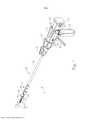
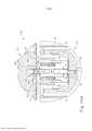
[007] Figura 1 mostra uma vista em perspectiva de um instrumento de grampeamento cirúrgico exemplificador;[007] Figure 1 shows a perspective view of an exemplary surgical stapling instrument;
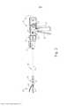
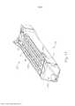
[008] Figura 2 mostra uma vista em elevação lateral do instrumento da Figura 1;[008] Figure 2 shows a side elevation view of the instrument of Figure 1;
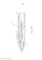
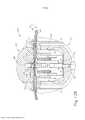
[009] Figura 3 representa uma vista em perspectiva do atuador de extremidade do instrumento da Figura 1, com o atuador de extremidade em uma configuração fechada;[009] Figure 3 represents a perspective view of the end actuator of the instrument of Figure 1, with the end actuator in a closed configuration;
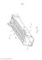
[0010] Figura 4 representa uma vista em perspectiva do atuador de extremidade da Figura 3, com o atuador de extremidade em uma configuração aberta;[0010] Figure 4 represents a perspective view of the end actuator of Figure 3, with the end actuator in an open configuration;
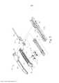
[0011] Figura 5 mostra uma vista em perspectiva explodida do atuador de extremidade da Figura 3;[0011] Figure 5 shows an exploded perspective view of the end actuator of Figure 3;
[0012] Figura 6 representa uma vista em seção transversal da extremidade do atuador de extremidade da Figura 3, tomada ao longo da linha 6-6 da Figura 4;[0012] Figure 6 represents a cross-sectional view of the end of the end actuator of Figure 3, taken along line 6-6 of Figure 4;
[0013] Figura 7A representa uma vista lateral em seção transversal do atuador de extremidade da Figura 3, tomada ao longo da linha 7-7 da Figura 4, com um braço de disparo em uma posição proximal;[0013] Figure 7A represents a cross-sectional side view of the end actuator of Figure 3, taken along line 7-7 of Figure 4, with a firing arm in a proximal position;
[0014] Figura 7B representa uma vista lateral em seção transversal do atuador de extremidade da Figura 3, tomada ao longo da linha 7-7 da Figura 4, com a braço de disparo em uma posição distal;[0014] Figure 7B represents a cross-sectional side view of the end actuator of Figure 3, taken along line 7-7 of Figure 4, with the trigger arm in a distal position;
[0015] Figura 8 representa uma vista em perspectiva do atuador de extremidade da Figura 3, posicionado no tecido e após ser acionado uma vez no tecido;[0015] Figure 8 represents a perspective view of the end actuator of Figure 3, positioned in the tissue and after being activated once in the tissue;
[0016] Figura 9A representa uma vista em perspectiva de um a- tuador de extremidade alternativo exemplificador que pode ser incorporado ao instrumento da Figura 1, com um braço de disparo em uma posição proximal;[0016] Figure 9A represents a perspective view of an exemplary alternative end actuator that can be incorporated into the instrument of Figure 1, with a firing arm in a proximal position;
[0017] Figura 9B mostra uma vista em perspectiva do atuador de extremidade da Figura 9A, com o braço de disparo em uma posição distal;[0017] Figure 9B shows a perspective view of the end actuator of Figure 9A, with the firing arm in a distal position;
[0018] Figura 10A mostra uma vista em seção transversal do a- tuador de extremidade da Figura 9A, tomada ao longo da linha 10-10 da Figura 9A, com o braço de disparo na posição proximal;[0018] Figure 10A shows a cross-sectional view of the end actuator of Figure 9A, taken along line 10-10 of Figure 9A, with the firing arm in the proximal position;
[0019] Figura 10B mostra uma vista em seção transversal do a- tuador de extremidade da Figura 9A, tomada ao longo da linha 10-10 da Figura 9A, com o braço de disparo em uma posição proximal e o tecido posicionado entre uma bigorna e uma plataforma de cartucho de grampos do atuador de extremidade;[0019] Figure 10B shows a cross-sectional view of the end actuator of Figure 9A, taken along line 10-10 of Figure 9A, with the trigger arm in a proximal position and the tissue positioned between an anvil and an end actuator staple cartridge deck;
[0020] Figura 10C mostra uma vista em seção transversal do a- tuador de extremidade da Figura 9A, tomada ao longo da linha 10-10 da Figura 9A, com o braço de disparo em uma posição distal e o tecido posicionado entre a bigorna e a plataforma de cartucho de grampos do atuador de extremidade;[0020] Figure 10C shows a cross-sectional view of the end actuator of Figure 9A, taken along line 10-10 of Figure 9A, with the trigger arm in a distal position and the tissue positioned between the anvil and the end actuator staple cartridge deck;
[0021] Figura 11 mostra uma vista em perspectiva de um outro atuador de extremidade alternativo exemplificador que pode ser incorporado ao instrumento da Figura 1, com uma bigorna do atuador de extremidade omitida para fins de clareza;[0021] Figure 11 shows a perspective view of another exemplary alternative end actuator that may be incorporated into the instrument of Figure 1, with an end actuator anvil omitted for clarity;
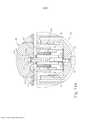
[0022] Figura 12A mostra uma vista de extremidade em seção transversal do atuador de extremidade da Figura 11, com um braço de disparo em uma posição proximal;[0022] Figure 12A shows an end view in cross section of the end actuator of Figure 11, with a firing arm in a proximal position;
[0023] Figura 12B mostra uma vista de extremidade em seção transversal do atuador de extremidade da Figura 11, com o braço de disparo em uma posição proximal e o tecido posicionado entre uma bigorna e uma plataforma de cartucho de grampos do atuador de extremidade;[0023] Figure 12B shows an end view in cross-section of the end actuator of Figure 11, with the trigger arm in a proximal position and tissue positioned between an anvil and an end actuator staple cartridge platform;
[0024] Figura 12C mostra uma vista de extremidade em seção transversal do atuador de extremidade da Figura 11, com o braço de disparo em uma posição distal e o tecido posicionado entre a bigorna e a plataforma de cartucho de grampos do atuador de extremidade;[0024] Figure 12C shows an end view in cross section of the end actuator of Figure 11, with the trigger arm in a distal position and the tissue positioned between the anvil and the end actuator staple cartridge platform;
[0025] Figura 13 mostra uma vista em perspectiva de um outro atuador de extremidade alternativo exemplificador que pode ser incorporado ao instrumento da Figura 1, com uma bigorna do atuador de extremidade omitida para fins de clareza;[0025] Figure 13 shows a perspective view of another exemplary alternative end actuator that may be incorporated into the instrument of Figure 1, with an end actuator anvil omitted for clarity;
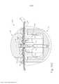
[0026] Figura 14A mostra uma vista de extremidade em seção transversal do atuador de extremidade da Figura 13, com um braço de disparo em uma posição proximal;[0026] Figure 14A shows an end view in cross section of the end actuator of Figure 13, with a firing arm in a proximal position;
[0027] Figura 14B mostra uma vista em seção transversal do a- tuador de extremidade da Figura 13, com o braço de disparo em uma posição proximal e o tecido posicionado entre uma bigorna e uma plataforma de cartucho de grampos do atuador de extremidade;[0027] Figure 14B shows a cross-sectional view of the end actuator of Figure 13, with the firing arm in a proximal position and the tissue positioned between an anvil and an end actuator staple cartridge platform;
[0028] Figura 14C mostra uma vista em seção transversal do a- tuador de extremidade da Figura 13, com o braço de disparo em uma posição distal e o tecido posicionado entre a bigorna e a plataforma de cartucho de grampos do atuador de extremidade;[0028] Figure 14C shows a cross-sectional view of the end actuator of Figure 13, with the firing arm in a distal position and the tissue positioned between the anvil and the end actuator staple cartridge platform;
[0029] Figura 15 mostra uma vista em perspectiva de uma bigorna alternativa exemplificadora que pode ser incorporada ao atuador de extremidade da Figura 3;[0029] Figure 15 shows a perspective view of an exemplary alternative anvil that can be incorporated into the end actuator of Figure 3;
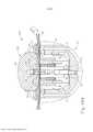
[0030] Figura 16A mostra uma vista de extremidade em seção transversal de um atuador de extremidade alternativo exemplificador da Figura 16A, com um braço de disparo em uma posição proximal;[0030] Figure 16A shows an end view in cross section of an exemplified alternative end actuator of Figure 16A, with a firing arm in a proximal position;
[0031] Figura 16B mostra uma vista em seção transversal do a- tuador de extremidade da Figura 16A, com o braço de disparo em uma posição distal e o tecido posicionado entre uma bigorna e uma plataforma de cartucho de grampos do atuador de extremidade; e[0031] Figure 16B shows a cross-sectional view of the end actuator of Figure 16A, with the trigger arm in a distal position and the tissue positioned between an anvil and an end actuator staple cartridge platform; and
[0032] Figura 16C mostra uma vista em seção transversal do atuador de extremidade da Figura 16A, com o braço de disparo em uma posição distal e o tecido posicionado entre a bigorna e a plataforma de cartucho de grampos do atuador de extremidade.[0032] Figure 16C shows a cross-sectional view of the end actuator of Figure 16A, with the trigger arm in a distal position and the tissue positioned between the anvil and the end actuator staple cartridge platform.
[0033] De modo algum, os desenhos destinam-se a ser limitantes e contempla-se que várias modalidades da invenção possam ser executadas em uma variedade de outras maneiras, incluindo aquelas não necessariamente representadas nos desenhos. Os desenhos em anexo incorporados e que constituem uma parte do relatório descritivo ilustram vários aspectos da presente invenção e, juntamente com a descrição, servem para explicar os princípios da invenção; entendendo-se, entretanto, que esta invenção não se limita especificamente às disposições mostradas.[0033] The drawings are not intended to be limiting in any way, and it is contemplated that various embodiments of the invention may be embodied in a variety of other ways, including those not necessarily depicted in the drawings. The accompanying drawings incorporated in and forming a part of the specification illustrate various aspects of the present invention and, together with the description, serve to explain the principles of the invention; it being understood, however, that this invention is not specifically limited to the arrangements shown.
[0034] A descrição a seguir de exemplos específicos da invenção não deve ser usada para limitar o escopo da presente invenção. Outros exemplos, características, aspectos, modalidades e vantagens da invenção ficarão evidentes aos versados na técnica a partir da descrição a seguir, que é, a título de ilustração, um dos melhores modos contemplados para executar a invenção. Conforme será compreendido, a invenção pode ter outros aspectos diferentes e óbvios, todos sem que se afaste da invenção. Consequentemente, os desenhos e as descrições devem ser considerados como de natureza ilustrativa e não restritiva.[0034] The following description of specific examples of the invention should not be used to limit the scope of the present invention. Other examples, features, aspects, embodiments and advantages of the invention will become apparent to those skilled in the art from the following description, which is, by way of illustration, one of the best contemplated modes for carrying out the invention. As will be understood, the invention may have other different and obvious aspects, all without departing from the invention. Consequently, the drawings and descriptions are to be considered as illustrative and not restrictive in nature.
[0035] Figura 1 representa um instrumento de grampeamento e corte cirúrgico (10) exemplificador que inclui um conjunto de cabo (20), um conjunto de eixo de acionamento (30), e um atuador de extremidade (40). O atuador de extremidade (40) e a porção distal do conjunto de eixo de acionamento (30) são dimensionados para inserção, em um estado não articulado como representado na Figura 1, através de uma cânula de trocarte para um local cirúrgico em um paciente para realizar um procedimento cirúrgico. Somente a título de exemplo, tal trocarte pode ser inserido no abdômen do paciente, entre duas das costelas do paciente, ou em outra parte. Em alguns casos, o instrumento (10) é usado sem um trocarte. Por exemplo, o atuador de extremidade (40) e a porção distal do conjunto de eixo de acionamento (30) podem ser inseridos diretamente através de uma toracotomia ou outro tipo de incisão. Deve-se compreender que termos como "proximal" e "distal" são usados na presente invenção com referência a um médico segurando o conjunto de cabo (20) do instrumento (10). Dessa forma, o atuador de extremidade (40) é distal em relação ao conjunto de cabo (20) mais proximal. Será entendido ainda que, para conveniência e clareza, os termos espaciais como "vertical" e "horizontal" são usados na presente invenção em relação aos desenhos. Entretanto, os instrumentos cirúrgicos são usados em muitas orientações e posições, e tais termos não se destinam a serem limitadores e absolutos.[0035] Figure 1 depicts an exemplary surgical stapling and cutting instrument (10) that includes a cable assembly (20), a drive shaft assembly (30), and an end actuator (40). The end actuator (40) and the distal portion of the drive shaft assembly (30) are sized for insertion, in an unarticulated state as depicted in Figure 1, through a trocar cannula into a surgical site in a patient to perform a surgical procedure. By way of example only, such a trocar could be inserted into the patient's abdomen, between two of the patient's ribs, or elsewhere. In some cases, the instrument (10) is used without a trocar. For example, the end actuator (40) and the distal portion of the drive shaft assembly (30) can be inserted directly through a thoracotomy or other type of incision. It should be understood that terms such as "proximal" and "distal" are used in the present invention with reference to a physician holding the handle assembly (20) of the instrument (10). Thus, the end actuator (40) is distal to the most proximal cable assembly (20). It will be further understood that, for convenience and clarity, spatial terms such as "vertical" and "horizontal" are used in the present invention in relation to the drawings. However, surgical instruments are used in many orientations and positions, and such terms are not intended to be limiting and absolute.
[0036] Conforme representado nas Figuras 1-2, o conjunto de cabo (20) do presente exemplo compreende uma empunhadura de pistola (22), um gatilho de fechamento (24) e um gatilho de disparo (26). Cada gatilho (24, 26) pode ser seletivamente pivotante em direção e para longe da empunhadura de pistola (22) como será descrito com mais detalhes abaixo. O conjunto de cabo (20) inclui, ainda, um botão de liberação de bigorna (25), uma chave inversa do braço de disparo (27), e um conjunto de bateria removível (28). Estes componentes serão também descritos com mais detalhes abaixo. Naturalmente, o conjunto de cabo (20) pode ter uma variedade de outros componentes, recursos e funcionalidades, além de, ou em vez de, qualquer um dos elementos mencionados acima. Outras configurações adequadas para o conjunto de cabo (20) se tornarão evidentes aos versados na técnica considerando os ensinamentos da presente invenção.[0036] As shown in Figures 1-2, the handle assembly (20) of the present example comprises a pistol grip (22), a closing trigger (24) and a firing trigger (26). Each trigger (24, 26) can be selectively pivotable towards and away from the pistol grip (22) as will be described in more detail below. The handle assembly (20) further includes an anvil release button (25), a firing arm reverse switch (27), and a removable battery pack (28). These components will also be described in more detail below. Of course, the cable assembly (20) can have a variety of other components, features and functionality in addition to, or instead of, any of the above-mentioned elements. Other suitable configurations for the cable assembly (20) will become apparent to those skilled in the art considering the teachings of the present invention.
[0037] Conforme representado nas Figuras 1 a 3, a conjunto de eixo de acionamento (30) do presente exemplo compreende um tubo de fechamento externo (32), uma seção de articulação (34), e um anel de fechamento (36), que é ainda acoplado a um atuador de extremidade (40). O tubo de fechamento (32) estende-se ao longo do comprimento do conjunto de eixo de acionamento (30). O anel de fechamento (36) está posicionado distal à seção de articulação (34). O tubo de fechamento (32) e o anel de fechamento (36) são configurados para transladar longitudinalmente em relação ao conjunto de cabo (20) . A translação longitudinal do tubo de fechamento (32) é comunicada ao anel de fechamento (36) através da seção de articulação (34). Os recursos exemplificadores que podem ser usados para fornecer a translação longitudinal do tubo de fechamento (32) e do anel de fechamento (36) serão descritos com mais detalhes abaixo.[0037] As shown in Figures 1 to 3, the drive shaft assembly (30) of the present example comprises an external closing tube (32), a articulation section (34), and a closing ring (36), which is further coupled to an end actuator (40). The closure tube (32) extends the length of the drive shaft assembly (30). The closure ring (36) is positioned distal to the pivot section (34). The closure tube (32) and closure ring (36) are configured to translate longitudinally relative to the handle assembly (20). The longitudinal translation of the closing tube (32) is communicated to the closing ring (36) through the articulation section (34). Exemplary features that can be used to provide longitudinal translation of the closure tube (32) and closure ring (36) will be described in more detail below.
[0038] A seção de articulação (34) é operável para defletir lateralmente o anel de fechamento (36) e o atuador de extremidade (40) lateralmente na direção oposta ao eixo geométrico longitudinal (LA) do conjunto de eixo de acionamento (30) em um ângulo desejado (α). O atuador de extremidade (40) pode, assim, alcançar a parte de trás de um órgão, ou se aproximar do tecido a partir de um ângulo desejado ou por outras razões. Em algumas versões, a seção de articulação (34) permite deflexão do atuador de extremidade (40) ao longo de um único plano. Em algumas outras versões, a seção de articulação (34) permite deflexão do atuador de extremidade ao longo de mais de um plano. No presente exemplo, a articulação é controlada através de um botão de controle de articulação (35) que está localizado na extremidade proximal do conjunto de eixo de acionamento (30). O botão (35) é giratório em torno de um eixo geométrico que é perpendicular ao eixo geométrico longitudinal (LA) do conjunto de eixo de acionamento (30). O anel de fechamento (36) e o atuador de extremidade (40) articulam-se em torno de um eixo geométrico que é perpendicular ao eixo geométrico longitudinal (LA) do conjunto de eixo de acionamento (30) em resposta à rotação do botão (35). Apenas a título de exemplo, a rotação do botão (35) no sentido horário pode causar a rotação no sentido horário correspondente do anel de fechamento (36) e do atuador de extremidade (40) na seção de articulação (34). A seção de articulação (34) está configurada para comunicar a translação longitudinal do tubo de fechamento (32) para o anel de fechamento (36), independente da possibilidade de a seção de articulação (34) estar em uma configuração reta ou em uma configuração articulada.[0038] The articulation section (34) is operable to laterally deflect the closing ring (36) and the end actuator (40) laterally in the opposite direction to the longitudinal axis (LA) of the drive shaft assembly (30) at a desired angle (α). The end actuator (40) can thus reach the back of an organ, or approach the tissue from a desired angle or for other reasons. In some versions, the pivot section (34) allows deflection of the end actuator (40) along a single plane. In some other versions, the pivot section (34) allows deflection of the end actuator along more than one plane. In the present example, articulation is controlled via a articulation control knob (35) which is located at the proximal end of the driveshaft assembly (30). The knob (35) is rotatable about an axis that is perpendicular to the longitudinal axis (LA) of the drive shaft assembly (30). The closure ring (36) and end actuator (40) pivot about an axis that is perpendicular to the longitudinal axis (LA) of the drive shaft assembly (30) in response to rotation of the knob ( 35). By way of example only, clockwise rotation of knob (35) can cause corresponding clockwise rotation of closure ring (36) and end actuator (40) on pivot section (34). The hinge section (34) is configured to communicate the longitudinal translation of the closure tube (32) to the closure ring (36), regardless of whether the hinge section (34) is in a straight configuration or in a horizontal configuration. articulated.
[0039] Em algumas versões, a seção de articulação (34) e/ou o botão de controle de articulação (35) são/é construído e operável de acordo com pelo menos alguns dos ensinamentos da Publicação US n° 2014/0243801, intitulado "Surgical Instrument End Effector Articulation Drive with Pinion and Opposing Racks", publicado em 28 de agosto de 2014, cuja descrição está aqui incorporada a título de referência. A seção de articulação (34) pode também ser construída e operável de acordo com pelo menos alguns dos ensinamentos do pedido de patente US n° 14/314.125, intitulado "Articulation Drive Features for Surgical Stapler", depositado em 25 de junho de 2014, cuja descrição está aqui incorporada a título de referência. e/ou de acordo com os vários ensinamentos abaixo. Outras formas adequadas que a seção de articulação (34) e o botão de articulação (35) podem tomar serão aparentes aos versados na técnica, tendo em vista os ensinamentos da presente invenção.[0039] In some versions, the articulation section (34) and/or the articulation control knob (35) are/is constructed and operable in accordance with at least some of the teachings of US Publication No. 2014/0243801, entitled "Surgical Instrument End Effector Articulation Drive with Pinion and Opposing Racks", published August 28, 2014, description of which is incorporated herein by reference. The hinge section (34) may also be constructed and operable in accordance with at least some of the teachings of US Patent Application No. 14/314,125, entitled "Articulation Drive Features for Surgical Stapler", filed June 25, 2014, the description of which is incorporated herein by reference. and/or in accordance with the various teachings below. Other suitable shapes that the pivot section (34) and pivot knob (35) can take will be apparent to those skilled in the art in view of the teachings of the present invention.
[0040] Conforme mostrado nas Figuras 1 a 2, o conjunto de eixo de acionamento (30) do presente exemplo inclui adicionalmente ainda um botão de rotação (31). O botão de rotação (31) é operável para girar todo o conjunto de eixo de acionamento (30) e o atuador de extremidade (40), em relação ao conjunto do cabo (20) em torno do eixo geométrico longitudinal (LA) definido pelo conjunto de eixo de acionamento (30). Em algumas versões, o botão de rotação (31) é operável para travar seletivamente a posição angular do conjunto de eixo de acionamento (30) e o atuador de extremidade (40), em relação ao conjunto do cabo (20) em torno do eixo longitudinal geométrico (LA) do conjunto de eixo de acionamento (30). Por exemplo, o botão de rotação (31) pode ser transladável entre uma primeira posição longitudinal, em que o conjunto de eixo de acionamento (30) e o atuador de extremidade (40) são giratórios em relação ao conjunto de cabo (20) em torno do eixo geométrico longitudinal (LA) do conjunto de eixo de acionamento (30); e uma segunda posição longitudinal, em que o conjunto de eixo de acionamento (30) e o atuador de extremidade (40) não são giratórios em relação ao conjunto de cabo (20) em torno do eixo geométrico longitudinal (LA) do conjunto de eixo de acionamento (30). Naturalmente, o conjunto de eixo de acionamento (30) pode ter uma variedade de outros componentes, recursos e funcionalidades, além de, ou em vez de, qualquer um dos elementos mencionados acima. Somente a título de exemplo, ao menos parte do conjunto de eixo de acionamento (30) é construída de acordo com ao menos alguns dos ensinamentos do pedido de patente US n° 2014/0239038, intitulado "Surgical Instrument with Multi-Diameter Shaft", publicado em 28 de agosto de 2014, cuja divulgação está aqui incorporada a título de referência. Outras configurações adequadas para o conjunto de eixo de acionamento (30) serão evidentes aos versados na técnica em vista dos ensinamentos aqui apresentados.[0040] As shown in Figures 1 to 2, the drive shaft assembly (30) of the present example additionally includes a rotation knob (31). The rotation knob (31) is operable to rotate the entire drive shaft assembly (30) and end actuator (40) relative to the cable assembly (20) about the longitudinal axis (LA) defined by the drive shaft assembly (30). On some versions, the rotation knob (31) is operable to selectively lock the angular position of the drive shaft assembly (30) and end actuator (40), relative to the cable assembly (20) around the shaft. geometric longitudinal (LA) of the drive shaft assembly (30). For example, the rotation knob (31) may be translatable between a first longitudinal position, where the drive shaft assembly (30) and end actuator (40) are rotatable relative to the cable assembly (20) in around the longitudinal axis (LA) of the drive shaft assembly (30); and a second longitudinal position, in which the drive shaft assembly (30) and the end actuator (40) are not rotatable with respect to the cable assembly (20) about the longitudinal axis (LA) of the shaft assembly drive (30). Of course, the driveshaft assembly (30) can have a variety of other components, features and functionality in addition to, or instead of, any of the elements mentioned above. Just by way of example, at least part of the drive shaft assembly (30) is constructed in accordance with at least some of the teachings of US patent application No. 2014/0239038, entitled "Surgical Instrument with Multi-Diameter Shaft", published on August 28, 2014, the disclosure of which is incorporated herein by reference. Other suitable configurations for the driveshaft assembly (30) will become apparent to those skilled in the art in view of the teachings presented herein.
[0041] Como também representado nas Figuras 1 a 3, o atuador de extremidade (40) do presente exemplo inclui uma garra inferior (50) e uma bigorna articulada (60). A bigorna (60) inclui um par de pinos (66) integrais que se estendem para fora que estão dispostos em fendas curvas correspondentes (54) da garra inferior (50). Pinos (66) e fendas (54) são mostrados na Figura 5. A bigorna (60) é pivotante em direção e para longe da garra inferior (50) entre uma posição aberta (mostrada nas Figuras 2 e 4) e uma posição fechada (mostrada nas Figuras 1, 3 e 7A a 7B). O uso do termo "pivotante" (e termos similares com "pivô" como a base) não devem ser lidos como necessariamente necessitando de movimento pivotante em torno de um eixo geométrico fixo. Por exemplo, no presente exemplo, a bigorna (60) gira em torno de um eixo geométrico que é definido pelos pinos (66), que deslizam ao longo das fendas curvas (54) da garra inferior (50) à medida que a bigorna (60) se move para a garra inferior (50). Em tais versões, o eixo geométrico de pivô traslada ao longo da trajetória definida pelas fendas (54) enquanto a bigorna (60) gira simultaneamente em torno deste eixo geométrico. Além disso ou de maneira alternativa, o eixo geométrico de pivô pode deslizar ao longo das fendas (54), com a bigorna (60) então pivotando em torno do eixo geométrico de pivô depois que o eixo geométrico de pivô deslizou por uma certa distância ao longo das fendas (54). Deve-se compreender que tal movimento pivotante deslizante/traslado é abrangido dentro de termos como "pivô", "pivôs", "pivotante". "giratório", "articulado" e similares. Naturalmente, algumas versões podem proporcionar movimento pivotante da bigorna (60) em torno de um eixo geométrico que permanece fixo e não traslada dentro de uma fenda ou canaleta, etc.[0041] As also shown in Figures 1 to 3, the end actuator (40) of the present example includes a lower jaw (50) and an articulated anvil (60). The anvil (60) includes a pair of integral outwardly extending pins (66) that are disposed in corresponding curved slots (54) of the lower jaw (50). Pins (66) and slots (54) are shown in Figure 5. The anvil (60) is pivotable towards and away from the lower jaw (50) between an open position (shown in Figures 2 and 4) and a closed position ( shown in Figures 1, 3 and 7A to 7B). The use of the term "pivot" (and similar terms with "pivot" as the base) should not be read as necessarily necessitating pivotal motion about a fixed axis. For example, in the present example, the anvil (60) rotates around a geometric axis that is defined by the pins (66), which slide along the curved slots (54) of the lower jaw (50) as the anvil (50) moves. 60) moves to the bottom claw (50). In such versions, the pivot axis translates along the path defined by the slots (54) while the anvil (60) simultaneously rotates around this axis. Additionally or alternatively, the pivot axis can slide along the slots (54), with the anvil (60) then pivoting about the pivot axis after the pivot axis has slid a certain distance along the along the slots (54). It should be understood that such pivotal sliding/translating movement is encompassed within terms such as "pivot", "pivots", "pivoting". "swivel", "hinged" and the like. Naturally, some versions can provide pivotal movement of the anvil (60) around a geometric axis that remains fixed and does not move within a slot or groove, etc.
[0042] Como melhor visto na Figura 5, a garra inferior (50) do presente exemplo define uma canaleta (52) que é configurada para receber um cartucho de grampos (70). O cartucho de grampos (70) pode ser inserido na canaleta (52), o atuador de extremidade (40) pode ser atuado e, em seguida, o cartucho de grampos (70) pode ser removido e substituído por um outro cartucho de grampos (70). A garra inferior (50), assim retém de modo liberável o cartucho de grampos (70) em alinhamento com a bigorna (60) para a atuação do atuador de extremidade (40). Em algumas versões, a garra inferior (50) é construída de acordo com ao menos alguns dos ensinamentos do pedido de patente n° 2014/0239044, intitulado "Installation Features for Surgical Instrument End Effector Cartridge", publicado em 28 de agosto de 2014, cuja descrição está aqui incorporada a título de referência. Outras formas adequadas que a garra inferior (50) pode tomar serão evidentes aos versados na técnica com base nos ensinamentos da presente invenção.[0042] As best seen in Figure 5, the lower claw (50) of the present example defines a channel (52) that is configured to receive a staple cartridge (70). The staple cartridge (70) can be inserted into the groove (52), the end actuator (40) can be actuated, and then the staple cartridge (70) can be removed and replaced with another staple cartridge ( 70). The lower jaw (50) thus releasably retains the staple cartridge (70) in alignment with the anvil (60) for actuation of the end actuator (40). In some versions, the lower claw (50) is constructed in accordance with at least some of the teachings of patent application No. 2014/0239044, entitled "Installation Features for Surgical Instrument End Effector Cartridge", published on August 28, 2014, the description of which is incorporated herein by reference. Other suitable shapes that the
[0043] Como melhor visto nas Figuras 4 a 6, cartucho de grampos (70) do presente exemplo, compreende um corpo de cartucho (71) e uma bandeja (76) presa ao lado inferior do corpo do cartucho (71). O lado superior do corpo do cartucho (71) apresenta uma plataforma (73), contra a qual o tecido pode ser comprimido quando a bigorna (60) está em uma posição fechada. O corpo de cartucho (71) define, ainda, uma canaleta que se estende longitudinalmente (72) e uma pluralidade de bolsos de grampos (74). Um grampo (77) está posicionado em cada bolso de grampos (74). Um acionador de grampos (75) também está posicionado em cada bolso de grampos (74), sob um grampo correspondente (77), e acima da bandeja (76). Como será descrito com mais detalhes abaixo, os acionadores de grampos (75) são operáveis para transladar para cima em bolsos de grampos (74) para, assim, acionar grampos (77) para cima através dos bolsos de grampos (74) e para engate com a bigorna (60). Os acionadores de grampos (75) são movidos para cima por um deslizador em cunha (78), que é capturado entre o corpo de cartucho (71) e a bandeja (76), e que translada longitudinalmente através do corpo de cartucho (71). O deslizador em cunha (78) inclui um par de superfícies de came obliquamente anguladas (79), que são configuradas para engatar acionadores de grampos (75) e, desse modo, acionar os acionadores de grampos (75) para cima, à medida que o deslizador em cunha (78) translada longitudinalmente através do cartucho (70). Por exemplo, quando o deslizador em cunha (78) está em uma posição proximal, como mostrado na Figura 7A, os acionadores de grampos (75) estão em posições descendentes e os grampos (77) estão localizados em bolsos de grampos (74). À medida que o deslizador em cunha (78) é acionado para a posição distal mostrada na Figura 7B através de uma translação do elemento de faca (80), o deslizador em cunha (78) aciona os acionadores de grampos (75) para cima, acionando, assim, os grampos (77) para fora dos bolsos de grampos (74) e para dentro dos bolsos de formação de grampos (64). Dessa forma, os acionadores de grampos (75) transladam ao longo de uma dimensão vertical à medida que o deslizador em cunha (78) translada ao longo de uma dimensão horizontal.[0043] As best seen in Figures 4 to 6, the staple cartridge (70) of the present example comprises a cartridge body (71) and a tray (76) attached to the underside of the cartridge body (71). The upper side of the cartridge body (71) has a platform (73) against which tissue can be pressed when the anvil (60) is in a closed position. The cartridge body (71) further defines a longitudinally extending channel (72) and a plurality of clip pockets (74). A staple (77) is positioned in each staple pocket (74). A staple driver (75) is also positioned in each staple pocket (74), under a corresponding staple (77), and above the tray (76). As will be described in more detail below, the staple drivers (75) are operable to translate upward into staple pockets (74) to thereby drive staples (77) upward through the staple pockets (74) and to engage with the anvil (60). The staple drivers (75) are moved upwards by a wedge slider (78), which is captured between the cartridge body (71) and the tray (76), and which translates longitudinally through the cartridge body (71) . The wedge slider (78) includes a pair of obliquely angled cam surfaces (79) that are configured to engage clip drivers (75) and thereby drive the clip drivers (75) upward as the wedge slider (78) translates longitudinally through the cartridge (70). For example, when the wedge slider (78) is in a proximal position, as shown in Figure 7A, the staple drivers (75) are in downward positions and the staples (77) are located in staple pockets (74). As the wedge slider (78) is driven into the distal position shown in Figure 7B through a translation of the knife element (80), the wedge slider (78) drives the clip drivers (75) upward, thereby driving the staples (77) out of the staple pockets (74) and into the staple forming pockets (64). In this way, the clip drivers (75) translate along a vertical dimension as the wedge slider (78) translates along a horizontal dimension.
[0044] Deve-se compreender que a configuração do cartucho de grampos (70) pode ser variada de inúmeras maneiras. Por exemplo, o cartucho de grampos (70) do presente exemplo inclui duas fileiras que se estendem longitudinalmente de bolsos de grampos (74) de um lado da canaleta (72); e um outro conjunto de duas fileiras que se estendem longitudinalmente de bolsos de grampos (74) sobre o outro lado da canaleta (72). No entanto, em algumas outras versões, o cartucho de grampos (70) inclui três, um, ou algum outro número de bolsos de grampos (74) em cada lado da canaleta (72). Em algumas versões, o cartucho de grampos (70) é construído e operável de acordo com ao menos algumas das instruções do pedido de patente US n° 2014/0239042, intitulado "Integrated Tissue Positioning and Jaw Alignment Features for Surgical Stapler", publicado em 28 de agosto de 2014, cuja descrição está aqui incorporada a título de referência. De forma adicional ou alternativa, o cartucho de grampos (70) pode ser construído e operável de acordo com pelo menos alguns dos ensinamentos do pedido de patente US n° 2014/0239044, intitulado "Installation Features for Surgical Instrument End Effector Cartridge", publicado em 28 de agosto de 2014, cuja descrição está aqui incorporada a título de referência. Outras formas adequadas que o cartucho de grampos (70) pode assumir serão evidentes aos versados na técnica em vista dos ensinamentos da presente invenção.[0044] It should be understood that the configuration of the staple cartridge (70) can be varied in a number of ways. For example, the staple cartridge (70) of the present example includes two longitudinally extending rows of staple pockets (74) on one side of the groove (72); and another set of two longitudinally extending rows of staple pockets (74) on the other side of the channel (72). However, in some other versions, the staple cartridge (70) includes three, one, or some other number of staple pockets (74) on each side of the groove (72). In some versions, the staple cartridge (70) is constructed and operable in accordance with at least some of the instructions in US Patent Application No. 2014/0239042, entitled "Integrated Tissue Positioning and Jaw Alignment Features for Surgical Stapler", published in August 28, 2014, the description of which is incorporated herein by reference. Additionally or alternatively, the staple cartridge (70) can be constructed and operable in accordance with at least some of the teachings of US Patent Application No. 2014/0239044, entitled "Installation Features for Surgical Instrument End Effector Cartridge", published on August 28, 2014, the description of which is incorporated herein by reference. Other suitable shapes that the
[0045] Como melhor visto na Figura 4, a bigorna (60) do presente exemplo compreende uma canaleta que se estende longitudinalmente (62) e uma pluralidade de bolsos de formação de grampos (64). A canaleta (62) está configurada para se alinhar com a canaleta (72) do cartucho de grampos (70) quando a bigorna (60) está em uma posição fechada. Cada bolso de formação de grampos (64) está posicionado para se situar sobre um bolso de grampos correspondente (74) de cartucho de grampos (70) quando a bigorna (60) está em uma posição fechada. Os bolsos de formação de grampos (64) estão configurados para deformar as pernas de grampos (77) quando os grampos (77) são acionados através do tecido e para dentro da bigorna (60). Em particular, os bolsos de formação de grampos (64) estão configurados para flexionar as pernas de grampos (77) para prender os grampos (77) formados no tecido. A bigorna (60) pode ser construída de acordo com pelo menos alguns dos ensinamentos do pedido de patente US n° 2014/0239042, intitulado "Integrated Tissue Positioning and Jaw Alignment Features for Surgical Stapler", publicada em 28 de agosto de 2014; ao menos alguns dos ensinamentos do pedido de patente US n° 2014/0239036, intitulado "Jaw Closure Feature for End Effector of Surgical Instrument", publicada em 28 de agosto de 2014; e/ou ao menos alguns dos ensinamentos do pedido de patente US n° 2014/0239037, intitulado "Staple Forming Features for Surgical Stapling Instrument", publicado em 28 de agosto de 2014, cuja descrição está aqui incorporada a título de referência. Outras formas adequadas que a bigorna (60) pode adquirir serão evidentes aos versados na técnica em vista dos ensinamentos da presente invenção.[0045] As best seen in Figure 4, the anvil (60) of the present example comprises a longitudinally extending groove (62) and a plurality of staple forming pockets (64). The groove (62) is configured to align with the groove (72) of the staple cartridge (70) when the anvil (60) is in a closed position. Each staple forming pocket (64) is positioned to lie over a corresponding staple pocket (74) of staple cartridge (70) when the anvil (60) is in a closed position. The staple forming pockets (64) are configured to deform the staple legs (77) when the staples (77) are driven through the fabric and into the anvil (60). In particular, the staple forming pockets (64) are configured to flex the staple legs (77) to secure the formed staples (77) to the fabric. The anvil (60) can be constructed in accordance with at least some of the teachings of US Patent Application No. 2014/0239042, entitled "Integrated Tissue Positioning and Jaw Alignment Features for Surgical Stapler", published on August 28, 2014; at least some of the teachings of US Patent Application No. 2014/0239036, entitled "Jaw Closure Feature for End Effector of Surgical Instrument", published on August 28, 2014; and/or at least some of the teachings of US Patent Application No. 2014/0239037, entitled "Staple Forming Features for Surgical Stapling Instrument", published on August 28, 2014, the description of which is incorporated herein by reference. Other suitable shapes that the anvil (60) can take will be apparent to those skilled in the art in view of the teachings of the present invention.
[0046] No presente exemplo, um membro de faca (80) está configurado para transladar através do atuador de extremidade (40). Como melhor visto nas Figuras 5 e 7A a 7B, um membro de faca (80) é preso à extremidade distal de um braço de disparo (82), que se estende através de uma porção de conjunto de eixo de acionamento (30). Como melhor visto nas Figuras 4 e 6, um membro de faca (80) está posicionado em canaletas (62, 72) da bigorna (60) e do cartucho de grampos (70). O elemento de faca (80) inclui um gume cortante distalmente apresentado (84) que é configurado para cortar o tecido que é comprimido entre a bigorna (60) e a plataforma (73) do cartucho de grampos (70) à medida que o elemento de faca (80) traslada distalmente através do atuador de extremidade (40). Conforme observado acima e conforme mostrado nas Figuras 7A a 7B, o membro de faca (80) aciona também o deslizador em cunha (78) distalmente à medida que o membro de faca (80) translada distalmente através do atuador de extremidade (40), empurrando assim os grampos (77) através do tecido e contra a bigorna (60) para formação. Vários recursos que podem ser usados para acionar o membro de faca (80) distalmente através do atuador de extremidade (40) serão descritos com mais detalhes abaixo.[0046] In the present example, a knife member (80) is configured to translate through the end actuator (40). As best seen in Figures 5 and 7A to 7B, a knife member (80) is attached to the distal end of a firing arm (82), which extends through a portion of the drive shaft assembly (30). As best seen in Figures 4 and 6, a knife member (80) is positioned in channels (62, 72) of the anvil (60) and the staple cartridge (70). The knife element (80) includes a distally presented cutting edge (84) that is configured to cut tissue that is compressed between the anvil (60) and the platform (73) of the staple cartridge (70) as the element knife (80) travels distally through the end actuator (40). As noted above and as shown in Figures 7A to 7B, the knife member (80) also drives the wedge slider (78) distally as the knife member (80) translates distally through the end actuator (40), thereby pushing the staples (77) through the tissue and against the anvil (60) for forming. Various features that can be used to drive the knife member (80) distally through the end actuator (40) will be described in more detail below.
[0047] Em algumas versões, o atuador de extremidade (40) inclui recursos de travamento que estão configurados para impedir que o membro de faca (80) avance distalmente através do atuador de extremidade (40), quando um cartucho de grampos (70) não é inserido na garra inferior (50). Além disso ou alternativamente, o atuador de extremidade (40) pode incluir recursos de travamento que são configuradas para impedir que o membro de faca (80) avance distalmente através do atuador de extremidade (40), quando o cartucho de grampos (70) que já foi atuado uma vez (por exemplo, com todos os grampos (77) implantados a partir do mesmo) é inserido na garra inferior (50). Apenas a título de exemplo, tais recursos de travamento podem ser configurados de acordo com pelo menos alguns dos ensinamentos do pedido de patente US n° 2014/0239041, intitulado "Lockout Feature for Movable Cutting Member of Surgical Instrument", publicado em 28 de agosto de 2014, cuja descrição está aqui incorporada a título de referência; e/ou ao menos alguns dos ensinamentos do pedido de patente US n° 14/314.108, intitulado "Method of Using Lockout Features for Surgical Stapler Cartridge", depositado em 25 de junho de 2014, cuja descrição está aqui incorporada a título de referência. Outras formas adequadas que os recursos de travamento podem adquirir serão evidentes aos versados na técnica em vista dos ensinamentos da presente invenção. Alternativamente, o atuador de extremidade (40) pode simplesmente omitir tais recursos de travamento.[0047] In some versions, the end actuator (40) includes locking features that are configured to prevent the knife member (80) from advancing distally through the end actuator (40) when a staple cartridge (70) it is not inserted into the lower jaw (50). Additionally or alternatively, the end actuator (40) may include locking features that are configured to prevent the knife member (80) from advancing distally through the end actuator (40) when the staple cartridge (70) has already been actuated once (for example, with all the clamps (77) deployed therefrom) is inserted into the lower jaw (50). By way of example only, such locking features may be configured in accordance with at least some of the teachings of US Patent Application No. 2014/0239041 entitled "Lockout Feature for Movable Cutting Member of Surgical Instrument", published on August 28 2014, the description of which is incorporated herein by way of reference; and/or at least some of the teachings of US Patent Application No. 14/314,108, entitled "Method of Using Lockout Features for Surgical Stapler Cartridge", filed June 25, 2014, the description of which is incorporated herein by reference. Other suitable forms that the locking means can take will become apparent to those skilled in the art in view of the teachings of the present invention. Alternatively, the end actuator (40) can simply omit such locking features.
[0048] No presente exemplo, a bigorna (60) é acionada para a garra inferior (50) através do avanço do anel de fechamento (36) distalmente em relação ao atuador de extremidade (40). O anel de fechamento (36) coopera com a bigorna (60) através de uma ação de came (60) em direção à garra inferior (50) em resposta à translação distal do anel de fechamento (36) em relação ao atuador de extremidade (40). Do mesmo modo, o anel de fechamento (36) pode cooperar com a bigorna (60) para abrir a bigorna (60) para longe da garra inferior (50) em resposta à translação proximal do anel de fechamento (36) em relação ao atuador de extremidade (40). A título de exemplo apenas, o anel de fechamento (36) e a bigorna (60) podem interagir de acordo com pelo menos alguns dos ensinamentos do pedido de patente US n° 2014/0239036, intitulado "Jaw Closure Feature for End Effector of Surgical Instrument", publicado em 28 de agosto de 2014, cuja descrição está aqui incorporada a título de referência; e/ou pode ser configurado de acordo com pelo menos alguns dos ensinamentos do pedido de patente US n° 14/314.108, intitulado "Jaw Opening Feature for Surgical Stapler", depositado em 25 de junho de 2014, cuja descrição está aqui incorporada a título de referência. Recursos exemplificadores que podem ser usados para fornecer a translação longitudinal do anel de fechamento (36) em relação ao atuador de extremidade (40) vão ser descritos com mais detalhes abaixo.[0048] In this example, the anvil (60) is driven to the lower jaw (50) by advancing the closing ring (36) distally in relation to the end actuator (40). The closure ring (36) cooperates with the anvil (60) through a cam action (60) towards the lower jaw (50) in response to distal translation of the closure ring (36) relative to the end actuator ( 40). Likewise, the closure ring (36) can cooperate with the anvil (60) to open the anvil (60) away from the lower jaw (50) in response to proximal translation of the closure ring (36) relative to the actuator. end cap (40). By way of example only, the closure ring (36) and the anvil (60) can interact according to at least some of the teachings of US Patent Application No. 2014/0239036, entitled "Jaw Closure Feature for End Effector of Surgical Instrument", published on August 28, 2014, the description of which is incorporated herein by reference; and/or may be configured in accordance with at least some of the teachings of US Patent Application No. 14/314,108, entitled "Jaw Opening Feature for Surgical Stapler", filed June 25, 2014, the description of which is incorporated herein by way of of reference. Exemplary features that can be used to provide longitudinal translation of the closure ring (36) relative to the end actuator (40) will be described in more detail below.
[0049] Como observado acima, conjunto de cabo (20) inclui uma empunhadura de pistola (22) e um gatilho de fechamento (24). Como também observado acima, a bigorna (60) é fechada em direção à garra inferior (50) em resposta ao avanço distal do anel de fechamento (36). No presente exemplo, o gatilho de fechamento (24) é pivotante em direção à empunhadura de pistola (22) para acionar o tubo de fechamento (32) e o anel de fechamento (36) distalmente. Vários componentes adequados que podem ser usados para converter o movimento pivotante do gatilho de fechamento (24) em direção à empunhadura da pistola (22) para a translação distal do tubo de fechamento (32) e o anel de fechamento (36) em relação ao conjunto de cabo (20) serão evidentes para aqueles versados na técnica tendo em vista os ensinamentos aqui contidos. Quando o gatilho de fechamento (24) atinge um estado completamente pivotado, de modo que bigorna (60) esteja em uma posição completamente fechada em relação à garra inferior (50), os recursos de travamento no conjunto de cabo (20) travam a posição do gatilho (24) e o tubo de fechamento (32), travando, assim, a bigorna (60) em uma posição completamente fechada em relação à garra inferior (50). Esses recursos de travamento são liberados pela atuação do botão de liberação da bigorna (25). O botão de liberação da bigorna (25) é configurado e posicionado para ser atuado pelo polegar da mão do operador que segura a empunhadura de pistola (22). Em outras palavras, o operador pode segurar a empunhadura de pistola (22) com uma mão, atuar o gatilho de fechamento (24) com um ou mais dedos da mesma mão e, em seguida, atuar o botão de liberação de bigorna (25) com o polegar da mesma mão, sem precisar liberar o aperto da empunhadura de pistola (22) com a mesma mão. Outros recursos adequados que podem ser usados para atuar a bigorna (60) serão evidentes para os versados na técnica em vista dos ensinamentos da presente invenção. D. Atuação do braço de disparo exemplificador[0049] As noted above, handle assembly (20) includes a pistol grip (22) and a closing trigger (24). As also noted above, the anvil (60) is closed towards the lower jaw (50) in response to distal advancement of the closure ring (36). In the present example, the closure trigger (24) is pivotable toward the pistol grip (22) to actuate the closure tube (32) and closure ring (36) distally. Various suitable components that can be used to convert the pivotal movement of the closure trigger (24) towards the gun handle (22) to the distal translation of the closure tube (32) and closure ring (36) relative to the cable assembly (20) will be apparent to those skilled in the art in view of the teachings contained herein. When the closing trigger (24) reaches a fully pivoted state such that the anvil (60) is in a fully closed position with respect to the lower jaw (50), the locking features on the handle assembly (20) lock the position of the trigger (24) and the closing tube (32), thus locking the anvil (60) in a completely closed position with respect to the lower jaw (50). These locking features are released by actuation of the anvil release button (25). The anvil release button (25) is configured and positioned to be actuated by the thumb of the operator's hand holding the pistol grip (22). In other words, the operator can hold the pistol grip (22) with one hand, actuate the closing trigger (24) with one or more fingers of the same hand, and then actuate the anvil release button (25) with the thumb of the same hand, without having to release the grip of the pistol grip (22) with the same hand. Other suitable devices that can be used to actuate the anvil (60) will be apparent to those skilled in the art in view of the teachings of the present invention. D. Actuation of the exemplary firing arm
[0050] No presente exemplo, o instrumento (10) fornece controle motorizado do braço de disparo (82). Em particular, o instrumento (10) inclui componentes motorizados que são configurados para acionar o braço de disparo (82) distalmente em resposta à articulação do gatilho de disparo (26) na direção da empunhadura de pistola (22). Em algumas versões, um motor (não mostrado) está contido na empunhadura de pistola (22) e é energizado pela da bateria (28). Este motor está acoplado com um conjunto de transmissão (não mostrado) que converte movimento giratório de um eixo de acionamento do motor em translação linear do braço de disparo (82). Em algumas versões, o braço de disparo (82) somente pode ser avançado distalmente quando a bigorna (60) estiver em uma posição completamente fechada em relação à garra inferior (50). Após o braço de disparo (82) ser avançado distalmente para cortar o tecido e acionar os grampos (77), conforme descrito acima com referência às Figuras 7A a 7B, o conjunto de acionamento para o braço de disparo (82) pode ser invertido automaticamente para acionar o braço de disparo (82) de modo proximal de volta para a posição retraída (por exemplo, de volta a partir da posição mostrada na Figura 7B para a posição mostrada na Figura 7A). Alternativamente, o operador pode atuar a chave de inversão (27) do braço de disparo, que pode inverter o conjunto de acionamento para o braço de disparo (82), a fim de se retrair o braço de disparo (82) para uma posição proximal. O conjunto de cabo (20) do presente exemplo inclui adicionalmente um recurso de resgate (21), que é operável para fornecer um resgate mecânico, permitindo que o operador retraia manualmente o braço de disparo (82) proximalmente (por exemplo, no caso de perda de potência enquanto o braço de disparo (82) está em uma posição distal, etc).[0050] In the present example, the instrument (10) provides motorized control of the trigger arm (82). In particular, the instrument (10) includes motorized components that are configured to drive the firing arm (82) distally in response to the linkage of the firing trigger (26) toward the pistol grip (22). On some versions, a motor (not shown) is contained in the pistol grip (22) and is powered by the battery (28). This motor is coupled with a transmission assembly (not shown) which converts rotary movement of a motor drive shaft into linear translation of the firing arm (82). In some versions, the trigger arm (82) can only be advanced distally when the anvil (60) is in a completely closed position relative to the lower jaw (50). After the trigger arm (82) is advanced distally to cut tissue and drive the staples (77), as described above with reference to Figures 7A to 7B, the drive assembly for the trigger arm (82) can be automatically reversed. to actuate the trigger arm (82) proximally back to the retracted position (eg, back from the position shown in Figure 7B to the position shown in Figure 7A). Alternatively, the operator can actuate the trigger arm reversing switch (27), which can reverse the trigger arm assembly for the trigger arm (82) in order to retract the trigger arm (82) to a proximal position. . The cable assembly (20) of the present example further includes a rescue feature (21) that is operable to provide a mechanical rescue, allowing the operator to manually retract the firing arm (82) proximally (e.g., in the event of a loss of power while the trigger arm (82) is in a distal position, etc.).
[0051] Somente a título de exemplo, os recursos que são operáveis para fornecer uma atuação motorizada do braço de disparo (82) podem ser configurados e operáveis de acordo com ao menos alguns dos ensinamentos da patente US n° 8.210.411, intitulada "Motor-Driven Surgical Instrument", concedida em 3 de julho de 2012, cuja descrição está aqui incorporada a título de referência. Como outro exemplo meramente ilustrativo, os recursos que são operáveis para fornecer atuação motorizada do braço de disparo (82) podem ser configurados e operáveis de acordo com pelo menos alguns dos ensinamentos da patente US n° 8.453.914, intitulada "Motor-Driven Surgical Cutting Instrument with Electric Actuator Directional Control Assembly", concedida em 4 de junho de 2013, cuja descrição está aqui incorporada, a título de referência. Como ainda outro exemplo meramente ilustrativo, os recursos que são operáveis para fornecer atuação motorizada do braço de disparo (82) podem ser configurados e operáveis de acordo com pelo menos alguns dos ensinamentos do pedido de patente US. n° 14/226.142, intitulado "Surgical Instrument Comprising a Sensor System", publicado em 26 de março de 2014, cuja divulgação está aqui incorporada a título de referência.[0051] By way of example only, features that are operable to provide a motorized actuation of the firing arm (82) can be configured and operable in accordance with at least some of the teachings of US patent No. 8,210,411, entitled " Motor-Driven Surgical Instrument", granted on July 3, 2012, the description of which is incorporated herein by reference. As another merely illustrative example, features that are operable to provide motorized actuation of the trigger arm (82) can be configured and operable in accordance with at least some of the teachings of U.S. Patent No. 8,453,914, entitled "Motor-Driven Surgical Cutting Instrument with Electric Actuator Directional Control Assembly", granted June 4, 2013, the description of which is incorporated herein by reference. As yet another merely illustrative example, features that are operable to provide motorized actuation of the trigger arm (82) can be configured and operable in accordance with at least some of the teachings of the US patent application. No. 14/226,142, entitled "Surgical Instrument Comprising a Sensor System", published on March 26, 2014, the disclosure of which is incorporated herein by reference.
[0052] Outros componentes, recursos e configurações adequados que podem ser usados para fornecer motorização do braço de disparo (82) serão evidentes aos versados na técnica, tendo em vista os ensinamentos da presente invenção. Deve-se compreender também que algumas outras versões podem proporcionar acionamento manual do braço de disparo (82), de modo que um motor possa ser omitido. Somente a título de exemplo, o braço de disparo (82) pode ser manualmente acionado de acordo com pelo menos alguns dos ensinamentos de qualquer outra referência citada aqui.[0052] Other suitable components, features, and configurations that can be used to provide motorization of the firing arm (82) will be apparent to those skilled in the art in view of the teachings of the present invention. It should also be understood that some other versions may provide manual actuation of the trigger arm (82) so that a motor can be omitted. By way of example only, the trigger arm (82) can be manually actuated in accordance with at least some of the teachings of any other reference cited herein.
[0053] Figura 8 mostra o atuador de extremidade (40) tendo sido atuado através de uma única passada através do tecido (90). Conforme mostrado, o gume cortante (84) (omitido na Figura 8) corta através do tecido (90), enquanto os acionadores de grampos (75) conduzem duas fileiras alternadas de grampos (77) através do tecido (90) em cada lado da linha de corte produzida pelo gume cortante (84). Os grampos (77) são todos orientados substancialmente paralelos à linha de corte neste exemplo, embora deve-se compreender que os grampos (77) podem ser posicionados em quaisquer orientações adequadas. No presente exemplo, o atuador de extremidade (40) é removido do trocarte depois de o primeiro curso ser completado, o cartucho de grampos consumido (70) é substituído por um novo cartucho de grampos (70), e o atuador de extremidade (40) é, então, novamente inserido através do trocarte para alcançar o local do grampeamento para corte e grampeamento adicionais. Esse processo pode ser repetido até que a quantidade desejada de cortes e grampos (77) tenha sido fornecida. Pode ser necessário fechar a garra fixa (60) para facilitar a inserção e a remoção através do trocarte; e pode ser necessário abrir a garra fixa (60) para facilitar a substituição do cartucho de grampos (70).[0053] Figure 8 shows the end actuator (40) having been actuated through a single pass through the fabric (90). As shown, the cutting edge (84) (omitted in Figure 8) cuts through the fabric (90), while the staple drivers (75) drive two alternating rows of staples (77) through the fabric (90) on each side of the cutting line produced by the cutting edge (84). The clips (77) are all oriented substantially parallel to the cut line in this example, although it should be understood that the clips (77) can be positioned in any suitable orientation. In the present example, the end actuator (40) is removed from the trocar after the first stroke is completed, the consumed staple cartridge (70) is replaced with a new staple cartridge (70), and the end actuator (40 ) is then re-inserted through the trocar to reach the stapling site for further cutting and stapling. This process can be repeated until the desired number of cuts and staples (77) have been supplied. It may be necessary to close the fixed jaw (60) to facilitate insertion and removal through the trocar; and it may be necessary to open the fixed jaw (60) to facilitate the replacement of the staple cartridge (70).
[0054] Deve-se compreender que o gume cortante (84) pode cortar o tecido de modo substancialmente contemporâneo à condução dos grampos (77) através do tecido durante cada curso de atuação. No presente exemplo, o gume cortante (84) tem um pequeno atraso em relação ao acionamento dos grampos (77), de modo que um grampo (47) seja acionado através do tecido pouco antes de o gume cortante (84) passar através da mesma região do tecido, embora deva ser compreendido que essa ordem pode ser invertida ou que o gume cortante (84) pode estar diretamente sincronizado com os grampos adjacentes. Embora a Figura 8 mostre o atuador de extremidade (40) sendo atuado em duas camadas (92, 94) de tecido (90), deve-se compreender que o atuador de extremidade (40) pode ser atuado através de uma camada única de tecido (90) ou mais do que duas camadas (92, 94) de tecido. Deve-se compreender também que a formação e o posicionamento dos grampos (77) adjacentes à linha de corte produzida pelo gume cortante (84) podem vedar substancialmente o tecido na linha de corte, reduzindo ou evitando, assim, sangramento e/ou vazamento de outros fluidos corporais na linha de corte. Além disso, enquanto a Figura 8 mostra o atuador de extremidade (40) sendo atuado em duas camadas planares justapostas (92, 94) de tecido substancialmente planas, deve-se compreender que o atuador de extremidade (40) pode também ser atuado ao longo de uma estrutura tubular como um vaso sanguíneo, uma seção do trato gastrointestinal, etc. Figura 8 não deve, portanto, ser vista como uma demonstração de qualquer limitação dos usos contemplados para o atuador de extremidade (40). Vários cenários e procedimentos adequados nos quais o instrumento (10) pode ser usado serão aparentes aos versados na técnica com base nos ensinamentos da presente invenção.[0054] It should be understood that the cutting edge (84) can cut the tissue substantially contemporaneously with driving the staples (77) through the tissue during each actuation stroke. In the present example, the cutting edge (84) has a small delay in relation to the actuation of the staples (77), so that a staple (47) is driven through the tissue just before the cutting edge (84) passes through it. tissue region, although it should be understood that this order can be reversed or that the cutting edge (84) can be directly synchronized with adjacent staples. Although Figure 8 shows the end actuator (40) being actuated through two layers (92, 94) of fabric (90), it should be understood that the end actuator (40) can be actuated through a single layer of fabric. (90) or more than two layers (92, 94) of fabric. It should also be understood that forming and positioning the staples (77) adjacent to the cut line produced by the cutting edge (84) can substantially seal tissue at the cut line, thereby reducing or preventing bleeding and/or leaking of other body fluids in the cut line. Furthermore, while Figure 8 shows the end actuator (40) being actuated on two juxtaposed planar layers (92, 94) of substantially flat fabric, it should be understood that the end actuator (40) can also be actuated along of a tubular structure such as a blood vessel, a section of the gastrointestinal tract, etc. Figure 8 should therefore not be seen as demonstrating any limitation of the contemplated uses for the end actuator (40). Various suitable scenarios and procedures in which the instrument (10) can be used will be apparent to those skilled in the art based on the teachings of the present invention.
[0055] Deve também ser compreendido que outros componentes ou recursos do instrumento (10) podem ser configurados e operados de acordo com as várias referências citadas na presente invenção. Modificações exemplificadoras adicionais que podem ser fornecidas para o instrumento (10) serão descritas com mais detalhes abaixo. Várias formas adequadas através das quais os ensinamentos abaixo podem ser incorporados ao instrumento (10) serão aparentes aos versados na técnica. De modo similar, várias formas adequadas através das quais os ensinamentos abaixo podem ser combinados com os vários ensinamentos das referências citadas na presente invenção serão aparentes aos versados na técnica. Deve-se entender também que os ensinamentos abaixo não se limitam ao instrumento (10) ou aos dispositivos ensinados nas referências citadas na presente invenção. Os ensinamentos abaixo podem ser prontamente aplicados a vários outros tipos de instrumentos, incluindo instrumentos que não seriam classificados como grampeadores cirúrgicos. Vários outros dispositivos e cenários adequados aos quais os ensinamentos abaixo podem ser aplicados serão aparentes aos versados na técnica com base nos ensinamentos da presente invenção.[0055] It should also be understood that other components or features of the instrument (10) can be configured and operated in accordance with the various references cited in the present invention. Additional exemplary modifications that can be provided for the instrument (10) will be described in more detail below. Various suitable ways in which the teachings below can be incorporated into instrument (10) will be apparent to those skilled in the art. Similarly, various suitable ways in which the teachings below can be combined with the various teachings of the references cited in the present invention will be apparent to those skilled in the art. It should also be understood that the teachings below are not limited to the instrument (10) or the devices taught in the references cited in the present invention. The teachings below can be readily applied to many other types of instruments, including instruments that would not be classified as surgical staplers. Various other suitable devices and scenarios to which the teachings below can be applied will be apparent to those skilled in the art based on the teachings of the present invention.
[0056] O atuador de extremidade (40) pode ser estruturado para fornecer um vão predefinido que separa a superfície de plataforma de cartucho (73) e a superfície de bigorna correspondente (60) quando a bigorna (60) está em uma posição fechada. Em alguns casos, o corte e o grampeamento do tecido podem ser um desafio se a espessura do tecido-alvo diferir dessa distância de vão predefinida. Por exemplo, se o tecido-alvo for significativamente mais espesso do que o vão, um operador pode ter problemas ao disparar o instrumento para cortar e grampear o tecido de maneira eficaz. Por outro lado, se o tecido-alvo for mais fino do que o vão entre a plataforma de cartucho e a bigorna, pode ser difícil manter a posição do tecido-alvo entre a bigorna (60) e a plataforma (73). Particularmente, durante o disparo, conforme o elemento de faca (80) avança contra o tecido, o tecido pode mudar de posição dentro das garras do instrumento, tornando, assim, um desafio cortar o tecido-alvo de maneira eficaz. Em alguns casos, os grampos (77) são acionados através das regiões de tecido antes que o elemento de faca (80) atinja as mesmas regiões de tecido, de modo que as pernas dos grampos (77) são dispostas no tecido antes que aquela região de tecido seja cortada. Nos casos em que o tecido é tão fino a ponto de não poder ser mantido no lugar devido à compressão entre a bigorna (60) e a plataforma (73), o elemento de faca (80) pode abrir caminho pelo tecido em vez de cortá-lo totalmente, o que pode resultar no laceramento do tecido pelos grampos (77) com um efeito de cortador de queijo com fio.[0056] The end actuator (40) can be structured to provide a predefined gap separating the cartridge platform surface (73) and the corresponding anvil surface (60) when the anvil (60) is in a closed position. In some cases, tissue cutting and stapling can be challenging if the target tissue thickness differs from this preset gap distance. For example, if the target tissue is significantly thicker than the gap, an operator may have problems triggering the instrument to effectively cut and staple the tissue. On the other hand, if the target tissue is thinner than the gap between the cartridge platform and the anvil, it may be difficult to maintain the position of the target tissue between the anvil (60) and the platform (73). Particularly during firing, as the knife element (80) advances against the tissue, the tissue may change position within the instrument's jaws, thus making it challenging to effectively cut the target tissue. In some cases, the staples (77) are driven through regions of fabric before the knife element (80) reaches the same regions of fabric, so that the legs of the staples (77) are disposed in the fabric before that region is reached. of fabric is cut. In cases where the tissue is so thin that it cannot be held in place due to compression between the anvil (60) and the platform (73), the knife element (80) can cut through the tissue instead of cutting through it. it fully, which may result in the staples (77) tearing the tissue with a string cheese cutter effect.
[0057] Em vista do supracitado, pode ser desejável fornecer um ou mais recursos no atuador de extremidade (40) que comprimem relativamente o tecido fino para, assim, prender o tecido quando o elemento de faca (80) é acionado. Tal compressão de tecido pode evitar o movimento indesejado do tecido que, de outro modo, poderia ocorrer quando o tecido é posicionado entre uma bigorna fechada (60) e a plataforma (73). Em algumas versões, os recursos de compressão estão presentes no cartucho de grampos (70), na bigorna (60) ou em ambos, conforme discutido com mais detalhes abaixo. Ao manter o tecido-alvo no lugar durante o disparo do elemento de faca (80), tais recursos de compressão auxiliam o corte e o grampeamento do tecido de maneira eficaz, mesmo quando o tecido-alvo é mais delgado do que a distância do vão predefinido entre a bigorna (60) e a plataforma (73) quando a bigorna (60) está em uma posição fechada. Vários exemplos de recursos de compressão de tecido são descritos em mais detalhes abaixo, enquanto que outros exemplos serão evidentes aos versados na técnica em vista dos ensinamentos da presente invenção.[0057] In view of the foregoing, it may be desirable to provide one or more features on the end actuator (40) that relatively compress the thin tissue to thereby grip the tissue when the knife element (80) is actuated. Such tissue compression can prevent unwanted tissue movement that might otherwise occur when tissue is positioned between a closed anvil (60) and the platform (73). In some versions, compression features are present in the staple cartridge (70), the anvil (60) or both, as discussed in more detail below. By holding the target tissue in place during firing of the knife element (80), such compression features aid in effectively cutting and stapling the tissue, even when the target tissue is thinner than the gap distance. preset between the anvil (60) and the platform (73) when the anvil (60) is in a closed position. Various examples of tissue compression devices are described in more detail below, while other examples will become apparent to those skilled in the art in view of the teachings of the present invention.
[0058] As Figuras 9A a 16C mostram exemplos diferentes de a- tuadores de extremidade (140, 240, 340, 440) que incluem uma bigorna (60, 460) e uma garra inferior (50, 150, 250, 350). A bigorna (60) é omitida das Figuras 9A a 9B, 11 e 13 para fins de clareza. A garra inferior (50, 150, 250, 350) inclui um cartucho de grampos alternativo exemplificador (70, 170, 270, 370). O atuador de extremidade (140, 240, 340, 440) pode ser prontamente incorporado ao instrumento (10) no lugar do atuador de extremidade (40). Exceto se descrito em contrário abaixo, o atuador de extremidade (140, 240, 340, 440) está configurado e é operado da mesma forma que o atuador de extremidade (40) descrito acima. Por exemplo, o elemento de faca (80) pode ser acionado através do atuador de extremidade (140, 240, 340, 440) da mesma forma que o elemento de faca (80) é acionado através do atuador de extremidade (40) conforme descrito acima.[0058] Figures 9A to 16C show different examples of end actuators (140, 240, 340, 440) that include an anvil (60, 460) and a lower jaw (50, 150, 250, 350). The anvil (60) is omitted from Figures 9A to 9B, 11 and 13 for clarity. The lower jaw (50, 150, 250, 350) includes an exemplary alternate staple cartridge (70, 170, 270, 370). The end actuator (140, 240, 340, 440) can be readily incorporated into the instrument (10) in place of the end actuator (40). Unless otherwise described below, the end actuator (140, 240, 340, 440) is configured and operated the same as the end actuator (40) described above. For example, the knife element (80) can be driven through the end actuator (140, 240, 340, 440) in the same way that the knife element (80) is driven through the end actuator (40) as described above.
[0059] Os cartuchos de grampo (170, 270, 370) e a bigorna (460) do presente exemplo incluem ao menos um recurso compressível que auxilia na aplicação de força de compressão ao tecido-alvo preso entre a bigorna (60, 460) e a garra inferior (50, 150, 250, 350), para assim manter o tecido-alvo no lugar. Nos exemplos mostrados, ao menos uma porção do tecido-alvo é mais delgada do que a distância de vão predefinida entre a bigorna (60, 460) e a garra inferior (50, 150, 250, 350) quando a bigorna (60, 460) está na posição fechada. Entretanto, será compreendido que os atuadores de extremidade (140, 240, 340, 440) são adequados para uso com uma variedade de espessuras de tecido, incluindo tecido que é mais espesso do que a distância de vão predefinida entre a bigorna (60, 460) e a plataforma (73) quando a bigorna (60, 460) está em uma posição fechada.[0059] The staple cartridges (170, 270, 370) and the anvil (460) of the present example include at least one compressible resource that assists in applying compressive force to target tissue trapped between the anvil (60, 460) and the bottom claw (50, 150, 250, 350) to hold the target tissue in place. In the examples shown, at least a portion of the target tissue is thinner than the preset span distance between the anvil (60, 460) and the lower jaw (50, 150, 250, 350) when the anvil (60, 460 ) is in the closed position. However, it will be understood that the end actuators (140, 240, 340, 440) are suitable for use with a variety of fabric thicknesses, including fabric that is thicker than the preset span distance between the anvil (60, 460 ) and the platform (73) when the anvil (60, 460) is in a closed position.
[0060] As Figuras 9A a 10C mostram um atuador de extremidade alternativo exemplificador (140). Conforme discutido acima, o atuador de extremidade (140) é configurado para operar de modo substancialmente similar ao atuador de extremidade (40), exceto pelas diferenças descritas abaixo. O atuador de extremidade (140) compreende uma bigorna (60) e uma garra inferior (50). A bigorna (60) é omitida das Figuras 9A a 9B para fins de clareza. Um cartucho de grampos (170) está disposto na garra inferior (50). O cartucho de grampos (170) é configurado para operar de modo substancialmente similar, conforme discutido em relação ao cartucho de grampos (70). Entretanto, o cartucho de grampos (170) do presente exemplo inclui um recurso compressível (196) disposto ao longo de uma canaleta longitudinal (72) do cartucho (170).[0060] Figures 9A to 10C show an exemplary alternative end actuator (140). As discussed above, the end actuator (140) is configured to operate substantially similar to the end actuator (40), except for the differences described below. The end actuator (140) comprises an anvil (60) and a lower jaw (50). The anvil (60) is omitted from Figures 9A to 9B for clarity. A staple cartridge (170) is disposed in the lower jaw (50). The staple cartridge (170) is configured to operate substantially similarly as discussed with respect to the staple cartridge (70). However, the staple cartridge (170) of the present example includes a compressible feature (196) disposed along a longitudinal groove (72) of the cartridge (170).
[0061] O recurso compressível (196) é configurado para forçar o tecido que é capturado entre a bigorna (60) e a garra inferior (50) em direção à bigorna (60). Particularmente, o recurso compressível (196) inclui um primeiro lado (196a) que é fixado à plataforma de cartucho (73) em um lado da canaleta (72), um segundo lado (196b) que é fixado à plataforma do cartucho (73) em um outro lado da canaleta (72), e uma porção média (196c) que se estende entre o primeiro e o segundo lados (196a, 196b). Portanto, no presente exemplo, o recurso compressível (196) se estende sobre a canaleta (72). Conforme mostrado, o recurso compressível (196) tem um perfil em seção transversal sob a forma de uma curva em formato de C (ao longo de um plano que é perpendicular ao eixo geométrico longitudinal do instrumento (10)), de modo que a porção média (196c) é espaçada a partir da plataforma de cartucho (73). Particularmente, conforme se pode observar melhor na Figura 10A, a distância entre a porção média (196C) e a plataforma de cartucho (73) é menor do que a distância de vão entre a plataforma de cartucho (73) e a bigorna (60) quando a bigorna (60) está na posição fechada.[0061] The compressible feature (196) is configured to force the tissue that is captured between the anvil (60) and the lower claw (50) towards the anvil (60). Particularly, the compressible resource (196) includes a first side (196a) that is attached to the cartridge platform (73) on one side of the groove (72), a second side (196b) that is attached to the cartridge platform (73) on another side of the channel (72), and a middle portion (196c) extending between the first and second sides (196a, 196b). Therefore, in the present example, the compressible resource (196) extends over the channel (72). As shown, the compressible resource (196) has a cross-sectional profile in the form of a C-shaped curve (along a plane that is perpendicular to the longitudinal axis of the instrument (10)), such that the portion middle (196c) is spaced from the cartridge platform (73). Particularly, as best seen in Figure 10A, the distance between the middle portion (196C) and the cartridge platform (73) is less than the span distance between the cartridge platform (73) and the anvil (60) when the anvil (60) is in the closed position.
[0062] Conforme mostrado no presente exemplo, o recurso compressível (196) é formado como um recurso único e alongado disposto substancialmente ao longo de todo o comprimento e toda a largura da canaleta (72). No entanto, em exemplos alternativos, o recurso compressível (196) pode ser formado como uma pluralidade de elementos distintos que são distanciados uns dos outros ao longo do comprimento da canaleta (72). Além disso, em alguns exemplos, o recurso compressível (196) se estende somente ao longo de uma porção ou de certas porções da canaleta (72). Outras configurações e posições adequadas para o recurso compressível (196) serão evidentes aos versados na técnica em vista dos ensinamentos da presente invenção.[0062] As shown in the present example, the compressible resource (196) is formed as a single, elongated resource disposed substantially along the entire length and the entire width of the channel (72). However, in alternative examples, the compressible resource (196) may be formed as a plurality of discrete elements that are spaced apart along the length of the channel (72). Furthermore, in some examples, the compressible feature (196) extends only along a portion or certain portions of the channel (72). Other suitable configurations and positions for the compressible resource (196) will become apparent to those skilled in the art in view of the teachings of the present invention.
[0063] No exemplo mostrado, o recurso compressível (196) é formado como um elemento separado da plataforma de cartucho (73) e é fixado à plataforma de cartucho (73) no primeiro e no segundo lados (196a, 196b) através de vários métodos adequados, como será evidente aos versados na técnica em vista dos ensinamentos da presente invenção. Em algumas versões, o recurso compressível (196) pode ser sobremoldado sobre a plataforma de cartucho (73) ou sobre outras partes do cartucho (170). Em algumas versões, o recurso compressível (196) é integral ao cartucho (170). Em algumas dessas versões, o recurso compressível (196) pode ser comoldado com a plataforma de cartucho (73) ou com outras partes do cartucho (170). No exemplo mostrado, o recurso compressível (196) é configurado de modo a ser suficientemente rígido para manter sua posição e forçar o tecido contra a bigorna (60) quando um operador segura o tecido entre a bigorna (60) e a garra inferior (50). Entretanto, o recurso compressível (196) é também configurado para ser compressível uma quantidade suficiente, de modo que quando um operador segura o tecido (90) entre a garra inferior (50) e a bigorna (60), o recurso compressível (196) não evita que a bigorna (60) se mova para a posição totalmente fechada em relação à garra inferior (50) (como, por exemplo, mostrado nas Figuras 10B a 10C). Outras configurações adequadas do recurso compressível (196) serão evidentes aos versados na técnica em vista dos ensinamentos da presente invenção.[0063] In the example shown, the compressible resource (196) is formed as a separate element of the cartridge platform (73) and is attached to the cartridge platform (73) on the first and second sides (196a, 196b) through several suitable methods, as will be apparent to those skilled in the art in view of the teachings of the present invention. In some versions, the compressible resource (196) may be overmolded over the cartridge platform (73) or over other parts of the cartridge (170). In some versions, the compressible resource (196) is integral to the cartridge (170). In some of these versions, the compressible resource (196) can be co-molded with the cartridge platform (73) or other parts of the cartridge (170). In the example shown, the compressible feature (196) is configured so that it is rigid enough to maintain its position and force the tissue against the anvil (60) when an operator holds the tissue between the anvil (60) and the lower jaw (50 ). However, the compressible resource (196) is also configured to be compressible a sufficient amount so that when an operator holds the tissue (90) between the lower jaw (50) and the anvil (60), the compressible resource (196) does not prevent the anvil (60) from moving into the fully closed position with respect to the lower jaw (50) (as, for example, shown in Figures 10B to 10C). Other suitable configurations of
[0064] Em alguns exemplos, o recurso compressível (196) pode compreender um polímero e/ou um elastômero. Além disso ou alternativamente, o recurso compressível (196) pode ser formado de um material resiliente, de modo que o recurso compressível (196) força resi-lientemente o tecido (90) contra a bigorna (60) quando o tecido (90) é capturado entre a bigorna (60) e a plataforma (73). Outros materiais adequados que podem ser usados para formar o recurso compressível (196) serão evidentes aos versados na técnica em vista dos ensinamentos da presente invenção. Deve-se compreender que, devido à compressibilidade e/ou a outras propriedades do recurso compressível (196), o recurso compressível (196) não causará nenhum trauma ao tecido (90), mesmo quando o recurso compressível (196) comprimir o tecido (90) contra a bigorna (60).[0064] In some examples, the compressible resource (196) may comprise a polymer and/or an elastomer. Additionally or alternatively, the compressible resource (196) may be formed of a resilient material such that the compressible resource (196) resiliently forces the tissue (90) against the anvil (60) when the tissue (90) is captured between the anvil (60) and the platform (73). Other suitable materials that can be used to form the compressible resource (196) will become apparent to those skilled in the art in view of the teachings of the present invention. It should be understood that due to the compressibility and/or other properties of the compressible feature (196), the compressible feature (196) will not cause any trauma to the tissue (90) even when the compressible feature (196) compresses the tissue ( 90) against the anvil (60).
[0065] Com referência às Figuras 10B a 10C, em uso, o atuador de extremidade (140) pode prender o tecido da mesma maneira descrita acima em relação ao atuador de extremidade (40). Conforme mostrado, as camadas (92, 94) de tecido (90) são posicionadas entre a bigorna (60) e a garra inferior (50). No exemplo mostrado, a espessura combinada das camadas (92, 94) de tecido (90) ao longo de ao menos uma porção do tecido (90) é menor que a distância de vão predefinida entre a bigorna (60) e a plataforma de cartucho (73) quando a bigorna (60) está na posição fechada. Entretanto, o recurso compressível (196) aplica uma carga substancialmente vertical ao tecido (90) que é coincidente com o recurso compressível (196), comprimindo a região de tecido correspondente (90) para cima contra a bigorna (60).[0065] With reference to Figures 10B to 10C, in use, the end actuator (140) can grip the tissue in the same manner described above in relation to the end actuator (40). As shown, layers (92, 94) of fabric (90) are positioned between the anvil (60) and the lower jaw (50). In the example shown, the combined thickness of the layers (92, 94) of fabric (90) along at least a portion of the fabric (90) is less than the predefined span distance between the anvil (60) and the cartridge platform (73) when the anvil (60) is in the closed position. Meanwhile, the compressible feature (196) applies a substantially vertical load to the tissue (90) that is coincident with the compressible feature (196), compressing the corresponding tissue region (90) upwardly against the anvil (60).
[0066] No exemplo mostrado, o recurso compressível (196) entra em contato com uma região de tecido (90) que está substancialmente alinhada com as canaletas (62, 72). Conforme mostrado nas Figuras 9B e 10C, conforme o elemento de faca (80) se desloca ao longo das canaletas (62, 72), o elemento de faca (80) separa simultaneamente o tecido (90) e o recurso compressível (196), de modo que as porções separadas (196a, 196b) do recurso compressível (196) são forçadas para longe da canaleta (72) e são posicionadas contra os lados laterais do elemento de faca (80). Além disso, o elemento de faca (80) aciona o deslizador em cunha (78) distalmente à medida que o elemento de faca (80) translada distalmente através do atuador de extremidade (140), empurrando, assim, os grampos (77) através do tecido (90) e contra a bigorna (60) para formação, da mesma forma descrita acima em relação ao atuador de extremidade (40).[0066] In the example shown, the compressible resource (196) contacts a tissue region (90) that is substantially aligned with the channels (62, 72). As shown in Figures 9B and 10C, as the knife element (80) travels along the channels (62, 72), the knife element (80) simultaneously separates the fabric (90) and the compressible resource (196), such that the separated portions (196a, 196b) of the compressible resource (196) are forced away from the channel (72) and are positioned against the lateral sides of the knife element (80). Furthermore, the knife element (80) drives the wedge slider (78) distally as the knife element (80) translates distally through the end actuator (140), thereby pushing the clamps (77) through tissue (90) and against the anvil (60) for forming, in the same manner as described above with respect to the end actuator (40).
[0067] Conforme mostrado, o recurso compressível (196) evita que o tecido (90) se desloque substancialmente durante o corte e grampeamento do tecido (90). Em particular, ao comprimir o tecido (90) contra a bigorna (60), o recurso compressível (196) mantém o tecido (90) substancialmente estacionário ao longo da largura da plataforma (73) e da bigorna (60), impedindo, assim, o movimento do tecido (90) ao longo das trajetórias laterais que são transversais ao eixo geométrico longitudinal do atuador de extremidade (140). Além disso, o recurso compressível (196) evita o movimento do tecido (90) ao longo das trajetórias que são paralelas ao eixo geométrico longitudinal do atuador de extremidade (140). Ao manter firmemente a posição do tecido (90) entre a bigorna (60) e a plataforma de cartucho (73), o recurso compressível (196) pode reduzir a tensão que poderia de outro modo ser imposta ao tecido (90), nas regiões onde as pernas dos grampos (77) são acionadas através do tecido (90), à medida que o elemento de faca (80) é conduzido através do tecido. Em outras palavras, o recurso compressível (196), em vez dos grampos (77), pode ter a função de manter o tecido (90) no lugar à medida que o elemento de faca (80) corta através do tecido (90). Na ausência do recurso compressível (196), quando o tecido (90) é mais delgado do que o vão predefinido que separa a superfície de plataforma de cartucho (73) e a superfície de bigorna correspondente (60) quando a bigorna (60) está em uma posição fechada, os grampos (77) podem precisar ter a função de manter o tecido (90) no lugar à medida que o elemento de faca (80) corta através do tecido (90), o que pode fazer com que o tecido (90) rasgue nos grampos (77) com um efeito de cortador de queijo com fio. Tal rasgamento pode comprometer a fixação dos grampos (77) no tecido (90), o que pode, por fim, resultar em falha total ou parcial de uma linha de grampos instalados (77). O recurso compressível (196) pode, então, manter uma maior integridade estrutural do tecido (90) após o atuador de extremidade (140) ter sido acionado no tecido (90); e pode, portanto, fornecer uma linha de grampos mais confiável (77) no tecido.[0067] As shown, the compressible feature (196) prevents the fabric (90) from substantially shifting during cutting and stapling the fabric (90). In particular, by compressing the fabric (90) against the anvil (60), the compressible resource (196) keeps the fabric (90) substantially stationary across the width of the platform (73) and the anvil (60), thereby preventing , moving the fabric (90) along lateral paths that are transverse to the longitudinal axis of the end actuator (140). Furthermore, the compressible feature (196) prevents movement of the tissue (90) along paths that are parallel to the longitudinal axis of the end actuator (140). By firmly maintaining the position of the tissue (90) between the anvil (60) and the cartridge platform (73), the compressible resource (196) can reduce tension that might otherwise be imposed on the tissue (90) in the regions where the legs of the staples (77) are driven through the fabric (90) as the knife element (80) is driven through the fabric. In other words, the compressible resource (196), rather than the staples (77), may serve to hold the tissue (90) in place as the knife element (80) cuts through the tissue (90). In the absence of the compressible feature (196), when the tissue (90) is thinner than the predefined gap separating the cartridge platform surface (73) and the corresponding anvil surface (60) when the anvil (60) is in a closed position, the clips (77) may need to function to hold the fabric (90) in place as the knife element (80) cuts through the fabric (90), which may cause the fabric to (90) tear into the clips (77) with a wired cheese cutter effect. Such tearing can compromise the attachment of the staples (77) to the fabric (90), which can ultimately result in total or partial failure of an installed staple line (77). The compressible resource (196) can then maintain greater structural integrity of the tissue (90) after the end actuator (140) has been engaged in the tissue (90); and can therefore provide a more reliable staple line (77) in the fabric.
[0068] Em algumas versões, o elemento de faca (80) pode incluir ao menos um recurso que direciona as porções separadas do recurso compressível (196) na direção oposta ao tecido (90) para evitar que o recurso compressível (196) interfira substancialmente com o avanço adicional do elemento de faca (80). Além disso, em alguns exemplos, o elemento de faca (80) e/ou o recurso compressível (196) pode incluir um revestimento escorregadio para impedir que o recurso compressível (196) interfira substancialmente com o avanço adicional do elemento de faca (80). Outras configurações adequadas do recurso compressível (196) serão evidentes aos versados na técnica em vista dos ensinamentos da presente invenção.[0068] In some versions, the knife element (80) may include at least one feature that directs the separated portions of the compressible feature (196) in the opposite direction to the fabric (90) to prevent the compressible feature (196) from substantially interfering with further advancement of the knife element (80). Furthermore, in some instances, the knife element (80) and/or the compressible resource (196) may include a slippery coating to prevent the compressible resource (196) from substantially interfering with further advancement of the knife element (80). . Other suitable configurations of
[0069] Embora o recurso compressível (196) seja mostrado como parte do cartucho (170) no presente exemplo, deve-se compreender que um ou mais recursos compressíveis similares podem ser prontamente incorporados à bigorna (60). Em versões em que a bigorna (60) inclui um recurso compressível integral como o recurso compressível (196), o cartucho (170) pode incluir ainda o recurso compressível (196). Em algumas dessas versões, os recursos compressíveis da bigorna (60) podem ser lateralmente deslocados a partir do recurso compressível (196) do cartucho (170). Em algumas outras versões em que a bigorna (60) inclui um ou mais recursos compressíveis integrais como o recurso compressível (196), o cartucho (170) pode simplesmente não ter o recurso compressível (196). O cartucho (170) pode também incluir mais de um recurso compressível (196) em quaisquer posições adequadas ao longo da largura da plataforma (73). Deve-se também compreender que, independente de os recursos compressíveis estarem na bigorna (60) e/ou no cartucho (170), o atuador de extremidade (140) pode ser usado como uma garra de tecido mediante a abertura e o fechamento seletivos da bigorna (60), mesmo com estruturas de tecido delgado, sem necessariamente disparar o elemento de faca (80). Outras formas adequadas nas quais o recurso compressível (196) pode ser variado e usado serão evidentes aos versados na técnica em vista dos ensinamentos da presente invenção.[0069] Although the compressible resource (196) is shown as part of the cartridge (170) in the present example, it should be understood that one or more similar compressible resources can be readily incorporated into the anvil (60). In versions where the anvil (60) includes an integral compressible resource as the compressible resource (196), the cartridge (170) may further include the compressible resource (196). In some of these versions, the compressible features of the anvil (60) can be laterally displaced from the compressible feature (196) of the cartridge (170). In some other versions where the anvil (60) includes one or more integral compressible features as the compressible feature (196), the cartridge (170) may simply not have the compressible feature (196). The cartridge (170) may also include more than one compressible resource (196) at any suitable positions along the width of the platform (73). It should also be understood that, regardless of whether the compressible resources are in the anvil (60) and/or the cartridge (170), the end actuator (140) can be used as a tissue gripper by selectively opening and closing the anvil (60), even with thin tissue structures, without necessarily firing the knife element (80). Other suitable ways in which the compressible resource (196) can be varied and used will become apparent to those skilled in the art in view of the teachings of the present invention.
[0070] As Figuras 11 a 12C mostram um outro atuador de extremidade alternativo exemplificador (240). Conforme discutido acima, o atuador de extremidade (240) é configurado para operar de modo substancialmente similar ao atuador de extremidade (40), exceto pelas diferenças discutidas abaixo. O atuador de extremidade (240) compreende uma bigorna (60) e uma garra inferior (50). A bigorna (60) é omitida na Figura 11 para fins de clareza. Um cartucho de grampos alternativo exemplificador (270) está disposto na garra inferior (50). O cartucho de grampos (270) é configurado para operar de modo substancialmente similar ao que foi discutido com relação ao cartucho de grampos (70). Entretanto, o cartucho de grampos (170) do presente exemplo inclui um recurso compressível (296) disposto ao longo de uma canaleta longitudinal (72) do cartucho (270).[0070] Figures 11 to 12C show another exemplary alternative end actuator (240). As discussed above, the end actuator (240) is configured to operate substantially similar to the end actuator (40), except for the differences discussed below. The end actuator (240) comprises an anvil (60) and a bottom jaw (50). The anvil (60) is omitted in Figure 11 for clarity. An exemplary alternative staple cartridge (270) is disposed in the lower jaw (50). The staple cartridge (270) is configured to operate substantially similar to that discussed with respect to the staple cartridge (70). However, the staple cartridge (170) of the present example includes a compressible feature (296) disposed along a longitudinal groove (72) of the cartridge (270).
[0071] O recurso compressível (296) é configurado para forçar o tecido que é capturado entre a bigorna (60) e a garra inferior (50) em direção à bigorna (60). O recurso compressível (296) do presente exemplo compreende um par de aletas opostas (298a, 298b). A aleta (298a) é fixada à plataforma de cartucho (73) em um lado da canaleta (72), e a aleta (298b) é fixada à plataforma de cartucho (73) em um outro lado da canaleta (72). Conforme mostrado, cada uma das aletas (298a, 298b) se estende para dentro em direção a um plano vertical central do atuador de extremidade (240) que se estende longitudinalmente. Deste modo, as aletas (298a, 298b) se estendem juntas sobre a canaleta (72). Além disso, as aletas (298a, 298b) se estendem para cima em direção à bigorna (60), de modo que o recurso compressível (296) é configurado para impelir o tecido capturado entre a bigorna (60) e a garra inferior (50) em direção à bigorna (60).[0071] The compressible feature (296) is configured to force the tissue that is captured between the anvil (60) and the lower jaw (50) towards the anvil (60). The compressible resource (296) of the present example comprises a pair of opposing fins (298a, 298b). The fin (298a) is attached to the cartridge platform (73) on one side of the channel (72), and the fin (298b) is attached to the cartridge platform (73) on another side of the channel (72). As shown, each of the fins (298a, 298b) extends inwardly toward a longitudinally extending central vertical plane of the end actuator (240). In this way, the fins (298a, 298b) extend together over the channel (72). Furthermore, the fins (298a, 298b) extend upward toward the anvil (60) such that the compressible feature (296) is configured to urge captured tissue between the anvil (60) and the lower jaw (50 ) towards the anvil (60).
[0072] No presente exemplo, as aletas (298a, 298b) estão em contato uma com a outra. Antes de o elemento de faca (80) avançar ao longo da canaleta (72), a aleta (298a) é disposta no topo da aleta (298b) de maneira parcialmente sobreposta. Entretanto, em outros exemplos, a aleta (298b) pode ser disposta no topo da aleta (298a). Em outros exemplos, uma das aletas (298a, 298b) pode não ficar sobre a outra. Por exemplo, as aletas (298a, 298b) podem se estender ao menos parcialmente sobre a canaleta (72) de modo que elas entram em contato uma com a outra, mas não se sobrepõem uma à outra, ou de modo que elas não entram em contato uma com a outra, por exemplo.[0072] In the present example, the fins (298a, 298b) are in contact with each other. Before the knife element (80) advances along the channel (72), the vane (298a) is arranged on top of the vane (298b) in a partially overlapping manner. However, in other examples, the fin (298b) may be disposed on top of the fin (298a). In other examples, one of the fins (298a, 298b) may not lie over the other. For example, the fins (298a, 298b) may extend at least partially over the channel (72) so that they contact each other but do not overlap each other, or so that they do not come into contact with each other. contact with each other, for example.
[0073] Cada aleta (298a, 298b) é formada como um recurso alongado único, disposto substancialmente ao longo de todo o comprimento da canaleta (72). No entanto, em exemplos alternativos, uma ou ambas as aletas (298a, 298b) podem ser formadas como uma pluralidade de elementos distintos que são distanciados uns dos outros ao longo do comprimento da canaleta (72). Além disso, em alguns exemplos, uma ou ambas as aletas (298a, 298b) se estendem ao longo de apenas uma porção ou ao longo de determinadas porções da canaleta (72). Outras configurações e posições adequadas para as aletas (298a, 298b) serão evidentes aos versados na técnica em vista dos ensinamentos da presente invenção.[0073] Each fin (298a, 298b) is formed as a single elongated feature, disposed substantially along the entire length of the channel (72). However, in alternative examples, one or both of the fins (298a, 298b) may be formed as a plurality of distinct elements that are spaced apart along the length of the channel (72). Furthermore, in some examples, one or both of the fins (298a, 298b) extend along only a portion or along certain portions of the channel (72). Other suitable configurations and positions for the fins (298a, 298b) will become apparent to those skilled in the art in view of the teachings of the present invention.
[0074] No exemplo mostrado, as aletas (298a, 298b) são, cada uma, formadas como um elemento separado da plataforma de cartucho (73) e são fixadas à plataforma de cartucho (73) através de vários métodos adequados, como será evidente aos versados na técnica em vista dos ensinamentos da presente invenção. Por exemplo, as aletas (298a, 298b) podem ser fixadas à plataforma de cartucho (73) por meio de um adesivo. Em algumas versões, as aletas (298a, 298b) podem ser sobremoldadas sobre a plataforma de cartucho (73) ou sobre outras partes do cartucho (270). Em algumas versões, cada aleta (298a, 298b) é integral com o cartucho (270). Em algumas dessas versões, as aletas (298a, 298b) podem ser comoldadas com a plataforma de cartucho (73) ou com outras partes do cartucho (270). No exemplo mostrado, as aletas (298a, 298b) estão configuradas para serem suficientemente rígidas a fim de manter sua posição e impelirem o tecido contra a bigorna (60) quando um operador segurar o tecido entre a bigorna (60) e a garra inferior (50). Entretanto, as aletas (298a, 298b) também estão configuradas para serem compressíveis uma quantidade suficiente, de modo que quando um operador segura o tecido (90) entre a garra inferior (50) e a bigorna (60), as aletas (298a, 298b) não evitam que a bigorna (60) se mova para a posição totalmente fechada em relação à garra inferior (50) (como, por exemplo, mostrado nas Figuras 12A a 12C). Outras configurações adequadas do recurso compressível (296) serão evidentes aos versados na técnica em vista dos ensinamentos da presente invenção.[0074] In the example shown, the fins (298a, 298b) are each formed as a separate element of the cartridge platform (73) and are attached to the cartridge platform (73) by various suitable methods, as will be evident those skilled in the art in view of the teachings of the present invention. For example, the fins (298a, 298b) can be secured to the cartridge platform (73) by means of an adhesive. In some versions, the fins (298a, 298b) can be overmolded over the cartridge platform (73) or over other parts of the cartridge (270). In some versions, each fin (298a, 298b) is integral with the cartridge (270). In some of these versions, the fins (298a, 298b) can be co-molded with the cartridge platform (73) or with other parts of the cartridge (270). In the example shown, the fins (298a, 298b) are configured to be rigid enough to maintain their position and urge the tissue against the anvil (60) when an operator grips the tissue between the anvil (60) and the lower jaw ( 50). However, the fins (298a, 298b) are also configured to be compressible a sufficient amount so that when an operator holds the tissue (90) between the lower jaw (50) and the anvil (60), the fins (298a, 298b) do not prevent the anvil (60) from moving into the fully closed position with respect to the lower jaw (50) (as, for example, shown in Figures 12A to 12C). Other suitable configurations of
[0075] Em alguns exemplos, as aletas (298a, 298b) podem compreender um polímero e/ou um elastômero. Além disso ou alternativamente, as aletas (298a, 298b) podem ser formadas de um material resiliente, de modo que as aletas (298a, 298b) forcem resilientemente o tecido (90) contra a bigorna (60) quando o tecido (90) for capturado entre a bigorna (60) e a plataforma (73). Outros materiais adequados que podem ser usados para formar as aletas (298a, 298b) serão evidentes aos versados na técnica em vista dos ensinamentos da presente invenção. Deve-se compreender que, devido à compressibilidade e/ou a outras propriedades das aletas (298a, 298b), as aletas (298a, 298b) não causarão nenhum trauma ao tecido (90), mesmo quando as aletas (298a, 298b) comprimirem o tecido (90) contra a bigorna (60). No exemplo mostrado, as aletas (298a, 298b) compreendem o mesmo material e a mesma configuração (por exemplo, espuma, etc.) entre si, mas, em alguns exemplos, a aleta (298a) pode ser formada de um material e/ou com uma configuração diferente da aleta (298b).[0075] In some examples, the fins (298a, 298b) may comprise a polymer and/or an elastomer. Additionally or alternatively, the fins (298a, 298b) may be formed of a resilient material, such that the fins (298a, 298b) resiliently force the fabric (90) against the anvil (60) when the fabric (90) is captured between the anvil (60) and the platform (73). Other suitable materials that can be used to form the fins (298a, 298b) will become apparent to those skilled in the art in view of the teachings of the present invention. It should be understood that, due to the compressibility and/or other properties of the fins (298a, 298b), the fins (298a, 298b) will not cause any trauma to the tissue (90), even when the fins (298a, 298b) compress the fabric (90) against the anvil (60). In the example shown, the fins (298a, 298b) comprise the same material and the same configuration (e.g. foam, etc.) with each other, but, in some examples, the fin (298a) may be formed of a material and/or or with a different fin configuration (298b).
[0076] Com referência às Figuras 12B a 12C, em uso, o atuador de extremidade (240) pode ser usado para cortar e grampear o tecido da mesma maneira descrita acima em relação ao atuador de extremidade (40). As camadas (92, 94) de tecido (90) são inicialmente posi-cionadas entre a bigorna (60) e a garra inferior (50). No exemplo mostrado, a espessura combinada das camadas (92, 94) de tecido (90) ao longo de ao menos uma porção do tecido (90) é menor que a distância de vão predefinida entre a bigorna (60) e a plataforma de cartucho (73) quando a bigorna (60) está na posição fechada. Entretanto, conforme mostrado, as aletas (298a, 298b) aplicam uma carga substancialmente vertical às porções de tecido (90) que são coincidentes com as aletas (298a, 298b), comprimindo a região de tecido correspondente (90) para cima contra a bigorna (60).[0076] With reference to Figures 12B to 12C, in use, the end actuator (240) can be used to cut and staple tissue in the same manner described above in relation to the end actuator (40). Layers (92, 94) of fabric (90) are initially positioned between the anvil (60) and the lower jaw (50). In the example shown, the combined thickness of the layers (92, 94) of fabric (90) along at least a portion of the fabric (90) is less than the predefined span distance between the anvil (60) and the cartridge platform (73) when the anvil (60) is in the closed position. However, as shown, the fins (298a, 298b) apply a substantially vertical load to the tissue portions (90) that are coincident with the fins (298a, 298b), compressing the corresponding tissue region (90) upwards against the anvil. (60).
[0077] No exemplo mostrado, o recurso compressível (296) entra em contato com uma região de tecido (90) que está substancialmente alinhada com as canaletas (62, 72). Conforme mostrado na Figura 12C, à medida que o elemento de faca (80) se desloca ao longo das canaletas (62, 72), o elemento de faca (80) corta simultaneamente o tecido (90) e desloca as aletas (298a, 298b) na direção oposta ao plano vertical central do atuador de extremidade (240) que se estende longitudinalmente, de modo que as aletas (298a, 298b) são impelidas para longe da canaleta (72) e posicionadas contra os respectivos lados do elemento de faca (80). Além disso, o elemento de faca (80) aciona o deslizador em cunha (78) distalmente à medida que o elemento de faca (80) translada distalmente através do atuador de extremidade (240), empurrando, assim, os grampos (77) através do tecido e contra a bigorna (60) para formação, da mesma forma descrita acima em relação ao atuador de extremidade (40).[0077] In the example shown, the compressible resource (296) contacts a tissue region (90) that is substantially aligned with the channels (62, 72). As shown in Figure 12C, as the knife element (80) moves along the channels (62, 72), the knife element (80) simultaneously cuts the fabric (90) and moves the fins (298a, 298b ) in the opposite direction to the central vertical plane of the end actuator (240) which extends longitudinally, so that the vanes (298a, 298b) are urged away from the groove (72) and positioned against the respective sides of the knife element ( 80). Furthermore, the knife element (80) drives the wedge slider (78) distally as the knife element (80) translates distally through the end actuator (240), thereby pushing the clamps (77) through tissue and against the anvil (60) for forming, in the same manner as described above with respect to the end actuator (40).
[0078] O recurso compressível (296) evita que o tecido (90) se desloque substancialmente durante o corte e grampeamento do tecido (90). Em particular, ao comprimir o tecido (90) contra a bigorna (60), o recurso compressível (296) mantém o tecido (90) substancialmente estacionário ao longo da largura da plataforma (73) e da bigorna (60), impedindo, assim, o movimento do tecido (90) ao longo das trajetórias laterais que são transversais ao eixo geométrico longitudinal do atuador de extremidade (240). Além disso, o recurso compressível (296) evita o movimento do tecido (90) ao longo das trajetórias que são paralelas ao eixo geométrico longitudinal do atuador de extremidade (240). Ao manter firmemente a posição do tecido (90) entre a bigorna (60) e a plataforma de cartucho (73), o recurso compressível (296) pode reduzir a tensão que poderia de outro modo ser imposta ao tecido (90), nas regiões onde as pernas dos grampos (77) são acionadas através do tecido (90), à medida que o elemento de faca (80) é conduzido através do tecido. Em outras palavras, o recurso compressível (296), em vez dos grampos (77), pode ter a função de manter o tecido (90) no lugar à medida que o elemento de faca (80) corta através do tecido (90). Na ausência do recurso compressível (296), quando o tecido (90) é mais delgado do que o vão predefinido que separa a superfície de plataforma de cartucho (73) e a superfície de bigorna correspondente (60) quando a bigorna (60) está em uma posição fechada, os grampos (77) podem precisar ter a função de manter o tecido (90) no lugar à medida que o elemento de faca (80) corta através do tecido (90), o que pode fazer com que o tecido (90) rasgue nos grampos (77) com um efeito de cortador de queijo com fio. Tal rasgamento pode comprometer a fixação dos grampos (77) no tecido (90), o que pode, por fim, resultar em falha total ou parcial de uma linha de grampos instalados (77). O recurso compressível (296) pode, então, manter uma maior integridade estrutural do tecido (90) após o atuador de extremidade (240) ter sido acionado no tecido (90); e pode, portanto, fornecer uma linha de grampos mais confiável (77) no tecido.[0078] The compressible feature (296) prevents the fabric (90) from substantially shifting during cutting and stapling the fabric (90). In particular, by compressing the fabric (90) against the anvil (60), the compressible resource (296) keeps the fabric (90) substantially stationary across the width of the platform (73) and the anvil (60), thereby preventing , moving the fabric (90) along lateral paths that are transverse to the longitudinal axis of the end actuator (240). Furthermore, the compressible feature (296) prevents movement of the tissue (90) along paths that are parallel to the longitudinal axis of the end actuator (240). By firmly maintaining the position of the tissue (90) between the anvil (60) and the cartridge platform (73), the compressible resource (296) can reduce tension that might otherwise be imposed on the tissue (90) in the regions where the legs of the staples (77) are driven through the fabric (90) as the knife element (80) is driven through the fabric. In other words, the compressible resource (296), rather than the staples (77), may serve to hold the tissue (90) in place as the knife element (80) cuts through the tissue (90). In the absence of the compressible feature (296), when the tissue (90) is thinner than the predefined gap separating the cartridge platform surface (73) and the corresponding anvil surface (60) when the anvil (60) is in a closed position, the clips (77) may need to function to hold the fabric (90) in place as the knife element (80) cuts through the fabric (90), which may cause the fabric to (90) tear into the clips (77) with a wired cheese cutter effect. Such tearing can compromise the attachment of the staples (77) to the fabric (90), which can ultimately result in total or partial failure of an installed staple line (77). The compressible resource (296) can then maintain greater structural integrity of the tissue (90) after the end actuator (240) has been actuated on the tissue (90); and can therefore provide a more reliable staple line (77) in the fabric.
[0079] Em algumas versões, o elemento de faca (80) pode incluir ao menos um recurso que direciona as aletas (298a, 298b) na direção oposta ao tecido (90) para evitar que as aletas (298a, 298b) interfiram substancialmente com o avanço adicional do elemento de faca (80). Além disso, em alguns exemplos, o elemento de faca (80) e/ou as aletas (298a, 298b) podem incluir um revestimento escorregadio para impedir que as aletas (298a, 298b) interfiram substancialmente com o avanço adicional do elemento de faca (80). Outras configurações adequadas das aletas (298a, 298b) serão evidentes aos versados na técnica em vista dos ensinamentos da presente invenção.[0079] In some versions, the knife element (80) may include at least one feature that directs the fins (298a, 298b) in the opposite direction to the fabric (90) to prevent the fins (298a, 298b) from substantially interfering with the further advancement of the knife element (80). Furthermore, in some examples, the knife element (80) and/or the vanes (298a, 298b) may include a slip coating to prevent the vanes (298a, 298b) from substantially interfering with further advancement of the knife element ( 80). Other suitable fin configurations (298a, 298b) will be apparent to those skilled in the art in view of the teachings of the present invention.
[0080] Embora o recurso compressível (296) seja mostrado como parte do cartucho (270) no presente exemplo, deve-se compreender que um ou mais recursos compressíveis similares podem ser prontamente incorporados à bigorna (60). Em versões em que a bigorna (60) inclui um recurso compressível integral como o recurso compressível (296), o cartucho (270) pode incluir ainda o recurso compressível (296). Em algumas dessas versões, os recursos compressíveis da bigorna (60) podem ser lateralmente deslocados a partir do recurso compressível (296) do cartucho (270). Em algumas outras versões em que a bigorna (60) inclui um ou mais recursos compressíveis integrais como o recurso compressível (296), o cartucho (270) pode simplesmente não ter o recurso compressível (296). O cartucho (270) pode também incluir mais de um recurso compressível (196) em quaisquer posições adequadas ao longo da largura da plataforma (73). Deve-se também compreender que, independente de os recursos compressíveis (296) estarem na bigorna (60) e/ou no cartucho (270), o atuador de extremidade (240) pode ser usado como uma garra de tecido mediante a abertura e o fechamento seletivos da bigorna (60), mesmo com estruturas de tecido delgado, sem necessariamente disparar o elemento de faca (80). Outras formas adequadas nas quais o recurso compressível (296) pode ser variado e usado serão evidentes aos versados na técnica em vista dos ensinamentos da presente invenção.[0080] Although the compressible resource (296) is shown as part of the cartridge (270) in the present example, it should be understood that one or more similar compressible resources can be readily incorporated into the anvil (60). In versions where the anvil (60) includes an integral compressible resource as the compressible resource (296), the cartridge (270) may further include the compressible resource (296). In some of these versions, the compressible features of the anvil (60) can be laterally displaced from the compressible feature (296) of the cartridge (270). In some other versions where the anvil (60) includes one or more integral compressible features as the compressible feature (296), the cartridge (270) may simply not have the compressible feature (296). The cartridge (270) may also include more than one compressible resource (196) at any suitable positions along the width of the platform (73). It should also be understood that, regardless of whether the compressible resources (296) are in the anvil (60) and/or the cartridge (270), the end actuator (240) can be used as a tissue gripper by opening and closing. selective closing of the anvil (60), even with thin tissue structures, without necessarily triggering the knife element (80). Other suitable ways in which
[0081] As Figuras 13 a 14C mostram um atuador de extremidade alternativo exemplificador (340). Conforme discutido acima, o atuador de extremidade (340) é configurado para operar de modo substancialmente similar ao atuador de extremidade (40), exceto pelas diferenças descritas abaixo. O atuador de extremidade (340) compreende uma bigorna (60) e uma garra inferior (50). A bigorna (60) é omitida na Figura 13 para fins de clareza. Um cartucho de grampos alternativo exemplificador (370) está disposto na garra inferior (50). O cartucho de grampos (370) é configurado para operar de modo substancialmente similar ao que foi discutido com relação ao cartucho de grampos (70). Entretanto, o cartucho de grampos (370) do presente exemplo inclui um recurso compressível (396) disposto ao longo de uma canaleta longitudinal (72) do cartucho (270).[0081] Figures 13 to 14C show an exemplary alternative end actuator (340). As discussed above, the end actuator (340) is configured to operate substantially similar to the end actuator (40), except for the differences described below. The end actuator (340) comprises an anvil (60) and a bottom jaw (50). The anvil (60) is omitted in Figure 13 for clarity. An exemplary alternative staple cartridge (370) is disposed in the lower jaw (50). The staple cartridge (370) is configured to operate substantially similar to that discussed with respect to the staple cartridge (70). However, the staple cartridge (370) of the present example includes a compressible feature (396) disposed along a longitudinal groove (72) of the cartridge (270).
[0082] O recurso compressível (396) é configurado para forçar o tecido capturado entre a bigorna (60) e a garra inferior (50) em direção à bigorna (60). O recurso compressível (396) do presente exemplo compreende um par de elementos compressíveis alongados (398a, 398b). No presente exemplo, os elementos alongados (398a, 398B) estão sob a forma de trilhos de para-choque. O elemento alongado (398a) é fixado à plataforma de cartucho (73) em um lado da canaleta (72) e se estende longitudinalmente ao longo do comprimento da canaleta (72). De modo similar, o elemento alongado (398b) é fixado à plataforma de cartucho (73) em um outro lado da canaleta (72) e se estende longitudinalmente ao longo do comprimento da canaleta (72). Conforme mostrado, cada elemento alongado (398a, 398B) se estende para cima a partir da plataforma (73) e paralelo ao eixo geométrico longitudinal do atuador de extremidade (340) e do instrumento (10). Cada elemento alongado (398a, 398b) do presente exemplo tem um formato genericamente retangular com bordas arredondadas, em seção transversal (ao longo de um plano que é perpendicular ao eixo geométrico longitudinal do atuador de extremidade (340) e do instrumento (10)). Alternativamente, qualquer outra configuração em seção transversal adequada pode ser usada, incluindo, mas não se limitando a, triangular, semicircular, semielíptica, etc.[0082] The compressible feature (396) is configured to force the captured tissue between the anvil (60) and the lower jaw (50) towards the anvil (60). The compressible resource (396) of the present example comprises a pair of elongated compressible elements (398a, 398b). In the present example, the elongated elements (398a, 398B) are in the form of bumper rails. The elongate member (398a) is attached to the cartridge platform (73) on one side of the channel (72) and extends longitudinally along the length of the channel (72). Similarly, the elongate member (398b) is attached to the cartridge platform (73) on another side of the channel (72) and extends longitudinally along the length of the channel (72). As shown, each elongate member (398a, 398B) extends upward from the platform (73) and parallel to the longitudinal axis of the end actuator (340) and instrument (10). Each elongated element (398a, 398b) of the present example has a generally rectangular shape with rounded edges, in cross section (along a plane that is perpendicular to the longitudinal axis of the end actuator (340) and instrument (10)) . Alternatively, any other suitable cross-sectional configuration may be used, including, but not limited to, triangular, semi-circular, semi-elliptical, etc.
[0083] No presente exemplo, cada elemento alongado (398a, 398b) é formado como um recurso alongado único, disposto substancialmente ao longo de todo o comprimento da canaleta (72). No entanto, em exemplos alternativos, um ou ambos os elementos alongados (398a, 398b) podem ser formados como uma pluralidade de elementos distintos que são distanciados uns dos outros ao longo do comprimento da canaleta (72). Além disso, em alguns exemplos, um ou ambos os elementos alongados (398a, 398b) se estendem ao longo de apenas uma porção ou de determinadas porções da canaleta (72). Outras configurações adequadas dos elementos alongados (398a, 398b) serão evidentes aos versados na técnica em vista dos ensinamentos da presente invenção.[0083] In the present example, each elongated element (398a, 398b) is formed as a single elongated feature, disposed substantially along the entire length of the channel (72). However, in alternative examples, one or both of the elongated elements (398a, 398b) may be formed as a plurality of distinct elements that are spaced apart along the length of the channel (72). Furthermore, in some examples, one or both of the elongated members (398a, 398b) extend along only a portion or certain portions of the channel (72). Other suitable configurations of the elongated elements (398a, 398b) will become apparent to those skilled in the art in view of the teachings of the present invention.
[0084] No exemplo mostrado, os elementos alongados (398a, 398b) são, cada um, formados como um elemento separado da plataforma de cartucho (73) e são fixados à plataforma de cartucho (73) através de vários métodos adequados, como será evidente aos versados na técnica em vista dos ensinamentos da presente invenção. Por exemplo, os elementos alongados (398a, 398b) podem ser fixados à plataforma de cartucho (73) por meio de um adesivo. Em algumas versões, os elementos alongados (398a, 398b) podem ser sobremoldados sobre a plataforma de cartucho (73) ou sobre outras partes do cartucho (370). Em algumas versões, cada elemento alongado (398a, 398b) é integral com o cartucho (370). Em alguns desses exemplos, os elementos alongados (398a, 398b) podem ser comoldados com a plataforma de cartucho (73) ou com outras partes do cartucho (370). No exemplo mostrado, os elementos alongados (398a, 398b) são configurados para serem suficientemente rígidos a fim de manter suas posições e impelirem o tecido contra a bigorna (60) quando um operador segura o tecido entre a bigorna (60) e a garra inferior (50). Entretanto, os elementos alongados (398a, 398b) também são configurados para serem compressíveis uma quantidade suficiente, de modo que quando um operador segura o tecido (90) entre a garra inferior (50) e a bigorna (60), os elementos alongados (398a, 398b) não evitam que a bigorna (60) se mova para a posição totalmente fechada em relação à garra inferior (50) (como, por exemplo, mostrado nas Figuras 14A a 14C).[0084] In the example shown, the elongated elements (398a, 398b) are each formed as a separate element of the cartridge platform (73) and are attached to the cartridge platform (73) by various suitable methods, as will be seen evident to those skilled in the art in view of the teachings of the present invention. For example, the elongate members (398a, 398b) can be secured to the cartridge platform (73) by means of an adhesive. In some versions, the elongated elements (398a, 398b) can be overmolded onto the cartridge platform (73) or onto other parts of the cartridge (370). In some versions, each elongated member (398a, 398b) is integral with the cartridge (370). In some of these examples, the elongated elements (398a, 398b) may be co-molded with the cartridge platform (73) or other parts of the cartridge (370). In the example shown, the elongated elements (398a, 398b) are configured to be rigid enough to maintain their positions and urge the tissue against the anvil (60) when an operator holds the tissue between the anvil (60) and the lower grip. (50). However, the elongate elements (398a, 398b) are also configured to be compressible a sufficient amount so that when an operator holds the tissue (90) between the lower jaw (50) and the anvil (60), the elongated elements ( 398a, 398b) do not prevent the anvil (60) from moving into the fully closed position with respect to the lower jaw (50) (as, for example, shown in Figures 14A to 14C).
[0085] Em alguns exemplos, os elementos alongados (398a, 398b) podem compreender um polímero e/ou um elastômero. Além disso ou alternativamente, os elementos alongados (398a, 398b) podem ser formados de um material resiliente, de modo que os elementos alongados (398a, 398b) forcem resilientemente o tecido (90) contra a bigorna (60) quando o tecido (90) for capturado entre a bigorna (60) e a plataforma (73). Outros materiais adequados que podem ser usados para formar os elementos alongados (398a, 398b) serão evidentes aos versados na técnica em vista dos ensinamentos da presente invenção. Deve-se compreender que, devido à compressibilidade e/ou a outras propriedades dos elementos alongados (398a, 398b), os elementos alongados (398a, 398b) não causarão nenhum trauma ao tecido (90), mesmo quando os elementos alongados (398a, 398b) comprimirem o tecido (90) contra a bigorna (60). No exemplo mostrado, os elementos alongados (398a, 398b) compreendem o mesmo material e a mesma configuração (por exemplo, espuma, etc.) entre si, mas, em alguns exemplos, o elemento alongado (398a) pode ser formado de um material e/ou com uma configuração diferente do elemento alongado (398b).[0085] In some examples, the elongated elements (398a, 398b) may comprise a polymer and/or an elastomer. Additionally or alternatively, the elongate members (398a, 398b) may be formed of a resilient material such that the elongate members (398a, 398b) resiliently urge the fabric (90) against the anvil (60) when the fabric (90 ) is captured between the anvil (60) and the platform (73). Other suitable materials that can be used to form the elongate members (398a, 398b) will become apparent to those skilled in the art in view of the teachings of the present invention. It should be understood that due to the compressibility and/or other properties of the elongated elements (398a, 398b), the elongated elements (398a, 398b) will not cause any trauma to the tissue (90), even when the elongated elements (398a, 398a, 398b) compress the tissue (90) against the anvil (60). In the example shown, the elongated elements (398a, 398b) comprise the same material and the same configuration (e.g. foam, etc.) with each other, but, in some examples, the elongated element (398a) may be formed of a material and/or with a different configuration of the elongated element (398b).
[0086] Com referência às Figuras 14B a 14C, em uso, o atuador de extremidade (340) pode ser usado para cortar e grampear o tecido da mesma maneira descrita acima em relação ao atuador de extremidade (40). As camadas (92, 94) de tecido (90) são inicialmente posicionadas entre a bigorna (60) e a garra inferior (50). No exemplo mostrado, a espessura combinada das camadas (92, 94) de tecido (90) ao longo de ao menos uma porção do tecido (90) é menor que a distância de vão predefinida entre a bigorna (60) e a plataforma de cartucho (73) quando a bigorna (60) está na posição fechada. Entretanto, conforme mostrado, os elementos alongados (398a, 398b) aplicam uma carga substancialmente vertical às porções de tecido (90) que são coincidentes com os elementos alongados (398a, 398b), comprimindo a região de tecido correspondente (90) para cima contra a bigorna (60). Assim, conforme mostrado, os elementos alongados (398a, 398B) forçam as porções de tecido que são posicionadas para fora das canaletas (62, 72) contra a bigorna (60). Os elementos alongados (398a, 398B), portanto, fornecem duas áreas distintas de estabilidade para que o tecido permaneça na posição à medida que o elemento de faca (80) avança entre os elementos alongados (398a, 398B) e ao longo das canaletas (62, 72).[0086] With reference to Figures 14B to 14C, in use, the end actuator (340) can be used to cut and staple tissue in the same manner described above in relation to the end actuator (40). Layers (92, 94) of fabric (90) are initially positioned between the anvil (60) and the lower jaw (50). In the example shown, the combined thickness of the layers (92, 94) of fabric (90) along at least a portion of the fabric (90) is less than the predefined span distance between the anvil (60) and the cartridge platform (73) when the anvil (60) is in the closed position. However, as shown, the elongated elements (398a, 398b) apply a substantially vertical load to the tissue portions (90) that are coincident with the elongated elements (398a, 398b), compressing the corresponding tissue region (90) upwards against the anvil (60). Thus, as shown, the elongated elements (398a, 398B) urge the tissue portions that are positioned out of the channels (62, 72) against the anvil (60). The elongated elements (398a, 398B), therefore, provide two distinct areas of stability for the fabric to remain in position as the knife element (80) is advanced between the elongated elements (398a, 398B) and along the channels (398a, 398B). 62, 72).
[0087] Conforme mostrado na Figura 14C, à medida que o elemento de faca (80) avança ao longo das canaletas (62, 72), o elemento de faca (80) corta o tecido (90). Além disso, o elemento de faca (80) aciona o deslizador em cunha (78) distalmente à medida que o elemento de faca (80) translada distalmente através do atuador de extremidade (340), empurrando, assim, os grampos (77) através do tecido e contra a bigorna (60) para formação, da mesma forma descrita acima em relação ao atuador de extremidade (40). Em alguns exemplos, o elemento de faca (80) e/ou os elementos alongados (398a, 398b) podem incluir um revestimento escorregadio para não atrapalhar o avanço do elemento de faca (80).[0087] As shown in Figure 14C, as the knife element (80) advances along the channels (62, 72), the knife element (80) cuts the fabric (90). Furthermore, the knife element (80) drives the wedge slider (78) distally as the knife element (80) translates distally through the end actuator (340), thereby pushing the clamps (77) through tissue and against the anvil (60) for forming, in the same manner as described above with respect to the end actuator (40). In some examples, the knife element (80) and/or the elongated elements (398a, 398b) may include a slippery coating so as not to hinder the advancement of the knife element (80).
[0088] O recurso compressível (396) evita que o tecido (90) se desloque substancialmente durante o corte e grampeamento do tecido (90). Em particular, ao comprimir o tecido (90) contra a bigorna (60), o recurso compressível (396) mantém o tecido (90) substancialmente estacionário ao longo da largura da plataforma (73) e da bigorna (60), impedindo, assim, o movimento do tecido (90) ao longo das trajetórias laterais que são transversais ao eixo geométrico longitudinal do atuador de extremidade (340). Além disso, o recurso compressível (396) evita o movimento do tecido (90) ao longo das trajetórias que são paralelas ao eixo geométrico longitudinal do atuador de extremidade (340). Ao manter firmemente a posição do tecido (90) entre a bigorna (60) e a plataforma de cartucho (73), o recurso compressível (396) pode reduzir a tensão que poderia de outro modo ser imposta ao tecido (90), nas regiões onde as pernas dos grampos (77) são acionadas através do tecido (90), à medida que o elemento de faca (80) é conduzido através do tecido. Em outras palavras, o recurso compressível (396), em vez dos grampos (77), pode ter a função de manter o tecido (90) no lugar à medida que o elemento de faca (80) corta através do tecido (90). Na ausência do recurso compressível (396), quando o tecido (90) é mais delgado do que o vão predefinido que separa a superfície de plataforma de cartucho (73) e a superfície de bigorna correspondente (60) quando a bigorna (60) está em uma posição fechada, os grampos (77) podem precisar ter a função de manter o tecido (90) no lugar à medida que o elemento de faca (80) corta através do tecido (90), o que pode fazer com que o tecido (90) rasgue nos grampos (77) com um efeito de cortador de queijo com fio. Tal rasgamento pode comprometer a fixação dos grampos (77) no tecido (90), o que pode, por fim, resultar em falha total ou parcial de uma linha de grampos instalados (77). O recurso compressível (296) pode, então, manter uma maior integridade estrutural do tecido (90) após o atuador de extremidade (340) ter sido acionado no tecido (90); e pode, portanto, fornecer uma linha de grampos mais confiável (77) no tecido.[0088] The compressible feature (396) prevents the fabric (90) from substantially shifting during cutting and stapling the fabric (90). In particular, by compressing the fabric (90) against the anvil (60), the compressible resource (396) keeps the fabric (90) substantially stationary across the width of the platform (73) and the anvil (60), thereby preventing , moving the fabric (90) along lateral paths that are transverse to the longitudinal axis of the end actuator (340). Furthermore, the compressible feature (396) prevents movement of the tissue (90) along paths that are parallel to the longitudinal axis of the end actuator (340). By firmly maintaining the position of the tissue (90) between the anvil (60) and the cartridge platform (73), the compressible resource (396) can reduce tension that might otherwise be imposed on the tissue (90) in the regions where the legs of the staples (77) are driven through the fabric (90) as the knife element (80) is driven through the fabric. In other words, the compressible resource (396), rather than the staples (77), may serve to hold the tissue (90) in place as the knife element (80) cuts through the tissue (90). In the absence of the compressible feature (396), when the tissue (90) is thinner than the predefined gap separating the cartridge platform surface (73) and the corresponding anvil surface (60) when the anvil (60) is in a closed position, the clips (77) may need to function to hold the fabric (90) in place as the knife element (80) cuts through the fabric (90), which may cause the fabric to (90) tear into the clips (77) with a wired cheese cutter effect. Such tearing can compromise the attachment of the staples (77) to the fabric (90), which can ultimately result in total or partial failure of an installed staple line (77). The compressible resource (296) can then maintain greater structural integrity of the tissue (90) after the end actuator (340) has been engaged in the tissue (90); and can therefore provide a more reliable staple line (77) in the fabric.
[0089] Embora o recurso compressível (396) seja mostrado como parte do cartucho (370) no presente exemplo, deve-se compreender que um ou mais recursos compressíveis similares podem ser prontamente incorporados à bigorna (60). Em versões em que a bigorna (60) inclui um recurso compressível integral como o recurso compressível (396), o cartucho (370) pode incluir ainda o recurso compressível (396). Em algumas dessas versões, os recursos compressíveis da bigorna (60) podem ser lateralmente deslocados a partir do recurso compressível (396) do cartucho (370). Em algumas outras versões em que a bigorna (60) inclui um ou mais recursos compressíveis integrais como o recurso compressível (296), o cartucho (370) pode simplesmente não ter o recurso compressível (396). Deve-se também compreender que, independente de os recursos compressíveis (396) estarem na bigorna (60) e/ou no cartucho (370), o atuador de extremidade (340) pode ser usado como uma garra de tecido mediante a abertura e o fechamento seletivos da bigorna (60), mesmo com estruturas de tecido delgado, sem necessariamente disparar o elemento de faca (80). Outras formas adequadas nas quais o recurso compressível (396) pode ser variado e usado serão evidentes aos versados na técnica em vista dos ensinamentos da presente invenção.[0089] Although the compressible resource (396) is shown as part of the cartridge (370) in the present example, it should be understood that one or more similar compressible resources can be readily incorporated into the anvil (60). In versions where the anvil (60) includes an integral compressible resource as the compressible resource (396), the cartridge (370) may further include the compressible resource (396). In some of these versions, the compressible features of the anvil (60) can be laterally displaced from the compressible feature (396) of the cartridge (370). In some other versions where the anvil (60) includes one or more integral compressible features as the compressible feature (296), the cartridge (370) may simply not have the compressible feature (396). It should also be understood that regardless of whether the compressible resources (396) are in the anvil (60) and/or the cartridge (370), the end actuator (340) can be used as a tissue gripper by opening and selective closing of the anvil (60), even with thin tissue structures, without necessarily triggering the knife element (80). Other suitable ways in which
[0090] Figura 15 mostra uma bigorna alternativa exemplificadora (460) que pode ser incorporada a um outro atuador de extremidade alternativo exemplificador (440), conforme mostrado nas Figuras 16A a 16C. Conforme discutido acima, o atuador de extremidade (440) é configurado para operar de modo substancialmente similar ao atuador de extremidade (40), exceto pelas diferenças discutidas abaixo. O atuador de extremidade (440) compreende uma bigorna (460) e uma garra inferior (50), que inclui o cartucho de grampos (70). A bigorna (460) é configurada para operar de modo substancialmente similar ao que foi discutido com relação à bigorna (60). Entretanto, a bigorna (460) do presente exemplo inclui um recurso compressível (496) disposto ao longo de uma canaleta longitudinal (62) da bigorna (460).[0090] Figure 15 shows an exemplary alternative anvil (460) that can be incorporated into another exemplary alternative end actuator (440), as shown in Figures 16A to 16C. As discussed above, the end actuator (440) is configured to operate substantially similarly to the end actuator (40), except for the differences discussed below. The end actuator (440) comprises an anvil (460) and a lower jaw (50) which includes the staple cartridge (70). The anvil (460) is configured to operate substantially similar to that discussed with respect to the anvil (60). However, the anvil (460) of the present example includes a compressible feature (496) disposed along a longitudinal groove (62) of the anvil (460).
[0091] O recurso compressível (496) é configurado para forçar o tecido que é capturado entre a bigorna (60) e a garra inferior (50) em direção à plataforma de cartucho (73). O recurso compressível (496) do presente exemplo compreende um par de aletas opostas (498a, 498b). A aleta (498a) é fixada à bigorna (460) em um lado da canaleta (62), e a aleta (498b) é fixada à bigorna (460) em um outro lado da canaleta (62). Conforme mostrado, cada uma das aletas (498a, 498b) se estende para dentro em direção a um plano vertical central do atuador de extremidade (440), que se estende longitudinalmente, e do instrumento (10). Deste modo, as aletas (498a, 498b) se estendem juntas sobre a canaleta (62). Além disso, as aletas (498a, 498b) se estendem para baixo em direção à plataforma (73), de modo que o recurso compressível (496) é configurado para impelir o tecido capturado entre a bigorna (60) e a garra inferior (50) em direção à plataforma (73).[0091] The compressible resource (496) is configured to force the tissue that is captured between the anvil (60) and the lower jaw (50) towards the cartridge platform (73). The compressible resource (496) of the present example comprises a pair of opposing fins (498a, 498b). The vane (498a) is attached to the anvil (460) on one side of the channel (62), and the vane (498b) is attached to the anvil (460) on another side of the channel (62). As shown, each of the fins (498a, 498b) extends inwardly toward a central vertical plane of the longitudinally extending end actuator (440) and instrument (10). In this way, the fins (498a, 498b) extend together over the channel (62). Furthermore, the fins (498a, 498b) extend downwardly towards the platform (73) such that the compressible resource (496) is configured to urge the captured tissue between the anvil (60) and the lower jaw (50 ) towards the platform (73).
[0092] No presente exemplo, as aletas (498a, 498b) estão em contato uma com a outra. Antes de o elemento de faca (80) avançar ao longo da canaleta (62), a aleta (498b) é colocada sobre a aleta (498a) de maneira parcialmente sobreposta. Entretanto, em outros exemplos, a aleta (498a) pode recobrir a aleta (498b). Em outros exemplos, uma das aletas (498a, 498b) pode não recobrir a outra. Por exemplo, as aletas (498a, 498b) podem se estender ao menos parcialmente sobre a canaleta (62) de modo que elas entram em contato uma com a outra, mas não se sobrepõem uma à outra, ou de modo que não entram em contato uma com a outra, por exemplo.[0092] In the present example, the fins (498a, 498b) are in contact with each other. Before the knife element (80) advances along the channel (62), the vane (498b) is placed over the vane (498a) in a partially overlapping manner. However, in other examples, the fin (498a) may cover the fin (498b). In other examples, one of the fins (498a, 498b) may not cover the other. For example, the fins (498a, 498b) can extend at least partially over the channel (62) so that they contact each other but do not overlap each other, or so that they do not come into contact with each other. with each other, for example.
[0093] Cada aleta (498a, 498b) é formada como um recurso alongado único, disposto substancialmente ao longo de todo o comprimento da canaleta (62). No entanto, em exemplos alternativos, uma ou ambas as aletas (498a, 498b) podem ser formadas como uma pluralidade de elementos distintos que são distanciados uns dos outros ao longo do comprimento da canaleta (62). Além disso, em alguns exemplos, uma ou ambas as aletas (498a, 498b) se estendem ao longo de apenas uma porção ou ao longo de determinadas porções de canaleta (62). Outras configurações e posições adequadas para as aletas (498a, 498b) serão evidentes aos versados na técnica em vista dos ensinamentos da presente invenção.[0093] Each fin (498a, 498b) is formed as a single elongated feature disposed substantially along the entire length of the channel (62). However, in alternative examples, one or both of the fins (498a, 498b) may be formed as a plurality of distinct elements that are spaced apart along the length of the channel (62). Furthermore, in some examples, one or both of the fins (498a, 498b) extend along only one portion or along certain portions of the channel (62). Other suitable configurations and positions for the fins (498a, 498b) will become apparent to those skilled in the art in view of the teachings of the present invention.
[0094] No exemplo mostrado, as aletas (498a, 498b) são, cada uma, formadas como um elemento separado da bigorna (460) e são fixadas à bigorna (460) através de vários métodos adequados, como será evidente aos versados na técnica em vista dos ensinamentos da presente invenção. Por exemplo, as aletas (498a, 498b) podem ser fixadas à bigorna (460) por meio de um adesivo. Em algumas versões, as aletas (498a, 498b) podem ser sobremoldadas sobre a bigorna (460). Em algumas versões, cada aleta (498a, 498b) é integral com a bigorna (460). Em algumas dessas versões, as aletas (498a, 498b) podem ser comoldadas com a bigorna (460). No exemplo mostrado, as aletas (498a, 498b) estão configuradas para serem suficientemente rígidas a fim de manter suas posições e impelirem o tecido contra a plataforma (73) quando um operador segura o tecido entre a bigorna (460) e a garra inferior (50). Entretanto, as aletas (498a, 498b) também são configuradas para serem compressíveis uma quantidade suficiente, de modo que quando um operador segura o tecido (90) entre a garra inferior (50) e a bigorna (460), as aletas (498a, 498b) não evitam que a bigorna (460) se mova para a posição fechada em relação à garra inferior (50) (como, por exemplo, mostrado nas Figuras 16A a 16C).[0094] In the example shown, the fins (498a, 498b) are each formed as a separate element of the anvil (460) and are attached to the anvil (460) by various suitable methods, as will be apparent to those skilled in the art in view of the teachings of the present invention. For example, the fins (498a, 498b) can be attached to the anvil (460) using an adhesive. In some versions, the fins (498a, 498b) can be overmolded on the anvil (460). In some versions, each fin (498a, 498b) is integral with the anvil (460). In some of these versions, the fins (498a, 498b) can be co-molded with the anvil (460). In the example shown, the vanes (498a, 498b) are configured to be rigid enough to maintain their positions and propel the tissue against the platform (73) when an operator holds the tissue between the anvil (460) and the lower grip ( 50). However, the fins (498a, 498b) are also configured to be compressible a sufficient amount so that when an operator holds the tissue (90) between the lower jaw (50) and the anvil (460), the fins (498a, 498b) do not prevent the anvil (460) from moving into the closed position with respect to the lower jaw (50) (as, for example, shown in Figures 16A to 16C).
[0095] Em alguns exemplos, as aletas (498a, 498b) podem compreender um polímero e/ou um elastômero. Além disso ou alternativamente, as aletas (498a, 498b) podem ser formadas de um material resiliente, de modo que as aletas (498a, 498b) forcem resilientemente o tecido (90) contra a plataforma (73) quando o tecido (90) for capturado entre a bigorna (60) e a plataforma (73). Outros materiais adequados que podem ser usados para formar as aletas (498a, 498b) serão evidentes aos versados na técnica em vista dos ensinamentos da presente invenção. Deve-se compreender que, devido à compressibilidade e/ou a outras propriedades das aletas (498a, 498b), as aletas (498a, 498b) não causarão nenhum trauma ao tecido (90), mesmo quando as aletas (498a, 498b) comprimirem o tecido (90) contra a plataforma (73). No exemplo mostrado, as aletas (498a, 498b) compreendem o mesmo material e a mesma configuração (por exemplo, espuma, etc.) entre si, mas, em alguns exemplos, a aleta (498a) pode ser formada de um material e/ou com uma configuração diferente da aleta (498b).[0095] In some examples, the fins (498a, 498b) may comprise a polymer and/or an elastomer. Additionally or alternatively, the fins (498a, 498b) may be formed of a resilient material, such that the fins (498a, 498b) resiliently urge the fabric (90) against the platform (73) when the fabric (90) is captured between the anvil (60) and the platform (73). Other suitable materials that can be used to form the fins (498a, 498b) will become apparent to those skilled in the art in view of the teachings of the present invention. It should be understood that, due to the compressibility and/or other properties of the fins (498a, 498b), the fins (498a, 498b) will not cause any trauma to the tissue (90), even when the fins (498a, 498b) compress the fabric (90) against the platform (73). In the example shown, the fins (498a, 498b) comprise the same material and the same configuration (e.g. foam, etc.) with each other, but, in some examples, the fin (498a) may be formed of a material and/or or with a different fin configuration (498b).
[0096] Com referência às Figuras 16B a 16C, em uso, o atuador de extremidade (440) pode prender o tecido da mesma maneira descrita acima em relação ao atuador de extremidade (40). As camadas (92, 94) de tecido (90) são inicialmente posicionadas entre a bigorna (460) e a garra inferior (50). No exemplo mostrado, a espessura combinada das camadas (92, 94) de tecido (90) ao longo de ao menos uma porção do tecido (90) é menor que a distância de vão predefinida entre a bigorna (460) e a plataforma de cartucho (73) quando a bigorna (460) está na posição fechada. Entretanto, conforme mostrado, as aletas (498a, 498b) aplicam uma carga substancialmente vertical às porções de tecido (90) que são coincidentes com as aletas (498a, 498b), comprimindo a região de tecido correspondente (90) para baixo contra a plataforma (73).[0096] With reference to Figures 16B to 16C, in use, the end actuator (440) can grip the fabric in the same manner described above in relation to the end actuator (40). Layers (92, 94) of fabric (90) are initially positioned between the anvil (460) and the lower jaw (50). In the example shown, the combined thickness of the layers (92, 94) of fabric (90) along at least a portion of the fabric (90) is less than the predefined span distance between the anvil (460) and the cartridge platform (73) when the anvil (460) is in the closed position. However, as shown, the fins (498a, 498b) apply a substantially vertical load to the tissue portions (90) that are coincident with the fins (498a, 498b), compressing the corresponding tissue region (90) down against the platform. (73).
[0097] No exemplo mostrado, o recurso compressível (496) entra em contato com uma região de tecido (90) que está substancialmente alinhada com as canaletas (62, 72). Conforme mostrado na Figura 16C, à medida que o elemento de faca (80) se desloca ao longo das canaletas (62, 72), o elemento de faca (80) corta simultaneamente o tecido (90) e desloca as aletas (498a, 498b) na direção oposta ao plano vertical central do atuador de extremidade (440) que se estende longitudinalmente, de modo que as aletas (498a, 498b) são impelidas para longe da canaleta (72) e posicionadas contra os respectivos lados do elemento de faca (80). Além disso, o elemento de faca (80) aciona o deslizador em cunha (78) distalmente à medida que o elemento de faca (80) translada distalmente através do atuador de extremidade (440), empurrando, assim, os grampos (77) através do tecido e contra a bigorna (460) para formação, da mesma forma descrita acima em relação ao atuador de extremidade (40).[0097] In the example shown, the compressible resource (496) contacts a tissue region (90) that is substantially aligned with the grooves (62, 72). As shown in Figure 16C, as the knife element (80) travels along the channels (62, 72), the knife element (80) simultaneously cuts the fabric (90) and moves the fins (498a, 498b ) in the opposite direction to the central vertical plane of the end actuator (440) which extends longitudinally, so that the vanes (498a, 498b) are urged away from the groove (72) and positioned against the respective sides of the knife element ( 80). Furthermore, the knife element (80) drives the wedge slider (78) distally as the knife element (80) translates distally through the end actuator (440), thereby pushing the clamps (77) through tissue and against the anvil (460) for forming, in the same manner described above with respect to the end actuator (40).
[0098] O recurso compressível (496) evita que o tecido (90) se desloque substancialmente durante o corte e grampeamento do tecido (90). Em particular, ao comprimir o tecido (90) contra a plataforma (73), o recurso compressível (496) mantém o tecido (90) substancialmente estacionário ao longo da largura da plataforma (73) e da bigorna (460), impedindo, assim, o movimento do tecido (90) ao longo das trajetórias laterais que são transversais ao eixo geométrico longitudinal do atuador de extremidade (440). Além disso, o recurso compressível (496) evita o movimento do tecido (90) ao longo das trajetórias que são paralelas ao eixo geométrico longitudinal do atuador de extremidade (440). Ao manter firmemente a posição do tecido (90) entre a bigorna (460) e a plataforma de cartucho (73), o recurso compressível (496) pode reduzir a tensão que poderia de outro modo ser imposta ao tecido (90), nas regiões onde as pernas dos grampos (77) são acionadas através do tecido (90), à medida que o elemento de faca (80) é conduzido através do tecido. Em outras palavras, o recurso compressível (496), em vez dos grampos (77), pode ter a função de manter o tecido (90) no lugar à medida que o elemento de faca (80) corta através do tecido (90). Na ausência do recurso compressível (496), quando o tecido (90) é mais delgado do que o vão predefinido que separa a superfície de plataforma de cartucho (73) e a superfície de bigorna correspondente (460) quando a bigorna (460) está em uma posição fechada, os grampos (77) podem precisar ter a função de manter o tecido (90) no lugar à medida que o elemento de faca (80) corta através do tecido (90), o que pode fazer com que o tecido (90) rasgue nos grampos (77) com um efeito de cortador de queijo com fio. Tal rasgamento pode comprometer a fixação dos grampos (77) no tecido (90), o que pode, por fim, resultar em falha total ou parcial de uma linha de grampos instalados (77). O recurso compressível (496) pode, então, manter uma maior integridade estrutural do tecido (90) após o atuador de extremidade (440) ter sido acionado no tecido (90); e pode, portanto, fornecer uma linha de grampos mais confiável (77) no tecido.[0098] The compressible feature (496) prevents the fabric (90) from substantially shifting during cutting and stapling the fabric (90). In particular, by compressing the fabric (90) against the platform (73), the compressible resource (496) keeps the fabric (90) substantially stationary across the width of the platform (73) and the anvil (460), thereby preventing , moving the fabric (90) along lateral paths that are transverse to the longitudinal axis of the end actuator (440). Furthermore, the compressible feature (496) prevents movement of the tissue (90) along paths that are parallel to the longitudinal axis of the end actuator (440). By firmly maintaining the position of the tissue (90) between the anvil (460) and the cartridge platform (73), the compressible resource (496) can reduce the stress that might otherwise be placed on the tissue (90) in the regions where the legs of the staples (77) are driven through the fabric (90) as the knife element (80) is driven through the fabric. In other words, the compressible resource (496), rather than the staples (77), may serve to hold the tissue (90) in place as the knife element (80) cuts through the tissue (90). In the absence of the compressible feature (496), when the tissue (90) is thinner than the predefined gap separating the cartridge platform surface (73) and the corresponding anvil surface (460) when the anvil (460) is in a closed position, the clips (77) may need to function to hold the fabric (90) in place as the knife element (80) cuts through the fabric (90), which may cause the fabric to (90) tear into the clips (77) with a wired cheese cutter effect. Such tearing can compromise the attachment of the staples (77) to the fabric (90), which can ultimately result in total or partial failure of an installed staple line (77). The compressible resource (496) can then maintain greater structural integrity of the tissue (90) after the end actuator (440) has been actuated on the tissue (90); and can therefore provide a more reliable staple line (77) in the fabric.
[0099] Em algumas versões, o elemento de faca (80) pode incluir ao menos um recurso que direciona as aletas (498a, 498b) na direção oposta ao tecido (90) para evitar que as aletas (498a, 498b) interfiram substancialmente com o avanço adicional do elemento de faca (80). Além disso, em alguns exemplos, o elemento de faca (80) e/ou as aletas (498a, 498b) podem incluir um revestimento escorregadio para impedir que as aletas (498a, 498b) interfiram substancialmente com o avanço adicional do elemento de faca (80). Outras configurações adequadas das aletas (498a, 498b) serão evidentes aos versados na técnica em vista dos ensinamentos da presente invenção.[0099] In some versions, the knife element (80) may include at least one feature that directs the fins (498a, 498b) in the opposite direction to the fabric (90) to prevent the fins (498a, 498b) from substantially interfering with the further advancement of the knife element (80). Furthermore, in some examples, the knife element (80) and/or the vanes (498a, 498b) may include a slip coating to prevent the vanes (498a, 498b) from substantially interfering with further advancement of the knife element ( 80). Other suitable fin configurations (498a, 498b) will be apparent to those skilled in the art in view of the teachings of the present invention.
[00100] Os exemplos a seguir se referem a várias formas não exaustivas nas quais os ensinamentos da presente invenção podem ser combinados ou aplicados. Deve-se compreender que os exemplos a seguir não se destinam a restringir a cobertura de quaisquer reivindicações que possam ser apresentadas a qualquer momento neste pedido ou em depósitos subsequentes a este pedido. Não se pretende fazer nenhuma renúncia de direitos. Os exemplos a seguir são fornecidos apenas para propósitos meramente ilustrativos. Contempla-se que os vários ensinamentos da presente invenção podem ser dispostos e aplicados de várias outras formas. Contempla- se também que algumas variações podem omitir certos recursos referidos nos exemplos abaixo. Portanto, nenhum dos aspectos ou recursos referidos abaixo devem ser considerados críticos, salvo indicação explícita em contrário em uma data posterior feita pelos inventores ou por um sucessor de interesse dos inventores. Se quaisquer reivindicações forem apresentadas no presente pedido ou em depósitos subsequentes relacionados a este pedido que incluam recursos adicionais além dos referidos abaixo, não se presume que esses recursos adicionais tenham sido adicionados por qualquer motivo relacionado à paten-teabilidade.[00100] The following examples refer to various non-exhaustive ways in which the teachings of the present invention can be combined or applied. It is to be understood that the examples below are not intended to restrict the coverage of any claims that may be brought at any time in this application or in filings subsequent to this application. No waiver of rights is intended. The following examples are provided for illustrative purposes only. It is contemplated that the various teachings of the present invention may be arranged and applied in various other ways. It is also contemplated that some variations may omit certain features referred to in the examples below. Therefore, none of the aspects or features referred to below should be considered critical, unless explicitly stated otherwise at a later date by the inventors or a successor of interest to the inventors. If any claims are presented in this application or in subsequent filings relating to this application that include additional features in addition to those referred to below, it is not presumed that those additional features were added for any reason related to patentability.
[00101] Aparelho, que compreende: (a) um corpo; (b) um conjunto de eixo de acionamento que se estende distalmente a partir do corpo, sendo que o conjunto de eixo de acionamento define um eixo geométrico longitudinal; (c) um atuador de extremidade, sendo que o atuador de extremidade compreende: (i) uma bigorna, e (ii) uma garra inferior, sendo que a bigorna é pivotante em direção à garra inferior para capturar o tecido entre a bigorna e a garra inferior; e (d) um cartucho de grampos acoplado à garra inferior, sendo que o cartucho de grampos compreende: (i) uma plataforma voltada para a bigorna, e (ii) uma pluralidade de grampos posicionados em uma pluralidade de aberturas de grampo formadas através da plataforma; sendo que ao menos uma dentre a bigorna ou a plataforma compreende um recurso compressível que se estende em direção à outra dentre a bigorna ou a plataforma, sendo que o ao menos um recurso compressível da bigorna ou da plataforma é configurado para comprimir o tecido contra a outra dentre a bigorna ou a plataforma.[00101] Apparatus, comprising: (a) a body; (b) a driveshaft assembly extending distally from the body, the driveshaft assembly defining a longitudinal axis; (c) an end actuator, the end actuator comprising: (i) an anvil, and (ii) a lower jaw, the anvil pivoting toward the lower jaw to capture tissue between the anvil and the bottom claw; and (d) a staple cartridge coupled to the lower jaw, the staple cartridge comprising: (i) a platform facing the anvil, and (ii) a plurality of staples positioned in a plurality of staple openings formed through the platform; wherein the at least one of the anvil or platform comprises a compressible feature extending toward the other of the anvil or platform, the at least one compressible feature of the anvil or platform being configured to compress tissue against the anvil or platform. another from the anvil or the platform.
[00102] Aparelho, de acordo com o Exemplo 1, em que o cartucho de grampos define uma canaleta, em que o recurso compressível se estende ao menos parcialmente ao longo da canaleta em uma direção que é paralela ao eixo geométrico longitudinal.[00102] Apparatus, according to Example 1, in which the staple cartridge defines a groove, in which the compressible resource extends at least partially along the groove in a direction that is parallel to the longitudinal axis.
[00103] Aparelho, de acordo com o Exemplo 2, em que o recurso compressível compreende um elemento unitário único que se estende lateralmente ao longo da canaleta.[00103] Apparatus, according to Example 2, in which the compressible resource comprises a single unitary element extending laterally along the channel.
[00104] Aparelho, de acordo com o Exemplo 2, em que o recurso compressível compreende um par de elementos alongados que se estendem ao longo de laterais opostas da canaleta.[00104] Apparatus, according to Example 2, in which the compressible resource comprises a pair of elongated elements that extend along opposite sides of the channel.
[00105] Aparelho, de acordo com o Exemplo 4, em que os elementos alongados compreendem, cada um, uma aleta.[00105] Apparatus, according to Example 4, in which the elongated elements each comprise a fin.
[00106] Aparelho, de acordo com qualquer um ou mais dentre os Exemplos 2 a 5, em que o recurso compressível se estende lateralmente através da canaleta ao longo de um arco.[00106] Apparatus according to any one or more of Examples 2 to 5, in which the compressible resource extends laterally through the channel along an arc.
[00107] Aparelho, de acordo com qualquer um ou mais dentre os Exemplos 2 a 6, compreendendo ainda uma barra de disparo recebida de modo deslizante na canaleta e móvel através do atuador de extremidade para efetuar o corte e grampeamento do tecido.[00107] Apparatus according to any one or more of Examples 2 to 6, further comprising a trigger bar slidably received in the channel and movable through the end actuator to effect cutting and stapling of tissue.
[00108] Aparelho, de acordo com o Exemplo 7, em que o recurso compressível é posicionado em relação à canaleta de modo que a barra de disparo é configurada para afastar o recurso compressível à medida que a barra de disparo se move através da canaleta.[00108] Apparatus, in accordance with Example 7, in which the compressible resource is positioned relative to the channel so that the trigger bar is configured to move away from the compressible resource as the trigger bar moves through the channel.
[00109] Aparelho, de acordo com o Exemplo 7, em que o recurso compressível é posicionado em relação à canaleta de modo que a barra de disparo é configurada para deslocar o recurso compressível na direção oposta a um plano que passa através do eixo geométrico longitudinal.[00109] Apparatus, according to Example 7, in which the compressible resource is positioned in relation to the groove so that the trigger bar is configured to move the compressible resource in the opposite direction to a plane that passes through the longitudinal axis .
[00110] Aparelho, de acordo com qualquer um ou mais dentre os Exemplos 7 a 9, em que o recurso compressível é configurado para permanecer sobre a bigorna ou sobre a plataforma após a barra de disparo se mover através do atuador de extremidade para cortar e grampear o tecido.[00110] Apparatus according to any one or more of Examples 7 to 9, in which the compressible resource is configured to remain on the anvil or on the platform after the trigger bar moves through the end actuator to cut and staple the fabric.
[00111] Aparelho, de acordo com o Exemplo 2 ou 10, em que o recurso compressível compreende um par de trilhos de para-choque, sendo que os trilhos de para-choque se estendem longitudinalmente ao longo de ao menos uma porção do comprimento da canaleta, sendo que os trilhos de para-choque são posicionados sobre lados laterais opostos da canaleta.[00111] Apparatus according to Example 2 or 10, wherein the compressible resource comprises a pair of bumper rails, the bumper rails extending longitudinally along at least a portion of the length of the channel, with the bumper rails positioned on opposite side sides of the channel.
[00112] Aparelho, de acordo com o Exemplo 1, em que a bigorna define uma canaleta, em que o recurso compressível se estende ao menos parcialmente ao longo da canaleta.[00112] Apparatus, according to Example 1, in which the anvil defines a channel, in which the compressible resource extends at least partially along the channel.
[00113] Aparelho, de acordo com o Exemplo 1 ou 12, em que a plataforma apresenta uma superfície de plataforma voltada para a bigorna, em que o recurso compressível é integral com a superfície de plataforma.[00113] Apparatus, according to Example 1 or 12, in which the platform has a platform surface facing the anvil, in which the compressible resource is integral with the platform surface.
[00114] Aparelho, de acordo com qualquer um ou mais dentre os Exemplos 1 ou 12 a 13, em que a bigorna apresenta uma superfície de bigorna voltada para a plataforma, em que o recurso compressível é integral com a superfície de bigorna.[00114] Apparatus according to any one or more of Examples 1 or 12 to 13, wherein the anvil has an anvil surface facing the platform, wherein the compressible resource is integral with the anvil surface.
[00115] Aparelho, de acordo com qualquer um ou mais dentre os Exemplos 1 a 14, em que o recurso compressível compreende um material de espuma.[00115] Apparatus according to any one or more of Examples 1 to 14, wherein the compressible resource comprises a foam material.
[00116] Aparelho, de acordo com qualquer um ou mais dentre os Exemplos 1 a 15, em que o recurso compressível compreende um material elastomérico.[00116] Apparatus according to any one or more of Examples 1 to 15, wherein the compressible resource comprises an elastomeric material.
[00117] Aparelho, de acordo com qualquer um ou mais dentre os Exemplos 1 a 16, em que o recurso compressível é configurado para deformar em resposta à compressão do tecido pelo recurso compressível.[00117] Apparatus according to any one or more of Examples 1 to 16, wherein the compressible resource is configured to deform in response to compression of the tissue by the compressible resource.
[00118] Atuador de extremidade para uso com um grampeador cirúrgico, sendo que o atuador de extremidade compreende: (a) uma primeira garra, sendo que a primeira garra compreende uma primeira canaleta que se estende ao longo de um plano que se estende longitudinalmente; (b) uma segunda garra, sendo que a segunda garra compreende uma segunda canaleta que se estende ao longo do plano que se estende longitudinalmente, sendo que a primeira e a segunda canaletas são configuradas para receber de modo deslizante uma porção de um elemento de disparo, sendo que a primeira garra é pivotante em direção à segunda garra para capturar o tecido entre a primeira e a segunda garras; e (c) um recurso compressível posicionado ao longo de uma ou ambas dentre a primeira e a segunda canaletas, sendo que o recurso compressível é configurado para forçar o tecido capturado entre a primeira e a segunda garras em direção à outra dentre a primeira ou a segunda garras.[00118] End actuator for use with a surgical stapler, the end actuator comprising: (a) a first gripper, the first gripper comprising a first groove extending along a longitudinally extending plane; (b) a second jaw, the second jaw comprising a second groove extending along the longitudinally extending plane, the first and second grooves being configured to slidably receive a portion of a trigger element , the first claw pivoting toward the second claw to capture tissue between the first and second claws; and (c) a compressible feature positioned along one or both of the first and second channels, the compressible feature configured to force tissue captured between the first and second jaws toward the other of the first or second jaws. second claws.
[00119] Atuador de extremidade, de acordo com o Exemplo 18, em que a segunda garra compreende um cartucho de grampos que define uma plataforma de cartucho, sendo que o cartucho de grampos define a segunda canaleta, em que o recurso compressível se estende a partir da plataforma de cartucho ao longo da segunda canaleta.[00119] End actuator, according to Example 18, in which the second claw comprises a staple cartridge that defines a cartridge platform, and the staple cartridge defines the second groove, in which the compressible resource extends to from the cartridge platform along the second channel.
[00120] Método para uso de um instrumento cirúrgico, em que o instrumento cirúrgico compreende: (a) um atuador de extremidade, sendo que o atuador de extremidade compreende: (i) uma bigorna que define uma canaleta de bigorna, (ii) uma garra inferior, sendo que a bigorna é configurada para se mover em direção a e na direção oposta à garra inferior, e (ii) um cartucho de grampus disposto na garra inferior, sendo que o cartucho de grampus compreende: (A) uma pluralidade de grampos, e (B) uma plataforma voltada para a bigorna, sendo que os grampos são configurados para passar através da plataforma, sendo que a plataforma define uma canaleta de plataforma, sendo que a canaleta de plataforma se estende ao longo de um plano comum com a canaleta de bigorna, e (iv) um recurso compressível, sendo que o recurso compressível está posicionado sobre a bigorna ou sobre a plataforma adjacente à canaleta de bigorna ou à canaleta de plataforma; e (B) um membro de disparo configurado para transladar ao longo da canaleta de bigorna e da canaleta de plataforma; sendo que o método compreende: (a) posicionar o tecido entre a bigorna e a garra inferior; (b) mover a bigorna em direção à garra para colocar a bigorna em uma posição fechada, sendo que o movimento da bigorna em direção à garra faz com que o recurso compressível comprima o tecido contra a bigorna ou contra a plataforma, sendo que o recurso compressível comprime em resposta à compressão do tecido; e (c) avançar o membro de disparo através da canaleta de bigorna e da canaleta de plataforma, sendo que o membro de disparo afasta ou desloca o recurso compressível durante o avanço do elemento de disparo. IV. Diversos[00120] Method for using a surgical instrument, in which the surgical instrument comprises: (a) an end actuator, the end actuator comprising: (i) an anvil defining an anvil channel, (ii) a lower jaw, the anvil being configured to move towards and away from the lower jaw, and (ii) a grampus cartridge disposed in the lower jaw, the grampus cartridge comprising: (A) a plurality of staples , and (B) a platform facing the anvil, the clamps being configured to pass through the platform, the platform defining a platform channel, the platform channel extending along a common plane with the anvil channel, and (iv) a compressible resource, the compressible resource being positioned on the anvil or on the platform adjacent to the anvil channel or the platform channel; and (B) a trigger member configured to translate along the anvil groove and the platform groove; the method comprising: (a) positioning the tissue between the anvil and the lower claw; (b) moving the anvil toward the gripper to bring the anvil into a closed position, whereby movement of the anvil toward the gripper causes the compressible feature to compress the tissue against the anvil or the platform, with the feature compressible compresses in response to tissue compression; and (c) advancing the trigger member through the anvil channel and the platform channel, the trigger member pushing away or displacing the compressible resource during advancement of the trigger member. IV. Several
[00121] Deve-se compreender que qualquer um ou mais dos ensinamentos, expressões, modalidades, exemplos, etc. aqui descritos podem ser combinados com qualquer um ou mais dos outros ensinamentos, expressões, modalidades, exemplos, etc. que são descritos na presente invenção. Os ensinamentos, expressões, modalidades, exemplos, etc. descritos acima não devem, portanto, ser vistos isolados uns dos outros. Várias maneiras adequadas, pelas quais os ensinamentos da presente invenção podem ser combinados, se tornarão prontamente evidentes aos versados na técnica tendo em vista dos ensinamentos da presente invenção. Essas modificações e variações são destinadas a serem incluídas no escopo das reivindicações anexas.[00121] It should be understood that any one or more of the teachings, expressions, modalities, examples, etc. described herein may be combined with any one or more of the other teachings, expressions, embodiments, examples, etc. which are described in the present invention. The teachings, expressions, modalities, examples, etc. described above should therefore not be seen in isolation from each other. Various suitable ways in which the teachings of the present invention may be combined will become readily apparent to those skilled in the art in view of the teachings of the present invention. Such modifications and variations are intended to be included within the scope of the appended claims.
[00122] Deve-se compreender que qualquer patente, publicação, ou outro material de divulgação tidos como incorporados à presente invenção a título de referência, total ou parcialmente, estão incorporados à presente invenção somente na medida em que o material incorporado não entrar em conflito com as definições, declarações ou outro material divulgado apresentados nesta divulgação. Desse modo, e na medida em que for necessário, a divulgação como explicitamente aqui apresentada substitui qualquer material conflitante incorporado à presente invenção a título de referência. Qualquer material, ou porção do mesmo, tido como aqui incorporado a título de referência, mas que entre em conflito com as definições, declarações, ou outros materiais de divulgação existentes aqui apresentados estará aqui incorporado apenas na medida em que não haja conflito entre o material incorporado e o material de divulgação existente.[00122] It should be understood that any patent, publication, or other disclosure material incorporated into the present invention by way of reference, in whole or in part, are incorporated into the present invention only to the extent that the incorporated material does not conflict with the definitions, statements or other disclosure material set forth in this disclosure. Accordingly, and to the extent necessary, the disclosure as explicitly set forth herein supersedes any conflicting material incorporated by reference into the present invention. Any material, or portion thereof, incorporated herein by reference but which conflicts with existing definitions, statements, or other disclosure materials presented herein, is incorporated herein only to the extent that there is no conflict between the material incorporated and existing promotional material.
[00123] Versões dos dispositivos descritos acima podem ter aplicação em tratamentos médicos convencionais e procedimentos conduzidos por um profissional médico, bem como aplicação em tratamentos e procedimentos médicos assistidos por robótica. Somente a título de exemplo, vários ensinamentos da presente invenção podem ser prontamente incorporados a um sistema cirúrgico robótico como o sistema DAVINCI™ pelo Intuitive Surgical, Inc., de Sunnyvale, Califórnia, EUA. De modo similar, os versados na técnica reconhecerão que vários ensinamentos aqui podem ser prontamente combinados com vários ensinamentos de qualquer uma das seguintes: patente US n° 5.792.135, intitulada "Articulated Surgical Instrument For Performing Minimally Invasive Surgery With Enhanced Dexterity and Sensitivity", concedida em 11 de agosto de 1998, cuja descrição está aqui incorporada a título de referência; patente US n° 5.817.084, intitulada "Remote Center Positioning Device with Flexible Drive", concedida em 6 de outubro de 1998, cuja descrição está aqui incorporada a título de referência; patente US n° 5.878.193, intitulada "Automated Endoscope System for Optimal Positioning", concedida em 2 de março de 1999, cuja descrição está aqui incorporada a título de referência; patente US n° 6.231.565, intitulada "Robotic Arm DLUS for Performing Surgical Tasks", concedida em 15 de maio de 2001, cuja descrição está aqui incorporada a título de referência; patente US n° 6.783.524, intitulada "Robotic Surgical Tool with UltrasoundCauterizing and Cutting Instrument", concedida em 31 de agosto de 2004, cuja descrição está aqui incorporada a título de referência; patente US n° 6.364.888, intitulada "Alignment of Master and Slave in a Minimally Invasive Surgical Apparatus", concedida em 2 de abril de 2002, cuja descrição está aqui incorporada a título de referência; patente US n° 7.524.320, intitulada "Mechanical Actuator Interface System for Robotic Surgical Tools", concedida em 28 de abril de 2009, cuja descrição está aqui incorporada a título de referência; patente US n° 7.691.098, intitulada "Platform Link Wrist Mechanism", concedida em 6 de abril de 2010, cuja descrição está aqui incorporada a título de referência; patente US n° 7.806.891, intitulada "Repositioning and Reorientation of Master/Slave Relationship in Minimally Invasive Telesurgery", concedida em 5 de outubro de 2010, cuja divulgação está aqui incorporada a título de referência; publicação de patente US n° 2013/0012957, intitulada "Automated End Effector Component Reloading System for Use with a Robotic System", publicada em 10 de janeiro de 2013, cuja descrição está aqui incorporada a título de referência; publicação de patente US n° 2012/0199630, intitulada "Robotically-Controlled Surgical Instrument with Force-Feedback Capabilities", publicada em 9 de agosto de 2012, cuja descrição está aqui incorporada a título de referência; publicação de patente US n° 2012/0132450, intitulada "Shiftable Drive Interface for Robotically- Controlled Surgical Tool", publicada em 31 de maio de 2012, cuja descrição está aqui incorporada a título de referência; publicação de patente US n° 2012/0199633, intitulada "Surgical Stapling Instruments with Cam-Driven Staple Deployment Arrangements", publicada em 9 de agosto de 2012, cuja descrição está aqui incorporada a título de referência; publicação de patente US n° 2012/0199631, intitulada "Robotically-Controlled Motorized Surgical End Effector System with Rotary Actuated Closure Systems Having Variable Actuation Speeds", publicada em 9 de agosto de 2012, cuja descrição está aqui incorporada a título de referência; publicação de patente US n° 2012/0199632, intitulada "Robotically-Controlled Surgical Instrument with Selectively Articulatable End Effector", publicada em 9 de agosto de 2012, cuja descrição está aqui incorporada a título de referência; publicação de patente US n° 2012/0203247, intitulada "Robotically- Controlled Surgical End Effector System", publicada em 9 de agosto de 2012, cuja descrição está aqui incorporada a título de referência; publicação de patente US n° 2012/0211546, intitulada "Drive Interface for Operably Coupling a Manipulatable Surgical Tool to a Robot", publicada em 23 de agosto de 2012; publicação de patente US n° 2012/0138660, intitulada "Robotically-Controlled Cable-Based Surgical End Effectors", publicada em 7 de junho de 2012, cuja descrição está aqui incorporada a título de referência; e/ou da publicação de patente US n° 2012/0205421 intitulada "Robotically-Controlled Surgical End Effector System with Rotary Actuated Closure Systems", publicada em 16 de agosto de 2012, cuja divulgação está aqui incorporada a título de referência.[00123] Versions of the devices described above may have application in conventional medical treatments and procedures conducted by a medical professional, as well as application in robotic-assisted medical treatments and procedures. By way of example only, various teachings of the present invention can be readily incorporated into a robotic surgical system such as the DAVINCI™ system by Intuitive Surgical, Inc., of Sunnyvale, California, USA. Similarly, those skilled in the art will recognize that various teachings herein can be readily combined with various teachings from any of the following: US Patent No. 5,792,135, entitled "Articulated Surgical Instrument For Performing Minimally Invasive Surgery With Enhanced Dexterity and Sensitivity" , issued August 11, 1998, the description of which is incorporated herein by reference; US Patent No. 5,817,084, entitled "Remote Center Positioning Device with Flexible Drive", issued October 6, 1998, the disclosure of which is incorporated herein by reference; US Patent No. 5,878,193, entitled "Automated Endoscope System for Optimal Positioning", issued March 2, 1999, the disclosure of which is incorporated herein by reference; US Patent No. 6,231,565, entitled "Robotic Arm DLUS for Performing Surgical Tasks", issued May 15, 2001, the description of which is incorporated herein by reference; US Patent No. 6,783,524, entitled "Robotic Surgical Tool with UltrasoundCauterizing and Cutting Instrument", issued August 31, 2004, the disclosure of which is incorporated herein by reference; US Patent No. 6,364,888, entitled "Alignment of Master and Slave in a Minimally Invasive Surgical Apparatus", issued April 2, 2002, the description of which is incorporated herein by reference; US Patent No. 7,524,320 entitled "Mechanical Actuator Interface System for Robotic Surgical Tools", issued April 28, 2009, the description of which is incorporated herein by reference; US Patent No. 7,691,098, entitled "Platform Link Wrist Mechanism", issued April 6, 2010, the description of which is incorporated herein by reference; US Patent No. 7,806,891, entitled "Repositioning and Reorientation of Master/Slave Relationship in Minimally Invasive Telesurgery", issued October 5, 2010, the disclosure of which is incorporated herein by reference; US Patent Publication No. 2013/0012957 entitled "Automated End Effector Component Reloading System for Use with a Robotic System", published January 10, 2013, the description of which is incorporated herein by reference; US Patent Publication No. 2012/0199630 entitled "Robotically-Controlled Surgical Instrument with Force-Feedback Capabilities", published August 9, 2012, the description of which is incorporated herein by reference; US Patent Publication No. 2012/0132450 entitled "Shiftable Drive Interface for Robotically-Controlled Surgical Tool", published May 31, 2012, the description of which is incorporated herein by reference; US Patent Publication No. 2012/0199633, entitled "Surgical Stapling Instruments with Cam-Driven Staple Deployment Arrangements", published August 9, 2012, the description of which is incorporated herein by reference; US Patent Publication No. 2012/0199631 entitled "Robotically-Controlled Motorized Surgical End Effector System with Rotary Actuated Closure Systems Having Variable Actuation Speeds", published August 9, 2012, the description of which is incorporated herein by reference; US Patent Publication No. 2012/0199632 entitled "Robotically-Controlled Surgical Instrument with Selectively Articulatable End Effector", published August 9, 2012, the description of which is incorporated herein by reference; US Patent Publication No. 2012/0203247 entitled "Robotically-Controlled Surgical End Effector System", published August 9, 2012, the description of which is incorporated herein by reference; US Patent Publication No. 2012/0211546 entitled "Drive Interface for Operably Coupling a Manipulatable Surgical Tool to a Robot", published August 23, 2012; US Patent Publication No. 2012/0138660 entitled "Robotically-Controlled Cable-Based Surgical End Effectors", published June 7, 2012, the description of which is incorporated herein by reference; and/or US Patent Publication No. 2012/0205421 entitled "Robotically-Controlled Surgical End Effector System with Rotary Actuated Closure Systems", published August 16, 2012, the disclosure of which is incorporated herein by reference.
[00124] Versões do que foi descrito acima podem ser projetadas para serem descartadas após um único uso, ou as mesmas podem ser projetadas para serem usadas múltiplas vezes. As versões podem, em qualquer um ou em ambos os casos, ser recondicionadas para reutilização após ao menos uma utilização. O recondicionamento pode incluir qualquer combinação das etapas de desmontagem do dispositivo, seguida de limpeza ou substituição de peças específicas e a subsequente remontagem. Especificamente, algumas versões do dispositivo podem ser desmontadas em qualquer número de peças particulares ou partes do dispositivo podem ser seletivamente substituídas ou removidas em qualquer combinação. Com a limpeza e/ou substituição de partes particulares, algumas versões do dispositivo podem ser remontadas para uso subsequente em uma instalação de recondicionamento ou por um usuário imediatamente antes de um procedimento cirúrgico. Os versados na técnica compreenderão que o recondicionamento de um dispositivo pode usar uma variedade de técnicas de desmontagem, limpeza/substituição e remontagem. O uso de tais técnicas e o dispositivo recondicionado resultante estão dentro do escopo do presente pedido.[00124] Versions of the above can be designed to be discarded after a single use, or they can be designed to be used multiple times. Versions may, in either or both cases, be reconditioned for reuse after at least one use. Reconditioning can include any combination of the steps of disassembling the device, followed by cleaning or replacing specific parts, and subsequent reassembly. Specifically, some versions of the device can be disassembled into any number of particular parts, or device parts can be selectively replaced or removed in any combination. By cleaning and/or replacing particular parts, some versions of the device can be reassembled for subsequent use in an overhaul facility or by a user immediately prior to a surgical procedure. Those skilled in the art will understand that refurbishing a device can use a variety of disassembly, cleaning/replacement, and reassembly techniques. The use of such techniques and the resulting refurbished device are within the scope of the present application.
[00125] Apenas a título de exemplo, as versões aqui descritas podem ser esterilizadas antes e/ou depois de um procedimento. Em uma técnica de esterilização, o dispositivo é colocado em um recipiente fechado e vedado, como um saco plástico ou de TYVEK. O recipiente e o dispositivo podem então ser colocados em um campo de radiação, como radiação gama, raios X ou elétrons de alta energia, que pode penetrar no recipiente. A radiação pode exterminar bactérias no dispositivo e no recipiente. O dispositivo esterilizado pode, então, ser guardado em um recipiente estéril para uso posterior. O dispositivo pode também ser esterilizado com o uso de qualquer outra técnica conhecida, incluindo, mas não se limitando a, radiação beta ou gama, óxido de etileno ou vapor d'água.[00125] Just as an example, the versions described here can be sterilized before and/or after a procedure. In a sterilization technique, the device is placed in a closed, sealed container, such as a plastic or TYVEK bag. The container and device can then be placed in a field of radiation, such as gamma radiation, X-rays or high-energy electrons, which can penetrate the container. Radiation can kill bacteria in the device and container. The sterilized device can then be stored in a sterile container for later use. The device may also be sterilized using any other known technique, including, but not limited to, beta or gamma radiation, ethylene oxide or water vapor.
[00126] Tendo mostrado e descrito várias modalidades da presente invenção, outras adaptações dos métodos e sistemas descritos na presente invenção podem ser realizadas por meio de modificações adequadas por uma pessoa versada na técnica sem se afastar do escopo da presente invenção. Várias dessas possíveis modificações foram mencionadas, e outras ficarão evidentes aos versados na técnica. Por exemplo, os exemplos, modalidades, geometria, materiais, dimensões, proporções, etapas e similares discutidos acima são ilustrativos e não são obrigatórios. Consequentemente, o escopo da presente invenção deve ser considerado de acordo com os termos das reivindicações a seguir e entende-se que o mesmo não está limitado aos detalhes da estrutura e operação mostrados e descritos no relatório descritivo e nos desenhos.[00126] Having shown and described various embodiments of the present invention, further adaptations of the methods and systems described in the present invention can be carried out through suitable modifications by a person skilled in the art without departing from the scope of the present invention. Several such possible modifications have been mentioned, and others will be apparent to those skilled in the art. For example, the examples, modalities, geometry, materials, dimensions, proportions, steps and the like discussed above are illustrative and are not binding. Consequently, the scope of the present invention is to be considered in accordance with the terms of the following claims and it is understood that the same is not limited to the details of structure and operation shown and described in the specification and drawings.
Claims (15)
Translated fromPortugueseApplications Claiming Priority (3)
| Application Number | Priority Date | Filing Date | Title |
|---|---|---|---|
| US14/810,786US10314580B2 (en) | 2015-07-28 | 2015-07-28 | Surgical staple cartridge with compression feature at knife slot |
| US14/810,786 | 2015-07-28 | ||
| PCT/US2016/042731WO2017019348A1 (en) | 2015-07-28 | 2016-07-18 | Surgical staple cartridge with compression feature at knife slot |
Publications (2)
| Publication Number | Publication Date |
|---|---|
| BR112018001741A2 BR112018001741A2 (en) | 2018-09-11 |
| BR112018001741B1true BR112018001741B1 (en) | 2022-11-08 |
Family
ID=56551257
Family Applications (1)
| Application Number | Title | Priority Date | Filing Date |
|---|---|---|---|
| BR112018001741-8ABR112018001741B1 (en) | 2015-07-28 | 2016-07-18 | DEVICE |
Country Status (7)
| Country | Link |
|---|---|
| US (2) | US10314580B2 (en) |
| EP (2) | EP3123949B1 (en) |
| JP (1) | JP6808713B2 (en) |
| CN (1) | CN107847229B (en) |
| BR (1) | BR112018001741B1 (en) |
| RU (1) | RU2724439C2 (en) |
| WO (1) | WO2017019348A1 (en) |
Families Citing this family (324)
| Publication number | Priority date | Publication date | Assignee | Title |
|---|---|---|---|---|
| US20070084897A1 (en) | 2003-05-20 | 2007-04-19 | Shelton Frederick E Iv | Articulating surgical stapling instrument incorporating a two-piece e-beam firing mechanism |
| US9060770B2 (en) | 2003-05-20 | 2015-06-23 | Ethicon Endo-Surgery, Inc. | Robotically-driven surgical instrument with E-beam driver |
| US9072535B2 (en) | 2011-05-27 | 2015-07-07 | Ethicon Endo-Surgery, Inc. | Surgical stapling instruments with rotatable staple deployment arrangements |
| US11890012B2 (en) | 2004-07-28 | 2024-02-06 | Cilag Gmbh International | Staple cartridge comprising cartridge body and attached support |
| US7934630B2 (en) | 2005-08-31 | 2011-05-03 | Ethicon Endo-Surgery, Inc. | Staple cartridges for forming staples having differing formed staple heights |
| US11246590B2 (en) | 2005-08-31 | 2022-02-15 | Cilag Gmbh International | Staple cartridge including staple drivers having different unfired heights |
| US7669746B2 (en) | 2005-08-31 | 2010-03-02 | Ethicon Endo-Surgery, Inc. | Staple cartridges for forming staples having differing formed staple heights |
| US10159482B2 (en) | 2005-08-31 | 2018-12-25 | Ethicon Llc | Fastener cartridge assembly comprising a fixed anvil and different staple heights |
| US11484312B2 (en) | 2005-08-31 | 2022-11-01 | Cilag Gmbh International | Staple cartridge comprising a staple driver arrangement |
| US20070106317A1 (en) | 2005-11-09 | 2007-05-10 | Shelton Frederick E Iv | Hydraulically and electrically actuated articulation joints for surgical instruments |
| US7753904B2 (en) | 2006-01-31 | 2010-07-13 | Ethicon Endo-Surgery, Inc. | Endoscopic surgical instrument with a handle that can articulate with respect to the shaft |
| US8186555B2 (en) | 2006-01-31 | 2012-05-29 | Ethicon Endo-Surgery, Inc. | Motor-driven surgical cutting and fastening instrument with mechanical closure system |
| US11278279B2 (en) | 2006-01-31 | 2022-03-22 | Cilag Gmbh International | Surgical instrument assembly |
| US20110295295A1 (en) | 2006-01-31 | 2011-12-01 | Ethicon Endo-Surgery, Inc. | Robotically-controlled surgical instrument having recording capabilities |
| US7845537B2 (en) | 2006-01-31 | 2010-12-07 | Ethicon Endo-Surgery, Inc. | Surgical instrument having recording capabilities |
| US8708213B2 (en) | 2006-01-31 | 2014-04-29 | Ethicon Endo-Surgery, Inc. | Surgical instrument having a feedback system |
| US8820603B2 (en) | 2006-01-31 | 2014-09-02 | Ethicon Endo-Surgery, Inc. | Accessing data stored in a memory of a surgical instrument |
| US20120292367A1 (en) | 2006-01-31 | 2012-11-22 | Ethicon Endo-Surgery, Inc. | Robotically-controlled end effector |
| US11793518B2 (en) | 2006-01-31 | 2023-10-24 | Cilag Gmbh International | Powered surgical instruments with firing system lockout arrangements |
| US8992422B2 (en) | 2006-03-23 | 2015-03-31 | Ethicon Endo-Surgery, Inc. | Robotically-controlled endoscopic accessory channel |
| US8322455B2 (en) | 2006-06-27 | 2012-12-04 | Ethicon Endo-Surgery, Inc. | Manually driven surgical cutting and fastening instrument |
| US10568652B2 (en) | 2006-09-29 | 2020-02-25 | Ethicon Llc | Surgical staples having attached drivers of different heights and stapling instruments for deploying the same |
| US11980366B2 (en) | 2006-10-03 | 2024-05-14 | Cilag Gmbh International | Surgical instrument |
| US8684253B2 (en) | 2007-01-10 | 2014-04-01 | Ethicon Endo-Surgery, Inc. | Surgical instrument with wireless communication between a control unit of a robotic system and remote sensor |
| US8632535B2 (en) | 2007-01-10 | 2014-01-21 | Ethicon Endo-Surgery, Inc. | Interlock and surgical instrument including same |
| US11291441B2 (en) | 2007-01-10 | 2022-04-05 | Cilag Gmbh International | Surgical instrument with wireless communication between control unit and remote sensor |
| US20080169333A1 (en) | 2007-01-11 | 2008-07-17 | Shelton Frederick E | Surgical stapler end effector with tapered distal end |
| US7673782B2 (en) | 2007-03-15 | 2010-03-09 | Ethicon Endo-Surgery, Inc. | Surgical stapling instrument having a releasable buttress material |
| US8931682B2 (en) | 2007-06-04 | 2015-01-13 | Ethicon Endo-Surgery, Inc. | Robotically-controlled shaft based rotary drive systems for surgical instruments |
| US11564682B2 (en) | 2007-06-04 | 2023-01-31 | Cilag Gmbh International | Surgical stapler device |
| US7753245B2 (en) | 2007-06-22 | 2010-07-13 | Ethicon Endo-Surgery, Inc. | Surgical stapling instruments |
| US11849941B2 (en) | 2007-06-29 | 2023-12-26 | Cilag Gmbh International | Staple cartridge having staple cavities extending at a transverse angle relative to a longitudinal cartridge axis |
| US11986183B2 (en) | 2008-02-14 | 2024-05-21 | Cilag Gmbh International | Surgical cutting and fastening instrument comprising a plurality of sensors to measure an electrical parameter |
| US9179912B2 (en) | 2008-02-14 | 2015-11-10 | Ethicon Endo-Surgery, Inc. | Robotically-controlled motorized surgical cutting and fastening instrument |
| JP5410110B2 (en) | 2008-02-14 | 2014-02-05 | エシコン・エンド−サージェリィ・インコーポレイテッド | Surgical cutting / fixing instrument with RF electrode |
| US8636736B2 (en) | 2008-02-14 | 2014-01-28 | Ethicon Endo-Surgery, Inc. | Motorized surgical cutting and fastening instrument |
| US7866527B2 (en) | 2008-02-14 | 2011-01-11 | Ethicon Endo-Surgery, Inc. | Surgical stapling apparatus with interlockable firing system |
| US7819298B2 (en) | 2008-02-14 | 2010-10-26 | Ethicon Endo-Surgery, Inc. | Surgical stapling apparatus with control features operable with one hand |
| US8573465B2 (en) | 2008-02-14 | 2013-11-05 | Ethicon Endo-Surgery, Inc. | Robotically-controlled surgical end effector system with rotary actuated closure systems |
| US9585657B2 (en) | 2008-02-15 | 2017-03-07 | Ethicon Endo-Surgery, Llc | Actuator for releasing a layer of material from a surgical end effector |
| US9386983B2 (en) | 2008-09-23 | 2016-07-12 | Ethicon Endo-Surgery, Llc | Robotically-controlled motorized surgical instrument |
| US9005230B2 (en) | 2008-09-23 | 2015-04-14 | Ethicon Endo-Surgery, Inc. | Motorized surgical instrument |
| US11648005B2 (en) | 2008-09-23 | 2023-05-16 | Cilag Gmbh International | Robotically-controlled motorized surgical instrument with an end effector |
| US8210411B2 (en) | 2008-09-23 | 2012-07-03 | Ethicon Endo-Surgery, Inc. | Motor-driven surgical cutting instrument |
| US8608045B2 (en) | 2008-10-10 | 2013-12-17 | Ethicon Endo-Sugery, Inc. | Powered surgical cutting and stapling apparatus with manually retractable firing system |
| US8220688B2 (en) | 2009-12-24 | 2012-07-17 | Ethicon Endo-Surgery, Inc. | Motor-driven surgical cutting instrument with electric actuator directional control assembly |
| US8783543B2 (en) | 2010-07-30 | 2014-07-22 | Ethicon Endo-Surgery, Inc. | Tissue acquisition arrangements and methods for surgical stapling devices |
| US12213666B2 (en) | 2010-09-30 | 2025-02-04 | Cilag Gmbh International | Tissue thickness compensator comprising layers |
| US11812965B2 (en) | 2010-09-30 | 2023-11-14 | Cilag Gmbh International | Layer of material for a surgical end effector |
| US10945731B2 (en) | 2010-09-30 | 2021-03-16 | Ethicon Llc | Tissue thickness compensator comprising controlled release and expansion |
| US9351730B2 (en) | 2011-04-29 | 2016-05-31 | Ethicon Endo-Surgery, Llc | Tissue thickness compensator comprising channels |
| US9629814B2 (en) | 2010-09-30 | 2017-04-25 | Ethicon Endo-Surgery, Llc | Tissue thickness compensator configured to redistribute compressive forces |
| US9788834B2 (en) | 2010-09-30 | 2017-10-17 | Ethicon Llc | Layer comprising deployable attachment members |
| US9386988B2 (en) | 2010-09-30 | 2016-07-12 | Ethicon End-Surgery, LLC | Retainer assembly including a tissue thickness compensator |
| US9016542B2 (en) | 2010-09-30 | 2015-04-28 | Ethicon Endo-Surgery, Inc. | Staple cartridge comprising compressible distortion resistant components |
| US11298125B2 (en) | 2010-09-30 | 2022-04-12 | Cilag Gmbh International | Tissue stapler having a thickness compensator |
| US11925354B2 (en) | 2010-09-30 | 2024-03-12 | Cilag Gmbh International | Staple cartridge comprising staples positioned within a compressible portion thereof |
| US8695866B2 (en) | 2010-10-01 | 2014-04-15 | Ethicon Endo-Surgery, Inc. | Surgical instrument having a power control circuit |
| AU2012250197B2 (en) | 2011-04-29 | 2017-08-10 | Ethicon Endo-Surgery, Inc. | Staple cartridge comprising staples positioned within a compressible portion thereof |
| US11207064B2 (en) | 2011-05-27 | 2021-12-28 | Cilag Gmbh International | Automated end effector component reloading system for use with a robotic system |
| BR112014024098B1 (en) | 2012-03-28 | 2021-05-25 | Ethicon Endo-Surgery, Inc. | staple cartridge |
| MX358135B (en) | 2012-03-28 | 2018-08-06 | Ethicon Endo Surgery Inc | Tissue thickness compensator comprising a plurality of layers. |
| US9101358B2 (en) | 2012-06-15 | 2015-08-11 | Ethicon Endo-Surgery, Inc. | Articulatable surgical instrument comprising a firing drive |
| US11278284B2 (en) | 2012-06-28 | 2022-03-22 | Cilag Gmbh International | Rotary drive arrangements for surgical instruments |
| US12383267B2 (en) | 2012-06-28 | 2025-08-12 | Cilag Gmbh International | Robotically powered surgical device with manually-actuatable reversing system |
| US9408606B2 (en) | 2012-06-28 | 2016-08-09 | Ethicon Endo-Surgery, Llc | Robotically powered surgical device with manually-actuatable reversing system |
| US20140001231A1 (en) | 2012-06-28 | 2014-01-02 | Ethicon Endo-Surgery, Inc. | Firing system lockout arrangements for surgical instruments |
| BR112014032776B1 (en) | 2012-06-28 | 2021-09-08 | Ethicon Endo-Surgery, Inc | SURGICAL INSTRUMENT SYSTEM AND SURGICAL KIT FOR USE WITH A SURGICAL INSTRUMENT SYSTEM |
| US9289256B2 (en) | 2012-06-28 | 2016-03-22 | Ethicon Endo-Surgery, Llc | Surgical end effectors having angled tissue-contacting surfaces |
| US9282974B2 (en) | 2012-06-28 | 2016-03-15 | Ethicon Endo-Surgery, Llc | Empty clip cartridge lockout |
| RU2672520C2 (en) | 2013-03-01 | 2018-11-15 | Этикон Эндо-Серджери, Инк. | Hingedly turnable surgical instruments with conducting ways for signal transfer |
| BR112015021082B1 (en) | 2013-03-01 | 2022-05-10 | Ethicon Endo-Surgery, Inc | surgical instrument |
| US9629629B2 (en) | 2013-03-14 | 2017-04-25 | Ethicon Endo-Surgey, LLC | Control systems for surgical instruments |
| BR112015026109B1 (en) | 2013-04-16 | 2022-02-22 | Ethicon Endo-Surgery, Inc | surgical instrument |
| US9826976B2 (en) | 2013-04-16 | 2017-11-28 | Ethicon Llc | Motor driven surgical instruments with lockable dual drive shafts |
| US9775609B2 (en) | 2013-08-23 | 2017-10-03 | Ethicon Llc | Tamper proof circuit for surgical instrument battery pack |
| MX369362B (en) | 2013-08-23 | 2019-11-06 | Ethicon Endo Surgery Llc | Firing member retraction devices for powered surgical instruments. |
| MX369672B (en) | 2013-12-17 | 2019-11-15 | Standard Bariatrics Inc | Resection line guide for a medical procedure and method of using same. |
| BR112016021943B1 (en) | 2014-03-26 | 2022-06-14 | Ethicon Endo-Surgery, Llc | SURGICAL INSTRUMENT FOR USE BY AN OPERATOR IN A SURGICAL PROCEDURE |
| US20150272580A1 (en) | 2014-03-26 | 2015-10-01 | Ethicon Endo-Surgery, Inc. | Verification of number of battery exchanges/procedure count |
| US10013049B2 (en) | 2014-03-26 | 2018-07-03 | Ethicon Llc | Power management through sleep options of segmented circuit and wake up control |
| US12232723B2 (en) | 2014-03-26 | 2025-02-25 | Cilag Gmbh International | Systems and methods for controlling a segmented circuit |
| AU2015241193B2 (en) | 2014-03-29 | 2020-01-02 | Standard Bariatrics, Inc. | End effectors surgical stapling devices, and methods of using same |
| WO2015153324A1 (en) | 2014-03-29 | 2015-10-08 | Standard Bariatrics, Inc. | End effectors, surgical stapling devices, and methods of using same |
| US10327764B2 (en) | 2014-09-26 | 2019-06-25 | Ethicon Llc | Method for creating a flexible staple line |
| CN106456159B (en) | 2014-04-16 | 2019-03-08 | 伊西康内外科有限责任公司 | Fastener Cartridge Assembly and Nail Retainer Cover Arrangement |
| CN106456176B (en) | 2014-04-16 | 2019-06-28 | 伊西康内外科有限责任公司 | Fastener Cartridge Including Extensions With Different Configurations |
| BR112016023825B1 (en) | 2014-04-16 | 2022-08-02 | Ethicon Endo-Surgery, Llc | STAPLE CARTRIDGE FOR USE WITH A SURGICAL STAPLER AND STAPLE CARTRIDGE FOR USE WITH A SURGICAL INSTRUMENT |
| US20150297225A1 (en) | 2014-04-16 | 2015-10-22 | Ethicon Endo-Surgery, Inc. | Fastener cartridges including extensions having different configurations |
| US10135242B2 (en) | 2014-09-05 | 2018-11-20 | Ethicon Llc | Smart cartridge wake up operation and data retention |
| US11311294B2 (en) | 2014-09-05 | 2022-04-26 | Cilag Gmbh International | Powered medical device including measurement of closure state of jaws |
| BR112017004361B1 (en) | 2014-09-05 | 2023-04-11 | Ethicon Llc | ELECTRONIC SYSTEM FOR A SURGICAL INSTRUMENT |
| US10105142B2 (en) | 2014-09-18 | 2018-10-23 | Ethicon Llc | Surgical stapler with plurality of cutting elements |
| US11523821B2 (en) | 2014-09-26 | 2022-12-13 | Cilag Gmbh International | Method for creating a flexible staple line |
| US9924944B2 (en) | 2014-10-16 | 2018-03-27 | Ethicon Llc | Staple cartridge comprising an adjunct material |
| US10517594B2 (en) | 2014-10-29 | 2019-12-31 | Ethicon Llc | Cartridge assemblies for surgical staplers |
| US11141153B2 (en) | 2014-10-29 | 2021-10-12 | Cilag Gmbh International | Staple cartridges comprising driver arrangements |
| US9844376B2 (en) | 2014-11-06 | 2017-12-19 | Ethicon Llc | Staple cartridge comprising a releasable adjunct material |
| US10736636B2 (en) | 2014-12-10 | 2020-08-11 | Ethicon Llc | Articulatable surgical instrument system |
| US9987000B2 (en) | 2014-12-18 | 2018-06-05 | Ethicon Llc | Surgical instrument assembly comprising a flexible articulation system |
| US9844374B2 (en) | 2014-12-18 | 2017-12-19 | Ethicon Llc | Surgical instrument systems comprising an articulatable end effector and means for adjusting the firing stroke of a firing member |
| MX389118B (en) | 2014-12-18 | 2025-03-20 | Ethicon Llc | SURGICAL INSTRUMENT WITH AN ANVIL THAT CAN BE SELECTIVELY MOVED ON A DISCRETE, NON-MOBILE AXIS RELATIVE TO A STAPLE CARTRIDGE. |
| US10085748B2 (en) | 2014-12-18 | 2018-10-02 | Ethicon Llc | Locking arrangements for detachable shaft assemblies with articulatable surgical end effectors |
| US9943309B2 (en) | 2014-12-18 | 2018-04-17 | Ethicon Llc | Surgical instruments with articulatable end effectors and movable firing beam support arrangements |
| US9844375B2 (en) | 2014-12-18 | 2017-12-19 | Ethicon Llc | Drive arrangements for articulatable surgical instruments |
| US11154301B2 (en) | 2015-02-27 | 2021-10-26 | Cilag Gmbh International | Modular stapling assembly |
| US10548504B2 (en) | 2015-03-06 | 2020-02-04 | Ethicon Llc | Overlaid multi sensor radio frequency (RF) electrode system to measure tissue compression |
| US9993248B2 (en) | 2015-03-06 | 2018-06-12 | Ethicon Endo-Surgery, Llc | Smart sensors with local signal processing |
| JP2020121162A (en) | 2015-03-06 | 2020-08-13 | エシコン エルエルシーEthicon LLC | Time dependent evaluation of sensor data to determine stability element, creep element and viscoelastic element of measurement |
| US10441279B2 (en) | 2015-03-06 | 2019-10-15 | Ethicon Llc | Multiple level thresholds to modify operation of powered surgical instruments |
| US10433844B2 (en) | 2015-03-31 | 2019-10-08 | Ethicon Llc | Surgical instrument with selectively disengageable threaded drive systems |
| US10314580B2 (en) | 2015-07-28 | 2019-06-11 | Ethicon Llc | Surgical staple cartridge with compression feature at knife slot |
| US10342542B2 (en) | 2015-08-24 | 2019-07-09 | Ethicon Llc | Surgical stapler buttress applicator with end effector actuated release mechanism |
| US10349940B2 (en) | 2015-08-24 | 2019-07-16 | Ethicon Llc | Surgical stapler buttress applicator with state indicator |
| US10639039B2 (en) | 2015-08-24 | 2020-05-05 | Ethicon Llc | Surgical stapler buttress applicator with multi-zone platform for pressure focused release |
| US10342532B2 (en) | 2015-08-24 | 2019-07-09 | Ethicon Llc | Surgical stapler buttress applicator with multi-point actuated release mechanism |
| US11039832B2 (en) | 2015-08-24 | 2021-06-22 | Cilag Gmbh International | Surgical stapler buttress applicator with spent staple cartridge lockout |
| US10166023B2 (en) | 2015-08-24 | 2019-01-01 | Ethicon Llc | Method of applying a buttress to a surgical stapler end effector |
| US10285837B1 (en) | 2015-09-16 | 2019-05-14 | Standard Bariatrics, Inc. | Systems and methods for measuring volume of potential sleeve in a sleeve gastrectomy |
| US10238386B2 (en) | 2015-09-23 | 2019-03-26 | Ethicon Llc | Surgical stapler having motor control based on an electrical parameter related to a motor current |
| US10105139B2 (en) | 2015-09-23 | 2018-10-23 | Ethicon Llc | Surgical stapler having downstream current-based motor control |
| US10299878B2 (en) | 2015-09-25 | 2019-05-28 | Ethicon Llc | Implantable adjunct systems for determining adjunct skew |
| US10478188B2 (en) | 2015-09-30 | 2019-11-19 | Ethicon Llc | Implantable layer comprising a constricted configuration |
| US10433846B2 (en) | 2015-09-30 | 2019-10-08 | Ethicon Llc | Compressible adjunct with crossing spacer fibers |
| US11890015B2 (en) | 2015-09-30 | 2024-02-06 | Cilag Gmbh International | Compressible adjunct with crossing spacer fibers |
| US10342535B2 (en) | 2015-10-15 | 2019-07-09 | Ethicon Llc | Method of applying staples to liver and other organs |
| US10265073B2 (en)* | 2015-10-15 | 2019-04-23 | Ethicon Llc | Surgical stapler with terminal staple orientation crossing center line |
| US11141159B2 (en) | 2015-10-15 | 2021-10-12 | Cilag Gmbh International | Surgical stapler end effector with multi-staple driver crossing center line |
| US10292704B2 (en) | 2015-12-30 | 2019-05-21 | Ethicon Llc | Mechanisms for compensating for battery pack failure in powered surgical instruments |
| US10265068B2 (en) | 2015-12-30 | 2019-04-23 | Ethicon Llc | Surgical instruments with separable motors and motor control circuits |
| BR112018016098B1 (en) | 2016-02-09 | 2023-02-23 | Ethicon Llc | SURGICAL INSTRUMENT |
| US11213293B2 (en) | 2016-02-09 | 2022-01-04 | Cilag Gmbh International | Articulatable surgical instruments with single articulation link arrangements |
| US11224426B2 (en) | 2016-02-12 | 2022-01-18 | Cilag Gmbh International | Mechanisms for compensating for drivetrain failure in powered surgical instruments |
| US10448948B2 (en) | 2016-02-12 | 2019-10-22 | Ethicon Llc | Mechanisms for compensating for drivetrain failure in powered surgical instruments |
| US10357247B2 (en) | 2016-04-15 | 2019-07-23 | Ethicon Llc | Surgical instrument with multiple program responses during a firing motion |
| US10492783B2 (en) | 2016-04-15 | 2019-12-03 | Ethicon, Llc | Surgical instrument with improved stop/start control during a firing motion |
| US11607239B2 (en) | 2016-04-15 | 2023-03-21 | Cilag Gmbh International | Systems and methods for controlling a surgical stapling and cutting instrument |
| US10426467B2 (en) | 2016-04-15 | 2019-10-01 | Ethicon Llc | Surgical instrument with detection sensors |
| US10828028B2 (en) | 2016-04-15 | 2020-11-10 | Ethicon Llc | Surgical instrument with multiple program responses during a firing motion |
| US20170296173A1 (en) | 2016-04-18 | 2017-10-19 | Ethicon Endo-Surgery, Llc | Method for operating a surgical instrument |
| US10363037B2 (en) | 2016-04-18 | 2019-07-30 | Ethicon Llc | Surgical instrument system comprising a magnetic lockout |
| US11317917B2 (en) | 2016-04-18 | 2022-05-03 | Cilag Gmbh International | Surgical stapling system comprising a lockable firing assembly |
| US10500000B2 (en) | 2016-08-16 | 2019-12-10 | Ethicon Llc | Surgical tool with manual control of end effector jaws |
| US10542981B2 (en) | 2016-11-14 | 2020-01-28 | Ethicon Llc | Atraumatic stapling head features for circular surgical stapler |
| CN110087565A (en) | 2016-12-21 | 2019-08-02 | 爱惜康有限责任公司 | Surgical stapling system |
| JP7010956B2 (en) | 2016-12-21 | 2022-01-26 | エシコン エルエルシー | How to staple tissue |
| US10582928B2 (en) | 2016-12-21 | 2020-03-10 | Ethicon Llc | Articulation lock arrangements for locking an end effector in an articulated position in response to actuation of a jaw closure system |
| US10973516B2 (en) | 2016-12-21 | 2021-04-13 | Ethicon Llc | Surgical end effectors and adaptable firing members therefor |
| US10813638B2 (en) | 2016-12-21 | 2020-10-27 | Ethicon Llc | Surgical end effectors with expandable tissue stop arrangements |
| MX2019007295A (en) | 2016-12-21 | 2019-10-15 | Ethicon Llc | Surgical instrument system comprising an end effector lockout and a firing assembly lockout. |
| US20180168625A1 (en) | 2016-12-21 | 2018-06-21 | Ethicon Endo-Surgery, Llc | Surgical stapling instruments with smart staple cartridges |
| US20180168615A1 (en) | 2016-12-21 | 2018-06-21 | Ethicon Endo-Surgery, Llc | Method of deforming staples from two different types of staple cartridges with the same surgical stapling instrument |
| JP2020501815A (en) | 2016-12-21 | 2020-01-23 | エシコン エルエルシーEthicon LLC | Surgical stapling system |
| JP6983893B2 (en) | 2016-12-21 | 2021-12-17 | エシコン エルエルシーEthicon LLC | Lockout configuration for surgical end effectors and replaceable tool assemblies |
| JP7010957B2 (en) | 2016-12-21 | 2022-01-26 | エシコン エルエルシー | Shaft assembly with lockout |
| US11419606B2 (en) | 2016-12-21 | 2022-08-23 | Cilag Gmbh International | Shaft assembly comprising a clutch configured to adapt the output of a rotary firing member to two different systems |
| US10542982B2 (en) | 2016-12-21 | 2020-01-28 | Ethicon Llc | Shaft assembly comprising first and second articulation lockouts |
| US11090048B2 (en) | 2016-12-21 | 2021-08-17 | Cilag Gmbh International | Method for resetting a fuse of a surgical instrument shaft |
| US11517325B2 (en) | 2017-06-20 | 2022-12-06 | Cilag Gmbh International | Closed loop feedback control of motor velocity of a surgical stapling and cutting instrument based on measured displacement distance traveled over a specified time interval |
| US10881399B2 (en) | 2017-06-20 | 2021-01-05 | Ethicon Llc | Techniques for adaptive control of motor velocity of a surgical stapling and cutting instrument |
| US10779820B2 (en) | 2017-06-20 | 2020-09-22 | Ethicon Llc | Systems and methods for controlling motor speed according to user input for a surgical instrument |
| US11382638B2 (en) | 2017-06-20 | 2022-07-12 | Cilag Gmbh International | Closed loop feedback control of motor velocity of a surgical stapling and cutting instrument based on measured time over a specified displacement distance |
| US10307170B2 (en) | 2017-06-20 | 2019-06-04 | Ethicon Llc | Method for closed loop control of motor velocity of a surgical stapling and cutting instrument |
| US11653914B2 (en) | 2017-06-20 | 2023-05-23 | Cilag Gmbh International | Systems and methods for controlling motor velocity of a surgical stapling and cutting instrument according to articulation angle of end effector |
| US11324503B2 (en) | 2017-06-27 | 2022-05-10 | Cilag Gmbh International | Surgical firing member arrangements |
| US10993716B2 (en) | 2017-06-27 | 2021-05-04 | Ethicon Llc | Surgical anvil arrangements |
| US11266405B2 (en) | 2017-06-27 | 2022-03-08 | Cilag Gmbh International | Surgical anvil manufacturing methods |
| USD906355S1 (en) | 2017-06-28 | 2020-12-29 | Ethicon Llc | Display screen or portion thereof with a graphical user interface for a surgical instrument |
| US11484310B2 (en) | 2017-06-28 | 2022-11-01 | Cilag Gmbh International | Surgical instrument comprising a shaft including a closure tube profile |
| JP7263268B2 (en)* | 2017-06-28 | 2023-04-24 | エシコン エルエルシー | Surgical instrument with shaft including closed tube profile |
| US10758232B2 (en) | 2017-06-28 | 2020-09-01 | Ethicon Llc | Surgical instrument with positive jaw opening features |
| EP3420947B1 (en) | 2017-06-28 | 2022-05-25 | Cilag GmbH International | Surgical instrument comprising selectively actuatable rotatable couplers |
| US11564686B2 (en) | 2017-06-28 | 2023-01-31 | Cilag Gmbh International | Surgical shaft assemblies with flexible interfaces |
| US10765427B2 (en) | 2017-06-28 | 2020-09-08 | Ethicon Llc | Method for articulating a surgical instrument |
| US10932772B2 (en) | 2017-06-29 | 2021-03-02 | Ethicon Llc | Methods for closed loop velocity control for robotic surgical instrument |
| US11974742B2 (en) | 2017-08-03 | 2024-05-07 | Cilag Gmbh International | Surgical system comprising an articulation bailout |
| US11944300B2 (en) | 2017-08-03 | 2024-04-02 | Cilag Gmbh International | Method for operating a surgical system bailout |
| US11471155B2 (en) | 2017-08-03 | 2022-10-18 | Cilag Gmbh International | Surgical system bailout |
| US11304695B2 (en) | 2017-08-03 | 2022-04-19 | Cilag Gmbh International | Surgical system shaft interconnection |
| US10912562B2 (en) | 2017-08-14 | 2021-02-09 | Standard Bariatrics, Inc. | End effectors, surgical stapling devices, and methods of using same |
| US10743872B2 (en) | 2017-09-29 | 2020-08-18 | Ethicon Llc | System and methods for controlling a display of a surgical instrument |
| US11134944B2 (en) | 2017-10-30 | 2021-10-05 | Cilag Gmbh International | Surgical stapler knife motion controls |
| US10842490B2 (en) | 2017-10-31 | 2020-11-24 | Ethicon Llc | Cartridge body design with force reduction based on firing completion |
| US10779826B2 (en) | 2017-12-15 | 2020-09-22 | Ethicon Llc | Methods of operating surgical end effectors |
| US10835330B2 (en) | 2017-12-19 | 2020-11-17 | Ethicon Llc | Method for determining the position of a rotatable jaw of a surgical instrument attachment assembly |
| US11179151B2 (en) | 2017-12-21 | 2021-11-23 | Cilag Gmbh International | Surgical instrument comprising a display |
| US11311290B2 (en) | 2017-12-21 | 2022-04-26 | Cilag Gmbh International | Surgical instrument comprising an end effector dampener |
| US12336705B2 (en) | 2017-12-21 | 2025-06-24 | Cilag Gmbh International | Continuous use self-propelled stapling instrument |
| US11207065B2 (en) | 2018-08-20 | 2021-12-28 | Cilag Gmbh International | Method for fabricating surgical stapler anvils |
| US11324501B2 (en) | 2018-08-20 | 2022-05-10 | Cilag Gmbh International | Surgical stapling devices with improved closure members |
| US11291440B2 (en) | 2018-08-20 | 2022-04-05 | Cilag Gmbh International | Method for operating a powered articulatable surgical instrument |
| US20200054321A1 (en) | 2018-08-20 | 2020-02-20 | Ethicon Llc | Surgical instruments with progressive jaw closure arrangements |
| US11701109B2 (en) | 2018-12-28 | 2023-07-18 | Cilag Gmbh International | Surgical stapler with sloped staple deck for varying tissue compression |
| US11696761B2 (en) | 2019-03-25 | 2023-07-11 | Cilag Gmbh International | Firing drive arrangements for surgical systems |
| US11471157B2 (en) | 2019-04-30 | 2022-10-18 | Cilag Gmbh International | Articulation control mapping for a surgical instrument |
| US11452528B2 (en) | 2019-04-30 | 2022-09-27 | Cilag Gmbh International | Articulation actuators for a surgical instrument |
| US11903581B2 (en) | 2019-04-30 | 2024-02-20 | Cilag Gmbh International | Methods for stapling tissue using a surgical instrument |
| US11426251B2 (en) | 2019-04-30 | 2022-08-30 | Cilag Gmbh International | Articulation directional lights on a surgical instrument |
| US11648009B2 (en) | 2019-04-30 | 2023-05-16 | Cilag Gmbh International | Rotatable jaw tip for a surgical instrument |
| US11253254B2 (en) | 2019-04-30 | 2022-02-22 | Cilag Gmbh International | Shaft rotation actuator on a surgical instrument |
| US11432816B2 (en) | 2019-04-30 | 2022-09-06 | Cilag Gmbh International | Articulation pin for a surgical instrument |
| US11246678B2 (en) | 2019-06-28 | 2022-02-15 | Cilag Gmbh International | Surgical stapling system having a frangible RFID tag |
| US11376098B2 (en) | 2019-06-28 | 2022-07-05 | Cilag Gmbh International | Surgical instrument system comprising an RFID system |
| US11464601B2 (en) | 2019-06-28 | 2022-10-11 | Cilag Gmbh International | Surgical instrument comprising an RFID system for tracking a movable component |
| US11627959B2 (en) | 2019-06-28 | 2023-04-18 | Cilag Gmbh International | Surgical instruments including manual and powered system lockouts |
| US11478241B2 (en) | 2019-06-28 | 2022-10-25 | Cilag Gmbh International | Staple cartridge including projections |
| US11553971B2 (en) | 2019-06-28 | 2023-01-17 | Cilag Gmbh International | Surgical RFID assemblies for display and communication |
| US11660163B2 (en) | 2019-06-28 | 2023-05-30 | Cilag Gmbh International | Surgical system with RFID tags for updating motor assembly parameters |
| US11684434B2 (en) | 2019-06-28 | 2023-06-27 | Cilag Gmbh International | Surgical RFID assemblies for instrument operational setting control |
| US11259803B2 (en) | 2019-06-28 | 2022-03-01 | Cilag Gmbh International | Surgical stapling system having an information encryption protocol |
| US11241235B2 (en) | 2019-06-28 | 2022-02-08 | Cilag Gmbh International | Method of using multiple RFID chips with a surgical assembly |
| US11497492B2 (en) | 2019-06-28 | 2022-11-15 | Cilag Gmbh International | Surgical instrument including an articulation lock |
| US11771419B2 (en) | 2019-06-28 | 2023-10-03 | Cilag Gmbh International | Packaging for a replaceable component of a surgical stapling system |
| US11399837B2 (en) | 2019-06-28 | 2022-08-02 | Cilag Gmbh International | Mechanisms for motor control adjustments of a motorized surgical instrument |
| US11298127B2 (en) | 2019-06-28 | 2022-04-12 | Cilag GmbH Interational | Surgical stapling system having a lockout mechanism for an incompatible cartridge |
| US11426167B2 (en) | 2019-06-28 | 2022-08-30 | Cilag Gmbh International | Mechanisms for proper anvil attachment surgical stapling head assembly |
| US11523822B2 (en) | 2019-06-28 | 2022-12-13 | Cilag Gmbh International | Battery pack including a circuit interrupter |
| US11298132B2 (en) | 2019-06-28 | 2022-04-12 | Cilag GmbH Inlernational | Staple cartridge including a honeycomb extension |
| US11361176B2 (en) | 2019-06-28 | 2022-06-14 | Cilag Gmbh International | Surgical RFID assemblies for compatibility detection |
| US11291451B2 (en) | 2019-06-28 | 2022-04-05 | Cilag Gmbh International | Surgical instrument with battery compatibility verification functionality |
| US11853835B2 (en) | 2019-06-28 | 2023-12-26 | Cilag Gmbh International | RFID identification systems for surgical instruments |
| US12004740B2 (en) | 2019-06-28 | 2024-06-11 | Cilag Gmbh International | Surgical stapling system having an information decryption protocol |
| US11638587B2 (en) | 2019-06-28 | 2023-05-02 | Cilag Gmbh International | RFID identification systems for surgical instruments |
| JP1660089S (en)* | 2019-10-04 | 2020-05-25 | ||
| JP1660090S (en)* | 2019-10-04 | 2020-05-25 | ||
| JP1660086S (en)* | 2019-10-04 | 2020-05-25 | ||
| JP1660087S (en)* | 2019-10-04 | 2020-05-25 | ||
| US12274635B2 (en) | 2019-11-04 | 2025-04-15 | Standard Bariatrics, Inc. | Systems and methods of performing surgery using laplace's law tension retraction during surgery |
| BR112022008009A2 (en) | 2019-11-04 | 2022-07-12 | Standard Bariatrics Inc | SYSTEMS AND METHODS OF PERFORMING SURGERY USING LAPLACE'S LAW TENSION RETRACTION DURING SURGERY |
| CN110811726B (en)* | 2019-12-16 | 2024-09-24 | 上海博洽医疗器械有限公司 | Safety mechanism of endoscope cutting anastomat |
| US11304696B2 (en) | 2019-12-19 | 2022-04-19 | Cilag Gmbh International | Surgical instrument comprising a powered articulation system |
| US12035913B2 (en) | 2019-12-19 | 2024-07-16 | Cilag Gmbh International | Staple cartridge comprising a deployable knife |
| US11701111B2 (en) | 2019-12-19 | 2023-07-18 | Cilag Gmbh International | Method for operating a surgical stapling instrument |
| US11559304B2 (en) | 2019-12-19 | 2023-01-24 | Cilag Gmbh International | Surgical instrument comprising a rapid closure mechanism |
| US11911032B2 (en)* | 2019-12-19 | 2024-02-27 | Cilag Gmbh International | Staple cartridge comprising a seating cam |
| US11529137B2 (en) | 2019-12-19 | 2022-12-20 | Cilag Gmbh International | Staple cartridge comprising driver retention members |
| US11464512B2 (en) | 2019-12-19 | 2022-10-11 | Cilag Gmbh International | Staple cartridge comprising a curved deck surface |
| US11607219B2 (en) | 2019-12-19 | 2023-03-21 | Cilag Gmbh International | Staple cartridge comprising a detachable tissue cutting knife |
| US11291447B2 (en) | 2019-12-19 | 2022-04-05 | Cilag Gmbh International | Stapling instrument comprising independent jaw closing and staple firing systems |
| US11446029B2 (en) | 2019-12-19 | 2022-09-20 | Cilag Gmbh International | Staple cartridge comprising projections extending from a curved deck surface |
| US11504122B2 (en) | 2019-12-19 | 2022-11-22 | Cilag Gmbh International | Surgical instrument comprising a nested firing member |
| US11576672B2 (en) | 2019-12-19 | 2023-02-14 | Cilag Gmbh International | Surgical instrument comprising a closure system including a closure member and an opening member driven by a drive screw |
| US11931033B2 (en) | 2019-12-19 | 2024-03-19 | Cilag Gmbh International | Staple cartridge comprising a latch lockout |
| US11529139B2 (en) | 2019-12-19 | 2022-12-20 | Cilag Gmbh International | Motor driven surgical instrument |
| US11844520B2 (en) | 2019-12-19 | 2023-12-19 | Cilag Gmbh International | Staple cartridge comprising driver retention members |
| US11234698B2 (en) | 2019-12-19 | 2022-02-01 | Cilag Gmbh International | Stapling system comprising a clamp lockout and a firing lockout |
| EP4114280A4 (en)* | 2020-03-04 | 2024-02-28 | Covidien LP | Anvil assembly with cutting plate |
| USD966512S1 (en) | 2020-06-02 | 2022-10-11 | Cilag Gmbh International | Staple cartridge |
| USD975278S1 (en) | 2020-06-02 | 2023-01-10 | Cilag Gmbh International | Staple cartridge |
| USD975851S1 (en) | 2020-06-02 | 2023-01-17 | Cilag Gmbh International | Staple cartridge |
| USD974560S1 (en) | 2020-06-02 | 2023-01-03 | Cilag Gmbh International | Staple cartridge |
| USD975850S1 (en) | 2020-06-02 | 2023-01-17 | Cilag Gmbh International | Staple cartridge |
| USD967421S1 (en) | 2020-06-02 | 2022-10-18 | Cilag Gmbh International | Staple cartridge |
| USD976401S1 (en) | 2020-06-02 | 2023-01-24 | Cilag Gmbh International | Staple cartridge |
| CN115955943A (en) | 2020-06-30 | 2023-04-11 | 标准肥胖病研究公司 | Systems, devices, and methods for preventing or reducing insufflation loss during laparoscopic procedures |
| US12023027B2 (en)* | 2020-07-02 | 2024-07-02 | Covidien Lp | Surgical stapling device with compressible staple cartridge |
| US11871925B2 (en) | 2020-07-28 | 2024-01-16 | Cilag Gmbh International | Surgical instruments with dual spherical articulation joint arrangements |
| US11517390B2 (en) | 2020-10-29 | 2022-12-06 | Cilag Gmbh International | Surgical instrument comprising a limited travel switch |
| US11931025B2 (en) | 2020-10-29 | 2024-03-19 | Cilag Gmbh International | Surgical instrument comprising a releasable closure drive lock |
| US11896217B2 (en) | 2020-10-29 | 2024-02-13 | Cilag Gmbh International | Surgical instrument comprising an articulation lock |
| USD1013170S1 (en) | 2020-10-29 | 2024-01-30 | Cilag Gmbh International | Surgical instrument assembly |
| US12053175B2 (en) | 2020-10-29 | 2024-08-06 | Cilag Gmbh International | Surgical instrument comprising a stowed closure actuator stop |
| USD980425S1 (en) | 2020-10-29 | 2023-03-07 | Cilag Gmbh International | Surgical instrument assembly |
| US11717289B2 (en) | 2020-10-29 | 2023-08-08 | Cilag Gmbh International | Surgical instrument comprising an indicator which indicates that an articulation drive is actuatable |
| US11617577B2 (en) | 2020-10-29 | 2023-04-04 | Cilag Gmbh International | Surgical instrument comprising a sensor configured to sense whether an articulation drive of the surgical instrument is actuatable |
| US11534259B2 (en) | 2020-10-29 | 2022-12-27 | Cilag Gmbh International | Surgical instrument comprising an articulation indicator |
| US11452526B2 (en) | 2020-10-29 | 2022-09-27 | Cilag Gmbh International | Surgical instrument comprising a staged voltage regulation start-up system |
| US11779330B2 (en) | 2020-10-29 | 2023-10-10 | Cilag Gmbh International | Surgical instrument comprising a jaw alignment system |
| US11844518B2 (en) | 2020-10-29 | 2023-12-19 | Cilag Gmbh International | Method for operating a surgical instrument |
| US11744581B2 (en) | 2020-12-02 | 2023-09-05 | Cilag Gmbh International | Powered surgical instruments with multi-phase tissue treatment |
| US11737751B2 (en) | 2020-12-02 | 2023-08-29 | Cilag Gmbh International | Devices and methods of managing energy dissipated within sterile barriers of surgical instrument housings |
| US11653920B2 (en) | 2020-12-02 | 2023-05-23 | Cilag Gmbh International | Powered surgical instruments with communication interfaces through sterile barrier |
| US11849943B2 (en) | 2020-12-02 | 2023-12-26 | Cilag Gmbh International | Surgical instrument with cartridge release mechanisms |
| US11890010B2 (en)* | 2020-12-02 | 2024-02-06 | Cllag GmbH International | Dual-sided reinforced reload for surgical instruments |
| US11653915B2 (en) | 2020-12-02 | 2023-05-23 | Cilag Gmbh International | Surgical instruments with sled location detection and adjustment features |
| US11944296B2 (en) | 2020-12-02 | 2024-04-02 | Cilag Gmbh International | Powered surgical instruments with external connectors |
| US11678882B2 (en) | 2020-12-02 | 2023-06-20 | Cilag Gmbh International | Surgical instruments with interactive features to remedy incidental sled movements |
| US11627960B2 (en) | 2020-12-02 | 2023-04-18 | Cilag Gmbh International | Powered surgical instruments with smart reload with separately attachable exteriorly mounted wiring connections |
| US11744583B2 (en) | 2021-02-26 | 2023-09-05 | Cilag Gmbh International | Distal communication array to tune frequency of RF systems |
| US11696757B2 (en) | 2021-02-26 | 2023-07-11 | Cilag Gmbh International | Monitoring of internal systems to detect and track cartridge motion status |
| US12108951B2 (en) | 2021-02-26 | 2024-10-08 | Cilag Gmbh International | Staple cartridge comprising a sensing array and a temperature control system |
| US11793514B2 (en) | 2021-02-26 | 2023-10-24 | Cilag Gmbh International | Staple cartridge comprising sensor array which may be embedded in cartridge body |
| US11980362B2 (en) | 2021-02-26 | 2024-05-14 | Cilag Gmbh International | Surgical instrument system comprising a power transfer coil |
| US11925349B2 (en) | 2021-02-26 | 2024-03-12 | Cilag Gmbh International | Adjustment to transfer parameters to improve available power |
| US11812964B2 (en) | 2021-02-26 | 2023-11-14 | Cilag Gmbh International | Staple cartridge comprising a power management circuit |
| US11723657B2 (en) | 2021-02-26 | 2023-08-15 | Cilag Gmbh International | Adjustable communication based on available bandwidth and power capacity |
| US11950779B2 (en) | 2021-02-26 | 2024-04-09 | Cilag Gmbh International | Method of powering and communicating with a staple cartridge |
| US11730473B2 (en) | 2021-02-26 | 2023-08-22 | Cilag Gmbh International | Monitoring of manufacturing life-cycle |
| US11749877B2 (en) | 2021-02-26 | 2023-09-05 | Cilag Gmbh International | Stapling instrument comprising a signal antenna |
| US11751869B2 (en) | 2021-02-26 | 2023-09-12 | Cilag Gmbh International | Monitoring of multiple sensors over time to detect moving characteristics of tissue |
| US12324580B2 (en) | 2021-02-26 | 2025-06-10 | Cilag Gmbh International | Method of powering and communicating with a staple cartridge |
| US11701113B2 (en) | 2021-02-26 | 2023-07-18 | Cilag Gmbh International | Stapling instrument comprising a separate power antenna and a data transfer antenna |
| US11950777B2 (en) | 2021-02-26 | 2024-04-09 | Cilag Gmbh International | Staple cartridge comprising an information access control system |
| US11717291B2 (en) | 2021-03-22 | 2023-08-08 | Cilag Gmbh International | Staple cartridge comprising staples configured to apply different tissue compression |
| US11723658B2 (en) | 2021-03-22 | 2023-08-15 | Cilag Gmbh International | Staple cartridge comprising a firing lockout |
| US11737749B2 (en) | 2021-03-22 | 2023-08-29 | Cilag Gmbh International | Surgical stapling instrument comprising a retraction system |
| US11759202B2 (en) | 2021-03-22 | 2023-09-19 | Cilag Gmbh International | Staple cartridge comprising an implantable layer |
| US11826042B2 (en) | 2021-03-22 | 2023-11-28 | Cilag Gmbh International | Surgical instrument comprising a firing drive including a selectable leverage mechanism |
| US11806011B2 (en) | 2021-03-22 | 2023-11-07 | Cilag Gmbh International | Stapling instrument comprising tissue compression systems |
| US11826012B2 (en) | 2021-03-22 | 2023-11-28 | Cilag Gmbh International | Stapling instrument comprising a pulsed motor-driven firing rack |
| AU2022242751B2 (en) | 2021-03-23 | 2024-05-02 | Standard Bariatrics, Inc. | Systems and methods for preventing tissue migration in surgical staplers |
| US11793516B2 (en) | 2021-03-24 | 2023-10-24 | Cilag Gmbh International | Surgical staple cartridge comprising longitudinal support beam |
| US11857183B2 (en) | 2021-03-24 | 2024-01-02 | Cilag Gmbh International | Stapling assembly components having metal substrates and plastic bodies |
| US11832816B2 (en) | 2021-03-24 | 2023-12-05 | Cilag Gmbh International | Surgical stapling assembly comprising nonplanar staples and planar staples |
| US11849945B2 (en) | 2021-03-24 | 2023-12-26 | Cilag Gmbh International | Rotary-driven surgical stapling assembly comprising eccentrically driven firing member |
| US11896219B2 (en) | 2021-03-24 | 2024-02-13 | Cilag Gmbh International | Mating features between drivers and underside of a cartridge deck |
| US11744603B2 (en) | 2021-03-24 | 2023-09-05 | Cilag Gmbh International | Multi-axis pivot joints for surgical instruments and methods for manufacturing same |
| US11786239B2 (en) | 2021-03-24 | 2023-10-17 | Cilag Gmbh International | Surgical instrument articulation joint arrangements comprising multiple moving linkage features |
| US11786243B2 (en) | 2021-03-24 | 2023-10-17 | Cilag Gmbh International | Firing members having flexible portions for adapting to a load during a surgical firing stroke |
| US11944336B2 (en) | 2021-03-24 | 2024-04-02 | Cilag Gmbh International | Joint arrangements for multi-planar alignment and support of operational drive shafts in articulatable surgical instruments |
| US11849944B2 (en) | 2021-03-24 | 2023-12-26 | Cilag Gmbh International | Drivers for fastener cartridge assemblies having rotary drive screws |
| US11896218B2 (en) | 2021-03-24 | 2024-02-13 | Cilag Gmbh International | Method of using a powered stapling device |
| US11903582B2 (en) | 2021-03-24 | 2024-02-20 | Cilag Gmbh International | Leveraging surfaces for cartridge installation |
| US12102323B2 (en) | 2021-03-24 | 2024-10-01 | Cilag Gmbh International | Rotary-driven surgical stapling assembly comprising a floatable component |
| JP1702878S (en)* | 2021-04-09 | 2021-12-20 | ||
| CN113243950B (en)* | 2021-05-21 | 2022-08-26 | 绵阳美科电子设备有限责任公司 | Five-axis minimally invasive instrument integrated system |
| US11826047B2 (en) | 2021-05-28 | 2023-11-28 | Cilag Gmbh International | Stapling instrument comprising jaw mounts |
| US11877745B2 (en) | 2021-10-18 | 2024-01-23 | Cilag Gmbh International | Surgical stapling assembly having longitudinally-repeating staple leg clusters |
| US11980363B2 (en) | 2021-10-18 | 2024-05-14 | Cilag Gmbh International | Row-to-row staple array variations |
| US11957337B2 (en) | 2021-10-18 | 2024-04-16 | Cilag Gmbh International | Surgical stapling assembly with offset ramped drive surfaces |
| US12239317B2 (en) | 2021-10-18 | 2025-03-04 | Cilag Gmbh International | Anvil comprising an arrangement of forming pockets proximal to tissue stop |
| US12089841B2 (en) | 2021-10-28 | 2024-09-17 | Cilag CmbH International | Staple cartridge identification systems |
| US12432790B2 (en) | 2021-10-28 | 2025-09-30 | Cilag Gmbh International | Method and device for transmitting UART communications over a security short range wireless communication |
| US11937816B2 (en) | 2021-10-28 | 2024-03-26 | Cilag Gmbh International | Electrical lead arrangements for surgical instruments |
Family Cites Families (66)
| Publication number | Priority date | Publication date | Assignee | Title |
|---|---|---|---|---|
| US4805823A (en) | 1988-03-18 | 1989-02-21 | Ethicon, Inc. | Pocket configuration for internal organ staplers |
| US5014899A (en)* | 1990-03-30 | 1991-05-14 | United States Surgical Corporation | Surgical stapling apparatus |
| US5657429A (en) | 1992-08-10 | 1997-08-12 | Computer Motion, Inc. | Automated endoscope system optimal positioning |
| US5415334A (en) | 1993-05-05 | 1995-05-16 | Ethicon Endo-Surgery | Surgical stapler and staple cartridge |
| EP0699053B1 (en) | 1993-05-14 | 1999-03-17 | Sri International | Surgical apparatus |
| US5441193A (en) | 1993-09-23 | 1995-08-15 | United States Surgical Corporation | Surgical fastener applying apparatus with resilient film |
| RU2110221C1 (en)* | 1993-10-01 | 1998-05-10 | Тофик Аскерович Султанов | Surgical suture appliance for endoscopic operations |
| US5465895A (en) | 1994-02-03 | 1995-11-14 | Ethicon Endo-Surgery, Inc. | Surgical stapler instrument |
| US5597107A (en) | 1994-02-03 | 1997-01-28 | Ethicon Endo-Surgery, Inc. | Surgical stapler instrument |
| US5551622A (en)* | 1994-07-13 | 1996-09-03 | Yoon; Inbae | Surgical stapler |
| US5632432A (en) | 1994-12-19 | 1997-05-27 | Ethicon Endo-Surgery, Inc. | Surgical instrument |
| US5704534A (en) | 1994-12-19 | 1998-01-06 | Ethicon Endo-Surgery, Inc. | Articulation assembly for surgical instruments |
| US5814055A (en) | 1995-09-19 | 1998-09-29 | Ethicon Endo-Surgery, Inc. | Surgical clamping mechanism |
| US5792135A (en) | 1996-05-20 | 1998-08-11 | Intuitive Surgical, Inc. | Articulated surgical instrument for performing minimally invasive surgery with enhanced dexterity and sensitivity |
| US6364888B1 (en) | 1996-09-09 | 2002-04-02 | Intuitive Surgical, Inc. | Alignment of master and slave in a minimally invasive surgical apparatus |
| US6331181B1 (en) | 1998-12-08 | 2001-12-18 | Intuitive Surgical, Inc. | Surgical robotic tools, data architecture, and use |
| US6231565B1 (en) | 1997-06-18 | 2001-05-15 | United States Surgical Corporation | Robotic arm DLUs for performing surgical tasks |
| US6459926B1 (en) | 1998-11-20 | 2002-10-01 | Intuitive Surgical, Inc. | Repositioning and reorientation of master/slave relationship in minimally invasive telesurgery |
| US6783524B2 (en) | 2001-04-19 | 2004-08-31 | Intuitive Surgical, Inc. | Robotic surgical tool with ultrasound cauterizing and cutting instrument |
| AU2002322374B2 (en) | 2001-06-29 | 2006-10-26 | Intuitive Surgical, Inc. | Platform link wrist mechanism |
| US9060770B2 (en) | 2003-05-20 | 2015-06-23 | Ethicon Endo-Surgery, Inc. | Robotically-driven surgical instrument with E-beam driver |
| US7380695B2 (en) | 2003-05-20 | 2008-06-03 | Ethicon Endo-Surgery, Inc. | Surgical stapling instrument having a single lockout mechanism for prevention of firing |
| US7143923B2 (en) | 2003-05-20 | 2006-12-05 | Ethicon Endo-Surgery, Inc. | Surgical stapling instrument having a firing lockout for an unclosed anvil |
| US7380696B2 (en) | 2003-05-20 | 2008-06-03 | Ethicon Endo-Surgery, Inc. | Articulating surgical stapling instrument incorporating a two-piece E-beam firing mechanism |
| US6978921B2 (en) | 2003-05-20 | 2005-12-27 | Ethicon Endo-Surgery, Inc. | Surgical stapling instrument incorporating an E-beam firing mechanism |
| US7434715B2 (en) | 2003-09-29 | 2008-10-14 | Ethicon Endo-Surgery, Inc. | Surgical stapling instrument having multistroke firing with opening lockout |
| US7303108B2 (en) | 2003-09-29 | 2007-12-04 | Ethicon Endo-Surgery, Inc. | Surgical stapling instrument incorporating a multi-stroke firing mechanism with a flexible rack |
| US7367485B2 (en) | 2004-06-30 | 2008-05-06 | Ethicon Endo-Surgery, Inc. | Surgical stapling instrument incorporating a multistroke firing mechanism having a rotary transmission |
| US8579176B2 (en) | 2005-07-26 | 2013-11-12 | Ethicon Endo-Surgery, Inc. | Surgical stapling and cutting device and method for using the device |
| US8579178B2 (en) | 2005-08-15 | 2013-11-12 | Covidien Lp | Surgical stapling instruments including a cartridge having multiple staples sizes |
| US7401721B2 (en) | 2005-08-15 | 2008-07-22 | Tyco Healthcare Group Lp | Surgical stapling instruments including a cartridge having multiple staple sizes |
| US8800838B2 (en) | 2005-08-31 | 2014-08-12 | Ethicon Endo-Surgery, Inc. | Robotically-controlled cable-based surgical end effectors |
| US7845537B2 (en) | 2006-01-31 | 2010-12-07 | Ethicon Endo-Surgery, Inc. | Surgical instrument having recording capabilities |
| US20110295295A1 (en) | 2006-01-31 | 2011-12-01 | Ethicon Endo-Surgery, Inc. | Robotically-controlled surgical instrument having recording capabilities |
| US8992422B2 (en) | 2006-03-23 | 2015-03-31 | Ethicon Endo-Surgery, Inc. | Robotically-controlled endoscopic accessory channel |
| US10130359B2 (en) | 2006-09-29 | 2018-11-20 | Ethicon Llc | Method for forming a staple |
| US7506791B2 (en)* | 2006-09-29 | 2009-03-24 | Ethicon Endo-Surgery, Inc. | Surgical stapling instrument with mechanical mechanism for limiting maximum tissue compression |
| US7708180B2 (en)* | 2006-11-09 | 2010-05-04 | Ethicon Endo-Surgery, Inc. | Surgical fastening device with initiator impregnation of a matrix or buttress to improve adhesive application |
| US7721930B2 (en) | 2006-11-10 | 2010-05-25 | Thicon Endo-Surgery, Inc. | Disposable cartridge with adhesive for use with a stapling device |
| US8684253B2 (en) | 2007-01-10 | 2014-04-01 | Ethicon Endo-Surgery, Inc. | Surgical instrument with wireless communication between a control unit of a robotic system and remote sensor |
| US8931682B2 (en) | 2007-06-04 | 2015-01-13 | Ethicon Endo-Surgery, Inc. | Robotically-controlled shaft based rotary drive systems for surgical instruments |
| US8408439B2 (en) | 2007-06-22 | 2013-04-02 | Ethicon Endo-Surgery, Inc. | Surgical stapling instrument with an articulatable end effector |
| US9179912B2 (en) | 2008-02-14 | 2015-11-10 | Ethicon Endo-Surgery, Inc. | Robotically-controlled motorized surgical cutting and fastening instrument |
| US8573465B2 (en) | 2008-02-14 | 2013-11-05 | Ethicon Endo-Surgery, Inc. | Robotically-controlled surgical end effector system with rotary actuated closure systems |
| US7980443B2 (en)* | 2008-02-15 | 2011-07-19 | Ethicon Endo-Surgery, Inc. | End effectors for a surgical cutting and stapling instrument |
| US8210411B2 (en) | 2008-09-23 | 2012-07-03 | Ethicon Endo-Surgery, Inc. | Motor-driven surgical cutting instrument |
| US9386983B2 (en) | 2008-09-23 | 2016-07-12 | Ethicon Endo-Surgery, Llc | Robotically-controlled motorized surgical instrument |
| US8220688B2 (en) | 2009-12-24 | 2012-07-17 | Ethicon Endo-Surgery, Inc. | Motor-driven surgical cutting instrument with electric actuator directional control assembly |
| US9016542B2 (en) | 2010-09-30 | 2015-04-28 | Ethicon Endo-Surgery, Inc. | Staple cartridge comprising compressible distortion resistant components |
| CN103717151B (en)* | 2011-04-29 | 2016-05-04 | 伊西康内外科公司 | Comprise the nail bin of compressible resistance to deformation parts |
| US9999408B2 (en)* | 2011-09-14 | 2018-06-19 | Ethicon Endo-Surgery, Inc. | Surgical instrument with fluid fillable buttress |
| JP6224070B2 (en)* | 2012-03-28 | 2017-11-01 | エシコン・エンド−サージェリィ・インコーポレイテッドEthicon Endo−Surgery,Inc. | Retainer assembly including tissue thickness compensator |
| US9386984B2 (en) | 2013-02-08 | 2016-07-12 | Ethicon Endo-Surgery, Llc | Staple cartridge comprising a releasable cover |
| US9622746B2 (en) | 2013-02-28 | 2017-04-18 | Ethicon Endo-Surgery, Llc | Distal tip features for end effector of surgical instrument |
| US10092292B2 (en) | 2013-02-28 | 2018-10-09 | Ethicon Llc | Staple forming features for surgical stapling instrument |
| US9517065B2 (en) | 2013-02-28 | 2016-12-13 | Ethicon Endo-Surgery, Llc | Integrated tissue positioning and jaw alignment features for surgical stapler |
| US9795379B2 (en) | 2013-02-28 | 2017-10-24 | Ethicon Llc | Surgical instrument with multi-diameter shaft |
| US9808248B2 (en) | 2013-02-28 | 2017-11-07 | Ethicon Llc | Installation features for surgical instrument end effector cartridge |
| US9717497B2 (en) | 2013-02-28 | 2017-08-01 | Ethicon Llc | Lockout feature for movable cutting member of surgical instrument |
| US9186142B2 (en) | 2013-02-28 | 2015-11-17 | Ethicon Endo-Surgery, Inc. | Surgical instrument end effector articulation drive with pinion and opposing racks |
| US9867615B2 (en) | 2013-02-28 | 2018-01-16 | Ethicon Llc | Surgical instrument with articulation lock having a detenting binary spring |
| US9839421B2 (en) | 2013-02-28 | 2017-12-12 | Ethicon Llc | Jaw closure feature for end effector of surgical instrument |
| US9913642B2 (en) | 2014-03-26 | 2018-03-13 | Ethicon Llc | Surgical instrument comprising a sensor system |
| US10314577B2 (en) | 2014-06-25 | 2019-06-11 | Ethicon Llc | Lockout engagement features for surgical stapler |
| US10335147B2 (en) | 2014-06-25 | 2019-07-02 | Ethicon Llc | Method of using lockout features for surgical stapler cartridge |
| US10314580B2 (en) | 2015-07-28 | 2019-06-11 | Ethicon Llc | Surgical staple cartridge with compression feature at knife slot |
- 2015
- 2015-07-28USUS14/810,786patent/US10314580B2/enactiveActive
- 2016
- 2016-07-18CNCN201680043714.8Apatent/CN107847229B/enactiveActive
- 2016-07-18RURU2018107135Apatent/RU2724439C2/enactive
- 2016-07-18BRBR112018001741-8Apatent/BR112018001741B1/enactiveIP Right Grant
- 2016-07-18JPJP2018504168Apatent/JP6808713B2/enactiveActive
- 2016-07-18WOPCT/US2016/042731patent/WO2017019348A1/ennot_activeCeased
- 2016-07-27EPEP16181400.9Apatent/EP3123949B1/enactiveActive
- 2016-07-27EPEP19173116.5Apatent/EP3542734B1/enactiveActive
- 2019
- 2019-05-21USUS16/417,832patent/US11166722B2/enactiveActive
Also Published As
| Publication number | Publication date |
|---|---|
| RU2018107135A (en) | 2019-08-28 |
| BR112018001741A2 (en) | 2018-09-11 |
| US20170027567A1 (en) | 2017-02-02 |
| US20190328388A1 (en) | 2019-10-31 |
| US10314580B2 (en) | 2019-06-11 |
| RU2724439C2 (en) | 2020-06-23 |
| CN107847229A (en) | 2018-03-27 |
| RU2018107135A3 (en) | 2019-12-30 |
| EP3542734B1 (en) | 2023-10-18 |
| EP3542734C0 (en) | 2023-10-18 |
| EP3123949B1 (en) | 2019-05-08 |
| WO2017019348A1 (en) | 2017-02-02 |
| EP3123949A1 (en) | 2017-02-01 |
| EP3542734A1 (en) | 2019-09-25 |
| US11166722B2 (en) | 2021-11-09 |
| JP2018521780A (en) | 2018-08-09 |
| JP6808713B2 (en) | 2021-01-06 |
| CN107847229B (en) | 2021-06-11 |
Similar Documents
| Publication | Publication Date | Title |
|---|---|---|
| US11166722B2 (en) | Surgical staple cartridge with compression feature at knife slot | |
| JP6776328B2 (en) | Surgical staple cartridge with outer edge compression mechanism | |
| RU2731200C2 (en) | End effector for a surgical stapling instrument with variable bend and taper | |
| EP3123951B1 (en) | Surgical stapler cartridge with compression features at staple driver edges | |
| RU2728716C2 (en) | Surgical suturing instrument with gradually actuated asymmetric alternating staple erectors | |
| EP3155985B1 (en) | Surgical stapler with terminal staple orientation crossing center line | |
| RU2732381C2 (en) | End effector of surgical stapling instrument with scalpel position indicators | |
| EP2974675A2 (en) | Jaw opening feature for surgical stapler | |
| BR112018007456B1 (en) | SURGICAL INSTRUMENT WITH SURGICAL CLIP ACTIVATION SLIDE WITH ACTIVATION COURSE THAT HAS MINIMIZED DISTANCE IN RELATION TO THE DISTAL CLIP | |
| RU2729530C2 (en) | Staple cartridge with variable width of staple head along curve |
Legal Events
| Date | Code | Title | Description |
|---|---|---|---|
| B06U | Preliminary requirement: requests with searches performed by other patent offices: procedure suspended [chapter 6.21 patent gazette] | ||
| B09A | Decision: intention to grant [chapter 9.1 patent gazette] | ||
| B16A | Patent or certificate of addition of invention granted [chapter 16.1 patent gazette] | Free format text:PRAZO DE VALIDADE: 20 (VINTE) ANOS CONTADOS A PARTIR DE 18/07/2016, OBSERVADAS AS CONDICOES LEGAIS |