BR112017028087B1 - SURGICAL INSTRUMENT - Google Patents
SURGICAL INSTRUMENTDownload PDFInfo
- Publication number
- BR112017028087B1 BR112017028087B1BR112017028087-6ABR112017028087ABR112017028087B1BR 112017028087 B1BR112017028087 B1BR 112017028087B1BR 112017028087 ABR112017028087 ABR 112017028087ABR 112017028087 B1BR112017028087 B1BR 112017028087B1
- Authority
- BR
- Brazil
- Prior art keywords
- indicator
- anvil
- assembly
- head assembly
- surgical instrument
- Prior art date
Links
- 230000004044responseEffects0.000claimsabstractdescription42
- 238000013519translationMethods0.000claimsabstractdescription38
- 210000003128headAnatomy0.000claimsdescription167
- 230000033001locomotionEffects0.000claimsdescription53
- 230000000007visual effectEffects0.000claimsdescription23
- 230000004913activationEffects0.000claimsdescription15
- 239000003550markerSubstances0.000claimsdescription9
- 210000001785incusAnatomy0.000claimsdescription3
- 238000010304firingMethods0.000description23
- 230000007246mechanismEffects0.000description23
- 238000000034methodMethods0.000description22
- 230000005355Hall effectEffects0.000description17
- 210000003484anatomyAnatomy0.000description16
- 210000001035gastrointestinal tractAnatomy0.000description16
- 239000004744fabricSubstances0.000description15
- 230000003872anastomosisEffects0.000description14
- 238000005516engineering processMethods0.000description10
- 230000000295complement effectEffects0.000description9
- 239000000463materialSubstances0.000description9
- 230000003874surgical anastomosisEffects0.000description8
- 238000004891communicationMethods0.000description7
- 230000001960triggered effectEffects0.000description7
- 230000000875corresponding effectEffects0.000description6
- 230000007704transitionEffects0.000description6
- 238000003491arrayMethods0.000description5
- 230000000903blocking effectEffects0.000description4
- 210000001072colonAnatomy0.000description4
- 230000005855radiationEffects0.000description4
- 125000006850spacer groupChemical group0.000description4
- 230000003213activating effectEffects0.000description3
- 238000004140cleaningMethods0.000description3
- 230000006870functionEffects0.000description3
- 230000014509gene expressionEffects0.000description3
- 230000003993interactionEffects0.000description3
- 230000004048modificationEffects0.000description3
- 238000012986modificationMethods0.000description3
- 230000009471actionEffects0.000description2
- 230000008901benefitEffects0.000description2
- 230000008859changeEffects0.000description2
- 230000008878couplingEffects0.000description2
- 238000010168coupling processMethods0.000description2
- 238000005859coupling reactionMethods0.000description2
- 230000007423decreaseEffects0.000description2
- 239000012636effectorSubstances0.000description2
- 210000003238esophagusAnatomy0.000description2
- 238000005286illuminationMethods0.000description2
- 239000011295pitchSubstances0.000description2
- 210000000664rectumAnatomy0.000description2
- 238000001356surgical procedureMethods0.000description2
- 238000012546transferMethods0.000description2
- 238000011282treatmentMethods0.000description2
- 241000894006BacteriaSpecies0.000description1
- IAYPIBMASNFSPL-UHFFFAOYSA-NEthylene oxideChemical compoundC1CO1IAYPIBMASNFSPL-UHFFFAOYSA-N0.000description1
- 244000048443Gomphrena celosioidesSpecies0.000description1
- 239000004775TyvekSubstances0.000description1
- 229920000690TyvekPolymers0.000description1
- 230000006978adaptationEffects0.000description1
- 238000013459approachMethods0.000description1
- 238000005452bendingMethods0.000description1
- 239000003086colorantSubstances0.000description1
- 230000006835compressionEffects0.000description1
- 238000007906compressionMethods0.000description1
- 230000002596correlated effectEffects0.000description1
- 230000009849deactivationEffects0.000description1
- 230000003247decreasing effectEffects0.000description1
- 238000010586diagramMethods0.000description1
- 230000010339dilationEffects0.000description1
- 238000007599dischargingMethods0.000description1
- 230000000977initiatory effectEffects0.000description1
- 208000014674injuryDiseases0.000description1
- 238000003780insertionMethods0.000description1
- 230000037431insertionEffects0.000description1
- 238000002955isolationMethods0.000description1
- 239000011159matrix materialSubstances0.000description1
- 238000002355open surgical procedureMethods0.000description1
- 230000003287optical effectEffects0.000description1
- 230000037361pathwayEffects0.000description1
- 230000008569processEffects0.000description1
- 238000000926separation methodMethods0.000description1
- 230000011664signalingEffects0.000description1
- 230000001954sterilising effectEffects0.000description1
- 238000004659sterilization and disinfectionMethods0.000description1
- 210000000115thoracic cavityAnatomy0.000description1
- 230000008733traumaEffects0.000description1
- XLYOFNOQVPJJNP-UHFFFAOYSA-NwaterChemical compoundOXLYOFNOQVPJJNP-UHFFFAOYSA-N0.000description1
Images


Classifications
- A—HUMAN NECESSITIES
- A61—MEDICAL OR VETERINARY SCIENCE; HYGIENE
- A61B—DIAGNOSIS; SURGERY; IDENTIFICATION
- A61B17/00—Surgical instruments, devices or methods
- A61B17/11—Surgical instruments, devices or methods for performing anastomosis; Buttons for anastomosis
- A61B17/115—Staplers for performing anastomosis, e.g. in a single operation
- A61B17/1155—Circular staplers comprising a plurality of staples
- A—HUMAN NECESSITIES
- A61—MEDICAL OR VETERINARY SCIENCE; HYGIENE
- A61B—DIAGNOSIS; SURGERY; IDENTIFICATION
- A61B17/00—Surgical instruments, devices or methods
- A61B17/068—Surgical staplers, e.g. containing multiple staples or clamps
- A—HUMAN NECESSITIES
- A61—MEDICAL OR VETERINARY SCIENCE; HYGIENE
- A61B—DIAGNOSIS; SURGERY; IDENTIFICATION
- A61B17/00—Surgical instruments, devices or methods
- A61B2017/00017—Electrical control of surgical instruments
- A—HUMAN NECESSITIES
- A61—MEDICAL OR VETERINARY SCIENCE; HYGIENE
- A61B—DIAGNOSIS; SURGERY; IDENTIFICATION
- A61B17/00—Surgical instruments, devices or methods
- A61B2017/00367—Details of actuation of instruments, e.g. relations between pushing buttons, or the like, and activation of the tool, working tip, or the like
- A61B2017/00398—Details of actuation of instruments, e.g. relations between pushing buttons, or the like, and activation of the tool, working tip, or the like using powered actuators, e.g. stepper motors, solenoids
- A—HUMAN NECESSITIES
- A61—MEDICAL OR VETERINARY SCIENCE; HYGIENE
- A61B—DIAGNOSIS; SURGERY; IDENTIFICATION
- A61B17/00—Surgical instruments, devices or methods
- A61B17/28—Surgical forceps
- A61B17/29—Forceps for use in minimally invasive surgery
- A61B2017/2926—Details of heads or jaws
- A61B2017/2932—Transmission of forces to jaw members
- A61B2017/2943—Toothed members, e.g. rack and pinion
- A—HUMAN NECESSITIES
- A61—MEDICAL OR VETERINARY SCIENCE; HYGIENE
- A61B—DIAGNOSIS; SURGERY; IDENTIFICATION
- A61B90/00—Instruments, implements or accessories specially adapted for surgery or diagnosis and not covered by any of the groups A61B1/00 - A61B50/00, e.g. for luxation treatment or for protecting wound edges
- A61B90/06—Measuring instruments not otherwise provided for
- A61B2090/061—Measuring instruments not otherwise provided for for measuring dimensions, e.g. length
- A—HUMAN NECESSITIES
- A61—MEDICAL OR VETERINARY SCIENCE; HYGIENE
- A61B—DIAGNOSIS; SURGERY; IDENTIFICATION
- A61B90/00—Instruments, implements or accessories specially adapted for surgery or diagnosis and not covered by any of the groups A61B1/00 - A61B50/00, e.g. for luxation treatment or for protecting wound edges
- A61B90/06—Measuring instruments not otherwise provided for
- A61B2090/062—Measuring instruments not otherwise provided for penetration depth
- A—HUMAN NECESSITIES
- A61—MEDICAL OR VETERINARY SCIENCE; HYGIENE
- A61B—DIAGNOSIS; SURGERY; IDENTIFICATION
- A61B90/00—Instruments, implements or accessories specially adapted for surgery or diagnosis and not covered by any of the groups A61B1/00 - A61B50/00, e.g. for luxation treatment or for protecting wound edges
- A61B90/06—Measuring instruments not otherwise provided for
- A61B2090/064—Measuring instruments not otherwise provided for for measuring force, pressure or mechanical tension
- A—HUMAN NECESSITIES
- A61—MEDICAL OR VETERINARY SCIENCE; HYGIENE
- A61B—DIAGNOSIS; SURGERY; IDENTIFICATION
- A61B90/00—Instruments, implements or accessories specially adapted for surgery or diagnosis and not covered by any of the groups A61B1/00 - A61B50/00, e.g. for luxation treatment or for protecting wound edges
- A61B90/08—Accessories or related features not otherwise provided for
- A61B2090/0807—Indication means
- A61B2090/0811—Indication means for the position of a particular part of an instrument with respect to the rest of the instrument, e.g. position of the anvil of a stapling instrument
Landscapes
- Health & Medical Sciences (AREA)
- Life Sciences & Earth Sciences (AREA)
- Surgery (AREA)
- Heart & Thoracic Surgery (AREA)
- Engineering & Computer Science (AREA)
- Biomedical Technology (AREA)
- Nuclear Medicine, Radiotherapy & Molecular Imaging (AREA)
- Medical Informatics (AREA)
- Molecular Biology (AREA)
- Animal Behavior & Ethology (AREA)
- General Health & Medical Sciences (AREA)
- Public Health (AREA)
- Veterinary Medicine (AREA)
- Surgical Instruments (AREA)
Abstract
Translated fromPortugueseDescription
Translated fromPortuguese[001] Em alguns procedimentos cirúrgicos (por exemplo, procedimentos colorretais, bariátricos, torácicos, etc.), porções do trato digestivo de um paciente (por exemplo, trato gastrointestinal e/ou esôfago, etc.) podem ser cortadas e removidas para eliminar tecido indesejado ou por outras razões. Uma vez que o tecido indesejável é removido, as porções restantes do trato digestivo podem ser unidas em uma anastomose de extremidade a extremidade. A anastomose de extremidade a extremidade pode fornecer uma trajetória de fluxo substancialmente desobstruída de uma porção do trato digestivo à outra porção do trato digestivo, sem resultar em qualquer tipo de vazamento no local da anastomose.[001] In some surgical procedures (eg, colorectal, bariatric, thoracic procedures, etc.), portions of a patient's digestive tract (eg, GI tract and/or esophagus, etc.) may be cut and removed to eliminate unwanted tissue or for other reasons. Once the unwanted tissue is removed, the remaining portions of the digestive tract can be joined together in an end-to-end anastomosis. The end-to-end anastomosis can provide a substantially unobstructed flow path from one portion of the digestive tract to the other portion of the digestive tract without resulting in any type of leakage at the site of the anastomosis.
[002] Um exemplo de um instrumento que pode ser usado para possibilitar uma anastomose de extremidade a extremidade é um grampeador circular. Alguns desses grampeadores funcionam de modo a prender camadas de tecido, cortar através das camadas de tecido presas e impelir os grampos através das camadas de tecido para selar substancialmente essas camadas de tecido próximo das extremidades separadas das mesmas, unindo, assim, duas extremidades separadas do lúmen anatômico. Os grampeadores circulares podem ser configurados para separar e selar o tecido de modo substancialmente simultâneo. Por exemplo, o grampeador circular pode cortar o excesso de tecido que está na parte interna de uma matriz anular de grampos em uma anastomose para possibilitar uma transição substancialmente suave entre as seções de lúmen anatômicas que são unidas na anastomose. Grampeadores circulares podem ser usados em procedimentos abertos ou em procedimentos endoscópicos. Em alguns casos, uma porção do grampeador circular é inserida através de um orifício de ocorrência natural do paciente.[002] An example of an instrument that can be used to enable an end-to-end anastomosis is a circular stapler. Some of these staplers function to clamp fabric layers, cut through the trapped fabric layers, and drive the staples through the fabric layers to substantially seal those fabric layers close to the separated ends thereof, thereby joining two separate ends of the fabric together. anatomical lumen. Circular staplers can be configured to separate and seal tissue substantially simultaneously. For example, the circular stapler can cut excess tissue that is on the inside of an annular array of staples at an anastomosis to allow for a substantially smooth transition between anatomical lumen sections that are joined at the anastomosis. Circular staplers can be used in open procedures or in endoscopic procedures. In some cases, a portion of the circular stapler is inserted through a naturally occurring orifice in the patient.
[003] Exemplos de grampeadores cirúrgicos circulares são descritos na patente US n° 5.205.459, intitulada "Surgical Anastomosis Stapling Instrument", concedida em 27 de abril de 1993; na patente US n° 5.271.544, intitulada "Surgical Anastomosis Stapling Instrument", concedida em 21 de dezembro de 1993; na patente US n° 5.275.322, intitulada "Surgical Anastomosis Stapling Instrument", concedida em 4 de janeiro de 1994; na patente US n° 5.285.945, intitulada "Surgical Anastomosis Stapling Instrument", concedida em 15 de fevereiro de 1994; na patente US n° 5.292.053, intitulada "Surgical Anastomosis Stapling Instrument", concedida em 8 de março de 1994; na patente US n° 5.333.773, intitulada "Surgical Anastomosis Stapling Instrument", concedida em 2 de agosto de 1994; na patente US n° 5.350.104, intitulada "Surgical Anastomosis Stapling Instrument", concedida em 27 de setembro de 1994; na patente US n° 5.533.661, intitulada "Surgical Anastomosis Stapling Instrument", concedida em 9 de julho de 1996; e na patente US n° 8.910.847, intitulada "Low Cost Anvil Assembly for a Circular Stapler", concedida em 16 de dezembro de 2014. A descrição de cada uma das patentes US supracitadas está incorporada na presente invenção a título de referência.[003] Examples of circular surgical staplers are described in US patent No. 5,205,459, entitled "Surgical Anastomosis Stapling Instrument", issued on April 27, 1993; in US Patent No. 5,271,544, entitled "Surgical Anastomosis Stapling Instrument", issued December 21, 1993; in US Patent No. 5,275,322, entitled "Surgical Anastomosis Stapling Instrument", issued January 4, 1994; in US Patent No. 5,285,945, entitled "Surgical Anastomosis Stapling Instrument", issued February 15, 1994; in US Patent No. 5,292,053, entitled "Surgical Anastomosis Stapling Instrument", issued March 8, 1994; in US Patent No. 5,333,773, entitled "Surgical Anastomosis Stapling Instrument", issued August 2, 1994; in US Patent No. 5,350,104, entitled "Surgical Anastomosis Stapling Instrument", issued September 27, 1994; in US Patent No. 5,533,661, entitled "Surgical Anastomosis Stapling Instrument", issued July 9, 1996; and US Patent No. 8,910,847 entitled "Low Cost Anvil Assembly for a Circular Stapler", issued December 16, 2014. The description of each of the foregoing US patents is incorporated herein by reference.
[004] Alguns grampeadores circulares podem incluir um mecanismo de atuação motorizado. Exemplos de grampeadores circulares com mecanismos de atuação motorizados são descritos na publicação de patente US n° 2015/0083772, intitulada "Surgical Stapler with Rotary Cam Drive and Return", publicada em 26 de março de 2015; na publicação de patente US n° 2015/0083773, intitulada "Surgical Stapling Instrument with Drive Assembly Having Toggle Features", publicada em 26 de março de 2015; na publicação de patente US n° 2015/0083774, intitulada "Control Features for Motorized Surgical Stapling Instrument", publicada em 26 de março de 2015; e na publicação US n° 2015/0083775, intitulada "Surgical Stapler with Rotary Cam Drive", publicada em 26 de março de 2015. A divulgação de cada um dos Pedidos de Patente US supracitados está incorporada na presente invenção a título de referência.[004] Some circular staplers may include a motorized actuation mechanism. Examples of circular staplers with motorized actuation mechanisms are described in US Patent Publication No. 2015/0083772 entitled "Surgical Stapler with Rotary Cam Drive and Return", published March 26, 2015; in US Patent Publication No. 2015/0083773 entitled "Surgical Stapling Instrument with Drive Assembly Having Toggle Features", published March 26, 2015; in US Patent Publication No. 2015/0083774 entitled "Control Features for Motorized Surgical Stapling Instrument", published March 26, 2015; and in US Publication No. 2015/0083775 entitled "Surgical Stapler with Rotary Cam Drive", published March 26, 2015. The disclosure of each of the foregoing US Patent Applications is incorporated herein by reference.
[005] Apesar de vários tipos de instrumentos de grampeamento cirúrgico e componentes associados terem sido produzidos e usados, acredita-se que ninguém antes do(s) inventor(es) tenha produzido ou usado a invenção descrita nas reivindicações em anexo.[005] Although various types of surgical stapling instruments and associated components have been produced and used, it is believed that no one before the inventor(s) has produced or used the invention described in the appended claims.
[006] Embora o relatório descritivo conclua com reivindicações que especificamente indicam e distintamente reivindicam esta tecnologia, acredita-se que esta tecnologia será mais bem compreendida a partir da descrição a seguir de certos exemplos, tomada em conjunto com os desenhos anexos, nos quais números de referência iguais identificam elementos iguais, e em que:[006] Although the specification concludes with claims that specifically indicate and distinctly claim this technology, it is believed that this technology will be better understood from the following description of certain examples, taken in conjunction with the accompanying drawings, in which numbers like reference marks identify like elements, and where:
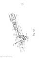
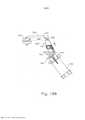
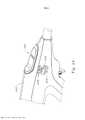
[007] A Figura 1 mostra uma vista em perspectiva de um grampeador circular exemplificador;[007] Figure 1 shows a perspective view of an exemplary circular stapler;
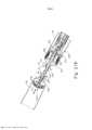
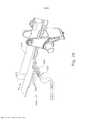
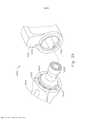
[008] A Figura 2 mostra uma vista em perspectiva do grampeador circular da Figura 1, com uma bateria removida de um conjunto de cabo e uma bigorna removida do conjunto de cabeça de grampeamento;[008] Figure 2 shows a perspective view of the circular stapler of Figure 1, with a battery removed from a handle assembly and an anvil removed from the stapler head assembly;
[009] A Figura 3 mostra uma vista em perspectiva da bigorna do grampeador circular da Figura 1;[009] Figure 3 shows a perspective view of the circular stapler anvil of Figure 1;
[0010] A Figura 4 mostra uma outra vista em perspectiva da bigorna da Figura 3;[0010] Figure 4 shows another perspective view of the anvil of Figure 3;
[0011] A Figura 5 mostra uma vista em elevação lateral explodida da bigorna da Figura 3;[0011] Figure 5 shows an exploded side elevation view of the anvil of Figure 3;
[0012] A Figura 6 mostra uma vista em perspectiva do conjunto de cabeça de grampeamento do grampeador circular da Figura 1;[0012] Figure 6 shows a perspective view of the stapling head assembly of the circular stapler of Figure 1;
[0013] A Figura 7 mostra uma vista em perspectiva explodida do conjunto de cabeça de grampeamento da Figura 6;[0013] Figure 7 shows an exploded perspective view of the stapling head assembly of Figure 6;
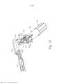
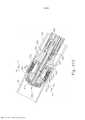
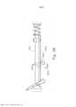
[0014] A Figura 8 mostra uma vista em perspectiva explodida do grampeador circular da Figura 1, com porções do conjunto de eixo de acionamento mostradas separadamente umas das outras;[0014] Figure 8 shows an exploded perspective view of the circular stapler of Figure 1, with portions of the drive shaft assembly shown separately from one another;
[0015] A Figura 9 mostra uma vista em perspectiva de um conjunto de cabo do grampeador circular da Figura 1, com uma metade do compartimento omitida para revelar os componentes internos do conjunto de cabo;[0015] Figure 9 shows a perspective view of a cable assembly of the circular stapler of Figure 1, with one half of the compartment omitted to reveal the internal components of the cable assembly;
[0016] A Figura 10 mostra uma vista em perspectiva de um bráquete do conjunto de cabo da Figura 9;[0016] Figure 10 shows a perspective view of a bracket of the cable assembly of Figure 9;
[0017] A Figura 11 mostra uma vista em perspectiva de um elemento de indicador do conjunto de cabo da Figura 9;[0017] Figure 11 shows a perspective view of an indicator element of the cable assembly of Figure 9;
[0018] A Figura 12A mostra uma vista em perspectiva de um conjunto de atuação da bigorna do grampeador circular da Figura 1, com uma haste de atuação em uma primeira posição;[0018] Figure 12A shows a perspective view of an actuation assembly of the anvil of the circular stapler of Figure 1, with an actuation rod in a first position;
[0019] A Figura 12B mostra uma vista em perspectiva do conjunto de atuação da bigorna da Figura 12A, com a haste de atuação movida para uma segunda posição para engatar com o bráquete da Figura 10;[0019] Figure 12B shows a perspective view of the anvil actuation assembly of Figure 12A, with the actuation rod moved to a second position to engage with the bracket of Figure 10;
[0020] A Figura 12C mostra uma vista em perspectiva do conjunto de atuação da bigorna da Figura 12A, com a haste de atuação movida para uma terceira posição para retrair o bráquete da Figura 10 proximalmente;[0020] Figure 12C shows a perspective view of the anvil actuation assembly of Figure 12A, with the actuation rod moved to a third position to retract the bracket of Figure 10 proximally;
[0021] A Figura 12D mostra uma vista em perspectiva do conjunto de atuação da bigorna da Figura 12A, com um gatilho de segurança articulado de uma primeira posição para uma segunda posição;[0021] Figure 12D shows a perspective view of the anvil actuation assembly of Figure 12A, with a hinged safety trigger from a first position to a second position;
[0022] A Figura 12E mostra uma vista em perspectiva do conjunto de atuação da bigorna da Figura 12A, com um gatilho de disparo articulado de uma primeira posição para uma segunda posição;[0022] Figure 12E shows a perspective view of the anvil actuation assembly of Figure 12A, with an articulated firing trigger from a first position to a second position;
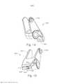
[0023] A Figura 13 mostra uma vista em perspectiva de um conjunto de atuação da cabeça de grampeamento do grampeador circular da Figura 1;[0023] Figure 13 shows a perspective view of an actuation set of the stapler head of the circular stapler of Figure 1;
[0024] A Figura 14 mostra uma vista em perspectiva de um seguidor de came do conjunto de atuação da cabeça de grampeamento da Figura 13;[0024] Figure 14 shows a perspective view of a cam follower of the staple head actuation assembly of Figure 13;
[0025] A Figura 15 mostra uma outra vista em perspectiva do seguidor de came da Figura 14;[0025] Figure 15 shows another perspective view of the cam follower of Figure 14;
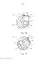
[0026] A Figura 16 mostra uma vista em perspectiva de um came giratório do conjunto de atuação da cabeça de grampeamento da Figura 13;[0026] Figure 16 shows a perspective view of a rotating cam of the staple head actuation assembly of Figure 13;
[0027] A Figura 17 mostra uma outra vista em perspectiva do came giratório da Figura 16;[0027] Figure 17 shows another perspective view of the rotating cam in Figure 16;
[0028] A Figura 18A mostra uma vista em elevação lateral do conjunto de atuação da cabeça de grampeamento da Figura 13, com o came giratório em uma primeira posição angular, e do seguidor de came em uma primeira posição pivotante;[0028] Figure 18A shows a side elevation view of the staple head actuation assembly of Figure 13, with the rotating cam in a first angular position, and the cam follower in a first pivotal position;
[0029] A Figura 18B mostra uma vista em elevação lateral do conjunto de atuação da cabeça de grampeamento da Figura 13, com o came giratório em uma segunda posição angular, e do seguidor de came em uma segunda posição pivotante;[0029] Figure 18B shows a side elevation view of the staple head actuation assembly of Figure 13, with the rotating cam in a second angular position, and the cam follower in a second pivotal position;
[0030] A Figura 19A mostra uma vista em perspectiva do came giratório da Figura 16, de um elemento oscilante e de uma chave de bloqueio, com o came giratório em uma primeira posição angular e elemento oscilante em uma primeira posição pivotante;[0030] Figure 19A shows a perspective view of the rotating cam of Figure 16, a rocking element and a lock key, with the rotating cam in a first angular position and rocking element in a first pivotal position;
[0031] A Figura 19B mostra uma vista em perspectiva do came giratório da Figura 16, do elemento oscilante da Figura 19A e da chave de bloqueio da Figura 19A, com o came giratório em uma quarta posição angular e o elemento oscilante em uma segunda posição pivotante;[0031] Figure 19B shows a perspective view of the rotating cam of Figure 16, the oscillating element of Figure 19A and the lock switch of Figure 19A, with the rotating cam in a fourth angular position and the oscillating element in a second position pivoting;
[0032] A Figura 20A mostra uma vista de extremidade esquemática do came giratório da Figura 16, do seguidor de came da Figura 14 e do elemento oscilante da Figura 19A, com o came giratório na primeira posição angular, o seguidor de came na primeira posição pivotante e o elemento oscilante na primeira posição pivotante;[0032] Figure 20A shows a schematic end view of the rotating cam of Figure 16, the cam follower of Figure 14 and the oscillating element of Figure 19A, with the rotating cam in the first angular position, the cam follower in the first position pivotal and the oscillating element in the first pivotal position;
[0033] A Figura 20B mostra uma vista de extremidade esquemática do came giratório da Figura 16 e do came giratório da Figura 14, com o came giratório na segunda posição angular, o seguidor de came na segunda posição pivotante e o elemento oscilante da Figura 19A na primeira posição pivotante;[0033] Figure 20B shows a schematic end view of the rotating cam of Figure 16 and the rotating cam of Figure 14, with the rotating cam in the second angular position, the cam follower in the second pivotal position and the oscillating element of Figure 19A in the first pivotal position;
[0034] A Figura 20C mostra uma vista de extremidade esquemática do came giratório da Figura 16 e do came giratório da Figura 14, com o came giratório em uma terceira posição angular, o seguidor de came na segunda posição pivotante e o elemento oscilante da Figura 19A na primeira posição pivotante;[0034] Figure 20C shows a schematic end view of the rotating cam of Figure 16 and the rotating cam of Figure 14, with the rotating cam in a third angular position, the cam follower in the second pivotal position and the oscillating element of Figure 19A in the first pivotal position;
[0035] A Figura 20D mostra uma vista de extremidade esquemática do came giratório da Figura 16, o came giratório da Figura 14 e o elemento oscilante da Figura 19A, com o came giratório em uma quarta posição angular, o seguidor de came em uma terceira posição pivotante e o elemento oscilante em uma segunda posição pivotante;[0035] Figure 20D shows a schematic end view of the rotating cam of Figure 16, the rotating cam of Figure 14 and the oscillating element of Figure 19A, with the rotating cam in a fourth angular position, the cam follower in a third pivotal position and the oscillating element in a second pivotal position;
[0036] A Figura 21A mostra uma vista lateral em seção transversal da bigorna da Figura 3 posicionada em uma primeira seção de um trato digestivo, e do conjunto de cabeça de grampeamento da Figura 6 posicionado em uma segunda seção do trato digestivo, com a bigorna separada do conjunto de cabeça de grampeamento;[0036] Figure 21A shows a side view in cross section of the anvil of Figure 3 positioned on a first section of a digestive tract, and the stapling head assembly of Figure 6 positioned on a second section of the digestive tract, with the anvil separate from the stapling head assembly;
[0037] A Figura 21B mostra uma vista lateral em seção transversal da bigorna da Figura 3 posicionada na primeira seção do trato digestivo, e do conjunto de cabeça de grampeamento da Figura 6 posicionado na segunda seção do trato digestivo, com a bigorna presa ao conjunto de cabeça de grampeamento;[0037] Figure 21B shows a side view in cross section of the anvil of Figure 3 positioned in the first section of the digestive tract, and the stapling head assembly of Figure 6 positioned in the second section of the digestive tract, with the anvil attached to the assembly clipping head;
[0038] A Figura 21C mostra uma vista lateral em seção transversal da bigorna da Figura 3 posicionada na primeira seção do trato digestivo, e do conjunto de cabeça de grampeamento da Figura 6 posicionado na segunda seção do trato digestivo, com a bigorna retraída em direção ao conjunto de cabeça de grampeamento para, dessa forma, prender o tecido entre a bigorna e o conjunto de cabeça de grampeamento;[0038] Figure 21C shows a side view in cross section of the anvil of Figure 3 positioned in the first section of the digestive tract, and the stapling head assembly of Figure 6 positioned in the second section of the digestive tract, with the anvil retracted towards to the stapling head assembly to thereby clamp tissue between the anvil and the stapling head assembly;
[0039] A Figura 21D mostra uma vista lateral em seção transversal da bigorna da Figura 3 posicionada na primeira seção do trato digestivo, e do conjunto de cabeça de grampeamento da Figura 6 posicionado na segunda seção do trato digestivo, com o conjunto de cabeça de grampeamento acionado para cortar e grampear o tecido pinçado; e[0039] Figure 21D shows a side view in cross section of the anvil of Figure 3 positioned in the first section of the digestive tract, and the stapling head assembly of Figure 6 positioned in the second section of the digestive tract, with the stapling head assembly of Stapling triggered to cut and staple pinched tissue; and
[0040] A Figura 21E mostra uma vista lateral em seção transversal da primeira e da segunda seções do trato digestivo da Figura 21A unidas em uma anastomose de extremidade a extremidade;[0040] Figure 21E shows a cross-sectional side view of the first and second digestive tract sections of Figure 21A joined together in an end-to-end anastomosis;
[0041] A Figura 22 mostra uma vista esquemática de um sistema de indicação de disparo exemplificador que pode ser incorporado ao grampeador circular da Figura 1;[0041] Figure 22 shows a schematic view of an exemplary shot indication system that can be incorporated into the circular stapler of Figure 1;
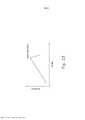
[0042] A Figura 23 mostra um gráfico da corrente como função do tempo em relação a uma fonte de energia que fornece energia a um motor do sistema de indicação de disparo da Figura 22;[0042] Figure 23 shows a graph of the current as a function of time in relation to a power source that supplies energy to a motor of the trip indication system of Figure 22;
[0043] A Figura 24 mostra uma vista em perspectiva parcial de um cabo de um sistema de indicação de disparo exemplificador que pode ser incorporado ao grampeador circular da Figura 1;[0043] Figure 24 shows a partial perspective view of a cable from an exemplary trip indication system that can be incorporated into the circular stapler of Figure 1;
[0044] A Figura 25 mostra uma vista em perspectiva em recorte do sistema de indicação de disparo da Figura 24;[0044] Figure 25 shows a perspective cutaway view of the trigger indication system of Figure 24;
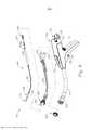
[0045] A Figura 26 mostra uma vista em perspectiva parcial de um conjunto de atuação do trocarte exemplificador com um sistema de indicador de liberação de tecido que pode ser incorporado ao grampeador circular da Figura 1;[0045] Figure 26 shows a partial perspective view of an exemplary trocar performance assembly with a tissue release indicator system that can be incorporated into the circular stapler of Figure 1;
[0046] A Figura 27 mostra uma vista em perspectiva de um bráquete do sistema de indicador de liberação de tecido da Figura 26;[0046] Figure 27 shows a perspective view of a bracket of the tissue release indicator system of Figure 26;
[0047] A Figura 28 mostra uma vista em elevação lateral do conjunto de atuação do trocarte da Figura 26;[0047] Figure 28 shows a side elevation view of the trocar actuation set of Figure 26;
[0048] A Figura 29 mostra uma vista em perspectiva segmentada de um sistema de indicador de liberação de tecido exemplificador que pode ser incorporado ao grampeador circular da Figura 1, sendo que o sistema de indicador de liberação de tecido é fixado a um botão de giro e a um cabo;[0048] Figure 29 shows a segmented perspective view of an exemplary tissue release indicator system that can be incorporated into the circular stapler of Figure 1, with the tissue release indicator system attached to a turning knob and to a cable;
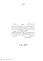
[0049] A Figura 30A mostra uma vista em seção transversal de topo do botão de giro e do cabo do sistema de indicador de liberação de tecido da Figura 29, com o botão sendo girado em uma primeira direção, e com um recurso detentor do botão aproximando-se de uma aba do cabo;[0049] Figure 30A shows a top cross-sectional view of the pivot knob and cable of the tissue release indicator system of Figure 29, with the knob being rotated in a first direction, and with a knob detainer feature approaching a cable tab;
[0050] A Figura 30B mostra uma vista em seção transversal de topo do botão de giro e do cabo do sistema de indicador de liberação de tecido da Figura 29, com o botão sendo girado adicionalmente na primeira direção, com o recurso detentor engatando no cabo;[0050] Figure 30B shows a top cross-sectional view of the knob and cable of the fabric release indicator system of Figure 29, with the knob being additionally rotated in the first direction, with the detent feature engaging the cable ;
[0051] A Figura 30C mostra uma vista em seção transversal de topo do botão de giro e do cabo do sistema de indicador de liberação de tecido da Figura 29, com o botão sendo girado adicionalmente na primeira direção, com o recurso detentor desengatando do cabo para criar um clique audível;[0051] Figure 30C shows a top cross-sectional view of the turning knob and cable of the fabric release indicator system of Figure 29, with the knob being additionally rotated in the first direction, with the keeper feature disengaging from the cable to create an audible click;
[0052] A Figura 31A mostra uma vista em seção transversal de topo do botão de giro e do cabo do sistema de indicador de liberação de tecido da Figura 29, com o botão sendo girado em uma segunda direção, e com um recurso detentor do botão aproximando-se de uma aba do cabo;[0052] Figure 31A shows a top cross-sectional view of the twist knob and cable of the tissue release indicator system of Figure 29, with the knob being rotated in a second direction, and with a knob detainer feature approaching a cable tab;
[0053] A Figura 31B mostra uma vista em seção transversal de topo do botão de giro e do cabo do sistema de indicador de liberação de tecido da Figura 29, com o botão sendo girado adicionalmente na segunda direção, com o recurso detentor engatando no cabo;[0053] Figure 31B shows a top cross-sectional view of the turning knob and cable of the fabric release indicator system of Figure 29, with the knob being additionally rotated in the second direction, with the detainer feature engaging the cable ;
[0054] A Figura 31C mostra uma vista em seção transversal de topo do botão de giro e do cabo do sistema de indicador de liberação de tecido da Figura 29, com o botão sendo girado adicionalmente na segunda direção, com o recurso detentor desengatando do cabo para criar um clique audível;[0054] Figure 31C shows a top cross-sectional view of the turning knob and cable of the fabric release indicator system of Figure 29, with the knob being additionally rotated in the second direction, with the keeper feature disengaging from the cable to create an audible click;
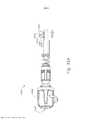
[0055] A Figura 32A mostra uma vista em elevação lateral de um conjunto de atuação de trocarte exemplificador que inclui um indicador de liberação de tecido que pode ser incorporado ao grampeador circular da Figura 1, com uma haste de atuação do trocarte em uma posição longitudinal proximal e o indicador de liberação de tecido em um primeiro estado;[0055] Figure 32A shows a side elevation view of an exemplary trocar actuation assembly that includes a tissue release indicator that can be incorporated into the circular stapler of Figure 1, with a trocar actuation rod in a longitudinal position proximal and the tissue release indicator in a first state;
[0056] A Figura 32B mostra uma vista em elevação lateral do conjunto de atuação do trocarte da Figura 32A, com a haste de atuação do trocarte em uma posição distal e o indicador de liberação de tecido em um segundo estado;[0056] Figure 32B shows a side elevation view of the trocar actuation assembly of Figure 32A, with the trocar actuation rod in a distal position and the tissue release indicator in a second state;
[0057] A Figura 33 mostra uma vista em perspectiva de um indicador de liberação de tecido exemplificador que pode ser incorporado ao grampeador circular da Figura 1, sendo que o indicador de liberação de tecido compreende um mecanismo audível/tátil passível de posicionamento;[0057] Figure 33 shows a perspective view of an exemplary tissue release indicator that can be incorporated into the circular stapler of Figure 1, the tissue release indicator comprising an audible/tactile mechanism that can be positioned;
[0058] A Figura 34A mostra uma vista em elevação lateral do indicador de liberação de tecido da Figura 33 em uma posição de pré- prontidão;[0058] Figure 34A shows a side elevation view of the tissue release indicator of Figure 33 in a pre-ready position;
[0059] A Figura 34B mostra uma vista em elevação lateral do indicador de liberação de tecido da Figura 33 em uma posição de prontidão enquanto um bráquete associado está estacionário;[0059] Figure 34B shows a side elevation view of the tissue release indicator of Figure 33 in a ready position while an associated bracket is stationary;
[0060] A Figura 34C mostra uma vista em elevação lateral do indicador de liberação de tecido da Figura 33 em uma posição de prontidão enquanto o bráquete translada longitudinalmente;[0060] Figure 34C shows a side elevation view of the tissue release indicator of Figure 33 in a ready position while the bracket translates longitudinally;
[0061] A Figura 35 mostra uma vista em perspectiva de um indicador de liberação de tecido baseado em resistência que pode ser incorporado ao grampeador circular da Figura 1;[0061] Figure 35 shows a perspective view of a resistance-based tissue release indicator that can be incorporated into the circular stapler of Figure 1;
[0062] A Figura 36A mostra uma vista em elevação lateral do indicador de liberação de tecido baseado em resistência da Figura 35 com uma haste de atuação do trocarte em uma primeira posição longitudinal;[0062] Figure 36A shows a side elevation view of the resistance-based tissue release indicator of Figure 35 with a trocar actuating rod in a first longitudinal position;
[0063] A Figura 36B mostra uma vista em elevação lateral do indicador de liberação de tecido baseado em resistência da Figura 35 com uma haste de atuação do trocarte em uma segunda posição longitudinal;[0063] Figure 36B shows a side elevation view of the resistance-based tissue release indicator of Figure 35 with a trocar actuating rod in a second longitudinal position;
[0064] A Figura 36C mostra uma vista em elevação lateral do indicador de liberação de tecido baseado em resistência da Figura 35 com uma haste de atuação do trocarte em uma terceira posição longitudinal;[0064] Figure 36C shows a side elevation view of the resistance-based tissue release indicator of Figure 35 with a trocar actuating rod in a third longitudinal position;
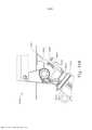
[0065] A Figura 37 mostra uma vista em recorte e em perspectiva de um exemplo de um indicador de liberação de tecido visual que pode ser incorporado ao grampeador circular da Figura 1;[0065] Figure 37 shows a cutaway and perspective view of an example of a visual tissue release indicator that can be incorporated into the circular stapler of Figure 1;
[0066] A Figura 38A mostra uma vista em elevação lateral do indicador de liberação de tecido visual da Figura 37, com uma porção do compartimento removida, e com uma haste de atuação do trocarte em uma primeira posição longitudinal;[0066] Figure 38A shows a side elevation view of the visual tissue release indicator of Figure 37, with a portion of the compartment removed, and with a trocar actuation rod in a first longitudinal position;
[0067] A Figura 38B mostra uma vista em elevação lateral do indicador de liberação de tecido visual da Figura 37, com uma porção do compartimento removida, e com uma haste de atuação do trocarte em uma segunda posição longitudinal;[0067] Figure 38B shows a side elevation view of the visual tissue release indicator of Figure 37, with a portion of the compartment removed, and with a trocar actuation rod in a second longitudinal position;
[0068] A Figura 38C mostra uma vista em elevação lateral do indicador de liberação de tecido visual da Figura 37, com uma porção do compartimento removida, e com uma haste de atuação do trocarte em uma terceira posição longitudinal; e[0068] Figure 38C shows a side elevation view of the visual tissue release indicator of Figure 37, with a portion of the compartment removed, and with a trocar actuation rod in a third longitudinal position; and
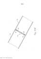
[0069] A Figura 39 mostra uma vista em elevação de topo da janela visual usada no indicador de liberação de tecido visual da Figura 37.[0069] Figure 39 shows a top elevation view of the visual window used in the visual tissue release indicator of Figure 37.
[0070] Os desenhos não pretendem ser limitadores de modo algum e contempla-se que várias modalidades da tecnologia podem ser executadas em uma variedade de outras maneiras, incluindo aquelas não necessariamente representadas nos desenhos. Os desenhos incorporados em anexo e formando uma parte do relatório descritivo ilustram vários aspectos da presente tecnologia e, em conjunto com a descrição, servem para explicar os princípios da tecnologia; entende- se, entretanto, que esta tecnologia não se limita precisamente às disposições mostradas.[0070] The drawings are not intended to be limiting in any way and it is contemplated that various embodiments of the technology may be performed in a variety of other ways, including those not necessarily represented in the drawings. The drawings incorporated in the annex and forming a part of the specification illustrate various aspects of the present technology and, together with the description, serve to explain the principles of the technology; it is understood, however, that this technology is not limited precisely to the arrangements shown.
[0071] A descrição a seguir de certos exemplos da tecnologia não deve ser usada para limitar o seu escopo. Outros exemplos, recursos, aspectos, modalidades e vantagens da tecnologia se tornarão evidentes aos versados na técnica com a descrição a seguir, que é por meio de ilustrações, um dos melhores modos contemplados para realização da tecnologia. Conforme será compreendido, a tecnologia aqui descrita é capaz de outros aspectos diferentes e óbvios, todos sem desconsiderar a invenção. Consequentemente, os desenhos e as descrições devem ser considerados como de natureza ilustrativa e não restritiva.[0071] The following description of certain examples of the technology should not be used to limit its scope. Other examples, features, aspects, modalities and advantages of the technology will become apparent to those skilled in the art with the following description, which is by way of illustrations one of the best contemplated modes for realizing the technology. As will be understood, the technology described herein is capable of other different and obvious aspects, all without disregarding the invention. Consequently, the drawings and descriptions are to be considered as illustrative and not restrictive in nature.
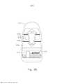
[0072] As Figuras 1 e 2 ilustram um instrumento cirúrgico de grampeamento circular (10) exemplificador que pode ser usado para fornecer uma anastomose de extremidade a extremidade entre duas seções de um lúmen anatômico, como uma porção do trato digestivo de um paciente. O instrumento (10) deste exemplo compreende um conjunto de cabo (100), um conjunto de eixo de acionamento (200), um conjunto de cabeça de grampeamento (300) e uma bigorna (400). O conjunto de cabo (100) compreende um compartimento (110) que define uma empunhadura da pistola (112) orientada obliquamente. Em algumas versões, a empunhadura da pistola (112) é orientada perpendicularmente. Em algumas outras versões, a empunhadura da pistola (112) é omitida. O conjunto de cabo (110) inclui adicionalmente uma janela (114) que permite ver uma agulha de indicador móvel (526), conforme será descrito com mais detalhes abaixo. Em algumas versões, uma série de marcas, regiões coloridas e/ou outros indicadores fixos é posicionada adjacente à janela (114) para fornecer um contexto visual para a agulha de indicador (526), facilitando, assim, a avaliação do operador da posição da agulha (526) no interior da janela (114). Várias características e configurações adequadas para o conjunto de cabo (112) serão evidentes para os versados na técnica em vista dos ensinamentos da presente invenção.[0072] Figures 1 and 2 illustrate an exemplary circular stapling surgical instrument (10) that can be used to provide an end-to-end anastomosis between two sections of an anatomical lumen, such as a portion of a patient's digestive tract. The instrument (10) of this example comprises a handle assembly (100), a drive shaft assembly (200), a stapling head assembly (300) and an anvil (400). The handle assembly (100) comprises a housing (110) defining an obliquely oriented pistol grip (112). In some versions, the pistol grip (112) is oriented perpendicularly. In some other versions, the pistol grip (112) is omitted. The cable assembly (110) further includes a window (114) that allows viewing of a movable indicator needle (526), as will be described in more detail below. In some versions, a series of marks, colored regions and/or other fixed indicators is positioned adjacent the window (114) to provide a visual context for the indicator needle (526), thereby facilitating the operator's assessment of the position of the indicator. needle (526) inside the window (114). Various features and suitable configurations for the
[0073] O instrumento (10) do presente exemplo inclui adicionalmente uma bateria (120). A bateria (120) tem por finalidade fornecer potência elétrica para um motor (160) na empunhadura da pistola (112), conforme será descrito com mais detalhes abaixo. A bateria (120) é removível do conjunto de cabo (100). Em particular, conforme mostrado nas Figuras 1 e 2, a bateria (120) pode ser inserida dentro de um soquete (116) definido pelo compartimento (110). Quando a bateria, (120) é totalmente inserida no soquete (116), travas (122) da bateria (120) podem se engatar resilientemente em recursos internos do compartimento (110) para possibilitar um encaixe por pressão. Para remover a bateria (120), o operador pode pressionar as travas (122) para dentro para desengatar travas (122) dos recursos internos do compartimento (110) e então puxar a bateria (120) para fora do soquete (116) de maneira proximal. Deve-se compreender que a bateria (120) e o conjunto de cabo (100) podem ter contatos elétricos, pinos e soquetes complementares e/ou outros recursos que fornecem caminhos para a comunicação elétrica da bateria (120) com componentes alimentados eletricamente no conjunto de cabo (100), quando a bateria (120) é inserida no soquete (116). Deve-se compreender, também, que, em algumas versões, a bateria (120) é incorporada como uma unidade dentro do conjunto de cabo (100) de modo que a bateria (120) não possa ser removida do conjunto de cabo (100).[0073] The instrument (10) of the present example additionally includes a battery (120). The battery (120) is intended to provide electrical power to a motor (160) in the pistol grip (112), as will be described in more detail below. The battery (120) is removable from the cable assembly (100). In particular, as shown in Figures 1 and 2, the battery (120) can be inserted into a socket (116) defined by the compartment (110). When the battery (120) is fully inserted into the socket (116), latches (122) of the battery (120) can resiliently engage with internal features of the compartment (110) to provide a snap fit. To remove the battery (120), the operator can press the latches (122) inward to disengage latches (122) from the internal features of the compartment (110) and then pull the battery (120) out of the socket (116) in a manner proximal. It should be understood that the battery (120) and cable assembly (100) may have electrical contacts, complementary pins and sockets, and/or other features that provide pathways for electrical communication from the battery (120) with electrically powered components in the assembly. cable (100) when the battery (120) is inserted into the socket (116). It should also be understood that, in some versions, the battery (120) is incorporated as a unit within the cable assembly (100) so that the battery (120) cannot be removed from the cable assembly (100). .
[0074] O conjunto de eixo de acionamento (200) se estende distalmente a partir do conjunto de cabo (100) e inclui uma curva pré- formada. Em algumas versões, a curva pré-formada é configurada para facilitar o posicionamento do conjunto de cabeça de grampeamento (300) no interior do cólon de um paciente. Vários ângulos ou raios de flexão adequados que podem ser usados serão evidentes para os versados na técnica em vista dos ensinamentos da presente invenção. Em algumas outras versões, o conjunto de eixo de acionamento (200) é reto e não apresenta uma curva pré-formada. Vários componentes exemplificadores que podem ser incorporados no conjunto de eixo de acionamento (100) serão descritos com mais detalhes abaixo.[0074] The drive shaft assembly (200) extends distally from the cable assembly (100) and includes a preformed bend. In some versions, the preformed curve is configured to facilitate positioning the stapling head assembly (300) within a patient's colon. Various suitable bending angles or radii that can be used will be apparent to those skilled in the art in view of the teachings of the present invention. In some other versions, the drive shaft assembly (200) is straight and does not have a preformed curve. Various exemplary components that may be incorporated into the driveshaft assembly (100) will be described in more detail below.
[0075] O conjunto de cabeça de grampeamento (300) está situado na extremidade distal do conjunto de eixo de acionamento (200). Conforme mostrado nas Figuras 1 e 2, e conforme será descrito com mais detalhes abaixo, a bigorna (400) é configurada para acoplar de modo removível com o conjunto de eixo de acionamento (200) em posição adjacente ao conjunto de cabeça de grampeamento (300). Conforme também será descrito com mais detalhes abaixo, a bigorna (400) e do conjunto de cabeça de grampeamento (300) são configurados para cooperar de modo a permitir a manipulação de tecido de três formas: pinçar o tecido, cortar o tecido o tecido e grampear o tecido. Um botão (130), na extremidade proximal do conjunto de cabo (100) é giratório em relação ao compartimento (110) para possibilitar a fixação precisa do tecido entre a bigorna (400) e do conjunto de cabeça de grampeamento (300). Quando um gatilho de segurança (140) do conjunto de cabo (100) é articulado de modo a se afastar de um gatilho de disparo (150) do conjunto de cabo (100), o gatilho de disparo pode ser acionado (150) de modo a possibilitar corte e grampeamento do tecido.[0075] The stapling head assembly (300) is located at the distal end of the drive shaft assembly (200). As shown in Figures 1 and 2, and as will be described in more detail below, the anvil (400) is configured to releasably mate with the drive shaft assembly (200) adjacent the stapling head assembly (300). ). As will also be described in more detail below, the anvil (400) and the stapling head assembly (300) are configured to cooperate to allow manipulation of tissue in three ways: pinching tissue, cutting tissue, and tissue. staple the fabric. A knob (130) at the proximal end of the handle assembly (100) is rotatable with respect to the housing (110) to provide precise tissue attachment between the anvil (400) and the stapling head assembly (300). When a safety trigger (140) of the cable assembly (100) is pivoted away from a firing trigger (150) of the cable assembly (100), the firing trigger can be actuated (150) so that to allow cutting and stapling of the tissue.
[0076] Na discussão apresentada a seguir da bigorna (400), os termos "distal" e "proximal" (e suas variações) são usados com referência à orientação da bigorna (400) quando esta é acoplada com o conjunto de eixo de acionamento (200) do instrumento (10). Dessa forma, os recursos proximais da bigorna (400) estarão mais próximos do operador do instrumento (10); ao passo que os recursos distais da bigorna (400) estarão mais distantes do operador do instrumento (10).[0076] In the following discussion of the anvil (400), the terms "distal" and "proximal" (and their variations) are used with reference to the orientation of the anvil (400) when it is coupled with the drive shaft assembly (200) of the instrument (10). In this way, the proximal features of the anvil (400) will be closer to the instrument operator (10); whereas the distal features of the anvil (400) will be furthest from the instrument operator (10).
[0077] Conforme se pode observar melhor nas Figuras 3 a 5, a bigorna (400) do presente exemplo compreende uma cabeça (410) e uma haste (420). A cabeça (410) inclui uma superfície proximal (412) que define uma pluralidade de bolsos formadores de grampo (414). Os bolsos formadores de grampo (414) são dispostos em duas matrizes anulares concêntricas. Em algumas outras versões, os bolsos formadores de grampo (414) são dispostos em três ou mais matrizes anulares concêntricas. Os bolsos formadores de grampo (414) são configurados para deformar os grampos à medida que estes são impelidos para o interior dos bolsos formadores de grampo (414). Por exemplo, cada bolso formador de grampo (414) pode deformar um grampo com um formato genérico de "U" em um grampo em um formato de "B", conforme é conhecido na técnica. Conforme se pode observar melhor na Figura 4, uma superfície proximal (412) termina em uma borda interna (416), a qual define um contorno externo de uma reentrância anular (418) ao redor da haste (420).[0077] As best seen in Figures 3 to 5, the anvil (400) of the present example comprises a head (410) and a shank (420). The head (410) includes a proximal surface (412) that defines a plurality of clip-forming pockets (414). The staple forming pockets (414) are arranged in two concentric annular arrays. In some other versions, the staple forming pockets (414) are arranged in three or more concentric annular arrays. The staple forming pockets (414) are configured to deform the staples as they are urged into the staple forming pockets (414). For example, each clip forming pocket (414) can deform a generic "U" shaped clip into a "B" shaped clip as is known in the art. As best seen in Figure 4, a proximal surface (412) terminates in an inner rim (416), which defines an outer contour of an annular recess (418) around the rod (420).
[0078] A haste (420) define um orifício (422) e inclui um par de membros de trava pivotantes (430) posicionados no orifício (422). Conforme se pode observar melhor na Figura 5, cada membro de trava (430) inclui uma extremidade distal em formato de "T" (432), uma extremidade proximal arredondada (434) e uma projeção de trava (436) situada distalmente à extremidade proximal (434). As extremidades distais em formato de "T" (432) formam membros de trava (430) firmes dentro do orifício (422). Os membros de trava (430) são posicionados dentro do orifício (422), de modo que as extremidades distais (434) fiquem posicionadas nas extremidades proximais de aberturas laterais (424), que são formadas através da parede lateral da haste (420). As aberturas laterais (424) fornecem, desse modo, folga para as extremidades distais (434) e as projeções de trava (436) para defletirem radialmente para fora em relação ao eixo longitudinal definido pela haste (420). Entretanto, os membros de trava (430) são configurados para inclinar de modo resiliente as extremidades distais (434) e as projeções de trava (436) radialmente para dentro em direção ao eixo longitudinal definido pela haste (420). Os membros de trava (430) agem, assim, como virolas de retenção. Isso permite que a bigorna (400) seja presa de modo removível a um trocarte (330) do conjunto de cabeça de grampeamento (300), conforme será descrito com mais detalhes abaixo. Deve-se compreender, contudo, que os membros de trava (436) são meramente opcionais. A bigorna (400) pode ser presa de modo removível a um trocarte (330) com o uso de quaisquer outros componentes, recursos ou técnicas adequados.[0078] The rod (420) defines a hole (422) and includes a pair of pivotal latch members (430) positioned in the hole (422). As best seen in Figure 5, each latch member (430) includes a "T" shaped distal end (432), a rounded proximal end (434) and a latch projection (436) located distal to the proximal end. (434). The T-shaped distal ends (432) form locking members (430) securely within the bore (422). The latch members (430) are positioned within the hole (422) so that the distal ends (434) are positioned at the proximal ends of side openings (424) which are formed through the side wall of the rod (420). The side openings (424) thereby provide clearance for the distal ends (434) and latch projections (436) to deflect radially outward from the longitudinal axis defined by the rod (420). However, the latch members (430) are configured to resiliently bias the distal ends (434) and latch projections (436) radially inwardly toward the longitudinal axis defined by the rod (420). Latch members (430) thus act as retaining ferrules. This allows the anvil (400) to be releasably attached to a trocar (330) of the stapling head assembly (300), as will be described in more detail below. It should be understood, however, that the latch members (436) are merely optional. The anvil (400) may be releasably attached to a trocar (330) using any other suitable components, devices or techniques.
[0079] Em adição ou em substituição ao supracitado, a bigorna (400) pode ser adicionalmente construída e operável de acordo com pelo menos alguns dos ensinamentos da patente US n° 5.205.459; da patente US n° 5.271.544; da patente US n° 5.275.322; da patente US n° 5.285.945; da patente US n° 5.292.053; da patente US n° 5.333.773; da patente US n° 5.350.104; da patente US n° 5.533.661; e/ou da patente US n° 8.910.847, estando as revelações das mesmas aqui incorporadas, por referência. Outras configurações ainda serão evidentes para o versado na técnica com base nos ensinamentos da presente invenção.[0079] In addition to or in place of the foregoing, the anvil (400) can be further constructed and operable in accordance with at least some of the teachings of US Patent No. 5,205,459; US Patent No. 5,271,544; US Patent No. 5,275,322; US Patent No. 5,285,945; US Patent No. 5,292,053; US Patent No. 5,333,773; US Patent No. 5,350,104; US Patent No. 5,533,661; and/or US Patent No. 8,910,847, the disclosures thereof being incorporated herein by reference. Still other configurations will be apparent to the skilled artisan based on the teachings of the present invention.
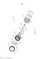
[0080] Conforme se pode observar melhor nas Figuras 6 e 7, o conjunto de cabeça de grampeamento (300) do presente exemplo é acoplado a uma extremidade distal do conjunto de eixo de acionamento (200) e compreende um compartimento tubular (310) que abriga um membro de acionador de grampo deslizante (350). Um membro de núcleo interno (312) similar a um cilindro se estende distalmente dentro do compartimento tubular (310). O compartimento tubular (310) é preso de modo fixo a uma bainha externa (210) do conjunto de eixo de acionamento (200), de modo que compartimento tubular (310) sirva como uma base mecânica para o conjunto de cabeça de grampeamento (300).[0080] As best seen in Figures 6 and 7, the stapling head assembly (300) of the present example is coupled to a distal end of the drive shaft assembly (200) and comprises a tubular housing (310) that houses a slide clamp driver member (350). A cylinder-like inner core member (312) extends distally within the tubular housing (310). The tubular housing (310) is fixedly attached to an outer sheath (210) of the drive shaft assembly (200) so that the tubular housing (310) serves as a mechanical base for the stapling head assembly (300) ).
[0081] O trocarte (330) é posicionado coaxialmente dentro do membro de núcleo interno (312) do compartimento tubular (310). Conforme será descrito com mais detalhes abaixo, (330) é operável para transladar distal e proximalmente em relação ao compartimento tubular (310) em resposta à rotação do botão (130) em relação ao compartimento (110) do conjunto de cabo (100). O trocarte (330) compreende um eixo de acionamento (332) e uma cabeça (334). A cabeça (334) inclui uma ponteira (336) e uma superfície proximal (338) que se estende para dentro. O eixo de acionamento (332) fornece, portanto, um diâmetro externo reduzido adjacente à cabeça (334), com a superfície (338) fornecendo uma transição entre esse diâmetro externo reduzido do eixo de acionamento (332) e o diâmetro externo da cabeça (334). Embora a ponteira (336) seja uma ponta no presente exemplo, ela não é pontiaguda. Dessa forma, a ponteira (336) não causará trauma facilmente ao tecido devido ao contato acidental com o tecido. A cabeça (334) e a porção distal do eixo de acionamento (332) são configuradas para inserção no orifício (422) da bigorna (420). A superfície proximal (338) e as projeções de trava (436) têm posições e configurações complementares, de modo que as projeções de trava (436) se engatem à superfície proximal (338) quando a haste (420) da bigorna (400) está totalmente assentada no trocarte (330). A bigorna (400) é, dessa forma, presa ao trocarte (330) através de um encaixe por pressão devido aos membros de trava (430).[0081] The trocar (330) is positioned coaxially within the inner core member (312) of the tubular housing (310). As will be described in more detail below, (330) is operable to translate distally and proximally relative to the tubular housing (310) in response to rotation of the knob (130) relative to the housing (110) of the cable assembly (100). The trocar (330) comprises a drive shaft (332) and a head (334). The head (334) includes a ferrule (336) and a proximal surface (338) that extends inwardly. The drive shaft (332) therefore provides a reduced outside diameter adjacent to the head (334), with the surface (338) providing a transition between that reduced outside diameter of the drive shaft (332) and the outside diameter of the head (332). 334). Although the tip (336) is a point in the present example, it is not pointed. In this way, the tip (336) will not easily cause tissue trauma due to accidental tissue contact. The head (334) and distal portion of the drive shaft (332) are configured for insertion into the bore (422) of the anvil (420). The proximal surface (338) and latch projections (436) have complementary positions and configurations such that the latch projections (436) engage the proximal surface (338) when the stem (420) of the anvil (400) is fully seated in the trocar (330). The anvil (400) is thus attached to the trocar (330) via a press fit due to the locking members (430).
[0082] O membro de acionador de grampo (350) é operável para atuar longitudinalmente dentro do compartimento tubular (310) em resposta à ativação do motor (160), conforme será descrito com mais detalhes abaixo. O membro de acionador de grampo (350) inclui duas matrizes anulares concêntricas de acionadores de grampo (352) dispostas distalmente. Os acionadores de grampo (352) são dispostos de modo a corresponder com a disposição dos bolsos formadores de grampo (414) descritos acima. Dessa forma, cada acionador de grampo (352) está configurado para impelir um grampo correspondente para dentro de um bolso formador de grampo correspondente (414) quando o conjunto de cabeça de grampeamento (300) é acionado. Deve-se compreender que a disposição de acionadores de grampo (352) pode ser modificada assim como a disposição de bolsos formadores de grampo (414), conforme descrito acima. O membro de acionador de grampo (350) define também um orifício (354) que é configurado para receber coaxialmente o membro de núcleo (312) do compartimento tubular (310). Uma matriz anular de cavilhas (356) projeta-se distalmente a partir de uma superfície disposta distalmente que circunda o orifício (354).[0082] The clip driver member (350) is operable to actuate longitudinally within the tubular housing (310) in response to activation of the motor (160), as will be described in more detail below. The clip driver member (350) includes two distally disposed concentric annular clip driver arrays (352). The staple drivers (352) are arranged to correspond with the arrangement of the staple forming pockets (414) described above. Thus, each staple driver (352) is configured to drive a corresponding staple into a corresponding staple forming pocket (414) when the staple head assembly (300) is actuated. It should be understood that the arrangement of clip drivers (352) can be modified as well as the arrangement of clip forming pockets (414) as described above. The clip driver member (350) also defines an orifice (354) that is configured to coaxially receive the core member (312) of the tubular housing (310). An annular array of pegs (356) projects distally from a distally disposed surface surrounding the hole (354).
[0083] Um membro de faca (340) de formato similar a um cilindro é posicionado coaxialmente dentro do membro de acionador de grampo (350). O membro de faca (340) inclui um gume cortante circular afiado (342) disposto distalmente. O membro de faca (340) é dimensionado de modo a definir um diâmetro externo que é menor que o diâmetro definido pela matriz anular interna de acionadores de grampo (352). O membro de faca (340) também define uma abertura que é configurada para receber coaxialmente o membro de núcleo (312) do compartimento tubular (310). Uma matriz anular de aberturas (346) formadas no membro de faca (340) é configurada de modo a complementar a matriz anular de cavilhas (356) do membro de acionador de grampo (350), de modo que o membro de faca (340) seja preso de modo fixo ao membro de acionador de grampo (350) por meio das cavilhas (356) e das aberturas (346). Outras relações estruturais adequadas entre o membro de faca (340) e o membro de acionador de grampo (350) serão evidentes para os versados na técnica em vista dos ensinamentos da presente invenção.[0083] A knife member (340) shaped like a cylinder is positioned coaxially within the clip driver member (350). The knife member (340) includes a distally disposed circular sharp cutting edge (342). The knife member (340) is sized to define an outer diameter that is less than the diameter defined by the inner annular array of clip drivers (352). The knife member (340) also defines an opening that is configured to coaxially receive the core member (312) of the tubular housing (310). An annular array of apertures (346) formed in the knife member (340) is configured to complement the annular array of dowels (356) of the clip driver member (350) so that the knife member (340) is fixedly attached to the clip driver member (350) by means of the pegs (356) and openings (346). Other suitable structural relationships between knife member (340) and clip driver member (350) will become apparent to those skilled in the art in view of the teachings of the present invention.
[0084] O membro de plataforma (320) é preso de maneira fixa ao compartimento tubular (310). O membro de plataforma (320) inclui uma superfície de bráquete (322) disposta distalmente que define duas matrizes anulares concêntricas de aberturas para grampos (324). As aberturas para grampos (324) estão dispostas de modo a corresponder com a disposição de acionadores de grampo (352) e bolsos formadores de grampo (414) descritos acima. Dessa forma, cada abertura para grampo (324) é configurada para fornecer uma trajetória a um acionador de grampo correspondente (352) para impelir um grampo correspondente através do membro de plataforma (320) e para dentro de um bolso formador de grampo correspondente (414) quando o conjunto de cabeça de grampeamento (300) é acionado. Deve-se compreender que a disposição de aberturas para grampos (322) pode ser modificada assim como a disposição de bolsos formadores de grampo (414), conforme descrito acima. Deve-se compreender, também, que várias estruturas e técnicas podem ser usadas para conter grampos no conjunto de cabeça de grampeamento (300) antes do acionamento do conjunto de cabeça de grampeamento (300). Tais estruturas e técnicas que são usadas para conter grampos no conjunto de cabeça de grampeamento (300) podem impedir que os grampos acidentalmente caiam para fora através das aberturas para grampos (324) antes do acionamento do conjunto de cabeça de grampeamento (300). Várias formas adequadas que tais estruturas e técnicas podem assumir serão evidentes para os versados na técnica em vista dos ensinamentos da presente invenção.[0084] The platform member (320) is fixedly attached to the tubular housing (310). The platform member (320) includes a distally disposed bracket surface (322) defining two concentric annular arrays of clasp apertures (324). The staple openings (324) are arranged to correspond with the arrangement of staple drivers (352) and staple forming pockets (414) described above. Thus, each staple opening (324) is configured to provide a path for a corresponding staple driver (352) to urge a corresponding staple through the platform member (320) and into a corresponding staple forming pocket (414). ) when the stapling head assembly (300) is actuated. It should be understood that the arrangement of clip openings (322) can be modified as well as the arrangement of clip forming pockets (414) as described above. It should also be understood that various structures and techniques can be used to contain staples in the stapler head assembly (300) prior to actuation of the stapler head assembly (300). Such structures and techniques that are used to contain staples in the stapling head assembly (300) can prevent staples from accidentally falling out through the staple openings (324) prior to actuation of the stapling head assembly (300). Various suitable forms that such structures and techniques can assume will be apparent to those skilled in the art in view of the teachings of the present invention.
[0085] Conforme se pode observar melhor na Figura 6, o membro de plataforma (320) define um diâmetro interno que é apenas ligeiramente maior que o diâmetro externo definido pelo membro de faca (340). O membro de plataforma (320) é, dessa forma, configurado para permitir que o membro de faca (340) translade distalmente para um ponto onde o gume cortante (342) é distal à superfície de bráquete (322).[0085] As best seen in Figure 6, the platform member (320) defines an inside diameter that is only slightly larger than the outside diameter defined by the knife member (340). The platform member (320) is thus configured to allow the knife member (340) to translate distally to a point where the cutting edge (342) is distal to the bracket surface (322).
[0086] Além disso ou em substituição ao supracitado, o conjunto de cabeça de acionamento (300) pode ser construído e operável de acordo com pelo menos alguns dos ensinamentos da publicação de patente US n° 5.205.459; da patente US n° 5.271.544; da patente US n° 5.275.322; da patente US n° 5.285.945; da patente US n° 5.292.053; da patente US n° 5.333.773; da patente US n° 5.350.104; da patente US n° 5.533.661; e/ou da patente US n° 8.910.847, estando as revelações das mesmas aqui incorporadas, por referência. Outras configurações ainda serão evidentes para o versado na técnica com base nos ensinamentos da presente invenção.[0086] In addition to or in lieu of the foregoing, the drive head assembly (300) can be constructed and operable in accordance with at least some of the teachings of US Patent Publication No. 5,205,459; US Patent No. 5,271,544; US Patent No. 5,275,322; US Patent No. 5,285,945; US Patent No. 5,292,053; US Patent No. 5,333,773; US Patent No. 5,350,104; US Patent No. 5,533,661; and/or US Patent No. 8,910,847, the disclosures thereof being incorporated herein by reference. Still other configurations will be apparent to the skilled artisan based on the teachings of the present invention.
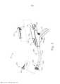
[0087] A Figura 8 mostra vários componentes do conjunto de eixo de acionamento (200), o qual acopla componentes do conjunto de cabeça de grampeamento (300) com componentes do conjunto de cabo (100). Em particular, e conforme observado acima, o conjunto de eixo de acionamento (200) inclui uma bainha externa (210) que se estende entre o conjunto de cabo (100) e o compartimento tubular (310). No presente exemplo, a bainha externa (210) é rígida, e inclui uma seção curva pré-formada, conforme observado acima.[0087] Figure 8 shows various components of the drive shaft assembly (200), which couples components of the stapling head assembly (300) with components of the cable assembly (100). In particular, and as noted above, the driveshaft assembly (200) includes an outer sheath (210) that extends between the cable assembly (100) and the tubular housing (310). In the present example, the outer sheath (210) is rigid, and includes a preformed curved section, as noted above.
[0088] O conjunto de eixo de acionamento (200) inclui ainda uma haste de atuação do trocarte (220) e um conjunto de faixa de atuação do trocarte (230). A extremidade distal do conjunto de faixa de atuação do trocarte (230) é presa de modo fixo à extremidade proximal do eixo de acionamento do trocarte (332). A extremidade proximal do conjunto de faixa de atuação do trocarte (230) é presa de modo fixo à extremidade distal da haste de atuação do trocarte (220). Portanto, deve-se compreender que o trocarte (330) transladará longitudinalmente em relação à bainha externa (210) em resposta à translação do conjunto de faixa de atuação do trocarte (230) e da haste de atuação do trocarte (220) em relação à bainha externa (210). O conjunto de faixa de atuação do trocarte (230) é configurado para flexionar de tal modo que o mesmo possa seguir ao longo da curva pré- formada no conjunto de eixo de acionamento (200) à medida que o conjunto de faixa de atuação do trocarte (230) é transladado longitudinalmente em relação à bainha externa (210). Entretanto, o conjunto de faixa de atuação do trocarte (230) tem resistência de coluna e resistência à tração suficientes para transferir forças distais e proximais da haste de atuação (220) para o eixo de acionamento do trocarte (332). A haste de atuação do trocarte (220) é rígida. Uma presilha (222) é presa de modo fixo à haste de atuação do trocarte (220) e é configurada para cooperar com recursos complementares no conjunto de cabo de acionamento (100) para impedir que a haste de atuação do trocarte (220) gire dentro do conjunto de cabo (100) e permitir, ao mesmo tempo, que a haste de atuação do trocarte (220) translade longitudinalmente no interior do conjunto de cabo (100). A haste de atuação do trocarte (220) inclui adicionalmente uma rosca helicoidal grossa (224) e uma rosca helicoidal fina (226). Detalhes relacionados com o movimento da haste de atuação do trocarte (220) serão descritos com mais detalhes abaixo.[0088] The drive shaft assembly (200) also includes a trocar actuation rod (220) and a trocar actuation range assembly (230). The distal end of the trocar actuation strip assembly (230) is fixedly attached to the proximal end of the trocar drive shaft (332). The proximal end of the trocar actuation strip assembly (230) is fixedly attached to the distal end of the trocar actuation rod (220). Therefore, it should be understood that the trocar (330) will translate longitudinally relative to the outer sheath (210) in response to translation of the trocar actuation range assembly (230) and the trocar actuation rod (220) relative to the outer sheath (210). The Trocar Range Assembly (230) is configured to flex such that it can follow along the pre-formed curve in the Drive Shaft Assembly (200) as the Trocar Range Assembly moves. (230) is translated longitudinally relative to the outer sheath (210). However, the trocar actuation range assembly (230) has sufficient spine strength and tensile strength to transfer distal and proximal forces from the actuation rod (220) to the trocar actuation shaft (332). The trocar actuation rod (220) is rigid. A clip (222) is fixedly attached to the trocar actuation rod (220) and is configured to cooperate with complementary features on the actuation handle assembly (100) to prevent the trocar actuation rod (220) from rotating within of the handle assembly (100) and at the same time allow the trocar actuation rod (220) to translate longitudinally within the handle assembly (100). The trocar actuating rod (220) further includes a coarse helical thread (224) and a fine helical thread (226). Details relating to movement of the trocar actuation rod (220) will be described in more detail below.
[0089] O conjunto de eixo de acionamento (200) inclui adicionalmente um acionador do conjunto de cabeça de grampeamento (240) que é recebido de maneira deslizante dentro da bainha externa (210). A extremidade distal do acionador do conjunto de cabeça de grampeamento (240) é presa de modo fixo à extremidade proximal do membro de acionador de grampo (350). A extremidade proximal do acionador do conjunto de cabeça de grampeamento (240) é presa a um bráquete de acionamento (250) por meio de um pino (242). Deve-se, portanto, entender que o membro de acionador de grampo (350) transladará longitudinalmente em relação à bainha externa (210) em resposta à translação do acionador do conjunto de cabeça de grampeamento (240) e do bráquete de acionamento (250) em relação à bainha externa (210). O acionador do conjunto de cabeça de grampeamento (240) é configurado para flexionar de tal modo que o mesmo possa seguir ao longo da curva pré-formada no conjunto de eixo de acionamento (200) à medida que o acionador do conjunto de cabeça de grampeamento (240) é transladado longitudinalmente em relação à bainha externa (210). Entretanto, o acionador do conjunto de cabeça de grampeamento (240) tem resistência de coluna suficiente para transferir forças distais do bráquete de acionamento (250) para o membro de acionador de grampo (350). Detalhes relacionados com o movimento do bráquete de acionamento (250) serão descritos com mais detalhes abaixo.[0089] The drive shaft assembly (200) further includes a stapler head assembly driver (240) that is slidably received within the outer sheath (210). The distal end of the staple driver assembly (240) is fixedly attached to the proximal end of the staple driver member (350). The proximal end of the driver of the stapling head assembly (240) is attached to a driver bracket (250) via a pin (242). It should therefore be understood that the staple driver member (350) will translate longitudinally relative to the outer sheath (210) in response to translation of the driver of the staple head assembly (240) and the driver bracket (250) relative to the outer sheath (210). The stapler head assembly driver (240) is configured to flex such that it can travel along the pre-formed curve in the drive shaft assembly (200) as the stapler head assembly driver (240) is translated longitudinally relative to the outer sheath (210). However, the stapler head assembly driver (240) has sufficient column strength to transfer distal forces from the driver bracket (250) to the staple driver member (350). Details relating to the movement of the driver bracket (250) will be described in more detail below.
[0090] Embora não mostrado na Figura 8, deve-se compreender que o conjunto de eixo de acionamento (200) pode incluir, ainda, um ou mais elementos espaçadores dentro da bainha externa (210). Tais elementos espaçadores podem ser configurados para suportar o conjunto de faixa de atuação do trocarte (230) e/ou o acionador do conjunto de cabeça de grampeamento (240) à medida que o conjunto de faixa de atuação do trocarte (230) e o acionador do conjunto de cabeça de grampeamento (240) transladam através da bainha externa (210). Por exemplo, tais elementos espaçadores podem impedir que o conjunto de faixa de atuação do trocarte (230) e/ou o acionador do conjunto de cabeça de grampeamento (240) se engatem quando o conjunto de faixa de atuação do trocarte (230) e/ou o acionador do conjunto de cabeça de grampeamento (240) transladam através da bainha externa (210). Várias formas adequadas que tais elementos espaçadores podem assumir serão evidentes para os versados na técnica em vista dos ensinamentos da presente invenção.[0090] Although not shown in Figure 8, it should be understood that the drive shaft assembly (200) may further include one or more spacer elements within the outer sheath (210). Such spacer elements may be configured to support the trocar range assembly (230) and/or the driver of the stapling head assembly (240) as the trocar range assembly (230) and driver of the stapling head assembly (240) translate through the outer sheath (210). For example, such spacer elements can prevent the Trocar Range Assembly (230) and/or the driver of the Stapling Head Assembly (240) from engaging when the Trocar Range Assembly (230) and/or or the driver of the stapling head assembly (240) translates through the outer sheath (210). Various suitable shapes that such spacer elements can assume will be apparent to those skilled in the art in view of the teachings of the present invention.
[0091] Além disso, ou em substituição ao supracitado, o conjunto de eixo de acionamento (200) pode ser construído e operável de acordo com pelo menos alguns dos ensinamentos da publicação de patente US 5.205.459; da patente US n° 5.271.544; da patente US n° 5.275.322; da patente US n° 5.285.945; da patente US n° 5.292.053; da patente US n° 5.333.773; da patente US n° 5.350.104; da patente US n° 5.533.661; e/ou da patente US n° 8.910.847, estando as revelações das mesmas aqui incorporadas, por referência. Outras configurações ainda serão evidentes para o versado na técnica com base nos ensinamentos da presente invenção.[0091] In addition, or in lieu of the foregoing, the drive shaft assembly (200) can be constructed and operable in accordance with at least some of the teachings of US Patent Publication 5,205,459; US Patent No. 5,271,544; US Patent No. 5,275,322; US Patent No. 5,285,945; US Patent No. 5,292,053; US Patent No. 5,333,773; US Patent No. 5,350,104; US Patent No. 5,533,661; and/or US Patent No. 8,910,847, the disclosures thereof being incorporated herein by reference. Still other configurations will be apparent to the skilled artisan based on the teachings of the present invention.
[0092] Conforme mostrado na Figura 9, o conjunto de cabo (100) inclui vários componentes que têm por finalidade acionar a bigorna (400) e do conjunto de cabeça de grampeamento (300). O conjunto de cabo (100) inclui também componentes que são operáveis para seletivamente travar gatilhos (140, 150) com base na posição da bigorna (400) em relação ao conjunto de cabeça de grampeamento (300). Quando os gatilhos (140, 150) são travados, o gatilho de disparo (150) é impedido de iniciar a atuação do conjunto de cabeça de grampeamento (300). Dessa forma, o gatilho (150) tem capacidade apenas para iniciar a atuação do conjunto de cabeça de grampeamento (300) quando a posição da bigorna (400) em relação ao conjunto de cabeça de grampeamento (300) está dentro de uma faixa predefinida. Os componentes do conjunto de cabo (100) que fornecem a operabilidade supracitada serão descritos com mais detalhes abaixo.[0092] As shown in Figure 9, the handle assembly (100) includes several components that are intended to drive the anvil (400) and the stapling head assembly (300). The handle assembly (100) also includes components that are operable to selectively lock triggers (140, 150) based on the position of the anvil (400) relative to the clipping head assembly (300). When the triggers (140, 150) are locked, the firing trigger (150) is prevented from initiating actuation of the clipping head assembly (300). In this way, the trigger (150) is only capable of starting the actuation of the stapling head assembly (300) when the position of the anvil (400) in relation to the stapling head assembly (300) is within a predefined range. The components of the cable assembly (100) that provide the foregoing operability will be described in more detail below.
[0093] O botão (130) projeta-se proximalmente do compartimento (110) do conjunto de cabo, e pode ser girado em relação ao compartimento (110). Conforme mostrado na Figura 9, uma porca (160) é presa à extremidade distal do botão (130). No presente exemplo, a porca (160) está presa de modo fixo à extremidade distal do botão (130) de forma que a porca (160) irá girar juntamente com o botão (130) como uma unidade. A porca (160) e o botão (130) são configurados para cooperar com a haste de atuação do trocarte (220) de modo a transladar a haste de atuação do trocarte (220) longitudinalmente em relação ao compartimento (110) em resposta à rotação da porca (160) e do botão (130) em relação ao compartimento (110). Como observado acima, o trocarte (330) transladará longitudinalmente em relação à bainha externa (210) em resposta à translação da haste de atuação do trocarte (220) em relação à bainha externa (210) e do compartimento (110).[0093] The knob (130) protrudes proximally from the compartment (110) of the cable assembly, and can be rotated relative to the compartment (110). As shown in Figure 9, a nut (160) is attached to the distal end of the knob (130). In the present example, the nut (160) is fixedly attached to the distal end of the knob (130) so that the nut (160) will rotate together with the knob (130) as a unit. The nut (160) and knob (130) are configured to cooperate with the trocar actuation rod (220) to translate the trocar actuation rod (220) longitudinally relative to the housing (110) in response to rotation. of the nut (160) and the knob (130) relative to the housing (110). As noted above, the trocar (330) will translate longitudinally relative to the outer sheath (210) in response to translation of the trocar actuation rod (220) relative to the outer sheath (210) and housing (110).
[0094] A porção proximal da haste de atuação do trocarte (220) é posicionada dentro do conjunto de cabo (100) para engatar a porca (160) e o botão (130). Em particular, a haste de atuação do trocarte (220) é posicionada dentro do conjunto de cabo (100) de modo que a rosca helicoidal grossa (224) irá se engatar seletivamente a um recurso de engate de rosca (não mostrado) no interior da porca (160); e de modo que a rosca helicoidal fina (226) irá se engatar seletivamente a um recurso de engate de rosca (não mostrado) no interior do botão (130). Em algumas versões, o recurso de engate de rosca da porca (160) compreende uma aba direcionada para dentro; enquanto o recurso de engate de rosca do botão (130) compreende uma rosca helicoidal. Outras formas adequadas que tais recursos de engate podem assumir serão evidentes para os versados na técnica em vista dos ensinamentos da presente invenção.[0094] The proximal portion of the trocar actuation rod (220) is positioned within the cable assembly (100) to engage the nut (160) and the knob (130). In particular, the trocar actuating rod (220) is positioned within the handle assembly (100) such that the coarse helical thread (224) will selectively engage with a thread engagement feature (not shown) within the nut (160); and such that the fine helical thread (226) will selectively engage with a thread engagement feature (not shown) within the knob (130). In some versions, the nut thread engagement feature (160) comprises an inwardly directed tab; while the knob's thread engagement feature (130) comprises a helical thread. Other suitable forms that such engagement features may assume will become apparent to those skilled in the art in view of the teachings of the present invention.
[0095] No presente exemplo, quando a porca (160) e o botão (130) são girados em relação ao compartimento (110), a haste de atuação do trocarte (220) se move proximalmente através de uma primeira faixa de movimento longitudinal, onde a rosca helicoidal grossa (224) é engatada com a porca (160) para possibilitar uma taxa relativamente rápida de translação. A rosca helicoidal fina (226) não é engatada com o botão (130) durante essa faixa de movimento. Quando a porca (160) e o botão (130) são girados adicionalmente em relação ao compartimento (110), depois que a haste de atuação do trocarte (220) completa a primeira faixa de movimento, a haste de atuação do trocarte (220) continuará a se deslocar proximalmente através de uma segunda faixa de movimento longitudinal onde a rosca helicoidal fina (226) é engatada com o botão (130) para possibilitar uma taxa relativamente lenta de translação. Dessa forma, a haste de atuação do trocarte (220) transladará proximalmente através de uma sequência de translação rápida seguida de uma translação lenta, com base no engate entre a rosca helicoidal grossa (224) e a porca (160) seguido do engate entre a rosca helicoidal fina (226) e o botão (130).[0095] In the present example, when the nut (160) and knob (130) are rotated relative to the housing (110), the trocar actuation rod (220) moves proximally through a first range of longitudinal movement, where the coarse helical thread (224) is engaged with the nut (160) to enable a relatively fast rate of translation. The fine helical thread (226) is not engaged with the knob (130) during this range of motion. When the nut (160) and knob (130) are rotated further relative to the housing (110), after the trocar actuation rod (220) completes the first range of motion, the trocar actuation rod (220) it will continue to travel proximally through a second range of longitudinal movement where the fine helical thread (226) is engaged with the knob (130) to provide a relatively slow rate of translation. In this way, the trocar actuation rod (220) will translate proximally through a rapid translation sequence followed by a slow translation, based on the engagement between the thick helical thread (224) and the nut (160) followed by the engagement between the fine helical thread (226) and the knob (130).
[0096] Deve-se compreender que quando a bigorna (400) é acoplada com o trocarte (330), a rotação do botão (130) irá fornecer translação correspondente da bigorna em relação ao conjunto de cabeça de grampeamento (300). Deve-se compreender, também, que que o botão (130) pode ser girado em uma primeira direção angular (por exemplo, em sentido horário) para retrair a bigorna (400) em direção ao conjunto de cabeça de grampeamento, (300); e em uma segunda direção angular (por exemplo, em sentido anti-horário) para afastar avançar a bigorna (500) na direção oposta ao conjunto de cabeça de grampeamento (300). O botão (130) pode, dessa forma, ser usado para ajustar a distância de vão (d) entre as superfícies opostas (412, 322) da bigorna (400) e do conjunto de cabeça de grampeamento (300) até que seja alcançada uma distância de vão (d) adequada, conforme mostrado na Figura 21C e conforme descrito com mais detalhes abaixo.[0096] It should be understood that when the anvil (400) is coupled with the trocar (330), rotation of the knob (130) will provide corresponding translation of the anvil relative to the stapling head assembly (300). It should also be understood that the knob (130) can be rotated in a first angular direction (e.g., clockwise) to retract the anvil (400) toward the stapling head assembly, (300); and in a second angular direction (eg, counterclockwise) to move the anvil (500) away from the stapling head assembly (300) in the opposite direction. The knob (130) can therefore be used to adjust the gap distance (d) between the opposing surfaces (412, 322) of the anvil (400) and the stapling head assembly (300) until a proper span (d) distance as shown in Figure 21C and as described in more detail below.
[0097] Conforme observado acima, o botão pode ser usado para ajustar a distância de vão (d) entre as superfícies opostas (412, 322) da bigorna (400) e do conjunto de cabeça de grampeamento (300). Ajustar uma distância de vão (d) adequada antes de acionar o conjunto de cabeça de grampeamento (300) pode ser de importância crítica para o sucesso de uma anastomose. Por exemplo, se a distância de vão (d) for muito grande, os grampos que são aplicados ao local de anastomose poderão não ser suficientemente formados pelos bolsos formadores de grampo (414). Isso pode resultar em vazamentos no sítio da anastomose, e, em alguns casos, pode levar, por fim, à separação das seções de lúmen anatômico que são unidas no sítio da anastomose. Se a distância de vão (d) for pequena demais, a estrutura interna do tecido comprimido entre as superfícies (412, 322) poderá ser danificada até um ponto que comprometa a integridade estrutural do tecido. Isso pode evitar que o tecido retenha adequadamente os grampos formados, o que, por sua vez, poderá resultar em vazamentos ou outras falhas da anastomose. Portanto, pode ser desejável fornecer ao operador algum tipo de retroinformação indicando se a distância de vão (d) está dentro de uma faixa adequada. Também pode ser desejável impedir que o operador acione o conjunto de cabeça de grampeamento (300) se a distância de vão (d) não estiver dentro de uma faixa adequada.[0097] As noted above, the knob can be used to adjust the gap distance (d) between the opposing surfaces (412, 322) of the anvil (400) and the stapling head assembly (300). Setting a proper span distance (d) before actuating the stapling head assembly (300) can be critical to the success of an anastomosis. For example, if the span distance (d) is too large, the staples that are applied to the anastomotic site may not be sufficiently formed by the staple forming pockets (414). This can result in leaks at the anastomotic site, and in some cases can ultimately lead to separation of anatomical lumen sections that are joined together at the anastomotic site. If the span distance (d) is too small, the internal structure of the fabric compressed between the surfaces (412, 322) can be damaged to an extent that compromises the structural integrity of the fabric. This can prevent the tissue from properly retaining the formed staples, which in turn can result in leaks or other anastomotic failure. Therefore, it may be desirable to provide the operator with some form of feedback indicating whether the span distance (d) is within an adequate range. It may also be desirable to prevent the operator from actuating the stapling head assembly (300) if the span distance (d) is not within a suitable range.
[0098] As Figuras 9 a 12E mostram que componentes que fornecem ao operador retroinformação indicando se a distância de vão (d) está dentro de uma faixa adequada; e impedir o operador de acionar o conjunto de cabeça de grampeamento (300) se a distância de vão (d) não estiver dentro de uma faixa adequada. Conforme se pode observar melhor na Figuras 12B e 12C, um bráquete (500) é configurado e posicionado para se mover em resposta ao movimento da haste de atuação do trocarte (220). Conforme se pode observar melhor na Figura 10, o bráquete (500) inclui um corpo rígido (502) que define uma primeira fenda (504), uma segunda fenda (506) e uma terceira fenda (508). Um recurso vertical (510) é posicionado na extremidade proximal do corpo (502) e define uma abertura (512). A haste de atuação do trocarte (220) se estende coaxialmente através da abertura (512). Conforme mostrado na Figura 9, uma mola em espiral (170) é disposta entre a extremidade proximal do recurso vertical (510) e um recurso de anteparo rígido que é definido pelo compartimento (110) e que forma um mancal de bráquete para a porca (160). O anteparo é fixado no interior do compartimento (110) e, dessa forma, proporciona uma base para a extremidade proximal da mola em espiral (170), de modo que esta confere resilientemente uma inclinação distal ao bráquete (500) por meio do recurso vertical (510). O bráquete (500) inclui, ainda, um flange (516) disposto lateralmente na extremidade distal do corpo (502). O flange (516) define uma fenda (514).[0098] Figures 9 to 12E show that components that provide the operator with feedback indicating whether the span distance (d) is within an adequate range; and preventing the operator from actuating the stapling head assembly (300) if the span distance (d) is not within a suitable range. As best seen in Figures 12B and 12C, a bracket (500) is configured and positioned to move in response to movement of the trocar actuation rod (220). As best seen in Figure 10, the bracket (500) includes a rigid body (502) that defines a first slot (504), a second slot (506) and a third slot (508). A vertical feature (510) is positioned at the proximal end of the body (502) and defines an opening (512). The trocar actuation rod (220) extends coaxially through the opening (512). As shown in Figure 9, a coiled spring (170) is disposed between the proximal end of the vertical feature (510) and a rigid bulkhead feature which is defined by the housing (110) and which forms a bracket bearing for the nut ( 160). The shield is secured within the housing (110) and thereby provides a base for the proximal end of the coil spring (170) so that it resiliently imparts a distal tilt to the bracket (500) via the vertical feature. (510). The bracket (500) further includes a flange (516) disposed laterally at the distal end of the body (502). The flange (516) defines a slot (514).
[0099] Conforme se pode observar melhor na Figuras 12B e 12C, um elemento de indicador (520) é configurado para girar em resposta à translação do bráquete (500). Conforme se pode observar melhor na Figura 11, o elemento de indicador (520) compreende um braço vertical (522), um pino de encaixe (524) que se projeta lateralmente a partir de uma extremidade inferior do braço (522), uma agulha de indicador (526) que se projeta lateralmente a partir de uma extremidade superior do braço (522), e um pino de acoplamento (528) que se projeta lateralmente a partir de uma região intermediária do braço (522). O pino de encaixe (524) é configurado para se encaixar por pressão em uma reentrância complementar fornecida pelo compartimento (110). O pino de encaixe (524) prende, desse modo, o elemento de indicador (520) ao compartimento (110) e, ao mesmo tempo, permite que o elemento de indicador (520) gire em relação ao compartimento (110) em torno do eixo longitudinal do pino de encaixe (524). A agulha de indicador (526) é posicionada de modo a ser visível através da janela (114) do conjunto de cabo (110) de modo a indicar visualmente a posição pivotante do elemento de indicador (520). O pino de acoplamento (528) é recebido de modo deslizável na fenda (514) do flange do bráquete (516) (500). Esse engate entre o elemento de indicador (520), o compartimento (110) e o bráquete (500) possibilita o movimento pivotante do elemento de indicador (520) em resposta à translação do bráquete (500).[0099] As best seen in Figures 12B and 12C, an indicator element (520) is configured to rotate in response to translation of the bracket (500). As best seen in Figure 11, the indicator element (520) comprises a vertical arm (522), a socket pin (524) projecting laterally from a lower end of the arm (522), a indicator (526) projecting laterally from an upper end of the arm (522), and a coupling pin (528) projecting laterally from an intermediate region of the arm (522). The dowel pin (524) is configured to press fit into a complementary recess provided by the housing (110). The dowel pin (524) thereby secures the indicator element (520) to the housing (110) and at the same time allows the indicator element (520) to rotate relative to the housing (110) around the longitudinal axis of the dowel pin (524). The indicator needle (526) is positioned so that it is visible through the window (114) of the handle assembly (110) so as to visually indicate the pivotal position of the indicator element (520). The coupling pin (528) is slidably received in the slot (514) of the bracket flange (516) (500). This engagement between the indicator element (520), housing (110) and bracket (500) enables pivotal movement of the indicator element (520) in response to translation of the bracket (500).
[00100] O bráquete (500) é configurado para seletivamente impedir e permitir a atuação dos gatilhos (140, 150). Em particular, as fendas (504, 506) do bráquete (500) são configuradas para fornecer folga para a atuação dos gatilhos (140, 150). Conforme mostrado nas Figuras 12A a 12E, um gatilho de segurança (140) é acoplado de modo articulado com um primeiro membro vertical (144). O primeiro membro vertical (144) é acoplado com o compartimento (110), de modo que o primeiro membro vertical (144) seja configurado para transladar para cima em resposta à rotação do gatilho de segurança (140) na direção da empunhadura da pistola (112). Entretanto, o corpo (502) do bráquete (500) é configurado para impedir esse movimento do primeiro membro vertical (144) e do gatilho de segurança (140) mediante o engate da extremidade superior (146) do primeiro membro vertical (144). O corpo (502) bloqueia, assim, o movimento do primeiro membro vertical (144) e do gatilho de segurança (140) até que o bráquete (500) seja movido para uma posição na qual a fenda (506) fique alinhada com a extremidade superior (146) para, assim, fornecer uma folga para o movimento ascendente do primeiro membro vertical (144). Portanto, deve-se compreender que o gatilho de segurança (140) não pode ser articulado na direção da empunhadura da pistola (112) até que a fenda (506) seja posicionada sobre a extremidade superior (146).[00100] The bracket (500) is configured to selectively prevent and allow the actuation of the triggers (140, 150). In particular, the slots (504, 506) of the bracket (500) are configured to provide clearance for actuation of the triggers (140, 150). As shown in Figures 12A to 12E, a safety trigger (140) is pivotally coupled with a first vertical member (144). The first vertical member (144) is coupled with the magazine (110) such that the first vertical member (144) is configured to translate upward in response to rotation of the safety trigger (140) in the direction of the pistol grip ( 112). However, the body (502) of the bracket (500) is configured to prevent such movement of the first vertical member (144) and the safety trigger (140) by engaging the upper end (146) of the first vertical member (144). The body (502) thus blocks movement of the first vertical member (144) and the safety trigger (140) until the bracket (500) is moved into a position in which the slot (506) is aligned with the end top (146) to thereby provide clearance for upward movement of the first vertical member (144). Therefore, it should be understood that the safety trigger (140) cannot be pivoted towards the pistol grip (112) until the slot (506) is positioned over the upper end (146).
[00101] De modo similar, o gatilho de disparo (150) é acoplado de modo articulado com um segundo membro vertical (154). O segundo membro vertical (154) é acoplado com o compartimento (110), de modo que o segundo membro vertical (154) seja configurado para transladar para cima em resposta à rotação do gatilho de segurança (150) na direção da empunhadura da pistola (112). Entretanto, o corpo (502) do bráquete (500) é configurado para evitar esse movimento do segundo membro vertical (154) e do gatilho de disparo (150) mediante o engate da extremidade superior (156) do segundo membro vertical (154). Mesmo se o gatilho de segurança (140) for articulado para fora do caminho para, de outro modo, permitir o movimento do gatilho de disparo (150), o corpo (502) bloqueará o movimento do segundo membro vertical (154) e do gatilho de disparo (150) até que o bráquete (500) seja movido para uma posição na qual a fenda (504) fique alinhada com a extremidade superior (156) para, assim, fornecer uma folga para o movimento ascendente do segundo membro vertical (154). Portanto, deve-se compreender que, mesmo que o gatilho de segurança (140) seja articulado para fora do caminho para, de outro modo, permitir o movimento do gatilho de disparo (150), o gatilho de disparo (150) não poderá ser articulado na direção da empunhadura da pistola (112) até que a fenda (504) fique posicionada sobre a extremidade superior (156).[00101] Similarly, the firing trigger (150) is pivotally coupled with a second vertical member (154). The second vertical member (154) is coupled with the magazine (110) such that the second vertical member (154) is configured to translate upward in response to rotation of the safety trigger (150) in the direction of the pistol grip ( 112). However, the body (502) of the bracket (500) is configured to prevent this movement of the second vertical member (154) and the firing trigger (150) upon engagement of the upper end (156) of the second vertical member (154). Even if the safety trigger (140) is pivoted out of the way to otherwise allow movement of the firing trigger (150), the body (502) will block movement of the second vertical member (154) and the trigger. trigger (150) until the bracket (500) is moved into a position in which the slit (504) is aligned with the top end (156) to thereby provide clearance for upward movement of the second vertical member (154 ). Therefore, it should be understood that even if the safety trigger (140) is pivoted out of the way to otherwise allow movement of the firing trigger (150), the firing trigger (150) cannot be pivoted toward the gun handle (112) until the slit (504) is positioned over the upper end (156).
[00102] A terceira fenda (508) é configurada para receber uma saliência que se projeta para baixo (223) da presilha (222), que é presa de modo fixo à haste de atuação do trocarte (220). Embora o compartimento (110) seja configurado para permitir que o bráquete (500) translade longitudinalmente dentro do compartimento (110), o compartimento (110) inclui trilhos, canais e/ou outros recursos que impedem que o bráquete (500) gire dentro do compartimento (110). Dessa forma, o posicionamento da saliência (223) na fenda (508) impede a presilha (222) e a haste de atuação do trocarte (220) de girar dentro do compartimento (110). Contudo, a saliência (223) e a fenda (508) permitem que o bráquete (500) translade longitudinalmente no compartimento (110), conforme será descrito com mais detalhes abaixo.[00102] The third slot (508) is configured to receive a projection that projects downwards (223) from the clip (222), which is fixedly attached to the trocar actuation rod (220). Although the housing (110) is configured to allow the bracket (500) to translate longitudinally within the housing (110), the housing (110) includes rails, channels, and/or other features that prevent the bracket (500) from rotating within the housing. compartment (110). In this way, the positioning of the projection (223) in the slot (508) prevents the clip (222) and the trocar actuation rod (220) from rotating within the compartment (110). However, the protrusion (223) and slot (508) allow the bracket (500) to translate longitudinally in the compartment (110), as will be described in more detail below.
[00103] As Figuras 12A a 12E mostram os componentes acima descritos em vários estágios de operação. Em particular, na Figura 12A, a haste de atuação do trocarte (220) está na posição mais distal, de modo que o trocarte (330) está na posição mais distal. Nesse estágio, o operador pode acoplar a bigorna (400) com o trocarte (330) inserindo o trocarte (330) no orifício (422) até que os membros de trava (430) fiquem presos à cabeça (334) do trocarte (330). O operador então gira o botão (130), que gira a porca (160). Quando o botão (130) e a porca (160) giram, o engate entre a rosca helicoidal grossa (224) da haste de atuação do trocarte (220) e o recurso complementar da porca (160) faz com que a haste de atuação do trocarte (220) se retraia proximalmente em uma taxa relativamente rápida, de modo que a haste de atuação do trocarte (220) alcance a posição mostrada na Figura 12B. Isso resulta na retração proximal da haste de atuação do trocarte (220) resulta na retração do trocarte (330) e da bigorna (400). Enquanto a haste de atuação do trocarte (220) se move da posição mostrada na Figura 12A para a posição mostrada na Figura 12B, o bráquete (500) permanece estacionário. Isto se deve ao fato de que a presilha (222) é distanciada do recurso vertical (510) no estágio mostrado na Figura 12A e não engata o recurso vertical (510) até que a haste de atuação do trocarte (220) alcance a posição mostrada na Figura 12B.[00103] Figures 12A to 12E show the components described above in various stages of operation. In particular, in Figure 12A, the trocar actuation rod (220) is in the most distal position, so that the trocar (330) is in the most distal position. At this stage, the operator can couple the anvil (400) with the trocar (330) by inserting the trocar (330) into the hole (422) until the locking members (430) are secured to the head (334) of the trocar (330) . The operator then turns the knob (130), which turns the nut (160). When the knob (130) and nut (160) turn, engagement between the coarse helical thread (224) of the trocar actuation rod (220) and the complementary feature of the nut (160) causes the actuation rod of the trocar (220) retracts proximally at a relatively rapid rate such that the trocar actuation rod (220) reaches the position shown in Figure 12B. This results in proximal retraction of the trocar actuation rod (220) results in retraction of the trocar (330) and anvil (400). As the trocar actuation rod (220) moves from the position shown in Figure 12A to the position shown in Figure 12B, the bracket (500) remains stationary. This is due to the fact that the clip (222) is moved away from the vertical feature (510) at the stage shown in Figure 12A and does not engage the vertical feature (510) until the trocar actuation rod (220) reaches the position shown. in Figure 12B.
[00104] Depois de alcançar o estágio mostrado na Figura 12B, o operador pode continuar a girar o botão (130) e a porca (160), o que causa retração proximal adicional da haste de atuação do trocarte (220), conforme mostrado na Figura 12C. Isso, obviamente, causa uma retração proximal adicional do trocarte (330) e da bigorna (400). Conforme a haste de atuação do trocarte (220) se move da posição mostrada na Figura 12B para a posição mostrada na Figura 12C, a presilha (222) se apoia contra o bráquete (500), impelindo o bráquete (500) na direção proximal. Esse movimento proximal do bráquete (500) faz o elemento de indicador (520) girar da posição mostrada na Figura 12B para a posição mostrada na Figura 12C devido ao posicionamento do pino (528) na fenda (514) do flange (516).[00104] After reaching the stage shown in Figure 12B, the operator can continue to turn the knob (130) and the nut (160), which causes additional proximal retraction of the trocar actuation rod (220), as shown in Figure 12C. This obviously causes further proximal retraction of the trocar (330) and incus (400). As the trocar actuation rod (220) moves from the position shown in Figure 12B to the position shown in Figure 12C, the clip (222) rests against the bracket (500), urging the bracket (500) in a proximal direction. This proximal movement of the bracket (500) rotates the indicator element (520) from the position shown in Figure 12B to the position shown in Figure 12C due to the placement of the pin (528) in the slot (514) of the flange (516).
[00105] Conforme o elemento de indicador (520) gira da posição mostrada na Figura 12B para a posição mostrada na Figura 12C, o operador pode observar a posição da agulha de indicador (526) através da janela (114) do conjunto de cabo (110). Conforme observado acima, uma série de marcas, regiões coloridas e/ou outros indicadores fixos pode ser posicionada de modo adjacente à janela (114) para fornecer um contexto visual para a agulha de indicador (526), facilitando, assim, a avaliação do operador da posição da agulha (526) no interior da janela (114). Deve-se compreender que a posição da agulha (526) dentro da janela (114) será indicativa da posição longitudinal do trocarte (330) e da bigorna (400). A posição da agulha (526) dentro da janela (114) indicará, desse modo, a distância de vão (d) entre as superfícies opostas (412, 322) da bigorna (400) e do conjunto de cabeça de grampeamento (300). Enquanto observa a posição da agulha (526) dentro da janela (114), o operador pode girar o botão (130) em sentido horário ou anti-horário para retrair ou avançar adicionalmente o trocarte (330) e a bigorna (400), possibilitando, assim, um ajuste fino da distância de vão (d) até que uma distância de vão (d) desejada seja alcançada dentro de uma faixa adequada.[00105] As the indicator element (520) rotates from the position shown in Figure 12B to the position shown in Figure 12C, the operator can observe the position of the indicator needle (526) through the window (114) of the cable assembly ( 110). As noted above, a series of fixed marks, colored regions and/or other indicators can be positioned adjacent the window (114) to provide a visual context for the indicator needle (526), thereby facilitating the operator's assessment. of the position of the needle (526) inside the window (114). It should be understood that the position of the needle (526) within the window (114) will be indicative of the longitudinal position of the trocar (330) and anvil (400). The position of the needle (526) within the window (114) will thereby indicate the gap distance (d) between the opposing surfaces (412, 322) of the anvil (400) and the stapling head assembly (300). While observing the position of the needle (526) within the window (114), the operator can rotate the knob (130) clockwise or counterclockwise to further retract or advance the trocar (330) and anvil (400), enabling thus a fine adjustment of the span distance (d) until a desired span distance (d) is achieved within a suitable range.
[00106] Para possibilitar um controle fino do ajuste da distância de vão (d) no estágio mostrado na Figura 12C, a haste de atuação do trocarte (220) estará em uma posição longitudinal onde a rosca helicoidal fina (226) é engatada com um recurso complementar do botão (130) e a rosca helicoidal grossa (224) é desengatada do recurso complementar da porca (160). Em algumas versões, a rosca helicoidal grossa (224) desengata da porca rosca (160) e a rosca helicoidal fina (226) começa a engatar o botão (130) depois que a haste de atuação do trocarte (220) atinge a posição longitudinal mostrado na Figura 12B (isto é, quando a presilha (222) engata primeiro no elemento vertical (510)). Em algumas outras versões, a transição do engate da rosca helicoidal grossa (224) para a rosca helicoidal fina (226) ocorre em algum momento entre o estágio mostrado na Figura 12B e o estágio mostrado na Figura 12C. Outros estágios adequados nos quais a transição grossa-para-fina pode ocorrer serão evidentes para os versados na técnica em vista dos ensinamentos da presente invenção. Deve-se compreender, também, que algumas versões alternativas de haste de atuação do trocarte (220) podem ter apenas uma única seção de rosca, com o passo da rosca sendo consistente ao longo do comprimento da rosca. Em outras palavras, a haste de atuação do trocarte (220) não precisa necessariamente ter duas seções de rosca (224, 226) diferentes com passos diferentes.[00106] To enable fine control of the span distance adjustment (d) in the stage shown in Figure 12C, the trocar actuation rod (220) will be in a longitudinal position where the fine helical thread (226) is engaged with a the knob's complementary feature (130) and the coarse helical thread (224) is disengaged from the nut's complementary feature (160). On some versions, the coarse helical thread (224) disengages from the threaded nut (160) and the fine helical thread (226) begins to engage the knob (130) after the trocar actuation rod (220) reaches the longitudinal position shown in Figure 12B (ie, when the clip (222) first engages the vertical member (510)). In some other versions, the transition from engaging the coarse helical thread (224) to the fine helical thread (226) occurs at some point between the stage shown in Figure 12B and the stage shown in Figure 12C. Other suitable stages at which the coarse-to-fine transition can occur will be apparent to those skilled in the art in view of the teachings of the present invention. It should also be understood that some alternate versions of the trocar actuating rod (220) may only have a single thread section, with the thread pitch being consistent along the length of the thread. In other words, the trocar actuating rod (220) need not necessarily have two different thread sections (224, 226) with different pitches.
[00107] No estágio mostrado na Figura 12C, a fenda (506) é alinhada com extremidade superior (146), de modo a fornecer uma folga para o movimento ascendente do primeiro membro vertical (144). De modo similar, a fenda (504) é alinhada com a extremidade superior (156) de modo a fornecer uma folga para o movimento ascendente do segundo membro vertical (154). No presente exemplo, as fendas (504, 506) são dimensionadas e posicionadas de modo que as fendas (504, 506) forneçam folga para o movimento ascendente dos elementos verticais (144, 154) apenas quando a distância de vão (d) está dentro de uma faixa clinicamente aceitável. A título de exemplo apenas, uma "faixa clinicamente aceitável" para a distância de vão (d) pode variar entre cerca de 0,280 centímetro e cerca de 0,10 centímetro (0,110 polegada e cerca de 0,040 polegada). Como outro exemplo meramente ilustrativo, uma "faixa clinicamente aceitável" para a distância de vão (d) pode estar entre cerca de 0,280 centímetro e cerca de 0,051 centímetro (0,110 polegada e cerca de 0,020 polegada). Mesmo quando as fendas (504, 506) são posicionadas de modo a fornecer uma folga para o movimento ascendente dos elementos verticais (144, 154), conforme mostrado na Figura 12C, o gatilho de segurança (140) ainda bloqueará o movimento pivotante do gatilho de disparo (150) em torno de um pino (152) (Figura 9) quando o gatilho de segurança (140) estiver na posição não atuada mostrada na Figura 12C. Dessa forma, para permitir o movimento do gatilho de disparo (150), o operador precisará primeiro atuar o gatilho de segurança (140) em torno de um pino (142) (Figura 9) da posição mostrada na Figura 12C para a posição mostrada na Figura 12D.[00107] In the stage shown in Figure 12C, the slit (506) is aligned with the upper end (146), in order to provide clearance for the upward movement of the first vertical member (144). Similarly, the slot (504) is aligned with the upper end (156) to provide clearance for upward movement of the second vertical member (154). In the present example, the slots (504, 506) are sized and positioned so that the slots (504, 506) provide clearance for upward movement of the vertical members (144, 154) only when the span distance (d) is within within a clinically acceptable range. By way of example only, a "clinically acceptable range" for span distance (d) can range from about 0.280 centimeter to about 0.10 centimeter (0.110 inch to about 0.040 inch). As another merely illustrative example, a "clinically acceptable range" for span distance (d) can be between about 0.280 centimeter and about 0.051 centimeter (0.110 inch and about 0.020 inch). Even when the slots (504, 506) are positioned to provide clearance for upward movement of the vertical members (144, 154), as shown in Figure 12C, the safety trigger (140) will still block pivotal movement of the trigger. trigger (150) around a pin (152) (Figure 9) when the safety trigger (140) is in the non-actuated position shown in Figure 12C. Thus, to allow movement of the firing trigger (150), the operator will first need to actuate the safety trigger (140) around a pin (142) (Figure 9) from the position shown in Figure 12C to the position shown in Figure 12D.
[00108] Conforme mostrado na Figura 12D, a extremidade superior (146) passa através da fenda (506) à medida que o gatilho de segurança (140) é articulado da posição mostrada na Figura 12C para a posição mostrada na Figura 12D. Deve-se compreender que esse movimento da extremidade superior (146) não seria possível nos estágios mostrados nas Figuras 12A e 12B (quando a distância de vão (d) é grande demais) porque o corpo (502) bloquearia fisicamente o movimento ascendente do elemento vertical (144) bloqueando, assim, fisicamente o movimento pivotante do gatilho de segurança (140). No presente exemplo, uma tampa (não mostrada) incorporada no botão (130) impede que o botão (130) gire até um ponto em que a bigorna (400) seria excessivamente retraída na direção proximal (tornando a distância de vão (d) muito pequena). Em algumas outras variações, mesmo se o botão (130) permitisse que a bigorna (400) fosse excessivamente retraída na direção proximal (tornando a distância de vão (d) muito pequena), o corpo (502) iria bloquear fisicamente o movimento ascendente do elemento vertical (144) bloqueando, assim, fisicamente o movimento pivotante do gatilho de segurança (140), no caso de o operador retrair o trocarte (330) e a bigorna (400) excessivamente na direção proximal (tornando a distância de vão (d) muito pequena). Independentemente de o corpo (502), o botão (130) ou algum outro recurso evitar a atuação quando a distância de vão (d) for pequena demais, deve-se compreender que o instrumento (10) permite o acionamento do gatilho de segurança (140) somente quando a distância de vão (d) está dentro da faixa clinicamente aceitável.[00108] As shown in Figure 12D, the upper end (146) passes through the slot (506) as the safety trigger (140) is pivoted from the position shown in Figure 12C to the position shown in Figure 12D. It should be understood that such movement of the upper end (146) would not be possible in the stages shown in Figures 12A and 12B (when the span distance (d) is too great) because the body (502) would physically block the upward movement of the element vertical (144) thereby physically blocking pivotal movement of the safety trigger (140). In the present example, a cap (not shown) incorporated into the knob (130) prevents the knob (130) from rotating to a point where the anvil (400) would be excessively retracted in the proximal direction (making the gap distance (d) too little). In some other variations, even if the knob (130) allowed the anvil (400) to be excessively retracted in the proximal direction (making the span distance (d) too small), the body (502) would physically block the upward movement of the vertical element (144) thus physically blocking the pivotal movement of the safety trigger (140), in case the operator retracts the trocar (330) and the anvil (400) excessively in the proximal direction (making the gap distance (d ) too small). Regardless of whether the body (502), the button (130) or some other feature prevents actuation when the gap distance (d) is too small, it must be understood that the instrument (10) allows the actuation of the safety trigger ( 140) only when the span distance (d) is within the clinically acceptable range.
[00109] Conforme observado acima, o gatilho de segurança (140) é configurado para impedir a atuação do gatilho de disparo (150) até que a gatilho de segurança (140) seja acionado. Depois que o gatilho de segurança (140) é acionado, o operador pode atuar o gatilho de disparo (150) da posição mostrada na Figura 12D para a posição mostrada na Figura 12E. Conforme mostrado na Figura 12E, a extremidade superior (156) passa através da fenda (504), à medida que o gatilho de disparo (150) é articulado da posição mostrada na Figura 12D para a posição mostrada na Figura 12E. Deve-se compreender que, mesmo na ausência completa do gatilho de segurança (140), esse movimento da extremidade superior (156) não seria possível nos estágios mostrados nas Figuras 12A e 12B (quando a distância de vão (d) é grande demais) porque o corpo (502) bloquearia fisicamente o movimento ascendente do elemento vertical (154) bloqueando, assim, fisicamente o movimento pivotante do gatilho de disparo (150). Deve-se compreender, também, que o corpo (502) também bloquearia fisicamente o movimento ascendente do elemento vertical (154) bloqueando, assim, fisicamente o movimento pivotante do gatilho de disparo (150), no caso de o operador retrair o trocarte (330) e a bigorna (400) excessivamente na direção proximal (tornando a distância de vão (d) muito pequena). Dessa forma, mesmo na ausência completa do gatilho de segurança (140), o gatilho de disparo (150) somente poderá ser atuado quando a distância de vão (d) estiver dentro da faixa clinicamente aceitável.[00109] As noted above, the safety trigger (140) is configured to prevent the actuation of the trigger (150) until the safety trigger (140) is triggered. After the safety trigger (140) is engaged, the operator can actuate the firing trigger (150) from the position shown in Figure 12D to the position shown in Figure 12E. As shown in Figure 12E, the upper end (156) passes through the slot (504) as the trigger (150) is pivoted from the position shown in Figure 12D to the position shown in Figure 12E. It should be understood that, even in the complete absence of the safety trigger (140), such movement of the upper end (156) would not be possible in the stages shown in Figures 12A and 12B (when the span distance (d) is too great) because the body (502) would physically block the upward movement of the vertical element (154) thereby physically blocking the pivotal movement of the firing trigger (150). It should also be understood that the body (502) would also physically block the upward movement of the vertical element (154) thus physically blocking the pivotal movement of the firing trigger (150) in the event that the operator retracts the trocar ( 330) and the anvil (400) excessively in the proximal direction (making the span distance (d) too small). In this way, even in the complete absence of the safety trigger (140), the firing trigger (150) can only be actuated when the gap distance (d) is within the clinically acceptable range.
[00110] O gatilho de disparo (150) do presente exemplo inclui uma pá (158) integral. A pá (158) se move para frente quando o gatilho de disparo (150) é articulado da posição mostrada na Figura 12D para a posição mostrada na Figura 12E. A pá (158) é configurada para atuar uma chave de um módulo de ativação do motor (180), que é mostrado na Figura 9, quando o gatilho de disparo (150) é movido da posição mostrada na Figura 12D para a posição mostrada na Figura 12E. O módulo de ativação do motor (180) está em comunicação com a bateria (120) e o motor (160), de modo que o módulo de ativação do motor (180) é configurado para possibilitar a ativação do motor (160) com energia elétrica da bateria (120) em resposta à atuação da chave do módulo de ativação do motor (180) pela pá (158). Dessa forma, o motor (160) será ativado quando o gatilho de disparo (150) for articulado da posição mostrada na Figura 12D para a posição mostrada na Figura 12E. Essa ativação do motor (160) atuará também o conjunto de cabeça de grampeamento (300), conforme será descrito com mais detalhes abaixo.[00110] The firing trigger (150) of the present example includes an integral paddle (158). The paddle (158) moves forward when the trigger (150) is pivoted from the position shown in Figure 12D to the position shown in Figure 12E. The paddle (158) is configured to actuate a motor activation module switch (180), which is shown in Figure 9, when the firing trigger (150) is moved from the position shown in Figure 12D to the position shown in Figure 12E. The engine activation module (180) is in communication with the battery (120) and the engine (160), so that the engine activation module (180) is configured to enable activation of the engine (160) with power from the battery (120) in response to actuation of the engine activation module switch (180) by the blade (158). In this way, the motor (160) will be activated when the firing trigger (150) is pivoted from the position shown in Figure 12D to the position shown in Figure 12E. This activation of the motor (160) will also actuate the stapling head assembly (300), as will be described in more detail below.
[00111] As Figuras 13 a 20D mostram vários componentes que têm por finalidade acionar o conjunto de cabeça de grampeamento (300). Esses componentes incluem o motor (160), uma caixa de engrenagens (162), um elemento de came giratório (700), um seguidor de came (600), o bráquete de acionamento (250) e o acionador do conjunto de cabeça de grampeamento (240). A caixa de engrenagens (162) é acoplada com um eixo de acionamento do motor (160) e é adicionalmente acoplada com o elemento de came (700). Dessa forma, a ativação de motor (160) causa a rotação do elemento de came (700) por meio da caixa de engrenagens (162). Várias configurações adequadas que podem ser usadas para a caixa de engrenagens (162) serão evidentes para os versados na técnica em vista dos ensinamentos da presente invenção. O elemento de came (700) é configurado para interagir com o seguidor de came (160) para girar o seguidor de came (160) em duas direções angulares em torno de um pino (118), conforme será descrito com mais detalhes abaixo. O pino (118) é acoplado com o compartimento (110). Um coxim (701) fornece bráquete giratório ao elemento de came (700) em relação ao compartimento (110).[00111] Figures 13 to 20D show various components that are intended to trigger the stapling head assembly (300). These components include the motor (160), a gearbox (162), a rotating cam element (700), a cam follower (600), the drive bracket (250) and the driver of the stapler head assembly. (240). The gearbox (162) is coupled with a motor drive shaft (160) and is further coupled with the cam element (700). In this way, activation of the motor (160) causes rotation of the cam element (700) through the gearbox (162). Various suitable configurations that can be used for the gearbox (162) will be apparent to those skilled in the art in view of the teachings of the present invention. The cam member (700) is configured to interact with the cam follower (160) to rotate the cam follower (160) in two angular directions about a pin (118), as will be described in more detail below. The pin (118) is coupled with the housing (110). A pad (701) provides rotatable bracket to the cam member (700) relative to the housing (110).
[00112] O seguidor de came (600) é acoplado de modo articulado com o bráquete de acionamento (250) por meio de um par de pinos (602) integrais, que são recebidos em entalhes complementares (252) do bráquete de acionamento (250). Conforme mostrado nas Figuras 14 e 15, o seguidor de came (600) inclui um primeiro recurso de bráquete (604) e um segundo recurso de bráquete (610). O primeiro recurso de bráquete (604) consiste em uma superfície arredondada que se estende horizontalmente. O segundo recurso de bráquete (610) tem o formato de "um quarto de pizza" definido por uma superfície vertical reta (612), uma superfície que se estende horizontalmente (614) e uma superfície curva (616). O segundo recurso de bráquete (610) projeta-se proximalmente em relação ao primeiro recurso de bráquete (504).[00112] The cam follower (600) is pivotally coupled with the drive bracket (250) by means of a pair of integral pins (602), which are received in complementary notches (252) of the drive bracket (250 ). As shown in Figures 14 and 15, the cam follower (600) includes a first bracket feature (604) and a second bracket feature (610). The first bracket feature (604) consists of a horizontally extending rounded surface. The second bracket feature (610) has a "quarter pie" shape defined by a straight vertical surface (612), a horizontally extending surface (614) and a curved surface (616). The second bracket feature (610) projects proximally of the first bracket feature (504).
[00113] As Figuras 16 e 17 mostram o elemento de came (700) em mais detalhes. O elemento de came (700) compreende uma face distal (702), uma coluna que se projeta distalmente (704) e uma superfície circunferencial externa (706). Um primeiro recurso de came (710) e um segundo recurso de came (720) projetam-se distalmente a partir da face distal (702). A coluna (704) se encaixa no coxim (701). O primeiro recurso de came (710) compreende uma primeira região de superfície (712), uma segunda região de superfície (714) e uma terceira região de superfície (716). A primeira região de superfície (712) é definida de forma convexa por um raio de curvatura relativamente grande, de modo que a primeira região de superfície (712) seja quase plana. A segunda região de superfície (714) é definida de forma convexa por um raio de curvatura progressivamente crescente. A terceira região de superfície (716) é definida de forma côncava por um raio de curvatura relativamente grande. Além de se projetar distalmente a partir da face distal (702), o segundo recurso de came (720) projeta-se para fora a partir da superfície circunferencial externa (706). O segundo recurso de came (720) inclui uma primeira região de superfície (722) e uma segunda região de superfície (724). A primeira região de superfície (722) é substancialmente plana, enquanto a segunda região de superfície (724) é curva de forma côncava. O ponto de partida do raio de curvatura para cada região de superfície curva (712, 714, 716, 724) é deslocado do centro da coluna (704).[00113] Figures 16 and 17 show the cam element (700) in more detail. The cam element (700) comprises a distal face (702), a distally projecting post (704) and an outer circumferential surface (706). A first cam feature (710) and a second cam feature (720) project distally from the distal face (702). The column (704) fits into the pad (701). The first cam feature (710) comprises a first surface region (712), a second surface region (714) and a third surface region (716). The first surface region (712) is convexly defined by a relatively large radius of curvature such that the first surface region (712) is nearly flat. The second surface region (714) is convexly defined by a progressively increasing radius of curvature. The third surface region (716) is concavely defined by a relatively large radius of curvature. In addition to projecting distally from the distal face (702), the second cam feature (720) projects outwardly from the outer circumferential surface (706). The second cam feature (720) includes a first surface region (722) and a second surface region (724). The first surface region (722) is substantially flat, while the second surface region (724) is concavely curved. The starting point of the radius of curvature for each curved surface region (712, 714, 716, 724) is offset from the center of the column (704).
[00114] As Figuras 18A e 18B mostram a interação entre o seguidor de came (600) e o primeiro e o segundo recursos de came (710, 720), embora essa interação será descrita com mais detalhes abaixo, com referência às Figuras 20A a 20D. Conforme o elemento de came (700) é girado da posição mostrada na Figura 18A para a posição mostrada na Figura 18B, o primeiro recurso de came (710) se apoia contra o primeiro recurso de bráquete (604) do seguidor de came (600), fazendo o seguidor de came girar em torno do pino (118). Na vista mostrada nas Figuras 18A e 18B, o seguidor de came (600) gira em sentido anti- horário à medida que o elemento de came (700) é girado da posição mostrada na Figura 18A para a posição mostrada na Figura 18B. Como pode ser visto na transição da Figura 18A para a Figura 18B, essa rotação em sentido anti-horário do seguidor de came (600) move distalmente o bráquete de acionamento (250) e o acionador do conjunto de cabeça de grampeamento (240), acionando, assim, o conjunto de cabeça de grampeamento (300). Conforme o elemento de came (700) continua a girar na mesma direção de volta para a posição mostrada na Figura 18A, o segundo recurso de came (720) engata e se apoia contra o segundo recurso de bráquete (610) do seguidor de came (600), fazendo o seguidor de came girar em sentido horário (600) em torno do pino (118). Essa rotação em sentido horário do seguidor de came (600) em torno do pino (118) retrai proximalmente o bráquete de acionamento (250) e o acionador do conjunto de cabeça de grampeamento (240) de volta para a posição mostrada na Figura 18A.[00114] Figures 18A and 18B show the interaction between the cam follower (600) and the first and second cam features (710, 720), although this interaction will be described in more detail below, with reference to Figures 20A to 20D. As the cam element (700) is rotated from the position shown in Figure 18A to the position shown in Figure 18B, the first cam feature (710) rests against the first bracket feature (604) of the cam follower (600) , causing the cam follower to rotate about the pin (118). In the view shown in Figures 18A and 18B, the cam follower (600) rotates counterclockwise as the cam element (700) is rotated from the position shown in Figure 18A to the position shown in Figure 18B. As can be seen in the transition from Figure 18A to Figure 18B, this counterclockwise rotation of the cam follower (600) distally moves the driver bracket (250) and driver of the stapler head assembly (240), thus actuating the stapling head assembly (300). As the cam element (700) continues to rotate in the same direction back to the position shown in Figure 18A, the second cam feature (720) engages and bears against the second bracket feature (610) of the cam follower ( 600), causing the cam follower to rotate clockwise (600) around the pin (118). This clockwise rotation of the cam follower (600) around the post (118) proximally retracts the driver bracket (250) and the driver of the stapling head assembly (240) back to the position shown in Figure 18A.
[00115] Novamente com referência às Figuras 16 e 17, um terceiro recurso de came (730) projeta-se para fora a partir da superfície circunferencial externa (706). O terceiro recurso de came (730) compreende uma primeira região de superfície (732) e uma segunda região de superfície (734). A primeira região de superfície (732) é plana e é orientada de modo geralmente tangencial em relação à superfície circunferencial externa (706). A segunda região de superfície (732) também é plana e é orientada radialmente para fora em relação à superfície circunferencial externa (706). O terceiro recurso de came (730) é configurado para interagir com um elemento oscilante (800) da maneira mostrada nas Figuras 19A e 19B. O elemento oscilante (800) compreende um pino integral (802), um membro de plataforma (804) e uma placa deslizante (806). O pino (802) é acoplado de modo articulado com o compartimento (110), de modo que o elemento oscilante (800) seja pivotante dentro do compartimento (110) em torno do eixo longitudinal definido pelo pino (802). O membro de plataforma (804) é configurado para interagir com o terceiro recurso de came (730), conforme será descrito com mais detalhes abaixo. A placa deslizante (806) tem por finalidade atuar um botão de chaveamento (192) de um módulo de curto-circuito (190), conforme será descrito com mais detalhes abaixo.[00115] With reference again to Figures 16 and 17, a third cam feature (730) projects outward from the outer circumferential surface (706). The third cam feature (730) comprises a first surface region (732) and a second surface region (734). The first surface region (732) is planar and is oriented generally tangential to the outer circumferential surface (706). The second surface region (732) is also planar and is oriented radially outward from the outer circumferential surface (706). The third cam feature (730) is configured to interact with a rocker element (800) in the manner shown in Figures 19A and 19B. The oscillating element (800) comprises an integral pin (802), a platform member (804) and a skid plate (806). The pin (802) is pivotally coupled to the housing (110) such that the oscillating element (800) is pivotal within the housing (110) about the longitudinal axis defined by the pin (802). The platform member (804) is configured to interact with the third cam feature (730), as will be described in more detail below. The sliding plate (806) is intended to actuate a switching button (192) of a short-circuit module (190), as will be described in more detail below.
[00116] A Figura 19A mostra o elemento de came (700) na mesma posição que a mostrada na Figura 18A. Nesse estágio, a segunda região de superfície (734) do terceiro recurso de came (730) é adjacente ao membro de plataforma (804) do elemento oscilante (800). A Figura 19B mostra o elemento de came (700) em uma posição em que o elemento de came (700) foi girado além da posição mostrada na Figura 18B e de volta para a posição mostrada na Figura 18A. Entretanto, o elemento de came (700) não realizou uma revolução completa. No estágio mostrado na Figura 19B, a primeira região de superfície (732) engatou e está suportada contra o membro de plataforma (804) girando, dessa forma, o elemento oscilante (800) em torno do eixo longitudinal definido pelo pino (802). Isso fez a placa deslizante (806) atuar o botão de chaveamento (192) do módulo de curto-circuito (190). O módulo de curto-circuito (190) é configurado para impedir o motor (160) de ser novamente ativado quando o botão de chaveamento (192) foi acionado. Em algumas versões, o módulo de curto-circuito (190) acopla a bateria (120) com um dissipador de energia, além de curto-circuitar o motor (160), quando o botão de chaveamento (192) é acionado. Isso pode resultar na descarga da bateria (120) além de cessar a ativação do motor (160) depois que um curso de ativação do conjunto de cabeça de grampeamento (300) for concluído. Somente a título de exemplo, o módulo de curto-circuito (190) pode ser construído e operável de acordo com pelo menos alguns dos ensinamentos da publicação de patente US n° 2015/0083774, estando as revelações das mesmas aqui incorporadas, por referência. Outras configurações adequadas serão evidentes aos versados na técnica com base nos ensinamentos de presente invenção.[00116] Figure 19A shows the cam element (700) in the same position as shown in Figure 18A. At this stage, the second surface region (734) of the third cam feature (730) is adjacent to the platform member (804) of the oscillating element (800). Figure 19B shows the cam element (700) in a position where the cam element (700) has been rotated past the position shown in Figure 18B and back to the position shown in Figure 18A. However, the cam element (700) has not made a full revolution. In the stage shown in Figure 19B, the first surface region (732) has engaged and is supported against the platform member (804) thereby rotating the oscillating element (800) about the longitudinal axis defined by the pin (802). This caused the sliding plate (806) to actuate the switching button (192) of the short circuit module (190). The short-circuit module (190) is configured to prevent the motor (160) from being activated again when the switching button (192) was actuated. In some versions, the short-circuit module (190) couples the battery (120) with an energy sink, in addition to short-circuiting the motor (160), when the switching button (192) is activated. This can result in discharging the battery (120) in addition to ceasing to activate the motor (160) after a course of activating the stapling head assembly (300) is completed. By way of example only, shorting
[00117] As Figuras 20A a 20D ilustram esquematicamente a interação entre o elemento de came (700), os recursos de seguidor de came (600) e os recursos de elemento oscilante (800) conforme o elemento de came (700) gira. Deve-se compreender que a rotação do elemento de came (700) ao longo dos estágios mostrados nas Figuras 20A a 20D é acionada pelo motor (160) e a caixa de engrenagens (162). A Figura 20A mostra o elemento de came (700) na mesma posição que a mostrada nas Figuras 18A e 19A. Nesse estágio, um primeiro recurso de bráquete (604) do seguidor de came (600) é posicionado na primeira região de superfície (712) e o membro de plataforma (804) ou o elemento oscilante (800) é adjacente à segunda região de superfície (734) do terceiro recurso de came (730). Também nesse estágio, o membro de faca (340) e o membro de acionador de grampo (350) estão em posições proximais, de modo que o conjunto de cabeça de grampeamento (300) esteja em um estado não atuado. Conforme o elemento de came (700) é girado para a posição mostrada na Figura 20B, a segunda região de superfície (714) se apoia contra o membro de plataforma (804) impelindo, assim, o membro de plataforma (804) para cima. Isto faz o seguidor de came (600) girar em torno do pino (118) para a posição mostrada na Figura 18B. Dessa forma, o seguidor de came (600) impele distalmente o membro de faca (340) e o membro de acionador de grampo (350) por meio do bráquete de acionamento (250) e do acionador do conjunto de cabeça de grampeamento (240). O conjunto de cabeça de grampeamento (300) está, desse modo, em um estado atuado no estágio mostrado na Figura 20B. Em algumas versões, um elemento de came (700) gira ao longo de uma faixa angular de aproximadamente 270° para mudar o conjunto de cabeça de grampeamento (300) do estado não atuado para o estado atuado.[00117] Figures 20A to 20D schematically illustrate the interaction between the cam element (700), the cam follower features (600) and the oscillating element features (800) as the cam element (700) rotates. It should be understood that the rotation of the cam element (700) through the stages shown in Figures 20A to 20D is driven by the motor (160) and the gearbox (162). Figure 20A shows the cam element (700) in the same position as shown in Figures 18A and 19A. At this stage, a first bracket feature (604) of the cam follower (600) is positioned on the first surface region (712) and the platform member (804) or oscillating element (800) is adjacent to the second surface region (734) of the third cam feature (730). Also at this stage, the knife member (340) and the staple driver member (350) are in proximal positions such that the staple head assembly (300) is in an unactuated state. As the cam element (700) is rotated to the position shown in Figure 20B, the second surface region (714) abuts against the platform member (804) thereby urging the platform member (804) upward. This causes the cam follower (600) to rotate about the pin (118) to the position shown in Figure 18B. In this way, the cam follower (600) distally drives the knife member (340) and the staple driver member (350) through the driver bracket (250) and the driver of the stapler head assembly (240) . The clipping head assembly (300) is thus in an actuated state in the stage shown in Figure 20B. In some versions, a cam element (700) rotates through an angular range of approximately 270° to change the stapling head assembly (300) from the non-actuated state to the actuated state.
[00118] Depois que o conjunto de cabeça de grampeamento (300) é acionado, o elemento de came (700) continua a girar até a posição mostrada na Figura 20C. Nesse estágio, a primeira região de superfície (722) do segundo membro de came (720) começa a engatar a superfície curva (616) do segundo recurso de bráquete (610) do seguidor de came (600). Conforme o elemento de came (700) continua a girar até a posição mostrada na Figura 20D, a segunda região de superfície (724) se engata à superfície curva (616) do segundo recurso de bráquete (610), impelindo o segundo recurso de bráquete (610) para baixo. Isto faz o seguidor de came (600) girar em torno do pino (118) de volta da posição mostrada na Figura 18B para a posição mostrada na Figura 18A. Dessa forma, o seguidor de came (600) impele proximalmente o membro de faca (340) e o membro de acionador de grampo (350) por meio do bráquete de acionamento (250) e do acionador do conjunto de cabeça de grampeamento (240). Além disso, a primeira região de superfície (732) engatou e está suportada contra o membro de plataforma (804) girando, dessa forma, o elemento oscilante (800) em torno do eixo longitudinal definido pelo pino (802) no estágio mostrado na Figura 20D. O elemento oscilante (800) está, portanto, no mesmo estado na Figura 20D que o mostrado na Figura 19B. O módulo de curto-circuito (190), foi, portanto, acionado no estágio mostrado na Figura 20D.[00118] After the stapling head assembly (300) is activated, the cam element (700) continues to rotate to the position shown in Figure 20C. At this stage, the first surface region (722) of the second cam member (720) begins to engage the curved surface (616) of the second bracket feature (610) of the cam follower (600). As the cam element (700) continues to rotate to the position shown in Figure 20D, the second surface region (724) engages the curved surface (616) of the second bracket feature (610), propelling the second bracket feature (610) down. This rotates the cam follower (600) around the pin (118) back from the position shown in Figure 18B to the position shown in Figure 18A. In this way, the cam follower (600) proximally drives the knife member (340) and the staple driver member (350) through the driver bracket (250) and the driver of the stapler head assembly (240) . Furthermore, the first surface region (732) has engaged and is supported against the platform member (804) thereby rotating the oscillating member (800) about the longitudinal axis defined by the pin (802) at the stage shown in Figure 20D. Oscillating element (800) is therefore in the same state in Figure 20D as shown in Figure 19B. The short circuit module (190) has therefore been triggered at the stage shown in Figure 20D.
[00119] Deve-se compreender, a partir do supracitado, que o elemento de came (700) tem por finalidade acionar distalmente o membro de faca (340) e o membro de acionador de grampo (350), e então acionar proximalmente o membro de faca (340) e o membro de acionador de grampo (350) e atuar o módulo de curto-circuito (190) mediante rotação em uma única direção angular ao longo da faixa de movimento mostrada nas Figuras 20A a 20D. Outras formas adequadas nas quais o membro de faca (340), o membro de acionador de grampo (350) e o módulo de curto-circuito (190) podem ser acionados serão evidentes para os versados na técnica em vista dos ensinamentos da presente invenção.[00119] It should be understood, from the aforementioned, that the cam element (700) is intended to actuate the knife member (340) and the clamp driver member (350) distally, and then actuate the member proximally (340) and the clamp driver member (350) and actuate the short circuit module (190) upon rotation in a single angular direction through the range of motion shown in Figures 20A to 20D. Other suitable ways in which the knife member (340), clip driver member (350) and short circuit module (190) can be actuated will be apparent to those skilled in the art in view of the teachings of the present invention.
[00120] As Figuras 21A a 21E mostram o instrumento (10) sendo usado para formar uma anastomose (70) entre duas estruturas anatômicas tubulares (20, 40). Somente a título de exemplo, as estruturas anatômicas tubulares (20, 40) podem compreender seções do esôfago de um paciente, seções do cólon de um paciente, outras seções do trato digestivo do paciente, ou quaisquer outras estruturas anatômicas tubulares. Conforme mostrado na Figura 21A, a bigorna (400) é posicionada em uma estrutura anatômica tubular (20) e do conjunto de cabeça de grampeamento (300) é posicionado em outra estrutura anatômica tubular (40). Em versões onde as estruturas anatômicas tubulares (20, 40) compreendem seções do cólon de um paciente, o conjunto de cabeça de grampeamento (300) pode ser inserido através do reto do paciente. Deve-se compreender, também, que o procedimento mostrado nas Figuras 21A a 21E é um procedimento cirúrgico aberto, embora o procedimento possa, em vez disso, ser realizado laparoscopicamente. Várias outras maneiras adequadas nas quais o instrumento (10) pode ser usado para formar uma anastomose (70) em um procedimento laparoscópico serão evidentes para os versados na técnica em vista dos ensinamentos da presente invenção.[00120] Figures 21A to 21E show the instrument (10) being used to form an anastomosis (70) between two tubular anatomical structures (20, 40). By way of example only, tubular anatomical structures (20, 40) may comprise sections of a patient's esophagus, sections of a patient's colon, other sections of the patient's digestive tract, or any other tubular anatomical structures. As shown in Figure 21A, the anvil (400) is positioned on a tubular anatomical structure (20) and the stapling head assembly (300) is positioned on another tubular anatomical structure (40). In versions where the tubular anatomical structures (20, 40) comprise sections of a patient's colon, the stapling head assembly (300) can be inserted through the patient's rectum. It should also be understood that the procedure shown in Figures 21A through 21E is an open surgical procedure, although the procedure may instead be performed laparoscopically. Various other suitable ways in which the instrument (10) can be used to form an anastomosis (70) in a laparoscopic procedure will be apparent to those skilled in the art in view of the teachings of the present invention.
[00121] Conforme mostrado na Figura 21A, a bigorna (400) é posicionada na estrutura anatômica tubular (20), de modo que a haste (420) se projeta a partir da extremidade aberta separada (22) da estrutura anatômica tubular (20). Uma estrutura de bolsa de sutura (30) é fornecida em torno de uma região mediana da haste (420) para fixar genericamente a posição da bigorna (400) na estrutura anatômica tubular (20). De modo similar, o conjunto de cabeça de grampeamento (300) é posicionado na estrutura anatômica tubular (40), de modo que o trocarte (330) se projeta a partir da extremidade aberta separada (42) da estrutura anatômica tubular (20). Uma bolsa de sutura (50) é fornecida em torno de uma região mediana do eixo de acionamento (332) para fixar genericamente a posição do conjunto de cabeça de grampeamento (300) na estrutura anatômica tubular (40).[00121] As shown in Figure 21A, the anvil (400) is positioned in the tubular anatomical structure (20), so that the rod (420) protrudes from the separate open end (22) of the tubular anatomical structure (20) . A suture pocket structure (30) is provided around a mid region of the shaft (420) to generally fix the position of the anvil (400) on the tubular anatomical structure (20). Similarly, the stapling head assembly (300) is positioned on the tubular anatomical structure (40) so that the trocar (330) protrudes from the separated open end (42) of the tubular anatomical structure (20). A suture pocket (50) is provided around a median region of the drive shaft (332) to generally fix the position of the stapling head assembly (300) in the tubular anatomical structure (40).
[00122] Em seguida, a bigorna (400) é presa ao trocarte (330) mediante a inserção do trocarte (330) no orifício (422), conforme mostrado na Figura 21B. Os membros de trava (430) engatam a cabeça (334) do trocarte (330), possibilitando, assim, um encaixe firme entre a bigorna (400) e o trocarte (330). O operador então gira o botão (130) enquanto mantém o compartimento (110) estacionário por meio da empunhadura da pistola (112). Essa rotação do botão (130) faz o trocarte (330) e a bigorna (400) se retraírem proximalmente (conforme descrito acima com referência às Figuras 12A a 12C). Conforme mostrado na Figura 21C, essa retração proximal do trocarte (330) e da bigorna (400) comprime o tecido das estruturas anatômicas tubulares (20, 40) entre as superfícies (412, 322) da bigorna (400) e do conjunto de cabeça de grampeamento (300). O operador observa a posição da agulha (526) no interior da janela (114) para determinar se a distância de vão (d) entre as superfícies opostas (412, 322) da bigorna (400) e do conjunto de cabeça de grampeamento (300) é adequada; e faz os ajustes necessários por meio do botão (130).[00122] Then, the anvil (400) is attached to the trocar (330) by inserting the trocar (330) into the hole (422), as shown in Figure 21B. The locking members (430) engage the head (334) of the trocar (330), thereby enabling a tight fit between the anvil (400) and the trocar (330). The operator then turns the knob (130) while holding the magazine (110) stationary by means of the gun grip (112). This rotation of the knob (130) causes the trocar (330) and anvil (400) to retract proximally (as described above with reference to Figures 12A to 12C). As shown in Figure 21C, this proximal retraction of the trocar (330) and anvil (400) compresses the tissue of the tubular anatomical structures (20, 40) between the surfaces (412, 322) of the anvil (400) and the head assembly stapling tool (300). The operator observes the position of the needle (526) inside the window (114) to determine whether the gap distance (d) between the opposing surfaces (412, 322) of the anvil (400) and the stapling head assembly (300) ) is adequate; and makes the necessary adjustments by means of the button (130).
[00123] Depois de ajustar adequadamente a distância de vão (d) usando o botão (130), o operador aciona o gatilho de segurança (140) (conforme mostrado na Figura 12D) para possibilitar a atuação do gatilho de disparo (150). O operador aciona, então, o gatilho de disparo (150), conforme mostrado na Figura 12D. Isto faz com que a pá (158) atue a chave de um módulo de ativação do motor (180) ativando, desse modo, o motor para girar o membro de came (700) (conforme mostrados nas Figuras 20A a 20D). Essa rotação do elemento de came (700) aciona o conjunto de cabeça de grampeamento (300) acionando distalmente o membro de faca (340) e o membro de acionador de grampo (350), conforme-mostrado na Figura 21D. À medida que o membro de faca (340) translada distalmente, o gume cortante (342) do membro de faca (340) coopera com a borda interna (416) da bigorna (400), cortando, assim, o excesso de tecido dentro da reentrância anular (418) da bigorna (400) e no interior do membro de faca (340).[00123] After properly adjusting the gap distance (d) using the button (130), the operator activates the safety trigger (140) (as shown in Figure 12D) to enable the actuation of the trigger (150). The operator then activates the firing trigger (150), as shown in Figure 12D. This causes the paddle (158) to actuate a motor activation module switch (180) thereby activating the motor to rotate the cam member (700) (as shown in Figures 20A to 20D). This rotation of the cam element (700) drives the stapler head assembly (300) distally driving the knife member (340) and the staple driver member (350) as shown in Figure 21D. As the knife member (340) translates distally, the cutting edge (342) of the knife member (340) cooperates with the inner edge (416) of the anvil (400), thereby cutting away excess tissue within the knife member (340). annular recess (418) of the anvil (400) and into the interior of the knife member (340).
[00124] Conforme mostrado na Figura 4, a bigorna (400) do presente exemplo inclui uma arruela rompível (417) na reentrância anular (418). Essa arruela (417) é rompida pelo membro de faca (340) quando este completa toda a faixa de movimento distal entre a posição mostrada na Figura 21C e a posição mostrada na Figura 21D. O raio de curvatura progressivamente crescente da segunda região de superfície pode fornecer uma vantagem mecânica maior quando o membro de faca (340) chega ao fim de seu movimento distal, fornecendo, assim, maior força de ruptura por meio da qual romper a arruela (417). Obviamente, a arruela rompível (417) pode ser omitida completamente em algumas versões. Em versões que incluem a arruela (417), deve-se compreender que a arruela (417) pode também servir como uma placa de corte para o membro de faca (340) para auxiliar a cortar tecido. Essa técnica de corte pode ser empregada em adição a ou em vez da ação de corte supracitada entre a borda interna (416) e o membro de faca (340).[00124] As shown in Figure 4, the anvil (400) of the present example includes a breakable washer (417) in the annular recess (418). This washer (417) is broken by the knife member (340) as it completes the full range of distal movement between the position shown in Figure 21C and the position shown in Figure 21D. The progressively increasing radius of curvature of the second surface region can provide a greater mechanical advantage as the knife member (340) reaches the end of its distal movement, thereby providing greater breaking force by which to break the washer (417) ). Obviously, the breakable washer (417) can be omitted completely on some versions. In versions that include the washer (417), it should be understood that the washer (417) can also serve as a cutting plate for the knife member (340) to aid in cutting tissue. This cutting technique can be employed in addition to or instead of the aforementioned cutting action between the inner edge (416) and the knife member (340).
[00125] Conforme o membro de acionador de grampo (350) translada distalmente da posição mostrada na Figura 21C para a posição mostrada na Figura 21D, o membro de acionador de grampo (350) aciona os grampos (90) através do tecido das estruturas anatômicas tubulares (20, 40) e para o interior dos bolsos formadores de grampo (414) da bigorna (400). Os bolsos formadores de grampo (414) deformam os grampos acionados (90) em um formato de "B", conforme é conhecido na técnica. Os grampos formados (90) unem, dessa forma, as extremidades do tecido.[00125] As the staple driver member (350) distally translates from the position shown in Figure 21C to the position shown in Figure 21D, the staple driver member (350) drives the staples (90) through the tissue of anatomical structures tubes (20, 40) and into the clip forming pockets (414) of the anvil (400). The clip forming pockets (414) deform the driven clips (90) into a "B" shape, as is known in the art. The formed clips (90) thus join the ends of the fabric.
[00126] Depois de ter atuado o conjunto de cabeça de grampeamento (300) conforme mostrado na Figura 21D, o operador gira o botão (130) para acionar a bigorna (400) em posição distalmente oposta ao conjunto de cabeça de grampeamento (300), aumentando a distância de vão (d) para facilitar a liberação do tecido entre as superfícies (412, 322). O operador então remove o instrumento (10) do paciente, com a bigorna (400) ainda presa ao trocarte (330). Novamente com referência ao exemplo onde as estruturas anatômicas tubulares (20, 40) compreendem seções do cólon de um paciente, o instrumento (10) pode ser removido do paciente através do reto. Com o instrumento (10) removido, as estruturas anatômicas tubulares (20, 40) são mantidas presas uma à outra por meio de duas matrizes anulares de grampos (90) em uma anastomose (70), conforme mostrado na Figura 21E. O diâmetro interno da anastomose (70) é definido pela borda separada (60) deixada pelo membro de faca (340).[00126] After having actuated the stapling head assembly (300) as shown in Figure 21D, the operator turns the knob (130) to activate the anvil (400) in a position distally opposite the stapling head assembly (300) , increasing the span distance (d) to facilitate tissue release between the surfaces (412, 322). The operator then removes the instrument (10) from the patient, with the anvil (400) still attached to the trocar (330). Again referring to the example where the tubular anatomical structures (20, 40) comprise sections of a patient's colon, the instrument (10) can be removed from the patient through the rectum. With the instrument (10) removed, the tubular anatomical structures (20, 40) are held together by means of two annular arrays of staples (90) in an anastomosis (70), as shown in Figure 21E. The internal diameter of the anastomosis (70) is defined by the separated edge (60) left by the knife member (340).
[00127] Em alguns casos, pode ser desejável que um operador verifique o acionamento completo do conjunto de cabeça de grampeamento (300). Em particular, pode ser útil que um operador saiba quando o membro de acionador de grampo (350) acionou grampos (90) e o gume cortante (342) do membro de faca (340) cortou corretamente o excesso de tecido para que operador possa determinar o momento apropriado para atuar a bigorna (400) distalmente na direção oposta ao conjunto de cabeça de grampeamento (300) para, com isso, aumentar a distância de vão (d) e facilitar a liberação de tecido entre as superfícies (412, 322) antes de remover o instrumento (10) do paciente. O que segue são exemplos meramente ilustrativos de várias maneiras para indicar quando as ações do membro de acionador de grampo (350) e do membro de faca (340) foram completadas. Outras variações ou combinações adequadas destes exemplos e/ou outras variações serão evidentes para os versados na técnica em vista dos ensinamentos da presente invenção.[00127] In some cases, it may be desirable for an operator to verify the complete activation of the stapling head assembly (300). In particular, it may be helpful for an operator to know when the staple driver member (350) has driven staples (90) and the cutting edge (342) of the knife member (340) has correctly cut excess tissue so that the operator can determine the appropriate moment to actuate the anvil (400) distally away from the stapling head assembly (300) to thereby increase the span distance (d) and facilitate tissue release between the surfaces (412, 322) before removing the instrument (10) from the patient. What follows are merely illustrative examples of various ways to indicate when the actions of the clip driver member (350) and the knife member (340) have been completed. Other variations or suitable combinations of these examples and/or other variations will be apparent to those skilled in the art in view of the teachings of the present invention.
[00128] A Figura 22 mostra um diagrama de blocos de um sistema exemplificador (6000) que pode ser prontamente incorporado ao instrumento (10) para indicar quando o conjunto de cabeça de grampeamento (300) foi completamente atuado. O sistema (6000) do presente exemplo compreende um microprocessador (6002) que está em comunicação com uma fonte de energia (6001), um motor (6003) e um indicador (6004). A fonte de energia (6001) é configurada para fornecer potência elétrica ao motor (6003) quando um operador ativa os mecanismos de disparo adequados (não mostrados). Somente a título de exemplo, o motor (6003) pode compreender o motor (160) descrita acima; e a fonte de energia (6001) pode compreender a bateria (120) descrita acima.[00128] Figure 22 shows a block diagram of an exemplary system (6000) that can be readily incorporated into the instrument (10) to indicate when the stapling head assembly (300) has been fully actuated. The system (6000) of the present example comprises a microprocessor (6002) which is in communication with a power source (6001), a motor (6003) and an indicator (6004). The power source (6001) is configured to provide electrical power to the motor (6003) when an operator activates the appropriate firing mechanisms (not shown). By way of example only, motor (6003) may comprise motor (160) described above; and the energy source (6001) may comprise the battery (120) described above.
[00129] O indicador (6004) pode estar situado em qualquer parte, no, dentro ou próximo do instrumento, de modo a comunicar adequadamente informações para um operador. Por exemplo, o indicador (6004) pode incluir um recurso de retroinformação auditiva (capaz de gerar uma variedade de sons quando ativado), situado dentro ou fora do instrumento cirúrgico. Adicionalmente, o indicador (6004) pode incluir uma luz LED disposta em uma porção translúcida do corpo do instrumento, capaz de emitir luz fora do grampeador cirúrgico para transmitir a informação ao operador. O indicador (6004) poderia também ser posicionado fora do corpo do instrumento de modo a comunicar informações adequadas para o operador. O indicador (6004) pode também compreender um visor de LCD conectado ao corpo do instrumento ou separado do instrumento. Em alguns casos, o indicador (6004) é visível através da janela (114) ou, de outro modo, colocado no local da janela (114). Várias formas adequadas que o indicador (6004) pode assumir, assim como vários locais em que o indicador (6004) pode ser utilizado, serão evidentes para os versados na técnica em vista dos ensinamentos da presente invenção.[00129] The indicator (6004) can be located anywhere, on, inside or near the instrument, in order to properly communicate information to an operator. For example, the indicator (6004) can include an auditory feedback feature (capable of generating a variety of sounds when activated) located inside or outside the surgical instrument. Additionally, the indicator (6004) may include an LED light disposed on a translucent portion of the body of the instrument capable of emitting light outside the surgical stapler to convey information to the operator. The indicator (6004) could also be positioned outside the body of the instrument in order to communicate adequate information to the operator. Indicator (6004) may also comprise an LCD display connected to the body of the instrument or separate from the instrument. In some cases, the indicator (6004) is visible through the window (114) or is otherwise placed in the location of the window (114). Various suitable forms that the indicator (6004) can assume, as well as various locations in which the indicator (6004) can be used, will be apparent to those skilled in the art in view of the teachings of the present invention.
[00130] O microprocessador (6002) é acoplado eletricamente à fonte de energia (6001) e ao motor (6003). Portanto, o microprocessador (6002) é capaz de medir a corrente elétrica fornecida pela fonte de energia (6001) ao motor (6003). Obviamente, quaisquer outros meios de medição de corrente podem ser usados em vez do microprocessador (6002). Conforme é melhor mostrado na Figura 23, a corrente fornecida pela fonte de energia (6001) ao motor (6003) aumenta uma vez que os mecanismos de disparo adequados tenham sido ativados. Quando o motor tiver completado seu curso, conforme exemplificado na Figura 20D, a fonte de energia (6001) deixa de acionar o membro de acionador de grampo (350) ou o membro de faca (340). Isto é mostrado aproximadamente em torno do ponto de corte mostrado na Figura 23. Devido ao fato de que a fonte de energia (6001) não está mais acionando o membro de acionador de grampo (350) ou o membro de faca (340), o nível de corrente medido pelo microprocessador (6002) diminui em comparação a quando a fonte de energia (6001) estava alimentando o motor (6003).[00130] The microprocessor (6002) is electrically coupled to the power source (6001) and the motor (6003). Therefore, the microprocessor (6002) is capable of measuring the electrical current supplied by the power source (6001) to the motor (6003). Obviously, any other current measuring means can be used instead of the microprocessor (6002). As best shown in Figure 23, the current supplied by the power source (6001) to the motor (6003) increases once the proper triggering mechanisms have been activated. When the motor has completed its stroke, as exemplified in Figure 20D, the power source (6001) ceases to drive the clamp driver member (350) or knife member (340). This is shown approximately around the cutoff point shown in Figure 23. Due to the fact that the power source (6001) is no longer driving the clip driver member (350) or the knife member (340), the current level measured by the microprocessor (6002) decreases compared to when the power source (6001) was powering the motor (6003).
[00131] Quando o microprocessador (6002) detecta uma queda na corrente associada ao fim do acionamento do conjunto de cabeça de grampeamento (300), o microprocessador (6002) ativa, então, o indicador (6004). Dessa forma, o indicador (6004) indica a um operador que o nível de corrente da energia fornecida pela fonte de energia (6001) ao motor (6003) diminuiu, significando o término da atuação do conjunto de cabeça de grampeamento (300). Deve-se notar que embora o microprocessador (6002) meça a corrente fornecida pela fonte de energia (6001) ao motor (6003), o microprocessador (6002) não precisa estritamente medir a corrente ou ser conectado à fonte de energia (6001) e o motor (6003) para determinar o fim do processo de disparo. Por exemplo, o microprocessador (6002) poderia estar em comunicação apenas com a fonte de energia (6001) e o indicador (6004) e medir a queda de potencial da fonte de energia (6001) causada pela ativação do motor (6003). Outras configurações e técnicas adequadas que podem ser usadas para medir a ativação e desativação do motor (6003) serão evidentes para o versado na técnica em vista dos ensinamentos da presente invenção.[00131] When the microprocessor (6002) detects a drop in current associated with the end of actuation of the stapling head assembly (300), the microprocessor (6002) then activates the indicator (6004). In this way, the indicator (6004) indicates to an operator that the current level of the energy supplied by the energy source (6001) to the motor (6003) has decreased, signifying the end of the actuation of the stapling head assembly (300). It should be noted that although the microprocessor (6002) measures the current supplied by the power source (6001) to the motor (6003), the microprocessor (6002) need not strictly measure current or be connected to the power source (6001) and the motor (6003) to determine the end of the firing process. For example, the microprocessor (6002) could be in communication only with the power source (6001) and the indicator (6004) and measure the potential drop of the power source (6001) caused by the activation of the motor (6003). Other suitable configurations and techniques that can be used to measure the activation and deactivation of the motor (6003) will be apparent to the person skilled in the art in view of the teachings of the present invention.
[00132] As Figuras 24 e 25 ilustram os vários recursos que podem ser utilizados para verificar a atuação completa do conjunto de cabeça de grampeamento (300). Esses recursos podem ser prontamente incorporados ao instrumento (10). Em vez de medir as propriedades elétricas entre a fonte de energia (6001) e o motor (6003), os recursos mostrados nas Figuras 24 e 25 medem o posicionamento físico dos componentes que atuam o conjunto de cabeça de grampeamento (300). Deve-se compreender que a localização física dos componentes que atuam o conjunto de cabeça de grampeamento (300) pode indicar se o conjunto de cabeça de grampeamento (300) está em um estado de disparado ou em um estado não disparado.[00132] Figures 24 and 25 illustrate the various resources that can be used to verify the complete performance of the stapling head assembly (300). These features can be readily incorporated into the instrument (10). Rather than measuring the electrical properties between the power source (6001) and the motor (6003), the features shown in Figures 24 and 25 measure the physical placement of the components that actuate the stapling head assembly (300). It should be understood that the physical location of the components actuating the clipping head assembly (300) can indicate whether the clipping head assembly (300) is in a triggered state or an untriggered state.
[00133] A Figura 24 mostra um compartimento (6107), um dispositivo de iluminação de indicação (6101), uma janela de indicador transparente (6105) e uma marcação indicadora (6102) situada no bráquete de acionamento (6103). Deve-se notar que o compartimento (6107) é substancialmente similar ao compartimento (110) mencionado acima. Adicionalmente, o bráquete de acionamento (6103) é substancialmente similar ao bráquete de acionamento (250) mencionado acima. A janela de indicador transparente (6105) e a marcação indicadora (6102) são usadas em conjunto para exibir visualmente a localização física do bráquete de acionamento (6103). A janela de indicador transparente (6105) e o compartimento (6107) incluem marcações fixas que fornecem pontos de referência para comparar o local da marcação indicadora (6102) para determinar a posição do bráquete de acionamento (6103). Deve-se compreender que, com base na localização da marcação indicadora (6102) em relação às marcações predeterminadas na janela de indicador transparente (6105) e no compartimento (6107), um operador pode determinar se o conjunto de cabeça de grampeamento (300) completou sua atuação.[00133] Figure 24 shows a compartment (6107), an indication lighting device (6101), a transparent indicator window (6105) and an indicator marking (6102) located on the drive bracket (6103). It should be noted that the compartment (6107) is substantially similar to the compartment (110) mentioned above. Additionally, the drive bracket (6103) is substantially similar to the drive bracket (250) mentioned above. The transparent indicator window (6105) and indicator marking (6102) are used together to visually display the physical location of the driver bracket (6103). The transparent indicator window (6105) and housing (6107) include fixed markings that provide reference points for comparing the location of the indicator marking (6102) to determine the position of the driver bracket (6103). It should be understood that based on the location of the indicator marking (6102) relative to the predetermined markings on the transparent indicator window (6105) and on the housing (6107), an operator can determine whether the stapling head assembly (300) completed his performance.
[00134] Por exemplo, quando o conjunto de cabeça de grampeamento (300) estiver em um estado não disparado, o bráquete de acionamento (6103) estará em uma posição proximal, de modo que a marcação indicadora (6102) também estará em uma posição proximal. Na posição proximal, a marcação indicadora (6102) será visível através da janela de indicador transparente (6105) adjacente a um "X" ou alguma outra indicação, indicando, assim, ao operador que o conjunto de cabeça de grampeamento (300) está em um estado não disparado. Quando o conjunto de cabeça de grampeamento (300) estiver em um estado disparado ou tiver sido disparado, o bráquete de acionamento (6103) será avançado para uma posição distal, de modo que a marcação indicadora (6102) também será avançada para uma posição distal. Na posição distal, a marcação indicadora (6102) será visível através da janela de indicador transparente (6105) adjacente a uma marca de verificação ou outro tipo de indicação, indicando, portanto, ao operador que o conjunto de cabeça de grampeamento (300) foi disparado.[00134] For example, when the stapling head assembly (300) is in an unfired state, the drive bracket (6103) will be in a proximal position, so the indicator marking (6102) will also be in a position proximal. In the proximal position, the indicator marking (6102) will be visible through the transparent indicator window (6105) adjacent to an "X" or some other indication, thereby indicating to the operator that the stapling head assembly (300) is in an unfired state. When the stapling head assembly (300) is in a triggered state or has been triggered, the driver bracket (6103) will be advanced to a distal position, so that the indicator marking (6102) will also be advanced to a distal position . In the distal position, the indicator marking (6102) will be visible through the transparent indicator window (6105) adjacent to a check mark or other type of indication, therefore indicating to the operator that the stapling head assembly (300) has been fired.
[00135] A luz indicadora (6101) funciona de maneira separada e independente da marcação (6102) e da janela de indicador transparente (6105). Portanto, deve-se compreender que um instrumento pode incluir a luz indicadora (6101) e mesmo assim não dispor da marcação indicadora (6102) e da janela de indicador transparente (6105). De modo similar, um instrumento pode incluir a marcação indicadora (6102) e a janela de indicador transparente (6105), mas não a luz indicadora (6101). Conforme mostrado na Figura 25, no presente exemplo, a luz indicadora (6101) está em comunicação com uma chave (6106) por meio de uma fiação (6107). A luz indicadora (6101) e a chave (6106) são ambas presas ao compartimento (6107). A chave (6106) é projetada para girar com base no contato com uma protuberância (6104). A rotação da chave (6106) ativará a luz indicadora (6101), de modo que a luz indicadora (6101) acenderá quando a protuberância (6104) aciona a chave (6106). A luz indicadora (6101) pode ser configurada para acender em diferentes cores com base na direção angular em que a chave (6106) é girada, ou por qualquer outra razão que será evidente a um versado na técnica em vista dos ensinamentos da presente invenção.[00135] The indicator light (6101) works separately and independently from the marking (6102) and the transparent indicator window (6105). Therefore, it should be understood that an instrument may include the indicator light (6101) and still not have the indicator marking (6102) and transparent indicator window (6105). Similarly, an instrument may include the indicator marking (6102) and the transparent indicator window (6105), but not the indicator light (6101). As shown in Figure 25, in the present example, the indicator light (6101) is in communication with a switch (6106) via a wiring (6107). The indicator light (6101) and key (6106) are both attached to the housing (6107). The key (6106) is designed to rotate based on contact with a protrusion (6104). Rotation of the switch (6106) will activate the indicator light (6101), so the indicator light (6101) will light up when the bulge (6104) actuates the switch (6106). The indicator light (6101) can be configured to light up in different colors based on the angular direction in which the key (6106) is turned, or for any other reason that will be apparent to one skilled in the art in view of the teachings of the present invention.
[00136] A protuberância (6104) é fixa no bráquete de acionamento (6103). A protuberância (6104) estende-se a partir do bráquete de acionamento (6103) em um local tal que a protuberância (6104) moverá a chave (6106) com base no estado de disparo do conjunto de cabeça de grampeamento (300). Por exemplo, quando o conjunto de cabeça de grampeamento (300) está em um estado não disparado, o bráquete de acionamento (6103) estará em uma posição proximal. Portanto, a protuberância (6104) também estará em uma posição proximal, de modo que a protuberância (6104) esteja afastada de chave (6106). Como a protuberância (6104) ainda precisa girar a chave (6106) em qualquer direção angular, a luz indicadora (6101) permanece desligada (isto é, não iluminada), indicando, assim, a um operador que o conjunto de cabeça de grampeamento (300) está em um estado não disparado. Quando o conjunto de cabeça de grampeamento (300) estiver em um estado disparado ou tiver sido disparado, o bráquete de acionamento (6103) será movido para uma posição distal, de modo que a protuberância (6104) também será movida para uma posição distal. Ao se deslocar de uma posição proximal para uma posição distal, a protuberância (6104) gira chave (6106) em uma primeira direção angular. Quando a protuberância (6104) gira a chave em uma primeira direção angular, a luz indicadora (6101) acende em uma primeira cor de luz, indicando ao operador que o conjunto de cabeça de grampeamento (300) foi disparado.[00136] The bulge (6104) is fixed on the drive bracket (6103). The protrusion (6104) extends from the driver bracket (6103) at a location such that the protrusion (6104) will move the switch (6106) based on the firing state of the clipping head assembly (300). For example, when the stapling head assembly (300) is in an unfired state, the driver bracket (6103) will be in a proximal position. Therefore, the protrusion (6104) will also be in a proximal position such that the protrusion (6104) is keyed away (6106). As the protrusion (6104) has yet to turn the key (6106) in any angular direction, the indicator light (6101) remains off (i.e., not illuminated), thereby indicating to an operator that the stapling head assembly ( 300) is in an untriggered state. When the stapling head assembly (300) is in a fired state or has been fired, the driver bracket (6103) will be moved to a distal position, so that the protrusion (6104) will also be moved to a distal position. When moving from a proximal position to a distal position, the protrusion (6104) rotates the key (6106) in a first angular direction. When the knob (6104) rotates the key in a first angular direction, the indicator light (6101) illuminates in a first color of light, indicating to the operator that the stapling head assembly (300) has been fired.
[00137] Adicionalmente, a protuberância (6104) pode ser configurada para acionar a chave (6106) uma segunda vez quando o bráquete de acionamento (6103) retorna à posição proximal depois de o conjunto de cabeça de grampeamento (300) ter grampeado e cortado tecido. Se a protuberância (6104) for posicionada dessa forma no bráquete de acionamento (6103), a protuberância (6104) transladará de uma posição distal de volta a uma posição proximal, girando, portanto, a chave (6106) em uma segunda direção angular que é oposta à direção na qual a chave (6106) gira durante a translação distal do bráquete de acionamento (6103). Quando a protuberância (6104) gira a chave em uma segunda direção angular, a luz indicadora (6101) pode acender em uma segunda cor de luz, indicando ao operador que o curso completo do conjunto do cabeçote de grampeamento (300) foi concluído. Em outras palavras, a protuberância (6104) pode girar a chave (6106) em uma primeira direção angular para indicar quando ocorrem o grampeamento e o corte do tecido e, então, a protuberância (6104) pode girar a chave (6106) em uma segunda direção angular para indicar que o curso completo do conjunto de cabeça de grampeamento (300) foi concluído.[00137] Additionally, the protuberance (6104) can be configured to drive the wrench (6106) a second time when the drive bracket (6103) returns to the proximal position after the stapling head assembly (300) has stapled and cut tissue. If the protrusion (6104) is positioned in this way on the driver bracket (6103), the protrusion (6104) will translate from a distal position back to a proximal position, therefore rotating the driver (6106) in a second angular direction that is opposite to the direction in which the driver (6106) rotates during distal translation of the driver bracket (6103). When the knob (6104) rotates the wrench in a second angular direction, the indicator light (6101) can illuminate in a second color of light, indicating to the operator that the full stroke of the stapling head assembly (300) has been completed. In other words, the hump (6104) can rotate the key (6106) in a first angular direction to indicate when stapling and tissue cutting occurs, and then the hump (6104) can rotate the key (6106) in a second angular direction to indicate that the full stroke of the stapling head assembly (300) has been completed.
[00138] Para fins de exemplo, a chave (6106) pode ser configurada para acender apenas quando a protuberância (6104) girar a chave (6106) em uma primeira direção angular ou em uma segunda direção angular. A chave (6106) pode acender a luz indicadora (6101) em apenas uma cor, e piscar quando esta for girada em uma primeira direção angular e permanecer acesa quando girar em uma segunda direção angular oposta. A luz indicadora (6101) pode usar outras formas de indicação, como um alerta auditivo em vez de visual. Outras variações adequadas serão evidentes para os versados na técnica em vista dos ensinamentos de presente invenção.[00138] For purposes of example, the switch (6106) can be configured to light only when the protrusion (6104) rotates the switch (6106) in a first angular direction or in a second angular direction. The key (6106) can light the indicator light (6101) in only one color, and flash when it is rotated in a first angular direction and remain lit when rotated in a second opposite angular direction. The indicator light (6101) can use other forms of indication, such as an auditory alert rather than a visual one. Other suitable variations will be apparent to those skilled in the art in view of the teachings of the present invention.
[00139] Conforme mencionado acima, depois de ter atuado o conjunto de cabeça de grampeamento (300) conforme mostrado na Figura 21D, o operador gira o botão (130) para acionar a bigorna (400) em posição distalmente oposta ao conjunto de cabeça de grampeamento (300), aumentando a distância de vão (d) para facilitar a liberação do tecido entre as superfícies (412, 322). O operador então remove o instrumento (10) do paciente, com a bigorna (400) ainda presa ao trocarte (330). Em alguns casos, pode ser desejável que um operador saiba quando o botão (130) foi girado o suficiente para acionar a bigorna (400) e movê-la a uma distância suficiente do conjunto de cabeça de grampeamento (300), de modo a aumentar uma distância de vão (d) adequada para facilitar a liberação do tecido entre as superfícies (412, 322). O que segue são exemplos meramente ilustrativos de várias maneiras para indicar quando a bigorna (400) e do conjunto de cabeça de grampeamento (300) têm uma distância de vão suficiente (d) para facilitar a liberação do tecido entre as superfícies (412, 322) da bigorna (400) e do conjunto de cabeça de grampeamento (300). Outras variações ou combinações adequadas destes exemplos e/ou outras variações serão evidentes para os versados na técnica em vista dos ensinamentos da presente invenção.[00139] As mentioned above, after having actuated the stapling head assembly (300) as shown in Figure 21D, the operator turns the knob (130) to actuate the anvil (400) in a position distally opposite the stapling head assembly stapling (300), increasing the gap distance (d) to facilitate tissue release between the surfaces (412, 322). The operator then removes the instrument (10) from the patient, with the anvil (400) still attached to the trocar (330). In some cases, it may be desirable for an operator to know when the knob (130) has been turned far enough to engage the anvil (400) and move it a sufficient distance from the stapling head assembly (300) so as to increase a gap distance (d) suitable to facilitate the release of the fabric between the surfaces (412, 322). What follows are merely illustrative examples of various ways to indicate when the anvil (400) and the stapling head assembly (300) have a sufficient span distance (d) to facilitate tissue release between the surfaces (412, 322 ) from the anvil (400) and the stapling head assembly (300). Other variations or suitable combinations of these examples and/or other variations will be apparent to those skilled in the art in view of the teachings of the present invention.
[00140] As Figuras 26 a 28 ilustram um sistema de chave (6200) que tem por finalidade indicar uma distância de vão (d) suficiente para facilitar a liberação adequada de tecido grampeado entre as superfícies (412, 322) da bigorna (400) e do conjunto de cabeça de grampeamento (300). O sistema de chave (6200) pode ser prontamente incorporado ao instrumento (10). O sistema de chave (6200) compreende uma haste de atuação do trocarte (6201), um bráquete (6202) acoplado à haste de atuação do trocarte (6201), uma chave (6205) fixa ao compartimento (6206), um contador (6207) e um indicador (6208). A haste de atuação do trocarte (6201) é substancialmente similar à haste de atuação do trocarte (220) mencionado acima. Portanto, deve-se compreender que o trocarte (330) e a bigorna (400) irão transladar longitudinalmente em relação à bainha externa (210) em resposta à translação da haste de atuação do trocarte (6201) em relação à bainha externa (210). O bráquete (6202) é substancialmente similar ao bráquete (500) mencionado acima. Entretanto, o bráquete (6202) do presente exemplo compreende adicionalmente um conjunto linear de marcadores (6203) que são dispostos em uma matriz entendendo-se longitudinalmente ao longo de uma trajetória que é paralela à direção longitudinal definida pela haste de atuação do trocarte (6201). O bráquete (6202) é configurado e posicionado para se mover longitudinalmente em resposta ao movimento longitudinal da haste de atuação do trocarte (6201).[00140] Figures 26 to 28 illustrate a key system (6200) whose purpose is to indicate a span distance (d) sufficient to facilitate the proper release of stapled tissue between the surfaces (412, 322) of the anvil (400) and the stapling head assembly (300). The key system (6200) can be readily incorporated into the instrument (10). The key system (6200) comprises a trocar actuation rod (6201), a bracket (6202) coupled to the trocar actuation rod (6201), a key (6205) attached to the housing (6206), a counter (6207 ) and an indicator (6208). The trocar actuation rod (6201) is substantially similar to the trocar actuation rod (220) mentioned above. Therefore, it should be understood that the trocar (330) and anvil (400) will translate longitudinally relative to the outer sheath (210) in response to translation of the trocar actuating rod (6201) relative to the outer sheath (210) . Bracket (6202) is substantially similar to bracket (500) mentioned above. However, the bracket (6202) of the present example additionally comprises a linear set of markers (6203) that are arranged in a matrix extending longitudinally along a path that is parallel to the longitudinal direction defined by the trocar actuation rod (6201 ). The bracket (6202) is configured and positioned to move longitudinally in response to longitudinal movement of the trocar actuating rod (6201).
[00141] Marcadores adjacentes (6203) do conjunto linear de marcadores (6203) são posicionados de modo equidistante uns dos outros. Os marcadores (6203) são posicionados ao longo do bráquete (6202) para comprimir e liberar a chave (6205), ao passo que a haste de atuação do trocarte (6201) atua distalmente o trocarte (330) afastando-o do conjunto de cabeça de grampeamento (300) para criar uma distância de vão (d) suficiente para liberar tecido. Em outras palavras, os marcadores (6203) são acionados distalmente com o bráquete (6202) e a haste de atuação do trocarte (6201), e os marcadores (6203) se engatam sucessivamente na chave fixa (6205). Em algumas versões, os marcadores (6203) pressionam fisicamente contra a chave (6205) e, dessa forma, atuam a chave (6205) por meio de contato direto. Em algumas outras versões, a chave (6205) compreende um sensor de proximidade, um sensor ótico, ou um outro tipo de sensor que é responsivo à passagem dos marcadores (6203) sobre a chave (6205) sem necessariamente precisar entrar em contato direto os marcadores (6203).[00141] Adjacent markers (6203) of the linear set of markers (6203) are positioned equidistant from each other. Markers (6203) are positioned along the bracket (6202) to compress and release the driver (6205), while the trocar actuation rod (6201) distally actuates the trocar (330) away from the head assembly stapling tool (300) to create a gap distance (d) sufficient to release tissue. In other words, the markers (6203) are driven distally with the bracket (6202) and the trocar actuation rod (6201), and the markers (6203) successively engage the fixed driver (6205). In some versions, the markers (6203) physically press against the switch (6205) and thus actuate the switch (6205) through direct contact. In some other versions, the key (6205) comprises a proximity sensor, an optical sensor, or another type of sensor that is responsive to the passage of markers (6203) over the key (6205) without necessarily needing to come into direct contact with the markers (6203).
[00142] A chave (6205) é acoplada a um contador (6207), (que pode ser similar ao microprocessador (6002)), por meio de uma fiação (6204). O contador (6207) conta o número de vezes que os marcadores (6203) pressionam e liberam a chave (6205). Como os marcadores (6203) são espaçados uns dos outros de modo equidistante, cada compressão e liberação da chave (6205) está correlacionada a uma distância (y) predeterminada de curso do bráquete (6202), da haste de atuação do trocarte (6201) e da bigorna (400). Portanto, quando a chave (6205) é pressionada e liberada um certo número de vezes, o contador (6207) pode determinar quando uma distância de vão (d) suficiente é criada para facilitar a liberação de tecido entre as superfícies (412, 322).[00142] The key (6205) is coupled to a counter (6207), (which may be similar to the microprocessor (6002)), through a wiring (6204). The counter (6207) counts the number of times the markers (6203) press and release the switch (6205). As the markers (6203) are equidistantly spaced from each other, each compression and release of the wrench (6205) is correlated to a predetermined travel distance (y) of the bracket (6202) from the trocar actuation rod (6201) and the anvil (400). Therefore, when the switch (6205) is pressed and released a certain number of times, the counter (6207) can determine when a sufficient gap distance (d) is created to facilitate tissue release between the surfaces (412, 322) .
[00143] Conforme mostrado na Figura 28, é importante que os marcadores (6203) estejam separados por uma distância suficiente uns dos outros para permitir que a chave (6205) seja completamente pressionada e liberada, assegurando, assim, que cada segmento da distância (y) predeterminada seja considerado pelo contador (6207). Adicionalmente, embora a chave (6205) seja mostrada como sendo atuada linearmente, a chave pode também contar marcas através da rotação ou quaisquer outros meios evidentes para o versado na técnica em vista dos ensinamentos da presente invenção. Além disso, o conjunto linear dos marcadores (6203) pode ser substituído por um marcador (6203) que é disposto para engatar a chave (6405) precisamente no ponto onde uma distância de vão (d) suficiente é definida para a remoção segura de tecido das superfícies (412, 322) da bigorna (400) e do conjunto de cabeça de grampeamento (300).[00143] As shown in Figure 28, it is important that the markers (6203) are separated by a sufficient distance from each other to allow the key (6205) to be completely pressed and released, thus ensuring that each segment of the distance ( y) default is considered by the counter (6207). Additionally, although the key (6205) is shown as being linearly actuated, the key can also count marks through rotation or any other means apparent to one skilled in the art in view of the teachings of the present invention. Furthermore, the linear array of markers (6203) can be replaced by a marker (6203) that is arranged to engage the wrench (6405) precisely at the point where a sufficient gap distance (d) is defined for safe tissue removal. the surfaces (412, 322) of the anvil (400) and the stapling head assembly (300).
[00144] Uma vez que o contador (6207) determina que a chave (6205) foi acionada um número suficiente de vezes indicando uma distância de vão (d) adequada, o contador (6207) ativa o indicador (6208). A ativação do indicador (6208) pode indicar ao operador que uma distância de vão (d) suficiente foi criada para liberar tecido entre as superfícies (412, 322). O operador pode, então, remover o instrumento (10) do paciente. Somente a título de exemplo, o indicador (6208) pode fornecer um tom audível, uma resposta de voz automatizada, uma indicação textual, uma indicação gráfica, a acendimento de uma luz, vibração da empunhadura da pistola (112) e/ou qualquer outra forma adequada de retroinformação audível, visual e/ou tátil. Várias formas adequadas que o indicador (6208) pode assumir serão evidentes para os versados na técnica, em vista dos ensinamentos da presente invenção.[00144] Once the counter (6207) determines that the switch (6205) has been activated a sufficient number of times indicating an adequate span distance (d), the counter (6207) activates the indicator (6208). Activation of the indicator (6208) may indicate to the operator that a sufficient span distance (d) has been created to release tissue between the surfaces (412, 322). The operator can then remove the instrument (10) from the patient. By way of example only, the indicator (6208) may provide an audible tone, an automated voice response, a textual indication, a graphic indication, the lighting of a light, vibration of the pistol grip (112) and/or any other adequate form of audible, visual and/or tactile feedback. Various suitable forms that
[00145] As Figuras 29 a 31C mostram um indicador de detentor do botão (6300) exemplificador que tem por finalidade indicar uma distância de vão (d) suficiente para facilitar a liberação adequada de tecido grampeado entre as superfícies (412, 322) da bigorna (400) e do conjunto de cabeça de grampeamento (300). O indicador de detentor do botão (6300) pode ser prontamente incorporado ao instrumento (10). Conforme se pode observar melhor na Figura 29, o indicador de detentor do botão (6300) compreende um botão (6304), um conjunto de cabo (6301) e um segmento de eixo de acionamento proximal (6305) acoplado como uma unidade a um segmento de eixo de acionamento distal (6306). O conjunto de cabo (6301) é substancialmente similar ao conjunto de cabo (100) mencionado acima, com exceção de que o conjunto de cabo (6301) compreende uma aba resiliente (6302) que é configurada para interagir com o botão (6304), conforme será descrito com mais detalhes abaixo. A aba (6302) estende-se proximalmente a partir do conjunto de cabo (6301) e é orientada ao longo de uma trajetória circunferencial.[00145] Figures 29 to 31C show an exemplary button holder indicator (6300) which is intended to indicate a span distance (d) sufficient to facilitate the proper release of stapled tissue between the surfaces (412, 322) of the anvil (400) and the stapling head assembly (300). The button keeper indicator (6300) can be readily incorporated into the instrument (10). As best seen in Figure 29, the button keeper indicator (6300) comprises a button (6304), a cable assembly (6301) and a proximal drive shaft segment (6305) coupled as a unit to a segment of distal drive shaft (6306). The cable assembly (6301) is substantially similar to the cable assembly (100) mentioned above, except that the cable assembly (6301) comprises a resilient tab (6302) that is configured to interact with the button (6304), as will be described in more detail below. The tab (6302) extends proximally from the handle assembly (6301) and is oriented along a circumferential path.
[00146] O botão (6304) é substancialmente idêntico ao botão (130) descrito acima, com exceção de que o botão (6304) compreende adicionalmente uma matriz anular de detentores (6303) configurados para interagir com a aba resiliente (6306) do conjunto de cabo (6301), conforme será descrito com mais detalhes abaixo. Os detentores (6303) estendem-se distalmente a partir do botão (6304) e são dispostos em uma matriz anular em um raio que corresponde ao local da aba (6302) em relação ao eixo longitudinal compartilhado pelos segmentos de eixo de acionamento (6305, 6306). O segmento de eixo de acionamento proximal (6305) e o segmento de eixo de acionamento distal (6306) conectam-se unitariamente ao botão (6304) com a porca (160) de modo que o botão (6304) e a porca (160) giram juntos de maneira unitária, conforme descrito acima.[00146] The button (6304) is substantially identical to the button (130) described above, except that the button (6304) further comprises an annular array of detents (6303) configured to interact with the resilient tab (6306) of the assembly cable (6301), as will be described in more detail below. The detents (6303) extend distally from the knob (6304) and are arranged in an annular array at a radius that corresponds to the location of the tab (6302) relative to the longitudinal axis shared by the drive shaft segments (6305, 6306). The proximal drive shaft segment (6305) and the distal drive shaft segment (6306) unitarily connect to the knob (6304) with the nut (160) so that the knob (6304) and nut (160) rotate together in a unitary manner, as described above.
[00147] Como mencionado anteriormente, o operador gira o botão (6304) depois de acionar o conjunto de cabeça de grampeamento (300), conforme mostrado na Figura 21D para aumentar a distância de vão (d). O aumento da distância de vão (d) ajuda a facilitar a liberação do tecido entre as superfícies (412, 322). Os detentores (6303) são espaçados de maneira anular uns dos outros em segmentos angulares iguais, e são configurados para interagir com a aba resiliente (6302) para fornecer uma resposta audível/tátil sob a forma de um "clique" quando cada detentor (6303) passa sobre a aba resiliente (6302). Como os detentores (6303) são espaçados uns dos outros em segmentos angulares iguais, cada vez que um detentor (6303) e uma aba resiliente (6302) interagem para fornecer um clique audível/tátil, o operador pode, então, ser informado de que a haste de atuação do trocarte (220) percorreu uma distância predeterminada em uma direção proximal ou em uma direção distal, dependendo da direção de rotação. Uma vez que o operador pode determinar a distância que a haste de atuação do trocarte (220) percorreu com base na retroinformação audível/tátil dos detentores (6303) e da aba resiliente (6302), o operador pode determinar quando uma distância de vão (d) suficiente é criada para facilitar a liberação adequada de tecido grampeado mediante a contagem de um número predeterminado de cliques audíveis/táteis associados com a distância de vão (d) suficiente. Depois de contar o número predeterminado de cliques audíveis/táteis, o operador pode confirmar que foi criada uma distância de vão (d) suficiente para liberar tecido entre as superfícies (412, 322) da bigorna (400) e do conjunto de cabeça de grampeamento (300). O operador pode, então, ser informado de que a bigorna (400) atingiu uma posição na qual é adequado remover o instrumento (10) do paciente.[00147] As mentioned earlier, the operator turns the knob (6304) after activating the stapling head assembly (300), as shown in Figure 21D to increase the gap distance (d). Increasing the span distance (d) helps facilitate tissue release between the surfaces (412, 322). The detents (6303) are annularly spaced from one another in equal angular segments, and are configured to interact with the resilient tab (6302) to provide an audible/tactile response in the form of a "click" when each detent (6303 ) passes over the resilient tab (6302). As the detents (6303) are spaced apart from each other in equal angular segments, each time a detent (6303) and a resilient tab (6302) interact to provide an audible/tactile click, the operator can then be informed that the trocar actuating rod (220) has traveled a predetermined distance in either a proximal direction or a distal direction, depending on the direction of rotation. Since the operator can determine the distance the trocar actuation rod (220) has traveled based on audible/tactile feedback from the detents (6303) and the resilient tab (6302), the operator can determine when a span distance ( d) Enough is created to facilitate proper release of stapled tissue by counting a predetermined number of audible/tactile clicks associated with sufficient gap distance (d). After counting the predetermined number of audible/tactile clicks, the operator can confirm that sufficient span distance (d) has been created to release tissue between the surfaces (412, 322) of the anvil (400) and the stapling head assembly (300). The operator can then be informed that the anvil (400) has reached a position at which it is appropriate to remove the instrument (10) from the patient.
[00148] Como a atuação distal da haste de atuação do trocarte (220) é mais relevante do que a atuação proximal da haste de atuação do trocarte (220) durante a criação da distância de vão (d) suficiente para facilitar a liberação adequada de tecido grampeado, pode ser desejável criar um nível diferente de resposta audível/tátil com base na direção de rotação do botão (6304). Entretanto, a criação de respostas audíveis/táteis diferentes com base na direção de rotação do botão (6304) é completamente opcional.[00148] As the distal actuation of the trocar actuation rod (220) is more relevant than the proximal actuation of the trocar actuation rod (220) during the creation of the span distance (d) sufficient to facilitate the adequate release of stapled tissue, it may be desirable to create a different level of audible/tactile response based on the direction of knob rotation (6304). However, creating different audible/tactile responses based on the direction the knob (6304) is rotated is completely optional.
[00149] Conforme mostrado na Figuras 30A a 30C, a matriz anular de detentores (6303) é configurada para interagir com a aba resiliente (6302) do cabo (6301) para produzir cliques relativamente altos ou pronunciados quando a rotação do botão (6304) transladar a haste de atuação do trocarte (220) em uma direção distal. Cada detentor (6303) é definido por uma inclinação gradual (6308) estendendo-se obliquamente a partir da face distal do botão (6304) e uma inclinação íngreme (6307) estendendo-se em relação à normal ou obliquamente a partir da face distal do botão (6304). Como visto na Figura 30B, quando o botão (6304) é girado em uma primeira direção, a inclinação gradual (6308) faz contato com a aba resiliente (6302), deslocando-a em uma distância predeterminada com base no ápice do detentor (6303). Conforme se pode observar melhor na Figura 30C, quando a inclinação gradual (6308) do detentor (6303) deixa de fazer contato com a aba resiliente (6302), a aba resiliente (6302) retorna a um estado não- deformado. Entretanto, devido à mudança drástica na inclinação entre a inclinação gradual (6308) e a inclinação íngreme (6307), a aba resiliente (6302) não é liberada gradualmente para um estado não- deformado, e, portanto, a aba resiliente (6302) produz um alto som de encaixe. Como mencionado anteriormente, sempre que a aba resiliente (6302) produz esse som, o operador pode ouvir e/ou sentir o clique e, dessa forma, compreender que a haste de atuação do trocarte (220) se deslocou uma distância predeterminada.[00149] As shown in Figures 30A to 30C, the annular array of detents (6303) is configured to interact with the resilient tab (6302) of the handle (6301) to produce relatively loud or pronounced clicks when the knob (6304) is rotated translate the trocar actuation rod (220) in a distal direction. Each detent (6303) is defined by a graded slope (6308) extending obliquely from the distal face of the knob (6304) and a steep slope (6307) extending normal or obliquely from the distal face of the button. button (6304). As seen in Figure 30B, when the knob (6304) is rotated in a first direction, the gradual tilt (6308) makes contact with the resilient tab (6302), displacing it a predetermined distance based on the apex of the detent (6303 ). As best seen in Figure 30C, when the gradual tilt (6308) of the detent (6303) ceases to make contact with the resilient tab (6302), the resilient tab (6302) returns to an undeformed state. However, due to the drastic change in slope between the gradual slope (6308) and the steep slope (6307), the resilient tab (6302) is not released gradually to an undeformed state, and therefore the resilient tab (6302) produces a loud snapping sound. As mentioned earlier, whenever the resilient tab (6302) produces this sound, the operator can hear and/or feel the click and thereby understand that the trocar actuation rod (220) has moved a predetermined distance.
[00150] Conforme mostrado nas Figuras 31A a 31C, a matriz anular de detentores (6303) é configurada para interagir com a aba resiliente (6302) do cabo (6301) para produzir cliques relativamente suaves ou de baixa intensidade quando a rotação do botão (6304) translada a haste de atuação do trocarte (220) em uma direção proximal. As Figuras 31A e 31B mostram o botão (6304) girado em uma segunda direção (oposta à primeira direção associada com as Figuras 30A a 30C) de modo que a inclinação íngreme (6307) desloca a aba resiliente para o ápice predeterminado do detentor (6303). No entanto, conforme se pode observar melhor na Figura 31C, quando a inclinação íngreme (6307) deixa de fazer contato com a aba resiliente (6302), a aba resiliente (6302) é colocada gradualmente de volta a um estado não-deformado por meio do contato com a inclinação gradual (6308). A liberação gradual da aba resiliente (6302) produz um clique ‘baixo’ em comparação com o clique ‘alto’ que é produzido quando o botão (6303) é girado na primeira direção. Portanto, um operador será capaz de determinar em qual direção a haste de atuação do trocarte (220) está transladando com base no som do clique, e será capaz também de determinar a distância percorrida pela haste de atuação do trocarte (220) com base no número de cliques que ouvir e/ou sentir.[00150] As shown in Figures 31A to 31C, the annular array of detents (6303) is configured to interact with the resilient tab (6302) of the handle (6301) to produce relatively smooth or low-intensity clicks when the knob is rotated ( 6304) translates the trocar actuation rod (220) in a proximal direction. Figures 31A and 31B show the knob (6304) rotated in a second direction (opposite to the first direction associated with Figures 30A to 30C) such that the steep incline (6307) displaces the resilient tab towards the predetermined apex of the detent (6303 ). However, as best seen in Figure 31C, when the steep slope (6307) ceases to make contact with the resilient tab (6302), the resilient tab (6302) is gradually brought back to an undeformed state by means of of contact with the gradual slope (6308). The gradual release of the resilient tab (6302) produces a 'low' click as compared to the 'high' click that is produced when the knob (6303) is turned in the first direction. Therefore, an operator will be able to determine which direction the trocar actuation rod (220) is translating based on the click sound, and will also be able to determine the distance traveled by the trocar actuation rod (220) based on the number of clicks you hear and/or feel.
[00151] As Figuras 32A e 32B mostram um sistema de indicador de sensor de efeito Hall (6400) que tem por finalidade indicar uma distância de vão (d) suficiente para facilitar a liberação adequada de tecido grampeado entre as superfícies (412, 322) da bigorna (400) e do conjunto de cabeça de grampeamento (300). O sistema de indicador de sensor de efeito Hall (6400) pode ser prontamente incorporado ao instrumento (10). O sistema de indicador de sensor de efeito Hall (6400) compreende um sensor de efeito Hall (6401), uma haste de atuação do trocarte (6404), um magneto (6405) e um indicador (6407) fixado ao botão (6406). O sensor de efeito Hall (6401) é fixo em relação a um compartimento (6402). O sensor de efeito Hall (6401) é conectado ao indicador (6407) por meio de uma fiação (6403) de modo que o sensor de efeito Hall (6401) funcione efetivamente como uma chave para ativar o indicador (6407), conforme será descrito com mais detalhes abaixo. O botão (6406), o compartimento (6402) e a haste de atuação do trocarte (6404) são basicamente idênticos ao botão (130), ao compartimento (110) e à haste de atuação (220) mencionados acima. Portanto, deve- se compreender que o trocarte (330) transladará longitudinalmente em relação a bainha externa (210) em resposta à translação da haste de atuação do trocarte (6404) em relação à bainha externa (210). Adicionalmente, a rotação do botão (6406) translada a haste de atuação do trocarte (6404). Entretanto, o magneto (6405) é estrategicamente fixado à haste de atuação do trocarte (6404) de modo que o sensor de efeito Hall (6401) fique diretamente adjacente ao magneto quando a haste de atuação do trocarte (6404) é posicionada de maneira a definir uma distância de vão (d) suficiente para facilitar a liberação adequada de tecido grampeado.[00151] Figures 32A and 32B show a Hall effect sensor indicator system (6400) which is intended to indicate a span distance (d) sufficient to facilitate the proper release of stapled tissue between the surfaces (412, 322) the anvil (400) and the stapling head assembly (300). The Hall effect sensor indicator system (6400) can be readily incorporated into the instrument (10). The Hall effect sensor indicator system (6400) comprises a Hall effect sensor (6401), a trocar actuation rod (6404), a magnet (6405) and an indicator (6407) attached to the button (6406). The Hall effect sensor (6401) is fixed relative to a housing (6402). The Hall effect sensor (6401) is connected to the indicator (6407) via wiring (6403) so that the Hall effect sensor (6401) effectively functions as a switch to activate the indicator (6407), as will be described with more details below. The button (6406), housing (6402) and the trocar actuation rod (6404) are basically identical to the button (130), housing (110) and actuation rod (220) mentioned above. Therefore, it should be understood that the trocar (330) will translate longitudinally relative to the outer sheath (210) in response to translation of the trocar actuation rod (6404) relative to the outer sheath (210). Additionally, rotation of the knob (6406) translates the actuation rod of the trocar (6404). However, the magnet (6405) is strategically attached to the trocar actuation rod (6404) so that the Hall effect sensor (6401) is directly adjacent to the magnet when the trocar actuation rod (6404) is positioned so as to set a span distance (d) sufficient to facilitate proper release of stapled tissue.
[00152] O sensor de efeito Hall (9401) funciona como uma chave para ativar o indicador (6407). Portanto, quando o sensor de efeito Hall (9401) não está em posição adjacente ao magneto, a chave está efetivamente desligada, deixando o indicador (6407) em um estado desativado. No entanto, quando o sensor de efeito Hall (6401) está em posição diretamente adjacente ao magneto, a chave está efetivamente ligada, colocando o indicador (6407) em um estado ativado. No presente exemplo, o indicador (6407) compreende um LED que acende quando o magneto (6405) aciona o sensor de efeito Hall (9401). Obviamente, o indicador (6407) pode assumir outra forma adequada e pode fornecer uma resposta ao operador sob a forma de uma retroinformação audível, visual e/ou tátil.[00152] The Hall effect sensor (9401) works as a switch to activate the indicator (6407). Therefore, when the Hall effect sensor (9401) is not adjacent to the magnet, the switch is effectively off, leaving the indicator (6407) in an off state. However, when the Hall effect sensor (6401) is in position directly adjacent to the magnet, the switch is effectively on, placing the indicator (6407) in an on state. In the present example, the indicator (6407) comprises an LED that lights up when the magnet (6405) triggers the Hall effect sensor (9401). Obviously, the indicator (6407) can take another suitable form and can provide a response to the operator in the form of audible, visual and/or tactile feedback.
[00153] Conforme mostrado na Figura 32A, quando o tecido é cortado e os grampos são aplicados, um operador pode começar a girar o botão para forçar a haste de atuação do trocarte (6404) em uma direção distal para facilitar a liberação adequada de tecido grampeado. À medida que a haste de atuação do trocarte (6404) se desloca na direção distal, o magneto (6405) se aproxima do sensor de efeito Hall (6401). Como mencionado anteriormente, quando o magneto (6405) está em posição adjacente ao sensor de efeito Hall (6401), a haste de atuação do trocarte (6404) é posicionada de modo a definir uma distância de vão (d) suficiente para facilitar a liberação adequada de tecido grampeado. Assim, o sensor de efeito Hall (6401) alterna o indicador (6407) para um estado ativado, permitindo que o operador confirme que foi criada uma distância de vão (d) suficiente para liberar tecido entre as superfícies (412, 322) da bigorna (400) e do conjunto de cabeça de grampeamento (300). O operador pode, então, ser informado de que a bigorna (400) atingiu uma posição na qual é adequado remover o instrumento (10) do paciente.[00153] As shown in Figure 32A, when tissue is cut and staples are applied, an operator can begin turning the knob to force the trocar actuation rod (6404) in a distal direction to facilitate proper tissue release stapled. As the trocar actuation rod (6404) moves in the distal direction, the magnet (6405) approaches the Hall effect sensor (6401). As previously mentioned, when the magnet (6405) is positioned adjacent to the Hall effect sensor (6401), the trocar actuation rod (6404) is positioned so as to define a gap distance (d) sufficient to facilitate the release suitable stapled fabric. Thus, the Hall effect sensor (6401) switches the indicator (6407) to an activated state, allowing the operator to confirm that sufficient span distance (d) has been created to release tissue between the surfaces (412, 322) of the anvil (400) and the stapling head assembly (300). The operator can then be informed that the anvil (400) has reached a position at which it is appropriate to remove the instrument (10) from the patient.
[00154] As Figuras 33 a 34C mostram um exemplo de um sistema de indicador passível de posicionamento (6500) que fornece retroinformação audível para indicar uma distância de vão (d) suficiente para facilitar a liberação adequada de tecido grampeado entre as superfícies (412, 322) da bigorna (400) e do conjunto de cabeça de grampeamento (300). O sistema de indicador passível de posicionamento (6500) pode ser prontamente incorporado ao instrumento (10). O sistema de indicador passível de posicionamento (6500) compreende um recurso de came giratório (6512) que é acionado por uma caixa de engrenagens (6502), um mecanismo de clique (6509) que é acoplado de maneira deslizante a compartimento (6508), um membro resiliente (6507) com uma extremidade engatando no mecanismo de clique (6509) e uma extremidade fixa no compartimento (6508) e um bráquete (6511). A caixa de engrenagens (6502) é substancialmente similar à caixa de engrenagens (162) no sentido de que a caixa de engrenagens (6502) é acionada pelo motor (não mostrado) e aciona o elemento de came giratório (6512) para acionar o conjunto de cabeça de grampeamento (300).[00154] Figures 33 to 34C show an example of a positionable indicator system (6500) that provides audible feedback to indicate a span distance (d) sufficient to facilitate the proper release of stapled tissue between the surfaces (412, 322) from the anvil (400) and the stapling head assembly (300). The positionable indicator system (6500) can be readily incorporated into the instrument (10). The positionable indicator system (6500) comprises a rotating cam feature (6512) that is driven by a gearbox (6502), a click mechanism (6509) that is slidably coupled to housing (6508), a resilient member (6507) with one end engaging the click mechanism (6509) and one end fixed in the housing (6508) and a bracket (6511). The gearbox (6502) is substantially similar to the gearbox (162) in that the gearbox (6502) is driven by the motor (not shown) and drives the rotating cam element (6512) to actuate the assembly. of stapling head (300).
[00155] O elemento de came giratório (6512) é substancialmente similar ao elemento de came giratório (700) descrito acima. O elemento de came giratório (6512) compreende um primeiro recurso de came (6503), a segundo recurso de came (6513) e um terceiro recurso de came (não mostrado) substancialmente similares ao primeiro recurso de came (710), ao segundo recurso de came (720) e a um terceiro recurso de came (730) do elemento de came giratório (700), respectivamente. Entretanto, ao contrário do elemento de came (700) descrito acima, o elemento de came (6512) do presente exemplo compreende um quarto recurso de came (6505) adicional. Conforme se pode observar melhor na Figuras 34A a 34C, o quarto recurso de came (6505) inclina em uma trajetória radial no topo do primeiro recurso de came (6503) de tal maneira que a face inclinada do quarto recurso de came (6505) engata a extremidade proximal do mecanismo de clique (6509) quando o elemento de came giratório (6512) é acionado pela caixa de engrenagens (6502).[00155] The rotating cam element (6512) is substantially similar to the rotating cam element (700) described above. The rotatable cam element (6512) comprises a first cam feature (6503), a second cam feature (6513) and a third cam feature (not shown) substantially similar to the first cam feature (710), the second feature cam feature (720) and a third cam feature (730) of the rotatable cam element (700), respectively. However, unlike the cam element (700) described above, the cam element (6512) of the present example comprises an additional fourth cam feature (6505). 34A to 34C, the fourth cam feature (6505) inclines in a radial path on top of the first cam feature (6503) such that the inclined face of the fourth cam feature (6505) engages the proximal end of the click mechanism (6509) when the rotating cam element (6512) is actuated by the gearbox (6502).
[00156] O bráquete (6511) é substancialmente similar ao bráquete (500) descrito acima. O bráquete (6511) é configurado e posicionado para transladar longitudinalmente em resposta ao movimento da haste de atuação do trocarte (6514). A haste de atuação do trocarte (6514) é substancialmente similar à haste de atuação do trocarte (220) descrita acima. Portanto, deve-se compreender que o trocarte (330) e a bigorna (400) irão transladar longitudinalmente em relação à bainha externa (210) em resposta à translação da haste de atuação do trocarte (6514) em relação à bainha externa (210). Ao contrário do bráquete (500) descrito acima, o bráquete (6511) do presente exemplo compreende também um conjunto de dentes (6510) posicionado em uma matriz estendendo-se longitudinalmente que é paralela à direção longitudinal definida pela haste de atuação do trocarte (6514). Conforme será descrito com mais detalhes abaixo, os dentes (6510) são configurados para engatar o mecanismo de clique (6509) quando o mecanismo de clique (6509) está em uma posição utilizada.[00156] The bracket (6511) is substantially similar to the bracket (500) described above. The bracket (6511) is configured and positioned to translate longitudinally in response to movement of the trocar actuation rod (6514). The trocar actuation rod (6514) is substantially similar to the trocar actuation rod (220) described above. Therefore, it should be understood that the trocar (330) and anvil (400) will translate longitudinally relative to the outer sheath (210) in response to translation of the trocar actuating rod (6514) relative to the outer sheath (210) . Unlike the bracket (500) described above, the bracket (6511) of the present example also comprises a set of teeth (6510) positioned in a longitudinally extending array that is parallel to the longitudinal direction defined by the trocar actuation rod (6514 ). As will be described in more detail below, the teeth (6510) are configured to engage the click mechanism (6509) when the click mechanism (6509) is in a used position.
[00157] Conforme observado acima, o mecanismo de clique (6509) é acoplado de maneira deslizante ao compartimento (6508) de modo que o mecanismo de clique (6509) possa deslizar ao longo de uma trajetória linear. O membro resiliente (6507) tem uma extremidade fixa no compartimento (6508) e outra extremidade fixa no mecanismo de clique (6509). Conforme se pode observar melhor na Figura 34A, o membro resiliente (6507) força o mecanismo de clique (6509) em direção ao recurso de came (6505) e na direção oposta ao bráquete (6511), de modo que o mecanismo de clique (6509) seja resilientemente forçado a desengatar do conjunto linear dos dentes (6510) em uma posição de pré-prontidão.[00157] As noted above, the click mechanism (6509) is slidably coupled to the housing (6508) so that the click mechanism (6509) can slide along a linear path. The resilient member (6507) has one end attached to the housing (6508) and the other end attached to the click mechanism (6509). As best seen in Figure 34A, the resilient member (6507) forces the click mechanism (6509) towards the cam feature (6505) and away from the bracket (6511), so that the click mechanism ( 6509) is resiliently forced to disengage from the linear set of teeth (6510) in a pre-ready position.
[00158] As Figuras 34A a 34C mostram os componentes acima descritos em vários estágios de operação. A Figura 34A mostra o sistema de indicador passível de posicionamento (6500) em uma posição de pré-prontidão. Em uma posição de pré-prontidão, o mecanismo de clique (6509) é forçado em uma posição proximal afastado do bráquete (6511). O elemento de came giratório (6512) é posicionado em uma posição similar à do elemento de came (700) mostrada nas Figuras 18A, 19A e 20A. Portanto, nesse estágio, o membro de faca (340) e o membro de acionador de grampo (350) estão em posições proximais, de modo que o conjunto de cabeça de grampeamento (300) esteja em um estado não atuado.[00158] Figures 34A to 34C show the components described above in various stages of operation. Figure 34A shows the deployable indicator system (6500) in a pre-ready position. In a pre-ready position, the click mechanism (6509) is forced into a proximal position away from the bracket (6511). The rotating cam element (6512) is positioned in a position similar to that of the cam element (700) shown in Figures 18A, 19A and 20A. Therefore, at this stage, the knife member (340) and the staple driver member (350) are in proximal positions such that the staple head assembly (300) is in an unactuated state.
[00159] A Figura 34B mostra o sistema de indicador passível de posicionamento (6500) em uma posição de pós-prontidão. Em uma posição de pós-prontidão, o elemento de came rotativo (6512) é posicionado em uma posição similar àquela do elemento de came (700) mostrado na Figura 20D. Portanto, nesse estágio, o membro de faca (340) e o membro de acionador de grampo (350) foram atuados distal e proximalmente, completando o movimento de corte e grampeamento. Entretanto, conforme observado acima, o quarto recurso de came (6505) foi girado de modo que a face inclinada do quarto recurso de came (6505) engata o mecanismo de clique (6509), deslocando, assim, o mecanismo de clique (6509) em uma direção distal na direção do bráquete (6511) em oposição à inclinação causada pelo membro resiliente (6507). É importante notar, nesse ponto, que o mecanismo de clique (6509) é posicionado em um nível capaz de interagir com o conjunto linear dos dentes (6510) se o bráquete (6511) for transladado longitudinalmente.[00159] Figure 34B shows the deployable indicator system (6500) in a post-ready position. In a post-ready position, the rotatable cam element (6512) is positioned in a position similar to that of the cam element (700) shown in Figure 20D. Therefore, at this stage, the knife member (340) and the staple driver member (350) have been actuated distally and proximally, completing the cutting and stapling movement. However, as noted above, the fourth cam feature (6505) has been rotated such that the angled face of the fourth cam feature (6505) engages the click mechanism (6509), thereby displacing the click mechanism (6509) in a distal direction towards the bracket (6511) as opposed to the tilt caused by the resilient member (6507). It is important to note at this point that the click mechanism (6509) is positioned at a level capable of interacting with the linear set of teeth (6510) if the bracket (6511) is translated longitudinally.
[00160] A Figura 34C mostra o sistema de indicador passível de posicionamento (6500) em uma posição de pós-prontidão enquanto o bráquete (6511) está sendo atuado por meio da haste de atuação do trocarte (6514) e do botão (130). Conforme pode ser visto, a extremidade distal do mecanismo de clique (6509) está em contato com o conjunto linear dos dentes (6510) de modo que o acionamento linear do bráquete (6511) arrasta os dentes (6510) sobre o mecanismo de clique (6509) para produzir um som audível. Em outras palavras, o mecanismo de clique (6509) fornece uma lingueta que se engrena com os dentes (6510) à medida que o bráquete (6511) é transladado longitudinalmente. Os dentes (6510) podem ser posicionados ao longo do bráquete (6511) de modo que qualquer clique audível entre os dentes (6510) e o mecanismo de clique em prontidão (6509) indique ao operador que uma distância de vão (d) suficiente foi criada para liberar tecido entre as superfícies (412, 322) da bigorna (400) e do conjunto de cabeça de grampeamento (300), sinalizando que é adequado remover o instrumento. Adicionalmente, os dentes (6510) podem ser posicionados ao longo do bráquete (65111) de modo que um número predeterminado de cliques entre os dentes (6510) e o mecanismo de clique em prontidão (6509) indicará ao operador que uma distância de vão (d) suficiente foi criada para liberar tecido entre as superfícies (412, 322) da bigorna (400) e do conjunto de cabeça de grampeamento (300), indicando, assim, que é adequado remover o instrumento (10) do paciente.[00160] Figure 34C shows the positionable indicator system (6500) in a post-ready position while the bracket (6511) is being actuated through the trocar actuation rod (6514) and the button (130) . As can be seen, the distal end of the clicker (6509) is in contact with the linear set of teeth (6510) so that the linear bracket drive (6511) drives the teeth (6510) over the clicker (6510). 6509) to produce an audible sound. In other words, the click mechanism (6509) provides a pawl that engages with the teeth (6510) as the bracket (6511) is translated longitudinally. The teeth (6510) can be positioned along the bracket (6511) so that any audible click between the teeth (6510) and the ready click mechanism (6509) indicates to the operator that a sufficient gap distance (d) has been designed to release tissue between the surfaces (412, 322) of the anvil (400) and the stapling head assembly (300), signaling that it is appropriate to remove the instrument. Additionally, the teeth (6510) can be positioned along the bracket (65111) so that a predetermined number of clicks between the teeth (6510) and the ready click mechanism (6509) will indicate to the operator that a gap distance ( d) enough has been created to release tissue between the surfaces (412, 322) of the anvil (400) and the stapling head assembly (300), thereby indicating that it is appropriate to remove the instrument (10) from the patient.
[00161] As Figuras 35 a 36C mostram um exemplo de sistema de indicador de resistência (6600) que tem por finalidade indicar uma distância de vão (d) suficiente para facilitar a liberação adequada de tecido grampeado entre as superfícies (412, 322) da bigorna (400) e do conjunto de cabeça de grampeamento (300). O sistema de indicador de resistência (6600) pode ser prontamente incorporado ao instrumento (10). O sistema de indicador de resistência (6600) compreende uma haste de atuação do trocarte (6606) e uma mola de resistência (6612) que é parcialmente fixada a um compartimento (6601). A haste de atuação do trocarte (6606) é substancialmente similar à haste de atuação do trocarte (220) descrita acima. Portanto, deve-se compreender que o trocarte (330) e a bigorna (400) irão transladar longitudinalmente em relação à bainha externa (210) em resposta à translação da haste de atuação do trocarte (6606) em relação à bainha externa (210). Ao contrário da haste de atuação do trocarte (220), a haste de atuação do trocarte (6606) do presente exemplo define um recorte (6608) que compreende uma superfície de guia em ângulo (6607), uma superfície plana (6609) e uma superfície de resistência (6610). Tanto a superfície de resistência (6610) como a superfície de guia (6607) inclina-se para dentro na direção da superfície plana (6609) a partir do exterior (6612) da haste de atuação do trocarte (6606).[00161] Figures 35 to 36C show an example of a resistance indicator system (6600) which is intended to indicate a span distance (d) sufficient to facilitate the proper release of stapled tissue between the surfaces (412, 322) of the anvil (400) and the stapling head assembly (300). The resistance indicator system (6600) can be readily incorporated into the instrument (10). The resistance indicator system (6600) comprises a trocar actuating rod (6606) and a resistance spring (6612) that is partially attached to a housing (6601). The trocar actuation rod (6606) is substantially similar to the trocar actuation rod (220) described above. Therefore, it should be understood that the trocar (330) and anvil (400) will translate longitudinally relative to the outer sheath (210) in response to translation of the trocar actuating rod (6606) relative to the outer sheath (210) . Unlike the trocar actuation rod (220), the trocar actuation rod (6606) of the present example defines a cutout (6608) comprising an angled guide surface (6607), a flat surface (6609) and a resistance surface (6610). Both the resistance surface (6610) and the guide surface (6607) slope inwardly towards the flat surface (6609) from the outside (6612) of the trocar actuating rod (6606).
[00162] A mola de resistência (6612) compreende um elemento fixo (6605) situado dentro de um canal (6602) do compartimento (6601), uma perna distal (6603), uma perna proximal (6611) e uma superfície deformadora (6604) entre a perna distal (6603) e a perna proximal (6611). A mola de resistência (6612) é configurada para se deformar em resposta à atuação distal da haste de atuação do trocarte (6606), conforme será descrito com mais detalhes abaixo.[00162] The resistance spring (6612) comprises a fixed element (6605) located inside a channel (6602) of the compartment (6601), a distal leg (6603), a proximal leg (6611) and a deforming surface (6604 ) between the distal leg (6603) and the proximal leg (6611). The resistance spring (6612) is configured to deform in response to distal actuation of the trocar actuating rod (6606), as will be described in more detail below.
[00163] As Figuras 36A a 36C mostram os componentes acima descritos em vários estágios de operação. A Figura 36A mostra o sistema de indicador de resistência (6600) em um estado onde o membro de faca (340) e o membro de acionador de grampo (350) foram atuados distal e proximalmente, completando o movimento de corte e grampeamento, porém antes de a distância de vão (d) ter sido aumentada para facilitar a liberação de tecido grampeado entre as superfícies (412, 322). Nesse estágio, a perna distal (6603) da mola de resistência (6605) está em contato com a superfície de guia (6607) do recorte (6608). A superfície de guia (6607) está em contato com perna distal (6603) até que o ápice da mola de resistência (6612) entre em contato com a superfície plana (6009). Entretanto, é importante notar que a superfície de guia (6607) não precisa estar em contato com a perna distal (6603) nesse estágio.[00163] Figures 36A to 36C show the components described above in various stages of operation. Figure 36A shows the resistance indicator system (6600) in a state where the knife member (340) and staple driver member (350) have been actuated distally and proximally, completing the cutting and stapling motion, but before that the gap distance (d) has been increased to facilitate the release of stapled tissue between the surfaces (412, 322). At this stage, the distal leg (6603) of the resistance spring (6605) is in contact with the guide surface (6607) of the cutout (6608). The guide surface (6607) is in contact with the distal leg (6603) until the apex of the resistance spring (6612) contacts the flat surface (6009). However, it is important to note that the guide surface (6607) need not be in contact with the distal leg (6603) at this stage.
[00164] À medida que a haste de atuação do trocarte (6606) é avançada distalmente para aumentar a distância de vão (d) para a remoção de tecido entre as superfícies (412, 322), o ápice da mola de resistência (6612) entra em contato com a superfície plana (6009), ao passo que a perna distal (6603) deixa de fazer contato com a superfície de guia (6607). O elemento fixo (6605) da mola de resistência (6612) impede que a mola de resistência (6612) translade distalmente com a haste de atuação do trocarte (6606). A haste de atuação do trocarte (6606) é avançada ainda mais distalmente até que a superfície deformadora (6604) faça contato com a superfície de resistência (6610), conforme mostrado na Figura 36B.[00164] As the trocar actuation rod (6606) is advanced distally to increase the span distance (d) for tissue removal between the surfaces (412, 322), the apex of the resistance spring (6612) comes into contact with the flat surface (6009), while the distal leg (6603) leaves the guide surface (6607). The fixed element (6605) of the resistance spring (6612) prevents the resistance spring (6612) from translating distally with the trocar actuation rod (6606). The trocar actuation rod (6606) is advanced even more distally until the deforming surface (6604) makes contact with the resistance surface (6610) as shown in Figure 36B.
[00165] A superfície de resistência (6610) é posicionada sobre a haste de atuação do trocarte (6606) para fazer contato com a superfície deformadora (6604) da mola (6612) depois que uma distância de vão (d) suficiente for criada. Como resultado do contato da superfície de resistência (6610) com a superfície deformadora, o operador irá, então, sentir uma resistência aumentada ao girar o botão (130) para transladar a haste de atuação do trocarte (6606) ainda mais distalmente. Esse aumento na resistência ocorre porque a superfície de resistência (6610) da haste de atuação do trocarte (6606) precisa exercer força adicional para deformar a mola de resistência (6612). A superfície de resistência (6610) é inclinada de modo a impulsionar a mola de resistência (6612) para baixo à medida que a haste de atuação do trocarte (6606) é deslocada ainda mais distalmente. A mola de resistência (6612) tem resistência de coluna suficiente para não se deformar quando forçada pela atuação da superfície de resistência (6610). Nesse estágio, a resistência adicional oferecida pela mola (6612) e o recorte (6608) fornece retroinformação tátil ao operador, indicando que a haste de atuação do trocarte (6606) avançou para uma distância que permite um vão suficientemente grande entre as superfícies (412, 322) para facilitar a remoção do instrumento (10) do paciente.[00165] The resistance surface (6610) is positioned on the trocar actuation rod (6606) to make contact with the deforming surface (6604) of the spring (6612) after a sufficient gap distance (d) has been created. As a result of the resistance surface (6610) contacting the deforming surface, the operator will then feel increased resistance when turning the knob (130) to translate the trocar actuation rod (6606) even more distally. This increase in resistance occurs because the resistance surface (6610) of the trocar actuation rod (6606) needs to exert additional force to deform the resistance spring (6612). The resistance surface (6610) is angled to urge the resistance spring (6612) downward as the trocar actuating rod (6606) is moved even more distally. The resistance spring (6612) has sufficient column resistance not to deform when forced by the actuation of the resistance surface (6610). At this stage, the additional resistance offered by the spring (6612) and cutout (6608) provides tactile feedback to the operator, indicating that the trocar actuation rod (6606) has advanced to a distance that allows a sufficiently large gap between the surfaces (412 , 322) to facilitate removal of the instrument (10) from the patient.
[00166] No caso de o operador acionar a haste de atuação do trocarte (6606) ainda mais distalmente a partir da posição mostrada na Figura 36B, a superfície de resistência (6610) e a superfície deformadora (6604) irão cooperar para finalmente fazer a transição da mola (6612) para um estado contraído, conforme mostrado na Figura 36C. Quando a mola (6612) atinge esse estado contraído, a resistência para girar adicionalmente o botão (130) pode diminuir repentinamente. Essa queda repentina da resistência à rotação do botão (130) pode fornecer mais retroinformação tátil para o operador, indicando que a haste de atuação do trocarte (6606) avançou para uma distância que permite um vão suficientemente grande entre as superfícies (412, 322) para facilitar a remoção do instrumento (10) do paciente. Em alguns casos, porém, o operador pode remover o instrumento (10) do paciente quando os componentes descritos acima estiverem no estado mostrado na Figura 36B, de modo que os componentes não alcancem jamais o estado mostrado na Figura 36C.[00166] In case the operator triggers the trocar actuation rod (6606) even more distally from the position shown in Figure 36B, the resistance surface (6610) and the deforming surface (6604) will cooperate to finally make the spring (6612) transitions to a contracted state, as shown in Figure 36C. When the spring (6612) reaches this contracted state, the resistance to further turning the knob (130) can suddenly decrease. This sudden drop in resistance to knob rotation (130) can provide more tactile feedback to the operator, indicating that the trocar actuation rod (6606) has advanced to a distance that allows for a sufficiently large gap between surfaces (412, 322) to facilitate removal of the instrument (10) from the patient. In some cases, however, the operator can remove the instrument (10) from the patient when the components described above are in the state shown in Figure 36B, so that the components never reach the state shown in Figure 36C.
[00167] As Figuras 37 a 39 mostram um sistema de indicador exemplificador (6700) que é configurado para fornecer outra forma de retroinformação visual para indicar uma distância de vão (d) suficiente para facilitar a liberação adequada de tecido grampeado entre o conjunto de cabeça de grampeamento (300) e a bigorna (400). O sistema de indicador (6700) pode ser prontamente incorporado ao instrumento (10). O sistema de indicador (6700) compreende uma janela de indicador (6707), um painel de indicador (6708), uma luz de fundo (6708), um elemento de indicador pivotante (6711) e um indicador de liberação de tecido (6705).[00167] Figures 37 to 39 show an example indicator system (6700) that is configured to provide another form of visual feedback to indicate a span distance (d) sufficient to facilitate proper release of stapled tissue between the head assembly stapling tool (300) and the anvil (400). The indicator system (6700) can be readily incorporated into the instrument (10). The indicator system (6700) comprises an indicator window (6707), an indicator panel (6708), a backlight (6708), a pivoting indicator element (6711) and a tissue release indicator (6705) .
[00168] A janela de indicador (6707) é substancialmente igual à janela de indicador (114) descrita acima. O elemento de indicador (6711) é posicionado entre a janela de indicador (6707) e o painel de indicador (6708). O elemento de indicador (6711) é substancialmente idêntico ao elemento de indicador (520) descrito acima. O elemento de indicador (6711) é configurado para pivotar em resposta à translação de um bráquete (6702), que é substancialmente idêntico ao bráquete (500) descrito acima. O bráquete (6702) é configurado para transladar em resposta à translação de uma haste de atuação do trocarte (6701), que é substancialmente idêntica à haste de atuação do trocarte (220) descrita acima.[00168] The indicator window (6707) is substantially the same as the indicator window (114) described above. The indicator element (6711) is positioned between the indicator window (6707) and the indicator panel (6708). Indicator element (6711) is substantially identical to indicator element (520) described above. Indicator element (6711) is configured to pivot in response to translation of a bracket (6702), which is substantially identical to bracket (500) described above. The bracket (6702) is configured to translate in response to translation of a trocar actuation rod (6701), which is substantially identical to the trocar actuation rod (220) described above.
[00169] Deve-se compreender a partir do supracitado que o operador pode ver o elemento de indicador (6711) através da janela (6707) para determinar se a distância de vão (d) está dentro da faixa adequada antes de o operador atuar o conjunto de cabeça de grampeamento (300). Conforme mostrado na Figura 39, o painel de indicador (6708) pode fornecer símbolos fixos (6720) que fornecem ao operador pontos de referência contra os quais ele pode ver o elemento de indicador (6711). A luz de fundo (6708) pode fornecer iluminação que facilita a visualização do elemento de indicador (6711) contra o painel de indicador (6708) através da janela de indicador (6707). As Figuras 38A e 38B mostram o elemento de indicador (6711) movendo-se acima do elemento de indicador (6711) em resposta ao movimento proximal da haste de atuação do trocarte (6701) e do bráquete (6702) quando o operador ajusta a distância de vão (d) entre as superfícies opostas (412, 322) da bigorna (400) e do conjunto de cabeça de grampeamento (300) antes de atuar o conjunto de cabeça de grampeamento (300).[00169] It should be understood from the foregoing that the operator can view the indicator element (6711) through the window (6707) to determine whether the span distance (d) is within the proper range before the operator actuates the stapling head set (300). As shown in Figure 39, the indicator panel (6708) can provide stationary symbols (6720) that provide the operator with reference points against which he can view the indicator element (6711). The backlight (6708) can provide illumination that facilitates viewing of the indicator element (6711) against the indicator panel (6708) through the indicator window (6707). Figures 38A and 38B show the indicator element (6711) moving above the indicator element (6711) in response to proximal movement of the trocar actuation rod (6701) and bracket (6702) when the operator adjusts the distance gap (d) between opposing surfaces (412, 322) of the anvil (400) and the stapling head assembly (300) before actuating the stapling head assembly (300).
[00170] O indicador de liberação de tecido (6705) é fixo na haste de atuação do trocarte (6701). O indicador de liberação de tecido (6705) compreende uma porção de âncora (6713), uma haste (6709), um braço de extensão opcional (6704), um braço de mola (6706) e uma aba distal (6714). A porção de âncora (6713) é presa de modo fixo à haste de atuação do trocarte (6701). A haste (6709) se projeta para cima a partir da porção de âncora (6713) através de uma fenda (6710) formada em um acionador do conjunto de cabeça de grampeamento (6715). A fenda (6710) do acionador do conjunto de cabeça de grampeamento (6715) fornece folga suficiente para a haste (6709) que permite que o indicador de liberação de tecido (6705) e a haste de atuação do trocarte (6701) se movam juntas e independentemente em relação ao acionador do conjunto de cabeça de grampeamento (6715). Conforme mostrado na Figura 37, o braço de extensão (6704) pode ser projetado para se estender proximalmente para prender o braço de mola (6706) à haste (6709). Alternativamente, conforme mostrado nas Figuras 38A a 38C, o braço de mola (6706) pode ser preso diretamente à haste (6709). Em ambas as versões, a aba distal (6714) é fornecida na extremidade distal livre do braço de mola (6706).[00170] The tissue release indicator (6705) is fixed to the trocar actuation rod (6701). The tissue release indicator (6705) comprises an anchor portion (6713), a rod (6709), an optional extension arm (6704), a spring arm (6706) and a distal wing (6714). The anchor portion (6713) is fixedly attached to the trocar actuation rod (6701). The rod (6709) projects upwardly from the anchor portion (6713) through a slot (6710) formed in a driver of the stapling head assembly (6715). The slot (6710) of the driver of the stapling head assembly (6715) provides enough clearance for the rod (6709) that allows the Tissue Release Indicator (6705) and the Trocar Actuation Rod (6701) to move together and independently of the driver of the stapling head assembly (6715). As shown in Figure 37, the extension arm (6704) can be designed to extend proximally to secure the spring arm (6706) to the rod (6709). Alternatively, as shown in Figures 38A to 38C, the spring arm (6706) can be attached directly to the rod (6709). In both versions, the distal tab (6714) is provided on the free distal end of the spring arm (6706).
[00171] O braço de mola (6706) é resilientemente forçado a impulsionar a aba distal (6714) para cima em direção à janela (6707). Entretanto, durante os estágios iniciais de operação antes que a bigorna (400) seja retraída para trazer as superfícies (412, 322) para dentro da faixa adequada de distância de vão (d) para atuar o conjunto de cabeça de grampeamento (300), a aba distal (6714) é posicionada debaixo do painel de indicador (6708) e é, dessa forma, oculta pelo painel de indicador (6708), conforme mostrado na Figura 38A. O estágio de operação mostrado na Figura 38A corresponde aos estágios de operação mostrados nas Figuras 21A e 21B, conforme descrito acima.[00171] The spring arm (6706) is resiliently forced to propel the distal flap (6714) upwards towards the window (6707). However, during the initial stages of operation before the anvil (400) is retracted to bring the surfaces (412, 322) within the proper span distance range (d) to actuate the stapling head assembly (300), the distal flap (6714) is positioned underneath the indicator panel (6708) and is thereby hidden by the indicator panel (6708), as shown in Figure 38A. The operating stage shown in Figure 38A corresponds to the operating stages shown in Figures 21A and 21B, as described above.
[00172] Quando a bigorna (400) é retraída para uma posição onde as superfícies (412, 322) estão dentro da faixa adequada de distância de vão (d) para atuar o conjunto de cabeça de grampeamento (300), a aba distal (6714) afasta a extremidade proximal do painel de indicador (6708), de modo que o braço de mola (6706) acione a aba distal (6714) para cima, conforme mostrado na Figura 38B. Nesse estágio, o operador atuará o conjunto de cabeça de grampeamento (300), conforme descrito acima. O estágio de operação mostrado na Figura 38B corresponde, assim, aos estágios de operação mostrados nas Figuras 21C a 21D, conforme descrito acima.[00172] When the anvil (400) is retracted to a position where the surfaces (412, 322) are within the proper span distance range (d) to actuate the stapling head assembly (300), the distal flap ( 6714) pushes the proximal end of the indicator panel (6708) apart so that the spring arm (6706) drives the distal tab (6714) upward, as shown in Figure 38B. At this stage, the operator will actuate the stapling head assembly (300) as described above. The operating stage shown in Figure 38B thus corresponds to the operating stages shown in Figures 21C to 21D, as described above.
[00173] Depois que o conjunto de cabeça de grampeamento (300) é acionado, o operador pode desejar avançar a bigorna (400) distalmente para aumentar a distância de vão (d), e, assim, facilitar a liberação do tecido entre as superfícies (412, 322), para, dessa forma, facilitar a remoção do instrumento (10) do paciente, conforme descrito acima em relação à Figura 21E. À medida que o operador avança a bigorna (400) distalmente por meio da haste de atuação do trocarte (6701), a aba distal (6714) também é deslocada distalmente. Conforme mostrado na Figura 38C, a aba distal (6714) é posicionada entre a janela (6707) e o painel de indicador (6708) à medida que a aba distal (6714) se desloca distalmente durante esse estágio de operação. O operador pode, então, observar visualmente a posição da aba distal (6714) contra o painel de indicador (6708) através da janela (6707) para receber retroinformação visual indicativa da distância de vão (d) aumentada. Novamente com referência à Figura 39, a região associada do painel de indicador (6708) pode fornecer símbolos fixos (6722) que servem como pontos de referência contra os quais o operador pode ver a aba distal (6714) móvel. Novamente, a luz de fundo (6708) pode fornecer iluminação que facilita a visualização da aba distal (6714) contra o painel de indicador (6708) através da janela de indicador (6707).[00173] After the stapling head assembly (300) is triggered, the operator may wish to advance the anvil (400) distally to increase the gap distance (d), and thus facilitate the release of tissue between the surfaces (412, 322) to thereby facilitate removal of the instrument (10) from the patient, as described above in relation to Figure 21E. As the operator advances the anvil (400) distally through the trocar actuation rod (6701), the distal wing (6714) is also displaced distally. As shown in Figure 38C, the distal flap (6714) is positioned between the window (6707) and the indicator panel (6708) as the distal flap (6714) travels distally during this stage of operation. The operator can then visually observe the position of the distal flap (6714) against the indicator panel (6708) through the window (6707) to receive visual feedback indicative of the increased span distance (d). Referring again to Figure 39, the associated indicator panel region (6708) may provide stationary symbols (6722) that serve as reference points against which the operator can view the movable distal flap (6714). Again, the backlight (6708) can provide illumination that facilitates viewing of the distal flap (6714) against the indicator panel (6708) through the indicator window (6707).
[00174] Deve-se compreender a partir do supracitado que o painel de indicador (6708) é configurado para fornecer dois tipos diferentes de retroinformação visual - uma indicando se foi atingida uma distância de vão (d) adequada antes de conjunto de cabeça de grampeamento (300) ser atuado; e outra indicando de a distância de vão (d) foi suficientemente aumentada para facilitar a liberação do tecido entre as superfícies (412, 322), para, assim, facilitar a remoção do instrumento (10) do paciente. Deve-se compreender que o exemplo de painel de indicador (6708) mostrado na Figura 39 é meramente ilustrativo. Várias outras formas adequadas que o painel de indicador (6708) pode assumir serão evidentes para as pessoas versadas na técnica em vista dos ensinamentos da presente invenção.[00174] It should be understood from the foregoing that the indicator panel (6708) is configured to provide two different types of visual feedback - one indicating whether a suitable span distance (d) has been reached before the stapling head assembly (300) be acted upon; and another indicating that the gap distance (d) has been increased sufficiently to facilitate the release of tissue between the surfaces (412, 322), to thereby facilitate removal of the instrument (10) from the patient. It should be understood that the example indicator panel (6708) shown in Figure 39 is merely illustrative. Various other suitable shapes that
[00175] Os exemplos a seguir se referem a várias formas não exaustivas nas quais os ensinamentos da presente invenção podem ser combinados ou aplicados. Deve-se compreender que os exemplos a seguir não se destinam a restringir a cobertura de quaisquer reivindicações que possam ser apresentadas a qualquer momento neste pedido ou em depósitos subsequentes a este pedido. Não se pretende fazer nenhuma renúncia de direitos. Os exemplos a seguir são fornecidos apenas para propósitos meramente ilustrativos. Contempla- se que os vários ensinamentos da presente invenção podem ser dispostos e aplicados de várias outras formas. Contempla-se também que algumas variações podem omitir certos recursos referidos nos exemplos abaixo. Portanto, nenhum dos aspectos ou recursos referidos abaixo devem ser considerados críticos, salvo indicação explícita em contrário em uma data posterior feita pelos inventores ou por um sucessor de interesse dos inventores. Se quaisquer reivindicações forem apresentadas no presente pedido ou em depósitos subsequentes relacionados a este pedido que incluam recursos adicionais além dos referidos abaixo, não se presume que esses recursos adicionais tenham sido adicionados por qualquer motivo relacionado à patenteabilidade.[00175] The following examples refer to various non-exhaustive ways in which the teachings of the present invention can be combined or applied. It is to be understood that the examples below are not intended to restrict the coverage of any claims that may be brought at any time in this application or in filings subsequent to this application. No waiver of rights is intended. The following examples are provided for illustrative purposes only. It is contemplated that the various teachings of the present invention may be arranged and applied in various other ways. It is also contemplated that some variations may omit certain features referred to in the examples below. Therefore, none of the aspects or features referred to below should be considered critical, unless explicitly stated otherwise at a later date by the inventors or a successor of interest to the inventors. If any claims are presented in this application or in subsequent filings relating to this application that include additional features in addition to those referenced below, it is not presumed that those additional features were added for any reason related to patentability.
[00176] Um instrumento cirúrgico que compreende: (a) um corpo; (b) um conjunto de eixo de acionamento estendendo-se distalmente a partir do corpo; (c) um conjunto de cabeça de grampeamento, situado na extremidade distal do conjunto de haste, sendo que o conjunto de cabeça de grampeamento compreende uma superfície distal, sendo que o conjunto de cabeça de grampeamento tem por finalidade acionar uma matriz anular de grampos através da superfície distal; (d) uma bigorna configurada para ser acoplada com o conjunto de cabeça de grampeamento; (e) um conjunto de ajuste da bigorna, sendo que o conjunto de ajuste da bigorna compreende um membro de translação, sendo que o membro de translação tem por finalidade transladar em relação ao corpo ao longo de um eixo longitudinal para ajustar uma distância de vão entre a bigorna e a superfície distal do conjunto de cabeça de grampeamento; e (f) e um primeiro conjunto de indicador que compreende: (i) um primeiro membro que é configurado para transladar em resposta à translação do membro de translação em relação ao corpo, e (ii) um segundo membro configurado para permanecer estacionário em relação ao corpo enquanto o primeiro membro translada em relação ao corpo, sendo que o primeiro conjunto de indicador é configurado para fornecer retroinformação indicando se a distância de vão está dimensionada para liberar tecido preso entre a bigorna e a superfície distal com base no posicionamento do primeiro membro em relação ao segundo membro.[00176] A surgical instrument comprising: (a) a body; (b) a driveshaft assembly extending distally from the body; (c) a stapling head assembly, located at the distal end of the stem assembly, the stapling head assembly comprising a distal surface, the stapler head assembly being intended to drive an annular array of staples through from the distal surface; (d) an anvil configured to be coupled with the stapling head assembly; (e) an anvil adjustment assembly, the anvil adjustment assembly comprising a translation member, the translation member having the purpose of translating relative to the body along a longitudinal axis to adjust a span distance between the anvil and the distal surface of the stapling head assembly; and (f) and a first indicator assembly comprising: (i) a first member configured to translate in response to translation of the translation member relative to the body, and (ii) a second member configured to remain stationary relative to the body. to the body as the first limb translates relative to the body, the first indicator set being configured to provide feedback indicating whether the span distance is sized to release tissue trapped between the anvil and the distal surface based on the placement of the first limb with respect to the second member.
[00177] O instrumento cirúrgico do Exemplo 1, em que o primeiro membro compreende uma matriz de marcadores.[00177] The surgical instrument of Example 1, wherein the first member comprises an array of markers.
[00178] O instrumento cirúrgico do Exemplo 2, em que os marcadores são configurados para transladar sucessivamente além do segundo membro.[00178] The surgical instrument of Example 2, in which the markers are configured to successively translate beyond the second limb.
[00179] O instrumento cirúrgico do Exemplo 3, em que o segundo membro compreende uma chave, sendo que os marcadores são configurados para atuar sucessivamente a chave à medida que os marcadores transladam sucessivamente além da chave.[00179] The surgical instrument of Example 3, wherein the second member comprises a key, the markers being configured to successively actuate the key as the markers successively translate beyond the key.
[00180] O instrumento cirúrgico de qualquer um ou mais dentre os Exemplos 3 a 4, em que o primeiro conjunto de indicador tem por finalidade contar um número de marcadores que transladam além do segundo membro, sendo que o primeiro conjunto de indicador é configurado para fornecer retroinformação indicando se a distância de vão está dimensionada para liberar tecido entre a bigorna e a superfície distal com base no número de marcadores contados como transladando além do segundo membro.[00180] The surgical instrument of any one or more of Examples 3 to 4, in which the first indicator set is intended to count a number of markers that translate beyond the second member, and the first indicator set is configured to provide feedback indicating whether the span distance is sized to release tissue between the incus and the distal surface based on the number of markers counted as translating beyond the second limb.
[00181] O instrumento cirúrgico de qualquer um ou mais dentre os Exemplos 1 a 5, que compreende adicionalmente um segundo conjunto de indicador, sendo que o segundo conjunto de indicador é configurado para indicar se o conjunto de cabeça de grampeamento foi atuado para acionar uma matriz anular de grampos através da superfície distal.[00181] The surgical instrument of any one or more of Examples 1 to 5, further comprising a second indicator set, the second indicator set being configured to indicate whether the stapling head assembly has been actuated to trigger a annular array of staples across the distal surface.
[00182] O instrumento cirúrgico do Exemplo 6, que compreende adicionalmente um atuador de acionamento de grampo, sendo que o segundo conjunto de indicador é configurado para indicar se o conjunto de cabeça de grampeamento foi atuado para acionar uma matriz anular de grampos através da superfície distal com base em uma posição do atuador de acionamento de grampo em relação ao corpo.[00182] The surgical instrument of Example 6, which further comprises a staple drive actuator, the second indicator set being configured to indicate whether the staple head assembly has been actuated to drive an annular array of staples across the surface distal based on a position of the clip-drive actuator relative to the body.
[00183] O instrumento cirúrgico do Exemplo 7, em que o segundo conjunto de indicador compreende uma janela formada no corpo, sendo que a janela é configurada para fornecer uma trajetória visual para observação do movimento de uma porção do atuador de acionamento de grampo.[00183] The surgical instrument of Example 7, wherein the second indicator assembly comprises a window formed in the body, the window being configured to provide a visual path for observing movement of a portion of the clip-drive actuator.
[00184] O instrumento cirúrgico de qualquer um ou mais dentre os Exemplos 7 a 8, em que o segundo conjunto de indicador compreende: (i) um dispositivo de iluminação, e (ii) uma chave que é configurada para ativar o dispositivo de iluminação em resposta ao movimento do atuador de acionamento de grampo.[00184] The surgical instrument of any one or more of Examples 7 to 8, wherein the second indicator set comprises: (i) a lighting device, and (ii) a switch that is configured to activate the lighting device in response to movement of the clamp-drive actuator.
[00185] O instrumento cirúrgico de qualquer um ou mais dentre os Exemplos 1 a 9, em que o membro de translação compreende uma haste.[00185] The surgical instrument of any one or more of Examples 1 to 9, wherein the translation member comprises a rod.
[00186] O instrumento cirúrgico do Exemplo 10, em que o primeiro membro compreende um bráquete, sendo que o bráquete é configurado para transladar em relação ao corpo em resposta à translação da haste em relação ao corpo.[00186] The surgical instrument of Example 10, wherein the first member comprises a bracket, the bracket being configured to translate relative to the body in response to translation of the rod relative to the body.
[00187] O instrumento cirúrgico de qualquer um ou mais dentre os Exemplos 1 a 11, que compreende adicionalmente um segundo conjunto de indicador, sendo que o segundo conjunto de indicador compreende: (i) o primeiro membro, e (ii) um terceiro membro, sendo que o primeiro membro é configurado para acionar o terceiro membro para, dessa forma, indicar se a distância de vão está dimensionada para grampear tecido entre a bigorna e a superfície distal com base no posicionamento do primeiro membro em relação ao corpo.[00187] The surgical instrument of any one or more of Examples 1 to 11, further comprising a second indicator set, the second indicator set comprising: (i) the first member, and (ii) a third member , the first member being configured to drive the third member to thereby indicate whether the span distance is sized to clamp tissue between the anvil and the distal surface based on the positioning of the first member relative to the body.
[00188] O instrumento cirúrgico do Exemplo 12, em que o terceiro membro é configurado para pivotar em resposta à translação do primeiro membro, sendo que o terceiro membro compreende uma agulha de indicador.[00188] The surgical instrument of Example 12, wherein the third member is configured to pivot in response to translation of the first member, the third member comprising an index needle.
[00189] O instrumento cirúrgico de qualquer um ou mais dentre os Exemplos 12 a 13, que compreende adicionalmente um visor, sendo que o visor é configurado para fornecer retroinformação visual a partir do segundo conjunto de indicador durante uma primeira faixa de movimento do primeiro membro, sendo que o visor não é configurado para fornecer retroinformação visual a partir do primeiro conjunto de indicador durante a primeira faixa de movimento do primeiro membro, sendo que o visor é configurado para fornecer retroinformação visual a partir do primeiro conjunto de indicador durante uma segunda faixa de movimento do primeiro membro.[00189] The surgical instrument of any one or more of Examples 12 to 13, further comprising a display, the display being configured to provide visual feedback from the second indicator set during a first range of motion of the first limb , wherein the display is not configured to provide visual feedback from the first set of indicators during the first range of movement of the first limb, whereby the display is configured to provide visual feedback from the first set of indicators during a second range movement of the first member.
[00190] O instrumento cirúrgico de qualquer um ou mais dentre os Exemplos 1 a 14, em que o primeiro conjunto de indicador compreende um dispositivo de iluminação, sendo que o primeiro conjunto de indicador é configurado para acender a luz em resposta ao posicionamento do primeiro membro em relação ao segundo membro indicando que a distância de vão está dimensionada para liberar tecido entre a bigorna e a superfície distal.[00190] The surgical instrument of any one or more of Examples 1 to 14, wherein the first indicator set comprises a lighting device, the first indicator set being configured to turn on the light in response to the positioning of the first limb relative to the second limb indicating that the gap distance is dimensioned to release tissue between the anvil and the distal surface.
[00191] O instrumento cirúrgico de qualquer um ou mais dentre os Exemplos 1 a 15, em que o primeiro membro compreende um magneto, sendo que o segundo membro compreende um sensor de efeito Hall.[00191] The surgical instrument of any one or more of Examples 1 to 15, wherein the first member comprises a magnet, the second member comprising a Hall-effect sensor.
[00192] O instrumento cirúrgico de qualquer um ou mais dentre os Exemplos 1 a 16, em que o primeiro membro compreende um conjunto de dentes, sendo que o segundo membro compreende uma lingueta configurada para se engrenar com os dentes.[00192] The surgical instrument of any one or more of Examples 1 to 16, wherein the first member comprises a set of teeth, the second member comprising a pawl configured to engage with the teeth.
[00193] O instrumento cirúrgico de qualquer um ou mais dentre os Exemplos 1 a 17, que compreende adicionalmente um recurso de entrada manual que tem por finalidade acionar o membro de translação longitudinalmente, sendo que o primeiro conjunto de indicador é configurado para fornecer resistência aumentada ao movimento do recurso de entrada manual em resposta ao posicionamento do primeiro membro em relação ao segundo membro indicando que a distância de vão está dimensionada para liberar tecido entre a bigorna e a superfície distal.[00193] The surgical instrument of any one or more of Examples 1 to 17, which further comprises a manual input feature that is intended to drive the translating member longitudinally, the first indicator set being configured to provide increased resistance to movement of the manual input feature in response to positioning the first limb relative to the second limb indicating that the span distance is sized to release tissue between the anvil and the distal surface.
[00194] Um instrumento cirúrgico que compreende: (a) um corpo; (b) um conjunto de eixo de acionamento estendendo-se distalmente a partir do corpo; (c) um conjunto de cabeça de grampeamento, situado na extremidade distal do conjunto de haste, sendo que o conjunto de cabeça de grampeamento compreende uma superfície distal, sendo que o conjunto de cabeça de grampeamento tem por finalidade acionar uma matriz anular de grampos através da superfície distal; (d) uma bigorna configurada para ser acoplada com o conjunto de cabeça de grampeamento; (e) um conjunto de disparo que tem por finalidade atuar o conjunto de cabeça de grampeamento para, desse modo, impelir os grampos através da superfície distal em direção à bigorna, sendo que o conjunto de disparo compreende um motor; (f) uma fonte de energia que tem por finalidade fornecer potência para o motor; (g) um módulo de controle em comunicação com a fonte de energia e o motor, sendo que o módulo de controle tem por finalidade monitorar a corrente elétrica fornecida pela fonte de energia ao motor; e (h) um indicador em comunicação com o módulo de controle, sendo que o módulo de controle é configurado para ativar o indicador em resposta à corrente monitorada indicando o fim de um curso de disparo pelo conjunto de disparo.[00194] A surgical instrument comprising: (a) a body; (b) a driveshaft assembly extending distally from the body; (c) a stapling head assembly, located at the distal end of the stem assembly, the stapling head assembly comprising a distal surface, the stapler head assembly being intended to drive an annular array of staples through from the distal surface; (d) an anvil configured to be coupled with the stapling head assembly; (e) a firing assembly for actuating the stapling head assembly to thereby drive the staples across the distal surface towards the anvil, the firing assembly comprising a motor; (f) an energy source intended to provide power to the engine; (g) a control module in communication with the power source and the engine, the purpose of which is the control module to monitor the electric current supplied by the power source to the engine; and (h) an indicator in communication with the control module, the control module being configured to activate the indicator in response to monitored current indicating the end of a tripping stroke by the tripping assembly.
[00195] Um instrumento cirúrgico que compreende: (a) um corpo; (b) um conjunto de eixo de acionamento estendendo-se distalmente a partir do corpo; (c) um conjunto de cabeça de grampeamento, situado na extremidade distal do conjunto de haste, sendo que o conjunto de cabeça de grampeamento compreende uma superfície distal, sendo que o conjunto de cabeça de grampeamento tem por finalidade acionar uma matriz anular de grampos através da superfície distal; (d) uma bigorna configurada para ser acoplada com o conjunto de cabeça de grampeamento; (e) um conjunto de ajuste da bigorna, sendo que o conjunto de ajuste da bigorna compreende um membro de translação, sendo que o membro de translação tem por finalidade transladar em relação ao corpo ao longo de um eixo longitudinal para ajustar uma distância de vão entre a bigorna e a superfície distal do conjunto de cabeça de grampeamento; e (f) um conjunto de indicador, sendo que o primeiro conjunto de indicador compreende: (i) um conjunto de elementos de marcador distintos, (ii) um sensor, sendo que os elementos de marcador são configurados para ativar sucessivamente o sensor em resposta à translação do membro de translação, e (iii) um indicador configurado para fornecer retroinformação indicando se a distância de vão está dimensionada para liberar tecido entre a bigorna e a superfície distal com base na ativação do sensor pelos elementos de marcador.[00195] A surgical instrument comprising: (a) a body; (b) a driveshaft assembly extending distally from the body; (c) a stapling head assembly, located at the distal end of the stem assembly, the stapling head assembly comprising a distal surface, the stapler head assembly being intended to drive an annular array of staples through from the distal surface; (d) an anvil configured to be coupled with the stapling head assembly; (e) an anvil adjustment assembly, the anvil adjustment assembly comprising a translation member, the translation member having the purpose of translating relative to the body along a longitudinal axis to adjust a span distance between the anvil and the distal surface of the stapling head assembly; and (f) an indicator set, the first indicator set comprising: (i) a set of discrete marker elements, (ii) a sensor, the marker elements being configured to successively activate the sensor in response to translation of the translation member, and (iii) an indicator configured to provide feedback indicating whether the span distance is sized to release tissue between the anvil and the distal surface based on sensor activation by the marker elements.
[00196] Deve-se compreender também que qualquer um ou mais dentre os ensinamentos, as expressões, as modalidades, os exemplos, etc. aqui descritos podem ser combinados com qualquer um ou mais dentre os outros ensinamentos, expressões, modalidades, exemplos, etc. que são aqui descritos. Os ensinamentos, expressões, modalidades, exemplos, etc. descritos acima não devem, portanto, ser vistos isolados uns dos outros. Várias maneiras adequadas, pelas quais os ensinamentos da presente invenção podem ser combinados, se tornarão prontamente evidentes aos versados na técnica tendo em vista dos ensinamentos da presente invenção. Essas modificações e variações são destinadas a serem incluídas no escopo das reivindicações anexas.[00196] It should also be understood that any one or more of the teachings, expressions, modalities, examples, etc. described herein may be combined with any one or more of the other teachings, expressions, embodiments, examples, etc. that are described here. The teachings, expressions, modalities, examples, etc. described above should therefore not be seen in isolation from each other. Various suitable ways in which the teachings of the present invention may be combined will become readily apparent to those skilled in the art in view of the teachings of the present invention. Such modifications and variations are intended to be included within the scope of the appended claims.
[00197] Pelo menos alguns dos ensinamentos da presente invenção podem ser prontamente combinados com um ou mais dos ensinamentos da Patente US N° 7.794.475, intitulada "Surgical Staples Having Compressible or Crushable Members for Securing Tissue Therein and Stapling Instruments for Deploying the Same", concedida em 14 de setembro de 2010, cuja descrição está aqui incorporada a título de referência; na publicação de patente US n° 2014/0151429, intitulada "Trans-Oral Circular Anvil Introduction System with Dilation Feature", publicada em 5 de junho de 2014, cuja descrição está aqui incorporada por referência; na publicação de patente US n° 2014/0144968, intitulada "Surgical Staple with Integral Pledget for Tip Deflection", publicada em 29 de maio de 2014, cuja descrição está aqui incorporada por referência; na publicação de patente US n° 2014/0158747, intitulada "Surgical Stapler with Varying Staple Widths along Different Circumferences", publicada em 12 de junho de 2014, cuja descrição está aqui incorporada por referência; na publicação de patente US n° 2014/0144969, intitulada "Pivoting Anvil for Surgical Circular Stapler", publicada em 29 de maio de 2014, cuja revelação está aqui incorporada por referência; na publicação de patente US n° 2014/0151430, intitulada "Circular Anvil Introduction System with Alignment Feature", publicada em 5 de junho de 2014, cuja descrição está aqui incorporada por referência; na publicação de patente US n° 2014/0166717, intitulada "Circular Stapler with Selectable Motorized And Manual Control, Including a Control Ring", publicada em 19 de junho de 2014, cuja descrição está aqui incorporada por referência; na publicação de patente US n° 2014/0166728, intitulada "Motor Driven Rotary Input Circular Stapler with Modular End Effector", publicada em 19 de junho de 2014, cuja descrição está aqui incorporada por referência; e/ou na publicação US n° 2014/0166718, intitulada "Motor Driven Rotary Input Circular Stapler with Lockable Flexible Shaft", publicada em 19 de junho de 2014, cuja descrição está aqui incorporada por referência. Várias formas adequadas através das quais tais ensinamentos podem ser combinados serão evidentes aos versados na técnica.[00197] At least some of the teachings of the present invention can be readily combined with one or more of the teachings of US Patent No. 7,794,475, entitled "Surgical Staples Having Compressible or Crushable Members for Securing Tissue Therein and Stapling Instruments for Deploying the Same ", granted on September 14, 2010, the description of which is incorporated herein by reference; in US Patent Publication No. 2014/0151429 entitled "Trans-Oral Circular Anvil Introduction System with Dilation Feature", published June 5, 2014, the disclosure of which is incorporated herein by reference; in US Patent Publication No. 2014/0144968 entitled "Surgical Staple with Integral Pledget for Tip Deflection", published May 29, 2014, the description of which is incorporated herein by reference; in US Patent Publication No. 2014/0158747 entitled "Surgical Stapler with Varying Staple Widths along Different Circumferences", published June 12, 2014, the description of which is incorporated herein by reference; in US Patent Publication No. 2014/0144969 entitled "Pivoting Anvil for Surgical Circular Stapler", published May 29, 2014, the disclosure of which is incorporated herein by reference; in US Patent Publication No. 2014/0151430 entitled "Circular Anvil Introduction System with Alignment Feature", published June 5, 2014, the disclosure of which is incorporated herein by reference; in US Patent Publication No. 2014/0166717 entitled "Circular Stapler with Selectable Motorized And Manual Control, Including a Control Ring", published June 19, 2014, the description of which is incorporated herein by reference; in US Patent Publication No. 2014/0166728 entitled "Motor Driven Rotary Input Circular Stapler with Modular End Effector", published June 19, 2014, the description of which is incorporated herein by reference; and/or US Publication No. 2014/0166718 entitled "Motor Driven Rotary Input Circular Stapler with Lockable Flexible Shaft", published June 19, 2014, the description of which is incorporated herein by reference. Various suitable ways in which such teachings can be combined will be apparent to those skilled in the art.
[00198] Embora os exemplos da presente invenção sejam fornecidos no contexto de um instrumento de grampeamento circular, deve-se entender que os vários ensinamentos da presente invenção podem ser prontamente aplicados a vários outros tipos de instrumentos cirúrgicos. Apenas a título de exemplo, os vários ensinamentos aqui mencionados podem ser prontamente aplicados a dispositivos de grampeamento linear (por exemplo, endocortadores). Por exemplo, vários ensinamentos aqui mostrados podem ser prontamente combinados com vários ensinamentos da publicação de patente US n° 2012/0239012, intitulada "Motor-Driven Surgical Cutting Instrument with Electric Actuator Directional Control Assembly", publicada em 20 de setembro de 2012, cuja descrição está aqui incorporada a título de referência e ou da publicação de patente US n° 2010/0264193, intitulada "Surgical Stapling Instrument with An Articulatable End Effector", publicada em 21 de outubro de 2010, cuja descrição está aqui incorporada a título de referência, como será aparente para o versado na técnica. Como outro exemplo meramente ilustrativo, os vários ensinamentos da presente invenção podem ser prontamente aplicados a um dispositivo eletrocirúrgico motorizado. Por exemplo, vários ensinamentos aqui mostrados podem ser prontamente combinados com vários ensinamentos da publicação de patente US n° 2012/0116379, intitulada "Motor Driven Electrosurgical Device with Mechanical and Electrical Feedback", publicada em 10 de maio de 2012, cuja descrição está aqui incorporada a título de referência, como será aparente para o versado na técnica. Outros tipos adequados de instrumentos em que os ensinamentos da presente invenção podem ser aplicados e várias formas em que os ensinamentos da presente invenção podem ser aplicados a tais instrumentos serão aparentes para o versado na técnica.[00198] While the examples of the present invention are provided in the context of a circular stapling instrument, it should be understood that the various teachings of the present invention can be readily applied to various other types of surgical instruments. By way of example only, the various teachings mentioned herein can be readily applied to linear stapling devices (e.g., endocutters). For example, various teachings shown herein can be readily combined with various teachings from U.S. Patent Publication No. 2012/0239012, entitled "Motor-Driven Surgical Cutting Instrument with Electric Actuator Directional Control Assembly", published on September 20, 2012, whose description is incorporated herein by reference and or US Patent Publication No. 2010/0264193, entitled "Surgical Stapling Instrument with An Articulatable End Effector", published October 21, 2010, which description is incorporated herein by reference , as will be apparent to one skilled in the art. As another merely illustrative example, the various teachings of the present invention can readily be applied to a motorized electrosurgical device. For example, various teachings shown here can be readily combined with various teachings from US Patent Publication No. 2012/0116379 entitled "Motor Driven Electrosurgical Device with Mechanical and Electrical Feedback", published May 10, 2012, the description of which is here incorporated by reference, as will be apparent to one skilled in the art. Other suitable types of instruments to which the teachings of the present invention can be applied and various ways in which the teachings of the present invention can be applied to such instruments will be apparent to one skilled in the art.
[00199] Deve-se compreender que qualquer patente, publicação, ou outro material de revelação tidos como incorporados à presente invenção a título de referência, total ou parcialmente, estão incorporados à presente invenção somente na medida em que o material incorporado não entrar em conflito com as definições, declarações ou outro material revelado apresentados nesta revelação. Desse modo, e na medida em que for necessário, a revelação como explicitamente aqui apresentada substitui qualquer material conflitante incorporado à presente invenção a título de referência. Qualquer material, ou porção do mesmo, tido como aqui incorporado a título de referência, mas que entre em conflito com as definições, declarações, ou outros materiais de revelação existentes aqui apresentados estará aqui incorporado apenas na medida em que não haja conflito entre o material incorporado e o material de revelação existente.[00199] It should be understood that any patent, publication, or other disclosure material incorporated into the present invention by way of reference, in whole or in part, are incorporated into the present invention only to the extent that the incorporated material does not conflict with the definitions, statements or other disclosed material presented in this disclosure. Accordingly, and to the extent necessary, the disclosure as explicitly set forth herein supersedes any conflicting material incorporated by reference into the present invention. Any material, or portion thereof, incorporated herein by reference but which conflicts with existing definitions, statements, or other disclosure materials set forth herein, is incorporated herein only to the extent that there is no conflict between the material incorporated and existing disclosure material.
[00200] Versões dos dispositivos descritos acima podem ter aplicação em tratamentos médicos convencionais e procedimentos conduzidos por um profissional médico, bem como aplicação em tratamentos e procedimentos médicos assistidos por robótica. Somente a título de exemplo, vários ensinamentos da presente invenção podem ser prontamente incorporados a um sistema cirúrgico robótico como o sistema DAVINCI™ pelo Intuitive Surgical, Inc., de Sunnyvale, Califórnia, EUA.[00200] Versions of the devices described above may have application in conventional medical treatments and procedures conducted by a medical professional, as well as application in robotic-assisted medical treatments and procedures. By way of example only, various teachings of the present invention can be readily incorporated into a robotic surgical system such as the DAVINCI™ system by Intuitive Surgical, Inc., of Sunnyvale, California, USA.
[00201] As versões descritas acima podem ser projetadas para serem descartadas após um único uso ou podem ser projetadas para serem usadas múltiplas vezes. As versões podem, em qualquer um ou em ambos os casos, ser recondicionadas para reutilização após ao menos uma utilização. O recondicionamento pode incluir qualquer combinação das etapas de desmontagem do dispositivo, seguida de limpeza ou substituição de peças específicas e a subsequente remontagem. Especificamente, algumas versões do dispositivo podem ser desmontadas em qualquer número de peças particulares ou partes do dispositivo podem ser seletivamente substituídas ou removidas em qualquer combinação. Com a limpeza e/ou substituição de partes particulares, algumas versões do dispositivo podem ser remontadas para uso subsequente em uma instalação de recondicionamento ou por um usuário imediatamente antes de um procedimento cirúrgico. Os versados na técnica compreenderão que o recondicionamento de um dispositivo pode usar uma variedade de técnicas de desmontagem, limpeza/substituição e remontagem. O uso de tais técnicas e o dispositivo recondicionado resultante estão dentro do escopo do presente pedido.[00201] The versions described above can be designed to be discarded after a single use or can be designed to be used multiple times. Versions may, in either or both cases, be reconditioned for reuse after at least one use. Reconditioning can include any combination of the steps of disassembling the device, followed by cleaning or replacing specific parts, and subsequent reassembly. Specifically, some versions of the device can be disassembled into any number of particular parts, or device parts can be selectively replaced or removed in any combination. By cleaning and/or replacing particular parts, some versions of the device can be reassembled for subsequent use in an overhaul facility or by a user immediately prior to a surgical procedure. Those skilled in the art will understand that refurbishing a device can use a variety of disassembly, cleaning/replacement, and reassembly techniques. The use of such techniques and the resulting refurbished device are within the scope of the present application.
[00202] Apenas a título de exemplo, as versões aqui descritas podem ser esterilizadas antes e/ou depois de um procedimento. Em uma técnica de esterilização, o dispositivo é colocado em um recipiente fechado e vedado, como um saco plástico ou de TYVEK. O recipiente e o dispositivo podem então ser colocados em um campo de radiação, como radiação gama, raios X ou elétrons de alta energia, que pode penetrar no recipiente. A radiação pode exterminar bactérias no dispositivo e no recipiente. O dispositivo esterilizado pode, então, ser guardado em um recipiente estéril para uso posterior. O dispositivo pode também ser esterilizado com o uso de qualquer outra técnica conhecida, incluindo, mas não se limitando a, radiação beta ou gama, óxido de etileno ou vapor d'água.[00202] Just as an example, the versions described here can be sterilized before and/or after a procedure. In a sterilization technique, the device is placed in a closed, sealed container, such as a plastic or TYVEK bag. The container and device can then be placed in a field of radiation, such as gamma radiation, X-rays or high-energy electrons, which can penetrate the container. Radiation can kill bacteria in the device and container. The sterilized device can then be stored in a sterile container for later use. The device may also be sterilized using any other known technique, including, but not limited to, beta or gamma radiation, ethylene oxide or water vapor.
[00203] Tendo mostrado e descrito várias modalidades da presente invenção, outras adaptações dos métodos e sistemas descritos na presente invenção podem ser realizadas por meio de modificações adequadas por uma pessoa versada na técnica sem se afastar do escopo da presente invenção. Várias dessas possíveis modificações foram mencionadas, e outras ficarão evidentes aos versados na técnica. Por exemplo, os exemplos, modalidades, geometria, materiais, dimensões, proporções, etapas e similares discutidos acima são ilustrativos e não são obrigatórios. Consequentemente, o escopo da presente invenção deve ser considerado de acordo com os termos das reivindicações a seguir e entende-se que o mesmo não está limitado aos detalhes da estrutura e operação mostrados e descritos no relatório descritivo e nos desenhos.[00203] Having shown and described various embodiments of the present invention, further adaptations of the methods and systems described in the present invention can be carried out through suitable modifications by a person skilled in the art without departing from the scope of the present invention. Several such possible modifications have been mentioned, and others will be apparent to those skilled in the art. For example, the examples, modalities, geometry, materials, dimensions, proportions, steps and the like discussed above are illustrative and are not binding. Consequently, the scope of the present invention is to be considered in accordance with the terms of the following claims and it is understood that the same is not limited to the details of structure and operation shown and described in the specification and drawings.
Claims (15)
Translated fromPortugueseApplications Claiming Priority (3)
| Application Number | Priority Date | Filing Date | Title |
|---|---|---|---|
| US14/751,517 | 2015-06-26 | ||
| US14/751,517US10188386B2 (en) | 2015-06-26 | 2015-06-26 | Surgical stapler with anvil state indicator |
| PCT/US2016/038939WO2016210079A1 (en) | 2015-06-26 | 2016-06-23 | Surgical stapler with anvil state indicator |
Publications (2)
| Publication Number | Publication Date |
|---|---|
| BR112017028087A2 BR112017028087A2 (en) | 2018-08-28 |
| BR112017028087B1true BR112017028087B1 (en) | 2022-10-04 |
Family
ID=56203267
Family Applications (1)
| Application Number | Title | Priority Date | Filing Date |
|---|---|---|---|
| BR112017028087-6ABR112017028087B1 (en) | 2015-06-26 | 2016-06-23 | SURGICAL INSTRUMENT |
Country Status (8)
| Country | Link |
|---|---|
| US (1) | US10188386B2 (en) |
| EP (2) | EP3738526B1 (en) |
| JP (1) | JP6869904B2 (en) |
| CN (1) | CN107708579B (en) |
| BR (1) | BR112017028087B1 (en) |
| ES (1) | ES2977420T3 (en) |
| PL (1) | PL3738526T3 (en) |
| WO (1) | WO2016210079A1 (en) |
Families Citing this family (47)
| Publication number | Priority date | Publication date | Assignee | Title |
|---|---|---|---|---|
| US10695068B2 (en)* | 2017-04-28 | 2020-06-30 | Ethicon Llc | Hysteresis removal feature in surgical stapling instrument |
| US10709452B2 (en)* | 2013-09-23 | 2020-07-14 | Ethicon Llc | Methods and systems for performing circular stapling |
| US10405855B2 (en)* | 2015-06-26 | 2019-09-10 | Ethicon Llc | Firing circuit for surgical stapler |
| US10517602B2 (en)* | 2015-06-26 | 2019-12-31 | Ethicon Llc | Surgical stapler with reversible polarity |
| US9987013B2 (en)* | 2015-09-24 | 2018-06-05 | Ethicon Llc | Surgical staple buttress with magnetic elements |
| WO2017079970A1 (en)* | 2015-11-13 | 2017-05-18 | Covidien Lp | Circular stapler with audible indicator mechanism |
| US10835256B2 (en) | 2017-09-27 | 2020-11-17 | Ethicon Llc | Circular stapling instrument with firing trigger having integral resilient features |
| US11039839B2 (en) | 2017-09-27 | 2021-06-22 | Cilag Gmbh International | Circular stapling instrument with unitary closure rod |
| US10751059B2 (en) | 2017-09-27 | 2020-08-25 | Ethicon Llc | Circular stapling instrument anvil with shank having unitary latches with living hinge |
| US10758236B2 (en) | 2017-09-27 | 2020-09-01 | Ethicon Llc | Circular stapling instrument with torque limiting feature |
| US11058428B2 (en) | 2017-09-27 | 2021-07-13 | Cilag Gmbh International | Circular stapling instrument with asymmetric molded shroud components |
| ES2981319T3 (en)* | 2018-12-18 | 2024-10-08 | Touchstone International Medical Science Co Ltd | Round tube type stapler and grip assembly |
| US11116508B2 (en) | 2019-03-08 | 2021-09-14 | Cilag Gmbh International | Electrical potential shifting circuit for powered surgical stapler |
| US11123075B2 (en)* | 2019-03-08 | 2021-09-21 | Cilag Gmbh International | Circular surgical stapler |
| US11224432B2 (en) | 2019-03-08 | 2022-01-18 | Cilag Gmbh International | Timer circuit to control firing of powered surgical stapler |
| US12082817B2 (en) | 2019-03-08 | 2024-09-10 | Cilag Gmbh International | Power control circuit for powered surgical stapler |
| US11147559B2 (en) | 2019-03-08 | 2021-10-19 | Cilag Gmbh International | Staple height indicator for powered surgical stapler |
| CA3139541A1 (en) | 2019-05-31 | 2020-12-03 | Covidien Lp | Circular stapling device |
| US11426167B2 (en)* | 2019-06-28 | 2022-08-30 | Cilag Gmbh International | Mechanisms for proper anvil attachment surgical stapling head assembly |
| CN110537951B (en)* | 2019-08-09 | 2025-02-11 | 西安迈格纳特医疗科技有限公司 | A magnetic compression anastomosis system for laparoscopic cholecystoenterostomy |
| US11185324B2 (en)* | 2019-09-18 | 2021-11-30 | Cilag Gmbh International | Anvil retention and release features for powered circular surgical stapler |
| US11622767B2 (en) | 2020-02-19 | 2023-04-11 | Covidien Lp | Sealed trocar assembly for stapling device |
| US11779343B2 (en) | 2020-02-26 | 2023-10-10 | Covidien Lp | Staple reload assembly with releasable knife |
| US11234704B2 (en)* | 2020-03-03 | 2022-02-01 | Covidien Lp | Cable-actuated adapter for surgical stapling instrument |
| US11653925B2 (en) | 2020-05-21 | 2023-05-23 | Covidien Lp | Tissue relaxation monitoring for optimized tissue stapling |
| US11547405B2 (en) | 2020-05-22 | 2023-01-10 | Covidien Lp | Surgical stapling device |
| US11553921B2 (en) | 2020-07-15 | 2023-01-17 | Covidien Lp | Surgical stapling device with flexible shaft |
| US11627966B2 (en) | 2020-08-26 | 2023-04-18 | Covidien Lp | Surgical stapling device |
| US11801054B2 (en) | 2020-09-22 | 2023-10-31 | Covidien Lp | Surgical stapler with oval tool assembly |
| US11712509B2 (en) | 2020-10-02 | 2023-08-01 | Covidien Lp | Seal assembly for circular stapling instrument |
| US11627967B2 (en) | 2020-11-23 | 2023-04-18 | Covidien Lp | Trans-anastomotic insertion device |
| EP4262580B1 (en) | 2020-12-15 | 2025-10-08 | Covidien LP | Surgical stapling device rotatable camming element |
| US11877750B2 (en) | 2021-01-21 | 2024-01-23 | Covidien Lp | Surgical stapler with powered and manual functions |
| CN114795352A (en)* | 2021-01-27 | 2022-07-29 | 苏州英途康医疗科技有限公司 | Tubular anastomat |
| US11986187B2 (en) | 2021-01-29 | 2024-05-21 | Covidien Lp | Circular stapling device with integrated visualization device |
| US11786241B2 (en) | 2021-02-16 | 2023-10-17 | Covidien Lp | Surgical stapling device including a hydraulic staple formation mechanism |
| US11553920B2 (en) | 2021-05-03 | 2023-01-17 | Covidien Lp | Trocar retainer assembly for surgical stapler |
| US11490894B1 (en) | 2021-05-12 | 2022-11-08 | Covidien Lp | Surgical device with grease filter |
| US11642131B2 (en) | 2021-05-17 | 2023-05-09 | Covidien Lp | Devices and methods for shortening a rectal stump during a lower anterior resection procedure |
| CN117715596A (en) | 2021-05-24 | 2024-03-15 | 柯惠有限合伙公司 | Anvil and delivery system components with automatic holding suture release |
| US11612400B2 (en) | 2021-05-24 | 2023-03-28 | Covidien Lp | Trocar assembly with bearing assembly for load sharing |
| US11737759B2 (en) | 2021-08-05 | 2023-08-29 | Covidien Lp | Surgical stapling device accommodating prolapsed tissue |
| US11883028B2 (en) | 2021-09-08 | 2024-01-30 | Covidien Lp | Systems and methods for post-operative anastomotic leak detection |
| US11717299B2 (en) | 2021-10-12 | 2023-08-08 | Covidien Lp | Surgical stapling device with probiotics |
| CN118369054A (en)* | 2021-12-02 | 2024-07-19 | 柯惠有限合伙公司 | Surgical stapling device with anvil tilt indicator |
| US12213674B2 (en) | 2021-12-08 | 2025-02-04 | Covidien Lp | Determination of premature staple ejection |
| CN118285897A (en)* | 2024-04-10 | 2024-07-05 | 江苏博朗森思医疗器械有限公司 | Electric puncture anastomat |
Family Cites Families (43)
| Publication number | Priority date | Publication date | Assignee | Title |
|---|---|---|---|---|
| US4606344A (en)* | 1984-07-16 | 1986-08-19 | Ethicon, Inc. | Surgical instrument for applying fasteners having improved gap indicating means (Case V) |
| US5333773A (en) | 1991-08-23 | 1994-08-02 | Ethicon, Inc. | Sealing means for endoscopic surgical anastomosis stapling instrument |
| GR920100358A (en) | 1991-08-23 | 1993-06-07 | Ethicon Inc | Surgical anastomosis stapling instrument. |
| US5350104A (en) | 1991-08-23 | 1994-09-27 | Ethicon, Inc. | Sealing means for endoscopic surgical anastomosis stapling instrument |
| US5443198A (en)* | 1991-10-18 | 1995-08-22 | United States Surgical Corporation | Surgical fastener applying apparatus |
| US6050742A (en) | 1996-03-06 | 2000-04-18 | Energy Absorption Systems, Inc. | Pavement marker |
| US6050472A (en) | 1996-04-26 | 2000-04-18 | Olympus Optical Co., Ltd. | Surgical anastomosis stapler |
| EP2397080B1 (en) | 2001-04-03 | 2018-08-01 | Covidien LP | Surgical stapling device |
| US20030229344A1 (en)* | 2002-01-22 | 2003-12-11 | Dycus Sean T. | Vessel sealer and divider and method of manufacturing same |
| US7464847B2 (en) | 2005-06-03 | 2008-12-16 | Tyco Healthcare Group Lp | Surgical stapler with timer and feedback display |
| US9113880B2 (en)* | 2007-10-05 | 2015-08-25 | Covidien Lp | Internal backbone structural chassis for a surgical device |
| US7717312B2 (en)* | 2005-06-03 | 2010-05-18 | Tyco Healthcare Group Lp | Surgical instruments employing sensors |
| US7959050B2 (en)* | 2005-07-26 | 2011-06-14 | Ethicon Endo-Surgery, Inc | Electrically self-powered surgical instrument with manual release |
| US8573462B2 (en)* | 2006-05-19 | 2013-11-05 | Ethicon Endo-Surgery, Inc. | Electrical surgical instrument with optimized power supply and drive |
| US8627995B2 (en)* | 2006-05-19 | 2014-01-14 | Ethicon Endo-Sugery, Inc. | Electrically self-powered surgical instrument with cryptographic identification of interchangeable part |
| US8627993B2 (en)* | 2007-02-12 | 2014-01-14 | Ethicon Endo-Surgery, Inc. | Active braking electrical surgical instrument and method for braking such an instrument |
| US7506791B2 (en) | 2006-09-29 | 2009-03-24 | Ethicon Endo-Surgery, Inc. | Surgical stapling instrument with mechanical mechanism for limiting maximum tissue compression |
| US8733614B2 (en)* | 2006-10-06 | 2014-05-27 | Covidien Lp | End effector identification by mechanical features |
| US8408439B2 (en) | 2007-06-22 | 2013-04-02 | Ethicon Endo-Surgery, Inc. | Surgical stapling instrument with an articulatable end effector |
| US7918377B2 (en) | 2008-10-16 | 2011-04-05 | Ethicon Endo-Surgery, Inc. | Surgical stapling instrument with apparatus for providing anvil position feedback |
| US8220688B2 (en) | 2009-12-24 | 2012-07-17 | Ethicon Endo-Surgery, Inc. | Motor-driven surgical cutting instrument with electric actuator directional control assembly |
| US8561871B2 (en)* | 2009-12-31 | 2013-10-22 | Covidien Lp | Indicators for surgical staplers |
| US9161803B2 (en) | 2010-11-05 | 2015-10-20 | Ethicon Endo-Surgery, Inc. | Motor driven electrosurgical device with mechanical and electrical feedback |
| US8733615B2 (en) | 2011-05-19 | 2014-05-27 | Ethicon Endo-Surgery, Inc. | Circular stapler with frictional reducing member |
| US9220505B2 (en)* | 2011-12-16 | 2015-12-29 | Ethicon Endo-Surgery, Inc. | Surgical stapling instrument with locking feature to lock anvil actuator |
| US9220502B2 (en)* | 2011-12-28 | 2015-12-29 | Covidien Lp | Staple formation recognition for a surgical device |
| US9186148B2 (en) | 2012-01-05 | 2015-11-17 | Ethicon Endo-Surgery, Inc. | Tissue stapler anvil feature to prevent premature jaw opening |
| US9289207B2 (en) | 2012-11-29 | 2016-03-22 | Ethicon Endo-Surgery, Llc | Surgical staple with integral pledget for tip deflection |
| US9498222B2 (en) | 2012-11-29 | 2016-11-22 | Ethicon Endo-Surgery, Llc | Pivoting anvil for surgical circular stapler |
| US9724100B2 (en) | 2012-12-04 | 2017-08-08 | Ethicon Llc | Circular anvil introduction system with alignment feature |
| US9572573B2 (en) | 2012-12-04 | 2017-02-21 | Ethicon Endo-Surgery, Llc | Trans-oral circular anvil introduction system with dilation feature |
| US20140158747A1 (en) | 2012-12-06 | 2014-06-12 | Ethicon Endo-Surgery, Inc. | Surgical stapler with varying staple widths along different circumferences |
| US9597081B2 (en) | 2012-12-17 | 2017-03-21 | Ethicon Endo-Surgery, Llc | Motor driven rotary input circular stapler with modular end effector |
| US9445816B2 (en) | 2012-12-17 | 2016-09-20 | Ethicon Endo-Surgery, Llc | Circular stapler with selectable motorized and manual control |
| US9463022B2 (en) | 2012-12-17 | 2016-10-11 | Ethicon Endo-Surgery, Llc | Motor driven rotary input circular stapler with lockable flexible shaft |
| US9826976B2 (en) | 2013-04-16 | 2017-11-28 | Ethicon Llc | Motor driven surgical instruments with lockable dual drive shafts |
| US9907552B2 (en) | 2013-09-23 | 2018-03-06 | Ethicon Llc | Control features for motorized surgical stapling instrument |
| US9936949B2 (en) | 2013-09-23 | 2018-04-10 | Ethicon Llc | Surgical stapling instrument with drive assembly having toggle features |
| US9713469B2 (en) | 2013-09-23 | 2017-07-25 | Ethicon Llc | Surgical stapler with rotary cam drive |
| US20150083772A1 (en) | 2013-09-23 | 2015-03-26 | Ethicon Endo-Surgery, Inc. | Surgical stapler with rotary cam drive and return |
| US10154841B2 (en)* | 2015-06-18 | 2018-12-18 | Ethicon Llc | Surgical stapling instruments with lockout arrangements for preventing firing system actuation when a cartridge is spent or missing |
| US10265066B2 (en)* | 2015-06-26 | 2019-04-23 | Ethicon Llc | Surgical stapler with incomplete firing indicator |
| US10188320B2 (en)* | 2015-09-08 | 2019-01-29 | Boehringer Technologies, Lp | Laparoscopic tissue thickness measuring device and method of use |
- 2015
- 2015-06-26USUS14/751,517patent/US10188386B2/enactiveActive
- 2016
- 2016-06-23JPJP2017567135Apatent/JP6869904B2/enactiveActive
- 2016-06-23BRBR112017028087-6Apatent/BR112017028087B1/enactiveIP Right Grant
- 2016-06-23WOPCT/US2016/038939patent/WO2016210079A1/ennot_activeCeased
- 2016-06-23CNCN201680037725.5Apatent/CN107708579B/enactiveActive
- 2016-06-24PLPL20156669.2Tpatent/PL3738526T3/enunknown
- 2016-06-24EPEP20156669.2Apatent/EP3738526B1/enactiveActive
- 2016-06-24ESES20156669Tpatent/ES2977420T3/enactiveActive
- 2016-06-24EPEP16176106.9Apatent/EP3108821B1/enactiveActive
Also Published As
| Publication number | Publication date |
|---|---|
| PL3738526T3 (en) | 2024-06-03 |
| US10188386B2 (en) | 2019-01-29 |
| EP3738526A1 (en) | 2020-11-18 |
| CN107708579B (en) | 2021-02-09 |
| EP3738526C0 (en) | 2024-02-21 |
| JP2018519067A (en) | 2018-07-19 |
| BR112017028087A2 (en) | 2018-08-28 |
| EP3108821A2 (en) | 2016-12-28 |
| EP3108821A3 (en) | 2017-02-22 |
| CN107708579A (en) | 2018-02-16 |
| ES2977420T3 (en) | 2024-08-23 |
| EP3738526B1 (en) | 2024-02-21 |
| US20160374671A1 (en) | 2016-12-29 |
| JP6869904B2 (en) | 2021-05-12 |
| WO2016210079A1 (en) | 2016-12-29 |
| EP3108821B1 (en) | 2020-02-12 |
Similar Documents
| Publication | Publication Date | Title |
|---|---|---|
| BR112017028087B1 (en) | SURGICAL INSTRUMENT | |
| US10194911B2 (en) | Surgical stapler with ready state indicator | |
| US12029427B2 (en) | Methods and systems for performing circular stapling | |
| US20220249088A1 (en) | Surgical stapler with anvil seating detection | |
| BR112017028100B1 (en) | SURGICAL INSTRUMENT | |
| US10271842B2 (en) | Anvil stabilization features for surgical stapler | |
| BR112017028084B1 (en) | SURGICAL INSTRUMENT | |
| BR112017028092B1 (en) | SURGICAL INSTRUMENT | |
| EP3705061A2 (en) | Staple height indicator for powered surgical stapler | |
| BR112017028123B1 (en) | METHOD TO RESET A TISSUE STAPLER CONFIGURED APPARATUS AND TISSUE STAPLER SURGICAL INSTRUMENT | |
| BR112017027922B1 (en) | SURGICAL INSTRUMENT | |
| BR112019022496A2 (en) | HYSTERESIS REMOVAL FEATURE IN SURGICAL STAPLING INSTRUMENT | |
| BR112016006289B1 (en) | SURGICAL STAPLER | |
| BR112016006299B1 (en) | surgical instrument | |
| BR102019003934B1 (en) | METHOD FOR RESETTING AN APPARATUS CONFIGURED FOR STAPLED TISSUE AND SURGICAL INSTRUMENT |
Legal Events
| Date | Code | Title | Description |
|---|---|---|---|
| B06U | Preliminary requirement: requests with searches performed by other patent offices: procedure suspended [chapter 6.21 patent gazette] | ||
| B09A | Decision: intention to grant [chapter 9.1 patent gazette] | ||
| B16A | Patent or certificate of addition of invention granted [chapter 16.1 patent gazette] | Free format text:PRAZO DE VALIDADE: 20 (VINTE) ANOS CONTADOS A PARTIR DE 23/06/2016, OBSERVADAS AS CONDICOES LEGAIS |