BR112017008078B1 - Filtering device and maintenance process of a filtering device - Google Patents
Filtering device and maintenance process of a filtering deviceDownload PDFInfo
- Publication number
- BR112017008078B1 BR112017008078B1BR112017008078-8ABR112017008078ABR112017008078B1BR 112017008078 B1BR112017008078 B1BR 112017008078B1BR 112017008078 ABR112017008078 ABR 112017008078ABR 112017008078 B1BR112017008078 B1BR 112017008078B1
- Authority
- BR
- Brazil
- Prior art keywords
- cover
- tubular
- tubular projection
- inlet cover
- filtering device
- Prior art date
Links
- 238000001914filtrationMethods0.000titleclaimsabstractdescription49
- 238000000034methodMethods0.000titleclaimsabstractdescription7
- 238000012423maintenanceMethods0.000titledescription2
- 230000000295complement effectEffects0.000claimsabstractdescription6
- 239000013013elastic materialSubstances0.000claims2
- 239000012530fluidSubstances0.000abstractdescription10
- 238000002485combustion reactionMethods0.000abstractdescription4
- 238000007789sealingMethods0.000description19
- NJPPVKZQTLUDBO-UHFFFAOYSA-NnovaluronChemical compoundC1=C(Cl)C(OC(F)(F)C(OC(F)(F)F)F)=CC=C1NC(=O)NC(=O)C1=C(F)C=CC=C1FNJPPVKZQTLUDBO-UHFFFAOYSA-N0.000description6
- 239000002245particleSubstances0.000description6
- 230000002093peripheral effectEffects0.000description5
- 230000014759maintenance of locationEffects0.000description4
- 229920001971elastomerPolymers0.000description3
- 238000010276constructionMethods0.000description2
- 239000002826coolantSubstances0.000description2
- 239000000463materialSubstances0.000description2
- 238000003825pressingMethods0.000description2
- 238000011403purification operationMethods0.000description2
- 239000012815thermoplastic materialSubstances0.000description2
- 229920005830Polyurethane FoamPolymers0.000description1
- 238000004026adhesive bondingMethods0.000description1
- 108010066114cabin-2Proteins0.000description1
- 210000000078clawAnatomy0.000description1
- 238000004140cleaningMethods0.000description1
- 239000011248coating agentSubstances0.000description1
- 238000000576coating methodMethods0.000description1
- 230000006835compressionEffects0.000description1
- 238000007906compressionMethods0.000description1
- 239000000428dustSubstances0.000description1
- 239000000806elastomerSubstances0.000description1
- 239000000706filtrateSubstances0.000description1
- 239000011521glassSubstances0.000description1
- 230000005484gravityEffects0.000description1
- 238000002347injectionMethods0.000description1
- 239000007924injectionSubstances0.000description1
- 239000007788liquidSubstances0.000description1
- 239000003658microfiberSubstances0.000description1
- 239000002121nanofiberSubstances0.000description1
- 239000011496polyurethane foamSubstances0.000description1
- 230000035939shockEffects0.000description1
- 125000006850spacer groupChemical group0.000description1
- 229920002725thermoplastic elastomerPolymers0.000description1
- XLYOFNOQVPJJNP-UHFFFAOYSA-NwaterSubstancesOXLYOFNOQVPJJNP-UHFFFAOYSA-N0.000description1
- 238000003466weldingMethods0.000description1
Images


Classifications
- F—MECHANICAL ENGINEERING; LIGHTING; HEATING; WEAPONS; BLASTING
- F02—COMBUSTION ENGINES; HOT-GAS OR COMBUSTION-PRODUCT ENGINE PLANTS
- F02M—SUPPLYING COMBUSTION ENGINES IN GENERAL WITH COMBUSTIBLE MIXTURES OR CONSTITUENTS THEREOF
- F02M35/00—Combustion-air cleaners, air intakes, intake silencers, or induction systems specially adapted for, or arranged on, internal-combustion engines
- F02M35/02—Air cleaners
- F02M35/04—Air cleaners specially arranged with respect to engine, to intake system or specially adapted to vehicle; Mounting thereon ; Combinations with other devices
- F02M35/048—Arranging or mounting on or with respect to engines or vehicle bodies
- B—PERFORMING OPERATIONS; TRANSPORTING
- B01—PHYSICAL OR CHEMICAL PROCESSES OR APPARATUS IN GENERAL
- B01D—SEPARATION
- B01D46/00—Filters or filtering processes specially modified for separating dispersed particles from gases or vapours
- B01D46/0002—Casings; Housings; Frame constructions
- B01D46/0005—Mounting of filtering elements within casings, housings or frames
- B—PERFORMING OPERATIONS; TRANSPORTING
- B01—PHYSICAL OR CHEMICAL PROCESSES OR APPARATUS IN GENERAL
- B01D—SEPARATION
- B01D46/00—Filters or filtering processes specially modified for separating dispersed particles from gases or vapours
- B01D46/24—Particle separators, e.g. dust precipitators, using rigid hollow filter bodies
- B01D46/2403—Particle separators, e.g. dust precipitators, using rigid hollow filter bodies characterised by the physical shape or structure of the filtering element
- B01D46/2411—Filter cartridges
- B01D46/2414—End caps including additional functions or special forms
- B—PERFORMING OPERATIONS; TRANSPORTING
- B01—PHYSICAL OR CHEMICAL PROCESSES OR APPARATUS IN GENERAL
- B01D—SEPARATION
- B01D46/00—Filters or filtering processes specially modified for separating dispersed particles from gases or vapours
- B01D46/52—Particle separators, e.g. dust precipitators, using filters embodying folded corrugated or wound sheet material
- B01D46/521—Particle separators, e.g. dust precipitators, using filters embodying folded corrugated or wound sheet material using folded, pleated material
- B—PERFORMING OPERATIONS; TRANSPORTING
- B01—PHYSICAL OR CHEMICAL PROCESSES OR APPARATUS IN GENERAL
- B01D—SEPARATION
- B01D50/00—Combinations of methods or devices for separating particles from gases or vapours
- B01D50/20—Combinations of devices covered by groups B01D45/00 and B01D46/00
- F—MECHANICAL ENGINEERING; LIGHTING; HEATING; WEAPONS; BLASTING
- F02—COMBUSTION ENGINES; HOT-GAS OR COMBUSTION-PRODUCT ENGINE PLANTS
- F02M—SUPPLYING COMBUSTION ENGINES IN GENERAL WITH COMBUSTIBLE MIXTURES OR CONSTITUENTS THEREOF
- F02M35/00—Combustion-air cleaners, air intakes, intake silencers, or induction systems specially adapted for, or arranged on, internal-combustion engines
- F02M35/02—Air cleaners
- F02M35/0201—Housings; Casings; Frame constructions; Lids; Manufacturing or assembling thereof
- F02M35/0202—Manufacturing or assembling; Materials for air cleaner housings
- F02M35/0203—Manufacturing or assembling; Materials for air cleaner housings by using clamps, catches, locks or the like, e.g. for disposable plug-in filter cartridges
- F—MECHANICAL ENGINEERING; LIGHTING; HEATING; WEAPONS; BLASTING
- F02—COMBUSTION ENGINES; HOT-GAS OR COMBUSTION-PRODUCT ENGINE PLANTS
- F02M—SUPPLYING COMBUSTION ENGINES IN GENERAL WITH COMBUSTIBLE MIXTURES OR CONSTITUENTS THEREOF
- F02M35/00—Combustion-air cleaners, air intakes, intake silencers, or induction systems specially adapted for, or arranged on, internal-combustion engines
- F02M35/02—Air cleaners
- F02M35/0212—Multiple cleaners
- F02M35/0214—Multiple cleaners arranged concentrically or coaxially
- F—MECHANICAL ENGINEERING; LIGHTING; HEATING; WEAPONS; BLASTING
- F02—COMBUSTION ENGINES; HOT-GAS OR COMBUSTION-PRODUCT ENGINE PLANTS
- F02M—SUPPLYING COMBUSTION ENGINES IN GENERAL WITH COMBUSTIBLE MIXTURES OR CONSTITUENTS THEREOF
- F02M35/00—Combustion-air cleaners, air intakes, intake silencers, or induction systems specially adapted for, or arranged on, internal-combustion engines
- F02M35/02—Air cleaners
- F02M35/0212—Multiple cleaners
- F02M35/0216—Multiple cleaners arranged in series, e.g. pre- and main filter in series
- F—MECHANICAL ENGINEERING; LIGHTING; HEATING; WEAPONS; BLASTING
- F02—COMBUSTION ENGINES; HOT-GAS OR COMBUSTION-PRODUCT ENGINE PLANTS
- F02M—SUPPLYING COMBUSTION ENGINES IN GENERAL WITH COMBUSTIBLE MIXTURES OR CONSTITUENTS THEREOF
- F02M35/00—Combustion-air cleaners, air intakes, intake silencers, or induction systems specially adapted for, or arranged on, internal-combustion engines
- F02M35/02—Air cleaners
- F02M35/022—Air cleaners acting by gravity, by centrifugal, or by other inertial forces, e.g. with moistened walls
- F02M35/0223—Air cleaners acting by gravity, by centrifugal, or by other inertial forces, e.g. with moistened walls by centrifugal forces, e.g. cyclones
- F—MECHANICAL ENGINEERING; LIGHTING; HEATING; WEAPONS; BLASTING
- F02—COMBUSTION ENGINES; HOT-GAS OR COMBUSTION-PRODUCT ENGINE PLANTS
- F02M—SUPPLYING COMBUSTION ENGINES IN GENERAL WITH COMBUSTIBLE MIXTURES OR CONSTITUENTS THEREOF
- F02M35/00—Combustion-air cleaners, air intakes, intake silencers, or induction systems specially adapted for, or arranged on, internal-combustion engines
- F02M35/02—Air cleaners
- F02M35/024—Air cleaners using filters, e.g. moistened
- F02M35/02416—Fixing, mounting, supporting or arranging filter elements; Filter element cartridges
- F—MECHANICAL ENGINEERING; LIGHTING; HEATING; WEAPONS; BLASTING
- F02—COMBUSTION ENGINES; HOT-GAS OR COMBUSTION-PRODUCT ENGINE PLANTS
- F02M—SUPPLYING COMBUSTION ENGINES IN GENERAL WITH COMBUSTIBLE MIXTURES OR CONSTITUENTS THEREOF
- F02M35/00—Combustion-air cleaners, air intakes, intake silencers, or induction systems specially adapted for, or arranged on, internal-combustion engines
- F02M35/02—Air cleaners
- F02M35/024—Air cleaners using filters, e.g. moistened
- F02M35/02475—Air cleaners using filters, e.g. moistened characterised by the shape of the filter element
- F02M35/02483—Cylindrical, conical, oval, spherical or the like filter elements; wounded filter elements
- F—MECHANICAL ENGINEERING; LIGHTING; HEATING; WEAPONS; BLASTING
- F02—COMBUSTION ENGINES; HOT-GAS OR COMBUSTION-PRODUCT ENGINE PLANTS
- F02M—SUPPLYING COMBUSTION ENGINES IN GENERAL WITH COMBUSTIBLE MIXTURES OR CONSTITUENTS THEREOF
- F02M35/00—Combustion-air cleaners, air intakes, intake silencers, or induction systems specially adapted for, or arranged on, internal-combustion engines
- F02M35/02—Air cleaners
- F02M35/08—Air cleaners with means for removing dust, particles or liquids from cleaners; with means for indicating clogging; with by-pass means; Regeneration of cleaners
- F02M35/084—Dust collection chambers or discharge sockets, e.g. chambers fed by gravity or closed by a valve
- F—MECHANICAL ENGINEERING; LIGHTING; HEATING; WEAPONS; BLASTING
- F02—COMBUSTION ENGINES; HOT-GAS OR COMBUSTION-PRODUCT ENGINE PLANTS
- F02M—SUPPLYING COMBUSTION ENGINES IN GENERAL WITH COMBUSTIBLE MIXTURES OR CONSTITUENTS THEREOF
- F02M35/00—Combustion-air cleaners, air intakes, intake silencers, or induction systems specially adapted for, or arranged on, internal-combustion engines
- F02M35/02—Air cleaners
- F02M35/08—Air cleaners with means for removing dust, particles or liquids from cleaners; with means for indicating clogging; with by-pass means; Regeneration of cleaners
- F02M35/088—Water, snow or ice proofing; Separation or drainage of water, snow or ice
- F—MECHANICAL ENGINEERING; LIGHTING; HEATING; WEAPONS; BLASTING
- F02—COMBUSTION ENGINES; HOT-GAS OR COMBUSTION-PRODUCT ENGINE PLANTS
- F02M—SUPPLYING COMBUSTION ENGINES IN GENERAL WITH COMBUSTIBLE MIXTURES OR CONSTITUENTS THEREOF
- F02M35/00—Combustion-air cleaners, air intakes, intake silencers, or induction systems specially adapted for, or arranged on, internal-combustion engines
- F02M35/10—Air intakes; Induction systems
- F02M35/10006—Air intakes; Induction systems characterised by the position of elements of the air intake system in direction of the air intake flow, i.e. between ambient air inlet and supply to the combustion chamber
- F02M35/10013—Means upstream of the air filter; Connection to the ambient air
- F—MECHANICAL ENGINEERING; LIGHTING; HEATING; WEAPONS; BLASTING
- F02—COMBUSTION ENGINES; HOT-GAS OR COMBUSTION-PRODUCT ENGINE PLANTS
- F02M—SUPPLYING COMBUSTION ENGINES IN GENERAL WITH COMBUSTIBLE MIXTURES OR CONSTITUENTS THEREOF
- F02M35/00—Combustion-air cleaners, air intakes, intake silencers, or induction systems specially adapted for, or arranged on, internal-combustion engines
- F02M35/16—Combustion-air cleaners, air intakes, intake silencers, or induction systems specially adapted for, or arranged on, internal-combustion engines characterised by use in vehicles
- F02M35/164—Heavy duty vehicles, e.g. trucks, trains, agricultural or construction machines
- B—PERFORMING OPERATIONS; TRANSPORTING
- B01—PHYSICAL OR CHEMICAL PROCESSES OR APPARATUS IN GENERAL
- B01D—SEPARATION
- B01D2265/00—Casings, housings or mounting for filters specially adapted for separating dispersed particles from gases or vapours
- B01D2265/02—Non-permanent measures for connecting different parts of the filter
- B01D2265/024—Mounting aids
- B01D2265/026—Mounting aids with means for avoiding false mounting
- Y—GENERAL TAGGING OF NEW TECHNOLOGICAL DEVELOPMENTS; GENERAL TAGGING OF CROSS-SECTIONAL TECHNOLOGIES SPANNING OVER SEVERAL SECTIONS OF THE IPC; TECHNICAL SUBJECTS COVERED BY FORMER USPC CROSS-REFERENCE ART COLLECTIONS [XRACs] AND DIGESTS
- Y02—TECHNOLOGIES OR APPLICATIONS FOR MITIGATION OR ADAPTATION AGAINST CLIMATE CHANGE
- Y02T—CLIMATE CHANGE MITIGATION TECHNOLOGIES RELATED TO TRANSPORTATION
- Y02T10/00—Road transport of goods or passengers
- Y02T10/10—Internal combustion engine [ICE] based vehicles
- Y02T10/12—Improving ICE efficiencies
Landscapes
- Engineering & Computer Science (AREA)
- Chemical & Material Sciences (AREA)
- Combustion & Propulsion (AREA)
- Mechanical Engineering (AREA)
- General Engineering & Computer Science (AREA)
- Chemical Kinetics & Catalysis (AREA)
- Manufacturing & Machinery (AREA)
- Physics & Mathematics (AREA)
- Geometry (AREA)
- Filtering Of Dispersed Particles In Gases (AREA)
Abstract
Translated fromPortugueseDescription
Translated fromPortuguese[0001] A presente invenção refere-se a sistemas de filtragem de fluido, incluindo um dispositivo de filtragem e um processo de manutenção de um dispositivo de filtragem, que pode ser usada em um motor de combustão interna.[0001] The present invention relates to fluid filtration systems, including a filtering device and a process for maintaining a filtering device, which can be used in an internal combustion engine.
[0002] O Documento WO2014/121990 descreve um filtro de ar que inclui um elemento de filtragem interno e um elemento de filtragem externo. Os documentos US 2005/0016138, US 2008/0209869, e US 2014/299540 descrevem um pré-limpadores de fluido em ciclone. O Documento WO 2009/047196 descreve uma função de vedação de um elemento de filtragem e de um sistema de filtragem.[0002] Document WO2014/121990 describes an air filter that includes an internal filter element and an external filter element. US 2005/0016138 , US 2008/0209869 , and US 2014/299540 describe a cyclone fluid pre-cleaner. WO 2009/047196 describes a sealing function of a filter element and a filter system.
[0003] O objetivo da presente invenção é o aprimoramento dos dispositivos conhecidos até o presente momento.[0003] The objective of the present invention is the improvement of the devices known to date.
[0004] Para esse fim, a presente invenção refere-se a um dispositivo de filtragem que inclui um corpo de alojamento que delimita uma cavidade e é equipado com uma saída de ar filtrado; um elemento de filtragem tubular instalado na referida cavidade e que apresenta uma extremidade axial aberta disposta em torno da referida saída de ar filtrado, e uma extremidade axial fechada por uma cobertura; e uma cobertura de entrada que fecha a referida cavidade oposta à saída de ar filtrado. A referida cobertura inclui pelo menos uma primeira saliência tubular que se projeta em direção da cobertura de entrada; e a cobertura de entrada inclui pelo menos uma segunda saliência tubular complementar à primeira saliência tubular e que se projeta em direção da cobertura; a primeira saliência tubular sendo fendida na segunda saliência tubular.[0004] To that end, the present invention relates to a filtering device that includes a housing body that delimits a cavity and is equipped with an outlet for filtered air; a tubular filter element installed in said cavity and having an open axial end arranged around said filtered air outlet, and an axial end closed by a cover; and an inlet cover that closes said cavity opposite the filtered air outlet. Said cover includes at least a first tubular projection projecting towards the inlet cover; and the inlet cover includes at least one second tubular projection complementary to the first tubular projection and projecting towards the cover; the first tubular ridge being slit in the second tubular ridge.
[0005] O dispositivo de filtragem pode também incluir qualquer uma das características opcionais a seguir, ou uma combinação das referidas características.[0005] The filtering device may also include any of the following optional features, or a combination of said features.
[0006] A segunda saliência tubular inclui um elemento de suporte disposto contra a cobertura de modo a manter um espaço entre a cobertura e a cobertura de entrada.[0006] The second tubular projection includes a support element arranged against the cover so as to maintain a space between the cover and the inlet cover.
[0007] A primeira saliência tubular apresenta uma cavidade ao longo do seu eixo.[0007] The first tubular projection has a cavity along its axis.
[0008] O elemento de suporte é um elemento de suporte central ao longo do eixo da segunda saliência cilíndrica, em que o referido elemento de suporte central é inserido na referida cavidade.[0008] The support element is a central support element along the axis of the second cylindrical projection, wherein said central support element is inserted into said cavity.
[0009] O elemento de suporte central é equipado com um orifício de saída.[0009] The central support element is equipped with an outlet hole.
[0010] A primeira saliência tubular apresenta uma extremidade chanfrada em sua borda.[0010] The first tubular projection has a beveled end at its edge.
[0011] A extremidade chanfrada é comprimida no fundo da segunda saliência tubular.[0011] The beveled end is pressed into the bottom of the second tubular boss.
[0012] A distância entre a cobertura e a extremidade chanfrada é maior do que a distância entre o elemento de suporte e o fundo da segunda saliência tubular.[0012] The distance between the cover and the beveled end is greater than the distance between the support element and the bottom of the second tubular projection.
[0013] A primeira saliência tubular e a segunda saliência tubular são de seção transversal redonda.[0013] The first tubular boss and the second tubular boss are of round cross-section.
[0014] A cobertura inclui duas primeiras saliências tubulares e a cobertura de entrada inclui duas segundas saliências tubulares.[0014] The cover includes two first tubular projections and the inlet cover includes two second tubular projections.
[0015] A cobertura de entrada inclui um pré-limpador do tipo de ciclone.[0015] The inlet cover includes a cyclone type pre-cleaner.
[0016] A presente invenção também se refere a um elemento de filtragem tubular que apresenta uma extremidade axial aberta e uma extremidade axial fechada por uma cobertura. A referida cobertura inclui pelo menos uma primeira saliência tubular que se projeta perpendicularmente à cobertura.[0016] The present invention also relates to a tubular filter element that has an open axial end and an axial end closed by a cover. Said cover includes at least a first tubular projection that projects perpendicularly to the cover.
[0017] O elemento de filtragem tubular pode também incluir qualquer uma das características opcionais a seguir, ou uma combinação das referidas características.[0017] The tubular filter element may also include any of the following optional features, or a combination of said features.
[0018] A referida saliência tubular apresenta uma cavidade ao longo do seu eixo.[0018] Said tubular projection has a cavity along its axis.
[0019] A referida primeira saliência tubular apresenta a extremidade chanfrada em sua borda.[0019] Said first tubular projection has the beveled end on its edge.
[0020] O elemento de filtragem tubular inclui duas das referidas primeiras saliências tubulares.[0020] The tubular filter element includes two of said first tubular projections.
[0021] A cobertura inclui dois elementos de deslize.[0021] The cover includes two sliding elements.
[0022] A presente invenção se refere também a um processo de manutenção de um dispositivo de filtragem que inclui um corpo de alojamento que delimita uma cavidade e é equipado com uma saída de ar filtrado; um elemento de filtragem tubular instalado na referida cavidade e que apresenta uma extremidade axial aberta disposta em torno da referida saída de ar filtrado, e uma extremidade axial fechada por uma cobertura; e uma cobertura de entrada que fecha a referida cavidade oposta à saída de ar filtrado; a referida cobertura inclui pelo menos uma primeira saliência tubular que se projeta em direção da cobertura de entrada; e a cobertura de entrada inclui pelo menos uma segunda saliência tubular complementar à primeira saliência tubular e que se projeta em direção da cobertura; a primeira saliência tubular é fendida na segunda saliência tubular. O processo inclui as etapas a seguir: - abrir a cobertura de entrada; - retirar o elemento de filtragem usado; - inserir um novo corpo de alojamento dentro do corpo de alojamento; - fechar a cobertura de entrada de modo que a primeira saliência tubular da cobertura é fendida na segunda saliência tubular da cobertura de entrada.[0022] The present invention also relates to a method of maintaining a filtering device that includes a housing body that delimits a cavity and is equipped with an outlet for filtered air; a tubular filter element installed in said cavity and having an open axial end arranged around said filtered air outlet, and an axial end closed by a cover; and an inlet cover closing said cavity opposite the filtered air outlet; said cover includes at least a first tubular projection projecting towards the inlet cover; and the inlet cover includes at least one second tubular projection complementary to the first tubular projection and projecting towards the cover; the first tubular ridge is slit in the second tubular ridge. The process includes the following steps: - opening the entrance cover; - removing the used filter element; - inserting a new housing body into the housing body; - closing the inlet cover so that the first tubular projection of the cover is slit in the second tubular projection of the inlet cover.
[0023] A presente invenção é explicada abaixo pela descrição de uma modalidade preferida, dada como um exemplo, com referência ás figuras, nas quais:[0023] The present invention is explained below by describing a preferred embodiment, given as an example, with reference to the figures, in which:
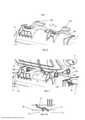
[0024] A figura 1 reapresenta um dispositivo de filtragem, de acordo com a presente invenção, montado em um veículo;[0024] Figure 1 shows a filtering device, according to the present invention, mounted on a vehicle;
[0025] A figura 2 é uma vista lateral do veículo da figura 2;[0025] Figure 2 is a side view of the vehicle of figure 2;
[0026] A figura 3 é uma vista ampliada da figura 2 que mostra o dispositivo de filtragem;[0026] Figure 3 is an enlarged view of figure 2 showing the filtering device;
[0027] A figura 4 é uma vista em perspectiva do dispositivo de filtragem;[0027] Figure 4 is a perspective view of the filtering device;
[0028] As figuras 5, 6, 7, e 7A são vistas detalhadas da figura 4;[0028] Figures 5, 6, 7, and 7A are detailed views of figure 4;
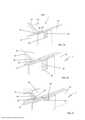
[0029] A figura 7B é uma vista em perspectiva do dispositivo de filtragem e de seus meios para montagem no veículo;[0029] Figure 7B is a perspective view of the filtering device and its means for mounting on the vehicle;
[0030] A figura 8 é uma vista em perspectiva do dispositivo de filtragem;[0030] Figure 8 is a perspective view of the filtering device;
[0031] As figuras 9 e 10 são vistas ampliadas da figura 8, dos detalhes IX e X, respectivamente;[0031] Figures 9 and 10 are enlarged views of figure 8, details IX and X, respectively;
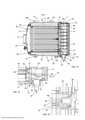
[0032] A figura 11 é uma vista explodida do dispositivo de filtragem;[0032] Figure 11 is an exploded view of the filtering device;
[0033] A figura 12 reapresenta não só uma vista em perspectiva, mas também uma vista seccionada longitudinal do dispositivo de filtragem;[0033] Figure 12 shows not only a perspective view, but also a longitudinal sectional view of the filtering device;
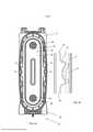
[0034] A figura 13 é uma vista seccionada longitudinal do dispositivo de filtragem;[0034] Figure 13 is a longitudinal sectional view of the filtering device;
[0035] As figuras 14, 15 e 16 são vistas ampliadas da figura 13, dos detalhes XIV, XV, e XVI, respectivamente;[0035] Figures 14, 15 and 16 are enlarged views of figure 13, details XIV, XV, and XVI, respectively;
[0036] A figura 17 é uma vista em perspectiva da cobertura de entrada do dispositivo de filtragem;[0036] Figure 17 is a perspective view of the inlet cover of the filtering device;
[0037] A figura 18 é uma vista explodida da cobertura de entrada do dispositivo de filtragem;[0037] Figure 18 is an exploded view of the inlet cover of the filtering device;
[0038] As figuras 19, 20, e 21 são vistas seccionadas detalhadas da cobertura de entrada do dispositivo de filtragem, mostrando três modos de montagem alternativos;[0038] Figures 19, 20, and 21 are detailed sectional views of the inlet cover of the filtering device, showing three alternative mounting modes;
[0039] A figura 22 é uma vista seccionada em detalhes da cobertura de entrada;[0039] Figure 22 is a detailed sectional view of the entrance cover;
[0040] A figura 23 é uma vista ampliada do detalhe XXIII da figura 23;[0040] Figure 23 is an enlarged view of detail XXIII of figure 23;
[0041] A figura 24 é uma vista dianteira do dispositivo de filtragem; e[0041] Figure 24 is a front view of the filtering device; and
[0042] A figura 25 é uma vista em perspectiva detalhada da figura 25.[0042] Figure 25 is a detailed perspective view of figure 25.
[0043] As figuras 1, 2 e 3 representam um dispositivo de filtragem 1 montado em um veículo 2. No presente exemplo, o veículo 2 é um veículo comercial leve que compreende uma cabine 3 e um compartimento 4.[0043] Figures 1, 2 and 3 represent a
[0044] Dispositivo de filtragem 1 é preferivelmente montado em uma estrutura externa 5 de veículo 2 de modo que o mesmo pode ser disposto entre a cabine 2 e o compartimento 4, em especial na parte de trás da cabine 3.[0044]
[0045] A figura 4 separadamente reapresenta o dispositivo de filtragem 1. O mesmo preferivelmente inclui um corpo de alojamento 6, uma cobertura de entrada 7 e uma saída de ar filtrado 8. A cobertura de entrada 7 e saída de ar 8 são preferivelmente localizadas em extremidades opostas do dispositivo de filtragem 1, o que define a distância na direção axial.[0045] Figure 4 separately represents the
[0046] O dispositivo de filtragem 1 pode ser usada, como na presente modalidade, como um filtro de ar para um motor de combustão. A função de dispositivo de filtragem 1 é aquela de proporcionar ar filtrado para o motor do veículo 2.[0046] The
[0047] Para isso, o ar é aspirado pela cobertura de entrada 7 preferivelmente essencialmente em direção axial, é filtrado dentro do corpo do alojamento 6 por elemento de filtragem 24, e sai através da saída de ar filtrado 8 que é conectada ao motor preferivelmente em direção axial. O dispositivo de filtragem 1 é preferivelmente arranjado em uma posição de modo que a direção axial definida acima é essencialmente horizontal.[0047] For this, the air is sucked in by the
[0048] O dispositivo de filtragem 1 pode também incluir um reservatório de fluido 10 que pode conter qualquer fluido, em especial líquido adequado para a funcionalidade do motor e/ou para os outros elementos de veículo 2 tais como o refrigerante, líquido de limpeza de vidro, líquido de freio, etc.[0048] The
[0049] Como mostrado na presente modalidade, o reservatório 10 pode ser um reservatório de refrigerante para o motor do veículo 2.[0049] As shown in the present embodiment, the
[0050] O reservatório 10 preferivelmente inclui uma cobertura 11 e é conectada a tubos de fluido 12 e cabos elétricos 13, necessários para a funcionalidade de reservatório 10. Os tubos de fluido 12 são conectados ao motor e os cabos elétricos 13 são conectados ao sistema de controle do motor.[0050]
[0051] O corpo de alojamento 6 inclui garras 14 para manter os tubos 12 e os cabos 13 de modo que os mesmos circundam perfeitamente a saída de ar filtrado 8 e que os mesmos permanecem fixados (a figura 5). As garras 14 são preferivelmente localizadas na extremidade de saída do corpo de alojamento 6, preferivelmente em proximidade com a saída de ar filtrado 8.[0051] The
[0052] Em referência à figura 6, o corpo de alojamento 6 é preferivelmente equipado com um membro de suporte 15 para o reservatório 10. O membro de suporte 15 inclui um elemento de suporte de encaixe traseiro 16A, um elemento de suporte de encaixe dianteiro 17A, e um primeiro elemento 71 de um sistema de retenção 70. O membro de suporte 15 é preferivelmente localizado seja no lado de cima ou no lado de fundo do corpo de alojamento 6.[0052] Referring to Figure 6, the
[0053] O reservatório 10 é, por outro lado, preferivelmente equipado com pelo menos um alojamento traseiro 16B e/ou um alojamento dianteiro 17B, ajustado a pelo menos um elemento de suporte de encaixe 16A, 17A do corpo de alojamento 6 (a figura 7). Os alojamentos 16B, 17B do reservatório 10 podem ser internamente revestidos com borracha, de modo que o contato entre cada elemento de suporte de encaixe 16A, 17A e o alojamento correspondente 16B, 17B ocorre através da espessura da borracha para uma fixação flexível e livre de espaços do reservatório 10.[0053] The
[0054] No momento da montagem de reservatório 10 no corpo de alojamento 6, o reservatório 10 é axialmente fendido no membro de suporte 15. Preferivelmente, o mesmo é fendido em um modo que o elemento de suporte 16A, 17A se projeta para dentro dos alojamentos 16B, 17B, desse modo proporcionando uma conexão de encaixe de forma. Os alojamentos 16B, 17B podem deslizar e/ou ser guiados ao longo dos elementos de suporte 16A, 17A. Preferivelmente, os elementos de suporte de encaixe 16A, 17A e os alojamentos 16B, 17B cooperam como mostrado na figura 7, em que os elementos de deslize do reservatório em uma direção axial, preferivelmente ao longo de uma pista definida para uma posição final onde o reservatório é fixado, por exemplo, por um parafuso. Preferivelmente, o reservatório 10 e o corpo de alojamento 6 compreendem um sistema de retenção 70 para fixar o reservatório 10 em sua posição final. O sistema de retenção é preferivelmente proporcionado como uma conexão de encaixe. A conexão de encaixe pode ser consistida de um primeiro elemento 71, fixado no corpo de alojamento 6, e um segundo elemento 72, fixado no reservatório 10. No presente exemplo, o primeiro elemento é uma trava 71 e o segundo elemento é um entalhe 72. Alternativamente, os referidos elementos 71, 72 podem ser trocados ou substituídos por outros elementos adaptados para a função do sistema de retenção 70, tal como, por exemplo, grampos ou presilhas. Com a conexão de encaixe, o reservatório 10 pode deslizar até a parada do sistema de retenção com o que o reservatório é fixado com segurança em sua posição final sem uma etapa de aparafusamento, soldagem, ou colagem do conjunto separada.[0054] At the time of mounting the
[0055] O referido ajuste garante um conjunto simples e seguro e a desmontagem do reservatório 10 no membro de suporte 15.[0055] Said adjustment guarantees a simple and safe assembly and disassembly of the
[0056] O corpo de alojamento 6 também preferivelmente inclui um pedestal 18 para a fixação do dispositivo de filtragem 1 no veículo.[0056] The
[0057] O pedestal 18 pode compreender dois membros de suporte de fixação 19, 20 que são aparafusados em uma estrutura externa 5 de veículo 2 (a figura 7B).[0057] The
[0058] O corpo de alojamento 6 também preferivelmente inclui ranhuras de enrijecimento 75 entre o pedestal 18 e o membro de suporte 15.[0058] The
[0059] Assim sendo, o dispositivo de filtragem 1 preferivelmente forma um conjunto autônomo que realiza não só a função de filtragem de ar para o motor, mas também membro de suporte para o reservatório 10, tubos guias 12 e cabos 13. A fixação do referido conjunto é vantajosamente simplesmente realizado através da fixação do pedestal 18 ao veículo 2.[0059] Therefore, the
[0060] Em referência às figuras 2 e 3, o dispositivo de filtragem 1 pode ser montado na estrutura externa 5 de veículo 2 de modo que a cobertura de entrada 7 e a cobertura 11 do reservatório 10 são acessíveis a partir do lado de fora do veículo para maior facilidade de acesso.[0060] With reference to figures 2 and 3, the
[0061] Na referida modalidade, o corpo de alojamento 6 preferivelmente tem uma seção transversal essencialmente oblongada ao longo da direção axial, que define uma borda vertical superior 66 e borda inferior 67 do corpo de alojamento 6. O pedestal 18 pode ser disposto na borda inferior 67 como mostrado na figura ou em uma parede lateral. O membro de suporte 15 para o reservatório de fluido 10 é preferivelmente disposto na borda superior 66, embora o mesmo possa também ser disposto na borda inferior 67 em caso do pedestal ser localizado na parede lateral.[0061] In said embodiment, the
[0062] Assim sendo, o reservatório 10 é preferivelmente em cima do dispositivo de filtragem 1, o que cria um ajuste apertado verticalmente montado em um interstício do veículo 2, entre a cabine 3 e o compartimento 4. A referida localização facilita as operações de manutenção e controle do dispositivo de filtragem até que as coberturas de entrada 7 e a cobertura 11 do reservatório 10 possam ser diretamente removidas a partir do lado de fora do veículo.[0062] Therefore, the
[0063] O arranjo do dispositivo de filtragem 1 também faz espaço no compartimento do motor.[0063] The arrangement of
[0064] Alternativamente, o dispositivo de filtragem 1 pode ser também disposto em outro interstício do veículo onde o mesmo é prático e acessível, por exemplo, em um interstício horizontal.[0064] Alternatively, the
[0065] A referida pronta acessibilidade permite a abertura do dispositivo de filtragem 1, ou seja, a remoção da cobertura de entrada 7.[0065] Said ready accessibility allows the opening of the
[0066] A figura 8 mostra uma modalidade do meio de fixação de cobertura de entrada 7 no corpo de alojamento 6. O referido meio de fixação pode compreender prendedores superior e inferior, os prendedores preferivelmente incluem um ou um par de grampos superiores 22 (vide a figura 9) e/ou uma articulação inferior 23 (vide a figura 10).[0066] Figure 8 shows an embodiment of the inlet cover fixing means 7 on the
[0067] A remoção da cobertura de entrada 7 é realizada pelo desengate do par de grampos 22 e mover a cobertura de entrada 7 para trás sobre a articulação 23 até a liberação da articulação 23, desse modo liberando a cobertura de entrada 7.[0067] Removal of the
[0068] A articulação 23 preferivelmente compreende uma parte de articulação do corpo do alojamento e uma parte de articulação da cobertura de entrada, em que as referidas partes[0068] The
[0069] A figura 11 é uma vista explodida que mostra a cobertura de entrada 7 desmontada. O elemento de filtragem 24 é montado dentro do corpo de alojamento 6 e é também representado desmontado em sai vista explodida da figura 11. O corpo do alojamento 6 delimita uma cavidade para receber um elemento de filtragem 24.[0069] Figure 11 is an exploded view showing the
[0070] O elemento de filtragem 24 é oco e de formato tubular. O mesmo preferivelmente compreende um filtro laminado em forma de estrela 25 produzido de um meio de filtro tal como um papel ou não tecido e pode ser revestido com um revestimento de filtragem tal como microou nano-fibras. O elemento de filtro preferivelmente apresenta uma extremidade axial aberta 26, e uma extremidade axial fechada 27 com uma cobertura 28. A cobertura pode também ser definida como um disco de extremidade ou tampa de extremidade. Ao longo de sua circunferência, a extremidade axial aberta 26 inclui uma gaxeta de vedação 29 para a vedação com o corpo de alojamento 6. O elemento de filtro 24 preferivelmente tem um formato oval, seja elíptico ou estabelecido por duas seções opostas o que cria meios círculos opostos que são conectados por linhas totalmente retas ou linhas quase retas. O corpo de alojamento 6 e a cobertura de entrada preferivelmente espelham o formato do elemento de filtro 24 e são também ovais, em que o elemento de filtro 24 e o corpo de alojamento têm seção com uma altura que é pelo menos duas vezes, preferivelmente três vezes maior do que a largura na direção horizontal perpendicular à direção axial.[0070] The
[0071] A cobertura 28 preferivelmente inclui dois elementos de deslize 73 localizados nos lados longos da cobertura que estão preferivelmente cooperando com dois trilhos 74 do corpo de alojamento 6, para dispor o elemento de filtragem 24 transversalmente. Isso permite o po-sicionamento do elemento de filtragem 24 em sua posição vertical final antes de fechar a cobertura de entrada 7 que interage com os elementos de filtragem 24 da cobertura 28. A figura 12 mostra, em seção, o corpo de alojamento 6 com o elemento de filtragem 24 montado dentro do mesmo e com a cobertura de entrada 7 fechada.[0071] The
[0072] De acordo com a o funcionamento do dispositivo de filtragem 1, o ar entra através da cobertura de entrada 7 (seta 30) e cruza a mesma onde a operação de pré-purificação ocorre, o que leva à expulsão das partículas mais pesadas (seta 31). O ar pré-limpo deixa a cobertura de entrada 7, e vai em torno da cobertura 28, e é filtrado (seta 33) por passar o meio de filtro do elemento de filtragem 24. Finalmente, o ar filtrado sai através da saída de ar filtrado 8 (seta 33).[0072] According to the functioning of the
[0073] A figura 13 é também uma vista seccionada do dispositivo de filtragem 1, e põe em evidência três detalhes de sua construção, que serão individualmente explicados abaixo.[0073] Figure 13 is also a sectional view of the
[0074] O detalhe XIV da figura 13 é ampliado na figura 14 e ilustra a operação de pré-purificação. A cobertura de entrada 7 inclui um pré- limpador do tipo de "ciclone" (também referido como "vórtice" pré-limpador).[0074] Detail XIV of figure 13 is enlarged in figure 14 and illustrates the pre-purification operation. The
[0075] O funcionamento do pré-limpador do tipo de ciclone é descrito abaixo.[0075] The operation of the cyclone type pre-cleaner is described below.
[0076] A cobertura de entrada 7 preferivelmente inclui uma pluralidade de células de ciclone do tipo de ciclone em linha, em que cada uma das mesmas compreende um tubo de redemoinho 34 que coopera com um tubo de descarga 35.[0076] The
[0077] O tubo de redemoinho inclui uma hélice 36 em sua entrada para fazer com que o ar que entra (seta 37) gire (seta 38). As partículas mais pesadas, tal como poeira e água contida no ar são assim orienta- das contra a parede de tubo de redemoinho 34, em virtude da força centrífuga gerada pela rotação 38, e move em torno do tubo de descarga 35, sem entrar no mesmo. As partículas pesadas, que se moveram em torno de tubo de descarga 35, saem através de uma abertura 48 e caem por gravidade em um tubo de expulsão 39 do pré-limpador, o qual equipado com uma válvula 40, permite que as partículas saiam, mas evitam a entrada de ar. O ar pré-purificado, livre de partículas, entra no tubo de descarga 35 para alcançar a cavidade delimitada pelo corpo de alojamento 6. O ar pré-purificado é então filtrado pelo elemento de filtragem 24, como explicado acima.[0077] The swirl tube includes a
[0078] Uma construção preferida do pré-limpador do tipo de ciclone é descrita abaixo.[0078] A preferred construction of the cyclone type pre-cleaner is described below.
[0079] A vista dianteira de uma cobertura de entrada vantajosa 7 é representada na figura 11 e a sua vista traseira é representada na figura 17.[0079] The front view of an
[0080] A vista explodida da figura 18 mostra que a cobertura de entrada pode compreender três elementos fendidos: uma grade 41, um conjunto de tubos de redemoinho 42, e uma base 43.[0080] The exploded view of figure 18 shows that the inlet cover can comprise three slotted elements: a
[0081] A válvula 40 é preferivelmente fendida na base 43 e uma ga- xeta de vedação da cobertura 44 é proporcionada entre a cobertura de entrada 7 e o corpo de alojamento 6, para fins de vedação.[0081] The
[0082] A grade 41 e a base 43 são preferivelmente fixadas uma a outra por meio de encaixes de pressão 45, 46 de modo a encerrar o conjunto de tubos de redemoinho 42.[0082] The
[0083] Os encaixes de pressão podem incluir perfurações 45 produzidas na grade 41 e grampos complementares 46 produzidos na base 43.[0083] Snap fittings may include
[0084] Conjunto de redemoinho 42 preferivelmente compreende uma pluralidade de tubos de redemoinho 34 agrupados em uma placa 47. A placa 47 apresenta uma extremidade periférica 49 em torno de tubos de redemoinho 42 que permitem a fixação da placa 47 à base 43 e à grade 41.[0084]
[0085] O conjunto de redemoinho 34 pode ser vantajosamente e integralmente moldado em apenas uma peça.[0085] The
[0086] A figura 19 é uma vista em perspectiva de uma seção transversal de uma cobertura de entrada preferida 7, a nível de encaixes de pressão 45 e 46, e mostra a cooperação preferida da base 43, da grade 41, e do conjunto de redemoinho 42.[0086] Figure 19 is a perspective view of a cross-section of a
[0087] O grampo 46 é fendido na perfuração 45 para prender a grade 41 e a base 43. Ademais, a base 43 apresenta uma borda 50 e a grade 41 apresenta uma porção de ombro 51 arranjada de modo que a extremidade periférica 49 do conjunto de redemoinho 42 é fixado entre a referida borda 50 de base 43 e a porção de ombro 51.[0087]
[0088] Assim, o pré-limpador preferivelmente compreende apenas três peças 41, 42, 43 e a fenda simples de encaixes de pressão 45, 46 permite a fixação e o posicionamento das três peças 41, 42, 43 uma com relação a outra.[0088] Thus, the pre-cleaner preferably comprises only three
[0089] As figuras 20 e 21 ilustram duas alternativas para realizar a fenda.[0089] Figures 20 and 21 illustrate two alternatives to perform the slit.
[0090] Em uma primeira alternativa da figura 20, a extremidade periférica 49 do conjunto de redemoinho 42 é, dessa vez, fixada em uma ranhura 52 feita na base 43.[0090] In a first alternative of figure 20, the
[0091] Em uma segunda alternativa da figura 21, a extremidade periférica 49 do conjunto de redemoinho 42 é também fixada na ranhura 52 e, ademais, a grade 41 tem um elemento de suporte 53 para a referida extremidade periférica 49. Com relação à figura 22, a base 43 inclui tubos de descarga 35 que são relativamente cônicos de modo que os mesmos podem cooperar com os tubos de redemoinho 34 na função de pré-limpeza.[0091] In a second alternative of figure 21, the
[0092] Uma vedação pode ser usada entre cada tubo de redemoinho 34 e o tubo de descarga correspondente 35, mas na área de abertura 48, para fazer com que apenas as partículas pesadas saiam através da referida abertura 48.[0092] A seal can be used between each
[0093] Com relação a vista ampliada da figura 23, a referida vedação preferivelmente compreende um ressalto 54 que é coaxial com o tubo de descarga 35, disposto em torno do tubo de descarga 35, mas na área de abertura 48. A fenda do tubo de redemoinho 34 contra o referido ressalto 54 realiza a referida vedação que é, assim, alcançada junto com as fendas de encaixe de pressão simples 45, 46 e permite a fixação e o posicionamento das três peças 41, 42 e 43, uma com relação a outra.[0093] With respect to the enlarged view of figure 23, said seal preferably comprises a
[0094] A cooperação de uma modalidade de cobertura de entrada preferida 7 com uma modalidade de elemento de filtragem preferido 24 é descrita abaixo, com relação ao detalhe XV da figura 13, que é ampliado na figura 15.[0094] The cooperation of a preferred
[0095] A fixação do elemento de filtragem 24 no corpo de alojamento 6 é vantajosamente realizada por meio da cobertura de entrada 7 que retém o elemento de filtragem 24 de modo que a gaxeta de vedação 29 é comprimida contra o corpo de alojamento 6.[0095] The fixing of the
[0096] De modo a realizar essa função, a cobertura 28 de elemento de filtragem 24 preferivelmente inclui um par de primeiras saliências tubulares 55, que se projetam perpendicularmente em afastamento a partir da cobertura 28, em direção da cobertura de entrada 7. As referidas primeiras saliências tubulares 55 podem ser integralmente moldadas com a cobertura 28.[0096] In order to perform this function, the
[0097] As primeiras saliências tubulares 55 podem exibir diferentes seções, tal como, por exemplo, redonda, quadrada ou oval.[0097] The first
[0098] Na presente modalidade as primeiras saliências tubulares 55 são de seção redonda, ou seja, as primeiras saliências tubulares 55 são cilíndricas.[0098] In the present embodiment the first
[0099] Com referência à figura 15, cada primeira saliência tubular 55 apresenta uma cavidade 68 ao longo do seu eixo e também a extremidade chanfrada 56 em sua borda. Nesta modalidade preferida, uma saliência tubular 55 é localizada na parte superior da cobertura 28 e a outra é localizada na parte inferior, em especial simetricamente ao eixo do meio do elemento de filtragem 24. Isso permite a montagem do elemento de filtro em ambas as orientações geometricamente possíveis. Em relação a função, apenas uma em especial central ou mais do que duas saliências excêntricas podem também ser usadas para suportar o elemento de filtragem 24 na cobertura de entrada 7.[0099] With reference to figure 15, each first
[0100] A base 43 de cobertura de entrada 7 inclui um par ou outro número correspondente de segundas saliências tubulares ocas 57, que são dispostas em correspondência com as primeiras saliências tubulares 55 e permitem a fenda das primeiras saliências tubulares 55.[0100] The
[0101] Na figura 15, a extremidade chanfrada 56 é representada com linhas pontilhadas, que ilustram a sua forma quando a modalidade preferida da primeira saliência tubular 55 não é fendida na segunda saliência tubular correspondente preferida 57. Após a primeira saliência tubular 55 sendo fendida na segunda saliência tubular 57, a extremidade chanfrada 56, que é produzida de um material elasticamente deformá- vel, se encaixa no fundo da segunda saliência tubular 57.[0101] In Figure 15, the
[0102] Cada segunda saliência tubular 57 preferivelmente apresenta ao longo do seu eixo um elemento de suporte central 58 que pode inserir na cavidade 68 e que é assim aplicado contra a cobertura 28 quando a primeira saliência tubular 55 é fendida na segunda saliência tubular 57.[0102] Each second
[0103] A figura 17 mostra uma modalidade das segundas saliências tubulares 57 na base 43.[0103] Figure 17 shows an embodiment of the second
[0104] A interface entre a cobertura de entrada 7 e o elemento de filtragem 24 é assim preferivelmente produzida pela aplicação do elemento de suporte central 58 contra a cobertura 28 e, simultaneamente, por compressão da extremidade chanfrada 56 no fundo da segunda saliência tubular oca 57.[0104] The interface between the
[0105] Os comprimentos da extremidade chanfrada 56 e do elemento de suporte central 58 são preferivelmente tal que, no momento de fechar a cobertura de entrada 7, a extremidade chanfrada 56 alcança o fundo da segunda saliência tubular 57 antes do elemento de suporte central 58 alcançar a cobertura 28. Ou seja, a distância entre a cobertura 28 e a extremidade chanfrada 56 é preferivelmente maior do que a distância entre o elemento de suporte central 58 e o fundo de segunda saliência tubular 57.[0105] The lengths of the
[0106] A extremidade chanfrada 56 é preferivelmente comprimida contra o fundo da segunda saliência 57 na medida em que a cobertura de entrada é fechada. O elemento de suporte central 58 pode ser finalmente disposto contra a cobertura 28, uma vez que a extremidade chanfrada 56 é comprimida e adaptada ao fundo da segunda saliência tubular 57.[0106] The
[0107] Isso permite uma redução e a progressividade da resistência necessária para fechar a cobertura de entrada.[0107] This allows for a reduction and progressivity of the resistance required to close the inlet cover.
[0108] Para a emissão de ar quando o elemento de suporte central 58 é inserido na cavidade 68, o elemento de suporte central 58 pode ser equipado com um orifício de saída 69 e o fundo da segunda saliência tubular 57 pode ser equipado com um orifício de saída 76 (a figura 15).[0108] For the emission of air when the
[0109] A referida interface tem uma primeira função de retenção do elemento de filtragem 24 para a sua cobertura 28, a segunda função de vedação pela aplicação da pressão na cobertura 28, que permite a compressão da gaxeta de vedação 29 contra o corpo de alojamento 6, e uma terceira função do espaçador para manter um espaço necessário para a circulação do ar entre a cobertura de entrada 7 e a cobertura 28 (vide a figura 12).[0109] Said interface has a first function of retaining the
[0110] A primeira operação de retenção do elemento de filtragem 24 é realizada com segurança com relação a choques e vibração ao longo de todos os eixos.[0110] The first operation of holding the
[0111] Uma modalidade preferida com diversas características preferidas da vedação entre o elemento de filtragem 24 e o corpo de alojamento 6 é descrita abaixo, com referência ao detalhe XVI da figura 13 que é ampliado na figura 16.[0111] A preferred embodiment with several preferred characteristics of the seal between the
[0112] O corpo de alojamento 6 apresenta um rebordo anular axialmente arranjado 59 em torno da saída de ar filtrado 8, e da borda da gaxeta de vedação 60 em torno do referido rebordo anular 59.[0112] The
[0113] A gaxeta de vedação 29 do elemento de filtragem 24 preferivelmente apresenta uma ranhura axial 61 que é fendida no rebordo da gaxeta de vedação 60. Isso garante a vedação axial (seta 62) e preferivelmente também a vedação radial e o suporte da principal função de vedação radial descrita abaixo.[0113] The
[0114] A gaxeta de vedação 29 inclui uma parede anular interna 63 que se apoia contra o rebordo anular 59 que cria a principal função de vedação radial.[0114] The sealing
[0115] A gaxeta de vedação 29 preferivelmente apresenta uma tal espessura de modo que a distância radial entre a ranhura axial 61 e a parede anular interna 63 é maior do que a distância entre o rebordo da gaxeta de vedação 60 e o rebordo anular 59. Desse modo, quando a ranhura axial 61 é embutida no rebordo da gaxeta de vedação 60, a gaxeta de vedação 29 é comprimida radialmente entre o rebordo anular 59 e o rebordo da gaxeta de vedação 60, que também resulta na vedação radial (seta 64).[0115] The
[0116] O corpo de alojamento 6 preferivelmente apresenta uma rampa anular 65 designada para guiar a ranhura axial 61 na direção de rebordo da gaxeta de vedação 60 durante a montagem do elemento de filtragem 24 no corpo de alojamento 6.[0116] The
[0117] A figura 24 mostra a vista dianteira do dispositivo de filtragem sem cobertura de entrada 7. O elemento de filtragem 24 é preferivelmente mantido através do corpo de alojamento 6 com elementos de deslize 73 dispostos nos trilhos 74 (a figura 25) e é adicionalmente preferivelmente mantido longitudinalmente com a primeira e segunda saliências tubulares, 55 e 57, comprimindo a gaxeta de vedação 29.[0117] Figure 24 shows the front view of the filter device without
[0118] O dispositivo de filtragem 1 é acessível a partir do lado de fora do veículo e a operação da substituição do filtro precisa apenas que a cobertura de entrada 7 seja aberta. Posteriormente o elemento de filtragem 24 usado é retirado com a mão, puxando a cobertura 28, e o novo elemento de filtragem 24 é axialmente inserido. Quando os elementos de deslize 73 e os trilhos 74 são proporcionados como preferivelmente proposto, o elemento de filtragem 24 é axialmente inserido até que os elementos de deslize 73 corram em trilhos 74 e até que a rampa anular 65 aciona a gaxeta de vedação 29 de modo que as fendas da ranhura axial 61 no rebordo da gaxeta de vedação 60 e a vedação anular ocorra. O elemento de filtragem 24 é preferivelmente comprimido por duas segundas saliências tubulares 57 contra as primeiras saliências tubulares 55, em que a pressão é preferivelmente mantida por fechar a cobertura de entrada 7.[0118] The
[0119] A gaxeta de vedação 29 e a cobertura 28, com as duas primeiras saliências tubulares 55 e os elementos de deslize 73, podem ser produzidas seja de uma espuma de poliuretano ou de outro elastômero, ou também um elastômero termoplástico, que permite as funções de vedação.[0119] The sealing
[0120] O corpo de alojamento e a cobertura de entrada são produzidas de um material rígido tal como um material termoplástico tal como um material termoplástico moldado a injeção.[0120] The housing body and inlet cover are produced from a rigid material such as a thermoplastic material such as an injection molded thermoplastic material.
[0121] Embora a modalidade preferida tenha sido descrita, o âmbito da presente invenção inclui outras variações possíveis, e é apenas limitada pelo conteúdo das reivindicações em anexo, que inclui as possíveis equivalentes.[0121] While the preferred embodiment has been described, the scope of the present invention includes other possible variations, and is only limited by the content of the appended claims, which include possible equivalents.
[0122] Por exemplo, o dispositivo de filtragem pode filtrar outro fluido diferente do ar.[0122] For example, the filtering device can filter fluid other than air.
[0123] Se o dispositivo de filtragem for usado como o filtro de ar em um motor de combustão, o mesmo pode ser montado em qualquer tipo de veículo assim como em outras máquinas moveis ou estacionárias tal como uma unidade de gerador.[0123] If the filtering device is used as the air filter in a combustion engine, it can be mounted on any type of vehicle as well as other mobile or stationary machines such as a generator unit.
Claims (5)
Translated fromPortugueseApplications Claiming Priority (1)
| Application Number | Priority Date | Filing Date | Title |
|---|---|---|---|
| PCT/EP2014/075375WO2016082854A1 (en) | 2014-11-24 | 2014-11-24 | Filtering device, filtering element and maintenance process of a filtering device |
Publications (2)
| Publication Number | Publication Date |
|---|---|
| BR112017008078A2 BR112017008078A2 (en) | 2017-12-19 |
| BR112017008078B1true BR112017008078B1 (en) | 2022-01-25 |
Family
ID=52002904
Family Applications (1)
| Application Number | Title | Priority Date | Filing Date |
|---|---|---|---|
| BR112017008078-8ABR112017008078B1 (en) | 2014-11-24 | 2014-11-24 | Filtering device and maintenance process of a filtering device |
Country Status (5)
| Country | Link |
|---|---|
| US (1) | US10539101B2 (en) |
| EP (1) | EP3223927B1 (en) |
| CN (1) | CN107002598B (en) |
| BR (1) | BR112017008078B1 (en) |
| WO (1) | WO2016082854A1 (en) |
Families Citing this family (17)
| Publication number | Priority date | Publication date | Assignee | Title |
|---|---|---|---|---|
| CN100406102C (en) | 2002-10-28 | 2008-07-30 | 唐纳森公司 | Air cleaner, replaceable filter cartridge and method of making the same |
| US9593441B2 (en)* | 2014-02-28 | 2017-03-14 | ADR Products, LLC | Lint catching system and exhaust assembly |
| DE102016003455B4 (en)* | 2015-04-10 | 2020-08-06 | Mann+Hummel Gmbh | Filter holder and filter arrangement |
| DE102016003456A1 (en)* | 2015-04-10 | 2016-10-13 | Mann + Hummel Gmbh | Filter holder, filter element and filter assembly |
| DE102016003454A1 (en)* | 2015-04-10 | 2016-10-13 | Mann + Hummel Gmbh | Filter holder and filter assembly |
| DE102016012330A1 (en)* | 2016-10-17 | 2018-04-19 | Mann + Hummel Gmbh | Round filter element, in particular for gas filtration |
| MX2020002137A (en)* | 2017-08-31 | 2020-07-20 | Donaldson Co Inc | Filter cartridges; air cleaner assemblies; housings; features; components; and, methods. |
| CN107489568A (en)* | 2017-09-30 | 2017-12-19 | 广西玉柴机器股份有限公司 | A kind of attachment structure of air filter lid |
| DE112018006269T5 (en) | 2017-12-08 | 2020-08-20 | Cummins Filtration Ip, Inc. | Oval seal with stabilizing contour |
| FR3078490B1 (en)* | 2018-03-05 | 2022-10-14 | Cummins Filtration Sarl | FILTERING ELEMENT AND HOUSING HAVING NON-CIRCULAR CROSS-SECTIONS |
| US10918978B2 (en) | 2018-05-08 | 2021-02-16 | Cummins Filtration Ip, Inc. | Oval filter with exterior elliptical radial seal and internal support structure |
| USD884866S1 (en) | 2018-05-08 | 2020-05-19 | Cummins Filtration Ip, Inc. | Filter element |
| WO2020052782A1 (en)* | 2018-09-14 | 2020-03-19 | Volvo Truck Corporation | An air cleaner housing, an air cleaner housing arrangement, and a method |
| USD969289S1 (en) | 2020-03-05 | 2022-11-08 | Cummins Filtration Inc. | Filter element |
| DE102020110996A1 (en)* | 2020-04-22 | 2021-10-28 | Daimler Ag | Filter element for an air filter device of a motor vehicle and air filter device |
| CN114962090A (en)* | 2021-02-26 | 2022-08-30 | 唐纳森公司 | Plastic connecting piece and parallel air filter system using same |
| EP4344763A1 (en)* | 2022-09-29 | 2024-04-03 | MANN+HUMMEL GmbH | Filter element and filter system |
Family Cites Families (10)
| Publication number | Priority date | Publication date | Assignee | Title |
|---|---|---|---|---|
| DE10026437A1 (en)* | 2000-05-29 | 2001-12-06 | Mann & Hummel Filter | Filter device |
| DE10354401A1 (en)* | 2003-03-14 | 2004-09-23 | Mann + Hummel Gmbh | Air filter for IC engine comprises cylindrical filter insert, filter medium being held at one end by plate with axial gripping components and at opposite end by hollow cylindrical collar with concentric sealing ring |
| DE102005031058A1 (en)* | 2005-07-02 | 2007-01-04 | Mahle International Gmbh | Filter element and a filter housing suitable for receiving it |
| US8292984B2 (en)* | 2007-07-20 | 2012-10-23 | Donaldson Company, Inc. | Air cleaner arrangments with end support for cartridge; components; and, methods |
| DE202007013822U1 (en)* | 2007-10-02 | 2009-02-19 | Mann+Hummel Gmbh | Filter element and filter system |
| DE202007014821U1 (en) | 2007-10-02 | 2009-02-26 | Mann+Hummel Gmbh | Filter element V-seal |
| DE102009036475A1 (en)* | 2009-08-07 | 2011-02-10 | Mahle International Gmbh | Filter device and wound filter element |
| DE102011011595A1 (en)* | 2011-02-17 | 2012-08-23 | Mann + Hummel Gmbh | filter element |
| US9726123B2 (en)* | 2013-06-20 | 2017-08-08 | Mann+Hummel Gmbh | Air filter, filter element and filter housing of an air filter |
| DE102014006850B4 (en)* | 2013-06-20 | 2022-08-25 | Mann+Hummel Gmbh | Filter housing, hollow filter element and filter |
- 2014
- 2014-11-24BRBR112017008078-8Apatent/BR112017008078B1/enactiveIP Right Grant
- 2014-11-24EPEP14805807.6Apatent/EP3223927B1/enactiveActive
- 2014-11-24CNCN201480083623.8Apatent/CN107002598B/enactiveActive
- 2014-11-24WOPCT/EP2014/075375patent/WO2016082854A1/enactiveApplication Filing
- 2017
- 2017-05-22USUS15/601,407patent/US10539101B2/enactiveActive
Also Published As
| Publication number | Publication date |
|---|---|
| BR112017008078A2 (en) | 2017-12-19 |
| CN107002598B (en) | 2020-09-08 |
| US10539101B2 (en) | 2020-01-21 |
| EP3223927B1 (en) | 2020-05-13 |
| WO2016082854A1 (en) | 2016-06-02 |
| EP3223927A1 (en) | 2017-10-04 |
| CN107002598A (en) | 2017-08-01 |
| US20170254301A1 (en) | 2017-09-07 |
Similar Documents
| Publication | Publication Date | Title |
|---|---|---|
| BR112017008078B1 (en) | Filtering device and maintenance process of a filtering device | |
| JP7569411B2 (en) | Air cleaner assembly and method of use | |
| US12214307B2 (en) | Air cleaner assemblies and methods of use | |
| US10316804B2 (en) | Filter element with at least one guide crosspiece, filter with a filter element and filter housing of a filter | |
| WO2016082853A1 (en) | Filtering device, filtering element and maintenance process of a filtering device | |
| BRPI0806858A2 (en) | REPLACABLE FUEL FILTER ELEMENT AND FUEL FILTER ASSEMBLY | |
| BR112015030223B1 (en) | Hollow filter element, filter housing of a fluid filter and a fluid filter | |
| CN105289120B (en) | Modular filtration system, housing frame part for a modular filtration system, filtration module and housing module | |
| BR112015023464B1 (en) | FILTER ASSEMBLY AND METHOD OF REPLACING A FILTER CARTRIDGE IN A FILTER ASSEMBLY | |
| US20250001345A1 (en) | Safety filter element | |
| BR112019000186B1 (en) | FILTER ELEMENT FOR USE WITH TUBULAR SHEET APERTURES AND METHOD OF ASSEMBLING A PLURALITY OF FILTER ELEMENTS | |
| WO2016082852A1 (en) | Filtering device, filtering element and maintenance process of a filtering device | |
| KR101619895B1 (en) | Air cleaner for vehicle | |
| BR102014020700B1 (en) | fluid filter, filter element and filter housing of a filter | |
| BR112017008624B1 (en) | FILTERING DEVICE, FILTERING ELEMENT AND MAINTENANCE PROCESS OF A FILTERING DEVICE | |
| WO2012147729A1 (en) | Air intake device | |
| KR20160113434A (en) | Air cleaner for vehicle | |
| BR112020010512B1 (en) | AIR PURIFIER ASSEMBLY | |
| BR122022017214B1 (en) | FILTER CARTRIDGE FOR AN AIR PURIFIER ASSEMBLY | |
| BR102015020065A2 (en) | secondary element for a filtration system | |
| BR102014008040A2 (en) | filtration system and filter cartridge | |
| KR20170000957U (en) | Filter type air cleaners usable individuals carry |
Legal Events
| Date | Code | Title | Description |
|---|---|---|---|
| B06U | Preliminary requirement: requests with searches performed by other patent offices: procedure suspended [chapter 6.21 patent gazette] | ||
| B09A | Decision: intention to grant [chapter 9.1 patent gazette] | ||
| B16A | Patent or certificate of addition of invention granted [chapter 16.1 patent gazette] | Free format text:PRAZO DE VALIDADE: 20 (VINTE) ANOS CONTADOS A PARTIR DE 24/11/2014, OBSERVADAS AS CONDICOES LEGAIS. |