BR112017004361B1 - ELECTRONIC SYSTEM FOR A SURGICAL INSTRUMENT - Google Patents
ELECTRONIC SYSTEM FOR A SURGICAL INSTRUMENTDownload PDFInfo
- Publication number
- BR112017004361B1 BR112017004361B1BR112017004361-0ABR112017004361ABR112017004361B1BR 112017004361 B1BR112017004361 B1BR 112017004361B1BR 112017004361 ABR112017004361 ABR 112017004361ABR 112017004361 B1BR112017004361 B1BR 112017004361B1
- Authority
- BR
- Brazil
- Prior art keywords
- sensor
- surgical instrument
- circuit
- power supply
- end actuator
- Prior art date
Links
Images


Classifications
- A—HUMAN NECESSITIES
- A61—MEDICAL OR VETERINARY SCIENCE; HYGIENE
- A61B—DIAGNOSIS; SURGERY; IDENTIFICATION
- A61B17/00—Surgical instruments, devices or methods
- A61B17/068—Surgical staplers, e.g. containing multiple staples or clamps
- A61B17/072—Surgical staplers, e.g. containing multiple staples or clamps for applying a row of staples in a single action, e.g. the staples being applied simultaneously
- A61B17/07207—Surgical staplers, e.g. containing multiple staples or clamps for applying a row of staples in a single action, e.g. the staples being applied simultaneously the staples being applied sequentially
- A—HUMAN NECESSITIES
- A61—MEDICAL OR VETERINARY SCIENCE; HYGIENE
- A61B—DIAGNOSIS; SURGERY; IDENTIFICATION
- A61B17/00—Surgical instruments, devices or methods
- A—HUMAN NECESSITIES
- A61—MEDICAL OR VETERINARY SCIENCE; HYGIENE
- A61B—DIAGNOSIS; SURGERY; IDENTIFICATION
- A61B17/00—Surgical instruments, devices or methods
- A61B17/064—Surgical staples, i.e. penetrating the tissue
- A61B17/0644—Surgical staples, i.e. penetrating the tissue penetrating the tissue, deformable to closed position
- A—HUMAN NECESSITIES
- A61—MEDICAL OR VETERINARY SCIENCE; HYGIENE
- A61B—DIAGNOSIS; SURGERY; IDENTIFICATION
- A61B17/00—Surgical instruments, devices or methods
- A61B17/068—Surgical staplers, e.g. containing multiple staples or clamps
- A—HUMAN NECESSITIES
- A61—MEDICAL OR VETERINARY SCIENCE; HYGIENE
- A61B—DIAGNOSIS; SURGERY; IDENTIFICATION
- A61B17/00—Surgical instruments, devices or methods
- A61B17/068—Surgical staplers, e.g. containing multiple staples or clamps
- A61B17/072—Surgical staplers, e.g. containing multiple staples or clamps for applying a row of staples in a single action, e.g. the staples being applied simultaneously
- A61B17/07292—Reinforcements for staple line, e.g. pledgets
- A—HUMAN NECESSITIES
- A61—MEDICAL OR VETERINARY SCIENCE; HYGIENE
- A61B—DIAGNOSIS; SURGERY; IDENTIFICATION
- A61B17/00—Surgical instruments, devices or methods
- A61B17/10—Surgical instruments, devices or methods for applying or removing wound clamps, e.g. containing only one clamp or staple; Wound clamp magazines
- A61B17/105—Wound clamp magazines
- A—HUMAN NECESSITIES
- A61—MEDICAL OR VETERINARY SCIENCE; HYGIENE
- A61B—DIAGNOSIS; SURGERY; IDENTIFICATION
- A61B17/00—Surgical instruments, devices or methods
- A61B17/11—Surgical instruments, devices or methods for performing anastomosis; Buttons for anastomosis
- A61B17/115—Staplers for performing anastomosis, e.g. in a single operation
- A61B17/1155—Circular staplers comprising a plurality of staples
- A—HUMAN NECESSITIES
- A61—MEDICAL OR VETERINARY SCIENCE; HYGIENE
- A61B—DIAGNOSIS; SURGERY; IDENTIFICATION
- A61B17/00—Surgical instruments, devices or methods
- A61B17/32—Surgical cutting instruments
- A—HUMAN NECESSITIES
- A61—MEDICAL OR VETERINARY SCIENCE; HYGIENE
- A61B—DIAGNOSIS; SURGERY; IDENTIFICATION
- A61B5/00—Measuring for diagnostic purposes; Identification of persons
- A61B5/68—Arrangements of detecting, measuring or recording means, e.g. sensors, in relation to patient
- A61B5/6846—Arrangements of detecting, measuring or recording means, e.g. sensors, in relation to patient specially adapted to be brought in contact with an internal body part, i.e. invasive
- A61B5/6847—Arrangements of detecting, measuring or recording means, e.g. sensors, in relation to patient specially adapted to be brought in contact with an internal body part, i.e. invasive mounted on an invasive device
- A—HUMAN NECESSITIES
- A61—MEDICAL OR VETERINARY SCIENCE; HYGIENE
- A61B—DIAGNOSIS; SURGERY; IDENTIFICATION
- A61B90/00—Instruments, implements or accessories specially adapted for surgery or diagnosis and not covered by any of the groups A61B1/00 - A61B50/00, e.g. for luxation treatment or for protecting wound edges
- A61B90/06—Measuring instruments not otherwise provided for
- A—HUMAN NECESSITIES
- A61—MEDICAL OR VETERINARY SCIENCE; HYGIENE
- A61B—DIAGNOSIS; SURGERY; IDENTIFICATION
- A61B90/00—Instruments, implements or accessories specially adapted for surgery or diagnosis and not covered by any of the groups A61B1/00 - A61B50/00, e.g. for luxation treatment or for protecting wound edges
- A61B90/70—Cleaning devices specially adapted for surgical instruments
- A—HUMAN NECESSITIES
- A61—MEDICAL OR VETERINARY SCIENCE; HYGIENE
- A61B—DIAGNOSIS; SURGERY; IDENTIFICATION
- A61B90/00—Instruments, implements or accessories specially adapted for surgery or diagnosis and not covered by any of the groups A61B1/00 - A61B50/00, e.g. for luxation treatment or for protecting wound edges
- A61B90/90—Identification means for patients or instruments, e.g. tags
- A61B90/92—Identification means for patients or instruments, e.g. tags coded with colour
- A—HUMAN NECESSITIES
- A61—MEDICAL OR VETERINARY SCIENCE; HYGIENE
- A61B—DIAGNOSIS; SURGERY; IDENTIFICATION
- A61B90/00—Instruments, implements or accessories specially adapted for surgery or diagnosis and not covered by any of the groups A61B1/00 - A61B50/00, e.g. for luxation treatment or for protecting wound edges
- A61B90/90—Identification means for patients or instruments, e.g. tags
- A61B90/98—Identification means for patients or instruments, e.g. tags using electromagnetic means, e.g. transponders
- G—PHYSICS
- G01—MEASURING; TESTING
- G01R—MEASURING ELECTRIC VARIABLES; MEASURING MAGNETIC VARIABLES
- G01R33/00—Arrangements or instruments for measuring magnetic variables
- G01R33/007—Environmental aspects, e.g. temperature variations, radiation, stray fields
- G01R33/0082—Compensation, e.g. compensating for temperature changes
- G—PHYSICS
- G01—MEASURING; TESTING
- G01R—MEASURING ELECTRIC VARIABLES; MEASURING MAGNETIC VARIABLES
- G01R33/00—Arrangements or instruments for measuring magnetic variables
- G01R33/02—Measuring direction or magnitude of magnetic fields or magnetic flux
- G—PHYSICS
- G01—MEASURING; TESTING
- G01R—MEASURING ELECTRIC VARIABLES; MEASURING MAGNETIC VARIABLES
- G01R33/00—Arrangements or instruments for measuring magnetic variables
- G01R33/02—Measuring direction or magnitude of magnetic fields or magnetic flux
- G01R33/06—Measuring direction or magnitude of magnetic fields or magnetic flux using galvano-magnetic devices
- G01R33/07—Hall effect devices
- G01R33/072—Constructional adaptation of the sensor to specific applications
- G—PHYSICS
- G06—COMPUTING OR CALCULATING; COUNTING
- G06F—ELECTRIC DIGITAL DATA PROCESSING
- G06F1/00—Details not covered by groups G06F3/00 - G06F13/00 and G06F21/00
- G06F1/26—Power supply means, e.g. regulation thereof
- G06F1/266—Arrangements to supply power to external peripherals either directly from the computer or under computer control, e.g. supply of power through the communication port, computer controlled power-strips
- G—PHYSICS
- G06—COMPUTING OR CALCULATING; COUNTING
- G06F—ELECTRIC DIGITAL DATA PROCESSING
- G06F1/00—Details not covered by groups G06F3/00 - G06F13/00 and G06F21/00
- G06F1/26—Power supply means, e.g. regulation thereof
- G06F1/28—Supervision thereof, e.g. detecting power-supply failure by out of limits supervision
- G—PHYSICS
- G06—COMPUTING OR CALCULATING; COUNTING
- G06F—ELECTRIC DIGITAL DATA PROCESSING
- G06F1/00—Details not covered by groups G06F3/00 - G06F13/00 and G06F21/00
- G06F1/26—Power supply means, e.g. regulation thereof
- G06F1/30—Means for acting in the event of power-supply failure or interruption, e.g. power-supply fluctuations
- G06F1/305—Means for acting in the event of power-supply failure or interruption, e.g. power-supply fluctuations in the event of power-supply fluctuations
- G—PHYSICS
- G06—COMPUTING OR CALCULATING; COUNTING
- G06F—ELECTRIC DIGITAL DATA PROCESSING
- G06F1/00—Details not covered by groups G06F3/00 - G06F13/00 and G06F21/00
- G06F1/26—Power supply means, e.g. regulation thereof
- G06F1/32—Means for saving power
- G06F1/3203—Power management, i.e. event-based initiation of a power-saving mode
- G06F1/3206—Monitoring of events, devices or parameters that trigger a change in power modality
- G06F1/3215—Monitoring of peripheral devices
- G—PHYSICS
- G06—COMPUTING OR CALCULATING; COUNTING
- G06F—ELECTRIC DIGITAL DATA PROCESSING
- G06F1/00—Details not covered by groups G06F3/00 - G06F13/00 and G06F21/00
- G06F1/26—Power supply means, e.g. regulation thereof
- G06F1/32—Means for saving power
- G06F1/3203—Power management, i.e. event-based initiation of a power-saving mode
- G06F1/3234—Power saving characterised by the action undertaken
- G06F1/3287—Power saving characterised by the action undertaken by switching off individual functional units in the computer system
- H—ELECTRICITY
- H02—GENERATION; CONVERSION OR DISTRIBUTION OF ELECTRIC POWER
- H02H—EMERGENCY PROTECTIVE CIRCUIT ARRANGEMENTS
- H02H1/00—Details of emergency protective circuit arrangements
- H02H1/06—Arrangements for supplying operative power
- H—ELECTRICITY
- H02—GENERATION; CONVERSION OR DISTRIBUTION OF ELECTRIC POWER
- H02H—EMERGENCY PROTECTIVE CIRCUIT ARRANGEMENTS
- H02H11/00—Emergency protective circuit arrangements for preventing the switching-on in case an undesired electric working condition might result
- H02H11/002—Emergency protective circuit arrangements for preventing the switching-on in case an undesired electric working condition might result in case of inverted polarity or connection; with switching for obtaining correct connection
- H—ELECTRICITY
- H02—GENERATION; CONVERSION OR DISTRIBUTION OF ELECTRIC POWER
- H02H—EMERGENCY PROTECTIVE CIRCUIT ARRANGEMENTS
- H02H3/00—Emergency protective circuit arrangements for automatic disconnection directly responsive to an undesired change from normal electric working condition with or without subsequent reconnection ; integrated protection
- H02H3/02—Details
- H02H3/06—Details with automatic reconnection
- H—ELECTRICITY
- H02—GENERATION; CONVERSION OR DISTRIBUTION OF ELECTRIC POWER
- H02H—EMERGENCY PROTECTIVE CIRCUIT ARRANGEMENTS
- H02H3/00—Emergency protective circuit arrangements for automatic disconnection directly responsive to an undesired change from normal electric working condition with or without subsequent reconnection ; integrated protection
- H02H3/08—Emergency protective circuit arrangements for automatic disconnection directly responsive to an undesired change from normal electric working condition with or without subsequent reconnection ; integrated protection responsive to excess current
- H02H3/087—Emergency protective circuit arrangements for automatic disconnection directly responsive to an undesired change from normal electric working condition with or without subsequent reconnection ; integrated protection responsive to excess current for DC applications
- H—ELECTRICITY
- H02—GENERATION; CONVERSION OR DISTRIBUTION OF ELECTRIC POWER
- H02H—EMERGENCY PROTECTIVE CIRCUIT ARRANGEMENTS
- H02H3/00—Emergency protective circuit arrangements for automatic disconnection directly responsive to an undesired change from normal electric working condition with or without subsequent reconnection ; integrated protection
- H02H3/18—Emergency protective circuit arrangements for automatic disconnection directly responsive to an undesired change from normal electric working condition with or without subsequent reconnection ; integrated protection responsive to reversal of direct current
- H—ELECTRICITY
- H02—GENERATION; CONVERSION OR DISTRIBUTION OF ELECTRIC POWER
- H02H—EMERGENCY PROTECTIVE CIRCUIT ARRANGEMENTS
- H02H3/00—Emergency protective circuit arrangements for automatic disconnection directly responsive to an undesired change from normal electric working condition with or without subsequent reconnection ; integrated protection
- H02H3/20—Emergency protective circuit arrangements for automatic disconnection directly responsive to an undesired change from normal electric working condition with or without subsequent reconnection ; integrated protection responsive to excess voltage
- H02H3/202—Emergency protective circuit arrangements for automatic disconnection directly responsive to an undesired change from normal electric working condition with or without subsequent reconnection ; integrated protection responsive to excess voltage for DC systems
- H—ELECTRICITY
- H02—GENERATION; CONVERSION OR DISTRIBUTION OF ELECTRIC POWER
- H02H—EMERGENCY PROTECTIVE CIRCUIT ARRANGEMENTS
- H02H3/00—Emergency protective circuit arrangements for automatic disconnection directly responsive to an undesired change from normal electric working condition with or without subsequent reconnection ; integrated protection
- H02H3/20—Emergency protective circuit arrangements for automatic disconnection directly responsive to an undesired change from normal electric working condition with or without subsequent reconnection ; integrated protection responsive to excess voltage
- H02H3/207—Emergency protective circuit arrangements for automatic disconnection directly responsive to an undesired change from normal electric working condition with or without subsequent reconnection ; integrated protection responsive to excess voltage also responsive to under-voltage
- H—ELECTRICITY
- H02—GENERATION; CONVERSION OR DISTRIBUTION OF ELECTRIC POWER
- H02H—EMERGENCY PROTECTIVE CIRCUIT ARRANGEMENTS
- H02H3/00—Emergency protective circuit arrangements for automatic disconnection directly responsive to an undesired change from normal electric working condition with or without subsequent reconnection ; integrated protection
- H02H3/24—Emergency protective circuit arrangements for automatic disconnection directly responsive to an undesired change from normal electric working condition with or without subsequent reconnection ; integrated protection responsive to undervoltage or no-voltage
- H02H3/243—Emergency protective circuit arrangements for automatic disconnection directly responsive to an undesired change from normal electric working condition with or without subsequent reconnection ; integrated protection responsive to undervoltage or no-voltage for DC systems
- H—ELECTRICITY
- H02—GENERATION; CONVERSION OR DISTRIBUTION OF ELECTRIC POWER
- H02H—EMERGENCY PROTECTIVE CIRCUIT ARRANGEMENTS
- H02H7/00—Emergency protective circuit arrangements specially adapted for specific types of electric machines or apparatus or for sectionalised protection of cable or line systems, and effecting automatic switching in the event of an undesired change from normal working conditions
- H02H7/20—Emergency protective circuit arrangements specially adapted for specific types of electric machines or apparatus or for sectionalised protection of cable or line systems, and effecting automatic switching in the event of an undesired change from normal working conditions for electronic equipment
- H—ELECTRICITY
- H02—GENERATION; CONVERSION OR DISTRIBUTION OF ELECTRIC POWER
- H02J—CIRCUIT ARRANGEMENTS OR SYSTEMS FOR SUPPLYING OR DISTRIBUTING ELECTRIC POWER; SYSTEMS FOR STORING ELECTRIC ENERGY
- H02J1/00—Circuit arrangements for DC mains or DC distribution networks
- H02J1/08—Three-wire systems; Systems having more than three wires
- H—ELECTRICITY
- H02—GENERATION; CONVERSION OR DISTRIBUTION OF ELECTRIC POWER
- H02J—CIRCUIT ARRANGEMENTS OR SYSTEMS FOR SUPPLYING OR DISTRIBUTING ELECTRIC POWER; SYSTEMS FOR STORING ELECTRIC ENERGY
- H02J1/00—Circuit arrangements for DC mains or DC distribution networks
- H02J1/10—Parallel operation of DC sources
- H—ELECTRICITY
- H02—GENERATION; CONVERSION OR DISTRIBUTION OF ELECTRIC POWER
- H02J—CIRCUIT ARRANGEMENTS OR SYSTEMS FOR SUPPLYING OR DISTRIBUTING ELECTRIC POWER; SYSTEMS FOR STORING ELECTRIC ENERGY
- H02J7/00—Circuit arrangements for charging or depolarising batteries or for supplying loads from batteries
- H02J7/0068—Battery or charger load switching, e.g. concurrent charging and load supply
- A—HUMAN NECESSITIES
- A61—MEDICAL OR VETERINARY SCIENCE; HYGIENE
- A61B—DIAGNOSIS; SURGERY; IDENTIFICATION
- A61B17/00—Surgical instruments, devices or methods
- A61B2017/00017—Electrical control of surgical instruments
- A—HUMAN NECESSITIES
- A61—MEDICAL OR VETERINARY SCIENCE; HYGIENE
- A61B—DIAGNOSIS; SURGERY; IDENTIFICATION
- A61B17/00—Surgical instruments, devices or methods
- A61B2017/00017—Electrical control of surgical instruments
- A61B2017/00022—Sensing or detecting at the treatment site
- A—HUMAN NECESSITIES
- A61—MEDICAL OR VETERINARY SCIENCE; HYGIENE
- A61B—DIAGNOSIS; SURGERY; IDENTIFICATION
- A61B17/00—Surgical instruments, devices or methods
- A61B2017/00017—Electrical control of surgical instruments
- A61B2017/00022—Sensing or detecting at the treatment site
- A61B2017/00026—Conductivity or impedance, e.g. of tissue
- A—HUMAN NECESSITIES
- A61—MEDICAL OR VETERINARY SCIENCE; HYGIENE
- A61B—DIAGNOSIS; SURGERY; IDENTIFICATION
- A61B17/00—Surgical instruments, devices or methods
- A61B2017/00017—Electrical control of surgical instruments
- A61B2017/00022—Sensing or detecting at the treatment site
- A61B2017/00039—Electric or electromagnetic phenomena other than conductivity, e.g. capacity, inductivity, Hall effect
- A—HUMAN NECESSITIES
- A61—MEDICAL OR VETERINARY SCIENCE; HYGIENE
- A61B—DIAGNOSIS; SURGERY; IDENTIFICATION
- A61B17/00—Surgical instruments, devices or methods
- A61B2017/00017—Electrical control of surgical instruments
- A61B2017/00022—Sensing or detecting at the treatment site
- A61B2017/00057—Light
- A61B2017/00061—Light spectrum
- A—HUMAN NECESSITIES
- A61—MEDICAL OR VETERINARY SCIENCE; HYGIENE
- A61B—DIAGNOSIS; SURGERY; IDENTIFICATION
- A61B17/00—Surgical instruments, devices or methods
- A61B2017/00017—Electrical control of surgical instruments
- A61B2017/00022—Sensing or detecting at the treatment site
- A61B2017/00057—Light
- A61B2017/00066—Light intensity
- A—HUMAN NECESSITIES
- A61—MEDICAL OR VETERINARY SCIENCE; HYGIENE
- A61B—DIAGNOSIS; SURGERY; IDENTIFICATION
- A61B17/00—Surgical instruments, devices or methods
- A61B2017/00017—Electrical control of surgical instruments
- A61B2017/00022—Sensing or detecting at the treatment site
- A61B2017/00075—Motion
- A—HUMAN NECESSITIES
- A61—MEDICAL OR VETERINARY SCIENCE; HYGIENE
- A61B—DIAGNOSIS; SURGERY; IDENTIFICATION
- A61B17/00—Surgical instruments, devices or methods
- A61B2017/00017—Electrical control of surgical instruments
- A61B2017/00022—Sensing or detecting at the treatment site
- A61B2017/00106—Sensing or detecting at the treatment site ultrasonic
- A—HUMAN NECESSITIES
- A61—MEDICAL OR VETERINARY SCIENCE; HYGIENE
- A61B—DIAGNOSIS; SURGERY; IDENTIFICATION
- A61B17/00—Surgical instruments, devices or methods
- A61B2017/00017—Electrical control of surgical instruments
- A61B2017/00115—Electrical control of surgical instruments with audible or visual output
- A61B2017/00119—Electrical control of surgical instruments with audible or visual output alarm; indicating an abnormal situation
- A61B2017/00123—Electrical control of surgical instruments with audible or visual output alarm; indicating an abnormal situation and automatic shutdown
- A—HUMAN NECESSITIES
- A61—MEDICAL OR VETERINARY SCIENCE; HYGIENE
- A61B—DIAGNOSIS; SURGERY; IDENTIFICATION
- A61B17/00—Surgical instruments, devices or methods
- A61B2017/00017—Electrical control of surgical instruments
- A61B2017/00199—Electrical control of surgical instruments with a console, e.g. a control panel with a display
- A—HUMAN NECESSITIES
- A61—MEDICAL OR VETERINARY SCIENCE; HYGIENE
- A61B—DIAGNOSIS; SURGERY; IDENTIFICATION
- A61B17/00—Surgical instruments, devices or methods
- A61B2017/00367—Details of actuation of instruments, e.g. relations between pushing buttons, or the like, and activation of the tool, working tip, or the like
- A61B2017/00389—Button or wheel for performing multiple functions, e.g. rotation of shaft and end effector
- A61B2017/00393—Button or wheel for performing multiple functions, e.g. rotation of shaft and end effector with means for switching between functions
- A—HUMAN NECESSITIES
- A61—MEDICAL OR VETERINARY SCIENCE; HYGIENE
- A61B—DIAGNOSIS; SURGERY; IDENTIFICATION
- A61B17/00—Surgical instruments, devices or methods
- A61B2017/00367—Details of actuation of instruments, e.g. relations between pushing buttons, or the like, and activation of the tool, working tip, or the like
- A61B2017/00398—Details of actuation of instruments, e.g. relations between pushing buttons, or the like, and activation of the tool, working tip, or the like using powered actuators, e.g. stepper motors, solenoids
- A—HUMAN NECESSITIES
- A61—MEDICAL OR VETERINARY SCIENCE; HYGIENE
- A61B—DIAGNOSIS; SURGERY; IDENTIFICATION
- A61B17/00—Surgical instruments, devices or methods
- A61B2017/00367—Details of actuation of instruments, e.g. relations between pushing buttons, or the like, and activation of the tool, working tip, or the like
- A61B2017/00407—Ratchet means
- A—HUMAN NECESSITIES
- A61—MEDICAL OR VETERINARY SCIENCE; HYGIENE
- A61B—DIAGNOSIS; SURGERY; IDENTIFICATION
- A61B17/00—Surgical instruments, devices or methods
- A61B2017/0046—Surgical instruments, devices or methods with a releasable handle; with handle and operating part separable
- A—HUMAN NECESSITIES
- A61—MEDICAL OR VETERINARY SCIENCE; HYGIENE
- A61B—DIAGNOSIS; SURGERY; IDENTIFICATION
- A61B17/00—Surgical instruments, devices or methods
- A61B2017/00477—Coupling
- A—HUMAN NECESSITIES
- A61—MEDICAL OR VETERINARY SCIENCE; HYGIENE
- A61B—DIAGNOSIS; SURGERY; IDENTIFICATION
- A61B17/00—Surgical instruments, devices or methods
- A61B2017/00681—Aspects not otherwise provided for
- A61B2017/00725—Calibration or performance testing
- A—HUMAN NECESSITIES
- A61—MEDICAL OR VETERINARY SCIENCE; HYGIENE
- A61B—DIAGNOSIS; SURGERY; IDENTIFICATION
- A61B17/00—Surgical instruments, devices or methods
- A61B2017/00681—Aspects not otherwise provided for
- A61B2017/00734—Aspects not otherwise provided for battery operated
- A—HUMAN NECESSITIES
- A61—MEDICAL OR VETERINARY SCIENCE; HYGIENE
- A61B—DIAGNOSIS; SURGERY; IDENTIFICATION
- A61B17/00—Surgical instruments, devices or methods
- A61B2017/00831—Material properties
- A61B2017/00876—Material properties magnetic
- A—HUMAN NECESSITIES
- A61—MEDICAL OR VETERINARY SCIENCE; HYGIENE
- A61B—DIAGNOSIS; SURGERY; IDENTIFICATION
- A61B17/00—Surgical instruments, devices or methods
- A61B17/068—Surgical staplers, e.g. containing multiple staples or clamps
- A61B17/072—Surgical staplers, e.g. containing multiple staples or clamps for applying a row of staples in a single action, e.g. the staples being applied simultaneously
- A61B2017/07214—Stapler heads
- A61B2017/07257—Stapler heads characterised by its anvil
- A—HUMAN NECESSITIES
- A61—MEDICAL OR VETERINARY SCIENCE; HYGIENE
- A61B—DIAGNOSIS; SURGERY; IDENTIFICATION
- A61B17/00—Surgical instruments, devices or methods
- A61B17/068—Surgical staplers, e.g. containing multiple staples or clamps
- A61B17/072—Surgical staplers, e.g. containing multiple staples or clamps for applying a row of staples in a single action, e.g. the staples being applied simultaneously
- A61B2017/07214—Stapler heads
- A61B2017/07271—Stapler heads characterised by its cartridge
- A—HUMAN NECESSITIES
- A61—MEDICAL OR VETERINARY SCIENCE; HYGIENE
- A61B—DIAGNOSIS; SURGERY; IDENTIFICATION
- A61B17/00—Surgical instruments, devices or methods
- A61B17/068—Surgical staplers, e.g. containing multiple staples or clamps
- A61B17/072—Surgical staplers, e.g. containing multiple staples or clamps for applying a row of staples in a single action, e.g. the staples being applied simultaneously
- A61B2017/07214—Stapler heads
- A61B2017/07285—Stapler heads characterised by its cutter
- A—HUMAN NECESSITIES
- A61—MEDICAL OR VETERINARY SCIENCE; HYGIENE
- A61B—DIAGNOSIS; SURGERY; IDENTIFICATION
- A61B17/00—Surgical instruments, devices or methods
- A61B17/28—Surgical forceps
- A61B17/29—Forceps for use in minimally invasive surgery
- A61B2017/2926—Details of heads or jaws
- A61B2017/2927—Details of heads or jaws the angular position of the head being adjustable with respect to the shaft
- A—HUMAN NECESSITIES
- A61—MEDICAL OR VETERINARY SCIENCE; HYGIENE
- A61B—DIAGNOSIS; SURGERY; IDENTIFICATION
- A61B18/00—Surgical instruments, devices or methods for transferring non-mechanical forms of energy to or from the body
- A61B2018/00636—Sensing and controlling the application of energy
- A61B2018/00642—Sensing and controlling the application of energy with feedback, i.e. closed loop control
- A61B2018/00648—Sensing and controlling the application of energy with feedback, i.e. closed loop control using more than one sensed parameter
- A—HUMAN NECESSITIES
- A61—MEDICAL OR VETERINARY SCIENCE; HYGIENE
- A61B—DIAGNOSIS; SURGERY; IDENTIFICATION
- A61B90/00—Instruments, implements or accessories specially adapted for surgery or diagnosis and not covered by any of the groups A61B1/00 - A61B50/00, e.g. for luxation treatment or for protecting wound edges
- A61B90/06—Measuring instruments not otherwise provided for
- A61B2090/061—Measuring instruments not otherwise provided for for measuring dimensions, e.g. length
- A—HUMAN NECESSITIES
- A61—MEDICAL OR VETERINARY SCIENCE; HYGIENE
- A61B—DIAGNOSIS; SURGERY; IDENTIFICATION
- A61B90/00—Instruments, implements or accessories specially adapted for surgery or diagnosis and not covered by any of the groups A61B1/00 - A61B50/00, e.g. for luxation treatment or for protecting wound edges
- A61B90/06—Measuring instruments not otherwise provided for
- A61B2090/064—Measuring instruments not otherwise provided for for measuring force, pressure or mechanical tension
- A61B2090/065—Measuring instruments not otherwise provided for for measuring force, pressure or mechanical tension for measuring contact or contact pressure
- A—HUMAN NECESSITIES
- A61—MEDICAL OR VETERINARY SCIENCE; HYGIENE
- A61B—DIAGNOSIS; SURGERY; IDENTIFICATION
- A61B90/00—Instruments, implements or accessories specially adapted for surgery or diagnosis and not covered by any of the groups A61B1/00 - A61B50/00, e.g. for luxation treatment or for protecting wound edges
- A61B90/08—Accessories or related features not otherwise provided for
- A61B2090/0803—Counting the number of times an instrument is used
- A—HUMAN NECESSITIES
- A61—MEDICAL OR VETERINARY SCIENCE; HYGIENE
- A61B—DIAGNOSIS; SURGERY; IDENTIFICATION
- A61B90/00—Instruments, implements or accessories specially adapted for surgery or diagnosis and not covered by any of the groups A61B1/00 - A61B50/00, e.g. for luxation treatment or for protecting wound edges
- A61B90/08—Accessories or related features not otherwise provided for
- A61B2090/0804—Counting number of instruments used; Instrument detectors
- A61B2090/0805—Counting number of instruments used; Instrument detectors automatically, e.g. by means of magnetic, optical or photoelectric detectors
- A—HUMAN NECESSITIES
- A61—MEDICAL OR VETERINARY SCIENCE; HYGIENE
- A61B—DIAGNOSIS; SURGERY; IDENTIFICATION
- A61B90/00—Instruments, implements or accessories specially adapted for surgery or diagnosis and not covered by any of the groups A61B1/00 - A61B50/00, e.g. for luxation treatment or for protecting wound edges
- A61B90/08—Accessories or related features not otherwise provided for
- A61B2090/0804—Counting number of instruments used; Instrument detectors
- A61B2090/0806—Instrument detectors with a removable part, e.g. working tip
- A—HUMAN NECESSITIES
- A61—MEDICAL OR VETERINARY SCIENCE; HYGIENE
- A61B—DIAGNOSIS; SURGERY; IDENTIFICATION
- A61B90/00—Instruments, implements or accessories specially adapted for surgery or diagnosis and not covered by any of the groups A61B1/00 - A61B50/00, e.g. for luxation treatment or for protecting wound edges
- A61B90/08—Accessories or related features not otherwise provided for
- A61B2090/0807—Indication means
- A61B2090/0808—Indication means for indicating correct assembly of components, e.g. of the surgical apparatus
- A—HUMAN NECESSITIES
- A61—MEDICAL OR VETERINARY SCIENCE; HYGIENE
- A61B—DIAGNOSIS; SURGERY; IDENTIFICATION
- A61B90/00—Instruments, implements or accessories specially adapted for surgery or diagnosis and not covered by any of the groups A61B1/00 - A61B50/00, e.g. for luxation treatment or for protecting wound edges
- A61B90/08—Accessories or related features not otherwise provided for
- A61B2090/0807—Indication means
- A61B2090/081—Indication means for contamination or dirt
- A—HUMAN NECESSITIES
- A61—MEDICAL OR VETERINARY SCIENCE; HYGIENE
- A61B—DIAGNOSIS; SURGERY; IDENTIFICATION
- A61B90/00—Instruments, implements or accessories specially adapted for surgery or diagnosis and not covered by any of the groups A61B1/00 - A61B50/00, e.g. for luxation treatment or for protecting wound edges
- A61B90/08—Accessories or related features not otherwise provided for
- A61B2090/0807—Indication means
- A61B2090/0811—Indication means for the position of a particular part of an instrument with respect to the rest of the instrument, e.g. position of the anvil of a stapling instrument
- A—HUMAN NECESSITIES
- A61—MEDICAL OR VETERINARY SCIENCE; HYGIENE
- A61B—DIAGNOSIS; SURGERY; IDENTIFICATION
- A61B90/00—Instruments, implements or accessories specially adapted for surgery or diagnosis and not covered by any of the groups A61B1/00 - A61B50/00, e.g. for luxation treatment or for protecting wound edges
- A61B90/08—Accessories or related features not otherwise provided for
- A61B2090/0814—Preventing re-use
- A—HUMAN NECESSITIES
- A61—MEDICAL OR VETERINARY SCIENCE; HYGIENE
- A61B—DIAGNOSIS; SURGERY; IDENTIFICATION
- A61B90/00—Instruments, implements or accessories specially adapted for surgery or diagnosis and not covered by any of the groups A61B1/00 - A61B50/00, e.g. for luxation treatment or for protecting wound edges
- A61B90/08—Accessories or related features not otherwise provided for
- A61B2090/0818—Redundant systems, e.g. using two independent measuring systems and comparing the signals
- A—HUMAN NECESSITIES
- A61—MEDICAL OR VETERINARY SCIENCE; HYGIENE
- A61B—DIAGNOSIS; SURGERY; IDENTIFICATION
- A61B90/00—Instruments, implements or accessories specially adapted for surgery or diagnosis and not covered by any of the groups A61B1/00 - A61B50/00, e.g. for luxation treatment or for protecting wound edges
- A61B90/30—Devices for illuminating a surgical field, the devices having an interrelation with other surgical devices or with a surgical procedure
- A61B2090/304—Devices for illuminating a surgical field, the devices having an interrelation with other surgical devices or with a surgical procedure using chemi-luminescent materials
- A—HUMAN NECESSITIES
- A61—MEDICAL OR VETERINARY SCIENCE; HYGIENE
- A61B—DIAGNOSIS; SURGERY; IDENTIFICATION
- A61B90/00—Instruments, implements or accessories specially adapted for surgery or diagnosis and not covered by any of the groups A61B1/00 - A61B50/00, e.g. for luxation treatment or for protecting wound edges
- A61B90/30—Devices for illuminating a surgical field, the devices having an interrelation with other surgical devices or with a surgical procedure
- A61B2090/309—Devices for illuminating a surgical field, the devices having an interrelation with other surgical devices or with a surgical procedure using white LEDs
- A—HUMAN NECESSITIES
- A61—MEDICAL OR VETERINARY SCIENCE; HYGIENE
- A61B—DIAGNOSIS; SURGERY; IDENTIFICATION
- A61B90/00—Instruments, implements or accessories specially adapted for surgery or diagnosis and not covered by any of the groups A61B1/00 - A61B50/00, e.g. for luxation treatment or for protecting wound edges
- A61B90/70—Cleaning devices specially adapted for surgical instruments
- A61B2090/702—Devices for testing the cleaning process, e.g. test soils
- A—HUMAN NECESSITIES
- A61—MEDICAL OR VETERINARY SCIENCE; HYGIENE
- A61B—DIAGNOSIS; SURGERY; IDENTIFICATION
- A61B2505/00—Evaluating, monitoring or diagnosing in the context of a particular type of medical care
- A61B2505/05—Surgical care
- A—HUMAN NECESSITIES
- A61—MEDICAL OR VETERINARY SCIENCE; HYGIENE
- A61B—DIAGNOSIS; SURGERY; IDENTIFICATION
- A61B2562/00—Details of sensors; Constructional details of sensor housings or probes; Accessories for sensors
- A61B2562/02—Details of sensors specially adapted for in-vivo measurements
- A61B2562/0223—Magnetic field sensors
- A—HUMAN NECESSITIES
- A61—MEDICAL OR VETERINARY SCIENCE; HYGIENE
- A61B—DIAGNOSIS; SURGERY; IDENTIFICATION
- A61B2562/00—Details of sensors; Constructional details of sensor housings or probes; Accessories for sensors
- A61B2562/02—Details of sensors specially adapted for in-vivo measurements
- A61B2562/0247—Pressure sensors
- A—HUMAN NECESSITIES
- A61—MEDICAL OR VETERINARY SCIENCE; HYGIENE
- A61B—DIAGNOSIS; SURGERY; IDENTIFICATION
- A61B2562/00—Details of sensors; Constructional details of sensor housings or probes; Accessories for sensors
- A61B2562/02—Details of sensors specially adapted for in-vivo measurements
- A61B2562/0257—Proximity sensors
- A—HUMAN NECESSITIES
- A61—MEDICAL OR VETERINARY SCIENCE; HYGIENE
- A61B—DIAGNOSIS; SURGERY; IDENTIFICATION
- A61B2562/00—Details of sensors; Constructional details of sensor housings or probes; Accessories for sensors
- A61B2562/02—Details of sensors specially adapted for in-vivo measurements
- A61B2562/0261—Strain gauges
- A—HUMAN NECESSITIES
- A61—MEDICAL OR VETERINARY SCIENCE; HYGIENE
- A61B—DIAGNOSIS; SURGERY; IDENTIFICATION
- A61B2562/00—Details of sensors; Constructional details of sensor housings or probes; Accessories for sensors
- A61B2562/02—Details of sensors specially adapted for in-vivo measurements
- A61B2562/029—Humidity sensors
- A—HUMAN NECESSITIES
- A61—MEDICAL OR VETERINARY SCIENCE; HYGIENE
- A61B—DIAGNOSIS; SURGERY; IDENTIFICATION
- A61B2562/00—Details of sensors; Constructional details of sensor housings or probes; Accessories for sensors
- A61B2562/04—Arrangements of multiple sensors of the same type
- A61B2562/043—Arrangements of multiple sensors of the same type in a linear array
- A—HUMAN NECESSITIES
- A61—MEDICAL OR VETERINARY SCIENCE; HYGIENE
- A61B—DIAGNOSIS; SURGERY; IDENTIFICATION
- A61B2562/00—Details of sensors; Constructional details of sensor housings or probes; Accessories for sensors
- A61B2562/06—Arrangements of multiple sensors of different types
- A—HUMAN NECESSITIES
- A61—MEDICAL OR VETERINARY SCIENCE; HYGIENE
- A61B—DIAGNOSIS; SURGERY; IDENTIFICATION
- A61B2562/00—Details of sensors; Constructional details of sensor housings or probes; Accessories for sensors
- A61B2562/22—Arrangements of medical sensors with cables or leads; Connectors or couplings specifically adapted for medical sensors
- A61B2562/221—Arrangements of sensors with cables or leads, e.g. cable harnesses
- A61B2562/223—Optical cables therefor
- A—HUMAN NECESSITIES
- A61—MEDICAL OR VETERINARY SCIENCE; HYGIENE
- A61B—DIAGNOSIS; SURGERY; IDENTIFICATION
- A61B5/00—Measuring for diagnostic purposes; Identification of persons
- A61B5/06—Devices, other than using radiation, for detecting or locating foreign bodies ; Determining position of diagnostic devices within or on the body of the patient
- A61B5/065—Determining position of the probe employing exclusively positioning means located on or in the probe, e.g. using position sensors arranged on the probe
- A61B5/067—Determining position of the probe employing exclusively positioning means located on or in the probe, e.g. using position sensors arranged on the probe using accelerometers or gyroscopes
- A—HUMAN NECESSITIES
- A61—MEDICAL OR VETERINARY SCIENCE; HYGIENE
- A61B—DIAGNOSIS; SURGERY; IDENTIFICATION
- A61B5/00—Measuring for diagnostic purposes; Identification of persons
- A61B5/103—Measuring devices for testing the shape, pattern, colour, size or movement of the body or parts thereof, for diagnostic purposes
- A61B5/107—Measuring physical dimensions, e.g. size of the entire body or parts thereof
- A61B5/1076—Measuring physical dimensions, e.g. size of the entire body or parts thereof for measuring dimensions inside body cavities, e.g. using catheters
- A—HUMAN NECESSITIES
- A61—MEDICAL OR VETERINARY SCIENCE; HYGIENE
- A61B—DIAGNOSIS; SURGERY; IDENTIFICATION
- A61B5/00—Measuring for diagnostic purposes; Identification of persons
- A61B5/68—Arrangements of detecting, measuring or recording means, e.g. sensors, in relation to patient
- A61B5/6846—Arrangements of detecting, measuring or recording means, e.g. sensors, in relation to patient specially adapted to be brought in contact with an internal body part, i.e. invasive
- A61B5/6885—Monitoring or controlling sensor contact pressure
- A—HUMAN NECESSITIES
- A61—MEDICAL OR VETERINARY SCIENCE; HYGIENE
- A61B—DIAGNOSIS; SURGERY; IDENTIFICATION
- A61B8/00—Diagnosis using ultrasonic, sonic or infrasonic waves
- A61B8/12—Diagnosis using ultrasonic, sonic or infrasonic waves in body cavities or body tracts, e.g. by using catheters
- A—HUMAN NECESSITIES
- A61—MEDICAL OR VETERINARY SCIENCE; HYGIENE
- A61B—DIAGNOSIS; SURGERY; IDENTIFICATION
- A61B8/00—Diagnosis using ultrasonic, sonic or infrasonic waves
- A61B8/44—Constructional features of the ultrasonic, sonic or infrasonic diagnostic device
- A61B8/4483—Constructional features of the ultrasonic, sonic or infrasonic diagnostic device characterised by features of the ultrasound transducer
- A—HUMAN NECESSITIES
- A61—MEDICAL OR VETERINARY SCIENCE; HYGIENE
- A61B—DIAGNOSIS; SURGERY; IDENTIFICATION
- A61B90/00—Instruments, implements or accessories specially adapted for surgery or diagnosis and not covered by any of the groups A61B1/00 - A61B50/00, e.g. for luxation treatment or for protecting wound edges
- A61B90/90—Identification means for patients or instruments, e.g. tags
- A61B90/94—Identification means for patients or instruments, e.g. tags coded with symbols, e.g. text
- A61B90/96—Identification means for patients or instruments, e.g. tags coded with symbols, e.g. text using barcodes
- H—ELECTRICITY
- H02—GENERATION; CONVERSION OR DISTRIBUTION OF ELECTRIC POWER
- H02H—EMERGENCY PROTECTIVE CIRCUIT ARRANGEMENTS
- H02H3/00—Emergency protective circuit arrangements for automatic disconnection directly responsive to an undesired change from normal electric working condition with or without subsequent reconnection ; integrated protection
- H02H3/02—Details
- H02H3/04—Details with warning or supervision in addition to disconnection, e.g. for indicating that protective apparatus has functioned
- H—ELECTRICITY
- H02—GENERATION; CONVERSION OR DISTRIBUTION OF ELECTRIC POWER
- H02H—EMERGENCY PROTECTIVE CIRCUIT ARRANGEMENTS
- H02H3/00—Emergency protective circuit arrangements for automatic disconnection directly responsive to an undesired change from normal electric working condition with or without subsequent reconnection ; integrated protection
- H02H3/20—Emergency protective circuit arrangements for automatic disconnection directly responsive to an undesired change from normal electric working condition with or without subsequent reconnection ; integrated protection responsive to excess voltage
- H—ELECTRICITY
- H02—GENERATION; CONVERSION OR DISTRIBUTION OF ELECTRIC POWER
- H02J—CIRCUIT ARRANGEMENTS OR SYSTEMS FOR SUPPLYING OR DISTRIBUTING ELECTRIC POWER; SYSTEMS FOR STORING ELECTRIC ENERGY
- H02J2310/00—The network for supplying or distributing electric power characterised by its spatial reach or by the load
- H02J2310/10—The network having a local or delimited stationary reach
- H02J2310/20—The network being internal to a load
- H02J2310/23—The load being a medical device, a medical implant, or a life supporting device
- H—ELECTRICITY
- H02—GENERATION; CONVERSION OR DISTRIBUTION OF ELECTRIC POWER
- H02J—CIRCUIT ARRANGEMENTS OR SYSTEMS FOR SUPPLYING OR DISTRIBUTING ELECTRIC POWER; SYSTEMS FOR STORING ELECTRIC ENERGY
- H02J9/00—Circuit arrangements for emergency or stand-by power supply, e.g. for emergency lighting
- H02J9/04—Circuit arrangements for emergency or stand-by power supply, e.g. for emergency lighting in which the distribution system is disconnected from the normal source and connected to a standby source
- H02J9/06—Circuit arrangements for emergency or stand-by power supply, e.g. for emergency lighting in which the distribution system is disconnected from the normal source and connected to a standby source with automatic change-over, e.g. UPS systems
- Y—GENERAL TAGGING OF NEW TECHNOLOGICAL DEVELOPMENTS; GENERAL TAGGING OF CROSS-SECTIONAL TECHNOLOGIES SPANNING OVER SEVERAL SECTIONS OF THE IPC; TECHNICAL SUBJECTS COVERED BY FORMER USPC CROSS-REFERENCE ART COLLECTIONS [XRACs] AND DIGESTS
- Y02—TECHNOLOGIES OR APPLICATIONS FOR MITIGATION OR ADAPTATION AGAINST CLIMATE CHANGE
- Y02D—CLIMATE CHANGE MITIGATION TECHNOLOGIES IN INFORMATION AND COMMUNICATION TECHNOLOGIES [ICT], I.E. INFORMATION AND COMMUNICATION TECHNOLOGIES AIMING AT THE REDUCTION OF THEIR OWN ENERGY USE
- Y02D10/00—Energy efficient computing, e.g. low power processors, power management or thermal management
Landscapes
- Health & Medical Sciences (AREA)
- Engineering & Computer Science (AREA)
- Life Sciences & Earth Sciences (AREA)
- Surgery (AREA)
- Theoretical Computer Science (AREA)
- Physics & Mathematics (AREA)
- Animal Behavior & Ethology (AREA)
- Veterinary Medicine (AREA)
- Public Health (AREA)
- General Health & Medical Sciences (AREA)
- Biomedical Technology (AREA)
- Heart & Thoracic Surgery (AREA)
- Medical Informatics (AREA)
- Molecular Biology (AREA)
- Nuclear Medicine, Radiotherapy & Molecular Imaging (AREA)
- General Engineering & Computer Science (AREA)
- General Physics & Mathematics (AREA)
- Pathology (AREA)
- Oral & Maxillofacial Surgery (AREA)
- Power Engineering (AREA)
- Computer Hardware Design (AREA)
- Condensed Matter Physics & Semiconductors (AREA)
- Computing Systems (AREA)
- Electromagnetism (AREA)
- Biophysics (AREA)
- Environmental & Geological Engineering (AREA)
- Toxicology (AREA)
- Surgical Instruments (AREA)
- Emergency Protection Circuit Devices (AREA)
Abstract
Translated fromPortugueseDescription
Translated fromPortuguese[001] A presente invenção refere-se a números de registro: END7420USNP/140125 intitulado "CIRCUITRY AND SENSORS FOR POWERED MEDICAL DEVICE", END7421USNP/140126 intitulado "ADJUNCT WITH INTEGRATED SENSORS TO QUANTIFY TISSUE COMPRESSION", END7422USNP/140127 intitulado "MONITORING DEVICE DEGRADATION BASED ON COMPONENT EVALUATION", END7423USNP/140128 intitulado "MULTIPLE SENSORS WITH ONE SENSOR AFFECTING A SECOND SENSOR’S OUTPUT OR INTERPRETATION", END7424USNP/140129 intitulado "POLARITY OF HALL MAGNET TO DETECT MISLOADED CARTRIDGE", END7426USNP/140131 intitulado "MULTIPLE MO TOR CONTROL FOR POWERED MEDICAL DEVICE", e END7427USNP/140132 intitulado "LOCAL DISPLAY OF TISSUE PARAMETER STABILIZATION", cada um dos quais é depositado simultaneamente e em conjunto, e cada um dos quais está aqui integralmente incorporado, por referência.[001] The present invention refers to registration numbers: END7420USNP/140125 entitled "CIRCUITRY AND SENSORS FOR POWERED MEDICAL DEVICE", END7421USNP/140126 entitled "ADJUNCT WITH INTEGRATED SENSORS TO QUANTIFY TISSUE COMPRESSION", END7422USNP/140127 entitled "MONITORING DEVICE DEGRADATION BASED ON COMPONENT EVALUATION", END7423USNP/140128 titled "MULTIPLE SENSORS WITH ONE SENSOR AFFECTING A SECOND SENSOR'S OUTPUT OR INTERPRETATION", END7424USNP/140129 titled "POLARITY OF HALL MAGNET TO DETECT MISLOADED CARTRIDGE", END7426USNP/1401 31 titled "MULTIPLE MOTOR CONTROL FOR POWERED MEDICAL DEVICE", and END7427USNP/140132 entitled "LOCAL DISPLAY OF TISSUE PARAMETER STABILIZATION", each of which is deposited concurrently and together, and each of which is incorporated herein by reference in its entirety.
[002] As presentes modalidades da invenção referem-se a ins trumentos cirúrgicos e, em várias circunstâncias, a instrumentos cirúrgicos de grampeamento e corte, bem como cartuchos de grampos para os mesmos, que são projetados para grampear e cortar o tecido. SUMÁRIO[002] The present embodiments of the invention relate to surgical instruments and, in various circumstances, surgical stapling and cutting instruments, as well as staple cartridges therefor, which are designed to staple and cut tissue. SUMMARY
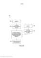
[003] Em uma modalidade, é fornecido um sistema eletrônico pa ra um instrumento cirúrgico. O sistema eletrônico compreende um circuito de fonte de alimentação principal configurado para fornecer energia elétrica a um circuito primário; um circuito de fonte de alimentação suplementar configurado para fornecer energia elétrica a um cir- cuito secundário; um circuito de proteção contra curto-circuito acoplado entre o circuito de fonte de alimentação principal e o circuito de fonte de alimentação suplementar; O circuito de fonte de alimentação suplementar é configurado para isolar-se do circuito de fonte de alimentação principal quando o circuito de fonte de alimentação suplementar detecta uma condição de curto-circuito no circuito secundário. O circuito de fonte de alimentação suplementar é configurado para unir-se novamente ao circuito de fonte de alimentação principal e fornecer energia ao circuito secundário depois de corrigida a condição de curto- circuito.[003] In one embodiment, an electronic system is provided for a surgical instrument. The electronic system comprises a main power supply circuit configured to supply electrical power to a primary circuit; a supplemental power supply circuit configured to supply electrical power to a secondary circuit; a short-circuit protection circuit coupled between the main power supply circuit and the supplementary power supply circuit; The supplementary power supply circuit is configured to isolate itself from the main power supply circuit when the supplemental power supply circuit detects a short circuit condition in the secondary circuit. The supplemental power supply circuit is configured to rejoin the main power supply circuit and supply power to the secondary circuit after the short circuit condition is corrected.
[004] Em uma modalidade, o circuito de proteção contra curto- circuito é configurado para monitorar uma ou mais condições de curto- circuito. Em uma modalidade, o circuito de proteção é configurado para travar o disparo do instrumento cirúrgico quando houver indicação de um evento de curto-circuito. Em uma modalidade, o sistema eletrônico compreende uma pluralidade de circuitos de proteção suplementares ligados uns aos outros em rede para isolar, detectar ou proteger as funções de outros circuitos.[004] In one embodiment, the short circuit protection circuit is configured to monitor one or more short circuit conditions. In one embodiment, the protection circuit is configured to lock the surgical instrument from firing when a short circuit event is indicated. In one embodiment, the electronic system comprises a plurality of supplementary protection circuits networked together to isolate, detect, or protect the functions of other circuits.
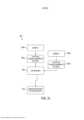
[005] Em uma modalidade, é fornecido um sistema eletrônico pa ra um instrumento cirúrgico. O sistema eletrônico compreende um circuito de fonte de alimentação principal configurado para fornecer energia elétrica a um circuito primário; um circuito de fonte de alimentação suplementar configurado para fornecer energia elétrica a um circuito secundário; e um monitor de taxa de amostragem acoplado entre o circuito de fonte de alimentação principal e o circuito de fonte de alimentação suplementar, em que o monitor de taxa de amostragem é configurado para limitar as taxas de amostragem e/ou o ciclo de trabalho do circuito secundário quando o instrumento cirúrgico está em um estado de não detecção.[005] In one embodiment, an electronic system is provided for a surgical instrument. The electronic system comprises a main power supply circuit configured to supply electrical power to a primary circuit; a supplementary power supply circuit configured to supply electrical power to a secondary circuit; and a sample rate monitor coupled between the main power supply circuit and the supplementary power supply circuit, wherein the sample rate monitor is configured to limit the sampling rates and/or the duty cycle of the circuit secondary when the surgical instrument is in a non-sensing state.
[006] Em uma modalidade, o sistema eletrônico compreende adi- cionalmente um monitor de estado do dispositivo acoplado ao circuito primário, em que o monitor de estado do dispositivo é configurado para detectar um estado de vários subsistemas elétricos e mecânicos do instrumento cirúrgico. Em uma modalidade, o monitor de taxa de amostragem funciona em conjunto com o monitor de estado do dispositivo. Em uma modalidade, o monitor de estado do dispositivo é confi-gurado para detectar o estado de um atuador de extremidade do instrumento cirúrgico em um estado operacional solto (Estado 1), prendendo (Estado 2) ou preso (Estado 3), e em que o monitor de taxa de amostragem é configurado para definir a taxa de amostragem e/ou o ciclo de trabalho do circuito secundário com base no estado do atua- dor de extremidade, determinado pelo monitor de estado do dispositivo. Em uma modalidade, o monitor de taxa de amostragem pode definir o ciclo de trabalho para cerca de 10% quando o atuador de extremidade estiver no Estado 1, para cerca de 50% quando o atuador de extremidade estiver no Estado 2, ou para cerca de 20% quando o atu- ador de extremidade estiver no Estado 3.[006] In one embodiment, the electronic system further comprises a device status monitor coupled to the primary circuit, wherein the device status monitor is configured to detect a status of various electrical and mechanical subsystems of the surgical instrument. In one embodiment, the sample rate monitor works in conjunction with the device status monitor. In one embodiment, the device status monitor is configured to detect the state of a surgical instrument end actuator in an operating state released (State 1), holding (State 2), or stuck (State 3), and in that the sample rate monitor is configured to set the sample rate and/or secondary circuit duty cycle based on the state of the end actuator as determined by the device state monitor. In one embodiment, the sample rate monitor can set the duty cycle to about 10% when the end actuator is in
[007] Em uma modalidade, é fornecido um sistema eletrônico pa ra um instrumento cirúrgico. O sistema eletrônico compreende um circuito de fonte de alimentação principal configurado para fornecer energia elétrica a um circuito primário; um circuito de fonte de alimentação suplementar configurado para fornecer energia elétrica a um circuito secundário; e um circuito de proteção contra sobrecorren- te/sobretensão acoplado entre o circuito de fonte de alimentação principal e o circuito de fonte de alimentação suplementar, em que o circuito de proteção contra sobrecorrente/sobretensão é configurado para isolar a corrente do circuito de fonte de alimentação principal quando o circuito secundário é submetido a níveis de corrente ou de tensão mais altos que o esperado.[007] In one embodiment, an electronic system is provided for a surgical instrument. The electronic system comprises a main power supply circuit configured to supply electrical power to a primary circuit; a supplementary power supply circuit configured to supply electrical power to a secondary circuit; and an overcurrent/overvoltage protection circuit coupled between the main power supply circuit and the supplementary power supply circuit, wherein the overcurrent/overvoltage protection circuit is configured to isolate the current from the power supply circuit. mains supply when the secondary circuit is subjected to higher than expected current or voltage levels.
[008] Em uma modalidade, a condição de sobrecorrente ou de sobretensão é corrigida, o circuito de fonte de alimentação suplementar une-se novamente ao circuito de fonte de alimentação principal e é configurado para fornecer energia ao circuito secundário. Em uma modalidade, o circuito de proteção contra sobrecorrente/sobretensão é configurado para travar o disparo do instrumento cirúrgico quando o evento de condição de sobrecorrente/sobretensão for indicado, quando uma condição de sobrecorrente/sobretensão for detectada. Em uma modalidade, o circuito de proteção contra sobrecorren- te/sobretensão é configurado para indicar uma condição de sobrecor- rente/sobretensão a um usuário final do instrumento cirúrgico, quando for detectada uma condição de sobrecorrente/sobretensão. Em uma modalidade, o circuito de proteção contra sobrecorrente/sobretensão é configurado para bloquear o instrumento cirúrgico e impedir que ele seja disparado, ou para travar outras operações do instrumento cirúr-gico, quando for detectada uma condição de sobrecorren- te/sobretensão.[008] In one embodiment, the overcurrent or overvoltage condition is corrected, the supplemental power supply circuit rejoins the main power supply circuit, and is configured to supply power to the secondary circuit. In one embodiment, the overcurrent/overvoltage protection circuit is configured to lock the surgical instrument from firing when the overcurrent/overvoltage condition event is indicated when an overcurrent/overvoltage condition is detected. In one embodiment, the overcurrent/overvoltage protection circuit is configured to indicate an overcurrent/overvoltage condition to an end user of the surgical instrument when an overcurrent/overvoltage condition is detected. In one embodiment, the overcurrent/overvoltage protection circuit is configured to lockout the surgical instrument and prevent it from firing, or to lockout further operations of the surgical instrument, when an overcurrent/overvoltage condition is detected.
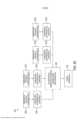
[009] Em uma modalidade, é fornecido um sistema eletrônico pa ra um instrumento cirúrgico. O sistema eletrônico compreende um circuito de fonte de alimentação principal configurado para fornecer energia elétrica a um circuito primário; um circuito de fonte de alimentação suplementar configurado para fornecer energia elétrica a um circuito secundário; e um circuito de proteção contra polaridade reversa acoplado entre o circuito de fonte de alimentação principal e o circuito de fonte de alimentação suplementar, em que o circuito de proteção contra polaridade reversa é configurado para isolar o circuito secundário do circuito de fonte de alimentação principal quando uma tensão com polaridade inversa for aplicada ao circuito secundário.[009] In one embodiment, an electronic system is provided for a surgical instrument. The electronic system comprises a main power supply circuit configured to supply electrical power to a primary circuit; a supplementary power supply circuit configured to supply electrical power to a secondary circuit; and a reverse polarity protection circuit coupled between the main power supply circuit and the supplementary power supply circuit, wherein the reverse polarity protection circuit is configured to isolate the secondary circuit from the main power supply circuit when a voltage with reverse polarity is applied to the secondary circuit.
[0010] Em uma modalidade, o circuito de proteção contra polari dade reversa é configurado para isolar o circuito de fonte de alimentação suplementar do circuito secundário quando uma tensão com pola- ridade inversa for aplicada ao circuito secundário. Em uma modalidade, o circuito de proteção contra polaridade reversa é configurado para unir-se novamente ao circuito de fonte de alimentação suplementar para fornecer energia ao circuito secundário depois de corrigida a condição de tensão com polaridade inversa. Em uma modalidade, o circuito de polaridade inversa compreende um relé que compreende uma bobina de entrada e contatos de saída acoplados ao circuito secundário, em que a bobina de entrada está em série com um diodo configurado para bloquear a passagem de corrente através da bobina de entrada do relé quando uma tensão de uma primeira polaridade é aplicada ao circuito secundário através dos contatos de saída. Em uma modalidade, o diodo é configurado para permitir que a corrente passe através do diodo e da bobina de entrada quando uma tensão com uma segunda polaridade é aplicada ao circuito secundário, em que a corrente através da bobina de entrada energiza o relé para desconectar a tensão de saída do circuito secundário da segunda polaridade.[0010] In one embodiment, the reverse polarity protection circuit is configured to isolate the supplementary power supply circuit from the secondary circuit when a voltage with reverse polarity is applied to the secondary circuit. In one embodiment, the reverse polarity protection circuit is configured to rejoin the supplementary power supply circuit to supply power to the secondary circuit after correcting the reverse polarity voltage condition. In one embodiment, the reverse polarity circuit comprises a relay comprising an input coil and output contacts coupled to the secondary circuit, wherein the input coil is in series with a diode configured to block the flow of current through the input coil. relay input when a voltage of a first polarity is applied to the secondary circuit through the output contacts. In one embodiment, the diode is configured to allow current to pass through the diode and input coil when a voltage with a second polarity is applied to the secondary circuit, wherein current through the input coil energizes the relay to disconnect the input coil. output voltage of the secondary circuit of the second polarity.
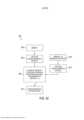
[0011] Em uma modalidade, é fornecido um sistema eletrônico pa ra um instrumento cirúrgico. O sistema eletrônico compreende um circuito de fonte de alimentação principal configurado para fornecer energia elétrica a um circuito primário; um circuito de fonte de alimentação suplementar configurado para fornecer energia elétrica a um circuito secundário; e um monitor de modo inativo acoplado entre o circuito de fonte de alimentação principal e o circuito de fonte de alimentação suplementar, em que o monitor de modo inativo é configurado para indicar uma ou mais condições de modo inativo.[0011] In one embodiment, an electronic system is provided for a surgical instrument. The electronic system comprises a main power supply circuit configured to supply electrical power to a primary circuit; a supplementary power supply circuit configured to supply electrical power to a secondary circuit; and an idle monitor coupled between the main power supply circuit and the supplementary power supply circuit, wherein the idle monitor is configured to indicate one or more idle conditions.
[0012] Em uma modalidade, o sistema eletrônico compreende adi cionalmente um monitor de estado do dispositivo acoplado ao circuito primário, em que o monitor de estado do dispositivo é configurado para detectar um estado de vários subsistemas elétricos e mecânicos do instrumento cirúrgico. Em uma modalidade, o monitor de modo inativo funciona em conjunto com o monitor de estado do dispositivo. Em uma modalidade, o monitor de estado do dispositivo é configurado para detectar o estado de um atuador de extremidade do instrumento cirúrgico em um estado operacional solto (Estado 1), prendendo (Estado 2) ou preso (Estado 3), e em que o monitor de modo inativo é configurado para colocar o circuito secundário em modo inativo quando o instrumento cirúrgico estiver no estado solto (Estado 1), e para colocar o circuito secundário em modo ativo quando o instrumento cirúrgico estiver no estado prendendo (Estado 2) ou preso (Estado 3).[0012] In one embodiment, the electronic system further comprises a device status monitor coupled to the primary circuit, wherein the device status monitor is configured to detect a status of various electrical and mechanical subsystems of the surgical instrument. In one embodiment, the idle monitor works in conjunction with the device status monitor. In one embodiment, the device status monitor is configured to detect the state of a surgical instrument end actuator in an operating state released (State 1), holding (State 2), or stuck (State 3), and where the Idle mode monitor is configured to put the secondary circuit in idle mode when the surgical instrument is in the loose state (State 1), and to put the secondary circuit in active mode when the surgical instrument is in the holding state (State 2) or stuck (State 3).
[0013] Em uma modalidade, é fornecido um sistema eletrônico pa ra um instrumento cirúrgico. O sistema eletrônico compreende um circuito de fonte de alimentação principal configurado para fornecer energia elétrica a um circuito primário; um circuito de fonte de alimentação suplementar configurado para fornecer energia elétrica a um circuito secundário; e um circuito de perda temporária de energia acoplado entre o circuito de fonte de alimentação principal e o circuito de fonte de alimentação suplementar, em que o circuito de perda temporária de energia é configurado para fornecer proteção contra perda intermitente de energia no circuito secundário. Em uma modalidade, o circuito de perda temporária de energia é configurado para fornecer energia contínua durante curtos períodos de tempo, caso seja interrompida a energia proveniente do circuito de fonte de alimentação principal.[0013] In one embodiment, an electronic system is provided for a surgical instrument. The electronic system comprises a main power supply circuit configured to supply electrical power to a primary circuit; a supplementary power supply circuit configured to supply electrical power to a secondary circuit; and a temporary power loss circuit coupled between the main power supply circuit and the supplemental power supply circuit, wherein the temporary power loss circuit is configured to provide protection against intermittent power loss in the secondary circuit. In one embodiment, the temporary power loss circuit is configured to provide continuous power for short periods of time if power from the main power supply circuit is interrupted.
[0014] As características e vantagens das várias modalidades da invenção, bem como a maneira de obtê-las, ficarão mais evidentes e a modalidade da própria invenção será melhor compreendida por referência à seguinte descrição de modalidades da modalidade da invenção, tomada em conjunto com os desenhos em anexo, em que:[0014] The features and advantages of the various embodiments of the invention, as well as the way to obtain them, will become more apparent and the embodiment of the invention itself will be better understood by reference to the following description of embodiments of the embodiment of the invention, taken in conjunction with the attached drawings, in which:
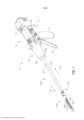
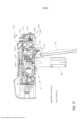
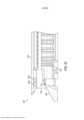
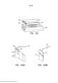
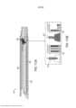
[0015] a Figura 1 é uma vista em perspectiva de um instrumento cirúrgico que tem um conjunto de eixo intercambiável operacionalmen- te acoplado ao mesmo;[0015] Figure 1 is a perspective view of a surgical instrument that has an interchangeable shaft assembly operationally coupled thereto;
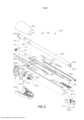
[0016] a Figura 2 é uma vista de montagem explodida do conjunto de eixo intercambiável e do instrumento cirúrgico da Figura 1;[0016] Figure 2 is an exploded assembly view of the interchangeable shaft assembly and the surgical instrument of Figure 1;
[0017] a Figura 3 é uma outra vista de conjunto explodida mos trando porções do conjunto de eixo intercambiável e do instrumento cirúrgico das Figuras 1 e 2;[0017] Figure 3 is another exploded assembly view showing portions of the interchangeable shaft and surgical instrument assembly of Figures 1 and 2;
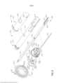
[0018] a Figura 4 é uma vista de conjunto explodida de uma por ção do instrumento cirúrgico das Figuras 1 e 3;[0018] Figure 4 is an exploded assembly view of a portion of the surgical instrument of Figures 1 and 3;
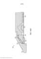
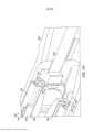
[0019] a Figura 5 é uma vista lateral em seção transversal de uma porção do instrumento cirúrgico da Figura 4 com o gatilho de disparo em uma posição totalmente ativada;[0019] Figure 5 is a cross-sectional side view of a portion of the surgical instrument of Figure 4 with the firing trigger in a fully activated position;
[0020] a Figura 6 é uma outra vista em seção transversal de uma porção do instrumento cirúrgico da Figura 5 com o gatilho de disparo em uma posição desativada;[0020] Figure 6 is another cross-sectional view of a portion of the surgical instrument of Figure 5 with the firing trigger in a disabled position;
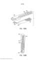
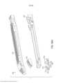
[0021] a Figura 7 é uma vista de conjunto explodida de uma forma de um conjunto de eixo intercambiável;[0021] Figure 7 is an exploded assembly view of one form of an interchangeable axle assembly;
[0022] a Figura 8 é uma outra vista de conjunto explodida mos trando porções do conjunto de eixo intercambiável da Figura 7;[0022] Figure 8 is a further exploded assembly view showing portions of the interchangeable shaft assembly of Figure 7;
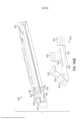
[0023] a Figura 9 é uma outra vista de conjunto explodida mos trando porções do conjunto de eixo intercambiável das Figuras 7 e 8;[0023] Figure 9 is a further exploded assembly view showing portions of the interchangeable shaft assembly of Figures 7 and 8;
[0024] a Figura 10 é uma vista em seção transversal de uma por ção do conjunto de eixo intercambiável das Figuras 7 a 9;[0024] Figure 10 is a cross-sectional view of a portion of the interchangeable shaft assembly of Figures 7 to 9;
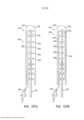
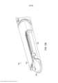
[0025] a Figura 11 é uma vista em perspectiva de uma porção do conjunto de eixo das Figuras 7 a 10 com a chave de tambor omitida para maior clareza;[0025] Figure 11 is a perspective view of a portion of the axle assembly of Figures 7 to 10 with the drum key omitted for clarity;
[0026] a Figura 12 é uma outra vista em perspectiva da porção do conjunto de eixo intercambiável da Figura 11, com a chave de tambor montada sobre a mesma;[0026] Figure 12 is another perspective view of the interchangeable shaft assembly portion of Figure 11, with the drum key mounted thereon;
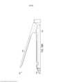
[0027] a Figura 13 é uma vista em perspectiva de uma porção do conjunto de eixo intercambiável da Figura 11 operacionalmente aco- plado a uma porção do instrumento cirúrgico da Figura 1, ilustrado com o gatilho de fechamento do mesmo em uma posição não acionada;[0027] Figure 13 is a perspective view of a portion of the interchangeable shaft assembly of Figure 11 operationally coupled to a portion of the surgical instrument of Figure 1, illustrated with the trigger closing the same in a non-actuated position;
[0028] a Figura 14 é uma vista elevada lateral direita do conjunto de eixo intercambiável e do instrumento cirúrgico da Figura 13;[0028] Figure 14 is a right side elevation view of the interchangeable shaft assembly and surgical instrument of Figure 13;
[0029] a Figura 15 é uma vista elevada lateral esquerda do conjun to de eixo intercambiável e do instrumento cirúrgico das Figuras 13 e 14;[0029] Figure 15 is a left side elevation view of the interchangeable shaft assembly and surgical instrument of Figures 13 and 14;
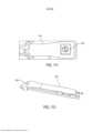
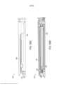
[0030] a Figura 16 é uma vista em perspectiva de uma porção do conjunto de eixo intercambiável da Figura 11, operacionalmente acoplado a uma porção do instrumento cirúrgico da Figura 1, ilustrado com o gatilho de fechamento do mesmo em uma posição ativada e um gatilho de disparo do mesmo em uma posição não acionada;[0030] Figure 16 is a perspective view of a portion of the interchangeable shaft assembly of Figure 11, operatively coupled to a portion of the surgical instrument of Figure 1, illustrated with the trigger closing the same in an activated position and a trigger triggering it in a non-triggered position;
[0031] a Figura 17 é uma vista elevada lateral direita do conjunto de eixo intercambiável e do instrumento cirúrgico da Figura 16;[0031] Figure 17 is a right side elevation view of the interchangeable shaft assembly and surgical instrument of Figure 16;
[0032] a Figura 18 é uma vista elevada lateral esquerda do conjun to de eixo intercambiável e do instrumento cirúrgico das Figuras 16 e 17;[0032] Figure 18 is a left side elevation view of the interchangeable shaft assembly and surgical instrument of Figures 16 and 17;
[0033] a Figura 18A é uma vista elevada lateral direita do conjunto de eixo intercambiável da Figura 11, operacionalmente acoplado a uma porção do instrumento cirúrgico da Figura 1, ilustrado com o gatilho de fechamento do mesmo em uma posição ativada e o gatilho de disparo do mesmo em uma posição ativada;[0033] Figure 18A is a right side elevation view of the interchangeable shaft assembly of Figure 11, operatively coupled to a portion of the surgical instrument of Figure 1, illustrated with its closing trigger in an activated position and the firing trigger of the same in an activated position;
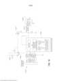
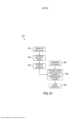
[0034] a Figura 19 é uma representação esquemática de um sis tema para desenergizar um conector elétrico de um punho de instrumento cirúrgico, quando um conjunto de eixo não estiver acoplado ao mesmo;[0034] Figure 19 is a schematic representation of a system for de-energizing an electrical connector of a surgical instrument handle, when a shaft assembly is not coupled thereto;
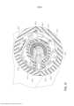
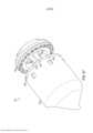
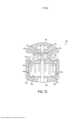
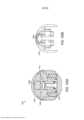
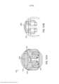
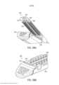
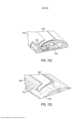
[0035] a Figura 20 é uma vista explodida de uma modalidade de um atuador de extremidade do instrumento cirúrgico da Figura 1;[0035] Figure 20 is an exploded view of an embodiment of an end actuator of the surgical instrument of Figure 1;
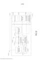
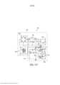
[0036] as Figuras 21A a 21B são um diagrama de circuitos do ins- trumento cirúrgico da Figura 1 abrangendo duas folhas de desenhos;[0036] Figures 21A to 21B are a circuit diagram of the surgical instrument of Figure 1 comprising two sheets of drawings;
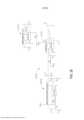
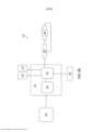
[0037] a Figura 22 ilustra um exemplo de um conjunto de alimen tação compreendendo um circuito de ciclos de uso configurado para gerar uma contagem de ciclos de uso da reserva de bateria;[0037] Figure 22 illustrates an example of a power pack comprising a usage cycle circuit configured to generate a battery reserve usage cycle count;
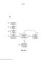
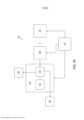
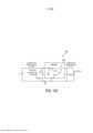
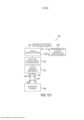
[0038] a Figura 23 ilustra uma modalidade de um processo para energizar sequencialmente um circuito segmentado;[0038] Figure 23 illustrates an embodiment of a process for sequentially energizing a segmented circuit;
[0039] a Figura 24 ilustra uma modalidade de um segmento de alimentação que compreende uma pluralidade de conversores de energia conectados em série;[0039] Figure 24 illustrates an embodiment of a power supply segment comprising a plurality of series-connected power converters;
[0040] a Figura 25 ilustra uma modalidade de um circuito segmen tado configurado para maximizar a energia disponível para funções intensas críticas e/ou de alimentação;[0040] Figure 25 illustrates one embodiment of a segmented circuit configured to maximize available energy for critical and/or power intensive functions;
[0041] a Figura 26 ilustra uma modalidade de um sistema de ali mentação que compreende uma pluralidade de conversores de energia conectados em série configurados para serem energizados sequencialmente;[0041] Figure 26 illustrates an embodiment of a power supply system comprising a plurality of series-connected power converters configured to be energized sequentially;
[0042] a Figura 27 ilustra uma modalidade de um circuito segmen tado que compreende uma seção de controle isolada;[0042] Figure 27 illustrates an embodiment of a segmented circuit comprising an isolated control section;
[0043] a Figura 28 ilustra uma modalidade de um atuador de ex tremidade compreendendo um primeiro sensor e um segundo sensor;[0043] Figure 28 illustrates an embodiment of an end actuator comprising a first sensor and a second sensor;
[0044] a Figura 29 é um diagrama lógico ilustrando uma modalida de de um processo para ajustar a medição do primeiro sensor com base na entrada proveniente do segundo sensor do atuador de extremidade ilustrado na Figura 28;[0044] Figure 29 is a logic diagram illustrating one embodiment of a process for adjusting the measurement of the first sensor based on input from the second sensor of the end actuator illustrated in Figure 28;
[0045] a Figura 30 é um diagrama lógico ilustrando uma modalida de de um processo para determinar uma tabela de consulta para um primeiro sensor com base na entrada proveniente de um segundo sensor;[0045] Figure 30 is a logic diagram illustrating one embodiment of a process for determining a look-up table for a first sensor based on input from a second sensor;
[0046] a Figura 31 é um diagrama lógico ilustrando uma modalida de de um processo para calibrar um primeiro sensor em resposta a uma entrada proveniente de um segundo sensor;[0046] Figure 31 is a logic diagram illustrating one embodiment of a process for calibrating a first sensor in response to input from a second sensor;
[0047] a Figura 32A é um diagrama lógico ilustrando uma modali dade de um processo para determinar e exibir a espessura de uma seção de tecido pinçada entre uma bigorna e um cartucho de grampos de um atuador de extremidade;[0047] Figure 32A is a logic diagram illustrating one embodiment of a process for determining and displaying the thickness of a tissue section pinched between an anvil and a staple cartridge of an end actuator;
[0048] a Figura 32B é um diagrama lógico ilustrando uma modali dade de um processo para determinar e exibir a espessura de uma seção de tecido pinçada entre a bigorna e o cartucho de grampos do atuador de extremidade;[0048] Figure 32B is a logic diagram illustrating one embodiment of a process for determining and displaying the thickness of a tissue section clamped between the anvil and the end actuator staple cartridge;
[0049] a Figura 33 é um gráfico ilustrando uma medição de espes sura por efeito Hall ajustada, em comparação a uma medição de espessura por efeito Hall não modificada;[0049] Figure 33 is a graph illustrating an adjusted Hall effect thickness measurement versus an unmodified Hall effect thickness measurement;
[0050] a Figura 34 ilustra uma modalidade de um atuador de ex tremidade compreendendo um primeiro sensor e um segundo sensor;[0050] Figure 34 illustrates an embodiment of an end actuator comprising a first sensor and a second sensor;
[0051] a Figura 35 ilustra uma modalidade de um atuador de ex tremidade compreendendo um primeiro sensor e uma pluralidade de segundos sensores;[0051] Figure 35 illustrates an embodiment of an end actuator comprising a first sensor and a plurality of second sensors;
[0052] a Figura 36 é um diagrama lógico ilustrando uma modalida de de um processo para ajustar uma medição de um primeiro sensor em resposta a uma pluralidade de sensores secundários;[0052] Figure 36 is a logic diagram illustrating one embodiment of a process for adjusting a measurement from a first sensor in response to a plurality of secondary sensors;
[0053] a Figura 37 ilustra uma modalidade de um circuito configu rado para converter sinais provenientes de um primeiro sensor e de uma pluralidade de sensores secundários em sinais digitais recebíveis por um processador;[0053] Figure 37 illustrates an embodiment of a circuit configured to convert signals from a first sensor and a plurality of secondary sensors into digital signals receivable by a processor;
[0054] a Figura 38 ilustra uma modalidade de um atuador de ex tremidade compreendendo uma pluralidade de sensores;[0054] Figure 38 illustrates an embodiment of an end actuator comprising a plurality of sensors;
[0055] a Figura 39 é um diagrama lógico ilustrando uma modalida de de um processo para determinar uma ou mais propriedades do tecido com base em uma pluralidade de sensores;[0055] Figure 39 is a logic diagram illustrating one embodiment of a process for determining one or more fabric properties based on a plurality of sensors;
[0056] a Figura 40 ilustra uma modalidade de um atuador de ex- tremidade compreendendo uma pluralidade de sensores acoplados a um segundo membro de garra;[0056] Figure 40 illustrates an embodiment of an end actuator comprising a plurality of sensors coupled to a second claw member;
[0057] a Figura 41 ilustra uma modalidade de um cartucho de grampos compreendendo uma pluralidade de sensores formados integralmente no mesmo;[0057] Figure 41 illustrates one embodiment of a staple cartridge comprising a plurality of sensors integrally formed therein;
[0058] a Figura 42 é um diagrama lógico ilustrando uma modalida de de um processo para determinar um ou mais parâmetros de uma seção de tecido pinçada dentro de um atuador de extremidade;[0058] Figure 42 is a logic diagram illustrating one embodiment of a process for determining one or more parameters of a tissue section clamped within an end actuator;
[0059] a Figura 43 ilustra uma modalidade de um atuador de ex tremidade compreendendo uma pluralidade de sensores redundantes;[0059] Figure 43 illustrates an embodiment of an end actuator comprising a plurality of redundant sensors;
[0060] a Figura 44 é um diagrama lógico ilustrando uma modalida de de um processo para selecionar a saída mais confiável dentre uma pluralidade de sensores redundantes;[0060] Figure 44 is a logic diagram illustrating one embodiment of a process for selecting the most reliable output from a plurality of redundant sensors;
[0061] a Figura 45 ilustra uma modalidade de um atuador de ex tremidade compreendendo um sensor que compreende uma taxa de amostragem específica para limitar ou eliminar sinais falsos;[0061] Figure 45 illustrates an embodiment of an end actuator comprising a sensor comprising a specific sampling rate to limit or eliminate false signals;
[0062] a Figura 46 é um diagrama lógico ilustrando uma modalida de de um processo para gerar uma medição de espessura para uma seção de tecido situada entre uma bigorna e um cartucho de grampos de um atuador de extremidade;[0062] Figure 46 is a logic diagram illustrating one embodiment of a process for generating a thickness measurement for a tissue section located between an anvil and a staple cartridge of an end actuator;
[0063] a Figura 47 ilustra uma modalidade de um grampeador cir cular;[0063] Figure 47 illustrates an embodiment of a circular stapler;
[0064] as Figuras 48A a 48D ilustram um processo de grampea- mento do grampeador circular ilustrado na Figura 47, em que a Figura 48A ilustra o grampeador circular em uma posição inicial com a bigorna e o corpo em uma configuração fechada, a Figura 48B ilustra que a bigorna é movida distalmente para desengatar-se do corpo e criar um vão configurado para receber em seu interior uma seção de tecido, uma vez que o grampeador circular 3400 esteja posicionado, a Figura 48C ilustra a seção de tecido comprimida até uma compressão prede- terminada entre a bigorna e o corpo, e a Figura 48D ilustra o grampeador circular em posição correspondente à implantação do grampo;[0064] Figures 48A to 48D illustrate a stapling process of the circular stapler illustrated in Figure 47, in which Figure 48A illustrates the circular stapler in a starting position with the anvil and body in a closed configuration, Figure 48B illustrates that the anvil is moved distally to disengage from the body and create a gap configured to receive within it a tissue section, once the
[0065] a Figura 49 ilustra uma modalidade de uma bigorna de grampeador circular e um conector elétrico configurado para interface- ar com a mesma;[0065] Figure 49 illustrates an embodiment of a circular stapler anvil and an electrical connector configured to interface with it;
[0066] a Figura 50 ilustra uma modalidade de um instrumento ci rúrgico compreendendo um sensor acoplado a um eixo de acionamento do instrumento cirúrgico;[0066] Figure 50 illustrates an embodiment of a surgical instrument comprising a sensor coupled to a drive shaft of the surgical instrument;
[0067] a Figura 51 é um fluxograma ilustrando uma modalidade de um processo para determinar o carregamento irregular do tecido em um atuador de extremidade;[0067] Figure 51 is a flowchart illustrating one embodiment of a process for determining irregular tissue loading on an end actuator;
[0068] a Figura 52 ilustra uma modalidade de um atuador de ex tremidade configurado para determinar um ou mais parâmetros de uma seção de tecido durante uma operação de pinçamento;[0068] Figure 52 illustrates an embodiment of an end actuator configured to determine one or more parameters of a tissue section during a clamping operation;
[0069] as Figuras 53A e 53B ilustram uma modalidade de um atu- ador de extremidade configurado para normalizar uma tensão de efeito Hall independentemente da altura de suporte de um cartucho de grampos;[0069] Figures 53A and 53B illustrate an embodiment of an end actuator configured to normalize a Hall effect voltage regardless of the support height of a staple cartridge;
[0070] a Figura 54 é um diagrama lógico ilustrando uma modalida de de um processo para determinar quando a compressão do tecido dentro de um atuador de extremidade como, por exemplo, o atuador de extremidade ilustrado nas Figuras 53A a 53B, atingiu um estado de equilíbrio;[0070] Figure 54 is a logic diagram illustrating one embodiment of a process for determining when tissue compression within an end actuator, such as the end actuator illustrated in Figures 53A to 53B, has reached a state of balance;
[0071] a Figura 55 é um gráfico ilustrando várias leituras de senso res de efeito Hall;[0071] Figure 55 is a graph illustrating various Hall effect sensor readings;
[0072] a Figura 56 é um diagrama lógico ilustrando uma modalida de de um processo para determinar quando a compressão do tecido dentro de um atuador de extremidade como, por exemplo, o atuador de extremidade ilustrado nas Figuras 53A a 53B, atingiu um estado de equilíbrio;[0072] Figure 56 is a logic diagram illustrating one embodiment of a process for determining when tissue compression within an end actuator, such as the end actuator illustrated in Figures 53A to 53B, has reached a state of balance;
[0073] a Figura 57 é um diagrama lógico ilustrando uma modalida de de um processo para controlar um atuador de extremidade de modo a otimizar a formação adequada do grampo durante a implantação;[0073] Figure 57 is a logic diagram illustrating one embodiment of a process for controlling an end actuator to optimize proper clip formation during implantation;
[0074] a Figura 58 é um diagrama lógico ilustrando uma modalida de de um processo para controlar um atuador de extremidade de modo a permitir a evacuação de fluidos e proporcionar a formação otimizada de grampos;[0074] Figure 58 is a logic diagram illustrating one embodiment of a process for controlling an end actuator to allow fluid evacuation and provide optimal clip formation;
[0075] as Figuras 59A a 59B ilustram uma modalidade de um atu- ador de extremidade compreendendo um sensor de pressão;[0075] Figures 59A to 59B illustrate an embodiment of an end actuator comprising a pressure sensor;
[0076] a Figura 60 ilustra uma modalidade de um atuador de ex tremidade compreendendo um segundo sensor situado entre um cartucho de grampos e um segundo membro de garra;[0076] Figure 60 illustrates one embodiment of an end actuator comprising a second sensor located between a staple cartridge and a second gripper member;
[0077] a Figura 61 é um diagrama lógico ilustrando uma modalida de de um processo para determinar e exibir a espessura de uma seção de tecido pinçada em um atuador de extremidade, de acordo com as Figuras 59A a 59B ou com a Figura 60;[0077] Figure 61 is a logic diagram illustrating an embodiment of a process for determining and displaying the thickness of a tissue section clamped onto an end actuator, according to Figures 59A to 59B or Figure 60;
[0078] a Figura 62 ilustra uma modalidade de um atuador de ex tremidade compreendendo uma pluralidade de segundos sensores situados entre um cartucho de grampos e uma canaleta alongada;[0078] Figure 62 illustrates an embodiment of an end actuator comprising a plurality of second sensors located between a staple cartridge and an elongated raceway;
[0079] as Figuras 63A e 63B ilustram com mais detalhes o efeito de uma mordedura total do tecido versus uma mordedura parcial;[0079] Figures 63A and 63B illustrate in more detail the effect of a full tissue bite versus a partial bite;
[0080] a Figura 64 ilustra uma modalidade de um atuador de ex tremidade compreendendo uma bobina e um circuito oscilador para medição do vão entre a bigorna e o cartucho de grampos;[0080] Figure 64 illustrates an embodiment of an end actuator comprising a coil and an oscillator circuit for measuring the gap between the anvil and the staple cartridge;
[0081] a Figura 65 ilustra uma vista alternativa do atuador de ex tremidade. Conforme ilustrado, em algumas modalidades a fiação externa pode fornecer energia ao circuito oscilador;[0081] Figure 65 illustrates an alternative view of the end actuator. As illustrated, in some embodiments external wiring can power the oscillator circuit;
[0082] a Figura 66 ilustra exemplos da operação de uma bobina para detectar correntes parasitas em um alvo;[0082] Figure 66 illustrates examples of the operation of a coil to detect eddy currents in a target;
[0083] a Figura 67 ilustra um gráfico de um fator de qualidade me- dido, a indutância medida e a resistência medida do raio de uma bobina como uma função da distância entre a bobina e um alvo;[0083] Figure 67 illustrates a graph of a measured quality factor, the measured inductance, and the measured resistance of a coil beam as a function of the distance between the coil and a target;
[0084] a Figura 68 ilustra uma modalidade de um atuador de ex tremidade compreendendo um emissor e sensor disposto entre o cartucho de grampos e a canaleta alongada;[0084] Figure 68 illustrates an embodiment of an end actuator comprising an emitter and sensor disposed between the staple cartridge and the elongated raceway;
[0085] a Figura 69 ilustra uma modalidade de um emissor e sensor em funcionamento;[0085] Figure 69 illustrates a mode of an emitter and sensor in operation;
[0086] a Figura 70 ilustra a superfície de uma modalidade de um emissor e sensor compreendendo um transdutor MEMS;[0086] Figure 70 illustrates the surface of an embodiment of an emitter and sensor comprising a MEMS transducer;
[0087] a Figura 71 ilustra um gráfico de um exemplo do sinal refle tido que pode ser medido pelo emissor e sensor da Figura 69;[0087] Figure 71 illustrates a graph of an example of the reflected signal that can be measured by the emitter and sensor of Figure 69;
[0088] a Figura 72 ilustra uma modalidade de um atuador de ex tremidade que é configurado para determinar a localização de um membro de corte ou faca;[0088] Figure 72 illustrates one embodiment of an end actuator that is configured to determine the location of a cutting member or knife;
[0089] a Figura 73 ilustra um exemplo da tira de código em funcio namento, com LEDs vermelhos e um LED infravermelho;[0089] Figure 73 illustrates an example of the code strip in operation, with red LEDs and an infrared LED;
[0090] a Figura 74 ilustra uma vista em perspectiva parcial de um atuador de extremidade de um instrumento cirúrgico compreendendo um cartucho de grampos, de acordo com várias modalidades aqui descritas;[0090] Figure 74 illustrates a partial perspective view of an end actuator of a surgical instrument comprising a staple cartridge, in accordance with various embodiments described herein;
[0091] a Figura 75 ilustra uma vista em elevação de uma porção do atuador de extremidade da Figura 74 de acordo com várias modalidades aqui descritas;[0091] Figure 75 illustrates an elevation view of a portion of the end actuator of Figure 74 in accordance with various embodiments described herein;
[0092] a Figura 76 ilustra um diagrama lógico de um módulo do instrumento cirúrgico da Figura 74 de acordo com várias modalidades aqui descritas;[0092] Figure 76 illustrates a logic diagram of a module of the surgical instrument of Figure 74 in accordance with various embodiments described herein;
[0093] a Figura 77 ilustra uma vista parcial de um gume cortante, um sensor óptico, e uma fonte de luz do instrumento cirúrgico da Figura 74, de acordo com várias modalidades aqui descritas;[0093] Figure 77 illustrates a partial view of a cutting edge, an optical sensor, and a light source of the surgical instrument of Figure 74, in accordance with various embodiments described herein;
[0094] a Figura 78 ilustra uma vista parcial de um gume cortante, um sensor óptico, e uma fonte de luz do instrumento cirúrgico da Figura 74, de acordo com várias modalidades aqui descritas;[0094] Figure 78 illustrates a partial view of a cutting edge, an optical sensor, and a light source of the surgical instrument of Figure 74, in accordance with various embodiments described herein;
[0095] a Figura 79 ilustra uma vista parcial de um gume cortante, um sensor óptico, e uma fonte de luz do instrumento cirúrgico da Figura 74, de acordo com várias modalidades aqui descritas;[0095] Figure 79 illustrates a partial view of a cutting edge, an optical sensor, and a light source of the surgical instrument of Figure 74, in accordance with various embodiments described herein;
[0096] a Figura 80 ilustra uma vista parcial de um gume cortante, sensores ópticos e fontes de luz do instrumento cirúrgico da Figura 74, de acordo com várias modalidades aqui descritas;[0096] Figure 80 illustrates a partial view of a cutting edge, optical sensors and light sources of the surgical instrument of Figure 74, according to various embodiments described herein;
[0097] a Figura 81 ilustra uma vista parcial de um gume cortante, um sensor óptico, e uma fonte de luz do instrumento cirúrgico da Figura 74, de acordo com várias modalidades aqui descritas;[0097] Figure 81 illustrates a partial view of a cutting edge, an optical sensor, and a light source of the surgical instrument of Figure 74, in accordance with various embodiments described herein;
[0098] a Figura 82 ilustra uma vista parcial de um gume cortante entre lâminas de limpeza do instrumento cirúrgico da Figura 74, de acordo com várias modalidades aqui descritas;[0098] Figure 82 illustrates a partial view of a cutting edge between cleaning blades of the surgical instrument of Figure 74, according to various embodiments described herein;
[0099] a Figura 83 ilustra uma vista parcial de um gume cortante entre esponjas de limpeza do instrumento cirúrgico da Figura 74, de acordo com várias modalidades aqui descritas;[0099] Figure 83 illustrates a partial view of a cutting edge between cleaning sponges of the surgical instrument of Figure 74, according to various embodiments described herein;
[00100] a Figura 84 ilustra uma vista em perspectiva de um cartucho de grampos incluindo um membro de teste de afiamento de acordo com várias modalidades aqui descritas;[00100] Figure 84 illustrates a perspective view of a staple cartridge including a sharpening test member in accordance with various embodiments described herein;
[00101] a Figura 85 ilustra um diagrama lógico de um módulo de um instrumento cirúrgico de acordo com várias modalidades aqui descritas;[00101] Figure 85 illustrates a logic diagram of a module of a surgical instrument according to various embodiments described herein;
[00102] a Figura 86 ilustra um diagrama lógico de um módulo de um instrumento cirúrgico de acordo com várias modalidades aqui descritas;[00102] Figure 86 illustrates a logic diagram of a module of a surgical instrument according to various embodiments described herein;
[00103] a Figura 87 ilustra um diagrama lógico delineando um método para avaliação do afiamento de um gume cortante de um instrumento cirúrgico, de acordo com várias modalidades aqui descritas;[00103] Figure 87 illustrates a logic diagram outlining a method for evaluating the sharpness of a cutting edge of a surgical instrument, according to various modalities described herein;
[00104] a Figura 88 ilustra um gráfico das forças aplicadas contra um gume cortante de um instrumento cirúrgico pelo membro de teste de afiamento da Figura 84 em vários níveis de afiamento, de acordo com várias modalidades aqui descritas;[00104] Figure 88 illustrates a graph of the forces applied against a cutting edge of a surgical instrument by the sharpening test member of Figure 84 at various levels of sharpening, according to various embodiments described herein;
[00105] a Figura 89 ilustra um fluxograma delineando um método para determinar se um gume cortante de um instrumento cirúrgico está suficientemente afiado para fazer a transeção do tecido capturado pelo instrumento cirúrgico, de acordo com várias modalidades aqui descritas; e[00105] Figure 89 illustrates a flowchart outlining a method for determining whether a cutting edge of a surgical instrument is sharp enough to transect the tissue captured by the surgical instrument, according to various modalities described herein; It is
[00106] a Figura 90 ilustra uma tabela mostrando espessuras de tecido predefinidas e as correspondentes forças-limite predefinidas de acordo com várias modalidades aqui descritas.[00106] Figure 90 illustrates a table showing predefined tissue thicknesses and the corresponding predefined limiting forces according to various embodiments described herein.
[00107] a Figura 91 ilustra uma vista em perspectiva de um instrumento cirúrgico incluindo um punho, um conjunto de eixo e um atuador de extremidade;[00107] Figure 91 illustrates a perspective view of a surgical instrument including a handle, a shaft assembly and an end actuator;
[00108] a Figura 92 ilustra um diagrama lógico de um módulo de controle comum para uso com uma pluralidade de motores do instrumento cirúrgico da Figura 91;[00108] Figure 92 illustrates a logic diagram of a common control module for use with a plurality of motors of the surgical instrument of Figure 91;
[00109] a Figura 93 ilustra uma vista em elevação parcial do punho do instrumento cirúrgico da Figura 91, com um compartimento externo removido;[00109] Figure 93 illustrates a partial elevation view of the handle of the surgical instrument in Figure 91, with an external compartment removed;
[00110] a Figura 94 ilustra uma vista em elevação parcial do instrumento cirúrgico da Figura 91, com um compartimento externo removido.[00110] Figure 94 illustrates a partial elevation view of the surgical instrument of Figure 91, with an external compartment removed.
[00111] a Figura 95A ilustra uma vista em ângulo lateral de um atu- ador de extremidade com a bigorna em uma posição fechada, ilustrando um LED situado em cada lado do suporte do cartucho;[00111] Figure 95A illustrates a side angled view of an end actuator with the anvil in a closed position, illustrating an LED located on each side of the cartridge holder;
[00112] a Figura 95B ilustra uma vista em ângulo a três quartos do atuador de extremidade com a bigorna em uma posição aberta, e um LED situado em cada lado do suporte do cartucho;[00112] Figure 95B illustrates a three-quarter angle view of the end actuator with the anvil in an open position, and an LED located on each side of the cartridge holder;
[00113] a Figura 96A ilustra uma vista em ângulo lateral de um atu- ador de extremidade com a bigorna em uma posição fechada, e uma pluralidade de LEDs situados em cada lado do suporte do cartucho;[00113] Figure 96A illustrates a side angled view of an end actuator with the anvil in a closed position, and a plurality of LEDs located on each side of the cartridge holder;
[00114] a Figura 96B ilustra uma vista em ângulo a três quartos do atuador de extremidade com a bigorna em uma posição aberta, e uma pluralidade de LEDs situados em cada lado do suporte do cartucho;[00114] Figure 96B illustrates a three-quarter angled view of the end actuator with the anvil in an open position, and a plurality of LEDs located on each side of the cartridge holder;
[00115] a Figura 97A ilustra uma vista em ângulo lateral de um atu- ador de extremidade com a bigorna em uma posição fechada, e uma pluralidade de LEDs da extremidade proximal à distal, em cada lado do suporte do cartucho; e[00115] Figure 97A illustrates a side angled view of an end actuator with the anvil in a closed position, and a plurality of LEDs from the proximal to the distal end, on each side of the cartridge holder; It is
[00116] a Figura 97B ilustra uma vista em ângulo a três quartos do atuador de extremidade com a bigorna em uma posição aberta, ilustrando uma pluralidade de LEDs da extremidade proximal à distal do cartucho de grampos, e em cada lado do suporte do cartucho.[00116] Figure 97B illustrates a three-quarter angled view of the end actuator with the anvil in an open position, illustrating a plurality of LEDs from the proximal to the distal end of the staple cartridge, and on each side of the cartridge holder.
[00117] a Figura 98A ilustra uma modalidade em que o compensador de tecido é fixado de modo removível à porção de bigorna do atu- ador de extremidade;[00117] Figure 98A illustrates an embodiment in which the tissue compensator is removablely attached to the anvil portion of the end actuator;
[00118] a Figura 98B ilustra uma vista detalhada de uma porção do compensador de tecido mostrado na Figura 98A;[00118] Figure 98B illustrates a detailed view of a portion of the fabric compensator shown in Figure 98A;
[00119] a Figura 99 ilustra vários exemplos de modalidades que usam uma camada de elementos condutivos, bem como elementos condutivos no cartucho de grampos, para detectar a distância entre a bigorna e a superfície superior do cartucho de grampos;[00119] Figure 99 illustrates several examples of embodiments that use a layer of conductive elements, as well as conductive elements in the staple cartridge, to detect the distance between the anvil and the top surface of the staple cartridge;
[00120] as Figuras 100A e 100B ilustram uma modalidade do compensador de tecido compreendendo uma camada de elementos con- dutivos em funcionamento;[00120] Figures 100A and 100B illustrate an embodiment of fabric compensator comprising a layer of conductive elements in operation;
[00121] as Figuras 101A e 101B ilustram uma modalidade de um atuador de extremidade compreendendo um compensador de tecido que compreende adicionalmente condutores incorporados em seu interior;[00121] Figures 101A and 101B illustrate an embodiment of an end actuator comprising a fabric compensator further comprising conductors incorporated therein;
[00122] as Figuras 102A e 102B ilustram uma modalidade de um atuador de extremidade compreendendo um compensador de tecido que compreende adicionalmente condutores incorporados ao mesmo;[00122] Figures 102A and 102B illustrate an embodiment of an end actuator comprising a fabric compensator further comprising conductors incorporated therein;
[00123] a Figura 103 ilustra uma modalidade de um cartucho de grampos e um compensador de tecido em que o cartucho de grampos fornece energia aos elementos condutivos que compreendem o compensador de tecido;[00123] Figure 103 illustrates an embodiment of a staple cartridge and a tissue compensator in which the staple cartridge supplies power to the conductive elements comprising the tissue compensator;
[00124] as Figuras 104A e 104B ilustram uma modalidade de um cartucho de grampos e um compensador de tecido em que o cartucho de grampos fornece energia aos elementos condutivos que compreendem o compensador de tecido;[00124] Figures 104A and 104B illustrate an embodiment of a staple cartridge and a tissue compensator in which the staple cartridge supplies power to the conductive elements comprising the tissue compensator;
[00125] as Figuras 105A e 105B ilustram uma modalidade de um atuador de extremidade compreendendo elementos de detecção de posição e um compensador de tecido;[00125] Figures 105A and 105B illustrate an embodiment of an end actuator comprising position sensing elements and a fabric compensator;
[00126] as Figuras 106A e 106B ilustram uma modalidade de um atuador de extremidade compreendendo elementos de detecção de posição e um compensador de tecido;[00126] Figures 106A and 106B illustrate an embodiment of an end actuator comprising position sensing elements and a fabric compensator;
[00127] as Figuras 107A e 107B ilustram uma modalidade de um cartucho de grampos e um compensador de tecido que é operável para indicar a posição de um membro de corte ou barra de corte;[00127] Figures 107A and 107B illustrate an embodiment of a staple cartridge and a tissue compensator that is operable to indicate the position of a cutting member or cutting bar;
[00128] a Figura 108 ilustra uma modalidade de um atuador de extremidade compreendendo um magneto e um sensor de efeito Hall, em que o campo magnético detectado pode ser usado para identificar um cartucho de grampos;[00128] Figure 108 illustrates an embodiment of an end actuator comprising a magnet and a Hall effect sensor, in which the detected magnetic field can be used to identify a staple cartridge;
[00129] a Figura 109 ilustra uma modalidade de um atuador de extremidade compreendendo um magneto e um sensor de efeito Hall, em que o campo magnético detectado pode ser usado para identificar um cartucho de grampos;[00129] Figure 109 illustrates an embodiment of an end actuator comprising a magnet and a Hall effect sensor, in which the detected magnetic field can be used to identify a staple cartridge;
[00130] a Figura 110 ilustra um gráfico da tensão detectada por um sensor de efeito Hall situado na ponta distal de um cartucho de grampos, como é ilustrado nas Figuras 108 e 109, em resposta à distância ou vão entre um magneto situado na bigorna e o sensor de efeito Hall no cartucho de grampos, como ilustrado nas Figuras 108 e 109;[00130] Figure 110 illustrates a graph of the voltage detected by a Hall effect sensor located at the distal end of a staple cartridge, as shown in Figures 108 and 109, in response to the distance or gap between a magnet located on the anvil and the Hall effect sensor in the staple cartridge, as illustrated in Figures 108 and 109;
[00131] a Figura 111 ilustra uma modalidade do compartimento do instrumento cirúrgico, compreendendo uma tela;[00131] Figure 111 illustrates an embodiment of the surgical instrument compartment, comprising a screen;
[00132] a Figura 112 ilustra uma modalidade de um retentor de grampo compreendendo um magneto;[00132] Figure 112 illustrates an embodiment of a clip retainer comprising a magnet;
[00133] as Figuras 113A e 113B ilustram uma modalidade de um atuador de extremidade compreendendo um sensor para identificar cartuchos de grampos de diferentes tipos;[00133] Figures 113A and 113B illustrate an embodiment of an end actuator comprising a sensor for identifying staple cartridges of different types;
[00134] a Figura 114 é uma vista parcial de um atuador de extremidade com condutores de energia do sensor, destinados a transferir sinais de energia e de dados entre os componentes conectados do instrumento cirúrgico, de acordo com uma modalidade.[00134] Figure 114 is a partial view of an end actuator with sensor power leads, intended to transfer power and data signals between connected components of the surgical instrument, according to one embodiment.
[00135] a Figura 115 é uma vista parcial do atuador de extremidade mostrado na Figura 114, mostrando sensores e/ou componentes eletrônicos situados em um atuador de extremidade.[00135] Figure 115 is a partial view of the end actuator shown in Figure 114, showing sensors and/or electronics located in an end actuator.
[00136] a Figura 116 é um diagrama de blocos de um subsistema eletrônico de instrumento cirúrgico compreendendo um circuito de proteção contra curto-circuito para os sensores e/ou componentes eletrônicos de acordo com uma modalidade.[00136] Figure 116 is a block diagram of a surgical instrument electronic subsystem comprising a short circuit protection circuit for sensors and/or electronic components according to an embodiment.
[00137] a Figura 117 é um circuito de proteção contra curto-circuito compreendendo um circuito de fonte de alimentação suplementar 7014 acoplado a um circuito de fonte de alimentação principal, de acordo com uma modalidade.[00137] Figure 117 is a short circuit protection circuit comprising a supplementary
[00138] a Figura 118 é um diagrama de blocos de um subsistema eletrônico de instrumento cirúrgico compreendendo um monitor de taxa de amostragem para fornecer redução de potência mediante a limitação das taxas de amostragem e/ou o ciclo de trabalho dos componentes de sensor, quando o instrumento cirúrgico está em um estado de não detecção, de acordo com uma modalidade.[00138] Figure 118 is a block diagram of a surgical instrument electronic subsystem comprising a sampling rate monitor to provide power reduction by limiting the sampling rates and/or the duty cycle of the sensor components, when the surgical instrument is in a non-sensing state according to a modality.
[00139] a Figura 119 é um diagrama de blocos de um subsistema eletrônico de instrumento cirúrgico compreendendo um circuito de proteção contra sobrecorrente/sobretensão para sensores e/ou componentes eletrônicos de um instrumento cirúrgico, de acordo com uma modalidade.[00139] Figure 119 is a block diagram of a surgical instrument electronic subsystem comprising an overcurrent/overvoltage protection circuit for sensors and/or electronic components of a surgical instrument, according to one embodiment.
[00140] a Figura 120 é um circuito de proteção contra sobrecorren- te/sobretensão destinado a sensores e componentes eletrônicos para um instrumento cirúrgico, de acordo com uma modalidade.[00140] Figure 120 is a protection circuit against overcurrent/overvoltage intended for sensors and electronic components for a surgical instrument, according to one modality.
[00141] a Figura 121 é um diagrama de blocos de um subsistema eletrônico de instrumento cirúrgico com um circuito de proteção contra polaridade inversa para sensores e/ou componentes eletrônicos, de acordo com uma modalidade.[00141] Figure 121 is a block diagram of a surgical instrument electronic subsystem with a reverse polarity protection circuit for sensors and/or electronic components, according to one embodiment.
[00142] a Figura 122 é um circuito de proteção contra polaridade inversa destinado a sensores e componentes eletrônicos para um instrumento cirúrgico, de acordo com uma modalidade.[00142] Figure 122 is a reverse polarity protection circuit for sensors and electronic components for a surgical instrument, according to one embodiment.
[00143] a Figura 123 é um diagrama de blocos de um subsistema eletrônico de instrumento cirúrgico com redução de potência mediante o uso de um monitor de modo inativo para sensores e/ou componentes eletrônicos, de acordo com uma modalidade.[00143] Figure 123 is a block diagram of a surgical instrument electronic subsystem with power reduction through the use of an idle mode monitor for sensors and/or electronic components, according to one embodiment.
[00144] a Figura 124 é um diagrama de blocos de um subsistema eletrônico de instrumento cirúrgico compreendendo um circuito de perda temporária de energia para proporcionar proteção contra perda intermitente de energia a sensores e/ou componentes eletrônicos em instrumentos cirúrgicos modulares.[00144] Figure 124 is a block diagram of a surgical instrument electronic subsystem comprising a temporary power loss circuit for providing protection against intermittent power loss to sensors and/or electronic components in modular surgical instruments.
[00145] a Figura 125 ilustra uma modalidade de um circuito de perda temporária de energia implementado sob a forma de um circuito de hardware.[00145] Figure 125 illustrates an embodiment of a temporary power loss circuit implemented as a hardware circuit.
[00146] a Figura 126A ilustra uma vista em perspectiva de uma modalidade de um atuador de extremidade compreendendo um magneto e um sensor de efeito Hall em comunicação com um processador;[00146] Figure 126A illustrates a perspective view of an embodiment of an end actuator comprising a magnet and a Hall effect sensor in communication with a processor;
[00147] a Figura 126B ilustra uma vista em seção transversal lateral de uma modalidade de um atuador de extremidade compreendendo um magneto e um sensor de efeito Hall em comunicação com um processador;[00147] Figure 126B illustrates a side cross-sectional view of an embodiment of an end actuator comprising a magnet and a Hall effect sensor in communication with a processor;
[00148] a Figura 127 ilustra uma modalidade das dimensões operacionais que se referem ao funcionamento do sensor de efeito Hall;[00148] Figure 127 illustrates a modality of the operational dimensions that refer to the operation of the Hall effect sensor;
[00149] a Figura 128A ilustra uma vista lateral externa de uma modalidade de um cartucho de grampos;[00149] Figure 128A illustrates an external side view of an embodiment of a staple cartridge;
[00150] a Figura 128B ilustra várias dimensões possíveis entre a superfície inferior do pino extrator e o topo do sensor de efeito Hall;[00150] Figure 128B illustrates several possible dimensions between the lower surface of the extractor pin and the top of the Hall effect sensor;
[00151] a Figura 128C ilustra uma vista lateral externa de uma modalidade de um cartucho de grampos;[00151] Figure 128C illustrates an external side view of an embodiment of a staple cartridge;
[00152] a Figura 128D ilustra várias dimensões possíveis entre a superfície inferior do pino extrator e a superfície superior do cartucho de grampos acima do sensor de efeito Hall;[00152] Figure 128D illustrates several possible dimensions between the lower surface of the extractor pin and the upper surface of the staple cartridge above the Hall effect sensor;
[00153] a Figura 129A ilustra adicionalmente uma vista em seção transversal de extremidade frontal 10054 da bigorna 10002 e do ponto de eixo central da bigorna;[00153] Figure 129A further illustrates a cross-sectional view of the
[00154] a Figura 129B é uma vista em seção transversal de um magneto mostrado na Figura 129A;[00154] Figure 129B is a cross-sectional view of a magnet shown in Figure 129A;
[00155] as Figuras 130A a 130E ilustram uma modalidade de um atuador de extremidade que compreende um magneto onde a Figura 130A ilustra uma vista de extremidade frontal em seção transversal do atuador de extremidade, a Figura 130B ilustra uma vista de extremidade frontal em recorte da bigorna e do magneto localmente, a Figura 130C ilustra uma vista em perspectiva em recorte da bigorna e do magneto, a Figura 130D ilustra uma vista lateral em recorte da bigorna e do magneto, e a Figura 130E ilustra uma vista de topo em recorte da bigorna e do magneto;[00155] Figures 130A to 130E illustrate an embodiment of an end actuator comprising a magnet where Figure 130A illustrates a front end view in cross section of the end actuator, Figure 130B illustrates a front end view in cutout of the anvil and magnet locally, Figure 130C illustrates a cutaway perspective view of the anvil and magnet, Figure 130D illustrates a cutaway side view of the anvil and magnet, and Figure 130E illustrates a cutaway top view of the anvil and the magnet;
[00156] as Figuras 131A a 131E ilustram uma outra modalidade de um atuador de extremidade que compreende um magneto onde a Figura 131B ilustra uma vista de extremidade frontal em seção transversal do atuador de extremidade, a Figura 130B ilustra uma vista de extremidade frontal em recorte da bigorna e do magneto localmente, a Figura 131C ilustra uma vista em perspectiva em recorte da bigorna e do magneto, a Figura 131D ilustra uma vista lateral em recorte da bigorna e do magneto, e a Figura 130E ilustra uma vista de topo em recorte da bigorna e do magneto;[00156] Figures 131A to 131E illustrate another embodiment of an end actuator comprising a magnet where Figure 131B illustrates a front end view in cross section of the end actuator, Figure 130B illustrates a front end view in cutout of the anvil and magnet locally, Figure 131C illustrates a cutaway perspective view of the anvil and magnet, Figure 131D illustrates a cutaway side view of the anvil and magnet, and Figure 130E illustrates a cutaway top view of the anvil and magnet. anvil and the magnet;
[00157] a Figura 132 ilustra pontos de contato entre a bigorna e ou o cartucho de grampos e/ou a canaleta alongada;[00157] Figure 132 illustrates points of contact between the anvil and/or the staple cartridge and/or the elongated groove;
[00158] as Figuras 133A e 133B ilustram uma modalidade de um atuador de extremidade que é operável para usar superfícies conduti- vas no ponto de contato distal para criar uma conexão elétrica;[00158] Figures 133A and 133B illustrate an embodiment of an end actuator that is operable to use conductive surfaces at the distal contact point to create an electrical connection;
[00159] as Figuras 134A a 134C ilustram uma modalidade de um atuador de extremidade que é operável para usar superfícies conduti- vas para formar uma conexão elétrica, onde a Figura 134A ilustra um atuador de extremidade compreendendo uma bigorna, uma canaleta alongada e um cartucho de grampos, a Figura 134B ilustra a superfície interna da bigorna compreendendo adicionalmente as primeiras superfícies condutivas situadas distalmente a partir das reentrâncias formadoras de grampo, e a Figura 134C ilustra o cartucho de grampos compreendendo um corpo de cartucho e as primeiras superfícies conduti- vas situadas de modo que possam entrar em contato com uma segunda superfície condutiva situada sobre o cartucho de grampos;[00159] Figures 134A to 134C illustrate an embodiment of an end actuator that is operable to use conductive surfaces to form an electrical connection, where Figure 134A illustrates an end actuator comprising an anvil, an elongated channel and a cartridge of staples, Figure 134B illustrates the inner surface of the anvil further comprising first conductive surfaces located distally from the staple forming recesses, and Figure 134C illustrates the staple cartridge comprising a cartridge body and first conductive surfaces located so that they can come into contact with a second conductive surface located on the staple cartridge;
[00160] as Figuras 135A e 135B ilustram uma modalidade de um atuador de extremidade que é operável para usar superfícies conduti- vas para formar uma conexão elétrica, onde a Figura 135A ilustra um atuador de extremidade compreendendo uma bigorna, uma canaleta alongada e um cartucho de grampos, e a Figura 135B é uma vista em aproximação do cartucho de grampos ilustrando a primeira superfície condutiva situada de modo que possa entrar em contato com as segundas superfícies condutivas;[00160] Figures 135A and 135B illustrate an embodiment of an end actuator that is operable to use conductive surfaces to form an electrical connection, where Figure 135A illustrates an end actuator comprising an anvil, an elongated channel and a cartridge of staples, and Figure 135B is a close-up view of the staple cartridge illustrating the first conductive surface positioned so that it can contact the second conductive surfaces;
[00161] as Figuras 136A e 136B ilustram uma modalidade de um atuador de extremidade que é operável para usar superfícies conduti- vas para formar uma conexão elétrica, onde a Figura 136A ilustra um atuador de extremidade compreendendo uma bigorna, uma canaleta alongada e um cartucho de grampos, e a Figura 136B é uma vista em aproximação do cartucho de grampos ilustrando a bigorna que compreende adicionalmente um magneto e uma superfície interna, a qual compreende adicionalmente várias reentrâncias formadoras de grampo;[00161] Figures 136A and 136B illustrate an embodiment of an end actuator that is operable to use conductive surfaces to form an electrical connection, where Figure 136A illustrates an end actuator comprising an anvil, an elongated channel and a cartridge of staples, and Figure 136B is a close-up view of the staple cartridge illustrating the anvil further comprising a magnet and an inner surface which further comprises a plurality of staple-forming recesses;
[00162] as Figuras 137A a 137C ilustram uma modalidade de um atuador de extremidade que é operável para usar o ponto de contato proximal para formar uma conexão elétrica, onde a Figura 137A ilustra o atuador de extremidade, que compreende uma bigorna, uma canale- ta alongada e um cartucho de grampos, a Figura 137B é uma vista em aproximação de um pino conforme este repousa no interior de uma abertura definida para esse propósito na canaleta alongada, e a Figura 137C ilustra uma modalidade alternativa, com uma localização alternativa para uma segunda superfície condutiva sobre a superfície da abertura;[00162] Figures 137A to 137C illustrate an embodiment of an end actuator that is operable to use the proximal contact point to form an electrical connection, where Figure 137A illustrates the end actuator, which comprises an anvil, a channel- elongated pin and a staple cartridge, Figure 137B is a close-up view of a pin as it rests within an opening defined for that purpose in the elongated groove, and Figure 137C illustrates an alternative embodiment, with an alternative location for a second conductive surface on the aperture surface;
[00163] a Figura 138 ilustra uma modalidade de um atuador de extremidade com um plugue sensor distal;[00163] Figure 138 illustrates an embodiment of an end actuator with a distal sensor plug;
[00164] a Figura 139A ilustra o atuador de extremidade mostrado na Figura 138 com a bigorna em uma posição aberta;[00164] Figure 139A illustrates the end actuator shown in Figure 138 with the anvil in an open position;
[00165] a Figura 139B ilustra uma vista em seção transversal do atuador de extremidade mostrado na Figura 139A com a bigorna em uma posição aberta;[00165] Figure 139B illustrates a cross-sectional view of the end actuator shown in Figure 139A with the anvil in an open position;
[00166] a Figura 139C ilustra o atuador de extremidade mostrado na Figura 138 com a bigorna em uma posição fechada;[00166] Figure 139C illustrates the end actuator shown in Figure 138 with the anvil in a closed position;
[00167] a Figura 139D ilustra uma vista em seção transversal do atuador de extremidade mostrado na Figura 139C com a bigorna em uma posição fechada;[00167] Figure 139D illustrates a cross-sectional view of the end actuator shown in Figure 139C with the anvil in a closed position;
[00168] a Figura 140 fornece uma vista em aproximação da seção transversal da extremidade distal do atuador de extremidade;[00168] Figure 140 provides a close-up view of the cross-section of the distal end of the end actuator;
[00169] a Figura 141 ilustra uma vista em aproximação do cartucho de grampos, o qual compreende um plugue sensor distal;[00169] Figure 141 illustrates a close-up view of the staple cartridge, which comprises a distal sensor plug;
[00170] a Figura 142A é uma vista em perspectiva do lado inferior de um cartucho de grampos que compreende um plugue sensor distal;[00170] Figure 142A is a perspective view of the underside of a staple cartridge comprising a distal sensor plug;
[00171] a Figura 142B ilustra uma vista em seção transversal da extremidade distal do cartucho de grampos;[00171] Figure 142B illustrates a cross-sectional view of the distal end of the staple cartridge;
[00172] as Figuras 143A a 143C ilustram uma modalidade de um cartucho de grampos que compreende um cabo flexível conectado a um sensor de efeito Hall e um processador, onde a Figura 143A é uma vista explodida do cartucho de grampos, a Figura 143B ilustra o conjunto do cartucho de grampos e do cabo flexível com mais detalhes, e a Figura 143C ilustra a vista em seção transversal do cartucho de grampos para ilustrar o posicionamento do sensor de efeito Hall, do processador e do acoplamento condutivo dentro da extremidade distal do cartucho de grampos, de acordo com a presente modalidade;[00172] Figures 143A to 143C illustrate an embodiment of a staple cartridge comprising a flexible cable connected to a Hall effect sensor and a processor, where Figure 143A is an exploded view of the staple cartridge, Figure 143B illustrates the staple cartridge and flexible cable assembly in more detail, and Figure 143C illustrates the cross-sectional view of the staple cartridge to illustrate the placement of the Hall Effect sensor, processor, and conductive coupling within the distal end of the staple cartridge. clips, according to the present embodiment;
[00173] as Figuras 144A a 144F ilustram uma modalidade de um cartucho de grampos que compreende um cabo flexível conectado a um sensor de efeito Hall e um processador, onde a Figura 144A é uma vista explodida do cartucho de grampos, a Figura 144B ilustra o conjunto do cartucho de grampos, a Figura 144C ilustra o lado inferior de um cartucho de grampos montado e também ilustra o cabo flexível com mais detalhes, a Figura 144D ilustra a vista em seção transversal do cartucho de grampos para ilustrar o posicionamento do sensor de efeito Hall, do processador e do acoplamento condutivo, a Figura 144E ilustra o lado inferior do cartucho de grampos sem a bandeja do cartu- cho e incluindo o deslizador em cunha, em sua posição mais distal, e a Figura 144F ilustra o cartucho de grampos sem a bandeja do cartucho, de modo a ilustrar um possível posicionamento para as trilhas de cabo;[00173] Figures 144A to 144F illustrate an embodiment of a staple cartridge comprising a flexible cable connected to a Hall effect sensor and a processor, where Figure 144A is an exploded view of the staple cartridge, Figure 144B illustrates the staple cartridge assembly, Figure 144C illustrates the underside of an assembled staple cartridge and also illustrates the flex cable in more detail, Figure 144D illustrates the cross-sectional view of the staple cartridge to illustrate effect sensor placement Hall, processor, and conductive coupling, Figure 144E illustrates the underside of the staple cartridge without the cartridge tray and including the wedge slider, in its most distal position, and Figure 144F illustrates the staple cartridge without the cartridge tray, to illustrate possible placement for the cable tracks;
[00174] as Figuras 145A e 145B ilustram uma modalidade de um cartucho de grampos que compreende um cabo flexível, um sensor de efeito Hall e um processador, onde a Figura 145A é uma vista explodida do cartucho de grampos, e a Figura 145B ilustra com mais detalhes o conjunto do cartucho de grampos e o cabo flexível;[00174] Figures 145A and 145B illustrate an embodiment of a staple cartridge comprising a flexible cable, a Hall effect sensor and a processor, where Figure 145A is an exploded view of the staple cartridge, and Figure 145B illustrates with more detail the staple cartridge assembly and flex cable;
[00175] a Figura 146A ilustra uma vista em perspectiva de um atua- dor de extremidade acoplado a um conjunto de eixo;[00175] Figure 146A illustrates a perspective view of an end actuator coupled to a shaft assembly;
[00176] a Figura 146B ilustra uma vista em perspectiva de um lado inferior do atuador de extremidade e do conjunto de eixo mostrados na Figura 146A;[00176] Figure 146B illustrates a perspective view of an underside of the end actuator and shaft assembly shown in Figure 146A;
[00177] a Figura 146C ilustra o atuador de extremidade mostrado nas Figuras 146A e 146B com um cabo flexível e sem o conjunto de eixo;[00177] Figure 146C illustrates the end actuator shown in Figures 146A and 146B with a flexible cable and without the shaft assembly;
[00178] as Figuras 146D e 146E ilustram uma porção de canaleta alongada do atuador de extremidade mostrado nas Figuras 146A e 146B sem a bigorna ou o cartucho de grampos, para ilustrar como o cabo flexível mostrado na Figura 146C pode ser assentado no interior da canaleta alongada;[00178] Figures 146D and 146E illustrate an elongated raceway portion of the end actuator shown in Figures 146A and 146B without the anvil or staple cartridge, to illustrate how the flexible cable shown in Figure 146C can be seated inside the raceway elongated;
[00179] a Figura 146F ilustra o cabo flexível, mostrado nas Figuras 146C a 146E, sozinho;[00179] Figure 146F illustrates the flexible cable, shown in Figures 146C to 146E, alone;
[00180] a Figura 147 ilustra uma vista em aproximação da canaleta alongada mostrada nas Figuras 146D e 146E, com um cartucho de grampos acoplado à mesma;[00180] Figure 147 illustrates a close-up view of the elongated groove shown in Figures 146D and 146E, with a staple cartridge coupled thereto;
[00181] as Figuras 148A a 148D ilustram adicionalmente uma modalidade de um cartucho de grampos operacional com a presente modalidade de um atuador de extremidade, onde a Figura 148A ilustra uma vista em aproximação da extremidade proximal do cartucho de grampos, a Figura 148B ilustra uma vista em aproximação da extremidade distal do cartucho de grampos com um espaço para um plugue sensor distal, a Figura 148C ilustra adicionalmente o plugue sensor distal, e a Figura 148D ilustra o lado voltado para a parte proximal do plugue sensor distal;[00181] Figures 148A to 148D further illustrate an embodiment of a staple cartridge operational with the present embodiment of an end actuator, where Figure 148A illustrates a close-up view of the proximal end of the staple cartridge, Figure 148B illustrates a close-up view of the distal end of the staple cartridge with a space for a distal sense plug, Figure 148C further illustrates the distal sense plug, and Figure 148D illustrates the proximally facing side of the distal sense plug;
[00182] as Figuras 149A e 149B ilustram uma modalidade de um plugue sensor distal, onde a Figura 149A ilustra uma vista em recorte do plugue sensor distal e a Figura 149B ilustra adicionalmente o sensor de efeito Hall e o processador operacionalmente acoplados à placa flexível, de modo que sejam capazes de se comunicar;[00182] Figures 149A and 149B illustrate an embodiment of a distal sensor plug, where Figure 149A illustrates a cutaway view of the distal sensor plug and Figure 149B additionally illustrates the Hall effect sensor and the processor operationally coupled to the flexible plate, so that they are able to communicate;
[00183] a Figura 150 ilustra uma modalidade de um atuador de extremidade com um cabo flexível operável para fornecer energia a sensores e circuitos eletrônicos na ponta distal da porção de bigorna;[00183] Figure 150 illustrates an embodiment of an end actuator with a flexible cable operable to supply power to sensors and electronic circuits at the distal end of the anvil portion;
[00184] as Figuras 151A a 151C ilustram a operação da junta articulada e do cabo flexível do atuador de extremidade, onde a Figura 151A ilustra uma vista de topo do atuador de extremidade com o atua- dor de extremidade girado a -45 graus em relação ao conjunto de eixo, a Figura 151B ilustra uma vista de topo do atuador de extremidade, e a Figura 151C ilustra uma vista de topo do atuador de extremidade com o atuador de extremidade girado a +45 graus em relação ao conjunto de eixo;[00184] Figures 151A to 151C illustrate the operation of the articulated joint and the flexible cable of the end actuator, where Figure 151A illustrates a top view of the end actuator with the end actuator rotated at -45 degrees in relation to to the shaft assembly, Figure 151B illustrates an end view of the end actuator, and Figure 151C illustrates a top view of the end actuator with the end actuator rotated at +45 degrees relative to the shaft assembly;
[00185] a Figura 152 ilustra uma vista em seção transversal da ponta distal de uma modalidade de uma bigorna com sensores e circuitos eletrônicos; e[00185] Figure 152 illustrates a cross-sectional view of the distal tip of an embodiment of an anvil with sensors and electronic circuits; It is
[00186] a Figura 153 ilustra uma vista em recorte da ponta distal da bigorna.[00186] Figure 153 illustrates a cutaway view of the distal tip of the anvil.
[00187] Certos exemplos de modalidades serão agora descritos para proporcionar o entendimento geral dos princípios da estrutura, da função, da fabricação e do uso dos dispositivos e métodos descritos aqui. Um ou mais exemplos dessas modalidades estão ilustrados nos desenhos em anexo. Os versados na técnica entenderão que os dispositivos e os métodos especificamente aqui descritos e ilustrados nos desenhos em anexo são modalidades exemplificadoras não limitadoras. As características ilustradas ou descritas em relação a uma modalidade exemplificadora podem ser combinadas com as características de outras modalidades. Tais modificações e variações destinam-se a estar incluídas no escopo da presente modalidade da invenção.[00187] Certain exemplary embodiments will now be described to provide a general understanding of the principles of structure, function, fabrication, and use of the devices and methods described herein. One or more examples of such embodiments are illustrated in the accompanying drawings. Those skilled in the art will understand that the devices and methods specifically described herein and illustrated in the accompanying drawings are non-limiting exemplary embodiments. Features illustrated or described in connection with an exemplary embodiment may be combined with features of other embodiments. Such modifications and variations are intended to be included within the scope of the present embodiment of the invention.
[00188] Ao longo de todo este relatório descritivo, os termos "várias modalidades", "algumas modalidades", "uma (1) modalidade" ou "uma modalidade", ou similares, significam que um recurso, uma estrutura ou característica específicos descritos em conjunto com a modalidade estão incluídos em ao menos uma modalidade. Dessa forma, o aparecimento das expressões "em várias modalidades", "em algumas modalidades", "em uma modalidade" ou "na modalidade", ou similares, em lugares ao longo de todo o relatório descritivo não está necessariamente se referindo à mesma modalidade. Além disso, os recursos, estruturas ou características específicos podem ser combinados de qualquer maneira adequada em uma ou mais modalidades. Portanto, os recursos, estruturas ou características específicos ilustrados ou descritos em conjunto com uma modalidade podem ser combinados, no todo ou em parte, com as estruturas dos recursos ou das características de uma ou mais outras modalidades, sem limitação. Tais modificações e variações destinam-se a estar incluídas no escopo da presente modalidade da invenção.[00188] Throughout this descriptive report, the terms "various modalities", "some modalities", "one (1) modalities" or "one modalities", or similar, mean that a specific resource, structure or characteristic described together with the modality are included in at least one modality. Thus, the appearance of the expressions "in various ways", "in some ways", "in one way" or "in the way", or similar, in places throughout the descriptive report is not necessarily referring to the same way . Furthermore, the specific features, structures or characteristics may be combined in any suitable manner in one or more embodiments. Therefore, specific features, structures, or features illustrated or described in conjunction with one embodiment may be combined, in whole or in part, with the feature or feature structures of one or more other embodiments, without limitation. Such modifications and variations are intended to be included within the scope of the present embodiment of the invention.
[00189] Os termos "proximal" e "distal" são usados na presente invenção com referência a um médico que manipula a porção de punho do instrumento cirúrgico. O termo "proximal" refere-se à porção mais próxima ao médico, e o termo "distal" refere-se à porção situada na direção oposta ao médico. Também será entendido que, por uma questão de conveniência e clareza, termos espaciais como "vertical", "horizontal", "para cima" e "para baixo" podem ser usados na presente invenção com relação aos desenhos. Entretanto, instrumentos cirúrgicos podem ser usados em muitas orientações e posições, e esses termos não se destinam a ser limitadores e/ou absolutos.[00189] The terms "proximal" and "distal" are used in the present invention with reference to a physician manipulating the handle portion of the surgical instrument. The term "proximal" refers to the portion closest to the practitioner, and the term "distal" refers to the portion located away from the practitioner. It will also be understood that, for the sake of convenience and clarity, spatial terms such as "vertical", "horizontal", "up" and "down" may be used in the present invention in connection with the drawings. However, surgical instruments can be used in many orientations and positions, and these terms are not intended to be limiting and/or absolute.
[00190] São fornecidos vários dispositivos e métodos exemplifica- dores para realização de procedimentos cirúrgicos laparoscópicos e minimamente invasivos. Entretanto, o versado na técnica entenderá prontamente que os vários métodos e dispositivos aqui descritos podem ser usados em inúmeros procedimentos e aplicações cirúrgicos inclusive, por exemplo, aqueles em conjunto com procedimentos cirúrgicos abertos. Conforme prossegue a presente Descrição Detalhada, os versados na técnica entenderão adicionalmente que os vários instrumentos aqui descritos podem ser inseridos de qualquer maneira em um corpo, como através de um orifício natural, através de uma incisão ou de uma perfuração formada no tecido, etc. As porções funcionais ou porções de atuador de extremidade dos instrumentos podem ser inseridas diretamente no corpo de um paciente, ou podem ser inseridas por meio de um dispositivo de acesso que tenha uma canaleta de trabalho através da qual possam ser avançados o atuador de extremidade e o eixo alongado de um instrumento cirúrgico.[00190] Several exemplary devices and methods are provided for performing laparoscopic and minimally invasive surgical procedures. However, one skilled in the art will readily understand that the various methods and devices described herein can be used in a number of surgical procedures and applications including, for example, those in conjunction with open surgical procedures. As the present Detailed Description continues, those skilled in the art will further understand that the various instruments described herein can be inserted into a body in any manner, such as through a natural orifice, through an incision or a hole formed in tissue, etc. The functional portions or end actuator portions of the instruments can be inserted directly into a patient's body, or can be inserted through an access device that has a working channel through which the end actuator and the end actuator can be advanced. elongated shaft of a surgical instrument.
[00191] As Figuras 1 a 6 representam um instrumento cirúrgico de corte e fixação acionado por motor 10 que pode ou não ser reutilizado. Na modalidade ilustrada, o instrumento 10 inclui um compartimento 12 que compreende um punho 14 que é configurado para ser pego, manipulado e acionado pelo médico. O compartimento 12 é configurado para fixação operacional a um conjunto de eixo intercambiável 200 que tem um atuador de extremidade cirúrgico 300 operacionalmente acoplado ao mesmo que é configurado para executar uma ou mais tarefas ou procedimentos cirúrgicos. Conforme a presente descrição detalha- da prossegue, será compreendido que várias disposições únicas e inovadoras das várias formas de conjuntos de eixo intercambiáveis aqui apresentados podem também ser eficazmente empregadas em relação a sistemas cirúrgicos controlados roboticamente. Dessa forma, o termo "compartimento" também pode abranger um compartimento ou porção similar de um sistema robótico que aloja ou sustenta de qualquer modo ao menos um sistema de acionamento configurado para gerar e aplicar ao menos um movimento de controle que possa ser usado para acionar os conjuntos de eixos intercambiáveis descritos na presente invenção e seus respectivos equivalentes. O termo "estrutura" pode referir-se a uma porção de um instrumento cirúrgico de mão. O termo "estrutura" também pode representar uma porção de um instrumento cirúrgico controlado por robô e/ou uma porção do sistema robótico que podem ser usadas para controlar de modo operável o instrumento cirúrgico. Por exemplo, os conjuntos de eixo intercambiáveis aqui apresentados podem ser empregados com vários sistemas, instrumentos, componentes e métodos robóticos descritos no pedido de patente US n° de série 13/118.241, intitulado SURGICAL STAPLING INSTRUMENTS WITH ROTATABLE STAPLE DEPLOYMENT ARRANGEMENTS, agora publicação de pedido de patente US n° 2012/0298719. O pedido patente US n° de série 13/118.241, intitulado SURGICAL STAPLING INSTRUMENTS WITH ROTATABLE STAPLE DEPLOYMENT ARRANGEMENTS, agora publicação de pedido de patente US n° 2012/0298719, está incorporado em sua totalidade à presente invenção por meio da referência.[00191] Figures 1 to 6 represent a surgical cutting and fixing instrument driven by
[00192] O compartimento 12 ilustrado nas Figuras 1 a 3 é mostrado em conexão com um conjunto de eixo intercambiável 200 que inclui um atuador de extremidade 300 que compreende um dispositivo cirúrgico para corte e fixação que é configurado para sustentar, de modo operável, um cartucho de grampos cirúrgicos 304 em seu interior. O compartimento 12 pode ser configurado para uso em conjunto com os conjuntos de eixos intercambiáveis que incluem os atuadores de extremidade que são adaptados para sustentar diferentes tamanhos e tipos de cartuchos de grampos, e que têm diferentes comprimentos, tamanhos e tipos de eixo, etc. Além disso, o compartimento 12 pode, também, ser empregado eficazmente com uma variedade de outros conjuntos de eixos intercambiáveis, inclusive aqueles conjuntos que são configurados para aplicar outros movimentos e formas de energia como, por exemplo, energia de radiofrequência (RF), energia ultrassô- nica e/ou movimento a disposições de atuadores de extremidade adaptados ao uso em várias aplicações e procedimentos cirúrgicos. Além disso, os atuadores de extremidade, os conjuntos de eixos, os punhos, os instrumentos cirúrgicos e/ou os sistemas de instrumentos cirúrgicos podem usar quaisquer um ou mais prendedores adequados para fixar o tecido. Por exemplo, um cartucho de grampos que compreenda uma pluralidade de grampos armazenada de modo removível em seu interior pode ser inserido e/ou fixado de modo removível ao atuador de extremidades de um conjunto de eixo.[00192] The
[00193] A Figura 1 ilustra o instrumento cirúrgico 10 com um conjunto de eixo intercambiável 200 acoplado de modo operável ao mesmo. As Figuras 2 e 3 ilustram a fixação do conjunto de eixo intercam- biável 200 ao compartimento 12 ou ao punho 14. Conforme mostrado na Figura 4, o punho 14 pode compreender um par de segmentos in- terconectáveis do compartimento do punho, 16 e 18, que podem ser interconectados por parafusos, elementos de encaixe por pressão, adesivo, etc. Na disposição ilustrada, os segmentos do compartimento do punho, 16 e 18, cooperam para formar uma porção da empunhadu- ra de pistola 19 que pode ser empunhada e manipulada pelo médico. Como será discutido em mais detalhes abaixo, o punho 14 sustenta operacionalmente, em seu interior, uma pluralidade de sistemas de acionamento, que são configurados para gerar e aplicar vários movimentos de controle às porções correspondentes do conjunto de eixo intercambiável que está operacionalmente fixado ao mesmo.[00193] Figure 1 illustrates the
[00194] Agora com referência à Figura 4, o punho 14 pode incluir, também, uma estrutura 20 que sustenta operacionalmente uma pluralidade de sistemas de acionamento. Por exemplo, a estrutura 20 pode sustentar operacionalmente um "primeiro" sistema de acionamento ou sistema de acionamento de fechamento, geralmente designado como 30, que pode ser empregado para aplicar movimentos de fechamento e abertura ao conjunto de eixo intercambiável 200 que está fixado ou acoplado operacionalmente à mesma. Em ao menos uma forma, o sistema de acionamento de fechamento 30 pode incluir um atuador sob a forma de um gatilho de fechamento 32, sustentado de forma articulada pela estrutura 20. Mais especificamente, conforme ilustrado na Figura 4, o gatilho de fechamento 32 é acoplado de modo pivotante ao com-partimento 14 por um pino 33. Essa disposição permite que o gatilho de fechamento 32 seja manipulado por um médico, de modo que, quando o médico empunha a porção da empunhadura da pistola 19 do punho 14, o gatilho de fechamento 32 possa ser facilmente girado de uma posição inicial ou "não atuada" para uma posição "atuada" e, mais particularmente, para uma posição completamente comprimida ou completamente atuada. O gatilho de fechamento 32 pode ser deslocado para a posição não acionada por uma mola ou outra disposição de deslocamento (não mostrada). Sob várias formas, o sistema de acionamento de fechamento 30 inclui adicionalmente um sistema articulado de fechamento 34, que é acoplado de forma articulada ao gatilho de fechamento 32. Conforme mostrado na Figura 4, o sistema articulado de fechamento 34 pode incluir um primeiro elo de fechamento 36 e um segundo elo de fechamento 38 que são acoplados de modo pivo- tante ao gatilho de fechamento 32 por um pino 35. O segundo elo de fechamento 38 pode, também, ser chamado de "elemento de fixação" e incluir um pino de fixação transversal 37.[00194] Now referring to Figure 4, the
[00195] Ainda com referência à Figura 4, pode ser observado que o primeiro elo de fechamento 36 pode ter uma parede ou extremidade de travamento 39 sobre o mesmo que é configurada para cooperar com um conjunto de liberação de fechamento 60 que é acoplado de modo pivotante à estrutura 20. Em ao menos uma forma, o conjunto de liberação de fechamento 60 pode compreender um conjunto de botão de liberação 62 que tem uma lingueta de travamento que se projeta distalmente 64 formada sobre a mesma. O conjunto de botão de liberação 62 pode ser pivotado em sentido anti-horário por uma mola de liberação (não mostrada). Quando o médico pressiona o gatilho de fe-chamento 32 de sua posição não atuada em direção à porção da em- punhadura da pistola 19 do punho 14, o primeiro elo de fechamento 36 gira para cima, para um ponto em que a lingueta de travamento 64 cai em um engate de retenção com a parede de travamento 39 no primeiro elo de fechamento 36 impedindo, assim, que o gatilho de fechamento 32 retorne para a posição não atuada. Vide Figura 18. Desse modo, o conjunto de liberação de fechamento 60 serve para travar o gatilho de fechamento 32 na posição completamente atuada. Quando o médico deseja destravar o gatilho de fechamento 32 para permitir que o mesmo seja forçado para a posição não atuada, o mesmo simplesmente gira o conjunto do botão de liberação de fechamento 62 de modo que a lingueta de travamento 64 seja movida para fora de engate com a parede de travamento 39 no primeiro elo de fechamento 36. Quando a lingueta de travamento 64 tiver sido movida para fora de engate com o primeiro elo de fechamento 36, o gatilho de fechamento 32 pode girar de volta para a posição não atuada. Outras disposições para travamento e liberação do gatilho de fechamento também podem ser empregadas.[00195] Still referring to Figure 4, it can be seen that the
[00196] Além do descrito acima, as Figuras 13 a 15 ilustram o gatilho de fechamento 32 em sua posição não acionada que está associada a uma configuração aberta ou não grampeada do conjunto de eixo 200 na qual o tecido pode ser posicionado entre as garras do conjunto de eixo 200. As Figuras 16 a 18 ilustram o gatilho de fechamento 32 em sua posição ativada que está associada com uma configuração aberta ou grampeada do conjunto de eixo 200 na qual o tecido é grampeado entre as garras do conjunto de eixo 200. Quando as Figuras 14 e 17 são comparadas, o leitor observa que, quando o gatilho de fechamento 32 é deslocado de sua posição não ativada (Figura 14) para sua posição ativada (Figura 17), o botão de liberação de fechamento 62 é articulado entre uma primeira posição (Figura 14) e uma segunda posição (Figura 17). A rotação do botão de liberação de fechamento 62 pode ser designada como uma rotação ascendente; entretanto, ao menos uma porção do botão de liberação de fechamento 62 está sendo girada em direção à placa de circuito 100. Com referência à Figura 4, o botão de liberação de fechamento 62 pode incluir um braço 61 que se estende a partir do mesmo e um elemento magnético 63, como um magneto permanente, por exemplo, montado no braço 61. Quando o botão de liberação de fechamento 62 é girado de sua primeira posição para sua segunda posição, o elemento magnético 63 pode mover-se em direção à placa de circuito 100. A placa de circuito 100 pode incluir ao menos um sensor configurado para detectar o movimento do elemento magnético 63. Em ao menos uma modalidade, um sensor de efeito Hall 65, por exemplo, pode ser montado na superfície inferior da placa de circuito 100. O sensor de efeito Hall 65 pode ser configurado para detectar alterações em um campo magnético que circunda o sensor de efeito Hall 65 causadas pelo movimento do elemento magnético 63. O sensor de efeito Hall 65 pode estar em comunicação de sinal com um microcontrolador 1500 (Figura 19), por exemplo, que pode determinar se o botão de liberação de fechamento 62 está em sua primeira posição, a qual está associada à posição não ativada do gatilho de fechamento 32 e à configuração aberta do atua- dor de extremidade, sua segunda posição, a qual está associada à posição ativada do gatilho de fechamento 32 e à configuração fechada do atuador de extremidade, e/ou qualquer posição entre a primeira posição e a segunda posição.[00196] In addition to what is described above, Figures 13 to 15 illustrate the
[00197] Em ao menos uma forma, o punho 14 e a estrutura 20 podem sustentar operacionalmente um outro sistema de acionamento aqui chamado de sistema de acionamento de disparo 80, que é configurado para aplicar movimentos de disparo às porções correspondentes do conjunto de eixo intercambiável fixado ao mesmo. O sistema de acionamento de disparo 80 também pode ser chamado aqui de "segundo sistema de acionamento". O sistema de acionamento de disparo 80 pode empregar um motor elétrico 82 situado na porção da em- punhadura da pistola 19 do punho 14. Em várias formas, o motor 82 pode ser um motor de acionamento com escovas de corrente contí-nua, com uma rotação máxima de, aproximadamente, 25.000 RPM, por exemplo. Em outras disposições, o motor pode incluir um motor sem escovas, um motor sem fio, um motor síncrono, um motor de passo ou qualquer outro motor elétrico adequado. O motor 82 pode ser alimentado por uma fonte de alimentação 90 que, em uma forma, pode compreender uma fonte de energia removível 92. Conforme mostrado na Figura 4, por exemplo, a fonte de energia 92 pode compreender uma porção do compartimento proximal 94 que é configurada para fixação a uma porção do compartimento distal 96. A porção de compartimento proximal 94 e a porção de compartimento distal 96 são configuradas para sustentar operacionalmente uma pluralidade de baterias 98. As baterias 98 podem compreender, cada uma, por exemplo, uma bateria de íons de lítio ("LI") ou outra bateria adequada. A porção de compartimento distal 96 está configurada para fixação operacional removível a um conjunto da placa de circuito de controle 100 que também está operacionalmente acoplada ao motor 82. Várias baterias 98 que podem ser conectadas em série podem ser usadas como a fonte de alimentação para o instrumento cirúrgico 10. Além disso, a fonte de energia 90 pode ser substituível e/ou recarregável.[00197] In at least one form, the
[00198] Como descrito acima em relação a outras várias formas, o motor elétrico 82 pode incluir um eixo giratório (não mostrado), que, de modo operacional, faz interface com um conjunto redutor de engrenagem 84, que está montado em engate de acoplamento com um conjunto ou cremalheira, de dentes de acionamento 122 em um elemento de acionamento longitudinalmente móvel 120. Em uso, uma polaridade de tensão fornecida pela fonte de alimentação 90 pode operar o motor elétrico 82 no sentido horário, em que a polaridade de tensão aplicada ao motor elétrico pela bateria pode ser revertida de modo a operar o motor elétrico 82 no sentido anti-horário. Quando o motor elétrico 82 é girado em uma direção, o elemento de acionamento 120 será axialmente ativado na direção distal "DD". Quando o motor 82 é acionado em uma direção giratória oposta, o elemento de acionamento 120 será axialmente ativado na direção proximal "PD". O punho 14 pode incluir uma chave que pode ser configurada para reverter a polaridade aplicada ao motor elétrico 82 pela fonte de alimentação 90. Assim como com as outras formas descritas na presente invenção, o punho 14 também pode incluir um sensor configurado para detectar a posição do elemento de acionamento 120 e/ou a direção em que o elemento de acionamento 120 está sendo movido.[00198] As described above in relation to other various forms, the
[00199] O acionamento do motor 82 pode ser controlado por um gatilho de disparo 130 suportado de modo pivotante no punho 14. O gatilho de disparo 130 pode ser girado entre uma posição não acionada e uma posição acionada. O gatilho de disparo 130 pode ser forçado para a posição não atuada por uma mola 132 ou outra disposição de deslocamento de modo que quando o médico libera o gatilho de disparo 130, o mesmo possa ser girado ou retornado de outro modo para a posição não atuada pela mola 132 ou disposição de deslocamento. Em ao menos uma forma, o gatilho de disparo 130 pode ser posicionado "distante" do gatilho de fechamento 32, como discutido acima. Em ao menos uma forma, um botão de segurança do gatilho de disparo 134 pode ser montado de maneira articulada ao gatilho de fechamento 32 pelo pino 35. O botão de segurança 134 pode ser posicionado entre o gatilho de disparo 130 e o gatilho de fechamento 32 e ter um braço de pivô 136 que se projeta a partir do mesmo. Vide Figura 4. Quando o gatilho de fechamento 32 está na posição não atuada, o botão de segurança 134 está contido no punho 14, onde o médico não pode acessá-lo prontamente e movê-lo entre uma posição de segurança, que impede a atuação do gatilho de disparo 130, e uma posição de disparo na qual o gatilho de disparo 130 pode ser disparado. Conforme o médico pressiona o gatilho de fechamento 32, o botão de segurança 134 e o gatilho de disparo 130 articulam-se para baixo, numa posição em que podem ser manipulados pelo médico.[00199] The activation of the
[00200] Conforme discutido acima, o punho 14 pode incluir um gatilho de fechamento 32 e um gatilho de disparo 130. Com referência às Figuras 14 a 18A, o gatilho de disparo 130 pode ser montado de forma pivotante no gatilho de fechamento 32. O gatilho de fechamento 32 pode incluir um braço 31 que se estende a partir do mesmo e o gatilho de disparo 130 pode ser montado de forma pivotante ao braço 31 em torno de um pino pivotante 33. Quando o gatilho de fechamento 32 é movido de sua posição não ativada (Figura 14) para sua posição ativada (Figura 17), o gatilho de disparo 130 pode mover-se para baixo, conforme descrito acima. Após o botão de segurança 134 ter sido movido para sua posição de disparo, com referência principalmente à Fi- gura 18A, o gatilho de disparo 130 pode ser pressionado para operar o motor do sistema de disparo do instrumento cirúrgico. Em várias circunstâncias, o punho 14 pode incluir um sistema de rastreamento, como o sistema 800, por exemplo, configurado para determinar a posição do gatilho de fechamento 32 e/ou a posição do gatilho de disparo 130. Com referência principalmente às Figuras 14, 17 e 18A, o sistema de rastreamento 800 pode incluir um elemento magnético, como um magneto permanente 802, por exemplo, que é montado em um braço 801 que se estende a partir do gatilho de disparo 130. O sistema de rastreamento 800 pode compreender um ou mais sensores, como um primeiro sensor de efeito Hall 803 e um segundo sensor de efeito Hall 804, por exemplo, que podem ser configurados para rastrear a posição do magneto 802. Quando as Figuras 14 e 17 são comparadas, o leitor observa que, quando o gatilho de fechamento 32 é deslocado de sua posição desativada para sua posição ativada, o magneto 802 pode mover-se entre uma primeira posição adjacente ao primeiro sensor de efeito Hall 803 e uma segunda posição adjacente ao segundo sensor de efeito Hall 804. Quando as Figuras 17 e 18A são comparadas, o leitor observa que, quando o gatilho de disparo 130 é movido de uma posição não disparada (Figura 17) para uma posição disparada (Figura 18A), o magneto 802 pode mover-se em relação ao segundo sensor de efeito Hall 804. Os sensores 803 e 804 podem rastrear o movimento do magneto 802 e podem estar em comunicação de sinal com um microcontrolador na placa de circuito 100. Com os dados do primeiro sensor 803 e/ou do segundo sensor 804, o microcontrolador pode determinar a posição do magneto 802 ao longo de uma trajetória predefi- nida e, com base naquela posição, o microcontrolador pode determinar se o gatilho de fechamento 32 está em sua posição não ativada, em sua posição ativada, ou em uma posição entre as mesmas. De modo similar, com os dados do primeiro sensor 803 e/ou do segundo sensor 804, o microcontrolador pode determinar a posição do magneto 802 ao longo de uma trajetória predefinida e, com base naquela posição, o microcontrolador pode determinar se o gatilho de disparo 130 está em sua posição não disparada, em sua posição totalmente disparada, ou em uma posição entre as mesmas.[00200] As discussed above, the
[00201] Como indicado acima, em ao menos uma forma, o elemento de acionamento móvel longitudinalmente 120 tem uma cremalheira de dentes 122 formada na mesma para o engate por engrenamento com a engrenagem de acionamento correspondente 86 do conjunto do redutor de engrenagem 84. Ao menos uma forma inclui também um conjunto de "resgate" atuável manualmente 140 que é configurado para permitir ao médico retrair manualmente o elemento de acionamento móvel longitudinalmente 120 caso o motor 82 desligue. O conjunto de resgate 140 pode incluir uma alavanca ou um conjunto de punho de resgate 142 que é configurado para ser girado manualmente para engate de catraca com os dentes 124 também fornecidos no elemento de acionamento 120. Dessa forma, o médico pode retrair manualmente o elemento de acionamento 120 usando o conjunto de punho de resgate 142 para engrenar o elemento de acionamento 120 na direção proximal "DP". A publicação de pedido de patente US n° US 2010/0089970 apresenta disposições de ejeção e outros componentes, disposições e sistemas que também podem ser empregados com os vários instrumentos aqui descritos. O pedido de patente US n° de série 12/249.117, intitulado POWERED SURGICAL CUTTING AND STAPLING APPARATUS WITH MANUALLY RETRACTABLE FIRING SYSTEM, agora publicação de pedido de patente US n° 2010/0089970, é aqui incorporado em sua totalidade a título de referência.[00201] As indicated above, in at least one form, the longitudinally
[00202] Agora com relação às Figuras 1 e 7, o conjunto de eixo in- tercambiável 200 inclui um atuador de extremidade cirúrgico 300 que compreende uma canaleta alongada 302 que é configurada para suportar operacionalmente em seu interior um cartucho de grampos 304. O atuador de extremidade 300 pode incluir adicionalmente uma bigorna 306 que é sustentada de modo pivotante em relação à canaleta alongada 302. O conjunto de eixo intercambiável 200 pode adicionalmente incluir uma junta de articulação 270 e uma trava de articulação 350 (Figura 8) que pode ser configurada para prender de modo liberá- vel o atuador de extremidade 300 em uma posição desejada em relação a um eixo geométrico SA-SA do eixo. Os detalhes relativos à construção e operação do atuador de extremidade 300, da junta de articulação 270 e da trava de articulação 350 são apresentados no pe-dido de patente U.S. n° de série 13/803.086, depositado em 14 de março de 2013, intitulado ARTICULATABLE SURGICAL INSTRUMENT COMPRISING AN ARTICULATION LOCK. A revelação completa do pedido de patente US n° de série 13/803.086, depositado em 14 de março de 2013, intitulado ARTICULATABLE SURGICAL INSTRUMENT COMPRISING AN ARTICULATION LOCK está aqui incorporada, por referência. Conforme mostrado nas Figuras 7 e 8, o conjunto de eixo intercambiável 200 pode incluir adicionalmente um compartimento ou bocal proximal 201 composto pelas porções de bocal 202 e 203. O conjunto de eixo intercambiável 200 pode incluir adicionalmente um tubo de fechamento 260 que pode ser usado para fechar e/ou abrir a bigorna 306 do atuador de extremidade 300. Com referência principalmente às Figuras 8 e 9, o conjunto de eixo 200 pode incluir uma coluna 210, que pode ser configurada para sustentar fixamente a porção de estrutura de eixo 212, da trava de articulação 350. Vide Figura 8. A coluna 210 pode ser configurada para, um, sustentar de modo deslizante um elemento de disparo 220 nela, e, dois, sustentar de modo deslizante o tubo de fechamento 260, que se estende em torno da coluna 210. A coluna 210 também pode ser configurada para sus- tentar de modo deslizante um acionador de articulação proximal 230. O acionador de articulação 230 tem uma extremidade distal 231 que é configurada para engatar, de modo operável, a trava de articulação 350. A trava de articulação 350 realiza interface com uma estrutura de articulação 352 adaptada para engatar, de modo operável, um pino de acionamento (não mostrado) na estrutura de atuador de extremidade (não mostrada). Conforme indicado acima, detalhes adicionais relacionados com a operação da trava de articulação 350 e a estrutura de articulação podem ser encontrados no pedido de patente U.S. n° de série 13/803.086. Em várias circunstâncias, a coluna central 210 pode compreender uma extremidade proximal 211 que é sustentada de maneira giratória em um chassi 240. Em uma disposição, por exemplo, a extremidade proximal 211 da coluna central 210 tem uma rosca 214 formada na mesma para fixação rosqueada a um rolamento da coluna central 216 configurado para ser sustentado dentro do chassi 240. Vide Figura 7. Essa disposição facilita a fixação giratória da coluna 210 ao chassi 240, de modo que a coluna 210 possa ser girada seletivamente ao redor de um eixo geométrico SA-SA do eixo em relação ao chassi 240.[00202] Now referring to Figures 1 and 7, the
[00203] Referindo-se principalmente à Figura 7, o conjunto de eixo intercambiável 200 inclui um elemento de transporte de fechamento 250 que é sustentado de maneira deslizante dentro do chassi 240, de modo que possa ser movido axialmente em relação ao mesmo. Conforme mostrado nas Figuras 3 e 7, o elemento de transporte de fechamento 250 inclui um par de ganchos em projeção proximal 252 configurados para serem fixados ao pino de fixação 37 que é fixado à segunda conexão de fechamento 38, conforme será discutido com mais detalhes abaixo. Uma extremidade proximal 261 do tubo de fe-chamento 260 é acoplada ao elemento de transporte de fechamento 250 para rotação relativa em relação ao mesmo. Por exemplo, um co- nector em forma de U 263 é inserido em uma fenda anular 262 na extremidade proximal 261 do tubo de fechamento 260 e é retido dentro das fendas verticais 253 no elemento de transporte de fechamento 250. Vide Figura 7. Essa disposição serve para fixar o tubo de fechamento 260 ao elemento de transporte de fechamento 250 para deslocamento axial com o mesmo, ao mesmo tempo em que se possibilita que o tubo de fechamento 260 gire em relação ao elemento de transporte de fechamento 250 ao redor do eixo geométrico SA-SA do eixo. Uma mola de fechamento 268 é assentada sobre o tubo de fechamento 260 e serve para inclinar o tubo de fechamento 260 na direção proximal "DP", o que pode servir para girar o gatilho de fechamento para a posição não atuada quando o conjunto de eixo é operacionalmente acoplado ao punho 14.[00203] Referring mainly to Figure 7, the
[00204] Em ao menos uma forma, o conjunto de eixo intercambiável 200 pode incluir, também, uma junta articulada 270. Outros conjuntos de eixo intercambiável, entretanto, podem não ser capazes de articulação. Conforme mostrado na Figura 7, por exemplo, a junta articulada 270 inclui um conjunto de luva de fechamento com dupla articulação 271. De acordo com várias formas, o conjunto de luva de fechamento com dupla articulação 271 inclui um conjunto de luva de fechamento do atuador de extremidade 272 que tem os terminais de conexão que se projetam distalmente superior e inferior 273, 274. Um conjunto de luva de fechamento do atuador de extremidade 272 inclui uma abertura em formato de ferradura 275 e uma aba 276 para engatar uma aba de abertura na bigorna 306 nas várias formas descritas no pedido de patente U.S. n° de série 13/803.086, depositado em 14 de março de 2013, intitulado ARTICULATABLE SURGICAL INSTRUMENT COMPRISING AN ARTICULATION LOCK, que foi aqui incorporado a título de referência. Conforme descrito em mais detalhes aqui, a abertura de ferradura 275 e a aba 276 engatam uma aba na bigorna quando a bigorna 306 é aberta. Um elo de articulação dupla superior 277 inclui os pinos de articulação distal e proximal que se projetam para cima que engatam, respectivamente, um orifício distal superior no terminal de conexão superior que se projeta de maneira proximal 273 e um orifício proximal superior em um terminal de conexão superior que se projeta de maneira distal 264 no tubo de fechamento 260. Um elo de articulação dupla inferior 278 inclui pinos de articulação distal e proximal que se projetam para cima que engatam, respectivamente, um orifício distal inferior no terminal de conexão inferior que se projeta de maneira proximal 274 e um orifício proximal inferior no terminal de conexão inferior que se projeta de maneira distal 265. Consulte também a Figura 8.[00204] In at least one form, the
[00205] Em uso, o tubo de fechamento 260 é transladado distal- mente (direção "DD") para fechar a bigorna 306, por exemplo, em resposta à atuação do gatilho de fechamento 32. A bigorna 306 é fechada trasladando distalmente o tubo de fechamento 260 e, dessa forma, o conjunto de luva de fechamento do eixo 272, fazendo com que atinja uma superfície proximal na bigorna 360, da maneira descrita na referência anteriormente mencionada do pedido de patente US n° de série 13/803.086. Conforme também foi descrito em detalhes nesta referência, a bigorna 306 é aberta transladando-se de maneira proximal o tubo de fechamento 260 e o conjunto de luva de fechamento do eixo 272, fazendo com que a aba 276 e a abertura de ferradura 275 entrem em contato e empurrem contra a aba da bigorna para levantar a bigorna 306. Na posição aberta da bigorna, o tubo de fechamento do eixo 260 é movido para sua posição proximal.[00205] In use, the closing
[00206] Conforme indicado acima, o instrumento cirúrgico 10 pode adicionalmente incluir uma trava de articulação 350 dos tipos e construção descritos mais detalhadamente no pedido de patente U.S. n° de série 13/803.086, que pode ser configurada e operada para travar, de modo seletivo, um atuador de extremidade 300 na posição. Essa dis- posição permite que o atuador de extremidade 300 seja girado ou articulado, em relação ao tubo de fechamento de eixo 260 quando a trava de articulação 350 estiver em seu estado destravado. Em tal estado destravado, o atuador de extremidade 300 pode ser posicionado e forçado contra o tecido mole e/ou osso, por exemplo, que circunda o sítio cirúrgico no paciente, de forma a fazer com que o atuador de extremidade 300 se articule em relação ao tubo de fechamento 260. O atua- dor de extremidade 300 pode também ser articulado em relação ao tubo de fechamento 260 através de um acionador de articulação 230.[00206] As indicated above, the
[00207] Como foi indicado acima, o conjunto de eixo intercambiável 200 inclui adicionalmente um elemento de disparo 220 que é sustentado para realizar um deslocamento axial na coluna do eixo 210. O elemento de disparo 220 inclui uma porção intermediária de eixo de disparo 222, que é configurada para se conectar a uma porção de corte distal ou barra de corte 280. O elemento de disparo 220 pode também ser chamado na presente invenção de um "segundo eixo" e/ou um "segundo conjunto de eixo". Conforme mostrado nas Figuras 8 e 9, a porção intermediária do eixo de disparo 222 pode incluir uma fenda longitudinal 223 em sua extremidade distal, a qual pode ser configurada para receber uma aba 284 na extremidade proximal 282 da barra de corte distal 280. A fenda longitudinal 223 e a extremidade proximal 282 podem ser dimensionadas e configuradas para permitir o movimento relativo entre as mesmas e podem compreender uma junta deslizante 286. A junta deslizante 286 pode permitir que uma porção intermediária de eixo de disparo 222 do acionamento de disparo 220 seja movida para articular o atuador de extremidade 300 sem mover, ou ao menos sem mover substancialmente, a barra de corte 280. Quando o atuador de extremidade 300 tiver sido adequadamente orientado, a porção intermediária do eixo de disparo 222 pode ser avançada dis- talmente até que uma parede lateral proximal da fenda longitudinal 223 entre em contato com a aba 284 de modo a avançar a barra de corte 280 e disparar o cartucho de grampos posicionado na canaleta 302. Como é possível observar nas Figuras 8 e 9, a coluna do eixo 210 tem uma abertura alongada ou janela 213 em seu interior para facilitar a montagem e a inserção da porção intermediária do eixo de disparo 222 na estrutura de eixo 210. Quando a porção intermediária do eixo de disparo 222 tiver sido inserida no mesmo, um segmento superior da estrutura 215 pode ser engatado na estrutura do eixo 212 para encerrar em si a porção intermediária do eixo de disparo 222 e a barra de corte 280. Uma discussão mais detalhada sobre a operação do ele-mento de disparo 220 pode ser vista na publicação de pedido de patente US n° US 13/803.086.[00207] As indicated above, the
[00208] Além do acima exposto, o conjunto de eixo 200 pode incluir um conjunto de embreagem 400, que pode ser configurado para acoplar de modo seletivo e liberável o acionador de articulação proximal 230 ao elemento de disparo 220. Em uma forma, o conjunto de embreagem 400 compreende um anel ou luva de travamento 402 posicionado em torno do elemento de disparo 220, em que a luva de trava- mento 402 pode ser girada entre uma posição engatada, em que a luva de travamento 402 acopla o acionador de articulação 360 ao elemento de disparo 220, e uma posição desengatada, em que o aciona- dor de articulação 360 não está acoplado de modo operável ao ele-mento de disparo 200. Quando a luva de travamento 402 está em sua posição engatada, o movimento distal do elemento de disparo 220 pode mover o acionador de articulação 360 em sentido distal e, correspondentemente, o movimento proximal do elemento de disparo 220 pode mover o acionador de articulação 230 de maneira proximal. Quando a luva de travamento 402 está em sua posição desengatada, o movimento do elemento de disparo 220 não é transmitido para o aci- onador de articulação 230 e, como resultado, o elemento de disparo 220 pode mover-se independentemente do acionador de articulação 230. Em várias circunstâncias, o acionador de articulação proximal 230 pode ser mantido em posição pela trava de articulação 350 quando o acionador de articulação 230 não estiver sendo movido nas direções proximal ou distal pelo elemento de disparo 220.[00208] In addition to the foregoing, the
[00209] Com referência principalmente à Figura 9, a luva de trava- mento 402 pode compreender um corpo cilíndrico, ou ao menos substancialmente cilíndrico, incluindo uma abertura longitudinal 403 definida nele, configurada para receber o elemento de disparo 220. A luva de travamento 402 pode compreender protuberâncias de travamento diametralmente opostas voltadas para dentro 404 e um elemento de travamento voltado para fora 406. As protuberâncias de travamento 404 podem ser configuradas para serem seletivamente engatadas ao elemento de disparo 220. Mais particularmente, quando a luva de tra- vamento 402 está em sua posição engatada, as protuberâncias de tra- vamento 404 são posicionadas em um entalhe de acionamento 224 definido no elemento de disparo 220, de modo que uma força de compressão distal e/ou uma força de tração proximal possam ser transmi-tidas do elemento de disparo 220 para a luva de travamento 402. Quando a luva de travamento 402 está em sua posição engatada, o segundo elemento de travamento 406 é recebido no interior de um entalhe de acionamento 232 definido no acionador de articulação 230, de modo que a força de compressão distal e/ou a força de tração proximal aplicada à luva de travamento 402 possa ser transmitida ao acionador de articulação 230. Com efeito, o elemento de disparo 220, a luva de travamento 402 e o acionador de articulação 230 se moverão em conjunto quando a luva de travamento 402 estiver em sua posição engatada. Por outro lado, quando a luva de travamento 402 estiver em sua posição desengatada, as protuberâncias de travamento 404 podem não estar posicionadas no interior do entalhe de acionamento 224 do elemento de disparo 220 e, como resultado, uma força de compressão distal e/ou uma força de tração proximal podem não ser transmitidas do elemento de disparo 220 para a luva de travamento 402. Correspondentemente, a força de compressão distal e/ou a força de tração proximal podem não ser transmitidas ao acionador de articulação 230. Nessas circunstâncias, o elemento de disparo 220 pode ser deslizado em sentido proximal e/ou em sentido distal em relação à luva de tra- vamento 402 e o acionador de articulação proximal 230.[00209] Referring mainly to Figure 9, the locking
[00210] Conforme mostrado nas Figuras 8 a 12, o conjunto de eixo 200 inclui adicionalmente um cilindro de comutação 500 que é recebido de modo giratório no tubo de fechamento 260. O cilindro de comutação 500 compreende um segmento de eixo oco 502 que tem uma saliência de eixo 504 formada no mesmo, destinada a receber em seu interior um pino de atuação 410 que se projeta para fora. Em várias circunstâncias, o pino de atuação 410 estende-se através de uma fenda 267 para dentro de uma fenda longitudinal 408 fornecida na luva de travamento 402 para facilitar o movimento axial da luva de travamento 402 quando ela está engatada com o acionador de articulação 230. Uma mola de torção giratória 420 está configurada para engatar a saliência 504 no cilindro de comutação 500 e uma porção do compartimento do bocal 203, conforme mostrado na Figura 10, para aplicar uma força de deslocamento ao cilindro de comutação 500. O cilindro de comutação 500 pode compreender adicionalmente aberturas ao menos parcialmente circunferenciais 506 definidas em seu interior, as quais, com referência às Figuras 5 e 6, podem ser configuradas para receber engastes circunferenciais 204, 205 que se estendem a partir das metades do bocal 202, 203, e permitem uma rotação relativa, mas não a translação, entre o cilindro de comutação 500 e o bocal proximal 201. Conforme mostrado naquelas Figuras, os engastes 204 e 205 também se estendem através das aberturas 266 no tubo de fechamen- to 260 para serem assentados nas reentrâncias 211 presentes na coluna do eixo 210. Entretanto, a rotação do bocal 201 até um ponto no qual os engastes 204, 205 alcançam a extremidade de suas respectivas fendas 506 no cilindro de comutação 500 resultará na rotação do cilindro de comutação 500 ao redor do eixo geométrico SA-SA do eixo. A rotação da chave de tambor 500 resultará, por fim, na rotação do pino de atuação 410 e da luva de travamento 402 entre suas posições engatada e desengatada. Dessa forma, em essência, o bocal 201 pode ser empregado para engatar e desengatar, de modo operável, o sistema de acionamento de articulação com o sistema de acionamento de disparo nas várias maneiras descritas mais detalhadamente no pedido de patente U.S. n° de série 13/803.086.[00210] As shown in Figures 8 to 12, the
[00211] Também como ilustrado nas Figuras 8 a 12, o conjunto de eixo 200 pode compreender um conjunto de anel deslizante 600 que pode ser configurado para conduzir energia elétrica ao atuador de extremidade 300 e/ou a partir dele e/ou comunicar sinais ao atuador de extremidade 300 e/ou a partir dele, por exemplo. O conjunto de anel deslizante 600 pode compreender um flange de conector proximal 604 montado a um flange de chassi 242 que se estende a partir do chassi 240 e um flange de conector distal 601 posicionado no interior de uma fenda definida nos compartimentos de eixo 202, 203. O flange de conector proximal 604 pode compreender uma primeira face e o flange de conector distal 601 pode compreender uma segunda face que está posicionada adjacente a e que é móvel em relação à primeira face. O flange de conector distal 601 pode girar em relação ao flange de conector proximal 604 ao redor do eixo geométrico SA-SA do eixo. O flange de conector proximal 604 pode compreender uma pluralidade de condutores concêntricos ou ao menos substancialmente concêntricos 602, definidos na sua primeira face. Um conector 607 pode ser montado sobre o lado proximal do flange de conector 601 e pode ter uma pluralidade de contatos (não mostrados), em que cada contato corresponde e está em contato elétrico com um dos condutores 602. Essa disposição permite a rotação relativa entre o flange de conector proximal 604 e o flange de conector distal 601, enquanto o contato elétrico é mantido entre os mesmos. O flange de conector proximal 604 pode incluir um conector elétrico 606 que pode colocar os condutores 602 em comunicação de sinal com uma placa de circuito de eixo 610 montada no chassi de eixo 240, por exemplo. Em ao menos um caso, um chicote elétrico que compreende uma pluralidade de condutores pode se estender entre o conector elétrico 606 e a placa de circuito do eixo 610. O conector elétrico 606 pode se estender de maneira proximal através de uma abertura do conector 243 definida no flange de montagem do chassi 242. Vide Figura 7. O pedido de patente US n° de série 13/800,067, intitulado STAPLE CARTRIDGE TISSUE THICKNESS SENSOR SYSTEM, depositado em 13 de março de 2013, está incorporado por meio da referência em sua totalidade. O pedido de patente US n° de série 13/800,025, intitulado STAPLE CARTRIDGE TISSUE THICKNESS SENSOR SYSTEM, depositado em 13 de março de 2013, está incorporado por meio da referência em sua totalidade. Detalhes adicionais com relação ao conjunto do anel de deslizamento 600 podem ser encontrados no pedido de patente US n° de série 13/803.086.[00211] Also as illustrated in Figures 8 to 12, the
[00212] Conforme discutido acima, o conjunto de eixo 200 pode incluir uma porção proximal que é montada de forma fixável ao punho 14, e uma porção distal que é giratória em torno de um eixo longitudinal. A porção giratória distal do eixo pode ser girada em relação à porção proximal ao redor do conjunto do anel de deslizamento 600, conforme discutido acima. O flange de conector distal 601 do conjunto de anel deslizante 600 pode ser posicionado na porção de eixo giratório distal. Além disso, além do exposto acima, o tambor de chaveamento 500 também pode ser posicionado dentro da porção giratória distal do eixo. Quando a porção de eixo giratório distal é girada, o flange de conector distal 601 e a chave de tambor 500 podem ser girados, de modo sincrônico, entre si. Além disso, a chave de tambor 500 pode ser girada entre uma primeira posição e uma segunda posição em relação ao flange de conector distal 601. Quando o tambor de chaveamento 500 está na sua primeira posição, o sistema de acionamento de articulação pode ser desengatado operacionalmente do sistema de acionamento de disparo e, dessa forma, o funcionamento do sistema de acionamento de disparo pode não articular o atuador de extremidade 300 do conjunto de eixo 200. Quando o tambor de chaveamento 500 está na sua segunda posição, o sistema de acionamento de articulação pode ser engatado operacionalmente com o sistema de acionamento de disparo e, dessa forma, o funcionamento do sistema de acionamento de disparo pode articular o atuador de extremidade 300 do conjunto de eixo 200. Quando a chave de tambor 500 é movida entre sua primeira posição e sua segunda posição, a chave de tambor 500 é movida em relação ao flange de conector distal 601. Em vários casos, o conjunto de eixo 200 pode compreender ao menos um sensor configurado para detectar a posição do tambor de chaveamento 500. Voltando agora às Figuras 11 e 12, o flange de conector distal 601 pode compreender um sensor de efeito Hall 605, por exemplo, e o tambor de chaveamento 500 pode compreender um elemento magnético, como um magneto permanente 505, por exemplo. O sensor de efeito Hall 605 pode ser configurado para detectar a posição do magneto permanente 505. Quando o tambor de chaveamento 500 é girado entre sua primeira posição e sua segunda posição, o magneto permanente 505 pode mo-ver-se em relação ao sensor de efeito Hall 605. Em várias circunstâncias, o sensor de efeito Hall 605 pode detectar alterações em um campo magnético criado quando o magneto permanente 505 é movido. O sensor de efeito Hall 605 pode estar em comunicação de sinais com a placa de circuito do eixo 610 e/ou com a placa de circuito do punho 100, por exemplo. Com base no sinal do sensor de efeito Hall 605, um microcontrolador na placa de circuito do eixo 610 e/ou a placa de circuito do punho 100 pode determinar se o sistema de acionamento de articulação está engatado ou desengatado do sistema de acionamento de disparo.[00212] As discussed above, the
[00213] Novamente com referência às Figuras 3 e 7, o chassi 240 inclui ao menos uma e, de preferência, duas porções cônicas de fixação 244 formadas no mesmo e que são adaptadas para serem recebidas nas fendas em forma de rabo de andorinha 702 formadas em uma porção de flange de fixação distal 700 da estrutura 20. Cada fenda de encaixe 702 pode ser afunilada ou, em outras palavras, ter um formato aproximado de V para receber de forma assentada as porções de fixação 244. Conforme também pode ser visto nas Figuras 3 e 7, um pino de fixação de eixo 226 é formado na extremidade proximal do eixo de disparo intermediário 222. Conforme será discutido com mais detalhes abaixo, quando o conjunto de eixo intercambiável 200 é acoplado ao punho 14, o pino de fixação de eixo 226 é recebido em um berço de fixação de eixo de disparo 126, formado na extremidade distal 125 do elemento de acionamento longitudinal 120. Vide Figuras 3 e 6.[00213] Again with reference to Figures 3 and 7, the
[00214] Várias modalidades do conjunto de eixo empregam um sistema de travas 710 para acoplar de modo removível o conjunto de eixo 200 ao compartimento 12 e mais especificamente à estrutura 20. Conforme mostrado na Figura 7, por exemplo, em ao menos uma forma, o sistema de fechos 710 inclui um elemento de travamento ou gancho de travamento 712 que é acoplado de modo móvel ao chassi 240. Na modalidade ilustrada, por exemplo, a forquilha de travamento 712 tem um formato de U com duas pernas espaçadas que se estendem para baixo 714. As pernas 714 têm cada uma um pino de pivô 716 formado nas mesmas, que são adaptados para serem recebidos em orifícios correspondentes 245 formados no chassi 240. Tal disposição facilita a fixação pivotante da forquilha de travamento 712 ao chassi 240. A forquilha de travamento 712 pode incluir dois pinos de travamento que se projetam de maneira proximal 714 que são configurados para engatar de forma liberável os detentores ou sulcos de travamento correspondentes 704 no flange de fixação distal 700 da estrutura 20. Vide Figura 3. Sob várias formas, a garra de travamento 712 é deslocada na direção proximal pela mola ou elemento de deslocamento (não mostrado). A atuação da forquilha de travamento 712 pode ser feita por um botão de travamento 722 que é montado de maneira deslizante em um conjunto do atuador da trava 720 que é montado no chassi 240. O botão de travamento 722 pode ser forçado em uma direção proximal em re-lação à forquilha de travamento 712. Conforme será discutido em mais detalhes abaixo, a forquilha de travamento 712 pode ser movida para uma posição destravada por forçar o botão de travamento na direção distal, o que também faz com que a forquilha de travamento 712 gire para fora de engate de retenção com o flange de fixação distal 700 da estrutura 20. Quando a forquilha de travamento 712 está em "engate de retenção" com o flange de fixação distal 700 da estrutura 20, os pinos de travamento 716 são assentados com retenção dentro dos detentores ou sulcos de travamento correspondentes 704 no flange de fixação distal 700.[00214] Various embodiments of the axle assembly employ a
[00215] Quando se emprega um conjunto de eixo intercambiável que inclui um atuador de extremidade do tipo descrito aqui que é adaptado para cortar e prender o tecido, bem como outros tipos de atuado- res de extremidade, pode ser desejável impedir o descolamento inadvertido do conjunto de eixo intercambiável do compartimento durante a atuação do atuador de extremidade. Por exemplo, em uso, o médico pode atuar o gatilho de fechamento 32 para empunhar e manipular o tecido alvo para uma posição desejada. Quando o tecido alvo está posicionado dentro do atuador de extremidade 300 em uma orientação desejada, o médico pode, então, atuar completamente o gatilho de fechamento 32 para fechar a bigorna 306 e prender o tecido alvo na posição para corte e grampeamento. Neste caso, o primeiro sistema de acionamento 30 foi completamente atuado. Após o tecido alvo ter sido grampeado no atuador de extremidade 300, pode ser desejável impedir o descolamento inadvertido do conjunto de eixo 200 da carcaça 12. Uma forma do sistema de travamento 710 é configurada para impedir este descolamento inadvertido.[00215] When using an interchangeable shaft assembly that includes an end actuator of the type described here that is adapted to cut and clamp tissue, as well as other types of end actuators, it may be desirable to prevent inadvertent detachment of the housing interchangeable shaft assembly during end actuator actuation. For example, in use, the practitioner can actuate the
[00216] Conforme pode ser visto mais particularmente na Figura 7, a forquilha de travamento 712 inclui ao menos um e, de preferência, dois ganchos de travamento 718 que são adaptados para entrar em contato com as porções de contato do pino de travamento correspondentes 256 que são formadas no elemento de transporte de fechamento 250. Com referência às Figuras 13 a 15, quando o carrinho de fechamento 250 está em uma posição não ativada (isto é, o primeiro sistema de acionamento 30 está desativado e a bigorna 306 está aberta), a garra de travamento 712 pode ser girada em uma direção distal para destravar o conjunto de eixo intercambiável 200 do compartimento 12. Quando está nesta posição, os ganchos de travamento 718 não entram em contato com as porções do pino de travamento 256 no elemento de transporte de fechamento 250. Entretanto, quando o elemento de transporte de fechamento 250 é movido para uma posição atuada (isto é, o primeiro sistema de acionamento 30 é atuado e a bigorna 306 está na posição fechada), a forquilha de travamento 712 é impedida de ser girada para uma posição destravada. Vide Figuras 16 a 18. Em outras palavras, se o médico tentasse girar a forquilha de trava- mento 712 para uma posição destravada ou, por exemplo, se a forquilha de travamento 712 estivesse inadvertidamente ressaltada ou colo- cada em contato de uma forma que pudesse fazer de outro modo com que a mesma girasse distalmente, os ganchos de travamento 718 na forquilha de travamento 712 irão entrar em contato com os pinos de travamento 256 no elemento de transporte de fechamento 250 e impedir o movimento da forquilha de travamento 712 para uma posição destravada.[00216] As can be seen more particularly in Figure 7, the locking
[00217] A fixação do conjunto de eixo intercambiável 200 ao punho 14 será agora descrita com referência à Figura 3. Para começar o processo de acoplamento, o médico pode posicionar o chassi 240 do conjunto de eixo intercambiável 200 acima ou adjacente ao flange de fixação distal 700 da estrutura 20 de modo que as porções de fixação afuniladas 244 formadas no chassi 240 sejam alinhadas com as fendas de encaixe 702 na estrutura 20. O médico pode, então, mover o conjunto de eixo 200 ao longo de um eixo geométrico de instalação IA que é perpendicular ao eixo geométrico SA-SA do eixo para assentar as porções de fixação 244 em "engate operacional" com as correspondentes fendas receptoras em formato de cauda de andorinha 702. Ao fazer isto, o pino de fixação do eixo 226 no eixo de disparo intermediário 222 também será assentado no berço 126 no elemento de acionamento móvel longitudinalmente 120 e as porções do pino 37 no segundo elo de fechamento 38 serão assentadas nos ganchos correspondentes 252 na forquilha de fechamento 250. Como usado na presente invenção, o termo "engate operável" em referência a dois componentes significa que os dois componentes estão engatados entre si de tal modo que, mediante aplicação de um movimento de atuação aos mesmos, os componentes possam realizar a ação, função e/ou procedimento pretendidos.[00217] The attachment of the
[00218] Como discutido acima, ao menos cinco sistemas do conjunto de eixo intercambiável 200 podem ser operacionalmente acoplados a pelo menos cinco sistemas correspondentes do punho 14. Um pri- meiro sistema pode compreender um sistema de estrutura que acopla e/ou alinha a estrutura ou a coluna central do conjunto de eixo 200 com a estrutura 20 do punho 14. Um outro sistema pode compreender um sistema de acionamento de fechamento 30 que pode conectar operacionalmente o gatilho de fechamento 32 do punho 14 e o tubo de fechamento 260 e a bigorna 306 do conjunto de eixo 200. Conforme descrito acima, a forquilha de fixação do tubo de fechamento 250 do conjunto de eixo 200 pode ser engatada com o pino 37 no segundo elo de fechamento 38. Um outro sistema pode compreender o sistema de acionamento de disparo 80 que pode conectar operacionalmente o gatilho de disparo 130 do punho 14 com o eixo de disparo intermediário 222 do conjunto de eixo 200.[00218] As discussed above, at least five systems of the
[00219] Como descrito acima, o pino de fixação de eixo 226 pode ser conectado operacionalmente ao berço 126 do elemento de acionamento longitudinal 120. Um outro sistema pode compreender um sistema elétrico que pode sinalizar a um controlador no punho 14, como o microcontrolador, por exemplo, que um conjunto de eixo, como o conjunto de eixo 200, por exemplo, foi engatado operacionalmente com o punho 14 e/ou, dois, conduzir energia e/ou sinais de comunicação entre o conjunto de eixo 200 e o punho 14. Por exemplo, o conjunto de eixo 200 pode incluir um conector elétrico 1410 que é montado operacionalmente à placa de circuito do eixo 610. O conector elétrico 1410 é configurado para engate pareado com um conector elétrico cor-respondente 1400 na placa de controle do punho 100. Detalhes adicionais dos sistemas de circuito e controle podem ser encontrados no pedido de patente U.S. n° de série 13/803.086, cuja totalidade foi anteriormente incorporada, a título de referência, à presente invenção. O quinto sistema pode consistir no sistema de travamento para travar de modo liberável o conjunto de eixo 200 ao punho 14.[00219] As described above, the
[00220] Novamente com referência às Figuras 2 e 3, o punho 14 po- de incluir um conector elétrico 1400 compreendendo uma pluralidade de contatos elétricos. Voltando agora à Figura 19, o conector elétrico 1400 pode compreender um primeiro contato 1401a, um segundo contato 1401b, um terceiro contato 1401c, um quarto contato 1401d, um quinto contato 1401e e um sexto contato 1401f, por exemplo. Embora a modalidade ilustrada use seis contatos, são concebidas outras modalidades que usem mais de seis contatos ou menos de seis contatos.[00220] Again with reference to Figures 2 and 3, the
[00221] Como ilustrado na Figura 19, o primeiro contato 1401a pode estar em comunicação elétrica com um transistor 1408, os contatos 1401b a 1401e podem estar em comunicação elétrica com um micro- controlador 1500, e o sexto contato 1401f pode estar em comunicação elétrica com um terra. Em certos casos, um ou mais dos contatos elétricos 1401b a 1401e podem estar em comunicação elétrica com um ou mais canais de saída do microcontrolador 1500 e podem ser ener- gizados ou ter uma diferença de potencial aplicada a eles quando o punho 1042 está em estado energizado. Em algumas circunstâncias, um ou mais dos contatos elétricos 1401b a 1401e pode estar em comunicação elétrica com um ou mais canais de entrada do microcontro- lador 1500 e, quando o punho 14 está em estado energizado, o micro- controlador 1500 pode ser configurado para detectar quando é aplicada uma diferença de potencial a esses contatos elétricos. Quando um conjunto de eixo, como o conjunto de eixo 200, por exemplo, é disposto em conjunto no punho 14, os contatos elétricos 1401a a 1401f não podem se comunicar. Quando um conjunto de eixo não está disposto em conjunto no punho 14, contudo, os contatos elétricos 1401a a 1401f do conector elétrico 1400 podem estar expostos e, em algumas circunstâncias, um ou mais dos contatos 1401a a 1401f podem ser acidentalmente colocados em comunicação elétrica. Essas circunstâncias podem surgir quando um ou mais dos contatos 1401a a 1401f entrarem em contato com um material condutor de eletricidade, por exemplo. Quando isso ocorre, o microcontrolador 1500 pode receber uma entrada errada e/ou o conjunto de eixo 200 pode receber uma saída errada, por exemplo. Para lidar com esse problema, em várias circunstâncias, o punho 14 pode ser desenergizado quando um conjunto de eixo, como o conjunto de eixo 200, por exemplo, não está fixado ao punho 14.[00221] As illustrated in Figure 19, the
[00222] Em outras circunstâncias, o punho 1042 pode ser energiza- do quando um conjunto de eixo, como o conjunto de eixo 200, por exemplo, não está fixado ao mesmo. Nessas circunstâncias, o micro- controlador 1500 pode ser configurado para ignorar entradas ou diferenças de potenciais aplicadas aos contatos em comunicação elétrica com o microcontrolador 1500, ou seja, contatos 1401b a 1401e, por exemplo, até que um conjunto de eixo seja fixado ao punho 14. Embora o microcontrolador 1500 possa ser alimentado com energia para operar outras funcionalidades do punho 14 nessas circunstâncias, o punho 14 pode estar em estado desenergizado. De certo modo, o conector elétrico 1400 pode estar em estado desenergizado, pois as diferenças de potencial aplicadas aos contatos elétricos 1401b a 1401e não conseguem afetar a operação do punho 14. O leitor entenderá que, embora os contatos 1401b a 1401e possam estar em um estado desenergizado, os contatos elétricos 1401a e 1401f, que não estão em comunicação elétrica com o microcontrolador 1500, podem ou não estar em um estado desenergizado. Por exemplo, o sexto contato 1401f pode permanecer em comunicação elétrica com um terra, independentemente de o punho 14 estar em estado energizado ou desenergizado.[00222] In other circumstances, the handle 1042 can be energized when an axis assembly, such as the
[00223] Além disso, o transistor 1408, e/ou qualquer outra disposição adequada de transistores, como o transistor 1410, por exemplo, e/ou chaves, podem ser configurados para controlar o fornecimento de energia proveniente de uma fonte de energia 1404, como uma bateria 90, dentro do punho 14, por exemplo, para o primeiro contato elétrico 1401a, independentemente de o punho 14 estar em um estado energi- zado ou desenergizado, conforme descrito acima. Em várias circunstâncias, o conjunto de eixo 200, por exemplo, pode ser configurado para alterar o estado do transistor 1408 quando o conjunto de eixo 200 está engatado ao punho 14. Em certos casos, além do que é mencionado abaixo, um sensor de efeito Hall 1402 pode ser configurado para comutar o estado do transistor 1410, o que, como resultado, pode comutar o estado do transistor 1408 e, por fim, fornecer a energia proveniente da fonte de energia 1404 ao primeiro contato 1401a. Desse modo, tanto os circuitos de energia como os circuitos de sinais para o conector 1400 podem ser desenergizados quando um conjunto de eixo não está instalado no punho 14 e energizados quando um conjunto de eixo está instalado no punho 14.[00223] Furthermore,
[00224] Em várias circunstâncias, novamente com referência à Figura 19, o punho 14 pode incluir o sensor de efeito Hall 1402, por exemplo, que pode ser configurado para detectar um elemento detec- tável, como um elemento magnético 1407 (Figura 3), por exemplo, em um conjunto de eixo, como o conjunto de eixo 200, por exemplo, quando o conjunto de eixo estiver acoplado ao punho 14. O sensor de efeito Hall 1402 pode ser energizado por uma fonte de alimentação 1406, como uma bateria, por exemplo, que pode, na verdade, amplificar o sinal de detecção do sensor de efeito Hall 1402 e comunicar-se com um canal de entrada do microcontrolador 1500 por meio do circuito ilustrado na Figura 19. Quando o microcontrolador 1500 tiver recebido uma entrada indicando que um conjunto de eixo foi pelo menos parcialmente acoplado ao punho 14 e que, como resultado, os contatos elétricos 1401a a 1401f não estão mais expostos, o microcontrola- dor 1500 pode entrar em seu estado normal, ou energizado. Em tal estado operacional, o microcontrolador 1500 avaliará os sinais transmitidos a um ou mais dos contatos 1401b a 1401e a partir do conjunto de eixo e/ou transmitirá sinais para o conjunto de eixo por meio de um ou mais dos contatos 1401b a 1401e em seu uso normal. Em várias circunstâncias, o conjunto de eixo 200 pode precisar ser assentado completamente antes que o sensor de efeito Hall 1402 possa detectar o elemento magnético 1407. Embora um sensor de efeito Hall 1402 possa ser usado para detectar a presença do conjunto de eixo 200, qualquer sistema adequado de sensores e/ou chaves pode ser usado para detectar se um conjunto de eixo foi disposto em conjunto no punho 14, por exemplo. Desse modo, além do que foi dito acima, tanto os circuitos de energia como os circuitos de sinais para o conector 1400 podem ser desenergizados quando um conjunto de eixo não está instalado no punho 14 e energizados quando um conjunto de eixo está instalado no punho 14.[00224] In various circumstances, again with reference to Figure 19, the
[00225] Em várias modalidades, qualquer número de elementos de detecção magnética podem ser empregados para detectar se um conjunto de eixo foi disposto em conjunto no punho 14, por exemplo. Por exemplo, as tecnologias usadas para a detecção de campo magnético incluem fluxômetro, fluxo saturado, bombeamento óptico, precessão nuclear, SQUID, efeito Hall, magnetorresistência anisotrópica, magne- torresistência gigante, junções túnel magnética, magnetoimpedância gigante, compostos magnetostritivos/piesoelétricos, magnetodiodo, transistor magnético, fibra óptica, magneto-óptica e sensores magnéticos baseados em sistemas microeletromecânicos, dentre outros.[00225] In various embodiments, any number of magnetic detection elements can be employed to detect whether a shaft assembly has been disposed together in the
[00226] Com referência à Figura 19, o microcontrolador 1500 pode genericamente compreender um microprocessador ("processador") e uma ou mais unidades de memória acopladas, de modo operacional, ao processador. Ao executar o código de instrução armazenado na memória, o processador pode controlar vários componentes do instrumento cirúrgico, como o motor, vários sistemas de acionamento, e/ou uma tela de usuário, por exemplo. O microcontrolador 1500 pode ser implemen- tado com o uso de elementos de hardware integrados e/ou distintos, elementos de software e/ou uma combinação de ambos. Exemplos de elementos de hardware integrados podem incluir processadores, microprocessadores, microcontroladores, circuitos integrados, circuitos integrados de aplicação específica (ASIC, ou "application specific integrated circuits"), dispositivos lógicos programáveis (PLD, ou "programmable logic devices"), processadores de sinal digital (DSP, ou "digital signal processors"), arranjos de portas programáveis em campo (FPGA, ou "field programmable gate arrays"), portas lógicas, registros, dispositivos semicondutores, chips, microcircuitos, chipsets, microcontroladores, sistemas em um chip (SoC, ou "system-on-chip") e/ou sistemas em pacote (SiP, ou "system-in-package"). Exemplos de elementos de hardware discretos podem incluir circuitos e/ou elementos de circuito, como portas lógicas, transistores de efeito de campo, transistores bipolares, resisto- res, capacitores, indutores, e/ou relés. Em determinadas modalidades, o microcontrolador 1500 pode incluir um circuito híbrido que compreende elementos ou componentes de circuitos integrados e distintos em um ou mais substratos, por exemplo.[00226] With reference to Figure 19, the
[00227] Com referência à Figura 19, o microcontrolador 1500 pode ser um LM 4F230H5QR, disponível junto à Texas Instruments, por exemplo. Em certas instâncias, o LM4F230H5QR da Texas Instruments é um núcleo processador ARM Cortex-M4F que compreende uma memória integrada do tipo flash de ciclo único de 256 KB, ou outra memória não volátil, até 40 MHz, um buffer de pré-busca para otimizar o desempenho acima de 40 MHz, uma memória de acesso aleatório serial (SRAM, ou "serial random access memory") de ciclo único de 32 KB, memória só de leitura (ROM, ou "internal read-only memory") interna carregada com o software StellarisWare®, memória só de leitura programável eletricamente apagável (EEPROM, ou "electrically erasable programmable read-only memory") de 2KB, um ou mais mó- dulos de modulação de largura de pulso (PWM, ou "pulse width modulation"), um ou mais análogos de entradas do codificador de quadratura (QEI, ou "quadrature encoder inputs"), um ou mais conversores analógico-digitais (ADC, "Analog-to-Digital Converters") de 12 bits com 12 canais de entrada analógicos, dentre outros recursos que estão prontamente disponíveis. Outros microcontroladores podem ser imediatamente substituídos para uso na presente modalidade. Consequentemente, a presente revelação não deve ser limitada nesse contexto.[00227] With reference to Figure 19, the
[00228] Como discutido acima, o punho 14 e/ou o conjunto de eixo 200 pode incluir sistemas e configurações configurados para impedir, ou ao menos reduzir, a possibilidade de os contatos do conector elétrico de punho 1400 e/ou os contatos do conector elétrico do eixo 1410 entrarem em curto-circuito quando o conjunto de eixo 200 não estiver montado, ou completamente montado, no punho 14. Com referência à Figura 3, o conector elétrico de punho 1400 pode ser ao menos parcialmente rebaixado no interior de uma cavidade 1409 definida na estrutura de punho 20. Os seis contatos 1401a a 1401f do conector elétrico 1400 podem ser completamente rebaixados no interior da cavidade 1409. Essas disposições podem reduzir a possibilidade de um objeto entrar em contato acidental com um ou mais dos contatos 1401a- 1401f. De modo similar, o conector elétrico de eixo 1410 pode ser posicionado no interior de uma reentrância, definida no chassi do eixo 240, o que pode reduzir a possibilidade de um objeto entrar em contato acidental com um ou mais contatos 1411a a 1411f do conector elétrico de eixo 1410. Em relação à modalidade específica mostrada na Figura 3, os contatos de eixo 1411a a 1411f podem compreender contatos macho. Em ao menos uma modalidade, cada contato de eixo 1411a a 1411f pode compreender uma projeção flexível que se estende a partir dele e que pode ser configurada para engatar um contato de punho 1401a a 1401f correspondente, por exemplo. Os contatos de eixo 1401a a 1401f podem compreender contatos fêmea. Em ao menos uma modalidade, cada contato de eixo 1401a a 1401f pode compreender uma superfície plana, por exemplo, contra a qual os contatos macho de eixo 1401a a 1401f podem tocar ou deslizar e manter uma interface eletricamente condutiva entre os mesmos. Em várias circunstâncias, a direção na qual o conjunto de eixo 200 é montado no punho 14 pode ser paralela, ou ao menos substancialmente paralela, aos contatos de punho 1401a a 1401f, de modo que os contatos de eixo 1411a a 1411f deslizem de encontro aos contatos de punho 1401a a 1401f, quando o conjunto de eixo 200 estiver montado no punho 14. Em várias modalidades alternativas, os contatos de punho 1401a a 1401f podem compreender contatos macho, e os contatos de eixo 1411a a 1411f podem compreender contatos fêmea. Em determinadas modalidades alternativas, os contatos de punho 1401a a 1401f e os contatos de eixo 1411a a 1411f podem compreender qualquer disposição adequada de contatos.[00228] As discussed above, the
[00229] Em várias circunstâncias, o punho 14 pode compreender um anteparo de conector configurado para cobrir ao menos parcialmente o conector elétrico do punho 1400 e/ou um anteparo de conector configurado para cobrir ao menos parcialmente o conector elétrico do eixo 1410. Um anteparo de conector pode evitar, ou ao menos reduzir, a possibilidade de um objeto acidentalmente tocar os contatos de um conector elétrico quando o conjunto de eixo não estiver montado, ou estiver apenas parcialmente montado, no punho. Um anteparo de conector pode ser móvel. Por exemplo, o anteparo de conector pode ser movido entre uma posição de proteção, na qual ele, ao menos parcialmente, protege um conector, e uma posição desprotegida, na qual ele não protege, ou ao menos protege menos, o conector. Em ao menos uma modalidade, um anteparo de conector pode ser deslocado conforme o conjunto de eixo estiver sendo montado no punho. Por exemplo, se o punho compreender um anteparo de conector do punho, o conjunto de eixo pode entrar em contato com o anteparo de conector do punho e deslocá-lo conforme o conjunto de eixo está sendo montado no punho. De forma similar, se o conjunto de eixo compreender um anteparo de conector do eixo, o punho pode entrar em contato com o anteparo de conector do eixo e deslocá-lo conforme o conjunto de eixo está sendo montado no punho. Em vários casos, um anteparo de conector pode compreender uma porta, por exemplo. Em ao menos um caso, a porta pode compreender uma superfície chanfrada que, quando colocada em contato com o punho ou o eixo, pode facilitar o deslocamento da porta em uma determinada direção. Em vários casos, o anteparo de conector pode ser transladado e/ou girado, por exemplo. Em certos casos, um anteparo de conector pode compreender ao menos um filme que reveste os contatos de um conector elétrico. Quando o conjunto de eixo é montado no punho, o filme pode se romper. Em ao menos um caso, os contatos macho de um conector podem penetrar no filme antes do engate dos contatos correspondentes posicionados debaixo do filme.[00229] In various circumstances, the
[00230] Conforme descrito acima, o instrumento cirúrgico pode incluir um sistema que pode seletivamente energizar ou ativar os contatos de um conector elétrico, como o conector elétrico 1400, por exemplo. Em vários casos, os contatos podem fazer a transição entre uma condição não ativada e uma condição ativada. Em certos casos, os contatos podem fazer a transição entre uma condição monitorada, uma condição não ativada e uma condição ativada. Por exemplo, o microcontrolador 1500 pode, por exemplo, monitorar os contatos elétricos 1401a a 1401f quando um conjunto de eixo não tiver sido montado no punho 14, para determinar se um ou mais dos contatos elétricos 1401a a 1401f podem ter entrado em curto-circuito. O microcontro- lador 1500 pode ser configurado para aplicar um potencial de baixa tensão a cada um dos contatos 1401a a 1401f e avaliar se apenas uma resistência mínima está presente em cada um dos contatos. Esse estado operacional pode compreender uma condição monitorada. Caso a resistência detectada em um contato seja alta ou esteja acima de uma resistência limite, o microcontrolador 1500 pode desativar aquele contato, pode desativar mais de um contato ou, alternativamente, pode desativar todos os contatos. Esse estado operacional pode compreender uma condição desativada. Se um conjunto de eixo estiver montado no punho 14 e for detectado pelo microcontrolador 1500, conforme discutido acima, o microcontrolador 1500 pode aumentar o potencial de tensão para os contatos elétricos 1401a a 1401f. Esse estado operacional pode compreender uma condição ativada.[00230] As described above, the surgical instrument may include a system that can selectively energize or activate the contacts of an electrical connector, such as
[00231] Os vários conjuntos de eixo descritos na presente invenção podem empregar sensores e vários outros componentes que requeiram comunicação elétrica com o controlador no compartimento. Esses conjuntos de eixo são genericamente configurados para que possam girar em relação ao compartimento necessitando de uma conexão que facilite tal comunicação elétrica entre dois ou mais componentes que podem girar entre si. Quando são empregados os atuadores de extremidade dos tipos descritos na presente invenção, as disposições do conector precisam ter natureza relativamente robusta, ao mesmo tempo em que precisam ser um tanto compactas para se ajustarem à porção de conector de conjunto de eixo.[00231] The various shaft assemblies described in the present invention can employ sensors and various other components that require electrical communication with the controller in the compartment. These shaft assemblies are generally configured so that they can rotate relative to the housing, requiring a connection that facilitates such electrical communication between two or more components that can rotate with each other. When end actuators of the types described in the present invention are employed, the connector arrangements need to be relatively robust in nature while also needing to be somewhat compact to fit the connector portion of the shaft assembly.
[00232] Com referência à Figura 20, é ilustrada uma forma não limitadora do atuador de extremidade 300. Conforme descrito acima, o atuador de extremidade 300 pode incluir a bigorna 306 e o cartucho de grampos 304. Em sua modalidade não limitadora, a bigorna 306 está acoplada a um canaleta alongada 198. Por exemplo, aberturas 199 podem ser definidas na canaleta alongada 198, as quais podem receber pinos 152 estendendo-se a partir da bigorna 306 e permitir que a bigorna 306 se revolva de uma posição aberta a uma posição fechada em relação à canaleta alongada 198 e o cartucho de grampos 304. Além disso, a Figura 20 mostra uma barra de disparo 172, configurada para trasladar-se longitudinalmente para dentro do atuador de extremidade 300. A barra de disparo 172 pode ser construída em uma seção sólida ou, em várias modalidades, pode incluir um material laminado compreendendo, por exemplo, uma pilha de placas de aço. Uma extremidade da barra de disparo 172 distalmente projetada pode ser fixada a uma viga com perfil em E 178 que pode, dentre outras coisas, auxiliar no espaçamento da bigorna 306 a partir de um cartucho de grampos 304 posicionado na canaleta alongada 198, quando a bigorna 306 estiver em posição fechada. A viga com perfil em E 178 também pode incluir um gume cortante afiado 182, que pode ser usado para separar tecido, conforme a viga com perfil em E 178 é avançada dis- talmente pela barra de disparo 172. Em funcionamento, a viga com perfil em E 178 também pode ativar, ou disparar, o cartucho de grampos 304. O cartucho de grampo 304 pode incluir um corpo de cartucho moldado 194 que suporta uma pluralidade de grampos 191, os quais repousam sobre os acionadores de grampo 192 dentro de respectivas aberturas de grampo abertas em sentido ascendente 195. Um desliza- dor em cunha 190 é acionado distalmente pela viga com perfil em E 178, deslizando sobre uma bandeja do cartucho 196 que mantém unidos os vários componentes do cartucho de grampos substituível 304. O deslizador em cunha 190 desloca para cima, por came, os aciona- dores de grampo 192, para expelir os grampos 191 em contato de deformação com a bigorna 306, enquanto uma superfície de corte 182 da viga com perfil em E 178 separa o tecido pinçado.[00232] With reference to Figure 20, a non-limiting form of the
[00233] Além do que foi dito acima, a viga com perfil em E 178 pode incluir pinos superiores 180 que se prendem à bigorna 306 durante o disparo. A viga com perfil em E 178 pode incluir ainda pinos médios 184 e uma base 186, que podem engatar-se a várias porções do corpo do cartucho 194, da bandeja de cartucho 196 e da canaleta alongada 198. Quando um cartucho de grampos 304 está posicionado no interior da canaleta alongada 198, uma fenda 193 definida no corpo do cartucho 194 pode ser alinhada com uma fenda 197 definida na bandeja de cartucho 196 e uma fenda 189 definida na canaleta alongada 198. Em uso, a viga com perfil em E 178 pode deslizar através das fendas alinhadas 193, 197 e 189, em que, como indicado na Figura 20, a base 186 da viga com perfil em E 178 pode engatar-se a um sulco posicionado ao longo da superfície inferior da canaleta 198 ao longo do com-primento da fenda 189, os pinos médios 184 podem engatar-se às superfícies superiores da bandeja de cartucho 196 ao longo do comprimento da fenda longitudinal 197, e os pinos superiores 180 podem engatar-se à bigorna 306. Nessas circunstâncias, a viga com perfil em E 178 pode espaçar ou limitar o movimento relativo entre a bigorna 306 e o cartucho de grampos 304, enquanto a barra de disparo 172 é movida distalmente de forma a disparar os grampos do cartucho de grampos 304 e/ou fazer uma incisão no tecido capturado entre a bigorna 306 e o cartucho de grampos 304. Depois disso, a barra de disparo 172 e a viga com perfil em E 178 podem ser proximalmente recolhidas, permitindo que a bigorna 306 seja aberta para liberar duas porções de tecido grampeadas e separadas (não mostradas).[00233] In addition to the above, the
[00234] Tendo descrito um instrumento cirúrgico 10 em termos gerais, a descrição agora se volta para uma descrição detalhada de vários componentes elétricos / eletrônicos do instrumento cirúrgico 10. Agora se faz referência à Figura 4, onde é ilustrada uma modalidade de um circuito segmentado 2000 que compreende uma pluralidade de segmentos de circuito 2002a a 2002g. O circuito segmentado 2000 compreendendo a pluralidade de segmentos de circuito 2002a a 2002g é configurado para controlar um instrumento cirúrgico energizado co mo, por exemplo, o instrumento cirúrgico 10 ilustrado nas Figuras 1 a 18A, sem limitação. A pluralidade de segmentos de circuito 2002a- 2002g é configurada para controlar uma ou mais operações do instrumento cirúrgico energizado 10. Um segmento do processador de segurança 2002a (segmento 1) compreende um processador de segurança 2004. Um segmento de processador primário 2002b (segmento 2) compreende um processador primário 2006. O processador de segurança 2004 e/ou o processador primário 2006 são configurados para interagir com um ou mais segmentos de circuito adicionais 2002c- 2002g para controlar a operação do instrumento cirúrgico energizado 10. O processador primário 2006 compreende uma pluralidade de entradas acopladas, por exemplo, a um ou mais segmentos de circuito 2002c-2002 g, uma bateria 2008, e/ou uma pluralidade de chaves 2058a-2070. O circuito segmentado 2000 pode ser implementado por qualquer circuito adequado, como, por exemplo, um conjunto de placa de circuito impresso (PCBA) dentro do instrumento cirúrgico energiza- do 10. Deve-se compreender que o termo processador, conforme usado aqui, inclui qualquer microprocessador, microcontrolador, ou outro dispositivo de computação básico que incorpora as funções de uma unidade de processamento central do computador (CPU) em um circuito integrado ou no máximo alguns circuitos integrados. O processador é um dispositivo programável multiuso que aceita dados digitais como entrada, as processa de acordo com instruções armazenadas na sua memória, e fornece resultados como saída. Este é um exemplo de lógica digital sequencial, já que ele tem memória interna. Os processadores operam em números e símbolos representados no sistema binário de numerais.[00234] Having described a
[00235] Em uma modalidade, o processador principal 2006 pode ser qualquer processador de núcleo único ou de múltiplos núcleos, como aqueles conhecidos sob o nome comercial de ARM Cortex pela Texas Instruments. Em uma modalidade, o processador de segurança 2004 pode ser uma plataforma de microcontrolador de segurança que compreende duas famílias à base de microcontroladores, como TMS570 e RM4x conhecidas sob o nome comercial de Hercules ARM Cortex R4, também pela Texas Instruments. Entretanto, outros substitutos adequados para microcontroladores e processadores de segurança podem ser empregados, sem limitação. Em uma modalidade, o processador de segurança 2004 pode ser configurado especificamente para as aplicações críticas de segurança IEC 61508 e ISO 26262, dentre outras, para fornecer recursos avançados de segurança integrada enquanto fornece desempenho, conectividade e opções de memória escalonáveis.[00235] In one embodiment, the
[00236] Em determinados casos, o processador principal 2006 pode ser um LM 4F230H5QR, disponível junto à Texas Instruments, por exemplo. Em ao menos um exemplo, o LM4F230H5QR da Texas Instruments é um núcleo processador ARM Cortex-M4F que compreende uma memória integrada do tipo flash de ciclo único de 256 KB, ou outra memória não volátil, até 40 MHz, um buffer de pré-busca para otimizar o desempenho acima de 40 MHz, uma SRAM de ciclo único de 32 KB, ROM interna carregada com o software StellarisWare®, EE-PROM de 2 KB, um ou mais módulos de PWM, um ou mais análogos de QEI, um ou mais ADCs de 12 bits com 12 canais de entrada analógicos, dentre outros recursos que estão prontamente disponíveis para a ficha de dados do produto. Outros processadores podem ser facilmente substituídos e, consequentemente, a presente revelação não deve ser limitada neste contexto.[00236] In certain cases, the 2006 main processor may be an LM 4F230H5QR, available from Texas Instruments, for example. In at least one example, the Texas Instruments LM4F230H5QR is an ARM Cortex-M4F processor core comprising 256 KB single-cycle onboard flash-type memory, or other non-volatile memory, up to 40 MHz, a prefetch buffer to optimize performance above 40 MHz, a 32 KB single-cycle SRAM, internal ROM loaded with StellarisWare® software, 2 KB EE-PROM, one or more PWM modules, one or more QEI analogues, one or more plus 12-bit ADCs with 12 analog input channels, among other features that are readily available for the product data sheet. Other processors can easily be substituted and, accordingly, the present disclosure is not to be limited in this context.
[00237] Em uma modalidade, o circuito segmentado 2000 compreende um segmento de aceleração 2002c (segmento 3). O segmento de aceleração 2002c compreende um sensor de aceleração 2022. O sensor de aceleração 2022 pode compreender, por exemplo, um ace- lerômetro. O sensor de aceleração 2022 é configurado para detectar o movimento ou a aceleração do instrumento cirúrgico energizado 10. Em algumas modalidades, a entrada do sensor de aceleração 2022 é usada, por exemplo, para fazer transição para e de um modo de suspensão, identificar a orientação do instrumento cirúrgico energizado, e/ou identificar quando o instrumento cirúrgico foi deixado cair. Em algumas modalidades, o segmento de aceleração 2002c é acoplado ao processador de segurança 2004 e/ou ao processador primário 2006.[00237] In one embodiment, the segmented
[00238] Em uma modalidade, o circuito segmentado 2000 compreende um segmento de exibição 2002d (segmento 4). O segmento de exibição 2002d compreende um conector da tela 2024 acoplado ao processador primário 2006. O conector da tela 2024 acopla o processador primário 2006 a uma tela 2028 através de um ou mais circuitos integrados acionadores da tela 2026. Os circuitos integrados acionado- res da tela 2026 podem ser integrados com a tela 2028 e/ou podem estar localizados separadamente da tela 2028. A tela 2028 pode compreender qualquer tela adequada, como, por exemplo, uma tela de diodos emissores de luz orgânicos (OLED), uma tela de cristal líquido (LCD), e/ou qualquer outra tela adequada. Em algumas modalidades, o segmento de exibição 2002d é acoplado ao processador de segurança 2004.[00238] In one embodiment, the segmented
[00239] Em algumas modalidades, o circuito segmentado 2000 compreende um segmento de eixo 2002e (segmento 5). O segmento de eixo 2002e compreende um ou mais controles para um eixo 2004 acoplado ao instrumento cirúrgico 10 e/ou um ou mais controles para um atuador de extremidade 2006 acoplado ao eixo 2004. O segmento de eixo 2002e compreende um conector do eixo 2030 configurado para acoplar o processador primário 2006 a um PCBA do eixo 2031. O PCBA do eixo 2031 compreende uma primeira chave de articulação 2036, uma segunda chave de articulação 2032, e uma EEPROM de PCBA do eixo 2034. Em algumas modalidades, a EEPROM do PCBA do eixo 2034 compreende um ou mais parâmetros, rotinas, e/ou programas específicos para a eixo 2004 e/ou para o PCBA do eixo 2031. O PCBA do eixo 2031 pode ser acoplado ao eixo 2004 e/ou integral com o instrumento cirúrgico 10. Em algumas modalidades, o segmento de eixo 2002e compreende um segundo EEPROM do eixo 2038. O segundo EEPROM do eixo 2038 compreende uma pluralidade de algoritmos, rotinas, parâmetros, e/ou outros dados que correspondem a um ou mais eixos 2004 e/ou atuadores de extremidade 2006 que podem fazer interface com o instrumento cirúrgico energizado 10.[00239] In some embodiments, the segmented
[00240] Em algumas modalidades, o circuito segmentado 2000 compreende um segmento codificador de posição 2002f (segmento 6). O segmento codificador de posição 2002f compreende um ou mais codificadores de posição magnéticos giratórios 2040a-2040b. O um ou mais codificadores de posição magnéticos giratórios 2040a-2040b são configurados para identificar a posição rotacional de um motor 2048, de um eixo 2004, e/ou de um atuador de extremidade 2006 do instrumento cirúrgico 10. Em algumas modalidades, os codificadores de posição magnéticos giratórios 2040a-2040b podem ser acoplados ao processador de segurança 2004 e/ou ao processador primário 2006.[00240] In some embodiments, the segmented
[00241] Em algumas modalidades, o circuito segmentado 2000 compreende um segmento do motor 2002g (segmento 7). O segmento do motor 2002g compreende um motor 2048 configurado para controlar um ou mais movimentos do instrumento cirúrgico energizado 10. O motor 2048 é acoplado ao processador primário 2006 por um aciona- dor de ponte H 2042 e um ou mais transístores de efeito de campo de ponte H (FETs) 2044. Os FETs de ponte H 2044 são acoplados ao processador de segurança 2004. Um sensor de corrente do motor 2046 é acoplado em série com o motor 2048 para medir a drenagem de corrente do motor 2048. O sensor de corrente do motor 2046 está em comunicação de sinal com o processador primário 2006 e/ou com o processador de segurança 2004. Em algumas modalidades, o motor 2048 é acoplado a um filtro de interferência eletromagnética (IEM) do motor 2050.[00241] In some embodiments, the segmented
[00242] O circuito segmentado 2000 compreende um segmento de alimentação 2002h (segmento 8). Uma bateria 2008 é acoplada ao processador de segurança 2004, ao processador primário 2006, e a um ou mais dos segmentos de circuito adicionais 2002c-2002g. A bateria 2008 é acoplada ao circuito segmentado 2000 por um conector da bateria 2010 e um sensor de corrente 2012. O sensor de corrente 2012 é configurado para medir a drenagem de corrente total do circuito segmentado 2000. Em algumas modalidades, um ou mais conversores de tensão 2014a, 2014b, 2016 são configurados para fornecer valores de tensão predeterminados a um ou mais segmentos de circuito 2002a-2002g. Por exemplo, em algumas modalidades, o circuito segmentado 2000 pode compreender conversores de tensão de 3,3 V 2014a-2014b e/ou conversores de tensão de 5 V 2016. Um conversor de amplificação de tensão 2018 é configurado para fornecer uma elevação da tensão até uma quantidade predeterminada, como, por exemplo, até 13 V. O conversor de amplificação de tensão 2018 é configurado para fornecer tensão e/ou corrente adicional durante operações que exigem muita energia e evita apagão ou condições de baixo fornecimento de energia.[00242] The segmented
[00243] Em algumas modalidades, o segmento de segurança 2002a compreende uma chave de alimentação do motor 2020. A chave de alimentação do motor 2020 é acoplada entre o segmento de alimentação 2002h e o segmento do motor 2002g. O segmento de segurança 2002a é configurado para interromper a alimentação para o segmento do motor 2002g quando uma condição de erro ou falha é detectada pelo processador de segurança 2004 e/ou pelo processador primário 2006, conforme discutido em mais detalhes na presente invenção. Embora os segmentos de circuito 2002a-2002g sejam ilustrados com todos os componentes dos segmentos de circuito 2002a-2002h localizados em proximidade física, o versado na técnica compreenderá que um segmento de circuito 2002a-2002h pode compreender componentes fisicamente e/ou eletricamente separados dos outros componentes do mesmo segmento de circuito 2002a-2002g. Em algumas modalidades, um ou mais componentes podem ser compartilhados entre dois ou mais segmentos de circuito 2002a-2002g.[00243] In some embodiments, the
[00244] Em algumas modalidades, uma pluralidade de chaves 2056-2070 é acoplada ao processador de segurança 2004 e/ou ao processador primário 2006. A pluralidade de chaves 2056-2070 pode ser configurada para controlar uma ou mais operações do instrumento cirúrgico 10, controlar uma ou mais operações do circuito segmentado 2000, e/ou indicar um estado do instrumento cirúrgico 10. Por exemplo, uma chave da porta de ejeção 2056 é configurada para indicar o estado da porta de ejeção. Uma pluralidade de chaves de articulação, como, por exemplo, uma chave do lado esquerdo de articulação para o lado esquerdo 2058a, uma chave do lado direito de articulação para o lado esquerdo 2060a, uma chave central de articulação para o lado esquerdo 2062a, uma chave do lado esquerdo de articulação para o lado direito 2058b, uma chave do lado direito de articulação para o lado direito 2060b, e uma chave central de articulação para o lado direito 2062b são configuradas para controlar a articulação de um eixo 2004 e/ou um atuador de extremidade 2006. Uma chave reversa do lado esquerdo 2064a e uma chave reversa do lado direito 2064b são acopladas ao processador primário 2006. Em algumas modalidades, as chaves do lado esquerdo que compreendem a chave do lado esquerdo de articulação para o lado esquerdo 2058a, a chave do lado direito de articulação para o lado esquerdo 2060a, a chave central de articulação para o lado esquerdo 2062a e a chave reversa do lado esquerdo 2064a são acopladas ao processador primário 2006 por um conector de flexão à esquerda 2072a. As chaves do lado direito que compreendem a chave do lado esquerdo de articulação para o lado direito 2058b, a chave do lado direito de articulação para o lado direito 2060b, a chave central de articulação para o lado direito 2062b, e a chave reversa do lado direito 2064b são acopladas ao processador primário 2006 por um conector de flexão à direita 2072b. Em algumas modali-dades, uma chave de disparo 2066, uma chave de liberação de grampo 2068, e uma chave engatado ao eixo 2070 são acopladas ao processador primário 2006.[00244] In some embodiments, a plurality of switches 2056-2070 are coupled to the
[00245] A pluralidade de chaves 2056-2070 pode compreender, por exemplo, uma pluralidade de controles de punho montados em um punho do instrumento cirúrgico 10, uma pluralidade de chaves indicadoras, e/ou qualquer combinação dos mesmos. Em várias modalidades, a pluralidade de chaves 2056-2070 permite a um cirurgião manipular o instrumento cirúrgico, fornecer retroinformação ao circuito segmentado 2000 com relação à posição e/ou operação do instrumento cirúrgico, e/ou indicar operação insegura do instrumento cirúrgico 10. Em algumas modalidades, chaves adicionais ou menor número de chaves podem ser acoplados ao circuito segmentado 2000, uma ou mais das chaves 2056-2070 podem ser combinadas em uma única chave, e/ou expandidas para múltiplas chaves. Por exemplo, em uma modalidade, uma ou mais das chaves de articulação para lado esquerdo e/ou para o lado direito 2058a-2064b podem ser combinadas em uma única chave multiposição.[00245] The plurality of switches 2056-2070 may comprise, for example, a plurality of handle controls mounted on a handle of the
[00246] Em uma modalidade, o processador de segurança 2004 é configurado para implementar uma função de vigilância, entre outras operações de segurança. O processador de segurança 2004 e o processador primário 2006 do circuito segmentado 2000 estão em comu- nicação de sinal. Um sinal de funcionamento do microprocessador é fornecido na saída 2096. O segmento de aceleração 2002c compreende um acelerômetro 2022 configurado para monitorar o movimento do instrumento cirúrgico 10. Em várias modalidades, o acelerômetro 2022 pode ser um acelerômetro de eixo geométrico único, duplo, ou triplo. O acelerômetro 2022 pode ser empregado para medir a aceleração adequada que não é necessariamente a aceleração coordenada (taxa de alteração de velocidade). Em vez disso, o acelerômetro vê a aceleração associada ao fenômeno de peso experimentado por uma massa de teste em repouso na estrutura de referência do acelerômetro 2022. Por exemplo, o acelerômetro 2022 em repouso sobre a superfície da Terra irá medir uma aceleração g=9,8 m/s2 (gravidade) reta para cima, devido ao seu peso. Outro tipo de aceleração que o acelerômetro 2022 pode medir é a aceleração da força G. Em várias outras modalidades, o acelerômetro 2022 pode compreender um acelerômetro de eixo geométrico único, duplo, ou triplo. Adicionalmente, o segmento de aceleração 2002c pode compreender um ou mais sensores de inércia para detectar e medir a aceleração, inclinação, impacto, vibração, rotação, e múltiplos graus-de-liberdade (DoF). Um sensor de inércia adequado pode compreender um acelerômetro (eixo geométrico único, duplo ou triplo), um magnetômetro para medir um campo magnético no espaço como o campo magnético da Terra, e/ou um giroscópio para medir a velocidade angular.[00246] In one embodiment,
[00247] Em uma modalidade, o processador de segurança 2004 é configurado para implementar uma função de vigilância com relação a um ou mais segmentos de circuito 2002c-2002h, como, por exemplo, o segmento do motor 2002g. Neste sentido, o processador de segurança 2004 emprega a função de vigilância para detectar e se recuperar de falhas do processador primário 2006. Durante o funcionamento normal, o processador de segurança 2004 monitora as falhas do hardwa re ou erros de programa do processador primário 2004 e inicia a ação ou ações corretivas. As ações corretivas podem incluir a colocação do processador primário 2006 em um estado seguro e a restauração do funcionamento normal do sistema. Em uma modalidade, o processador de segurança 2004 é acoplado a ao menos um primeiro sensor. O primeiro sensor mede uma primeira propriedade do instrumento cirúrgico 10. Em algumas modalidades, o processador de segurança 2004 é configurado para comparar a propriedade medida do instrumento cirúrgico 10 a um valor predeterminado. Por exemplo, em uma modalidade, um sensor do motor 2040a é acoplado ao processador de segurança 2004. O sensor do motor 2040a fornece informações sobre a velocidade e a posição do motor ao processador de segurança 2004. O processador de segurança 2004 monitora o sensor do motor 2040a e compara o valor a um valor de velocidade e/ou posição máximo e evita a operação do motor 2048 acima dos valores predeterminados. Em algumas modalidades, os valores predeterminados são calculados com base na velocidade e/ou posição em tempo real do motor 2048, calculados a partir de valores fornecidos por um segundo sensor do motor 2040b em comunicação com o processador primário 2006, e/ou fornecidos ao processador de segurança 2004 a partir, por exemplo, de um módulo de memória acoplado ao processador de segurança 2004.[00247] In one embodiment, the
[00248] Em algumas modalidades, um segundo sensor é acoplado ao processador primário 2006. O segundo sensor é configurado para medir a primeira propriedade física. O processador de segurança 2004 e o processador primário 2006 são configurados para fornecer um sinal indicativo do valor do primeiro sensor e do segundo sensor, respectivamente. Quando o processador de segurança 2004 ou o processador primário 2006 indica um valor fora de um intervalo aceitável, o circuito segmentado 2000 impede o funcionamento de ao menos um dos segmentos de circuito 2002c-2002h, como, por exemplo, o segmento do motor 2002g. Por exemplo, na modalidade ilustrada nas Figuras 21A a 21B, o processador de segurança 2004 é acoplado a um primeiro sensor de posição do motor 2040a e o processador primário 2006 é acoplado a um segundo sensor de posição do motor 2040b. Os sensores de posição do motor 2040a, 2040b podem compreender qualquer sensor de posição do motor adequado, como, por exemplo, uma entrada giratória de ângulo magnético que compreende uma saída de seno e cosseno. Os sensores de posição do motor 2040a, 2040b fornecem os respectivos sinais ao processador de segurança 2004 e ao processador primário 2006 indicativas da posição do motor 2048.[00248] In some embodiments, a second sensor is coupled to
[00249] O processador de segurança 2004 e o processador primário 2006 geram um sinal de ativação quando os valores do primeiro sensor do motor 2040a e do segundo sensor do motor 2040b estão dentro de um intervalo predeterminado. Quando o processador primário 2006 ou o processador de segurança 2004 detectam um valor fora do intervalo predeterminado, o sinal de ativação é interrompido e o funcionamento de ao menos um segmento do circuito 2002c-2002h, como, por exemplo, o segmento do motor 2002g, é interrompido e/ou impedido. Por exemplo, em algumas modalidades, o sinal de ativação do processador primário 2006 e o sinal de ativação do processador de segurança 2004 são acoplados a uma porta AND. A porta AND é acoplada a uma chave de alimentação do motor 2020. A porta AND mantém a chave de alimentação do motor 2020 em uma posição fechada ou na posição quando o sinal de ativação do processador de segurança 2004 e do processador primário 2006 são altos, indicando um valor dos sensores do motor 2040a, 2040b dentro do intervalo predeterminado. Quando qualquer um dos sensores do motor 2040a, 2040b detecta um valor fora do intervalo predeterminado, o sinal de ativação daquele sensor do motor 2040a, 2040b é baixo e a saída da porta AND é baixa, abrindo a chave de alimentação do motor 2020. Em algumas modalidades, o valor do primeiro sensor 2040a e do segundo sensor 2040b é comparado, por exemplo, pelo processador de segurança 2004 e/ou pelo processador primário 2006. Quando os valores do primeiro sensor e do segundo sensor são diferentes, o processador de segurança 2004 e/ou o processador primário 2006 podem impedir o funcionamento do segmento do motor 2002g.[00249] The
[00250] Em algumas modalidades, o processador de segurança 2004 recebe um sinal indicativo do valor do segundo sensor 2040b e compara o valor do segundo sensor ao valor do primeiro sensor. Por exemplo, em uma modalidade, o processador de segurança 2004 é acoplado diretamente a um primeiro sensor do motor 2040a. Um segundo sensor do motor 2040b é acoplado a um processador primário 2006, que fornece o valor do segundo sensor do motor 2040b ao processador de segurança 2004, e/ou acoplado diretamente ao processador de segurança 2004. O processador de segurança 2004 compara o valor do primeiro sensor do motor 2040 ao valor do segundo sensor do motor 2040b. Quando o processador de segurança 2004 detecta uma disparidade entre o primeiro sensor do motor 2040a e o segundo sensor do motor 2040b, o processador de segurança 2004 pode interromper o funcionamento do segmento do motor 2002g, por exemplo, cortando a energia enviada ao segmento do motor 2002g.[00250] In some embodiments, the
[00251] Em algumas modalidades, o processador de segurança 2004 e/ou o processador primário 2006 é acoplado a um primeiro sensor 2040a configurado para medir uma primeira propriedade de um instrumento cirúrgico e um segundo sensor 2040b configurado para medir uma segunda propriedade do instrumento cirúrgico. A primeira propriedade e a segunda propriedade compreendem uma relação predeterminada quando o instrumento cirúrgico está operando normal- mente. O processador de segurança 2004 monitora a primeira propriedade e a segunda propriedade. Quando um valor da primeira propriedade e/ou da segunda propriedade inconsistente com a relação predeterminada é detectado, ocorre uma falha. Quando ocorre uma falha, o processador de segurança 2004 efetua ao menos uma ação, como, por exemplo, impedir a operação de ao menos um dos segmentos de circuito, executando uma operação predeterminada e/ou reajustando o processador primário 2006. Por exemplo, o processador de segurança 2004 pode abrir a chave de alimentação do motor 2020 para cortar a alimentação para o segmento do circuito do motor 2002g quando uma falha é detectada.[00251] In some embodiments, the
[00252] Em uma modalidade, o processador de segurança 2004 é configurado para executar um algoritmo de controle independente. Em funcionamento, o processador de segurança 2004 monitora o circuito segmentado 2000 e é configurado para controlar e/ou sobrepor os sinais de outros componentes do circuito, como, por exemplo, o processador primário 2006, independentemente. O processador de segurança 2004 pode executar um algoritmo pré-programado e/ou pode ser atualizado ou programado instantaneamente durante o funcionamento com base em uma ou mais ações e/ou posições do instrumento cirúrgico 10. Por exemplo, em uma modalidade, o processador de segurança 2004 é reprogramado com novos parâmetros e/ou algoritmos de segurança cada vez que um novo eixo e/ou atuador de extremidade é acoplado ao instrumento cirúrgico 10. Em algumas modalidades, um ou mais valores de segurança armazenados pelo processador de segurança 2004 são duplicados pelo processador primário 2006. A detecção de erro bidirecional é feita para assegurar que os valores e/ou parâmetros armazenados por qualquer um dos processadores 2004, 2006 são corretos.[00252] In one embodiment, the
[00253] Em algumas modalidades, o processador de segurança 2004 e o processador primário 2006 implementam uma verificação de segurança redundante. O processador de segurança 2004 e o processador primário 2006 fornecem sinais periódicos que indicam funcionamento normal. Por exemplo, durante o funcionamento, o processador de segurança 2004 pode indicar ao processador primário 2006 que o processador de segurança 2004 está executando o código e está funcionando normalmente. O processador primário 2006 pode, de modo semelhante, indicar ao processador de segurança 2004 que o processador primário 2006 está executando o código e funcionando normalmente. Em algumas modalidades, a comunicação entre o processador de segurança 2004 e o processador primário 2006 ocorre em um intervalo predeterminado. O intervalo predeterminado pode ser constante ou pode ser variável com base no estado do circuito e/ou no funcionamento do instrumento cirúrgico 10.[00253] In some embodiments,
[00254] A Figura 22 ilustra um exemplo de um conjunto de alimentação 2100 compreendendo um circuito de ciclos de uso 2102 configurado para monitorar uma contagem de ciclos de uso do conjunto de alimentação 2100. O conjunto de alimentação 2100 pode ser acoplado a um instrumento cirúrgico 2110. O circuito de ciclos de uso 2102 compreende um processador 2104 e um indicador de uso 2106. O indicador de uso 2106 é configurado para fornecer um sinal para o processador 2104 para indicar um uso da bateria 2100 e/de ou um instrumento cirúrgico 2110 acoplado ao conjunto de alimentação 2100. Um "uso" pode compreender qualquer ação, condição e/ou parâmetro adequados como, por exemplo, mudar um componente modular de um instrumento cirúrgico 2110, implantar ou disparar um componente descartável acoplado ao instrumento cirúrgico 2110, liberar a energia ele- trocirúrgica do instrumento cirúrgico 2110, recondicionar o instrumento cirúrgico 2110 e/ou o conjunto de alimentação 2100, trocar o conjunto de alimentação 2100 e/ou exceder um limite de segurança do instru- mento cirúrgico 2110 e/ou da bateria 2100.[00254] Figure 22 illustrates an example of a
[00255] Em alguns casos, um ciclo de uso, ou uso, é definido por um ou mais parâmetros de conjunto de alimentação 2100. Por exemplo, em um exemplo, um ciclo de uso compreende usar mais de 5% da energia total disponível do conjunto de alimentação 2100 quando o conjunto de alimentação 2100 está com um nível de carga completo. Em outro caso, um ciclo de uso compreende uma drenagem de energia contínua do conjunto de alimentação 2100 que excede um limite de tempo predeterminado. Por exemplo, um ciclo de uso pode corresponder a cinco minutos de drenagem de energia contínua e/ou total do conjunto de alimentação 2100. Em alguns casos, o conjunto de alimentação 2100 compreende um circuito de ciclos de uso 2102 tendo uma drenagem de energia contínua para manter um ou mais componentes do circuito de ciclos de uso 2102 como, por exemplo, o indicador de uso 2106 e/ou um contador 2108, em um estado ativo.[00255] In some cases, a duty cycle, or usage, is defined by one or more parameters of
[00256] O processador 2104 mantém uma contagem de ciclos de uso; A contagem de ciclos de uso indica o número de usos detectados pelo indicador de uso 2106 para o conjunto de alimentação 2100 e/ou o instrumento cirúrgico 2110. O processador 2104 pode incrementar e/ou reduzir a contagem de ciclos de uso com base na entrada do indicador de uso 2106. A contagem de ciclos de uso é usada para controlar uma ou mais operações do conjunto de alimentação 2100 e/ou do instrumento cirúrgico 2110. Por exemplo, em alguns casos, um conjunto de alimentação 2100 é desativado quando a contagem de ciclos de uso exceder um limite de uso predeterminado. Embora os casos aqui discutidos refiram-se ao aumento da contagem de ciclos de uso acima de um limite de uso predeterminado, os versados na técnica reconhecerão que a contagem de ciclos de uso pode começar em uma quantidade predeterminada e pode ser reduzida pelo processador 2104. Nesse caso, o processador 2104 inicia e/ou impede uma ou mais operações do conjunto de alimentação 2100 quando a contagem de ciclos de uso situa-se abaixo de um limite de uso predeterminado.[00256]
[00257] A contagem de ciclos de uso é mantida por um contador 2108. O contador 2108 compreende qualquer circuito adequado como, por exemplo, um módulo de memória, um contador analógico, e/ou qualquer circuito configurado para manter uma contagem de ciclos de uso. Em alguns casos, o contador 2108 é formado integralmente com o processador 2104. Em outros casos, o contador 2108 compreende um componente separado como, por exemplo, um módulo de memória em estado sólido. Em alguns casos, a contagem de ciclos de uso é fornecida para um sistema remoto como, por exemplo, um banco de dados central. A contagem de ciclos de uso é transmitida por um módulo de comunicações 2112 para o sistema remoto. O módulo de comunicações 2112 é configurado para usar qualquer meio de comunicação adequado, como, por exemplo, comunicação com fio e/ou sem fio. Em alguns casos, o módulo de comunicação 2112 é configurado para receber uma ou mais instruções do sistema remoto, como, por exemplo, um sinal de controle, quando a contagem de ciclos de uso exceder o limite de uso predeterminado.[00257] The usage cycle count is maintained by a
[00258] Em alguns casos, o indicador de uso 2106 é configurado para monitorar o número de componentes modulares usados com o instrumento cirúrgico 2110 acoplado ao conjunto de alimentação 2100. Um componente modular pode compreender, por exemplo, um eixo modular, um atuador de extremidade modular e/ou qualquer outro componente modular. Em alguns casos, o indicador de uso 2106 monitora o uso de um ou mais componentes descartáveis, como, por exemplo, inserção e/ou implantação de um cartucho de grampos no interior de um atuador de extremidade acoplado ao instrumento cirúrgico 2110. O indicador de uso 2106 compreende um ou mais sensores para detectar a troca de um ou mais componentes modulares e/ou descartáveis do instrumento cirúrgico 2110.[00258] In some cases, the
[00259] Em alguns casos, o indicador de uso 2106 é configurado para monitorar procedimentos cirúrgicos de paciente único executados enquanto o conjunto de alimentação 2100 está instalado. Por exemplo, o indicador de uso 2106 pode ser configurado para monitorar disparos do instrumento cirúrgico 2110 enquanto o conjunto de alimentação 2100 está acoplado ao instrumento cirúrgico 2110. Um disparo pode corresponder à implantação de um cartucho de grampos, à aplicação de energia eletrocirúrgica, e/ou a qualquer outro evento cirúrgico adequado. O indicador de uso 2106 pode compreender um ou mais circuitos para medir o número de disparos enquanto o conjunto de alimentação 2100 está instalado. O indicador de uso 2106 transmite um sinal para o processador 2104, quando um procedimento de paciente único é executado e o processador 2104 aumenta a contagem de ciclos de uso.[00259] In some cases, the 2106 usage indicator is configured to monitor single-patient surgical procedures performed while the 2100 power pack is installed. For example,
[00260] Em alguns casos, o indicador de uso 2106 compreende um circuito configurado para monitorar um ou mais parâmetros da fonte de energia 2114, como, por exemplo, uma drenagem de corrente da fonte de energia 2114. Os um ou mais parâmetros da fonte de energia 2114 corresponde a uma ou mais operações que podem ser executadas pelo instrumento cirúrgico 2110, como, por exemplo, uma operação de corte e vedação. O indicador de uso 2106 fornece os um ou mais parâmetros ao processador 2104, o que aumenta a contagem de ciclos de uso quando os um ou mais parâmetros indicam que um procedimento foi executado.[00260] In some cases, the
[00261] Em alguns casos, o indicador de uso 2106 compreende um circuito de temporização configurado para aumentar uma contagem de ciclos de uso após um período de tempo predeterminado. O período de tempo predeterminado corresponde a um tempo de procedimento de um único paciente, que é o tempo necessário para que um opera- dor execute um procedimento como, por exemplo, um procedimento de corte e cauterização. Quando o conjunto de alimentação 2100 é acoplado ao instrumento cirúrgico 2110, o processador 2104 verifica o indicador de uso 2106 para determinar quando o tempo de procedimento de paciente único expirou. Decorrido o período de tempo predeterminado, o processador 2104 aumenta a contagem de ciclos de uso. Após aumentar a contagem de ciclos de uso, o processador 2104 reinicializa o circuito de temporização do indicador de uso 2106.[00261] In some cases, the
[00262] Em alguns casos, o indicador de uso 2106 compreende uma constante de tempo que se aproxima do tempo de procedimento de paciente único. Em uma modalidade, o circuito de ciclo de uso 2102 compreende um circuito de temporização resistor-capacitor (RC) 2506. O circuito de temporização RC compreende uma constante de tempo definida por um par resistor-capacitor. A constante de tempo é definida pelos valores do resistor e do capacitor. Em uma modalidade, o circuito de ciclo de uso 2552 compreende uma bateria recarregável e um relógio. Quando o conjunto de alimentação 2100 é instalado em um instrumento cirúrgico, a bateria recarregável é carregada pela fonte de alimentação. A bateria recarregável compreende energia suficiente para fazer funcionar o relógio ao menos durante o tempo de procedimento de um único paciente. O relógio pode compreender um relógio em tempo real, um processador configurado para implementar uma função de tempo ou qualquer outro circuito de temporização adequado.[00262] In some cases, the
[00263] Referindo-se novamente à Figura 2, em alguns casos, o indicador de uso 2106 compreende um sensor configurado para monitorar uma ou mais condições ambientais experimentadas pelo conjunto de alimentação 2100. Por exemplo, o indicador de uso 2106 pode compreender um acelerômetro. O acelerômetro é configurado para monitorar a aceleração do conjunto de alimentação 2100. O conjunto de alimentação 2100 compreende uma tolerância máxima de acelera- ção. Uma aceleração acima de um limite predeterminado indica, por exemplo, que o conjunto de alimentação 2100 foi descartado. Quando o indicador de uso 2106 detectar aceleração acima da tolerância máxima de aceleração, o processador 2104 aumenta uma contagem de ciclos de uso. Em alguns casos, o indicador de uso 2106 compreende um sensor de umidade. O sensor de umidade é configurado para indicar quando o conjunto de alimentação 2100 foi exposto à umidade. O sensor de umidade pode compreender, por exemplo, um sensor de imersão configurado para indicar quando o conjunto de alimentação 2100 foi completamente imerso em um fluido de limpeza, um sensor de umidade configurado para indicar quando a umidade entra em contato com o conjunto de alimentação 2100 durante o uso e/ou qualquer outro sensor de umidade adequado.[00263] Referring again to Figure 2, in some cases, the
[00264] Em alguns casos, o indicador de uso 2106 compreende um sensor de exposição a produtos químicos. O sensor de exposição a produtos químicos é configurado para indicar quando o conjunto de alimentação 2100 entrou em contato com produtos químicos nocivos e/ou perigosos. Por exemplo, durante um procedimento de esterilização, um produto químico inadequado pode ser usado, levando à degradação do conjunto de alimentação 2100. O processador 2104 aumenta a contagem de ciclos de uso quando o indicador de uso 2106 detecta um produto químico inadequado.[00264] In some cases, the
[00265] Em alguns casos, o circuito de ciclos de uso 2102 é configurado para monitorar o número de ciclos de recondicionamento experimentados pelo conjunto de alimentação 2100. Um ciclo de recondici- onamento pode compreender, por exemplo, um ciclo de limpeza, um ciclo de esterilização, um ciclo de carga, manutenção de rotina e/ou preventiva e/ou qualquer outro ciclo de recondicionamento adequado. O indicador de uso 2106 é configurado para detectar um ciclo de re- condicionamento. Por exemplo, o indicador de uso 2106 pode com- preender um sensor de umidade para detectar um ciclo de limpeza e/ou esterilização. Em alguns casos, o circuito de ciclos de uso 2102 monitora o número de ciclos de recondicionamento experimentados pelo conjunto de alimentação 2100 e desativa o conjunto de alimentação 2100 após o número de ciclos de recondicionamento exceder um limite predeterminado.[00265] In some cases, the
[00266] O circuito de ciclos de uso 2102 pode ser configurado para monitorar o número de trocas de conjunto de alimentação 2100. O circuito de ciclos de uso 2102 aumenta a contagem de ciclos de uso cada vez que o conjunto de alimentação 2100 for trocado. Quando o número máximo de trocas for excedido, o circuito de ciclos de uso 2102 bloqueia o conjunto de alimentação 2100 e/ou o instrumento cirúrgico 2110. Em alguns casos, quando o conjunto de alimentação 2100 é acoplado ao instrumento cirúrgico 2110, o circuito de ciclos de uso 2102 identifica o número de série do conjunto de alimentação 2100 e trava o conjunto de alimentação 2100, de modo que o conjunto de ali-mentação 2100 possa ser usado somente com o instrumento cirúrgico 2110. Em alguns casos, o circuito de ciclos de uso 2102 aumenta a contagem de ciclos de uso cada vez que o conjunto de alimentação 2100 for removido do instrumento cirúrgico 2110 e/ou a ele acoplado.[00266] The
[00267] Em alguns casos, a contagem de ciclos de uso corresponde à esterilização do conjunto de alimentação 2100. O indicador de uso 2106 compreende um sensor configurado para detectar um ou mais parâmetros de um ciclo de esterilização como, por exemplo, um parâmetro de temperatura, um parâmetro químico, um parâmetro de umidade, e/ou qualquer outro parâmetro adequado. O processador 2104 aumenta a contagem de ciclos de uso quando um parâmetro de esterilização é detectado. O circuito de ciclos de uso 2102 desativa o conjunto de alimentação 2100 após um número de esterilizações predeterminados. Em alguns casos, o circuito de ciclos de uso 2102 é reini- cializado durante um ciclo de esterilização, um sensor de tensão detecta um ciclo de recarga e/ou qualquer sensor adequado. O processador 2104 aumenta a contagem de ciclos de uso quando um ciclo de recondicionamento é detectado. O circuito de ciclos de uso 2102 é desativado quando um ciclo de esterilização é detectado. O circuito de ciclos de uso 2102 é reativado e/ou reinicializado quando o conjunto de alimentação 2100 é acoplado ao instrumento cirúrgico 2110. Em alguns casos, o indicador de uso compreende um indicador de energia zero. O indicador de energia zero muda de estado durante um ciclo de esterilização e é verificado pelo processador 2104 quando o conjunto de alimentação 2100 está acoplado ao instrumento cirúrgico 2110. Quando o indicador de energia zero indicar que um ciclo de esterilização ocorreu, o processador 2104 aumenta a contagem de ciclos de uso.[00267] In some cases, the count of use cycles corresponds to the sterilization of the
[00268] Um contador 2108 mantém a contagem de ciclos de uso. Em alguns casos, o contador 2108 compreende um módulo de memória não volátil, O processador 2104 aumenta a contagem de ciclos de uso armazenada no módulo de memória não volátil cada vez que um ciclo de uso é detectado. O módulo de memória pode ser acessado pelo processador 2104 e/ou por um circuito de controle, como, por exemplo, o circuito de controle 200. Quando a contagem de ciclos de uso exceder um limite predeterminado, o processador 2104 desativa o conjunto de alimentação 2100. Em alguns casos, a contagem de ciclos de uso é mantida por uma pluralidade de componentes de circuito. Por exemplo, em um exemplo, o contador 2108 compreende um conjunto de resistores (ou fusíveis). Após cada uso do conjunto de alimentação 2100, um resistor (ou fusível) é queimado para uma posição aberta, alterando a resistência do conjunto de resistores. O conjunto de alimentação 2100 e/ou o instrumento cirúrgico 2110 faz a leitura da resistência restante. Quando o último resistor do conjunto de resistores é queimado, o conjunto de resistores tem uma resistência predeterminada, como, por exemplo, uma resistência infinita correspondente a um circuito aberto, o que indica que o conjunto de alimentação 2100 atingiu seu limite de uso. Em alguns casos, a resistência do conjunto de resistores é usada para derivar o número de usos restante.[00268] A
[00269] Em alguns casos, o circuito de ciclo de uso 2102 impede o uso adicional do conjunto de alimentação 2100 e/ou do instrumento cirúrgico 2110 quando a contagem do ciclo de uso excede um limite de uso predeterminado. Em um exemplo, a contagem de ciclos de uso associada com o conjunto de alimentação 2100 é fornecida para um operador, por exemplo, mediante uso de um monitor formado integralmente com o instrumento cirúrgico 2110. O instrumento cirúrgico 2110 fornece uma indicação ao operador de que a contagem de ciclos de uso excedeu um limite predeterminado para o conjunto de alimentação 2100 e impede a operação adicional do instrumento cirúrgico 2110.[00269] In some cases, the
[00270] Em alguns casos, o circuito de ciclos de uso 2102 é configurado para impedir fisicamente a operação quando o limite de uso predeterminado for atingido. Por exemplo, o conjunto de alimentação 2100 pode compreender uma proteção configurada para posicionamento sobre os contatos do conjunto de alimentação 2100 quando a contagem de ciclos de uso exceder um limite de uso predeterminado. A proteção evita a recarga e o uso do conjunto de alimentação 2100 cobrindo-se as conexões elétricas do conjunto de alimentação 2100.[00270] In some cases, the
[00271] Em alguns casos, o circuito de ciclos de uso 2102 está posicionado, ao menos parcialmente, no interior do instrumento cirúrgico 2110 e é configurado para manter uma contagem de ciclos de uso para o instrumento cirúrgico 2110. A Figura 22 ilustra um ou mais componentes do circuito de ciclos de uso 2102 no instrumento cirúrgico 2110 em linhas tracejadas, ilustrando o posicionamento alternativo do circuito de ciclos de uso 2102. Quando um limite de uso predeterminado do instrumento cirúrgico 2110 for excedido, o circuito de ciclos de uso 2102 desativa e/ou evita a operação do instrumento cirúrgico 2110. A contagem de ciclos de uso é aumentada pelo circuito de ciclos de uso 2102 quando o indicador de uso 2106 detecta um evento e/ou necessidade específica, como, por exemplo, disparo do instrumento cirúrgico 2110, um período de tempo predeterminado correspondente a um tempo de procedimento de paciente único, com base em um ou mais parâmetros de motor do instrumento cirúrgico 2110, em resposta a um diagnóstico de sistema indicando que um ou mais limites predeterminados foram atingidos e/ou qualquer outra necessidade adequada. Conforme discutido acima, em alguns casos, o indicador de uso 2106 compreende um circuito de temporização correspondente a um tempo de procedimento de paciente único. Em outros casos, o indicador de uso 2106 compreende um ou mais sensores configurados para detectar um evento e/ou condição específica do instrumento cirúrgico 2110.[00271] In some cases, the cycle of
[00272] Em alguns casos, o circuito de ciclos de uso 2102 é configurado para impedir a operação do instrumento cirúrgico 2110 após o limite de uso predeterminado ser atingido. Em alguns casos, o instrumento cirúrgico 2110 compreende um indicador visível para indicar quando o limite de uso predeterminado foi atingido e/ou excedido. Por exemplo, um sinalizador, como um sinalizador vermelho, pode ser exibido no instrumento cirúrgico 2110, como a partir do punho, para fornecer ao operador uma indicação visual de que o instrumento cirúrgico 2110 excedeu o limite de uso predeterminado. Como um outro exemplo, o circuito de ciclos de uso 2102 pode ser acoplado a uma tela formada integralmente com o instrumento cirúrgico 2110. O circuito de ciclos de uso 2102 exibe uma mensagem indicando que o limite de uso predeterminado foi excedido. O instrumento cirúrgico 2110 pode fornecer uma indicação audível ao operador de que o limite de uso predeterminado foi excedido. Por exemplo, em um exemplo, o instrumento cirúrgico 2110 emite um som audível quando o limite de uso predeterminado for excedido e o conjunto de alimentação 2100 for removido do instrumento cirúrgico 2110. O som audível indica o último uso do instrumento cirúrgico 2110 e indica que o instrumento cirúrgico 2110 deve ser descartado ou recondicionado.[00272] In some cases, the
[00273] Em alguns casos, o circuito de ciclos de uso 2102 é configurado para transmitir a contagem de ciclos de uso do instrumento cirúrgico 2110 para um local remoto, como, por exemplo, um banco de dados central. O circuito de ciclos de uso 2102 compreende um módulo de comunicações 2112 configurado para transmitir a contagem de ciclos de uso para um local remoto. O módulo de comunicações 2112 pode usar qualquer sistema de comunicações adequado, como, por exemplo, sistema de comunicação com fio e/ou sem fio. O local remoto pode compreender um banco de dados central configurado para manter as informações de uso. Em alguns casos, quando o conjunto de alimentação 2100 é acoplado ao instrumento cirúrgico 2110, o conjunto de alimentação 2100 registra um número de série do instrumento cirúrgico 2110. O número de série é transmitido para o banco de dados central, por exemplo, quando o conjunto de alimentação 2100 é acoplado a um carregador. Em alguns casos, o banco de dados central mantém uma contagem que corresponde a cada uso do instrumento cirúrgico 2110. Por exemplo, um código de barras associado ao instrumento cirúrgico 2110 pode ser varrido opticamente cada vez que o instrumento cirúrgico 2110 for usado. Quando a contagem de uso exceder um limite de uso predeterminado, o banco de dados central fornece um sinal ao instrumento cirúrgico 2110 indicando que o instru-mento cirúrgico 2110 deve ser descartado.[00273] In some cases, the
[00274] O instrumento cirúrgico 2110 pode ser configurado para bloquear e/ou impedir a operação do instrumento cirúrgico 2110 quando a contagem de ciclos de uso exceder um limite de uso predeterminado. Em alguns casos, o instrumento cirúrgico 2110 compreende um instrumento descartável e é descartado após a contagem de ciclos de uso exceder o limite de uso predeterminado. Em outros casos, o instrumento cirúrgico 2110 compreende um instrumento cirúrgico reutilizável que pode ser recondicionado após a contagem de ciclos de uso exceder o limite de uso predeterminado. O instrumento cirúrgico 2110 inicia um bloqueio reversível após o limite de uso predeterminado ser atingido. Um técnico recondiciona o instrumento cirúrgico 2110 e libera o bloqueio, por exemplo, com o uso de uma chave técnica especializada configurada para reinicializar o circuito de ciclos de uso 2102.[00274] The
[00275] Em algumas modalidades, o circuito segmentado 2000 é configurado para inicialização sequencial. Uma verificação de erro é feita por cada segmento do circuito 2002a-2002g antes da energização do próximo segmento de circuito 2002a-2002g sequencial. A Figura 23 ilustra uma modalidade de um processo para energizar sequencialmente um circuito segmentado 2270, como, por exemplo, o circuito segmentado 2000. Quando uma bateria 2008 é acoplada ao circuito segmentado 2000, o processador de segurança 2004 é energizado 2272. O processador de segurança 2004 realiza uma autoverificação de erro 2274. Quando um erro é detectado 2276a, o processador de segurança para de energizar o circuito segmentado 2000 e gera um código de erro 2278a. Quando nenhum erro é detectado 2276b, o pro-cessador de segurança 2004 inicia 2278b a energização do processador primário 2006. O processador primário 2006 realiza uma autoveri- ficação de erro. Quando nenhum erro é detectado, o processador primário 2006 começa a energização sequencial de cada um dos segmentos de circuito remanescentes 2278b. Cada segmento de circuito é energizado e verificado para erros pelo processador primário 2006. Quando nenhum erro é detectado, o próximo segmento de circuito é energizado 2278b. Quando um erro é detectado, o processador de segurança 2004 e/ou o processador primário para de energizar o segmento da corrente e gera um erro 2278a. A inicialização sequencial continua até todos os segmentos de circuito 2002a-2002g terem sido energizados. Em algumas modalidades, o circuito segmentado 2000 faz transição do modo suspenso após um processo de energização sequencial 11250 similar.[00275] In some embodiments, segmented
[00276] A Figura 24 ilustra uma modalidade de um segmento de alimentação 2302 que compreende uma pluralidade de conversores de energia conectados em série 2314, 2316, 2318. O segmento de alimentação 2302 compreende uma bateria 2308. A bateria 2308 é configurada para fornecer uma tensão-fonte, como, por exemplo, 12 V. Um sensor de corrente 2312 é acoplado à bateria 2308 para monitorar a drenagem de corrente de um circuito segmentado e/ou de um ou mais segmentos de circuito. O sensor de corrente 2312 é acoplado a uma chave FET 2313. A bateria 2308 é acoplada a um ou mais conversores de tensão 2309, 2314, 2316. Um conversor sempre ligado 2309 fornece uma tensão constante a um ou mais componentes do circuito, como, por exemplo, um sensor de movimento 2322. O conversor sempre ligado 2309 compreende, por exemplo, um conversor de 3,3 V. O conversor sempre ligado 2309 pode proporcionar uma tensão constante aos componentes de circuito adicionais, como, por exemplo, um processador de segurança (não mostrado). A bateria 2308 é acoplada a um conversor de amplificação 2318. O conversor de amplificação 2318 é configurado para fornecer uma tensão amplificada acima da tensão fornecida pela bateria 2308. Por exemplo, na modalidade ilustrada, a bateria 2308 fornece uma tensão de 12 V. O conversor de amplificação 2318 é configurado para elevar a tensão para 13 V. O conversor de amplificação 2318 é configurado para man ter uma tensão mínima durante o funcionamento de um instrumento cirúrgico, por exemplo, o instrumento cirúrgico 10 ilustrado nas Figuras 69 a 71. O funcionamento de um motor pode resultar na queda da energia fornecida ao processador primário 2306 abaixo de um limite mínimo e criação de um apagão ou condição de reajuste no processador primário 2306. O conversor de amplificação 2318 garante que energia suficiente está disponível para o processador primário 2306 e/ou para outros componentes do circuito, como o controlador do motor 2343, durante o funcionamento do instrumento cirúrgico 10. Em algumas modalidades, o conversor de amplificação 2318 está acoplado diretamente a um ou mais componentes do circuito, como, por exemplo, uma tela de OLED 2388.[00276] Figure 24 illustrates an embodiment of a
[00277] O conversor de amplificação 2318 é acoplado a um ou mais conversores de redução para fornecer tensões abaixo do nível de tensão intensificado. Um primeiro conversor de tensão 2316 é acoplado ao conversor de amplificação 2318 e fornece uma primeira tensão reduzida a um ou mais componentes do circuito. Na modalidade ilustrada, o primeiro conversor de tensão 2316 fornece uma tensão de 5 V. O primeiro conversor de tensão 2316 é acoplado a um codificador de posição giratório 2340. Uma chave FET 2317 é acoplada entre o primeiro conversor de tensão 2316 e o codificador de posição giratório 2340. A chave FET 2317 é controlada pelo processador 2306. O processador 2306 abre a chave FET 2317 para desativar o codificador de posição 2340, por exemplo, durante operações que exigem muita energia. O primeiro conversor de tensão 2316 é acoplado a um segundo conversor de tensão 2314 configurado para fornecer uma segunda tensão reduzida. A segunda tensão reduzida compreende, por exemplo, 3,3 V. O segundo conversor de tensão 2314 é acoplado a um processador 2306. Em algumas modalidades, o conversor de amplificação 2318, o primeiro conversor de tensão 2316, e o segundo conversor de tensão 2314 são acoplados em uma configuração em série. A configuração em série permite o uso de conversores menores e mais eficientes para gerar níveis de tensão abaixo do nível de tensão amplificado. As modalidades, entretanto, não se limitam à(s) faixa(s) de tensão particu- lar(es) descrita(s) no contexto deste relatório descritivo.[00277] The
[00278] A Figura 25 ilustra uma modalidade de um circuito segmentado 2400 configurado para maximizar a energia disponível para funções intensas críticas e/ou de alimentação. O circuito segmentado 2400 compreende uma bateria 2408. A bateria 2408 é configurada para fornecer uma tensão-fonte, como, por exemplo, 12 V. A tensão- fonte é fornecida a uma pluralidade de conversores de tensão 2409, 2418. Um conversor de tensão sempre ligado 2409 fornece uma tensão constante a um ou mais componentes do circuito, por exemplo, um sensor de movimento 2422 e um processador de segurança 2404. O conversor de tensão sempre ligado 2409 é acoplado diretamente à bateria 2408. O conversor sempre ligado 2409 fornece uma tensão, por exemplo, de 3,3 V. As modalidades, entretanto, não se limitam à(s) faixa(s) de tensão particular(es) descrita(s) no contexto deste relatório descritivo.[00278] Figure 25 illustrates an embodiment of a
[00279] O circuito segmentado 2400 compreende um conversor de amplificação 2418. O conversor de amplificação 2418 fornece uma tensão amplificada maior que a tensão-fonte fornecida pela bateria 2408, como, por exemplo, 13 V. Um conversor de amplificação 2418 fornece uma tensão amplificada diretamente a um ou mais componentes do circuito, por exemplo, uma tela de OLED 2488 e um controlador do motor 2443. Pelo acoplamento da tela de OLED 2488 diretamente ao conversor de amplificação 2418, o circuito segmentado 2400 elimina a necessidade de um conversor de potência dedicado à tela de OLED 2488. O conversor de amplificação 2418 fornece uma tensão amplificada ao controlador do motor 2443 e ao motor 2448 durante uma ou mais operações que exigem muita energia do motor 2448, como, por exemplo, uma operação de corte. O conversor de amplificação 2418 é acoplado a um conversor de redução 2416. O conversor de redução 2416 é configurado para fornecer uma tensão abaixo da tensão amplificada a um ou mais componentes do circuito, como, por exemplo, 5 V. O conversor de redução 2416 é acoplado, por exemplo, a uma chave FET 2451 e a um codificador de posição 2440. A chave FET 2451 é acoplada ao processador primário 2406. O processador primário 2406 abre a chave FET 2451 quando faz a transição do circuito segmentado 2400 para o modo de espera e/ou durante funções que exigem muita energia e que exigem tensão adicional liberada ao motor 2448. A abertura da chave FET 2451 desativa o codificador de posição 2440 e elimina a drenagem de energia do codificador de posição 2440. As modalidades, entretanto, não se limitam à(s) faixa(s) de tensão par- ticular(es) descrita(s) no contexto deste relatório descritivo.[00279] The segmented
[00280] O conversor de redução 2416 é acoplado a um conversor linear 2414. O conversor linear 2414 é configurado para fornecer uma tensão, por exemplo, de 3,3 V. O conversor linear 2414 é acoplado ao processador primário 2406. O conversor linear 2414 fornece uma tensão de funcionamento ao processador primário 2406. O conversor linear 2414 pode ser acoplado a um ou mais componentes do circuito adicionais. As modalidades, entretanto, não se limitam à(s) faixa(s) de tensão particular(es) descrita(s) no contexto deste relatório descritivo.[00280] The
[00281] O circuito segmentado 2400 compreende uma chave de ejeção 2456. A chave de ejeção 2456 é acoplada a uma porta de eje-ção no instrumento cirúrgico 10. A chave de ejeção 2456 e o processador de segurança 2404 são acoplados a uma porta AND 2419. A porta AND 2419 fornece uma entrada a uma chave FET 2413. Quando a chave de ejeção 2456 detecta uma condição de ejeção, a chave de ejeção 2456 fornece um sinal de desligamento de ejeção para a porta AND 2419. Quando o processador de segurança 2404 detecta uma condição insegura, como, por exemplo, causada por um desempare- lhamento do sensor, o processador de segurança 2404 fornece um sinal de desligamento à porta AND 2419. Em algumas modalidades, tanto o sinal de desligamento de ejeção quanto o sinal de desligamento são altos durante o funcionamento normal e são baixos quando uma condição de ejeção ou uma condição insegura é detectada. Quando a saída da porta AND 2419 é baixa, a chave FET 2413 é aberta e o funcionamento do mecanismo 2448 é impedido. Em algumas modalidades, o processador de segurança 2404 usa o sinal de desligamento para fazer a transição do motor 2448 para um estado desligado no modo suspenso. Uma terceira entrada à chave FET 2413 é fornecida pelo sensor de corrente 2412 acoplado à bateria 2408. O sensor de corrente 2412 monitora a corrente consumida pelo circuito 2400 e abre a chave FET 2413 para desligar a alimentação para o motor 2448 quando uma corrente elétrica acima de um limite predeterminado é detectada. A chave FET 2413 e o controlador do motor 2443 são acoplados a um banco de chaves FET 2445 configurado para controlar o funcionamento do motor 2448.[00281] The segmented
[00282] Um sensor de corrente do motor 2446 é acoplado em série com o motor 2448 para fornecer uma leitura do sensor de corrente do motor para um monitor de corrente 2447. O monitor de corrente 2447 é acoplado ao processador primário 2406. O monitor de corrente 2447 fornece um sinal indicativo da drenagem de corrente do motor 2448. O processador primário 2406 pode usar o sinal da corrente do motor 2447 para controlar o funcionamento do motor, por exemplo, para assegurar que a drenagem de corrente do motor 2448 está dentro de um intervalo aceitável, para comparar a drenagem de corrente do motor 2448 a um ou mais parâmetros do circuito 2400 como, por exemplo, o codificador de posição 2440, e/ou para determinar um ou mais parâ- metros de um local de tratamento. Em algumas modalidades, o monitor de corrente 2447 pode ser acoplado ao processador de segurança 2404.[00282] A
[00283] Em algumas modalidades, a atuação de um ou mais controles de punho, como, por exemplo, um gatilho de disparo, faz com que o processador primário 2406 diminua a alimentação para um ou mais componentes enquanto o controle do punho é atuado. Por exemplo, em uma modalidade, um gatilho de disparo controla um curso de disparo de um membro de corte. O membro de corte é acionado pelo motor 2448. A ativação do gatilho de disparo resulta na operação para frente do motor 2448 e avanço do membro de corte. Durante o disparo, o processador primário 2406 fecha a chave FET 2451 para remover a alimentação do codificador de posição 2440. A desativação de um ou mais componentes do circuito permite que mais energia seja liberada ao motor 2448. Quando o gatilho de disparo é liberado, a energia total é restaurada para os componentes desativados, por exemplo, fechando a chave FET 2451 e reativando o codificador de posição 2440.[00283] In some embodiments, actuation of one or more wrist controls, such as, for example, a trigger trigger, causes the
[00284] Em algumas modalidades, o processador de segurança 2404 controla o funcionamento do circuito segmentado 2400. Por exemplo, o processador de segurança 2404 pode iniciar uma energi- zação sequencial do circuito segmentado 2400, transição do circuito segmentado 2400 para o modo suspenso e do modo suspenso, e/ou pode sobrepor um ou mais sinais de controle do processador primário 2406. Por exemplo, na modalidade ilustrada, o processador de segurança 2404 é acoplado ao conversor de redução 2416. O processador de segurança 2404 controla o funcionamento do circuito segmentado 2400 pela ativação ou desativação do conversor de redução 2416 para fornecer energia ao restante do circuito segmentado 2400.[00284] In some embodiments, the
[00285] A Figura 26 ilustra uma modalidade de um sistema de alimentação 2500 que compreende uma pluralidade de conversores de energia conectados em série 2514, 2516, 2518 configurados para serem energizados sequencialmente; A pluralidade de conversores de potência conectados em série 2514, 2516, 2518 pode ser ativada sequencialmente, por exemplo, por um processador de segurança durante a energização inicial e/ou transição do modo suspenso. O processador de segurança pode ser alimentado por um conversor de potência independente (não mostrado). Por exemplo, em uma modalidade, quando uma tensão da bateria VBATT é acoplada ao sistema de alimentação 2500 e/ou quando um acelerômetro detecta movimento no modo suspenso, o processador de segurança inicia uma inicialização sequencial dos conversores de potência conectados em série 2514, 2516, 2518. O processador de segurança ativa a seção de elevação para 13 V 2518. A seção de elevação 2518 é energizada e realiza uma autoverificação. Em algumas modalidades, a seção de elevação 2518 compreende um circuito integrado 2520 configurado para elevar a tensão-fonte e executar uma autoverificação. Um diodo D impede a ener- gização de uma seção de suprimento de 5 V 2516 até a seção de elevação 2518 ter completado uma autoverificação e fornecido um sinal ao diodo D indicando que a seção de elevação 2518 não identificou erros. Em algumas modalidades, este sinal é fornecido pelo processador de segurança. As modalidades, entretanto, não se limitam à(s) fai- xa(s) de tensão particular(es) descrita(s) no contexto deste relatório descritivo.[00285] Figure 26 illustrates an embodiment of a
[00286] A seção de suprimento de 5 V 2516 é energizada sequencialmente após a seção de elevação 2518. A seção de suprimento de 5 V 2516 executa uma autoverificação durante a energização para identificar quaisquer erros na seção de suprimento de 5 V 2516. A seção de suprimento de 5 V 2516 compreende um circuito integrado 2515 configurado para fornecer uma tensão reduzida em relação à tensão amplificada e para executar uma verificação de erro. Quando nenhum erro é detectado, a seção de suprimento de 5 V 2516 completa a energização sequencial e fornece um sinal de ativação à seção de suprimento de 3,3 V 2514. Em algumas modalidades, o processador de segurança fornece um sinal de ativação à seção de suprimento de 3,3 V 2514. A seção de suprimento de 3,3 V compreende um circuito integrado 2513 configurado para fornecer uma tensão reduzida em relação à seção de suprimento de 5 V 2516 e fazer uma autoverificação de erro durante a energização. Quando nenhum erro é detectado durante a autoverificação, a seção de suprimento de 3,3 V 2514 fornece energia ao processador primário. O processador primário é configura-do para energizar sequencialmente cada um dos segmentos de circuito remanescentes. Pela energização sequencial do sistema de alimentação 2500 e/ou do restante de um circuito segmentado, o sistema de alimentação 2500 reduz riscos de erro, permite a estabilização dos níveis de tensão antes de as cargas serem aplicadas e impede grandes drenagens de corrente de todo o hardware que é ligado simultaneamente de uma forma descontrolada. As modalidades, entretanto, não se limitam à(s) faixa(s) de tensão particular(es) descrita(s) no contexto deste relatório descritivo.[00286] The 2516 5V supply section is energized sequentially after the 2518 lift section. The 2516 5V supply section performs a self-check during powerup to identify any errors in the 2516 5V supply section.
[00287] Em uma modalidade, o sistema de alimentação 2500 compreende um circuito de identificação e mitigação de sobretensão. O circuito de identificação e mitigação de sobretensão é configurado para detectar uma corrente de retorno monopolar no instrumento cirúrgico e interromper a alimentação do segmento de alimentação quando a corrente de retorno monopolar é detectada. O circuito de identificação e mitigação de sobretensão é configurado para identificar flutuação de terra do sistema de alimentação. O circuito de identificação e mitigação de sobretensão compreende um varistor de óxido metálico. O circuito de identificação e mitigação de sobretensão compreende ao menos um diodo de supressão de tensão temporário.[00287] In one embodiment, the
[00288] A Figura 27 ilustra uma modalidade de um circuito segmentado 2600 que compreende uma seção de controle isolada 2602. A seção de controle isolada 2602 isola o hardware de controle do circuito segmentado 2600 de uma seção de alimentação (não mostrada) do circuito segmentado 2600. A seção de controle 2602 compreende, por exemplo, um processador primário 2606, um processador de segurança (não mostrado), e/ou hardware de controle adicional, por exemplo, uma chave FET 2617. A seção de alimentação compreende, por exemplo, um motor, um acionador do motor e/ou uma pluralidade de MOSFETS do motor. A seção de controle isolada 2602 compreende um circuito de carregamento 2603 e uma bateria recarregável 2608 acoplada a um conversor de potência de 5 V 2616. O circuito de car-regamento 2603 e a bateria recarregável 2608 isolam o processador primário 2606 da seção de alimentação. Em algumas modalidades, a bateria recarregável 2608 é acoplada a um processador de segurança e a qualquer hardware de suporte adicional. O isolamento da seção de controle 2602 da seção de alimentação permite que a seção de controle 2602, por exemplo, o processador primário 2606, permaneça ativo mesmo quando a alimentação principal é removida, fornece um filtro, através da bateria recarregável 2608, para manter o ruído fora da seção de controle 2602, isola a seção de controle 2602 de grandes oscilações na tensão da bateria para assegurar o funcionamento adequado mesmo durante grandes cargas do motor, e/ou permite que o sistema operacional em tempo real (RTOS) seja usado pelo circuito segmentado 2600. Em algumas modalidades, a bateria recarregável 2608 fornece uma tensão reduzida ao processador primário, como, por exemplo, 3,3 V. As modalidades, entretanto, não se limitam à(s) fai- xa(s) de tensão particular(es) descrita(s) no contexto deste relatório descritivo. USO DE MÚLTIPLOS SENSORES, COM UM SENSOR AFETANDO A SAÍDA OU A INTERPRETAÇÃO DE UM SEGUNDO SENSOR[00288] Figure 27 illustrates an embodiment of a segmented circuit 2600 comprising an isolated control section 2602. The isolated control section 2602 isolates the segmented circuit control hardware 2600 from a power section (not shown) of the segmented circuit 2600. The control section 2602 comprises, for example, a
[00289] A Figura 28 ilustra uma modalidade de um atuador de extremidade 3000 compreendendo um primeiro sensor 3008a e um segundo sensor 3008b. O atuador de extremidade 3000 é similar ao atu- ador de extremidade 300 descrito acima. O atuador de extremidade 3000 compreende um primeiro membro de garra, ou bigorna, 3002 acoplado de modo pivotante a um segundo membro de garra 3004. O segundo elemento de garra 3004 é configurado para receber em seu interior um cartucho de grampos 3006. O cartucho de grampos 3006 compreende uma pluralidade de grampos (não mostrada). A pluralidade de grampos é implantável a partir do cartucho de grampos 3006 durante uma operação cirúrgica. O atuador de extremidade 3000 compreende um primeiro sensor 3008a. O primeiro sensor 3008a é configurado para medir um ou mais parâmetros do atuador de extremidade 3000. Em uma modalidade, por exemplo, o primeiro sensor 3008a é configurado para medir o vão 3010 entre a bigorna 3002 e o segundo membro de garra 3004. O primeiro sensor 3008a pode compreender, por exemplo, um sensor de efeito Hall configurado para detectar um campo magnético gerado por um magneto 3012 incorporado ao segundo membro de garra 3004 e/ou ao cartucho de grampos 3006. Como um outro exemplo, em uma modalidade, o primeiro sensor 3008a é configurado para medir uma ou mais forças exercidas sobre a bigorna 3002 pelo segundo membro de garra 3004 e/ou o tecido pin- çado entre a bigorna 3002 e o segundo membro de garra 3004.[00289] Figure 28 illustrates an embodiment of an end actuator 3000 comprising a
[00290] O atuador de extremidade 3000 compreende um segundo sensor 3008b. O segundo sensor 3008b é configurado para medir um ou mais parâmetros do atuador de extremidade 3000. Por exemplo, em várias modalidades, o segundo sensor 3008b pode compreender um medidor de esforço configurado para medir a magnitude do esforço na bigorna 3002 durante uma condição pinçada. O medidor de esforço fornece um sinal elétrico cuja amplitude varia com a magnitude do esforço. Em várias modalidades, o primeiro sensor 3008a e/ou o segundo sensor 3008b podem compreender, por exemplo, um sensor magnético como, por exemplo, um sensor de efeito Hall, um medidor de esforço, um sensor de pressão, um sensor de força, um sensor indutivo como, por exemplo, um sensor de correntes parasitas, um sensor resistivo, um sensor capacitivo, um sensor óptico, e/ou quaisquer outros sensores adequados para medição de um ou mais parâmetros do atuador de extremidade 3000. O primeiro sensor 3008a e o segundo sensor 3008b podem ser dispostos em uma configuração em série e/ou uma configuração paralela. Em uma configuração em série, o segundo sensor 3008b pode ser configurado para afetar diretamente a saída do primeiro sensor 3008a. Em uma configuração paralela, o segundo sensor 3008b pode ser configurado para afetar indiretamente a saída do primeiro sensor 3008a.[00290] The end actuator 3000 comprises a
[00291] Em uma modalidade, um ou mais parâmetros medidos pelo primeiro sensor 3008a são relacionados a um ou mais parâmetros medidos pelo segundo sensor 3008b. Em uma modalidade, por exemplo, o primeiro sensor 3008a é configurado para medir o vão 3010 entre a bigorna 3002 e o segundo membro de garra 3004. O vão 3010 é representativo da espessura e/ou da compressibilidade de uma seção de tecido pinçado entre a bigorna 3002 e o cartucho de grampos 3006. O primeiro sensor 3008a pode compreender, por exemplo, um sensor de efeito Hall configurado para detectar um campo magnético gerado por um magneto 3012 acoplado ao segundo membro de garra 3004 e/ou ao cartucho de grampos 3006. A medição em um único local descreve com exatidão a espessura do tecido comprimidos para uma mordedura total do tecido calibrada, mas pode fornecer resultados imprecisos quando uma mordedura parcial do tecido é colocada entre a bigorna 3002 e o segundo membro de garra 3004. Uma mordedura parcial do tecido, seja uma mordedura parcial proximal ou uma mordedura parcial distal, altera a geometria de pinçamento da bigorna 3002.[00291] In one embodiment, one or more parameters measured by the
[00292] Em algumas modalidades, o segundo sensor 3008b é configurado para detectar um ou mais parâmetros indicativos de um tipo de mordedura do tecido, por exemplo, uma mordedura total, uma mordedura parcial proximal e/ou uma mordedura parcial distal. A medição do segundo sensor 3008b pode ser usada para ajustar a medição do primeiro sensor 3008a para representar com exatidão a verdadeira espessura de tecido comprimido de uma mordedura parcial em posicionamento proximal ou distal. Em uma modalidade, por exemplo, o segundo sensor 3008b compreende um medidor de esforço como, por exemplo, um medidor de microesforço, configurado para monitorar a amplitude do esforço na bigorna durante uma condição pinçada. A amplitude do esforço da bigorna 3002 é usada para modificar a saída do primeiro sensor 3008a, por exemplo, um sensor de efeito Hall, para representar com exatidão a verdadeira espessura do tecido comprimidos de uma mordedura parcial em posicionamento proximal ou distal. O primeiro sensor 3008a e o segundo sensor 3008b podem ser medidos em tempo real durante uma operação de pinçamento. A medição em tempo real permite que as informações baseadas em tempo sejam analisadas, por exemplo, pelo processador primário 2006, e usadas para selecionar um ou mais algoritmos e/ou tabelas de consulta para reconhecer as características do tecido e o posicionamento do pinçamento para ajustar dinamicamente as medições de espessura do tecido.[00292] In some embodiments, the
[00293] Em algumas modalidades, a medição de espessura do primeiro sensor 3008a pode ser fornecida a um dispositivo de saída de um instrumento cirúrgico 10 acoplado ao atuador de extremidade 3000. Em uma modalidade, por exemplo, o atuador de extremidade 3000 é acoplado ao instrumento cirúrgico 10 que compreende uma tela 2028. A medição do primeiro sensor 3008a é fornecida a um pro- cessador, por exemplo, o processador primário 2006. O processador primário 2006 ajusta a medição do primeiro sensor 3008a com base na medição do segundo sensor 3008b para refletir a verdadeira espessura do tecido de uma seção de tecido pinçada entre a bigorna 3002 e o cartucho de grampos 3006. O processador primário 2006 emite para a tela 2028 a medição de espessura do tecido ajustada e uma indicação de mordedura total ou parcial. Um operador pode determinar a implantação ou não dos grampos no cartucho de grampos 3006, com base nos valores exibidos.[00293] In some embodiments, the thickness measurement of the
[00294] Em algumas modalidades, o primeiro sensor 3008a e o segundo sensor 3008b podem estar situados em ambientes diferentes como, por exemplo, o primeiro sensor 3008a estando situado dentro de um paciente, em um sítio de tratamento, e o segundo sensor 3008b estando situado externamente ao paciente. O segundo sensor 3008b pode ser configurado para calibrar e/ou modificar a saída do primeiro sensor 3008a. O primeiro sensor 3008a e/ou o segundo sensor 3008b podem compreender, por exemplo, um sensor ambiental. Os sensores ambientais podem compreender, por exemplo, sensores de temperatura, sensores de umidade, sensores de pressão e/ou qualquer outro sensor ambiental adequado.[00294] In some embodiments, the
[00295] A Figura 29 é um diagrama lógico ilustrando uma modalidade de um processo 3020 para ajustar a medição de um primeiro sensor 3008a com base na entrada proveniente de um segundo sensor 3008b. Um primeiro sinal 3022a é capturado pelo primeiro sensor 3008a. O primeiro sinal 3022a pode ser condicionado com base em um ou mais parâmetros predeterminados como, por exemplo, uma função de suavização, uma tabela de consulta e/ou quaisquer outros parâmetros de condicionamento adequados. Um segundo sinal 3022b é capturado pelo segundo sensor 3008b. O segundo sinal 3022b pode ser condicionado com base em um ou mais parâmetros de condicio- namento predeterminados. O primeiro sinal 3022a e o segundo sinal 3022b são fornecidos a um processador como, por exemplo, o processador primário 2006. O processador 2006 ajusta a medição do primeiro sensor 3022a, conforme representado pelo primeiro sinal 3022a, com base no segundo sinal 3022b proveniente do segundo sensor. Em uma modalidade, por exemplo, o primeiro sensor 3022a compreende um sensor de efeito Hall e o segundo sensor 3022b compreende um medidor de esforço. A medição de distância do primeiro sensor 3022a é ajustada pela amplitude do esforço medido pelo segundo sensor 3022b para determinar a completude da mordedura do tecido no atua- dor de extremidade 3000. A medição ajustada 3026 é exibida a um operador por meio de, por exemplo, uma tela 2026 incorporada ao instrumento cirúrgico 10.[00295] Figure 29 is a logic diagram illustrating one embodiment of a
[00296] A Figura 30 é um diagrama lógico ilustrando uma modalidade de um processo 3030 para determinar uma tabela de consulta para um primeiro sensor 3008a com base na entrada proveniente de um segundo sensor 3008b. O primeiro sensor 3008a captura um sinal indicativo 3022a de um ou mais parâmetros do atuador de extremidade 3000. O primeiro sinal 3022a pode ser condicionado com base em um ou mais parâmetros predeterminados como, por exemplo, uma função de suavização, uma tabela de consulta e/ou quaisquer outros parâmetros de condicionamento adequados. Um segundo sinal 3022b é capturado pelo segundo sensor 3008b. O segundo sinal 3022b pode ser condicionado com base em um ou mais parâmetros de condicio-namento predeterminados. O primeiro sinal 3022a e o segundo sinal 3022b são fornecidos a um processador como, por exemplo, o processador primário 2006. O processador 2006 seleciona uma tabela de consulta a partir de uma ou mais tabelas de consulta 3034a, 3034b disponíveis, com base no valor do segundo sinal. A tabela de consulta selecionada é usada para converter o primeiro sinal em uma medição de espessura do tecido situados entre a bigorna 3002 e o cartucho de grampos 3006. A medição ajustada 3026 é exibida a um operador por meio de, por exemplo, uma tela 2026 incorporada ao instrumento cirúrgico 10.[00296] Figure 30 is a logic diagram illustrating one embodiment of a
[00297] A Figura 31 é um diagrama lógico ilustrando uma modalidade de um processo 3040 para calibrar um primeiro sensor 3008a em resposta a uma entrada proveniente de um segundo sensor 3008b. O primeiro sensor 3008a é configurado para capturar um sinal indicativo 3022a de um ou mais parâmetros do atuador de extremidade 3000. O primeiro sinal 3022a pode ser condicionado com base em um ou mais parâmetros predeterminados como, por exemplo, uma função de sua- vização, uma tabela de consulta e/ou quaisquer outros parâmetros de condicionamento adequados. Um segundo sinal 3022b é capturado pelo segundo sensor 3008b. O segundo sinal 3022b pode ser condicionado com base em um ou mais parâmetros de condicionamento pre-determinados. O primeiro sinal 3022a e o segundo sinal 3022b são fornecidos a um processador como, por exemplo, o processador primário 2006. O processador primário 2006 calibra 3042 o primeiro sinal 3022a em resposta ao segundo sinal 3022b. O primeiro sinal 3022a é calibrado 3042 para refletir a completude da mordedura do tecido no atuador de extremidade 3000. O sinal calibrado 3026 é exibido a um operador por meio de, por exemplo, uma tela 2026 incorporada ao instrumento cirúrgico 10.[00297] Figure 31 is a logic diagram illustrating one embodiment of a
[00298] A Figura 32A é um diagrama lógico ilustrando uma modalidade de um processo 3050 para determinar e exibir a espessura de uma seção de tecido pinçada entre a bigorna 3002 e o cartucho de grampos 3006 do atuador de extremidade 3000. O processo 3050 compreende obter uma tensão de efeito Hall 3052, por exemplo, por meio de um sensor de efeito Hall situado na ponta distal da bigorna 3002. A tensão de efeito Hall 3052 é fornecida a um conversor analó- gico-digital 3054 e convertida em um sinal digital. O sinal digital é fornecido a um processador como, por exemplo, o processador primário 2006. O processador primário 2006 calibra 3056 a entrada de curva do sinal de tensão de efeito Hall 3052. Um medidor de esforço 3058 como, por exemplo, um medidor de microesforço, é configurado para medir um ou mais parâmetros do atuador de extremidade 3000 como, por exemplo, a amplitude do esforço exercido sobre a bigorna 3002 durante uma operação de pinçamento. O esforço medido é convertido 3060 em um sinal digital e fornecido ao processador como, por exemplo, o processador primário 2006. O processador primário 2006 usa um ou mais algoritmos e/ou tabelas de consulta para ajustar a tensão de efeito Hall 3052 em resposta ao esforço medido pelo medidor de esforço 3058 para refletir a verdadeira espessura e a completude da mordedura do tecido pinçado pela bigorna 3002 e pelo cartucho de grampos 3006. A espessura ajustada é exibida 3026 a um operador por meio de, por exemplo, uma tela 2026 incorporada ao instrumento cirúrgico 10.[00298] Figure 32A is a logic diagram illustrating one embodiment of a
[00299] Em algumas modalidades, o instrumento cirúrgico pode compreender adicionalmente uma célula de carga ou sensor 3082. O sensor de carga 3082 pode estar situado, por exemplo, no conjunto de eixo 200, descrito acima, ou no compartimento 12, também descrito acima. A Figura 32B é um diagrama lógico ilustrando uma modalidade de um processo 3070 para determinar e exibir a espessura de uma seção de tecido pinçada entre a bigorna 3002 e o cartucho de grampos 3006 do atuador de extremidade 3000. O processo compreende obter uma tensão de efeito Hall 3072, por exemplo, por meio de um sensor de efeito Hall situado na ponta distal da bigorna 3002. A tensão de efeito Hall 3072 é fornecida a um conversor analógico-digital 3074 e convertida em um sinal digital. O sinal digital é fornecido a um processador como, por exemplo, o processador primário 2006. O processa- dor primário 2006 calibra 3076 a entrada de curva do sinal da tensão de efeito Hall 3072. Um medidor de esforço 3078 como, por exemplo, um medidor de microesforço, é configurado para medir um ou mais parâmetros do atuador de extremidade 3000 como, por exemplo, a amplitude do esforço exercido sobre a bigorna 3002 durante uma operação de pinçamento. O esforço medido é convertido 3080 em um sinal digital e fornecido ao processador como, por exemplo, o processador primário 2006. O sensor de carga 3082 mede a força de pinçamen- to da bigorna 3002 contra o cartucho de grampos 3006. A força de pinçamento medida é convertida 3084 em um sinal digital e fornecida ao processador como, por exemplo, o processador primário 2006. O processador primário 2006 usa um ou mais algoritmos e/ou tabelas de consulta para ajustar a tensão de efeito Hall 3072 em resposta ao esforço medido pelo medidor de esforço 3078 e a força de pinçamento medida pelo sensor de carga 3082 para refletir a verdadeira espessura e a completude da mordedura do tecido pinçado pela bigorna 3002 e pelo cartucho de grampos 3006. A espessura ajustada é exibida 3026 a um operador por meio de, por exemplo, uma tela 2026 incorporada ao instrumento cirúrgico 10.[00299] In some embodiments, the surgical instrument may additionally comprise a load cell or
[00300] A Figura 33 é um gráfico 3090 ilustrando uma medição de espessura por efeito Hall ajustada 3094, em comparação a uma medição de espessura por efeito Hall não modificada 3092. Conforme mostrado na Figura 33, a medição de espessura por efeito Hall não modificada 3092 indica um tecido mais espesso, já que o sensor único não é capaz de compensar mordeduras parciais distais/proximais que resultam de medições de espessura incorretas. A medição de espessura ajustada 3094 é gerada, por exemplo, pelo processo 3050 ilustrado na Figura 32A. A medição de espessura por efeito Hall 3092 é calibrada com base na entrada proveniente de um ou mais sensores adicionais como, por exemplo, um medidor de esforço. A espessura por efeito Hall ajustada 3094 reflete a verdadeira espessura do tecido situados entre uma bigorna 3002 e um cartucho de grampos 3006.[00300] Figure 33 is a
[00301] A Figura 34 ilustra uma modalidade de um atuador de extremidade 3100 compreendendo um primeiro sensor 3108a e um segundo sensor 3108b. O atuador de extremidade 3100 é similar ao atu- ador de extremidade 3000 ilustrado na Figura 28. O atuador de extremidade 3100 compreende um primeiro membro de garra, ou bigorna, 3102 acoplado de modo pivotante a um segundo membro de garra 3104. O segundo elemento de garra 3104 é configurado para receber em seu interior um cartucho de grampos 3106. O atuador de extremidade 3100 compreende um primeiro sensor 3108a acoplado à bigorna 3102. O primeiro sensor 3108a é configurado para medir um ou mais parâmetros do atuador de extremidade 3100 como, por exemplo, o vão 3110 entre a bigorna 3102 e o cartucho de grampos 3106. O vão 3110 pode corresponder, por exemplo, a uma espessura de tecido pinçado entre a bigorna 3102 e o cartucho de grampos 3106. O primeiro sensor 3108a pode compreender qualquer sensor adequado para medir um ou mais parâmetros do atuador de extremidade. Em várias modalidades, por exemplo, o primeiro sensor 3108a pode compreender um sensor magnético, como um sensor de efeito Hall, um medidor de esforço, um sensor de pressão, um sensor indutivo, como um sensor de corrente parasita, um sensor resistivo, um sensor capacitivo, um sensor óptico e/ou qualquer outro sensor adequado.[00301] Figure 34 illustrates an embodiment of an end actuator 3100 comprising a
[00302] Em algumas modalidades, o atuador de extremidade 3100 compreende um segundo sensor 3108b. O segundo sensor 3108b é acoplado ao segundo membro de garra 3104 e/ou ao cartucho de grampos 3106. O segundo sensor 3108b é configurado para detectar um ou mais parâmetros do atuador de extremidade 3100. Em algumas modalidades, por exemplo, o segundo sensor 3108b é configurado para detectar uma ou mais condições de instrumentos como, por exem- plo, uma cor do cartucho de grampos 3106 acoplado ao segundo membro de garra 3104, um comprimento do cartucho de grampos 3106, uma condição de pinçamento do atuador de extremidade 3100, o número de usos/número de usos restantes do atuador de extremidade 3100 e/ou do cartucho de grampos 3106, e/ou qualquer outra condição do instrumento adequada. O segundo sensor 3108b pode compreender qualquer sensor adequado para detectar uma ou mais condições do instrumento como, por exemplo, um sensor magnético, como um sensor de efeito Hall, um medidor de esforço, um sensor de pressão, um sensor indutivo como um sensor de correntes parasitas, um sensor resistivo, um sensor capacitivo, um sensor óptico e/ou qualquer outro sensor adequado.[00302] In some embodiments, the end actuator 3100 comprises a
[00303] O atuador de extremidade 3100 pode ser usado em conjunto com qualquer um dos processos mostrados nas Figuras de 29 a 33. Em uma modalidade, por exemplo, a entrada proveniente do segundo sensor 3108b pode ser usada para calibrar a entrada do primeiro sensor 3108a. O segundo sensor 3108b pode ser configurado para detectar um ou mais parâmetros do cartucho de grampos 3106 como, por exemplo, a cor e/ou o comprimento do cartucho de grampos 3106. Os parâmetros detectados, como a cor e/ou o comprimento do cartucho de grampos 3106, pode corresponder a uma ou mais propriedades do cartucho como, por exemplo, a altura do suporte do cartucho, a espessura do tecido útil/ótima para o cartucho de grampos e/ou o padrão dos grampos no cartucho de grampos 3106. Os parâmetros conhecidos do cartucho de grampos 3106 podem ser usados para ajustar a medição de espessura fornecida pelo primeiro sensor 3108a. Por exemplo, se o cartucho de grampos 3106 tem uma altura de suporte mais alta, a medição de espessura fornecida pelo primeiro sensor 3108a pode ser reduzida para compensar a altura adicional do suporte. A espessura ajustada pode ser exibida a um operador, por exem- plo, por meio de uma tela 2026 acoplada ao instrumento cirúrgico 10.[00303] The end actuator 3100 can be used in conjunction with any of the processes shown in Figures 29 to 33. In one embodiment, for example, the input from the
[00304] A Figura 35 ilustra uma modalidade de um atuador de extremidade 3150 compreendendo um primeiro sensor 3158 e uma pluralidade de segundos sensores 3160a, 3160b. O atuador de extremidade 3150 compreende um primeiro membro de garra, ou bigorna, 3152 e um segundo membro de garra 3154. O segundo elemento de garra 3154 é configurado para receber um cartucho de grampos 3156. A bigorna 3152 é articuladamente móvel em relação ao segundo membro de garra 3154, para pinçar o tecido entre a bigorna 3152 e o cartucho de grampos 3156. A bigorna compreende um primeiro sensor 3158. O primeiro sensor 3158 é configurado para detectar um ou mais parâmetros do atuador de extremidade 3150 como, por exemplo, o vão 3110 entre a bigorna 3152 e o cartucho de grampos 3156. O vão 3110 pode corresponder, por exemplo, a uma espessura de tecido pinçado entre a bigorna 3152 e o cartucho de grampos 3156. O primeiro sensor 3158 pode compreender qualquer sensor adequado para medir um ou mais parâmetros do atuador de extremidade. Em várias modalidades, por exemplo, o primeiro sensor 3158 pode compreender um sensor magnético, como um sensor de efeito Hall, um medidor de esforço, um sensor de pressão, um sensor indutivo, como um sensor de corrente parasita, um sensor resistivo, um sensor capacitivo, um sensor óptico e/ou qualquer outro sensor adequado.[00304] Figure 35 illustrates an embodiment of an end actuator 3150 comprising a
[00305] Em algumas modalidades, o atuador de extremidade 3150 compreende uma pluralidade de sensores secundários 3160a, 3160b. Os sensores secundários 3160a, 3160b são configurados para detectar um ou mais parâmetros do atuador de extremidade 3150. Em algumas modalidades, por exemplo, os sensores secundários 3160a, 3160b são configurados para medir uma amplitude do esforço exercido sobre a bigorna 3152 durante um procedimento de pinçamento. Em várias modalidades, os sensores secundários 3160a, 3160b podem compreender um sensor magnético, como um sensor de efeito Hall, um medidor de esforço, um sensor de pressão, um sensor indutivo, como um sensor de corrente parasita, um sensor resistivo, um sensor capacitivo, um sensor óptico e/ou qualquer outro sensor adequado. Os sensores secundários 3160a, 3160b podem ser configurados para medir um ou mais parâmetros idênticos em diferentes locais na bigorna 3152, diferentes parâmetros em locais idênticos na bigorna 3152, e/ou diferentes parâmetros em diferentes locais na bigorna 3152.[00305] In some embodiments, the end actuator 3150 comprises a plurality of
[00306] A Figura 36 é um diagrama lógico ilustrando uma modalidade de um processo 3170 para ajustar uma medição de um primeiro sensor 3158 em resposta a uma pluralidade de sensores secundários 3160a, 3160. Em uma modalidade, a tensão de efeito Hall é obtida 3172, por exemplo, por um sensor de efeito Hall. A tensão de efeito Hall é convertida 3174 por um conversor analógico-digital. O sinal de tensão de efeito Hall convertido é calibrado 3176. A curva calibrada representa a espessura de uma seção de tecido situada entre a bigorna 3152 e o cartucho de grampos 3156. Uma pluralidade de medições secundárias são obtidas 3178a, 3178b por uma pluralidade de sensores secundários como, por exemplo, uma pluralidade de medidores de esforço. A entrada dos medidores de esforço é convertida 3180a, 3180b em um ou mais sinais digitais, por exemplo, por uma pluralidade de circuitos eletrônicos de conversão de µEsforço. A tensão de efeito Hall calibrada e a pluralidade de medições secundárias são fornecidas a um processador como, por exemplo, o processador primário 2006. O processador primário usa as medições secundárias para ajustar 3182 a tensão de efeito Hall, por exemplo mediante a aplicação de um algoritmo e/ou o uso de uma ou mais tabelas de consulta. A tensão de efeito Hall ajustada representa a verdadeira espessura e a completude da mordedura do tecido pinçado pela bigorna 3152 e pelo cartucho de grampos 3156. A espessura ajustada é exibida 3026 a um operador por meio de, por exemplo, uma tela 2026 incorporada ao instrumento cirúrgico 10.[00306] Figure 36 is a logic diagram illustrating an embodiment of a
[00307] A Figura 37 ilustra uma modalidade de um circuito 3190 configurado para converter sinais provenientes do primeiro sensor 3158 e a pluralidade de sensores secundários 3160a, 3160b em sinais digitais recebíveis por um processador como, por exemplo, o processador primário 2006. O circuito 3190 compreende um conversor analógico-digital 3194. Em algumas modalidades, o conversor analógico- digital 3194 compreende um conversor analógico-digital de 18 bits e 4 canais. Os versados na técnica reconhecerão que o conversor analógico-digital 3194 pode compreender qualquer número adequado de canais e/ou bits para converter uma ou mais entradas provenientes de sinais analógicos para digitais. O circuito 3190 compreende um ou mais resistores de deslocamento de nível 3196 configurados para receber uma entrada proveniente do primeiro sensor 3158 como, por exemplo, um sensor de efeito Hall. Os resistores de deslocamento de nível 3196 ajustam a entrada proveniente do primeiro sensor, deslocando o valor para uma tensão mais alta ou mais baixa, dependendo da entrada. Os resistores de deslocamento de nível 3196 fornecem ao conversor analógico-digital a entrada com deslocamento de nível proveniente do primeiro sensor 3158.[00307] Figure 37 illustrates an embodiment of a
[00308] Em algumas modalidades, uma pluralidade de sensores secundários 3160a, 3160b é acoplada a uma pluralidade de pontes 3192a, 3192b dentro do circuito 3190. A pluralidade de pontes 3192a, 3192b pode proporcionar a filtragem da entrada proveniente da pluralidade de sensores secundários 3160a, 3160b. Após filtrar os sinais de entrada, a pluralidade de pontes 3192a, 3192b fornece ao conversor analógico-digital 3194 as entradas provenientes da pluralidade de sensores secundários 3160a, 3160b. Em algumas modalidades, uma chave 3198 acoplada a um ou mais resistores de deslocamento de nível pode ser acoplada ao conversor analógico-digital 3194. A chave 3198 é configurada para calibrar um ou mais dentre os sinais de entrada como, por exemplo, uma entrada proveniente de um sensor de efeito Hall. A chave 3198 pode ser engatada para fornecer um ou mais sinais de deslocamento de nível para ajustar a entrada de um ou mais dentre os sensores como, por exemplo, para calibrar a entrada de um sensor de efeito Hall. Em algumas modalidades, o ajuste não é necessário, e a chave 3198 é deixada na posição aberta para desacoplar os resisto- res de deslocamento de nível. A chave 3198 é acoplada ao conversor analógico-digital 3194. O conversor analógico-digital 3194 fornece uma saída a um ou mais processadores como, por exemplo, o processador primário 2006. O processador primário 2006 calcula um ou mais parâmetros do atuador de extremidade 3150 com base na entrada proveniente do conversor analógico-digital 3194. Em uma modalidade, por exemplo, o processador primário 2006 calcula uma espessura do tecido situados entre a bigorna 3152 e o cartucho de grampos 3156, com base na entrada proveniente de um ou mais sensores 3158, 3160a, 3160b.[00308] In some embodiments, a plurality of
[00309] A Figura 38 ilustra uma modalidade de um atuador de extremidade 3200 que compreende uma pluralidade de sensores 3208a a 3208d. O atuador de extremidade 3200 compreende uma bigorna 3202 acoplada de modo pivotante a um segundo membro de garra 3204. O segundo elemento de garra 3204 é configurado para receber em seu interior um cartucho de grampos 3206. A bigorna 3202 compreende uma pluralidade de sensores 3208a a 3208d sobre a mesma. A pluralidade de sensores 3208a a 3208d é configurada para detectar um ou mais parâmetros do atuador de extremidade 3200 como, por exemplo, a bigorna 3202. A pluralidade de sensores 3208a a 3208d pode compreender um ou mais sensores idênticos e/ou sensores diferentes. A pluralidade de sensores 3208a a 3208d pode compreender, por exemplo, sensores magnéticos, como um sensor de efeito Hall, medidores de esforço, sensores de pressão, sensores indutivos, como um sensor de correntes parasitas, sensores resistivos, sensores capa- citivos, sensores ópticos e/ou quaisquer outros sensores adequados ou combinações dos mesmos. Em uma modalidade, por exemplo, a pluralidade de sensores 3208a a 3208d pode compreender uma pluralidade de medidores de esforço.[00309] Figure 38 illustrates an embodiment of an end actuator 3200 comprising a plurality of sensors 3208a to 3208d. End actuator 3200 comprises an
[00310] Em uma modalidade, a pluralidade de sensores 3208a a 3208d permite que seja implementado um processo robusto de detecção da espessura do tecido. Mediante a detecção de vários parâmetros ao longo do comprimento da bigorna 3202, a pluralidade de sensores 3208a a 3208d permite que um instrumento cirúrgico como, por exemplo, o instrumento cirúrgico 10, calcule a espessura do tecido nas garras, independentemente da mordedura, por exemplo, uma mordedura parcial ou total. Em algumas modalidades, a pluralidade de sensores 3208a a 3208d compreende uma pluralidade de medidores de esforço. A pluralidade de medidores de esforço é configurada para medir o esforço em vários pontos sobre a bigorna 3202. A amplitude e/ou o coeficiente angular do esforço em cada um dos vários pontos sobre a bigorna 3202 podem ser usados para determinar a espessura do tecido dispostos entre a bigorna 3202 e o cartucho de grampos 3206. A pluralidade de medidores de esforço pode ser configurada para otimizar a amplitude máxima e/ou as diferenças de coeficiente angular com base na dinâmica de pinçamento para determinar a espessura, o posicionamento do tecido e/ou propriedades materiais do tecido. O monitoramento baseado em tempo da pluralidade de sensores 3208a a 3208d durante o pinçamento permite que um processador como, por exemplo, o processador primário 2006, use algoritmos e tabelas de consulta para reconhecer características do tecido e posições de pinçamento, e ajuste dinamicamente o atuador de extremidade 3200 e/ou o tecido pinçado entre a bigorna 3202 e o cartucho de grampos 3206.[00310] In one embodiment, the plurality of sensors 3208a to 3208d allows a robust fabric thickness detection process to be implemented. By sensing various parameters along the length of the
[00311] A Figura 39 é um diagrama lógico ilustrando uma modalidade de um processo 3220 para determinar uma ou mais propriedades do tecido com base em uma pluralidade de sensores 3208a a 3208d. Em uma modalidade, uma pluralidade de sensores de 3208a a 3208d geram, de 3222a a 3222d, uma pluralidade de sinais indicativa de um ou mais parâmetros do atuador de extremidade 3200. A pluralidade de sinais gerados é convertida, de 3224a a 3224d, em sinais digitais e fornecida a um processador. Em uma modalidade, por exemplo, compreendendo a pluralidade de medidores de esforço, a pluralidade circuitos eletrônicos de conversão de µStrain (microesforço) converte, de 3224a a 3224d, os sinais do medidor de esforço em sinais digitais. Os sinais digitais são fornecidos a um processador como, por exemplo, o processador primário 2006. O processador primário 2006 determina 3226 uma ou mais características do tecido com base na pluralidade de sinais. O processador 2006 pode determinar uma ou mais características do tecido mediante aplicação de um algoritmo e/ou uma tabela de consulta. Uma ou mais características do tecido são exibidas 3026 a um operador, por exemplo, por uma tela 2026 incorporada ao instrumento cirúrgico 10.[00311] Figure 39 is a logic diagram illustrating one embodiment of a
[00312] A Figura 40 ilustra uma modalidade de um atuador de extremidade 3250 compreendendo uma pluralidade de sensores 3260a a 3260d acoplados a um segundo membro de garra 3254. O atuador de extremidade 3250 compreende uma bigorna 3252 acoplada de modo pivotante a um segundo membro de garra 3254. A bigorna 3252 é móvel em relação ao segundo membro de garra 3254 para pinçar entre si um ou mais materiais como, por exemplo, uma seção de tecido 3264. O segundo elemento de garra 3254 é configurado para receber um cartucho de grampos 3256. Um primeiro sensor 3258 é acoplado à bi- gorna 3252. O primeiro sensor é configurado para detectar um ou mais parâmetros do atuador de extremidade 3150 como, por exemplo, o vão 3110 entre a bigorna 3252 e o cartucho de grampos 3256. O vão 3110 pode corresponder, por exemplo, a uma espessura de tecido pinçado entre a bigorna 3252 e o cartucho de grampos 3256. O primeiro sensor 3258 pode compreender qualquer sensor adequado para medir um ou mais parâmetros do atuador de extremidade. Em várias modalidades, por exemplo, o primeiro sensor 3258 pode compreender um sensor magnético, como um sensor de efeito Hall, um medidor de esforço, um sensor de pressão, um sensor indutivo, como um sensor de corrente parasita, um sensor resistivo, um sensor capacitivo, um sensor óptico e/ou qualquer outro sensor adequado.[00312] Figure 40 illustrates an embodiment of an end actuator 3250 comprising a plurality of
[00313] Uma pluralidade de sensores secundários 3260a a 3260d é acoplada ao segundo membro de garra 3254. A pluralidade de sensores secundários 3260a a 3260d pode ser formada integralmente com o segundo membro de garra 3254 e/ou o cartucho de grampos 3256. Em uma modalidade, por exemplo, a pluralidade de sensores secundários 3260a a 3260d é disposta sobre uma fileira externa do cartucho de grampos 3256 (consulte a Figura 41). A pluralidade de sensores secundários 3260a a 3260d está configurada para detectar um ou mais parâmetros do atuador de extremidade 3250 e/ou uma seção de tecido 3264 pinçada entre a bigorna 3252 e o cartucho de grampos 3256. A pluralidade de sensores secundários 3260a a 3260d pode compreender quaisquer sensores adequados para detectar um ou mais parâmetros do atuador de extremidade 3250 e/ou da seção de tecido 3264 como, por exemplo, sensores magnéticos, como um sensor de efeito Hall, medidores de esforço, sensores de pressão, sensores indutivos, como um sensor de correntes parasitas, sensores resistivos, sensores capacitivos, sensores ópticos e/ou quaisquer outros sensores adequados ou combinações dos mesmos. A pluralidade de sensores secun- dários 3260a a 3260d pode compreender sensores idênticos e/ou sensores diferentes.[00313] A plurality of
[00314] Em algumas modalidades, a pluralidade de sensores secundários 3260a a 3260d compreende elementos com duplo propósito de sensores e estabilizadores do tecido. A pluralidade de sensores secundários 3260a a 3260d compreende eletrodos e/ou geometrias de detecção configuradas para criar uma condição de tecido estabilizado quando a pluralidade de sensores secundários de 3260a a 3260d interage com uma seção de tecido 3264 como, por exemplo, durante uma operação de pinçamento. Em algumas modalidades, um ou mais dentre a pluralidade de sensores secundários 3260a a 3260d podem ser substituídos por elementos estabilizadores de tecido não detectores. Os sensores secundários 3260a a 3260d criam uma condição de tecido estabilizado mediante o controle do fluxo do tecido, a formação de grampos e/ou outras condições do tecido durante um pinçamento, um grampeamento e/ou outro processo de tratamento.[00314] In some embodiments, the plurality of
[00315] A Figura 41 ilustra uma modalidade de um cartucho de grampos 3270 compreendendo uma pluralidade de sensores 3272a a 3272h formados integralmente no mesmo. O cartucho de grampos 3270 compreende uma pluralidade de fileiras contendo uma pluralidade de orifícios para armazenamento de grampos em seu interior. Um ou mais dentre os orifícios na fileira externa 3278 são substituídos por um sensor dentre a pluralidade de sensores 3272a a 3272h. Uma seção em recorte 3274 é mostrada para ilustrar um sensor 3272f acoplado a um fio metálico de sensor 3276b. Os fios metálicos de sensor 3276a, 3276b podem compreender uma pluralidade de fios metálicos para acoplar a pluralidade de sensores 3272a a 3272h a um ou mais circuitos de um instrumento cirúrgico como, por exemplo, o instrumento cirúrgico 10. Em algumas modalidades, um ou mais dentre a pluralidade de sensores 3272a a 3272h compreendem elementos com duplo propósito de sensores e estabilizadores do tecido, tendo eletrodos e/ou geometrias de detecção configurados para proporcionar a estabilização do tecido. Em algumas modalidades, a pluralidade de sensores 3272a a 3272h pode ser substituída por e/ou co-populada com uma pluralidade de elementos estabilizadores do tecido. A estabilização do tecido pode ser obtida, por exemplo, mediante o controle do fluxo do tecido e/ou a formação de grampos durante um processo de pinça- mento e/ou grampeamento. A pluralidade de sensores 3272a a 3272h fornece sinais a um ou mais circuitos do instrumento cirúrgico 10 para aprimorar a retroinformação sobre desempenho de grampeamento e/ou detecção de espessura do tecido.[00315] Figure 41 illustrates an embodiment of a staple cartridge 3270 comprising a plurality of
[00316] A Figura 42 é um diagrama lógico ilustrando uma modalidade de um processo 3280 para determinar um ou mais parâmetros de uma seção de tecido 3264 pinçada dentro de um atuador de extremidade como, por exemplo, o atuador de extremidade 3250 ilustrado na Figura 40. Em uma modalidade, um primeiro sensor 3258 é configurado para detectar um ou mais parâmetros do atuador de extremidade 3250 e/ou da seção de tecido 3264 situada entre a bigorna 3252 e o cartucho de grampos 3256. Um primeiro sinal é gerado 3282 pelos primeiros sensores 3258. O primeiro sinal é indicativo dos um ou mais parâmetros detectados pelo primeiro sensor 3258. Um ou mais sensores secundários 3260 são configurados para detectar um ou mais parâmetros do atuador de extremidade 3250 e/ou da seção de tecido 3264. Os sensores secundários 3260 podem ser configurados para detectar os mesmos parâmetros, parâmetros adicionais ou parâmetros diferentes daqueles detectados pelo primeiro sensor 3258. Sinais secundários 3284 são gerados pelos sensores secundários 3260. Os sinais secundários 3284 são indicativos dos um ou mais parâmetros detectados pelos sensores secundários 3260. O primeiro sinal e os sinais secundários são fornecidos a um processador como, por exemplo, um processador primário 2006. O processador 2006 ajusta 3286 o primeiro sinal gerado pelo primeiro sensor 3258 com base na entrada gerada pelos sensores secundários 3260. O sinal ajustado pode ser indicativo, por exemplo, da verdadeira espessura de uma seção de tecido 3264 e da completude da mordedura. O sinal ajustado é exibido 3026 a um operador por meio de, por exemplo, uma tela 2026 incorporada ao instrumento cirúrgico 10.[00316] Figure 42 is a logic diagram illustrating an embodiment of a
[00317] A Figura 43 ilustra uma modalidade de um atuador de extremidade 3300 que compreende uma pluralidade de sensores redundantes 3308a, 3308b. O atuador de extremidade 3300 compreende um primeiro membro de garra, ou bigorna, 3302 acoplado de modo pivo- tante a um segundo membro de garra 3304. O segundo membro de garra 3304 é configurado para receber em seu interior um cartucho de grampos 3306. A bigorna 3302 é móvel em relação ao cartucho de grampos 3306 para prender um material como, por exemplo, uma seção de tecido, entre a bigorna 3302 e o cartucho de grampos 3306. Uma pluralidade de sensores 3308a, 3308b é acoplada à bigorna. A pluralidade de sensores 3308a, 3308b é configurada para detectar um ou mais parâmetros do atuador de extremidade 3300 e/ou de uma seção de tecido situada entre a bigorna 3302 e o cartucho de grampos 3306. Em algumas modalidades, a pluralidade de sensores 3308a, 3308b é configurada para detectar um vão 3310 entre a bigorna 3302 e o cartucho de grampos 3306. O vão 3310 pode corresponder, por exemplo, à espessura do tecido situado entre a bigorna 3302 e o cartucho de grampos 3306. A pluralidade de sensores 3308a, 3308b pode detectar o vão 3310 mediante, por exemplo, a detecção de um campo magnético gerado por um magneto 3312 acoplado ao segundo membro de garra 3304.[00317] Figure 43 illustrates an embodiment of an end actuator 3300 comprising a plurality of
[00318] Em algumas modalidades, a pluralidade de sensores 3308a, 3308b compreende sensores redundantes. Os sensores re- dundantes são configurados para detectar as mesmas propriedades do atuador de extremidade 3300 e/ou de uma seção de tecido situada entre a bigorna 3302 e o cartucho de grampos 3306. Os sensores redundantes podem compreender, por exemplo, sensores de efeito Hall configurados para detectar o vão 3310 entre a bigorna 3302 e o cartucho de grampos 3306. Os sensores redundantes fornecem sinais representativos de um ou mais parâmetros que permitem que um processador como, por exemplo, o processador primário 2006, avalie as múltiplas entradas e determine a entrada mais confiável. Em algumas modalidades, os sensores redundantes são usados para reduzir ruídos, falsos sinais e/ou desvios. Cada um dos sensores redundantes pode ser medido em tempo real durante o pinçamento, permitindo que as informações baseadas em tempo sejam analisadas, e que algoritmos e/ou tabelas de consulta reconheçam dinamicamente as características do tecido e a posição do pinçamento. A entrada de um ou mais dentre os sensores redundantes pode ser ajustada e/ou selecionada para identificar a verdadeira espessura do tecido e a mordedura de uma seção de tecido situada entre a bigorna 3302 e o cartucho de grampos 3306.[00318] In some embodiments, the plurality of
[00319] A Figura 44 é um diagrama lógico ilustrando uma modalidade de um processo 3320 para selecionar a saída mais confiável dentre uma pluralidade de sensores redundantes como, por exemplo, a pluralidade de sensores 3308a, 3308b ilustrada na Figura 43. Em uma modalidade, um primeiro sinal é gerado por um primeiro sensor 3308a. O primeiro sinal é convertido 3322a por um conversor analógico-digital. Um ou mais sinais adicionais são gerados por um ou mais sensores redundantes 3308b. Um ou mais sinais adicionais são con-vertidos 3322b por um conversor analógico-digital. Os sinais convertidos são fornecidos a um processador como, por exemplo, o processador primário 2006. O processador primário avalia 3324 as entradas redundantes para determinar a saída mais confiável. A saída mais confiável pode ser selecionada com base em um ou mais parâmetros como, por exemplo, algoritmos, tabelas de consulta, entradas provenientes de sensores adicionais e/ou condições do instrumento. Após selecionar a saída mais confiável, o processador pode ajustar a saída com base em um ou mais sensores adicionais para refletir, por exemplo, a verdadeira espessura e mordedura de uma seção de tecido situada entre a bigorna 3302 e o cartucho de grampos 3306. A saída mais confiável ajustada é exibida 3026 a um operador por meio de, por exemplo, uma tela 2026 incorporada ao instrumento cirúrgico 10.[00319] Figure 44 is a logic diagram illustrating an embodiment of a
[00320] A Figura 45 ilustra uma modalidade de um atuador de extremidade 3350 compreendendo um sensor 3358 que compreende uma taxa de amostragem específica para limitar ou eliminar sinais falsos. O atuador de extremidade 3350 compreende um primeiro membro de garra, ou bigorna, 3352 acoplado de modo pivotante a um segundo membro de garra 3354. O segundo elemento de garra 3354 é configurado para receber em seu interior um cartucho de grampos 3356. O cartucho de grampos 3356 contém uma pluralidade de grampos que pode ser aplicada a uma seção de tecido situada entre a bigorna 3352 e o cartucho de grampos 3356. Um sensor 3358 é acoplado à bigorna 3352. O sensor 3358 é configurado para detectar um ou mais parâmetros do atuador de extremidade 3350 como, por exemplo, o vão 3364 entre a bigorna 3352 e o cartucho de grampos 3356. O vão 3364 pode corresponder à espessura de um material como, por exemplo, uma seção de tecido e/ou a completude de uma mordedura de material situada entre a bigorna 3352 e o cartucho de grampos 3356. O sensor 3358 pode compreender qualquer sensor adequado para detectar um ou mais parâmetros do atuador de extremidade 3350 como, por exemplo, um sensor magnético, como um sensor de efeito Hall, um medidor de esforço, um sensor de pressão, um sensor indutivo como um sen sor de correntes parasitas, um sensor resistivo, um sensor capacitivo, um sensor óptico e/ou qualquer outro sensor adequado.[00320] Figure 45 illustrates an embodiment of an
[00321] Em uma modalidade, o sensor 3358 compreende um sensor magnético configurado para detectar um campo magnético gerado por uma fonte eletromagnética 3360 acoplada ao segundo membro de garra 3354 e/ou ao cartucho de grampos 3356. A fonte eletromagnética 3360 gera um campo magnético detectado pelo sensor 3358. A força do campo magnético detectado pode corresponder, por exemplo, à espessura e/ou à completude de uma mordedura do tecido situada entre a bigorna 3352 e o cartucho de grampos 3356. Em algumas modalidades, a fonte eletromagnética 3360 gera um sinal em uma frequência conhecida como, por exemplo, 1 MHz. Em outras modalidades, o sinal gerado pela fonte eletromagnética 3360 pode ser ajustável com base, por exemplo, no tipo de cartucho de grampos 3356 instalado no segundo membro de garra 3354, em um ou mais sensores adicionais, um algoritmo e/ou um ou mais parâmetros.[00321] In one embodiment, the
[00322] Em uma modalidade, um processador de sinais 3362 é acoplado ao atuador de extremidade 3350 como, por exemplo, a bigorna 3352. O processador de sinais 3362 é configurado para processar o sinal gerado pelo sensor 3358 para eliminar falsos sinais e para reforçar a entrada proveniente do sensor 3358. Em algumas modalidades, o processador de sinais 3362 pode estar situado separadamente do atuador de extremidade 3350 como, por exemplo, no punho 14 de um instrumento cirúrgico 10. Em algumas modalidades, o processador de sinais 3362 é formado integralmente com e/ou compreende um algoritmo executado por um processador geral como, por exemplo, o processador primário 2006. O processador de sinais 3362 é configurado para processar o sinal proveniente do sensor 3358 a uma fre-quência substancialmente igual à frequência do sinal gerado pela fonte eletromagnética 3360. Em uma modalidade, por exemplo, a fonte ele- tromagnética 3360 gera um sinal a uma frequência de 1 MHz. O sinal é detectado pelo sensor 3358. O sensor 3358 gera um sinal indicativo do campo magnético detectado, que é fornecido ao processador de sinais 3362. O sinal é processado pelo processador de sinais 3362 a uma frequência de 1 MHz para eliminar falsos sinais. O sinal processado é fornecido a um processador como, por exemplo, o processador primário 2006. O processador primário 2006 correlaciona o sinal recebido a um ou mais parâmetros do atuador de extremidade 3350 como, por exemplo, o vão 3364 entre a bigorna 3352 e o cartucho de grampos 3356.[00322] In one embodiment, a
[00323] A Figura 46 é um diagrama lógico ilustrando uma modalidade de um processo 3370 para gerar uma medição de espessura para uma seção de tecido situada entre uma bigorna e um cartucho de grampos de um atuador de extremidade como, por exemplo, o atuador de extremidade 3350 ilustrado na Figura 45. Em uma modalidade do processo 3370, um sinal é gerado 3372 por uma fonte eletromagnética modulada 3360. O sinal gerado pode compreender, por exemplo, um sinal de 1 MHz. Um sensor magnético 3358 é configurado para detectar 3374 o sinal gerado pela fonte eletromagnética 3360. O sensor magnético 3358 gera um sinal indicativo do campo magnético detectado e for-nece o sinal a um processador de sinais 3362. O processador de sinais 3362 processa 3376 o sinal para remover ruídos, falsos sinais e/ou para reforçar o sinal. O sinal processado é fornecido a um conversor analógico-digital para conversão 3378 em um sinal digital. O sinal digital pode ser calibrado 3380, por exemplo, mediante aplicação de um algoritmo e/ou uma tabela de consulta de entrada da curva de calibração. O processamento de sinais 3376, a conversão 3378 e a calibração 3380 podem ser executados por um ou mais circuitos. O sinal calibrado é exibido 3026 a um usuário por meio de, por exemplo, uma tela 2026 formada integralmente com um instrumento cirúrgico 10.[00323] Figure 46 is a logic diagram illustrating an embodiment of a 3370 process to generate a thickness measurement for a tissue section located between an anvil and a staple cartridge of an end actuator, such as the end actuator.
[00324] Embora as várias modalidades descritas até o momento compreendam um atuador de extremidade tendo os primeiro e segundo membros de garra acoplados de modo pivotante, as modalidades descritas não são limitadas desse modo. Em uma modalidade, por exemplo, o atuador de extremidade pode compreender um atuador de extremidade de grampeador circular. A Figura 47 ilustra uma modalidade de um grampeador circular 3400 configurado para implementar um ou mais dos processos descritos nas Figuras 28 a 46. O grampeador circular 3400 compreende um corpo 3402. O corpo 3402 pode ser acoplado a um eixo como, por exemplo, o conjunto de eixo 200 do instrumento cirúrgico 10. O corpo 3402 é configurado para receber um cartucho de grampos e/ou um ou mais grampos em seu interior (não mostrados). Uma bigorna 3404 é acoplada de maneira móvel ao corpo 3402. A bigorna 3404 pode ser acoplada ao corpo 3402 mediante, por exemplo, um eixo 3406. O eixo 3406 é recebível no interior de uma cavidade dentro do corpo (não mostrado). Em algumas modalidades, uma arruela separadora 3408 é acoplada à bigorna 3404. A arruela separadora 3408 pode compreender um contraforte ou material de reforço durante o grampeamento.[00324] Although the various embodiments described thus far comprise an end actuator having the first and second gripper members pivotally coupled, the described embodiments are not limited in this way. In one embodiment, for example, the end actuator may comprise a circular stapler end actuator. Figure 47 illustrates one embodiment of a
[00325] Em algumas modalidades, o grampeador circular 3400 compreende uma pluralidade de sensores 3410a, 3410b. A pluralidade de sensores 3410a, 3410b é configurada para detectar um ou mais parâmetros do grampeador circular 3400 e/ou uma seção de tecido situada entre o corpo 3402 e a bigorna 3404. A pluralidade de sensores 3410a, 3410b pode ser acoplada a qualquer porção adequada da bigorna 3404 como, por exemplo, ser posicionada sob a arruela separadora 3408. A pluralidade de sensores 3410a, 3410b pode ser disposta em qualquer disposição adequada como, por exemplo, ser igualmente espaçada em redor do perímetro da bigorna 3404. A pluralidade de sensores 3410a, 3410b pode compreender quaisquer sensores adequados para detectar um ou mais parâmetros do atuador de extremidade 3400 e/ou da seção de tecido situada entre o corpo 3402 e a bigorna 3404. Por exemplo, a pluralidade de sensores 3410a, 3410b pode compreender sensores magnéticos, como um sensor de efeito Hall, medidores de esforço, sensores de pressão, sensores indutivos, como um sensor de correntes parasitas, sensores resistivos, sensores capacitivos, sensores ópticos, qualquer combinação dos mesmos e/ou qualquer outro sensor adequado.[00325] In some embodiments, the
[00326] Em uma modalidade, a pluralidade de sensores 3410a, 3410b compreende uma pluralidade de sensores de pressão posicionados sob a arruela separadora 3408. Cada um dos sensores 3410a, 3410b é configurado para detectar uma pressão gerada pela presença de tecido comprimido entre o corpo 3402 e a bigorna 3404. Em algumas modalidades, a pluralidade de sensores 3410a, 3410b é configurada para detectar a impedância de uma seção de tecido situada entre a bigorna 3404 e o corpo 3402. A impedância detectada pode ser indicativa da espessura e/ou da completude do tecido situado entre a bigorna 3404 e o corpo 3402. A pluralidade de sensores 3410a, 3410b gera uma pluralidade de sinais indicativos da pressão detectada. A pluralidade de sinais gerados é fornecida a um processador como, por exemplo, o processador primário 2006. O processador primário 2006 aplica um ou mais algoritmos e/ou tabelas de consulta com base na entrada proveniente da pluralidade de sensores 3410a, 3410b para determinar um ou mais parâmetros do atuador de extremidade 3400 e/ou da seção de tecido situada entre o corpo 3402 e a bigorna 3404. Por exemplo, em uma modalidade que compreende uma pluralidade de sensores de pressão, o processador 2006 é configurado para aplicar um algoritmo para comparar quantitativamente as saídas da pluralidade de sensores 3410a, 3410b, uma em relação à outra e em relação a um limite predeterminado. Em uma modalidade, se o delta, ou a diferença, entre as saídas da pluralidade de sensores 3410a, 3410b for maior que um limite predeterminado, é fornecida uma retroinforma- ção ao operador indicando uma potencial condição de carga irregular. Em algumas modalidades, o atuador de extremidade 3400 pode ser acoplado a um eixo compreendendo um ou mais sensores adicionais como, por exemplo, o eixo de acionamento 3504 descrito em conexão com a Figura 50, abaixo.[00326] In one embodiment, the plurality of sensors 3410a, 3410b comprises a plurality of pressure sensors positioned under the separator washer 3408. Each of the sensors 3410a, 3410b is configured to detect a pressure generated by the presence of compressed tissue between the
[00327] As Figuras 48A a 48D ilustram um processo de pinçamento do grampeador circular 3400 ilustrado na Figura 47. A Figura 48A ilustra o grampeador circular 3400 em uma posição inicial com a bigorna 3404 e o corpo 3402 em uma configuração fechada. O grampeador circular 3400 é posicionado em um local de tratamento na configuração fechada. Uma vez que o grampeador circular 3400 esteja posicionado, a bigorna 3404 é movida distalmente para desengatar-se do corpo 3402 e criar um vão configurado para receber em seu interior uma seção de tecido 3412, conforme ilustrado na Figura 48B. A seção de tecido 3412 é comprimida até uma compressão predeterminada 3414 entre a bigorna 3404 e o corpo 3402, conforme mostrado na Figura 48C. A seção de tecido 3412 é adicionalmente comprimida entre a bigorna 3404 e o corpo 3402. A compressão adicional implanta um ou mais grampos do corpo 3402 na seção de tecido 3412. Os grampos são conformados pela bigorna 3404. A Figura 48D ilustra o grampeador circular 3400 em posição correspondente à implantação do grampo. A implantação adequada do grampo depende da obtenção de uma mordedura de tecido adequada entre o corpo 3402 e a bigorna 3404. A pluralidade de sensores 3410a, 3410b disposta sobre a bigorna 3404 permite que um processador determine se uma mordedura de tecido adequada está situada entre a bigorna 3404 e o corpo 3402, antes da implantação dos grampos.[00327] Figures 48A to 48D illustrate a clamping process of the
[00328] A Figura 49 ilustra uma modalidade de uma bigorna 3452 do grampeador circular e um conector elétrico 3466 configurado para interfacear com a mesma. A bigorna 3452 compreende uma cabeça de bigorna 3454 acoplada a um eixo de bigorna 3456. Uma arruela separadora 3458 é acoplada à cabeça da bigorna 3452. Uma pluralidade de sensores de pressão 3460a, 3460b é acoplada à cabeça da bigorna 3452, entre a cabeça da bigorna 3452 e a arruela separadora 3458. Um circuito flexível 3462 é formado sobre o eixo 3456. O circuito flexível 3462 é acoplado à pluralidade de sensores de pressão 3460a, 3460b. Um ou mais contatos 3464 são formados sobre o eixo 3456 para acoplar o circuito flexível 3462 a um ou mais circuitos como, por exemplo, o circuito de controle 2000 do instrumento cirúrgico 10. O circuito flexível 3462 pode ser acoplado a um ou mais circuitos por meio de um conector elétrico 3466. O conector elétrico 3466 é acoplado à bigorna 3454. Em uma modalidade, por exemplo, o eixo 3456 é oco e configurado para receber em seu interior o conector elétrico 3466. O conector elétrico 3466 compreende uma pluralidade de contatos 3468 configurados para interfacear com os contatos 3464 formados no eixo da bigorna 3456. A pluralidade de contatos 3468 sobre o conector elétrico 3466 é acoplada a um circuito flexível 3470, o qual é acoplado a um ou mais circuitos como, por exemplo, um circuito de controle 2000.[00328] Figure 49 illustrates an embodiment of an
[00329] A Figura 50 ilustra uma modalidade de um instrumento cirúrgico 3500 compreendendo um sensor 3506 acoplado a um eixo de acionamento 3504 do instrumento cirúrgico 3500. O instrumento cirúrgico 3500 pode ser similar ao instrumento cirúrgico 10 descrito acima. O instrumento cirúrgico 3500 compreende um punho 3502 e um eixo de acionamento 3504 acoplado a uma extremidade distal do punho. O eixo de acionamento 3504 é configurado para receber um atuador de extremidade (não mostrado) na extremidade distal. Um sensor 3506 é montado fixamente ao eixo de acionamento 3504. O sensor 3506 é configurado para detectar um ou mais parâmetros do eixo de acionamento 3504. O sensor 3506 pode compreender qualquer sensor adequado como, por exemplo, um sensor magnético, como um sensor de efeito Hall, um medidor de esforço, um sensor de pressão, um sensor indutivo como um sensor de correntes parasitas, um sensor resistivo, um sensor capacitivo, um sensor óptico e/ou qualquer outro sensor adequado.[00329] Figure 50 illustrates an embodiment of a
[00330] Em algumas modalidades, o sensor 3506 compreende um sensor de efeito Hall magnético. Um magneto 3508 está situado dentro do eixo de acionamento 3504. O sensor 3506 é configurado para detectar um campo magnético gerado pelo magneto. O magneto 3508 é acoplado a um bráquete apoiado por molas 3510. O bráquete apoiado por molas 3510 é acoplado ao atuador de extremidade. O bráquete apoiado por molas 3510 é móvel em resposta a uma ação do atuador de extremidade, por exemplo, à compressão de uma bigorna em direção a um corpo e/ou um segundo membro de garra. O bráquete apoiado por molas 3510 move o magneto 3508 em resposta ao movimento do atuador de extremidade. O sensor 3506 detecta a alteração o campo magnético gerado pelo magneto 3508 e gera um sinal indicativo do movimento do magneto 3508. O movimento do magneto 3508 pode corresponder, por exemplo, à espessura do tecido pinçados pelo atua- dor de extremidade. A espessura do tecido pode ser exibida a um operador, por exemplo por meio de uma tela 3512 incorporada ao punho 3502 do instrumento cirúrgico 3500. Em algumas modalidades, o sensor de efeito Hall 3508 pode ser combinado a um ou mais sensores adicionais como, por exemplo, os sensores de pressão ilustrados na Figura 47.[00330] In some embodiments, the
[00331] A Figura 51 é um fluxograma ilustrando uma modalidade de um processo 3550 para determinar carregamento irregular do tecido em um atuador de extremidade, por exemplo, o atuador de extremida- de 3400, ilustrado na Figura 47, acoplado ao instrumento cirúrgico 3500 ilustrado na Figura 50. Em uma modalidade, o processo 3550 compreende o uso de um ou mais primeiros sensores 3552 como, por exemplo, uma pluralidade de sensores de pressão, para detectar 3554 a presença do tecido em um atuador de extremidade. Durante uma operação de pinçamento do atuador de extremidade 3400, a entrada proveniente dos sensores de pressão, P, é analisada para determinar o valor de P. Se P for menor 3556 que um limite predeterminado, o atuador de extremidade 3400 continua 3558 a operação de pinçamen- to. Se P for maior ou igual ao 3560 limite predeterminado, o pinçamen- to é interrompido. O delta (diferença) entre a pluralidade de sensores 3552 é comparado 3562. Se o delta for maior que um delta predeter-minado, o instrumento cirúrgico 3500 exibe 3564 um alerta ao usuário. O alerta pode compreender, por exemplo, uma mensagem indicando que há pinçamento irregular no atuador de extremidade. Se o delta for menor ou igual ao delta predeterminado, a entrada de um ou mais sensores 3552 é comparada a uma entrada proveniente de um sensor adicional 3566.[00331] Figure 51 is a flowchart illustrating an embodiment of a
[00332] Em algumas modalidades, um segundo sensor 3566 é configurado para detectar um ou mais parâmetros do instrumento cirúrgico 3500. Em algumas modalidades, por exemplo, um sensor magnético como, por exemplo, um sensor de efeito Hall, está situado em um eixo 3504 do instrumento cirúrgico 3500. O segundo sensor 3566 gera um sinal indicativo de um ou mais parâmetros do instrumento cirúrgico 3500. Uma curva de calibração predefinida é aplicada 3568 à entrada proveniente do segundo sensor 3566. A curva de calibração predefini- da pode ajustar 3568 um sinal gerado pelo segundo sensor 3566 como, por exemplo, uma tensão de Hall gerada por um sensor de efeito Hall. Em uma modalidade, por exemplo, a tensão de efeito Hall é ajustada de modo que a tensão de efeito Hall gerada seja configurada para um valor predeterminado quando o vão entre a bigorna 3404 e o corpo 3402, X1, for igual a zero. A entrada de sensor 3566 ajustada é usada para calcular 3570 uma distância, X3, entre a bigorna 3404 e o corpo 3402 quando for atingido o limiar de pressão P. O processo de pinça- mento continua 3572 para implantar uma pluralidade de grampos na seção de tecido pinçada no atuador de extremidade 3400. A entrada proveniente do segundo sensor 3566 se altera dinamicamente durante o procedimento de pinçamento, e é usada para calcular em tempo real a distância, X2, entre a bigorna 3404 e o corpo 3402. Uma porcentagem de compressão em tempo real é calculada 3574 e exibida a um operador. Em uma modalidade, a porcentagem de compressão é calculada como: [((X3-X2)/X3)*100].[00332] In some embodiments, a
[00333] Em algumas modalidades, um ou mais dentre os sensores ilustrados nas Figuras 28 a 50 são usados para indicar: se a bigorna está fixada ao corpo do dispositivo cirúrgico; o vão do tecido comprimido; e/ou se a bigorna está em uma posição adequada para remoção do dispositivo, ou qualquer combinação desses indicadores.[00333] In some embodiments, one or more of the sensors illustrated in Figures 28 to 50 are used to indicate: if the anvil is attached to the body of the surgical device; the span of compressed tissue; and/or whether the anvil is in a suitable position for device removal, or any combination of these indicators.
[00334] Em algumas modalidades, um ou mais dentre os sensores ilustrados nas Figuras 28 a 50 são usados para afetar o desempenho do dispositivo. Um ou mais parâmetros de controle de um dispositivo cirúrgico 10 podem ser ajustados por ao menos uma saída de sensor. Em algumas modalidades, por exemplo, o controle de velocidade de uma operação de disparo pode ser ajustado pela saída de um ou mais sensores como, por exemplo, um sensor de efeito Hall. Em algumas modalidades, um ou mais dentre os sensores pode ajustar uma operação de fechamento e/ou pinçamento com base na carga e/ou no tipo de tecido. Em algumas modalidades, sensores de compressão de es-tágio múltiplo permitem que o instrumento cirúrgico 10 interrompa o fechamento a uma carga predeterminada e/ou um deslocamento pre-determinado. O circuito de controle 2000 pode aplicar um ou mais al- goritmos predeterminados para aplicar compressão variável a uma seção de tecido, de modo a determinar um tipo de tecido, por exemplo, com base em uma resposta do tecido. Os algoritmos podem ser variados com base na taxa de fechamento e/ou em parâmetros predeterminados do tecido. Em algumas modalidades, um ou mais sensores são configurados para detectar uma propriedade do tecido e um ou mais são configurados para detectar a propriedade e/ou o parâmetro de configuração de um dispositivo. Em uma modalidade, por exemplo, blocos capacitivos podem ser formados integralmente com um cartucho de grampos para medir a inclinação.[00334] In some embodiments, one or more of the sensors illustrated in Figures 28 to 50 are used to affect the performance of the device. One or more control parameters of a
[00335] A Figura 52 ilustra uma modalidade de um atuador de extremidade 3600 configurado para determinar um ou mais parâmetros de uma seção de tecido durante uma operação de pinçamento. O atu- ador de extremidade 3600 compreende um primeiro membro de garra, ou bigorna, 3602 acoplado de modo pivotante a um segundo membro de garra 3604. O segundo elemento de garra 3604 é configurado para receber em seu interior um cartucho de grampos 3606. O cartucho de grampos 3606 contém uma pluralidade de grampos (não mostrados) configurados para serem implementados em uma seção de tecido durante uma operação de pinçamento e grampeamento. O cartucho de grampos 3606 compreende um suporte do cartucho de grampos 3622 tendo uma altura predeterminada. O cartucho de grampos 3606 com-preende adicionalmente uma fenda 3624 definida dentro do corpo do cartucho de grampos, similar à fenda 193 descrita acima. Um sensor de efeito Hall 3608 é configurado para detectar a distância 3616 entre o sensor de efeito Hall 3608 e um magneto 3610 acoplado ao segundo membro de garra 3604. A distância 3616 entre o sensor de efeito Hall 3608 e o magneto 3610 é indicativa de uma espessura de tecido situ- ada entre a bigorna 3602 e o suporte do cartucho de grampos 3622.[00335] Figure 52 illustrates an embodiment of an
[00336] O segundo membro de garra 3604 é configurado para receber uma pluralidade de tipos de cartuchos de grampos 3606. Os tipos de cartuchos de grampos 3606 podem variar, por exemplo, ao conter grampos com diferentes comprimentos, compreender um material de reforço, e/ou conter diferentes tipos de grampos. Em algumas modalidades, a altura 3618 do suporte do cartucho de grampos 3622 pode variar com base no tipo de cartucho de grampos 3606 acoplado ao segundo membro de garra 3604. A variação na altura 3618 do cartucho pode resultar em uma medição imprecisa da espessura pelo sensor de efeito Hall 3608. Em uma modalidade, por exemplo, um primeiro cartucho compreende uma primeira altura X do suporte do car-tucho e um segundo cartucho compreende uma segunda altura Y do suporte do cartucho, onde Y > X. Um sensor de efeito Hall 3608 fixo e um magneto fixo produzirão uma medição exata da espessura apenas para uma das duas alturas de suporte do cartucho. Em algumas modalidades, um magneto ajustável é usado para compensar as várias alturas de suporte.[00336] The
[00337] Em algumas modalidades, o segundo membro de garra 3604 e o cartucho de grampos 3606 compreendem uma cavidade do magneto 3614. A cavidade do magneto 3614 é configurada para receber em seu interior o magneto 3610. O magneto é acoplado a um braço com mola 3612. O braço com mola 3612 é configurado para inclinar o magneto em direção à superfície superior da cavidade do magneto 3614. Uma profundidade 3620 da cavidade do magneto 3614 varia dependendo da altura do suporte 3618 do cartucho de grampos 3606. Por exemplo, cada cartucho de grampos 3606 pode definir uma profundidade 3620 da cavidade, de modo que a superfície superior da cavidade 3614 esteja a uma distância definida do plano do suporte 3622. O magneto 3610 é inclinado contra a superfície superior da cavidade 3614. A referência magnética do magneto 3610, conforme visto pelo sensor de efeito Hall 3608, é consistente em relação a todos os suportes de cartucho, mas variável em relação à fenda 3624. Em algumas modalidades, por exemplo, o magneto 3610 inclinado para cima e a cavidade 3614 proporcionam uma distância 3616 definida do sensor de efeito Hall 3608 ao magneto 3610, independentemente do cartucho de grampos 3606 inserido no segundo membro de garra 3604. A distância definida 3616 permite que o sensor de efeito Hall 3608 gere uma medição exata da espessura, independentemente do tipo de cartucho de grampos 3606. Em algumas modalidades, a profundidade 3620 da cavidade 3614 pode ser ajustada para calibrar o sensor de efeito Hall 3608 para um ou mais procedimentos cirúrgicos.[00337] In some embodiments, the
[00338] As Figuras 53A e 53B ilustram uma modalidade de um atu- ador de extremidade 3650 configurado para normalizar uma tensão de efeito Hall independentemente da altura de suporte de um cartucho de grampos 3656. A Figura 53A ilustra uma modalidade do atuador de extremidade 3650 compreendendo um primeiro cartucho 3656a inserido no mesmo. O atuador de extremidade 3650 compreende um primeiro membro de garra, ou bigorna, 3652 acoplado de modo pivotante a um segundo membro de garra 3654 para prender o tecido entre os mesmos. O segundo membro de garra 3654 é configurado para receber um cartucho de grampos 3656a. O cartucho de grampos 3656a pode compreender uma variedade de comprimentos de grampo, materiais de reforço e/ou alturas de suporte. Um sensor magnético 3658 como, por exemplo, um sensor de efeito Hall, é acoplado à bigorna 3652. O sensor magnético 3658 é configurado para detectar um campo magnético gerado por um magneto 3660. A força do campo magnético detectado é indicativa da distância 3664 entre o sensor magnético 3658 e o magneto 3660, o que pode ser indicativo, por exemplo, de uma espessura de uma seção de tecido presa entre a bigorna 3652 e o cartucho de grampos 3656. Conforme observado acima, os vários cartuchos de grampos 3656a podem compreender alturas de suporte variáveis que criam diferenças no vão 3664 de compressão calibrada.[00338] Figures 53A and 53B illustrate an embodiment of an
[00339] Em algumas modalidades, um atenuador magnético 3662 é acoplado ao cartucho de grampos 3656a. O atenuador magnético 3662 é configurado para atenuar o fluxo magnético gerado pelo magneto 3660. O atenuador magnético 3662 é calibrado para produzir um fluxo magnético com base na altura do cartucho de grampos 3656a. Mediante a atenuação do magneto 3660 com base no tipo de cartucho de grampos 3656, o atenuador magnético 3662 normaliza o sinal do sensor magnético 3658 para o mesmo nível de calibração para várias alturas de suporte. O atenuador magnético 3662 pode compreender qualquer atenuador de magneto adequado como, por exemplo, uma tampa metálica ferrosa. O atenuador magnético 3662 é moldado no cartucho de grampos 3656a, de modo que o atenuador magnético 3662 fique posicionado acima do magneto 3660 quando o cartucho de grampos 3656 é inserido no segundo membro de garra 3654.[00339] In some embodiments, a
[00340] Em algumas modalidades, a atenuação do magneto 3660 não é necessária para a altura de suporte do cartucho de grampos. A Figura 53B ilustra uma modalidade do atuador de extremidade 3650 compreendendo um segundo cartucho de grampos 3656b acoplado ao segundo membro de garra 3654. O segundo cartucho de grampos 3656b compreende uma altura de suporte coincidente com a calibra- ção do magneto 3660 e o sensor de efeito Hall 3658 e, desse modo, não requer atenuação. Conforme mostrado na Figura 53B, o segundo cartucho de grampos 3656b compreende uma cavidade 3666 no lugar do atenuador magnético 3662 do primeiro cartucho de grampos 3656a. Em algumas modalidades, são fornecidos membros de atenuação maiores e/ou menores, dependendo da altura do suporte do cartucho. O projeto do formato do membro de atenuação 3662 pode ser otimiza- do para criar, no sinal de resposta gerado pelo sensor de efeito Hall 3658, recursos que permitam a distinção de um ou mais atributos adicionais do cartucho.[00340] In some embodiments, the attenuation of the
[00341] A Figura 54 é um diagrama lógico ilustrando uma modalidade de um processo 3670 para determinar quando a compressão do tecido dentro de um atuador de extremidade como, por exemplo, o atuador de extremidade 3650 ilustrado nas Figuras 53A a 53B, atingiu um estado de equilíbrio. Em algumas modalidades, um médico inicia 3672 um procedimento de pinçamento para pinçar o tecido dentro do atuador de extremidade, por exemplo, entre uma bigorna 3652 e o cartucho de grampos 3656. O atuador de extremidade se engata 3674 ao tecido durante o procedimento de pinçamento. Uma vez que o tecido 3674 tenha sido engatado, o atuador de extremidade começa 3676 o monitoramento do vão em tempo real. O monitoramento do vão em tempo real monitora o vão entre, por exemplo, a bigorna 3652 e o cartucho de grampos 3656 do atuador de extremidade 3650. O vão pode ser monitorado, por exemplo, por um sensor 3658, como um sensor de efeito Hall, acoplado ao atuador de extremidade 3650. O sensor 3658 pode ser acoplado a um processador como, por exemplo, o processador primário 2006. O processador determina 3678 quando foram atendidos os requisitos de pinçamento de tecido do atuador de extremidade 3650 e/ou do cartucho de grampos 3656. Uma vez que o processador determine que o tecido se estabilizou, o processo indica 3680 ao usuário que o tecido se estabilizou. A indicação pode ser fornecida, por exemplo, por uma tela incorporada a um instrumento cirúrgico 10.[00341] Figure 54 is a logic diagram illustrating an embodiment of a
[00342] Em algumas modalidades, a medição do vão é fornecida por um sensor de efeito Hall. O sensor de efeito Hall pode estar situado, por exemplo, na ponta distal de uma bigorna 3652. O sensor de efeito Hall é configurado para medir o vão entre a bigorna 3652 e um suporte do cartucho de grampos 3656 na ponta distal. O vão medido pode ser usado para calcular um vão de fechamento da garra e/ou para monitorar uma alteração na compressão do tecido de uma seção de tecido pinçada no atuador de extremidade 3650. Em uma modalidade, o sensor de efeito Hall é acoplado a um processador como, por exemplo, o processador primário 2006. O processador é configurado para receber medições em tempo real provenientes do sensor de efeito Hall, e comparar o sinal recebido a um conjunto predeterminado de critérios. Em uma modalidade, por exemplo, uma equação lógica em intervalos igualmente espaçados, como um segundo, é usada para indicar ao usuário a estabilização de uma seção de tecido, quando a leitura de um vão permanece sem alterações durante um intervalo predeterminado como, por exemplo, 3,0 segundos. A estabilização do tecido também pode ser indicada após um período de tempo predeterminado como, por exemplo, 15,0 segundos. Como outro exemplo, a estabilização do tecido pode ser indicada quando yn=yn+1=yn+2, onde y é igual a uma medição do vão do sensor de efeito Hall e n é um intervalo de medição predeterminado. Um instrumento cirúrgico 10 pode exibir a um usuário uma indicação como, por exemplo, uma representação gráfica e/ou numérica quando a estabilização tiver ocorrido.[00342] In some embodiments, the span measurement is provided by a Hall effect sensor. The Hall effect sensor may be located, for example, at the distal end of an
[00343] A Figura 55 é um gráfico 3690 ilustrando várias leituras de sensor de efeito Hall 3692a a 3692d. Conforme mostrado no gráfico 3690, uma espessura, ou compressão, de uma seção de tecido se estabiliza após um período de tempo predeterminado. Um processador como, por exemplo, o processador primário 2006, pode ser configurado para indicar quando a espessura calculada proveniente de um sensor, como um sensor de efeito Hall, é relativamente consistente ou constante ao longo de um período de tempo predeterminado. O processador 2006 pode indicar a um usuário, por exemplo, por meio de uma exibição numérica, que um tecido se estabilizou.[00343] Figure 55 is a 3690 graph illustrating various readings from
[00344] A Figura 56 é um diagrama lógico ilustrando uma modali- dade de um processo 3700 para determinar quando a compressão do tecido dentro de um atuador de extremidade como, por exemplo, o atuador de extremidade 3650 ilustrado nas Figuras 53A a 53B, atingiu um estado de equilíbrio. Em algumas modalidades, um médico inicia 3702 um procedimento de pinçamento para pinçar o tecido dentro do atuador de extremidade, por exemplo, entre uma bigorna 3652 e o cartucho de grampos 3656. O atuador de extremidade se engata 3704 ao tecido durante o procedimento de pinçamento. Uma vez que o tecido 3704 tenha sido engatado, o atuador de extremidade começa 3706 o monitoramento do vão em tempo real. A técnica de monitoramento do vão em tempo real monitora 3706 o vão entre, por exemplo, a bigorna 3652 e o cartucho de grampos 3656 do atuador de extremidade 3650. O vão pode ser monitorado 3706, por exemplo, por um sensor 3658, como um sensor de efeito Hall, acoplado ao atuador de extremidade 3650. O sensor 3658 pode ser acoplado a um processador como, por exemplo, o processador primário 2006. O processador é configurado para executar um ou mais algoritmos e determinar quando a seção de tecido comprimida pelo atuador de extremidade 3650 se estabilizou.[00344] Figure 56 is a logic diagram illustrating an embodiment of a
[00345] Por exemplo, na modalidade ilustrada na Figura 56, o processo 3700 é configurado para usar um cálculo de coeficiente angular para determinar a estabilização do tecido. O processador calcula 3708 o coeficiente angular, S, de uma entrada proveniente de um sensor, como um sensor de efeito Hall. O coeficiente angular pode ser calculado 3708, por exemplo, pela equação S=((V_1-V_2))/((T_1-T_2)). O processador compara 3710 o coeficiente angular calculado a um valor predeterminado como, por exemplo, 0,005 volt/segundo. Se o valor do coeficiente angular calculado for maior que o valor predeterminado, o processador redefine 3712 uma contagem, C, para zero. Se o coeficiente angular calculado for menor ou igual ao valor predeterminado, o processador incrementa 3714 o valor da contagem C. A contagem, C, é comparada 3716 a um valor limite predeterminado como, por exemplo, 3. Se o valor da contagem C for maior ou igual ao valor limite predeterminado, o processador indica 3718 ao usuário que a seção de tecido se estabilizou. Se o valor da contagem C for menor que o valor limite predeterminado, o processador continua monitorando o sensor 3658. Em várias modalidades, pode-se monitorar o coeficiente angular da entrada do sensor, a alteração no coeficiente angular e/ou qualquer outra alteração adequada no sinal de entrada.[00345] For example, in the embodiment illustrated in Figure 56,
[00346] Em algumas modalidades, um atuador de extremidade como, por exemplo, os atuadores de extremidade 3600 e 3650, ilustrados nas Figuras 52, 53A e 53B, pode compreender um membro de corte posicionável em seu interior. O membro de corte pode compreender, por exemplo, uma viga com perfil em I configurada para simultaneamente cortar uma seção de tecido situada entre uma bigorna 3602 e um cartucho de grampos 3608, e implantar grampos provenientes do cartucho de grampos 3608. Em algumas modalidades, a viga com perfil em I pode compreender apenas um membro de corte, e/ou pode apenas implantar um ou mais grampos. O fluxo de tecido durante o disparo pode afetar a formação adequada dos grampos. Por exem-plo, durante o posicionamento da viga com perfil em I, fluidos presentes no tecido podem fazer aumentar temporariamente a espessura do tecido, causando uma implantação inadequada dos grampos.[00346] In some embodiments, an end actuator, such as
[00347] A Figura 57 é um diagrama lógico ilustrando uma modalidade de um processo 3730 para controlar um atuador de extremidade de modo a otimizar a formação adequada dos grampos durante a implantação. O processo de controle 3730 compreende gerar 3732 uma medição de sensor indicativa da espessura de uma seção de tecido dentro do atuador de extremidade 3650 como, por exemplo, uma tensão de efeito Hall gerada por um sensor de efeito Hall. A medição do sensor é convertida 3734 em um sinal digital por um conversor analó- gico-digital. O sinal digital é calibrado 3736. A calibração 3736 pode ser feita, por exemplo, por meio de um processador e/ou um circuito de calibração dedicado. O sinal digital é calibrado 3736 com base em uma ou mais entradas da curva de calibração. O sinal digital calibrado é exibido 3738 a um operador por meio de, por exemplo, uma tela 2026 incorporada em um instrumento cirúrgico 10. O sinal calibrado pode ser exibido 3738 como uma medição de espessura de uma seção de tecido presa entre a bigorna 3652 e o cartucho de grampos 3656 e/ou como um intervalo sem unidade.[00347] Figure 57 is a logic diagram illustrating one embodiment of a
[00348] Em algumas modalidades, a tensão de efeito Hall gerada 3732 é usada para controlar uma viga com perfil em I. Por exemplo, na modalidade ilustrada, a tensão de efeito Hall é fornecida a um processador configurado para controlar o posicionamento de uma viga com perfil em I dentro de um atuador de extremidade como, por exemplo, o processador primário 2006. O processador recebe a tensão de efeito Hall e calcula a taxa de alteração da tensão ao longo de um período de tempo predeterminado. O processador compara 3740 a taxa de alteração calculada com um valor predeterminado, x1. Se a taxa de alteração calculada for maior que o valor predeterminado, x1, o processador reduz 3742 a velocidade da viga com perfil em I. A velocidade pode ser reduzida, por exemplo, mediante o decréscimo de uma variável de velocidade por uma unidade predeterminada. Se a taxa de alteração calculada da tensão for maior ou igual ao valor predeterminado, x1, o processador mantém 3744 a velocidade atual da viga com perfil em I.[00348] In some embodiments, the generated
[00349] Em algumas modalidades, o processador pode reduzir temporariamente a velocidade da viga com perfil em I para compensar, por exemplo, tecido mais espesso, carga irregular e/ou qualquer outra característica do tecido. Em uma modalidade, por exemplo, o processador é configurado para monitorar 3740 a taxa de alteração de tensão de um sensor de efeito Hall. Se a taxa de alteração monitorada 3740 pelo processador exceder um primeiro valor predeterminado, x1, o processador desacelera ou interrompe o posicionamento da viga com perfil em I até que a taxa de alteração seja menor que um segundo valor predeterminado, x2. Quando a taxa de alteração for menor que o segundo valor predeterminado, x2, o processador pode retornar a viga com perfil em I à velocidade normal. Em algumas modalidades, a entrada de sensor pode ser gerada, por exemplo, por um sensor de pressão, um medidor de esforço, um sensor de efeito Hall e/ou qualquer outro sensor adequado. Em algumas modalidades, o processador pode implementar um ou mais pontos de pausa durante a implantação de uma viga com perfil em I. Em algumas modalidades, por exemplo, o processador pode implementar três pontos de pausa predeterminados, nos quais o processador pausa o posicionamento da viga com perfil em I durante um período de tempo predeterminado. Os pontos de pausa são configurados para proporcionar controle otimizado de fluxo do tecido.[00349] In some embodiments, the processor may temporarily reduce the speed of the I-beam to compensate for, for example, thicker fabric, uneven load, and/or any other characteristic of the fabric. In one embodiment, for example, the processor is configured to monitor 3740 the rate of change of voltage from a Hall effect sensor. If the rate of change monitored by the
[00350] A Figura 58 é um diagrama lógico ilustrando uma modalidade de um processo 3750 para controlar um atuador de extremidade, de modo a permitir a evacuação de fluidos e proporcionar a formação otimizada de grampos. O processo 3750 compreende gerar 3752 uma medição de sensor como, por exemplo, uma tensão de efeito Hall. A medição de sensor pode ser indicativa, por exemplo, da espessura de uma seção de tecido presa entre uma bigorna 3652 e um cartucho de grampos 3656 de um atuador de extremidade 3650. O sinal gerado é fornecido a um conversor analógico-digital para conversão 3754 em um sinal digital. O sinal convertido é calibrado 3756 com base em uma ou mais entradas como, por exemplo, uma segunda entrada de sensor e/ou uma curva de calibração predeterminada. O sinal calibrado é representativo de um ou mais parâmetros do atuador de extremidade 3650 como, por exemplo, a espessura de uma seção de tecido presa no mesmo. A medição de espessura calibrada pode ser exibida a um usuário como uma espessura e/ou como um intervalo sem unidade. A espessura calibrada pode ser exibida, por exemplo, por uma tela 2026 incorporada a um instrumento cirúrgico 10 acoplado ao atuador de extremidade 3650.[00350] Figure 58 is a logic diagram illustrating one embodiment of a 3750 process for controlling an end actuator to allow fluid evacuation and provide optimal clip formation.
[00351] Em algumas modalidades, a medição de espessura calibrada é usada para controlar o posicionamento de uma viga com perfil em I e/ou outro membro de disparo dentro do atuador de extremidade 3650. A medição de espessura calibrada é fornecida a um processador. O processador compara 3760 a alteração na medição de espessura calibrada com um limite de porcentagem predeterminado, x. Se a taxa de alteração da medição de espessura for maior que x, o processador desacelera 3762 a velocidade, ou taxa de implantação, da viga com perfil em I dentro do atuador de extremidade. O processador pode desacelerar 3762 a velocidade da viga com perfil em I, por exemplo, mediante o decréscimo de uma variável de velocidade por uma unidade predeterminada. Se a taxa de alteração da medição de espessura for menor ou igual a x, o processador mantém 3764 a velocidade da viga com perfil em I dentro do atuador de extremidade 3650. A retroin- formação em tempo real sobre espessura e/ou compressão do tecido permite que o instrumento cirúrgico 10 obtenha a velocidade de disparo para permitir a evacuação de fluidos e/ou obter o formato aprimorado dos grampos.[00351] In some embodiments, the calibrated thickness measurement is used to control the placement of an I-beam and/or other trigger member within the 3650 end actuator. The calibrated thickness measurement is provided to a processor. The processor compares the 3760 change in the calibrated thickness measurement to a predetermined percentage threshold, x. If the rate of change of the thickness measurement is greater than x, the processor slows 3762 the speed, or rate of deployment, of the I-beam within the end actuator. The processor can slow 3762 the speed of the I-beam, for example, by decreasing a speed variable by a predetermined unit. If the rate of change of the thickness measurement is less than or equal to x, the processor maintains the 3764 velocity of the I-beam within the 3650 End Actuator. Real-time feedback on tissue thickness and/or compression allows that the
[00352] Em algumas modalidades, a leitura de sensor gerada 3752 pelo sensor, por exemplo, uma tensão de efeito Hall, pode ser ajustada por uma ou mais entradas de sensores adicionais. Em uma modalidade, por exemplo, uma tensão de efeito Hall gerada 3752 pode ser ajustada por uma entrada proveniente de um sensor medidor de mi- croesforço na bigorna 3652. O medidor de microesforço pode ser configurado para monitorar a amplitude de esforço da bigorna 3652. A tensão de efeito Hall gerada 3752 pode ser ajustada pela amplitude de esforço monitorada para indicar, por exemplo, as mordeduras de tecido parciais proximais ou distais. O monitoramento baseado em tempo do microesforço e a saída do sensor de efeito Hall durante o pinça- mento permitem que um ou mais algoritmos e/ou tabelas de consulta reconheçam características do tecido e posicionamento do pinçamen- to, e que ajustem dinamicamente as medições de espessura do tecido para controlar a velocidade de posicionamento, por exemplo, de uma viga com perfil em I. Em algumas modalidades, o processador pode implementar um ou mais pontos de pausa durante a implantação de uma viga com perfil em I. Em algumas modalidades, por exemplo, o processador pode implementar três pontos de pausa predeterminados, nos quais o processador pausa o posicionamento da viga com perfil em I durante um período de tempo predeterminado. Os pontos de pausa são configurados para proporcionar controle otimizado de fluxo do tecido.[00352] In some embodiments, the sensor reading generated by the
[00353] As Figuras 59A a 59B ilustram uma modalidade de um atua- dor de extremidade 3800 compreendendo um sensor de pressão. O atuador de extremidade 3800 compreende um primeiro membro de garra, ou bigorna, 3802 acoplado de modo pivotante a um segundo membro de garra 3804. O segundo elemento de garra 3804 é configurado para receber em seu interior um cartucho de grampos 3806. O cartucho de grampos 3806 compreende uma pluralidade de grampos. Um primeiro sensor 3808 é acoplado à bigorna 3802 em uma ponta distal. O primeiro sensor 3808 é configurado para detectar um ou mais parâmetros do atuador de extremidade como, por exemplo, a distância, ou vão 3814, entre a bigorna 3802 e o cartucho de grampos 3806. O primeiro sensor 3808 pode compreender qualquer sensor adequado como, por exemplo, um sensor magnético. Um magneto 3810 pode ser acoplado ao segundo membro de garra 3804 e/ou ao cartucho de grampos 3806, para fornecer um sinal magnético ao sensor magnético.[00353] Figures 59A to 59B illustrate an embodiment of an
[00354] Em algumas modalidades, o atuador de extremidade 3800 compreende um segundo sensor 3812. O segundo sensor 3812 é configurado para detectar um ou mais parâmetros do atuador de extremidade 3800 e/ou uma seção de tecido situada entre os mesmos. O segundo sensor 3812 pode compreender qualquer sensor adequado como, por exemplo, um ou mais sensores de pressão. O segundo sensor 3812 pode ser acoplado à bigorna 3802, ao segundo membro de garra 3804 e/ou ao cartucho de grampos 3806. Um sinal proveniente do segundo sensor 3812 pode ser usado para ajustar a medição do primeiro sensor 3808, para ajustar a leitura do primeiro sensor, para representar com exatidão a verdadeira espessura do tecido comprimido em mordeduras parciais em posicionamento proximal ou distal. Em algumas modalidades, o segundo sensor 3812 pode ser substituto em relação ao primeiro sensor 3808.[00354] In some embodiments, the
[00355] Em algumas modalidades, o segundo sensor 3812 pode compreender, por exemplo, um único filme contínuo detector de pressão e/ou um conjunto de filmes detectores de pressão. O segundo sensor 3812 é acoplado ao suporte do cartucho de grampos 3806 ao longo da cobertura do eixo central, por exemplo, uma fenda 3816 configurada para receber um membro de corte e/ou de implantação de grampo. O segundo sensor 3812 fornece sinais indicativos da amplitude da pressão aplicada pelo tecido durante um procedimento de pin- çamento. Durante o disparo do membro de corte e/ou de implantação, o sinal proveniente do segundo sensor 3812 pode ser interrompido, por exemplo, mediante o corte das conexões elétricas entre o segundo sensor 3812 e um ou mais circuitos. Em algumas modalidades, um circuito interrompido do segundo sensor 3812 pode ser indicativo de um cartucho de grampos 3806 gasto. Em outras modalidades, o segundo sensor 3812 pode estar posicionado de modo que o posiciona- mento de um membro de corte e/ou de implantação não interrompa a conexão ao segundo sensor 3812.[00355] In some embodiments, the
[00356] A Figura 60 ilustra uma modalidade de um atuador de extremidade 3850 compreendendo um segundo sensor 3862 situado entre um cartucho de grampos 3806 e um segundo membro de garra 3804. O atuador de extremidade 3850 compreende um primeiro membro de garra, ou bigorna, 3852 acoplado de modo pivotante a um segundo membro de garra 3854. O segundo elemento de garra 3854 é configurado para receber em seu interior um cartucho de grampos 3856. Um primeiro sensor 3858 é acoplado à bigorna 3852 em uma ponta distal. O primeiro sensor 3858 é configurado para detectar um ou mais parâmetros do atuador de extremidade 3850 como, por exemplo, a distância, ou vão 3864, entre a bigorna 3852 e o cartucho de grampos 3856. O primeiro sensor 3858 pode compreender qualquer sensor adequado como, por exemplo, um sensor magnético. Um magneto 3860 pode ser acoplado ao segundo membro de garra 3854 e/ou ao cartucho de grampos 3856, para fornecer um sinal magnético ao sensor magnético. Em algumas modalidades, o atuador de extremidade 3850 compreende um segundo sensor 3862 similar em todos os aspectos ao segundo sensor 3812 das Figuras 59A a 59B, exceto pelo fato de que está situado entre o cartucho de grampos 3856 e o segundo membro de garra 3864.[00356] Figure 60 illustrates an embodiment of an end actuator 3850 comprising a second sensor 3862 located between a
[00357] A Figura 61 é um diagrama lógico ilustrando uma modalidade de um processo 3870 para determinar e exibir a espessura de uma seção de tecido pinçada em um atuador de extremidade 3800 ou 3850, de acordo com as Figuras 59A a 59B ou com a Figura 60. O processo compreende obter uma tensão de efeito Hall 3872, por exemplo, por meio de um sensor de efeito Hall situado na ponta distal da bigorna 3802. A tensão de efeito Hall 3872 é fornecida a um conversor analógico-digital 3874 e convertida em um sinal digital. O sinal digital é fornecido a um processador como, por exemplo, o processador primário 2006. O processador primário 2006 calibra 3874 a entrada de curva do sinal de tensão de efeito Hall 3872. Sensores de pressão como, por exemplo, o segundo sensor 3812, são configurados para medir 3880 um ou mais parâmetros, por exemplo, do atuador de extremidade 3800 como, por exemplo, a quantidade de pressão sendo exercida pela bigorna 3802 sobre o tecido pinçado no atuador de extremidade 3800. Em algumas modalidades, os sensores de pressão podem compreender um único filme contínuo detector de pressão e/ou conjunto de filmes detectores de pressão. Os sensores de pressão podem, dessa forma, ser operacionais para determinar variações na pressão medida em diferentes locais entre as extremidades proximal e distal do atuador de extremidade 3800. A pressão medida é fornecida ao processador como, por exemplo, o processador primário 2006. O processador primário 2006 usa um ou mais algoritmos e/ou tabelas de consulta para ajustar 3882 a tensão de efeito Hall 3872 em resposta à pressão medida pelos sensores de pressão 3880 para refletir com maior precisão a espessura do tecido pinçado entre, por exemplo, a bigorna 3802 e o cartucho de grampos 3806. A espessura ajustada é exibida 3878 a um operador por meio de, por exemplo, uma tela 2026 incorporada ao instrumento cirúrgico 10.[00357] Figure 61 is a logic diagram illustrating an embodiment of a
[00358] A Figura 62 ilustra uma modalidade de um atuador de extremidade 3900 compreendendo uma pluralidade de segundos sensores 3192a a 3192b situados entre um cartucho de grampos 3906 e uma canaleta alongada 3916. O atuador de extremidade 3900 compreende um primeiro membro de garra ou bigorna 3902 acoplado de modo pivotante a um segundo membro de garra ou canaleta alongada 3904. A canaleta alongada 3904 é configurada para receber em seu interior um cartucho de grampos 3906. A bigorna 3902 compreende adicionalmente um primeiro sensor 3908 situado na ponta distal. O primeiro sensor 3908 é configurado para detectar um ou mais parâmetros do atuador de extremidade 3900 como, por exemplo, a distância, ou vão, entre a bigorna 3902 e o cartucho de grampos 3906. O primeiro sensor 3908 pode compreender qualquer sensor adequado como, por exemplo, um sensor magnético. Um magneto 3910 pode ser acoplado à canaleta alongada 3904 e/ou ao cartucho de grampos 3906 para fornecer um sinal magnético ao primeiro sensor 3908. Em algumas modalidades, o atuador de extremidade 3900 compreende uma pluralidade de segundos sensores 3912a a 3912c situados entre o cartucho de grampos 3906 e a canaleta alongada 3904. Os segundos sensores 3912a a 3912c podem compreender quaisquer sensores adequados como, por exemplo, tiras de filme de pressão piezo- resistivo. Em algumas modalidades, os segundos sensores 3912a a 3912c podem ser uniformemente distribuídos entre as extremidades distal e proximal do atuador de extremidade 3900.[00358] Figure 62 illustrates an embodiment of an
[00359] Em algumas modalidades, os sinais provenientes dos segundos sensores 3912a a 3912c podem ser usados para ajustar a medição do primeiro sensor 3908. Por exemplo, os sinais provenientes dos segundos sensores 3912a a 3912c podem ser usados para ajustar a leitura do primeiro sensor 3908 para representar com exatidão o vão entre a bigorna 3908 e o cartucho de grampos 3906, o qual pode variar entre as extremidades distal e proximal do atuador de extremidade 3900, dependendo do local e/ou da densidade do tecido 3920 entre a bigorna 3902 e o cartucho de grampos 3906. A Figura 11 ilustra um exemplo de uma mordedura parcial de tecido 3920. Conforme ilustrado para os propósitos deste exemplo, o tecido está situado somente na área proximal do atuador de extremidade 3900, criando uma área de alta pressão 3918 perto da área proximal do atuador de extremidade 3900, e uma área de baixa pressão 3916 correspondente perto da extremidade distal do atuador de extremidade.[00359] In some embodiments, the signals from the
[00360] As Figuras 63A e 63B ilustram com mais detalhes o efeito de uma mordedura total em comparação a uma mordedura parcial de tecido 3920. A Figura 63A ilustra o atuador de extremidade 3900 com uma mordedura total de tecido 3920, onde o tecido 3920 tem densidade uniforme. Com uma mordedura total de tecido 3920 com densidade uniforme, o primeiro vão 3914a medido na ponta distal do atuador de extremidade 3900 pode ser aproximadamente igual ao segundo vão 3922a medido no meio ou na extremidade proximal do atuador de extremidade 3900. Por exemplo, o primeiro vão 3914a pode medir 2,4 mm, e o segundo vão pode medir 2,3 mm. A Figura 63B ilustra um atuador de extremidade 3900 com uma mordedura parcial de tecido 3920 ou, alternativamente, uma mordedura total de tecido 3920 com densidade não uniforme. Nesse caso, o primeiro vão 3914b medirá menos que o segundo vão 3922b mediu na porção mais espessa ou mais densa do tecido 3920. Por exemplo, o primeiro vão pode medir 1,0 mm, enquanto o segundo vão pode medir 1,9 mm. Nas condições ilustradas nas Figuras 63A e 63B, os sinais provenientes dos segundos sensores 3912a a 3912c como, por exemplo, a pressão medida em diferentes pontos ao longo do comprimento do atuador de extremidade 3900, podem ser usados pelo instrumento para determinar o po-sicionamento do tecido 3920 e/ou as propriedades materiais do tecido 3920. O instrumento pode ser adicionalmente operável para usar a pressão medida ao longo do tempo para reconhecer as características do tecido e a posição do tecido, e para ajustar dinamicamente as medições de espessura do tecido.[00360] Figures 63A and 63B illustrate in more detail the effect of a full bite compared to a
[00361] A Figura 64 ilustra uma modalidade de um atuador de extremidade 3950 compreendendo uma bobina 3958 e um circuito osci- lador 3962 para medição do vão entre a bigorna e o cartucho de grampos 3956. O atuador de extremidade 3950 compreende um primeiro membro de garra ou bigorna 3952 acoplado de modo pivotante a um segundo membro de garra ou canaleta alongada 3954. A canale- ta alongada 3954 é configurada para receber em seu interior um cartucho de grampos 3956. Em algumas modalidades, o cartucho de grampos 3954 compreende adicionalmente uma bobina 3958 e um circuito oscilador 3962 situado na extremidade distal. A bobina 3958 e o circuito oscilador 3962 são operáveis como sensores de corrente parasita e/ou sensores indutivos. A bobina 3958 e o circuito oscilador 3962 podem detectar correntes parasitas e/ou de indução conforme um alvo 3960, por exemplo, a ponta distal da bigorna 3952, se aproxima da bobina 3958. A corrente parasita e/ou de indução detectadas pela bobina 3958 e pelo circuito oscilador 3962 podem ser usadas para detectar a distância ou o vão entre a bigorna 3952 e o cartucho de grampos 3956.[00361] Figure 64 illustrates an embodiment of an
[00362] A Figura 65 ilustra uma vista alternativa do atuador de extremidade 3950. Conforme ilustrado, em algumas modalidades, uma fiação externa 3964 pode fornecer energia ao circuito oscilador 3962. A fiação externa 3964 pode estar disposta ao longo da parte externa da canaleta alongada 3954.[00362] Figure 65 illustrates an alternative view of the
[00363] A Figura 66 ilustra exemplos da operação de uma bobina 3958 para detectar correntes parasitas 3972 em um alvo 3960. A corrente alternada fluindo através da bobina 3958 a uma frequência escolhida gera um campo magnético 3970 em torno da bobina 3958. Quando a bobina 3958 está em uma posição 3976a a uma certa distância do alvo 3960, a bobina 3958 não induz uma corrente parasita 3972. Quando a bobina 3958 está em uma posição 3976b próxima de um alvo 3960 eletricamente condutivo, uma corrente parasita 3972 é produzida no alvo 3960. Quando a bobina 3958 está em uma posição 3976c próximo a uma falha no alvo 3960, a falha pode perturbar a cir-culação da corrente parasita; nesse caso, o acoplamento magnético com a bobina 3958 é alterado e um sinal de defeito 3974 pode ser lido mediante a medição da variação de impedância da bobina.[00363] Figure 66 illustrates examples of the operation of a
[00364] A Figura 67 ilustra um gráfico 3980 de um fator de qualidade 3984 medido, a indutância 3986 medida e a resistência 3988 medida do raio de uma bobina 3958 como uma função da distância 3978 entre a bobina 3958 e um alvo 3960. O fator de qualidade 3984 depende da distância 3978, enquanto tanto a indutância 3986 como a resistência 3988 são funções do deslocamento. Um fator de qualidade 3984 mais alto resulta em um sensor mais puramente reativo. Os valores específicos da indutância 3986 são constritos somente pela necessidade por uma bobina 3958 fabricável e um projeto de circuito prático que consuma uma quantidade razoável de energia em uma frequência razoável. A resistência 3988 é um efeito parasítico.[00364] Figure 67 illustrates a
[00365] O gráfico 3980 ilustra como a indutância 3986, a resistência 3988 e o fator de qualidade 3984 dependem da distância 3978 do alvo. Conforme aumenta a distância 3978, a indutância 3986 aumenta por um fator de quatro, a resistência 3988 diminui ligeiramente e, como consequência, o fator de qualidade 3984 aumenta. A alteração em todos os três parâmetros é altamente não linear, e cada curva tende a decair-se de modo aproximadamente exponencial conforme aumenta a distância 3978. A rápida perda de sensibilidade com a distância limita estritamente o alcance de um sensor de corrente parasita para aproximadamente 1/2 do diâmetro da bobina.[00365]
[00366] A Figura 68 ilustra uma modalidade de um atuador de extremidade 4000 compreendendo um emissor e sensor 4008 disposto entre o cartucho de grampos 4006 e a canaleta alongada 4004. O atu- ador de extremidade 4000 compreende um primeiro membro de garra ou bigorna 4002 acoplado de modo pivotante a um segundo membro de garra ou canaleta alongada 4004. A canaleta alongada 3904 é configurada para receber em seu interior um cartucho de grampos 4006. Em algumas modalidades, o atuador de extremidade 4000 compreen- de adicionalmente um emissor e sensor 4008 situado entre o cartucho de grampos 4006 e a canaleta alongada 4004. O emissor e sensor 4008 pode ser qualquer dispositivo adequado, por exemplo, um transdutor ultrassônico MEMS. Em algumas modalidades, o emissor e sensor pode ser disposto ao longo do comprimento do atuador de extremidade 4000.[00366] Figure 68 illustrates an embodiment of an end actuator 4000 comprising an emitter and
[00367] A Figura 69 ilustra uma modalidade de um emissor e sensor 4008 em operação. O emissor e sensor 4008 pode ser operável para emitir um pulso 4014 e detectar o sinal refletido 4016 do pulso 4014. O emissor e sensor 4008 pode adicionalmente ser operável para medir o tempo de voo 4018 entre a emissão do pulso 4014 e a recepção do sinal refletido 4016. O tempo de voo 4018 medido pode ser usado para determinar a espessura do tecido comprimido no atuador de extremidade 4000 ao longo de todo o comprimento do atuador de extremidade 4000. Em algumas modalidades, o emissor e sensor 4008 pode ser acoplado a um processador como, por exemplo, o processador primário 2006. O processador 2006 pode ser operável para usar o tempo de voo 4018 para determinar informações adicionais sobre o tecido como, por exemplo, se o tecido está doente, amontoado ou danificado. O instrumento cirúrgico pode adicionalmente ser operável para transmitir essas informações ao operador do instrumento.[00367] Figure 69 illustrates a mode of an emitter and
[00368] A Figura 70 ilustra a superfície de uma modalidade de um emissor e sensor 4008 compreendendo um transdutor MEMS.[00368] Figure 70 illustrates the surface of an embodiment of an emitter and
[00369] A Figura 71 ilustra um gráfico 4020 de um exemplo do sinal refletido 4016 que pode ser medido pelo emissor e sensor 4008 da Figura 69. A Figura 71 ilustra a amplitude 4022 do sinal refletido 4016 como uma função do tempo 4024. Conforme ilustrado, a amplitude do pulso transmitido 4026 é maior que a amplitude dos pulsos refletidos 4028a a 4028c. A amplitude do pulso transmitido 4026 pode ter um valor conhecido ou esperado. O primeiro pulso refletido 4028a pode ser, por exemplo, proveniente do tecido envolvido pelo atuador de extremidade 4000. O segundo pulso refletido 4028b pode ser, por exemplo, proveniente da superfície inferior da bigorna 4002. O terceiro pulso refletido 4028c pode ser, por exemplo, proveniente da superfície superior da bigorna 4002.[00369] Figure 71 illustrates a graph 4020 of an example of the reflected
[00370] A Figura 72 ilustra uma modalidade de um atuador de extremidade 4050 que é configurado para determinar a localização de um membro de corte ou faca 4058. O atuador de extremidade 4050 compreende um primeiro membro de garra ou bigorna 4052 acoplado de modo pivotante a um segundo membro de garra ou canaleta alongada 4054. A canaleta alongada 4054 é configurada para receber em seu interior um cartucho de grampos 4056. O cartucho de grampos 4056 compreende adicionalmente uma fenda 4058 (não mostrada) e um membro de corte ou faca 4062 situado em seu interior. A faca 4062 está operacionalmente acoplada a uma barra de corte 4064. A barra de corte 4064 é operável para mover a faca 4062 da extremidade proximal da fenda 4058 à extremidade distal. O atuador de extremidade 4050 pode compreender adicionalmente um sensor óptico 4060 situado perto da extremidade proximal da fenda 4058. O sensor óptico pode ser acoplado a um processador como, por exemplo, o processador primário 2006. O sensor óptico 4060 pode ser operável para emitir um sinal óptico em direção à barra de corte 4064. A barra de corte 4064 pode compreender adicionalmente uma tira de código 4066 ao longo de seu comprimento. A tira de código 4066 pode compreender recortes, entalhes, peças reflexivas ou qualquer outra configuração que seja oticamente legível. A tira de código 4066 é disposta de modo que o sinal óptico proveniente do sensor óptico 4060 seja refletido pela, ou através da, tira de código 4066. Conforme a faca 4062 e a barra de corte 4064 se movem 4068 ao longo da fenda 4058, o sensor óptico 4060 detecta o reflexo do sinal óptico emitido, acoplado à tira de códi- go 4066. O sensor óptico 4060 pode ser operável para comunicar o sinal detectado ao processador 2006. O processador 2006 pode ser configurado para usar o sinal detectado para determinar a posição da faca 4062. A posição da faca 4062 pode ser detectada com maior precisão mediante o projeto da tira de código 4066 de modo que o sinal óptico detectado tenha uma elevação e queda gradual.[00370] Figure 72 illustrates an embodiment of an end actuator 4050 that is configured to determine the location of a cutting member or knife 4058. The end actuator 4050 comprises a first claw member or
[00371] A Figura 73 ilustra um exemplo da tira de código 4066 em operação com LEDs vermelhos 4070 e LEDs infravermelhos 4072. Apenas para os propósitos deste exemplo, a tira de código 4066 compreende recortes. Conforme a tira de código 4066 se move 4068, a luz emitida pelos LEDs vermelhos 4070 será interrompida conforme os recortes passam diante da mesma. Os LEDs infravermelhos 4072 detectarão, portanto, o movimento 4068 da tira de código 4066 e, portanto, por extensão, o movimento da faca 4062.[00371] Figure 73 illustrates an example of
[00372] A Figura 74 representa uma vista parcial do atuador de extremidade 300 do instrumento cirúrgico 10. Na forma de exemplo representada na Figura 74, o atuador de extremidade 300 compreende um cartucho de grampos 1100 que é similar em muitos aspectos ao cartucho de grampos 304 (Figura 20). Várias partes do atuador de extremidade 300 são omitidas para permitir um entendimento mais claro da presente revelação. Em certas instâncias, o atuador de extremidade 300 pode incluir uma primeira garra como, por exemplo, a bigorna 306 (Figura 20) e uma segunda garra como, por exemplo, a canaleta 198 (Figura 20). Em certas instâncias, conforme descrito acima, a ca- naleta 198 pode acomodar um cartucho de grampos como, por exemplo, o cartucho de grampos 304 ou o cartucho de grampos 1100, por exemplo. Ao menos um dentre a canaleta 198 e a bigorna 306 pode ser móvel em relação ao outro dentre a canaleta 198 e a bigorna 306, para capturar o tecido entre o cartucho de grampos 1100 e a bigorna 306. Vários conjuntos de acionamento são aqui descritos para facilita- ção do movimento da canaleta 198 e/ou da bigorna 306 entre uma configuração aberta (Figura 1) e uma configuração fechada (Figura 75), por exemplo.[00372] Figure 74 represents a partial view of the
[00373] Em certas instâncias, conforme descrito acima, a viga com perfil em E 178 pode ser distalmente avançada para implantar os grampos 191 no tecido capturado e/ou avançar o gume cortante 182 entre uma pluralidade de posições para engatar e cortar o tecido capturado. Conforme ilustrado na Figura 74, o gume cortante 182 pode ser distalmente avançado ao longo de uma trajetória definida pela fenda 193, por exemplo. Em certas instâncias, o gume cortante 182 pode ser avançado de uma porção proximal 1102 do cartucho de grampos 1100 a uma porção distal 1104 do cartucho de grampos 1100, para cortar o tecido capturado, conforme ilustrado na Figura 74. Em certas instâncias, o gume cortante 182 pode ser retraído proximalmente da porção distal 1104 para a porção proximal 1102 mediante retração proximal da viga com perfil em E 178, por exemplo.[00373] In certain instances, as described above, the
[00374] Em certas instâncias, o gume cortante 182 pode ser usado para cortar o tecido capturado pelo atuador de extremidade 300 em múltiplos procedimentos. O leitor entenderá que o uso repetitivo do gume cortante 182 pode afetar o afiamento do gume cortante 182. O leitor entenderá também que, conforme diminui o afiamento do gume cortante 182, pode aumentar a força necessária para cortar o tecido capturado com o gume cortante 182. Com referência às Figuras 74 a 76, em certas instâncias, o instrumento cirúrgico 10 pode compreender um módulo 1106 (Figura 76) para monitorar o afiamento do gume cortante 182 durante, antes e/ou depois do funcionamento do instrumento cirúrgico 10 em um procedimento cirúrgico, por exemplo. Em certas instâncias, o módulo 1106 pode ser usado para testar o afiamento do gume cortante 182 antes de usar o gume cortante 182 para cortar o tecido capturado. Em certas instâncias, o módulo 1106 pode ser usado para testar o afiamento do gume cortante 182 depois do gume cortante 182 ter sido usado para cortar o tecido capturado. Em certas instâncias, o módulo 1106 pode ser usado para testar o afiamento do gume cortante 182 antes e depois de o gume cortante 182 ser usado para cortar o tecido capturado. Em certas instâncias, o módulo 1106 pode ser usado para testar o afiamento do gume cortante 1106 na porção proximal 1102 e/ou na porção distal 1104.[00374] In certain instances, the
[00375] Com referência às Figuras 74 a 76, o módulo 1106 pode incluir um ou mais sensores como, por exemplo, um sensor óptico 1108; o sensor óptico 1108 do módulo 1106 pode ser usado para testar a capacidade reflexiva do gume cortante 182, por exemplo. Em certas instâncias, a capacidade do gume cortante 182 para refletir luz pode correlacionar-se com o afiamento do gume cortante 182. Em outras palavras, uma diminuição no afiamento do gume cortante 182 pode resultar em uma diminuição na capacidade do gume cortante 182 de refletir a luz. Consequentemente, em certas instâncias, a ausência de fio do gume cortante 182 pode ser avaliada mediante o monitoramento da intensidade da luz refletida pelo gume cortante 182, por exemplo. Em certas instâncias, o sensor óptico 1108 pode definir uma região detectora de luz. O sensor óptico 1108 pode ser orientado de modo que a região detectora de luz esteja disposta na trajetória do gume cortante 182, por exemplo. O sensor óptico 1108 pode ser empregado para detectar a luz refletida pelo gume cortante 182, enquanto o gume cortante 182 estiver na região de detecção óptica, por exemplo. Uma diminuição na intensidade da luz refletida para além de um limiar pode indicar que o afiamento do gume cortante 182 diminuiu para além de um nível aceitável.[00375] With reference to Figures 74 to 76, the
[00376] Com referência às Figuras 74 a 76, o módulo 1106 pode incluir uma ou mais fontes de luz como, por exemplo, uma fonte de luz 1110. Em certas instâncias, o módulo 1106 pode incluir um microcon- trolador 1112 ("controlador") que pode ser operacionalmente acoplado ao sensor óptico 1108, conforme ilustrado na Figura 76. Em certas instâncias, o controlador 1112 pode incluir um microprocessador 1114 ("processador") e uma ou mais unidades de memória ou mídias legíveis por computador 1116 ("memória"). Em certas instâncias, a memória 1116 pode armazenar várias instruções de programa que, quando executadas, podem fazer com que o processador 1114 execute uma pluralidade de funções e/ou cálculos aqui descritos. Em certas instâncias, a memória 1116 pode ser acoplada ao processador 1114, por exemplo. Uma fonte de energia 1118 pode ser configurada para fornecer energia ao controlador 1112, aos sensores ópticos 1108 e/ou às fontes de luz 1110, por exemplo. Em certas instâncias, a fonte de energia 1118 pode compreender uma bateria (ou "conjunto de baterias" ou "fonte de energia"), como uma bateria de íons de Li, por exemplo. Em certas instâncias, o conjunto de baterias pode ser configurado para ser montado de modo liberável ao punho 14, para fornecer energia ao instrumento cirúrgico 10. Várias células de bateria conectadas em série podem ser usadas como a fonte de alimentação 4428. Em certas instâncias, a fonte de energia 1118 pode ser substituível e/ou recarregável, por exemplo.[00376] With reference to Figures 74 to 76, the
[00377] O controlador 1112 e/ou outros controladores da presente revelação podem ser implementados mediante o uso de elementos de hardware ou elementos de software integrados e/ou distintos, e/ou uma combinação de ambos. Exemplos de elementos de hardware integrados podem incluir processadores, microprocessadores, microcon- troladores, circuitos integrados, ASICs, PLDs, DSPs, FPGAs, portas lógicas, registros, dispositivos de semicondutores, circuitos integrados, microcircuitos, chipsets, microcontroladores, SoC e/ou SiP. Exemplos de elementos de hardware distintos podem incluir circuitos e/ou elementos de circuito, como portas lógicas, transistores de efeito de campo, transistores bipolares, resistores, capacitores, indutores e/ou relés. Em certas modalidades, o controlador 1112 pode incluir um circuito híbrido que compreende elementos ou componentes de circuitos integrados e distintos em um ou mais substratos, por exemplo.[00377] The
[00378] Em certas instâncias, o controlador 1112 e/ou outros controladores da presente revelação podem ser um LM 4F230H5QR, disponível junto à Texas Instruments, por exemplo. Em certas instâncias, o LM4F230H5QR da Texas Instruments é um núcleo processador ARM Cortex-M4F que compreende uma memória integrada do tipo flash de ciclo único de 256 KB, ou outra memória não volátil, até 40 MHz, um buffer de pré-busca para otimizar o desempenho acima de 40 MHz, uma SRAM de ciclo único de 32 KB, ROM interna carregada com o software StellarisWare®, EEPROM de 2KB, um ou mais módulos de PWM, um ou mais análogos de QEI, um ou mais ADCs de 12 bits com 12 canais de entrada analógicos, dentre outros recursos que são prontamente disponíveis. Outros microcontroladores podem ser imediatamente substituídos para uso na presente modalidade. Consequentemente, a presente revelação não deve ser limitada nesse contexto.[00378] In certain instances, the
[00379] Em certas instâncias, a fonte de luz 1110 pode ser usada para emitir luz que possa ser direcionada ao gume cortante 182 na região de detecção óptica, por exemplo. O sensor óptico 1108 pode ser usado para medir a intensidade da luz refletida pelo gume cortante 182 enquanto está na região de detecção óptica, em resposta à exposição à luz emitida pela fonte de luz 1110. Em certas instâncias, o processador 1114 pode receber um ou mais valores da intensidade medida da luz refletida, e pode armazenar um ou mais valores da intensidade medida da luz refletida na memória 1116, por exemplo. Os valores ar- mazenados podem ser detectados e/ou registrados antes, depois e/ou durante uma pluralidade de procedimentos cirúrgicos realizados pelo instrumento cirúrgico 10, por exemplo.[00379] In certain instances, the
[00380] Em certas instâncias, o processador 1114 pode comparar a intensidade medida da luz refletida aos valores de um limiar predefini- do que podem ser armazenados na memória 1116, por exemplo. Em certas instâncias, o controlador 1112 pode concluir que o afiamento do gume cortante 182 caiu abaixo de um nível aceitável, se uma intensidade de luz medida exceder o valor de limiar predefinido em 1%, 5%, 10%, 25%, 50%, 100% e/ou mais de 100%, por exemplo. Em certas instâncias, o processador 1114 pode ser empregado para detectar uma tendência de diminuição nos valores armazenados da intensidade medida da luz refletida pelo gume cortante 182, enquanto na região de detecção óptica.[00380] In certain instances,
[00381] Em certas instâncias, o instrumento cirúrgico 10 pode incluir um ou mais sistemas de retroinformação como, por exemplo, o sistema de retroinformação 1120. Em certas instâncias, o processador 1114 pode usar o sistema de retroinformação 1120 para alertar um usuário se a intensidade medida da luz refletida pelo gume cortante 182 enquanto na região de detecção óptica estiver além do valor limite armazenado, por exemplo. Em certas instâncias, o sistema de retroinformação 1120 pode compreender um ou mais sistemas de retroinformação visuais, como telas de exibição, luzes de fundo e/ou LEDs, por exemplo. Em certas instâncias, o sistema de retroinformação 1120 pode compreender um ou mais sistemas de retroinformação de áudio, como alto-falantes e/ou campainhas, por exemplo. Em certas instâncias, o sistema de retroin- formação 1120 pode compreender um ou mais sistemas de retroinfor- mação tátil, por exemplo. Em certas instâncias, o sistema de retroinfor- mação 1120 pode compreender combinações de sistemas de retroin- formação visual, de áudio e/ou tátil, por exemplo.[00381] In certain instances, the
[00382] Em certas instâncias, o instrumento cirúrgico 10 pode compreender um mecanismo de travamento de disparo 1122 que pode ser usado para impedir o avanço do gume cortante 182. Vários mecanismos de travamento de disparo adequados são descritos com mais detalhes na publicação de patente US n° 2014/0001231, intitulada "FIRING SYSTEM LOCKOUT ARRANGEMENTS FOR SURGICAL INSTRUMENTS", e depositada em 28 de junho de 2012, que está aqui incorporada, a título de referência, em sua totalidade. Em certas instâncias, conforme ilustrado na Figura 76, o processador 1114 pode ser operacionalmente acoplado ao mecanismo de travamento 1122; o processador 1114 pode usar o mecanismo de travamento 1122 para impedir o avanço do gume cortante 182, se for determinado que a intensidade medida da luz refletida pelo gume cortante 182 está além do limiar armazenado, por exemplo. Em outras palavras, o processador 1114 pode ativar o mecanismo de travamento 1122 se o gume cortante não estiver suficientemente afiado para cortar o tecido capturado pelo atuador de extremidade 300.[00382] In certain instances, the
[00383] Em certas instâncias, o sensor óptico 1108 e a fonte de luz 1110 podem ser abrigados em uma porção distal do conjunto de eixo 200. Em certas instâncias, o afiamento do gume cortante 182 pode ser avaliado pelo sensor óptico 1108, conforme descrito acima, antes da transição do gume cortante 182 para dentro do atuador de extremidade 300. A barra de disparo 172 (Figura 20) pode avançar o gume cortante 182 através da região de detecção óptica definida pelo sensor óptico 1108 enquanto o gume cortante 182 está no conjunto de eixo 182 e antes que entre no atuador de extremidade 300, por exemplo. Em certas instâncias, o afiamento do gume cortante 182 pode ser avaliado pelo sensor óptico 1108 após retrair o gume cortante 182 proxi- malmente do atuador de extremidade 300. A barra de disparo 172 (Figura 20) pode retrair o gume cortante 182 através da região de detec- ção óptica definida pelo sensor óptico 1108 após retrair o gume cortante 182 do atuador de extremidade 300 e para dentro do conjunto de eixo 200, por exemplo.[00383] In certain instances, the
[00384] Em certas instâncias, o sensor óptico 1108 e a fonte de luz 1110 podem ser abrigados em uma porção proximal do atuador de extremidade 300, que pode ser proximal ao cartucho de grampos 1100, por exemplo. O afiamento do gume cortante 182 pode ser avaliado pelo sensor óptico 1108 após a transição do gume cortante 182 para dentro do atuador de extremidade 300 mas antes de engatar o cartucho de grampos 1100, por exemplo. Em certas instâncias, a barra de disparo 172 (Figura 20) pode avançar o gume cortante 182 através da região de detecção óptica definida pelo sensor óptico 1108 enquanto o gume cortante 182 está no atuador de extremidade 300, mas antes de se engatar ao cartucho de grampos 1100, por exemplo.[00384] In certain instances, the
[00385] Em várias instâncias, o afiamento do gume cortante 182 pode ser avaliado pelo sensor óptico 1108 conforme o gume cortante 182 é avançado pela barra de disparo 172 através da fenda 193. Conforme ilustrado na Figura 74, o sensor óptico 1108 e a fonte de luz 1110 podem ser abrigados na porção proximal 1102 do cartucho de grampos 1100, por exemplo; e o afiamento do gume cortante 182 pode ser avaliado pelo sensor óptico 1108 na porção proximal 1102, por exemplo. A barra de disparo 172 (Figura 20) pode avançar o gume cortante 182 através da região de detecção óptica definida pelo sensor óptico 1108 na porção proximal 1102, antes que o gume cortante 182 se engate ao tecido capturado entre o cartucho de grampos 1100 e a bigorna 306, por exemplo. Em certas instâncias, conforme ilustrado na Figura 74, o sensor óptico 1108 e a fonte de luz 1110 podem ser abrigados na porção distal 1104 do cartucho de grampos 1100, por exemplo. O afiamento do gume cortante 182 pode ser avaliado pelo sensor óptico 1108 na porção distal 1104. Em certas instâncias, a barra de disparo 172 (Figura 20) pode avançar o gume cortante 182 através da região de detecção óptica definida pelo sensor óptico 1108 na porção distal 1104, após o gume cortante 182 ter passado através do tecido capturado entre o cartucho de grampos 1100 e a bigorna 306, por exemplo.[00385] In several instances, the sharpness of the
[00386] Novamente com referência à Figura 74, o cartucho de grampos 1100 pode compreender uma pluralidade de sensores ópticos 1108 e uma pluralidade de fontes de luz 1110 correspondentes, por exemplo. Em certas instâncias, um par de sensor óptico 1108 e fonte de luz 1110 pode ser abrigado na porção proximal 1102 do cartucho de grampos 1100, por exemplo; e um par de sensor óptico 1108 e fonte de luz 1110 pode ser abrigado na porção distal 1104 do cartucho de grampos 1100, por exemplo. Nessas instâncias, o afiamento do gume cortante 182 pode ser avaliado uma primeira vez na porção proximal 1102, antes de se engatar ao tecido, por exemplo, e uma segunda vez na porção distal 1104, após passar através do tecido capturado, por exemplo.[00386] Referring again to Figure 74, the
[00387] O leitor entenderá que um sensor óptico 1108 pode avaliar o afiamento do gume cortante 182 uma pluralidade de vezes durante um procedimento cirúrgico. Por exemplo, o afiamento do gume cortante pode ser avaliado uma primeira vez durante o avanço do gume cortante 182 através da fenda 193 em um curso de disparo, e uma segunda vez durante a retração do gume cortante 182 através da fenda 193 em um curso de retorno, por exemplo. Em outras palavras, a luz refletida pelo gume cortante 182 pode ser medida pelo mesmo sensor óptico 1108, uma vez conforme o gume cortante é avançado através da região de detecção óptica, e uma vez conforme o gume cortante 182 é retraído através da região de detecção óptica, por exemplo.[00387] The reader will understand that an
[00388] O leitor entenderá que o processador 1114 pode receber uma pluralidade de leituras da intensidade da luz refletida pelo gume cortante 182, provenientes de um ou mais dentre os sensores ópticos 1108. Em certas instâncias, o processador 1114 pode ser configurado para descartar resultados fora dos limites e calcular uma leitura média a partir da pluralidade de leituras, por exemplo. Em certas instâncias, a leitura média pode ser comparada a um limiar armazenado na memória 1116, por exemplo. Em certas instâncias, o processador 1114 pode ser configurado para alertar um usuário através do sistema de retroin- formação 1120 e/ou ativar o mecanismo de travamento 1122 se for determinado que a leitura média calculada está além do limiar armazenado na memória 1116, por exemplo.[00388] The reader will understand that the
[00389] Em certas instâncias, conforme ilustrado nas Figuras 75, 77 e 78, um par de sensor óptico 1108 e fonte de luz 1110 pode ser posicionado em lados opostos do cartucho de grampos 1100. Em outras palavras, o sensor óptico 1108 pode ser posicionado sobre um primeiro lado 1124 da fenda 193, por exemplo, e a fonte de luz 1110 pode ser posicionada sobre um segundo lado 1126, oposto ao primeiro lado 1124, da fenda 193, por exemplo. Em certas instâncias, o par de sensor óptico 1108 e fonte de luz 1110 pode ser substancialmente disposto em um plano que transecciona o cartucho de grampos 1100, conforme ilustrado na Figura 75. O par de sensor óptico 1108 e fonte de luz 1110 pode ser orientado para definir uma região de detecção ópti-ca que é posicionada, ou ao menos substancialmente posicionada, sobre o plano que transecciona o cartucho de grampos 1100, por exemplo. Alternativamente, o par de sensor óptico 1108 e fonte de luz 1110 pode ser orientado para definir uma região de detecção óptica que está posicionada proximalmente ao plano que transecciona o cartucho de grampos 1100, por exemplo, conforme ilustrado na Figura 78.[00389] In certain instances, as illustrated in Figures 75, 77 and 78, a pair of
[00390] Em certas instâncias, um par de sensor óptico 1108 e fonte de luz 1110 pode ser posicionado em um mesmo lado do cartucho de grampos 1100. Em outras palavras, conforme ilustrado na Figura 79, o par de sensor óptico 1108 e fonte de luz 1110 pode ser posicionado sobre um primeiro lado do gume cortante 182, por exemplo o lado 1128, conforme o gume cortante 182 é avançado através da fenda 193. Nessas instâncias, a fonte de luz 1110 pode ser orientada para direcionar a luz para o lado 1128 do gume cortante 182; e a intensidade da luz refletida pelo lado 1128, conforme medida pelo sensor óptico 1108, pode representar o afiamento do lado 1128.[00390] In certain instances, a pair of
[00391] Em certas instâncias, conforme ilustrado na Figura 80, um segundo par de sensor óptico 1108 e fonte de luz 1110 pode ser posicionado sobre um segundo lado do gume cortante 182, como o lado 1130, por exemplo. O segundo par pode ser usado para avaliar o afi- amento do lado 1130. Por exemplo, a fonte de luz 1110 do segundo par pode ser orientada para direcionar a luz para o lado 1130 do gume cortante 182; e a intensidade da luz refletida pelo lado 1130, conforme medida pelo sensor óptico 1108 do segundo par, pode representar o afiamento do lado 1130. Em certas instâncias, o processador pode ser configurado para avaliar o afiamento do gume cortante 182 com base nas intensidades medidas da luz refletida pelos lados 1128 e 1130 do gume cortante 182, por exemplo.[00391] In certain instances, as illustrated in Figure 80, a second pair of
[00392] Em certas instâncias, conforme ilustrado na Figura 75, um par de sensor óptico 1108 e fonte de luz 1110 pode ser abrigado na porção distal 1104 do cartucho de grampos 1100. Conforme ilustrado na Figura 81, a fonte de luz 1108 pode ser posicionada, ou ao menos substancialmente posicionada, sobre um eixo geométrico LL que se estende longitudinalmente ao longo da trajetória do gume cortante 182 através da fenda 193, por exemplo. Além disso, a fonte de luz 1110 pode ser posicionada distalmente ao gume cortante 182 e orientada para dirigir luz ao gume cortante 182, conforme o gume cortante é avançado em direção à fonte de luz 1110, por exemplo. Além disso, o sensor óptico 1108 pode ser posicionado, ou ao menos substancial- mente posicionado, ao longo de um eixo geométrico AA que intersec- ciona o eixo geométrico LL, conforme ilustrado na Figura 81. Em certas instâncias, o eixo geométrico AA pode ser perpendicular ao eixo geométrico LL, por exemplo. Em qualquer caso, o sensor óptico 1108 pode ser orientado a definir uma região de detecção óptica na inter- secção do eixo geométrico LL com o eixo geométrico AA, por exemplo.[00392] In certain instances, as illustrated in Figure 75, a pair of
[00393] O leitor entenderá que a posição, a orientação e/ou o nú mero de sensores ópticos e fontes de luz correspondentes aqui descritos em conexão com o instrumento cirúrgico 10 são exemplos de modalidades destinados a propósitos de ilustração. Várias outras disposições de sensores ópticos e fontes de luz podem ser usadas pela presente revelação para avaliar o afiamento do gume cortante 182.[00393] The reader will understand that the position, orientation and/or number of optical sensors and corresponding light sources described herein in connection with the
[00394] O leitor entenderá que o avanço do gume cortante 182 através do tecido capturado pelo atuador de extremidade 300 pode fazer com que o gume cortante acumule detritos do tecido e/ou fluidos corporais durante cada disparo do instrumento cirúrgico 10. Esses detritos podem interferir com a capacidade do módulo 1106 de avaliar com exatidão o afiamento do gume cortante 182. Em certas instâncias, o instrumento cirúrgico 10 pode ser equipado com um ou mais mecanismos de limpeza que podem ser usados para limpar o gume cortante 182 antes de avaliar o afiamento do gume cortante 182, por exemplo. Em certas instâncias, conforme ilustrado na Figura 82, um mecanismo de limpeza 1131 pode compreender um ou mais membros de limpeza 1132, por exemplo. Em certas instâncias, os membros de limpeza 1132 podem estar dispostos em lados opostos da fenda 193, para receber entre si o gume cortante 182 (consulte a Figura 82), conforme o gume cortante 182 é avançado através da fenda 193, por exemplo. Em certas instâncias, conforme ilustrado na Figura 82, os membros de limpeza 1132 podem compreender lâminas de limpador, por exemplo. Em certas instâncias, conforme ilustrado na Figura 830, os membros de limpeza 1132 podem compreender esponjas, por exemplo. O leitor entenderá que vários outros membros de limpeza podem ser usados para limpar o gume cortante 182, por exemplo.[00394] The reader will understand that advancing the
[00395] Com referência à Figura 74, em certas instâncias o cartucho de grampos 1100 pode incluir um primeiro par de sensor óptico 1108 e fonte de luz 1110, o qual pode ser abrigado na porção proximal 1102 do cartucho de grampos 1100, por exemplo. Além disso, conforme ilustrado na Figura 74, o cartucho de grampos 1100 pode incluir um primeiro par de membros de limpeza 1132, o qual pode ser abrigado na porção proximal 1102, em lados opostos da fenda 193. O primeiro par de membros de limpeza 1132 pode ser posicionado distalmente ao primeiro par de sensor óptico 1108 e fonte de luz 1110, por exemplo. Conforme ilustrado na Figura 74, o cartucho de grampos 1100 pode incluir um segundo par de sensor óptico 1108 e fonte de luz 1110, o qual pode ser abrigado na porção distal 1104 do cartucho de grampos 1100, por exemplo. Conforme ilustrado na Figura 74, o cartucho de grampos 1100 pode incluir um segundo par de membros de limpeza 1132, o qual pode ser abrigado na porção distal 1104, em lados opostos da fenda 193. O segundo par dos membros de limpeza 1132 pode ser posicionado proximalmente ao segundo par de sensor óptico 1108 e fonte de luz 1110.[00395] Referring to Figure 74, in certain instances the
[00396] Adicionalmente ao exposto acima, conforme ilustrado na Figura 74, o gume cortante 182 pode ser avançado distalmente em um curso de disparo para cortar o tecido capturado pelo atuador de extremidade 300. Conforme o gume cortante é avançado, uma primeira avaliação do afiamento do gume cortante 182 pode ser realizada pelo primeiro par de sensor óptico 1108 e fonte de luz 1110, antes do engate do tecido pelo gume cortante 182, por exemplo. Uma segunda avaliação do afiamento do gume cortante 182 pode ser executada pelo segundo par de sensor óptico 1108 e fonte de luz 1110, após o gume cortante 182 ter transeccionado o tecido capturado, por exemplo. O gume cortante 182 pode ser avançado através do segundo par de membros de limpeza 1132, antes da segunda avaliação do afiamento do gume cortante 182, para remover quaisquer detritos coletados pelo gume cortante 182 durante a transecção do tecido capturado.[00396] In addition to the above, as illustrated in Figure 74, the
[00397] Adicionalmente ao exposto acima, conforme ilustrado na Figura 74, o gume cortante 182 pode ser proximalmente retraído em um curso de retorno. Conforme o gume cortante é retraído, uma terceira avaliação do afiamento do gume cortante 182 pode ser executada pelo primeiro par de sensor óptico 1108 e fonte de luz 1110, durante o curso de retorno. O gume cortante 182 pode ser retraído através do primeiro par de membros de limpeza 1132, antes da terceira avaliação do afiamento do gume cortante 182, para remover quaisquer detritos coletados pelo gume cortante 182 durante a transecção do tecido cap-turado, por exemplo.[00397] In addition to the above, as illustrated in Figure 74, the
[00398] Em certas instâncias, uma ou mais das fontes de luz 1110 podem compreender um ou mais cabos de fibra óptica. Em certas instâncias, um ou mais circuitos flexíveis 1134 podem ser usados para transmitir energia da fonte de energia 1118 aos sensores ópticos 1108 e/ou às fontes de luz 1110. Em certas instâncias, os circuitos flexíveis 1134 podem ser configurados para transmitir uma ou mais das leituras dos sensores ópticos 1108 ao controlador 1112, por exemplo.[00398] In certain instances, one or more of the
[00399] Agora com referência à Figura 84, é representado um cartucho de grampos 4300; o cartucho de grampos 4300 é similar, em muitos aspectos, ao cartucho de grampos 304 (Figura 20). Por exemplo, o cartucho de grampos 4300 pode ser usado com o atuador de extremidade 300. Em certas instâncias, conforme ilustrado na Figura 84, o cartucho de grampos 4300 pode compreender um membro de teste de afiamento 4302, o qual pode ser usado para testar o afiamen- to do gume cortante 182. Em certas instâncias, o membro de teste de afiamento 4302 pode ser fixado a e/ou integrado com o corpo do cartucho 194 do cartucho de grampos 4300, por exemplo. Em certas instâncias, o membro de teste de afiamento 4302 pode estar disposto na porção proximal 1102 do cartucho de grampos 4300, por exemplo. Em certas instâncias, conforme ilustrado na Figura 84, o membro de teste de afiamento 4302 pode estar disposto sobre um suporte de cartucho 4304 do cartucho de grampos 4300, por exemplo.[00399] Now referring to Figure 84, a
[00400] Em certas instâncias, conforme ilustrado na Figura 84, o membro de teste de afiamento 4302 pode se estender através da fenda 193 do cartucho de grampos 4300 até formar uma ponte, ou formar ao menos parcialmente uma ponte, no vão definido pela fenda 193, por exemplo. Em certas instâncias, o membro de teste de afia- mento 4302 pode interromper, ou ao menos parcialmente interromper, a trajetória do gume cortante 182. O gume cortante 182 pode engatar, cortar e/ou passar através do membro de teste de afiamento 4302, conforme o gume cortante 182 é avançado durante um curso de disparo, por exemplo. Em certas instâncias, o gume cortante 182 pode ser configurado para engatar, cortar e/ou passar através do membro de teste de afiamento 4302, antes de se engatar ao tecido capturado pelo atuador de extremidade 300 em um curso de disparo, por exemplo. Em certas instâncias, o gume cortante 182 pode ser configurado para engatar o membro de teste de afiamento 4302 em uma extremidade proximal 4306 do membro de teste de afiamento 4302, e sair e/ou desengatar o membro de teste de afiamento 4302 em uma extremidade distal 4308 do membro de teste de afiamento 4302, por exemplo. Em certas instâncias, o gume cortante 182 pode deslocar-se e/ou cortar através do membro de teste de afiamento 4302 por uma distância (D) entre a extremidade proximal 4306 e a extremidade distal 4308, por exemplo, conforme o gume cortante 182 é avançado durante um curso de disparo.[00400] In certain instances, as illustrated in Figure 84, the sharpening
[00401] Referindo-se principalmente às Figuras 84 e 85, o instrumento cirúrgico 10 pode compreender um módulo de teste de afiamen- to 4310 para testar o afiamento do gume cortante 182, por exemplo. Em certas instâncias, o módulo 4310 pode avaliar o afiamento do gume cortante 182 testando a capacidade do gume cortante 182 de ser avançado através do membro de teste de afiamento 4302. Por exemplo, o módulo 4310 pode ser configurado para observar o período de tempo que o gume cortante 182 leva para transeccionar totalmente e/ou passar completamente através de ao menos uma porção predeterminada do membro de teste de afiamento 4302. Se o período de tempo observado exceder um limite predeterminado, o módulo 4310 pode concluir que o afiamento do gume cortante 182 caiu abaixo de um nível aceitável, por exemplo.[00401] Referring mainly to Figures 84 and 85, the
[00402] Em certas instâncias, o módulo 4310 pode incluir um micro- controlador 4312 ("controlador") que pode incluir um microprocessador 4314 ("processador") e uma ou mais mídias legíveis por computador ou unidades de memória 4316 ("memória"). Em certas instâncias, a memória 4316 pode armazenar várias instruções de programa que, quando executadas, podem fazer com que o processador 4314 execute uma pluralidade de funções e/ou cálculos aqui descritos. Em certas instâncias, a memória 4316 pode ser acoplada ao processador 4314, por exemplo. Uma fonte de alimentação 4318 pode ser configurada para fornecer energia ao controlador 4312, por exemplo. Em certas instâncias, a fonte de energia 4138 pode compreender uma bateria (ou "conjunto de baterias" ou "fonte de energia"), como uma bateria de íons de Li, por exemplo. Em certas instâncias, o conjunto de baterias pode ser configurado para ser montado de modo liberável ao punho 14. Várias células de bateria conectadas em série podem ser usadas como a fonte de alimentação 4318. Em certas instâncias, a fonte de energia 4318 pode ser substituível e/ou recarregável, por exemplo.[00402] In certain instances,
[00403] Em certas instâncias, o processador 4313 pode ser operacionalmente acoplado ao sistema de retroinformação 1120 e/ou ao mecanismo de travamento 1122, por exemplo.[00403] In certain instances, the processor 4313 can be operatively coupled to the
[00404] Com referência às Figuras 84 e 85, o módulo 4310 pode compreender um ou mais sensores de posição. Exemplos de sensores de posição e sistema de posicionamento adequados ao uso com a presente revelação são descritos no pedido de patente US n° de série 13/803.210, intitulado "SENSOR ARRANGEMENTS FOR ABSOLUTE POSITIONING SYSTEM FOR SURGICAL INSTRUMENTS", e depositado em 14 de março de 2013, cuja revelação está aqui incorporada, a título de referência, em sua totalidade. Em certas instâncias, o módulo 4310 pode incluir um primeiro sensor de posição 4320 e um segundo sensor de posição 4322. Em certas instâncias, o primeiro sensor de posição 4320 pode ser usado para detectar uma primeira posição do gume cortante 182 na extremidade proximal 4306 do membro de teste de afiamento 4302, por exemplo; e o segundo sensor de posição 4322 pode ser usado para detectar uma segunda posição do gume cortante 182 na extremidade distal 4308 do membro de teste de afiamento 4302, por exemplo.[00404] With reference to Figures 84 and 85, the 4310 module may comprise one or more position sensors. Examples of position sensors and positioning systems suitable for use with the present disclosure are described in US Patent Application Serial No. 13/803,210, entitled "SENSOR ARRANGEMENTS FOR ABSOLUTE POSITIONING SYSTEM FOR SURGICAL INSTRUMENTS", and filed March 14 2013, whose disclosure is incorporated herein, by way of reference, in its entirety. In certain instances,
[00405] Em certas instâncias, os sensores de posição 4320 e 4322 podem ser usados para fornecer ao microcontrolador 4312 os primeiro e segundo sinais de posição, respectivamente. Será entendido que os sinais de posição podem ser sinais analógicos ou valores digitais com base na interface entre o microcontrolador 4312 e os sensores de posição 4320 e 4322. Em uma modalidade, a interface entre o microcon- trolador 4312 e os sensores de posição 4320 e 4322 pode ser uma interface de periféricos serial padrão (SPI, ou "serial peripheral interface"), e os sinais de posição podem ser valores digitais representando as primeira e segunda posições do gume cortante 182, conforme descrito acima.[00405] In certain instances, the
[00406] Adicionalmente ao exposto acima, o processador 4314 pode determinar o período de tempo entre a recepção do primeiro sinal de posição e a recepção do segundo sinal de posição. O período de tempo determinado pode corresponder ao tempo necessário para que o gume cortante 182 avance através do membro de teste de afiamento 4302, da primeira posição na extremidade proximal 4306 do membro de teste de afiamento 4302, por exemplo, à segunda posição na extremidade distal 4308 do membro de teste de afiamento 4302, por exemplo. Em ao menos um exemplo, o controlador 4312 pode incluir um elemento de tempo que pode ser ativado pelo processador 4314 ao receber o primeiro sinal de posição, e desativado ao receber o segundo sinal de posição. O período de tempo entre a ativação e a desativação do elemento de tempo pode corresponder ao tempo necessário para que o gume cortante 182 avance da primeira posição à segunda posição, por exemplo. O elemento de tempo pode compreender um relógio em tempo real, um processador configurado para implementar uma função de tempo ou qualquer outro circuito de temporização adequado.[00406] In addition to the above,
[00407] Em várias instâncias, o controlador 4312 pode comparar com um valor de limiar predefinido o período de tempo necessário para que o gume cortante 182 avance da primeira posição à segunda posição, para avaliar se o afiamento do gume cortante 182 caiu abaixo de um nível aceitável, por exemplo. Em certas instâncias, o controlador 4312 pode concluir que o afiamento do gume cortante 182 caiu abaixo de um nível aceitável, se um período de tempo medido exceder o valor de limiar predefinido em 1%, 5%, 10%, 25%, 50%, 100% e/ou mais de 100%, por exemplo.[00407] In various instances, the
[00408] Com referência à Figura 86, em várias instâncias, um motor elétrico 4330 pode acionar a barra de disparo 172 (Figura 20) para avançar o gume cortante 182 durante um curso de disparo, e/ou para retrair o gume cortante 182 durante um curso de retorno, por exemplo. Um acionador de motor 4332 pode controlar o motor elétrico 4330; e um microcontrolador como, por exemplo, o microcontrolador 4312 pode estar em comunicação de sinais com o acionador o motor 4332. Conforme o motor elétrico 4330 avança o gume cortante 182, o micro- controlador 4312 pode determinar a corrente drenada pelo motor elétrico 4330, por exemplo. Nessas instâncias, a força necessária para avançar o gume cortante 182 pode corresponder à corrente drenada pelo motor elétrico 4330, por exemplo. Ainda com referência à Figura 86, o microcontrolador 4312 do instrumento cirúrgico 10 pode determinar se a corrente drenada pelo motor elétrico 4330 aumenta durante o avanço do gume cortante 182 e, se assim for, pode calcular o aumento percentual da corrente.[00408] With reference to Figure 86, in several instances, an electric motor 4330 can drive the firing bar 172 (Figure 20) to advance the
[00409] Em certas instâncias, a corrente drenada pelo motor elétrico 4330 pode aumentar significativamente enquanto o gume cortante 182 está em contato com o membro de teste de afiamento 4302, devido à resistência do membro de teste de afiamento 4302 ao gume cortante 182. Por exemplo, a corrente drenada pelo motor elétrico 4330 pode aumentar significativamente conforme o gume cortante 182 engata, passa e/ou corta através do membro de teste de afiamento 4302. O leitor entenderá que a resistência do membro de teste de afiamento 4302 ao gume cortante 182 depende, em parte, do afiamento do gume cortante 182; e conforme o afiamento do gume cortante 182 diminui devido ao uso repetitivo, aumenta a resistência do membro de teste de afiamento 4302 ao gume cortante 182. Consequentemente, o valor do aumento percentual da corrente drenada pelo motor 4330 enquanto o gume cortante está em contato com o membro de teste de afiamento 4302 pode aumentar, conforme o afiamento do gume cortante 182 diminui devido ao uso repetitivo, por exemplo.[00409] In certain instances, the current drawn by the electric motor 4330 can increase significantly while the
[00410] Em certas instâncias, o valor determinado do aumento per- centual da corrente drenada pelo motor 4330 pode ser o aumento percentual máximo detectado na corrente drenada pelo motor 4330. Em várias instâncias, o microcontrolador 4312 pode comparar o valor determinado do aumento percentual da corrente drenada pelo motor 4330 com um valor de limiar predefinido do aumento percentual da corrente drenada pelo motor 4330. Se o valor determinado exceder o valor de limiar predefinido, o microcontrolador 4312 pode concluir que o afiamento do gume cortante 182 caiu abaixo de um nível aceitável, por exemplo.[00410] In certain instances, the determined value of the percentage increase in the current drawn by the motor 4330 may be the maximum detected percentage increase in the current drawn by the motor 4330. In several instances, the
[00411] Em certas instâncias, conforme ilustrado na Figura 86, o processador 4314 pode estar em comunicação com o sistema de re- troinformação 1120 e/ou o mecanismo de travamento 1122, por exemplo. Em certas instâncias, o processador 4314 pode usar o sistema de retroinformação 1120 para alertar um usuário se o valor determinado do aumento percentual da corrente drenada pelo motor 4330 exceder o valor de limiar predefinido, por exemplo. Em certas instâncias, o processador 4314 pode usar o mecanismo de travamento 1122 para impedir o avanço do gume cortante 182 se o valor determinado do au-mento percentual da corrente drenada pelo motor 4330 exceder o valor de limiar predefinido, por exemplo.[00411] In certain instances, as illustrated in Figure 86, the
[00412] Em várias instâncias, o microcontrolador 43312 pode usar um algoritmo para determinar a alteração na corrente drenada pelo motor elétrico 4330. Por exemplo, um sensor de corrente pode detectar a corrente drenada pelo motor elétrico 4330 durante o curso de disparo. O sensor de corrente pode detectar continuamente a corrente drenada pelo motor elétrico e/ou pode detectar de modo intermitente a corrente drenada pelo motor elétrico. Em vários casos, o algoritmo pode comparar a leitura de corrente mais recente com a leitura de corrente imediatamente procedente, por exemplo. Adicional ou alternativamente, o algoritmo pode comparar uma leitura de amostra dentro de um período de tempo X com uma leitura de corrente anterior. Por exemplo, o algoritmo pode comparar a leitura de amostra com uma leitura de amostra anterior dentro de um período anterior de tempo X, como o período de tempo imediatamente procedente X, por exemplo. Em outros casos, o algoritmo pode calcular a tendência média de corrente drenada pelo motor. O algoritmo pode calcular a drenagem média de corrente durante um período de tempo X que inclui a leitura de corrente mais recente, por exemplo, e pode comparar aquela drenagem média de corrente com a drenagem média de corrente durante um período de tempo X imediatamente procedente, por exemplo.[00412] In various instances, the microcontroller 43312 can use an algorithm to determine the change in the current drawn by the electric motor 4330. For example, a current sensor can detect the current drawn by the electric motor 4330 during the course of firing. The current sensor can continuously detect the current drawn by the electric motor and/or it can intermittently detect the current drawn by the electric motor. In many cases, the algorithm may compare the most recent current reading with the immediately preceding current reading, for example. Additionally or alternatively, the algorithm can compare a sample reading within X time period with a previous current reading. For example, the algorithm can compare the sample reading to a previous sample reading within an earlier time period X, such as the immediately preceding time period X, for example. In other cases, the algorithm can calculate the average current drained by the motor. The algorithm can calculate the average current drain over X time period that includes the most recent current reading, for example, and can compare that average current drain to the immediately preceding average current drain over X time period, for example.
[00413] Com referência à Figura 87, é representado um método para avaliação do afiamento do gume cortante 182 do instrumento cirúrgico 10; e várias respostas são delineadas no caso do afiamento do gume cortante 182 cair a e/ou abaixo de um limiar de alerta, e/ou um limiar de alta gravidade, por exemplo. Em várias instâncias, um micro- controlador como, por exemplo, o microcontrolador 4312 pode ser configurado para implementar o método representado na Figura 87. Em certas instâncias, o instrumento cirúrgico 10 pode incluir uma célula de carga 4334 (Figura 86); conforme ilustrado na Figura 86, o microcon- trolador 4312 pode estar em comunicação com a célula de carga 4334. Em certas instâncias, a célula de carga 4334 pode incluir um sensor de força como, por exemplo, um medidor de esforço, o qual pode ser operacionalmente acoplado à barra de disparo 172, por exemplo. Em certas instâncias, o microcontrolador 4312 pode usar a célula de carga 4334 para monitorar a força (Fx) aplicada ao gume cortante 182, conforme o gume cortante 182 é avançado durante um curso de disparo.[00413] With reference to Figure 87, a method for evaluating the sharpness of the
[00414] Em certas instâncias, conforme ilustrado na Figura 88, a célula de carga 4334 pode ser configurada para monitorar a força (Fx) aplicada ao gume cortante 182 enquanto o gume cortante 182 está engatado ao e/ou em contato com o membro de teste de afiamento 4302, por exemplo. O leitor entenderá que a força (Fx) aplicada pelo membro de teste de afiamento 4302 ao gume cortante 182 enquanto o gume cortante 182 está engatado ao e/ou em contato com o membro de teste de afi- amento 4302 pode depender, ao menos em parte, do afiamento do gume cortante 182. Em certas instâncias, uma diminuição no afiamento do gume cortante 182 pode resultar em um aumento na força (FX) necessária para que o gume cortante 182 corte ou passe através do membro de teste de afiamento 4302. Por exemplo, conforme ilustrado na Figura 88, os gráficos 4336, 4338 e 4340 representam a força (Fx) aplicada ao gume cortante 182 enquanto o gume cortante 182 se desloca por uma distância (D) predefinida através de três membros de teste de afiamento 4302 idênticos, ou ao menos substancialmente idênticos. O gráfico 4336 corresponde a um primeiro afiamento do gume cortante 182; o gráfico 4338 corresponde a um segundo afiamento do gume cortante 182; e o gráfico 4340 corresponde a um terceiro afiamento do gume cortante 182. O primeiro afiamento é maior que o segundo afiamento, e o segundo afiamen- to é maior que o terceiro afiamento.[00414] In certain instances, as illustrated in Figure 88, the
[00415] Em certas instâncias, o microcontrolador 4312 pode comparar a um ou mais valores de limiar predefinidos um valor máximo da força (Fx) monitorada aplicada ao gume cortante 182. Em certas instâncias, conforme ilustrado na Figura 88, os valores de limiar predefi- nidos podem incluir um limiar de alerta (F1) e/ou um limiar de alta gravidade (F2). Em certas instâncias, conforme ilustrado no gráfico 4336 da Figura 88, a força (Fx) monitorada pode ser menor que o limiar de alerta (F1), por exemplo. Nessas instâncias, conforme ilustrado na Figura 87, o afiamento do gume cortante 182 está em um bom nível e o microcontrolador 4312 pode não executar qualquer ação para alertar um usuário quanto ao estado do gume cortante 182, ou pode informar o usuário de que o afiamento do gume cortante 182 está dentro de um intervalo aceitável.[00415] In certain instances, the
[00416] Em certas instâncias, conforme ilustrado no gráfico 4338 da Figura 88, a força (Fx) monitorada pode ser maior que o limiar de alerta (F1), porém menor que o limiar de alta gravidade (F2), por exemplo. Nessas instâncias, conforme ilustrado na Figura 87, o afiamento do gume cortante 182 pode estar perdendo o fio mas ainda estar dentro de um nível aceitável. O microcontrolador 4312 pode não executar qualquer ação para alertar um usuário quanto ao estado do gume cortante 182. Alternativamente, o microcontrolador 4312 pode informar o usuário de que o afiamento do gume cortante 182 está dentro de um intervalo aceitável. Alternativa ou adicionalmente, o microcontrolador 4312 pode determinar ou estimar o número de ciclos de corte restantes na vida útil do gume cortante 182, e pode alertar o usuário conforme necessário.[00416] In certain instances, as illustrated in
[00417] Em certas instâncias, a memória 4316 pode incluir uma base de dados ou uma tabela que correlaciona o número de ciclos de corte restantes na vida útil do gume cortante 182 a valores predeterminados da força (Fx) monitorada. O processador 4314 pode acessar a memória 4316 para determinar o número de ciclos de corte restantes na vida útil do gume cortante 182, o que corresponde a um valor medido específico da força (Fx) monitorada, e pode alertar o usuário quanto ao número de ciclos de corte restantes na vida útil do gume cortante 182, por exemplo.[00417] In certain instances, the
[00418] Em certas instâncias, conforme ilustrado no gráfico 4340 da Figura 88, a força (Fx) monitorada pode ser maior que o limiar de alta gravidade (F2), por exemplo. Nessas instâncias, conforme ilustrado na Figura 87, o afiamento do gume cortante 182 pode estar abaixo de um nível aceitável. Em resposta, o microcontrolador 4312 pode usar o sistema de retroinformação 1120 para alertar o usuário de que o gume cortante 182 está demasiadamente embotado para um uso seguro, por exemplo. Em certas instâncias, o microcontrolador 4312 pode usar o mecanismo de travamento 1122 para impedir o avanço do gume cortante 182, ao ocorrer a detecção de que a força (Fx) monitorada excede o limiar de alta gravidade (F2), por exemplo. Em certas instâncias, o microcontrolador 4312 pode usar o sistema de retroinformação 1122 para fornecer ao usuário instruções para desativar o mecanismo de travamento 1122, por exemplo.[00418] In certain instances, as illustrated in
[00419] Com referência à Figura 89, é representado um método para determinar se um gume cortante como, por exemplo, o gume cortante 182, está suficientemente afiado para ser usado na transecção de um tecido com uma espessura de tecido específica que está capturado pelo atuador de extremidade 300, por exemplo. Em certas instâncias, o microcontrolador 4312 pode ser implementado para executar o método representado na Figura 16, por exemplo. Conforme descrito acima, o uso repetitivo do gume cortante 182 pode embotar ou reduzir o afiamento do gume cortante 182, o que pode aumentar a força necessária para que o gume cortante 182 transeccione o tecido capturado. Em outras palavras, o nível de afiamento do gume cortante 182 pode ser definido pela força necessária para que o gume cortante 182 transeccione o tecido capturado, por exemplo. O leitor entenderá que a força necessária para que o gume cortante 182 transeccione um tecido capturado também pode depender da espessura do tecido capturado. Em certas instâncias, quanto maior a espessura do tecido capturado, maior será a força necessária para que o gume cortante 182 transec- cione o tecido capturado no mesmo nível de afiamento, por exemplo.[00419] With reference to Figure 89, a method is shown to determine whether a cutting edge, for example, the
[00420] Em certas instâncias, o gume cortante 182 pode ser suficientemente afiado para transeccionar um tecido capturado compreendendo uma primeira espessura, mas pode não ser suficientemente afiado para transeccionar um tecido capturado compreendendo uma segunda espessura maior que a primeira espessura, por exemplo. Em certas instâncias, um nível de afiamento do gume cortante 182, con- forme definido pela força necessária para que o gume cortante 182 transeccione um tecido capturado, pode ser adequado para transecci- onar o tecido capturado se o tecido capturado compreender uma espessura de tecido que está em um intervalo específico de espessuras de tecido, por exemplo. Em certas instâncias, conforme ilustrado na Figura 90, a memória 4316 pode armazenar um ou mais intervalos predefinidos de espessuras de tecido do tecido capturado pelo atuador de extremidade 300; e forças de limiar predefinido associadas aos intervalos predefinidos de espessura do tecido. Em certas instâncias, cada força de limiar predefinido pode representar um nível mínimo de afiamento do gume cortante 182 que é adequado para transeccionar um tecido capturado compreendendo uma espessura de tecido (Tx) abrangida pelo intervalo de espessuras do tecido que está associado à força de limiar predefinido. Em certas instâncias, se a força (Fx) necessária para que o gume cortante 182 transeccione o tecido capturado, compreendendo a espessura de tecido (Tx), exceder a força de limiar predefinido associada ao intervalo predefinido de espessuras do tecido que abrange a espessura de tecido (Tx), o gume cortante 182 pode não estar suficientemente afiado para transeccionar o tecido capturado, por exemplo.[00420] In certain instances, the
[00421] Em certas instâncias, as forças de limiar predefinido e seus intervalos predefinidos correspondentes de espessuras de tecido podem ser armazenados em uma base de dados e/ou uma tabela na memória 4316 como, por exemplo, uma tabela 4342, conforme ilustrado na Figura 90. Em certas instâncias, o processador 4314 pode ser configurado para receber um valor medido da força (Fx) necessária para que o gume cortante 182 transeccione um tecido capturado, e um valor medido da espessura de tecido (Tx) do tecido capturado. O processador 4314 pode acessar a tabela 4342 para determinar o intervalo predefinido de espessuras de tecido que abrange a espessura de teci- do (Tx) medida. Além disso, o processador 4314 pode comparar a força medida (Fx) à força de limiar predefinido associada ao intervalo predefinido de espessuras de tecido que abrange a espessura de tecido (Tx). Em certas instâncias, se a força medida (Fx) exceder a força de limiar predefinido, o processador 4314 pode concluir que o gume cortante 182 pode não estar suficientemente afiado para transeccionar o tecido capturado, por exemplo.[00421] In certain instances, the predefined threshold forces and their corresponding predefined ranges of tissue thicknesses can be stored in a database and/or a table in
[00422] Adicionalmente ao exposto acima, o processador 4314 pode usar um ou mais módulos detectores de espessura do tecido como, por exemplo, um módulo detector de espessura do tecido 4336 para determinar a espessura do tecido capturado. Vários módulos detectores de espessura do tecido adequados são descritos na presente revelação. Além disso, vários dispositivos e métodos para detecção da espessura do tecido, que são adequados ao uso com a presente revelação, são descritos na publicação US n° 2011/0155781, intitulada "SURGICAL CUTTING INSTRUMENT THAT ANALYZES TISSUE THICKNESS", e depositada em 24 de dezembro de 2009, cuja revelação está aqui incorporada, a título de referência, em sua totalidade.[00422] In addition to the above, the
[00423] Em certas instâncias, o processador 4314 pode usar a célula de carga 4334 para medir força (Fx) necessária para que o gume cortante 182 transeccione um tecido capturado compreendendo uma espessura do tecido (Tx). O leitor entenderá que a força aplicada ao gume cortante 182 pelo tecido capturado, enquanto o gume cortante 182 está engatado e/ou em contato com o tecido capturado, pode aumentar conforme o gume cortante 182 é avançado contra o tecido capturado, até a força (Fx) na qual o gume cortante 182 pode transeccio- nar o tecido capturado. Em certas instâncias, o processador 4314 pode usar a célula de carga 4334 para monitorar continuamente a força aplicada pelo tecido capturado contra o gume cortante 182, conforme o gume cortante 182 é avançado contra o tecido capturado. O proces- sador 4314 pode comparar continuamente a força monitorada à força de limiar predefinido associada ao intervalo de espessura de tecido predefinido abrangendo a espessura de tecido (Tx) do tecido capturado. Em certas instâncias, se a força monitorada exceder a força de limiar predefinido, o processador 4314 pode concluir que o gume cortante não está suficientemente afiado para transeccionar com segurança o tecido capturado, por exemplo.[00423] In certain instances,
[00424] O método descrito na Figura 89 delineia vários exemplos de ações que podem ser executadas pelo processador 4313 no caso de se determinar que o gume cortante 182 não está suficientemente afiado para transeccionar com segurança o tecido capturado, por exemplo. Em certas instâncias, o microcontrolador 4312 pode alertar o usuário de que o gume cortante 182 está demasiadamente embotado para o uso seguro, por exemplo, através do sistema de retroinformação 1120, por exemplo. Em certas instâncias, o microcontrolador 4312 pode usar o mecanismo de travamento 1122 para impedir o avanço do gume cortante 182, ao concluir que o gume cortante 182 não está suficientemente afiado para transeccionar com segurança o tecido capturado, por exemplo. Em certas instâncias, o microcontrolador 4312 pode usar o sistema de retroinformação 1122 para fornecer ao usuário instruções para desativar o mecanismo de travamento 1122, por exemplo. CONTROLE DE MÚLTIPLOS MOTORES PARA DISPOSITIVO MÉDICO ENERGIZADO[00424] The method described in Figure 89 outlines several examples of actions that can be performed by the processor 4313 in case it is determined that the
[00425] As Figuras 91 a 93 ilustram várias modalidades de um aparelho, sistema e método para usar um método de controle comum com uma pluralidade de motores em conexão com um instrumento cirúrgico como, por exemplo, um instrumento cirúrgico 4400. O instrumento cirúrgico 4400 é similar, em muitos aspectos, a outros instrumentos cirúrgicos descritos pela presente revelação como, por exemplo, o ins- trumento cirúrgico 10 da Figura 1, que é descrito com mais detalhes, acima. Por exemplo, conforme ilustrado na Figura 91, o instrumento cirúrgico 4400 inclui o compartimento 12, o punho 14, o gatilho de fechamento 32, o conjunto de eixo 200 e o atuador de extremidade cirúrgico 300. Consequentemente, por uma questão de concisão e clareza da revelação, uma descrição detalhada de certos recursos do instrumento cirúrgico 4400, que são comuns ao instrumento cirúrgico 10, não será repetida aqui.[00425] Figures 91 to 93 illustrate various embodiments of an apparatus, system and method for using a common control method with a plurality of motors in connection with a surgical instrument, such as a
[00426] Referindo-se principalmente à Figura 92, o instrumento cirúrgico 4400 pode incluir uma pluralidade de motores que podem ser ativados para executar várias funções em conexão com o funcionamento do instrumento cirúrgico 4400. Em certas instâncias, um primeiro motor pode ser ativado para executar uma primeira função; um segundo motor pode ser ativado para executar uma segunda função; e um terceiro motor pode ser ativado para executar uma terceira função. Em certas instâncias, a pluralidade de motores do instrumento cirúrgico 4400 pode ser individualmente ativada para causar movimentos de articulação, fechamento e/ou disparo no atuador de extremidade 300. Os movimentos de articulação, fechamento e/ou disparo podem ser transmitidos ao atuador de extremidade 300 através do conjunto de eixo 200, por exemplo.[00426] Referring primarily to Figure 92, the
[00427] Em certas instâncias, conforme ilustrado na Figura 92, o instrumento cirúrgico 4400 pode incluir um motor de disparo 4402. O motor de disparo 4402 pode ser operacionalmente acoplado a um conjunto de acionamento de disparo 4404, o qual pode ser configurado para transmitir, ao atuador de extremidade 300, movimentos de disparo gerados pelo motor 4402. Em certas instâncias, os movimentos de disparo gerados pelo motor 4402 podem fazer com que os grampos 191 sejam implementados a partir do cartucho de grampos 304 e para dentro do tecido capturado pelo atuador de extremidade 300, e/ou que o gume cortante 182 seja avançado para cortar o tecido capturado, por exemplo.[00427] In certain instances, as illustrated in Figure 92, the
[00428] Em certas instâncias, conforme ilustrado na Figura 92, o instrumento cirúrgico 4400 pode incluir um motor de articulação 4406, por exemplo. O motor 4406 pode ser operacionalmente acoplado a um conjunto de acionamento de articulação 4408, o qual pode ser configurado para transmitir, ao atuador de extremidade 300, movimentos de articulação gerados pelo motor 4406. Em certas instâncias, os movimentos de articulação podem fazer com que o atuador de extremidade 300 se articule em relação ao conjunto de eixo 200, por exemplo. Em certas instâncias, o instrumento cirúrgico 4400 pode incluir um motor de fechamento, por exemplo. O motor de fechamento pode ser operacionalmente acoplado a um conjunto de acionamento de fechamento, o qual pode ser configurado para transmitir, ao atuador de extremidade 300, movimentos de fechamento. Em certas instâncias, os movimentos de fechamento podem fazer com que o atuador de extremidade 300 transicione de uma configuração aberta para uma configuração aproximada para capturar o tecido, por exemplo. O leitor entenderá que os motores aqui descritos e seus conjuntos de acionamento correspondentes se destinam ao uso como exemplos dos tipos de motores e/ou conjuntos de acionamento que podem ser usados em conexão com a presente revelação. O instrumento cirúrgico 4400 pode incluir vários outros motores que podem ser usados para executar várias funções em conexão com o funcionamento do instrumento cirúrgico 4400.[00428] In certain instances, as illustrated in Figure 92, the
[00429] Conforme descrito acima, o instrumento cirúrgico 4400 pode incluir uma pluralidade de motores que podem ser configurados para executar várias funções independentes. Em certas instâncias, a pluralidade de motores do instrumento cirúrgico 4400 pode ser ativada individualmente ou separadamente para executar uma ou mais funções, enquanto outros motores permanecem inativos. Por exemplo, o motor de articulação 4406 pode ser ativado para fazer com que o atu- ador de extremidade 300 seja articulado, enquanto o motor de disparo 4402 permanece inativo. Alternativamente, o motor de disparo 4402 pode ser ativado para disparar a pluralidade de grampos 191 e/ou avançar o gume cortante 182, enquanto o motor de articulação 4406 permanece inativo.[00429] As described above, the
[00430] Em certas instâncias, o instrumento cirúrgico 4400 pode incluir um módulo de controle comum 4410 que pode ser usado com uma pluralidade de motores do instrumento cirúrgico 4400. Em certas instâncias, o módulo de controle comum 4410 pode acomodar um dentre a pluralidade de motores de cada vez. Por exemplo, o módulo de controle comum 4410 pode ser acoplável de modo separável à pluralidade de motores do instrumento cirúrgico 4400, individualmente. Em certas instâncias, uma pluralidade de motores do instrumento cirúrgico 4400 pode compartilhar um ou mais módulos de controle comum, como o módulo 4410. Em certas instâncias, a pluralidade de motores do instrumento cirúrgico 4400 pode ser individualmente e seletivamente engatada pelo módulo de controle comum 4410. Em certas instâncias, o módulo 4410 pode ser seletivamente chaveado entre interfacear com um dentre uma pluralidade de motores do instrumento cirúrgico 4400, e interfacear com outro dentre a pluralidade de motores do instrumento cirúrgico 4400.[00430] In certain instances, the
[00431] Em ao menos um exemplo, o módulo 4410 pode ser seletivamente chaveado entre o engate operacional com o motor de articulação 4406 e o engate operacional com o motor de disparo 4402. Em ao menos um exemplo, conforme ilustrado na Figura 92, uma chave 4414 pode ser movida ou transicionada entre uma pluralidade de posições e/ou estados, como uma primeira posição 4416 e uma segunda posição 4418, por exemplo. Na primeira posição 4416, a chave 4414 pode acoplar eletricamente o módulo 4410 ao motor de articulação 4406; e na segunda posição 4418, a chave 4414 pode acoplar eletricamente o módulo 4410 ao motor de disparo 4402, por exemplo. Em certas instâncias, o módulo 4410 pode ser acoplado eletricamente ao motor de articulação 4406, enquanto a chave 4414 está na primeira posição 4416, para controlar o funcionamento do motor 4406 de modo a articular o atuador de extremidade 300 a uma posição desejada. Em certas instâncias, o módulo 4410 pode ser acoplado eletricamente ao motor de disparo 4402, enquanto a chave 4414 está na segunda posição 4418, para controlar o funcionamento do motor 4402 de modo a disparar a pluralidade de grampos 191 e/ou avançar o gume cortante 182, por exemplo. Em certas instâncias, a chave 4414 pode ser uma chave mecânica, uma chave eletromecânica, uma chave em estado sólido ou qualquer mecanismo de chaveamento adequado.[00431] In at least one example, the 4410 module can be selectively switched between the operational engagement with the 4406 articulation motor and the operational engagement with the 4402 trigger motor. In at least one example, as illustrated in Figure 92, a key 4414 can be moved or transitioned between a plurality of positions and/or states, such as a first position 4416 and a second position 4418, for example. At first position 4416,
[00432] Agora com referência à Figura 93, um compartimento externo do punho 14 do instrumento cirúrgico 4400 é removido, e vários recursos e elementos do instrumento cirúrgico 4400 também são removidos por uma questão de clareza na revelação. Em certas instâncias, conforme ilustrado na Figura 93, o instrumento cirúrgico 4400 pode incluir uma interface 4412 que pode ser seletivamente transiciona- da entre uma pluralidade de posições e/ou estados. Em uma primeira posição e/ou estado, a interface 4412 pode acoplar o módulo 4410 a um primeiro motor como, por exemplo, o motor de articulação 4406; e, em uma segunda posição e/ou estado, a interface 4412 pode acoplar o módulo 4410 a um segundo motor como, por exemplo, o motor de disparo 4402. Posições e/ou estados adicionais da interface 4412 são contemplados pela presente revelação.[00432] Now referring to Figure 93, an outer compartment of the
[00433] Em certas instâncias, a interface 4412 é móvel entre uma primeira posição e uma segunda posição, em que o módulo 4410 é acoplado a um primeiro motor na primeira posição e a um segundo motor na segunda posição. Em certas instâncias, o módulo 4410 é de- sacoplado do primeiro motor conforme a interface 4412 é movida da primeira posição; e o módulo 4410 é desacoplado do segundo motor conforme a interface 4412 é movida da segunda posição. Em certas instâncias, uma chave ou um gatilho pode ser configurado para transi- cionar a interface 4412 entre a pluralidade posições e/ou estados. Em certas instâncias, um gatilho pode ser móvel para simultaneamente acionar o atuador de extremidade e transicionar o módulo de controle 4410 do engate operacional com um dos motores do instrumento cirúrgico 4400 para o engate operacional com outro dentre os motores do instrumento cirúrgico 4400.[00433] In certain instances, the
[00434] Em ao menos um exemplo, conforme ilustrado na Figura 93, o gatilho de fechamento 32 pode ser operacionalmente acoplado à interface 4412, e pode ser configurado para transicionar a interface 4412 entre uma pluralidade de posições e/ou estados. Conforme ilustrado na Figura 93, o gatilho de fechamento 32 pode ser móvel, por exemplo, durante um curso de fechamento, para transicionar a interface 4412 de uma primeira posição e/ou estado para uma segunda posição e/ou estado, enquanto se transiciona o atuador de extremidade 300 para uma configuração aproximada de captura do tecido pelo atu- ador de extremidade, por exemplo.[00434] In at least one example, as illustrated in Figure 93, the
[00435] Em certas instâncias, na primeira posição e/ou estado, o módulo 4410 pode ser acoplado eletricamente a um primeiro motor como, por exemplo, o motor de articulação 4406, e na segunda posição e/ou estado, o módulo 4410 pode ser acoplado eletricamente a um segundo motor como, por exemplo, o motor de disparo 4402. Na primeira posição e/ou estado, o módulo 4410 pode ser engatado ao motor de articulação 4406 para permitir que o usuário articule o atuador de extremidade 300 até uma posição desejada; e o módulo 4410 pode permanecer engatado ao motor de articulação 4406 até que o gatilho 32 seja acionado. Conforme o usuário aciona o gatilho de fechamento 32 para capturar o tecido pelo atuador de extremidade 300 na posição desejada, a interface 4412 pode ser transicionada ou deslocada para transicionar o módulo 4410 de um engate operacional com o motor de articulação 4406, por exemplo, para um engate operacional com o motor de disparo 4402, por exemplo. Uma vez estabelecido o engate operacional com o motor de disparo 4402, o módulo 4410 pode assumir o controle do motor de disparo 4402; e o módulo 4410 pode ativar o motor 4402, em resposta à entrada de dados pelo usuário, para disparar a pluralidade de grampos 191 e/ou avançar o gume cortante 182, por exemplo.[00435] In certain instances, in the first position and/or state, the 4410 module can be electrically coupled to a first motor, such as, for example, the 4406 articulation motor, and in the second position and/or state, the 4410 module can be electrically coupled to a second motor, such as
[00436] Em certas instâncias, conforme ilustrado na Figura 93, o módulo 4410 pode incluir uma pluralidade de contatos elétricos e/ou mecânicos 4411 adaptados para engate por acoplamento com a interface 4412. Cada um dentre a pluralidade de motores do instrumento cirúrgico 4400, que compartilham o módulo 4410, pode compreender um ou mais contatos elétricos e/ou mecânicos 4413 correspondentes, adaptados para engate por acoplamento com a interface 4412, por exemplo.[00436] In certain instances, as illustrated in Figure 93, the
[00437] Em várias instâncias, os motores do instrumento cirúrgico 4400 podem ser motores elétricos. Em certas instâncias, um ou mais dentre os motores do instrumento cirúrgico 4400 podem ser um motor de acionamento CC com escovas, tendo uma rotação máxima de, aproximadamente, 25.000 RPM, por exemplo. Em outras disposições, os motores do instrumento cirúrgico 4400 podem incluir um ou mais motores selecionados de um grupo de motores que compreende um motor sem escovas, um motor sem fio, um motor síncrono, um motor de passo ou qualquer outro motor elétrico adequado.[00437] In many instances, the 4400 surgical instrument motors may be electric motors. In certain instances, one or more of the motors in the 4400 surgical instrument may be a brushed DC drive motor, having a maximum speed of approximately 25,000 RPM, for example. In other arrangements, the motors of the
[00438] Em várias instâncias, conforme ilustrado na Figura 92, o módulo de controle comum 4410 pode compreender um acionador de motor 4426 que pode compreender um ou mais transistores de efeito de campo (FETs, ou "field-effect transistors") H-Bridge. O acionador do motor 4426 pode modular a energia transmitida a partir de uma fonte de alimentação 4428 a um motor acoplado ao módulo 4410, com base na entrada proveniente de um microcontrolador 4420 ("controlador"), por exemplo. Em certas instâncias, o controlador 4420 pode ser usado para determinar a corrente drenada pelo motor, por exemplo, enquanto o motor está acoplado ao módulo 4410, conforme descrito acima.[00438] In various instances, as illustrated in Figure 92, the
[00439] Em certas instâncias, o controlador 4420 pode incluir um microprocessador 4422 ("processador") e uma ou mais unidades de memória ou mídias legíveis por computador 4424 ("memória"). Em certas instâncias, a memória 4424 pode armazenar várias instruções de programa que, quando executadas, podem fazer com que o processador 4422 execute uma pluralidade de funções e/ou cálculos aqui descritos. Em certas instâncias, uma ou mais dentre as unidades de memória 4424 podem ser acopladas ao processador 4422, por exemplo.[00439] In certain instances, the
[00440] Em certas instâncias, a fonte de alimentação 4428 pode ser usada para fornecer energia ao controlador 4420, por exemplo. Em certas instâncias, a fonte de energia 4428 pode compreender uma bateria (ou "conjunto de baterias" ou "fonte de energia"), como uma bateria de íons de Li, por exemplo. Em certas instâncias, o conjunto de baterias pode ser configurado para ser montado de modo liberável ao punho 14, para fornecer energia ao instrumento cirúrgico 4400. Várias células de bateria conectadas em série podem ser usadas como a fonte de alimentação 4428. Em certas instâncias, a fonte de energia 4428 pode ser substituível e/ou recarregável, por exemplo.[00440] In certain instances, the 4428 power supply may be used to supply power to the 4420 controller, for example. In certain instances,
[00441] Em várias instâncias, o processador 4422 pode controlar o acionador do motor 4426 para controlar a posição, a direção de rotação e/ou a velocidade de um motor que está acoplado ao módulo 4410. Em certas instâncias, o processador 4422 pode sinalizar ao aci- onador do motor 4426 para parar e/ou desativar um motor que esteja acoplado ao módulo 4410. Deve-se compreender que o termo processador, conforme usado aqui, inclui qualquer microprocessador, micro- controlador, ou outro dispositivo de computação básico adequado que incorpora as funções de uma unidade de processamento central de computador (CPU) em um circuito integrado ou no máximo alguns circuitos integrados. O processador é um dispositivo programável multiu- so que aceita dados digitais como entrada, as processa de acordo com instruções armazenadas na sua memória, e fornece resultados como saída. Este é um exemplo de lógica digital sequencial, já que ele tem memória interna. Os processadores operam em números e símbolos representados no sistema binário de numerais.[00441] In various instances,
[00442] Em um exemplo, o processador 4422 pode ser qualquer processador de núcleo único ou de múltiplos núcleos, como aqueles conhecidos pelo nome comercial de ARM Cortex da Texas Instruments. Em determinados casos, o microcontrolador 4420 pode ser um LM 4F230H5QR, disponível junto à Texas Instruments, por exemplo. Em ao menos um exemplo, o LM4F230H5QR da Texas Instruments é um núcleo processador ARM Cortex-M4F que compreende uma memória integrada do tipo flash de ciclo único de 256 KB, ou outra memória não volátil, até 40 MHz, um buffer de pré-busca para otimizar o desempenho acima de 40 MHz, uma SRAM de ciclo único de 32 KB, ROM interna carregada com o software StellarisWare®, EEPROM de 2KB, um ou mais módulos de PWM, um ou mais análogos de QEI, um ou mais ADCs de 12 bits com 12 canais de entrada analógicos, dentre outros recursos que são prontamente disponíveis para a ficha de dados do produto. Outros microcontroladores podem ser prontamente substituídos para uso com o módulo 4410. Consequentemente, a presente revelação não deve ser limitada nesse contexto.[00442] In one example,
[00443] Em certas instâncias, a memória 4424 pode incluir instruções de programa para controlar cada um dos motores do instrumento cirúrgico 4400 que são acopláveis ao módulo 4410. Por exemplo, a memória 4424 pode incluir instruções de programa para controlar o motor de articulação 4406. Essas instruções de programa podem fazer com que o processador 4422 controle o motor de articulação 4406 para articular o atuador de extremidade 300 de acordo com a entrada de dados pelo usuário, enquanto o motor de articulação 4406 está acoplado ao módulo 4410. Em um outro exemplo, a memória 4424 pode incluir instruções de programa para controlar o motor de disparo 4402. Essas instruções de programa podem fazer com que o processador 4422 controle o motor de disparo 4402 para disparar a pluralidade de grampos 191 e/ou avançar o gume cortante 182 de acordo com a entrada de dados pelo usuário, enquanto o motor de disparo 4402 está acoplado ao módulo 4410.[00443] In certain instances,
[00444] Em certas instâncias, um ou mais mecanismos e/ou sensores como, por exemplo, sensores 4430 podem ser usados para alertar o processador 4422 quanto às instruções de programa que precisam ser usadas em uma configuração específica. Por exemplo, os sensores 4430 podem alertar o processador 4422 para usar as instruções de programa associadas à articulação do atuador de extremidade 300, enquanto o módulo 4410 está acoplado ao motor de articulação 4406; e os sensores 4430 podem alertar o processador 4422 para usar as instruções de programa associadas ao disparo do instrumento cirúrgico 4400, enquanto o módulo 4410 está acoplado ao motor de articulação 4402. Em certas instâncias, os sensores 4430 podem compreender sensores de posição que podem ser usados para detectar a posi-ção da chave 4414, por exemplo. Consequentemente, o processador 4422 pode usar as instruções de programa associadas à articulação do atuador de extremidade 300 ao detectar através dos sensores 4430, por exemplo, que a chave 4414 está na primeira posição 4416; e o processador 4422 pode usar as instruções de programa associadas ao disparo do instrumento cirúrgico 4400 ao detectar através dos sensores 4430, por exemplo, que a chave 4414 está na segunda posição 4418.[00444] In certain instances, one or more mechanisms and/or sensors, such as
[00445] Agora com referência à Figura 94, um compartimento externo do instrumento cirúrgico 4400 é removido, e vários recursos e elementos do instrumento cirúrgico 4400 também são removidos por uma questão de clareza na revelação. Conforme ilustrado na Figura 94, o instrumento cirúrgico 4400 pode incluir uma pluralidade de sensores que podem ser usados para executar várias funções em conexão com o funcionamento do instrumento cirúrgico 4400. Por exemplo, conforme ilustrado na Figura 94, o instrumento cirúrgico 4400 pode incluir os sensores A, B e/ou C. Em certas instâncias, o sensor A pode ser usado para executar uma primeira função, por exemplo; o sensor B pode ser usado para executar uma segunda função, por exemplo; e o sensor C pode ser usado para executar uma terceira função, por exemplo. Em certas instâncias, o sensor A pode ser usado para detectar uma espessura do tecido capturado pelo atuador de extremidade 300 durante um primeiro segmento de um curso de fechamento; o sensor B pode ser usado para detectar a espessura do tecido durante um segundo segmento do curso de fechamento, em seguida ao primeiro segmento; e o sensor C pode ser usado para detectar a espessura do tecido durante um terceiro segmento do curso de fechamento, em seguida ao segundo segmento, por exemplo. Em certas instâncias, os sensores A, B e C podem ser dispostos ao longo do atuador de extremidade 300, por exemplo.[00445] Now referring to Figure 94, an outer compartment of the
[00446] Em certas instâncias, os sensores A, B e C podem ser dispostos, conforme ilustrado na Figura 94, de modo que o sensor A esteja disposto proximal ao sensor B, e o sensor C esteja disposto proximal ao sensor B, por exemplo. Em certas instâncias, conforme ilustrado na Figura 94, o sensor A pode detectar a espessura de tecido do tecido capturado pelo atuador de extremidade 300 em uma primeira posição; o sensor B pode detectar a espessura de tecido do tecido capturado pelo atuador de extremidade 300 em uma segunda posição distal à primeira posição; e o sensor C pode detectar a espessura de tecido do tecido capturado pelo atuador de extremidade 300 em uma terceira posição distal à segunda posição, por exemplo. O leitor entenderá que os sensores aqui descritos se destinam ao uso como exemplos dos tipos de sensores que podem ser usados em conexão com a presente revelação. Outros sensores e disposições de detecção podem ser usados pela presente revelação.[00446] In certain instances, sensors A, B and C can be arranged, as shown in Figure 94, so that sensor A is arranged proximal to sensor B, and sensor C is arranged proximal to sensor B, for example . In certain instances, as illustrated in Figure 94, sensor A may detect the tissue thickness of the tissue captured by
[00447] Em certas instâncias, o instrumento cirúrgico 4400 pode incluir um módulo de controle comum 4450 que pode ser similar em muitos aspectos ao módulo 4410. Por exemplo, o módulo 4450, como o módulo 4410, pode compreender o controlador 4420, o processador 4422 e/ou a memória 4424. Em certas instâncias, a fonte de alimentação 4428 pode fornecer energia ao módulo 4450, por exemplo. Em certas instâncias, o instrumento cirúrgico 4400 pode incluir uma pluralidade de sensores, como os sensores A, B e C, por exemplo, os quais podem ser ativados para executar várias funções em conexão com o funcionamento do instrumento cirúrgico 4400. Em certas instâncias, um dos sensores A, B e C, por exemplo, pode ser individualmente ou separadamente ativado para executar uma ou mais funções, enquanto os outros sensores permanecem inativos. Em certas instâncias, uma pluralidade de sensores do instrumento cirúrgico 4400 como, por exemplo, os sensores A, B e C podem compartilhar o módulo 4450. Em certas instâncias, somente um dos sensores A, B e C pode ser acoplado ao módulo 4450, a cada vez. Em certas instâncias, a pluralidade de sensores do instrumento cirúrgico 4400 pode ser individualmente e separadamente acoplável ao módulo 4450, por exemplo. Em ao menos um exemplo, o módulo 4450 pode ser seletivamente chave- ado entre o engate operacional ao Sensor A, ao Sensor B e/ou ao Sensor C.[00447] In certain instances, the
[00448] Em certas instâncias, conforme ilustrado na Figura 94, o módulo 4450 pode estar disposto no punho 14, por exemplo, e os sensores que compartilham o módulo 4450 podem estar dispostos no atu- ador de extremidade 300, por exemplo. O leitor entenderá que o módulo 4450 e/ou os sensores que compartilham o módulo 4450 não se limitam às posições identificadas acima. Em certas instâncias, o módulo 4450 e os sensores que compartilham o módulo 4450 podem estar dispostos no atuador de extremidade 300, por exemplo. Outras disposições para as posições do módulo 4450 e/ou dos sensores que compartilham o módulo 4450 são contempladas pela presente revelação.[00448] In certain instances, as illustrated in Figure 94, the
[00449] Em certas instâncias, conforme ilustrado na Figura 94, uma interface 4452 pode ser usada para gerenciar o acoplamento e/ou de- sacoplamento dos sensores do instrumento cirúrgico 4400 em relação ao módulo 4450. Em certas instâncias, a interface 4452 pode ser seletivamente transicionada entre uma pluralidade de posições e/ou estados. Em uma primeira posição e/ou estado, a interface 4452 pode acoplar o módulo 4450 ao sensor A, por exemplo; em uma segunda posição e/ou estado, a interface 4452 pode acoplar o módulo 4450 ao sensor B, por exemplo; e, em uma terceira posição e/ou estado, a interface 4452 pode acoplar o módulo 4450 ao sensor C, por exemplo. Posições e/ou estados adicionais da interface 4452 são contemplados pela presente revelação.[00449] In certain instances, as illustrated in Figure 94, an
[00450] Em certas instâncias, a interface 4452 pode se mover entre uma primeira posição, uma segunda posição e/ou uma terceira posição, por exemplo, em que o módulo 4450 é acoplado a um primeiro sensor na primeira posição, um segundo sensor na segunda posição, e um terceiro sensor na terceira posição. Em certas instâncias, o módulo 4450 é desacoplado do primeiro sensor conforme a interface 4452 se move da primeira posição; o módulo 4450 é desacoplado do segundo sensor conforme a interface 4452 é movida da segunda posição; e o módulo 4450 é desacoplado do terceiro sensor conforme a interface 4452 é movida da terceira posição. Em certas instâncias, uma chave ou um gatilho pode ser configurado para transicionar a interface 4452 entre a pluralidade posições e/ou estados. Em certas instâncias, um gatilho pode ser móvel para simultaneamente acionar |o atuador de extremidade e transicionar o módulo de controle 4450 do engate operacional com um dos sensores que compartilham o módulo 4450 para o engate operacional com outro dentre os sensores que compartilham o módulo 4450, por exemplo.[00450] In certain instances, the 4452 interface can move between a first position, a second position and/or a third position, for example, where the 4450 module is coupled to a first sensor in the first position, a second sensor in the second position, and a third sensor in the third position. In certain instances, the 4450 module is decoupled from the first sensor as the 4452 interface moves from the first position; the 4450 module is decoupled from the second sensor as the 4452 interface is moved from the second position; and the 4450 module is decoupled from the third sensor as the 4452 interface is moved from the third position. In certain instances, a switch or trigger may be configured to transition the 4452 interface between a plurality of positions and/or states. In certain instances, a trigger may be movable to simultaneously actuate |the end actuator and transition the 4450 control module from operational engagement with one of the sensors sharing the 4450 module to operational engagement with another of the sensors sharing the 4450 module. , for example.
[00451] Em ao menos um exemplo, conforme ilustrado na Figura 94, o gatilho de fechamento 32 pode ser operacionalmente acoplado à interface 4450, e pode ser configurado para transicionar a interface 4450 entre uma pluralidade de posições e/ou estados. Conforme ilustrado na Figura 94, o gatilho de fechamento 32 pode ser móvel entre uma pluralidade de posições, por exemplo durante um curso de fechamento, para transicionar a interface 4450 entre uma primeira posição e/ou estado em que o módulo 4450 está eletricamente acoplado ao sensor A, por exemplo, uma segunda posição e/ou estado em que o módulo 4450 está eletricamente acoplado ao sensor B, por exemplo, e/ou uma terceira posição e/ou estado em que o módulo 4450 está eletricamente acoplado ao sensor C, por exemplo.[00451] In at least one example, as illustrated in Figure 94, the
[00452] Em certas instâncias, um usuário pode acionar o gatilho de fechamento 32 para captura do tecido pelo atuador de extremidade 300. O acionamento do gatilho de fechamento pode fazer com que a interface 4452 seja transicionada ou deslocada para transicionar o módulo 4450 de um engate operacional com o sensor A, por exemplo, para um engate operacional com o sensor B, por exemplo, e/ou de um engate operacional com o sensor B, por exemplo, para um engate operacional com o sensor C, por exemplo.[00452] In certain instances, a user can trigger the
[00453] Em certas instâncias, o módulo 4450 pode estar acoplado ao sensor A enquanto o gatilho 32 está em uma primeira posição acionada. Conforme o gatilho 32 é acionado para além da primeira posição acionada e em direção a uma segunda posição acionada, o módulo 4450 pode ser desacoplado do sensor A. Alternativamente, o módulo 4450 pode estar acoplado ao sensor A enquanto o gatilho 32 está em uma posição não acionada. Conforme o gatilho 32 é acionado para além da posição não acionada e em direção a uma segunda posição acionada, o módulo 4450 pode ser desacoplado do sensor A. Em certas instâncias, o módulo 4450 pode estar acoplado ao sensor B en-quanto o gatilho 32 está na segunda posição acionada. Conforme o gatilho 32 é acionado para além da segunda posição acionada e em direção a uma terceira posição acionada, o módulo 4450 pode ser de- sacoplado do sensor B. Em certas instâncias, o módulo 4450 pode estar acoplado ao sensor C enquanto o gatilho 32 está na terceira posição acionada.[00453] In certain instances, the 4450 module may be coupled to sensor A while
[00454] Em certas instâncias, conforme ilustrado na Figura 94, o módulo 4450 pode incluir uma pluralidade de contatos elétricos e/ou mecânicos 4451 adaptados para engate por acoplamento com a interface 4452. Cada um dentre a pluralidade de sensores do instrumento cirúrgico 4400, que compartilham o módulo 4450, pode compreender um ou mais contatos elétricos e/ou mecânicos 4453 correspondentes, adaptados para engate por acoplamento com a interface 4452, por exemplo.[00454] In certain instances, as illustrated in Figure 94, the
[00455] Em certas instâncias, o processador 4422 pode receber entradas provenientes da pluralidade de sensores que compartilham o módulo 4450, enquanto os sensores estão acoplados ao módulo 4452. Por exemplo, o processador 4422 pode receber entradas provenientes do sensor A enquanto o sensor A está acoplado ao módulo 4450; o processador 4422 pode receber entradas provenientes do sensor B enquanto o sensor B está acoplado ao módulo 4450; e o processador 4422 pode receber entradas provenientes do sensor C enquanto o sensor C está acoplado ao módulo 4450. Em certas instâncias, a entrada pode ser um valor de medição como, por exemplo, um valor de medição de uma espessura de tecido do tecido capturado pelo atuador de extremidade 300. Em certas instâncias, o processador 4422 pode armazenar na memória 4426 as entradas de um ou mais dentre os sensores A, B e C. Em certas instâncias, o processador 4422 pode executar vários cálculos com base na entrada fornecida pelos sensores A, B e C, por exemplo.[00455] In certain instances,
[00456] As Figuras 95A e 95B ilustram uma modalidade de um atu- ador de extremidade 5300 compreendendo um cartucho de grampos 5306 que compreende adicionalmente dois diodos emissores de luz (LEDs, ou "light-emitting diodes") 5310. O atuador de extremidade 5300 é similar ao atuador de extremidade 300 descrito acima. O atua- dor de extremidade compreende um primeiro membro de garra ou bigorna 5302, acoplado de modo pivotante a um segundo membro de garra ou canaleta alongada 5304. A canaleta alongada 5304 é configurada para receber em seu interior o cartucho de grampos 5306. O cartucho de grampos 5306 compreende uma pluralidade de grampos (não mostrada). A pluralidade de grampos é implantável a partir do cartucho de grampos 5306 durante uma operação cirúrgica. O cartucho de grampos 5306 compreende adicionalmente dois LEDs 5310 montados sobre a superfície superior ou suporte do cartucho 5308 do cartucho de grampos 5306. Os LEDs 5310 são montados de modo que serão visíveis quando a bigorna 5304 estiver em uma posição fechada. Além disso, os LEDs 5310 podem ser suficientemente brilhantes para serem visíveis através de qualquer tecido que possa estar impedindo uma visualização direta dos LEDs 5360. Adicionalmente, um LED 5310 pode ser montado em cada lado do cartucho de grampos 5306, de modo que ao menos um LED 5310 seja visível em cada lado do atuador de extremidade 5300. O LED 5310 pode ser montado perto da extremidade proximal do cartucho de grampos 530, conforme ilustrado, ou pode ser montado na extremidade distal do cartucho de grampos 5306.[00456] Figures 95A and 95B illustrate an embodiment of an
[00457] Os LEDs 5310 podem estar em comunicação com um processador ou microcontrolador como, por exemplo, o microcontrolador 1500 da Figura 19. O microcontrolador 1500 pode ser configurado para detectar uma propriedade do tecido comprimido pela bigorna 5304 contra o suporte do cartucho 5308. O tecido que está capturado pelo atuador de extremidade 5300 pode mudar de altura conforme o fluido no interior do tecido é exudado das camadas do tecido. Grampear o tecido antes que esteja suficientemente estabilizado pode afetar a eficácia dos grampos. A estabilização do tecido é tipicamente comunicada sob a forma de uma taxa de alteração, onde a taxa de alteração indica o quão rapidamente o tecido capturado pelo atuador de extremidade está mudando de altura.[00457] The
[00458] Os LEDs 5310 montados no cartucho de grampos 5306, às vistas do operador do instrumento, podem ser usados para indicar a velocidade na qual o tecido capturado está se estabilizando, e/ou se o tecido atingiu um estado estável. Os LEDs 5310 podem, por exemplo, ser configurados para piscar a uma velocidade que se correlaciona diretamente com a taxa de estabilização do tecido, ou seja, pode piscar rapidamente no início, piscar mais devagar conforme o tecido se estabiliza, e permanecer fixa quando o tecido estiver estável. Alternativamente, os LEDs 5310 podem piscar lentamente no início, piscar mais rapidamente conforme o tecido se estabiliza, e apagar quando o tecido está estável.[00458] The 5310 LEDs mounted on the 5306 staple cartridge, in view of the instrument operator, can be used to indicate the speed at which the captured tissue is stabilizing, and/or if the tissue has reached a stable state. The 5310 LEDs can, for example, be configured to blink at a rate that directly correlates with the rate of tissue stabilization, i.e., it can blink quickly at the start, blink more slowly as the tissue stabilizes, and stay steady when the tissue stabilizes. fabric is stable. Alternatively, the 5310 LEDs can blink slowly at first, blink faster as the tissue stabilizes, and turn off when the tissue is stable.
[00459] Os LEDs 5310 montados no cartucho de grampos 5306 po- dem ser usados, adicional ou opcionalmente, para indicar outras informações. Os exemplos de outras informações incluem, mas não se limitam a: se o atuador de extremidade 5300 está capturando uma quantidade suficiente de tecido, se o cartucho de grampos 5306 é adequado para o tecido capturado, se há mais tecido capturado do que seria adequado para o cartucho de grampos 5306, se o cartucho de grampos 5306 não é compatível com o instrumento cirúrgico, ou qualquer outro indicador que seria útil ao operador do instrumento. Os LEDs 5310 podem indicar informações seja piscando a uma velocidade específica, acendendo ou apagando em uma instância específica, ou iluminando-se em diferentes cores para diferentes informações. Os LEDs 5310 podem, alternativa ou adicionalmente, ser usados para iluminar a área de operação. Em algumas modalidades, os LEDs 5310 podem ser selecionados para emitir luz ultravioleta ou infravermelha, para iluminar informações não visíveis sob luz normal, onde essas informações são impressas sobre o cartucho de grampos 5300 ou sobre um compensador de tecido (não ilustrado). Alternativa ou adicionalmente, os grampos podem ser revestidos com um corante fluorescente, e o comprimento de onda dos LEDs 5310 pode ser escolhido de modo que os LEDs 5310 façam com que o corante fluorescente se ilumine. A iluminação dos grampos com os LEDs 5310 permite que o operador do instrumento veja os grampos após estes terem sido instalados.[00459] The 5310 LEDs mounted on the 5306 staple cartridge can be used, additionally or optionally, to indicate other information. Examples of other information include, but are not limited to: whether the 5300 End Actuator is capturing enough tissue, whether the 5306 staple cartridge is adequate for the captured tissue, whether there is more tissue captured than would be adequate for the 5306 staple cartridge, whether the 5306 staple cartridge is not compatible with the surgical instrument, or any other indicator that would be helpful to the instrument operator. The 5310 LEDs can indicate information by either flashing at a specific speed, turning on or off at a specific instance, or illuminating different colors for different information. The 5310 LEDs can alternatively or additionally be used to illuminate the operating area. In some embodiments, the 5310 LEDs can be selected to emit ultraviolet or infrared light to illuminate information not visible under normal light, where that information is printed onto the
[00460] Novamente com referência às Figuras 95A e 95B, a Figura 95A ilustra uma vista em ângulo lateral do atuador de extremidade 5300 com a bigorna 5304 em uma posição fechada. A modalidade ilustrada compreende, a título de exemplo, um LED 5310 situado em cada lado do suporte do cartucho 5308. A Figura 95B ilustra uma vista em ângulo a três quartos do atuador de extremidade 5300 com a bigorna 5304 em uma posição aberta, e um LED 5310 situado em cada lado do suporte do cartucho 5308.[00460] Again with reference to Figures 95A and 95B, Figure 95A illustrates a side angle view of the
[00461] As Figuras 96A e 96B ilustram uma modalidade do atuador de extremidade 5300 compreendendo um cartucho de grampos 5356 que compreende adicionalmente uma pluralidade de LEDs 5360. O cartucho de grampos 5356 compreende uma pluralidade de LEDs 5360 montados sobre o suporte de cartucho 5358 do cartucho de grampos 5356. Os LEDs 5360 são montados de modo que serão visíveis quando a bigorna 5304 estiver em uma posição fechada. Além disso, os LEDs 5360 podem ser suficientemente brilhantes para serem visíveis através de qualquer tecido que possa estar impedindo uma visualização direta dos LEDs 5360. Adicionalmente, o mesmo número de LEDs 5360 pode ser montado em cada lado do cartucho de gram-pos 5356, de modo que o mesmo número de LEDs 5360 é visível em cada lado do atuador de extremidade 5300. Os LEDs 5360 podem ser montados perto da extremidade proximal do cartucho de grampos 5356, conforme ilustrado, ou podem ser montados na extremidade distal do cartucho de grampos 5356.[00461] Figures 96A and 96B illustrate an embodiment of the
[00462] Os LEDs 5360 podem estar em comunicação com um processador ou microcontrolador como, por exemplo, o microcontrolador 1500 da Figura 15. O microcontrolador 1500 pode ser configurado para detectar uma propriedade do tecido comprimido pela bigorna 5304 contra o suporte do cartucho 5358, como a taxa de estabilização do tecido, conforme descrito acima. Os LEDs 5360 podem ser usados para indicar a velocidade na qual o tecido capturado está se estabilizando, e/ou se o tecido atingiu um estado estável. Os LEDs 5360 podem ser configurados, por exemplo, para acender em sequência, iniciando na extremidade proximal do cartucho de grampos 5356 com cada LED 5360 subsequente se acendendo na velocidade em que o tecido capturado está se estabilizando; quando o tecido estiver estável, todos os LEDs 5360 podem ser acesos. Alternativamente, os LEDs 5360 podem se acender em sequência iniciando na extremidade distal do car- tucho de grampos 5356. Ainda outra alternativa é que os LEDs 5360 se acendam em uma sequência de repetição, com a sequência se iniciando na extremidade proximal ou distal dos LEDs 5360. A taxa em que os LEDs 5360 se acendem e/ou a velocidade da repetição podem indicar a taxa na qual o tecido capturado está se estabilizando. Entende-se que estes são apenas exemplos de como os LEDs 5360 podem indicar informações sobre o tecido, e que são possíveis outras combinações da sequência em que os LEDs 5360 se acendem, a taxa na qual se acendem e/ou seu estado ligado ou desligado. Entende-se também que os LEDs 5360 podem ser usados para comunicar algumas outras informações ao operador do instrumento cirúrgico, ou para iluminar a área de trabalho, conforme descrito acima.[00462] The
[00463] Novamente com referência às Figuras 96A e 96B, a Figura 96A ilustra uma vista em ângulo lateral do atuador de extremidade 5300 com a bigorna 5304 em uma posição fechada. A modalidade ilustrada compreende, a título de exemplo, uma pluralidade de LEDs 5360 situada em cada lado do suporte do cartucho 5358. A Figura 96B ilustra uma vista em ângulo a três quartos do atuador de extremidade 5300 com a bigorna 5304 em uma posição aberta, e uma pluralidade de LEDs 5360 situada em cada lado do suporte do cartucho 5358.[00463] Again with reference to Figures 96A and 96B, Figure 96A illustrates a side angle view of the
[0464] As Figuras 97A e 97B ilustram uma modalidade do atuador de extremidade 5300 compreendendo um cartucho de grampos 5406 que compreende adicionalmente uma pluralidade de LEDs 5410. O cartucho de grampos 5406 compreende uma pluralidade de LEDs 5410 montados sobre o suporte de cartucho 5408 do cartucho de grampos 5406, com os LEDs 5410 dispostos continuamente da extremidade proximal à distal do cartucho de grampos 5406. Os LEDs 5410 são montados de modo que serão visíveis quando a bigorna 5302 estiver em uma posição fechada. O mesmo número de LEDs 5410 pode ser montado em cada lado do cartucho de grampos 5406, de modo que o mesmo número de LEDs 5410 seja visível em cada lado do atuador de extremidade 5300.[0464] Figures 97A and 97B illustrate an embodiment of the
[00465] Os LEDs 5410 podem estar em comunicação com um processador ou microcontrolador como, por exemplo, o microcontrolador 1500 da Figura 15. O microcontrolador 1500 pode ser configurado para detectar uma propriedade do tecido comprimido pela bigorna 5304 contra o suporte do cartucho 5408, como a taxa de estabilização do tecido, conforme descrito acima. Os LEDs 5410 podem ser configurados para serem ligados ou desligados em sequências ou grupos, conforme desejado, para indicar a taxa de estabilização do tecido e/ou que o tecido está estável. Os LEDs 5410 podem adicionalmente ser configurados para comunicar algumas outras informações ao operador do instrumento cirúrgico, ou para iluminar a área de trabalho, conforme descrito acima. Adicional ou alternativamente, os LEDs 5410 podem ser configurados para indicar quais áreas do atuador de extremidade 5300 contêm um tecido estável, e/ou quais áreas do atuador de extremidade 5300 estão capturando tecido, e/ou se aquelas áreas estão capturando tecido suficiente. Os LEDs 5410 podem ser adicionalmente configurados para indicar se qualquer porção do tecido capturado é inadequada para o cartucho de grampos 5406.[00465] The
[00466] Novamente com referência às Figuras 97A e 97B, a Figura 97A ilustra uma vista em ângulo lateral do atuador de extremidade 5300 com a bigorna 5304 em uma posição fechada. A modalidade ilustrada compreende, a título de exemplo, uma pluralidade de LEDs 5410 da extremidade proximal à distal do cartucho de grampos 5406, em cada lado do suporte do cartucho 5408. A Figura 97B ilustra uma vista em ângulo a três quartos do atuador de extremidade 5300 com a bigorna 5304 em uma posição aberta, ilustrando uma pluralidade de LEDs 5410 da extremidade proximal à distal do cartucho de grampos 5406, e em cada lado do suporte do cartucho 5408.[00466] Again with reference to Figures 97A and 97B, Figure 97A illustrates a side angle view of the
[00467] A Figura 98A ilustra uma modalidade de um atuador de extremidade 5500 compreendendo um compensador de tecido 5510 que compreende adicionalmente uma camada de elementos condutivos 5512. O atuador de extremidade 5500 é similar ao atuador de extremidade 300 descrito acima. O atuador de extremidade 5500 compreende um primeiro membro de garra, ou bigorna, 5502 acoplado de modo pivotante a um segundo membro de garra 5504 (não mostrado). O segundo elemento de garra 5504 é configurado para receber em seu interior um cartucho de grampos 5506 (não mostrado). O cartucho de grampos 5506 compreende uma pluralidade de grampos (não mostrada). A pluralidade de grampos 191 é implantável a partir do cartucho de grampos 3006 durante uma operação cirúrgica. Em algumas modalidades, o atuador de extremidade 5500 compreende adicionalmente um compensador de tecido 5510 posicionado de modo removível sobre a bigorna 5502 ou sobre o cartucho de grampos 5506. A Figura 98B ilustra uma vista detalhada de uma porção do compensador de tecido 5510 mostrado na Figura 98A.[00467] Figure 98A illustrates an embodiment of an end actuator 5500 comprising a
[00468] Conforme descrito acima, a pluralidade de grampos 191 pode ser implantada entre uma posição não disparada e uma posição disparada, de modo que as pernas de grampo 5530 se movam através e penetrem o tecido 5518 comprimido entre a bigorna 5502 e o cartucho de grampos 5506, e entrem em contato com a superfície formadora de grampos da bigorna 5502. Em modalidades que incluem um compensador de tecido 5510, as pernas de grampo 5530 também penetram e perfuram o compensador de tecido 5510. Quando as pernas do grampo 5530 são deformadas contra a superfície formadora de grampo da bigorna, cada grampo 191 pode capturar uma porção do tecido 5518 e do compensador de tecido 5510, e aplicar uma força de compressão ao tecido. O compensador de tecido 5510 permanece, dessa forma, no lugar com os grampos 191, após o instrumento cirúrgico 10 ser removido do corpo do paciente. Como se destinam a ser retidos pelo corpo do paciente, os compensadores de tecido 5510 são compostos por materiais bioduráveis e/ou biodegradáveis. Os compensadores de tecido 5510 são descritos com mais detalhes na patente US n° 8.657.176, intitulada "TISSUE THICKNESS COMPENSATOR FOR SURGICAL STAPLER", que está aqui incorporada, a título de referência, em sua totalidade.[00468] As described above, the plurality of
[00469] Novamente com referência à Figura 98A, em algumas modalidades, o compensador de tecido 5510 compreende uma camada de elementos condutivos 5512. Os elementos condutivos 5512 podem compreender qualquer combinação de materiais condutivos em qualquer número de configurações como, por exemplo, bobinas de fio metálico, uma tela ou grade de fio metálico, tiras condutivas, placas con- dutivas, circuitos elétricos, microprocessadores ou qualquer combinação dos mesmos. A camada contendo elementos condutivos 5512 pode estar situada sobre a superfície do compensador de tecido 5510 voltada para a bigorna 5514. Alternativa ou adicionalmente, a camada de elementos condutivos 5512 pode estar situada sobre a superfície voltada para o cartucho de grampos 5516 do compensador de tecido 5510. Alternativa ou adicionalmente, a camada de elementos conduti- vos 5512 pode estar incorporada ao compensador de tecido 5510. Alternativamente, a camada de elementos condutivos 5512 pode compreender a totalidade do compensador de tecido 5510, como quando um material condutivo está uniformemente ou não uniformemente distribuído no material que compreende o compensador de tecido 5510.[00469] Again referring to Figure 98A, in some embodiments, the
[00470] A Figura 98A ilustra uma modalidade em que o compensador de tecido 5510 é fixado de modo removível à porção de bigorna 5502 do atuador de extremidade 5500. O compensador de tecido 5510 seria assim fixado antes que o atuador de extremidade 5500 fosse inserido no corpo de um paciente. Adicional ou alternativamente, um compensador de tecido 5610 pode ser fixado a um cartucho de grampos 5506 (não ilustrado) antes ou depois do cartucho de grampos 5506 ser aplicado ao atuador de extremidade 6600, e antes que o dispositivo seja inserido no corpo de um paciente.[00470] Figure 98A illustrates an embodiment in which the
[00471] A Figura 99 ilustra vários exemplos de modalidades que usam uma camada de elementos condutivos 5512 e, bem como elementos condutivos 5524, 5526 e 5528, no cartucho de grampos 5506, para detectar a distância entre a bigorna 5502 e a superfície superior do cartucho de grampos 5506. A distância entre a bigorna 5502 e o cartucho de grampos 5506 indica a quantidade e/ou a densidade do tecido 5518 comprimido entre os mesmos. Essa distância pode, adicional ou alternativamente, indicar quais áreas do atuador de extremidade 5500 contém tecido. A espessura, a densidade e/ou a localização do tecido 5518 podem ser comunicadas ao operador do instrumento cirúrgico 10.[00471] Figure 99 illustrates several examples of embodiments that use a layer of
[00472] Nos exemplos de modalidades ilustrados, a camada de elementos condutivos 5512 está situada na superfície voltada para a bigorna 5514 do compensador de tecido 5510, e compreende uma ou mais bobinas de fio metálico 5522 em comunicação com um microprocessador 5520. O microprocessador 5500 pode estar situado no atua- dor de extremidade 5500 ou em qualquer componente do mesmo, ou pode estar situado no compartimento 12 do instrumento, ou pode compreender qualquer microprocessador ou microcontrolador anteriormente descrito. Nos exemplos de modalidades ilustrados, o cartucho de grampos 5506 também inclui elementos condutivos, os quais podem ser qualquer um dentre: uma ou mais bobinas de fio metálico 5524, uma ou mais placas condutivas 5526, uma tela de fio metálico 5528 ou qualquer outra configuração conveniente, ou qualquer combi- nação dos mesmos. Os elementos condutivos do cartucho de grampos 5506 podem estar em comunicação com o mesmo microprocessador 5520, ou com algum outro microprocessador no instrumento.[00472] In the examples of illustrated embodiments, the layer of
[00473] Quando a bigorna 5502 está em uma posição fechada e, portanto, está comprimindo o tecido 5518 contra o cartucho de grampos 5506, a camada de elementos condutivos 5512 do compensador de tecido 5510 pode se acoplar capacitivamente aos condutores no cartucho de grampos 5506. A força do campo capacitivo entre a camada de elementos condutivos 5512 e os elementos condutivos do cartucho de grampos 5506 pode ser usada para determinar a quantidade de tecido 5518 sendo comprimida. Alternativamente, o cartucho de grampos 5506 pode compreender sensores de corrente parasita em comunicação com um microprocessador 5520, em que os sensores de corrente parasita são operáveis para detectar a distância entre a bigorna 5502 e a superfície superior do cartucho de grampos 5506 mediante o uso de correntes parasitas.[00473] When the
[00474] Entende-se que são possíveis outras configurações de elementos condutivos, e que as modalidades da Figura 99 são somente a título de exemplo, e não de limitação. Em algumas modalidades, por exemplo, a camada de elementos condutivos 5512 pode estar situada sobre a superfície voltada para o cartucho de grampos 5516 do compensador de tecido 5510. Além disso, em algumas modalidades, os elementos condutivos 5524, 5526 e/ou 5528 podem estar situados sobre ou dentro da bigorna 5502. Dessa forma, em algumas modalidades, a camada de elementos condutivos 5512 pode se acoplar ca- pacitivamente com elementos condutivos na bigorna 5502 e, assim, detectar propriedades do tecido 5518 capturado dentro do atuador de extremidade.[00474] It is understood that other configurations of conductive elements are possible, and that the modalities of Figure 99 are only by way of example, and not limitation. In some embodiments, for example, the layer of
[00475] Será reconhecido, também, que o compensador de tecido 5512 pode compreender uma camada de elementos condutivos 5512 tanto na superfície voltada para a bigorna 5514 como na superfície voltada para o cartucho 5516. Um sistema para detectar a quantidade, a densidade e/ou a localização do tecido 5518 comprimido pela bigorna 5502 contra o cartucho de grampos 5506 pode compreender condutores ou sensores na bigorna 5502, no cartucho de grampos 5506, ou em ambos. As modalidades que incluem condutores ou sensores tanto na bigorna 5502 como no cartucho de grampos 5506 podem, opcionalmente, obter resultados otimizados ao permitir uma análise diferencial dos sinais que podem ser obtidos por esta configuração.[00475] It will also be recognized that the
[00476] As Figuras 100A e 100B ilustram uma modalidade do compensador de tecido 5510 compreendendo uma camada de elementos condutivos 5512 em funcionamento. A Figura 100A ilustra um dentre a pluralidade de grampos 191, após ter sido implantado. Conforme ilustrado, o grampo 191 penetrou tanto o tecido 5518 como o compensador de tecido 5510. A camada de elementos condutivos 5512 pode compreender, por exemplo, telas de fio metálico. Ao penetrar a camada de elementos condutivos 5512, as pernas de grampo 5530 podem perfurar a tela de fio metálico, alterando assim a condutividade de uma camada de elementos condutivos 5512. Essa alteração na condutivi- dade pode ser usada para indicar os locais de cada um dentre a pluralidade de grampos 191. A localização dos grampos 191 pode ser comparada contra a localização esperada dos grampos, e essa comparação pode ser usada para determinar se quaisquer grampos não foram disparados ou se quaisquer grampos não estão onde se esperava que estivessem.[00476] Figures 100A and 100B illustrate an embodiment of
[00477] A Figura 100A ilustra também as pernas de grampo 5530 que deixaram de se deformar completamente. A Figura 100B ilustra as pernas de grampo 5530 que se deformaram adequada e completamente. Conforme ilustrado na Figura 100B, a camada de elementos condutivos 5512 pode ser perfurada pelas pernas de grampo 5530 uma segunda vez, como quando as pernas de grampo 5530 se deformam contra a superfície formadora de grampo da bigorna 5502 e viram de volta em direção ao tecido 5518. As rupturas secundárias em uma camada de elementos condutivos 5512 pode ser usada para indicar formação completa do grampo 191, conforme ilustrado na Figura 100B, ou formação incompleta do grampo 191, como na Figura 100A.[00477] Figure 100A also illustrates the legs of the
[00478] As Figuras 101A e 101B ilustram uma modalidade de um atuador de extremidade 5600 compreendendo um compensador de tecido 5610 que compreende adicionalmente condutores 5620 incorporados em seu interior. O atuador de extremidade 5600 compreende um primeiro membro de garra, ou bigorna, 5602 acoplado de modo pivo- tante a um segundo membro de garra 5604. O segundo elemento de garra 5604 é configurado para receber em seu interior um cartucho de grampos 5606. Em algumas modalidades, o atuador de extremidade 5600 compreende adicionalmente um compensador de tecido 5610 posicionado de modo removível sobre a bigorna 5602 ou o cartucho de grampos 5606.[00478] Figures 101A and 101B illustrate an embodiment of an end actuator 5600 comprising a
[00479] Voltando primeiro à Figura 4B, esta ilustra a uma vista em recorte do compensador de tecido 5610 posicionado de modo removível sobre o cartucho de grampos 5606. A vista em recorte ilustra um conjunto de condutores 5620 incorporados ao material que compreende o compensador de tecido 5610. O conjunto de condutores 5620 pode ser disposto em uma configuração oposta, e os elementos opostos podem ser separados por material isolante. Cada um dentre o conjunto de condutores 5620 é acoplado a um ou mais fios condutivos 5622. Os fios condutivos 5622 permitem que o conjunto de condutores 5620 se comunique com um microprocessador como, por exemplo, o microprocessador 1500. O conjunto de condutores 5620 pode abranger a largura do compensador de tecido 5610, de modo que estejam na trajetória de um membro de corte ou barra de corte 280. Conforme a barra de corte 280 avança, ela cortará, destruirá ou, de outro modo, desabilitará os condutores 5620, e assim indicará sua posição dentro do atuador de extremidade 5600. O conjunto de condutores 5610 pode compreender elementos condutivos, circuitos elétricos, microprocessadores ou qualquer combinação dos mesmos.[00479] Turning first to Figure 4B, this illustrates a cutaway view of the
[00480] Agora com referência à Figura 101A, esta ilustra uma vista em recorte em aproximação do atuador de extremidade 5600 com a bigorna 5602 em uma posição fechada. Em uma posição fechada, a bigorna 5602 pode comprimir o tecido 5618 e o compensador de tecido 5610 contra o cartucho de grampos 5606. Em alguns casos, somente uma parte do atuador de extremidade 5600 pode estar capturando o tecido 5618. Em áreas do atuador de extremidade 5600 que estão capturando tecido 5618, o compensador de tecido 5610 pode ser comprimido 5624 por uma quantidade maior em comparação a áreas que não capturam o tecido 5618, em que o compensador de tecido 5618 pode permanecer não comprimido 5626 ou ser menos comprimido. Em áreas de maior compressão 5624, o conjunto de condutores 5620 também será comprimido, enquanto em áreas não comprimidas 5626, o conjunto de condutores 5620 ficará mais separado. Portanto, a condutividade, a resistência, a capacitância e/ou alguma outra propriedade elétrica entre o conjunto de condutores 5620 pode indicar quais áreas do atuador de extremidade 5600 contêm tecido.[00480] Now referring to Figure 101A, this illustrates a close-up cutaway view of the end actuator 5600 with the
[00481] As Figuras 102A e 102B ilustram uma modalidade de um atuador de extremidade 5650 compreendendo um compensador de tecido 5660 que compreende adicionalmente condutores 5662 incorporados em seu interior. O atuador de extremidade 5650 compreende um primeiro membro de garra, ou bigorna, 5652 acoplado de modo pivo- tante a um segundo membro de garra 5654. O segundo elemento de garra 5654 é configurado para receber em seu interior um cartucho de grampos 5656. Em algumas modalidades, o atuador de extremidade 5650 compreende adicionalmente um compensador de tecido 5660 posicionado de modo removível sobre a bigorna 5652 ou o cartucho de grampos 5656.[00481] Figures 102A and 102B illustrate an embodiment of an end actuator 5650 comprising a
[00482] A Figura 102A ilustra a uma vista em recorte do compensador de tecido 5660 posicionado de modo removível sobre o cartucho de grampos 5656. A vista em recorte ilustra condutores 5670 incorporados ao material que compreende o compensador de tecido 5660. Cada um dos condutores 5672 é acoplado a um fio condutivo 5672. Os fios condutivos 5672 permitem que o conjunto de condutores 5672 se comunique com um microprocessador como, por exemplo, o microprocessador 1500. Os condutores 5672 podem compreender elementos condutivos, circuitos elétricos, microprocessadores ou qualquer combinação dos mesmos.[00482] Figure 102A shows a cutaway view of the
[00483] A Figura 102A ilustra uma vista lateral em aproximação do atuador de extremidade 5650 com a bigorna 5652 em uma posição fechada. Em uma posição fechada, a bigorna 5652 pode comprimir o tecido 5658 e o compensador de tecido 5660 contra o cartucho de grampos 5656. Os condutores 5672 incorporados ao compensador de tecido 5660 podem ser operáveis para aplicação, ao tecido 5658, de pulsos de corrente elétrica 5674, em frequências predeterminadas. Os mesmos condutores 5672, ou condutores adicionais, podem detectar a resposta do tecido 5658 e transmitir essa resposta a um microprocessador ou microcontrolador situado no instrumento. A resposta do tecido 5658 aos pulsos elétricos 5674 pode ser usada para determinar uma propriedade do tecido 5658. Por exemplo, a resposta galvânica do tecido 5658 indica o teor de umidade do tecido 5658. Como outro exemplo, a medição da impedância elétrica através do tecido 5658 poderia ser usada para determinar a condutividade do tecido 5648, que é um indicador do tipo de tecido. Outras propriedades que podem ser determinadas incluem, a título de exemplo, e não de limitação: teor de oxigênio, salinidade, densidade e/ou a presença de certos produtos químicos. Mediante a combinação de dados provenientes de vários sensores, outras propriedades poderiam ser determinadas, como fluxo sanguíneo, tipo sanguíneo, a presença de anticorpos etc.[00483] Figure 102A illustrates an approaching side view of the end actuator 5650 with the
[00484] A Figura 103 ilustra uma modalidade de um cartucho de grampos 5706 e um compensador de tecido 5710 em que o cartucho de grampos 5706 fornece energia aos elementos condutivos 5720 que compreendem o compensador de tecido 5710. Conforme ilustrado, o cartucho de grampos 5706 compreende contatos elétricos 5724 sob a forma de retalhos, picos, saliências ou alguma outra configuração elevada. O compensador de tecido 5710 compreende pontos de contato 5722 em tela ou sólidos, que podem se acoplar eletricamente aos contatos 5724 no cartucho de grampos 5706.[00484] Figure 103 illustrates an embodiment of a
[00485] As Figuras 104A e 104B ilustram uma modalidade de um cartucho de grampos 5756 e um compensador de tecido 5760 em que o cartucho de grampos fornece energia aos elementos condutivos 5770 que compreendem o compensador de tecido 5710. Conforme ilustrado na Figura 104A, o compensador de tecido 5760 compreende uma extensão ou aba 5772 configurada para entrar em contato com o cartucho de grampos 5756. A aba 5772 pode entrar em contato e aderir a um contato elétrico (não mostrado) sobre o cartucho de grampos 5756. A aba 5772 compreende adicionalmente um ponto de ruptura 5774 situado em um fio metálico compreendendo os elementos condu- tivos 5770 do compensador de tecido 5760. Quando o compensador de tecido 5760 é comprimido, como quando uma bigorna está em uma posição fechada em direção ao cartucho de grampos 5756, o ponto de ruptura 5774 se romperá, permitindo assim que o compensador de tecido 5756 fique livre do cartucho de grampos 5756. A Figura 104B ilustra uma outra modalidade usando um ponto de ruptura 5774 posicionado na aba 5772.[00485] Figures 104A and 104B illustrate an embodiment of a
[00486] As Figuras 105A e 105B ilustram uma modalidade de um atuador de extremidade 5800 compreendendo elementos de detecção de posição 5824 e um compensador de tecido 5810. O atuador de extremidade 5800 compreende um primeiro membro de garra, ou bigorna, 5802 acoplado de modo pivotante a um segundo membro de garra 5804 (não mostrado). O segundo elemento de garra 5804 é configurado para receber em seu interior um cartucho de grampos 5806 (não mostrado). Em algumas modalidades, o atuador de extremidade 5800 compreende adicionalmente um compensador de tecido 5810 posicionado de modo removível sobre a bigorna 5802 ou o cartucho de grampos 5806.[00486] Figures 105A and 105B illustrate an embodiment of an end actuator 5800 comprising
[00487] A Figura 105A ilustra a porção de bigorna 5804 do atuador de extremidade 5800. Em algumas modalidades, a bigorna 5804 compreende elementos de detecção de posição 5824. Os elementos de detecção de posição 5824 podem compreender, por exemplo, contatos elétricos, magnetos, sensores de RF, etc. Os elementos de detecção de posição 5824 podem estar situados em locais de importância chave como, por exemplo, nos pontos de canto onde o compensador de tecido 5810 será fixado, ou ao longo das bordas externas da superfície da bigorna 5802 voltada para o tecido. Em algumas modalidades, o compensador de tecido 5810 pode compreender elementos de indicação de posição 5820. Os elementos de indicação de posição 5820 podem estar situados em locais correspondentes aos elementos de detecção de posição 5824 sobre a bigorna 5802, ou em locais proximais, ou em locais sobrepostos. O compensador de tecido 5810 opcionalmente compreende adicionalmente uma camada de elementos condutivos 5812. A camada de elementos condutivos 5812 e/ou os elementos de indicação de posição 5820 podem ser eletricamente acoplados aos fios condutivos 5822. Os fios condutivos 5822 podem fornecer comunicação com um microprocessador como, por exemplo, o micropro- cessador 1500.[00487] Figure 105A illustrates the anvil portion 5804 of the end actuator 5800. In some embodiments, the anvil 5804 comprises
[00488] A Figura 105B ilustra uma modalidade dos elementos de detecção de posição 5824 e dos elementos de indicação de posição 5820 em operação. Quando o compensador de tecido 5810 está posicionado, a bigorna 5802 pode detectar 5826 que o compensador de tecido 5810 está adequadamente posicionado. Quando o compensador de tecido 5810 está desalinhado ou completamente ausente, a bigorna 5802 (ou algum outro componente) pode detectar 5826 que o compensador de tecido 5810 está desalinhado. Se o desalinhamento estiver acima de uma magnitude limite, um alerta pode ser assinalado para o operador do instrumento, e/ou uma função do instrumento pode ser desabilitada para impedir que os grampos sejam disparados.[00488] Figure 105B illustrates a mode of
[00489] Nas Figuras 105A e 105B, os elementos de detecção de posição 5824 são ilustrados como parte da bigorna 5804 somente a título de exemplo. Entende-se que os elementos de detecção de posição 5824 podem estar situados, em vez disso ou adicionalmente, sobre o cartucho de grampos 5806. Entende-se também que a localização dos elementos de detecção de posição 5824 dos elementos de indicação de posição 5820 pode ser invertida, de modo que o compensador de tecido 5810 seja operável para indicar se está correta-mente alinhado.[00489] In Figures 105A and 105B, the
[00490] As Figuras 106A e 106B ilustram uma modalidade de um atuador de extremidade 5850 compreendendo elementos de detecção de posição 5874 e um compensador de tecido 5860. O atuador de extremidade 5850 compreende um primeiro membro de garra, ou bigorna, 5852 acoplado de modo pivotante a um segundo membro de garra 5854 (não mostrado). O segundo elemento de garra 5854 é configurado para receber em seu interior um cartucho de grampos 5856 (não mostrado). Em algumas modalidades, o atuador de extremidade 5850 compreende adicionalmente um compensador de tecido 5860 posicio- nado de modo removível sobre a bigorna 5852 ou o cartucho de grampos 5856.[00490] Figures 106A and 106B illustrate an embodiment of an end actuator 5850 comprising
[00491] A Figura 106A ilustra a porção de bigorna 5852 do atuador de extremidade 5850. Em algumas modalidades, a bigorna 5854 compreende um conjunto de elementos condutivos 5474. O conjunto de elementos condutivos 5474 pode compreender, por exemplo, contatos elétricos, magnetos, sensores de RF, etc. O conjunto de elementos condutivos 5474 está disposto ao longo do comprimento da superfície da bigorna 5852 voltada para o tecido. Em algumas modalidades, o compensador de tecido 5860 pode compreender uma camada de elementos condutivos 5862, em que os elementos condutivos compreendem uma grade ou tela de fio metálico. A camada de elementos con- dutivos 5862 pode ser acoplada a fios metálicos condutivos 5876. Os fios condutivos 5862 podem fornecer comunicação com um microprocessador como, por exemplo, o microprocessador 1500.[00491] Figure 106A illustrates the
[00492] A Figura 106A ilustra uma modalidade em que os elementos condutivos 5474 da bigorna 5852 e a camada de elementos condu- tivos 5862 são operáveis para indicar se o compensador de tecido 5860 está desalinhado ou ausente. Conforme ilustrado, o conjunto de elementos condutivos 5874 é operável para acoplar-se eletricamente com uma camada de elementos condutivos 5862. Quando o compensador de tecido 5860 está desalinhado ou ausente, o acoplamento elétrico é incompleto. Se o desalinhamento estiver acima de uma magnitude limite, um alerta pode ser assinalado para o operador do instrumento, e/ou uma função do instrumento pode ser desabilitada para impedir que os grampos sejam disparados.[00492] Figure 106A illustrates an embodiment in which the conductive elements 5474 of the
[00493] Entende-se que o conjunto de elementos condutivos 5874 pode, adicional ou alternativamente, estar situado no cartucho de grampos 5856. Entende-se também que qualquer um dentre a bigorna 5852, o cartucho de grampos 5856 e/ou o compensador de tecido 5860 pode ser operável para indicar o desalinhamento do compensador de tecido 5860.[00493] It is understood that the set of
[00494] As Figuras 107A e 107B ilustram uma modalidade de um cartucho de grampos 5906 e um compensador de tecido 5910 que é operável para indicar a posição de um membro de corte ou barra de corte 280. A Figura 107A é uma vista em planta do cartucho de grampos 5906 que tem um compensador de tecido 5920 disposto sobre sua superfície superior 5916. O cartucho de grampos 5906 compreende adicionalmente uma canaleta do cartucho 5918, operável para aceitar um membro de corte ou barra de corte 280. A Figura 107A ilustra somente a camada de elementos condutivos 5922 do compensador de tecido 5910, por questão de clareza. Conforme ilustrado, a camada de elementos condutivos 5922 compreende um segmento longitudinal 5930 que está situado fora do centro. O segmento longitudinal 5930 é acoplado aos fios metálicos condutivos 5926. Os fios metálicos condu- tivos 5926 permitem que a camada de elementos condutivos 5922 se comunique com um microprocessador como, por exemplo, o microprocessador 1500. A camada de elementos condutivos 5922 compreende adicionalmente elementos horizontais 5932 acoplados ao segmento longitudinal 5930 e abrangendo a largura do compensador de tecido 5910, cruzando assim a trajetória da barra de corte 280. Conforme a barra de corte 280 avança, irá cortar os elementos horizontais 5932 e, assim, alterar uma propriedade elétrica da camada de elementos con- dutivos 5922. Por exemplo, o avanço da barra de corte 280 pode alterar a resistência, a capacitância, a condutividade ou alguma outra propriedade elétrica da camada de elementos condutivos 5922. Conforme cada elemento horizontal 5932 é cortado pela barra de corte 280, a alteração nas propriedades elétricas da camada de elementos condu- tivos 5922 indicará a posição da barra de corte 280.[00494] Figures 107A and 107B illustrate an embodiment of a
[00495] A Figura 107B ilustra uma configuração alternativa para uma camada de elementos condutivos 5922. Conforme ilustrado, a camada de elementos condutivos 5922 compreende um segmento longitudinal 5934 em cada lado da canaleta do cartucho 5918. A camada de elementos condutivos 5922 compreende adicionalmente elementos horizontais 5936 acoplados a ambos os segmentos longitu-dinais 5934, abrangendo assim a trajetória da barra de corte 280. Como a barra de corte 280, a resistência, por exemplo, entre a barra de corte e os elementos horizontais 5396, pode ser medida e usada para determinar a localização da barra de corte 280. Outras configurações da camada de elementos condutivos 5922 pode ser usada para obter o mesmo resultado como, por exemplo, qualquer das disposições ilustradas nas Figuras 98A a 102B. Por exemplo, a camada de elementos condutivos 5922 pode compreender uma tela ou grade metálica, de modo que, conforme a barra de corte 280 avança, pode cortar a tela metálica e, assim, alterar a condutividade na tela metálica. Essa alteração na condutividade pode ser usada para indicar a posição da barra de corte 280.[00495] Figure 107B illustrates an alternative configuration for a layer of
[00496] Outros usos para a camada de elementos condutivos 5922 podem ser imaginados. Por exemplo, uma resistência específica pode ser criada em uma camada de elementos condutivos 592, ou uma escada binária de resistores ou condutores pode ser implementada, de modo que dados simples possam ser armazenados no compensador de tecido 5910. Esses dados podem ser extraídos do compensador de tecido 5910 pelos elementos condutivos na bigorna e/ou no cartucho de grampos, quando um deles se acopla eletricamente com uma camada de elementos condutivos 5922. Os dados podem representar, por exemplo, um número serial, uma data de validade, etc.[00496] Other uses for the layer of
[00497] A Figura 108 ilustra uma modalidade de um atuador de ex- tremidade 6000 compreendendo um magneto 6008 e um sensor de efeito Hall 6010, em que o campo magnético 6016 detectado pode ser usado para identificar um cartucho de grampos 6006. O atuador de extremidade 6000 é similar ao atuador de extremidade 300 descrito acima. O atuador de extremidade 6000 compreende um primeiro membro de garra ou bigorna 6002, acoplado de modo pivotante a um segundo membro de garra ou canaleta alongada 6004. A canaleta alongada 6004 é configurada para suportar operacionalmente em seu interior um cartucho de grampos 6006. O cartucho de grampos 6006 é similar ao cartucho de grampos 304 descrito acima. A bigorna 6002 compreende adicionalmente um magneto 6008. O cartucho de grampos 6006 compreende adicionalmente um sensor de efeito Hall 6010 e um processador 6012. O sensor de efeito Hall 6010 é operável para comunicar-se com o processador 6012 através de um acoplamento condutivo 6014. O sensor de efeito Hall 6010 está posicionado dentro do cartucho de grampos 6006 para acoplar-se de modo operacional ao magneto 6008, quando a bigorna 6002 está em uma posição fechada. O sensor de efeito Hall 6010 pode ser operável para detectar o campo magnético 6016 produzido pelo magneto 6008. A polaridade do campo magnético 6016 pode ser uma dentre norte ou sul, dependendo da orientação do magneto 6008 dentro da bigorna 6002. Na modalidade ilustrada da Figura 108, o magneto 6008 é orientado de modo que seu pólo sul esteja orientado em direção ao cartucho de grampos 6006. O sensor de efeito Hall 6010 pode ser operável para detectar o campo magnético 6016 produzido por um pólo sul. Se o sensor de efeito Hall 6010 detecta um pólo sul magnético, então o cartucho de grampos 6006 pode ser identificado como de um primeiro tipo.[00497] Figure 108 illustrates an embodiment of an
[00498] A Figura 109 ilustra uma modalidade de um atuador de extremidade 6050 compreendendo um magneto 6058 e um sensor de efeito Hall 6060, em que o campo magnético 6066 detectado pode ser usado para identificar um cartucho de grampos 6056. O atuador de extremidade 6050 compreende um primeiro membro de garra ou bigorna 6052, acoplado de modo pivotante a um segundo membro de garra ou canaleta alongada 6054. A canaleta alongada 6054 é configurada para suportar operacionalmente em seu interior um cartucho de grampos 6056. A bigorna 6052 compreende adicionalmente um magneto 6058. O cartucho de grampos 6056 compreende adicionalmente um sensor de efeito Hall 6060 em comunicação com um processador 6062 em um acoplamento condutivo 6064. O sensor de efeito Hall 6060 é posicionado de modo a se acoplar de modo operacional ao magneto 6058 quando a bigorna 6052 está em uma posição fechada. O sensor de efeito Hall 6060 pode ser operável para detectar o campo magnético 6066 produzido pelo magneto 6058. Na modalidade ilustrada, o magneto 6058 é orientado de modo que seu pólo norte magnético fique em direção ao cartucho de grampos 6056. O sensor de efeito Hall 6060 pode ser operável para detectar o campo magnético 6066 produzido por um pólo norte. Se o sensor de efeito Hall 6060 detecta um pólo norte magnético, então o cartucho de grampos 6056 pode ser identificado como de um segundo tipo.[00498] Figure 109 illustrates an embodiment of an
[00499] Pode-se reconhecer que o cartucho de grampos 6056 do segundo tipo da Figura 109 pode ser substituído pelo cartucho de grampos 6006 do primeiro tipo da Figura 108, e vice-versa. Na Figura 108, o segundo tipo de cartucho de grampos 6056 seria operável para detectar um pólo norte magnético, mas em vez disso detectará um pólo sul magnético. Nesse caso, o atuador de extremidade 6000 identificará o cartucho de grampos 6056 como sendo do segundo tipo. Se o atuador de extremidade 6000 não esperava um cartucho de grampos 6056 do segundo tipo, o operador do instrumento pode ser alertado, e/ou uma função do instrumento pode ser desabilitada. O tipo do cartucho de grampos 6056 pode, adicional ou alternativamente, ser usado para identificar algum parâmetro do cartucho de grampos 6056 como, por exemplo, o comprimento do cartucho e/ou a altura e o comprimento dos grampos.[00499] It can be recognized that the
[00500] De modo similar, conforme mostrado na Figura 109, o cartucho de grampos 6006 do primeiro tipo pode ser substituído pelo segundo cartucho de grampos 6056. O cartucho de grampos 6006 do primeiro tipo seria operável para detectar um pólo sul magnético, mas em vez disso detectará um pólo norte magnético. Nesse caso, o atua- dor de extremidade 6050 identificará o cartucho de grampos 6006 como sendo do primeiro tipo.[00500] Similarly, as shown in Figure 109, the
[00501] A Figura 110 ilustra um gráfico 6020 da tensão 6022 detectada por um sensor de efeito Hall situado na ponta distal de um cartucho de grampos, como é ilustrada nas Figuras 108 e 109, em resposta à distância ou vão 6024 entre um magneto situado na bigorna e o sensor de efeito Hall no cartucho de grampos, como ilustrado nas Figuras 108 e 109. Conforme ilustrado na Figura 110, quando o magneto na bigorna está orientado de modo que seu pólo norte esteja voltado para o cartucho de grampos, a tensão tenderá em direção ao primeiro valor, conforme o magneto se aproxima do sensor de efeito Hall; quando o magneto está orientado com seu pólo sul voltado para o cartucho de grampos, a tensão tenderá em direção a um segundo valor diferente. A tensão medida pode ser usada pelo instrumento para identificar o cartucho de grampos.[00501] Figure 110 illustrates a
[00502] A Figura 111 ilustra uma modalidade do compartimento 6100 do instrumento cirúrgico, compreendendo uma tela 6102. O compartimento 6100 é similar ao compartimento 12 descrito acima. A tela 6102 pode ser operável para transmitir informações ao operador do instrumento como, por exemplo, que o cartucho de grampos acoplado ao atuador de extremidade é inadequado para a presente aplicação. Adicional ou alternativamente, a tela 6102 pode exibir os parâ- metros do cartucho de grampos, como o comprimento do cartucho e/ou a altura e o comprimento dos grampos.[00502] Figure 111 illustrates an embodiment of the
[00503] A Figura 112 ilustra uma modalidade de um retentor de grampos 6160 compreendendo um magneto 6162. O retentor de grampos 6160 pode ser operacionalmente acoplado a um cartucho de grampos 6156 e funciona para impedir que os grampos saiam do cartucho de grampos 6156. O retentor de grampos 6160 pode ser deixado no lugar quando o cartucho de grampos 6156 é aplicado a um atuador de extremidade. Em algumas modalidades, o retentor de grampos 6160 compreende um magneto 6162 situado na área do retentor de grampos 6160. A bigorna do atuador de extremidade pode compreender um sensor de efeito Hall operável para acoplar ao magneto 6162 no retentor de grampos 6160. O sensor de efeito Hall pode ser operá- vel para detectar as propriedades do magneto 6162 como, por exemplo, a força do campo magnético e a polaridade magnética. A força do campo magnético pode ser variada mediante, por exemplo, a disposição do magneto 6162 em locais e/ou profundidades diferentes sobre, ou no, retentor de grampos 6160, ou mediante a seleção de magnetos 6162 com diferentes composições. As diferentes propriedades do magneto 6162 podem ser usadas para identificar cartuchos de grampos de tipos diferentes.[00503] Figure 112 illustrates an embodiment of a
[00504] As Figuras 113A e 113B ilustram uma modalidade de um atuador de extremidade 6200 compreendendo um sensor 6208 para identificar cartuchos de grampos 6206 de diferentes tipos. O atuador de extremidade 6200 compreende um primeiro membro de garra ou bigorna 6202, acoplado de modo pivotante a um segundo membro de garra ou canaleta alongada 6204. A canaleta alongada 6204 é configurada para suportar operacionalmente em seu interior um cartucho de grampos 6206. O atuador de extremidade 6200 compreende adicionalmente a sensor 6208 situado na área proximal. O sensor 6208 pode ser qualquer dentre um sensor óptico, um sensor magnético, um sensor elétrico ou qualquer outro sensor adequado.[00504] Figures 113A and 113B illustrate an embodiment of an
[00505] O sensor 6208 pode ser operável para detectar uma propriedade do cartucho de grampos 6206 e, assim, identificar o tipo do cartucho de grampos 6206. A Figura 113B ilustra um exemplo onde o sensor 6208 é um emissor e detector 6210 óptico. O corpo do cartucho de grampos 6206 pode ter cores diferentes, de modo que a cor identifique o tipo do cartucho de grampos 6206. Um emissor e detector óptico 6210 pode ser operável para interrogar a cor do corpo do cartucho de grampos 6206. No exemplo ilustrado, o emissor e detector óptico 6210 pode detectar branco 6212 mediante a recepção da luz refletida nos espectros vermelho, verde e azul em igual intensidade. O emissor e detector óptico 6210 pode detectar vermelho 6214 mediante a recepção de muito pouca luz refletida nos espectros verde e azul, enquanto recebe luz no espectro vermelho em maior intensidade.[00505] The
[00506] Alternativa ou adicionalmente, o emissor e detector óptico 6210, ou outro sensor 6208 adequado, pode interrogar e identificar algum outro símbolo ou marcação no cartucho de grampos 6206. O símbolo ou marcação pode ser qualquer um dentre um código de barras, um formato ou caractere, um emblema codificado por cor ou qualquer outra marcação adequada. As informações lidas pelo sensor 6208 podem ser comunicadas a um microcontrolador no dispositivo cirúrgico 10 como, por exemplo, o microcontrolador 1500. O microcon- trolador 1500 pode ser configurado para comunicar informações sobre o cartucho de grampos 6206 ao operador do instrumento. Por exemplo, o cartucho de grampos 6206 identificado pode não ser adequado para uma dada aplicação; nesse caso, o operador do instrumento pode ser informado, e/ou uma função do instrumento é inadequada. Nessa instância, o microcontrolador 1500 pode, opcionalmente, ser configurado para desabilitar uma função do instrumento cirúrgico que pode ser desabilitada. Alternativa ou adicionalmente, o microcontrolador 1500 pode ser configurado para informar o operador do instrumento cirúrgico 10 quanto aos parâmetros do tipo de cartucho de grampos 6206 identificado como, por exemplo, o comprimento do cartucho de grampos 6206, ou informações sobre os grampos, como altura e comprimento.[00506] Alternatively or additionally, the emitter and
[00507] Em uma modalidade, o instrumento cirúrgico aqui descrito compreende técnicas de proteção contra curto-circuito para sensores e/ou componentes eletrônicos. Para habilitar esses sensores e outras tecnologias eletrônicas, sinais tanto de energia como de dados são transferidos entre componentes modulares do instrumento cirúrgico. Durante a montagem dos condutores elétricos dos componentes de sensor modular que, quando conectados, são usados para transferir sinais de energia e dados entre os componentes conectados, ficam tipicamente expostos.[00507] In one embodiment, the surgical instrument described herein comprises short circuit protection techniques for sensors and/or electronic components. To enable these sensors and other electronic technologies, both power and data signals are transferred between modular components of the surgical instrument. During assembly the electrical conductors of modular sensor components that, when connected, are used to transfer power and data signals between the connected components, are typically exposed.
[00508] A Figura 114 é uma vista parcial de um atuador de extremidade 7000 com condutores elétricos 7002 e 7004, destinados a transferir sinais de energia e de dados entre os componentes conectados do instrumento cirúrgico de acordo com uma modalidade. Há potencial para que esses condutores elétricos 7002, 7004 entrem em curto- circuito e, assim, danifiquem componentes eletrônicos de importância crítica para o sistema. A Figura 115 é uma vista parcial do atuador de extremidade 7000 mostrado na Figura 114, mostrando sensores e/ou componentes eletrônicos 7005 situados em um atuador de extremidade. Agora com referência a ambas as Figuras 114 e 115, em várias modalidades, os instrumentos cirúrgicos descritos por toda a presente revelação fornecem retroinformação em tempo real sobre a compres- sibilidade e a espessura do tecido mediante o uso de sensores eletrô- nicos. Arquiteturas modulares permitirão a configuração de eixos modulares adaptados para uso de tecnologias específicas ao trabalho. Para habilitar sensores e outros componentes de circuitos eletrônicos em instrumentos cirúrgicos é necessário transferir sinais tanto de energia como de dados entre um circuito secundário compreendendo o sensor modular e/ou componentes de circuito eletrônico 7005. Durante a montagem dos sensores modulares e/ou componentes eletrônicos 7005, os condutores elétricos 7002, 7004 ficam expostos de modo que, quando conectados, são usados para transferir sinais de energia e dados entre os sensores e/ou componentes eletrônicos 7005 co-nectados. Como há potencial para que esses condutores elétricos 7002, 7004 entrem em curto-circuito durante o processo de montagem, danificando assim outros circuitos eletrônicos do sistema, várias modalidades dos instrumentos cirúrgicos aqui descritos compreendem técnicas de proteção contra curto-circuito para os sensores e/ou componentes eletrônicos 7005.[00508] Figure 114 is a partial view of an
[00509] Em uma modalidade, a presente revelação fornece um circuito de proteção contra curto-circuito 7012 para os sensores e/ou componentes eletrônicos 7005 dos circuitos secundários do instrumento cirúrgico. A Figura 116 é um diagrama de blocos de um subsistema eletrônico 7006 de instrumento cirúrgico compreendendo um circuito de proteção contra curto-circuito 7012 para os sensores e/ou componentes eletrônicos 7005, de acordo com uma modalidade. Um circuito de fonte de alimentação principal 7010 está conectado a um circuito primário que compreende um microprocessador e outros componentes eletrônicos 7008 (deste ponto em diante, processador 7008) através dos terminais 7018 e 7020 da fonte de alimentação principal. O circuito de fonte de alimentação principal 7010 também está conectado a um circuito de proteção contra curto-circuito 7012. O circuito de proteção contra curto-circuito 7012 é acoplado a um circuito de fonte de alimen- tação suplementar 7014, o qual fornece energia aos sensores e/ou componentes eletrônicos 7005 por meio dos condutores elétricos, 7002 e 7004.[00509] In one embodiment, the present disclosure provides a short
[00510] Para reduzir os danos ao processador 7008 conectado aos terminais da fonte de alimentação principal, 7018 e 7020, durante um curto-circuito entre os condutores elétricos, 7002 e 7004, dos terminais da fonte de alimentação que alimentam os sensores e/ou os componentes eletrônicos 7005, é fornecido um circuito de proteção contra curto-circuito com autoisolamento/autorrestauração 7012. Em uma modalidade, o circuito de proteção contra curto-circuito 7012 pode ser implementado mediante o acoplamento de um circuito de fonte de alimentação suplementar 7014 ao circuito de fonte de alimentação principal 7010. Em circunstâncias nas quais os condutores de energia 7002, 7004 do circuito de fonte de alimentação suplementar 7014 entram em curto, o circuito de fonte de alimentação suplementar 7014 isola a si mesmo do circuito de fonte de alimentação principal 7010 para evitar danos ao processador 7008 do instrumento cirúrgico. Dessa forma, não há virtualmente qualquer efeito para o processador 7008 e outros componentes de circuito eletrônico acoplados aos terminais 7018, 7020 da fonte de alimentação principal, quando um curto-circuito ocorre nos condutores elétricos 7002, 7004 do circuito de fonte de alimentação suplementar 7014. Consequentemente, caso ocorra um curto-circuito entre os condutores elétricos 7002, 7004 do circuito de fonte de alimentação suplementar 7014, o circuito de fonte de alimentação principal 7010 não é afetado e permanece ativo para fornecer energia ao processador protegido 7008 de modo que o processador 7008 possa monitorar a condição de curto-circuito. Quando o curto-circuito entre os condutores elétricos 7002, 7004 do circuito de fonte de alimentação suplementar 7014 é reparado, o circuito de fonte de alimentação suplementar 7014 volta a se unir ao circuito de fonte de alimentação principal 7010, e está novamente disponível para fornecer energia aos componentes de sensor 7005. O circuito de proteção contra curto- circuito 7012 pode também ser monitorado para indicar uma ou mais condições de curto-circuito ao usuário final do instrumento cirúrgico. O circuito de proteção contra curto-circuito 7012 também pode ser monitorado para travar o disparo do instrumento cirúrgico quando é indicado um evento de curto-circuito. Muitos circuitos de proteção suplementares podem ser colocados juntos em rede para isolar, detectar ou proteger outras funções do circuito.[00510] To reduce damage to the 7008 processor connected to the main power supply terminals, 7018 and 7020, during a short circuit between the electrical conductors, 7002 and 7004, of the power supply terminals that feed the sensors and/or
[00511] Consequentemente, em um aspecto, a presente revelação apresenta um circuito de proteção contra curto-circuito 7012 para os condutores elétricos 7002, 7004 no atuador de extremidade 7000 (Figuras 114 e 115) ou outros elementos do instrumento cirúrgico. Em uma modalidade, o circuito de proteção contra curto-circuito 7012 usa um circuito de fonte de alimentação suplementar autoisolan- te/autorrestaurador 7014 acoplado ao circuito de fonte de alimentação principal 7010. O circuito de proteção contra curto-circuito 7012 pode ser monitorado para indicar uma ou mais condições de curto-circuito ao usuário final do instrumento cirúrgico. No caso de um curto-circuito, o circuito de proteção contra curto-circuito 7012 pode ser usado para travar o instrumento cirúrgico contra disparo ou outras operações do dispositivo. Muitos outros circuitos de proteção suplementares podem ser colocados juntos em rede para isolar, detectar ou proteger outras funções do circuito.[00511] Accordingly, in one aspect, the present disclosure presents a short
[00512] A Figura 117 é um circuito de proteção 7012 contra curto- circuito compreendendo um circuito de fonte de alimentação suplementar 7014 acoplado a um circuito de fonte de alimentação principal 7010, de acordo com uma modalidade. O circuito de fonte de alimentação principal 7010 compreende um transformador 7023 (X1) acoplado a um retificador de onda completa 7025 implementado com os dio dos 91 a 94. O retificador de onda completa 7025 é acoplado ao regulador de tensão 7027. A saída (OUT) do regulador de tensão 7027 é acoplada a ambos os terminais de saída 7018, 7020 do circuito de fonte de alimentação principal 7010 (OP1) e o circuito de fonte de alimentação suplementar 7014. Um capacitor de entrada C1 filtra a tensão de entrada no regulador de tensão 7027 e um ou mais capacitores C2 filtram a saída do regulador de tensão 7027.[00512] Figure 117 is a short-
[00513] Na modalidade ilustrada na Figura 117, o circuito de fonte de alimentação suplementar 7014 compreende um par de transistores T1, T2 configurados para controlar a saída da fonte de alimentação OP2 entre os condutores elétricos 7002, 7004. Durante o funcionamento normal, quando os condutores elétricos 7002, 7004 não estão em curto-circuito, a saída OP2 fornece energia aos componentes do sensor 7005. Uma vez que os transístores T1 e T2 são ligados ("ON", ativados) e começam a conduzir corrente, a corrente proveniente da saída do regulador de tensão 7027 é desviada pelo primeiro transistor T1 de modo que nenhuma corrente flua através de R1 e iR1 = 0. A tensão de saída do regulador +V é aplicada no nó, de modo que Vn ~ +V, que é então a tensão de saída OP2 do circuito de fonte de alimentação suplementar 7014 e o primeiro transistor T1 conduz a corrente aos componentes de sensor 7005 através do terminal de saída 7002, onde o terminal de saída 7004 é o curso de retorno da corrente. Uma porção da corrente de saída iR5 é desviada através de R5 para acionar o indicador de saída, LED2. A corrente através do LED2 é iR5. Contanto que a tensão no nó Vn esteja acima do limiar necessário para ligar ("ON", ativar) o segundo transistor T2, o circuito de fonte de alimentação suplementar 7014 funciona como um circuito de fonte de alimentação para alimentar os sensores e/ou componentes eletrônicos 7005.[00513] In the embodiment illustrated in Figure 117, the supplementary
[00514] Quando os condutores elétricos 7002, 7004 do circuito secundário entram em curto-circuito, a tensão Vn do nó cai para terra ou zero, e o segundo transistor T2 se desliga ("OFF") e para de conduzir, o que desliga o primeiro transistor T1. Quando o primeiro transistor T1 é desligado ("OFF"), a tensão de saída +V do regulador de tensão 7027 faz com que a corrente iR1 flua através do indicador de curto- circuito, LED1, e para o terra através do curto-circuito entre os condutores elétricos 7002, 7004. Dessa forma, nenhuma corrente flui através de R5, e iR5 = 0A e +VOP2 = 0V. O circuito de fonte de alimentação suplementar 7014 se isola do circuito de fonte de alimentação principal 7010 até que o curto-circuito tenha sido removido. Durante o curto- circuito, apenas o indicador de curto-circuito LED1 é energizado, enquanto o indicador de saída LED2 não é. Quando é removido o curto- circuito entre os condutores elétricos 7002 e 7004, a tensão Vn do nó se eleva até que T2 seja ligado ("ON") e, subsequentemente, T1 seja ligado. Quando T1 e T2 são ligados (são impelidos a um estado de condução, como saturação), até que a tensão Vn do nó chegue a +VOP2 e o circuito de fonte de alimentação suplementar 7014 retome sua função de fonte de energia para os componentes 7005 do sensor. Uma vez que o circuito de fonte de alimentação suplementar 7014 restaura sua função de fonte de energia, o indicador de curto-circuito LED1 é desligado ("OFF") e o indicador de saída LED2 é ligado ("ON"). O ciclo é repetido no caso de outro curto-circuito entre os condutores elétricos 7002 e 7004 do circuito de fonte de alimentação suplementar 7014.[00514] When the
[00515] Em uma modalidade, é fornecido um monitor de taxa de amostragem para permitir a redução da energia mediante a limitação das taxas de amostragem e/ou do ciclo de trabalho dos componentes de sensor, quando o instrumento cirúrgico está em um estado de não detecção. A Figura 118 é um diagrama de blocos de um subsistema eletrônico 7022 de instrumento cirúrgico compreendendo um monitor de taxa de amostragem 7024 para fornecer redução de potência medi- ante a limitação das taxas de amostragem e/ou do ciclo de trabalho dos sensores e/ou componentes eletrônicos 7005 do circuito secundário, quando o instrumento cirúrgico está em um estado de não detecção, de acordo com uma modalidade. Conforme mostrado na Figura 118, o subsistema eletrônico de instrumento cirúrgico 7022 compreende um processador 7008 acoplado a um circuito de fonte de alimentação principal 7010. O circuito de fonte de alimentação principal 7010 é acoplado a um circuito de monitoramento de taxa de amostragem 7024. Um circuito de fonte de alimentação suplementar 7014 é acoplado ao circuito de taxa de amostragem 7024 que energiza os sensores e/ou componentes eletrônicos 7005 por meio dos condutores elétricos 7002, 7004. O circuito primário compreendendo o processador 7008 é acoplado a um monitor de estado do dispositivo 7026. Em várias modalidades, o subsistema eletrônico de instrumento cirúrgico 7022 fornece retroinformação em tempo real sobre a compressibilida- de e a espessura do tecido mediante o uso dos sensores e/ou componentes eletrônicos 7005, conforme anteriormente descrito na presente invenção. A arquitetura modular do instrumento cirúrgico permite que a configuração dos eixos modulares personalizados use tecnologias es-pecíficas para trabalho e função. Para permitir esse tipo de funcionalidade adicional, componentes e pontos de conexão eletrônicos são usados para transferir tanto energia como sinais entre componentes modulares do instrumento cirúrgico. Um aumento no número de sensores e/ou componentes eletrônicos 7005 aumenta o consumo de energia do sistema de instrumento cirúrgico 7022 e cria a necessidade por várias técnicas de redução do consumo de energia do sistema de instrumento cirúrgico 7022.[00515] In one embodiment, a sampling rate monitor is provided to allow energy reduction by limiting the sampling rates and/or the duty cycle of the sensor components, when the surgical instrument is in a state of no detection. Figure 118 is a block diagram of a surgical
[00516] Em uma modalidade, para reduzir o consumo de energia, um instrumento cirúrgico configurado com sensores e/ou componentes eletrônicos 7005 (circuito secundário) compreende um monitor de taxa de amostragem 7024, o qual pode ser implementado sob a forma de um circuito de hardware ou técnica de software para reduzir a taxa de amostragem e/ou o ciclo de trabalho dos sensores e/ou componentes eletrônicos 7005. O monitor de taxa de amostragem 7024 funciona em conjunto com o monitor de estado do dispositivo 7026. O monitor de estado do dispositivo 7026 detecta o estado de vários subsistemas elétricos/mecânicos do instrumento cirúrgico. Na modalidade ilustrada na Figura 118, o monitor de estado do dispositivo 7026 detecta se o atuador de extremidade está em um estado de operação não pinçado (estado 1), pinçando (estado 2), ou pinçado (estado 3).[00516] In one embodiment, to reduce energy consumption, a surgical instrument configured with sensors and/or electronic components 7005 (secondary circuit) comprises a
[00517] O monitor de taxa de amostragem 7024 define a taxa de amostragem e/ou o ciclo de trabalho para os componentes de sensor 7005 com base no estado do atuador de extremidade determinado pelo monitor de estado do dispositivo 7026. Em um aspecto, o monitor de taxa de amostragem 7024 pode definir o ciclo de trabalho para cerca de 10% quando o atuador de extremidade estiver no Estado 1, para cerca de 50% quando o atuador de extremidade estiver no Estado 2, ou para cerca de 20% quando o atuador de extremidade estiver no Estado 3. Em várias outras modalidades, o ciclo de trabalho e/ou a taxa de amostragem configurada pelo monitor de taxa de amostragem 7024 pode considerar faixas de valores. Em um outro aspecto, por exemplo, o monitor de taxa de amostragem 7024 pode configurar o ciclo de trabalho para um valor entre cerca de 5% e cerca de 15% quando o atu- ador de extremidade estiver no Estado 1, para um valor de cerca de 45% a cerca de 55% quando o atuador de extremidade estiver no Estado 2, ou para um valor de cerca de 15% a cerca de 25% quando o atuador de extremidade estiver no Estado 3. Em várias outras modalidades, o ciclo de trabalho e/ou a taxa de amostragem configurada pelo monitor de taxa de amostragem 7024 pode considerar faixas de valores adicionais. Em um outro aspecto, por exemplo, o monitor de taxa de amostragem 7024 pode configurar o ciclo de trabalho para um valor entre cerca de 1% e cerca de 20% quando o atuador de extremidade estiver no Estado 1, para um valor de cerca de 20% a cerca de 80% quando o atuador de extremidade estiver no Estado 2, ou para um valor de cerca de 1% a cerca de 50% quando o atuador de extremidade estiver no Estado 3. Em várias outras modalidades, o ciclo de trabalho e/ou a taxa de amostragem configurada pelo monitor de taxa de amostragem 7024 pode considerar faixas de valores adicionais.[00517] The
[00518] Em um aspecto, o monitor de taxa de amostragem 7024 pode ser implementado mediante a criação de um circuito/software suplementar acoplado a um circuito/software principal. Quando o cir- cuito/software suplementar determina que o sistema de instrumento cirúrgico 7022 está em uma condição de não detecção, o monitor de taxa de amostragem 7024 coloca os sensores e/ou componentes eletrônicos 7005 em um modo de amostragem ou ciclo de trabalho reduzido, reduzindo a carga de energia sobre o circuito principal. O circuito de fonte de alimentação principal 7010 ainda estará ativo para fornecer energia, de modo que o processador protegido 7008 do circuito primário possa monitorar a condição. Quando o sistema de instrumento ci-rúrgico 7022 entra em uma condição que requer uma atividade de detecção mais rigorosa, o monitor de taxa de amostragem 7024 aumenta a taxa de amostragem ou o ciclo de trabalho do circuito suplementar. O circuito poderia usar uma mistura de circuitos integrados, componentes em estado sólido, microprocessadores e firmware. O circuito para modo reduzido de taxa de amostragem ou ciclo de trabalho também pode ser monitorado para indicar a condição ao usuário final do sistema de instrumento cirúrgico 7022. O circuito/software também pode ser monitorado para travar o disparo ou funcionamento do dispositivo, caso o dispositivo esteja no modo de economia de energia.[00518] In one aspect, the
[00519] Em uma modalidade, o circuito de hardware ou a técnica de software do monitor de taxa de amostragem 7024 reduz a taxa de amostragem e/ou o ciclo de trabalho dos sensores e/ou componentes eletrônicos 7005 para reduzir o consumo de energia do instrumento cirúrgico. A taxa de amostragem e/ou o ciclo de trabalho reduzidos podem ser monitorados para indicar uma ou mais condições ao usuário final do instrumento cirúrgico. No caso de uma condição de redução da taxa de amostragem e/ou do ciclo de trabalho no instrumento cirúrgico, o circuito/software de proteção pode ser configurado para travar o instrumento cirúrgico para impedir que seja disparado ou, de outro modo, operado.[00519] In one embodiment, the hardware circuit or software technique of the
[00520] Em uma modalidade, a presente revelação fornece um circuito de proteção contra sobrecorrente e/ou sobretensão para os sensores e/ou componentes eletrônicos de um instrumento cirúrgico. A Figura 119 é um diagrama de blocos de um subsistema eletrônico 7028 de instrumento cirúrgico compreendendo um circuito de proteção 7030 contra sobrecorrente e/ou sobretensão para sensores e/ou componentes eletrônicos 7005 do circuito secundário de um instrumento cirúrgico, de acordo com uma modalidade. Em várias modalidades, o subsistema eletrônico 7028 de instrumento cirúrgico fornece retroin- formação em tempo real sobre a compressibilidade e a espessura do tecido mediante o uso dos sensores e/ou componentes eletrônicos 7005 do circuito secundário, conforme anteriormente descrito na presente invenção. A arquitetura modular do instrumento cirúrgico permite que a configuração dos eixos modulares personalizados use tecnologias específicas para trabalho e função. Para habilitar os sensores e/ou componentes eletrônicos 7005, são adicionados componentes e pontos de conexão eletrônicos adicionais para transferir tanto energia como sinais entre os componentes modulares. Há potencial para que esses condutores adicionais dos sensores e/ou componentes eletrônicos 7005 provenientes das peças modulares sofram curto-circuito e/ou danos, causando grandes drenagens de corrente que poderiam danificar os frágeis circuitos do processador 7008 e/ou de outros componentes eletrônicos do circuito primário. Em uma modalidade, o circuito de proteção contra sobrecorrente/sobretensão 7030 protege os condutores para os sensores e/ou componentes eletrônicos 7005 em um instrumento cirúrgico mediante o uso de um circuito suplementar autoiso- lante/autorrestaurador 7014 acoplado ao circuito de fonte de alimentação principal 7010. O funcionamento de uma modalidade do circuito suplementar autoisolante/autorrestaurador 7014 é descrito em conexão com a Figura 117, e não será repetido aqui por questão de concisão e clareza da revelação.[00520] In one embodiment, the present disclosure provides an overcurrent and/or overvoltage protection circuit for sensors and/or electronic components of a surgical instrument. Figure 119 is a block diagram of a surgical
[00521] Em uma modalidade, para reduzir os danos a componentes eletrônicos durante grandes drenos de corrente em um instrumento cirúrgico detector, o subsistema eletrônico 7028 do instrumento cirúrgico compreende um circuito de proteção contra sobrecorrente/sobretensão 7030 para os condutores dos sensores e/ou componentes eletrônicos 7005. O circuito de proteção contra sobrecorrente/sobretensão 7030 pode ser implementado mediante a criação de um circuito suplementar acoplado a um circuito de fonte de alimentação principal 7010. Se os condutores elétricos 7002 e 7004 do circuito suplementar experimentarem níveis de corrente mais altos que os esperados, o circuito de proteção contra sobrecorrente/sobretensão 7030 isola a corrente do circuito de fonte de alimentação principal 7010 para evitar danos. O circuito de fonte de alimentação principal 7010 ainda estará ativo para fornecer energia, de modo que o processador principal protegido 7008 possa monitorar a condição. Quando uma grande drenagem de corrente no circuito de fonte de alimentação suplementar 7014 é reparada, o circuito de fonte de alimentação suplementar 7014 torna a se unir ao circuito de fonte de alimentação principal 7010 e está disponível para fornecer energia aos sensores e/ou componentes eletrônicos 7005 (por exemplo, o circuito secundário). O circuito de proteção contra sobrecorren- te/sobretensão 7030 pode usar uma mistura de circuitos integrados, componentes em estado sólido, microprocessadores, firmware, disjuntores, fusíveis ou tecnologias do tipo PTC (de "positive temperature coefficient", ou coeficiente positivo de temperatura).[00521] In one embodiment, to reduce damage to electronic components during large current drains in a surgical instrument detector, the
[00522] Em várias modalidades, o circuito de proteção contra so- brecorrente/sobretensão 7030 pode também ser monitorado para indicar a condição de sobrecorrente/sobretensão ao usuário final do dispositivo. O circuito de proteção contra sobrecorrente/sobretensão 7030 também pode ser monitorado para travar o disparo do instrumento cirúrgico quando é indicado um evento de sobrecorrente/sobretensão. O circuito de proteção contra sobrecorrente/sobretensão 7030 pode também ser monitorado para indicar uma ou mais condições de sobrecor- rente/sobretensão ao usuário final do dispositivo. Caso ocorra uma condição de sobrecorrente/sobretensão no dispositivo, o circuito de proteção contra sobrecorrente/sobretensão 7030 pode travar o instrumento cirúrgico para impedir que seja disparado, ou travar outras operações do instrumento cirúrgico.[00522] In various embodiments, the overcurrent/
[00523] A Figura 120 é um circuito de proteção 7030 contra sobre- corrente/sobretensão destinado a sensores e componentes eletrônicos 7005 (Figura 119) do circuito secundário de um instrumento cirúrgico, de acordo com uma modalidade. O circuito de proteção contra sobre- corrente/sobretensão 7030 fornece um curso para a corrente durante um curto-circuito direto ("SHORT") na saída do circuito de proteção contra sobrecorrente/sobretensão 7030, e também fornece um curso para corrente de passagem através de um capacitor de desvio CDESVIO acionado por indutância parasita LPARASITA.[00523] Figure 120 is a
[00524] Em uma modalidade, o circuito de proteção contra sobre- corrente/sobretensão 7030 compreende uma chave limitada por corrente 7032 com autorreiniciação. A chave limitada por corrente 7032 compreende um resistor sensor de corrente RCS acoplado a um amplificador A. Quando o amplificador A detecta uma corrente de sobreten- são acima de um limite predeterminado, o amplificador ativa um disjuntor CB (ou "circuit breaker") para abrir o curso da corrente de modo a interromper a corrente de sobretensão. Em uma modalidade, a chave limitada por corrente 7032 com autorreiniciação pode ser implementada com um circuito integrado MAX1558, disponível junto à Maxim. A chave limitada por corrente 7032 com autorreiniciação. A autorreinicia- ção trava a chave 7032 na posição desligada se estiver em curto- circuito durante mais de 20 ms, economizando energia do sistema. A saída em curto-circuito ("SHORT") é, então, testada para determinar quando o curto-circuito é removido, para reiniciar automaticamente o canal. A corrente de baixa alimentação em repouso (45 µA) e a corrente de espera (3 µA) conservam a energia da bateria no instrumento cirúrgico. A chave limitada por corrente 7032 com recurso de segurança de autorreiniciação assegura que o instrumento cirúrgico esteja protegido. A proteção integrada contra sobrecarga térmica limita a dissipação de energia e a temperatura de junção. Circuitos limitadores de corrente precisos e programáveis protegem o suprimento de entrada contra condições tanto de sobrecarga como de curto-circuito. A desconsideração temporária de falhas com duração de 20 ms permite que o circuito ignore falhas temporárias, como aquelas causadas ao fazer a troca a quente de uma carga capacitiva, evitando alarmes falsos ao sistema hospedeiro. Em uma modalidade, a chave limitada por corrente 7032 com autorreiniciação também apresenta um circuito de proteção contra corrente inversa para bloquear o fluxo de corrente da saída para a entrada quando a chave 7032 é desligada.[00524] In one embodiment, the overcurrent/
[00525] Em uma modalidade, a presente revelação fornece uma proteção contra polaridade inversa para sensores e/ou componentes eletrônicos em um instrumento cirúrgico. A Figura 121 é um diagrama de blocos de um subsistema eletrônico 7040 de instrumento cirúrgico com um circuito de proteção contra polaridade inversa 7042 para sensores e/ou componentes eletrônicos 7005 do circuito secundário de acordo com uma modalidade. A proteção contra polaridade inversa é fornecida aos contatos expostos (condutores elétricos 7002 e 7004) de um instrumento cirúrgico usando um circuito suplementar autoisolan- te/autorrestaurador, aqui chamado de circuito de fonte de alimentação suplementar 7014, acoplado ao circuito de fonte de alimentação principal 7010. O circuito de proteção contra polaridade inversa 7042 pode ser monitorado para indicar uma ou mais condições de polaridade inversa ao usuário final do dispositivo. No caso de polaridade inversa ser aplicada ao dispositivo, o circuito de proteção 7042 pode travar o dispositivo para impedir o disparo ou outras operações de importância crítica do dispositivo.[00525] In one embodiment, the present disclosure provides reverse polarity protection for sensors and/or electronic components in a surgical instrument. Figure 121 is a block diagram of a surgical instrument electronics subsystem 7040 having a reverse
[00526] Em várias modalidades, os instrumentos cirúrgicos aqui descritos fornecem retroinformação em tempo real sobre a compressi- bilidade e a espessura do tecido mediante o uso de sensores e/ou componentes eletrônicos 7005. A arquitetura modular do instrumento cirúrgico permite que a configuração dos eixos modulares personalizados use tecnologias específicas ao trabalho. Para habilitar sensores e/ou componentes eletrônicos 7005, sinais tanto de energia como de dados são transferidos entre os componentes modulares. Durante a montagem dos componentes modulares há condutores elétricos tipicamente expostos que, quando conectados, são usados para transferir sinais de energia e dados entre os componentes conectados. Há po-tencial para que esses condutores sejam energizados com polaridade inversa.[00526] In several modalities, the surgical instruments described here provide feedback in real time on the compressibility and thickness of the tissue through the use of sensors and/or
[00527] Consequentemente, em uma modalidade, o subsistema eletrônico de instrumento cirúrgico 7040 é configurado para reduzir danos aos componentes eletrônicos durante a aplicação de uma cone- xão com polaridade inversa 7044 em um instrumento cirúrgico detector. O subsistema eletrônico de instrumento cirúrgico 7040 usa um circuito de proteção contra polaridade 7042 em linha com os condutores elétricos expostos 7002, 7004. Em uma modalidade, o circuito de proteção contra polaridade 7042 pode ser implementado mediante a criação de um circuito de fonte de alimentação suplementar 7014 acoplado a um circuito de fonte de alimentação principal 7010. Caso os condutores elétricos 7002 e 7004 do circuito de fonte de alimentação suplementar 7014 sejam energizados com polaridade inversa, a energia é isolada do circuito de fonte de alimentação principal 7010 para evitar danos. O circuito de fonte de alimentação principal 7010 ainda estará ativo para fornecer energia, de modo que o processador protegido 7008 do circuito principal possa monitorar a condição. Quando a polaridade inversa no circuito de fonte de alimentação suplementar 7014 é reparada, o circuito de fonte de alimentação suplementar 7014 torna a se unir ao circuito de fonte de alimentação principal 7010 e está disponível para fornecer energia ao circuito secundário. O circuito de proteção contra polaridade inversa 7042 pode também ser monitorado para indicar a condição de polaridade inversa ao usuário final do dispositivo. O circuito de proteção contra polaridade inversa 7042 pode também ser monitorado para travar o disparo do dispositivo se for indicado um evento de polaridade inversa.[00527] Accordingly, in one embodiment, the surgical instrument
[00528] A Figura 122 é um circuito de proteção 7042 contra polaridade inversa destinado a sensores e/ou componentes eletrônicos 7005 do circuito secundário de um instrumento cirúrgico, de acordo com uma modalidade. Durante o funcionamento normal, a chave eletromagnética S1 compreende contatos de saída na posição normalmente fechada (NC, ou "normally closed") e a tensão da bateria B1 do circuito de fonte de alimentação principal 7010 (Figura 121) é aplicada à VSAÍDA acoplada ao circuito secundário. O diodo D1 bloqueia a corren- te e a impede de fluir através da bobina 7046 (indutor) do relé S1. Quando a polaridade da bateria B1 é invertida, o diodo D1 conduz e a corrente flui através da bobina 7046 do relé S1 energizando o relé S1 para colocar os contatos de saída na posição normalmente aberta (NO, ou "normally open") e, assim, desconectando a tensão reversa de VSAÍDA aplicada ao circuito secundário. Uma vez que a chave S1 esteja na posição "NO", a corrente proveniente do terminal positivo da bateria B1 flui através do LED D3 e do resistor R1 para impedir que a bateria B1 entre em curto-circuito. O diodo D2 é um diodo de bloqueio para proteger contra picos gerados pela bobina 7046 durante o chaveamento.[00528] Figure 122 is a
[00529] Em uma modalidade, os instrumentos cirúrgicos aqui descritos oferecem uma técnica de redução de energia mediante o uso de um modo inativo para sensores em um dispositivo modular. A Figura 123 é um diagrama de blocos de um subsistema eletrônico 7050 de instrumento cirúrgico com redução de potência mediante o uso de um monitor de modo inativo 7052 para sensores e/ou componentes eletrônicos 7005, de acordo com uma modalidade. Em uma modalidade, o monitor de modo inativo 7052 para os sensores e/ou componentes eletrônicos 7005 do circuito secundário podem ser implementados sob a forma de um circuito e/ou de uma rotina de software para reduzir o consumo de energia de um instrumento cirúrgico. O circuito de prote-ção do monitor de modo inativo 7052 pode ser monitorado para indicar uma ou mais condições de modo inativo ao usuário final do dispositivo. Caso ocorra uma condição de modo inativo no dispositivo, o circui- to/software de proteção do monitor de modo inativo 7052 pode estar configurado para travar o dispositivo de modo a impedir que seja disparado ou operado pelo usuário.[00529] In one embodiment, the surgical instruments described herein offer an energy reduction technique through the use of an idle mode for sensors in a modular device. Figure 123 is a block diagram of a surgical instrument electronics subsystem 7050 with power reduction upon use of an
[00530] Em várias modalidades, os instrumentos cirúrgicos aqui descritos fornecem retroinformação em tempo real sobre a compressi- bilidade e a espessura do tecido mediante o uso de sensores eletrôni- cos 7005. A arquitetura modular permite que o instrumento cirúrgico seja configurado com eixos modulares personalizados para usar tecnologias específicas à função. Para habilitar os sensores e/ou componentes eletrônicos 7005, componentes e pontos de conexão eletrônicos adicionais podem ser usados para transferir sinais tanto de energia como de dados entre os componentes modulares. Conforme aumenta o número de sensores e/ou componentes eletrônicos 7005, aumenta o consumo de energia do instrumento cirúrgico, criando assim uma necessidade por técnicas para reduzir o consumo de energia do instrumento cirúrgico.[00530] In various modalities, the surgical instruments described here provide real-time feedback on compressibility and tissue thickness through the use of 7005 electronic sensors. The modular architecture allows the surgical instrument to be configured with modular axes customized to use role-specific technologies. To enable the 7005 sensors and/or electronics, additional electronics components and connection points can be used to transfer both power and data signals between the modular components. As the number of sensors and/or
[00531] Em uma modalidade, o subsistema eletrônico 7050 compreende um circuito e/ou software monitor de modo inativo 7052 para os sensores 7005, para reduzir o consumo de energia do instrumento cirúrgico detector. O monitor de modo inativo 7052 pode ser implementado mediante a criação de um circuito de fonte de alimentação suplementar 7014 acoplado a um circuito de fonte de alimentação principal 7010. Um monitor de estado do dispositivo 7054 monitora se o instrumento cirúrgico está em um estado 1 = Não pinçado, 2 = Pinçando ou 3 = Pinçado. Quando o software monitor de modo inativo 7052 determina que o instrumento cirúrgico está em uma condição de não detecção (Estado 1 = Não Pinçado), o monitor de modo inativo 7052 coloca os sensores e/ou componentes eletrônicos 7005 do circuito secundário em um modo inativo, para reduzir a carga de energia sobre o circuito de fonte de alimentação principal 7010. O circuito de fonte de alimentação principal 7010 ainda estará ativo para fornecer energia, de modo que o processador protegido 7008 do circuito primário possa monitorar a condição. Quando o instrumento cirúrgico entra em uma condição que requer atividade de detecção, o circuito da fonte de alimentação suplementar 7014 é ativado e torna a se unir ao circuito de fonte de alimentação principal 7010. O monitor de modo inativo 7051 pode usar uma mistura de circuitos integrados, componentes em estado sólido, microprocessadores e/ou firmware. O circuito do monitor de modo inativo 7051 também pode ser monitorado para indicar a condição ao usuário final do dispositivo. O circuito do monitor de modo inativo 7051 também pode ser monitorado para travar o disparo ou funcionamento do dispositivo, caso o dispositivo esteja no modo inativo.[00531] In one embodiment, the
[00532] Em uma modalidade, a presente revelação fornece proteção contra perda intermitente de energia para sensores e/ou componentes eletrônicos em instrumentos cirúrgicos modulares. A Figura 124 é um diagrama de blocos de um subsistema eletrônico 7060 de instrumento cirúrgico compreendendo um circuito de perda temporária de energia 7062 para proporcionar proteção contra perda intermitente de energia a sensores e/ou componentes eletrônicos 7005 do circuito secundário em instrumentos cirúrgicos modulares.[00532] In one embodiment, the present disclosure provides protection against intermittent loss of power to sensors and/or electronic components in modular surgical instruments. Figure 124 is a block diagram of a surgical
[00533] Em várias modalidades, os instrumentos cirúrgicos aqui descritos fornecem retroinformação em tempo real sobre a compressi- bilidade e a espessura do tecido mediante o uso de sensores e/ou componentes eletrônicos 7005. A arquitetura modular permite que o instrumento cirúrgico seja configurado com eixos modulares personalizados para usar tecnologias específicas à função. Para habilitar os sensores e/ou componentes eletrônicos 7005, componentes e pontos de conexão eletrônicos adicionais podem ser usados para transferir tanto energia como sinais entre os componentes modulares. Conforme aumenta o número de pontos de conexão elétrica, aumenta o potencial para sensores e/ou componentes eletrônicos 7005 sofrerem perda intermitente de energia em curto prazo.[00533] In several modalities, the surgical instruments described here provide real-time feedback on compressibility and tissue thickness through the use of sensors and/or
[00534] De acordo com uma modalidade, o circuito de perda temporária de energia 7062 está configurado para reduzir os erros de operação do dispositivo devidos à perda intermitente de energia em curto prazo em um instrumento cirúrgico detector. O circuito de perda tem- porária de energia 7062 tem a capacidade para fornecer energia contínua durante curtos períodos de tempo, no caso de interrupção da energia proveniente do circuito de fonte de alimentação principal 7010. O circuito de perda temporária de energia 7062 pode compreender elementos capacitivos, baterias e/ou outros elementos eletrônicos capazes de nivelar, detectar ou armazenar energia.[00534] According to an embodiment, the temporary
[00535] Conforme mostrado na Figura 124, o circuito de perda temporária de energia 7062 pode ser implementado mediante a criação de um circuito/software suplementar acoplado a um circuito/software principal. Caso o circuito/software suplementar sofra uma súbita perda de energia proveniente da fonte de energia principal, os sensores e/ou componentes eletrônicos 7005 alimentados pelo circuito de fonte de alimentação suplementar 7014 não serão afetados durante curtos períodos de tempo. Durante a perda de energia, o circuito de fonte de alimentação suplementar 7014 pode ser alimentado por elementos ca- pacitivos, baterias e/ou outros elementos eletrônicos que são capazes de nivelar ou armazenar energia. O circuito de perda temporária de energia 7062 implementado em hardware ou software também pode ser monitorado para travar o disparo ou funcionamento do instrumento cirúrgico, caso o dispositivo esteja no modo de economia de energia. No caso de uma condição de perda intermitente de energia no instrumento cirúrgico, o circuito de perda temporária de energia 7062 implementado em hardware ou software pode travar o instrumento cirúrgico para impedir que seja disparado ou operado.[00535] As shown in Figure 124, the temporary
[00536] A Figura 125 ilustra uma modalidade de um circuito de perda temporária de energia 7062 implementado sob a forma de um circuito de hardware. O circuito de hardware do circuito de perda temporária de energia 7062 é configurado para reduzir os erros de operação do instrumento cirúrgico devidos à perda intermitente de energia em curto prazo. O circuito de perda temporária de energia 7062 tem a ca- pacidade para fornecer energia contínua durante curtos períodos de tempo, no caso de interrupção da energia proveniente do circuito de fonte de alimentação principal 7010 (Figura 124). O circuito de perda temporária de energia 7062 usa elementos capacitivos, baterias e/ou outros elementos eletrônicos que são capazes de nivelar, detectar ou armazenar energia. O circuito de perda temporária de energia 7062 pode ser monitorado para indicar uma ou mais condições ao usuário final do instrumento cirúrgico. No caso de uma condição de perda intermitente de energia no instrumento cirúrgico, o circuito/software de proteção do circuito de perda temporária de energia 7062 pode travar o instrumento cirúrgico para impedir que seja disparado ou operado.[00536] Figure 125 illustrates an embodiment of a temporary
[00537] Na modalidade ilustrada, o circuito de perda temporária de energia 7062 compreende um circuito integrado de chave analógica U1. Em uma modalidade, o circuito integrado de chave analógica U1 é uma chave analógica unipolar/de uma posição (SPST, ou "single- pole/single-throw"), de baixa tensão, de fonte única, CMOS, como MAX4501, disponível junto à Maxim. Em uma modalidade, o circuito integrado de chave analógica U1 é normalmente aberto (NO, ou "normally open"). Em outras modalidades, o circuito integrado de chave analógica U1 pode ser normalmente fechado (NC, ou "normally clo-sed"). A entrada IN ativa a chave analógica NO 7064 para conectar a saída de um conversor elevador CC-CC U3 para a entrada de um regulador linear U2 por meio de um "CAPACITOR DE RESERVA" em espera. A saída do regulador linear U2 é acoplada à entrada do conversor CC-CC U3. O regulador linear U2 maximiza a vida útil da bateria mediante a combinação de correntes de alimentação ultrabaixas e baixas tensões mínimas. Em uma modalidade, o regulador linear U2 é um circuito integrado MAX882, disponível junto à Maxim.[00537] In the illustrated embodiment, the temporary
[00538] As baterias também são acopladas à entrada do conversor elevador CC-CC U3. O conversor elevador CC-CC U3 pode ser um conversor elevador CC-CC compacto de alta eficiência com um retifi- cador síncrono para otimizar a eficiência e reduzir o tamanho e o custo mediante a eliminação da necessidade de um diodo Schottky externo. Em uma modalidade, o conversor elevador CC-CC U3 é um circuito integrado MAX1674, disponível junto à Maxim.[00538] The batteries are also coupled to the input of the DC-DC boost converter U3. The U3 DC-DC step-up converter can be a compact, high-efficiency DC-DC step-up converter with a synchronous rectifier to optimize efficiency and reduce size and cost by eliminating the need for an external Schottky diode. In one embodiment, the U3 DC-DC step-up converter is a MAX1674 integrated circuit, available from Maxim.
[00539] As Figuras 126A e 126B ilustram uma modalidade de um atuador de extremidade 10000 compreendendo um magneto 10008 e um sensor de efeito Hall 10010 em comunicação com um processador 10012. O atuador de extremidade 10000 é similar ao atuador de extremidade 300 descrito acima. O atuador de extremidade compreende um primeiro membro de garra ou bigorna 10002, acoplado de modo pivotante a um segundo membro de garra ou canaleta alongada 10004. A canaleta alongada 10004 é configurada para suportar operacionalmente em seu interior um cartucho de grampos 10006. O cartucho de grampos 10006 é similar ao cartucho de grampos 304 descrito acima. A bigorna 10008 compreende um magneto 10008. O cartucho de grampos compreende um sensor de efeito Hall 10010 e um processador 10012. O sensor de efeito Hall 10010 é operável para comunicar-se com o processador 10012 através de um acoplamento conduti- vo 10014. O sensor de efeito Hall 10010 está posicionado dentro do cartucho de grampos 10006 para acoplar-se de modo operacional ao magneto 10008, quando a bigorna 10002 está em uma posição fechada. O sensor de efeito Hall 10010 pode ser configurado para detectar alterações no campo magnético que circunda o sensor de efeito Hall 10010 causadas pelo movimento ou pela localização do magneto 10008.[00539] Figures 126A and 126B illustrate an embodiment of an
[00540] A Figura 127 ilustra uma modalidade das dimensões operacionais que se referem ao funcionamento do sensor de efeito Hall 10010. A primeira dimensão 10020 está entre o fundo do centro do magneto 10008 e o topo do cartucho de grampos 10006. A primeira dimensão 10020 pode variar com o tamanho e o formato do cartucho de grampos 10006 como, por exemplo, entre 0,1184 centímetros, 0,0826 centímetros, 0,0391 centímetros ou 0,0391 centímetros (0,0464 polegadas, 0,0325 polegadas, 0,0154 polegadas ou 0,0154 polegadas), ou qualquer valor razoável. A segunda dimensão 10022 está entre o fundo do centro do magneto 10008 e o topo do sensor de efeito Hall 10010. A segunda dimensão também pode variar com o tamanho e o formato do cartucho de grampos 10006 como, por exemplo, entre 0,1692 centímetros, 0,1334 centímetros, 0,0899 centímetros ou 0,0881 centímetros (0,0666 polegadas, 0,0525 polegadas, 0,0354 polegadas ou 0,0347 polegadas), ou qualquer valor razoável. Uma terceira dimensão 10024 está entre o topo do processador 10012 e a superfície da área de entrada 10028 do cartucho de grampos 10006. A terceira dimensão também pode variar com o tamanho e o formato do cartucho de grampos como, por exemplo, entre 0,1128 centímetros, 0,1118 centímetros, 0,1011 centímetros ou 0,0904 centímetros (0,0444 polegadas, 0,0440 polegadas, 0,0398 polegadas ou 0,0356 polegadas), ou qualquer valor razoável. Um ângulo 10026 é o ângulo entre a bigorna 10002 e o topo do cartucho de grampos 10006. O ângulo 10026 tam-bém pode variar com o tamanho e o formato do cartucho de grampos 10006 como, por exemplo, 0,91 graus, 0,68 graus, 0,62 graus, 0,15 graus, ou qualquer valor razoável.[00540] Figure 127 illustrates an embodiment of the operational dimensions that refer to the operation of the
[00541] As Figuras 128A a 128D ilustram adicionalmente dimensões que podem variar com o tamanho e o formato de um cartucho de grampos 10006, e afetar a operação do sensor de efeito Hall 10010. A Figura 128A ilustra uma vista lateral externa de uma modalidade de um cartucho de grampos 10006. O cartucho de grampos 10006 compreende um pino extrator 10036. Quando o cartucho de grampos 10006 é operacionalmente acoplado ao atuador de extremidade 10000, conforme ilustrado na Figura 126A, o pino extrator 10036 repousa sobre o lado da canaleta alongada 10004.[00541] Figures 128A to 128D further illustrate dimensions that may vary with the size and shape of a
[00542] A Figura 128B ilustra várias dimensões possíveis entre a superfície inferior 10038 do pino extrator 10036 e o topo do sensor de efeito Hall 10010 (não representado). A primeira dimensão 10030a é possível com cartuchos de grampos 10006 pretos, azuis, verdes ou dourados, em que a cor do corpo do cartucho de grampos 10006 pode ser usada para identificar vários aspectos do cartucho de grampos 10006. A primeira dimensão 10030a pode estar, por exemplo, 0,013 centímetros (0,005 polegadas) abaixo da superfície inferior 10038 do pino extrator 10036. Uma segunda dimensão 10030b é possível com cartuchos de grampos 10006 acinzentados, e pode estar 0,152 centímetros (0,060 polegadas) acima da superfície inferior 10038 do pino extrator 10036. Uma terceira dimensão 10030c é possível com cartuchos de grampos 10006 brancos, e pode estar 0,076 centímetros (0,030 polegadas) acima da superfície inferior 10038 do pino extrator 10036.[00542] Figure 128B illustrates several possible dimensions between the
[00543] A Figura 128C ilustra uma vista lateral externa de uma modalidade de um cartucho de grampos 10006. O cartucho de grampos 10006 compreende um pino extrator 10036 com uma superfície inferior 10038. O cartucho de grampos 10006 compreende adicionalmente uma superfície superior 10046 imediatamente acima do sensor de efeito Hall 10010 (não representado). A Figura 128D ilustra várias dimensões possíveis entre a superfície inferior 10038 do pino extrator 10036 e a superfície superior 10046 do cartucho de grampos, acima do sensor de efeito Hall 10010. Uma primeira dimensão 10040 é possível para cartuchos de grampos 10006 pretos, azuis, verdes ou dourados, e pode estar, por exemplo, 0,038 centímetros (0,015 polegadas) acima da superfície inferior 10038 do pino extrator 10036. Uma segunda di-mensão 10042 é possível para cartuchos de grampos 10006 acinzen- tados, e pode estar, por exemplo, a 0,203 centímetros (0,080 polegadas). Uma terceira dimensão 10044 é possível para cartuchos de grampos 10006 brancos, e pode estar, por exemplo, a 0,127 centímetros (0,050 polegadas).[00543] Figure 128C illustrates an external side view of an embodiment of a
[00544] Entende-se que as referências à cor do corpo de um cartucho de grampos 10006 são por conveniência e somente a título de exemplo. Entende-se que outras cores de corpo do cartucho de grampos 10006 são possíveis. Entende-se também que as dimensões dadas para as Figuras 128A a 128D também são exemplos e não limitadoras.[00544] References to the body color of a
[00545] A Figura 129A ilustra várias modalidades de magnetos 10058a a 10058d em vários tamanhos, de acordo com como cada magneto 10058a a 10058d pode se encaixar na extremidade distal de uma bigorna, como a bigorna 10002 ilustrada nas Figuras 126A a 126B. Um magneto 10058a a 10058d pode ser posicionado na ponta distal da bigorna 10002 a uma dada distância 10050 do pino ou ponto de pivô 10052 da bigorna. Entende-se que essa distância 10050 pode variar com a construção do atuador de extremidade e do cartucho de grampos, e/ou com a posição desejada do magneto. A Figura 129B ilustra adicionalmente uma vista em seção transversal de extremidade frontal 10054 da bigorna 10002 e do ponto de eixo central da bigorna 10002. A Figura 129A também ilustra um exemplo 10056 de como várias modalidades de magnetos 10058a a 10058d podem se encaixar dentro da mesma bigorna 10002.[00545] Figure 129A illustrates various embodiments of
[00546] As Figuras 130A a 130E ilustram uma modalidade de um atuador de extremidade 10100 que compreende, a título de exemplo, um magneto 10058a conforme ilustrado nas Figuras 129A a 129B. A Figura 130A ilustra uma vista em seção transversal da extremidade frontal do atuador de extremidade 10100. O atuador de extremidade 10100 é similar ao atuador de extremidade 300 descrito acima. O atu- ador de extremidade 10100 compreende um primeiro membro de garra ou bigorna 10102, um segundo membro de garra ou canaleta alongada 10104, e um cartucho de grampos 10106 operacionalmente acoplado à canaleta alongada 10104. A bigorna 10102 compreende adicionalmente o magneto 10058a. O cartucho de grampos 10106 compreende adicionalmente um sensor de efeito Hall 10110. A bigorna 10102 está ilustrada aqui em uma posição fechada. A Figura 130B ilustra uma vista em recorte de extremidade frontal da bigorna 10102 e do magneto 10058a, no local. A Figura 130C ilustra uma vista em perspectiva em recorte da bigorna 10102 e do magneto 10058a, em um local opcional. A Figura 130D ilustra uma vista em recorte lateral da bigorna 10102 e do magneto 10058a, em um local opcional. A Figura 130E ilustra uma vista em recorte de topo da bigorna 10102 e do magneto 10058a, em um local opcional.[00546] Figures 130A to 130E illustrate an embodiment of an
[00547] As Figuras 131A a 131E ilustram uma modalidade de um atuador de extremidade 10150 que compreende, a título de exemplo, um magneto 10058d conforme ilustrado nas Figuras 129A a 129B. A Figura 131A ilustra uma vista em seção transversal da extremidade frontal do atuador de extremidade 10150. O atuador de extremidade 10150 compreende uma bigorna 10152, uma canaleta alongada 10154 e um cartucho de grampos 10156. A bigorna 10152 compreende adicionalmente um magneto 10058d. O cartucho de grampos 10156 compreende adicionalmente um sensor de efeito Hall 10160. A Figura 131B ilustra uma vista em recorte da extremidade frontal da bigorna 10150 e do magneto 10058d, no local. A Figura 131C ilustra uma vista em perspectiva em recorte da bigorna 10152 e do magneto 10058d, em um local opcional. A Figura 131D ilustra uma vista em recorte lateral da bigorna 10152 e do magneto 10058d, em um local opcional. A Figura 131E ilustra uma vista em recorte de topo da bigorna 10152 e do magneto 10058d, em um local opcional.[00547] Figures 131A to 131E illustrate an embodiment of an
[00548] A Figura 132 ilustra um atuador de extremidade 300 conforme descrito acima, e ilustra pontos de contato entre a bigorna 306 e o cartucho de grampos 304 e/ou a canaleta alongada 302. Os pontos de contato entre a bigorna 306 e o cartucho de grampos 304 e/ou a canaleta alongada 302 podem ser usados para determinar a posição da bigorna 306 e/ou fornecer um ponto para um contato elétrico entre a bigorna 306 e o cartucho de grampos 304, e/ou a bigorna 306 e a canaleta alongada 302. O ponto de contato distal 10170 pode fornecer um ponto de contato entre a bigorna 306 e o cartucho de grampos 304. O ponto de contato proximal 10172 pode fornecer um ponto de contato entre a bigorna 306 e a canaleta alongada 302.[00548] Figure 132 illustrates an
[00549] As Figuras 133A e 133B ilustram uma modalidade de um atuador de extremidade 10200 que é operável para usar superfícies condutivas no ponto de contato distal para criar uma conexão elétrica. O atuador de extremidade 10200 é similar ao atuador de extremidade 300 descrito acima. O atuador de extremidade compreende uma bigorna 10202, uma canaleta alongada 10204 e um cartucho de grampos 10206. A bigorna 10202 compreende adicionalmente um magneto 10208 e uma superfície interna 10210, a qual compreende adicionalmente várias reentrâncias formadoras de grampo 10212. Em algumas modalidades, a superfície interna 10210 da bigorna 10202 compreende adicionalmente uma primeira superfície condutiva 10214 circundando as reentrâncias formadoras de grampo 10212. A primeira superfície condutiva 10214 pode entrar em contato com as segundas superfícies condutivas 10222 sobre o cartucho de grampos 10206, conforme ilustrado na Figura 107B. A Figura 107B ilustra uma vista em aproximação do corpo de cartucho 10216 do cartucho de grampos 10206. O corpo do cartucho 10216 compreende várias cavidades de grampo 10218 projetadas para conter grampos (não representadas). Em algumas modalidades, as cavidades de grampo 10218 compreendem adi- cionalmente extensões de cavidade de grampo 10220 que se projetam acima da superfície do corpo do cartucho 10216. As extensões de cavidade de grampo 10220 podem ser revestidas com as segundas superfícies condutivas 10222. Como as extensões de cavidade de grampo 10222 se projetam acima da superfície do corpo do cartucho 10216, as segundas superfícies condutivas 10222 entrarão em contato com as primeiras superfícies condutivas 10214 quando a bigorna 10202 está em uma posição fechada. Desse modo, a bigorna 10202 pode formar um contato elétrico com o cartucho de grampos 10206.[00549] Figures 133A and 133B illustrate an embodiment of an
[00550] As Figuras 134A a 134C ilustram uma modalidade de um atuador de extremidade 10250 que tem por finalidade o uso de superfícies condutivas para formar uma conexão elétrica. A Figura 134A ilustra o atuador de extremidade 10250 compreendendo uma bigorna 10252, uma canaleta alongada 10254 e um cartucho de grampos 10256. A bigorna compreende adicionalmente um magneto 10258 e uma superfície interna 10260, a qual compreende adicionalmente várias reentrâncias formadoras de grampo 10262. Em algumas modalidades, a superfície interna 10260 da bigorna 10250 pode compreender adicionalmente as primeiras superfícies condutivas 10264 situadas, a título de exemplo, distalmente em relação às reentrâncias formadoras de grampo 10262, conforme ilustrado na Figura 134B. As primeiras superfícies condutivas 10264 estão situadas de modo que possam entrar em contato com uma segunda superfície condutiva 10272 situada no cartucho de grampos 10256, conforme ilustrado na Figura 134C. A Figura 134C ilustra o cartucho de grampos 10256, que compreende um corpo do cartucho 10266. O corpo do cartucho 10266 compreende adicionalmente uma superfície superior 10270 que, em algumas modalidades, pode ser revestida com a segunda superfície condutiva 10272. As primeiras superfícies condutivas 10264 estão situadas sobre a superfície interna 10260 da bigorna 10252, de modo que entrem em con- tato com a segunda superfície condutiva 10272 quando a bigorna 10252 está em uma posição fechada. Desse modo, a bigorna 10250 pode formar um contato elétrico com o cartucho de grampos 10256.[00550] Figures 134A to 134C illustrate an embodiment of an
[00551] As Figuras 135A e 135B ilustram uma modalidade de um atuador de extremidade 10300 que tem por finalidade o uso de superfícies condutivas para formar uma conexão elétrica. O atuador de extremidade 10300 compreende uma bigorna 10302, uma canaleta alongada 10304 e um cartucho de grampos 10306. A bigorna 10302 compreende adicionalmente um magneto 10308 e uma superfície interna 10310, a qual compreende adicionalmente várias reentrâncias formadoras de grampo 10312. Em algumas modalidades, a superfície interna 10310 compreende adicionalmente uma primeira superfície condu- tiva 10314 circundando algumas das reentrâncias formadoras de grampo 10312. A primeira superfície condutiva está situada de modo que possa entrar em contato com as segundas superfícies condutivas 10322, conforme ilustrado na Figura 109B. A Figura 109B ilustra uma vista em aproximação do cartucho de grampos 10306. O cartucho de grampos 10306 compreende um corpo de cartucho 10316, o qual compreende adicionalmente uma superfície superior 10320. Em algumas modalidades, a borda anterior da superfície superior 10320 pode ser revestida com as segundas superfícies condutivas 10322. A primeira superfície condutiva 10312 está posicionada de modo que entrará em contato com as segundas superfícies condutivas 10322, quando a bigorna 10302 estiver em uma posição fechada. Desse modo, a bi-gorna 10302 pode formar uma conexão elétrica com o cartucho de grampos 10306.[00551] Figures 135A and 135B illustrate an embodiment of an
[00552] As Figuras 136A e 136B ilustram uma modalidade de um atuador de extremidade 10350 que tem por finalidade o uso de superfícies condutivas para formar uma conexão elétrica. A Figura 136A ilustra um atuador de extremidade 10350 compreendendo uma bigorna 10352, uma canaleta alongada 10354 e um cartucho de grampos 10356. A bigorna 10352 compreende adicionalmente um magneto 10358 e uma superfície interna 10360, a qual compreende adicionalmente várias reentrâncias formadoras de grampo 10362. Em algumas modalidades, a superfície interna 10360 compreende adicionalmente uma primeira superfície condutiva 10364 circundando algumas das reentrâncias formadoras de grampo 10362. A primeira superfície con- dutiva está situada de modo que possa entrar em contato com as segundas superfícies condutivas 10372, conforme ilustrado na Figura 136B. A Figura 136B ilustra uma vista em aproximação do cartucho de grampos 10356. O cartucho de grampos 10356 compreende um corpo de cartucho 10366, o qual compreende adicionalmente uma superfície superior 10370. Em algumas modalidades, a borda anterior da superfície superior 10327 pode ser revestida com as segundas superfícies condutivas 10372. A primeira superfície condutiva 10362 está posicionada de modo que entrará em contato com as segundas superfícies condutivas 10372, quando a bigorna 10352 estiver em uma posição fechada. Desse modo, a bigorna 10352 pode formar uma conexão elétrica com o cartucho de grampos 10356.[00552] Figures 136A and 136B illustrate an embodiment of an
[00553] As Figuras 137A a 137C ilustram uma modalidade de um atuador de extremidade 10400 que tem por finalidade o uso do ponto de contato proximal 10408 para formar uma conexão elétrica. A Figura 137A ilustra o atuador de extremidade 10400, que compreende uma bigorna 10402, uma canaleta alongada 10404 e um cartucho de grampos 10406. A bigorna 10402 compreende adicionalmente pinos 10410 que se estendem a partir da bigorna 10402 e permitem que a bigorna se articule entre uma posição aberta e uma posição fechada em relação à canaleta alongada 10404 e ao cartucho de grampos 10406. A Figura 137B é uma vista em aproximação de um pino 10410 conforme este repousa no interior de uma abertura 10418 definida na canaleta alongada 10404 para esse propósito. Em algumas modalidades, o pino 10410 compreende adicionalmente uma primeira superfície condutiva 10412 situada sobre o exterior do pino 10410. Em algumas modalidades, a abertura 10418 compreende adicionalmente uma segunda superfície condutiva 10141 sobre sua superfície externa. Conforme a bigorna 10402 se move entre uma posição fechada e uma posição aberta, a primeira superfície condutiva 10412 sobre o pino 10410 gira e entra em contato com a segunda superfície condutiva 10414 sobre a superfície da abertura 10418, formando, dessa forma, um contato elétrico. A Figura 137C ilustra uma modalidade alternativa, com uma locali-zação alternativa para uma segunda superfície condutiva 10416 sobre a superfície da abertura 10418.[00553] Figures 137A to 137C illustrate an embodiment of an
[00554] A Figura 138 ilustra uma modalidade de um atuador de extremidade 10450 com um plugue sensor distal 10466. O atuador de extremidade 10450 compreende um primeiro membro de garra ou bigorna 10452, um segundo membro de garra ou canaleta alongada 10454, e um cartucho de grampos 10466. O cartucho de grampos 10466 compreende adicionalmente o plugue sensor distal 10466, situado na extremidade distal do cartucho de grampos 10466.[00554] Figure 138 illustrates an embodiment of an
[00555] A Figura 139A ilustra o atuador de extremidade 10450 com a bigorna 10452 em uma posição aberta. A Figura 139B ilustra uma vista em seção transversal do atuador de extremidade 10450 com a bigorna 10452 em uma posição aberta. Conforme ilustrado, a bigorna 10452 pode compreender adicionalmente um magneto 10458, e o cartucho de grampos 10456 pode compreender adicionalmente o plugue sensor distal 10466 e um deslizador em cunha 10468, que é similar ao deslizador em cunha 190 descrito acima. A Figura 139C ilustra o atua- dor de extremidade 10450 com a bigorna 10452 em uma posição fechada. A Figura 139D ilustra uma vista em seção transversal do atua- dor de extremidade 10450 com a bigorna 10452 em uma posição fe- chada. Conforme ilustrado, a bigorna 10452 pode compreender adicionalmente um magneto 10458, e o cartucho de grampos 10456 pode compreender adicionalmente o plugue sensor distal 10466 e um desli- zador em cunha 10468. Conforme ilustrado, quando a bigorna 10452 está em uma posição fechada em relação ao cartucho de grampos 10456, o magneto 10458 está próximo ao plugue sensor distal 10466.[00555] Figure 139A illustrates the 10450 end actuator with the 10452 anvil in an open position. Figure 139B illustrates a cross-sectional view of
[00556] A Figura 140 fornece uma vista em aproximação da seção transversal da extremidade distal do atuador de extremidade 10450. Conforme ilustrado, o plugue sensor distal 10466 pode compreender adicionalmente um sensor de efeito Hall 10460 em comunicação com um processador 10462. O sensor de efeito Hall 10460 pode estar co-nectado de modo operacional a uma placa flexível 10464. O processador 10462 também pode ser conectado de maneira operacional à placa flexível 10464, de modo que a placa flexível 10464 forneça um curso de comunicação entre o sensor de efeito Hall 10460 e o processador 10462. A bigorna 10452 é ilustrada em uma posição fechada e, conforme ilustrado, quando a bigorna 10452 está em uma posição fechada, o magneto 10458 está próximo ao sensor de efeito Hall 10460.[00556] Figure 140 provides a close-up view of the cross section of the distal end of the
[00557] A Figura 141 ilustra uma vista em aproximação do cartucho de grampos 10456, que compreende um plugue sensor distal 10466. O cartucho de grampos 10456 compreende adicionalmente um corpo de cartucho 10470. O corpo do cartucho 10470 compreende adicionalmente trilhas elétricas 10472. As trilhas elétricas 10472 fornecem energia ao plugue sensor distal 10466, e estão conectadas a uma fonte de energia na extremidade proximal do cartucho de grampos 10456, conforme descrito com mais detalhes abaixo. As trilhas elétricas 10472 podem ser dispostas no corpo do cartucho 10470 por vários métodos como, por exemplo, gravação a laser.[00557] Figure 141 illustrates a close-up view of the
[00558] As Figuras 142A e 142B ilustram uma modalidade de um cartucho de grampos 10506 com um plugue sensor distal 10516. A Figura 142A é uma vista em perspectiva do lado inferior do cartucho de grampos 10506. O cartucho de grampos 10506 compreende um corpo de cartucho 10520 e uma bandeja do cartucho 10522. O cartucho de grampos 10506 compreende adicionalmente uma tampa de sensor distal 10524 que encerra a área inferior da extremidade distal do cartucho de grampos 10506. A bandeja do cartucho 10522 compreende adicionalmente um contato elétrico 10526. A Figura 142B ilustra uma vista em seção transversal da extremidade distal do cartucho de grampos 10506. Conforme ilustrado, o cartucho de grampos 10506 pode compreender adicionalmente um plugue sensor distal 10516 situado dentro do corpo do cartucho 10520. O plugue sensor distal 10516 compreende adicionalmente um sensor de efeito Hall 10510 e um processador 10512, ambos conectados de modo operacional a uma placa flexível 10514. O plugue sensor distal 10516 pode ser conectado ao contato elétrico 10526 e pode, dessa forma, usar a condu- tividade na bandeja do cartucho 10522 como uma fonte de energia. A Figura 142B ilustra adicionalmente a tampa de sensor distal 10524, que encerra o plugue sensor distal 10516 dentro do corpo do cartucho 10520.[00558] Figures 142A and 142B illustrate an embodiment of a
[00559] As Figuras 143A a 143C ilustram uma modalidade de um cartucho de grampos 10606 que compreende um cabo flexível 10630 conectado a um sensor de efeito Hall 10610 e um processador 10612. O cartucho de grampos 10606 é similar ao cartucho de grampos 306 descrito acima. A Figura 143A é uma vista explodida do cartucho de grampos 10606. O cartucho de grampos compreende 10606 um corpo do cartucho 10620, um deslizador em cunha 10618, uma bandeja do cartucho 10622 e um cabo flexível 10630. O cabo flexível 10630 compreende adicionalmente contatos elétricos 10632 na extremidade proximal do cartucho de grampos 10606, dispostos de modo a formar uma conexão elétrica quando o cartucho de grampos 10606 é opera- cionalmente acoplado a um atuador de extremidade, como o atuador de extremidade 10800 descrito abaixo. Os contatos elétricos 10632 são integrados com trilhas de cabo 10634, que se estendem ao longo de parte do comprimento do cartucho de grampos 10606. As trilhas de cabo 10634 se conectam 10636 perto da extremidade distal do cartucho de grampos 10606, e essa conexão 10636 se une a um acoplamento condutivo 10614. Um sensor de efeito Hall 10610 e um processador 10612 são operacionalmente acoplados ao acoplamento condu- tivo 10614, de modo que o sensor de efeito Hall 10610 e o processador 10612 sejam capazes de se comunicar.[00559] Figures 143A to 143C illustrate an embodiment of a
[00560] A Figura 143B ilustra com mais detalhes o conjunto do cartucho de grampos 10606 e o cabo flexível 10630. Conforme ilustrado, a bandeja do cartucho 10622 encerra o lado inferior do corpo do cartucho 10620, circundando assim o deslizador em cunha 10618. O cabo flexível 10630 pode estar situado sobre o exterior da bandeja do cartucho 10622 com o acoplamento condutivo 10614 posicionado dentro da extremidade distal do corpo do cartucho 10620, e os contatos elétricos 10632 situados na parte externa perto da extremidade proximal. O cabo flexível 10630 pode ser posicionado na parte externa da bandeja do cartucho 10622 por quaisquer meios adequados como, por exemplo, colagem ou gravação a laser.[00560] Figure 143B illustrates in more detail the
[00561] A Figura 143C ilustra uma vista em seção transversal do cartucho de grampos 10606 para ilustrar o posicionamento do sensor de efeito Hall 10610, do processador 10612 e do acoplamento condu- tivo 10614 dentro da extremidade distal do cartucho de grampos, de acordo com a presente modalidade.[00561] Figure 143C illustrates a cross-sectional view of the
[00562] As Figuras 144A a 144F ilustram uma modalidade de um cartucho de grampos 10656 que compreende um cabo flexível 10680 conectado a um sensor de efeito Hall 10660 e um processador 10662. A Figura 144A é uma vista explodida do cartucho de grampos 10656. O cartucho de grampos compreende um corpo de cartucho 10670, um deslizador em cunha 10668, uma bandeja do cartucho 10672 e um cabo flexível 10680. O cabo flexível 10680 compreende adicionalmente trilhas de cabo 10684 que se estendem ao longo de parte do comprimento do cartucho de grampos 10656. Cada uma das trilhas de cabo 10684 tem um ângulo 10686 perto de sua extremidade distal, e se conecta dali a um acoplamento condutivo 10664. Um sensor de efeito Hall 10660 e um processador 10662 são operacionalmente acoplados ao acoplamento condutivo 10664, de modo que o sensor de efeito Hall 10660 e o processador 10662 sejam capazes de se comunicar.[00562] Figures 144A to 144F illustrate an embodiment of a
[00563] A Figura 144B ilustra o conjunto do cartucho de grampos 10656. A bandeja do cartucho 10672 encerra o lado inferior do corpo do cartucho 10670, circundando assim o deslizador em cunha 10668. O cabo flexível 10680 está situado entre o corpo do cartucho 10670 e a bandeja do cartucho 10672. Assim sendo, na ilustração somente o ângulo 10686 e o acoplamento condutivo 10664 são visíveis.[00563] Figure 144B illustrates the
[00564] A Figura 144C ilustra o lado inferior de um cartucho de grampos 10656 montado, e também ilustra com mais detalhes o cabo flexível 10680. Em um cartucho de grampos 10656 montado, o acoplamento condutivo 10664 está situado na extremidade distal do cartucho de grampos 10656. Como o cabo flexível 10680 pode estar situado entre o corpo do cartucho 10670 e a bandeja do cartucho 10672, somente as extremidades do ângulo 10686 das trilhas de cabo 10684 estariam visíveis a partir do lado inferior do cartucho de grampos 10656, bem como o acoplamento condutivo 10664.[00564] Figure 144C illustrates the underside of an assembled
[00565] A Figura 144D ilustra uma vista em seção transversal do cartucho de grampos 10656 para ilustrar o posicionamento do sensor de efeito Hall 10660, do processador 10662 e do acoplamento condu- tivo 10664. É ilustrado, também, um ângulo 10686 de uma trilha de cabo 10684, para ilustrar onde o ângulo 10686 poderia ser disposto. As trilhas de cabo 10684 não são representadas.[00565] Figure 144D illustrates a cross-sectional view of the
[00566] A Figura 144E ilustra o lado inferior do cartucho de grampos 10656 sem a bandeja do cartucho 10672 e incluindo o deslizador em cunha 10668, em sua posição mais distal. O cartucho de grampos 10656 é ilustrado sem a bandeja do cartucho 10672 de modo a ilustrar uma possível disposição para as trilhas de cabo 10684, que são de outro modo ocultadas pela bandeja do cartucho 10672. Conforme ilustrado, as trilhas de cabo 10684 podem ser dispostas dentro do corpo do cartucho 10670. O ângulo 10686 opcionalmente permite que as trilhas de cabo 10684 ocupem um espaço mais estreito na extremidade distal do corpo do cartucho 10670.[00566] Figure 144E illustrates the underside of the
[00567] A Figura 144F também ilustra o cartucho de grampos 10656 sem a bandeja do cartucho 10672, de modo a ilustrar uma possível disposição para as trilhas de cabo 10684. Conforme ilustrado, as trilhas de cabo 10684 podem ser dispostas ao longo do comprimento do exterior do corpo do cartucho 10670. Além disso, as trilhas de cabo 10684 podem formar um ângulo 10686 para entrar no interior da extremidade distal do corpo do cartucho 10670.[00567] Figure 144F also illustrates the
[00568] As Figuras 145A e 145B ilustram uma modalidade de um cartucho de grampos 10706 que compreende um cabo flexível 10730, um sensor de efeito Hall 10710 e um processador 10712. A Figura 145A é uma vista explodida do cartucho de grampos 10706. O cartucho de grampos 10706 compreende um corpo de cartucho 10720, um deslizador em cunha 10718, uma bandeja do cartucho 10722 e um cabo flexível 10730. O cabo flexível 10730 compreende adicionalmente contatos elétricos 10732, dispostos de modo a formar uma conexão elétrica quando o cartucho de grampos 10706 é operacionalmente acoplado a um atuador de extremidade. Os contatos elétricos 10732 são integrados com trilhas de cabo 10734. As trilhas de cabo se conectam 10736 perto da extremidade distal do cartucho de grampos 10706, e essa conexão 10736 se une a um acoplamento condutivo 10714. Um sensor de efeito Hall 10710 e um processador 10712 são operacionalmente conectados ao acoplamento condutivo 10714, de modo que sejam capazes de se comunicar.[00568] Figures 145A and 145B illustrate an embodiment of a
[00569] A Figura 145B ilustra com mais detalhes o conjunto do cartucho de grampos 10706 e o cabo flexível 10730. Conforme ilustrado, a bandeja do cartucho 10722 encerra o lado inferior do corpo do cartucho 10720, circundando assim o deslizador em cunha 10718. O cabo flexível 10730 pode estar situado sobre o exterior da bandeja do cartucho 10722 com o acoplamento condutivo 10714 posicionado dentro da extremidade distal do corpo do cartucho 10720. O cabo flexível 10730 pode ser posicionado na parte externa da bandeja do cartucho 10722 por quaisquer meios adequados como, por exemplo, colagem ou gravação a laser.[00569] Figure 145B illustrates in more detail the
[00570] As Figuras 146A a 146F ilustram uma modalidade de um atuador de extremidade 10800 com um cabo flexível 10840 operável para fornecer energia a um cartucho de grampos 10806 que compreende um plugue sensor distal 10816. O atuador de extremidade 10800 é similar ao atuador de extremidade 300 descrito acima. O atuador de extremidade 10800 compreende um primeiro membro de garra ou bigorna 10802, um segundo membro de garra ou canaleta alongada 10804, e um cartucho de grampos 10806 operacionalmente acoplado à canaleta alongada 10804. O atuador de extremidade 10800 é opera-cionalmente acoplado a um conjunto de eixo 10900. O conjunto de eixo 10900 é similar ao conjunto de eixo 200 descrito acima. O conjunto de eixo 10900 compreende adicionalmente um tubo de fechamento 10902 que circunda o exterior do conjunto de eixo 10900. Em algumas modalidades, o conjunto de eixo 10900 compreende adicionalmente uma junta articulada 10904, que inclui um conjunto de luva de fechamento com dupla articulação 10906. O conjunto de luva de fechamen- to 10906 com dupla articulação inclui um conjunto de luva de fechamento 10908 de atuador de extremidade que é operável para acoplar- se ao atuador de extremidade 10800.[00570] Figures 146A to 146F illustrate an embodiment of an
[00571] A Figura 146A ilustra uma vista em perspectiva do atuador de extremidade 10800 acoplado ao conjunto de eixo 10900. Em várias modalidades, o conjunto de eixo 10900 compreende adicionalmente um cabo flexível 10830 que é configurado para não interferir com a função da junta articulada 10904, conforme descrito com mais detalhes abaixo. A Figura 146B ilustra uma vista em perspectiva do lado inferior do atuador de extremidade 10800 e do conjunto de eixo 10900. Em algumas modalidades, o tubo de fechamento 10902 do conjunto de eixo 10900 compreende adicionalmente uma primeira abertura 10908, através da qual o cabo flexível 10908 pode se estender. O conjunto de luva de fechamento 10908 compreende adicionalmente uma segunda abertura 10910, através da qual o cabo flexível 10908 também pode passar.[00571] Figure 146A illustrates a perspective view of the
[00572] A Figura 146C ilustra o atuador de extremidade 10800 com o cabo flexível 10830 e sem o conjunto de eixo 10900. Conforme ilustrado, em algumas modalidades, o cabo flexível 10830 pode incluir uma única bobina 10832 operável para passar em redor da junta articulada 10904 e, assim, ser operável para fletir-se com o movimento da junta articulada 10904.[00572] Figure 146C illustrates the
[00573] As Figuras 146D e 146E ilustram a porção de canaleta alongada 10804 do atuador de extremidade 10800, sem a bigorna 10802 ou o cartucho de grampos 10806, para ilustrar como o cabo flexível 10830 pode ser assentado no interior da canaleta alongada 10804. Em algumas modalidades, a canaleta alongada 10804 compreende adicionalmente uma terceira abertura 10824 para receber o cabo flexível 10830. Dentro do corpo da canaleta alongada 10804, o cabo flexível se divide 10834 para formar extensões 10836 em cada lado da canaleta alongada 10804. A Figura 146E ilustra adicionalmente que os conectores 10838 podem ser operacionalmente acoplados às extensões 10836 do cabo flexível.[00573] Figures 146D and 146E illustrate the
[00574] A Figura 146F ilustra o cabo flexível 10830 sozinho. Conforme ilustrado, o cabo flexível 10830 compreende uma única bobina 10832 operacional para passar em redor da junta articulada 10904, e uma divisão 10834 que se fixa às extensões 10836. As extensões podem ser acopladas a conectores 10838 que têm, sobre suas superfícies voltadas para a parte distal, pinos 10840 para acoplamento ao cartucho de grampos 10806, conforme descrito abaixo.[00574] Figure 146F illustrates the
[00575] A Figura 147 ilustra uma vista em aproximação da canaleta alongada 10804 com um cartucho de grampos 10806 acoplado à mesma. O cartucho de grampos 10804 compreende um corpo de cartucho 10822 e uma bandeja do cartucho 10820. Em algumas modalidades, o cartucho de grampos 10806 compreende adicionalmente trilhas elétricas 10828 que são acopladas aos contatos proximais 10856 na extremidade proximal do cartucho de grampos 10806. Os contatos proximais 10856 podem ser posicionados de modo a formar uma conexão condutiva com os pinos 10840 dos conectores 10838 que são acoplados às extensões de cabo flexível 10836. Dessa forma, quando o cartucho de grampos 10806 é acoplado de modo operacional com a canaleta alongada 10804, o cabo flexível 10830, através dos conectores 10838 e dos pinos conectores 10840, pode fornecer energia ao cartucho de grampos 10806.[00575] Figure 147 illustrates an approximate view of the
[00576] As Figuras 148A a 148D ilustram adicionalmente uma modalidade de um cartucho de grampos 10806 operacional com a presente modalidade de um atuador de extremidade 10800. A Figura 148A ilustra uma vista em aproximação da extremidade proximal do cartucho de grampos 10806. Conforme discutido acima, o cartucho de grampos 10806 compreende trilhas elétricas 10828 que, na extremi- dade proximal do cartucho de grampos 10806, formam contatos pro- ximais 10856 que são operacionais para se acoplarem ao cabo flexível 10830, conforme descrito acima. A Figura 148B ilustra uma vista em aproximação da extremidade distal do cartucho de grampos 10806, com um espaço para um plugue sensor distal 10816, descrito abaixo. Conforme ilustrado, as trilhas elétricas 10828 podem se estender ao longo do comprimento do corpo do cartucho de grampos 10822 e, na extremidade distal, formar contatos distais 10856. A Figura 148C ilustra adicionalmente o plugue sensor distal 10816 que, em algumas modalidades, é formado para ser recebido pelo espaço formado para ele na extremidade distal do cartucho de grampos 10806. A Figura 148D ilustra o lado voltado para a parte proximal do plugue sensor distal 10816. Conforme ilustrado, o plugue sensor distal 10816 tem contatos de plugue sensor 10854, posicionados para acoplamento aos contatos distais 10858 do cartucho de grampos 10806. Dessa forma, em algumas modalidades, as trilhas elétricas 10828 podem ser operacionais para fornecer energia ao plugue sensor distal 10816.[00576] Figures 148A to 148D further illustrate an embodiment of a
[00577] As Figuras 149A e 149B ilustram uma modalidade de um plugue sensor distal 10816. A Figura 149A ilustra uma vista em recorte do plugue sensor distal 10816. Conforme ilustrado, o plugue sensor distal 10816 compreende um sensor de efeito Hall 10810 e um processador 10812. O plugue sensor distal 10816 compreende adicionalmente uma placa flexível 10814. Conforme ilustrado na Figura 149B, o sensor de efeito Hall 10810 e o processador 10812 são acoplados de modo operacional à placa flexível 10814, de modo que sejam capazes de se comunicar.[00577] Figures 149A and 149B illustrate an embodiment of a
[00578] A Figura 150 ilustra uma modalidade de um atuador de extremidade 10960 com um cabo flexível 10980 operável para fornecer energia a sensores e circuitos eletrônicos 10972 na ponta distal da porção de bigorna 19052. O atuador de extremidade 10950 compre- ende um primeiro membro de garra ou bigorna 10962, um segundo membro de garra ou canaleta alongada 10964, e um cartucho de grampos 10956 operacionalmente acoplado à canaleta alongada 10952. O atuador de extremidade 10960 é operacionalmente acoplado a um conjunto de eixo 10960. O conjunto de eixo 10960 compreende adicionalmente um tubo de fechamento 10962 que circunda o conjunto de eixo 10960. Em algumas modalidades, o conjunto de eixo 10960 compreende adicionalmente uma junta articulada 10964, que inclui um conjunto de luva de fechamento com dupla articulação 10966.[00578] Figure 150 illustrates an embodiment of an
[00579] Em várias modalidades, o atuador de extremidade 10950 compreende adicionalmente um cabo flexível 19080 que é configurado para não interferir com a função da junta articulada 10964. Em algumas modalidades, o tubo de fechamento 10962 compreende uma primeira abertura 10968 através da qual o cabo flexível 10980 pode se estender. Em algumas modalidades, o cabo flexível 10980 compreende adicionalmente um circuito ou bobina 10982 que passa em redor da junta articulada 10964 de modo que o cabo flexível 10980 não interfira com o funcionamento da junta articulada 10964, conforme adicionalmente descrito abaixo. Em algumas modalidades, o cabo flexível 10980 se estende ao longo do comprimento da bigorna 10951 até uma segunda abertura 10970 na ponta distal da bigorna 10951.[00579] In various embodiments, the
[00580] As Figuras 151A a 151C ilustram o funcionamento da junta articulada 10964 e do cabo flexível 19080 do atuador de extremidade 10950. A Figura 151A ilustra uma vista de topo do atuador de extremidade 10952, com o atuador de extremidade 10950 girado a -45 graus em relação ao conjunto de eixo 10960. Conforme ilustrado, a bobina 10982 do cabo flexível 10980 flexiona-se com a junta articulada 10964, de modo que o cabo flexível 10980 não interfere com o funcionamento da junta articulada 10964. A Figura 151B ilustra uma vista de topo do atuador de extremidade 10950. Conforme ilustrado, a bobina 10982 passa uma vez em redor da junta articulada 10964. A Figura 151C ilustra uma vista de topo do atuador de extremidade 10950, com o atuador de extremidade 10950 girado a +45 graus em relação ao conjunto de eixo 10960. Conforme ilustrado, a bobina 10982 do cabo flexível 10980 flexiona-se com a junta articulada 10964, de modo que o cabo flexível 10980 não interfere com o funcionamento da junta articulada 10964.[00580] Figures 151A to 151C illustrate the operation of the articulated joint 10964 and the flexible cable 19080 of the
[00581] A Figura 152 ilustra uma vista em seção transversal da ponta distal de uma modalidade de uma bigorna 10952 com sensores e circuitos eletrônicos 10972. A bigorna 10952 compreende um cabo flexível 10980, conforme descrito em relação às Figuras 150 e 151A a 151C. Conforme ilustrado na Figura 152, a bigorna 10952 compreende adicionalmente uma segunda abertura 10970 através da qual o cabo flexível 10980 pode passar, de modo que o cabo flexível 10980 possa entrar em um compartimento 10974 no interior da bigorna 10952. Dentro do compartimento 10974, o cabo flexível 10980 pode se acoplar operacionalmente a sensores e componentes eletrônicos 10972 situados no interior do compartimento 10974 e, assim, fornecer energia aos sensores e componentes eletrônicos 10972.[00581] Figure 152 illustrates a cross-sectional view of the distal tip of an embodiment of an
[00582] A Figura 153 ilustra uma vista em recorte da ponta distal da bigorna 10952. A Figura 153 ilustra uma modalidade do compartimento 10974 que pode conter sensores e componentes eletrônicos 10972, conforme ilustrado pela Figura 152.[00582] Figure 153 illustrates a cutaway view of the distal tip of the
[00583] De acordo com várias modalidades, os instrumentos cirúrgicos aqui descritos podem compreender um ou mais processadores (por exemplo, microprocessador, microcontrolador) acoplados a vários sensores. Em adição ao(s) processador(es), um armazenamento (tendo lógica operacional) e uma interface de comunicação são acoplados um ao outro.[00583] According to various embodiments, the surgical instruments described herein may comprise one or more processors (e.g., microprocessor, microcontroller) coupled to various sensors. In addition to the processor(s), a storage (having operational logic) and a communication interface are coupled to each other.
[00584] Conforme descrito anteriormente, os sensores podem ser configurados para detectar e coletar dados associados com o dispositivo cirúrgico. O processador processa os dados recebidos pelo sensor a partir do(s) sensor(es).[00584] As previously described, the sensors can be configured to detect and collect data associated with the surgical device. The processor processes the data received by the sensor from the sensor(s).
[00585] O processador pode ser configurado para executar a lógica operacional. O processador pode ser qualquer um entre inúmeros pro-cessadores individuais ou processadores de múltiplos núcleos (multicore) conhecidos na técnica. A armazenagem pode compreender meios de armazenamento voláteis e não voláteis configurados para armazenar cópia (de trabalho) temporal e persistente da lógica de operação.[00585] The processor can be configured to execute operational logic. The processor can be any of a number of individual processors or multicore processors known in the art. The storage may comprise volatile and non-volatile storage media configured to store temporal and persistent (working) copy of the operating logic.
[00586] Em várias modalidades, a lógica de funcionamento pode ser configurada para realizar o processamento inicial, e transmitir os dados para o computador que aloja o aplicativo para determinar e gerar instruções. Para estas modalidades, a lógica de operação pode ser ainda configurada para receber informações e fornecer feedback para um computador hospedeiro. Em modalidades alternativas, a lógica de operação pode ser configurada para assumir um papel maior em receber informações e determinar o feedback. Em ambos os casos, se determinada por si só ou responsiva a instruções de um computador hospedeiro, a lógica de operação pode ser ainda configurada para controlar e fornecer o feedback ao usuário.[00586] In various embodiments, the operating logic can be configured to perform the initial processing, and transmit the data to the computer that hosts the application to determine and generate instructions. For these embodiments, the operating logic can be further configured to receive information and provide feedback to a host computer. In alternative embodiments, the operating logic can be configured to take on a greater role in receiving information and determining feedback. In either case, whether self-determined or responsive to instructions from a host computer, the operating logic can be further configured to control and provide feedback to the user.
[00587] Em várias modalidades, a lógica de operação pode ser implementada em instruções suportadas pela arquitetura do conjunto de instruções (instruction set architecture- ISA) do processador, ou linguagens de alto nível e compilada no ISA suportado. A lógica de operação pode compreender uma ou mais unidades ou módulos lógicos. A lógica de operação pode ser implementada de uma maneira orientada por objetos. A lógica de operação pode ser configurada para ser executada em um modo de multi-tasking (multi-tarefas) e/ou o multi-thread (multi-cadeias). Em outras modalidades, a lógica de operação pode ser implementada em hardware, como uma matriz de portas.[00587] In various embodiments, the operating logic can be implemented in instructions supported by the instruction set architecture (ISA) of the processor, or high-level languages, and compiled into the supported ISA. The operating logic may comprise one or more logic units or modules. The operating logic can be implemented in an object-oriented manner. The operating logic can be configured to run in multi-tasking and/or multi-thread mode. In other embodiments, the operating logic can be implemented in hardware, such as an array of gates.
[00588] Em várias modalidades, a interface de comunicação pode ser configurada para facilitar a comunicação entre um dispositivo periférico e o sistema de computação. A comunicação pode incluir a transmissão dos dados biométricos coletados associados à dados de posição, postura, e/ou de movimento da(s) parte(s) do corpo do usuário para um computador hospedeiro, e a transmissão de dados associados com o feedback tátil do computador hospedeiro para o dispositivo periférico. Em várias modalidades, a interface de comunicação pode ser uma interface de comunicação com fio ou sem fio. Um exemplo de uma interface de comunicação com fios pode incluir, mas não se limita a, um Barramento Serial Universal (Universal Serial Bus - USB). Um exemplo de uma interface de comunicação sem fios pode incluir, mas não se limita a, uma interface de Bluetooth.[00588] In various embodiments, the communication interface can be configured to facilitate communication between a peripheral device and the computing system. Communication may include transmission of collected biometric data associated with position, posture, and/or movement data of the user's body part(s) to a host computer, and transmission of data associated with haptic feedback. from the host computer to the peripheral device. In various embodiments, the communication interface can be a wired or wireless communication interface. An example of a wired communication interface may include, but is not limited to, a Universal Serial Bus (USB). An example of a wireless communication interface can include, but is not limited to, a Bluetooth interface.
[00589] Para várias modalidades, o processador pode ser empacotado em conjunto com a lógica de operação. Em várias modalidades, o processador pode ser embalado em conjunto com a lógica de operação para formar um SiP. Em várias modalidades, o processador pode ser integrado na mesma matriz com a lógica de operação. Em várias modalidades, o processador pode ser empacotado em conjunto com a lógica de operação para formar um sistema em chip (System on Chip - SoC).[00589] For several modalities, the processor can be packaged together with the operating logic. In various embodiments, the processor can be packaged together with the operating logic to form a SiP. In various embodiments, the processor can be integrated into the same matrix with the operating logic. In various embodiments, the processor can be packaged together with the operating logic to form a System on Chip (SoC).
[00590] Várias modalidades podem ser descritas aqui, no contexto geral de instruções executáveis por computador, como software, módulos de programa e/ou motores sendo executados por um processador. De modo geral, software, módulos de programa e/ou motores incluem qualquer elemento de software disposto de modo a executar operações específicas ou implementar tipos de dados abstratos específicos. Software, módulos de programa e/ou motores podem incluir rotinas, programas, objetos, componentes, estruturas de dados e similares, que realizam tarefas específicas ou implementam tipos de dados abstratos específicos. Uma implementação dos componentes e técnicas de software, módulos de programa e/ou motores pode ser armazenada em, e/ou transmitida por, alguma forma de meios legíveis por computador. Nesse sentido, meios legíveis por computador podem ser qualquer meio ou meios disponíveis, que podem ser usados para armazenar informações e que sejam acessíveis por um dispositivo de computação. Algumas modalidades podem, também, ser praticadas em ambientes de computação distribuída, onde as operações são realizadas por um ou mais dispositivos de processamento remoto, que estão ligados através de uma rede de comunicações. Em um ambiente de computação distribuída, o software, os módulos de programa e/ou os motores podem estar situados em meios de armazenamento em computador tanto locais como remotos, inclusive em dispositivos de armazenamento de memória. Uma memória como uma memória de acesso aleatório (RAM) ou outro dispositivo de armazenamento dinâmico pode ser usada para armazenar informações e instruções a serem executadas pelo processador. A memória também pode ser usada para armazenar variáveis temporárias ou outras informações intermediárias durante a execução de instruções a serem executadas pelo processador.[00590] Various embodiments can be described here, in the general context of computer executable instructions, such as software, program modules and/or engines being executed by a processor. Generally speaking, software, program modules and/or engines include any element of software arranged to perform specific operations or implement specific types of abstract data. Software, program modules and/or engines may include routines, programs, objects, components, data structures and the like, which perform specific tasks or implement specific abstract data types. An implementation of the software components and techniques, program modules and/or engines may be stored on, and/or transmitted by, some form of computer readable media. In this sense, computer-readable media can be any available media or media that can be used to store information and that are accessible by a computing device. Some modalities can also be practiced in distributed computing environments, where operations are performed by one or more remote processing devices, which are connected through a communications network. In a distributed computing environment, software, program modules and/or engines may reside on both local and remote computer storage media, including on memory storage devices. Memory such as random access memory (RAM) or other dynamic storage device can be used to store information and instructions to be executed by the processor. Memory can also be used to store temporary variables or other intermediate information during the execution of instructions to be executed by the processor.
[00591] Embora algumas modalidades possam ser ilustradas e descritas como compreendendo componentes funcionais, software, motores e/ou módulos executando várias operações, pode ser entendido que esses componentes ou módulos podem ser implementados por um ou mais componentes de hardware, componentes de software e/ou uma combinação dos mesmos. Os componentes funcionais, software, motores e/ou módulos podem ser implementados, por exemplo, por lógica (por exemplo, instruções, dados e/ou código) a ser executada por um dispositivo lógico (por exemplo, processador). Essa lógica pode ser armazenada interna ou externamente em um dispositivo lógi- co, em um ou mais tipos de meios de armazenamento legíveis por computador. Em outras modalidades, os componentes funcionais, como software, motores e/ou módulos podem ser implementados por elementos de hardware que podem incluir processadores, microprocessadores, circuitos, elementos de circuito (por exemplo, transístores, resistores, capacitores, indutores e assim por diante), circuitos integrados, ASICs, PLDs, DSPs, FPGAs, portas lógicas, registros, dispositivo semicondutor, circuitos integrados, microchips, chipsets e assim por diante.[00591] Although some embodiments can be illustrated and described as comprising functional components, software, engines and/or modules performing various operations, it can be understood that these components or modules can be implemented by one or more hardware components, software components and /or a combination thereof. Functional components, software, engines and/or modules can be implemented, for example, by logic (eg, instructions, data and/or code) being executed by a logic device (eg, processor). This logic may be stored internally or externally on a logic device, on one or more types of computer-readable storage media. In other embodiments, the functional components such as software, motors, and/or modules may be implemented by hardware elements which may include processors, microprocessors, circuits, circuit elements (e.g., transistors, resistors, capacitors, inductors, and so on). ), integrated circuits, ASICs, PLDs, DSPs, FPGAs, logic gates, registers, semiconductor device, integrated circuits, microchips, chipsets and so on.
[00592] Os exemplos de software, motores e/ou módulos podem incluir componentes de software, programas, aplicativos, programas de computador, programas aplicativos, programas de sistema, programas de máquina, software de sistema operacional, middleware, firmware, módulos de software, rotinas, subrotinas, funções, métodos, procedimentos, interfaces de software, interfaces de programa de aplicação (API), conjuntos de instrução, código de computação, código de computador, segmentos de código, segmentos de código de computador, palavras, valores, símbolos ou qualquer combinação dos mesmos. A determinação quanto a se uma modalidade é implementada mediante o uso de elementos de hardware e/ou elementos de software pode variar de acordo com qualquer número de fatores, como velocidade computacional desejada, níveis de potência, tolerâncias a calor, provisão do ciclo de processamento, taxas de dados de entrada, taxas de dados de saída, recursos de memória, velocidades de barramento de dados e outras restrições de design ou desempenho.[00592] Examples of software, engines and/or modules may include software components, programs, applications, computer programs, application programs, system programs, machine programs, operating system software, middleware, firmware, software modules , routines, subroutines, functions, methods, procedures, software interfaces, application program interfaces (API), instruction sets, computing code, computer code, code segments, computer code segments, words, values, symbols or any combination thereof. The determination as to whether a modality is implemented using hardware elements and/or software elements can vary depending on any number of factors such as desired computational speed, power levels, heat tolerances, processing cycle allowance , input data rates, output data rates, memory resources, data bus speeds, and other design or performance constraints.
[00593] Um ou mais dos módulos aqui descritos podem compreender uma ou mais aplicações incorporadas implementadas como firmware, software, hardware, ou qualquer combinação dos mesmos. Um ou mais dentre os módulos aqui descritos podem incluir vários módulos executáveis, como software, programas, dados, drivers, APIs e assim por diante. O firmware pode ser armazenado em uma memória do controlador e/ou no controlador, que pode compreender uma memória não volátil (NVM, ou "nonvolatile memory"), como uma ROM mascarada por bits ou uma memória flash. Em várias implementações, o armazenamento do firmware na ROM pode preservar a memória flash. A NVM pode compreender outros tipos de memória incluindo, por exemplo, ROM programável (PROM, ou "programmable ROM"), ROM programável apagável (EPROM, ou "erasable programmable ROM"), EEPROM, ou memória de acesso aleatório (RAM, de "randomaccess memory") apoiada por bateria, como RAM dinâmica (DRAM, de "dynamic RAM"), DRAM com dupla taxa de dados (DDRAM, de "Dou- ble-Data-Rate DRAM"), e/ou DRAM síncrona (SDRAM, de "synchronous DRAM").[00593] One or more of the modules described herein may comprise one or more embedded applications implemented as firmware, software, hardware, or any combination thereof. One or more of the modules described here may include various executable modules such as software, programs, data, drivers, APIs, and so on. Firmware may be stored in controller memory and/or in the controller, which may comprise non-volatile memory (NVM, or "nonvolatile memory"), such as bit-masked ROM or flash memory. In many implementations, storing firmware in ROM can preserve flash memory. The NVM may comprise other types of memory including, for example, programmable ROM (PROM, or "programmable ROM"), programmable erasable ROM (EPROM, or "erasable programmable ROM"), EEPROM, or random access memory (RAM, battery-backed "randomaccess memory"), such as dynamic RAM (DRAM, for "dynamic RAM"), double-data-rate DRAM (DDRAM, for "Double-Data-Rate DRAM"), and/or synchronous DRAM ( SDRAM, from "synchronous DRAM").
[00594] Em alguns casos, várias modalidades podem ser implementadas sob a forma de um artigo de manufatura. O artigo de manufatura pode incluir um meio de armazenamento legível por computador disposto de modo a armazenar lógica, instruções e/ou dados para realização de várias operações de uma ou mais modalidades. Em várias modalidades, por exemplo, o artigo de manufatura pode compreender um disco magnético, um disco óptico, memória flash ou firmware contendo instruções do programa de computador adequado para execução por um processador de uso geral ou processador específico para a aplicação. As modalidades, entretanto, não estão limitadas neste contexto.[00594] In some cases, several modalities can be implemented in the form of an article of manufacture. The article of manufacture may include computer-readable storage medium arranged to store logic, instructions and/or data for performing various operations of one or more embodiments. In various embodiments, for example, the article of manufacture may comprise a magnetic disk, an optical disk, flash memory or firmware containing computer program instructions suitable for execution by a general purpose processor or application specific processor. Modalities, however, are not limited in this context.
[00595] As funções dos vários elementos funcionais, blocos lógicos, módulos e os elementos de circuitos descritos em conexão com as modalidades aqui descritas podem ser implementadas no contexto geral de instruções executáveis por computador, como software, módulos de controle, lógica e/ou módulos de lógica executados pela unidade de processamento. Em geral, software, módulos de controle, lógica e/ou módulos de lógica compreendem qualquer elemento de software preparado para realizar operações específicas. Software, módulos de controle, lógica e/ou módulos de lógica podem compreender rotinas, programas, objetos, componentes, estruturas de dados e similares, que realizam tarefas específicas ou implementam tipos de dados abstratos específicos. Uma implementação do software, módulos de controle, lógica e/ou módulos e técnicas de lógica pode ser armazenada em, e/ou transmitida por, alguma forma de meios legíveis por computador. Nesse sentido, meios legíveis por computador podem ser qualquer meio ou meios disponíveis, que podem ser usados para armazenar informações e que sejam acessíveis por um dispositivo de computação. Algumas modalidades podem, também, ser praticadas em ambientes de computação distribuída, onde as operações são realizadas por um ou mais dispositivos de processamento remoto, que estão ligados através de uma rede de comunicações. Em um ambiente de com-putação distribuída, o software, os módulos de controle lógica e/ou módulos de lógica podem estar situados em meios de armazenamento em computador tanto locais como remotos, inclusive em dispositivos de armazenamento de memória.[00595] The functions of the various functional elements, logic blocks, modules and circuit elements described in connection with the embodiments described herein can be implemented in the general context of computer executable instructions, such as software, control modules, logic and/or logic modules executed by the processing unit. In general, software, control modules, logic and/or logic modules comprise any software element prepared to perform specific operations. Software, control modules, logic and/or logic modules may comprise routines, programs, objects, components, data structures and the like, which perform specific tasks or implement specific abstract data types. An implementation of the software, control modules, logic and/or logic modules and techniques may be stored on, and/or transmitted by, some form of computer readable media. In this sense, computer-readable media can be any available media or media that can be used to store information and that are accessible by a computing device. Some modalities can also be practiced in distributed computing environments, where operations are performed by one or more remote processing devices, which are connected through a communications network. In a distributed computing environment, software, control logic modules, and/or logic modules may be located on both local and remote computer storage media, including on memory storage devices.
[00596] Além disso, deve ser apreciado que as modalidades aqui descritas ilustram exemplos de implementações, e que os elementos funcionais, blocos de lógica, módulos e os elementos de circuitos podem ser implementados de várias outras maneiras que são consistentes com as modalidades descritas. Ademais, as operações executadas por esses elementos funcionais, blocos de lógica, módulos e os elementos de circuitos podem ser combinadas e/ou separadas por uma dada aplicação e podem ser realizadas por um número maior ou número menor de componentes ou módulos. Como ficará evidente aos versados na técnica, após a leitura da presente revelação, cada uma das modalidades individuais descritas e ilustradas aqui tem componen- tes e características que podem ser facilmente separados a partir de, ou em combinação com, as características de qualquer um dos outros vários aspectos sem que se afaste do escopo da presente revelação. Qualquer método recitado pode ser realizado na ordem dos eventos recitados ou em qualquer outra ordem que seja logicamente possível.[00596] Furthermore, it should be appreciated that the embodiments described herein illustrate exemplary implementations, and that the functional elements, logic blocks, modules, and circuit elements can be implemented in various other ways that are consistent with the described embodiments. Furthermore, the operations performed by these functional elements, logic blocks, modules and circuit elements may be combined and/or separated by a given application and may be performed by a greater or lesser number of components or modules. As will become apparent to those skilled in the art upon reading the present disclosure, each of the individual embodiments described and illustrated herein has components and features that can be easily separated from, or in combination with, the features of any one of the other various aspects without departing from the scope of the present disclosure. Any recited method can be performed in the order of the recited events or in any other order that is logically possible.
[00597] É importante notar que qualquer referência a "uma modalidade" ou "a modalidade" significa que um recurso, estrutura ou característica específica descrita em relação à modalidade estão incluída em pelo menos uma modalidade. O aparecimento da frase "em uma modalidade" ou "em um aspecto" no relatório descritivo não se refere necessariamente à mesma modalidade[00597] It is important to note that any reference to "an embodiment" or "the embodiment" means that a specific feature, structure, or characteristic described in relation to the embodiment is included in at least one embodiment. The appearance of the phrase "in a modality" or "in an aspect" in the specification does not necessarily refer to the same modality
[00598] Exceto quando especificamente declarado em contrário, deve ser entendido que os termos como "processamento", "computação", "calcular", "determinação" ou similares, referem-se à ação e/ou aos processos de um sistema de computação ou computador, ou dispositivo de computação eletrônico semelhante, como um processador de propósito geral, um DSP, ASIC, FPGA ou outro dispositivo lógico programável, lógica distinta de porta ou transistor, componentes de hardware distintos, ou qualquer combinação dos mesmos, projetados para executar as funções aqui descritas que manipule e/ou transforme dados representados como grandezas físicas (por exemplo, eletrônica) em registros e/ou memórias em outros dados representados de modo similar como quantidades físicas no interior das memórias, registros ou outros tais dispositivos de armazenamento, transmissão ou exibição de informações.[00598] Except when specifically stated otherwise, it should be understood that terms such as "processing", "computing", "calculating", "determining" or similar, refer to the action and/or processes of a computing system or computer, or similar electronic computing device, such as a general purpose processor, a DSP, ASIC, FPGA or other programmable logic device, discrete gate or transistor logic, discrete hardware components, or any combination thereof, designed to perform the functions described herein that manipulate and/or transform data represented as physical quantities (e.g. electronics) in records and/or memories into other data similarly represented as physical quantities within memories, registers or other such storage devices, transmission or display of information.
[00599] É importante notar que algumas modalidades podem ser descritas usando a expressão "acoplado" e "conectado" junto aos seus derivados. Estes termos não são concebidos como sinônimos entre si. Por exemplo, algumas modalidades podem ser descritas com o uso dos termos "conectado" e/ou acoplado para indicar que dois ou mais elementos estão em contato físico direto ou em contato elétrico um com o outro. O termo "acoplado", entretanto, também pode significar que dois ou mais elementos não estão em contato direto um com o outro, mas ainda assim cooperam ou interagem entre si. Com respeito aos elementos de software, por exemplo, o termo "acoplado" pode se referir a interfaces, interfaces de mensagens, API, troca de mensagens e assim por diante.[00599] It is important to note that some modalities can be described using the expression "coupled" and "connected" together with their derivatives. These terms are not intended to be synonymous with each other. For example, some embodiments may be described using the terms "connected" and/or coupled to indicate that two or more elements are in direct physical contact or electrical contact with each other. The term "coupled", however, can also mean that two or more elements are not in direct contact with each other, but still cooperate or interact with each other. With respect to software elements, for example, the term "coupled" can refer to interfaces, messaging interfaces, API, messaging, and so on.
[00600] Deve-se compreender que qualquer patente, publicação, ou outro material de revelação tidos como incorporados à presente invenção a título de referência, total ou parcialmente, estão incorporados à presente invenção somente na medida em que o material incorporado não entrar em conflito com as definições, declarações ou outro material descrito apresentados nesta revelação. Desse modo, e na medida em que for necessário, a revelação como explicitamente aqui apresentada substitui qualquer material conflitante incorporado à presente invenção a título de referência. Qualquer material, ou porção do mesmo, tido como aqui incorporado a título de referência, mas que entre em conflito com as definições, declarações, ou outros materiais de revelação existentes aqui apresentados estará aqui incorporado apenas na medida em que não haja conflito entre o material incorporado e o material de revelação existente.[00600] It should be understood that any patent, publication, or other disclosure material incorporated into the present invention by way of reference, in whole or in part, are incorporated into the present invention only to the extent that the incorporated material does not conflict with the definitions, statements or other described material presented in this disclosure. Accordingly, and to the extent necessary, the disclosure as explicitly set forth herein supersedes any conflicting material incorporated by reference into the present invention. Any material, or portion thereof, incorporated herein by reference but which conflicts with existing definitions, statements, or other disclosure materials set forth herein, is incorporated herein only to the extent that there is no conflict between the material incorporated and existing disclosure material.
[00601] Modalidades descritas têm aplicação na instrumentação para cirurgias abertas e endoscópicas convencionais, bem como aplicação em cirurgia auxiliada por robótica.[00601] Modalities described have application in instrumentation for conventional open and endoscopic surgeries, as well as application in robotic-assisted surgery.
[00602] As modalidades dos dispositivos aqui descritos podem também ser projetadas para serem descartadas após um único uso, ou para serem usadas múltiplas vezes. As modalidades podem, em qualquer um ou em ambos os casos, ser recondicionadas para reutilização após ao menos um uso. O recondicionamento pode incluir qualquer combinação das etapas de desmontagem do dispositivo, seguida de limpeza ou substituição de peças específicas e a subsequente remontagem. Em particular, as modalidades do dispositivo podem ser desmontadas, em qualquer número de peças ou partes específicas do dispositivo pode ser seletivamente substituído ou removido em qualquer combinação. Com a limpeza e/ou substituição de partes específicas, as modalidades do dispositivo podem ser remontadas para uso subsequente em uma instalação de recondicionamento, ou por uma equipe cirúrgica imediatamente antes de um procedimento cirúrgico. Os versados na técnica compreenderão que o recondicionamento de um dispositivo pode usar uma variedade de técnicas de desmontagem, limpeza/substituição e remonta- gem. O uso de tais técnicas e o dispositivo recondicionado resultante estão dentro do escopo do presente pedido.[00602] The embodiments of the devices described herein may also be designed to be discarded after a single use, or to be used multiple times. The modalities may, in either or both cases, be reconditioned for reuse after at least one use. Reconditioning can include any combination of the steps of disassembling the device, followed by cleaning or replacing specific parts, and subsequent reassembly. In particular, embodiments of the device can be disassembled into any number of parts or specific parts of the device can be selectively replaced or removed in any combination. By cleaning and/or replacing specific parts, device modalities can be reassembled for subsequent use in a refurbishment facility, or by a surgical team immediately prior to a surgical procedure. Those skilled in the art will understand that refurbishing a device can use a variety of disassembly, cleaning/replacement, and reassembly techniques. The use of such techniques and the resulting refurbished device are within the scope of the present application.
[00603] Apenas a título de exemplo, as modalidades aqui descritas podem ser processadas antes da cirurgia. Primeiro, um instrumento novo ou usado pode ser obtido e, se necessário, limpo. O instrumento pode ser, então, esterilizado. Em uma técnica de esterilização, o instrumento é disposto em um recipiente fechado e selado, como uma bolsa plástica ou de TYVEK. O recipiente e o instrumento podem, então, ser colocados em um campo de radiação que possa penetrar no recipiente, como radiação gama, raios X ou elétrons de alta energia. A radiação pode exterminar as bactérias no instrumento e no recipiente. O instrumento esterilizado pode, então, ser armazenado em um recipiente estéril. O recipiente vedado pode manter o instrumento estéril até que seja aberto na instalação médica. O dispositivo pode também ser esterilizado com o uso de qualquer outra técnica conhecida, incluindo, mas não se limitando a, radiação beta ou gama, óxido de etileno ou vapor d'água.[00603] By way of example only, the modalities described here can be processed prior to surgery. First, a new or used instrument can be obtained and, if necessary, cleaned. The instrument can then be sterilized. In a sterilization technique, the instrument is placed in a closed, sealed container, such as a plastic bag or TYVEK. The container and instrument can then be placed in a field of radiation that can penetrate the container, such as gamma radiation, X-rays or high-energy electrons. Radiation can kill bacteria in the instrument and container. The sterilized instrument can then be stored in a sterile container. The sealed container can keep the instrument sterile until it is opened in the medical facility. The device may also be sterilized using any other known technique, including, but not limited to, beta or gamma radiation, ethylene oxide or water vapor.
[00604] Os versados na técnica reconhecerão que os componentes (por exemplo, operações), dispositivos e objetivos descritos na presente invenção, e a discussão que os acompanha, são usados como exemplos tendo em vista a clareza conceitual, e que são contempladas várias modificações de configuração. Consequentemente, como usado na presente invenção, os exemplares específicos apresentados e a discussão que os acompanha pretendem ser representativos de suas classes mais gerais. Em geral, o uso de qualquer exemplar específico pretende ser representativo de sua classe, e a não inclusão de componentes (por exemplo, operações), dispositivos e objetos específicos não deve ser considerada limitadora.[00604] Those skilled in the art will recognize that the components (e.g., operations), devices, and purposes described in the present invention, and the accompanying discussion, are used as examples for conceptual clarity, and that various modifications are contemplated configuration. Accordingly, as used in the present invention, the specific exemplars shown and the accompanying discussion are intended to be representative of their more general classes. In general, the use of any specific instance is intended to be representative of its class, and the failure to include specific components (eg, operations), devices, and objects should not be considered limiting.
[00605] Com respeito ao uso de substancialmente quaisquer termos plurais e/ou singulares na presente invenção, os versados na técnica podem mudar do plural para o singular e/ou do singular para o plural conforme seja adequado ao contexto e/ou aplicação. As várias permutações singular/plural não estão expressamente apresentadas na presente invenção por motivos de clareza.[00605] With respect to the use of substantially any plural and/or singular terms in the present invention, those skilled in the art may switch from plural to singular and/or from singular to plural as appropriate to the context and/or application. The various singular/plural permutations are not expressly shown in the present invention for the sake of clarity.
[00606] O assunto descrito na presente invenção ilustra por vezes componentes distintos contidos em outros componentes distintos, ou a eles relacionados. É necessário compreender que essas arquiteturas representadas são meramente exemplos, e que, de fato, podem ser implementadas muitas outras arquiteturas que alcancem a mesma funcionalidade. No sentido conceitual, qualquer disposição de componentes para alcançar a mesma funcionalidade está efetivamente "associada" se a funcionalidade desejada for alcançada. Assim, quaisquer dois componentes mencionados na presente invenção que sejam combinados para alcançar uma funcionalidade específica podem ser vistos como "associados" um ao outro se a funcionalidade desejada é alcançada, independentemente das arquiteturas ou dos componentes intermediários. De modo semelhante, quaisquer desses dois componentes assim associados também podem ser vistos como estando "conectados de modo operável" ou "acoplados de modo operável" um ao outro para alcançar a funcionalidade desejada, e quaisquer desses dois componentes capazes de serem associados dessa forma podem ser vistos como sendo "acopláveis de modo operável" um ao outro para alcançar a funcionalidade desejada. Exemplos específicos de componentes operacionalmente acopláveis incluem, mas não se limitam a, componentes fisicamente encaixáveis e/ou em interação física, e/ou os que podem interagir por conexão sem fio, e/ou que interajam por lógica, e/ou podem interagir por lógica.[00606] The subject described in the present invention sometimes illustrates distinct components contained in other distinct components, or related to them. It is necessary to understand that these represented architectures are merely examples, and that, in fact, many other architectures that achieve the same functionality can be implemented. In a conceptual sense, any arrangement of components to achieve the same functionality is effectively "associated" if the desired functionality is achieved. Thus, any two components mentioned in the present invention that are combined to achieve a specific functionality can be seen as "associated" with each other if the desired functionality is achieved, regardless of architectures or intermediate components. Similarly, any of these two components so associated can also be viewed as being "operably connected" or "operably coupled" to one another to achieve the desired functionality, and any of these two components capable of being associated in this way can be viewed as being "operably coupleable" to one another to achieve the desired functionality. Specific examples of operationally attachable components include, but are not limited to, components that are physically pluggable and/or physically interacting, and/or those that can interact wirelessly, and/or that interact logically, and/or can interact via logic.
[00607] Alguns aspectos podem ser descritos usando a expressão "acoplado" e "conectado" junto aos seus derivados. Deve-se compreender que esses termos não são concebidos como sinônimos entre si. Por exemplo, alguns aspectos podem ser descritos com o uso do termo "conectado" para indicar que dois ou mais elementos estão em contato físico direto ou em contato elétrico um com o outro. Em outro exemplo, alguns aspectos podem ser descritos com o uso do termo "acoplado" para indicar que dois ou mais elementos estão em contato físico direto ou em contato elétrico. O termo "acoplado", entretanto, também pode significar que dois ou mais elementos não estão em contato direto um com o outro, mas ainda assim cooperam ou interagem entre si.[00607] Some aspects can be described using the expression "coupled" and "connected" together with their derivatives. It must be understood that these terms are not intended as synonyms. For example, some aspects may be described using the term "connected" to indicate that two or more elements are in direct physical contact or electrical contact with each other. In another example, some aspects can be described using the term "coupled" to indicate that two or more elements are in direct physical contact or in electrical contact. The term "coupled", however, can also mean that two or more elements are not in direct contact with each other, but still cooperate or interact with each other.
[00608] Em alguns casos, um ou mais componentes podem ser mencionados na presente invenção como "configurado para", "configu- rável para", "operável/operacional para", "adaptado/adaptável", "capaz de", "conformável/conformado a", etc. Os versados na técnica reconhecerão que "configurado para" pode, de modo geral, abranger componentes em estado ativo, e/ou componentes em estado inativo, e/ou componentes em estado de espera, exceto quando o contexto determinar em contrário.[00608] In some cases, one or more components may be mentioned in the present invention as "configured for", "configurable for", "operable/operational for", "adapted/adaptable", "capable of", "conformable /conformed to", etc. Those skilled in the art will recognize that "configured to" can generally encompass components in an active state, and/or components in an inactive state, and/or components in a standby state, unless the context dictates otherwise.
[00609] Embora aspectos específicos do presente assunto aqui descrito tenham sido mostrados e descritos, ficará evidente aos versados na técnica que, com base nos ensinamentos na presente inven- ção, mudanças e modificações podem ser produzidas sem se afastar do assunto aqui descrito e de seus aspectos mais amplos e, portanto, as concretizações em anexo são para abranger entre o seu escopo todas essas alterações e modificações do mesmo modo que estão dentro do verdadeiro escopo do assunto aqui descrito. Será compreendido pelos versados na técnica que, em geral, os termos usados aqui, e principalmente nas concretizações em anexo (por exemplo, corpos das concretizações em anexo) destinam-se geralmente como termos "abertos" (por exemplo, o termo "incluindo" deve ser interpretado como "incluindo mas não se limitando a", o termo "tendo" deve ser interpretado como "tendo, pelo menos", o termo "inclui" deve ser interpretado como "inclui, mas não se limita a", etc.). Será ainda entendido pelos versados na técnica que, quando um número específico de uma recitação de concretização introduzida é destinado, tal intenção será expressamente recitada na concretização e, na ausência de tal recitação, nenhuma intenção está presente. Por exemplo, como uma ajuda para a compreensão, as seguintes concretizações em anexo podem conter o uso das frases introdutórias "pelo menos um" e "um ou mais" para introduzir recitações de concretização. Entretanto, o uso de tais frases não deve ser interpretado como implicando que a introdução de uma recitação da concretização pelos artigos indefinidos "um, uns" ou "uma, umas" limita qualquer concretização específica contendo a recitação da concretização introduzida a concretizações que contêm apenas uma tal recitação, mesmo quando a mesma concretização inclui as frases introdutórias "um ou mais" ou "pelo menos um" e artigos in-definidos, como "um, uns" ou "uma, umas" (por exemplo, "um, uns" e/ou "uma, umas" deve tipicamente ser interpretado para significar "pelo menos um" ou "um ou mais"); o mesmo vale para o uso de artigos definidos usados para introduzir as recitações de concretização.[00609] Although specific aspects of the present subject described herein have been shown and described, it will be evident to those skilled in the art that, based on the teachings in the present invention, changes and modifications can be produced without departing from the subject described herein and from its broader aspects, and therefore the appended embodiments are to encompass within their scope all such alterations and modifications as they are within the true scope of the subject here described. It will be understood by those skilled in the art that, in general, terms used herein, and particularly in the appended embodiments (e.g., bodies of the appended embodiments) are generally intended as "open-ended" terms (e.g., the term "including" shall be construed as "including but not limited to", the term "having" shall be construed as "having at least", the term "includes" shall be construed as "includes but is not limited to", etc. ). It will further be understood by those skilled in the art that when a specific number of an entered embodiment recitation is intended, such intention will be expressly recited in the embodiment and, in the absence of such recitation, no intention is present. For example, as an aid to understanding, the following accompanying embodiments may contain the use of the introductory phrases "at least one" and "one or more" to introduce embodiment recitations. However, the use of such phrases should not be interpreted to imply that the introduction of a recitation of the embodiment by the indefinite articles "one, one" or "one, one" limits any specific embodiment containing the recitation of the introduced embodiment to embodiments that contain only such a recitation, even when the same embodiment includes the introductory phrases "one or more" or "at least one" and indefinite articles such as "one, ones" or "one, ones" (e.g., "one, ones " and/or "one, one" should typically be interpreted to mean "at least one" or "one or more"); the same goes for the use of definite articles used to introduce the recitations of concretion.
[00610] Além disso, mesmo quando um número específico de uma recitação de concretização introduzida é expressamente recitado, os versados na técnica reconhecerão que a recitação deve, tipicamente, ser interpretada como significando, pelo menos, o número recitado (por exemplo, a mera recitação de "duas recitações" sem outros modificadores, tipicamente significa pelo menos duas recitações, ou duas ou mais recitações). Além disso, nos casos em que uma convenção análoga a "pelo menos um de A, B, e C, etc" é usada, em geral, essa construção é destinada no sentido de que um versado na técnica compreenderá a convenção (por exemplo, "um sistema que tem pelo menos um de A, B, e C" pode incluir, mas não se limita a sistemas que têm A sozinho, B sozinho, C sozinho, A e B, em conjunto, A e C em conjunto, B e C em conjunto, e/ou A, B, e C em conjunto, etc.). Naqueles casos em que uma convenção análoga a "pelo menos um de A, B, ou C, etc" é usada, em geral, essa construção é destinada no sentido de que um versado na técnica compreenderá a convenção (por exemplo, "um sistema que tem pelo menos um de A, B, e C" pode incluir, mas não se limita a sistemas que têm A sozinho, B sozinho, C sozinho, A e B, em conjunto, A e C em conjunto, B e C em conjunto, e/ou A, B, e C em conjunto, etc.). Será adicionalmente entendido pelos versados na técnica que tipicamente uma palavra e/ou frase disjuntiva apresentando dois ou mais termos alternativos, quer na descrição, concretizações ou desenhos, deve ser entendida para contemplar a possibilidade de incluir um dos termos, qualquer um dos termos, ou ambos os termos, exceto quando o contexto determinar em contrário. Por exemplo, a frase "A ou B" será tipicamente entendida como incluindo as possibilidades de "A" ou "B" ou "A e B".[00610] Furthermore, even when a specific number of an introduced embodiment recitation is expressly recited, those skilled in the art will recognize that the recitation should typically be interpreted as meaning at least the number recited (e.g., the mere recitation of "two recitations" without other modifiers, typically means at least two recitations, or two or more recitations). Furthermore, in cases where a convention analogous to "at least one of A, B, and C, etc" is used, in general, this construction is intended in the sense that one skilled in the art will understand the convention (e.g., "a system that has at least one of A, B, and C" can include, but is not limited to, systems that have A alone, B alone, C alone, A and B together, A and C together, B and C together, and/or A, B, and C together, etc.). In those cases where a convention analogous to "at least one of A, B, or C, etc" is used, in general, this construction is intended in the sense that one skilled in the art will understand the convention (e.g., "a system that has at least one of A, B, and C" may include, but is not limited to, systems that have A alone, B alone, C alone, A and B together, A and C together, B and C in together, and/or A, B, and C together, etc.). It will further be understood by those skilled in the art that typically a disjunctive word and/or phrase featuring two or more alternative terms, whether in the description, embodiments or drawings, should be understood to contemplate the possibility of including one of the terms, any of the terms, or both terms, unless the context dictates otherwise. For example, the phrase "A or B" will typically be understood to include the possibilities of "A" or "B" or "A and B".
[00611] Com respeito às concretizações em anexo, os versados na técnica entenderão que as operações referidas nas mesmas podem, de modo geral, ser realizadas em qualquer ordem. Ainda, embora vários fluxos operacionais sejam apresentados em alguma(s) sequên- cia(s), deve-se compreender que as várias operações podem ser realizadas em outras ordens diferentes daquelas ilustradas, ou podem ser feitas concomitantemente. Exemplos de tais ordenações alternativas podem incluir ordenações sobrepostas, intercaladas, interrompidas, reordenadas, incrementais, preparatórias, suplementares, simultâneas, inversas ou outras ordenações variadas, exceto quando o contexto determinar em contrário. Ademais, termos como "responsivo a", "relacionado a" ou outros particípios adjetivos não pretendem de modo geral excluir essas variantes, exceto quando o contexto determinar em contrário.[00611] With respect to the attached embodiments, those skilled in the art will understand that the operations referred to therein can, in general, be carried out in any order. Also, although various operational flows are presented in some sequence(s), it should be understood that the various operations may be performed in orders other than those illustrated, or may be performed concurrently. Examples of such alternate orderings may include overlapping, interleaved, interrupted, reordered, incremental, preparatory, supplementary, simultaneous, inverse, or other miscellaneous orderings, unless the context dictates otherwise. Furthermore, terms such as "responsive to", "relating to" or other adjectival participles are not generally intended to exclude these variants, except where the context dictates otherwise.
[00612] Em suma, foram descritos inúmeros benefícios que resultam do emprego dos conceitos descritos no presente documento. A descrição anteriormente mencionada de uma ou mais modalidades foi apresentada para propósitos de ilustração e descrição. Essa descrição não pretende ser exaustiva ou limitar a invenção à forma precisa apresentada. Modificações e variações são possíveis à luz dos ensinamentos acima. Uma ou mais modalidades foram escolhidas e descritas com a finalidade de ilustrar os princípios e a aplicação prática para, assim, permitir que o versado na técnica use as diversas modalidades e com inúmeras modificações, conforme sejam convenientes ao uso específico contemplado. Pretende-se que as concretizações apresentadas em anexo definam o escopo global.[00612] In short, numerous benefits have been described that result from the use of the concepts described in this document. The aforementioned description of one or more embodiments has been presented for purposes of illustration and description. This description is not intended to be exhaustive or to limit the invention to the precise form presented. Modifications and variations are possible in light of the above teachings. One or more modalities have been chosen and described for the purpose of illustrating the principles and practical application, thus allowing the person skilled in the art to use the various modalities and with numerous modifications, as appropriate for the specific use envisaged. It is intended that the implementations presented in the annex define the global scope.
Claims (17)
Translated fromPortugueseApplications Claiming Priority (3)
| Application Number | Priority Date | Filing Date | Title |
|---|---|---|---|
| US14/479,098US10135242B2 (en) | 2014-09-05 | 2014-09-05 | Smart cartridge wake up operation and data retention |
| US14/479,098 | 2014-09-05 | ||
| PCT/US2015/048086WO2016036818A2 (en) | 2014-09-05 | 2015-09-02 | Smart cartridge wake up operation and data retention |
Publications (2)
| Publication Number | Publication Date |
|---|---|
| BR112017004361A2 BR112017004361A2 (en) | 2017-12-05 |
| BR112017004361B1true BR112017004361B1 (en) | 2023-04-11 |
Family
ID=62554897
Family Applications (1)
| Application Number | Title | Priority Date | Filing Date |
|---|---|---|---|
| BR112017004361-0ABR112017004361B1 (en) | 2014-09-05 | 2015-09-02 | ELECTRONIC SYSTEM FOR A SURGICAL INSTRUMENT |
Country Status (2)
| Country | Link |
|---|---|
| US (6) | US11071545B2 (en) |
| BR (1) | BR112017004361B1 (en) |
Families Citing this family (390)
| Publication number | Priority date | Publication date | Assignee | Title |
|---|---|---|---|---|
| US20070084897A1 (en) | 2003-05-20 | 2007-04-19 | Shelton Frederick E Iv | Articulating surgical stapling instrument incorporating a two-piece e-beam firing mechanism |
| US9060770B2 (en) | 2003-05-20 | 2015-06-23 | Ethicon Endo-Surgery, Inc. | Robotically-driven surgical instrument with E-beam driver |
| US8215531B2 (en) | 2004-07-28 | 2012-07-10 | Ethicon Endo-Surgery, Inc. | Surgical stapling instrument having a medical substance dispenser |
| US9072535B2 (en) | 2011-05-27 | 2015-07-07 | Ethicon Endo-Surgery, Inc. | Surgical stapling instruments with rotatable staple deployment arrangements |
| US11998198B2 (en) | 2004-07-28 | 2024-06-04 | Cilag Gmbh International | Surgical stapling instrument incorporating a two-piece E-beam firing mechanism |
| US11890012B2 (en) | 2004-07-28 | 2024-02-06 | Cilag Gmbh International | Staple cartridge comprising cartridge body and attached support |
| US9237891B2 (en) | 2005-08-31 | 2016-01-19 | Ethicon Endo-Surgery, Inc. | Robotically-controlled surgical stapling devices that produce formed staples having different lengths |
| US10159482B2 (en) | 2005-08-31 | 2018-12-25 | Ethicon Llc | Fastener cartridge assembly comprising a fixed anvil and different staple heights |
| US7669746B2 (en) | 2005-08-31 | 2010-03-02 | Ethicon Endo-Surgery, Inc. | Staple cartridges for forming staples having differing formed staple heights |
| US11246590B2 (en) | 2005-08-31 | 2022-02-15 | Cilag Gmbh International | Staple cartridge including staple drivers having different unfired heights |
| US7934630B2 (en) | 2005-08-31 | 2011-05-03 | Ethicon Endo-Surgery, Inc. | Staple cartridges for forming staples having differing formed staple heights |
| US11484312B2 (en) | 2005-08-31 | 2022-11-01 | Cilag Gmbh International | Staple cartridge comprising a staple driver arrangement |
| US20070106317A1 (en) | 2005-11-09 | 2007-05-10 | Shelton Frederick E Iv | Hydraulically and electrically actuated articulation joints for surgical instruments |
| US7845537B2 (en) | 2006-01-31 | 2010-12-07 | Ethicon Endo-Surgery, Inc. | Surgical instrument having recording capabilities |
| US11793518B2 (en) | 2006-01-31 | 2023-10-24 | Cilag Gmbh International | Powered surgical instruments with firing system lockout arrangements |
| US8708213B2 (en) | 2006-01-31 | 2014-04-29 | Ethicon Endo-Surgery, Inc. | Surgical instrument having a feedback system |
| US8186555B2 (en) | 2006-01-31 | 2012-05-29 | Ethicon Endo-Surgery, Inc. | Motor-driven surgical cutting and fastening instrument with mechanical closure system |
| US20120292367A1 (en) | 2006-01-31 | 2012-11-22 | Ethicon Endo-Surgery, Inc. | Robotically-controlled end effector |
| US20110295295A1 (en) | 2006-01-31 | 2011-12-01 | Ethicon Endo-Surgery, Inc. | Robotically-controlled surgical instrument having recording capabilities |
| US11224427B2 (en) | 2006-01-31 | 2022-01-18 | Cilag Gmbh International | Surgical stapling system including a console and retraction assembly |
| US11278279B2 (en) | 2006-01-31 | 2022-03-22 | Cilag Gmbh International | Surgical instrument assembly |
| US7753904B2 (en) | 2006-01-31 | 2010-07-13 | Ethicon Endo-Surgery, Inc. | Endoscopic surgical instrument with a handle that can articulate with respect to the shaft |
| US20110024477A1 (en) | 2009-02-06 | 2011-02-03 | Hall Steven G | Driven Surgical Stapler Improvements |
| US8820603B2 (en) | 2006-01-31 | 2014-09-02 | Ethicon Endo-Surgery, Inc. | Accessing data stored in a memory of a surgical instrument |
| US8992422B2 (en) | 2006-03-23 | 2015-03-31 | Ethicon Endo-Surgery, Inc. | Robotically-controlled endoscopic accessory channel |
| US8322455B2 (en) | 2006-06-27 | 2012-12-04 | Ethicon Endo-Surgery, Inc. | Manually driven surgical cutting and fastening instrument |
| US10568652B2 (en) | 2006-09-29 | 2020-02-25 | Ethicon Llc | Surgical staples having attached drivers of different heights and stapling instruments for deploying the same |
| US11980366B2 (en) | 2006-10-03 | 2024-05-14 | Cilag Gmbh International | Surgical instrument |
| US11291441B2 (en) | 2007-01-10 | 2022-04-05 | Cilag Gmbh International | Surgical instrument with wireless communication between control unit and remote sensor |
| US8684253B2 (en) | 2007-01-10 | 2014-04-01 | Ethicon Endo-Surgery, Inc. | Surgical instrument with wireless communication between a control unit of a robotic system and remote sensor |
| US8632535B2 (en) | 2007-01-10 | 2014-01-21 | Ethicon Endo-Surgery, Inc. | Interlock and surgical instrument including same |
| US20080169333A1 (en) | 2007-01-11 | 2008-07-17 | Shelton Frederick E | Surgical stapler end effector with tapered distal end |
| US11039836B2 (en) | 2007-01-11 | 2021-06-22 | Cilag Gmbh International | Staple cartridge for use with a surgical stapling instrument |
| US7673782B2 (en) | 2007-03-15 | 2010-03-09 | Ethicon Endo-Surgery, Inc. | Surgical stapling instrument having a releasable buttress material |
| US11564682B2 (en) | 2007-06-04 | 2023-01-31 | Cilag Gmbh International | Surgical stapler device |
| US8931682B2 (en) | 2007-06-04 | 2015-01-13 | Ethicon Endo-Surgery, Inc. | Robotically-controlled shaft based rotary drive systems for surgical instruments |
| US7753245B2 (en) | 2007-06-22 | 2010-07-13 | Ethicon Endo-Surgery, Inc. | Surgical stapling instruments |
| US11849941B2 (en) | 2007-06-29 | 2023-12-26 | Cilag Gmbh International | Staple cartridge having staple cavities extending at a transverse angle relative to a longitudinal cartridge axis |
| US7866527B2 (en) | 2008-02-14 | 2011-01-11 | Ethicon Endo-Surgery, Inc. | Surgical stapling apparatus with interlockable firing system |
| US11986183B2 (en) | 2008-02-14 | 2024-05-21 | Cilag Gmbh International | Surgical cutting and fastening instrument comprising a plurality of sensors to measure an electrical parameter |
| US9179912B2 (en) | 2008-02-14 | 2015-11-10 | Ethicon Endo-Surgery, Inc. | Robotically-controlled motorized surgical cutting and fastening instrument |
| US8636736B2 (en) | 2008-02-14 | 2014-01-28 | Ethicon Endo-Surgery, Inc. | Motorized surgical cutting and fastening instrument |
| JP5410110B2 (en) | 2008-02-14 | 2014-02-05 | エシコン・エンド−サージェリィ・インコーポレイテッド | Surgical cutting / fixing instrument with RF electrode |
| US7819298B2 (en) | 2008-02-14 | 2010-10-26 | Ethicon Endo-Surgery, Inc. | Surgical stapling apparatus with control features operable with one hand |
| US8573465B2 (en) | 2008-02-14 | 2013-11-05 | Ethicon Endo-Surgery, Inc. | Robotically-controlled surgical end effector system with rotary actuated closure systems |
| US9585657B2 (en) | 2008-02-15 | 2017-03-07 | Ethicon Endo-Surgery, Llc | Actuator for releasing a layer of material from a surgical end effector |
| US9005230B2 (en) | 2008-09-23 | 2015-04-14 | Ethicon Endo-Surgery, Inc. | Motorized surgical instrument |
| US11648005B2 (en) | 2008-09-23 | 2023-05-16 | Cilag Gmbh International | Robotically-controlled motorized surgical instrument with an end effector |
| US9386983B2 (en) | 2008-09-23 | 2016-07-12 | Ethicon Endo-Surgery, Llc | Robotically-controlled motorized surgical instrument |
| US8210411B2 (en) | 2008-09-23 | 2012-07-03 | Ethicon Endo-Surgery, Inc. | Motor-driven surgical cutting instrument |
| US8608045B2 (en) | 2008-10-10 | 2013-12-17 | Ethicon Endo-Sugery, Inc. | Powered surgical cutting and stapling apparatus with manually retractable firing system |
| US8517239B2 (en) | 2009-02-05 | 2013-08-27 | Ethicon Endo-Surgery, Inc. | Surgical stapling instrument comprising a magnetic element driver |
| RU2525225C2 (en) | 2009-02-06 | 2014-08-10 | Этикон Эндо-Серджери, Инк. | Improvement of drive surgical suturing instrument |
| US11090104B2 (en) | 2009-10-09 | 2021-08-17 | Cilag Gmbh International | Surgical generator for ultrasonic and electrosurgical devices |
| US8220688B2 (en) | 2009-12-24 | 2012-07-17 | Ethicon Endo-Surgery, Inc. | Motor-driven surgical cutting instrument with electric actuator directional control assembly |
| US8851354B2 (en) | 2009-12-24 | 2014-10-07 | Ethicon Endo-Surgery, Inc. | Surgical cutting instrument that analyzes tissue thickness |
| US8783543B2 (en) | 2010-07-30 | 2014-07-22 | Ethicon Endo-Surgery, Inc. | Tissue acquisition arrangements and methods for surgical stapling devices |
| US10945731B2 (en) | 2010-09-30 | 2021-03-16 | Ethicon Llc | Tissue thickness compensator comprising controlled release and expansion |
| US9629814B2 (en) | 2010-09-30 | 2017-04-25 | Ethicon Endo-Surgery, Llc | Tissue thickness compensator configured to redistribute compressive forces |
| US9016542B2 (en) | 2010-09-30 | 2015-04-28 | Ethicon Endo-Surgery, Inc. | Staple cartridge comprising compressible distortion resistant components |
| US9351730B2 (en) | 2011-04-29 | 2016-05-31 | Ethicon Endo-Surgery, Llc | Tissue thickness compensator comprising channels |
| US9788834B2 (en) | 2010-09-30 | 2017-10-17 | Ethicon Llc | Layer comprising deployable attachment members |
| US11298125B2 (en) | 2010-09-30 | 2022-04-12 | Cilag Gmbh International | Tissue stapler having a thickness compensator |
| US12213666B2 (en) | 2010-09-30 | 2025-02-04 | Cilag Gmbh International | Tissue thickness compensator comprising layers |
| US11925354B2 (en) | 2010-09-30 | 2024-03-12 | Cilag Gmbh International | Staple cartridge comprising staples positioned within a compressible portion thereof |
| US9386988B2 (en) | 2010-09-30 | 2016-07-12 | Ethicon End-Surgery, LLC | Retainer assembly including a tissue thickness compensator |
| US11812965B2 (en) | 2010-09-30 | 2023-11-14 | Cilag Gmbh International | Layer of material for a surgical end effector |
| US8695866B2 (en) | 2010-10-01 | 2014-04-15 | Ethicon Endo-Surgery, Inc. | Surgical instrument having a power control circuit |
| AU2012250197B2 (en) | 2011-04-29 | 2017-08-10 | Ethicon Endo-Surgery, Inc. | Staple cartridge comprising staples positioned within a compressible portion thereof |
| US11207064B2 (en) | 2011-05-27 | 2021-12-28 | Cilag Gmbh International | Automated end effector component reloading system for use with a robotic system |
| BR112014024098B1 (en) | 2012-03-28 | 2021-05-25 | Ethicon Endo-Surgery, Inc. | staple cartridge |
| JP6224070B2 (en) | 2012-03-28 | 2017-11-01 | エシコン・エンド−サージェリィ・インコーポレイテッドEthicon Endo−Surgery,Inc. | Retainer assembly including tissue thickness compensator |
| MX358135B (en) | 2012-03-28 | 2018-08-06 | Ethicon Endo Surgery Inc | Tissue thickness compensator comprising a plurality of layers. |
| US9101358B2 (en) | 2012-06-15 | 2015-08-11 | Ethicon Endo-Surgery, Inc. | Articulatable surgical instrument comprising a firing drive |
| BR112014032776B1 (en) | 2012-06-28 | 2021-09-08 | Ethicon Endo-Surgery, Inc | SURGICAL INSTRUMENT SYSTEM AND SURGICAL KIT FOR USE WITH A SURGICAL INSTRUMENT SYSTEM |
| US11278284B2 (en) | 2012-06-28 | 2022-03-22 | Cilag Gmbh International | Rotary drive arrangements for surgical instruments |
| JP6290201B2 (en) | 2012-06-28 | 2018-03-07 | エシコン・エンド−サージェリィ・インコーポレイテッドEthicon Endo−Surgery,Inc. | Lockout for empty clip cartridge |
| US9289256B2 (en) | 2012-06-28 | 2016-03-22 | Ethicon Endo-Surgery, Llc | Surgical end effectors having angled tissue-contacting surfaces |
| US9282974B2 (en) | 2012-06-28 | 2016-03-15 | Ethicon Endo-Surgery, Llc | Empty clip cartridge lockout |
| US12383267B2 (en) | 2012-06-28 | 2025-08-12 | Cilag Gmbh International | Robotically powered surgical device with manually-actuatable reversing system |
| US20140001231A1 (en) | 2012-06-28 | 2014-01-02 | Ethicon Endo-Surgery, Inc. | Firing system lockout arrangements for surgical instruments |
| US9408606B2 (en) | 2012-06-28 | 2016-08-09 | Ethicon Endo-Surgery, Llc | Robotically powered surgical device with manually-actuatable reversing system |
| RU2672520C2 (en) | 2013-03-01 | 2018-11-15 | Этикон Эндо-Серджери, Инк. | Hingedly turnable surgical instruments with conducting ways for signal transfer |
| BR112015021082B1 (en) | 2013-03-01 | 2022-05-10 | Ethicon Endo-Surgery, Inc | surgical instrument |
| US9808244B2 (en) | 2013-03-14 | 2017-11-07 | Ethicon Llc | Sensor arrangements for absolute positioning system for surgical instruments |
| US9629629B2 (en) | 2013-03-14 | 2017-04-25 | Ethicon Endo-Surgey, LLC | Control systems for surgical instruments |
| BR112015026109B1 (en) | 2013-04-16 | 2022-02-22 | Ethicon Endo-Surgery, Inc | surgical instrument |
| US9826976B2 (en) | 2013-04-16 | 2017-11-28 | Ethicon Llc | Motor driven surgical instruments with lockable dual drive shafts |
| US9775609B2 (en) | 2013-08-23 | 2017-10-03 | Ethicon Llc | Tamper proof circuit for surgical instrument battery pack |
| MX369362B (en) | 2013-08-23 | 2019-11-06 | Ethicon Endo Surgery Llc | Firing member retraction devices for powered surgical instruments. |
| US9962161B2 (en) | 2014-02-12 | 2018-05-08 | Ethicon Llc | Deliverable surgical instrument |
| US12232723B2 (en) | 2014-03-26 | 2025-02-25 | Cilag Gmbh International | Systems and methods for controlling a segmented circuit |
| BR112016021943B1 (en) | 2014-03-26 | 2022-06-14 | Ethicon Endo-Surgery, Llc | SURGICAL INSTRUMENT FOR USE BY AN OPERATOR IN A SURGICAL PROCEDURE |
| US20150272580A1 (en) | 2014-03-26 | 2015-10-01 | Ethicon Endo-Surgery, Inc. | Verification of number of battery exchanges/procedure count |
| US10004497B2 (en) | 2014-03-26 | 2018-06-26 | Ethicon Llc | Interface systems for use with surgical instruments |
| US10013049B2 (en) | 2014-03-26 | 2018-07-03 | Ethicon Llc | Power management through sleep options of segmented circuit and wake up control |
| US10470768B2 (en) | 2014-04-16 | 2019-11-12 | Ethicon Llc | Fastener cartridge including a layer attached thereto |
| CN106456159B (en) | 2014-04-16 | 2019-03-08 | 伊西康内外科有限责任公司 | Fastener Cartridge Assembly and Nail Retainer Cover Arrangement |
| BR112016023825B1 (en) | 2014-04-16 | 2022-08-02 | Ethicon Endo-Surgery, Llc | STAPLE CARTRIDGE FOR USE WITH A SURGICAL STAPLER AND STAPLE CARTRIDGE FOR USE WITH A SURGICAL INSTRUMENT |
| US10327764B2 (en) | 2014-09-26 | 2019-06-25 | Ethicon Llc | Method for creating a flexible staple line |
| US20150297225A1 (en) | 2014-04-16 | 2015-10-22 | Ethicon Endo-Surgery, Inc. | Fastener cartridges including extensions having different configurations |
| CN106456176B (en) | 2014-04-16 | 2019-06-28 | 伊西康内外科有限责任公司 | Fastener Cartridge Including Extensions With Different Configurations |
| BR112017004361B1 (en) | 2014-09-05 | 2023-04-11 | Ethicon Llc | ELECTRONIC SYSTEM FOR A SURGICAL INSTRUMENT |
| US10135242B2 (en) | 2014-09-05 | 2018-11-20 | Ethicon Llc | Smart cartridge wake up operation and data retention |
| US11311294B2 (en) | 2014-09-05 | 2022-04-26 | Cilag Gmbh International | Powered medical device including measurement of closure state of jaws |
| US10105142B2 (en) | 2014-09-18 | 2018-10-23 | Ethicon Llc | Surgical stapler with plurality of cutting elements |
| US11523821B2 (en) | 2014-09-26 | 2022-12-13 | Cilag Gmbh International | Method for creating a flexible staple line |
| CN107427300B (en) | 2014-09-26 | 2020-12-04 | 伊西康有限责任公司 | Surgical suture buttresses and auxiliary materials |
| US9924944B2 (en) | 2014-10-16 | 2018-03-27 | Ethicon Llc | Staple cartridge comprising an adjunct material |
| US10517594B2 (en) | 2014-10-29 | 2019-12-31 | Ethicon Llc | Cartridge assemblies for surgical staplers |
| US11141153B2 (en) | 2014-10-29 | 2021-10-12 | Cilag Gmbh International | Staple cartridges comprising driver arrangements |
| US9844376B2 (en) | 2014-11-06 | 2017-12-19 | Ethicon Llc | Staple cartridge comprising a releasable adjunct material |
| US10736636B2 (en) | 2014-12-10 | 2020-08-11 | Ethicon Llc | Articulatable surgical instrument system |
| US9987000B2 (en) | 2014-12-18 | 2018-06-05 | Ethicon Llc | Surgical instrument assembly comprising a flexible articulation system |
| US9844374B2 (en) | 2014-12-18 | 2017-12-19 | Ethicon Llc | Surgical instrument systems comprising an articulatable end effector and means for adjusting the firing stroke of a firing member |
| US10085748B2 (en) | 2014-12-18 | 2018-10-02 | Ethicon Llc | Locking arrangements for detachable shaft assemblies with articulatable surgical end effectors |
| US9943309B2 (en) | 2014-12-18 | 2018-04-17 | Ethicon Llc | Surgical instruments with articulatable end effectors and movable firing beam support arrangements |
| MX389118B (en) | 2014-12-18 | 2025-03-20 | Ethicon Llc | SURGICAL INSTRUMENT WITH AN ANVIL THAT CAN BE SELECTIVELY MOVED ON A DISCRETE, NON-MOBILE AXIS RELATIVE TO A STAPLE CARTRIDGE. |
| US9844375B2 (en) | 2014-12-18 | 2017-12-19 | Ethicon Llc | Drive arrangements for articulatable surgical instruments |
| US11154301B2 (en) | 2015-02-27 | 2021-10-26 | Cilag Gmbh International | Modular stapling assembly |
| JP2020121162A (en) | 2015-03-06 | 2020-08-13 | エシコン エルエルシーEthicon LLC | Time dependent evaluation of sensor data to determine stability element, creep element and viscoelastic element of measurement |
| US10441279B2 (en) | 2015-03-06 | 2019-10-15 | Ethicon Llc | Multiple level thresholds to modify operation of powered surgical instruments |
| US9993248B2 (en) | 2015-03-06 | 2018-06-12 | Ethicon Endo-Surgery, Llc | Smart sensors with local signal processing |
| US9901342B2 (en) | 2015-03-06 | 2018-02-27 | Ethicon Endo-Surgery, Llc | Signal and power communication system positioned on a rotatable shaft |
| US10245033B2 (en) | 2015-03-06 | 2019-04-02 | Ethicon Llc | Surgical instrument comprising a lockable battery housing |
| US10548504B2 (en) | 2015-03-06 | 2020-02-04 | Ethicon Llc | Overlaid multi sensor radio frequency (RF) electrode system to measure tissue compression |
| US10433844B2 (en) | 2015-03-31 | 2019-10-08 | Ethicon Llc | Surgical instrument with selectively disengageable threaded drive systems |
| US10835249B2 (en) | 2015-08-17 | 2020-11-17 | Ethicon Llc | Implantable layers for a surgical instrument |
| US10238386B2 (en) | 2015-09-23 | 2019-03-26 | Ethicon Llc | Surgical stapler having motor control based on an electrical parameter related to a motor current |
| US10105139B2 (en) | 2015-09-23 | 2018-10-23 | Ethicon Llc | Surgical stapler having downstream current-based motor control |
| US10299878B2 (en) | 2015-09-25 | 2019-05-28 | Ethicon Llc | Implantable adjunct systems for determining adjunct skew |
| US10478188B2 (en) | 2015-09-30 | 2019-11-19 | Ethicon Llc | Implantable layer comprising a constricted configuration |
| US10433846B2 (en) | 2015-09-30 | 2019-10-08 | Ethicon Llc | Compressible adjunct with crossing spacer fibers |
| US11890015B2 (en) | 2015-09-30 | 2024-02-06 | Cilag Gmbh International | Compressible adjunct with crossing spacer fibers |
| US10980539B2 (en) | 2015-09-30 | 2021-04-20 | Ethicon Llc | Implantable adjunct comprising bonded layers |
| US10292704B2 (en) | 2015-12-30 | 2019-05-21 | Ethicon Llc | Mechanisms for compensating for battery pack failure in powered surgical instruments |
| US10265068B2 (en) | 2015-12-30 | 2019-04-23 | Ethicon Llc | Surgical instruments with separable motors and motor control circuits |
| US10368865B2 (en) | 2015-12-30 | 2019-08-06 | Ethicon Llc | Mechanisms for compensating for drivetrain failure in powered surgical instruments |
| US11051840B2 (en) | 2016-01-15 | 2021-07-06 | Ethicon Llc | Modular battery powered handheld surgical instrument with reusable asymmetric handle housing |
| US11129670B2 (en) | 2016-01-15 | 2021-09-28 | Cilag Gmbh International | Modular battery powered handheld surgical instrument with selective application of energy based on button displacement, intensity, or local tissue characterization |
| BR112018016098B1 (en) | 2016-02-09 | 2023-02-23 | Ethicon Llc | SURGICAL INSTRUMENT |
| US11213293B2 (en) | 2016-02-09 | 2022-01-04 | Cilag Gmbh International | Articulatable surgical instruments with single articulation link arrangements |
| US10448948B2 (en) | 2016-02-12 | 2019-10-22 | Ethicon Llc | Mechanisms for compensating for drivetrain failure in powered surgical instruments |
| US11224426B2 (en) | 2016-02-12 | 2022-01-18 | Cilag Gmbh International | Mechanisms for compensating for drivetrain failure in powered surgical instruments |
| US11607239B2 (en) | 2016-04-15 | 2023-03-21 | Cilag Gmbh International | Systems and methods for controlling a surgical stapling and cutting instrument |
| US10456137B2 (en) | 2016-04-15 | 2019-10-29 | Ethicon Llc | Staple formation detection mechanisms |
| US10492783B2 (en) | 2016-04-15 | 2019-12-03 | Ethicon, Llc | Surgical instrument with improved stop/start control during a firing motion |
| US10357247B2 (en) | 2016-04-15 | 2019-07-23 | Ethicon Llc | Surgical instrument with multiple program responses during a firing motion |
| US10828028B2 (en) | 2016-04-15 | 2020-11-10 | Ethicon Llc | Surgical instrument with multiple program responses during a firing motion |
| US10335145B2 (en) | 2016-04-15 | 2019-07-02 | Ethicon Llc | Modular surgical instrument with configurable operating mode |
| US10426467B2 (en) | 2016-04-15 | 2019-10-01 | Ethicon Llc | Surgical instrument with detection sensors |
| US11179150B2 (en) | 2016-04-15 | 2021-11-23 | Cilag Gmbh International | Systems and methods for controlling a surgical stapling and cutting instrument |
| US10363037B2 (en) | 2016-04-18 | 2019-07-30 | Ethicon Llc | Surgical instrument system comprising a magnetic lockout |
| US11317917B2 (en) | 2016-04-18 | 2022-05-03 | Cilag Gmbh International | Surgical stapling system comprising a lockable firing assembly |
| US20170296173A1 (en) | 2016-04-18 | 2017-10-19 | Ethicon Endo-Surgery, Llc | Method for operating a surgical instrument |
| US10500000B2 (en) | 2016-08-16 | 2019-12-10 | Ethicon Llc | Surgical tool with manual control of end effector jaws |
| US11266430B2 (en) | 2016-11-29 | 2022-03-08 | Cilag Gmbh International | End effector control and calibration |
| US9833256B1 (en)* | 2016-12-14 | 2017-12-05 | Ethicon Endo-Surgery, Llc | Ultrasonic surgical instrument with transducer slip joint |
| JP2020501815A (en) | 2016-12-21 | 2020-01-23 | エシコン エルエルシーEthicon LLC | Surgical stapling system |
| US10582928B2 (en) | 2016-12-21 | 2020-03-10 | Ethicon Llc | Articulation lock arrangements for locking an end effector in an articulated position in response to actuation of a jaw closure system |
| US10813638B2 (en) | 2016-12-21 | 2020-10-27 | Ethicon Llc | Surgical end effectors with expandable tissue stop arrangements |
| JP7010957B2 (en) | 2016-12-21 | 2022-01-26 | エシコン エルエルシー | Shaft assembly with lockout |
| US20180168615A1 (en) | 2016-12-21 | 2018-06-21 | Ethicon Endo-Surgery, Llc | Method of deforming staples from two different types of staple cartridges with the same surgical stapling instrument |
| US20180168625A1 (en) | 2016-12-21 | 2018-06-21 | Ethicon Endo-Surgery, Llc | Surgical stapling instruments with smart staple cartridges |
| JP7010956B2 (en) | 2016-12-21 | 2022-01-26 | エシコン エルエルシー | How to staple tissue |
| MX2019007295A (en) | 2016-12-21 | 2019-10-15 | Ethicon Llc | Surgical instrument system comprising an end effector lockout and a firing assembly lockout. |
| JP6983893B2 (en) | 2016-12-21 | 2021-12-17 | エシコン エルエルシーEthicon LLC | Lockout configuration for surgical end effectors and replaceable tool assemblies |
| US11134942B2 (en) | 2016-12-21 | 2021-10-05 | Cilag Gmbh International | Surgical stapling instruments and staple-forming anvils |
| US10898186B2 (en) | 2016-12-21 | 2021-01-26 | Ethicon Llc | Staple forming pocket arrangements comprising primary sidewalls and pocket sidewalls |
| CN110087565A (en) | 2016-12-21 | 2019-08-02 | 爱惜康有限责任公司 | Surgical stapling system |
| US10568625B2 (en) | 2016-12-21 | 2020-02-25 | Ethicon Llc | Staple cartridges and arrangements of staples and staple cavities therein |
| US10485543B2 (en) | 2016-12-21 | 2019-11-26 | Ethicon Llc | Anvil having a knife slot width |
| US10980536B2 (en) | 2016-12-21 | 2021-04-20 | Ethicon Llc | No-cartridge and spent cartridge lockout arrangements for surgical staplers |
| US10542982B2 (en) | 2016-12-21 | 2020-01-28 | Ethicon Llc | Shaft assembly comprising first and second articulation lockouts |
| US10973516B2 (en) | 2016-12-21 | 2021-04-13 | Ethicon Llc | Surgical end effectors and adaptable firing members therefor |
| US11090048B2 (en) | 2016-12-21 | 2021-08-17 | Cilag Gmbh International | Method for resetting a fuse of a surgical instrument shaft |
| US11419606B2 (en) | 2016-12-21 | 2022-08-23 | Cilag Gmbh International | Shaft assembly comprising a clutch configured to adapt the output of a rotary firing member to two different systems |
| US11653914B2 (en) | 2017-06-20 | 2023-05-23 | Cilag Gmbh International | Systems and methods for controlling motor velocity of a surgical stapling and cutting instrument according to articulation angle of end effector |
| US11090046B2 (en) | 2017-06-20 | 2021-08-17 | Cilag Gmbh International | Systems and methods for controlling displacement member motion of a surgical stapling and cutting instrument |
| USD879809S1 (en) | 2017-06-20 | 2020-03-31 | Ethicon Llc | Display panel with changeable graphical user interface |
| US10779820B2 (en) | 2017-06-20 | 2020-09-22 | Ethicon Llc | Systems and methods for controlling motor speed according to user input for a surgical instrument |
| US11517325B2 (en) | 2017-06-20 | 2022-12-06 | Cilag Gmbh International | Closed loop feedback control of motor velocity of a surgical stapling and cutting instrument based on measured displacement distance traveled over a specified time interval |
| US10980537B2 (en) | 2017-06-20 | 2021-04-20 | Ethicon Llc | Closed loop feedback control of motor velocity of a surgical stapling and cutting instrument based on measured time over a specified number of shaft rotations |
| US10888321B2 (en) | 2017-06-20 | 2021-01-12 | Ethicon Llc | Systems and methods for controlling velocity of a displacement member of a surgical stapling and cutting instrument |
| US10307170B2 (en) | 2017-06-20 | 2019-06-04 | Ethicon Llc | Method for closed loop control of motor velocity of a surgical stapling and cutting instrument |
| US11071554B2 (en) | 2017-06-20 | 2021-07-27 | Cilag Gmbh International | Closed loop feedback control of motor velocity of a surgical stapling and cutting instrument based on magnitude of velocity error measurements |
| US11382638B2 (en) | 2017-06-20 | 2022-07-12 | Cilag Gmbh International | Closed loop feedback control of motor velocity of a surgical stapling and cutting instrument based on measured time over a specified displacement distance |
| US10881399B2 (en) | 2017-06-20 | 2021-01-05 | Ethicon Llc | Techniques for adaptive control of motor velocity of a surgical stapling and cutting instrument |
| US10993716B2 (en) | 2017-06-27 | 2021-05-04 | Ethicon Llc | Surgical anvil arrangements |
| US11266405B2 (en) | 2017-06-27 | 2022-03-08 | Cilag Gmbh International | Surgical anvil manufacturing methods |
| US11324503B2 (en) | 2017-06-27 | 2022-05-10 | Cilag Gmbh International | Surgical firing member arrangements |
| US11090049B2 (en) | 2017-06-27 | 2021-08-17 | Cilag Gmbh International | Staple forming pocket arrangements |
| EP3420947B1 (en) | 2017-06-28 | 2022-05-25 | Cilag GmbH International | Surgical instrument comprising selectively actuatable rotatable couplers |
| US10758232B2 (en) | 2017-06-28 | 2020-09-01 | Ethicon Llc | Surgical instrument with positive jaw opening features |
| US10903685B2 (en) | 2017-06-28 | 2021-01-26 | Ethicon Llc | Surgical shaft assemblies with slip ring assemblies forming capacitive channels |
| US11564686B2 (en) | 2017-06-28 | 2023-01-31 | Cilag Gmbh International | Surgical shaft assemblies with flexible interfaces |
| US11246592B2 (en) | 2017-06-28 | 2022-02-15 | Cilag Gmbh International | Surgical instrument comprising an articulation system lockable to a frame |
| US11484310B2 (en) | 2017-06-28 | 2022-11-01 | Cilag Gmbh International | Surgical instrument comprising a shaft including a closure tube profile |
| US10765427B2 (en) | 2017-06-28 | 2020-09-08 | Ethicon Llc | Method for articulating a surgical instrument |
| USD906355S1 (en) | 2017-06-28 | 2020-12-29 | Ethicon Llc | Display screen or portion thereof with a graphical user interface for a surgical instrument |
| US11259805B2 (en) | 2017-06-28 | 2022-03-01 | Cilag Gmbh International | Surgical instrument comprising firing member supports |
| US10932772B2 (en) | 2017-06-29 | 2021-03-02 | Ethicon Llc | Methods for closed loop velocity control for robotic surgical instrument |
| US11471155B2 (en) | 2017-08-03 | 2022-10-18 | Cilag Gmbh International | Surgical system bailout |
| US11304695B2 (en) | 2017-08-03 | 2022-04-19 | Cilag Gmbh International | Surgical system shaft interconnection |
| US11974742B2 (en) | 2017-08-03 | 2024-05-07 | Cilag Gmbh International | Surgical system comprising an articulation bailout |
| US11944300B2 (en) | 2017-08-03 | 2024-04-02 | Cilag Gmbh International | Method for operating a surgical system bailout |
| USD917500S1 (en) | 2017-09-29 | 2021-04-27 | Ethicon Llc | Display screen or portion thereof with graphical user interface |
| USD907647S1 (en) | 2017-09-29 | 2021-01-12 | Ethicon Llc | Display screen or portion thereof with animated graphical user interface |
| US10743872B2 (en) | 2017-09-29 | 2020-08-18 | Ethicon Llc | System and methods for controlling a display of a surgical instrument |
| USD907648S1 (en) | 2017-09-29 | 2021-01-12 | Ethicon Llc | Display screen or portion thereof with animated graphical user interface |
| US11399829B2 (en) | 2017-09-29 | 2022-08-02 | Cilag Gmbh International | Systems and methods of initiating a power shutdown mode for a surgical instrument |
| US11134944B2 (en) | 2017-10-30 | 2021-10-05 | Cilag Gmbh International | Surgical stapler knife motion controls |
| US11090075B2 (en) | 2017-10-30 | 2021-08-17 | Cilag Gmbh International | Articulation features for surgical end effector |
| US10842490B2 (en) | 2017-10-31 | 2020-11-24 | Ethicon Llc | Cartridge body design with force reduction based on firing completion |
| US10779826B2 (en) | 2017-12-15 | 2020-09-22 | Ethicon Llc | Methods of operating surgical end effectors |
| US10966718B2 (en) | 2017-12-15 | 2021-04-06 | Ethicon Llc | Dynamic clamping assemblies with improved wear characteristics for use in connection with electromechanical surgical instruments |
| US11033267B2 (en) | 2017-12-15 | 2021-06-15 | Ethicon Llc | Systems and methods of controlling a clamping member firing rate of a surgical instrument |
| US10869666B2 (en) | 2017-12-15 | 2020-12-22 | Ethicon Llc | Adapters with control systems for controlling multiple motors of an electromechanical surgical instrument |
| US10779825B2 (en) | 2017-12-15 | 2020-09-22 | Ethicon Llc | Adapters with end effector position sensing and control arrangements for use in connection with electromechanical surgical instruments |
| US10828033B2 (en) | 2017-12-15 | 2020-11-10 | Ethicon Llc | Handheld electromechanical surgical instruments with improved motor control arrangements for positioning components of an adapter coupled thereto |
| US11071543B2 (en) | 2017-12-15 | 2021-07-27 | Cilag Gmbh International | Surgical end effectors with clamping assemblies configured to increase jaw aperture ranges |
| US11197670B2 (en) | 2017-12-15 | 2021-12-14 | Cilag Gmbh International | Surgical end effectors with pivotal jaws configured to touch at their respective distal ends when fully closed |
| USD910847S1 (en) | 2017-12-19 | 2021-02-16 | Ethicon Llc | Surgical instrument assembly |
| US10835330B2 (en) | 2017-12-19 | 2020-11-17 | Ethicon Llc | Method for determining the position of a rotatable jaw of a surgical instrument attachment assembly |
| US11020112B2 (en) | 2017-12-19 | 2021-06-01 | Ethicon Llc | Surgical tools configured for interchangeable use with different controller interfaces |
| US11076853B2 (en) | 2017-12-21 | 2021-08-03 | Cilag Gmbh International | Systems and methods of displaying a knife position during transection for a surgical instrument |
| US11129680B2 (en) | 2017-12-21 | 2021-09-28 | Cilag Gmbh International | Surgical instrument comprising a projector |
| US11179151B2 (en) | 2017-12-21 | 2021-11-23 | Cilag Gmbh International | Surgical instrument comprising a display |
| US11311290B2 (en) | 2017-12-21 | 2022-04-26 | Cilag Gmbh International | Surgical instrument comprising an end effector dampener |
| US12336705B2 (en) | 2017-12-21 | 2025-06-24 | Cilag Gmbh International | Continuous use self-propelled stapling instrument |
| US11109866B2 (en)* | 2017-12-28 | 2021-09-07 | Cilag Gmbh International | Method for circular stapler control algorithm adjustment based on situational awareness |
| US11207065B2 (en) | 2018-08-20 | 2021-12-28 | Cilag Gmbh International | Method for fabricating surgical stapler anvils |
| US11253256B2 (en) | 2018-08-20 | 2022-02-22 | Cilag Gmbh International | Articulatable motor powered surgical instruments with dedicated articulation motor arrangements |
| USD914878S1 (en) | 2018-08-20 | 2021-03-30 | Ethicon Llc | Surgical instrument anvil |
| US10856870B2 (en) | 2018-08-20 | 2020-12-08 | Ethicon Llc | Switching arrangements for motor powered articulatable surgical instruments |
| US10912559B2 (en) | 2018-08-20 | 2021-02-09 | Ethicon Llc | Reinforced deformable anvil tip for surgical stapler anvil |
| US20200054321A1 (en) | 2018-08-20 | 2020-02-20 | Ethicon Llc | Surgical instruments with progressive jaw closure arrangements |
| US11045192B2 (en) | 2018-08-20 | 2021-06-29 | Cilag Gmbh International | Fabricating techniques for surgical stapler anvils |
| US11083458B2 (en) | 2018-08-20 | 2021-08-10 | Cilag Gmbh International | Powered surgical instruments with clutching arrangements to convert linear drive motions to rotary drive motions |
| US11039834B2 (en) | 2018-08-20 | 2021-06-22 | Cilag Gmbh International | Surgical stapler anvils with staple directing protrusions and tissue stability features |
| US11324501B2 (en) | 2018-08-20 | 2022-05-10 | Cilag Gmbh International | Surgical stapling devices with improved closure members |
| US11291440B2 (en) | 2018-08-20 | 2022-04-05 | Cilag Gmbh International | Method for operating a powered articulatable surgical instrument |
| US11147551B2 (en) | 2019-03-25 | 2021-10-19 | Cilag Gmbh International | Firing drive arrangements for surgical systems |
| US11696761B2 (en) | 2019-03-25 | 2023-07-11 | Cilag Gmbh International | Firing drive arrangements for surgical systems |
| US11172929B2 (en) | 2019-03-25 | 2021-11-16 | Cilag Gmbh International | Articulation drive arrangements for surgical systems |
| US11147553B2 (en) | 2019-03-25 | 2021-10-19 | Cilag Gmbh International | Firing drive arrangements for surgical systems |
| US11253254B2 (en) | 2019-04-30 | 2022-02-22 | Cilag Gmbh International | Shaft rotation actuator on a surgical instrument |
| US11648009B2 (en) | 2019-04-30 | 2023-05-16 | Cilag Gmbh International | Rotatable jaw tip for a surgical instrument |
| US11426251B2 (en) | 2019-04-30 | 2022-08-30 | Cilag Gmbh International | Articulation directional lights on a surgical instrument |
| US11452528B2 (en) | 2019-04-30 | 2022-09-27 | Cilag Gmbh International | Articulation actuators for a surgical instrument |
| US11432816B2 (en) | 2019-04-30 | 2022-09-06 | Cilag Gmbh International | Articulation pin for a surgical instrument |
| US11471157B2 (en) | 2019-04-30 | 2022-10-18 | Cilag Gmbh International | Articulation control mapping for a surgical instrument |
| US11903581B2 (en) | 2019-04-30 | 2024-02-20 | Cilag Gmbh International | Methods for stapling tissue using a surgical instrument |
| US11660163B2 (en) | 2019-06-28 | 2023-05-30 | Cilag Gmbh International | Surgical system with RFID tags for updating motor assembly parameters |
| US11399837B2 (en) | 2019-06-28 | 2022-08-02 | Cilag Gmbh International | Mechanisms for motor control adjustments of a motorized surgical instrument |
| US11259803B2 (en) | 2019-06-28 | 2022-03-01 | Cilag Gmbh International | Surgical stapling system having an information encryption protocol |
| US11376098B2 (en) | 2019-06-28 | 2022-07-05 | Cilag Gmbh International | Surgical instrument system comprising an RFID system |
| US11298127B2 (en) | 2019-06-28 | 2022-04-12 | Cilag GmbH Interational | Surgical stapling system having a lockout mechanism for an incompatible cartridge |
| US11426167B2 (en) | 2019-06-28 | 2022-08-30 | Cilag Gmbh International | Mechanisms for proper anvil attachment surgical stapling head assembly |
| US11246678B2 (en) | 2019-06-28 | 2022-02-15 | Cilag Gmbh International | Surgical stapling system having a frangible RFID tag |
| US11298132B2 (en) | 2019-06-28 | 2022-04-12 | Cilag GmbH Inlernational | Staple cartridge including a honeycomb extension |
| US11291451B2 (en) | 2019-06-28 | 2022-04-05 | Cilag Gmbh International | Surgical instrument with battery compatibility verification functionality |
| US11627959B2 (en) | 2019-06-28 | 2023-04-18 | Cilag Gmbh International | Surgical instruments including manual and powered system lockouts |
| US11684434B2 (en) | 2019-06-28 | 2023-06-27 | Cilag Gmbh International | Surgical RFID assemblies for instrument operational setting control |
| US11638587B2 (en) | 2019-06-28 | 2023-05-02 | Cilag Gmbh International | RFID identification systems for surgical instruments |
| US11464601B2 (en) | 2019-06-28 | 2022-10-11 | Cilag Gmbh International | Surgical instrument comprising an RFID system for tracking a movable component |
| US11523822B2 (en) | 2019-06-28 | 2022-12-13 | Cilag Gmbh International | Battery pack including a circuit interrupter |
| US11361176B2 (en) | 2019-06-28 | 2022-06-14 | Cilag Gmbh International | Surgical RFID assemblies for compatibility detection |
| US11771419B2 (en) | 2019-06-28 | 2023-10-03 | Cilag Gmbh International | Packaging for a replaceable component of a surgical stapling system |
| US11219455B2 (en) | 2019-06-28 | 2022-01-11 | Cilag Gmbh International | Surgical instrument including a lockout key |
| US11241235B2 (en) | 2019-06-28 | 2022-02-08 | Cilag Gmbh International | Method of using multiple RFID chips with a surgical assembly |
| US12004740B2 (en) | 2019-06-28 | 2024-06-11 | Cilag Gmbh International | Surgical stapling system having an information decryption protocol |
| US11478241B2 (en) | 2019-06-28 | 2022-10-25 | Cilag Gmbh International | Staple cartridge including projections |
| US11051807B2 (en) | 2019-06-28 | 2021-07-06 | Cilag Gmbh International | Packaging assembly including a particulate trap |
| US11553971B2 (en) | 2019-06-28 | 2023-01-17 | Cilag Gmbh International | Surgical RFID assemblies for display and communication |
| US11853835B2 (en) | 2019-06-28 | 2023-12-26 | Cilag Gmbh International | RFID identification systems for surgical instruments |
| US11497492B2 (en) | 2019-06-28 | 2022-11-15 | Cilag Gmbh International | Surgical instrument including an articulation lock |
| US11224497B2 (en) | 2019-06-28 | 2022-01-18 | Cilag Gmbh International | Surgical systems with multiple RFID tags |
| CN114341655B (en)* | 2019-09-30 | 2023-11-10 | 华为技术有限公司 | A device, method and related equipment for determining the polarization voltage of a battery |
| US11931033B2 (en) | 2019-12-19 | 2024-03-19 | Cilag Gmbh International | Staple cartridge comprising a latch lockout |
| US11234698B2 (en) | 2019-12-19 | 2022-02-01 | Cilag Gmbh International | Stapling system comprising a clamp lockout and a firing lockout |
| US11304696B2 (en) | 2019-12-19 | 2022-04-19 | Cilag Gmbh International | Surgical instrument comprising a powered articulation system |
| US11464512B2 (en) | 2019-12-19 | 2022-10-11 | Cilag Gmbh International | Staple cartridge comprising a curved deck surface |
| US11529137B2 (en) | 2019-12-19 | 2022-12-20 | Cilag Gmbh International | Staple cartridge comprising driver retention members |
| US12035913B2 (en) | 2019-12-19 | 2024-07-16 | Cilag Gmbh International | Staple cartridge comprising a deployable knife |
| US11701111B2 (en) | 2019-12-19 | 2023-07-18 | Cilag Gmbh International | Method for operating a surgical stapling instrument |
| US11576672B2 (en) | 2019-12-19 | 2023-02-14 | Cilag Gmbh International | Surgical instrument comprising a closure system including a closure member and an opening member driven by a drive screw |
| US11559304B2 (en) | 2019-12-19 | 2023-01-24 | Cilag Gmbh International | Surgical instrument comprising a rapid closure mechanism |
| US11911032B2 (en) | 2019-12-19 | 2024-02-27 | Cilag Gmbh International | Staple cartridge comprising a seating cam |
| US11291447B2 (en) | 2019-12-19 | 2022-04-05 | Cilag Gmbh International | Stapling instrument comprising independent jaw closing and staple firing systems |
| US11446029B2 (en) | 2019-12-19 | 2022-09-20 | Cilag Gmbh International | Staple cartridge comprising projections extending from a curved deck surface |
| US11529139B2 (en) | 2019-12-19 | 2022-12-20 | Cilag Gmbh International | Motor driven surgical instrument |
| US11607219B2 (en) | 2019-12-19 | 2023-03-21 | Cilag Gmbh International | Staple cartridge comprising a detachable tissue cutting knife |
| US11504122B2 (en) | 2019-12-19 | 2022-11-22 | Cilag Gmbh International | Surgical instrument comprising a nested firing member |
| US11844520B2 (en) | 2019-12-19 | 2023-12-19 | Cilag Gmbh International | Staple cartridge comprising driver retention members |
| US20210196357A1 (en) | 2019-12-30 | 2021-07-01 | Ethicon Llc | Electrosurgical instrument with asynchronous energizing electrodes |
| US11786294B2 (en) | 2019-12-30 | 2023-10-17 | Cilag Gmbh International | Control program for modular combination energy device |
| US12343063B2 (en) | 2019-12-30 | 2025-07-01 | Cilag Gmbh International | Multi-layer clamp arm pad for enhanced versatility and performance of a surgical device |
| US12023086B2 (en) | 2019-12-30 | 2024-07-02 | Cilag Gmbh International | Electrosurgical instrument for delivering blended energy modalities to tissue |
| US12336747B2 (en) | 2019-12-30 | 2025-06-24 | Cilag Gmbh International | Method of operating a combination ultrasonic / bipolar RF surgical device with a combination energy modality end-effector |
| JP2021145728A (en)* | 2020-03-16 | 2021-09-27 | ソニーグループ株式会社 | Surgical tool unit, force detecting device and surgery assistance system |
| USD975278S1 (en) | 2020-06-02 | 2023-01-10 | Cilag Gmbh International | Staple cartridge |
| USD974560S1 (en) | 2020-06-02 | 2023-01-03 | Cilag Gmbh International | Staple cartridge |
| USD976401S1 (en) | 2020-06-02 | 2023-01-24 | Cilag Gmbh International | Staple cartridge |
| USD975851S1 (en) | 2020-06-02 | 2023-01-17 | Cilag Gmbh International | Staple cartridge |
| USD967421S1 (en) | 2020-06-02 | 2022-10-18 | Cilag Gmbh International | Staple cartridge |
| USD966512S1 (en) | 2020-06-02 | 2022-10-11 | Cilag Gmbh International | Staple cartridge |
| USD975850S1 (en) | 2020-06-02 | 2023-01-17 | Cilag Gmbh International | Staple cartridge |
| US11490891B2 (en) | 2020-07-10 | 2022-11-08 | Cilag Gmbh International | Load sensor for circular surgical stapler |
| US11737758B2 (en)* | 2020-07-10 | 2023-08-29 | Cilag Gmbh International | Compression and firing force sensor for circular surgical stapler |
| US11871925B2 (en) | 2020-07-28 | 2024-01-16 | Cilag Gmbh International | Surgical instruments with dual spherical articulation joint arrangements |
| JP7520678B2 (en)* | 2020-10-07 | 2024-07-23 | 株式会社メディカロイド | Surgical instruments |
| US11534259B2 (en) | 2020-10-29 | 2022-12-27 | Cilag Gmbh International | Surgical instrument comprising an articulation indicator |
| US11896217B2 (en) | 2020-10-29 | 2024-02-13 | Cilag Gmbh International | Surgical instrument comprising an articulation lock |
| US11717289B2 (en) | 2020-10-29 | 2023-08-08 | Cilag Gmbh International | Surgical instrument comprising an indicator which indicates that an articulation drive is actuatable |
| USD980425S1 (en) | 2020-10-29 | 2023-03-07 | Cilag Gmbh International | Surgical instrument assembly |
| US11452526B2 (en) | 2020-10-29 | 2022-09-27 | Cilag Gmbh International | Surgical instrument comprising a staged voltage regulation start-up system |
| US11617577B2 (en) | 2020-10-29 | 2023-04-04 | Cilag Gmbh International | Surgical instrument comprising a sensor configured to sense whether an articulation drive of the surgical instrument is actuatable |
| US11779330B2 (en) | 2020-10-29 | 2023-10-10 | Cilag Gmbh International | Surgical instrument comprising a jaw alignment system |
| USD1013170S1 (en) | 2020-10-29 | 2024-01-30 | Cilag Gmbh International | Surgical instrument assembly |
| US11931025B2 (en) | 2020-10-29 | 2024-03-19 | Cilag Gmbh International | Surgical instrument comprising a releasable closure drive lock |
| US11517390B2 (en) | 2020-10-29 | 2022-12-06 | Cilag Gmbh International | Surgical instrument comprising a limited travel switch |
| US12053175B2 (en) | 2020-10-29 | 2024-08-06 | Cilag Gmbh International | Surgical instrument comprising a stowed closure actuator stop |
| US11844518B2 (en) | 2020-10-29 | 2023-12-19 | Cilag Gmbh International | Method for operating a surgical instrument |
| US11678882B2 (en) | 2020-12-02 | 2023-06-20 | Cilag Gmbh International | Surgical instruments with interactive features to remedy incidental sled movements |
| US11737751B2 (en) | 2020-12-02 | 2023-08-29 | Cilag Gmbh International | Devices and methods of managing energy dissipated within sterile barriers of surgical instrument housings |
| US11653920B2 (en) | 2020-12-02 | 2023-05-23 | Cilag Gmbh International | Powered surgical instruments with communication interfaces through sterile barrier |
| US11744581B2 (en) | 2020-12-02 | 2023-09-05 | Cilag Gmbh International | Powered surgical instruments with multi-phase tissue treatment |
| US11890010B2 (en) | 2020-12-02 | 2024-02-06 | Cllag GmbH International | Dual-sided reinforced reload for surgical instruments |
| US11849943B2 (en) | 2020-12-02 | 2023-12-26 | Cilag Gmbh International | Surgical instrument with cartridge release mechanisms |
| US11627960B2 (en) | 2020-12-02 | 2023-04-18 | Cilag Gmbh International | Powered surgical instruments with smart reload with separately attachable exteriorly mounted wiring connections |
| US11653915B2 (en) | 2020-12-02 | 2023-05-23 | Cilag Gmbh International | Surgical instruments with sled location detection and adjustment features |
| US11944296B2 (en) | 2020-12-02 | 2024-04-02 | Cilag Gmbh International | Powered surgical instruments with external connectors |
| CN112530759B (en)* | 2020-12-25 | 2025-05-27 | 浙江奥来电器有限公司 | A locking device, a moving contact seat and a moving contact linkage device of a circuit breaker |
| US11950779B2 (en) | 2021-02-26 | 2024-04-09 | Cilag Gmbh International | Method of powering and communicating with a staple cartridge |
| US11950777B2 (en) | 2021-02-26 | 2024-04-09 | Cilag Gmbh International | Staple cartridge comprising an information access control system |
| US11723657B2 (en) | 2021-02-26 | 2023-08-15 | Cilag Gmbh International | Adjustable communication based on available bandwidth and power capacity |
| US11812964B2 (en) | 2021-02-26 | 2023-11-14 | Cilag Gmbh International | Staple cartridge comprising a power management circuit |
| US12324580B2 (en) | 2021-02-26 | 2025-06-10 | Cilag Gmbh International | Method of powering and communicating with a staple cartridge |
| US11751869B2 (en) | 2021-02-26 | 2023-09-12 | Cilag Gmbh International | Monitoring of multiple sensors over time to detect moving characteristics of tissue |
| US11701113B2 (en) | 2021-02-26 | 2023-07-18 | Cilag Gmbh International | Stapling instrument comprising a separate power antenna and a data transfer antenna |
| US11749877B2 (en) | 2021-02-26 | 2023-09-05 | Cilag Gmbh International | Stapling instrument comprising a signal antenna |
| US11744583B2 (en) | 2021-02-26 | 2023-09-05 | Cilag Gmbh International | Distal communication array to tune frequency of RF systems |
| US11730473B2 (en) | 2021-02-26 | 2023-08-22 | Cilag Gmbh International | Monitoring of manufacturing life-cycle |
| US12108951B2 (en) | 2021-02-26 | 2024-10-08 | Cilag Gmbh International | Staple cartridge comprising a sensing array and a temperature control system |
| US11696757B2 (en) | 2021-02-26 | 2023-07-11 | Cilag Gmbh International | Monitoring of internal systems to detect and track cartridge motion status |
| US11925349B2 (en) | 2021-02-26 | 2024-03-12 | Cilag Gmbh International | Adjustment to transfer parameters to improve available power |
| US11980362B2 (en) | 2021-02-26 | 2024-05-14 | Cilag Gmbh International | Surgical instrument system comprising a power transfer coil |
| US11793514B2 (en) | 2021-02-26 | 2023-10-24 | Cilag Gmbh International | Staple cartridge comprising sensor array which may be embedded in cartridge body |
| US11717291B2 (en) | 2021-03-22 | 2023-08-08 | Cilag Gmbh International | Staple cartridge comprising staples configured to apply different tissue compression |
| US11826042B2 (en) | 2021-03-22 | 2023-11-28 | Cilag Gmbh International | Surgical instrument comprising a firing drive including a selectable leverage mechanism |
| US11737749B2 (en) | 2021-03-22 | 2023-08-29 | Cilag Gmbh International | Surgical stapling instrument comprising a retraction system |
| US11806011B2 (en) | 2021-03-22 | 2023-11-07 | Cilag Gmbh International | Stapling instrument comprising tissue compression systems |
| US11759202B2 (en) | 2021-03-22 | 2023-09-19 | Cilag Gmbh International | Staple cartridge comprising an implantable layer |
| US11826012B2 (en) | 2021-03-22 | 2023-11-28 | Cilag Gmbh International | Stapling instrument comprising a pulsed motor-driven firing rack |
| US11723658B2 (en) | 2021-03-22 | 2023-08-15 | Cilag Gmbh International | Staple cartridge comprising a firing lockout |
| US11793516B2 (en) | 2021-03-24 | 2023-10-24 | Cilag Gmbh International | Surgical staple cartridge comprising longitudinal support beam |
| US11786243B2 (en) | 2021-03-24 | 2023-10-17 | Cilag Gmbh International | Firing members having flexible portions for adapting to a load during a surgical firing stroke |
| US11786239B2 (en) | 2021-03-24 | 2023-10-17 | Cilag Gmbh International | Surgical instrument articulation joint arrangements comprising multiple moving linkage features |
| US11832816B2 (en) | 2021-03-24 | 2023-12-05 | Cilag Gmbh International | Surgical stapling assembly comprising nonplanar staples and planar staples |
| US11944336B2 (en) | 2021-03-24 | 2024-04-02 | Cilag Gmbh International | Joint arrangements for multi-planar alignment and support of operational drive shafts in articulatable surgical instruments |
| US11849945B2 (en) | 2021-03-24 | 2023-12-26 | Cilag Gmbh International | Rotary-driven surgical stapling assembly comprising eccentrically driven firing member |
| US12102323B2 (en) | 2021-03-24 | 2024-10-01 | Cilag Gmbh International | Rotary-driven surgical stapling assembly comprising a floatable component |
| US11903582B2 (en) | 2021-03-24 | 2024-02-20 | Cilag Gmbh International | Leveraging surfaces for cartridge installation |
| US11896219B2 (en) | 2021-03-24 | 2024-02-13 | Cilag Gmbh International | Mating features between drivers and underside of a cartridge deck |
| US11744603B2 (en) | 2021-03-24 | 2023-09-05 | Cilag Gmbh International | Multi-axis pivot joints for surgical instruments and methods for manufacturing same |
| US11896218B2 (en) | 2021-03-24 | 2024-02-13 | Cilag Gmbh International | Method of using a powered stapling device |
| US11849944B2 (en) | 2021-03-24 | 2023-12-26 | Cilag Gmbh International | Drivers for fastener cartridge assemblies having rotary drive screws |
| US11857183B2 (en) | 2021-03-24 | 2024-01-02 | Cilag Gmbh International | Stapling assembly components having metal substrates and plastic bodies |
| JP1702878S (en)* | 2021-04-09 | 2021-12-20 | ||
| US11826047B2 (en) | 2021-05-28 | 2023-11-28 | Cilag Gmbh International | Stapling instrument comprising jaw mounts |
| US11684362B2 (en)* | 2021-06-07 | 2023-06-27 | Covidien Lp | Handheld electromechanical surgical system |
| US11992210B2 (en)* | 2021-08-16 | 2024-05-28 | Cilag Gmbh International | Multiple-sensor firing lockout mechanism for powered surgical stapler |
| US12102321B2 (en) | 2021-08-16 | 2024-10-01 | Cilag Gmbh International | Methods of operating a robotic surgical stapler |
| US11668761B2 (en)* | 2021-10-06 | 2023-06-06 | Dell Products, L.P. | Adaptive short circuit detection system and method for an information handling system (IHS) |
| US12279845B2 (en) | 2021-10-18 | 2025-04-22 | Cilag Gmbh International | Cable-driven actuation system for robotic surgical tool attachment |
| US11877745B2 (en) | 2021-10-18 | 2024-01-23 | Cilag Gmbh International | Surgical stapling assembly having longitudinally-repeating staple leg clusters |
| US11957337B2 (en) | 2021-10-18 | 2024-04-16 | Cilag Gmbh International | Surgical stapling assembly with offset ramped drive surfaces |
| US11980363B2 (en) | 2021-10-18 | 2024-05-14 | Cilag Gmbh International | Row-to-row staple array variations |
| US12239317B2 (en) | 2021-10-18 | 2025-03-04 | Cilag Gmbh International | Anvil comprising an arrangement of forming pockets proximal to tissue stop |
| US11937816B2 (en) | 2021-10-28 | 2024-03-26 | Cilag Gmbh International | Electrical lead arrangements for surgical instruments |
| US12089841B2 (en) | 2021-10-28 | 2024-09-17 | Cilag CmbH International | Staple cartridge identification systems |
| US12432790B2 (en) | 2021-10-28 | 2025-09-30 | Cilag Gmbh International | Method and device for transmitting UART communications over a security short range wireless communication |
| US20240000500A1 (en)* | 2022-06-30 | 2024-01-04 | Cilag Gmbh International | Advanced bipolar seal quality prediction |
| CN115429424B (en)* | 2022-09-06 | 2023-03-28 | 中国人民解放军空军军医大学 | A low temperature plasma surgery circuit |
| CN115778460A (en)* | 2022-12-01 | 2023-03-14 | 天臣国际医疗科技股份有限公司 | Storage device connection assembly and surgical stapler |
| CN116158792B (en)* | 2023-03-02 | 2023-12-19 | 露卡(重庆)医疗设备有限公司 | Handle identification planing machine |
| US20250143699A1 (en)* | 2023-11-02 | 2025-05-08 | Cilag Gmbh International | Intelligent anvil insert for linear surgical stapler |
| US20250143696A1 (en)* | 2023-11-02 | 2025-05-08 | Cilag Gmbh International | Clamp force sensor for surgical stapler |
| US12251106B1 (en)* | 2023-11-09 | 2025-03-18 | Cilag Gmbh International | Compulsory compression retainers for staple cartridges with implantable adjuncts |
Family Cites Families (6423)
| Publication number | Priority date | Publication date | Assignee | Title |
|---|---|---|---|---|
| DE273689C (en) | 1913-08-07 | 1914-05-08 | ||
| US1306107A (en) | 1919-06-10 | Assigotob to amebxcak | ||
| US66052A (en) | 1867-06-25 | smith | ||
| US2120951A (en) | 1938-06-14 | Steering repeater compass | ||
| US1314601A (en) | 1919-09-02 | Flexible shaft | ||
| US662587A (en) | 1900-05-18 | 1900-11-27 | Charles Chandler Blake | Insulated support for electric conductors. |
| US670748A (en) | 1900-10-25 | 1901-03-26 | Paul Weddeler | Flexible shafting. |
| US719487A (en) | 1901-09-16 | 1903-02-03 | William E Minor | Dilator. |
| US804229A (en) | 1904-07-27 | 1905-11-14 | Thomas C Hutchinson | Forceps and the like. |
| US903739A (en) | 1908-07-30 | 1908-11-10 | William Lesemann | Gearing. |
| US951393A (en) | 1909-04-06 | 1910-03-08 | John N Hahn | Staple. |
| FR459743A (en) | 1912-09-14 | 1913-11-12 | Bariquant Et Marre Des Atel | Flexible transmission |
| US1082105A (en) | 1912-10-17 | 1913-12-23 | George A Anderson | Releasable driving mechanism. |
| US1075556A (en) | 1913-05-12 | 1913-10-14 | American Carbon & Battery Company | Battery. |
| US1188721A (en) | 1915-05-05 | 1916-06-27 | Frank Bittner | Pipe-wrench. |
| US1466128A (en) | 1921-11-28 | 1923-08-28 | Baker Bros | Drill-press control |
| US1677337A (en) | 1924-09-27 | 1928-07-17 | Thomas E Grove | Antrum drill |
| US1849427A (en) | 1927-10-17 | 1932-03-15 | Westminster Tool And Electric | Handle of tools driven by flexible shafts |
| US1794907A (en) | 1929-07-19 | 1931-03-03 | Joseph N Kelly | Worm and gear |
| US1944116A (en) | 1930-05-26 | 1934-01-16 | Edward A Stratman | Lever locking device |
| US1954048A (en) | 1931-01-06 | 1934-04-10 | Jeffrey Mfg Co | Tool holder |
| US1912783A (en) | 1931-04-20 | 1933-06-06 | Meyer Josephine | Sanitary pad holder |
| US2028635A (en) | 1933-09-11 | 1936-01-21 | Wappler Frederick Charles | Forcipated surgical instrument |
| US2037727A (en) | 1934-12-27 | 1936-04-21 | United Shoe Machinery Corp | Fastening |
| US2132295A (en) | 1937-05-05 | 1938-10-04 | Hawkins Earl | Stapling device |
| US2211117A (en) | 1937-09-06 | 1940-08-13 | Rieter Joh Jacob & Cie Ag | Device for drawing rovings in speeders and spinning machines |
| US2256295A (en) | 1937-11-26 | 1941-09-16 | H A Douglas Mfg Co | Electric switch |
| US2161632A (en) | 1937-12-20 | 1939-06-06 | Martin L Nattenheimer | Fastening device |
| US2214870A (en) | 1938-08-10 | 1940-09-17 | William J West | Siding cutter |
| US2224108A (en) | 1939-04-15 | 1940-12-03 | Ingersoll Milling Machine Co | Machine tool |
| US2224882A (en) | 1939-08-01 | 1940-12-17 | Herbert G Peck | Umbrella |
| US2329440A (en) | 1941-04-02 | 1943-09-14 | Bocjl Corp | Fastener |
| US2318379A (en) | 1941-04-17 | 1943-05-04 | Walter S Davis | Suture package |
| US2406389A (en) | 1942-11-30 | 1946-08-27 | Lee Engineering Res Corp | Electric motor |
| US2420552A (en) | 1942-12-05 | 1947-05-13 | Gen Electric | Driving mechanism |
| US2377581A (en) | 1944-03-09 | 1945-06-05 | Matthew J Shaffrey | Divided nut construction |
| US2441096A (en) | 1944-09-04 | 1948-05-04 | Singer Mfg Co | Control means for portable electric tools |
| US2448741A (en) | 1945-04-25 | 1948-09-07 | American Cystoscope Makers Inc | Endoscopic surgical instrument |
| US2578686A (en) | 1945-04-27 | 1951-12-18 | Tubing Appliance Co Inc | Open-sided-socket ratchet wrench |
| US2450527A (en) | 1945-10-27 | 1948-10-05 | P & V Quicklocking Co | Semiautomatic coupling |
| US2507872A (en) | 1946-01-18 | 1950-05-16 | Unsinger Ap Corp | Implement or toolholder |
| US2491872A (en) | 1946-06-15 | 1949-12-20 | Int Resistance Co | Liquid cooled resistor |
| US2526902A (en) | 1947-07-31 | 1950-10-24 | Norman C Rublee | Insulating staple |
| US2527256A (en) | 1947-11-07 | 1950-10-24 | Earle R Jackson | Connector for brushes, brooms, and the like |
| FR999646A (en) | 1949-11-16 | 1952-02-04 | Cable clamp device | |
| US2742955A (en) | 1951-01-13 | 1956-04-24 | Richard A Dominguez | Collapsible seat structure |
| US2638901A (en) | 1951-07-30 | 1953-05-19 | Everett D Sugarbaker | Surgical clamp |
| US2701489A (en) | 1951-09-12 | 1955-02-08 | Leonard C Osborn | Cam-actuated slidable jaw wrench |
| US2674149A (en) | 1952-03-01 | 1954-04-06 | Jerry S Benson | Multiple pronged fastener device with spreading means |
| US2711461A (en) | 1953-12-24 | 1955-06-21 | Singer Mfg Co | Portable electric tool handle assemblies |
| US2724289A (en) | 1954-04-27 | 1955-11-22 | Janette Electric Mfg Co | Coupling apparatus |
| US2804848A (en) | 1954-09-30 | 1957-09-03 | Chicago Pneumatic Tool Co | Drilling apparatus |
| FR1112936A (en) | 1954-10-20 | 1956-03-20 | Electric motor and three-speed control enclosed in a sheath | |
| US2887004A (en) | 1954-11-04 | 1959-05-19 | William H Stewart | Staple having flat depressed head with reinforcing ridge |
| US2825178A (en) | 1955-10-07 | 1958-03-04 | Havilah S Hawkins | Articulated toy set of building blocks |
| US2808482A (en) | 1956-04-12 | 1957-10-01 | Miniature Switch Corp | Toggle switch construction |
| US2853074A (en) | 1956-06-15 | 1958-09-23 | Edward A Olson | Stapling instrument for surgical purposes |
| US2856192A (en) | 1956-10-29 | 1958-10-14 | Hi Shear Rivet Tool Company | Collet with spring jaws |
| US3060972A (en) | 1957-08-22 | 1962-10-30 | Bausch & Lomb | Flexible tube structures |
| US3972734A (en) | 1957-12-27 | 1976-08-03 | Catalyst Research Corporation | Thermal deferred action battery |
| US2959974A (en) | 1958-05-28 | 1960-11-15 | Melvin H Emrick | Forward and reverse friction drive tapping attachment |
| US2957353A (en) | 1958-08-26 | 1960-10-25 | Teleflex Inc | Connector |
| US3032769A (en) | 1959-08-18 | 1962-05-08 | John R Palmer | Method of making a bracket |
| US3078465A (en) | 1959-09-09 | 1963-02-26 | Bobrov Boris Sergueevitch | Instrument for stitching gastric stump |
| US3080564A (en) | 1959-09-10 | 1963-03-12 | Strekopitov Alexey Alexeevich | Instrument for stitching hollow organs |
| GB939929A (en) | 1959-10-30 | 1963-10-16 | Vasilii Fedotovich Goodov | Instrument for stitching blood vessels, intestines, bronchi and other soft tissues |
| US3079606A (en) | 1960-01-04 | 1963-03-05 | Bobrov Boris Sergeevich | Instrument for placing lateral gastrointestinal anastomoses |
| US3075062A (en) | 1960-02-02 | 1963-01-22 | J B T Instr Inc | Toggle switch |
| US3035256A (en) | 1960-02-02 | 1962-05-15 | Thompson Ramo Wooldridge Inc | Remote frequency indicator |
| US4034143A (en) | 1960-02-24 | 1977-07-05 | Catalyst Research Corporation | Thermal deferred action battery with interconnecting, foldable electrodes |
| SU143738A1 (en) | 1960-06-15 | 1960-11-30 | А.А. Стрекопытов | Method of suturing lung tissue by double-sided immersion sutures |
| US3026744A (en) | 1960-07-14 | 1962-03-27 | Cutler Hammer Inc | Motor operated and overriding manual drive for rotatable shaft operated devices |
| US3204731A (en) | 1961-05-26 | 1965-09-07 | Gardner Denver Co | Positive engaging jaw clutch or brake |
| US3196869A (en) | 1962-06-13 | 1965-07-27 | William M Scholl | Buttress pad and method of making the same |
| US3166072A (en) | 1962-10-22 | 1965-01-19 | Jr John T Sullivan | Barbed clips |
| US3180236A (en) | 1962-12-20 | 1965-04-27 | Beckett Harcum Co | Fluid motor construction |
| US3252643A (en) | 1962-12-24 | 1966-05-24 | Strekopytov Alexey Alexcevich | Instrument for suturing living tissue |
| US3266494A (en) | 1963-08-26 | 1966-08-16 | Possis Machine Corp | Powered forceps |
| US3317105A (en) | 1964-03-25 | 1967-05-02 | Niiex Khirurgicheskoi Apparatu | Instrument for placing lateral intestinal anastomoses |
| US3269630A (en) | 1964-04-30 | 1966-08-30 | Fleischer Harry | Stapling instrument |
| US3269631A (en) | 1964-06-19 | 1966-08-30 | Takaro Timothy | Surgical stapler |
| US3359978A (en) | 1964-10-26 | 1967-12-26 | Jr Raymond M Smith | Guide needle for flexible catheters |
| US3317103A (en) | 1965-05-03 | 1967-05-02 | Cullen | Apparatus for handling hose or similar elongate members |
| US3275211A (en) | 1965-05-10 | 1966-09-27 | United States Surgical Corp | Surgical stapler with replaceable cartridge |
| US3357296A (en) | 1965-05-14 | 1967-12-12 | Keuneth W Lefever | Staple fastener |
| US3315863A (en) | 1965-07-06 | 1967-04-25 | United States Surgical Corp | Medical instrument |
| US3726755A (en) | 1966-09-29 | 1973-04-10 | Owens Corning Fiberglass Corp | High-strength foam material |
| US3509629A (en) | 1966-10-01 | 1970-05-05 | Mitsubishi Electric Corp | Portable and adjustable contra-angle dental instrument |
| US3494533A (en) | 1966-10-10 | 1970-02-10 | United States Surgical Corp | Surgical stapler for stitching body organs |
| US3490675A (en) | 1966-10-10 | 1970-01-20 | United States Surgical Corp | Instrument for placing lateral gastrointestinal anastomoses |
| GB1210522A (en) | 1966-10-10 | 1970-10-28 | United States Surgical Corp | Instrument for placing lateral gastro-intestinal anastomoses |
| US3377893A (en) | 1967-03-06 | 1968-04-16 | John A. Shorb | Wrench having pivoted jaws adjustable by a lockable exterior camming sleeve |
| US3499591A (en) | 1967-06-23 | 1970-03-10 | United States Surgical Corp | Instrument for placing lateral gastro-intestinal anastomoses |
| NL6710441A (en) | 1967-07-28 | 1969-01-30 | ||
| US3480193A (en) | 1967-09-15 | 1969-11-25 | Robert E Ralston | Power-operable fastener applying device |
| DE1791114B1 (en) | 1967-09-19 | 1971-12-02 | Vnii Chirurgitscheskoj Apparat | Surgical device for stapling tissues |
| US3503396A (en) | 1967-09-21 | 1970-03-31 | American Hospital Supply Corp | Atraumatic surgical clamp |
| GB1217159A (en) | 1967-12-05 | 1970-12-31 | Coventry Gauge & Tool Co Ltd | Torque limiting device |
| US3583393A (en) | 1967-12-26 | 1971-06-08 | Olympus Optical Co | Bendable tube assembly |
| JPS4711908Y1 (en) | 1968-01-18 | 1972-05-02 | ||
| DE1775926A1 (en) | 1968-08-28 | 1972-01-27 | Ver Deutsche Metallwerke Ag | Verfaerkungen for plastic Bowden cable guide hoses without wire reinforcement |
| US3568675A (en) | 1968-08-30 | 1971-03-09 | Clyde B Harvey | Fistula and penetrating wound dressing |
| US3551987A (en) | 1968-09-12 | 1971-01-05 | Jack E Wilkinson | Stapling clamp for gastrointestinal surgery |
| US4369013A (en) | 1969-02-13 | 1983-01-18 | Velo-Bind, Inc. | Bookbinding strips |
| US3640317A (en) | 1969-03-21 | 1972-02-08 | Jack Panfili | Clip for closing fragile stuffed casings |
| US3661339A (en) | 1969-03-27 | 1972-05-09 | Nippon Kogaku Kk | Film rewinding mechanism for cameras |
| US3797494A (en) | 1969-04-01 | 1974-03-19 | Alza Corp | Bandage for the administration of drug by controlled metering through microporous materials |
| US3572159A (en) | 1969-06-12 | 1971-03-23 | Teleflex Inc | Motion transmitting remote control assembly |
| US3635394A (en) | 1969-07-30 | 1972-01-18 | Rohe Scientific Corp | Automated clinical laboratory |
| US3604561A (en) | 1969-08-07 | 1971-09-14 | Codman & Shurtleff | Multiple stapler cartridge |
| US3643851A (en) | 1969-08-25 | 1972-02-22 | United States Surgical Corp | Skin stapler |
| US3688966A (en) | 1969-11-10 | 1972-09-05 | Spotnails | Magazine and feed assembly for a fastener-driving tool |
| US3709221A (en) | 1969-11-21 | 1973-01-09 | Pall Corp | Microporous nonadherent surgical dressing |
| US3598943A (en) | 1969-12-01 | 1971-08-10 | Illinois Tool Works | Actuator assembly for toggle switch |
| US3744495A (en) | 1970-01-02 | 1973-07-10 | M Johnson | Method of securing prolapsed vagina in cattle |
| US3608549A (en) | 1970-01-15 | 1971-09-28 | Merrill Edward Wilson | Method of administering drugs and capsule therefor |
| US3662939A (en) | 1970-02-26 | 1972-05-16 | United States Surgical Corp | Surgical stapler for skin and fascia |
| FR2084475A5 (en) | 1970-03-16 | 1971-12-17 | Brumlik George | |
| US3618842A (en) | 1970-03-20 | 1971-11-09 | United States Surgical Corp | Surgical stapling cartridge with cylindrical driving cams |
| US3902247A (en) | 1970-05-15 | 1975-09-02 | Siemens Ag | Device for operating dental hand pieces |
| US3638652A (en) | 1970-06-01 | 1972-02-01 | James L Kelley | Surgical instrument for intraluminal anastomosis |
| US3695646A (en) | 1970-06-18 | 1972-10-03 | Metal Matic Inc | Ball and socket pipe joint with clip spring |
| US3685250A (en) | 1970-07-09 | 1972-08-22 | Woodman Co | Cam interrupted sealing jaws for product stripping |
| US3661666A (en) | 1970-08-06 | 1972-05-09 | Philip Morris Inc | Method for making swab applicators |
| US3650453A (en) | 1970-08-13 | 1972-03-21 | United States Surgical Corp | Staple cartridge with drive belt |
| US3740994A (en) | 1970-10-13 | 1973-06-26 | Surgical Corp | Three stage medical instrument |
| BE758685A (en) | 1970-10-14 | 1971-05-10 | Vnii Khirurgicheskoi Apparatur | SURGICAL APPARATUS FOR TISSUE SUTURE WITH STAPLES |
| US3717294A (en) | 1970-12-14 | 1973-02-20 | Surgical Corp | Cartridge and powering instrument for stapling skin and fascia |
| US3837555A (en) | 1970-12-14 | 1974-09-24 | Surgical Corp | Powering instrument for stapling skin and fascia |
| US3799151A (en) | 1970-12-21 | 1974-03-26 | Olympus Optical Co | Controllably bendable tube of an endoscope |
| US3727904A (en) | 1971-03-12 | 1973-04-17 | E Gabbey | Concentricity coil for screw threads |
| US3746002A (en) | 1971-04-29 | 1973-07-17 | J Haller | Atraumatic surgical clamp |
| US3724237A (en) | 1971-06-07 | 1973-04-03 | Black & Decker Mfg Co | Attachment coupling for power tool |
| US3836171A (en) | 1971-07-07 | 1974-09-17 | Tokai Rika Co Ltd | Safety belt locking device |
| CA960189A (en) | 1971-07-12 | 1974-12-31 | Hilti Aktiengesellschaft | Nail holder assembly |
| US3752161A (en) | 1971-08-02 | 1973-08-14 | Minnesota Mining & Mfg | Fluid operated surgical tool |
| US3747692A (en) | 1971-08-30 | 1973-07-24 | Parrott Bell Seltzer Park & Gi | Stonesetter{40 s hand tool |
| US3851196A (en) | 1971-09-08 | 1974-11-26 | Xynetics Inc | Plural axis linear motor structure |
| US3747603A (en) | 1971-11-03 | 1973-07-24 | B Adler | Cervical dilators |
| US3883624A (en) | 1971-11-18 | 1975-05-13 | Grandview Ind Limited | Recovery and utilization of scrap in production of foamed thermoplastic polymeric products |
| US3734207A (en) | 1971-12-27 | 1973-05-22 | M Fishbein | Battery powered orthopedic cutting tool |
| US3825007A (en) | 1972-01-07 | 1974-07-23 | R Rand | Pledgets |
| US3751902A (en) | 1972-02-22 | 1973-08-14 | Emhart Corp | Apparatus for installing insulation on a staple |
| US3940844A (en) | 1972-02-22 | 1976-03-02 | Pci Group, Inc. | Method of installing an insulating sleeve on a staple |
| US4198734A (en) | 1972-04-04 | 1980-04-22 | Brumlik George C | Self-gripping devices with flexible self-gripping means and method |
| GB1339394A (en) | 1972-04-06 | 1973-12-05 | Vnii Khirurgicheskoi Apparatur | Dies for surgical stapling instruments |
| US3819100A (en) | 1972-09-29 | 1974-06-25 | United States Surgical Corp | Surgical stapling instrument |
| USRE28932E (en) | 1972-09-29 | 1976-08-17 | United States Surgical Corporation | Surgical stapling instrument |
| US3892228A (en) | 1972-10-06 | 1975-07-01 | Olympus Optical Co | Apparatus for adjusting the flexing of the bending section of an endoscope |
| US3821919A (en) | 1972-11-10 | 1974-07-02 | Illinois Tool Works | Staple |
| US3887393A (en) | 1972-12-15 | 1975-06-03 | Bell & Howell Co | Battery holder assembly |
| US3822818A (en) | 1973-02-20 | 1974-07-09 | A Strekopytov | Surgical instrument for joining osseous tissues by staples |
| US3959879A (en) | 1973-02-26 | 1976-06-01 | Rockwell International Corporation | Electrically powered grass trimmer |
| US3944163A (en) | 1973-03-24 | 1976-03-16 | Kabushiki Kaisha Tokai Rika Denki Seisakusho | Seat belt retractor |
| US3826978A (en) | 1973-04-03 | 1974-07-30 | Dynalysis Of Princeton | Waveguide refractometer |
| US3863940A (en) | 1973-04-04 | 1975-02-04 | Philip T Cummings | Wide opening collet |
| US3808452A (en) | 1973-06-04 | 1974-04-30 | Gte Automatic Electric Lab Inc | Power supply system having redundant d. c. power supplies |
| SU511939A1 (en) | 1973-07-13 | 1976-04-30 | Центральная Научно-Исследовательская Лаборатория При 4-М Главном Управлении | Apparatus for imposing arcuate suture on the greater curvature of the stomach |
| JPS5033988U (en) | 1973-07-21 | 1975-04-11 | ||
| US3885491A (en) | 1973-12-21 | 1975-05-27 | Illinois Tool Works | Locking staple |
| US3899829A (en) | 1974-02-07 | 1975-08-19 | Fred Storm Ind Designs Inc | Holder and actuator means for surgical instruments |
| JPS552966Y2 (en) | 1974-02-08 | 1980-01-24 | ||
| JPS543B2 (en) | 1974-02-28 | 1979-01-05 | ||
| US3952747A (en) | 1974-03-28 | 1976-04-27 | Kimmell Jr Garman O | Filter and filter insertion instrument |
| US3863639A (en) | 1974-04-04 | 1975-02-04 | Richard N Kleaveland | Disposable visceral retainer |
| CA1015829A (en) | 1974-05-23 | 1977-08-16 | Kurt Pokrandt | Current sensing circuitry |
| US4459519A (en) | 1974-06-24 | 1984-07-10 | General Electric Company | Electronically commutated motor systems and control therefor |
| US4169990A (en) | 1974-06-24 | 1979-10-02 | General Electric Company | Electronically commutated motor |
| US3894174A (en) | 1974-07-03 | 1975-07-08 | Emhart Corp | Insulated staple and method of making the same |
| US3973179A (en) | 1974-08-23 | 1976-08-03 | The Black And Decker Manufacturing Company | Modular cordless tools |
| US3993072A (en) | 1974-08-28 | 1976-11-23 | Alza Corporation | Microporous drug delivery device |
| DE2442260A1 (en) | 1974-09-04 | 1976-03-18 | Bosch Gmbh Robert | CRAFT MACHINE |
| US3955581A (en) | 1974-10-18 | 1976-05-11 | United States Surgical Corporation | Three-stage surgical instrument |
| DE2530261C2 (en) | 1974-10-22 | 1986-10-23 | Asea S.p.A., Mailand/Milano | Programming device for a manipulator |
| US4129059A (en) | 1974-11-07 | 1978-12-12 | Eck William F Van | Staple-type fastener |
| US3950686A (en) | 1974-12-11 | 1976-04-13 | Trw Inc. | Series redundant drive system |
| US3999110A (en) | 1975-02-06 | 1976-12-21 | The Black And Decker Manufacturing Company | Battery pack and latch |
| GB1491083A (en) | 1975-03-19 | 1977-11-09 | Newage Kitchens Ltd | Joint assemblies |
| US4108211A (en) | 1975-04-28 | 1978-08-22 | Fuji Photo Optical Co., Ltd. | Articulated, four-way bendable tube structure |
| SU566574A1 (en) | 1975-05-04 | 1977-07-30 | Всесоюзный научно-исследовательский и испытательный институт медицинской техники | Apparatus for applying linear agraffe suture on organs and tissue |
| US4185701A (en) | 1975-05-19 | 1980-01-29 | Sps Technologies, Inc. | Tightening apparatus |
| US4060089A (en) | 1975-09-03 | 1977-11-29 | United States Surgical Corporation | Surgical fastening method and device therefor |
| US4027746A (en) | 1975-09-05 | 1977-06-07 | Shimano Industrial Company, Limited | Center-pull type caliper brake for a bicycle |
| US4085337A (en) | 1975-10-07 | 1978-04-18 | Moeller Wolfgang W | Electric drill multi-functional apparatus |
| US4047654A (en) | 1976-06-23 | 1977-09-13 | Alfredo Alvarado | Surgical stapler |
| DE2628508A1 (en) | 1976-06-25 | 1977-12-29 | Hilti Ag | SWIVEL NUT WITH TWO U-SHAPED DISCS |
| US4054108A (en) | 1976-08-02 | 1977-10-18 | General Motors Corporation | Internal combustion engine |
| US4100820A (en) | 1976-09-13 | 1978-07-18 | Joel Evett | Shift lever and integral handbrake apparatus |
| AU518664B2 (en) | 1976-10-08 | 1981-10-15 | K. Jarvik Robert | Surgical' clip applicator |
| US4127227A (en) | 1976-10-08 | 1978-11-28 | United States Surgical Corporation | Wide fascia staple cartridge |
| US4226242A (en) | 1977-09-13 | 1980-10-07 | United States Surgical Corporation | Repeating hemostatic clip applying instruments and multi-clip cartridges therefor |
| DE2649052C2 (en) | 1976-10-28 | 1979-01-25 | Roland Offsetmaschinenfabrik Faber & Schleicher Ag, 6050 Offenbach | Device for switching off the bearing play on printing cylinders of printing machines, in particular rotary offset printing machines |
| SU674747A1 (en) | 1976-11-24 | 1979-07-25 | Всесоюзный научно-исследовательский и испытательный институт медицинской техники | Apparatus for mechanical suturing of tissues |
| FR2446509A1 (en) | 1977-04-29 | 1980-08-08 | Garret Roger | PROGRAMMER |
| SU728848A1 (en) | 1977-05-24 | 1980-04-25 | Всесоюзный научно-исследовательский и испытательный институт медицинской техники | Surgical suturing arrangement |
| US4573468A (en) | 1977-05-26 | 1986-03-04 | United States Surgical Corporation | Hollow body organ stapling instrument and disposable cartridge employing relief vents |
| US4304236A (en) | 1977-05-26 | 1981-12-08 | United States Surgical Corporation | Stapling instrument having an anvil-carrying part of particular geometric shape |
| US4135517A (en) | 1977-07-21 | 1979-01-23 | Minnesota Mining And Manufacturing Company | Femoral prosthesis trial fitting device |
| CA1124605A (en) | 1977-08-05 | 1982-06-01 | Charles H. Klieman | Surgical stapler |
| US4452376A (en) | 1977-08-05 | 1984-06-05 | Charles H. Klieman | Hemostatic clip applicator |
| US4169476A (en) | 1977-08-12 | 1979-10-02 | Wolf Medical Instruments Corporation | Applicator for surgical clip |
| USD261356S (en) | 1977-09-07 | 1981-10-20 | Ofrex Group Limited | Strip of insulated cable clips |
| US6264617B1 (en) | 1977-09-12 | 2001-07-24 | Symbiosis Corporation | Radial jaw biopsy forceps |
| US5133727A (en) | 1990-05-10 | 1992-07-28 | Symbiosis Corporation | Radial jaw biopsy forceps |
| US4154122A (en) | 1977-09-16 | 1979-05-15 | Severin Hubert J | Hand-powered tool |
| US4106620A (en) | 1977-10-03 | 1978-08-15 | Brimmer Frances M | Surgical blade dispenser |
| JPS6060024B2 (en) | 1977-10-19 | 1985-12-27 | 株式会社日立製作所 | Engine control method |
| US4203444A (en) | 1977-11-07 | 1980-05-20 | Dyonics, Inc. | Surgical instrument suitable for closed surgery such as of the knee |
| US4241861A (en) | 1977-12-20 | 1980-12-30 | Fleischer Harry N | Scissor-type surgical stapler |
| US4160857A (en) | 1978-02-16 | 1979-07-10 | Codman & Shurtleff, Inc. | Canister and removable battery pack unit therefor |
| US4900303A (en) | 1978-03-10 | 1990-02-13 | Lemelson Jerome H | Dispensing catheter and method |
| US4190042A (en) | 1978-03-16 | 1980-02-26 | Manfred Sinnreich | Surgical retractor for endoscopes |
| US4321002A (en) | 1978-03-27 | 1982-03-23 | Minnesota Mining And Manufacturing Company | Medical stapling device |
| US4207898A (en) | 1978-03-27 | 1980-06-17 | Senco Products, Inc. | Intralumenal anastomosis surgical stapling instrument |
| US4274304A (en) | 1978-03-29 | 1981-06-23 | Cooper Industries, Inc. | In-line reversing mechanism |
| SU1036324A1 (en) | 1978-03-31 | 1983-08-23 | Всесоюзный научно-исследовательский и испытательный институт медицинской техники | Surgical suturing device |
| US4198982A (en) | 1978-03-31 | 1980-04-22 | Memorial Hospital For Cancer And Allied Diseases | Surgical stapling instrument and method |
| GB2024012B (en) | 1978-04-10 | 1982-07-28 | Johnson & Johnson | Oxygen-generating surgical dressing |
| DE2815486C2 (en) | 1978-04-10 | 1986-10-30 | Thermo Murg KG Apparatebau, 7886 Murg | Burner furnace |
| US4180285A (en) | 1978-05-11 | 1979-12-25 | Reneau Bobby J | Articulated ball connector for use with pipeline |
| DE2839990C2 (en) | 1978-09-14 | 1980-05-14 | Audi Nsu Auto Union Ag, 7107 Neckarsulm | Method for remelt hardening the surface of a workpiece rotating about its axis of rotation, which surface is at a different distance from the axis of rotation |
| US4321746A (en) | 1978-11-01 | 1982-03-30 | White Consolidated Industries, Inc. | Tool changer for vertical boring machine |
| SU886897A1 (en) | 1978-12-25 | 1981-12-07 | Всесоюзный Научно-Исследовательский Институт Медицинской Техники | Surgical apparatus for applying side gastroenterostomy |
| SE419421B (en) | 1979-03-16 | 1981-08-03 | Ove Larson | RESIDENTIAL ARM IN SPECIAL ROBOT ARM |
| SU886900A1 (en) | 1979-03-26 | 1981-12-07 | Всесоюзный научно-исследовательский и испытательный институт медицинской техники | Surgical apparatus for applying line sutures |
| US4340331A (en) | 1979-03-26 | 1982-07-20 | Savino Dominick J | Staple and anviless stapling apparatus therefor |
| JPS55138634A (en) | 1979-04-16 | 1980-10-29 | Kansai Electric Power Co Inc:The | Fault diagnosis apparatus of apparatus |
| US4512038A (en) | 1979-04-27 | 1985-04-23 | University Of Medicine And Dentistry Of New Jersey | Bio-absorbable composite tissue scaffold |
| US4274398A (en) | 1979-05-14 | 1981-06-23 | Scott Jr Frank B | Surgical retractor utilizing elastic tubes frictionally held in spaced notches |
| US4261244A (en) | 1979-05-14 | 1981-04-14 | Senco Products, Inc. | Surgical staple |
| US4289131A (en) | 1979-05-17 | 1981-09-15 | Ergo Instruments, Inc. | Surgical power tool |
| US4272662A (en) | 1979-05-21 | 1981-06-09 | C & K Components, Inc. | Toggle switch with shaped wire spring contact |
| US4275813A (en) | 1979-06-04 | 1981-06-30 | United States Surgical Corporation | Coherent surgical staple array |
| US4272002A (en) | 1979-07-23 | 1981-06-09 | Lawrence M. Smith | Internal surgical stapler |
| US4296654A (en) | 1979-08-20 | 1981-10-27 | Mercer Albert E | Adjustable angled socket wrench extension |
| US4250436A (en) | 1979-09-24 | 1981-02-10 | The Singer Company | Motor braking arrangement and method |
| SU942719A1 (en) | 1979-11-23 | 1982-07-15 | Всесоюзный научно-исследовательский и испытательный институт медицинской техники | Surgical suturing apparatus for application of linear sutures |
| US4357940A (en) | 1979-12-13 | 1982-11-09 | Detroit Neurosurgical Foundation | Tissue pneumatic separator structure |
| SU1022703A1 (en) | 1979-12-20 | 1983-06-15 | Всесоюзный научно-исследовательский и испытательный институт медицинской техники | Device for correcting and fixing vertebral column of patients ill with scoliosis surgical apparatus for applying compression sutures |
| CA1205525A (en) | 1980-02-01 | 1986-06-03 | Russell H. Taggart | Current detector |
| US4278091A (en) | 1980-02-01 | 1981-07-14 | Howmedica, Inc. | Soft tissue retainer for use with bone implants, especially bone staples |
| US4376380A (en) | 1980-02-05 | 1983-03-15 | John D. Brush & Co., Inc. | Combination lock |
| US4429695A (en) | 1980-02-05 | 1984-02-07 | United States Surgical Corporation | Surgical instruments |
| AU534210B2 (en) | 1980-02-05 | 1984-01-12 | United States Surgical Corporation | Surgical staples |
| JPS56112235A (en) | 1980-02-07 | 1981-09-04 | Vnii Ispytatel Med Tech | Surgical suturing implement for suturing staple |
| SU1042742A1 (en) | 1980-02-08 | 1983-09-23 | Всесоюзный Научно-Исследовательский Институт Клинической И Экспериментальной Хирургии | Surgical suturing apparatus for application of linear suture |
| US4368731A (en) | 1980-02-12 | 1983-01-18 | Schramm Heinrich W | Pistol-type syringe |
| US4396139A (en) | 1980-02-15 | 1983-08-02 | Technalytics, Inc. | Surgical stapling system, apparatus and staple |
| US4317451A (en) | 1980-02-19 | 1982-03-02 | Ethicon, Inc. | Plastic surgical staple |
| US4312363A (en) | 1980-02-26 | 1982-01-26 | Senco Products, Inc. | Surgical tissue thickness measuring instrument |
| US4319576A (en) | 1980-02-26 | 1982-03-16 | Senco Products, Inc. | Intralumenal anastomosis surgical stapling instrument |
| US4361057A (en) | 1980-02-28 | 1982-11-30 | John Sigan | Handlebar adjusting device |
| US4289133A (en) | 1980-02-28 | 1981-09-15 | Senco Products, Inc. | Cut-through backup washer for the scalpel of an intraluminal surgical stapling instrument |
| US4296881A (en) | 1980-04-03 | 1981-10-27 | Sukoo Lee | Surgical stapler using cartridge |
| US4428376A (en) | 1980-05-02 | 1984-01-31 | Ethicon Inc. | Plastic surgical staple |
| US4331277A (en) | 1980-05-23 | 1982-05-25 | United States Surgical Corporation | Self-contained gas powered surgical stapler |
| US5445604A (en) | 1980-05-22 | 1995-08-29 | Smith & Nephew Associated Companies, Ltd. | Wound dressing with conformable elastomeric wound contact layer |
| US4293604A (en) | 1980-07-11 | 1981-10-06 | Minnesota Mining And Manufacturing Company | Flocked three-dimensional network mat |
| US4380312A (en) | 1980-07-17 | 1983-04-19 | Minnesota Mining And Manufacturing Company | Stapling tool |
| US4606343A (en) | 1980-08-18 | 1986-08-19 | United States Surgical Corporation | Self-powered surgical fastening instrument |
| US4328839A (en) | 1980-09-19 | 1982-05-11 | Drilling Development, Inc. | Flexible drill pipe |
| US4353371A (en) | 1980-09-24 | 1982-10-12 | Cosman Eric R | Longitudinally, side-biting, bipolar coagulating, surgical instrument |
| DE3036217C2 (en) | 1980-09-25 | 1986-12-18 | Siemens AG, 1000 Berlin und 8000 München | Remote-controlled medical device |
| US4349028A (en) | 1980-10-03 | 1982-09-14 | United States Surgical Corporation | Surgical stapling apparatus having self-contained pneumatic system for completing manually initiated motion sequence |
| AU542936B2 (en) | 1980-10-17 | 1985-03-28 | United States Surgical Corporation | Self centering staple |
| JPS5778844A (en) | 1980-11-04 | 1982-05-17 | Kogyo Gijutsuin | Lasre knife |
| US4500024A (en) | 1980-11-19 | 1985-02-19 | Ethicon, Inc. | Multiple clip applier |
| US4430997A (en) | 1980-11-19 | 1984-02-14 | Ethicon, Inc. | Multiple clip applier |
| US4347450A (en) | 1980-12-10 | 1982-08-31 | Colligan Wallace M | Portable power tool |
| US4451743A (en) | 1980-12-29 | 1984-05-29 | Citizen Watch Company Limited | DC-to-DC Voltage converter |
| SU1235495A1 (en) | 1980-12-29 | 1986-06-07 | Всесоюзный научно-исследовательский и испытательный институт медицинской техники | Apparatus for placing compression anastomoses |
| US4394613A (en) | 1981-01-19 | 1983-07-19 | California Institute Of Technology | Full-charge indicator for battery chargers |
| US4382326A (en) | 1981-01-19 | 1983-05-10 | Minnesota Mining & Manufacturing Company | Staple supporting and staple removing strip |
| US4409057A (en) | 1981-01-19 | 1983-10-11 | Minnesota Mining & Manufacturing Company | Staple supporting and removing strip |
| US4348603A (en) | 1981-01-29 | 1982-09-07 | Black & Decker Inc. | Printed-circuit board and trigger-switch arrangement for a portable electric tool |
| FR2499395A1 (en) | 1981-02-10 | 1982-08-13 | Amphoux Andre | DEFORMABLE CONDUIT SUCH AS GAS FLUID SUCTION ARM |
| FR2499782A1 (en) | 1981-02-11 | 1982-08-13 | Faiveley Sa | METHOD FOR ADJUSTING THE POWER SUPPLY OF A DC MOTOR AND DEVICE FOR IMPLEMENTING SAID METHOD |
| US4379457A (en) | 1981-02-17 | 1983-04-12 | United States Surgical Corporation | Indicator for surgical stapler |
| US4350151A (en) | 1981-03-12 | 1982-09-21 | Lone Star Medical Products, Inc. | Expanding dilator |
| SU1009439A1 (en) | 1981-03-24 | 1983-04-07 | Предприятие П/Я Р-6094 | Surgical suturing device for application of anastomosis on digestive tract |
| US4389963A (en) | 1981-03-26 | 1983-06-28 | Pearson Richard W | Apparatus and method for monitoring periodic dispensation of pills |
| US4526174A (en) | 1981-03-27 | 1985-07-02 | Minnesota Mining And Manufacturing Company | Staple and cartridge for use in a tissue stapling device and a tissue closing method |
| SU982676A1 (en) | 1981-04-07 | 1982-12-23 | Всесоюзный научно-исследовательский и испытательный институт медицинской техники | Surgical cramp |
| DE3115192C2 (en) | 1981-04-15 | 1983-05-19 | Christian Prof. Dr.med. 2400 Lübeck Krüger | Medical instrument |
| US4406621A (en) | 1981-05-04 | 1983-09-27 | Young Dental Manufacturing Company, Inc. | Coupling ensemble for dental handpiece |
| US4383634A (en) | 1981-05-26 | 1983-05-17 | United States Surgical Corporation | Surgical stapler apparatus with pivotally mounted actuator assemblies |
| JPS57211361A (en) | 1981-06-23 | 1982-12-25 | Terumo Corp | Liquid injecting apparatus |
| US4485816A (en) | 1981-06-25 | 1984-12-04 | Alchemia | Shape-memory surgical staple apparatus and method for use in surgical suturing |
| US4421264A (en) | 1981-06-26 | 1983-12-20 | International Business Machines Corporation | Variable thickness set compensation for stapler |
| US4486928A (en) | 1981-07-09 | 1984-12-11 | Magnavox Government And Industrial Electronics Company | Apparatus for tool storage and selection |
| FR2509490B1 (en) | 1981-07-09 | 1985-02-22 | Tractel Sa | RELEASE MECHANISM FOR TRACTION EQUIPMENT ACTING ON A CABLE THROUGH IT |
| US4373147A (en) | 1981-07-23 | 1983-02-08 | General Signal Corporation | Torque compensated electric motor |
| US4475679A (en) | 1981-08-07 | 1984-10-09 | Fleury Jr George J | Multi-staple cartridge for surgical staplers |
| US4632290A (en) | 1981-08-17 | 1986-12-30 | United States Surgical Corporation | Surgical stapler apparatus |
| US4417890A (en) | 1981-08-17 | 1983-11-29 | Baxter Travenol Laboratories, Inc. | Antibacterial closure |
| US4576167A (en) | 1981-09-03 | 1986-03-18 | United States Surgical Corporation | Surgical stapler apparatus with curved shaft |
| US4461305A (en) | 1981-09-04 | 1984-07-24 | Cibley Leonard J | Automated biopsy device |
| JPS5844033A (en) | 1981-09-11 | 1983-03-14 | 富士写真光機株式会社 | Adaptor type treating tool introducing apparatus for endoscope |
| JPS5861747A (en) | 1981-10-08 | 1983-04-12 | 馬渕 健一 | Beauty tool |
| US4402445A (en) | 1981-10-09 | 1983-09-06 | United States Surgical Corporation | Surgical fastener and means for applying same |
| EP0077526B1 (en) | 1981-10-15 | 1987-09-16 | Olympus Optical Co., Ltd. | Endoscope system with an electric bending mechanism |
| US4483562A (en) | 1981-10-16 | 1984-11-20 | Arnold Schoolman | Locking flexible shaft device with live distal end attachment |
| US4809695A (en) | 1981-10-21 | 1989-03-07 | Owen M. Gwathmey | Suturing assembly and method |
| US4416276A (en) | 1981-10-26 | 1983-11-22 | Valleylab, Inc. | Adaptive, return electrode monitoring system |
| US4415112A (en) | 1981-10-27 | 1983-11-15 | United States Surgical Corporation | Surgical stapling assembly having resiliently mounted anvil |
| JPS5878639A (en) | 1981-11-04 | 1983-05-12 | オリンパス光学工業株式会社 | Endoscope |
| US4423456A (en) | 1981-11-13 | 1983-12-27 | Medtronic, Inc. | Battery reversal protection |
| JPS5887494U (en) | 1981-12-05 | 1983-06-14 | 株式会社モリタ製作所 | Speed control device for small medical motors |
| US4442964A (en) | 1981-12-07 | 1984-04-17 | Senco Products, Inc. | Pressure sensitive and working-gap controlled surgical stapling instrument |
| US4471781A (en) | 1982-02-03 | 1984-09-18 | Ethicon, Inc. | Surgical instrument with rotatable front housing and latch mechanism |
| US4448194A (en) | 1982-02-03 | 1984-05-15 | Ethicon, Inc. | Full stroke compelling mechanism for surgical instrument with drum drive |
| US4724840A (en) | 1982-02-03 | 1988-02-16 | Ethicon, Inc. | Surgical fastener applier with rotatable front housing and laterally extending curved needle for guiding a flexible pusher |
| US4586502A (en) | 1982-02-03 | 1986-05-06 | Ethicon, Inc. | Surgical instrument actuator with non-collinear hydraulic pistons |
| US4480641A (en) | 1982-02-05 | 1984-11-06 | Ethicon, Inc. | Tip configuration for a ligating clip applier |
| US4471780A (en) | 1982-02-05 | 1984-09-18 | Ethicon, Inc. | Multiple ligating clip applier instrument |
| US4478220A (en) | 1982-02-05 | 1984-10-23 | Ethicon, Inc. | Ligating clip cartridge |
| DE3204532C2 (en) | 1982-02-10 | 1983-12-08 | B. Braun Melsungen Ag, 3508 Melsungen | Surgical skin staple |
| SU1114405A1 (en) | 1982-02-23 | 1984-09-23 | Всесоюзный научно-исследовательский и испытательный институт медицинской техники | Surgical suturing apparatus for placing compression anastomoses on the organs of digestive tract |
| US4425915A (en) | 1982-02-26 | 1984-01-17 | Ethicon, Inc. | Surgical clip applier with in-line cartridge and interruptable biased feeder |
| DE3210466A1 (en) | 1982-03-22 | 1983-09-29 | Peter Dipl.-Kfm. Dr. 6230 Frankfurt Gschaider | Method and device for carrying out handling processes |
| USD278081S (en) | 1982-04-02 | 1985-03-19 | United States Surgical Corporation | Linear anastomosis surgical staple cartridge |
| US4408692A (en) | 1982-04-12 | 1983-10-11 | The Kendall Company | Sterile cover for instrument |
| US4523707A (en) | 1982-05-04 | 1985-06-18 | Blake Joseph W Iii | Surgical stapler |
| US4664305A (en) | 1982-05-04 | 1987-05-12 | Blake Joseph W Iii | Surgical stapler |
| US4485817A (en) | 1982-05-28 | 1984-12-04 | United States Surgical Corporation | Surgical stapler apparatus with flexible shaft |
| US4473077A (en) | 1982-05-28 | 1984-09-25 | United States Surgical Corporation | Surgical stapler apparatus with flexible shaft |
| US4467805A (en) | 1982-08-25 | 1984-08-28 | Mamoru Fukuda | Skin closure stapling device for surgical procedures |
| US4488523A (en) | 1982-09-24 | 1984-12-18 | United States Surgical Corporation | Flexible, hydraulically actuated device for applying surgical fasteners |
| JPS5949356U (en) | 1982-09-25 | 1984-04-02 | 新正工業株式会社 | Cassette type battery case |
| US4476864A (en) | 1982-09-29 | 1984-10-16 | Jirayr Tezel | Combined multiple punch and single punch hair transplant cutting device |
| FR2534801A1 (en) | 1982-10-21 | 1984-04-27 | Claracq Michel | DEVICE FOR PARTIALLY OCCLUDING A VESSEL, PARTICULARLY OF THE CAUDAL CAVE VEIN, AND CONSTITUENT PART THEREOF |
| US4604786A (en) | 1982-11-05 | 1986-08-12 | The Grigoleit Company | Method of making a composite article including a body having a decorative metal plate attached thereto |
| US4790225A (en) | 1982-11-24 | 1988-12-13 | Panduit Corp. | Dispenser of discrete cable ties provided on a continuous ribbon of cable ties |
| US4676245A (en) | 1983-02-09 | 1987-06-30 | Mamoru Fukuda | Interlocking surgical staple assembly |
| JPS59163608A (en) | 1983-03-08 | 1984-09-14 | Hitachi Koki Co Ltd | jigsaw |
| JPS59168848A (en) | 1983-03-11 | 1984-09-22 | エチコン・インコ−ポレ−テツド | Antiseptic surgical apparatus made of nonmetal having affinity to organism |
| US4652820A (en) | 1983-03-23 | 1987-03-24 | North American Philips Corporation | Combined position sensor and magnetic motor or bearing |
| US4556058A (en) | 1983-08-17 | 1985-12-03 | United States Surgical Corporation | Apparatus for ligation and division with fixed jaws |
| US4506671A (en) | 1983-03-30 | 1985-03-26 | United States Surgical Corporation | Apparatus for applying two-part surgical fasteners |
| US4569346A (en) | 1983-03-30 | 1986-02-11 | United States Surgical Corporation | Safety apparatus for surgical occluding and cutting device |
| US4481458A (en) | 1983-04-11 | 1984-11-06 | Levitt-Safety Limited | Miners lamp power pack |
| US4530357A (en) | 1983-04-18 | 1985-07-23 | Pawloski James A | Fluid actuated orthopedic tool |
| GB2138298B (en) | 1983-04-21 | 1986-11-05 | Hundon Forge Ltd | Pellet implanter |
| US4522327A (en) | 1983-05-18 | 1985-06-11 | United States Surgical Corporation | Surgical fastener applying apparatus |
| US4527724A (en) | 1983-06-10 | 1985-07-09 | Senmed, Inc. | Disposable linear surgical stapling instrument |
| US4548202A (en) | 1983-06-20 | 1985-10-22 | Ethicon, Inc. | Mesh tissue fasteners |
| GR81919B (en) | 1983-06-20 | 1984-12-12 | Ethicon Inc | |
| US4573469A (en) | 1983-06-20 | 1986-03-04 | Ethicon, Inc. | Two-piece tissue fastener with coinable leg staple and retaining receiver and method and instrument for applying same |
| US4693248A (en) | 1983-06-20 | 1987-09-15 | Ethicon, Inc. | Two-piece tissue fastener with deformable retaining receiver |
| US4532927A (en) | 1983-06-20 | 1985-08-06 | Ethicon, Inc. | Two-piece tissue fastener with non-reentry bent leg staple and retaining receiver |
| US4531522A (en) | 1983-06-20 | 1985-07-30 | Ethicon, Inc. | Two-piece tissue fastener with locking top and method for applying same |
| DE3325282C2 (en) | 1983-07-13 | 1986-09-25 | Howmedica International, Inc., 2301 Schönkirchen | Procedure for charging an accumulator |
| SU1175891A1 (en) | 1983-08-16 | 1985-08-30 | Предприятие П/Я А-7840 | Device for moulding articles |
| US4944443A (en) | 1988-04-22 | 1990-07-31 | Innovative Surgical Devices, Inc. | Surgical suturing instrument and method |
| US4669647A (en) | 1983-08-26 | 1987-06-02 | Technalytics, Inc. | Surgical stapler |
| US4667674A (en) | 1983-10-04 | 1987-05-26 | United States Surgical Corporation | Surgical fastener exhibiting improved hemostasis |
| US4530453A (en) | 1983-10-04 | 1985-07-23 | United States Surgical Corporation | Surgical fastener applying apparatus |
| US4589416A (en) | 1983-10-04 | 1986-05-20 | United States Surgical Corporation | Surgical fastener retainer member assembly |
| US4505414A (en) | 1983-10-12 | 1985-03-19 | Filipi Charles J | Expandable anvil surgical stapler |
| US4610383A (en) | 1983-10-14 | 1986-09-09 | Senmed, Inc. | Disposable linear surgical stapler |
| US4571213A (en) | 1983-11-17 | 1986-02-18 | Nikko Co., Ltd. | Direction-converting device for a toy car |
| JPS60113007A (en) | 1983-11-24 | 1985-06-19 | Nissan Motor Co Ltd | Internal combustion engine intake/exhaust valve control device |
| US4565109A (en) | 1983-12-27 | 1986-01-21 | Tsay Chi Chour | Instantaneous direction changing rotation mechanism |
| US4576165A (en) | 1984-01-23 | 1986-03-18 | United States Surgical Corporation | Surgical ligation and cutting device with safety means |
| US4635638A (en) | 1984-02-07 | 1987-01-13 | Galil Advanced Technologies Ltd. | Power-driven gripping tool particularly useful as a suturing device |
| US4589870A (en) | 1984-02-21 | 1986-05-20 | Indicon, Inc. | Incremental actuator for syringe |
| USD287278S (en) | 1984-02-21 | 1986-12-16 | Senmed, Inc. | Flexible surgical stapler |
| JPS60137406U (en) | 1984-02-24 | 1985-09-11 | シ−アイ化成株式会社 | magnetic sheet |
| US4600037A (en) | 1984-03-19 | 1986-07-15 | Texas Eastern Drilling Systems, Inc. | Flexible drill pipe |
| US4612933A (en) | 1984-03-30 | 1986-09-23 | Senmed, Inc. | Multiple-load cartridge assembly for a linear surgical stapling instrument |
| US4608980A (en) | 1984-04-13 | 1986-09-02 | Osada Electric Co., Ltd. | Laser hand piece |
| US4619391A (en) | 1984-04-18 | 1986-10-28 | Acme United Corporation | Surgical stapling instrument |
| US4607638A (en) | 1984-04-20 | 1986-08-26 | Design Standards Corporation | Surgical staples |
| JPS60232124A (en) | 1984-05-04 | 1985-11-18 | 旭光学工業株式会社 | Endoscope bending device |
| US5002553A (en) | 1984-05-14 | 1991-03-26 | Surgical Systems & Instruments, Inc. | Atherectomy system with a clutch |
| US4894051A (en) | 1984-05-14 | 1990-01-16 | Surgical Systems & Instruments, Inc. | Atherectomy system with a biasing sleeve and method of using the same |
| US4628636A (en) | 1984-05-18 | 1986-12-16 | Holmes-Hally Industries, Inc. | Garage door operator mechanism |
| DE3419477C1 (en) | 1984-05-24 | 1985-11-28 | Hörmann KG Antriebs- und Steuerungstechnik, 4834 Harsewinkel | Gearbox for converting a rotary into a translatory movement |
| US5464013A (en) | 1984-05-25 | 1995-11-07 | Lemelson; Jerome H. | Medical scanning and treatment system and method |
| US4781186A (en) | 1984-05-30 | 1988-11-01 | Devices For Vascular Intervention, Inc. | Atherectomy device having a flexible housing |
| GB8417562D0 (en) | 1984-07-10 | 1984-08-15 | Surgical Design Services | Fasteners |
| US4591085A (en) | 1984-07-16 | 1986-05-27 | Ethicon, Inc. | Surgical instrument for applying fasteners, said instrument having an improved trigger interlocking mechanism (Case VI) |
| US4741336A (en) | 1984-07-16 | 1988-05-03 | Ethicon, Inc. | Shaped staples and slotted receivers (case VII) |
| US4605004A (en) | 1984-07-16 | 1986-08-12 | Ethicon, Inc. | Surgical instrument for applying fasteners said instrument including force supporting means (case IV) |
| IN165375B (en) | 1984-07-16 | 1989-10-07 | Ethicon Inc | |
| US4607636A (en) | 1984-07-16 | 1986-08-26 | Ethicon, Inc. | Surgical instrument for applying fasteners having tissue locking means for maintaining the tissue in the instrument while applying the fasteners (case I) |
| US4585153A (en) | 1984-07-16 | 1986-04-29 | Ethicon, Inc. | Surgical instrument for applying two-piece fasteners comprising frictionally held U-shaped staples and receivers (Case III) |
| DE3426173A1 (en) | 1984-07-16 | 1986-01-23 | Hilti Ag, Schaan | DRIVING DEVICE FOR FASTENING ELEMENTS, LIKE NAILS, CLIPS AND THE LIKE |
| DE3427329A1 (en) | 1984-07-25 | 1986-01-30 | Mannesmann Kienzle GmbH, 7730 Villingen-Schwenningen | METHOD FOR POSITIONING A SWITCH ASSOCIATED WITH A SPEED LIMITER |
| US4655222A (en) | 1984-07-30 | 1987-04-07 | Ethicon, Inc. | Coated surgical staple |
| US4671445A (en) | 1984-08-09 | 1987-06-09 | Baxter Travenol Laboratories, Inc. | Flexible surgical stapler assembly |
| US4754909A (en) | 1984-08-09 | 1988-07-05 | Barker John M | Flexible stapler |
| US4589582A (en) | 1984-08-23 | 1986-05-20 | Senmed, Inc. | Cartridge and driver assembly for a surgical stapling instrument |
| US4560915A (en) | 1984-08-23 | 1985-12-24 | Wen Products, Inc. | Electronic charging circuit for battery operated appliances |
| IL73079A (en) | 1984-09-26 | 1989-01-31 | Porat Michael | Gripper means for medical instruments |
| USD286180S (en) | 1984-10-16 | 1986-10-14 | United States Surgical Corporation | Surgical fastener |
| US4633874A (en) | 1984-10-19 | 1987-01-06 | Senmed, Inc. | Surgical stapling instrument with jaw latching mechanism and disposable staple cartridge |
| US4566620A (en) | 1984-10-19 | 1986-01-28 | United States Surgical Corporation | Articulated surgical fastener applying apparatus |
| US4608981A (en) | 1984-10-19 | 1986-09-02 | Senmed, Inc. | Surgical stapling instrument with staple height adjusting mechanism |
| US4767044A (en) | 1984-10-19 | 1988-08-30 | United States Surgical Corporation | Surgical fastener applying apparatus |
| US4633861A (en) | 1984-10-19 | 1987-01-06 | Senmed, Inc. | Surgical stapling instrument with jaw clamping mechanism |
| US4573622A (en) | 1984-10-19 | 1986-03-04 | United States Surgical Corporation | Surgical fastener applying apparatus with variable fastener arrays |
| US4605001A (en) | 1984-10-19 | 1986-08-12 | Senmed, Inc. | Surgical stapling instrument with dual staple height mechanism |
| US4580712A (en) | 1984-10-19 | 1986-04-08 | United States Surgical Corporation | Surgical fastener applying apparatus with progressive application of fastener |
| IT1180106B (en) | 1984-11-05 | 1987-09-23 | Olivetti & Co Spa | CIRCUIT FOR PILOTING ELECTRIC MOTORS OF TABULATION SELECTION AND INTERLINE OF A ELECTRONIC WRITING MACHINE |
| US4787387A (en) | 1984-11-08 | 1988-11-29 | American Cyanamid Company | Surgical closure element |
| US4949707A (en) | 1984-11-08 | 1990-08-21 | Minnesota Scientific, Inc. | Retractor apparatus |
| DE3543096A1 (en) | 1984-12-05 | 1986-06-05 | Olympus Optical Co., Ltd., Tokio/Tokyo | DEVICE FOR THE CRUSHING OF STONES, LIKE KIDNEY AND GALLET STONES OR THE LIKE |
| US4646722A (en) | 1984-12-10 | 1987-03-03 | Opielab, Inc. | Protective endoscope sheath and method of installing same |
| SU1271497A1 (en) | 1985-01-07 | 1986-11-23 | Научно-производственное объединение "Мединструмент" | Apparatus for bringing together the wound edges |
| US4828542A (en) | 1986-08-29 | 1989-05-09 | Twin Rivers Engineering | Foam substrate and micropackaged active ingredient particle composite dispensing materials |
| US4671278A (en) | 1985-01-14 | 1987-06-09 | Thomas J. Fogarty | Scalp hemostatic clip and dispenser therefor |
| US4705038A (en) | 1985-01-23 | 1987-11-10 | Dyonics, Inc. | Surgical system for powered instruments |
| US4641076A (en) | 1985-01-23 | 1987-02-03 | Hall Surgical-Division Of Zimmer, Inc. | Method and apparatus for sterilizing and charging batteries |
| US4643173A (en) | 1985-01-29 | 1987-02-17 | Bell John H | Heated traction belt |
| JPS61129692U (en) | 1985-02-02 | 1986-08-14 | ||
| US4651734A (en) | 1985-02-08 | 1987-03-24 | The United States Of America As Represented By The United States Department Of Energy | Electrosurgical device for both mechanical cutting and coagulation of bleeding |
| JPH0663165B2 (en) | 1985-11-20 | 1994-08-17 | ユニ・チヤ−ム株式会社 | Nonwoven fabric manufacturing method and apparatus |
| US4569469A (en) | 1985-02-15 | 1986-02-11 | Minnesota Mining And Manufacturing Company | Bone stapler cartridge |
| IL74405A0 (en) | 1985-02-21 | 1985-05-31 | Moshe Meller | Illuminated dental drill |
| US4617935A (en) | 1985-03-12 | 1986-10-21 | Ndm Corporation | Medical electrode |
| JPS61209647A (en) | 1985-03-14 | 1986-09-17 | 須广 久善 | Incision opening retractor for connecting blood vessel |
| JPS635697Y2 (en) | 1985-04-04 | 1988-02-17 | ||
| JPS61235446A (en) | 1985-04-11 | 1986-10-20 | Karupu Kogyo Kk | Jacket tube for industrial robot |
| SU1377052A1 (en) | 1985-04-17 | 1988-02-28 | Всесоюзный онкологический научный центр | Arrangement for connecting hollow organs |
| US4833937A (en) | 1985-04-22 | 1989-05-30 | Shimano Industrial Company Limited | Adjusting device for a control cable for a bicycle |
| US4807628A (en) | 1985-04-26 | 1989-02-28 | Edward Weck & Company, Inc. | Method and apparatus for storing, dispensing, and applying surgical staples |
| DE3515659C1 (en) | 1985-05-02 | 1986-08-28 | Goetze Ag, 5093 Burscheid | Piston ring |
| US4671280A (en) | 1985-05-13 | 1987-06-09 | Ethicon, Inc. | Surgical fastening device and method for manufacture |
| US4642618A (en) | 1985-07-23 | 1987-02-10 | Ibm Corporation | Tool failure detector |
| US5012411A (en) | 1985-07-23 | 1991-04-30 | Charles J. Policastro | Apparatus for monitoring, storing and transmitting detected physiological information |
| US4665916A (en) | 1985-08-09 | 1987-05-19 | United States Surgical Corporation | Surgical stapler apparatus |
| US4643731A (en) | 1985-08-16 | 1987-02-17 | Alza Corporation | Means for providing instant agent from agent dispensing system |
| US4750488A (en) | 1986-05-19 | 1988-06-14 | Sonomed Technology, Inc. | Vibration apparatus preferably for endoscopic ultrasonic aspirator |
| US4750902A (en) | 1985-08-28 | 1988-06-14 | Sonomed Technology, Inc. | Endoscopic ultrasonic aspirators |
| US4728020A (en) | 1985-08-30 | 1988-03-01 | United States Surgical Corporation | Articulated surgical fastener applying apparatus |
| CH670753A5 (en) | 1985-09-10 | 1989-07-14 | Vnii Ispytatel Med Tech | |
| SU1377053A1 (en) | 1985-10-02 | 1988-02-28 | В. Г. Сахаутдинов, Р. А. Талипов, Р. М. Халиков и 3. X. Гарифуллин | Surgical suturing apparatus |
| US4610250A (en) | 1985-10-08 | 1986-09-09 | United States Surgical Corporation | Two-part surgical fastener for fascia wound approximation |
| US4715520A (en) | 1985-10-10 | 1987-12-29 | United States Surgical Corporation | Surgical fastener applying apparatus with tissue edge control |
| US4721099A (en) | 1985-10-30 | 1988-01-26 | Kabushiki Kaisha Machida Seisakusho | Operating mechanism for bendable section of endoscope |
| US4729260A (en) | 1985-12-06 | 1988-03-08 | Desoutter Limited | Two speed gearbox |
| SU1333319A2 (en) | 1985-12-10 | 1987-08-30 | Петрозаводский государственный университет им.О.В.Куусинена | Suture appliance for hollow organs |
| US4634419A (en) | 1985-12-13 | 1987-01-06 | Cooper Lasersonics, Inc. | Angulated ultrasonic surgical handpieces and method for their production |
| USD297764S (en) | 1985-12-18 | 1988-09-20 | Ethicon, Inc. | Surgical staple cartridge |
| US4679719A (en) | 1985-12-27 | 1987-07-14 | Senco Products, Inc. | Electronic control for a pneumatic fastener driving tool |
| USD286442S (en) | 1985-12-31 | 1986-10-28 | United States Surgical Corporation | Surgical fastener |
| US4763669A (en) | 1986-01-09 | 1988-08-16 | Jaeger John C | Surgical instrument with adjustable angle of operation |
| DE3603121A1 (en) | 1986-02-01 | 1987-10-29 | Hoermann Kg Antrieb Steuertec | DEVICE FOR CONVERTING A ROTATORY STRETCHABLE TO A TRANSLATORY MOVEMENT BY MEANS OF TWO STORAGE DRUMS |
| US4728876A (en) | 1986-02-19 | 1988-03-01 | Minnesota Mining And Manufacturing Company | Orthopedic drive assembly |
| US4672964A (en) | 1986-02-21 | 1987-06-16 | Dee Robert N | Scalpel with universally adjustable blade |
| US4662555A (en) | 1986-03-11 | 1987-05-05 | Edward Weck & Company, Inc. | Surgical stapler |
| US4675944A (en) | 1986-03-17 | 1987-06-30 | Wells Daryl F | Pneumatic meat saw |
| JPS62221897A (en) | 1986-03-24 | 1987-09-29 | Mitsubishi Electric Corp | Motor control apparatus |
| US4700703A (en) | 1986-03-27 | 1987-10-20 | Semion Resnick | Cartridge assembly for a surgical stapling instrument |
| US4903697A (en) | 1986-03-27 | 1990-02-27 | Semion Resnick | Cartridge assembly for a surgical stapling instrument |
| US4909789A (en) | 1986-03-28 | 1990-03-20 | Olympus Optical Co., Ltd. | Observation assisting forceps |
| US4827911A (en) | 1986-04-02 | 1989-05-09 | Cooper Lasersonics, Inc. | Method and apparatus for ultrasonic surgical fragmentation and removal of tissue |
| US4747820A (en) | 1986-04-09 | 1988-05-31 | Cooper Lasersonics, Inc. | Irrigation/aspiration manifold and fittings for ultrasonic surgical aspiration system |
| US4988334A (en) | 1986-04-09 | 1991-01-29 | Valleylab, Inc. | Ultrasonic surgical system with aspiration tubulation connector |
| JPS62170011U (en) | 1986-04-16 | 1987-10-28 | ||
| US4817847A (en) | 1986-04-21 | 1989-04-04 | Finanzaktiengesellschaft Globe Control | Instrument and a procedure for performing an anastomosis |
| SU1561964A1 (en) | 1986-04-24 | 1990-05-07 | Благовещенский государственный медицинский институт | Surgical suturing apparatus |
| US4688555A (en) | 1986-04-25 | 1987-08-25 | Circon Corporation | Endoscope with cable compensating mechanism |
| US4691703A (en) | 1986-04-25 | 1987-09-08 | Board Of Regents, University Of Washington | Thermal cautery system |
| EP0251444A1 (en) | 1986-04-30 | 1988-01-07 | Minnesota Mining And Manufacturing Company | Anvil assembly |
| FR2598905B1 (en) | 1986-05-22 | 1993-08-13 | Chevalier Jean Michel | DEVICE FOR INTERRUPTING THE CIRCULATION OF A FLUID IN A FLEXIBLE WALL CONDUIT, IN PARTICULAR A HOLLOW VISCERE AND CLIP ASSEMBLY COMPRISING THIS DEVICE |
| US4709120A (en) | 1986-06-06 | 1987-11-24 | Pearson Dean C | Underground utility equipment vault |
| USD298967S (en) | 1986-06-09 | 1988-12-13 | Ethicon, Inc. | Surgical staple cartridge |
| US5190544A (en) | 1986-06-23 | 1993-03-02 | Pfizer Hospital Products Group, Inc. | Modular femoral fixation system |
| US4744363A (en) | 1986-07-07 | 1988-05-17 | Hasson Harrith M | Intra-abdominal organ stabilizer, retractor and tissue manipulator |
| DE8620714U1 (en) | 1986-08-01 | 1986-11-20 | C. & E. Fein GmbH & Co KG, 70176 Stuttgart | Sterilizable battery |
| US4727308A (en) | 1986-08-28 | 1988-02-23 | International Business Machines Corporation | FET power converter with reduced switching loss |
| US4743214A (en) | 1986-09-03 | 1988-05-10 | Tai Cheng Yang | Steering control for toy electric vehicles |
| US4875486A (en) | 1986-09-04 | 1989-10-24 | Advanced Techtronics, Inc. | Instrument and method for non-invasive in vivo testing for body fluid constituents |
| US4890613A (en) | 1986-09-19 | 1990-01-02 | Ethicon, Inc. | Two piece internal organ fastener |
| US4893622A (en) | 1986-10-17 | 1990-01-16 | United States Surgical Corporation | Method of stapling tubular body organs |
| US4752024A (en) | 1986-10-17 | 1988-06-21 | Green David T | Surgical fastener and surgical stapling apparatus |
| CH674058A5 (en) | 1986-10-22 | 1990-04-30 | Festo Kg | |
| US4933843A (en) | 1986-11-06 | 1990-06-12 | Storz Instrument Company | Control system for ophthalmic surgical instruments |
| US4970656A (en) | 1986-11-07 | 1990-11-13 | Alcon Laboratories, Inc. | Analog drive for ultrasonic probe with tunable phase angle |
| US4954960A (en) | 1986-11-07 | 1990-09-04 | Alcon Laboratories | Linear power control for ultrasonic probe with tuned reactance |
| JPH0418209Y2 (en) | 1986-11-14 | 1992-04-23 | ||
| JPH0755222B2 (en) | 1986-12-12 | 1995-06-14 | オリンパス光学工業株式会社 | Treatment tool |
| SE457680B (en) | 1987-01-15 | 1989-01-16 | Toecksfors Verkstads Ab | ELECTRONIC SWITCH INCLUDING ONE IN A MUCH MOVABLE MANUAL |
| US4832158A (en) | 1987-01-20 | 1989-05-23 | Delaware Capital Formation, Inc. | Elevator system having microprocessor-based door operator |
| US4865030A (en) | 1987-01-21 | 1989-09-12 | American Medical Systems, Inc. | Apparatus for removal of objects from body passages |
| CA1322314C (en) | 1987-02-10 | 1993-09-21 | Paul Mulhauser | Venous cuff applicator |
| US4873977A (en) | 1987-02-11 | 1989-10-17 | Odis L. Avant | Stapling method and apparatus for vesicle-urethral re-anastomosis following retropubic prostatectomy and other tubular anastomosis |
| US4719917A (en) | 1987-02-17 | 1988-01-19 | Minnesota Mining And Manufacturing Company | Surgical staple |
| US5217478A (en) | 1987-02-18 | 1993-06-08 | Linvatec Corporation | Arthroscopic surgical instrument drive system |
| GB8704265D0 (en) | 1987-02-24 | 1987-04-01 | Yang T H | Manual electric tools(1) |
| US4950268A (en) | 1987-02-27 | 1990-08-21 | Xintec Corporation | Laser driver and control circuit |
| DE3807004A1 (en) | 1987-03-02 | 1988-09-15 | Olympus Optical Co | ULTRASONIC TREATMENT DEVICE |
| DE3709067A1 (en) | 1987-03-19 | 1988-09-29 | Ewald Hensler | Medical, especially surgical, instrument |
| US5001649A (en) | 1987-04-06 | 1991-03-19 | Alcon Laboratories, Inc. | Linear power control for ultrasonic probe with tuned reactance |
| US4730726A (en) | 1987-04-21 | 1988-03-15 | United States Surgical Corporation | Sealed sterile package |
| US4777780A (en) | 1987-04-21 | 1988-10-18 | United States Surgical Corporation | Method for forming a sealed sterile package |
| SU1443874A1 (en) | 1987-04-23 | 1988-12-15 | Всесоюзный научно-исследовательский и испытательный институт медицинской техники | Surgical apparatus for applying compression anastomoses |
| JPS63270040A (en) | 1987-04-28 | 1988-11-08 | Haruo Takase | Suturing method and device in surgical operation |
| US4941623A (en) | 1987-05-12 | 1990-07-17 | United States Surgical Corporation | Stapling process and device for use on the mesentery of the abdomen |
| US5542949A (en) | 1987-05-14 | 1996-08-06 | Yoon; Inbae | Multifunctional clip applier instrument |
| US4928699A (en) | 1987-05-18 | 1990-05-29 | Olympus Optical Co., Ltd. | Ultrasonic diagnosis device |
| US4838859A (en) | 1987-05-19 | 1989-06-13 | Steve Strassmann | Steerable catheter |
| US5158222A (en) | 1987-05-26 | 1992-10-27 | United States Surgical Corp. | Surgical stapler apparatus |
| US5285944A (en) | 1987-05-26 | 1994-02-15 | United States Surgical Corporation | Surgical stapler apparatus |
| USD309350S (en) | 1987-06-01 | 1990-07-17 | Pfizer Hospital Products Group, Inc. | Surgical sternotomy band tightening instrument |
| US4844068A (en) | 1987-06-05 | 1989-07-04 | Ethicon, Inc. | Bariatric surgical instrument |
| US4761326A (en) | 1987-06-09 | 1988-08-02 | Precision Fabrics Group, Inc. | Foam coated CSR/surgical instrument wrap fabric |
| SU1475611A1 (en) | 1987-06-10 | 1989-04-30 | Предприятие П/Я А-3697 | Device for joining tubular organs |
| US5027834A (en) | 1987-06-11 | 1991-07-02 | United States Surgical Corporation | Stapling process for use on the mesenteries of the abdomen |
| US4930503A (en) | 1987-06-11 | 1990-06-05 | Pruitt J Crayton | Stapling process and device for use on the mesenteries of the abdomen |
| US4848637A (en) | 1987-06-11 | 1989-07-18 | Pruitt J Crayton | Staple device for use on the mesenteries of the abdomen |
| US4773420A (en) | 1987-06-22 | 1988-09-27 | U.S. Surgical Corporation | Purse string applicator |
| JPS63318824A (en) | 1987-06-22 | 1988-12-27 | Oki Electric Ind Co Ltd | Capacity coupled rotary coupler |
| DE3723310A1 (en) | 1987-07-15 | 1989-01-26 | John Urquhart | PHARMACEUTICAL PREPARATION AND METHOD FOR THE PRODUCTION THEREOF |
| US4817643A (en) | 1987-07-30 | 1989-04-04 | Olson Mary Lou C | Chinese finger cuff dental floss |
| US5158567A (en) | 1987-09-02 | 1992-10-27 | United States Surgical Corporation | One-piece surgical staple |
| US4821939A (en) | 1987-09-02 | 1989-04-18 | United States Surgical Corporation | Staple cartridge and an anvilless surgical stapler |
| SU1509051A1 (en) | 1987-09-14 | 1989-09-23 | Институт прикладной физики АН СССР | Appliance for suturing organs |
| GB2209673B (en) | 1987-09-15 | 1991-06-12 | Wallace Ltd H G | Catheter and cannula assembly |
| US5025559A (en) | 1987-09-29 | 1991-06-25 | Food Industry Equipment International, Inc. | Pneumatic control system for meat trimming knife |
| US4931047A (en) | 1987-09-30 | 1990-06-05 | Cavitron, Inc. | Method and apparatus for providing enhanced tissue fragmentation and/or hemostasis |
| US5015227A (en) | 1987-09-30 | 1991-05-14 | Valleylab Inc. | Apparatus for providing enhanced tissue fragmentation and/or hemostasis |
| US4921479A (en) | 1987-10-02 | 1990-05-01 | Joseph Grayzel | Catheter sheath with longitudinal seam |
| US4834096A (en) | 1987-10-26 | 1989-05-30 | Edward Weck Incorporated | Plastic ligating clips |
| US4805617A (en) | 1987-11-05 | 1989-02-21 | Ethicon, Inc. | Surgical fastening systems made from polymeric materials |
| US4830855A (en) | 1987-11-13 | 1989-05-16 | Landec Labs, Inc. | Temperature-controlled active agent dispenser |
| FR2622429A1 (en) | 1987-11-16 | 1989-05-05 | Blagoveschensky G | SURGICAL SUTURE APPARATUS |
| GB2212433B (en) | 1987-11-16 | 1992-07-29 | Canon Kk | A sheet stapler |
| US5106627A (en) | 1987-11-17 | 1992-04-21 | Brown University Research Foundation | Neurological therapy devices |
| US5018515A (en) | 1987-12-14 | 1991-05-28 | The Kendall Company | See through absorbent dressing |
| US5062491A (en) | 1987-12-23 | 1991-11-05 | Honda Giken Kogyo Kabushiki Kaisha | Apparatus for controlling nut runner |
| US4834720A (en) | 1987-12-24 | 1989-05-30 | Becton, Dickinson And Company | Implantable port septum |
| US4951860A (en) | 1987-12-28 | 1990-08-28 | Edward Weck & Co. | Method and apparatus for storing, dispensing and applying surgical staples |
| US4819853A (en) | 1987-12-31 | 1989-04-11 | United States Surgical Corporation | Surgical fastener cartridge |
| US5100420A (en) | 1989-07-18 | 1992-03-31 | United States Surgical Corporation | Apparatus and method for applying surgical clips in laparoscopic or endoscopic procedures |
| US5030226A (en) | 1988-01-15 | 1991-07-09 | United States Surgical Corporation | Surgical clip applicator |
| US5197970A (en) | 1988-01-15 | 1993-03-30 | United States Surgical Corporation | Surgical clip applicator |
| US5084057A (en) | 1989-07-18 | 1992-01-28 | United States Surgical Corporation | Apparatus and method for applying surgical clips in laparoscopic or endoscopic procedures |
| GB8800909D0 (en) | 1988-01-15 | 1988-02-17 | Ethicon Inc | Gas powered surgical stapler |
| US5383881A (en) | 1989-07-18 | 1995-01-24 | United States Surgical Corporation | Safety device for use with endoscopic instrumentation |
| JPH01182196A (en) | 1988-01-18 | 1989-07-20 | Sanshin Ind Co Ltd | Auxiliary shift device |
| DE3805179A1 (en) | 1988-02-19 | 1989-08-31 | Wolf Gmbh Richard | DEVICE WITH A ROTATING DRIVEN SURGICAL INSTRUMENT |
| US5060658A (en) | 1988-02-23 | 1991-10-29 | Vance Products Incorporated | Fine-needle aspiration cell sampling apparatus |
| US4860644A (en) | 1988-02-29 | 1989-08-29 | Donaldson Company, Inc. | Articulatable fume exhauster trunk |
| US4827552A (en) | 1988-03-14 | 1989-05-09 | Better Health Concepts, Inc. | Rotary electric toothbrush |
| US4862891A (en) | 1988-03-14 | 1989-09-05 | Canyon Medical Products | Device for sequential percutaneous dilation |
| FR2628488B1 (en) | 1988-03-14 | 1990-12-28 | Ecia Equip Composants Ind Auto | QUICK ATTACHMENT OF THE IMPROVED BAYONET TYPE |
| US4790314A (en) | 1988-03-16 | 1988-12-13 | Kenneth Weaver | Orifice dilator |
| US4805823A (en) | 1988-03-18 | 1989-02-21 | Ethicon, Inc. | Pocket configuration for internal organ staplers |
| US4856078A (en) | 1988-03-23 | 1989-08-08 | Zenith Electronics Corporation | DC fan speed control |
| FR2631396B1 (en) | 1988-05-11 | 1991-01-04 | Marot Jacques | ASSEMBLY DEVICE FOR REMOVABLE OR MODULAR ELEMENTS |
| US4933800A (en) | 1988-06-03 | 1990-06-12 | Yang Tai Her | Motor overload detection with predetermined rotation reversal |
| US4880015A (en) | 1988-06-03 | 1989-11-14 | Nierman David M | Biopsy forceps |
| GB2220919B (en) | 1988-06-10 | 1992-04-08 | Seikosha Kk | Automatic feeder |
| JPH01313783A (en) | 1988-06-14 | 1989-12-19 | Philips Kk | Measuring circuit for capacity of battery |
| US5193731A (en) | 1988-07-01 | 1993-03-16 | United States Surgical Corporation | Anastomosis surgical stapling instrument |
| KR920001244Y1 (en) | 1988-07-06 | 1992-02-20 | 이재희 | Stapler |
| US5185717A (en) | 1988-08-05 | 1993-02-09 | Ryoichi Mori | Tamper resistant module having logical elements arranged in multiple layers on the outer surface of a substrate to protect stored information |
| US5444113A (en) | 1988-08-08 | 1995-08-22 | Ecopol, Llc | End use applications of biodegradable polymers |
| ES2011110A6 (en) | 1988-09-02 | 1989-12-16 | Lopez Hervas Pedro | Hydraulic device with flexible body for surgical anastomosts |
| CA1327424C (en) | 1988-09-16 | 1994-03-08 | James C. Armour | Compact tampon applicator |
| DE3831607A1 (en) | 1988-09-17 | 1990-03-22 | Haubold Kihlberg Gmbh | STRIKE DEVICE OPERATED BY COMPRESSED AIR WITH BLEEDING VALVE FOR THE MAIN VALVE |
| US5024671A (en) | 1988-09-19 | 1991-06-18 | Baxter International Inc. | Microporous vascular graft |
| US5071052A (en) | 1988-09-22 | 1991-12-10 | United States Surgical Corporation | Surgical fastening apparatus with activation lockout |
| US5024652A (en) | 1988-09-23 | 1991-06-18 | Dumenek Vladimir A | Ophthalmological device |
| DE3832528C1 (en) | 1988-09-24 | 1989-11-16 | Fresenius Ag, 6380 Bad Homburg, De | |
| US4869415A (en) | 1988-09-26 | 1989-09-26 | Ethicon, Inc. | Energy storage means for a surgical stapler |
| US4948327A (en) | 1988-09-28 | 1990-08-14 | Crupi Jr Theodore P | Towing apparatus for coupling to towed vehicle undercarriage |
| CA1308782C (en) | 1988-10-13 | 1992-10-13 | Gyrus Medical Limited | Screening and monitoring instrument |
| JP2625176B2 (en) | 1988-10-14 | 1997-07-02 | 株式会社テック | Rechargeable electric razor |
| US4938069A (en) | 1988-10-26 | 1990-07-03 | Matsushita Electric Industrial Co., Ltd. | Pressure sensor |
| US4892244A (en) | 1988-11-07 | 1990-01-09 | Ethicon, Inc. | Surgical stapler cartridge lockout device |
| US4962681A (en) | 1988-11-09 | 1990-10-16 | Yang Tai Her | Modular manual electric appliance |
| DE68924692T2 (en) | 1988-11-11 | 1996-04-25 | United States Surgical Corp | Surgical instrument. |
| US5197648A (en) | 1988-11-29 | 1993-03-30 | Gingold Bruce S | Surgical stapling apparatus |
| US4915100A (en) | 1988-12-19 | 1990-04-10 | United States Surgical Corporation | Surgical stapler apparatus with tissue shield |
| US4978333A (en) | 1988-12-20 | 1990-12-18 | Valleylab, Inc. | Resonator for surgical handpiece |
| US4986808A (en) | 1988-12-20 | 1991-01-22 | Valleylab, Inc. | Magnetostrictive transducer |
| US5098360A (en) | 1988-12-26 | 1992-03-24 | Tochigifujisangyo Kabushiki Kaisha | Differential gear with limited slip and locking mechanism |
| US5108368A (en) | 1990-01-04 | 1992-04-28 | Pilot Cardiovascular System, Inc. | Steerable medical device |
| US5111987A (en) | 1989-01-23 | 1992-05-12 | Moeinzadeh Manssour H | Semi-disposable surgical stapler |
| US5089606A (en) | 1989-01-24 | 1992-02-18 | Minnesota Mining And Manufacturing Company | Water-insoluble polysaccharide hydrogel foam for medical applications |
| US4919679A (en) | 1989-01-31 | 1990-04-24 | Osteonics Corp. | Femoral stem surgical instrument system |
| US5077506A (en) | 1989-02-03 | 1991-12-31 | Dyonics, Inc. | Microprocessor controlled arthroscopic surgical system |
| US5061269A (en) | 1989-02-07 | 1991-10-29 | Joseph J. Berke | Surgical rongeur power grip structure and method |
| EP0389102B1 (en) | 1989-02-22 | 1995-05-10 | United States Surgical Corporation | Skin fastener |
| US4930674A (en) | 1989-02-24 | 1990-06-05 | Abiomed, Inc. | Surgical stapler |
| US5186711A (en) | 1989-03-07 | 1993-02-16 | Albert Einstein College Of Medicine Of Yeshiva University | Hemostasis apparatus and method |
| IT1234756B (en) | 1989-03-17 | 1992-05-26 | Orthofix Srl | EXTERNAL FIXER PARTICULARLY SUITABLE TO BE APPLIED ON THE BASINS. |
| US5522817A (en) | 1989-03-31 | 1996-06-04 | United States Surgical Corporation | Absorbable surgical fastener with bone penetrating elements |
| US5062563A (en) | 1989-04-10 | 1991-11-05 | United States Surgical Corporation | Fascia stapler |
| US5104397A (en) | 1989-04-14 | 1992-04-14 | Codman & Shurtleff, Inc. | Multi-position latching mechanism for forceps |
| US5038247A (en) | 1989-04-17 | 1991-08-06 | Delco Electronics Corporation | Method and apparatus for inductive load control with current simulation |
| US5119009A (en) | 1989-04-20 | 1992-06-02 | Motorola, Inc. | Lithium battery deactivator |
| US5164652A (en) | 1989-04-21 | 1992-11-17 | Motorola, Inc. | Method and apparatus for determining battery type and modifying operating characteristics |
| US5009661A (en) | 1989-04-24 | 1991-04-23 | Michelson Gary K | Protective mechanism for surgical rongeurs |
| US6200320B1 (en) | 1989-04-24 | 2001-03-13 | Gary Karlin Michelson | Surgical rongeur |
| JP2722132B2 (en) | 1989-05-03 | 1998-03-04 | 日機装株式会社 | Device and method for alleviating stenosis from the lumen |
| SU1708312A1 (en) | 1989-05-16 | 1992-01-30 | Всесоюзный научно-исследовательский и испытательный институт медицинской техники | Surgical apparatus for suturing bone tissue |
| US5222976A (en) | 1989-05-16 | 1993-06-29 | Inbae Yoon | Suture devices particularly useful in endoscopic surgery |
| US5505363A (en) | 1989-05-26 | 1996-04-09 | United States Surgical Corporation | Surgical staples with plated anvils |
| US5031814A (en) | 1989-05-26 | 1991-07-16 | United States Surgical Corporation | Locking mechanism for surgical fastening apparatus |
| US5318221A (en) | 1989-05-26 | 1994-06-07 | United States Surgical Corporation | Apparatus and method for placing staples in laparoscopic or endoscopic procedures |
| US4978049A (en) | 1989-05-26 | 1990-12-18 | United States Surgical Corporation | Three staple drive member |
| US5040715B1 (en) | 1989-05-26 | 1994-04-05 | United States Surgical Corp | Apparatus and method for placing staples in laparoscopic or endoscopic procedures |
| US5106008A (en) | 1989-05-26 | 1992-04-21 | United States Surgical Corporation | Locking mechanism for a surgical fastening apparatus |
| US4955959A (en) | 1989-05-26 | 1990-09-11 | United States Surgical Corporation | Locking mechanism for a surgical fastening apparatus |
| US5413268A (en) | 1989-05-26 | 1995-05-09 | United States Surgical Corporation | Apparatus and method for placing stables in laparoscopic or endoscopic procedures |
| US5100422A (en) | 1989-05-26 | 1992-03-31 | Impra, Inc. | Blood vessel patch |
| US5104400A (en) | 1989-05-26 | 1992-04-14 | Impra, Inc. | Blood vessel patch |
| US5035040A (en) | 1989-05-30 | 1991-07-30 | Duo-Fast Corporation | Hog ring fastener, tool and methods |
| FR2647683B1 (en) | 1989-05-31 | 1993-02-12 | Kyocera Corp | BLOOD WATERPROOFING / COAGULATION DEVICE OUTSIDE BLOOD VESSELS |
| JPH034831A (en) | 1989-06-01 | 1991-01-10 | Toshiba Corp | endoscope equipment |
| US4946067A (en) | 1989-06-07 | 1990-08-07 | Wickes Manufacturing Company | Inflation valve with actuating lever interlock |
| US4987049A (en) | 1989-07-21 | 1991-01-22 | Konica Corporation | Image-receiving element for heat transfer type dye image |
| US5009222A (en) | 1989-07-24 | 1991-04-23 | Her Ming Long | Diving case massager |
| USD327323S (en) | 1989-08-02 | 1992-06-23 | Ethicon,Inc. | Combination skin stapler and rotating head |
| US6004330A (en) | 1989-08-16 | 1999-12-21 | Medtronic, Inc. | Device or apparatus for manipulating matter |
| US4932960A (en) | 1989-09-01 | 1990-06-12 | United States Surgical Corporation | Absorbable surgical fastener |
| DE3929575A1 (en) | 1989-09-06 | 1991-03-07 | Vascomed Kathetertech | DILATATION CATHETER FOR EXTENDING BLOOD VESSELS WITH MOTOR DRIVE |
| US5155941A (en) | 1989-09-18 | 1992-10-20 | Olympus Optical Co., Ltd. | Industrial endoscope system having a rotary treatment member |
| US4965709A (en) | 1989-09-25 | 1990-10-23 | General Electric Company | Switching converter with pseudo-resonant DC link |
| US4984564A (en) | 1989-09-27 | 1991-01-15 | Frank Yuen | Surgical retractor device |
| US4949927A (en) | 1989-10-17 | 1990-08-21 | John Madocks | Articulable column |
| CH677728A5 (en) | 1989-10-17 | 1991-06-28 | Bieffe Medital Sa | |
| US5264218A (en) | 1989-10-25 | 1993-11-23 | C. R. Bard, Inc. | Modifiable, semi-permeable, wound dressing |
| GB8924806D0 (en) | 1989-11-03 | 1989-12-20 | Neoligaments Ltd | Prosthectic ligament system |
| US5239981A (en) | 1989-11-16 | 1993-08-31 | Effner Biomet Gmbh | Film covering to protect a surgical instrument and an endoscope to be used with the film covering |
| US5188126A (en) | 1989-11-16 | 1993-02-23 | Fabian Carl E | Surgical implement detector utilizing capacitive coupling |
| US5176677A (en) | 1989-11-17 | 1993-01-05 | Sonokinetics Group | Endoscopic ultrasonic rotary electro-cauterizing aspirator |
| JPH0737603Y2 (en) | 1989-11-30 | 1995-08-30 | 晴夫 高瀬 | Surgical suture instrument |
| US5893863A (en) | 1989-12-05 | 1999-04-13 | Yoon; Inbae | Surgical instrument with jaws and movable internal hook member for use thereof |
| US5922001A (en) | 1989-12-05 | 1999-07-13 | Yoon; Inbae | Surgical instrument with jaws and a movable internal blade member and method for use thereof |
| US5098004A (en) | 1989-12-19 | 1992-03-24 | Duo-Fast Corporation | Fastener driving tool |
| JPH0527929Y2 (en) | 1989-12-19 | 1993-07-16 | ||
| US5156609A (en) | 1989-12-26 | 1992-10-20 | Nakao Naomi L | Endoscopic stapling device and method |
| US5109722A (en) | 1990-01-12 | 1992-05-05 | The Toro Company | Self-detenting transmission shift key |
| US6033378A (en) | 1990-02-02 | 2000-03-07 | Ep Technologies, Inc. | Catheter steering mechanism |
| US5195968A (en) | 1990-02-02 | 1993-03-23 | Ingemar Lundquist | Catheter steering mechanism |
| JP3021571B2 (en) | 1990-07-31 | 2000-03-15 | オリンパス光学工業株式会社 | Ultrasound surgical handpiece |
| AU7082091A (en) | 1990-02-13 | 1991-08-15 | Ethicon Inc. | Rotating head skin stapler |
| US5100042A (en) | 1990-03-05 | 1992-03-31 | United States Surgical Corporation | Surgical fastener apparatus |
| US5217457A (en) | 1990-03-15 | 1993-06-08 | Valleylab Inc. | Enhanced electrosurgical apparatus |
| US5088997A (en) | 1990-03-15 | 1992-02-18 | Valleylab, Inc. | Gas coagulation device |
| US5244462A (en) | 1990-03-15 | 1993-09-14 | Valleylab Inc. | Electrosurgical apparatus |
| US5014899A (en) | 1990-03-30 | 1991-05-14 | United States Surgical Corporation | Surgical stapling apparatus |
| SU1722476A1 (en) | 1990-04-02 | 1992-03-30 | Свердловский Филиал Научно-Производственного Объединения "Фтизиопульмонология" | Appliance for temporary occlusion of tubular organs |
| US5005754A (en) | 1990-04-04 | 1991-04-09 | Ethicon, Inc. | Bladder and mandrel for use with surgical stapler |
| US5002543A (en) | 1990-04-09 | 1991-03-26 | Bradshaw Anthony J | Steerable intramedullary fracture reduction device |
| US5343391A (en) | 1990-04-10 | 1994-08-30 | Mushabac David R | Device for obtaining three dimensional contour data and for operating on a patient and related method |
| US5124990A (en) | 1990-05-08 | 1992-06-23 | Caterpillar Inc. | Diagnostic hardware for serial datalink |
| US5454378A (en) | 1993-02-11 | 1995-10-03 | Symbiosis Corporation | Biopsy forceps having a detachable proximal handle and distal jaws |
| US5331971A (en) | 1990-05-10 | 1994-07-26 | Symbiosis Corporation | Endoscopic surgical instruments |
| US5613499A (en) | 1990-05-10 | 1997-03-25 | Symbiosis Corporation | Endoscopic biopsy forceps jaws and instruments incorporating same |
| US5431645A (en) | 1990-05-10 | 1995-07-11 | Symbiosis Corporation | Remotely activated endoscopic tools such as endoscopic biopsy forceps |
| US5086401A (en) | 1990-05-11 | 1992-02-04 | International Business Machines Corporation | Image-directed robotic system for precise robotic surgery including redundant consistency checking |
| CA2042006C (en) | 1990-05-11 | 1995-08-29 | Morito Idemoto | Surgical ultrasonic horn |
| US5290271A (en) | 1990-05-14 | 1994-03-01 | Jernberg Gary R | Surgical implant and method for controlled release of chemotherapeutic agents |
| US5116349A (en) | 1990-05-23 | 1992-05-26 | United States Surgical Corporation | Surgical fastener apparatus |
| US5396635A (en) | 1990-06-01 | 1995-03-07 | Vadem Corporation | Power conservation apparatus having multiple power reduction levels dependent upon the activity of the computer system |
| US5074454A (en) | 1990-06-04 | 1991-12-24 | Peters Ronald L | Surgical stapler |
| US5342395A (en) | 1990-07-06 | 1994-08-30 | American Cyanamid Co. | Absorbable surgical repair devices |
| NL9001564A (en) | 1990-07-09 | 1992-02-03 | Optische Ind De Oude Delft Nv | BODY CONTAINABLE TUBE EQUIPPED WITH A MANIPULATOR. |
| SU1752361A1 (en) | 1990-07-10 | 1992-08-07 | Производственное Объединение "Челябинский Тракторный Завод Им.В.И.Ленина" | Surgical sutural material |
| RU2008830C1 (en) | 1990-07-13 | 1994-03-15 | Константин Алексеевич Додонов | Electrosurgical apparatus |
| US5163598A (en) | 1990-07-23 | 1992-11-17 | Rudolph Peters | Sternum stapling apparatus |
| US5033552A (en) | 1990-07-24 | 1991-07-23 | Hu Cheng Te | Multi-function electric tool |
| US5234447A (en) | 1990-08-28 | 1993-08-10 | Robert L. Kaster | Side-to-end vascular anastomotic staple apparatus |
| US5094247A (en) | 1990-08-31 | 1992-03-10 | Cordis Corporation | Biopsy forceps with handle having a flexible coupling |
| US5389102A (en) | 1990-09-13 | 1995-02-14 | United States Surgical Corporation | Apparatus and method for subcuticular stapling of body tissue |
| US5156315A (en) | 1990-09-17 | 1992-10-20 | United States Surgical Corporation | Arcuate apparatus for applying two-part surgical fasteners |
| US5156614A (en) | 1990-09-17 | 1992-10-20 | United States Surgical Corporation | Apparatus for applying two-part surgical fasteners |
| US5653373A (en) | 1990-09-17 | 1997-08-05 | United States Surgical Corporation | Arcuate apparatus for applying two-part surgical fasteners |
| US5253793A (en) | 1990-09-17 | 1993-10-19 | United States Surgical Corporation | Apparatus for applying two-part surgical fasteners |
| US5104025A (en) | 1990-09-28 | 1992-04-14 | Ethicon, Inc. | Intraluminal anastomotic surgical stapler with detached anvil |
| US5080556A (en) | 1990-09-28 | 1992-01-14 | General Electric Company | Thermal seal for a gas turbine spacer disc |
| EP0484677B2 (en) | 1990-10-05 | 2000-07-05 | United States Surgical Corporation | Apparatus for placing staples in laparoscopic or endoscopic procedures |
| US5088979A (en) | 1990-10-11 | 1992-02-18 | Wilson-Cook Medical Inc. | Method for esophageal invagination and devices useful therein |
| US5042707A (en) | 1990-10-16 | 1991-08-27 | Taheri Syde A | Intravascular stapler, and method of operating same |
| USD330699S (en) | 1990-10-19 | 1992-11-03 | W. W. Cross, Inc. | Insulated staple |
| FR2668361A1 (en) | 1990-10-30 | 1992-04-30 | Mai Christian | OSTEOSYNTHESIS CLIP AND PLATE WITH SELF-RETENTIVE DYNAMIC COMPRESSION. |
| US5344454A (en) | 1991-07-24 | 1994-09-06 | Baxter International Inc. | Closed porous chambers for implanting tissue in a host |
| US5658307A (en) | 1990-11-07 | 1997-08-19 | Exconde; Primo D. | Method of using a surgical dissector instrument |
| GB9025131D0 (en) | 1990-11-19 | 1991-01-02 | Ofrex Group Holdings Plc | Improvements in or relating to a stapling machine |
| US5129570A (en) | 1990-11-30 | 1992-07-14 | Ethicon, Inc. | Surgical stapler |
| CA2055943C (en) | 1990-12-06 | 2003-09-23 | Daniel P. Rodak | Surgical fastening apparatus with locking mechanism |
| US5470009A (en) | 1990-12-06 | 1995-11-28 | United States Surgical Corporation | Surgical fastening apparatus with locking mechanism |
| USRE36720E (en) | 1990-12-13 | 2000-05-30 | United States Surgical Corporation | Apparatus and method for applying latchless surgical clips |
| US5209747A (en) | 1990-12-13 | 1993-05-11 | Knoepfler Dennis J | Adjustable angle medical forceps |
| US7384417B2 (en) | 1990-12-14 | 2008-06-10 | Cucin Robert L | Air-powered tissue-aspiration instrument system employing curved bipolar-type electro-cauterizing dual cannula assembly |
| US5122156A (en) | 1990-12-14 | 1992-06-16 | United States Surgical Corporation | Apparatus for securement and attachment of body organs |
| US5141144A (en) | 1990-12-18 | 1992-08-25 | Minnesota Mining And Manufacturing Company | Stapler and firing device |
| BR9107241A (en) | 1990-12-18 | 1994-02-16 | Minnesota Mining & Mfg | CLAMP CARTRIDGE SET ADAPTED FOR USE IN A SURGICAL STAPLER |
| US5083695A (en) | 1990-12-18 | 1992-01-28 | Minnesota Mining And Manufacturing Company | Stapler and firing device |
| CA2055985A1 (en) | 1990-12-20 | 1992-06-21 | Daniel Shichman | Fascia clip |
| US5195505A (en) | 1990-12-27 | 1993-03-23 | United States Surgical Corporation | Surgical retractor |
| US5354303A (en) | 1991-01-09 | 1994-10-11 | Endomedix Corporation | Devices for enclosing, manipulating, debulking and removing tissue through minimal incisions |
| EP0566694A1 (en) | 1991-01-09 | 1993-10-27 | EndoMedix Corporation | Method and device for intracorporeal liquidization of tissue and/or intracorporeal fragmentation of calculi during endoscopic surgical procedures |
| US5222963A (en) | 1991-01-17 | 1993-06-29 | Ethicon, Inc. | Pull-through circular anastomosic intraluminal stapler with absorbable fastener means |
| US5188111A (en) | 1991-01-18 | 1993-02-23 | Catheter Research, Inc. | Device for seeking an area of interest within a body |
| US5425355A (en) | 1991-01-28 | 1995-06-20 | Laserscope | Energy discharging surgical probe and surgical process having distal energy application without concomitant proximal movement |
| US5342385A (en) | 1991-02-05 | 1994-08-30 | Norelli Robert A | Fluid-expandable surgical retractor |
| CA2060635A1 (en) | 1991-02-12 | 1992-08-13 | Keith D'alessio | Bioabsorbable medical implants |
| US5690675A (en) | 1991-02-13 | 1997-11-25 | Fusion Medical Technologies, Inc. | Methods for sealing of staples and other fasteners in tissue |
| US5329923A (en) | 1991-02-15 | 1994-07-19 | Lundquist Ingemar H | Torquable catheter |
| US5168605A (en) | 1991-02-15 | 1992-12-08 | Russell Bartlett | Method and apparatus for securing a tarp |
| DE4104755A1 (en) | 1991-02-15 | 1992-08-20 | Heidmueller Harald | SURGICAL INSTRUMENT |
| US5156151A (en) | 1991-02-15 | 1992-10-20 | Cardiac Pathways Corporation | Endocardial mapping and ablation system and catheter probe |
| US5571285A (en) | 1991-02-19 | 1996-11-05 | Ethicon, Inc. | Surgical staple for insertion into tissue |
| AU1102192A (en) | 1991-02-19 | 1992-08-27 | Ethicon Inc. | Surgical staple for insertion into tissue |
| US5324489A (en) | 1991-03-04 | 1994-06-28 | Johnson & Johnson Medical, Inc. | Medical instrument sterilization container with a contaminant plug |
| US5219111A (en) | 1991-03-11 | 1993-06-15 | Ethicon, Inc. | Pneumatically actuated linear stapling device |
| JPH0747031B2 (en) | 1991-03-12 | 1995-05-24 | 株式会社江川 | Equipment for preparing restorations for crown restoration |
| US5438997A (en) | 1991-03-13 | 1995-08-08 | Sieben; Wayne | Intravascular imaging apparatus and methods for use and manufacture |
| US5445155A (en) | 1991-03-13 | 1995-08-29 | Scimed Life Systems Incorporated | Intravascular imaging apparatus and methods for use and manufacture |
| US5353798A (en) | 1991-03-13 | 1994-10-11 | Scimed Life Systems, Incorporated | Intravascular imaging apparatus and methods for use and manufacture |
| CA2061885A1 (en) | 1991-03-14 | 1992-09-15 | David T. Green | Approximating apparatus for surgical jaw structure |
| US5336232A (en) | 1991-03-14 | 1994-08-09 | United States Surgical Corporation | Approximating apparatus for surgical jaw structure and method of using the same |
| JP2760666B2 (en) | 1991-03-15 | 1998-06-04 | 株式会社東芝 | Method and apparatus for controlling PWM converter |
| US5217453A (en) | 1991-03-18 | 1993-06-08 | Wilk Peter J | Automated surgical system and apparatus |
| US5170925A (en) | 1991-03-18 | 1992-12-15 | Ethicon, Inc. | Laparoscopic stapler with knife means |
| SU1814161A1 (en) | 1991-03-19 | 1993-05-07 | Penzen Nii Elektronno Mekh Pri | Electric motor |
| US5171253A (en) | 1991-03-22 | 1992-12-15 | Klieman Charles H | Velcro-like closure system with absorbable suture materials for absorbable hemostatic clips and surgical strips |
| US5300087A (en) | 1991-03-22 | 1994-04-05 | Knoepfler Dennis J | Multiple purpose forceps |
| USD338729S (en) | 1991-03-22 | 1993-08-24 | Ethicon, Inc. | Linear surgical stapler |
| US5065929A (en) | 1991-04-01 | 1991-11-19 | Ethicon, Inc. | Surgical stapler with locking means |
| US5171247A (en) | 1991-04-04 | 1992-12-15 | Ethicon, Inc. | Endoscopic multiple ligating clip applier with rotating shaft |
| US5470010A (en) | 1991-04-04 | 1995-11-28 | Ethicon, Inc. | Multiple fire endoscopic stapling mechanism |
| US5171249A (en) | 1991-04-04 | 1992-12-15 | Ethicon, Inc. | Endoscopic multiple ligating clip applier |
| US5359993A (en) | 1992-12-31 | 1994-11-01 | Symbiosis Corporation | Apparatus for counting the number of times a medical instrument has been used |
| US5246156A (en) | 1991-09-12 | 1993-09-21 | Ethicon, Inc. | Multiple fire endoscopic stapling mechanism |
| JPH05226945A (en) | 1991-04-09 | 1993-09-03 | Olympus Optical Co Ltd | Voltage current conversion circuit and differential amplifier circuit having same circuit |
| JPH05208014A (en) | 1991-04-10 | 1993-08-20 | Olympus Optical Co Ltd | Treating tool |
| US5297714A (en) | 1991-04-17 | 1994-03-29 | Ethicon, Inc. | Surgical staple with modified "B" shaped configuration |
| US5339799A (en) | 1991-04-23 | 1994-08-23 | Olympus Optical Co., Ltd. | Medical system for reproducing a state of contact of the treatment section in the operation unit |
| US5338317A (en) | 1991-05-03 | 1994-08-16 | Vance Products Incorporated | Rotational surgical instrument handle |
| US5257713A (en) | 1991-05-07 | 1993-11-02 | United States Surgical Corporation | Surgical fastening device |
| AU671685B2 (en) | 1991-05-14 | 1996-09-05 | United States Surgical Corporation | Surgical stapler with spent cartridge sensing and lockout means |
| US5413267A (en) | 1991-05-14 | 1995-05-09 | United States Surgical Corporation | Surgical stapler with spent cartridge sensing and lockout means |
| US5137198A (en) | 1991-05-16 | 1992-08-11 | Ethicon, Inc. | Fast closure device for linear surgical stapling instrument |
| DE4116343A1 (en) | 1991-05-18 | 1992-11-19 | Bosch Gmbh Robert | HAND-MADE ELECTRIC TOOL, ESPECIALLY DRILLING MACHINE |
| US5181514A (en) | 1991-05-21 | 1993-01-26 | Hewlett-Packard Company | Transducer positioning system |
| FI93607C (en) | 1991-05-24 | 1995-05-10 | John Koivukangas | Cutting Remedy |
| JP2581082Y2 (en) | 1991-05-24 | 1998-09-17 | 三洋電機株式会社 | Battery device |
| US5527264A (en) | 1991-05-29 | 1996-06-18 | Origin Medsystem, Inc. | Methods of using endoscopic inflatable retraction devices |
| FR2677167B1 (en) | 1991-05-29 | 1994-07-08 | Dav | ELECTRIC SWITCH, PARTICULARLY FOR THE CONTROL OF AUTOMOTIVE EQUIPMENT AND ACCESSORIES. |
| US5361752A (en) | 1991-05-29 | 1994-11-08 | Origin Medsystems, Inc. | Retraction apparatus and methods for endoscopic surgery |
| US5370134A (en) | 1991-05-29 | 1994-12-06 | Orgin Medsystems, Inc. | Method and apparatus for body structure manipulation and dissection |
| US5258010A (en) | 1991-05-30 | 1993-11-02 | United States Surgical Corporation | Anvilless surgical apparatus for applying surgical fasteners |
| US5190517A (en) | 1991-06-06 | 1993-03-02 | Valleylab Inc. | Electrosurgical and ultrasonic surgical system |
| US5221036A (en) | 1991-06-11 | 1993-06-22 | Haruo Takase | Surgical stapler |
| US5190560A (en) | 1991-06-20 | 1993-03-02 | Woods John B | Instrument for ligation and castration |
| US5262678A (en) | 1991-06-21 | 1993-11-16 | Lutron Electronics Co., Inc. | Wallbox-mountable switch and dimmer |
| US5268622A (en) | 1991-06-27 | 1993-12-07 | Stryker Corporation | DC powered surgical handpiece having a motor control circuit |
| US5207697A (en) | 1991-06-27 | 1993-05-04 | Stryker Corporation | Battery powered surgical handpiece |
| US5735290A (en) | 1993-02-22 | 1998-04-07 | Heartport, Inc. | Methods and systems for performing thoracoscopic coronary bypass and other procedures |
| US5176688A (en) | 1991-07-17 | 1993-01-05 | Perinchery Narayan | Stone extractor and method |
| US5190657A (en) | 1991-07-22 | 1993-03-02 | Lydall, Inc. | Blood filter and method of filtration |
| US5261877A (en) | 1991-07-22 | 1993-11-16 | Dow Corning Wright | Method of performing a thrombectomy procedure |
| US5173133A (en) | 1991-07-23 | 1992-12-22 | United States Surgical Corporation | Method for annealing stapler anvils |
| US6773458B1 (en) | 1991-07-24 | 2004-08-10 | Baxter International Inc. | Angiogenic tissue implant systems and methods |
| US5187422A (en) | 1991-07-31 | 1993-02-16 | Stryker Corporation | Charger for batteries of different type |
| US5391180A (en) | 1991-08-05 | 1995-02-21 | United States Surgical Corporation | Articulating endoscopic surgical apparatus |
| US5490819A (en) | 1991-08-05 | 1996-02-13 | United States Surgical Corporation | Articulating endoscopic surgical apparatus |
| US5383888A (en) | 1992-02-12 | 1995-01-24 | United States Surgical Corporation | Articulating endoscopic surgical apparatus |
| US5251801A (en) | 1991-08-05 | 1993-10-12 | Edward Weck Incorporated | Surgical stapler |
| AU2063592A (en) | 1991-08-09 | 1993-02-11 | Emerson Electric Co. | Cordless power tool |
| US5282829A (en) | 1991-08-15 | 1994-02-01 | United States Surgical Corporation | Hollow body implants |
| US5302148A (en) | 1991-08-16 | 1994-04-12 | Ted Heinz | Rotatable demountable blocks of several shapes on a central elastic anchor |
| GR920100358A (en) | 1991-08-23 | 1993-06-07 | Ethicon Inc | Surgical anastomosis stapling instrument. |
| US5333773A (en) | 1991-08-23 | 1994-08-02 | Ethicon, Inc. | Sealing means for endoscopic surgical anastomosis stapling instrument |
| US5350104A (en) | 1991-08-23 | 1994-09-27 | Ethicon, Inc. | Sealing means for endoscopic surgical anastomosis stapling instrument |
| US5259835A (en) | 1991-08-29 | 1993-11-09 | Tri-Point Medical L.P. | Wound closure means and method using flowable adhesive |
| US5263973A (en) | 1991-08-30 | 1993-11-23 | Cook Melvin S | Surgical stapling method |
| US5142932A (en) | 1991-09-04 | 1992-09-01 | The United States Of America As Represented By The Administrator Of The National Aeronautics And Space Administration | Flexible robotic arm |
| US5200280A (en) | 1991-09-05 | 1993-04-06 | Black & Decker Inc. | Terminal cover for a battery pack |
| IT1251206B (en) | 1991-09-18 | 1995-05-04 | Magneti Marelli Spa | ELECTRICAL SYSTEM OF A MOTOR VEHICLE, INCLUDING AT LEAST A SUPER CAPACITOR. |
| US5476479A (en) | 1991-09-26 | 1995-12-19 | United States Surgical Corporation | Handle for endoscopic surgical instruments and jaw structure |
| CA2075319C (en) | 1991-09-26 | 1998-06-30 | Ernie Aranyi | Handle for surgical instruments |
| US5431654A (en) | 1991-09-30 | 1995-07-11 | Stryker Corporation | Bone cement injector |
| US5220269A (en) | 1991-10-04 | 1993-06-15 | Innova Electronics Corporation | Power supply unit |
| US5369565A (en) | 1991-10-04 | 1994-11-29 | Innova Electronics Corp. | Modular power supply system |
| JP2817749B2 (en) | 1991-10-07 | 1998-10-30 | 三菱電機株式会社 | Laser processing equipment |
| US5697909A (en) | 1992-01-07 | 1997-12-16 | Arthrocare Corporation | Methods and apparatus for surgical cutting |
| USD348930S (en) | 1991-10-11 | 1994-07-19 | Ethicon, Inc. | Endoscopic stapler |
| USD347474S (en) | 1991-10-11 | 1994-05-31 | Ethicon, Inc. | Endoscopic stapler |
| US5275608A (en) | 1991-10-16 | 1994-01-04 | Implemed, Inc. | Generic endoscopic instrument |
| CA2075141C (en) | 1991-10-17 | 1998-06-30 | Donald A. Morin | Anvil for surgical staplers |
| US5364001A (en) | 1991-10-18 | 1994-11-15 | United States Surgical Corporation | Self contained gas powered surgical apparatus |
| US5397046A (en) | 1991-10-18 | 1995-03-14 | United States Surgical Corporation | Lockout mechanism for surgical apparatus |
| US5289963A (en) | 1991-10-18 | 1994-03-01 | United States Surgical Corporation | Apparatus and method for applying surgical staples to attach an object to body tissue |
| US5326013A (en) | 1991-10-18 | 1994-07-05 | United States Surgical Corporation | Self contained gas powered surgical apparatus |
| US5478003A (en) | 1991-10-18 | 1995-12-26 | United States Surgical Corporation | Surgical apparatus |
| US5366134A (en) | 1991-10-18 | 1994-11-22 | United States Surgical Corporation | Surgical fastening apparatus |
| US5579978A (en) | 1991-10-18 | 1996-12-03 | United States Surgical Corporation | Apparatus for applying surgical fasteners |
| AU660712B2 (en) | 1991-10-18 | 1995-07-06 | United States Surgical Corporation | Apparatus for applying surgical fasteners |
| US5497933A (en) | 1991-10-18 | 1996-03-12 | United States Surgical Corporation | Apparatus and method for applying surgical staples to attach an object to body tissue |
| US5308576A (en) | 1991-10-18 | 1994-05-03 | United States Surgical Corporation | Injection molded anvils |
| US5395312A (en) | 1991-10-18 | 1995-03-07 | Desai; Ashvin | Surgical tool |
| CA2078794C (en) | 1991-10-18 | 1998-10-06 | Frank J. Viola | Locking device for an apparatus for applying surgical fasteners |
| US5711472A (en) | 1991-10-18 | 1998-01-27 | United States Surgical Corporation | Self contained gas powered surgical apparatus |
| US5312023A (en) | 1991-10-18 | 1994-05-17 | United States Surgical Corporation | Self contained gas powered surgical apparatus |
| US5474223A (en) | 1991-10-18 | 1995-12-12 | United States Surgical Corporation | Surgical fastener applying apparatus |
| CA2075227C (en) | 1991-10-18 | 2004-02-10 | Robert J. Geiste | Surgical fastening apparatus with shipping interlock |
| US5307976A (en) | 1991-10-18 | 1994-05-03 | Ethicon, Inc. | Linear stapling mechanism with cutting means |
| CA2079756A1 (en) | 1991-10-18 | 1993-04-19 | David T. Green | Apparatus for applying surgical fasteners |
| US5332142A (en) | 1991-10-18 | 1994-07-26 | Ethicon, Inc. | Linear stapling mechanism with cutting means |
| AU657364B2 (en) | 1991-10-18 | 1995-03-09 | United States Surgical Corporation | Self contained gas powered surgical apparatus |
| US5356064A (en) | 1991-10-18 | 1994-10-18 | United States Surgical Corporation | Apparatus and method for applying surgical staples to attach an object to body tissue |
| US6250532B1 (en) | 1991-10-18 | 2001-06-26 | United States Surgical Corporation | Surgical stapling apparatus |
| US5431322A (en) | 1991-10-18 | 1995-07-11 | United States Surgical Corporation | Self contained gas powered surgical apparatus |
| US5443198A (en) | 1991-10-18 | 1995-08-22 | United States Surgical Corporation | Surgical fastener applying apparatus |
| US5197649A (en) | 1991-10-29 | 1993-03-30 | The Trustees Of Columbia University In The City Of New York | Gastrointestinal endoscoptic stapler |
| EP0540461A1 (en) | 1991-10-29 | 1993-05-05 | SULZER Medizinaltechnik AG | Sterile puncturing apparatus for blood vessels with non-sterile ultrasound probe and device for preparing the apparatus |
| US5240163A (en) | 1991-10-30 | 1993-08-31 | American Cyanamid Company | Linear surgical stapling instrument |
| US5290310A (en) | 1991-10-30 | 1994-03-01 | Howmedica, Inc. | Hemostatic implant introducer |
| EP0541950B1 (en) | 1991-10-30 | 2004-03-10 | Sherwood Services AG | Stapling device comprising malleable, bioabsorbable, plastic staples |
| US5350400A (en) | 1991-10-30 | 1994-09-27 | American Cyanamid Company | Malleable, bioabsorbable, plastic staple; and method and apparatus for deforming such staple |
| US5713896A (en) | 1991-11-01 | 1998-02-03 | Medical Scientific, Inc. | Impedance feedback electrosurgical system |
| US5531744A (en) | 1991-11-01 | 1996-07-02 | Medical Scientific, Inc. | Alternative current pathways for bipolar surgical cutting tool |
| JPH05123325A (en) | 1991-11-01 | 1993-05-21 | Olympus Optical Co Ltd | Treating tool |
| US5665085A (en) | 1991-11-01 | 1997-09-09 | Medical Scientific, Inc. | Electrosurgical cutting tool |
| WO1993008754A1 (en) | 1991-11-01 | 1993-05-13 | Medical Scientific, Inc. | Electrosurgical cutting tool |
| US5741271A (en) | 1991-11-05 | 1998-04-21 | Nakao; Naomi L. | Surgical retrieval assembly and associated method |
| US5395034A (en) | 1991-11-07 | 1995-03-07 | American Cyanamid Co. | Linear surgical stapling instrument |
| CA2106410C (en) | 1991-11-08 | 2004-07-06 | Stuart D. Edwards | Ablation electrode with insulated temperature sensing elements |
| US5383874A (en) | 1991-11-08 | 1995-01-24 | Ep Technologies, Inc. | Systems for identifying catheters and monitoring their use |
| RU2069981C1 (en) | 1991-11-15 | 1996-12-10 | Ялмар Яковлевич Татти | Surgical suture appliance |
| US5236629A (en) | 1991-11-15 | 1993-08-17 | Xerox Corporation | Conductive composite particles and processes for the preparation thereof |
| WO1993009843A1 (en) | 1991-11-15 | 1993-05-27 | Schoendorf Erhard | Electrotherapy apparatus |
| US5242456A (en) | 1991-11-21 | 1993-09-07 | Kensey Nash Corporation | Apparatus and methods for clamping tissue and reflecting the same |
| US5173053A (en) | 1991-11-26 | 1992-12-22 | Caterpillar Inc. | Electrical connector for an electromechanical device |
| US5439467A (en) | 1991-12-03 | 1995-08-08 | Vesica Medical, Inc. | Suture passer |
| US5458579A (en) | 1991-12-31 | 1995-10-17 | Technalytics, Inc. | Mechanical trocar insertion apparatus |
| WO1993013704A1 (en) | 1992-01-09 | 1993-07-22 | Endomedix Corporation | Bi-directional miniscope |
| US5383880A (en) | 1992-01-17 | 1995-01-24 | Ethicon, Inc. | Endoscopic surgical system with sensing means |
| US5433721A (en) | 1992-01-17 | 1995-07-18 | Ethicon, Inc. | Endoscopic instrument having a torsionally stiff drive shaft for applying fasteners to tissue |
| CA2128606C (en) | 1992-01-21 | 2008-07-22 | Philip S. Green | Teleoperator system and method with telepresence |
| US6963792B1 (en) | 1992-01-21 | 2005-11-08 | Sri International | Surgical method |
| DE9290164U1 (en) | 1992-01-21 | 1994-09-15 | Valleylab, Inc., Boulder, Col. | Electrosurgical control for a trocar |
| US5631973A (en) | 1994-05-05 | 1997-05-20 | Sri International | Method for telemanipulation with telepresence |
| US5284128A (en) | 1992-01-24 | 1994-02-08 | Applied Medical Resources Corporation | Surgical manipulator |
| US5271543A (en) | 1992-02-07 | 1993-12-21 | Ethicon, Inc. | Surgical anastomosis stapling instrument with flexible support shaft and anvil adjusting mechanism |
| DE9290173U1 (en) | 1992-02-07 | 1994-10-27 | Valleylab, Inc., Boulder, Col. | Ultrasonic surgical device |
| WO1993015648A1 (en) | 1992-02-07 | 1993-08-19 | Wilk Peter J | Endoscope with disposable insertion member |
| US5348259A (en) | 1992-02-10 | 1994-09-20 | Massachusetts Institute Of Technology | Flexible, articulable column |
| US5514157A (en) | 1992-02-12 | 1996-05-07 | United States Surgical Corporation | Articulating endoscopic surgical apparatus |
| AU667877B2 (en) | 1992-02-14 | 1996-04-18 | Board Of Regents, The University Of Texas System | Multi-phase bioerodible implant/carrier and method of manufacturing and using same |
| US5350355A (en) | 1992-02-14 | 1994-09-27 | Automated Medical Instruments, Inc. | Automated surgical instrument |
| US5626595A (en) | 1992-02-14 | 1997-05-06 | Automated Medical Instruments, Inc. | Automated surgical instrument |
| US5261922A (en) | 1992-02-20 | 1993-11-16 | Hood Larry L | Improved ultrasonic knife |
| US5282806A (en) | 1992-08-21 | 1994-02-01 | Habley Medical Technology Corporation | Endoscopic surgical instrument having a removable, rotatable, end effector assembly |
| CA2089999A1 (en) | 1992-02-24 | 1993-08-25 | H. Jonathan Tovey | Resilient arm mesh deployer |
| JP3512435B2 (en) | 1992-02-24 | 2004-03-29 | スィロン エンジニアリング アンド マニュファクチュアリング コーポレイション | Ball coupling link |
| US5658238A (en) | 1992-02-25 | 1997-08-19 | Olympus Optical Co., Ltd. | Endoscope apparatus capable of being switched to a mode in which a curvature operating lever is returned and to a mode in which the curvature operating lever is not returned |
| US5282826A (en) | 1992-03-05 | 1994-02-01 | Quadtello Corporation | Dissector for endoscopic and laparoscopic use |
| US5352235A (en) | 1992-03-16 | 1994-10-04 | Tibor Koros | Laparoscopic grasper and cutter |
| GR1002537B (en) | 1992-03-30 | 1997-01-27 | Ethicon Inc. | Surgical staple for insertion into tissue. |
| US5484095A (en) | 1992-03-31 | 1996-01-16 | United States Surgical Corporation | Apparatus for endoscopically applying staples individually to body tissue |
| US5281216A (en) | 1992-03-31 | 1994-01-25 | Valleylab, Inc. | Electrosurgical bipolar treating apparatus |
| US5223675A (en) | 1992-04-02 | 1993-06-29 | Taft Anthony W | Cable fastener |
| US5478308A (en) | 1992-04-02 | 1995-12-26 | New Dimensions In Medicine, Inc. | Wound packing and package therefor |
| DE4211230C2 (en) | 1992-04-03 | 1997-06-26 | Ivoclar Ag | Rechargeable light curing device |
| US5314424A (en) | 1992-04-06 | 1994-05-24 | United States Surgical Corporation | Surgical instrument locking mechanism |
| US5411481A (en) | 1992-04-08 | 1995-05-02 | American Cyanamid Co. | Surgical purse string suturing instrument and method |
| US5672945A (en) | 1992-04-13 | 1997-09-30 | Smith & Nephew Endoscopy, Inc. | Motor controlled surgical system and method having self clearing motor control |
| US5314466A (en) | 1992-04-13 | 1994-05-24 | Ep Technologies, Inc. | Articulated unidirectional microwave antenna systems for cardiac ablation |
| US5602449A (en) | 1992-04-13 | 1997-02-11 | Smith & Nephew Endoscopy, Inc. | Motor controlled surgical system and method having positional control |
| WO1993020886A1 (en) | 1992-04-13 | 1993-10-28 | Ep Technologies, Inc. | Articulated systems for cardiac ablation |
| FR2689749B1 (en) | 1992-04-13 | 1994-07-22 | Toledano Haviv | FLEXIBLE SURGICAL STAPLING INSTRUMENT FOR CIRCULAR ANASTOMOSES. |
| US5563481A (en) | 1992-04-13 | 1996-10-08 | Smith & Nephew Endoscopy, Inc. | Brushless motor |
| US5236440A (en) | 1992-04-14 | 1993-08-17 | American Cyanamid Company | Surgical fastener |
| US5620459A (en) | 1992-04-15 | 1997-04-15 | Microsurge, Inc. | Surgical instrument |
| DK50592A (en) | 1992-04-15 | 1993-10-16 | Jane Noeglebaek Christensen | BACENTIAL TRAINING APPARATUS |
| US5318589A (en) | 1992-04-15 | 1994-06-07 | Microsurge, Inc. | Surgical instrument for endoscopic surgery |
| US5355897A (en) | 1992-04-16 | 1994-10-18 | Ethicon, Inc. | Method of performing a pyloroplasty/pylorectomy using a stapler having a shield |
| US5603318A (en) | 1992-04-21 | 1997-02-18 | University Of Utah Research Foundation | Apparatus and method for photogrammetric surgical localization |
| US5417203A (en) | 1992-04-23 | 1995-05-23 | United States Surgical Corporation | Articulating endoscopic surgical apparatus |
| US5443463A (en) | 1992-05-01 | 1995-08-22 | Vesta Medical, Inc. | Coagulating forceps |
| US5261135A (en) | 1992-05-01 | 1993-11-16 | Mitchell Brent R | Screw gun router for drywall installation |
| GR1002336B (en) | 1992-05-06 | 1996-05-21 | Ethicon Inc. | Endoscopic surgical apparatus capable of ligation and division. |
| US5211655A (en) | 1992-05-08 | 1993-05-18 | Hasson Harrith M | Multiple use forceps for endoscopy |
| US5242457A (en) | 1992-05-08 | 1993-09-07 | Ethicon, Inc. | Surgical instrument and staples for applying purse string sutures |
| US5484451A (en) | 1992-05-08 | 1996-01-16 | Ethicon, Inc. | Endoscopic surgical instrument and staples for applying purse string sutures |
| US5258007A (en) | 1992-05-14 | 1993-11-02 | Robert F. Spetzler | Powered surgical instrument |
| US5389098A (en) | 1992-05-19 | 1995-02-14 | Olympus Optical Co., Ltd. | Surgical device for stapling and/or fastening body tissues |
| JPH0630945A (en) | 1992-05-19 | 1994-02-08 | Olympus Optical Co Ltd | Suturing apparatus |
| US5344059A (en) | 1992-05-19 | 1994-09-06 | United States Surgical Corporation | Surgical apparatus and anvil delivery system therefor |
| US5405378A (en) | 1992-05-20 | 1995-04-11 | Strecker; Ernst P. | Device with a prosthesis implantable in the body of a patient |
| US5197966A (en) | 1992-05-22 | 1993-03-30 | Sommerkamp T Greg | Radiodorsal buttress blade plate implant for repairing distal radius fractures |
| US5192288A (en) | 1992-05-26 | 1993-03-09 | Origin Medsystems, Inc. | Surgical clip applier |
| US5906625A (en) | 1992-06-04 | 1999-05-25 | Olympus Optical Co., Ltd. | Tissue-fixing surgical instrument, tissue-fixing device, and method of fixing tissue |
| US5658300A (en) | 1992-06-04 | 1997-08-19 | Olympus Optical Co., Ltd. | Tissue fixing surgical instrument, tissue-fixing device, and method of fixing tissues |
| JPH0647050A (en) | 1992-06-04 | 1994-02-22 | Olympus Optical Co Ltd | Tissue suture and ligature device |
| US5389072A (en) | 1992-06-05 | 1995-02-14 | Mircor Biomedical, Inc. | Mechanism for manipulating a tool and flexible elongate device using the same |
| US5279416A (en) | 1992-06-05 | 1994-01-18 | Edward Weck Incorporated | Ligating device cartridge with separable retainer |
| US5361902A (en) | 1992-06-05 | 1994-11-08 | Leonard Bloom | Surgical blade dispenser and disposal system for use during an operating procedure and method thereof |
| US5236424A (en) | 1992-06-05 | 1993-08-17 | Cardiac Pathways Corporation | Catheter with retractable cannula for delivering a plurality of chemicals |
| JP3442423B2 (en) | 1992-06-05 | 2003-09-02 | 積水化学工業株式会社 | Simple corset and simple corset stuck body |
| US7928281B2 (en) | 1992-06-19 | 2011-04-19 | Arizant Technologies Llc | Wound covering |
| US5263629A (en) | 1992-06-29 | 1993-11-23 | Ethicon, Inc. | Method and apparatus for achieving hemostasis along a staple line |
| US5258012A (en) | 1992-06-30 | 1993-11-02 | Ethicon, Inc. | Surgical fasteners |
| US5258009A (en) | 1992-06-30 | 1993-11-02 | American Cyanamid Company | Malleable, bioabsorbable,plastic staple having a knotted configuration; and method and apparatus for deforming such staple |
| US5341807A (en) | 1992-06-30 | 1994-08-30 | American Cardiac Ablation Co., Inc. | Ablation catheter positioning system |
| US5221281A (en) | 1992-06-30 | 1993-06-22 | Valleylab Inc. | Electrosurgical tubular trocar |
| US5368606A (en) | 1992-07-02 | 1994-11-29 | Marlow Surgical Technologies, Inc. | Endoscopic instrument system |
| US5222975A (en) | 1992-07-13 | 1993-06-29 | Lawrence Crainich | Surgical staples |
| JPH0636757A (en) | 1992-07-21 | 1994-02-10 | Ricoh Co Ltd | Battery pack device |
| US5360428A (en) | 1992-07-22 | 1994-11-01 | Hutchinson Jr William B | Laparoscopic instrument with electrical cutting wires |
| US5313967A (en) | 1992-07-24 | 1994-05-24 | Medtronic, Inc. | Helical guidewire |
| US5511564A (en) | 1992-07-29 | 1996-04-30 | Valleylab Inc. | Laparoscopic stretching instrument and associated method |
| US5330486A (en) | 1992-07-29 | 1994-07-19 | Wilk Peter J | Laparoscopic or endoscopic anastomosis technique and associated instruments |
| US5258008A (en) | 1992-07-29 | 1993-11-02 | Wilk Peter J | Surgical stapling device and associated method |
| US5657429A (en) | 1992-08-10 | 1997-08-12 | Computer Motion, Inc. | Automated endoscope system optimal positioning |
| US5762458A (en) | 1996-02-20 | 1998-06-09 | Computer Motion, Inc. | Method and apparatus for performing minimally invasive cardiac procedures |
| US5524180A (en) | 1992-08-10 | 1996-06-04 | Computer Motion, Inc. | Automated endoscope system for optimal positioning |
| AU675077B2 (en) | 1992-08-14 | 1997-01-23 | British Telecommunications Public Limited Company | Position location system |
| US5375588A (en) | 1992-08-17 | 1994-12-27 | Yoon; Inbae | Method and apparatus for use in endoscopic procedures |
| US5291133A (en) | 1992-08-24 | 1994-03-01 | General Motors Corporation | Multi-bit encoder signal conditioning circuit having common mode disturbance compensation |
| US5308358A (en) | 1992-08-25 | 1994-05-03 | Bond Albert L | Rigid-shaft surgical instruments that can be disassembled for improved cleaning |
| DE4228909C2 (en) | 1992-08-28 | 1994-06-09 | Ethicon Gmbh | Endoscopic instrument for the application of ligature binders and ligature binders |
| US5308353A (en) | 1992-08-31 | 1994-05-03 | Merrimac Industries, Inc. | Surgical suturing device |
| JP3421038B2 (en) | 1992-09-01 | 2003-06-30 | エドウィン エル アデアー, | Sterilizable endoscope having a detachable disposable tube assembly |
| US5630782A (en) | 1992-09-01 | 1997-05-20 | Adair; Edwin L. | Sterilizable endoscope with separable auxiliary assembly |
| CA2104345A1 (en) | 1992-09-02 | 1994-03-03 | David T. Green | Surgical clamp apparatus |
| US5368215A (en) | 1992-09-08 | 1994-11-29 | United States Surgical Corporation | Surgical apparatus and detachable anvil rod therefor |
| US5285381A (en) | 1992-09-09 | 1994-02-08 | Vanderbilt University | Multiple control-point control system and method of use |
| US5772597A (en) | 1992-09-14 | 1998-06-30 | Sextant Medical Corporation | Surgical tool end effector |
| CA2100532C (en) | 1992-09-21 | 2004-04-20 | David T. Green | Device for applying a meniscal staple |
| US5485952A (en) | 1992-09-23 | 1996-01-23 | United States Surgical Corporation | Apparatus for applying surgical fasteners |
| US5465819A (en) | 1992-09-29 | 1995-11-14 | Borg-Warner Automotive, Inc. | Power transmitting assembly |
| US5281400A (en) | 1992-09-30 | 1994-01-25 | Carr Metal Products | Plastic autoclave tray and lid combination |
| US5573169A (en) | 1992-10-02 | 1996-11-12 | United States Surgical Corporation | Apparatus for applying two-part surgical fasteners in laparoscopic or endoscopic procedures |
| US5423471A (en) | 1992-10-02 | 1995-06-13 | United States Surgical Corporation | Apparatus for applying two-part surgical fasteners in laparoscopic or endoscopic procedures |
| US5383460A (en) | 1992-10-05 | 1995-01-24 | Cardiovascular Imaging Systems, Inc. | Method and apparatus for ultrasound imaging and atherectomy |
| US5368599A (en) | 1992-10-08 | 1994-11-29 | United States Surgical Corporation | Surgical fastening apparatus with suture array |
| US5569161A (en) | 1992-10-08 | 1996-10-29 | Wendell V. Ebling | Endoscope with sterile sleeve |
| US5330502A (en) | 1992-10-09 | 1994-07-19 | Ethicon, Inc. | Rotational endoscopic mechanism with jointed drive mechanism |
| US5431323A (en) | 1992-10-09 | 1995-07-11 | Ethicon, Inc. | Endoscopic surgical instrument with pivotable and rotatable staple cartridge |
| US5286253A (en) | 1992-10-09 | 1994-02-15 | Linvatec Corporation | Angled rotating surgical instrument |
| US5662662A (en) | 1992-10-09 | 1997-09-02 | Ethicon Endo-Surgery, Inc. | Surgical instrument and method |
| US5601224A (en) | 1992-10-09 | 1997-02-11 | Ethicon, Inc. | Surgical instrument |
| US5626587A (en) | 1992-10-09 | 1997-05-06 | Ethicon Endo-Surgery, Inc. | Method for operating a surgical instrument |
| US5454824A (en) | 1992-10-09 | 1995-10-03 | United States Surgical Corporation | Fragmentable ring applier |
| US5381943A (en) | 1992-10-09 | 1995-01-17 | Ethicon, Inc. | Endoscopic surgical stapling instrument with pivotable and rotatable staple cartridge |
| US5374277A (en) | 1992-10-09 | 1994-12-20 | Ethicon, Inc. | Surgical instrument |
| US5222945A (en) | 1992-10-13 | 1993-06-29 | Basnight Robert W | Hypodermic syringe with protective shield |
| US5350391A (en) | 1992-10-19 | 1994-09-27 | Benedetto Iacovelli | Laparoscopic instruments |
| US5718548A (en) | 1992-10-20 | 1998-02-17 | Clipmaster Corporation Pty Ltd | Staple assembly |
| CA2108605A1 (en) | 1992-10-21 | 1994-04-22 | Nagabhushanam Totakura | Bioabsorbable foam pledget |
| US5309927A (en) | 1992-10-22 | 1994-05-10 | Ethicon, Inc. | Circular stapler tissue retention spring method |
| US5578052A (en) | 1992-10-27 | 1996-11-26 | Koros; Tibor | Insulated laparoscopic grasper with removable shaft |
| US5259366A (en) | 1992-11-03 | 1993-11-09 | Boris Reydel | Method of using a catheter-sleeve assembly for an endoscope |
| US5409498A (en) | 1992-11-05 | 1995-04-25 | Ethicon, Inc. | Rotatable articulating endoscopic fastening instrument |
| GB2272159A (en) | 1992-11-10 | 1994-05-11 | Andreas G Constantinides | Surgical/diagnostic aid |
| IL103737A (en) | 1992-11-13 | 1997-02-18 | Technion Res & Dev Foundation | Stapler device particularly useful in medical suturing |
| US5441483A (en) | 1992-11-16 | 1995-08-15 | Avitall; Boaz | Catheter deflection control |
| US5389104A (en) | 1992-11-18 | 1995-02-14 | Symbiosis Corporation | Arthroscopic surgical instruments |
| US5346504A (en) | 1992-11-19 | 1994-09-13 | Ethicon, Inc. | Intraluminal manipulator with a head having articulating links |
| AU672227B2 (en) | 1992-11-30 | 1996-09-26 | Sherwood Services Ag | An ultrasonic surgical handpiece and an energy initiator to maintain the vibration and linear dynamics |
| US5372602A (en) | 1992-11-30 | 1994-12-13 | Device For Vascular Intervention, Inc. | Method of removing plaque using catheter cutter with torque control |
| US5333422A (en) | 1992-12-02 | 1994-08-02 | The United States Of America As Represented By The United States Department Of Energy | Lightweight extendable and retractable pole |
| US5769640A (en) | 1992-12-02 | 1998-06-23 | Cybernet Systems Corporation | Method and system for simulating medical procedures including virtual reality and control method and system for use therein |
| US5400267A (en) | 1992-12-08 | 1995-03-21 | Hemostatix Corporation | Local in-device memory feature for electrically powered medical equipment |
| US5356006A (en) | 1992-12-16 | 1994-10-18 | Ethicon, Inc. | Sterile package for surgical devices |
| US5330487A (en) | 1992-12-17 | 1994-07-19 | Tfi Acquistion Corp. | Drive mechanism for surgical instruments |
| JP3042816B2 (en) | 1992-12-18 | 2000-05-22 | 矢崎総業株式会社 | Power supply connector |
| US5807393A (en) | 1992-12-22 | 1998-09-15 | Ethicon Endo-Surgery, Inc. | Surgical tissue treating device with locking mechanism |
| US5558671A (en) | 1993-07-22 | 1996-09-24 | Yates; David C. | Impedance feedback monitor for electrosurgical instrument |
| US5403312A (en) | 1993-07-22 | 1995-04-04 | Ethicon, Inc. | Electrosurgical hemostatic device |
| FR2699806B1 (en) | 1992-12-30 | 1995-03-24 | Duthoit Francois | Instrument, intended in particular to allow the extraction of pathological venous sections such as varicose veins. |
| EP0604789A1 (en) | 1992-12-31 | 1994-07-06 | K. Widmann Ag | Surgical clamping element for making a purse string |
| US5313935A (en) | 1992-12-31 | 1994-05-24 | Symbiosis Corporation | Apparatus for counting the number of times a surgical instrument has been used |
| US5236269A (en) | 1993-01-14 | 1993-08-17 | Mattel, Inc. | Battery-powered dispenser for hot melt adhesive |
| US5468253A (en) | 1993-01-21 | 1995-11-21 | Ethicon, Inc. | Elastomeric medical device |
| US5358510A (en) | 1993-01-26 | 1994-10-25 | Ethicon, Inc. | Two part surgical fastener |
| JP2857555B2 (en) | 1993-01-27 | 1999-02-17 | 三菱電機株式会社 | Electric power steering device |
| CA2114282A1 (en) | 1993-01-28 | 1994-07-29 | Lothar Schilder | Multi-layered implant |
| US5336229A (en) | 1993-02-09 | 1994-08-09 | Laparomed Corporation | Dual ligating and dividing apparatus |
| US5304204A (en) | 1993-02-09 | 1994-04-19 | Ethicon, Inc. | Receiverless surgical fasteners |
| US5383895A (en) | 1993-02-10 | 1995-01-24 | Unisurge, Inc. | Endoscopic surgical grasper and method |
| US5263937A (en) | 1993-02-11 | 1993-11-23 | Shipp John I | Trocar with profile to reduce insertion force |
| US5342381A (en) | 1993-02-11 | 1994-08-30 | Everest Medical Corporation | Combination bipolar scissors and forceps instrument |
| US5553624A (en) | 1993-02-11 | 1996-09-10 | Symbiosis Corporation | Endoscopic biopsy forceps jaws and instruments incorporating same |
| JPH06237937A (en) | 1993-02-12 | 1994-08-30 | Olympus Optical Co Ltd | Suturing device for surgery |
| US5403276A (en) | 1993-02-16 | 1995-04-04 | Danek Medical, Inc. | Apparatus for minimally invasive tissue removal |
| DE4304571A1 (en) | 1993-02-16 | 1994-08-18 | Mdc Med Diagnostic Computing | Procedures for planning and controlling a surgical procedure |
| JPH08502438A (en) | 1993-02-22 | 1996-03-19 | ヴァリーラブ・インコーポレーテッド | Laparoscopic distraction tension retractor device and method |
| US5613937A (en) | 1993-02-22 | 1997-03-25 | Heartport, Inc. | Method of retracting heart tissue in closed-chest heart surgery using endo-scopic retraction |
| US5749968A (en) | 1993-03-01 | 1998-05-12 | Focal, Inc. | Device for priming for improved adherence of gels to substrates |
| US5643294A (en) | 1993-03-01 | 1997-07-01 | United States Surgical Corporation | Surgical apparatus having an increased range of operability |
| US5342396A (en) | 1993-03-02 | 1994-08-30 | Cook Melvin S | Staples |
| JP2672713B2 (en) | 1993-03-02 | 1997-11-05 | ホロビーム インコーポレイティド | Surgical equipment |
| DE4306786C1 (en) | 1993-03-04 | 1994-02-10 | Wolfgang Daum | Hand-type surgical manipulator for areas hard to reach - has distal components actuated by fingers via Bowden cables |
| US5336130A (en) | 1993-03-04 | 1994-08-09 | Metal-Fab, Inc. | Adjustable exhauster arm assembly |
| US5431676A (en) | 1993-03-05 | 1995-07-11 | Innerdyne Medical, Inc. | Trocar system having expandable port |
| US5397324A (en) | 1993-03-10 | 1995-03-14 | Carroll; Brendan J. | Surgical stapler instrument and method for vascular hemostasis |
| DE4308454A1 (en) | 1993-03-17 | 1994-09-22 | Ferdinand Dr Koeckerling | Surgical suture clip, in particular tobacco pouch suture clip |
| US5360305A (en) | 1993-03-19 | 1994-11-01 | Duo-Fast Corporation | Clinch staples and method of manufacturing and applying clinch staples |
| US5343382A (en) | 1993-04-05 | 1994-08-30 | Delco Electronics Corp. | Adaptive current control |
| US5312329A (en) | 1993-04-07 | 1994-05-17 | Valleylab Inc. | Piezo ultrasonic and electrosurgical handpiece |
| US5456917A (en) | 1993-04-12 | 1995-10-10 | Cambridge Scientific, Inc. | Method for making a bioerodible material for the sustained release of a medicament and the material made from the method |
| US5303606A (en) | 1993-04-15 | 1994-04-19 | Kokinda Mark A | Anti-backlash nut having a free floating insert for applying an axial force to a lead screw |
| US5370645A (en) | 1993-04-19 | 1994-12-06 | Valleylab Inc. | Electrosurgical processor and method of use |
| USD352780S (en) | 1993-04-19 | 1994-11-22 | Valleylab Inc. | Combined suction, irrigation and electrosurgical handle |
| DE69406845T2 (en) | 1993-04-20 | 1998-04-09 | United States Surgical Corp | Surgical stapling instrument |
| US5540375A (en) | 1993-04-20 | 1996-07-30 | United States Surgical Corporation | Endoscopic stapler |
| CA2121861A1 (en) | 1993-04-23 | 1994-10-24 | William D. Fox | Mechanical morcellator |
| JPH06304176A (en) | 1993-04-27 | 1994-11-01 | Olympus Optical Co Ltd | Suturing and ligating device |
| DE69403271T2 (en) | 1993-04-27 | 1997-09-18 | American Cyanamid Co | Automatic laparoscopic applicator for ligation clips |
| US5467911A (en) | 1993-04-27 | 1995-11-21 | Olympus Optical Co., Ltd. | Surgical device for stapling and fastening body tissues |
| US5464300A (en) | 1993-04-29 | 1995-11-07 | Crainich; Lawrence | Medical instrument and coupling apparatus for same |
| US5407293A (en) | 1993-04-29 | 1995-04-18 | Crainich; Lawrence | Coupling apparatus for medical instrument |
| US5431668A (en) | 1993-04-29 | 1995-07-11 | Ethicon, Inc. | Ligating clip applier |
| US6716232B1 (en) | 1993-04-30 | 2004-04-06 | United States Surgical Corporation | Surgical instrument having an articulated jaw structure and a detachable knife |
| US5447265A (en) | 1993-04-30 | 1995-09-05 | Minnesota Mining And Manufacturing Company | Laparoscopic surgical instrument with a mechanism for preventing its entry into the abdominal cavity once it is depleted and removed from the abdominal cavity |
| ES2122282T3 (en) | 1993-04-30 | 1998-12-16 | United States Surgical Corp | SURGICAL INSTRUMENT THAT HAS AN ARTICULATED JAW STRUCTURE. |
| GB9309142D0 (en) | 1993-05-04 | 1993-06-16 | Gyrus Medical Ltd | Laparoscopic instrument |
| GB9309151D0 (en) | 1993-05-04 | 1993-06-16 | Zeneca Ltd | Syringes and syringe pumps |
| US5415334A (en) | 1993-05-05 | 1995-05-16 | Ethicon Endo-Surgery | Surgical stapler and staple cartridge |
| US5364003A (en) | 1993-05-05 | 1994-11-15 | Ethicon Endo-Surgery | Staple cartridge for a surgical stapler |
| US5509918A (en) | 1993-05-11 | 1996-04-23 | David Romano | Method and apparatus for drilling a curved bore in an object |
| US5352229A (en) | 1993-05-12 | 1994-10-04 | Marlowe Goble E | Arbor press staple and washer and method for its use |
| US5449370A (en) | 1993-05-12 | 1995-09-12 | Ethicon, Inc. | Blunt tipped ultrasonic trocar |
| US5549621A (en) | 1993-05-14 | 1996-08-27 | Byron C. Sutherland | Apparatus and method for performing vertical banded gastroplasty |
| US6406472B1 (en) | 1993-05-14 | 2002-06-18 | Sri International, Inc. | Remote center positioner |
| EP0699053B1 (en) | 1993-05-14 | 1999-03-17 | Sri International | Surgical apparatus |
| US5791231A (en) | 1993-05-17 | 1998-08-11 | Endorobotics Corporation | Surgical robotic system and hydraulic actuator therefor |
| JPH06327684A (en) | 1993-05-19 | 1994-11-29 | Olympus Optical Co Ltd | Surgical suture instrument |
| CA2124109A1 (en) | 1993-05-24 | 1994-11-25 | Mark T. Byrne | Endoscopic surgical instrument with electromagnetic sensor |
| JP3172977B2 (en) | 1993-05-26 | 2001-06-04 | 富士重工業株式会社 | In-vehicle battery capacity meter |
| US5601604A (en) | 1993-05-27 | 1997-02-11 | Inamed Development Co. | Universal gastric band |
| US5404870A (en) | 1993-05-28 | 1995-04-11 | Ethicon, Inc. | Method of using a transanal inserter |
| US5489290A (en) | 1993-05-28 | 1996-02-06 | Snowden-Pencer, Inc. | Flush port for endoscopic surgical instruments |
| US5381649A (en) | 1993-06-04 | 1995-01-17 | Webb; Stephen A. | Medical staple forming die and punch |
| US5443197A (en) | 1993-06-16 | 1995-08-22 | United States Surgical Corporation | Locking mechanism for a skin stapler cartridge |
| RU2066128C1 (en) | 1993-06-21 | 1996-09-10 | Иван Александрович Корольков | Surgical suture appliance |
| US5409703A (en) | 1993-06-24 | 1995-04-25 | Carrington Laboratories, Inc. | Dried hydrogel from hydrophilic-hygroscopic polymer |
| US5354215A (en) | 1993-06-24 | 1994-10-11 | Viracola Joseph R | Circuit interconnect for a power tool |
| US5341724A (en) | 1993-06-28 | 1994-08-30 | Bronislav Vatel | Pneumatic telescoping cylinder and method |
| US6063025A (en) | 1993-07-09 | 2000-05-16 | Bioenterics Corporation | Apparatus for holding intestines out of an operative field |
| US5651762A (en) | 1993-07-09 | 1997-07-29 | Bridges; Doye R. | Apparatus for holding intestines out of an operative field |
| GB9314391D0 (en) | 1993-07-12 | 1993-08-25 | Gyrus Medical Ltd | A radio frequency oscillator and an electrosurgical generator incorporating such an oscillator |
| DE4323585A1 (en) | 1993-07-14 | 1995-01-19 | Delma Elektro Med App | Bipolar high-frequency surgical instrument |
| US5478354A (en) | 1993-07-14 | 1995-12-26 | United States Surgical Corporation | Wound closing apparatus and method |
| US5501654A (en) | 1993-07-15 | 1996-03-26 | Ethicon, Inc. | Endoscopic instrument having articulating element |
| DE4323815C2 (en) | 1993-07-15 | 1997-09-25 | Siemens Ag | Method and device for the hygienic preparation of medical, in particular dental, instruments |
| DE9310601U1 (en) | 1993-07-15 | 1993-09-02 | Siemens AG, 80333 München | Cassette for holding medical, in particular dental, instruments |
| US5805140A (en) | 1993-07-16 | 1998-09-08 | Immersion Corporation | High bandwidth force feedback interface using voice coils and flexures |
| US5827323A (en) | 1993-07-21 | 1998-10-27 | Charles H. Klieman | Surgical instrument for endoscopic and general surgery |
| US5792165A (en) | 1993-07-21 | 1998-08-11 | Charles H. Klieman | Endoscopic instrument with detachable end effector |
| US5582617A (en) | 1993-07-21 | 1996-12-10 | Charles H. Klieman | Surgical instrument for endoscopic and general surgery |
| CA2124505C (en) | 1993-07-21 | 2000-01-04 | William A. S. Buxton | User interface having simultaneously movable tools and cursor |
| ATE209875T1 (en) | 1993-07-21 | 2001-12-15 | Charles H Klieman | SURGICAL INSTRUMENT FOR ENDOSCOPIC AND GENERAL OPERATIONS |
| US5810811A (en) | 1993-07-22 | 1998-09-22 | Ethicon Endo-Surgery, Inc. | Electrosurgical hemostatic device |
| US5709680A (en) | 1993-07-22 | 1998-01-20 | Ethicon Endo-Surgery, Inc. | Electrosurgical hemostatic device |
| GR940100335A (en) | 1993-07-22 | 1996-05-22 | Ethicon Inc. | Electrosurgical device for placing staples. |
| US5817093A (en) | 1993-07-22 | 1998-10-06 | Ethicon Endo-Surgery, Inc. | Impedance feedback monitor with query electrode for electrosurgical instrument |
| US5693051A (en) | 1993-07-22 | 1997-12-02 | Ethicon Endo-Surgery, Inc. | Electrosurgical hemostatic device with adaptive electrodes |
| US5688270A (en) | 1993-07-22 | 1997-11-18 | Ethicon Endo-Surgery,Inc. | Electrosurgical hemostatic device with recessed and/or offset electrodes |
| JPH079622U (en) | 1993-07-27 | 1995-02-10 | 和光化成工業株式会社 | Vehicle sun visor holder structure |
| US5372596A (en) | 1993-07-27 | 1994-12-13 | Valleylab Inc. | Apparatus for leakage control and method for its use |
| US5441494A (en) | 1993-07-29 | 1995-08-15 | Ethicon, Inc. | Manipulable hand for laparoscopy |
| US5503320A (en) | 1993-08-19 | 1996-04-02 | United States Surgical Corporation | Surgical apparatus with indicator |
| US5447417A (en) | 1993-08-31 | 1995-09-05 | Valleylab Inc. | Self-adjusting pump head and safety manifold cartridge for a peristaltic pump |
| USD357981S (en) | 1993-09-01 | 1995-05-02 | United States Surgical Corporation | Surgical stapler |
| CH689906A5 (en) | 1993-09-16 | 2000-01-14 | Whitaker Corp | Module-like electrical contact arrangement. |
| US5441193A (en) | 1993-09-23 | 1995-08-15 | United States Surgical Corporation | Surgical fastener applying apparatus with resilient film |
| WO1995008354A1 (en) | 1993-09-24 | 1995-03-30 | Takiron Co., Ltd. | Implantation material |
| US5419766A (en) | 1993-09-28 | 1995-05-30 | Critikon, Inc. | Catheter with stick protection |
| CA2133159A1 (en) | 1993-09-30 | 1995-03-31 | Eric J. Butterfield | Surgical instrument having improved manipulating means |
| US5405344A (en) | 1993-09-30 | 1995-04-11 | Ethicon, Inc. | Articulable socket joint assembly for an endoscopic instrument for surgical fastner track therefor |
| DE4333983A1 (en) | 1993-10-05 | 1995-04-06 | Delma Elektro Med App | High frequency electrosurgical instrument |
| US5542594A (en) | 1993-10-06 | 1996-08-06 | United States Surgical Corporation | Surgical stapling apparatus with biocompatible surgical fabric |
| US5439155A (en) | 1993-10-07 | 1995-08-08 | United States Surgical Corporation | Cartridge for surgical fastener applying apparatus |
| CA2132917C (en) | 1993-10-07 | 2004-12-14 | John Charles Robertson | Circular anastomosis device |
| US5496312A (en) | 1993-10-07 | 1996-03-05 | Valleylab Inc. | Impedance and temperature generator control |
| US6210403B1 (en) | 1993-10-07 | 2001-04-03 | Sherwood Services Ag | Automatic control for energy from an electrosurgical generator |
| US5725554A (en) | 1993-10-08 | 1998-03-10 | Richard-Allan Medical Industries, Inc. | Surgical staple and stapler |
| US5562682A (en) | 1993-10-08 | 1996-10-08 | Richard-Allan Medical Industries, Inc. | Surgical Instrument with adjustable arms |
| US5607436A (en) | 1993-10-08 | 1997-03-04 | United States Surgical Corporation | Apparatus for applying surgical clips |
| US5560532A (en) | 1993-10-08 | 1996-10-01 | United States Surgical Corporation | Apparatus and method for applying surgical staples to body tissue |
| US5487499A (en) | 1993-10-08 | 1996-01-30 | United States Surgical Corporation | Surgical apparatus for applying surgical fasteners including a counter |
| RU2098025C1 (en) | 1993-10-11 | 1997-12-10 | Аркадий Вениаминович Дубровский | Rotary device |
| US5556416A (en) | 1993-10-12 | 1996-09-17 | Valleylab, Inc. | Endoscopic instrument |
| US5724025A (en) | 1993-10-21 | 1998-03-03 | Tavori; Itzchak | Portable vital signs monitor |
| US5427298A (en) | 1993-10-28 | 1995-06-27 | Tegtmeier; C. Allen | Method and apparatus for indicating quantity of fasteners in a fastening device |
| US5571100B1 (en) | 1993-11-01 | 1998-01-06 | Gyrus Medical Ltd | Electrosurgical apparatus |
| GB9322464D0 (en) | 1993-11-01 | 1993-12-22 | Gyrus Medical Ltd | Electrosurgical apparatus |
| JP3414455B2 (en) | 1993-11-02 | 2003-06-09 | オリンパス光学工業株式会社 | Suture device |
| US5376095A (en) | 1993-11-04 | 1994-12-27 | Ethicon Endo-Surgery | Endoscopic multi-fire flat stapler with low profile |
| US5531305A (en) | 1993-11-05 | 1996-07-02 | Borg-Warner Automotive, Inc. | Synchronizer clutch assembly for multiple ratio gearing |
| US5487377A (en) | 1993-11-05 | 1996-01-30 | Clinical Innovation Associates, Inc. | Uterine manipulator and manipulator tip assembly |
| US5658298A (en) | 1993-11-09 | 1997-08-19 | Inamed Development Company | Laparoscopic tool |
| US5503635A (en) | 1993-11-12 | 1996-04-02 | United States Surgical Corporation | Apparatus and method for performing compressional anastomoses |
| US5562690A (en) | 1993-11-12 | 1996-10-08 | United States Surgical Corporation | Apparatus and method for performing compressional anastomoses |
| US5449355A (en) | 1993-11-24 | 1995-09-12 | Valleylab Inc. | Retrograde tissue splitter and method |
| US5633374A (en) | 1993-11-26 | 1997-05-27 | The Upjohn Company | Pyrimidine, cyanoguanidines as K-channel blockers |
| DE4340707C2 (en) | 1993-11-30 | 1997-03-27 | Wolf Gmbh Richard | manipulator |
| US5514129A (en) | 1993-12-03 | 1996-05-07 | Valleylab Inc. | Automatic bipolar control for an electrosurgical generator |
| US5465894A (en) | 1993-12-06 | 1995-11-14 | Ethicon, Inc. | Surgical stapling instrument with articulated stapling head assembly on rotatable and flexible support shaft |
| US5405073A (en) | 1993-12-06 | 1995-04-11 | Ethicon, Inc. | Flexible support shaft assembly |
| US5543695A (en) | 1993-12-15 | 1996-08-06 | Stryker Corporation | Medical instrument with programmable torque control |
| US5743456A (en) | 1993-12-16 | 1998-04-28 | Stryker Corporation | Hand actuable surgical handpiece |
| US5470008A (en) | 1993-12-20 | 1995-11-28 | United States Surgical Corporation | Apparatus for applying surgical fasteners |
| US5422567A (en) | 1993-12-27 | 1995-06-06 | Valleylab Inc. | High frequency power measurement |
| US5564658A (en) | 1993-12-29 | 1996-10-15 | B-Line Systems, Inc. | Support system for data transmission lines |
| US5643293A (en) | 1993-12-29 | 1997-07-01 | Olympus Optical Co., Ltd. | Suturing instrument |
| WO1995017855A1 (en) | 1993-12-30 | 1995-07-06 | Valleylab, Inc. | Bipolar ultrasonic surgery |
| US5441191A (en) | 1993-12-30 | 1995-08-15 | Linden; Gerald E. | Indicating "staples low" in a paper stapler |
| US5782397A (en) | 1994-01-04 | 1998-07-21 | Alpha Surgical Technologies, Inc. | Stapling device |
| US5437681A (en) | 1994-01-13 | 1995-08-01 | Suturtek Inc. | Suturing instrument with thread management |
| US5452837A (en) | 1994-01-21 | 1995-09-26 | Ethicon Endo-Surgery, Inc. | Surgical stapler with tissue gripping ridge |
| US5382247A (en) | 1994-01-21 | 1995-01-17 | Valleylab Inc. | Technique for electrosurgical tips and method of manufacture and use |
| JP2925036B2 (en) | 1994-01-31 | 1999-07-26 | ヴァリーラブ・インコーポレーテッド | Telescopic telescopic bipolar electrode for non-invasive therapy |
| US5465895A (en) | 1994-02-03 | 1995-11-14 | Ethicon Endo-Surgery, Inc. | Surgical stapler instrument |
| US5597107A (en) | 1994-02-03 | 1997-01-28 | Ethicon Endo-Surgery, Inc. | Surgical stapler instrument |
| US5487500A (en) | 1994-02-03 | 1996-01-30 | Ethicon Endo-Surgery, Inc. | Surgical stapler instrument |
| US5452836A (en) | 1994-02-07 | 1995-09-26 | Ethicon Endo-Surgery, Inc. | Surgical stapling instrument with improved jaw closure and staple firing actuator mechanism |
| US5527320A (en) | 1994-02-10 | 1996-06-18 | Pilling Weck Inc. | Surgical clip applying instrument |
| US5503638A (en) | 1994-02-10 | 1996-04-02 | Bio-Vascular, Inc. | Soft tissue stapling buttress |
| US5413107A (en) | 1994-02-16 | 1995-05-09 | Tetrad Corporation | Ultrasonic probe having articulated structure and rotatable transducer head |
| US5507773A (en) | 1994-02-18 | 1996-04-16 | Ethicon Endo-Surgery | Cable-actuated jaw assembly for surgical instruments |
| US5431666A (en) | 1994-02-24 | 1995-07-11 | Lasersurge, Inc. | Surgical suture instrument |
| JPH0833642A (en) | 1994-02-25 | 1996-02-06 | Ethicon Endo Surgery Inc | Improved anvil receiving port for surgical stapler |
| WO1995023557A1 (en) | 1994-03-01 | 1995-09-08 | United States Surgical Corporation | Surgical stapler with anvil sensor and lockout |
| CA2143560C (en) | 1994-03-02 | 2007-01-16 | Mark Fogelberg | Sterile occlusion fasteners and instrument and method for their placement |
| US5445142A (en) | 1994-03-15 | 1995-08-29 | Ethicon Endo-Surgery, Inc. | Surgical trocars having optical tips defining one or more viewing ports |
| CA2144211C (en) | 1994-03-16 | 2005-05-24 | David T. Green | Surgical instruments useful for endoscopic spinal procedures |
| DE9404459U1 (en) | 1994-03-16 | 1994-07-14 | Chr. Renz GmbH & Co, 73540 Heubach | Device for packaging binding elements |
| JP3421117B2 (en) | 1994-03-17 | 2003-06-30 | テルモ株式会社 | Surgical instruments |
| US5484398A (en) | 1994-03-17 | 1996-01-16 | Valleylab Inc. | Methods of making and using ultrasonic handpiece |
| US5561881A (en) | 1994-03-22 | 1996-10-08 | U.S. Philips Corporation | Electric toothbrush |
| RU2052979C1 (en) | 1994-03-22 | 1996-01-27 | Товарищество с ограниченной ответственностью "Дипы" ЛТД | Apparatus for application of clamping clips and magazine for suturing staples or clamping clips |
| US5472442A (en) | 1994-03-23 | 1995-12-05 | Valleylab Inc. | Moveable switchable electrosurgical handpiece |
| US5860581A (en) | 1994-03-24 | 1999-01-19 | United States Surgical Corporation | Anvil for circular stapler |
| US5541376A (en) | 1994-03-28 | 1996-07-30 | Valleylab Inc | Switch and connector |
| CA2145723A1 (en) | 1994-03-30 | 1995-10-01 | Steven W. Hamblin | Surgical stapling instrument with remotely articulated stapling head assembly on rotatable support shaft |
| US5715987A (en) | 1994-04-05 | 1998-02-10 | Tracor Incorporated | Constant width, adjustable grip, staple apparatus and method |
| US5695524A (en) | 1994-04-05 | 1997-12-09 | Tracor Aerospace, Inc. | Constant width, adjustable grip, staple apparatus and method |
| US5415335A (en) | 1994-04-07 | 1995-05-16 | Ethicon Endo-Surgery | Surgical stapler cartridge containing lockout mechanism |
| CA2144818C (en) | 1994-04-07 | 2006-07-11 | Henry Bolanos | Graduated anvil for surgical stapling instruments |
| US5626979A (en) | 1994-04-08 | 1997-05-06 | Sony Corporation | Battery device and electronic equipment employing the battery device as power source |
| US5653677A (en) | 1994-04-12 | 1997-08-05 | Fuji Photo Optical Co. Ltd | Electronic endoscope apparatus with imaging unit separable therefrom |
| JPH07285089A (en) | 1994-04-14 | 1995-10-31 | Mitsubishi Heavy Ind Ltd | Pentadactylic hand arm mechanism |
| US5529235A (en) | 1994-04-28 | 1996-06-25 | Ethicon Endo-Surgery, Inc. | Identification device for surgical instrument |
| US5470007A (en) | 1994-05-02 | 1995-11-28 | Minnesota Mining And Manufacturing Company | Laparoscopic stapler with overload sensor and interlock |
| US5489058A (en) | 1994-05-02 | 1996-02-06 | Minnesota Mining And Manufacturing Company | Surgical stapler with mechanisms for reducing the firing force |
| CA2148667A1 (en) | 1994-05-05 | 1995-11-06 | Carlo A. Mililli | Self-contained powered surgical apparatus |
| US5628446A (en) | 1994-05-05 | 1997-05-13 | United States Surgical Corporation | Self-contained powered surgical apparatus |
| US5474566A (en) | 1994-05-05 | 1995-12-12 | United States Surgical Corporation | Self-contained powered surgical apparatus |
| US5843021A (en) | 1994-05-09 | 1998-12-01 | Somnus Medical Technologies, Inc. | Cell necrosis apparatus |
| US5498164A (en) | 1994-05-09 | 1996-03-12 | Ward; Mark C. | Automotive steering column electrical connector |
| US5480409A (en) | 1994-05-10 | 1996-01-02 | Riza; Erol D. | Laparoscopic surgical instrument |
| US5782749A (en) | 1994-05-10 | 1998-07-21 | Riza; Erol D. | Laparoscopic surgical instrument with adjustable grip |
| US6704210B1 (en) | 1994-05-20 | 2004-03-09 | Medtronic, Inc. | Bioprothesis film strip for surgical stapler and method of attaching the same |
| US5454827A (en) | 1994-05-24 | 1995-10-03 | Aust; Gilbert M. | Surgical instrument |
| USRE38335E1 (en) | 1994-05-24 | 2003-11-25 | Endius Incorporated | Surgical instrument |
| ES2135012T3 (en) | 1994-05-30 | 1999-10-16 | Canon Kk | RECHARGEABLE BATTERIES. |
| US5814057A (en) | 1994-06-03 | 1998-09-29 | Gunze Limited | Supporting element for staple region |
| GB9411429D0 (en) | 1994-06-08 | 1994-07-27 | Seton Healthcare Group Plc | Wound dressings |
| US5553675A (en) | 1994-06-10 | 1996-09-10 | Minnesota Mining And Manufacturing Company | Orthopedic surgical device |
| US5522831A (en) | 1994-06-13 | 1996-06-04 | Dennis R. Sleister | Incising trocar and cannula assembly |
| US5473204A (en) | 1994-06-16 | 1995-12-05 | Temple; Thomas D. | Time delay switch |
| US5732872A (en) | 1994-06-17 | 1998-03-31 | Heartport, Inc. | Surgical stapling instrument |
| US5881943A (en) | 1994-06-17 | 1999-03-16 | Heartport, Inc. | Surgical anastomosis apparatus and method thereof |
| WO1995035065A1 (en) | 1994-06-17 | 1995-12-28 | Heartport, Inc. | Surgical stapling instrument and method thereof |
| US5746224A (en) | 1994-06-24 | 1998-05-05 | Somnus Medical Technologies, Inc. | Method for ablating turbinates |
| US5558665A (en) | 1994-06-24 | 1996-09-24 | Archimedes Surgical, Inc. | Surgical instrument and method for intraluminal retraction of an anatomic structure |
| US5807376A (en) | 1994-06-24 | 1998-09-15 | United States Surgical Corporation | Apparatus and method for performing surgical tasks during laparoscopic procedures |
| DE19523332C2 (en) | 1994-06-27 | 1998-05-28 | Ricoh Kk | Battery disposal and collection device |
| DE4422621C1 (en) | 1994-06-28 | 1995-08-31 | Aesculap Ag | Surgical instrument for gripping, transporting or fixing objects |
| GB9413070D0 (en) | 1994-06-29 | 1994-08-17 | Gyrus Medical Ltd | Electrosurgical apparatus |
| US5833695A (en) | 1994-07-13 | 1998-11-10 | Yoon; Inbae | Surgical stapling system and method of applying staples from multiple staple cartridges |
| US5551622A (en) | 1994-07-13 | 1996-09-03 | Yoon; Inbae | Surgical stapler |
| US5623582A (en) | 1994-07-14 | 1997-04-22 | Immersion Human Interface Corporation | Computer interface or control input device for laparoscopic surgical instrument and other elongated mechanical objects |
| US5533521A (en) | 1994-07-15 | 1996-07-09 | United States Surgical Corporation | Interchangeable tissue measuring device |
| US5629577A (en) | 1994-07-15 | 1997-05-13 | Micro Medical Devices | Miniature linear motion actuator |
| US5712460A (en) | 1994-07-19 | 1998-01-27 | Linvatec Corporation | Multi-function surgical device control system |
| US5583114A (en) | 1994-07-27 | 1996-12-10 | Minnesota Mining And Manufacturing Company | Adhesive sealant composition |
| US5544802A (en) | 1994-07-27 | 1996-08-13 | Crainich; Lawrence | Surgical staple and stapler device therefor |
| DE9412228U1 (en) | 1994-07-28 | 1994-09-22 | Loctite Europa E.E.I.G. (E.W.I.V.), 85748 Garching | Peristaltic pump for precise dosing of small amounts of liquid |
| US5582907A (en) | 1994-07-28 | 1996-12-10 | Pall Corporation | Melt-blown fibrous web |
| AU694225B2 (en) | 1994-08-02 | 1998-07-16 | Ethicon Endo-Surgery, Inc. | Ultrasonic hemostatic and cutting instrument |
| US5607303A (en) | 1994-08-03 | 1997-03-04 | Nakamura; Shoukou | Accessory apparatus of dentistry drills for putting oral cavity organs out of way |
| RU2104671C1 (en) | 1994-08-03 | 1998-02-20 | Виктор Алексеевич Липатов | Surgical suturing device |
| EP0699418A1 (en) | 1994-08-05 | 1996-03-06 | United States Surgical Corporation | Self-contained powered surgical apparatus |
| US5779130A (en) | 1994-08-05 | 1998-07-14 | United States Surgical Corporation | Self-contained powered surgical apparatus |
| US5507426A (en) | 1994-08-05 | 1996-04-16 | United States Surgical Corporation | Apparatus for applying surgical fasteners |
| US5509916A (en) | 1994-08-12 | 1996-04-23 | Valleylab Inc. | Laser-assisted electrosurgery system |
| US5480089A (en) | 1994-08-19 | 1996-01-02 | United States Surgical Corporation | Surgical stapler apparatus with improved staple pockets |
| CA2146508C (en) | 1994-08-25 | 2006-11-14 | Robert H. Schnut | Anvil for circular stapler |
| US6120433A (en) | 1994-09-01 | 2000-09-19 | Olympus Optical Co., Ltd. | Surgical manipulator system |
| JPH08136626A (en) | 1994-09-16 | 1996-05-31 | Seiko Epson Corp | Battery remaining capacity meter and method for calculating battery remaining capacity |
| US5609601A (en) | 1994-09-23 | 1997-03-11 | United States Surgical Corporation | Endoscopic surgical apparatus with rotation lock |
| US5569284A (en) | 1994-09-23 | 1996-10-29 | United States Surgical Corporation | Morcellator |
| DE4434864C2 (en) | 1994-09-29 | 1997-06-19 | United States Surgical Corp | Surgical staple applicator with interchangeable staple magazine |
| US5916225A (en) | 1994-09-29 | 1999-06-29 | Surgical Sense, Inc. | Hernia mesh patch |
| US5571116A (en) | 1994-10-02 | 1996-11-05 | United States Surgical Corporation | Non-invasive treatment of gastroesophageal reflux disease |
| US5685474A (en) | 1994-10-04 | 1997-11-11 | United States Surgical Corporation | Tactile indicator for surgical instrument |
| US5797538A (en) | 1994-10-05 | 1998-08-25 | United States Surgical Corporation | Articulating apparatus for applying surgical fasteners to body tissue |
| US5901895A (en) | 1994-10-05 | 1999-05-11 | United States Surgical Corporation | Articulating apparatus for applying surgical fasteners to body tissue |
| US5540374A (en) | 1994-10-06 | 1996-07-30 | Minnesota Mining And Manufacturing Company | Bone stapler cartridge |
| US5575805A (en) | 1994-10-07 | 1996-11-19 | Li Medical Technologies, Inc. | Variable tip-pressure surgical grasper |
| CA2157744C (en) | 1994-10-07 | 2005-08-23 | Charles R. Sherts | Endoscopic vascular suturing apparatus |
| EP0705571A1 (en) | 1994-10-07 | 1996-04-10 | United States Surgical Corporation | Self-contained powered surgical apparatus |
| US5571090A (en) | 1994-10-07 | 1996-11-05 | United States Surgical Corporation | Vascular suturing apparatus |
| US5718714A (en) | 1994-10-11 | 1998-02-17 | Circon Corporation | Surgical instrument with removable shaft assembly |
| CN1163558A (en) | 1994-10-11 | 1997-10-29 | 查尔斯·H·克利曼 | Endoscopic instrument with detachable end effector |
| US5562694A (en) | 1994-10-11 | 1996-10-08 | Lasersurge, Inc. | Morcellator |
| US5591170A (en) | 1994-10-14 | 1997-01-07 | Genesis Orthopedics | Intramedullary bone cutting saw |
| AU706434B2 (en) | 1994-10-18 | 1999-06-17 | Ethicon Inc. | Injectable liquid copolymers for soft tissue repair and augmentation |
| US5599852A (en) | 1994-10-18 | 1997-02-04 | Ethicon, Inc. | Injectable microdispersions for soft tissue repair and augmentation |
| US5549627A (en) | 1994-10-21 | 1996-08-27 | Kieturakis; Maciej J. | Surgical instruments and method for applying progressive intracorporeal traction |
| US5752973A (en) | 1994-10-18 | 1998-05-19 | Archimedes Surgical, Inc. | Endoscopic surgical gripping instrument with universal joint jaw coupler |
| USD381077S (en) | 1994-10-25 | 1997-07-15 | Ethicon Endo-Surgery | Multifunctional surgical stapling instrument |
| US5620454A (en) | 1994-10-25 | 1997-04-15 | Becton, Dickinson And Company | Guarded surgical scalpel |
| US5575789A (en) | 1994-10-27 | 1996-11-19 | Valleylab Inc. | Energizable surgical tool safety device and method |
| US5549637A (en) | 1994-11-10 | 1996-08-27 | Crainich; Lawrence | Articulated medical instrument |
| JPH08136628A (en) | 1994-11-11 | 1996-05-31 | Fujitsu Ltd | Battery capacity monitor |
| US5989244A (en) | 1994-11-15 | 1999-11-23 | Gregory; Kenton W. | Method of use of a sheet of elastin or elastin-based material |
| US5709934A (en) | 1994-11-22 | 1998-01-20 | Tissue Engineering, Inc. | Bipolymer foams having extracellular matrix particulates |
| US5891558A (en) | 1994-11-22 | 1999-04-06 | Tissue Engineering, Inc. | Biopolymer foams for use in tissue repair and reconstruction |
| US6206897B1 (en) | 1994-12-02 | 2001-03-27 | Ethicon, Inc. | Enhanced visualization of the latching mechanism of latching surgical devices |
| US7235089B1 (en) | 1994-12-07 | 2007-06-26 | Boston Scientific Corporation | Surgical apparatus and method |
| US5868760A (en) | 1994-12-07 | 1999-02-09 | Mcguckin, Jr.; James F. | Method and apparatus for endolumenally resectioning tissue |
| US5569270A (en) | 1994-12-13 | 1996-10-29 | Weng; Edward E. | Laparoscopic surgical instrument |
| US5636779A (en) | 1994-12-13 | 1997-06-10 | United States Surgical Corporation | Apparatus for applying surgical fasteners |
| JPH08164141A (en) | 1994-12-13 | 1996-06-25 | Olympus Optical Co Ltd | Treating tool |
| US5988479A (en) | 1994-12-13 | 1999-11-23 | United States Surgical Corporation | Apparatus for applying surgical fasteners |
| US5541489A (en) | 1994-12-15 | 1996-07-30 | Intel Corporation | Smart battery power availability feature based on battery-specific characteristics |
| US5713505A (en) | 1996-05-13 | 1998-02-03 | Ethicon Endo-Surgery, Inc. | Articulation transmission mechanism for surgical instruments |
| US5632432A (en) | 1994-12-19 | 1997-05-27 | Ethicon Endo-Surgery, Inc. | Surgical instrument |
| US5704534A (en) | 1994-12-19 | 1998-01-06 | Ethicon Endo-Surgery, Inc. | Articulation assembly for surgical instruments |
| US5492671A (en) | 1994-12-20 | 1996-02-20 | Zimmer, Inc. | Sterilization case and method of sterilization |
| US5613966A (en) | 1994-12-21 | 1997-03-25 | Valleylab Inc | System and method for accessory rate control |
| US5628743A (en) | 1994-12-21 | 1997-05-13 | Valleylab Inc. | Dual mode ultrasonic surgical apparatus |
| GB9425781D0 (en) | 1994-12-21 | 1995-02-22 | Gyrus Medical Ltd | Electrosurgical instrument |
| US5620452A (en) | 1994-12-22 | 1997-04-15 | Yoon; Inbae | Surgical clip with ductile tissue penetrating members |
| AU701320B2 (en) | 1994-12-22 | 1999-01-28 | Ethicon Endo-Surgery, Inc. | Impedance feedback monitor with query electrode for electrosurgical instrument |
| US5695494A (en) | 1994-12-22 | 1997-12-09 | Valleylab Inc | Rem output stage topology |
| US5466020A (en) | 1994-12-30 | 1995-11-14 | Valleylab Inc. | Bayonet connector for surgical handpiece |
| US5713895A (en) | 1994-12-30 | 1998-02-03 | Valleylab Inc | Partially coated electrodes |
| US6430298B1 (en) | 1995-01-13 | 2002-08-06 | Lonnie Joe Kettl | Microphone mounting structure for a sound amplifying respirator and/or bubble suit |
| US5637110A (en) | 1995-01-31 | 1997-06-10 | Stryker Corporation | Electrocautery surgical tool with relatively pivoted tissue engaging jaws |
| CA2168404C (en) | 1995-02-01 | 2007-07-10 | Dale Schulze | Surgical instrument with expandable cutting element |
| CA2210517A1 (en) | 1995-02-03 | 1996-08-08 | Valleylab, Inc. | Electrosurgical aspirator combined with a pencil |
| USD372086S (en) | 1995-02-03 | 1996-07-23 | Valleylab Inc. | Aspirator attachment for a surgical device |
| AU4763296A (en) | 1995-02-03 | 1996-08-21 | Inbae Yoon | Cannula with distal end valve |
| EP0726632B1 (en) | 1995-02-10 | 2000-10-25 | The Raymond Corporation | Lift truck with internal temperature monitor and system |
| US5669907A (en) | 1995-02-10 | 1997-09-23 | Valleylab Inc. | Plasma enhanced bipolar electrosurgical system |
| US6409722B1 (en) | 1998-07-07 | 2002-06-25 | Medtronic, Inc. | Apparatus and method for creating, maintaining, and controlling a virtual electrode used for the ablation of tissue |
| US6110187A (en) | 1995-02-24 | 2000-08-29 | Heartport, Inc. | Device and method for minimizing heart displacements during a beating heart surgical procedure |
| US5695504A (en) | 1995-02-24 | 1997-12-09 | Heartport, Inc. | Devices and methods for performing a vascular anastomosis |
| US6213999B1 (en) | 1995-03-07 | 2001-04-10 | Sherwood Services Ag | Surgical gas plasma ignition apparatus and method |
| US5669904A (en) | 1995-03-07 | 1997-09-23 | Valleylab Inc. | Surgical gas plasma ignition apparatus and method |
| US5735445A (en) | 1995-03-07 | 1998-04-07 | United States Surgical Corporation | Surgical stapler |
| US5681341A (en) | 1995-03-14 | 1997-10-28 | Origin Medsystems, Inc. | Flexible lifting apparatus |
| DE19509116C2 (en) | 1995-03-16 | 2000-01-05 | Deutsch Zentr Luft & Raumfahrt | Flexible structure |
| DE19509115C2 (en) | 1995-03-16 | 1997-11-27 | Deutsche Forsch Luft Raumfahrt | Surgical device for preparing an anastomosis using minimally invasive surgical techniques |
| US5575799A (en) | 1995-03-30 | 1996-11-19 | United States Surgical Corporation | Articulating surgical apparatus |
| WO1996030666A1 (en) | 1995-03-31 | 1996-10-03 | Rockwell International Corporation | Yoke connections for universal joints |
| US5599350A (en) | 1995-04-03 | 1997-02-04 | Ethicon Endo-Surgery, Inc. | Electrosurgical clamping device with coagulation feedback |
| US5618307A (en) | 1995-04-03 | 1997-04-08 | Heartport, Inc. | Clamp assembly and method of use |
| US6669690B1 (en) | 1995-04-06 | 2003-12-30 | Olympus Optical Co., Ltd. | Ultrasound treatment system |
| US6056735A (en) | 1996-04-04 | 2000-05-02 | Olympus Optical Co., Ltd. | Ultrasound treatment system |
| US5619992A (en) | 1995-04-06 | 1997-04-15 | Guthrie; Robert B. | Methods and apparatus for inhibiting contamination of reusable pulse oximetry sensors |
| US5624452A (en) | 1995-04-07 | 1997-04-29 | Ethicon Endo-Surgery, Inc. | Hemostatic surgical cutting or stapling instrument |
| JPH08289895A (en) | 1995-04-21 | 1996-11-05 | Olympus Optical Co Ltd | Suture device |
| JPH10513390A (en) | 1995-04-21 | 1998-12-22 | ダブリュ.エル.ゴア アンド アソシエイツ,インコーポレイティド | Surgical pledget dispensing and feeding system |
| US5553765A (en) | 1995-04-28 | 1996-09-10 | Ethicon Endo-Surgery, Inc. | Surgical stapler with improved operating lever mounting arrangement |
| US5657417A (en) | 1995-05-02 | 1997-08-12 | Burndy Corporation | Control for battery powered tool |
| US5773991A (en) | 1995-05-02 | 1998-06-30 | Texas Instruments Incorporated | Motor current sense circuit using H bridge circuits |
| US6575969B1 (en) | 1995-05-04 | 2003-06-10 | Sherwood Services Ag | Cool-tip radiofrequency thermosurgery electrode system for tumor ablation |
| JP3526487B2 (en) | 1995-05-08 | 2004-05-17 | 株式会社伊垣医療設計 | Medical sutures |
| JP3795100B2 (en) | 1995-05-08 | 2006-07-12 | 株式会社伊垣医療設計 | Medical suture material |
| AU5741296A (en) | 1995-05-12 | 1996-11-29 | Rodney C. Perkins | Translumenal circumferential injector |
| US5540705A (en) | 1995-05-19 | 1996-07-30 | Suturtek, Inc. | Suturing instrument with thread management |
| CA2176047C (en) | 1995-05-22 | 2000-04-11 | Mohi Sobhani | Spring loaded rotary connector |
| US6123241A (en) | 1995-05-23 | 2000-09-26 | Applied Tool Development Corporation | Internal combustion powered tool |
| US5630540A (en) | 1995-05-24 | 1997-05-20 | United States Surgical Corporation | Surgical staple and staple drive member |
| US5678748A (en) | 1995-05-24 | 1997-10-21 | Vir Engineering | Surgical stapler with improved safety mechanism |
| US5599344A (en) | 1995-06-06 | 1997-02-04 | Valleylab Inc. | Control apparatus for electrosurgical generator power output |
| US5720744A (en) | 1995-06-06 | 1998-02-24 | Valleylab Inc | Control system for neurosurgery |
| US5628745A (en) | 1995-06-06 | 1997-05-13 | Bek; Robin B. | Exit spark control for an electrosurgical generator |
| WO1996039086A1 (en) | 1995-06-06 | 1996-12-12 | Valleylab Inc. | Power control for an electrosurgical generator |
| JPH10506564A (en) | 1995-06-06 | 1998-06-30 | ヴァリーラブ・インコーポレーテッド | Digital waveform generation for electrosurgical generators |
| US5614887A (en) | 1995-06-07 | 1997-03-25 | Buchbinder; Dale | Patient monitoring system and method thereof |
| US5814038A (en) | 1995-06-07 | 1998-09-29 | Sri International | Surgical manipulator for a telerobotic system |
| US5649956A (en) | 1995-06-07 | 1997-07-22 | Sri International | System and method for releasably holding a surgical instrument |
| US5667864A (en) | 1995-06-07 | 1997-09-16 | Landoll; Leo M. | Absorbant laminates and method of making same |
| US5620326A (en) | 1995-06-09 | 1997-04-15 | Simulab Corporation | Anatomical simulator for videoendoscopic surgical training |
| DE19521257C2 (en) | 1995-06-10 | 1999-01-28 | Winter & Ibe Olympus | Surgical forceps |
| FR2735350B1 (en) | 1995-06-15 | 1997-12-26 | Maurice Lanzoni | DEVICE FOR DEVELOPING EFFORTS OF A CUTTER |
| US5849011A (en) | 1995-06-19 | 1998-12-15 | Vidamed, Inc. | Medical device with trigger actuation assembly |
| KR19990028365A (en) | 1995-06-23 | 1999-04-15 | 니겔 마크 고블 | Electrosurgical surgical instruments |
| GB9600377D0 (en) | 1996-01-09 | 1996-03-13 | Gyrus Medical Ltd | Electrosurgical instrument |
| GB9526627D0 (en) | 1995-12-29 | 1996-02-28 | Gyrus Medical Ltd | An electrosurgical instrument and an electrosurgical electrode assembly |
| GB9604770D0 (en) | 1995-06-23 | 1996-05-08 | Gyrus Medical Ltd | An electrosurgical generator and system |
| US6293942B1 (en) | 1995-06-23 | 2001-09-25 | Gyrus Medical Limited | Electrosurgical generator method |
| US6780180B1 (en) | 1995-06-23 | 2004-08-24 | Gyrus Medical Limited | Electrosurgical instrument |
| EP1025807B1 (en) | 1995-06-23 | 2004-12-08 | Gyrus Medical Limited | An electrosurgical instrument |
| US6015406A (en) | 1996-01-09 | 2000-01-18 | Gyrus Medical Limited | Electrosurgical instrument |
| US6185356B1 (en) | 1995-06-27 | 2001-02-06 | Lumitex, Inc. | Protective cover for a lighting device |
| US6077280A (en) | 1995-06-29 | 2000-06-20 | Thomas Jefferson University | Surgical clamp |
| US5902312A (en) | 1995-07-03 | 1999-05-11 | Frater; Dirk A. | System for mounting bolster material on tissue staplers |
| US5878607A (en) | 1995-07-06 | 1999-03-09 | Johnson & Johnson Professional, Inc. | Surgical cast cutter |
| US5752644A (en) | 1995-07-11 | 1998-05-19 | United States Surgical Corporation | Disposable loading unit for surgical stapler |
| USRE38708E1 (en) | 1995-07-11 | 2005-03-01 | United States Surgical Corporation | Disposable loading unit for surgical stapler |
| US5591187A (en) | 1995-07-14 | 1997-01-07 | Dekel; Moshe | Laparoscopic tissue retrieval device and method |
| US5706998A (en) | 1995-07-17 | 1998-01-13 | United States Surgical Corporation | Surgical stapler with alignment pin locking mechanism |
| US6447518B1 (en) | 1995-07-18 | 2002-09-10 | William R. Krause | Flexible shaft components |
| US5749896A (en) | 1995-07-18 | 1998-05-12 | Cook; Melvin S. | Staple overlap |
| AU6499596A (en) | 1995-07-18 | 1997-02-18 | Edwards, Garland U. | Flexible shaft |
| US5810855A (en) | 1995-07-21 | 1998-09-22 | Gore Enterprise Holdings, Inc. | Endoscopic device and method for reinforcing surgical staples |
| US5556020A (en) | 1995-07-21 | 1996-09-17 | Hou; Chang F. | Power staple gun |
| US5702409A (en) | 1995-07-21 | 1997-12-30 | W. L. Gore & Associates, Inc. | Device and method for reinforcing surgical staples |
| US6023638A (en) | 1995-07-28 | 2000-02-08 | Scimed Life Systems, Inc. | System and method for conducting electrophysiological testing using high-voltage energy pulses to stun tissue |
| JP3264607B2 (en) | 1995-07-28 | 2002-03-11 | 株式会社モリタ製作所 | Motor control device for dental handpiece |
| RU2110965C1 (en) | 1995-08-03 | 1998-05-20 | Ярослав Петрович Кулик | Apparatus for laparoscopic interventions |
| US5810846A (en) | 1995-08-03 | 1998-09-22 | United States Surgical Corporation | Vascular hole closure |
| US5549583A (en) | 1995-08-04 | 1996-08-27 | Adam Spence Corporation | Surgical connector |
| JP3359472B2 (en) | 1995-08-07 | 2002-12-24 | 京セラ株式会社 | Battery pack |
| US5611709A (en) | 1995-08-10 | 1997-03-18 | Valleylab Inc | Method and assembly of member and terminal |
| US5718359A (en) | 1995-08-14 | 1998-02-17 | United States Of America Surgical Corporation | Surgical stapler with lockout mechanism |
| US5715988A (en) | 1995-08-14 | 1998-02-10 | United States Surgical Corporation | Surgical stapler with lockout mechanism |
| US5839639A (en) | 1995-08-17 | 1998-11-24 | Lasersurge, Inc. | Collapsible anvil assembly and applicator instrument |
| US5931853A (en) | 1995-08-25 | 1999-08-03 | Mcewen; James A. | Physiologic tourniquet with safety circuit |
| US5762256A (en) | 1995-08-28 | 1998-06-09 | United States Surgical Corporation | Surgical stapler |
| US5782396A (en) | 1995-08-28 | 1998-07-21 | United States Surgical Corporation | Surgical stapler |
| US6032849A (en) | 1995-08-28 | 2000-03-07 | United States Surgical | Surgical stapler |
| US5574431A (en) | 1995-08-29 | 1996-11-12 | Checkpoint Systems, Inc. | Deactivateable security tag |
| US5664404A (en) | 1995-08-31 | 1997-09-09 | Ethicon, Inc. | Automatic zipper package winding and packaging machine |
| US5891094A (en) | 1995-09-07 | 1999-04-06 | Innerdyne, Inc. | System for direct heating of fluid solution in a hollow body organ and methods |
| US5667526A (en) | 1995-09-07 | 1997-09-16 | Levin; John M. | Tissue retaining clamp |
| US6075441A (en) | 1996-09-05 | 2000-06-13 | Key-Trak, Inc. | Inventoriable-object control and tracking system |
| DE19534112A1 (en) | 1995-09-14 | 1997-03-20 | Wolf Gmbh Richard | Endoscopic instrument with steerable distal end |
| DE19534043A1 (en) | 1995-09-14 | 1997-03-20 | Carisius Christensen Gmbh Dr | Surgical machine with inductively stored electric energy driven electric motor |
| US5704087A (en) | 1995-09-19 | 1998-01-06 | Strub; Richard | Dental care apparatus and technique |
| US5662667A (en) | 1995-09-19 | 1997-09-02 | Ethicon Endo-Surgery, Inc. | Surgical clamping mechanism |
| US5776130A (en) | 1995-09-19 | 1998-07-07 | Valleylab, Inc. | Vascular tissue sealing pressure control |
| US5814055A (en) | 1995-09-19 | 1998-09-29 | Ethicon Endo-Surgery, Inc. | Surgical clamping mechanism |
| US5827271A (en) | 1995-09-19 | 1998-10-27 | Valleylab | Energy delivery system for vessel sealing |
| US5797959A (en) | 1995-09-21 | 1998-08-25 | United States Surgical Corporation | Surgical apparatus with articulating jaw structure |
| US5797927A (en) | 1995-09-22 | 1998-08-25 | Yoon; Inbae | Combined tissue clamping and suturing instrument |
| DE19535179A1 (en) | 1995-09-22 | 1997-03-27 | Wolf Gmbh Richard | Angled pipe and process for its manufacture |
| US5772659A (en) | 1995-09-26 | 1998-06-30 | Valleylab Inc. | Electrosurgical generator power control circuit and method |
| US5702387A (en) | 1995-09-27 | 1997-12-30 | Valleylab Inc | Coated electrosurgical electrode |
| US5732821A (en) | 1995-09-28 | 1998-03-31 | Biomet, Inc. | System for sterilizing medical devices |
| US5707392A (en) | 1995-09-29 | 1998-01-13 | Symbiosis Corporation | Hermaphroditic stamped forceps jaw for disposable endoscopic biopsy forceps and method of making the same |
| US5796188A (en) | 1995-10-05 | 1998-08-18 | Xomed Surgical Products, Inc. | Battery-powered medical instrument with power booster |
| US5804726A (en) | 1995-10-16 | 1998-09-08 | Mtd Products Inc. | Acoustic signature analysis for a noisy enviroment |
| US5697542A (en) | 1995-10-19 | 1997-12-16 | Ethicon Endo-Surgery, Inc. | Endoscopic surgical stapler with compact profile |
| US5809441A (en) | 1995-10-19 | 1998-09-15 | Case Corporation | Apparatus and method of neutral start control of a power transmission |
| US5653721A (en) | 1995-10-19 | 1997-08-05 | Ethicon Endo-Surgery, Inc. | Override mechanism for an actuator on a surgical instrument |
| US5839369A (en) | 1995-10-20 | 1998-11-24 | Eastman Kodak Company | Method of controlled laser imaging of zirconia alloy ceramic lithographic member to provide localized melting in exposed areas |
| US5997552A (en) | 1995-10-20 | 1999-12-07 | United States Surgical Corporation | Meniscal fastener applying device |
| US5700270A (en) | 1995-10-20 | 1997-12-23 | United States Surgical Corporation | Surgical clip applier |
| GB9521772D0 (en) | 1995-10-24 | 1996-01-03 | Gyrus Medical Ltd | An electrosurgical instrument |
| US5651491A (en) | 1995-10-27 | 1997-07-29 | United States Surgical Corporation | Surgical stapler having interchangeable loading units |
| CA2188738A1 (en) | 1995-10-27 | 1997-04-28 | Lisa W. Heaton | Surgical stapler having interchangeable loading units |
| US5941442A (en) | 1995-10-27 | 1999-08-24 | United States Surgical | Surgical stapler |
| US5804936A (en) | 1995-10-31 | 1998-09-08 | Smith & Nephew, Inc. | Motor controlled surgical system |
| US5827298A (en) | 1995-11-17 | 1998-10-27 | Innovasive Devices, Inc. | Surgical fastening system and method for using the same |
| US5860953A (en) | 1995-11-21 | 1999-01-19 | Catheter Imaging Systems, Inc. | Steerable catheter having disposable module and sterilizable handle and method of connecting same |
| US5746770A (en) | 1995-11-22 | 1998-05-05 | Zeitels; Jerrold Roy | Endoscopic retriever |
| JPH09149941A (en) | 1995-12-01 | 1997-06-10 | Tokai Rika Co Ltd | Sensor for intra-corporeal medical instrument |
| US5658281A (en) | 1995-12-04 | 1997-08-19 | Valleylab Inc | Bipolar electrosurgical scissors and method of manufacture |
| US5656917A (en) | 1995-12-14 | 1997-08-12 | Motorola, Inc. | Battery identification apparatus and associated method |
| US5638582A (en) | 1995-12-20 | 1997-06-17 | Flexible Steel Lacing Company | Belt fastener with pre-set staples |
| US5865638A (en) | 1995-12-21 | 1999-02-02 | Alcoa Fujikura Ltd. | Electrical connector |
| US5971916A (en) | 1995-12-27 | 1999-10-26 | Koren; Arie | Video camera cover |
| BR9612395A (en) | 1995-12-29 | 1999-07-13 | Gyrus Medical Ltd | Electrosurgical instrument and an electrosurgical electrode set |
| GB9600354D0 (en) | 1996-01-09 | 1996-03-13 | Gyrus Medical Ltd | Electrosurgical instrument |
| US6090106A (en) | 1996-01-09 | 2000-07-18 | Gyrus Medical Limited | Electrosurgical instrument |
| US6013076A (en) | 1996-01-09 | 2000-01-11 | Gyrus Medical Limited | Electrosurgical instrument |
| US5683432A (en) | 1996-01-11 | 1997-11-04 | Medtronic, Inc. | Adaptive, performance-optimizing communication system for communicating with an implanted medical device |
| US5755717A (en) | 1996-01-16 | 1998-05-26 | Ethicon Endo-Surgery, Inc. | Electrosurgical clamping device with improved coagulation feedback |
| US5738648A (en) | 1996-01-23 | 1998-04-14 | Valleylab Inc | Method and apparatus for a valve and irrigator |
| US6015417A (en) | 1996-01-25 | 2000-01-18 | Reynolds, Jr.; Walker | Surgical fastener |
| DE19603889C2 (en) | 1996-02-03 | 1999-05-06 | Aesculap Ag & Co Kg | Surgical application device |
| US20070244496A1 (en) | 1996-02-07 | 2007-10-18 | Hellenkamp Johann F | Automatic surgical device and control assembly for cutting a cornea |
| US7166117B2 (en) | 1996-02-07 | 2007-01-23 | Hellenkamp Johann F | Automatic surgical device and control assembly for cutting a cornea |
| GB9602580D0 (en) | 1996-02-08 | 1996-04-10 | Dual Voltage Ltd | Plastics flexible core |
| US5624398A (en) | 1996-02-08 | 1997-04-29 | Symbiosis Corporation | Endoscopic robotic surgical tools and methods |
| US5620289A (en) | 1996-02-09 | 1997-04-15 | Curry; Rinda M. | Colored staples |
| WO1997029680A1 (en) | 1996-02-13 | 1997-08-21 | Imagyn Medical, Inc. | Surgical access device and method of constructing same |
| US5749889A (en) | 1996-02-13 | 1998-05-12 | Imagyn Medical, Inc. | Method and apparatus for performing biopsy |
| US5713128A (en) | 1996-02-16 | 1998-02-03 | Valleylab Inc | Electrosurgical pad apparatus and method of manufacture |
| US5820009A (en) | 1996-02-20 | 1998-10-13 | Richard-Allan Medical Industries, Inc. | Articulated surgical instrument with improved jaw closure mechanism |
| US6063095A (en) | 1996-02-20 | 2000-05-16 | Computer Motion, Inc. | Method and apparatus for performing minimally invasive surgical procedures |
| US6436107B1 (en) | 1996-02-20 | 2002-08-20 | Computer Motion, Inc. | Method and apparatus for performing minimally invasive surgical procedures |
| US5725536A (en) | 1996-02-20 | 1998-03-10 | Richard-Allen Medical Industries, Inc. | Articulated surgical instrument with improved articulation control mechanism |
| US5894843A (en) | 1996-02-20 | 1999-04-20 | Cardiothoracic Systems, Inc. | Surgical method for stabilizing the beating heart during coronary artery bypass graft surgery |
| US5762255A (en) | 1996-02-20 | 1998-06-09 | Richard-Allan Medical Industries, Inc. | Surgical instrument with improvement safety lockout mechanisms |
| US5797537A (en) | 1996-02-20 | 1998-08-25 | Richard-Allan Medical Industries, Inc. | Articulated surgical instrument with improved firing mechanism |
| CA2197614C (en) | 1996-02-20 | 2002-07-02 | Charles S. Taylor | Surgical instruments and procedures for stabilizing the beating heart during coronary artery bypass graft surgery |
| US6010054A (en) | 1996-02-20 | 2000-01-04 | Imagyn Medical Technologies | Linear stapling instrument with improved staple cartridge |
| US6699177B1 (en) | 1996-02-20 | 2004-03-02 | Computer Motion, Inc. | Method and apparatus for performing minimally invasive surgical procedures |
| US5855583A (en) | 1996-02-20 | 1999-01-05 | Computer Motion, Inc. | Method and apparatus for performing minimally invasive cardiac procedures |
| US5800379A (en) | 1996-02-23 | 1998-09-01 | Sommus Medical Technologies, Inc. | Method for ablating interior sections of the tongue |
| US6402780B2 (en) | 1996-02-23 | 2002-06-11 | Cardiovascular Technologies, L.L.C. | Means and method of replacing a heart valve in a minimally invasive manner |
| US5716370A (en) | 1996-02-23 | 1998-02-10 | Williamson, Iv; Warren | Means for replacing a heart valve in a minimally invasive manner |
| US5891160A (en) | 1996-02-23 | 1999-04-06 | Cardiovascular Technologies, Llc | Fastener delivery and deployment mechanism and method for placing the fastener in minimally invasive surgery |
| US5868664A (en) | 1996-02-23 | 1999-02-09 | Envision Medical Corporation | Electrically isolated sterilizable endoscopic video camera head |
| US6099537A (en) | 1996-02-26 | 2000-08-08 | Olympus Optical Co., Ltd. | Medical treatment instrument |
| DE19607123C2 (en) | 1996-02-26 | 1998-07-16 | Aesculap Ag & Co Kg | Drilling machine for surgical purposes |
| US5951575A (en) | 1996-03-01 | 1999-09-14 | Heartport, Inc. | Apparatus and methods for rotationally deploying needles |
| US5810721A (en) | 1996-03-04 | 1998-09-22 | Heartport, Inc. | Soft tissue retractor and method for providing surgical access |
| US5673842A (en) | 1996-03-05 | 1997-10-07 | Ethicon Endo-Surgery | Surgical stapler with locking mechanism |
| US5697543A (en) | 1996-03-12 | 1997-12-16 | Ethicon Endo-Surgery, Inc. | Linear stapler with improved firing stroke |
| US5605272A (en) | 1996-03-12 | 1997-02-25 | Ethicon Endo-Surgery, Inc. | Trigger mechanism for surgical instruments |
| US5810240A (en) | 1996-03-15 | 1998-09-22 | United States Surgical Corporation | Surgical fastener applying device |
| IL117607A0 (en) | 1996-03-21 | 1996-07-23 | Dev Of Advanced Medical Produc | Surgical stapler and method of surgical fastening |
| WO1997035533A1 (en) | 1996-03-25 | 1997-10-02 | Enrico Nicolo | Surgical mesh prosthetic material and methods of use |
| US5747953A (en) | 1996-03-29 | 1998-05-05 | Stryker Corporation | Cordless, battery operated surical tool |
| US5772099A (en) | 1996-04-01 | 1998-06-30 | United States Surgical Corporation | Surgical fastening apparatus with alignment pin |
| USD416089S (en) | 1996-04-08 | 1999-11-02 | Richard-Allan Medical Industries, Inc. | Endoscopic linear stapling and dividing surgical instrument |
| US5785232A (en) | 1996-04-17 | 1998-07-28 | Vir Engineering | Surgical stapler |
| US5728121A (en) | 1996-04-17 | 1998-03-17 | Teleflex Medical, Inc. | Surgical grasper devices |
| US5836503A (en) | 1996-04-22 | 1998-11-17 | United States Surgical Corporation | Insertion device for surgical apparatus |
| US6149660A (en) | 1996-04-22 | 2000-11-21 | Vnus Medical Technologies, Inc. | Method and apparatus for delivery of an appliance in a vessel |
| US6050472A (en) | 1996-04-26 | 2000-04-18 | Olympus Optical Co., Ltd. | Surgical anastomosis stapler |
| JP3791856B2 (en) | 1996-04-26 | 2006-06-28 | オリンパス株式会社 | Medical suture device |
| US5880733A (en) | 1996-04-30 | 1999-03-09 | Microsoft Corporation | Display system and method for displaying windows of an operating system to provide a three-dimensional workspace for a computer system |
| US5928137A (en) | 1996-05-03 | 1999-07-27 | Green; Philip S. | System and method for endoscopic imaging and endosurgery |
| US6221007B1 (en) | 1996-05-03 | 2001-04-24 | Philip S. Green | System and method for endoscopic imaging and endosurgery |
| US5741305A (en) | 1996-05-06 | 1998-04-21 | Physio-Control Corporation | Keyed self-latching battery pack for a portable defibrillator |
| DE19618291A1 (en) | 1996-05-07 | 1998-01-29 | Storz Karl Gmbh & Co | Instrument with a bendable handle |
| US5823066A (en) | 1996-05-13 | 1998-10-20 | Ethicon Endo-Surgery, Inc. | Articulation transmission mechanism for surgical instruments |
| US5797900A (en) | 1996-05-20 | 1998-08-25 | Intuitive Surgical, Inc. | Wrist mechanism for surgical instrument for performing minimally invasive surgery with enhanced dexterity and sensitivity |
| US5792135A (en) | 1996-05-20 | 1998-08-11 | Intuitive Surgical, Inc. | Articulated surgical instrument for performing minimally invasive surgery with enhanced dexterity and sensitivity |
| US5772379A (en) | 1996-05-24 | 1998-06-30 | Evensen; Kenneth | Self-filling staple fastener |
| JPH09323068A (en) | 1996-06-07 | 1997-12-16 | Chowa Kogyo Kk | Method for controlling phase difference of eccentric weight for excitation and mechanism for controlling the same phase |
| US6119913A (en) | 1996-06-14 | 2000-09-19 | Boston Scientific Corporation | Endoscopic stapler |
| GB2314274A (en) | 1996-06-20 | 1997-12-24 | Gyrus Medical Ltd | Electrode construction for an electrosurgical instrument |
| US5735874A (en) | 1996-06-21 | 1998-04-07 | Ethicon Endo-Surgery, Inc. | Variable position handle locking mechanism |
| US6911916B1 (en) | 1996-06-24 | 2005-06-28 | The Cleveland Clinic Foundation | Method and apparatus for accessing medical data over a network |
| US5736271A (en) | 1996-06-28 | 1998-04-07 | Telxon Corporation | Battery pack for portable electronic device |
| US5853366A (en) | 1996-07-08 | 1998-12-29 | Kelsey, Inc. | Marker element for interstitial treatment and localizing device and method using same |
| US5782748A (en) | 1996-07-10 | 1998-07-21 | Symbiosis Corporation | Endoscopic surgical instruments having detachable proximal and distal portions |
| US5732712A (en) | 1996-07-12 | 1998-03-31 | Adair; Edwin L. | Sterile encapsulated operating room video monitor and video monitor support device |
| US5957831A (en) | 1996-07-12 | 1999-09-28 | Adair; Edwin L. | Sterile encapsulated endoscopic video monitor |
| US5812188A (en) | 1996-07-12 | 1998-09-22 | Adair; Edwin L. | Sterile encapsulated endoscopic video monitor |
| US5765565A (en) | 1996-07-12 | 1998-06-16 | Adair; Edwin L. | Sterile encapsulated operating room video monitor and video monitor support device |
| US5702408A (en) | 1996-07-17 | 1997-12-30 | Ethicon Endo-Surgery, Inc. | Articulating surgical instrument |
| US6440146B2 (en) | 1996-07-23 | 2002-08-27 | United States Surgical Corporation | Anastomosis instrument and method |
| US6024748A (en) | 1996-07-23 | 2000-02-15 | United States Surgical Corporation | Singleshot anastomosis instrument with detachable loading unit and method |
| US6083234A (en) | 1996-07-23 | 2000-07-04 | Surgical Dynamics, Inc. | Anastomosis instrument and method |
| US5785647A (en) | 1996-07-31 | 1998-07-28 | United States Surgical Corporation | Surgical instruments useful for spinal surgery |
| US6054142A (en) | 1996-08-01 | 2000-04-25 | Cyto Therapeutics, Inc. | Biocompatible devices with foam scaffolds |
| JP3752737B2 (en) | 1996-08-12 | 2006-03-08 | トヨタ自動車株式会社 | Angular velocity detector |
| US5830598A (en) | 1996-08-15 | 1998-11-03 | Ericsson Inc. | Battery pack incorporating battery pack contact assembly and method |
| US6017354A (en) | 1996-08-15 | 2000-01-25 | Stryker Corporation | Integrated system for powered surgical tools |
| USD393067S (en) | 1996-08-27 | 1998-03-31 | Valleylab Inc. | Electrosurgical pencil |
| US5997528A (en) | 1996-08-29 | 1999-12-07 | Bausch & Lomb Surgical, Inc. | Surgical system providing automatic reconfiguration |
| US5873885A (en) | 1996-08-29 | 1999-02-23 | Storz Instrument Company | Surgical handpiece |
| US6065679A (en) | 1996-09-06 | 2000-05-23 | Ivi Checkmate Inc. | Modular transaction terminal |
| US6364888B1 (en) | 1996-09-09 | 2002-04-02 | Intuitive Surgical, Inc. | Alignment of master and slave in a minimally invasive surgical apparatus |
| US5730758A (en) | 1996-09-12 | 1998-03-24 | Allgeyer; Dean O. | Staple and staple applicator for use in skin fixation of catheters |
| US20050143769A1 (en) | 2002-08-19 | 2005-06-30 | White Jeffrey S. | Ultrasonic dissector |
| US5833696A (en) | 1996-10-03 | 1998-11-10 | United States Surgical Corporation | Apparatus for applying surgical clips |
| US6036667A (en) | 1996-10-04 | 2000-03-14 | United States Surgical Corporation | Ultrasonic dissection and coagulation system |
| US6109500A (en) | 1996-10-04 | 2000-08-29 | United States Surgical Corporation | Lockout mechanism for a surgical stapler |
| US5843132A (en) | 1996-10-07 | 1998-12-01 | Ilvento; Joseph P. | Self-contained, self-powered temporary intravenous pacing catheter assembly |
| US5904647A (en) | 1996-10-08 | 1999-05-18 | Asahi Kogyo Kabushiki Kaisha | Treatment accessories for an endoscope |
| US5851179A (en) | 1996-10-10 | 1998-12-22 | Nellcor Puritan Bennett Incorporated | Pulse oximeter sensor with articulating head |
| JP3091420B2 (en) | 1996-10-18 | 2000-09-25 | 株式会社貝印刃物開発センター | Endoscope treatment tool |
| US5752965A (en) | 1996-10-21 | 1998-05-19 | Bio-Vascular, Inc. | Apparatus and method for producing a reinforced surgical fastener suture line |
| US5769892A (en) | 1996-10-22 | 1998-06-23 | Mitroflow International Inc. | Surgical stapler sleeve for reinforcing staple lines |
| US6043626A (en) | 1996-10-29 | 2000-03-28 | Ericsson Inc. | Auxiliary battery holder with multicharger functionality |
| US6162537A (en) | 1996-11-12 | 2000-12-19 | Solutia Inc. | Implantable fibers and medical articles |
| HU223059B1 (en) | 1996-11-15 | 2004-03-01 | Michael Stuart Gardner | Ear tag applicator |
| US6033105A (en) | 1996-11-15 | 2000-03-07 | Barker; Donald | Integrated bone cement mixing and dispensing system |
| BR9714740A (en) | 1996-11-18 | 2002-01-02 | Univ Massachusetts | Systems, methods and instruments for minimized penetration surgery |
| US6165184A (en) | 1996-11-18 | 2000-12-26 | Smith & Nephew, Inc. | Systems methods and instruments for minimally invasive surgery |
| US5993466A (en) | 1997-06-17 | 1999-11-30 | Yoon; Inbae | Suturing instrument with multiple rotatably mounted spreadable needle holders |
| US6159224A (en) | 1996-11-27 | 2000-12-12 | Yoon; Inbae | Multiple needle suturing instrument and method |
| FR2756574B1 (en) | 1996-11-29 | 1999-01-08 | Staubli Lyon | SELECTION DEVICE, THREE POSITION WEAPON MECHANICS AND WEAVING MACHINE EQUIPPED WITH SUCH WEAPON MECHANICS |
| US5899915A (en) | 1996-12-02 | 1999-05-04 | Angiotrax, Inc. | Apparatus and method for intraoperatively performing surgery |
| US6165188A (en) | 1996-12-02 | 2000-12-26 | Angiotrax, Inc. | Apparatus for percutaneously performing myocardial revascularization having controlled cutting depth and methods of use |
| US6102926A (en) | 1996-12-02 | 2000-08-15 | Angiotrax, Inc. | Apparatus for percutaneously performing myocardial revascularization having means for sensing tissue parameters and methods of use |
| US5766186A (en) | 1996-12-03 | 1998-06-16 | Simon Fraser University | Suturing device |
| US6162211A (en) | 1996-12-05 | 2000-12-19 | Thermolase Corporation | Skin enhancement using laser light |
| CA2224366C (en) | 1996-12-11 | 2006-10-31 | Ethicon, Inc. | Meniscal repair device |
| US6132368A (en) | 1996-12-12 | 2000-10-17 | Intuitive Surgical, Inc. | Multi-component telepresence system and method |
| US8206406B2 (en) | 1996-12-12 | 2012-06-26 | Intuitive Surgical Operations, Inc. | Disposable sterile surgical adaptor |
| US9050119B2 (en) | 2005-12-20 | 2015-06-09 | Intuitive Surgical Operations, Inc. | Cable tensioning in a robotic surgical system |
| US6331181B1 (en) | 1998-12-08 | 2001-12-18 | Intuitive Surgical, Inc. | Surgical robotic tools, data architecture, and use |
| US6019780A (en) | 1996-12-17 | 2000-02-01 | Tnco, Inc. | Dual pin and groove pivot for micro-instrument |
| GB9626512D0 (en) | 1996-12-20 | 1997-02-05 | Gyrus Medical Ltd | An improved electrosurgical generator and system |
| US5966126A (en) | 1996-12-23 | 1999-10-12 | Szabo; Andrew J. | Graphic user interface for database system |
| IL119883A0 (en) | 1996-12-23 | 1997-03-18 | Dev Of Advanced Medical Produc | Connector of rod posts in surgical stapler apparatus |
| US6063098A (en) | 1996-12-23 | 2000-05-16 | Houser; Kevin | Articulable ultrasonic surgical apparatus |
| US5849023A (en) | 1996-12-27 | 1998-12-15 | Mericle; Robert William | Disposable remote flexible drive cutting apparatus |
| US6007521A (en) | 1997-01-07 | 1999-12-28 | Bidwell; Robert E. | Drainage catheter system |
| DE19700402C2 (en) | 1997-01-08 | 1999-12-30 | Ferdinand Peer | Instrument to compensate for hand tremors when manipulating fine structures |
| US6074401A (en) | 1997-01-09 | 2000-06-13 | Coalescent Surgical, Inc. | Pinned retainer surgical fasteners, instruments and methods for minimally invasive vascular and endoscopic surgery |
| US5931847A (en) | 1997-01-09 | 1999-08-03 | Ethicon Endo-Surgery, Inc. | Surgical cutting instrument with improved cutting edge |
| US5769748A (en) | 1997-01-16 | 1998-06-23 | Hughes Electronics Corporation | Gimbal employing differential combination of offset drives |
| JPH10200699A (en) | 1997-01-16 | 1998-07-31 | Ricoh Co Ltd | Servo control device in scanner of image forming apparatus |
| US6485667B1 (en) | 1997-01-17 | 2002-11-26 | Rayonier Products And Financial Services Company | Process for making a soft, strong, absorbent material for use in absorbent articles |
| GB2323744B (en) | 1997-01-17 | 1999-03-24 | Connell Anne O | Method of supporting unknown addresses in an interface for data transmission in an asynchronous transfer mode |
| US5784934A (en) | 1997-01-30 | 1998-07-28 | Shinano Pneumatic Industries, Inc. | Ratchet wrench with pivotable head |
| US5908402A (en) | 1997-02-03 | 1999-06-01 | Valleylab | Method and apparatus for detecting tube occlusion in argon electrosurgery system |
| US6545384B1 (en) | 1997-02-07 | 2003-04-08 | Sri International | Electroactive polymer devices |
| US6376971B1 (en) | 1997-02-07 | 2002-04-23 | Sri International | Electroactive polymer electrodes |
| US5899824A (en) | 1997-02-12 | 1999-05-04 | Accudart Corporation | Snap-fit dart and adapter |
| US5797637A (en) | 1997-02-21 | 1998-08-25 | Ervin; Scott P. | Roll mover and method of using |
| DE19707373C1 (en) | 1997-02-25 | 1998-02-05 | Storz Karl Gmbh & Co | Releasable connection of two tube shaft instruments or instrument parts |
| US5907211A (en) | 1997-02-28 | 1999-05-25 | Massachusetts Institute Of Technology | High-efficiency, large stroke electromechanical actuator |
| IT1291164B1 (en) | 1997-03-04 | 1998-12-29 | Coral Spa | UNIVERSAL DUCT FOR THE CONVEYANCE OF HARMFUL SMOKES OR GAS FROM A WORKING PLACE. |
| US6626901B1 (en) | 1997-03-05 | 2003-09-30 | The Trustees Of Columbia University In The City Of New York | Electrothermal instrument for sealing and joining or cutting tissue |
| CA2283392C (en) | 1997-03-05 | 2009-06-30 | The Trustees Of Columbia University In The City Of New York | Electrothermal device for sealing and joining or cutting tissue |
| US5908149A (en) | 1997-03-12 | 1999-06-01 | Ethicon Endo-Surgery, Inc. | Skin stapler with multi-directional release mechanism |
| US5810821A (en) | 1997-03-28 | 1998-09-22 | Biomet Inc. | Bone fixation screw system |
| WO1998043543A1 (en) | 1997-03-31 | 1998-10-08 | Kabushikikaisha Igaki Iryo Sekkei | Suture retaining member for use in medical treatment |
| US6050172A (en) | 1997-04-04 | 2000-04-18 | Emhart Glass S.A. | Pneumatically operated mechanism |
| US5843169A (en) | 1997-04-08 | 1998-12-01 | Taheri; Syde A. | Apparatus and method for stapling graft material to a blood vessel wall while preserving the patency of orifices |
| US5846254A (en) | 1997-04-08 | 1998-12-08 | Ethicon Endo-Surgery, Inc. | Surgical instrument for forming a knot |
| US6033399A (en) | 1997-04-09 | 2000-03-07 | Valleylab, Inc. | Electrosurgical generator with adaptive power control |
| US6270916B1 (en) | 1997-04-10 | 2001-08-07 | Alcatel | Complete discharge device for lithium battery |
| RU2144791C1 (en) | 1997-04-14 | 2000-01-27 | Дубровский Аркадий Вениаминович | Gently sloping turning device |
| USD462758S1 (en) | 1997-04-14 | 2002-09-10 | Baxter International Inc. | Pistol grip manually operable irrigation surgical instrument |
| TW473600B (en) | 1997-04-15 | 2002-01-21 | Swagelok Co | Tube fitting, rear ferrule for a two ferrule tube fitting and ferrule for a tube fitting and a non-flared tube fitting |
| US5919198A (en) | 1997-04-17 | 1999-07-06 | Ethicon Endo-Surgery, Inc. | Disposable cartridge with drivers |
| US5893855A (en) | 1997-04-18 | 1999-04-13 | Jacobs; Robert A. | Surgical stapler |
| DE29720616U1 (en) | 1997-04-18 | 1998-08-20 | Kaltenbach & Voigt Gmbh & Co, 88400 Biberach | Handpiece for medical purposes, in particular for a medical or dental treatment facility, preferably for machining a tooth root canal |
| US5893878A (en) | 1997-04-24 | 1999-04-13 | Pierce; Javin | Micro traumatic tissue manipulator apparatus |
| GB9708268D0 (en) | 1997-04-24 | 1997-06-18 | Gyrus Medical Ltd | An electrosurgical instrument |
| JPH10296660A (en) | 1997-04-25 | 1998-11-10 | Hitachi Koki Co Ltd | Battery-powered portable tools |
| US5906577A (en) | 1997-04-30 | 1999-05-25 | University Of Massachusetts | Device, surgical access port, and method of retracting an incision into an opening and providing a channel through the incision |
| US6157169A (en) | 1997-04-30 | 2000-12-05 | Samsung Electronics Co., Ltd. | Monitoring technique for accurately determining residual capacity of a battery |
| US6037724A (en) | 1997-05-01 | 2000-03-14 | Osteomed Corporation | Electronic controlled surgical power tool |
| US6017358A (en) | 1997-05-01 | 2000-01-25 | Inbae Yoon | Surgical instrument with multiple rotatably mounted offset end effectors |
| WO1998049953A1 (en) | 1997-05-09 | 1998-11-12 | Xomed Surgical Products, Inc. | Angled rotary tissue cutting instrument |
| US6867248B1 (en) | 1997-05-12 | 2005-03-15 | Metabolix, Inc. | Polyhydroxyalkanoate compositions having controlled degradation rates |
| USH2037H1 (en) | 1997-05-14 | 2002-07-02 | David C. Yates | Electrosurgical hemostatic device including an anvil |
| USH1904H (en) | 1997-05-14 | 2000-10-03 | Ethicon Endo-Surgery, Inc. | Electrosurgical hemostatic method and device |
| US7048716B1 (en) | 1997-05-15 | 2006-05-23 | Stanford University | MR-compatible devices |
| US5817091A (en) | 1997-05-20 | 1998-10-06 | Medical Scientific, Inc. | Electrosurgical device having a visible indicator |
| DE19721076A1 (en) | 1997-05-20 | 1998-11-26 | Trw Repa Gmbh | Method for producing a rope section with a fastening element for a vehicle occupant restraint system, and rope section produced with this method |
| US5997952A (en) | 1997-05-23 | 1999-12-07 | The Dow Chemical Company | Fast-setting latex coating and formulations |
| US5851212A (en) | 1997-06-11 | 1998-12-22 | Endius Incorporated | Surgical instrument |
| US5899914A (en) | 1997-06-11 | 1999-05-04 | Endius Incorporated | Surgical instrument |
| US6231565B1 (en) | 1997-06-18 | 2001-05-15 | United States Surgical Corporation | Robotic arm DLUs for performing surgical tasks |
| US5947996A (en) | 1997-06-23 | 1999-09-07 | Medicor Corporation | Yoke for surgical instrument |
| US5951552A (en) | 1997-06-30 | 1999-09-14 | Ethicon Endo-Surgery, Inc. | Capacitively coupled cordless electrosurgical instrument |
| US5849020A (en) | 1997-06-30 | 1998-12-15 | Ethicon Endo-Surgery, Inc. | Inductively coupled electrosurgical instrument |
| US7021878B1 (en) | 1997-07-03 | 2006-04-04 | Trackers Company | Categorizing fasteners and construction connectors using visual identifiers |
| US6049145A (en) | 1997-07-07 | 2000-04-11 | Motorola, Inc. | Tamper proof safety circuit |
| FR2765794B1 (en) | 1997-07-11 | 1999-09-03 | Joel Bardeau | DRAINAGE DEVICE, PARTICULARLY FOR COVERING |
| US6338737B1 (en) | 1997-07-17 | 2002-01-15 | Haviv Toledano | Flexible annular stapler for closed surgery of hollow organs |
| WO1999003409A1 (en) | 1997-07-18 | 1999-01-28 | Gyrus Medical Limited | An electrosurgical instrument |
| US5937951A (en) | 1997-07-18 | 1999-08-17 | Ethicon Endo-Surgery, Inc. | Skin stapler with rack and pinion staple feed mechanism |
| GB2327352A (en) | 1997-07-18 | 1999-01-27 | Gyrus Medical Ltd | Electrosurgical instrument |
| DE19731021A1 (en) | 1997-07-18 | 1999-01-21 | Meyer Joerg | In vivo degradable metallic implant |
| AU731398B2 (en) | 1997-07-18 | 2001-03-29 | Gyrus Medical Limited | An electrosurgical instrument |
| WO1999003408A1 (en) | 1997-07-18 | 1999-01-28 | Gyrus Medical Limited | An electrosurgical instrument |
| US6923803B2 (en) | 1999-01-15 | 2005-08-02 | Gyrus Medical Limited | Electrosurgical system and method |
| US7278994B2 (en) | 1997-07-18 | 2007-10-09 | Gyrus Medical Limited | Electrosurgical instrument |
| GB9900964D0 (en) | 1999-01-15 | 1999-03-10 | Gyrus Medical Ltd | An electrosurgical system |
| CA2297122A1 (en) | 1997-07-24 | 1999-02-04 | James F. Mcguckin, Jr. | Stationary central tunnel dialysis catheter with optional separable sheath |
| AU8586298A (en) | 1997-07-25 | 1999-02-16 | University Of Massachusetts | Designed protein pores as components for biosensors |
| US5948030A (en) | 1997-07-25 | 1999-09-07 | General Motors Corporation | Steering angle determaination method and apparatus |
| US6371114B1 (en) | 1998-07-24 | 2002-04-16 | Minnesota Innovative Technologies & Instruments Corporation | Control device for supplying supplemental respiratory oxygen |
| ES2242289T3 (en) | 1997-07-25 | 2005-11-01 | MINNESOTA INNOVATIVE TECHNOLOGIES & INSTRUMENTS CORPORATION (MITI) | CONTROL DEVICE TO SUPPLY SUPPLEMENTARY OXYGEN FOR BREATHING. |
| US6532958B1 (en) | 1997-07-25 | 2003-03-18 | Minnesota Innovative Technologies & Instruments Corporation | Automated control and conservation of supplemental respiratory oxygen |
| DE69824545T2 (en) | 1997-07-29 | 2005-06-16 | Thomas & Betts International, Inc., Wilmington | DEVICE FOR DISTRIBUTING CABLE TIES |
| JP3811291B2 (en) | 1998-07-02 | 2006-08-16 | オリンパス株式会社 | Endoscope system |
| US5878938A (en) | 1997-08-11 | 1999-03-09 | Ethicon Endo-Surgery, Inc. | Surgical stapler with improved locking mechanism |
| US6024750A (en) | 1997-08-14 | 2000-02-15 | United States Surgical | Ultrasonic curved blade |
| US5904702A (en) | 1997-08-14 | 1999-05-18 | University Of Massachusetts | Instrument for thoracic surgical procedures |
| US6024764A (en) | 1997-08-19 | 2000-02-15 | Intermedics, Inc. | Apparatus for imparting physician-determined shapes to implantable tubular devices |
| US6211626B1 (en) | 1997-08-26 | 2001-04-03 | Color Kinetics, Incorporated | Illumination components |
| US6083223A (en) | 1997-08-28 | 2000-07-04 | Baker; James A. | Methods and apparatus for welding blood vessels |
| AUPO889497A0 (en) | 1997-09-01 | 1997-09-25 | N.J. Phillips Pty. Limited | An applicator |
| US6731976B2 (en) | 1997-09-03 | 2004-05-04 | Medtronic, Inc. | Device and method to measure and communicate body parameters |
| US6267761B1 (en) | 1997-09-09 | 2001-07-31 | Sherwood Services Ag | Apparatus and method for sealing and cutting tissue |
| WO1999012488A1 (en) | 1997-09-10 | 1999-03-18 | Sherwood Services Ag | Bipolar instrument for vessel fusion |
| AU9478498A (en) | 1997-09-11 | 1999-03-29 | Genzyme Corporation | Articulating endoscopic implant rotator surgical apparatus and method for using same |
| US5980569A (en) | 1997-09-19 | 1999-11-09 | United States Surgical Corp. | Prosthetic valve holder and method of use |
| US6214001B1 (en) | 1997-09-19 | 2001-04-10 | Oratec Interventions, Inc. | Electrocauterizing tool for orthopedic shave devices |
| EP2362286B1 (en) | 1997-09-19 | 2015-09-02 | Massachusetts Institute Of Technology | Robotic apparatus |
| US6017356A (en) | 1997-09-19 | 2000-01-25 | Ethicon Endo-Surgery Inc. | Method for using a trocar for penetration and skin incision |
| US20040236352A1 (en) | 1997-09-22 | 2004-11-25 | Yulun Wang | Method and apparatus for performing minimally invasive cardiac procedures |
| US5865361A (en) | 1997-09-23 | 1999-02-02 | United States Surgical Corporation | Surgical stapling apparatus |
| US5921956A (en) | 1997-09-24 | 1999-07-13 | Smith & Nephew, Inc. | Surgical instrument |
| CA2305375C (en) | 1997-09-29 | 2007-10-09 | Scimed Life Systems, Inc. | Intravascular imaging guidewire |
| US6173074B1 (en) | 1997-09-30 | 2001-01-09 | Lucent Technologies, Inc. | Acoustic signature recognition and identification |
| US6174318B1 (en) | 1998-04-23 | 2001-01-16 | Scimed Life Systems, Inc. | Basket with one or more moveable legs |
| CA2304663C (en) | 1997-10-02 | 2005-08-09 | Boston Scientific Limited | Device and method for delivering fiber into a body |
| GB2329840C (en) | 1997-10-03 | 2007-10-05 | Johnson & Johnson Medical | Biopolymer sponge tubes |
| US7030904B2 (en) | 1997-10-06 | 2006-04-18 | Micro-Medical Devices, Inc. | Reduced area imaging device incorporated within wireless endoscopic devices |
| US6293941B1 (en) | 1997-10-06 | 2001-09-25 | Somnus Medical Technologies, Inc. | Method and apparatus for impedance measurement in a multi-channel electro-surgical generator |
| US5984949A (en) | 1997-10-06 | 1999-11-16 | Levin; John M. | Tissue hooks and tools for applying same |
| US5944172A (en) | 1997-10-06 | 1999-08-31 | Allen-Bradley Company, Llc | Biasing assembly for a switching device |
| EP1674044B1 (en) | 1997-10-09 | 2015-08-19 | Aesculap AG | Systems for organ resection |
| US6206894B1 (en) | 1997-10-09 | 2001-03-27 | Ethicon Endo-Surgery, Inc. | Electrically powered needle holder to assist in suturing |
| US6171316B1 (en) | 1997-10-10 | 2001-01-09 | Origin Medsystems, Inc. | Endoscopic surgical instrument for rotational manipulation |
| US5893835A (en) | 1997-10-10 | 1999-04-13 | Ethicon Endo-Surgery, Inc. | Ultrasonic clamp coagulator apparatus having dual rotational positioning |
| US5947984A (en) | 1997-10-10 | 1999-09-07 | Ethicon Endo-Surger, Inc. | Ultrasonic clamp coagulator apparatus having force limiting clamping mechanism |
| US6241723B1 (en) | 1997-10-15 | 2001-06-05 | Team Medical Llc | Electrosurgical system |
| US6117148A (en) | 1997-10-17 | 2000-09-12 | Ravo; Biagio | Intraluminal anastomotic device |
| US6224617B1 (en) | 1997-10-17 | 2001-05-01 | Angiotrax, Inc. | Methods and apparatus for defibrillating a heart refractory to electrical stimuli |
| US6511468B1 (en) | 1997-10-17 | 2003-01-28 | Micro Therapeutics, Inc. | Device and method for controlling injection of liquid embolic composition |
| US6142149A (en) | 1997-10-23 | 2000-11-07 | Steen; Scot Kenneth | Oximetry device, open oxygen delivery system oximetry device and method of controlling oxygen saturation |
| US5903117A (en) | 1997-10-28 | 1999-05-11 | Xomed Surgical Products, Inc. | Method and adaptor for connecting a powered surgical instrument to a medical console |
| JP4121615B2 (en) | 1997-10-31 | 2008-07-23 | オリンパス株式会社 | Endoscope |
| US6086600A (en) | 1997-11-03 | 2000-07-11 | Symbiosis Corporation | Flexible endoscopic surgical instrument for invagination and fundoplication |
| US6187003B1 (en) | 1997-11-12 | 2001-02-13 | Sherwood Services Ag | Bipolar electrosurgical instrument for sealing vessels |
| US6050996A (en) | 1997-11-12 | 2000-04-18 | Sherwood Services Ag | Bipolar electrosurgical instrument with replaceable electrodes |
| US7435249B2 (en) | 1997-11-12 | 2008-10-14 | Covidien Ag | Electrosurgical instruments which reduces collateral damage to adjacent tissue |
| US5946978A (en) | 1997-11-13 | 1999-09-07 | Shimano Inc. | Cable adjustment device |
| US6228083B1 (en) | 1997-11-14 | 2001-05-08 | Sherwood Services Ag | Laparoscopic bipolar electrosurgical instrument |
| FR2771145B1 (en) | 1997-11-19 | 2000-02-25 | Car X | FLEXIBLE SHEATH WITH BELLOWS FOR ARTICULATED JOINT AND TOOLS FOR PLACING THIS SHEATH |
| US6010513A (en) | 1997-11-26 | 2000-01-04 | Bionx Implants Oy | Device for installing a tissue fastener |
| US6273876B1 (en) | 1997-12-05 | 2001-08-14 | Intratherapeutics, Inc. | Catheter segments having circumferential supports with axial projection |
| US6254642B1 (en) | 1997-12-09 | 2001-07-03 | Thomas V. Taylor | Perorally insertable gastroesophageal anti-reflux valve prosthesis and tool for implantation thereof |
| US6068627A (en) | 1997-12-10 | 2000-05-30 | Valleylab, Inc. | Smart recognition apparatus and method |
| US6171330B1 (en) | 1997-12-15 | 2001-01-09 | Sofradim Production | Pneumatic surgical instrument for the distribution and placement of connecting or fastening means |
| ES2227877T3 (en) | 1997-12-16 | 2005-04-01 | B. Braun Celsa | MEDICAL SET FOR THE TREATMENT OF AN ANATOMICAL CONDUCT AFFECTION. |
| US6472784B2 (en) | 1997-12-16 | 2002-10-29 | Fred N. Miekka | Methods and apparatus for increasing power of permanent magnet motors |
| US6055062A (en) | 1997-12-19 | 2000-04-25 | Hewlett-Packard Company | Electronic printer having wireless power and communications connections to accessory units |
| EP0923907A1 (en) | 1997-12-19 | 1999-06-23 | Gyrus Medical Limited | An electrosurgical instrument |
| US6228089B1 (en) | 1997-12-19 | 2001-05-08 | Depuy International Limited | Device for positioning and guiding a surgical instrument during orthopaedic interventions |
| JPH11178833A (en) | 1997-12-24 | 1999-07-06 | Olympus Optical Co Ltd | Ultrasonic treatment implement |
| US6033427A (en) | 1998-01-07 | 2000-03-07 | Lee; Benjamin I. | Method and device for percutaneous sealing of internal puncture sites |
| US6620166B1 (en) | 1998-01-09 | 2003-09-16 | Ethicon, Inc. | Suture buttress system |
| US6245081B1 (en) | 1998-01-09 | 2001-06-12 | Steven M. Bowman | Suture buttress |
| US6156056A (en) | 1998-01-09 | 2000-12-05 | Ethicon, Inc. | Suture buttress |
| GB2336214A (en) | 1998-01-16 | 1999-10-13 | David William Taylor | Preventionof multiple use of limited use devices |
| US6200311B1 (en) | 1998-01-20 | 2001-03-13 | Eclipse Surgical Technologies, Inc. | Minimally invasive TMR device |
| US6072299A (en) | 1998-01-26 | 2000-06-06 | Medtronic Physio-Control Manufacturing Corp. | Smart battery with maintenance and testing functions |
| US6096074A (en) | 1998-01-27 | 2000-08-01 | United States Surgical | Stapling apparatus and method for heart valve replacement |
| US6228454B1 (en) | 1998-02-02 | 2001-05-08 | Fort James Corporation | Sheet material having weakness zones and a system for dispensing the material |
| US6296640B1 (en) | 1998-02-06 | 2001-10-02 | Ethicon Endo-Surgery, Inc. | RF bipolar end effector for use in electrosurgical instruments |
| US6165175A (en) | 1999-02-02 | 2000-12-26 | Ethicon Endo-Surgery, Inc. | RF bipolar mesentery takedown device including improved bipolar end effector |
| US6457625B1 (en) | 1998-02-17 | 2002-10-01 | Bionx Implants, Oy | Device for installing a tissue fastener |
| US7052499B2 (en) | 1998-02-18 | 2006-05-30 | Walter Lorenz Surgical, Inc. | Method and apparatus for bone fracture fixation |
| US6645201B1 (en) | 1998-02-19 | 2003-11-11 | Curon Medical, Inc. | Systems and methods for treating dysfunctions in the intestines and rectum |
| US7789875B2 (en) | 1998-02-24 | 2010-09-07 | Hansen Medical, Inc. | Surgical instruments |
| US7090683B2 (en) | 1998-02-24 | 2006-08-15 | Hansen Medical, Inc. | Flexible instrument |
| US20020128661A1 (en) | 1998-02-24 | 2002-09-12 | Brock David L. | Surgical instrument |
| US7713190B2 (en) | 1998-02-24 | 2010-05-11 | Hansen Medical, Inc. | Flexible instrument |
| US6554844B2 (en) | 1998-02-24 | 2003-04-29 | Endovia Medical, Inc. | Surgical instrument |
| US8414598B2 (en) | 1998-02-24 | 2013-04-09 | Hansen Medical, Inc. | Flexible instrument |
| US20020095175A1 (en) | 1998-02-24 | 2002-07-18 | Brock David L. | Flexible instrument |
| US6949106B2 (en) | 1998-02-24 | 2005-09-27 | Endovia Medical, Inc. | Surgical instrument |
| US20020087048A1 (en) | 1998-02-24 | 2002-07-04 | Brock David L. | Flexible instrument |
| US7775972B2 (en) | 1998-02-24 | 2010-08-17 | Hansen Medical, Inc. | Flexible instrument |
| US6183442B1 (en) | 1998-03-02 | 2001-02-06 | Board Of Regents Of The University Of Texas System | Tissue penetrating device and methods for using same |
| US5909062A (en) | 1998-03-10 | 1999-06-01 | Krietzman; Mark Howard | Secondary power supply for use with handheld illumination devices |
| RU2141279C1 (en) | 1998-03-11 | 1999-11-20 | Кондратюк Георгий Константинович | Multipurpose attachment |
| US6099551A (en) | 1998-03-12 | 2000-08-08 | Shelhigh, Inc. | Pericardial strip and stapler assembly for dividing and sealing visceral tissues and method of use thereof |
| US7491232B2 (en) | 1998-09-18 | 2009-02-17 | Aptus Endosystems, Inc. | Catheter-based fastener implantation apparatus and methods with implantation force resolution |
| US6042601A (en) | 1998-03-18 | 2000-03-28 | United States Surgical Corporation | Apparatus for vascular hole closure |
| US6592538B1 (en) | 1998-03-20 | 2003-07-15 | New York Society For The Ruptured And Crippled Maintaining The Hospital For Special Surgery | Dynamic orthopedic braces |
| US20020025921A1 (en) | 1999-07-26 | 2002-02-28 | Petito George D. | Composition and method for growing, protecting, and healing tissues and cells |
| GB9807303D0 (en) | 1998-04-03 | 1998-06-03 | Gyrus Medical Ltd | An electrode assembly for an electrosurgical instrument |
| AU3157599A (en) | 1998-03-26 | 1999-10-18 | Gyrus Medical Limited | An electrosurgical instrument |
| US6626938B1 (en) | 2000-11-16 | 2003-09-30 | Cordis Corporation | Stent graft having a pleated graft member |
| GB2335858A (en) | 1998-04-03 | 1999-10-06 | Gyrus Medical Ltd | Resectoscope having pivoting electrode assembly |
| US6347241B2 (en) | 1999-02-02 | 2002-02-12 | Senorx, Inc. | Ultrasonic and x-ray detectable biopsy site marker and apparatus for applying it |
| US6001112A (en) | 1998-04-10 | 1999-12-14 | Endicor Medical, Inc. | Rotational atherectomy device |
| US6482217B1 (en) | 1998-04-10 | 2002-11-19 | Endicor Medical, Inc. | Neuro thrombectomy catheter |
| US6249076B1 (en) | 1998-04-14 | 2001-06-19 | Massachusetts Institute Of Technology | Conducting polymer actuator |
| US6047861A (en) | 1998-04-15 | 2000-04-11 | Vir Engineering, Inc. | Two component fluid dispenser |
| FR2777443B1 (en) | 1998-04-21 | 2000-06-30 | Tornier Sa | ANCILLARY FOR THE PLACEMENT AND REMOVAL OF AN IMPLANT AND MORE PARTICULARLY A SUTURE ANCHOR |
| US6450989B2 (en) | 1998-04-27 | 2002-09-17 | Artemis Medical, Inc. | Dilating and support apparatus with disease inhibitors and methods for use |
| US6023641A (en) | 1998-04-29 | 2000-02-08 | Medtronic, Inc. | Power consumption reduction in medical devices employing multiple digital signal processors |
| US6003517A (en) | 1998-04-30 | 1999-12-21 | Ethicon Endo-Surgery, Inc. | Method for using an electrosurgical device on lung tissue |
| US6514252B2 (en) | 1998-05-01 | 2003-02-04 | Perfect Surgical Techniques, Inc. | Bipolar surgical instruments having focused electrical fields |
| US6010520A (en) | 1998-05-01 | 2000-01-04 | Pattison; C. Phillip | Double tapered esophageal dilator |
| US6030384A (en) | 1998-05-01 | 2000-02-29 | Nezhat; Camran | Bipolar surgical instruments having focused electrical fields |
| US6171305B1 (en) | 1998-05-05 | 2001-01-09 | Cardiac Pacemakers, Inc. | RF ablation apparatus and method having high output impedance drivers |
| US6558378B2 (en) | 1998-05-05 | 2003-05-06 | Cardiac Pacemakers, Inc. | RF ablation system and method having automatic temperature control |
| US6517566B1 (en) | 1998-05-11 | 2003-02-11 | Surgical Connections, Inc. | Devices and methods for treating e.g. urinary stress incontinence |
| US6062360A (en) | 1998-05-13 | 2000-05-16 | Brunswick Corporation | Synchronizer for a gear shift mechanism for a marine propulsion system |
| US6039126A (en) | 1998-05-15 | 2000-03-21 | Hsieh; An-Fu | Multi-usage electric tool with angle-changeable grip |
| US6165929A (en) | 1998-05-18 | 2000-12-26 | Phillips Petroleum Company | Compositions that can produce polymers |
| US6261679B1 (en) | 1998-05-22 | 2001-07-17 | Kimberly-Clark Worldwide, Inc. | Fibrous absorbent material and methods of making the same |
| KR20010052459A (en) | 1998-05-29 | 2001-06-25 | 바이-패스, 인크. | Methods and devices for vascular surgery |
| US20050283188A1 (en) | 1998-05-29 | 2005-12-22 | By-Pass, Inc. | Vascular closure device |
| US6309403B1 (en) | 1998-06-01 | 2001-10-30 | Board Of Trustees Operating Michigan State University | Dexterous articulated linkage for surgical applications |
| US6599302B2 (en) | 1998-06-10 | 2003-07-29 | Converge Medical, Inc. | Aortic aneurysm treatment systems |
| JP2000002228A (en) | 1998-06-12 | 2000-01-07 | Chuo Spring Co Ltd | End structure of pull cable |
| JP3331172B2 (en) | 1998-06-12 | 2002-10-07 | 旭光学工業株式会社 | Endoscope foreign matter collection tool |
| US6126058A (en) | 1998-06-19 | 2000-10-03 | Scimed Life Systems, Inc. | Method and device for full thickness resectioning of an organ |
| US6585144B2 (en) | 1998-06-19 | 2003-07-01 | Acimed Life Systems, Inc. | Integrated surgical staple retainer for a full thickness resectioning device |
| US6629630B2 (en) | 1998-06-19 | 2003-10-07 | Scimed Life Systems, Inc. | Non-circular resection device and endoscope |
| US6478210B2 (en) | 2000-10-25 | 2002-11-12 | Scimed Life Systems, Inc. | Method and device for full thickness resectioning of an organ |
| US6601749B2 (en) | 1998-06-19 | 2003-08-05 | Scimed Life Systems, Inc. | Multi fire full thickness resectioning device |
| US6018227A (en) | 1998-06-22 | 2000-01-25 | Stryker Corporation | Battery charger especially useful with sterilizable, rechargeable battery packs |
| US5941890A (en) | 1998-06-26 | 1999-08-24 | Ethicon Endo-Surgery, Inc. | Implantable surgical marker |
| US6309400B2 (en) | 1998-06-29 | 2001-10-30 | Ethicon Endo-Surgery, Inc. | Curved ultrasonic blade having a trapezoidal cross section |
| CA2276313C (en) | 1998-06-29 | 2008-01-29 | Ethicon Endo-Surgery, Inc. | Balanced ultrasonic blade including a plurality of balance asymmetries |
| CA2276316C (en) | 1998-06-29 | 2008-02-12 | Ethicon Endo-Surgery, Inc. | Method of balancing asymmetric ultrasonic surgical blades |
| US6066132A (en) | 1998-06-30 | 2000-05-23 | Ethicon, Inc. | Articulating endometrial ablation device |
| US6228098B1 (en) | 1998-07-10 | 2001-05-08 | General Surgical Innovations, Inc. | Apparatus and method for surgical fastening |
| US6352503B1 (en) | 1998-07-17 | 2002-03-05 | Olympus Optical Co., Ltd. | Endoscopic surgery apparatus |
| JP3806518B2 (en) | 1998-07-17 | 2006-08-09 | オリンパス株式会社 | Endoscopic treatment device |
| US5977746A (en) | 1998-07-21 | 1999-11-02 | Stryker Corporation | Rechargeable battery pack and method for manufacturing same |
| JP2000055752A (en) | 1998-08-03 | 2000-02-25 | Kayaba Ind Co Ltd | Torque detector |
| WO2000007503A1 (en) | 1998-08-04 | 2000-02-17 | Intuitive Surgical, Inc. | Manipulator positioning linkage for robotic surgery |
| US6818018B1 (en) | 1998-08-14 | 2004-11-16 | Incept Llc | In situ polymerizable hydrogels |
| WO2000009179A2 (en) | 1998-08-14 | 2000-02-24 | Verigen Transplantation Service International (Vtsi) Ag | Methods, instruments and materials for chondrocyte cell transplantation |
| DE19836950B4 (en) | 1998-08-17 | 2004-09-02 | Deutsches Zentrum für Luft- und Raumfahrt e.V. | Surgical instrument in the form of a suturing device |
| DE19837258A1 (en) | 1998-08-17 | 2000-03-02 | Deutsch Zentr Luft & Raumfahrt | Device for operating a surgical instrument for anastomosis of hollow organs |
| US6554798B1 (en) | 1998-08-18 | 2003-04-29 | Medtronic Minimed, Inc. | External infusion device with remote programming, bolus estimator and/or vibration alarm capabilities |
| US6050989A (en) | 1998-08-24 | 2000-04-18 | Linvatec Corporation | Angularly adjustable powered surgical handpiece |
| US6458147B1 (en) | 1998-11-06 | 2002-10-01 | Neomend, Inc. | Compositions, systems, and methods for arresting or controlling bleeding or fluid leakage in body tissue |
| USH2086H1 (en) | 1998-08-31 | 2003-10-07 | Kimberly-Clark Worldwide | Fine particle liquid filtration media |
| US6726651B1 (en) | 1999-08-04 | 2004-04-27 | Cardeon Corporation | Method and apparatus for differentially perfusing a patient during cardiopulmonary bypass |
| US6131790A (en) | 1998-09-02 | 2000-10-17 | Piraka; Hadi A. | Surgical stapler and cartridge |
| DE19840163A1 (en) | 1998-09-03 | 2000-03-16 | Webasto Karosseriesysteme | Drive device and method for adjusting a vehicle part |
| US6924781B1 (en) | 1998-09-11 | 2005-08-02 | Visible Tech-Knowledgy, Inc. | Smart electronic label employing electronic ink |
| BR9913759A (en) | 1998-09-15 | 2001-06-12 | Medtronic Inc | System to temporarily immobilize an area of tissue, and system to stabilize tissue |
| FR2783429B1 (en) | 1998-09-18 | 2002-04-12 | Imedex Biomateriaux | BICOMPOSITE COLLAGENIC MATERIAL, ITS OBTAINING PROCESS AND ITS THERAPEUTIC APPLICATIONS |
| US6402748B1 (en) | 1998-09-23 | 2002-06-11 | Sherwood Services Ag | Electrosurgical device having a dielectrical seal |
| US6445530B1 (en) | 1998-09-25 | 2002-09-03 | Seagate Technology Llc | Class AB H-bridge using current sensing MOSFETs |
| JP3766552B2 (en) | 1998-10-01 | 2006-04-12 | 富士写真フイルム株式会社 | Film unit with lens with data imprinting device |
| US6262216B1 (en) | 1998-10-13 | 2001-07-17 | Affymetrix, Inc. | Functionalized silicon compounds and methods for their synthesis and use |
| US6245084B1 (en) | 1998-10-20 | 2001-06-12 | Promex, Inc. | System for controlling a motor driven surgical cutting instrument |
| US7137980B2 (en) | 1998-10-23 | 2006-11-21 | Sherwood Services Ag | Method and system for controlling output of RF medical generator |
| US7267677B2 (en) | 1998-10-23 | 2007-09-11 | Sherwood Services Ag | Vessel sealing instrument |
| AU756626B2 (en) | 1998-10-23 | 2003-01-16 | Covidien Ag | Open vessel sealing forceps with disposable electrodes |
| US6398779B1 (en) | 1998-10-23 | 2002-06-04 | Sherwood Services Ag | Vessel sealing system |
| WO2000024322A1 (en) | 1998-10-23 | 2000-05-04 | Applied Medical Resources Corporation | Surgical grasper with inserts and method of using same |
| JP4463424B2 (en) | 1998-10-23 | 2010-05-19 | ボストン サイエンティフィック リミテッド | Improved system and method for intraluminal imaging processing |
| JP4164235B2 (en) | 1998-10-23 | 2008-10-15 | コビディエン アクチェンゲゼルシャフト | Endoscopic bipolar electrosurgical forceps |
| US5951574A (en) | 1998-10-23 | 1999-09-14 | Ethicon Endo-Surgery, Inc. | Multiple clip applier having a split feeding mechanism |
| US6270508B1 (en) | 1998-10-26 | 2001-08-07 | Charles H. Klieman | End effector and instrument for endoscopic and general surgery needle control |
| JP2000210299A (en) | 1999-01-20 | 2000-08-02 | Olympus Optical Co Ltd | Surgical operation instrument |
| DE19851291A1 (en) | 1998-11-06 | 2000-01-05 | Siemens Ag | Data input unit suitable for use in operating theatre |
| JP3034508B1 (en) | 1998-11-12 | 2000-04-17 | 本田技研工業株式会社 | Motor drive |
| US6249105B1 (en) | 1998-11-13 | 2001-06-19 | Neal Andrews | System and method for detecting performance components of a battery pack |
| US6887710B2 (en) | 1998-11-13 | 2005-05-03 | Mesosystems Technology, Inc. | Robust system for screening mail for biological agents |
| US6659939B2 (en) | 1998-11-20 | 2003-12-09 | Intuitive Surgical, Inc. | Cooperative minimally invasive telesurgical system |
| US6459926B1 (en) | 1998-11-20 | 2002-10-01 | Intuitive Surgical, Inc. | Repositioning and reorientation of master/slave relationship in minimally invasive telesurgery |
| US6398726B1 (en) | 1998-11-20 | 2002-06-04 | Intuitive Surgical, Inc. | Stabilizer for robotic beating-heart surgery |
| US6200330B1 (en) | 1998-11-23 | 2001-03-13 | Theodore V. Benderev | Systems for securing sutures, grafts and soft tissue to bone and periosteum |
| US6102271A (en) | 1998-11-23 | 2000-08-15 | Ethicon Endo-Surgery, Inc. | Circular stapler for hemorrhoidal surgery |
| US6142933A (en) | 1998-11-23 | 2000-11-07 | Ethicon Endo-Surgery, Inc. | Anoscope for hemorrhoidal surgery |
| JP4542710B2 (en) | 1998-11-23 | 2010-09-15 | マイクロデクステラティー・システムズ・インコーポレーテッド | Surgical manipulator |
| US6167185A (en) | 1998-11-24 | 2000-12-26 | Jds Fitel Inc. | Adjustable optical attenuator |
| US7537564B2 (en) | 1998-12-01 | 2009-05-26 | Atropos Limited | Wound retractor device |
| US6254534B1 (en) | 1999-10-14 | 2001-07-03 | Atropos Limited | Retractor |
| US6620173B2 (en) | 1998-12-08 | 2003-09-16 | Intuitive Surgical, Inc. | Method for introducing an end effector to a surgical site in minimally invasive surgery |
| US6309397B1 (en) | 1999-12-02 | 2001-10-30 | Sri International | Accessories for minimally invasive robotic surgery and methods |
| US7125403B2 (en) | 1998-12-08 | 2006-10-24 | Intuitive Surgical | In vivo accessories for minimally invasive robotic surgery |
| JP2000171730A (en) | 1998-12-08 | 2000-06-23 | Olympus Optical Co Ltd | Battery type portable endoscopic device |
| JP4233656B2 (en) | 1998-12-11 | 2009-03-04 | ジョンソン・エンド・ジョンソン株式会社 | Automatic anastomosis instrument and guide balloon attachable to the anastomosis instrument |
| US6828902B2 (en) | 1998-12-14 | 2004-12-07 | Soundcraft, Inc. | Wireless data input to RFID reader |
| EP1142054A1 (en) | 1998-12-15 | 2001-10-10 | Electric Fuel Limited | Battery pack design for metal-air battery cells |
| US6126670A (en) | 1998-12-16 | 2000-10-03 | Medtronic, Inc. | Cordless surgical handpiece with disposable battery; and method |
| US6887244B1 (en) | 1998-12-16 | 2005-05-03 | Medtronic, Inc. | Cordless surgical handpiece with disposable battery; and method |
| DE19858512C1 (en) | 1998-12-18 | 2000-05-25 | Storz Karl Gmbh & Co Kg | Bipolar medical instrument for minimally invasive surgery for endoscopic operations; has mutually insulated leads passing through tubular shaft to conductor elements on linked jaw parts |
| DE19860444C2 (en) | 1998-12-28 | 2001-03-29 | Storz Karl Gmbh & Co Kg | Handle for a medical tubular shaft instrument |
| DE19860611C1 (en) | 1998-12-29 | 2000-03-23 | Fraunhofer Ges Forschung | Particulate polymer foam product molding process for impact resisting cushions, models, prototypes, involving shaping and microwave fusing of foam particles in evacuated bag |
| US6806867B1 (en) | 1998-12-31 | 2004-10-19 | A.T.X. International, Inc. | Palm pad system |
| US6147135A (en) | 1998-12-31 | 2000-11-14 | Ethicon, Inc. | Fabrication of biocompatible polymeric composites |
| US6113618A (en) | 1999-01-13 | 2000-09-05 | Stryker Corporation | Surgical saw with spring-loaded, low-noise cutting blade |
| US7001380B2 (en) | 1999-01-15 | 2006-02-21 | Gyrus Medical Limited | Electrosurgical system and method |
| US20040030333A1 (en) | 1999-01-15 | 2004-02-12 | Gyrus Medical Ltd. | Electrosurgical system and method |
| US6554861B2 (en) | 1999-01-19 | 2003-04-29 | Gyrus Ent L.L.C. | Otologic prosthesis |
| US6273252B1 (en) | 1999-01-20 | 2001-08-14 | Burke H. Mitchell | Protective covering for a hand-held device |
| ES2153313B1 (en) | 1999-01-21 | 2001-11-16 | Biomed S A | APPARATUS FOR THE GUIDED APPLICATION OF A RETRACTABLE CLAMP FOR THE PRECUTE CLOSURE OF ORIFICES, INCISIONS OR LACERATIONS IN VESSELS, DUCTS OR ANATOMICAL STRUCTURES, HUMAN RETRACTABLE AND PROCEDURE FOR APPLICATION. |
| US6394998B1 (en) | 1999-01-22 | 2002-05-28 | Intuitive Surgical, Inc. | Surgical tools for use in minimally invasive telesurgical applications |
| US8529588B2 (en) | 1999-01-25 | 2013-09-10 | Applied Medical Resources Corporation | Multiple clip applier apparatus and method |
| DE19905085A1 (en) | 1999-01-29 | 2000-08-03 | Black & Decker Inc N D Ges D S | Battery operated, hand-held power tool |
| US6387113B1 (en) | 1999-02-02 | 2002-05-14 | Biomet, Inc. | Method and apparatus for repairing a torn meniscus |
| US6174309B1 (en) | 1999-02-11 | 2001-01-16 | Medical Scientific, Inc. | Seal & cut electrosurgical instrument |
| DE19906191A1 (en) | 1999-02-15 | 2000-08-17 | Ingo F Herrmann | Mouldable endoscope for transmitting light and images with supplementary device has non-round cross section along longitudinal section for inserting in human or animal body opening |
| US6295888B1 (en) | 1999-02-16 | 2001-10-02 | Shimano Inc. | Gear indicator for a bicycle |
| US6083242A (en) | 1999-02-17 | 2000-07-04 | Holobeam, Inc. | Surgical staples with deformation zones of non-uniform cross section |
| US6065919A (en) | 1999-02-18 | 2000-05-23 | Peck; Philip D. | Self-tapping screw with an improved thread design |
| USD429252S (en) | 1999-02-22 | 2000-08-08 | 3Com Corporation | Computer icon for a display screen |
| US6806808B1 (en) | 1999-02-26 | 2004-10-19 | Sri International | Wireless event-recording device with identification codes |
| US20020022836A1 (en) | 1999-03-05 | 2002-02-21 | Gyrus Medical Limited | Electrosurgery system |
| GB9905209D0 (en) | 1999-03-05 | 1999-04-28 | Gyrus Medical Ltd | Electrosurgery system |
| US6398781B1 (en) | 1999-03-05 | 2002-06-04 | Gyrus Medical Limited | Electrosurgery system |
| US6666875B1 (en) | 1999-03-05 | 2003-12-23 | Olympus Optical Co., Ltd. | Surgical apparatus permitting recharge of battery-driven surgical instrument in noncontact state |
| GB9905210D0 (en) | 1999-03-05 | 1999-04-28 | Gyrus Medical Ltd | Electrosurgical system |
| GB9905211D0 (en) | 1999-03-05 | 1999-04-28 | Gyrus Medical Ltd | Electrosurgery system and instrument |
| US6582427B1 (en) | 1999-03-05 | 2003-06-24 | Gyrus Medical Limited | Electrosurgery system |
| US6190386B1 (en) | 1999-03-09 | 2001-02-20 | Everest Medical Corporation | Electrosurgical forceps with needle electrodes |
| US6159146A (en) | 1999-03-12 | 2000-12-12 | El Gazayerli; Mohamed Mounir | Method and apparatus for minimally-invasive fundoplication |
| US6179776B1 (en) | 1999-03-12 | 2001-01-30 | Scimed Life Systems, Inc. | Controllable endoscopic sheath apparatus and related method of use |
| US6512360B1 (en) | 1999-03-15 | 2003-01-28 | Amiteq Co., Ltd | Self-induction-type stroke sensor |
| DE19912038C1 (en) | 1999-03-17 | 2001-01-25 | Storz Karl Gmbh & Co Kg | Handle for a medical instrument |
| JP2000271141A (en) | 1999-03-23 | 2000-10-03 | Olympus Optical Co Ltd | Operation device |
| CA2368470C (en) | 1999-03-25 | 2011-05-17 | Metabolix, Inc. | Medical devices and applications of polyhydroxyalkanoate polymers |
| US6186957B1 (en) | 1999-03-30 | 2001-02-13 | Michael W. Milam | Stethoscope cover |
| US6416486B1 (en) | 1999-03-31 | 2002-07-09 | Ethicon Endo-Surgery, Inc. | Ultrasonic surgical device having an embedding surface and a coagulating surface |
| US6086544A (en) | 1999-03-31 | 2000-07-11 | Ethicon Endo-Surgery, Inc. | Control apparatus for an automated surgical biopsy device |
| AU4187800A (en) | 1999-03-31 | 2000-10-16 | Peter L. Rosenblatt | Systems and methods for soft tissue reconstruction |
| US6120462A (en) | 1999-03-31 | 2000-09-19 | Ethicon Endo-Surgery, Inc. | Control method for an automated surgical biopsy device |
| JP2000287987A (en) | 1999-04-01 | 2000-10-17 | Olympus Optical Co Ltd | Chargeable battery type medical treatment apparatus |
| DE19915291A1 (en) | 1999-04-03 | 2000-10-05 | Gardena Kress & Kastner Gmbh | Pipe connector comprises two connecting sections and locking sleeve which can be slid back to undo joint, sleeve and one part of the coupling having stops which fit into sockets on other part to lock connector together |
| US6228084B1 (en) | 1999-04-06 | 2001-05-08 | Kirwan Surgical Products, Inc. | Electro-surgical forceps having recessed irrigation channel |
| US6424885B1 (en) | 1999-04-07 | 2002-07-23 | Intuitive Surgical, Inc. | Camera referenced control in a minimally invasive surgical apparatus |
| US6594552B1 (en) | 1999-04-07 | 2003-07-15 | Intuitive Surgical, Inc. | Grip strength with tactile feedback for robotic surgery |
| US6565554B1 (en) | 1999-04-07 | 2003-05-20 | Intuitive Surgical, Inc. | Friction compensation in a minimally invasive surgical apparatus |
| US10327743B2 (en) | 1999-04-09 | 2019-06-25 | Evalve, Inc. | Device and methods for endoscopic annuloplasty |
| US7226467B2 (en) | 1999-04-09 | 2007-06-05 | Evalve, Inc. | Fixation device delivery catheter, systems and methods of use |
| AU770243B2 (en) | 1999-04-09 | 2004-02-19 | Evalve, Inc. | Methods and apparatus for cardiac valve repair |
| US6182673B1 (en) | 1999-04-12 | 2001-02-06 | Mike Kindermann Marketing/Vertriebs Gmbh | Dump facility for cassette sewage tanks |
| US6308089B1 (en) | 1999-04-14 | 2001-10-23 | O.B. Scientific, Inc. | Limited use medical probe |
| US7160311B2 (en) | 1999-04-16 | 2007-01-09 | Integrated Vascular Interventional Technologies, L.C. (Ivit Lc) | Locking compression plate anastomosis apparatus |
| US6689153B1 (en) | 1999-04-16 | 2004-02-10 | Orthopaedic Biosystems Ltd, Inc. | Methods and apparatus for a coated anchoring device and/or suture |
| US6569173B1 (en) | 1999-12-14 | 2003-05-27 | Integrated Vascular Interventional Technologies, L.C. | Compression plate anastomosis apparatus |
| US6248117B1 (en) | 1999-04-16 | 2001-06-19 | Vital Access Corp | Anastomosis apparatus for use in intraluminally directed vascular anastomosis |
| JP2000304153A (en) | 1999-04-19 | 2000-11-02 | Honda Motor Co Ltd | Electromagnetic actuator drive |
| US6319510B1 (en) | 1999-04-20 | 2001-11-20 | Alayne Yates | Gum pad for delivery of medication to mucosal tissues |
| US6325805B1 (en) | 1999-04-23 | 2001-12-04 | Sdgi Holdings, Inc. | Shape memory alloy staple |
| US20050222665A1 (en) | 1999-04-23 | 2005-10-06 | Ernest Aranyi | Endovascular fastener applicator |
| TNSN00088A1 (en) | 1999-04-26 | 2002-05-30 | Int Paper Co | VARIABLE MOTION SYSTEM AND METHOD |
| US6181105B1 (en) | 1999-04-26 | 2001-01-30 | Exonix Corporation | Self contained transportable power source maintenance and charge |
| DE59900101D1 (en) | 1999-04-29 | 2001-06-28 | Storz Karl Gmbh & Co Kg | Medical instrument for tissue preparation |
| US6383201B1 (en) | 1999-05-14 | 2002-05-07 | Tennison S. Dong | Surgical prosthesis for repairing a hernia |
| JP4503725B2 (en) | 1999-05-17 | 2010-07-14 | オリンパス株式会社 | Endoscopic treatment device |
| AU5150600A (en) | 1999-05-18 | 2000-12-05 | Vascular Innovations, Inc. | Tissue punch |
| US6921412B1 (en) | 1999-05-18 | 2005-07-26 | Cryolife, Inc. | Self-supporting, shaped, three-dimensional biopolymeric materials and methods |
| US6762339B1 (en) | 1999-05-21 | 2004-07-13 | 3M Innovative Properties Company | Hydrophilic polypropylene fibers having antimicrobial activity |
| GB9911954D0 (en) | 1999-05-21 | 1999-07-21 | Gyrus Medical Ltd | Electrosurgery system and instrument |
| US6063020A (en) | 1999-05-21 | 2000-05-16 | Datex-Ohmeda, Inc. | Heater door safety interlock for infant warming apparatus |
| GB9911956D0 (en) | 1999-05-21 | 1999-07-21 | Gyrus Medical Ltd | Electrosurgery system and method |
| US6547786B1 (en) | 1999-05-21 | 2003-04-15 | Gyrus Medical | Electrosurgery system and instrument |
| US6454781B1 (en) | 1999-05-26 | 2002-09-24 | Ethicon Endo-Surgery, Inc. | Feedback control in an ultrasonic surgical instrument for improved tissue effects |
| DE19924311A1 (en) | 1999-05-27 | 2000-11-30 | Walter A Rau | Clip cutting device to cut body tissue and place staple on at least one side of cut line; has clamp head with staples and pressure plate part, with collagen and fibrin fleece underlay covering staples |
| US6409724B1 (en) | 1999-05-28 | 2002-06-25 | Gyrus Medical Limited | Electrosurgical instrument |
| GB9912625D0 (en) | 1999-05-28 | 1999-07-28 | Gyrus Medical Ltd | An electrosurgical generator and system |
| GB9912627D0 (en) | 1999-05-28 | 1999-07-28 | Gyrus Medical Ltd | An electrosurgical instrument |
| US6491201B1 (en) | 2000-02-22 | 2002-12-10 | Power Medical Interventions, Inc. | Fluid delivery mechanism for use with anastomosing, stapling, and resecting instruments |
| US6517565B1 (en) | 1999-06-02 | 2003-02-11 | Power Medical Interventions, Inc. | Carriage assembly for controlling a steering wire steering mechanism within a flexible shaft |
| US8025199B2 (en) | 2004-02-23 | 2011-09-27 | Tyco Healthcare Group Lp | Surgical cutting and stapling device |
| US8241322B2 (en) | 2005-07-27 | 2012-08-14 | Tyco Healthcare Group Lp | Surgical device |
| US8229549B2 (en) | 2004-07-09 | 2012-07-24 | Tyco Healthcare Group Lp | Surgical imaging device |
| US7695485B2 (en) | 2001-11-30 | 2010-04-13 | Power Medical Interventions, Llc | Surgical device |
| US6443973B1 (en) | 1999-06-02 | 2002-09-03 | Power Medical Interventions, Inc. | Electromechanical driver device for use with anastomosing, stapling, and resecting instruments |
| US7032798B2 (en) | 1999-06-02 | 2006-04-25 | Power Medical Interventions, Inc. | Electro-mechanical surgical device |
| US6716233B1 (en) | 1999-06-02 | 2004-04-06 | Power Medical Interventions, Inc. | Electromechanical driver and remote surgical instrument attachment having computer assisted control capabilities |
| US6315184B1 (en) | 1999-06-02 | 2001-11-13 | Powermed, Inc. | Stapling device for use with an electromechanical driver device for use with anastomosing, stapling, and resecting instruments |
| US6793652B1 (en) | 1999-06-02 | 2004-09-21 | Power Medical Interventions, Inc. | Electro-mechanical surgical device |
| US7951071B2 (en) | 1999-06-02 | 2011-05-31 | Tyco Healthcare Group Lp | Moisture-detecting shaft for use with an electro-mechanical surgical device |
| US6981941B2 (en) | 1999-06-02 | 2006-01-03 | Power Medical Interventions | Electro-mechanical surgical device |
| US6264087B1 (en) | 1999-07-12 | 2001-07-24 | Powermed, Inc. | Expanding parallel jaw device for use with an electromechanical driver device |
| US6223833B1 (en) | 1999-06-03 | 2001-05-01 | One World Technologies, Inc. | Spindle lock and chipping mechanism for hammer drill |
| EP1058177A1 (en) | 1999-06-04 | 2000-12-06 | Alps Electric Co., Ltd. | Input device for game machine |
| GB9913652D0 (en) | 1999-06-11 | 1999-08-11 | Gyrus Medical Ltd | An electrosurgical generator |
| US6273902B1 (en) | 1999-06-18 | 2001-08-14 | Novare Surgical Systems, Inc. | Surgical clamp having replaceable pad |
| SE519023C2 (en) | 1999-06-21 | 2002-12-23 | Micromuscle Ab | Catheter-borne microsurgical tool kit |
| US6494888B1 (en) | 1999-06-22 | 2002-12-17 | Ndo Surgical, Inc. | Tissue reconfiguration |
| US7637905B2 (en) | 2003-01-15 | 2009-12-29 | Usgi Medical, Inc. | Endoluminal tool deployment system |
| FR2795301B1 (en) | 1999-06-25 | 2001-08-31 | Prec | ENDOSCOPIC SURGERY INSTRUMENT |
| US6257351B1 (en) | 1999-06-29 | 2001-07-10 | Microaire Surgical Instruments, Inc. | Powered surgical instrument having locking systems and a clutch mechanism |
| US6175290B1 (en) | 1999-06-30 | 2001-01-16 | Gt Development Corporation | Contactless stalk mounted control switch |
| US6355699B1 (en) | 1999-06-30 | 2002-03-12 | Ethicon, Inc. | Process for manufacturing biomedical foams |
| US6325810B1 (en) | 1999-06-30 | 2001-12-04 | Ethicon, Inc. | Foam buttress for stapling apparatus |
| US6333029B1 (en) | 1999-06-30 | 2001-12-25 | Ethicon, Inc. | Porous tissue scaffoldings for the repair of regeneration of tissue |
| US6488196B1 (en) | 1999-06-30 | 2002-12-03 | Axya Medical, Inc. | Surgical stapler and method of applying plastic staples to body tissue |
| US6306424B1 (en) | 1999-06-30 | 2001-10-23 | Ethicon, Inc. | Foam composite for the repair or regeneration of tissue |
| US6104304A (en) | 1999-07-06 | 2000-08-15 | Conexant Systems, Inc. | Self-test and status reporting system for microcontroller-controlled devices |
| JP3293802B2 (en) | 1999-07-07 | 2002-06-17 | エスエムシー株式会社 | Chuck with position detection function |
| US6117158A (en) | 1999-07-07 | 2000-09-12 | Ethicon Endo-Surgery, Inc. | Ratchet release mechanism for hand held instruments |
| US6168605B1 (en) | 1999-07-08 | 2001-01-02 | Ethicon Endo-Surgery, Inc. | Curved laparoscopic scissor having arcs of curvature |
| JP2001035827A (en) | 1999-07-16 | 2001-02-09 | Memc Kk | High concentration ozone water, preparation method thereof and cleaning method using the same |
| RU2161450C1 (en) | 1999-07-22 | 2001-01-10 | Каншин Николай Николаевич | Surgical suturing device |
| US6436110B2 (en) | 1999-07-23 | 2002-08-20 | Ethicon, Inc. | Method of securing a graft using a graft fixation device |
| US6402766B2 (en) | 1999-07-23 | 2002-06-11 | Ethicon, Inc. | Graft fixation device combination |
| US6391038B2 (en) | 1999-07-28 | 2002-05-21 | Cardica, Inc. | Anastomosis system and method for controlling a tissue site |
| US7063712B2 (en) | 2001-04-27 | 2006-06-20 | Cardica, Inc. | Anastomosis method |
| US7682368B1 (en) | 1999-07-28 | 2010-03-23 | Cardica, Inc. | Anastomosis tool actuated with stored energy |
| US7303570B2 (en) | 1999-07-28 | 2007-12-04 | Cardica, Inc. | Anastomosis tool having a connector holder |
| US7285131B1 (en) | 1999-07-28 | 2007-10-23 | Cardica, Inc. | System for performing anastomosis |
| US7766924B1 (en) | 1999-07-28 | 2010-08-03 | Cardica, Inc. | System for performing anastomosis |
| DE19935725C2 (en) | 1999-07-29 | 2003-11-13 | Wolf Gmbh Richard | Medical instrument, especially a rectoscope |
| DE19935904C1 (en) | 1999-07-30 | 2001-07-12 | Karlsruhe Forschzent | Applicator tip of a surgical applicator for placing clips / clips for the connection of tissue |
| US6927315B1 (en) | 1999-07-30 | 2005-08-09 | 3M Innovative Properties Company | Adhesive composite having distinct phases |
| US20020116063A1 (en) | 1999-08-02 | 2002-08-22 | Bruno Giannetti | Kit for chondrocyte cell transplantation |
| CA2380111A1 (en) | 1999-08-03 | 2001-02-08 | Smith & Nephew, Inc. | Controlled release implantable devices |
| US6527785B2 (en) | 1999-08-03 | 2003-03-04 | Onux Medical, Inc. | Surgical suturing instrument and method of use |
| US6788018B1 (en) | 1999-08-03 | 2004-09-07 | Intuitive Surgical, Inc. | Ceiling and floor mounted surgical robot set-up arms |
| IT1307263B1 (en) | 1999-08-05 | 2001-10-30 | Sorin Biomedica Cardio Spa | ANGIOPLASTIC STENT WITH RESTENOSIS ANTAGONIST ACTION, RELATED KIT AND COMPONENTS. |
| AU6519100A (en) | 1999-08-05 | 2001-03-05 | Biocardia, Inc. | A system and method for delivering thermally sensitive and reverse-thermal gelation matrials |
| EP1206254A1 (en) | 1999-08-06 | 2002-05-22 | The Board Of Regents, The University Of Texas System | Drug releasing biodegradable fiber implant |
| US6358197B1 (en) | 1999-08-13 | 2002-03-19 | Enteric Medical Technologies, Inc. | Apparatus for forming implants in gastrointestinal tract and kit for use therewith |
| US6666860B1 (en) | 1999-08-24 | 2003-12-23 | Olympus Optical Co., Ltd. | Electric treatment system |
| JP2001069758A (en) | 1999-08-26 | 2001-03-16 | Asahi Optical Co Ltd | Power supply for endoscope |
| US6338738B1 (en) | 1999-08-31 | 2002-01-15 | Edwards Lifesciences Corp. | Device and method for stabilizing cardiac tissue |
| DE19941859C2 (en) | 1999-09-02 | 2002-06-13 | Siemens Audiologische Technik | Digital hearing aid |
| US6611793B1 (en) | 1999-09-07 | 2003-08-26 | Scimed Life Systems, Inc. | Systems and methods to identify and disable re-use single use devices based on detecting environmental changes |
| US6237604B1 (en) | 1999-09-07 | 2001-05-29 | Scimed Life Systems, Inc. | Systems and methods for preventing automatic identification of re-used single use devices |
| US6387092B1 (en) | 1999-09-07 | 2002-05-14 | Scimed Life Systems, Inc. | Systems and methods to identify and disable re-used single use devices based on time elapsed from first therapeutic use |
| DE50014373D1 (en) | 1999-09-09 | 2007-07-12 | Tuebingen Scient Medical Gmbh | SURGICAL INSTRUMENT FOR MINIMALLY INVASIVE INTERVENTIONS |
| US6077290A (en) | 1999-09-10 | 2000-06-20 | Tnco, Incorporated | Endoscopic instrument with removable front end |
| US6104162A (en) | 1999-09-11 | 2000-08-15 | Sainsbury; Simon R. | Method and apparatus for multi-power source for power tools |
| US7267679B2 (en) | 1999-09-13 | 2007-09-11 | Rex Medical, L.P | Vascular hole closure device |
| US7662161B2 (en) | 1999-09-13 | 2010-02-16 | Rex Medical, L.P | Vascular hole closure device |
| US6317616B1 (en) | 1999-09-15 | 2001-11-13 | Neil David Glossop | Method and system to facilitate image guided surgery |
| US6636412B2 (en) | 1999-09-17 | 2003-10-21 | Taser International, Inc. | Hand-held stun gun for incapacitating a human target |
| US7075770B1 (en) | 1999-09-17 | 2006-07-11 | Taser International, Inc. | Less lethal weapons and methods for halting locomotion |
| US6358224B1 (en) | 1999-09-24 | 2002-03-19 | Tyco Healthcare Group Lp | Irrigation system for endoscopic surgery |
| JP2001087272A (en) | 1999-09-24 | 2001-04-03 | Motoko Iwabuchi | Automatic suturing unit for excising living body tissue |
| US6356072B1 (en) | 1999-09-24 | 2002-03-12 | Jacob Chass | Hall effect sensor of displacement of magnetic core |
| US6325811B1 (en) | 1999-10-05 | 2001-12-04 | Ethicon Endo-Surgery, Inc. | Blades with functional balance asymmetries for use with ultrasonic surgical instruments |
| US6458142B1 (en) | 1999-10-05 | 2002-10-01 | Ethicon Endo-Surgery, Inc. | Force limiting mechanism for an ultrasonic surgical instrument |
| CA2322061A1 (en) | 1999-10-05 | 2001-04-05 | Anil K. Nalagatla | Stapling instrument having two staple forming surfaces |
| US6312435B1 (en) | 1999-10-08 | 2001-11-06 | Intuitive Surgical, Inc. | Surgical instrument with extended reach for use in minimally invasive surgery |
| US6206903B1 (en) | 1999-10-08 | 2001-03-27 | Intuitive Surgical, Inc. | Surgical tool with mechanical advantage |
| EP1092487A3 (en) | 1999-10-15 | 2004-08-25 | Gustav Klauke GmbH | Pressing tool with pressure jaws |
| US7887535B2 (en) | 1999-10-18 | 2011-02-15 | Covidien Ag | Vessel sealing wave jaw |
| US6320123B1 (en) | 1999-10-20 | 2001-11-20 | Steven S. Reimers | System and method for shielding electrical components from electromagnetic waves |
| US6780151B2 (en) | 1999-10-26 | 2004-08-24 | Acmi Corporation | Flexible ureteropyeloscope |
| US6749560B1 (en) | 1999-10-26 | 2004-06-15 | Circon Corporation | Endoscope shaft with slotted tube |
| EP1095627A1 (en) | 1999-10-27 | 2001-05-02 | Everest Medical Corporation | Electrosurgical probe for surface treatment |
| US6471659B2 (en) | 1999-12-27 | 2002-10-29 | Neothermia Corporation | Minimally invasive intact recovery of tissue |
| DE19951940C2 (en) | 1999-10-28 | 2001-11-29 | Karlsruhe Forschzent | Clamping device that can be used endoscopically |
| US6716215B1 (en) | 1999-10-29 | 2004-04-06 | Image-Guided Neurologics | Cranial drill with sterile barrier |
| SE515391C2 (en) | 1999-11-08 | 2001-07-23 | Tagmaster Ab | Identification tag and reader with interference protection |
| DE19954497C1 (en) | 1999-11-11 | 2001-04-19 | Norbert Lemke | Electrical apparatus operating device for use in sterile area uses magnetic field device within sterile device cooperating with magnetic field sensor outside sterile area |
| US6666846B1 (en) | 1999-11-12 | 2003-12-23 | Edwards Lifesciences Corporation | Medical device introducer and obturator and methods of use |
| GB9927338D0 (en) | 1999-11-18 | 2000-01-12 | Gyrus Medical Ltd | Electrosurgical system |
| US6482063B1 (en) | 1999-11-18 | 2002-11-19 | Charles Raymond Frigard | Articulating blocks toy |
| DE19955412A1 (en) | 1999-11-18 | 2001-05-23 | Hilti Ag | Drilling and chiseling device |
| US6592572B1 (en) | 1999-11-22 | 2003-07-15 | Olympus Optical Co., Ltd. | Surgical operation apparatus |
| US6324339B1 (en) | 1999-11-29 | 2001-11-27 | Eveready Battery Company, Inc. | Battery pack including input and output waveform modification capability |
| US6494896B1 (en) | 1999-11-30 | 2002-12-17 | Closure Medical Corporation | Applicator for laparoscopic or endoscopic surgery |
| US20020022810A1 (en) | 1999-12-07 | 2002-02-21 | Alex Urich | Non-linear flow restrictor for a medical aspiration system |
| US6184655B1 (en) | 1999-12-10 | 2001-02-06 | Stryker Corporation | Battery charging system with internal power manager |
| US6352532B1 (en) | 1999-12-14 | 2002-03-05 | Ethicon Endo-Surgery, Inc. | Active load control of ultrasonic surgical instruments |
| US6736825B2 (en) | 1999-12-14 | 2004-05-18 | Integrated Vascular Interventional Technologies, L C (Ivit Lc) | Paired expandable anastomosis devices and related methods |
| US6428487B1 (en) | 1999-12-17 | 2002-08-06 | Ethicon Endo-Surgery, Inc. | Surgical biopsy system with remote control for selecting an operational mode |
| TW429637B (en) | 1999-12-17 | 2001-04-11 | Synergy Scientech Corp | Electrical energy storage device |
| US6432065B1 (en) | 1999-12-17 | 2002-08-13 | Ethicon Endo-Surgery, Inc. | Method for using a surgical biopsy system with remote control for selecting and operational mode |
| USD535657S1 (en) | 1999-12-20 | 2007-01-23 | Apple Computer, Inc. | User interface for computer display |
| US6254619B1 (en) | 1999-12-28 | 2001-07-03 | Antoine Garabet | Microkeratome |
| US6197042B1 (en) | 2000-01-05 | 2001-03-06 | Medical Technology Group, Inc. | Vascular sheath with puncture site closure apparatus and methods of use |
| US6942674B2 (en) | 2000-01-05 | 2005-09-13 | Integrated Vascular Systems, Inc. | Apparatus and methods for delivering a closure device |
| US6364828B1 (en) | 2000-01-06 | 2002-04-02 | Hubert K. Yeung | Elongated flexible inspection neck |
| RU2181566C2 (en) | 2000-01-10 | 2002-04-27 | Дубровский Аркадий Вениаминович | Controllable pivoting mechanism |
| US6361546B1 (en) | 2000-01-13 | 2002-03-26 | Endotex Interventional Systems, Inc. | Deployable recoverable vascular filter and methods for use |
| US6770078B2 (en) | 2000-01-14 | 2004-08-03 | Peter M. Bonutti | Movable knee implant and methods therefor |
| US8221402B2 (en) | 2000-01-19 | 2012-07-17 | Medtronic, Inc. | Method for guiding a medical device |
| US6699214B2 (en) | 2000-01-19 | 2004-03-02 | Scimed Life Systems, Inc. | Shear-sensitive injectable delivery system |
| US20030205029A1 (en) | 2000-01-20 | 2003-11-06 | Chapolini Robert J. | Method and apparatus for introducing a non-sterile component into a sterile device |
| HU225908B1 (en) | 2000-01-24 | 2007-12-28 | Ethicon Endo Surgery Europe | Surgical circular stapling head |
| US6193129B1 (en) | 2000-01-24 | 2001-02-27 | Ethicon Endo-Surgery, Inc. | Cutting blade for a surgical anastomosis stapling instrument |
| DE10003020C2 (en) | 2000-01-25 | 2001-12-06 | Aesculap Ag & Co Kg | Bipolar barrel instrument |
| US6377011B1 (en) | 2000-01-26 | 2002-04-23 | Massachusetts Institute Of Technology | Force feedback user interface for minimally invasive surgical simulator and teleoperator and other similar apparatus |
| US20010034530A1 (en) | 2000-01-27 | 2001-10-25 | Malackowski Donald W. | Surgery system |
| US6429611B1 (en) | 2000-01-28 | 2002-08-06 | Hui Li | Rotary and linear motor |
| JP2001208655A (en) | 2000-01-28 | 2001-08-03 | Rion Co Ltd | Failure diagnosis method and device |
| DE10004264C2 (en) | 2000-02-01 | 2002-06-13 | Storz Karl Gmbh & Co Kg | Device for the intracorporeal, minimally invasive treatment of a patient |
| KR20020081295A (en) | 2000-02-04 | 2002-10-26 | 이매진 메디칼 테크놀로지즈 캘리포니아, 인코포레이티드. | Surgical clip applier |
| US20040068307A1 (en) | 2000-02-08 | 2004-04-08 | Gyrus Medical Limited | Surgical instrument |
| GB0002849D0 (en) | 2000-02-08 | 2000-03-29 | Gyrus Medical Ltd | An electrosurgical instrument and an electosurgery system including such an instrument |
| GB0223348D0 (en) | 2002-10-08 | 2002-11-13 | Gyrus Medical Ltd | A surgical instrument |
| US20040181219A1 (en) | 2000-02-08 | 2004-09-16 | Gyrus Medical Limited | Electrosurgical instrument and an electrosugery system including such an instrument |
| US6758846B2 (en) | 2000-02-08 | 2004-07-06 | Gyrus Medical Limited | Electrosurgical instrument and an electrosurgery system including such an instrument |
| US7963964B2 (en) | 2000-02-10 | 2011-06-21 | Santilli Albert N | Surgical clamp assembly with electrodes |
| US6756705B2 (en) | 2000-02-10 | 2004-06-29 | Tri-Tech., Inc | Linear stepper motor |
| US6589164B1 (en) | 2000-02-15 | 2003-07-08 | Transvascular, Inc. | Sterility barriers for insertion of non-sterile apparatus into catheters or other medical devices |
| US6306149B1 (en) | 2000-02-15 | 2001-10-23 | Microline, Inc. | Medical clip device with cyclical pusher mechanism |
| US6569171B2 (en) | 2001-02-28 | 2003-05-27 | Microline, Inc. | Safety locking mechanism for a medical clip device |
| US6911033B2 (en) | 2001-08-21 | 2005-06-28 | Microline Pentax Inc. | Medical clip applying device |
| DE10007919C2 (en) | 2000-02-21 | 2003-07-17 | Wolf Gmbh Richard | Forceps for free preparation of tissue in a body cavity |
| US6533157B1 (en) | 2000-02-22 | 2003-03-18 | Power Medical Interventions, Inc. | Tissue stapling attachment for use with an electromechanical driver device |
| GB0004179D0 (en) | 2000-02-22 | 2000-04-12 | Gyrus Medical Ltd | Tissue resurfacing |
| US6629974B2 (en) | 2000-02-22 | 2003-10-07 | Gyrus Medical Limited | Tissue treatment method |
| US6348061B1 (en) | 2000-02-22 | 2002-02-19 | Powermed, Inc. | Vessel and lumen expander attachment for use with an electromechanical driver device |
| US7770773B2 (en) | 2005-07-27 | 2010-08-10 | Power Medical Interventions, Llc | Surgical device |
| US8016855B2 (en) | 2002-01-08 | 2011-09-13 | Tyco Healthcare Group Lp | Surgical device |
| JP4447196B2 (en) | 2000-02-22 | 2010-04-07 | パワー メディカル インターベンションズ, エルエルシー | Telesurgical instrument attachment with electromechanical driver and computer control capability |
| US7335199B2 (en) | 2000-02-22 | 2008-02-26 | Rhytec Limited | Tissue resurfacing |
| US6723091B2 (en) | 2000-02-22 | 2004-04-20 | Gyrus Medical Limited | Tissue resurfacing |
| US6488197B1 (en) | 2000-02-22 | 2002-12-03 | Power Medical Interventions, Inc. | Fluid delivery device for use with anastomosing resecting and stapling instruments |
| US6603050B2 (en) | 2000-02-23 | 2003-08-05 | Uxb International, Inc. | Destruction of energetic materials |
| US6582441B1 (en) | 2000-02-24 | 2003-06-24 | Advanced Bionics Corporation | Surgical insertion tool |
| US20010025183A1 (en) | 2000-02-25 | 2001-09-27 | Ramin Shahidi | Methods and apparatuses for maintaining a trajectory in sterotaxi for tracking a target inside a body |
| US6463824B1 (en) | 2000-02-29 | 2002-10-15 | S-B Power Tool Company | Right angle attachment for power hand tool |
| US6273897B1 (en) | 2000-02-29 | 2001-08-14 | Ethicon, Inc. | Surgical bettress and surgical stapling apparatus |
| US20030070683A1 (en) | 2000-03-04 | 2003-04-17 | Deem Mark E. | Methods and devices for use in performing pulmonary procedures |
| US6763307B2 (en) | 2000-03-06 | 2004-07-13 | Bioseek, Inc. | Patient classification |
| US6953461B2 (en) | 2002-05-16 | 2005-10-11 | Tissuelink Medical, Inc. | Fluid-assisted medical devices, systems and methods |
| DE60136862D1 (en) | 2000-03-06 | 2009-01-15 | Tyco Healthcare | DEVICE FOR IMPLEMENTING A BYPASS IN THE DIGESTING SYSTEM |
| US6423079B1 (en) | 2000-03-07 | 2002-07-23 | Blake, Iii Joseph W | Repeating multi-clip applier |
| USD455758S1 (en) | 2000-03-08 | 2002-04-16 | Ethicon Endo-Surgery, Inc. | Operational mode icon for a display screen of a control unit for a surgical device |
| GB0005897D0 (en) | 2000-03-10 | 2000-05-03 | Black & Decker Inc | Power tool |
| US6663623B1 (en) | 2000-03-13 | 2003-12-16 | Olympus Optical Co., Ltd. | Electric surgical operation apparatus |
| US6525499B2 (en) | 2000-03-15 | 2003-02-25 | Keihin Corporation | System for controlling vehicle power sliding door |
| US6510854B2 (en) | 2000-03-16 | 2003-01-28 | Gyrus Medical Limited | Method of treatment of prostatic adenoma |
| US7819799B2 (en) | 2000-03-16 | 2010-10-26 | Immersion Medical, Inc. | System and method for controlling force applied to and manipulation of medical instruments |
| IL139788A (en) | 2000-11-20 | 2006-10-05 | Minelu Zonnenschein | Stapler for endoscopes |
| JP4477280B2 (en) | 2000-03-16 | 2010-06-09 | メディガス リミテッド | Gastric fistula wall forming device |
| IL138632A (en) | 2000-09-21 | 2008-06-05 | Minelu Zonnenschein | Multiple view endoscopes |
| US6770070B1 (en) | 2000-03-17 | 2004-08-03 | Rita Medical Systems, Inc. | Lung treatment apparatus and method |
| US9314339B2 (en) | 2000-03-27 | 2016-04-19 | Formae, Inc. | Implants for replacing cartilage, with negatively-charged hydrogel surfaces and flexible matrix reinforcement |
| DE10015398A1 (en) | 2000-03-28 | 2001-10-11 | Bosch Gmbh Robert | Electrical device, especially hand-held tool, has connection point for transfer of information via information link for evaluation in power supply unit |
| JP2001276091A (en) | 2000-03-29 | 2001-10-09 | Toshiba Corp | Medical manipulator |
| US6778846B1 (en) | 2000-03-30 | 2004-08-17 | Medtronic, Inc. | Method of guiding a medical device and system regarding same |
| JP4723156B2 (en) | 2000-03-31 | 2011-07-13 | アンジオ ダイナミクス インコーポレイテッド | Tissue biopsy and treatment equipment |
| JP2001275941A (en) | 2000-03-31 | 2001-10-09 | Olympus Optical Co Ltd | Motor-driven bending endoscopic apparatus |
| US6802822B1 (en) | 2000-03-31 | 2004-10-12 | 3M Innovative Properties Company | Dispenser for an adhesive tissue sealant having a flexible link |
| US6837846B2 (en) | 2000-04-03 | 2005-01-04 | Neo Guide Systems, Inc. | Endoscope having a guide tube |
| US8888688B2 (en) | 2000-04-03 | 2014-11-18 | Intuitive Surgical Operations, Inc. | Connector device for a controllable instrument |
| US6984203B2 (en) | 2000-04-03 | 2006-01-10 | Neoguide Systems, Inc. | Endoscope with adjacently positioned guiding apparatus |
| WO2005018428A2 (en) | 2000-04-03 | 2005-03-03 | Neoguide Systems, Inc. | Activated polymer articulated instruments and methods of insertion |
| US6858005B2 (en) | 2000-04-03 | 2005-02-22 | Neo Guide Systems, Inc. | Tendon-driven endoscope and methods of insertion |
| IL135571A0 (en) | 2000-04-10 | 2001-05-20 | Doron Adler | Minimal invasive surgery imaging system |
| US6517528B1 (en) | 2000-04-13 | 2003-02-11 | Scimed Life Systems, Inc. | Magnetic catheter drive shaft clutch |
| JP4716594B2 (en) | 2000-04-17 | 2011-07-06 | オリンパス株式会社 | Endoscope |
| USD445745S1 (en) | 2000-04-18 | 2001-07-31 | Honda Giken Kogyo Kabushiki Kaisha | Indicator icon for a vehicle display screen |
| US6415542B1 (en) | 2000-04-19 | 2002-07-09 | International Business Machines Corporation | Location-based firearm discharge prevention |
| DE60111517T2 (en) | 2000-04-27 | 2006-05-11 | Medtronic, Inc., Minneapolis | VIBRATION-SENSITIVE ABLATION DEVICE |
| RU2187249C2 (en) | 2000-04-27 | 2002-08-20 | Общество с ограниченной ответственностью "ЭНДОМЕДИУМ+" | Surgical instrument |
| US6905498B2 (en) | 2000-04-27 | 2005-06-14 | Atricure Inc. | Transmural ablation device with EKG sensor and pacing electrode |
| US6387114B2 (en) | 2000-04-28 | 2002-05-14 | Scimed Life Systems, Inc. | Gastrointestinal compression clips |
| US6412639B1 (en) | 2000-04-28 | 2002-07-02 | Closure Medical Corporation | Medical procedure kit having medical adhesive |
| DE10058796A1 (en) | 2000-05-09 | 2001-11-15 | Heidelberger Druckmasch Ag | Saddle stitcher with separate drives |
| FR2808674B1 (en) | 2000-05-12 | 2002-08-02 | Cie Euro Etude Rech Paroscopie | GASTROPLASTY RING WITH GRIPPED LEGS |
| US6305891B1 (en) | 2000-05-15 | 2001-10-23 | Mark S. Burlingame | Fastening device and a spacer, and a method of using the same |
| US6361542B1 (en) | 2000-05-17 | 2002-03-26 | Prism Enterprises, Inc. | Obstetrical vacuum extractor cup with force measuring capabilities |
| US6485503B2 (en) | 2000-05-19 | 2002-11-26 | Coapt Systems, Inc. | Multi-point tissue tension distribution device, a brow and face lift variation, and a method of tissue approximation using the device |
| US7172615B2 (en) | 2000-05-19 | 2007-02-06 | Coapt Systems, Inc. | Remotely anchored tissue fixation device |
| US7510566B2 (en) | 2000-05-19 | 2009-03-31 | Coapt Systems, Inc. | Multi-point tissue tension distribution device and method, a chin lift variation |
| US6419695B1 (en) | 2000-05-22 | 2002-07-16 | Shlomo Gabbay | Cardiac prosthesis for helping improve operation of a heart valve |
| DE10026683C2 (en) | 2000-05-30 | 2003-07-10 | Ethicon Endo Surgery Europe | Surgical stapling device |
| US6805273B2 (en) | 2002-11-04 | 2004-10-19 | Federico Bilotti | Surgical stapling instrument |
| US20020023126A1 (en) | 2000-06-01 | 2002-02-21 | Flavin James D. | Systems and methods for application service provision |
| US6602262B2 (en) | 2000-06-02 | 2003-08-05 | Scimed Life Systems, Inc. | Medical device having linear to rotation control |
| US6306423B1 (en) | 2000-06-02 | 2001-10-23 | Allergan Sales, Inc. | Neurotoxin implant |
| US6883199B1 (en) | 2000-06-06 | 2005-04-26 | Koninklijke Philips Electronics, N.V. | Short-life power toothbrush for trial use |
| AU2001275511A1 (en) | 2000-06-07 | 2001-12-17 | Stereotaxis, Inc. | Guide for medical devices |
| GB0014059D0 (en) | 2000-06-09 | 2000-08-02 | Chumas Paul D | Method and apparatus |
| GB0014120D0 (en) | 2000-06-10 | 2000-08-02 | Sinton Richard T | Hand instrument |
| US6492785B1 (en) | 2000-06-27 | 2002-12-10 | Deere & Company | Variable current limit control for vehicle electric drive system |
| DE10031436A1 (en) | 2000-06-28 | 2002-01-10 | Alexander Von Fuchs | Anti-slip protection for a housing head of medical instruments |
| US6863694B1 (en) | 2000-07-03 | 2005-03-08 | Osteotech, Inc. | Osteogenic implants derived from bone |
| JP3789733B2 (en) | 2000-07-06 | 2006-06-28 | アルプス電気株式会社 | Compound operation switch |
| DE10033344B4 (en) | 2000-07-08 | 2011-04-07 | Robert Bosch Gmbh | Method and device for evaluating a sensor signal |
| US6660008B1 (en) | 2001-06-07 | 2003-12-09 | Opus Medical, Inc. | Method and apparatus for attaching connective tissues to bone using a suture anchoring device |
| JP3897962B2 (en) | 2000-07-19 | 2007-03-28 | 株式会社モリタ製作所 | Identification-type instrument body, identification-type adapter, identification-type tube, and medical device using these |
| US20100241137A1 (en) | 2000-07-20 | 2010-09-23 | Mark Doyle | Hand-actuated articulating surgical tool |
| EP2005914B1 (en) | 2000-07-20 | 2012-04-04 | CareFusion 2200, Inc. | Hand-actuated articulating surgical tool |
| EP1303222A1 (en) | 2000-07-21 | 2003-04-23 | Atropos Limited | A cannula |
| US6447799B1 (en) | 2000-07-24 | 2002-09-10 | Joseph M. Ullman | Thromboplastic system |
| JP2004520865A (en) | 2000-07-25 | 2004-07-15 | リタ メディカル システムズ インコーポレイテッド | Apparatus for tumor detection and treatment using localized impedance measurements |
| US6494882B1 (en) | 2000-07-25 | 2002-12-17 | Verimetra, Inc. | Cutting instrument having integrated sensors |
| US6392854B1 (en) | 2000-07-27 | 2002-05-21 | Motorola, Inc. | Method and system for testing continuity of a motor and associated drive circuitry |
| US6902560B1 (en) | 2000-07-27 | 2005-06-07 | Intuitive Surgical, Inc. | Roll-pitch-roll surgical tool |
| US6746443B1 (en) | 2000-07-27 | 2004-06-08 | Intuitive Surgical Inc. | Roll-pitch-roll surgical tool |
| US6585664B2 (en) | 2000-08-02 | 2003-07-01 | Ethicon Endo-Surgery, Inc. | Calibration method for an automated surgical biopsy device |
| US8366787B2 (en) | 2000-08-04 | 2013-02-05 | Depuy Products, Inc. | Hybrid biologic-synthetic bioabsorbable scaffolds |
| JP5162782B2 (en) | 2000-08-07 | 2013-03-13 | 株式会社小松製作所 | Work machine display |
| JP2002054903A (en) | 2000-08-10 | 2002-02-20 | Nippon Densan Corp | Displacement detecting device |
| JP2002051974A (en) | 2000-08-14 | 2002-02-19 | Fuji Photo Optical Co Ltd | Endoscope manipulator |
| US6572629B2 (en) | 2000-08-17 | 2003-06-03 | Johns Hopkins University | Gastric reduction endoscopy |
| GB0020461D0 (en) | 2000-08-18 | 2000-10-11 | Oliver Crispin Consulting Ltd | Improvements in and relating to the robotic positioning of a work tool to a sensor |
| US6533723B1 (en) | 2000-08-25 | 2003-03-18 | Ge Marquette Medical Systems, Inc. | Multiple-link cable management apparatus |
| AU2001288462A1 (en) | 2000-08-30 | 2002-03-13 | Cerebral Vascular Applications Inc. | Medical instrument |
| US6876850B2 (en) | 2000-08-30 | 2005-04-05 | Sony Corporation | Communication apparatus and communication method |
| JP2002074322A (en) | 2000-08-31 | 2002-03-15 | Sony Corp | Information processor, method for processing information and data recording medium |
| US20040093024A1 (en) | 2000-09-01 | 2004-05-13 | James Lousararian | Advanced wound site management systems and methods |
| US6767356B2 (en) | 2000-09-01 | 2004-07-27 | Angiolink Corporation | Advanced wound site management systems and methods |
| GB0021799D0 (en) | 2000-09-05 | 2000-10-18 | Gyrus Medical Ltd | Electrosurgery system |
| AU2001288945A1 (en) | 2000-09-07 | 2002-03-22 | Eva Arkin | Fluorescent surgical device |
| DE60144328D1 (en) | 2000-09-08 | 2011-05-12 | Abbott Vascular Inc | Surgical clamp |
| JP2002078674A (en) | 2000-09-08 | 2002-03-19 | Fuji Photo Optical Co Ltd | Curved surface structure of endoscope |
| US6712773B1 (en) | 2000-09-11 | 2004-03-30 | Tyco Healthcare Group Lp | Biopsy system |
| JP4297603B2 (en) | 2000-09-19 | 2009-07-15 | 株式会社トップ | Surgical stapler |
| ATE369800T1 (en) | 2000-09-24 | 2007-09-15 | Medtronic Inc | MOTOR CONTROL SYSTEM FOR A SURGICAL HANDPIECE |
| WO2002026143A1 (en) | 2000-09-27 | 2002-04-04 | Applied Medical Resources | Surgical apparatus with detachable handle assembly |
| US6755843B2 (en) | 2000-09-29 | 2004-06-29 | Olympus Optical Co., Ltd. | Endoscopic suturing device |
| JP4014792B2 (en) | 2000-09-29 | 2007-11-28 | 株式会社東芝 | manipulator |
| BR0017336B1 (en) | 2000-10-04 | 2008-11-18 | device for supplying electric power to an electric pen, electric pen for use with such a device as well as device with such an electric pen. | |
| US7007176B2 (en) | 2000-10-10 | 2006-02-28 | Primarion, Inc. | System and method for highly phased power regulation using adaptive compensation control |
| US6817508B1 (en) | 2000-10-13 | 2004-11-16 | Tyco Healthcare Group, Lp | Surgical stapling device |
| US7334717B2 (en) | 2001-10-05 | 2008-02-26 | Tyco Healthcare Group Lp | Surgical fastener applying apparatus |
| US7055730B2 (en) | 2000-10-13 | 2006-06-06 | Tyco Healthcare Group Lp | Surgical fastener applying apparatus |
| US7407076B2 (en) | 2000-10-13 | 2008-08-05 | Tyco Healthcare Group Lp | Surgical stapling device |
| WO2003079909A2 (en) | 2002-03-19 | 2003-10-02 | Tyco Healthcare Group, Lp | Surgical fastener applying apparatus |
| US7485124B2 (en) | 2000-10-19 | 2009-02-03 | Ethicon Endo-Surgery, Inc. | Surgical instrument having a fastener delivery mechanism |
| US6551333B2 (en) | 2000-10-19 | 2003-04-22 | Ethicon Endo-Surgery, Inc. | Method for attaching hernia mesh |
| US6773438B1 (en) | 2000-10-19 | 2004-08-10 | Ethicon Endo-Surgery | Surgical instrument having a rotary lockout mechanism |
| JP5190169B2 (en) | 2000-10-19 | 2013-04-24 | アプライド メディカル リソーシーズ コーポレイション | Surgical access instruments and methods |
| US7273483B2 (en) | 2000-10-20 | 2007-09-25 | Ethicon Endo-Surgery, Inc. | Apparatus and method for alerting generator functions in an ultrasonic surgical system |
| US6945981B2 (en) | 2000-10-20 | 2005-09-20 | Ethicon-Endo Surgery, Inc. | Finger operated switch for controlling a surgical handpiece |
| US20040267310A1 (en) | 2000-10-20 | 2004-12-30 | Racenet David C | Directionally biased staple and anvil assembly for forming the staple |
| US6908472B2 (en) | 2000-10-20 | 2005-06-21 | Ethicon Endo-Surgery, Inc. | Apparatus and method for altering generator functions in an ultrasonic surgical system |
| AU2002234140A1 (en) | 2000-10-20 | 2002-05-06 | Onux Medical, Inc. | Surgical suturing instrument and method of use |
| US6656177B2 (en) | 2000-10-23 | 2003-12-02 | Csaba Truckai | Electrosurgical systems and techniques for sealing tissue |
| US6913608B2 (en) | 2000-10-23 | 2005-07-05 | Viacor, Inc. | Automated annular plication for mitral valve repair |
| US6500176B1 (en) | 2000-10-23 | 2002-12-31 | Csaba Truckai | Electrosurgical systems and techniques for sealing tissue |
| US7665995B2 (en) | 2000-10-23 | 2010-02-23 | Toly Christopher C | Medical training simulator including contact-less sensors |
| US20020188287A1 (en) | 2001-05-21 | 2002-12-12 | Roni Zvuloni | Apparatus and method for cryosurgery within a body cavity |
| US6605090B1 (en) | 2000-10-25 | 2003-08-12 | Sdgi Holdings, Inc. | Non-metallic implant devices and intra-operative methods for assembly and fixation |
| US6793661B2 (en) | 2000-10-30 | 2004-09-21 | Vision Sciences, Inc. | Endoscopic sheath assemblies having longitudinal expansion inhibiting mechanisms |
| FR2815842B1 (en) | 2000-10-31 | 2003-05-09 | Assist Publ Hopitaux De Paris | MECHANICAL STAPLER FOR RECTUM SURGERY |
| US20030139741A1 (en) | 2000-10-31 | 2003-07-24 | Gyrus Medical Limited | Surgical instrument |
| US6843789B2 (en) | 2000-10-31 | 2005-01-18 | Gyrus Medical Limited | Electrosurgical system |
| GB0026586D0 (en) | 2000-10-31 | 2000-12-13 | Gyrus Medical Ltd | An electrosurgical system |
| US6893435B2 (en) | 2000-10-31 | 2005-05-17 | Gyrus Medical Limited | Electrosurgical system |
| JP2002149860A (en) | 2000-11-07 | 2002-05-24 | Japan Institute Of Plant Maintenance | Maintenance management method and maintenance management support system for equipment in manufacturing operations |
| JP2002143078A (en) | 2000-11-08 | 2002-05-21 | Olympus Optical Co Ltd | Outside tube for endoscope |
| US6749600B1 (en) | 2000-11-15 | 2004-06-15 | Impulse Dynamics N.V. | Braided splittable catheter sheath |
| US6506197B1 (en) | 2000-11-15 | 2003-01-14 | Ethicon, Inc. | Surgical method for affixing a valve to a heart using a looped suture combination |
| JP3822433B2 (en) | 2000-11-16 | 2006-09-20 | オリンパス株式会社 | TREATMENT TOOL, TREATMENT TOOL CONTROL DEVICE AND MEDICAL TREATMENT SYSTEM |
| US6498480B1 (en) | 2000-11-22 | 2002-12-24 | Wabash Technologies, Inc. | Magnetic non-contacting rotary transducer |
| US6520971B1 (en) | 2000-11-27 | 2003-02-18 | Scimed Life Systems, Inc. | Full thickness resection device control handle |
| US8286845B2 (en) | 2000-11-27 | 2012-10-16 | Boston Scientific Scimed, Inc. | Full thickness resection device control handle |
| US6821282B2 (en) | 2000-11-27 | 2004-11-23 | Scimed Life Systems, Inc. | Full thickness resection device control handle |
| WO2002043569A2 (en) | 2000-11-28 | 2002-06-06 | Intuitive Surgical, Inc. | Endoscopic beating-heart stabilizer and vessel occlusion fastener |
| JP2002159500A (en) | 2000-11-28 | 2002-06-04 | Koseki Ika Kk | Ligament fixing system |
| US7081114B2 (en) | 2000-11-29 | 2006-07-25 | St. Jude Medical, Atrial Fibrillation Division, Inc. | Electrophysiology/ablation catheter having lariat configuration of variable radius |
| US6899915B2 (en) | 2000-11-29 | 2005-05-31 | President And Fellows Of Harvard College | Methods and compositions for culturing a biological tooth |
| JP2002170622A (en) | 2000-11-30 | 2002-06-14 | Sumitomo Wiring Syst Ltd | Connector |
| US6398795B1 (en) | 2000-11-30 | 2002-06-04 | Scimed Life Systems, Inc. | Stapling and cutting in resectioning for full thickness resection devices |
| US6439446B1 (en) | 2000-12-01 | 2002-08-27 | Stephen J. Perry | Safety lockout for actuator shaft |
| US6569085B2 (en) | 2001-08-16 | 2003-05-27 | Syntheon, Llc | Methods and apparatus for delivering a medical instrument over an endoscope while the endoscope is in a body lumen |
| US20020138086A1 (en) | 2000-12-06 | 2002-09-26 | Robert Sixto | Surgical clips particularly useful in the endoluminal treatment of gastroesophageal reflux disease (GERD) |
| US6588931B2 (en) | 2000-12-07 | 2003-07-08 | Delphi Technologies, Inc. | Temperature sensor with flexible circuit substrate |
| ES2326467T3 (en) | 2000-12-08 | 2009-10-13 | Osteotech, Inc. | IMPLANT FOR ORTHOPEDIC APPLICATIONS. |
| US6852330B2 (en) | 2000-12-21 | 2005-02-08 | Depuy Mitek, Inc. | Reinforced foam implants with enhanced integrity for soft tissue repair and regeneration |
| US6406440B1 (en) | 2000-12-21 | 2002-06-18 | Ethicon Endo-Surgery, Inc. | Specimen retrieval bag |
| US6599323B2 (en) | 2000-12-21 | 2003-07-29 | Ethicon, Inc. | Reinforced tissue implants and methods of manufacture and use |
| US20020127265A1 (en) | 2000-12-21 | 2002-09-12 | Bowman Steven M. | Use of reinforced foam implants with enhanced integrity for soft tissue repair and regeneration |
| CA2365376C (en) | 2000-12-21 | 2006-03-28 | Ethicon, Inc. | Use of reinforced foam implants with enhanced integrity for soft tissue repair and regeneration |
| US20020185514A1 (en) | 2000-12-22 | 2002-12-12 | Shane Adams | Control module for flywheel operated hand tool |
| US6503259B2 (en) | 2000-12-27 | 2003-01-07 | Ethicon, Inc. | Expandable anastomotic device |
| KR100498302B1 (en) | 2000-12-27 | 2005-07-01 | 엘지전자 주식회사 | Copacity variable motor for linear compressor |
| US6840938B1 (en) | 2000-12-29 | 2005-01-11 | Intuitive Surgical, Inc. | Bipolar cauterizing instrument |
| US7041868B2 (en) | 2000-12-29 | 2006-05-09 | Kimberly-Clark Worldwide, Inc. | Bioabsorbable wound dressing |
| DE60218814T2 (en) | 2001-01-03 | 2007-12-06 | Santa Fe Science and Technology, Inc., Santa Fe | STABLE, CONJUGATED POLYMER-CONTAINING ELECTROCHROMIC DEVICES WITH IONIC LIQUIDS |
| US6482200B2 (en) | 2001-01-03 | 2002-11-19 | Ronald D. Shippert | Cautery apparatus and method |
| AU2002251732A1 (en) | 2001-01-04 | 2002-08-28 | Becomm Corporation | Universal media bar for controlling different types of media |
| US20020151770A1 (en) | 2001-01-04 | 2002-10-17 | Noll Austin F. | Implantable medical device with sensor |
| US20020133131A1 (en) | 2001-01-09 | 2002-09-19 | Krishnakumar Rangachari | Absorbent material incorporating synthetic fibers and process for making the material |
| US7037314B2 (en) | 2001-01-09 | 2006-05-02 | Armstrong David N | Multiple band ligator and anoscope system and method for using same |
| IL156876A0 (en) | 2001-01-11 | 2004-02-08 | Given Imaging Ltd | Device and system for in-vivo procedures |
| US6439439B1 (en) | 2001-01-12 | 2002-08-27 | Telios Orthopedic Systems, Inc. | Bone cement delivery apparatus and hand-held fluent material dispensing apparatus |
| US6494885B1 (en) | 2001-01-17 | 2002-12-17 | Avtar S. Dhindsa | Endoscopic stone extraction device with rotatable basket |
| JP4121730B2 (en) | 2001-01-19 | 2008-07-23 | 富士通コンポーネント株式会社 | Pointing device and portable information device |
| US6695774B2 (en) | 2001-01-19 | 2004-02-24 | Endactive, Inc. | Apparatus and method for controlling endoscopic instruments |
| US6620161B2 (en) | 2001-01-24 | 2003-09-16 | Ethicon, Inc. | Electrosurgical instrument with an operational sequencing element |
| EP1357844B1 (en) | 2001-01-24 | 2008-06-25 | Tyco Healthcare Group Lp | Anastomosis instrument and method for performing same |
| US6626834B2 (en) | 2001-01-25 | 2003-09-30 | Shane Dunne | Spiral scanner with electronic control |
| US20020111624A1 (en) | 2001-01-26 | 2002-08-15 | Witt David A. | Coagulating electrosurgical instrument with tissue dam |
| US20020134811A1 (en) | 2001-01-29 | 2002-09-26 | Senco Products, Inc. | Multi-mode power tool utilizing attachment |
| ES2304430T3 (en) | 2001-01-29 | 2008-10-16 | The Acrobot Company Limited | ROBOTS WITH ACTIVE LIMITATION. |
| US6835199B2 (en) | 2001-01-31 | 2004-12-28 | Rex Medical, L.P. | Apparatus and method for resectioning gastro-esophageal tissue |
| US20020103494A1 (en) | 2001-01-31 | 2002-08-01 | Pacey John Allen | Percutaneous cannula delvery system for hernia patch |
| US8313496B2 (en) | 2001-02-02 | 2012-11-20 | Lsi Solutions, Inc. | System for endoscopic suturing |
| US6997931B2 (en) | 2001-02-02 | 2006-02-14 | Lsi Solutions, Inc. | System for endoscopic suturing |
| US9050192B2 (en) | 2001-02-05 | 2015-06-09 | Formae, Inc. | Cartilage repair implant with soft bearing surface and flexible anchoring device |
| JP3939158B2 (en) | 2001-02-06 | 2007-07-04 | オリンパス株式会社 | Endoscope device |
| US6723109B2 (en) | 2001-02-07 | 2004-04-20 | Karl Storz Endoscopy-America, Inc. | Deployable surgical clamp with delivery/retrieval device and actuator |
| US6302743B1 (en) | 2001-02-09 | 2001-10-16 | Pen-Li Chiu | Electric outlet assembly with rotary receptacles |
| AU2002251958A1 (en) | 2001-02-15 | 2002-09-04 | Brock Rogers Surgical, Inc. | Surgical master/slave system |
| US7699835B2 (en) | 2001-02-15 | 2010-04-20 | Hansen Medical, Inc. | Robotically controlled surgical instruments |
| US20030135204A1 (en) | 2001-02-15 | 2003-07-17 | Endo Via Medical, Inc. | Robotically controlled medical instrument with a flexible section |
| US7008433B2 (en) | 2001-02-15 | 2006-03-07 | Depuy Acromed, Inc. | Vertebroplasty injection device |
| US7766894B2 (en) | 2001-02-15 | 2010-08-03 | Hansen Medical, Inc. | Coaxial catheter system |
| EP2298220B1 (en) | 2001-02-15 | 2016-06-08 | Hansen Medical, Inc. | Flexible instrument |
| DE10108732A1 (en) | 2001-02-23 | 2002-09-05 | Philips Corp Intellectual Pty | Device with a magnetic position sensor |
| US6533784B2 (en) | 2001-02-24 | 2003-03-18 | Csaba Truckai | Electrosurgical working end for transecting and sealing tissue |
| WO2002067798A1 (en) | 2001-02-26 | 2002-09-06 | Ntero Surgical, Inc. | System and method for reducing post-surgical complications |
| EP1234587B1 (en) | 2001-02-26 | 2005-11-23 | Ethicon, Inc. | Biocompatible foam composite |
| USD454951S1 (en) | 2001-02-27 | 2002-03-26 | Visionary Biomedical, Inc. | Steerable catheter |
| DE60224990T2 (en) | 2001-02-27 | 2009-02-05 | Tyco Healthcare Group Lp, Norwalk | EXTERNAL MIXING ARRANGEMENT |
| US7139016B2 (en) | 2001-02-28 | 2006-11-21 | Eastman Kodak Company | Intra-oral camera system with chair-mounted display |
| US6682527B2 (en) | 2001-03-13 | 2004-01-27 | Perfect Surgical Techniques, Inc. | Method and system for heating tissue with a bipolar instrument |
| US6551356B2 (en) | 2001-03-19 | 2003-04-22 | Ethicon, Inc. | Pocketed hernia repair |
| US6582387B2 (en) | 2001-03-20 | 2003-06-24 | Therox, Inc. | System for enriching a bodily fluid with a gas |
| US20020135474A1 (en) | 2001-03-21 | 2002-09-26 | Sylliassen Douglas G. | Method and device for sensor-based power management of a consumer electronic device |
| US6802844B2 (en) | 2001-03-26 | 2004-10-12 | Nuvasive, Inc | Spinal alignment apparatus and methods |
| US7605826B2 (en) | 2001-03-27 | 2009-10-20 | Siemens Corporate Research, Inc. | Augmented reality guided instrument positioning with depth determining graphics |
| JP2002282269A (en) | 2001-03-28 | 2002-10-02 | Gc Corp | Pin for fixing dental tissue regenerated membrane |
| US6861954B2 (en) | 2001-03-30 | 2005-03-01 | Bruce H. Levin | Tracking medical products with integrated circuits |
| US20030181900A1 (en) | 2002-03-25 | 2003-09-25 | Long Gary L. | Endoscopic ablation system with a plurality of electrodes |
| US7097644B2 (en) | 2001-03-30 | 2006-08-29 | Ethicon Endo-Surgery, Inc. | Medical device with improved wall construction |
| US6769590B2 (en) | 2001-04-02 | 2004-08-03 | Susan E. Vresh | Luminal anastomotic device and method |
| US6605669B2 (en) | 2001-04-03 | 2003-08-12 | E. I. Du Pont De Nemours And Company | Radiation-curable coating compounds |
| EP2397080B1 (en) | 2001-04-03 | 2018-08-01 | Covidien LP | Surgical stapling device |
| JP2004525707A (en) | 2001-04-05 | 2004-08-26 | ヒースレイ、ジョン、マーティン | General field isolation rubber dam |
| US7101372B2 (en) | 2001-04-06 | 2006-09-05 | Sherwood Sevices Ag | Vessel sealer and divider |
| ES2262639T3 (en) | 2001-04-06 | 2006-12-01 | Sherwood Services Ag | SHUTTER AND DIVIDER OF GLASSES WITH BUMPER MEMBERS N OCONDUCTIVES. |
| US7090673B2 (en) | 2001-04-06 | 2006-08-15 | Sherwood Services Ag | Vessel sealer and divider |
| US7101371B2 (en) | 2001-04-06 | 2006-09-05 | Dycus Sean T | Vessel sealer and divider |
| DE10117597C1 (en) | 2001-04-07 | 2002-11-28 | Itt Mfg Enterprises Inc | Switch |
| US6638285B2 (en) | 2001-04-16 | 2003-10-28 | Shlomo Gabbay | Biological tissue strip and system and method to seal tissue |
| JP2002314298A (en) | 2001-04-18 | 2002-10-25 | Matsushita Electric Ind Co Ltd | Electronic component mounting equipment |
| US7824401B2 (en) | 2004-10-08 | 2010-11-02 | Intuitive Surgical Operations, Inc. | Robotic tool with wristed monopolar electrosurgical end effectors |
| US7367973B2 (en) | 2003-06-30 | 2008-05-06 | Intuitive Surgical, Inc. | Electro-surgical instrument with replaceable end-effectors and inhibited surface conduction |
| US6994708B2 (en) | 2001-04-19 | 2006-02-07 | Intuitive Surgical | Robotic tool with monopolar electro-surgical scissors |
| US6783524B2 (en) | 2001-04-19 | 2004-08-31 | Intuitive Surgical, Inc. | Robotic surgical tool with ultrasound cauterizing and cutting instrument |
| US6620111B2 (en) | 2001-04-20 | 2003-09-16 | Ethicon Endo-Surgery, Inc. | Surgical biopsy device having automatic rotation of the probe for taking multiple samples |
| WO2002085254A1 (en) | 2001-04-20 | 2002-10-31 | The Research Foundation Of State University Of Newyork | Apparatus and method for fixation of vascular grafts |
| JP4617059B2 (en) | 2001-04-20 | 2011-01-19 | パワー メディカル インターベンションズ, エルエルシー | Imaging device |
| US20040110439A1 (en) | 2001-04-20 | 2004-06-10 | Chaikof Elliot L | Native protein mimetic fibers, fiber networks and fabrics for medical use |
| ATE551955T1 (en) | 2001-04-20 | 2012-04-15 | Tyco Healthcare | SURGICAL DEVICE HAVING BIPOLAR OR ULTRASONIC FEATURES |
| IL158527A0 (en) | 2001-04-26 | 2004-05-12 | Control Delivery Sys Inc | Sustained release drug delivery system containing codrugs |
| US20020188170A1 (en) | 2001-04-27 | 2002-12-12 | Santamore William P. | Prevention of myocardial infarction induced ventricular expansion and remodeling |
| US20020158593A1 (en) | 2001-04-27 | 2002-10-31 | Henderson Jeffery L. | Circuit for controlling dynamic braking of a motor shaft in a power tool |
| US7225959B2 (en) | 2001-04-30 | 2007-06-05 | Black & Decker, Inc. | Portable, battery-powered air compressor for a pneumatic tool system |
| US6535764B2 (en) | 2001-05-01 | 2003-03-18 | Intrapace, Inc. | Gastric treatment and diagnosis device and method |
| US6586898B2 (en) | 2001-05-01 | 2003-07-01 | Magnon Engineering, Inc. | Systems and methods of electric motor control |
| NZ511444A (en) | 2001-05-01 | 2004-01-30 | Deep Video Imaging Ltd | Information display |
| US6913579B2 (en) | 2001-05-01 | 2005-07-05 | Surgrx, Inc. | Electrosurgical working end and method for obtaining tissue samples for biopsy |
| DE10121305A1 (en) | 2001-05-02 | 2002-12-12 | Ethicon Endo Surgery Europe | Surgical instrument |
| US6349868B1 (en) | 2001-05-03 | 2002-02-26 | Chris A. Mattingly | Multipurpose stapler |
| DK1389958T3 (en) | 2001-05-06 | 2009-01-12 | Stereotaxis Inc | Catheter delivery system |
| US6503257B2 (en) | 2001-05-07 | 2003-01-07 | Ethicon Endo-Surgery, Inc. | Method for releasing buttress material attached to a surgical fastening device |
| US6656193B2 (en) | 2001-05-07 | 2003-12-02 | Ethicon Endo-Surgery, Inc. | Device for attachment of buttress material to a surgical fastening device |
| US6827725B2 (en) | 2001-05-10 | 2004-12-07 | Gyrus Medical Limited | Surgical instrument |
| US7160296B2 (en) | 2001-05-10 | 2007-01-09 | Rita Medical Systems, Inc. | Tissue ablation apparatus and method |
| US6588277B2 (en) | 2001-05-21 | 2003-07-08 | Ethicon Endo-Surgery | Method for detecting transverse mode vibrations in an ultrasonic hand piece/blade |
| US6630047B2 (en) | 2001-05-21 | 2003-10-07 | 3M Innovative Properties Company | Fluoropolymer bonding composition and method |
| US20020177848A1 (en) | 2001-05-24 | 2002-11-28 | Csaba Truckai | Electrosurgical working end for sealing tissue |
| US20050010158A1 (en) | 2001-05-24 | 2005-01-13 | Brugger James M. | Drop-in blood treatment cartridge with filter |
| US6766957B2 (en) | 2001-05-25 | 2004-07-27 | Sony Corporation | Optical device for bar-code reading, method for manufacturing an optical device, and light projection/receiving package |
| US6558400B2 (en) | 2001-05-30 | 2003-05-06 | Satiety, Inc. | Obesity treatment tools and methods |
| US8740987B2 (en) | 2001-06-04 | 2014-06-03 | Warsaw Orthopedic, Inc. | Tissue-derived mesh for orthopedic regeneration |
| IES20010547A2 (en) | 2001-06-07 | 2002-12-11 | Christy Cummins | Surgical Staple |
| DE50214070D1 (en) | 2001-06-07 | 2010-01-21 | Kaltenbach & Voigt | MEDICAL OR DENTAL MEDICINE INSTRUMENT AND / OR SUPPLY APPARATUS AND / OR CARE INSTRUMENT FOR THE MEDICAL OR DENTAL MEDICINE INSTRUMENT |
| US7041068B2 (en) | 2001-06-12 | 2006-05-09 | Pelikan Technologies, Inc. | Sampling module device and method |
| EP2308391B1 (en) | 2001-06-14 | 2016-08-31 | Endoevolution, Llc | Apparatus for surgical suturing with thread management |
| US7371403B2 (en) | 2002-06-14 | 2008-05-13 | Providence Health System-Oregon | Wound dressing and method for controlling severe, life-threatening bleeding |
| US20030040670A1 (en) | 2001-06-15 | 2003-02-27 | Assaf Govari | Method for measuring temperature and of adjusting for temperature sensitivity with a medical device having a position sensor |
| DE20121753U1 (en) | 2001-06-15 | 2003-04-17 | BEMA GmbH + Co. KG Endochirurgische Instrumente, 78576 Emmingen-Liptingen | Handle for a surgical instrument comprises a locking device having a sliding element attached to one handle part and axially moving in a clamping housing attached to the other handle part |
| USD465226S1 (en) | 2001-06-18 | 2002-11-05 | Bellsouth Intellecutal Property Corporation | Display screen with a user interface icon |
| AU2002315397A1 (en) | 2001-06-20 | 2003-01-08 | Power Medical Interventions, Inc. | A method and system for integrated medical tracking |
| US7000911B2 (en) | 2001-06-22 | 2006-02-21 | Delaware Capital Formation, Inc. | Motor pack for automated machinery |
| CA2814279C (en) | 2001-06-22 | 2015-12-29 | Tyco Healthcare Group Lp | Electro-mechanical surgical device with data memory unit |
| US6726706B2 (en) | 2001-06-26 | 2004-04-27 | Steven Dominguez | Suture tape and method for use |
| AU2002322374B2 (en) | 2001-06-29 | 2006-10-26 | Intuitive Surgical, Inc. | Platform link wrist mechanism |
| US20050182298A1 (en) | 2002-12-06 | 2005-08-18 | Intuitive Surgical Inc. | Cardiac tissue ablation instrument with flexible wrist |
| US6817974B2 (en) | 2001-06-29 | 2004-11-16 | Intuitive Surgical, Inc. | Surgical tool having positively positionable tendon-actuated multi-disk wrist joint |
| US20060178556A1 (en) | 2001-06-29 | 2006-08-10 | Intuitive Surgical, Inc. | Articulate and swapable endoscope for a surgical robot |
| US20060199999A1 (en) | 2001-06-29 | 2006-09-07 | Intuitive Surgical Inc. | Cardiac tissue ablation instrument with flexible wrist |
| US20040243147A1 (en) | 2001-07-03 | 2004-12-02 | Lipow Kenneth I. | Surgical robot and robotic controller |
| US7607189B2 (en) | 2004-07-14 | 2009-10-27 | Colgate-Palmolive | Oral care implement |
| JP3646162B2 (en) | 2001-07-04 | 2005-05-11 | 独立行政法人産業技術総合研究所 | Transplant for cartilage tissue regeneration |
| CN2488482Y (en) | 2001-07-05 | 2002-05-01 | 天津市华志计算机应用有限公司 | Joint locking mechanism for mechanical arm |
| CA2451102C (en) | 2001-07-09 | 2009-09-15 | Tyco Healthcare Group Lp | Right angle clip applier apparatus and method |
| US6696814B2 (en) | 2001-07-09 | 2004-02-24 | Tyco Electronics Corporation | Microprocessor for controlling the speed and frequency of a motor shaft in a power tool |
| US7137949B2 (en) | 2001-07-13 | 2006-11-21 | United States Surgical Corporation | Surgical instrument |
| US8025896B2 (en) | 2001-07-16 | 2011-09-27 | Depuy Products, Inc. | Porous extracellular matrix scaffold and method |
| US20050027307A1 (en) | 2001-07-16 | 2005-02-03 | Schwartz Herbert Eugene | Unitary surgical device and method |
| US7056123B2 (en) | 2001-07-16 | 2006-06-06 | Immersion Corporation | Interface apparatus with cable-driven force feedback and grounded actuators |
| AU2002313694B2 (en) | 2001-07-16 | 2007-08-30 | Depuy Products, Inc. | Cartilage repair apparatus and method |
| IL144446A0 (en) | 2001-07-19 | 2002-05-23 | Prochon Biotech Ltd | Plasma protein matrices and methods for their preparation |
| DE50109817D1 (en) | 2001-07-19 | 2006-06-22 | Hilti Ag | Bolt setting tool with setting depth control |
| US7510534B2 (en) | 2001-07-20 | 2009-03-31 | Ethicon Endo-Surgery, Inc. | Method for operating biopsy device |
| US7011668B2 (en) | 2001-07-23 | 2006-03-14 | Dvl Acquistion Sub, Inc. | Surgical suturing instrument and method of use |
| JP3646163B2 (en) | 2001-07-31 | 2005-05-11 | 国立大学法人 東京大学 | Active forceps |
| US6755854B2 (en) | 2001-07-31 | 2004-06-29 | Advanced Cardiovascular Systems, Inc. | Control device and mechanism for deploying a self-expanding medical device |
| DE20112837U1 (en) | 2001-08-02 | 2001-10-04 | Aesculap AG & Co. KG, 78532 Tuttlingen | Forceps or tweezers shaped surgical instrument |
| WO2003013374A1 (en) | 2001-08-06 | 2003-02-20 | Penn State Research Foundation | Multifunctional tool and method for minimally invasive surgery |
| DE60216676T2 (en) | 2001-08-07 | 2007-10-04 | Universitair Medisch Centrum Utrecht | Device for connecting a surgical device with a stable base |
| JP4235105B2 (en) | 2001-08-07 | 2009-03-11 | 並木精密宝石株式会社 | Magnetic microencoder and micromotor |
| EP2314233B1 (en) | 2001-08-08 | 2013-06-12 | Stryker Corporation | A surgical tool system with an intermediate attachment located between the handpiece and an accessory or an implant, the attachment able to transmit energy from the handpiece to the accessory or the implant and the transmission of data signals from the accessory or implant to the handpiece |
| US6592608B2 (en) | 2001-12-07 | 2003-07-15 | Biopsy Sciences, Llc | Bioabsorbable sealant |
| DE10139153A1 (en) | 2001-08-09 | 2003-02-27 | Ingo F Herrmann | Disposable endoscope sheath |
| IES20010748A2 (en) | 2001-08-09 | 2003-02-19 | Christy Cummins | Surgical Stapling Device and Method |
| JP3926119B2 (en) | 2001-08-10 | 2007-06-06 | 株式会社東芝 | Medical manipulator |
| ATE333094T1 (en) | 2001-08-10 | 2006-08-15 | Hoffmann La Roche | METHOD FOR PRODUCING PROTEIN-LOADED MICROPARTICLES |
| US6705503B1 (en) | 2001-08-20 | 2004-03-16 | Tricord Solutions, Inc. | Electrical motor driven nail gun |
| US6692507B2 (en) | 2001-08-23 | 2004-02-17 | Scimed Life Systems, Inc. | Impermanent biocompatible fastener |
| US7563862B2 (en) | 2001-08-24 | 2009-07-21 | Neuren Pharmaceuticals Limited | Neural regeneration peptides and methods for their use in treatment of brain damage |
| US7344532B2 (en) | 2001-08-27 | 2008-03-18 | Gyrus Medical Limited | Electrosurgical generator and system |
| US6808525B2 (en) | 2001-08-27 | 2004-10-26 | Gyrus Medical, Inc. | Bipolar electrosurgical hook probe for cutting and coagulating tissue |
| GB0425051D0 (en) | 2004-11-12 | 2004-12-15 | Gyrus Medical Ltd | Electrosurgical generator and system |
| US6966907B2 (en) | 2001-08-27 | 2005-11-22 | Gyrus Medical Limited | Electrosurgical generator and system |
| US6929641B2 (en) | 2001-08-27 | 2005-08-16 | Gyrus Medical Limited | Electrosurgical system |
| EP1287788B1 (en) | 2001-08-27 | 2011-04-20 | Gyrus Medical Limited | Electrosurgical system |
| WO2004078051A2 (en) | 2001-08-27 | 2004-09-16 | Gyrus Medial Limited | Electrosurgical system |
| US7282048B2 (en) | 2001-08-27 | 2007-10-16 | Gyrus Medical Limited | Electrosurgical generator and system |
| US6629988B2 (en) | 2001-08-28 | 2003-10-07 | Ethicon, Inc. | Composite staple for completing an anastomosis |
| US6755338B2 (en) | 2001-08-29 | 2004-06-29 | Cerebral Vascular Applications, Inc. | Medical instrument |
| US20030045835A1 (en) | 2001-08-30 | 2003-03-06 | Vascular Solutions, Inc. | Method and apparatus for coagulation and closure of pseudoaneurysms |
| NL1018874C2 (en) | 2001-09-03 | 2003-03-05 | Michel Petronella Hub Vleugels | Surgical instrument. |
| JP2003070804A (en) | 2001-09-05 | 2003-03-11 | Olympus Optical Co Ltd | Remote medical support system |
| US6747121B2 (en) | 2001-09-05 | 2004-06-08 | Synthes (Usa) | Poly(L-lactide-co-glycolide) copolymers, methods for making and using same, and devices containing same |
| JP4857504B2 (en) | 2001-09-10 | 2012-01-18 | マックス株式会社 | Electric stapler staple detection mechanism |
| KR100431690B1 (en) | 2001-09-12 | 2004-05-17 | 김중한 | Apparatus for binding wire |
| US6799669B2 (en) | 2001-09-13 | 2004-10-05 | Siemens Vdo Automotive Corporation | Dynamic clutch control |
| US6802843B2 (en) | 2001-09-13 | 2004-10-12 | Csaba Truckai | Electrosurgical working end with resistive gradient electrodes |
| US6773409B2 (en) | 2001-09-19 | 2004-08-10 | Surgrx Llc | Surgical system for applying ultrasonic energy to tissue |
| US6955864B1 (en) | 2001-09-21 | 2005-10-18 | Defibtech, Llc | Medical device battery pack with active status indication |
| GB2379878B (en) | 2001-09-21 | 2004-11-10 | Gyrus Medical Ltd | Electrosurgical system and method |
| US6587750B2 (en) | 2001-09-25 | 2003-07-01 | Intuitive Surgical, Inc. | Removable infinite roll master grip handle and touch sensor for robotic surgery |
| DE10147145C2 (en) | 2001-09-25 | 2003-12-18 | Kunz Reiner | Multi-function instrument for micro-invasive surgery |
| JP3557186B2 (en) | 2001-09-26 | 2004-08-25 | 三洋電機株式会社 | DC-DC converter |
| US6578751B2 (en) | 2001-09-26 | 2003-06-17 | Scimed Life Systems, Inc. | Method of sequentially firing staples using springs and a rotary or linear shutter |
| US7108701B2 (en) | 2001-09-28 | 2006-09-19 | Ethicon, Inc. | Drug releasing anastomosis devices and methods for treating anastomotic sites |
| JP4450622B2 (en) | 2001-09-28 | 2010-04-14 | アンジオ ダイナミクス インコーポレイテッド | Impedance-controlled tissue peeling device and method |
| SE523684C2 (en) | 2001-10-04 | 2004-05-11 | Isaberg Rapid Ab | Control device for a drive motor in a stapler |
| US6835173B2 (en) | 2001-10-05 | 2004-12-28 | Scimed Life Systems, Inc. | Robotic endoscope |
| CA2462536C (en) | 2001-10-05 | 2010-03-30 | Tyco Healthcare Group Lp | Tilt top anvil for a surgical fastener device |
| US6770027B2 (en) | 2001-10-05 | 2004-08-03 | Scimed Life Systems, Inc. | Robotic endoscope with wireless interface |
| JP4245480B2 (en) | 2001-10-05 | 2009-03-25 | タイコ ヘルスケア グループ エルピー | Surgical stapling apparatus and method |
| EP1434571B1 (en) | 2001-10-05 | 2005-05-11 | SurModics, Inc. | Particle immobilized coatings and uses thereof |
| EP1432358B1 (en) | 2001-10-05 | 2015-08-12 | Covidien LP | Surgical stapling device |
| US6929644B2 (en) | 2001-10-22 | 2005-08-16 | Surgrx Inc. | Electrosurgical jaw structure for controlled energy delivery |
| US7070597B2 (en) | 2001-10-18 | 2006-07-04 | Surgrx, Inc. | Electrosurgical working end for controlled energy delivery |
| US20050267464A1 (en) | 2001-10-18 | 2005-12-01 | Surgrx, Inc. | Electrosurgical instrument and method of use |
| US10285694B2 (en) | 2001-10-20 | 2019-05-14 | Covidien Lp | Surgical stapler with timer and feedback display |
| US7052454B2 (en) | 2001-10-20 | 2006-05-30 | Applied Medical Resources Corporation | Sealed surgical access device |
| US7464847B2 (en) | 2005-06-03 | 2008-12-16 | Tyco Healthcare Group Lp | Surgical stapler with timer and feedback display |
| US6770072B1 (en) | 2001-10-22 | 2004-08-03 | Surgrx, Inc. | Electrosurgical jaw structure for controlled energy delivery |
| US7041102B2 (en) | 2001-10-22 | 2006-05-09 | Surgrx, Inc. | Electrosurgical working end with replaceable cartridges |
| US20030216732A1 (en) | 2002-05-20 | 2003-11-20 | Csaba Truckai | Medical instrument with thermochromic or piezochromic surface indicators |
| US6905497B2 (en) | 2001-10-22 | 2005-06-14 | Surgrx, Inc. | Jaw structure for electrosurgical instrument |
| US7125409B2 (en) | 2001-10-22 | 2006-10-24 | Surgrx, Inc. | Electrosurgical working end for controlled energy delivery |
| US6926716B2 (en) | 2001-11-09 | 2005-08-09 | Surgrx Inc. | Electrosurgical instrument |
| US7311709B2 (en) | 2001-10-22 | 2007-12-25 | Surgrx, Inc. | Electrosurgical instrument and method of use |
| US7354440B2 (en) | 2001-10-22 | 2008-04-08 | Surgrx, Inc. | Electrosurgical instrument and method of use |
| US7083619B2 (en) | 2001-10-22 | 2006-08-01 | Surgrx, Inc. | Electrosurgical instrument and method of use |
| US7011657B2 (en) | 2001-10-22 | 2006-03-14 | Surgrx, Inc. | Jaw structure for electrosurgical instrument and method of use |
| WO2003054849A1 (en) | 2001-10-23 | 2003-07-03 | Immersion Corporation | Method of using tactile feedback to deliver silent status information to a user of an electronic device |
| US6677687B2 (en) | 2001-10-23 | 2004-01-13 | Sun Microsystems, Inc. | System for distributing power in CPCI computer architecture |
| US20060020336A1 (en) | 2001-10-23 | 2006-01-26 | Liddicoat John R | Automated annular plication for mitral valve repair |
| FR2831417B1 (en) | 2001-10-30 | 2004-08-06 | Eurosurgical | SURGICAL INSTRUMENT |
| JP2003135473A (en) | 2001-11-01 | 2003-05-13 | Mizuho Co Ltd | Active forceps for endoscopic surgery |
| AUPR865901A0 (en) | 2001-11-02 | 2002-01-24 | Poly Systems Pty Ltd | Projectile firing device |
| US7061292B2 (en) | 2001-11-09 | 2006-06-13 | The Regents Of The University Of Colorado | Adaptive voltage regulator for powered digital devices |
| US6716223B2 (en) | 2001-11-09 | 2004-04-06 | Micrus Corporation | Reloadable sheath for catheter system for deploying vasoocclusive devices |
| FR2832262A1 (en) | 2001-11-09 | 2003-05-16 | France Telecom | METHOD AND DEVICE FOR SUPPLYING ELECTRICAL ENERGY TO AN APPARATUS |
| US8089509B2 (en) | 2001-11-09 | 2012-01-03 | Karl Storz Imaging, Inc. | Programmable camera control unit with updatable program |
| US6471106B1 (en) | 2001-11-15 | 2002-10-29 | Intellectual Property Llc | Apparatus and method for restricting the discharge of fasteners from a tool |
| US6997935B2 (en) | 2001-11-20 | 2006-02-14 | Advanced Medical Optics, Inc. | Resonant converter tuning for maintaining substantially constant phaco handpiece power under increased load |
| US6993200B2 (en) | 2001-11-20 | 2006-01-31 | Sony Corporation | System and method for effectively rendering high dynamic range images |
| GB2382226A (en) | 2001-11-20 | 2003-05-21 | Black & Decker Inc | Switch mechanism for a power tool |
| JP2003164066A (en) | 2001-11-21 | 2003-06-06 | Hitachi Koki Co Ltd | Battery pack |
| US6605078B2 (en) | 2001-11-26 | 2003-08-12 | Scimed Life Systems, Inc. | Full thickness resection device |
| DE10158246C1 (en) | 2001-11-28 | 2003-08-21 | Ethicon Endo Surgery Europe | Surgical stapling instrument |
| US20070073389A1 (en) | 2001-11-28 | 2007-03-29 | Aptus Endosystems, Inc. | Endovascular aneurysm devices, systems, and methods |
| US9320503B2 (en) | 2001-11-28 | 2016-04-26 | Medtronic Vascular, Inc. | Devices, system, and methods for guiding an operative tool into an interior body region |
| US6671185B2 (en) | 2001-11-28 | 2003-12-30 | Landon Duval | Intelligent fasteners |
| DE60238362D1 (en) | 2001-11-29 | 2010-12-30 | Max Co Ltd | Electric stapler |
| JP2003170381A (en) | 2001-11-30 | 2003-06-17 | Seiko Epson Corp | Operation device |
| US10098640B2 (en) | 2001-12-04 | 2018-10-16 | Atricure, Inc. | Left atrial appendage devices and methods |
| US7542807B2 (en) | 2001-12-04 | 2009-06-02 | Endoscopic Technologies, Inc. | Conduction block verification probe and method of use |
| US7591818B2 (en) | 2001-12-04 | 2009-09-22 | Endoscopic Technologies, Inc. | Cardiac ablation devices and methods |
| EP1453432B1 (en) | 2001-12-04 | 2012-08-01 | Tyco Healthcare Group LP | System and method for calibrating a surgical instrument |
| US7331968B2 (en) | 2004-06-14 | 2008-02-19 | Ethicon Endo-Surgery, Inc. | Endoscopic clip applier with threaded clip |
| US7918867B2 (en) | 2001-12-07 | 2011-04-05 | Abbott Laboratories | Suture trimmer |
| US20030121586A1 (en) | 2001-12-11 | 2003-07-03 | 3M Innovative Properties Company | Tack-on-pressure films for temporary surface protection and surface modification |
| GB2383006A (en) | 2001-12-13 | 2003-06-18 | Black & Decker Inc | Mechanism for use in a power tool and a power tool including such a mechanism |
| US20030114851A1 (en) | 2001-12-13 | 2003-06-19 | Csaba Truckai | Electrosurgical jaws for controlled application of clamping pressure |
| US6723087B2 (en) | 2001-12-14 | 2004-04-20 | Medtronic, Inc. | Apparatus and method for performing surgery on a patient |
| US6974462B2 (en) | 2001-12-19 | 2005-12-13 | Boston Scientific Scimed, Inc. | Surgical anchor implantation device |
| US7122028B2 (en) | 2001-12-19 | 2006-10-17 | Allegiance Corporation | Reconfiguration surgical apparatus |
| US6939358B2 (en) | 2001-12-20 | 2005-09-06 | Gore Enterprise Holdings, Inc. | Apparatus and method for applying reinforcement material to a surgical stapler |
| US7729742B2 (en) | 2001-12-21 | 2010-06-01 | Biosense, Inc. | Wireless position sensor |
| EP1465555B1 (en) | 2001-12-21 | 2015-05-06 | QuickRing Medical Technologies Ltd. | Implantation system for annuloplasty rings |
| DE10163106A1 (en) | 2001-12-24 | 2003-07-10 | Univ Hannover | Medical implants, prostheses, prosthesis parts, medical instruments, devices and aids made of a halide-modified magnesium material |
| RU2225170C2 (en) | 2001-12-25 | 2004-03-10 | Дубровский Аркадий Вениаминович | Instrument having rotation device |
| JP4313205B2 (en) | 2001-12-27 | 2009-08-12 | ジラス メディカル リミティド | Surgical instruments |
| GB0130975D0 (en) | 2001-12-27 | 2002-02-13 | Gyrus Group Plc | A surgical instrument |
| US6942662B2 (en) | 2001-12-27 | 2005-09-13 | Gyrus Group Plc | Surgical Instrument |
| GB0425842D0 (en) | 2004-11-24 | 2004-12-29 | Gyrus Group Plc | An electrosurgical instrument |
| US20060264929A1 (en) | 2001-12-27 | 2006-11-23 | Gyrus Group Plc | Surgical system |
| US6729119B2 (en) | 2001-12-28 | 2004-05-04 | The Schnipke Family Limited Liability Company | Robotic loader for surgical stapling cartridge |
| US6913594B2 (en) | 2001-12-31 | 2005-07-05 | Biosense Webster, Inc. | Dual-function catheter handle |
| US6602252B2 (en) | 2002-01-03 | 2003-08-05 | Starion Instruments Corporation | Combined dissecting, cauterizing, and stapling device |
| US6740030B2 (en) | 2002-01-04 | 2004-05-25 | Vision Sciences, Inc. | Endoscope assemblies having working channels with reduced bending and stretching resistance |
| CA2472207A1 (en) | 2002-01-09 | 2003-07-24 | Neoguide Systems, Inc. | Apparatus and method for endoscopic colectomy |
| US6985870B2 (en) | 2002-01-11 | 2006-01-10 | Baxter International Inc. | Medication delivery system |
| DE60335080D1 (en) | 2002-01-16 | 2011-01-05 | Toyota Motor Co Ltd | TESTING PROCEDURE, STORAGE MEDIUM, PROGRAM, DRIVE |
| AU2003205148A1 (en) | 2002-01-16 | 2003-09-02 | Eva Corporation | Catheter hand-piece apparatus and method of using the same |
| US6869435B2 (en) | 2002-01-17 | 2005-03-22 | Blake, Iii John W | Repeating multi-clip applier |
| US6999821B2 (en) | 2002-01-18 | 2006-02-14 | Pacesetter, Inc. | Body implantable lead including one or more conductive polymer electrodes and methods for fabricating same |
| AU2003205316A1 (en) | 2002-01-22 | 2003-09-02 | Sciogen Llc | Electrosurgical instrument and method of use |
| US7091412B2 (en) | 2002-03-04 | 2006-08-15 | Nanoset, Llc | Magnetically shielded assembly |
| US6676660B2 (en) | 2002-01-23 | 2004-01-13 | Ethicon Endo-Surgery, Inc. | Feedback light apparatus and method for use with an electrosurgical instrument |
| DE10203282A1 (en) | 2002-01-29 | 2003-08-21 | Behrens Ag Friedrich Joh | Fasteners and process for its manufacture |
| US7530985B2 (en) | 2002-01-30 | 2009-05-12 | Olympus Corporation | Endoscopic suturing system |
| EP1478263B1 (en) | 2002-01-30 | 2011-03-09 | Tyco Healthcare Group LP | Surgical imaging device |
| US20030149406A1 (en) | 2002-02-07 | 2003-08-07 | Lucie Martineau | Multi-layer dressing as medical drug delivery system |
| US7501198B2 (en) | 2002-02-07 | 2009-03-10 | Linvatec Corporation | Sterile transfer battery container |
| JP2005516714A (en) | 2002-02-13 | 2005-06-09 | アプライド メディカル リソーシーズ コーポレイション | Tissue melting / welding apparatus and method |
| EP1336392A1 (en) | 2002-02-14 | 2003-08-20 | John S. Geis | Body vessel support and catheter system |
| US7494499B2 (en) | 2002-02-15 | 2009-02-24 | Olympus Corporation | Surgical therapeutic instrument |
| US6524180B1 (en) | 2002-02-19 | 2003-02-25 | Maury Simms | Adjustable duct assembly for fume and dust removal |
| US7427607B2 (en) | 2002-02-20 | 2008-09-23 | Next21 K.K. | Drug administration method |
| US6646307B1 (en) | 2002-02-21 | 2003-11-11 | Advanced Micro Devices, Inc. | MOSFET having a double gate |
| US7400752B2 (en) | 2002-02-21 | 2008-07-15 | Alcon Manufacturing, Ltd. | Video overlay system for surgical apparatus |
| US7197965B1 (en) | 2002-02-25 | 2007-04-03 | Anderson Steven P | Hinged socket wrench speed handle |
| US20050120836A1 (en) | 2003-03-04 | 2005-06-09 | Anderson Steven P. | Hinged socket wrench speed handle |
| US6847190B2 (en) | 2002-02-26 | 2005-01-25 | Linvatec Corporation | Method and apparatus for charging sterilizable rechargeable batteries |
| US6747300B2 (en) | 2002-03-04 | 2004-06-08 | Ternational Rectifier Corporation | H-bridge drive utilizing a pair of high and low side MOSFETs in a common insulation housing |
| US7831292B2 (en) | 2002-03-06 | 2010-11-09 | Mako Surgical Corp. | Guidance system and method for surgical procedures with improved feedback |
| US8010180B2 (en) | 2002-03-06 | 2011-08-30 | Mako Surgical Corp. | Haptic guidance system and method |
| TW200304608A (en) | 2002-03-06 | 2003-10-01 | Z Kat Inc | System and method for using a haptic device in combination with a computer-assisted surgery system |
| USD473239S1 (en) | 2002-03-08 | 2003-04-15 | Dca Design International Limited | Portion of a display panel with a computer icon image |
| US7289139B2 (en) | 2002-03-12 | 2007-10-30 | Karl Storz Imaging, Inc. | Endoscope reader |
| GB0206208D0 (en) | 2002-03-15 | 2002-05-01 | Gyrus Medical Ltd | A surgical instrument |
| US7660988B2 (en) | 2002-03-18 | 2010-02-09 | Cognomina, Inc. | Electronic notary |
| US20040049172A1 (en) | 2002-03-18 | 2004-03-11 | Root Thomas V. | Reusable instruments and related systems and methods |
| US9155544B2 (en) | 2002-03-20 | 2015-10-13 | P Tech, Llc | Robotic systems and methods |
| US7247161B2 (en) | 2002-03-22 | 2007-07-24 | Gyrus Ent L.L.C. | Powered surgical apparatus, method of manufacturing powered surgical apparatus, and method of using powered surgical apparatus |
| USD484977S1 (en) | 2002-03-22 | 2004-01-06 | Gyrus Ent L.L.C. | Surgical tool blade holder |
| USD478986S1 (en) | 2002-03-22 | 2003-08-26 | Gyrus Ent L.L.C. | Surgical tool |
| USD484243S1 (en) | 2002-03-22 | 2003-12-23 | Gyrus Ent L.L.C. | Surgical tool blade holder |
| USD484596S1 (en) | 2002-03-22 | 2003-12-30 | Gyrus Ent L.L.C. | Surgical tool blade holder |
| USD484595S1 (en) | 2002-03-22 | 2003-12-30 | Gyrus Ent L.L.C. | Surgical tool blade holder |
| USD478665S1 (en) | 2002-03-22 | 2003-08-19 | Gyrus Ent L.L.C. | Disposable trigger |
| US6991146B2 (en) | 2002-03-25 | 2006-01-31 | Design Circle, Inc. | Stapler having detached base |
| JP4071642B2 (en) | 2002-03-25 | 2008-04-02 | 株式会社リコー | Paper processing apparatus and image forming system |
| US7137981B2 (en) | 2002-03-25 | 2006-11-21 | Ethicon Endo-Surgery, Inc. | Endoscopic ablation system with a distally mounted image sensor |
| US7128748B2 (en) | 2002-03-26 | 2006-10-31 | Synovis Life Technologies, Inc. | Circular stapler buttress combination |
| JP4347705B2 (en) | 2002-04-09 | 2009-10-21 | ファン キム,ジェ | Medical intestinal tract manager for stool bypass of patients with bowel surgery |
| JP2003300416A (en) | 2002-04-10 | 2003-10-21 | Kyowa Sangyo Kk | Sun visor for vehicles |
| US7070083B2 (en) | 2002-04-11 | 2006-07-04 | Tyco Healthcare Group Lp | Surgical stapling apparatus including an anvil and cartridge each having cooperating mating surfaces |
| CA2479765C (en) | 2002-04-15 | 2009-01-27 | Cook Biotech Incorporated | Apparatus and method for producing a reinforced surgical staple line |
| WO2003088854A1 (en) | 2002-04-15 | 2003-10-30 | Tyco Healthcare Group, Lp | Instrument introducer |
| EP2298187B1 (en) | 2002-04-16 | 2017-06-07 | Covidien LP | Surgical stapler and method |
| US7547287B2 (en) | 2002-04-19 | 2009-06-16 | Pelikan Technologies, Inc. | Method and apparatus for penetrating tissue |
| JP4347216B2 (en) | 2002-04-22 | 2009-10-21 | マルシオ マルク アブリュー | Biological parameter measuring device |
| US6846811B2 (en) | 2002-04-22 | 2005-01-25 | Wisconsin Alumni Research Foundation | (20S) 1α-hydroxy-2α-methyl and 2β-methyl-19-nor-vitamin D3 and their uses |
| US7141055B2 (en) | 2002-04-24 | 2006-11-28 | Surgical Connections, Inc. | Resection and anastomosis devices and methods |
| US8241308B2 (en) | 2002-04-24 | 2012-08-14 | Boston Scientific Scimed, Inc. | Tissue fastening devices and processes that promote tissue adhesion |
| AU2003234088A1 (en) | 2002-04-25 | 2003-11-10 | Terumo Kabushiki Kaisha | Organism tissue suturing apparatus |
| US7161580B2 (en) | 2002-04-25 | 2007-01-09 | Immersion Corporation | Haptic feedback using rotary harmonic moving mass |
| WO2003090630A2 (en) | 2002-04-25 | 2003-11-06 | Tyco Healthcare Group, Lp | Surgical instruments including micro-electromechanical systems (mems) |
| US6692692B2 (en) | 2002-04-29 | 2004-02-17 | Eric J. Stetzel | Dental drill sterilization through application of high amperage current |
| US6969385B2 (en) | 2002-05-01 | 2005-11-29 | Manuel Ricardo Moreyra | Wrist with decoupled motion transmission |
| US7674270B2 (en) | 2002-05-02 | 2010-03-09 | Laparocision, Inc | Apparatus for positioning a medical instrument |
| US7101394B2 (en) | 2002-05-02 | 2006-09-05 | Boston Scientific Scimed, Inc. | Energetically-controlled delivery of biologically active material from an implanted medical device |
| AU2003224567A1 (en) | 2002-05-08 | 2003-11-11 | Radi Medical Systems Ab | Dissolvable medical sealing device |
| CN1457139A (en) | 2002-05-08 | 2003-11-19 | 精工爱普生株式会社 | Stabilized voltage swtich supply with overpressure output protective circuit and electronic device |
| US7044350B2 (en) | 2002-05-09 | 2006-05-16 | Toshiyuki Kameyama | Cartridge for stapler and stapler |
| JP4316491B2 (en) | 2002-05-10 | 2009-08-19 | タイコ ヘルスケア グループ エルピー | Wound closure material applicator and stapler |
| EP2292151B1 (en) | 2002-05-10 | 2014-08-27 | Covidien LP | Surgical stapling apparatus having a wound closure material applicator assembly |
| US6736854B2 (en) | 2002-05-10 | 2004-05-18 | C. R. Bard, Inc. | Prosthetic repair fabric with erosion resistant edge |
| AU2003230359B2 (en) | 2002-05-10 | 2008-11-13 | Covidien Lp | Electrosurgical stapling apparatus |
| TWI237916B (en) | 2002-05-13 | 2005-08-11 | Sun Bridge Corp | Cordless device system |
| AU2003234551A1 (en) | 2002-05-13 | 2003-11-11 | Tyco Healthcare Group, Lp | Surgical stapler and disposable loading unit having different size staples |
| US20040158261A1 (en) | 2002-05-15 | 2004-08-12 | Vu Dinh Q. | Endoscopic device for spill-proof laparoscopic ovarian cystectomy |
| US20040254455A1 (en) | 2002-05-15 | 2004-12-16 | Iddan Gavriel J. | Magneic switch for use in a system that includes an in-vivo device, and method of use thereof |
| WO2003097111A2 (en) | 2002-05-16 | 2003-11-27 | Scott Laboratories, Inc. | System and method for permitting sterile operation of a sedation and analgesia system |
| US7968569B2 (en) | 2002-05-17 | 2011-06-28 | Celgene Corporation | Methods for treatment of multiple myeloma using 3-(4-amino-1-oxo-1,3-dihydro-isoindol-2-yl)-piperidine-2,6-dione |
| US7967839B2 (en) | 2002-05-20 | 2011-06-28 | Rocky Mountain Biosystems, Inc. | Electromagnetic treatment of tissues and cells |
| US8147421B2 (en) | 2003-01-15 | 2012-04-03 | Nuvasive, Inc. | System and methods for determining nerve direction to a surgical instrument |
| US7075412B1 (en) | 2002-05-30 | 2006-07-11 | Thingmagic L.L.C. | Methods and apparatus for operating a radio device |
| US6638297B1 (en) | 2002-05-30 | 2003-10-28 | Ethicon Endo-Surgery, Inc. | Surgical staple |
| US7056330B2 (en) | 2002-05-31 | 2006-06-06 | Ethicon Endo-Surgery, Inc. | Method for applying tissue fastener |
| US20030225439A1 (en) | 2002-05-31 | 2003-12-04 | Cook Alonzo D. | Implantable product with improved aqueous interface characteristics and method for making and using same |
| US6769594B2 (en) | 2002-05-31 | 2004-08-03 | Tyco Healthcare Group, Lp | End-to-end anastomosis instrument and method for performing same |
| US7004174B2 (en) | 2002-05-31 | 2006-02-28 | Neothermia Corporation | Electrosurgery with infiltration anesthesia |
| US6543456B1 (en) | 2002-05-31 | 2003-04-08 | Ethicon Endo-Surgery, Inc. | Method for minimally invasive surgery in the digestive system |
| US6989034B2 (en) | 2002-05-31 | 2006-01-24 | Ethicon, Inc. | Attachment of absorbable tissue scaffolds to fixation devices |
| US6861142B1 (en) | 2002-06-06 | 2005-03-01 | Hills, Inc. | Controlling the dissolution of dissolvable polymer components in plural component fibers |
| ATE392998T1 (en) | 2002-06-07 | 2008-05-15 | Black & Decker Inc | POWER-DRIVEN TOOL WITH LOCKING DEVICE |
| JP3738843B2 (en) | 2002-06-11 | 2006-01-25 | ソニー株式会社 | Image detection apparatus, image detection method, and image detection program |
| US20050137454A1 (en) | 2002-06-13 | 2005-06-23 | Usgi Medical Corp. | Shape lockable apparatus and method for advancing an instrument through unsupported anatomy |
| US7166133B2 (en) | 2002-06-13 | 2007-01-23 | Kensey Nash Corporation | Devices and methods for treating defects in the tissue of a living being |
| US6790173B2 (en) | 2002-06-13 | 2004-09-14 | Usgi Medical, Inc. | Shape lockable apparatus and method for advancing an instrument through unsupported anatomy |
| CA2489727C (en) | 2002-06-14 | 2011-04-26 | Power Medical Interventions, Inc. | Surgical device |
| US7717873B2 (en) | 2002-06-14 | 2010-05-18 | Mcneil-Ppc, Inc. | Applicator device for suppositories and the like |
| EP1719461B1 (en) | 2002-06-17 | 2009-06-03 | Tyco Healthcare Group Lp | Annular support structures |
| EP1515645B1 (en) | 2002-06-17 | 2006-08-16 | Tyco Healthcare Group Lp | Annular support structures |
| US20030234194A1 (en) | 2002-06-21 | 2003-12-25 | Clark Dan Warren | Protective shield for a patient control unit |
| US7063671B2 (en) | 2002-06-21 | 2006-06-20 | Boston Scientific Scimed, Inc. | Electronically activated capture device |
| US6635838B1 (en) | 2002-06-24 | 2003-10-21 | Brent A. Kornelson | Switch actuating device and method of mounting same |
| RU2284160C2 (en) | 2002-06-24 | 2006-09-27 | Аркадий Вениаминович Дубровский | Device for rotating remote control instrument |
| US6726705B2 (en) | 2002-06-25 | 2004-04-27 | Incisive Surgical, Inc. | Mechanical method and apparatus for bilateral tissue fastening |
| US7112214B2 (en) | 2002-06-25 | 2006-09-26 | Incisive Surgical, Inc. | Dynamic bioabsorbable fastener for use in wound closure |
| US7220260B2 (en) | 2002-06-27 | 2007-05-22 | Gyrus Medical Limited | Electrosurgical system |
| US9126317B2 (en) | 2002-06-27 | 2015-09-08 | Snap-On Incorporated | Tool apparatus system and method of use |
| GB2390024B (en) | 2002-06-27 | 2005-09-21 | Gyrus Medical Ltd | Electrosurgical system |
| US7699856B2 (en) | 2002-06-27 | 2010-04-20 | Van Wyk Robert A | Method, apparatus, and kit for thermal suture cutting |
| US8287561B2 (en) | 2002-06-28 | 2012-10-16 | Boston Scientific Scimed, Inc. | Balloon-type actuator for surgical applications |
| AUPS322702A0 (en) | 2002-06-28 | 2002-07-18 | Cochlear Limited | Cochlear implant electrode array |
| US20040006340A1 (en) | 2002-07-02 | 2004-01-08 | Gyrus Medical, Inc. | Bipolar electrosurgical instrument for cutting, desiccating and sealing tissue |
| US7033356B2 (en) | 2002-07-02 | 2006-04-25 | Gyrus Medical, Inc. | Bipolar electrosurgical instrument for cutting desiccating and sealing tissue |
| EP1646320B1 (en) | 2002-07-03 | 2009-02-25 | Abbott Vascular Inc | Surgical stapling device |
| US6932218B2 (en) | 2002-07-03 | 2005-08-23 | Monica Rich Kosann Photography Llc | Folding photo case |
| US20040006335A1 (en) | 2002-07-08 | 2004-01-08 | Garrison Lawrence L. | Cauterizing surgical saw |
| US7029439B2 (en) | 2002-07-09 | 2006-04-18 | Welch Allyn, Inc. | Medical diagnostic instrument |
| US20060089535A1 (en) | 2002-07-11 | 2006-04-27 | Dan Raz | Piston-actuated endoscopic steering system |
| US7035762B2 (en) | 2002-07-11 | 2006-04-25 | Alcatel Canada Inc. | System and method for tracking utilization data for an electronic device |
| US20040006860A1 (en) | 2002-07-15 | 2004-01-15 | Haytayan Harry M. | Method and apparatus for attaching structural components with fasteners |
| US20040166169A1 (en) | 2002-07-15 | 2004-08-26 | Prasanna Malaviya | Porous extracellular matrix scaffold and method |
| US7769427B2 (en) | 2002-07-16 | 2010-08-03 | Magnetics, Inc. | Apparatus and method for catheter guidance control and imaging |
| US7054696B2 (en) | 2002-07-18 | 2006-05-30 | Black & Decker Inc. | System and method for data retrieval in AC power tools via an AC line cord |
| US7074880B2 (en) | 2002-07-22 | 2006-07-11 | Aspen Aerogels, Inc. | Polyimide aerogels, carbon aerogels, and metal carbide aerogels and methods of making same |
| IL150853A0 (en) | 2002-07-22 | 2003-02-12 | Niti Medical Technologies Ltd | Imppoved intussusception and anastomosis apparatus |
| JP4046569B2 (en) | 2002-07-30 | 2008-02-13 | オリンパス株式会社 | Surgical instrument |
| US8016881B2 (en) | 2002-07-31 | 2011-09-13 | Icon Interventional Systems, Inc. | Sutures and surgical staples for anastamoses, wound closures, and surgical closures |
| WO2004011037A2 (en) | 2002-07-31 | 2004-02-05 | Tyco Heathcare Group, Lp | Tool member cover and cover deployment device |
| JP4063166B2 (en) | 2002-07-31 | 2008-03-19 | 日産自動車株式会社 | Electric motor control device |
| US7179223B2 (en) | 2002-08-06 | 2007-02-20 | Olympus Optical Co., Ltd. | Endoscope apparatus having an internal channel |
| US6969395B2 (en) | 2002-08-07 | 2005-11-29 | Boston Scientific Scimed, Inc. | Electroactive polymer actuated medical devices |
| JP4142369B2 (en) | 2002-08-07 | 2008-09-03 | オリンパス株式会社 | Endoscopic treatment system |
| US6720734B2 (en) | 2002-08-08 | 2004-04-13 | Datex-Ohmeda, Inc. | Oximeter with nulled op-amp current feedback |
| US9271753B2 (en) | 2002-08-08 | 2016-03-01 | Atropos Limited | Surgical device |
| AU2003257309A1 (en) | 2002-08-13 | 2004-02-25 | Microbotics Corporation | Microsurgical robot system |
| US6863668B2 (en) | 2002-08-16 | 2005-03-08 | Edwards Lifesciences Corporation | Articulation mechanism for medical devices |
| US20040044295A1 (en) | 2002-08-19 | 2004-03-04 | Orthosoft Inc. | Graphical user interface for computer-assisted surgery |
| AU2002332597A1 (en) | 2002-08-21 | 2004-03-11 | Neothermia Corporation | Device and method for minimally invasive and intact recovery of tissue |
| US7494460B2 (en) | 2002-08-21 | 2009-02-24 | Medtronic, Inc. | Methods and apparatus providing suction-assisted tissue engagement through a minimally invasive incision |
| EP1531750B1 (en) | 2002-08-28 | 2014-08-27 | Heribert Schmid | Dental treatment system |
| US20040044364A1 (en) | 2002-08-29 | 2004-03-04 | Devries Robert | Tissue fasteners and related deployment systems and methods |
| US6784775B2 (en) | 2002-08-29 | 2004-08-31 | Ljm Associates, Inc. | Proximity safety switch suitable for use in a hair dryer for disabling operation |
| US6981978B2 (en) | 2002-08-30 | 2006-01-03 | Satiety, Inc. | Methods and devices for maintaining a space occupying device in a relatively fixed location within a stomach |
| DE10240719B4 (en) | 2002-09-04 | 2006-01-19 | Hilti Ag | Electric hand tool with soft start |
| US7174636B2 (en) | 2002-09-04 | 2007-02-13 | Scimed Life Systems, Inc. | Method of making an embolic filter |
| US20040049121A1 (en) | 2002-09-06 | 2004-03-11 | Uri Yaron | Positioning system for neurological procedures in the brain |
| US7223230B2 (en) | 2002-09-06 | 2007-05-29 | C. R. Bard, Inc. | External endoscopic accessory control system |
| AU2003270549A1 (en) | 2002-09-09 | 2004-03-29 | Brian Kelleher | Device and method for endoluminal therapy |
| US6925849B2 (en) | 2002-09-10 | 2005-08-09 | Acco Brands, Inc. | Stapler anvil |
| US6895176B2 (en) | 2002-09-12 | 2005-05-17 | General Electric Company | Method and apparatus for controlling electronically commutated motor operating characteristics |
| US8298161B2 (en) | 2002-09-12 | 2012-10-30 | Intuitive Surgical Operations, Inc. | Shape-transferring cannula system and method of use |
| US7096972B2 (en) | 2002-09-17 | 2006-08-29 | Orozco Jr Efrem | Hammer drill attachment |
| JP3680050B2 (en) | 2002-09-18 | 2005-08-10 | 株式会社東芝 | Medical manipulator and control method thereof |
| GB0221707D0 (en) | 2002-09-18 | 2002-10-30 | Gyrus Medical Ltd | Electrical system |
| KR100450086B1 (en) | 2002-09-18 | 2004-09-30 | 삼성테크윈 주식회사 | Means for containing batteries |
| US7033378B2 (en) | 2002-09-20 | 2006-04-25 | Id, Llc | Surgical fastener, particularly for the endoluminal treatment of gastroesophageal reflux disease (GERD) |
| US7001408B2 (en) | 2002-09-20 | 2006-02-21 | Ethicon Endo-Surgery,Inc. | Surgical device with expandable member |
| US8454628B2 (en) | 2002-09-20 | 2013-06-04 | Syntheon, Llc | Surgical fastener aligning instrument particularly for transoral treatment of gastroesophageal reflux disease |
| US6814154B2 (en) | 2002-09-23 | 2004-11-09 | Wen San Chou | Power tool having automatically selective driving direction |
| US7256695B2 (en) | 2002-09-23 | 2007-08-14 | Microstrain, Inc. | Remotely powered and remotely interrogated wireless digital sensor telemetry system |
| WO2004028402A2 (en) | 2002-09-26 | 2004-04-08 | Bioaccess, Inc. | Orthopedic medical device with unitary components |
| AU2002368279A1 (en) | 2002-09-27 | 2004-05-04 | Aesculap Ag And Co. Kg | Set of instruments for performing a surgical operation |
| WO2006047598A1 (en) | 2002-09-27 | 2006-05-04 | Surgifile, Inc. | Surgical file system |
| US7326203B2 (en) | 2002-09-30 | 2008-02-05 | Depuy Acromed, Inc. | Device for advancing a functional element through tissue |
| WO2004028585A2 (en) | 2002-09-30 | 2004-04-08 | Sightline Technologies Ltd. | Piston-actuated endoscopic tool |
| US7087054B2 (en) | 2002-10-01 | 2006-08-08 | Surgrx, Inc. | Electrosurgical instrument and method of use |
| JP4049217B2 (en) | 2002-10-02 | 2008-02-20 | イーメックス株式会社 | Conductive polymer molded article and apparatus using laminate |
| JP3912251B2 (en) | 2002-10-02 | 2007-05-09 | 株式会社日立製作所 | manipulator |
| US20040068224A1 (en) | 2002-10-02 | 2004-04-08 | Couvillon Lucien Alfred | Electroactive polymer actuated medication infusion pumps |
| US20040068161A1 (en) | 2002-10-02 | 2004-04-08 | Couvillon Lucien Alfred | Thrombolysis catheter |
| US6836611B2 (en) | 2002-10-03 | 2004-12-28 | J. W. Speaker Corporation | Light guide and lateral illuminator |
| AU2012268848B2 (en) | 2002-10-04 | 2016-01-28 | Covidien Lp | Surgical stapler with universal articulation and tissue pre-clamp |
| US7276068B2 (en) | 2002-10-04 | 2007-10-02 | Sherwood Services Ag | Vessel sealing instrument with electrical cutting mechanism |
| US7083626B2 (en) | 2002-10-04 | 2006-08-01 | Applied Medical Resources Corporation | Surgical access device with pendent valve |
| ES2289334T3 (en) | 2002-10-04 | 2008-02-01 | Tyco Healthcare Group Lp | TOOL ASSEMBLY FOR SURGICAL STAPLING DEVICE. |
| AU2003279854B2 (en) | 2002-10-04 | 2008-12-18 | Covidien Lp | Tool assembly for a surgical stapling device |
| JP4422027B2 (en) | 2002-10-04 | 2010-02-24 | タイコ ヘルスケア グループ エルピー | Surgical stapling device |
| CA2500785C (en) | 2002-10-04 | 2011-04-26 | Philip C. Roy | Pneumatic powered surgical stapling device |
| US7135027B2 (en) | 2002-10-04 | 2006-11-14 | Baxter International, Inc. | Devices and methods for mixing and extruding medically useful compositions |
| ES2730694T3 (en) | 2002-10-04 | 2019-11-12 | Covidien Lp | Surgical stapler with universal joint and prior tissue support |
| US20040070369A1 (en) | 2002-10-11 | 2004-04-15 | Makita Corporation | Adapters for battery chargers |
| US7041088B2 (en) | 2002-10-11 | 2006-05-09 | Ethicon, Inc. | Medical devices having durable and lubricious polymeric coating |
| US6958035B2 (en) | 2002-10-15 | 2005-10-25 | Dusa Pharmaceuticals, Inc | Medical device sheath apparatus and method of making and using same |
| US7023159B2 (en) | 2002-10-18 | 2006-04-04 | Black & Decker Inc. | Method and device for braking a motor |
| US20040092992A1 (en) | 2002-10-23 | 2004-05-13 | Kenneth Adams | Disposable battery powered rotary tissue cutting instruments and methods therefor |
| US8100872B2 (en) | 2002-10-23 | 2012-01-24 | Tyco Healthcare Group Lp | Medical dressing containing antimicrobial agent |
| AU2003287204B2 (en) | 2002-10-28 | 2008-12-11 | Covidien Lp | Fast curing compositions |
| JP4086621B2 (en) | 2002-10-28 | 2008-05-14 | 株式会社トップ | Surgical instrument handle structure |
| US6923093B2 (en) | 2002-10-29 | 2005-08-02 | Rizwan Ullah | Tool drive system |
| US20040085180A1 (en) | 2002-10-30 | 2004-05-06 | Cyntec Co., Ltd. | Current sensor, its production substrate, and its production process |
| US7083620B2 (en) | 2002-10-30 | 2006-08-01 | Medtronic, Inc. | Electrosurgical hemostat |
| US7037344B2 (en) | 2002-11-01 | 2006-05-02 | Valentx, Inc. | Apparatus and methods for treatment of morbid obesity |
| US8070743B2 (en) | 2002-11-01 | 2011-12-06 | Valentx, Inc. | Devices and methods for attaching an endolumenal gastrointestinal implant |
| US20090149871A9 (en) | 2002-11-01 | 2009-06-11 | Jonathan Kagan | Devices and methods for treating morbid obesity |
| US8142515B2 (en) | 2002-11-04 | 2012-03-27 | Sofradim Production | Prosthesis for reinforcement of tissue structures |
| US20040218451A1 (en) | 2002-11-05 | 2004-11-04 | Said Joe P. | Accessible user interface and navigation system and method |
| US6884392B2 (en) | 2002-11-12 | 2005-04-26 | Minntech Corporation | Apparatus and method for steam reprocessing flexible endoscopes |
| US6951562B2 (en) | 2002-11-13 | 2005-10-04 | Ralph Fritz Zwirnmann | Adjustable length tap and method for drilling and tapping a bore in bone |
| CA2505743A1 (en) | 2002-11-14 | 2004-06-03 | Ethicon Endo-Surgery, Inc. | Methods and devices for detecting tissue cells |
| US20050256452A1 (en) | 2002-11-15 | 2005-11-17 | Demarchi Thomas | Steerable vascular sheath |
| DE10253572A1 (en) | 2002-11-15 | 2004-07-29 | Vega Grieshaber Kg | Wireless communication |
| US7211092B2 (en) | 2002-11-19 | 2007-05-01 | Pilling Weck Incorporated | Automated-feed surgical clip applier and related methods |
| US7896897B2 (en) | 2002-11-22 | 2011-03-01 | Tyco Healthcare Group Lp | Sheath introduction apparatus and method |
| CN1486667A (en) | 2002-11-22 | 2004-04-07 | Endoscope system with disposable sheath | |
| DE10257760A1 (en) | 2002-11-26 | 2004-06-17 | Stefan Koscher | Surgical instrument |
| US20040101822A1 (en) | 2002-11-26 | 2004-05-27 | Ulrich Wiesner | Fluorescent silica-based nanoparticles |
| US20040102783A1 (en) | 2002-11-27 | 2004-05-27 | Sutterlin Chester E. | Powered Kerrison-like Rongeur system |
| US6801009B2 (en) | 2002-11-27 | 2004-10-05 | Siemens Vdo Automotive Inc. | Current limitation process of brush and brushless DC motors during severe voltage changes |
| CA2507803C (en) | 2002-11-29 | 2012-12-04 | John R. Liddicoat | Apparatus and method for manipulating tissue |
| EP1572259A2 (en) | 2002-12-05 | 2005-09-14 | Cardio Incorporated | Layered bioresorbable implant |
| US7386365B2 (en) | 2004-05-04 | 2008-06-10 | Intuitive Surgical, Inc. | Tool grip calibration for robotic surgery |
| KR100486596B1 (en) | 2002-12-06 | 2005-05-03 | 엘지전자 주식회사 | Apparatus and control method for driving of reciprocating compressor |
| JP3686947B2 (en) | 2002-12-09 | 2005-08-24 | 国立大学法人 東京大学 | High-rigid forceps tip structure for active forceps and active forceps including the same |
| KR100803798B1 (en) | 2002-12-16 | 2008-02-14 | 군제 가부시키가이샤 | Medical film |
| EP1572009A2 (en) | 2002-12-17 | 2005-09-14 | Applied Medical Resources Corporation | Surgical staple-clip and applier |
| US20040122419A1 (en) | 2002-12-18 | 2004-06-24 | Ceramoptec Industries, Inc. | Medical device recognition system with write-back feature |
| US7119534B2 (en) | 2002-12-18 | 2006-10-10 | Koninklijke Philips Electronics N.V. | Magnetic position sensor |
| US7682686B2 (en) | 2002-12-20 | 2010-03-23 | The Procter & Gamble Company | Tufted fibrous web |
| US7343920B2 (en) | 2002-12-20 | 2008-03-18 | Toby E Bruce | Connective tissue repair system |
| US7348763B1 (en) | 2002-12-20 | 2008-03-25 | Linvatec Corporation | Method for utilizing temperature to determine a battery state |
| US20040147909A1 (en) | 2002-12-20 | 2004-07-29 | Gyrus Ent L.L.C. | Surgical instrument |
| US7249267B2 (en) | 2002-12-21 | 2007-07-24 | Power-One, Inc. | Method and system for communicating filter compensation coefficients for a digital power control system |
| US20040119185A1 (en) | 2002-12-23 | 2004-06-24 | Chen Ching Hsi | Method for manufacturing opened-cell plastic foams |
| US6931830B2 (en) | 2002-12-23 | 2005-08-23 | Chase Liao | Method of forming a wire package |
| GB0230055D0 (en) | 2002-12-23 | 2003-01-29 | Gyrus Medical Ltd | Electrosurgical method and apparatus |
| US7131445B2 (en) | 2002-12-23 | 2006-11-07 | Gyrus Medical Limited | Electrosurgical method and apparatus |
| US6863924B2 (en) | 2002-12-23 | 2005-03-08 | Kimberly-Clark Worldwide, Inc. | Method of making an absorbent composite |
| US20040186349A1 (en) | 2002-12-24 | 2004-09-23 | Usgi Medical Corp. | Apparatus and methods for achieving endoluminal access |
| JP2004208922A (en) | 2002-12-27 | 2004-07-29 | Olympus Corp | Medical apparatus, medical manipulator and control process for medical apparatus |
| JP4160381B2 (en) | 2002-12-27 | 2008-10-01 | ローム株式会社 | Electronic device having audio output device |
| US7455687B2 (en) | 2002-12-30 | 2008-11-25 | Advanced Cardiovascular Systems, Inc. | Polymer link hybrid stent |
| US7914561B2 (en) | 2002-12-31 | 2011-03-29 | Depuy Spine, Inc. | Resilient bone plate and screw system allowing bi-directional assembly |
| JP2004209042A (en) | 2003-01-06 | 2004-07-29 | Olympus Corp | Ultrasonic treatment apparatus |
| GB0426648D0 (en) | 2004-12-03 | 2005-01-05 | Gyrus Medical Ltd | An electrosurgical generator |
| US7195627B2 (en) | 2003-01-09 | 2007-03-27 | Gyrus Medical Limited | Electrosurgical generator |
| CN1323649C (en) | 2003-01-09 | 2007-07-04 | 盖拉斯医疗有限公司 | electrosurgical generator |
| US7287682B1 (en) | 2003-01-20 | 2007-10-30 | Hazem Ezzat | Surgical device and method |
| TWI225129B (en) | 2003-01-21 | 2004-12-11 | Honda Motor Co Ltd | Transmission |
| US20040143297A1 (en) | 2003-01-21 | 2004-07-22 | Maynard Ramsey | Advanced automatic external defibrillator powered by alternative and optionally multiple electrical power sources and a new business method for single use AED distribution and refurbishment |
| US6960220B2 (en) | 2003-01-22 | 2005-11-01 | Cardia, Inc. | Hoop design for occlusion device |
| US6821284B2 (en) | 2003-01-22 | 2004-11-23 | Novare Surgical Systems, Inc. | Surgical clamp inserts with micro-tractive surfaces |
| US6852122B2 (en) | 2003-01-23 | 2005-02-08 | Cordis Corporation | Coated endovascular AAA device |
| US20040225186A1 (en) | 2003-01-29 | 2004-11-11 | Horne Guy E. | Composite flexible endoscope insertion shaft with tubular substructure |
| US7341591B2 (en) | 2003-01-30 | 2008-03-11 | Depuy Spine, Inc. | Anterior buttress staple |
| EP1442720A1 (en) | 2003-01-31 | 2004-08-04 | Tre Esse Progettazione Biomedica S.r.l | Apparatus for the maneuvering of flexible catheters in the human cardiovascular system |
| JP2004229976A (en) | 2003-01-31 | 2004-08-19 | Nippon Zeon Co Ltd | Forceps type electric treatment instrument |
| EP2263833B1 (en) | 2003-02-05 | 2012-01-18 | Makita Corporation | Power tool with a torque limiter using only rotational angle detecting means |
| US7041196B2 (en) | 2003-02-06 | 2006-05-09 | The Procter & Gamble Company | Process for making a fibrous structure comprising cellulosic and synthetic fibers |
| US7067038B2 (en) | 2003-02-06 | 2006-06-27 | The Procter & Gamble Company | Process for making unitary fibrous structure comprising randomly distributed cellulosic fibers and non-randomly distributed synthetic fibers |
| US20090318557A1 (en) | 2003-12-22 | 2009-12-24 | Stockel Richard F | Dermatological compositions |
| EP2196288B1 (en) | 2003-02-07 | 2011-11-23 | MAX Kabushiki Kaisha | Staple Refill, Stapler |
| DE602004015729D1 (en) | 2003-02-11 | 2008-09-25 | Olympus Corp | ABOUT TUBE |
| US7169146B2 (en) | 2003-02-14 | 2007-01-30 | Surgrx, Inc. | Electrosurgical probe and method of use |
| CN100442622C (en) | 2003-02-18 | 2008-12-10 | 美商波特-凯博公司 | Over current protective amperage control for battery of electric tool |
| US20040167572A1 (en) | 2003-02-20 | 2004-08-26 | Roth Noah M. | Coated medical devices |
| AU2004212990B2 (en) | 2003-02-20 | 2009-12-10 | Covidien Ag | Motion detector for controlling electrosurgical output |
| US7083615B2 (en) | 2003-02-24 | 2006-08-01 | Intuitive Surgical Inc | Surgical tool having electrocautery energy supply conductor with inhibited current leakage |
| EP2604216B1 (en) | 2003-02-25 | 2018-08-22 | Tria Beauty, Inc. | Self-contained, diode-laser-based dermatologic treatment apparatus |
| JP4754474B2 (en) | 2003-02-25 | 2011-08-24 | エシコン・エンド−サージェリィ・インコーポレイテッド | Biopsy device with variable speed cutter |
| JP4231707B2 (en) | 2003-02-25 | 2009-03-04 | オリンパス株式会社 | Capsule medical device |
| ES2570987T3 (en) | 2003-02-25 | 2016-05-23 | Tria Beauty Inc | Dermatological treatment device, based on diode laser and autonomous |
| CA2877504C (en) | 2003-02-25 | 2017-07-25 | Bennie Thompson | Biopsy device with variable speed cutter advance |
| US7476237B2 (en) | 2003-02-27 | 2009-01-13 | Olympus Corporation | Surgical instrument |
| WO2004078236A2 (en) | 2003-03-04 | 2004-09-16 | Norton Healthcare Limited | Medicament dispensing device with a display indicative of the state of an internal medicament reservoir |
| AU2004216886B9 (en) | 2003-03-05 | 2010-02-25 | Gyrus Medical Limited | Electrosurgical generator and system |
| US8197837B2 (en) | 2003-03-07 | 2012-06-12 | Depuy Mitek, Inc. | Method of preparation of bioabsorbable porous reinforced tissue implants and implants thereof |
| US7368124B2 (en) | 2003-03-07 | 2008-05-06 | Depuy Mitek, Inc. | Method of preparation of bioabsorbable porous reinforced tissue implants and implants thereof |
| IL154814A0 (en) | 2003-03-09 | 2003-10-31 | Edward G Shifrin | Sternal closure system, method and apparatus therefor |
| US7126879B2 (en) | 2003-03-10 | 2006-10-24 | Healthtrac Systems, Inc. | Medication package and method |
| FR2852226B1 (en) | 2003-03-10 | 2005-07-15 | Univ Grenoble 1 | LOCALIZED MEDICAL INSTRUMENT WITH ORIENTABLE SCREEN |
| US20060064086A1 (en) | 2003-03-13 | 2006-03-23 | Darren Odom | Bipolar forceps with multiple electrode array end effector assembly |
| EP1603452B1 (en) | 2003-03-17 | 2017-05-17 | Covidien LP | Endoscopic tissue removal apparatus |
| CA2433205A1 (en) | 2003-03-18 | 2004-09-18 | James Alexander Keenan | Drug delivery, bodily fluid drainage, and biopsy device with enhanced ultrasonic visibility |
| US6928902B1 (en) | 2003-03-20 | 2005-08-16 | Luis P. Eyssallenne | Air powered wrench device with pivotable head and method of using |
| US20060041188A1 (en) | 2003-03-25 | 2006-02-23 | Dirusso Carlo A | Flexible endoscope |
| US20040193189A1 (en) | 2003-03-25 | 2004-09-30 | Kortenbach Juergen A. | Passive surgical clip |
| US7559449B2 (en) | 2003-03-26 | 2009-07-14 | Tyco Healthcare Group Lp | Energy stored in spring with controlled release |
| US7572298B2 (en) | 2003-03-28 | 2009-08-11 | Ethicon, Inc. | Implantable medical devices and methods for making same |
| US7014640B2 (en) | 2003-03-28 | 2006-03-21 | Depuy Products, Inc. | Bone graft delivery device and method of use |
| DE10314072B4 (en) | 2003-03-28 | 2009-01-15 | Aesculap Ag | Surgical instrument |
| US7295893B2 (en) | 2003-03-31 | 2007-11-13 | Kabushiki Kaisha Toshiba | Manipulator and its control apparatus and method |
| JP3944108B2 (en) | 2003-03-31 | 2007-07-11 | 株式会社東芝 | Power transmission mechanism and manipulator for medical manipulator |
| JP3752494B2 (en) | 2003-03-31 | 2006-03-08 | 株式会社東芝 | Master-slave manipulator, control device and control method thereof |
| US7527632B2 (en) | 2003-03-31 | 2009-05-05 | Cordis Corporation | Modified delivery device for coated medical devices |
| US7591783B2 (en) | 2003-04-01 | 2009-09-22 | Boston Scientific Scimed, Inc. | Articulation joint for video endoscope |
| DE10314827B3 (en) | 2003-04-01 | 2004-04-22 | Tuebingen Scientific Surgical Products Gmbh | Surgical instrument used in minimal invasive surgery comprises an effector-operating gear train having a push bar displaceably arranged in a tubular shaft and lying in contact with a push bolt interacting with an engaging element |
| DE10324844A1 (en) | 2003-04-01 | 2004-12-23 | Tuebingen Scientific Surgical Products Gmbh | Surgical instrument with instrument handle and zero point adjustment |
| DE10330604A1 (en) | 2003-04-01 | 2004-10-28 | Tuebingen Scientific Surgical Products Gmbh | Surgical instrument |
| US20040197375A1 (en) | 2003-04-02 | 2004-10-07 | Alireza Rezania | Composite scaffolds seeded with mammalian cells |
| US20040243163A1 (en) | 2003-04-02 | 2004-12-02 | Gyrus Ent L.L.C | Surgical instrument |
| US20040199181A1 (en) | 2003-04-02 | 2004-10-07 | Knodel Bryan D. | Surgical device for anastomosis |
| US20070010702A1 (en) | 2003-04-08 | 2007-01-11 | Xingwu Wang | Medical device with low magnetic susceptibility |
| US20040204735A1 (en) | 2003-04-11 | 2004-10-14 | Shiroff Jason Alan | Subcutaneous dissection tool incorporating pharmacological agent delivery |
| US6754959B1 (en) | 2003-04-15 | 2004-06-29 | Guiette, Iii William E. | Hand-held, cartridge-actuated cutter |
| US20050116673A1 (en) | 2003-04-18 | 2005-06-02 | Rensselaer Polytechnic Institute | Methods and systems for controlling the operation of a tool |
| US8377029B2 (en) | 2003-04-23 | 2013-02-19 | Otsuka Pharmaceutical Factory, Inc. | Drug solution filling plastic ampoule and process for producing the same |
| CN100515381C (en) | 2003-04-23 | 2009-07-22 | 株式会社大塚制药工厂 | Plastic ampoule filled with medicinal liquid and its manufacturing method |
| CA2523270A1 (en) | 2003-04-25 | 2004-11-11 | Applied Medical Resources Corporation | Steerable kink-resistant sheath |
| TWI231076B (en) | 2003-04-29 | 2005-04-11 | Univ Nat Chiao Tung | Evanescent-field optical amplifiers and lasers |
| US8714429B2 (en) | 2003-04-29 | 2014-05-06 | Covidien Lp | Dissecting tip for surgical stapler |
| US9597078B2 (en) | 2003-04-29 | 2017-03-21 | Covidien Lp | Surgical stapling device with dissecting tip |
| US20040243151A1 (en) | 2003-04-29 | 2004-12-02 | Demmy Todd L. | Surgical stapling device with dissecting tip |
| RU32984U1 (en) | 2003-04-30 | 2003-10-10 | Институт экспериментальной ветеринарии Сибири и Дальнего Востока СО РАСХН | CUTIMETER |
| US7160299B2 (en) | 2003-05-01 | 2007-01-09 | Sherwood Services Ag | Method of fusing biomaterials with radiofrequency energy |
| US8128624B2 (en) | 2003-05-01 | 2012-03-06 | Covidien Ag | Electrosurgical instrument that directs energy delivery and protects adjacent tissue |
| CA2777958C (en) | 2003-05-06 | 2015-01-20 | Enpath Medical, Inc. | Rotatable lead introducer |
| JP4391762B2 (en) | 2003-05-08 | 2009-12-24 | オリンパス株式会社 | Surgical instrument |
| AU2003243219B2 (en) | 2003-05-09 | 2009-10-29 | Covidien Lp | Anastomotic staple with fluid dispensing capillary |
| US6722550B1 (en) | 2003-05-09 | 2004-04-20 | Illinois Tool Works Inc. | Fuel level indicator for combustion tools |
| US7404449B2 (en) | 2003-05-12 | 2008-07-29 | Bermingham Construction Limited | Pile driving control apparatus and pile driving system |
| US7025775B2 (en) | 2003-05-15 | 2006-04-11 | Applied Medical Resources Corporation | Surgical instrument with removable shaft apparatus and method |
| US7431694B2 (en) | 2003-05-16 | 2008-10-07 | Ethicon Endo-Surgery, Inc. | Method of guiding medical devices |
| US7615003B2 (en) | 2005-05-13 | 2009-11-10 | Ethicon Endo-Surgery, Inc. | Track for medical devices |
| US7815565B2 (en) | 2003-05-16 | 2010-10-19 | Ethicon Endo-Surgery, Inc. | Endcap for use with an endoscope |
| WO2004102824A1 (en) | 2003-05-19 | 2004-11-25 | Telefonaktiebolaget L M Ericsson (Publ) | Determination of a channel estimate of a transmission channel |
| US7286850B2 (en) | 2003-05-20 | 2007-10-23 | Agere Systems Inc. | Wireless communication module system and method for performing a wireless communication |
| US7380696B2 (en) | 2003-05-20 | 2008-06-03 | Ethicon Endo-Surgery, Inc. | Articulating surgical stapling instrument incorporating a two-piece E-beam firing mechanism |
| US9060770B2 (en) | 2003-05-20 | 2015-06-23 | Ethicon Endo-Surgery, Inc. | Robotically-driven surgical instrument with E-beam driver |
| US7140528B2 (en) | 2003-05-20 | 2006-11-28 | Ethicon Endo-Surgery, Inc. | Surgical stapling instrument having an electroactive polymer actuated single lockout mechanism for prevention of firing |
| US6978921B2 (en) | 2003-05-20 | 2005-12-27 | Ethicon Endo-Surgery, Inc. | Surgical stapling instrument incorporating an E-beam firing mechanism |
| US7143923B2 (en) | 2003-05-20 | 2006-12-05 | Ethicon Endo-Surgery, Inc. | Surgical stapling instrument having a firing lockout for an unclosed anvil |
| US20070010838A1 (en) | 2003-05-20 | 2007-01-11 | Shelton Frederick E Iv | Surgical stapling instrument having a firing lockout for an unclosed anvil |
| US20070084897A1 (en) | 2003-05-20 | 2007-04-19 | Shelton Frederick E Iv | Articulating surgical stapling instrument incorporating a two-piece e-beam firing mechanism |
| US7380695B2 (en) | 2003-05-20 | 2008-06-03 | Ethicon Endo-Surgery, Inc. | Surgical stapling instrument having a single lockout mechanism for prevention of firing |
| US6988649B2 (en) | 2003-05-20 | 2006-01-24 | Ethicon Endo-Surgery, Inc. | Surgical stapling instrument having a spent cartridge lockout |
| US7044352B2 (en) | 2003-05-20 | 2006-05-16 | Ethicon Endo-Surgery, Inc. | Surgical stapling instrument having a single lockout mechanism for prevention of firing |
| USD502994S1 (en) | 2003-05-21 | 2005-03-15 | Blake, Iii Joseph W | Repeating multi-clip applier |
| US8100824B2 (en) | 2003-05-23 | 2012-01-24 | Intuitive Surgical Operations, Inc. | Tool with articulation lock |
| US7090637B2 (en) | 2003-05-23 | 2006-08-15 | Novare Surgical Systems, Inc. | Articulating mechanism for remote manipulation of a surgical or diagnostic tool |
| US7410483B2 (en) | 2003-05-23 | 2008-08-12 | Novare Surgical Systems, Inc. | Hand-actuated device for remote manipulation of a grasping tool |
| NL1023532C2 (en) | 2003-05-26 | 2004-11-29 | Innosource B V | Speed control for a brushless DC motor. |
| US6921397B2 (en) | 2003-05-27 | 2005-07-26 | Cardia, Inc. | Flexible delivery device |
| US7583063B2 (en) | 2003-05-27 | 2009-09-01 | Pratt & Whitney Canada Corp. | Architecture for electric machine |
| US7413563B2 (en) | 2003-05-27 | 2008-08-19 | Cardia, Inc. | Flexible medical device |
| US6965183B2 (en) | 2003-05-27 | 2005-11-15 | Pratt & Whitney Canada Corp. | Architecture for electric machine |
| DE10325393B3 (en) | 2003-05-28 | 2005-01-05 | Karl Storz Gmbh & Co. Kg | retractor |
| US7430772B2 (en) | 2003-05-28 | 2008-10-07 | Koninklijke Philips Electronics N.V. | Device including moveable support for examining persons |
| JP3521910B1 (en) | 2003-05-29 | 2004-04-26 | 清輝 司馬 | External forceps channel device for endoscope |
| US7346344B2 (en) | 2003-05-30 | 2008-03-18 | Aol Llc, A Delaware Limited Liability Company | Identity-based wireless device configuration |
| US6796921B1 (en) | 2003-05-30 | 2004-09-28 | One World Technologies Limited | Three speed rotary power tool |
| US20040247415A1 (en) | 2003-06-04 | 2004-12-09 | Mangone Peter G. | Slotted fastener and fastening method |
| US8007511B2 (en) | 2003-06-06 | 2011-08-30 | Hansen Medical, Inc. | Surgical instrument design |
| US7043852B2 (en) | 2003-06-09 | 2006-05-16 | Mitutoyo Corporation | Measuring instrument |
| WO2004110553A1 (en) | 2003-06-09 | 2004-12-23 | The University Of Cincinnati | Actuation mechanisms for a heart actuation device |
| WO2005006939A2 (en) | 2003-06-11 | 2005-01-27 | Pelikan Technologies, Inc. | Method and apparatus for body fluid sampling and analyte sensing |
| US7597693B2 (en) | 2003-06-13 | 2009-10-06 | Covidien Ag | Vessel sealer and divider for use with small trocars and cannulas |
| US7156846B2 (en) | 2003-06-13 | 2007-01-02 | Sherwood Services Ag | Vessel sealer and divider for use with small trocars and cannulas |
| DE10326677A1 (en) | 2003-06-13 | 2005-01-20 | Zf Friedrichshafen Ag | planetary gear |
| US20040254590A1 (en) | 2003-06-16 | 2004-12-16 | Hoffman Gary H. | Method and instrument for the performance of stapled anastamoses |
| US7862546B2 (en) | 2003-06-16 | 2011-01-04 | Ethicon Endo-Surgery, Inc. | Subcutaneous self attaching injection port with integral moveable retention members |
| US20060052825A1 (en) | 2003-06-16 | 2006-03-09 | Ransick Mark H | Surgical implant alloy |
| US20060052824A1 (en) | 2003-06-16 | 2006-03-09 | Ransick Mark H | Surgical implant |
| US7905902B2 (en) | 2003-06-16 | 2011-03-15 | Ethicon Endo-Surgery, Inc. | Surgical implant with preferential corrosion zone |
| US20040260315A1 (en) | 2003-06-17 | 2004-12-23 | Dell Jeffrey R. | Expandable tissue support member and method of forming the support member |
| US7494039B2 (en) | 2003-06-17 | 2009-02-24 | Tyco Healthcare Group Lp | Surgical stapling device |
| US7038421B2 (en) | 2003-06-17 | 2006-05-02 | International Business Machines Corporation | Method and system for multiple servo motor control |
| EP2474272B1 (en) | 2003-06-17 | 2020-11-04 | Covidien LP | Surgical stapling device |
| AU2012200594B2 (en) | 2003-06-17 | 2014-03-27 | Covidien Lp | Surgical stapling device |
| JP4665432B2 (en) | 2003-06-20 | 2011-04-06 | 日立工機株式会社 | Combustion power tool |
| WO2004112652A2 (en) | 2003-06-20 | 2004-12-29 | Medtronic Vascular, Inc. | Device, system, and method for contracting tissue in a mammalian body |
| EP1635712B1 (en) | 2003-06-20 | 2015-09-30 | Covidien LP | Surgical stapling device |
| US20060154546A1 (en) | 2003-06-25 | 2006-07-13 | Andover Coated Products, Inc. | Air permeable pressure-sensitive adhesive tapes |
| SE526852C2 (en) | 2003-06-26 | 2005-11-08 | Kongsberg Automotive Ab | Method and arrangement for controlling DC motor |
| GB0314863D0 (en) | 2003-06-26 | 2003-07-30 | Univ Dundee | Medical apparatus and method |
| DE10328934B4 (en) | 2003-06-27 | 2005-06-02 | Christoph Zepf | Motor drive for surgical instruments |
| JP2005013573A (en) | 2003-06-27 | 2005-01-20 | Olympus Corp | Electronic endoscope system |
| US9002518B2 (en) | 2003-06-30 | 2015-04-07 | Intuitive Surgical Operations, Inc. | Maximum torque driving of robotic surgical tools in robotic surgical systems |
| US8226715B2 (en) | 2003-06-30 | 2012-07-24 | Depuy Mitek, Inc. | Scaffold for connective tissue repair |
| DE102004063606B4 (en) | 2004-02-20 | 2015-10-22 | Carl Zeiss Meditec Ag | Holding device, in particular for a medical-optical instrument, with a device for active vibration damping |
| US6998816B2 (en) | 2003-06-30 | 2006-02-14 | Sony Electronics Inc. | System and method for reducing external battery capacity requirement for a wireless card |
| US20050010213A1 (en) | 2003-07-08 | 2005-01-13 | Depuy Spine, Inc. | Attachment mechanism for surgical instrument |
| US7126303B2 (en) | 2003-07-08 | 2006-10-24 | Board Of Regents Of The University Of Nebraska | Robot for surgical applications |
| US7042184B2 (en) | 2003-07-08 | 2006-05-09 | Board Of Regents Of The University Of Nebraska | Microrobot for surgical applications |
| US7147648B2 (en) | 2003-07-08 | 2006-12-12 | Board Of Supervisors Of Louisiana State University And Agricultural And Mechanical College | Device for cutting and holding a cornea during a transplant procedure |
| US6786382B1 (en) | 2003-07-09 | 2004-09-07 | Ethicon Endo-Surgery, Inc. | Surgical stapling instrument incorporating an articulation joint for a firing bar track |
| US6964363B2 (en) | 2003-07-09 | 2005-11-15 | Ethicon Endo-Surgery, Inc. | Surgical stapling instrument having articulation joint support plates for supporting a firing bar |
| US7111769B2 (en) | 2003-07-09 | 2006-09-26 | Ethicon Endo-Surgery, Inc. | Surgical instrument incorporating an articulation mechanism having rotation about the longitudinal axis |
| US6981628B2 (en) | 2003-07-09 | 2006-01-03 | Ethicon Endo-Surgery, Inc. | Surgical instrument with a lateral-moving articulation control |
| US7055731B2 (en) | 2003-07-09 | 2006-06-06 | Ethicon Endo-Surgery Inc. | Surgical stapling instrument incorporating a tapered firing bar for increased flexibility around the articulation joint |
| US7213736B2 (en) | 2003-07-09 | 2007-05-08 | Ethicon Endo-Surgery, Inc. | Surgical stapling instrument incorporating an electroactive polymer actuated firing bar track through an articulation joint |
| US7931695B2 (en) | 2003-07-15 | 2011-04-26 | Kensey Nash Corporation | Compliant osteosynthesis fixation plate |
| EP1498077B8 (en) | 2003-07-15 | 2005-12-28 | University Of Dundee | Medical gripping and/or cutting instrument |
| US7066879B2 (en) | 2003-07-15 | 2006-06-27 | The Trustees Of Columbia University In The City Of New York | Insertable device and system for minimal access procedure |
| WO2005008769A1 (en) | 2003-07-16 | 2005-01-27 | Tokyo Electron Limited | Transportation apparatus and drive mechanism |
| CA2531909C (en) | 2003-07-16 | 2011-02-15 | Tyco Healthcare Group Lp | Surgical stapling device with tissue tensioner |
| ATE482656T1 (en) | 2003-07-17 | 2010-10-15 | Gunze Kk | SEAM REINFORCEMENT MATERIAL FOR AN AUTOMATIC SEWING DEVICE |
| US7183737B2 (en) | 2003-07-17 | 2007-02-27 | Asmo Co., Ltd. | Motor control device and motor control method |
| JP4124041B2 (en) | 2003-07-18 | 2008-07-23 | 日立工機株式会社 | DC power supply with charging function |
| DE102004034444A1 (en) | 2003-07-18 | 2005-02-03 | Pentax Corp. | Endoscope capsule for digestive tract investigations has power coupling coils at different angles to provide stable output and orientation information |
| US7712182B2 (en) | 2003-07-25 | 2010-05-11 | Milwaukee Electric Tool Corporation | Air flow-producing device, such as a vacuum cleaner or a blower |
| US6949196B2 (en) | 2003-07-28 | 2005-09-27 | Fkos, Llc | Methods and systems for improved dosing of a chemical treatment, such as chlorine dioxide, into a fluid stream, such as a wastewater stream |
| US7121773B2 (en) | 2003-08-01 | 2006-10-17 | Nitto Kohki Co., Ltd. | Electric drill apparatus |
| JP4472395B2 (en) | 2003-08-07 | 2010-06-02 | オリンパス株式会社 | Ultrasonic surgery system |
| US20050032511A1 (en) | 2003-08-07 | 2005-02-10 | Cardiac Pacemakers, Inc. | Wireless firmware download to an external device |
| FI120333B (en) | 2003-08-20 | 2009-09-30 | Bioretec Oy | Porous medical agent and process for its manufacture |
| JP3853807B2 (en) | 2003-08-28 | 2006-12-06 | 本田技研工業株式会社 | Sound vibration analysis apparatus, sound vibration analysis method, computer-readable recording medium recording sound vibration analysis program, and program for sound vibration analysis |
| US7313430B2 (en) | 2003-08-28 | 2007-12-25 | Medtronic Navigation, Inc. | Method and apparatus for performing stereotactic surgery |
| US7686201B2 (en) | 2003-09-01 | 2010-03-30 | Tyco Healthcare Group Lp | Circular stapler for hemorrhoid operations |
| CA2439536A1 (en) | 2003-09-04 | 2005-03-04 | Jacek Krzyzanowski | Variations of biopsy jaw and clevis and method of manufacture |
| JP4190983B2 (en) | 2003-09-04 | 2008-12-03 | ジョンソン・エンド・ジョンソン株式会社 | Staple device |
| US7205959B2 (en) | 2003-09-09 | 2007-04-17 | Sony Ericsson Mobile Communications Ab | Multi-layered displays providing different focal lengths with optically shiftable viewing formats and terminals incorporating the same |
| JP4722849B2 (en) | 2003-09-12 | 2011-07-13 | マイルストーン サイアンティフィック インク | Drug injection device that identifies tissue using pressure sensing |
| US20050058890A1 (en) | 2003-09-15 | 2005-03-17 | Kenneth Brazell | Removable battery pack for a portable electric power tool |
| US7901381B2 (en) | 2003-09-15 | 2011-03-08 | Allergan, Inc. | Implantable device fastening system and methods of use |
| JP4722850B2 (en) | 2003-09-15 | 2011-07-13 | アラーガン、インコーポレイテッド | Implantable device clamping system and method of use |
| US7547312B2 (en) | 2003-09-17 | 2009-06-16 | Gore Enterprise Holdings, Inc. | Circular stapler buttress |
| US20050059997A1 (en) | 2003-09-17 | 2005-03-17 | Bauman Ann M. | Circular stapler buttress |
| US20090325859A1 (en) | 2003-09-19 | 2009-12-31 | Northwestern University | Citric acid polymers |
| JP4533695B2 (en) | 2003-09-23 | 2010-09-01 | オリンパス株式会社 | Treatment endoscope |
| DE20321118U1 (en) | 2003-09-29 | 2005-12-22 | Robert Bosch Gmbh | Cordless drill/driver, comprising spring supported switch extending across full front of handle |
| US6905057B2 (en) | 2003-09-29 | 2005-06-14 | Ethicon Endo-Surgery, Inc. | Surgical stapling instrument incorporating a firing mechanism having a linked rack transmission |
| US7094202B2 (en) | 2003-09-29 | 2006-08-22 | Ethicon Endo-Surgery, Inc. | Method of operating an endoscopic device with one hand |
| US7303108B2 (en) | 2003-09-29 | 2007-12-04 | Ethicon Endo-Surgery, Inc. | Surgical stapling instrument incorporating a multi-stroke firing mechanism with a flexible rack |
| US7000819B2 (en) | 2003-09-29 | 2006-02-21 | Ethicon Endo-Surgery, Inc. | Surgical stapling instrument having multistroke firing incorporating a traction-biased ratcheting mechanism |
| US7083075B2 (en) | 2003-09-29 | 2006-08-01 | Ethicon Endo-Surgery, Inc. | Multi-stroke mechanism with automatic end of stroke retraction |
| US7364061B2 (en) | 2003-09-29 | 2008-04-29 | Ethicon Endo-Surgery, Inc. | Surgical stapling instrument incorporating a multistroke firing position indicator and retraction mechanism |
| US6959852B2 (en) | 2003-09-29 | 2005-11-01 | Ethicon Endo-Surgery, Inc. | Surgical stapling instrument with multistroke firing incorporating an anti-backup mechanism |
| US7434715B2 (en) | 2003-09-29 | 2008-10-14 | Ethicon Endo-Surgery, Inc. | Surgical stapling instrument having multistroke firing with opening lockout |
| JP4296894B2 (en) | 2003-09-30 | 2009-07-15 | 東海ゴム工業株式会社 | Fluid transfer tube bracket |
| US20050070929A1 (en) | 2003-09-30 | 2005-03-31 | Dalessandro David A. | Apparatus and method for attaching a surgical buttress to a stapling apparatus |
| US20050075561A1 (en) | 2003-10-01 | 2005-04-07 | Lucent Medical Systems, Inc. | Method and apparatus for indicating an encountered obstacle during insertion of a medical device |
| US7202576B1 (en) | 2003-10-03 | 2007-04-10 | American Power Conversion Corporation | Uninterruptible power supply systems and enclosures |
| US7556647B2 (en) | 2003-10-08 | 2009-07-07 | Arbor Surgical Technologies, Inc. | Attachment device and methods of using the same |
| US7533906B2 (en) | 2003-10-14 | 2009-05-19 | Water Pik, Inc. | Rotatable and pivotable connector |
| US7097650B2 (en) | 2003-10-14 | 2006-08-29 | Satiety, Inc. | System for tissue approximation and fixation |
| US7914543B2 (en) | 2003-10-14 | 2011-03-29 | Satiety, Inc. | Single fold device for tissue fixation |
| US20060161050A1 (en) | 2003-10-15 | 2006-07-20 | John Butler | A surgical sealing device |
| US7029435B2 (en) | 2003-10-16 | 2006-04-18 | Granit Medical Innovation, Llc | Endoscope having multiple working segments |
| US8770459B2 (en) | 2003-10-17 | 2014-07-08 | Covidien Lp | Surgical stapling device with independent tip rotation |
| USD509589S1 (en) | 2003-10-17 | 2005-09-13 | Tyco Healthcare Group, Lp | Handle for surgical instrument |
| US10105140B2 (en) | 2009-11-20 | 2018-10-23 | Covidien Lp | Surgical console and hand-held surgical device |
| US20090090763A1 (en) | 2007-10-05 | 2009-04-09 | Tyco Healthcare Group Lp | Powered surgical stapling device |
| US7840253B2 (en) | 2003-10-17 | 2010-11-23 | Medtronic Navigation, Inc. | Method and apparatus for surgical navigation |
| US8968276B2 (en) | 2007-09-21 | 2015-03-03 | Covidien Lp | Hand held surgical handle assembly, surgical adapters for use between surgical handle assembly and surgical end effectors, and methods of use |
| US10588629B2 (en) | 2009-11-20 | 2020-03-17 | Covidien Lp | Surgical console and hand-held surgical device |
| US10041822B2 (en) | 2007-10-05 | 2018-08-07 | Covidien Lp | Methods to shorten calibration times for powered devices |
| USD509297S1 (en) | 2003-10-17 | 2005-09-06 | Tyco Healthcare Group, Lp | Surgical instrument |
| US9055943B2 (en) | 2007-09-21 | 2015-06-16 | Covidien Lp | Hand held surgical handle assembly, surgical adapters for use between surgical handle assembly and surgical end effectors, and methods of use |
| US9113880B2 (en) | 2007-10-05 | 2015-08-25 | Covidien Lp | Internal backbone structural chassis for a surgical device |
| US10022123B2 (en) | 2012-07-09 | 2018-07-17 | Covidien Lp | Surgical adapter assemblies for use between surgical handle assembly and surgical end effectors |
| US8806973B2 (en) | 2009-12-02 | 2014-08-19 | Covidien Lp | Adapters for use between surgical handle assembly and surgical end effector |
| US7296722B2 (en) | 2003-10-17 | 2007-11-20 | Tyco Healthcare Group Lp | Surgical fastener applying apparatus with controlled beam deflection |
| EP1680028B1 (en) | 2003-10-17 | 2012-01-25 | Tyco Healthcare Group LP | Surgical stapling device |
| US20050090817A1 (en) | 2003-10-22 | 2005-04-28 | Scimed Life Systems, Inc. | Bendable endoscopic bipolar device |
| US20050214318A1 (en) | 2003-10-23 | 2005-09-29 | Nmk Research, Llc | Immunogenic composition and method of developing a vaccine based on fusion protein |
| CA2542849C (en) | 2003-10-23 | 2013-08-20 | Sherwood Services Ag | Redundant temperature monitoring in electrosurgical systems for safety mitigation |
| US7190147B2 (en) | 2003-10-24 | 2007-03-13 | Eagle-Picher Technologies, Llc | Battery with complete discharge device |
| WO2005039835A1 (en) | 2003-10-24 | 2005-05-06 | The University Of Western Ontario | Force reflective robotic control system and minimally invasive surgical device |
| EP1682297A4 (en) | 2003-10-28 | 2009-11-11 | Ibex Ind Ltd | Powered hand tool |
| US7338513B2 (en) | 2003-10-30 | 2008-03-04 | Cambridge Endoscopic Devices, Inc. | Surgical instrument |
| DE602004015134D1 (en) | 2003-10-30 | 2008-08-28 | Mcneil Ppc Inc | VACUUM ARTICLES WITH METAL-LOADED NANOTEILES |
| US7686826B2 (en) | 2003-10-30 | 2010-03-30 | Cambridge Endoscopic Devices, Inc. | Surgical instrument |
| US7842028B2 (en) | 2005-04-14 | 2010-11-30 | Cambridge Endoscopic Devices, Inc. | Surgical instrument guide device |
| US7147650B2 (en) | 2003-10-30 | 2006-12-12 | Woojin Lee | Surgical instrument |
| JP2005131163A (en) | 2003-10-31 | 2005-05-26 | Olympus Corp | External channel for endoscope |
| JP2005131164A (en) | 2003-10-31 | 2005-05-26 | Olympus Corp | External channel for endoscope |
| JP2005131212A (en) | 2003-10-31 | 2005-05-26 | Olympus Corp | External channel for endoscope and endoscope device |
| JP2005131173A (en) | 2003-10-31 | 2005-05-26 | Olympus Corp | Externally mounted channel for endoscope |
| JP2005131211A (en) | 2003-10-31 | 2005-05-26 | Olympus Corp | Externally mounted channel for endoscope |
| US20050096683A1 (en) | 2003-11-01 | 2005-05-05 | Medtronic, Inc. | Using thinner laminations to reduce operating temperature in a high speed hand-held surgical power tool |
| JP2005137423A (en) | 2003-11-04 | 2005-06-02 | Olympus Corp | External channel for endoscope and branch member for external channel |
| US7397364B2 (en) | 2003-11-11 | 2008-07-08 | Biosense Webster, Inc. | Digital wireless position sensor |
| JP4614965B2 (en) | 2003-11-12 | 2011-01-19 | アプライド メディカル リソーシーズ コーポレイション | Overmold gripping jaw |
| US6899593B1 (en) | 2003-11-18 | 2005-05-31 | Dieter Moeller | Grinding apparatus for blending defects on turbine blades and associated method of use |
| DE10353846A1 (en) | 2003-11-18 | 2005-06-16 | Maquet Gmbh & Co. Kg | Method of preparation of equipment intended for the performance of medical or surgical procedures |
| US8122128B2 (en) | 2003-11-18 | 2012-02-21 | Burke Ii Robert M | System for regulating access to and distributing content in a network |
| JP4594612B2 (en) | 2003-11-27 | 2010-12-08 | オリンパス株式会社 | Insertion aid |
| GB0327904D0 (en) | 2003-12-02 | 2004-01-07 | Qinetiq Ltd | Gear change mechanism |
| US8133500B2 (en) | 2003-12-04 | 2012-03-13 | Kensey Nash Bvf Technology, Llc | Compressed high density fibrous polymers suitable for implant |
| US8389588B2 (en) | 2003-12-04 | 2013-03-05 | Kensey Nash Corporation | Bi-phasic compressed porous reinforcement materials suitable for implant |
| US8257393B2 (en) | 2003-12-04 | 2012-09-04 | Ethicon, Inc. | Active suture for the delivery of therapeutic fluids |
| GB2408936B (en) | 2003-12-09 | 2007-07-18 | Gyrus Group Plc | A surgical instrument |
| US7439354B2 (en) | 2003-12-11 | 2008-10-21 | E.I. Du Pont De Nemours And Company | Process for preparing amide acetals |
| US7317955B2 (en) | 2003-12-12 | 2008-01-08 | Conmed Corporation | Virtual operating room integration |
| MXPA06006362A (en) | 2003-12-12 | 2006-08-23 | Automated Merchandising System | Adjustable storage rack for a vending machine. |
| US7375493B2 (en) | 2003-12-12 | 2008-05-20 | Microsoft Corporation | Inductive battery charger |
| US7378817B2 (en) | 2003-12-12 | 2008-05-27 | Microsoft Corporation | Inductive power adapter |
| US7604118B2 (en) | 2003-12-15 | 2009-10-20 | Panasonic Corporation | Puncture needle cartridge and lancet for blood collection |
| JP4460890B2 (en) | 2003-12-15 | 2010-05-12 | 衛 光石 | Multi-DOF manipulator |
| US20050131457A1 (en) | 2003-12-15 | 2005-06-16 | Ethicon, Inc. | Variable stiffness shaft |
| US8221424B2 (en) | 2004-12-20 | 2012-07-17 | Spinascope, Inc. | Surgical instrument for orthopedic surgery |
| US7091191B2 (en) | 2003-12-19 | 2006-08-15 | Ethicon, Inc. | Modified hyaluronic acid for use in musculoskeletal tissue repair |
| JP4552435B2 (en) | 2003-12-22 | 2010-09-29 | 住友化学株式会社 | Oxime production method |
| US7742036B2 (en) | 2003-12-22 | 2010-06-22 | Immersion Corporation | System and method for controlling haptic devices having multiple operational modes |
| US8590764B2 (en) | 2003-12-24 | 2013-11-26 | Boston Scientific Scimed, Inc. | Circumferential full thickness resectioning device |
| DE10361942A1 (en) | 2003-12-24 | 2005-07-21 | Restate Patent Ag | Radioopaque marker for medical implants |
| JP4398716B2 (en) | 2003-12-24 | 2010-01-13 | 呉羽テック株式会社 | Highly stretchable nonwoven fabric provided with a clear embossed pattern and method for producing the same |
| CN1634601A (en) | 2003-12-26 | 2005-07-06 | 吉林省中立实业有限公司 | Method for sterilizing medical appliance |
| US7618427B2 (en) | 2003-12-29 | 2009-11-17 | Ethicon Endo-Surgery, Inc. | Device and method for intralumenal anastomosis |
| US20050145672A1 (en) | 2003-12-30 | 2005-07-07 | Schwemberger Richard F. | Curved cutter stapler with aligned tissue retention feature |
| US7147139B2 (en) | 2003-12-30 | 2006-12-12 | Ethicon Endo-Surgery, Inc | Closure plate lockout for a curved cutter stapler |
| US7207472B2 (en) | 2003-12-30 | 2007-04-24 | Ethicon Endo-Surgery, Inc. | Cartridge with locking knife for a curved cutter stapler |
| US7134587B2 (en) | 2003-12-30 | 2006-11-14 | Ethicon Endo-Surgery, Inc. | Knife retraction arm for a curved cutter stapler |
| US7766207B2 (en) | 2003-12-30 | 2010-08-03 | Ethicon Endo-Surgery, Inc. | Articulating curved cutter stapler |
| US20050143759A1 (en) | 2003-12-30 | 2005-06-30 | Kelly William D. | Curved cutter stapler shaped for male pelvis |
| US7549563B2 (en) | 2003-12-30 | 2009-06-23 | Ethicon Endo-Surgery, Inc. | Rotating curved cutter stapler |
| US7204404B2 (en) | 2003-12-30 | 2007-04-17 | Ethicon Endo-Surgery, Inc. | Slotted pins guiding knife in a curved cutter stapler |
| US6988650B2 (en) | 2003-12-30 | 2006-01-24 | Ethicon Endo-Surgery, Inc. | Retaining pin lever advancement mechanism for a curved cutter stapler |
| US20050139636A1 (en) | 2003-12-30 | 2005-06-30 | Schwemberger Richard F. | Replaceable cartridge module for a surgical stapling and cutting instrument |
| US7147140B2 (en) | 2003-12-30 | 2006-12-12 | Ethicon Endo - Surgery, Inc. | Cartridge retainer for a curved cutter stapler |
| US20050191936A1 (en) | 2004-01-07 | 2005-09-01 | Marine Jon C. | Doll |
| US6995729B2 (en) | 2004-01-09 | 2006-02-07 | Biosense Webster, Inc. | Transponder with overlapping coil antennas on a common core |
| TWI228850B (en) | 2004-01-14 | 2005-03-01 | Asia Optical Co Inc | Laser driver circuit for burst mode and making method thereof |
| US20050197859A1 (en) | 2004-01-16 | 2005-09-08 | Wilson James C. | Portable electronic data storage and retreival system for group data |
| GB2410161B (en) | 2004-01-16 | 2008-09-03 | Btg Int Ltd | Method and system for calculating and verifying the integrity of data in data transmission system |
| US7146191B2 (en) | 2004-01-16 | 2006-12-05 | United States Thermoelectric Consortium | Wireless communications apparatus and method |
| US7219980B2 (en) | 2004-01-21 | 2007-05-22 | Silverbrook Research Pty Ltd | Printhead assembly with removable cover |
| US20050171522A1 (en) | 2004-01-30 | 2005-08-04 | Christopherson Mark A. | Transurethral needle ablation system with needle position indicator |
| JP2005211455A (en) | 2004-01-30 | 2005-08-11 | Olympus Corp | Surgical excision apparatus |
| US7204835B2 (en) | 2004-02-02 | 2007-04-17 | Gyrus Medical, Inc. | Surgical instrument |
| US20050177176A1 (en) | 2004-02-05 | 2005-08-11 | Craig Gerbi | Single-fold system for tissue approximation and fixation |
| DE102004005709A1 (en) | 2004-02-05 | 2005-08-25 | Polydiagnost Gmbh | Endoscope with a flexible probe |
| DE102004029611A1 (en) | 2004-02-06 | 2005-08-25 | Restate Patent Ag | Implant for e.g. releasing active substances into a vessel through which body fluids flow, comprises a base consisting of a biodegradable material as the carrier of the active substances |
| JP4845382B2 (en) | 2004-02-06 | 2011-12-28 | キヤノン株式会社 | Image processing apparatus, control method therefor, computer program, and computer-readable storage medium |
| KR100855957B1 (en) | 2004-02-09 | 2008-09-02 | 삼성전자주식회사 | Solid-state image sensor and its driving method for compensating the brightness of the periphery of the screen |
| US11395865B2 (en) | 2004-02-09 | 2022-07-26 | DePuy Synthes Products, Inc. | Scaffolds with viable tissue |
| AU2005212341B2 (en) | 2004-02-10 | 2011-11-24 | Synecor, Llc. | Intravascular delivery system for therapeutic agents |
| US7979137B2 (en) | 2004-02-11 | 2011-07-12 | Ethicon, Inc. | System and method for nerve stimulation |
| GB0403020D0 (en) | 2004-02-11 | 2004-03-17 | Pa Consulting Services | Portable charging device |
| ATE520440T1 (en) | 2004-02-12 | 2011-09-15 | Ndi Medical Llc | WEARABLE ARRANGEMENTS AND SYSTEMS FOR FUNCTIONAL OR THERAPEUTIC NEUROMUSCULAR STIMULATION |
| US7097089B2 (en) | 2004-02-17 | 2006-08-29 | Tyco Healthcare Group Lp | Surgical stapling apparatus with locking mechanism |
| US7886952B2 (en) | 2004-02-17 | 2011-02-15 | Tyco Healthcare Group Lp | Surgical stapling apparatus with locking mechanism |
| DE602005001328T2 (en) | 2004-02-17 | 2008-02-14 | Tyco Healthcare Group Lp, Norwalk | Surgical stapler |
| ES2285586T3 (en) | 2004-02-17 | 2007-11-16 | Tyco Healthcare Group Lp | SURGICAL ENGRAVING DEVICE WITH LOCKING MECHANISM. |
| US20100191292A1 (en) | 2004-02-17 | 2010-07-29 | Demeo Joseph | Oriented polymer implantable device and process for making same |
| GB2429651C (en) | 2004-02-17 | 2009-03-25 | Cook Biotech Inc | Medical devices and methods useful for applying bolster material |
| ES2285587T3 (en) | 2004-02-17 | 2007-11-16 | Tyco Healthcare Group Lp | SURGICAL ENGRAVING DEVICE WITH LOCKING MECHANISM. |
| US20050182443A1 (en) | 2004-02-18 | 2005-08-18 | Closure Medical Corporation | Adhesive-containing wound closure device and method |
| US6953138B1 (en) | 2004-02-18 | 2005-10-11 | Frank W. Dworak | Surgical stapler anvil with nested staple forming pockets |
| US7086267B2 (en) | 2004-02-18 | 2006-08-08 | Frank W. Dworak | Metal-forming die and method for manufacturing same |
| US20050187545A1 (en) | 2004-02-20 | 2005-08-25 | Hooven Michael D. | Magnetic catheter ablation device and method |
| US20050186240A1 (en) | 2004-02-23 | 2005-08-25 | Ringeisen Timothy A. | Gel suitable for implantation and delivery system |
| US8046049B2 (en) | 2004-02-23 | 2011-10-25 | Biosense Webster, Inc. | Robotically guided catheter |
| GB2411527B (en) | 2004-02-26 | 2006-06-28 | Itt Mfg Enterprises Inc | Electrical connector |
| JP2005279253A (en) | 2004-03-02 | 2005-10-13 | Olympus Corp | Endoscope |
| US7780662B2 (en) | 2004-03-02 | 2010-08-24 | Covidien Ag | Vessel sealing system using capacitive RF dielectric heating |
| US20050209614A1 (en) | 2004-03-04 | 2005-09-22 | Fenter Felix W | Anastomosis apparatus and methods with computer-aided, automated features |
| US8052636B2 (en) | 2004-03-05 | 2011-11-08 | Hansen Medical, Inc. | Robotic catheter system and methods |
| US20060100610A1 (en) | 2004-03-05 | 2006-05-11 | Wallace Daniel T | Methods using a robotic catheter system |
| WO2005087128A1 (en) | 2004-03-05 | 2005-09-22 | Hansen Medical, Inc. | Robotic catheter system |
| US8449560B2 (en) | 2004-03-09 | 2013-05-28 | Satiety, Inc. | Devices and methods for placement of partitions within a hollow body organ |
| US9028511B2 (en) | 2004-03-09 | 2015-05-12 | Ethicon Endo-Surgery, Inc. | Devices and methods for placement of partitions within a hollow body organ |
| US8252009B2 (en) | 2004-03-09 | 2012-08-28 | Ethicon Endo-Surgery, Inc. | Devices and methods for placement of partitions within a hollow body organ |
| US20080269596A1 (en) | 2004-03-10 | 2008-10-30 | Ian Revie | Orthpaedic Monitoring Systems, Methods, Implants and Instruments |
| WO2005084556A1 (en) | 2004-03-10 | 2005-09-15 | Olympus Corporation | Treatment tool for surgery |
| JP4610934B2 (en) | 2004-06-03 | 2011-01-12 | オリンパス株式会社 | Surgical instrument |
| US7066944B2 (en) | 2004-03-11 | 2006-06-27 | Laufer Michael D | Surgical fastening system |
| GB2412232A (en) | 2004-03-15 | 2005-09-21 | Ims Nanofabrication Gmbh | Particle-optical projection system |
| US7118528B1 (en) | 2004-03-16 | 2006-10-10 | Gregory Piskun | Hemorrhoids treatment method and associated instrument assembly including anoscope and cofunctioning tissue occlusion device |
| MXPA06010653A (en) | 2004-03-18 | 2007-03-26 | Contipi Ltd | Apparatus for the prevention of urinary incontinence in females. |
| FI20040415A7 (en) | 2004-03-18 | 2005-09-19 | Stora Enso Oyj | Food packaging and its manufacturing method |
| ES2400050T3 (en) | 2004-03-19 | 2013-04-05 | Covidien Lp | Anvil set with improved cutting ring |
| US8181840B2 (en) | 2004-03-19 | 2012-05-22 | Tyco Healthcare Group Lp | Tissue tensioner assembly and approximation mechanism for surgical stapling device |
| US7093492B2 (en) | 2004-03-19 | 2006-08-22 | Mechworks Systems Inc. | Configurable vibration sensor |
| US7625388B2 (en) | 2004-03-22 | 2009-12-01 | Alcon, Inc. | Method of controlling a surgical system based on a load on the cutting tip of a handpiece |
| WO2005092177A1 (en) | 2004-03-22 | 2005-10-06 | Bodymedia, Inc. | Non-invasive temperature monitoring device |
| JP4727158B2 (en) | 2004-03-23 | 2011-07-20 | オリンパス株式会社 | Endoscope system |
| DE102004014011A1 (en) | 2004-03-23 | 2005-10-20 | Airtec Pneumatic Gmbh | Multifunctional therapy device for shock wave or massage therapy comprises a module with a housing containing a rear and a front cylinder head and a cylinder tube, a piston, a control unit, a piston rod, and an adaptable treatment head |
| TWI234339B (en) | 2004-03-25 | 2005-06-11 | Richtek Techohnology Corp | High-efficiency voltage transformer |
| EP1584300A3 (en) | 2004-03-30 | 2006-07-05 | Kabushiki Kaisha Toshiba | Manipulator apparatus |
| DE102004015667B3 (en) | 2004-03-31 | 2006-01-19 | Sutter Medizintechnik Gmbh | Bipolar double jointed instrument |
| US7331403B2 (en) | 2004-04-02 | 2008-02-19 | Black & Decker Inc. | Lock-out for activation arm mechanism in a power tool |
| EP1591208A1 (en) | 2004-04-02 | 2005-11-02 | BLACK & DECKER INC. | Electronic fastening tool |
| US7036680B1 (en) | 2004-04-07 | 2006-05-02 | Avery Dennison Corporation | Device for dispensing plastic fasteners |
| JP2005296412A (en) | 2004-04-13 | 2005-10-27 | Olympus Corp | Endoscopic treatment apparatus |
| WO2006033671A2 (en) | 2004-04-15 | 2006-03-30 | Wilson-Cook Medical Inc. | Endoscopic surgical access devices and methods of articulating an external accessory channel |
| US6960107B1 (en) | 2004-04-16 | 2005-11-01 | Brunswick Corporation | Marine transmission with a cone clutch used for direct transfer of torque |
| WO2005102193A2 (en) | 2004-04-19 | 2005-11-03 | Acumed, Llc | Placement of fasteners into bone |
| US7361168B2 (en) | 2004-04-21 | 2008-04-22 | Acclarent, Inc. | Implantable device and methods for delivering drugs and other substances to treat sinusitis and other disorders |
| US7758612B2 (en) | 2004-04-27 | 2010-07-20 | Tyco Healthcare Group Lp | Surgery delivery device and mesh anchor |
| US7377918B2 (en) | 2004-04-28 | 2008-05-27 | Gyrus Medical Limited | Electrosurgical method and apparatus |
| US7098794B2 (en) | 2004-04-30 | 2006-08-29 | Kimberly-Clark Worldwide, Inc. | Deactivating a data tag for user privacy or tamper-evident packaging |
| US7336183B2 (en) | 2004-04-30 | 2008-02-26 | Kimberly-Clark Worldwide, Inc. | Decommissioning an electronic data tag |
| US7151455B2 (en) | 2004-04-30 | 2006-12-19 | Kimberly-Clark Worldwide, Inc. | Activating a data tag by load or orientation or user control |
| US7948381B2 (en) | 2004-04-30 | 2011-05-24 | Binforma Group Limited Liability Company | Reversibly deactivating a radio frequency identification data tag |
| CA2562096A1 (en) | 2004-05-03 | 2005-11-24 | Ams Research Corporation | Surgical implants and related methods |
| US7348875B2 (en) | 2004-05-04 | 2008-03-25 | Battelle Memorial Institute | Semi-passive radio frequency identification (RFID) tag with active beacon |
| CA2563426C (en) | 2004-05-05 | 2013-12-24 | Direct Flow Medical, Inc. | Unstented heart valve with formed in place support structure |
| US20050251063A1 (en) | 2004-05-07 | 2005-11-10 | Raghuveer Basude | Safety device for sampling tissue |
| US7736374B2 (en) | 2004-05-07 | 2010-06-15 | Usgi Medical, Inc. | Tissue manipulation and securement system |
| US8333764B2 (en) | 2004-05-12 | 2012-12-18 | Medtronic, Inc. | Device and method for determining tissue thickness and creating cardiac ablation lesions |
| US20050267529A1 (en) | 2004-05-13 | 2005-12-01 | Heber Crockett | Devices, systems and methods for tissue repair |
| US8251891B2 (en) | 2004-05-14 | 2012-08-28 | Nathan Moskowitz | Totally wireless electronically embedded action-ended endoscope utilizing differential directional illumination with digitally controlled mirrors and/or prisms |
| JP2005328882A (en) | 2004-05-18 | 2005-12-02 | Olympus Corp | Treatment instrument for endoscope, and endoscopic system |
| GB2414185A (en) | 2004-05-20 | 2005-11-23 | Gyrus Medical Ltd | Morcellating device using cutting electrodes on end-face of tube |
| US7158032B2 (en) | 2004-05-20 | 2007-01-02 | Xerox Corporation | Diagnosis of programmable modules |
| US7260431B2 (en) | 2004-05-20 | 2007-08-21 | Cardiac Pacemakers, Inc. | Combined remodeling control therapy and anti-remodeling therapy by implantable cardiac device |
| JP2005335432A (en) | 2004-05-24 | 2005-12-08 | Nissan Motor Co Ltd | Rear wheel steering control device |
| IES20040368A2 (en) | 2004-05-25 | 2005-11-30 | James E Coleman | Surgical stapler |
| IL162187A (en) | 2004-05-27 | 2010-05-31 | Elazar Sonnenschein | Stapling device |
| US7450991B2 (en) | 2004-05-28 | 2008-11-11 | Advanced Neuromodulation Systems, Inc. | Systems and methods used to reserve a constant battery capacity |
| US7828808B2 (en) | 2004-06-07 | 2010-11-09 | Novare Surgical Systems, Inc. | Link systems and articulation mechanisms for remote manipulation of surgical or diagnostic tools |
| DE102004027850A1 (en) | 2004-06-08 | 2006-01-05 | Henke-Sass Wolf Gmbh | Bendable section of an introducer tube of an endoscope and method for its manufacture |
| US7695493B2 (en) | 2004-06-09 | 2010-04-13 | Usgi Medical, Inc. | System for optimizing anchoring force |
| US7446131B1 (en) | 2004-06-10 | 2008-11-04 | The United States Of America As Represented By The Secretary Of Agriculture | Porous polymeric matrices made of natural polymers and synthetic polymers and optionally at least one cation and methods of making |
| US20050283226A1 (en) | 2004-06-18 | 2005-12-22 | Scimed Life Systems, Inc. | Medical devices |
| US8663245B2 (en) | 2004-06-18 | 2014-03-04 | Medtronic, Inc. | Device for occlusion of a left atrial appendage |
| GB2415140A (en) | 2004-06-18 | 2005-12-21 | Gyrus Medical Ltd | A surgical instrument |
| US7331406B2 (en) | 2004-06-21 | 2008-02-19 | Duraspin Products Llc | Apparatus for controlling a fastener driving tool, with user-adjustable torque limiting control |
| USD530339S1 (en) | 2004-06-23 | 2006-10-17 | Cellco Partnership | Animated icon for a cellularly communicative electronic device |
| KR20070039065A (en) | 2004-06-24 | 2007-04-11 | 필립 엘. 길덴버그 | Anti-robot sealing device |
| USD511525S1 (en) | 2004-06-24 | 2005-11-15 | Verizon Wireless | Icon for the display screen of a cellulary communicative electronic device |
| US7229408B2 (en) | 2004-06-30 | 2007-06-12 | Ethicon, Inc. | Low profile surgical retractor |
| US7367485B2 (en) | 2004-06-30 | 2008-05-06 | Ethicon Endo-Surgery, Inc. | Surgical stapling instrument incorporating a multistroke firing mechanism having a rotary transmission |
| US7059508B2 (en) | 2004-06-30 | 2006-06-13 | Ethicon Endo-Surgery, Inc. | Surgical stapling instrument incorporating an uneven multistroke firing mechanism having a rotary transmission |
| US20060020167A1 (en) | 2004-06-30 | 2006-01-26 | James Sitzmann | Medical devices for minimally invasive surgeries and other internal procedures |
| EP1614394A3 (en) | 2004-07-02 | 2006-11-02 | Discus Dental Impressions Inc. | Support system for dentistry |
| US7443547B2 (en) | 2004-07-03 | 2008-10-28 | Science Forge, Inc. | Portable electronic faxing, scanning, copying, and printing device |
| US7966236B2 (en) | 2004-07-07 | 2011-06-21 | Ubs Financial Services Inc. | Method and system for real time margin calculation |
| US7485133B2 (en) | 2004-07-14 | 2009-02-03 | Warsaw Orthopedic, Inc. | Force diffusion spinal hook |
| JP4257270B2 (en) | 2004-07-14 | 2009-04-22 | オリンパス株式会社 | Biological tissue suturing method and biological tissue suturing device |
| US20060020258A1 (en) | 2004-07-20 | 2006-01-26 | Medtronic, Inc. | Surgical apparatus with a manually actuatable assembly and a method of operating same |
| JP4596844B2 (en) | 2004-07-23 | 2010-12-15 | テルモ株式会社 | Medical article and ordering system for medical article |
| US20090078736A1 (en) | 2004-07-26 | 2009-03-26 | Van Lue Stephen J | Surgical stapler with magnetically secured components |
| RU42750U1 (en) | 2004-07-26 | 2004-12-20 | Альбертин Сергей Викторович | DEVICE FOR DOSED SUBMISSION OF SUBSTANCES |
| US8075476B2 (en) | 2004-07-27 | 2011-12-13 | Intuitive Surgical Operations, Inc. | Cannula system and method of use |
| US7513408B2 (en) | 2004-07-28 | 2009-04-07 | Ethicon Endo-Surgery, Inc. | Multiple firing stroke surgical instrument incorporating electroactive polymer anti-backup mechanism |
| US7143926B2 (en) | 2005-02-07 | 2006-12-05 | Ethicon Endo-Surgery, Inc. | Surgical stapling instrument incorporating a multi-stroke firing mechanism with return spring rotary manual retraction system |
| US7506790B2 (en) | 2004-07-28 | 2009-03-24 | Ethicon Endo-Surgery, Inc. | Surgical instrument incorporating an electrically actuated articulation mechanism |
| US11998198B2 (en) | 2004-07-28 | 2024-06-04 | Cilag Gmbh International | Surgical stapling instrument incorporating a two-piece E-beam firing mechanism |
| US9072535B2 (en) | 2011-05-27 | 2015-07-07 | Ethicon Endo-Surgery, Inc. | Surgical stapling instruments with rotatable staple deployment arrangements |
| US8057508B2 (en) | 2004-07-28 | 2011-11-15 | Ethicon Endo-Surgery, Inc. | Surgical instrument incorporating an electrically actuated articulation locking mechanism |
| US7879070B2 (en) | 2004-07-28 | 2011-02-01 | Ethicon Endo-Surgery, Inc. | Electroactive polymer-based actuation mechanism for grasper |
| US7143925B2 (en) | 2004-07-28 | 2006-12-05 | Ethicon Endo-Surgery, Inc. | Surgical instrument incorporating EAP blocking lockout mechanism |
| US8905977B2 (en) | 2004-07-28 | 2014-12-09 | Ethicon Endo-Surgery, Inc. | Surgical stapling instrument having an electroactive polymer actuated medical substance dispenser |
| US7147138B2 (en) | 2004-07-28 | 2006-12-12 | Ethicon Endo-Surgery, Inc. | Surgical stapling instrument having an electroactive polymer actuated buttress deployment mechanism |
| US7857183B2 (en) | 2004-07-28 | 2010-12-28 | Ethicon Endo-Surgery, Inc. | Surgical instrument incorporating an electrically actuated articulation mechanism |
| US7487899B2 (en) | 2004-07-28 | 2009-02-10 | Ethicon Endo-Surgery, Inc. | Surgical instrument incorporating EAP complete firing system lockout mechanism |
| US7354447B2 (en) | 2005-11-10 | 2008-04-08 | Ethicon Endo-Surgery, Inc. | Disposable loading unit and surgical instruments including same |
| CA2512948C (en) | 2004-07-28 | 2013-10-01 | Ethicon Endo-Surgery, Inc. | Surgical stapling instrument having an electroactive polymer actuated medical substance dispenser |
| US7410086B2 (en) | 2004-07-28 | 2008-08-12 | Ethicon Endo-Surgery, Inc. | Electroactive polymer-based actuation mechanism for circular stapler |
| US11890012B2 (en) | 2004-07-28 | 2024-02-06 | Cilag Gmbh International | Staple cartridge comprising cartridge body and attached support |
| US20060025812A1 (en) | 2004-07-28 | 2006-02-02 | Ethicon Endo-Surgery, Inc. | Surgical instrument incorporating an electrically actuated pivoting articulation mechanism |
| US8215531B2 (en) | 2004-07-28 | 2012-07-10 | Ethicon Endo-Surgery, Inc. | Surgical stapling instrument having a medical substance dispenser |
| US7407074B2 (en) | 2004-07-28 | 2008-08-05 | Ethicon Endo-Surgery, Inc. | Electroactive polymer-based actuation mechanism for multi-fire surgical fastening instrument |
| US7407077B2 (en) | 2004-07-28 | 2008-08-05 | Ethicon Endo-Surgery, Inc. | Electroactive polymer-based actuation mechanism for linear surgical stapler |
| DE202004012389U1 (en) | 2004-07-30 | 2004-09-30 | Aesculap Ag & Co. Kg | Surgical machine has brushless electric motor with space vector pulse width modulation control using rotor position sensing by reverse EMF during coil disconnection |
| DE102004038414A1 (en) | 2004-07-30 | 2006-03-23 | Aesculap Ag & Co. Kg | Surgical machine and method for operating a surgical machine |
| DE102004038415A1 (en) | 2004-07-30 | 2006-03-23 | Aesculap Ag & Co. Kg | Surgical machine and method for controlling and / or regulating a surgical machine |
| US7210609B2 (en) | 2004-07-30 | 2007-05-01 | Tools For Surgery, Llc | Stapling apparatus having a curved anvil and driver |
| EP1774037B1 (en) | 2004-08-06 | 2011-05-11 | Genentech, Inc. | Assays and methods using biomarkers |
| CN2716900Y (en) | 2004-08-09 | 2005-08-10 | 陈永 | Novel feeling mouse |
| US7779737B2 (en) | 2004-08-12 | 2010-08-24 | The Chisel Works, LLC. | Multi-axis panel saw |
| AU2005277448B2 (en) | 2004-08-17 | 2011-04-21 | Covidien Lp | Stapling support structures |
| EP1778752B1 (en) | 2004-08-19 | 2012-02-15 | Tyco Healthcare Group LP | Water-swellable copolymers and articles and coating made therefrom |
| US7395116B2 (en) | 2004-08-19 | 2008-07-01 | Medtronic, Inc. | Lead body-to-connector transition zone |
| US7644016B2 (en) | 2004-08-25 | 2010-01-05 | Warsaw Orthopedic, Inc. | Automated pass-through surgical instrument tray reader |
| DE102004041871B4 (en) | 2004-08-27 | 2014-01-30 | W.O.M. World Of Medicine Ag | Method for producing an autoclavable remote control and autoclavable remote control |
| US7182239B1 (en) | 2004-08-27 | 2007-02-27 | Myers Stephan R | Segmented introducer device for a circular surgical stapler |
| US8657808B2 (en) | 2004-08-31 | 2014-02-25 | Medtronic, Inc. | Surgical apparatus including a hand-activated, cable assembly and method of using same |
| WO2006026520A2 (en) | 2004-08-31 | 2006-03-09 | Surgical Solutions Llc | Medical device with articulating shaft |
| US8157839B2 (en) | 2004-08-31 | 2012-04-17 | Wadsworth Medical Technologies, Inc. | Systems and methods for closing a tissue opening |
| DE102004042886A1 (en) | 2004-09-04 | 2006-03-30 | Roche Diagnostics Gmbh | Lancet device for creating a puncture wound |
| US8066158B2 (en) | 2004-09-05 | 2011-11-29 | Gateway Plastics, Inc. | Closure for a container |
| US7128254B2 (en) | 2004-09-07 | 2006-10-31 | Ethicon Endo-Surgery, Inc. | Surgical stapling instrument incorporating a multistroke firing mechanism having a rotary slip-clutch transmission |
| CA2579606C (en) | 2004-09-10 | 2012-04-17 | Ethicon Endo-Surgery, Inc. | Surgical stapling instrument |
| KR100646762B1 (en) | 2004-09-10 | 2006-11-23 | 인하대학교 산학협력단 | Surgical staples and surgical anastomosis device having the same |
| US7162758B2 (en) | 2004-09-14 | 2007-01-16 | Skinner Lyle J | Multipurpose gripping tool |
| JP2006081687A (en) | 2004-09-15 | 2006-03-30 | Max Co Ltd | Medical stapler |
| US7726171B2 (en) | 2004-09-15 | 2010-06-01 | Ao Technology Ag | Device and process for calibrating geometrical measurements of surgical tools and orienting the same in space |
| US7391164B2 (en) | 2004-09-15 | 2008-06-24 | Research In Motion Limited | Visual notification methods for candy-bar type cellphones |
| US8123764B2 (en) | 2004-09-20 | 2012-02-28 | Endoevolution, Llc | Apparatus and method for minimally invasive suturing |
| GB0519252D0 (en) | 2005-09-21 | 2005-10-26 | Dezac Ltd | Laser hair removal device |
| US7540872B2 (en) | 2004-09-21 | 2009-06-02 | Covidien Ag | Articulating bipolar electrosurgical instrument |
| US20070055305A1 (en) | 2004-09-23 | 2007-03-08 | Guido Schnyder | Biodegradable and/or bioabsorbable member for vascular sealing |
| US7336184B2 (en) | 2004-09-24 | 2008-02-26 | Intel Corporation | Inertially controlled switch and RFID tag |
| JP5047797B2 (en) | 2004-09-30 | 2012-10-10 | コヴァロン・テクノロジーズ・インコーポレーテッド | Non-adhesive elastic gelatin matrix |
| BRPI0419120B8 (en) | 2004-09-30 | 2021-06-22 | Ethicon Endo Surgery Inc | surgical stapling instrument |
| US10646292B2 (en) | 2004-09-30 | 2020-05-12 | Intuitive Surgical Operations, Inc. | Electro-mechanical strap stack in robotic arms |
| US20070187857A1 (en) | 2004-09-30 | 2007-08-16 | Riley Susan L | Methods for making and using composites, polymer scaffolds, and composite scaffolds |
| US9261172B2 (en) | 2004-09-30 | 2016-02-16 | Intuitive Surgical Operations, Inc. | Multi-ply strap drive trains for surgical robotic arms |
| FR2876020B1 (en) | 2004-10-06 | 2007-03-09 | Sofradim Production Sa | APPARATUS FOR STORAGE, DISTRIBUTION AND INSTALLATION OF SURGICAL ATTACHES |
| US20120016239A1 (en) | 2004-10-06 | 2012-01-19 | Guided Therapy Systems, Llc | Systems for cosmetic treatment |
| USD541418S1 (en) | 2004-10-06 | 2007-04-24 | Sherwood Services Ag | Lung sealing device |
| EP2641548B1 (en) | 2004-10-08 | 2015-08-19 | Covidien LP | Endoscopic surgical clip applier |
| US20060079879A1 (en) | 2004-10-08 | 2006-04-13 | Faller Craig N | Actuation mechanism for use with an ultrasonic surgical instrument |
| US7819886B2 (en) | 2004-10-08 | 2010-10-26 | Tyco Healthcare Group Lp | Endoscopic surgical clip applier |
| CA2809110A1 (en) | 2004-10-08 | 2006-04-20 | Tyco Healthcare Group Lp | Apparatus for applying surgical clips |
| US8409222B2 (en) | 2004-10-08 | 2013-04-02 | Covidien Lp | Endoscopic surgical clip applier |
| US9763668B2 (en) | 2004-10-08 | 2017-09-19 | Covidien Lp | Endoscopic surgical clip applier |
| WO2006044581A2 (en) | 2004-10-13 | 2006-04-27 | Medtronic, Inc. | Single-use transurethral needle ablation device |
| US7857813B2 (en) | 2006-08-29 | 2010-12-28 | Baxano, Inc. | Tissue access guidewire system and method |
| US20100331883A1 (en) | 2004-10-15 | 2010-12-30 | Schmitz Gregory P | Access and tissue modification systems and methods |
| US8372094B2 (en) | 2004-10-15 | 2013-02-12 | Covidien Lp | Seal element for anastomosis |
| US8257356B2 (en) | 2004-10-15 | 2012-09-04 | Baxano, Inc. | Guidewire exchange systems to treat spinal stenosis |
| US7823592B2 (en) | 2004-10-18 | 2010-11-02 | Tyco Healthcare Group Lp | Annular adhesive structure |
| CA2583800C (en) | 2004-10-18 | 2013-12-10 | Tyco Healthcare Group Lp | Apparatus for applying wound treatment material using tissue-penetrating needles |
| WO2006044799A2 (en) | 2004-10-18 | 2006-04-27 | Tyco Healthcare Group, Lp | Extraluminal sealant applicator and method |
| US7922743B2 (en) | 2004-10-18 | 2011-04-12 | Tyco Healthcare Group Lp | Structure for applying sprayable wound treatment material |
| US7845536B2 (en) | 2004-10-18 | 2010-12-07 | Tyco Healthcare Group Lp | Annular adhesive structure |
| ES2748926T3 (en) | 2004-10-18 | 2020-03-18 | Covidien Lp | Surgical fixings coated with wound treatment materials |
| US7717313B2 (en) | 2004-10-18 | 2010-05-18 | Tyco Healthcare Group Lp | Surgical apparatus and structure for applying sprayable wound treatment material |
| CN201515238U (en) | 2004-10-18 | 2010-06-23 | 布莱克和戴克公司 | Cordless power tool system and battery pack for cordless power tool system |
| US7455682B2 (en) | 2004-10-18 | 2008-11-25 | Tyco Healthcare Group Lp | Structure containing wound treatment material |
| US7938307B2 (en) | 2004-10-18 | 2011-05-10 | Tyco Healthcare Group Lp | Support structures and methods of using the same |
| US9070068B2 (en) | 2004-10-19 | 2015-06-30 | Michael E. Coveley | Passive tamper-resistant seal and applications therefor |
| DE102004052204A1 (en) | 2004-10-19 | 2006-05-04 | Karl Storz Gmbh & Co. Kg | Deflectible endoscopic instrument |
| US8128662B2 (en) | 2004-10-20 | 2012-03-06 | Vertiflex, Inc. | Minimally invasive tooling for delivery of interspinous spacer |
| CN101137402B (en) | 2004-10-20 | 2012-01-11 | 伊西康公司 | Reinforced absorbable multilayered fabric for use in medical devices and its preparation thereof |
| US7582086B2 (en) | 2004-10-20 | 2009-09-01 | Atricure, Inc. | Surgical clamp |
| US20060087746A1 (en) | 2004-10-22 | 2006-04-27 | Kenneth Lipow | Remote augmented motor-sensory interface for surgery |
| US9463012B2 (en) | 2004-10-26 | 2016-10-11 | P Tech, Llc | Apparatus for guiding and positioning an implant |
| US20060086032A1 (en) | 2004-10-27 | 2006-04-27 | Joseph Valencic | Weapon and input device to record information |
| ATE479387T1 (en) | 2004-11-02 | 2010-09-15 | Medtronic Inc | TECHNIQUES FOR USER-ACTIVATED DATA RETENTION IN AN IMPLANTABLE MEDICAL DEVICE |
| US20060097699A1 (en) | 2004-11-05 | 2006-05-11 | Mathews Associates, Inc. | State of charge indicator for battery |
| US20060106369A1 (en) | 2004-11-12 | 2006-05-18 | Desai Jaydev P | Haptic interface for force reflection in manipulation tasks |
| KR20060046933A (en) | 2004-11-12 | 2006-05-18 | 노틸러스효성 주식회사 | Pinpad module protector |
| CN2738962Y (en) | 2004-11-15 | 2005-11-09 | 胡建坤 | Electric shaver and electric shaver with charger |
| US20060226957A1 (en) | 2004-11-15 | 2006-10-12 | Miller Ronald H | Health care operating system with radio frequency information transfer |
| US7492261B2 (en) | 2004-11-22 | 2009-02-17 | Warsaw Orthopedic, Inc. | Control system for an RFID-based system for assembling and verifying outbound surgical equipment corresponding to a particular surgery |
| US7641671B2 (en) | 2004-11-22 | 2010-01-05 | Design Standards Corporation | Closing assemblies for clamping device |
| US9700334B2 (en) | 2004-11-23 | 2017-07-11 | Intuitive Surgical Operations, Inc. | Articulating mechanisms and link systems with torque transmission in remote manipulation of instruments and tools |
| US7182763B2 (en) | 2004-11-23 | 2007-02-27 | Instrasurgical, Llc | Wound closure device |
| EP1838223A2 (en) | 2004-11-23 | 2007-10-03 | Novare Surgical Systems, Inc. | Articulating mechanisms and link systems with torque transmission in remote manipulation of instruments and tools |
| GB0425843D0 (en) | 2004-11-24 | 2004-12-29 | Gyrus Group Plc | An electrosurgical instrument |
| CA2526541C (en) | 2004-12-01 | 2013-09-03 | Tyco Healthcare Group Lp | Novel biomaterial drug delivery and surface modification compositions |
| US7255012B2 (en) | 2004-12-01 | 2007-08-14 | Rosemount Inc. | Process fluid flow device with variable orifice |
| JP2006158525A (en) | 2004-12-03 | 2006-06-22 | Olympus Medical Systems Corp | Ultrasonic surgical apparatus and driving method of ultrasonic treatment instrument |
| EP1833390B1 (en) | 2004-12-09 | 2010-05-12 | Stryker Corporation | Wireless system for providing instrument and implant data to a surgical navigation unit |
| US7121446B2 (en) | 2004-12-13 | 2006-10-17 | Niti Medical Technologies Ltd. | Palm-size surgical stapler for single hand operation |
| US7328829B2 (en) | 2004-12-13 | 2008-02-12 | Niti Medical Technologies Ltd. | Palm size surgical stapler for single hand operation |
| US7568619B2 (en) | 2004-12-15 | 2009-08-04 | Alcon, Inc. | System and method for identifying and controlling ophthalmic surgical devices and components |
| US7384403B2 (en) | 2004-12-17 | 2008-06-10 | Depuy Products, Inc. | Wireless communication system for transmitting information from a medical device |
| US7678121B1 (en) | 2004-12-23 | 2010-03-16 | Cardica, Inc. | Surgical stapling tool |
| US7611474B2 (en) | 2004-12-29 | 2009-11-03 | Ethicon Endo-Surgery, Inc. | Core sampling biopsy device with short coupled MRI-compatible driver |
| US7896869B2 (en) | 2004-12-29 | 2011-03-01 | Depuy Products, Inc. | System and method for ensuring proper medical instrument use in an operating room |
| US20060142772A1 (en) | 2004-12-29 | 2006-06-29 | Ralph James D | Surgical fasteners and related implant devices having bioabsorbable components |
| US7419321B2 (en) | 2005-01-05 | 2008-09-02 | Misha Tereschouk | Hand applicator of encapsulated liquids |
| US8182422B2 (en) | 2005-12-13 | 2012-05-22 | Avantis Medical Systems, Inc. | Endoscope having detachable imaging device and method of using |
| US7118020B2 (en) | 2005-01-05 | 2006-10-10 | Chung-Heng Lee | Stapler |
| US7686804B2 (en) | 2005-01-14 | 2010-03-30 | Covidien Ag | Vessel sealer and divider with rotating sealer and cutter |
| JP4681961B2 (en) | 2005-01-14 | 2011-05-11 | オリンパスメディカルシステムズ株式会社 | Surgical instrument |
| US7713542B2 (en) | 2005-01-14 | 2010-05-11 | Ada Foundation | Three dimensional cell protector/pore architecture formation for bone and tissue constructs |
| US20060161185A1 (en) | 2005-01-14 | 2006-07-20 | Usgi Medical Inc. | Methods and apparatus for transmitting force to an end effector over an elongate member |
| EP1847225B1 (en) | 2005-01-26 | 2011-12-21 | Suzhou Touchstone International Medical Science Co., Ltd. | Surgical stapler having a stapling head with a rotatable cutter |
| US20060167471A1 (en) | 2005-01-27 | 2006-07-27 | Vector Surgical | Surgical marker |
| US20060173470A1 (en) | 2005-01-31 | 2006-08-03 | Oray B N | Surgical fastener buttress material |
| US20060176031A1 (en) | 2005-02-04 | 2006-08-10 | Ess Technology, Inc. | Dual output switching regulator and method of operation |
| WO2006086223A2 (en) | 2005-02-08 | 2006-08-17 | Blue Belt Technologies, Inc. | Augmented reality device and method |
| US8007440B2 (en) | 2005-02-08 | 2011-08-30 | Volcano Corporation | Apparatus and methods for low-cost intravascular ultrasound imaging and for crossing severe vascular occlusions |
| WO2006085389A1 (en) | 2005-02-09 | 2006-08-17 | Johnson & Johnson Kabushiki Kaisha | Stapling instrument |
| EP1690638A1 (en) | 2005-02-09 | 2006-08-16 | BLACK & DECKER INC. | Power tool gear-train and torque overload clutch therefor |
| JP2006218129A (en) | 2005-02-10 | 2006-08-24 | Olympus Corp | Surgery supporting system |
| US7706853B2 (en) | 2005-02-10 | 2010-04-27 | Terumo Cardiovascular Systems Corporation | Near infrared spectroscopy device with reusable portion |
| GB2423199B (en) | 2005-02-11 | 2009-05-13 | Pa Consulting Services | Power supply systems for electrical devices |
| CA2597621C (en) | 2005-02-11 | 2012-04-17 | Radatec, Inc. | Microstrip patch antenna for high temperature environments |
| JP2006218228A (en) | 2005-02-14 | 2006-08-24 | Olympus Corp | Battery unit, battery device having the same, medical instrument and endoscope |
| US20060180633A1 (en) | 2005-02-17 | 2006-08-17 | Tyco Healthcare Group, Lp | Surgical staple |
| US7784662B2 (en) | 2005-02-18 | 2010-08-31 | Ethicon Endo-Surgery, Inc. | Surgical instrument with articulating shaft with single pivot closure and double pivot frame ground |
| US20060289602A1 (en) | 2005-06-23 | 2006-12-28 | Ethicon Endo-Surgery, Inc. | Surgical instrument with articulating shaft with double pivot closure and single pivot frame ground |
| US7780054B2 (en) | 2005-02-18 | 2010-08-24 | Ethicon Endo-Surgery, Inc. | Surgical instrument with laterally moved shaft actuator coupled to pivoting articulation joint |
| US7654431B2 (en) | 2005-02-18 | 2010-02-02 | Ethicon Endo-Surgery, Inc. | Surgical instrument with guided laterally moving articulation member |
| US7559450B2 (en) | 2005-02-18 | 2009-07-14 | Ethicon Endo-Surgery, Inc. | Surgical instrument incorporating a fluid transfer controlled articulation mechanism |
| US7572285B2 (en) | 2005-02-18 | 2009-08-11 | Smiths Medical Asd, Inc. | System for providing actuated optimal inflation to multiple temperature regulated blankets and method therefor |
| US7559452B2 (en) | 2005-02-18 | 2009-07-14 | Ethicon Endo-Surgery, Inc. | Surgical instrument having fluid actuated opposing jaws |
| US7878981B2 (en) | 2005-03-01 | 2011-02-01 | Checkpoint Surgical, Llc | Systems and methods for intra-operative stimulation |
| GB2423931B (en) | 2005-03-03 | 2009-08-26 | Michael John Radley Young | Ultrasonic cutting tool |
| US7699846B2 (en) | 2005-03-04 | 2010-04-20 | Gyrus Ent L.L.C. | Surgical instrument and method |
| US7674263B2 (en) | 2005-03-04 | 2010-03-09 | Gyrus Ent, L.L.C. | Surgical instrument and method |
| JP5484674B2 (en) | 2005-03-04 | 2014-05-07 | シー・アール・バード・インコーポレーテッド | Access port and identification method |
| US20060217729A1 (en) | 2005-03-09 | 2006-09-28 | Brasseler Usa Medical Llc | Surgical apparatus and tools for same |
| US20060206100A1 (en) | 2005-03-09 | 2006-09-14 | Brasseler Usa Medical Llc | Surgical apparatus and power module for same, and a method of preparing a surgical apparatus |
| US20060201989A1 (en) | 2005-03-11 | 2006-09-14 | Ojeda Herminio F | Surgical anvil and system for deploying the same |
| US7064509B1 (en) | 2005-03-14 | 2006-06-20 | Visteon Global Technologies, Inc. | Apparatus for DC motor position detection with capacitive ripple current extraction |
| US9364229B2 (en) | 2005-03-15 | 2016-06-14 | Covidien Lp | Circular anastomosis structures |
| US7942890B2 (en) | 2005-03-15 | 2011-05-17 | Tyco Healthcare Group Lp | Anastomosis composite gasket |
| AU2012200178B2 (en) | 2005-03-15 | 2013-07-11 | Covidien Lp | Anastomosis composite gasket |
| US20070203510A1 (en) | 2006-02-28 | 2007-08-30 | Bettuchi Michael J | Annular disk for reduction of anastomotic tension and methods of using the same |
| CN2785249Y (en) | 2005-03-16 | 2006-05-31 | 刘文辉 | H bridge power module bypassing circuit in H bridge series connection voltage type inverter |
| US7431230B2 (en) | 2005-03-16 | 2008-10-07 | Medtronic Ps Medical, Inc. | Apparatus and method for bone morselization for surgical grafting |
| US7784663B2 (en) | 2005-03-17 | 2010-08-31 | Ethicon Endo-Surgery, Inc. | Surgical stapling instrument having load sensing control circuitry |
| US9504521B2 (en) | 2005-03-17 | 2016-11-29 | Stryker Corporation | Surgical tool arrangement |
| JP4887838B2 (en) | 2005-03-18 | 2012-02-29 | 株式会社ジェイ・エム・エス | Method for producing porous body and porous body using the same |
| CN2796654Y (en) | 2005-03-21 | 2006-07-19 | 强生(上海)医疗器材有限公司 | Linear cutting and suturing instrument |
| US7116100B1 (en) | 2005-03-21 | 2006-10-03 | Hr Textron, Inc. | Position sensing for moveable mechanical systems and associated methods and apparatus |
| WO2006100658A2 (en) | 2005-03-22 | 2006-09-28 | Atropos Limited | A surgical instrument |
| US20060252993A1 (en) | 2005-03-23 | 2006-11-09 | Freed David I | Medical devices and systems |
| US7670337B2 (en) | 2005-03-25 | 2010-03-02 | Boston Scientific Scimed, Inc. | Ablation probe having a plurality of arrays of electrodes |
| US7918848B2 (en) | 2005-03-25 | 2011-04-05 | Maquet Cardiovascular, Llc | Tissue welding and cutting apparatus and method |
| ATE543455T1 (en) | 2005-03-29 | 2012-02-15 | Toshiba Kk | MANIPULATOR |
| JP2006271697A (en) | 2005-03-29 | 2006-10-12 | Fujinon Corp | Electronic endoscope |
| US8945095B2 (en) | 2005-03-30 | 2015-02-03 | Intuitive Surgical Operations, Inc. | Force and torque sensing for surgical instruments |
| US9138226B2 (en) | 2005-03-30 | 2015-09-22 | Covidien Lp | Cartridge assembly for a surgical stapling device |
| JP4857585B2 (en) | 2005-04-04 | 2012-01-18 | 日立工機株式会社 | Cordless power tool |
| US7780055B2 (en) | 2005-04-06 | 2010-08-24 | Tyco Healthcare Group Lp | Loading unit having drive assembly locking mechanism |
| US7408310B2 (en) | 2005-04-08 | 2008-08-05 | Lg Electronics Inc. | Apparatus for controlling driving of reciprocating compressor and method thereof |
| US20060241691A1 (en) | 2005-04-12 | 2006-10-26 | Wilk Patent, Llc | Medical treatment method and device utilizing magnetic elements |
| US7211979B2 (en) | 2005-04-13 | 2007-05-01 | The Broad Of Trustees Of The Leland Stanford Junior University | Torque-position transformer for task control of position controlled robots |
| US8523882B2 (en) | 2005-04-14 | 2013-09-03 | Ethicon Endo-Surgery, Inc. | Clip advancer mechanism with alignment features |
| US7731724B2 (en) | 2005-04-14 | 2010-06-08 | Ethicon Endo-Surgery, Inc. | Surgical clip advancement and alignment mechanism |
| US7699860B2 (en) | 2005-04-14 | 2010-04-20 | Ethicon Endo-Surgery, Inc. | Surgical clip |
| US7297149B2 (en) | 2005-04-14 | 2007-11-20 | Ethicon Endo-Surgery, Inc. | Surgical clip applier methods |
| US8038686B2 (en) | 2005-04-14 | 2011-10-18 | Ethicon Endo-Surgery, Inc. | Clip applier configured to prevent clip fallout |
| US9204830B2 (en) | 2005-04-15 | 2015-12-08 | Surgisense Corporation | Surgical instruments with sensors for detecting tissue properties, and system using such instruments |
| JP4892546B2 (en) | 2005-04-16 | 2012-03-07 | アエスキュラップ アーゲー | Surgical machine and method for controlling and / or adjusting surgical machine |
| EP1874211B1 (en) | 2005-04-21 | 2017-05-31 | Boston Scientific Scimed, Inc. | Control devices for energy delivery |
| US20080206186A1 (en) | 2005-04-26 | 2008-08-28 | Rimon Therapeutics Ltd. | Pro-Angiogenic Polymer Scaffolds |
| WO2006116392A2 (en) | 2005-04-27 | 2006-11-02 | The Regents Of The University Of Michigan | Particle-containing complex porous materials |
| US7837694B2 (en) | 2005-04-28 | 2010-11-23 | Warsaw Orthopedic, Inc. | Method and apparatus for surgical instrument identification |
| US20060244460A1 (en) | 2005-04-29 | 2006-11-02 | Weaver Jeffrey S | System and method for battery management |
| US8084001B2 (en) | 2005-05-02 | 2011-12-27 | Cornell Research Foundation, Inc. | Photoluminescent silica-based sensors and methods of use |
| DE102005020377B4 (en) | 2005-05-02 | 2021-08-12 | Robert Bosch Gmbh | Method for operating an electric machine tool |
| US20100100124A1 (en) | 2005-05-05 | 2010-04-22 | Tyco Healthcare Group Lp | Bioabsorbable surgical composition |
| US20090177226A1 (en) | 2005-05-05 | 2009-07-09 | Jon Reinprecht | Bioabsorbable Surgical Compositions |
| US20100016888A1 (en) | 2005-05-05 | 2010-01-21 | Allison Calabrese | Surgical Gasket |
| US20100012703A1 (en) | 2005-05-05 | 2010-01-21 | Allison Calabrese | Surgical Gasket |
| US20060252990A1 (en) | 2005-05-06 | 2006-11-09 | Melissa Kubach | Systems and methods for endoscope integrity testing |
| US7418078B2 (en) | 2005-05-06 | 2008-08-26 | Siemens Medical Solutions Usa, Inc. | Spot-size effect reduction |
| US7806871B2 (en) | 2005-05-09 | 2010-10-05 | Boston Scientific Scimed, Inc. | Method and device for tissue removal and for delivery of a therapeutic agent or bulking agent |
| WO2006122167A2 (en) | 2005-05-10 | 2006-11-16 | Cardinal Health 303, Inc | Medication safety system featuring a multiplexed rfid interrogator panel |
| US8287535B2 (en) | 2005-05-11 | 2012-10-16 | Mayo Foundation For Medical Education And Research | Apparatus and methods for internal surgical procedures |
| JP4339275B2 (en) | 2005-05-12 | 2009-10-07 | 株式会社エスティック | Method and apparatus for controlling impact type screw fastening device |
| US20060258904A1 (en) | 2005-05-13 | 2006-11-16 | David Stefanchik | Feeding tube and track |
| US7648457B2 (en) | 2005-05-13 | 2010-01-19 | Ethicon Endo-Surgery, Inc. | Method of positioning a device on an endoscope |
| US8108072B2 (en) | 2007-09-30 | 2012-01-31 | Intuitive Surgical Operations, Inc. | Methods and systems for robotic instrument tool tracking with adaptive fusion of kinematics information and image information |
| SG127831A1 (en) | 2005-05-17 | 2006-12-29 | Ethicon Endo Surgery Inc | Surgical stapler having a plastic closure plate |
| DE102006023187B4 (en) | 2005-05-17 | 2020-02-27 | Milwaukee Electric Tool Corp. | Method for operating a battery charger and a combination comprising a battery and a battery charger |
| DE102005000062A1 (en) | 2005-05-18 | 2006-11-23 | Hilti Ag | Electrically operated tacker |
| US7415827B2 (en) | 2005-05-18 | 2008-08-26 | United Technologies Corporation | Arrangement for controlling fluid jets injected into a fluid stream |
| US8840876B2 (en) | 2005-05-19 | 2014-09-23 | Ethicon, Inc. | Antimicrobial polymer compositions and the use thereof |
| US20060263444A1 (en) | 2005-05-19 | 2006-11-23 | Xintian Ming | Antimicrobial composition |
| US7682561B2 (en) | 2005-05-19 | 2010-03-23 | Sage Products, Inc. | Needleless hub disinfection device and method |
| US8157815B2 (en) | 2005-05-20 | 2012-04-17 | Neotract, Inc. | Integrated handle assembly for anchor delivery system |
| US7758594B2 (en) | 2005-05-20 | 2010-07-20 | Neotract, Inc. | Devices, systems and methods for treating benign prostatic hyperplasia and other conditions |
| US20060265031A1 (en) | 2005-05-20 | 2006-11-23 | Medtronic, Inc. | Operation indicator for a portable therapy delivery device |
| US20060261763A1 (en) | 2005-05-23 | 2006-11-23 | Masco Corporation | Brushed motor position control based upon back current detection |
| CA2508161C (en) | 2005-05-24 | 2010-03-30 | Lawrence Wayne Vereschagin | Automatic banding device and method |
| EP1883358B1 (en) | 2005-05-25 | 2009-12-02 | Gyrus Medical, Inc. | A surgical instrument |
| US20060271042A1 (en) | 2005-05-26 | 2006-11-30 | Gyrus Medical, Inc. | Cutting and coagulating electrosurgical forceps having cam controlled jaw closure |
| JP2006334029A (en) | 2005-05-31 | 2006-12-14 | Olympus Medical Systems Corp | Surgical surgical device |
| DE202005009061U1 (en) | 2005-05-31 | 2006-10-12 | Karl Storz Gmbh & Co. Kg | Clip and clip setter for closing blood vessels |
| US20060291981A1 (en) | 2005-06-02 | 2006-12-28 | Viola Frank J | Expandable backspan staple |
| CA2549209C (en) | 2005-06-02 | 2014-03-25 | Tyco Healthcare Group Lp | Multiple coil staple and staple applier |
| US11291443B2 (en) | 2005-06-03 | 2022-04-05 | Covidien Lp | Surgical stapler with timer and feedback display |
| AU2012203035B2 (en) | 2005-06-03 | 2014-10-23 | Covidien Lp | Surgical stapler with timer and feedback display |
| CA2609970C (en) | 2005-06-03 | 2014-08-12 | Tyco Healthcare Group Lp | Battery powered surgical instrument |
| AU2006344427B2 (en) | 2005-06-03 | 2012-03-01 | Covidien Lp | Surgical stapler with timer and feedback display |
| US20060276726A1 (en) | 2005-06-03 | 2006-12-07 | Holsten Henry E | Tissue tension detection system |
| US7909191B2 (en) | 2005-06-03 | 2011-03-22 | Greatbatch Ltd. | Connectable instrument trays for creating a modular case |
| US7717312B2 (en) | 2005-06-03 | 2010-05-18 | Tyco Healthcare Group Lp | Surgical instruments employing sensors |
| MX2007015387A (en) | 2005-06-06 | 2008-02-19 | Lutron Electronics Co | Method and apparatus for quiet variable motor speed control. |
| US7824579B2 (en) | 2005-06-07 | 2010-11-02 | E. I. Du Pont De Nemours And Company | Aluminum thick film composition(s), electrode(s), semiconductor device(s) and methods of making thereof |
| TW200642841A (en) | 2005-06-08 | 2006-12-16 | Nanoforce Technologies Corp | After glow lighting film having UV filtering and explosion-proof |
| US7265374B2 (en) | 2005-06-10 | 2007-09-04 | Arima Computer Corporation | Light emitting semiconductor device |
| US7295907B2 (en) | 2005-06-14 | 2007-11-13 | Trw Automotive U.S. Llc | Recovery of calibrated center steering position after loss of battery power |
| EP1736112B1 (en) | 2005-06-20 | 2011-08-17 | Heribert Schmid | Medical device |
| US7655003B2 (en) | 2005-06-22 | 2010-02-02 | Smith & Nephew, Inc. | Electrosurgical power control |
| EP2241270B1 (en) | 2005-06-28 | 2012-10-10 | Stryker Corporation | Control assembly for a motorized surgical tool that contains a sensor that monitors the state of the motor rotor |
| KR100846472B1 (en) | 2005-06-29 | 2008-07-17 | 엘지전자 주식회사 | Linear motor |
| US7898198B2 (en) | 2005-06-29 | 2011-03-01 | Drs Test & Energy Management, Llc | Torque controller in an electric motor |
| US9597063B2 (en) | 2006-06-28 | 2017-03-21 | Abbott Laboratories | Expandable introducer sheath to preserve guidewire access |
| US20070005002A1 (en) | 2005-06-30 | 2007-01-04 | Intuitive Surgical Inc. | Robotic surgical instruments for irrigation, aspiration, and blowing |
| EP1901884B1 (en) | 2005-06-30 | 2019-02-13 | Intuitive Surgical Operations Inc. | Indicator for tool state communication in multi-arm telesurgery |
| US7709136B2 (en) | 2005-07-01 | 2010-05-04 | Perimeter Technologies Incorporated | Battery pack assembly |
| US20080312686A1 (en) | 2005-07-01 | 2008-12-18 | Abbott Laboratories | Antimicrobial closure element and closure element applier |
| USD605201S1 (en) | 2005-07-01 | 2009-12-01 | Roche Diagnostics Operations, Inc. | Image for a risk evaluation system for a portion of a computer screen |
| KR100751733B1 (en) | 2005-07-07 | 2007-08-24 | 한국과학기술연구원 | Method of preparing porous polymer scaffold for tissue engineering using gel spinning technique |
| JP4879645B2 (en) | 2005-07-12 | 2012-02-22 | ローム株式会社 | Motor drive device and electric apparatus using the same |
| US7837685B2 (en) | 2005-07-13 | 2010-11-23 | Covidien Ag | Switch mechanisms for safe activation of energy on an electrosurgical instrument |
| US8409175B2 (en) | 2005-07-20 | 2013-04-02 | Woojin Lee | Surgical instrument guide device |
| JP4756943B2 (en) | 2005-07-22 | 2011-08-24 | オリンパス株式会社 | Endoscopic suturing device |
| WO2007014215A2 (en) | 2005-07-22 | 2007-02-01 | Berg Howard K | Ultrasonic scalpel device |
| US7871416B2 (en) | 2005-07-22 | 2011-01-18 | Phillips Edward H | Clamp device to plicate the stomach |
| US7554343B2 (en) | 2005-07-25 | 2009-06-30 | Piezoinnovations | Ultrasonic transducer control method and system |
| US7597699B2 (en) | 2005-07-25 | 2009-10-06 | Rogers William G | Motorized surgical handpiece |
| US8573462B2 (en) | 2006-05-19 | 2013-11-05 | Ethicon Endo-Surgery, Inc. | Electrical surgical instrument with optimized power supply and drive |
| US9662116B2 (en) | 2006-05-19 | 2017-05-30 | Ethicon, Llc | Electrically self-powered surgical instrument with cryptographic identification of interchangeable part |
| US8627993B2 (en) | 2007-02-12 | 2014-01-14 | Ethicon Endo-Surgery, Inc. | Active braking electrical surgical instrument and method for braking such an instrument |
| US7479608B2 (en) | 2006-05-19 | 2009-01-20 | Ethicon Endo-Surgery, Inc. | Force switch |
| US8679154B2 (en) | 2007-01-12 | 2014-03-25 | Ethicon Endo-Surgery, Inc. | Adjustable compression staple and method for stapling with adjustable compression |
| US8123523B2 (en) | 2005-07-26 | 2012-02-28 | Angstrom Manufacturing, Inc. | Prophy angle and adapter |
| JP4336386B2 (en) | 2005-07-26 | 2009-09-30 | エシコン エンド−サージェリー,インク. | Surgical stapling and cutting device and method of using the device |
| US8579176B2 (en) | 2005-07-26 | 2013-11-12 | Ethicon Endo-Surgery, Inc. | Surgical stapling and cutting device and method for using the device |
| US7959050B2 (en) | 2005-07-26 | 2011-06-14 | Ethicon Endo-Surgery, Inc | Electrically self-powered surgical instrument with manual release |
| US9554803B2 (en) | 2005-07-26 | 2017-01-31 | Ethicon Endo-Surgery, Llc | Electrically self-powered surgical instrument with manual release |
| US8627995B2 (en) | 2006-05-19 | 2014-01-14 | Ethicon Endo-Sugery, Inc. | Electrically self-powered surgical instrument with cryptographic identification of interchangeable part |
| WO2007014354A2 (en) | 2005-07-27 | 2007-02-01 | Power Medical Interventions, Inc. | Staple pocket arrangement for surgical stapler |
| CN101495046B (en) | 2005-07-27 | 2012-12-12 | Tyco医疗健康集团 | e.g. shafts for electromechanical surgical equipment |
| CA2617120C (en) | 2005-07-27 | 2014-10-07 | Power Medical Interventions, Inc. | System and method for forming staple pockets of a surgical stapler |
| US20070155010A1 (en) | 2005-07-29 | 2007-07-05 | Farnsworth Ted R | Highly porous self-cohered fibrous tissue engineering scaffold |
| KR20080045165A (en) | 2005-07-29 | 2008-05-22 | 알콘, 인코퍼레이티드 | Method and system for configuring a surgical device and entering data |
| US20070026039A1 (en) | 2005-07-29 | 2007-02-01 | Drumheller Paul D | Composite self-cohered web materials |
| CA2616886C (en) | 2005-07-29 | 2011-11-08 | Gore Enterprise Holdings, Inc. | Highly porous self-cohered web materials having haemostatic properties |
| US7655288B2 (en) | 2005-07-29 | 2010-02-02 | Gore Enterprise Holdings, Inc. | Composite self-cohered web materials |
| US7655584B2 (en) | 2005-07-29 | 2010-02-02 | Gore Enterprise Holdings, Inc. | Highly porous self-cohered web materials |
| US7604668B2 (en) | 2005-07-29 | 2009-10-20 | Gore Enterprise Holdings, Inc. | Composite self-cohered web materials |
| US20070027551A1 (en) | 2005-07-29 | 2007-02-01 | Farnsworth Ted R | Composite self-cohered web materials |
| US8048503B2 (en) | 2005-07-29 | 2011-11-01 | Gore Enterprise Holdings, Inc. | Highly porous self-cohered web materials |
| US20070026040A1 (en) | 2005-07-29 | 2007-02-01 | Crawley Jerald M | Composite self-cohered web materials |
| BRPI0520473A2 (en) | 2005-08-01 | 2009-05-12 | Miret Lab | preservative systems comprising cationic surfactants |
| US20070027468A1 (en) | 2005-08-01 | 2007-02-01 | Wales Kenneth S | Surgical instrument with an articulating shaft locking mechanism |
| JP4675709B2 (en) | 2005-08-03 | 2011-04-27 | 株式会社リコー | Optical scanning apparatus and image forming apparatus |
| US7641092B2 (en) | 2005-08-05 | 2010-01-05 | Ethicon Endo - Surgery, Inc. | Swing gate for device lockout in a curved cutter stapler |
| US7559937B2 (en) | 2005-08-09 | 2009-07-14 | Towertech Research Group | Surgical fastener apparatus and reinforcing material |
| US7101187B1 (en) | 2005-08-11 | 2006-09-05 | Protex International Corp. | Rotatable electrical connector |
| US8579178B2 (en) | 2005-08-15 | 2013-11-12 | Covidien Lp | Surgical stapling instruments including a cartridge having multiple staples sizes |
| US7407075B2 (en) | 2005-08-15 | 2008-08-05 | Tyco Healthcare Group Lp | Staple cartridge having multiple staple sizes for a surgical stapling instrument |
| US7401721B2 (en) | 2005-08-15 | 2008-07-22 | Tyco Healthcare Group Lp | Surgical stapling instruments including a cartridge having multiple staple sizes |
| US7398908B2 (en) | 2005-08-15 | 2008-07-15 | Tyco Healthcare Group Lp | Surgical stapling instruments including a cartridge having multiple staple sizes |
| US7388484B2 (en) | 2005-08-16 | 2008-06-17 | Honeywell International Inc. | Conductive tamper switch for security devices |
| DE102005038919A1 (en) | 2005-08-17 | 2007-03-15 | BSH Bosch und Siemens Hausgeräte GmbH | Electric motor kitchen appliance with electrical or electronic interlock |
| JP4402629B2 (en) | 2005-08-19 | 2010-01-20 | オリンパスメディカルシステムズ株式会社 | Ultrasonic coagulation and incision device |
| US8657814B2 (en) | 2005-08-22 | 2014-02-25 | Medtronic Ablation Frontiers Llc | User interface for tissue ablation system |
| CA2620196A1 (en) | 2005-08-24 | 2007-03-01 | Traxtal Inc. | System, method and devices for navigated flexible endoscopy |
| US20070049950A1 (en) | 2005-08-25 | 2007-03-01 | Microline Pentax Inc. | Medical clip applying device |
| US7828794B2 (en) | 2005-08-25 | 2010-11-09 | Covidien Ag | Handheld electrosurgical apparatus for controlling operating room equipment |
| US20080177392A1 (en) | 2005-08-30 | 2008-07-24 | Williams Michael S | Closed system artificial intervertebral disc |
| US11484312B2 (en) | 2005-08-31 | 2022-11-01 | Cilag Gmbh International | Staple cartridge comprising a staple driver arrangement |
| US10159482B2 (en) | 2005-08-31 | 2018-12-25 | Ethicon Llc | Fastener cartridge assembly comprising a fixed anvil and different staple heights |
| US9237891B2 (en) | 2005-08-31 | 2016-01-19 | Ethicon Endo-Surgery, Inc. | Robotically-controlled surgical stapling devices that produce formed staples having different lengths |
| US8800838B2 (en) | 2005-08-31 | 2014-08-12 | Ethicon Endo-Surgery, Inc. | Robotically-controlled cable-based surgical end effectors |
| US7673781B2 (en) | 2005-08-31 | 2010-03-09 | Ethicon Endo-Surgery, Inc. | Surgical stapling device with staple driver that supports multiple wire diameter staples |
| US7669746B2 (en) | 2005-08-31 | 2010-03-02 | Ethicon Endo-Surgery, Inc. | Staple cartridges for forming staples having differing formed staple heights |
| US7500979B2 (en) | 2005-08-31 | 2009-03-10 | Ethicon Endo-Surgery, Inc. | Surgical stapling device with multiple stacked actuator wedge cams for driving staple drivers |
| US7934630B2 (en) | 2005-08-31 | 2011-05-03 | Ethicon Endo-Surgery, Inc. | Staple cartridges for forming staples having differing formed staple heights |
| US11246590B2 (en) | 2005-08-31 | 2022-02-15 | Cilag Gmbh International | Staple cartridge including staple drivers having different unfired heights |
| CN2815700Y (en) | 2005-09-01 | 2006-09-13 | 煜日升电子(深圳)有限公司 | Electric book binding machine |
| US20070051375A1 (en) | 2005-09-06 | 2007-03-08 | Milliman Keith L | Instrument introducer |
| US7778004B2 (en) | 2005-09-13 | 2010-08-17 | Taser International, Inc. | Systems and methods for modular electronic weaponry |
| JP2009507617A (en) | 2005-09-14 | 2009-02-26 | ネオガイド システムズ, インコーポレイテッド | Method and apparatus for performing transluminal and other operations |
| US7407078B2 (en) | 2005-09-21 | 2008-08-05 | Ehthicon Endo-Surgery, Inc. | Surgical stapling instrument having force controlled spacing end effector |
| US20090204126A1 (en) | 2005-09-21 | 2009-08-13 | Andrew Le | Cutting Instrument |
| US7467740B2 (en) | 2005-09-21 | 2008-12-23 | Ethicon Endo-Surgery, Inc. | Surgical stapling instruments having flexible channel and anvil features for adjustable staple heights |
| CA2520413C (en) | 2005-09-21 | 2016-10-11 | Sherwood Services Ag | Bipolar forceps with multiple electrode array end effector assembly |
| US7772725B2 (en) | 2005-09-22 | 2010-08-10 | Eastman Kodak Company | Apparatus and method for current control in H-Bridge load drivers |
| EP1767163A1 (en) | 2005-09-22 | 2007-03-28 | Sherwood Services AG | Bipolar forceps with multiple electrode array end effector assembly |
| US7691106B2 (en) | 2005-09-23 | 2010-04-06 | Synvasive Technology, Inc. | Transverse acting surgical saw blade |
| US7451904B2 (en) | 2005-09-26 | 2008-11-18 | Ethicon Endo-Surgery, Inc. | Surgical stapling instrument having end effector gripping surfaces |
| JP4190530B2 (en) | 2005-09-26 | 2008-12-03 | オリンパスメディカルシステムズ株式会社 | Ultrasonic diagnostic equipment |
| JP2007097252A (en) | 2005-09-27 | 2007-04-12 | Nayuta:Kk | Power unit and its bidirectional step-up/step-down converter |
| JP4927371B2 (en) | 2005-09-28 | 2012-05-09 | 興和株式会社 | Intraocular lens |
| KR100699467B1 (en) | 2005-09-28 | 2007-03-26 | 삼성전자주식회사 | RF-ID tag, RF-ID privacy system and method |
| US8079950B2 (en) | 2005-09-29 | 2011-12-20 | Intuitive Surgical Operations, Inc. | Autofocus and/or autoscaling in telesurgery |
| US7357287B2 (en) | 2005-09-29 | 2008-04-15 | Ethicon Endo-Surgery, Inc. | Surgical stapling instrument having preloaded firing assistance mechanism |
| ES2381560T3 (en) | 2005-09-30 | 2012-05-29 | Covidien Ag | Insulating sleeve for electrosurgical forceps |
| AU2006222753B2 (en) | 2005-09-30 | 2012-09-27 | Ethicon Endo-Surgery, Inc. | Electroactive polymer-based actuation mechanism for linear surgical stapler |
| DE102005047320A1 (en) | 2005-09-30 | 2007-04-05 | Biotronik Crm Patent Ag | Detector for atrial flicker and flutter |
| US7722607B2 (en) | 2005-09-30 | 2010-05-25 | Covidien Ag | In-line vessel sealer and divider |
| US20070078484A1 (en) | 2005-10-03 | 2007-04-05 | Joseph Talarico | Gentle touch surgical instrument and method of using same |
| US20080190989A1 (en) | 2005-10-03 | 2008-08-14 | Crews Samuel T | Endoscopic plication device and method |
| US9055942B2 (en) | 2005-10-03 | 2015-06-16 | Boston Scienctific Scimed, Inc. | Endoscopic plication devices and methods |
| US7635074B2 (en) | 2005-10-04 | 2009-12-22 | Tyco Healthcare Group Lp | Staple drive assembly |
| US7641091B2 (en) | 2005-10-04 | 2010-01-05 | Tyco Healthcare Group Lp | Staple drive assembly |
| CA2625359A1 (en) | 2005-10-11 | 2007-04-19 | Blake Podaima | Smart medical compliance method and system |
| US8096459B2 (en) | 2005-10-11 | 2012-01-17 | Ethicon Endo-Surgery, Inc. | Surgical stapler with an end effector support |
| AU2006228045B2 (en) | 2005-10-14 | 2011-11-24 | Covidien Lp | Apparatus for laparoscopic or endoscopic procedures |
| CA2563147C (en) | 2005-10-14 | 2014-09-23 | Tyco Healthcare Group Lp | Surgical stapling device |
| AU2006304141B2 (en) | 2005-10-14 | 2012-07-05 | Applied Medical Resources Corporation | Gel cap for wound retractor |
| US8266232B2 (en) | 2005-10-15 | 2012-09-11 | International Business Machines Corporation | Hardware processing of commands within virtual client computing environment |
| US20070173870A2 (en) | 2005-10-18 | 2007-07-26 | Jaime Zacharias | Precision Surgical System |
| US7966269B2 (en) | 2005-10-20 | 2011-06-21 | Bauer James D | Intelligent human-machine interface |
| US20070244471A1 (en) | 2005-10-21 | 2007-10-18 | Don Malackowski | System and method for managing the operation of a battery powered surgical tool and the battery used to power the tool |
| DE602006018510D1 (en) | 2005-10-21 | 2011-01-05 | Stryker Corp | SYSTEM AND METHOD FOR RECHARGING A HARSH ENVIRONMENT EXPOSED BATTERY |
| US8080004B2 (en) | 2005-10-26 | 2011-12-20 | Earl Downey | Laparoscopic surgical instrument |
| US20070103437A1 (en) | 2005-10-26 | 2007-05-10 | Outland Research, Llc | Haptic metering for minimally invasive medical procedures |
| US7850623B2 (en) | 2005-10-27 | 2010-12-14 | Boston Scientific Scimed, Inc. | Elongate medical device with continuous reinforcement member |
| EP1780867B1 (en) | 2005-10-28 | 2016-11-30 | Black & Decker Inc. | Battery pack for cordless power tools |
| EP2919295B1 (en) | 2005-10-31 | 2018-08-29 | Black & Decker, Inc. | Method of arranging the components of a battery pack |
| US7656131B2 (en) | 2005-10-31 | 2010-02-02 | Black & Decker Inc. | Methods of charging battery packs for cordless power tool systems |
| CN101030709A (en) | 2005-11-01 | 2007-09-05 | 布莱克和戴克公司 | Recharging battery group and operation system |
| US20070102472A1 (en) | 2005-11-04 | 2007-05-10 | Ethicon Endo-Surgery, Inc. | Electrosurgical stapling instrument with disposable severing / stapling unit |
| US7673783B2 (en) | 2005-11-04 | 2010-03-09 | Ethicon Endo-Surgery, Inc. | Surgical stapling instruments structured for delivery of medical agents |
| US7607557B2 (en) | 2005-11-04 | 2009-10-27 | Ethicon Endo-Surgery, Inc. | Surgical stapling instruments structured for pump-assisted delivery of medical agents |
| US8182444B2 (en) | 2005-11-04 | 2012-05-22 | Medrad, Inc. | Delivery of agents such as cells to tissue |
| US7328828B2 (en) | 2005-11-04 | 2008-02-12 | Ethicon Endo-Surgery, Inc, | Lockout mechanisms and surgical instruments including same |
| US20070106113A1 (en) | 2005-11-07 | 2007-05-10 | Biagio Ravo | Combination endoscopic operative delivery system |
| US7673780B2 (en) | 2005-11-09 | 2010-03-09 | Ethicon Endo-Surgery, Inc. | Articulation joint with improved moment arm extension for articulating an end effector of a surgical instrument |
| US20070106317A1 (en) | 2005-11-09 | 2007-05-10 | Shelton Frederick E Iv | Hydraulically and electrically actuated articulation joints for surgical instruments |
| US7799039B2 (en) | 2005-11-09 | 2010-09-21 | Ethicon Endo-Surgery, Inc. | Surgical instrument having a hydraulically actuated end effector |
| CN2868212Y (en) | 2005-11-11 | 2007-02-14 | 钟李宽 | Random-replaceable laparoscope surgical forceps |
| CN101351236B (en) | 2005-11-15 | 2013-05-29 | 约翰霍普金斯大学 | An active sleeve for biosensing and surgery |
| EP1785703B1 (en) | 2005-11-15 | 2011-12-21 | Mettler-Toledo AG | Method for monitoring and/or determining the condition of a force measuring device and force measuring device |
| US7272002B2 (en) | 2005-11-16 | 2007-09-18 | Adc Dsl Systems, Inc. | Auxiliary cooling methods and systems for electrical device housings |
| WO2007061890A2 (en) | 2005-11-17 | 2007-05-31 | Calypso Medical Technologies, Inc. | Apparatus and methods for using an electromagnetic transponder in orthopedic procedures |
| US20070118115A1 (en) | 2005-11-22 | 2007-05-24 | Sherwood Services Ag | Bipolar electrosurgical sealing instrument having an improved tissue gripping device |
| US7651017B2 (en) | 2005-11-23 | 2010-01-26 | Ethicon Endo-Surgery, Inc. | Surgical stapler with a bendable end effector |
| US7896895B2 (en) | 2005-11-23 | 2011-03-01 | Ethicon Endo-Surgery, Inc. | Surgical clip and applier device and method of use |
| US7246734B2 (en) | 2005-12-05 | 2007-07-24 | Ethicon Endo-Surgery, Inc. | Rotary hydraulic pump actuated multi-stroke surgical instrument |
| DE102005058107A1 (en) | 2005-12-05 | 2007-07-26 | Müller, Erich Johann, Dr. med. | Surgical processing tool |
| CN101336315B (en) | 2005-12-07 | 2012-12-19 | 特拉维夫大学拉莫特有限公司 | Drug-delivering composite structures |
| US8498691B2 (en) | 2005-12-09 | 2013-07-30 | Hansen Medical, Inc. | Robotic catheter system and methods |
| US8190238B2 (en) | 2005-12-09 | 2012-05-29 | Hansen Medical, Inc. | Robotic catheter system and methods |
| US20070135686A1 (en) | 2005-12-14 | 2007-06-14 | Pruitt John C Jr | Tools and methods for epicardial access |
| CN2868208Y (en) | 2005-12-14 | 2007-02-14 | 苏州天臣国际医疗科技有限公司 | Round Tube Binding Instrument with Automatic Safety Mechanism |
| US8672922B2 (en) | 2005-12-20 | 2014-03-18 | Intuitive Surgical Operations, Inc. | Wireless communication in a robotic surgical system |
| KR101337278B1 (en) | 2005-12-20 | 2013-12-09 | 인튜어티브 서지컬 인코포레이티드 | Instrument interface of a robotic surgical system |
| US7464845B2 (en) | 2005-12-22 | 2008-12-16 | Welcome Co., Ltd. | Hand-held staple gun having a safety device |
| RU61114U1 (en) | 2005-12-23 | 2007-02-27 | Мирзакарим Санакулович Норбеков | DEVICE FOR THE DEVELOPMENT OF BRAIN ACTIVITY |
| WO2007074647A1 (en) | 2005-12-26 | 2007-07-05 | Nitto Kohki Co., Ltd. | Portable drilling machine |
| WO2007074430A1 (en) | 2005-12-28 | 2007-07-05 | Given Imaging Ltd. | Device, system and method for activation of an in vivo device |
| US20100145146A1 (en) | 2005-12-28 | 2010-06-10 | Envisionier Medical Technologies, Inc. | Endoscopic digital recording system with removable screen and storage device |
| US8628518B2 (en) | 2005-12-30 | 2014-01-14 | Intuitive Surgical Operations, Inc. | Wireless force sensor on a distal portion of a surgical instrument and method |
| US7481824B2 (en) | 2005-12-30 | 2009-01-27 | Ethicon Endo-Surgery, Inc. | Surgical instrument with bending articulation controlled articulation pivot joint |
| US7930065B2 (en) | 2005-12-30 | 2011-04-19 | Intuitive Surgical Operations, Inc. | Robotic surgery system including position sensors using fiber bragg gratings |
| US7553173B2 (en) | 2005-12-30 | 2009-06-30 | Click, Inc. | Vehicle connector lockout apparatus and method of using same |
| TWI288526B (en) | 2005-12-30 | 2007-10-11 | Yen Sun Technology Corp | Speed transmission control circuit of a brushless DC motor |
| USD552623S1 (en) | 2006-01-04 | 2007-10-09 | Microsoft Corporation | User interface for a portion of a display screen |
| JP4597871B2 (en) | 2006-01-05 | 2010-12-15 | 富士フイルム株式会社 | Digital camera |
| US7835823B2 (en) | 2006-01-05 | 2010-11-16 | Intuitive Surgical Operations, Inc. | Method for tracking and reporting usage events to determine when preventive maintenance is due for a medical robotic system |
| US7955257B2 (en) | 2006-01-05 | 2011-06-07 | Depuy Spine, Inc. | Non-rigid surgical retractor |
| US8202535B2 (en) | 2006-01-06 | 2012-06-19 | Acelrx Pharmaceuticals, Inc. | Small-volume oral transmucosal dosage forms |
| KR100752548B1 (en) | 2006-01-10 | 2007-08-29 | (주)이앤아이 | Control device of hybrid electric motor and control method thereof |
| US7670334B2 (en) | 2006-01-10 | 2010-03-02 | Ethicon Endo-Surgery, Inc. | Surgical instrument having an articulating end effector |
| DE102006001677B3 (en) | 2006-01-12 | 2007-05-03 | Gebr. Brasseler Gmbh & Co. Kg | Surgical connection device e.g. for removable connection of hand piece to surgical instrument, has recess in which coupling part of instrument can be inserted and at wall on inside of recess resting recess is provided |
| WO2007080783A1 (en) | 2006-01-13 | 2007-07-19 | Olympus Medical Systems Corp. | Rotary self-running endoscope system, program, and method of driving rotary self-running endoscope system |
| US20120064483A1 (en) | 2010-09-13 | 2012-03-15 | Kevin Lint | Hard-wired and wireless system with footswitch for operating a dental or medical treatment apparatus |
| US20070173872A1 (en) | 2006-01-23 | 2007-07-26 | Ethicon Endo-Surgery, Inc. | Surgical instrument for cutting and coagulating patient tissue |
| US20070173813A1 (en) | 2006-01-24 | 2007-07-26 | Sherwood Services Ag | System and method for tissue sealing |
| CA2574934C (en) | 2006-01-24 | 2015-12-29 | Sherwood Services Ag | System and method for closed loop monitoring of monopolar electrosurgical apparatus |
| US8147485B2 (en) | 2006-01-24 | 2012-04-03 | Covidien Ag | System and method for tissue sealing |
| US8248232B2 (en) | 2006-01-25 | 2012-08-21 | Greatbatch Ltd. | Hermetically sealed RFID microelectronic chip connected to a biocompatible RFID antenna |
| US7705559B2 (en) | 2006-01-27 | 2010-04-27 | Stryker Corporation | Aseptic battery with a removal cell cluster, the cell cluster configured for charging in a socket that receives a sterilizable battery |
| US20070198039A1 (en) | 2006-01-27 | 2007-08-23 | Wilson-Cook Medical, Inc. | Intragastric device for treating obesity |
| CA2854625C (en) | 2006-01-27 | 2017-01-24 | Suturtek Incorporated | Apparatus and method for tissue closure |
| US11224427B2 (en) | 2006-01-31 | 2022-01-18 | Cilag Gmbh International | Surgical stapling system including a console and retraction assembly |
| US8161977B2 (en) | 2006-01-31 | 2012-04-24 | Ethicon Endo-Surgery, Inc. | Accessing data stored in a memory of a surgical instrument |
| US7891531B1 (en) | 2006-01-31 | 2011-02-22 | Ward Gary L | Sub-miniature surgical staple cartridge |
| US20110295295A1 (en) | 2006-01-31 | 2011-12-01 | Ethicon Endo-Surgery, Inc. | Robotically-controlled surgical instrument having recording capabilities |
| US20110024477A1 (en) | 2009-02-06 | 2011-02-03 | Hall Steven G | Driven Surgical Stapler Improvements |
| US7568603B2 (en) | 2006-01-31 | 2009-08-04 | Ethicon Endo-Surgery, Inc. | Motor-driven surgical cutting and fastening instrument with articulatable end effector |
| US20070175950A1 (en) | 2006-01-31 | 2007-08-02 | Shelton Frederick E Iv | Disposable staple cartridge having an anvil with tissue locator for use with a surgical cutting and fastening instrument and modular end effector system therefor |
| US8708213B2 (en) | 2006-01-31 | 2014-04-29 | Ethicon Endo-Surgery, Inc. | Surgical instrument having a feedback system |
| US9861359B2 (en) | 2006-01-31 | 2018-01-09 | Ethicon Llc | Powered surgical instruments with firing system lockout arrangements |
| US11793518B2 (en) | 2006-01-31 | 2023-10-24 | Cilag Gmbh International | Powered surgical instruments with firing system lockout arrangements |
| US20070175951A1 (en) | 2006-01-31 | 2007-08-02 | Shelton Frederick E Iv | Gearing selector for a powered surgical cutting and fastening instrument |
| US8763879B2 (en) | 2006-01-31 | 2014-07-01 | Ethicon Endo-Surgery, Inc. | Accessing data stored in a memory of surgical instrument |
| US7575144B2 (en) | 2006-01-31 | 2009-08-18 | Ethicon Endo-Surgery, Inc. | Surgical fastener and cutter with single cable actuator |
| US7422139B2 (en) | 2006-01-31 | 2008-09-09 | Ethicon Endo-Surgery, Inc. | Motor-driven surgical cutting fastening instrument with tactile position feedback |
| US8820603B2 (en) | 2006-01-31 | 2014-09-02 | Ethicon Endo-Surgery, Inc. | Accessing data stored in a memory of a surgical instrument |
| US7464849B2 (en) | 2006-01-31 | 2008-12-16 | Ethicon Endo-Surgery, Inc. | Electro-mechanical surgical instrument with closure system and anvil alignment components |
| US11278279B2 (en) | 2006-01-31 | 2022-03-22 | Cilag Gmbh International | Surgical instrument assembly |
| US7766210B2 (en) | 2006-01-31 | 2010-08-03 | Ethicon Endo-Surgery, Inc. | Motor-driven surgical cutting and fastening instrument with user feedback system |
| US8186555B2 (en) | 2006-01-31 | 2012-05-29 | Ethicon Endo-Surgery, Inc. | Motor-driven surgical cutting and fastening instrument with mechanical closure system |
| GB2435214B (en) | 2006-01-31 | 2010-01-20 | Michael John Radley Young | Ultrasonic Cutting Tool |
| US20120292367A1 (en) | 2006-01-31 | 2012-11-22 | Ethicon Endo-Surgery, Inc. | Robotically-controlled end effector |
| US7416101B2 (en) | 2006-01-31 | 2008-08-26 | Ethicon Endo-Surgery, Inc. | Motor-driven surgical cutting and fastening instrument with loading force feedback |
| US7770775B2 (en) | 2006-01-31 | 2010-08-10 | Ethicon Endo-Surgery, Inc. | Motor-driven surgical cutting and fastening instrument with adaptive user feedback |
| US20070175955A1 (en) | 2006-01-31 | 2007-08-02 | Shelton Frederick E Iv | Surgical cutting and fastening instrument with closure trigger locking mechanism |
| US7644848B2 (en) | 2006-01-31 | 2010-01-12 | Ethicon Endo-Surgery, Inc. | Electronic lockouts and surgical instrument including same |
| US7753904B2 (en) | 2006-01-31 | 2010-07-13 | Ethicon Endo-Surgery, Inc. | Endoscopic surgical instrument with a handle that can articulate with respect to the shaft |
| US7845537B2 (en) | 2006-01-31 | 2010-12-07 | Ethicon Endo-Surgery, Inc. | Surgical instrument having recording capabilities |
| US7464846B2 (en) | 2006-01-31 | 2008-12-16 | Ethicon Endo-Surgery, Inc. | Surgical instrument having a removable battery |
| US7595642B2 (en) | 2006-02-01 | 2009-09-29 | Qualcomm Incorporated | Battery management system for determining battery charge sufficiency for a task |
| US7422138B2 (en) | 2006-02-01 | 2008-09-09 | Ethicon Endo-Surgery, Inc. | Elliptical intraluminal surgical stapler for anastomosis |
| US9629626B2 (en) | 2006-02-02 | 2017-04-25 | Covidien Lp | Mechanically tuned buttress material to assist with proper formation of surgical element in diseased tissue |
| US8062236B2 (en) | 2006-02-02 | 2011-11-22 | Tyco Healthcare Group, Lp | Method and system to determine an optimal tissue compression time to implant a surgical element |
| GB0602192D0 (en) | 2006-02-03 | 2006-03-15 | Tissuemed Ltd | Tissue-adhesive materials |
| EP1815950A1 (en) | 2006-02-03 | 2007-08-08 | The European Atomic Energy Community (EURATOM), represented by the European Commission | Robotic surgical system for performing minimally invasive medical procedures |
| EP1837041A1 (en) | 2006-03-20 | 2007-09-26 | Tissuemed Limited | Tissue-adhesive materials |
| WO2007092852A2 (en) | 2006-02-06 | 2007-08-16 | Mynosys Cellular Devices, Inc. | Microsurgical cutting instruments |
| US20070185545A1 (en) | 2006-02-06 | 2007-08-09 | Medtronic Emergency Response Systems, Inc. | Post-download patient data protection in a medical device |
| DE102006005998B4 (en) | 2006-02-08 | 2008-05-08 | Schnier, Dietmar, Dr. | Nut with at least two parts |
| WO2007095005A1 (en) | 2006-02-10 | 2007-08-23 | Z-Medica Corporation | Agents and devices for providing blood clotting functions to wounds |
| US7854735B2 (en) | 2006-02-16 | 2010-12-21 | Ethicon Endo-Surgery, Inc. | Energy-based medical treatment system and method |
| CN201263101Y (en) | 2006-02-20 | 2009-06-24 | 布莱克和戴克公司 | DC motor with double commutator strip set and selectable series/parallel connection adjacent coil |
| US20070208375A1 (en) | 2006-02-23 | 2007-09-06 | Kouji Nishizawa | Surgical device |
| JP4910423B2 (en) | 2006-02-27 | 2012-04-04 | ソニー株式会社 | Battery pack, electronic device, and battery remaining amount detection method |
| US8500628B2 (en) | 2006-02-28 | 2013-08-06 | Olympus Endo Technology America, Inc. | Rotate-to-advance catheterization system |
| US20070208359A1 (en) | 2006-03-01 | 2007-09-06 | Hoffman Douglas B | Method for stapling tissue |
| US20070207010A1 (en) | 2006-03-03 | 2007-09-06 | Roni Caspi | Split nut with magnetic coupling |
| US8706316B1 (en) | 2006-03-14 | 2014-04-22 | Snap-On Incorporated | Method and system for enhanced scanner user interface |
| US7955380B2 (en) | 2006-03-17 | 2011-06-07 | Medtronic Vascular, Inc. | Prosthesis fixation apparatus and methods |
| US7771396B2 (en) | 2006-03-22 | 2010-08-10 | Ethicon Endo-Surgery, Inc. | Intubation device for enteral feeding |
| US8348959B2 (en) | 2006-03-23 | 2013-01-08 | Symmetry Medical Manufacturing, Inc. | Angled surgical driver |
| US8992422B2 (en) | 2006-03-23 | 2015-03-31 | Ethicon Endo-Surgery, Inc. | Robotically-controlled endoscopic accessory channel |
| US20110163146A1 (en) | 2006-03-23 | 2011-07-07 | Ortiz Mark S | Surgical Stapling And Cuttting Device |
| US8236010B2 (en) | 2006-03-23 | 2012-08-07 | Ethicon Endo-Surgery, Inc. | Surgical fastener and cutter with mimicking end effector |
| US8721630B2 (en) | 2006-03-23 | 2014-05-13 | Ethicon Endo-Surgery, Inc. | Methods and devices for controlling articulation |
| JP4689511B2 (en) | 2006-03-24 | 2011-05-25 | 株式会社エヌ・ティ・ティ・ドコモ | Portable base station equipment |
| US20070270660A1 (en) | 2006-03-29 | 2007-11-22 | Caylor Edward J Iii | System and method for determining a location of an orthopaedic medical device |
| US9675375B2 (en) | 2006-03-29 | 2017-06-13 | Ethicon Llc | Ultrasonic surgical system and method |
| EP2007466A4 (en) | 2006-03-31 | 2012-01-18 | Automated Medical Instr Inc | System and method for advancing, orienting, and immobilizing on internal body tissue a catheter or other therapeutic device |
| US7836400B2 (en) | 2006-03-31 | 2010-11-16 | Research In Motion Limited | Snooze support for event reminders |
| US20090020958A1 (en) | 2006-03-31 | 2009-01-22 | Soul David F | Methods and apparatus for operating an internal combustion engine |
| JP4102409B2 (en) | 2006-04-03 | 2008-06-18 | オリンパス株式会社 | Suture and ligature applier |
| US7635922B2 (en) | 2006-04-03 | 2009-12-22 | C.E. Niehoff & Co. | Power control system and method |
| US8915842B2 (en) | 2008-07-14 | 2014-12-23 | Ethicon Endo-Surgery, Inc. | Methods and devices for maintaining visibility and providing irrigation and/or suction during surgical procedures |
| US8485970B2 (en) | 2008-09-30 | 2013-07-16 | Ethicon Endo-Surgery, Inc. | Surgical access device |
| US8926506B2 (en) | 2009-03-06 | 2015-01-06 | Ethicon Endo-Surgery, Inc. | Methods and devices for providing access into a body cavity |
| US20100081883A1 (en) | 2008-09-30 | 2010-04-01 | Ethicon Endo-Surgery, Inc. | Methods and devices for performing gastroplasties using a multiple port access device |
| CA2648283A1 (en) | 2006-04-07 | 2007-10-18 | Societe De Commercialisation Des Produits De La Recherche Appliquee Socp Ra Sciences Et Genie S.E.C. | Integrated cement delivery system for bone augmentation procedures and methods |
| MX2008012555A (en) | 2006-04-11 | 2008-10-14 | Tyco Healthcare | Wound dressings with anti-microbial and zinc-containing agents. |
| EP2006185B1 (en) | 2006-04-11 | 2016-07-20 | NSK Ltd. | Electric power steering device and method of assembling the same |
| US7741273B2 (en) | 2006-04-13 | 2010-06-22 | Warsaw Orthopedic, Inc. | Drug depot implant designs |
| KR100739165B1 (en) | 2006-04-13 | 2007-07-13 | 엘지전자 주식회사 | Operation control device and method of linear compressor |
| US20070243227A1 (en) | 2006-04-14 | 2007-10-18 | Michael Gertner | Coatings for surgical staplers |
| US7450010B1 (en) | 2006-04-17 | 2008-11-11 | Tc License Ltd. | RFID mutual authentication verification session |
| US8267849B2 (en) | 2006-04-18 | 2012-09-18 | Wazer David E | Radioactive therapeutic fastening instrument |
| AU2007250136B2 (en) | 2006-04-20 | 2011-05-26 | Illinois Tool Works Inc. | Fastener-driving tool having trigger control mechanism for alternatively permitting bump firing and sequential firing modes of operation |
| US20070246505A1 (en) | 2006-04-24 | 2007-10-25 | Medical Ventures Inc. | Surgical buttress assemblies and methods of uses thereof |
| US8518024B2 (en) | 2006-04-24 | 2013-08-27 | Transenterix, Inc. | System and method for multi-instrument surgical access using a single access port |
| US7650185B2 (en) | 2006-04-25 | 2010-01-19 | Cardiac Pacemakers, Inc. | System and method for walking an implantable medical device from a sleep state |
| US7278563B1 (en) | 2006-04-25 | 2007-10-09 | Green David T | Surgical instrument for progressively stapling and incising tissue |
| JP4566943B2 (en) | 2006-04-26 | 2010-10-20 | 株式会社マキタ | Charger |
| CN101484599A (en) | 2006-04-28 | 2009-07-15 | 生物镁系统有限公司 | Biodegradable magnesium alloys and uses thereof |
| JP2009535161A (en) | 2006-04-29 | 2009-10-01 | ボード・オブ・リージエンツ,ザ・ユニバーシテイ・オブ・テキサス・システム | Device for use in transmural and intraluminal surgery |
| EP2015681B1 (en) | 2006-05-03 | 2018-03-28 | Datascope Corp. | Tissue closure device |
| US20070260132A1 (en) | 2006-05-04 | 2007-11-08 | Sterling Bernhard B | Method and apparatus for processing signals reflecting physiological characteristics from multiple sensors |
| US20070262592A1 (en) | 2006-05-08 | 2007-11-15 | Shih-Ming Hwang | Mounting plate for lock and lock therewith |
| WO2007129121A1 (en) | 2006-05-08 | 2007-11-15 | Tayside Health Board | Device and method for improved surgical suturing |
| JP2007306710A (en) | 2006-05-11 | 2007-11-22 | Mitsubishi Electric Corp | Electric power steering device |
| JP4829005B2 (en) | 2006-05-12 | 2011-11-30 | テルモ株式会社 | manipulator |
| JP4584186B2 (en) | 2006-05-15 | 2010-11-17 | トヨタ自動車株式会社 | Failure diagnosis method and failure diagnosis apparatus |
| JP2007312515A (en) | 2006-05-18 | 2007-11-29 | Sony Corp | Switching power supply device, electronic apparatus, and method for controlling switching power circuit |
| BRPI0722407B8 (en) | 2006-05-19 | 2021-06-22 | Ethicon Endo Surgery Inc | surgical instrument with optimized power and operating period |
| EP2486862B1 (en) | 2006-05-19 | 2019-03-27 | Ethicon Endo-Surgery, Inc. | Electrical surgical instrument |
| EP2018248B1 (en) | 2006-05-19 | 2015-11-04 | Applied Medical Resources Corporation | Surgical stapler |
| WO2007136769A2 (en) | 2006-05-19 | 2007-11-29 | Mako Surgical Corp. | Method and apparatus for controlling a haptic device |
| EP3181063B1 (en) | 2006-05-19 | 2019-09-11 | Ethicon Endo-Surgery, Inc. | Surgical device |
| US7586289B2 (en) | 2006-05-23 | 2009-09-08 | Ultralife Corporation | Complete discharge device |
| US8105350B2 (en) | 2006-05-23 | 2012-01-31 | Cambridge Endoscopic Devices, Inc. | Surgical instrument |
| US20070275035A1 (en) | 2006-05-24 | 2007-11-29 | Microchips, Inc. | Minimally Invasive Medical Implant Devices for Controlled Drug Delivery |
| US20080039746A1 (en) | 2006-05-25 | 2008-02-14 | Medtronic, Inc. | Methods of using high intensity focused ultrasound to form an ablated tissue area containing a plurality of lesions |
| US20070276409A1 (en) | 2006-05-25 | 2007-11-29 | Ethicon Endo-Surgery, Inc. | Endoscopic gastric restriction methods and devices |
| WO2007138571A2 (en) | 2006-06-01 | 2007-12-06 | Mor Research Applications Ltd. | Membrane augmentation, such as of for treatment of cardiac valves, and fastening devices for membrane augmentation |
| US7615067B2 (en) | 2006-06-05 | 2009-11-10 | Cambridge Endoscopic Devices, Inc. | Surgical instrument |
| US7530984B2 (en) | 2006-06-05 | 2009-05-12 | Medigus Ltd. | Transgastric method for carrying out a partial fundoplication |
| IL176133A0 (en) | 2006-06-05 | 2006-10-05 | Medigus Ltd | Stapler |
| US9561045B2 (en) | 2006-06-13 | 2017-02-07 | Intuitive Surgical Operations, Inc. | Tool with rotation lock |
| US7862554B2 (en) | 2007-04-16 | 2011-01-04 | Intuitive Surgical Operations, Inc. | Articulating tool with improved tension member system |
| WO2007146984A2 (en) | 2006-06-13 | 2007-12-21 | Intuitive Surgical, Inc. | Control system configured to compensate for non-ideal actuator-to-joint linkage characteristics in a medical robotic system |
| US20070286892A1 (en) | 2006-06-13 | 2007-12-13 | Uri Herzberg | Compositions and methods for preventing or reducing postoperative ileus and gastric stasis in mammals |
| KR101477133B1 (en) | 2006-06-13 | 2014-12-29 | 인튜어티브 서지컬 인코포레이티드 | Minimally invasive surgical system |
| DE202007003114U1 (en) | 2006-06-13 | 2007-06-21 | Olympus Winter & Ibe Gmbh | Medical forceps has a removable tool that fits into a retaining sleeve that has a snap action element that prevents rotation |
| US8551076B2 (en) | 2006-06-13 | 2013-10-08 | Intuitive Surgical Operations, Inc. | Retrograde instrument |
| EP2040635A1 (en) | 2006-06-14 | 2009-04-01 | MacDonald Dettwiler & Associates Inc. | Surgical manipulator with right-angle pulley drive mechanisms |
| WO2007147058A2 (en) | 2006-06-14 | 2007-12-21 | Cornova, Inc. | Method and apparatus for identifying and treating myocardial infarction |
| US8560047B2 (en) | 2006-06-16 | 2013-10-15 | Board Of Regents Of The University Of Nebraska | Method and apparatus for computer aided surgery |
| EP2035723A4 (en) | 2006-06-20 | 2011-11-30 | Aortx Inc | Torque shaft and torque drive |
| DE502006006482C5 (en) | 2006-06-21 | 2017-08-17 | Steffpa Gmbh | DEVICE FOR INTRODUCING AND POSITIONING SURGICAL INSTRUMENTS |
| US9579088B2 (en) | 2007-02-20 | 2017-02-28 | Board Of Regents Of The University Of Nebraska | Methods, systems, and devices for surgical visualization and device manipulation |
| US8322455B2 (en) | 2006-06-27 | 2012-12-04 | Ethicon Endo-Surgery, Inc. | Manually driven surgical cutting and fastening instrument |
| US8974542B2 (en) | 2006-06-27 | 2015-03-10 | University of Pittsburgh—of the Commonwealth System of Higher Education | Biodegradable elastomeric patch for treating cardiac or cardiovascular conditions |
| US9718190B2 (en) | 2006-06-29 | 2017-08-01 | Intuitive Surgical Operations, Inc. | Tool position and identification indicator displayed in a boundary area of a computer display screen |
| EP1872729B1 (en) | 2006-06-29 | 2009-10-21 | The University of Dundee | Medical instrument for grasping on object, in particular needle holder |
| US20080003196A1 (en) | 2006-06-30 | 2008-01-03 | Jonn Jerry Y | Absorbable cyanoacrylate compositions |
| US7391173B2 (en) | 2006-06-30 | 2008-06-24 | Intuitive Surgical, Inc | Mechanically decoupled capstan drive |
| US20080200835A1 (en) | 2006-06-30 | 2008-08-21 | Monson Gavin M | Energy Biopsy Device for Tissue Penetration and Hemostasis |
| US9492192B2 (en) | 2006-06-30 | 2016-11-15 | Atheromed, Inc. | Atherectomy devices, systems, and methods |
| CN101500630B (en) | 2006-07-03 | 2012-05-30 | 诺沃-诺迪斯克有限公司 | Coupling for an injection device |
| JP4157574B2 (en) | 2006-07-04 | 2008-10-01 | オリンパスメディカルシステムズ株式会社 | Surgical instrument |
| WO2008004548A1 (en) | 2006-07-06 | 2008-01-10 | Nippon Oil Corporation | Refrigerator oil, compressor oil composition, hydraulic fluid composition, metalworking fluid composition, heat treatment oil composition, lubricant composition for machine tool and lubricant composition |
| US7776037B2 (en) | 2006-07-07 | 2010-08-17 | Covidien Ag | System and method for controlling electrode gap during tissue sealing |
| DE602006010845D1 (en) | 2006-07-07 | 2010-01-14 | Ethicon Endo Surgery Inc | Surgical stapling device |
| DE602006017990D1 (en) | 2006-07-07 | 2010-12-16 | Ethicon Endo Surgery Inc | Surgical stapling applicator and stapling cartridge and staple for such a device |
| US7993360B2 (en) | 2006-07-11 | 2011-08-09 | Arthrex, Inc. | Rotary shaver with improved connection between flexible and rigid rotatable tubes |
| DE102006031971A1 (en) | 2006-07-11 | 2008-01-17 | Karl Storz Gmbh & Co. Kg | Medical instrument |
| CA2592221C (en) | 2006-07-11 | 2014-10-07 | Tyco Healthcare Group Lp | Skin staples with thermal properties |
| FR2903696B1 (en) | 2006-07-12 | 2011-02-11 | Provence Technologies | PROCESS FOR PURIFYING DIAMINOPHENOTHIAZIUM COMPOUNDS |
| RU61122U1 (en) | 2006-07-14 | 2007-02-27 | Нина Васильевна Гайгерова | SURGICAL STAPER |
| IL176889A0 (en) | 2006-07-16 | 2006-10-31 | Medigus Ltd | Devices and methods for treating morbid obesity |
| WO2008011351A2 (en) | 2006-07-19 | 2008-01-24 | Boston Scientific Scimed, Inc. | Apparatus for tissue resection |
| DE102007020583B4 (en) | 2006-07-19 | 2012-10-11 | Erbe Elektromedizin Gmbh | Electrode device with an impedance measuring device and method for producing such an electrode device |
| US7748632B2 (en) | 2006-07-25 | 2010-07-06 | Hand Held Products, Inc. | Portable data terminal and battery therefor |
| WO2008013863A2 (en) | 2006-07-26 | 2008-01-31 | Cytori Therapeutics, Inc. | Generation of adipose tissue and adipocytes |
| US7740159B2 (en) | 2006-08-02 | 2010-06-22 | Ethicon Endo-Surgery, Inc. | Pneumatically powered surgical cutting and fastening instrument with a variable control of the actuating rate of firing with mechanical power assist |
| US20080029574A1 (en) | 2006-08-02 | 2008-02-07 | Shelton Frederick E | Pneumatically powered surgical cutting and fastening instrument with actuator at distal end |
| US7431189B2 (en) | 2006-08-02 | 2008-10-07 | Ethicon Endo-Surgery, Inc. | Pneumatically powered surgical cutting and fastening instrument with mechanical linkage coupling end effector and trigger motion |
| US20080030170A1 (en) | 2006-08-03 | 2008-02-07 | Bruno Dacquay | Safety charging system for surgical hand piece |
| JP4755047B2 (en) | 2006-08-08 | 2011-08-24 | テルモ株式会社 | Working mechanism and manipulator |
| WO2008021969A2 (en) | 2006-08-09 | 2008-02-21 | Coherex Medical, Inc. | Methods, systems and devices for reducing the size of an internal tissue opening |
| US20080042861A1 (en) | 2006-08-16 | 2008-02-21 | Bruno Dacquay | Safety battery meter system for surgical hand piece |
| US7708758B2 (en) | 2006-08-16 | 2010-05-04 | Cambridge Endoscopic Devices, Inc. | Surgical instrument |
| CN200942099Y (en) | 2006-08-17 | 2007-09-05 | 苏州天臣国际医疗科技有限公司 | Stapler Insurance Agency |
| DE102006038515A1 (en) | 2006-08-17 | 2008-02-21 | Karl Storz Gmbh & Co. Kg | Medical tubular shaft instrument |
| US7674253B2 (en) | 2006-08-18 | 2010-03-09 | Kensey Nash Corporation | Catheter for conducting a procedure within a lumen, duct or organ of a living being |
| US20080051833A1 (en) | 2006-08-25 | 2008-02-28 | Vincent Gramuglia | Suture passer and method of passing suture material |
| US20080196253A1 (en) | 2006-08-28 | 2008-08-21 | Richard Simon Ezra | Precision knife and blade dispenser for the same |
| US20080125749A1 (en) | 2006-08-29 | 2008-05-29 | Boston Scientific Scimed, Inc. | Self-powered medical devices |
| DE102006041951B4 (en) | 2006-08-30 | 2022-05-05 | Deltatech Controls Usa, Llc | Switch |
| WO2008026319A1 (en) | 2006-08-30 | 2008-03-06 | Rohm Co., Ltd. | Motor drive circuit, drive method, and motor unit and electronic device using the motor unit |
| US8323789B2 (en) | 2006-08-31 | 2012-12-04 | Cambridge Enterprise Limited | Nanomaterial polymer compositions and uses thereof |
| US20080071328A1 (en) | 2006-09-06 | 2008-03-20 | Medtronic, Inc. | Initiating medical system communications |
| US8230235B2 (en) | 2006-09-07 | 2012-07-24 | International Business Machines Corporation | Selective encryption of data stored on removable media in an automated data storage library |
| US8982195B2 (en) | 2006-09-07 | 2015-03-17 | Abbott Medical Optics Inc. | Digital video capture system and method with customizable graphical overlay |
| US20080064920A1 (en) | 2006-09-08 | 2008-03-13 | Ethicon Endo-Surgery, Inc. | Medical drive system for providing motion to at least a portion of a medical apparatus |
| US8136711B2 (en) | 2006-09-08 | 2012-03-20 | Tyco Healthcare Group Lp | Dissection tip and introducer for surgical instrument |
| US8403196B2 (en) | 2006-09-08 | 2013-03-26 | Covidien Lp | Dissection tip and introducer for surgical instrument |
| US20080065153A1 (en) | 2006-09-08 | 2008-03-13 | Warsaw Orthopedic, Inc. | Surgical staple |
| ATE440549T1 (en) | 2006-09-08 | 2009-09-15 | Ethicon Endo Surgery Inc | SURGICAL INSTRUMENT AND ACTUATING DEVICE FOR TRANSMITTING MOTION THEREFOR |
| JP5148092B2 (en) | 2006-09-11 | 2013-02-20 | オリンパスメディカルシステムズ株式会社 | Energy surgical device |
| US8794496B2 (en) | 2006-09-11 | 2014-08-05 | Covidien Lp | Rotating knob locking mechanism for surgical stapling device |
| CN100464715C (en) | 2006-09-11 | 2009-03-04 | 苏州天臣国际医疗科技有限公司 | Surgical binding instrument binding mechanism |
| EP2068743B1 (en) | 2006-09-12 | 2017-03-15 | Vidacare LLC | Medical procedures trays, kits and related methods |
| US8944069B2 (en) | 2006-09-12 | 2015-02-03 | Vidacare Corporation | Assemblies for coupling intraosseous (IO) devices to powered drivers |
| US7648519B2 (en) | 2006-09-13 | 2010-01-19 | Cambridge Endoscopic Devices, Inc. | Surgical instrument |
| DE502006007177D1 (en) | 2006-09-15 | 2010-07-22 | Brainlab Ag | Apparatus and method for measuring geometric properties of medical treatment devices, in particular for the automatic verification, calibration and measurement of instruments for computer-assisted surgery |
| US7887755B2 (en) | 2006-09-20 | 2011-02-15 | Binforma Group Limited Liability Company | Packaging closures integrated with disposable RFID devices |
| US8015506B2 (en) | 2006-09-22 | 2011-09-06 | Microsoft Corporation | Customizing a menu in a discovery interface |
| US7780663B2 (en) | 2006-09-22 | 2010-08-24 | Ethicon Endo-Surgery, Inc. | End effector coatings for electrosurgical instruments |
| US20190269402A1 (en) | 2006-09-29 | 2019-09-05 | Ethicon Llc | Surgical staple having a deformable member with a non-circular cross-sectional geometry |
| US20200038018A1 (en) | 2006-09-29 | 2020-02-06 | Ethicon Llc | End effector for use with a surgical fastening instrument |
| US10568652B2 (en) | 2006-09-29 | 2020-02-25 | Ethicon Llc | Surgical staples having attached drivers of different heights and stapling instruments for deploying the same |
| US20110087276A1 (en) | 2009-10-09 | 2011-04-14 | Ethicon Endo-Surgery, Inc. | Method for forming a staple |
| US10130359B2 (en) | 2006-09-29 | 2018-11-20 | Ethicon Llc | Method for forming a staple |
| US7506791B2 (en) | 2006-09-29 | 2009-03-24 | Ethicon Endo-Surgery, Inc. | Surgical stapling instrument with mechanical mechanism for limiting maximum tissue compression |
| US20100133317A1 (en) | 2006-09-29 | 2010-06-03 | Shelton Iv Frederick E | Motor-Driven Surgical Cutting And Fastening Instrument with Tactile Position Feedback |
| US20080082114A1 (en) | 2006-09-29 | 2008-04-03 | Mckenna Robert H | Adhesive Mechanical Fastener for Lumen Creation Utilizing Tissue Necrosing Means |
| US11980366B2 (en) | 2006-10-03 | 2024-05-14 | Cilag Gmbh International | Surgical instrument |
| US20080081948A1 (en) | 2006-10-03 | 2008-04-03 | Ethicon Endo-Surgery, Inc. | Apparatus for cleaning a distal scope end of a medical viewing scope |
| JP5481194B2 (en) | 2006-10-05 | 2014-04-23 | コヴィディエン リミテッド パートナーシップ | Flexible endoscopic suturing device |
| US7952464B2 (en) | 2006-10-05 | 2011-05-31 | Intermec Ip Corp. | Configurable RFID tag with protocol and band selection |
| DE102006047204B4 (en) | 2006-10-05 | 2015-04-23 | Erbe Elektromedizin Gmbh | Tubular shaft instrument |
| US8708210B2 (en) | 2006-10-05 | 2014-04-29 | Covidien Lp | Method and force-limiting handle mechanism for a surgical instrument |
| US8226667B2 (en) | 2006-10-05 | 2012-07-24 | Tyco Healthcare Group Lp | Axial stitching device |
| JP5225996B2 (en) | 2006-10-06 | 2013-07-03 | タイコ ヘルスケア グループ リミテッド パートナーシップ | Endoscopic vessel sealer and divider with flexible articulation shaft |
| US8475453B2 (en) | 2006-10-06 | 2013-07-02 | Covidien Lp | Endoscopic vessel sealer and divider having a flexible articulating shaft |
| US8733614B2 (en) | 2006-10-06 | 2014-05-27 | Covidien Lp | End effector identification by mechanical features |
| US7967178B2 (en) | 2006-10-06 | 2011-06-28 | Tyco Healthcare Group Lp | Grasping jaw mechanism |
| US7481348B2 (en) | 2006-10-06 | 2009-01-27 | Tyco Healthcare Group Lp | Surgical instrument with articulating tool assembly |
| US20080086078A1 (en) | 2006-10-06 | 2008-04-10 | Powell Darrel M | Devices for reduction of post operative ileus |
| US8584921B2 (en) | 2006-10-06 | 2013-11-19 | Covidien Lp | Surgical instrument with articulating tool assembly |
| CN101273908A (en) | 2006-10-06 | 2008-10-01 | 伊西康内外科公司 | Devices for reduction of post operative ileus |
| US7866525B2 (en) | 2006-10-06 | 2011-01-11 | Tyco Healthcare Group Lp | Surgical instrument having a plastic surface |
| EP1908422B1 (en) | 2006-10-06 | 2009-07-08 | Ethicon Endo-Surgery, Inc. | Improvements relating to an anastomotic ring applier |
| US8807414B2 (en) | 2006-10-06 | 2014-08-19 | Covidien Lp | System and method for non-contact electronic articulation sensing |
| US20080085296A1 (en) | 2006-10-06 | 2008-04-10 | Powell Darrel M | Methods for reduction of post operative ileus. |
| DE102006047882B3 (en) | 2006-10-10 | 2007-08-02 | Rasmussen Gmbh | Pluggable connection arrangement for hose and pipe or tube, uses leaf-spring ring for latching into annular groove |
| US7736254B2 (en) | 2006-10-12 | 2010-06-15 | Intuitive Surgical Operations, Inc. | Compact cable tension tender device |
| US20080094228A1 (en) | 2006-10-12 | 2008-04-24 | Welch James P | Patient monitor using radio frequency identification tags |
| ATE470399T1 (en) | 2006-10-13 | 2010-06-15 | Terumo Corp | MANIPULATOR |
| CA2605135C (en) | 2006-10-17 | 2014-12-30 | Tyco Healthcare Group Lp | Apparatus for applying surgical clips |
| US7862502B2 (en) | 2006-10-20 | 2011-01-04 | Ellipse Technologies, Inc. | Method and apparatus for adjusting a gastrointestinal restriction device |
| US8226635B2 (en) | 2006-10-23 | 2012-07-24 | Boston Scientific Scimed, Inc. | Device for circulating heated fluid |
| JP5198014B2 (en) | 2006-10-25 | 2013-05-15 | テルモ株式会社 | Medical manipulator |
| JP5085996B2 (en) | 2006-10-25 | 2012-11-28 | テルモ株式会社 | Manipulator system |
| EP1915963A1 (en) | 2006-10-25 | 2008-04-30 | The European Atomic Energy Community (EURATOM), represented by the European Commission | Force estimation for a minimally invasive robotic surgery system |
| US8157793B2 (en) | 2006-10-25 | 2012-04-17 | Terumo Kabushiki Kaisha | Manipulator for medical use |
| US7845533B2 (en) | 2007-06-22 | 2010-12-07 | Tyco Healthcare Group Lp | Detachable buttress material retention systems for use with a surgical stapling device |
| US8028883B2 (en) | 2006-10-26 | 2011-10-04 | Tyco Healthcare Group Lp | Methods of using shape memory alloys for buttress attachment |
| US7828854B2 (en) | 2006-10-31 | 2010-11-09 | Ethicon, Inc. | Implantable repair device |
| US8822934B2 (en) | 2006-11-03 | 2014-09-02 | Accuray Incorporated | Collimator changer |
| EP2091463B1 (en) | 2006-11-03 | 2018-03-07 | Koninklijke Philips N.V. | System for maintaining performance of battery-operated toothbrushes |
| US20080129253A1 (en) | 2006-11-03 | 2008-06-05 | Advanced Desalination Inc. | Battery energy reclamation apparatus and method thereby |
| JP2008114339A (en) | 2006-11-06 | 2008-05-22 | Terumo Corp | manipulator |
| SE0602364L (en) | 2006-11-08 | 2008-04-15 | Atlas Copco Tools Ab | Power tool with interchangeable gear unit |
| US7946453B2 (en) | 2006-11-09 | 2011-05-24 | Ethicon Endo-Surgery, Inc. | Surgical band fluid media dispenser |
| US7780685B2 (en) | 2006-11-09 | 2010-08-24 | Ethicon Endo-Surgery, Inc. | Adhesive and mechanical fastener |
| US7708180B2 (en) | 2006-11-09 | 2010-05-04 | Ethicon Endo-Surgery, Inc. | Surgical fastening device with initiator impregnation of a matrix or buttress to improve adhesive application |
| US7721930B2 (en) | 2006-11-10 | 2010-05-25 | Thicon Endo-Surgery, Inc. | Disposable cartridge with adhesive for use with a stapling device |
| US8834498B2 (en) | 2006-11-10 | 2014-09-16 | Ethicon Endo-Surgery, Inc. | Method and device for effecting anastomosis of hollow organ structures using adhesive and fasteners |
| US20080114250A1 (en) | 2006-11-10 | 2008-05-15 | Penrith Corporation | Transducer array imaging system |
| US7935130B2 (en) | 2006-11-16 | 2011-05-03 | Intuitive Surgical Operations, Inc. | Two-piece end-effectors for robotic surgical tools |
| US9011439B2 (en) | 2006-11-20 | 2015-04-21 | Poly-Med, Inc. | Selectively absorbable/biodegradable, fibrous composite constructs and applications thereof |
| WO2008061566A1 (en) | 2006-11-23 | 2008-05-29 | Tte Germany Gmbh | Power failure detection circuit |
| CN200984209Y (en) | 2006-11-24 | 2007-12-05 | 苏州天臣国际医疗科技有限公司 | Nail anvil molding groove of the chirurgery binding instrument |
| US8114100B2 (en) | 2006-12-06 | 2012-02-14 | Ethicon Endo-Surgery, Inc. | Safety fastener for tissue apposition |
| US20080140159A1 (en) | 2006-12-06 | 2008-06-12 | Transoma Medical, Inc. | Implantable device for monitoring biological signals |
| WO2008073362A2 (en) | 2006-12-08 | 2008-06-19 | Bovie Medical | Forceps for performing endoscopic surgery |
| US7871440B2 (en) | 2006-12-11 | 2011-01-18 | Depuy Products, Inc. | Unitary surgical device and method |
| US20080308504A1 (en) | 2006-12-12 | 2008-12-18 | Hallan Matthew J | Element loading mechanism and method |
| US8062306B2 (en) | 2006-12-14 | 2011-11-22 | Ethicon Endo-Surgery, Inc. | Manually articulating devices |
| CN200991269Y (en) | 2006-12-20 | 2007-12-19 | 张红 | Reload-unit structure of alimentary tract stapler |
| PL2094173T3 (en) | 2006-12-21 | 2016-09-30 | Disposable vitrectomy handpiece | |
| US7434716B2 (en) | 2006-12-21 | 2008-10-14 | Tyco Healthcare Group Lp | Staple driver for articulating surgical stapler |
| WO2008078879A1 (en) | 2006-12-22 | 2008-07-03 | Hyun Duk Uhm | Structure of staple magazine having permanent magnet |
| US8292801B2 (en) | 2006-12-22 | 2012-10-23 | Olympus Medical Systems Corp. | Surgical treatment apparatus |
| JP2008154804A (en) | 2006-12-25 | 2008-07-10 | Cyber Firm Inc | Device for discriminating living body condition, and laser blood flowmeter |
| CN201001747Y (en) | 2006-12-25 | 2008-01-09 | 苏州天臣国际医疗科技有限公司 | Illuminated round tube surgical stapler |
| ES1070456Y (en) | 2007-01-02 | 2009-11-25 | La Torre Martinez Ruben De | CLAMP CLAMP WITH SECURITY AND IDENTIFICATION SYSTEM |
| CN201029899Y (en) | 2007-01-05 | 2008-03-05 | 苏州天臣国际医疗科技有限公司 | Minimally Invasive Surgery Side-to-Side Binding Instruments |
| US11291441B2 (en) | 2007-01-10 | 2022-04-05 | Cilag Gmbh International | Surgical instrument with wireless communication between control unit and remote sensor |
| US20110174861A1 (en) | 2007-01-10 | 2011-07-21 | Shelton Iv Frederick E | Surgical Instrument With Wireless Communication Between Control Unit and Remote Sensor |
| US7900805B2 (en) | 2007-01-10 | 2011-03-08 | Ethicon Endo-Surgery, Inc. | Surgical instrument with enhanced battery performance |
| US8652120B2 (en) | 2007-01-10 | 2014-02-18 | Ethicon Endo-Surgery, Inc. | Surgical instrument with wireless communication between control unit and sensor transponders |
| US8459520B2 (en) | 2007-01-10 | 2013-06-11 | Ethicon Endo-Surgery, Inc. | Surgical instrument with wireless communication between control unit and remote sensor |
| US7721931B2 (en) | 2007-01-10 | 2010-05-25 | Ethicon Endo-Surgery, Inc. | Prevention of cartridge reuse in a surgical instrument |
| US7721936B2 (en) | 2007-01-10 | 2010-05-25 | Ethicon Endo-Surgery, Inc. | Interlock and surgical instrument including same |
| US7954682B2 (en) | 2007-01-10 | 2011-06-07 | Ethicon Endo-Surgery, Inc. | Surgical instrument with elements to communicate between control unit and end effector |
| US8684253B2 (en) | 2007-01-10 | 2014-04-01 | Ethicon Endo-Surgery, Inc. | Surgical instrument with wireless communication between a control unit of a robotic system and remote sensor |
| US8632535B2 (en) | 2007-01-10 | 2014-01-21 | Ethicon Endo-Surgery, Inc. | Interlock and surgical instrument including same |
| US7738971B2 (en) | 2007-01-10 | 2010-06-15 | Ethicon Endo-Surgery, Inc. | Post-sterilization programming of surgical instruments |
| US20220061862A1 (en) | 2007-01-11 | 2022-03-03 | Cilag Gmbh International | Surgical stapling device with a curved end effector |
| US11039836B2 (en) | 2007-01-11 | 2021-06-22 | Cilag Gmbh International | Staple cartridge for use with a surgical stapling instrument |
| US20080169328A1 (en) | 2007-01-11 | 2008-07-17 | Shelton Frederick E | Buttress material for use with a surgical stapler |
| US20080169333A1 (en) | 2007-01-11 | 2008-07-17 | Shelton Frederick E | Surgical stapler end effector with tapered distal end |
| AU2011218702B2 (en) | 2007-01-12 | 2013-06-06 | Ethicon Endo-Surgery, Inc | Adjustable compression staple and method for stapling with adjustable compression |
| WO2008089404A2 (en) | 2007-01-19 | 2008-07-24 | Synovis Life Technologies, Inc. | Circular stapler anvil introducer |
| WO2008092056A1 (en) | 2007-01-25 | 2008-07-31 | Eveready Battery Company, Inc. | Portable power supply |
| US7753246B2 (en) | 2007-01-31 | 2010-07-13 | Tyco Healthcare Group Lp | Surgical instrument with replaceable loading unit |
| US7950562B2 (en) | 2007-01-31 | 2011-05-31 | Tyco Healthcare Group Lp | Surgical instrument with replaceable loading unit |
| US20110125149A1 (en) | 2007-02-06 | 2011-05-26 | Rizk El-Galley | Universal surgical function control system |
| US7789883B2 (en) | 2007-02-14 | 2010-09-07 | Olympus Medical Systems Corp. | Curative treatment system, curative treatment device, and treatment method for living tissue using energy |
| US20080200933A1 (en) | 2007-02-15 | 2008-08-21 | Bakos Gregory J | Surgical devices and methods for forming an anastomosis between organs by gaining access thereto through a natural orifice in the body |
| US20080200911A1 (en) | 2007-02-15 | 2008-08-21 | Long Gary L | Electrical ablation apparatus, system, and method |
| US20080249536A1 (en) | 2007-02-15 | 2008-10-09 | Hansen Medical, Inc. | Interface assembly for controlling orientation of robotically controlled medical instrument |
| US20080200755A1 (en) | 2007-02-15 | 2008-08-21 | Bakos Gregory J | Method and device for retrieving suture tags |
| US20080200934A1 (en) | 2007-02-15 | 2008-08-21 | Fox William D | Surgical devices and methods using magnetic force to form an anastomosis |
| US7655004B2 (en) | 2007-02-15 | 2010-02-02 | Ethicon Endo-Surgery, Inc. | Electroporation ablation apparatus, system, and method |
| CA2621045A1 (en) | 2007-02-16 | 2008-08-16 | Serge Dube | Build-up monitoring system for refrigerated enclosures |
| US20080200762A1 (en) | 2007-02-16 | 2008-08-21 | Stokes Michael J | Flexible endoscope shapelock |
| US7430675B2 (en) | 2007-02-16 | 2008-09-30 | Apple Inc. | Anticipatory power management for battery-powered electronic device |
| EP1961433A1 (en) | 2007-02-20 | 2008-08-27 | National University of Ireland Galway | Porous substrates for implantation |
| US7681725B2 (en) | 2007-02-23 | 2010-03-23 | The Procter And Gamble Company | Container with ability to transfer a material to container content |
| US9265559B2 (en) | 2007-02-25 | 2016-02-23 | Avent, Inc. | Electrosurgical method |
| US7682367B2 (en) | 2007-02-28 | 2010-03-23 | Tyco Healthcare Group Lp | Surgical stapling apparatus |
| JP5096020B2 (en) | 2007-03-02 | 2012-12-12 | オリエンタルモーター株式会社 | Inductance load control device |
| EP1983312B1 (en) | 2007-03-05 | 2018-02-28 | LG Electronics Inc. | Automatic Liquid Dispenser And Refrigerator With The Same |
| US9888924B2 (en) | 2007-03-06 | 2018-02-13 | Covidien Lp | Wound closure material |
| US8011555B2 (en) | 2007-03-06 | 2011-09-06 | Tyco Healthcare Group Lp | Surgical stapling apparatus |
| US20100076489A1 (en) | 2007-03-06 | 2010-03-25 | Joshua Stopek | Wound closure material |
| CA2678889A1 (en) | 2007-03-06 | 2008-09-12 | Tyco Healthcare Group Lp | Wound closure material |
| EP3087929B1 (en) | 2007-03-06 | 2020-04-29 | Covidien LP | Surgical stapling apparatus |
| US8011550B2 (en) | 2009-03-31 | 2011-09-06 | Tyco Healthcare Group Lp | Surgical stapling apparatus |
| US7815662B2 (en) | 2007-03-08 | 2010-10-19 | Ethicon Endo-Surgery, Inc. | Surgical suture anchors and deployment device |
| US7473258B2 (en) | 2007-03-08 | 2009-01-06 | Cardica, Inc. | Surgical stapler |
| US7533790B1 (en) | 2007-03-08 | 2009-05-19 | Cardica, Inc. | Surgical stapler |
| US20080216704A1 (en) | 2007-03-09 | 2008-09-11 | Fisher Controls International Llc | Conformal Coating |
| US20100318085A1 (en) | 2007-03-13 | 2010-12-16 | Smith & Nephew, Inc. | Internal fixation devices |
| US20110016960A1 (en) | 2007-03-13 | 2011-01-27 | Franck Debrailly | Device For Detecting Angular Position, Electric Motor, Steering Column And Reduction Gear |
| US20150127021A1 (en) | 2007-03-13 | 2015-05-07 | Longevity Surgical, Inc. | Devices for reconfiguring a portion of the gastrointestinal tract |
| US8500777B2 (en) | 2007-03-13 | 2013-08-06 | Longevity Surgical, Inc. | Methods for approximation and fastening of soft tissue |
| EP2338325B1 (en) | 2007-03-14 | 2018-05-16 | Robert Bosch GmbH | Cutting tools |
| US7431188B1 (en) | 2007-03-15 | 2008-10-07 | Tyco Healthcare Group Lp | Surgical stapling apparatus with powered articulation |
| US7422136B1 (en) | 2007-03-15 | 2008-09-09 | Tyco Healthcare Group Lp | Powered surgical stapling device |
| US7673782B2 (en) | 2007-03-15 | 2010-03-09 | Ethicon Endo-Surgery, Inc. | Surgical stapling instrument having a releasable buttress material |
| US20110052660A1 (en) | 2007-03-16 | 2011-03-03 | Board Of Regents Of The University Of Texas System | Ceramic scaffolds for bone repair |
| US8308725B2 (en) | 2007-03-20 | 2012-11-13 | Minos Medical | Reverse sealing and dissection instrument |
| JP4916011B2 (en) | 2007-03-20 | 2012-04-11 | 株式会社日立製作所 | Master / slave manipulator system |
| US7776065B2 (en) | 2007-03-20 | 2010-08-17 | Symmetry Medical New Bedford Inc | End effector mechanism for a surgical instrument |
| US8226675B2 (en) | 2007-03-22 | 2012-07-24 | Ethicon Endo-Surgery, Inc. | Surgical instruments |
| US20080234709A1 (en) | 2007-03-22 | 2008-09-25 | Houser Kevin L | Ultrasonic surgical instrument and cartilage and bone shaping blades therefor |
| US8142461B2 (en) | 2007-03-22 | 2012-03-27 | Ethicon Endo-Surgery, Inc. | Surgical instruments |
| US8911460B2 (en) | 2007-03-22 | 2014-12-16 | Ethicon Endo-Surgery, Inc. | Ultrasonic surgical instruments |
| CA2681186C (en) | 2007-03-22 | 2015-07-21 | Tyco Healthcare Group Lp | Apparatus for forming variable height surgical fasteners |
| ES2369417T3 (en) | 2007-03-23 | 2011-11-30 | Stryker Trauma Gmbh | DEVICE FOR IMPLEMENTATION, PROCEDURE FOR PRODUCTION AND FOR THE APPLICATION OF THE SAME. |
| US8142200B2 (en) | 2007-03-26 | 2012-03-27 | Liposonix, Inc. | Slip ring spacer and method for its use |
| US8608745B2 (en) | 2007-03-26 | 2013-12-17 | DePuy Synthes Products, LLC | System, apparatus, and method for cutting bone during an orthopaedic surgical procedure |
| EP2157920B1 (en) | 2007-03-26 | 2017-09-27 | Covidien LP | Endoscopic surgical clip applier |
| US7490749B2 (en) | 2007-03-28 | 2009-02-17 | Ethicon Endo-Surgery, Inc. | Surgical stapling and cutting instrument with manually retractable firing member |
| US8893946B2 (en) | 2007-03-28 | 2014-11-25 | Ethicon Endo-Surgery, Inc. | Laparoscopic tissue thickness and clamp load measuring devices |
| US8056787B2 (en) | 2007-03-28 | 2011-11-15 | Ethicon Endo-Surgery, Inc. | Surgical stapling and cutting instrument with travel-indicating retraction member |
| US20080243088A1 (en) | 2007-03-28 | 2008-10-02 | Docusys, Inc. | Radio frequency identification drug delivery device and monitoring system |
| US8496153B2 (en) | 2007-03-29 | 2013-07-30 | Covidien Lp | Anvil-mounted dissecting tip for surgical stapling device |
| AU2008233166B2 (en) | 2007-03-30 | 2013-05-16 | Covidien Lp | Laparoscopic port assembly |
| US8377044B2 (en) | 2007-03-30 | 2013-02-19 | Ethicon Endo-Surgery, Inc. | Detachable end effectors |
| US7630841B2 (en) | 2007-03-30 | 2009-12-08 | Texas Instruments Incorporated | Supervising and sequencing commonly driven power supplies with digital information |
| US7923144B2 (en) | 2007-03-31 | 2011-04-12 | Tesla Motors, Inc. | Tunable frangible battery pack system |
| US20080242939A1 (en) | 2007-04-02 | 2008-10-02 | William Johnston | Retractor system for internal in-situ assembly during laparoscopic surgery |
| USD570868S1 (en) | 2007-04-02 | 2008-06-10 | Tokyo Electron Limited | Computer generated image for a display panel or screen |
| JP5090045B2 (en) | 2007-04-03 | 2012-12-05 | テルモ株式会社 | Manipulator and control method thereof |
| JP5006093B2 (en) | 2007-04-03 | 2012-08-22 | テルモ株式会社 | Manipulator system and control device |
| JP4728996B2 (en) | 2007-04-04 | 2011-07-20 | 三菱電機株式会社 | Particle beam therapy apparatus and particle beam irradiation dose calculation method |
| US20080249608A1 (en) | 2007-04-04 | 2008-10-09 | Vipul Dave | Bioabsorbable Polymer, Bioabsorbable Composite Stents |
| FR2914554B1 (en) | 2007-04-05 | 2009-07-17 | Germitec Soc Par Actions Simpl | METHOD OF MONITORING THE USE OF A MEDICAL DEVICE. |
| US8951274B2 (en) | 2007-04-06 | 2015-02-10 | Hologic, Inc. | Methods of high rate, low profile tissue removal |
| US8006885B2 (en) | 2007-04-09 | 2011-08-30 | Tyco Healthcare Group Lp | Surgical stapling apparatus with powered retraction |
| EP2144660A4 (en) | 2007-04-09 | 2016-05-04 | Creative Surgical Llc | FRAME DEVICE |
| US20080255420A1 (en) | 2007-04-10 | 2008-10-16 | Cambridge Endoscopic Devices, Inc. | Surgical instrument |
| CN102327136B (en) | 2007-04-11 | 2014-04-23 | 柯惠Lp公司 | Surgical clip applier |
| US20080255413A1 (en) | 2007-04-13 | 2008-10-16 | Michael Zemlok | Powered surgical instrument |
| USD582934S1 (en) | 2007-04-13 | 2008-12-16 | Samsung Electronics Co., Ltd. | Transitional video image display for portable phone |
| US20080255663A1 (en) | 2007-04-13 | 2008-10-16 | Akpek Esen K | Artificial Cornea and Method of Making Same |
| US8800837B2 (en) | 2007-04-13 | 2014-08-12 | Covidien Lp | Powered surgical instrument |
| US7950560B2 (en) | 2007-04-13 | 2011-05-31 | Tyco Healthcare Group Lp | Powered surgical instrument |
| US9050123B2 (en) | 2007-04-16 | 2015-06-09 | Smith & Nephew, Inc. | Powered surgical system |
| US7708182B2 (en) | 2007-04-17 | 2010-05-04 | Tyco Healthcare Group Lp | Flexible endoluminal surgical instrument |
| US7839109B2 (en) | 2007-04-17 | 2010-11-23 | Lutron Electronics Co., Inc. | Method of controlling a motorized window treatment |
| US8323271B2 (en) | 2007-04-20 | 2012-12-04 | Doheny Eye Institute | Sterile surgical tray |
| CN101765414B (en) | 2007-04-20 | 2013-09-25 | 多汉尼眼科研究所 | Independent surgical center |
| DE102007019409B3 (en) | 2007-04-23 | 2008-11-13 | Lösomat Schraubtechnik Neef Gmbh | power wrench |
| JP4668946B2 (en) | 2007-04-25 | 2011-04-13 | 株式会社デンソー | On-vehicle air conditioner operation unit and on-vehicle air conditioner control apparatus using the same |
| EP1986123A1 (en) | 2007-04-27 | 2008-10-29 | Italdata Ingegneria Dell'Idea S.p.A. | Data survey device, integrated with an anti-tamper system |
| US7823760B2 (en) | 2007-05-01 | 2010-11-02 | Tyco Healthcare Group Lp | Powered surgical stapling device platform |
| US8028882B2 (en) | 2007-05-01 | 2011-10-04 | Tyco Healthcare Group | Anvil position detector for a surgical stapler |
| US8486047B2 (en) | 2007-05-03 | 2013-07-16 | Covidien Lp | Packaged medical device |
| JP2007289715A (en) | 2007-05-07 | 2007-11-08 | Olympus Corp | Ultrasonic diagnostic and therapeutic system |
| US9636111B2 (en) | 2007-05-07 | 2017-05-02 | Covidien Lp | Method of stapling tissues with a staple assembly |
| US20080281332A1 (en) | 2007-05-07 | 2008-11-13 | Warsaw Orthopedic, Inc. | Surgical screwdriver |
| US20080281171A1 (en) | 2007-05-08 | 2008-11-13 | Abbott Diabetes Care, Inc. | Analyte monitoring system and methods |
| US7931660B2 (en) | 2007-05-10 | 2011-04-26 | Tyco Healthcare Group Lp | Powered tacker instrument |
| JP4348714B2 (en) | 2007-05-10 | 2009-10-21 | シャープ株式会社 | Data transmission system and data transmission method |
| CA2691269C (en) | 2007-05-12 | 2016-04-12 | Barosense, Inc. | Devices and methods for stomach partitioning |
| US7832611B2 (en) | 2007-05-16 | 2010-11-16 | The Invention Science Fund I, Llc | Steerable surgical stapler |
| US7823761B2 (en) | 2007-05-16 | 2010-11-02 | The Invention Science Fund I, Llc | Maneuverable surgical stapler |
| DE102007023585B4 (en) | 2007-05-16 | 2009-08-20 | Esab Cutting Systems Gmbh | Device and method for calibrating swivel units, in particular on cutting machines |
| US7810691B2 (en) | 2007-05-16 | 2010-10-12 | The Invention Science Fund I, Llc | Gentle touch surgical stapler |
| US9545258B2 (en) | 2007-05-17 | 2017-01-17 | Boston Scientific Scimed, Inc. | Tissue aperture securing and sealing apparatuses and related methods of use |
| US8910846B2 (en) | 2007-05-17 | 2014-12-16 | Covidien Lp | Gear driven knife drive mechanism |
| US7981102B2 (en) | 2007-05-21 | 2011-07-19 | Asante Solutions, Inc. | Removable controller for an infusion pump |
| US20080293910A1 (en) | 2007-05-24 | 2008-11-27 | Tyco Healthcare Group Lp | Adhesive formulatiions |
| US8038045B2 (en) | 2007-05-25 | 2011-10-18 | Tyco Healthcare Group Lp | Staple buttress retention system |
| US8409234B2 (en) | 2007-05-25 | 2013-04-02 | Hansen Medical, Inc. | Rotational apparatus system and method for a robotic instrument system |
| US7810693B2 (en) | 2007-05-30 | 2010-10-12 | Ethicon Endo-Surgery, Inc. | Surgical stapling and cutting instrument with articulatable end effector |
| US7549564B2 (en) | 2007-06-22 | 2009-06-23 | Ethicon Endo-Surgery, Inc. | Surgical stapling instrument with an articulating end effector |
| US20080297287A1 (en) | 2007-05-30 | 2008-12-04 | Magnetecs, Inc. | Magnetic linear actuator for deployable catheter tools |
| US7971414B1 (en) | 2007-05-30 | 2011-07-05 | Walgreen Co. | Multi-dose filling machine |
| US7798386B2 (en) | 2007-05-30 | 2010-09-21 | Ethicon Endo-Surgery, Inc. | Surgical instrument articulation joint cover |
| US20080296346A1 (en) | 2007-05-31 | 2008-12-04 | Shelton Iv Frederick E | Pneumatically powered surgical cutting and fastening instrument with electrical control and recording mechanisms |
| US8157145B2 (en) | 2007-05-31 | 2012-04-17 | Ethicon Endo-Surgery, Inc. | Pneumatically powered surgical cutting and fastening instrument with electrical feedback |
| US7939152B2 (en) | 2007-06-01 | 2011-05-10 | M-Tech Corporation | Heat-shrinkable anti-fomitic device |
| US7905380B2 (en) | 2007-06-04 | 2011-03-15 | Ethicon Endo-Surgery, Inc. | Surgical instrument having a multiple rate directional switching mechanism |
| US8931682B2 (en) | 2007-06-04 | 2015-01-13 | Ethicon Endo-Surgery, Inc. | Robotically-controlled shaft based rotary drive systems for surgical instruments |
| US7832408B2 (en) | 2007-06-04 | 2010-11-16 | Ethicon Endo-Surgery, Inc. | Surgical instrument having a directional switching mechanism |
| US11564682B2 (en) | 2007-06-04 | 2023-01-31 | Cilag Gmbh International | Surgical stapler device |
| KR101349639B1 (en) | 2007-06-04 | 2014-01-09 | 타이코 일렉트로닉스 저팬 지.케이. | A memory card and a SIM card mounting socket having a sensing switch |
| US7819299B2 (en) | 2007-06-04 | 2010-10-26 | Ethicon Endo-Surgery, Inc. | Surgical instrument having a common trigger for actuating an end effector closing system and a staple firing system |
| US20080298784A1 (en) | 2007-06-04 | 2008-12-04 | Mark Allen Kastner | Method of Sensing Speed of Electric Motors and Generators |
| US8534528B2 (en) | 2007-06-04 | 2013-09-17 | Ethicon Endo-Surgery, Inc. | Surgical instrument having a multiple rate directional switching mechanism |
| US7780309B2 (en) | 2007-06-05 | 2010-08-24 | Eveready Battery Company, Inc. | Preparedness flashlight |
| US8016841B2 (en) | 2007-06-11 | 2011-09-13 | Novus Scientific Pte. Ltd. | Mesh implant with an interlocking knitted structure |
| US8899460B2 (en) | 2007-06-12 | 2014-12-02 | Black & Decker Inc. | Magazine assembly for nailer |
| JP2008307383A (en) | 2007-06-12 | 2008-12-25 | Tyco Healthcare Group Lp | Surgical fastener |
| US9096033B2 (en) | 2007-06-13 | 2015-08-04 | Intuitive Surgical Operations, Inc. | Surgical system instrument sterile adapter |
| US8620473B2 (en) | 2007-06-13 | 2013-12-31 | Intuitive Surgical Operations, Inc. | Medical robotic system with coupled control modes |
| JP5331389B2 (en) | 2007-06-15 | 2013-10-30 | 株式会社半導体エネルギー研究所 | Method for manufacturing display device |
| US7665646B2 (en) | 2007-06-18 | 2010-02-23 | Tyco Healthcare Group Lp | Interlocking buttress material retention system |
| US7731072B2 (en) | 2007-06-18 | 2010-06-08 | Ethicon Endo-Surgery, Inc. | Surgical stapling and cutting instrument with improved anvil opening features |
| US7950561B2 (en) | 2007-06-18 | 2011-05-31 | Tyco Healthcare Group Lp | Structure for attachment of buttress material to anvils and cartridges of surgical staplers |
| USD578644S1 (en) | 2007-06-20 | 2008-10-14 | Abbott Laboratories | Medical device delivery handle |
| US7597229B2 (en) | 2007-06-22 | 2009-10-06 | Ethicon Endo-Surgery, Inc. | End effector closure system for a surgical stapling instrument |
| US7753245B2 (en) | 2007-06-22 | 2010-07-13 | Ethicon Endo-Surgery, Inc. | Surgical stapling instruments |
| US8408439B2 (en) | 2007-06-22 | 2013-04-02 | Ethicon Endo-Surgery, Inc. | Surgical stapling instrument with an articulatable end effector |
| US7658311B2 (en) | 2007-06-22 | 2010-02-09 | Ethicon Endo-Surgery, Inc. | Surgical stapling instrument with a geared return mechanism |
| US7604150B2 (en) | 2007-06-22 | 2009-10-20 | Ethicon Endo-Surgery, Inc. | Surgical stapling instrument with an anti-back up mechanism |
| ES2677323T3 (en) | 2007-06-22 | 2018-08-01 | Medical Components, Inc. | Bushing for removable sheath assembly with hemostatic valve |
| US7441685B1 (en) | 2007-06-22 | 2008-10-28 | Ethicon Endo-Surgery, Inc. | Surgical stapling instrument with a return mechanism |
| US20090007014A1 (en) | 2007-06-27 | 2009-01-01 | Microsoft Corporation | Center locked lists |
| US8062330B2 (en) | 2007-06-27 | 2011-11-22 | Tyco Healthcare Group Lp | Buttress and surgical stapling apparatus |
| US20090004455A1 (en) | 2007-06-27 | 2009-01-01 | Philippe Gravagna | Reinforced composite implant |
| CN101873834B (en) | 2007-06-29 | 2012-12-05 | 伊西康内外科公司 | Washer for use with a surgical stapling instrument |
| CA2698728C (en) | 2007-06-29 | 2016-08-02 | Ethicon Endo-Surgery, Inc. | Washer for use with a surgical stapling instrument |
| US8093572B2 (en) | 2007-06-29 | 2012-01-10 | Accuray Incorporated | Integrated variable-aperture collimator and fixed-aperture collimator |
| US10219832B2 (en) | 2007-06-29 | 2019-03-05 | Actuated Medical, Inc. | Device and method for less forceful tissue puncture |
| US11849941B2 (en) | 2007-06-29 | 2023-12-26 | Cilag Gmbh International | Staple cartridge having staple cavities extending at a transverse angle relative to a longitudinal cartridge axis |
| DE102007031008A1 (en) | 2007-07-04 | 2009-01-08 | Braun Gmbh | Device with electrical device and charging station |
| US7600663B2 (en) | 2007-07-05 | 2009-10-13 | Green David T | Apparatus for stapling and incising tissue |
| US8758366B2 (en) | 2007-07-09 | 2014-06-24 | Neotract, Inc. | Multi-actuating trigger anchor delivery system |
| US9492278B2 (en) | 2007-07-10 | 2016-11-15 | Warsaw Orthopedic, Inc. | Delivery system |
| US8348972B2 (en) | 2007-07-11 | 2013-01-08 | Covidien Lp | Surgical staple with augmented compression area |
| US7823076B2 (en) | 2007-07-13 | 2010-10-26 | Adobe Systems Incorporated | Simplified user interface navigation |
| US7967791B2 (en) | 2007-07-23 | 2011-06-28 | Ethicon Endo-Surgery, Inc. | Surgical access device |
| US9539061B2 (en) | 2007-07-25 | 2017-01-10 | Karl Storz Gmbh & Co. Kg | Medical manipulator and welding method |
| JP2009028157A (en) | 2007-07-25 | 2009-02-12 | Terumo Corp | Medical manipulator system |
| KR101540920B1 (en) | 2007-07-26 | 2015-08-03 | 사노피 파스퇴르 리미티드 | Antigen-adjuvant compositions and methods |
| US8808319B2 (en) | 2007-07-27 | 2014-08-19 | Ethicon Endo-Surgery, Inc. | Surgical instruments |
| JP5042738B2 (en) | 2007-07-30 | 2012-10-03 | テルモ株式会社 | Working mechanism and cleaning method of medical manipulator |
| US9044261B2 (en) | 2007-07-31 | 2015-06-02 | Ethicon Endo-Surgery, Inc. | Temperature controlled ultrasonic surgical instruments |
| US8430898B2 (en) | 2007-07-31 | 2013-04-30 | Ethicon Endo-Surgery, Inc. | Ultrasonic surgical instruments |
| US7829416B2 (en) | 2007-08-07 | 2010-11-09 | Panasonic Corporation | Silicon carbide semiconductor device and method for producing the same |
| US7747146B2 (en) | 2007-08-08 | 2010-06-29 | Allegro Microsystems, Inc. | Motor controller having a multifunction port |
| US7787256B2 (en) | 2007-08-10 | 2010-08-31 | Gore Enterprise Holdings, Inc. | Tamper respondent system |
| US20090048589A1 (en) | 2007-08-14 | 2009-02-19 | Tomoyuki Takashino | Treatment device and treatment method for living tissue |
| EP2626030A3 (en) | 2007-08-14 | 2017-03-08 | Koninklijke Philips N.V. | Robotic instrument systems and methods utilizing optical fiber sensors |
| WO2009023745A1 (en) | 2007-08-14 | 2009-02-19 | The Regents Of The University Of California | Mesocellular oxide foams as hemostatic compositions and methods of use |
| US7556185B2 (en) | 2007-08-15 | 2009-07-07 | Tyco Healthcare Group Lp | Surgical instrument with flexible drive mechanism |
| CA2695619C (en) | 2007-08-15 | 2015-11-24 | Board Of Regents Of The University Of Nebraska | Modular and cooperative medical devices and related systems and methods |
| US7714334B2 (en) | 2007-08-16 | 2010-05-11 | Lin Peter P W | Polarless surface mounting light emitting diode |
| US8165663B2 (en) | 2007-10-03 | 2012-04-24 | The Invention Science Fund I, Llc | Vasculature and lymphatic system imaging and ablation |
| US20090053288A1 (en) | 2007-08-20 | 2009-02-26 | Eskridge Jr E Stan | Hemostatic woven fabric |
| JP2009050288A (en) | 2007-08-23 | 2009-03-12 | Terumo Corp | Work mechanism of medical manipulator |
| US9005238B2 (en) | 2007-08-23 | 2015-04-14 | Covidien Lp | Endoscopic surgical devices |
| US7967181B2 (en) | 2007-08-29 | 2011-06-28 | Tyco Healthcare Group Lp | Rotary knife cutting systems |
| US8465515B2 (en) | 2007-08-29 | 2013-06-18 | Ethicon Endo-Surgery, Inc. | Tissue retractors |
| KR101387404B1 (en) | 2007-08-30 | 2014-04-21 | 삼성전자주식회사 | Apparatus of controlling digital image processing apparatus and method thereof |
| USD580942S1 (en) | 2007-08-30 | 2008-11-18 | Microsoft Corporation | Graphical user interface for a portion of a display screen |
| US8579897B2 (en) | 2007-11-21 | 2013-11-12 | Ethicon Endo-Surgery, Inc. | Bipolar forceps |
| US8061576B2 (en) | 2007-08-31 | 2011-11-22 | Tyco Healthcare Group Lp | Surgical instrument |
| US7624902B2 (en) | 2007-08-31 | 2009-12-01 | Tyco Healthcare Group Lp | Surgical stapling apparatus |
| JP2009056164A (en) | 2007-08-31 | 2009-03-19 | Terumo Corp | Medical manipulator system |
| US8262655B2 (en) | 2007-11-21 | 2012-09-11 | Ethicon Endo-Surgery, Inc. | Bipolar forceps |
| FR2920683B1 (en) | 2007-09-06 | 2010-02-12 | Pellenc Sa | MULTIPURPOSE ELECTROPORTATIVE DEVICES. |
| US9168039B1 (en) | 2007-09-06 | 2015-10-27 | Cardica, Inc. | Surgical stapler with staples of different sizes |
| US7988026B2 (en) | 2007-09-06 | 2011-08-02 | Cardica, Inc. | Endocutter with staple feed |
| US8257386B2 (en) | 2007-09-11 | 2012-09-04 | Cambridge Endoscopic Devices, Inc. | Surgical instrument |
| US8556151B2 (en) | 2007-09-11 | 2013-10-15 | Covidien Lp | Articulating joint for surgical instruments |
| GB2452720A (en) | 2007-09-11 | 2009-03-18 | Ethicon Inc | Wound dressing with an antimicrobial absorbent layer and an apertured cover sheet |
| US8317790B2 (en) | 2007-09-14 | 2012-11-27 | W. L. Gore & Associates, Inc. | Surgical staple line reinforcements |
| EP2039302A3 (en) | 2007-09-18 | 2009-06-10 | Ethicon Endo-Surgery, Inc. | Devices for reduction of post operative ileus |
| US20090076506A1 (en) | 2007-09-18 | 2009-03-19 | Surgrx, Inc. | Electrosurgical instrument and method |
| US7513407B1 (en) | 2007-09-20 | 2009-04-07 | Acuman Power Tools Corp. | Counterforce-counteracting device for a nailer |
| AU2008302043B2 (en) | 2007-09-21 | 2013-06-27 | Covidien Lp | Surgical device |
| CN102793571B (en) | 2007-09-21 | 2014-12-17 | 柯惠Lp公司 | Surgical device |
| US9023014B2 (en) | 2007-09-21 | 2015-05-05 | Covidien Lp | Quick connect assembly for use between surgical handle assembly and surgical accessories |
| US8678263B2 (en) | 2007-09-24 | 2014-03-25 | Covidien Lp | Materials delivery system for stapling device |
| US9597080B2 (en) | 2007-09-24 | 2017-03-21 | Covidien Lp | Insertion shroud for surgical instrument |
| US8721666B2 (en) | 2007-09-26 | 2014-05-13 | Ethicon, Inc. | Method of facial reconstructive surgery using a self-anchoring tissue lifting device |
| US20090088659A1 (en) | 2007-09-27 | 2009-04-02 | Immersion Corporation | Biological Sensing With Haptic Feedback |
| US7703653B2 (en) | 2007-09-28 | 2010-04-27 | Tyco Healthcare Group Lp | Articulation mechanism for surgical instrument |
| US20090132400A1 (en) | 2007-09-28 | 2009-05-21 | Verizon Services Organization Inc. | Data metering |
| US9050120B2 (en) | 2007-09-30 | 2015-06-09 | Intuitive Surgical Operations, Inc. | Apparatus and method of user interface with alternate tool mode for robotic surgical tools |
| US8084969B2 (en) | 2007-10-01 | 2011-12-27 | Allegro Microsystems, Inc. | Hall-effect based linear motor controller |
| US9707003B2 (en) | 2007-10-02 | 2017-07-18 | Covidien Lp | Articulating surgical instrument |
| US8285367B2 (en) | 2007-10-05 | 2012-10-09 | The Invention Science Fund I, Llc | Vasculature and lymphatic system imaging and ablation associated with a reservoir |
| US7945798B2 (en) | 2007-10-03 | 2011-05-17 | Lenovo (Singapore) Pte. Ltd. | Battery pack for portable computer |
| US10500309B2 (en) | 2007-10-05 | 2019-12-10 | Cook Biotech Incorporated | Absorbable adhesives and their formulation for use in medical applications |
| US10779818B2 (en) | 2007-10-05 | 2020-09-22 | Covidien Lp | Powered surgical stapling device |
| US8967443B2 (en) | 2007-10-05 | 2015-03-03 | Covidien Lp | Method and apparatus for determining parameters of linear motion in a surgical instrument |
| US20110022032A1 (en) | 2007-10-05 | 2011-01-27 | Tyco Healthcare Group Lp | Battery ejection design for a surgical device |
| US8517241B2 (en) | 2010-04-16 | 2013-08-27 | Covidien Lp | Hand-held surgical devices |
| US10498269B2 (en) | 2007-10-05 | 2019-12-03 | Covidien Lp | Powered surgical stapling device |
| US8763874B2 (en) | 2007-10-05 | 2014-07-01 | Senco Brands, Inc. | Gas spring fastener driving tool with improved lifter and latch mechanisms |
| US8960520B2 (en) | 2007-10-05 | 2015-02-24 | Covidien Lp | Method and apparatus for determining parameters of linear motion in a surgical instrument |
| US20130214025A1 (en) | 2007-10-05 | 2013-08-22 | Covidien Lp | Powered surgical stapling device |
| US8012170B2 (en) | 2009-04-27 | 2011-09-06 | Tyco Healthcare Group Lp | Device and method for controlling compression of tissue |
| EP2044888B1 (en) | 2007-10-05 | 2016-12-07 | Covidien LP | Articulation mechanism for a surgical instrument |
| US10271844B2 (en) | 2009-04-27 | 2019-04-30 | Covidien Lp | Surgical stapling apparatus employing a predictive stapling algorithm |
| AU2008311321B2 (en) | 2007-10-08 | 2012-11-08 | W. L. Gore & Associates, Inc. | Apparatus for supplying surgical staple line reinforcement |
| US20120289979A1 (en) | 2007-10-08 | 2012-11-15 | Sherif Eskaros | Apparatus for Supplying Surgical Staple Line Reinforcement |
| WO2009047664A1 (en) | 2007-10-09 | 2009-04-16 | St Wireless Sa | Non-recursive adaptive filter for predicting the mean processing performance of a complex system´s processing core |
| US8044536B2 (en) | 2007-10-10 | 2011-10-25 | Ams Research Corporation | Powering devices having low and high voltage circuits |
| US8992409B2 (en) | 2007-10-11 | 2015-03-31 | Peter Forsell | Method for controlling flow in a bodily organ |
| US20090099579A1 (en) | 2007-10-16 | 2009-04-16 | Tyco Healthcare Group Lp | Self-adherent implants and methods of preparation |
| CN101188900B (en) | 2007-10-17 | 2011-07-20 | 廖云峰 | Medical diagnosis X ray high-frequency and high-voltage generator based on dual-bed and dual-tube |
| US7945792B2 (en) | 2007-10-17 | 2011-05-17 | Spansion Llc | Tamper reactive memory device to secure data from tamper attacks |
| EP2995276B1 (en) | 2007-10-17 | 2017-07-05 | Davol, Inc. | Fixating means between a mesh and mesh deployment means especially useful for hernia repair surgeries |
| EP2052678A1 (en) | 2007-10-24 | 2009-04-29 | F. Hoffmann-Roche AG | Medical system with monitoring of consumables |
| US8142425B2 (en) | 2007-10-30 | 2012-03-27 | Hemostatix Medical Techs, LLC | Hemostatic surgical blade, system and method of blade manufacture |
| CN101203085B (en) | 2007-10-30 | 2011-08-10 | 杨扬 | X ray high frequency high voltage generator for medical use diagnose |
| JP5011067B2 (en) | 2007-10-31 | 2012-08-29 | 株式会社東芝 | Manipulator system |
| US20090112234A1 (en) | 2007-10-31 | 2009-04-30 | Lawrence Crainich | Reloadable laparoscopic fastener deploying device for use in a gastric volume reduction procedure |
| US7922063B2 (en) | 2007-10-31 | 2011-04-12 | Tyco Healthcare Group, Lp | Powered surgical instrument |
| JP5364255B2 (en) | 2007-10-31 | 2013-12-11 | テルモ株式会社 | Medical manipulator |
| US20090118762A1 (en) | 2007-10-31 | 2009-05-07 | Lawrence Crainch | Disposable cartridge for use in a gastric volume reduction procedure |
| AU2008318560B2 (en) | 2007-10-31 | 2014-12-04 | Cardinal Health 529, Llc | Method of making a vascular closure device |
| KR100877721B1 (en) | 2007-11-05 | 2009-01-07 | (주)건양트루넷 | Riveting device |
| US7954687B2 (en) | 2007-11-06 | 2011-06-07 | Tyco Healthcare Group Lp | Coated surgical staples and an illuminated staple cartridge for a surgical stapling instrument |
| US7954685B2 (en) | 2007-11-06 | 2011-06-07 | Tyco Healthcare Group Lp | Articulation and firing force mechanisms |
| JP2009115640A (en) | 2007-11-07 | 2009-05-28 | Honda Motor Co Ltd | Navigation device |
| RU2010123052A (en) | 2007-11-08 | 2011-12-20 | Сеапро Инк. (Ca) | AVENANTRAMID COMPOSITIONS |
| US8425600B2 (en) | 2007-11-14 | 2013-04-23 | G. Patrick Maxwell | Interfaced medical implant assembly |
| US8125168B2 (en) | 2007-11-19 | 2012-02-28 | Honeywell International Inc. | Motor having controllable torque |
| US20090131819A1 (en) | 2007-11-20 | 2009-05-21 | Ritchie Paul G | User Interface On Biopsy Device |
| EP2214612B1 (en) | 2007-11-21 | 2019-05-01 | Smith & Nephew PLC | Wound dressing |
| WO2009067649A2 (en) | 2007-11-21 | 2009-05-28 | Ethicon Endo-Surgery, Inc. | Bipolar forceps having a cutting element |
| ES2715605T3 (en) | 2007-11-21 | 2019-06-05 | Smith & Nephew | Wound dressing |
| GB0722820D0 (en) | 2007-11-21 | 2008-01-02 | Smith & Nephew | Vacuum assisted wound dressing |
| US8457757B2 (en) | 2007-11-26 | 2013-06-04 | Micro Transponder, Inc. | Implantable transponder systems and methods |
| US7791009B2 (en) | 2007-11-27 | 2010-09-07 | University Of Washington | Eliminating illumination crosstalk while using multiple imaging devices with plural scanning devices, each coupled to an optical fiber |
| DE102007057033A1 (en) | 2007-11-27 | 2009-05-28 | Robert Bosch Gmbh | Electrically drivable hand tool machine |
| US8377059B2 (en) | 2007-11-28 | 2013-02-19 | Covidien Ag | Cordless medical cauterization and cutting device |
| US9050098B2 (en) | 2007-11-28 | 2015-06-09 | Covidien Ag | Cordless medical cauterization and cutting device |
| WO2009073577A2 (en) | 2007-11-29 | 2009-06-11 | Surgiquest, Inc. | Surgical instruments with improved dexterity for use in minimally invasive surgical procedures |
| JP5283209B2 (en) | 2007-11-29 | 2013-09-04 | マニー株式会社 | Medical staples |
| US20090143855A1 (en) | 2007-11-29 | 2009-06-04 | Boston Scientific Scimed, Inc. | Medical Device Including Drug-Loaded Fibers |
| JP5377944B2 (en) | 2007-11-30 | 2013-12-25 | 住友ベークライト株式会社 | Gastrostomy sheath, sheathed dilator, gastrostomy sheath with insertion aid, gastrostomy catheter kit |
| US8061014B2 (en) | 2007-12-03 | 2011-11-22 | Covidien Ag | Method of assembling a cordless hand-held ultrasonic cautery cutting device |
| US20090143800A1 (en) | 2007-12-03 | 2009-06-04 | Derek Dee Deville | Cordless Hand-Held Ultrasonic Cautery Cutting Device |
| US7772720B2 (en) | 2007-12-03 | 2010-08-10 | Spx Corporation | Supercapacitor and charger for secondary power |
| US9017355B2 (en) | 2007-12-03 | 2015-04-28 | Covidien Ag | Battery-powered hand-held ultrasonic surgical cautery cutting device |
| US9314261B2 (en) | 2007-12-03 | 2016-04-19 | Covidien Ag | Battery-powered hand-held ultrasonic surgical cautery cutting device |
| US9107690B2 (en) | 2007-12-03 | 2015-08-18 | Covidien Ag | Battery-powered hand-held ultrasonic surgical cautery cutting device |
| US8425545B2 (en) | 2007-12-03 | 2013-04-23 | Covidien Ag | Cordless hand-held ultrasonic cautery cutting device and method |
| US8334468B2 (en) | 2008-11-06 | 2012-12-18 | Covidien Ag | Method of switching a cordless hand-held ultrasonic cautery cutting device |
| US8663262B2 (en) | 2007-12-03 | 2014-03-04 | Covidien Ag | Battery assembly for battery-powered surgical instruments |
| WO2009073815A1 (en) | 2007-12-06 | 2009-06-11 | Cpair, Inc. | Cpr system with feed back instruction |
| US8319002B2 (en) | 2007-12-06 | 2012-11-27 | Nanosys, Inc. | Nanostructure-enhanced platelet binding and hemostatic structures |
| JP5235394B2 (en) | 2007-12-06 | 2013-07-10 | 株式会社ハーモニック・エイディ | Switchable rotary drive |
| US8180458B2 (en) | 2007-12-17 | 2012-05-15 | Thermage, Inc. | Method and apparatus for digital signal processing for radio frequency surgery measurements |
| US8561473B2 (en) | 2007-12-18 | 2013-10-22 | Intuitive Surgical Operations, Inc. | Force sensor temperature compensation |
| AU2008345557B2 (en) | 2007-12-21 | 2014-11-27 | Smith & Nephew, Inc. | Surgical drilling aimer |
| US8352004B2 (en) | 2007-12-21 | 2013-01-08 | Covidien Lp | Medical sensor and technique for using the same |
| JP5071103B2 (en) | 2007-12-29 | 2012-11-14 | ブラザー工業株式会社 | Display body and display body structure |
| US20090171147A1 (en) | 2007-12-31 | 2009-07-02 | Woojin Lee | Surgical instrument |
| TWI348086B (en) | 2008-01-02 | 2011-09-01 | Mstar Semiconductor Inc | Dc power converter and mode-switching method |
| US8727199B2 (en) | 2008-01-03 | 2014-05-20 | Covidien Lp | Surgical stapler |
| US9192376B2 (en) | 2008-01-04 | 2015-11-24 | Luis Jose Almodovar | Rotational driver |
| JP5116490B2 (en) | 2008-01-08 | 2013-01-09 | 株式会社マキタ | Motor control device and electric tool using the same |
| EP2240083B8 (en) | 2008-01-10 | 2015-08-19 | Covidien LP | Imaging system for a surgical device |
| US8647258B2 (en) | 2008-01-10 | 2014-02-11 | Covidien Lp | Apparatus for endoscopic procedures |
| US20090181290A1 (en) | 2008-01-14 | 2009-07-16 | Travis Baldwin | System and Method for an Automated Battery Arrangement |
| US8031069B2 (en) | 2008-01-14 | 2011-10-04 | Oded Yair Cohn | Electronic security seal and system |
| US8490851B2 (en) | 2008-01-15 | 2013-07-23 | Covidien Lp | Surgical stapling apparatus |
| WO2009091497A2 (en) | 2008-01-16 | 2009-07-23 | John Hyoung Kim | Minimally invasive surgical instrument |
| US20110287082A1 (en) | 2008-01-25 | 2011-11-24 | Jennifer Margaret Smith | Multilayer Scaffold |
| US8192350B2 (en) | 2008-01-28 | 2012-06-05 | Ethicon Endo-Surgery, Inc. | Methods and devices for measuring impedance in a gastric restriction system |
| US8814836B2 (en) | 2008-01-29 | 2014-08-26 | Edge Systems Llc | Devices, systems and methods for treating the skin using time-release substances |
| WO2009097468A2 (en) | 2008-01-29 | 2009-08-06 | Kliman Gilbert H | Drug delivery devices, kits and methods therefor |
| MX2010008003A (en) | 2008-01-29 | 2010-09-24 | Milux Holding Sa | Apparatus for treating obesity. |
| US20090192534A1 (en) | 2008-01-29 | 2009-07-30 | Ethicon Endo-Surgery, Inc. | Sensor trigger |
| US8006365B2 (en) | 2008-01-30 | 2011-08-30 | Easylap Ltd. | Device and method for applying rotary tacks |
| CN101219648B (en) | 2008-01-31 | 2010-12-08 | 北京经纬恒润科技有限公司 | Car lamp steering driving mechanism |
| JP4672031B2 (en) | 2008-01-31 | 2011-04-20 | オリンパスメディカルシステムズ株式会社 | Medical instruments |
| US20100249947A1 (en) | 2009-03-27 | 2010-09-30 | Evera Medical, Inc. | Porous implant with effective extensibility and methods of forming an implant |
| US8870867B2 (en) | 2008-02-06 | 2014-10-28 | Aesculap Ag | Articulable electrosurgical instrument with a stabilizable articulation actuator |
| US20090198272A1 (en) | 2008-02-06 | 2009-08-06 | Lawrence Kerver | Method and apparatus for articulating the wrist of a laparoscopic grasping instrument |
| US8114345B2 (en) | 2008-02-08 | 2012-02-14 | Ethicon Endo-Surgery, Inc. | System and method of sterilizing an implantable medical device |
| US20090204925A1 (en) | 2008-02-08 | 2009-08-13 | Sony Ericsson Mobile Communications Ab | Active Desktop with Changeable Desktop Panels |
| US8540133B2 (en) | 2008-09-19 | 2013-09-24 | Ethicon Endo-Surgery, Inc. | Staple cartridge |
| US7766209B2 (en) | 2008-02-13 | 2010-08-03 | Ethicon Endo-Surgery, Inc. | Surgical stapling instrument with improved firing trigger arrangement |
| US8453908B2 (en) | 2008-02-13 | 2013-06-04 | Ethicon Endo-Surgery, Inc. | Surgical stapling instrument with improved firing trigger arrangement |
| US8561870B2 (en) | 2008-02-13 | 2013-10-22 | Ethicon Endo-Surgery, Inc. | Surgical stapling instrument |
| US8752749B2 (en) | 2008-02-14 | 2014-06-17 | Ethicon Endo-Surgery, Inc. | Robotically-controlled disposable motor-driven loading unit |
| US8459525B2 (en) | 2008-02-14 | 2013-06-11 | Ethicon Endo-Sugery, Inc. | Motorized surgical cutting and fastening instrument having a magnetic drive train torque limiting device |
| US8758391B2 (en) | 2008-02-14 | 2014-06-24 | Ethicon Endo-Surgery, Inc. | Interchangeable tools for surgical instruments |
| US7819297B2 (en) | 2008-02-14 | 2010-10-26 | Ethicon Endo-Surgery, Inc. | Surgical stapling apparatus with reprocessible handle assembly |
| US8622274B2 (en) | 2008-02-14 | 2014-01-07 | Ethicon Endo-Surgery, Inc. | Motorized cutting and fastening instrument having control circuit for optimizing battery usage |
| US7866527B2 (en) | 2008-02-14 | 2011-01-11 | Ethicon Endo-Surgery, Inc. | Surgical stapling apparatus with interlockable firing system |
| US7861906B2 (en) | 2008-02-14 | 2011-01-04 | Ethicon Endo-Surgery, Inc. | Surgical stapling apparatus with articulatable components |
| US8636736B2 (en) | 2008-02-14 | 2014-01-28 | Ethicon Endo-Surgery, Inc. | Motorized surgical cutting and fastening instrument |
| JP5496520B2 (en) | 2008-02-14 | 2014-05-21 | エシコン・エンド−サージェリィ・インコーポレイテッド | Motorized cutting and fastening device with control circuit to optimize battery use |
| US11986183B2 (en) | 2008-02-14 | 2024-05-21 | Cilag Gmbh International | Surgical cutting and fastening instrument comprising a plurality of sensors to measure an electrical parameter |
| US7913891B2 (en) | 2008-02-14 | 2011-03-29 | Ethicon Endo-Surgery, Inc. | Disposable loading unit with user feedback features and surgical instrument for use therewith |
| JP5410110B2 (en) | 2008-02-14 | 2014-02-05 | エシコン・エンド−サージェリィ・インコーポレイテッド | Surgical cutting / fixing instrument with RF electrode |
| US9179912B2 (en) | 2008-02-14 | 2015-11-10 | Ethicon Endo-Surgery, Inc. | Robotically-controlled motorized surgical cutting and fastening instrument |
| US7857185B2 (en) | 2008-02-14 | 2010-12-28 | Ethicon Endo-Surgery, Inc. | Disposable loading unit for surgical stapling apparatus |
| US7819298B2 (en) | 2008-02-14 | 2010-10-26 | Ethicon Endo-Surgery, Inc. | Surgical stapling apparatus with control features operable with one hand |
| US20090206133A1 (en) | 2008-02-14 | 2009-08-20 | Ethicon Endo-Surgery, Inc. | Articulatable loading units for surgical stapling and cutting instruments |
| US7810692B2 (en) | 2008-02-14 | 2010-10-12 | Ethicon Endo-Surgery, Inc. | Disposable loading unit with firing indicator |
| US8657174B2 (en) | 2008-02-14 | 2014-02-25 | Ethicon Endo-Surgery, Inc. | Motorized surgical cutting and fastening instrument having handle based power source |
| US7793812B2 (en) | 2008-02-14 | 2010-09-14 | Ethicon Endo-Surgery, Inc. | Disposable motor-driven loading unit for use with a surgical cutting and stapling apparatus |
| US7819296B2 (en) | 2008-02-14 | 2010-10-26 | Ethicon Endo-Surgery, Inc. | Surgical stapling apparatus with retractable firing systems |
| US8573465B2 (en) | 2008-02-14 | 2013-11-05 | Ethicon Endo-Surgery, Inc. | Robotically-controlled surgical end effector system with rotary actuated closure systems |
| US8584919B2 (en) | 2008-02-14 | 2013-11-19 | Ethicon Endo-Sugery, Inc. | Surgical stapling apparatus with load-sensitive firing mechanism |
| US7980443B2 (en) | 2008-02-15 | 2011-07-19 | Ethicon Endo-Surgery, Inc. | End effectors for a surgical cutting and stapling instrument |
| US8047100B2 (en) | 2008-02-15 | 2011-11-01 | Black & Decker Inc. | Tool assembly having telescoping fastener support |
| US20220175372A1 (en) | 2008-02-15 | 2022-06-09 | Cilag Gmbh International | Releasable layer of material and surgical end effector having the same |
| US20090206141A1 (en) | 2008-02-15 | 2009-08-20 | Ethicon Endo-Surgery, Inc. | Buttress material having an activatable adhesive |
| US9585657B2 (en) | 2008-02-15 | 2017-03-07 | Ethicon Endo-Surgery, Llc | Actuator for releasing a layer of material from a surgical end effector |
| US20090206131A1 (en) | 2008-02-15 | 2009-08-20 | Ethicon Endo-Surgery, Inc. | End effector coupling arrangements for a surgical cutting and stapling instrument |
| US8398673B2 (en) | 2008-02-15 | 2013-03-19 | Surgical Innovations V.O.F. | Surgical instrument for grasping and cutting tissue |
| US7959051B2 (en) | 2008-02-15 | 2011-06-14 | Ethicon Endo-Surgery, Inc. | Closure systems for a surgical cutting and stapling instrument |
| US11272927B2 (en) | 2008-02-15 | 2022-03-15 | Cilag Gmbh International | Layer arrangements for surgical staple cartridges |
| US20090206137A1 (en) | 2008-02-15 | 2009-08-20 | Ethicon Endo-Surgery, Inc. | Disposable loading units for a surgical cutting and stapling instrument |
| JP5507093B2 (en) | 2008-02-15 | 2014-05-28 | エシコン・エンド−サージェリィ・インコーポレイテッド | Surgical end effector with support retention feature |
| US8608044B2 (en) | 2008-02-15 | 2013-12-17 | Ethicon Endo-Surgery, Inc. | Feedback and lockout mechanism for surgical instrument |
| EP2252222B1 (en) | 2008-02-18 | 2014-03-26 | Texas Scottish Rite Hospital For Children | Tool for external fixation strut adjustment |
| JP5377991B2 (en) | 2008-02-26 | 2013-12-25 | テルモ株式会社 | manipulator |
| JP2009207260A (en) | 2008-02-27 | 2009-09-10 | Denso Corp | Motor controller |
| US8733611B2 (en) | 2008-03-12 | 2014-05-27 | Covidien Lp | Ratcheting mechanism for surgical stapling device |
| US8870049B2 (en) | 2008-03-14 | 2014-10-28 | Transenterix, Inc. | Hernia stapler |
| US8118206B2 (en) | 2008-03-15 | 2012-02-21 | Surgisense Corporation | Sensing adjunct for surgical staplers |
| US20090234273A1 (en) | 2008-03-17 | 2009-09-17 | Alfred Intoccia | Surgical trocar with feedback |
| US8020741B2 (en) | 2008-03-18 | 2011-09-20 | Barosense, Inc. | Endoscopic stapling devices and methods |
| US8328802B2 (en) | 2008-03-19 | 2012-12-11 | Covidien Ag | Cordless medical cauterization and cutting device |
| US8491581B2 (en) | 2008-03-19 | 2013-07-23 | Covidien Ag | Method for powering a surgical instrument |
| US8197501B2 (en) | 2008-03-20 | 2012-06-12 | Medtronic Xomed, Inc. | Control for a powered surgical instrument |
| JP2009226028A (en) | 2008-03-24 | 2009-10-08 | Terumo Corp | Manipulator |
| US8639936B2 (en) | 2008-03-25 | 2014-01-28 | Alcatel Lucent | Methods and entities using IPSec ESP to support security functionality for UDP-based traffic |
| US8136713B2 (en) | 2008-03-25 | 2012-03-20 | Tyco Healthcare Group Lp | Surgical stapling instrument having transducer effecting vibrations |
| US20090247901A1 (en) | 2008-03-25 | 2009-10-01 | Brian Zimmer | Latching side removal spacer |
| US20090242610A1 (en) | 2008-03-26 | 2009-10-01 | Shelton Iv Frederick E | Disposable loading unit and surgical instruments including same |
| US8317744B2 (en) | 2008-03-27 | 2012-11-27 | St. Jude Medical, Atrial Fibrillation Division, Inc. | Robotic catheter manipulator assembly |
| US8684962B2 (en) | 2008-03-27 | 2014-04-01 | St. Jude Medical, Atrial Fibrillation Division, Inc. | Robotic catheter device cartridge |
| US8808164B2 (en) | 2008-03-28 | 2014-08-19 | Intuitive Surgical Operations, Inc. | Controlling a robotic surgical tool with a display monitor |
| US20090248100A1 (en) | 2008-03-28 | 2009-10-01 | Defibtech, Llc | System and Method for Conditioning a Lithium Battery in an Automatic External Defibrillator |
| US9895813B2 (en) | 2008-03-31 | 2018-02-20 | Intuitive Surgical Operations, Inc. | Force and torque sensing in a surgical robot setup arm |
| US20090247368A1 (en) | 2008-03-31 | 2009-10-01 | Boson Technology Co., Ltd. | Sports health care apparatus with physiological monitoring function |
| US7843158B2 (en) | 2008-03-31 | 2010-11-30 | Intuitive Surgical Operations, Inc. | Medical robotic system adapted to inhibit motions resulting in excessive end effector forces |
| ES2442241T3 (en) | 2008-03-31 | 2014-02-10 | Applied Medical Resources Corporation | Electrosurgical system with a switching mechanism |
| US10368838B2 (en) | 2008-03-31 | 2019-08-06 | Intuitive Surgical Operations, Inc. | Surgical tools for laser marking and laser cutting |
| JP2009240605A (en) | 2008-03-31 | 2009-10-22 | Gc Corp | Cell engineering support and its manufacturing method |
| US7886743B2 (en) | 2008-03-31 | 2011-02-15 | Intuitive Surgical Operations, Inc. | Sterile drape interface for robotic surgical instrument |
| WO2009146089A2 (en) | 2008-04-01 | 2009-12-03 | Cardiomems, Inc. | System and apparatus for in-vivo assessment of relative position of an implant |
| FR2929544B1 (en) | 2008-04-02 | 2010-09-03 | Facom | AUTONOMOUS PORTABLE ELECTRICAL APPARATUS WITH ELECTRIC POWER SUPPLY BLOCK LOCKING. |
| US8534527B2 (en) | 2008-04-03 | 2013-09-17 | Black & Decker Inc. | Cordless framing nailer |
| JP5301867B2 (en) | 2008-04-07 | 2013-09-25 | オリンパスメディカルシステムズ株式会社 | Medical manipulator system |
| JP5145103B2 (en) | 2008-04-08 | 2013-02-13 | ローム株式会社 | Inverter, control circuit thereof, control method, and liquid crystal display device using the same |
| DE102008018158A1 (en) | 2008-04-10 | 2009-10-15 | Aesculap Ag | Ligature clip magazine and bearing body for use in this |
| US8100310B2 (en) | 2008-04-14 | 2012-01-24 | Tyco Healthcare Group Lp | Variable compression surgical fastener apparatus |
| US20090255974A1 (en) | 2008-04-14 | 2009-10-15 | Tyco Healthcare Group Lp | Single loop surgical fastener apparatus for applying variable compression |
| US8231040B2 (en) | 2008-04-14 | 2012-07-31 | Tyco Healthcare Group Lp | Variable compression surgical fastener cartridge |
| US7926691B2 (en) | 2008-04-14 | 2011-04-19 | Tyco Healthcare Group, L.P. | Variable compression surgical fastener cartridge |
| US9078671B2 (en) | 2008-04-17 | 2015-07-14 | Warsaw Orthopedic, Inc. | Surgical tool |
| US8170241B2 (en) | 2008-04-17 | 2012-05-01 | Intouch Technologies, Inc. | Mobile tele-presence system with a microphone system |
| US20090261141A1 (en) | 2008-04-18 | 2009-10-22 | Stratton Lawrence D | Ergonomic stapler and method for setting staples |
| US8021375B2 (en) | 2008-04-21 | 2011-09-20 | Conmed Corporation | Surgical clip applicator |
| US20090262078A1 (en) | 2008-04-21 | 2009-10-22 | David Pizzi | Cellular phone with special sensor functions |
| US8028884B2 (en) | 2008-04-22 | 2011-10-04 | Tyco Healthcare Group Lp | Cartridge for applying varying amounts of tissue compression |
| US8357158B2 (en) | 2008-04-22 | 2013-01-22 | Covidien Lp | Jaw closure detection system |
| US8640940B2 (en) | 2008-04-30 | 2014-02-04 | Educational Foundation Jichi Medical University | Surgical system and surgical method for natural orifice transluminal endoscopic surgery (NOTES) |
| US7997468B2 (en) | 2008-05-05 | 2011-08-16 | Tyco Healthcare Group Lp | Surgical instrument with clamp |
| CA2665017A1 (en) | 2008-05-05 | 2009-11-05 | Tyco Healthcare Group Lp | Surgical instrument with sequential clamping and cutting |
| EP2502595B1 (en) | 2008-05-05 | 2014-10-01 | Stryker Corporation | Control console for a surgical tool, the console capable of reading data from a memory integral with the tool from the console terminals over which power is sourced to the tool |
| WO2009137410A1 (en) | 2008-05-06 | 2009-11-12 | Corindus Ltd. | Catheter system |
| DE102008001664B4 (en) | 2008-05-08 | 2015-07-30 | Deutsches Zentrum für Luft- und Raumfahrt e.V. | Medical robot and method for meeting the performance requirement of a medical robot |
| US8186556B2 (en) | 2008-05-09 | 2012-05-29 | Tyco Healthcare Group Lp | Variable compression surgical fastener apparatus |
| US8464922B2 (en) | 2008-05-09 | 2013-06-18 | Covidien Lp | Variable compression surgical fastener cartridge |
| JP5145113B2 (en) | 2008-05-09 | 2013-02-13 | Hoya株式会社 | Endoscope operation part |
| US8006577B2 (en) | 2008-05-09 | 2011-08-30 | The Schnipke Family, LLC | Method and apparatus for testing for the presence of excess drivers in a surgical cartridge |
| US8308659B2 (en) | 2008-05-09 | 2012-11-13 | Greatbatch Ltd. | Bi-directional sheath deflection mechanism |
| US8795308B2 (en) | 2008-05-09 | 2014-08-05 | Elmer Valin | Laparoscopic gastric and intestinal trocar |
| US8091756B2 (en) | 2008-05-09 | 2012-01-10 | Tyco Healthcare Group Lp | Varying tissue compression using take-up component |
| US9016541B2 (en) | 2008-05-09 | 2015-04-28 | Covidien Lp | Varying tissue compression with an anvil configuration |
| US8967446B2 (en) | 2008-05-09 | 2015-03-03 | Covidien Lp | Variable compression surgical fastener cartridge |
| US8409079B2 (en) | 2008-05-14 | 2013-04-02 | Olympus Medical Systems Corp. | Electric bending operation device and medical treatment system including electric bending operation device |
| DE102008024438A1 (en) | 2008-05-14 | 2009-11-19 | Aesculap Ag | Surgical drive unit, surgical instrument and surgical drive system |
| US7430849B1 (en) | 2008-05-16 | 2008-10-07 | Practical Inventions, Llc | Conveyor chain pin remover |
| US8273404B2 (en) | 2008-05-19 | 2012-09-25 | Cordis Corporation | Extraction of solvents from drug containing polymer reservoirs |
| US20090290016A1 (en) | 2008-05-20 | 2009-11-26 | Hoya Corporation | Endoscope system |
| DE112009001239T5 (en) | 2008-05-21 | 2011-04-07 | Cook Biotech, Inc., West Lafayette | Apparatus and methods for attaching reinforcing materials to surgical fasteners |
| US7922061B2 (en) | 2008-05-21 | 2011-04-12 | Ethicon Endo-Surgery, Inc. | Surgical instrument with automatically reconfigurable articulating end effector |
| US9402679B2 (en) | 2008-05-27 | 2016-08-02 | Maquet Cardiovascular Llc | Surgical instrument and method |
| US8179705B2 (en) | 2008-05-27 | 2012-05-15 | Power-One, Inc. | Apparatus and method of optimizing power system efficiency using a power loss model |
| MX2010012963A (en) | 2008-05-30 | 2011-04-05 | Xbiotech Inc | Il-1î± abs and methods of use. |
| US8771260B2 (en) | 2008-05-30 | 2014-07-08 | Ethicon Endo-Surgery, Inc. | Actuating and articulating surgical device |
| US8016176B2 (en) | 2008-06-04 | 2011-09-13 | Tyco Healthcare Group, Lp | Surgical stapling instrument with independent sequential firing |
| US8403926B2 (en) | 2008-06-05 | 2013-03-26 | Ethicon Endo-Surgery, Inc. | Manually articulating devices |
| US7942303B2 (en) | 2008-06-06 | 2011-05-17 | Tyco Healthcare Group Lp | Knife lockout mechanisms for surgical instrument |
| US8701959B2 (en) | 2008-06-06 | 2014-04-22 | Covidien Lp | Mechanically pivoting cartridge channel for surgical instrument |
| US7789283B2 (en) | 2008-06-06 | 2010-09-07 | Tyco Healthcare Group Lp | Knife/firing rod connection for surgical instrument |
| US20090306639A1 (en) | 2008-06-06 | 2009-12-10 | Galil Medical Ltd. | Cryoprobe incorporating electronic module, and system utilizing same |
| WO2009151064A1 (en) | 2008-06-10 | 2009-12-17 | 株式会社マキタ | Circular saw |
| EP2303353B1 (en) | 2008-06-12 | 2018-01-10 | Ramot at Tel-Aviv University Ltd. | Drug-eluting medical devices |
| BRPI0915375B8 (en) | 2008-06-12 | 2021-06-22 | Ethicon Endo Surgery Inc | surgical stapler for installing staples in fabrics |
| US8267951B2 (en) | 2008-06-12 | 2012-09-18 | Ncontact Surgical, Inc. | Dissecting cannula and methods of use thereof |
| US8007513B2 (en) | 2008-06-12 | 2011-08-30 | Ethicon Endo-Surgery, Inc. | Partially reusable surgical stapler |
| US8628545B2 (en) | 2008-06-13 | 2014-01-14 | Covidien Lp | Endoscopic stitching devices |
| US9396669B2 (en) | 2008-06-16 | 2016-07-19 | Microsoft Technology Licensing, Llc | Surgical procedure capture, modelling, and editing interactive playback |
| US9486126B2 (en) | 2008-06-17 | 2016-11-08 | Apollo Endosurgery, Inc. | Endoscopic helix tissue grasping device |
| US20140100558A1 (en) | 2012-10-05 | 2014-04-10 | Gregory P. Schmitz | Micro-articulated surgical instruments using micro gear actuation |
| US7543730B1 (en) | 2008-06-24 | 2009-06-09 | Tyco Healthcare Group Lp | Segmented drive member for surgical instruments |
| DE102008002641A1 (en) | 2008-06-25 | 2009-12-31 | Biotronik Vi Patent Ag | Fiber strand and implantable support body with a fiber strand |
| US8414469B2 (en) | 2008-06-27 | 2013-04-09 | Intuitive Surgical Operations, Inc. | Medical robotic system having entry guide controller with instrument tip velocity limiting |
| US9179832B2 (en) | 2008-06-27 | 2015-11-10 | Intuitive Surgical Operations, Inc. | Medical robotic system with image referenced camera control using partitionable orientational and translational modes |
| US8011551B2 (en) | 2008-07-01 | 2011-09-06 | Tyco Healthcare Group Lp | Retraction mechanism with clutch-less drive for use with a surgical apparatus |
| US8704849B2 (en) | 2008-07-01 | 2014-04-22 | Canon Kabushiki Kaisha | Display control apparatus and display control method |
| DE102008040061A1 (en) | 2008-07-02 | 2010-01-07 | Robert Bosch Gmbh | Power tool |
| US20100005035A1 (en) | 2008-07-02 | 2010-01-07 | Cake Financial Corporation | Systems and Methods for a Cross-Linked Investment Trading Platform |
| US8206482B2 (en) | 2008-07-04 | 2012-06-26 | Emerson Electric Co. | Vacuum appliance filter assemblies and associated vacuum systems |
| JP2011527611A (en) | 2008-07-08 | 2011-11-04 | パワー メディカル インターベンションズ, エルエルシー | Surgical attachment for use with robotic surgical systems |
| CN104539027A (en) | 2008-07-09 | 2015-04-22 | 捷通国际有限公司 | Wireless charging system |
| DE102008040341A1 (en) | 2008-07-11 | 2010-01-14 | Robert Bosch Gmbh | Accumulator with several accumulator cells |
| US8888792B2 (en) | 2008-07-14 | 2014-11-18 | Ethicon Endo-Surgery, Inc. | Tissue apposition clip application devices and methods |
| US8834465B2 (en) | 2008-07-15 | 2014-09-16 | Immersion Corporation | Modular tool with signal feedback |
| US8487487B2 (en) | 2008-07-15 | 2013-07-16 | Ethicon Endo-Surgery, Inc. | Magnetostrictive actuator of a medical ultrasound transducer assembly, and a medical ultrasound handpiece and a medical ultrasound system having such actuator |
| US8771270B2 (en) | 2008-07-16 | 2014-07-08 | Intuitive Surgical Operations, Inc. | Bipolar cautery instrument |
| US9204923B2 (en) | 2008-07-16 | 2015-12-08 | Intuitive Surgical Operations, Inc. | Medical instrument electronically energized using drive cables |
| US9186221B2 (en) | 2008-07-16 | 2015-11-17 | Intuitive Surgical Operations Inc. | Backend mechanism for four-cable wrist |
| US8074858B2 (en) | 2008-07-17 | 2011-12-13 | Tyco Healthcare Group Lp | Surgical retraction mechanism |
| WO2010011661A1 (en) | 2008-07-21 | 2010-01-28 | Atricure, Inc. | Apparatus and methods for occluding an anatomical structure |
| US20110101794A1 (en) | 2008-07-21 | 2011-05-05 | Kirk Schroeder | Portable Power Supply Device |
| US20100022824A1 (en) | 2008-07-22 | 2010-01-28 | Cybulski James S | Tissue modification devices and methods of using the same |
| US20100023024A1 (en) | 2008-07-25 | 2010-01-28 | Zeiner Mark S | Reloadable laparoscopic fastener deploying device with disposable cartridge for use in a gastric volume reduction procedure |
| US9061392B2 (en) | 2008-07-25 | 2015-06-23 | Sylvain Forgues | Controlled electro-pneumatic power tools and interactive consumable |
| US20110088921A1 (en) | 2008-07-25 | 2011-04-21 | Sylvain Forgues | Pneumatic hand tool rotational speed control method and portable apparatus |
| US8317437B2 (en) | 2008-08-01 | 2012-11-27 | The Boeing Company | Adaptive positive feed drilling system |
| US8968355B2 (en) | 2008-08-04 | 2015-03-03 | Covidien Lp | Articulating surgical device |
| US8801752B2 (en) | 2008-08-04 | 2014-08-12 | Covidien Lp | Articulating surgical device |
| US8058771B2 (en) | 2008-08-06 | 2011-11-15 | Ethicon Endo-Surgery, Inc. | Ultrasonic device for cutting and coagulating with stepped output |
| US9089360B2 (en) | 2008-08-06 | 2015-07-28 | Ethicon Endo-Surgery, Inc. | Devices and techniques for cutting and coagulating tissue |
| US20100036370A1 (en) | 2008-08-07 | 2010-02-11 | Al Mirel | Electrosurgical instrument jaw structure with cutting tip |
| US8109426B2 (en) | 2008-08-12 | 2012-02-07 | Tyco Healthcare Group Lp | Surgical tilt anvil assembly |
| DE102008038911A1 (en) | 2008-08-13 | 2010-02-18 | Technische Universität Darmstadt | Manipulation device for a surgical instrument |
| US8413661B2 (en) | 2008-08-14 | 2013-04-09 | Ethicon, Inc. | Methods and devices for treatment of obstructive sleep apnea |
| US8211125B2 (en) | 2008-08-15 | 2012-07-03 | Ethicon Endo-Surgery, Inc. | Sterile appliance delivery device for endoscopic procedures |
| US8465475B2 (en) | 2008-08-18 | 2013-06-18 | Intuitive Surgical Operations, Inc. | Instrument with multiple articulation locks |
| US8532747B2 (en) | 2008-08-22 | 2013-09-10 | Devicor Medical Products, Inc. | Biopsy marker delivery device |
| US7954688B2 (en) | 2008-08-22 | 2011-06-07 | Medtronic, Inc. | Endovascular stapling apparatus and methods of use |
| WO2010022329A1 (en) | 2008-08-22 | 2010-02-25 | Zevex, Inc. | Removable adapter for phacoemulsification handpiece having irrigation and aspiration fluid paths |
| US8465502B2 (en) | 2008-08-25 | 2013-06-18 | Covidien Lp | Surgical clip applier and method of assembly |
| JP2010054718A (en) | 2008-08-27 | 2010-03-11 | Sony Corp | Display device |
| US9358015B2 (en) | 2008-08-29 | 2016-06-07 | Covidien Lp | Endoscopic surgical clip applier with wedge plate |
| US8409223B2 (en) | 2008-08-29 | 2013-04-02 | Covidien Lp | Endoscopic surgical clip applier with clip retention |
| US8834353B2 (en) | 2008-09-02 | 2014-09-16 | Olympus Medical Systems Corp. | Medical manipulator, treatment system, and treatment method |
| US8113405B2 (en) | 2008-09-03 | 2012-02-14 | Tyco Healthcare Group, Lp | Surgical instrument with indicator |
| US20100051668A1 (en) | 2008-09-03 | 2010-03-04 | Milliman Keith L | Surgical instrument with indicator |
| US20100057118A1 (en) | 2008-09-03 | 2010-03-04 | Dietz Timothy G | Ultrasonic surgical blade |
| WO2010028332A2 (en) | 2008-09-08 | 2010-03-11 | Mayo Foundation For Medical Education And Research | Devices, kits and methods for surgical fastening |
| WO2010028701A1 (en) | 2008-09-09 | 2010-03-18 | , Olympus Winter & Ibe Gmbh | Laparoscope having adjustable shaft |
| US8808294B2 (en) | 2008-09-09 | 2014-08-19 | William Casey Fox | Method and apparatus for a multiple transition temperature implant |
| JP5089537B2 (en) | 2008-09-10 | 2012-12-05 | 三菱電機株式会社 | Failure diagnosis device for electric blower and electric device equipped with the same |
| CN101669833A (en) | 2008-09-11 | 2010-03-17 | 苏州天臣国际医疗科技有限公司 | Automatic purse-string device |
| WO2010030850A2 (en) | 2008-09-12 | 2010-03-18 | Ethicon Endo-Surgery, Inc. | Ultrasonic device for fingertip control |
| US9107688B2 (en) | 2008-09-12 | 2015-08-18 | Ethicon Endo-Surgery, Inc. | Activation feature for surgical instrument with pencil grip |
| US8047236B2 (en) | 2008-09-12 | 2011-11-01 | Boston Scientific Scimed, Inc. | Flexible conduit with locking element |
| EP2163209A1 (en) | 2008-09-15 | 2010-03-17 | Zhiqiang Weng | Lockout mechanism for a surgical stapler |
| US20100069942A1 (en) | 2008-09-18 | 2010-03-18 | Ethicon Endo-Surgery, Inc. | Surgical instrument with apparatus for measuring elapsed time between actions |
| US8083120B2 (en) | 2008-09-18 | 2011-12-27 | Ethicon Endo-Surgery, Inc. | End effector for use with a surgical cutting and stapling instrument |
| US8290883B2 (en) | 2008-09-18 | 2012-10-16 | Honda Motor Co., Ltd. | Learning system and learning method comprising an event list database |
| US7837080B2 (en) | 2008-09-18 | 2010-11-23 | Ethicon Endo-Surgery, Inc. | Surgical stapling instrument with device for indicating when the instrument has cut through tissue |
| BRPI0903919B8 (en) | 2008-09-19 | 2021-06-22 | Ethicon Endo Surgery Inc | staple cartridge and surgical stapler |
| US7954686B2 (en) | 2008-09-19 | 2011-06-07 | Ethicon Endo-Surgery, Inc. | Surgical stapler with apparatus for adjusting staple height |
| BRPI0904975B1 (en) | 2008-09-19 | 2019-09-10 | Ethicon Endo Surgery Inc | surgical stapler |
| US8210411B2 (en) | 2008-09-23 | 2012-07-03 | Ethicon Endo-Surgery, Inc. | Motor-driven surgical cutting instrument |
| US8628544B2 (en) | 2008-09-23 | 2014-01-14 | Covidien Lp | Knife bar for surgical instrument |
| US8215532B2 (en) | 2008-09-23 | 2012-07-10 | Tyco Healthcare Group Lp | Tissue stop for surgical instrument |
| US7896214B2 (en) | 2008-09-23 | 2011-03-01 | Tyco Healthcare Group Lp | Tissue stop for surgical instrument |
| US11648005B2 (en) | 2008-09-23 | 2023-05-16 | Cilag Gmbh International | Robotically-controlled motorized surgical instrument with an end effector |
| US9050083B2 (en) | 2008-09-23 | 2015-06-09 | Ethicon Endo-Surgery, Inc. | Motorized surgical instrument |
| US9005230B2 (en) | 2008-09-23 | 2015-04-14 | Ethicon Endo-Surgery, Inc. | Motorized surgical instrument |
| US9327061B2 (en) | 2008-09-23 | 2016-05-03 | Senorx, Inc. | Porous bioabsorbable implant |
| US9386983B2 (en) | 2008-09-23 | 2016-07-12 | Ethicon Endo-Surgery, Llc | Robotically-controlled motorized surgical instrument |
| US7988028B2 (en) | 2008-09-23 | 2011-08-02 | Tyco Healthcare Group Lp | Surgical instrument having an asymmetric dynamic clamping member |
| US8360298B2 (en) | 2008-09-23 | 2013-01-29 | Covidien Lp | Surgical instrument and loading unit for use therewith |
| JP2010075242A (en) | 2008-09-24 | 2010-04-08 | Terumo Corp | Medical manipulator |
| US20120256494A1 (en) | 2008-09-27 | 2012-10-11 | Kesler Morris P | Tunable wireless energy transfer for medical applications |
| US8937408B2 (en) | 2008-09-27 | 2015-01-20 | Witricity Corporation | Wireless energy transfer for medical applications |
| US9339342B2 (en) | 2008-09-30 | 2016-05-17 | Intuitive Surgical Operations, Inc. | Instrument interface |
| US9259274B2 (en) | 2008-09-30 | 2016-02-16 | Intuitive Surgical Operations, Inc. | Passive preload and capstan drive for surgical instruments |
| JP5475262B2 (en) | 2008-10-01 | 2014-04-16 | テルモ株式会社 | Medical manipulator |
| US8608045B2 (en) | 2008-10-10 | 2013-12-17 | Ethicon Endo-Sugery, Inc. | Powered surgical cutting and stapling apparatus with manually retractable firing system |
| US8808308B2 (en) | 2008-10-13 | 2014-08-19 | Alcon Research, Ltd. | Automated intraocular lens injector device |
| US8020743B2 (en) | 2008-10-15 | 2011-09-20 | Ethicon Endo-Surgery, Inc. | Powered articulatable surgical cutting and fastening instrument with flexible drive member |
| US20100094340A1 (en) | 2008-10-15 | 2010-04-15 | Tyco Healthcare Group Lp | Coating compositions |
| US8287487B2 (en) | 2008-10-15 | 2012-10-16 | Asante Solutions, Inc. | Infusion pump system and methods |
| JP2010098844A (en) | 2008-10-16 | 2010-04-30 | Toyota Motor Corp | Power supply system of vehicle |
| US7918377B2 (en) | 2008-10-16 | 2011-04-05 | Ethicon Endo-Surgery, Inc. | Surgical stapling instrument with apparatus for providing anvil position feedback |
| US20100100123A1 (en) | 2008-10-17 | 2010-04-22 | Confluent Surgical, Inc. | Hemostatic implant |
| US9889230B2 (en) | 2008-10-17 | 2018-02-13 | Covidien Lp | Hemostatic implant |
| US8063619B2 (en) | 2008-10-20 | 2011-11-22 | Dell Products L.P. | System and method for powering an information handling system in multiple power states |
| US8996165B2 (en) | 2008-10-21 | 2015-03-31 | Intouch Technologies, Inc. | Telepresence robot with a camera boom |
| US9211125B2 (en) | 2008-10-23 | 2015-12-15 | Microline Surgical, Inc. | Flexible clip applier |
| US9370341B2 (en) | 2008-10-23 | 2016-06-21 | Covidien Lp | Surgical retrieval apparatus |
| CN101721236A (en) | 2008-10-29 | 2010-06-09 | 苏州天臣国际医疗科技有限公司 | Surgical cutting and binding apparatus |
| US8561617B2 (en) | 2008-10-30 | 2013-10-22 | Ethicon, Inc. | Implant systems and methods for treating obstructive sleep apnea |
| MX2011004313A (en) | 2008-10-31 | 2011-06-16 | Dsm Ip Assets Bv | Improved composition for making a dairy product. |
| KR101075363B1 (en) | 2008-10-31 | 2011-10-19 | 정창욱 | Surgical Robot System Having Tool for Minimally Invasive Surgery |
| US8231042B2 (en) | 2008-11-06 | 2012-07-31 | Tyco Healthcare Group Lp | Surgical stapler |
| US9119898B2 (en) | 2008-11-07 | 2015-09-01 | Sofradim Production | Medical implant including a 3D mesh of oxidized cellulose and a collagen sponge |
| US7934631B2 (en) | 2008-11-10 | 2011-05-03 | Barosense, Inc. | Multi-fire stapling systems and methods for delivering arrays of staples |
| US20110009694A1 (en) | 2009-07-10 | 2011-01-13 | Schultz Eric E | Hand-held minimally dimensioned diagnostic device having integrated distal end visualization |
| US9782217B2 (en) | 2008-11-13 | 2017-10-10 | Covidien Ag | Radio frequency generator and method for a cordless medical cauterization and cutting device |
| EP2355720A4 (en) | 2008-11-14 | 2015-11-11 | Cole Isolation Tech Llc | Follicular dissection device and method |
| US8657821B2 (en) | 2008-11-14 | 2014-02-25 | Revascular Therapeutics Inc. | Method and system for reversibly controlled drilling of luminal occlusions |
| AU2009313687B2 (en) | 2008-11-17 | 2015-11-26 | Vytronus, Inc. | Systems and methods for ablating body tissue |
| JP4752900B2 (en) | 2008-11-19 | 2011-08-17 | ソニー株式会社 | Image processing apparatus, image display method, and image display program |
| US7886951B2 (en) | 2008-11-24 | 2011-02-15 | Tyco Healthcare Group Lp | Pouch used to deliver medication when ruptured |
| TWI414713B (en) | 2008-11-24 | 2013-11-11 | Everlight Electronics Co Ltd | Led lamp device manufacturing method |
| US8157834B2 (en) | 2008-11-25 | 2012-04-17 | Ethicon Endo-Surgery, Inc. | Rotational coupling device for surgical instrument with flexible actuators |
| CN101756727A (en) | 2008-11-27 | 2010-06-30 | 苏州天臣国际医疗科技有限公司 | Nail barn of linear type cutting closer |
| US8539866B2 (en) | 2008-12-01 | 2013-09-24 | Castrax, L.L.C. | Method and apparatus to remove cast from an individual |
| USD600712S1 (en) | 2008-12-02 | 2009-09-22 | Microsoft Corporation | Icon for a display screen |
| GB0822110D0 (en) | 2008-12-03 | 2009-01-07 | Angiomed Ag | Catheter sheath for implant delivery |
| GB2466180B (en) | 2008-12-05 | 2013-07-10 | Surgical Innovations Ltd | Surgical instrument, handle for a surgical instrument and surgical instrument system |
| US8348837B2 (en) | 2008-12-09 | 2013-01-08 | Covidien Lp | Anoscope |
| US8034363B2 (en) | 2008-12-11 | 2011-10-11 | Advanced Technologies And Regenerative Medicine, Llc. | Sustained release systems of ascorbic acid phosphate |
| USD607010S1 (en) | 2008-12-12 | 2009-12-29 | Microsoft Corporation | Icon for a portion of a display screen |
| US20100331856A1 (en) | 2008-12-12 | 2010-12-30 | Hansen Medical Inc. | Multiple flexible and steerable elongate instruments for minimally invasive operations |
| US8060250B2 (en) | 2008-12-15 | 2011-11-15 | GM Global Technology Operations LLC | Joint-space impedance control for tendon-driven manipulators |
| US20100147921A1 (en) | 2008-12-16 | 2010-06-17 | Lee Olson | Surgical Apparatus Including Surgical Buttress |
| US8770460B2 (en) | 2008-12-23 | 2014-07-08 | George E. Belzer | Shield for surgical stapler and method of use |
| US8245594B2 (en) | 2008-12-23 | 2012-08-21 | Intuitive Surgical Operations, Inc. | Roll joint and method for a surgical apparatus |
| US20100168741A1 (en) | 2008-12-29 | 2010-07-01 | Hideo Sanai | Surgical operation apparatus |
| US8374723B2 (en) | 2008-12-31 | 2013-02-12 | Intuitive Surgical Operations, Inc. | Obtaining force information in a minimally invasive surgical procedure |
| US9477649B1 (en) | 2009-01-05 | 2016-10-25 | Perceptive Pixel, Inc. | Multi-layer telestration on a multi-touch display device |
| US8632539B2 (en) | 2009-01-14 | 2014-01-21 | Covidien Lp | Vessel sealer and divider |
| US8281974B2 (en) | 2009-01-14 | 2012-10-09 | Tyco Healthcare, Group LP | Surgical stapler with suture locator |
| WO2010083110A1 (en) | 2009-01-16 | 2010-07-22 | Rhaphis Medical, Inc. | Surgical suturing latch |
| US20130268062A1 (en) | 2012-04-05 | 2013-10-10 | Zeus Industrial Products, Inc. | Composite prosthetic devices |
| US20100180711A1 (en) | 2009-01-19 | 2010-07-22 | Comau, Inc. | Robotic end effector system and method |
| US20100191262A1 (en) | 2009-01-26 | 2010-07-29 | Harris Jason L | Surgical stapler for applying a large staple through small delivery port and a method of using the stapler to secure a tissue fold |
| US8833219B2 (en) | 2009-01-26 | 2014-09-16 | Illinois Tool Works Inc. | Wire saw |
| US20100187285A1 (en) | 2009-01-26 | 2010-07-29 | Harris Jason L | Surgical stapler for applying a large staple though a small delivery port and a method of using the stapler to secure a tissue fold |
| US9713468B2 (en) | 2009-01-26 | 2017-07-25 | Ethicon Endo-Surgery, Inc. | Surgical stapler for applying a large staple through a small delivery port and a method of using the stapler to secure a tissue fold |
| US20100191255A1 (en) | 2009-01-26 | 2010-07-29 | Lawrence Crainich | Method for Applying A Surgical Staple |
| US20120330329A1 (en) | 2011-06-21 | 2012-12-27 | Harris Jason L | Methods of forming a laparoscopic greater curvature plication using a surgical stapler |
| HRP20211671T1 (en) | 2009-01-29 | 2022-03-04 | Implantica Patent Ltd. | Obesity treatment |
| US20110278343A1 (en) | 2009-01-29 | 2011-11-17 | Cardica, Inc. | Clamping of Hybrid Surgical Instrument |
| US8228048B2 (en) | 2009-01-30 | 2012-07-24 | Hewlett-Packard Development Company, L.P. | Method and system of regulating voltages |
| US8037591B2 (en) | 2009-02-02 | 2011-10-18 | Ethicon Endo-Surgery, Inc. | Surgical scissors |
| US8523900B2 (en) | 2009-02-03 | 2013-09-03 | Terumo Kabushiki Kaisha | Medical manipulator |
| US8485413B2 (en) | 2009-02-05 | 2013-07-16 | Ethicon Endo-Surgery, Inc. | Surgical stapling instrument comprising an articulation joint |
| US20100193566A1 (en) | 2009-02-05 | 2010-08-05 | Ethicon Endo-Surgery, Inc. | Surgical stapling instrument |
| US8414577B2 (en) | 2009-02-05 | 2013-04-09 | Ethicon Endo-Surgery, Inc. | Surgical instruments and components for use in sterile environments |
| US8517239B2 (en) | 2009-02-05 | 2013-08-27 | Ethicon Endo-Surgery, Inc. | Surgical stapling instrument comprising a magnetic element driver |
| US8397971B2 (en) | 2009-02-05 | 2013-03-19 | Ethicon Endo-Surgery, Inc. | Sterilizable surgical instrument |
| US8444036B2 (en) | 2009-02-06 | 2013-05-21 | Ethicon Endo-Surgery, Inc. | Motor driven surgical fastener device with mechanisms for adjusting a tissue gap within the end effector |
| US20120007442A1 (en) | 2009-02-06 | 2012-01-12 | Mark Rhodes | Rotary data and power transfer system |
| US8245899B2 (en) | 2009-02-06 | 2012-08-21 | Ethicon Endo-Surgery, Inc. | Driven surgical stapler improvements |
| US8453907B2 (en) | 2009-02-06 | 2013-06-04 | Ethicon Endo-Surgery, Inc. | Motor driven surgical fastener device with cutting member reversing mechanism |
| US20110024478A1 (en) | 2009-02-06 | 2011-02-03 | Shelton Iv Frederick E | Driven Surgical Stapler Improvements |
| RU2525225C2 (en) | 2009-02-06 | 2014-08-10 | Этикон Эндо-Серджери, Инк. | Improvement of drive surgical suturing instrument |
| USD622286S1 (en) | 2009-02-11 | 2010-08-24 | Ricoh Company, Ltd. | Portion of liquid crystal panel with icon image |
| EP2395941B1 (en) | 2009-02-11 | 2017-01-11 | Nanyang Technological University | Multi-layered surgical prosthesis |
| US20100204717A1 (en) | 2009-02-12 | 2010-08-12 | Cardica, Inc. | Surgical Device for Multiple Clip Application |
| WO2010093955A1 (en) | 2009-02-12 | 2010-08-19 | Osteotech,Inc. | Segmented delivery system |
| US8708211B2 (en) | 2009-02-12 | 2014-04-29 | Covidien Lp | Powered surgical instrument with secondary circuit board |
| US8690776B2 (en) | 2009-02-17 | 2014-04-08 | Inneroptic Technology, Inc. | Systems, methods, apparatuses, and computer-readable media for image guided surgery |
| US20100298636A1 (en) | 2009-02-19 | 2010-11-25 | Salvatore Castro | Flexible rigidizing instruments |
| US8349987B2 (en) | 2009-02-19 | 2013-01-08 | Covidien Lp | Adhesive formulations |
| JP2010193994A (en) | 2009-02-24 | 2010-09-09 | Fujifilm Corp | Clip package, multiple clip system, and mechanism for preventing mismatch of the multiple clip system |
| US8393516B2 (en) | 2009-02-26 | 2013-03-12 | Covidien Lp | Surgical stapling apparatus with curved cartridge and anvil assemblies |
| DE102009012175A1 (en) | 2009-02-27 | 2010-09-02 | Andreas Stihl Ag & Co. Kg | Electrical appliance with a battery pack |
| US20130066304A1 (en) | 2009-02-27 | 2013-03-14 | Modular Surgical, Inc. | Apparatus and methods for hybrid endoscopic and laparoscopic surgery |
| US9030169B2 (en) | 2009-03-03 | 2015-05-12 | Robert Bosch Gmbh | Battery system and method for system state of charge determination |
| JP5431749B2 (en) | 2009-03-04 | 2014-03-05 | テルモ株式会社 | Medical manipulator |
| US20100228250A1 (en) | 2009-03-05 | 2010-09-09 | Intuitive Surgical Operations, Inc. | Cut and seal instrument |
| US8858547B2 (en) | 2009-03-05 | 2014-10-14 | Intuitive Surgical Operations, Inc. | Cut and seal instrument |
| US7918376B1 (en) | 2009-03-09 | 2011-04-05 | Cardica, Inc. | Articulated surgical instrument |
| US8397973B1 (en) | 2009-03-09 | 2013-03-19 | Cardica, Inc. | Wide handle for true multi-fire surgical stapler |
| US8418073B2 (en) | 2009-03-09 | 2013-04-09 | Intuitive Surgical Operations, Inc. | User interfaces for electrosurgical tools in robotic surgical systems |
| US8120301B2 (en) | 2009-03-09 | 2012-02-21 | Intuitive Surgical Operations, Inc. | Ergonomic surgeon control console in robotic surgical systems |
| US8356740B1 (en) | 2009-03-09 | 2013-01-22 | Cardica, Inc. | Controlling compression applied to tissue by surgical tool |
| US8317071B1 (en) | 2009-03-09 | 2012-11-27 | Cardica, Inc. | Endocutter with auto-feed buttress |
| US8423182B2 (en) | 2009-03-09 | 2013-04-16 | Intuitive Surgical Operations, Inc. | Adaptable integrated energy control system for electrosurgical tools in robotic surgical systems |
| US8007370B2 (en) | 2009-03-10 | 2011-08-30 | Cobra Golf, Inc. | Metal injection molded putter |
| JP5177683B2 (en) | 2009-03-12 | 2013-04-03 | 株式会社リコー | Image reading apparatus and copying machine |
| JP4875117B2 (en) | 2009-03-13 | 2012-02-15 | 株式会社東芝 | Image processing device |
| DE102009013034B4 (en) | 2009-03-16 | 2015-11-19 | Olympus Winter & Ibe Gmbh | Autoclavable charging device for an energy store of a surgical instrument and method for charging a rechargeable energy store in an autoclaved surgical instrument or for an autoclaved surgical instrument |
| US8597287B2 (en) | 2009-03-17 | 2013-12-03 | Stryker Corporation | Method and system for varying output intensity of energy applied to an electrosurgical probe |
| US8366719B2 (en) | 2009-03-18 | 2013-02-05 | Integrated Spinal Concepts, Inc. | Image-guided minimal-step placement of screw into bone |
| US8066167B2 (en) | 2009-03-23 | 2011-11-29 | Ethicon Endo-Surgery, Inc. | Circular surgical stapling instrument with anvil locking system |
| CN102421384B (en) | 2009-03-27 | 2014-11-12 | 内球外科股份有限公司 | Cannula with integrated camera and illumination |
| JP5292155B2 (en) | 2009-03-27 | 2013-09-18 | Tdkラムダ株式会社 | Power supply control device, power supply device, and power supply control method |
| US8092443B2 (en) | 2009-03-30 | 2012-01-10 | Medtronic, Inc. | Element for implantation with medical device |
| US8110208B1 (en) | 2009-03-30 | 2012-02-07 | Biolife, L.L.C. | Hemostatic compositions for arresting blood flow from an open wound or surgical site |
| US20100249497A1 (en) | 2009-03-30 | 2010-09-30 | Peine William J | Surgical instrument |
| JP2010239817A (en) | 2009-03-31 | 2010-10-21 | Brother Ind Ltd | Information display device |
| US9486215B2 (en) | 2009-03-31 | 2016-11-08 | Covidien Lp | Surgical stapling apparatus |
| US8348126B2 (en) | 2009-03-31 | 2013-01-08 | Covidien Lp | Crimp and release of suture holding buttress material |
| US7967179B2 (en) | 2009-03-31 | 2011-06-28 | Tyco Healthcare Group Lp | Center cinch and release of buttress material |
| US8365972B2 (en) | 2009-03-31 | 2013-02-05 | Covidien Lp | Surgical stapling apparatus |
| US8016178B2 (en) | 2009-03-31 | 2011-09-13 | Tyco Healthcare Group Lp | Surgical stapling apparatus |
| US7988027B2 (en) | 2009-03-31 | 2011-08-02 | Tyco Healthcare Group Lp | Crimp and release of suture holding buttress material |
| US20100249520A1 (en) | 2009-03-31 | 2010-09-30 | Shelton Iv Frederick E | Method Of Surgical Access |
| US8945163B2 (en) | 2009-04-01 | 2015-02-03 | Ethicon Endo-Surgery, Inc. | Methods and devices for cutting and fastening tissue |
| US9277969B2 (en) | 2009-04-01 | 2016-03-08 | Covidien Lp | Microwave ablation system with user-controlled ablation size and method of use |
| KR101132659B1 (en) | 2009-04-02 | 2012-04-02 | 한국과학기술원 | A Laparoscopic Surgical Instrument with 4 Degree of Freedom |
| US9050176B2 (en) | 2009-04-03 | 2015-06-09 | Biomerix Corporation | At least partially resorbable reticulated elastomeric matrix elements and methods of making same |
| EP2413838A4 (en) | 2009-04-03 | 2012-09-19 | Biomerix Corp | At least partially resorbable reticulated elastomeric matrix elements and methods of making same |
| AU2010232921B2 (en) | 2009-04-03 | 2016-04-28 | The Board Of Trustees Of The Leland Stanford Junior University | Surgical device and method |
| FR2943906B1 (en) | 2009-04-03 | 2013-03-22 | Univ Pierre Et Marie Curie Paris 6 | SURGICAL INSTRUMENT. |
| US20100256675A1 (en) | 2009-04-03 | 2010-10-07 | Romans Matthew L | Absorbable surgical staple |
| US8257251B2 (en) | 2009-04-08 | 2012-09-04 | Ethicon Endo-Surgery, Inc. | Methods and devices for providing access into a body cavity |
| US8419635B2 (en) | 2009-04-08 | 2013-04-16 | Ethicon Endo-Surgery, Inc. | Surgical access device having removable and replaceable components |
| US20100267525A1 (en) | 2009-04-16 | 2010-10-21 | Mark Tanner | Athletic Training Aid and Method |
| US8444549B2 (en) | 2009-04-16 | 2013-05-21 | Covidien Lp | Self-steering endoscopic device |
| US9131977B2 (en) | 2009-04-17 | 2015-09-15 | Domain Surgical, Inc. | Layered ferromagnetic coated conductor thermal surgical tool |
| US9730749B2 (en) | 2009-04-17 | 2017-08-15 | Domain Surgical, Inc. | Surgical scalpel with inductively heated regions |
| US20100274160A1 (en) | 2009-04-22 | 2010-10-28 | Chie Yachi | Switching structure and surgical equipment |
| WO2010121356A1 (en) | 2009-04-24 | 2010-10-28 | Storefront.Com Online Inc. | Automated battery and data delivery system |
| EP2424448A4 (en) | 2009-04-27 | 2015-03-04 | Intersect Ent Inc | Devices and methods for treating pain associated with tonsillectomies |
| PL2424458T3 (en) | 2009-04-29 | 2019-09-30 | Erbe Elektromedizin Gmbh | Hf surgery generator and method for operating an hf surgery generator |
| JP5886043B2 (en) | 2009-04-30 | 2016-03-16 | カール シュトルツ ゲゼルシャフト ミット ベシュレンクテル ハフツング ウント コンパニー コマンディートゲゼルシャフト | Medical manipulator |
| US9192430B2 (en) | 2009-05-01 | 2015-11-24 | Covidien Lp | Electrosurgical instrument with time limit circuit |
| US8631992B1 (en) | 2009-05-03 | 2014-01-21 | Cardica, Inc. | Feeder belt with padded staples for true multi-fire surgical stapler |
| US8167898B1 (en) | 2009-05-05 | 2012-05-01 | Cardica, Inc. | Flexible cutter for surgical stapler |
| US9038881B1 (en) | 2009-05-05 | 2015-05-26 | Cardica, Inc. | Feeder belt actuation mechanism for true multi-fire surgical stapler |
| US8365975B1 (en) | 2009-05-05 | 2013-02-05 | Cardica, Inc. | Cam-controlled knife for surgical instrument |
| US8328064B2 (en) | 2009-05-06 | 2012-12-11 | Covidien Lp | Pin locking mechanism for a surgical instrument |
| US8523881B2 (en) | 2010-07-26 | 2013-09-03 | Valtech Cardio, Ltd. | Multiple anchor delivery tool |
| US8127976B2 (en) | 2009-05-08 | 2012-03-06 | Tyco Healthcare Group Lp | Stapler cartridge and channel interlock |
| US8324585B2 (en) | 2009-05-11 | 2012-12-04 | General Electric Company | Digital image detector |
| US8728099B2 (en) | 2009-05-12 | 2014-05-20 | Ethicon, Inc. | Surgical fasteners, applicator instruments, and methods for deploying surgical fasteners |
| US20100292540A1 (en) | 2009-05-12 | 2010-11-18 | Hess Christopher J | Surgical retractor and method |
| JP5428515B2 (en) | 2009-05-15 | 2014-02-26 | マックス株式会社 | Electric stapler and motor driving method of electric stapler |
| US9023069B2 (en) | 2009-05-18 | 2015-05-05 | Covidien Lp | Attachable clamp for use with surgical instruments |
| US8308043B2 (en) | 2009-05-19 | 2012-11-13 | Covidien Lp | Recognition of interchangeable component of a device |
| WO2010134913A1 (en) | 2009-05-20 | 2010-11-25 | California Institute Of Technology | Endoscope and system and method of operation thereof |
| CN102448389B (en) | 2009-05-26 | 2014-10-15 | 捷迈公司 | Handheld tool for driving a bone pin into a fractured bone |
| US9004339B1 (en) | 2009-05-26 | 2015-04-14 | Cardica, Inc. | Cartridgizable feeder belt for surgical stapler |
| DE202009012796U1 (en) | 2009-05-29 | 2009-11-26 | Aesculap Ag | Surgical instrument |
| US8070034B1 (en) | 2009-05-29 | 2011-12-06 | Cardica, Inc. | Surgical stapler with angled staple bays |
| SG176213A1 (en) | 2009-05-29 | 2011-12-29 | Univ Nanyang Tech | Robotic system for flexible endoscopy |
| US8418909B2 (en) | 2009-06-02 | 2013-04-16 | Covidien Lp | Surgical instrument and method for performing a resection |
| US9383881B2 (en) | 2009-06-03 | 2016-07-05 | Synaptics Incorporated | Input device and method with pressure-sensitive layer |
| US8056789B1 (en) | 2009-06-03 | 2011-11-15 | Cardica, Inc. | Staple and feeder belt configurations for surgical stapler |
| US8132706B2 (en) | 2009-06-05 | 2012-03-13 | Tyco Healthcare Group Lp | Surgical stapling apparatus having articulation mechanism |
| US9086875B2 (en) | 2009-06-05 | 2015-07-21 | Qualcomm Incorporated | Controlling power consumption of a mobile device based on gesture recognition |
| US20100310623A1 (en) | 2009-06-05 | 2010-12-09 | Laurencin Cato T | Synergetic functionalized spiral-in-tubular bone scaffolds |
| US8821514B2 (en) | 2009-06-08 | 2014-09-02 | Covidien Lp | Powered tack applier |
| CH701320B1 (en) | 2009-06-16 | 2013-10-15 | Frii S A | A device for resection treatments / endoscopic tissue removal. |
| WO2010148167A2 (en) | 2009-06-19 | 2010-12-23 | Google Inc. | User interface visualizations |
| US8827134B2 (en) | 2009-06-19 | 2014-09-09 | Covidien Lp | Flexible surgical stapler with motor in the head |
| US8087562B1 (en) | 2009-06-22 | 2012-01-03 | Cardica, Inc. | Anvil for surgical instrument |
| US8701960B1 (en) | 2009-06-22 | 2014-04-22 | Cardica, Inc. | Surgical stapler with reduced clamp gap for insertion |
| USD604325S1 (en) | 2009-06-26 | 2009-11-17 | Microsoft Corporation | Animated image for a portion of a display screen |
| US9463260B2 (en) | 2009-06-29 | 2016-10-11 | Covidien Lp | Self-sealing compositions |
| US8784404B2 (en) | 2009-06-29 | 2014-07-22 | Carefusion 2200, Inc. | Flexible wrist-type element and methods of manufacture and use thereof |
| US9030166B2 (en) | 2009-07-03 | 2015-05-12 | Nikon Corporation | Electronic device, and method controlling electronic power supply |
| CN101940844A (en) | 2009-07-03 | 2011-01-12 | 林翠琼 | Analog dog tail oscillator |
| KR101180665B1 (en) | 2009-07-03 | 2012-09-07 | 주식회사 이턴 | Hybrid surgical robot system and control method thereof |
| US8276802B2 (en) | 2009-07-11 | 2012-10-02 | Tyco Healthcare Group Lp | Surgical instrument with double cartridge and anvil assemblies |
| US8146790B2 (en) | 2009-07-11 | 2012-04-03 | Tyco Healthcare Group Lp | Surgical instrument with safety mechanism |
| CN102497827B (en) | 2009-07-15 | 2016-06-01 | 伊西康内外科公司 | Electrosurgical generator for ultrasonic surgical instrument |
| US8343150B2 (en) | 2009-07-15 | 2013-01-01 | Covidien Lp | Mechanical cycling of seal pressure coupled with energy for tissue fusion |
| US20110011916A1 (en) | 2009-07-16 | 2011-01-20 | New York University | Anastomosis device |
| US8328062B2 (en) | 2009-07-21 | 2012-12-11 | Covidien Lp | Surgical instrument with curvilinear tissue-contacting surfaces |
| USD606992S1 (en) | 2009-07-21 | 2009-12-29 | Micro-Star Int'l Co., Ltd. | Laptop computer |
| US8143520B2 (en) | 2009-07-22 | 2012-03-27 | Paul Cutler | Universal wall plate thermometer |
| US8205779B2 (en) | 2009-07-23 | 2012-06-26 | Tyco Healthcare Group Lp | Surgical stapler with tactile feedback system |
| US20110021871A1 (en) | 2009-07-27 | 2011-01-27 | Gerry Berkelaar | Laparoscopic surgical instrument |
| US9592108B2 (en) | 2009-07-29 | 2017-03-14 | Covidien Lp | System and method of laparoscopic use of hemostatic patch |
| US20110025311A1 (en) | 2009-07-29 | 2011-02-03 | Logitech Europe S.A. | Magnetic rotary system for input devices |
| MX2012001210A (en) | 2009-07-29 | 2012-03-26 | Hitachi Koki Kk | Impact tool. |
| JP5440766B2 (en) | 2009-07-29 | 2014-03-12 | 日立工機株式会社 | Impact tools |
| FR2948594B1 (en) | 2009-07-31 | 2012-07-20 | Dexterite Surgical | ERGONOMIC AND SEMI-AUTOMATIC MANIPULATOR AND INSTRUMENT APPLICATIONS FOR MINI-INVASIVE SURGERY |
| EP2281506B1 (en) | 2009-08-03 | 2013-01-16 | Fico Mirrors, S.A. | Method and system for determining an individual's state of attention |
| US8172004B2 (en) | 2009-08-05 | 2012-05-08 | Techtronic Power Tools Technology Limited | Automatic transmission for a power tool |
| US8968358B2 (en) | 2009-08-05 | 2015-03-03 | Covidien Lp | Blunt tissue dissection surgical instrument jaw designs |
| US10383629B2 (en) | 2009-08-10 | 2019-08-20 | Covidien Lp | System and method for preventing reprocessing of a powered surgical instrument |
| US8955732B2 (en) | 2009-08-11 | 2015-02-17 | Covidien Lp | Surgical stapling apparatus |
| US8276801B2 (en) | 2011-02-01 | 2012-10-02 | Tyco Healthcare Group Lp | Surgical stapling apparatus |
| US8360299B2 (en) | 2009-08-11 | 2013-01-29 | Covidien Lp | Surgical stapling apparatus |
| DE202009011312U1 (en) | 2009-08-11 | 2010-12-23 | C. & E. Fein Gmbh | Hand tool with an oscillation drive |
| US20110036891A1 (en) | 2009-08-11 | 2011-02-17 | Tyco Healthcare Group Lp | Surgical stapler with visual positional indicator |
| CA2770743C (en) | 2009-08-14 | 2018-05-01 | Ethicon Endo-Surgery, Inc. | Ultrasonic surgical apparatus and silicon waveguide and methods for use thereof |
| US8459524B2 (en) | 2009-08-14 | 2013-06-11 | Covidien Lp | Tissue fastening system for a medical device |
| US8733612B2 (en) | 2009-08-17 | 2014-05-27 | Covidien Lp | Safety method for powered surgical instruments |
| US8342378B2 (en) | 2009-08-17 | 2013-01-01 | Covidien Lp | One handed stapler |
| US20110046667A1 (en) | 2009-08-17 | 2011-02-24 | Patrick John Culligan | Apparatus for housing a plurality of needles and method of use therefor |
| US9271718B2 (en) | 2009-08-18 | 2016-03-01 | Karl Storz Gmbh & Co. Kg | Suturing and ligating method |
| US9265500B2 (en) | 2009-08-19 | 2016-02-23 | Covidien Lp | Surgical staple |
| US8387848B2 (en) | 2009-08-20 | 2013-03-05 | Covidien Lp | Surgical staple |
| US8162965B2 (en) | 2009-09-09 | 2012-04-24 | Tyco Healthcare Group Lp | Low profile cutting assembly with a return spring |
| JP2011079510A (en) | 2009-09-10 | 2011-04-21 | Makita Corp | Electric vehicle |
| US8258745B2 (en) | 2009-09-10 | 2012-09-04 | Syntheon, Llc | Surgical sterilizer with integrated battery charging device |
| TWI394362B (en) | 2009-09-11 | 2013-04-21 | Anpec Electronics Corp | Method of driving dc motor and related circuit for avoiding reverse current |
| US9168144B2 (en) | 2009-09-14 | 2015-10-27 | Evgeny Rivin | Prosthesis for replacement of cartilage |
| US8974932B2 (en) | 2009-09-14 | 2015-03-10 | Warsaw Orthopedic, Inc. | Battery powered surgical tool with guide wire |
| EP2296350B1 (en) | 2009-09-14 | 2018-11-07 | Alcatel Lucent | Management of application server-related user data |
| US20110066156A1 (en) | 2009-09-14 | 2011-03-17 | Warsaw Orthopedic, Inc. | Surgical Tool |
| DE102009041329A1 (en) | 2009-09-15 | 2011-03-24 | Celon Ag Medical Instruments | Combined Ultrasonic and HF Surgical System |
| DE102009042411A1 (en) | 2009-09-21 | 2011-03-31 | Richard Wolf Gmbh | Medical instrument |
| EP2485079B1 (en) | 2009-09-29 | 2016-12-21 | Olympus Corporation | Endoscope system |
| JP2011072574A (en) | 2009-09-30 | 2011-04-14 | Terumo Corp | Medical manipulator |
| WO2011041488A2 (en) | 2009-09-30 | 2011-04-07 | Mayo Foundation For Medical Education And Research | Tissue capture and occlusion systems and methods |
| WO2011041571A2 (en) | 2009-10-01 | 2011-04-07 | Kardium Inc. | Medical device, kit and method for constricting tissue or a bodily orifice, for example, a mitral valve |
| US8470355B2 (en) | 2009-10-01 | 2013-06-25 | Covidien Lp | Mesh implant |
| US8970507B2 (en) | 2009-10-02 | 2015-03-03 | Blackberry Limited | Method of waking up and a portable electronic device configured to perform the same |
| US8430892B2 (en) | 2009-10-06 | 2013-04-30 | Covidien Lp | Surgical clip applier having a wireless clip counter |
| US8257634B2 (en) | 2009-10-06 | 2012-09-04 | Tyco Healthcare Group Lp | Actuation sled having a curved guide member and method |
| US8236011B2 (en) | 2009-10-06 | 2012-08-07 | Ethicon Endo-Surgery, Inc. | Method for deploying fasteners for use in a gastric volume reduction procedure |
| US10194904B2 (en) | 2009-10-08 | 2019-02-05 | Covidien Lp | Surgical staple and method of use |
| US9474540B2 (en) | 2009-10-08 | 2016-10-25 | Ethicon-Endo-Surgery, Inc. | Laparoscopic device with compound angulation |
| US8496154B2 (en) | 2009-10-08 | 2013-07-30 | Covidien Lp | Pair of double staple pusher in triple row stapler |
| US9050093B2 (en) | 2009-10-09 | 2015-06-09 | Ethicon Endo-Surgery, Inc. | Surgical generator for ultrasonic and electrosurgical devices |
| US10172669B2 (en) | 2009-10-09 | 2019-01-08 | Ethicon Llc | Surgical instrument comprising an energy trigger lockout |
| US10441345B2 (en) | 2009-10-09 | 2019-10-15 | Ethicon Llc | Surgical generator for ultrasonic and electrosurgical devices |
| WO2011044343A2 (en) | 2009-10-09 | 2011-04-14 | Ethicon Endo-Surgery, Inc. | Surgical instrument |
| US9168054B2 (en) | 2009-10-09 | 2015-10-27 | Ethicon Endo-Surgery, Inc. | Surgical generator for ultrasonic and electrosurgical devices |
| US8152041B2 (en) | 2009-10-14 | 2012-04-10 | Tyco Healthcare Group Lp | Varying tissue compression aided by elastic members |
| US9610080B2 (en) | 2009-10-15 | 2017-04-04 | Covidien Lp | Staple line reinforcement for anvil and cartridge |
| US8157151B2 (en) | 2009-10-15 | 2012-04-17 | Tyco Healthcare Group Lp | Staple line reinforcement for anvil and cartridge |
| US20150231409A1 (en) | 2009-10-15 | 2015-08-20 | Covidien Lp | Buttress brachytherapy and integrated staple line markers for margin identification |
| US9693772B2 (en) | 2009-10-15 | 2017-07-04 | Covidien Lp | Staple line reinforcement for anvil and cartridge |
| US10293553B2 (en) | 2009-10-15 | 2019-05-21 | Covidien Lp | Buttress brachytherapy and integrated staple line markers for margin identification |
| US8038693B2 (en) | 2009-10-21 | 2011-10-18 | Tyco Healthcare Group Ip | Methods for ultrasonic tissue sensing and feedback |
| US8523042B2 (en) | 2009-10-21 | 2013-09-03 | The General Hospital Corporation | Apparatus and method for preserving a tissue margin |
| US20110095064A1 (en) | 2009-10-22 | 2011-04-28 | Taylor Walter J | Fuel level monitoring system for combustion-powered tools |
| ES2388867B1 (en) | 2009-10-27 | 2013-09-18 | Universitat Politècnica De Catalunya | MINIMALLY INVASIVE LAPAROSCOPIC SURGERY CLAMPS. |
| JPWO2011052391A1 (en) | 2009-10-28 | 2013-03-21 | オリンパスメディカルシステムズ株式会社 | Medical device |
| US8413872B2 (en) | 2009-10-28 | 2013-04-09 | Covidien Lp | Surgical fastening apparatus |
| US8322590B2 (en) | 2009-10-28 | 2012-12-04 | Covidien Lp | Surgical stapling instrument |
| US8430292B2 (en) | 2009-10-28 | 2013-04-30 | Covidien Lp | Surgical fastening apparatus |
| JP4704520B1 (en) | 2009-10-28 | 2011-06-15 | オリンパスメディカルシステムズ株式会社 | High-frequency surgical apparatus and medical device operating method |
| US8657175B2 (en) | 2009-10-29 | 2014-02-25 | Medigus Ltd. | Medical device comprising alignment systems for bringing two portions into alignment |
| MX2012004919A (en) | 2009-10-29 | 2012-08-15 | Prosidyan Inc | Bone graft material. |
| US8357161B2 (en) | 2009-10-30 | 2013-01-22 | Covidien Lp | Coaxial drive |
| US8225979B2 (en) | 2009-10-30 | 2012-07-24 | Tyco Healthcare Group Lp | Locking shipping wedge |
| US8398633B2 (en) | 2009-10-30 | 2013-03-19 | Covidien Lp | Jaw roll joint |
| WO2011055244A1 (en) | 2009-11-04 | 2011-05-12 | Koninklijke Philips Electronics N.V. | Disposable tip with sheath |
| US8418907B2 (en) | 2009-11-05 | 2013-04-16 | Covidien Lp | Surgical stapler having cartridge with adjustable cam mechanism |
| US20110112530A1 (en) | 2009-11-06 | 2011-05-12 | Keller Craig A | Battery Powered Electrosurgery |
| US20110112517A1 (en) | 2009-11-06 | 2011-05-12 | Peine Willliam J | Surgical instrument |
| US8162138B2 (en) | 2009-11-09 | 2012-04-24 | Containmed, Inc. | Universal surgical fastener sterilization caddy |
| US8186558B2 (en) | 2009-11-10 | 2012-05-29 | Tyco Healthcare Group Lp | Locking mechanism for use with loading units |
| EP2498710B1 (en) | 2009-11-13 | 2018-05-16 | Intuitive Surgical Operations, Inc. | Motor interface for parallel drive shafts within an independently rotating member |
| KR102152042B1 (en) | 2009-11-13 | 2020-09-04 | 인튜어티브 서지컬 오퍼레이션즈 인코포레이티드 | Surgical tool with a compact wrist |
| EP2467065B1 (en) | 2009-11-13 | 2020-01-08 | Intuitive Surgical Operations, Inc. | End effector with redundant closing mechanisms |
| US20110118708A1 (en) | 2009-11-13 | 2011-05-19 | Intuitive Surgical Operations, Inc. | Double universal joint |
| US20110114697A1 (en) | 2009-11-19 | 2011-05-19 | Ethicon Endo-Surgery, Inc. | Circular stapler introducer with multi-lumen sheath |
| US8235272B2 (en) | 2009-11-20 | 2012-08-07 | Tyco Healthcare Group Lp | Surgical stapling device with captive anvil |
| US9226686B2 (en) | 2009-11-23 | 2016-01-05 | Rf Surgical Systems, Inc. | Method and apparatus to account for transponder tagged objects used during medical procedures |
| JP5211022B2 (en) | 2009-11-30 | 2013-06-12 | 株式会社日立製作所 | Lithium ion secondary battery |
| JP5073733B2 (en) | 2009-11-30 | 2012-11-14 | シャープ株式会社 | Storage battery forced discharge mechanism and safety switch device |
| US8167622B2 (en) | 2009-12-02 | 2012-05-01 | Mig Technology Inc. | Power plug with a freely rotatable delivery point |
| DE102009060987A1 (en) | 2009-12-07 | 2011-06-09 | Deutsches Zentrum für Luft- und Raumfahrt e.V. | Surgical manipulation instrument |
| US8136712B2 (en) | 2009-12-10 | 2012-03-20 | Ethicon Endo-Surgery, Inc. | Surgical stapler with discrete staple height adjustment and tactile feedback |
| FR2953752B1 (en) | 2009-12-11 | 2012-01-20 | Prospection & Inventions | INTERNAL COMBUSTION ENGINE FIXING TOOL WITH SINGLE CHAMBER OPENING AND CLOSING |
| CN101716090A (en) | 2009-12-15 | 2010-06-02 | 李东瑞 | Nut cap of tubular anastomat |
| DE102009059196A1 (en) | 2009-12-17 | 2011-06-22 | Aesculap AG, 78532 | Surgical system for connecting body tissue |
| GB2476461A (en) | 2009-12-22 | 2011-06-29 | Neosurgical Ltd | Laparoscopic surgical device with jaws biased closed |
| DE102009060495A1 (en) | 2009-12-23 | 2011-06-30 | Karl Storz GmbH & Co. KG, 78532 | Holding device for medical instruments |
| US8220688B2 (en) | 2009-12-24 | 2012-07-17 | Ethicon Endo-Surgery, Inc. | Motor-driven surgical cutting instrument with electric actuator directional control assembly |
| US8851354B2 (en) | 2009-12-24 | 2014-10-07 | Ethicon Endo-Surgery, Inc. | Surgical cutting instrument that analyzes tissue thickness |
| US8267300B2 (en) | 2009-12-30 | 2012-09-18 | Ethicon Endo-Surgery, Inc. | Dampening device for endoscopic surgical stapler |
| US8561871B2 (en) | 2009-12-31 | 2013-10-22 | Covidien Lp | Indicators for surgical staplers |
| US8714430B2 (en) | 2009-12-31 | 2014-05-06 | Covidien Lp | Indicator for surgical stapler |
| US8261958B1 (en) | 2010-01-06 | 2012-09-11 | Cardica, Inc. | Stapler cartridge with staples frangibly affixed thereto |
| CN102753782B (en) | 2010-01-07 | 2015-09-30 | 布莱克和戴克公司 | There is the electric screw driver rotating input control |
| US9475180B2 (en) | 2010-01-07 | 2016-10-25 | Black & Decker Inc. | Power tool having rotary input control |
| US8608046B2 (en) | 2010-01-07 | 2013-12-17 | Ethicon Endo-Surgery, Inc. | Test device for a surgical tool |
| US8313509B2 (en) | 2010-01-19 | 2012-11-20 | Covidien Lp | Suture and retainer assembly and SULU |
| AU2011341678B2 (en) | 2010-01-21 | 2014-12-11 | OrthAlign, Inc. | Systems and methods for joint replacement |
| CN102811675B (en) | 2010-01-22 | 2016-01-20 | 奥林巴斯株式会社 | Treatment instrument for treatment, treatment device for treatment, and treatment method for treatment |
| US10911515B2 (en) | 2012-05-24 | 2021-02-02 | Deka Products Limited Partnership | System, method, and apparatus for electronic patient care |
| US8469254B2 (en) | 2010-01-22 | 2013-06-25 | Covidien Lp | Surgical instrument having a drive assembly |
| ES2662543T3 (en) | 2010-01-26 | 2018-04-06 | Artack Medical (2013) Ltd. | Articulated medical instrument |
| US8322901B2 (en) | 2010-01-28 | 2012-12-04 | Michelotti William M | Illuminated vehicle wheel with bearing seal slip ring assembly |
| US9510925B2 (en) | 2010-02-02 | 2016-12-06 | Covidien Lp | Surgical meshes |
| US8328061B2 (en) | 2010-02-02 | 2012-12-11 | Covidien Lp | Surgical instrument for joining tissue |
| US8381834B2 (en) | 2010-02-04 | 2013-02-26 | Robert Bosch Gmbh | Drive system for interconnecting attachment devices and handheld rotary power tools |
| WO2011097634A1 (en) | 2010-02-08 | 2011-08-11 | On Demand Therapeutics, Inc. | Low-permeability, laser-activated drug delivery device |
| JP5432761B2 (en) | 2010-02-12 | 2014-03-05 | 株式会社マキタ | Electric tool powered by multiple battery packs |
| JP5461221B2 (en) | 2010-02-12 | 2014-04-02 | 株式会社マキタ | Electric tool powered by multiple battery packs |
| US20110199225A1 (en) | 2010-02-15 | 2011-08-18 | Honeywell International Inc. | Use of token switch to indicate unauthorized manipulation of a protected device |
| CN101779977B (en) | 2010-02-25 | 2011-12-14 | 上海创亿医疗器械技术有限公司 | Nail bin for surgical linear cut stapler |
| US8403945B2 (en) | 2010-02-25 | 2013-03-26 | Covidien Lp | Articulating endoscopic surgical clip applier |
| US8672209B2 (en) | 2010-02-25 | 2014-03-18 | Design Standards Corporation | Laproscopic stapler |
| US8403832B2 (en) | 2010-02-26 | 2013-03-26 | Covidien Lp | Drive mechanism for articulation of a surgical instrument |
| EP2538841A2 (en) | 2010-02-26 | 2013-01-02 | Myskin, Inc. | Analytic methods of tissue evaluation |
| US9610412B2 (en) | 2010-03-02 | 2017-04-04 | Covidien Lp | Internally pressurized medical devices |
| US20110295299A1 (en) | 2010-03-03 | 2011-12-01 | Gavin Braithwaite | Gastric volume filling construct |
| US20110218400A1 (en) | 2010-03-05 | 2011-09-08 | Tyco Healthcare Group Lp | Surgical instrument with integrated wireless camera |
| US20110218550A1 (en) | 2010-03-08 | 2011-09-08 | Tyco Healthcare Group Lp | System and method for determining and adjusting positioning and orientation of a surgical device |
| DE102010002702A1 (en) | 2010-03-09 | 2011-09-15 | Robert Bosch Gmbh | Electrical appliance, in particular electric hand tool |
| US8623004B2 (en) | 2010-03-10 | 2014-01-07 | Covidien Lp | Method for determining proximity relative to a critical structure |
| US8864761B2 (en) | 2010-03-10 | 2014-10-21 | Covidien Lp | System and method for determining proximity relative to a critical structure |
| AU2011200961B2 (en) | 2010-03-12 | 2014-05-29 | Covidien Lp | Method and apparatus for determining parameters of linear motion in a surgical instrument |
| JP5875973B2 (en) | 2010-03-15 | 2016-03-02 | カール シュトルツ ゲゼルシャフト ミット ベシュレンクテル ハフツング ウント コンパニー コマンディートゲゼルシャフト | Medical manipulator |
| US8575880B2 (en) | 2010-03-17 | 2013-11-05 | Alan Lyndon Grantz | Direct current motor with independently driven and switchable stators |
| US8288984B2 (en) | 2010-03-17 | 2012-10-16 | Tai-Her Yang | DC brushless motor drive circuit with speed variable-voltage |
| DE102010003339B4 (en) | 2010-03-26 | 2012-02-02 | Leica Microsystems (Schweiz) Ag | Sterile control unit with touch screen |
| US8696665B2 (en) | 2010-03-26 | 2014-04-15 | Ethicon Endo-Surgery, Inc. | Surgical cutting and sealing instrument with reduced firing force |
| US20110172495A1 (en) | 2010-03-26 | 2011-07-14 | Armstrong David N | Surgical retractor |
| DE102010013150A1 (en) | 2010-03-27 | 2011-09-29 | Volkswagen Ag | Device for thermal insulation of e.g. lead acid battery utilized in engine component of hybrid car, has battery arranged at distance from inner surfaces of base part, side panel and upper part of housing |
| US20110241597A1 (en) | 2010-03-30 | 2011-10-06 | Lin Engineering | H-bridge drive circuit for step motor control |
| CN102834064B (en) | 2010-03-30 | 2016-01-27 | 卡尔·施托尔茨两合公司 | Medical manipulator system |
| US8894654B2 (en) | 2010-03-31 | 2014-11-25 | Smart Medical Devices, Inc. | Depth controllable and measurable medical driver devices and methods of use |
| US8074859B2 (en) | 2010-03-31 | 2011-12-13 | Tyco Healthcare Group Lp | Surgical instrument |
| CN201719298U (en) | 2010-04-01 | 2011-01-26 | 江苏瑞安贝医疗器械有限公司 | Free handle anti-dropping mechanism for straight line cutting anastomat |
| USD667018S1 (en) | 2010-04-02 | 2012-09-11 | Kewaunee Scientific Corporation | Display screen of a biological safety cabinet with graphical user interface |
| US20120265220A1 (en) | 2010-04-06 | 2012-10-18 | Pavel Menn | Articulating Steerable Clip Applier for Laparoscopic Procedures |
| US8348127B2 (en) | 2010-04-07 | 2013-01-08 | Covidien Lp | Surgical fastener applying apparatus |
| US9722334B2 (en) | 2010-04-07 | 2017-08-01 | Black & Decker Inc. | Power tool with light unit |
| US8662370B2 (en) | 2010-04-08 | 2014-03-04 | Hidehisa Thomas Takei | Introducer system and assembly for surgical staplers |
| US8961504B2 (en) | 2010-04-09 | 2015-02-24 | Covidien Lp | Optical hydrology arrays and system and method for monitoring water displacement during treatment of patient tissue |
| US8834518B2 (en) | 2010-04-12 | 2014-09-16 | Ethicon Endo-Surgery, Inc. | Electrosurgical cutting and sealing instruments with cam-actuated jaws |
| US8597295B2 (en) | 2010-04-12 | 2013-12-03 | Covidien Lp | Surgical instrument with non-contact electrical coupling |
| EP2377477B1 (en) | 2010-04-14 | 2012-05-30 | Tuebingen Scientific Medical GmbH | Surgical instrument with elastically moveable instrument head |
| US8734831B2 (en) | 2010-04-16 | 2014-05-27 | Snu R&Db Foundation | Method for manufacturing a porous ceramic scaffold having an organic/inorganic hybrid coating layer containing a bioactive factor |
| IT1399603B1 (en) | 2010-04-26 | 2013-04-26 | Scuola Superiore Di Studi Universitari E Di Perfez | ROBOTIC SYSTEM FOR MINIMUM INVASIVE SURGERY INTERVENTIONS |
| US9451938B2 (en) | 2010-04-27 | 2016-09-27 | DePuy Synthes Products, Inc. | Insertion instrument for anchor assembly |
| CA2797582C (en) | 2010-04-29 | 2018-04-10 | Ethicon, Llc | High-density self-retaining sutures, manufacturing equipment and methods |
| US20110271186A1 (en) | 2010-04-30 | 2011-11-03 | John Colin Owens | Visual audio mixing system and method thereof |
| US9226760B2 (en) | 2010-05-07 | 2016-01-05 | Ethicon Endo-Surgery, Inc. | Laparoscopic devices with flexible actuation mechanisms |
| US8562592B2 (en) | 2010-05-07 | 2013-10-22 | Ethicon Endo-Surgery, Inc. | Compound angle laparoscopic methods and devices |
| US20110276083A1 (en) | 2010-05-07 | 2011-11-10 | Ethicon Endo-Surgery, Inc. | Bendable shaft for handle positioning |
| US20110275901A1 (en) | 2010-05-07 | 2011-11-10 | Ethicon Endo-Surgery, Inc. | Laparoscopic devices with articulating end effectors |
| US8464925B2 (en) | 2010-05-11 | 2013-06-18 | Ethicon Endo-Surgery, Inc. | Methods and apparatus for delivering tissue treatment compositions to stapled tissue |
| US8646674B2 (en) | 2010-05-11 | 2014-02-11 | Ethicon Endo-Surgery, Inc. | Methods and apparatus for delivering tissue treatment compositions to stapled tissue |
| CN101828940A (en) | 2010-05-12 | 2010-09-15 | 苏州天臣国际医疗科技有限公司 | Flexural linear closed cutter |
| US8689901B2 (en) | 2010-05-12 | 2014-04-08 | X'pole Precision Tools Inc. | Electric power tool |
| US8603077B2 (en) | 2010-05-14 | 2013-12-10 | Intuitive Surgical Operations, Inc. | Force transmission for robotic surgical instrument |
| US8958860B2 (en) | 2010-05-17 | 2015-02-17 | Covidien Lp | Optical sensors for intraoperative procedures |
| US8685020B2 (en) | 2010-05-17 | 2014-04-01 | Ethicon Endo-Surgery, Inc. | Surgical instruments and end effectors therefor |
| JP5085684B2 (en) | 2010-05-19 | 2012-11-28 | オリンパスメディカルシステムズ株式会社 | Treatment instrument system and manipulator system |
| DE102010029100A1 (en) | 2010-05-19 | 2011-11-24 | Osram Gesellschaft mit beschränkter Haftung | Circuit arrangement for operating at least one discharge lamp and at least one LED |
| JP5534327B2 (en) | 2010-05-19 | 2014-06-25 | 日立工機株式会社 | Electric tool |
| US20110285507A1 (en) | 2010-05-21 | 2011-11-24 | Nelson Erik T | Tamper Detection RFID Tape |
| US20110293690A1 (en) | 2010-05-27 | 2011-12-01 | Tyco Healthcare Group Lp | Biodegradable Polymer Encapsulated Microsphere Particulate Film and Method of Making Thereof |
| US20110292258A1 (en) | 2010-05-28 | 2011-12-01 | C2Cure, Inc. | Two sensor imaging systems |
| US9091588B2 (en) | 2010-05-28 | 2015-07-28 | Prognost Systems Gmbh | System and method of mechanical fault detection based on signature detection |
| USD666209S1 (en) | 2010-06-05 | 2012-08-28 | Apple Inc. | Display screen or portion thereof with graphical user interface |
| CN101856250B (en) | 2010-06-07 | 2011-08-31 | 常州威克医疗器械有限公司 | Disposable automatic safety circular anastomat |
| US9144455B2 (en) | 2010-06-07 | 2015-09-29 | Just Right Surgical, Llc | Low power tissue sealing device and method |
| KR101095099B1 (en) | 2010-06-07 | 2011-12-16 | 삼성전기주식회사 | Flat vibration motor |
| FR2961087B1 (en) | 2010-06-09 | 2013-06-28 | Allflex Europ | TOOL FOR SAMPLING AN ANIMAL TISSUE SAMPLE. |
| US8795276B2 (en) | 2010-06-09 | 2014-08-05 | Ethicon Endo-Surgery, Inc. | Electrosurgical instrument employing a plurality of electrodes |
| WO2011156776A2 (en) | 2010-06-10 | 2011-12-15 | The Regents Of The University Of California | Smart electric vehicle (ev) charging and grid integration apparatus and methods |
| US8825164B2 (en) | 2010-06-11 | 2014-09-02 | Enteromedics Inc. | Neural modulation devices and methods |
| US20120130217A1 (en) | 2010-11-23 | 2012-05-24 | Kauphusman James V | Medical devices having electrodes mounted thereon and methods of manufacturing therefor |
| US20110313894A1 (en) | 2010-06-18 | 2011-12-22 | Dye Alan W | System and Method for Surgical Pack Manufacture, Monitoring, and Tracking |
| US8596515B2 (en) | 2010-06-18 | 2013-12-03 | Covidien Lp | Staple position sensor system |
| US8302323B2 (en) | 2010-06-21 | 2012-11-06 | Confluent Surgical, Inc. | Hemostatic patch |
| KR20110139127A (en) | 2010-06-21 | 2011-12-28 | 엔비전 에너지 (덴마크) 에이피에스 | Wind turbines and shafts for wind turbines |
| US9028495B2 (en) | 2010-06-23 | 2015-05-12 | Covidien Lp | Surgical instrument with a separable coaxial joint |
| US9226799B2 (en) | 2010-06-23 | 2016-01-05 | Mako Surgical Corp. | Inertially tracked objects |
| US8366559B2 (en) | 2010-06-23 | 2013-02-05 | Lenkbar, Llc | Cannulated flexible drive shaft |
| US20110315413A1 (en) | 2010-06-25 | 2011-12-29 | Mako Surgical Corp. | Kit-Of Parts for Multi-Functional Tool, Drive Unit, and Operating Members |
| USD650789S1 (en) | 2010-06-25 | 2011-12-20 | Microsoft Corporation | Display screen with in-process indicator |
| KR101143469B1 (en) | 2010-07-02 | 2012-05-08 | 에스케이하이닉스 주식회사 | Output enable signal generation circuit of semiconductor memory |
| US20120004636A1 (en) | 2010-07-02 | 2012-01-05 | Denny Lo | Hemostatic fibrous material |
| US20120008880A1 (en) | 2010-07-06 | 2012-01-12 | Landy Toth | Isolation system for a mobile computing device |
| EP2405439B1 (en) | 2010-07-07 | 2013-01-23 | Crocus Technology S.A. | Magnetic device with optimized heat confinement |
| US9149324B2 (en) | 2010-07-08 | 2015-10-06 | Ethicon Endo-Surgery, Inc. | Surgical instrument comprising an articulatable end effector |
| US10737398B2 (en) | 2010-07-08 | 2020-08-11 | Vanderbilt University | Continuum devices and control methods thereof |
| WO2012006306A2 (en) | 2010-07-08 | 2012-01-12 | Ethicon Endo-Surgery, Inc. | Surgical instrument comprising an articulatable end effector |
| US8834466B2 (en) | 2010-07-08 | 2014-09-16 | Ethicon Endo-Surgery, Inc. | Surgical instrument comprising an articulatable end effector |
| WO2012149480A2 (en) | 2011-04-29 | 2012-11-01 | University Of Southern California | Systems and methods for in vitro and in vivo imaging of cells on a substrate |
| US8453906B2 (en) | 2010-07-14 | 2013-06-04 | Ethicon Endo-Surgery, Inc. | Surgical instruments with electrodes |
| JP2012023847A (en) | 2010-07-14 | 2012-02-02 | Panasonic Electric Works Co Ltd | Rechargeable electrical apparatus |
| US20120016413A1 (en) | 2010-07-14 | 2012-01-19 | Ethicon Endo-Surgery, Inc. | Surgical fastening devices comprising rivets |
| US8439246B1 (en) | 2010-07-20 | 2013-05-14 | Cardica, Inc. | Surgical stapler with cartridge-adjustable clamp gap |
| US8663270B2 (en) | 2010-07-23 | 2014-03-04 | Conmed Corporation | Jaw movement mechanism and method for a surgical tool |
| US8979843B2 (en) | 2010-07-23 | 2015-03-17 | Ethicon Endo-Surgery, Inc. | Electrosurgical cutting and sealing instrument |
| US8840609B2 (en) | 2010-07-23 | 2014-09-23 | Conmed Corporation | Tissue fusion system and method of performing a functional verification test |
| US9011437B2 (en) | 2010-07-23 | 2015-04-21 | Ethicon Endo-Surgery, Inc. | Electrosurgical cutting and sealing instrument |
| WO2012013577A1 (en) | 2010-07-26 | 2012-02-02 | Laboratorios Miret, S.A. | Composition for coating medical devices containing lae and a polycationic amphoteric polymer |
| US8968337B2 (en) | 2010-07-28 | 2015-03-03 | Covidien Lp | Articulating clip applier |
| US8403946B2 (en) | 2010-07-28 | 2013-03-26 | Covidien Lp | Articulating clip applier cartridge |
| US8783543B2 (en) | 2010-07-30 | 2014-07-22 | Ethicon Endo-Surgery, Inc. | Tissue acquisition arrangements and methods for surgical stapling devices |
| JP5686236B2 (en) | 2010-07-30 | 2015-03-18 | 日立工機株式会社 | Electric tools and electric tools for screw tightening |
| US8789740B2 (en) | 2010-07-30 | 2014-07-29 | Ethicon Endo-Surgery, Inc. | Linear cutting and stapling device with selectively disengageable cutting member |
| US8801734B2 (en) | 2010-07-30 | 2014-08-12 | Ethicon Endo-Surgery, Inc. | Circular stapling instruments with secondary cutting arrangements and methods of using same |
| US8900267B2 (en) | 2010-08-05 | 2014-12-02 | Microline Surgical, Inc. | Articulable surgical instrument |
| US8852199B2 (en) | 2010-08-06 | 2014-10-07 | Abyrx, Inc. | Method and device for handling bone adhesives |
| CN103140226B (en) | 2010-08-06 | 2015-07-08 | 大日本住友制药株式会社 | Preparation for treatment of spinal cord injury |
| CN102378503A (en) | 2010-08-06 | 2012-03-14 | 鸿富锦精密工业(深圳)有限公司 | Electronic device combination |
| US8675820B2 (en) | 2010-08-10 | 2014-03-18 | Varian Medical Systems, Inc. | Electronic conical collimator verification |
| EP2417925B1 (en) | 2010-08-12 | 2016-12-07 | Immersion Corporation | Electrosurgical tool having tactile feedback |
| CN101912284B (en) | 2010-08-13 | 2012-07-18 | 李东瑞 | Arc-shaped cutting anastomat |
| US8298233B2 (en) | 2010-08-20 | 2012-10-30 | Tyco Healthcare Group Lp | Surgical instrument configured for use with interchangeable hand grips |
| JP2013126430A (en) | 2010-08-25 | 2013-06-27 | Kevin W Smith | Battery-powered hand-held ultrasonic surgical cautery cutting device |
| WO2012033860A1 (en) | 2010-09-07 | 2012-03-15 | Boston Scientific Scimed, Inc. | Self-powered ablation catheter for renal denervation |
| US8360296B2 (en) | 2010-09-09 | 2013-01-29 | Ethicon Endo-Surgery, Inc. | Surgical stapling head assembly with firing lockout for a surgical stapler |
| ES2887194T3 (en) | 2010-09-09 | 2021-12-22 | Queen Mary & Westfield College Univ Of London | Device for trephine formation and stoma anastomosis |
| US9289212B2 (en) | 2010-09-17 | 2016-03-22 | Ethicon Endo-Surgery, Inc. | Surgical instruments and batteries for surgical instruments |
| US8632525B2 (en) | 2010-09-17 | 2014-01-21 | Ethicon Endo-Surgery, Inc. | Power control arrangements for surgical instruments and batteries |
| WO2012036296A1 (en) | 2010-09-17 | 2012-03-22 | ユニバーサル・バイオ・リサーチ株式会社 | Cartridge and automatic analysis device |
| US9545253B2 (en) | 2010-09-24 | 2017-01-17 | Ethicon Endo-Surgery, Llc | Surgical instrument with contained dual helix actuator assembly |
| US20130131651A1 (en) | 2010-09-24 | 2013-05-23 | Ethicon Endo-Surgery, Inc. | Features providing linear actuation through articulation joint in surgical instrument |
| US20120078244A1 (en) | 2010-09-24 | 2012-03-29 | Worrell Barry C | Control features for articulating surgical device |
| US9220559B2 (en) | 2010-09-24 | 2015-12-29 | Ethicon Endo-Surgery, Inc. | Articulation joint features for articulating surgical device |
| DK2621339T3 (en) | 2010-09-29 | 2020-02-24 | Dexcom Inc | ADVANCED SYSTEM FOR CONTINUOUS ANALYTICAL MONITORING |
| US8733613B2 (en) | 2010-09-29 | 2014-05-27 | Ethicon Endo-Surgery, Inc. | Staple cartridge |
| US9055941B2 (en) | 2011-09-23 | 2015-06-16 | Ethicon Endo-Surgery, Inc. | Staple cartridge including collapsible deck |
| US9301752B2 (en) | 2010-09-30 | 2016-04-05 | Ethicon Endo-Surgery, Llc | Tissue thickness compensator comprising a plurality of capsules |
| JP5902177B2 (en) | 2010-09-30 | 2016-04-13 | エシコン・エンド−サージェリィ・インコーポレイテッドEthicon Endo−Surgery,Inc. | Implantable fastener cartridge including support retainer |
| US9629814B2 (en) | 2010-09-30 | 2017-04-25 | Ethicon Endo-Surgery, Llc | Tissue thickness compensator configured to redistribute compressive forces |
| CN103458808B (en) | 2010-09-30 | 2016-10-05 | 伊西康内外科公司 | There is the surgery suturing appliance of compact articulation control arrangement |
| US9364233B2 (en) | 2010-09-30 | 2016-06-14 | Ethicon Endo-Surgery, Llc | Tissue thickness compensators for circular surgical staplers |
| US9277919B2 (en) | 2010-09-30 | 2016-03-08 | Ethicon Endo-Surgery, Llc | Tissue thickness compensator comprising fibers to produce a resilient load |
| US9314246B2 (en) | 2010-09-30 | 2016-04-19 | Ethicon Endo-Surgery, Llc | Tissue stapler having a thickness compensator incorporating an anti-inflammatory agent |
| US9386988B2 (en) | 2010-09-30 | 2016-07-12 | Ethicon End-Surgery, LLC | Retainer assembly including a tissue thickness compensator |
| US11298125B2 (en) | 2010-09-30 | 2022-04-12 | Cilag Gmbh International | Tissue stapler having a thickness compensator |
| US12213666B2 (en) | 2010-09-30 | 2025-02-04 | Cilag Gmbh International | Tissue thickness compensator comprising layers |
| US9351730B2 (en) | 2011-04-29 | 2016-05-31 | Ethicon Endo-Surgery, Llc | Tissue thickness compensator comprising channels |
| US20120248169A1 (en) | 2010-09-30 | 2012-10-04 | Ethicon Endo-Surgery, Inc. | Methods for forming tissue thickness compensator arrangements for surgical staplers |
| US9332974B2 (en) | 2010-09-30 | 2016-05-10 | Ethicon Endo-Surgery, Llc | Layered tissue thickness compensator |
| US9220501B2 (en) | 2010-09-30 | 2015-12-29 | Ethicon Endo-Surgery, Inc. | Tissue thickness compensators |
| US9301753B2 (en) | 2010-09-30 | 2016-04-05 | Ethicon Endo-Surgery, Llc | Expandable tissue thickness compensator |
| US9788834B2 (en) | 2010-09-30 | 2017-10-17 | Ethicon Llc | Layer comprising deployable attachment members |
| RU2013119928A (en) | 2010-09-30 | 2014-11-10 | Этикон Эндо-Серджери, Инк. | A STAPLING SYSTEM CONTAINING A RETAINING MATRIX AND A LEVELING MATRIX |
| CN102440813B (en) | 2010-09-30 | 2013-05-08 | 上海创亿医疗器械技术有限公司 | Endoscopic surgical cutting anastomat with chain joints |
| RU2586246C2 (en) | 2010-09-30 | 2016-06-10 | Этикон Эндо-Серджери, Инк. | Compressible fastener cartridge |
| US9232941B2 (en) | 2010-09-30 | 2016-01-12 | Ethicon Endo-Surgery, Inc. | Tissue thickness compensator comprising a reservoir |
| BR112013007624B1 (en) | 2010-09-30 | 2020-09-08 | Ethicon Endo-Surgery, Inc. | CUTTING AND FIXING SURGICAL INSTRUMENTS WITH SEPARATE SYSTEMS AND DIFFERENT CUTTING AND TISSUE CUTTING SYSTEMS |
| US10945731B2 (en) | 2010-09-30 | 2021-03-16 | Ethicon Llc | Tissue thickness compensator comprising controlled release and expansion |
| US11925354B2 (en) | 2010-09-30 | 2024-03-12 | Cilag Gmbh International | Staple cartridge comprising staples positioned within a compressible portion thereof |
| EP3120781B1 (en) | 2010-09-30 | 2018-03-21 | Ethicon LLC | Surgical stapling instrument with interchangeable staple cartridge arrangements |
| US11812965B2 (en) | 2010-09-30 | 2023-11-14 | Cilag Gmbh International | Layer of material for a surgical end effector |
| US20220175370A1 (en) | 2010-09-30 | 2022-06-09 | Cilag Gmbh International | Tissue thickness compensator comprising at least one medicament |
| US8893949B2 (en) | 2010-09-30 | 2014-11-25 | Ethicon Endo-Surgery, Inc. | Surgical stapler with floating anvil |
| US9016542B2 (en) | 2010-09-30 | 2015-04-28 | Ethicon Endo-Surgery, Inc. | Staple cartridge comprising compressible distortion resistant components |
| US9307989B2 (en) | 2012-03-28 | 2016-04-12 | Ethicon Endo-Surgery, Llc | Tissue stapler having a thickness compensator incorportating a hydrophobic agent |
| US9113862B2 (en) | 2010-09-30 | 2015-08-25 | Ethicon Endo-Surgery, Inc. | Surgical stapling instrument with a variable staple forming system |
| US9750502B2 (en) | 2010-10-01 | 2017-09-05 | Covidien Lp | Surgical stapling device for performing circular anastomosis and surgical staples for use therewith |
| US8888809B2 (en) | 2010-10-01 | 2014-11-18 | Ethicon Endo-Surgery, Inc. | Surgical instrument with jaw member |
| US8695866B2 (en) | 2010-10-01 | 2014-04-15 | Ethicon Endo-Surgery, Inc. | Surgical instrument having a power control circuit |
| US8998061B2 (en) | 2010-10-01 | 2015-04-07 | Covidien Lp | Surgical fastener applying apparatus |
| US8979890B2 (en) | 2010-10-01 | 2015-03-17 | Ethicon Endo-Surgery, Inc. | Surgical instrument with jaw member |
| EP2621390A2 (en) | 2010-10-01 | 2013-08-07 | Ethicon Endo-Surgery, Inc. | Surgical instrument with jaw member |
| USD650074S1 (en) | 2010-10-01 | 2011-12-06 | Ethicon Endo-Surgery, Inc. | Surgical instrument |
| US8899461B2 (en) | 2010-10-01 | 2014-12-02 | Covidien Lp | Tissue stop for surgical instrument |
| JP5636247B2 (en) | 2010-10-06 | 2014-12-03 | Hoya株式会社 | Electronic endoscope processor and electronic endoscope apparatus |
| EP2627278B1 (en) | 2010-10-11 | 2015-03-25 | Ecole Polytechnique Fédérale de Lausanne (EPFL) | Mechanical manipulator for surgical instruments |
| GB2500478A (en) | 2010-10-12 | 2013-09-25 | Hewlett Packard Development Co | Supplying power to an electronic device using multiple power sources |
| US8828046B2 (en) | 2010-10-14 | 2014-09-09 | Ethicon Endo-Surgery, Inc. | Laparoscopic device with distal handle |
| US20110225105A1 (en) | 2010-10-21 | 2011-09-15 | Ford Global Technologies, Llc | Method and system for monitoring an energy storage system for a vehicle for trip planning |
| US9039694B2 (en) | 2010-10-22 | 2015-05-26 | Just Right Surgical, Llc | RF generator system for surgical vessel sealing |
| US8628529B2 (en) | 2010-10-26 | 2014-01-14 | Ethicon Endo-Surgery, Inc. | Surgical instrument with magnetic clamping force |
| US20120109186A1 (en) | 2010-10-29 | 2012-05-03 | Parrott David A | Articulating laparoscopic surgical instruments |
| US8568425B2 (en) | 2010-11-01 | 2013-10-29 | Covidien Lp | Wire spool for passing of wire through a rotational coupling |
| US8292150B2 (en) | 2010-11-02 | 2012-10-23 | Tyco Healthcare Group Lp | Adapter for powered surgical devices |
| US9526921B2 (en) | 2010-11-05 | 2016-12-27 | Ethicon Endo-Surgery, Llc | User feedback through end effector of surgical instrument |
| US20120116381A1 (en) | 2010-11-05 | 2012-05-10 | Houser Kevin L | Surgical instrument with charging station and wireless communication |
| US9017849B2 (en) | 2010-11-05 | 2015-04-28 | Ethicon Endo-Surgery, Inc. | Power source management for medical device |
| US9039720B2 (en) | 2010-11-05 | 2015-05-26 | Ethicon Endo-Surgery, Inc. | Surgical instrument with ratcheting rotatable shaft |
| US9782214B2 (en) | 2010-11-05 | 2017-10-10 | Ethicon Llc | Surgical instrument with sensor and powered control |
| US9089338B2 (en) | 2010-11-05 | 2015-07-28 | Ethicon Endo-Surgery, Inc. | Medical device packaging with window for insertion of reusable component |
| US20120116265A1 (en) | 2010-11-05 | 2012-05-10 | Houser Kevin L | Surgical instrument with charging devices |
| US9161803B2 (en) | 2010-11-05 | 2015-10-20 | Ethicon Endo-Surgery, Inc. | Motor driven electrosurgical device with mechanical and electrical feedback |
| US9421062B2 (en) | 2010-11-05 | 2016-08-23 | Ethicon Endo-Surgery, Llc | Surgical instrument shaft with resiliently biased coupling to handpiece |
| US9017851B2 (en) | 2010-11-05 | 2015-04-28 | Ethicon Endo-Surgery, Inc. | Sterile housing for non-sterile medical device component |
| US9000720B2 (en) | 2010-11-05 | 2015-04-07 | Ethicon Endo-Surgery, Inc. | Medical device packaging with charging interface |
| US9381058B2 (en) | 2010-11-05 | 2016-07-05 | Ethicon Endo-Surgery, Llc | Recharge system for medical devices |
| US9011471B2 (en) | 2010-11-05 | 2015-04-21 | Ethicon Endo-Surgery, Inc. | Surgical instrument with pivoting coupling to modular shaft and end effector |
| US20120116261A1 (en) | 2010-11-05 | 2012-05-10 | Mumaw Daniel J | Surgical instrument with slip ring assembly to power ultrasonic transducer |
| US9510895B2 (en) | 2010-11-05 | 2016-12-06 | Ethicon Endo-Surgery, Llc | Surgical instrument with modular shaft and end effector |
| US9072523B2 (en) | 2010-11-05 | 2015-07-07 | Ethicon Endo-Surgery, Inc. | Medical device with feature for sterile acceptance of non-sterile reusable component |
| US9375255B2 (en) | 2010-11-05 | 2016-06-28 | Ethicon Endo-Surgery, Llc | Surgical instrument handpiece with resiliently biased coupling to modular shaft and end effector |
| US9597143B2 (en) | 2010-11-05 | 2017-03-21 | Ethicon Endo-Surgery, Llc | Sterile medical instrument charging device |
| US8308041B2 (en) | 2010-11-10 | 2012-11-13 | Tyco Healthcare Group Lp | Staple formed over the wire wound closure procedure |
| US20120123463A1 (en) | 2010-11-11 | 2012-05-17 | Moises Jacobs | Mechanically-guided transoral bougie |
| EP2640301B1 (en) | 2010-11-15 | 2016-03-30 | Intuitive Surgical Operations, Inc. | Decoupling instrument shaft roll and end effector actuation in a surgical instrument |
| US8480703B2 (en) | 2010-11-19 | 2013-07-09 | Covidien Lp | Surgical device |
| US20120175398A1 (en) | 2010-11-22 | 2012-07-12 | Mayo Foundation For Medical Education And Research | Stapling apparatus and methods of assembling or operating the same |
| US8679093B2 (en) | 2010-11-23 | 2014-03-25 | Microchips, Inc. | Multi-dose drug delivery device and method |
| KR20120059105A (en) | 2010-11-30 | 2012-06-08 | 현대자동차주식회사 | Water drain apparatus of mounting high voltage battery pack in vehicle |
| US20120132663A1 (en) | 2010-11-30 | 2012-05-31 | Tyco Healthcare Group Lp | Jaw Restraint |
| WO2012072133A1 (en) | 2010-12-01 | 2012-06-07 | Ethicon Endo-Surgery, Inc. | A surgical stapling device and a method for anchoring a liner to a hollow organ |
| US9731410B2 (en) | 2010-12-02 | 2017-08-15 | Makita Corporation | Power tool |
| JP5530911B2 (en) | 2010-12-02 | 2014-06-25 | Hoya株式会社 | Zoom electronic endoscope |
| CN102038532A (en) | 2010-12-07 | 2011-05-04 | 苏州天臣国际医疗科技有限公司 | Nail bin assembly |
| US8801710B2 (en) | 2010-12-07 | 2014-08-12 | Immersion Corporation | Electrosurgical sealing tool having haptic feedback |
| US8523043B2 (en) | 2010-12-07 | 2013-09-03 | Immersion Corporation | Surgical stapler having haptic feedback |
| DE102010053811A1 (en) | 2010-12-08 | 2012-06-14 | Moog Gmbh | Fault-proof actuation system |
| US20120239068A1 (en) | 2010-12-10 | 2012-09-20 | Morris James R | Surgical instrument |
| US8348130B2 (en) | 2010-12-10 | 2013-01-08 | Covidien Lp | Surgical apparatus including surgical buttress |
| CN101991453B (en) | 2010-12-10 | 2012-07-18 | 苏州天臣国际医疗科技有限公司 | Linear type cutting seaming device |
| CN101991452B (en) | 2010-12-10 | 2012-07-04 | 苏州天臣国际医疗科技有限公司 | Linear type surgical stapling apparatus |
| US8714352B2 (en) | 2010-12-10 | 2014-05-06 | Covidien Lp | Cartridge shipping aid |
| CN201949071U (en) | 2010-12-10 | 2011-08-31 | 苏州天臣国际医疗科技有限公司 | Linear type cutting suturing device |
| FR2968564B1 (en) | 2010-12-13 | 2013-06-21 | Perouse Medical | MEDICAL DEVICE FOR INPUT IN CONTACT WITH TISSUE OF A PATIENT AND ASSOCIATED MANUFACTURING METHOD. |
| US8540735B2 (en) | 2010-12-16 | 2013-09-24 | Apollo Endosurgery, Inc. | Endoscopic suture cinch system |
| CN102068290B (en) | 2010-12-16 | 2013-06-05 | 苏州天臣国际医疗科技有限公司 | Linear cutting stapler |
| US8736212B2 (en) | 2010-12-16 | 2014-05-27 | St. Jude Medical, Atrial Fibrillation Division, Inc. | System and method of automatic detection and prevention of motor runaway |
| CN201879759U (en) | 2010-12-21 | 2011-06-29 | 南京迈迪欣医疗器械有限公司 | Cartridge device of disposable rotary cutting anastomat capable of controlling tissue thickness |
| CN106377294B (en) | 2010-12-21 | 2020-02-18 | 史赛克公司 | Control module for powered surgical tool including active seal |
| WO2012083468A1 (en) | 2010-12-24 | 2012-06-28 | Ao Technology Ag | Surgical instrument |
| US9124097B2 (en) | 2010-12-29 | 2015-09-01 | International Safety And Development, Inc. | Polarity correcting device |
| CN102228387B (en) | 2010-12-29 | 2012-11-07 | 北京中法派尔特医疗设备有限公司 | Numerically controlled surgical stapling apparatus |
| US8936614B2 (en) | 2010-12-30 | 2015-01-20 | Covidien Lp | Combined unilateral/bilateral jaws on a surgical instrument |
| DE102011002404A1 (en) | 2011-01-03 | 2012-07-05 | Robert Bosch Gmbh | Hand machine tool power supply unit |
| DE102012100086A1 (en) | 2011-01-07 | 2012-08-02 | Z-Medical Gmbh & Co. Kg | Surgical instrument |
| JP2012143283A (en) | 2011-01-07 | 2012-08-02 | Tomato Inc:Kk | Optical beauty instrument and handpiece used for it |
| WO2012097342A1 (en) | 2011-01-14 | 2012-07-19 | Transenterix, Inc. | Surgical stapling device and method |
| US8603089B2 (en) | 2011-01-19 | 2013-12-10 | Covidien Lp | Surgical instrument including inductively coupled accessory |
| JPWO2012101728A1 (en) | 2011-01-25 | 2014-06-30 | パナソニック株式会社 | Battery module and assembled battery used therefor |
| US9084602B2 (en) | 2011-01-26 | 2015-07-21 | Covidien Lp | Buttress film with hemostatic action for surgical stapling apparatus |
| US20120197239A1 (en) | 2011-01-31 | 2012-08-02 | Paul Smith | Endoscopic medical device with articulating joints |
| EP3964146B1 (en) | 2011-01-31 | 2023-10-18 | Boston Scientific Scimed Inc. | Medical devices having releasable coupling |
| US9730717B2 (en) | 2011-02-03 | 2017-08-15 | Karl Storz Gmbh & Co. Kg | Medical manipulator system |
| US8336754B2 (en) | 2011-02-04 | 2012-12-25 | Covidien Lp | Locking articulation mechanism for surgical stapler |
| US8348124B2 (en) | 2011-02-08 | 2013-01-08 | Covidien Lp | Knife bar with geared overdrive |
| US9216062B2 (en) | 2011-02-15 | 2015-12-22 | Intuitive Surgical Operations, Inc. | Seals and sealing methods for a surgical instrument having an articulated end effector actuated by a drive shaft |
| KR102143818B1 (en) | 2011-02-15 | 2020-08-13 | 인튜어티브 서지컬 오퍼레이션즈 인코포레이티드 | Indicator for knife location in a stapling or vessel sealing instrument |
| WO2012112251A1 (en) | 2011-02-15 | 2012-08-23 | Intuitive Surgical Operations, Inc. | Systems for indicating a clamping prediction |
| US9393017B2 (en) | 2011-02-15 | 2016-07-19 | Intuitive Surgical Operations, Inc. | Methods and systems for detecting staple cartridge misfire or failure |
| WO2012110119A1 (en) | 2011-02-15 | 2012-08-23 | Zimmer Surgical Sa | Battery housing for powered surgical tool |
| KR102359695B1 (en) | 2011-02-15 | 2022-02-09 | 인튜어티브 서지컬 오퍼레이션즈 인코포레이티드 | Systems for detecting clamping or firing failure |
| DE102011011497A1 (en) | 2011-02-17 | 2012-08-23 | Kuka Roboter Gmbh | Surgical instrument |
| BR112013021042B1 (en) | 2011-02-18 | 2021-08-17 | DePuy Synthes Products, LLC | MANUAL TOOL |
| JP6518403B2 (en) | 2011-02-18 | 2019-05-22 | インテュイティブ サージカル オペレーションズ, インコーポレイテッド | Fusion and cutting surgical instruments and related methods |
| US8968340B2 (en) | 2011-02-23 | 2015-03-03 | Covidien Lp | Single actuating jaw flexible endolumenal stitching device |
| US20120211542A1 (en) | 2011-02-23 | 2012-08-23 | Tyco Healthcare Group I.P | Controlled tissue compression systems and methods |
| US9585672B2 (en) | 2011-02-25 | 2017-03-07 | Thd S.P.A. | Device for implanting a prosthesis in a tissue |
| US8479968B2 (en) | 2011-03-10 | 2013-07-09 | Covidien Lp | Surgical instrument buttress attachment |
| CN106217295B (en) | 2011-03-11 | 2019-07-12 | S·D·温纳德 | Hand-held drive device |
| US9211122B2 (en) | 2011-03-14 | 2015-12-15 | Ethicon Endo-Surgery, Inc. | Surgical access devices with anvil introduction and specimen retrieval structures |
| US8800841B2 (en) | 2011-03-15 | 2014-08-12 | Ethicon Endo-Surgery, Inc. | Surgical staple cartridges |
| US8556935B1 (en) | 2011-03-15 | 2013-10-15 | Cardica, Inc. | Method of manufacturing surgical staples |
| US8857693B2 (en) | 2011-03-15 | 2014-10-14 | Ethicon Endo-Surgery, Inc. | Surgical instruments with lockable articulating end effector |
| US8540131B2 (en) | 2011-03-15 | 2013-09-24 | Ethicon Endo-Surgery, Inc. | Surgical staple cartridges with tissue tethers for manipulating divided tissue and methods of using same |
| US8926598B2 (en) | 2011-03-15 | 2015-01-06 | Ethicon Endo-Surgery, Inc. | Surgical instruments with articulatable and rotatable end effector |
| US20120234895A1 (en) | 2011-03-15 | 2012-09-20 | Ethicon Endo-Surgery, Inc. | Surgical staple cartridges and end effectors with vessel measurement arrangements |
| US9044229B2 (en) | 2011-03-15 | 2015-06-02 | Ethicon Endo-Surgery, Inc. | Surgical fastener instruments |
| US8397972B2 (en) | 2011-03-18 | 2013-03-19 | Covidien Lp | Shipping wedge with lockout |
| WO2012127462A1 (en) | 2011-03-22 | 2012-09-27 | Human Extensions Ltd. | Motorized surgical instruments |
| US9949754B2 (en) | 2011-03-28 | 2018-04-24 | Avinger, Inc. | Occlusion-crossing devices |
| US8575895B2 (en) | 2011-03-29 | 2013-11-05 | Rally Manufacturing, Inc. | Method and device for voltage detection and charging of electric battery |
| US10729458B2 (en) | 2011-03-30 | 2020-08-04 | Covidien Lp | Ultrasonic surgical instruments |
| WO2012135721A1 (en) | 2011-03-30 | 2012-10-04 | Tyco Healthcare Group Lp | Ultrasonic surgical instruments |
| US20120253328A1 (en) | 2011-03-30 | 2012-10-04 | Tyco Healthcare Group Lp | Combined presentation unit for reposable battery operated surgical system |
| US20140330579A1 (en) | 2011-03-31 | 2014-11-06 | Healthspot, Inc. | Medical Kiosk and Method of Use |
| US20120251861A1 (en) | 2011-03-31 | 2012-10-04 | De Poan Pneumatic Corp. | Shock proof structure of battery pack for receiving battery cell |
| US10146423B1 (en) | 2011-04-07 | 2018-12-04 | Wells Fargo Bank, N.A. | System and method for generating a position based user interface |
| US9370362B2 (en) | 2011-04-07 | 2016-06-21 | Wake Forest University Health Sciences | Surgical staplers with tissue protection and related methods |
| CN103402414B (en) | 2011-04-08 | 2016-05-11 | 奥林巴斯株式会社 | Endoscope |
| DE102011007121A1 (en) | 2011-04-11 | 2012-10-11 | Karl Storz Gmbh & Co. Kg | Handling device for a micro-invasive-surgical instrument |
| WO2012141679A1 (en) | 2011-04-11 | 2012-10-18 | Hassan Chandra | Surgical technique(s) and/or device(s) |
| CA2774751C (en) | 2011-04-15 | 2018-11-06 | Covidien Ag | Battery powered hand-held ultrasonic surgical cautery cutting device |
| US9131950B2 (en) | 2011-04-15 | 2015-09-15 | Endoplus, Inc. | Laparoscopic instrument |
| JP5703497B2 (en) | 2011-04-18 | 2015-04-22 | ▲華▼▲為▼▲終▼端有限公司 | Battery, battery assembly, and user equipment |
| US8540646B2 (en) | 2011-04-18 | 2013-09-24 | Jose Arturo Mendez-Coll | Biopsy and sutureless device |
| US9655615B2 (en) | 2011-04-19 | 2017-05-23 | Dextera Surgical Inc. | Active wedge and I-beam for surgical stapler |
| US9021684B2 (en) | 2011-04-19 | 2015-05-05 | Tyco Electronics Corporation | Method of fabricating a slip ring component |
| CN102743201B (en) | 2011-04-20 | 2014-03-12 | 苏州天臣国际医疗科技有限公司 | Linear cutting suturing device |
| US20140039549A1 (en) | 2011-04-21 | 2014-02-06 | Novogate Medical Ltd | Tissue closure device and method of deliver and uses thereof |
| JP5839828B2 (en) | 2011-04-25 | 2016-01-06 | キヤノン株式会社 | Image forming apparatus, image forming apparatus control method, and program |
| US8631990B1 (en) | 2011-04-25 | 2014-01-21 | Cardica, Inc. | Staple trap for surgical stapler |
| US10603044B2 (en) | 2011-04-27 | 2020-03-31 | Covidien Lp | Surgical instruments for use with diagnostic scanning devices |
| US8789737B2 (en) | 2011-04-27 | 2014-07-29 | Covidien Lp | Circular stapler and staple line reinforcement material |
| JP2014513512A (en) | 2011-04-28 | 2014-05-29 | ゾール サーキュレイション インコーポレイテッド | Battery management system for control of lithium power cell |
| CN103797681B (en) | 2011-04-28 | 2018-05-11 | 佐尔循环公司 | The system and method for tracking and achieving battery performance |
| US9337668B2 (en) | 2011-04-28 | 2016-05-10 | Zoll Circulation, Inc. | Viral distribution of battery management parameters |
| CA3182519A1 (en) | 2011-04-29 | 2012-11-01 | Selecta Biosciences, Inc. | Tolerogenic synthetic nanocarriers for antigen-specific deletion of t effector cells |
| BR112013027777B1 (en) | 2011-04-29 | 2020-11-24 | Ethicon Endo-Surgery, Inc. | staple cartridge |
| RU2606316C2 (en) | 2011-04-29 | 2017-01-10 | Этикон Эндо-Серджери, Инк. | Staple cartridge with implanted compressed part and cap for introduction |
| US9901412B2 (en) | 2011-04-29 | 2018-02-27 | Vanderbilt University | Dexterous surgical manipulator and method of use |
| AU2012250197B2 (en) | 2011-04-29 | 2017-08-10 | Ethicon Endo-Surgery, Inc. | Staple cartridge comprising staples positioned within a compressible portion thereof |
| CN102125450B (en) | 2011-04-29 | 2012-07-25 | 常州市康迪医用吻合器有限公司 | Cutter stapler for surgery |
| CN102247182A (en) | 2011-04-29 | 2011-11-23 | 常州市康迪医用吻合器有限公司 | Electric anastomat for surgical department |
| AU2012201645B2 (en) | 2011-04-29 | 2015-04-16 | Covidien Lp | Surgical stapling apparatus |
| CN103648410B (en) | 2011-04-29 | 2016-10-26 | 伊西康内外科公司 | Compressible cartridge assembly |
| HK1198738A1 (en) | 2011-05-03 | 2015-06-05 | Endosee股份有限公司 | Method and apparatus for hysteroscopy and endometrial biopsy |
| US9820741B2 (en) | 2011-05-12 | 2017-11-21 | Covidien Lp | Replaceable staple cartridge |
| JP5816457B2 (en) | 2011-05-12 | 2015-11-18 | オリンパス株式会社 | Surgical device |
| US20120289811A1 (en) | 2011-05-13 | 2012-11-15 | Tyco Healthcare Group Lp | Mask on monitor hernia locator |
| US8852185B2 (en) | 2011-05-19 | 2014-10-07 | Covidien Lp | Apparatus for performing an electrosurgical procedure |
| FR2975534B1 (en) | 2011-05-19 | 2013-06-28 | Electricite De France | METAL-AIR ACCUMULATOR WITH PROTECTION DEVICE FOR THE AIR ELECTRODE |
| US8733615B2 (en) | 2011-05-19 | 2014-05-27 | Ethicon Endo-Surgery, Inc. | Circular stapler with frictional reducing member |
| JP5159918B2 (en) | 2011-05-20 | 2013-03-13 | 浩平 窪田 | Medical implantable staples |
| US20120296342A1 (en) | 2011-05-22 | 2012-11-22 | Kathleen Haglund Wendelschafer | Electric hand-held grooming tool |
| US9161807B2 (en) | 2011-05-23 | 2015-10-20 | Covidien Lp | Apparatus for performing an electrosurgical procedure |
| WO2012160163A1 (en) | 2011-05-25 | 2012-11-29 | Sanofi-Aventis Deutschland Gmbh | Medicament delivery device with cap |
| US11207064B2 (en) | 2011-05-27 | 2021-12-28 | Cilag Gmbh International | Automated end effector component reloading system for use with a robotic system |
| US10542978B2 (en) | 2011-05-27 | 2020-01-28 | Covidien Lp | Method of internally potting or sealing a handheld medical device |
| KR102109615B1 (en) | 2011-05-31 | 2020-05-12 | 인튜어티브 서지컬 오퍼레이션즈 인코포레이티드 | Positive control of robotic surgical instrument end effector |
| US9913694B2 (en) | 2011-05-31 | 2018-03-13 | Intuitive Surgical Operations, Inc. | Grip force control in a robotic surgical instrument |
| WO2012166817A2 (en) | 2011-05-31 | 2012-12-06 | Intuitive Surgical Operations, Inc. | Surgical instrument with single drive input for two end effector mechanisms |
| US9050089B2 (en) | 2011-05-31 | 2015-06-09 | Covidien Lp | Electrosurgical apparatus with tissue site sensing and feedback control |
| CN107951563B (en) | 2011-05-31 | 2021-03-16 | 直观外科手术操作公司 | Controlling a surgical instrument that detects a fault condition |
| US9358065B2 (en) | 2011-06-23 | 2016-06-07 | Covidien Lp | Shaped electrode bipolar resection apparatus, system and methods of use |
| US8523787B2 (en) | 2011-06-03 | 2013-09-03 | Biosense Webster (Israel), Ltd. | Detection of tenting |
| CN102217963A (en) | 2011-06-08 | 2011-10-19 | 刘忠臣 | Sandwiched stapler type alimentary tract anastomosis dissecting sealer |
| US9289209B2 (en) | 2011-06-09 | 2016-03-22 | Covidien Lp | Surgical fastener applying apparatus |
| WO2012171423A1 (en) | 2011-06-14 | 2012-12-20 | 常州市康迪医用吻合器有限公司 | Kidney-shaped surgical stapler nail and shaping groove therefor |
| US8715302B2 (en) | 2011-06-17 | 2014-05-06 | Estech, Inc. (Endoscopic Technologies, Inc.) | Left atrial appendage treatment systems and methods |
| CN102835977A (en) | 2011-06-21 | 2012-12-26 | 达华国际股份有限公司 | Minimally invasive medical device |
| US8963714B2 (en) | 2011-06-24 | 2015-02-24 | Abbvie Inc. | Tamper-evident packaging |
| CN102243850B (en) | 2011-06-27 | 2013-03-06 | 青岛海信电器股份有限公司 | Backlight source driving circuit, driving method thereof as well as liquid crystal television |
| US9381010B2 (en) | 2011-06-27 | 2016-07-05 | Covidien Lp | Surgical instrument with adapter for facilitating multi-direction end effector articulation |
| CN103764061B (en) | 2011-06-27 | 2017-03-08 | 内布拉斯加大学评议会 | On Tool Tracking System and Computer Assisted Surgery Method |
| US9498231B2 (en) | 2011-06-27 | 2016-11-22 | Board Of Regents Of The University Of Nebraska | On-board tool tracking system and methods of computer assisted surgery |
| US8763876B2 (en) | 2011-06-30 | 2014-07-01 | Covidien Lp | Surgical instrument and cartridge for use therewith |
| US9474513B2 (en) | 2011-06-30 | 2016-10-25 | Karl Storz Gmbh & Co. Kg | Medical manipulator |
| US20130012983A1 (en) | 2011-07-08 | 2013-01-10 | Tyco Healthcare Group Lp | Surgical Instrument with Flexible Shaft |
| EP2734121A2 (en) | 2011-07-11 | 2014-05-28 | Agile Endosurgery, Inc. | Articulated surgical tool |
| WO2013009252A2 (en) | 2011-07-11 | 2013-01-17 | Medical Vision Research & Development Ab | Status control for electrically powered surgical tool systems |
| CN103648414A (en) | 2011-07-11 | 2014-03-19 | 意昂外科手术有限公司 | Laparoscopic graspers |
| WO2013010107A2 (en) | 2011-07-13 | 2013-01-17 | Cook Medical Technologies Llc | Surgical retractor device |
| US8758235B2 (en) | 2011-07-13 | 2014-06-24 | Cook Medical Technologies Llc | Foldable surgical retractor |
| US8960521B2 (en) | 2011-07-15 | 2015-02-24 | Covidien Lp | Loose staples removal system |
| US9421682B2 (en) | 2011-07-18 | 2016-08-23 | Black & Decker Inc. | Multi-head power tool with reverse lock-out capability |
| ES2951258T3 (en) | 2011-07-20 | 2023-10-19 | Int Paper Co | Substrate for board joint tape and process for its manufacture |
| US8574263B2 (en) | 2011-07-20 | 2013-11-05 | Covidien Lp | Coaxial coil lock |
| US8603135B2 (en) | 2011-07-20 | 2013-12-10 | Covidien Lp | Articulating surgical apparatus |
| US20130023910A1 (en) | 2011-07-21 | 2013-01-24 | Solomon Clifford T | Tissue-identifying surgical instrument |
| US9259265B2 (en) | 2011-07-22 | 2016-02-16 | Ethicon Endo-Surgery, Llc | Surgical instruments for tensioning tissue |
| CN103891089B (en) | 2011-07-26 | 2016-10-12 | 睿能创意公司 | Apparatus, method and article for authentication, security and control of electric power storage devices such as batteries |
| TWI485572B (en) | 2011-07-26 | 2015-05-21 | 睿能創意公司 | Apparatus, method and article for physical preservation of power storage devices in vehicles |
| US10512459B2 (en) | 2011-07-27 | 2019-12-24 | William Casey Fox | Bone staple, instrument and method of use and manufacturing |
| US8998059B2 (en) | 2011-08-01 | 2015-04-07 | Ethicon Endo-Surgery, Inc. | Adjunct therapy device having driver with cavity for hemostatic agent |
| JP5841451B2 (en) | 2011-08-04 | 2016-01-13 | オリンパス株式会社 | Surgical instrument and control method thereof |
| US8931692B2 (en) | 2011-08-05 | 2015-01-13 | Murat Sancak | Multi-communication featured, touch-operated or keyboard cash register with contact and non-contact credit card reader |
| US9724095B2 (en) | 2011-08-08 | 2017-08-08 | Covidien Lp | Surgical fastener applying apparatus |
| US20130041292A1 (en) | 2011-08-09 | 2013-02-14 | Tyco Healthcare Group Lp | Customizable Haptic Assisted Robot Procedure System with Catalog of Specialized Diagnostic Tips |
| US9492170B2 (en) | 2011-08-10 | 2016-11-15 | Ethicon Endo-Surgery, Inc. | Device for applying adjunct in endoscopic procedure |
| KR20130017624A (en) | 2011-08-11 | 2013-02-20 | 주식회사 모바수 | Apparatus for holding articulative structure |
| WO2013027202A2 (en) | 2011-08-21 | 2013-02-28 | M.S.T. Medical Surgery Technologies Ltd. | Device and method for asissting laparoscopic surgery - rule based approach |
| JP5859650B2 (en) | 2011-08-25 | 2016-02-10 | アンドコントロルEndocontrol | Surgical instrument with disengageable handle |
| US9004799B1 (en) | 2011-08-31 | 2015-04-14 | Skylar Tibbits | Transformable linked self-assembly system |
| US8956342B1 (en) | 2011-09-01 | 2015-02-17 | Microaire Surgical Instruments Llc | Method and device for ergonomically and ambidextrously operable surgical device |
| US9707043B2 (en) | 2011-09-02 | 2017-07-18 | Stryker Corporation | Surgical instrument including housing, a cutting accessory that extends from the housing and actuators that establish the position of the cutting accessory relative to the housing |
| US8833632B2 (en) | 2011-09-06 | 2014-09-16 | Ethicon Endo-Surgery, Inc. | Firing member displacement system for a stapling instrument |
| JP5330627B2 (en) | 2011-09-08 | 2013-10-30 | オリンパスメディカルシステムズ株式会社 | Multi-DOF forceps |
| US9099863B2 (en) | 2011-09-09 | 2015-08-04 | Covidien Lp | Surgical generator and related method for mitigating overcurrent conditions |
| USD677273S1 (en) | 2011-09-12 | 2013-03-05 | Microsoft Corporation | Display screen with icon |
| US8998060B2 (en) | 2011-09-13 | 2015-04-07 | Ethicon Endo-Surgery, Inc. | Resistive heated surgical staple cartridge with phase change sealant |
| US8679098B2 (en) | 2011-09-13 | 2014-03-25 | Covidien Lp | Rotation knobs for surgical instruments |
| US9101359B2 (en) | 2011-09-13 | 2015-08-11 | Ethicon Endo-Surgery, Inc. | Surgical staple cartridge with self-dispensing staple buttress |
| CN104010773B (en) | 2011-09-13 | 2017-01-18 | 美的洛博迪克斯公司 | Highly Articulated Probes With Anti-Twist Link Arrangement, Methods Of Formation Thereof, And Methods Of Performing Medical Procedures |
| EP2755549A1 (en) | 2011-09-13 | 2014-07-23 | Dose Medical Corporation | Intraocular physiological sensor |
| DE102011113126B4 (en) | 2011-09-14 | 2015-05-13 | Olaf Storz | Power unit and medical hand-held device |
| US9999408B2 (en) | 2011-09-14 | 2018-06-19 | Ethicon Endo-Surgery, Inc. | Surgical instrument with fluid fillable buttress |
| DE102011113127B4 (en) | 2011-09-14 | 2015-05-13 | Olaf Storz | Medical handset and power unit |
| US8814025B2 (en) | 2011-09-15 | 2014-08-26 | Ethicon Endo-Surgery, Inc. | Fibrin pad matrix with suspended heat activated beads of adhesive |
| US20130068816A1 (en) | 2011-09-15 | 2013-03-21 | Venkataramanan Mandakolathur Vasudevan | Surgical instrument and buttress material |
| US20130069088A1 (en) | 2011-09-20 | 2013-03-21 | The Regents Of The University Of California | Light emitting diode with conformal surface electrical contacts with glass encapsulation |
| WO2013042118A1 (en) | 2011-09-20 | 2013-03-28 | A.A. Cash Technology Ltd | Methods and devices for occluding blood flow to an organ |
| US9393018B2 (en) | 2011-09-22 | 2016-07-19 | Ethicon Endo-Surgery, Inc. | Surgical staple assembly with hemostatic feature |
| US20130075447A1 (en) | 2011-09-22 | 2013-03-28 | II William B. Weisenburgh | Adjunct therapy device for applying hemostatic agent |
| US9198644B2 (en) | 2011-09-22 | 2015-12-01 | Ethicon Endo-Surgery, Inc. | Anvil cartridge for surgical fastening device |
| USD680646S1 (en) | 2011-09-23 | 2013-04-23 | Ethicon Endo-Surgery, Inc. | Circular stapler |
| US9050084B2 (en) | 2011-09-23 | 2015-06-09 | Ethicon Endo-Surgery, Inc. | Staple cartridge including collapsible deck arrangement |
| US8985429B2 (en) | 2011-09-23 | 2015-03-24 | Ethicon Endo-Surgery, Inc. | Surgical stapling device with adjunct material application feature |
| US8911448B2 (en) | 2011-09-23 | 2014-12-16 | Orthosensor, Inc | Device and method for enabling an orthopedic tool for parameter measurement |
| KR101609959B1 (en) | 2011-09-30 | 2016-04-06 | 히타치가세이가부시끼가이샤 | Rfid tag |
| CN104105957B (en) | 2011-09-30 | 2018-06-19 | 生命科技公司 | For the optical system and method for bioanalysis |
| JP2014528796A (en) | 2011-09-30 | 2014-10-30 | コヴィディエン リミテッド パートナーシップ | Implantable device having a swellable gripping member |
| US8899464B2 (en) | 2011-10-03 | 2014-12-02 | Ethicon Endo-Surgery, Inc. | Attachment of surgical staple buttress to cartridge |
| US9089326B2 (en) | 2011-10-07 | 2015-07-28 | Ethicon Endo-Surgery, Inc. | Dual staple cartridge for surgical stapler |
| US9629652B2 (en) | 2011-10-10 | 2017-04-25 | Ethicon Endo-Surgery, Llc | Surgical instrument with clutching slip ring assembly to power ultrasonic transducer |
| US8585721B2 (en) | 2011-10-12 | 2013-11-19 | Covidien Lp | Mesh fixation system |
| DE102011084499A1 (en) | 2011-10-14 | 2013-04-18 | Robert Bosch Gmbh | tool attachment |
| US9153994B2 (en) | 2011-10-14 | 2015-10-06 | Welch Allyn, Inc. | Motion sensitive and capacitor powered handheld device |
| US8931679B2 (en) | 2011-10-17 | 2015-01-13 | Covidien Lp | Surgical stapling apparatus |
| US20130096568A1 (en) | 2011-10-18 | 2013-04-18 | Warsaw Orthopedic, Inc. | Modular tool apparatus and method |
| US9060794B2 (en) | 2011-10-18 | 2015-06-23 | Mako Surgical Corp. | System and method for robotic surgery |
| US8708212B2 (en) | 2011-10-18 | 2014-04-29 | Covidien Lp | Tilt top anvil with torsion spring |
| EP2768418B1 (en) | 2011-10-19 | 2017-07-19 | Ethicon Endo-Surgery, Inc. | Clip applier adapted for use with a surgical robot |
| US8968308B2 (en) | 2011-10-20 | 2015-03-03 | Covidien Lp | Multi-circuit seal plates |
| US9333025B2 (en) | 2011-10-24 | 2016-05-10 | Ethicon Endo-Surgery, Llc | Battery initialization clip |
| US9161855B2 (en) | 2011-10-24 | 2015-10-20 | Ethicon, Inc. | Tissue supporting device and method |
| US9016539B2 (en) | 2011-10-25 | 2015-04-28 | Covidien Lp | Multi-use loading unit |
| US8899462B2 (en) | 2011-10-25 | 2014-12-02 | Covidien Lp | Apparatus for endoscopic procedures |
| US8657177B2 (en) | 2011-10-25 | 2014-02-25 | Covidien Lp | Surgical apparatus and method for endoscopic surgery |
| US11207089B2 (en) | 2011-10-25 | 2021-12-28 | Covidien Lp | Apparatus for endoscopic procedures |
| US9480492B2 (en) | 2011-10-25 | 2016-11-01 | Covidien Lp | Apparatus for endoscopic procedures |
| US9492146B2 (en) | 2011-10-25 | 2016-11-15 | Covidien Lp | Apparatus for endoscopic procedures |
| US20130098970A1 (en) | 2011-10-25 | 2013-04-25 | David Racenet | Surgical Apparatus and Method for Endoluminal Surgery |
| US8672206B2 (en) | 2011-10-25 | 2014-03-18 | Covidien Lp | Apparatus for endoscopic procedures |
| US8912746B2 (en) | 2011-10-26 | 2014-12-16 | Intuitive Surgical Operations, Inc. | Surgical instrument motor pack latch |
| KR102019754B1 (en) | 2011-10-26 | 2019-09-10 | 인튜어티브 서지컬 오퍼레이션즈 인코포레이티드 | Surgical instrument with integral knife blade |
| US8418908B1 (en) | 2011-10-26 | 2013-04-16 | Covidien Lp | Staple feeding and forming apparatus |
| US9675351B2 (en) | 2011-10-26 | 2017-06-13 | Covidien Lp | Buttress release from surgical stapler by knife pushing |
| EP2770937B1 (en) | 2011-10-26 | 2016-10-05 | Intuitive Surgical Operations, Inc. | Cartridge status and presence detection |
| US9364231B2 (en) | 2011-10-27 | 2016-06-14 | Covidien Lp | System and method of using simulation reload to optimize staple formation |
| JP2013099120A (en) | 2011-10-31 | 2013-05-20 | Sanyo Electric Co Ltd | Charger, battery pack attachment unit, and battery pack unit |
| US9393354B2 (en) | 2011-11-01 | 2016-07-19 | J&M Shuler Medical, Inc. | Mechanical wound therapy for sub-atmospheric wound care system |
| JP5855423B2 (en) | 2011-11-01 | 2016-02-09 | オリンパス株式会社 | Surgery support device |
| US8584920B2 (en) | 2011-11-04 | 2013-11-19 | Covidien Lp | Surgical stapling apparatus including releasable buttress |
| WO2013063674A1 (en) | 2011-11-04 | 2013-05-10 | Titan Medical Inc. | Apparatus and method for controlling an end-effector assembly |
| CN202313537U (en) | 2011-11-07 | 2012-07-11 | 苏州天臣国际医疗科技有限公司 | Staple cartridge component for linear stapling and cutting device |
| CN103083053A (en) | 2011-11-07 | 2013-05-08 | 苏州天臣国际医疗科技有限公司 | Nail head assembly of stitching device and sewing cutting device |
| US20130123816A1 (en) | 2011-11-10 | 2013-05-16 | Gerald Hodgkinson | Hydrophilic medical devices |
| US9486213B2 (en) | 2011-11-14 | 2016-11-08 | Thd Lap Ltd. | Drive mechanism for articulating tacker |
| US8992042B2 (en) | 2011-11-14 | 2015-03-31 | Halma Holdings, Inc. | Illumination devices using natural light LEDs |
| WO2013074694A1 (en) | 2011-11-15 | 2013-05-23 | Oneeros, Inc. | Pulse oximetry system |
| CN111281457B (en) | 2011-11-15 | 2023-10-20 | 直观外科手术操作公司 | Surgical instrument with retracting blade |
| US8968312B2 (en) | 2011-11-16 | 2015-03-03 | Covidien Lp | Surgical device with powered articulation wrist rotation |
| EP2781195B1 (en) | 2011-11-16 | 2016-10-26 | Olympus Corporation | Medical instrument |
| DE102011086826A1 (en) | 2011-11-22 | 2013-05-23 | Robert Bosch Gmbh | System with a hand tool battery and at least one hand tool battery charger |
| US9283334B2 (en) | 2011-11-23 | 2016-03-15 | Northgate Technologies Inc. | System for identifying the presence and correctness of a medical device accessory |
| JP5591213B2 (en) | 2011-11-25 | 2014-09-17 | 三菱電機株式会社 | Inverter device and air conditioner equipped with the same |
| WO2013137942A1 (en) | 2012-03-13 | 2013-09-19 | Eca Medical Instruments | Bidirectional ramped disposable torque limiting device |
| WO2013082310A1 (en) | 2011-12-02 | 2013-06-06 | Barosense, Inc. | Positioning device and articulation assembly for remote positioning of a tool |
| US9486186B2 (en) | 2011-12-05 | 2016-11-08 | Devicor Medical Products, Inc. | Biopsy device with slide-in probe |
| US9259268B2 (en) | 2011-12-06 | 2016-02-16 | Covidien Lp | Vessel sealing using microwave energy |
| US9125651B2 (en) | 2011-12-07 | 2015-09-08 | Ethicon Endo-Surgery, Inc. | Reusable linear stapler cartridge device for tissue thickness measurement |
| WO2013087092A1 (en) | 2011-12-13 | 2013-06-20 | Ethicon Endo-Surgery, Inc. | An applier and a method for anchoring a lining to a hollow organ |
| US9113885B2 (en) | 2011-12-14 | 2015-08-25 | Covidien Lp | Buttress assembly for use with surgical stapling device |
| US9237892B2 (en) | 2011-12-14 | 2016-01-19 | Covidien Lp | Buttress attachment to the cartridge surface |
| US9351732B2 (en) | 2011-12-14 | 2016-05-31 | Covidien Lp | Buttress attachment to degradable polymer zones |
| US9351731B2 (en) | 2011-12-14 | 2016-05-31 | Covidien Lp | Surgical stapling apparatus including releasable surgical buttress |
| US9010608B2 (en) | 2011-12-14 | 2015-04-21 | Covidien Lp | Releasable buttress retention on a surgical stapler |
| US8967448B2 (en) | 2011-12-14 | 2015-03-03 | Covidien Lp | Surgical stapling apparatus including buttress attachment via tabs |
| US9173657B2 (en) | 2011-12-15 | 2015-11-03 | Ethicon Endo-Surgery, Inc. | Devices and methods for endoluminal plication |
| US9113868B2 (en) | 2011-12-15 | 2015-08-25 | Ethicon Endo-Surgery, Inc. | Devices and methods for endoluminal plication |
| US9603599B2 (en) | 2011-12-16 | 2017-03-28 | Ethicon Endo-Surgery, Llc | Feature to reengage safety switch of tissue stapler |
| CN103169493A (en) | 2011-12-20 | 2013-06-26 | 通用电气公司 | Device and method for guiding ultraphonic probe and ultraphonic system |
| CN202568350U (en) | 2011-12-21 | 2012-12-05 | 常州市康迪医用吻合器有限公司 | Clamping thickness adjustment mechanism for surgical linear cut stapler |
| US8920368B2 (en) | 2011-12-22 | 2014-12-30 | St. Jude Medical, Atrial Fibrillation Division, Inc. | Multi-user touch-based control of a remote catheter guidance system (RCGS) |
| CN202426586U (en) | 2011-12-22 | 2012-09-12 | 苏州天臣国际医疗科技有限公司 | Nail cabinet for surgical suture cutter |
| USD701238S1 (en) | 2011-12-23 | 2014-03-18 | Citrix Systems, Inc. | Display screen with animated graphical user interface |
| CA2796525A1 (en) | 2011-12-23 | 2013-06-23 | Covidien Lp | Apparatus for endoscopic procedures |
| JP5361983B2 (en) | 2011-12-27 | 2013-12-04 | 株式会社東芝 | Information processing apparatus and control method |
| US9220502B2 (en) | 2011-12-28 | 2015-12-29 | Covidien Lp | Staple formation recognition for a surgical device |
| US9402555B2 (en) | 2011-12-29 | 2016-08-02 | St. Jude Medical, Atrial Fibrillation Division, Inc. | Drive assembly for use in a robotic control and guidance system |
| WO2013101485A1 (en) | 2011-12-29 | 2013-07-04 | Boston Scientific Scimed, Inc. | Device and methods for renal nerve modulation monitoring |
| CN202397539U (en) | 2011-12-29 | 2012-08-29 | 瑞奇外科器械(中国)有限公司 | Surgical suturing machine and suturing nail drive thereof |
| CN202489990U (en) | 2011-12-30 | 2012-10-17 | 苏州天臣国际医疗科技有限公司 | Linear sewing and cutting device for surgery |
| US9186148B2 (en) | 2012-01-05 | 2015-11-17 | Ethicon Endo-Surgery, Inc. | Tissue stapler anvil feature to prevent premature jaw opening |
| US20130175315A1 (en) | 2012-01-11 | 2013-07-11 | Covidien Lp | Method and device for performing a surgical anastomosis |
| US9168042B2 (en) | 2012-01-12 | 2015-10-27 | Covidien Lp | Circular stapling instruments |
| US8894647B2 (en) | 2012-01-13 | 2014-11-25 | Covidien Lp | System and method for performing surgical procedures with a reusable instrument module |
| USD736792S1 (en) | 2012-01-13 | 2015-08-18 | Htc Corporation | Display screen with graphical user interface |
| US9636091B2 (en) | 2012-01-13 | 2017-05-02 | Covidien Lp | Hand-held electromechanical surgical system |
| EP2804541B1 (en) | 2012-01-18 | 2017-10-04 | Covidien LP | Surgical fastener applying apparatus |
| US8864010B2 (en) | 2012-01-20 | 2014-10-21 | Covidien Lp | Curved guide member for articulating instruments |
| US20130211244A1 (en) | 2012-01-25 | 2013-08-15 | Surgix Ltd. | Methods, Devices, Systems, Circuits and Associated Computer Executable Code for Detecting and Predicting the Position, Orientation and Trajectory of Surgical Tools |
| US9326812B2 (en) | 2012-01-25 | 2016-05-03 | Covidien Lp | Portable surgical instrument |
| US9098153B2 (en) | 2012-02-01 | 2015-08-04 | Qualcomm Technologies, Inc. | Touch panel excitation using a drive signal having time-varying characteristics |
| WO2013116869A1 (en) | 2012-02-02 | 2013-08-08 | Transenterix, Inc. | Mechanized multi-instrument surgical system |
| US9265510B2 (en) | 2012-02-06 | 2016-02-23 | Zimmer, Inc. | Cone lock quick connect mechanism |
| WO2013119545A1 (en) | 2012-02-10 | 2013-08-15 | Ethicon-Endo Surgery, Inc. | Robotically controlled surgical instrument |
| US9931116B2 (en) | 2012-02-10 | 2018-04-03 | Covidien Lp | Buttress composition |
| US9044230B2 (en) | 2012-02-13 | 2015-06-02 | Ethicon Endo-Surgery, Inc. | Surgical cutting and fastening instrument with apparatus for determining cartridge and firing motion status |
| JP5620932B2 (en) | 2012-02-14 | 2014-11-05 | 富士フイルム株式会社 | Endoscope system, processor device for endoscope system, and method for operating endoscope system |
| USD686244S1 (en) | 2012-02-23 | 2013-07-16 | JVC Kenwood Corporation | Display screen with an animated dial for a wireless communication device |
| US8820606B2 (en) | 2012-02-24 | 2014-09-02 | Covidien Lp | Buttress retention system for linear endostaplers |
| USD725674S1 (en) | 2012-02-24 | 2015-03-31 | Samsung Electronics Co., Ltd. | Display screen or portion thereof with transitional graphical user interface |
| US20130231661A1 (en) | 2012-03-01 | 2013-09-05 | Hasan M. Sh. Sh. Alshemari | Electrosurgical midline clamping scissors |
| KR101965892B1 (en) | 2012-03-05 | 2019-04-08 | 삼성디스플레이 주식회사 | DC-DC Converter and Organic Light Emitting Display Device Using the same |
| ES2422332B1 (en) | 2012-03-05 | 2014-07-01 | Iv�n Jes�s ARTEAGA GONZ�LEZ | Surgical device |
| US20150066000A1 (en) | 2012-03-06 | 2015-03-05 | Briteseed Llc | Surgical Tool With Integrated Sensor |
| US8752264B2 (en) | 2012-03-06 | 2014-06-17 | Covidien Lp | Surgical tissue sealer |
| EP2825105B1 (en) | 2012-03-13 | 2022-05-04 | Medtronic Xomed, Inc. | Surgical system including powered rotary-type handpiece |
| JP2013188812A (en) | 2012-03-13 | 2013-09-26 | Hitachi Koki Co Ltd | Impact tool |
| US9113881B2 (en) | 2012-03-16 | 2015-08-25 | Covidien Lp | Travel clip for surgical staple cartridge |
| MX368000B (en) | 2012-03-22 | 2019-09-13 | Trb Chemedica Int S A | Method for repair of ligament or tendon. |
| US20130253480A1 (en) | 2012-03-22 | 2013-09-26 | Cory G. Kimball | Surgical instrument usage data management |
| US8855822B2 (en) | 2012-03-23 | 2014-10-07 | Innovative Surgical Solutions, Llc | Robotic surgical system with mechanomyography feedback |
| US9078653B2 (en) | 2012-03-26 | 2015-07-14 | Ethicon Endo-Surgery, Inc. | Surgical stapling device with lockout system for preventing actuation in the absence of an installed staple cartridge |
| KR101400981B1 (en) | 2012-03-27 | 2014-05-30 | 주식회사 루트로닉 | Radio-frequency surgical electrode, radio-frequency surgical devices and method for controlling thereof |
| MX373516B (en) | 2012-03-28 | 2020-04-30 | Ethicon Endo Surgery Inc | TISSUE THICKNESS COMPENSATOR COMPRISING CONTROLLED EXPANSION AND RELEASE. |
| JP6224070B2 (en) | 2012-03-28 | 2017-11-01 | エシコン・エンド−サージェリィ・インコーポレイテッドEthicon Endo−Surgery,Inc. | Retainer assembly including tissue thickness compensator |
| JP6193351B2 (en) | 2012-03-28 | 2017-09-06 | エシコン・エンド−サージェリィ・インコーポレイテッドEthicon Endo−Surgery,Inc. | Tissue thickness compensator with at least one drug |
| BR112014024098B1 (en) | 2012-03-28 | 2021-05-25 | Ethicon Endo-Surgery, Inc. | staple cartridge |
| MX358135B (en) | 2012-03-28 | 2018-08-06 | Ethicon Endo Surgery Inc | Tissue thickness compensator comprising a plurality of layers. |
| BR112014024153B1 (en) | 2012-03-28 | 2021-09-14 | Ethicon Endo-Surgery, Inc | CLAMP ATTACHED TO AN ANGEL OF A HOLDING INSTRUMENT |
| US20130256373A1 (en) | 2012-03-28 | 2013-10-03 | Ethicon Endo-Surgery, Inc. | Devices and methods for attaching tissue thickness compensating materials to surgical stapling instruments |
| JP6305977B2 (en) | 2012-03-28 | 2018-04-04 | エシコン・エンド−サージェリィ・インコーポレイテッドEthicon Endo−Surgery,Inc. | Tissue thickness compensator containing structures that generate elastic loads |
| EP3275378B1 (en) | 2012-03-28 | 2019-07-17 | Ethicon LLC | Tissue thickness compensator comprising a plurality of capsules |
| US9198662B2 (en) | 2012-03-28 | 2015-12-01 | Ethicon Endo-Surgery, Inc. | Tissue thickness compensator having improved visibility |
| EP2833802A4 (en) | 2012-04-04 | 2015-11-18 | Cardica Inc | Surgical staple cartridge with bendable tip |
| US9526563B2 (en) | 2012-04-06 | 2016-12-27 | Covidien Lp | Spindle assembly with mechanical fuse for surgical instruments |
| EP2836123B1 (en) | 2012-04-09 | 2017-05-10 | Facet Technologies, LLC | Push-to-charge lancing device |
| US9241731B2 (en) | 2012-04-09 | 2016-01-26 | Ethicon Endo-Surgery, Inc. | Rotatable electrical connection for ultrasonic surgical instruments |
| US9237921B2 (en) | 2012-04-09 | 2016-01-19 | Ethicon Endo-Surgery, Inc. | Devices and techniques for cutting and coagulating tissue |
| US9724118B2 (en) | 2012-04-09 | 2017-08-08 | Ethicon Endo-Surgery, Llc | Techniques for cutting and coagulating tissue for ultrasonic surgical instruments |
| WO2013152452A1 (en) | 2012-04-09 | 2013-10-17 | Intel Corporation | Parallel processing image data having top-left dependent pixels |
| US9144456B2 (en) | 2012-04-09 | 2015-09-29 | Intuitive Surgical Operations, Inc. | Surgical instrument control |
| CA2809613C (en) | 2012-04-09 | 2019-11-12 | Covidien Lp | Surgical fastener applying apparatus |
| US9439668B2 (en) | 2012-04-09 | 2016-09-13 | Ethicon Endo-Surgery, Llc | Switch arrangements for ultrasonic surgical instruments |
| US9044238B2 (en) | 2012-04-10 | 2015-06-02 | Covidien Lp | Electrosurgical monopolar apparatus with arc energy vascular coagulation control |
| US9113887B2 (en) | 2012-04-10 | 2015-08-25 | Covidien Lp | Electrosurgical generator |
| AU2013201994B2 (en) | 2012-04-11 | 2017-09-07 | Covidien Lp | Apparatus for endoscopic procedures |
| JP5883343B2 (en) | 2012-04-12 | 2016-03-15 | 株式会社スズキプレシオン | Medical manipulator |
| US9788851B2 (en) | 2012-04-18 | 2017-10-17 | Ethicon Llc | Surgical instrument with tissue density sensing |
| JP5997365B2 (en) | 2012-04-18 | 2016-09-28 | カーディカ インコーポレイテッド | Safety lockout for surgical staplers |
| WO2013156071A1 (en) | 2012-04-19 | 2013-10-24 | Deru Gmbh | Disassemblable surgical forceps |
| US9539726B2 (en) | 2012-04-20 | 2017-01-10 | Vanderbilt University | Systems and methods for safe compliant insertion and hybrid force/motion telemanipulation of continuum robots |
| US9507399B2 (en) | 2012-04-24 | 2016-11-29 | Analog Devices, Inc. | Accelerometer-controlled master power switch for electronic devices |
| US8818523B2 (en) | 2012-04-25 | 2014-08-26 | Medtronic, Inc. | Recharge of an implantable device in the presence of other conductive objects |
| US20130284792A1 (en) | 2012-04-26 | 2013-10-31 | Covidien Lp | Surgical Stapling Device Including A Camera |
| US9331721B2 (en) | 2012-04-30 | 2016-05-03 | The Trustees Of Columbia University In The City Of New York | Systems, devices, and methods for continuous time signal processing |
| KR101800189B1 (en) | 2012-04-30 | 2017-11-23 | 삼성전자주식회사 | Apparatus and method for controlling power of surgical robot |
| US9668807B2 (en) | 2012-05-01 | 2017-06-06 | Covidien Lp | Simplified spring load mechanism for delivering shaft force of a surgical instrument |
| US9204920B2 (en) | 2012-05-02 | 2015-12-08 | Covidien Lp | External reader for device management |
| EP2846710B1 (en) | 2012-05-09 | 2016-07-13 | Boston Scientific Scimed, Inc. | Bushing arm deformation mechanism |
| DE102012207707A1 (en) | 2012-05-09 | 2013-11-28 | Deutsches Zentrum für Luft- und Raumfahrt e.V. | Minimally invasive instrument for robotic surgery |
| CA2873076A1 (en) | 2012-05-10 | 2013-11-14 | The Trustees Of The Stevens Institute Of Technology | Biphasic osteochondral scaffold for reconstruction of articular cartilage |
| US10575716B2 (en) | 2012-05-11 | 2020-03-03 | Ethicon Llc | Applicator instruments with imaging systems for dispensing surgical fasteners during open repair procedures |
| US9364228B2 (en) | 2012-05-11 | 2016-06-14 | Ethicon, Llc | Applicator instruments having distal end caps for facilitating the accurate placement of surgical fasteners during open repair procedures |
| US11871901B2 (en) | 2012-05-20 | 2024-01-16 | Cilag Gmbh International | Method for situational awareness for surgical network or surgical network connected device capable of adjusting function based on a sensed situation or usage |
| EP2852336B1 (en) | 2012-05-23 | 2021-06-23 | Stryker Corporation | Battery and control module for a powered surgical tool, the module including a switch and sensors for both the surgical tool and the switch |
| US8973805B2 (en) | 2012-05-25 | 2015-03-10 | Covidien Lp | Surgical fastener applying apparatus including a knife guard |
| US9572592B2 (en) | 2012-05-31 | 2017-02-21 | Ethicon Endo-Surgery, Llc | Surgical instrument with orientation sensing |
| AU2013203675B2 (en) | 2012-05-31 | 2014-11-27 | Covidien Lp | Hand held surgical handle assembly, surgical adapters for use between surgical handle assembly and surgical end effectors, and methods of use |
| US9681884B2 (en) | 2012-05-31 | 2017-06-20 | Ethicon Endo-Surgery, Llc | Surgical instrument with stress sensor |
| US9868198B2 (en) | 2012-06-01 | 2018-01-16 | Covidien Lp | Hand held surgical handle assembly, surgical adapters for use between surgical handle assembly and surgical loading units, and methods of use |
| US9597104B2 (en) | 2012-06-01 | 2017-03-21 | Covidien Lp | Handheld surgical handle assembly, surgical adapters for use between surgical handle assembly and surgical end effectors, and methods of use |
| CA2789488C (en) | 2012-06-07 | 2014-01-28 | Jae E. Dauvin | Flexible transmission device for tool extensions and the like |
| US20130327552A1 (en) | 2012-06-08 | 2013-12-12 | Black & Decker Inc. | Power tool having multiple operating modes |
| US10039440B2 (en) | 2012-06-11 | 2018-08-07 | Intuitive Surgical Operations, Inc. | Systems and methods for cleaning a minimally invasive instrument |
| US20130334280A1 (en) | 2012-06-14 | 2013-12-19 | Covidien Lp | Sliding Anvil/Retracting Cartridge Reload |
| US9101358B2 (en) | 2012-06-15 | 2015-08-11 | Ethicon Endo-Surgery, Inc. | Articulatable surgical instrument comprising a firing drive |
| US9364220B2 (en) | 2012-06-19 | 2016-06-14 | Covidien Lp | Apparatus for endoscopic procedures |
| US11589771B2 (en) | 2012-06-21 | 2023-02-28 | Globus Medical Inc. | Method for recording probe movement and determining an extent of matter removed |
| USD692916S1 (en) | 2012-06-22 | 2013-11-05 | Mako Surgical Corp. | Display device or portion thereof with graphical user interface |
| US20140107697A1 (en) | 2012-06-25 | 2014-04-17 | Castle Surgical, Inc. | Clamping Forceps and Associated Methods |
| US9641122B2 (en) | 2012-06-26 | 2017-05-02 | Johnson Controls Technology Company | HVAC actuator with automatic end stop recalibration |
| US9028494B2 (en) | 2012-06-28 | 2015-05-12 | Ethicon Endo-Surgery, Inc. | Interchangeable end effector coupling arrangement |
| US20140005718A1 (en) | 2012-06-28 | 2014-01-02 | Ethicon Endo-Surgery, Inc. | Multi-functional powered surgical device with external dissection features |
| US9282974B2 (en) | 2012-06-28 | 2016-03-15 | Ethicon Endo-Surgery, Llc | Empty clip cartridge lockout |
| US20140005640A1 (en) | 2012-06-28 | 2014-01-02 | Ethicon Endo-Surgery, Inc. | Surgical end effector jaw and electrode configurations |
| US20140001231A1 (en) | 2012-06-28 | 2014-01-02 | Ethicon Endo-Surgery, Inc. | Firing system lockout arrangements for surgical instruments |
| US9289256B2 (en) | 2012-06-28 | 2016-03-22 | Ethicon Endo-Surgery, Llc | Surgical end effectors having angled tissue-contacting surfaces |
| US9408606B2 (en) | 2012-06-28 | 2016-08-09 | Ethicon Endo-Surgery, Llc | Robotically powered surgical device with manually-actuatable reversing system |
| US9119657B2 (en) | 2012-06-28 | 2015-09-01 | Ethicon Endo-Surgery, Inc. | Rotary actuatable closure arrangement for surgical end effector |
| US11278284B2 (en) | 2012-06-28 | 2022-03-22 | Cilag Gmbh International | Rotary drive arrangements for surgical instruments |
| US8747238B2 (en) | 2012-06-28 | 2014-06-10 | Ethicon Endo-Surgery, Inc. | Rotary drive shaft assemblies for surgical instruments with articulatable end effectors |
| US9072536B2 (en) | 2012-06-28 | 2015-07-07 | Ethicon Endo-Surgery, Inc. | Differential locking arrangements for rotary powered surgical instruments |
| US9101385B2 (en) | 2012-06-28 | 2015-08-11 | Ethicon Endo-Surgery, Inc. | Electrode connections for rotary driven surgical tools |
| JP6290201B2 (en) | 2012-06-28 | 2018-03-07 | エシコン・エンド−サージェリィ・インコーポレイテッドEthicon Endo−Surgery,Inc. | Lockout for empty clip cartridge |
| RU2686954C2 (en) | 2012-06-28 | 2019-05-06 | Конинклейке Филипс Н.В. | Navigation by optical fiber sensor for visualization and monitoring of vessels |
| US9125662B2 (en) | 2012-06-28 | 2015-09-08 | Ethicon Endo-Surgery, Inc. | Multi-axis articulating and rotating surgical tools |
| BR112014032776B1 (en) | 2012-06-28 | 2021-09-08 | Ethicon Endo-Surgery, Inc | SURGICAL INSTRUMENT SYSTEM AND SURGICAL KIT FOR USE WITH A SURGICAL INSTRUMENT SYSTEM |
| US9561038B2 (en) | 2012-06-28 | 2017-02-07 | Ethicon Endo-Surgery, Llc | Interchangeable clip applier |
| US20140005702A1 (en) | 2012-06-29 | 2014-01-02 | Ethicon Endo-Surgery, Inc. | Ultrasonic surgical instruments with distally positioned transducers |
| US9283045B2 (en) | 2012-06-29 | 2016-03-15 | Ethicon Endo-Surgery, Llc | Surgical instruments with fluid management system |
| EP2693954B1 (en) | 2012-06-29 | 2022-03-02 | Gyrus ACMI, Inc. | Blade retention mechanism for surgical instrument |
| US9326788B2 (en) | 2012-06-29 | 2016-05-03 | Ethicon Endo-Surgery, Llc | Lockout mechanism for use with robotic electrosurgical device |
| US9226767B2 (en) | 2012-06-29 | 2016-01-05 | Ethicon Endo-Surgery, Inc. | Closed feedback control for electrosurgical device |
| JP2014011047A (en) | 2012-06-29 | 2014-01-20 | Canon Components Inc | Shielded cable, manufacturing method of the same, and wireless communication module |
| US9408622B2 (en) | 2012-06-29 | 2016-08-09 | Ethicon Endo-Surgery, Llc | Surgical instruments with articulating shafts |
| CN103505240B (en) | 2012-06-29 | 2018-05-22 | 通用电气公司 | Supersonic imaging apparatus and the device and method for adjust automatically user interface layout |
| US9220570B2 (en) | 2012-06-29 | 2015-12-29 | Children's National Medical Center | Automated surgical and interventional procedures |
| US9039691B2 (en) | 2012-06-29 | 2015-05-26 | Covidien Lp | Surgical forceps |
| US9820768B2 (en) | 2012-06-29 | 2017-11-21 | Ethicon Llc | Ultrasonic surgical instruments with control mechanisms |
| JP6235008B2 (en) | 2012-07-02 | 2017-11-22 | ボストン サイエンティフィック サイムド,インコーポレイテッドBoston Scientific Scimed,Inc. | Stapling apparatus and staple cartridge assembly |
| EP2883511B1 (en) | 2012-07-03 | 2018-08-22 | KUKA Deutschland GmbH | Surgical instrument arrangement |
| DE102012211886A1 (en) | 2012-07-06 | 2014-01-09 | Technische Universität Berlin | Medical instrument and method for pivoting such a medical instrument |
| US9973021B2 (en) | 2012-07-06 | 2018-05-15 | Energous Corporation | Receivers for wireless power transmission |
| US9839480B2 (en) | 2012-07-09 | 2017-12-12 | Covidien Lp | Surgical adapter assemblies for use between surgical handle assembly and surgical end effectors |
| US9955965B2 (en) | 2012-07-09 | 2018-05-01 | Covidien Lp | Switch block control assembly of a medical device |
| US10492814B2 (en) | 2012-07-09 | 2019-12-03 | Covidien Lp | Apparatus for endoscopic procedures |
| US9408605B1 (en) | 2012-07-12 | 2016-08-09 | Cardica, Inc. | Single-trigger clamping and firing of surgical stapler |
| WO2014010998A1 (en) | 2012-07-13 | 2014-01-16 | Samsung Electronics Co., Ltd. | Method for transmitting and receiving data between memo layer and application and electronic device using the same |
| WO2014014965A1 (en) | 2012-07-16 | 2014-01-23 | Mirabilis Medica, Inc. | Human interface and device for ultrasound guided treatment |
| US8939975B2 (en) | 2012-07-17 | 2015-01-27 | Covidien Lp | Gap control via overmold teeth and hard stops |
| US10194907B2 (en) | 2012-07-18 | 2019-02-05 | Covidien Lp | Multi-fire stapler with electronic counter, lockout, and visual indicator |
| US9554796B2 (en) | 2012-07-18 | 2017-01-31 | Covidien Lp | Multi-fire surgical stapling apparatus including safety lockout and visual indicator |
| AU2013206807A1 (en) | 2012-07-18 | 2014-02-06 | Covidien Lp | Apparatus for endoscopic procedures |
| US9572576B2 (en) | 2012-07-18 | 2017-02-21 | Covidien Lp | Surgical apparatus including surgical buttress |
| US9402604B2 (en) | 2012-07-20 | 2016-08-02 | Covidien Lp | Apparatus for endoscopic procedures |
| US20140022283A1 (en) | 2012-07-20 | 2014-01-23 | University Health Network | Augmented reality apparatus |
| US10058317B2 (en) | 2012-07-26 | 2018-08-28 | Smith & Nephew, Inc. | Knotless anchor for instability repair |
| DE102012213322A1 (en) | 2012-07-30 | 2014-01-30 | Siemens Aktiengesellschaft | Medical apparatus e.g. C-arm X-ray machine has control panel with holding device for releasable attachment of sterile cover, such that cover is clamped on and locked against displacement relative to display |
| US9161769B2 (en) | 2012-07-30 | 2015-10-20 | Covidien Lp | Endoscopic instrument |
| US9572552B1 (en) | 2012-08-09 | 2017-02-21 | Integrated Medical Systems International, Inc. | Battery pack for power surgical hand piece with heat dissipating means |
| KR101359053B1 (en) | 2012-08-14 | 2014-02-06 | 정창욱 | Apparatus for holding articulative structure |
| US9468447B2 (en) | 2012-08-14 | 2016-10-18 | Insurgical, LLC | Limited-use tool system and method of reprocessing |
| KR102283182B1 (en) | 2012-08-15 | 2021-07-29 | 인튜어티브 서지컬 오퍼레이션즈 인코포레이티드 | User initiated break-away clutching of a surgical mounting platform |
| AU2013206804B2 (en) | 2012-08-15 | 2017-12-07 | Covidien Lp | Buttress attachment to degradable polymer zones |
| US9277957B2 (en) | 2012-08-15 | 2016-03-08 | Ethicon Endo-Surgery, Inc. | Electrosurgical devices and methods |
| US8690893B2 (en) | 2012-08-16 | 2014-04-08 | Coloplast A/S | Vaginal manipulator head with tissue index and head extender |
| CN102783741B (en) | 2012-08-16 | 2014-10-15 | 东华大学 | Multistage-spreading heat-dissipation fire-proof heat-insulation composite fabric, preparation method and application |
| US9154189B2 (en) | 2012-08-17 | 2015-10-06 | Qualcomm Incorporated | Wireless power system with capacitive proximity sensing |
| US20140048580A1 (en) | 2012-08-20 | 2014-02-20 | Covidien Lp | Buttress attachment features for surgical stapling apparatus |
| US9610068B2 (en) | 2012-08-29 | 2017-04-04 | Boston Scientific Scimed, Inc. | Articulation joint with bending member |
| US9131957B2 (en) | 2012-09-12 | 2015-09-15 | Gyrus Acmi, Inc. | Automatic tool marking |
| US9353917B2 (en) | 2012-09-14 | 2016-05-31 | Cree, Inc. | High efficiency lighting device including one or more solid state light emitters, and method of lighting |
| US9713474B2 (en) | 2012-09-17 | 2017-07-25 | The Cleveland Clinic Foundation | Endoscopic stapler |
| CN104640514B (en) | 2012-09-17 | 2019-05-07 | 直观外科手术操作公司 | Method and system for assigning input devices to teleoperated surgical instrument functionality |
| CN102885641B (en) | 2012-09-18 | 2015-04-01 | 上海逸思医疗科技有限公司 | Improved performer for surgical instruments |
| SG11201502034WA (en) | 2012-09-19 | 2015-05-28 | Univ Nanyang Tech | Flexible master - slave robotic endoscopy system |
| JP6082553B2 (en) | 2012-09-26 | 2017-02-15 | カール シュトルツ ゲゼルシャフト ミット ベシュレンクテル ハフツング ウント コンパニー コマンディートゲゼルシャフト | Brake release mechanism and medical manipulator having the same |
| JP2014069252A (en) | 2012-09-28 | 2014-04-21 | Hitachi Koki Co Ltd | Power tool |
| US20140094681A1 (en) | 2012-10-02 | 2014-04-03 | Covidien Lp | System for navigating surgical instruments adjacent tissue of interest |
| US9526564B2 (en) | 2012-10-08 | 2016-12-27 | Covidien Lp | Electric stapler device |
| US10842357B2 (en) | 2012-10-10 | 2020-11-24 | Moskowitz Family Llc | Endoscopic surgical system |
| US9161753B2 (en) | 2012-10-10 | 2015-10-20 | Covidien Lp | Buttress fixation for a circular stapler |
| US9386985B2 (en) | 2012-10-15 | 2016-07-12 | Ethicon Endo-Surgery, Llc | Surgical cutting instrument |
| US9364217B2 (en) | 2012-10-16 | 2016-06-14 | Covidien Lp | In-situ loaded stapler |
| US9044281B2 (en) | 2012-10-18 | 2015-06-02 | Ellipse Technologies, Inc. | Intramedullary implants for replacing lost bone |
| US10478182B2 (en) | 2012-10-18 | 2019-11-19 | Covidien Lp | Surgical device identification |
| US9421014B2 (en) | 2012-10-18 | 2016-08-23 | Covidien Lp | Loading unit velocity and position feedback |
| US20140115229A1 (en) | 2012-10-19 | 2014-04-24 | Lsi Corporation | Method and system to reduce system boot loader download time for spi based flash memories |
| US9095367B2 (en) | 2012-10-22 | 2015-08-04 | Ethicon Endo-Surgery, Inc. | Flexible harmonic waveguides/blades for surgical instruments |
| US10201365B2 (en) | 2012-10-22 | 2019-02-12 | Ethicon Llc | Surgeon feedback sensing and display methods |
| US9265585B2 (en) | 2012-10-23 | 2016-02-23 | Covidien Lp | Surgical instrument with rapid post event detection |
| USD686240S1 (en) | 2012-10-25 | 2013-07-16 | Advanced Mediwatch Co., Ltd. | Display screen with graphical user interface for a sports device |
| JP6304661B2 (en) | 2012-10-26 | 2018-04-04 | 勝行 戸津 | Automatic screw tightening control method and apparatus |
| WO2014070831A1 (en) | 2012-10-30 | 2014-05-08 | Board Of Trustees Of The University Of Alabama | Distributed battery power electronics architecture and control |
| JP5154710B1 (en) | 2012-11-01 | 2013-02-27 | 株式会社テクノプロジェクト | Medical image exchange system, image relay server, medical image transmission system, and medical image reception system |
| CN104755041B (en) | 2012-11-02 | 2018-11-13 | 直观外科手术操作公司 | Self-antagonistic drive for medical instruments |
| US20140131418A1 (en) | 2012-11-09 | 2014-05-15 | Covidien Lp | Surgical Stapling Apparatus Including Buttress Attachment |
| US9192384B2 (en) | 2012-11-09 | 2015-11-24 | Covidien Lp | Recessed groove for better suture retention |
| US9610397B2 (en) | 2012-11-20 | 2017-04-04 | Medimop Medical Projects Ltd. | System and method to distribute power to both an inertial device and a voltage sensitive device from a single current limited power source |
| WO2014080862A1 (en) | 2012-11-20 | 2014-05-30 | オリンパスメディカルシステムズ株式会社 | Tissue ablation apparatus |
| USD748668S1 (en) | 2012-11-23 | 2016-02-02 | Samsung Electronics Co., Ltd. | Display screen or portion thereof with transitional graphical user interface |
| CN103829981A (en) | 2012-11-26 | 2014-06-04 | 天津瑞贝精密机械技术研发有限公司 | Electric endoscope anastomat |
| CN103841802B (en) | 2012-11-27 | 2017-04-05 | 华硕电脑股份有限公司 | electronic device |
| US20140148803A1 (en) | 2012-11-28 | 2014-05-29 | Covidien Lp | External actuator for an electrosurgical instrument |
| US9289207B2 (en) | 2012-11-29 | 2016-03-22 | Ethicon Endo-Surgery, Llc | Surgical staple with integral pledget for tip deflection |
| USD729274S1 (en) | 2012-11-30 | 2015-05-12 | Google Inc. | Portion of a display screen with icon |
| US9295466B2 (en) | 2012-11-30 | 2016-03-29 | Covidien Lp | Surgical apparatus including surgical buttress |
| US9681936B2 (en) | 2012-11-30 | 2017-06-20 | Covidien Lp | Multi-layer porous film material |
| US9566062B2 (en) | 2012-12-03 | 2017-02-14 | Ethicon Endo-Surgery, Llc | Surgical instrument with secondary jaw closure feature |
| KR102076233B1 (en) | 2012-12-05 | 2020-02-11 | 가부시키가이샤 아이피솔루션즈 | Facility-management-system control interface |
| US20140158747A1 (en) | 2012-12-06 | 2014-06-12 | Ethicon Endo-Surgery, Inc. | Surgical stapler with varying staple widths along different circumferences |
| US9050100B2 (en) | 2012-12-10 | 2015-06-09 | Ethicon Endo-Surgery, Inc. | Surgical instrument with feedback at end effector |
| US9445808B2 (en) | 2012-12-11 | 2016-09-20 | Ethicon Endo-Surgery, Llc | Electrosurgical end effector with tissue tacking features |
| US8815594B2 (en) | 2012-12-12 | 2014-08-26 | Southwest Research Institute | Hybrid tissue scaffold for tissue engineering |
| CN102973300B (en) | 2012-12-13 | 2014-10-15 | 常州市新能源吻合器总厂有限公司 | Tissue clamping piece of linear cutting anastomat and nail bin seat thereof |
| US9398905B2 (en) | 2012-12-13 | 2016-07-26 | Ethicon Endo-Surgery, Llc | Circular needle applier with offset needle and carrier tracks |
| US9402627B2 (en) | 2012-12-13 | 2016-08-02 | Covidien Lp | Folded buttress for use with a surgical apparatus |
| KR101484208B1 (en) | 2012-12-14 | 2015-01-21 | 현대자동차 주식회사 | The motor velocity compensating device of the fuel cell vehicle and sensor, the motor velocity compensating method thereof |
| US9445816B2 (en) | 2012-12-17 | 2016-09-20 | Ethicon Endo-Surgery, Llc | Circular stapler with selectable motorized and manual control |
| BR112015013795A2 (en) | 2012-12-17 | 2017-07-11 | Koninklijke Philips Nv | method for performing the self-test of a defibrillator, and defibrillator that has an automatic self-test protocol |
| JP6154483B2 (en) | 2012-12-17 | 2017-06-28 | コーニンクレッカ フィリップス エヌ ヴェKoninklijke Philips N.V. | Apparatus and method for preparing extrudable food |
| CN103860225B (en) | 2012-12-18 | 2016-03-09 | 苏州天臣国际医疗科技有限公司 | Linear seam cutting device |
| USD741895S1 (en) | 2012-12-18 | 2015-10-27 | 2236008 Ontario Inc. | Display screen or portion thereof with graphical user interface |
| CN103860221B (en) | 2012-12-18 | 2016-08-17 | 苏州天臣国际医疗科技有限公司 | Linear stapling cutter nail-head component |
| US9470297B2 (en) | 2012-12-19 | 2016-10-18 | Covidien Lp | Lower anterior resection 90 degree instrument |
| AU2013266989A1 (en) | 2012-12-19 | 2014-07-03 | Covidien Lp | Buttress attachment to the cartridge surface |
| US9566065B2 (en) | 2012-12-21 | 2017-02-14 | Cardica, Inc. | Apparatus and methods for surgical stapler clamping and deployment |
| US9099922B2 (en) | 2012-12-21 | 2015-08-04 | Silicon Laboratories Inc. | System and method for adaptive current limit of a switching regulator |
| JP6024446B2 (en) | 2012-12-22 | 2016-11-16 | 日立工機株式会社 | Impact tools |
| DE102012025393A1 (en) | 2012-12-24 | 2014-06-26 | Festool Group Gmbh & Co. Kg | Electric device in the form of a hand-held machine tool or a suction device |
| US20140181710A1 (en) | 2012-12-26 | 2014-06-26 | Harman International Industries, Incorporated | Proximity location system |
| US9614258B2 (en) | 2012-12-28 | 2017-04-04 | Semiconductor Energy Laboratory Co., Ltd. | Power storage device and power storage system |
| CN103908313A (en) | 2012-12-29 | 2014-07-09 | 苏州天臣国际医疗科技有限公司 | Surgical operating instrument |
| JP6297060B2 (en) | 2012-12-31 | 2018-03-20 | インテュイティブ サージカル オペレーションズ, インコーポレイテッド | Surgical staple cartridge with enhanced knife clearance |
| GB2509523A (en) | 2013-01-07 | 2014-07-09 | Anish Kumar Mampetta | Surgical instrument with flexible members and a motor |
| USD750129S1 (en) | 2013-01-09 | 2016-02-23 | Samsung Electronics Co., Ltd. | Display screen or portion thereof with graphical user interface |
| US9204881B2 (en) | 2013-01-11 | 2015-12-08 | Covidien Lp | Buttress retainer for EEA anvil |
| US9675354B2 (en) | 2013-01-14 | 2017-06-13 | Intuitive Surgical Operations, Inc. | Torque compensation |
| US9522003B2 (en) | 2013-01-14 | 2016-12-20 | Intuitive Surgical Operations, Inc. | Clamping instrument |
| US10265090B2 (en) | 2013-01-16 | 2019-04-23 | Covidien Lp | Hand held electromechanical surgical system including battery compartment diagnostic display |
| US9345480B2 (en) | 2013-01-18 | 2016-05-24 | Covidien Lp | Surgical instrument and cartridge members for use therewith |
| US9782187B2 (en) | 2013-01-18 | 2017-10-10 | Covidien Lp | Adapter load button lockout |
| PL2945549T3 (en) | 2013-01-18 | 2019-01-31 | Ethicon Llc | Motorized surgical instrument |
| US20140207124A1 (en) | 2013-01-23 | 2014-07-24 | Ethicon Endo-Surgery, Inc. | Surgical instrument with selectable integral or external power source |
| US9433420B2 (en) | 2013-01-23 | 2016-09-06 | Covidien Lp | Surgical apparatus including surgical buttress |
| EP2948274A1 (en) | 2013-01-24 | 2015-12-02 | Hitachi Koki Co., Ltd. | Power tool |
| US10918364B2 (en) | 2013-01-24 | 2021-02-16 | Covidien Lp | Intelligent adapter assembly for use with an electromechanical surgical system |
| US20140209658A1 (en) | 2013-01-25 | 2014-07-31 | Covidien Lp | Foam application to stapling device |
| US9241758B2 (en) | 2013-01-25 | 2016-01-26 | Ethicon Endo-Surgery, Inc. | Surgical instrument with blade compliant along vertical cutting edge plane |
| US9149325B2 (en) | 2013-01-25 | 2015-10-06 | Ethicon Endo-Surgery, Inc. | End effector with compliant clamping jaw |
| US9610114B2 (en) | 2013-01-29 | 2017-04-04 | Ethicon Endo-Surgery, Llc | Bipolar electrosurgical hand shears |
| US9028510B2 (en) | 2013-02-01 | 2015-05-12 | Olympus Medical Systems Corp. | Tissue excision method |
| JP6033698B2 (en) | 2013-02-01 | 2016-11-30 | 株式会社マキタ | Electric tool |
| DE102013101158A1 (en) | 2013-02-06 | 2014-08-07 | Karl Storz Gmbh & Co. Kg | Medical device e.g. endoscope, for forming medical system to perform diagnostic or therapeutic surgeries for patient, has signaling device producing viewable, audible or instruction signal to medical elements with coupling mode |
| US20140224857A1 (en) | 2013-02-08 | 2014-08-14 | Ethicon Endo-Surgery, Inc. | Staple cartridge comprising a compressible portion |
| MX360430B (en) | 2013-02-08 | 2018-10-31 | Ethicon Endo Surgery Inc | Staple cartridge comprising a releasable cover. |
| CN105120771B (en) | 2013-02-08 | 2018-07-24 | 伊西康内外科公司 | Multi-thickness for surgical stapling device can plant layer |
| BR112015018699B1 (en) | 2013-02-08 | 2022-01-11 | Ethicon Endo-Surgery, Inc | END ACTUATOR ASSEMBLY FOR USE WITH A SURGICAL INSTRUMENT |
| US9386984B2 (en) | 2013-02-08 | 2016-07-12 | Ethicon Endo-Surgery, Llc | Staple cartridge comprising a releasable cover |
| JP5733332B2 (en) | 2013-02-13 | 2015-06-10 | 株式会社豊田自動織機 | Battery module |
| USD759063S1 (en) | 2013-02-14 | 2016-06-14 | Healthmate International, LLC | Display screen with graphical user interface for an electrotherapy device |
| US10231728B2 (en) | 2013-02-15 | 2019-03-19 | Surgimatix, Inc. | Medical fastening device |
| US9216013B2 (en) | 2013-02-18 | 2015-12-22 | Covidien Lp | Apparatus for endoscopic procedures |
| US9421003B2 (en) | 2013-02-18 | 2016-08-23 | Covidien Lp | Apparatus for endoscopic procedures |
| US9186142B2 (en) | 2013-02-28 | 2015-11-17 | Ethicon Endo-Surgery, Inc. | Surgical instrument end effector articulation drive with pinion and opposing racks |
| US9517065B2 (en) | 2013-02-28 | 2016-12-13 | Ethicon Endo-Surgery, Llc | Integrated tissue positioning and jaw alignment features for surgical stapler |
| US9808248B2 (en) | 2013-02-28 | 2017-11-07 | Ethicon Llc | Installation features for surgical instrument end effector cartridge |
| US9867615B2 (en) | 2013-02-28 | 2018-01-16 | Ethicon Llc | Surgical instrument with articulation lock having a detenting binary spring |
| US9795379B2 (en) | 2013-02-28 | 2017-10-24 | Ethicon Llc | Surgical instrument with multi-diameter shaft |
| US9622746B2 (en) | 2013-02-28 | 2017-04-18 | Ethicon Endo-Surgery, Llc | Distal tip features for end effector of surgical instrument |
| US10092292B2 (en) | 2013-02-28 | 2018-10-09 | Ethicon Llc | Staple forming features for surgical stapling instrument |
| US9839421B2 (en) | 2013-02-28 | 2017-12-12 | Ethicon Llc | Jaw closure feature for end effector of surgical instrument |
| US9717497B2 (en) | 2013-02-28 | 2017-08-01 | Ethicon Llc | Lockout feature for movable cutting member of surgical instrument |
| US20140239047A1 (en) | 2013-02-28 | 2014-08-28 | Covidien Lp | Adherence concepts for non-woven absorbable felt buttresses |
| BR112015021082B1 (en) | 2013-03-01 | 2022-05-10 | Ethicon Endo-Surgery, Inc | surgical instrument |
| MX373144B (en) | 2013-03-01 | 2020-05-26 | Ethicon Endo Surgery Inc | ROTATIONALLY FED SURGICAL INSTRUMENTS WITH MULTIPLE DEGREES OF FREEDOM. |
| RU2672520C2 (en) | 2013-03-01 | 2018-11-15 | Этикон Эндо-Серджери, Инк. | Hingedly turnable surgical instruments with conducting ways for signal transfer |
| JP2014194211A (en) | 2013-03-01 | 2014-10-09 | Aisan Ind Co Ltd | Electric vacuum pump |
| US9468438B2 (en) | 2013-03-01 | 2016-10-18 | Eticon Endo-Surgery, LLC | Sensor straightened end effector during removal through trocar |
| US9483095B2 (en) | 2013-03-04 | 2016-11-01 | Abbott Medical Optics Inc. | Apparatus and method for providing a modular power supply with multiple adjustable output voltages |
| US10561432B2 (en) | 2013-03-05 | 2020-02-18 | Covidien Lp | Pivoting screw for use with a pair of jaw members of a surgical instrument |
| AU2014200501B2 (en) | 2013-03-07 | 2017-08-24 | Covidien Lp | Powered surgical stapling device |
| US9839481B2 (en) | 2013-03-07 | 2017-12-12 | Intuitive Surgical Operations, Inc. | Hybrid manual and robotic interventional instruments and methods of use |
| US9706993B2 (en) | 2013-03-08 | 2017-07-18 | Covidien Lp | Staple cartridge with shipping wedge |
| USD711905S1 (en) | 2013-03-12 | 2014-08-26 | Arthrocare Corporation | Display screen for electrosurgical controller with graphical user interface |
| US9936951B2 (en) | 2013-03-12 | 2018-04-10 | Covidien Lp | Interchangeable tip reload |
| CN104042267A (en) | 2013-03-12 | 2014-09-17 | 伊西康内外科公司 | Powered Surgical Instruments With Firing System Lockout Arrangements |
| US9492189B2 (en) | 2013-03-13 | 2016-11-15 | Covidien Lp | Apparatus for endoscopic procedures |
| US9254170B2 (en) | 2013-03-13 | 2016-02-09 | Ethicon Endo-Surgery, Inc. | Electrosurgical device with disposable shaft having modular subassembly |
| US9668729B2 (en) | 2013-03-13 | 2017-06-06 | Covidien Lp | Surgical stapling apparatus |
| US9402687B2 (en) | 2013-03-13 | 2016-08-02 | Ethicon Endo-Surgery, Llc | Robotic electrosurgical device with disposable shaft |
| US9814463B2 (en) | 2013-03-13 | 2017-11-14 | Covidien Lp | Surgical stapling apparatus |
| US9345481B2 (en) | 2013-03-13 | 2016-05-24 | Ethicon Endo-Surgery, Llc | Staple cartridge tissue thickness sensor system |
| US9717498B2 (en) | 2013-03-13 | 2017-08-01 | Covidien Lp | Surgical stapling apparatus |
| US9107685B2 (en) | 2013-03-13 | 2015-08-18 | Ethicon Endo-Surgery, Inc. | Electrosurgical device with disposable shaft having clamshell coupling |
| US9629628B2 (en) | 2013-03-13 | 2017-04-25 | Covidien Lp | Surgical stapling apparatus |
| EP3135225B1 (en) | 2013-03-13 | 2019-08-14 | Covidien LP | Surgical stapling apparatus |
| US9808244B2 (en) | 2013-03-14 | 2017-11-07 | Ethicon Llc | Sensor arrangements for absolute positioning system for surgical instruments |
| US9352071B2 (en) | 2013-03-14 | 2016-05-31 | Ethicon, Inc. | Method of forming an implantable device |
| US9867620B2 (en) | 2013-03-14 | 2018-01-16 | Covidien Lp | Articulation joint for apparatus for endoscopic procedures |
| EP2967564B1 (en) | 2013-03-14 | 2018-09-12 | Applied Medical Resources Corporation | Surgical stapler with partial pockets |
| US20140276730A1 (en) | 2013-03-14 | 2014-09-18 | Ethicon Endo-Surgery, Inc. | Surgical instrument with reinforced articulation section |
| US10314559B2 (en) | 2013-03-14 | 2019-06-11 | Inneroptic Technology, Inc. | Medical device guidance |
| JP6114583B2 (en) | 2013-03-14 | 2017-04-12 | カール シュトルツ ゲゼルシャフト ミット ベシュレンクテル ハフツング ウント コンパニー コマンディートゲゼルシャフト | Medical manipulator |
| US9592056B2 (en) | 2013-03-14 | 2017-03-14 | Covidien Lp | Powered stapling apparatus |
| US9629629B2 (en) | 2013-03-14 | 2017-04-25 | Ethicon Endo-Surgey, LLC | Control systems for surgical instruments |
| US9655613B2 (en) | 2013-03-14 | 2017-05-23 | Dextera Surgical Inc. | Beltless staple chain for cartridge and cartridgeless surgical staplers |
| CN105228443B (en) | 2013-03-15 | 2019-05-03 | 索迈克创新公司 | The equipment, system and method for microelectronics animal identification |
| US10303851B2 (en) | 2013-03-15 | 2019-05-28 | Md24 Patent Technology, Llc | Physician-centric health care delivery platform |
| AU2014228789A1 (en) | 2013-03-15 | 2015-10-29 | Board Of Regents Of The University Of Nebraska | On-board tool tracking system and methods of computer assisted surgery |
| JP6396987B2 (en) | 2013-03-15 | 2018-09-26 | エスアールアイ インターナショナルSRI International | Super elaborate surgical system |
| US9283028B2 (en) | 2013-03-15 | 2016-03-15 | Covidien Lp | Crest-factor control of phase-shifted inverter |
| US8961191B2 (en) | 2013-03-15 | 2015-02-24 | Garmin Switzerland Gmbh | Electrical connector for pedal spindle |
| US9615816B2 (en) | 2013-03-15 | 2017-04-11 | Vidacare LLC | Drivers and drive systems |
| US20140263558A1 (en) | 2013-03-15 | 2014-09-18 | Cardica, Inc. | Extended curved tip for surgical apparatus |
| KR102526549B1 (en) | 2013-03-15 | 2023-04-27 | 어플라이드 메디컬 리소시스 코포레이션 | Surgical stapler having actuation mechanism with rotatable shaft |
| US9722236B2 (en) | 2013-03-15 | 2017-08-01 | General Atomics | Apparatus and method for use in storing energy |
| US10105149B2 (en) | 2013-03-15 | 2018-10-23 | Board Of Regents Of The University Of Nebraska | On-board tool tracking system and methods of computer assisted surgery |
| US9515366B2 (en) | 2013-03-19 | 2016-12-06 | Texas Instruments Incorporated | Printed circuit board dielectric waveguide core and metallic waveguide end |
| US9420967B2 (en) | 2013-03-19 | 2016-08-23 | Surgisense Corporation | Apparatus, systems and methods for determining tissue oxygenation |
| FR3003660B1 (en) | 2013-03-22 | 2016-06-24 | Schneider Electric Ind Sas | MAN-MACHINE DIALOGUE SYSTEM |
| US9510827B2 (en) | 2013-03-25 | 2016-12-06 | Covidien Lp | Micro surgical instrument and loading unit for use therewith |
| US20140291379A1 (en) | 2013-03-27 | 2014-10-02 | Ethicon Endo-Surgery, Inc. | Tissue thickness compensator comprising a cutting member path |
| US9572577B2 (en) | 2013-03-27 | 2017-02-21 | Ethicon Endo-Surgery, Llc | Fastener cartridge comprising a tissue thickness compensator including openings therein |
| US9795384B2 (en) | 2013-03-27 | 2017-10-24 | Ethicon Llc | Fastener cartridge comprising a tissue thickness compensator and a gap setting element |
| US9332984B2 (en) | 2013-03-27 | 2016-05-10 | Ethicon Endo-Surgery, Llc | Fastener cartridge assemblies |
| US20140303660A1 (en) | 2013-04-04 | 2014-10-09 | Elwha Llc | Active tremor control in surgical instruments |
| US9700318B2 (en) | 2013-04-09 | 2017-07-11 | Covidien Lp | Apparatus for endoscopic procedures |
| US9775610B2 (en) | 2013-04-09 | 2017-10-03 | Covidien Lp | Apparatus for endoscopic procedures |
| BR112015026109B1 (en) | 2013-04-16 | 2022-02-22 | Ethicon Endo-Surgery, Inc | surgical instrument |
| US9826976B2 (en) | 2013-04-16 | 2017-11-28 | Ethicon Llc | Motor driven surgical instruments with lockable dual drive shafts |
| MX377739B (en) | 2013-04-16 | 2025-03-11 | Ethicon Endo Surgery Inc | SURGICAL INSTRUMENT COMPRISING A CLOSING DRIVE MECHANISM AND A FIRING DRIVE MECHANISM OPERATED FROM THE SAME ROTATING OUTLET. |
| WO2014172589A1 (en) | 2013-04-17 | 2014-10-23 | Sp Surgical Inc. | Method and apparatus for passing suture |
| ITMI20130666A1 (en) | 2013-04-23 | 2014-10-24 | Valuebiotech S R L | ROBOT STRUCTURE, PARTICULARLY FOR MINI-INVASIVE SURGERY THROUGH SINGLE PARIETAL ENGRAVING OR NATURAL ORIFICE. |
| US10542908B2 (en) | 2013-04-25 | 2020-01-28 | Intuitive Surgical Operations, Inc. | Surgical equipment control input visualization field |
| WO2014175894A1 (en) | 2013-04-25 | 2014-10-30 | Cardica, Inc. | Active wedge and i-beam for surgical stapler |
| KR20140129702A (en) | 2013-04-30 | 2014-11-07 | 삼성전자주식회사 | Surgical robot system and method for controlling the same |
| USD741882S1 (en) | 2013-05-01 | 2015-10-27 | Viber Media S.A.R.L. | Display screen or a portion thereof with graphical user interface |
| US20140330298A1 (en) | 2013-05-03 | 2014-11-06 | Ethicon Endo-Surgery, Inc. | Clamp arm features for ultrasonic surgical instrument |
| US9956677B2 (en) | 2013-05-08 | 2018-05-01 | Black & Decker Inc. | Power tool with interchangeable power heads |
| US9687233B2 (en) | 2013-05-09 | 2017-06-27 | Dextera Surgical Inc. | Surgical stapling and cutting apparatus—deployment mechanisms, systems and methods |
| CN105473031B (en) | 2013-05-10 | 2018-11-02 | 竹斯柔公司 | Juicing system and method |
| US9237900B2 (en) | 2013-05-10 | 2016-01-19 | Ethicon Endo-Surgery, Inc. | Surgical instrument with split jaw |
| ES2799580T3 (en) | 2013-05-15 | 2020-12-18 | Aesculap Ag | Stapling and cutting surgical apparatus |
| US11020016B2 (en) | 2013-05-30 | 2021-06-01 | Auris Health, Inc. | System and method for displaying anatomy and devices on a movable display |
| US9574644B2 (en) | 2013-05-30 | 2017-02-21 | Ethicon Endo-Surgery, Llc | Power module for use with a surgical instrument |
| US9240740B2 (en) | 2013-05-30 | 2016-01-19 | The Boeing Company | Active voltage controller for an electric motor |
| US10722292B2 (en) | 2013-05-31 | 2020-07-28 | Covidien Lp | Surgical device with an end-effector assembly and system for monitoring of tissue during a surgical procedure |
| US9504520B2 (en) | 2013-06-06 | 2016-11-29 | Ethicon Endo-Surgery, Llc | Surgical instrument with modular motor |
| USD742893S1 (en) | 2013-06-09 | 2015-11-10 | Apple Inc. | Display screen or portion thereof with graphical user interface |
| USD740851S1 (en) | 2013-06-10 | 2015-10-13 | Apple Inc. | Display screen or portion thereof with icon |
| USD742894S1 (en) | 2013-06-10 | 2015-11-10 | Apple Inc. | Display screen or portion thereof with graphical user interface |
| US20140373003A1 (en) | 2013-06-13 | 2014-12-18 | L'oreal | Appliance-based firmware upgrade system |
| DE102013106277A1 (en) | 2013-06-17 | 2014-12-18 | Aesculap Ag | Surgical clip applicator |
| US10117654B2 (en) | 2013-06-18 | 2018-11-06 | Covidien Lp | Method of emergency retraction for electro-mechanical surgical devices and systems |
| US20140367445A1 (en) | 2013-06-18 | 2014-12-18 | Covidien Lp | Emergency retraction for electro-mechanical surgical devices and systems |
| TWM473838U (en) | 2013-06-19 | 2014-03-11 | Mouldex Co Ltd | Rotary medical connector |
| CN104224254B (en) | 2013-06-20 | 2016-03-30 | 瑞奇外科器械(中国)有限公司 | Surgical operating instrument and driving device thereof |
| CN203328751U (en) | 2013-06-20 | 2013-12-11 | 瑞奇外科器械(中国)有限公司 | Surgical operating instrument and driving device thereof |
| US9797486B2 (en) | 2013-06-20 | 2017-10-24 | Covidien Lp | Adapter direct drive with manual retraction, lockout and connection mechanisms |
| US9351728B2 (en) | 2013-06-28 | 2016-05-31 | Covidien Lp | Articulating apparatus for endoscopic procedures |
| US9668730B2 (en) | 2013-06-28 | 2017-06-06 | Covidien Lp | Articulating apparatus for endoscopic procedures with timing system |
| US9358004B2 (en) | 2013-06-28 | 2016-06-07 | Covidien Lp | Articulating apparatus for endoscopic procedures |
| US10085746B2 (en) | 2013-06-28 | 2018-10-02 | Covidien Lp | Surgical instrument including rotating end effector and rotation-limiting structure |
| EP3014394B1 (en) | 2013-07-05 | 2022-06-22 | Rubin, Jacob A. | Whole-body human-computer interface |
| US9757129B2 (en) | 2013-07-08 | 2017-09-12 | Covidien Lp | Coupling member configured for use with surgical devices |
| KR101550600B1 (en) | 2013-07-10 | 2015-09-07 | 현대자동차 주식회사 | Hydraulic circuit for automatic transmission |
| US9750503B2 (en) | 2013-07-11 | 2017-09-05 | Covidien Lp | Methods and devices for performing a surgical anastomosis |
| KR102113853B1 (en) | 2013-07-17 | 2020-06-03 | 삼성전자주식회사 | Method and aparatus of detecting coupling region |
| JP6157258B2 (en) | 2013-07-26 | 2017-07-05 | オリンパス株式会社 | Manipulator and manipulator system |
| US10285750B2 (en) | 2013-07-29 | 2019-05-14 | Covidien Lp | Systems and methods for operating an electrosurgical generator |
| USD757028S1 (en) | 2013-08-01 | 2016-05-24 | Palantir Technologies Inc. | Display screen or portion thereof with graphical user interface |
| US10828089B2 (en) | 2013-08-02 | 2020-11-10 | Biosense Webster (Israel) Ltd. | Catheter with improved irrigated tip electrode having two-piece construction, and method of manufacturing therefor |
| USD749623S1 (en) | 2013-08-07 | 2016-02-16 | Robert Bosch Gmbh | Display screen with an animated graphical user interface |
| CN104337556B (en) | 2013-08-09 | 2016-07-13 | 瑞奇外科器械(中国)有限公司 | Curved rotation control apparatus and surgical operating instrument |
| CN103391037B (en) | 2013-08-13 | 2016-01-20 | 山东大学 | Based on the chaos mixing control system that ARM single-chip microcomputer chaotic maps controls |
| US9597074B2 (en) | 2013-08-15 | 2017-03-21 | Ethicon Endo-Surgery, Llc | Endoluminal stapler with rotating wheel cam for multi-staple firing |
| US9561029B2 (en) | 2013-08-15 | 2017-02-07 | Ethicon Endo-Surgery, Llc | Surgical stapler with rolling anvil |
| US9636112B2 (en) | 2013-08-16 | 2017-05-02 | Covidien Lp | Chip assembly for reusable surgical instruments |
| JP6090576B2 (en) | 2013-08-19 | 2017-03-08 | 日立工機株式会社 | Electric tool |
| BR112016003537B1 (en) | 2013-08-23 | 2023-01-17 | Ethicon Endo-Surgery, Llc | SURGICAL INSTRUMENT, EQUIPPED WITH A MOTOR, WITH SECONDARY BATTERY PROVISIONS |
| WO2015025493A1 (en) | 2013-08-23 | 2015-02-26 | 日本電産コパル電子株式会社 | Damping mechanism |
| US9775609B2 (en) | 2013-08-23 | 2017-10-03 | Ethicon Llc | Tamper proof circuit for surgical instrument battery pack |
| MX369362B (en) | 2013-08-23 | 2019-11-06 | Ethicon Endo Surgery Llc | Firing member retraction devices for powered surgical instruments. |
| US9539006B2 (en) | 2013-08-27 | 2017-01-10 | Covidien Lp | Hand held electromechanical surgical handle assembly for use with surgical end effectors, and methods of use |
| US9295514B2 (en) | 2013-08-30 | 2016-03-29 | Ethicon Endo-Surgery, Llc | Surgical devices with close quarter articulation features |
| US9662108B2 (en) | 2013-08-30 | 2017-05-30 | Covidien Lp | Surgical stapling apparatus |
| USD740414S1 (en) | 2013-08-30 | 2015-10-06 | Karl Storz Gmbh & Co. Kg | Operation handle for medical manipulator system |
| WO2015032797A1 (en) | 2013-09-03 | 2015-03-12 | Frank Wenger | Intraluminal stapler |
| US20150067582A1 (en) | 2013-09-05 | 2015-03-05 | Storehouse Media, Inc. | Content navigation structure and transition mechanism |
| EP3041427B1 (en) | 2013-09-06 | 2024-11-06 | Brigham and Women's Hospital, Inc. | System for a tissue resection margin measurement device |
| US9220508B2 (en) | 2013-09-06 | 2015-12-29 | Ethicon Endo-Surgery, Inc. | Surgical clip applier with articulation section |
| CN104422849A (en) | 2013-09-09 | 2015-03-18 | 南京南瑞继保电气有限公司 | Short circuit simulation test circuit and test method thereof |
| EP3043733A1 (en) | 2013-09-13 | 2016-07-20 | Boston Scientific Scimed, Inc. | Ablation balloon with vapor deposited cover layer |
| US20140018832A1 (en) | 2013-09-13 | 2014-01-16 | Ethicon Endo-Surgery, Inc. | Method For Applying A Surgical Clip Having A Compliant Portion |
| USD751082S1 (en) | 2013-09-13 | 2016-03-08 | Airwatch Llc | Display screen with a graphical user interface for an email application |
| US20140014707A1 (en) | 2013-09-16 | 2014-01-16 | Ethicon Endo-Surgery, Inc. | Surgical Stapling Instrument Having An Improved Coating |
| US20140014704A1 (en) | 2013-09-16 | 2014-01-16 | Ethicon Endo-Surgery, Inc. | Medical Device Having An Improved Coating |
| US10172636B2 (en) | 2013-09-17 | 2019-01-08 | Ethicon Llc | Articulation features for ultrasonic surgical instrument |
| US20150076211A1 (en) | 2013-09-17 | 2015-03-19 | Covidien Lp | Surgical instrument controls with illuminated feedback |
| US9955966B2 (en) | 2013-09-17 | 2018-05-01 | Covidien Lp | Adapter direct drive with manual retraction, lockout, and connection mechanisms for improper use prevention |
| US9962157B2 (en) | 2013-09-18 | 2018-05-08 | Covidien Lp | Apparatus and method for differentiating between tissue and mechanical obstruction in a surgical instrument |
| CN103505264B (en) | 2013-09-18 | 2015-06-24 | 大连理工大学 | Minimally invasive surgical instrument for treating thoracolumbar spine burst fracture through vertebral pedicle tunnel |
| US9642642B2 (en) | 2013-09-20 | 2017-05-09 | Kok Hoo LIM | Guide tip introducer and method to create thereof |
| USD768152S1 (en) | 2013-09-20 | 2016-10-04 | ACCO Brands Corporation | Display screen including a graphical user interface |
| US20150088547A1 (en) | 2013-09-22 | 2015-03-26 | Ricoh Company, Ltd. | Mobile Information Gateway for Home Healthcare |
| US10709452B2 (en) | 2013-09-23 | 2020-07-14 | Ethicon Llc | Methods and systems for performing circular stapling |
| US10478189B2 (en) | 2015-06-26 | 2019-11-19 | Ethicon Llc | Method of applying an annular array of staples to tissue |
| US9936949B2 (en) | 2013-09-23 | 2018-04-10 | Ethicon Llc | Surgical stapling instrument with drive assembly having toggle features |
| US20180132849A1 (en) | 2016-11-14 | 2018-05-17 | Ethicon Endo-Surgery, Llc | Staple forming pocket configurations for circular surgical stapler anvil |
| US9907552B2 (en) | 2013-09-23 | 2018-03-06 | Ethicon Llc | Control features for motorized surgical stapling instrument |
| CN203564287U (en) | 2013-09-23 | 2014-04-30 | 瑞奇外科器械(中国)有限公司 | End effector, surgical operating instrument and purse-string forceps |
| CN203564285U (en) | 2013-09-23 | 2014-04-30 | 瑞奇外科器械(中国)有限公司 | End effector, surgical operating instrument and purse-string clamp |
| US10695119B2 (en) | 2013-09-24 | 2020-06-30 | Covidien Lp | Power and bi directional data interface assembly and surgical system including the same |
| US20150087952A1 (en) | 2013-09-24 | 2015-03-26 | Alivecor, Inc. | Smartphone and ecg device microbial shield |
| US9392885B2 (en) | 2013-09-24 | 2016-07-19 | Marketing Impact Limited | Modular manual lift dispenser security systems and methods for assembling, manufacturing and/or utilizing said security systems |
| US20150082624A1 (en) | 2013-09-24 | 2015-03-26 | Covidien Lp | Aseptic bag to encapsulate an energy source of a surgical instrument |
| US20150088127A1 (en) | 2013-09-24 | 2015-03-26 | Covidien Lp | Aseptic bag to encapsulate an energy source of a surgical instrument |
| CN110074755A (en) | 2013-09-25 | 2019-08-02 | 柯惠Lp公司 | Surgical instrument with magnetic sensor |
| WO2015046349A1 (en) | 2013-09-27 | 2015-04-02 | オリンパスメディカルシステムズ株式会社 | Treatment tool and treatment system |
| US20140175150A1 (en) | 2013-10-01 | 2014-06-26 | Ethicon Endo-Surgery, Inc. | Providing Near Real Time Feedback To A User of A Surgical Instrument |
| USD749128S1 (en) | 2013-10-04 | 2016-02-09 | Microsoft Corporation | Display screen with icon |
| CN104580654B (en) | 2013-10-09 | 2019-05-10 | 中兴通讯股份有限公司 | A kind of method of terminal and electronics waterproof |
| EP3441023B1 (en) | 2013-10-10 | 2021-04-07 | Gyrus ACMI, Inc. (D.B.A. Olympus Surgical Technologies America) | Laparoscopic forceps assembly |
| US9295565B2 (en) | 2013-10-18 | 2016-03-29 | Spine Wave, Inc. | Method of expanding an intradiscal space and providing an osteoconductive path during expansion |
| CN203597997U (en) | 2013-10-31 | 2014-05-21 | 山东威瑞外科医用制品有限公司 | Nail bin of anastomat and anastomat |
| US11504346B2 (en) | 2013-11-03 | 2022-11-22 | Arizona Board Of Regents On Behalf Of The University Of Arizona | Redox-activated pro-chelators |
| DE102013018499B3 (en) | 2013-11-04 | 2014-12-24 | Wagner GmbH Fabrik für medizinische Geräte | Ventilation valve arrangement for a vacuum sterilizing container |
| US20150134077A1 (en) | 2013-11-08 | 2015-05-14 | Ethicon Endo-Surgery, Inc. | Sealing materials for use in surgical stapling |
| US9295522B2 (en) | 2013-11-08 | 2016-03-29 | Covidien Lp | Medical device adapter with wrist mechanism |
| US9936950B2 (en) | 2013-11-08 | 2018-04-10 | Ethicon Llc | Hybrid adjunct materials for use in surgical stapling |
| USD746459S1 (en) | 2013-11-14 | 2015-12-29 | Karl Storz Gmbh & Co. Kg | Laparoscopic vacuum grasper |
| US9901358B2 (en) | 2013-11-15 | 2018-02-27 | Ethicon Llc | Ultrasonic surgical instrument with integral blade cleaning feature |
| US9907600B2 (en) | 2013-11-15 | 2018-03-06 | Ethicon Llc | Ultrasonic anastomosis instrument with piezoelectric sealing head |
| WO2015076780A1 (en) | 2013-11-19 | 2015-05-28 | Perfecseal, Inc | A vented rigid gas sterilization packaging tray |
| US10368892B2 (en) | 2013-11-22 | 2019-08-06 | Ethicon Llc | Features for coupling surgical instrument shaft assembly with instrument body |
| CN104682792B (en) | 2013-11-27 | 2020-01-31 | 德昌电机(深圳)有限公司 | Direct current motor control circuit |
| EP2878274A1 (en) | 2013-12-02 | 2015-06-03 | Ethicon Endo-Surgery, Inc. | Electrically self-powered surgical instrument with cryptographic identification of interchangeable part |
| MX2016007236A (en) | 2013-12-04 | 2016-08-04 | Obalon Therapeutics Inc | Systems and methods for locating and/or characterizing intragastric devices. |
| USD750122S1 (en) | 2013-12-04 | 2016-02-23 | Medtronic, Inc. | Display screen or portion thereof with graphical user interface |
| USD746854S1 (en) | 2013-12-04 | 2016-01-05 | Medtronic, Inc. | Display screen or portion thereof with graphical user interface |
| ES2755485T3 (en) | 2013-12-09 | 2020-04-22 | Covidien Lp | Adapter assembly for the interconnection of electromechanical surgical devices and surgical load units, and surgical systems thereof |
| US9782193B2 (en) | 2013-12-11 | 2017-10-10 | Medos International Sàrl | Tissue shaving device having a fluid removal path |
| CN105813582B (en) | 2013-12-11 | 2019-05-28 | 柯惠Lp公司 | Wrist and jaw assemblies for robotic surgical systems |
| CN110448377A (en) | 2013-12-12 | 2019-11-15 | 柯惠Lp公司 | Gear train for robotic surgical system |
| MX369672B (en) | 2013-12-17 | 2019-11-15 | Standard Bariatrics Inc | Resection line guide for a medical procedure and method of using same. |
| USD769930S1 (en) | 2013-12-18 | 2016-10-25 | Aliphcom | Display screen or portion thereof with animated graphical user interface |
| USD744528S1 (en) | 2013-12-18 | 2015-12-01 | Aliphcom | Display screen or portion thereof with animated graphical user interface |
| US9867613B2 (en) | 2013-12-19 | 2018-01-16 | Covidien Lp | Surgical staples and end effectors for deploying the same |
| US9839428B2 (en) | 2013-12-23 | 2017-12-12 | Ethicon Llc | Surgical cutting and stapling instruments with independent jaw control features |
| US9724092B2 (en) | 2013-12-23 | 2017-08-08 | Ethicon Llc | Modular surgical instruments |
| US9681870B2 (en) | 2013-12-23 | 2017-06-20 | Ethicon Llc | Articulatable surgical instruments with separate and distinct closing and firing systems |
| US20150173756A1 (en) | 2013-12-23 | 2015-06-25 | Ethicon Endo-Surgery, Inc. | Surgical cutting and stapling methods |
| US20150173749A1 (en) | 2013-12-23 | 2015-06-25 | Ethicon Endo-Surgery, Inc. | Surgical staples and staple cartridges |
| US20150173789A1 (en) | 2013-12-23 | 2015-06-25 | Ethicon Endo-Surgery, Inc. | Surgical instruments with articulatable shaft arrangements |
| US9642620B2 (en) | 2013-12-23 | 2017-05-09 | Ethicon Endo-Surgery, Llc | Surgical cutting and stapling instruments with articulatable end effectors |
| USD775336S1 (en) | 2013-12-23 | 2016-12-27 | Ethicon Endo-Surgery, Llc | Surgical fastener |
| EP3087928A4 (en) | 2013-12-27 | 2017-11-08 | Olympus Corporation | Treatment tool handle and treatment tool |
| WO2015096530A1 (en) | 2013-12-27 | 2015-07-02 | 瑞奇外科器械(中国)有限公司 | Flexible drive element, end effector and surgical instrument |
| TWI548388B (en) | 2013-12-30 | 2016-09-11 | 國立臺灣大學 | A handheld robot for orthopedic surgery and a control method thereof |
| CN203736251U (en) | 2013-12-30 | 2014-07-30 | 瑞奇外科器械(中国)有限公司 | Support of flexible driving element, end effector and surgical operating instrument |
| CN103750872B (en) | 2013-12-31 | 2016-05-11 | 苏州天臣国际医疗科技有限公司 | Straight line stitching instrument cutter sweep |
| CN103690212B (en) | 2013-12-31 | 2015-08-12 | 上海创亿医疗器械技术有限公司 | There is the surgical linear anastomat from changing cutter function |
| US20150201918A1 (en) | 2014-01-02 | 2015-07-23 | Osseodyne Surgical Solutions, Llc | Surgical Handpiece |
| CN203693685U (en) | 2014-01-09 | 2014-07-09 | 杨宗德 | High-speed automatic stop vertebral plate drill |
| US9655616B2 (en) | 2014-01-22 | 2017-05-23 | Covidien Lp | Apparatus for endoscopic procedures |
| US9700312B2 (en) | 2014-01-28 | 2017-07-11 | Covidien Lp | Surgical apparatus |
| US9629627B2 (en) | 2014-01-28 | 2017-04-25 | Coviden Lp | Surgical apparatus |
| US9801679B2 (en) | 2014-01-28 | 2017-10-31 | Ethicon Llc | Methods and devices for controlling motorized surgical devices |
| US9802033B2 (en) | 2014-01-28 | 2017-10-31 | Ethicon Llc | Surgical devices having controlled tissue cutting and sealing |
| CN203815517U (en) | 2014-01-29 | 2014-09-10 | 上海创亿医疗器械技术有限公司 | Surgical anastomotic nail forming groove with nail bending groove |
| US9936952B2 (en) | 2014-02-03 | 2018-04-10 | Covidien Lp | Introducer assembly for a surgical fastener applying apparatus |
| US9706674B2 (en) | 2014-02-04 | 2017-07-11 | Covidien Lp | Authentication system for reusable surgical instruments |
| US9795449B2 (en) | 2014-02-06 | 2017-10-24 | Faculty Physicians And Surgeons Of Loma Linda University School Of Medicine | Methods and devices for performing abdominal surgery |
| US10213266B2 (en) | 2014-02-07 | 2019-02-26 | Covidien Lp | Robotic surgical assemblies and adapter assemblies thereof |
| USD787548S1 (en) | 2014-02-10 | 2017-05-23 | What Watch Ag | Display screen or portion thereof with animated graphical user interface |
| US11090109B2 (en) | 2014-02-11 | 2021-08-17 | Covidien Lp | Temperature-sensing electrically-conductive tissue-contacting plate configured for use in an electrosurgical jaw member, electrosurgical system including same, and methods of controlling vessel sealing using same |
| USD758433S1 (en) | 2014-02-11 | 2016-06-07 | Samsung Electronics Co., Ltd. | Display screen or portion thereof with graphical user interface |
| US9962161B2 (en) | 2014-02-12 | 2018-05-08 | Ethicon Llc | Deliverable surgical instrument |
| US9974541B2 (en) | 2014-02-14 | 2018-05-22 | Covidien Lp | End stop detection |
| US10420607B2 (en) | 2014-02-14 | 2019-09-24 | Arthrocare Corporation | Methods and systems related to an electrosurgical controller |
| US9707005B2 (en) | 2014-02-14 | 2017-07-18 | Ethicon Llc | Lockout mechanisms for surgical devices |
| CA2939345C (en) | 2014-02-17 | 2022-05-31 | Children's National Medical Center | Method and system for providing recommendation for optimal execution of surgical procedures |
| JP6218634B2 (en) | 2014-02-20 | 2017-10-25 | オリンパス株式会社 | ENDOSCOPE SYSTEM AND ENDOSCOPE OPERATING METHOD |
| USD756373S1 (en) | 2014-02-21 | 2016-05-17 | Aliphcom | Display screen or portion thereof with graphical user interface |
| US9301691B2 (en) | 2014-02-21 | 2016-04-05 | Covidien Lp | Instrument for optically detecting tissue attributes |
| CN111938820B (en) | 2014-02-21 | 2024-12-10 | 直观外科手术操作公司 | Mechanical joints and related systems and methods |
| US11033182B2 (en) | 2014-02-21 | 2021-06-15 | 3Dintegrated Aps | Set comprising a surgical instrument |
| KR20230056068A (en) | 2014-02-21 | 2023-04-26 | 인튜어티브 서지컬 오퍼레이션즈 인코포레이티드 | Articulatable members having constrained motion, and related devices and methods |
| US20140166724A1 (en) | 2014-02-24 | 2014-06-19 | Ethicon Endo-Surgery, Inc. | Staple cartridge including a barbed staple |
| JP6462004B2 (en) | 2014-02-24 | 2019-01-30 | エシコン エルエルシー | Fastening system with launcher lockout |
| RU2703827C2 (en) | 2014-02-24 | 2019-10-22 | ЭТИКОН ЭНДО-СЕРДЖЕРИ, ЭлЭлСи. | Implantable layers containing compressed area |
| USD755196S1 (en) | 2014-02-24 | 2016-05-03 | Kennedy-Wilson, Inc. | Display screen or portion thereof with graphical user interface |
| US20150238118A1 (en) | 2014-02-27 | 2015-08-27 | Biorasis, Inc. | Detection of the spatial location of an implantable biosensing platform and method thereof |
| CN103829983A (en) | 2014-03-07 | 2014-06-04 | 常州威克医疗器械有限公司 | Anti-skid cartridge with different staple heights |
| WO2015134755A2 (en) | 2014-03-07 | 2015-09-11 | Ubiquiti Networks, Inc. | Devices and methods for networked living and work spaces |
| US10342623B2 (en) | 2014-03-12 | 2019-07-09 | Proximed, Llc | Surgical guidance systems, devices, and methods |
| WO2015138760A1 (en) | 2014-03-12 | 2015-09-17 | Conextions, Inc. | Soft tissue repair devices, systems, and methods |
| US9861261B2 (en) | 2014-03-14 | 2018-01-09 | Hrayr Karnig Shahinian | Endoscope system and method of operation thereof |
| WO2015137040A1 (en) | 2014-03-14 | 2015-09-17 | ソニー株式会社 | Robot arm device, robot arm control method and program |
| US10595836B2 (en) | 2014-03-17 | 2020-03-24 | Intuitive Surgical Operations, Inc. | Systems and methods for confirming disc engagement |
| KR102553082B1 (en) | 2014-03-17 | 2023-07-10 | 인튜어티브 서지컬 오퍼레이션즈 인코포레이티드 | Surgical cannula mounts and related systems and methods |
| JP6725424B2 (en) | 2014-03-17 | 2020-07-15 | インテュイティブ サージカル オペレーションズ, インコーポレイテッド | Guidance setup for teleoperated medical system |
| US9554854B2 (en) | 2014-03-18 | 2017-01-31 | Ethicon Endo-Surgery, Llc | Detecting short circuits in electrosurgical medical devices |
| JP2017508590A (en) | 2014-03-20 | 2017-03-30 | ステップワイズ エルティーディーStepwise Ltd | Convertible surgical tissue stapler and application method thereof |
| JP6204858B2 (en) | 2014-03-25 | 2017-09-27 | 富士フイルム株式会社 | Touch panel module and electronic device |
| BR112016021974B1 (en) | 2014-03-26 | 2022-07-12 | Ethicon Endo-Surgery, Llc | SURGICAL INSTRUMENT |
| BR112016021943B1 (en) | 2014-03-26 | 2022-06-14 | Ethicon Endo-Surgery, Llc | SURGICAL INSTRUMENT FOR USE BY AN OPERATOR IN A SURGICAL PROCEDURE |
| BR112016021815B1 (en) | 2014-03-26 | 2022-07-19 | Ethicon Endo-Surgery, Llc. | METHOD TO CONTROL A SURGICAL INSTRUMENT |
| CN106413578B (en) | 2014-03-26 | 2019-09-06 | 伊西康内外科有限责任公司 | Surgery suturing appliance system |
| US20220218344A1 (en) | 2014-03-26 | 2022-07-14 | Cilag Gmbh International | Surgical instrument comprising a sensor system |
| US9913642B2 (en) | 2014-03-26 | 2018-03-13 | Ethicon Llc | Surgical instrument comprising a sensor system |
| US20150272580A1 (en) | 2014-03-26 | 2015-10-01 | Ethicon Endo-Surgery, Inc. | Verification of number of battery exchanges/procedure count |
| US10013049B2 (en) | 2014-03-26 | 2018-07-03 | Ethicon Llc | Power management through sleep options of segmented circuit and wake up control |
| US10004497B2 (en) | 2014-03-26 | 2018-06-26 | Ethicon Llc | Interface systems for use with surgical instruments |
| US20180132850A1 (en) | 2014-03-26 | 2018-05-17 | Ethicon Llc | Surgical instrument comprising a sensor system |
| US10130382B2 (en) | 2014-03-27 | 2018-11-20 | Medtronic Xomed, Inc. | Powered surgical handpiece having a surgical tool with an RFID tag |
| US9526518B2 (en) | 2014-03-28 | 2016-12-27 | Ethicon Endo-Surgery, Llc | Surgical cutting devices and methods that include a self-adjusting cutting blade |
| CN106456267B (en) | 2014-03-28 | 2020-04-03 | 直观外科手术操作公司 | Quantitative 3D visualization of instruments in the field of view |
| WO2015153324A1 (en) | 2014-03-29 | 2015-10-08 | Standard Bariatrics, Inc. | End effectors, surgical stapling devices, and methods of using same |
| AU2015241193B2 (en) | 2014-03-29 | 2020-01-02 | Standard Bariatrics, Inc. | End effectors surgical stapling devices, and methods of using same |
| US10420577B2 (en) | 2014-03-31 | 2019-09-24 | Covidien Lp | Apparatus and method for tissue thickness sensing |
| CN106163445B (en) | 2014-03-31 | 2019-11-29 | 直观外科手术操作公司 | Surgical instruments with switchable drives |
| US9757126B2 (en) | 2014-03-31 | 2017-09-12 | Covidien Lp | Surgical stapling apparatus with firing lockout mechanism |
| US9549750B2 (en) | 2014-03-31 | 2017-01-24 | Ethicon Endo-Surgery, Llc | Surgical devices with articulating end effectors and methods of using surgical devices with articulating end effectors |
| US11116383B2 (en) | 2014-04-02 | 2021-09-14 | Asensus Surgical Europe S.à.R.L. | Articulated structured light based-laparoscope |
| US10285763B2 (en) | 2014-04-02 | 2019-05-14 | Intuitive Surgical Operations, Inc. | Actuation element guide with twisting channels |
| US9918730B2 (en) | 2014-04-08 | 2018-03-20 | Ethicon Llc | Methods and devices for controlling motorized surgical devices |
| US9675405B2 (en) | 2014-04-08 | 2017-06-13 | Ethicon Llc | Methods and devices for controlling motorized surgical devices |
| JP6654623B2 (en) | 2014-04-08 | 2020-02-26 | アキュイティバイオ コーポレーション | Delivery system for placing and gluing a surgical mesh or surgical buttress over a resection edge |
| US9980769B2 (en) | 2014-04-08 | 2018-05-29 | Ethicon Llc | Methods and devices for controlling motorized surgical devices |
| US10105126B2 (en) | 2014-04-09 | 2018-10-23 | Lsi Solutions, Inc. | Self-articulating joint for a minimally invasive surgical apparatus |
| WO2015154188A1 (en) | 2014-04-09 | 2015-10-15 | The University Of British Columbia | Drill cover and chuck mechanism |
| US10636104B2 (en) | 2014-04-16 | 2020-04-28 | Vios Medical, Inc. | Patient care and health information management systems and methods |
| US10327764B2 (en) | 2014-09-26 | 2019-06-25 | Ethicon Llc | Method for creating a flexible staple line |
| BR112016023825B1 (en) | 2014-04-16 | 2022-08-02 | Ethicon Endo-Surgery, Llc | STAPLE CARTRIDGE FOR USE WITH A SURGICAL STAPLER AND STAPLE CARTRIDGE FOR USE WITH A SURGICAL INSTRUMENT |
| CN106456176B (en) | 2014-04-16 | 2019-06-28 | 伊西康内外科有限责任公司 | Fastener Cartridge Including Extensions With Different Configurations |
| US10470768B2 (en) | 2014-04-16 | 2019-11-12 | Ethicon Llc | Fastener cartridge including a layer attached thereto |
| CN106456159B (en) | 2014-04-16 | 2019-03-08 | 伊西康内外科有限责任公司 | Fastener Cartridge Assembly and Nail Retainer Cover Arrangement |
| US20150297225A1 (en) | 2014-04-16 | 2015-10-22 | Ethicon Endo-Surgery, Inc. | Fastener cartridges including extensions having different configurations |
| US20150297200A1 (en) | 2014-04-17 | 2015-10-22 | Covidien Lp | End of life transmission system for surgical instruments |
| USD756377S1 (en) | 2014-04-17 | 2016-05-17 | Google Inc. | Portion of a display panel with an animated computer icon |
| DE102015201574A1 (en) | 2014-04-17 | 2015-10-22 | Robert Bosch Gmbh | battery device |
| US10164466B2 (en) | 2014-04-17 | 2018-12-25 | Covidien Lp | Non-contact surgical adapter electrical interface |
| US10080552B2 (en) | 2014-04-21 | 2018-09-25 | Covidien Lp | Adapter assembly with gimbal for interconnecting electromechanical surgical devices and surgical loading units, and surgical systems thereof |
| US9668733B2 (en) | 2014-04-21 | 2017-06-06 | Covidien Lp | Stapling device with features to prevent inadvertent firing of staples |
| CN105358072B (en) | 2014-04-22 | 2018-11-09 | 香港生物医学工程有限公司 | Single access channel surgical robotic devices and systems and methods of configuring single access channel surgical robotic devices and systems |
| US9855108B2 (en) | 2014-04-22 | 2018-01-02 | Bio-Medical Engineering (HK) Limited | Robotic devices and systems for performing single incision procedures and natural orifice translumenal endoscopic surgical procedures, and methods of configuring robotic devices and systems |
| US10258363B2 (en) | 2014-04-22 | 2019-04-16 | Ethicon Llc | Method of operating an articulating ultrasonic surgical instrument |
| US10133248B2 (en) | 2014-04-28 | 2018-11-20 | Covidien Lp | Systems and methods for determining an end of life state for surgical devices |
| US9844378B2 (en) | 2014-04-29 | 2017-12-19 | Covidien Lp | Surgical stapling apparatus and methods of adhering a surgical buttress thereto |
| CA2947530A1 (en) | 2014-04-30 | 2015-11-05 | Vanderbilt Universtiy | Surgical grasper |
| USD786280S1 (en) | 2014-05-01 | 2017-05-09 | Beijing Qihoo Technology Company Limited | Display screen with a graphical user interface |
| US10175127B2 (en) | 2014-05-05 | 2019-01-08 | Covidien Lp | End-effector force measurement drive circuit |
| US9872722B2 (en) | 2014-05-05 | 2018-01-23 | Covidien Lp | Wake-up system and method for powered surgical instruments |
| US9861366B2 (en) | 2014-05-06 | 2018-01-09 | Covidien Lp | Ejecting assembly for a surgical stapler |
| US20150324317A1 (en) | 2014-05-07 | 2015-11-12 | Covidien Lp | Authentication and information system for reusable surgical instruments |
| US9675368B2 (en) | 2014-05-07 | 2017-06-13 | Stmicroelectronics Asia Pacific Pte Ltd. | Touch panel scanning method, circuit and system |
| USD754679S1 (en) | 2014-05-08 | 2016-04-26 | Express Scripts, Inc. | Display screen with a graphical user interface |
| CN103981635B (en) | 2014-05-09 | 2017-01-11 | 浙江省纺织测试研究院 | Preparation method of porous fiber non-woven fabric |
| JP2017518800A (en) | 2014-05-15 | 2017-07-13 | コヴィディエン リミテッド パートナーシップ | Surgical fastener application device |
| EP3142569B1 (en) | 2014-05-15 | 2023-12-27 | Covidien LP | Surgical fastener applying apparatus |
| JP2015217112A (en) | 2014-05-16 | 2015-12-07 | キヤノン株式会社 | Mobile radiography apparatus and mobile radiation generation apparatus |
| US9668734B2 (en) | 2014-05-16 | 2017-06-06 | Covidien Lp | In-situ loaded stapler |
| US9713466B2 (en) | 2014-05-16 | 2017-07-25 | Covidien Lp | Adaptor for surgical instrument for converting rotary input to linear output |
| US9901341B2 (en) | 2014-05-16 | 2018-02-27 | Covidien Lp | Surgical instrument |
| US9751176B2 (en) | 2014-05-30 | 2017-09-05 | Black & Decker Inc. | Power tool accessory attachment system |
| JP1517663S (en) | 2014-05-30 | 2015-02-16 | ||
| USD771112S1 (en) | 2014-06-01 | 2016-11-08 | Apple Inc. | Display screen or portion thereof with graphical user interface |
| WO2015187107A1 (en) | 2014-06-05 | 2015-12-10 | Eae Elektri̇k Asansör Endüstri̇si̇ İnşaat Sanayi̇ Ve Ti̇caret Anoni̇m Şi̇rketi̇ | Rotary connection mechanism carrying cable in the wind turbines |
| CN104027145B (en) | 2014-06-06 | 2016-07-06 | 山东威瑞外科医用制品有限公司 | Anti-misoperation type Endo-GIA |
| US10251725B2 (en) | 2014-06-09 | 2019-04-09 | Covidien Lp | Authentication and information system for reusable surgical instruments |
| US9936954B2 (en) | 2014-06-10 | 2018-04-10 | Ethicon Llc | Devices and methods for sealing staples in tissue |
| US10172611B2 (en) | 2014-06-10 | 2019-01-08 | Ethicon Llc | Adjunct materials and methods of using same in surgical methods for tissue sealing |
| US9848871B2 (en) | 2014-06-10 | 2017-12-26 | Ethicon Llc | Woven and fibrous materials for reinforcing a staple line |
| ES2861258T3 (en) | 2014-06-11 | 2021-10-06 | Applied Med Resources | Circumferential Shot Surgical Stapler |
| US10045781B2 (en) | 2014-06-13 | 2018-08-14 | Ethicon Llc | Closure lockout systems for surgical instruments |
| US9918714B2 (en) | 2014-06-13 | 2018-03-20 | Cook Medical Technologies Llc | Stapling device and method |
| US9987099B2 (en) | 2014-06-18 | 2018-06-05 | Covidien Lp | Disposable housings for encasing handle assemblies |
| US20150366585A1 (en) | 2014-06-18 | 2015-12-24 | Matthieu Olivier Lemay | Tension-limiting temporary epicardial pacing wire extraction device |
| US9471969B2 (en) | 2014-06-23 | 2016-10-18 | Exxonmobil Upstream Research Company | Methods for differential image quality enhancement for a multiple detector system, systems and use thereof |
| US10064620B2 (en) | 2014-06-25 | 2018-09-04 | Ethicon Llc | Method of unlocking articulation joint in surgical stapler |
| JP2016007800A (en) | 2014-06-25 | 2016-01-18 | 株式会社リコー | Abnormality detection system, electronic apparatus, abnormality detection method, and program |
| US10335147B2 (en) | 2014-06-25 | 2019-07-02 | Ethicon Llc | Method of using lockout features for surgical stapler cartridge |
| US9693774B2 (en) | 2014-06-25 | 2017-07-04 | Ethicon Llc | Pivotable articulation joint unlocking feature for surgical stapler |
| US10314577B2 (en) | 2014-06-25 | 2019-06-11 | Ethicon Llc | Lockout engagement features for surgical stapler |
| US10456132B2 (en) | 2014-06-25 | 2019-10-29 | Ethicon Llc | Jaw opening feature for surgical stapler |
| US9999423B2 (en) | 2014-06-25 | 2018-06-19 | Ethicon Llc | Translatable articulation joint unlocking feature for surgical stapler |
| US10561418B2 (en) | 2014-06-26 | 2020-02-18 | Covidien Lp | Adapter assemblies for interconnecting surgical loading units and handle assemblies |
| US9987095B2 (en) | 2014-06-26 | 2018-06-05 | Covidien Lp | Adapter assemblies for interconnecting electromechanical handle assemblies and surgical loading units |
| US20150374372A1 (en) | 2014-06-26 | 2015-12-31 | Covidien Lp | Hand held surgical handle assembly, surgical adapters for use between surgical handle assembly and surgical end effectors, and methods of use |
| US10163589B2 (en) | 2014-06-26 | 2018-12-25 | Covidien Lp | Adapter assemblies for interconnecting surgical loading units and handle assemblies |
| USD753167S1 (en) | 2014-06-27 | 2016-04-05 | Opower, Inc. | Display screen of a communications terminal with graphical user interface |
| US9629631B2 (en) | 2014-07-01 | 2017-04-25 | Covidien Lp | Composite drive beam for surgical stapling |
| DE102014009893B4 (en) | 2014-07-04 | 2016-04-28 | gomtec GmbH | End effector for an instrument |
| US10064649B2 (en) | 2014-07-07 | 2018-09-04 | Covidien Lp | Pleated seal for surgical hand or instrument access |
| CN112862775A (en) | 2014-07-25 | 2021-05-28 | 柯惠Lp公司 | Augmenting surgical reality environment |
| US10717179B2 (en) | 2014-07-28 | 2020-07-21 | Black & Decker Inc. | Sound damping for power tools |
| JP6265859B2 (en) | 2014-07-28 | 2018-01-24 | オリンパス株式会社 | Treatment instrument drive |
| US10542976B2 (en) | 2014-07-31 | 2020-01-28 | Covidien Lp | Powered surgical instrument with pressure sensitive motor speed control |
| US10285724B2 (en) | 2014-07-31 | 2019-05-14 | Ethicon Llc | Actuation mechanisms and load adjustment assemblies for surgical instruments |
| US10058395B2 (en) | 2014-08-01 | 2018-08-28 | Intuitive Surgical Operations, Inc. | Active and semi-active damping in a telesurgical system |
| EP3178411B1 (en) | 2014-08-04 | 2023-12-20 | Olympus Corporation | Surgical instrument |
| US9913733B2 (en) | 2014-08-20 | 2018-03-13 | Synaptive Medical (Barbados) Inc. | Intra-operative determination of dimensions for fabrication of artificial bone flap |
| US10194976B2 (en) | 2014-08-25 | 2019-02-05 | Ethicon Llc | Lockout disabling mechanism |
| US9877776B2 (en) | 2014-08-25 | 2018-01-30 | Ethicon Llc | Simultaneous I-beam and spring driven cam jaw closure mechanism |
| US20160051316A1 (en) | 2014-08-25 | 2016-02-25 | Ethicon Endo-Surgery, Inc. | Electrosurgical electrode mechanism |
| CA2959162C (en) | 2014-08-28 | 2023-02-28 | Unitract Syringe Pty Ltd | Sensor systems for drug delivery devices |
| US9943312B2 (en) | 2014-09-02 | 2018-04-17 | Ethicon Llc | Methods and devices for locking a surgical device based on loading of a fastener cartridge in the surgical device |
| US9877722B2 (en) | 2014-09-02 | 2018-01-30 | Ethicon Llc | Devices and methods for guiding surgical fasteners |
| US9788835B2 (en) | 2014-09-02 | 2017-10-17 | Ethicon Llc | Devices and methods for facilitating ejection of surgical fasteners from cartridges |
| US10004500B2 (en) | 2014-09-02 | 2018-06-26 | Ethicon Llc | Devices and methods for manually retracting a drive shaft, drive beam, and associated components of a surgical fastening device |
| US9700320B2 (en) | 2014-09-02 | 2017-07-11 | Ethicon Llc | Devices and methods for removably coupling a cartridge to an end effector of a surgical device |
| US9795380B2 (en) | 2014-09-02 | 2017-10-24 | Ethicon Llc | Devices and methods for facilitating closing and clamping of an end effector of a surgical device |
| USD762659S1 (en) | 2014-09-02 | 2016-08-02 | Apple Inc. | Display screen or portion thereof with graphical user interface |
| US9848877B2 (en) | 2014-09-02 | 2017-12-26 | Ethicon Llc | Methods and devices for adjusting a tissue gap of an end effector of a surgical device |
| US9413128B2 (en) | 2014-09-04 | 2016-08-09 | Htc Corporation | Connector module having a rotating element disposed within and rotatable relative to a case |
| US11311294B2 (en) | 2014-09-05 | 2022-04-26 | Cilag Gmbh International | Powered medical device including measurement of closure state of jaws |
| US10135242B2 (en) | 2014-09-05 | 2018-11-20 | Ethicon Llc | Smart cartridge wake up operation and data retention |
| BR112017004361B1 (en)* | 2014-09-05 | 2023-04-11 | Ethicon Llc | ELECTRONIC SYSTEM FOR A SURGICAL INSTRUMENT |
| CN204092074U (en) | 2014-09-05 | 2015-01-14 | 瑞奇外科器械(中国)有限公司 | The driving device of surgical operating instrument and surgical operating instrument |
| US20160069449A1 (en) | 2014-09-08 | 2016-03-10 | Nidec Copal Electronics Corporation | Thin-type gear motor and muscle force assisting device using thin-type gear motor |
| WO2016037529A1 (en) | 2014-09-12 | 2016-03-17 | 瑞奇外科器械(中国)有限公司 | End effector and staple magazine assembly thereof, and surgical operation instrument |
| US10820939B2 (en) | 2014-09-15 | 2020-11-03 | Covidien Lp | Vessel-sealing device including force-balance interface and electrosurgical system including same |
| KR102773368B1 (en) | 2014-09-15 | 2025-02-27 | 어플라이드 메디컬 리소시스 코포레이션 | Surgical stapler with self-adjusting staple height |
| US10105142B2 (en) | 2014-09-18 | 2018-10-23 | Ethicon Llc | Surgical stapler with plurality of cutting elements |
| US20160081678A1 (en) | 2014-09-22 | 2016-03-24 | Boston Scientific Scimed, Inc. | Hinged needle |
| US11523821B2 (en) | 2014-09-26 | 2022-12-13 | Cilag Gmbh International | Method for creating a flexible staple line |
| CN107427300B (en) | 2014-09-26 | 2020-12-04 | 伊西康有限责任公司 | Surgical suture buttresses and auxiliary materials |
| CN204158441U (en) | 2014-09-26 | 2015-02-18 | 重庆康美唯外科器械有限公司 | Pin chamber of straight anastomat structure |
| CN204158440U (en) | 2014-09-26 | 2015-02-18 | 重庆康美唯外科器械有限公司 | Linear anastomat suturing nail chamber structure |
| US10039564B2 (en) | 2014-09-30 | 2018-08-07 | Ethicon Llc | Surgical devices having power-assisted jaw closure and methods for compressing and sensing tissue |
| US9953193B2 (en) | 2014-09-30 | 2018-04-24 | Tego, Inc. | Operating systems for an RFID tag |
| US9924943B2 (en) | 2014-10-01 | 2018-03-27 | Covidien Lp | Method of manufacturing jaw members for surgical stapling instrument |
| US9901406B2 (en) | 2014-10-02 | 2018-02-27 | Inneroptic Technology, Inc. | Affected region display associated with a medical device |
| US10603128B2 (en) | 2014-10-07 | 2020-03-31 | Covidien Lp | Handheld electromechanical surgical system |
| USD766261S1 (en) | 2014-10-10 | 2016-09-13 | Salesforce.Com, Inc. | Display screen or portion thereof with animated graphical user interface |
| US10076325B2 (en) | 2014-10-13 | 2018-09-18 | Ethicon Llc | Surgical stapling apparatus comprising a tissue stop |
| US9974539B2 (en) | 2014-10-15 | 2018-05-22 | Ethicon Llc | Surgical instrument battery pack with voltage polling |
| GB2531994B (en) | 2014-10-15 | 2020-06-24 | Cmr Surgical Ltd | Surgical articulation |
| US9924944B2 (en) | 2014-10-16 | 2018-03-27 | Ethicon Llc | Staple cartridge comprising an adjunct material |
| USD780803S1 (en) | 2014-10-16 | 2017-03-07 | Orange Research, Inc. | Display panel portion with icon |
| USD761309S1 (en) | 2014-10-17 | 2016-07-12 | Samsung Electronics Co., Ltd. | Display screen or portion thereof with animated graphical user interface |
| JP5945653B1 (en) | 2014-10-20 | 2016-07-05 | オリンパス株式会社 | Solid-state imaging device and electronic endoscope provided with the solid-state imaging device |
| US10729443B2 (en) | 2014-10-21 | 2020-08-04 | Covidien Lp | Adapter, extension, and connector assemblies for surgical devices |
| US10085750B2 (en) | 2014-10-22 | 2018-10-02 | Covidien Lp | Adapter with fire rod J-hook lockout |
| US9991069B2 (en) | 2014-10-22 | 2018-06-05 | Covidien Lp | Surgical instruments and switch assemblies thereof |
| US11141153B2 (en) | 2014-10-29 | 2021-10-12 | Cilag Gmbh International | Staple cartridges comprising driver arrangements |
| US10517594B2 (en) | 2014-10-29 | 2019-12-31 | Ethicon Llc | Cartridge assemblies for surgical staplers |
| US11504192B2 (en) | 2014-10-30 | 2022-11-22 | Cilag Gmbh International | Method of hub communication with surgical instrument systems |
| US9844376B2 (en) | 2014-11-06 | 2017-12-19 | Ethicon Llc | Staple cartridge comprising a releasable adjunct material |
| ES2907269T3 (en) | 2014-11-07 | 2022-04-22 | Corium Inc | Medical device container. |
| WO2016076100A1 (en) | 2014-11-11 | 2016-05-19 | オリンパス株式会社 | Treatment instrument and treatment system |
| USD772905S1 (en) | 2014-11-14 | 2016-11-29 | Volvo Car Corporation | Display screen with graphical user interface |
| EP3220797A1 (en) | 2014-11-17 | 2017-09-27 | Lina Medical ApS | A device for use in hysteroscopy |
| US9651032B2 (en) | 2014-12-09 | 2017-05-16 | General Electric Company | Submersible power generators and method of operating thereof |
| US10736636B2 (en) | 2014-12-10 | 2020-08-11 | Ethicon Llc | Articulatable surgical instrument system |
| EP3229703B1 (en) | 2014-12-10 | 2024-08-28 | Edwards Lifesciences AG | Multiple-firing securing device |
| USD777773S1 (en) | 2014-12-11 | 2017-01-31 | Lenovo (Beijing) Co., Ltd. | Display screen or portion thereof with graphical user interface |
| WO2016100682A1 (en) | 2014-12-17 | 2016-06-23 | Maquet Cardiovascular Llc | Surgical device |
| JP6518766B2 (en) | 2014-12-17 | 2019-05-22 | コヴィディエン リミテッド パートナーシップ | Surgical stapling device with firing indicator |
| US9844374B2 (en) | 2014-12-18 | 2017-12-19 | Ethicon Llc | Surgical instrument systems comprising an articulatable end effector and means for adjusting the firing stroke of a firing member |
| US9943309B2 (en) | 2014-12-18 | 2018-04-17 | Ethicon Llc | Surgical instruments with articulatable end effectors and movable firing beam support arrangements |
| US9844375B2 (en) | 2014-12-18 | 2017-12-19 | Ethicon Llc | Drive arrangements for articulatable surgical instruments |
| US9987000B2 (en) | 2014-12-18 | 2018-06-05 | Ethicon Llc | Surgical instrument assembly comprising a flexible articulation system |
| US10117649B2 (en) | 2014-12-18 | 2018-11-06 | Ethicon Llc | Surgical instrument assembly comprising a lockable articulation system |
| US10188385B2 (en) | 2014-12-18 | 2019-01-29 | Ethicon Llc | Surgical instrument system comprising lockable systems |
| MX389118B (en) | 2014-12-18 | 2025-03-20 | Ethicon Llc | SURGICAL INSTRUMENT WITH AN ANVIL THAT CAN BE SELECTIVELY MOVED ON A DISCRETE, NON-MOBILE AXIS RELATIVE TO A STAPLE CARTRIDGE. |
| US10085748B2 (en) | 2014-12-18 | 2018-10-02 | Ethicon Llc | Locking arrangements for detachable shaft assemblies with articulatable surgical end effectors |
| US9993284B2 (en) | 2014-12-19 | 2018-06-12 | Ethicon Llc | Electrosurgical instrument with jaw cleaning mode |
| USD785794S1 (en) | 2014-12-23 | 2017-05-02 | Gyrus Acmi, Inc. | Adapter for a surgical device |
| CN104434250B (en) | 2014-12-30 | 2017-01-18 | 苏州天臣国际医疗科技有限公司 | Reload unit and medical stapler using same |
| WO2016107585A1 (en) | 2014-12-30 | 2016-07-07 | 苏州天臣国际医疗科技有限公司 | Nail head assembly and suturing and cutting apparatus for endoscopic surgery |
| ES2971142T3 (en) | 2014-12-30 | 2024-06-03 | Touchstone International Medical Science Co Ltd | Stapling head and suturing and cutting apparatus set for endoscopic surgery |
| CN104490440B (en) | 2014-12-30 | 2016-09-14 | 苏州天臣国际医疗科技有限公司 | Surgical Instruments |
| US10888323B2 (en) | 2014-12-31 | 2021-01-12 | Touchstone International Medical Science Co., Ltd. | Staple cartridge assembly and medical stapler using the staple cartridge assembly |
| US9775611B2 (en) | 2015-01-06 | 2017-10-03 | Covidien Lp | Clam shell surgical stapling loading unit |
| US20170106302A1 (en) | 2015-01-16 | 2017-04-20 | Kma Concepts Limited | Toy Figure with Articulating Limbs and Body |
| AU2016200084B2 (en) | 2015-01-16 | 2020-01-16 | Covidien Lp | Powered surgical stapling device |
| CN104586463A (en) | 2015-01-19 | 2015-05-06 | 鲁仁义 | Medical disposable electric motor saw |
| WO2016118616A1 (en) | 2015-01-20 | 2016-07-28 | Talon Medical, LLC | Tissue engagement devices, systems, and methods |
| US11026750B2 (en) | 2015-01-23 | 2021-06-08 | Queen's University At Kingston | Real-time surgical navigation |
| USD798319S1 (en) | 2015-02-02 | 2017-09-26 | Scanmaskin Sverige Ab | Portion of an electronic display panel with changeable computer-generated screens and icons |
| US9396369B1 (en) | 2015-02-03 | 2016-07-19 | Apple Inc. | Electronic tag transmissions corresponding to physical disturbance of tag |
| US10470767B2 (en) | 2015-02-10 | 2019-11-12 | Covidien Lp | Surgical stapling instrument having ultrasonic energy delivery |
| US10111658B2 (en) | 2015-02-12 | 2018-10-30 | Covidien Lp | Display screens for medical devices |
| CN204520822U (en) | 2015-02-15 | 2015-08-05 | 王超航 | A kind of interchangeable cartridge device for surgical stapling device |
| US10034668B2 (en) | 2015-02-19 | 2018-07-31 | Covidien Lp | Circular knife blade for linear staplers |
| US10111665B2 (en) | 2015-02-19 | 2018-10-30 | Covidien Lp | Electromechanical surgical systems |
| USD791784S1 (en) | 2015-02-20 | 2017-07-11 | Google Inc. | Portion of a display panel with a graphical user interface with icons |
| US10039545B2 (en) | 2015-02-23 | 2018-08-07 | Covidien Lp | Double fire stapling |
| US10285698B2 (en) | 2015-02-26 | 2019-05-14 | Covidien Lp | Surgical apparatus |
| WO2016138443A2 (en) | 2015-02-26 | 2016-09-01 | Stryker Corporation | Surgical instrument with articulation region |
| US10085749B2 (en) | 2015-02-26 | 2018-10-02 | Covidien Lp | Surgical apparatus with conductor strain relief |
| USD767624S1 (en) | 2015-02-26 | 2016-09-27 | Samsung Electronics Co., Ltd. | Display screen or portion thereof with animated graphical user interface |
| US11154301B2 (en) | 2015-02-27 | 2021-10-26 | Cilag Gmbh International | Modular stapling assembly |
| US10180463B2 (en) | 2015-02-27 | 2019-01-15 | Ethicon Llc | Surgical apparatus configured to assess whether a performance parameter of the surgical apparatus is within an acceptable performance band |
| US10159483B2 (en) | 2015-02-27 | 2018-12-25 | Ethicon Llc | Surgical apparatus configured to track an end-of-life parameter |
| US9993258B2 (en) | 2015-02-27 | 2018-06-12 | Ethicon Llc | Adaptable surgical instrument handle |
| JP6762952B2 (en) | 2015-02-27 | 2020-09-30 | エシコン エルエルシーEthicon LLC | Surgical instrument system with inspection station |
| USD770515S1 (en) | 2015-02-27 | 2016-11-01 | Samsung Electronics Co., Ltd. | Display screen or portion thereof with graphical user interface |
| US9855040B2 (en) | 2015-03-04 | 2018-01-02 | Covidien Lp | Surgical stapling loading unit having articulating jaws |
| US10064642B2 (en) | 2015-03-04 | 2018-09-04 | Covidien Lp | Surgical instrument for dissecting tissue |
| US20160256159A1 (en) | 2015-03-05 | 2016-09-08 | Covidien Lp | Jaw members and methods of manufacture |
| US20160256221A1 (en) | 2015-03-05 | 2016-09-08 | Donald L. Smith | Anesthesia cover system |
| JP2020121162A (en) | 2015-03-06 | 2020-08-13 | エシコン エルエルシーEthicon LLC | Time dependent evaluation of sensor data to determine stability element, creep element and viscoelastic element of measurement |
| US10045776B2 (en) | 2015-03-06 | 2018-08-14 | Ethicon Llc | Control techniques and sub-processor contained within modular shaft with select control processing from handle |
| US9993248B2 (en) | 2015-03-06 | 2018-06-12 | Ethicon Endo-Surgery, Llc | Smart sensors with local signal processing |
| US9901342B2 (en) | 2015-03-06 | 2018-02-27 | Ethicon Endo-Surgery, Llc | Signal and power communication system positioned on a rotatable shaft |
| US9808246B2 (en) | 2015-03-06 | 2017-11-07 | Ethicon Endo-Surgery, Llc | Method of operating a powered surgical instrument |
| US10687806B2 (en) | 2015-03-06 | 2020-06-23 | Ethicon Llc | Adaptive tissue compression techniques to adjust closure rates for multiple tissue types |
| US10441279B2 (en) | 2015-03-06 | 2019-10-15 | Ethicon Llc | Multiple level thresholds to modify operation of powered surgical instruments |
| US10245033B2 (en) | 2015-03-06 | 2019-04-02 | Ethicon Llc | Surgical instrument comprising a lockable battery housing |
| US10617412B2 (en) | 2015-03-06 | 2020-04-14 | Ethicon Llc | System for detecting the mis-insertion of a staple cartridge into a surgical stapler |
| US10548504B2 (en) | 2015-03-06 | 2020-02-04 | Ethicon Llc | Overlaid multi sensor radio frequency (RF) electrode system to measure tissue compression |
| US9924961B2 (en) | 2015-03-06 | 2018-03-27 | Ethicon Endo-Surgery, Llc | Interactive feedback system for powered surgical instruments |
| US9895148B2 (en) | 2015-03-06 | 2018-02-20 | Ethicon Endo-Surgery, Llc | Monitoring speed control and precision incrementing of motor for powered surgical instruments |
| US10190888B2 (en) | 2015-03-11 | 2019-01-29 | Covidien Lp | Surgical stapling instruments with linear position assembly |
| CN204636451U (en) | 2015-03-12 | 2015-09-16 | 葛益飞 | Arteriovenous is cut and stapling apparatus |
| US10159506B2 (en) | 2015-03-16 | 2018-12-25 | Ethicon Llc | Methods and devices for actuating surgical instruments |
| US10092290B2 (en) | 2015-03-17 | 2018-10-09 | Covidien Lp | Surgical instrument, loading unit for use therewith and related methods |
| US9918717B2 (en) | 2015-03-18 | 2018-03-20 | Covidien Lp | Pivot mechanism for surgical device |
| US10004552B1 (en) | 2015-03-19 | 2018-06-26 | Expandoheat, L.L.C. | End effector structure for stapling apparatus |
| US9883843B2 (en) | 2015-03-19 | 2018-02-06 | Medtronic Navigation, Inc. | Apparatus and method of counterbalancing axes and maintaining a user selected position of a X-Ray scanner gantry |
| US10595929B2 (en) | 2015-03-24 | 2020-03-24 | Ethicon Llc | Surgical instruments with firing system overload protection mechanisms |
| US10136891B2 (en) | 2015-03-25 | 2018-11-27 | Ethicon Llc | Naturally derived bioabsorbable polymer gel adhesive for releasably attaching a staple buttress to a surgical stapler |
| US10548593B2 (en) | 2015-03-25 | 2020-02-04 | Ethicon Llc | Flowable bioabsorbable polymer adhesive for releasably attaching a staple buttress to a surgical stapler |
| US10568621B2 (en) | 2015-03-25 | 2020-02-25 | Ethicon Llc | Surgical staple buttress with integral adhesive for releasably attaching to a surgical stapler |
| US10863984B2 (en) | 2015-03-25 | 2020-12-15 | Ethicon Llc | Low inherent viscosity bioabsorbable polymer adhesive for releasably attaching a staple buttress to a surgical stapler |
| US10172617B2 (en) | 2015-03-25 | 2019-01-08 | Ethicon Llc | Malleable bioabsorbable polymer adhesive for releasably attaching a staple buttress to a surgical stapler |
| US10349939B2 (en) | 2015-03-25 | 2019-07-16 | Ethicon Llc | Method of applying a buttress to a surgical stapler |
| US10172618B2 (en) | 2015-03-25 | 2019-01-08 | Ethicon Llc | Low glass transition temperature bioabsorbable polymer adhesive for releasably attaching a staple buttress to a surgical stapler |
| US10478187B2 (en) | 2015-03-25 | 2019-11-19 | Ethicon Llc | Biologically derived extracellular matrix with infused viscous absorbable copolymer for releasably attaching a staple buttress to a surgical stapler |
| USD832301S1 (en) | 2015-03-30 | 2018-10-30 | Creed Smith | Display screen or portion thereof with animated graphical user interface |
| US10433844B2 (en) | 2015-03-31 | 2019-10-08 | Ethicon Llc | Surgical instrument with selectively disengageable threaded drive systems |
| CA2980685A1 (en) | 2015-04-01 | 2016-10-06 | Artack Medical (2013) Ltd. | Articulating medical device |
| US20160287279A1 (en) | 2015-04-01 | 2016-10-06 | Auris Surgical Robotics, Inc. | Microsurgical tool for robotic applications |
| AU2016243992B2 (en) | 2015-04-03 | 2019-02-21 | Conmed Corporation | Autoclave tolerant battery powered motorized surgical hand piece tool and motor control method |
| US10016656B2 (en) | 2015-04-07 | 2018-07-10 | Ohio State Innovation Foundation | Automatically adjustable treadmill control system |
| USD768167S1 (en) | 2015-04-08 | 2016-10-04 | Anthony M Jones | Display screen with icon |
| US10226239B2 (en) | 2015-04-10 | 2019-03-12 | Covidien Lp | Adapter assembly with gimbal for interconnecting electromechanical surgical devices and surgical loading units, and surgical systems thereof |
| US10226274B2 (en) | 2015-04-16 | 2019-03-12 | Ethicon Llc | Ultrasonic surgical instrument with articulation joint having plurality of locking positions |
| US10029125B2 (en) | 2015-04-16 | 2018-07-24 | Ethicon Llc | Ultrasonic surgical instrument with articulation joint having integral stiffening members |
| US10342567B2 (en) | 2015-04-16 | 2019-07-09 | Ethicon Llc | Ultrasonic surgical instrument with opposing thread drive for end effector articulation |
| US10111698B2 (en) | 2015-04-16 | 2018-10-30 | Ethicon Llc | Surgical instrument with rotatable shaft having plurality of locking positions |
| JP6344674B2 (en) | 2015-04-20 | 2018-06-20 | メディ チューリップ カンパニー,リミテッド | Surgical linear stapling device |
| JP6109448B2 (en) | 2015-04-21 | 2017-04-05 | オリンパス株式会社 | Energy treatment tool |
| EP3741309A1 (en) | 2015-04-22 | 2020-11-25 | Covidien LP | Handheld electromechanical surgical system |
| US20160314712A1 (en) | 2015-04-27 | 2016-10-27 | KindHeart, Inc. | Telerobotic surgery system for remote surgeon training using robotic surgery station and remote surgeon station and associated methods |
| US20160314717A1 (en) | 2015-04-27 | 2016-10-27 | KindHeart, Inc. | Telerobotic surgery system for remote surgeon training using robotic surgery station coupled to remote surgeon trainee and instructor stations and associated methods |
| US10117650B2 (en) | 2015-05-05 | 2018-11-06 | Covidien Lp | Adapter assembly and loading units for surgical stapling devices |
| US10299789B2 (en) | 2015-05-05 | 2019-05-28 | Covidie LP | Adapter assembly for surgical stapling devices |
| US10039532B2 (en) | 2015-05-06 | 2018-08-07 | Covidien Lp | Surgical instrument with articulation assembly |
| EP4245227A3 (en) | 2015-05-08 | 2024-01-17 | Bolder Surgical, LLC | Surgical stapler |
| CA3029355A1 (en) | 2015-05-22 | 2016-11-22 | Covidien Lp | Surgical instruments and methods for performing tonsillectomy, adenoidectomy, and other surgical procedures |
| CN107635481B (en) | 2015-05-25 | 2021-01-05 | 柯惠有限合伙公司 | Minor diameter surgical suturing device |
| US10022120B2 (en) | 2015-05-26 | 2018-07-17 | Ethicon Llc | Surgical needle with recessed features |
| US10349941B2 (en) | 2015-05-27 | 2019-07-16 | Covidien Lp | Multi-fire lead screw stapling device |
| US10172615B2 (en) | 2015-05-27 | 2019-01-08 | Covidien Lp | Multi-fire push rod stapling device |
| US10722293B2 (en) | 2015-05-29 | 2020-07-28 | Covidien Lp | Surgical device with an end effector assembly and system for monitoring of tissue before and after a surgical procedure |
| US10426555B2 (en) | 2015-06-03 | 2019-10-01 | Covidien Lp | Medical instrument with sensor for use in a system and method for electromagnetic navigation |
| USD772269S1 (en) | 2015-06-05 | 2016-11-22 | Apple Inc. | Display screen or portion thereof with graphical user interface |
| USD764498S1 (en) | 2015-06-07 | 2016-08-23 | Apple Inc. | Display screen or portion thereof with graphical user interface |
| EP3307197B1 (en) | 2015-06-10 | 2024-06-26 | Intuitive Surgical Operations, Inc. | System for patient-side instrument control |
| US10201381B2 (en) | 2015-06-11 | 2019-02-12 | Conmed Corporation | Hand instruments with shaped shafts for use in laparoscopic surgery |
| US9888914B2 (en) | 2015-06-16 | 2018-02-13 | Ethicon Endo-Surgery, Llc | Suturing instrument with motorized needle drive |
| KR101719208B1 (en) | 2015-06-17 | 2017-03-23 | 주식회사 하이딥 | Touch pressure detectable touch input device including display module |
| US10154841B2 (en) | 2015-06-18 | 2018-12-18 | Ethicon Llc | Surgical stapling instruments with lockout arrangements for preventing firing system actuation when a cartridge is spent or missing |
| US10271841B2 (en) | 2015-06-26 | 2019-04-30 | Ethicon Llc | Bailout assembly for surgical stapler |
| US10905415B2 (en) | 2015-06-26 | 2021-02-02 | Ethicon Llc | Surgical stapler with electromechanical lockout |
| US10226276B2 (en) | 2015-06-26 | 2019-03-12 | Covidien Lp | Tissue-removing catheter including operational control mechanism |
| US10194911B2 (en) | 2015-06-26 | 2019-02-05 | Ethicon Llc | Surgical stapler with ready state indicator |
| CN104921730B (en) | 2015-06-30 | 2017-09-12 | 上海理工大学 | Measure the intelligent apparatus of tissue thickness |
| US11051873B2 (en) | 2015-06-30 | 2021-07-06 | Cilag Gmbh International | Surgical system with user adaptable techniques employing multiple energy modalities based on tissue parameters |
| US9839470B2 (en) | 2015-06-30 | 2017-12-12 | Covidien Lp | Electrosurgical generator for minimizing neuromuscular stimulation |
| US10709894B2 (en) | 2015-07-01 | 2020-07-14 | Btl Medical Technologies S.R.O. | Aesthetic method of biological structure treatment by magnetic field |
| USD769315S1 (en) | 2015-07-09 | 2016-10-18 | Monthly Gift Inc. | Display screen or portion thereof with graphical user interface |
| CN108024806B (en) | 2015-07-21 | 2022-07-01 | 3D集成公司 | Cannula assembly kit, trocar assembly kit, sleeve assembly, minimally invasive surgical system and method thereof |
| GB201512964D0 (en) | 2015-07-22 | 2015-09-02 | Cambridge Medical Robotics Ltd | Communication paths for robot arms |
| GB2540757B (en) | 2015-07-22 | 2021-03-31 | Cmr Surgical Ltd | Torque sensors |
| US10314580B2 (en) | 2015-07-28 | 2019-06-11 | Ethicon Llc | Surgical staple cartridge with compression feature at knife slot |
| US10201348B2 (en) | 2015-07-28 | 2019-02-12 | Ethicon Llc | Surgical stapler cartridge with compression features at staple driver edges |
| US10194912B2 (en) | 2015-07-28 | 2019-02-05 | Ethicon Llc | Surgical staple cartridge with outer edge compression features |
| US10064622B2 (en) | 2015-07-29 | 2018-09-04 | Covidien Lp | Surgical stapling loading unit with stroke counter and lockout |
| US11154300B2 (en) | 2015-07-30 | 2021-10-26 | Cilag Gmbh International | Surgical instrument comprising separate tissue securing and tissue cutting systems |
| US10194913B2 (en) | 2015-07-30 | 2019-02-05 | Ethicon Llc | Surgical instrument comprising systems for assuring the proper sequential operation of the surgical instrument |
| US10045782B2 (en) | 2015-07-30 | 2018-08-14 | Covidien Lp | Surgical stapling loading unit with stroke counter and lockout |
| USD768709S1 (en) | 2015-07-31 | 2016-10-11 | Gen-Probe Incorporated | Display screen or portion thereof with animated graphical user interface |
| USD763277S1 (en) | 2015-08-06 | 2016-08-09 | Fore Support Services, Llc | Display screen with an insurance authorization/preauthorization dashboard graphical user interface |
| EP3331455B1 (en) | 2015-08-06 | 2019-10-09 | Applied Medical Resources Corporation | Surgical stapler having locking articulation joint |
| WO2017026141A1 (en) | 2015-08-07 | 2017-02-16 | オリンパス株式会社 | Treatment device |
| US10136949B2 (en) | 2015-08-17 | 2018-11-27 | Ethicon Llc | Gathering and analyzing data for robotic surgical systems |
| US10835249B2 (en) | 2015-08-17 | 2020-11-17 | Ethicon Llc | Implantable layers for a surgical instrument |
| US11039832B2 (en) | 2015-08-24 | 2021-06-22 | Cilag Gmbh International | Surgical stapler buttress applicator with spent staple cartridge lockout |
| US10166023B2 (en) | 2015-08-24 | 2019-01-01 | Ethicon Llc | Method of applying a buttress to a surgical stapler end effector |
| US10342542B2 (en) | 2015-08-24 | 2019-07-09 | Ethicon Llc | Surgical stapler buttress applicator with end effector actuated release mechanism |
| US10349940B2 (en) | 2015-08-24 | 2019-07-16 | Ethicon Llc | Surgical stapler buttress applicator with state indicator |
| USD803234S1 (en) | 2015-08-26 | 2017-11-21 | General Electric Company | Display screen or portion thereof with graphical user interface |
| US10980538B2 (en) | 2015-08-26 | 2021-04-20 | Ethicon Llc | Surgical stapling configurations for curved and circular stapling instruments |
| RU2725081C2 (en) | 2015-08-26 | 2020-06-29 | ЭТИКОН ЭлЭлСи | Strips with surgical staples allowing the presence of staples with variable properties and providing simple loading of the cartridge |
| USD770476S1 (en) | 2015-08-27 | 2016-11-01 | Google Inc. | Display screen with animated graphical user interface |
| US10245034B2 (en) | 2015-08-31 | 2019-04-02 | Ethicon Llc | Inducing tissue adhesions using surgical adjuncts and medicants |
| US10188389B2 (en) | 2015-08-31 | 2019-01-29 | Ethicon Llc | Adjunct material for delivery to colon tissue |
| US9829698B2 (en) | 2015-08-31 | 2017-11-28 | Panasonic Corporation | Endoscope |
| US10569071B2 (en) | 2015-08-31 | 2020-02-25 | Ethicon Llc | Medicant eluting adjuncts and methods of using medicant eluting adjuncts |
| US10130738B2 (en) | 2015-08-31 | 2018-11-20 | Ethicon Llc | Adjunct material to promote tissue growth |
| MX2022006189A (en) | 2015-09-02 | 2022-06-16 | Ethicon Llc | Surgical staple configurations with camming surfaces located between portions supporting surgical staples. |
| US10238390B2 (en) | 2015-09-02 | 2019-03-26 | Ethicon Llc | Surgical staple cartridges with driver arrangements for establishing herringbone staple patterns |
| CN108348264B (en) | 2015-09-03 | 2021-04-30 | 史赛克公司 | Powered surgical drill with integrated depth gauge including probe sliding on drill bit |
| US20170066054A1 (en) | 2015-09-08 | 2017-03-09 | Caterpillar Inc. | Powdered metal compacting |
| HRP20240478T1 (en) | 2015-09-15 | 2024-07-05 | Ilc Therapeutics Ltd | Compositions and methods relating to the treatment of diseases |
| US10085751B2 (en) | 2015-09-23 | 2018-10-02 | Ethicon Llc | Surgical stapler having temperature-based motor control |
| US10327769B2 (en) | 2015-09-23 | 2019-06-25 | Ethicon Llc | Surgical stapler having motor control based on a drive system component |
| US10105139B2 (en) | 2015-09-23 | 2018-10-23 | Ethicon Llc | Surgical stapler having downstream current-based motor control |
| US10076326B2 (en) | 2015-09-23 | 2018-09-18 | Ethicon Llc | Surgical stapler having current mirror-based motor control |
| US10363036B2 (en) | 2015-09-23 | 2019-07-30 | Ethicon Llc | Surgical stapler having force-based motor control |
| US20170079642A1 (en) | 2015-09-23 | 2017-03-23 | Ethicon Endo-Surgery, Llc | Surgical stapler having magnetic field-based motor control |
| US10238386B2 (en) | 2015-09-23 | 2019-03-26 | Ethicon Llc | Surgical stapler having motor control based on an electrical parameter related to a motor current |
| US10299878B2 (en) | 2015-09-25 | 2019-05-28 | Ethicon Llc | Implantable adjunct systems for determining adjunct skew |
| US10258419B2 (en) | 2015-09-25 | 2019-04-16 | Ethicon Llc | Methods for hybrid robotic laparoscopic surgery |
| US10314578B2 (en) | 2015-09-29 | 2019-06-11 | Ethicon Llc | Battery drain circuit for surgical instrument |
| US10182813B2 (en) | 2015-09-29 | 2019-01-22 | Ethicon Llc | Surgical stapling instrument with shaft release, powered firing, and powered articulation |
| US10642633B1 (en) | 2015-09-29 | 2020-05-05 | EMC IP Holding Company LLC | Intelligent backups with dynamic proxy in virtualized environment |
| US10478188B2 (en) | 2015-09-30 | 2019-11-19 | Ethicon Llc | Implantable layer comprising a constricted configuration |
| US10433846B2 (en) | 2015-09-30 | 2019-10-08 | Ethicon Llc | Compressible adjunct with crossing spacer fibers |
| US10980539B2 (en) | 2015-09-30 | 2021-04-20 | Ethicon Llc | Implantable adjunct comprising bonded layers |
| US11890015B2 (en) | 2015-09-30 | 2024-02-06 | Cilag Gmbh International | Compressible adjunct with crossing spacer fibers |
| US9987097B2 (en) | 2015-10-02 | 2018-06-05 | Elucent Medical, Inc. | Signal tag detection components, devices, and systems |
| US10213204B2 (en) | 2015-10-02 | 2019-02-26 | Covidien Lp | Micro surgical instrument and loading unit for use therewith |
| US10052164B2 (en) | 2015-10-02 | 2018-08-21 | Ethicon Llc | System and method of converting user input into motion of a surgical instrument via a robotic surgical system |
| WO2017062516A1 (en) | 2015-10-05 | 2017-04-13 | Flexdex, Inc. | Medical devices having smoothly articulating multi-cluster joints |
| US10404136B2 (en) | 2015-10-14 | 2019-09-03 | Black & Decker Inc. | Power tool with separate motor case compartment |
| US10342535B2 (en) | 2015-10-15 | 2019-07-09 | Ethicon Llc | Method of applying staples to liver and other organs |
| US11141159B2 (en) | 2015-10-15 | 2021-10-12 | Cilag Gmbh International | Surgical stapler end effector with multi-staple driver crossing center line |
| US10226251B2 (en) | 2015-10-15 | 2019-03-12 | Ethicon Llc | Surgical staple actuating sled with actuation stroke having minimized distance relative to distal staple |
| US10499917B2 (en) | 2015-10-15 | 2019-12-10 | Ethicon Llc | Surgical stapler end effector with knife position indicators |
| US10265073B2 (en) | 2015-10-15 | 2019-04-23 | Ethicon Llc | Surgical stapler with terminal staple orientation crossing center line |
| US20170105727A1 (en) | 2015-10-15 | 2017-04-20 | Ethicon Endo-Surgery, Llc | Surgical stapler with progressively driven asymmetric alternating staple drivers |
| US10595930B2 (en) | 2015-10-16 | 2020-03-24 | Ethicon Llc | Electrode wiping surgical device |
| USD788140S1 (en) | 2015-10-16 | 2017-05-30 | Nasdaq, Inc. | Display screen or portion thereof with animated graphical user interface |
| JP6938488B2 (en) | 2015-10-20 | 2021-09-22 | ルメンディ リミテッド | Medical equipment for minimally invasive procedures |
| USD788123S1 (en) | 2015-10-20 | 2017-05-30 | 23Andme, Inc. | Display screen or portion thereof with a graphical user interface for conveying genetic information |
| US10561412B2 (en) | 2015-10-21 | 2020-02-18 | Ethicon Llc | Suturing instrument with integrated cover needle release |
| USD788792S1 (en) | 2015-10-28 | 2017-06-06 | Technogym S.P.A. | Portion of a display screen with a graphical user interface |
| US10772632B2 (en) | 2015-10-28 | 2020-09-15 | Covidien Lp | Surgical stapling device with triple leg staples |
| US10357248B2 (en) | 2015-10-29 | 2019-07-23 | Ethicon Llc | Extensible buttress assembly for surgical stapler |
| US10433839B2 (en) | 2015-10-29 | 2019-10-08 | Ethicon Llc | Surgical stapler buttress assembly with gel adhesive retainer |
| US10499918B2 (en) | 2015-10-29 | 2019-12-10 | Ethicon Llc | Surgical stapler buttress assembly with features to interact with movable end effector components |
| US10251649B2 (en) | 2015-10-29 | 2019-04-09 | Ethicon Llc | Surgical stapler buttress applicator with data communication |
| US10314588B2 (en) | 2015-10-29 | 2019-06-11 | Ethicon Llc | Fluid penetrable buttress assembly for a surgical stapler |
| US10517592B2 (en) | 2015-10-29 | 2019-12-31 | Ethicon Llc | Surgical stapler buttress assembly with adhesion to wet end effector |
| WO2017075541A1 (en) | 2015-10-29 | 2017-05-04 | Sharp Fluidics Llc | Systems and methods for data capture in an operating room |
| US10441286B2 (en) | 2015-10-29 | 2019-10-15 | Ethicon Llc | Multi-layer surgical stapler buttress assembly |
| US10729435B2 (en) | 2015-11-06 | 2020-08-04 | Covidien Lp | Adapter assemblies for interconnecting surgical loading units and handle assemblies |
| WO2017079044A1 (en) | 2015-11-06 | 2017-05-11 | Intuitive Surgical Operations, Inc. | Knife with mechanical fuse |
| DE102015221998B4 (en) | 2015-11-09 | 2019-01-17 | Siemens Healthcare Gmbh | A method of assisting a finder in locating a target structure in a breast, apparatus and computer program |
| EP3373838B1 (en) | 2015-11-11 | 2020-10-28 | Intuitive Surgical Operations Inc. | Reconfigurable end effector architecture |
| US10772630B2 (en) | 2015-11-13 | 2020-09-15 | Intuitive Surgical Operations, Inc. | Staple pusher with lost motion between ramps |
| US10709495B2 (en) | 2015-11-13 | 2020-07-14 | Ethicon Llc | Dual step bailout for motorized RF device |
| EP3373831B1 (en) | 2015-11-13 | 2024-01-03 | Intuitive Surgical Operations, Inc. | Push-pull stapler with two degree of freedom wrist |
| US10307204B2 (en) | 2015-11-13 | 2019-06-04 | Ethicon Llc | Integrated bailout for motorized RF device |
| US10143514B2 (en) | 2015-11-13 | 2018-12-04 | Ethicon Llc | Electronic bailout for motorized RF device |
| US10973517B2 (en) | 2015-11-13 | 2021-04-13 | Intuitive Surgical Operations, Inc. | Stapler with composite cardan and screw drive |
| WO2017083129A1 (en) | 2015-11-13 | 2017-05-18 | Intuitive Surgical Operations, Inc. | Stapler anvil with compliant tip |
| WO2017083989A1 (en) | 2015-11-16 | 2017-05-26 | Ao Technology Ag | Surgical power drill including a measuring unit suitable for bone screw length determination |
| US10675080B2 (en) | 2015-11-25 | 2020-06-09 | Smith & Nephew, Inc. | System and methods of controlling temperature related to electrosurgical procedures |
| US10617411B2 (en) | 2015-12-01 | 2020-04-14 | Covidien Lp | Adapter assembly for surgical device |
| US10111660B2 (en) | 2015-12-03 | 2018-10-30 | Covidien Lp | Surgical stapler flexible distal tip |
| JP6682627B2 (en) | 2015-12-03 | 2020-04-15 | ボストン サイエンティフィック サイムド,インコーポレイテッドBoston Scientific Scimed,Inc. | Electrocautery hemostatic clip |
| USD803235S1 (en) | 2015-12-04 | 2017-11-21 | Capital One Services, Llc | Display screen with a graphical user interface |
| EP3388004B1 (en) | 2015-12-07 | 2022-02-02 | Olympus Corporation | Ultrasonic treatment instrument |
| USD789384S1 (en) | 2015-12-09 | 2017-06-13 | Facebook, Inc. | Display screen with animated graphical user interface |
| GB201521812D0 (en) | 2015-12-10 | 2016-01-27 | Cambridge Medical Robotics Ltd | Driving a surgical instrument articulation |
| US10952726B2 (en) | 2015-12-10 | 2021-03-23 | Covidien Lp | Handheld electromechanical surgical instruments |
| USD800766S1 (en) | 2015-12-11 | 2017-10-24 | Samsung Electronics Co., Ltd. | Display screen or portion thereof with graphical user interface |
| US10338259B2 (en) | 2015-12-14 | 2019-07-02 | Covidien Lp | Surgical adapter assemblies and wireless detection of surgical loading units |
| AU2016262637B2 (en) | 2015-12-17 | 2020-12-10 | Covidien Lp | Multi-fire stapler with electronic counter, lockout, and visual indicator |
| USD795919S1 (en) | 2015-12-17 | 2017-08-29 | The Procter & Gamble Company | Display screen with icon |
| US10624616B2 (en) | 2015-12-18 | 2020-04-21 | Covidien Lp | Surgical instruments including sensors |
| USD864388S1 (en) | 2015-12-21 | 2019-10-22 | avateramedical GmBH | Instrument unit |
| US10420554B2 (en) | 2015-12-22 | 2019-09-24 | Covidien Lp | Personalization of powered surgical devices |
| DE102015122802A1 (en) | 2015-12-23 | 2017-06-29 | Karl Storz Gmbh & Co. Kg | Joint arrangement, guide device, manufacture and use of a joint arrangement |
| JP6180692B1 (en) | 2015-12-28 | 2017-08-16 | オリンパス株式会社 | Medical manipulator system |
| US10368865B2 (en) | 2015-12-30 | 2019-08-06 | Ethicon Llc | Mechanisms for compensating for drivetrain failure in powered surgical instruments |
| US10292704B2 (en) | 2015-12-30 | 2019-05-21 | Ethicon Llc | Mechanisms for compensating for battery pack failure in powered surgical instruments |
| US10265068B2 (en) | 2015-12-30 | 2019-04-23 | Ethicon Llc | Surgical instruments with separable motors and motor control circuits |
| US10561474B2 (en) | 2015-12-31 | 2020-02-18 | Ethicon Llc | Surgical stapler with end of stroke indicator |
| US10314579B2 (en) | 2016-01-07 | 2019-06-11 | Covidien Lp | Adapter assemblies for interconnecting surgical loading units and handle assemblies |
| US10966717B2 (en) | 2016-01-07 | 2021-04-06 | Covidien Lp | Surgical fastener apparatus |
| CN108430350B (en) | 2016-01-11 | 2021-06-08 | 捷锐士阿希迈公司(以奥林巴斯美国外科技术名义) | Clamps with Tissue Stops |
| US10786248B2 (en) | 2016-01-11 | 2020-09-29 | Ethicon. Inc. | Intra dermal tissue fixation device |
| GB201600546D0 (en) | 2016-01-12 | 2016-02-24 | Gyrus Medical Ltd | Electrosurgical device |
| US11051840B2 (en) | 2016-01-15 | 2021-07-06 | Ethicon Llc | Modular battery powered handheld surgical instrument with reusable asymmetric handle housing |
| US11129670B2 (en) | 2016-01-15 | 2021-09-28 | Cilag Gmbh International | Modular battery powered handheld surgical instrument with selective application of energy based on button displacement, intensity, or local tissue characterization |
| EP3192491B1 (en) | 2016-01-15 | 2020-01-08 | Evonik Operations GmbH | Composition comprising polyglycerol esters and hydroxy-alkyl modified guar |
| US10508720B2 (en) | 2016-01-21 | 2019-12-17 | Covidien Lp | Adapter assembly with planetary gear drive for interconnecting electromechanical surgical devices and surgical loading units, and surgical systems thereof |
| KR102760033B1 (en) | 2016-01-29 | 2025-02-03 | 인튜어티브 서지컬 오퍼레이션즈 인코포레이티드 | Systems and methods for variable speed surgical devices |
| US10695123B2 (en) | 2016-01-29 | 2020-06-30 | Covidien Lp | Surgical instrument with sensor |
| USD782530S1 (en) | 2016-02-01 | 2017-03-28 | Microsoft Corporation | Display screen with animated graphical user interface |
| EP3410957B1 (en) | 2016-02-04 | 2020-06-03 | Covidien LP | Circular stapler with visual indicator mechanism |
| US10413291B2 (en) | 2016-02-09 | 2019-09-17 | Ethicon Llc | Surgical instrument articulation mechanism with slotted secondary constraint |
| WO2017138905A1 (en) | 2016-02-09 | 2017-08-17 | Gnatenko Vitaliy I | Scissors |
| US11213293B2 (en) | 2016-02-09 | 2022-01-04 | Cilag Gmbh International | Articulatable surgical instruments with single articulation link arrangements |
| BR112018016098B1 (en) | 2016-02-09 | 2023-02-23 | Ethicon Llc | SURGICAL INSTRUMENT |
| US10349937B2 (en) | 2016-02-10 | 2019-07-16 | Covidien Lp | Surgical stapler with articulation locking mechanism |
| US10420559B2 (en) | 2016-02-11 | 2019-09-24 | Covidien Lp | Surgical stapler with small diameter endoscopic portion |
| US11224426B2 (en) | 2016-02-12 | 2022-01-18 | Cilag Gmbh International | Mechanisms for compensating for drivetrain failure in powered surgical instruments |
| US10258331B2 (en) | 2016-02-12 | 2019-04-16 | Ethicon Llc | Mechanisms for compensating for drivetrain failure in powered surgical instruments |
| US20170231628A1 (en) | 2016-02-12 | 2017-08-17 | Ethicon Endo-Surgery, Llc | Mechanisms for compensating for drivetrain failure in powered surgical instruments |
| US10448948B2 (en) | 2016-02-12 | 2019-10-22 | Ethicon Llc | Mechanisms for compensating for drivetrain failure in powered surgical instruments |
| US10555769B2 (en) | 2016-02-22 | 2020-02-11 | Ethicon Llc | Flexible circuits for electrosurgical instrument |
| US20170242455A1 (en) | 2016-02-24 | 2017-08-24 | Shavena Dickens | Sterile Screen Protector |
| US9824251B2 (en) | 2016-03-04 | 2017-11-21 | Motorola Mobility Llc | Automating device testing using RFID |
| US11045626B2 (en) | 2016-03-06 | 2021-06-29 | Andrew N. Ellingson | Guide wire device and method |
| US10315566B2 (en) | 2016-03-07 | 2019-06-11 | Lg Electronics Inc. | Vehicle control device mounted on vehicle and method for controlling the vehicle |
| US10625062B2 (en) | 2016-03-08 | 2020-04-21 | Acclarent, Inc. | Dilation catheter assembly with rapid change components |
| USD800904S1 (en) | 2016-03-09 | 2017-10-24 | Ethicon Endo-Surgery, Llc | Surgical stapling instrument |
| US20170262110A1 (en) | 2016-03-10 | 2017-09-14 | Synaptics Incorporated | Hybrid force sensor |
| CN111329553B (en) | 2016-03-12 | 2021-05-04 | P·K·朗 | Devices and methods for surgery |
| US10350016B2 (en) | 2016-03-17 | 2019-07-16 | Intuitive Surgical Operations, Inc. | Stapler with cable-driven advanceable clamping element and dual distal pulleys |
| US10631858B2 (en) | 2016-03-17 | 2020-04-28 | Intuitive Surgical Operations, Inc. | Stapler with cable-driven advanceable clamping element and distal pulley |
| US10278703B2 (en) | 2016-03-21 | 2019-05-07 | Ethicon, Inc. | Temporary fixation tools for use with circular anastomotic staplers |
| USD800742S1 (en) | 2016-03-25 | 2017-10-24 | Illumina, Inc. | Display screen or portion thereof with graphical user interface |
| US20190110779A1 (en) | 2016-03-31 | 2019-04-18 | Snpshot Trustee Limited | Biological sampler, collector and storage container |
| US10617413B2 (en) | 2016-04-01 | 2020-04-14 | Ethicon Llc | Closure system arrangements for surgical cutting and stapling devices with separate and distinct firing shafts |
| US11284890B2 (en) | 2016-04-01 | 2022-03-29 | Cilag Gmbh International | Circular stapling system comprising an incisable tissue support |
| US10413297B2 (en) | 2016-04-01 | 2019-09-17 | Ethicon Llc | Surgical stapling system configured to apply annular rows of staples having different heights |
| JP7010838B2 (en) | 2016-04-01 | 2022-01-26 | エシコン エルエルシー | Surgical staple fasteners |
| US10531874B2 (en) | 2016-04-01 | 2020-01-14 | Ethicon Llc | Surgical cutting and stapling end effector with anvil concentric drive member |
| CN109219405B (en) | 2016-04-01 | 2022-05-24 | 伊西康有限责任公司 | Surgical Suture System |
| US10420552B2 (en) | 2016-04-01 | 2019-09-24 | Ethicon Llc | Surgical stapling system configured to provide selective cutting of tissue |
| US10507034B2 (en) | 2016-04-04 | 2019-12-17 | Ethicon Llc | Surgical instrument with motorized articulation drive in shaft rotation knob |
| US10743850B2 (en) | 2016-04-04 | 2020-08-18 | Ethicon Llc | Surgical instrument with locking articulation drive wheel |
| US10722233B2 (en) | 2016-04-07 | 2020-07-28 | Intuitive Surgical Operations, Inc. | Stapling cartridge |
| KR102388183B1 (en) | 2016-04-12 | 2022-04-19 | 어플라이드 메디컬 리소시스 코포레이션 | Reload Shaft Assembly for Surgical Stapler |
| AU2017250206B2 (en) | 2016-04-12 | 2022-03-24 | Applied Medical Resources Corporation | Surgical stapler having a powered handle |
| US20170297106A1 (en) | 2016-04-14 | 2017-10-19 | Desktop Metal, Inc. | System for fabricating an interface layer to separate binder jetted objects from support structures |
| US10492783B2 (en) | 2016-04-15 | 2019-12-03 | Ethicon, Llc | Surgical instrument with improved stop/start control during a firing motion |
| US11607239B2 (en) | 2016-04-15 | 2023-03-21 | Cilag Gmbh International | Systems and methods for controlling a surgical stapling and cutting instrument |
| US11179150B2 (en) | 2016-04-15 | 2021-11-23 | Cilag Gmbh International | Systems and methods for controlling a surgical stapling and cutting instrument |
| US10426467B2 (en) | 2016-04-15 | 2019-10-01 | Ethicon Llc | Surgical instrument with detection sensors |
| US10828028B2 (en) | 2016-04-15 | 2020-11-10 | Ethicon Llc | Surgical instrument with multiple program responses during a firing motion |
| US10456137B2 (en) | 2016-04-15 | 2019-10-29 | Ethicon Llc | Staple formation detection mechanisms |
| US10335145B2 (en) | 2016-04-15 | 2019-07-02 | Ethicon Llc | Modular surgical instrument with configurable operating mode |
| US10357247B2 (en) | 2016-04-15 | 2019-07-23 | Ethicon Llc | Surgical instrument with multiple program responses during a firing motion |
| US10405859B2 (en) | 2016-04-15 | 2019-09-10 | Ethicon Llc | Surgical instrument with adjustable stop/start control during a firing motion |
| US10363037B2 (en) | 2016-04-18 | 2019-07-30 | Ethicon Llc | Surgical instrument system comprising a magnetic lockout |
| EP4104775A1 (en) | 2016-04-18 | 2022-12-21 | Ethicon LLC | Surgical instrument comprising a lockout |
| US20170296173A1 (en) | 2016-04-18 | 2017-10-19 | Ethicon Endo-Surgery, Llc | Method for operating a surgical instrument |
| US11317917B2 (en) | 2016-04-18 | 2022-05-03 | Cilag Gmbh International | Surgical stapling system comprising a lockable firing assembly |
| US10285700B2 (en) | 2016-04-20 | 2019-05-14 | Ethicon Llc | Surgical staple cartridge with hydraulic staple deployment |
| USD786896S1 (en) | 2016-04-29 | 2017-05-16 | Salesforce.Com, Inc. | Display screen or portion thereof with animated graphical user interface |
| US10561419B2 (en) | 2016-05-04 | 2020-02-18 | Covidien Lp | Powered end effector assembly with pivotable channel |
| CN114588435A (en) | 2016-05-19 | 2022-06-07 | 曼金德公司 | Devices, systems and methods for detecting and monitoring inhalation |
| US11076908B2 (en) | 2016-06-02 | 2021-08-03 | Gyrus Acmi, Inc. | Two-stage electrosurgical device for vessel sealing |
| US20170348010A1 (en) | 2016-06-03 | 2017-12-07 | Orion Biotech Inc. | Surgical drill and method of controlling the automatic stop thereof |
| USD790575S1 (en) | 2016-06-12 | 2017-06-27 | Apple Inc. | Display screen or portion thereof with graphical user interface |
| US10349963B2 (en) | 2016-06-14 | 2019-07-16 | Gyrus Acmi, Inc. | Surgical apparatus with jaw force limiter |
| US10959731B2 (en) | 2016-06-14 | 2021-03-30 | Covidien Lp | Buttress attachment for surgical stapling instrument |
| US10251645B2 (en) | 2016-06-14 | 2019-04-09 | Covidien Lp | Surgical fastening with W-shaped surgical fasteners |
| US20170360441A1 (en) | 2016-06-15 | 2017-12-21 | Covidien Lp | Tool assembly for leak resistant tissue dissection |
| WO2017214928A1 (en) | 2016-06-16 | 2017-12-21 | 深圳市汇顶科技股份有限公司 | Touch sensor, touch detection apparatus and detection method, and touch control device |
| USD822206S1 (en) | 2016-06-24 | 2018-07-03 | Ethicon Llc | Surgical fastener |
| USD826405S1 (en) | 2016-06-24 | 2018-08-21 | Ethicon Llc | Surgical fastener |
| US10893863B2 (en) | 2016-06-24 | 2021-01-19 | Ethicon Llc | Staple cartridge comprising offset longitudinal staple rows |
| USD850617S1 (en) | 2016-06-24 | 2019-06-04 | Ethicon Llc | Surgical fastener cartridge |
| USD847989S1 (en) | 2016-06-24 | 2019-05-07 | Ethicon Llc | Surgical fastener cartridge |
| USD819682S1 (en) | 2016-06-29 | 2018-06-05 | Rockwell Collins, Inc. | Ground system display screen portion with transitional graphical user interface |
| CN105997173A (en) | 2016-06-30 | 2016-10-12 | 江苏风和医疗器材有限公司 | Nail cartridge for surgical instrument and surgical instrument |
| CN105919642A (en) | 2016-06-30 | 2016-09-07 | 江苏风和医疗器材有限公司 | Nail cabin for surgical instrument and surgical instrument |
| US10512464B2 (en) | 2016-07-11 | 2019-12-24 | Chul Hi Park | Surgical brace device for stapled tissue |
| JP6602979B2 (en) | 2016-07-11 | 2019-11-06 | オリンパス株式会社 | Endoscope device |
| WO2018011664A1 (en) | 2016-07-12 | 2018-01-18 | Stepwise Ltd | Asymmetric stapler heads and applications thereof |
| USD813899S1 (en) | 2016-07-20 | 2018-03-27 | Facebook, Inc. | Display screen with animated graphical user interface |
| USD844666S1 (en) | 2016-08-02 | 2019-04-02 | Smule, Inc. | Display screen or portion thereof with graphical user interface |
| USD844667S1 (en) | 2016-08-02 | 2019-04-02 | Smule, Inc. | Display screen or portion thereof with graphical user interface |
| USD845342S1 (en) | 2016-08-02 | 2019-04-09 | Smule, Inc. | Display screen or portion thereof with graphical user interface |
| US10383631B2 (en) | 2016-08-04 | 2019-08-20 | Covidien Lp | Variable speed control of powered surgical device |
| CA2972840A1 (en) | 2016-08-11 | 2018-02-11 | Ronald Aho | Hammer drill adaptors and methods of use |
| US10765428B2 (en) | 2016-08-15 | 2020-09-08 | Covidien Lp | Hermetic force sensors for surgical devices |
| US10595951B2 (en) | 2016-08-15 | 2020-03-24 | Covidien Lp | Force sensor for surgical devices |
| US10687904B2 (en) | 2016-08-16 | 2020-06-23 | Ethicon Llc | Robotics tool exchange |
| US10849698B2 (en) | 2016-08-16 | 2020-12-01 | Ethicon Llc | Robotics tool bailouts |
| US10993760B2 (en) | 2016-08-16 | 2021-05-04 | Ethicon, Llc | Modular surgical robotic tool |
| US10500000B2 (en) | 2016-08-16 | 2019-12-10 | Ethicon Llc | Surgical tool with manual control of end effector jaws |
| US10413373B2 (en) | 2016-08-16 | 2019-09-17 | Ethicon, Llc | Robotic visualization and collision avoidance |
| US10736702B2 (en) | 2016-08-16 | 2020-08-11 | Ethicon Llc | Activating and rotating surgical end effectors |
| US9943377B2 (en) | 2016-08-16 | 2018-04-17 | Ethicon Endo-Surgery, Llc | Methods, systems, and devices for causing end effector motion with a robotic surgical system |
| US10952759B2 (en) | 2016-08-25 | 2021-03-23 | Ethicon Llc | Tissue loading of a surgical instrument |
| US10682137B2 (en) | 2016-08-29 | 2020-06-16 | Ethicon Llc | Surgical stapler |
| US10125586B2 (en) | 2016-09-02 | 2018-11-13 | Saudi Arabian Oil Company | Controlling hydrocarbon production |
| US10345165B2 (en) | 2016-09-08 | 2019-07-09 | Covidien Lp | Force sensor for surgical devices |
| JP7130627B2 (en) | 2016-09-09 | 2022-09-05 | インテュイティブ サージカル オペレーションズ, インコーポレイテッド | stapler beam structure |
| US11234700B2 (en) | 2016-09-09 | 2022-02-01 | Intuitive Surgical Operations, Inc. | Wrist architecture |
| KR102456430B1 (en) | 2016-09-09 | 2022-10-19 | 인튜어티브 서지컬 오퍼레이션즈 인코포레이티드 | Stapler reload detection and identification |
| EP3512435B1 (en) | 2016-09-14 | 2023-11-01 | Intuitive Surgical Operations, Inc. | Joint assemblies with cross-axis flexural pivots |
| CN106344091B (en) | 2016-09-23 | 2018-09-14 | 普瑞斯星(常州)医疗器械有限公司 | The nail bin groupware of disposable intracavitary cutting incisxal edge stapler |
| CN109996490B (en) | 2016-09-28 | 2023-01-10 | 项目莫里股份有限公司 | Base station, charging station and/or server for robotic catheter systems and other uses, and improved articulation apparatus and systems |
| US20180092710A1 (en) | 2016-09-30 | 2018-04-05 | Kerr Corporation | Electronic tool recognition system for dental devices |
| US10482292B2 (en) | 2016-10-03 | 2019-11-19 | Gary L. Sharpe | RFID scanning device |
| USD806108S1 (en) | 2016-10-07 | 2017-12-26 | General Electric Company | Display screen portion with graphical user interface for a healthcare command center computing system |
| KR20240129097A (en) | 2016-10-11 | 2024-08-27 | 인튜어티브 서지컬 오퍼레이션즈 인코포레이티드 | Stapler cartridge with an integral knife |
| CN107967874B (en) | 2016-10-19 | 2020-04-28 | 元太科技工业股份有限公司 | pixel structure |
| MY197572A (en) | 2016-10-26 | 2023-06-26 | Virginia Flavin Pribanic | System and method for synthetic interaction with user and devices |
| US10610236B2 (en) | 2016-11-01 | 2020-04-07 | Covidien Lp | Endoscopic reposable surgical clip applier |
| US10631857B2 (en) | 2016-11-04 | 2020-04-28 | Covidien Lp | Loading unit for surgical instruments with low profile pushers |
| USD819684S1 (en) | 2016-11-04 | 2018-06-05 | Microsoft Corporation | Display screen with graphical user interface |
| US11642126B2 (en) | 2016-11-04 | 2023-05-09 | Covidien Lp | Surgical stapling apparatus with tissue pockets |
| US11116594B2 (en) | 2016-11-08 | 2021-09-14 | Covidien Lp | Surgical systems including adapter assemblies for interconnecting electromechanical surgical devices and end effectors |
| ES2984481T3 (en) | 2016-11-10 | 2024-10-29 | Reach Surgical Inc | Surgical instrument with interlocking function |
| USD833608S1 (en) | 2016-11-14 | 2018-11-13 | Ethicon Llc | Stapling head feature for surgical stapler |
| US10603041B2 (en) | 2016-11-14 | 2020-03-31 | Ethicon Llc | Circular surgical stapler with angularly asymmetric deck features |
| USD830550S1 (en) | 2016-11-14 | 2018-10-09 | Ethicon Llc | Surgical stapler |
| KR20180053811A (en) | 2016-11-14 | 2018-05-24 | 재단법인 오송첨단의료산업진흥재단 | Distance detecting system for real-time detection of tumor location and method for detecting tumor location using the same |
| US11602364B2 (en) | 2016-11-16 | 2023-03-14 | Cilag Gmbh International | Surgical instrument with removable end effector components |
| USD820307S1 (en) | 2016-11-16 | 2018-06-12 | Airbnb, Inc. | Display screen with graphical user interface for a video pagination indicator |
| US11382649B2 (en) | 2016-11-17 | 2022-07-12 | Covidien Lp | Rotation control systems for surgical instruments |
| USD810099S1 (en) | 2016-11-17 | 2018-02-13 | Nasdaq, Inc. | Display screen or portion thereof with graphical user interface |
| US10337148B2 (en) | 2016-11-23 | 2019-07-02 | Kimberly-Clark Worldwide, Inc. | Hesperaloe tissue having improved cross-machine direction properties |
| US10463371B2 (en) | 2016-11-29 | 2019-11-05 | Covidien Lp | Reload assembly with spent reload indicator |
| US10251716B2 (en) | 2016-12-19 | 2019-04-09 | Ethicon Llc | Robotic surgical system with selective motion control decoupling |
| US10881446B2 (en) | 2016-12-19 | 2021-01-05 | Ethicon Llc | Visual displays of electrical pathways |
| USD841667S1 (en) | 2016-12-19 | 2019-02-26 | Coren Intellect LLC | Display screen with employee survey graphical user interface |
| USD831676S1 (en) | 2016-12-20 | 2018-10-23 | Hancom, Inc. | Display screen or portion thereof with icon |
| US10987177B2 (en) | 2016-12-20 | 2021-04-27 | Ethicon Llc | Robotic endocutter drivetrain with bailout and manual opening |
| US10398460B2 (en) | 2016-12-20 | 2019-09-03 | Ethicon Llc | Robotic endocutter drivetrain with bailout and manual opening |
| USD808989S1 (en) | 2016-12-20 | 2018-01-30 | Abbott Laboratories | Display screen with graphical user interface |
| US10945727B2 (en) | 2016-12-21 | 2021-03-16 | Ethicon Llc | Staple cartridge with deformable driver retention features |
| US10758229B2 (en) | 2016-12-21 | 2020-09-01 | Ethicon Llc | Surgical instrument comprising improved jaw control |
| US20180168648A1 (en) | 2016-12-21 | 2018-06-21 | Ethicon Endo-Surgery, Llc | Durability features for end effectors and firing assemblies of surgical stapling instruments |
| JP2020501822A (en) | 2016-12-21 | 2020-01-23 | エシコン エルエルシーEthicon LLC | Surgical stapling system |
| US10471282B2 (en) | 2016-12-21 | 2019-11-12 | Ethicon Llc | Ultrasonic robotic tool actuation |
| US10568625B2 (en) | 2016-12-21 | 2020-02-25 | Ethicon Llc | Staple cartridges and arrangements of staples and staple cavities therein |
| CN110087565A (en) | 2016-12-21 | 2019-08-02 | 爱惜康有限责任公司 | Surgical stapling system |
| JP7010956B2 (en) | 2016-12-21 | 2022-01-26 | エシコン エルエルシー | How to staple tissue |
| US10973516B2 (en) | 2016-12-21 | 2021-04-13 | Ethicon Llc | Surgical end effectors and adaptable firing members therefor |
| US10898186B2 (en) | 2016-12-21 | 2021-01-26 | Ethicon Llc | Staple forming pocket arrangements comprising primary sidewalls and pocket sidewalls |
| US11134942B2 (en) | 2016-12-21 | 2021-10-05 | Cilag Gmbh International | Surgical stapling instruments and staple-forming anvils |
| JP6983893B2 (en) | 2016-12-21 | 2021-12-17 | エシコン エルエルシーEthicon LLC | Lockout configuration for surgical end effectors and replaceable tool assemblies |
| US10426471B2 (en) | 2016-12-21 | 2019-10-01 | Ethicon Llc | Surgical instrument with multiple failure response modes |
| US10980536B2 (en) | 2016-12-21 | 2021-04-20 | Ethicon Llc | No-cartridge and spent cartridge lockout arrangements for surgical staplers |
| US10993715B2 (en) | 2016-12-21 | 2021-05-04 | Ethicon Llc | Staple cartridge comprising staples with different clamping breadths |
| US10582928B2 (en) | 2016-12-21 | 2020-03-10 | Ethicon Llc | Articulation lock arrangements for locking an end effector in an articulated position in response to actuation of a jaw closure system |
| CN110099637B (en) | 2016-12-21 | 2022-07-29 | 爱惜康有限责任公司 | Surgical stapling instrument with smart staple cartridge |
| US10687810B2 (en) | 2016-12-21 | 2020-06-23 | Ethicon Llc | Stepped staple cartridge with tissue retention and gap setting features |
| US10695055B2 (en) | 2016-12-21 | 2020-06-30 | Ethicon Llc | Firing assembly comprising a lockout |
| JP7010957B2 (en) | 2016-12-21 | 2022-01-26 | エシコン エルエルシー | Shaft assembly with lockout |
| US20180168625A1 (en) | 2016-12-21 | 2018-06-21 | Ethicon Endo-Surgery, Llc | Surgical stapling instruments with smart staple cartridges |
| US10813638B2 (en) | 2016-12-21 | 2020-10-27 | Ethicon Llc | Surgical end effectors with expandable tissue stop arrangements |
| US11090048B2 (en) | 2016-12-21 | 2021-08-17 | Cilag Gmbh International | Method for resetting a fuse of a surgical instrument shaft |
| US10485543B2 (en) | 2016-12-21 | 2019-11-26 | Ethicon Llc | Anvil having a knife slot width |
| US11419606B2 (en) | 2016-12-21 | 2022-08-23 | Cilag Gmbh International | Shaft assembly comprising a clutch configured to adapt the output of a rotary firing member to two different systems |
| MX2019007295A (en) | 2016-12-21 | 2019-10-15 | Ethicon Llc | Surgical instrument system comprising an end effector lockout and a firing assembly lockout. |
| US20180168615A1 (en) | 2016-12-21 | 2018-06-21 | Ethicon Endo-Surgery, Llc | Method of deforming staples from two different types of staple cartridges with the same surgical stapling instrument |
| US10542982B2 (en) | 2016-12-21 | 2020-01-28 | Ethicon Llc | Shaft assembly comprising first and second articulation lockouts |
| JP2018107934A (en) | 2016-12-27 | 2018-07-05 | 日本電産株式会社 | Motor life estimation method, motor control system, blower system, and multicopter system |
| USD820867S1 (en) | 2016-12-30 | 2018-06-19 | Facebook, Inc. | Display screen with animated graphical user interface |
| US10758298B2 (en) | 2017-01-20 | 2020-09-01 | Ethicon Llc | Articulating electrosurgical tools |
| US10952767B2 (en) | 2017-02-06 | 2021-03-23 | Covidien Lp | Connector clip for securing an introducer to a surgical fastener applying apparatus |
| US10575787B2 (en) | 2017-02-13 | 2020-03-03 | Wright State University | Hydration sensor |
| US20180231111A1 (en) | 2017-02-14 | 2018-08-16 | Disney Enterprises, Inc. | Drive system using balls within a conduit for transmission of motive power |
| US11141150B2 (en) | 2017-02-17 | 2021-10-12 | Cilag Gmbh International | Buttress loader for surgical staplers |
| US11564684B2 (en) | 2017-02-17 | 2023-01-31 | Cilag Gmbh International | Surgical stapling end effector component with tip having varying bend angle |
| US10758231B2 (en) | 2017-02-17 | 2020-09-01 | Ethicon Llc | Surgical stapler with bent anvil tip, angled staple cartridge tip, and tissue gripping features |
| US11564687B2 (en) | 2017-02-17 | 2023-01-31 | Cilag Gmbh International | Method of surgical stapling with end effector component having a curved tip |
| US10828031B2 (en) | 2017-02-17 | 2020-11-10 | Ethicon Llc | Surgical stapler with elastically deformable tip |
| US10716564B2 (en) | 2017-02-17 | 2020-07-21 | Ethicon Llc | Stapling adjunct attachment |
| US10729434B2 (en) | 2017-02-17 | 2020-08-04 | Ethicon Llc | Surgical stapler with insertable distal anvil tip |
| US10806451B2 (en) | 2017-02-17 | 2020-10-20 | Ethicon Llc | Surgical stapler with cooperating distal tip features on anvil and staple cartridge |
| US10869663B2 (en) | 2017-02-17 | 2020-12-22 | Ethicon Llc | End effector configured to mate with adjunct materials |
| US20180235618A1 (en) | 2017-02-22 | 2018-08-23 | Covidien Lp | Loading unit for surgical instruments with low profile pushers |
| US10849621B2 (en) | 2017-02-23 | 2020-12-01 | Covidien Lp | Surgical stapler with small diameter endoscopic portion |
| WO2018156928A1 (en) | 2017-02-27 | 2018-08-30 | Applied Logic, Inc. | System and method for managing the use of surgical instruments |
| WO2018159338A1 (en) | 2017-02-28 | 2018-09-07 | ソニー株式会社 | Medical support arm system and control device |
| US20180242970A1 (en) | 2017-02-28 | 2018-08-30 | Covidien Lp | Reusable powered surgical devices having improved durability |
| US10813710B2 (en) | 2017-03-02 | 2020-10-27 | KindHeart, Inc. | Telerobotic surgery system using minimally invasive surgical tool with variable force scaling and feedback and relayed communications between remote surgeon and surgery station |
| USD854032S1 (en) | 2017-03-03 | 2019-07-16 | Deere & Company | Display screen with a graphical user interface |
| US10299790B2 (en) | 2017-03-03 | 2019-05-28 | Covidien Lp | Adapter with centering mechanism for articulation joint |
| US20180250002A1 (en) | 2017-03-03 | 2018-09-06 | Covidien Lp | Powered surgical devices having tissue sensing function |
| US10743899B2 (en) | 2017-03-24 | 2020-08-18 | Ethicon Llc | Surgical instrument with articulating and rotating end effector and flexible coaxial drive |
| US11078945B2 (en) | 2017-03-26 | 2021-08-03 | Verb Surgical Inc. | Coupler to attach robotic arm to surgical table |
| USD837245S1 (en) | 2017-03-27 | 2019-01-01 | Vudu, Inc. | Display screen or portion thereof with graphical user interface |
| USD837244S1 (en) | 2017-03-27 | 2019-01-01 | Vudu, Inc. | Display screen or portion thereof with interactive graphical user interface |
| EP3599977A4 (en) | 2017-03-30 | 2020-12-30 | Shifamed Holdings, LLC | Medical tool positioning devices, systems, and methods of use and manufacture |
| USD819072S1 (en) | 2017-03-30 | 2018-05-29 | Facebook, Inc. | Display panel of a programmed computer system with a graphical user interface |
| JP6557274B2 (en) | 2017-03-31 | 2019-08-07 | ファナック株式会社 | Component mounting position guidance device, component mounting position guidance system, and component mounting position guidance method |
| US10433842B2 (en) | 2017-04-07 | 2019-10-08 | Lexington Medical, Inc. | Surgical handle assembly |
| US10765442B2 (en) | 2017-04-14 | 2020-09-08 | Ethicon Llc | Surgical devices and methods for biasing an end effector to a closed configuration |
| US10524784B2 (en) | 2017-05-05 | 2020-01-07 | Covidien Lp | Surgical staples with expandable backspan |
| US11311295B2 (en) | 2017-05-15 | 2022-04-26 | Covidien Lp | Adaptive powered stapling algorithm with calibration factor |
| US10588231B2 (en) | 2017-05-18 | 2020-03-10 | Covidien Lp | Hermetically sealed printed circuit boards |
| US10667408B2 (en) | 2017-05-18 | 2020-05-26 | Covidien Lp | Fully encapsulated electronics and printed circuit boards |
| US10420551B2 (en) | 2017-05-30 | 2019-09-24 | Covidien Lp | Authentication and information system for reusable surgical instruments |
| JP1603246S (en) | 2017-05-31 | 2018-05-07 | ||
| US10478185B2 (en) | 2017-06-02 | 2019-11-19 | Covidien Lp | Tool assembly with minimal dead space |
| AU2018202705B2 (en) | 2017-06-02 | 2023-11-16 | Covidien Lp | Handheld electromechanical surgical system |
| JP1601498S (en) | 2017-06-05 | 2018-04-09 | ||
| CA3064576A1 (en) | 2017-06-09 | 2018-12-13 | Stryker Corporation | Surgical systems with twist-lock battery connection |
| US11045199B2 (en) | 2017-06-09 | 2021-06-29 | Covidien Lp | Handheld electromechanical surgical system |
| US11596400B2 (en) | 2017-06-09 | 2023-03-07 | Covidien Lp | Handheld electromechanical surgical system |
| US10932784B2 (en) | 2017-06-09 | 2021-03-02 | Covidien Lp | Handheld electromechanical surgical system |
| WO2018229889A1 (en) | 2017-06-14 | 2018-12-20 | オリンパス株式会社 | Manipulator |
| US10425894B2 (en) | 2017-06-16 | 2019-09-24 | Stryker Corporation | System and method for providing power from a battery to a medical device |
| USD836124S1 (en) | 2017-06-19 | 2018-12-18 | Abishkking Ltd. | Display screen or portion thereof with a graphical user interface |
| US10327767B2 (en) | 2017-06-20 | 2019-06-25 | Ethicon Llc | Control of motor velocity of a surgical stapling and cutting instrument based on angle of articulation |
| US10881399B2 (en) | 2017-06-20 | 2021-01-05 | Ethicon Llc | Techniques for adaptive control of motor velocity of a surgical stapling and cutting instrument |
| US10888321B2 (en) | 2017-06-20 | 2021-01-12 | Ethicon Llc | Systems and methods for controlling velocity of a displacement member of a surgical stapling and cutting instrument |
| USD890784S1 (en) | 2017-06-20 | 2020-07-21 | Ethicon Llc | Display panel with changeable graphical user interface |
| US10881396B2 (en) | 2017-06-20 | 2021-01-05 | Ethicon Llc | Surgical instrument with variable duration trigger arrangement |
| US11090046B2 (en) | 2017-06-20 | 2021-08-17 | Cilag Gmbh International | Systems and methods for controlling displacement member motion of a surgical stapling and cutting instrument |
| USD879809S1 (en) | 2017-06-20 | 2020-03-31 | Ethicon Llc | Display panel with changeable graphical user interface |
| USD879808S1 (en) | 2017-06-20 | 2020-03-31 | Ethicon Llc | Display panel with graphical user interface |
| US10624633B2 (en) | 2017-06-20 | 2020-04-21 | Ethicon Llc | Systems and methods for controlling motor velocity of a surgical stapling and cutting instrument |
| US10980537B2 (en) | 2017-06-20 | 2021-04-20 | Ethicon Llc | Closed loop feedback control of motor velocity of a surgical stapling and cutting instrument based on measured time over a specified number of shaft rotations |
| US10368864B2 (en) | 2017-06-20 | 2019-08-06 | Ethicon Llc | Systems and methods for controlling displaying motor velocity for a surgical instrument |
| US10307170B2 (en) | 2017-06-20 | 2019-06-04 | Ethicon Llc | Method for closed loop control of motor velocity of a surgical stapling and cutting instrument |
| US11382638B2 (en) | 2017-06-20 | 2022-07-12 | Cilag Gmbh International | Closed loop feedback control of motor velocity of a surgical stapling and cutting instrument based on measured time over a specified displacement distance |
| US20180360456A1 (en) | 2017-06-20 | 2018-12-20 | Ethicon Llc | Surgical instrument having controllable articulation velocity |
| US11071554B2 (en) | 2017-06-20 | 2021-07-27 | Cilag Gmbh International | Closed loop feedback control of motor velocity of a surgical stapling and cutting instrument based on magnitude of velocity error measurements |
| US10390841B2 (en) | 2017-06-20 | 2019-08-27 | Ethicon Llc | Control of motor velocity of a surgical stapling and cutting instrument based on angle of articulation |
| US11653914B2 (en) | 2017-06-20 | 2023-05-23 | Cilag Gmbh International | Systems and methods for controlling motor velocity of a surgical stapling and cutting instrument according to articulation angle of end effector |
| US10779820B2 (en) | 2017-06-20 | 2020-09-22 | Ethicon Llc | Systems and methods for controlling motor speed according to user input for a surgical instrument |
| US10813639B2 (en) | 2017-06-20 | 2020-10-27 | Ethicon Llc | Closed loop feedback control of motor velocity of a surgical stapling and cutting instrument based on system conditions |
| US11517325B2 (en) | 2017-06-20 | 2022-12-06 | Cilag Gmbh International | Closed loop feedback control of motor velocity of a surgical stapling and cutting instrument based on measured displacement distance traveled over a specified time interval |
| US10646220B2 (en) | 2017-06-20 | 2020-05-12 | Ethicon Llc | Systems and methods for controlling displacement member velocity for a surgical instrument |
| US10677853B2 (en) | 2017-06-22 | 2020-06-09 | Stryker Corporation | System and method for determining an amount of degradation of a medical device battery |
| EP3644875B1 (en) | 2017-06-26 | 2023-06-07 | Bolder Surgical, LLC | Anti-buckling actuator |
| USD865174S1 (en) | 2017-06-27 | 2019-10-29 | Ethicon Llc | Shaft assembly for surgical stapler |
| US10772629B2 (en) | 2017-06-27 | 2020-09-15 | Ethicon Llc | Surgical anvil arrangements |
| US10828029B2 (en) | 2017-06-27 | 2020-11-10 | Ethicon Llc | Surgical stapler with independently actuated drivers to provide varying staple heights |
| US11324503B2 (en) | 2017-06-27 | 2022-05-10 | Cilag Gmbh International | Surgical firing member arrangements |
| US10511065B2 (en) | 2017-06-27 | 2019-12-17 | Ethicon Llc | Battery powered surgical instrument with dual power utilization circuits for dual modes |
| US10856869B2 (en) | 2017-06-27 | 2020-12-08 | Ethicon Llc | Surgical anvil arrangements |
| US11266405B2 (en) | 2017-06-27 | 2022-03-08 | Cilag Gmbh International | Surgical anvil manufacturing methods |
| US10993716B2 (en) | 2017-06-27 | 2021-05-04 | Ethicon Llc | Surgical anvil arrangements |
| USD835785S1 (en) | 2017-06-27 | 2018-12-11 | Ethicon Llc | Handle for surgical stapler |
| US11090049B2 (en) | 2017-06-27 | 2021-08-17 | Cilag Gmbh International | Staple forming pocket arrangements |
| US10639018B2 (en) | 2017-06-27 | 2020-05-05 | Ethicon Llc | Battery pack with integrated circuit providing sleep mode to battery pack and associated surgical instrument |
| USD865175S1 (en) | 2017-06-28 | 2019-10-29 | Ethicon Llc | Staple cartridge for surgical instrument |
| US10265120B2 (en) | 2017-06-28 | 2019-04-23 | Ethicon Llc | Systems and methods for controlling control circuits for an independent energy delivery over segmented sections |
| US10888369B2 (en) | 2017-06-28 | 2021-01-12 | Ethicon Llc | Systems and methods for controlling control circuits for independent energy delivery over segmented sections |
| USD893717S1 (en) | 2017-06-28 | 2020-08-18 | Ethicon Llc | Staple cartridge for surgical instrument |
| USD869655S1 (en) | 2017-06-28 | 2019-12-10 | Ethicon Llc | Surgical fastener cartridge |
| US10765427B2 (en) | 2017-06-28 | 2020-09-08 | Ethicon Llc | Method for articulating a surgical instrument |
| US10813640B2 (en) | 2017-06-28 | 2020-10-27 | Ethicon Llc | Method of coating slip rings |
| USD908216S1 (en) | 2017-06-28 | 2021-01-19 | Ethicon Llc | Surgical instrument |
| US11013552B2 (en) | 2017-06-28 | 2021-05-25 | Cilag Gmbh International | Electrosurgical cartridge for use in thin profile surgical cutting and stapling instrument |
| US10888325B2 (en) | 2017-06-28 | 2021-01-12 | Ethicon Llc | Cartridge arrangements for surgical cutting and fastening instruments with lockout disablement features |
| US11564686B2 (en) | 2017-06-28 | 2023-01-31 | Cilag Gmbh International | Surgical shaft assemblies with flexible interfaces |
| US10758232B2 (en) | 2017-06-28 | 2020-09-01 | Ethicon Llc | Surgical instrument with positive jaw opening features |
| US11103301B2 (en) | 2017-06-28 | 2021-08-31 | Cilag Gmbh International | Surgical system coupleable with staple cartridge and radio frequency cartridge, and having a plurality of radio-frequency energy return paths |
| US11065048B2 (en) | 2017-06-28 | 2021-07-20 | Cilag Gmbh International | Flexible circuit arrangement for surgical fastening instruments |
| US10211586B2 (en) | 2017-06-28 | 2019-02-19 | Ethicon Llc | Surgical shaft assemblies with watertight housings |
| USD854151S1 (en) | 2017-06-28 | 2019-07-16 | Ethicon Llc | Surgical instrument shaft |
| US10603117B2 (en) | 2017-06-28 | 2020-03-31 | Ethicon Llc | Articulation state detection mechanisms |
| EP3420947B1 (en) | 2017-06-28 | 2022-05-25 | Cilag GmbH International | Surgical instrument comprising selectively actuatable rotatable couplers |
| US11484310B2 (en) | 2017-06-28 | 2022-11-01 | Cilag Gmbh International | Surgical instrument comprising a shaft including a closure tube profile |
| US11259805B2 (en) | 2017-06-28 | 2022-03-01 | Cilag Gmbh International | Surgical instrument comprising firing member supports |
| US10903685B2 (en) | 2017-06-28 | 2021-01-26 | Ethicon Llc | Surgical shaft assemblies with slip ring assemblies forming capacitive channels |
| US11298128B2 (en) | 2017-06-28 | 2022-04-12 | Cilag Gmbh International | Surgical system couplable with staple cartridge and radio frequency cartridge, and method of using same |
| BR112019027065B1 (en) | 2017-06-28 | 2023-12-26 | Ethicon Llc | SURGICAL INSTRUMENT AND SURGICAL SYSTEM |
| US10716614B2 (en) | 2017-06-28 | 2020-07-21 | Ethicon Llc | Surgical shaft assemblies with slip ring assemblies with increased contact pressure |
| USD906355S1 (en) | 2017-06-28 | 2020-12-29 | Ethicon Llc | Display screen or portion thereof with a graphical user interface for a surgical instrument |
| US11246592B2 (en) | 2017-06-28 | 2022-02-15 | Cilag Gmbh International | Surgical instrument comprising an articulation system lockable to a frame |
| US11129666B2 (en) | 2017-06-28 | 2021-09-28 | Cilag Gmbh International | Shaft module circuitry arrangements |
| USD851762S1 (en) | 2017-06-28 | 2019-06-18 | Ethicon Llc | Anvil |
| US10898183B2 (en) | 2017-06-29 | 2021-01-26 | Ethicon Llc | Robotic surgical instrument with closed loop feedback techniques for advancement of closure member during firing |
| US10932772B2 (en) | 2017-06-29 | 2021-03-02 | Ethicon Llc | Methods for closed loop velocity control for robotic surgical instrument |
| US11007022B2 (en) | 2017-06-29 | 2021-05-18 | Ethicon Llc | Closed loop velocity control techniques based on sensed tissue parameters for robotic surgical instrument |
| US10258418B2 (en) | 2017-06-29 | 2019-04-16 | Ethicon Llc | System for controlling articulation forces |
| US10398434B2 (en) | 2017-06-29 | 2019-09-03 | Ethicon Llc | Closed loop velocity control of closure member for robotic surgical instrument |
| US10927585B2 (en) | 2017-07-17 | 2021-02-23 | Magna Closures Inc. | System for electronic control unit wake-up on movement of a controlled member and protection from motor back electromotive force |
| USD865796S1 (en) | 2017-07-19 | 2019-11-05 | Lenovo (Beijing) Co., Ltd. | Smart glasses with graphical user interface |
| US11172580B2 (en) | 2017-07-24 | 2021-11-09 | Rosemount Aerospace Inc. | BGA component masking dam and a method of manufacturing with the BGA component masking dam |
| US11471155B2 (en) | 2017-08-03 | 2022-10-18 | Cilag Gmbh International | Surgical system bailout |
| US11944300B2 (en) | 2017-08-03 | 2024-04-02 | Cilag Gmbh International | Method for operating a surgical system bailout |
| US11304695B2 (en) | 2017-08-03 | 2022-04-19 | Cilag Gmbh International | Surgical system shaft interconnection |
| US11974742B2 (en) | 2017-08-03 | 2024-05-07 | Cilag Gmbh International | Surgical system comprising an articulation bailout |
| US10849625B2 (en) | 2017-08-07 | 2020-12-01 | Covidien Lp | Surgical buttress retention systems for surgical stapling apparatus |
| USD858767S1 (en) | 2017-08-10 | 2019-09-03 | Ethicon Llc | Surgical clip applier device |
| US10912562B2 (en) | 2017-08-14 | 2021-02-09 | Standard Bariatrics, Inc. | End effectors, surgical stapling devices, and methods of using same |
| US10163065B1 (en) | 2017-08-16 | 2018-12-25 | Nmetric, Llc | Systems and methods of ensuring and maintaining equipment viability for a task |
| USD855634S1 (en) | 2017-08-17 | 2019-08-06 | Samsung Electronics Co., Ltd. | Display screen or portion thereof with transitional graphical user interface |
| US20190059986A1 (en) | 2017-08-29 | 2019-02-28 | Ethicon Llc | Methods, systems, and devices for controlling electrosurgical tools |
| US10695060B2 (en) | 2017-09-01 | 2020-06-30 | RevMedica, Inc. | Loadable power pack for surgical instruments |
| US10966720B2 (en) | 2017-09-01 | 2021-04-06 | RevMedica, Inc. | Surgical stapler with removable power pack |
| USD831209S1 (en) | 2017-09-14 | 2018-10-16 | Ethicon Llc | Surgical stapler cartridge |
| AU2018342093B2 (en) | 2017-09-26 | 2023-09-07 | Stryker Corporation | System and method for wirelessly charging a medical device battery |
| USD863343S1 (en) | 2017-09-27 | 2019-10-15 | Bigfoot Biomedical, Inc. | Display screen or portion thereof with graphical user interface associated with insulin delivery |
| US11399829B2 (en) | 2017-09-29 | 2022-08-02 | Cilag Gmbh International | Systems and methods of initiating a power shutdown mode for a surgical instrument |
| US10743872B2 (en) | 2017-09-29 | 2020-08-18 | Ethicon Llc | System and methods for controlling a display of a surgical instrument |
| USD917500S1 (en) | 2017-09-29 | 2021-04-27 | Ethicon Llc | Display screen or portion thereof with graphical user interface |
| US10729501B2 (en) | 2017-09-29 | 2020-08-04 | Ethicon Llc | Systems and methods for language selection of a surgical instrument |
| USD907648S1 (en) | 2017-09-29 | 2021-01-12 | Ethicon Llc | Display screen or portion thereof with animated graphical user interface |
| US10765429B2 (en) | 2017-09-29 | 2020-09-08 | Ethicon Llc | Systems and methods for providing alerts according to the operational state of a surgical instrument |
| US10796471B2 (en) | 2017-09-29 | 2020-10-06 | Ethicon Llc | Systems and methods of displaying a knife position for a surgical instrument |
| USD907647S1 (en) | 2017-09-29 | 2021-01-12 | Ethicon Llc | Display screen or portion thereof with animated graphical user interface |
| NL2019672B1 (en) | 2017-10-05 | 2019-04-15 | N V Nederlandsche Apparatenfabriek Nedap | System of RFID reader units transmitting synchronized modulation using asynchronous carrier waves |
| USD847199S1 (en) | 2017-10-16 | 2019-04-30 | Caterpillar Inc. | Display screen with animated graphical user interface |
| US10624709B2 (en) | 2017-10-26 | 2020-04-21 | Ethicon Llc | Robotic surgical tool with manual release lever |
| US11090075B2 (en) | 2017-10-30 | 2021-08-17 | Cilag Gmbh International | Articulation features for surgical end effector |
| US11801098B2 (en) | 2017-10-30 | 2023-10-31 | Cilag Gmbh International | Method of hub communication with surgical instrument systems |
| US11026687B2 (en) | 2017-10-30 | 2021-06-08 | Cilag Gmbh International | Clip applier comprising clip advancing systems |
| US11129634B2 (en) | 2017-10-30 | 2021-09-28 | Cilag Gmbh International | Surgical instrument with rotary drive selectively actuating multiple end effector functions |
| US10987104B2 (en) | 2017-10-30 | 2021-04-27 | Covidien Lp | Apparatus for endoscopic procedures |
| US10932804B2 (en) | 2017-10-30 | 2021-03-02 | Ethicon Llc | Surgical instrument with sensor and/or control systems |
| US11311342B2 (en) | 2017-10-30 | 2022-04-26 | Cilag Gmbh International | Method for communicating with surgical instrument systems |
| US11229436B2 (en) | 2017-10-30 | 2022-01-25 | Cilag Gmbh International | Surgical system comprising a surgical tool and a surgical hub |
| US11317919B2 (en) | 2017-10-30 | 2022-05-03 | Cilag Gmbh International | Clip applier comprising a clip crimping system |
| US11911045B2 (en) | 2017-10-30 | 2024-02-27 | Cllag GmbH International | Method for operating a powered articulating multi-clip applier |
| EP3476339A3 (en) | 2017-10-30 | 2019-07-31 | Ethicon LLC | Surgical clip applier comprising an empty clip cartridge lockout |
| US11564756B2 (en) | 2017-10-30 | 2023-01-31 | Cilag Gmbh International | Method of hub communication with surgical instrument systems |
| US11291510B2 (en) | 2017-10-30 | 2022-04-05 | Cilag Gmbh International | Method of hub communication with surgical instrument systems |
| US11925373B2 (en) | 2017-10-30 | 2024-03-12 | Cilag Gmbh International | Surgical suturing instrument comprising a non-circular needle |
| US11510741B2 (en) | 2017-10-30 | 2022-11-29 | Cilag Gmbh International | Method for producing a surgical instrument comprising a smart electrical system |
| US11134944B2 (en) | 2017-10-30 | 2021-10-05 | Cilag Gmbh International | Surgical stapler knife motion controls |
| EP3476301A1 (en) | 2017-10-30 | 2019-05-01 | Ethicon LLC | Surgical suturing instrument |
| US10736616B2 (en) | 2017-10-30 | 2020-08-11 | Ethicon Llc | Surgical instrument with remote release |
| US10842490B2 (en) | 2017-10-31 | 2020-11-24 | Ethicon Llc | Cartridge body design with force reduction based on firing completion |
| US10779903B2 (en) | 2017-10-31 | 2020-09-22 | Ethicon Llc | Positive shaft rotation lock activated by jaw closure |
| USD848473S1 (en) | 2017-11-01 | 2019-05-14 | General Electric Company | Display screen with transitional graphical user interface |
| US11207068B2 (en) | 2017-11-03 | 2021-12-28 | Ethicon, Inc. | Anvil assembly for use with surgical stapling instruments |
| USD839900S1 (en) | 2017-11-06 | 2019-02-05 | Shenzhen Valuelink E-Commerce Co., Ltd. | Display screen with graphical user interface |
| JP1630005S (en) | 2017-11-21 | 2019-04-22 | ||
| AU201812807S (en) | 2017-11-24 | 2018-06-14 | Dyson Technology Ltd | Display screen with graphical user interface |
| US10966718B2 (en) | 2017-12-15 | 2021-04-06 | Ethicon Llc | Dynamic clamping assemblies with improved wear characteristics for use in connection with electromechanical surgical instruments |
| US10869666B2 (en) | 2017-12-15 | 2020-12-22 | Ethicon Llc | Adapters with control systems for controlling multiple motors of an electromechanical surgical instrument |
| US10828033B2 (en) | 2017-12-15 | 2020-11-10 | Ethicon Llc | Handheld electromechanical surgical instruments with improved motor control arrangements for positioning components of an adapter coupled thereto |
| US10743874B2 (en) | 2017-12-15 | 2020-08-18 | Ethicon Llc | Sealed adapters for use with electromechanical surgical instruments |
| US11006955B2 (en) | 2017-12-15 | 2021-05-18 | Ethicon Llc | End effectors with positive jaw opening features for use with adapters for electromechanical surgical instruments |
| US11033267B2 (en) | 2017-12-15 | 2021-06-15 | Ethicon Llc | Systems and methods of controlling a clamping member firing rate of a surgical instrument |
| US10779826B2 (en) | 2017-12-15 | 2020-09-22 | Ethicon Llc | Methods of operating surgical end effectors |
| US10687813B2 (en) | 2017-12-15 | 2020-06-23 | Ethicon Llc | Adapters with firing stroke sensing arrangements for use in connection with electromechanical surgical instruments |
| US20190183502A1 (en) | 2017-12-15 | 2019-06-20 | Ethicon Llc | Systems and methods of controlling a clamping member |
| US10743875B2 (en) | 2017-12-15 | 2020-08-18 | Ethicon Llc | Surgical end effectors with jaw stiffener arrangements configured to permit monitoring of firing member |
| US10779825B2 (en) | 2017-12-15 | 2020-09-22 | Ethicon Llc | Adapters with end effector position sensing and control arrangements for use in connection with electromechanical surgical instruments |
| US11197670B2 (en) | 2017-12-15 | 2021-12-14 | Cilag Gmbh International | Surgical end effectors with pivotal jaws configured to touch at their respective distal ends when fully closed |
| US11071543B2 (en) | 2017-12-15 | 2021-07-27 | Cilag Gmbh International | Surgical end effectors with clamping assemblies configured to increase jaw aperture ranges |
| USD910847S1 (en) | 2017-12-19 | 2021-02-16 | Ethicon Llc | Surgical instrument assembly |
| US10729509B2 (en) | 2017-12-19 | 2020-08-04 | Ethicon Llc | Surgical instrument comprising closure and firing locking mechanism |
| US11020112B2 (en) | 2017-12-19 | 2021-06-01 | Ethicon Llc | Surgical tools configured for interchangeable use with different controller interfaces |
| US11045270B2 (en) | 2017-12-19 | 2021-06-29 | Cilag Gmbh International | Robotic attachment comprising exterior drive actuator |
| US10716565B2 (en) | 2017-12-19 | 2020-07-21 | Ethicon Llc | Surgical instruments with dual articulation drivers |
| US10835330B2 (en) | 2017-12-19 | 2020-11-17 | Ethicon Llc | Method for determining the position of a rotatable jaw of a surgical instrument attachment assembly |
| US11311290B2 (en) | 2017-12-21 | 2022-04-26 | Cilag Gmbh International | Surgical instrument comprising an end effector dampener |
| US11179151B2 (en) | 2017-12-21 | 2021-11-23 | Cilag Gmbh International | Surgical instrument comprising a display |
| US11129680B2 (en) | 2017-12-21 | 2021-09-28 | Cilag Gmbh International | Surgical instrument comprising a projector |
| US11076853B2 (en) | 2017-12-21 | 2021-08-03 | Cilag Gmbh International | Systems and methods of displaying a knife position during transection for a surgical instrument |
| US20190201027A1 (en) | 2017-12-28 | 2019-07-04 | Ethicon Llc | Surgical instrument with acoustic-based motor control |
| US11937769B2 (en) | 2017-12-28 | 2024-03-26 | Cilag Gmbh International | Method of hub communication, processing, storage and display |
| US11576677B2 (en) | 2017-12-28 | 2023-02-14 | Cilag Gmbh International | Method of hub communication, processing, display, and cloud analytics |
| US10932872B2 (en) | 2017-12-28 | 2021-03-02 | Ethicon Llc | Cloud-based medical analytics for linking of local usage trends with the resource acquisition behaviors of larger data set |
| US11324557B2 (en) | 2017-12-28 | 2022-05-10 | Cilag Gmbh International | Surgical instrument with a sensing array |
| US20190201112A1 (en) | 2017-12-28 | 2019-07-04 | Ethicon Llc | Computer implemented interactive surgical systems |
| US11100631B2 (en) | 2017-12-28 | 2021-08-24 | Cilag Gmbh International | Use of laser light and red-green-blue coloration to determine properties of back scattered light |
| US11744604B2 (en) | 2017-12-28 | 2023-09-05 | Cilag Gmbh International | Surgical instrument with a hardware-only control circuit |
| US20190200906A1 (en) | 2017-12-28 | 2019-07-04 | Ethicon Llc | Dual cmos array imaging |
| US11896443B2 (en) | 2017-12-28 | 2024-02-13 | Cilag Gmbh International | Control of a surgical system through a surgical barrier |
| US10849697B2 (en) | 2017-12-28 | 2020-12-01 | Ethicon Llc | Cloud interface for coupled surgical devices |
| US11389164B2 (en) | 2017-12-28 | 2022-07-19 | Cilag Gmbh International | Method of using reinforced flexible circuits with multiple sensors to optimize performance of radio frequency devices |
| US11559308B2 (en) | 2017-12-28 | 2023-01-24 | Cilag Gmbh International | Method for smart energy device infrastructure |
| US10695081B2 (en)* | 2017-12-28 | 2020-06-30 | Ethicon Llc | Controlling a surgical instrument according to sensed closure parameters |
| US11410259B2 (en) | 2017-12-28 | 2022-08-09 | Cilag Gmbh International | Adaptive control program updates for surgical devices |
| US11969142B2 (en) | 2017-12-28 | 2024-04-30 | Cilag Gmbh International | Method of compressing tissue within a stapling device and simultaneously displaying the location of the tissue within the jaws |
| US20190200987A1 (en) | 2017-12-28 | 2019-07-04 | Ethicon Llc | Variable output cartridge sensor assembly |
| US11026751B2 (en) | 2017-12-28 | 2021-06-08 | Cilag Gmbh International | Display of alignment of staple cartridge to prior linear staple line |
| US11559307B2 (en) | 2017-12-28 | 2023-01-24 | Cilag Gmbh International | Method of robotic hub communication, detection, and control |
| US11013563B2 (en) | 2017-12-28 | 2021-05-25 | Ethicon Llc | Drive arrangements for robot-assisted surgical platforms |
| US11311306B2 (en) | 2017-12-28 | 2022-04-26 | Cilag Gmbh International | Surgical systems for detecting end effector tissue distribution irregularities |
| US11589888B2 (en) | 2017-12-28 | 2023-02-28 | Cilag Gmbh International | Method for controlling smart energy devices |
| CN208625784U (en) | 2017-12-28 | 2019-03-22 | 重庆西山科技股份有限公司 | Sealing structure of stapler power handle |
| US11998193B2 (en) | 2017-12-28 | 2024-06-04 | Cilag Gmbh International | Method for usage of the shroud as an aspect of sensing or controlling a powered surgical device, and a control algorithm to adjust its default operation |
| US20190206569A1 (en) | 2017-12-28 | 2019-07-04 | Ethicon Llc | Method of cloud based data analytics for use with the hub |
| US10944728B2 (en) | 2017-12-28 | 2021-03-09 | Ethicon Llc | Interactive surgical systems with encrypted communication capabilities |
| US11864728B2 (en) | 2017-12-28 | 2024-01-09 | Cilag Gmbh International | Characterization of tissue irregularities through the use of mono-chromatic light refractivity |
| US11109866B2 (en) | 2017-12-28 | 2021-09-07 | Cilag Gmbh International | Method for circular stapler control algorithm adjustment based on situational awareness |
| US11786245B2 (en) | 2017-12-28 | 2023-10-17 | Cilag Gmbh International | Surgical systems with prioritized data transmission capabilities |
| US12127729B2 (en) | 2017-12-28 | 2024-10-29 | Cilag Gmbh International | Method for smoke evacuation for surgical hub |
| US11678881B2 (en) | 2017-12-28 | 2023-06-20 | Cilag Gmbh International | Spatial awareness of surgical hubs in operating rooms |
| US20190206564A1 (en) | 2017-12-28 | 2019-07-04 | Ethicon Llc | Method for facility data collection and interpretation |
| US11903601B2 (en) | 2017-12-28 | 2024-02-20 | Cilag Gmbh International | Surgical instrument comprising a plurality of drive systems |
| US11179208B2 (en) | 2017-12-28 | 2021-11-23 | Cilag Gmbh International | Cloud-based medical analytics for security and authentication trends and reactive measures |
| US11069012B2 (en) | 2017-12-28 | 2021-07-20 | Cilag Gmbh International | Interactive surgical systems with condition handling of devices and data capabilities |
| US20190201142A1 (en) | 2017-12-28 | 2019-07-04 | Ethicon Llc | Automatic tool adjustments for robot-assisted surgical platforms |
| EP3505095B1 (en) | 2017-12-28 | 2022-07-06 | Ethicon LLC | Mechanisms for controlling different electromechanical systems of an electrosurgical instrument |
| US11696760B2 (en)* | 2017-12-28 | 2023-07-11 | Cilag Gmbh International | Safety systems for smart powered surgical stapling |
| US11202570B2 (en) | 2017-12-28 | 2021-12-21 | Cilag Gmbh International | Communication hub and storage device for storing parameters and status of a surgical device to be shared with cloud based analytics systems |
| US11166772B2 (en) | 2017-12-28 | 2021-11-09 | Cilag Gmbh International | Surgical hub coordination of control and communication of operating room devices |
| US11432885B2 (en) | 2017-12-28 | 2022-09-06 | Cilag Gmbh International | Sensing arrangements for robot-assisted surgical platforms |
| US11076921B2 (en) | 2017-12-28 | 2021-08-03 | Cilag Gmbh International | Adaptive control program updates for surgical hubs |
| US10987178B2 (en) | 2017-12-28 | 2021-04-27 | Ethicon Llc | Surgical hub control arrangements |
| US10892899B2 (en) | 2017-12-28 | 2021-01-12 | Ethicon Llc | Self describing data packets generated at an issuing instrument |
| US11424027B2 (en) | 2017-12-28 | 2022-08-23 | Cilag Gmbh International | Method for operating surgical instrument systems |
| US11132462B2 (en) | 2017-12-28 | 2021-09-28 | Cilag Gmbh International | Data stripping method to interrogate patient records and create anonymized record |
| US11284936B2 (en) | 2017-12-28 | 2022-03-29 | Cilag Gmbh International | Surgical instrument having a flexible electrode |
| US12096916B2 (en) | 2017-12-28 | 2024-09-24 | Cilag Gmbh International | Method of sensing particulate from smoke evacuated from a patient, adjusting the pump speed based on the sensed information, and communicating the functional parameters of the system to the hub |
| US20190201115A1 (en) | 2017-12-28 | 2019-07-04 | Ethicon Llc | Aggregation and reporting of surgical hub data |
| US11376002B2 (en) | 2017-12-28 | 2022-07-05 | Cilag Gmbh International | Surgical instrument cartridge sensor assemblies |
| US20190200997A1 (en) | 2017-12-28 | 2019-07-04 | Ethicon Llc | Stapling device with both compulsory and discretionary lockouts based on sensed parameters |
| US11304699B2 (en) | 2017-12-28 | 2022-04-19 | Cilag Gmbh International | Method for adaptive control schemes for surgical network control and interaction |
| JP7225249B2 (en) | 2017-12-28 | 2023-02-20 | エシコン エルエルシー | Surgical system for detecting irregularities in end effector tissue distribution |
| US20190206561A1 (en) | 2017-12-28 | 2019-07-04 | Ethicon Llc | Data handling and prioritization in a cloud analytics network |
| US20190201034A1 (en) | 2017-12-28 | 2019-07-04 | Ethicon Llc | Powered stapling device configured to adjust force, advancement speed, and overall stroke of cutting member based on sensed parameter of firing or clamping |
| US11266468B2 (en) | 2017-12-28 | 2022-03-08 | Cilag Gmbh International | Cooperative utilization of data derived from secondary sources by intelligent surgical hubs |
| US11317937B2 (en) | 2018-03-08 | 2022-05-03 | Cilag Gmbh International | Determining the state of an ultrasonic end effector |
| US20190206555A1 (en) | 2017-12-28 | 2019-07-04 | Ethicon Llc | Cloud-based medical analytics for customization and recommendations to a user |
| US11659023B2 (en) | 2017-12-28 | 2023-05-23 | Cilag Gmbh International | Method of hub communication |
| US11419630B2 (en) | 2017-12-28 | 2022-08-23 | Cilag Gmbh International | Surgical system distributed processing |
| US20190201140A1 (en) | 2017-12-28 | 2019-07-04 | Ethicon Llc | Surgical hub situational awareness |
| US20190205567A1 (en) | 2017-12-28 | 2019-07-04 | Ethicon Llc | Data pairing to interconnect a device measured parameter with an outcome |
| US11857152B2 (en) | 2017-12-28 | 2024-01-02 | Cilag Gmbh International | Surgical hub spatial awareness to determine devices in operating theater |
| JP7263367B2 (en) | 2017-12-28 | 2023-04-24 | エシコン エルエルシー | surgical instrument cartridge sensor assembly |
| US10966791B2 (en) | 2017-12-28 | 2021-04-06 | Ethicon Llc | Cloud-based medical analytics for medical facility segmented individualization of instrument function |
| WO2019136041A1 (en) | 2018-01-04 | 2019-07-11 | Covidien Lp | Robotic surgical instrument including high articulation wrist assembly with torque transmission and mechanical manipulation |
| US10614184B2 (en) | 2018-01-08 | 2020-04-07 | Atlazo, Inc. | Semiconductor process and performance sensor |
| USD870742S1 (en) | 2018-01-26 | 2019-12-24 | Facebook, Inc. | Display screen or portion thereof with animated user interface |
| US10667818B2 (en) | 2018-02-06 | 2020-06-02 | Ethicon Llc | Lockout assembly for linear surgical stapler |
| US10687819B2 (en) | 2018-02-06 | 2020-06-23 | Ethicon Llc | Clamping mechanism for linear surgical stapler |
| US10210244B1 (en) | 2018-02-12 | 2019-02-19 | Asapp, Inc. | Updating natural language interfaces by processing usage data |
| US10820910B2 (en) | 2018-02-15 | 2020-11-03 | Ethicon Llc | Surgical clip applier with articulating joint path for surgical clips |
| CN111741721B (en) | 2018-02-23 | 2023-08-04 | 波士顿科学国际有限公司 | Attachment Mechanisms for Medical Implants |
| US11439390B2 (en) | 2018-02-26 | 2022-09-13 | Intuitive Surgical Operations, Inc. | Surgical instrument with lockout mechanism |
| US20190261982A1 (en) | 2018-02-27 | 2019-08-29 | Covidien Lp | Powered stapler having varying staple heights and sizes |
| US11134946B2 (en) | 2018-02-27 | 2021-10-05 | Bolder Surgical, Llc | Staple cartridge and methods for surgical staplers |
| KR20250038836A (en) | 2018-02-27 | 2025-03-19 | 어플라이드 메디컬 리소시스 코포레이션 | Surgical stapler having a powered handle |
| USD861035S1 (en) | 2018-03-01 | 2019-09-24 | Google Llc | Display screen with animated icon |
| US11160601B2 (en) | 2018-03-13 | 2021-11-02 | Cilag Gmbh International | Supplying electrical energy to electrosurgical instruments |
| US10631860B2 (en) | 2018-03-23 | 2020-04-28 | Ethicon Llc | Surgical instrument with electrical contact under membrane |
| US11207067B2 (en) | 2018-03-28 | 2021-12-28 | Cilag Gmbh International | Surgical stapling device with separate rotary driven closure and firing systems and firing member that engages both jaws while firing |
| US11471156B2 (en) | 2018-03-28 | 2022-10-18 | Cilag Gmbh International | Surgical stapling devices with improved rotary driven closure systems |
| JP7348199B2 (en) | 2018-03-28 | 2023-09-20 | データスコープ コーポレイション | Device for atrial appendage exclusion |
| US11589865B2 (en) | 2018-03-28 | 2023-02-28 | Cilag Gmbh International | Methods for controlling a powered surgical stapler that has separate rotary closure and firing systems |
| US11090047B2 (en) | 2018-03-28 | 2021-08-17 | Cilag Gmbh International | Surgical instrument comprising an adaptive control system |
| US11219453B2 (en) | 2018-03-28 | 2022-01-11 | Cilag Gmbh International | Surgical stapling devices with cartridge compatible closure and firing lockout arrangements |
| US11278280B2 (en) | 2018-03-28 | 2022-03-22 | Cilag Gmbh International | Surgical instrument comprising a jaw closure lockout |
| US11213294B2 (en) | 2018-03-28 | 2022-01-04 | Cilag Gmbh International | Surgical instrument comprising co-operating lockout features |
| US20190298353A1 (en) | 2018-03-28 | 2019-10-03 | Ethicon Llc | Surgical stapling devices with asymmetric closure features |
| US10973520B2 (en) | 2018-03-28 | 2021-04-13 | Ethicon Llc | Surgical staple cartridge with firing member driven camming assembly that has an onboard tissue cutting feature |
| US11096688B2 (en) | 2018-03-28 | 2021-08-24 | Cilag Gmbh International | Rotary driven firing members with different anvil and channel engagement features |
| US10912578B2 (en) | 2018-04-24 | 2021-02-09 | Covidien Lp | Clamping device with parallel jaw closure |
| WO2019208902A1 (en) | 2018-04-27 | 2019-10-31 | 삼성전자 주식회사 | Wireless power transmission device, and electronic device for wirelessly receiving power and operating method therefor |
| US11896230B2 (en) | 2018-05-07 | 2024-02-13 | Covidien Lp | Handheld electromechanical surgical device including load sensor having spherical ball pivots |
| USD856359S1 (en) | 2018-05-30 | 2019-08-13 | Mindtronic Ai Co., Ltd. | Vehicle display screen or portion thereof with an animated graphical user interface |
| US20210204941A1 (en) | 2018-06-01 | 2021-07-08 | Steerable Instruments nv | Controllable steerable fusing device |
| US20190388091A1 (en) | 2018-06-21 | 2019-12-26 | Covidien Lp | Powered surgical devices including strain gauges incorporated into flex circuits |
| US10912561B2 (en) | 2018-07-16 | 2021-02-09 | Ethicon Llc | Buttress applier cartridge for surgical stapler having end effector with deflectable curved tip |
| US10973515B2 (en) | 2018-07-16 | 2021-04-13 | Ethicon Llc | Permanent attachment means for curved tip of component of surgical stapling instrument |
| US11324544B2 (en) | 2018-07-25 | 2022-05-10 | Gyrus Acmi, Inc. | Medical instrument |
| WO2020028148A1 (en) | 2018-08-03 | 2020-02-06 | Dexcom, Inc. | Systems and methods for communication with analyte sensor electronics |
| USD904612S1 (en) | 2018-08-13 | 2020-12-08 | Ethicon Llc | Cartridge for linear surgical stapler |
| USD904613S1 (en) | 2018-08-13 | 2020-12-08 | Ethicon Llc | Cartridge for linear surgical stapler |
| US20200054321A1 (en) | 2018-08-20 | 2020-02-20 | Ethicon Llc | Surgical instruments with progressive jaw closure arrangements |
| JP7394117B2 (en) | 2018-08-20 | 2023-12-07 | ブライトシード・エルエルシー | A stimulation system used to detect or identify tissue or artifacts |
| US11045192B2 (en) | 2018-08-20 | 2021-06-29 | Cilag Gmbh International | Fabricating techniques for surgical stapler anvils |
| US10842492B2 (en) | 2018-08-20 | 2020-11-24 | Ethicon Llc | Powered articulatable surgical instruments with clutching and locking arrangements for linking an articulation drive system to a firing drive system |
| US10856870B2 (en) | 2018-08-20 | 2020-12-08 | Ethicon Llc | Switching arrangements for motor powered articulatable surgical instruments |
| US11083458B2 (en) | 2018-08-20 | 2021-08-10 | Cilag Gmbh International | Powered surgical instruments with clutching arrangements to convert linear drive motions to rotary drive motions |
| US10912559B2 (en) | 2018-08-20 | 2021-02-09 | Ethicon Llc | Reinforced deformable anvil tip for surgical stapler anvil |
| US11207065B2 (en) | 2018-08-20 | 2021-12-28 | Cilag Gmbh International | Method for fabricating surgical stapler anvils |
| USD914878S1 (en) | 2018-08-20 | 2021-03-30 | Ethicon Llc | Surgical instrument anvil |
| US11291440B2 (en) | 2018-08-20 | 2022-04-05 | Cilag Gmbh International | Method for operating a powered articulatable surgical instrument |
| US11039834B2 (en) | 2018-08-20 | 2021-06-22 | Cilag Gmbh International | Surgical stapler anvils with staple directing protrusions and tissue stability features |
| US11253256B2 (en) | 2018-08-20 | 2022-02-22 | Cilag Gmbh International | Articulatable motor powered surgical instruments with dedicated articulation motor arrangements |
| US10779821B2 (en) | 2018-08-20 | 2020-09-22 | Ethicon Llc | Surgical stapler anvils with tissue stop features configured to avoid tissue pinch |
| US11324501B2 (en) | 2018-08-20 | 2022-05-10 | Cilag Gmbh International | Surgical stapling devices with improved closure members |
| US11304704B2 (en) | 2018-08-22 | 2022-04-19 | Covidien Lp | Surgical clip applier and ligation clips |
| EP3852668B1 (en) | 2018-09-17 | 2023-12-13 | Covidien LP | Highly articulated laparoscopic joint including electrical signal transmission therethrough |
| CN111134849B (en) | 2018-11-02 | 2024-05-31 | 威博外科公司 | Surgical robot system |
| CN111134754B (en) | 2018-11-02 | 2025-03-18 | 逸思(苏州)医疗科技有限公司 | A push rod adaptive structure |
| US20200138507A1 (en) | 2018-11-02 | 2020-05-07 | Ethicon Llc | Distal closure mechanism for surgical instruments |
| US11406442B2 (en) | 2018-11-05 | 2022-08-09 | Cilag Gmbh International | Articulate wrist with flexible central member |
| EP3897405A4 (en) | 2018-12-21 | 2022-09-14 | Intuitive Surgical Operations, Inc. | ACTUATION MECHANISMS FOR SURGICAL INSTRUMENTS |
| US11116505B2 (en) | 2018-12-28 | 2021-09-14 | Cilag Gmbh International | Applicator for surgical stapler buttress |
| US11701109B2 (en) | 2018-12-28 | 2023-07-18 | Cilag Gmbh International | Surgical stapler with sloped staple deck for varying tissue compression |
| US11202628B2 (en) | 2018-12-28 | 2021-12-21 | Cilag Gmbh International | Surgical stapler with tissue engagement features around tissue containment pin |
| US11369373B2 (en) | 2019-01-23 | 2022-06-28 | Lexington Medical, Inc. | Surgical stapler |
| US11439391B2 (en) | 2019-01-30 | 2022-09-13 | Cilag Gmbh International | Surgical stapler with toggling distal tip |
| US11317912B2 (en) | 2019-01-30 | 2022-05-03 | Cilag Gmbh International | Surgical stapler with rotatable distal tip |
| US11304697B2 (en) | 2019-01-30 | 2022-04-19 | Cilag Gmbh International | Surgical stapler with deflectable distal tip |
| US11369377B2 (en) | 2019-02-19 | 2022-06-28 | Cilag Gmbh International | Surgical stapling assembly with cartridge based retainer configured to unlock a firing lockout |
| US11464511B2 (en) | 2019-02-19 | 2022-10-11 | Cilag Gmbh International | Surgical staple cartridges with movable authentication key arrangements |
| US11317915B2 (en) | 2019-02-19 | 2022-05-03 | Cilag Gmbh International | Universal cartridge based key feature that unlocks multiple lockout arrangements in different surgical staplers |
| US12274419B2 (en) | 2019-02-19 | 2025-04-15 | Korea Institute Of Medical Microrobotics | Micro-robot control apparatus |
| US11331100B2 (en) | 2019-02-19 | 2022-05-17 | Cilag Gmbh International | Staple cartridge retainer system with authentication keys |
| US11357503B2 (en) | 2019-02-19 | 2022-06-14 | Cilag Gmbh International | Staple cartridge retainers with frangible retention features and methods of using same |
| CN109730735B (en) | 2019-02-21 | 2024-04-12 | 上海逸思医疗科技股份有限公司 | Reduction mechanism, stapler and medical device |
| US11376000B2 (en) | 2019-03-13 | 2022-07-05 | Covidien Lp | Surgical stapler anvil with directionally biased staple pockets |
| CN113573650B (en) | 2019-03-15 | 2024-05-28 | 后续医疗股份有限公司 | Silk device with flexible connector for treating vascular defects |
| US11317978B2 (en) | 2019-03-22 | 2022-05-03 | Globus Medical, Inc. | System for neuronavigation registration and robotic trajectory guidance, robotic surgery, and related methods and devices |
| US11147553B2 (en) | 2019-03-25 | 2021-10-19 | Cilag Gmbh International | Firing drive arrangements for surgical systems |
| US11696761B2 (en) | 2019-03-25 | 2023-07-11 | Cilag Gmbh International | Firing drive arrangements for surgical systems |
| US11147551B2 (en) | 2019-03-25 | 2021-10-19 | Cilag Gmbh International | Firing drive arrangements for surgical systems |
| US11172929B2 (en) | 2019-03-25 | 2021-11-16 | Cilag Gmbh International | Articulation drive arrangements for surgical systems |
| KR20210145248A (en) | 2019-03-29 | 2021-12-01 | 어플라이드 메디컬 리소시스 코포레이션 | Reload cover for surgical stapling system |
| US11534164B2 (en) | 2019-04-05 | 2022-12-27 | Covidien Lp | Strain gauge stabilization in a surgical device |
| WO2020214397A1 (en) | 2019-04-17 | 2020-10-22 | Intuitive Surgical Operations, Inc. | Surgical stapling instrument |
| US11076933B2 (en) | 2019-04-19 | 2021-08-03 | Elt Sight, Inc. | Authentication systems and methods for an excimer laser system |
| US11426251B2 (en) | 2019-04-30 | 2022-08-30 | Cilag Gmbh International | Articulation directional lights on a surgical instrument |
| US11452528B2 (en) | 2019-04-30 | 2022-09-27 | Cilag Gmbh International | Articulation actuators for a surgical instrument |
| US11253254B2 (en) | 2019-04-30 | 2022-02-22 | Cilag Gmbh International | Shaft rotation actuator on a surgical instrument |
| US11432816B2 (en) | 2019-04-30 | 2022-09-06 | Cilag Gmbh International | Articulation pin for a surgical instrument |
| US20200345359A1 (en) | 2019-04-30 | 2020-11-05 | Ethicon Llc | Tissue stop for a surgical instrument |
| US20200345357A1 (en) | 2019-04-30 | 2020-11-05 | Ethicon Llc | Intelligent firing associated with a surgical instrument |
| US11471157B2 (en) | 2019-04-30 | 2022-10-18 | Cilag Gmbh International | Articulation control mapping for a surgical instrument |
| US11903581B2 (en) | 2019-04-30 | 2024-02-20 | Cilag Gmbh International | Methods for stapling tissue using a surgical instrument |
| US20200345356A1 (en) | 2019-04-30 | 2020-11-05 | Ethicon Llc | Intelligent firing associated with a surgical instrument |
| US11648009B2 (en) | 2019-04-30 | 2023-05-16 | Cilag Gmbh International | Rotatable jaw tip for a surgical instrument |
| CN110336545B (en) | 2019-06-14 | 2020-08-04 | 东南大学 | A Bidirectional Adaptive Clock Circuit Supporting Wide Frequency Range |
| USD952144S1 (en) | 2019-06-25 | 2022-05-17 | Cilag Gmbh International | Surgical staple cartridge retainer with firing system authentication key |
| USD950728S1 (en) | 2019-06-25 | 2022-05-03 | Cilag Gmbh International | Surgical staple cartridge |
| USD964564S1 (en) | 2019-06-25 | 2022-09-20 | Cilag Gmbh International | Surgical staple cartridge retainer with a closure system authentication key |
| US11369443B2 (en) | 2019-06-27 | 2022-06-28 | Cilag Gmbh International | Method of using a surgical modular robotic assembly |
| US11607278B2 (en) | 2019-06-27 | 2023-03-21 | Cilag Gmbh International | Cooperative robotic surgical systems |
| US11413102B2 (en) | 2019-06-27 | 2022-08-16 | Cilag Gmbh International | Multi-access port for surgical robotic systems |
| US11207146B2 (en) | 2019-06-27 | 2021-12-28 | Cilag Gmbh International | Surgical instrument drive systems with cable-tightening system |
| US11376082B2 (en) | 2019-06-27 | 2022-07-05 | Cilag Gmbh International | Robotic surgical system with local sensing of functional parameters based on measurements of multiple physical inputs |
| US11291451B2 (en) | 2019-06-28 | 2022-04-05 | Cilag Gmbh International | Surgical instrument with battery compatibility verification functionality |
| US11660163B2 (en) | 2019-06-28 | 2023-05-30 | Cilag Gmbh International | Surgical system with RFID tags for updating motor assembly parameters |
| US11361176B2 (en) | 2019-06-28 | 2022-06-14 | Cilag Gmbh International | Surgical RFID assemblies for compatibility detection |
| US11298127B2 (en) | 2019-06-28 | 2022-04-12 | Cilag GmbH Interational | Surgical stapling system having a lockout mechanism for an incompatible cartridge |
| US20200405307A1 (en) | 2019-06-28 | 2020-12-31 | Ethicon Llc | Control circuit comprising a coating |
| US11219455B2 (en) | 2019-06-28 | 2022-01-11 | Cilag Gmbh International | Surgical instrument including a lockout key |
| US11376098B2 (en) | 2019-06-28 | 2022-07-05 | Cilag Gmbh International | Surgical instrument system comprising an RFID system |
| US11553971B2 (en) | 2019-06-28 | 2023-01-17 | Cilag Gmbh International | Surgical RFID assemblies for display and communication |
| US11051807B2 (en) | 2019-06-28 | 2021-07-06 | Cilag Gmbh International | Packaging assembly including a particulate trap |
| US11241235B2 (en) | 2019-06-28 | 2022-02-08 | Cilag Gmbh International | Method of using multiple RFID chips with a surgical assembly |
| US11464601B2 (en) | 2019-06-28 | 2022-10-11 | Cilag Gmbh International | Surgical instrument comprising an RFID system for tracking a movable component |
| US11399837B2 (en) | 2019-06-28 | 2022-08-02 | Cilag Gmbh International | Mechanisms for motor control adjustments of a motorized surgical instrument |
| US11259803B2 (en) | 2019-06-28 | 2022-03-01 | Cilag Gmbh International | Surgical stapling system having an information encryption protocol |
| US12004740B2 (en) | 2019-06-28 | 2024-06-11 | Cilag Gmbh International | Surgical stapling system having an information decryption protocol |
| US11684434B2 (en) | 2019-06-28 | 2023-06-27 | Cilag Gmbh International | Surgical RFID assemblies for instrument operational setting control |
| US20200405292A1 (en) | 2019-06-28 | 2020-12-31 | Ethicon Llc | Surgical instrument including a battery unit |
| US11853835B2 (en) | 2019-06-28 | 2023-12-26 | Cilag Gmbh International | RFID identification systems for surgical instruments |
| US11426167B2 (en) | 2019-06-28 | 2022-08-30 | Cilag Gmbh International | Mechanisms for proper anvil attachment surgical stapling head assembly |
| US11523822B2 (en) | 2019-06-28 | 2022-12-13 | Cilag Gmbh International | Battery pack including a circuit interrupter |
| US20200405306A1 (en) | 2019-06-28 | 2020-12-31 | Ethicon Llc | Surgical instrument including a firing system bailout |
| US11497492B2 (en) | 2019-06-28 | 2022-11-15 | Cilag Gmbh International | Surgical instrument including an articulation lock |
| US11224497B2 (en) | 2019-06-28 | 2022-01-18 | Cilag Gmbh International | Surgical systems with multiple RFID tags |
| US11627959B2 (en) | 2019-06-28 | 2023-04-18 | Cilag Gmbh International | Surgical instruments including manual and powered system lockouts |
| US11298132B2 (en) | 2019-06-28 | 2022-04-12 | Cilag GmbH Inlernational | Staple cartridge including a honeycomb extension |
| US20200405308A1 (en) | 2019-06-28 | 2020-12-31 | Ethicon Llc | Surgical instrument including a firing lockout |
| US11478241B2 (en) | 2019-06-28 | 2022-10-25 | Cilag Gmbh International | Staple cartridge including projections |
| US11771419B2 (en) | 2019-06-28 | 2023-10-03 | Cilag Gmbh International | Packaging for a replaceable component of a surgical stapling system |
| US11246678B2 (en) | 2019-06-28 | 2022-02-15 | Cilag Gmbh International | Surgical stapling system having a frangible RFID tag |
| US11638587B2 (en) | 2019-06-28 | 2023-05-02 | Cilag Gmbh International | RFID identification systems for surgical instruments |
| CN212089645U (en) | 2019-07-31 | 2020-12-08 | 柯惠有限合伙公司 | Handle unit and electric hand-held surgical instrument |
| US11559149B2 (en) | 2020-08-14 | 2023-01-24 | Nabors Drilling Technologies Usa, Inc. | Method and apparatus for transitioning between rotary drilling and slide drilling while maintaining a bit of a bottom hole assembly on a wellbore bottom |
| EP3791810B1 (en) | 2019-09-16 | 2023-12-20 | Ethicon LLC | Compressible non-fibrous adjuncts |
| US11642130B2 (en) | 2019-09-16 | 2023-05-09 | Cilag Gmbh International | Compressible non-fibrous adjuncts |
| US11395653B2 (en) | 2019-11-26 | 2022-07-26 | Covidien Lp | Surgical stapling device with impedance sensor |
| US11523824B2 (en) | 2019-12-12 | 2022-12-13 | Covidien Lp | Anvil buttress loading for a surgical stapling apparatus |
| US12383260B2 (en) | 2019-12-13 | 2025-08-12 | Covidien Lp | Surgical stapler with universal tip reload |
| US12035913B2 (en) | 2019-12-19 | 2024-07-16 | Cilag Gmbh International | Staple cartridge comprising a deployable knife |
| US11234698B2 (en) | 2019-12-19 | 2022-02-01 | Cilag Gmbh International | Stapling system comprising a clamp lockout and a firing lockout |
| US11529139B2 (en) | 2019-12-19 | 2022-12-20 | Cilag Gmbh International | Motor driven surgical instrument |
| US11844520B2 (en) | 2019-12-19 | 2023-12-19 | Cilag Gmbh International | Staple cartridge comprising driver retention members |
| US11504122B2 (en) | 2019-12-19 | 2022-11-22 | Cilag Gmbh International | Surgical instrument comprising a nested firing member |
| US11911032B2 (en) | 2019-12-19 | 2024-02-27 | Cilag Gmbh International | Staple cartridge comprising a seating cam |
| US11576672B2 (en) | 2019-12-19 | 2023-02-14 | Cilag Gmbh International | Surgical instrument comprising a closure system including a closure member and an opening member driven by a drive screw |
| US11701111B2 (en) | 2019-12-19 | 2023-07-18 | Cilag Gmbh International | Method for operating a surgical stapling instrument |
| US11304696B2 (en) | 2019-12-19 | 2022-04-19 | Cilag Gmbh International | Surgical instrument comprising a powered articulation system |
| US11291447B2 (en) | 2019-12-19 | 2022-04-05 | Cilag Gmbh International | Stapling instrument comprising independent jaw closing and staple firing systems |
| US11529137B2 (en) | 2019-12-19 | 2022-12-20 | Cilag Gmbh International | Staple cartridge comprising driver retention members |
| US11446029B2 (en) | 2019-12-19 | 2022-09-20 | Cilag Gmbh International | Staple cartridge comprising projections extending from a curved deck surface |
| US11931033B2 (en) | 2019-12-19 | 2024-03-19 | Cilag Gmbh International | Staple cartridge comprising a latch lockout |
| US11464512B2 (en) | 2019-12-19 | 2022-10-11 | Cilag Gmbh International | Staple cartridge comprising a curved deck surface |
| US11559304B2 (en) | 2019-12-19 | 2023-01-24 | Cilag Gmbh International | Surgical instrument comprising a rapid closure mechanism |
| US11607219B2 (en) | 2019-12-19 | 2023-03-21 | Cilag Gmbh International | Staple cartridge comprising a detachable tissue cutting knife |
| US12303217B2 (en) | 2019-12-20 | 2025-05-20 | Auris Health, Inc. | Functional indicators for robotic medical systems |
| US20210204951A1 (en) | 2020-01-08 | 2021-07-08 | Covidien Lp | Surgical apparatus |
| US20210212671A1 (en) | 2020-01-14 | 2021-07-15 | Covidien Lp | Handheld electromechanical surgical instruments |
| US11707278B2 (en) | 2020-03-06 | 2023-07-25 | Covidien Lp | Surgical stapler tool assembly to minimize bleeding |
| US12108953B2 (en) | 2020-03-24 | 2024-10-08 | Covidien Lp | Surgical stapling device with replaceable staple cartridge |
| US20210307744A1 (en) | 2020-04-07 | 2021-10-07 | Covidien Lp | Surgical stapling device with adjustable dissecting tip |
| US11219454B2 (en) | 2020-05-29 | 2022-01-11 | Cilag Gmbh International | Pin trap mechanism for surgical linear cutter |
| USD975850S1 (en) | 2020-06-02 | 2023-01-17 | Cilag Gmbh International | Staple cartridge |
| USD974560S1 (en) | 2020-06-02 | 2023-01-03 | Cilag Gmbh International | Staple cartridge |
| USD975278S1 (en) | 2020-06-02 | 2023-01-10 | Cilag Gmbh International | Staple cartridge |
| USD975851S1 (en) | 2020-06-02 | 2023-01-17 | Cilag Gmbh International | Staple cartridge |
| USD966512S1 (en) | 2020-06-02 | 2022-10-11 | Cilag Gmbh International | Staple cartridge |
| USD976401S1 (en) | 2020-06-02 | 2023-01-24 | Cilag Gmbh International | Staple cartridge |
| USD967421S1 (en) | 2020-06-02 | 2022-10-18 | Cilag Gmbh International | Staple cartridge |
| US20220015760A1 (en) | 2020-07-20 | 2022-01-20 | Covidien Lp | Surgical stapling device with tissue gap control and controlled staple formation |
| US11871925B2 (en) | 2020-07-28 | 2024-01-16 | Cilag Gmbh International | Surgical instruments with dual spherical articulation joint arrangements |
| US11564683B2 (en) | 2020-09-16 | 2023-01-31 | Cilag Gmbh International | Apparatus and method to apply buttress to end effector of surgical stapler via driven member |
| US20220104820A1 (en) | 2020-10-02 | 2022-04-07 | Ethicon Llc | Surgical instrument with adaptive motor control |
| US11576674B2 (en) | 2020-10-06 | 2023-02-14 | Covidien Lp | Surgical stapling device with articulation lock assembly |
| US11717289B2 (en) | 2020-10-29 | 2023-08-08 | Cilag Gmbh International | Surgical instrument comprising an indicator which indicates that an articulation drive is actuatable |
| US11931025B2 (en) | 2020-10-29 | 2024-03-19 | Cilag Gmbh International | Surgical instrument comprising a releasable closure drive lock |
| US11517390B2 (en) | 2020-10-29 | 2022-12-06 | Cilag Gmbh International | Surgical instrument comprising a limited travel switch |
| US20220133303A1 (en) | 2020-10-29 | 2022-05-05 | Ethicon Llc | Surgical instrument comprising sealable interface |
| US11617577B2 (en) | 2020-10-29 | 2023-04-04 | Cilag Gmbh International | Surgical instrument comprising a sensor configured to sense whether an articulation drive of the surgical instrument is actuatable |
| US12053175B2 (en) | 2020-10-29 | 2024-08-06 | Cilag Gmbh International | Surgical instrument comprising a stowed closure actuator stop |
| US11896217B2 (en) | 2020-10-29 | 2024-02-13 | Cilag Gmbh International | Surgical instrument comprising an articulation lock |
| US11844518B2 (en) | 2020-10-29 | 2023-12-19 | Cilag Gmbh International | Method for operating a surgical instrument |
| US11779330B2 (en) | 2020-10-29 | 2023-10-10 | Cilag Gmbh International | Surgical instrument comprising a jaw alignment system |
| USD980425S1 (en) | 2020-10-29 | 2023-03-07 | Cilag Gmbh International | Surgical instrument assembly |
| US11452526B2 (en) | 2020-10-29 | 2022-09-27 | Cilag Gmbh International | Surgical instrument comprising a staged voltage regulation start-up system |
| US11534259B2 (en) | 2020-10-29 | 2022-12-27 | Cilag Gmbh International | Surgical instrument comprising an articulation indicator |
| US11744581B2 (en) | 2020-12-02 | 2023-09-05 | Cilag Gmbh International | Powered surgical instruments with multi-phase tissue treatment |
| US20220167982A1 (en) | 2020-12-02 | 2022-06-02 | Ethicon Llc | Surgical instruments with electrical connectors for power transmission across sterile barrier |
| US20220167973A1 (en) | 2020-12-02 | 2022-06-02 | Ethicon Llc | Surgical systems with detachable shaft reload detection |
| US11627960B2 (en) | 2020-12-02 | 2023-04-18 | Cilag Gmbh International | Powered surgical instruments with smart reload with separately attachable exteriorly mounted wiring connections |
| US11890010B2 (en) | 2020-12-02 | 2024-02-06 | Cllag GmbH International | Dual-sided reinforced reload for surgical instruments |
| US20220168038A1 (en) | 2020-12-02 | 2022-06-02 | Cilag Gmbh International | Method for tissue treatment by surgical instrument |
| US11944296B2 (en) | 2020-12-02 | 2024-04-02 | Cilag Gmbh International | Powered surgical instruments with external connectors |
| US11678882B2 (en) | 2020-12-02 | 2023-06-20 | Cilag Gmbh International | Surgical instruments with interactive features to remedy incidental sled movements |
| US11737751B2 (en) | 2020-12-02 | 2023-08-29 | Cilag Gmbh International | Devices and methods of managing energy dissipated within sterile barriers of surgical instrument housings |
| US11849943B2 (en) | 2020-12-02 | 2023-12-26 | Cilag Gmbh International | Surgical instrument with cartridge release mechanisms |
| US11653915B2 (en) | 2020-12-02 | 2023-05-23 | Cilag Gmbh International | Surgical instruments with sled location detection and adjustment features |
| US11653920B2 (en) | 2020-12-02 | 2023-05-23 | Cilag Gmbh International | Powered surgical instruments with communication interfaces through sterile barrier |
| US12324580B2 (en) | 2021-02-26 | 2025-06-10 | Cilag Gmbh International | Method of powering and communicating with a staple cartridge |
| US11950777B2 (en) | 2021-02-26 | 2024-04-09 | Cilag Gmbh International | Staple cartridge comprising an information access control system |
| US12108951B2 (en) | 2021-02-26 | 2024-10-08 | Cilag Gmbh International | Staple cartridge comprising a sensing array and a temperature control system |
| US11730473B2 (en) | 2021-02-26 | 2023-08-22 | Cilag Gmbh International | Monitoring of manufacturing life-cycle |
| US11751869B2 (en) | 2021-02-26 | 2023-09-12 | Cilag Gmbh International | Monitoring of multiple sensors over time to detect moving characteristics of tissue |
| US11701113B2 (en) | 2021-02-26 | 2023-07-18 | Cilag Gmbh International | Stapling instrument comprising a separate power antenna and a data transfer antenna |
| US11812964B2 (en) | 2021-02-26 | 2023-11-14 | Cilag Gmbh International | Staple cartridge comprising a power management circuit |
| US11723657B2 (en) | 2021-02-26 | 2023-08-15 | Cilag Gmbh International | Adjustable communication based on available bandwidth and power capacity |
| US11744583B2 (en) | 2021-02-26 | 2023-09-05 | Cilag Gmbh International | Distal communication array to tune frequency of RF systems |
| US11950779B2 (en) | 2021-02-26 | 2024-04-09 | Cilag Gmbh International | Method of powering and communicating with a staple cartridge |
| US11696757B2 (en) | 2021-02-26 | 2023-07-11 | Cilag Gmbh International | Monitoring of internal systems to detect and track cartridge motion status |
| US11749877B2 (en) | 2021-02-26 | 2023-09-05 | Cilag Gmbh International | Stapling instrument comprising a signal antenna |
| US11980362B2 (en) | 2021-02-26 | 2024-05-14 | Cilag Gmbh International | Surgical instrument system comprising a power transfer coil |
| US11793514B2 (en) | 2021-02-26 | 2023-10-24 | Cilag Gmbh International | Staple cartridge comprising sensor array which may be embedded in cartridge body |
| US11925349B2 (en) | 2021-02-26 | 2024-03-12 | Cilag Gmbh International | Adjustment to transfer parameters to improve available power |
| US11759202B2 (en) | 2021-03-22 | 2023-09-19 | Cilag Gmbh International | Staple cartridge comprising an implantable layer |
| US11717291B2 (en) | 2021-03-22 | 2023-08-08 | Cilag Gmbh International | Staple cartridge comprising staples configured to apply different tissue compression |
| US11826042B2 (en) | 2021-03-22 | 2023-11-28 | Cilag Gmbh International | Surgical instrument comprising a firing drive including a selectable leverage mechanism |
| US11723658B2 (en) | 2021-03-22 | 2023-08-15 | Cilag Gmbh International | Staple cartridge comprising a firing lockout |
| US11806011B2 (en) | 2021-03-22 | 2023-11-07 | Cilag Gmbh International | Stapling instrument comprising tissue compression systems |
| US11737749B2 (en) | 2021-03-22 | 2023-08-29 | Cilag Gmbh International | Surgical stapling instrument comprising a retraction system |
| US20220296230A1 (en) | 2021-03-22 | 2022-09-22 | Ethicon Llc | Method of shifting a surgical stapling instrument |
| US11826012B2 (en) | 2021-03-22 | 2023-11-28 | Cilag Gmbh International | Stapling instrument comprising a pulsed motor-driven firing rack |
| US20220304682A1 (en) | 2021-03-24 | 2022-09-29 | Ethicon Llc | Fastener cartridge with non-repeating fastener rows |
| US11903582B2 (en) | 2021-03-24 | 2024-02-20 | Cilag Gmbh International | Leveraging surfaces for cartridge installation |
| US11849944B2 (en) | 2021-03-24 | 2023-12-26 | Cilag Gmbh International | Drivers for fastener cartridge assemblies having rotary drive screws |
| US11944336B2 (en) | 2021-03-24 | 2024-04-02 | Cilag Gmbh International | Joint arrangements for multi-planar alignment and support of operational drive shafts in articulatable surgical instruments |
| US11786243B2 (en) | 2021-03-24 | 2023-10-17 | Cilag Gmbh International | Firing members having flexible portions for adapting to a load during a surgical firing stroke |
| US11832816B2 (en) | 2021-03-24 | 2023-12-05 | Cilag Gmbh International | Surgical stapling assembly comprising nonplanar staples and planar staples |
| US11857183B2 (en) | 2021-03-24 | 2024-01-02 | Cilag Gmbh International | Stapling assembly components having metal substrates and plastic bodies |
| US11793516B2 (en) | 2021-03-24 | 2023-10-24 | Cilag Gmbh International | Surgical staple cartridge comprising longitudinal support beam |
| US11896218B2 (en) | 2021-03-24 | 2024-02-13 | Cilag Gmbh International | Method of using a powered stapling device |
| US11896219B2 (en) | 2021-03-24 | 2024-02-13 | Cilag Gmbh International | Mating features between drivers and underside of a cartridge deck |
| US12102323B2 (en) | 2021-03-24 | 2024-10-01 | Cilag Gmbh International | Rotary-driven surgical stapling assembly comprising a floatable component |
| US11849945B2 (en) | 2021-03-24 | 2023-12-26 | Cilag Gmbh International | Rotary-driven surgical stapling assembly comprising eccentrically driven firing member |
| US11744603B2 (en) | 2021-03-24 | 2023-09-05 | Cilag Gmbh International | Multi-axis pivot joints for surgical instruments and methods for manufacturing same |
| US11786239B2 (en) | 2021-03-24 | 2023-10-17 | Cilag Gmbh International | Surgical instrument articulation joint arrangements comprising multiple moving linkage features |
| US11826047B2 (en) | 2021-05-28 | 2023-11-28 | Cilag Gmbh International | Stapling instrument comprising jaw mounts |
- 2015
- 2015-09-02BRBR112017004361-0Apatent/BR112017004361B1/ennot_activeIP Right Cessation
- 2019
- 2019-09-30USUS16/587,785patent/US11071545B2/enactiveActive
- 2020
- 2020-09-17USUS17/023,469patent/US11389162B2/enactiveActive
- 2020-09-17USUS17/023,875patent/US11406386B2/enactiveActive
- 2022
- 2022-06-06USUS17/833,234patent/US11717297B2/enactiveActive
- 2023
- 2023-06-15USUS18/210,297patent/US12042147B2/enactiveActive
- 2024
- 2024-06-24USUS18/752,062patent/US12336709B2/enactiveActive
Also Published As
| Publication number | Publication date |
|---|---|
| US11406386B2 (en) | 2022-08-09 |
| US20200093487A1 (en) | 2020-03-26 |
| BR112017004361A2 (en) | 2017-12-05 |
| US20230057935A1 (en) | 2023-02-23 |
| US12336709B2 (en) | 2025-06-24 |
| US11717297B2 (en) | 2023-08-08 |
| US12042147B2 (en) | 2024-07-23 |
| US11071545B2 (en) | 2021-07-27 |
| US11389162B2 (en) | 2022-07-19 |
| US20240341764A1 (en) | 2024-10-17 |
| US20230320731A1 (en) | 2023-10-12 |
| US20210068830A1 (en) | 2021-03-11 |
| US20210068831A1 (en) | 2021-03-11 |
Similar Documents
| Publication | Publication Date | Title |
|---|---|---|
| BR112017004361B1 (en) | ELECTRONIC SYSTEM FOR A SURGICAL INSTRUMENT | |
| BR112017004302B1 (en) | SURGICAL STAPPING SYSTEM | |
| CN107106167B (en) | Multi-motor control for powered medical devices | |
| RU2727594C2 (en) | Surgical suturing instrument with current mirror motor control | |
| RU2731410C2 (en) | Surgical stapling tool with engine control based on electrical parameter associated with motor current | |
| JP6608449B2 (en) | Addenda with integrated sensor for quantifying tissue compression | |
| BR112017004321B1 (en) | surgical instrument | |
| US20170209145A1 (en) | Powered medical device including measurement of closure state of jaws | |
| BR112017004338B1 (en) | SURGICAL INSTRUMENT | |
| CN108323157A (en) | Modular Power Supply with Overcurrent Protection for Medical Devices | |
| BR112017004363B1 (en) | SURGICAL INSTRUMENT |
Legal Events
| Date | Code | Title | Description |
|---|---|---|---|
| B06U | Preliminary requirement: requests with searches performed by other patent offices: procedure suspended [chapter 6.21 patent gazette] | ||
| B06A | Patent application procedure suspended [chapter 6.1 patent gazette] | ||
| B09A | Decision: intention to grant [chapter 9.1 patent gazette] | ||
| B16A | Patent or certificate of addition of invention granted [chapter 16.1 patent gazette] | Free format text:PRAZO DE VALIDADE: 20 (VINTE) ANOS CONTADOS A PARTIR DE 02/09/2015, OBSERVADAS AS CONDICOES LEGAIS | |
| B21F | Lapse acc. art. 78, item iv - on non-payment of the annual fees in time | Free format text:REFERENTE A 9A ANUIDADE. | |
| B24J | Lapse because of non-payment of annual fees (definitively: art 78 iv lpi, resolution 113/2013 art. 12) | Free format text:EM VIRTUDE DA EXTINCAO PUBLICADA NA RPI 2790 DE 25-06-2024 E CONSIDERANDO AUSENCIA DE MANIFESTACAO DENTRO DOS PRAZOS LEGAIS, INFORMO QUE CABE SER MANTIDA A EXTINCAO DA PATENTE E SEUS CERTIFICADOS, CONFORME O DISPOSTO NO ARTIGO 12, DA RESOLUCAO 113/2013. |