BR112016015502B1 - PANELS COMPRISING A MECHANICAL LOCKING DEVICE AND ASSEMBLY PRODUCT COMPRISING THE PANELS - Google Patents
PANELS COMPRISING A MECHANICAL LOCKING DEVICE AND ASSEMBLY PRODUCT COMPRISING THE PANELSDownload PDFInfo
- Publication number
- BR112016015502B1 BR112016015502B1BR112016015502-5ABR112016015502ABR112016015502B1BR 112016015502 B1BR112016015502 B1BR 112016015502B1BR 112016015502 ABR112016015502 ABR 112016015502ABR 112016015502 B1BR112016015502 B1BR 112016015502B1
- Authority
- BR
- Brazil
- Prior art keywords
- panel
- edge
- groove
- edge section
- tongue
- Prior art date
Links
- 238000003780insertionMethods0.000claimsabstractdescription37
- 230000037431insertionEffects0.000claimsabstractdescription37
- 239000011162core materialSubstances0.000claimsabstractdescription17
- 238000006073displacement reactionMethods0.000claimsdescription14
- 239000000835fiberSubstances0.000claimsdescription8
- 229920002522Wood fibrePolymers0.000claimsdescription6
- 239000002025wood fiberSubstances0.000claimsdescription6
- 239000011120plywoodSubstances0.000claimsdescription4
- 239000002131composite materialSubstances0.000claimsdescription3
- 239000002245particleSubstances0.000claimsdescription3
- 239000004033plasticSubstances0.000claimsdescription3
- 239000007787solidSubstances0.000claimsdescription3
- 239000002023woodSubstances0.000claimsdescription3
- 210000002105tongueAnatomy0.000description71
- 238000004519manufacturing processMethods0.000description4
- 238000005520cutting processMethods0.000description2
- 238000000034methodMethods0.000description2
- 238000003801millingMethods0.000description2
- 239000002985plastic filmSubstances0.000description2
- 238000004513sizingMethods0.000description2
- 239000007767bonding agentSubstances0.000description1
- 239000003292glueSubstances0.000description1
Images


Classifications
- F—MECHANICAL ENGINEERING; LIGHTING; HEATING; WEAPONS; BLASTING
- F16—ENGINEERING ELEMENTS AND UNITS; GENERAL MEASURES FOR PRODUCING AND MAINTAINING EFFECTIVE FUNCTIONING OF MACHINES OR INSTALLATIONS; THERMAL INSULATION IN GENERAL
- F16B—DEVICES FOR FASTENING OR SECURING CONSTRUCTIONAL ELEMENTS OR MACHINE PARTS TOGETHER, e.g. NAILS, BOLTS, CIRCLIPS, CLAMPS, CLIPS OR WEDGES; JOINTS OR JOINTING
- F16B12/00—Jointing of furniture or the like, e.g. hidden from exterior
- F16B12/10—Jointing of furniture or the like, e.g. hidden from exterior using pegs, bolts, tenons, clamps, clips, or the like
- F16B12/12—Jointing of furniture or the like, e.g. hidden from exterior using pegs, bolts, tenons, clamps, clips, or the like for non-metal furniture parts, e.g. made of wood, of plastics
- F16B12/24—Jointing of furniture or the like, e.g. hidden from exterior using pegs, bolts, tenons, clamps, clips, or the like for non-metal furniture parts, e.g. made of wood, of plastics using separate pins, dowels, or the like
- F—MECHANICAL ENGINEERING; LIGHTING; HEATING; WEAPONS; BLASTING
- F16—ENGINEERING ELEMENTS AND UNITS; GENERAL MEASURES FOR PRODUCING AND MAINTAINING EFFECTIVE FUNCTIONING OF MACHINES OR INSTALLATIONS; THERMAL INSULATION IN GENERAL
- F16B—DEVICES FOR FASTENING OR SECURING CONSTRUCTIONAL ELEMENTS OR MACHINE PARTS TOGETHER, e.g. NAILS, BOLTS, CIRCLIPS, CLAMPS, CLIPS OR WEDGES; JOINTS OR JOINTING
- F16B12/00—Jointing of furniture or the like, e.g. hidden from exterior
- F16B12/44—Leg joints; Corner joints
- F16B12/46—Non-metal corner connections
- A—HUMAN NECESSITIES
- A47—FURNITURE; DOMESTIC ARTICLES OR APPLIANCES; COFFEE MILLS; SPICE MILLS; SUCTION CLEANERS IN GENERAL
- A47B—TABLES; DESKS; OFFICE FURNITURE; CABINETS; DRAWERS; GENERAL DETAILS OF FURNITURE
- A47B88/00—Drawers for tables, cabinets or like furniture; Guides for drawers
- A47B88/90—Constructional details of drawers
- A47B2088/902—Corner connectors for drawers
- A—HUMAN NECESSITIES
- A47—FURNITURE; DOMESTIC ARTICLES OR APPLIANCES; COFFEE MILLS; SPICE MILLS; SUCTION CLEANERS IN GENERAL
- A47B—TABLES; DESKS; OFFICE FURNITURE; CABINETS; DRAWERS; GENERAL DETAILS OF FURNITURE
- A47B47/00—Cabinets, racks or shelf units, characterised by features related to dismountability or building-up from elements
- A47B47/04—Cabinets, racks or shelf units, characterised by features related to dismountability or building-up from elements made mainly of wood or plastics
- A47B47/042—Panels connected without frames
Landscapes
- Engineering & Computer Science (AREA)
- General Engineering & Computer Science (AREA)
- Mechanical Engineering (AREA)
- Life Sciences & Earth Sciences (AREA)
- Wood Science & Technology (AREA)
- Connection Of Plates (AREA)
- Assembled Shelves (AREA)
- Furniture Connections (AREA)
- Cabinets, Racks, Or The Like Of Rigid Construction (AREA)
- Tables And Desks Characterized By Structural Shape (AREA)
- Clamps And Clips (AREA)
- Sanitary Device For Flush Toilet (AREA)
- Pallets (AREA)
Abstract
Translated fromPortugueseDescription
Translated fromPortuguese[0001] A presente invenção é relativa a painéis que podem ser dispostos perpendiculares um ao outro e travados juntos com um dispositivo de travamento mecânico. Os painéis podem ser montados e travados juntos para obter um mobiliário, tal como uma estante para livros, um guarda louça, um guarda roupa, uma caixa, uma gaveta ou um componente de mobiliário. O dispositivo de travamento pode compreender uma lingueta flexível.[0001] The present invention relates to panels that can be arranged perpendicular to each other and locked together with a mechanical locking device. The panels can be assembled and locked together to obtain furniture such as a bookcase, a cupboard, a wardrobe, a box, a drawer or a furniture component. The locking device may comprise a flexible tongue.
[0002] Um mobiliário dotado de um dispositivo de travamento mecânico é conhecido na técnica como evidenciado pela WO2012154113(A1). O mobiliário compreende um primeiro painel conectado perpendicular a um segundo painel por um dispositivo de travamento mecânico que compreende uma lingueta flexível em uma ranhura de inserção.[0002] A furniture provided with a mechanical locking device is known in the art as evidenced by WO2012154113(A1). The furniture comprises a first panel connected perpendicularly to a second panel by a mechanical locking device comprising a flexible tongue in an insertion slot.
[0003] Um objetivo de certas modalidades da presente invenção é fornecer um melhoramento sobre a técnica acima descrita e a técnica conhecida. Um objetivo específico é melhorar a resistência de um dispositivo de travamento mecânico em um canto de um produto montado tal como um mobiliário, um componente de mobiliário, uma gaveta, um guarda louça uma estante para livros, um guarda roupa, um acessório de cozinha ou uma caixa para armazenar ou transportar.[0003] An objective of certain embodiments of the present invention is to provide an improvement over the above-described technique and the known technique. A specific objective is to improve the strength of a mechanical locking device in a corner of an assembled product such as a furniture, a furniture component, a drawer, a cupboard, a bookcase, a wardrobe, a kitchen accessory or a box to store or transport.
[0004] Outro objetivo de modalidades da invenção é fornecer um produto de mobiliário com resistência e estabilidade aumentadas.[0004] Another objective of embodiments of the invention is to provide a furniture product with increased strength and stability.
[0005] Pelo menos alguns destes, e outros objetivos e vantagens que serão evidentes da descrição, foram alcançados por um conjunto de painéis que compreende um primeiro painel que tem um primeiro plano principal e um segundo painel que tem um segundo plano principal. O primeiro painel e o segundo painel são dotados de um dispositivo de travamento mecânico para travar uma primeira borda do primeiro painel a uma segunda borda do segundo painel, no qual o primeiro plano principal é essencialmente perpendicular ao segundo plano principal. O primeiro painel compreende um núcleo que compreende fibras dispostas essencialmente paralelas ao primeiro plano principal, e o segundo painel compreende um núcleo que compreende fibras arranjadas essencialmente paralelas ao segundo plano principal. O dispositivo de travamento mecânico compreende: uma ranhura de seção borda na primeira borda, na qual uma seção borda da segunda borda do segundo painel é inserível na ranhura da seção borda para travar juntos o primeiro painel e o segundo painel em uma primeira direção paralela ao primeiro plano principal, e uma lingueta flexível disposta em uma ranhura de inserção fornecida na ranhura de seção borda da primeira borda, na qual dita lingueta flexível opera em conjunto com uma ranhura de lingueta disposta na seção borda da segunda borda do segundo painel, para travar o primeiro painel e o segundo painel em uma segunda direção paralela ao segundo plano principal.[0005] At least some of these, and other objectives and advantages which will be evident from the description, have been achieved by a panel set comprising a first panel having a main foreground and a second panel having a main background. The first panel and the second panel are provided with a mechanical locking device for locking a first edge of the first panel to a second edge of the second panel, in which the first main plane is essentially perpendicular to the second main plane. The first panel comprises a core comprising fibers arranged essentially parallel to the first major plane, and the second panel comprises a core comprising fibers arranged essentially parallel to the second major plane. The mechanical locking device comprises: an edge section slot on the first edge, in which an edge section of the second edge of the second panel is insertable into the edge section slot to lock the first panel and the second panel together in a first direction parallel to the first main plane, and a flexible tongue disposed in an insertion groove provided in the first edge edge section groove, in which said flexible tongue co-operates with a tongue groove disposed in the second edge edge section of the second panel, to lock the first panel and the second panel in a second direction parallel to the main background.
[0006] Uma primeira espessura de um material núcleo do primeiro painel entre a ranhura de seção borda e a superfície a mais exterior da primeira borda em uma direção paralela ao primeiro plano principal é maior do que uma segunda espessura mínima de um material núcleo da seção borda da segunda borda do segundo painel. Além disto, uma primeira espessura do primeiro painel entre a ranhura de seção borda e a superfície a mais exterior da primeira borda em uma direção paralela ao primeiro plano principal pode ser maior do que uma segunda espessura mínima da seção borda da segunda borda do segundo painel.[0006] A first thickness of a first panel core material between the edge section groove and the outermost surface of the first edge in a direction parallel to the main first plane is greater than a second minimum thickness of a section core material edge of the second edge of the second panel. Furthermore, a first thickness of the first panel between the edge section groove and the outermost surface of the first edge in a direction parallel to the first main plane may be greater than a second minimum thickness of the edge section of the second edge of the second panel .
[0007] O dispositivo de travamento mecânico pode estar submetido à tensão máxima na primeira direção paralela ao primeiro plano principal. A tensão na primeira direção pode surgir de uma carga de pressão aplicada sobre o painel lateral no topo de um mobiliário tal como uma estante para livros, um guarda louça ou um guarda roupa. A segunda espessura mínima pode ser bastante fina, uma vez que a seção borda da segunda borda do segundo painel tem a direção de fibra essencialmente perpendicular à tensão na primeira direção. A primeira espessura é preferivelmente maior do que a segunda distância mínima, uma vez que a direção de fibra da ranhura de seção borda do primeiro painel é essencialmente paralela à tensão na primeira direção. A tensão na primeira direção pode também surgir antes que o primeiro painel e o segundo painel estejam montados e travados juntos, por exemplo, durante transporte, produção, ou durante uma montagem e travamento do primeiro painel e do segundo painel.[0007] The mechanical locking device may be subjected to maximum stress in the first direction parallel to the main first plane. Strain in the first direction can arise from a pressure load applied to the side panel on top of furniture such as a bookcase, cupboard or wardrobe. The second minimum thickness can be quite thin since the edge section of the second edge of the second panel has the fiber direction essentially perpendicular to the tension in the first direction. The first thickness is preferably greater than the second minimum distance, since the fiber direction of the edge section groove of the first panel is essentially parallel to the tension in the first direction. Tension in the first direction can also arise before the first panel and the second panel are assembled and locked together, for example, during transport, production, or during an assembly and locking of the first panel and the second panel.
[0008] A primeira espessura se situa desde entre 1,1 e 3,0 vezes maior do que a segunda espessura mínima e pode ser no mínimo aproximada- mente 1,25 vezes maior, preferivelmente aproximadamente 1,5 vezes maior, e mais preferivelmente aproximadamente 2,0 vezes maior do que a segunda espessura mínima.[0008] The first thickness is between 1.1 and 3.0 times greater than the second minimum thickness and may be at least approximately 1.25 times greater, preferably approximately 1.5 times greater, and more preferably approximately 2.0 times larger than the second minimum thickness.
[0009] A primeira direção é preferivelmente perpendicular à primeira borda do primeiro painel e a segunda direção é preferivelmente perpendicular à segunda borda do segundo painel.[0009] The first direction is preferably perpendicular to the first edge of the first panel and the second direction is preferably perpendicular to the second edge of the second panel.
[00010] A lingueta flexível pode, alternativamente, ser disposta em uma ranhura de inserção na seção borda da segunda borda do segundo painel e a ranhura de lingueta pode ser disposta na ranhura de seção borda da primeira borda do primeiro painel. Contudo, um tamanho maior da ranhura de inserção quando comparada à ranhura de lingueta pode ser requerida. Portanto, a alternativa com a ranhura de inserção na ranhura de seção borda do primeiro painel pode ser a alternativa preferida.[00010] The flexible tongue can alternatively be disposed in an insertion groove in the edge section of the second edge of the second panel and the tongue groove can be disposed in the groove of the edge section of the first edge of the first panel. However, a larger size of the insertion groove as compared to the tongue groove may be required. Therefore, the alternative with the insertion slot in the edge section slot of the first panel may be the preferred alternative.
[00011] A ranhura de seção borda pode compreender uma primeira parede e uma segunda parede oposta, na qual a primeira parede está mais perto da superfície a mais exterior da primeira borda do que a segunda parede, na qual a primeira espessura é medida entre a primeira parede e a superfície a mais exterior da primeira borda.[00011] The edge section groove may comprise a first wall and an opposite second wall, in which the first wall is closer to the outermost surface of the first edge than the second wall, in which the first thickness is measured between the first wall and the outermost surface of the first edge.
[00012] A ranhura de inserção pode se estender ao longo de essencialmente todo o comprimento da ranhura de seção borda da primeira borda.[00012] The insertion groove may extend along essentially the entire length of the edge section groove of the first edge.
[00013] A ranhura de lingueta pode se estender ao longo de essencialmente todo o comprimento da seção borda do segundo painel.[00013] The tongue groove can extend along essentially the entire length of the edge section of the second panel.
[00014] A seção borda do segundo painel pode também compreender duas ou mais ranhuras de inserção e/ou linguetas flexíveis. A seção borda da primeira borda pode compreender duas ou mais ranhuras de lingueta.[00014] The edge section of the second panel may also comprise two or more insertion slots and/or flexible tongues. The edge section of the first edge may comprise two or more tongue grooves.
[00015] A ranhura de seção borda pode se estender ao longo de essencialmente toda a primeira borda e é preferivelmente coberta, por exemplo, por uma camada decorativa tal como folha de plástico ou um folheado em uma borda frontal do primeiro painel, e pode também ser coberta em uma borda traseira do primeiro painel. Um comprimento da seção borda da segunda borda (medida ao longo da segunda borda) preferivelmente corresponde a um comprimento da ranhura de seção borda (medida ao longo da primeira borda). O segundo painel pode ser dotado de no mínimo uma ranhura de desmontagem em uma face interior ou exterior do segundo painel. A modalidade do primeiro painel que é dotada de uma ranhura de seção borda que é coberta, por exemplo, por uma camada decorativa tal como uma folha de plástico ou um folheado na borda traseira e frontal, é preferivelmente conectada à modalidade do segundo painel que é dotada de no mínimo uma ranhura de desmontagem na face interior ou exterior do segundo painel. A ranhura de desmontagem é preferivelmente adaptada para inserção de uma ferramenta de desmontagem. A ferramenta de desmontagem pode ser inserida na ranhura de desmontagem para destravar o dispositivo de travamento mecânico. A ranhura de lingueta na seção borda da segunda borda do segundo painel pode ser aberta em uma borda traseira do segundo painel. Uma ferramenta de desmontagem pode ser inserida na ranhura de lingueta, desde que a ranhura de seção borda e a ranhura de lingueta sejam abertas na traseira do primeiro e segundo painel.[00015] The edge section groove may extend along essentially the entire first edge and is preferably covered, for example, by a decorative layer such as plastic sheet or a veneer on a front edge of the first panel, and may also be covered on a rear edge of the first panel. A length of the second edge edge section (measured along the second edge) preferably corresponds to a length of the edge section groove (measured along the first edge). The second panel may be provided with at least one disassembly groove on an inner or outer face of the second panel. The embodiment of the first panel which is provided with an edge section groove which is covered, for example, by a decorative layer such as a plastic sheet or veneer at the rear and front edge, is preferably connected to the embodiment of the second panel which is equipped with at least one disassembly groove on the inner or outer face of the second panel. The disassembly slot is preferably adapted for insertion of a disassembly tool. The disassembly tool can be inserted into the disassembly groove to unlock the mechanical locking device. The tongue groove in the edge section of the second edge of the second panel can be opened in a trailing edge of the second panel. A disassembly tool can be inserted into the tongue groove as long as the edge section groove and tongue groove are open at the rear of the first and second panels.
[00016] A lingueta flexível pode ser deslocável na ranhura de inserção.[00016] The flexible tongue can be displaceable in the insertion groove.
[00017] A seção borda do segundo painel pode ser dotada de uma ranhura de calibração.[00017] The edge section of the second panel can be provided with a calibration groove.
[00018] O primeiro painel ou o segundo painel pode ser dotado de uma ranhura ou rebaixo de desmontagem, no qual a ranhura ou rebaixa de desmontável é preferivelmente adaptada para inserção de uma ferramenta de desmontagem.[00018] The first panel or the second panel may be provided with a disassembly slot or recess, in which the dismountable slot or recess is preferably adapted for insertion of a disassembly tool.
[00019] A seção borda do segundo painel pode compreender uma primeira parede e uma segunda parede oposta, na qual a ranhura de lingueta pode ser fornecida na primeira parede e a segunda espessura mínima pode ser medida entre um fundo da ranhura de lingueta e a segunda parede.[00019] The edge section of the second panel may comprise a first wall and an opposite second wall, in which the tongue groove can be provided in the first wall and the second minimum thickness can be measured between a bottom of the tongue groove and the second Wall.
[00020] A lingueta flexível pode ter uma primeira superfície de deslocamento e uma segunda superfície de deslocamento oposta, que são configuradas para serem deslocadas ao longo de uma terceira superfície de deslocamento e uma quarta superfície de deslocamento, respectivamente, da ranhura de inserção.[00020] The flexible tongue may have a first displacement surface and an opposite second displacement surface, which are configured to be displaced along a third displacement surface and a fourth displacement surface, respectively, of the insertion groove.
[00021] O material núcleo do primeiro painel e do segundo painel pode compreender uma placa com base em fibra de madeira, tal como HDF, MDF, compensado de madeira, madeira sólida ou placa de partículas, placa reforçada com plástico, ou uma placa de compósito de fibra de madeira.[00021] The core material of the first panel and the second panel may comprise a wood fiber based board, such as HDF, MDF, plywood, solid wood or particle board, plastic reinforced board, or a plywood board. wood fiber composite.
[00022] O primeiro painel e o segundo painel são, preferivelmente dotados de uma camada decorativa.[00022] The first panel and the second panel are preferably provided with a decorative layer.
[00023] A superfície a mais exterior da primeira borda do primeiro painel pode estar essencialmente no mesmo plano como, por exemplo, em nível com uma face exterior do segundo painel.[00023] The outermost surface of the first edge of the first panel can be essentially in the same plane as, for example, flush with an outer face of the second panel.
[00024] Um segundo aspecto da presente divulgação é um produto montado tal como um mobiliário, que compreende o conjunto de painéis descrito acima. O produto montado é preferivelmente configurado para ser montado sem ferramentas.[00024] A second aspect of the present disclosure is an assembled product such as furniture, comprising the set of panels described above. The assembled product is preferably configured to be assembled without tools.
[00025] Modalidades da presente invenção serão, à guisa de exemplo, descritas em mais detalhe com referência aos desenhos esquemáticos anexos, nos quais:[00025] Modalities of the present invention will, by way of example, be described in more detail with reference to the accompanying schematic drawings, in which:
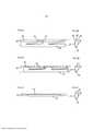
[00026] As figuras 1A-1B mostram painéis dotados de um sistema de travamento mecânico de acordo com uma modalidade da invenção.[00026] Figures 1A-1B show panels provided with a mechanical locking system according to an embodiment of the invention.
[00027] As figuras 2A-2F mostram uma lingueta flexível de acordo com uma modalidade da presente invenção.[00027] Figures 2A-2F show a flexible tongue according to an embodiment of the present invention.
[00028] As figuras 3A-3B mostram uma lingueta flexível de acordo com uma modalidade da presente invenção.[00028] Figures 3A-3B show a flexible tongue according to an embodiment of the present invention.
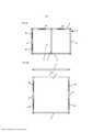
[00029] As figuras 3C-3D mostram um sistema de travamento mecânico para um lado traseiro ou painel de fundo de acordo com uma modalidade da presente invenção.[00029] Figures 3C-3D show a mechanical locking system for a rear side or bottom panel according to an embodiment of the present invention.
[00030] As figuras 4A-4B mostram modalidades de um produto montado.[00030] Figures 4A-4B show modalities of an assembled product.
[00031] A figura 5 mostra painéis dotados de um sistema de travamento mecânico de acordo com uma modalidade da presente invenção.[00031] Figure 5 shows panels provided with a mechanical locking system according to an embodiment of the present invention.
[00032] As figuras 6A-6B mostram painéis dotados de um sistema de travamento mecânico de acordo com uma modalidade da presente invenção.[00032] Figures 6A-6B show panels provided with a mechanical locking system according to an embodiment of the present invention.
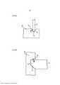
[00033] As figuras 7A-7B mostram painéis e uma ferramenta de desmontagem e ranhura de acordo com uma modalidade da presente invenção.[00033] Figures 7A-7B show panels and a disassembly tool and slot according to an embodiment of the present invention.
[00034] As figuras 1A-B mostram dois painéis 2, 4 que são arranjados perpendiculares um ao outro e travados juntos. Os dois painéis podem ser uma parte de um mobiliário ou um componente de mobiliário tal como uma estante para livros, um guarda louça, um guarda roupa, uma caixa, uma gaveta, ou um componente de mobiliário. Os dois painéis podem ser um primeiro painel 2 que tem um primeiro plano principal e um segundo painel 4 que tem um segundo plano principal. O primeiro painel 2 e o segundo painel 4 são dotados de um dispositivo de travamento mecânico para travar uma primeira borda do primeiro painel 2 a uma segunda borda do segundo painel 4, no qual o primeiro plano principal é essencialmente perpendicular ao segundo plano principal. O primeiro painel 2 compreende um núcleo que compreende fibras arranjadas essencialmente paralelas ao primeiro plano principal, e o segundo painel 4 compreende um núcleo que compreende fibras arranjadas essencialmente paralelas ao segundo plano principal. O dispositivo de travamento mecânico compreende uma ranhura de seção borda 21 na primeira borda, e uma seção borda 22 na segunda borda do segundo painel 4. A seção borda 22 é inserida na ranhura de seção borda 21 para travar o primeiro painel 2 e o segundo painel 4 em uma direção paralela ao primeiro plano principal. O dispositivo de travamento mecânico ainda compreende uma lingueta flexível 30 disposta em uma ranhura de inserção 20, preferivelmente fornecida na ranhura de seção borda 21, como mostrado na figura 1A. A lingueta flexível 30 opera em conjunto com uma ranhura de lingueta 10, preferivelmente fornecida na seção borda 22, como mostrado na figura 1A para travar o primeiro painel 2 e o segundo painel 4 em uma direção paralela ao segundo plano principal. A ranhura de seção borda 21 e a ranhura de lingueta 10 são preferivelmente formadas por corte de maneira mecânica, tal como fresagem do primeiro painel 2 e do segundo painel 4, respectivamente. O primeiro painel compreende uma face interior 60 e uma face exterior 61 que são preferivelmente essencialmente paralelas ao primeiro plano principal. O segundo painel 4 compreende face interior 62 e uma face exterior 63 que são preferivelmente essencialmente paralelas ao segundo plano principal. A face interior 60 do primeiro painel 2 e a face interior 62 do segundo painel são preferivelmente configuradas para facear no sentido de um interior de um produto montado. A seção borda 22 do segundo painel 4 pode ser dotada de uma ranhura de calibração 40, que reduz a espessura da seção borda 22 na face interior 62 e/ou na face exterior 63 do segundo painel 4. A ranhura de calibração 40 é preferivelmente formada por meio de corte de maneira mecânica, tal como fresagem do segundo painel 4.[00034] Figures 1A-B show two
[00035] A figura 1B mostra que a lingueta flexível 30 pode, alternativamente, ser disposta em uma ranhura de inserção 20 na seção borda 22 do segundo painel 4, e a ranhura de lingueta 10 pode ser disposta na ranhura de seção borda 21 da primeira borda do primeiro painel 2. Contudo, um tamanho maior da ranhura de inserção 20 quando comparado com a ranhura de lingueta 10, pode se requerido. Portanto, a modalidade na figura 1A com a ranhura de inserção 20 na ranhura de seção borda 21 pode ser a modalidade preferida.[00035] Figure 1B shows that the
[00036] Uma modalidade da lingueta flexível 30 que é deslocável em uma ranhura de inserção 20 está mostrada nas figuras 2A-2D. As figuras 2A-2B mostram a lingueta flexível 30 em uma posição travada, e as figuras 2C-2D mostram a lingueta flexível 30 durante a montagem do primeiro painel 2 e do segundo painel 4. A figura 2B mostra uma seção transversal da lingueta flexível 30 na figura 2A. A figura 2D mostra uma seção transversal da lingueta flexível 30 na figura 2C. A lingueta flexível 30 compreende partes salientes dobráveis 24. Um espaço 23 é fornecido entre a lingueta flexível 30 e uma parede de fundo da ranhura de inserção 20. A figura 2C mostra que a lingueta flexível 30 é empurrada para o interior da ranhura de inserção 20 no sentido da parede de fundo da ranhura de inserção 20 durante a montagem do primeiro painel 2 com o segundo painel 4. A lingueta flexível 30 salta para trás no sentido de sua posição inicial quando o primeiro painel 2 e o segundo painel 4 alcançaram uma posição travada. Um rebaixo 25 é preferivelmente arranjado em cada peça saliente dobrável.[00036] An embodiment of the
[00037] A lingueta flexível 30 pode ter uma primeira superfície de deslocamento 26 e uma segunda superfície de deslocamento oposta 27, configuradas para serem deslocadas ao longo de uma terceira superfície de deslocamento 28 e uma quarta superfície de deslocamento 29, respectivamente, da ranhura de inserção 20.[00037] The
[00038] Uma modalidade alternativa da lingueta flexível 30 sem as partes dobráveis salientes 24 está mostrada nas figuras 2E-2F. A figura 2F mostra uma seção transversal da lingueta flexível 30 mostrada na figura 2E. A modalidade alternativa é dobrável na direção de seu comprimento para realizar a mesma função que a modalidade mostrada nas figuras 2A-2D.[00038] An alternative embodiment of the
[00039] Outra modalidade da lingueta flexível 30 está mostrada nas figuras 3A-3B. A figura 3A mostra a lingueta flexível 30 antes que o primeiro painel 2 e o segundo painel 4 estejam travados na direção paralela ao segundo plano principal. A lingueta flexível 30 compreende uma parte interior 31 dotada de elementos cunha e parte exterior para o travamento do primeiro painel 2 e do segundo painel 4 na direção paralela ao segundo plano principal. O travamento é obtido aplicando uma força P em uma direção paralela à primeira borda do primeiro painel 2, em uma borda curta da parte exterior. A força P desloca a parte exterior da lingueta flexível 30 na direção paralela à primeira borda do primeiro painel 2 e os elementos cunha forçam a parte exterior da lingueta flexível 30 em uma direção perpendicular, fora da ranhura de inserção 20. O deslocamento resultante, mostrado com a seta 32, da parte exterior da lingueta flexível 30 é, portanto, em uma direção entre a direção paralela à primeira borda do primeiro painel 2 e a direção perpendicular. Cada um dos painéis 2-6 pode incluir uma lingueta flexível 30.[00039] Another embodiment of the
[00040] A figura 4A mostra um produto montado tal como mobiliário, com uma estrutura que compreende um primeiro conjunto do primeiro painel 2 e do segundo painel 4, travado a um segundo conjunto de primeiro painel 6 e segundo painel 5. Uma primeira borda do segundo painel 4, 5 pode ser essencialmente idêntica à segunda borda do segundo painel 4, 5 e uma segunda borda do primeiro painel 2, 6 pode ser essencialmente idêntica à primeira borda do primeiro painel 2, 6 para possibilitar travamento do primeiro conjunto e do segundo conjunto juntos, como mostrado na figura 4A. O primeiro painel 2 do primeiro conjunto é arranjado oposto ao primeiro painel 6 do segundo conjunto. O segundo painel 4 do primeiro conjunto é arranjado oposto ao segundo painel 5 do segundo conjunto. Um terceiro painel 3, configurado essencialmente como o segundo painel e dotado com a lingueta flexível 30 em uma seção borda do terceiro painel, pode ser travado ao primeiro painel 2 do primeiro conjunto e ao primeiro painel 6 do segundo conjunto.[00040] Figure 4A shows an assembled product such as furniture, with a structure comprising a first set of
[00041] A figura 4B mostra uma modalidade alternativa da estrutura com uma configuração alternativa da primeira borda do segundo painel 6 do segundo conjunto e a segunda borda do primeiro painel 2 do primeiro conjunto. A figura 4B mostra que a montagem envolve, usando o primeiro painel 6 do segundo conjunto como um exemplo, simplesmente deslocar o primeiro painel na direção da seta 44, tal que nenhuma etapa ou ferramenta adicional possa ser necessária para travar o primeiro painel 6 do segundo conjunto com outros painéis do produto. Ver também o Pedido de Patente Sueca SE 1351060, que é expressamente incorporado aqui para referência em sua totalidade.[00041] Figure 4B shows an alternative embodiment of the structure with an alternative configuration of the first edge of the
[00042] Todas as bordas de painéis 2-6 do produto montado podem ser travadas juntas com um dispositivo mecânico que compreende a lingueta flexível 30. A montagem pode ser completada sem o uso de ferramentas e/ou agentes de ligação, tal como cola.[00042] All edges of panels 2-6 of the assembled product can be locked together with a mechanical device comprising the
[00043] Um quarto painel 8, tal como um painel traseiro ou um painel de fundo, pode ser disposto em um terceiro plano principal que é essencialmente perpendicular ao primeiro plano principal e ao segundo plano principal. Uma primeira borda e uma segunda borda do quarto painel 8 podem ser travadas por um dispositivo de a uma primeira borda traseira ou de fundo e uma segunda borda traseira ou de fundo, respectivamente, da estrutura. Uma terceira borda e uma quarta borda do quarto painel 8 são preferivelmente inseridas em uma ranhura fornecida em uma terceira borda traseira ou de fundo e uma quarta borda traseira ou de fundo, respectivamente, da estrutura. A estrutura pode ser submetida assim a uma força F durante transporte, produção ou montagem do produto montado. Travamento do quarto painel 8 à estrutura pelo dispositivo de travamento mecânico, melhora a resistência e estabilidade do produto montado. O quarto painel pode compreender dois ou mais elementos 8a, 8b, que são preferivelmente travados juntos por um sistema de travamento mecânico. Uma modalidade do sistema de travamento mecânico está mostrada na figura 3C discutida abaixo.[00043] A
[00044] O primeiro painel 6 do segundo conjunto pode ser travado aos outros painéis da estrutura em uma ocasião posterior e/ou em outra localização. O primeiro painel 6 do segundo conjunto pode ser travado aos outros painéis da estrutura e ao painel de fundo ou traseiro, por simples deslocamento 44 como discutido acima, e nenhuma outra etapa ou ferramenta pode ser necessária.[00044] The
[00045] A figura 3C mostra uma modalidade de um painel de mobiliário 8, tal como um painel traseiro ou de fundo que compreende um primeiro elemento 8a e um segundo elemento 8b dotado de um sistema de travamento mecânico configurado para travar juntos o primeiro elemento 8a e o segundo elemento 8b.[00045] Figure 3C shows an embodiment of a
[00046] O primeiro plano principal do primeiro elemento 8a é essencialmente paralelo a u segundo plano principal do segundo elemento 8b, no qual o painel de mobiliário compreende uma primeira face 85 e uma segunda face oposta 86 que são paralelas ao plano principal do painel de mobiliário 8. O sistema de travamento mecânico pode incluir: uma primeira lingueta 64 fornecida em uma primeira borda do primeiro elemento 8a na qual a primeira lingueta 84 é configurada para operar em conjunto com uma primeira ranhura de lingueta 50 fornecida em uma segunda borda do segundo elemento 8b para travar juntos o primeiro elemento 8a e o segundo elemento 8b em uma primeira direção vertical V1; uma segunda lingueta 72 na segunda borda do segundo elemento 8b na qual a segunda lingueta 72 é configurada para operar em conjunto com uma segunda ranhura de lingueta 73 na primeira borda do primeiro elemento 8a para travar juntos o primeiro elemento 8a e o segundo elemento 8b em uma segunda direção vertical V2; um primeiro par de superfícies de travamento 83 fornecido acima da segunda lingueta 72 e da segunda ranhura de lingueta 73 para travar juntos o primeiro elemento 8a e o segundo elemento 8b em uma primeira direção horizontal H1; e segundo par de superfícies de travamento 84 fornecido abaixo da primeira lingueta 64 e a primeira ranhura de lingueta 50 para travar juntos o primeiro elemento 8a e o segundo elemento 8b em uma segunda direção horizontal h2.[00046] The first main plane of the
[00047] O primeiro par de superfícies de travamento 83 é preferivelmente essencialmente vertical. O segundo par de superfícies de travamento 84 é também preferivelmente essencialmente vertical.[00047] The first pair of locking surfaces 83 is preferably essentially vertical. The second pair of interlocking
[00048] A primeira lingueta 64 e a primeira ranhura de lingueta 50 operam em conjunto em um terceiro par de superfícies de travamento 87 que é preferivelmente arranjado essencialmente de maneira horizontal.[00048] The
[00049] A segunda lingueta 72 e a segunda ranhura de lingueta 73 operam em conjunto em um quarto par de superfícies de travamento 74 que é preferivelmente disposto em um ângulo 88 com o plano principal do painel de mobiliário 8 que é maior do que zero. O ângulo 88 tem uma faixa que permite ao primeiro elemento 8a ser travado ao segundo elemento 8b por um movimento de angulação do primeiro elemento 8a em relação ao segundo elemento 8b, ou do segundo elemento 8b em relação ao primeiro elemento 8a no qual a primeira lingueta 64 é inserida na primeira ranhura de lingueta 50.[00049] The
[00050] A primeira face 85 do primeiro elemento 8a e o segundo elemento 8b são dispostos para cima na direção vertical, por exemplo, na direção onde a carga máxima F1 tem probabilidade de ser exercida sobre o painel de mobiliário 8 para impedir que o primeiro elemento 8a e o segundo elemento 8b sejam destravados por um movimento de angulação invertido. Uma segunda face 86 é arranjada para baixo na direção vertical, por exemplo, na direção onde a carga mínima F2 é provável de ser aplicada sobre o painel de mobiliário 8.[00050] The
[00051] O segundo elemento 8b pode incluir uma tira 70 que se estende desde a primeira ranhura de lingueta 50 e que inclui um elemento saliente 71 e a tira 70 pode incluir um rebaixo adjacente ao elemento saliente 71. O elemento saliente 71 essencialmente corresponde com uma terceira ranhura 80 fornecida na primeira borda do primeiro elemento 8a. O elemento saliente 71 pode se salientar para cima na direção vertical V e a ranhura 80 pode ser aberta para baixo na direção vertical V e a ranhura 80 pode ser aberta para baixo na direção vertical V. Um terceiro espaço 75 que se estende na direção horizontal H pode ser fornecido entre o elemento saliente 73 e a terceira ranhura 80. O terceiro espaço 75 pode facilitar o travamento por um movimento de angulação. A figura 5 mostra uma modalidade que compreendeu uma primeira espessura 55 de um material núcleo do primeiro painel 2 entre a ranhura de seção borda 21 e a superfície a mais exterior da primeira borda em uma direção paralela ao primeiro plano principal. A primeira espessura 55 é maior do que uma segunda espessura mínima 54 de um material núcleo da seção borda 22 do segundo painel 4. A primeira espessura 55 se situa desde entre 1,1 e 3,0 vezes maior do que a segunda espessura mínima 54 e pode ser no mínimo aproximadamente 1,25 vezes maior, preferivelmente aproximadamente 1,5 vezes maior e, mais preferivelmente, aproximadamente 2,0 vezes maior do que a segunda espessura mínima. Em uma modalidade a ranhura de seção borda 21 compreende uma primeira parede 56 e uma segunda parede oposta 57, onde a primeira parede 56 está mais perto da superfície a mais exterior 53 da primeira borda do que a segunda parede 57. A primeira espessura 55 é preferivelmente medida entre a primeira parede 56 e a superfície a mais exterior 53 da primeira borda. A primeira parede 56 e a segunda parede 57 são preferivelmente conectadas por uma parede de fundo 58.[00051] The
[00052] A seção borda 22 do segundo painel 4 pode compreender uma primeira parede 96 e uma segunda parede oposta 98, na qual a ranhura 10 é fornecida na primeira parede 96. A segunda espessura mínima 54 pode ser medida entre um fundo da ranhura de lingueta 10 e a segunda parede 98.[00052] The
[00053] Na modalidade, ter a ranhura de inserção 20 estendida ao longo de essencialmente todo o comprimento da ranhura de seção borda 21 da primeira borda do primeiro painel, pode conduzir a uma produção mais fácil do primeiro painel 2. Ter a ranhura de lingueta 10 se estendendo ao longo de essencialmente todo o comprimento da seção borda 22 do segundo painel 4 pode também conduzir a uma produção mais fácil do segundo painel 4.[00053] In the embodiment, having the
[00054] A superfície a mais exterior 53 do primeiro painel 2 está, em uma modalidade preferida, essencialmente no mesmo plano, por exemplo, em nível com a face exterior 63 do segundo painel 4.[00054] The
[00055] Uma borda da abertura de ranhura de seção borda 21 pode ser dotada de um chanfro 59 ou arredondamento para facilitar a inserção da lingueta flexível 30 para o interior da ranhura de inserção 20.[00055] An edge of the edge
[00056] A figura 6A mostra uma modalidade de um dispositivo de travamento mecânico para travar o quarto painel 8 a qualquer primeira ou segunda borda traseira ou de fundo 81 de uma estrutura. Uma modalidade da estrutura está mostrada nas figuras 4A-4B. O dispositivo de travamento mecânico pode ser essencialmente idêntico ao dispositivo de travamento mecânico descrito acima.[00056] Figure 6A shows an embodiment of a mechanical locking device for locking the
[00057] A figura 6B mostra uma modalidade de um dispositivo de travamento mecânico para travar o terceiro painel a qualquer primeiro ou segundo painel 82 de uma estrutura. Uma modalidade da estrutura está mostrada nas figuras 4A-4B. O dispositivo de travamento mecânico pode ser essencialmente idêntico ao dispositivo de travamento descrito acima.[00057] Figure 6B shows an embodiment of a mechanical locking device for locking the third panel to any first or
[00058] As figuras 7A-7B mostram uma modalidade de uma ranhura ou rebaixo de desmontagem 34 que é fornecida na face interior 62 do segundo painel 4. Dita ranhura ou rebaixo de desmontagem 34 é preferivelmente adaptada para inserção de uma ferramenta de desmontagem 90. O sistema de travamento mecânico pode ser destravado por meio de inserção da ferramenta de desmontagem 90 na ranhura de desmontagem. A ferramenta de inserção 90 é preferivelmente configurada para empurrar a lingueta flexível 30 ainda mais para o interior da ranhura de inserção 20 para destravar o sistema de travamento mecânico.[00058] Figures 7A-7B show an embodiment of a disassembly groove or
[00059] A figura 7b mostra que uma ferramenta de desmontagem 90 pode ser inserida na ranhura de lingueta 10 desde que a ranhura de seção borda 21 e a ranhura de lingueta 10 sejam abertas na traseira e/ou frente do primeiro painel 2 e do segundo painel 4.[00059] Figure 7b shows that a
[00060] A inserção da lingueta flexível 30 para o interior da ranhura de inserção 20 pode ser facilitada se uma superfície de topo 92 da primeira seção borda do primeiro painel 2 na primeira parede 56 da ranhura de seção borda 21 for abaixada. Uma superfície de topo abaixada 92 aumenta a distância entre um plano 91 que se estende em uma direção de uma superfície inferior da ranhura de inserção 20 e a superfície de topo 92. Esta distância aumentada pode fornecer mais espaço para uma máquina de inserção de lingueta.[00060] The insertion of the
[00061] O material núcleo dos painéis e elementos nas modalidades acima preferivelmente compreende uma placa com base em fibra de madeira tal como HDF, MDF, compensado de madeira, madeira sólida ou placa de partículas, uma placa reforçada por plástico, ou uma placa de compósito de fibra de madeira.[00061] The core material of the panels and elements in the above embodiments preferably comprises a wood fiber-based board such as HDF, MDF, plywood, solid wood or particle board, a plastic reinforced board, or a board. wood fiber composite.
[00062] Quando a palavra "aproximadamente" é usada nesta especificação em conexão com um valor, é projetado que o valor associado inclua uma tolerância de ±10% ao redor do valor descrito.[00062] When the word "approximately" is used in this specification in connection with a value, the associated value is designed to include a tolerance of ±10% around the described value.
Claims (12)
Translated fromPortugueseApplications Claiming Priority (3)
| Application Number | Priority Date | Filing Date | Title |
|---|---|---|---|
| SE1450022-7 | 2014-01-10 | ||
| SE1450022 | 2014-01-10 | ||
| PCT/SE2014/051521WO2015105449A1 (en) | 2014-01-10 | 2014-12-17 | Panels comprising a mechanical locking device and an assembled product comprising the panels |
Publications (2)
| Publication Number | Publication Date |
|---|---|
| BR112016015502A2 BR112016015502A2 (en) | 2017-08-08 |
| BR112016015502B1true BR112016015502B1 (en) | 2021-10-26 |
Family
ID=53524182
Family Applications (1)
| Application Number | Title | Priority Date | Filing Date |
|---|---|---|---|
| BR112016015502-5ABR112016015502B1 (en) | 2014-01-10 | 2014-12-17 | PANELS COMPRISING A MECHANICAL LOCKING DEVICE AND ASSEMBLY PRODUCT COMPRISING THE PANELS |
Country Status (21)
| Country | Link |
|---|---|
| EP (2) | EP3092415B1 (en) |
| JP (1) | JP6505719B2 (en) |
| KR (1) | KR102250749B1 (en) |
| CN (1) | CN105874222B (en) |
| AU (1) | AU2014376415B2 (en) |
| BR (1) | BR112016015502B1 (en) |
| CA (1) | CA2933049C (en) |
| CL (1) | CL2016001500A1 (en) |
| CR (1) | CR20160302A (en) |
| DK (1) | DK3092415T3 (en) |
| EA (1) | EA031386B1 (en) |
| ES (1) | ES2751499T3 (en) |
| HR (1) | HRP20191861T1 (en) |
| LT (1) | LT3092415T (en) |
| MX (1) | MX373684B (en) |
| MY (1) | MY175150A (en) |
| PL (1) | PL3092415T3 (en) |
| PT (1) | PT3092415T (en) |
| UA (1) | UA120919C2 (en) |
| WO (1) | WO2015105449A1 (en) |
| ZA (1) | ZA201604174B (en) |
Families Citing this family (42)
| Publication number | Priority date | Publication date | Assignee | Title |
|---|---|---|---|---|
| PT3014034T (en) | 2013-06-27 | 2019-11-29 | Vaelinge Innovation Ab | Building panel with a mechanical locking system |
| US9726210B2 (en) | 2013-09-16 | 2017-08-08 | Valinge Innovation Ab | Assembled product and a method of assembling the product |
| CN109854597B (en) | 2013-09-16 | 2021-03-19 | 瓦林格创新股份有限公司 | Combination product and method for assembling the same |
| MX376334B (en) | 2014-01-10 | 2025-03-07 | Vaelinge Innovation Ab | FURNITURE BOARD. |
| US9714672B2 (en) | 2014-01-10 | 2017-07-25 | Valinge Innovation Ab | Panels comprising a mechanical locking device and an assembled product comprising the panels |
| MY175150A (en)* | 2014-01-10 | 2020-06-11 | Valinge Innovation Ab | Panels comprising a mechanical locking device and an assembled product comprising the panels |
| EP3851684A1 (en) | 2014-05-09 | 2021-07-21 | Välinge Innovation AB | Mechanical locking system for building panels |
| BR112016029151A2 (en) | 2014-07-11 | 2017-08-22 | Vaelinge Innovation Ab | panel with a slider |
| JP6900313B2 (en) | 2014-11-27 | 2021-07-07 | ベーリンゲ、イノベイション、アクチボラグVaelinge Innovation Ab | Mechanical locking system for floor panels |
| ES2758673T3 (en) | 2014-12-19 | 2020-05-06 | Vaelinge Innovation Ab | Panels comprising a mechanical locking device |
| EP3285620A4 (en) | 2015-04-21 | 2018-11-14 | Välinge Innovation AB | Panel with a slider |
| KR20170141223A (en) | 2015-04-30 | 2017-12-22 | 뵈린게 이노베이션 에이비이 | A panel having a fastening device |
| UA125554C2 (en) | 2015-09-22 | 2022-04-20 | Велінге Інновейшн Аб | Panels comprising a mechanical locking device and an assembled product comprising the panels |
| MX2018006522A (en)* | 2015-12-03 | 2018-11-29 | Vaelinge Innovation Ab | Panels comprising a mechanical locking device and an assembled product comprising the panels. |
| EP3407765B1 (en)* | 2016-01-26 | 2021-03-03 | Välinge Innovation AB | Panels comprising a mechanical locking device to obtain a furniture product |
| KR20180109957A (en) | 2016-02-04 | 2018-10-08 | 뵈린게 이노베이션 에이비이 | Set of panels for assembled products |
| CA3011703A1 (en)* | 2016-02-09 | 2017-08-17 | Valinge Innovation Ab | Element and method for providing dismantling groove |
| US10415613B2 (en) | 2016-02-09 | 2019-09-17 | Valinge Innovation Ab | Set of panel-shaped elements for a composed element |
| JP6921834B2 (en) | 2016-02-15 | 2021-08-18 | ベーリンゲ、イノベイション、アクチボラグVaelinge Innovation Ab | How to form panels for furniture products |
| FR3054419B1 (en) | 2016-07-26 | 2018-12-07 | Inovame | FURNITURE BOX |
| CN117703894A (en) | 2016-10-27 | 2024-03-15 | 瓦林格创新股份有限公司 | Panel assembly with mechanical locking means |
| ES2685267B1 (en)* | 2017-03-31 | 2019-07-17 | Iriarte Christian Gonzalez | Joint retention system |
| EP3612739A4 (en)* | 2017-04-20 | 2020-12-23 | Välinge Innovation AB | PLATES FOR AN ASSEMBLED PRODUCT |
| HRP20230089T1 (en) | 2017-05-15 | 2023-03-17 | Välinge Innovation AB | Elements and a locking device for an assembled product |
| CN111465773B (en) | 2017-12-22 | 2021-11-02 | 瓦林格创新股份有限公司 | Panel set, method for assembling the panel set and locking device for furniture products |
| RU2740868C1 (en) | 2017-12-22 | 2021-01-21 | Велинге Инновейшн Аб | Set of panels, method of their assembling and locking device for furniture product |
| MY204146A (en) | 2018-03-23 | 2024-08-09 | Vlinge Innovation Ab | Panels comprising a mechanical locking device and an assembled product comprising the panels |
| PL3781822T3 (en) | 2018-04-18 | 2024-11-18 | Välinge Innovation AB | Set of panels with a mechanical locking device |
| US11448252B2 (en) | 2018-04-18 | 2022-09-20 | Valinge Innovation Ab | Set of panels with a mechanical locking device |
| PL3781824T3 (en) | 2018-04-18 | 2024-06-24 | Välinge Innovation AB | Set of panels with a mechanical locking device |
| EA202092409A1 (en) | 2018-04-18 | 2021-02-26 | Велинге Инновейшн Аб | SYMMETRIC TONGUE AND T-SHAPED KNOT |
| US11614114B2 (en) | 2018-04-19 | 2023-03-28 | Valinge Innovation Ab | Panels for an assembled product |
| PT3844407T (en) | 2018-08-30 | 2024-06-18 | Vaelinge Innovation Ab | Set of panels with a mechanical locking device |
| US11060302B2 (en)* | 2019-01-10 | 2021-07-13 | Valinge Innovation Ab | Unlocking system for panels |
| EP3918213A1 (en) | 2019-01-29 | 2021-12-08 | Vilox AB | Joining system for furniture parts |
| EP4090198B1 (en)* | 2020-01-13 | 2025-08-20 | Välinge Innovation AB | A set comprising a panel and a pull grip arranged with a mechanical locking mechanism |
| US11702844B2 (en) | 2020-06-05 | 2023-07-18 | Valinge Innovation Ab | Building panels comprising a locking device |
| CN115867171A (en) | 2020-07-17 | 2023-03-28 | 瓦林格创新股份有限公司 | Mechanical locking system for panels |
| MX2023007995A (en)* | 2021-01-07 | 2023-09-18 | Vaelinge Innovation Ab | Wedge-shaped tongue insertion groove. |
| JP2022158867A (en)* | 2021-03-31 | 2022-10-17 | オールセーフ株式会社 | Panel assembly and panel connection structure |
| CN117545928A (en) | 2021-06-29 | 2024-02-09 | 瓦林格创新股份有限公司 | Panels and related assembled products containing mechanical locking devices |
| EP4413272A4 (en) | 2021-10-04 | 2025-05-14 | Välinge Innovation AB | MECHANICAL CONNECTION ARRANGEMENT FOR PANELS |
Family Cites Families (12)
| Publication number | Priority date | Publication date | Assignee | Title |
|---|---|---|---|---|
| US5658086A (en)* | 1995-11-24 | 1997-08-19 | Brokaw; Paul E. | Furniture connector |
| JP3743546B2 (en)* | 1998-06-22 | 2006-02-08 | 富士写真フイルム株式会社 | Magnetic tape cartridge |
| JP4649120B2 (en)* | 2004-04-30 | 2011-03-09 | 株式会社パイオラックス | clip |
| ES2378330T3 (en)* | 2004-10-22 | 2012-04-11 | Välinge Innovation AB | A method of providing floor panels with a mechanical locking system |
| US20080052878A1 (en)* | 2006-08-31 | 2008-03-06 | Lewis Jeffrey C | Fastener Clip with Seal |
| BE1018389A3 (en)* | 2008-12-17 | 2010-10-05 | Unilin Bvba | COMPOSITE ELEMENT, MULTI-LAYER PLATE AND PANEL-SHAPED ELEMENT FOR FORMING SUCH COMPOSITE ELEMENT. |
| US8671528B2 (en)* | 2009-06-12 | 2014-03-18 | Piolax, Inc. | Assembling construction of clip to mountable member |
| GB201002535D0 (en)* | 2010-02-15 | 2010-03-31 | Fgb Ltd | Improvements relating to cabinets |
| BE1019361A5 (en)* | 2010-06-03 | 2012-06-05 | Unilin Bvba | COMPOSED ELEMENT. |
| UA109938C2 (en)* | 2011-05-06 | 2015-10-26 | MECHANICAL LOCKING SYSTEM FOR CONSTRUCTION PANELS | |
| CN202531575U (en)* | 2011-08-02 | 2012-11-14 | 夏福明 | Locking device used for furniture |
| MY175150A (en)* | 2014-01-10 | 2020-06-11 | Valinge Innovation Ab | Panels comprising a mechanical locking device and an assembled product comprising the panels |
- 2014
- 2014-12-17MYMYPI2016702073Apatent/MY175150A/enunknown
- 2014-12-17EPEP14877862.4Apatent/EP3092415B1/enactiveActive
- 2014-12-17CACA2933049Apatent/CA2933049C/enactiveActive
- 2014-12-17ESES14877862Tpatent/ES2751499T3/enactiveActive
- 2014-12-17WOPCT/SE2014/051521patent/WO2015105449A1/enactiveApplication Filing
- 2014-12-17BRBR112016015502-5Apatent/BR112016015502B1/enactiveIP Right Grant
- 2014-12-17PLPL14877862Tpatent/PL3092415T3/enunknown
- 2014-12-17UAUAA201607961Apatent/UA120919C2/enunknown
- 2014-12-17EAEA201691255Apatent/EA031386B1/ennot_activeIP Right Cessation
- 2014-12-17JPJP2016544151Apatent/JP6505719B2/enactiveActive
- 2014-12-17CNCN201480072113.0Apatent/CN105874222B/enactiveActive
- 2014-12-17HRHRP20191861TTpatent/HRP20191861T1/enunknown
- 2014-12-17KRKR1020167019579Apatent/KR102250749B1/enactiveActive
- 2014-12-17EPEP19183663.4Apatent/EP3594513A1/ennot_activeWithdrawn
- 2014-12-17DKDK14877862.4Tpatent/DK3092415T3/enactive
- 2014-12-17LTLT14877862Tpatent/LT3092415T/enunknown
- 2014-12-17AUAU2014376415Apatent/AU2014376415B2/enactiveActive
- 2014-12-17PTPT148778624Tpatent/PT3092415T/enunknown
- 2014-12-17MXMX2016008746Apatent/MX373684B/enactiveIP Right Grant
- 2016
- 2016-06-15CLCL2016001500Apatent/CL2016001500A1/enunknown
- 2016-06-21ZAZA2016/04174Apatent/ZA201604174B/enunknown
- 2016-06-30CRCR20160302Apatent/CR20160302A/enunknown
Also Published As
| Publication number | Publication date |
|---|---|
| LT3092415T (en) | 2019-11-11 |
| MX373684B (en) | 2020-04-02 |
| WO2015105449A1 (en) | 2015-07-16 |
| CA2933049C (en) | 2021-12-28 |
| KR20160107197A (en) | 2016-09-13 |
| CL2016001500A1 (en) | 2016-11-25 |
| KR102250749B1 (en) | 2021-05-10 |
| JP6505719B2 (en) | 2019-04-24 |
| AU2014376415B2 (en) | 2018-01-18 |
| MY175150A (en) | 2020-06-11 |
| ZA201604174B (en) | 2017-10-25 |
| UA120919C2 (en) | 2020-03-10 |
| PL3092415T3 (en) | 2020-03-31 |
| CA2933049A1 (en) | 2015-07-16 |
| JP2017510757A (en) | 2017-04-13 |
| EP3092415B1 (en) | 2019-08-07 |
| CN105874222B (en) | 2019-04-12 |
| EP3092415A1 (en) | 2016-11-16 |
| BR112016015502A2 (en) | 2017-08-08 |
| CN105874222A (en) | 2016-08-17 |
| EA031386B1 (en) | 2018-12-28 |
| PT3092415T (en) | 2019-11-04 |
| EP3594513A1 (en) | 2020-01-15 |
| MX2016008746A (en) | 2016-09-08 |
| DK3092415T3 (en) | 2019-10-21 |
| HRP20191861T1 (en) | 2019-12-27 |
| EP3092415A4 (en) | 2017-06-21 |
| ES2751499T3 (en) | 2020-03-31 |
| CR20160302A (en) | 2016-07-29 |
| EA201691255A1 (en) | 2016-11-30 |
| AU2014376415A1 (en) | 2016-06-30 |
Similar Documents
| Publication | Publication Date | Title |
|---|---|---|
| BR112016015502B1 (en) | PANELS COMPRISING A MECHANICAL LOCKING DEVICE AND ASSEMBLY PRODUCT COMPRISING THE PANELS | |
| US11448249B2 (en) | Panels comprising a mechanical locking device and an assembled product comprising the panels | |
| US11445820B2 (en) | Panels comprising a mechanical locking device and an assembled product comprising the panels | |
| US11204051B2 (en) | Assembled product and a method of assembling the assembled product | |
| US10830268B2 (en) | Furniture panel | |
| BR112018010856B1 (en) | SET OF PANELS COMPRISING A MECHANICAL LOCKING DEVICE | |
| EP3594514B1 (en) | Panels comprising a mechanical locking device | |
| BR112019007619B1 (en) | ASSEMBLY OF PANELS WITH A MECHANICAL LOCKING DEVICE |
Legal Events
| Date | Code | Title | Description |
|---|---|---|---|
| B06U | Preliminary requirement: requests with searches performed by other patent offices: procedure suspended [chapter 6.21 patent gazette] | ||
| B09A | Decision: intention to grant [chapter 9.1 patent gazette] | ||
| B16A | Patent or certificate of addition of invention granted [chapter 16.1 patent gazette] | Free format text:PRAZO DE VALIDADE: 20 (VINTE) ANOS CONTADOS A PARTIR DE 17/12/2014, OBSERVADAS AS CONDICOES LEGAIS. |