BR112016014836B1 - SURGICAL INSTRUMENT WITH ARTICULATE ARRANGEMENT - Google Patents
SURGICAL INSTRUMENT WITH ARTICULATE ARRANGEMENTDownload PDFInfo
- Publication number
- BR112016014836B1 BR112016014836B1BR112016014836-3ABR112016014836ABR112016014836B1BR 112016014836 B1BR112016014836 B1BR 112016014836B1BR 112016014836 ABR112016014836 ABR 112016014836ABR 112016014836 B1BR112016014836 B1BR 112016014836B1
- Authority
- BR
- Brazil
- Prior art keywords
- surgical
- pivot
- ribs
- twist
- distal
- Prior art date
Links
- 230000033001locomotionEffects0.000claimsabstractdescription39
- 238000010304firingMethods0.000claimsdescription31
- 238000005520cutting processMethods0.000claimsdescription10
- 239000004744fabricSubstances0.000claimsdescription4
- 230000007423decreaseEffects0.000claimsdescription3
- 238000001356surgical procedureMethods0.000abstractdescription6
- 239000000463materialSubstances0.000description10
- 238000000034methodMethods0.000description10
- 230000004913activationEffects0.000description8
- 230000004048modificationEffects0.000description8
- 238000012986modificationMethods0.000description8
- 238000006073displacement reactionMethods0.000description4
- 230000004044responseEffects0.000description4
- 239000000853adhesiveSubstances0.000description3
- 230000001070adhesive effectEffects0.000description3
- 230000000712assemblyEffects0.000description3
- 238000000429assemblyMethods0.000description3
- 230000008901benefitEffects0.000description3
- 230000005855radiationEffects0.000description3
- 238000004140cleaningMethods0.000description2
- 239000012636effectorSubstances0.000description2
- 230000006870functionEffects0.000description2
- 238000009434installationMethods0.000description2
- 239000002184metalSubstances0.000description2
- 239000004033plasticSubstances0.000description2
- 229920003023plasticPolymers0.000description2
- 230000009467reductionEffects0.000description2
- 230000001960triggered effectEffects0.000description2
- 241000894006BacteriaSpecies0.000description1
- 229920006060Grivory®Polymers0.000description1
- 239000004433Thermoplastic polyurethaneSubstances0.000description1
- 229920000690TyvekPolymers0.000description1
- 239000004775TyvekSubstances0.000description1
- 230000003213activating effectEffects0.000description1
- 230000004075alterationEffects0.000description1
- 229920006020amorphous polyamidePolymers0.000description1
- 230000015572biosynthetic processEffects0.000description1
- 230000000903blocking effectEffects0.000description1
- 210000001124body fluidAnatomy0.000description1
- 239000010839body fluidSubstances0.000description1
- 230000008859changeEffects0.000description1
- 239000003638chemical reducing agentSubstances0.000description1
- 230000000295complement effectEffects0.000description1
- 238000010276constructionMethods0.000description1
- 230000000994depressogenic effectEffects0.000description1
- 230000000694effectsEffects0.000description1
- 239000012530fluidSubstances0.000description1
- 238000005755formation reactionMethods0.000description1
- 230000014509gene expressionEffects0.000description1
- 239000003365glass fiberSubstances0.000description1
- 238000001764infiltrationMethods0.000description1
- 230000008595infiltrationEffects0.000description1
- 230000003993interactionEffects0.000description1
- 238000012830laparoscopic surgical procedureMethods0.000description1
- 229910001416lithium ionInorganic materials0.000description1
- 238000004519manufacturing processMethods0.000description1
- 230000007246mechanismEffects0.000description1
- 238000012978minimally invasive surgical procedureMethods0.000description1
- 238000002355open surgical procedureMethods0.000description1
- 238000009419refurbishmentMethods0.000description1
- 230000000717retained effectEffects0.000description1
- 238000005476solderingMethods0.000description1
- 229910001220stainless steelInorganic materials0.000description1
- 239000010935stainless steelSubstances0.000description1
- 230000001954sterilising effectEffects0.000description1
- 238000004659sterilization and disinfectionMethods0.000description1
- 239000000126substanceSubstances0.000description1
- 238000006467substitution reactionMethods0.000description1
- 230000001360synchronised effectEffects0.000description1
- 229920002803thermoplastic polyurethanePolymers0.000description1
Images


Classifications
- A—HUMAN NECESSITIES
- A61—MEDICAL OR VETERINARY SCIENCE; HYGIENE
- A61B—DIAGNOSIS; SURGERY; IDENTIFICATION
- A61B17/00—Surgical instruments, devices or methods
- A61B17/32—Surgical cutting instruments
- A61B17/320016—Endoscopic cutting instruments, e.g. arthroscopes, resectoscopes
- A—HUMAN NECESSITIES
- A61—MEDICAL OR VETERINARY SCIENCE; HYGIENE
- A61B—DIAGNOSIS; SURGERY; IDENTIFICATION
- A61B17/00—Surgical instruments, devices or methods
- A61B17/068—Surgical staplers, e.g. containing multiple staples or clamps
- A61B17/072—Surgical staplers, e.g. containing multiple staples or clamps for applying a row of staples in a single action, e.g. the staples being applied simultaneously
- A61B17/07207—Surgical staplers, e.g. containing multiple staples or clamps for applying a row of staples in a single action, e.g. the staples being applied simultaneously the staples being applied sequentially
- A—HUMAN NECESSITIES
- A61—MEDICAL OR VETERINARY SCIENCE; HYGIENE
- A61B—DIAGNOSIS; SURGERY; IDENTIFICATION
- A61B17/00—Surgical instruments, devices or methods
- A61B17/068—Surgical staplers, e.g. containing multiple staples or clamps
- A61B17/072—Surgical staplers, e.g. containing multiple staples or clamps for applying a row of staples in a single action, e.g. the staples being applied simultaneously
- A—HUMAN NECESSITIES
- A61—MEDICAL OR VETERINARY SCIENCE; HYGIENE
- A61B—DIAGNOSIS; SURGERY; IDENTIFICATION
- A61B17/00—Surgical instruments, devices or methods
- A61B17/064—Surgical staples, i.e. penetrating the tissue
- A—HUMAN NECESSITIES
- A61—MEDICAL OR VETERINARY SCIENCE; HYGIENE
- A61B—DIAGNOSIS; SURGERY; IDENTIFICATION
- A61B17/00—Surgical instruments, devices or methods
- A61B17/068—Surgical staplers, e.g. containing multiple staples or clamps
- A61B17/0682—Surgical staplers, e.g. containing multiple staples or clamps for applying U-shaped staples or clamps, e.g. without a forming anvil
- A61B17/0684—Surgical staplers, e.g. containing multiple staples or clamps for applying U-shaped staples or clamps, e.g. without a forming anvil having a forming anvil staying above the tissue during stapling
- A—HUMAN NECESSITIES
- A61—MEDICAL OR VETERINARY SCIENCE; HYGIENE
- A61B—DIAGNOSIS; SURGERY; IDENTIFICATION
- A61B17/00—Surgical instruments, devices or methods
- A61B17/00234—Surgical instruments, devices or methods for minimally invasive surgery
- A61B2017/00292—Surgical instruments, devices or methods for minimally invasive surgery mounted on or guided by flexible, e.g. catheter-like, means
- A61B2017/003—Steerable
- A61B2017/00305—Constructional details of the flexible means
- A61B2017/00309—Cut-outs or slits
- A—HUMAN NECESSITIES
- A61—MEDICAL OR VETERINARY SCIENCE; HYGIENE
- A61B—DIAGNOSIS; SURGERY; IDENTIFICATION
- A61B17/00—Surgical instruments, devices or methods
- A61B17/00234—Surgical instruments, devices or methods for minimally invasive surgery
- A61B2017/00292—Surgical instruments, devices or methods for minimally invasive surgery mounted on or guided by flexible, e.g. catheter-like, means
- A61B2017/003—Steerable
- A61B2017/00305—Constructional details of the flexible means
- A61B2017/00314—Separate linked members
- A—HUMAN NECESSITIES
- A61—MEDICAL OR VETERINARY SCIENCE; HYGIENE
- A61B—DIAGNOSIS; SURGERY; IDENTIFICATION
- A61B17/00—Surgical instruments, devices or methods
- A61B17/00234—Surgical instruments, devices or methods for minimally invasive surgery
- A61B2017/00353—Surgical instruments, devices or methods for minimally invasive surgery one mechanical instrument performing multiple functions, e.g. cutting and grasping
- A—HUMAN NECESSITIES
- A61—MEDICAL OR VETERINARY SCIENCE; HYGIENE
- A61B—DIAGNOSIS; SURGERY; IDENTIFICATION
- A61B17/00—Surgical instruments, devices or methods
- A61B2017/00367—Details of actuation of instruments, e.g. relations between pushing buttons, or the like, and activation of the tool, working tip, or the like
- A61B2017/00398—Details of actuation of instruments, e.g. relations between pushing buttons, or the like, and activation of the tool, working tip, or the like using powered actuators, e.g. stepper motors, solenoids
- A—HUMAN NECESSITIES
- A61—MEDICAL OR VETERINARY SCIENCE; HYGIENE
- A61B—DIAGNOSIS; SURGERY; IDENTIFICATION
- A61B17/00—Surgical instruments, devices or methods
- A61B2017/00681—Aspects not otherwise provided for
- A61B2017/00734—Aspects not otherwise provided for battery operated
- A—HUMAN NECESSITIES
- A61—MEDICAL OR VETERINARY SCIENCE; HYGIENE
- A61B—DIAGNOSIS; SURGERY; IDENTIFICATION
- A61B17/00—Surgical instruments, devices or methods
- A61B17/064—Surgical staples, i.e. penetrating the tissue
- A61B2017/0645—Surgical staples, i.e. penetrating the tissue being elastically deformed for insertion
- A—HUMAN NECESSITIES
- A61—MEDICAL OR VETERINARY SCIENCE; HYGIENE
- A61B—DIAGNOSIS; SURGERY; IDENTIFICATION
- A61B17/00—Surgical instruments, devices or methods
- A61B17/068—Surgical staplers, e.g. containing multiple staples or clamps
- A61B17/072—Surgical staplers, e.g. containing multiple staples or clamps for applying a row of staples in a single action, e.g. the staples being applied simultaneously
- A61B2017/07214—Stapler heads
- A61B2017/07257—Stapler heads characterised by its anvil
- A—HUMAN NECESSITIES
- A61—MEDICAL OR VETERINARY SCIENCE; HYGIENE
- A61B—DIAGNOSIS; SURGERY; IDENTIFICATION
- A61B17/00—Surgical instruments, devices or methods
- A61B17/068—Surgical staplers, e.g. containing multiple staples or clamps
- A61B17/072—Surgical staplers, e.g. containing multiple staples or clamps for applying a row of staples in a single action, e.g. the staples being applied simultaneously
- A61B2017/07214—Stapler heads
- A61B2017/07271—Stapler heads characterised by its cartridge
- A—HUMAN NECESSITIES
- A61—MEDICAL OR VETERINARY SCIENCE; HYGIENE
- A61B—DIAGNOSIS; SURGERY; IDENTIFICATION
- A61B17/00—Surgical instruments, devices or methods
- A61B17/068—Surgical staplers, e.g. containing multiple staples or clamps
- A61B17/072—Surgical staplers, e.g. containing multiple staples or clamps for applying a row of staples in a single action, e.g. the staples being applied simultaneously
- A61B2017/07214—Stapler heads
- A61B2017/07278—Stapler heads characterised by its sled or its staple holder
- A—HUMAN NECESSITIES
- A61—MEDICAL OR VETERINARY SCIENCE; HYGIENE
- A61B—DIAGNOSIS; SURGERY; IDENTIFICATION
- A61B17/00—Surgical instruments, devices or methods
- A61B17/068—Surgical staplers, e.g. containing multiple staples or clamps
- A61B17/072—Surgical staplers, e.g. containing multiple staples or clamps for applying a row of staples in a single action, e.g. the staples being applied simultaneously
- A61B2017/07214—Stapler heads
- A61B2017/07285—Stapler heads characterised by its cutter
- A—HUMAN NECESSITIES
- A61—MEDICAL OR VETERINARY SCIENCE; HYGIENE
- A61B—DIAGNOSIS; SURGERY; IDENTIFICATION
- A61B17/00—Surgical instruments, devices or methods
- A61B17/28—Surgical forceps
- A61B17/29—Forceps for use in minimally invasive surgery
- A61B2017/2926—Details of heads or jaws
- A61B2017/2932—Transmission of forces to jaw members
- A61B2017/2933—Transmission of forces to jaw members camming or guiding means
- A61B2017/2936—Pins in guiding slots
Landscapes
- Health & Medical Sciences (AREA)
- Life Sciences & Earth Sciences (AREA)
- Surgery (AREA)
- Heart & Thoracic Surgery (AREA)
- Engineering & Computer Science (AREA)
- Biomedical Technology (AREA)
- Nuclear Medicine, Radiotherapy & Molecular Imaging (AREA)
- Medical Informatics (AREA)
- Molecular Biology (AREA)
- Animal Behavior & Ethology (AREA)
- General Health & Medical Sciences (AREA)
- Public Health (AREA)
- Veterinary Medicine (AREA)
- Orthopedic Medicine & Surgery (AREA)
- Surgical Instruments (AREA)
Abstract
Translated fromPortugueseDescription
Translated fromPortuguese[0001] A presente invenção refere-se a instrumentos cirúrgicos e,em várias modalidades, a instrumentos cirúrgicos de corte e grampeamento e cartuchos de grampos para os mesmos, os quais são projetados para cortar e grampear tecidos.[0001] The present invention relates to surgical instruments and, in various embodiments, surgical cutting and stapling instruments and staple cartridges therefor, which are designed to cut and staple tissue.
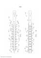
[0002] As características e vantagens de várias formas dainvenção, e a maneira de obtê-las, se tornarão aparentes e a própria invenção será mais bem entendida com referência à descrição das modalidades a seguir da invenção consideradas em conjunto com os desenhos em anexo, em que:a Figura 1 é uma vista em perspectiva de uma forma de um instrumento cirúrgico da presente invenção;a Figura 2 é uma vista em perspectiva explodida de uma forma de atuador de extremidade da presente invenção;a Figura 3 é uma vista em perspectiva explodida de uma porção do instrumento cirúrgico da Figura 1;a Figura 4 é uma vista em perspectiva explodida doconjunto de uma outra porção do instrumento cirúrgico da Figura 1;a Figura 5 é uma vista em perspectiva explodida doconjunto de uma porção do conjunto de haste alongada do instrumento cirúrgico da Figura 1;a Figura 6 é uma vista em perspectiva do atuador de extremidade cirúrgico da Figura 2 e um segmento do tubo de fechamento distal;a Figura 7 é uma vista em perspectiva posterior de uma porção da modalidade de bigorna; Figura 7A éuma vista emperspectiva explodida do um outro conjunto do atuador de extremidade cirúrgico; Figura 7B éumavista em perspectiva posterior de umaporção deoutra modalidade de conjunto de bigorna e outramodalidadede segmento do tubo de fechamento;Figura 7C éuma vista em perspectiva de uma porção deoutro conjunto de bigorna e outro segmento do tubo de fechamento;a Figura 7Dé umavista deconjuntoperspectiva explodida de outra modalidade do atuador de extremidade cirúrgico; atuador de extremidade e do segmento do tubo de fechamento distalcom o conjunto de bigorna em uma posição aberta; sistema de acionamento de disparo; intermediária de uma modalidade de conjunto de haste alongada; a Figura 16 é uma vista em elevação lateral ampliada das porções das nervuras adjacentes da porção de haste intermediária das Figuras 12 a 15;a Figura 17 é uma vista plana de uma outra modalidade da porção de haste intermediária;a Figura 18 é uma vista em elevação lateral da porção de haste intermediária da Figura 17; ea Figura 19 é uma vista plana em seção transversal da porção de haste intermediária das Figuras 17 e 18 articuladas substancialmente em formato de U.[0002] The features and advantages of various forms of the invention, and the manner of obtaining them, will become apparent and the invention itself will be better understood with reference to the description of the following embodiments of the invention considered in conjunction with the accompanying drawings, wherein: Figure 1 is a perspective view of a shape of a surgical instrument of the present invention; Figure 2 is an exploded perspective view of an end actuator shape of the present invention; Figure 3 is a perspective view an exploded view of a portion of the surgical instrument of Figure 1; Figure 4 is an exploded perspective view of an assembly of another portion of the surgical instrument of Figure 1; Figure 5 is an exploded perspective view of an assembly of a portion of the elongated stem assembly of the surgical instrument of Figure 1; Figure 6 is a perspective view of the surgical end actuator of Figure 2 and a segment of the distal closure tube; Figure 7 is a plan view rear view of a portion of the anvil modality; Figure 7A is an exploded perspective view of another surgical end actuator assembly; Figure 7B is a rear perspective view of a portion of another form of anvil assembly and another form of closure tube segment; Figure 7C is a perspective view of a portion of another anvil assembly and another closure tube segment; Figure 7D is an exploded perspective assembly view of another modality of the surgical end actuator; end actuator and distal closing tube segment with the anvil assembly in an open position; triggering system; intermediate of an elongated rod assembly embodiment; Figure 16 is an enlarged side elevation view of adjacent rib portions of the intermediate shank portion of Figures 12 to 15; Figure 17 is a plan view of another embodiment of the intermediate shank portion; Figure 18 is a side view. side elevation of the intermediate rod portion of Figure 17; and Figure 19 is a cross-sectional plan view of the intermediate rod portion of Figures 17 and 18 hinged substantially in a U-shape.
[0003] Os caracteres de referência correspondentes indicam aspartes correspondentes através das várias vistas. As exemplificações apresentadas na presente invenção ilustram certas modalidades da invenção, em uma forma, e tais exemplificações não devem ser entendidas como limitadoras do escopo da invenção de nenhuma maneira.[0003] Corresponding reference characters indicate the corresponding parts across the various views. The exemplifications presented in the present invention illustrate certain embodiments of the invention, in one form, and such exemplifications are not to be construed as limiting the scope of the invention in any way.
[0004] A requerente do presente pedido também é a autora dosseguintes pedidos de patente que foram depositados na mesma data do presente pedido e que estão, todos, aqui incorporados a título de referência, em sua totalidade:- Pedido de patente US intitulado: "Surgical Staples and Staple Cartridges", n° do documento do procurador END7341USNP/130301;- Pedido de patente US intitulado: "Surgical Staples and Staple Cartridges", n° do documento do procurador END7331USNP/130304:- Pedido de patente US intitulado: "Surgical Staples and Methods For Making the Same", n° do documento do procurador END7335USNP/130305; - Pedido de patente US intitulado: "Surgical Staples, Staple Cartridges and Surgical End Effectors", n° do documento do procurador END7332USNP/130306;- Pedido de patente US intitulado: "Surgical Fastener", n° do documento do procurador, END7338USDP/130307;- Pedido de patente US intitulado: "Fastener Cartridge Comprising an Extendable Firing Member", n° do documento do procurador END7344USNP/130308;- Pedido de patente US intitulado: "Fastener Cartridge Comprising a Firing Member Configured to Directly Engage and Eject Fasteners From the Fastener Cartridge", n° do documento do procurador END7339USNP/130309;- Pedido de patente US intitulado: "Fastener Cartridge Comprising a Firing Member Including Fastener Surfaces", n° do documento do procurador END7340USNP/130310;- Pedido de patente US intitulado: "Articulatable Surgical Instruments With Separate and Distinct Closing and Firing Systems", n° do documento do procurador END7333USNP/130322;- Pedido de patente US intitulado: "Surgical Cutting and Stapling Instruments With Independent Jaw Control Features", n° do documento do procurador END7336USNP/130303;- Pedido de patente US intitulado: "Surgical Cutting and Stapling Instruments With Articulatable End Effectors", n° do documento do procurador END7334USNP/130312;- Pedido de patente US intitulado: "Surgical Cutting and Stapling Methods", n° do documento do procurador END7330USNP/130313; e- Pedido de patente US intitulado: "Modular Surgical Instruments", n° do documento do procurador END7342USNP/130311. Certas modalidades exemplificadoras serão agora descritas para propiciar o entendimento geral dos princípios da estrutura, da função, da fabricação e do uso dos dispositivos e métodos aqui revelados. Um ou mais exemplos dessas modalidades estão ilustrados nos desenhos em anexo. Os versados na técnica entenderão que os dispositivos e métodos especificamente descritos na presente invenção e ilustrados nos desenhos aqui anexados são modalidades exemplificadoras não limitantes e que o escopo das várias modalidades da presente invenção é definido unicamente pelas concretizações. As características ilustradas ou descritas em relação a uma modalidade exemplificadora podem ser combinadas com as características de outras modalidades. Tais modificações e variações destinam-se a estar incluídas no escopo da presente invenção.[0004] The applicant of the present application is also the author of the following patent applications that were filed on the same date as the present application and which are all incorporated herein by reference in their entirety:- US patent application entitled: " Surgical Staples and Staple Cartridges", Attorney Document No. END7341USNP/130301;- US Patent Application titled: "Surgical Staples and Staple Cartridges", Attorney Document No. END7331USNP/130304:- US Patent Application titled: " Surgical Staples and Methods For Making the Same", Attorney Document No. END7335USNP/130305; - US patent application titled: "Surgical Staples, Staple Cartridges and Surgical End Effectors", attorney document no. END7332USNP/130306;- US patent application titled: "Surgical Fastener", attorney document no., END7338USDP/ 130307;- US patent application titled: "Fastener Cartridge Comprising an Extendable Firing Member", attorney document no. END7344USNP/130308;- US patent application titled: "Fastener Cartridge Comprising a Firing Member Configured to Directly Engage and Eject Fasteners From the Fastener Cartridge", Attorney Document No. END7339USNP/130309;- US Patent Application entitled: "Fastener Cartridge Comprising a Firing Member Including Fastener Surfaces", Attorney Document No. END7340USNP/130310;- US Patent Application entitled: "Articulatable Surgical Instruments With Separate and Distinct Closing and Firing Systems", attorney's document no. END7333USNP/130322;- US patent application titled: "Surgical Cuttin g and Stapling Instruments With Independent Jaw Control Features", Attorney Document No. END7336USNP/130303;- US Patent Application entitled: "Surgical Cutting and Stapling Instruments With Articulatable End Effectors", Attorney Document No. END7334USNP/130312; - US patent application entitled: "Surgical Cutting and Stapling Methods", Attorney Document No. END7330USNP/130313; e- US patent application entitled: "Modular Surgical Instruments", Attorney Document No. END7342USNP/130311. Certain exemplary embodiments will now be described to provide a general understanding of the principles of structure, function, fabrication, and use of the devices and methods disclosed herein. One or more examples of such embodiments are illustrated in the accompanying drawings. Those skilled in the art will understand that the devices and methods specifically described in the present invention and illustrated in the accompanying drawings are non-limiting exemplary embodiments and that the scope of the various embodiments of the present invention is defined solely by the embodiments. Features illustrated or described in connection with one exemplary embodiment may be combined with features of other embodiments. Such modifications and variations are intended to be included within the scope of the present invention.
[0005] Ao longo de todo este relatório descritivo, os termos "váriasmodalidades", "algumas modalidades", "uma modalidade" ou "a modalidade", ou similares, significam que um recurso, uma estrutura ou uma característica específicos descritos em conjunto com a modalidade está incluído em pelo menos uma modalidade. Dessa forma, o aparecimento das expressões "em várias modalidades", "em algumas modalidades", "em uma modalidade" ou "na modalidade", ou similares, em lugares ao longo de todo o relatório descritivo não estão necessariamente se referindo à mesma modalidade. Além disso, os recursos, estruturas ou características específicos(as) podem ser combinados de qualquer maneira adequada em uma ou mais modalidades. Portanto, os recursos, estruturas ou características específicos ilustrados ou descritos em conjunto com uma modalidade podem ser combinados, no todo ou em parte, com as estruturas dos recursos ou das características de uma ou mais outras modalidades, sem limitação. Tais modificações e variações destinam-se a estar incluídas no escopo da presente invenção.[0005] Throughout this specification, the terms "several modalities", "some modalities", "a modality" or "the modality", or the like, mean that a specific feature, structure or characteristic described in conjunction with the modality is included in at least one modality. Thus, the appearance of the expressions "in several modalities", "in some modalities", "in a modality" or "in the modality", or similar, in places throughout the descriptive report are not necessarily referring to the same modality. . In addition, specific features, structures or characteristics may be combined in any suitable way in one or more modalities. Therefore, the specific features, structures or characteristics illustrated or described in conjunction with one modality may be combined, in whole or in part, with the structures of the features or characteristics of one or more other modality, without limitation. Such modifications and variations are intended to be included within the scope of the present invention.
[0006] Os termos "proximal" e "distal" são usados na presente invenção com referência a um médico que manipula a porção de cabo do instrumento cirúrgico. O termo "proximal" refere-se à porção mais próxima ao médico, e o termo "distal" refere-se à porção situada na direção oposta ao médico. Também será entendido que, por uma questão de conveniência e clareza, termos espaciais como "vertical", "horizontal", "para cima" e "para baixo" podem ser usados na presente invenção com relação aos desenhos. Entretanto, instrumentos cirúrgicos podem ser usados em muitas orientações e posições, e esses termos não se destinam a ser limitadores e/ou absolutos.[0006] The terms "proximal" and "distal" are used in the present invention with reference to a physician who manipulates the handle portion of the surgical instrument. The term "proximal" refers to the portion closest to the physician, and the term "distal" refers to the portion located away from the physician. It will also be understood that, for the sake of convenience and clarity, spatial terms such as "vertical", "horizontal", "upwards" and "downwards" may be used in the present invention in connection with the drawings. However, surgical instruments can be used in many orientations and positions, and these terms are not intended to be limiting and/or absolute.
[0007] São fornecidos vários dispositivos e métodosexemplificadores para a realização de procedimentos cirúrgicos laparoscópicos e minimamente invasivos. Entretanto, o versado na técnica entenderá prontamente que os vários métodos e dispositivos aqui revelados podem ser usados em inúmeros procedimentos e aplicações cirúrgicos inclusive, por exemplo, aqueles em conjunto com procedimentos cirúrgicos abertos. Com o avanço da presente Descrição Detalhada, aqueles de habilidade comum na técnica apreciarão adicionalmente que os vários instrumentos aqui revelados podem ser inseridos em um corpo de qualquer maneira, como através de um orifício natural, através de uma incisão ou perfuração formada em tecido, etc. As porções funcionais ou porções do atuador de extremidade dos instrumentos podem ser inseridas diretamente no corpo de um paciente ou podem ser inseridas por meio de um dispositivo de acesso que tenha uma canaleta de trabalho através da qual o atuador de extremidade e a haste alongada de um instrumento cirúrgico podem ser avançados.[0007] Various devices and exemplary methods are provided for performing laparoscopic and minimally invasive surgical procedures. However, one of skill in the art will readily understand that the various methods and devices disclosed herein can be used in numerous surgical procedures and applications including, for example, those in conjunction with open surgical procedures. As the present Detailed Description advances, those of ordinary skill in the art will further appreciate that the various instruments disclosed herein can be inserted into a body in any manner, such as through a natural orifice, through an incision or perforation formed in tissue, etc. . Functional portions or end actuator portions of instruments may be inserted directly into a patient's body or may be inserted through an access device having a working channel through which the end actuator and elongated stem of a surgical instrument can be advanced.
[0008] A Figura 1 ilustra um instrumento cirúrgico exemplificador10 que pode incluir um compartimento 20, um conjunto de haste alongada 50 que projeta-se operacionalmente do compartimento 20 e que é acoplada operacionalmente a um atuador de extremidade cirúrgico 100. O instrumento cirúrgico 10 representado na Figura 1 compreende um compartimento 20 que consiste em um cabo 22 que é configurado para ser apreendido, manipulado e ativado por um médico. À medida que a presente descrição detalhada prosseguir, entretanto, será entendido que as várias disposições únicas e novas das várias formas de disposições da haste e das disposições do atuador de extremidade aqui reveladas também podem ser eficazmente empregadas em conexão com os sistemas cirúrgicos controlados roboticamente. Assim, o termo "compartimento" também pode englobar um compartimento ou porção similar de um sistema robótico que contém ou de outra forma sustenta operacionalmente pelo menos um sistema de acionamento que é configurado para gerar e aplicar pelo menos um movimento de controle que poderia ser usado para ativar várias formas de atuadores de extremidade cirúrgicos a ele acoplados. O termo "estrutura" pode referir-se a uma porção de um instrumento cirúrgico de mão. O termo "estrutura" também pode representar uma porção de um instrumento cirúrgico controlado por robô e/ou uma porção do sistema robótico que podem ser usadas para controlar de modo operável o instrumento cirúrgico. Por exemplo, o pedido de patente U.S. n° de série 13/536.323, intitulado ROBOTICALLY-POWERED SURGICAL DEVICE WITH MANUALLY ACTUATABLE REVERSING SYSTEM, depositado em 28 de junho de 2012, cuja descrição está aqui incorporada em sua totalidade a título de referência, revela várias disposições de sistema robótico que também podem ser efetivamente empregadas. Além disso, como será discutido com mais detalhes abaixo, o instrumento cirúrgico 10 representado em pelo menos alguns dos desenhos aqui anexados emprega um motor para gerar movimentos de controle para ativar vários componentes e características do atuador de extremidade cirúrgico. À medida que a presente descrição detalhada prosseguir, entretanto, os versados na técnica compreenderão que certas característica e vantagens da presente invenção também podem ser eficazmente obtidas em conexão com os instrumentos cirúrgicos que são equipados com ativação gerada manualmente (ou seja, geração sem motor) e movimentos de controle.[0008] Figure 1 illustrates an exemplary
[0009] Como ilustrado nas Figuras 1 e 3, o cabo 22 podecompreender um par de segmentos de compartimento interconectados 24, 26 por parafusos, recursos por pressão, adesivo, etc. Como usado aqui, o termo "recurso por pressão" inclui, mas não se limita a, por exemplo, uma aba que tem uma protuberância nela que é configurada para engatar-se com retenção a uma porção correspondente de outro componente. Tais recursos podem ser projetados para engatarem-se de forma liberável à porção correspondente ou podem não ser projetados ou concebidos para serem removidos. Na disposição ilustrada, os segmentos de compartimento de cabo 24 e 26 cooperam para formar uma porção de preensão de pistola 28, que pode ser segurada e manipulada pelo médico. Como será discutido com mais detalhes abaixo, o cabo 22 sustenta operacionalmente uma pluralidade de sistemas de acionamento ou sistemas de controle nele que são configurados para gerar e aplicar vários movimentos de controle a porções de componentes correspondentes do conjunto de haste alongada 50 que é operacionalmente fixado a um atuador de extremidade cirúrgico 100. Na modalidade ilustrada, o atuador de extremidade 100 é configurado para cortar e prender o tecido, por exemplo.[0009] As illustrated in Figures 1 and 3, the
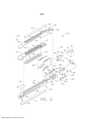
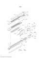
[00010] A Figura 2 ilustra uma forma de atuador de extremidade cirúrgico 100 que pode ser empregado. Como pode ser visto nesta Figura, o atuador de extremidade cirúrgico 100 pode compreender uma canaleta alongada 102 que é configurada para receber um cartucho de prendedores 110 nela. O cartucho de prendedores cirúrgicos 110 pode incluir um corpo de cartucho 112 que tem uma fenda alongada centralizada 114 nele. O corpo do cartucho 112 pode adicionalmente incluir fileiras de bolsos de prendedores 116 que estão localizados em cada lado da fenda alongada 114 e que são configurados para sustentar os prendedores cirúrgicos 120 correspondentes nele. A canaleta alongada 102 pode adicionalmente sustentar operacionalmente um elemento de corte de tecido ou conjunto de facas 150 nela que é configurado para transitar axialmente na fenda 114 no corpo do cartucho 112 quando instalado na canaleta alongada 102. O conjunto de facas 150 pode ser configurado com um gume cortante de tecido 152 que é disposto centralmente entre um pé inferior 154 e um pé ou aba superior 156. Como será discutido com mais detalhes, o conjunto de facas 150 é configurado para ser axialmente direcionado dentro da canaleta alongada 102 e do cartucho de prendedores cirúrgicos 110 em resposta aos movimentos aplicados a ele por um sistema de acionamento de disparo 300.[00010] Figure 2 illustrates a form of
[00011] Como também pode ser visto na Figura 2, o atuador de extremidade cirúrgico 100 pode adicionalmente incluir um conjunto de bigorna 130 que é sustentado de forma móvel na canaleta alongada 102. O conjunto de bigorna 130 pode ser móvel em relação ao cartucho de prendedores cirúrgicos 110, por exemplo, em resposta aos movimentos de fechamento e abertura transferidos a ele a partir do sistema de acionamento de fechamento 200. Em outras disposições, entretanto, o conjunto de bigorna pode ser fixo e o cartucho de prendedores cirúrgicos pode ser configurado para mover- se em relação ao conjunto de bigorna mediante a aplicação de movimentos de fechamento ali. Em outra disposição, por exemplo, o conjunto de bigorna 130 inclui uma porção de corpo de bigorna 132 que tem uma superfície de formação de prendedor 134 formada na parte inferior do mesmo. A superfície de formação de prendedor 134 pode compreender uma série de bolsos de formação (não mostrados) que correspondem aos prendedores cirúrgicos 120 sustentados no cartucho de prendedores cirúrgicos 110. À medida que as pernas dos prendedores cirúrgicos 120 são direcionadas para fazer contato com os bolsos de formação correspondentes no conjunto de bigorna 130, elas são formadas em uma configuração retentora de tecido desejada. O conjunto de bigorna 130 pode adicionalmente incluir uma porção de montagem de bigorna 136 que tem um par de munhões 138 projetando-se a partir deles que são recebidos dentro das fendas arqueadas correspondentes 106 formadas em uma porção de montagem proximal 104 da canaleta alongada 102. Em várias disposições, os prendedores cirúrgicos 120 são acionados para fora de seus respectivos bolsos de prendedores 116 no cartucho de prendedores cirúrgicos 110 por conjuntos de carrinhos correspondentes 160 e 170 que são sustentados de forma móvel dentro da canaleta alongada 102 e são móveis em resposta aos movimentos de disparo aplicados a ele pelo sistema de acionamento de disparo 300.[00011] As can also be seen in Figure 2, the
[00012] Com referência agora à Figura 3, o cabo 22 pode adicionalmente incluir uma estrutura 30 que sustenta operacionalmente vários componentes do sistema de acionamento de fechamento 200 e o sistema de acionamento de disparo 300. Em pelo menos uma forma, o sistema de acionamento de fechamento 200 pode incluir um atuador sob a forma de um gatilho de fechamento 202, sustentado de forma articulada pela estrutura 30. O gatilho de fechamento 202 pode ser sustentado de maneira pivotante pela estrutura 30 de modo que quando o médico pega a porção de preensão da pistola 28 do cabo 22, o gatilho de fechamento 202 pode ser facilmente pivotado a partir de uma posição inicial ou não acionada para uma posição acionada e mais particularmente para uma posição totalmente comprimida ou totalmente acionada. O gatilho de fechamento 202 pode ser deslocado para a posição não acionada por uma mola ou outra disposição de deslocamento (não mostrada). Vários detalhes relacionados a certos aspectos da construção e operação do sistema de acionamento de fechamento 200 podem ser encontrados no pedido de patente U.S. n° de série 13/803.097, depositado em 14 de março de 2013, intitulado ARTICULATABLE SURGICAL INSTRUMENT COMPRISING A FIRING DRIVE, cuja descrição está aqui incorporada a título de referência. Conforme discutido nesta referência e conforme mostrado na Figura 3 da presente invenção, o gatilho de fechamento 202 pode ser configurado para cooperar com um conjunto de liberação de fechamento 220 que é acoplado de forma pivotante à estrutura 30. Em pelo menos uma forma, o conjunto de liberação de fechamento 220 pode compreender um conjunto de botão de liberação 222 que pode ser pivotado no sentido anti-horário por uma mola de liberação (não mostrada). À medida que o médico pressiona o gatilho de fechamento 202 de sua posição não acionada em direção à porção de preensão da pistola 28 do cabo 22, o conjunto de liberação de fechamento 220 atua para travar o gatilho de fechamento 202 na posição totalmente acionada. Quando o médico deseja destravar o gatilho de fechamento 202 para permitir que seja forçado para a posição não acionada, ele simplesmente gira o conjunto do botão de liberação de fechamento 220 para fazê-lo desengatar da disposição do gatilho de fechamento e, assim, permitir que o gatilho de fechamento 202 gire de volta para a posição não acionada. Outras disposições para travamento e liberação do gatilho de fechamento também podem ser empregadas.[00012] Referring now to Figure 3, the
[00013] Com referência às Figuras 3 e 4, o sistema de acionamento de fechamento 200 pode adicionalmente compreender o segmento do tubo de fechamento 210 que tem uma extremidade proximal 212 que é adaptada para ser acoplada rotacionalmente a uma forquilha de fixação do tubo de fechamento 230. A extremidade proximal 212 do segmento do tubo de fechamento proximal 210 está configurada para ser recebida dentro de uma armação 232 (Figura 3) na forquilha de fixação do tubo de fechamento 230 para permitir a rotação relativa em relação a ele. O segmento do tubo de fechamento proximal 210 pode ser rotacionalmente fixado à forquilha de fixação do tubo de fechamento 230 por meio de um conector em formato de U 236 que é configurado para ser recebido em uma fenda anular 214 na extremidade proximal 212 do segmento do tubo de fechamento proximal 210 e ser colocado em uma fenda 234 (Figura 3) na forquilha de fixação de tubo de fechamento 230. Tal disposição serve para acoplar de forma giratória o segmento do tubo de fechamento proximal 210 à forquilha de fixação do tubo de fechamento 230 de modo que o segmento do tubo de fechamento proximal 210 possa girar em relação a ela. Mais especificamente, tal disposição facilita a rotação manual do conjunto de haste alongada 50 em relação ao cabo 22 ao redor de um eixo de ferramenta longitudinal "LT-LT" definido pelo conjunto de haste alongada 50 para possibilitar que o médico gire o atuador de extremidade cirúrgico 100 da forma representada pela seta "R" na Figura 1.[00013] Referring to Figures 3 and 4, the
[00014] Em várias disposições, a forquilha de fixação do tubo de fechamento 230 é montada de forma móvel em um tubo de articulação proximal 402 de um sistema de articulação 400 que será discutido com mais detalhes abaixo. Tal disposição permite que a forquilha de fixação do tubo de fechamento 230 mova-se axialmente no tubo de articulação proximal 402 em resposta à ativação do gatilho de fechamento 202. Em particular, a forquilha de fixação do tubo de fechamento 230 pode ser acoplada de forma pivotante ao gatilho de fechamento 202 por uma barra de ligação de fechamento 240. Vide Figura 3. Assim, quando o médico gira o gatilho de fechamento 202 para dentro em direção à porção de preensão da pistola 28 do cabo 22, a forquilha de fixação do tubo de fechamento 230 será avançada na direção distal "D". Quando o gatilho de disparo 202 volta para a posição não acionada, a forquilha de fixação do tubo de fechamento 230 será avançada proximalmente (direção "P") no tubo de articulação proximal 402 para uma posição inicial.[00014] In various arrangements, the locking
[00015] O sistema de acionamento de fechamento 200 pode adicionalmente incluir um segmento do tubo flexível intermediário 250 que é configurado para fixação à extremidade distal 218 do segmento do tubo de fechamento proximal 210. Como pode ser visto na Figura 5, o segmento do tubo intermediário 250 pode incluir uma porção de articulação flexível 260 e uma porção de haste de fixação 252. A porção de haste de fixação 252 pode ser dimensionada para estender- se para a extremidade distal aberta 218 do segmento do tubo de fechamento proximal 210 em engate por atrito com ele. A porção de articulação flexível 260 pode ser integralmente formada pela porção de haste de fixação 252 e inclui uma coluna de articulação 262 que inclui porções da extremidade proximal 264 (apenas uma pode ser vista na Figura 5) que são configuradas para serem recebidas nos entalhes 219 correspondentes na extremidade distal 218 do segmento do tubo de fechamento proximal 210 para evitar a rotação relativa entre o segmento do tubo de fechamento proximal 210 e o segmento do tubo intermediário 250. O segmento do tubo intermediário 250 não pode ser fixado de forma giratória (ou seja, fixado para evitar a rotação relativa entre esses componentes) ao segmento do tubo de fechamento proximal 210 por, por exemplo, parafusos, retentores, adesivos, etc.[00015] The
[00016] O sistema de acionamento de fechamento 200 pode adicionalmente incluir um segmento do tubo de fechamento distal 280 que é configurado para fixar axialmente e aplicar movimentos de abertura e fechamento ao conjunto de bigorna 130. O segmento do tubo de fechamento distal 280 pode ser fixado à extremidade distal do segmento do tubo intermediário 250 para o trajeto axial entre eles. A coluna de articulação 262 pode incluir adicionalmente porções da extremidade distal 266 que são configuradas para ser recebidas nos entalhes correspondentes 284 na extremidade proximal 282 do segmento do tubo de fechamento distal 280 para evitar a rotação relativa entre o segmento do tubo de fechamento distal 280 e o segmento do tubo intermediário 250. Vide Figura 5. A extremidade proximal 282 do segmento do tubo de fechamento distal 280 pode se estender para dentro as abas de fixação 286 que são adaptadas para serem flexionadas nos entalhes correspondentes 266 no segmento do tubo intermediário 250. Vide Figuras 5 e 6. Tal disposição serve para facilitar a fixação do segmento do tubo de fechamento distal 280 ao segmento do tubo intermediário 250 para o trajeto axial entre eles.[00016] The
[00017] O segmento do tubo de fechamento distal 280 é configurado para aplicar movimentos de abertura e fechamento ao conjunto da bigorna 130. Conforme pode ser visto na Figura 7, uma forma da porção de montagem da bigorna 136 pode ser formada com um sulco 140 que define uma aba de bigorna 142. Conforme pode ser visto nas Figuras 6 e 8, a extremidade distal 288 do segmento do tubo de fechamento distal 280 tem uma aba de ativação 290, estendendo- se para dentro, formada nela que é configurada para interagir com a aba de bigorna 142. Por exemplo, quando o segmento do tubo de fechamento distal 280 está na posição aberta (Figuras 6 e 8), a aba de ativação 290 está em contato de deslocamento com a aba de bigorna 142 que serve para pivotar o conjunto da bigorna 130 para a posição aberta. Como mostrado na Figura 9, quando o conjunto da bigorna 130 está em uma posição aberta, as fendas de munhões 138 estão localizadas no fundo das fendas de munhões 106 na porção de montagem proximal 104 da canaleta alongada 102. Quando o segmento do tubo de fechamento distal 280 é avançado distalmente, a extremidade distal 288 entra em contato com a parede da extremidade vertical 144 no corpo da bigorna 132 para fazer com que o conjunto da bigorna 130 pivote ou de outra forma mova-se em direção ao cartucho de prendedores cirúrgicos 110. Quando montado, os munhões 138 estendem-se, cada um, para uma abertura correspondente 292 no segmento do tubo de fechamento distal 280. Vide Figura 6.[00017] The distal
[00018] A operação do sistema de acionamento de fechamento 200 será descrita agora. O conjunto da bigorna 130 pode ser movido em relação ao cartucho de prendedores cirúrgicos 110 pelo pivotamento do gatilho de fechamento na direção e na direção oposta da porção de preensão da pistola 28 do cabo 22. Assim, ativar o gatilho de disparo 202 faz com que o segmento do tubo de fechamento 210, o segmento do tubo intermediário 250 e o segmento do tubo de fechamento distal 280 movam-se axialmente na direção distal "DD" para entrar em contato com a parede da extremidade 144 da porção de corpo da bigorna 132 para pivotar ou de outra forma mover a bigorna 130 em direção ao cartucho de prendedores cirúrgicos 110. O médico pode pegar e manipular o tecido entre o conjunto da bigorna 130 e o cartucho de prendedores 110 abrindo e fechando o conjunto da bigorna 130. Assim que o tecido alvo é capturado entre o conjunto da bigorna 130 e o cartucho de prendedores 110, o médico pode pivotar o gatilho de fechamento 202 para a posição totalmente acionada em que ele é travado no lugar para disparar.[00018] The operation of the
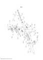
[00019] Como indicado acima, a estrutura 30 também pode ser configurada para sustentar operacionalmente o sistema de acionamento de disparo 300 que é configurado para aplicar movimentos de disparo nas porções correspondentes do conjunto de haste alongada 50 e finalmente no conjunto de faca 150 e nos conjuntos de carrinhos 160, 170. Conforme pode ser visto nas Figuras 3 e 10, o sistema de acionamento de disparo 300 pode empregar um motor elétrico 302 que é sustentado na porção de preensão da pistola 28 do cabo 22. Em várias formas, o motor 302 pode ser um motor de acionamento com escovas de corrente contínua, com uma rotação máxima de, aproximadamente, 25.000 RPM, por exemplo. Em outras disposições, o motor 302 pode incluir um motor sem escovas, um motor sem fio, um motor síncrono, um motor de passo ou qualquer outro tipo de motor elétrico adequado. Uma bateria 304 (ou "fonte de alimentação" ou "conjunto de baterias"), como uma bateria de íons de Li, por exemplo, pode ser acoplada ao cabo 22 para fornecer energia, a um conjunto de placa de circuito de controle 306 e, por fim, ao motor 302. A Figura 3 ilustra um compartimento de pacote de bateria 305 que é configurado para ser montado de forma removível ao cabo 22 para fornecer poder de controle ao instrumento cirúrgico 10. Um número de células de bateria conectado em série pode ser usado como a fonte de alimentação para alimentar o motor 302. Além disso, a fonte de energia pode ser substituível e/ou recarregável.[00019] As indicated above, the
[00020] Como esboçado acima com relação a outras várias formas, o motor elétrico 302 pode incluir uma haste giratória 308 que interliga operacionalmente o conjunto de engrenagem redutora 310 que é montado em engate engrenado com um conjunto, ou cremalheira, de dentes de acionamento 322 em um elemento de acionamento longitudinalmente móvel 320. O conjunto de engrenagem redutora 310 pode incluir, entre outras coisas, um compartimento 312 e uma engrenagem de pinhão 314. Vide Figura 11. Em certas modalidades, a engrenagem de pinhão de saída 314 pode ser diretamente engatada de forma operacional ao elemento de acionamento longitudinalmente móvel 320 ou, alternativamente, engatada de modo operacional ao elemento de acionamento 320 através de uma ou mais engrenagens intermediárias 316. A engrenagem intermediária 316, em pelo menos uma de tal modalidade, pode ser engatada por engrenamento ao conjunto, ou cremalheira, de dentes de acionamento 322 definido no elemento de acionamento 320. Em uso, o motor elétrico 302 pode mover o elemento de acionamento distalmente, indicado por uma seta "DD" e/ou proximalmente, indicado por uma seta "PD", dependendo da direção em que o motor elétrico 302 gira a engrenagem intermediária 316. Em uso, uma polaridade de tensão fornecida pela bateria é capaz de operar o motor elétrico 302 em sentido horário, sendo que a polaridade de tensão aplicada ao motor elétrico pela bateria pode ser invertida de forma a operar o motor elétrico 302 em sentido anti- horário. Quando o motor elétrico 302 é girado em uma direção, o elemento de acionamento 320 será axialmente ativado na direção distal "DD". Quando o motor 302 é acionado em uma direção giratória oposta, o elemento de acionamento 320 será axialmente ativado na direção proximal "PD". O cabo 22 pode incluir um interruptor que pode ser configurado para inverter a polaridade aplicada ao motor elétrico 302 pela bateria. O cabo 22 também pode incluir um sensor que é configurado para detectar a posição do elemento de acionamento móvel 320 e/ou a direção em que o elemento de acionamento móvel 320 está sendo movido.[00020] As outlined above with respect to other various forms, the
[00021] O acionamento do motor 302 pode ser controlado por um gatilho de disparo 330, sustentado de forma articulada pelo cabo 22. O gatilho de disparo 330 pode ser girado entre uma posição não acionada e uma posição acionada. O gatilho de disparo 330 pode ser deslocado para a posição acionada por uma mola (não mostrada) ou outra disposição de deslocamento, de forma que, quando o médico libera o gatilho de disparo 330, este pode ser girado, ou outro modo, retorna à posição não acionada pela mola ou disposição de deslocamento. Em pelo menos uma forma, o gatilho de disparo 330 pode ser posicionado "externamente" do gatilho de fechamento 202, conforme discutido com mais detalhes no pedido de patente U.S. N° de série 13/803.097 que foi anteriormente incorporado a título de referência, em sua totalidade, na presente invenção. Em pelo menos uma forma, um botão de segurança do gatilho de disparo 332 pode ser montado de maneira pivotante no gatilho de fechamento 202. O botão de segurança 332 pode estar posicionado entre o gatilho de disparo 330 e o gatilho de fechamento 202 e tem um braço pivotante (não mostrado) projetando-se dele. Quando o gatilho de fechamento 202 está em uma posição não acionada, o botão de segurança 332 é contido no compartimento do cabo, onde o médico não pode acessá-lo e movê-lo entre uma posição de segurança evitando a ativação do gatilho de disparo 330 e uma posição de disparo em que o gatilho de disparo 330 pode ser ativado. Quando o médico pressiona o gatilho de fechamento 202, o botão de segurança 332 e o gatilho de disparo 330 pivotam para baixo, para uma posição em que eles possam, então, ser manipulados pelo médico.[00021] The drive of the
[00022] Como indicado acima, em pelo menos uma forma, oelemento de acionamento móvel longitudinalmente 320 tem uma cremalheira de dentes 322 formada na mesma para o engate por engrenamento com a engrenagem de acionamento correspondente 312 do conjunto do redutor de engrenagem 310. Pelo menos uma forma também pode incluir um conjunto "ejeção" que é configurado para possibilitar que o médico retraia manualmente o elemento de acionamento longitudinalmente móvel 320 se o motor ficar desabilitado. O pedido de patente U.S. N° de série 13/803.097 contém mais detalhes de uma forma de conjunto ejeção que pode ser empregado. O pedido de patente U.S. N° de série 2010/0089970 também revela disposições de "ejeção" e outros componentes, disposições e sistemas que também podem ser empregados com os vários instrumentos aqui revelados. O pedido de patente U.S. Novo quadro reivindicatório (total de -- reivindicações), incorporando as emendas às reivindicações conforme Emendas do PCT.° de série 12/249.117, intitulado POWERED SURGICAL CUTTING AND STAPLING APPARATUS WITH MANUALLY RETRACTABLE FIRING SYSTEM, agora publicação de pedido de patente US n° 2010/0089970, está aqui incorporado na íntegra, a título de referência em sua totalidade.[00022] As indicated above, in at least one form, the longitudinally
[00023] Com referência às Figuras 4 e 5, várias formas de conjunto de haste alongada 50 podem incluir um conjunto de elemento de disparo 60 que é sustentado por trajetória axial dentro de um conjunto de haste de articulação 430 que é parte do sistema de articulação 400 e que funciona essencialmente como estrutura ou coluna da haste. O conjunto de elemento de disparo 60 pode adicionalmente incluir uma haste de disparo proximal 62 que tem uma porção de extremidade proximal 64 que é configurada para ser recebida rotacionalmente em uma armação distal 326 fornecida em uma extremidade distal 324 do elemento de acionamento móvel 320. Tal disposição permite que a haste de disparo proximal 62 gire em relação ao elemento de acionamento móvel 320 enquanto também se move axialmente com ela. A haste de disparo proximal 62 pode adicionalmente ter uma fenda 68 formada em sua extremidade distal 66 para receber uma extremidade proximal 72 de um conjunto de haste de disparo distal flexível 70 nela. Vide Figura 5. Conforme pode ser visto nessa figura, a extremidade proximal 72 do conjunto de haste de disparo distal 70 pode ser recebida dentro da fenda 68 na haste de disparo distal 62 e pode ser presa a ela com um pino 73.[00023] Referring to Figures 4 and 5, various forms of
[00024] O conjunto de haste de disparo distal 70 pode incluir uma viga de disparo central 74 que está localizada entre uma viga propulsora de deslizador direita 76 e uma viga propulsora de deslizador esquerda 78. A viga de disparo central 74 e as vigas propulsoras 76, 78 podem, por exemplo, cada uma, ser fabricada de metal, o que facilita a ativação axial dos conjuntos de deslizadores 160, 170 no atuador de extremidade cirúrgico 100 ao mesmo tempo que também facilita a flexão do mesmo quando o atuador de extremidade 100 é articulado, conforme será discutido com mais detalhes abaixo. Em pelo menos uma disposição, a viga propulsora central 74, a viga propulsora de deslizador direita 76 e a vigapropulsora de deslizador esquerda 78 podem estender-se através de uma fenda 146 na porção de montagem da bigorna 136. A vigapropulsora de deslizador direita 76 corresponde ao conjunto de deslizador direito 160 e a viga propulsora de deslizador esquerda 78 corresponde ao conjunto de deslizador esquerdo 170 sustentado de forma móvel dentro da canaleta alongada 102. O movimento axial da viga propulsora de deslizador direita 76 e da viga propulsora de deslizador esquerda 78 resultará no avanço axial dos conjuntos de deslizador direito e esquerdo 160, 170, respectivamente, dentro da canaleta alongada 102. À medida que o conjunto de deslizador direito 160 é axialmente avançado dentro da canaleta alongada 102, ele aciona os prendedores cirúrgicos 120 sustentados no corpo do cartucho 112 no lado direito da fenda 114 para fora de seus bolsos respectivos 116 e à medida que o conjunto de deslizador esquerdo 170 é axialmente avançado dentro da canaleta alongada 102, ele aciona os prendedores cirúrgicos 120 sustentados dentro do corpo do cartucho 112 no lado esquerdo da fenda 114 fora de seus bolsos respectivos 116.[00024] The distal
[00025] A viga de disparo central 74 tem uma extremidade distal 80 que pode ser configurada para ser recebida dentro de uma fenda 151 fornecida no conjunto de faca 154 e retida nela, por exemplo, por um encaixe por atrito, adesivo, soldaetc.ma janelade fundo 105 podeser formada emumaextremidadedistal 103 dacanaletaalongada 102para possibilitar que o conjunto de faca150 sejinseridoatravés delaEmpelo menos uma forma, a canaletaalongada102 é formadacomumaparedeverticaldireita 107 eumaparedeverticalesquerda108quedefineuma fendadecanaletadispostantralmente109. Assimqueo conjuntode faca150 é inseridona janelade fundo 105nacanaletaalongada 102,porçãopo 151do conjunto de faca150 pode ser inseridanafendadacanaleta109 eproximalmentenacanaletaalongada 102 a seracoplada comextremidade distal180 ddedisparo central 74. Umacoberturade canaletainferior 111pode ser fixada ao fundo da canaleta alongada102evitateetc. entrem102,dificultar ofa150[00025] The
[00026]130 pinstalad102,njunto da big130 é p102 de fo138 pcanaletaentalhes 113alongada 102,nas fendas deporçãntageml 104 do que possibilita quemunhõescorrespondentes102. Vide Figura 2. Estasegmentodo tubo deos106munhões138entremcanaletaalongadainstalação pode ser realizada antes dofechamento distal280 ter sido fixadosegmentodo tubointermediário250após o segmento do tubo defechamentodistal 280tersido movido proximalmentede formasuficiente para permitir que abigorna seja assimposicionadaAssimque osmunhões138sãorecebidosdentro desuas fendas demunhões respectivas106,segmento do tubo de fechamento distal280 pode ser movido paraa posiçãomostradanasFiguras 8 e 9 em que o segmento do tubo de fechamento distal 280 retém os munhões 138 em suas respectivas fendas de munhões 106 e a aba de ativação 290 está em contato de deslocamento com a aba de bigorna 142 que serve para pivotar o conjunto da bigorna 130 para a posição aberta. Quando naquela posição, cada munhão 138 projeta-se para uma abertura correspondente 192 no segmento do tubo de fechamento distal 280. Vide Figura 6. Conforme mostrado nas Figuras 2 e 8, quando o conjunto de bigorna 130 está em uma posição aberta, a extremidade superior do conjunto de facas 150 entra em uma janela 133 na porção de corpo da bigorna 132. Tal janela 133 fornece distância para que o conjunto da bigorna 130 seja movido para as posições fechadas enquanto o conjunto de facas 150 permanece na posição não acionada. Assim que o conjunto da bigorna 130 tiver sido instalado com o conjunto de facas 150 no lugar, uma cobertura de bigorna 135 pode ser fixada ao corpo da bigorna 134 para evitar que o tecido, fluidos corporais, etc. entrem no corpo da bigorna 134 o que poderia dificultar o movimento do conjunto de faca 150 nela. À medida que o conjunto de facas 150 é avançado distalmente no atuador de extremidade 100, a aba superior 156 do conjunto de facas 150 engata as saliências no corpo da bigorna e o pé inferior 154 engata as porções 115 da canaleta alongada 102 e serve para reter um conjunto de bigorna 130 na posição fechada e essencialmente mantém o espaçamento entre o conjunto de bigorna 130 e o cartucho de prendedores 110.[00026] 130 installed 102, together with the big130 is p102 of fo138 pchannel
[00027] As Figuras 7A e 7B ilustram uma disposição de tubo de fechamento distal alternativo 280' que pode trabalhar com um conjunto de bigorna 130' que pode ser substancialmente idêntico ao conjunto de bigorna 130, exceto que o conjunto de bigorna 130' não tem a aba de bigorna. Quando naquela disposição, por exemplo, cada munhão 138 estende-se para uma abertura correspondente 292' no segmento do tubo de fechamento distal 280'. O segmento do tubo de fechamento distal 280 inclui adicionalmente uma aba respiradora estendendo-se para dentro 294 que projeta-se para dentro para entrar em contato com o munhão da bigorna correspondente 138. Quando o segmento do tubo de fechamento distal 280' é arrastado na direção proximal "PD", cada aba respiradora 294 entra em contato com o munhão correspondente 138 para fazer com que o munhão mova-se para baixo em sua fenda de munhão correspondente 106 na canaleta alongada 102 para pivotar ou de outra forma mover o conjunto da bigorna 130' para as posições abertas. A Figura 7C ilustra ainda uma outra disposição de tubo de fechamento distal 280'' em que a aba de ativação é formada por um entalhe 290'' no segmento do tubo de fechamento distal 280'' para a interação com a aba de bigorna 142 da forma acima descrita.[00027] Figures 7A and 7B illustrate an alternative distal closure tube arrangement 280' that can work with an anvil assembly 130' that can be substantially identical to
[00028] A Figura 7D ilustra um conjunto de bigorna alternativo 130'' em que a aba de bigorna 142' é fixada de forma removível à porção de montagem da bigorna 136. Em uma disposição, por exemplo, a aba de bigorna 142' é configurada com uma aba de encaixe de pressão 143 disposta para engatar de forma retentora uma abertura 141 na porção de montagem da bigorna 136. O conjunto de bigorna 130'' pode, de outra forma, ser o mesmo conjunto de bigorna 130 descrito acima e pode ser aberto e fechado de maneira similar pelo segmento do tubo de fechamento distal 280. A Figura 7E ilustra um outro conjunto de bigorna 130'' em que a aba de bigorna é formada por um parafuso 148 que é fixável de forma removível à porção de montagem da bigorna 138. Tais disposições de aba/parafuso de bigorna removíveis podem facilitar a instalação do conjunto de bigorna 130'.[00028] Figure 7D illustrates an alternative anvil assembly 130'' wherein the anvil wing 142' is removably secured to the
[00029] Com referência às Figuras 4 e 5, uma forma de sistema de articulação 400 inclui um conjunto de haste de articulação 430 que pode ser controlado operacionalmente por um sistema de controle de articulação 460. Em uma forma, por exemplo, o conjunto de haste de articulação 430 pode incluir um segmento de haste de articulação direito 440 e um segmento de haste de articulação esquerdo 450. O segmento de haste de articulação direito 440 inclui uma extremidade proximal 442 que tem um segmento de passagem direito 444 formado nela. De modo similar, o segmento de haste de articulação esquerdo 450 inclui uma porção de extremidade proximal 452 que tem um segmento de passagem esquerdo 454 formado nela. Quando o segmento de haste de articulação direito 440 e o segmento de haste de articulação esquerdo 450 são instalados dentro do segmento do tubo de fechamento proximal 210, eles formam o conjunto de haste de articulação 430. O segmento de passagem direito 444 e o segmento de passagem esquerdo 454 cooperam para receber uma porção da haste de disparo proximal 62 neles. O segmento de haste de articulação direito 440 e o segmento de haste de articulação esquerdo 450 podem ser, por exemplo, compostos de um plástico, especialmente uma poliamida amorfa reforçada por fibra de vidro, vendida comercialmente sob o nome comercial Grivory GB-6H pela EMS-American Grilon.[00029] Referring to Figures 4 and 5, one form of
[00030] Em várias disposições, por exemplo, o sistema de controle de articulação 460 pode incluir um conjunto de bocal 462 que é sustentado para a trajetória rotacional em relação ao cabo 22. Como pode ser visto na Figura 4, o conjunto de bocal 462 pode compreender um segmento de bocal superior 464 e um segmento de bocal inferior 466 que são fixados juntos por uma série de prendedores (por exemplo, parafusos) 468. O segmento de bocal superior 464 pode ser configurado para sustentar rotacionalmente um botão de controle de articulação 470 nele. Em uma disposição, por exemplo, o botão de controle de articulação 470 estende-se através de uma abertura (não mostrada) no segmento de bocal superior 464 e é acoplado a um elemento de engrenagem da articulação 472 por parafusos 474. O elemento de engrenagem de articulação 472 pode incluir uma roda dentada de articulação 476 que se estende para uma abertura 216 na porção de extremidade proximal 212 do segmento do tubo de fechamento proximal 210. Conforme pode ser visto adicionalmente na Figura 4, o sistema de articulação 400 inclui adicionalmente um adaptador de tubo de acionamento direito 478 e um adaptador de tubo de articulação esquerdo 480. O adaptador do tubo de articulação direito 478 tem uma reentrância direita 479 formada nele que é adaptada para receber uma patilha de adaptador direita 446 formada na extremidade proximal 442 do segmento da haste de articulação direito 440. Da mesma forma, o adaptador do tubo de articulação esquerdo 480 inclui uma reentrância esquerda 482 que é adaptada para engatar uma patilha de adaptador esquerda 456 formada na extremidade proximal 452 do segmento da haste de articulação esquerdo 450. O adaptador de tubo de articulação direito 478 tem adicionalmente uma série de engrenagens de acionamento de articulação direitas 481 que são configuradas para o engate por engrenamento com a engrenagem com roda dentada de articulação 476. O adaptador de tubo de articulação esquerdo 480 tem uma série de engrenagens de acionamento de articulação esquerda 484 formadas nele que são adaptadas para intercalamento com a roda dentada de articulação 476. Assim, quando o botão de controle de articulação 470 é girado ao redor de um eixo de controle CA-CA que é transversal ao eixo de ferramenta longitudinal LT-LT em relação ao cabo 22 (Figura 1), o segmento de haste de articulação esquerdo 450 é, por exemplo, acionado axialmente na direção distal "DD" dentro do segmento do tubo de fechamento proximal 210 e o segmento de haste de articulação direito 440 é acionado de forma axial simultaneamente na direção proximal "PD". Ainda com referência à Figura 5 o conjunto de haste de articulação 430 pode incluir, adicionalmente, uma faixa de articulação direita 490 e uma faixa de articulação esquerda 500. Em uma forma, uma porção de extremidade proximal 492 da faixa de articulação direita 490 pode serfixada a uma porção distal 448 do segmento da haste de articulaçãodireita de modo que uma porção distal 494 da faixa de articulaçãodireita 490 projete-se para fora da passagem direita 449 da mesma. Aporção da extremidade proximal 492 da faixa de articulação direita 490 pode incluir orifícios ou cavidades 493 que são configurados para receber as patilhas correspondentes (não mostradas) no segmento de haste de articulação direita 440 para facilitar a fixação da faixa de articulação direita 490 ao segmento de haste de articulação direita 440. Da mesma forma, a porção da extremidade proximal 502 da faixa de articulação esquerda 500 pode ter orifícios ou cavidades 503 que são configurados para receber as patilhas (não mostradas) na porção distal 458 do segmento de haste de articulação esquerdo 450 para facilitar a fixação da faixa de articulação esquerda 500 ao segmento de haste de articulação 450. As faixas de articulação 490 e 500 podem ser compostas de um metal, vantajosamente aço inoxidável 301 totalmente rígido ou seu equivalente.[00030] In various arrangements, for example, the
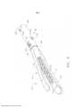
[00031] Com referência agora às Figuras 12 a 15, como foi brevemente discutido acima, o segmento do tubo intermediário 250 pode ter uma porção de haste de fixação 252 e uma porção de articulação flexível 260. Em várias disposições, o segmento do tubo intermediário 250 pode ser fabricado a partir de, por exemplo, poliuretano termoplástico rígido vendido comercialmente como ISOPLAST grau 2510 pela Dow Chemical Company e inclui uma coluna de articulação que se estende verticalmente, disposta centralmente 262. A coluna de articulação 262 inclui uma extremidade de coluna proximal 264 e uma extremidade de coluna distal 266 que facilitam a fixação ao segmento do tubo de fechamento proximal 210 e o segmento do tubo de fechamento distal 280, respectivamente, conforme foi discutido acima. A coluna de articulação 262 inclui adicionalmente um componente disposto centralmente ou uma fenda de faca 270 para facilitar a passagem de vários componentes de controle por ela. Na disposição ilustrada, a fenda 270 sustenta de forma móvel a viga de disparo central 74, a viga propulsora direita 76 e a viga propulsora esquerda 78. Em várias formas, a fenda disposta centralmente 270 é substancialmente embutida para retardar ou evitar a infiltração dos fluidos corporais e de tecido nela, o que poderia, de outra forma, dificultar o movimento dos componentes de controle passando operacionalmente através dela.[00031] Referring now to Figures 12 to 15, as briefly discussed above, the
[00032] Conforme pode ser visto mais especificamente na Figura 15, a porção de articulação flexível 260 inclui adicionalmente uma pluralidade de nervuras direitas 510 e uma pluralidade de nervuras esquerdas 520 que podem ser integralmente formadas com, e projetarem-se lateralmente da coluna de articulação 262. Em várias formas, por exemplo, cada nervura direita 510 pode compreender uma porção de corpo de nervura 512 que é espaçada da coluna de articulação 262 por uma porção de pescoço de nervura direita 516. Da mesma maneira, cada nervura esquerda 520 pode compreender uma porção de corpo de nervura esquerda 522 que é espaçada da coluna de articulação 262 por uma porção de pescoço de nervura esquerda 526. Conforme pode ser visto na Figura 13, as porções de corpo de nervura direita e esquerda 512, 522 têm um formato arqueado para fornecer à porção de articulação flexível 260 do segmento do tubo intermediário 250 um formato em seção transversal substancialmente circular. Tal formato pode facilitar a passagem fácil do segmento do tubo intermediário 250 através de uma passagem circular como, por exemplo, um trocarte adequadamente dimensionado.[00032] As can be seen more specifically in Figure 15, the
[00033] Em várias disposições, cada uma das porções de pescoço de nervura direita 516 serve para definir uma passagem de articulação direita 518 para receber, de forma móvel, a faixa de articulação direita 490 através dela. A faixa de articulação direita 490 pode estender-se através da passagem de articulação direita 518 e ser acoplada à porção de montagem proximal 104 da canaleta alongada 102. Por exemplo, a extremidade distal 494 da faixa de articulação direita 490 pode ter uma porção de gancho direita 496 que é adaptada para ser acoplada a uma porção de fixação direita 497 da canaleta alongada 102. Vide Figura 2. Similarmente, cada uma das porções de pescoço de nervura esquerda 526 serve para definir uma passagem de articulação esquerda 528 para receber, de forma móvel, a faixa de articulação esquerda 500 através dela. A faixa de articulação esquerda 500 pode estender-se através da passagem de articulação esquerda 528 e ser acoplada à porção de montagem proximal 104 da canaleta alongada 102. Por exemplo, a extremidade distal 504 da faixa de articulação esquerda 500 pode ter uma porção de gancho esquerda 506 que é adaptada para ser acoplada a uma porção de fixação esquerda 507 da canaleta alongada 102.[00033] In various arrangements, each of the right
[00034] Um método de operação do sistema de articulação 400 será descrito agora. Quando o médico deseja articular o atuador de extremidade 100 para a direita, em relação ao eixo de ferramenta longitudinal LT-LT (a direção direita é representada pela seta "RD" na Figura 15), o médico simplesmente gira o botão de controle de articulação 470 na direção adequada. Por exemplo, girar o botão de controle 470 na direção horária (quando visto de cima) faz com que a faixa de articulação esquerda seja empurrada na direção distal "DD" e a faixa de articulação direita 490 seja levada para a direção proximal "PD" que serve para aplicar um movimento de articulação à canaleta alongada 102. À medida que o movimento de articulação é aplicado à canaleta alongada 102, a porção de articulação flexível 260 flexiona-se para acomodar o movimento do atuador de extremidade cirúrgico 100 na direção "direita". Por outro lado, se o médico desejar articular o atuador de extremidade 100 na direção esquerda "LD", o médico simplesmente gira o botão de controle 470 no sentido anti-horário, o que faz com que a faixa de articulação direita 490 seja empurrada na direção distal "DD" e a faixa de articulação esquerda 500 seja levada na direção proximal "PD" fazendo, assim, o atuador de extremidade cirúrgico 100 mover-se para a esquerda. O atuador de extremidade 100 também pode ser articulado por um sistema robótico (não mostrado) que é configurado para aplicar movimentos de controle às faixas de articulação 490, 500.[00034] A method of operation of the
[00035] Devido à aplicação dos movimentos de articulação descritos acima ao atuador de extremidade cirúrgico 100, pode ser desejável evitar torcer ou apertar a porção de articulação flexível 260 do segmento do tubo intermediário 250. Se for necessário que tal torque ou torção ocorra, existe a possibilidade de dificultar ou, em casos de torção séria, bloquear completamente a operação da viga de disparo central 74 e das vigas propulsoras de deslizadores esquerda direito e esquerdo 76, 78. Para evitar este problema, as nervuras direita e esquerda 510, 520 podem ser configuradas de forma única para evitar a torção entre as nervuras.[00035] Due to the application of the linkage movements described above to the
[00036] Em pelo menos uma disposição, por exemplo, cada corpo de nervura 512 tem extremidades laterais que são dispostas espaçadas, em confrontamento com as extremidades laterais dos corpos de nervuras das nervuras adjacentes. Com referência novamente à Figura 15, por exemplo, o corpo da nervura 512 de cada nervura direita 510 tem uma primeira extremidade lateral direita 513 e uma segunda extremidade lateral direita 514. Com exceção da nervura direita mais proximal 510P e a nervura direita mais distal 510D, a primeira extremidade lateral direita 513 de uma nervura direita 510 está confrontando a segunda extremidade de lateral direita 514 de uma nervura direita adjacente 510. Quando a porção de articulação flexível 260 do segmento do tubo intermediário 250 não está articulada (por exemplo, a porção de articulação flexível 260 está substancialmente alinhada axialmente ao eixo de ferramenta longitudinal LT-LT), a primeira extremidade lateral direita 513 de cada nervura direita 510 é espaçada a partir da segunda extremidade lateral direita 514 da nervura direita adjacente 510 por um espaço de nervura direita 515. Na disposição representada na Figura 15, por exemplo, todos os espaços da nervura direita 515 têm substancialmente a mesma largura de espaço "SWR". Da mesma forma, o corpo da nervura 522 de cada nervura esquerda 520 tem uma primeira extremidade lateral esquerda 523 e uma segunda extremidade lateral esquerda 524. Com exceção da nervura esquerda mais proximal 520P e a nervura esquerda mais distal 520D, a primeira extremidade lateral esquerda 523 de uma nervura esquerda 520 está confrontando a segunda extremidade de lateral esquerda 524 de uma nervura esquerda adjacente 520. Quando a porção de articulação flexível 260 do segmento do tubo intermediário 250 não está articulada, a primeira extremidade lateral esquerda 523 de cada nervura esquerda 520 é espaçada a partir da segunda extremidade lateral esquerda 524 da nervura esquerda adjacente 520 por um espaço de nervura esquerda 525. Na disposição representada na Figura 15, por exemplo, todos os espaços da nervura esquerda 525 têm substancialmente a mesma largura de espaço "SWL". Em pelo menos uma forma, as larguras do espaço de nervura direito SWR são substancialmente iguais às larguras do espaço de nervura esquerda SWL. Entretanto, as larguras do espaço de nervura esquerda e direita podem ser diferentes uma da outra.[00036] In at least one arrangement, for example, each
[00037] Ainda com referência à Figura 15, cada nervura pode ser fornecida com uma configuração que evita a torção, geralmente designada como 530. Em pelo menos uma disposição, por exemplo, uma protuberância antitorção 532 pode ser formada em cada uma das primeiras extremidades laterais direitas 513 dos corpos da nervura direita 512 e em cada uma das primeiras extremidades laterais esquerdas 523 de cada um dos corpos de nervura esquerda 522. Cada protuberância antitorção 532 corresponde a uma reentrância com formato substancialmente complementar 534 formada na nervura que é imediatamente adjacente e em confronto com ela. A Figura 14 ilustra esta disposição nas nervuras esquerdas 520. Em pelo menos uma disposição, as nervuras direitas 510 empregam uma configuração idêntica. Em pelo menos uma forma, as protuberâncias 532 podem estar substancialmente alinhadas ao longo do eixo lateral. Ou seja, as protuberâncias 532 formadas nas nervuras diretas 510 podem estar substancialmente alinhadas ao longo de um eixo lateral direito RLA- RLA no lado direito da coluna de articulação 262 e as protuberâncias 532 formadas nas nervuras esquerdas 520 podem estar substancialmente alinhadas no lado esquerdo da coluna de articulação 262 ao longo de um eixo lateral esquerdo LLA-LLA. Quando a porção flexível 260 não está articulada, o eixo lateral direito RLA-RLA o eixo lateral esquerdo LLA-LLA e o eixo de ferramenta longitudinal LT-LT podem ser substancialmente paralelos um ao outro. Conforme pode ser visto na Figura 15, o eixo lateral direito RLA-RLA e o eixo lateral esquerdo LLA-LLA são espaçados do eixo de ferramenta longitudinal LT-LT.[00037] Still referring to Figure 15, each rib may be provided with a twist-preventing configuration, generally designated as 530. In at least one arrangement, for example, an
[00038] Conforme a porção de articulação flexível 260 é articulada na direção direita "RD", pelo menos algumas das protuberâncias 532 nas nervuras direitas 510 engatarão por fricção uma porção de uma reentrância correspondente 532 em uma nervura direita adjacente 510 para evitar que a porção flexível 260 sofra torção. Similarmente, conforme a porção de articulação flexível 260 é articulada na direção esquerda "LD", pelo menos algumas das protuberâncias 532 nas nervuras esquerdas 520 engatarão uma porção da reentrância correspondente 532 em uma "orientação para evitar a torção" para evitar que a porção flexível 260 torça. Este engate/orientação entre a protuberâncias 532 e o fundo da cavidade 534 na nervura esquerda adjacente 520, por exemplo, é ilustrado na Figura 16. Conforme pode ser visto nesta figura, neste exemplo, a primeira extremidade lateral esquerda 523 de uma da segunda nervura 520 está em contato contíguo com a segunda extremidade lateral esquerda 524 da nervura esquerda adjacente 520 para, assim, evitar ou retardar a torção da porção flexível 260 do segmento do tubo intermediário 250.[00038] As the
[00039] Várias disposições antitorção alternativas também são contempladas. Por exemplo, as características antitorção podem não ser fornecidas, por exemplo, nas quatro nervuras mais proximais. Em ainda outras disposições, as características antitorção podem ser fornecidas em uma pluralidade de nervuras compreendendo uma área central do segmento flexível, mas não nas nervuras mais distais e mais proximais. Em outras disposições, as características antitorção podem ser empregadas em todos os outros pares de nervuras ao longo do comprimento do segmento flexível. Por exemplo, o par mais proximal das nervuras adjacentes podem ter características antitorção, assim a próxima nervura ou nervuras (distal àquelas nervuras) podem não ter características antitorção e as próximas nervuras (distais a elas) podem ter as características antitorção e assim por diante. Essas disposições alternativas podem ser aplicadas apenas nas nervuras em um lado da coluna de articulação ou podem ser empregadas nas nervuras em ambos os lados da coluna de articulação. Ao alterar o número, localização e/ou espaçamento das nervuras com as características antitorção, bem como as larguras dos espaços entre as nervuras (com e sem características antitorção), bem como o formato geométrico da coluna de articulação, pode-se vantajosamente ajustar a flexibilidade geral do segmento flexível, seu grau de articulação, seu grau de dureza e sua taxa de articulação.[00039] Various alternative anti-twist provisions are also contemplated. For example, anti-twist characteristics may not be provided, for example, on the four most proximal ribs. In still other arrangements, the anti-twist features may be provided on a plurality of ribs comprising a central area of the flexible segment, but not on the most distal and most proximal ribs. In other arrangements, the anti-twist features may be employed on all other pairs of ribs along the length of the flexible segment. For example, the most proximal pair of adjacent ribs may have anti-twist characteristics, so the next rib or ribs (distal to those ribs) may not have anti-twist characteristics and the next ribs (distal to them) may have anti-twist characteristics, and so on. These alternative arrangements can be applied only to the ribs on one side of the pivot column or they can be employed to the ribs on both sides of the pivot column. By changing the number, location and/or spacing of the ribs with anti-twist characteristics, as well as the widths of the spaces between the ribs (with and without anti-twist characteristics), as well as the geometric shape of the pivot column, one can advantageously adjust the general flexibility of the flexible segment, its degree of articulation, its degree of hardness and its rate of articulation.
[00040] Com referência às Figuras 12 e 13, na disposição ilustrada a coluna de articulação 262 é alongada e tem uma altura, geralmente designada por "H". Em pelo menos uma disposição, a altura "H" é substancialmente consistente para o comprimento "L" da coluna de articulação 262. Além disso, a coluna de articulação 262 pode afunilar- se de forma decrescente a partir da porção da extremidade proximal 264 para a porção de extremidade distal 266. Mais especificamente, conforme pode ser visto na Figura 12, a porção da extremidade proximal 262 tem uma largura proximal "PW" e a porção da extremidade distal 266 tem uma largura distal "DW". Na modalidade ilustrada, a "PW" é maior do que a largura distal "DW" e a largura da coluna de articulação gradualmente afunila-se na largura (em oposição à altura) a partir da extremidade proximal 264 para a extremidade distal 266 ao longo do comprimento "L". Tal disposição de coluna de articulação afunilada serve, adicionalmente, para retardar a torção durante a articulação do atuador de extremidade cirúrgico enquanto facilita a articulação aumentada da extremidade distal ou porção flexível 260 em relação à extremidade proximal da porção flexível 260 e enquanto facilita a passagem móvel de vários componentes de controle (por exemplo, a viga de disparo central 74, a viga propulsora de deslizador direita 76, a viga propulsora de deslizador esquerda 78, etc.) através dela.[00040] Referring to Figures 12 and 13, in the illustrated arrangement the
[00041] Adicionalmente, em uma disposição, quando a porção flexível 260 está em uma posição não articulada ou flexionada, todos os espaços de nervura direita 515 e espaços de nervura esquerda 525 têm a mesma largura inicial. Assim, naquela configuração, SWR=SWL. As Figuras 17 e 18 ilustram um outro segmento do tubo intermediário 250' que pode ser substancialmente idêntico ao segmento do tubo intermediário 250' descrito acima, exceto que os espaços da nervura direita 515' e os espaços da nervura esquerda 525' diminuem de magnitude da extremidade proximal da porção de articulação flexível 260' para a extremidade distal da porção de articulação flexível 260. Ou seja, o espaço de nervura direita 515P' é o mais largo espaço de nervura direita e o espaço de nervura direita mais distal 515D' é o espaço de nervura direita mais estreito com os espaços da nervura direita 515' ficando sucessivamente mais estreitos na direção distal "DD". De modo similar, o espaço de nervura esquerda mais proximal 525P' é o mais largo espaço de nervura esquerda e o espaço de nervura esquerda mais distal 525D' é o espaço de nervura esquerda mais estreito com os espaços da nervura esquerda 525' ficando sucessivamente mais estreitos na direção distal. Em tal disposição, quando o movimento de articulação é aplicado ao atuador de extremidade cirúrgico, a porção flexível 260' terá uma taxa mais rápida de flexão em sua extremidade distal. Ou seja, uma porção distal do segmento flexível 260' flexionará ou articulará a uma taxa que é maior do que a taxa em que uma outra porção de 260' que é proximal àquele segmento distal articulará mediante a aplicação de um movimento de articulação ao atuador de extremidade. Posto de outra maneira, o movimento relativo entre as nervuras na extremidade distal irá parar antes que o movimento relativo entre as nervuras mais proximais pare porque os espaços entre as nervuras distais são menores do que os espaços entre as nervuras proximais. Na disposição ilustrada, as larguras dos espaços de nervura direita e esquerda 515' e 525' que estão lateralmente alinhados um ao outro podem ser iguais em magnitude. Tais disposições de largura de espaço de nervura podem possibilitar que a porção de articulação flexível 260' assuma um formato substancialmente em "U", se desejado. Vide, por exemplo, a Figura 19. Será entendido, entretanto, que várias outras disposições de largura de fenda, tamanhos e configurações podem ser empregadas para obter-se uma quantidade/faixa desejada de articulação ao mesmo tempo que evita-se que o tubo intermediário torça inadvertidamente ao redor do eixo de ferramenta longitudinal.[00041] Additionally, in one arrangement, when the
[00042] Várias formas da invenção podem ser usadas em conexão com uma variedade de diferentes formas de atuador de extremidade cirúrgico para efetivar a articulação e a operação de tais atuadores de extremidade sem incorrer em torção que poderia dificultar a operação dos componentes de controle interligando o atuador de extremidade e vários sistemas de controle. Em uma forma, por exemplo, é fornecido um instrumento cirúrgico que pode incluir um atuador de extremidade cirúrgico e um conjunto de haste alongada que definem um eixo de ferramenta longitudinal. O conjunto de haste alongada é acoplado operacionalmente ao atuador de extremidade cirúrgico e inclui um segmento flexível que tem uma extremidade proximal e uma extremidade distal. O segmento flexível é configurado de forma que uma porção distal do mesmo articule em uma taxa de articulação que é mais rápida do que uma outra taxa de articulação de uma outra porção de segmento flexível que é proximal à porção distal mediante a aplicação de movimentos de articulação ao atuador de extremidade cirúrgico.[00042] Various forms of the invention can be used in connection with a variety of different shapes of surgical end actuators to effect articulation and operation of such end actuators without incurring torsion that could hamper the operation of the control components interconnecting the end actuator and various control systems. In one form, for example, a surgical instrument is provided which may include a surgical end actuator and an elongate shank assembly that define a longitudinal tool axis. The elongate rod assembly is operatively coupled to the surgical end actuator and includes a flexible segment having a proximal end and a distal end. The flexible segment is configured so that a distal portion thereof articulates at a rate of articulation that is faster than another rate of articulation of another portion of the flexible segment that is proximal to the distal portion upon application of joint movements. to the surgical end actuator.
[00043] De acordo com uma outra forma geral, é fornecido um instrumento cirúrgico que inclui um atuador de extremidade cirúrgico que é configurado para realizar pelo menos um procedimento cirúrgico mediante a aplicação de pelo menos um movimento de controle a ele a partir de pelo menos um componente de controle. Um conjunto de haste alongada pode definir um eixo de ferramenta longitudinal e pode ser acoplado de forma operacional ao atuador de extremidade cirúrgico. O conjunto de haste alongada pode operacionalmente sustentar pelo menos um dos componentes de controle e incluir uma porção de articulação flexível para facilitar a articulação do atuador de extremidade cirúrgico em relação ao eixo de ferramenta longitudinal mediante a aplicação de movimentos de articulação ao atuador de extremidade cirúrgico. Em pelo menos uma forma, a porção de articulação flexível pode compreender uma coluna de articulação alongada que se estende longitudinalmente que inclui dois lados laterais. Uma pluralidade de nervuras pode estender-se de cada lado lateral da coluna de articulação ao longo de um comprimento da mesma. Cada uma das nervuras pode incluir pelo menos uma característica antitorção formada nela para evitar que a porção de articulação flexível torça ao redor do eixo de ferramenta longitudinal durante a articulação do atuador de extremidade cirúrgico em relação ao eixo de ferramenta.[00043] According to another general form, a surgical instrument is provided that includes a surgical end actuator that is configured to perform at least one surgical procedure by applying at least one control movement thereto from at least one a control component. An elongated shank assembly may define a longitudinal tool axis and may be operatively coupled to the surgical end actuator. The elongate rod assembly may operatively support at least one of the control components and include a flexible pivot portion to facilitate pivoting of the surgical end actuator with respect to the longitudinal tool axis upon application of pivot motions to the surgical end actuator. . In at least one form, the flexible hinge portion may comprise a longitudinally extending elongate hinge column that includes two side sides. A plurality of ribs may extend from each lateral side of the pivot post along a length thereof. Each of the ribs may include at least one anti-twist feature formed therein to prevent the flexible hinge portion from twisting around the longitudinal tool axis during pivoting of the surgical end actuator with respect to the tool axis.
[00044] De acordo com pelo menos uma outra forma geral, é fornecido um instrumento cirúrgico que pode incluir um compartimento que sustenta operacionalmente pelo menos um sistema de controle que é configurado para gerar seletivamente pelo menos um movimento de controle. O instrumento cirúrgico pode, adicionalmente, compreender um atuador de extremidade cirúrgico que é configurado para realizar pelo menos um procedimento cirúrgico mediante a aplicação de pelo menos um movimento de controle a ele. Um conjunto de haste alongada pode ser acoplado operacionalmente ao compartimento e ao atuador de extremidade cirúrgico e definem um eixo de ferramenta longitudinal. O conjunto de haste alongada pode incluir uma porção de articulação flexível que compreende uma coluna de articulação alongada que se estende longitudinalmente que inclui dois lados laterais. Uma pluralidade de nervuras pode estender-se de cada lado lateral da coluna de articulação ao longo de um comprimento da mesma. Cada uma das nervuras pode incluir pelo menos uma característica antitorção para evitar que a porção de articulação flexível torça ao redor do eixo de ferramenta longitudinal durante a articulação do atuador de extremidade cirúrgico em relação ao eixo de ferramenta.[00044] In accordance with at least one other general form, a surgical instrument is provided that may include a housing that operationally supports at least one control system that is configured to selectively generate at least one control movement. The surgical instrument may further comprise a surgical end actuator which is configured to perform at least one surgical procedure upon application of at least one control movement thereto. An elongate rod assembly is operatively coupled to the housing and surgical end actuator and defines a longitudinal tool axis. The elongate rod assembly may include a flexible hinge portion that comprises a longitudinally extending elongate hinge column that includes two side sides. A plurality of ribs may extend from each lateral side of the pivot post along a length thereof. Each of the ribs may include at least one anti-twist feature to prevent the flexible hinge portion from twisting around the longitudinal tool axis during pivoting of the surgical end actuator with respect to the tool axis.
[00045] De acordo com pelo menos uma outra forma geral, é fornecido um instrumento cirúrgico que pode incluir um atuador de extremidade que compreende uma canaleta alongada que é configurada para sustentar um cartucho de prendedores cirúrgicos que inclui uma pluralidade de prendedores cirúrgicos e um elemento de corte de tecido. Um conjunto de bigorna pode ser sustentado em relação à canaleta alongada. O instrumento cirúrgico pode adicionalmente compreender um compartimento que sustenta operacionalmente pelo menos uma porção de um sistema de acionamento de disparo que é configurado para gerar seletivamente movimentos de disparo. O compartimento pode adicionalmente sustentar pelo menos uma porção de um sistema de fechamento para gerar os movimentos de fechamento e abertura, O compartimento também pode sustentar pelo menos uma porção de um sistema de articulação que é configurado para gerar movimentos de articulação. Um conjunto de haste alongada pode ser acoplado operacionalmente ao compartimento e ao atuador de extremidade cirúrgico e define um eixo de ferramenta longitudinal. O conjunto de haste alongada pode operacionalmente interligar-se ao sistema de fechamento para seletivamente aplicar os movimentos de abertura e fechamento ao atuador de extremidade. O conjunto de haste alongada também pode compreender uma porção de articulação flexível que inclui uma coluna de articulação alongada estendendo-se longitudinalmente que tem um comprimento e uma largura que se afunila ao longo do comprimento. A coluna de articulação alongada também pode ter uma passagem de componente que se estende através dela. Uma pluralidade de nervuras pode estender-se de cada lado lateral da coluna de articulação ao longo de um comprimento da mesma. Cada nervura pode incluir pelo menos uma característica antitorção formada nela para evitar que a porção de articulação flexível torça ao redor do eixo de ferramenta longitudinal durante a articulação do atuador de extremidade cirúrgico em relação ao eixo de ferramenta. O instrumento cirúrgico pode adicionalmente compreender uma viga de disparo flexível que é sustentada de forma móvel dentro da passagem de componente e interliga-se operacionalmente ao sistema de controle de disparo e ao elemento de corte de tecido. Uma viga de articulação direito pode ser operacionalmente sustentada pelas nervuras direitas e operacionalmente interligada ao sistema de articulação e à canaleta alongada. Uma viga de articulação esquerda pode ser operacionalmente sustentado pelas nervuras esquerdas e operacionalmente interligada ao sistema de articulação e à canaleta alongada.[00045] In accordance with at least one other general form, a surgical instrument is provided which may include an end actuator comprising an elongated channel that is configured to hold a cartridge of surgical fasteners that includes a plurality of surgical fasteners and an element. fabric cutting. An anvil assembly can be supported in relation to the elongated groove. The surgical instrument may further comprise a housing that operatively supports at least a portion of a triggering system that is configured to selectively generate triggering motions. The housing may additionally support at least a portion of a closing system to generate the closing and opening movements. The housing may also support at least a portion of a hinge system that is configured to generate hinge movements. An elongate rod assembly is operatively coupled to the housing and surgical end actuator and defines a longitudinal tool axis. The elongated stem assembly can operatively interface with the closing system to selectively apply the opening and closing motions to the end actuator. The elongate rod assembly may also comprise a flexible hinge portion that includes a longitudinally extending elongate hinge column that has a length and a width that tapers along the length. The elongated pivot column may also have a component passageway extending therethrough. A plurality of ribs may extend from each lateral side of the pivot post along a length thereof. Each rib may include at least one anti-twist feature formed therein to prevent the flexible pivot portion from twisting around the longitudinal tool axis during pivoting of the surgical end actuator with respect to the tool axis. The surgical instrument may further comprise a flexible trigger beam which is movably supported within the component passage and operatively interconnects with the trigger control system and tissue cutting element. A straight hinge beam may be operatively supported by the straight ribs and operatively interconnected to the hinge system and elongated channel. A left hinge beam may be operatively supported by the left ribs and operatively interconnected to the hinge system and the elongated channel.
[00046] Os versados na técnica reconhecerão que os componentes (por exemplo, operações), dispositivos e objetivos descritos na presente invenção, e a discussão que os acompanha, são usados como exemplos tendo em vista a clareza conceitual, e que são contempladas várias modificações de configuração.Consequentemente, como usado na presente invenção, os exemplares específicos apresentados e a discussão que os acompanha pretendem ser representativos de suas classes mais gerais. Em geral, o uso de qualquer exemplar específico pretende ser representativo de sua classe, e a não inclusão de componentes (por exemplo, operações), dispositivos e objetos específicos não deve ser considerada limitadora.[00046] Those skilled in the art will recognize that the components (e.g., operations), devices, and objects described in the present invention, and the accompanying discussion, are used as examples for conceptual clarity, and that various modifications are contemplated. Accordingly, as used in the present invention, the specific exemplars shown and the accompanying discussion are intended to be representative of their more general classes. In general, the use of any particular instance is intended to be representative of its class, and the non-inclusion of specific components (eg operations), devices, and objects should not be considered limiting.
[00047] Com respeito ao uso de substancialmente quaisquer termos plurais e/ou singulares na presente invenção, os versados na técnica podem mudar do plural para o singular e/ou do singular para o plural conforme seja adequado ao contexto e/ou aplicação. As várias permutações singular/plural não estão expressamente apresentadas na presente invenção por motivos de clareza.[00047] With respect to the use of substantially any plural and/or singular terms in the present invention, those skilled in the art may change from plural to singular and/or singular to plural as appropriate to the context and/or application. The various singular/plural permutations are not expressly shown in the present invention for the sake of clarity.
[00048] Embora várias modalidades tenham sido descritas na presente invenção, muitas modificações, variações, substituições, alterações e equivalentes a essas modalidades podem serimplementadas e irão ocorrer aos versados na técnica. Além disso,quando os materiais são apresentados para determinados componentes, outros materiais podem ser usados. Deve-secompreender, portanto, que a descrição precedente e asconcretizações pretendem cobrir todas essas modificações e variações abrangidas pelo escopo das modalidades apresentadas. As concretizações a seguir pretendem englobar todas essas modificações e variações.[00048] While various embodiments have been described in the present invention, many modifications, variations, substitutions, alterations and equivalents of these embodiments can be implemented and will occur to those skilled in the art. Also, when materials are presented for certain components, other materials may be used. It should be understood, therefore, that the preceding description and the embodiments are intended to cover all those modifications and variations within the scope of the presented modalities. The following embodiments are intended to encompass all such modifications and variations.
[00049] Os dispositivos aqui descritos podem ser projetados para que sejam descartados após um único uso, ou podem ser projetados para que sejam usados múltiplas vezes. Em qualquer dos casos, entretanto, o dispositivo pode ser recondicionado para reuso após pelo menos um uso. O recondicionamento pode incluir qualquer combinação das etapas de desmontagem do dispositivo, seguida de limpeza ou substituição de peças específicas e subsequente remontagem. Em particular, o dispositivo pode ser desmontado e qualquer número de peças ou partes específicas do dispositivo podem ser seletivamente substituídas ou removidas, em qualquer combinação. Mediante a limpeza e/ou substituição de partes específicas, o dispositivo pode ser remontado para uso subsequente na instalação de recondicionamento ou por uma equipe cirúrgica, imediatamente antes de um procedimento cirúrgico. Os versados na técnica entenderão que o recondicionamento de um dispositivo pode usar uma variedade de técnicas para desmontar, limpar/substituir e remontar. O uso de tais técnicas e o dispositivo recondicionado resultante estão dentro do escopo do presente pedido.[00049] The devices described here may be designed to be discarded after a single use, or they may be designed to be used multiple times. In either case, however, the device may be refurbished for reuse after at least one use. Overhaul can include any combination of the steps of disassembling the device, followed by cleaning or replacing specific parts and subsequent reassembly. In particular, the device can be disassembled and any number of specific parts or parts of the device can be selectively replaced or removed, in any combination. Upon cleaning and/or replacement of specific parts, the device can be reassembled for subsequent use in the refurbishment facility or by a surgical team, immediately prior to a surgical procedure. Those skilled in the art will understand that refurbishing a device can use a variety of techniques to disassemble, clean/replace, and reassemble. The use of such techniques and the resulting refurbished device are within the scope of this application.
[00050] De preferência, a invenção aqui descrita será processada antes da cirurgia. Primeiramente, um instrumento novo ou usado é obtido e, se necessário, limpo. O instrumento pode ser, então, esterilizado. Em uma técnica de esterilização, o instrumento é disposto em um recipiente fechado e selado, como uma bolsa plástica ou de TYVEK. O recipiente e o instrumento são, então, colocados em um campo de radiação que pode penetrar no recipiente, como radiação gama, raios X ou elétrons de alta energia. A radiação extermina bactérias no instrumento e no recipiente. O instrumento esterilizado pode ser, então, armazenado em um recipiente estéril. O recipiente vedado mantém o instrumento estéril até que o mesmo seja aberto na unidade médica.[00050] Preferably, the invention described herein will be processed prior to surgery. First, a new or used instrument is obtained and, if necessary, cleaned. The instrument can then be sterilized. In a sterilization technique, the instrument is placed in a closed and sealed container, such as a plastic or TYVEK bag. The container and instrument are then placed in a field of radiation that can penetrate the container, such as gamma radiation, X-rays, or high-energy electrons. Radiation kills bacteria on the instrument and container. The sterilized instrument can then be stored in a sterile container. The sealed container keeps the instrument sterile until it is opened in the medical facility.
[00051] Qualquer patente, publicação ou outro material de revelação, no todo ou em parte, que seja tido como incorporado a título de referência à presente invenção, é incorporado à presente invenção apenas até o ponto em que os materiais incorporados não entrem em conflito com definições, declarações ou outros materiais de revelação existentes apresentados nesta revelação. Desse modo, e na medida em que for necessário, a revelação como explicitamente aqui apresentada substitui qualquer material conflitante incorporado à presente invenção a título de referência. Qualquer material, ou porção do mesmo, tido como aqui incorporado a título de referência, mas que entre em conflito com as definições, declarações, ou outros materiais de revelação existentes aqui apresentados estará aqui incorporado apenas na medida em que não haja conflito entre o material incorporado e o material de revelação existente.[00051] Any patent, publication or other disclosure material, in whole or in part, which is deemed to be incorporated by reference to the present invention, is incorporated into the present invention only to the extent that the materials incorporated do not conflict with definitions, statements, or other existing disclosure materials set forth in this disclosure. Accordingly, and to the extent necessary, the disclosure as explicitly presented herein supersedes any conflicting material incorporated into the present invention by reference. Any material, or portions thereof, which is incorporated herein by reference, but which conflicts with the definitions, statements, or other existing disclosure material presented herein, is incorporated herein only to the extent that there is no conflict between the material embedded and existing developing material.
[00052] Em suma, foram descritos inúmeros benefícios que resultam do emprego dos conceitos descritos no presente documento. A descrição anteriormente mencionada de uma ou mais modalidades foi apresentada para propósitos de ilustração e descrição. Essa descrição não pretende ser exaustiva ou limitar a invenção à forma precisa apresentada. Modificações e variações são possíveis à luz dos ensinamentos acima. Uma ou mais modalidades foram escolhidas e descritas com a finalidade de ilustrar os princípios e a aplicação prática para, assim, permitir que o versado na técnica use as diversas modalidades e com inúmeras modificações, conforme sejam convenientes ao uso específico contemplado. Pretende-se que as concretizações definam o escopo global.[00052] In short, numerous benefits have been described that result from the use of the concepts described in this document. The aforementioned description of one or more embodiments has been presented for purposes of illustration and description. This description is not intended to be exhaustive or to limit the invention to the precise form presented. Modifications and variations are possible in light of the above teachings. One or more modalities have been chosen and described for the purpose of illustrating the principles and practical application to thus allow the skilled person to use the various modalities and with numerous modifications, as appropriate to the specific use contemplated. The embodiments are intended to define the global scope.
Claims (9)
Translated fromPortugueseApplications Claiming Priority (3)
| Application Number | Priority Date | Filing Date | Title |
|---|---|---|---|
| US14/138,554US20150173789A1 (en) | 2013-12-23 | 2013-12-23 | Surgical instruments with articulatable shaft arrangements |
| US14/138,554 | 2013-12-23 | ||
| PCT/US2014/070808WO2015100100A2 (en) | 2013-12-23 | 2014-12-17 | Surgical instruments with articulatable shaft arrangements |
Publications (2)
| Publication Number | Publication Date |
|---|---|
| BR112016014836A2 BR112016014836A2 (en) | 2020-09-24 |
| BR112016014836B1true BR112016014836B1 (en) | 2021-12-28 |
Family
ID=52278442
Family Applications (1)
| Application Number | Title | Priority Date | Filing Date |
|---|---|---|---|
| BR112016014836-3ABR112016014836B1 (en) | 2013-12-23 | 2014-12-17 | SURGICAL INSTRUMENT WITH ARTICULATE ARRANGEMENT |
Country Status (9)
| Country | Link |
|---|---|
| US (1) | US20150173789A1 (en) |
| EP (1) | EP2886068B1 (en) |
| JP (1) | JP6517214B2 (en) |
| CN (1) | CN106232026B (en) |
| BR (1) | BR112016014836B1 (en) |
| MX (1) | MX378813B (en) |
| PL (1) | PL2886068T3 (en) |
| RU (1) | RU2677918C2 (en) |
| WO (1) | WO2015100100A2 (en) |
Families Citing this family (530)
| Publication number | Priority date | Publication date | Assignee | Title |
|---|---|---|---|---|
| US9060770B2 (en) | 2003-05-20 | 2015-06-23 | Ethicon Endo-Surgery, Inc. | Robotically-driven surgical instrument with E-beam driver |
| US20070084897A1 (en) | 2003-05-20 | 2007-04-19 | Shelton Frederick E Iv | Articulating surgical stapling instrument incorporating a two-piece e-beam firing mechanism |
| US11998198B2 (en) | 2004-07-28 | 2024-06-04 | Cilag Gmbh International | Surgical stapling instrument incorporating a two-piece E-beam firing mechanism |
| US11890012B2 (en) | 2004-07-28 | 2024-02-06 | Cilag Gmbh International | Staple cartridge comprising cartridge body and attached support |
| US8215531B2 (en) | 2004-07-28 | 2012-07-10 | Ethicon Endo-Surgery, Inc. | Surgical stapling instrument having a medical substance dispenser |
| US9072535B2 (en) | 2011-05-27 | 2015-07-07 | Ethicon Endo-Surgery, Inc. | Surgical stapling instruments with rotatable staple deployment arrangements |
| US10159482B2 (en) | 2005-08-31 | 2018-12-25 | Ethicon Llc | Fastener cartridge assembly comprising a fixed anvil and different staple heights |
| US7673781B2 (en) | 2005-08-31 | 2010-03-09 | Ethicon Endo-Surgery, Inc. | Surgical stapling device with staple driver that supports multiple wire diameter staples |
| US7934630B2 (en) | 2005-08-31 | 2011-05-03 | Ethicon Endo-Surgery, Inc. | Staple cartridges for forming staples having differing formed staple heights |
| US7669746B2 (en) | 2005-08-31 | 2010-03-02 | Ethicon Endo-Surgery, Inc. | Staple cartridges for forming staples having differing formed staple heights |
| US9237891B2 (en) | 2005-08-31 | 2016-01-19 | Ethicon Endo-Surgery, Inc. | Robotically-controlled surgical stapling devices that produce formed staples having different lengths |
| US11246590B2 (en) | 2005-08-31 | 2022-02-15 | Cilag Gmbh International | Staple cartridge including staple drivers having different unfired heights |
| US11484312B2 (en) | 2005-08-31 | 2022-11-01 | Cilag Gmbh International | Staple cartridge comprising a staple driver arrangement |
| US20070106317A1 (en) | 2005-11-09 | 2007-05-10 | Shelton Frederick E Iv | Hydraulically and electrically actuated articulation joints for surgical instruments |
| US20110295295A1 (en) | 2006-01-31 | 2011-12-01 | Ethicon Endo-Surgery, Inc. | Robotically-controlled surgical instrument having recording capabilities |
| US9861359B2 (en) | 2006-01-31 | 2018-01-09 | Ethicon Llc | Powered surgical instruments with firing system lockout arrangements |
| US7753904B2 (en) | 2006-01-31 | 2010-07-13 | Ethicon Endo-Surgery, Inc. | Endoscopic surgical instrument with a handle that can articulate with respect to the shaft |
| US8186555B2 (en) | 2006-01-31 | 2012-05-29 | Ethicon Endo-Surgery, Inc. | Motor-driven surgical cutting and fastening instrument with mechanical closure system |
| US7845537B2 (en) | 2006-01-31 | 2010-12-07 | Ethicon Endo-Surgery, Inc. | Surgical instrument having recording capabilities |
| US20110024477A1 (en) | 2009-02-06 | 2011-02-03 | Hall Steven G | Driven Surgical Stapler Improvements |
| US11224427B2 (en) | 2006-01-31 | 2022-01-18 | Cilag Gmbh International | Surgical stapling system including a console and retraction assembly |
| US8708213B2 (en) | 2006-01-31 | 2014-04-29 | Ethicon Endo-Surgery, Inc. | Surgical instrument having a feedback system |
| US11278279B2 (en) | 2006-01-31 | 2022-03-22 | Cilag Gmbh International | Surgical instrument assembly |
| US11793518B2 (en) | 2006-01-31 | 2023-10-24 | Cilag Gmbh International | Powered surgical instruments with firing system lockout arrangements |
| US20120292367A1 (en) | 2006-01-31 | 2012-11-22 | Ethicon Endo-Surgery, Inc. | Robotically-controlled end effector |
| US8820603B2 (en) | 2006-01-31 | 2014-09-02 | Ethicon Endo-Surgery, Inc. | Accessing data stored in a memory of a surgical instrument |
| US8236010B2 (en) | 2006-03-23 | 2012-08-07 | Ethicon Endo-Surgery, Inc. | Surgical fastener and cutter with mimicking end effector |
| US8992422B2 (en) | 2006-03-23 | 2015-03-31 | Ethicon Endo-Surgery, Inc. | Robotically-controlled endoscopic accessory channel |
| US8322455B2 (en) | 2006-06-27 | 2012-12-04 | Ethicon Endo-Surgery, Inc. | Manually driven surgical cutting and fastening instrument |
| US7506791B2 (en) | 2006-09-29 | 2009-03-24 | Ethicon Endo-Surgery, Inc. | Surgical stapling instrument with mechanical mechanism for limiting maximum tissue compression |
| US10568652B2 (en) | 2006-09-29 | 2020-02-25 | Ethicon Llc | Surgical staples having attached drivers of different heights and stapling instruments for deploying the same |
| US10130359B2 (en) | 2006-09-29 | 2018-11-20 | Ethicon Llc | Method for forming a staple |
| US11980366B2 (en) | 2006-10-03 | 2024-05-14 | Cilag Gmbh International | Surgical instrument |
| US8684253B2 (en) | 2007-01-10 | 2014-04-01 | Ethicon Endo-Surgery, Inc. | Surgical instrument with wireless communication between a control unit of a robotic system and remote sensor |
| US8632535B2 (en) | 2007-01-10 | 2014-01-21 | Ethicon Endo-Surgery, Inc. | Interlock and surgical instrument including same |
| US11291441B2 (en) | 2007-01-10 | 2022-04-05 | Cilag Gmbh International | Surgical instrument with wireless communication between control unit and remote sensor |
| US8652120B2 (en) | 2007-01-10 | 2014-02-18 | Ethicon Endo-Surgery, Inc. | Surgical instrument with wireless communication between control unit and sensor transponders |
| US11039836B2 (en) | 2007-01-11 | 2021-06-22 | Cilag Gmbh International | Staple cartridge for use with a surgical stapling instrument |
| US20080169333A1 (en) | 2007-01-11 | 2008-07-17 | Shelton Frederick E | Surgical stapler end effector with tapered distal end |
| US7673782B2 (en) | 2007-03-15 | 2010-03-09 | Ethicon Endo-Surgery, Inc. | Surgical stapling instrument having a releasable buttress material |
| US8893946B2 (en) | 2007-03-28 | 2014-11-25 | Ethicon Endo-Surgery, Inc. | Laparoscopic tissue thickness and clamp load measuring devices |
| US8931682B2 (en) | 2007-06-04 | 2015-01-13 | Ethicon Endo-Surgery, Inc. | Robotically-controlled shaft based rotary drive systems for surgical instruments |
| US11564682B2 (en) | 2007-06-04 | 2023-01-31 | Cilag Gmbh International | Surgical stapler device |
| US8408439B2 (en) | 2007-06-22 | 2013-04-02 | Ethicon Endo-Surgery, Inc. | Surgical stapling instrument with an articulatable end effector |
| US7753245B2 (en) | 2007-06-22 | 2010-07-13 | Ethicon Endo-Surgery, Inc. | Surgical stapling instruments |
| US11849941B2 (en) | 2007-06-29 | 2023-12-26 | Cilag Gmbh International | Staple cartridge having staple cavities extending at a transverse angle relative to a longitudinal cartridge axis |
| US8561870B2 (en) | 2008-02-13 | 2013-10-22 | Ethicon Endo-Surgery, Inc. | Surgical stapling instrument |
| JP5410110B2 (en) | 2008-02-14 | 2014-02-05 | エシコン・エンド−サージェリィ・インコーポレイテッド | Surgical cutting / fixing instrument with RF electrode |
| US8758391B2 (en) | 2008-02-14 | 2014-06-24 | Ethicon Endo-Surgery, Inc. | Interchangeable tools for surgical instruments |
| US7866527B2 (en) | 2008-02-14 | 2011-01-11 | Ethicon Endo-Surgery, Inc. | Surgical stapling apparatus with interlockable firing system |
| US8636736B2 (en) | 2008-02-14 | 2014-01-28 | Ethicon Endo-Surgery, Inc. | Motorized surgical cutting and fastening instrument |
| US11986183B2 (en) | 2008-02-14 | 2024-05-21 | Cilag Gmbh International | Surgical cutting and fastening instrument comprising a plurality of sensors to measure an electrical parameter |
| US8657174B2 (en) | 2008-02-14 | 2014-02-25 | Ethicon Endo-Surgery, Inc. | Motorized surgical cutting and fastening instrument having handle based power source |
| US7819298B2 (en) | 2008-02-14 | 2010-10-26 | Ethicon Endo-Surgery, Inc. | Surgical stapling apparatus with control features operable with one hand |
| US8573465B2 (en) | 2008-02-14 | 2013-11-05 | Ethicon Endo-Surgery, Inc. | Robotically-controlled surgical end effector system with rotary actuated closure systems |
| US9179912B2 (en) | 2008-02-14 | 2015-11-10 | Ethicon Endo-Surgery, Inc. | Robotically-controlled motorized surgical cutting and fastening instrument |
| US9585657B2 (en) | 2008-02-15 | 2017-03-07 | Ethicon Endo-Surgery, Llc | Actuator for releasing a layer of material from a surgical end effector |
| US11272927B2 (en) | 2008-02-15 | 2022-03-15 | Cilag Gmbh International | Layer arrangements for surgical staple cartridges |
| US20090206131A1 (en) | 2008-02-15 | 2009-08-20 | Ethicon Endo-Surgery, Inc. | End effector coupling arrangements for a surgical cutting and stapling instrument |
| PL3476312T3 (en) | 2008-09-19 | 2024-03-11 | Ethicon Llc | Surgical stapler with apparatus for adjusting staple height |
| US7954686B2 (en) | 2008-09-19 | 2011-06-07 | Ethicon Endo-Surgery, Inc. | Surgical stapler with apparatus for adjusting staple height |
| US11648005B2 (en) | 2008-09-23 | 2023-05-16 | Cilag Gmbh International | Robotically-controlled motorized surgical instrument with an end effector |
| US9005230B2 (en) | 2008-09-23 | 2015-04-14 | Ethicon Endo-Surgery, Inc. | Motorized surgical instrument |
| US8210411B2 (en) | 2008-09-23 | 2012-07-03 | Ethicon Endo-Surgery, Inc. | Motor-driven surgical cutting instrument |
| US9386983B2 (en) | 2008-09-23 | 2016-07-12 | Ethicon Endo-Surgery, Llc | Robotically-controlled motorized surgical instrument |
| US8608045B2 (en) | 2008-10-10 | 2013-12-17 | Ethicon Endo-Sugery, Inc. | Powered surgical cutting and stapling apparatus with manually retractable firing system |
| US8517239B2 (en) | 2009-02-05 | 2013-08-27 | Ethicon Endo-Surgery, Inc. | Surgical stapling instrument comprising a magnetic element driver |
| US8453907B2 (en) | 2009-02-06 | 2013-06-04 | Ethicon Endo-Surgery, Inc. | Motor driven surgical fastener device with cutting member reversing mechanism |
| US8444036B2 (en) | 2009-02-06 | 2013-05-21 | Ethicon Endo-Surgery, Inc. | Motor driven surgical fastener device with mechanisms for adjusting a tissue gap within the end effector |
| RU2525225C2 (en) | 2009-02-06 | 2014-08-10 | Этикон Эндо-Серджери, Инк. | Improvement of drive surgical suturing instrument |
| US8220688B2 (en) | 2009-12-24 | 2012-07-17 | Ethicon Endo-Surgery, Inc. | Motor-driven surgical cutting instrument with electric actuator directional control assembly |
| US8851354B2 (en) | 2009-12-24 | 2014-10-07 | Ethicon Endo-Surgery, Inc. | Surgical cutting instrument that analyzes tissue thickness |
| US8608046B2 (en) | 2010-01-07 | 2013-12-17 | Ethicon Endo-Surgery, Inc. | Test device for a surgical tool |
| US8783543B2 (en) | 2010-07-30 | 2014-07-22 | Ethicon Endo-Surgery, Inc. | Tissue acquisition arrangements and methods for surgical stapling devices |
| US9289212B2 (en) | 2010-09-17 | 2016-03-22 | Ethicon Endo-Surgery, Inc. | Surgical instruments and batteries for surgical instruments |
| US8632525B2 (en) | 2010-09-17 | 2014-01-21 | Ethicon Endo-Surgery, Inc. | Power control arrangements for surgical instruments and batteries |
| US8733613B2 (en) | 2010-09-29 | 2014-05-27 | Ethicon Endo-Surgery, Inc. | Staple cartridge |
| US9629814B2 (en) | 2010-09-30 | 2017-04-25 | Ethicon Endo-Surgery, Llc | Tissue thickness compensator configured to redistribute compressive forces |
| US9386988B2 (en) | 2010-09-30 | 2016-07-12 | Ethicon End-Surgery, LLC | Retainer assembly including a tissue thickness compensator |
| US12213666B2 (en) | 2010-09-30 | 2025-02-04 | Cilag Gmbh International | Tissue thickness compensator comprising layers |
| RU2013119928A (en) | 2010-09-30 | 2014-11-10 | Этикон Эндо-Серджери, Инк. | A STAPLING SYSTEM CONTAINING A RETAINING MATRIX AND A LEVELING MATRIX |
| US9220501B2 (en) | 2010-09-30 | 2015-12-29 | Ethicon Endo-Surgery, Inc. | Tissue thickness compensators |
| US11298125B2 (en) | 2010-09-30 | 2022-04-12 | Cilag Gmbh International | Tissue stapler having a thickness compensator |
| US10945731B2 (en) | 2010-09-30 | 2021-03-16 | Ethicon Llc | Tissue thickness compensator comprising controlled release and expansion |
| US11812965B2 (en) | 2010-09-30 | 2023-11-14 | Cilag Gmbh International | Layer of material for a surgical end effector |
| US9332974B2 (en) | 2010-09-30 | 2016-05-10 | Ethicon Endo-Surgery, Llc | Layered tissue thickness compensator |
| US11925354B2 (en) | 2010-09-30 | 2024-03-12 | Cilag Gmbh International | Staple cartridge comprising staples positioned within a compressible portion thereof |
| US9314246B2 (en) | 2010-09-30 | 2016-04-19 | Ethicon Endo-Surgery, Llc | Tissue stapler having a thickness compensator incorporating an anti-inflammatory agent |
| US9307989B2 (en) | 2012-03-28 | 2016-04-12 | Ethicon Endo-Surgery, Llc | Tissue stapler having a thickness compensator incorportating a hydrophobic agent |
| US9351730B2 (en) | 2011-04-29 | 2016-05-31 | Ethicon Endo-Surgery, Llc | Tissue thickness compensator comprising channels |
| US9055941B2 (en) | 2011-09-23 | 2015-06-16 | Ethicon Endo-Surgery, Inc. | Staple cartridge including collapsible deck |
| US9232941B2 (en) | 2010-09-30 | 2016-01-12 | Ethicon Endo-Surgery, Inc. | Tissue thickness compensator comprising a reservoir |
| US9016542B2 (en) | 2010-09-30 | 2015-04-28 | Ethicon Endo-Surgery, Inc. | Staple cartridge comprising compressible distortion resistant components |
| US9301753B2 (en) | 2010-09-30 | 2016-04-05 | Ethicon Endo-Surgery, Llc | Expandable tissue thickness compensator |
| US9364233B2 (en) | 2010-09-30 | 2016-06-14 | Ethicon Endo-Surgery, Llc | Tissue thickness compensators for circular surgical staplers |
| US9277919B2 (en) | 2010-09-30 | 2016-03-08 | Ethicon Endo-Surgery, Llc | Tissue thickness compensator comprising fibers to produce a resilient load |
| US9788834B2 (en) | 2010-09-30 | 2017-10-17 | Ethicon Llc | Layer comprising deployable attachment members |
| US8695866B2 (en) | 2010-10-01 | 2014-04-15 | Ethicon Endo-Surgery, Inc. | Surgical instrument having a power control circuit |
| AU2012250197B2 (en) | 2011-04-29 | 2017-08-10 | Ethicon Endo-Surgery, Inc. | Staple cartridge comprising staples positioned within a compressible portion thereof |
| US11207064B2 (en) | 2011-05-27 | 2021-12-28 | Cilag Gmbh International | Automated end effector component reloading system for use with a robotic system |
| US9050084B2 (en) | 2011-09-23 | 2015-06-09 | Ethicon Endo-Surgery, Inc. | Staple cartridge including collapsible deck arrangement |
| US9044230B2 (en) | 2012-02-13 | 2015-06-02 | Ethicon Endo-Surgery, Inc. | Surgical cutting and fastening instrument with apparatus for determining cartridge and firing motion status |
| BR112014024098B1 (en) | 2012-03-28 | 2021-05-25 | Ethicon Endo-Surgery, Inc. | staple cartridge |
| MX358135B (en) | 2012-03-28 | 2018-08-06 | Ethicon Endo Surgery Inc | Tissue thickness compensator comprising a plurality of layers. |
| JP6224070B2 (en) | 2012-03-28 | 2017-11-01 | エシコン・エンド−サージェリィ・インコーポレイテッドEthicon Endo−Surgery,Inc. | Retainer assembly including tissue thickness compensator |
| US9101358B2 (en) | 2012-06-15 | 2015-08-11 | Ethicon Endo-Surgery, Inc. | Articulatable surgical instrument comprising a firing drive |
| US9289256B2 (en) | 2012-06-28 | 2016-03-22 | Ethicon Endo-Surgery, Llc | Surgical end effectors having angled tissue-contacting surfaces |
| US20140005718A1 (en) | 2012-06-28 | 2014-01-02 | Ethicon Endo-Surgery, Inc. | Multi-functional powered surgical device with external dissection features |
| US12383267B2 (en) | 2012-06-28 | 2025-08-12 | Cilag Gmbh International | Robotically powered surgical device with manually-actuatable reversing system |
| BR112014032776B1 (en) | 2012-06-28 | 2021-09-08 | Ethicon Endo-Surgery, Inc | SURGICAL INSTRUMENT SYSTEM AND SURGICAL KIT FOR USE WITH A SURGICAL INSTRUMENT SYSTEM |
| JP6290201B2 (en) | 2012-06-28 | 2018-03-07 | エシコン・エンド−サージェリィ・インコーポレイテッドEthicon Endo−Surgery,Inc. | Lockout for empty clip cartridge |
| US11278284B2 (en) | 2012-06-28 | 2022-03-22 | Cilag Gmbh International | Rotary drive arrangements for surgical instruments |
| US20140001231A1 (en) | 2012-06-28 | 2014-01-02 | Ethicon Endo-Surgery, Inc. | Firing system lockout arrangements for surgical instruments |
| US9408606B2 (en) | 2012-06-28 | 2016-08-09 | Ethicon Endo-Surgery, Llc | Robotically powered surgical device with manually-actuatable reversing system |
| US9282974B2 (en) | 2012-06-28 | 2016-03-15 | Ethicon Endo-Surgery, Llc | Empty clip cartridge lockout |
| US9386985B2 (en) | 2012-10-15 | 2016-07-12 | Ethicon Endo-Surgery, Llc | Surgical cutting instrument |
| US9386984B2 (en) | 2013-02-08 | 2016-07-12 | Ethicon Endo-Surgery, Llc | Staple cartridge comprising a releasable cover |
| RU2672520C2 (en) | 2013-03-01 | 2018-11-15 | Этикон Эндо-Серджери, Инк. | Hingedly turnable surgical instruments with conducting ways for signal transfer |
| US9468438B2 (en) | 2013-03-01 | 2016-10-18 | Eticon Endo-Surgery, LLC | Sensor straightened end effector during removal through trocar |
| BR112015021082B1 (en) | 2013-03-01 | 2022-05-10 | Ethicon Endo-Surgery, Inc | surgical instrument |
| US9345481B2 (en) | 2013-03-13 | 2016-05-24 | Ethicon Endo-Surgery, Llc | Staple cartridge tissue thickness sensor system |
| US9808244B2 (en) | 2013-03-14 | 2017-11-07 | Ethicon Llc | Sensor arrangements for absolute positioning system for surgical instruments |
| US9629629B2 (en) | 2013-03-14 | 2017-04-25 | Ethicon Endo-Surgey, LLC | Control systems for surgical instruments |
| US9795384B2 (en) | 2013-03-27 | 2017-10-24 | Ethicon Llc | Fastener cartridge comprising a tissue thickness compensator and a gap setting element |
| US9332984B2 (en) | 2013-03-27 | 2016-05-10 | Ethicon Endo-Surgery, Llc | Fastener cartridge assemblies |
| US9572577B2 (en) | 2013-03-27 | 2017-02-21 | Ethicon Endo-Surgery, Llc | Fastener cartridge comprising a tissue thickness compensator including openings therein |
| US9826976B2 (en) | 2013-04-16 | 2017-11-28 | Ethicon Llc | Motor driven surgical instruments with lockable dual drive shafts |
| BR112015026109B1 (en) | 2013-04-16 | 2022-02-22 | Ethicon Endo-Surgery, Inc | surgical instrument |
| US9574644B2 (en) | 2013-05-30 | 2017-02-21 | Ethicon Endo-Surgery, Llc | Power module for use with a surgical instrument |
| MX369362B (en) | 2013-08-23 | 2019-11-06 | Ethicon Endo Surgery Llc | Firing member retraction devices for powered surgical instruments. |
| US9775609B2 (en) | 2013-08-23 | 2017-10-03 | Ethicon Llc | Tamper proof circuit for surgical instrument battery pack |
| US9681870B2 (en) | 2013-12-23 | 2017-06-20 | Ethicon Llc | Articulatable surgical instruments with separate and distinct closing and firing systems |
| US9642620B2 (en) | 2013-12-23 | 2017-05-09 | Ethicon Endo-Surgery, Llc | Surgical cutting and stapling instruments with articulatable end effectors |
| US9839428B2 (en) | 2013-12-23 | 2017-12-12 | Ethicon Llc | Surgical cutting and stapling instruments with independent jaw control features |
| US20150173756A1 (en) | 2013-12-23 | 2015-06-25 | Ethicon Endo-Surgery, Inc. | Surgical cutting and stapling methods |
| US9724092B2 (en) | 2013-12-23 | 2017-08-08 | Ethicon Llc | Modular surgical instruments |
| US20150173749A1 (en) | 2013-12-23 | 2015-06-25 | Ethicon Endo-Surgery, Inc. | Surgical staples and staple cartridges |
| US9962161B2 (en) | 2014-02-12 | 2018-05-08 | Ethicon Llc | Deliverable surgical instrument |
| JP6462004B2 (en) | 2014-02-24 | 2019-01-30 | エシコン エルエルシー | Fastening system with launcher lockout |
| US20140166724A1 (en) | 2014-02-24 | 2014-06-19 | Ethicon Endo-Surgery, Inc. | Staple cartridge including a barbed staple |
| US10013049B2 (en) | 2014-03-26 | 2018-07-03 | Ethicon Llc | Power management through sleep options of segmented circuit and wake up control |
| BR112016021943B1 (en) | 2014-03-26 | 2022-06-14 | Ethicon Endo-Surgery, Llc | SURGICAL INSTRUMENT FOR USE BY AN OPERATOR IN A SURGICAL PROCEDURE |
| US10004497B2 (en) | 2014-03-26 | 2018-06-26 | Ethicon Llc | Interface systems for use with surgical instruments |
| US9913642B2 (en) | 2014-03-26 | 2018-03-13 | Ethicon Llc | Surgical instrument comprising a sensor system |
| US20150272580A1 (en) | 2014-03-26 | 2015-10-01 | Ethicon Endo-Surgery, Inc. | Verification of number of battery exchanges/procedure count |
| US12232723B2 (en) | 2014-03-26 | 2025-02-25 | Cilag Gmbh International | Systems and methods for controlling a segmented circuit |
| BR112016023825B1 (en) | 2014-04-16 | 2022-08-02 | Ethicon Endo-Surgery, Llc | STAPLE CARTRIDGE FOR USE WITH A SURGICAL STAPLER AND STAPLE CARTRIDGE FOR USE WITH A SURGICAL INSTRUMENT |
| CN106456176B (en) | 2014-04-16 | 2019-06-28 | 伊西康内外科有限责任公司 | Fastener Cartridge Including Extensions With Different Configurations |
| CN106456159B (en) | 2014-04-16 | 2019-03-08 | 伊西康内外科有限责任公司 | Fastener Cartridge Assembly and Nail Retainer Cover Arrangement |
| US20150297225A1 (en) | 2014-04-16 | 2015-10-22 | Ethicon Endo-Surgery, Inc. | Fastener cartridges including extensions having different configurations |
| US10470768B2 (en) | 2014-04-16 | 2019-11-12 | Ethicon Llc | Fastener cartridge including a layer attached thereto |
| US10327764B2 (en) | 2014-09-26 | 2019-06-25 | Ethicon Llc | Method for creating a flexible staple line |
| US10045781B2 (en) | 2014-06-13 | 2018-08-14 | Ethicon Llc | Closure lockout systems for surgical instruments |
| US10335147B2 (en)* | 2014-06-25 | 2019-07-02 | Ethicon Llc | Method of using lockout features for surgical stapler cartridge |
| BR112017004361B1 (en) | 2014-09-05 | 2023-04-11 | Ethicon Llc | ELECTRONIC SYSTEM FOR A SURGICAL INSTRUMENT |
| USD798686S1 (en)* | 2014-09-05 | 2017-10-03 | Mohammed Ali Barakat | Ergonomical trigger handle |
| US11311294B2 (en) | 2014-09-05 | 2022-04-26 | Cilag Gmbh International | Powered medical device including measurement of closure state of jaws |
| US10135242B2 (en) | 2014-09-05 | 2018-11-20 | Ethicon Llc | Smart cartridge wake up operation and data retention |
| US10105142B2 (en) | 2014-09-18 | 2018-10-23 | Ethicon Llc | Surgical stapler with plurality of cutting elements |
| CN107427300B (en) | 2014-09-26 | 2020-12-04 | 伊西康有限责任公司 | Surgical suture buttresses and auxiliary materials |
| US11523821B2 (en) | 2014-09-26 | 2022-12-13 | Cilag Gmbh International | Method for creating a flexible staple line |
| US10076325B2 (en) | 2014-10-13 | 2018-09-18 | Ethicon Llc | Surgical stapling apparatus comprising a tissue stop |
| US9924944B2 (en) | 2014-10-16 | 2018-03-27 | Ethicon Llc | Staple cartridge comprising an adjunct material |
| US10517594B2 (en) | 2014-10-29 | 2019-12-31 | Ethicon Llc | Cartridge assemblies for surgical staplers |
| US11141153B2 (en) | 2014-10-29 | 2021-10-12 | Cilag Gmbh International | Staple cartridges comprising driver arrangements |
| US9844376B2 (en) | 2014-11-06 | 2017-12-19 | Ethicon Llc | Staple cartridge comprising a releasable adjunct material |
| US10736636B2 (en) | 2014-12-10 | 2020-08-11 | Ethicon Llc | Articulatable surgical instrument system |
| US9844374B2 (en) | 2014-12-18 | 2017-12-19 | Ethicon Llc | Surgical instrument systems comprising an articulatable end effector and means for adjusting the firing stroke of a firing member |
| US9987000B2 (en) | 2014-12-18 | 2018-06-05 | Ethicon Llc | Surgical instrument assembly comprising a flexible articulation system |
| US10188385B2 (en) | 2014-12-18 | 2019-01-29 | Ethicon Llc | Surgical instrument system comprising lockable systems |
| US10085748B2 (en) | 2014-12-18 | 2018-10-02 | Ethicon Llc | Locking arrangements for detachable shaft assemblies with articulatable surgical end effectors |
| US10117649B2 (en) | 2014-12-18 | 2018-11-06 | Ethicon Llc | Surgical instrument assembly comprising a lockable articulation system |
| MX389118B (en) | 2014-12-18 | 2025-03-20 | Ethicon Llc | SURGICAL INSTRUMENT WITH AN ANVIL THAT CAN BE SELECTIVELY MOVED ON A DISCRETE, NON-MOBILE AXIS RELATIVE TO A STAPLE CARTRIDGE. |
| US9943309B2 (en) | 2014-12-18 | 2018-04-17 | Ethicon Llc | Surgical instruments with articulatable end effectors and movable firing beam support arrangements |
| US9844375B2 (en) | 2014-12-18 | 2017-12-19 | Ethicon Llc | Drive arrangements for articulatable surgical instruments |
| US9993258B2 (en) | 2015-02-27 | 2018-06-12 | Ethicon Llc | Adaptable surgical instrument handle |
| US10159483B2 (en) | 2015-02-27 | 2018-12-25 | Ethicon Llc | Surgical apparatus configured to track an end-of-life parameter |
| US11154301B2 (en) | 2015-02-27 | 2021-10-26 | Cilag Gmbh International | Modular stapling assembly |
| US10180463B2 (en) | 2015-02-27 | 2019-01-15 | Ethicon Llc | Surgical apparatus configured to assess whether a performance parameter of the surgical apparatus is within an acceptable performance band |
| US9808246B2 (en) | 2015-03-06 | 2017-11-07 | Ethicon Endo-Surgery, Llc | Method of operating a powered surgical instrument |
| US10441279B2 (en) | 2015-03-06 | 2019-10-15 | Ethicon Llc | Multiple level thresholds to modify operation of powered surgical instruments |
| US9895148B2 (en) | 2015-03-06 | 2018-02-20 | Ethicon Endo-Surgery, Llc | Monitoring speed control and precision incrementing of motor for powered surgical instruments |
| US10045776B2 (en) | 2015-03-06 | 2018-08-14 | Ethicon Llc | Control techniques and sub-processor contained within modular shaft with select control processing from handle |
| US10245033B2 (en) | 2015-03-06 | 2019-04-02 | Ethicon Llc | Surgical instrument comprising a lockable battery housing |
| US9924961B2 (en) | 2015-03-06 | 2018-03-27 | Ethicon Endo-Surgery, Llc | Interactive feedback system for powered surgical instruments |
| US9993248B2 (en) | 2015-03-06 | 2018-06-12 | Ethicon Endo-Surgery, Llc | Smart sensors with local signal processing |
| US10617412B2 (en) | 2015-03-06 | 2020-04-14 | Ethicon Llc | System for detecting the mis-insertion of a staple cartridge into a surgical stapler |
| US10548504B2 (en) | 2015-03-06 | 2020-02-04 | Ethicon Llc | Overlaid multi sensor radio frequency (RF) electrode system to measure tissue compression |
| US10687806B2 (en) | 2015-03-06 | 2020-06-23 | Ethicon Llc | Adaptive tissue compression techniques to adjust closure rates for multiple tissue types |
| US9901342B2 (en) | 2015-03-06 | 2018-02-27 | Ethicon Endo-Surgery, Llc | Signal and power communication system positioned on a rotatable shaft |
| JP2020121162A (en) | 2015-03-06 | 2020-08-13 | エシコン エルエルシーEthicon LLC | Time dependent evaluation of sensor data to determine stability element, creep element and viscoelastic element of measurement |
| US10433844B2 (en) | 2015-03-31 | 2019-10-08 | Ethicon Llc | Surgical instrument with selectively disengageable threaded drive systems |
| US10154841B2 (en) | 2015-06-18 | 2018-12-18 | Ethicon Llc | Surgical stapling instruments with lockout arrangements for preventing firing system actuation when a cartridge is spent or missing |
| US10835249B2 (en) | 2015-08-17 | 2020-11-17 | Ethicon Llc | Implantable layers for a surgical instrument |
| MX2018002392A (en) | 2015-08-26 | 2018-08-01 | Ethicon Llc | Staple cartridge assembly comprising various tissue compression gaps and staple forming gaps. |
| US10980538B2 (en) | 2015-08-26 | 2021-04-20 | Ethicon Llc | Surgical stapling configurations for curved and circular stapling instruments |
| MX2022009705A (en) | 2015-08-26 | 2022-11-07 | Ethicon Llc | Surgical staples comprising hardness variations for improved fastening of tissue. |
| RU2725081C2 (en) | 2015-08-26 | 2020-06-29 | ЭТИКОН ЭлЭлСи | Strips with surgical staples allowing the presence of staples with variable properties and providing simple loading of the cartridge |
| US10238390B2 (en) | 2015-09-02 | 2019-03-26 | Ethicon Llc | Surgical staple cartridges with driver arrangements for establishing herringbone staple patterns |
| MX2022006189A (en) | 2015-09-02 | 2022-06-16 | Ethicon Llc | Surgical staple configurations with camming surfaces located between portions supporting surgical staples. |
| US10363036B2 (en) | 2015-09-23 | 2019-07-30 | Ethicon Llc | Surgical stapler having force-based motor control |
| US10085751B2 (en) | 2015-09-23 | 2018-10-02 | Ethicon Llc | Surgical stapler having temperature-based motor control |
| US10238386B2 (en) | 2015-09-23 | 2019-03-26 | Ethicon Llc | Surgical stapler having motor control based on an electrical parameter related to a motor current |
| US10327769B2 (en) | 2015-09-23 | 2019-06-25 | Ethicon Llc | Surgical stapler having motor control based on a drive system component |
| US10105139B2 (en) | 2015-09-23 | 2018-10-23 | Ethicon Llc | Surgical stapler having downstream current-based motor control |
| US10076326B2 (en) | 2015-09-23 | 2018-09-18 | Ethicon Llc | Surgical stapler having current mirror-based motor control |
| US10299878B2 (en) | 2015-09-25 | 2019-05-28 | Ethicon Llc | Implantable adjunct systems for determining adjunct skew |
| US10433846B2 (en) | 2015-09-30 | 2019-10-08 | Ethicon Llc | Compressible adjunct with crossing spacer fibers |
| US10980539B2 (en) | 2015-09-30 | 2021-04-20 | Ethicon Llc | Implantable adjunct comprising bonded layers |
| US11890015B2 (en) | 2015-09-30 | 2024-02-06 | Cilag Gmbh International | Compressible adjunct with crossing spacer fibers |
| US10478188B2 (en) | 2015-09-30 | 2019-11-19 | Ethicon Llc | Implantable layer comprising a constricted configuration |
| US10973517B2 (en) | 2015-11-13 | 2021-04-13 | Intuitive Surgical Operations, Inc. | Stapler with composite cardan and screw drive |
| US10292704B2 (en) | 2015-12-30 | 2019-05-21 | Ethicon Llc | Mechanisms for compensating for battery pack failure in powered surgical instruments |
| US10368865B2 (en) | 2015-12-30 | 2019-08-06 | Ethicon Llc | Mechanisms for compensating for drivetrain failure in powered surgical instruments |
| US10265068B2 (en) | 2015-12-30 | 2019-04-23 | Ethicon Llc | Surgical instruments with separable motors and motor control circuits |
| US10413291B2 (en) | 2016-02-09 | 2019-09-17 | Ethicon Llc | Surgical instrument articulation mechanism with slotted secondary constraint |
| US11213293B2 (en) | 2016-02-09 | 2022-01-04 | Cilag Gmbh International | Articulatable surgical instruments with single articulation link arrangements |
| BR112018016098B1 (en) | 2016-02-09 | 2023-02-23 | Ethicon Llc | SURGICAL INSTRUMENT |
| US10258331B2 (en) | 2016-02-12 | 2019-04-16 | Ethicon Llc | Mechanisms for compensating for drivetrain failure in powered surgical instruments |
| US10448948B2 (en) | 2016-02-12 | 2019-10-22 | Ethicon Llc | Mechanisms for compensating for drivetrain failure in powered surgical instruments |
| US11224426B2 (en) | 2016-02-12 | 2022-01-18 | Cilag Gmbh International | Mechanisms for compensating for drivetrain failure in powered surgical instruments |
| US10617413B2 (en) | 2016-04-01 | 2020-04-14 | Ethicon Llc | Closure system arrangements for surgical cutting and stapling devices with separate and distinct firing shafts |
| US10413297B2 (en) | 2016-04-01 | 2019-09-17 | Ethicon Llc | Surgical stapling system configured to apply annular rows of staples having different heights |
| US10492783B2 (en) | 2016-04-15 | 2019-12-03 | Ethicon, Llc | Surgical instrument with improved stop/start control during a firing motion |
| US11179150B2 (en) | 2016-04-15 | 2021-11-23 | Cilag Gmbh International | Systems and methods for controlling a surgical stapling and cutting instrument |
| US10357247B2 (en) | 2016-04-15 | 2019-07-23 | Ethicon Llc | Surgical instrument with multiple program responses during a firing motion |
| US11607239B2 (en) | 2016-04-15 | 2023-03-21 | Cilag Gmbh International | Systems and methods for controlling a surgical stapling and cutting instrument |
| US10828028B2 (en) | 2016-04-15 | 2020-11-10 | Ethicon Llc | Surgical instrument with multiple program responses during a firing motion |
| US10335145B2 (en) | 2016-04-15 | 2019-07-02 | Ethicon Llc | Modular surgical instrument with configurable operating mode |
| US10456137B2 (en) | 2016-04-15 | 2019-10-29 | Ethicon Llc | Staple formation detection mechanisms |
| US10405859B2 (en) | 2016-04-15 | 2019-09-10 | Ethicon Llc | Surgical instrument with adjustable stop/start control during a firing motion |
| US10426467B2 (en) | 2016-04-15 | 2019-10-01 | Ethicon Llc | Surgical instrument with detection sensors |
| US20170296173A1 (en) | 2016-04-18 | 2017-10-19 | Ethicon Endo-Surgery, Llc | Method for operating a surgical instrument |
| US10363037B2 (en) | 2016-04-18 | 2019-07-30 | Ethicon Llc | Surgical instrument system comprising a magnetic lockout |
| US11317917B2 (en) | 2016-04-18 | 2022-05-03 | Cilag Gmbh International | Surgical stapling system comprising a lockable firing assembly |
| JP6957532B2 (en) | 2016-06-24 | 2021-11-02 | エシコン エルエルシーEthicon LLC | Staple cartridges including wire staples and punched staples |
| USD847989S1 (en) | 2016-06-24 | 2019-05-07 | Ethicon Llc | Surgical fastener cartridge |
| USD826405S1 (en) | 2016-06-24 | 2018-08-21 | Ethicon Llc | Surgical fastener |
| JP6980705B2 (en) | 2016-06-24 | 2021-12-15 | エシコン エルエルシーEthicon LLC | Stapling system for use with wire staples and punched staples |
| US10893863B2 (en) | 2016-06-24 | 2021-01-19 | Ethicon Llc | Staple cartridge comprising offset longitudinal staple rows |
| USD822206S1 (en) | 2016-06-24 | 2018-07-03 | Ethicon Llc | Surgical fastener |
| USD850617S1 (en) | 2016-06-24 | 2019-06-04 | Ethicon Llc | Surgical fastener cartridge |
| US10500000B2 (en) | 2016-08-16 | 2019-12-10 | Ethicon Llc | Surgical tool with manual control of end effector jaws |
| US10398460B2 (en) | 2016-12-20 | 2019-09-03 | Ethicon Llc | Robotic endocutter drivetrain with bailout and manual opening |
| US10987177B2 (en) | 2016-12-20 | 2021-04-27 | Ethicon Llc | Robotic endocutter drivetrain with bailout and manual opening |
| US10758229B2 (en) | 2016-12-21 | 2020-09-01 | Ethicon Llc | Surgical instrument comprising improved jaw control |
| US10687810B2 (en) | 2016-12-21 | 2020-06-23 | Ethicon Llc | Stepped staple cartridge with tissue retention and gap setting features |
| US10973516B2 (en) | 2016-12-21 | 2021-04-13 | Ethicon Llc | Surgical end effectors and adaptable firing members therefor |
| US20180168625A1 (en) | 2016-12-21 | 2018-06-21 | Ethicon Endo-Surgery, Llc | Surgical stapling instruments with smart staple cartridges |
| US11684367B2 (en) | 2016-12-21 | 2023-06-27 | Cilag Gmbh International | Stepped assembly having and end-of-life indicator |
| US11419606B2 (en) | 2016-12-21 | 2022-08-23 | Cilag Gmbh International | Shaft assembly comprising a clutch configured to adapt the output of a rotary firing member to two different systems |
| JP2020501815A (en) | 2016-12-21 | 2020-01-23 | エシコン エルエルシーEthicon LLC | Surgical stapling system |
| US11090048B2 (en) | 2016-12-21 | 2021-08-17 | Cilag Gmbh International | Method for resetting a fuse of a surgical instrument shaft |
| US10813638B2 (en) | 2016-12-21 | 2020-10-27 | Ethicon Llc | Surgical end effectors with expandable tissue stop arrangements |
| US10568625B2 (en) | 2016-12-21 | 2020-02-25 | Ethicon Llc | Staple cartridges and arrangements of staples and staple cavities therein |
| JP6983893B2 (en) | 2016-12-21 | 2021-12-17 | エシコン エルエルシーEthicon LLC | Lockout configuration for surgical end effectors and replaceable tool assemblies |
| US11134942B2 (en) | 2016-12-21 | 2021-10-05 | Cilag Gmbh International | Surgical stapling instruments and staple-forming anvils |
| US20180168615A1 (en) | 2016-12-21 | 2018-06-21 | Ethicon Endo-Surgery, Llc | Method of deforming staples from two different types of staple cartridges with the same surgical stapling instrument |
| US10582928B2 (en) | 2016-12-21 | 2020-03-10 | Ethicon Llc | Articulation lock arrangements for locking an end effector in an articulated position in response to actuation of a jaw closure system |
| CN110087565A (en) | 2016-12-21 | 2019-08-02 | 爱惜康有限责任公司 | Surgical stapling system |
| JP7010957B2 (en) | 2016-12-21 | 2022-01-26 | エシコン エルエルシー | Shaft assembly with lockout |
| US10542982B2 (en) | 2016-12-21 | 2020-01-28 | Ethicon Llc | Shaft assembly comprising first and second articulation lockouts |
| US20180168648A1 (en) | 2016-12-21 | 2018-06-21 | Ethicon Endo-Surgery, Llc | Durability features for end effectors and firing assemblies of surgical stapling instruments |
| US10426471B2 (en) | 2016-12-21 | 2019-10-01 | Ethicon Llc | Surgical instrument with multiple failure response modes |
| US10898186B2 (en) | 2016-12-21 | 2021-01-26 | Ethicon Llc | Staple forming pocket arrangements comprising primary sidewalls and pocket sidewalls |
| JP7010956B2 (en) | 2016-12-21 | 2022-01-26 | エシコン エルエルシー | How to staple tissue |
| US10485543B2 (en) | 2016-12-21 | 2019-11-26 | Ethicon Llc | Anvil having a knife slot width |
| JP7080891B2 (en)* | 2016-12-21 | 2022-06-06 | エシコン エルエルシー | Surgical instrument with positive jaw opening mechanism |
| US10695055B2 (en) | 2016-12-21 | 2020-06-30 | Ethicon Llc | Firing assembly comprising a lockout |
| US10980536B2 (en) | 2016-12-21 | 2021-04-20 | Ethicon Llc | No-cartridge and spent cartridge lockout arrangements for surgical staplers |
| JP7071372B2 (en)* | 2016-12-21 | 2022-05-18 | エシコン エルエルシー | Closing member configuration for surgical instruments |
| MX2019007295A (en) | 2016-12-21 | 2019-10-15 | Ethicon Llc | Surgical instrument system comprising an end effector lockout and a firing assembly lockout. |
| US10945727B2 (en) | 2016-12-21 | 2021-03-16 | Ethicon Llc | Staple cartridge with deformable driver retention features |
| US10993715B2 (en) | 2016-12-21 | 2021-05-04 | Ethicon Llc | Staple cartridge comprising staples with different clamping breadths |
| US10687811B2 (en)* | 2017-03-08 | 2020-06-23 | Covidien Lp | Surgical instruments including sensors |
| US11517325B2 (en) | 2017-06-20 | 2022-12-06 | Cilag Gmbh International | Closed loop feedback control of motor velocity of a surgical stapling and cutting instrument based on measured displacement distance traveled over a specified time interval |
| US10980537B2 (en) | 2017-06-20 | 2021-04-20 | Ethicon Llc | Closed loop feedback control of motor velocity of a surgical stapling and cutting instrument based on measured time over a specified number of shaft rotations |
| US10390841B2 (en) | 2017-06-20 | 2019-08-27 | Ethicon Llc | Control of motor velocity of a surgical stapling and cutting instrument based on angle of articulation |
| US10813639B2 (en) | 2017-06-20 | 2020-10-27 | Ethicon Llc | Closed loop feedback control of motor velocity of a surgical stapling and cutting instrument based on system conditions |
| US11071554B2 (en) | 2017-06-20 | 2021-07-27 | Cilag Gmbh International | Closed loop feedback control of motor velocity of a surgical stapling and cutting instrument based on magnitude of velocity error measurements |
| USD890784S1 (en) | 2017-06-20 | 2020-07-21 | Ethicon Llc | Display panel with changeable graphical user interface |
| US10888321B2 (en) | 2017-06-20 | 2021-01-12 | Ethicon Llc | Systems and methods for controlling velocity of a displacement member of a surgical stapling and cutting instrument |
| US11653914B2 (en) | 2017-06-20 | 2023-05-23 | Cilag Gmbh International | Systems and methods for controlling motor velocity of a surgical stapling and cutting instrument according to articulation angle of end effector |
| USD879808S1 (en) | 2017-06-20 | 2020-03-31 | Ethicon Llc | Display panel with graphical user interface |
| US10624633B2 (en) | 2017-06-20 | 2020-04-21 | Ethicon Llc | Systems and methods for controlling motor velocity of a surgical stapling and cutting instrument |
| US10646220B2 (en) | 2017-06-20 | 2020-05-12 | Ethicon Llc | Systems and methods for controlling displacement member velocity for a surgical instrument |
| USD879809S1 (en) | 2017-06-20 | 2020-03-31 | Ethicon Llc | Display panel with changeable graphical user interface |
| US11382638B2 (en) | 2017-06-20 | 2022-07-12 | Cilag Gmbh International | Closed loop feedback control of motor velocity of a surgical stapling and cutting instrument based on measured time over a specified displacement distance |
| US10881399B2 (en) | 2017-06-20 | 2021-01-05 | Ethicon Llc | Techniques for adaptive control of motor velocity of a surgical stapling and cutting instrument |
| US11090046B2 (en) | 2017-06-20 | 2021-08-17 | Cilag Gmbh International | Systems and methods for controlling displacement member motion of a surgical stapling and cutting instrument |
| US10881396B2 (en) | 2017-06-20 | 2021-01-05 | Ethicon Llc | Surgical instrument with variable duration trigger arrangement |
| US10779820B2 (en) | 2017-06-20 | 2020-09-22 | Ethicon Llc | Systems and methods for controlling motor speed according to user input for a surgical instrument |
| US10307170B2 (en) | 2017-06-20 | 2019-06-04 | Ethicon Llc | Method for closed loop control of motor velocity of a surgical stapling and cutting instrument |
| US10327767B2 (en) | 2017-06-20 | 2019-06-25 | Ethicon Llc | Control of motor velocity of a surgical stapling and cutting instrument based on angle of articulation |
| US10368864B2 (en) | 2017-06-20 | 2019-08-06 | Ethicon Llc | Systems and methods for controlling displaying motor velocity for a surgical instrument |
| USD835785S1 (en) | 2017-06-27 | 2018-12-11 | Ethicon Llc | Handle for surgical stapler |
| US11266405B2 (en) | 2017-06-27 | 2022-03-08 | Cilag Gmbh International | Surgical anvil manufacturing methods |
| US10856869B2 (en) | 2017-06-27 | 2020-12-08 | Ethicon Llc | Surgical anvil arrangements |
| US10772629B2 (en) | 2017-06-27 | 2020-09-15 | Ethicon Llc | Surgical anvil arrangements |
| US10993716B2 (en)* | 2017-06-27 | 2021-05-04 | Ethicon Llc | Surgical anvil arrangements |
| US10667812B2 (en)* | 2017-06-27 | 2020-06-02 | Ethicon Llc | Modular powered electrical connection for surgical instrument with features to prevent electrical discharge |
| US11090049B2 (en) | 2017-06-27 | 2021-08-17 | Cilag Gmbh International | Staple forming pocket arrangements |
| US11324503B2 (en) | 2017-06-27 | 2022-05-10 | Cilag Gmbh International | Surgical firing member arrangements |
| US11259805B2 (en) | 2017-06-28 | 2022-03-01 | Cilag Gmbh International | Surgical instrument comprising firing member supports |
| US10211586B2 (en) | 2017-06-28 | 2019-02-19 | Ethicon Llc | Surgical shaft assemblies with watertight housings |
| US11246592B2 (en) | 2017-06-28 | 2022-02-15 | Cilag Gmbh International | Surgical instrument comprising an articulation system lockable to a frame |
| EP3420947B1 (en) | 2017-06-28 | 2022-05-25 | Cilag GmbH International | Surgical instrument comprising selectively actuatable rotatable couplers |
| USD854151S1 (en) | 2017-06-28 | 2019-07-16 | Ethicon Llc | Surgical instrument shaft |
| USD869655S1 (en) | 2017-06-28 | 2019-12-10 | Ethicon Llc | Surgical fastener cartridge |
| USD851762S1 (en) | 2017-06-28 | 2019-06-18 | Ethicon Llc | Anvil |
| BR112019027065B1 (en)* | 2017-06-28 | 2023-12-26 | Ethicon Llc | SURGICAL INSTRUMENT AND SURGICAL SYSTEM |
| USD906355S1 (en) | 2017-06-28 | 2020-12-29 | Ethicon Llc | Display screen or portion thereof with a graphical user interface for a surgical instrument |
| US10903685B2 (en) | 2017-06-28 | 2021-01-26 | Ethicon Llc | Surgical shaft assemblies with slip ring assemblies forming capacitive channels |
| US10765427B2 (en) | 2017-06-28 | 2020-09-08 | Ethicon Llc | Method for articulating a surgical instrument |
| US11484310B2 (en) | 2017-06-28 | 2022-11-01 | Cilag Gmbh International | Surgical instrument comprising a shaft including a closure tube profile |
| US10758232B2 (en)* | 2017-06-28 | 2020-09-01 | Ethicon Llc | Surgical instrument with positive jaw opening features |
| US11564686B2 (en) | 2017-06-28 | 2023-01-31 | Cilag Gmbh International | Surgical shaft assemblies with flexible interfaces |
| US10716614B2 (en) | 2017-06-28 | 2020-07-21 | Ethicon Llc | Surgical shaft assemblies with slip ring assemblies with increased contact pressure |
| US11007022B2 (en) | 2017-06-29 | 2021-05-18 | Ethicon Llc | Closed loop velocity control techniques based on sensed tissue parameters for robotic surgical instrument |
| US10258418B2 (en) | 2017-06-29 | 2019-04-16 | Ethicon Llc | System for controlling articulation forces |
| US10398434B2 (en) | 2017-06-29 | 2019-09-03 | Ethicon Llc | Closed loop velocity control of closure member for robotic surgical instrument |
| US10932772B2 (en) | 2017-06-29 | 2021-03-02 | Ethicon Llc | Methods for closed loop velocity control for robotic surgical instrument |
| US10898183B2 (en) | 2017-06-29 | 2021-01-26 | Ethicon Llc | Robotic surgical instrument with closed loop feedback techniques for advancement of closure member during firing |
| US11944300B2 (en) | 2017-08-03 | 2024-04-02 | Cilag Gmbh International | Method for operating a surgical system bailout |
| US11974742B2 (en) | 2017-08-03 | 2024-05-07 | Cilag Gmbh International | Surgical system comprising an articulation bailout |
| US11471155B2 (en) | 2017-08-03 | 2022-10-18 | Cilag Gmbh International | Surgical system bailout |
| US11304695B2 (en) | 2017-08-03 | 2022-04-19 | Cilag Gmbh International | Surgical system shaft interconnection |
| US10881403B2 (en)* | 2017-08-29 | 2021-01-05 | Ethicon Llc | Endocutter control system |
| US10925602B2 (en) | 2017-08-29 | 2021-02-23 | Ethicon Llc | Endocutter control system |
| US11331099B2 (en)* | 2017-09-01 | 2022-05-17 | Rev Medica, Inc. | Surgical stapler with removable power pack and interchangeable battery pack |
| US10695060B2 (en) | 2017-09-01 | 2020-06-30 | RevMedica, Inc. | Loadable power pack for surgical instruments |
| US10966720B2 (en) | 2017-09-01 | 2021-04-06 | RevMedica, Inc. | Surgical stapler with removable power pack |
| US10729501B2 (en) | 2017-09-29 | 2020-08-04 | Ethicon Llc | Systems and methods for language selection of a surgical instrument |
| US11399829B2 (en) | 2017-09-29 | 2022-08-02 | Cilag Gmbh International | Systems and methods of initiating a power shutdown mode for a surgical instrument |
| US10796471B2 (en) | 2017-09-29 | 2020-10-06 | Ethicon Llc | Systems and methods of displaying a knife position for a surgical instrument |
| USD907648S1 (en) | 2017-09-29 | 2021-01-12 | Ethicon Llc | Display screen or portion thereof with animated graphical user interface |
| US10765429B2 (en) | 2017-09-29 | 2020-09-08 | Ethicon Llc | Systems and methods for providing alerts according to the operational state of a surgical instrument |
| USD917500S1 (en) | 2017-09-29 | 2021-04-27 | Ethicon Llc | Display screen or portion thereof with graphical user interface |
| US10743872B2 (en) | 2017-09-29 | 2020-08-18 | Ethicon Llc | System and methods for controlling a display of a surgical instrument |
| USD907647S1 (en) | 2017-09-29 | 2021-01-12 | Ethicon Llc | Display screen or portion thereof with animated graphical user interface |
| US11134944B2 (en) | 2017-10-30 | 2021-10-05 | Cilag Gmbh International | Surgical stapler knife motion controls |
| US11090075B2 (en) | 2017-10-30 | 2021-08-17 | Cilag Gmbh International | Articulation features for surgical end effector |
| US10842490B2 (en) | 2017-10-31 | 2020-11-24 | Ethicon Llc | Cartridge body design with force reduction based on firing completion |
| US10779903B2 (en) | 2017-10-31 | 2020-09-22 | Ethicon Llc | Positive shaft rotation lock activated by jaw closure |
| US10863988B2 (en) | 2017-11-29 | 2020-12-15 | Intuitive Surgical Operations, Inc. | Surgical instrument with lockout mechanism |
| US10743874B2 (en) | 2017-12-15 | 2020-08-18 | Ethicon Llc | Sealed adapters for use with electromechanical surgical instruments |
| US10743875B2 (en) | 2017-12-15 | 2020-08-18 | Ethicon Llc | Surgical end effectors with jaw stiffener arrangements configured to permit monitoring of firing member |
| US10869666B2 (en) | 2017-12-15 | 2020-12-22 | Ethicon Llc | Adapters with control systems for controlling multiple motors of an electromechanical surgical instrument |
| US10779826B2 (en) | 2017-12-15 | 2020-09-22 | Ethicon Llc | Methods of operating surgical end effectors |
| US10828033B2 (en) | 2017-12-15 | 2020-11-10 | Ethicon Llc | Handheld electromechanical surgical instruments with improved motor control arrangements for positioning components of an adapter coupled thereto |
| US10687813B2 (en) | 2017-12-15 | 2020-06-23 | Ethicon Llc | Adapters with firing stroke sensing arrangements for use in connection with electromechanical surgical instruments |
| US10966718B2 (en) | 2017-12-15 | 2021-04-06 | Ethicon Llc | Dynamic clamping assemblies with improved wear characteristics for use in connection with electromechanical surgical instruments |
| US11006955B2 (en) | 2017-12-15 | 2021-05-18 | Ethicon Llc | End effectors with positive jaw opening features for use with adapters for electromechanical surgical instruments |
| US10779825B2 (en) | 2017-12-15 | 2020-09-22 | Ethicon Llc | Adapters with end effector position sensing and control arrangements for use in connection with electromechanical surgical instruments |
| US11197670B2 (en) | 2017-12-15 | 2021-12-14 | Cilag Gmbh International | Surgical end effectors with pivotal jaws configured to touch at their respective distal ends when fully closed |
| US11033267B2 (en) | 2017-12-15 | 2021-06-15 | Ethicon Llc | Systems and methods of controlling a clamping member firing rate of a surgical instrument |
| US11071543B2 (en) | 2017-12-15 | 2021-07-27 | Cilag Gmbh International | Surgical end effectors with clamping assemblies configured to increase jaw aperture ranges |
| US10729509B2 (en) | 2017-12-19 | 2020-08-04 | Ethicon Llc | Surgical instrument comprising closure and firing locking mechanism |
| US10716565B2 (en) | 2017-12-19 | 2020-07-21 | Ethicon Llc | Surgical instruments with dual articulation drivers |
| US10835330B2 (en) | 2017-12-19 | 2020-11-17 | Ethicon Llc | Method for determining the position of a rotatable jaw of a surgical instrument attachment assembly |
| US11045270B2 (en) | 2017-12-19 | 2021-06-29 | Cilag Gmbh International | Robotic attachment comprising exterior drive actuator |
| US11020112B2 (en)* | 2017-12-19 | 2021-06-01 | Ethicon Llc | Surgical tools configured for interchangeable use with different controller interfaces |
| USD910847S1 (en) | 2017-12-19 | 2021-02-16 | Ethicon Llc | Surgical instrument assembly |
| US11076853B2 (en) | 2017-12-21 | 2021-08-03 | Cilag Gmbh International | Systems and methods of displaying a knife position during transection for a surgical instrument |
| US12336705B2 (en) | 2017-12-21 | 2025-06-24 | Cilag Gmbh International | Continuous use self-propelled stapling instrument |
| US11311290B2 (en) | 2017-12-21 | 2022-04-26 | Cilag Gmbh International | Surgical instrument comprising an end effector dampener |
| US11179151B2 (en) | 2017-12-21 | 2021-11-23 | Cilag Gmbh International | Surgical instrument comprising a display |
| US11129680B2 (en) | 2017-12-21 | 2021-09-28 | Cilag Gmbh International | Surgical instrument comprising a projector |
| CN111989051B (en) | 2018-02-12 | 2024-09-24 | 直观外科手术操作公司 | Surgical instruments with locking mechanism |
| US11439390B2 (en) | 2018-02-26 | 2022-09-13 | Intuitive Surgical Operations, Inc. | Surgical instrument with lockout mechanism |
| US12029473B2 (en) | 2018-05-31 | 2024-07-09 | Intuitive Surgical Operations, Inc. | Surgical instruments having a jaw locking mechanism |
| US10842492B2 (en) | 2018-08-20 | 2020-11-24 | Ethicon Llc | Powered articulatable surgical instruments with clutching and locking arrangements for linking an articulation drive system to a firing drive system |
| US11039834B2 (en) | 2018-08-20 | 2021-06-22 | Cilag Gmbh International | Surgical stapler anvils with staple directing protrusions and tissue stability features |
| US11253256B2 (en) | 2018-08-20 | 2022-02-22 | Cilag Gmbh International | Articulatable motor powered surgical instruments with dedicated articulation motor arrangements |
| US11083458B2 (en) | 2018-08-20 | 2021-08-10 | Cilag Gmbh International | Powered surgical instruments with clutching arrangements to convert linear drive motions to rotary drive motions |
| US11045192B2 (en) | 2018-08-20 | 2021-06-29 | Cilag Gmbh International | Fabricating techniques for surgical stapler anvils |
| US10856870B2 (en) | 2018-08-20 | 2020-12-08 | Ethicon Llc | Switching arrangements for motor powered articulatable surgical instruments |
| US11207065B2 (en) | 2018-08-20 | 2021-12-28 | Cilag Gmbh International | Method for fabricating surgical stapler anvils |
| US11324501B2 (en) | 2018-08-20 | 2022-05-10 | Cilag Gmbh International | Surgical stapling devices with improved closure members |
| USD914878S1 (en) | 2018-08-20 | 2021-03-30 | Ethicon Llc | Surgical instrument anvil |
| US20200054321A1 (en) | 2018-08-20 | 2020-02-20 | Ethicon Llc | Surgical instruments with progressive jaw closure arrangements |
| US10912559B2 (en) | 2018-08-20 | 2021-02-09 | Ethicon Llc | Reinforced deformable anvil tip for surgical stapler anvil |
| US10779821B2 (en) | 2018-08-20 | 2020-09-22 | Ethicon Llc | Surgical stapler anvils with tissue stop features configured to avoid tissue pinch |
| US11291440B2 (en) | 2018-08-20 | 2022-04-05 | Cilag Gmbh International | Method for operating a powered articulatable surgical instrument |
| CN118750062A (en) | 2018-10-19 | 2024-10-11 | 直观外科手术操作公司 | Endoscopic purse-line suture surgical device |
| US20200170659A1 (en)* | 2018-12-04 | 2020-06-04 | Acclarent, Inc. | Bi-directional articulating surgical shaver |
| EP3897405A4 (en) | 2018-12-21 | 2022-09-14 | Intuitive Surgical Operations, Inc. | ACTUATION MECHANISMS FOR SURGICAL INSTRUMENTS |
| WO2020131692A1 (en) | 2018-12-21 | 2020-06-25 | Intuitive Surgical Operations, Inc. | Surgical instruments having mechanisms for identifying and/or deactivating stapler cartridges |
| US11857188B2 (en) | 2018-12-21 | 2024-01-02 | Intuitive Surgical Operations, Inc. | Articulation assemblies for surgical instruments |
| JP7241178B2 (en)* | 2018-12-21 | 2023-03-16 | インテュイティブ サージカル オペレーションズ, インコーポレイテッド | Surgical instrument with reinforced staple cartridge |
| US11696761B2 (en) | 2019-03-25 | 2023-07-11 | Cilag Gmbh International | Firing drive arrangements for surgical systems |
| US11172929B2 (en) | 2019-03-25 | 2021-11-16 | Cilag Gmbh International | Articulation drive arrangements for surgical systems |
| US11147551B2 (en) | 2019-03-25 | 2021-10-19 | Cilag Gmbh International | Firing drive arrangements for surgical systems |
| US11147553B2 (en) | 2019-03-25 | 2021-10-19 | Cilag Gmbh International | Firing drive arrangements for surgical systems |
| US11284892B2 (en)* | 2019-04-02 | 2022-03-29 | Covidien Lp | Loading unit and adapter with modified coupling assembly |
| US11944302B2 (en) | 2019-04-15 | 2024-04-02 | Intuitive Surgical Operations, Inc. | Staple cartridge for a surgical instrument |
| WO2020214397A1 (en) | 2019-04-17 | 2020-10-22 | Intuitive Surgical Operations, Inc. | Surgical stapling instrument |
| US11432816B2 (en) | 2019-04-30 | 2022-09-06 | Cilag Gmbh International | Articulation pin for a surgical instrument |
| US11471157B2 (en) | 2019-04-30 | 2022-10-18 | Cilag Gmbh International | Articulation control mapping for a surgical instrument |
| US11253254B2 (en) | 2019-04-30 | 2022-02-22 | Cilag Gmbh International | Shaft rotation actuator on a surgical instrument |
| US11903581B2 (en) | 2019-04-30 | 2024-02-20 | Cilag Gmbh International | Methods for stapling tissue using a surgical instrument |
| US11452528B2 (en) | 2019-04-30 | 2022-09-27 | Cilag Gmbh International | Articulation actuators for a surgical instrument |
| US11648009B2 (en) | 2019-04-30 | 2023-05-16 | Cilag Gmbh International | Rotatable jaw tip for a surgical instrument |
| US11426251B2 (en) | 2019-04-30 | 2022-08-30 | Cilag Gmbh International | Articulation directional lights on a surgical instrument |
| CN113905675B (en) | 2019-05-31 | 2025-01-14 | 直观外科手术操作公司 | Staple cartridge for surgical instruments |
| US11478241B2 (en) | 2019-06-28 | 2022-10-25 | Cilag Gmbh International | Staple cartridge including projections |
| US11684434B2 (en) | 2019-06-28 | 2023-06-27 | Cilag Gmbh International | Surgical RFID assemblies for instrument operational setting control |
| US11241235B2 (en) | 2019-06-28 | 2022-02-08 | Cilag Gmbh International | Method of using multiple RFID chips with a surgical assembly |
| US11246678B2 (en) | 2019-06-28 | 2022-02-15 | Cilag Gmbh International | Surgical stapling system having a frangible RFID tag |
| US11219455B2 (en) | 2019-06-28 | 2022-01-11 | Cilag Gmbh International | Surgical instrument including a lockout key |
| US11660163B2 (en) | 2019-06-28 | 2023-05-30 | Cilag Gmbh International | Surgical system with RFID tags for updating motor assembly parameters |
| US11224497B2 (en) | 2019-06-28 | 2022-01-18 | Cilag Gmbh International | Surgical systems with multiple RFID tags |
| US11051807B2 (en) | 2019-06-28 | 2021-07-06 | Cilag Gmbh International | Packaging assembly including a particulate trap |
| US11426167B2 (en) | 2019-06-28 | 2022-08-30 | Cilag Gmbh International | Mechanisms for proper anvil attachment surgical stapling head assembly |
| US11771419B2 (en) | 2019-06-28 | 2023-10-03 | Cilag Gmbh International | Packaging for a replaceable component of a surgical stapling system |
| US11298132B2 (en) | 2019-06-28 | 2022-04-12 | Cilag GmbH Inlernational | Staple cartridge including a honeycomb extension |
| US11298127B2 (en) | 2019-06-28 | 2022-04-12 | Cilag GmbH Interational | Surgical stapling system having a lockout mechanism for an incompatible cartridge |
| US11376098B2 (en) | 2019-06-28 | 2022-07-05 | Cilag Gmbh International | Surgical instrument system comprising an RFID system |
| US11464601B2 (en) | 2019-06-28 | 2022-10-11 | Cilag Gmbh International | Surgical instrument comprising an RFID system for tracking a movable component |
| US11638587B2 (en) | 2019-06-28 | 2023-05-02 | Cilag Gmbh International | RFID identification systems for surgical instruments |
| US11553971B2 (en) | 2019-06-28 | 2023-01-17 | Cilag Gmbh International | Surgical RFID assemblies for display and communication |
| US12004740B2 (en) | 2019-06-28 | 2024-06-11 | Cilag Gmbh International | Surgical stapling system having an information decryption protocol |
| US11627959B2 (en) | 2019-06-28 | 2023-04-18 | Cilag Gmbh International | Surgical instruments including manual and powered system lockouts |
| US11497492B2 (en) | 2019-06-28 | 2022-11-15 | Cilag Gmbh International | Surgical instrument including an articulation lock |
| US11399837B2 (en) | 2019-06-28 | 2022-08-02 | Cilag Gmbh International | Mechanisms for motor control adjustments of a motorized surgical instrument |
| US11259803B2 (en) | 2019-06-28 | 2022-03-01 | Cilag Gmbh International | Surgical stapling system having an information encryption protocol |
| US11523822B2 (en) | 2019-06-28 | 2022-12-13 | Cilag Gmbh International | Battery pack including a circuit interrupter |
| US11291451B2 (en) | 2019-06-28 | 2022-04-05 | Cilag Gmbh International | Surgical instrument with battery compatibility verification functionality |
| US11786325B2 (en) | 2019-07-02 | 2023-10-17 | Intuitive Surgical Operations, Inc. | Remotely controlling a system using video |
| US12290257B2 (en) | 2019-07-19 | 2025-05-06 | RevMedica, Inc. | Surgical clip applier with removable power pack |
| US12279771B2 (en) | 2019-07-19 | 2025-04-22 | RevMedica, Inc. | Power pack for activating surgical instruments and providing user feedback |
| US12279770B2 (en) | 2019-07-19 | 2025-04-22 | RevMedica, Inc. | Power pack for activating surgical instruments and providing user feedback |
| EP3998960A4 (en) | 2019-07-19 | 2022-12-14 | Revmedica, Inc. | Surgical stapler with removable power pack |
| US12357307B2 (en) | 2022-05-13 | 2025-07-15 | RevMedica, Inc. | Power pack for activating surgical instruments and providing user feedback |
| CN112568944A (en)* | 2019-09-30 | 2021-03-30 | 卢门迪公司 | Medical instrument for performing minimally invasive procedures |
| CN114502083A (en) | 2019-10-18 | 2022-05-13 | 直观外科手术操作公司 | Surgical instrument with adjustable jaws |
| US11701111B2 (en) | 2019-12-19 | 2023-07-18 | Cilag Gmbh International | Method for operating a surgical stapling instrument |
| US11304696B2 (en) | 2019-12-19 | 2022-04-19 | Cilag Gmbh International | Surgical instrument comprising a powered articulation system |
| US11529139B2 (en) | 2019-12-19 | 2022-12-20 | Cilag Gmbh International | Motor driven surgical instrument |
| US11234698B2 (en) | 2019-12-19 | 2022-02-01 | Cilag Gmbh International | Stapling system comprising a clamp lockout and a firing lockout |
| US12035913B2 (en) | 2019-12-19 | 2024-07-16 | Cilag Gmbh International | Staple cartridge comprising a deployable knife |
| US11464512B2 (en) | 2019-12-19 | 2022-10-11 | Cilag Gmbh International | Staple cartridge comprising a curved deck surface |
| US11291447B2 (en) | 2019-12-19 | 2022-04-05 | Cilag Gmbh International | Stapling instrument comprising independent jaw closing and staple firing systems |
| US11529137B2 (en) | 2019-12-19 | 2022-12-20 | Cilag Gmbh International | Staple cartridge comprising driver retention members |
| US11844520B2 (en) | 2019-12-19 | 2023-12-19 | Cilag Gmbh International | Staple cartridge comprising driver retention members |
| US11911032B2 (en) | 2019-12-19 | 2024-02-27 | Cilag Gmbh International | Staple cartridge comprising a seating cam |
| US11576672B2 (en) | 2019-12-19 | 2023-02-14 | Cilag Gmbh International | Surgical instrument comprising a closure system including a closure member and an opening member driven by a drive screw |
| US11607219B2 (en) | 2019-12-19 | 2023-03-21 | Cilag Gmbh International | Staple cartridge comprising a detachable tissue cutting knife |
| US11931033B2 (en) | 2019-12-19 | 2024-03-19 | Cilag Gmbh International | Staple cartridge comprising a latch lockout |
| US11446029B2 (en) | 2019-12-19 | 2022-09-20 | Cilag Gmbh International | Staple cartridge comprising projections extending from a curved deck surface |
| US11559304B2 (en) | 2019-12-19 | 2023-01-24 | Cilag Gmbh International | Surgical instrument comprising a rapid closure mechanism |
| US11504122B2 (en) | 2019-12-19 | 2022-11-22 | Cilag Gmbh International | Surgical instrument comprising a nested firing member |
| WO2021141971A1 (en) | 2020-01-07 | 2021-07-15 | Intuitive Surgical Operations, Inc. | Surgical instruments for applying multiple clips |
| US11642129B2 (en) | 2020-01-15 | 2023-05-09 | Intuitive Surgical Operations, Inc. | Staple cartridge and drive member for surgical instrument |
| USD976401S1 (en) | 2020-06-02 | 2023-01-24 | Cilag Gmbh International | Staple cartridge |
| USD967421S1 (en) | 2020-06-02 | 2022-10-18 | Cilag Gmbh International | Staple cartridge |
| USD975851S1 (en) | 2020-06-02 | 2023-01-17 | Cilag Gmbh International | Staple cartridge |
| USD975850S1 (en) | 2020-06-02 | 2023-01-17 | Cilag Gmbh International | Staple cartridge |
| USD966512S1 (en) | 2020-06-02 | 2022-10-11 | Cilag Gmbh International | Staple cartridge |
| USD974560S1 (en) | 2020-06-02 | 2023-01-03 | Cilag Gmbh International | Staple cartridge |
| USD975278S1 (en) | 2020-06-02 | 2023-01-10 | Cilag Gmbh International | Staple cartridge |
| US11871925B2 (en) | 2020-07-28 | 2024-01-16 | Cilag Gmbh International | Surgical instruments with dual spherical articulation joint arrangements |
| US11896217B2 (en) | 2020-10-29 | 2024-02-13 | Cilag Gmbh International | Surgical instrument comprising an articulation lock |
| US11534259B2 (en) | 2020-10-29 | 2022-12-27 | Cilag Gmbh International | Surgical instrument comprising an articulation indicator |
| US11452526B2 (en) | 2020-10-29 | 2022-09-27 | Cilag Gmbh International | Surgical instrument comprising a staged voltage regulation start-up system |
| US11779330B2 (en) | 2020-10-29 | 2023-10-10 | Cilag Gmbh International | Surgical instrument comprising a jaw alignment system |
| US11717289B2 (en) | 2020-10-29 | 2023-08-08 | Cilag Gmbh International | Surgical instrument comprising an indicator which indicates that an articulation drive is actuatable |
| USD1013170S1 (en) | 2020-10-29 | 2024-01-30 | Cilag Gmbh International | Surgical instrument assembly |
| US11517390B2 (en) | 2020-10-29 | 2022-12-06 | Cilag Gmbh International | Surgical instrument comprising a limited travel switch |
| US12053175B2 (en) | 2020-10-29 | 2024-08-06 | Cilag Gmbh International | Surgical instrument comprising a stowed closure actuator stop |
| US11617577B2 (en) | 2020-10-29 | 2023-04-04 | Cilag Gmbh International | Surgical instrument comprising a sensor configured to sense whether an articulation drive of the surgical instrument is actuatable |
| USD980425S1 (en) | 2020-10-29 | 2023-03-07 | Cilag Gmbh International | Surgical instrument assembly |
| US11844518B2 (en) | 2020-10-29 | 2023-12-19 | Cilag Gmbh International | Method for operating a surgical instrument |
| US11931025B2 (en) | 2020-10-29 | 2024-03-19 | Cilag Gmbh International | Surgical instrument comprising a releasable closure drive lock |
| US11737751B2 (en) | 2020-12-02 | 2023-08-29 | Cilag Gmbh International | Devices and methods of managing energy dissipated within sterile barriers of surgical instrument housings |
| US11944296B2 (en) | 2020-12-02 | 2024-04-02 | Cilag Gmbh International | Powered surgical instruments with external connectors |
| US11890010B2 (en) | 2020-12-02 | 2024-02-06 | Cllag GmbH International | Dual-sided reinforced reload for surgical instruments |
| US11849943B2 (en) | 2020-12-02 | 2023-12-26 | Cilag Gmbh International | Surgical instrument with cartridge release mechanisms |
| US11653920B2 (en) | 2020-12-02 | 2023-05-23 | Cilag Gmbh International | Powered surgical instruments with communication interfaces through sterile barrier |
| US11627960B2 (en) | 2020-12-02 | 2023-04-18 | Cilag Gmbh International | Powered surgical instruments with smart reload with separately attachable exteriorly mounted wiring connections |
| US11653915B2 (en) | 2020-12-02 | 2023-05-23 | Cilag Gmbh International | Surgical instruments with sled location detection and adjustment features |
| US11744581B2 (en) | 2020-12-02 | 2023-09-05 | Cilag Gmbh International | Powered surgical instruments with multi-phase tissue treatment |
| US11678882B2 (en) | 2020-12-02 | 2023-06-20 | Cilag Gmbh International | Surgical instruments with interactive features to remedy incidental sled movements |
| US12402883B2 (en) | 2021-01-08 | 2025-09-02 | Intuitive Surgical Operations, Inc. | Surgical instrument with linear and purse string suture staples |
| WO2022182981A1 (en) | 2021-02-25 | 2022-09-01 | Lumendi LLC | Medical instruments for performing minimally-invasive procedures |
| US11730473B2 (en) | 2021-02-26 | 2023-08-22 | Cilag Gmbh International | Monitoring of manufacturing life-cycle |
| US11744583B2 (en) | 2021-02-26 | 2023-09-05 | Cilag Gmbh International | Distal communication array to tune frequency of RF systems |
| US11812964B2 (en) | 2021-02-26 | 2023-11-14 | Cilag Gmbh International | Staple cartridge comprising a power management circuit |
| US12108951B2 (en) | 2021-02-26 | 2024-10-08 | Cilag Gmbh International | Staple cartridge comprising a sensing array and a temperature control system |
| US11950779B2 (en) | 2021-02-26 | 2024-04-09 | Cilag Gmbh International | Method of powering and communicating with a staple cartridge |
| US11696757B2 (en) | 2021-02-26 | 2023-07-11 | Cilag Gmbh International | Monitoring of internal systems to detect and track cartridge motion status |
| US11749877B2 (en) | 2021-02-26 | 2023-09-05 | Cilag Gmbh International | Stapling instrument comprising a signal antenna |
| US11701113B2 (en) | 2021-02-26 | 2023-07-18 | Cilag Gmbh International | Stapling instrument comprising a separate power antenna and a data transfer antenna |
| US11950777B2 (en) | 2021-02-26 | 2024-04-09 | Cilag Gmbh International | Staple cartridge comprising an information access control system |
| US11751869B2 (en) | 2021-02-26 | 2023-09-12 | Cilag Gmbh International | Monitoring of multiple sensors over time to detect moving characteristics of tissue |
| US11793514B2 (en) | 2021-02-26 | 2023-10-24 | Cilag Gmbh International | Staple cartridge comprising sensor array which may be embedded in cartridge body |
| US11925349B2 (en) | 2021-02-26 | 2024-03-12 | Cilag Gmbh International | Adjustment to transfer parameters to improve available power |
| US11980362B2 (en) | 2021-02-26 | 2024-05-14 | Cilag Gmbh International | Surgical instrument system comprising a power transfer coil |
| US12324580B2 (en) | 2021-02-26 | 2025-06-10 | Cilag Gmbh International | Method of powering and communicating with a staple cartridge |
| US11723657B2 (en) | 2021-02-26 | 2023-08-15 | Cilag Gmbh International | Adjustable communication based on available bandwidth and power capacity |
| US12178535B2 (en) | 2021-03-01 | 2024-12-31 | RevMedica, Inc. | Power pack for activating surgical instruments |
| US11826012B2 (en) | 2021-03-22 | 2023-11-28 | Cilag Gmbh International | Stapling instrument comprising a pulsed motor-driven firing rack |
| US11723658B2 (en) | 2021-03-22 | 2023-08-15 | Cilag Gmbh International | Staple cartridge comprising a firing lockout |
| US11717291B2 (en) | 2021-03-22 | 2023-08-08 | Cilag Gmbh International | Staple cartridge comprising staples configured to apply different tissue compression |
| US11759202B2 (en) | 2021-03-22 | 2023-09-19 | Cilag Gmbh International | Staple cartridge comprising an implantable layer |
| US11826042B2 (en) | 2021-03-22 | 2023-11-28 | Cilag Gmbh International | Surgical instrument comprising a firing drive including a selectable leverage mechanism |
| US11737749B2 (en) | 2021-03-22 | 2023-08-29 | Cilag Gmbh International | Surgical stapling instrument comprising a retraction system |
| US11806011B2 (en) | 2021-03-22 | 2023-11-07 | Cilag Gmbh International | Stapling instrument comprising tissue compression systems |
| US11903582B2 (en) | 2021-03-24 | 2024-02-20 | Cilag Gmbh International | Leveraging surfaces for cartridge installation |
| US11793516B2 (en) | 2021-03-24 | 2023-10-24 | Cilag Gmbh International | Surgical staple cartridge comprising longitudinal support beam |
| US11786239B2 (en) | 2021-03-24 | 2023-10-17 | Cilag Gmbh International | Surgical instrument articulation joint arrangements comprising multiple moving linkage features |
| US11849945B2 (en) | 2021-03-24 | 2023-12-26 | Cilag Gmbh International | Rotary-driven surgical stapling assembly comprising eccentrically driven firing member |
| US11857183B2 (en) | 2021-03-24 | 2024-01-02 | Cilag Gmbh International | Stapling assembly components having metal substrates and plastic bodies |
| US12102323B2 (en) | 2021-03-24 | 2024-10-01 | Cilag Gmbh International | Rotary-driven surgical stapling assembly comprising a floatable component |
| US11744603B2 (en) | 2021-03-24 | 2023-09-05 | Cilag Gmbh International | Multi-axis pivot joints for surgical instruments and methods for manufacturing same |
| US11896219B2 (en) | 2021-03-24 | 2024-02-13 | Cilag Gmbh International | Mating features between drivers and underside of a cartridge deck |
| US11832816B2 (en) | 2021-03-24 | 2023-12-05 | Cilag Gmbh International | Surgical stapling assembly comprising nonplanar staples and planar staples |
| US11786243B2 (en) | 2021-03-24 | 2023-10-17 | Cilag Gmbh International | Firing members having flexible portions for adapting to a load during a surgical firing stroke |
| US11896218B2 (en) | 2021-03-24 | 2024-02-13 | Cilag Gmbh International | Method of using a powered stapling device |
| US11849944B2 (en) | 2021-03-24 | 2023-12-26 | Cilag Gmbh International | Drivers for fastener cartridge assemblies having rotary drive screws |
| US11944336B2 (en) | 2021-03-24 | 2024-04-02 | Cilag Gmbh International | Joint arrangements for multi-planar alignment and support of operational drive shafts in articulatable surgical instruments |
| US11826047B2 (en) | 2021-05-28 | 2023-11-28 | Cilag Gmbh International | Stapling instrument comprising jaw mounts |
| US11957337B2 (en) | 2021-10-18 | 2024-04-16 | Cilag Gmbh International | Surgical stapling assembly with offset ramped drive surfaces |
| US12239317B2 (en) | 2021-10-18 | 2025-03-04 | Cilag Gmbh International | Anvil comprising an arrangement of forming pockets proximal to tissue stop |
| US11877745B2 (en) | 2021-10-18 | 2024-01-23 | Cilag Gmbh International | Surgical stapling assembly having longitudinally-repeating staple leg clusters |
| US11980363B2 (en) | 2021-10-18 | 2024-05-14 | Cilag Gmbh International | Row-to-row staple array variations |
| US12432790B2 (en) | 2021-10-28 | 2025-09-30 | Cilag Gmbh International | Method and device for transmitting UART communications over a security short range wireless communication |
| US12089841B2 (en) | 2021-10-28 | 2024-09-17 | Cilag CmbH International | Staple cartridge identification systems |
| US11937816B2 (en) | 2021-10-28 | 2024-03-26 | Cilag Gmbh International | Electrical lead arrangements for surgical instruments |
| KR102727389B1 (en)* | 2024-08-05 | 2024-11-07 | 주식회사 메디튤립 | A surgical stapler |
Family Cites Families (45)
| Publication number | Priority date | Publication date | Assignee | Title |
|---|---|---|---|---|
| US3060972A (en)* | 1957-08-22 | 1962-10-30 | Bausch & Lomb | Flexible tube structures |
| US3583393A (en)* | 1967-12-26 | 1971-06-08 | Olympus Optical Co | Bendable tube assembly |
| US3799151A (en)* | 1970-12-21 | 1974-03-26 | Olympus Optical Co | Controllably bendable tube of an endoscope |
| US4108211A (en)* | 1975-04-28 | 1978-08-22 | Fuji Photo Optical Co., Ltd. | Articulated, four-way bendable tube structure |
| US4473077A (en)* | 1982-05-28 | 1984-09-25 | United States Surgical Corporation | Surgical stapler apparatus with flexible shaft |
| US4894051A (en)* | 1984-05-14 | 1990-01-16 | Surgical Systems & Instruments, Inc. | Atherectomy system with a biasing sleeve and method of using the same |
| US4781186A (en)* | 1984-05-30 | 1988-11-01 | Devices For Vascular Intervention, Inc. | Atherectomy device having a flexible housing |
| US4754909A (en)* | 1984-08-09 | 1988-07-05 | Barker John M | Flexible stapler |
| US5329923A (en)* | 1991-02-15 | 1994-07-19 | Lundquist Ingemar H | Torquable catheter |
| WO1993013704A1 (en)* | 1992-01-09 | 1993-07-22 | Endomedix Corporation | Bi-directional miniscope |
| US5271543A (en)* | 1992-02-07 | 1993-12-21 | Ethicon, Inc. | Surgical anastomosis stapling instrument with flexible support shaft and anvil adjusting mechanism |
| RU2098025C1 (en)* | 1993-10-11 | 1997-12-10 | Аркадий Вениаминович Дубровский | Rotary device |
| US5405073A (en)* | 1993-12-06 | 1995-04-11 | Ethicon, Inc. | Flexible support shaft assembly |
| US5465894A (en)* | 1993-12-06 | 1995-11-14 | Ethicon, Inc. | Surgical stapling instrument with articulated stapling head assembly on rotatable and flexible support shaft |
| USRE38335E1 (en)* | 1994-05-24 | 2003-11-25 | Endius Incorporated | Surgical instrument |
| US5704534A (en)* | 1994-12-19 | 1998-01-06 | Ethicon Endo-Surgery, Inc. | Articulation assembly for surgical instruments |
| US5632432A (en)* | 1994-12-19 | 1997-05-27 | Ethicon Endo-Surgery, Inc. | Surgical instrument |
| US6447518B1 (en)* | 1995-07-18 | 2002-09-10 | William R. Krause | Flexible shaft components |
| US5865361A (en)* | 1997-09-23 | 1999-02-02 | United States Surgical Corporation | Surgical stapling apparatus |
| US6171316B1 (en)* | 1997-10-10 | 2001-01-09 | Origin Medsystems, Inc. | Endoscopic surgical instrument for rotational manipulation |
| US6348061B1 (en)* | 2000-02-22 | 2002-02-19 | Powermed, Inc. | Vessel and lumen expander attachment for use with an electromechanical driver device |
| US6863668B2 (en)* | 2002-08-16 | 2005-03-08 | Edwards Lifesciences Corporation | Articulation mechanism for medical devices |
| US8100824B2 (en)* | 2003-05-23 | 2012-01-24 | Intuitive Surgical Operations, Inc. | Tool with articulation lock |
| US7213736B2 (en)* | 2003-07-09 | 2007-05-08 | Ethicon Endo-Surgery, Inc. | Surgical stapling instrument incorporating an electroactive polymer actuated firing bar track through an articulation joint |
| US7143926B2 (en)* | 2005-02-07 | 2006-12-05 | Ethicon Endo-Surgery, Inc. | Surgical stapling instrument incorporating a multi-stroke firing mechanism with return spring rotary manual retraction system |
| US7506790B2 (en)* | 2004-07-28 | 2009-03-24 | Ethicon Endo-Surgery, Inc. | Surgical instrument incorporating an electrically actuated articulation mechanism |
| US7857183B2 (en)* | 2004-07-28 | 2010-12-28 | Ethicon Endo-Surgery, Inc. | Surgical instrument incorporating an electrically actuated articulation mechanism |
| US8057508B2 (en)* | 2004-07-28 | 2011-11-15 | Ethicon Endo-Surgery, Inc. | Surgical instrument incorporating an electrically actuated articulation locking mechanism |
| US7850623B2 (en)* | 2005-10-27 | 2010-12-14 | Boston Scientific Scimed, Inc. | Elongate medical device with continuous reinforcement member |
| US7993360B2 (en)* | 2006-07-11 | 2011-08-09 | Arthrex, Inc. | Rotary shaver with improved connection between flexible and rigid rotatable tubes |
| US7703653B2 (en)* | 2007-09-28 | 2010-04-27 | Tyco Healthcare Group Lp | Articulation mechanism for surgical instrument |
| EP2044888B1 (en)* | 2007-10-05 | 2016-12-07 | Covidien LP | Articulation mechanism for a surgical instrument |
| US7861906B2 (en)* | 2008-02-14 | 2011-01-04 | Ethicon Endo-Surgery, Inc. | Surgical stapling apparatus with articulatable components |
| US8608045B2 (en) | 2008-10-10 | 2013-12-17 | Ethicon Endo-Sugery, Inc. | Powered surgical cutting and stapling apparatus with manually retractable firing system |
| US9370341B2 (en)* | 2008-10-23 | 2016-06-21 | Covidien Lp | Surgical retrieval apparatus |
| US20100312056A1 (en)* | 2009-06-03 | 2010-12-09 | Gyrus, ACMI, Inc. | Endoscope shaft |
| US8733612B2 (en)* | 2009-08-17 | 2014-05-27 | Covidien Lp | Safety method for powered surgical instruments |
| KR20110139127A (en)* | 2010-06-21 | 2011-12-28 | 엔비전 에너지 (덴마크) 에이피에스 | Wind turbines and shafts for wind turbines |
| US9220559B2 (en)* | 2010-09-24 | 2015-12-29 | Ethicon Endo-Surgery, Inc. | Articulation joint features for articulating surgical device |
| US20120078244A1 (en)* | 2010-09-24 | 2012-03-29 | Worrell Barry C | Control features for articulating surgical device |
| US8540735B2 (en)* | 2010-12-16 | 2013-09-24 | Apollo Endosurgery, Inc. | Endoscopic suture cinch system |
| US9078653B2 (en)* | 2012-03-26 | 2015-07-14 | Ethicon Endo-Surgery, Inc. | Surgical stapling device with lockout system for preventing actuation in the absence of an installed staple cartridge |
| US9364220B2 (en)* | 2012-06-19 | 2016-06-14 | Covidien Lp | Apparatus for endoscopic procedures |
| US10058317B2 (en)* | 2012-07-26 | 2018-08-28 | Smith & Nephew, Inc. | Knotless anchor for instability repair |
| US10045781B2 (en)* | 2014-06-13 | 2018-08-14 | Ethicon Llc | Closure lockout systems for surgical instruments |
- 2013
- 2013-12-23USUS14/138,554patent/US20150173789A1/ennot_activeAbandoned
- 2014
- 2014-12-17BRBR112016014836-3Apatent/BR112016014836B1/ennot_activeIP Right Cessation
- 2014-12-17JPJP2016542213Apatent/JP6517214B2/ennot_activeExpired - Fee Related
- 2014-12-17WOPCT/US2014/070808patent/WO2015100100A2/enactiveApplication Filing
- 2014-12-17RURU2016130055Apatent/RU2677918C2/ennot_activeIP Right Cessation
- 2014-12-17MXMX2016008381Apatent/MX378813B/enunknown
- 2014-12-17CNCN201480076139.2Apatent/CN106232026B/ennot_activeExpired - Fee Related
- 2014-12-23EPEP14200121.3Apatent/EP2886068B1/ennot_activeNot-in-force
- 2014-12-23PLPL14200121Tpatent/PL2886068T3/enunknown
Also Published As
| Publication number | Publication date |
|---|---|
| MX378813B (en) | 2025-03-11 |
| RU2016130055A3 (en) | 2018-07-02 |
| US20150173789A1 (en) | 2015-06-25 |
| RU2677918C2 (en) | 2019-01-22 |
| JP6517214B2 (en) | 2019-05-22 |
| CN106232026B (en) | 2019-05-10 |
| MX2016008381A (en) | 2017-01-09 |
| PL2886068T3 (en) | 2019-04-30 |
| EP2886068A3 (en) | 2015-09-30 |
| JP2017500148A (en) | 2017-01-05 |
| BR112016014836A2 (en) | 2020-09-24 |
| WO2015100100A2 (en) | 2015-07-02 |
| EP2886068B1 (en) | 2018-07-18 |
| RU2016130055A (en) | 2018-01-30 |
| EP2886068A2 (en) | 2015-06-24 |
| WO2015100100A3 (en) | 2015-08-06 |
| CN106232026A (en) | 2016-12-14 |
Similar Documents
| Publication | Publication Date | Title |
|---|---|---|
| BR112016014836B1 (en) | SURGICAL INSTRUMENT WITH ARTICULATE ARRANGEMENT | |
| BR112016014726B1 (en) | SURGICAL END ACTUATOR | |
| BR112016014768B1 (en) | surgical cutting and stapling instrument and surgical cutting and fixation instrument | |
| BR112017013037B1 (en) | surgical instrument | |
| BR112016014817B1 (en) | SURGICAL INSTRUMENT | |
| RU2711421C2 (en) | Drive structures for surgical instruments with possibility of articulated turn | |
| JP6316852B2 (en) | Driving articulation of surgical instrument end effectors by pinions and opposing racks | |
| BR112016030370B1 (en) | SURGICAL INSTRUMENT WITH JOINT DRIVE FEATURES | |
| JP6411384B2 (en) | Lockout mechanism for a movable cutting member of a surgical instrument | |
| BR112021002946A2 (en) | motor-equipped surgical instruments with clutch arrangements to convert linear drive motions to rotary drive motions | |
| BR112020019583A2 (en) | IMPROVED SURGICAL STAPLING DEVICES WITH IMPROVED ROTATION CLOSING SYSTEMS | |
| BR112021003032A2 (en) | articulating surgical instruments equipped with a motor with clutch and lock arrangements for connecting a articulation drive system to a trigger drive system | |
| BR112020011861A2 (en) | surgical end actuators with pivoting claws configured to touch their respective distal ends when fully closed | |
| BR112013006855B1 (en) | SURGICAL INSTRUMENT | |
| BR112016014829B1 (en) | MODULAR SURGICAL INSTRUMENTS | |
| BR112016030398B1 (en) | ENDOSCOPIC SURGICAL INSTRUMENT | |
| BR112017012979B1 (en) | DRIVE SHAFT ASSEMBLY FOR USE WITH A SURGICAL INSTRUMENT | |
| BR112017012996B1 (en) | SURGICAL INSTRUMENT WITH AN ANvil WHICH IS SELECTIVELY MOVABLE ABOUT AN IMMOVABLE GEOMETRIC AXIS DIFFERENT FROM A STAPLE CARTRIDGE | |
| BR112012018797B1 (en) | SURGICAL INSTRUMENT | |
| BR112014031399B1 (en) | SURGICAL INSTRUMENT FOR TISSUE TREATMENT | |
| BR112015020623B1 (en) | DEVICE | |
| BR112017012940B1 (en) | surgical instrument | |
| BR112017012924B1 (en) | SURGICAL INSTRUMENT | |
| BR112017012957B1 (en) | SURGICAL INSTRUMENT | |
| BR112016030400B1 (en) | DEVICE |
Legal Events
| Date | Code | Title | Description |
|---|---|---|---|
| B06U | Preliminary requirement: requests with searches performed by other patent offices: procedure suspended [chapter 6.21 patent gazette] | ||
| B09A | Decision: intention to grant [chapter 9.1 patent gazette] | ||
| B350 | Update of information on the portal [chapter 15.35 patent gazette] | ||
| B16A | Patent or certificate of addition of invention granted [chapter 16.1 patent gazette] | Free format text:PRAZO DE VALIDADE: 20 (VINTE) ANOS CONTADOS A PARTIR DE 17/12/2014, OBSERVADAS AS CONDICOES LEGAIS. | |
| B21F | Lapse acc. art. 78, item iv - on non-payment of the annual fees in time | Free format text:REFERENTE A 10A ANUIDADE. | |
| B24J | Lapse because of non-payment of annual fees (definitively: art 78 iv lpi, resolution 113/2013 art. 12) | Free format text:EM VIRTUDE DA EXTINCAO PUBLICADA NA RPI 2805 DE 08-10-2024 E CONSIDERANDO AUSENCIA DE MANIFESTACAO DENTRO DOS PRAZOS LEGAIS, INFORMO QUE CABE SER MANTIDA A EXTINCAO DA PATENTE E SEUS CERTIFICADOS, CONFORME O DISPOSTO NO ARTIGO 12, DA RESOLUCAO 113/2013. |