BR112016011680B1 - DEVICE - Google Patents
DEVICEDownload PDFInfo
- Publication number
- BR112016011680B1 BR112016011680B1BR112016011680-1ABR112016011680ABR112016011680B1BR 112016011680 B1BR112016011680 B1BR 112016011680B1BR 112016011680 ABR112016011680 ABR 112016011680ABR 112016011680 B1BR112016011680 B1BR 112016011680B1
- Authority
- BR
- Brazil
- Prior art keywords
- ultrasonic blade
- wetting
- ultrasonic
- blade
- block
- Prior art date
Links
- 239000012530fluidSubstances0.000claimsabstractdescription20
- 239000012809cooling fluidSubstances0.000claimsabstractdescription10
- 238000009736wettingMethods0.000claimsabstract31
- 210000000078clawAnatomy0.000claimsdescription26
- 238000013519translationMethods0.000claimsdescription19
- 238000010521absorption reactionMethods0.000claimsdescription12
- 229920006395saturated elastomerPolymers0.000claimsdescription10
- 230000033001locomotionEffects0.000claimsdescription7
- 239000006261foam materialSubstances0.000claimsdescription4
- 230000009471actionEffects0.000claimsdescription3
- 238000004891communicationMethods0.000claimsdescription3
- 238000001816coolingMethods0.000description19
- 238000001356surgical procedureMethods0.000description16
- 238000005516engineering processMethods0.000description14
- 239000000463materialSubstances0.000description14
- 239000007788liquidSubstances0.000description12
- 238000000034methodMethods0.000description11
- 239000002826coolantSubstances0.000description9
- 238000005520cutting processMethods0.000description9
- 210000003813thumbAnatomy0.000description9
- 238000000576coating methodMethods0.000description7
- FAPWRFPIFSIZLT-UHFFFAOYSA-MSodium chlorideChemical compound[Na+].[Cl-]FAPWRFPIFSIZLT-UHFFFAOYSA-M0.000description6
- 230000001112coagulating effectEffects0.000description6
- 239000011248coating agentSubstances0.000description6
- 210000003811fingerAnatomy0.000description6
- 239000011780sodium chlorideSubstances0.000description6
- 239000004744fabricSubstances0.000description5
- 238000010438heat treatmentMethods0.000description5
- 239000011253protective coatingSubstances0.000description4
- 230000005855radiationEffects0.000description4
- 230000005540biological transmissionEffects0.000description3
- 238000004140cleaningMethods0.000description3
- 230000014509gene expressionEffects0.000description3
- 239000012212insulatorSubstances0.000description3
- 238000012986modificationMethods0.000description3
- 230000004048modificationEffects0.000description3
- 102000004169proteins and genesHuman genes0.000description3
- 108090000623proteins and genesProteins0.000description3
- 230000002745absorbentEffects0.000description2
- 239000002250absorbentSubstances0.000description2
- 230000004913activationEffects0.000description2
- 238000003780insertionMethods0.000description2
- 230000037431insertionEffects0.000description2
- 230000010358mechanical oscillationEffects0.000description2
- 239000007769metal materialSubstances0.000description2
- 238000012978minimally invasive surgical procedureMethods0.000description2
- 238000002355open surgical procedureMethods0.000description2
- 230000010355oscillationEffects0.000description2
- 239000004033plasticSubstances0.000description2
- 238000010791quenchingMethods0.000description2
- 238000012546transferMethods0.000description2
- 230000007704transitionEffects0.000description2
- 238000011282treatmentMethods0.000description2
- 238000002604ultrasonographyMethods0.000description2
- 239000004925Acrylic resinSubstances0.000description1
- 229920000178Acrylic resinPolymers0.000description1
- 241000894006BacteriaSpecies0.000description1
- IAYPIBMASNFSPL-UHFFFAOYSA-NEthylene oxideChemical compoundC1CO1IAYPIBMASNFSPL-UHFFFAOYSA-N0.000description1
- RTAQQCXQSZGOHL-UHFFFAOYSA-NTitaniumChemical compound[Ti]RTAQQCXQSZGOHL-UHFFFAOYSA-N0.000description1
- 239000004775TyvekSubstances0.000description1
- 229920000690TyvekPolymers0.000description1
- 230000006978adaptationEffects0.000description1
- PNEYBMLMFCGWSK-UHFFFAOYSA-Naluminium oxideInorganic materials[O-2].[O-2].[O-2].[Al+3].[Al+3]PNEYBMLMFCGWSK-UHFFFAOYSA-N0.000description1
- 230000004888barrier functionEffects0.000description1
- 239000000090biomarkerSubstances0.000description1
- 210000004204blood vesselAnatomy0.000description1
- 230000015271coagulationEffects0.000description1
- 238000005345coagulationMethods0.000description1
- 230000000295complement effectEffects0.000description1
- 238000005260corrosionMethods0.000description1
- 230000007797corrosionEffects0.000description1
- 238000002224dissectionMethods0.000description1
- 239000003814drugSubstances0.000description1
- 230000001700effect on tissueEffects0.000description1
- 239000000945fillerSubstances0.000description1
- 238000007373indentationMethods0.000description1
- 238000012905input functionMethods0.000description1
- 239000011810insulating materialSubstances0.000description1
- 238000009413insulationMethods0.000description1
- 238000002955isolationMethods0.000description1
- 210000004932little fingerAnatomy0.000description1
- 230000007246mechanismEffects0.000description1
- 239000002114nanocompositeSubstances0.000description1
- TWNQGVIAIRXVLR-UHFFFAOYSA-Noxo(oxoalumanyloxy)alumaneChemical compoundO=[Al]O[Al]=OTWNQGVIAIRXVLR-UHFFFAOYSA-N0.000description1
- RVTZCBVAJQQJTK-UHFFFAOYSA-Noxygen(2-);zirconium(4+)Chemical compound[O-2].[O-2].[Zr+4]RVTZCBVAJQQJTK-UHFFFAOYSA-N0.000description1
- 238000003825pressingMethods0.000description1
- 230000002035prolonged effectEffects0.000description1
- 230000001681protective effectEffects0.000description1
- 238000009419refurbishmentMethods0.000description1
- 238000007789sealingMethods0.000description1
- 239000007787solidSubstances0.000description1
- 230000001954sterilising effectEffects0.000description1
- 238000004659sterilization and disinfectionMethods0.000description1
- 239000000725suspensionSubstances0.000description1
- 229940124597therapeutic agentDrugs0.000description1
- 229910052719titaniumInorganic materials0.000description1
- 239000010936titaniumSubstances0.000description1
- 230000001960triggered effectEffects0.000description1
- XLYOFNOQVPJJNP-UHFFFAOYSA-NwaterChemical compoundOXLYOFNOQVPJJNP-UHFFFAOYSA-N0.000description1
- 229910001928zirconium oxideInorganic materials0.000description1
Images


Classifications
- A—HUMAN NECESSITIES
- A61—MEDICAL OR VETERINARY SCIENCE; HYGIENE
- A61N—ELECTROTHERAPY; MAGNETOTHERAPY; RADIATION THERAPY; ULTRASOUND THERAPY
- A61N7/00—Ultrasound therapy
- A—HUMAN NECESSITIES
- A61—MEDICAL OR VETERINARY SCIENCE; HYGIENE
- A61B—DIAGNOSIS; SURGERY; IDENTIFICATION
- A61B17/00—Surgical instruments, devices or methods
- A61B17/28—Surgical forceps
- A61B17/2812—Surgical forceps with a single pivotal connection
- A—HUMAN NECESSITIES
- A61—MEDICAL OR VETERINARY SCIENCE; HYGIENE
- A61B—DIAGNOSIS; SURGERY; IDENTIFICATION
- A61B17/00—Surgical instruments, devices or methods
- A61B17/32—Surgical cutting instruments
- A—HUMAN NECESSITIES
- A61—MEDICAL OR VETERINARY SCIENCE; HYGIENE
- A61B—DIAGNOSIS; SURGERY; IDENTIFICATION
- A61B17/00—Surgical instruments, devices or methods
- A61B17/32—Surgical cutting instruments
- A61B17/320068—Surgical cutting instruments using mechanical vibrations, e.g. ultrasonic
- A—HUMAN NECESSITIES
- A61—MEDICAL OR VETERINARY SCIENCE; HYGIENE
- A61B—DIAGNOSIS; SURGERY; IDENTIFICATION
- A61B17/00—Surgical instruments, devices or methods
- A61B17/32—Surgical cutting instruments
- A61B17/320068—Surgical cutting instruments using mechanical vibrations, e.g. ultrasonic
- A61B17/320092—Surgical cutting instruments using mechanical vibrations, e.g. ultrasonic with additional movable means for clamping or cutting tissue, e.g. with a pivoting jaw
- A—HUMAN NECESSITIES
- A61—MEDICAL OR VETERINARY SCIENCE; HYGIENE
- A61B—DIAGNOSIS; SURGERY; IDENTIFICATION
- A61B18/00—Surgical instruments, devices or methods for transferring non-mechanical forms of energy to or from the body
- A61B18/04—Surgical instruments, devices or methods for transferring non-mechanical forms of energy to or from the body by heating
- A61B18/12—Surgical instruments, devices or methods for transferring non-mechanical forms of energy to or from the body by heating by passing a current through the tissue to be heated, e.g. high-frequency current
- A61B18/14—Probes or electrodes therefor
- A61B18/1442—Probes having pivoting end effectors, e.g. forceps
- A—HUMAN NECESSITIES
- A61—MEDICAL OR VETERINARY SCIENCE; HYGIENE
- A61B—DIAGNOSIS; SURGERY; IDENTIFICATION
- A61B17/00—Surgical instruments, devices or methods
- A61B17/00234—Surgical instruments, devices or methods for minimally invasive surgery
- A61B2017/00353—Surgical instruments, devices or methods for minimally invasive surgery one mechanical instrument performing multiple functions, e.g. cutting and grasping
- A—HUMAN NECESSITIES
- A61—MEDICAL OR VETERINARY SCIENCE; HYGIENE
- A61B—DIAGNOSIS; SURGERY; IDENTIFICATION
- A61B17/00—Surgical instruments, devices or methods
- A61B17/28—Surgical forceps
- A61B17/2812—Surgical forceps with a single pivotal connection
- A61B17/282—Jaws
- A61B2017/2825—Inserts of different material in jaws
- A—HUMAN NECESSITIES
- A61—MEDICAL OR VETERINARY SCIENCE; HYGIENE
- A61B—DIAGNOSIS; SURGERY; IDENTIFICATION
- A61B17/00—Surgical instruments, devices or methods
- A61B17/28—Surgical forceps
- A61B17/2812—Surgical forceps with a single pivotal connection
- A61B17/282—Jaws
- A61B2017/2829—Jaws with a removable cover
- A—HUMAN NECESSITIES
- A61—MEDICAL OR VETERINARY SCIENCE; HYGIENE
- A61B—DIAGNOSIS; SURGERY; IDENTIFICATION
- A61B17/00—Surgical instruments, devices or methods
- A61B17/32—Surgical cutting instruments
- A61B17/320016—Endoscopic cutting instruments, e.g. arthroscopes, resectoscopes
- A61B2017/32004—Endoscopic cutting instruments, e.g. arthroscopes, resectoscopes having a laterally movable cutting member at its most distal end which remains within the contours of said end
- A—HUMAN NECESSITIES
- A61—MEDICAL OR VETERINARY SCIENCE; HYGIENE
- A61B—DIAGNOSIS; SURGERY; IDENTIFICATION
- A61B17/00—Surgical instruments, devices or methods
- A61B17/32—Surgical cutting instruments
- A61B17/320068—Surgical cutting instruments using mechanical vibrations, e.g. ultrasonic
- A61B2017/320071—Surgical cutting instruments using mechanical vibrations, e.g. ultrasonic with articulating means for working tip
- A—HUMAN NECESSITIES
- A61—MEDICAL OR VETERINARY SCIENCE; HYGIENE
- A61B—DIAGNOSIS; SURGERY; IDENTIFICATION
- A61B17/00—Surgical instruments, devices or methods
- A61B17/32—Surgical cutting instruments
- A61B17/320068—Surgical cutting instruments using mechanical vibrations, e.g. ultrasonic
- A61B2017/320072—Working tips with special features, e.g. extending parts
- A61B2017/320074—Working tips with special features, e.g. extending parts blade
- A61B2017/320077—Working tips with special features, e.g. extending parts blade double edge blade, e.g. reciprocating
- A—HUMAN NECESSITIES
- A61—MEDICAL OR VETERINARY SCIENCE; HYGIENE
- A61B—DIAGNOSIS; SURGERY; IDENTIFICATION
- A61B17/00—Surgical instruments, devices or methods
- A61B17/32—Surgical cutting instruments
- A61B17/320068—Surgical cutting instruments using mechanical vibrations, e.g. ultrasonic
- A61B2017/320072—Working tips with special features, e.g. extending parts
- A61B2017/320078—Tissue manipulating surface
- A—HUMAN NECESSITIES
- A61—MEDICAL OR VETERINARY SCIENCE; HYGIENE
- A61B—DIAGNOSIS; SURGERY; IDENTIFICATION
- A61B17/00—Surgical instruments, devices or methods
- A61B17/32—Surgical cutting instruments
- A61B17/320068—Surgical cutting instruments using mechanical vibrations, e.g. ultrasonic
- A61B2017/320084—Irrigation sleeves
- A—HUMAN NECESSITIES
- A61—MEDICAL OR VETERINARY SCIENCE; HYGIENE
- A61B—DIAGNOSIS; SURGERY; IDENTIFICATION
- A61B17/00—Surgical instruments, devices or methods
- A61B17/32—Surgical cutting instruments
- A61B17/320068—Surgical cutting instruments using mechanical vibrations, e.g. ultrasonic
- A61B2017/320089—Surgical cutting instruments using mechanical vibrations, e.g. ultrasonic node location
- A—HUMAN NECESSITIES
- A61—MEDICAL OR VETERINARY SCIENCE; HYGIENE
- A61B—DIAGNOSIS; SURGERY; IDENTIFICATION
- A61B17/00—Surgical instruments, devices or methods
- A61B17/32—Surgical cutting instruments
- A61B17/320068—Surgical cutting instruments using mechanical vibrations, e.g. ultrasonic
- A61B17/320092—Surgical cutting instruments using mechanical vibrations, e.g. ultrasonic with additional movable means for clamping or cutting tissue, e.g. with a pivoting jaw
- A61B2017/320093—Surgical cutting instruments using mechanical vibrations, e.g. ultrasonic with additional movable means for clamping or cutting tissue, e.g. with a pivoting jaw additional movable means performing cutting operation
- A—HUMAN NECESSITIES
- A61—MEDICAL OR VETERINARY SCIENCE; HYGIENE
- A61B—DIAGNOSIS; SURGERY; IDENTIFICATION
- A61B17/00—Surgical instruments, devices or methods
- A61B17/32—Surgical cutting instruments
- A61B17/320068—Surgical cutting instruments using mechanical vibrations, e.g. ultrasonic
- A61B17/320092—Surgical cutting instruments using mechanical vibrations, e.g. ultrasonic with additional movable means for clamping or cutting tissue, e.g. with a pivoting jaw
- A61B2017/320094—Surgical cutting instruments using mechanical vibrations, e.g. ultrasonic with additional movable means for clamping or cutting tissue, e.g. with a pivoting jaw additional movable means performing clamping operation
- A—HUMAN NECESSITIES
- A61—MEDICAL OR VETERINARY SCIENCE; HYGIENE
- A61B—DIAGNOSIS; SURGERY; IDENTIFICATION
- A61B18/00—Surgical instruments, devices or methods for transferring non-mechanical forms of energy to or from the body
- A61B2018/00005—Cooling or heating of the probe or tissue immediately surrounding the probe
- A61B2018/00011—Cooling or heating of the probe or tissue immediately surrounding the probe with fluids
- A—HUMAN NECESSITIES
- A61—MEDICAL OR VETERINARY SCIENCE; HYGIENE
- A61B—DIAGNOSIS; SURGERY; IDENTIFICATION
- A61B18/00—Surgical instruments, devices or methods for transferring non-mechanical forms of energy to or from the body
- A61B2018/00053—Mechanical features of the instrument of device
- A61B2018/00107—Coatings on the energy applicator
- A—HUMAN NECESSITIES
- A61—MEDICAL OR VETERINARY SCIENCE; HYGIENE
- A61B—DIAGNOSIS; SURGERY; IDENTIFICATION
- A61B18/00—Surgical instruments, devices or methods for transferring non-mechanical forms of energy to or from the body
- A61B2018/00571—Surgical instruments, devices or methods for transferring non-mechanical forms of energy to or from the body for achieving a particular surgical effect
- A61B2018/0063—Sealing
- A—HUMAN NECESSITIES
- A61—MEDICAL OR VETERINARY SCIENCE; HYGIENE
- A61B—DIAGNOSIS; SURGERY; IDENTIFICATION
- A61B90/00—Instruments, implements or accessories specially adapted for surgery or diagnosis and not covered by any of the groups A61B1/00 - A61B50/00, e.g. for luxation treatment or for protecting wound edges
- A61B90/04—Protection of tissue around surgical sites against effects of non-mechanical surgery, e.g. laser surgery
- A61B2090/0409—Specification of type of protection measures
- A61B2090/0436—Shielding
- A—HUMAN NECESSITIES
- A61—MEDICAL OR VETERINARY SCIENCE; HYGIENE
- A61B—DIAGNOSIS; SURGERY; IDENTIFICATION
- A61B90/00—Instruments, implements or accessories specially adapted for surgery or diagnosis and not covered by any of the groups A61B1/00 - A61B50/00, e.g. for luxation treatment or for protecting wound edges
- A61B90/04—Protection of tissue around surgical sites against effects of non-mechanical surgery, e.g. laser surgery
- A61B2090/0472—Protection of tissue around surgical sites against effects of non-mechanical surgery, e.g. laser surgery against ultrasound energy
Landscapes
- Health & Medical Sciences (AREA)
- Life Sciences & Earth Sciences (AREA)
- Surgery (AREA)
- Engineering & Computer Science (AREA)
- General Health & Medical Sciences (AREA)
- Veterinary Medicine (AREA)
- Nuclear Medicine, Radiotherapy & Molecular Imaging (AREA)
- Biomedical Technology (AREA)
- Public Health (AREA)
- Animal Behavior & Ethology (AREA)
- Molecular Biology (AREA)
- Medical Informatics (AREA)
- Heart & Thoracic Surgery (AREA)
- Dentistry (AREA)
- Mechanical Engineering (AREA)
- Radiology & Medical Imaging (AREA)
- Ophthalmology & Optometry (AREA)
- Surgical Instruments (AREA)
Abstract
Translated fromPortugueseDescription
Translated fromPortuguese[0001] Este pedido de patente reivindica prioridade sobre o pedido de patente provisório US n° 61/908.920, intitulado "Heat Management for Ultrasonic Surgical Instrument", depositado em 26 de novembro de 2013, cuja revelação está aqui incorporada a título de referência.[0001] This patent application claims priority over US Provisional Patent Application No. 61/908,920 entitled "Heat Management for Ultrasonic Surgical Instrument", filed November 26, 2013, the disclosure of which is incorporated herein by reference.
[0002] Uma variedade de instrumentos cirúrgicos inclui um atuador de extremidade com um elemento de lâmina que vibra em frequências ultrassônicas para cortar e/ou selar os tecidos (por exemplo, através da desnaturação de proteínas nas células do tecido). Esses instrumentos incluem elementos piezoelétricos que convertem energia elétrica em vibrações ultrassônicas que, por sua vez, são comunicadas ao longo de um guia de ondas acústicas para o elemento de lâmina. A precisão do corte e da coagulação pode ser controlada pela técnica do cirurgião e através do ajuste do nível de energia, do gume da lâmina, da tração do tecido e da pressão da lâmina.[0002] A variety of surgical instruments include an end actuator with a blade element that vibrates at ultrasonic frequencies to cut and/or seal tissue (eg, through denaturing proteins in tissue cells). These instruments include piezoelectric elements that convert electrical energy into ultrasonic vibrations which, in turn, are communicated along an acoustic waveguide to the blade element. Cutting and coagulation precision can be controlled by the surgeon's technique and by adjusting the energy level, blade edge, tissue traction, and blade pressure.
[0003] Exemplos de instrumentos cirúrgicos ultrassônicos incluem as tesouras ultrassônicas HARMONIC ACE®, as tesouras ultrassônicas HARMONIC WAVE®, as tesouras ultrassônicas HARMONIC FOCUS® e as lâminas ultrassônicas HARMONIC SYNERGY®, todas produzidas pela Ethicon Endo-Surgery, Inc. de Cincinnati, Ohio, EUA. Outros exemplos de tais dispositivos e conceitos relacionados são revelados na patente US n° 5.322.055, intitulada "Clamp Coagulator/Cutting System for Ultrasonic Surgical Instruments", concedida em 21 de junho de 1994, cuja revelação está aqui incorporada a título de referência; na patente US n° 5.873.873, intitulada "Ultrasonic Clamp Coagulator Apparatus Having Improved Clamp Mechanism", concedida em 23 de fevereiro de 1999, cuja revelação está aqui incorporada a título de referência; na patente US n° 5.980.510, intitulada "Ultrasonic Clamp Coagulator Apparatus Having Improved Clamp Arm Pivot Mount", depositada em 10 de outubro de 1997, cuja revelação está aqui incorporada a título de referência; na patente US n° 6.325.811, intitulada "Blades with Functional Balance Asymmetries for use with Ultrasonic Surgical Instruments", concedida em 4 de dezembro de 2001, cuja revelação está aqui incorporada a título de referência; na patente US n° 6.773.444, intitulada "Blades with Functional Balance Asymmetries for Use with Ultrasonic Surgical Instruments", concedida em 10 de agosto de 2004, cuja revelação está aqui incorporada a título de referência; e na patente US n° 6.783.524, intitulada "Robotic Surgical Tool with Ultrasound Cauterizing and Cutting Instrument", concedida em 31 de agosto de 2004, cuja revelação está aqui incorporada a título de referência.[0003] Examples of ultrasonic surgical instruments include HARMONIC ACE® Ultrasonic Scissors, HARMONIC WAVE® Ultrasonic Scissors, HARMONIC FOCUS® Ultrasonic Scissors, and HARMONIC SYNERGY® Ultrasonic Blades, all produced by Ethicon Endo-Surgery, Inc. of Cincinnati, Ohio, USA. Other examples of such devices and related concepts are disclosed in US Patent No. 5,322,055 entitled "Clamp Coagulator/Cutting System for Ultrasonic Surgical Instruments", issued June 21, 1994, the disclosure of which is incorporated herein by reference; US Patent No. 5,873,873 entitled "Ultrasonic Clamp Coagulator Apparatus Having Improved Clamp Mechanism", issued February 23, 1999, the disclosure of which is incorporated herein by reference; US Patent No. 5,980,510 entitled "Ultrasonic Clamp Coagulator Apparatus Having Improved Clamp Arm Pivot Mount", filed October 10, 1997, the disclosure of which is incorporated herein by reference; US Patent No. 6,325,811 entitled "Blades with Functional Balance Asymmetries for use with Ultrasonic Surgical Instruments", issued December 4, 2001, the disclosure of which is incorporated herein by reference; US Patent No. 6,773,444 entitled "Blades with Functional Balance Asymmetries for Use with Ultrasonic Surgical Instruments", issued August 10, 2004, the disclosure of which is incorporated herein by reference; and US Patent No. 6,783,524 entitled "Robotic Surgical Tool with Ultrasound Cauterizing and Cutting Instrument", issued August 31, 2004, the disclosure of which is incorporated herein by reference.
[0004] Exemplos adicionais de instrumentos cirúrgicos ultrassônicos são revelados na publicação US n° 2006/0079874 intitulada "Tissue Pad for Use with an Ultrasonic Surgical Instrument", publicada em 13 de abril de 2006, cuja revelação está aqui incorporada a título de referência; a publicação de patente n° 2007/0191713 intitulada "Ultrasonic Device for Cutting and Coagulating", publicada em 16 de agosto de 2007, cuja revelação está aqui incorporada a título de referência; a publicação de patente n° 2007/0282333 intitulada "Ultrasonic Waveguide and Blade", publicada em 6 de dezembro de 2007, cuja revelação está aqui incorporada a título de referência; a publicação de patente n° 2008/0200940 intitulada "Ultrasonic Device for Cutting and Coagulating", publicada em 21 de agosto de 2008, cuja revelação está aqui incorporada a título de referência; a publicação de patente n° 2009/0105750 intitulada "Ergonomic Surgical Instruments", publicada em 23 de abril de 2009, cuja revelação está aqui incorporada a título de referência; a publicação de patente n° 2010/0069940, intitulada "Ultrasonic Device for Fingertip Control", publicada em 18 de março de 2010, cuja revelação está incorporada à presente invenção a título de referência; e na publicação de patente US n° 2011/0015660 intitulada "Rotating Transducer Mount for Ultrasonic Surgical Instruments", publicada em 20 de janeiro de 2011, cuja revelação está incorporada à presente invenção a título de referência; e na publicação de patente US n° 2012/0029546 intitulada "Ultrasonic Surgical Instrument Blades", publicada em 2 de fevereiro de 2012, cuja revelação está aqui incorporada a título de referência.[0004] Additional examples of ultrasonic surgical instruments are disclosed in US Publication No. 2006/0079874 entitled "Tissue Pad for Use with an Ultrasonic Surgical Instrument", published April 13, 2006, the disclosure of which is incorporated herein by reference; Patent Publication No. 2007/0191713 entitled "Ultrasonic Device for Cutting and Coagulating", published August 16, 2007, the disclosure of which is incorporated herein by reference; Patent Publication No. 2007/0282333 entitled "Ultrasonic Waveguide and Blade", published December 6, 2007, the disclosure of which is incorporated herein by reference; Patent Publication No. 2008/0200940 entitled "Ultrasonic Device for Cutting and Coagulating", published August 21, 2008, the disclosure of which is incorporated herein by reference; Patent Publication No. 2009/0105750 entitled "Ergonomic Surgical Instruments", published April 23, 2009, the disclosure of which is incorporated herein by reference; Patent Publication No. 2010/0069940, entitled "Ultrasonic Device for Fingertip Control", published March 18, 2010, the disclosure of which is incorporated by reference into the present invention; and in US Patent Publication No. 2011/0015660 entitled "Rotating Transducer Mount for Ultrasonic Surgical Instruments", published January 20, 2011, the disclosure of which is incorporated by reference herein; and in US Patent Publication No. 2012/0029546 entitled "Ultrasonic Surgical Instrument Blades", published February 2, 2012, the disclosure of which is incorporated herein by reference.
[0005] Alguns dos instrumentos cirúrgicos ultrassônicos podem incluir um transdutor sem fio, como o revelado na publicação US n° 2012/0112687, intitulada "Ultrasonic Device for Fingertip Control", publicada em 10 de maio de 2012, cuja revelação está incorporada à presente invenção a título de referência; a publicação de patente n° 2012/0116265, intitulada "Surgical Instrument with Charging Devices", publicada em 10 de maio de 2012, cuja revelação está aqui incorporada a título de referência; e/ou no pedido de patente US n° 61/410.603, depositado em 5 de novembro de 2010, intitulado "Energy-Based Surgical Instruments", cuja revelação está aqui incorporada a título de referência.[0005] Some of the ultrasonic surgical instruments may include a wireless transducer, as disclosed in US Publication No. 2012/0112687 entitled "Ultrasonic Device for Fingertip Control", published May 10, 2012, the disclosure of which is incorporated herein invention by way of reference; Patent Publication No. 2012/0116265 entitled "Surgical Instrument with Charging Devices", published May 10, 2012, the disclosure of which is incorporated herein by reference; and/or US Patent Application No. 61/410,603, filed November 5, 2010, entitled "Energy-Based Surgical Instruments", the disclosure of which is incorporated herein by reference.
[0006] Adicionalmente, alguns instrumentos cirúrgicos podem incluir uma seção de eixo de articulação. Exemplos destes instrumentos cirúrgicos ultrassônicos são revelados na publicação de patente US n° 2014/0005701, intitulada "Surgical Instruments with Articulating Shafts", publicada em 2 de janeiro de 2014, cuja revelação está aqui incorporada a título de referência; e na publicação de patente US n° 2014/0114334, intitulada "Flexible Harmonic Waveguides/Blades for Surgical Instruments", publicada em 24 de abril de 2014, cuja revelação está aqui incorporada a título de referência.[0006] Additionally, some surgical instruments may include a pivot axis section. Examples of these ultrasonic surgical instruments are disclosed in US Patent Publication No. 2014/0005701 entitled "Surgical Instruments with Articulating Shafts", published January 2, 2014, the disclosure of which is incorporated herein by reference; and in US Patent Publication No. 2014/0114334 entitled "Flexible Harmonic Waveguides/Blades for Surgical Instruments", published April 24, 2014, the disclosure of which is incorporated herein by reference.
[0007] Embora vários instrumentos e sistemas cirúrgicos tenham sido desenvolvidos e usados, acredita-se que ninguém antes dos inventores tenha desenvolvido ou usado a invenção descrita nas reivindicações anexas.[0007] Although various surgical instruments and systems have been developed and used, it is believed that no one prior to the inventors developed or used the invention described in the appended claims.
[0008] Embora o relatório descritivo conclua com reivindicações que especificamente indicam e distintamente reivindicam esta tecnologia, acredita-se que esta tecnologia será melhor compreendida a partir da descrição a seguir de certos exemplos, tomada em conjunto com os desenhos anexos, nos quais números de referência iguais identificam elementos iguais, e em que:[0008] Although the specification concludes with claims that specifically indicate and distinctly claim this technology, it is believed that this technology will be better understood from the following description of certain examples, taken in conjunction with the accompanying drawings, in which part numbers like reference identifies like elements, and where:
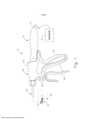
[0009] A Figura 1 representa uma vista em elevação lateral de um instrumento cirúrgico exemplificador;[0009] Figure 1 represents a side elevation view of an exemplary surgical instrument;
[0010] A Figura 2 representa uma vista em perspectiva do atuador de extremidade do instrumento da Figura 1, em uma configuração aberta;[0010] Figure 2 represents a perspective view of the end actuator of the instrument of Figure 1, in an open configuration;
[0011] A Figura 3A representa uma vista em seção transversal lateral do atuador de extremidade da Figura 2, em uma configuração aberta;[0011] Figure 3A represents a side cross-sectional view of the end actuator of Figure 2, in an open configuration;
[0012] A Figura 3B representa uma vista em seção transversal lateral do atuador de extremidade da Figura 2, em uma configuração fechada;[0012] Figure 3B represents a side cross-sectional view of the end actuator of Figure 2, in a closed configuration;
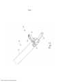
[0013] A Figura 4 representa uma vista em perspectiva de um outro instrumento cirúrgico exemplificador;[0013] Figure 4 represents a perspective view of another exemplary surgical instrument;
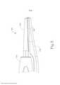
[0014] A Figura 5 representa uma vista em elevação lateral do atuador de extremidade do instrumento da Figura 4, em uma configuração fechada;[0014] Figure 5 represents a side elevation view of the end actuator of the instrument of Figure 4, in a closed configuration;
[0015] A Figura 6A representa uma vista em perspectiva do atuador de extremidade da Figura 5, em uma configuração aberta;[0015] Figure 6A represents a perspective view of the end actuator of Figure 5, in an open configuration;
[0016] A Figura 6B representa uma vista em perspectiva do atuador de extremidade da Figura 5, em uma configuração fechada;[0016] Figure 6B represents a perspective view of the end actuator of Figure 5, in a closed configuration;
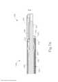
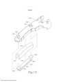
[0017] A Figura 7A representa uma vista lateral em seção transversal de um atuador de extremidade alternativo exemplificador, em uma configuração fechada, com um elemento de resfriamento afastado do guia de ondas;[0017] Figure 7A represents a cross-sectional side view of an exemplary alternative end actuator, in a closed configuration, with a cooling element away from the waveguide;
[0018] A Figura 7B representa uma vista lateral em seção transversal do atuador de extremidade da Figura 7A, em uma configuração aberta, com um elemento de resfriamento em contato com o guia de ondas;[0018] Figure 7B represents a side view in cross section of the end actuator of Figure 7A, in an open configuration, with a cooling element in contact with the waveguide;
[0019] A Figura 8 representa uma vista em perspectiva do elemento de resfriamento da Figura 7A;[0019] Figure 8 represents a perspective view of the cooling element of Figure 7A;
[0020] A Figura 9 representa uma vista em perspectiva de um braço com garra alternativo exemplificador;[0020] Figure 9 represents a perspective view of an exemplary alternative gripper arm;
[0021] A Figura 10 representa uma vista explodida do braço com garra da Figura 9;[0021] Figure 10 represents an exploded view of the gripper arm of Figure 9;
[0022] A Figura 11 representa uma vista da extremidade em seção transversal do braço com garra da Figura 9, fixado contra uma lâmina ultrassônica;[0022] Figure 11 represents an end view in cross section of the gripper arm of Figure 9, fixed against an ultrasonic blade;
[0023] A Figura 12 representa uma outra vista em perspectiva de um braço com garra alternativo exemplificador;[0023] Figure 12 represents another perspective view of an exemplary alternative claw arm;
[0024] A Figura 13 representa uma vista explodida do braço com garra da Figura 12;[0024] Figure 13 represents an exploded view of the gripper arm of Figure 12;
[0025] A Figura 14A representa uma vista em elevação lateral de um outro atuador de extremidade alternativo exemplificador, em uma configuração fechada, com um elemento de resfriamento afastado da lâmina ultrassônica;[0025] Figure 14A represents a side elevation view of another exemplary alternative end actuator, in a closed configuration, with a cooling element away from the ultrasonic blade;
[0026] A Figura 14B representa uma vista em elevação lateral do atuador de extremidade da Figura 14A, em uma configuração aberta, com um elemento de resfriamento em contato com a lamina ultrassônica; e[0026] Figure 14B represents a side elevation view of the end actuator of Figure 14A, in an open configuration, with a cooling element in contact with the ultrasonic blade; and
[0027] A Figura 15 representa uma vista da extremidade em seção transversal do elemento de resfriamento da Figura 14A, em contato com a lâmina ultrassônica.[0027] Figure 15 represents an end view in cross section of the cooling element of Figure 14A, in contact with the ultrasonic blade.
[0028] Os desenhos não pretendem ser limitadores de modo algum e contempla-se que várias modalidades da tecnologia podem ser executadas em uma variedade de outras maneiras, incluindo aquelas não necessariamente representadas nos desenhos. Os desenhos incorporados em anexo e formando uma parte do relatório descritivo ilustram vários aspectos da presente tecnologia e, em conjunto com a descrição, servem para explicar os princípios da tecnologia; entende-se, entretanto, que esta tecnologia não se limita precisamente às disposições mostradas.[0028] The drawings are not intended to be limiting in any way and it is contemplated that various embodiments of the technology may be performed in a variety of other ways, including those not necessarily represented in the drawings. The drawings incorporated in the annex and forming a part of the specification illustrate various aspects of the present technology and, in conjunction with the description, serve to explain the principles of the technology; it is understood, however, that this technology is not limited precisely to the provisions shown.
[0029] A descrição a seguir de certos exemplos da tecnologia não deve ser usada para limitar o seu escopo. Outros exemplos, características, aspectos, modalidades e vantagens da tecnologia se tornarão evidentes aos versados na técnica com a descrição a seguir, que é por meio de ilustrações, um dos melhores modos contemplados para realização da tecnologia. Conforme será compreendido, a tecnologia aqui descrita é capaz de outros aspectos diferentes e óbvios, todos sem desconsiderar a invenção. Consequentemente, os desenhos e as descrições devem ser considerados como de natureza ilustrativa e não restritiva.[0029] The following description of certain examples of the technology should not be used to limit its scope. Other examples, features, aspects, modalities and advantages of the technology will become apparent to those skilled in the art with the following description, which is, by way of illustration, one of the best contemplated modes for carrying out the technology. As will be understood, the technology described herein is capable of other different and obvious aspects, all without disregarding the invention. Accordingly, the drawings and descriptions are to be regarded as illustrative and not restrictive in nature.
[0030] É entendido adicionalmente que qualquer um ou mais dentre os ensinamentos, expressões, modalidades, exemplos etc. aqui descritos podem ser combinados com qualquer um ou mais dentre os outros ensinamentos, expressões, modalidades, exemplos etc. que são descritos na presente invenção. Os ensinamentos, expressões, modalidades, exemplos etc. descritos a seguir não devem ser vistos isoladamente um em relação ao outro. Várias maneiras adequadas, pelas quais os ensinamentos da presente invenção podem ser combinados, se tornarão prontamente evidentes aos versados na técnica tendo em vista dos ensinamentos da presente invenção. Essas modificações e variações são destinadas a serem incluídas no escopo das reivindicações anexas.[0030] It is further understood that any one or more of the teachings, expressions, modalities, examples, etc. described herein may be combined with any one or more of the other teachings, expressions, embodiments, examples, etc. which are described in the present invention. The teachings, expressions, modalities, examples, etc. described below should not be viewed in isolation from one another. Various suitable ways in which the teachings of the present invention may be combined will become readily apparent to those skilled in the art in view of the teachings of the present invention. These modifications and variations are intended to be included within the scope of the appended claims.
[0031] Para maior clareza da revelação, os termos "proximal" e "distal" são aqui definidos em relação a um operador humano ou robótico do instrumento cirúrgico. O termo "proximal" se refere à posição de um elemento mais próximo ao operador humano ou robótico do instrumento cirúrgico e mais afastado do atuador de extremidade cirúrgico do instrumento cirúrgico. O termo "distal" se refere à posição de um elemento mais próximo ao atuador de extremidade cirúrgico do instrumento cirúrgico e mais afastado do operador humano ou robótico do instrumento cirúrgico.[0031] For clarity of disclosure, the terms "proximal" and "distal" are defined herein in relation to a human or robotic operator of the surgical instrument. The term "proximal" refers to the position of an element closest to the human or robotic operator of the surgical instrument and furthest from the surgical end actuator of the surgical instrument. The term "distal" refers to the position of an element closest to the surgical end actuator of the surgical instrument and furthest from the human or robotic operator of the surgical instrument.
[0032] As Figuras 1 a 6B ilustram instrumentos cirúrgicos ultrassônicos exemplificadores (10, 100). Ao menos parte de cada instrumento (10, 100) pode ser construída e operável de acordo com ao menos alguns dos ensinamentos da patente US n° 5.322.055; patente US n° 5.873.873; patente US n° 5.980.510; patente US n° 6.325.811; patente US n° 6.773.444; patente US n° 6.783.524; publicação de patente US n° 2006/0079874; publicação de patente US n° 2007/0191713; publicação de patente US n° 2007/0282333; publicação de patente US n° 2008/0200940; publicação de patente US n° 2009/0105750; publicação de patente US n° 2010/0069940; publicação de patente US n° 2011/0015660; publicação de patente US n° 2012/0112687; publicação de patente US n° 2012/0116265; publicação de patente US n° 2014/0005701; publicação de patente US n° 2014/0114334; pedido de patente US n° 61/410.603; e/ou pedido de patente US n° 14/028.717. As revelações de cada uma das patentes, publicações e pedidos supracitados estão aqui incorporadas a título de referência. Conforme descrito ali e, conforme será descrito com mais detalhes abaixo, cada instrumento (10, 100) tem por finalidade cortar tecido e vedar ou selar tecidos (por exemplo, um vaso sanguíneo, etc.) de maneira substancialmente simultânea. Deve-se entender que os instrumentos (10, 100) podem ter várias semelhanças estruturais e funcionais com as tesouras ultrassônicas HARMONIC ACE®, as tesouras ultrassônicas HARMONIC WAVE®, as tesouras ultrassônicas HARMONIC FOCUS® e/ou com as lâminas ultrassônicas HARMONIC SYNERGY®. Além disso, os instrumentos (10, 100) podem ter várias semelhanças estruturais e funcionais com os dispositivos ensinados em qualquer uma das outras referências citadas e incorporadas a título de referência na presente invenção.[0032] Figures 1 to 6B illustrate exemplifying ultrasonic surgical instruments (10, 100). At least part of each instrument (10, 100) may be constructed and operable in accordance with at least some of the teachings of US Patent No. 5,322,055; US Patent No. 5,873,873; US Patent No. 5,980,510; US Patent No. 6,325,811; US Patent No. 6,773,444; US Patent No. 6,783,524; US Patent Publication No. 2006/0079874; US Patent Publication No. 2007/0191713 ; US Patent Publication No. 2007/0282333 ; US Patent Publication No. 2008/0200940; US Patent Publication No. 2009/0105750; US Patent Publication No. 2010/0069940; US Patent Publication No. 2011/0015660; US Patent Publication No. 2012/0112687; US Patent Publication No. 2012/0116265; US Patent Publication No. 2014/0005701; US Patent Publication No. 2014/0114334; US Patent Application No. 61/410,603; and/or US Patent Application No. 14/028,717. The disclosures of each of the foregoing patents, publications and applications are incorporated herein by reference. As described there and as will be described in more detail below, each instrument (10, 100) is intended to cut tissue and seal or seal tissue (e.g., a blood vessel, etc.) substantially simultaneously. It should be understood that the instruments (10, 100) may have many structural and functional similarities to HARMONIC ACE® Ultrasonic Scissors, HARMONIC WAVE® Ultrasonic Scissors, HARMONIC FOCUS® Ultrasonic Scissors and/or HARMONIC SYNERGY® Ultrasonic Blades . In addition, the instruments (10, 100) may have many structural and functional similarities to the devices taught in any of the other references cited and incorporated by reference into the present invention.
[0033] Até o ponto em que houver algum grau de sobreposição entre os ensinamentos das referências citadas na presente invenção, nas tesouras ultrassônicas HARMONIC ACE®, nas tesouras ultrassônicas HARMONIC WAVE®, nas tesouras ultrassônicas HARMONIC FOCUS® e/ou nas lâminas ultrassônicas HARMONIC SYNERGY®, e nos ensinamentos a seguir relacionados aos instrumentos (10, 100), não se pretende que qualquer descrição contida na presente invenção seja entendida como técnica anterior reconhecida. Pelo contrário, o escopo de vários dos ensinamentos da presente invenção é mais amplo que o escopo dos ensinamentos das referências citadas na presente invenção e das tesouras ultrassônicas HARMONIC ACE®, das tesouras ultrassônicas HARMONIC WAVE®, das tesouras ultrassônicas HARMONIC FOCUS® e das lâminas ultrassônicas HARMONIC SYNERGY®.[0033] To the extent that there is some degree of overlap between the teachings of the references cited in the present invention, HARMONIC ACE® ultrasonic scissors, HARMONIC WAVE® ultrasonic scissors, HARMONIC FOCUS® ultrasonic scissors and/or HARMONIC ultrasonic blades SYNERGY®, and in the following teachings relating to instruments (10, 100), any description contained in the present invention is not intended to be understood as prior art recognized. On the contrary, the scope of several of the teachings of the present invention is broader than the scope of the teachings of the references cited in the present invention and HARMONIC ACE® ultrasonic scissors, HARMONIC WAVE® ultrasonic scissors, HARMONIC FOCUS® ultrasonic scissors and blades. HARMONIC SYNERGY® ultrasonic devices.
[0034] A Figura 1 ilustra um instrumento cirúrgico ultrassônico exemplificador (10) que é configurado para ser usado em procedimentos cirúrgicos minimamente invasivos (por exemplo, através de um trocarte ou outra porta de acesso de pequeno diâmetro, etc.). O instrumento (10) deste exemplo compreende um conjunto do cabo (20), um conjunto de eixo (30) e um atuador de extremidade (40). Conforme mostrado nas Figuras 2 a 3B, o conjunto de eixo (30) compreende uma bainha externa (32), um tubo interno (34) disposto de modo deslizante dentro da bainha externa (32) e um guia de ondas (38) disposto dentro do tubo interno (34). Conforme será discutido em mais detalhes abaixo, a translação longitudinal do tubo interno (34) em relação à bainha externa (32) leva ao acionamento do braço com garra (44) no atuador de extremidade (40). O conjunto do cabo (20) compreende um corpo (22) incluindo uma empunhadura de pistola (24) e um par de botões (26). O conjunto do cabo (20) inclui também um gatilho (28) que é articulável na direção da empunhadura de pistola (24) e na direção contrária. Deve-se entender, entretanto, que várias outras configurações adequadas podem ser usadas, incluindo, mas não limitado a, uma configuração de empunhadura de tesoura. No presente exemplo, um membro resilientemente traciona o gatilho (28) na direção contrária da empunhadura de pistola (24). O gatilho (28) é articulável em direção à empunhadura de pistola (24) para conduzir o tubo interno (34) proximalmente em relação à bainha externa (32). Quando o gatilho (28) é então liberado ou liberado da empunhadura de pistola (24), o tubo interno (34) é conduzido distalmente em relação à bainha externa (32). Somente a título de exemplo, o gatilho (28) pode ser acoplado ao tubo interno (34), de acordo com os ensinamentos de várias referências aqui citadas. Outras maneiras adequadas nas quais o acionador (28) pode ser acoplado com o tubo interno (34) serão evidentes para os versados na técnica, em vista dos ensinamentos da presente invenção.[0034] Figure 1 illustrates an example ultrasonic surgical instrument (10) that is configured to be used in minimally invasive surgical procedures (eg, through a trocar or other small diameter access port, etc.). The instrument (10) of this example comprises a cable assembly (20), a shaft assembly (30) and an end actuator (40). As shown in Figures 2 to 3B, the shaft assembly (30) comprises an outer sheath (32), an inner tube (34) slidably disposed within the outer sheath (32), and a waveguide (38) disposed inside. of the inner tube (34). As will be discussed in more detail below, longitudinal translation of the inner tube (34) with respect to the outer sheath (32) leads to actuation of the gripper arm (44) on the end actuator (40). The handle assembly (20) comprises a body (22) including a pistol grip (24) and a pair of buttons (26). The handle assembly (20) also includes a trigger (28) which is pivotable towards the pistol grip (24) and away. It should be understood, however, that a number of other suitable configurations may be used, including, but not limited to, a scissor grip configuration. In the present example, a member resiliently pulls the trigger (28) away from the pistol grip (24). The trigger (28) is pivotable towards the pistol grip (24) to drive the inner tube (34) proximally to the outer sheath (32). When the trigger (28) is then released or released from the pistol grip (24), the inner tube (34) is led distally to the outer sheath (32). By way of example only, the trigger (28) may be coupled to the inner tube (34), in accordance with the teachings of various references cited herein. Other suitable ways in which the actuator (28) may be coupled with the inner tube (34) will be apparent to those skilled in the art, in view of the teachings of the present invention.
[0035] Conforme mostrado nas Figuras 2 a 3B, o atuador de extremidade (40) inclui uma lâmina ultrassônica (42) e um braço com garra pivotante (44). O braço com garra (44) inclui um bloco de fixação (46) voltado para a lâmina ultrassônica (42). O braço com garra (44) está acoplado de modo pivotante com uma extremidade distal da bainha externa (32) do conjunto de eixo (30), sobre a lâmina ultrassônica (42), por meio de um pino (33). Uma extremidade distal do tubo interno (34) está acoplada de modo pivotante com uma extremidade proximal do braço com garra (44), sob a lâmina ultrassônica (42), por meio de um outro pino (35). Dessa forma, a translação longitudinal do tubo interno (34) em relação à bainha externa (32) leva o braço com garra (44) a pivotar em torno do pino (33) na mesma direção e na direção contrária da lâmina ultrassônica (42) para fixar, assim, o tecido entre o bloco de fixação (46) e a lâmina ultrassônica (42) para cortar transversalmente e/ou vedar o tecido. Em particular, conforme visto na transição da Figura 3A para a Figura 3B, a translação proximal longitudinal do tubo interno (34) em relação à bainha externa (32) e ao conjunto de cabo (20) leva o braço com garra (44) a pivotar em direção à lâmina ultrassônica (42); e a translação longitudinal distal do tubo interno (34) em relação à bainha externa (32) e ao conjunto de cabo (20) leva o braço com garra (44) a pivotar em direção contrária à lâmina ultrassônica (42). Deve-se compreender, portanto, que a articulação do gatilho (28) em direção à empunhadura de pistola (24) provoca a articulação do braço com garra (44) em direção à lâmina ultrassônica; e que a articulação do gatilho (28) em direção contrária à empunhadura de pistola (24) provocará a articulação do braço com garra (44) em direção contrária à lâmina ultrassônica.[0035] As shown in Figures 2 to 3B, the end actuator (40) includes an ultrasonic blade (42) and a pivoting jaw arm (44). The claw arm (44) includes a clamping block (46) facing the ultrasonic blade (42). The claw arm (44) is pivotally coupled with a distal end of the outer sheath (32) of the shaft assembly (30) onto the ultrasonic blade (42) by means of a pin (33). A distal end of the inner tube (34) is pivotally coupled to a proximal end of the gripper arm (44) under the ultrasonic blade (42) by means of another pin (35). In this way, the longitudinal translation of the inner tube (34) in relation to the outer sheath (32) causes the claw arm (44) to pivot around the pin (33) in the same direction and in the opposite direction of the ultrasonic blade (42) to thereby secure the tissue between the fixation block (46) and the ultrasonic blade (42) to transversely cut and/or seal the tissue. In particular, as seen in the transition from Figure 3A to Figure 3B, proximal longitudinal translation of the inner tube (34) with respect to the outer sheath (32) and cable assembly (20) causes the gripper arm (44) to pivot towards the ultrasonic blade (42); and distal longitudinal translation of the inner tube (34) with respect to the outer sheath (32) and handle assembly (20) causes the gripper arm (44) to pivot against the ultrasonic blade (42). It should be understood, therefore, that the articulation of the trigger (28) towards the pistol grip (24) causes the articulation of the claw arm (44) towards the ultrasonic blade; and that articulating the trigger (28) away from the pistol grip (24) will cause the grapple arm (44) to pivot away from the ultrasonic blade.
[0036] Um conjunto transdutor ultrassônico (12) se estende de maneira proximal do corpo (22) do conjunto do cabo (20). O conjunto transdutor (12) é acoplado a um gerador (16) através de um cabo (14). O conjunto transdutor (12) recebe energia elétrica do gerador (16) e converte tal energia em vibrações ultrassônicas através de princípios piezoelétricos. O gerador (16) pode incluir uma fonte de energia e um módulo de controle que é configurado para fornecer um perfil de energia ao conjunto transdutor (12), que é especialmente adequado para a geração de vibrações ultrassônicas através do conjunto transdutor (12). Somente a título de exemplo, o gerador (16) pode compreender um GEN 300 vendido pela Ethicon Endo-Surgery, Inc. de Cincinnati, Ohio, EUA. Adicional ou alternativamente, o gerador (16) pode ser construído de acordo com ao menos alguns dos ensinamentos da publicação de patente US n° 2011/0087212 intitulada "Ultrasonic Device for Cutting and Coagulating", publicada em 14 de abril de 2011, cuja revelação está aqui incorporada a título de referência. Deve-se entender também que ao menos algumas das funcionalidades do gerador (16) podem ser integradas ao conjunto do cabo (20), e que o conjunto do cabo (20) pode até mesmo incluir uma bateria ou outra fonte de energia embutida, de modo que o cabo (14) seja omitido. Outras formas adequadas que o gerador (16) pode assumir, bem como vários recursos e funcionalidades que o gerador (16) pode fornecer, se tornarão evidentes para os versados na técnica a partir dos ensinamentos da presente invenção.[0036] An ultrasonic transducer assembly (12) extends proximally from the body (22) of the cable assembly (20). The transducer assembly (12) is coupled to a generator (16) through a cable (14). The transducer assembly (12) receives electrical energy from the generator (16) and converts such energy into ultrasonic vibrations through piezoelectric principles. The generator (16) may include a power source and a control module that is configured to provide a power profile to the transducer assembly (12) that is especially suited for generating ultrasonic vibrations through the transducer assembly (12). By way of example only, the generator (16) may comprise a
[0037] Vibrações ultrassônicas geradas pelo conjunto transdutor (12) são comunicadas ao longo de um guia de ondas acústicas (38), que se estende através do conjunto do cabo (30) até atingir a lâmina ultrassônica (42). O guia de ondas (38) está preso dentro do conjunto de eixo (30) por meio de um pino (não mostrado), que passa através de um guia de ondas (38) e de um conjunto de eixo (30). Esse pino está localizado em uma posição ao longo do comprimento do guia de ondas (38) que corresponde a um nó associado às vibrações ultrassônicas ressonantes comunicadas através do guia de ondas (38). Como se observa acima, quando a lâmina ultrassônica (42) está em um estado ativado (isto é, vibrando ultrassonicamente), a lâmina ultrassônica (42) tem por finalidade cortar eficazmente através do tecido e vedá-lo, particularmente quando o tecido está sendo segurado entre o bloco de fixação (46) e a lâmina ultrassônica (42). Deve-se entender que o guia de ondas (38) pode ser configurado para amplificar vibrações magnéticas transmitidas através do guia de ondas (38). Além disso, o guia de ondas (38) pode incluir ainda recursos para controlar o ganho de vibrações longitudinais ao longo do guia de ondas (38) e/ou recursos para sintonizar o guia de ondas (38) à frequência ressonante do sistema.[0037] Ultrasonic vibrations generated by the transducer assembly (12) are communicated along an acoustic waveguide (38), which extends through the cable assembly (30) until reaching the ultrasonic blade (42). The waveguide (38) is secured within the axle assembly (30) by means of a pin (not shown) which passes through a waveguide (38) and an axle assembly (30). This pin is located at a position along the length of the waveguide (38) that corresponds to a node associated with the resonant ultrasonic vibrations communicated through the waveguide (38). As noted above, when the ultrasonic blade (42) is in an activated state (i.e., vibrating ultrasonically), the ultrasonic blade (42) is intended to effectively cut through the tissue and seal it, particularly when the tissue is being held between the clamping block (46) and the ultrasonic blade (42). It should be understood that the waveguide (38) may be configured to amplify magnetic vibrations transmitted through the waveguide (38). Furthermore, the waveguide (38) may further include means for controlling the gain of longitudinal vibrations along the waveguide (38) and/or means for tuning the waveguide (38) to the resonant frequency of the system.
[0038] No presente exemplo, a extremidade distal da lamina ultrassônica (42) fica localizada em uma posição que corresponde a um antinó associado às vibrações ultrassônicas ressonantes, comunicadas através do guia de ondas (38), para sintonizar o conjunto acústico a uma frequência ressonante fo preferencial quando o conjunto acústico não está carregado com tecido. Quando o conjunto transdutor (12) está energizado, a extremidade distal da lâmina ultrassônica (42) é configurada para se mover longitudinalmente na faixa de, por exemplo, aproximadamente 10 a 500 mícrons de pico a pico e, em alguns casos, na faixa de cerca de 20 a cerca de 200 mícrons em uma frequência vibratória fo predeterminada de, por exemplo, 55,5 kHz. Quando o conjunto transdutor (12) do presente exemplo está ativado, essas oscilações mecânicas são transmitidas através do guia de ondas para atingir a lâmina ultrassônica (102), causando, assim, a oscilação da lâmina ultrassônica (102) na frequência ultrassônica ressonante. Portanto, quando o tecido é fixado entre a lâmina ultrassônica (42) e o bloco de fixação (46), a oscilação ultrassônica da lâmina ultrassônica (42) pode simultaneamente cortar o tecido e desnaturar as proteínas nas células do tecido adjacente, fornecendo, assim, um efeito coagulante com relativamente pouca propagação térmica. Em algumas versões, uma corrente elétrica pode também ser fornecida através da lâmina ultrassônica (42) e/ou do bloco de fixação (46) para selar também o tecido.[0038] In the present example, the distal end of the ultrasonic blade (42) is located in a position that corresponds to an antinode associated with the resonant ultrasonic vibrations, communicated through the waveguide (38), to tune the acoustic set to a frequency resonant is preferred when the acoustic assembly is not loaded with tissue. When the transducer assembly (12) is energized, the distal end of the ultrasonic blade (42) is configured to move longitudinally in the range, for example, approximately 10 to 500 microns from peak to peak, and in some cases, in the range of about 20 to about 200 microns at a predetermined frequency of vibration of, for example, 55.5 kHz. When the transducer assembly (12) of the present example is activated, these mechanical oscillations are transmitted through the waveguide to strike the ultrasonic blade (102), thereby causing the ultrasonic blade (102) to oscillate at the resonant ultrasonic frequency. Therefore, when tissue is clamped between the ultrasonic blade (42) and the fixation block (46), the ultrasonic oscillation of the ultrasonic blade (42) can simultaneously cut the tissue and denature proteins in adjacent tissue cells, thereby providing , a coagulating effect with relatively little thermal propagation. In some versions, an electrical current can also be supplied through the ultrasonic blade (42) and/or the fixation block (46) to also seal the tissue.
[0039] Um operador pode ativar botões (26) para ativar seletivamente o conjunto transdutor (12) para, assim, ativar a lâmina ultrassônica (42). No presente exemplo, dois botões (26) são fornecidos - um para ativar a lâmina ultrassónica (42) com uma energia baixa e outro para ativar a lâmina ultrassônica (42) com uma energia alta. No entanto, deve-se entender que pode ser fornecido qualquer outro número adequado de botões e/ou níveis de energia selecionáveis. Por exemplo, pode ser fornecido um pedal para ativar seletivamente o conjunto transdutor (12). Os botões (26) do presente exemplo estão posicionados de modo que um operador possa operar pronta e completamente o instrumento (10) com uma única mão. Por exemplo, o operador pode posicionar seu polegar sobre a empunhadura de pistola (24), posicionar seu dedo médio, anelar ou mínimo sobre o gatilho (28) e manipular os botões (26) usando seu dedo indicador. Obviamente, quaisquer outras técnicas adequadas podem ser usadas para segurar e operar o instrumento (10); e os botões (26) podem estar localizados em quaisquer outras posições adequadas.[0039] An operator can activate buttons (26) to selectively activate the transducer assembly (12) to thus activate the ultrasonic blade (42). In the present example, two buttons (26) are provided - one to activate the ultrasonic blade (42) at a low energy and the other to activate the ultrasonic blade (42) at a high energy. However, it should be understood that any other suitable number of buttons and/or selectable power levels may be provided. For example, a footswitch can be provided to selectively activate the transducer assembly (12). The buttons (26) of the present example are positioned so that an operator can readily and completely operate the instrument (10) with a single hand. For example, the operator can position his thumb over the pistol grip (24), position his middle, ring or little finger over the trigger (28), and manipulate the buttons (26) using his index finger. Of course, any other suitable techniques can be used to hold and operate the instrument (10); and buttons (26) may be located in any other suitable positions.
[0040] Os componentes supracitados e operacionalidades do instrumento (10) são meramente ilustrativos. O instrumento (10) pode ser configurado de diversas outras maneiras, conforme se tornará aparente para os versados na técnica, com base nos ensinamentos da presente invenção. Somente a título de exemplo, ao menos parte do instrumento (10) pode ser construída e/ou operável de acordo com ao menos alguns dos ensinamentos de qualquer um das seguintes patentes e publicações, cujas revelações estão todas incorporadas à presente invenção para fins de referência: patente US n° 5.322.055; patente US n° 5.873.873; patente US n° 5.980.510; patente US n° 6.325.811; patente US n° 6.783.524; publicação de patente US n° 2006/0079874; publicação de patente US n° 2007/0191713;publicação de patente US n° 2007/0282333; publicação de patente US n° 2008/0200940; publicação de patente US n° 2010/0069940; publicação de patente US n° 2011/0015660; publicação de patente US n° 2012/0112687; publicação de patente US n° 2012/0116265; publicação de patente US n° 2014/0005701; e/ou da publicação de patente US n° 2014/0114334. Variações adicionais meramente ilustrativas do instrumento (10) serão descritas em mais detalhes abaixo. Deve-se entender que as variações descritas abaixo podem ser prontamente aplicadas ao instrumento (10) acima descrito e a quaisquer instrumentos referidos em qualquer uma das referências citadas na presente invenção, dentre outras.[0040] The aforementioned components and instrument operability (10) are merely illustrative. The instrument 10 may be configured in a number of other ways, as will become apparent to those skilled in the art based on the teachings of the present invention. By way of example only, at least part of the instrument (10) may be constructed and/or operable in accordance with at least some of the teachings of any of the following patents and publications, the disclosures of which are all incorporated by the present invention by reference. : US Patent No. 5,322,055; US Patent No. 5,873,873; US Patent No. 5,980,510; US Patent No. 6,325,811; US Patent No. 6,783,524; US Patent Publication No. 2006/0079874; US Patent Publication No. 2007/0191713; US Patent Publication No. 2007/0282333; US Patent Publication No. 2008/0200940; US Patent Publication No. 2010/0069940; US Patent Publication No. 2011/0015660; US Patent Publication No. 2012/0112687; US Patent Publication No. 2012/0116265; US Patent Publication No. 2014/0005701; and/or from US Patent Publication No. 2014/0114334. Additional merely illustrative variations of the instrument (10) will be described in more detail below. It should be understood that the variations described below can be readily applied to the instrument (10) described above and to any instruments referred to in any of the references cited in the present invention, among others.
[0041] A Figura 4 ilustra um instrumento cirúrgico ultrassônico exemplificador (100) que está configurado para ser usado em procedimentos cirúrgicos abertos. O instrumento (100) deste exemplo compreende um conjunto do cabo (120), um conjunto de eixo (130) e um atuador de extremidade (140). O conjunto do cabo (120) compreende um corpo (122) incluindo um apoio para os dedos (124) e um par de botões (126). O instrumento (100) inclui também um conjunto de braço com garra (150) que é articulável na direção do corpo e na direção contrária do corpo (122). O braço com garra (150) inclui uma haste (152) com um apoio para o dedo polegar (154). O apoio para o dedo polegar (154) e o apoio para os dedos (124) juntos fornecem uma configuração do tipo empunhadura de tesoura. Deve-se entender, entretanto, que várias outras configurações adequadas podem ser usadas, incluindo, mas não limitado a, uma configuração de empunhadura de pistola.[0041] Figure 4 illustrates an example ultrasonic surgical instrument (100) that is configured for use in open surgical procedures. The instrument (100) of this example comprises a cable assembly (120), a shaft assembly (130) and an end actuator (140). The handle assembly (120) comprises a body (122) including a finger rest (124) and a pair of buttons (126). The instrument (100) also includes a claw arm assembly (150) that is pivotable toward the body and away from the body (122). The claw arm (150) includes a rod (152) with a thumb rest (154). The thumb rest (154) and the finger rest (124) together provide a scissor grip type configuration. It should be understood, however, that a number of other suitable configurations may be used, including, but not limited to, a pistol grip configuration.
[0042] O conjunto de eixo (130) compreende uma bainha externa (132) que se estende distalmente a partir do corpo (122). Uma tampa (134) é presa à extremidade distal da bainha (132). Conforme se pode observar melhor nas Figuras 5 a 6B, o atuador de extremidade (140) compreende uma lâmina ultrassônica (142) e um braço com garra (144). Uma lâmina ultrassônica (142) se estende distalmente a partir da tampa (134). O braço com garra (144) é um recurso integral do conjunto de braço com garra (150). O braço com garra (144) inclui um bloco de fixação (146) voltado para a lâmina ultrassônica (142). O conjunto de braço com garra (150) é acoplado de forma articulada com a bainha externa (132) por meio de um pino (156). O braço com garra (144) está posicionado distal ao pino (156); enquanto a haste (152) e o apoio para o dedo polegar (154) estão posicionados proximais ao pino (156). Dessa forma, conforme mostrado nas Figuras 6A a 6B, o braço com garra (144) é articulável na direção e na direção contrária da lâmina ultrassônica (142) com base na articulação do apoio para o dedo polegar (154) na direção e na direção contrária do corpo (122) do conjunto de cabo (120). Deve-se compreender, portanto, que um operador pode apertar o apoio para o dedo polegar (154) em direção ao corpo (122) para, assim, fixar o tecido entre o bloco de fixação (146) e a lâmina ultrassônica (142) para cortar transversalmente e/ou vedar o tecido. Em algumas versões, um ou mais membros resilientes são usados para inclinar o braço com garra (144) para a posição aberta mostrada na Figura 6A. Somente a título de exemplo, tal membro resiliente pode compreender um feixe de molas, uma mola de torção e/ou qualquer outro tipo adequado de membro resiliente.[0042] The shaft assembly (130) comprises an outer sheath (132) that extends distally from the body (122). A cap (134) is attached to the distal end of the sheath (132). As can best be seen in Figures 5 to 6B, the end actuator (140) comprises an ultrasonic blade (142) and a gripper arm (144). An ultrasonic blade (142) extends distally from the cap (134). The grapple arm (144) is an integral feature of the grapple arm assembly (150). The gripper arm (144) includes a clamping block (146) facing the ultrasonic blade (142). The claw arm assembly (150) is pivotally coupled to the outer sheath (132) by means of a pin (156). The claw arm (144) is positioned distal to the pin (156); while the rod (152) and thumb rest (154) are positioned proximal to the pin (156). Thus, as shown in Figures 6A to 6B, the gripper arm (144) is pivotable toward and away from the ultrasonic blade (142) based on the thumb rest (154) pivot toward and toward opposite the body (122) of the cable assembly (120). It should be understood, therefore, that an operator can squeeze the thumb rest (154) towards the body (122) to thereby secure the tissue between the fixation block (146) and the ultrasonic blade (142) to cross-cut and/or seal the fabric. In some versions, one or more resilient members are used to tilt the grapple arm (144) into the open position shown in Figure 6A. By way of example only, such a resilient member may comprise a spring bundle, a torsion spring and/or any other suitable type of resilient member.
[0043] Com referência à Figura 4, um conjunto transdutor ultrassônico (112) se estende de maneira proximal a partir do corpo (122) do conjunto do cabo (120). O conjunto transdutor (112) é acoplado a um gerador (116) através de um cabo (114). O conjunto transdutor (112) recebe energia elétrica do gerador (116) e converte tal energia em vibrações ultrassônicas através de princípios piezoelétricos. O gerador (116) pode incluir uma fonte de energia e um módulo de controle que é configurado para fornecer um perfil de energia ao conjunto transdutor (112), que é especialmente adequado para a geração de vibrações ultrassônicas através do conjunto transdutor (112). Somente a título de exemplo, o gerador (116) pode compreender um GEN 300 vendido pela Ethicon Endo-Surgery, Inc. de Cincinnati, Ohio, EUA. Adicional ou alternativamente, o gerador (116) pode ser construído de acordo com ao menos alguns dos ensinamentos da publicação de patente US n° 2011/0087212 intitulada "Ultrasonic Device for Cutting and Coagulating", publicada em 14 de abril de 2011, cuja revelação está aqui incorporada a título de referência. Deve-se entender também que ao menos algumas das funcionalidades do gerador (116) podem ser integradas ao conjunto do cabo (120), e que o conjunto do cabo (120) pode até mesmo incluir uma bateria ou outra fonte de energia embutida, de modo que o cabo (114) seja omitido. Outras formas adequadas que o gerador (116) pode assumir, bem como vários recursos e operacionabilidades que o gerador (116) pode fornecer, se tornarão evidentes para os versados na técnica a partir dos ensinamentos da presente invenção.[0043] Referring to Figure 4, an ultrasonic transducer assembly (112) extends proximally from the body (122) of the cable assembly (120). The transducer assembly (112) is coupled to a generator (116) via a cable (114). The transducer assembly (112) receives electrical energy from the generator (116) and converts such energy into ultrasonic vibrations through piezoelectric principles. The generator (116) may include a power source and a control module that is configured to provide a power profile to the transducer assembly (112) that is especially suited for generating ultrasonic vibrations through the transducer assembly (112). By way of example only,
[0044] As vibrações ultrassônicas geradas pelo conjunto transdutor (112) são comunicadas ao longo de um guia de ondas acústicas (138), que se estende através do conjunto do cabo (130) até atingir a lâmina ultrassônica (142). O guia de ondas (138) está preso dentro do conjunto de eixo (130) por meio de um pino (não mostrado),que passa através de um guia de ondas (138) e de um conjunto de eixo (130). Esse pino está localizado em uma posição ao longo do comprimento do guia de ondas (138) que corresponde a um nó associado às vibrações ultrassônicas ressonantes comunicadas através do guia de ondas (138). Conforme dito acima, quando a lâmina ultrassônica (142) está em um estado ativado (isto é, vibrando ultrassonicamente), a lâmina ultrassônica (142) tem por finalidade cortar eficazmente através do tecido e vedá-lo, particularmente quando o tecido está sendo segurado entre o bloco de fixação (146) e a lâmina ultrassônica (142). Deve-se entender que o guia de ondas (138) pode ser configurado para amplificar vibrações magnéticas transmitidas através do guia de ondas (138). Além disso, o guia de ondas (138) pode incluir ainda recursos para controlar o ganho de vibrações longitudinais ao longo do guia de ondas (138) e/ou recursos para sintonizar o guia de ondas (138) à frequência ressonante do sistema.[0044] The ultrasonic vibrations generated by the transducer assembly (112) are communicated along an acoustic waveguide (138), which extends through the cable assembly (130) until reaching the ultrasonic blade (142). The waveguide (138) is secured within the shaft assembly (130) by means of a pin (not shown) which passes through a waveguide (138) and shaft assembly (130). This pin is located at a position along the length of the waveguide (138) that corresponds to a node associated with the resonant ultrasonic vibrations communicated through the waveguide (138). As stated above, when the ultrasonic blade (142) is in an activated state (i.e., vibrating ultrasonically), the ultrasonic blade (142) is intended to effectively cut through the tissue and seal it, particularly when the tissue is being held. between the clamping block (146) and the ultrasonic blade (142). It should be understood that the waveguide (138) may be configured to amplify magnetic vibrations transmitted through the waveguide (138). In addition, the waveguide (138) may further include means for controlling the gain of longitudinal vibrations along the waveguide (138) and/or means for tuning the waveguide (138) to the resonant frequency of the system.
[0045] No presente exemplo, a extremidade distal da lamina ultrassônica (142) fica localizada em uma posição que corresponde a um antinó associado às vibrações ultrassônicas ressonantes, comunicadas através do guia de ondas (138), para sintonizar o conjunto acústico a uma frequência ressonante fo preferencial quando o conjunto acústico não está carregado com tecido. Quando o conjunto transdutor (112) está energizado, a extremidade distal da lâmina ultrassônica (142) é configurada para se mover longitudinalmente na faixa de, por exemplo, aproximadamente 10 a 500 mícrons de pico a pico e, em alguns casos, na faixa de cerca de 20 a cerca de 200 mícrons em uma frequência vibratória fo predeterminada de, por exemplo, 55,5 kHz. Quando o conjunto transdutor (112) do presente exemplo está ativado, essas oscilações mecânicas são transmitidas através do guia de ondas para atingir a lâmina ultrassônica (102), causando, assim, a oscilação da lâmina ultrassônica (102) na frequência ultrassônica ressonante. Portanto, quando o tecido é fixado entre a lâmina ultrassônica (142) e o bloco de fixação (46), a oscilação ultrassônica da lâmina ultrassônica (142) pode simultaneamente cortar o tecido e desnaturar as proteínas nas células do tecido adjacente, fornecendo, assim, um efeito coagulante com relativamente pouca propagação térmica. Em algumas versões, uma corrente elétrica pode também ser fornecida através da lâmina ultrassônica (142) e/ou do bloco de fixação (146) para selar também o tecido.[0045] In the present example, the distal end of the ultrasonic blade (142) is located in a position that corresponds to an antinode associated with the resonant ultrasonic vibrations, communicated through the waveguide (138), to tune the acoustic set to a frequency resonant is preferred when the acoustic assembly is not loaded with tissue. When the transducer assembly (112) is energized, the distal end of the ultrasonic blade (142) is configured to move longitudinally in the range of, for example, approximately 10 to 500 microns from peak to peak and, in some cases, in the range of about 20 to about 200 microns at a predetermined frequency of vibration of, for example, 55.5 kHz. When the transducer assembly (112) of the present example is activated, these mechanical oscillations are transmitted through the waveguide to strike the ultrasonic blade (102), thereby causing the ultrasonic blade (102) to oscillate at the resonant ultrasonic frequency. Therefore, when tissue is clamped between the ultrasonic blade (142) and the fixation block (46), the ultrasonic oscillation of the ultrasonic blade (142) can simultaneously cut through the tissue and denature proteins in adjacent tissue cells, thereby providing , a coagulating effect with relatively little thermal propagation. In some versions, an electrical current can also be supplied through the ultrasonic blade (142) and/or the fixation block (146) to also seal the tissue.
[0046] Um operador pode ativar botões (126) para ativar seletivamente o conjunto transdutor (112) para, assim, ativar a lâmina ultrassônica (142). No presente exemplo, dois botões (126) são fornecidos - um para ativar a lâmina ultrassónica (142) com uma energia baixa e outro para ativar a lâmina ultrassônica (142) com uma energia alta. No entanto, deve-se entender que pode ser fornecido qualquer outro número adequado de botões e/ou níveis de energia selecionáveis. Por exemplo, pode ser fornecido um pedal para ativar seletivamente o conjunto transdutor (112). Os botões (126) do presente exemplo estão posicionados de modo que um operador possa operar pronta e completamente o instrumento (100) com uma única mão. Por exemplo, o operador pode posicionar seu polegar sobre o apoio para o dedo polegar (154), posicionar seu dedo anelar no apoio para o dedo (124), posicionar seu dedo médio sobre o corpo (122) e manipular os botões (126) usando seu dedo indicador. Obviamente, quaisquer outras técnicas adequadas podem ser usadas para segurar e operar o instrumento (100); e os botões (126) podem estar localizados em quaisquer outras posições adequadas.[0046] An operator can activate buttons (126) to selectively activate the transducer assembly (112) to thereby activate the ultrasonic blade (142). In the present example, two buttons (126) are provided - one to activate the ultrasonic blade (142) at a low energy and the other to activate the ultrasonic blade (142) at a high energy. However, it should be understood that any other suitable number of buttons and/or selectable power levels may be provided. For example, a footswitch can be provided to selectively activate the transducer assembly (112). The buttons (126) of the present example are positioned so that an operator can readily and completely operate the instrument (100) with a single hand. For example, the operator can place their thumb on the thumb rest (154), place their ring finger on the thumb rest (124), place their middle finger on the body (122) and manipulate the buttons (126) using your index finger. Of course, any other suitable techniques may be used to hold and operate the instrument (100); and buttons (126) may be located in any other suitable positions.
[0047] Os componentes supracitados e funcionalidades do instrumento (100) são meramente ilustrativos. O instrumento (100) pode ser configurado de diversas outras maneiras, conforme se tornará aparente para os versados na técnica, com base nos ensinamentos da presente invenção. Somente a título de exemplo, ao menos parte do instrumento (100) pode ser construída e/ou operável de acordo com ao menos alguns dos ensinamentos de qualquer um dos seguintes, cujas revelações estão todas incorporadas à presente invenção para fins de referência: patente US n° 5.322.055; patente US n° 5.873.873; patente US n° 5.980.510; patente US n° 6.325.811; patente US n° 6.783.524; publicação de patente US n° 2006/0079874; publicação de patente US n° 2007/0191713; publicação de patente US n° 2007/0282333; publicação de patente US n° 2008/0200940; publicação de patente US n° 2010/0069940; publicação de patente US n° 2011/0015660; publicação de patente US n° 2012/0112687; publicação de patente US n° 2012/0116265; publicação de patente US n° 2014/0005701; publicação de patente US n° 2014/0114334; e/ou pedido de patente US n° 14/031.665. Variações adicionais meramente ilustrativas do instrumento (100) serão descritas em mais detalhes abaixo. Deve-se entender que as variações descritas abaixo podem ser prontamente aplicadas ao instrumento (100) acima descrito e a quaisquer instrumentos referidos em qualquer uma das referências citadas na presente invenção, dentre outras.[0047] The aforementioned components and features of the instrument (100) are merely illustrative. Instrument 100 may be configured in a number of other ways, as will become apparent to those skilled in the art based on the teachings of the present invention. By way of example only, at least part of the instrument (100) may be constructed and/or operable in accordance with at least some of the teachings of any of the following, the disclosures of which are all incorporated by the present invention by reference: US patent No. 5,322,055; US Patent No. 5,873,873; US Patent No. 5,980,510; US Patent No. 6,325,811; US Patent No. 6,783,524; US Patent Publication No. 2006/0079874; US Patent Publication No. 2007/0191713 ; US Patent Publication No. 2007/0282333 ; US Patent Publication No. 2008/0200940; US Patent Publication No. 2010/0069940; US Patent Publication No. 2011/0015660; US Patent Publication No. 2012/0112687; US Patent Publication No. 2012/0116265; US Patent Publication No. 2014/0005701; US Patent Publication No. 2014/0114334; and/or US Patent Application No. 14/031,665. Additional merely illustrative variations of the instrument 100 will be described in more detail below. It should be understood that the variations described below can be readily applied to the instrument 100 described above and to any instruments referred to in any of the references cited in the present invention, among others.
[0048] Em alguns casos, uma ou mais regiões do instrumento (10,100) podem superaquecer durante uma operação prolongada do instrumento (10, 100) em um procedimento cirúrgico. Somente a título de exemplo, a lâmina (42, 142), o braço com garra (44, 144) e/ou outras porções do instrumento (10, 100) podem, finalmente, superaquecer ao longo do tempo. Tal aquecimento pode ser causado por atrito e/ou outros fatores. Até o ponto em que o calor é gerado inicialmente em um componente específico do instrumento (10, 100) (por exemplo, a lâmina (42, 142) ou o braço com garra (44, 144), etc.),tal calor pode ser gradualmente transmitido para outras porções do instrumento (10, 100). Pode ser desejável minimizar tal aquecimento e/ou de outro modo administrar esse aquecimento, a fim de evitar que as porções aquecidas do instrumento (10, 100) entrem em contato com o tecido, que não deve ser aquecido. Por exemplo, o operador pode desejar que o atuador de extremidade (40, 140) esteja relativamente resfriado quando o operador desejar usar o atuador de extremidade (40, 140) para executar o afastamento por dissecções rombas e/ou a simples apreensão de tecido, etc. Pode também ser desejável minimizar o calor e/ou de outro modo controlar o calor de uma forma que não aumente significativamente o tamanho ou a operacionalidade do instrumento (10, 100). Vários exemplos de como o aquecimento pode ser minimizado e/ou de outra forma gerenciado estão descritos com mais detalhes abaixo; enquanto outros exemplos serão evidentes para os versados na técnica em vista dos ensinamentos da presente invenção.[0048] In some cases, one or more regions of the instrument (10,100) may overheat during prolonged operation of the instrument (10, 100) in a surgical procedure. By way of example only, the blade (42, 142), the gripper arm (44, 144) and/or other portions of the instrument (10, 100) can ultimately overheat over time. Such heating can be caused by friction and/or other factors. To the extent that heat is initially generated in a specific instrument component (10, 100) (e.g. blade (42, 142) or gripper arm (44, 144), etc.), such heat can be gradually transmitted to other portions of the instrument (10, 100). It may be desirable to minimize such heating and/or otherwise administer such heating in order to prevent the heated portions of the instrument (10, 100) from contacting tissue, which should not be heated. For example, the operator may want the end actuator (40, 140) to be relatively cool when the operator wants to use the end actuator (40, 140) to perform retraction by blunt dissections and/or simple tissue grasping, etc. It may also be desirable to minimize heat and/or otherwise control heat in a way that does not significantly increase the size or operability of the instrument (10, 100). Several examples of how heating can be minimized and/or otherwise managed are described in more detail below; while other examples will be apparent to those skilled in the art in view of the teachings of the present invention.
[0049] Em adição aos exemplos descritos abaixo, deve-se compreender que uma ou mais porções do instrumento (10, 100) podem incluir um isolante térmico ou revestimento protetor (por exemplo, uma fina camada de isolante térmico ou material protetor com uma condutividade térmica muito baixa). Um exemplo de um isolante térmico ou revestimento protetor é um nanocompósito (por exemplo, hidro-NM-óxido) em uma suspensão de resina acrílica. Um exemplo de um tal revestimento é o revestimento NANSULATE® disponível junto à Industrial Nanotech, Inc. de Naples, Flórida, EUA. Exemplos adicionais meramente ilustrativos de isolantes térmicos ou de revestimentos protetores incluem o seguinte: EST 1711 disponível junto à Surface Technologies Ellison, Inc. de Mason, Ohio, EUA; EST 1732 disponível junto à Surface Technologies Ellison, Inc. de Mason, Ohio, EUA; EST 3030 disponível junto à Surface Technologies Ellison, Inc. de Mason, Ohio, EUA; EST 1711 + EST 3030 disponível junto à Surface Technologies Ellison, Inc. de Mason, Ohio, EUA; OXytech V disponível junto à Techmetals, Inc. de Dayton, Ohio, EUA; Alumina de Titânio; Óxido de Zircônio; Óxido de Alumínio; e/ou em vários outros tipos de revestimentos, incluindo combinações dos mesmos.[0049] In addition to the examples described below, it should be understood that one or more portions of the instrument (10, 100) may include a thermal insulating or protective coating (e.g. a thin layer of thermal insulating or protective material with a conductivity very low heat). An example of a thermal insulator or protective coating is a nanocomposite (eg hydro-NM-oxide) in an acrylic resin suspension. An example of such a coating is the NANSULATE® coating available from Industrial Nanotech, Inc. from Naples, Florida, USA. Additional merely illustrative examples of thermal insulators or protective coatings include the following: EST 1711 available from Surface Technologies Ellison, Inc. of Mason, Ohio, USA; EST 1732 available from Surface Technologies Ellison, Inc. of Mason, Ohio, USA; EST 3030 available from Surface Technologies Ellison, Inc. of Mason, Ohio, USA; EST 1711 + EST 3030 available from Surface Technologies Ellison, Inc. of Mason, Ohio, USA; OXytech V available from Techmetals, Inc. of Dayton, Ohio, USA; Titanium Alumina; Zirconium Oxide; Aluminum Oxide; and/or in various other types of coatings, including combinations thereof.
[0050] Um isolante térmico ou um revestimento protetor pode ser aplicado a várias superfícies externas do instrumento (10, 100), como as regiões da lâmina (42, 142) que não são destinadas a entrar em contato com o tecido, o braço com garra (44, 144), o bloco de fixação (46, 146), a bainha externa (32, 132), a tampa (134), etc. Além disso, ou alternativamente, esse revestimento pode ser aplicado a várias superfícies internas do instrumento (10, 100), como superfícies no gerador (16, 116), o conjunto do transdutor (12, 112), componentes eletrônicos internos, etc. Além de proporcionar uma proteção ou isolamento térmico, esse revestimento pode servir como uma proteção contra corrosão, barreira contra fogo, etc. Nos exemplos abaixo que incluem vários componentes que são adicionados ou de outro modo incorporados em variações do instrumento (10, 100), o revestimento pode também ser aplicado em uma ou mais regiões de tais componentes. Outras maneiras adequadas nas quais um revestimento térmico pode ser incorporado no instrumento (10, 100) e variações dos mesmos serão evidentes para os versados na técnica em vista dos ensinamentos da presente invenção.[0050] A thermal insulator or protective coating can be applied to various external surfaces of the instrument (10, 100), such as the regions of the blade (42, 142) that are not intended to contact tissue, the arm with jaw (44, 144), clamping block (46, 146), outer sheath (32, 132), cover (134), etc. Additionally, or alternatively, this coating can be applied to various internal surfaces of the instrument (10, 100), such as surfaces on the generator (16, 116), the transducer assembly (12, 112), internal electronics, etc. In addition to providing thermal protection or insulation, this coating can serve as a corrosion protection, fire barrier, etc. In the examples below which include various components that are added or otherwise incorporated into variations of the instrument (10, 100), the coating may also be applied to one or more regions of such components. Other suitable ways in which a thermal coating may be incorporated into the instrument (10, 100) and variations thereof will be apparent to those skilled in the art in view of the teachings of the present invention.
[0051] Até o ponto em que qualquer um dos exemplos discutidos abaixo são mostrados e descritos no contexto de uma variação de um tipo específico de instrumento (10 ou 100), deve-se compreender que os mesmos ensinamentos podem ser prontamente aplicados a outro tipo de instrumento (10 ou 100). Cada exemplo descrito abaixo, portanto, não deve ser visto apenas como tendo aplicabilidade para o instrumento (10) ou para o instrumento (100). Além disso, é contemplado que os ensinamentos abaixo podem ser prontamente aplicados a outros tipos de instrumentos, e não apenas a variações dos instrumentos (10, 100).[0051] To the extent that any of the examples discussed below are shown and described in the context of a variation of a specific type of instrument (10 or 100), it should be understood that the same teachings can readily be applied to another type. instrument (10 or 100). Each example described below, therefore, should not be seen only as having applicability to instrument (10) or instrument (100). Furthermore, it is contemplated that the teachings below can be readily applied to other types of instruments, not just variations of instruments (10, 100).
[0052] Uma forma meramente exemplar em que o calor pode ser controlado no instrumento (10, 100) é pelo uso de um fluido para resfriamento da lâmina (42, 142). Por exemplo, um líquido de resfriamento (por exemplo, solução salina, etc.) pode ser aplicado na extremidade proximal da lâmina (42, 142). O fluido de resfriamento pode, então, ser transmitido de modo distal ao longo do resto do comprimento da lâmina (42, 142) para, assim, resfriar a lâmina. A vibração ultrassônica da lâmina (42, 142) pode proporcionar essa transmissão distal do fluido. Em algumas dessas versões, um esquema vibracional específico pode ser usado para conduzir o líquido distalmente ao longo da lâmina (42, 142). Esse esquema vibracional específico pode não ter efeito significativo sobre o tecido que está em contato com a lâmina (42, 142), enquanto a lâmina estiver sendo conduzida dessa forma. Por exemplo, a lâmina (42, 142) pode ser vibrada em pulsos curtos (por exemplo, de cerca de 10 a 20 milissegundos de duração) de baixa amplitude de movimento para conduzir o líquido distalmente ao longo da lâmina (42, 142). Em alguns desses casos, o gerador (16, 116) está programado para fornecer essa ativação ultrassônica da lâmina (42, 142) para a condução do líquido quando o operador não está pressionando qualquer um dos botões (26, 126). Além disso ou em alternativa, o gerador (16, 116) pode ser programado para fornecer a ativação ultrassônica da lâmina (42, 142) para a condução do líquido quando o gerador (16, 116) detecta que a lâmina (42, 142) não está em contato com o tecido. Ainda como um outro exemplo meramente ilustrativo, o instrumento (10, 100) pode incluir uma função de entrada pelo usuário separada que é operável manualmente para disparar um esquema vibracional de condução de líquido. Outras maneiras adequadas em que um esquema vibracional de condução de líquido pode ser disparado será evidente ao versado na técnica com base nos ensinamentos da presente invenção.[0052] A merely exemplary way in which heat can be controlled in the instrument (10, 100) is by the use of a blade cooling fluid (42, 142). For example, a coolant (eg saline, etc.) can be applied to the proximal end of the blade (42, 142). The cooling fluid can then be transmitted distally along the remainder of the length of the blade (42, 142) to thereby cool the blade. The ultrasonic vibration of the blade (42, 142) can provide such distal fluid transmission. In some of these versions, a specific vibrational scheme can be used to drive liquid distally along the blade (42, 142). This specific vibrational scheme may have no significant effect on tissue that is in contact with the blade (42, 142) while the blade is being driven in this way. For example, the blade (42, 142) can be vibrated in short pulses (e.g., of about 10 to 20 milliseconds in duration) of low range of motion to drive liquid distally along the blade (42, 142). In some of these cases, the generator (16, 116) is programmed to provide this ultrasonic activation of the blade (42, 142) for liquid conduction when the operator is not pressing any of the buttons (26, 126). In addition or alternatively, the generator (16, 116) may be programmed to provide ultrasonic activation of the blade (42, 142) for liquid conduction when the generator (16, 116) detects that the blade (42, 142) is not in contact with the fabric. As yet another merely illustrative example, the instrument (10, 100) may include a separate user input function that is manually operable to trigger a liquid conduction vibrational scheme. Other suitable ways in which a liquid conduction vibrational scheme can be triggered will be apparent to those skilled in the art based on the teachings of the present invention.
[0053] Em algumas outras versões, o mesmo movimento vibracional que é usado para acionar a lâmina durante o corte/vedação do tecido, pode conduzir o líquido distalmente ao longo da lâmina (42, 142). Ainda como outro exemplo meramente ilustrativo, o fluido por de ser transmitido para e /ou ao longo da lâmina, de acordo com, ao menos, algum dos ensinamentos da publicação de patente US n° 2011/0152759, intitulada "Use of Biomarkers and Therapeutic Agents with Surgical Devices", publicada em 23 de junho de 2011, cuja revelação está aqui incorporada a título de referência. Deve-se compreender que os ensinamentos na publicação de patente US n° 2011/0152759 relativos à dispensação de fluidos médicos podem ser prontamente adaptados para fornecer a transmissão de fluido de resfriamento. Exemplos adicionais de formas através das quais o fluido pode ser usado para resfriar a lâmina (42, 142) são descritos com mais detalhes abaixo; ao mesmo tempo ainda em que outros exemplos serão aparentes para os versados na técnica em vista dos ensinamentos da presente invenção. Deve-se compreender que os ensinamentos abaixo podem ser prontamente combinados com os ensinamentos do pedido de patente US n° [n° do documento do procurador END7577USNP.0621500], intitulado "Features for Communication of Fluid through Shaft Assembly of Ultrasonic Surgical Instrument", depositado na mesma data do presente pedido, cuja revelação está aqui incorporada a título de referência; da publicação de pedido de patente US n° [n° do documento do procurador END7578USNP.0621502], intitulado "Ultrasonic Surgical Instrument with Blade Cooling through Retraction", depositada na mesma data do presente pedido, cuja revelação está aqui incorporada a título de referência; e/ou do pedido de patente US n° [n° do documento do procurador END7479USNP.0616774], intitulado "Features to Drive Fluid toward an Ultrasonic Blade of a Surgical Instrument", depositado na mesma data do presente pedido, cuja revelação está aqui incorporada a título de referência.[0053] In some other versions, the same vibrational motion that is used to drive the blade during tissue cutting/sealing can drive liquid distally along the blade (42, 142). As yet another merely illustrative example, fluid may be transmitted to and/or along the slide, in accordance with at least some of the teachings of US Patent Publication No. 2011/0152759 entitled "Use of Biomarkers and Therapeutic Agents with Surgical Devices", published June 23, 2011, the disclosure of which is incorporated herein by reference. It should be understood that the teachings in US Patent Publication No. 2011/0152759 relating to the dispensing of medical fluids can be readily adapted to provide for the transmission of cooling fluid. Additional examples of ways in which the fluid can be used to cool the blade (42, 142) are described in more detail below; while still other examples will be apparent to those skilled in the art in view of the teachings of the present invention. It should be understood that the teachings below can be readily combined with the teachings of US Patent Application No. [Attorney's Document No. END7577USNP.0621500], entitled "Features for Communication of Fluid through Shaft Assembly of Ultrasonic Surgical Instrument", filed on the same date as the present application, the disclosure of which is incorporated herein by reference; of US Patent Application Publication No. [Attorney's Document No. END7578USNP.0621502], entitled "Ultrasonic Surgical Instrument with Blade Cooling through Retraction", filed on the same date as the present application, the disclosure of which is incorporated herein by reference ; and/or US Patent Application No. [Attorney's Document No. END7479USNP.0616774], entitled "Features to Drive Fluid toward an Ultrasonic Blade of a Surgical Instrument", filed on the same date as the present application, the disclosure of which is here incorporated by way of reference.
[0054] As Figuras 7A a 7B mostram um atuador de extremidade alternativo exemplificador (240) posicionado na extremidade distal de conjunto de eixo alternativo exemplificador (230). O atuador de extremidade (240) deste exemplo é substancialmente idêntico ao atuador de extremidade (40) descrito acima. Em particular, o atuador de extremidade (240) inclui uma lâmina ultrassônica (242) e um braço com garra pivotante (244) com um bloco de fixação (246). O conjunto de eixo (230) é substancialmente similar ao conjunto de eixo (30) descrito acima. Em particular, o conjunto de eixo (230) inclui uma bainha externa (232) e um tubo interno (234). A bainha externa (232) é acoplada de modo pivotante ao braço com garra (244) por meio de um pino (233); enquanto o tubo interno (234) é acoplado de modo pivotante ao braço com garra (244) por meio de um pino (235). O tubo interno (234) se translada longitudinalmente em relação à bainha externa (232) para articular seletivamente o braço com garra (244) em direção à lâmina (242) (Figura 7A) e na direção contrária da mesma (Figura 7B). Ao contrário do tubo interno (34), entretanto, o tubo interno (234) deste exemplo inclui uma protuberância direcionada para o dentro (260). A protuberância (260) é configurada para engatar um recurso de resfriamento (250).[0054] Figures 7A to 7B show an exemplary alternative end actuator (240) positioned at the distal end of an exemplary alternative shaft assembly (230). The end actuator (240) of this example is substantially identical to the end actuator (40) described above. In particular, the end actuator (240) includes an ultrasonic blade (242) and a pivoting jaw arm (244) with a clamping block (246). The axle assembly (230) is substantially similar to the axle assembly (30) described above. In particular, the axle assembly (230) includes an outer sheath (232) and an inner tube (234). The outer sheath (232) is pivotally coupled to the claw arm (244) by means of a pin (233); while the inner tube (234) is pivotally coupled to the gripper arm (244) by means of a pin (235). The inner tube (234) translates longitudinally with respect to the outer sheath (232) to selectively articulate the gripper arm (244) towards the blade (242) (Figure 7A) and away from it (Figure 7B). Unlike the inner tube (34), however, the inner tube (234) of this example includes an inwardly directed bulge (260). The bulge (260) is configured to engage a cooling feature (250).
[0055] O recurso de resfriamento (250) está disposto entre o guia de ondas (238) e o tubo interno (234). O recurso de resfriamento (250) inclui um feixe fixo em cantiléver (252), que está mecanicamente aterrado em relação à bainha externa (232). O tubo interno (234) então se translada em relação ao feixe fixo em cantiléver (252) quando o tubo interno (234) se translada em relação à bainha externa (232). Um bloco hidrofílico (254) está localizado na extremidade distal do feixe fixo em cantiléver (252). Somente a título de exemplo, o bloco (254) pode compreender um material de espuma. Vários outros materiais adequados que podem ser usados para formar o bloco (254) serão evidentes para os versados na técnica em vista dos ensinamentos da presente invenção. Conforme pode ser visto na transição da Figura 7A para a Figura 7B, a protuberância (260) do tubo interno (34) está configurada para direcionar o bloco (254) para engate com a extremidade proximal da lâmina (242) cada vez que o tubo interno (234) se translada distalmente em relação ao feixe fixo em cantiléver (252) e à bainha externa (232). Isto ocorre devido a um engate de cames por meio da protrusão (260) contra a face inferior do feixe fixo em cantiléver (252). O feixe fixo em cantiléver (252) é dobrado de modo que a protuberância (260) desengata o lado inferior do feixe fixo em cantiléver (252) quando o tubo interno (234) retorna a uma posição proximal em relação ao feixe fixo em cantiléver (252) e à bainha externa (232). O feixe fixo em cantiléver (252) é resilientemente forçado para desengatar o bloco (254) da extremidade proximal da lâmina (242) quando a protuberância (260) é desengatada do lado inferior do feixe fixo em cantiléver (252).[0055] The cooling feature (250) is arranged between the waveguide (238) and the inner tube (234). The cooling facility (250) includes a fixed cantilevered beam (252), which is mechanically grounded to the outer sheath (232). The inner tube (234) then translates with respect to the fixed cantilevered bundle (252) as the inner tube (234) translates with respect to the outer sheath (232). A hydrophilic block (254) is located at the distal end of the fixed cantilever bundle (252). By way of example only, block 254 may comprise a foam material. Various other suitable materials that can be used to form block 254 will be apparent to those skilled in the art in view of the teachings of the present invention. As can be seen in the transition from Figure 7A to Figure 7B, the bulge (260) of the inner tube (34) is configured to direct the block (254) into engagement with the proximal end of the blade (242) each time the tube (234) translates distally with respect to the fixed cantilevered bundle (252) and the outer sheath (232). This is due to a cam engagement via the protrusion (260) against the underside of the cantilevered fixed beam (252). The fixed cantilever bundle (252) is bent so that the bulge (260) disengages the underside of the fixed cantilever bundle (252) as the inner tube (234) returns to a position proximal to the fixed cantilever bundle (252) 252) and the outer sheath (232). The fixed cantilever bundle (252) is resiliently biased to disengage the block (254) from the proximal end of the blade (242) when the protuberance (260) is disengaged from the underside of the fixed cantilever bundle (252).
[0056] No presente exemplo, o bloco (254) é saturado em um fluido de resfriamento, de modo que o bloco (254) aplica o fluido de resfriamento sobre a lâmina (242) quando o bloco (254) se engata na lâmina (242). O bloco saturado (254) pode, assim, temperar ou de outra forma resfriar a lâmina (242) cada vez que o braço com garra (244) é articulado para longe da lâmina (242). Somente a título de exemplo, o operador pode mergulhar o atuador de extremidade (240) e a extremidade distal do conjunto do eixo (230) em um recipiente contendo solução salina ou qualquer outro fluido de resfriamento, a fim de saturar ou de outra forma umedecer o bloco (254). Isto pode ser feito no início de um procedimento cirúrgico e/ou durante um procedimento cirúrgico. A Figura 8 mostra um recurso de resfriamento alternativo exemplificador (250) que compreende um feixe fixo em cantiléver (272), um bloco hidrofílico (274) e um elemento de absorção por efeito capilar (276) que se estende proximalmente a partir do bloco hidrofílico (274) ao longo de um lado superior do feixe fixo em cantiléver (272). O elemento de absorção por efeito capilar (276) está em comunicação de fluidos com o bloco (274) de modo que o fluido absorvido pelo bloco (274) pode ser absorvido para o para elemento de absorção (276) por meio de uma ação capilar. Quando o bloco (274) começa a secar (por exemplo, depois de se engatar a uma lâmina quente (242) uma ou mais vezes, etc.), o fluido no elemento de absorção por efeito capilar (276) pode ser atraído de volta para o bloco (274) através de uma ação capilar.[0056] In the present example, the block (254) is saturated in a coolant, so that the block (254) applies the coolant to the blade (242) when the block (254) engages the blade ( 242). The saturated block (254) can thus quench or otherwise cool the blade (242) each time the gripper arm (244) is pivoted away from the blade (242). By way of example only, the operator may dip the end actuator (240) and the distal end of the shaft assembly (230) into a container containing saline or any other coolant in order to saturate or otherwise moisten the block (254). This can be done at the beginning of a surgical procedure and/or during a surgical procedure. Figure 8 shows an exemplary alternative cooling feature (250) comprising a fixed cantilevered beam (272), a hydrophilic block (274) and a capillary absorption element (276) that extends proximally from the hydrophilic block. (274) along an upper side of the fixed cantilever beam (272). The capillary absorption element (276) is in fluid communication with the block (274) so that the fluid absorbed by the block (274) can be absorbed into the absorption element (276) by means of capillary action. . When the block (274) begins to dry (e.g., after engaging a hot blade (242) one or more times, etc.), fluid in the capillary absorption element (276) may be drawn back. to the block (274) through capillary action.
[0057] Ainda como uma outra variação meramente ilustrativa, um conduto de fluido pode ser acoplado ao elemento de absorção por efeito capilar (276) e/ou ao bloco (254, 274) para transmitir o fluido diretamente ao elemento de absorção por efeito capilar (276) e/ou ao bloco (254, 274) a partir de uma fonte externa para o paciente (por exemplo, um reservatório dentro de um conjunto de cabo, etc). Nessas versões, o elemento de absorção por efeito capilar (276) e/ou o bloco (254, 274) podem ser reabastecidos com líquido durante um procedimento cirúrgico sem a necessidade de remover o atuador de extremidade (240) do paciente. Deve-se compreender também que vapor pode ser gerado no sítio cirúrgico quando a lâmina (242) corta e veda o tecido. O elemento de absorção por efeito capilar (276) e/ou o bloco (254, 274) podem absorver o líquido desse vapor durante o procedimento cirúrgico. O mesmo conceito pode também ser aplicado a qualquer outro bloco absorvente aqui descrito.[0057] As yet another illustrative variation, a fluid conduit can be coupled to the capillary absorption element (276) and/or to the block (254, 274) to transmit the fluid directly to the capillary absorption element (276) and/or to the block (254, 274) from a source external to the patient (e.g., a reservoir within a cable assembly, etc.). In these versions, the capillary absorption element (276) and/or the block (254, 274) can be replenished with liquid during a surgical procedure without the need to remove the end actuator (240) from the patient. It is also to be understood that steam can be generated at the surgical site when the
[0058] Embora os feixes fixos em cantiléver (252, 272) e os blocos (254, 274) sejam mostrados como sendo geralmente planos no presente exemplo, deve-se compreender que os feixes fixos em cantiléver (252, 272) e os blocos (254, 274) podem, em vez disso, ter um perfil curvo para complementar a curvatura do guia de ondas (238), da lâmina (242) e do tubo interno (234). Como uma outra variação meramente ilustrativa, o bloco (254, 274) pode entrar em contato com o guia de ondas (238) em vez de entrar em contato com a lâmina (242). Ainda outras variações adequadas serão evidentes aos versados na técnica em vista dos ensinamentos de presente invenção.[0058] While cantilevered beams (252, 272) and blocks (254, 274) are shown to be generally flat in the present example, it should be understood that cantilevered beams (252, 272) and blocks (254, 274) may instead have a curved profile to complement the curvature of the waveguide (238), blade (242) and inner tube (234). As another merely illustrative variation, the block (254, 274) may contact the waveguide (238) instead of the blade (242). Still other suitable variations will be apparent to those skilled in the art in view of the teachings of the present invention.
[0059] As Figuras 9 a 11 mostram um braço com garra exemplificador (300) que pode ser usado como um substituto do braço com garra (44). O braço com garra (300) deste exemplo inclui um feixe de suporte que se estende longitudinalmente (306), um bloco de fixação (310) e um bloco de resfriamento (320). O bloco de fixação (310) é fixado do lado inferior do feixe de suporte (306). O bloco de resfriamento (320) pode ser inserido através de duas canaletas (302, 304) formadas no braço com garra (300) em lados opostos do feixe de suporte (306). Em particular, o bloco de resfriamento (320) pode ser dobrado para formar um formato de "U" invertido; e pode então ser disposto sobre o feixe de suporte (306) definido pelo braço com garra (300). O bloco de resfriamento (320) pode permanecer no local devido ao atrito. Com o bloco de resfriamento (320) fixo ao braço com garra (300), as extremidades livres (322, 324) do bloco de resfriamento (320) se estendem para baixo do braço com garra (300) e para baixo do bloco de fixação (310). Somente a título de exemplo, o bloco (320) pode compreender um material de espuma. Vários outros materiais adequados que podem ser usados para formar o bloco (320) serão evidentes para os versados na técnica em vista dos ensinamentos da presente invenção.[0059] Figures 9 to 11 show an exemplary claw arm (300) that can be used as a replacement for the claw arm (44). The claw arm (300) of this example includes a longitudinally extending support beam (306), a clamping block (310) and a cooling block (320). The fixing block (310) is fixed to the underside of the support beam (306). The cooling block (320) can be inserted through two channels (302, 304) formed in the claw arm (300) on opposite sides of the support beam (306). In particular, the cooling block (320) can be bent to form an inverted "U" shape; and may then be disposed on the support beam (306) defined by the claw arm (300). The cooling block (320) may remain in place due to friction. With the chill block (320) attached to the grip arm (300), the free ends (322, 324) of the chill block (320) extend below the grip arm (300) and down the grip block. (310). By way of example only, block 320 may comprise a foam material. Various other suitable materials that can be used to form block 320 will be apparent to those skilled in the art in view of the teachings of the present invention.
[0060] Conforme se pode observar melhor na Figura 11, as extremidades livres (322, 324) estão dispostas sobre os lados da lâmina (42) quando o braço com garra (300) está na posição fechada em relação à lâmina (42). As extremidades livres (322, 324) definem uma distância de folga que é inferior à largura da lâmina (42), de modo que as extremidades livres (322, 324) inclinam-se para dentro, contra as superfícies exteriores das lâminas (42) quando o braço com garra (300) está em uma posição fechada em relação à lâmina (42), conforme mostrado na Figura 11. Deve-se compreender que, durante o uso do braço com garra (300) em um procedimento cirúrgico, o tecido pode inicialmente ser capturado entre o braço com garra (300) e a lâmina (42) de modo que o tecido seja interposto entre o bloco (320) e a lâmina (42). O bloco de fixação (310) e a lâmina (42) podem cooperar para cortar e vedar o tecido, que pode, então, se separar da lâmina (42). Uma vez que o tecido já não se encontra interposto entre o bloco (320) e a lâmina (42), o bloco (320) pode se engatar diretamente na lâmina (42), conforme mostrado na Figura 11. Portanto, deve-se compreender que o bloco (320) pode se engatar na lâmina (42), conforme mostrado na Figura 11, logo após a lâmina (42) ter cortado e vedado o tecido capturado entre o bloco de fixação (310) e a lâmina (42).[0060] As can best be seen in Figure 11, the free ends (322, 324) are disposed on the sides of the blade (42) when the gripper arm (300) is in the closed position with respect to the blade (42). The free ends (322, 324) define a clearance distance that is less than the width of the blade (42), so that the free ends (322, 324) slope inwardly against the outer surfaces of the blades (42) when the gripper arm (300) is in a closed position relative to the blade (42), as shown in Figure 11. It should be understood that during use of the gripper arm (300) in a surgical procedure, tissue may initially be captured between the gripper arm (300) and the blade (42) so that the tissue is interposed between the block (320) and the blade (42). The fastening block (310) and the blade (42) can cooperate to cut and seal the fabric, which can then separate from the blade (42). Once the fabric is no longer interposed between the block (320) and the blade (42), the block (320) can directly engage the blade (42), as shown in Figure 11. Therefore, it should be understood that the block (320) can engage the blade (42), as shown in Figure 11, shortly after the blade (42) has cut and sealed the captured tissue between the fixation block (310) and the blade (42).
[0061] O bloco (320) deste exemplo pode ser usado de modo similar ao bloco (254, 274) descrito acima. Em particular, o bloco (320) pode ser saturado ou de outra forma umedecido com um fluido de resfriamento (por exemplo, solução salina, etc.). O bloco (320) pode, então, aplicar o fluido de resfriamento sobre a lâmina (42) quando o bloco (320) se engata na lâmina (42), de modo que o bloco saturado (320) tempera ou de outra forma resfria a lâmina (42) cada vez que o braço com garra (300) atinge uma posição fechada em relação à lâmina (42). Um atuador de extremidade que esteja equipado com um braço com garra (300) pode ser mergulhado em um recipiente contendo solução salina ou outro fluido de resfriamento, a fim de saturar ou de outra forma umedecer o bloco (320). Isto pode ser feito no início de um procedimento cirúrgico e/ou durante um procedimento cirúrgico. Além disso ou em alternativa, o bloco (320) pode absorver o líquido do vapor emitido pelo tecido durante um procedimento cirúrgico e/ou outro fluido de um sítio cirúrgico. Ainda como outra variação meramente ilustrativa, um conduto de fluido pode ser acoplado ao bloco (320) para transmitir o fluido diretamente ao bloco (320) a partir de uma fonte externa para o paciente (por exemplo, um reservatório dentro de um conjunto de cabo, etc). Outras formas adequadas nas quais o bloco (320) pode ser saturado e de outra forma umedecido, ficarão evidentes para os versados na técnica considerando os ensinamentos da presente invenção.[0061] The block (320) of this example can be used similarly to the block (254, 274) described above. In particular, the block (320) may be saturated or otherwise moistened with a cooling fluid (e.g. saline, etc.). The block (320) can then apply coolant to the blade (42) when the block (320) engages the blade (42), so that the saturated block (320) quenches or otherwise cools the blade (42). blade (42) each time the gripper arm (300) reaches a closed position with respect to the blade (42). An end actuator that is equipped with a gripper arm (300) may be dipped into a vessel containing saline or other coolant in order to saturate or otherwise moisten the block (320). This can be done at the beginning of a surgical procedure and/or during a surgical procedure. Additionally or alternatively, block 320 may absorb liquid from vapor emitted by tissue during a surgical procedure and/or other fluid from a surgical site. As yet another merely illustrative variation, a fluid conduit may be coupled to block (320) to transmit fluid directly to block (320) from a source external to the patient (e.g., a reservoir within a cable assembly). , etc). Other suitable ways in which block 320 may be saturated and otherwise moistened will become apparent to those skilled in the art considering the teachings of the present invention.
[0062] As Figuras 12 e 13 mostram um outro braço com garra exemplificadora (350) que pode ser combinado com o bloco (320). O braço com garra (350) deste exemplo pode também ser usado como um substituto para o braço com garra (44). O braço com garra (350) deste exemplo inclui um par de canaletas de engate (352, 354) que são longitudinalmente espaçadas uma da outra. Cada canaleta de engate (352, 354) inclui um respectivo ressalto interno (356, 358). Um membro de retenção (360) é configurado para se engatar ao braço com garra (350). Um bloco de fixação (370) é fixado do lado inferior do membro de retenção (360). O membro de retenção (360) inclui um par de braços que se estendem transversalmente (362, 364). Cada braço (362, 364) inclui uma respectiva trava (366, 368). Os braços (362, 364) são configurados para ser inseridos através das canaletas de engate correspondentes (352, 354), de modo que as travas (366, 368) se engatem nos ressaltos correspondentes (356, 358) para fixar o membro de retenção (360) ao braço com garra (350) em um encaixe por pressão.[0062] Figures 12 and 13 show another arm with exemplary claw (350) that can be combined with the block (320). The claw arm (350) of this example can also be used as a replacement for the claw arm (44). The claw arm (350) of this example includes a pair of catch channels (352, 354) that are longitudinally spaced apart. Each engagement channel (352, 354) includes a respective internal shoulder (356, 358). A retaining member (360) is configured to engage the claw arm (350). An attachment block (370) is attached to the underside of the retaining member (360). The retaining member (360) includes a pair of transversely extending arms (362, 364). Each arm (362, 364) includes a respective latch (366, 368). The arms (362, 364) are configured to be inserted through the corresponding engagement channels (352, 354) so that the latches (366, 368) engage the corresponding lugs (356, 358) to secure the retaining member. (360) to the claw arm (350) in a snap fit.
[0063] O membro de retenção (360) está configurado para fixar o bloco (320) em relação ao braço com garra (350). Em particular, o bloco (320) pode estar disposto sobre o membro de retenção (360); e o membro de retenção (360) pode então ser fixado ao braço com garra (350), conforme descrito acima, de modo que o bloco (320) seja capturado entre o membro de retenção (360) e o braço com garra (350). As extremidades livres (322, 324) podem voltar a se estender para baixo do braço com garra (300) e para baixo do bloco de fixação (310), de modo que o bloco (320) possa se engatar em uma lâmina (42), de uma maneira similar à mostrada na Figura 11 e descrita acima, quando o braço com garra (350) está em uma posição fechada em relação à lâmina (42). Dessa forma, quando o bloco (320) está saturado ou de outra forma umedecido com um fluido de resfriamento, o bloco (320) pode temperar ou de outra forma resfriar a lâmina (42) quando o braço com garra (350) está na posição fechada em relação à lâmina (42). Outras maneiras adequadas nas quais o braço com garra pode incorporar um bloco de resfriamento serão evidentes para as pessoas versadas na técnica em vista dos ensinamentos da presente invenção.[0063] The retaining member (360) is configured to secure the block (320) in relation to the claw arm (350). In particular, the block (320) may be arranged over the retaining member (360); and the retaining member (360) can then be attached to the gripping arm (350) as described above so that the block (320) is captured between the retaining member (360) and the gripping arm (350). . The free ends (322, 324) can re-extend under the gripper arm (300) and under the clamp block (310) so that the block (320) can engage a blade (42) , in a manner similar to that shown in Figure 11 and described above, when the gripper arm (350) is in a closed position with respect to the blade (42). Thus, when the block (320) is saturated or otherwise moistened with a coolant, the block (320) can quench or otherwise cool the blade (42) when the gripper arm (350) is in position. closed in relation to the blade (42). Other suitable ways in which the claw arm may incorporate a cooling block will be apparent to those skilled in the art in view of the teachings of the present invention.
[0064] As Figuras 14A a 15 mostram um atuador de extremidade alternativo exemplificador (440) posicionado na extremidade distal de conjunto de eixo alternativo exemplificador (430). O tubo externo (440) deste exemplo é substancialmente idêntico ao tubo externo (40) descrito acima. Em particular, o atuador de extremidade (440) inclui uma lâmina ultrassônica (442) e um braço com garra pivotante (444) com um bloco de fixação (446). O conjunto de eixo (430) é substancialmente similar ao conjunto de eixo (30) descrito acima. Em particular, o conjunto de eixo (430) inclui uma bainha externa (432) e um tubo interno (434). A bainha externa (432) é acoplada de modo pivotante ao braço com garra (444) por meio de um pino (433); enquanto o tubo interno (434) é acoplado de modo pivotante ao braço com garra (444) por meio de um pino (435). O tubo interno (434) se translada longitudinalmente em relação à bainha externa (432) para articular seletivamente o braço com garra (444) em direção à lâmina (442) (Figura 14A) e na direção contrária da mesma (Figura 14B). Ao contrário do tubo interno (34), entretanto, a extremidade distal (437) do tubo interno (434) deste exemplo é resiliente e inclui um bloco de resfriamento integral (450). Ao contrário de bainha externa (32), a bainha externa (432) deste exemplo inclui um elemento de came (452).[0064] Figures 14A to 15 show an exemplary reciprocating end actuator (440) positioned at the distal end of exemplary alternate shaft assembly (430). The outer tube (440) of this example is substantially identical to the outer tube (40) described above. In particular, the end actuator (440) includes an ultrasonic blade (442) and a pivoting jaw arm (444) with a clamping block (446). The axle assembly (430) is substantially similar to the axle assembly (30) described above. In particular, the shaft assembly (430) includes an outer sheath (432) and an inner tube (434). The outer sheath (432) is pivotally coupled to the claw arm (444) by means of a pin (433); while the inner tube (434) is pivotally coupled to the gripper arm (444) by means of a pin (435). The inner tube (434) translates longitudinally with respect to the outer sheath (432) to selectively articulate the gripper arm (444) towards the blade (442) (Figure 14A) and away from it (Figure 14B). Unlike the inner tube (34), however, the distal end (437) of the inner tube (434) of this example is resilient and includes an integral cooling block (450). Unlike the outer sheath (32), the outer sheath (432) of this example includes a cam element (452).
[0065] Conforme se pode observar melhor na Figura 15, a extremidade distal (437) do tubo interno (434) é dobrada em formato de "U"; e o bloco (450) define também um formato de "U". Este formato complementa a configuração da lâmina (442). A extremidade distal (437) do tubo interno (434) e o elemento de came (452) da bainha externa (432) são configurados de modo que o elemento de came (452) conduza a extremidade distal do tubo interno (434) para dentro em direção à lâmina (442) quando o tubo interno (434) se desloca distalmente, conforme mostrado na Figura 14B. Quando o tubo interno (434) se desloca para trás proximalmente, a resiliência da extremidade distal do tubo interno (434) conduz a extremidade distal (437) do tubo interno (434) para o exterior. Este movimento para dentro/para fora da extremidade distal do tubo interno (434) fornece o engate seletivo entre o bloco (450) e a lâmina (442). Em algumas versões, a extremidade distal (437) compreende um material plástico que é inserido moldado com um material de metal que forma a parte restante do tubo interno (434). Em algumas outras versões, a extremidade distal (437) é unilateralmente formada por um material de metal que forma a parte restante do tubo interno (434). Outras maneiras adequadas nas quais a extremidade distal (437) pode ser usada, serão evidentes para os versados na técnica em vista dos ensinamentos da presente invenção. Somente a título de exemplo também, o bloco (450) pode compreender um material de espuma. Vários outros materiais adequados que podem ser usados para formar o bloco (450) serão evidentes para os versados na técnica em vista dos ensinamentos da presente invenção.[0065] As can be seen better in Figure 15, the distal end (437) of the inner tube (434) is bent in a "U" shape; and block (450) also defines a "U" shape. This shape complements the blade configuration (442). The distal end (437) of the inner tube (434) and the cam element (452) of the outer sheath (432) are configured so that the cam element (452) drives the distal end of the inner tube (434) inward. towards the blade (442) as the inner tube (434) moves distally, as shown in Figure 14B. As the inner tube (434) moves rearwardly proximally, the resilience of the distal end of the inner tube (434) drives the distal end (437) of the inner tube (434) outward. This in/out movement of the distal end of the inner tube (434) provides selective engagement between the block (450) and the blade (442). In some versions, the distal end (437) comprises a plastic material that is inserted molded with a metal material that forms the remainder of the inner tube (434). In some other versions, the distal end (437) is unilaterally formed of a metal material that forms the remainder of the inner tube (434). Other suitable ways in which the
[0066] Como em outros blocos aqui descritos, o bloco (450) pode ser saturado ou de outra forma umedecido com um fluido de resfriamento (por exemplo, solução salina, etc.). O bloco (450) pode, então, aplicar o fluido de resfriamento sobre a lâmina (442) quando o bloco (450) se engata na lâmina (442), de modo que o bloco saturado (450) tempera ou de outra forma resfria a lâmina (442) cada vez que o atuador de extremidade (440) atinge uma configuração aberta. Um atuador de extremidade (440) pode ser mergulhado em um recipiente contendo solução salina ou outro fluido de resfriamento, a fim de saturar ou de outra forma umedecer o bloco (450). Isto pode ser feito no início de um procedimento cirúrgico e/ou durante um procedimento cirúrgico. Além disso ou em alternativa, o bloco (450) pode absorver o líquido do vapor emitido pelo tecido durante um procedimento cirúrgico e/ou outro fluido de um sítio cirúrgico. Ainda como uma outra variação meramente ilustrativa, um conduto de fluido pode ser acoplado ao bloco (450) para transmitir o fluido diretamente ao bloco (450) a partir de uma fonte externa para o paciente (por exemplo, um reservatório dentro de um conjunto de cabo, etc). Outras formas adequadas na qual o bloco (450) pode ser saturado e de outra forma umedecido, ficarão evidentes para os versados na técnica considerando os ensinamentos da presente invenção.[0066] As with other blocks described herein, the block (450) may be saturated or otherwise moistened with a cooling fluid (e.g. saline, etc.). The block (450) can then apply coolant to the blade (442) as the block (450) engages the blade (442), so that the saturated block (450) quenches or otherwise cools the blade (450). blade (442) each time the end actuator (440) reaches an open configuration. An end actuator (440) may be dipped into a vessel containing saline or other coolant in order to saturate or otherwise moisten the block (450). This can be done at the beginning of a surgical procedure and/or during a surgical procedure. Additionally or alternatively, block 450 can absorb liquid from vapor emitted by tissue during a surgical procedure and/or other fluid from a surgical site. As yet another merely illustrative variation, a fluid conduit may be coupled to block (450) to transmit fluid directly to block (450) from an external source to the patient (e.g., a reservoir within a set of cable, etc.). Other suitable ways in which block 450 may be saturated and otherwise moistened will become apparent to those skilled in the art considering the teachings of the present invention.
[0067] Em adição ou como alternativa ao uso de fluido para reduzir o calor em uma versão do instrumento (10, 100), um ou mais elementos de blindagem podem ser usados para evitar o contato direto entre uma porção quente do instrumento (10, 100) e o tecido (ou outras estruturas). Um vão pode ser definido entre o elemento de blindagem e a porção quente correspondente do instrumento (10, 100), para evitar ou minimizar a transmissão de calor da parte quente do instrumento (10, 100) e o elemento de blindagem. Esse vão pode ser preenchido com líquido, ar ou algum outro gás, um material de isolamento sólido e/ou qualquer outro tipo adequado de material de enchimento, incluindo combinações dos mesmos. Deve-se compreender também que vários tipos de elementos estruturais podem ser interpostos entre a porção quente do instrumento (10, 100) e o elemento de blindagem, incluindo, mas não se limitando a, uma superfície rugosa, sulcos, endentações, bolhas, protuberâncias, estrias, uma estrutura de colmeia, etc. Tais elementos estruturais podem minimizar a transferência de calor da porção quente do instrumento (10, 100) e o elemento de blindagem. De modo similar, um elemento de blindagem (e/ou um elemento quente do instrumento (10, 100)) podem incluir estruturas de superfície externas, como uma superfície rugosa, com sulcos, ondulações, bolhas, protuberâncias, saliências, uma estrutura de colmeia, etc., para minimizar a transferência de calor do elemento de blindagem (ou elemento quente) para o tecido adjacente, etc. Vários exemplos meramente ilustrativos de elementos de blindagem estão descritos no pedido provisório de patente US n° 61/908.920, cuja revelação está aqui incorporada a título de referência; e/ou também no pedido de patente US n° [n° do documento do procurador END7325USNP1.0616770], intitulado "Shielding Features for Ultrasonic Blade of a Surgical Instrument", depositado na mesma data do presente pedido, cuja revelação está aqui incorporada a título de referência; e/ou também no pedido de patente US n° [n° do documento do procurador END7325USNP3.0621498], intitulado "Sleeve Features for Ultrasonic Blade of a Surgical Instrument", depositado na mesma data do presente pedido, cuja revelação está aqui incorporada a título de referência. Deve-se compreender que os ensinamentos na presente invenção podem ser prontamente combinados com os ensinamentos daquelas e de várias outras referências que são citadas na presente invenção. Outros exemplos adequados serão aparentes aos versados na técnica em vista dos ensinamentos de presente invenção.[0067] In addition to or as an alternative to using fluid to reduce heat in a version of the instrument (10, 100), one or more shielding elements may be used to prevent direct contact between a hot portion of the instrument (10, 100) 100) and tissue (or other structures). A gap may be defined between the shield element and the corresponding hot portion of the instrument (10, 100) to avoid or minimize heat transmission from the hot part of the instrument (10, 100) and the shield element. This gap may be filled with liquid, air or some other gas, a solid insulating material and/or any other suitable type of filler, including combinations thereof. It is also to be understood that various types of structural elements may be interposed between the hot portion of the instrument (10, 100) and the shield element, including, but not limited to, a rough surface, grooves, indentations, bubbles, bulges. , streaks, a beehive structure, etc. Such structural elements can minimize heat transfer from the hot portion of the instrument (10, 100) and the shielding element. Similarly, a shielding element (and/or a hot instrument element (10, 100)) may include external surface structures, such as a roughened surface, ridges, undulations, blisters, bulges, protrusions, a honeycomb structure , etc., to minimize heat transfer from the shielding element (or hot element) to the adjacent fabric, etc. Several merely illustrative examples of shielding elements are described in US Provisional Patent Application No. 61/908,920, the disclosure of which is incorporated herein by reference; and/or also in US Patent Application No. [Attorney Document No. END7325USNP1.0616770], entitled "Shielding Features for Ultrasonic Blade of a Surgical Instrument", filed on the same date as the present application, the disclosure of which is incorporated herein by reference title; and/or also in US Patent Application No. [Attorney's Document No. END7325USNP3.0621498], entitled "Sleeve Features for Ultrasonic Blade of a Surgical Instrument", filed on the same date as the present application, the disclosure of which is incorporated herein by reference title. It is to be understood that the teachings in the present invention can be readily combined with the teachings of those and various other references which are cited in the present invention. Other suitable examples will be apparent to those skilled in the art in view of the teachings of the present invention.
[0068] Em alguns casos, o aquecimento em um atuador de extremidade (40, 140) pode ser causado ou acelerado pelo contato direto entre o bloco de fixação (46, 146) e a lâmina (42, 142), enquanto o braço com garra (44, 144) é fechado e a lâmina (42, 142) é ativada, etc. Tal contato direto pode ocorrer em regiões onde o tecido não se interpõe entre o bloco de fixação (46, 146) e a lâmina (42, 142). Alguns operadores podem posicionar o tecido apenas entre a porção distal do bloco de fixação (46, 146) e a porção distal da lâmina (42, 142). Isto pode ocorrer quando o atuador de extremidade (40, 140) é usado para cortar transversalmente vasos relativamente pequenos. Quando isto acontece, as porções distais do bloco de fixação (46, 146) e da lâmina (42, 142) podem entrar em contato com o tecido comprimido entre o bloco de fixação (46, 146) e a lâmina (42, 142); ainda as porções proximais do bloco de fixação (46, 146) e da lâmina (42, 142) podem apenas entrar em contato diretamente uma com a outra. Quando a lâmina (42, 142) é ativada nesses casos, o bloco de fixação (46, 146) e a lâmina (42, 142) podem gerar rapidamente uma quantidade significativa de calor nas porções proximais, onde o contato direto ocorre.[0068] In some cases, heating in an end actuator (40, 140) can be caused or accelerated by direct contact between the clamp block (46, 146) and the blade (42, 142), while the arm with jaw (44, 144) is closed and blade (42, 142) is activated, etc. Such direct contact can occur in regions where tissue does not come between the fixation block (46, 146) and the blade (42, 142). Some operators may position tissue only between the distal portion of the fixation block (46, 146) and the distal portion of the blade (42, 142). This can occur when the end actuator (40, 140) is used to transverse relatively small vessels. When this happens, the distal portions of the fixation block (46, 146) and the blade (42, 142) may contact the compressed tissue between the fixation block (46, 146) and the blade (42, 142). ; yet the proximal portions of the clamping block (46, 146) and the blade (42, 142) can only directly contact each other. When the blade (42, 142) is activated in these cases, the clamping block (46, 146) and blade (42, 142) can quickly generate a significant amount of heat in the proximal portions where direct contact occurs.
[0069] Portanto, pode ser desejável minimizar a quantidade de contato direto entre o bloco de fixação (46, 146) e a lâmina (42, 142), particularmente nas regiões proximais do bloco de fixação (46, 146) e da lâmina (42, 142). Em outras palavras, pode ser desejável proporcionar um engate escalonado entre o bloco de fixação (46, 146) e a lâmina (42, 142), de modo que as regiões distais do bloco de fixação (46, 146) e da lâmina (42, 142) se engatem primeiro; então, nas regiões proximais do bloco de fixação (46, 146) e da lâmina (42, 142). Vários exemplos de como um atuador de extremidade (40, 140) pode proporcionar tal engate escalonado são descritos no pedido provisório de patente US n° 61/908.920, cuja revelação está aqui incorporada a título de referência; e/ou também no pedido de patente US n° [n° do documento do procurador END7325USNP2.0616772], intitulado "Ultrasonic Surgical Instrument with Staged Clamping", depositado na mesma data do presente pedido, cuja revelação está incorporada à presente invenção a título de referência. Deve-se compreender que os ensinamentos na presente invenção podem ser prontamente combinados com os ensinamentos daquelas e de várias outras referências que são citadas na presente invenção. Outros exemplos serão aparentes para as pessoas versadas na técnica em vista dos ensinamentos da presente invenção.[0069] Therefore, it may be desirable to minimize the amount of direct contact between the clamping block (46, 146) and the blade (42, 142), particularly in the proximal regions of the clamping block (46, 146) and the blade ( 42, 142). In other words, it may be desirable to provide staggered engagement between the clamping block (46, 146) and the blade (42, 142), so that the distal regions of the clamping block (46, 146) and blade (42) , 142) engage first; then, in the proximal regions of the fixing block (46, 146) and the blade (42, 142). Various examples of how an end actuator (40, 140) can provide such stepped engagement are described in US Provisional Patent Application No. 61/908,920, the disclosure of which is incorporated herein by reference; and/or also in US patent application no. [attorney's document no. END7325USNP2.0616772], entitled "Ultrasonic Surgical Instrument with Staged Clamping", filed on the same date as the present application, the disclosure of which is incorporated into the present invention by way of title of reference. It is to be understood that the teachings in the present invention can be readily combined with the teachings of those and various other references which are cited in the present invention. Other examples will be apparent to those skilled in the art in view of the teachings of the present invention.
[0070] Deve-se compreender que qualquer uma das versões dos instrumentos aqui descritos pode incluir várias outras características além ou em vez daquelas descritas acima. Somente a título de exemplo, qualquer dos instrumentos aqui descritos pode também incluir um ou mais dos vários recursos revelados em qualquer das várias referências que estão aqui incorporadas a título de referência. Deve ser também compreendido que os ensinamentos da presente invenção podem ser facilmente aplicados a qualquer um dos instrumentos descritos em qualquer uma das outras referências citadas na presente invenção, de modo que os ensinamentos da presente invenção possam ser facilmente combinados com os ensinamentos de qualquer uma das referências citadas na presente invenção de várias formas. Outros tipos de instrumentos aos quais os ensinamentos da presente invenção podem ser incorporados se tornarão evidentes para as pessoas versadas na técnica.[0070] It should be understood that any of the versions of the instruments described herein may include various other features in addition to or instead of those described above. By way of example only, any of the instruments described herein may also include one or more of the various features disclosed in any of the various references which are incorporated herein by reference. It is also to be understood that the teachings of the present invention can be readily applied to any of the instruments described in any of the other references cited in the present invention, so that the teachings of the present invention can be readily combined with the teachings of any of the references cited in the present invention in various ways. Other types of instruments into which the teachings of the present invention may be incorporated will become apparent to those skilled in the art.
[0071] Deve-se compreender que qualquer patente, publicação, ou outro material de revelação tidos como incorporados à presente invenção a título de referência, total ou parcialmente, estão incorporados à presente invenção somente na medida em que o material incorporado não entrar em conflito com as definições, declarações ou outro material revelado apresentados nesta revelação. Desse modo, e na medida em que for necessário, a revelação como explicitamente aqui apresentada substitui qualquer material conflitante incorporado à presente invenção a título de referência. Qualquer material, ou porção do mesmo, tido como aqui incorporado a título de referência, mas que entre em conflito com as definições, declarações, ou outros materiais de revelação existentes aqui apresentados estará aqui incorporado apenas na medida em que não haja conflito entre o material incorporado e o material de revelação existente.[0071] It is to be understood that any patent, publication, or other disclosure material deemed to be incorporated by reference into the present invention, in whole or in part, is incorporated into the present invention only to the extent that the material incorporated does not conflict with it. with the definitions, statements or other disclosed material presented in this disclosure. Accordingly, and to the extent necessary, the disclosure as explicitly presented herein supersedes any conflicting material incorporated into the present invention by reference. Any material, or portions thereof, which is incorporated herein by reference, but which conflicts with the definitions, statements, or other existing disclosure material presented herein, is incorporated herein only to the extent that there is no conflict between the material embedded and existing developing material.
[0072] Versões dos dispositivos descritos acima podem ter aplicação em tratamentos médicos convencionais e procedimentos conduzidos por um profissional médico, bem como aplicação em tratamentos e procedimentos médicos assistidos por robótica. Somente a título de exemplo, vários ensinamentos da presente invenção podem ser prontamente incorporados a um sistema cirúrgico robótico como o sistema DAVINCI™ pelo Intuitive Surgical, Inc., de Sunnyvale, Califórnia, EUA. De modo similar, as pessoas versadas na técnica reconhecerão que vários ensinamentos da presente invenção podem ser facilmente combinados com vários ensinamentos da patente US n° 6.783.524, intitulada "Robotic Surgical Tool with Ultrasound Cauterizing and Cutting Instrument", publicada em 31 de agosto de 2004, cuja revelação está aqui incorporada a título de referência.[0072] Versions of the devices described above may have application in conventional medical treatments and procedures conducted by a medical professional, as well as application in robotic-assisted medical treatments and procedures. By way of example only, various teachings of the present invention can be readily incorporated into a robotic surgical system such as the DAVINCI™ system by Intuitive Surgical, Inc., of Sunnyvale, California, USA. Similarly, those skilled in the art will recognize that various teachings of the present invention can be readily combined with various teachings of U.S. Patent No. 6,783,524 entitled "Robotic Surgical Tool with Ultrasound Cauterizing and Cutting Instrument", issued Aug. 2004, the disclosure of which is incorporated herein by reference.
[0073] As versões descritas acima podem ser projetadas para serem descartadas após um único uso ou podem ser projetadas para serem usadas múltiplas vezes. As versões podem, em qualquer um ou em ambos os casos, ser recondicionadas para reutilização após ao menos uma utilização. O recondicionamento pode incluir qualquer combinação das etapas de desmontagem do dispositivo, seguida de limpeza ou substituição de peças específicas e a subsequente remontagem. Especificamente, algumas versões do dispositivo podem ser desmontadas em qualquer número de peças particulares ou partes do dispositivo podem ser seletivamente substituídas ou removidas em qualquer combinação. Com a limpeza e/ou substituição de partes particulares, algumas versões do dispositivo podem ser remontadas para uso subsequente em uma instalação de recondicionamento ou por um usuário imediatamente antes de um procedimento cirúrgico. Os versados na técnica compreenderão que o recondicionamento de um dispositivo pode usar uma variedade de técnicas de desmontagem, limpeza/substituição e remontagem. O uso de tais técnicas e o dispositivo recondicionado resultante estão dentro do escopo do presente pedido.[0073] The versions described above can be designed to be discarded after a single use or can be designed to be used multiple times. Versions can, in either or both cases, be reconditioned for reuse after at least one use. Overhaul can include any combination of the steps of disassembling the device, followed by cleaning or replacing specific parts, and subsequent reassembly. Specifically, some versions of the device may be disassembled into any number of particular parts, or parts of the device may be selectively replaced or removed in any combination. By cleaning and/or replacing particular parts, some versions of the device can be reassembled for subsequent use in a refurbishment facility or by a user immediately prior to a surgical procedure. Those skilled in the art will understand that refurbishing a device can use a variety of disassembly, cleaning/replacement and reassembly techniques. The use of such techniques and the resulting refurbished device are within the scope of this application.
[0074] Apenas a título de exemplo, as versões aqui descritas podem ser esterilizadas antes e/ou depois de um procedimento. Em uma técnica de esterilização, o dispositivo é colocado em um recipiente fechado e vedado, como um saco plástico ou de TYVEK. O recipiente e o dispositivo podem então ser colocados em um campo de radiação, como radiação gama, raios X ou elétrons de alta energia, que pode penetrar no recipiente. A radiação pode exterminar bactérias no dispositivo e no recipiente. O dispositivo esterilizado pode, então, ser guardado em um recipiente estéril para uso posterior. O dispositivo pode também ser esterilizado com o uso de qualquer outra técnica conhecida, incluindo, mas não se limitando a, radiação beta ou gama, óxido de etileno ou vapor d'água.[0074] By way of example only, the versions described here can be sterilized before and/or after a procedure. In a sterilization technique, the device is placed in a closed, sealed container, such as a plastic or TYVEK bag. The container and device can then be placed in a field of radiation, such as gamma radiation, X-rays, or high-energy electrons, which can penetrate the container. Radiation can kill bacteria in the device and container. The sterile device can then be stored in a sterile container for later use. The device may also be sterilized using any other known technique, including, but not limited to, beta or gamma radiation, ethylene oxide, or water vapor.
[0075] Tendo mostrado e descrito várias modalidades da presente invenção, outras adaptações dos métodos e sistemas descritos na presente invenção podem ser realizados por meio de modificações adequadas por uma pessoa versada na técnica sem se afastar do escopo da presente invenção. Várias dessas possíveis modificações foram mencionadas, e outras se tornarão evidentes àqueles versados na técnica. Por exemplo, os exemplos, modalidades, geometria, materiais, dimensões, proporções, etapas e similares discutidos acima são ilustrativos e não são obrigatórios. Consequentemente, o escopo da presente invenção deve ser considerado de acordo com os termos das reivindicações a seguir e entende-se que o mesmo não está limitado aos detalhes da estrutura e operação mostrados e descritos no relatório descritivo e nos desenhos.[0075] Having shown and described various embodiments of the present invention, further adaptations of the methods and systems described in the present invention may be made through suitable modifications by a person skilled in the art without departing from the scope of the present invention. Several such possible modifications have been mentioned, and others will become apparent to those skilled in the art. For example, the examples, modalities, geometry, materials, dimensions, proportions, steps, and the like discussed above are illustrative and not mandatory. Accordingly, the scope of the present invention is to be considered in accordance with the terms of the following claims and it is understood that the same is not limited to the details of structure and operation shown and described in the specification and drawings.
Claims (18)
Translated fromPortugueseApplications Claiming Priority (3)
| Application Number | Priority Date | Filing Date | Title |
|---|---|---|---|
| US201361908920P | 2013-11-26 | 2013-11-26 | |
| US61/908,920 | 2013-11-26 | ||
| PCT/US2014/067218WO2015081038A1 (en) | 2013-11-26 | 2014-11-25 | Features to apply fluid to an ultrasonic blade of a surgical instrument |
Publications (2)
| Publication Number | Publication Date |
|---|---|
| BR112016011680A2 BR112016011680A2 (en) | 2020-06-09 |
| BR112016011680B1true BR112016011680B1 (en) | 2022-02-15 |
Family
ID=52101609
Family Applications (4)
| Application Number | Title | Priority Date | Filing Date |
|---|---|---|---|
| BR112016011723-9ABR112016011723B1 (en) | 2013-11-26 | 2014-11-25 | DEVICE |
| BR112016011719-0ABR112016011719B1 (en) | 2013-11-26 | 2014-11-25 | APPARATUS FOR RESILIENT GLOVE FEATURES FOR ULTRASONIC BLADE OF A SURGICAL INSTRUMENT |
| BR112016011728-0ABR112016011728B1 (en) | 2013-11-26 | 2014-11-25 | DEVICE |
| BR112016011680-1ABR112016011680B1 (en) | 2013-11-26 | 2014-11-25 | DEVICE |
Family Applications Before (3)
| Application Number | Title | Priority Date | Filing Date |
|---|---|---|---|
| BR112016011723-9ABR112016011723B1 (en) | 2013-11-26 | 2014-11-25 | DEVICE |
| BR112016011719-0ABR112016011719B1 (en) | 2013-11-26 | 2014-11-25 | APPARATUS FOR RESILIENT GLOVE FEATURES FOR ULTRASONIC BLADE OF A SURGICAL INSTRUMENT |
| BR112016011728-0ABR112016011728B1 (en) | 2013-11-26 | 2014-11-25 | DEVICE |
Country Status (8)
| Country | Link |
|---|---|
| US (7) | US10004528B2 (en) |
| EP (6) | EP3073941B1 (en) |
| JP (4) | JP6509858B2 (en) |
| CN (4) | CN105934209B (en) |
| BR (4) | BR112016011723B1 (en) |
| MX (4) | MX387096B (en) |
| PL (1) | PL3073940T3 (en) |
| WO (4) | WO2015081038A1 (en) |
Families Citing this family (287)
| Publication number | Priority date | Publication date | Assignee | Title |
|---|---|---|---|---|
| US11229472B2 (en) | 2001-06-12 | 2022-01-25 | Cilag Gmbh International | Modular battery powered handheld surgical instrument with multiple magnetic position sensors |
| US8182501B2 (en) | 2004-02-27 | 2012-05-22 | Ethicon Endo-Surgery, Inc. | Ultrasonic surgical shears and method for sealing a blood vessel using same |
| US20060079879A1 (en) | 2004-10-08 | 2006-04-13 | Faller Craig N | Actuation mechanism for use with an ultrasonic surgical instrument |
| US20070191713A1 (en) | 2005-10-14 | 2007-08-16 | Eichmann Stephen E | Ultrasonic device for cutting and coagulating |
| US7621930B2 (en) | 2006-01-20 | 2009-11-24 | Ethicon Endo-Surgery, Inc. | Ultrasound medical instrument having a medical ultrasonic blade |
| US8057498B2 (en) | 2007-11-30 | 2011-11-15 | Ethicon Endo-Surgery, Inc. | Ultrasonic surgical instrument blades |
| US8142461B2 (en) | 2007-03-22 | 2012-03-27 | Ethicon Endo-Surgery, Inc. | Surgical instruments |
| US8911460B2 (en) | 2007-03-22 | 2014-12-16 | Ethicon Endo-Surgery, Inc. | Ultrasonic surgical instruments |
| US8808319B2 (en) | 2007-07-27 | 2014-08-19 | Ethicon Endo-Surgery, Inc. | Surgical instruments |
| US8523889B2 (en) | 2007-07-27 | 2013-09-03 | Ethicon Endo-Surgery, Inc. | Ultrasonic end effectors with increased active length |
| US9044261B2 (en) | 2007-07-31 | 2015-06-02 | Ethicon Endo-Surgery, Inc. | Temperature controlled ultrasonic surgical instruments |
| US8512365B2 (en) | 2007-07-31 | 2013-08-20 | Ethicon Endo-Surgery, Inc. | Surgical instruments |
| US8430898B2 (en) | 2007-07-31 | 2013-04-30 | Ethicon Endo-Surgery, Inc. | Ultrasonic surgical instruments |
| EP2217157A2 (en) | 2007-10-05 | 2010-08-18 | Ethicon Endo-Surgery, Inc. | Ergonomic surgical instruments |
| US10010339B2 (en) | 2007-11-30 | 2018-07-03 | Ethicon Llc | Ultrasonic surgical blades |
| US9089360B2 (en) | 2008-08-06 | 2015-07-28 | Ethicon Endo-Surgery, Inc. | Devices and techniques for cutting and coagulating tissue |
| US9700339B2 (en) | 2009-05-20 | 2017-07-11 | Ethicon Endo-Surgery, Inc. | Coupling arrangements and methods for attaching tools to ultrasonic surgical instruments |
| US8663220B2 (en) | 2009-07-15 | 2014-03-04 | Ethicon Endo-Surgery, Inc. | Ultrasonic surgical instruments |
| US11090104B2 (en) | 2009-10-09 | 2021-08-17 | Cilag Gmbh International | Surgical generator for ultrasonic and electrosurgical devices |
| US8469981B2 (en) | 2010-02-11 | 2013-06-25 | Ethicon Endo-Surgery, Inc. | Rotatable cutting implement arrangements for ultrasonic surgical instruments |
| US8486096B2 (en) | 2010-02-11 | 2013-07-16 | Ethicon Endo-Surgery, Inc. | Dual purpose surgical instrument for cutting and coagulating tissue |
| US8951272B2 (en) | 2010-02-11 | 2015-02-10 | Ethicon Endo-Surgery, Inc. | Seal arrangements for ultrasonically powered surgical instruments |
| US9241757B2 (en) | 2012-01-13 | 2016-01-26 | Covidien Lp | System and method for performing surgical procedures with a reusable instrument module |
| US9636091B2 (en) | 2012-01-13 | 2017-05-02 | Covidien Lp | Hand-held electromechanical surgical system |
| US9439668B2 (en) | 2012-04-09 | 2016-09-13 | Ethicon Endo-Surgery, Llc | Switch arrangements for ultrasonic surgical instruments |
| US11871901B2 (en) | 2012-05-20 | 2024-01-16 | Cilag Gmbh International | Method for situational awareness for surgical network or surgical network connected device capable of adjusting function based on a sensed situation or usage |
| US20140005705A1 (en) | 2012-06-29 | 2014-01-02 | Ethicon Endo-Surgery, Inc. | Surgical instruments with articulating shafts |
| US9393037B2 (en) | 2012-06-29 | 2016-07-19 | Ethicon Endo-Surgery, Llc | Surgical instruments with articulating shafts |
| US9351754B2 (en) | 2012-06-29 | 2016-05-31 | Ethicon Endo-Surgery, Llc | Ultrasonic surgical instruments with distally positioned jaw assemblies |
| US9198714B2 (en) | 2012-06-29 | 2015-12-01 | Ethicon Endo-Surgery, Inc. | Haptic feedback devices for surgical robot |
| US9820768B2 (en) | 2012-06-29 | 2017-11-21 | Ethicon Llc | Ultrasonic surgical instruments with control mechanisms |
| US9226767B2 (en) | 2012-06-29 | 2016-01-05 | Ethicon Endo-Surgery, Inc. | Closed feedback control for electrosurgical device |
| US9408622B2 (en) | 2012-06-29 | 2016-08-09 | Ethicon Endo-Surgery, Llc | Surgical instruments with articulating shafts |
| US9186215B2 (en) | 2012-09-27 | 2015-11-17 | City Of Hope | Microwave coaptive surgical sealing tool |
| US9095367B2 (en) | 2012-10-22 | 2015-08-04 | Ethicon Endo-Surgery, Inc. | Flexible harmonic waveguides/blades for surgical instruments |
| US20140135804A1 (en) | 2012-11-15 | 2014-05-15 | Ethicon Endo-Surgery, Inc. | Ultrasonic and electrosurgical devices |
| US10226273B2 (en) | 2013-03-14 | 2019-03-12 | Ethicon Llc | Mechanical fasteners for use with surgical energy devices |
| US9622767B2 (en) | 2013-09-11 | 2017-04-18 | Covidien Lp | Ultrasonic surgical instrument with cooling system |
| US9901358B2 (en)* | 2013-11-15 | 2018-02-27 | Ethicon Llc | Ultrasonic surgical instrument with integral blade cleaning feature |
| WO2015081038A1 (en) | 2013-11-26 | 2015-06-04 | Ethicon Endo-Surgery, Inc. | Features to apply fluid to an ultrasonic blade of a surgical instrument |
| GB2521229A (en) | 2013-12-16 | 2015-06-17 | Ethicon Endo Surgery Inc | Medical device |
| US10349967B2 (en)* | 2014-02-28 | 2019-07-16 | Ethicon Llc | Ultrasonic surgical instrument with removable handle assembly |
| US9675374B2 (en) | 2014-03-24 | 2017-06-13 | Ethicon Llc | Ultrasonic forceps |
| US10092310B2 (en) | 2014-03-27 | 2018-10-09 | Ethicon Llc | Electrosurgical devices |
| US9737355B2 (en) | 2014-03-31 | 2017-08-22 | Ethicon Llc | Controlling impedance rise in electrosurgical medical devices |
| US9913680B2 (en) | 2014-04-15 | 2018-03-13 | Ethicon Llc | Software algorithms for electrosurgical instruments |
| US10285724B2 (en) | 2014-07-31 | 2019-05-14 | Ethicon Llc | Actuation mechanisms and load adjustment assemblies for surgical instruments |
| WO2016028980A1 (en) | 2014-08-20 | 2016-02-25 | City Of Hope | Hand-held grasping device |
| US11504192B2 (en) | 2014-10-30 | 2022-11-22 | Cilag Gmbh International | Method of hub communication with surgical instrument systems |
| US10206705B2 (en) | 2014-11-25 | 2019-02-19 | Ethicon Llc | Features for communication of fluid through shaft assembly of ultrasonic surgical instrument |
| US10433863B2 (en) | 2014-11-25 | 2019-10-08 | Ethicon Llc | Ultrasonic surgical instrument with blade cooling through retraction |
| US10004529B2 (en) | 2014-11-25 | 2018-06-26 | Ethicon Llc | Features to drive fluid toward an ultrasonic blade of a surgical instrument |
| US10537667B2 (en)* | 2015-01-28 | 2020-01-21 | Ethicon Llc | High temperature material for use in medical devices |
| US10245095B2 (en) | 2015-02-06 | 2019-04-02 | Ethicon Llc | Electrosurgical instrument with rotation and articulation mechanisms |
| EP3287086B1 (en)* | 2015-05-29 | 2020-09-02 | Olympus Corporation | Medical device |
| US11020140B2 (en) | 2015-06-17 | 2021-06-01 | Cilag Gmbh International | Ultrasonic surgical blade for use with ultrasonic surgical instruments |
| US11141213B2 (en) | 2015-06-30 | 2021-10-12 | Cilag Gmbh International | Surgical instrument with user adaptable techniques |
| US10357303B2 (en) | 2015-06-30 | 2019-07-23 | Ethicon Llc | Translatable outer tube for sealing using shielded lap chole dissector |
| US10154852B2 (en) | 2015-07-01 | 2018-12-18 | Ethicon Llc | Ultrasonic surgical blade with improved cutting and coagulation features |
| US10507033B2 (en) | 2015-08-26 | 2019-12-17 | Ethicon Llc | Ultrasonic surgical instrument with replaceable clamp pad |
| US10456157B2 (en) | 2015-08-26 | 2019-10-29 | Ethicon Llc | Ultrasonic surgical instrument clamp arm with snap-on clamp pad |
| WO2017043120A1 (en) | 2015-09-09 | 2017-03-16 | オリンパス株式会社 | Medical device |
| EP3295879A4 (en)* | 2015-09-17 | 2019-01-23 | Olympus Corporation | Gripping treatment instrument |
| US10194973B2 (en) | 2015-09-30 | 2019-02-05 | Ethicon Llc | Generator for digitally generating electrical signal waveforms for electrosurgical and ultrasonic surgical instruments |
| US10327797B2 (en)* | 2015-10-16 | 2019-06-25 | Ethicon Llc | Ultrasonic surgical instrument with removable shaft assembly portion |
| US10595930B2 (en) | 2015-10-16 | 2020-03-24 | Ethicon Llc | Electrode wiping surgical device |
| US11020200B2 (en) | 2015-10-19 | 2021-06-01 | Ethicon Llc | Surgical instrument with dual mode end effector and compound lever with detents |
| US20170164997A1 (en)* | 2015-12-10 | 2017-06-15 | Ethicon Endo-Surgery, Llc | Method of treating tissue using end effector with ultrasonic and electrosurgical features |
| US10470790B2 (en)* | 2015-12-16 | 2019-11-12 | Ethicon Llc | Surgical instrument with selector |
| US10743901B2 (en) | 2015-12-29 | 2020-08-18 | Ethicon Llc | Snap fit clamp pad for ultrasonic surgical instrument |
| US10470791B2 (en) | 2015-12-30 | 2019-11-12 | Ethicon Llc | Surgical instrument with staged application of electrosurgical and ultrasonic energy |
| US11051840B2 (en) | 2016-01-15 | 2021-07-06 | Ethicon Llc | Modular battery powered handheld surgical instrument with reusable asymmetric handle housing |
| US11229471B2 (en) | 2016-01-15 | 2022-01-25 | Cilag Gmbh International | Modular battery powered handheld surgical instrument with selective application of energy based on tissue characterization |
| US12193698B2 (en) | 2016-01-15 | 2025-01-14 | Cilag Gmbh International | Method for self-diagnosing operation of a control switch in a surgical instrument system |
| US11129670B2 (en) | 2016-01-15 | 2021-09-28 | Cilag Gmbh International | Modular battery powered handheld surgical instrument with selective application of energy based on button displacement, intensity, or local tissue characterization |
| US10603065B2 (en) | 2016-02-18 | 2020-03-31 | Covidien Lp | Surgical instruments and jaw members thereof |
| US10555769B2 (en) | 2016-02-22 | 2020-02-11 | Ethicon Llc | Flexible circuits for electrosurgical instrument |
| US10456156B2 (en) | 2016-03-29 | 2019-10-29 | Covidien Lp | Devices, systems, and methods for cooling a surgical instrument |
| US10342566B2 (en) | 2016-03-29 | 2019-07-09 | Covidien Lp | Devices, systems, and methods for cooling a surgical instrument |
| US10433864B2 (en)* | 2016-04-13 | 2019-10-08 | Ethicon Llc | Ultrasonic surgical instrument with sliding blade sheath |
| WO2017181092A1 (en)* | 2016-04-15 | 2017-10-19 | Just Right Surgical, Llc | Electrosurgical sealer and divider |
| US10765471B2 (en) | 2016-04-15 | 2020-09-08 | Bolder Surgical, Llc | Electrosurgical sealer and divider |
| US10172684B2 (en) | 2016-04-29 | 2019-01-08 | Ethicon Llc | Lifecycle monitoring features for surgical instrument |
| US10456193B2 (en) | 2016-05-03 | 2019-10-29 | Ethicon Llc | Medical device with a bilateral jaw configuration for nerve stimulation |
| US10543013B2 (en)* | 2016-05-19 | 2020-01-28 | Ethicon Llc | Passive dissection features for ultrasonic surgical instrument |
| US10660663B2 (en) | 2016-05-25 | 2020-05-26 | Ethicon Llc | Ultrasonic surgical instrument blade with heat reduction feature |
| US10702296B2 (en) | 2016-05-25 | 2020-07-07 | Ethicon Llc | Ultrasonic surgical instrument with cooling conduit |
| US10555748B2 (en) | 2016-05-25 | 2020-02-11 | Ethicon Llc | Features and methods to control delivery of cooling fluid to end effector of ultrasonic surgical instrument |
| US10245064B2 (en) | 2016-07-12 | 2019-04-02 | Ethicon Llc | Ultrasonic surgical instrument with piezoelectric central lumen transducer |
| US10893883B2 (en) | 2016-07-13 | 2021-01-19 | Ethicon Llc | Ultrasonic assembly for use with ultrasonic surgical instruments |
| US10842522B2 (en) | 2016-07-15 | 2020-11-24 | Ethicon Llc | Ultrasonic surgical instruments having offset blades |
| US10376305B2 (en) | 2016-08-05 | 2019-08-13 | Ethicon Llc | Methods and systems for advanced harmonic energy |
| US10285723B2 (en) | 2016-08-09 | 2019-05-14 | Ethicon Llc | Ultrasonic surgical blade with improved heel portion |
| USD847990S1 (en) | 2016-08-16 | 2019-05-07 | Ethicon Llc | Surgical instrument |
| JP6639683B2 (en) | 2016-08-23 | 2020-02-05 | オリンパス株式会社 | Surgical treatment tools |
| US10736649B2 (en) | 2016-08-25 | 2020-08-11 | Ethicon Llc | Electrical and thermal connections for ultrasonic transducer |
| US10952759B2 (en) | 2016-08-25 | 2021-03-23 | Ethicon Llc | Tissue loading of a surgical instrument |
| US11602364B2 (en) | 2016-11-16 | 2023-03-14 | Cilag Gmbh International | Surgical instrument with removable end effector components |
| US10987124B2 (en) | 2016-11-22 | 2021-04-27 | Covidien Lp | Surgical instruments and jaw members thereof |
| US10603064B2 (en) | 2016-11-28 | 2020-03-31 | Ethicon Llc | Ultrasonic transducer |
| US11266430B2 (en) | 2016-11-29 | 2022-03-08 | Cilag Gmbh International | End effector control and calibration |
| US10758231B2 (en)* | 2017-02-17 | 2020-09-01 | Ethicon Llc | Surgical stapler with bent anvil tip, angled staple cartridge tip, and tissue gripping features |
| US11058472B2 (en)* | 2017-05-22 | 2021-07-13 | Cilag Gmbh International | Combination ultrasonic and electrosurgical instrument having clamp arm electrode |
| US10820920B2 (en) | 2017-07-05 | 2020-11-03 | Ethicon Llc | Reusable ultrasonic medical devices and methods of their use |
| US10478211B2 (en)* | 2017-07-07 | 2019-11-19 | Ethicon Llc | Features to promote removal of debris from within ultrasonic surgical instrument |
| US11311342B2 (en) | 2017-10-30 | 2022-04-26 | Cilag Gmbh International | Method for communicating with surgical instrument systems |
| US11317919B2 (en) | 2017-10-30 | 2022-05-03 | Cilag Gmbh International | Clip applier comprising a clip crimping system |
| US11026687B2 (en) | 2017-10-30 | 2021-06-08 | Cilag Gmbh International | Clip applier comprising clip advancing systems |
| US11564756B2 (en) | 2017-10-30 | 2023-01-31 | Cilag Gmbh International | Method of hub communication with surgical instrument systems |
| US11911045B2 (en) | 2017-10-30 | 2024-02-27 | Cllag GmbH International | Method for operating a powered articulating multi-clip applier |
| US11229436B2 (en) | 2017-10-30 | 2022-01-25 | Cilag Gmbh International | Surgical system comprising a surgical tool and a surgical hub |
| US11801098B2 (en) | 2017-10-30 | 2023-10-31 | Cilag Gmbh International | Method of hub communication with surgical instrument systems |
| US11510741B2 (en) | 2017-10-30 | 2022-11-29 | Cilag Gmbh International | Method for producing a surgical instrument comprising a smart electrical system |
| US11925373B2 (en) | 2017-10-30 | 2024-03-12 | Cilag Gmbh International | Surgical suturing instrument comprising a non-circular needle |
| US11291510B2 (en) | 2017-10-30 | 2022-04-05 | Cilag Gmbh International | Method of hub communication with surgical instrument systems |
| US11357565B2 (en) | 2017-11-03 | 2022-06-14 | City Of Hope | Energy-enhanced, hand-held vascular sealer |
| US12396806B2 (en) | 2017-12-28 | 2025-08-26 | Cilag Gmbh International | Adjustment of a surgical device function based on situational awareness |
| US11589888B2 (en) | 2017-12-28 | 2023-02-28 | Cilag Gmbh International | Method for controlling smart energy devices |
| US12127729B2 (en) | 2017-12-28 | 2024-10-29 | Cilag Gmbh International | Method for smoke evacuation for surgical hub |
| US11304763B2 (en) | 2017-12-28 | 2022-04-19 | Cilag Gmbh International | Image capturing of the areas outside the abdomen to improve placement and control of a surgical device in use |
| US11786245B2 (en) | 2017-12-28 | 2023-10-17 | Cilag Gmbh International | Surgical systems with prioritized data transmission capabilities |
| US20190201142A1 (en) | 2017-12-28 | 2019-07-04 | Ethicon Llc | Automatic tool adjustments for robot-assisted surgical platforms |
| US11051876B2 (en) | 2017-12-28 | 2021-07-06 | Cilag Gmbh International | Surgical evacuation flow paths |
| US11069012B2 (en) | 2017-12-28 | 2021-07-20 | Cilag Gmbh International | Interactive surgical systems with condition handling of devices and data capabilities |
| US11786251B2 (en) | 2017-12-28 | 2023-10-17 | Cilag Gmbh International | Method for adaptive control schemes for surgical network control and interaction |
| US11284936B2 (en) | 2017-12-28 | 2022-03-29 | Cilag Gmbh International | Surgical instrument having a flexible electrode |
| US11464559B2 (en) | 2017-12-28 | 2022-10-11 | Cilag Gmbh International | Estimating state of ultrasonic end effector and control system therefor |
| US20190206569A1 (en) | 2017-12-28 | 2019-07-04 | Ethicon Llc | Method of cloud based data analytics for use with the hub |
| US10892995B2 (en) | 2017-12-28 | 2021-01-12 | Ethicon Llc | Surgical network determination of prioritization of communication, interaction, or processing based on system or device needs |
| US11903601B2 (en) | 2017-12-28 | 2024-02-20 | Cilag Gmbh International | Surgical instrument comprising a plurality of drive systems |
| US11291495B2 (en) | 2017-12-28 | 2022-04-05 | Cilag Gmbh International | Interruption of energy due to inadvertent capacitive coupling |
| US11529187B2 (en) | 2017-12-28 | 2022-12-20 | Cilag Gmbh International | Surgical evacuation sensor arrangements |
| US11304745B2 (en) | 2017-12-28 | 2022-04-19 | Cilag Gmbh International | Surgical evacuation sensing and display |
| US11376002B2 (en) | 2017-12-28 | 2022-07-05 | Cilag Gmbh International | Surgical instrument cartridge sensor assemblies |
| US11253315B2 (en) | 2017-12-28 | 2022-02-22 | Cilag Gmbh International | Increasing radio frequency to create pad-less monopolar loop |
| US11602393B2 (en) | 2017-12-28 | 2023-03-14 | Cilag Gmbh International | Surgical evacuation sensing and generator control |
| US11304699B2 (en) | 2017-12-28 | 2022-04-19 | Cilag Gmbh International | Method for adaptive control schemes for surgical network control and interaction |
| US11832899B2 (en) | 2017-12-28 | 2023-12-05 | Cilag Gmbh International | Surgical systems with autonomously adjustable control programs |
| US11324557B2 (en) | 2017-12-28 | 2022-05-10 | Cilag Gmbh International | Surgical instrument with a sensing array |
| US11540855B2 (en) | 2017-12-28 | 2023-01-03 | Cilag Gmbh International | Controlling activation of an ultrasonic surgical instrument according to the presence of tissue |
| US11160605B2 (en) | 2017-12-28 | 2021-11-02 | Cilag Gmbh International | Surgical evacuation sensing and motor control |
| US11571234B2 (en) | 2017-12-28 | 2023-02-07 | Cilag Gmbh International | Temperature control of ultrasonic end effector and control system therefor |
| US11969216B2 (en) | 2017-12-28 | 2024-04-30 | Cilag Gmbh International | Surgical network recommendations from real time analysis of procedure variables against a baseline highlighting differences from the optimal solution |
| WO2019133144A1 (en) | 2017-12-28 | 2019-07-04 | Ethicon Llc | Detection and escalation of security responses of surgical instruments to increasing severity threats |
| US10755813B2 (en) | 2017-12-28 | 2020-08-25 | Ethicon Llc | Communication of smoke evacuation system parameters to hub or cloud in smoke evacuation module for interactive surgical platform |
| US11832840B2 (en) | 2017-12-28 | 2023-12-05 | Cilag Gmbh International | Surgical instrument having a flexible circuit |
| US10849697B2 (en) | 2017-12-28 | 2020-12-01 | Ethicon Llc | Cloud interface for coupled surgical devices |
| US10944728B2 (en) | 2017-12-28 | 2021-03-09 | Ethicon Llc | Interactive surgical systems with encrypted communication capabilities |
| US11166772B2 (en) | 2017-12-28 | 2021-11-09 | Cilag Gmbh International | Surgical hub coordination of control and communication of operating room devices |
| US20190201039A1 (en) | 2017-12-28 | 2019-07-04 | Ethicon Llc | Situational awareness of electrosurgical systems |
| US11659023B2 (en) | 2017-12-28 | 2023-05-23 | Cilag Gmbh International | Method of hub communication |
| US11666331B2 (en) | 2017-12-28 | 2023-06-06 | Cilag Gmbh International | Systems for detecting proximity of surgical end effector to cancerous tissue |
| US11317937B2 (en) | 2018-03-08 | 2022-05-03 | Cilag Gmbh International | Determining the state of an ultrasonic end effector |
| US12376855B2 (en) | 2017-12-28 | 2025-08-05 | Cilag Gmbh International | Safety systems for smart powered surgical stapling |
| US10966791B2 (en) | 2017-12-28 | 2021-04-06 | Ethicon Llc | Cloud-based medical analytics for medical facility segmented individualization of instrument function |
| US11896322B2 (en) | 2017-12-28 | 2024-02-13 | Cilag Gmbh International | Sensing the patient position and contact utilizing the mono-polar return pad electrode to provide situational awareness to the hub |
| US11857152B2 (en) | 2017-12-28 | 2024-01-02 | Cilag Gmbh International | Surgical hub spatial awareness to determine devices in operating theater |
| US11076921B2 (en) | 2017-12-28 | 2021-08-03 | Cilag Gmbh International | Adaptive control program updates for surgical hubs |
| US11132462B2 (en) | 2017-12-28 | 2021-09-28 | Cilag Gmbh International | Data stripping method to interrogate patient records and create anonymized record |
| US11056244B2 (en) | 2017-12-28 | 2021-07-06 | Cilag Gmbh International | Automated data scaling, alignment, and organizing based on predefined parameters within surgical networks |
| US12062442B2 (en) | 2017-12-28 | 2024-08-13 | Cilag Gmbh International | Method for operating surgical instrument systems |
| US11202570B2 (en) | 2017-12-28 | 2021-12-21 | Cilag Gmbh International | Communication hub and storage device for storing parameters and status of a surgical device to be shared with cloud based analytics systems |
| US11364075B2 (en) | 2017-12-28 | 2022-06-21 | Cilag Gmbh International | Radio frequency energy device for delivering combined electrical signals |
| US11419630B2 (en) | 2017-12-28 | 2022-08-23 | Cilag Gmbh International | Surgical system distributed processing |
| US11234756B2 (en) | 2017-12-28 | 2022-02-01 | Cilag Gmbh International | Powered surgical tool with predefined adjustable control algorithm for controlling end effector parameter |
| US11266468B2 (en) | 2017-12-28 | 2022-03-08 | Cilag Gmbh International | Cooperative utilization of data derived from secondary sources by intelligent surgical hubs |
| US11419667B2 (en) | 2017-12-28 | 2022-08-23 | Cilag Gmbh International | Ultrasonic energy device which varies pressure applied by clamp arm to provide threshold control pressure at a cut progression location |
| US12096916B2 (en) | 2017-12-28 | 2024-09-24 | Cilag Gmbh International | Method of sensing particulate from smoke evacuated from a patient, adjusting the pump speed based on the sensed information, and communicating the functional parameters of the system to the hub |
| US10943454B2 (en) | 2017-12-28 | 2021-03-09 | Ethicon Llc | Detection and escalation of security responses of surgical instruments to increasing severity threats |
| US11424027B2 (en) | 2017-12-28 | 2022-08-23 | Cilag Gmbh International | Method for operating surgical instrument systems |
| US10987178B2 (en) | 2017-12-28 | 2021-04-27 | Ethicon Llc | Surgical hub control arrangements |
| US11937769B2 (en) | 2017-12-28 | 2024-03-26 | Cilag Gmbh International | Method of hub communication, processing, storage and display |
| US20190201090A1 (en) | 2017-12-28 | 2019-07-04 | Ethicon Llc | Capacitive coupled return path pad with separable array elements |
| US11464535B2 (en) | 2017-12-28 | 2022-10-11 | Cilag Gmbh International | Detection of end effector emersion in liquid |
| US11410259B2 (en) | 2017-12-28 | 2022-08-09 | Cilag Gmbh International | Adaptive control program updates for surgical devices |
| US11179208B2 (en) | 2017-12-28 | 2021-11-23 | Cilag Gmbh International | Cloud-based medical analytics for security and authentication trends and reactive measures |
| US11633237B2 (en) | 2017-12-28 | 2023-04-25 | Cilag Gmbh International | Usage and technique analysis of surgeon / staff performance against a baseline to optimize device utilization and performance for both current and future procedures |
| US11864728B2 (en) | 2017-12-28 | 2024-01-09 | Cilag Gmbh International | Characterization of tissue irregularities through the use of mono-chromatic light refractivity |
| US10758310B2 (en) | 2017-12-28 | 2020-09-01 | Ethicon Llc | Wireless pairing of a surgical device with another device within a sterile surgical field based on the usage and situational awareness of devices |
| US11998193B2 (en) | 2017-12-28 | 2024-06-04 | Cilag Gmbh International | Method for usage of the shroud as an aspect of sensing or controlling a powered surgical device, and a control algorithm to adjust its default operation |
| US11818052B2 (en) | 2017-12-28 | 2023-11-14 | Cilag Gmbh International | Surgical network determination of prioritization of communication, interaction, or processing based on system or device needs |
| US11559307B2 (en) | 2017-12-28 | 2023-01-24 | Cilag Gmbh International | Method of robotic hub communication, detection, and control |
| US10695081B2 (en) | 2017-12-28 | 2020-06-30 | Ethicon Llc | Controlling a surgical instrument according to sensed closure parameters |
| US10892899B2 (en) | 2017-12-28 | 2021-01-12 | Ethicon Llc | Self describing data packets generated at an issuing instrument |
| US11147607B2 (en) | 2017-12-28 | 2021-10-19 | Cilag Gmbh International | Bipolar combination device that automatically adjusts pressure based on energy modality |
| US10918310B2 (en) | 2018-01-03 | 2021-02-16 | Biosense Webster (Israel) Ltd. | Fast anatomical mapping (FAM) using volume filling |
| US20190201112A1 (en) | 2017-12-28 | 2019-07-04 | Ethicon Llc | Computer implemented interactive surgical systems |
| US11311306B2 (en) | 2017-12-28 | 2022-04-26 | Cilag Gmbh International | Surgical systems for detecting end effector tissue distribution irregularities |
| US11432885B2 (en) | 2017-12-28 | 2022-09-06 | Cilag Gmbh International | Sensing arrangements for robot-assisted surgical platforms |
| US11969142B2 (en) | 2017-12-28 | 2024-04-30 | Cilag Gmbh International | Method of compressing tissue within a stapling device and simultaneously displaying the location of the tissue within the jaws |
| US10932872B2 (en) | 2017-12-28 | 2021-03-02 | Ethicon Llc | Cloud-based medical analytics for linking of local usage trends with the resource acquisition behaviors of larger data set |
| US11109866B2 (en) | 2017-12-28 | 2021-09-07 | Cilag Gmbh International | Method for circular stapler control algorithm adjustment based on situational awareness |
| US11576677B2 (en) | 2017-12-28 | 2023-02-14 | Cilag Gmbh International | Method of hub communication, processing, display, and cloud analytics |
| US11096693B2 (en) | 2017-12-28 | 2021-08-24 | Cilag Gmbh International | Adjustment of staple height of at least one row of staples based on the sensed tissue thickness or force in closing |
| US11696760B2 (en) | 2017-12-28 | 2023-07-11 | Cilag Gmbh International | Safety systems for smart powered surgical stapling |
| US11179175B2 (en) | 2017-12-28 | 2021-11-23 | Cilag Gmbh International | Controlling an ultrasonic surgical instrument according to tissue location |
| US11744604B2 (en) | 2017-12-28 | 2023-09-05 | Cilag Gmbh International | Surgical instrument with a hardware-only control circuit |
| US11100631B2 (en) | 2017-12-28 | 2021-08-24 | Cilag Gmbh International | Use of laser light and red-green-blue coloration to determine properties of back scattered light |
| US11304720B2 (en) | 2017-12-28 | 2022-04-19 | Cilag Gmbh International | Activation of energy devices |
| US11896443B2 (en) | 2017-12-28 | 2024-02-13 | Cilag Gmbh International | Control of a surgical system through a surgical barrier |
| US11423007B2 (en) | 2017-12-28 | 2022-08-23 | Cilag Gmbh International | Adjustment of device control programs based on stratified contextual data in addition to the data |
| US11257589B2 (en) | 2017-12-28 | 2022-02-22 | Cilag Gmbh International | Real-time analysis of comprehensive cost of all instrumentation used in surgery utilizing data fluidity to track instruments through stocking and in-house processes |
| US11446052B2 (en) | 2017-12-28 | 2022-09-20 | Cilag Gmbh International | Variation of radio frequency and ultrasonic power level in cooperation with varying clamp arm pressure to achieve predefined heat flux or power applied to tissue |
| US11273001B2 (en) | 2017-12-28 | 2022-03-15 | Cilag Gmbh International | Surgical hub and modular device response adjustment based on situational awareness |
| US11389164B2 (en) | 2017-12-28 | 2022-07-19 | Cilag Gmbh International | Method of using reinforced flexible circuits with multiple sensors to optimize performance of radio frequency devices |
| US11678881B2 (en) | 2017-12-28 | 2023-06-20 | Cilag Gmbh International | Spatial awareness of surgical hubs in operating rooms |
| US11308075B2 (en) | 2017-12-28 | 2022-04-19 | Cilag Gmbh International | Surgical network, instrument, and cloud responses based on validation of received dataset and authentication of its source and integrity |
| US11013563B2 (en) | 2017-12-28 | 2021-05-25 | Ethicon Llc | Drive arrangements for robot-assisted surgical platforms |
| US10898622B2 (en) | 2017-12-28 | 2021-01-26 | Ethicon Llc | Surgical evacuation system with a communication circuit for communication between a filter and a smoke evacuation device |
| US11612444B2 (en) | 2017-12-28 | 2023-03-28 | Cilag Gmbh International | Adjustment of a surgical device function based on situational awareness |
| US11026751B2 (en) | 2017-12-28 | 2021-06-08 | Cilag Gmbh International | Display of alignment of staple cartridge to prior linear staple line |
| US11278281B2 (en) | 2017-12-28 | 2022-03-22 | Cilag Gmbh International | Interactive surgical system |
| US11559308B2 (en) | 2017-12-28 | 2023-01-24 | Cilag Gmbh International | Method for smart energy device infrastructure |
| KR102012840B1 (en)* | 2017-12-29 | 2019-08-21 | (의료)길의료재단 | High-temperature spray inhalation ultrasonic cutting machine |
| US10881424B2 (en) | 2018-02-13 | 2021-01-05 | Covidien Lp | Removable fluid reservoir and ultrasonic surgical instrument including the same |
| US11534196B2 (en) | 2018-03-08 | 2022-12-27 | Cilag Gmbh International | Using spectroscopy to determine device use state in combo instrument |
| US11986233B2 (en) | 2018-03-08 | 2024-05-21 | Cilag Gmbh International | Adjustment of complex impedance to compensate for lost power in an articulating ultrasonic device |
| US11259830B2 (en) | 2018-03-08 | 2022-03-01 | Cilag Gmbh International | Methods for controlling temperature in ultrasonic device |
| US12303159B2 (en) | 2018-03-08 | 2025-05-20 | Cilag Gmbh International | Methods for estimating and controlling state of ultrasonic end effector |
| US11278280B2 (en) | 2018-03-28 | 2022-03-22 | Cilag Gmbh International | Surgical instrument comprising a jaw closure lockout |
| US11207067B2 (en) | 2018-03-28 | 2021-12-28 | Cilag Gmbh International | Surgical stapling device with separate rotary driven closure and firing systems and firing member that engages both jaws while firing |
| US10973520B2 (en) | 2018-03-28 | 2021-04-13 | Ethicon Llc | Surgical staple cartridge with firing member driven camming assembly that has an onboard tissue cutting feature |
| US11090047B2 (en) | 2018-03-28 | 2021-08-17 | Cilag Gmbh International | Surgical instrument comprising an adaptive control system |
| US11471156B2 (en) | 2018-03-28 | 2022-10-18 | Cilag Gmbh International | Surgical stapling devices with improved rotary driven closure systems |
| US11219453B2 (en) | 2018-03-28 | 2022-01-11 | Cilag Gmbh International | Surgical stapling devices with cartridge compatible closure and firing lockout arrangements |
| US11213294B2 (en) | 2018-03-28 | 2022-01-04 | Cilag Gmbh International | Surgical instrument comprising co-operating lockout features |
| US11589865B2 (en) | 2018-03-28 | 2023-02-28 | Cilag Gmbh International | Methods for controlling a powered surgical stapler that has separate rotary closure and firing systems |
| US11096688B2 (en) | 2018-03-28 | 2021-08-24 | Cilag Gmbh International | Rotary driven firing members with different anvil and channel engagement features |
| US10828060B2 (en)* | 2018-06-13 | 2020-11-10 | Covidien Lp | Hemostat-style ultrasonic surgical instrument with clamp force-limiting feature |
| US11311314B2 (en) | 2018-07-31 | 2022-04-26 | GetSet Surgical SA | Spinal surgery systems and methods |
| CN209422040U (en)* | 2018-08-24 | 2019-09-24 | 北京水木天蓬医疗技术有限公司 | Metal liquid flow sleeve |
| US11331115B2 (en) | 2018-10-03 | 2022-05-17 | Covidien Lp | Reusable ultrasonic transducer and generator assemblies, surgical instruments including the same, and methods of manufacturing the same |
| US11369377B2 (en) | 2019-02-19 | 2022-06-28 | Cilag Gmbh International | Surgical stapling assembly with cartridge based retainer configured to unlock a firing lockout |
| US11317915B2 (en) | 2019-02-19 | 2022-05-03 | Cilag Gmbh International | Universal cartridge based key feature that unlocks multiple lockout arrangements in different surgical staplers |
| US11464511B2 (en) | 2019-02-19 | 2022-10-11 | Cilag Gmbh International | Surgical staple cartridges with movable authentication key arrangements |
| US11357503B2 (en) | 2019-02-19 | 2022-06-14 | Cilag Gmbh International | Staple cartridge retainers with frangible retention features and methods of using same |
| US11331100B2 (en) | 2019-02-19 | 2022-05-17 | Cilag Gmbh International | Staple cartridge retainer system with authentication keys |
| JP7305788B2 (en)* | 2019-04-16 | 2023-07-10 | ラブンピープル カンパニー リミテッド | tissue removal device |
| US11350960B2 (en) | 2019-04-30 | 2022-06-07 | Cilag Gmbh International | Dual sterilization and temperature based sterilization detection |
| US11179177B2 (en) | 2019-04-30 | 2021-11-23 | Cilag Gmbh International | Ultrasonic blade and clamp arm matching design |
| US11123095B2 (en) | 2019-04-30 | 2021-09-21 | Cilag Gmbh International | Blade grounding mechanisms and alternative pin designs |
| US11202650B2 (en) | 2019-04-30 | 2021-12-21 | Cilag Gmbh International | Blade cooling gas/fluid storage |
| USD927687S1 (en) | 2019-06-07 | 2021-08-10 | GetSet Surgical SA | Surgical instrument handle |
| USD896384S1 (en) | 2019-06-07 | 2020-09-15 | GetSet Surgical SA | Spinal fusion cage |
| USD926312S1 (en) | 2019-06-07 | 2021-07-27 | GetSet Surgical SA | Surgical instrument handle |
| USD926978S1 (en) | 2019-06-07 | 2021-08-03 | GetSet Surgical SA | Surgical instrument handle |
| US11607267B2 (en)* | 2019-06-10 | 2023-03-21 | Covidien Lp | Electrosurgical forceps |
| USD952144S1 (en) | 2019-06-25 | 2022-05-17 | Cilag Gmbh International | Surgical staple cartridge retainer with firing system authentication key |
| USD950728S1 (en) | 2019-06-25 | 2022-05-03 | Cilag Gmbh International | Surgical staple cartridge |
| USD964564S1 (en) | 2019-06-25 | 2022-09-20 | Cilag Gmbh International | Surgical staple cartridge retainer with a closure system authentication key |
| US11844563B2 (en) | 2019-11-19 | 2023-12-19 | Covidien Lp | Energy-based surgical instruments incorporating cooling features |
| US11786294B2 (en) | 2019-12-30 | 2023-10-17 | Cilag Gmbh International | Control program for modular combination energy device |
| US12343063B2 (en) | 2019-12-30 | 2025-07-01 | Cilag Gmbh International | Multi-layer clamp arm pad for enhanced versatility and performance of a surgical device |
| US11684412B2 (en) | 2019-12-30 | 2023-06-27 | Cilag Gmbh International | Surgical instrument with rotatable and articulatable surgical end effector |
| US12076006B2 (en) | 2019-12-30 | 2024-09-03 | Cilag Gmbh International | Surgical instrument comprising an orientation detection system |
| US11696776B2 (en) | 2019-12-30 | 2023-07-11 | Cilag Gmbh International | Articulatable surgical instrument |
| US20210196357A1 (en) | 2019-12-30 | 2021-07-01 | Ethicon Llc | Electrosurgical instrument with asynchronous energizing electrodes |
| US12262937B2 (en) | 2019-12-30 | 2025-04-01 | Cilag Gmbh International | User interface for surgical instrument with combination energy modality end-effector |
| US11911063B2 (en) | 2019-12-30 | 2024-02-27 | Cilag Gmbh International | Techniques for detecting ultrasonic blade to electrode contact and reducing power to ultrasonic blade |
| US12053224B2 (en) | 2019-12-30 | 2024-08-06 | Cilag Gmbh International | Variation in electrode parameters and deflectable electrode to modify energy density and tissue interaction |
| US11786291B2 (en) | 2019-12-30 | 2023-10-17 | Cilag Gmbh International | Deflectable support of RF energy electrode with respect to opposing ultrasonic blade |
| US11937866B2 (en) | 2019-12-30 | 2024-03-26 | Cilag Gmbh International | Method for an electrosurgical procedure |
| US11950797B2 (en) | 2019-12-30 | 2024-04-09 | Cilag Gmbh International | Deflectable electrode with higher distal bias relative to proximal bias |
| US12114912B2 (en) | 2019-12-30 | 2024-10-15 | Cilag Gmbh International | Non-biased deflectable electrode to minimize contact between ultrasonic blade and electrode |
| US12336747B2 (en) | 2019-12-30 | 2025-06-24 | Cilag Gmbh International | Method of operating a combination ultrasonic / bipolar RF surgical device with a combination energy modality end-effector |
| US12064109B2 (en) | 2019-12-30 | 2024-08-20 | Cilag Gmbh International | Surgical instrument comprising a feedback control circuit |
| US11944366B2 (en) | 2019-12-30 | 2024-04-02 | Cilag Gmbh International | Asymmetric segmented ultrasonic support pad for cooperative engagement with a movable RF electrode |
| US12023086B2 (en) | 2019-12-30 | 2024-07-02 | Cilag Gmbh International | Electrosurgical instrument for delivering blended energy modalities to tissue |
| US11660089B2 (en) | 2019-12-30 | 2023-05-30 | Cilag Gmbh International | Surgical instrument comprising a sensing system |
| US11779329B2 (en) | 2019-12-30 | 2023-10-10 | Cilag Gmbh International | Surgical instrument comprising a flex circuit including a sensor system |
| US11452525B2 (en) | 2019-12-30 | 2022-09-27 | Cilag Gmbh International | Surgical instrument comprising an adjustment system |
| US11779387B2 (en) | 2019-12-30 | 2023-10-10 | Cilag Gmbh International | Clamp arm jaw to minimize tissue sticking and improve tissue control |
| US11986201B2 (en) | 2019-12-30 | 2024-05-21 | Cilag Gmbh International | Method for operating a surgical instrument |
| US11937863B2 (en) | 2019-12-30 | 2024-03-26 | Cilag Gmbh International | Deflectable electrode with variable compression bias along the length of the deflectable electrode |
| US12082808B2 (en) | 2019-12-30 | 2024-09-10 | Cilag Gmbh International | Surgical instrument comprising a control system responsive to software configurations |
| US20210196362A1 (en) | 2019-12-30 | 2021-07-01 | Ethicon Llc | Electrosurgical end effectors with thermally insulative and thermally conductive portions |
| US11812957B2 (en) | 2019-12-30 | 2023-11-14 | Cilag Gmbh International | Surgical instrument comprising a signal interference resolution system |
| WO2021152753A1 (en)* | 2020-01-29 | 2021-08-05 | オリンパス株式会社 | Treatment instrument, and method for manufacturing treatment instrument |
| WO2022003810A1 (en)* | 2020-06-30 | 2022-01-06 | オリンパス株式会社 | Vibration transmission member, ultrasonic treatment instrument, and vibration transmission member production method |
| USD974558S1 (en) | 2020-12-18 | 2023-01-03 | Stryker European Operations Limited | Ultrasonic knife |
| US12414793B2 (en) | 2021-01-06 | 2025-09-16 | Covidien Lp | Devices, systems, and methods of manufacturing fluid-cooled ultrasonic surgical instruments |
| US20220265307A1 (en)* | 2021-02-23 | 2022-08-25 | Olympus Medical Systems Corp. | Ultrasonic treatment devices |
| WO2022185406A1 (en)* | 2021-03-02 | 2022-09-09 | オリンパスメディカルシステムズ株式会社 | Ultrasonic treatment tool |
| CN113616281B (en)* | 2021-04-22 | 2024-08-09 | 厚凯(北京)医疗科技有限公司 | Ultrasonic knife |
| CN113598893B (en)* | 2021-08-30 | 2024-02-20 | 无锡贝恩外科器械有限公司 | Jaw pressure uniform distribution structure for ultrasonic knife and ultrasonic knife |
| US20230131317A1 (en)* | 2021-10-22 | 2023-04-27 | Ring Rescue Inc. | Ring cutter for safely transecting a ring trapped on an appendage |
| CN118058807B (en)* | 2024-04-19 | 2024-06-21 | 以诺康医疗科技(苏州)有限公司 | Ultrasonic bone knife capable of efficiently reducing temperature |
Family Cites Families (95)
| Publication number | Priority date | Publication date | Assignee | Title |
|---|---|---|---|---|
| US5322055B1 (en) | 1993-01-27 | 1997-10-14 | Ultracision Inc | Clamp coagulator/cutting system for ultrasonic surgical instruments |
| US6544264B2 (en) | 1995-03-10 | 2003-04-08 | Seedling Enterprises, Llc | Electrosurgery with cooled electrodes |
| US6669690B1 (en)* | 1995-04-06 | 2003-12-30 | Olympus Optical Co., Ltd. | Ultrasound treatment system |
| US6056735A (en) | 1996-04-04 | 2000-05-02 | Olympus Optical Co., Ltd. | Ultrasound treatment system |
| US5938633A (en)* | 1997-07-09 | 1999-08-17 | Ethicon Endo-Surgery, Inc. | Ultrasonic surgical devices |
| JP4229491B2 (en) | 1997-07-16 | 2009-02-25 | オリンパス株式会社 | Surgical instrument |
| US6024750A (en) | 1997-08-14 | 2000-02-15 | United States Surgical | Ultrasonic curved blade |
| US5980510A (en) | 1997-10-10 | 1999-11-09 | Ethicon Endo-Surgery, Inc. | Ultrasonic clamp coagulator apparatus having improved clamp arm pivot mount |
| US5873873A (en) | 1997-10-10 | 1999-02-23 | Ethicon Endo-Surgery, Inc. | Ultrasonic clamp coagulator apparatus having improved clamp mechanism |
| JP2000033092A (en)* | 1998-05-13 | 2000-02-02 | Olympus Optical Co Ltd | Ultrasonic treatment device |
| US6193709B1 (en) | 1998-05-13 | 2001-02-27 | Olympus Optical Co., Ltd. | Ultrasonic treatment apparatus |
| US6325811B1 (en)* | 1999-10-05 | 2001-12-04 | Ethicon Endo-Surgery, Inc. | Blades with functional balance asymmetries for use with ultrasonic surgical instruments |
| JP4233742B2 (en) | 1999-10-05 | 2009-03-04 | エシコン・エンド−サージェリィ・インコーポレイテッド | Connecting curved clamp arms and tissue pads used with ultrasonic surgical instruments |
| JP2001353165A (en)* | 2000-06-15 | 2001-12-25 | Olympus Optical Co Ltd | Operation instrument |
| US7235073B2 (en) | 2000-07-06 | 2007-06-26 | Ethicon Endo-Surgery, Inc. | Cooled electrosurgical forceps |
| US6500176B1 (en) | 2000-10-23 | 2002-12-31 | Csaba Truckai | Electrosurgical systems and techniques for sealing tissue |
| US8348880B2 (en)* | 2001-04-04 | 2013-01-08 | Ethicon Endo-Surgery, Inc. | Ultrasonic surgical instrument incorporating fluid management |
| US6783524B2 (en) | 2001-04-19 | 2004-08-31 | Intuitive Surgical, Inc. | Robotic surgical tool with ultrasound cauterizing and cutting instrument |
| US6929644B2 (en) | 2001-10-22 | 2005-08-16 | Surgrx Inc. | Electrosurgical jaw structure for controlled energy delivery |
| US7311709B2 (en) | 2001-10-22 | 2007-12-25 | Surgrx, Inc. | Electrosurgical instrument and method of use |
| US7125409B2 (en) | 2001-10-22 | 2006-10-24 | Surgrx, Inc. | Electrosurgical working end for controlled energy delivery |
| US7189233B2 (en) | 2001-10-22 | 2007-03-13 | Surgrx, Inc. | Electrosurgical instrument |
| US7354440B2 (en) | 2001-10-22 | 2008-04-08 | Surgrx, Inc. | Electrosurgical instrument and method of use |
| AU2003205316A1 (en) | 2002-01-22 | 2003-09-02 | Sciogen Llc | Electrosurgical instrument and method of use |
| JP2004209042A (en)* | 2003-01-06 | 2004-07-29 | Olympus Corp | Ultrasonic treatment apparatus |
| US7169146B2 (en) | 2003-02-14 | 2007-01-30 | Surgrx, Inc. | Electrosurgical probe and method of use |
| US7011656B2 (en)* | 2003-11-14 | 2006-03-14 | Starion Instruments Corporation | Thermal cautery devices with improved heating profiles |
| US7309849B2 (en) | 2003-11-19 | 2007-12-18 | Surgrx, Inc. | Polymer compositions exhibiting a PTC property and methods of fabrication |
| US7442193B2 (en)* | 2003-11-20 | 2008-10-28 | Covidien Ag | Electrically conductive/insulative over-shoe for tissue fusion |
| US7223267B2 (en)* | 2004-02-06 | 2007-05-29 | Misonix, Incorporated | Ultrasonic probe with detachable slidable cauterization forceps |
| US20050192610A1 (en) | 2004-02-27 | 2005-09-01 | Houser Kevin L. | Ultrasonic surgical shears and tissue pad for same |
| US20050192611A1 (en) | 2004-02-27 | 2005-09-01 | Houser Kevin L. | Ultrasonic surgical instrument, shears and tissue pad, method for sealing a blood vessel and method for transecting patient tissue |
| US7220951B2 (en) | 2004-04-19 | 2007-05-22 | Surgrx, Inc. | Surgical sealing surfaces and methods of use |
| US20050273126A1 (en)* | 2004-06-07 | 2005-12-08 | Crescendo Technologies, Inc. | Color treated condition-indicating ultrasonic surgical device and method |
| US7066936B2 (en) | 2004-06-07 | 2006-06-27 | Ethicon, Inc. | Surgical cutting and tissue vaporizing instrument |
| US20060079879A1 (en) | 2004-10-08 | 2006-04-13 | Faller Craig N | Actuation mechanism for use with an ultrasonic surgical instrument |
| JP4481922B2 (en) | 2005-05-13 | 2010-06-16 | オリンパスメディカルシステムズ株式会社 | Medical treatment tool |
| JP5019723B2 (en)* | 2005-06-30 | 2012-09-05 | オリンパスメディカルシステムズ株式会社 | Incision forceps |
| JP4402629B2 (en)* | 2005-08-19 | 2010-01-20 | オリンパスメディカルシステムズ株式会社 | Ultrasonic coagulation and incision device |
| US20070191713A1 (en) | 2005-10-14 | 2007-08-16 | Eichmann Stephen E | Ultrasonic device for cutting and coagulating |
| US8366727B2 (en) | 2006-06-01 | 2013-02-05 | Ethicon Endo-Surgery, Inc. | Tissue pad ultrasonic surgical instrument |
| US7717914B2 (en)* | 2006-07-11 | 2010-05-18 | Olympus Medical Systems Corporation | Treatment device |
| JP5165696B2 (en) | 2007-01-16 | 2013-03-21 | エシコン・エンド−サージェリィ・インコーポレイテッド | Ultrasonic device for cutting and coagulation |
| CN101674780B (en)* | 2007-03-22 | 2012-05-23 | 伊西康内外科公司 | Ultrasonic surgical instrument blades |
| US8057498B2 (en) | 2007-11-30 | 2011-11-15 | Ethicon Endo-Surgery, Inc. | Ultrasonic surgical instrument blades |
| US8523889B2 (en) | 2007-07-27 | 2013-09-03 | Ethicon Endo-Surgery, Inc. | Ultrasonic end effectors with increased active length |
| US9044261B2 (en) | 2007-07-31 | 2015-06-02 | Ethicon Endo-Surgery, Inc. | Temperature controlled ultrasonic surgical instruments |
| EP2217157A2 (en) | 2007-10-05 | 2010-08-18 | Ethicon Endo-Surgery, Inc. | Ergonomic surgical instruments |
| CA2702075C (en) | 2007-10-10 | 2016-06-28 | Ethicon Endo-Surgery, Inc. | Ultrasonic device for cutting and coagulating |
| US7901423B2 (en) | 2007-11-30 | 2011-03-08 | Ethicon Endo-Surgery, Inc. | Folded ultrasonic end effectors with increased active length |
| US20100063527A1 (en)* | 2008-09-05 | 2010-03-11 | Beaupre Jean Michael | Tissue pad |
| WO2010030850A2 (en) | 2008-09-12 | 2010-03-18 | Ethicon Endo-Surgery, Inc. | Ultrasonic device for fingertip control |
| US20100331873A1 (en) | 2009-06-30 | 2010-12-30 | Dannaher William D | Ultrasonic device for cutting and coagulating |
| US8461744B2 (en) | 2009-07-15 | 2013-06-11 | Ethicon Endo-Surgery, Inc. | Rotating transducer mount for ultrasonic surgical instruments |
| US9050093B2 (en) | 2009-10-09 | 2015-06-09 | Ethicon Endo-Surgery, Inc. | Surgical generator for ultrasonic and electrosurgical devices |
| US8591459B2 (en) | 2009-12-21 | 2013-11-26 | Ethicon Endo-Surgery, Inc. | Use of biomarkers and therapeutic agents with surgical devices |
| ES2436516T3 (en)* | 2010-02-04 | 2014-01-02 | Aesculap Ag | Laparoscopic radiofrequency surgical device |
| US8685020B2 (en) | 2010-05-17 | 2014-04-01 | Ethicon Endo-Surgery, Inc. | Surgical instruments and end effectors therefor |
| US9005199B2 (en) | 2010-06-10 | 2015-04-14 | Ethicon Endo-Surgery, Inc. | Heat management configurations for controlling heat dissipation from electrosurgical instruments |
| US8535257B1 (en) | 2010-07-07 | 2013-09-17 | Michael S. Zelten | Syringe and swab system |
| US9782214B2 (en)* | 2010-11-05 | 2017-10-10 | Ethicon Llc | Surgical instrument with sensor and powered control |
| US9381058B2 (en) | 2010-11-05 | 2016-07-05 | Ethicon Endo-Surgery, Llc | Recharge system for medical devices |
| US20120116265A1 (en) | 2010-11-05 | 2012-05-10 | Houser Kevin L | Surgical instrument with charging devices |
| US9072523B2 (en) | 2010-11-05 | 2015-07-07 | Ethicon Endo-Surgery, Inc. | Medical device with feature for sterile acceptance of non-sterile reusable component |
| WO2012116957A1 (en) | 2011-03-01 | 2012-09-07 | Universität Zürich Prorektorat Mnw | Electrocoagulation device with limited heat damage |
| CN103108600B (en) | 2011-03-24 | 2015-07-22 | 奥林巴斯医疗株式会社 | Surgical gripping device |
| CN103747752B (en) | 2011-03-24 | 2017-04-26 | 伊西康内外科公司 | Energy-based scissor device |
| WO2012135715A1 (en) | 2011-03-30 | 2012-10-04 | Tyco Healthcare Group Lp | Ultrasonic surgical instruments |
| WO2012135721A1 (en)* | 2011-03-30 | 2012-10-04 | Tyco Healthcare Group Lp | Ultrasonic surgical instruments |
| US10729458B2 (en) | 2011-03-30 | 2020-08-04 | Covidien Lp | Ultrasonic surgical instruments |
| US9113943B2 (en)* | 2011-03-30 | 2015-08-25 | Covidien Lp | Ultrasonic surgical instruments |
| US8444664B2 (en)* | 2011-05-16 | 2013-05-21 | Covidien Lp | Medical ultrasound instrument with articulated jaws |
| US8968283B2 (en)* | 2011-05-19 | 2015-03-03 | Covidien Lp | Ultrasound device for precise tissue sealing and blade-less cutting |
| US20130090576A1 (en) | 2011-10-10 | 2013-04-11 | Foster B. Stulen | Surgical instrument with ultrasonic waveguide defining a fluid lumen |
| US10085762B2 (en) | 2011-10-21 | 2018-10-02 | Ethicon Llc | Ultrasonic device for cutting and coagulating |
| CN103889355B (en) | 2011-10-26 | 2016-06-15 | 奥林巴斯株式会社 | Ultrasonic treatment equipment |
| US8662745B2 (en) | 2011-11-11 | 2014-03-04 | Covidien Lp | Methods of measuring conditions of an ultrasonic instrument |
| US20130231528A1 (en) | 2012-03-05 | 2013-09-05 | Misonix Incorporated | Protective sleeve and associated surgical method |
| CN104135955B (en) | 2012-04-20 | 2016-10-19 | 奥林巴斯株式会社 | surgical device |
| CN203107225U (en)* | 2012-05-18 | 2013-08-07 | 北京速迈医疗科技有限公司 | Ultrasonic orthopedic fine operation system and composite ultrasonic vibration handle of ultrasonic orthopedic fine operation system |
| EP2859859B1 (en) | 2012-06-06 | 2016-09-14 | Olympus Corporation | Ultrasonic surgical treatment apparatus |
| JP2014000311A (en)* | 2012-06-20 | 2014-01-09 | Olympus Corp | Ultrasonic treatment instrument |
| US9283045B2 (en) | 2012-06-29 | 2016-03-15 | Ethicon Endo-Surgery, Llc | Surgical instruments with fluid management system |
| US9393037B2 (en) | 2012-06-29 | 2016-07-19 | Ethicon Endo-Surgery, Llc | Surgical instruments with articulating shafts |
| US9095367B2 (en) | 2012-10-22 | 2015-08-04 | Ethicon Endo-Surgery, Inc. | Flexible harmonic waveguides/blades for surgical instruments |
| US20140135804A1 (en) | 2012-11-15 | 2014-05-15 | Ethicon Endo-Surgery, Inc. | Ultrasonic and electrosurgical devices |
| US9050100B2 (en) | 2012-12-10 | 2015-06-09 | Ethicon Endo-Surgery, Inc. | Surgical instrument with feedback at end effector |
| US9895161B2 (en)* | 2013-03-15 | 2018-02-20 | Ethicon Llc | Ultrasonic surgical shears with clamping feature |
| US10172636B2 (en) | 2013-09-17 | 2019-01-08 | Ethicon Llc | Articulation features for ultrasonic surgical instrument |
| US20150080925A1 (en) | 2013-09-19 | 2015-03-19 | Ethicon Endo-Surgery, Inc. | Alignment features for ultrasonic surgical instrument |
| JP2015090894A (en) | 2013-11-05 | 2015-05-11 | イビデン株式会社 | Printed wiring board |
| WO2015081038A1 (en) | 2013-11-26 | 2015-06-04 | Ethicon Endo-Surgery, Inc. | Features to apply fluid to an ultrasonic blade of a surgical instrument |
| US10206705B2 (en) | 2014-11-25 | 2019-02-19 | Ethicon Llc | Features for communication of fluid through shaft assembly of ultrasonic surgical instrument |
| US10433863B2 (en) | 2014-11-25 | 2019-10-08 | Ethicon Llc | Ultrasonic surgical instrument with blade cooling through retraction |
| US10004529B2 (en) | 2014-11-25 | 2018-06-26 | Ethicon Llc | Features to drive fluid toward an ultrasonic blade of a surgical instrument |
- 2014
- 2014-11-25WOPCT/US2014/067218patent/WO2015081038A1/enactiveApplication Filing
- 2014-11-25WOPCT/US2014/067225patent/WO2015081042A1/enactiveApplication Filing
- 2014-11-25EPEP14816009.6Apatent/EP3073941B1/enactiveActive
- 2014-11-25USUS14/552,681patent/US10004528B2/enactiveActive
- 2014-11-25USUS14/552,530patent/US10034685B2/enactiveActive
- 2014-11-25CNCN201480073943.5Apatent/CN105934209B/enactiveActive
- 2014-11-25CNCN201480073956.2Apatent/CN106413597B/enactiveActive
- 2014-11-25BRBR112016011723-9Apatent/BR112016011723B1/enactiveIP Right Grant
- 2014-11-25MXMX2016006846Apatent/MX387096B/enunknown
- 2014-11-25EPEP14812367.2Apatent/EP3073939B1/enactiveActive
- 2014-11-25EPEP20172910.0Apatent/EP3711693B1/enactiveActive
- 2014-11-25EPEP21175501.2Apatent/EP3912575B1/enactiveActive
- 2014-11-25JPJP2016534210Apatent/JP6509858B2/enactiveActive
- 2014-11-25BRBR112016011719-0Apatent/BR112016011719B1/enactiveIP Right Grant
- 2014-11-25EPEP14816508.7Apatent/EP3073942B1/enactiveActive
- 2014-11-25USUS14/552,552patent/US9993260B2/enactiveActive
- 2014-11-25CNCN201480074070.XApatent/CN105939680A/enactivePending
- 2014-11-25BRBR112016011728-0Apatent/BR112016011728B1/enactiveIP Right Grant
- 2014-11-25JPJP2016534211Apatent/JP2016538069A/enactivePending
- 2014-11-25MXMX2016006847Apatent/MX2016006847A/enactiveIP Right Grant
- 2014-11-25JPJP2016534207Apatent/JP6453329B2/enactiveActive
- 2014-11-25JPJP2016534204Apatent/JP6509857B2/enactiveActive
- 2014-11-25PLPL14815516Tpatent/PL3073940T3/enunknown
- 2014-11-25BRBR112016011680-1Apatent/BR112016011680B1/enactiveIP Right Grant
- 2014-11-25WOPCT/US2014/067221patent/WO2015081040A1/enactiveApplication Filing
- 2014-11-25USUS14/552,614patent/US10004527B2/enactiveActive
- 2014-11-25MXMX2016006849Apatent/MX2016006849A/enactiveIP Right Grant
- 2014-11-25CNCN201480074069.7Apatent/CN105934210B/enactiveActive
- 2014-11-25WOPCT/US2014/067219patent/WO2015081039A1/enactiveApplication Filing
- 2014-11-25MXMX2016006844Apatent/MX383547B/enunknown
- 2014-11-25EPEP14815516.1Apatent/EP3073940B1/enactiveActive
- 2018
- 2018-05-02USUS15/969,028patent/US10716957B2/enactiveActive
- 2020
- 2020-06-02USUS16/890,198patent/US11801399B2/enactiveActive
- 2023
- 2023-09-20USUS18/470,765patent/US20240009488A1/enactivePending
Also Published As
Similar Documents
| Publication | Publication Date | Title |
|---|---|---|
| BR112016011680B1 (en) | DEVICE | |
| US12318107B2 (en) | Handpiece and blade configurations for ultrasonic surgical instrument | |
| KR102559682B1 (en) | Ultrasonic Surgical Instruments with Cooling Ducts | |
| BR112017010826B1 (en) | ULTRASONIC SURGICAL INSTRUMENT WITH BLADE COOLING THROUGH RETRACTION | |
| BR112016010518B1 (en) | SURGICAL INSTRUMENT | |
| BR112016011159B1 (en) | DEVICE | |
| BR112017001211B1 (en) | ULTRASONIC INSTRUMENT AND METHOD FOR ASSEMBLY OF AN ULTRASONIC INSTRUMENT | |
| BR112017010785B1 (en) | Device for operating on fabric | |
| BR112016013817B1 (en) | APPLIANCE TO OPERATE ON FABRIC | |
| BR112016013820B1 (en) | APPLIANCE TO OPERATE ON FABRIC | |
| BR112018013222B1 (en) | Ultrasonic surgical instrument and method for mounting a grip pad with a grip arm of an ultrasonic surgical instrument | |
| BR112016014972B1 (en) | SURGICAL INSTRUMENT AND METHOD FOR OPERATING A SURGICAL INSTRUMENT | |
| BR112017005480B1 (en) | Ultrasonic surgical instrument with a removable grip arm | |
| BR112017005322B1 (en) | ULTRASONIC INSTRUMENT | |
| BR112018012535B1 (en) | ULTRASONIC SURGICAL INSTRUMENT WITH TUBULAR SEGMENT OF ACOUSTIC WAVE GUIDE | |
| EP3457960B1 (en) | Passive dissection features for ultrasonic surgical instrument |
Legal Events
| Date | Code | Title | Description |
|---|---|---|---|
| B06U | Preliminary requirement: requests with searches performed by other patent offices: procedure suspended [chapter 6.21 patent gazette] | ||
| B06I | Publication of requirement cancelled [chapter 6.9 patent gazette] | Free format text:ANULADA A PUBLICACAO CODIGO 6.21 NA RPI NO 2565 DE 03/03/2020 POR TER SIDO INDEVIDA. | |
| B06U | Preliminary requirement: requests with searches performed by other patent offices: procedure suspended [chapter 6.21 patent gazette] | ||
| B350 | Update of information on the portal [chapter 15.35 patent gazette] | ||
| B09A | Decision: intention to grant [chapter 9.1 patent gazette] | ||
| B16A | Patent or certificate of addition of invention granted [chapter 16.1 patent gazette] | Free format text:PRAZO DE VALIDADE: 20 (VINTE) ANOS CONTADOS A PARTIR DE 25/11/2014, OBSERVADAS AS CONDICOES LEGAIS. |