BR112016005923B1 - METHOD OF CONNECTING TO AN EXISTING WELL HOLE IN THE WELL BOTTOM AND WELL SYSTEM - Google Patents
METHOD OF CONNECTING TO AN EXISTING WELL HOLE IN THE WELL BOTTOM AND WELL SYSTEMDownload PDFInfo
- Publication number
- BR112016005923B1 BR112016005923B1BR112016005923-9ABR112016005923ABR112016005923B1BR 112016005923 B1BR112016005923 B1BR 112016005923B1BR 112016005923 ABR112016005923 ABR 112016005923ABR 112016005923 B1BR112016005923 B1BR 112016005923B1
- Authority
- BR
- Brazil
- Prior art keywords
- wellbore
- existing
- relief
- well
- well hole
- Prior art date
Links
- 238000000034methodMethods0.000titleclaimsabstractdescription39
- 239000000463materialSubstances0.000claimsabstractdescription64
- 238000005553drillingMethods0.000claimsabstractdescription15
- 230000008961swellingEffects0.000claimsdescription27
- 239000012530fluidSubstances0.000claimsdescription23
- 230000004044responseEffects0.000claimsdescription7
- 238000009434installationMethods0.000claimsdescription3
- 230000003213activating effectEffects0.000description10
- 239000003795chemical substances by applicationSubstances0.000description10
- 238000007789sealingMethods0.000description9
- 238000004891communicationMethods0.000description8
- XLYOFNOQVPJJNP-UHFFFAOYSA-NwaterSubstancesOXLYOFNOQVPJJNP-UHFFFAOYSA-N0.000description8
- 229930195733hydrocarbonNatural products0.000description6
- 150000002430hydrocarbonsChemical class0.000description6
- 239000004215Carbon black (E152)Substances0.000description3
- 239000004568cementSubstances0.000description3
- 238000003801millingMethods0.000description3
- 238000010276constructionMethods0.000description2
- 238000002347injectionMethods0.000description2
- 239000007924injectionSubstances0.000description2
- 238000004519manufacturing processMethods0.000description2
- 230000007246mechanismEffects0.000description2
- 239000003566sealing materialSubstances0.000description2
- 238000006467substitution reactionMethods0.000description2
- 238000010795Steam FloodingMethods0.000description1
- 238000005299abrasionMethods0.000description1
- 239000002253acidSubstances0.000description1
- 238000007792additionMethods0.000description1
- 230000015572biosynthetic processEffects0.000description1
- 229920002678cellulosePolymers0.000description1
- 239000001913celluloseSubstances0.000description1
- 239000004927claySubstances0.000description1
- 230000006835compressionEffects0.000description1
- 238000007906compressionMethods0.000description1
- 230000008878couplingEffects0.000description1
- 238000010168coupling processMethods0.000description1
- 238000005859coupling reactionMethods0.000description1
- 238000012217deletionMethods0.000description1
- 230000037430deletionEffects0.000description1
- 238000009792diffusion processMethods0.000description1
- 230000003628erosive effectEffects0.000description1
- 238000010348incorporationMethods0.000description1
- 238000012986modificationMethods0.000description1
- 230000004048modificationEffects0.000description1
- 230000003204osmotic effectEffects0.000description1
- 230000008569processEffects0.000description1
- 239000000523sampleSubstances0.000description1
- 239000000126substanceSubstances0.000description1
Images


Classifications
- E—FIXED CONSTRUCTIONS
- E21—EARTH OR ROCK DRILLING; MINING
- E21B—EARTH OR ROCK DRILLING; OBTAINING OIL, GAS, WATER, SOLUBLE OR MELTABLE MATERIALS OR A SLURRY OF MINERALS FROM WELLS
- E21B7/00—Special methods or apparatus for drilling
- E21B7/04—Directional drilling
- E21B7/06—Deflecting the direction of boreholes
- E—FIXED CONSTRUCTIONS
- E21—EARTH OR ROCK DRILLING; MINING
- E21B—EARTH OR ROCK DRILLING; OBTAINING OIL, GAS, WATER, SOLUBLE OR MELTABLE MATERIALS OR A SLURRY OF MINERALS FROM WELLS
- E21B29/00—Cutting or destroying pipes, packers, plugs or wire lines, located in boreholes or wells, e.g. cutting of damaged pipes, of windows; Deforming of pipes in boreholes or wells; Reconditioning of well casings while in the ground
- E21B29/06—Cutting windows, e.g. directional window cutters for whipstock operations
Landscapes
- Geology (AREA)
- Life Sciences & Earth Sciences (AREA)
- Engineering & Computer Science (AREA)
- Mining & Mineral Resources (AREA)
- Environmental & Geological Engineering (AREA)
- Fluid Mechanics (AREA)
- Physics & Mathematics (AREA)
- General Life Sciences & Earth Sciences (AREA)
- Geochemistry & Mineralogy (AREA)
- Earth Drilling (AREA)
- Underground Structures, Protecting, Testing And Restoring Foundations (AREA)
- Branch Pipes, Bends, And The Like (AREA)
- Laying Of Electric Cables Or Lines Outside (AREA)
Abstract
Translated fromPortugueseDescription
Translated fromPortuguese[0001] Esta divulgação se refere em geral a equipamentos utilizados e operações executadas em conjunto com furos de poços subterrâneos e, num exemplo descrito abaixo, mais particularmente proporciona comunicação de fundo de poço entre furos de poços utilizando materiais intumescentes. Fundamentos[0001] This disclosure generally refers to equipment used and operations performed in conjunction with underground well holes and, in an example described below, more particularly provides downhole communication between well holes using intumescent materials. Fundamentals
[0002] Em algumas circunstâncias, um furo de poço existente pode ficar inutilizável, por exemplo, devido a problemas estruturais (tal como, colapso ou destacamento de revestimento, etc.) ou questões de fluido/pressão (tal como, um blowout ou integridade de cimento ruim, etc.). No entanto, uma seção do furo de poço pode ser aproveitável para posterior produção ou uso de injeção. Portanto, será apreciado que melhorias são continuamente necessárias na arte de construir sistemas de poços e proporcionar medidas de contingência em tais circunstâncias. Estas melhorias podem ser úteis se ou não qualquer seção ou a totalidade de um furo de poço existente é considerada utilizável.[0002] In some circumstances, an existing wellbore may become unusable, for example, due to structural problems (such as casing collapse or detachment, etc.) or fluid/pressure issues (such as a blowout or integrity of bad cement, etc.). However, a section of the wellbore may be usable for further production or injection use. Therefore, it will be appreciated that improvements are continually needed in the art of constructing well systems and providing contingency measures in such circumstances. These improvements can be useful whether or not any section or the entirety of an existing wellbore is considered usable.
[0003] A FIG. 1 é uma vista em seção transversal representativa de um primeiro estágio de um sistema de poço e método associado que pode incorporar os princípios desta divulgação.[0003] FIG. 1 is a representative cross-sectional view of a first stage well system and associated method that may incorporate the principles of this disclosure.
[0004] A FIG. 2 é uma vista em seção transversal representativa do sistema e método, em que um furo de poço de alívio foi perfurado e revestido.[0004] FIG. 2 is a representative cross-sectional view of the system and method in which a relief well hole has been drilled and lined.
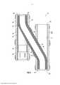
[0005] A FIG. 3 é uma vista parcialmente em seção transversal representativa do sistema e método, em que um furo de poço de conexão foi perfurado.[0005] FIG. 3 is a representative partially cross-sectional view of the system and method in which a connecting well hole has been drilled.
[0006] A FIG. 4 é uma vista parcialmente em seção transversal representativa do sistema e método, em que uma coluna de tubular foi instalada através do furo de poço de conexão.[0006] FIG. 4 is a representative partially cross-sectional view of the system and method in which a tubular string has been installed through the connecting well hole.
[0007] A FIG. 5 é uma vista parcialmente em seção transversal representativa do sistema e método, em que outro exemplo da coluna de tubular foi instalado através do furo de poço de conexão.[0007] FIG. 5 is a representative partially cross-sectional view of the system and method in which another example of the tubular string has been installed through the connecting well hole.
[0008] Representativamente ilustrado nas FIGS. 1-5 está um sistema 10 para uso com um poço, e um método associado, cujo sistema e método podem incorporar princípios desta divulgação. No entanto, deve ser claramente entendido que o sistema 10 e o método são meramente um exemplo de uma aplicação dos princípios desta divulgação na prática e uma ampla variedade de outros exemplos é possível. Portanto, o escopo desta divulgação não é limitado absolutamente aos detalhes do sistema 10 e método aqui descritos e/ou representados nos desenhos.[0008] Representatively illustrated in FIGS. 1-5 is a
[0009] Na FIG. 1, uma porção de um furo de poço existente 12 é ilustrada representativamente. Neste exemplo, o furo de poço existente 12 é geralmente vertical e é revestido com cimento 14 e revestimento 16, mas em outros exemplos, o método poderia ser realizado em um intervalo inclinado, horizontal ou de outra forma não vertical, sem revestimento e/ou não cimentado do furo de poço. Assim, o escopo desta divulgação não é limitado a qualquer um dos detalhes do furo de poço existente 12 representado nos desenhos ou descrito aqui.[0009] In FIG. 1, a portion of an existing
[0010] É desejável, neste exemplo, estabelecer comunicação com uma seção inferior 12a do furo de poço existente 12. Uma seção superior 12b do furo de poço existente 12 pode, por exemplo, ter experimentado problemas tais como colapso ou erosão de revestimento, um blowout, comunicação interzonal, etc. No entanto, deve ser entendido que não é necessário de acordo com os princípios desta divulgação para qualquer seção particular de um furo de poço existente ser "superior" ou "inferior" com respeito a qualquer outra seção e não é necessário para qualquer seção de um furo de poço existente ter experimentado qualquer questão ou problema particular.[0010] It is desirable, in this example, to establish communication with a
[0011] Com referência adicionalmente agora à FIG. 2, um furo de poço de alívio 18 foi perfurado pelo menos parcialmente próximo ao furo de poço existente 12. Um "furo de poço de alívio" é aqui utilizado para se referir a um furo de poço perfurado para estabelecer comunicação de fundo de poço entre a superfície e um furo de poço preexistente, tipicamente (mas não necessariamente) para resolver um problema ou uma questão com o furo de poço preexistente.[0011] Referring further now to FIG. 2, a
[0012] O furo de poço de alívio 18 está representado na FIG. 2 como sendo geralmente vertical e revestido com cimento 20 e revestimento 22, mas em outros exemplos, o método poderia ser realizado em um intervalo inclinado, horizontal ou de outra forma não vertical, sem revestimento e/ou não cimentado do furo de poço de alívio. Assim, o escopo desta divulgação não é limitado a qualquer um dos detalhes do furo de poço de alívio 18 representado nos desenhos ou descrito aqui.[0012] The
[0013] Na FIG. 2, o furo de poço existente 12 e o furo de poço de alívio 18 parecem ser paralelos e dispostos talvez apenas a um metro ou menos de afastamento. No entanto, em outros exemplos os furos de poços existentes e de alívio 12, 18 podem não ser paralelos entre si e podem ser mais afastados.[0013] In FIG. 2, the existing
[0014] De preferência, os furos de poços 12, 18 são "próximos"entre si, em que um furo de poço de conexão (não mostrado na FIG. 2, ver FIG. 3) pode convenientemente ser perfurado entre os furos de poços. Por exemplo, os furos de poços 12, 18 poderiam estar dezenas ou centenas de metros afastados, mas de preferência não estão mil metros ou mais afastados.[0014] Preferably, the
[0015] Na FIG. 2 de exemplo, o revestimento 22 inclui uma junta de janela pré-formada 24 e um receptáculo de trinco de orientação 26. A junta de janela 24 proporciona uma janela lateral passante relativamente facilmente fresada ou perfurada 28 para perfurar através de um lado do revestimento 22 e o receptáculo de trinco de orientação 26 proporciona fixar e orientar um whipstock ou outro desviador (não mostrado na FIG. 2, ver FIG. 3) durante o processo de fresagem e/ou perfuração.[0015] In FIG. 2 for example, the
[0016] No entanto, não é necessário de acordo com os princípios desta divulgação o revestimento 22 incluir a junta de janela 24 e/ou o receptáculo de trinco de orientação 26. É possível, por exemplo, fresar através de um lado do revestimento 22 sem o uso da junta de janela 24 e fixar e orientar um whipstock ou desviador sem uso do receptáculo 26 (por exemplo, usando um packer para fixar o desviador e uma ferramenta de orientação separada para orientar o desviador, etc). Assim, o escopo desta divulgação não é limitado ao uso de quaisquer ferramentas ou técnicas particulares na realização dos métodos aqui descritos.[0016] However, it is not necessary in accordance with the principles of this disclosure for the
[0017] Uma junta de janela adequada para uso no sistema 10 da FIG. 2 é uma junta de janela LATCHRITE (TM) e um receptáculo de trinco de orientação adequado para o uso no sistema da FIG. 2 é um SPERRY LATCH COUPLING(TM), ambos comercializados por Halliburton Energy Services, Inc. de Houston, Texas, EUA. No entanto, outras juntas de janelas e receptáculos de trinco de orientação podem ser utilizados de acordo com os princípios desta divulgação.[0017] A window gasket suitable for use in
[0018] Com referência adicionalmente agora à FIG. 3, o sistema 10 está representado depois de um furo de poço de conexão 30 ter sido perfurado a partir do furo de poço de alívio 18 para o furo de poço existente 12. O furo de poço de conexão 30 proporciona comunicação entre o furo de poço de alívio 18 e a seção 12a do furo de poço existente 12, como descrito mais completamente abaixo.[0018] With further reference now to FIG. 3,
[0019] Para perfurar o furo de poço de conexão 30, um whipstock ou desviador 32 é posicionado no furo de poço de alívio 18 para defletir lateralmente várias fresas e/ou brocas (não mostradas), de modo que a janela 28 seja aberta e o furo de poço de conexão seja perfurado para interceptar o furo de poço existente 12. Um trinco de orientação 34 orienta azimutalmente uma face de deflexão inclinada 32a do desviador 32, de modo que ela fique voltada para a janela 28 (ou pelo menos numa direção do furo de poço existente 12, por exemplo, se a janela não for pré-fresada no revestimento 22).[0019] To drill the connecting
[0020] O trinco de orientação 34 pode também fixar o desviador 32 relativamente ao revestimento 22. Um packer ou outra vedação anular 36 pode ser utilizada para impedir detritos de fresagem e/ou perfuração de incrustarem no trinco 34 ou acumularem no furo de poço de alívio 18.
[0021] O mesmo desviador 32, trinco 34 e vedação anular 36 podem ser usados para todos os estágios de uma operação de fresagem e/ou de perfuração e para defletir uma ou mais colunas de tubulares (não mostradas na FIG. 3, ver FIGS. 4 & 5) a partir do furo de poço de alívio 18 para o furo de poço de conexão 30. Em outros exemplos, desviadores, trincos e/ou vedações especializadas separadas podem ser utilizadas para diferentes estágios ou para diferentes operações.[0021] The
[0022] Com referência adicionalmente agora à FIG. 4, o sistema 10 é representativamente ilustrado depois de uma coluna de tubular 38 ter sido instalada nos furos de poços de alívio existentes e de conexão 12, 18, 30. Neste exemplo, a coluna de tubular 38 pode ser instalada defletindo uma extremidade inferior lateralmente para fora da face inclinada 32a do desviador 32, do furo de poço de alívio 18 para o poço de conexão 30 e, por conseguinte, do furo de poço de conexão para o furo de poço existente 12.[0022] Referring further now to FIG. 4,
[0023] Em alguns exemplos, o desviador 32 pode não estar presente no furo de poço de alívio 18 quando a coluna de tubular 38 é instalada. Por exemplo, o desviador 32 pode ter sido recuperado após o furo de poço de conexão 30 ser perfurado, ou o desviador 32 pode não ter sido usado para perfurar o furo de poço de conexão, etc. Se o desviador 32 não for usado para defletir a coluna de tubular 38 para o furo de poço de conexão 30, a coluna de tubular pode ser de outra forma dirigida para o furo do poço de conexão, por exemplo, pelo uso de uma junta dobrada ou um dispositivo de desvio (não representado) conectado a uma extremidade inferior da coluna de tubular.[0023] In some examples, the
[0024] A coluna de tubular 38 proporciona comunicação de fluido entre o furo de poço existente 12 e o furo de poço de alívio 18, por exemplo, para produção de fluido 40 da seção 12a do furo de poço existente e para o furo de poço de alívio e, então, para a superfície da terra. Se, no entanto, o furo de poço existente 12 for usado para fins de injeção (tal como, em operações de inundação de água ou vapor, para descarte, etc.), o fluido 40 poderia fluir numa direção oposta. Assim, o escopo desta divulgação não é limitado a qualquer direção, origem ou destino particular do fluxo de fluido.[0024] The
[0025] Na FIG. 4 de exemplo, uma vedação anular 42 é posicionada em cada extremidade da coluna de tubular 38. Uma de cada uma das vedações anulares 42 está posicionada no furo de poço existente 12 e no furo de poço de alívio 18. A vedação anular 42 no furo de poço existente 12 veda um anular 44 formado radialmente entre a coluna de tubular 38 e o furo de poço existente e a vedação anular no furo de poço de alívio 18 veda um anular 46 formado radialmente entre a coluna de tubular e o furo de poço de alívio.[0025] In FIG. 4 for example, an
[0026] Embora apenas uma única vedação anular 42 seja representada em cada um dos furos de poços existentes e de alívio 12, 18, deve ser entendido que qualquer número de vedações anulares pode ser utilizado. Além disso, não é necessário para as vedações anulares 42 serem da mesma configuração ou construção, ou para as vedações anulares serem posicionadas nas extremidades da coluna de tubular 38. Assim, o escopo desta divulgação não é limitado a qualquer número, tamanho, construção, configuração, posição ou outros detalhes particulares das vedações anulares 42.[0026] Although only a single
[0027] Neste exemplo, as vedações anulares 42 incluem de preferência um material intumescente 48 que intumesce no fundo de poço pelo menos depois de a coluna de tubular 38 ter sido adequadamente instalada a fim de fixar e vedar a coluna de tubular nos furos de poços existentes e de alívio 18. Deste modo, os anulares 44, 46 podem ser eficazmente vedados, desse modo proporcionando comunicação vedada entre o furo de poço de alívio 18 e a seção 12a do furo de poço existente.[0027] In this example, the
[0028] Preferencialmente, o material intumescente 48 intumesce quando ele é contatado com um agente de ativação particular (por exemplo, óleo, gás, outros hidrocarbonetos, água, ácido, outros produtos químicos, etc.) no poço. O agente de ativação pode já estar presente no poço ou ele pode ser introduzido após instalação da coluna de tubular 38 no poço, ou ele pode ser transportado para o poço com a coluna de tubular, etc. O material intumescente 48 poderia em vez disso intumescer em resposta à exposição a uma temperatura particular ou mediante passagem de um período de tempo ou em resposta a outro estímulo, etc.[0028] Preferably, the
[0029] Assim, será apreciado que uma ampla variedade de diferentes formas de intumescimento do material intumescente 48 existe e é conhecida daqueles versados na arte. Por conseguinte, o escopo desta divulgação não está limitado a qualquer modo particular de intumescer o material intumescente 48. Além disso, o escopo desta divulgação também não está limitado a qualquer um dos detalhes do sistema de poço 10 e do método aqui descritos, uma vez que os princípios desta divulgação podem ser aplicados a muitas circunstâncias diferentes.[0029] Thus, it will be appreciated that a wide variety of different forms of swelling of the swelling
[0030] O termo "intumescer" e termos semelhantes (tais como "intumescente") são aqui utilizados para indicar um aumento em volume de um material intumescente. Tipicamente, este aumento de volume é devido à incorporação de componentes moleculares do agente de ativação no próprio material intumescente, mas podem ser utilizados outros mecanismos ou técnicas de intumescimento, se desejado. Notem que o intumescimento não é o mesmo que expansão, embora um material de vedação possa expandir como um resultado do intumescimento.[0030] The term "swelling" and similar terms (such as "swelling") are used herein to indicate an increase in volume of an intumescent material. Typically, this swelling is due to the incorporation of molecular components of the activating agent into the swelling material itself, but other swelling mechanisms or techniques can be used if desired. Note that swelling is not the same as expansion, although a sealing material may expand as a result of swelling.
[0031] Por exemplo, em alguns packers convencionais, um elemento de vedação pode ser expandido radialmente para fora pela compressão longitudinal do elemento de vedação, ou pela inflação do elemento de vedação. Em cada um destes casos, o elemento de vedação é expandido sem qualquer aumento de volume do material de vedação do qual o elemento de vedação é feito. Assim, nestes packers convencionais, o elemento de vedação expande, mas não intumesce.[0031] For example, in some conventional packers, a sealing element can be expanded radially outward by longitudinal compression of the sealing element, or by inflation of the sealing element. In each of these cases, the sealing element is expanded without any swelling of the sealing material from which the sealing element is made. Thus, in these conventional packers, the sealing element expands but does not swell.
[0032] O agente de ativação que provoca intumescimento do material intumescente 48 é, neste exemplo, de preferência, um fluido de hidrocarboneto (tal como óleo ou gás). No sistema de poço 10, o material intumescente 48 pode intumescer quando o fluido 40 compreende o agente de ativação (por exemplo, quando o fluido entra no furo de poço de existente 12 a partir de uma formação circundando o furo de poço, quando o fluido é circulado para a coluna de tubular 38 a partir da superfície, quando o fluido é liberado de uma câmara transportada com a coluna de tubular, etc.). Em resposta, as vedações anulares 42 intumescem e vedam os anulares 44, 46.[0032] The activating agent that causes swelling of the swelling
[0033] O agente de ativação que provoca o intumescimento do material intumescente 48 poderia ser compreendido de qualquer tipo de fluido. O agente de ativação poderia estar naturalmente presente no poço, ou ele poderia ser transportado com as vedações de anular 42, transportado separadamente ou escoado em contato com o material intumescente 48 no poço, quando desejado. Qualquer modo de contatar o agente de ativação com o material intumescente 48 pode ser usado de acordo com os princípios desta divulgação.[0033] The activating agent that causes the swelling of the swelling
[0034] Vários materiais intumescentes são conhecidos daqueles versados na técnica, cujos materiais intumescem quando contatados com água e/ou fluido de hidrocarboneto, de modo que uma lista completa destes materiais não será aqui apresentada. Listas parciais de materiais intumescentes podem ser encontradas nas Patentes US 3385367, 7059415 e 7143832, cujas divulgações completas são aqui incorporadas por esta referência.[0034] Various swellable materials are known to those skilled in the art, which materials swell when contacted with water and/or hydrocarbon fluid, so a complete list of these materials will not be presented here. Partial lists of intumescent materials can be found in US Patents 3385367, 7059415 and 7143832, the entire disclosures of which are incorporated herein by this reference.
[0035] Como outra alternativa, o material intumescente 48 pode ter uma porção substancial de cavidades no mesmo as quais são comprimidas ou colapsadas na condição da superfície. Então, depois de ter sido colocado no poço a uma pressão mais alta, o material 48 é expandido pelas cavidades enchendo com fluido.[0035] As another alternative, the
[0036] Este tipo de aparelho e método poderia ser utilizado quando se desejar intumescer o material intumescente 48 na presença de gás em vez de óleo ou água. Um material intumescente adequado é descrito no Pedido Publicado US 2007-0257405, a divulgação inteira do qual é aqui incorporada por esta referência.[0036] This type of apparatus and method could be used when it is desired to swell the
[0037] De preferência, o material intumescente 48 utilizado nas vedações anulares 42 intumesce por difusão de hidrocarbonetos para o material intumescente, ou no caso de um material intumescente em água, pela água sendo absorvida por um material superabsorvente (tal como celulose, argila, etc.) e/ou por atividade osmótica com um material semelhante a sal. Materiais intumescentes por hidrocarbonetos, água e gás podem ser combinados, se desejado.[0037] Preferably, the
[0038] Deve, portanto, ser claramente entendido que qualquer material intumescente que intumesce quando contatado com um agente de ativação predeterminado pode ser usado em conformidade com os princípios desta divulgação. O material intumescente 48 também poderia intumescer em resposta a contato com qualquer um de múltiplos agentes de ativação. Por exemplo, o material intumescente 48 poderia intumescer quando contatado por fluido de hidrocarboneto, ou quando contatado por água.[0038] It should, therefore, be clearly understood that any swellable material that swells when contacted with a predetermined activating agent may be used in accordance with the principles of this disclosure. The
[0039] O material intumescente 48 pode ele próprio vedar os anulares 44, 46. Em outros exemplos, o material intumescente 48 pode deslocar uma vedação ou camada de vedação para contato com os furos de poços 12, 18 quando o material intumescente intumesce. Assim, o escopo desta divulgação não é limitado a qualquer mecanismo particular para vedar os anulares 44, 46 em resposta ao intumescimento do material intumescente 48.The
[0040] Embora as vedações de anulares 42 sejam representadas na FIG. 4 como incluindo o mesmo material intumescente 48, em outros materiais intumescentes diferentes de exemplo ou múltiplos materiais intumescentes podem ser usados nas vedações anulares. Por exemplo, a vedação anular 42 que é defletida do furo de poço de alívio 18 para o furo de poço de conexão 30 e, então, para o furo de poço existente 12 pode incluir um ou material mais furo ou de outra forma mais durável ou resistente a abrasão em comparação com a vedação anular que permanece no furo de poço de alívio.[0040] Although the
[0041] Note que a vedação anular 42 que veda o anular 44 no furo de poço existente 12 também desempenha uma função de isolar a seção inferior 12a da seção superior 12b do furo de poço. Desta forma, quaisquer questões ou problemas experimentados na seção superior 12b não afetará um fluxo controlado do fluido 40 entre os furos de poços existentes e de alívio 12, 18.[0041] Note that the
[0042] Além disso, notem que, vedando os anulares 44, 46 em cada lado do furo de poço de conexão 30, o furo de poço de conexão é isolado da seção inferior 12a do furo de poço existente 12 (do qual o fluido 40 é produzido ou para o qual o fluido é injetado) e é isolado do furo de poço de alívio 18 acima da vedação anular 42. Deste modo, o furo de poço de conexão não revestido 30 não comunica com estas outras seções do poço. No entanto, o furo de poço de conexão 30 pode ser revestido, se desejado, em outros exemplos.[0042] Furthermore, note that by sealing the
[0043] Com referência adicionalmente agora à FIG. 5, outro exemplo do sistema 10 e método é ilustrado representativamente. Neste exemplo, vedações anulares separadas 42 em extremidades opostas da coluna de tubular 38 não são usadas. Em vez disso, uma única vedação anular 42 se estende através do furo de poço de conexão 30 e para cada um dos furos de poços existentes e de alívio 12, 18.[0043] With further reference now to FIG. 5, another example of
[0044] No furo de poço de conexão 30, a vedação anular 42 veda um anular 50 formado radialmente entre a coluna de tubular 38 e o furo de poço de conexão. Desta maneira, a vedação anular 42 pode proporcionar uma junção completamente vedada entre os furos de poços existentes e de conexão 12, 30 e entre os furos de poços de alívio e de conexão 18, 30.[0044] In the
[0045] A coluna de tubular 38 se estende para baixo no furo de poço existente 12 além da vedação anular 42 e se estende para cima no furo de poço de alívio 18 além da vedação anular. Assim, a vedação anular 42 não é necessariamente posicionada em qualquer extremidade particular da coluna de tubular 38.[0045] The
[0046] A coluna de tubular 38 que se estende para cima ou para baixo além da vedação anular 42 pode, por exemplo, proporcionar espaço para o uso de chaves e/ou cunhas numa sonda na superfície. Espaços adicionais ou alternativos para chaves e/ou cunhas podem ser proporcionados ao longo de um comprimento da vedação anular 42, se desejado.[0046] The
[0047] Embora a vedação anular 42 esteja representado na FIG. 5 como sendo um único elemento, podem ser proporcionadas múltiplas vedações anulares. As múltiplas vedações anulares 42 podem ser posicionadas adjacentes uma a outro ou afastadas (por exemplo, para proporcionar espaços adequados para utilização de chaves e/ou cunhas ou de modo que diferentes vedações anulares vedem os respectivos anulares 44, 46, 50, etc.). Assim, o escopo desta divulgação não é limitado a qualquer número, espaçamento, configuração ou outros detalhes particulares da vedação anular 42.[0047] Although the
[0048] Pode agora ser totalmente apreciado que a divulgação acima proporciona avanços significativos para as técnicas de construir sistemas de poços e fornecer medidas de contingência em várias circunstâncias. Nos exemplos descritos acima, a(s) vedação(ões) anular(es) intumescente(s) 42 pode(m) ser utilizada(s) com a coluna de tubular 38 para proporcionar comunicação de fluido vedada entre os furos de poços existentes e de alívio 12, 18 via um furo de poço de conexão 30 que conecta os furos de poços existentes e de alívio.[0048] It can now be fully appreciated that the above disclosure provides significant advances to the techniques of constructing well systems and providing contingency measures in various circumstances. In the examples described above, the intumescent annular seal(s) 42 may be used with the
[0049] Um método de conectar a um furo de poço existente 12 no fundo de poço é fornecido para a técnica pela divulgação acima. Num exemplo, o método compreende: instalar um material intumescente 48 no furo de poço existente 12 a partir de um furo de poço de conexão 30 perfurado para o furo de poço existente 12.[0049] A method of connecting to an existing
[0050] O método pode incluir perfurar o furo de poço de conexão 30 a partir de um furo de poço de alívio 18 perfurado próximo ao furo de poço existente 12.[0050] The method may include drilling the connecting
[0051] O método pode incluir o material intumescente 48 intumescendo no furo de poço existente 12.[0051] The method may include the
[0052] A etapa de instalar pode compreender inserir uma coluna de tubular 38 a partir de um furo de poço de alívio 18 através do furo de poço de conexão 30 e para o furo de poço existente 12. O intumescimento do material intumescente 48 pode vedar um anular 44 formado entre a coluna de tubular 38 e o furo de poço existente 12.[0052] The step of installing may comprise inserting a
[0053] O intumescimento do material intumescente 48 pode vedar um anular 50 formado entre a coluna de tubular 38 e o furo de poço de conexão 30. O intumescimento do material intumescente 48 pode vedar um anular 46 formado entre a coluna de tubular 38 e o furo de poço de alívio 18.[0053] The swelling of the
[0054] O método pode incluir perfurar um furo de poço de alívio 18 próximo ao furo de poço existente 12 e, então, perfurar o furo de poço de conexão 30 a partir do furo de poço de alívio 18 para o furo de poço existente 12. A etapa de instalar pode ser realizada após perfurar o furo de poço de conexão 30.[0054] The method may include drilling a
[0055] Um sistema de poço 10 é também descrito acima. Num exemplo, o sistema de poço 10 pode incluir um furo de poço de alívio 18 perfurado próximo a um furo de poço existente 12; um furo de poço de conexão 30 perfurado do furo de poço de alívio 18 para o furo de poço existente 12; uma coluna de tubular 38 se estendendo do furo de poço de alívio 18 através do furo de poço de conexão 30 e para o furo de existente 12; e um material intumescente 48 que intumesce em um anular (44, 46 e/ou 50) formado entre a coluna de tubular 38 e pelo menos um do grupo que compreende o furo de poço de alívio 18, o furo de poço de conexão 30 e o furo de poço existente 12.[0055] A 10 well system is also described above. In one example, the
[0056] O material intumescente 48 pode intumescer em resposta a contato com um fluido (tal como fluido 40) no fundo de poço. O material intumescente 48 pode intumescer em cada um do furo de poço de alívio 18, do furo de poço de conexão 30 e do furo de poço existente 12.[0056] The
[0057] Um fluido 40 pode fluir entre o furo de poço existente 12 e o furo de poço de alívio 18 via a coluna de tubular 38.[0057] A fluid 40 may flow between the existing
[0058] O material intumescente 48 pode isolar as seções 12a,b do furo de poço existente 12 uma da outra.[0058] The
[0059] O material intumescente 48 pode intumescer nos anulares 44, 46 entre a coluna de tubular 38 e cada um do furo de poço de alívio 18 e do furo de poço existente 12. O material intumescente 48 pode intumesce no anular 50 entre a coluna de tubular 38 e o furo de poço de conexão 30.[0059] The
[0060] Outro método de conectar a um furo de poço existente 12 no fundo de poço pode compreender: perfurar um furo de poço de alívio 18 próximo ao furo de poço existente 12; então, perfurar um furo de poço de conexão 30 a partir do furo de poço de alívio 18 para o furo de poço existente 12; e, então, instalar um material intumescente 48 no furo de poço existente 12 a partir do furo de poço de conexão 30.[0060] Another method of connecting to an existing
[0061] Embora vários exemplos tenham sido descritos acima, com cada exemplo tendo determinadas características, deve ser entendido que não é necessário para uma determinada característica de um exemplo ser usada exclusivamente com esse exemplo. Em vez disso, qualquer uma das características descritas acima e/ou representadas nos desenhos pode ser combinada com qualquer um dos exemplos, em adição ou substituição a qualquer uma das outras características desses exemplos. As características de um exemplo não são mutuamente exclusivas para as características de outro exemplo. Em vez disso, o escopo desta divulgação engloba qualquer combinação de qualquer uma das características.[0061] Although several examples have been described above, with each example having certain characteristics, it should be understood that it is not necessary for a particular characteristic of an example to be used exclusively with that example. Rather, any of the features described above and/or depicted in the drawings may be combined with any of the examples, in addition to or substitution for any of the other features in those examples. The characteristics of one example are not mutually exclusive to the characteristics of another example. Rather, the scope of this disclosure encompasses any combination of any of the characteristics.
[0062] Embora cada exemplo descrito acima inclua uma determinada combinação de características, deve ser entendido que não é necessário que todas as características de um exemplo sejam utilizadas. Em vez disso, qualquer uma das características descritas acima pode ser utilizada sem que qualquer outra característica ou características particulares também sejam usadas.[0062] Although each example described above includes a certain combination of features, it should be understood that it is not necessary that all features of an example be used. Rather, any of the features described above can be used without any other particular feature or features being used as well.
[0063] Deve ser entendido que as várias modalidades aqui descritas podem ser utilizadas em várias orientações, tal como inclinadas, invertidas, horizontais, verticais, etc., e em várias configurações, sem se afastar dos princípios desta divulgação. As modalidades são descritas apenas como exemplos de aplicações úteis dos princípios da divulgação, o que não se limitam a detalhes específicos destas modalidades.[0063] It should be understood that the various embodiments described herein can be used in various orientations, such as tilted, inverted, horizontal, vertical, etc., and in various configurations, without departing from the principles of this disclosure. The modalities are described only as examples of useful applications of the disclosure principles, which are not limited to specific details of these modalities.
[0064] Na descrição acima dos exemplos representativos, termos direcionais (tais como "acima", "abaixo", "superior", "inferior", etc.) são utilizados por conveniência ao se referir aos desenhos anexos. No entanto, deve ser claramente entendido que o escopo desta divulgação não é limitado a quaisquer direções particulares aqui descritas.[0064] In the above description of representative examples, directional terms (such as "above", "below", "upper", "lower", etc.) are used for convenience when referring to the accompanying drawings. However, it should be clearly understood that the scope of this disclosure is not limited to any particular directions described herein.
[0065] Os termos "incluindo", "inclui", "compreendendo", "compreende", e termos semelhantes são utilizados num sentido não limitativo neste relatório descritivo. Por exemplo, se um sistema, método, aparelho, dispositivo, etc., é descrito como "incluindo" uma determinada característica ou elemento, o sistema, método, aparelho, dispositivo, etc., podem incluir essa característica ou esse elemento e também podem incluir outras características ou outros elementos. Da mesma forma, o termo "compreende"é considerado significar "compreende, mas não está limitado a".[0065] The terms "including", "includes", "comprising", "comprises", and similar terms are used in a non-limiting sense in this specification. For example, if a system, method, apparatus, device, etc., is described as "including" a particular feature or element, the system, method, apparatus, device, etc. may include that feature or element and may also include other features or other elements. Likewise, the term "comprises" is taken to mean "understands, but is not limited to".
[0066] Naturalmente, um perito na arte mediante uma cuidadosa consideração da descrição acima de modalidades representativas da divulgação, prontamente apreciará que muitas modificações, adições, substituições, deleções e outras mudanças podem ser feitas às modalidades específicas, e tais mudanças são contempladas pelos princípios desta divulgação. Por exemplo, as estruturas divulgadas como sendo formadas separadamente podem, em outros exemplos, ser integralmente formadas e VICE-VERSA. Por conseguinte, a descrição detalhada anterior deve ser claramente entendida como sendo dada a título de ilustração e exemplo somente, o espírito e escopo da invenção sendo limitados somente pelas reivindicações anexas e seus equivalentes.[0066] Of course, one skilled in the art upon careful consideration of the above description of representative modalities of the disclosure will readily appreciate that many modifications, additions, substitutions, deletions and other changes can be made to the specific modalities, and such changes are contemplated by the principles of this disclosure. For example, structures disclosed as being separately formed may, in other examples, be integrally formed and VICE-VERSA. Therefore, the foregoing detailed description is to be clearly understood to be given by way of illustration and example only, the spirit and scope of the invention being limited only by the appended claims and their equivalents.
Claims (12)
Translated fromPortugueseApplications Claiming Priority (1)
| Application Number | Priority Date | Filing Date | Title |
|---|---|---|---|
| PCT/US2013/067133WO2015065321A1 (en) | 2013-10-28 | 2013-10-28 | Downhole communication between wellbores utilizing swellable materials |
Publications (2)
| Publication Number | Publication Date |
|---|---|
| BR112016005923A2 BR112016005923A2 (en) | 2017-08-01 |
| BR112016005923B1true BR112016005923B1 (en) | 2021-06-29 |
Family
ID=53004743
Family Applications (1)
| Application Number | Title | Priority Date | Filing Date |
|---|---|---|---|
| BR112016005923-9ABR112016005923B1 (en) | 2013-10-28 | 2013-10-28 | METHOD OF CONNECTING TO AN EXISTING WELL HOLE IN THE WELL BOTTOM AND WELL SYSTEM |
Country Status (11)
| Country | Link |
|---|---|
| US (1) | US10174558B2 (en) |
| EP (1) | EP3063362B1 (en) |
| AR (1) | AR098150A1 (en) |
| AU (1) | AU2013404088B2 (en) |
| BR (1) | BR112016005923B1 (en) |
| CA (1) | CA2923014C (en) |
| DK (1) | DK3063362T3 (en) |
| MX (1) | MX375180B (en) |
| SA (1) | SA516370778B1 (en) |
| SG (1) | SG11201601552TA (en) |
| WO (1) | WO2015065321A1 (en) |
Families Citing this family (2)
| Publication number | Priority date | Publication date | Assignee | Title |
|---|---|---|---|---|
| BR112016005923B1 (en) | 2013-10-28 | 2021-06-29 | Halliburton Energy Services, Inc | METHOD OF CONNECTING TO AN EXISTING WELL HOLE IN THE WELL BOTTOM AND WELL SYSTEM |
| US20250101809A1 (en)* | 2023-09-26 | 2025-03-27 | Thru Tubing Solutions, Inc. | Accessing wells below an obstruction or discontinuity |
Family Cites Families (21)
| Publication number | Priority date | Publication date | Assignee | Title |
|---|---|---|---|---|
| US3385367A (en) | 1966-12-07 | 1968-05-28 | Kollsman Paul | Sealing device for perforated well casing |
| US4044830A (en) | 1973-07-02 | 1977-08-30 | Huisen Allen T Van | Multiple-completion geothermal energy production systems |
| US5230387A (en) | 1988-10-28 | 1993-07-27 | Magrange, Inc. | Downhole combination tool |
| US5655605A (en) | 1993-05-14 | 1997-08-12 | Matthews; Cameron M. | Method and apparatus for producing and drilling a well |
| AU4819797A (en)* | 1996-10-08 | 1998-05-05 | Baker Hughes Incorporated | A method of forming and servicing wellbores from a main wellbore |
| US6026913A (en)* | 1997-09-30 | 2000-02-22 | Halliburton Energy Services, Inc. | Acoustic method of connecting boreholes for multi-lateral completion |
| US6119776A (en)* | 1998-02-12 | 2000-09-19 | Halliburton Energy Services, Inc. | Methods of stimulating and producing multiple stratified reservoirs |
| WO2000061914A1 (en) | 1999-04-09 | 2000-10-19 | Shell Internationale Research Maatschappij B.V. | Method for annular sealing |
| US6199633B1 (en)* | 1999-08-27 | 2001-03-13 | James R. Longbottom | Method and apparatus for intersecting downhole wellbore casings |
| NO312478B1 (en) | 2000-09-08 | 2002-05-13 | Freyer Rune | Procedure for sealing annulus in oil production |
| MY135121A (en)* | 2001-07-18 | 2008-02-29 | Shell Int Research | Wellbore system with annular seal member |
| US7584795B2 (en)* | 2004-01-29 | 2009-09-08 | Halliburton Energy Services, Inc. | Sealed branch wellbore transition joint |
| NO325434B1 (en) | 2004-05-25 | 2008-05-05 | Easy Well Solutions As | Method and apparatus for expanding a body under overpressure |
| DE602006013437D1 (en)* | 2005-04-22 | 2010-05-20 | Shell Int Research | A TEMPERATURE-LIMITED HEATING DEVICE USING A NON-FERROMAGNETIC LADDER |
| CA2626923A1 (en)* | 2005-11-16 | 2007-05-24 | Shell Canada Limited | Wellbore system |
| US7984762B2 (en)* | 2008-09-25 | 2011-07-26 | Halliburton Energy Services, Inc. | Pressure relieving transition joint |
| BRPI0902366B1 (en)* | 2009-07-06 | 2018-10-16 | Petroleo Brasileiro S.A. - Petrobras | receiver lateral well and method for its implantation |
| US20130037272A1 (en) | 2009-12-10 | 2013-02-14 | Bruce A Dale | Method and system for well access to subterranean formations |
| US9388668B2 (en)* | 2012-11-23 | 2016-07-12 | Robert Francis McAnally | Subterranean channel for transporting a hydrocarbon for prevention of hydrates and provision of a relief well |
| BR112016005923B1 (en) | 2013-10-28 | 2021-06-29 | Halliburton Energy Services, Inc | METHOD OF CONNECTING TO AN EXISTING WELL HOLE IN THE WELL BOTTOM AND WELL SYSTEM |
| WO2016099439A1 (en)* | 2014-12-15 | 2016-06-23 | Halliburton Energy Services, Inc. | Wellbore sealing system with degradable whipstock |
- 2013
- 2013-10-28BRBR112016005923-9Apatent/BR112016005923B1/enactiveIP Right Grant
- 2013-10-28USUS15/023,775patent/US10174558B2/enactiveActive
- 2013-10-28MXMX2016003570Apatent/MX375180B/enactiveIP Right Grant
- 2013-10-28WOPCT/US2013/067133patent/WO2015065321A1/enactiveApplication Filing
- 2013-10-28SGSG11201601552TApatent/SG11201601552TA/enunknown
- 2013-10-28AUAU2013404088Apatent/AU2013404088B2/enactiveActive
- 2013-10-28DKDK13896557.9Tpatent/DK3063362T3/enactive
- 2013-10-28EPEP13896557.9Apatent/EP3063362B1/enactiveActive
- 2013-10-28CACA2923014Apatent/CA2923014C/enactiveActive
- 2014
- 2014-10-22ARARP140103965Apatent/AR098150A1/enunknown
- 2016
- 2016-03-20SASA516370778Apatent/SA516370778B1/enunknown
Also Published As
| Publication number | Publication date |
|---|---|
| MX2016003570A (en) | 2016-06-02 |
| US10174558B2 (en) | 2019-01-08 |
| AU2013404088B2 (en) | 2016-09-22 |
| CA2923014A1 (en) | 2015-05-07 |
| MX375180B (en) | 2025-03-06 |
| SA516370778B1 (en) | 2020-08-24 |
| CA2923014C (en) | 2018-05-08 |
| WO2015065321A1 (en) | 2015-05-07 |
| EP3063362A1 (en) | 2016-09-07 |
| SG11201601552TA (en) | 2016-03-30 |
| AU2013404088A1 (en) | 2016-03-24 |
| AR098150A1 (en) | 2016-05-04 |
| EP3063362A4 (en) | 2017-08-23 |
| US20160230464A1 (en) | 2016-08-11 |
| EP3063362B1 (en) | 2019-12-25 |
| BR112016005923A2 (en) | 2017-08-01 |
| DK3063362T3 (en) | 2020-03-23 |
Similar Documents
| Publication | Publication Date | Title |
|---|---|---|
| US9416638B2 (en) | Multi-lateral well system | |
| US6199633B1 (en) | Method and apparatus for intersecting downhole wellbore casings | |
| BR112020014586B1 (en) | TEMPORARY SEALING DEVICE FOR A DOWNHOLE COMPONENT AND METHOD FOR PROVIDING A TEMPORARY SEAL FOR A DOWNHOLE COMPONENT | |
| BR112015025870B1 (en) | PACKER ASSEMBLY, METHOD FOR BUILDING A PACKER ASSEMBLY, AND, WELL SYSTEM | |
| AU2012369999B2 (en) | Swelling debris barrier and methods | |
| MX2013006301A (en) | Packer for alternate flow channel gravel packing and method for completing a wellbore. | |
| BR112013013149B1 (en) | CONNECTION JOINT FOR EXCENTRIC FLOW PATHWAYS TO CONCENTRIC FLOW PATHWAYS | |
| WO2017074733A1 (en) | Junction isolation tool for fracking of wells with multiple laterals | |
| WO2018200402A1 (en) | Systems and methods for deploying an expandable sealing device | |
| BR112017016450B1 (en) | SET AND APPARATUS ADAPTED TO BE DISPOSED INSIDE A WELL, AND METHOD FOR CONSTITUTING A CONNECTION BETWEEN A FIRST AND SECOND COMPLETION JOINTS | |
| BR112016005923B1 (en) | METHOD OF CONNECTING TO AN EXISTING WELL HOLE IN THE WELL BOTTOM AND WELL SYSTEM | |
| US11286721B2 (en) | Combined multilateral window and deflector and junction system | |
| BRPI1102049A2 (en) | system for opening a window in a casing column positioned in a wellbore and method for opening a window in a casing column positioned in a wellbore | |
| Van Noort et al. | Water Production Reduced Using Solid Expandable Tubular Technology to" Clad" in Fractured Carbonate Formation | |
| BR102022026688A2 (en) | SYSTEM AND METHOD FOR CONSTRUCTION AND COMPLETION OF PRODUCTION AND INJECTION WELLS IN PRE-SALT FIELDS | |
| Østvik et al. | Increasing Production with an Innovative Through Flow Line (TFL) Multi-Zone Completion Design for a Major Norwegian Operator | |
| Denney | Record ERD Well Drilled From a Floating Installation | |
| Stracke et al. | A New Concept for Multibranch Technology | |
| BRPI0702620B1 (en) | DYNAMIC COATING TO ENSURE OIL WELLS INTEGRITY AND ITS INSTALLATION METHOD |
Legal Events
| Date | Code | Title | Description |
|---|---|---|---|
| B06F | Objections, documents and/or translations needed after an examination request according [chapter 6.6 patent gazette] | ||
| B06U | Preliminary requirement: requests with searches performed by other patent offices: procedure suspended [chapter 6.21 patent gazette] | ||
| B09A | Decision: intention to grant [chapter 9.1 patent gazette] | ||
| B16A | Patent or certificate of addition of invention granted [chapter 16.1 patent gazette] | Free format text:PRAZO DE VALIDADE: 20 (VINTE) ANOS CONTADOS A PARTIR DE 28/10/2013, OBSERVADAS AS CONDICOES LEGAIS. |