BR112013030486B1 - system comprising robotic system and surgical instrument - Google Patents
system comprising robotic system and surgical instrumentDownload PDFInfo
- Publication number
- BR112013030486B1 BR112013030486B1BR112013030486-3ABR112013030486ABR112013030486B1BR 112013030486 B1BR112013030486 B1BR 112013030486B1BR 112013030486 ABR112013030486 ABR 112013030486ABR 112013030486 B1BR112013030486 B1BR 112013030486B1
- Authority
- BR
- Brazil
- Prior art keywords
- closing
- sensor
- trigger
- surgical
- end actuator
- Prior art date
Links
- 230000033001locomotionEffects0.000claimsdescription246
- 239000004744fabricSubstances0.000claimsdescription30
- 230000008878couplingEffects0.000claimsdescription29
- 238000010168coupling processMethods0.000claimsdescription29
- 238000005859coupling reactionMethods0.000claimsdescription29
- 238000004891communicationMethods0.000claimsdescription25
- 238000003860storageMethods0.000claimsdescription4
- 238000005520cutting processMethods0.000description162
- 238000010304firingMethods0.000description89
- 230000005540biological transmissionEffects0.000description76
- 238000000034methodMethods0.000description59
- 230000007246mechanismEffects0.000description34
- 238000006073displacement reactionMethods0.000description32
- 238000000605extractionMethods0.000description23
- 230000002441reversible effectEffects0.000description20
- 239000000463materialSubstances0.000description19
- 230000000670limiting effectEffects0.000description18
- 230000036961partial effectEffects0.000description17
- 230000008569processEffects0.000description17
- 230000004044responseEffects0.000description17
- 230000008859changeEffects0.000description14
- 229910052751metalInorganic materials0.000description12
- 239000002184metalSubstances0.000description12
- 238000001356surgical procedureMethods0.000description12
- 230000009471actionEffects0.000description10
- 230000004913activationEffects0.000description10
- 210000000078clawAnatomy0.000description10
- 239000004033plasticSubstances0.000description10
- 229920003023plasticPolymers0.000description10
- 239000000853adhesiveSubstances0.000description9
- 230000001070adhesive effectEffects0.000description9
- 238000000926separation methodMethods0.000description9
- 230000002411adverseEffects0.000description8
- 230000006835compressionEffects0.000description8
- 238000007906compressionMethods0.000description8
- 239000004020conductorSubstances0.000description8
- 230000002439hemostatic effectEffects0.000description8
- 230000009467reductionEffects0.000description8
- 230000002459sustained effectEffects0.000description8
- 230000001960triggered effectEffects0.000description8
- 238000012986modificationMethods0.000description7
- 230000004048modificationEffects0.000description7
- 239000012811non-conductive materialSubstances0.000description7
- 208000012886VertigoDiseases0.000description6
- 238000010276constructionMethods0.000description6
- 208000002925dental cariesDiseases0.000description6
- 230000006870functionEffects0.000description6
- 238000007789sealingMethods0.000description6
- 238000009987spinningMethods0.000description6
- 229910001220stainless steelInorganic materials0.000description6
- 239000010935stainless steelSubstances0.000description6
- 230000003213activating effectEffects0.000description5
- 230000008901benefitEffects0.000description5
- 239000012636effectorSubstances0.000description5
- 238000003780insertionMethods0.000description5
- 230000037431insertionEffects0.000description5
- 238000009434installationMethods0.000description5
- 230000000717retained effectEffects0.000description5
- 238000002604ultrasonographyMethods0.000description5
- 229910000831SteelInorganic materials0.000description4
- 230000000994depressogenic effectEffects0.000description4
- 238000010586diagramMethods0.000description4
- 238000007667floatingMethods0.000description4
- 230000001939inductive effectEffects0.000description4
- 238000005304joiningMethods0.000description4
- 239000010959steelSubstances0.000description4
- 230000007704transitionEffects0.000description4
- 238000004140cleaningMethods0.000description3
- 238000013016dampingMethods0.000description3
- 239000003989dielectric materialSubstances0.000description3
- 238000012544monitoring processMethods0.000description3
- 230000000630rising effectEffects0.000description3
- 230000008093supporting effectEffects0.000description3
- 230000000007visual effectEffects0.000description3
- 229920002292Nylon 6Polymers0.000description2
- RTAQQCXQSZGOHL-UHFFFAOYSA-NTitaniumChemical compound[Ti]RTAQQCXQSZGOHL-UHFFFAOYSA-N0.000description2
- 230000003044adaptive effectEffects0.000description2
- 230000015572biosynthetic processEffects0.000description2
- 238000013461designMethods0.000description2
- 230000009977dual effectEffects0.000description2
- 229920001746electroactive polymerPolymers0.000description2
- 210000003414extremityAnatomy0.000description2
- 238000001415gene therapyMethods0.000description2
- 230000003993interactionEffects0.000description2
- 238000004519manufacturing processMethods0.000description2
- 239000002991molded plasticSubstances0.000description2
- 230000007935neutral effectEffects0.000description2
- 238000005192partitionMethods0.000description2
- 230000000144pharmacologic effectEffects0.000description2
- 230000001681protective effectEffects0.000description2
- 239000010936titaniumSubstances0.000description2
- 229910052719titaniumInorganic materials0.000description2
- 239000010963304 stainless steelSubstances0.000description1
- 2299100010946061 aluminium alloyInorganic materials0.000description1
- 2299100010087075 aluminium alloyInorganic materials0.000description1
- OKTJSMMVPCPJKN-UHFFFAOYSA-NCarbonChemical compound[C]OKTJSMMVPCPJKN-UHFFFAOYSA-N0.000description1
- 229910000669Chrome steelInorganic materials0.000description1
- 241000950314FiguraSpecies0.000description1
- 244000043261Hevea brasiliensisSpecies0.000description1
- 229920000106Liquid crystal polymerPolymers0.000description1
- 239000004977Liquid-crystal polymers (LCPs)Substances0.000description1
- HBBGRARXTFLTSG-UHFFFAOYSA-NLithium ionChemical compound[Li+]HBBGRARXTFLTSG-UHFFFAOYSA-N0.000description1
- 241000590518MestraSpecies0.000description1
- 239000004677NylonSubstances0.000description1
- 239000004698PolyethyleneSubstances0.000description1
- 229910000589SAE 304 stainless steelInorganic materials0.000description1
- 206010044565TremorDiseases0.000description1
- 230000004308accommodationEffects0.000description1
- 229910052782aluminiumInorganic materials0.000description1
- XAGFODPZIPBFFR-UHFFFAOYSA-NaluminiumChemical compound[Al]XAGFODPZIPBFFR-UHFFFAOYSA-N0.000description1
- 238000004458analytical methodMethods0.000description1
- 230000000712assemblyEffects0.000description1
- 238000000429assemblyMethods0.000description1
- 238000007664blowingMethods0.000description1
- 238000004364calculation methodMethods0.000description1
- 229910052799carbonInorganic materials0.000description1
- 239000000919ceramicSubstances0.000description1
- 238000012790confirmationMethods0.000description1
- 238000013500data storageMethods0.000description1
- 230000007547defectEffects0.000description1
- 238000011161developmentMethods0.000description1
- 238000003745diagnosisMethods0.000description1
- 238000002651drug therapyMethods0.000description1
- 239000006260foamSubstances0.000description1
- 239000002783friction materialSubstances0.000description1
- 230000002068genetic effectEffects0.000description1
- 239000011521glassSubstances0.000description1
- 230000003370grooming effectEffects0.000description1
- 230000001976improved effectEffects0.000description1
- 230000006872improvementEffects0.000description1
- 238000007373indentationMethods0.000description1
- 230000000977initiatory effectEffects0.000description1
- 229910001416lithium ionInorganic materials0.000description1
- 239000012764mineral fillerSubstances0.000description1
- 238000002324minimally invasive surgeryMethods0.000description1
- 229920003052natural elastomerPolymers0.000description1
- 229920001194natural rubberPolymers0.000description1
- 229920001778nylonPolymers0.000description1
- 230000003287optical effectEffects0.000description1
- 238000011422pharmacological therapyMethods0.000description1
- 229920000515polycarbonatePolymers0.000description1
- 239000004417polycarbonateSubstances0.000description1
- -1polyethylenePolymers0.000description1
- 229920000573polyethylenePolymers0.000description1
- 230000002980postoperative effectEffects0.000description1
- 238000003825pressingMethods0.000description1
- 239000003380propellantSubstances0.000description1
- 108090000623proteins and genesProteins0.000description1
- 238000011084recoveryMethods0.000description1
- 230000002829reductive effectEffects0.000description1
- 238000002432robotic surgeryMethods0.000description1
- 239000004065semiconductorSubstances0.000description1
- 230000035945sensitivityEffects0.000description1
- 230000001225therapeutic effectEffects0.000description1
- 238000002560therapeutic procedureMethods0.000description1
- 238000012546transferMethods0.000description1
- 238000003466weldingMethods0.000description1
- 210000000707wristAnatomy0.000description1
Images


Classifications
- A—HUMAN NECESSITIES
- A61—MEDICAL OR VETERINARY SCIENCE; HYGIENE
- A61B—DIAGNOSIS; SURGERY; IDENTIFICATION
- A61B17/00—Surgical instruments, devices or methods
- A61B17/068—Surgical staplers, e.g. containing multiple staples or clamps
- A—HUMAN NECESSITIES
- A61—MEDICAL OR VETERINARY SCIENCE; HYGIENE
- A61B—DIAGNOSIS; SURGERY; IDENTIFICATION
- A61B17/00—Surgical instruments, devices or methods
- A61B17/068—Surgical staplers, e.g. containing multiple staples or clamps
- A61B17/072—Surgical staplers, e.g. containing multiple staples or clamps for applying a row of staples in a single action, e.g. the staples being applied simultaneously
- A61B17/07207—Surgical staplers, e.g. containing multiple staples or clamps for applying a row of staples in a single action, e.g. the staples being applied simultaneously the staples being applied sequentially
- A—HUMAN NECESSITIES
- A61—MEDICAL OR VETERINARY SCIENCE; HYGIENE
- A61B—DIAGNOSIS; SURGERY; IDENTIFICATION
- A61B17/00—Surgical instruments, devices or methods
- A61B17/32—Surgical cutting instruments
- A61B17/320068—Surgical cutting instruments using mechanical vibrations, e.g. ultrasonic
- A61B17/320092—Surgical cutting instruments using mechanical vibrations, e.g. ultrasonic with additional movable means for clamping or cutting tissue, e.g. with a pivoting jaw
- A—HUMAN NECESSITIES
- A61—MEDICAL OR VETERINARY SCIENCE; HYGIENE
- A61B—DIAGNOSIS; SURGERY; IDENTIFICATION
- A61B34/00—Computer-aided surgery; Manipulators or robots specially adapted for use in surgery
- A61B34/30—Surgical robots
- A—HUMAN NECESSITIES
- A61—MEDICAL OR VETERINARY SCIENCE; HYGIENE
- A61B—DIAGNOSIS; SURGERY; IDENTIFICATION
- A61B34/00—Computer-aided surgery; Manipulators or robots specially adapted for use in surgery
- A61B34/70—Manipulators specially adapted for use in surgery
- A—HUMAN NECESSITIES
- A61—MEDICAL OR VETERINARY SCIENCE; HYGIENE
- A61B—DIAGNOSIS; SURGERY; IDENTIFICATION
- A61B34/00—Computer-aided surgery; Manipulators or robots specially adapted for use in surgery
- A61B34/70—Manipulators specially adapted for use in surgery
- A61B34/71—Manipulators operated by drive cable mechanisms
- A—HUMAN NECESSITIES
- A61—MEDICAL OR VETERINARY SCIENCE; HYGIENE
- A61B—DIAGNOSIS; SURGERY; IDENTIFICATION
- A61B34/00—Computer-aided surgery; Manipulators or robots specially adapted for use in surgery
- A61B34/70—Manipulators specially adapted for use in surgery
- A61B34/76—Manipulators having means for providing feel, e.g. force or tactile feedback
- A—HUMAN NECESSITIES
- A61—MEDICAL OR VETERINARY SCIENCE; HYGIENE
- A61B—DIAGNOSIS; SURGERY; IDENTIFICATION
- A61B50/00—Containers, covers, furniture or holders specially adapted for surgical or diagnostic appliances or instruments, e.g. sterile covers
- A61B50/30—Containers specially adapted for packaging, protecting, dispensing, collecting or disposing of surgical or diagnostic appliances or instruments
- A61B50/36—Containers specially adapted for packaging, protecting, dispensing, collecting or disposing of surgical or diagnostic appliances or instruments for collecting or disposing of used articles
- A—HUMAN NECESSITIES
- A61—MEDICAL OR VETERINARY SCIENCE; HYGIENE
- A61B—DIAGNOSIS; SURGERY; IDENTIFICATION
- A61B90/00—Instruments, implements or accessories specially adapted for surgery or diagnosis and not covered by any of the groups A61B1/00 - A61B50/00, e.g. for luxation treatment or for protecting wound edges
- A61B90/08—Accessories or related features not otherwise provided for
- B—PERFORMING OPERATIONS; TRANSPORTING
- B23—MACHINE TOOLS; METAL-WORKING NOT OTHERWISE PROVIDED FOR
- B23P—METAL-WORKING NOT OTHERWISE PROVIDED FOR; COMBINED OPERATIONS; UNIVERSAL MACHINE TOOLS
- B23P6/00—Restoring or reconditioning objects
- B—PERFORMING OPERATIONS; TRANSPORTING
- B23—MACHINE TOOLS; METAL-WORKING NOT OTHERWISE PROVIDED FOR
- B23Q—DETAILS, COMPONENTS, OR ACCESSORIES FOR MACHINE TOOLS, e.g. ARRANGEMENTS FOR COPYING OR CONTROLLING; MACHINE TOOLS IN GENERAL CHARACTERISED BY THE CONSTRUCTION OF PARTICULAR DETAILS OR COMPONENTS; COMBINATIONS OR ASSOCIATIONS OF METAL-WORKING MACHINES, NOT DIRECTED TO A PARTICULAR RESULT
- B23Q3/00—Devices holding, supporting, or positioning work or tools, of a kind normally removable from the machine
- B23Q3/155—Arrangements for automatic insertion or removal of tools, e.g. combined with manual handling
- B23Q3/1552—Arrangements for automatic insertion or removal of tools, e.g. combined with manual handling parts of devices for automatically inserting or removing tools
- B23Q3/1554—Transfer mechanisms, e.g. tool gripping arms; Drive mechanisms therefore
- A—HUMAN NECESSITIES
- A61—MEDICAL OR VETERINARY SCIENCE; HYGIENE
- A61B—DIAGNOSIS; SURGERY; IDENTIFICATION
- A61B17/00—Surgical instruments, devices or methods
- A61B2017/00017—Electrical control of surgical instruments
- A—HUMAN NECESSITIES
- A61—MEDICAL OR VETERINARY SCIENCE; HYGIENE
- A61B—DIAGNOSIS; SURGERY; IDENTIFICATION
- A61B17/00—Surgical instruments, devices or methods
- A61B2017/00017—Electrical control of surgical instruments
- A61B2017/00022—Sensing or detecting at the treatment site
- A—HUMAN NECESSITIES
- A61—MEDICAL OR VETERINARY SCIENCE; HYGIENE
- A61B—DIAGNOSIS; SURGERY; IDENTIFICATION
- A61B17/00—Surgical instruments, devices or methods
- A61B2017/00017—Electrical control of surgical instruments
- A61B2017/00022—Sensing or detecting at the treatment site
- A61B2017/00039—Electric or electromagnetic phenomena other than conductivity, e.g. capacity, inductivity, Hall effect
- A—HUMAN NECESSITIES
- A61—MEDICAL OR VETERINARY SCIENCE; HYGIENE
- A61B—DIAGNOSIS; SURGERY; IDENTIFICATION
- A61B17/00—Surgical instruments, devices or methods
- A61B2017/00017—Electrical control of surgical instruments
- A61B2017/00022—Sensing or detecting at the treatment site
- A61B2017/00075—Motion
- A—HUMAN NECESSITIES
- A61—MEDICAL OR VETERINARY SCIENCE; HYGIENE
- A61B—DIAGNOSIS; SURGERY; IDENTIFICATION
- A61B17/00—Surgical instruments, devices or methods
- A61B2017/00017—Electrical control of surgical instruments
- A61B2017/00199—Electrical control of surgical instruments with a console, e.g. a control panel with a display
- A—HUMAN NECESSITIES
- A61—MEDICAL OR VETERINARY SCIENCE; HYGIENE
- A61B—DIAGNOSIS; SURGERY; IDENTIFICATION
- A61B17/00—Surgical instruments, devices or methods
- A61B2017/00017—Electrical control of surgical instruments
- A61B2017/00212—Electrical control of surgical instruments using remote controls
- A—HUMAN NECESSITIES
- A61—MEDICAL OR VETERINARY SCIENCE; HYGIENE
- A61B—DIAGNOSIS; SURGERY; IDENTIFICATION
- A61B17/00—Surgical instruments, devices or methods
- A61B2017/00017—Electrical control of surgical instruments
- A61B2017/00221—Electrical control of surgical instruments with wireless transmission of data, e.g. by infrared radiation or radiowaves
- A—HUMAN NECESSITIES
- A61—MEDICAL OR VETERINARY SCIENCE; HYGIENE
- A61B—DIAGNOSIS; SURGERY; IDENTIFICATION
- A61B17/00—Surgical instruments, devices or methods
- A61B2017/00367—Details of actuation of instruments, e.g. relations between pushing buttons, or the like, and activation of the tool, working tip, or the like
- A61B2017/00398—Details of actuation of instruments, e.g. relations between pushing buttons, or the like, and activation of the tool, working tip, or the like using powered actuators, e.g. stepper motors, solenoids
- A—HUMAN NECESSITIES
- A61—MEDICAL OR VETERINARY SCIENCE; HYGIENE
- A61B—DIAGNOSIS; SURGERY; IDENTIFICATION
- A61B17/00—Surgical instruments, devices or methods
- A61B2017/00477—Coupling
- A—HUMAN NECESSITIES
- A61—MEDICAL OR VETERINARY SCIENCE; HYGIENE
- A61B—DIAGNOSIS; SURGERY; IDENTIFICATION
- A61B17/00—Surgical instruments, devices or methods
- A61B2017/00681—Aspects not otherwise provided for
- A61B2017/00685—Archimedes screw
- A—HUMAN NECESSITIES
- A61—MEDICAL OR VETERINARY SCIENCE; HYGIENE
- A61B—DIAGNOSIS; SURGERY; IDENTIFICATION
- A61B17/00—Surgical instruments, devices or methods
- A61B2017/00681—Aspects not otherwise provided for
- A61B2017/00734—Aspects not otherwise provided for battery operated
- A—HUMAN NECESSITIES
- A61—MEDICAL OR VETERINARY SCIENCE; HYGIENE
- A61B—DIAGNOSIS; SURGERY; IDENTIFICATION
- A61B17/00—Surgical instruments, devices or methods
- A61B17/068—Surgical staplers, e.g. containing multiple staples or clamps
- A61B2017/0688—Packages or dispensers for surgical staplers
- A—HUMAN NECESSITIES
- A61—MEDICAL OR VETERINARY SCIENCE; HYGIENE
- A61B—DIAGNOSIS; SURGERY; IDENTIFICATION
- A61B17/00—Surgical instruments, devices or methods
- A61B17/068—Surgical staplers, e.g. containing multiple staples or clamps
- A61B17/072—Surgical staplers, e.g. containing multiple staples or clamps for applying a row of staples in a single action, e.g. the staples being applied simultaneously
- A61B2017/07214—Stapler heads
- A61B2017/07278—Stapler heads characterised by its sled or its staple holder
- A—HUMAN NECESSITIES
- A61—MEDICAL OR VETERINARY SCIENCE; HYGIENE
- A61B—DIAGNOSIS; SURGERY; IDENTIFICATION
- A61B17/00—Surgical instruments, devices or methods
- A61B17/068—Surgical staplers, e.g. containing multiple staples or clamps
- A61B17/072—Surgical staplers, e.g. containing multiple staples or clamps for applying a row of staples in a single action, e.g. the staples being applied simultaneously
- A61B2017/07214—Stapler heads
- A61B2017/07285—Stapler heads characterised by its cutter
- A—HUMAN NECESSITIES
- A61—MEDICAL OR VETERINARY SCIENCE; HYGIENE
- A61B—DIAGNOSIS; SURGERY; IDENTIFICATION
- A61B17/00—Surgical instruments, devices or methods
- A61B17/28—Surgical forceps
- A61B17/29—Forceps for use in minimally invasive surgery
- A61B2017/2926—Details of heads or jaws
- A61B2017/2932—Transmission of forces to jaw members
- A61B2017/2943—Toothed members, e.g. rack and pinion
- A—HUMAN NECESSITIES
- A61—MEDICAL OR VETERINARY SCIENCE; HYGIENE
- A61B—DIAGNOSIS; SURGERY; IDENTIFICATION
- A61B17/00—Surgical instruments, devices or methods
- A61B17/28—Surgical forceps
- A61B17/29—Forceps for use in minimally invasive surgery
- A61B2017/2946—Locking means
- A—HUMAN NECESSITIES
- A61—MEDICAL OR VETERINARY SCIENCE; HYGIENE
- A61B—DIAGNOSIS; SURGERY; IDENTIFICATION
- A61B17/00—Surgical instruments, devices or methods
- A61B17/32—Surgical cutting instruments
- A61B17/320068—Surgical cutting instruments using mechanical vibrations, e.g. ultrasonic
- A61B17/320092—Surgical cutting instruments using mechanical vibrations, e.g. ultrasonic with additional movable means for clamping or cutting tissue, e.g. with a pivoting jaw
- A61B2017/320094—Surgical cutting instruments using mechanical vibrations, e.g. ultrasonic with additional movable means for clamping or cutting tissue, e.g. with a pivoting jaw additional movable means performing clamping operation
- A—HUMAN NECESSITIES
- A61—MEDICAL OR VETERINARY SCIENCE; HYGIENE
- A61B—DIAGNOSIS; SURGERY; IDENTIFICATION
- A61B17/00—Surgical instruments, devices or methods
- A61B17/32—Surgical cutting instruments
- A61B17/320068—Surgical cutting instruments using mechanical vibrations, e.g. ultrasonic
- A61B17/320092—Surgical cutting instruments using mechanical vibrations, e.g. ultrasonic with additional movable means for clamping or cutting tissue, e.g. with a pivoting jaw
- A61B2017/320095—Surgical cutting instruments using mechanical vibrations, e.g. ultrasonic with additional movable means for clamping or cutting tissue, e.g. with a pivoting jaw with sealing or cauterizing means
- A—HUMAN NECESSITIES
- A61—MEDICAL OR VETERINARY SCIENCE; HYGIENE
- A61B—DIAGNOSIS; SURGERY; IDENTIFICATION
- A61B17/00—Surgical instruments, devices or methods
- A61B17/32—Surgical cutting instruments
- A61B17/320068—Surgical cutting instruments using mechanical vibrations, e.g. ultrasonic
- A61B17/320092—Surgical cutting instruments using mechanical vibrations, e.g. ultrasonic with additional movable means for clamping or cutting tissue, e.g. with a pivoting jaw
- A61B2017/320097—Surgical cutting instruments using mechanical vibrations, e.g. ultrasonic with additional movable means for clamping or cutting tissue, e.g. with a pivoting jaw with stapling means
- A—HUMAN NECESSITIES
- A61—MEDICAL OR VETERINARY SCIENCE; HYGIENE
- A61B—DIAGNOSIS; SURGERY; IDENTIFICATION
- A61B90/00—Instruments, implements or accessories specially adapted for surgery or diagnosis and not covered by any of the groups A61B1/00 - A61B50/00, e.g. for luxation treatment or for protecting wound edges
- A61B90/06—Measuring instruments not otherwise provided for
- A61B2090/064—Measuring instruments not otherwise provided for for measuring force, pressure or mechanical tension
- A61B2090/065—Measuring instruments not otherwise provided for for measuring force, pressure or mechanical tension for measuring contact or contact pressure
- A—HUMAN NECESSITIES
- A61—MEDICAL OR VETERINARY SCIENCE; HYGIENE
- A61B—DIAGNOSIS; SURGERY; IDENTIFICATION
- A61B90/00—Instruments, implements or accessories specially adapted for surgery or diagnosis and not covered by any of the groups A61B1/00 - A61B50/00, e.g. for luxation treatment or for protecting wound edges
- A61B90/08—Accessories or related features not otherwise provided for
- A61B2090/0803—Counting the number of times an instrument is used
- A—HUMAN NECESSITIES
- A61—MEDICAL OR VETERINARY SCIENCE; HYGIENE
- A61B—DIAGNOSIS; SURGERY; IDENTIFICATION
- A61B90/00—Instruments, implements or accessories specially adapted for surgery or diagnosis and not covered by any of the groups A61B1/00 - A61B50/00, e.g. for luxation treatment or for protecting wound edges
- A61B90/08—Accessories or related features not otherwise provided for
- A61B2090/0807—Indication means
- A61B2090/0811—Indication means for the position of a particular part of an instrument with respect to the rest of the instrument, e.g. position of the anvil of a stapling instrument
- Y—GENERAL TAGGING OF NEW TECHNOLOGICAL DEVELOPMENTS; GENERAL TAGGING OF CROSS-SECTIONAL TECHNOLOGIES SPANNING OVER SEVERAL SECTIONS OF THE IPC; TECHNICAL SUBJECTS COVERED BY FORMER USPC CROSS-REFERENCE ART COLLECTIONS [XRACs] AND DIGESTS
- Y10—TECHNICAL SUBJECTS COVERED BY FORMER USPC
- Y10T—TECHNICAL SUBJECTS COVERED BY FORMER US CLASSIFICATION
- Y10T29/00—Metal working
- Y10T29/49—Method of mechanical manufacture
- Y10T29/49718—Repairing
- Y10T29/49721—Repairing with disassembling
- Y—GENERAL TAGGING OF NEW TECHNOLOGICAL DEVELOPMENTS; GENERAL TAGGING OF CROSS-SECTIONAL TECHNOLOGIES SPANNING OVER SEVERAL SECTIONS OF THE IPC; TECHNICAL SUBJECTS COVERED BY FORMER USPC CROSS-REFERENCE ART COLLECTIONS [XRACs] AND DIGESTS
- Y10—TECHNICAL SUBJECTS COVERED BY FORMER USPC
- Y10T—TECHNICAL SUBJECTS COVERED BY FORMER US CLASSIFICATION
- Y10T29/00—Metal working
- Y10T29/51—Plural diverse manufacturing apparatus including means for metal shaping or assembling
- Y10T29/5191—Assembly
Landscapes
- Health & Medical Sciences (AREA)
- Surgery (AREA)
- Life Sciences & Earth Sciences (AREA)
- Engineering & Computer Science (AREA)
- General Health & Medical Sciences (AREA)
- Public Health (AREA)
- Heart & Thoracic Surgery (AREA)
- Medical Informatics (AREA)
- Molecular Biology (AREA)
- Animal Behavior & Ethology (AREA)
- Nuclear Medicine, Radiotherapy & Molecular Imaging (AREA)
- Biomedical Technology (AREA)
- Veterinary Medicine (AREA)
- Robotics (AREA)
- Mechanical Engineering (AREA)
- Dentistry (AREA)
- Oral & Maxillofacial Surgery (AREA)
- Pathology (AREA)
- Surgical Instruments (AREA)
- Manipulator (AREA)
Abstract
Translated fromPortugueseDescription
Translated fromPortuguese[0001] O presente pedido é um pedido de patente de continuação- em-parte e reivindica o benefício do pedido de patente US n° de série 12/949.099, depositado em 18 de novembro de 2010, intitulado "Surgical Instrument Having Recording Capabilities" de Frederick E. Shelton, IV, John N. Ouwerkerk e Eugene L. Timperman, que é uma continuação de e reivindica o benefício do pedido de patente US n° de série 11/343.803, depositado em 31 de janeiro de 2006, intitulado "Surgical Instrument Having Recording Capabilities" de Frederick E. Shelton, IV, John N. Ouwerkerk e Eugene L. Timperman, agora patente US n° 7.845.537, que foi concedida em 7 de dezembro de 2010, que está aqui integralmente incorporada, por referência.[0001] This application is a continuation-part patent application and claims benefit from US patent
[0002] O presente pedido está relacionado aos seguintes pedidos de patente US, os quais estão aqui incorporados a título de referência: pedido de patente US n° de série 11/343.498, depositado em 31 de janeiro de 2006, agora patente US n° 7.766.210, intitulado MOTOR-DRIVEN SURGICAL CUTTING AND FASTENING INSTRUMENT WITH USER FEEDBACK SYSTEM; Inventores: Frederick E. Shelton, IV, John Ouwerkerk e Jerome R. Morgan pedido de patente US n° de série 11/343.573, depositado em 31 de janeiro de 2006, agora patente US n° 7.416.101, intitulada MOTOR-DRIVEN SURGICAL CUTTING AND FASTENING INSTRUMENT WITH LOADING FORCE FEEDBACK; Inventores: Frederick E. Shelton, IV, John N. Ouwerkerk, Jerome R. Morgan e Jeffrey S. Swayze pedido de patente US n° de série 11/344.035, depositado em 31 de janeiro de 2006, agora patente US n° 7.422.139, intitulada MOTOR-DRIVEN SURGICAL CUTTING AND FASTENING INSTRUMENT WITH TACTILE POSITION FEEDBACK; Inventores: Frederick E. Shelton, IV, John N. Ouwerkerk, Jerome R. Morgan e Jeffrey S. Swayze pedido de patente US n° de série 11/343.447, depositado em 31 de janeiro de 2006, agora patente US n° 7.770.775, intitulada MOTOR-DRIVEN SURGICAL CUTTING AND FASTENING INSTRUMENT WITH ADAPTIVE USER FEEDBACK; Inventores: Frederick E. Shelton, IV, John N. Ouwerkerk e Jerome R. Morgan pedido de patente US n° de série 11/343.562, depositado em 31 de janeiro de 2006, agora patente US n° 7.568.603, intitulada MOTOR-DRIVEN SURGICAL CUTTING AND FASTENING INSTRUMENT WITH ARTICULATABLE END EFFECTOR; Inventores: Frederick E. Shelton, IV e Christoph L. Gillum pedido de patente US n° de série 11/344.024, depositado em 31 de janeiro de 2006, agora publicação de patente US n° 2007/0175955, intitulada MOTOR-DRIVEN SURGICAL CUTTING AND FASTENING INSTRUMENT WITH MECHANICAL CLOSURE SYSTEM; Inventores: Frederick E. Shelton, IV e Christoph L. Gillum pedido de patente US n° de série 11/343.321, depositado em 31 de janeiro de 2006, agora publicação de patente US n° 2007/0175955, intitulada SURGICAL CUTTING AND FASTENING INSTRUMENT WITH CLOSURE TRIGGER LOCKING MECHANISM; Inventores: Frederick E. Shelton, IV e Kevin R. Doll pedido de patente US n° de série 11/343.563, depositado em 31 de janeiro de 2006, agora publicação de patente US n° 2007/0175951, intitulada GEARING SELECTOR FOR A POWERED SURGICAL CUTTING AND FASTENING STAPLING INSTRUMENT; Inventores: Frederick E. Shelton, IV, Jeffrey S. Swayze, Eugene L. Timperman pedido de patente US n° de série 11/344.020, depositado em 31 de janeiro de 2006, agora patente US n° 7.464.846, intitulada SURGICAL INSTRUMENT HAVING A REMOVABLE BATTERY; Inventores: Frederick E. Shelton, IV, Kevin R. Doll, Jeffrey S. Swayze e Eugene Timperman pedido de patente US n° de série 11/343.439, depositado em 31 de janeiro de 2006, agora patente US n° 7.644.848, intitulada ELECTRONIC LOCKOUTS AND SURGICAL INSTRUMENT INCLUDING SAME; Inventores: Jeffrey S. Swayze, Frederick E. Shelton, IV, Kevin R. Doll pedido de patente US n° de série 11/343.547, depositado em 31 de janeiro de 2006, agora patente US n° 7.753.904, intitulada ENDOSCOPIC SURGICAL INSTRUMENT WITH A HANDLE THAT CAN ARTICULATE WITH RESPECT TO THE SHAFT; Inventores: Frederick E. Shelton, IV, Jeffrey S. Swayze, Mark S. Ortiz e Leslie M. Fugikawa pedido de patente US n° de série 11/344.021, depositado em 31 de janeiro de 2006, agora patente US n° 7.464.849, intitulada ELECTRO-MECHANICAL SURGICAL CUTTING AND FASTENING INSTRUMENT HAVING A ROTARY FIRING AND CLOSURE SYSTEM WITH PARALLEL CLOSURE AND ANVIL ALIGNMENT COMPONENTS; Inventores: Frederick E. Shelton, IV, Stephen J. Balek e Eugene L. Timperman pedido de patente US n° de série 11/343.546, depositado em 31 de janeiro de 2006, agora publicação de patente US n° 2007/0175950, intitulada DISPOSABLE cartucho de grampo HAVING AN bigorna WITH TISSUE LOCATOR FOR USE WITH A SURGICAL CUTTING AND FASTENING INSTRUMENT AND MODULAR END EFFECTOR SYSTEM THEREFOR; Inventores: Frederick E. Shelton, IV, Michael S. Cropper, Joshua M. Broehl, Ryan S. Crisp, Jamison J. Float, Eugene L. Timperman pedido de patente US n° de série 11/343.545, depositado em 31 de janeiro de 2006, agora publicação de patente US n° 2007/0175949, intitulada SURGICAL INSTRUMENT HAVING A FEEDBACK SYSTEM; Inventores: Frederick E. Shelton, IV, Jerome R. Morgan, Kevin R. Doll, Jeffrey S. Swayze e Eugene Timperman pedido de patente US n° de série 13/021.105, depositado em 4 de fevereiro de 2011, intitulado SURGICAL INSTRUMENT HAVING RECORDING CAPABILITIES; Inventores: Frederick E. Shelton, IV, John N. Ouwerkerk, Eugene L. Timperman (n° do documento do procurador END5773USCNT2/050698CON2)[0002] This application relates to the following US patent applications, which are hereby incorporated by reference: US patent application serial number 11 / 343,498, filed on January 31, 2006, now US patent no. 7,766,210, entitled MOTOR-DRIVEN SURGICAL CUTTING AND FASTENING INSTRUMENT WITH USER FEEDBACK SYSTEM; Inventors: Frederick E. Shelton, IV, John Ouwerkerk and Jerome R. Morgan US patent application serial number 11 / 343,573, filed on January 31, 2006, now US patent No. 7,416,101, entitled MOTOR-DRIVEN SURGICAL CUTTING AND FASTENING INSTRUMENT WITH LOADING FORCE FEEDBACK; Inventors: Frederick E. Shelton, IV, John N. Ouwerkerk, Jerome R. Morgan and Jeffrey S. Swayze US patent application serial number 11 / 344,035, filed January 31, 2006, now US patent No. 7,422. 139, entitled MOTOR-DRIVEN SURGICAL CUTTING AND FASTENING INSTRUMENT WITH TACTILE POSITION FEEDBACK; Inventors: Frederick E. Shelton, IV, John N. Ouwerkerk, Jerome R. Morgan and Jeffrey S. Swayze US patent application serial number 11 / 343,447, filed January 31, 2006, now US patent No. 7,770. 775, entitled MOTOR-DRIVEN SURGICAL CUTTING AND FASTENING INSTRUMENT WITH ADAPTIVE USER FEEDBACK; Inventors: Frederick E. Shelton, IV, John N. Ouwerkerk and Jerome R. Morgan US patent application serial number 11 / 343,562, filed on January 31, 2006, now US patent No. 7,568,603, entitled MOTOR- DRIVEN SURGICAL CUTTING AND FASTENING INSTRUMENT WITH ARTICULATABLE END EFFECTOR; Inventors: Frederick E. Shelton, IV and Christoph L. Gillum US patent application serial number 11 / 344,024, filed on January 31, 2006, now US patent publication 2007/0175955, entitled MOTOR-DRIVEN SURGICAL CUTTING AND FASTENING INSTRUMENT WITH MECHANICAL CLOSURE SYSTEM; Inventors: Frederick E. Shelton, IV and Christoph L. Gillum US patent application serial number 11 / 343,321, filed January 31, 2006, now US patent publication 2007/0175955, entitled SURGICAL CUTTING AND FASTENING INSTRUMENT WITH CLOSURE TRIGGER LOCKING MECHANISM; Inventors: Frederick E. Shelton, IV and Kevin R. Doll US patent application serial number 11 / 343,563, filed January 31, 2006, now US patent publication No. 2007/0175951, entitled GEARING SELECTOR FOR A POWERED SURGICAL CUTTING AND FASTENING STAPLING INSTRUMENT; Inventors: Frederick E. Shelton, IV, Jeffrey S. Swayze, Eugene L. Timperman US Patent Application Serial No. 11 / 344,020, filed January 31, 2006, now US Patent No. 7,464,846, entitled SURGICAL INSTRUMENT HAVING A REMOVABLE BATTERY; Inventors: Frederick E. Shelton, IV, Kevin R. Doll, Jeffrey S. Swayze and Eugene Timperman US patent application serial number 11 / 343,439, filed on January 31, 2006, now US patent No. 7,644,848, entitled ELECTRONIC LOCKOUTS AND SURGICAL INSTRUMENT INCLUDING SAME; Inventors: Jeffrey S. Swayze, Frederick E. Shelton, IV, Kevin R. Doll US Patent Application Serial No. 11 / 343,547, filed January 31, 2006, now US Patent No. 7,753,904, entitled ENDOSCOPIC SURGICAL INSTRUMENT WITH A HANDLE THAT CAN ARTICULATE WITH RESPECT TO THE SHAFT; Inventors: Frederick E. Shelton, IV, Jeffrey S. Swayze, Mark S. Ortiz and Leslie M. Fugikawa US Patent Application Serial No. 11 / 344,021, filed January 31, 2006, now US Patent No. 7,464. 849, entitled ELECTRO-MECHANICAL SURGICAL CUTTING AND FASTENING INSTRUMENT HAVING A ROTARY FIRING AND CLOSURE SYSTEM WITH PARALLEL CLOSURE AND ANVIL ALIGNMENT COMPONENTS; Inventors: Frederick E. Shelton, IV, Stephen J. Balek and Eugene L. Timperman US patent application serial number 11 / 343,546, filed January 31, 2006, now US patent publication No. 2007/0175950, entitled DISPOSABLE staple cartridge HAVING AN anvil WITH TISSUE LOCATOR FOR USE WITH A SURGICAL CUTTING AND FASTENING INSTRUMENT AND MODULAR END EFFECTOR SYSTEM THEREFOR; Inventors: Frederick E. Shelton, IV, Michael S. Cropper, Joshua M. Broehl, Ryan S. Crisp, Jamison J. Float, Eugene L. Timperman US patent application serial number 11 / 343,545, filed January 31 2006, now US patent publication No. 2007/0175949, entitled SURGICAL INSTRUMENT HAVING A FEEDBACK SYSTEM; Inventors: Frederick E. Shelton, IV, Jerome R. Morgan, Kevin R. Doll, Jeffrey S. Swayze and Eugene Timperman US patent application serial number 13 / 021,105, filed on February 4, 2011, entitled SURGICAL INSTRUMENT HAVING RECORDING CAPABILITIES; Inventors: Frederick E. Shelton, IV, John N. Ouwerkerk, Eugene L. Timperman (Attorney document number END5773USCNT2 / 050698CON2)
[0003] A presente invenção refere-se em geral a instrumentos cirúrgicos e, mais particularmente, a instrumentos cirúrgicos minimamente invasivos capazes de gravar várias condições do instrumento.[0003] The present invention relates in general to surgical instruments and, more particularly, to minimally invasive surgical instruments capable of recording various conditions of the instrument.
[0004] Instrumentos cirúrgicos endoscópicos são, com frequência, preferenciais a dispositivos para cirurgias abertas tradicionais, já que uma incisão menor tende a reduzir o tempo de recuperação e as complicações no período pós-operatório. Consequentemente, um desenvolvimento significativo tem sido aplicado a uma variedade de instrumentos cirúrgicos endoscópicos que são adequados ao posicionamento preciso de um atuador de extremidade distal em um sítio cirúrgico, através da cânula de um trocarte. Esses atuadores de extremidade distal se engatam ao tecido de várias maneiras para se obter um diagnóstico ou um efeito terapêutico (por exemplo um instrumento cirúrgico endoscópico, uma pinça, um cortador, grampeadores, aplicador de presilhas, dispositivo de acesso, dispositivo para aplicação de terapia farmacológica/genética, e dispositivo de energia usando ultrassom, RF, laser etc.).[0004] Endoscopic surgical instruments are often preferable to traditional open surgery devices, since a smaller incision tends to reduce recovery time and complications in the postoperative period. Consequently, significant development has been applied to a variety of endoscopic surgical instruments that are suitable for the precise positioning of a distal end actuator in a surgical site, through the trocar cannula. These distal end actuators engage the tissue in various ways to obtain a diagnosis or a therapeutic effect (for example an endoscopic surgical instrument, forceps, cutter, staplers, clamp applicator, access device, therapy delivery device pharmacological / genetic, and energy device using ultrasound, RF, laser, etc.).
[0005] Os grampeadores cirúrgicos incluem um atuador de extremidade que simultaneamente faz uma incisão longitudinal no tecido e aplica fileiras de grampos em lados opostos da incisão. O atuador de extremidade inclui um par de membros de garra cooperantes que, caso o instrumento se destine a aplicações endoscópicas ou laparoscópicas, é capaz de passar através de uma cânula. Um dos membros de garra recebe um cartucho de grampos que tem pelo menos duas fileiras de grampos lateralmente espaçadas. O outro membro de garra define uma bigorna tendo bolsos formadores de grampos alinhados às fileiras de grampos dentro do cartucho. O instrumento inclui uma pluralidade de cunhas reciprocantes que, quando conduzidas distalmente, passam através de aberturas existentes no cartucho de grampos e se engatam aos acionadores que suportam os grampos, para realizar o disparo dos grampos em direção à garra fixa.[0005] Surgical staplers include an end actuator that simultaneously makes a longitudinal incision in the tissue and applies rows of staples on opposite sides of the incision. The end actuator includes a pair of cooperating claw members which, if the instrument is intended for endoscopic or laparoscopic applications, is capable of passing through a cannula. One of the claw members receives a staple cartridge that has at least two rows of staples laterally spaced. The other claw member defines an anvil having staple-forming pockets aligned with the staple rows within the cartridge. The instrument includes a plurality of reciprocating wedges that, when driven distally, pass through openings in the staple cartridge and engage the actuators that support the staples, to trigger the staples towards the fixed grapple.
[0006] Um exemplo de um grampeador cirúrgico adequado para aplicações endoscópicas é descrito na patente US n° 5.465.895, intitulada "SURGICAL STAPLER INSTRUMENT" para Knodel et al. que apresenta um instrumento cirúrgico endoscópico com ações de fechamento e disparo distintas. Um clínico usando esse dispositivo é capaz de fechar os membros de garra do grampeador sobre os tecidos, para posicionar os ditos tecidos antes de disparar os grampos. Uma vez que o clínico tenha determinado que os membros de garra estão prendendo adequadamente os tecidos, o mesmo pode então disparar o grampeador cirúrgico com um único movimento de disparo, ou com múltiplos movimentos de disparo, dependendo do dispositivo. Disparar o grampeador cirúrgico causa seccionamento e grampeamento do tecido. O uso de seccionamento e grampeamento simultâneos evita complicações que podem surgir durante a realização sequencial dessas ações com diferentes instrumentos cirúrgicos que, respectivamente, apenas seccionam ou grampeiam o tecido.[0006] An example of a surgical stapler suitable for endoscopic applications is described in US patent No. 5,465,895, entitled "SURGICAL STAPLER INSTRUMENT" to Knodel et al. which presents an endoscopic surgical instrument with different closing and firing actions. A clinician using this device is able to close the staple's claw members over the tissues, to position said tissues before firing the staples. Once the clinician has determined that the claw members are adequately gripping the tissues, they can then fire the surgical stapler with a single firing motion, or with multiple firing movements, depending on the device. Triggering the surgical stapler causes sectioning and stapling of the tissue. The use of simultaneous sectioning and stapling avoids complications that may arise during the sequential performance of these actions with different surgical instruments that, respectively, only section or staple the tissue.
[0007] Uma vantagem específica de ser capaz de fechar sobre o tecido antes de disparar é a que o clínico pode verificar via um endoscópio que a localização desejada para o corte foi alcançada, incluindo uma quantidade suficiente de tecido que foi capturada entre garras opostas. De outra maneira, as garras opostas podem ser puxadas muito próximas uma da outra, especificamente pinçando as extremidades distais das mesmas, e dessa forma não formando efetivamente grampos fechados no tecido separado. No outro extremo, uma quantidade excessiva de tecido preso pode causar ligação e um disparo incompleto.[0007] A specific advantage of being able to close on tissue before firing is that the clinician can verify via an endoscope that the desired location for the cut has been achieved, including a sufficient amount of tissue that has been captured between opposing claws. Otherwise, the opposing claws can be pulled very close to each other, specifically by pinching the distal ends of them, and thus not effectively forming closed clips on the separate fabric. At the other extreme, an excessive amount of trapped tissue can cause ligation and incomplete firing.
[0008] Quando instrumentos cirúrgicos endoscópicos falham, eles são, com frequência, devolvidos ao fabricante, ou outra entidade, para análise da falha. Se a falha resultou em uma classe crítica de defeito no aparelho, é necessário que o fabricante determine a causa da falha e determine se uma alteração de design é necessária. Nesse caso, o fabricante pode gastar centenas de horas de trabalho analisando um instrumento que falhou e tentando reconstruir as condições em que ele falhou com base apenas no dano ao instrumento. Pode ser caro e um grande desafio analisar falhas de instrumentos desta maneira. Além disso, muitas dessas análises simplesmente concluem que a falha foi devido ao uso indevido do instrumento.[0008] When endoscopic surgical instruments fail, they are often returned to the manufacturer, or another entity, for analysis of the failure. If the failure resulted in a critical defect class in the device, the manufacturer must determine the cause of the failure and determine whether a design change is necessary. In that case, the manufacturer can spend hundreds of hours of work analyzing an instrument that has failed and trying to reconstruct the conditions under which it failed based solely on the damage to the instrument. It can be expensive and a big challenge to analyze instrument failures in this way. In addition, many of these analyzes simply conclude that the failure was due to the misuse of the instrument.
[0009] Em um aspecto geral, a presente invenção refere-se a um instrumento cirúrgico. O instrumento cirúrgico tem um atuador de extremidade e um gatilho em comunicação com o atuador de extremidade. O instrumento cirúrgico tem, também, uma primeiro sensor e um dispositivo de memória externamente acessível em comunicação com o primeiro sensor. O primeiro sensor tem uma saída que representa uma primeira condição do gatilho ou do atuador de extremidade. O dispositivo de memória é configurado para registrar a saída do primeiro sensor. Em várias modalidades, o dispositivo de memória pode incluir uma porta de saída e/ou um meio de armazenamento removível.[0009] In a general aspect, the present invention relates to a surgical instrument. The surgical instrument has an end actuator and a trigger in communication with the end actuator. The surgical instrument also has a first sensor and an externally accessible memory device in communication with the first sensor. The first sensor has an output that represents a first condition of the trigger or end actuator. The memory device is configured to register the output of the first sensor. In various embodiments, the memory device may include an exit port and / or a removable storage medium.
[00010] Ademais, em várias modalidades, a saída do primeiro sensor representa uma condição do atuador de extremidade e o instrumento compreende adicionalmente um segundo sensor com uma saída que representa uma condição do gatilho. O dispositivo de memória é configurado para registrar a saída do primeiro sensor e do segundo sensor.[00010] Furthermore, in several modalities, the output of the first sensor represents a condition of the end actuator and the instrument additionally comprises a second sensor with an output which represents a condition of the trigger. The memory device is configured to register the output of the first sensor and the second sensor.
[00011] Em um outro aspecto geral, a presente invenção refere-se a um método de registro do estado de um instrumento cirúrgico. O método compreende a etapa de monitoramento de saídas de uma pluralidade de sensores. As saídas representam as condições do instrumento cirúrgico. O método compreende também a etapa de registro das saídas em um dispositivo de memória quando ao menos uma dentre as condições do instrumento cirúrgico se altera. Em várias modalidades, o método pode compreender também a etapa de fornecimento das saídas registradas da pluralidade de sensores para um dispositivo externo.[00011] In another general aspect, the present invention relates to a method of recording the status of a surgical instrument. The method comprises the step of monitoring the outputs of a plurality of sensors. The outlets represent the conditions of the surgical instrument. The method also comprises the step of recording the outputs on a memory device when at least one of the conditions of the surgical instrument changes. In various embodiments, the method may also comprise the step of providing the recorded outputs of the plurality of sensors to an external device.
[00012] De acordo com outros aspectos gerais de várias modalidades da presente invenção, é fornecido um instrumento cirúrgico que inclui um atuador de extremidade que é configurado para engatar o tecido. Em várias modalidades, o atuador de extremidade compreende uma canaleta de grampos e uma bigorna que é transladável articuladamente em relação à canaleta de grampos. Ao menos um dentre a bigorna e a canaleta de grampos define um canal longitudinal. Uma faca reciprocante é posicionada para deslizar distalmente através do canal longitudinal quando a bigorna é girada para uma posição substancialmente paralela à canaleta de grampos; Uma porção de montagem da ferramenta é configurada para fazer interface com um sistema robótico e se comunicar operacionalmente com o atuador de extremidade. Várias modalidades incluem, ainda, um primeiro sensor que tem uma saída que representa uma primeira condição de uma porção do sistema robótico. O instrumento inclui adicionalmente um segundo sensor que tem uma saída que representa uma posição da bigorna. O instrumento inclui também um terceiro sensor que tem uma saída que representa uma posição da faca reciprocante. Em várias modalidades, o sistema robótico compreende um dispositivo de memória acessível externamente em comunicação com o primeiro, segundo e terceiro sensores, em que o dispositivo de memória é configurado para registrar a saída do primeiro, segundo e terceiro sensores.[00012] In accordance with other general aspects of various embodiments of the present invention, a surgical instrument is provided that includes an end actuator that is configured to engage the tissue. In various embodiments, the end actuator comprises a clamp channel and an anvil that is translatable articulatively in relation to the clamp channel. At least one of the anvils and the staple channel defines a longitudinal channel. A reciprocating knife is positioned to slide distally through the longitudinal channel when the anvil is rotated to a position substantially parallel to the staple channel; A tool mounting portion is configured to interface with a robotic system and communicate operationally with the end actuator. Several embodiments also include a first sensor that has an output that represents a first condition for a portion of the robotic system. The instrument additionally includes a second sensor that has an outlet that represents an anvil position. The instrument also includes a third sensor that has an outlet that represents a reciprocating knife position. In various modalities, the robotic system comprises a memory device accessible externally in communication with the first, second and third sensors, in which the memory device is configured to register the output of the first, second and third sensors.
[00013] De acordo com outros aspectos gerais de várias modalidades da presente invenção, é fornecido um instrumento cirúrgico que inclui um atuador de extremidade e uma porção de montagem da ferramenta que é configurada para fazer interface com um sistema robótico para gerar movimentos de atuação para ativar porções do atuador de extremidade. O instrumento inclui adicionalmente um primeiro sensor que tem uma saída que representa uma condição do atuador de extremidade. Além disso, o instrumento inclui adicionalmente um segundo sensor que tem uma saída que representa uma condição do sistema robótico. Várias modalidades incluem, ainda, um dispositivo de memória em comunicação com o primeiro sensor e o segundo sensor, em que o dispositivo de memória é configurado para registrar a saída do primeiro sensor e a saída do segundo sensor.[00013] In accordance with other general aspects of various modalities of the present invention, a surgical instrument is provided that includes an end actuator and a tool mounting portion that is configured to interface with a robotic system to generate actuation movements for activate portions of the end actuator. The instrument additionally includes a first sensor that has an output that represents a condition of the end actuator. In addition, the instrument additionally includes a second sensor that has an output that represents a condition of the robotic system. Several modalities also include a memory device in communication with the first sensor and the second sensor, in which the memory device is configured to register the output of the first sensor and the output of the second sensor.
[00014] Várias modalidades da presente invenção são aqui descritas a título de exemplo, em conjunto com as Figuras apresentadas a seguir, nas quais[00014] Various embodiments of the present invention are described here by way of example, together with the Figures presented below, in which
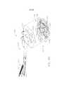
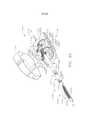
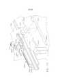
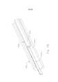
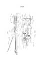
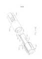
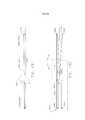
[00015] As Figuras 1 e 2 são vistas perspectivas de um instrumento cirúrgico para corte e fixação de acordo com várias modalidades da presente invenção;[00015] Figures 1 and 2 are perspective views of a surgical instrument for cutting and fixing according to various modalities of the present invention;
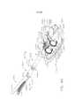
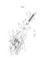
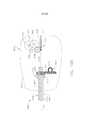
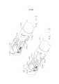
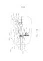
[00016] As Figuras 3 a 5 são vistas explodidas de um atuador de extremidade e haste do instrumento de acordo com várias modalidades da presente invenção;[00016] Figures 3 to 5 are exploded views of an end and stem actuator of the instrument according to various modalities of the present invention;
[00017] A Figura 6 é uma vista lateral do atuador de extremidade de acordo com várias modalidades da presente invenção;[00017] Figure 6 is a side view of the end actuator according to various embodiments of the present invention;
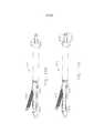
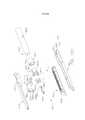
[00018] A Figura 7 é uma vista explodida do cabo do instrumento de acordo com várias modalidades da presente invenção;[00018] Figure 7 is an exploded view of the instrument cable in accordance with various embodiments of the present invention;
[00019] As Figuras 8 e 9 são vistas de perspectiva parcial do cabo de acordo com várias modalidades da presente invenção;[00019] Figures 8 and 9 are partial perspective views of the cable according to various embodiments of the present invention;
[00020] A Figura 10 é uma vista lateral do cabo de acordo com várias modalidades da presente invenção;[00020] Figure 10 is a side view of the cable according to various embodiments of the present invention;
[00021] As Figuras 10A e 10B ilustram uma sensor proporcional que pode ser usado de acordo com várias modalidades da presente invenção;[00021] Figures 10A and 10B illustrate a proportional sensor that can be used in accordance with various embodiments of the present invention;
[00022] A Figura 11 é um diagrama esquemático de um outro circuito usado no instrumento de acordo com várias modalidades da presente invenção;[00022] Figure 11 is a schematic diagram of another circuit used in the instrument according to various modalities of the present invention;
[00023] As Figuras 12 a 13 são vistas laterais do manípulo de acordo com outras modalidades da presente invenção;[00023] Figures 12 to 13 are side views of the handle according to other embodiments of the present invention;
[00024] As Figuras 14 a 22 ilustram diferentes mecanismos para travar o gatilho de fechamento de acordo com várias modalidades da presente invenção;[00024] Figures 14 to 22 illustrate different mechanisms for locking the closing trigger according to various embodiments of the present invention;
[00025] As Figuras 23A e B mostram uma junta universal ("junta u") que pode ser empregada no ponto de articulação do instrumento de acordo com várias modalidades da presente invenção;[00025] Figures 23A and B show a universal joint ("u joint") that can be used at the articulation point of the instrument according to various modalities of the present invention;
[00026] As Figuras 24A e B mostram um cabo de torção que pode ser empregado no ponto de articulação do instrumento de acordo com várias modalidades da presente invenção;[00026] Figures 24A and B show a torsion cable that can be used at the point of articulation of the instrument according to various modalities of the present invention;
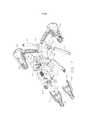
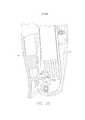
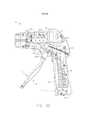
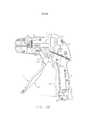
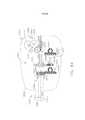
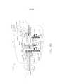
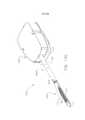
[00027] As Figuras 25 a 31 ilustram um instrumento cirúrgico para corte e fixação com auxiliar de potência de acordo com uma outra modalidade da presente invenção;[00027] Figures 25 to 31 illustrate a surgical instrument for cutting and fixing with power aid according to another embodiment of the present invention;
[00028] As Figuras 32 a 36 ilustram um instrumento cirúrgico para corte e fixação com auxiliar de potência de acordo com ainda outra modalidade da presente invenção;[00028] Figures 32 to 36 illustrate a surgical instrument for cutting and fixing with power aid in accordance with yet another embodiment of the present invention;
[00029] As Figuras 37 a 40 ilustram um instrumento cirúrgico para corte e fixação com retroinformação tátil para modalidades da presente invenção;[00029] Figures 37 to 40 illustrate a surgical instrument for cutting and fixing with tactile feedback for modalities of the present invention;
[00030] A Figura 41 ilustra uma vista explodida de um atuador de extremidade e eixo do instrumento de acordo com várias modalidades da presente invenção;[00030] Figure 41 illustrates an exploded view of an instrument end and axis actuator according to various embodiments of the present invention;
[00031] A Figura 42 ilustra uma vista lateral do manípulo de um instrumento mecânico de acordo com várias modalidades da presente invenção;[00031] Figure 42 illustrates a side view of the handle of a mechanical instrument according to various embodiments of the present invention;
[00032] A Figura 43 ilustra uma vista explodida do manípulo do instrumento mecanicamente atuado da Figura 42;[00032] Figure 43 illustrates an exploded view of the mechanically actuated instrument handle of Figure 42;
[00033] A Figura 44 ilustra um diagrama de blocos de um sistema de registro para registrar várias condições do instrumento de acordo com várias modalidades da presente invenção;[00033] Figure 44 illustrates a block diagram of a recording system for recording various conditions of the instrument according to various modalities of the present invention;
[00034] As Figuras 45 a 46 ilustrar vistas laterais cortadas de um manípulo do instrumento mostrando vários sensores de acordo com várias modalidades da presente invenção;[00034] Figures 45 to 46 illustrate cut-away side views of an instrument handle showing various sensors according to various embodiments of the present invention;
[00035] A Figura 47 ilustra o atuador de extremidade do instrumento que mostra vários sensores de acordo com várias modalidades da presente invenção;[00035] Figure 47 illustrates the end actuator of the instrument showing several sensors according to various modalities of the present invention;
[00036] A Figura 48 ilustra uma barra de disparo do instrumento que inclui um sensor de acordo com várias modalidades da presente invenção;[00036] Figure 48 illustrates an instrument firing bar that includes a sensor according to various modalities of the present invention;
[00037] A Figura 49 ilustra uma vista lateral do manípulo, do atuador de extremidade e da barra de disparo do instrumento mostrando um sensor de acordo com várias modalidades da presente invenção;[00037] Figure 49 illustrates a side view of the handle, the end actuator and the firing bar of the instrument showing a sensor according to various modalities of the present invention;
[00038] A Figura 50 ilustra uma vista explodida do canal de grampo e de porções de um cartucho de grampo do instrumento mostrando vários sensores de acordo com várias modalidades da presente invenção;[00038] Figure 50 illustrates an exploded view of the staple channel and portions of an instrument staple cartridge showing various sensors according to various embodiments of the present invention;
[00039] A Figura 51 ilustra uma vista descendente de topo da canaleta de grampo do instrumento que mostra vários sensores de acordo com várias modalidades da presente invenção;[00039] Figure 51 illustrates a top downward view of the instrument clamp channel showing various sensors according to various embodiments of the present invention;
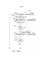
[00040] As Figuras 52A e 52B ilustram um fluxograma que mostra um método para operar o instrumento de acordo com várias modalidades;[00040] Figures 52A and 52B illustrate a flow chart showing a method for operating the instrument according to various modalities;
[00041] A Figura 53 ilustra um gráfico de memória que mostra condições registradas exemplificadoras do instrumento de acordo com várias modalidades da presente invenção;[00041] Figure 53 illustrates a memory graph that shows recorded conditions exemplifying the instrument according to various modalities of the present invention;
[00042] A Figura 54 é uma vista em perspectiva de uma modalidade de controlador robótico;[00042] Figure 54 is a perspective view of a robotic controller modality;
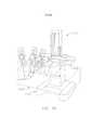
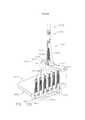
[00043] A Figura 55 é uma vista em perspectiva de um manipulador/carro de braço cirúrgico robótico de um sistema robótico que sustenta de modo operacional uma pluralidade de modalidades de ferramenta cirúrgica da presente invenção;[00043] Figure 55 is a perspective view of a robotic surgical arm manipulator / cart of a robotic system that operationally supports a plurality of surgical tool modalities of the present invention;
[00044] A Figura 56 é uma vista lateral do manipulador/carro de braço cirúrgico robótico mostrado na Figura 55;[00044] Figure 56 is a side view of the manipulator / robotic surgical arm cart shown in Figure 55;
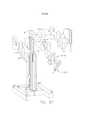
[00045] A Figura 57 é uma vista em perspectiva de uma estrutura de carro exemplificadora com ligações de posicionamento para sustentar de modo operacional os manipuladores robóticos que podem ser usados com várias modalidades de ferramenta cirúrgica da presente invenção;[00045] Figure 57 is a perspective view of an exemplary carriage structure with positioning links for operationally supporting robotic manipulators that can be used with various surgical tool modalities of the present invention;
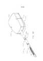
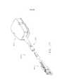
[00046] A Figura 58 é uma vista em perspectiva de uma modalidade de ferramenta cirúrgica da presente invenção;[00046] Figure 58 is a perspective view of a surgical tool modality of the present invention;
[00047] A Figura 59 é uma vista de conjunto explodida de uma adaptador e uma disposição de sustentação de ferramenta para fixar várias modalidades de ferramenta cirúrgica a uma sistema robótico;[00047] Figure 59 is an exploded view of an adapter and a tool holding arrangement for attaching various surgical tool modalities to a robotic system;
[00048] A Figura 60 é uma vista lateral do adaptador mostrado na Figura 59;[00048] Figure 60 is a side view of the adapter shown in Figure 59;
[00049] A Figura 61 é uma vista inferior do adaptador mostrado na Figura 59;[00049] Figure 61 is a bottom view of the adapter shown in Figure 59;
[00050] A Figura 62 é uma vista superior do adaptador das Figuras 59 e 60;[00050] Figure 62 is a top view of the adapter of Figures 59 and 60;
[00051] A Figura 63 é uma vista em perspectiva inferior parcial da modalidade de ferramenta cirúrgica da Figura 58;[00051] Figure 63 is a partial bottom perspective view of the surgical tool modality of Figure 58;
[00052] A Figura 64 é uma vista explodida parcial de uma porção de uma modalidade de atuador de extremidade cirúrgico articulável da presente invenção;[00052] Figure 64 is a partial exploded view of a portion of an articulated surgical end actuator modality of the present invention;
[00053] A Figura 65 é uma vista em perspectiva da modalidade de ferramenta cirúrgica da Figura 63 com o alojamento de montagem de ferramenta removido;[00053] Figure 65 is a perspective view of the surgical tool modality of Figure 63 with the tool mounting housing removed;
[00054] A Figura 66 é uma vista em perspectiva posterior da modalidade de ferramenta cirúrgica da Figura 63 com o alojamento de montagem de ferramenta removido;[00054] Figure 66 is a rear perspective view of the surgical tool modality of Figure 63 with the tool mounting housing removed;
[00055] A Figura 67 é uma vista em perspectiva anterior da modalidade de ferramenta cirúrgica da Figura 63 com o alojamento de montagem de ferramenta removido;[00055] Figure 67 is an anterior perspective view of the surgical tool modality of Figure 63 with the tool mounting housing removed;
[00056] A Figura 68 é uma vista em perspectiva explodida parcial da modalidade de ferramenta cirúrgica da Figura 67;[00056] Figure 68 is a partial exploded perspective view of the surgical tool modality of Figure 67;
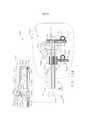
[00057] A Figura 69 é uma vista lateral em seção transversal parcial da modalidade de ferramenta cirúrgica da Figura 63;[00057] Figure 69 is a side view in partial cross section of the surgical tool modality in Figure 63;
[00058] A Figura 70 é uma vista em seção transversal ampliada de uma porção da ferramenta cirúrgica mostrada na Figura 69;[00058] Figure 70 is an enlarged cross-sectional view of a portion of the surgical tool shown in Figure 69;
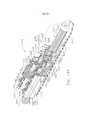
[00059] A Figura 71 é uma vista em perspectiva explodida de uma porção da porção de montagem de ferramenta da modalidade de ferramenta cirúrgica mostrada na Figura 63;[00059] Figure 71 is an exploded perspective view of a portion of the tool mounting portion of the surgical tool embodiment shown in Figure 63;
[00060] A Figura 72 é uma vista em perspectiva explodida ampliada de uma porção da porção de montagem de ferramenta da Figura 71;[00060] Figure 72 is an enlarged exploded perspective view of a portion of the tool mounting portion of Figure 71;
[00061] A Figura 73 é uma vista em seção transversal parcial de uma porção do conjunto de haste alongada da ferramenta cirúrgica da Figura 63;[00061] Figure 73 is a partial cross-sectional view of a portion of the elongated nail assembly of the surgical tool of Figure 63;
[00062] A Figura 74 é uma vista lateral de uma porção de metade de uma modalidade de porca de fechamento de uma modalidade de ferramenta cirúrgica da presente invenção;[00062] Figure 74 is a side view of a half portion of a lock nut embodiment of a surgical tool embodiment of the present invention;
[00063] A Figura 75 é uma vista em perspectiva de uma outra modalidade de ferramenta cirúrgica da presente invenção;[00063] Figure 75 is a perspective view of another embodiment of the surgical tool of the present invention;
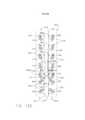
[00064] A Figura 76 é uma vista lateral em seção transversal de uma porção do atuador de extremidade cirúrgico e do conjunto de haste alongada da modalidade de ferramenta cirúrgica da Figura 75 com a bigorna na posição aberta e o conjunto de embreagem de fechamento em uma posição neutra;[00064] Figure 76 is a side cross-sectional view of a portion of the surgical end actuator and the elongated shank assembly of the surgical tool mode of Figure 75 with the anvil in the open position and the clutch assembly in one neutral position;
[00065] A Figura 77 é uma outra vista lateral em seção transversal do atuador de extremidade cirúrgico e do conjunto de haste alongada mostrado na Figura 76 com o conjunto de embreagem engatado em uma posição de fechamento;[00065] Figure 77 is another side view in cross section of the surgical end actuator and the elongated stem assembly shown in Figure 76 with the clutch assembly engaged in a closed position;
[00066] A Figura 78 é um outra vista lateral em seção transversal do atuador de extremidade cirúrgico e do conjunto de haste alongada mostrado na Figura 76 com o conjunto de embreagem engatado em uma posição de disparo;[00066] Figure 78 is another side view in cross section of the surgical end actuator and the elongated stem assembly shown in Figure 76 with the clutch assembly engaged in a firing position;
[00067] A Figura 79 é uma vista superior de uma porção de uma porção de modalidade de montagem de ferramenta da presente invenção;[00067] Figure 79 is a top view of a portion of a portion of the tool mounting embodiment of the present invention;
[00068] A Figura 80 é uma vista em perspectiva de um outra modalidade de ferramenta cirúrgica da presente invenção;[00068] Figure 80 is a perspective view of another embodiment of the surgical tool of the present invention;
[00069] A Figura 81 é uma vista lateral em seção transversal de uma porção do atuador de extremidade cirúrgico e do conjunto de haste alongada da modalidade de ferramenta cirúrgica da Figura 80 com a bigorna na posição aberta;[00069] Figure 81 is a cross-sectional side view of a portion of the surgical end actuator and the elongated stem assembly of the surgical tool modality of Figure 80 with the anvil in the open position;
[00070] A Figura 82 é uma outra vista lateral em seção transversal de uma porção do atuador de extremidade cirúrgico e do conjunto de haste alongada da modalidade de ferramenta cirúrgica da Figura 80 com a bigorna na posição fechada;[00070] Figure 82 is another cross-sectional side view of a portion of the surgical end actuator and the elongated stem assembly of the surgical tool modality of Figure 80 with the anvil in the closed position;
[00071] A Figura 83 é uma vista em perspectiva de uma porca de acionamento de fechamento e da porção de uma modalidade de barra de faca da presente invenção;[00071] Figure 83 is a perspective view of a closing drive nut and the portion of a knife bar embodiment of the present invention;
[00072] A Figura 84 é uma vista superior de uma outra modalidade de porção de montagem de ferramenta da presente invenção;[00072] Figure 84 is a top view of another embodiment of the tool mounting portion of the present invention;
[00073] A Figura 85 é uma vista em perspectiva de uma outra modalidade de ferramenta cirúrgica da presente invenção;[00073] Figure 85 is a perspective view of another embodiment of the surgical tool of the present invention;
[00074] A Figura 86 é uma vista lateral em seção transversal de uma porção do atuador de extremidade cirúrgico e do conjunto de haste alongada da modalidade de ferramenta cirúrgica da Figura 85 com a bigorna na posição aberta;[00074] Figure 86 is a side view in cross section of a portion of the surgical end actuator and the elongated stem assembly of the surgical tool modality of Figure 85 with the anvil in the open position;
[00075] A Figura 87 é uma outra vista lateral em seção transversal de uma porção do atuador de extremidade cirúrgico e do conjunto de haste alongada da modalidade de ferramenta cirúrgica da Figura 86 com a bigorna na posição fechada;[00075] Figure 87 is another side view in cross section of a portion of the surgical end actuator and the elongated stem assembly of the surgical tool modality of Figure 86 with the anvil in the closed position;
[00076] A Figura 88 uma vista em seção transversal de uma modalidade de colar de montagem de uma modalidade de ferramenta cirúrgica da presente invenção que mostra a barra de faca e a porção de extremidade distal do eixo de acionamento de fechamento;[00076] Figure 88 is a cross-sectional view of an assembly collar embodiment of a surgical tool embodiment of the present invention showing the knife bar and the distal end portion of the closing drive shaft;
[00077] A Figura 89 uma vista em seção transversal da modalidade de colar de montagem da Figura 88;[00077] Figure 89 is a cross-sectional view of the assembly collar modality of Figure 88;
[00078] A Figura 90 é uma vista superior de uma outra modalidade de porção de montagem de ferramenta de uma outra modalidade de ferramenta cirúrgica da presente invenção;[00078] Figure 90 is a top view of another embodiment of the tool mounting portion of another embodiment of the surgical tool of the present invention;
[00079] A Figura 90A é uma vista em perspectiva explodida de uma porção de uma disposição de engrenagem de uma outra modalidade de ferramenta cirúrgica da presente invenção;[00079] Figure 90A is an exploded perspective view of a portion of a gear arrangement of another embodiment of the surgical tool of the present invention;
[00080] A Figura 90B é uma vista em perspectiva em seção transversal da disposição de engrenagem mostrada na Figura 90A;[00080] Figure 90B is a cross-sectional perspective view of the gear arrangement shown in Figure 90A;
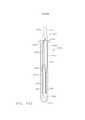
[00081] A Figura 91 é uma vista lateral em seção transversal de uma porção de um atuador de extremidade cirúrgico e do conjunto de haste alongada de uma outra modalidade de ferramenta cirúrgica da presente invenção que emprega uma disposição de sensor de pressão com a bigorna na posição aberta;[00081] Figure 91 is a cross-sectional side view of a portion of a surgical end actuator and the elongated stem assembly of another embodiment of the surgical tool of the present invention that employs a pressure sensor arrangement with the anvil on open position;
[00082] A Figura 92 é uma outra vista lateral em seção transversal de uma porção do atuador de extremidade cirúrgico e do conjunto de haste alongada da modalidade de ferramenta cirúrgica da Figura 91 com a bigorna na posição fechada;[00082] Figure 92 is another side view in cross section of a portion of the surgical end actuator and the elongated stem assembly of the surgical tool modality of Figure 91 with the anvil in the closed position;
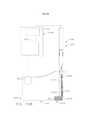
[00083] A Figura 93 é uma vista lateral de uma porção de uma outra modalidade de ferramenta cirúrgica da presente invenção em relação com uma porção de sustentação de ferramenta de um sistema robótico com alguns dos componentes dos mesmos mostrados em seção transversal;[00083] Figure 93 is a side view of a portion of another surgical tool embodiment of the present invention in relation to a tool holding portion of a robotic system with some of its components shown in cross section;
[00084] A Figura 94 é uma vista lateral de uma porção de uma outra modalidade de ferramenta cirúrgica da presente invenção em relação com uma porção de sustentação de ferramenta de um sistema robótico com alguns dos componentes dos mesmos mostrados em seção transversal;[00084] Figure 94 is a side view of a portion of another embodiment of the surgical tool of the present invention in relation to a tool holding portion of a robotic system with some of the components thereof shown in cross section;
[00085] A Figura 95 é uma vista lateral de uma porção de uma outra modalidade de ferramenta cirúrgica da presente invenção com alguns dos componentes da mesma mostrados em seção transversal;[00085] Figure 95 is a side view of a portion of another embodiment of the surgical tool of the present invention with some of its components shown in cross section;
[00086] A Figura 96 é uma vista lateral de uma porção de uma outra modalidade de atuador de extremidade cirúrgico de uma porção de uma modalidade de ferramenta cirúrgica da presente invenção com alguns componentes da mesma mostrados em seção transversal;[00086] Figure 96 is a side view of a portion of another surgical end actuator embodiment of a portion of a surgical tool embodiment of the present invention with some components thereof shown in cross section;
[00087] A Figura 97 é uma vista lateral de uma porção de uma outra modalidade de atuador de extremidade cirúrgico de uma porção de uma modalidade de ferramenta cirúrgica da presente invenção com alguns componentes da mesma mostrados em seção transversal;[00087] Figure 97 is a side view of a portion of another surgical end actuator embodiment of a portion of a surgical tool embodiment of the present invention with some components thereof shown in cross section;
[00088] A Figura 98 é uma vista lateral de uma porção de uma outra modalidade de atuador de extremidade cirúrgico de uma porção de uma modalidade de ferramenta cirúrgica da presente invenção com alguns componentes da mesma mostrados em seção transversal;[00088] Figure 98 is a side view of a portion of another surgical end actuator embodiment of a portion of a surgical tool embodiment of the present invention with some components thereof shown in cross section;
[00089] A Figura 99 é uma vista em seção transversal ampliada de uma porção do atuador de extremidade da Figura 98;[00089] Figure 99 is an enlarged cross-sectional view of a portion of the end actuator of Figure 98;
[00090] A Figura 100 é uma outra vista em seção transversal de uma porção do atuador de extremidade das Figuras 98 e 99;[00090] Figure 100 is another cross-sectional view of a portion of the end actuator of Figures 98 and 99;
[00091] A Figura 101 é uma vista lateral em seção transversal de uma porção de um atuador de extremidade cirúrgico e do conjunto de haste alongada de uma outra modalidade de ferramenta cirúrgica da presente invenção com a bigorna na posição aberta;[00091] Figure 101 is a cross-sectional side view of a portion of a surgical end actuator and the elongated stem assembly of another embodiment of the surgical tool of the present invention with the anvil in the open position;
[00092] A Figura 102 é uma vista lateral em seção transversal ampliada de uma porção do atuador de extremidade cirúrgico e do conjunto de haste alongada da modalidade de ferramenta cirúrgica da Figura 101;[00092] Figure 102 is a side view in enlarged cross section of a portion of the surgical end actuator and the elongated stem assembly of the surgical tool modality of Figure 101;
[00093] A Figura 103 é uma outra vista lateral em seção transversal de uma porção do atuador de extremidade cirúrgico e do conjunto de haste alongada das Figuras 101 e 102 com a bigorna dos mesmos na posição fechada;[00093] Figure 103 is another cross-sectional side view of a portion of the surgical end actuator and the elongated stem assembly of Figures 101 and 102 with their anvil in the closed position;
[00094] A Figura 104 é uma vista lateral em seção transversal ampliada de uma porção do atuador de extremidade cirúrgico e do conjunto de haste alongada da modalidade de ferramenta cirúrgica das Figuras 101 a 103;[00094] Figure 104 is a side view in enlarged cross section of a portion of the surgical end actuator and the elongated stem assembly of the surgical tool modality of Figures 101 to 103;
[00095] A Figura 105 é uma vista superior de uma modalidade de porção de montagem de ferramenta de uma modalidade de ferramenta cirúrgica da presente invenção;[00095] Figure 105 is a top view of a tool assembly portion embodiment of a surgical tool embodiment of the present invention;
[00096] A Figura 106 é uma vista de conjunto em perspectiva de uma outra modalidade de ferramenta cirúrgica da presente invenção;[00096] Figure 106 is an overall perspective view of another embodiment of the surgical tool of the present invention;
[00097] A Figura 107 é uma vista em perspectiva anterior de uma disposição de unidade de carregamento descartável que pode ser empregada com várias modalidades de ferramenta cirúrgica da presente invenção;[00097] Figure 107 is a front perspective view of a disposable loading unit arrangement that can be employed with various surgical tool embodiments of the present invention;
[00098] A Figura 108 é uma vista em perspectiva posterior da unidade de carregamento descartável da Figura 107;[00098] Figure 108 is a rear perspective view of the disposable loading unit of Figure 107;
[00099] A Figura 109 é uma vista em perspectiva inferior da unidade de carregamento descartável das Figuras 107 e 108;[00099] Figure 109 is a bottom perspective view of the disposable loading unit of Figures 107 and 108;
[000100] A Figura 110 é uma vista em perspectiva inferior de uma outra modalidade de unidade de carregamento descartável que pode ser empregada com várias modalidades de ferramenta cirúrgica da presente invenção;[000100] Figure 110 is a bottom perspective view of another embodiment of a disposable loading unit that can be employed with various embodiments of the surgical tool of the present invention;
[000101] A Figura 111 é uma vista em perspectiva explodida de uma porção de montagem de uma unidade de carregamento descartável mostrada nas Figuras 107 a 109;[000101] Figure 111 is an exploded perspective view of an assembly portion of a disposable loading unit shown in Figures 107 to 109;
[000102] A Figura 112 é uma vista em perspectiva de uma porção de uma unidade de carregamento descartável e uma modalidade de conjunto de haste alongada de uma modalidade de ferramenta cirúrgica da presente invenção com a unidade de carregamento descartável em uma primeira posição;[000102] Figure 112 is a perspective view of a portion of a disposable loading unit and an elongated rod assembly embodiment of a surgical tool embodiment of the present invention with the disposable loading unit in a first position;
[000103] A Figura 113 é uma outra vista em perspectiva de uma porção da unidade de carregamento descartável e do conjunto de haste alongada da Figura 112 com a unidade de carregamento descartável em uma segunda posição;[000103] Figure 113 is another perspective view of a portion of the disposable loading unit and the elongated rod assembly of Figure 112 with the disposable loading unit in a second position;
[000104] A Figura 114 é uma vista em seção transversal de uma porção da unidade de carregamento descartável e da modalidade de conjunto de haste alongada mostrada nas Figuras 112 e 113;[000104] Figure 114 is a cross-sectional view of a portion of the disposable loading unit and the elongated rod assembly mode shown in Figures 112 and 113;
[000105] A Figura 115 é uma outra vista em seção transversal da unidade de carregamento descartável e da modalidade de conjunto de haste alongada mostrada nas Figuras 112 a 114;[000105] Figure 115 is another cross-sectional view of the disposable loading unit and the lengthened rod assembly mode shown in Figures 112 to 114;
[000106] A Figura 116 é uma vista em perspectiva explodida parcial de uma porção de uma outra modalidade de unidade de carregamento descartável e de uma modalidade de conjunto de haste alongada de uma modalidade de ferramenta cirúrgica da presente invenção;[000106] Figure 116 is a partial exploded perspective view of a portion of another disposable loading unit modality and an elongated rod assembly modality of a surgical tool modality of the present invention;
[000107] A Figura 117 é uma vista em perspectiva explodida parcial de uma porção de uma outra modalidade de unidade de carregamento descartável e de uma modalidade de conjunto de haste alongada de uma modalidade de ferramenta cirúrgica da presente invenção;[000107] Figure 117 is a partial exploded perspective view of a portion of another disposable loading unit modality and an elongated rod assembly modality of a surgical tool modality of the present invention;
[000108] A Figura 118 é uma outra vista em perspectiva explodida parcial da modalidade de unidade de carregamento descartável e de uma modalidade de conjunto de haste alongada da Figura 117;[000108] Figure 118 is another partial exploded perspective view of the disposable loading unit modality and an elongated rod assembly modality of Figure 117;
[000109] A Figura 119 é uma vista superior de uma outra modalidade de porção de montagem de ferramenta de uma modalidade de ferramenta cirúrgica da presente invenção;[000109] Figure 119 is a top view of another embodiment of the tool mounting portion of a surgical tool embodiment of the present invention;
[000110] A Figura 120 é uma vista lateral de uma outra modalidade de ferramenta cirúrgica da presente invenção com alguns dos componentes da mesma mostrados em seção transversal e em relação a um suporte de ferramenta robótica de um sistema robótico;[000110] Figure 120 is a side view of another embodiment of the surgical tool of the present invention with some of its components shown in cross section and in relation to a robotic tool holder of a robotic system;
[000111] A Figura 121 é uma vista de conjunto explodida de uma modalidade de atuador de extremidade cirúrgico que pode ser usada em conjunto com várias modalidades de ferramenta cirúrgica da presente invenção;[000111] Figure 121 is an exploded view of a surgical end actuator modality that can be used in conjunction with various surgical tool embodiments of the present invention;
[000112] A Figura 122 é uma vista lateral de uma porção de um sistema acionado por cabo para acionar um instrumento de corte empregado em várias modalidades de atuador de extremidade cirúrgico da presente invenção;[000112] Figure 122 is a side view of a portion of a cable-driven system for driving a cutting instrument used in various surgical end actuator modalities of the present invention;
[000113] A Figura 123 é uma vista superior do sistema acionado por cabo e do instrumento de corte da Figura 122;[000113] Figure 123 is a top view of the cable-driven system and the cutting instrument of Figure 122;
[000114] A Figura 124 é uma vista superior de uma modalidade de transmissão de acionamento de cabo da presente invenção em uma posição de fechamento;[000114] Figure 124 is a top view of a cable drive transmission modality of the present invention in a closed position;
[000115] A Figura 125 é uma outra vista superior da modalidade de transmissão de acionamento de cabo da Figura 124 em uma posição neutra;[000115] Figure 125 is another top view of the cable drive transmission mode of Figure 124 in a neutral position;
[000116] A Figura 126 é uma outra vista superior da modalidade de transmissão de acionamento de cabo das Figuras 124 e 125 em uma posição de disparo;[000116] Figure 126 is another top view of the cable drive transmission mode of Figures 124 and 125 in a firing position;
[000117] A Figura 127 é uma vista em perspectiva da modalidade de transmissão de acionamento de cabo na posição mostrada na Figura 124;[000117] Figure 127 is a perspective view of the cable drive transmission mode in the position shown in Figure 124;
[000118] A Figura 128 é uma vista em perspectiva da modalidade de transmissão de acionamento de cabo na posição mostrada na Figura 125;[000118] Figure 128 is a perspective view of the cable drive transmission mode in the position shown in Figure 125;
[000119] A Figura 129 é uma vista em perspectiva da modalidade de transmissão de acionamento de cabo na posição mostrada na Figura 126;[000119] Figure 129 is a perspective view of the cable drive transmission mode in the position shown in Figure 126;
[000120] A Figura 130 é uma vista em perspectiva de uma outra modalidade de ferramenta cirúrgica da presente invenção;[000120] Figure 130 is a perspective view of another embodiment of the surgical tool of the present invention;
[000121] A Figura 131 é uma vista lateral de uma porção de uma outra modalidade de sistema acionado por cabo para acionar um instrumento de corte empregado em várias modalidades de atuador de extremidade cirúrgico da presente invenção;[000121] Figure 131 is a side view of a portion of another modality of a cable-driven system for driving a cutting instrument employed in various modalities of the surgical end actuator of the present invention;
[000122] A Figura 132 é uma vista superior da modalidade de sistema acionado por cabo da Figura 131;[000122] Figure 132 is a top view of the cable-driven system modality of Figure 131;
[000123] A Figura 133 é uma vista superior de uma modalidade de porção de montagem de ferramenta de uma outra modalidade de ferramenta cirúrgica da presente invenção;[000123] Figure 133 is a top view of a tool assembly portion embodiment of another surgical tool embodiment of the present invention;
[000124] A Figura 134 é uma vista superior em seção transversal de uma outra modalidade de ferramenta cirúrgica da presente invenção;[000124] Figure 134 is a top cross-sectional view of another embodiment of the surgical tool of the present invention;
[000125] A Figura 135 é uma vista em seção transversal de uma porção de uma modalidade de atuador de extremidade cirúrgico de uma modalidade de ferramenta cirúrgica da presente invenção;[000125] Figure 135 is a cross-sectional view of a portion of a surgical end actuator modality of a surgical tool modality of the present invention;
[000126] A Figura 136 é uma vista de extremidade em seção transversal do atuador de extremidade cirúrgico da Figura 103 tomada ao longo da linha 136-136 na Figura 135;[000126] Figure 136 is an end view in cross section of the surgical end actuator of Figure 103 taken along line 136-136 in Figure 135;
[000127] A Figura 137 é uma vista em perspectiva do atuador de extremidade cirúrgico das Figuras 135 e 136 com porções do mesmo mostradas em seção transversal;[000127] Figure 137 is a perspective view of the surgical end actuator of Figures 135 and 136 with portions thereof shown in cross section;
[000128] A Figura 138 é uma vista lateral de uma porção do atuador de extremidade cirúrgico das Figuras 135 a 137;[000128] Figure 138 is a side view of a portion of the surgical end actuator of Figures 135 to 137;
[000129] A Figura 139 é uma vista em perspectiva de uma modalidade de conjunto de sustentação deslizante de várias modalidades de ferramenta cirúrgica da presente invenção;[000129] Figure 139 is a perspective view of a sliding support assembly modality of various surgical tool modalities of the present invention;
[000130] A Figura 140 é uma vista em seção transversal da modalidade de conjunto de sustentação deslizante da Figura 139 e uma porção da canaleta alongada da Figura 138;[000130] Figure 140 is a cross-sectional view of the sliding support assembly of Figure 139 and a portion of the elongated channel of Figure 138;
[000131] As Figuras 141 a 146 mostram diagramaticamente o disparo sequencial de grampos em uma modalidade de ferramenta cirúrgica da presente invenção;[000131] Figures 141 to 146 diagrammatically show the sequential firing of clamps in a surgical tool modality of the present invention;
[000132] A Figura 147 é uma vista em perspectiva parcial de uma porção de uma modalidade de atuador de extremidade cirúrgico da presente invenção;[000132] Figure 147 is a partial perspective view of a portion of a surgical end actuator embodiment of the present invention;
[000133] A Figura 148 é uma vista em perspectiva em seção transversal parcial de uma porção de uma modalidade de atuador de extremidade cirúrgico de uma modalidade de ferramenta cirúrgica da presente invenção;[000133] Figure 148 is a partial cross-sectional perspective view of a portion of a surgical end actuator modality of a surgical tool modality of the present invention;
[000134] A Figura 149 é uma outra vista em perspectiva em seção transversal parcial da modalidade de atuador de extremidade cirúrgico da Figura 148 com um conjunto de sustentação deslizante que avança axialmente através do mesmo;[000134] Figure 149 is another perspective view in partial cross section of the surgical end actuator modality of Figure 148 with a sliding support assembly that advances axially through it;
[000135] A Figura 150 é uma vista em perspectiva de uma outra modalidade de conjunto de sustentação deslizante de uma outra modalidade de ferramenta cirúrgica da presente invenção;[000135] Figure 150 is a perspective view of another type of sliding support assembly of another type of surgical tool of the present invention;
[000136] A Figura 151 é uma vista superior parcial de uma porção da modalidade de atuador de extremidade cirúrgico mostrada nas Figuras 148 e 149 com o conjunto de sustentação deslizante que avança axialmente através do mesmo;[000136] Figure 151 is a partial top view of a portion of the surgical end actuator modality shown in Figures 148 and 149 with the sliding support assembly that advances axially through it;
[000137] A Figura 152 é uma outra vista superior parcial da modalidade de atuador de extremidade cirúrgico da Figura 151 com a superfície de topo do cartucho de grampo cirúrgico omitida para maior clareza;[000137] Figure 152 is another partial top view of the surgical end actuator mode of Figure 151 with the top surface of the surgical clamp cartridge omitted for clarity;
[000138] A Figura 153 é uma vista lateral em seção transversal parcial de uma modalidade de acionador giratório e uma modalidade de propulsor de grampo do atuador de extremidade cirúrgico mostrado nas Figuras 148 e 149;[000138] Figure 153 is a side view in partial cross-section of a rotary actuator mode and a clamp propeller mode of the surgical end actuator shown in Figures 148 and 149;
[000139] A Figura 154 é uma vista em perspectiva de uma modalidade de sistema de recarregamento automatizado da presente invenção com um atuador de extremidade cirúrgico em engate de extração com o sistema de extração do mesmo;[000139] Figure 154 is a perspective view of an automated reloading system modality of the present invention with a surgical end actuator in extraction engagement with the extraction system thereof;
[000140] A Figura 155 é uma outra vista em perspectiva da modalidade de sistema de recarregamento automatizado mostrada na Figura 154;[000140] Figure 155 is another perspective view of the automated reloading system modality shown in Figure 154;
[000141] A Figura 156 é uma vista em elevação em seção transversal da modalidade de sistema de recarregamento automatizado mostrada nas Figuras 154 e 155;[000141] Figure 156 is a cross-sectional elevation view of the automated reloading system modality shown in Figures 154 and 155;
[000142] A Figura 157 é uma outra vista em elevação em seção transversal da modalidade de sistema de recarregamento automatizado mostrada nas Figuras 154 a 156 com o sistema de extração do mesmo que remove um cartucho de grampo cirúrgico gasto do atuador de extremidade cirúrgico;[000142] Figure 157 is another elevation view in cross section of the automated reloading system modality shown in Figures 154 to 156 with the extraction system of the same that removes a worn surgical staple cartridge from the surgical end actuator;
[000143] A Figura 158 é uma outra vista em elevação em seção transversal da modalidade de sistema de recarregamento automatizado mostrada nas Figuras 154 a 157 que ilustra o carregamento de um novo cartucho de grampo cirúrgico em um atuador de extremidade cirúrgico;[000143] Figure 158 is another elevation view in cross-section of the automated reloading system modality shown in Figures 154 to 157 that illustrates the loading of a new surgical clamp cartridge on a surgical end actuator;
[000144] A Figura 159 é uma vista em perspectiva de uma outra modalidade de sistema de recarregamento automatizado da presente invenção com alguns componentes mostrados em seção transversal;[000144] Figure 159 is a perspective view of another embodiment of the automated reloading system of the present invention with some components shown in cross section;
[000145] A Figura 160 é uma vista em perspectiva explodida de uma porção da modalidade de sistema de recarregamento automatizado da Figura 159;[000145] Figure 160 is an exploded perspective view of a portion of the automated reloading system modality of Figure 159;
[000146] A Figura 161 é uma outra vista em perspectiva explodida da porção da modalidade de sistema de recarregamento automatizado mostrada na Figura 160;[000146] Figure 161 is another exploded perspective view of the portion of the automated reloading system modality shown in Figure 160;
[000147] A Figura 162 é uma vista em elevação em seção transversal da modalidade do sistema de recarregamento automatizado das Figuras 159 a 161;[000147] Figure 162 is a cross-sectional elevation view of the mode of the automated reloading system of Figures 159 to 161;
[000148] A Figura 163 é uma vista em seção transversal de uma modalidade de tubo de orientação que sustenta uma unidade de carregamento descartável nisso;[000148] Figure 163 is a cross-sectional view of an orientation tube modality that supports a disposable loading unit therein;
[000149] A Figura 164 é uma vista em perspectiva de uma outra modalidade de ferramenta cirúrgica da presente invenção;[000149] Figure 164 is a perspective view of another embodiment of the surgical tool of the present invention;
[000150] A Figura 165 é uma vista em perspectiva parcial de uma modalidade de junta de articulação de uma modalidade de ferramenta cirúrgica da presente invenção;[000150] Figure 165 is a partial perspective view of an articulation joint embodiment of a surgical tool embodiment of the present invention;
[000151] A Figura 166 é uma vista em perspectiva de uma modalidade de tubo de fechamento de uma modalidade de ferramenta cirúrgica da presente invenção;[000151] Figure 166 is a perspective view of a closure tube embodiment of a surgical tool embodiment of the present invention;
[000152] A Figura 167 é uma vista em perspectiva da modalidade de tubo de fechamento da Figura 166 montada na modalidade de junta de articulação da Figura 165;[000152] Figure 167 is a perspective view of the closure tube modality of Figure 166 assembled in the articulation joint mode of Figure 165;
[000153] A Figura 168 é uma vista superior de uma porção de uma modalidade de porção de montagem de ferramenta de uma modalidade de ferramenta cirúrgica da presente invenção;[000153] Figure 168 is a top view of a portion of a tool assembly portion embodiment of a surgical tool embodiment of the present invention;
[000154] A Figura 169 é uma vista em perspectiva de uma modalidade de conjunto de acionamento de articulação empregada na modalidade de porção de montagem de ferramenta da Figura 168;[000154] Figure 169 is a perspective view of an articulation drive assembly modality employed in the tool assembly portion modality of Figure 168;
[000155] A Figura 170 é uma vista em perspectiva de uma outra modalidade de ferramenta cirúrgica da presente invenção; e[000155] Figure 170 is a perspective view of another embodiment of the surgical tool of the present invention; and
[000156] A Figura 171 é uma vista em perspectiva de uma outra modalidade de ferramenta cirúrgica da presente invenção.[000156] Figure 171 is a perspective view of another embodiment of the surgical tool of the present invention.
[000157] A requerente do presente pedido também é a autora dos seguintes pedidos de patente que foram depositados na mesma data do presente pedido e que estão, cada um, incorporados a título de referência em suas respectivas totalidades: - pedido de patente US n° de série , intitulado "Surgical Instrument With Wireless Communication Between a Control Unit of a Robotic System and Remote Sensor", Dossiê do advogado n° END5924USCIP2/060339CIP2; - pedido de patente US n° de série , intitulado "Robotically-Controlled Disposable Motor Driven Loading Unit", Dossiê do advogado n° END6213USCIP1/070330CIP1; - pedido de patente US n° de série , intitulado "Robotically-Controlled Endoscopic Accessory Channel", Dossiê do advogado n° END5568USCIP2/100809CIP2; - pedido de patente US n° de série , intitulado "Robotically-Controlled Motorized Surgical Instrument", Dossiê do advogado n° END6416USCIP1/080205CIP1; - pedido de patente US n° de série , intitulado "Robotically-Controlled Surgical Stapling Devices That Produce Formed Staples Having Different Lengths", n° do documento do procurador END5675USCIP6/050504CIP6; - pedido de patente US n° de série , intitulado "Robotically-Controlled Motorized Cutting and Fastening Instrument", Dossiê do advogado n° END6269USCIP1/070391CIP1; - pedido de patente US n° de série , intitulado "Robotically-Controlled Shaft Based Rotary Drive Systems For Surgical Instruments", Dossiê do advogado n° END6089USCIP1/070059CIP1; - pedido de patente US n° de série , intitulado "Robotically-Controlled Surgical Instrument With Force Feedback Capabilities", Dossiê do advogado n° END5773USCIP5/050698CIP5; - pedido de patente US n° de série , intitulado "Robotically-Driven Surgical Instrument With E-Beam Driver", Dossiê do advogado n° END0908USCIP2/100810CIP2; - pedido de patente US n° de série , intitulado "Surgical Stapling Instruments With Rotatable Staple Deployment Arrangements", Dossiê do advogado n° END7002USNP/110262.[000157] The applicant for this application is also the author of the following patent applications that were filed on the same date as this application and that are each incorporated by reference in their respective totalities: - US patent application no. serial, entitled "Surgical Instrument With Wireless Communication Between a Control Unit of a Robotic System and Remote Sensor", Lawyer Dossier No. END5924USCIP2 / 060339CIP2; - US Patent Application Serial No., entitled "Robotically-Controlled Disposable Motor Driven Loading Unit", Lawyer Dossier No. END6213USCIP1 / 070330CIP1; - US Patent Application Serial No., entitled "Robotically-Controlled Endoscopic Accessory Channel", Lawyer Dossier No. END5568USCIP2 / 100809CIP2; - US Patent Application Serial No., entitled "Robotically-Controlled Motorized Surgical Instrument", Lawyer Dossier No. END6416USCIP1 / 080205CIP1; - US patent application serial number, entitled "Robotically-Controlled Surgical Stapling Devices That Produce Formed Staples Having Different Lengths", Attorney Document No. END5675USCIP6 / 050504CIP6; - US patent application No. Serial, entitled "Robotically-Controlled Motorized Cutting and Fastening Instrument", Lawyer Dossier No. END6269USCIP1 / 070391CIP1; - US patent application No. Serial, entitled "Robotically-Controlled Shaft Based Rotary Drive Systems For Surgical Instruments", Lawyer Dossier No. END6089USCIP1 / 070059CIP1; - US patent application No. Serial, entitled "Robotically-Controlled Surgical Instrument With Force Feedback Capabilities", Lawyer Dossier No. END5773USCIP5 / 050698CIP5; - US patent application No. Serial, entitled "Robotically-Driven Surgical Instrument With E-Beam Driver", Lawyer Dossier No. END0908USCIP2 / 100810CIP2; - US Patent Application Serial No., entitled "Surgical Stapling Instruments With Rotatable Staple Deployment Arrangements", Lawyer Dossier No. END7002USNP / 110262.
[000158] Certas modalidades exemplificadoras serão descritas agora para fornecer uma compreensão geral dos princípios da estrutura, função, fabricação e uso dos dispositivos e métodos da presente invenção apresentados. Um ou mais exemplos destas modalidades estão ilustrados nos desenhos em anexo. Os elementos versados na técnica entenderão que os dispositivos e os métodos especificamente aqui descritos e ilustrados nos desenhos em anexo são modalidades exemplares não-limitadoras, e que o escopo das várias modalidades da presente invenção é definido somente pelas reivindicações. As características ilustradas ou descritas em conjunto com uma modalidade exemplificadora podem ser combinadas com as características de outras modalidades. Tais modificações e variações são concebidas para serem incluídas dentro do escopo da presente invenção.[000158] Certain exemplary embodiments will now be described to provide a general understanding of the principles of structure, function, manufacture and use of the devices and methods of the present invention presented. One or more examples of these modalities are illustrated in the attached drawings. Those skilled in the art will understand that the devices and methods specifically described herein and illustrated in the accompanying drawings are exemplary non-limiting modalities, and that the scope of the various modalities of the present invention is defined only by the claims. The characteristics illustrated or described in conjunction with an exemplary modality can be combined with the characteristics of other modalities. Such modifications and variations are designed to be included within the scope of the present invention.
[000159] Os usos de frases "em várias modalidades", "em algumas modalidades", "em uma modalidade", ou "na modalidade", ou similares, em lugares do início ao fim do relatório descritivo não estão necessariamente todos se referindo à mesma modalidade. Ademais, os atributos, estruturas ou características particulares de uma ou mais modalidades podem ser combinados de qualquer maneira adequada em uma ou mais outras modalidades. Tais modificações e variações são concebidas para serem incluídas dentro do escopo da presente invenção.[000159] The uses of phrases "in various modalities", "in some modalities", "in one modality", or "in modality", or similar, in places from beginning to end of the specification are not necessarily all referring to the same modality. Furthermore, the particular attributes, structures or characteristics of one or more modalities can be combined in any suitable way into one or more other modalities. Such modifications and variations are designed to be included within the scope of the present invention.
[000160] As Figuras 1 e 2 representam um instrumento de corte e fixação 10 de acordo com várias modalidades de presente invenção. A modalidade ilustrada é um instrumento cirúrgico endoscópico 10 e, em geral, as modalidades do instrumento 10 aqui descritas são instrumentos cirúrgicos endoscópicos de corte e fixação. Deve notar- se, entretanto, que de acordo com outras modalidades da presente invenção, o instrumento 10 pode ser um instrumento de corte cirúrgico não-endoscópico, como um instrumento laparoscópico.[000160] Figures 1 and 2 represent a cutting and clamping
[000161] O instrumento cirúrgico 10 representado nas Figuras 1 e 2 compreende um cabo 6, uma haste 8, e um atuador de extremidade articulado 12 conectado de forma articulada à haste 8 a um pivô de articulação 14. Um controle de articulação 16 pode ser fornecido adjacente ao cabo 6 para realizar a rotação do atuador de extremidade 12 sobre o pivô de articulação 14. Ficará entendido que várias modalidades podem incluir um atuador de extremidade não pivotante e, consequentemente, podem não ter um pivô de articulação 14 ou controle de articulação 16. Ademais, na modalidade ilustrada, o atuador de extremidade 12 é configurado para atuar como um endocortador para prender, separar e grampear tecido, embora, em outras modalidades, diferentes tipos de atuadores de extremidade podem ser usados, como atuadores de extremidade para outros tipos de dispositivos cirúrgicos, como pinças, cortadores, grampeadores, aplicadores de presilha, dispositivos de acesso, dispositivos de terapia de gene/fármaco, ultrassom, RF ou dispositivos a laser, etc.[000161] The
[000162] O cabo 6 do instrumento 10 pode incluir um gatilho de fechamento 18 e um gatilho de disparo 20 para acionar o atuador de extremidade 12. Será reconhecido que os instrumentos que têm atuadores de extremidade direcionados a diferentes tarefas cirúrgicas podem ter números ou tipos diferentes de gatilhos ou outros controles adequados para operar o atuador de extremidade 12. O atuador de extremidade 12 é mostrado separadamente do cabo 6 por uma haste 8, de preferência, alongada. Em uma modalidade, um médico ou operador do instrumento 10 pode articular o atuador de extremidade 12 em relação ao eixo 8 através da utilização do controle de articulação 16, conforme descrito em maiores detalhes no pedido de patente pendente US n° de série 11/329.020, depositado em 10 de janeiro de 2006, intitulado "Surgical Instrument Having An Articulating End Effector," de Geoffrey C. Hueil et al., que é aqui incorporado, por referência.[000162] The
[000163] O atuador de extremidade 12 inclui nesse exemplo, entre outras coisas, uma canaleta de grampos 22 e um membro de fixação transladável de modo articulado, tal como uma bigorna 24, que são mantidos em um espaçamento que assegura o grampeamento efetivo ou seccionamento do tecido fixado no atuador de extremidade 12. O cabo 6 inclui uma pega de pistola 26 em direção ao qual um gatilho de fechamento 18 é puxado de forma articulada pelo clínico para levar à fixação ou fechamento da bigorna 24 em direção à canaleta de grampos 22 do atuador de extremidade 12 para desse modo fixar o tecido posicionado entre a garra da bigorna 24 e a canaleta 22. O gatilho de disparo 20 está situado mais para fora, em relação ao gatilho de fechamento 18. Uma vez que o gatilho de fechamento 18 esteja travado na posição de fechamento, conforme descrito abaixo com mais detalhes, o gatilho de disparo 20 pode girar levemente em direção à pega de pistola 26, de modo que o mesmo possa ser alcançado pelo operador com o uso de uma só mão. Então o operador pode puxar o gatilho de disparo 20 de forma articulada em direção à pega de pistola 26 para causar o grampeamento e seccionamento de tecido fixado no atuador de extremidade 12. Em outras modalidades, diferentes tipos de membros de fixação além da bigorna 24 podem ser usados, como, por exemplo, uma garra de oposição, etc.[000163] The
[000164] Será reconhecido que os termos "proximal" e "distal"são usados aqui com referência ao ato de apertar o cabo 6 de um instrumento 10 pelo clínico. Portanto, o atuador de extremidade 12 é distal em relação ao cabo, que é mais proximal 6. Deve-se reconhecer adicionalmente que, por uma questão de conveniência e clareza, termos espaciais como "vertical" e "horizontal"são usados na presente invenção em relação aos desenhos. Entretanto, instrumentos cirúrgicos podem ser usados em muitas orientações e posições, e não pretende-se que esses termos sejam limitadores e absolutos.[000164] It will be recognized that the terms "proximal" and "distal" are used here with reference to the act of tightening the
[000165] O gatilho de fechamento 18 pode ser acionado primeiro. Quando satisfeito com o posicionamento do atuador de extremidade 12, o médico pode retrair o gatilho de fechamento 18 para a posição completamente fechada e travada adjacente à pega de pistola 26. O gatilho de disparo 20 pode então ser atuado. O gatilho de disparo 20 volta para a posição aberta (mostrado nas Figuras 1 e 2) quando o médico remove a pressão, conforme descrito mais completamente abaixo. Um botão de liberação presente no cabo 6 pode, quando pressionado, liberar a trava do gatilho de fechamento 18. O botão de liberação pode ser implementado sob várias formas como, por exemplo, o botão de liberação 30 mostrado nas Figuras 42 a 43, botão de liberação de deslizamento 160 mostrado na Figura 14, e/ou o botão 172 mostrado na Figura 16.[000165] The
[000166] As Figuras 3 a 6 mostram modalidades de um atuador de extremidade acionado por rotação 12 e haste 8 de acordo com várias modalidades. A Figura 3 é uma vista explodida do atuador de extremidade 12 de acordo com várias modalidades. Conforme mostrado na modalidade ilustrada, o atuador de extremidade 12 pode incluir, em adição à canaleta 22 e à bigorna 24 previamente mencionadas, um instrumento de corte 32, um trilho 33, um cartucho de grampos 34 que é assentado de modo removível na canaleta 22, e uma haste de parafuso helicoidal 36. O instrumento de corte 32 pode ser, por exemplo, uma faca. A bigorna 24 pode ser aberta e fechada articuladamente nos pinos pivôs 25 conectados à extremidade adjacente da canaleta 22. A bigorna 24 também pode incluir, em sua extremidade proximal, uma aba 27 que é inserida em um componente do sistema de fechamento mecânico para abrir e fechar a bigorna 24. Quando o gatilho de fechamento 18 é atuado, isto é, extraído por um usuário do instrumento 10, a bigorna 24 pode girar em torno dos pinos pivôs 25 formando uma posição fechada ou presa. Se a fixação do atuador de extremidade é 12 for satisfatória, o operador pode acionar o gatilho de disparo 20 que, como explicado em mais detalhes acima, faz com que a faca 32 e o trilho 33 corram longitudinalmente ao longo da canaleta 22, cortando desse modo o tecido fixado dentro do atuador de extremidade 12. O movimento do suporte deslizante 33 ao longo da canaleta 22 faz com que os grampos (não mostrados) do cartucho de grampo 34 sejam acionados através do tecido separado e em relação à bigorna fechada 24, que vira os grampos para fixar o tecido separado. Em várias modalidades, o trilho 33 pode ser um componente integral do cartucho 34. A patente US n° 6.978.921, intitulada "SURGICAL STAPLING INSTRUMENT INCORPORATING AN E-BEAM FIRING MECHANISM" de Shelton, IV et al., que é aqui incorporada, por referência, fornece mais detalhes sobre tais instrumentos de corte e fixação de dois cursos. O suporte deslizante 33 pode ser parte do cartucho 34, de modo que quando a faca 32 retrai após a operação de corte, o suporte deslizante 33 não retrai.[000166] Figures 3 to 6 show modalities of an end actuator driven by
[000167] Deve ser observado que embora as modalidades do instrumento 10 aqui descritas empreguem um atuador de extremidade 12 que grampeia o tecido seccionado, em outras modalidades técnicas diferentes para unir ou selar o tecido seccionado podem ser usadas. Por exemplo, atuadores de extremidade que usam energia RF (rádio frequência) ou adesivos para unir o tecido separado também podem ser usados. A patente US n° 5.709.680 intitulada "ELECTROSURGICAL HEMOSTATIC DEVICE" de Yates et al. e a patente US n° 5.688.270 intitulada "ELECTOSURGICAL HEMOSTATIC DEVICE WITH RECESSED AND/OR OFFSET ELECTRODES" de Yates et al. os quais estão aqui incorporados a título de referência, revelam um instrumento de corte endoscópico que usa energia de RF para vedar o tecido separado. O pedido de patente US n° de série 11/267.811 de Jerome R. Morgan, et. al. e o pedido de patente US n° de série 11/267.383 de Frederick E. Shelton, IV, et. al., que também são aqui incorporados, a título de referência, revelam instrumentos de corte que usam adesivos para prender o tecido separado. Desse modo, embora a descrição da presente invenção refira-se a operações de corte/grampeamento e similares, deve ser reconhecido que esta é uma modalidade exemplificadora, e não pretende ser limitadora. Outras técnicas de preensão de tecido podem também ser usadas.[000167] It should be noted that although the instrument modalities 10 described herein employ an
[000168] As Figuras 4 e 5 são vistas explodidas e a Figura 6 é uma vista lateral do atuador de extremidade 12 e da haste 8 de acordo com várias modalidades. Conforme mostrado na modalidade ilustrada, a haste 8 pode incluir um tubo de fechamento adjacente 40 e um tubo de fechamento distal 42 ligado articuladamente por uma ligação de pivô 44. O tubo de fechamento distal 42 inclui uma abertura 45 na qual é inserida a aba 27 existente na bigorna 24, de modo a abrir e fechar a bigorna 24, conforme descrito abaixo com mais detalhes. Disposto dentro dos tubos de fechamento 40 e 42 pode estar um tubo dentado proximal 46. Disposto dentro do tubo dentado proximal 46 pode estar uma haste de acionamento principal 48 giratória (ou proximal) que se comunica com uma haste de acionamento 50 secundária (ou distal) por meio de um conjunto de engrenagens cônicas 52. O eixo de acionamento secundário 50 está conectado a uma engrenagem propulsora 54 que engata uma engrenagem propulsora adjacente 56 da haste de parafuso helicoidal 36. A engrenagem chanfrada vertical 52b pode assentar e girar em uma abertura 57 na extremidade distal do tubo estruturante adjacente 46. Um tubo estruturante distal 58 pode ser usado para fechar o eixo de acionamento secundário 50 e as engrenagens propulsoras 54, 56. Coletivamente, a haste de acionamento principal 48, a haste de acionamento secundária 50, e o conjunto de articulação (por exemplo, o conjunto de engrenagem de chanfro 52a a c) são, algumas vezes, chamados na presente invenção de "conjunto de haste de acionamento principal".[000168] Figures 4 and 5 are exploded and Figure 6 is a side view of
[000169] Um rolamento 38, posicionado em uma extremidade distal da canaleta de grampos 22, recebe o parafuso helicoidal 36, permitindo que o parafuso helicoidal 36 gire livremente com relação à canaleta 22. A haste de parafuso helicoidal 36 pode interligar uma abertura rosqueada (não mostrada) da faca 32 de modo que a rotação da haste 36 faz com que a faca 32 gire em posição distal ou em direção proximal (dependendo da direção da rotação) através da canaleta de grampos 22. Consequentemente, quando se provoca a rotação da haste de acionamento principal 48 através da atuação do gatilho de disparo 20 (conforme explicado em maiores detalhes abaixo), o conjunto de engrenagem de chanfro 52a-c faz com que a haste de acionamento secundária 50 gire, que, por sua vez, por causa do engate das engrenagens de acionamento 54, 56, a haste de parafuso helicoidal 36 gira, o que faz com que o membro de acionamento de faca 32 percorra longitudinalmente ao longo da canaleta 22 para cortar qualquer tecido preso dentro do atuador de extremidade 12. A peça deslizante 33 pode ser feita, por exemplo, de plástico, e pode ter uma superfície distal inclinada. Conforme o suporte deslizante 33 atravessa a canaleta 22, a superfície dianteira inclinada pode empurrar para cima ou acionar os grampos no cartucho de grampo através do tecido preso e contra a bigorna 24. A bigorna 24 vira os grampos grampeando, assim, o tecido cortado. Quando a faca 32 é retraída, a faca 32 e o trilho 33 podem ficar desengatados saindo, assim, do trilho 33 na extremidade distal da canaleta 22.[000169] A
[000170] Conforme descrito acima, devido à falta de retroinformação ao usuário para a operação de corte/grampeamento, há uma falta de aceitação geral entre os médicos que utilizam instrumentos cirúrgicos endoscópicos acionados por motor onde a operação de corte/grampeamento é atuada por uma simples pressão de um botão. Em contraste, as modalidades da presente invenção fornecem um endocortador acionado por motor com retroalimentação de usuário do posicionamento, força e/ou posição do instrumento de corte 32 em atuador de extremidade 12.[000170] As described above, due to the lack of feedback to the user for the cutting / stapling operation, there is a general lack of acceptance among doctors who use motor-driven endoscopic surgical instruments where the cutting / stapling operation is performed by a simple press of a button. In contrast, the embodiments of the present invention provide a motor driven cutter with user feedback of the position, force and / or position of the cutting
[000171] As Figuras 7 a 10 ilustram uma modalidade exemplificadora de um endocortador acionado por motor e, em particular, o cabo do mesmo, que fornece retroalimentação de usuários relacionada ao posicionamento e à força de carregamento do instrumento de corte 32 no atuador de extremidade 12. Além disso, a modalidade pode usar a energia fornecida pelo usuário ao retrair o gatilho de disparo 20 para alimentar o dispositivo (um modo chamado "esforço assistido"). A modalidade pode ser usada com as modalidades descritas acima do atuador de extremidade acionado por rotação 12 e da haste 8. Conforme mostrado na modalidade ilustrada, o cabo 6 inclui peças laterais inferiores externas 59 e 60, e peças lateral superior externa 61 e 62, as quais se unem para formar, de modo geral, a parte externa do cabo 6. Uma bateria 64, como uma bateria de íons de lítio, pode estar disposta dentro da porção de empunhadura de pistola 26 do cabo 6. A bateria 64 alimenta um motor 65 disposto em uma porção superior da porção de empunhadura de pistola 26 do cabo 6. De acordo com várias modalidades, o motor 65 pode ser um motor de corrente contínua com escova, que tem uma rotação máxima de aproximadamente 5.000 RPM. O motor 65 pode direcionar um conjunto de engrenagens chanfradas a 90° 66 que compreende uma primeira engrenagem chanfrada 68 e uma segunda engrenagem chanfrada 70. O conjunto de engrenagens cônicas 66 pode acionar um conjunto de engrenagens planetárias 72. O conjunto de engrenagens planetárias 72 pode incluir uma engrenagem de pinhão 74 conectada a uma haste de acionamento 76. A engrenagem de pinhão 74 pode acionar uma engrenagem anular de acoplamento 78 que aciona um tambor de engrenagem helicoidal 80 por meio de uma haste de acionamento 82. Um anel 84 pode estar rosqueado sobre o tambor de engrenagem helicoidal 80. Portanto, quando o motor 65 gira, o anel 84 é forçado a se mover ao longo do tambor de engrenagem helicoidal 80, por meio do conjunto de engrenagens cônicas 66, do conjunto de engrenagens planetárias 72 e da engrenagem anular 78, ali interpostas.[000171] Figures 7 to 10 illustrate an exemplary modality of a motor driven cutter and, in particular, its cable, which provides feedback to users related to the positioning and loading force of the cutting
[000172] O cabo 6 pode também incluir um sensor de motor de operação 110 (consulte Figura 10) em comunicação com o gatilho de disparo 20 para detectar quando o gatilho de disparo 20 foi retirado (ou "fechado") em direção à porção de pega da pistola 26 do cabo 6 pelo operador para, por meio disso, atuar a operação de corte/grampeamento pelo atuador de extremidade 12. O sensor 110 pode ser um sensor proporcional, como um reostato ou um resistor variável. Quando o gatilho de disparo 20 é puxado, o sensor 110 detecta o movimento, e envia um sinal elétrico indicativo da tensão (ou potência) a ser fornecida ao motor 65. Quando o sensor 110 é um resistor variável ou similar, a rotação do motor 65 pode ser genericamente proporcional à quantidade de movimento do gatilho de disparo 20. Ou seja, se o operador somente puxa ou fecha apenas um pouco o gatilho de disparo 20, a rotação do motor 65 é relativamente baixa. Quando o gatilho de disparo 20 é totalmente puxado (ou colocado na posição totalmente fechada), a rotação do motor 65 está em seu máximo. Em outras palavras, quanto mais força o usuário aplica ao puxar o gatilho de disparo 20, mais tensão é aplicada ao motor 65, causando velocidades de rotação maiores.[000172]
[000173] O cabo 6 pode incluir uma peça intermediária do cabo 104, adjacente à porção superior do gatilho de disparo 20. O cabo 6 também pode compreender uma mola de retorno 112 conectada entre colunas sobre a peça intermediária do cabo 104 e o gatilho de disparo 20. A mola de retorno 112 pode forçar o gatilho de disparo 20 para sua posição totalmente aberta. Desse modo, quando o operador solta o gatilho de disparo 20, a mola de retorno 112 puxa o gatilho de disparo 20 para sua posição aberta, removendo assim o acionamento do sensor 110, e interrompendo a rotação do motor 65. Além disso, devido à mola de retorno 112, sempre que um usuário fechar o gatilho de disparo 20, experimentará uma resistência à operação de fechamento, obtendo assim uma retroinformação quanto à quantidade de rotação exercida pelo motor 65. Adicionalmente, o operador poderia parar de retrair o gatilho de disparo 20 para, assim, remover a força do sensor 100, de modo a parar o motor 65. Desse modo, o usuário pode parar o posicionamento do atuador de extremidade 12, o que oferece ao operador um certo controle da operação de corte/fixação.[000173] The
[000174] A extremidade distal do tambor de engrenagem helicoidal 80 inclui uma haste de acionamento distal 120 que aciona uma engrenagem de anel 122, que corresponde a uma engrenagem de pinhão 124. A engrenagem de pinhão 124 está conectada à haste de acionamento principal 48 do conjunto da haste de acionamento principal. Desse modo, a rotação do motor 65 faz girar o conjunto da haste de acionamento principal, o que ocasiona o acionamento do atuador de extremidade 12, conforme descrito acima.[000174] The distal end of the
[000175] O anel 84 rosqueado sobre o tambor de engrenagem helicoidal 80 pode incluir uma coluna 86 que está disposta dentro de uma fenda 88 de um braço dotado de fendas 90. O braço dotado de fendas 90 tem, em sua extremidade oposta 94, uma abertura 92 que recebe um pino pivô 96 que fica conectado entre as peças laterais externas 59 e 60 do cabo. O pino pivô 96 fica, também, disposto através de uma abertura 100 no gatilho de disparo 20 e de uma abertura 102 na peça intermediária 104 do cabo.[000175] The
[000176] Além disso, o cabo 6 pode incluir um sensor de reversão do motor (ou sensor de final de curso) 130 e um sensor de parada de motor (ou começo de curso) 142. Em várias modalidades, o sensor de reversão do motor 130 pode ser uma chave de limite situada na extremidade distal do tambor de engrenagem helicoidal 80, de modo que o anel 84 rosqueado sobre o tambor de engrenagem helicoidal 80 entre em contato com, e acione, o sensor de reversão do motor 130, quando o anel 84 atinge a extremidade distal do tambor de engrenagem helicoidal 80. O sensor de reversão do motor 130, quando ativado, envia um sinal para o motor 65 reverter sua direção de rotação, removendo, assim, a faca 32 do atuador de extremidade 12 após a operação de corte.[000176] In addition,
[000177] O sensor de parada do motor 142 pode ser, por exemplo, uma chave de limite normalmente fechada. Em várias modalidades, ele pode estar localizado na extremidade adjacente do tambor com engrenagem helicoidal 80 de modo que o anel 84 ative a chave 142 quando o anel 84 atingir a extremidade adjacente do tambor com engrenagem helicoidal 80.[000177] The
[000178] Em funcionamento, quando um operador do instrumento 10 puxa de volta o gatilho de disparo 20, o sensor 110 detecta o posicionamento do gatilho de disparo 20 e envia um sinal para o motor 65 para induzir rotação para diante motor 65, por exemplo, a uma taxa proporcional à intensidade com que o operador puxa de volta o gatilho de disparo 20. A rotação para diante do motor 65, por sua vez, faz girar a engrenagem anular 78 presente na extremidade distal do conjunto de engrenagens planetárias 72, fazendo assim girar o tambor de engrenagem helicoidal 80, e fazendo com que o anel 84 rosqueado no tambor de engrenagem helicoidal 80 se mova distalmente ao longo do dito tambor de engrenagem helicoidal 80. A rotação do tambor com engrenagem helicoidal 80 também direciona o conjunto do eixo de acionamento principal conforme descrito acima que, por sua vez, leva ao posicionamento da faca 32 no atuador de extremidade 12. Isto é, a faca 32 e o trilho 33 são levados a cruzar a canaleta 22 longitudinalmente, cortando, assim, o tecido fixado no atuador de extremidade 12. Além disso, a operação de grampeamento do atuador de extremidade 12 é ocasionada em modalidades nas quais é usado um atuador de extremidade 12 do tipo grampeador.[000178] In operation, when an operator of
[000179] Quando a operação de corte/grampeamento pelo atuador de extremidade 12 estiver completa, o anel 84 sobre o tambor de engrenagem helicoidal 80 terá alcançado a extremidade distal do tambor de engrenagem helicoidal 80, causando assim o acionamento do sensor de reversão do motor 130, que envia um sinal ao motor 65 para fazer com que o motor 65 reverta sua rotação. Por sua vez, isto faz com que a faca 32 se retraia e também faz com que o anel 84 no tambor com engrenagem helicoidal 80 se movimente para trás até a extremidade adjacente do tambor com engrenagem helicoidal 80.[000179] When the cutting / stapling operation by the
[000180] A peça intermediária do cabo 104 inclui um ressalto na parte posterior 106 que se acopla ao braço fendido 90, conforme é melhor mostrado nas Figuras 8 e 9. A peça intermediária do cabo 104 tem, também, um bloqueio de movimento para diante 107, o qual se engata ao gatilho de disparo 20. O movimento do braço dotado de fendas 90 é controlado, conforme explicado acima, pela rotação do motor 65. Quando o braço dotado de fendas 90 gira em sentido anti- horário conforme o anel 84 percorre a partir da extremidade adjacente do tambor de engrenagem helicoidal 80 para a extremidade distal, a peça de cabo mediana 104 será livre para girar em sentido anti- horário. Dessa forma, conforme o usuário retira o gatilho de disparo 20, o gatilho de disparo 20 irá se engatar no batente de movimento dianteiro 107 da peça de cabo mediana 104, fazendo com que a peça de cabo mediana 104 gire em sentido anti-horário. Devido ao anteparo da parte posterior 106 que engata o braço dotado de fendas 90, entretanto, a peça de cabo mediana 104 irá somente ser capaz de girar em sentido anti-horário o quão longe o braço dotado de fendas 90 permitir. Desse modo, se o motor 65 parar de girar por alguma razão, o braço dotado de fendas 90 irá para de rodar, e o usuário não será capaz de retirar ainda mais o gatilho de disparo 20, devido ao fato de a peça de cabo mediana 104 não estar livre para girar em sentido anti- horário devido aos braços dotados de fendas 90.[000180] The intermediate part of the
[000181] As Figuras 10A e 10B ilustram dois estados de sensor variáveis que podem ser usados como o sensor de funcionamento do motor 110 de acordo com várias modalidades da presente invenção. O sensor 110 pode incluir uma porção de face 280, um primeiro eletrodo (A) 282, um segundo eletrodo (B) 284, e um material dielétrico compressível 286 entre os eletrodos 282 e 284, como, por exemplo, um polímero eletroativo (EAP). O sensor 110 pode ser posicionado de modo que a porção de face 280 entre em contato com o gatilho de disparo 20 quando retraída. Consequentemente, quando o gatilho de disparo 20 é retraído, o material dielétrico 286 é comprimido, conforme mostrado na Figura 10B, de modo que os eletrodos 282 e 284 estão mais próximos. Uma vez que a distância "b" entre os eletrodos 282, 284 está diretamente relacionada com a impedância entre os eletrodos 282, 284, quanto maior a distância, maior é a impedância, e quanto menor a distância, menor é a impedância. Desta forma, a quantidade de compressão do material dielétrico 286 causada pela retração do gatilho de disparo 20 (denotada como força "F" na Figura 42) é proporcional à impedância entre os eletrodos 282, 284, que pode ser usada para controlar proporcionalmente o motor 65.[000181] Figures 10A and 10B illustrate two variable sensor states that can be used as the
[000182] Os componentes de um sistema de fechamento exemplificador para fechar (ou fixar) a bigorna 24 do atuador de extremidade 12 pela retração do gatilho de fechamento 18 também são mostrados nas Figuras 7 a 10. Na modalidade ilustrada, o sistema de fechamento inclui uma forquilha 250 conectada ao gatilho de fechamento 18 por um pino pivô 251 inserida através de aberturas alinhadas tanto no gatilho de fechamento 18 quanto na forquilha 250. Um pino pivô 252, em torno do qual se articula o gatilho de fechamento 18, é inserido através de outra abertura existente no gatilho de fechamento 18, que está deslocada em relação ao ponto no qual o pino 251 é inserido através do gatilho de fechamento 18. Dessa forma, a retração do gatilho de fechamento 18 faz com que a parte superior do gatilho de fechamento 18, à qual a forquilha 250 é fixada através do pino 251, gire em sentido anti-horário. A extremidade distal da forquilha 250 está conectada, por meio de um pino 254, a um primeiro suporte de fechamento 256. O primeiro suporte de fechamento 256 se conecta a um segundo suporte de fechamento 258. Coletivamente, os suportes de fechamento 256 e 258 definem uma abertura na qual a extremidade proximal do tubo de fechamento proximal 40 (consulte a Figura 4) é apoiado e mantido de modo que o movimento longitudinal dos suportes de fechamento 256 e 258 cause um movimento longitudinal do tubo de fechamento proximal 40. O instrumento 10 inclui, também, uma haste de fechamento 260 disposta dentro do tubo de fechamento proximal 40. A haste de fechamento 260 pode incluir uma janela 261 dentro da qual uma coluna 263 existente sobre uma das peças externas do cabo, como a peça lateral inferior externa 59 na modalidade ilustrada, está disposta para conectar de maneira fixa a haste de fechamento 260 ao cabo 6. Dessa maneira, o tubo de fechamento proximal 40 é capaz de mover-se longitudinalmente em relação à haste de fechamento 260. A haste de fechamento 260 pode, também, incluir um colar distal 267 que se encaixa dentro de uma cavidade 269 no tubo estruturante adjacente 46 e é nele mantido por uma tampa 271 (vide Figura 4).[000182] The components of an exemplary closing system for closing (or fixing) the
[000183] Em funcionamento, quando a forquilha 250 gira devido à retração do gatilho de fechamento 18, as braçadeiras de fechamento 256, 258 fazem com que o tubo de fechamento adjacente 40 se mova distalmente (isto é, na direção contrária à extremidade de cabo do instrumento 10), que faz com que o tubo de fechamento distal 42 se mova distalmente, o que faz com que a bigorna 24 gire em torno dos pinos pivôs 25 para a posição fechada ou presa. Quando o gatilho de fechamento 18 é destravado da posição travada, o tubo de fechamento adjacente 40 é provocado a deslizar aproximadamente, o que faz com que o tubo de fechamento distal 42 deslize aproximadamente, que, em virtude da aba 27 que é inserida na janela 45 do tubo de fechamento distal 42, faz com que a bigorna 24 gire em torno dos pinos pivôs 25 para a posição aberta ou não presa. Desse modo, ao retrair e travar o gatilho de fechamento 18, um operador pode pinçar os tecidos entre a bigorna 24 e o canal 22, e pode soltar os tecidos em seguida à operação de corte/grampeamento, mediante o destravamento do gatilho de fechamento 20 de sua posição travada.[000183] In operation, when the
[000184] A Figura 11 é um diagrama esquemático de um circuito elétrico do instrumento 10, de acordo com várias modalidades da presente invenção. Quando um operador puxa inicialmente o gatilho de disparo 20, após travar o gatilho de fechamento 18, o sensor 110 é ativada, permitindo que uma corrente flua através do mesmo. Se a chave normalmente aberta 130 do sensor de reversão do motor estiver aberta (significando que não foi atingido o final do curso do atuador de extremidade), a corrente fluirá para um relé de polo único e duplo acionamento 132. Como a chave do sensor de reversão do motor 130 não está fechada, o indutor 134 do relé 132 não estará energizada, portanto o relé 132 estará em seu estado não-energizado. O circuito também inclui um sensor de travamento do cartucho 136. Se o atuador de extremidade 12 incluir um cartucho de grampos 34, o sensor 136 estará no estado fechado, permitindo que a corrente flua. De outro modo, se o atuador de extremidade 12 não incluir um cartucho de grampos 34, o sensor 136 estará aberto, impedindo assim que a bateria 64 alimente o motor 65.[000184] Figure 11 is a schematic diagram of an electrical circuit of the
[000185] Quando o cartucho de grampos 34 está presente, o sensor 136 está fechado, o que energiza um relé de pólo único e acionamento único 138. Quando o relé 138 está energizado, a corrente flui através do relé 136, através do sensor de resistor variável 110, e até o motor 65 por meio de um relé de pólo duplo e duplo acionamento 140, alimentando assim o motor 65 e permitindo que o mesmo gire na direção para diante.[000185] When
[000186] Quando o atuador de extremidade 12 atingir o final de seu curso, o sensor de reversão do motor 130 será ativado, fechando assim a chave 130 e energizando o relé 134. Isto faz com que o relé 134 assuma seu estado energizado (não mostrado na Figura 13) que faz com que a corrente contorne o sensor de travamento do cartucho 136 e o resistor variável 110, e em vez disso faz com que a corrente flua para o relé de polo duplo e acionamento duplo normalmente fechado 142 e de volta para o motor 65, mas através do relé 140, o que faz com que o motor 65 reverta sua direção rotacional.[000186] When the
[000187] Como a chave do sensor de parada do motor 142 está normalmente fechada, a corrente fluirá de volta ao relé 134 para mantê-lo fechado até que a chave 142 se abra. Quando o bisturi 32 está totalmente retraído, a chave do sensor de parada do motor 142 é ativada, fazendo com que a chave 142 se abra, e removendo assim a energia do motor 65.[000187] Since the motor
[000188] Em outras modalidades, em vez de um sensor do tipo proporcional 110, um sensor do tipo liga-desliga poderia ser usado. Nessas modalidades, a taxa de rotação do motor 65 não seria proporcional à força aplicada pelo operador. Em vez disso, o motor 65 giraria, de modo geral, a uma velocidade constante. O operador, contudo, ainda experimentaria uma retroinformação da força, pois o gatilho de disparo 20 está engatado ao trem de acionamento das engrenagens.[000188] In other modalities, instead of a
[000189] A Figura 12 é uma vista lateral do cabo 6 de um endocortador motorizado energizado de acordo com outra modalidade. A modalidade da Figura 12 é similar àquela das Figura 7 a 10 exceto pelo fato de que na modalidade da Figura 12, não há braço dotado de fendas conectado ao anel 84 rosqueado no tambor de engrenagem helicoidal 80. Em vez disso, na modalidade da Figura 12, o anel 84 inclui uma porção sensora 114 que se move com o anel 84 conforme o anel 84 avança para baixo (e de volta) no tambor com engrenagem helicoidal 80. A porção sensora 114 inclui um entalhe 116. O sensor de reversão do motor 130 pode estar situado na extremidade distal do entalhe 116 e o sensor de parada do motor 142 pode estar situado na extremidade adjacente do entalhe 116. Conforme o anel 84 se move para baixo do tambor com engrenagem helicoidal 80 (e de volta), a porção sensora 114 se move com ele. Adicionalmente, conforme mostrado na Figura 12, a peça intermediária 104 pode ter um braço 118 que se estende para dentro do entalhe 12.[000189] Figure 12 is a side view of the
[000190] Em funcionamento, conforme um operador do instrumento 10 retrai o gatilho de disparo 20 em direção à empunhadura de pistola 26, o sensor de funcionamento do motor 110 detecta o movimento e envia um sinal para energizar o motor 65, o que faz com que, dentre outras coisas, o tambor com engrenagem helicoidal 80 gire. Conforme o tambor com engrenagem helicoidal 80 gira, o anel 84 rosqueado no tambor com engrenagem helicoidal 80 avança (ou retrai, dependendo da rotação). Ademais, devido ao puxamento do gatilho de disparo 20, a peça mediana 104 é provocada a girar em sentido anti-horário com o gatilho de disparo 20 devido ao batente de movimento dianteiro 107 que engata o gatilho de disparo 20. A rotação em sentido anti-horário da peça mediana 104 faz com que o braço 118 gire em sentido anti- horário com a porção de sensor 114 do anel 84 de modo que o braço 118 fica disposto no entalhe 116. Quando o anel 84 alcança a extremidade distal do tambor com engrenagem helicoidal 80, o braço 118 irá entrar em contato e, assim, ativar o sensor de reversão do motor 130. De modo similar, quando o anel 84 atinge a extremidade adjacente do tambor com engrenagem helicoidal 80, o braço irá entrar em contato e, assim, acionar o sensor de parada do motor 142. Tais ações podem reverter e interromper o motor 65, respectivamente conforme descrito acima.[000190] In operation, as an operator of the
[000191] A Figura 13 é uma vista lateral do cabo 6 de um endocortador motorizado energizado de acordo com outra modalidade. A modalidade da Figura 13 é similar a das Figuras 7 a 10 com a exceção de que na modalidade da Figura 13, não há fenda no braço 90. Em vez disso, o anel 84 rosqueado no tambor com engrenagem helicoidal 80 inclui um canal vertical 126. Em vez de uma fenda, o braço 90 inclui uma coluna 128 que é disposta no canal 126. Conforme o tambor com engrenagem helicoidal 80 gira, o anel 84 rosqueado no tambor com engrenagem helicoidal 80 avança (ou retrai, dependendo da rotação). O braço 90 gira em sentido anti-horário conforme o anel 84 avança devido à coluna 128 que é disposta na canaleta 126, conforme mostrado na Figura 13.[000191] Figure 13 is a side view of the
[000192] Conforme mencionado acima, ao usar um instrumento motorizado de dois tempos, o operador primeiro puxa de volta e trava o gatilho de fechamento 18. As Figuras 14 e 15 mostram uma modalidade de uma forma de travar o gatilho de fechamento 18 à porção de pega de pistola 26 do cabo 6. Na modalidade ilustrada, a porção de pega da pistola 26 inclui um gancho 150 que é orientado para girar em sentido anti-horário ao redor de um ponto pivô 151 por uma mola de torção 152. Além disso, o gatilho de fechamento 18 inclui uma barra de fechamento 154. Conforme o operador retira o gatilho de fechamento 18, a barra de fechamento 154 se engata a uma porção inclinada 156 do gancho 150, girando assim o gancho 150 para cima (ou sentido horário nas Figuras 14 a 15) até que a barra de fechamento 154 passe por completo a porção inclinada 156 para o interior de um entalhe rebaixado 158 do gancho 150, que trava o gatilho de fechamento 18 no lugar. O operador pode liberar o gatilho de fechamento 18 ao pressionar um botão deslizante de liberação 160 no lado de trás ou oposto da porção de pega de pistola 26. O empurramento para baixo da liberação de botão de deslizamento 160 gira o gancho 150 no sentido horário de modo que a barra de fechamento 154 é liberada do entalhe rebaixado 158.[000192] As mentioned above, when using a two-stroke motorized instrument, the operator first pulls back and locks the
[000193] A Figura 16 mostra outro mecanismo de travamento do gatilho de fechamento de acordo com várias modalidades. Na modalidade da Figura 16, o gatilho de fechamento 18 inclui uma cunha 160 dotada de uma porção em forma de cabeça de seta 161. A porção de cabeça de seta 161 é orientada para baixo (ou sentido horário) por um feixe de molas 162. A cunha 160 e a mola de folha 162 podem ser produzidas a partir de, por exemplo, plástico moldado. Quando o gatilho de fechamento 18 é retraído, a porção em forma de cabeça de seta 161 é inserida através de uma abertura 164 na porção de pega de pistola 26 do cabo 6. Uma superfície chanfrada inferior 166 da porção de cabeça de seta 161 se engata a uma parede lateral inferior 168 da abertura 164, forçando a porção de cabeça de seta 161 para girar em sentido anti-horário. Eventualmente, a superfície chanfrada inferior 166 passa completamente a parede lateral inferior 168, removendo a força em sentido anti-horário na porção de cabeça de seta 161, fazendo com que a parede lateral inferior 168 deslize para uma posição travada em um entalhe 170 atrás da porção de cabeça de seta 161.[000193] Figure 16 shows another mechanism for locking the closing trigger according to various modalities. In the embodiment of Figure 16, the
[000194] Para destravar o gatilho de fechamento 18, um usuário pressiona para baixo um botão 172 no lado oposto do gatilho de fechamento 18, fazendo com que a porção de cabeça de seta 161 gire em sentido anti-horário e permitindo que a porção de cabeça de seta 161 deslize para fora da abertura 164.[000194] To unlock the
[000195] As Figuras 17 a 22 mostram um mecanismo de travamento do gatilho de fechamento de acordo com outra modalidade. Conforme mostrado nesta modalidade, o gatilho de fechamento 18 inclui um braço longitudinal flexível 176 que inclui um pino lateral 178 que se estende a partir do mesmos. O braço 176 e o pino 178 podem ser produzidos a partir de plástico moldado, por exemplo. A porção de pega de pistola 26 do cabo 6 inclui uma abertura 180 com uma cunha estendendo-se lateralmente 182 disposta na mesma. Quando o gatilho de fechamento 18 é retraído, o pino 178 se engata na cunha 182, e o pino 178 é forçado para baixo (isto é, o braço 176 é girado em sentido horário) pela superfície inferior 184 da cunha 182, conforme mostrado nas Figuras 17 e 18. Quando o pino 178 passa completamente pela superfície inferior 184, a força em sentido horário no braço 176 é removida, e o pino 178 é girado em sentido anti-horário de modo que o pino 178 entra em repouso em um entalhe 186 atrás da cunha 182, conforme mostrado na Figura 19, travando assim o gatilho de fechamento 18. O pino 178 é adicionalmente mantido no lugar na posição travada por um batente flexível 188 que se estende a partir da cunha 184.[000195] Figures 17 to 22 show a mechanism for locking the closing trigger according to another modality. As shown in this embodiment, the
[000196] Para destravar o gatilho de fechamento 18, o operador pode, ainda, apertar o gatilho de fechamento 18, fazendo com que o pino 178 engate em uma parede traseira inclinada 190 da abertura 180, forçando o pino 178 para cima após o batente flexível 188, conforme mostrado nas Figuras 20 e 21. O pino 178 está então livre para ir para fora de um canal superior 192 na abertura 180 de modo que o gatilho de fechamento 18 não está mais preso à porção de pega de pistola 26, conforme mostrado na Figura 22.[000196] To unlock the
[000197] As Figuras 23A e B mostram uma junta universal ("junta em u") 195. A segunda peça 195-2 da junta em u 195 gira em um plano horizontal no qual a primeira peça 195-1 repousa. A Figura 23A mostra a junta em u 195 em uma orientação linear (180°) e a Figura 23B mostra a junta em u 195 em uma orientação de aproximadamente 150°. A junta em u 195 pode ser usada em vez das engrenagens chanfradas 52a-c (vide Figura 4, por exemplo) no ponto de articulação 14 do conjunto do eixo de acionamento principal para articular o atuador de extremidade 12. As Figuras 24A-B mostram um cabo de torção 197 que pode ser usado em vez das engrenagens chanfradas 52a-c e da junta em u 195 para efetuar a articulação do atuador de extremidade 12.[000197] Figures 23A and B show a universal joint ("u-joint") 195. The second part 195-2 of the u-joint 195 rotates in a horizontal plane on which the first part 195-1 rests. Figure 23A shows the u-joint 195 in a linear orientation (180 °) and Figure 23B shows the u-joint 195 in an approximately 150 ° orientation. The u-joint 195 can be used instead of
[000198] As Figuras 25 a 31 ilustram outra modalidade de um instrumento cirúrgico motorizado de corte e de fixação de dois cursos 10 com "esforço assistido", de acordo com outra modalidade da presente invenção. A modalidade das Figuras 25 a 31 é similar a das Figuras 6 a 10 com a exceção de que ao invés do tambor com engrenagem helicoidal 80, a modalidade das Figuras 23 a 28 inclui um conjunto de acionador de engrenagem alternativo. A modalidade das Figuras 25 a 31 inclui um conjunto de caixa de engrenagem 200 incluindo várias engrenagens dispostas em uma estrutura 201, em que as engrenagens são conectadas entre a engrenagem planetária 72 e a engrenagem de pinhão 124 na extremidade adjacente do eixo de acionamento 48. Conforme explicado adicionalmente abaixo, o conjunto de caixa de engrenagem 200 proporciona retroinformação ao usuário através do gatilho de disparo 20 com relação ao posicionamento e força de carregamento do atuador de extremidade 12. Além disso, o usuário pode proporcionar potência ao sistema através do conjunto de caixa de engrenagem 200 para ajudar no posicionamento do atuador de extremidade 12. Nesse sentido, como as modalidades descritas acima, a modalidade das Figuras 23 a 32 é ou instrumento motorizado auxiliado por energia 10 que fornece retroinformação para o usuário a respeito da força de carregamento experimentada pelo instrumento.[000198] Figures 25 to 31 illustrate another modality of a motorized surgical instrument for cutting and fixing two
[000199] Na modalidade ilustrada, o acionador de disparo 20 inclui duas peças: uma parte estrutural principal 202 e uma porção de endurecimento 204. A porção do corpo principal 202 pode ser produzida a partir de plástico, por exemplo, e a porção de endurecimento 204 pode ser produzida de um material mais rígido, como metal. Na modalidade ilustrada, a porção de endurecimento 204 é adjacente à porção do corpo principal 202, mas de acordo com outras modalidades, a porção de endurecimento 204 pode estar disposta dentro da porção do corpo principal 202. Um pino pivô 207 pode ser inserido através de aberturas nas peças do gatilho de disparo 202 e 204 e pode ser o ponto em torno do qual o gatilho de disparo 20 gira. Além disso, uma mola 222 pode orientar o gatilho de disparo 20 para girar em uma direção em sentido anti-horário. A mola 222 pode ter uma extremidade distal conectada a um pino 224 que é conectado às peças 202, 204 do gatilho de disparo 20. A extremidade adjacente da mola 222 pode ser conectada a uma das peças laterais inferiores externas do cabo 59, 60.[000199] In the illustrated embodiment, the
[000200] Na modalidade ilustrada, tanto a porção do corpo principal 202 quanto a porção de endurecimento 204 incluem porções de engrenagem 206, 208 (respectivamente) nas suas porções de extremidade superior. As porções de engrenagem 206, 208 engatam uma engrenagem no conjunto de caixa de engrenagem 200, como explicado abaixo, para direcionar o conjunto do eixo de acionamento principal e fornecer retroinformação ao usuário com relação ao posicionamento do atuador de extremidade 12.[000200] In the illustrated embodiment, both the
[000201] O conjunto de caixa de engrenagem 200 pode incluir, conforme mostrado na modalidade ilustrada, seis (6) engrenagens. Uma primeira engrenagem 210 do conjunto de caixa de engrenagem 200 engata as porções de engrenagem 206, 208 do gatilho de disparo 20. Além disso, a primeira engrenagem 210 engata uma segunda engrenagem menor 212, a segunda engrenagem menor 212 sendo coaxial com uma terceira engrenagem maior 214. A terceira engrenagem 214 engata uma quarta engrenagem menor 216, a quarta engrenagem menor sendo coaxial com uma quinta engrenagem 218. A quinta engrenagem 218 é uma engrenagem chanfrada a 90° que engata uma engrenagem chanfrada 90° correspondente 220 (melhor mostrado na Figura 31) que é conectada à engrenagem de pinhão 124 que direciona o eixo de acionamento principal 48.[000201] The
[000202] Em funcionamento, quando o usuário retrai o gatilho de disparo 20, um sensor de funcionamento do motor (não mostrado) é ativado, o que pode proporcionar um sinal para o motor 65 girar a uma taxa proporcional à extensão ou força com a qual o operador está retraindo o gatilho de disparo 20. Isto faz com que o motor 65 gire a uma velocidade proporcional ao sinal do sensor. O sensor não é mostrado para esta modalidade, mas ele pode ser similar ao sensor de funcionamento do motor 110 descrito acima. O sensor pode estar localizado no cabo 6 de modo que ele é pressionado quando o gatilho de disparo 20 é retraído. Além disso, ao invés de um sensor do tipo proporcional, um sensor do tipo liga/desliga pode ser usado.[000202] In operation, when the user retracts the
[000203] A rotação do motor 65 faz com que a engrenagem de chanfros 68, 70 gire, o que faz com que a engrenagem planetária 72 gire, o que faz com que, através do eixo de acionamento 76, a engrenagem de anel 122 gire. A engrenagem de anel 122 se entrelaça com a engrenagem de pinhão 124, que é conectada à haste de acionamento principal 48. Desta forma, a rotação da engrenagem de pinhão 124 direciona o eixo de acionamento principal 48, que gera o acionamento da operação de corte/grampeamento do atuador de extremidade 12.[000203] Rotation of
[000204] A rotação para frente da engrenagem de pinhão 124, por sua vez, faz com que a engrenagem chanfrada 220 gire, o que faz com que a primeira engrenagem 210 gire por meio do resto das engrenagens do conjunto de caixa de engrenagem 200. A primeira engrenagem 210 engata as porções de engrenagem 206 e 208 do gatilho de disparo 20, por meio disso, fazendo com que o gatilho de disparo 20 gire em sentido anti-horário quando o motor 65 fornece acionamento dianteiro para o atuador de extremidade 12 (e para girar em sentido anti-horário quando o motor 65 gira em reverso para retrair o atuador de extremidade 12). Desta forma, o usuário percebe retroinformação com relação à força de carregamento e ao posicionamento do atuador de extremidade 12 através da pega do usuário sobre o gatilho de disparo 20. Desta forma, quando o usuário retrai o gatilho de disparo 20, o operador sentirá uma resistência relacionada com a força de carga sentida pelo atuador de extremidade 12. De modo similar, quando o operador libera o gatilho de disparo 20 após a operação de corte/grampeamento de modo que ele pode retornar para sua posição original, o usuário irá experimentar força de rotação no sentido horário a partir do gatilho de disparo 20 que é geralmente proporcional à velocidade reversa do motor 65.[000204] The forward rotation of the
[000205] Deve-se observar também que nesta modalidade o usuário pode aplicar força (seja em vez ou em adição à força do motor 65) para acionar o conjunto do eixo de acionamento principal (e consequentemente a operação de corte/grampeamento do atuador de extremidade 12) através da retração do gatilho de disparo 20. Ou seja, a retração do gatilho de disparo 20 faz com que as porções de engrenagem 206 e 208 girem em sentido anti-horário, o que faz com que as engrenagens do conjunto de caixa de engrenagem 200 girem, por meio disso, fazendo com que a engrenagem de pinhão 124 gire, o que faz com que a haste de acionamento principal 48 gire.[000205] It should also be noted that in this mode the user can apply force (either instead of or in addition to the motor power 65) to drive the main drive shaft assembly (and consequently the cutting / stapling operation of the actuator) end 12) through the retraction of the
[000206] Embora não seja mostrado nas Figuras 25 a 31, o instrumento 10 pode incluir, também, sensores de reversão do motor e de parada do motor. Conforme descrito acima, os sensores de motor reverso e motor de parada podem detectar, respectivamente, o fim do curso de corte (posicionamento completo da faca 32) e o fim da operação de retração (retração completa da faca 32). Um circuito similar ao descrito acima com relação à Figura 11 pode ser usado para energizar apropriadamente o motor 65.[000206] Although not shown in Figures 25 to 31,
[000207] As Figuras 32 a 36 ilustram um instrumento cirúrgico motorizado para corte e fixação de dois tempos 10 energizado de acordo com outra modalidade. A modalidade das Figuras 32 a 36 é similar a das Figuras 25 a 31 com a exceção de que na modalidade das Figuras 32 a 36, o gatilho de disparo 20 inclui uma porção inferior 228 e uma porção superior 230. Ambas as porções 228, 230 são conectadas a e giram em torno de um pino pivô 207 que está disposto em cada porção 228, 230. A porção superior 230 inclui uma porção de engrenagem 232 que engata a primeira engrenagem 210 do conjunto de caixa de engrenagem 200. A mola 222 é conectada à porção superior 230 de modo que a porção superior é orientada na direção em sentido horário. A porção superior 230 pode também incluir um braço inferior 234 que entra em contato com uma superfície inferior da porção inferior 228 do gatilho de disparo 20 de modo que quando a porção superior 230 é provocada a girar em sentido horário, a porção inferior 228 também gira em sentido horário, e quando a porção inferior 228 gira em sentido anti-horário a porção superior 230 também gira em sentido anti-horário. De modo similar, a porção inferior 228 inclui um batente rotacional 238 que se engata a um anteparo da porção superior 230. Desse modo, quando a porção superior 230 é provocada a girar em sentido anti-horário a porção inferior 228 também gira em sentido anti-horário, e quando a porção inferior 228 gira em sentido horário a porção superior 230 também gira em sentido horário.[000207] Figures 32 to 36 illustrate a motorized surgical instrument for cutting and fixing two
[000208] A modalidade ilustrada inclui, também, o sensor de funcionamento do motor 110 que comunica um sinal ao motor 65 que, em várias modalidades, pode fazer com que o motor 65 gire em uma velocidade proporcional à força aplicada pelo operador ao retrair o gatilho de disparo 20. O sensor 110 pode ser, por exemplo, um reostato ou algum outro sensor de resistência variável, como explicado acima. Além disso, o instrumento 10 pode incluir o sensor de reversão do motor 130 que é obstruído ou comutado quando contatado por uma face frontal 242 da porção superior 230 do gatilho de disparo 20. Quando ativado, o sensor de reversão do motor 130 envia um sinal ao motor 65 para reverter a direção. Além disso, o instrumento 10 pode incluir um sensor de parada do motor 142 que é ativado ou acionado quando entra em contato com a porção inferior 228 do gatilho de disparo 20. Quando ativado, o sensor de parada do motor 142 envia um sinal para parar a rotação reversa do motor 65.[000208] The illustrated mode also includes the
[000209] Em operação, quando um operador retrai o gatilho de fechamento 18 na posição travada, o gatilho de disparo 20 é retraído ligeiramente (através de mecanismos conhecidos na técnica, incluindo patente US n° 6.978.921 de Frederick Shelton, IV et. al. e patente US n° 6.905.057 de Jeffery S. Swayze et. al., as quais estão aqui incorporados a título de referência) de modo que o usuário possa segurar o gatilho de disparo 20 para iniciar a operação de corte/grampeamento, conforme mostrado nas Figuras 32 e 33. Neste momento, conforme mostrado na Figura 33, a porção de engrenagem 232 da porção superior 230 do gatilho de disparo 20 se move em engate com a primeira engrenagem 210 do conjunto de caixa de engrenagem 200. Quando o operador retrai o gatilho de disparo 20, de acordo com várias modalidades, o gatilho de disparo 20 pode girar um pouco, tal como cinco graus, antes de ativar o sensor de funcionamento do motor 110, conforme mostrado na Figura 34. A ativação do sensor 110 faz com que o motor 65 gire para frente a uma taxa proporcional à força de retração aplicada pelo operador. A rotação para frente do motor 65 faz com que, conforme descrito acima, o eixo de acionamento principal 48 gire, o que faz com que a faca 32 no atuador de extremidade 12 seja posicionada (isto é, comece a atravessar o canal 22). A rotação da engrenagem de pinhão 124, que está conectada ao eixo de acionamento principal 48, faz com que as engrenagens 210 a 220 no conjunto de caixa de engrenagem 200 girem. Uma vez que a primeira engrenagem 210 está em engate com a porção de engrenagem 232 da porção superior 230 do gatilho de disparo 20, a porção superior 232 é impelida a girar em sentido anti- horário, o que faz com que a porção inferior 228 também gire em sentido anti-horário.[000209] In operation, when an operator retracts the
[000210] Quando a faca 32 estiver completamente posicionada (isto é, no final do curso de corte), a face anterior 242 da porção superior 230 ativa o sensor de reversão do motor 130, que envia um sinal para o motor 65 reverter a direção rotacional. Isto faz com que o conjunto do eixo de acionamento principal reverta a direção rotacional para retrair a faca 32. A rotação reversa do conjunto de haste de acionamento principal também faz com que as engrenagens 210 a 220 no conjunto de caixa de engrenagem mudem para a direção reversa, o que faz com que a porção superior 230 do gatilho de disparo 20 gire em sentido horário, o que faz com que a porção inferior 228 do gatilho de disparo 20 gire em sentido horário até que a porção inferior 228 percorra ou atue sobre o sensor de motor de parada 142 quando a faca 32 é completamente retraída, o que faz com que o motor 65 pare. Desta forma, o usuário percebe retroinformação com relação ao posicionamento do atuador de extremidade 12 através da pega do usuário sobre o gatilho de disparo 20. Desta forma, quando o usuário retrai o gatilho de disparo 20, o operador sentirá uma resistência relacionada com o posicionamento do atuador de extremidade 12, e em particular, à força de carregamento sentida pela faca 32. De modo similar, quando o operador libera o gatilho de disparo 20 após a operação de corte/grampeamento de modo que ele pode retornar para sua posição original, o usuário irá experimentar força de rotação no sentido horário a partir do gatilho de disparo 20 que é geralmente proporcional à velocidade reversa do motor 65.[000210] When
[000211] Deve-se observar também que nesta modalidade o usuário pode aplicar força (seja em vez ou em adição à força do motor 65) para acionar o conjunto do eixo de acionamento principal (e consequentemente a operação de corte/grampeamento do atuador de extremidade 12) através da retração do gatilho de disparo 20. Ou seja, a retração do gatilho de disparo 20 faz com que a porção de engrenagem 232 da porção superior 230 gire em sentido anti-horário, o que faz com que as engrenagens do conjunto de caixa de engrenagem 200 girem, por meio disso, fazendo com que a engrenagem de pinhão 124 gire, o que faz com que o conjunto de haste de acionamento principal gire.[000211] It should also be noted that in this mode the user can apply force (either instead of or in addition to the motor power 65) to drive the main drive shaft assembly (and consequently the cutting / stapling operation of the actuator) end 12) through the retraction of the
[000212] As modalidades descritas acima empregaram sistemas de retroalimentação auxiliados por energia, com ou sem controle adaptativo (por exemplo, com o uso de um sensor 110, 130 e 142 fora do sistema de circuito fechado do motor 65, trem de acionamento de engrenagem, e atuador de extremidade 12) para um instrumento de fixação e corte cirúrgico motorizado de dois cursos. Ou seja, a força aplicada pelo usuário na retração do gatilho de disparo 20 pode ser adicionada à força aplicada pelo motor 65 pelo fato do gatilho de disparo 20 ser engrenado (diretamente ou indiretamente) ao trem do acionador de engrenagem entre o motor 65 e o eixo de acionamento principal 48. Em outras modalidades da presente invenção, retroinformação tátil com relação à posição da faca 32 no atuador de extremidade pode ser fornecida ao usuário, mas sem ter o gatilho de disparo 20 engrenado no trem de acionamento de engrenagem. As Figuras 37 a 40 ilustram um instrumento cirúrgico motorizado para corte e fixação com o referido sistema de retroinformação tátil de posição.[000212] The modalities described above employed energy-assisted feedback systems, with or without adaptive control (for example, with the use of a
[000213] Na modalidade ilustrada nas Figuras 37 a 40, o gatilho de disparo 20 pode ter uma porção inferior 228 e uma porção superior 230, de forma similar ao instrumento 10 mostrado nas Figuras 32 a 36. Diferente da modalidade das Figuras 32 a 36, entretanto, a porção superior 230 não possui uma porção de engrenagem que se combina com uma parte do trem do acionador de engrenagem. Em vez disso, o instrumento inclui um segundo motor 265 com uma haste rosqueada 266 rosqueada no mesmo. A haste rosqueada 266 se move longitudinalmente para dentro e para fora do motor 265 enquanto o motor 265 gira, dependendo da direção de rotação. O instrumento 10 inclui, também, um codificador 268 que responde às rotações do eixo de acionamento principal 48 para traduzir o movimento angular incremental do eixo de acionamento principal 48 (ou outro componente do conjunto de acionamento principal) em uma série correspondente de sinais digitais, por exemplo. Na modalidade ilustrada, a engrenagem de pinhão 124 inclui um eixo de acionamento proximal 270 que se conecta ao codificador 268.[000213] In the embodiment illustrated in Figures 37 to 40, the
[000214] O instrumento 10 inclui, também, um circuito de controle (não mostrado), que pode ser implementado com o uso de um microcontroladora ou algum outro tipo de circuito integrado, que recebe os sinais digitais do codificador 268. Com base nos sinais do codificador 268, o circuito de controle pode calcular o estágio de posicionamento da faca 32 no atuador de extremidade 12. Isto é, o circuito de controle pode calcular se a faca 32 está completamente posicionada, completamente retraída, ou em um estágio intermitente. Com base no cálculo do estágio de posicionamento do atuador de extremidade 12, o circuito de controle pode enviar um sinal para o segundo motor 265 controlar sua rotação para, assim, controlar o movimento reciprocante da haste rosqueada 266.[000214]
[000215] Em funcionamento, conforme mostrado na Figura 37, quando o gatilho de fechamento 18 não está travado na posição fechada, o gatilho de disparo 20 é girado para longe da porção de pega de pistola 26 do cabo 6 de modo que a face anterior 242 da porção superior 230 do gatilho de disparo 20 não fique em contato com a extremidade adjacente da haste rosqueada 266. Quando o operador retrai o gatilho de fechamento 18 e o trava na posição fechada, o gatilho de disparo 20 gira levemente em direção ao gatilho de fechamento 20 para que o operador possa segurar o gatilho de disparo 20, conforme mostrado na Figura 38. Nesta posição, a face anterior 242 da porção superior 230 entra em contato com a extremidade adjacente da haste rosqueada 266.[000215] In operation, as shown in Figure 37, when the
[000216] Conforme o usuário, então, retrai o gatilho de disparo 20, após uma quantidade rotacional inicial (por exemplo, 5 graus de rotação), o sensor de motor de operação 110 pode ser ativado de modo que, conforme explicado acima, o sensor 110 envia um sinal ao motor 65 para fazer com que ele gire a uma velocidade de avanço proporcional à quantidade de força de retração aplicada pelo operador ao gatilho de disparo 20. A rotação para frente do motor 65 faz com que o eixo de acionamento principal 48 gire através do trem do acionador de engrenagem, o que faz com que a faca 32 e o trilho 33 desçam pelo canal 22 e cortem o tecido preso no atuador de extremidade 12. O circuito de controle recebe os sinais de saída do codificador 268 relacionados às rotações incrementais do conjunto de haste de acionamento principal e envia um sinal para o segundo motor 265 para fazer com que o segundo motor 265 gire, o que faz com que um bastão rosqueado 266 se retraia no motor 265. Isto permite que a porção superior 230 do gatilho de disparo 20 gire em sentido anti- horário, o que permite que a porção inferior 228 do gatilho de disparo também gire em sentido anti-horário. Desta forma, pelo fato do movimento reciprocante da haste rosqueada 266 estar relacionado às rotações do conjunto do eixo de acionamento principal, o operador do instrumento 10, através de sua pegada no gatilho de disparo 20, sente um retroinformação tátil quanto à posição do atuador de extremidade 12. A força de retração aplicada pelo operador, entretanto, não afeta diretamente o direcionamento do conjunto do eixo de acionamento principal porque o gatilho de disparo 20 não está engrenado ao trem do acionador de engrenagem nesta modalidade.[000216] As the user then retracts the
[000217] Devido ao rastreamento das rotações incrementais do conjunto do eixo de acionamento principal através dos sinais de saída do codificador 268, o circuito de controle pode calcular quando a faca 32 está completamente posicionada (isto é, completamente estendida). Neste ponto, o circuito de controle pode enviar um sinal para o motor 65 reverter a direção para ocasionar a retração da faca 32. A direção reversa do motor 65 faz com que a rotação do conjunto da haste de acionamento principal mude de direção, o que também é detectado pelo codificador 268. Com base na rotação reversa detectada pelo codificador 268, o circuito de controle envia um sinal para o segundo motor 265 para fazer com ele mude a direção rotacional de modo que a haste rosqueada 266 comece a se estender longitudinalmente a partir do motor 265. Este movimento força a porção superior 230 do gatilho de disparo 20 a girar em sentido horário, o que faz com que a porção inferior 228 gire em sentido horário. Desse modo, o operador pode experimentar uma força em sentido horário a partir do gatilho de disparo 20, o que fornece retroinformação para o operador como para a posição de retração da facas 32 no atuador de extremidade 12. O circuito de controle pode determinar quando a faca 32 está completamente retraída. Neste ponto, o circuito de controle pode enviar um sinal para o motor 65 para a rotação.[000217] Due to the tracking of the incremental rotations of the main drive shaft assembly through the output signals of the
[000218] De acordo com outras modalidades, ao invés do circuito de controle determinar a posição da faca 32, os sensores de reversão do motor e de parada do motor podem ser usados, conforme descrito acima. Ademais, em vez de usar um sensor proporcional 110 para controlar a rotação do motor 65, uma chave ou sensor do tipo liga/desliga pode ser usada. Nesta modalidade, o operador não seria capaz de controlar a taxa de rotação do motor 65. Em vez disso, ele giraria a uma taxa pré-programada.[000218] According to other modalities, instead of the control circuit determining the position of the
[000219] As Figuras 41 a 43 ilustram uma modalidade exemplificadora de um endocortador mecanicamente atuado e, em particular, o cabo 6, a haste 8 e o atuador de extremidade 12 do mesmo. Detalhes adicionais de um endocortador mecanicamente atuado podem ser encontrados no pedido de patente US n° de série 11/052.632 intitulado, "Surgical Stapling Instrument Incorporating A Multi-Stroke Firing Mechanism With Automatic End Of Firing Travel Retraction," que é aqui incorporado, por referência. Em referência à Figura 41, o atuador de extremidade 12 responde ao movimento de fechamento do cabo 6 (não mostrado na Figura 41) primeiro através da inclusão de uma face de bigorna 1002 que se conecta a uma extremidade proximal de bigorna 1004 que inclui pinos pivô de bigorna que se projetam lateralmente 25 que são proximais a uma aba de bigorna que se projeta verticalmente 27. Os pinos pivô de bigorna 25 percorre o interior das aberturas com formato de rim 1006 na canaleta de grampo 22 para abrir e fechar a bigorna 24 em relação à canaleta 22. A aba 27 engata uma aba flexionada 1007 que se estende para dentro na abertura da aba 45 em uma extremidade distal 1008 do tubo de fechamento 1005, sendo que o último termina distalmente em uma borda distal 1008 que empurra contra a face de bigorna 1002. Dessa forma, quando o tubo de fechamento 1005 se move de maneira proximal a partir de sua posição aberta, a aba flexionada 1007 do tubo de fechamento 1005 puxa a aba de bigorna 27 de maneira proximal, e os pinos pivô de bigorna 25 seguem as aberturas com formato de rim 1006 da canaleta de grampo 22 fazendo com que a bigorna 24 percorra simultaneamente de maneira proximal e levante para a posição aberta. Quando o tubo de fechamento 1005 se move distalmente, a aba flexionada 1007 na abertura da aba 45 é liberada da aba de bigorna 27 e a borda distal 1008 empurra a face de bigorna 1002, fechando a bigorna 24.[000219] Figures 41 to 43 illustrate an exemplary embodiment of a mechanically actuated cutter and, in particular,
[000220] Em referência continuada à Figura 41, a haste 8 e o atuador de extremidade 12 incluem também componentes que respondem a um movimento de disparo de uma bastão de disparo 1010. Em particular, o bastão de disparo 1010 engata de forma giratória um membro de rebaixo de disparo 1012 que tem uma reentrância longitudinal 1014. O membro de rebaixo de disparo 1012 se move longitudinalmente dentro da armação 1016 em resposta direta ao movimento longitudinal do bastão de disparo 1010. Uma fenda longitudinal 1018 no tubo de fechamento 1005 se acopla de modo operável às peças de cabo laterais exteriores direita e esquerda 61 e 62 do cabo 6 (não mostrado na Figura 41). O comprimento da fenda longitudinal 1018 no tubo de fechamento 1005 é suficientemente longo para permitir o movimento longitudinal relativo com as peças do cabo 61 e 62 para realizar os movimentos de fechamento e disparo respectivamente com o acoplamento das peças do cabo 61 e 62 passando através de uma fenda longitudinal 1020 na armação 1016 para engatar de modo deslizante a reentrância longitudinal 1014 no membro de rebaixo da armação 1012.[000220] In continued reference to Figure 41,
[000221] A extremidade distal do membro de rebaixo da estrutura 1012 é fixada a uma extremidade proximal de uma barra de ignição 1022 que se move no interior da estrutura 1016, especificamente no interior de uma guia 1024 na mesma, para projetar distalmente a facas 32 para o interior do atuador de extremidade 12. O atuador de extremidade 12 inclui um cartucho de grampo 34 que é atuado pela faca 32. O cartucho de grampo 34 tem uma bandeja 1028 que contém um corpo de cartucho de grampo 1030, um acionador de sustentação deslizante de cunha 33, acionadores de grampo 1034 e grampos 1036. Será entendido que o acionador de sustentação deslizante de cunha 33 se move longitudinalmente no interior de uma reentrância de disparo (não mostrada) localizada entre a bandeja de cartucho 1028 e o corpo de cartucho 1030. O acionador de sustentação deslizante de cunha 33 apresenta superfícies de came que entram em contato e levantam os acionadores de grampo 1034 para cima, acionando os grampos 1036. O corpo de cartucho de grampo 1030 inclui adicionalmente uma fenda vertical aberta de maneira proximal 1031 para passagem da faca 32. Especificamente, uma superfície de corte 1027 é fornecida ao longo de uma extremidade distal da faca 32 para cortar tecido após ser grampeado.[000221] The distal end of the recess member of the
[000222] Deve ser entendido que a haste 8 é mostrada na Figura 4 como uma haste não articulada. De qualquer forma, as aplicações podem incluir instrumentos capazes de articulação, por exemplo, conforme mostrado acima com referência às Figuras 1 a 4 e descritos nas seguintes patentes e pedidos de patentes US, cujas descrições estão aqui incorporadas a título de referência em suas totalidades: (1) "SURGICAL INSTRUMENT INCORPORATING AN ARTICULATION MECHANISM HAVING ROTATION ABOUT THE LONGITUDINAL AXIS", publicação de pedido de patente US n° 2005/0006434, por Frederick E. Shelton IV, Brian J. Hemmelgarn, Jeffrey S. Swayze, Kenneth S. Wales, depositado em 9 de julho de 2003; (2) "SURGICAL STAPLING INSTRUMENT INCORPORATING AN ARTICULATION JOINT FOR A FIRING BAR TRACK", patente US n° 6.786.382 por Brian J. Hemmelgarn; (3) "A SURGICAL INSTRUMENT WITH A LATERAL-MOVING ARTICULATION CONTROL", patente US n° 6.981.628 para Jeffrey S. Swayze; (4) "SURGICAL STAPLING INSTRUMENT INCORPORATING A TAPERED FIRING BAR FOR INCREASED FLEXIBILITY AROUND THE ARTICULATION JOINT", patente US n° 6.964.363, para Frederick E. Shelton IV, Michael Setser, Bruce Weisenburgh II; e (5) "SURGICAL STAPLING INSTRUMENT HAVING ARTICULATION JOINT SUPPORT PLATES FOR SUPPORTING A FIRING BAR", publicação de pedido de patente US n° 2005/0006431, por Jeffrey S. Swayze, Joseph Charles Hueil, depositado em 9 de julho de 2003.[000222] It should be understood that the
[000223] As Figuras 42 a 43 mostram uma modalidade do cabo 6 que é configurada para uso em um endocortador mecanicamente atuado junto com a modalidade da haste 8 e do atuador de extremidade 12 conforme mostrado acima na Figura 41. Será entendido que qualquer projeto de cabo adequado pode ser usado para fechar mecanicamente e disparar o atuador de extremidade 12. Nas Figuras 42 a 43, o cabo 6 do instrumento de separação e grampeamento cirúrgico 10 inclui um mecanismo de disparo de transmissão ligado 1060 que fornece recursos como força aumentada, tamanho de cabo reduzido, ligação minimizada, etc.[000223] Figures 42 to 43 show a modality of
[000224] O fechamento do atuador de extremidade 12 (não mostrado nas Figuras 42 a 43) é provocado a deprimir o gatilho de fechamento 18 em direção à pega da pistola 26 do cabo 6. O gatilho de fechamento 18 se articula em torno de um pino pivô de fechamento 252 que é acoplado nas peças laterais inferiores exteriores direita e esquerda 59 e 60 do cabo 6, fazendo com que uma porção superior 1094 do gatilho de fechamento 18 se mova para frente. O tubo de fechamento 1005 recebe este movimento de fechamento através da forquilha de fechamento 250 que é presa por pinos em um enlace de fechamento 1042 e na porção superior 1094 do gatilho de fechamento 18 respectivamente por um pino da forquilha de fechamento 1044 e um pino de enlace de fechamento 1046.[000224] The closing of the end actuator 12 (not shown in Figures 42 to 43) is caused to depress the
[000225] Na posição completamente aberta da Figura 42, a porção superior 1094 do gatilho de fechamento 18 entra em contato e retém um braço de travamento 1048 do botão de liberação de fechamento pivotante 30 na posição mostrada. Quando o gatilho de fechamento 18 alcança sua posição completamente deprimida, o gatilho de fechamento 18 libera o braço de travamento 1048 e uma superfície contígua 1050 gira para formar o engate com um entalhe distal virado para a direita 1052 do braço de travamento pivotante 1048, retendo o gatilho de fechamento 18 nesta posição fechada ou presa. Uma extremidade proximal do braço de travamento 1048 se articula em torno de uma conexão pivotante lateral 1054 com as peças 59 e 60 para expor o botão de liberação de fechamento 30. Um lado distal intermediário 1056 do botão de liberação de fechamento 30 é erguido de maneira proximal por uma mola de compressão 1058, que é comprimida entre uma estrutura de alojamento 1040 e o botão de liberação de fechamento 30. O resultado é que o botão de liberação de fechamento 30 ergue o braço de travamento 1048 em sentido anti- horário (quando visualizado da esquerda) formando o contato de travamento com a superfície contígua 1050 do gatilho de fechamento 18, o que impede o destravamento do gatilho de fechamento 18 quando o sistema de disparo de transmissão ligado 1040 está em uma condição não retraída.[000225] In the fully open position of Figure 42, the
[000226] Com o gatilho de fechamento 18 retraído e completamente deprimido, o gatilho de disparo 20 é destravado e pode ser deprimido em direção à pega da pistola 26, múltiplas vezes nesta modalidade, para efetuar o disparo do atuador de extremidade 12. Conforme mostrado, o mecanismo de disparo de transmissão ligado 1060 é inicialmente retraído, erguido para permanecer nesta posição por uma mola de compressão/tensão em combinação 1062 que é constrita dentro da pega da pistola 26 do cabo 6, com sua extremidade não móvel 1063 conectada às peças 59 e 60 e uma extremidade móvel 1064 conectada a uma extremidade retraída proximal e flexionada para baixo 1067 de uma banda de aço 1066.[000226] With the
[000227] Uma extremidade distalmente disposta 1068 da banda de aço 1066 é fixada um acoplamento de enlace 1070 para carregamento estrutural que, por sua vez, é fixado a um enlace frontal 1072a de uma pluralidade de enlaces 1072a a 1072d que formam um prateleira ligada 1074. A cremalheira encadeada 1074 é flexível e ainda tem elos distais que formam um conjunto de cremalheira rígida linear que pode transferir uma força de disparo significativa através do bastão de disparo 1010 na haste 6, ainda, prontamente se retrair na empunhadura da pistola 26 para minimizar o comprimento longitudinal do cabo 6. Deve ser observado que a mola de compressão/tensão em combinação 1062 aumenta a quantidade de percurso de disparo disponível enquanto reduz essencialmente o comprimento mínimo pela metade sobre uma única mola.[000227] A distally disposed
[000228] O gatilho de disparo 20 se articula em torno de um pino do gatilho de disparo 96 que é conectado às peças do cabo 59 e 60. Uma porção superior 228 do gatilho de disparo 20 se move distalmente em torno do pino do gatilho de disparo 96 conforme o gatilho de disparo 20 é deprimido em direção à pega da pistola 26, estirando uma mola de tensão de gatilho de disparo colocada de maneira proximal 222 conectado de maneira proximal entre a porção superior 228 do gatilho de disparo 20 e as peças 59 e 60. A porção superior 228 do gatilho de disparo 20 engata a prateleira ligada 1074 durante cada depressão de gatilho de disparo por um mecanismo de tração 1078 que também se desengata quando o gatilho de disparo 20 é liberado. A mola de tensão de gatilho de disparo 222 ergue o gatilho de disparo 20 distalmente quando liberada e desengata o mecanismo de tração 1078.[000228] The
[000229] Conforme o mecanismo de disparo de transmissão ligado 1040 atua, uma engrenagem intermediária 1080 é girada em sentido horário (conforme visualizado a partir do lado esquerdo) através do engate com uma superfície inferior dentada 1082 da prateleira ligada 1074. Esta rotação é acoplada a uma engrenagem indicadora 1084, que, dessa forma, gira em sentido anti-horário em resposta à engrenagem intermediária 1080. Tanto a engrenagem intermediária 1080 quanto a engrenagem indicadora 1084 são conectadas de maneira giratória às peças 59 e 60 do cabo 6. A relação de engrenagem entre a prateleira ligada 1074, a engrenagem intermediária 1080 e a engrenagem indicadora 1084 pode ser vantajosamente selecionada de modo que a superfície inferior dentada 1082 tenha dimensões de dente que são adequadamente fortes e que a engrenagem indicadora 1084 não faça mais que uma revolução durante todo o percurso de disparo do mecanismo de disparo de transmissão ligado 1060.[000229] As the connected
[000230] Conforme descrito com mais detalhes abaixo, a engrenagem indicadora 1084 executa pelo menos quatro funções. Primeiro, quando a prateleira ligada 1074 é completamente retraída e ambos os gatilhos 18 e 20 estão abertos conforme mostrado na Figura 42, uma abertura 1086 em uma crista circular 1088 no lado esquerdo da engrenagem indicadora 1084 é apresentada a uma superfície inferior 1090 do braço de travamento 1048. O braço de travamento 1048 é orientado para o interior da abertura 1086 através do contato com o gatilho de fechamento 18 que, por sua vez, é erguido para a posição aberta através de uma mola de tensão de fechamento 1092. A mola de tensão de gatilho de fechamento 1092 é conectada de maneira proximal à porção superior 1094 do gatilho de fechamento 18 e das peças do cabo 59 e 60 e, dessa forma, tem energia armazenada durante o fechamento do gatilho de fechamento 18 que ergue o gatilho de fechamento 18 distalmente para sua posição não fechada.[000230] As described in more detail below,
[000231] Uma segunda função da engrenagem indicadora 1084 é que esta é conectada ao botão de retração de indicação 1096 externamente disposto sobre o cabo 6. Dessa forma, a engrenagem indicadora 1084 comunica a posição relativa do mecanismo de disparo 1060 para o botão de retração de indicação 1096 de modo que o cirurgião tenha uma indicação visual de quantos cursos do gatilho de disparo 20 são necessários para completar o disparo.[000231] A second function of the
[000232] Uma terceira função da engrenagem indicadora 1084 é mover longitudinal e angularmente uma alavanca de liberação antirretorno 1098 de um mecanismo antirretorno (mecanismo de aperto de sentido único) 1097 conforme o instrumento de separação e grampeamento cirúrgico 10 é operado. Durante os cursos de disparo, o movimento proximal da alavanca de liberação antirretorno 1098 através da engrenagem indicadora 1084 ativa o mecanismo antirretorno 1097 que permite o movimento distal da barra de ignição 1010 e impede o movimento proximal da barra de ignição 1010. Este movimento também estende o botão de liberação antirretorno 1100 da extremidade proximal das peças do cabo 59 e 60 para o operador atuar, sendo que pode surgir uma necessidade de que o mecanismo de disparo de transmissão ligado 1060 seja retraído durante os cursos de disparo. Após a conclusão dos cursos de disparo, a engrenagem indicadora 1084 reverte a direção de rotação conforme o mecanismo de disparo 1060 se retrai. A rotação reversa desativa o mecanismo antirretorno 1097, extrai o botão de liberação antirretorno 1100 no cabo 6, e gira a alavanca de liberação antirretorno 1098 lateralmente para a direita para permitir a rotação reversa contínua da engrenagem indicadora 1084.[000232] A third function of
[000233] Uma quarta função da engrenagem indicadora 1084 consiste em receber uma rotação manual do botão de retração de indicação 1096 (em sentido horário na apresentação da Figura 42) para retrair o mecanismo de disparo 1060 com o mecanismo antirretorno 1097 destravado, superando assim qualquer ligação no mecanismo de disparo 1060 que não seja prontamente superada pela mola de compressão/tensão em combinação 1062. Este auxílio de retração manual pode ser empregado após um disparo parcial do mecanismo de disparo 1060 que seria, de outro modo, impedido pelo mecanismo antirretorno 1097 que extrai o botão de liberação antirretorno 1100 de modo que o último pode não mover lateralmente a alavanca de liberação antirretorno 1098.[000233] A fourth function of
[000234] Continuando com as Figuras 42 a 43, o mecanismo antirretorno 1097 consiste na alavanca de liberação antirretorno acessível pelo operador 1098 acoplado de modo operável na extremidade proximal ao botão de liberação antirretorno 1100 e na extremidade distal a uma forquilha antirretorno 1102. Em particular, uma extremidade distal 1099 da alavanca de liberação antirretorno 1098 é engatada à forquilha antirretorno 1102 por um pino de forquilha antirretorno 1104. A forquilha antirretorno 1102 se move longitudinalmente para conferir uma rotação a um tubo de fenda de came antirretorno 1106 que é longitudinalmente constrito pelas peças do cabo 59 e 90 e que abrange o bastão de disparo 1010 distalmente em relação à conexão do bastão de disparo 1010 para o acoplamento de enlace 1070 da prateleira ligada 1074. A forquilha antirretorno 1102 comunica o movimento longitudinal da alavanca de liberação antirretorno 1098 através de um pino de tubo de fenda de came 1108 para o tubo de fenda de came antirretorno 1106. Ou seja, o movimento longitudinal do pino de tubo de fenda de came 1108 em uma fenda angular no tubo de fenda de came antirretorno 1106 gira o tubo de fenda de came antirretorno 1106.[000234] Continuing with Figures 42 to 43, the
[000235] Aprisionadas entre uma extremidade proximal da armação 1016 e do tubo de fenda de came antirretorno 1106 respectivamente estão uma mola de compressão antirretorno 1110, uma placa antirretorno 1112, e um tubo de came antirretorno 1114. Conforme mostrado, o movimento proximal do bastão de disparo 1010 faz com que a placa antirretorno 1112 se articule do topo para a traseira, apresentando um contato friccional aumentado para o bastão de disparo 1010 que resiste adicionalmente ao movimento proximal do bastão de disparo 1010.[000235] Trapped between a proximal end of the
[000236] Esta placa antirretorno 1112 se articula de uma maneira similar àquela de uma trava de porta de tela que mantém aberta uma porta de tela quando o tubo de fenda de came antirretorno 1106 é separado com espaçamento próximo em relação ao tubo de came antirretorno 1114. Especificamente, a mola de compressão antirretorno 1110 é capaz de atuar sobre uma superfície de topo da placa 1112 para inclinar a placa antirretorno 1112 para sua posição travada. A rotação do tubo de fenda de came antirretorno 1106 ocasiona um movimento de came distal do tubo de came antirretorno 1114 forçando assim o topo da placa antirretorno 1112 distalmente, superando a força da mola de compressão antirretorno 1110, dessa forma, posicionando a placa antirretorno 1112 em uma posição destravada não inclinada (perpendicular) que permite a retração proximal do bastão de disparo 1010.[000236] This 1112 non-return plate hinges in a similar manner to that of a screen door lock that keeps a screen door open when the non-return
[000237] Em referência particular à Figura 43, o mecanismo de tração 1078 é mostrado como sendo composto de uma lingueta 1116 que tem uma ponta estreita que se projeta distalmente 1118 e um pino lateral que se projeta para a direita 1120 em sua extremidade proximal que é inserida de forma rotacional através de um orifício 1076 na porção superior 230 do gatilho de disparo 20. No lado direito do gatilho de disparo 20, o pino lateral 1120 recebe um membro de orientação, mostrado como roda de orientação 1122. Conforme o gatilho de disparo 20 se desloca para frente e para trás, a roda de orientação 1122 atravessa um arco adjacente à peça da metade direita 59 do cabo 6, invadindo em sua porção distal de percurso uma rampa de orientação 1124 integralmente formada na peça da metade direita 59. A roda de orientação 1122 pode ser vantajosamente ser formada a partir de um material friccional resiliente que induz uma rotação em sentido anti-horário (quando visualizado da esquerda) no pino lateral 1120 da lingueta 1116, dessa forma, orientando com tração a ponta estreita que se projeta distalmente 1118 para baixo em um trilho central em ascensão 1075 do enlace mais próximo 1072a a d para engatar a prateleira ligada 1074.[000237] With particular reference to Figure 43, the
[000238] Conforme o gatilho de disparo 20 é liberado, a roda de orientação 1122 orienta tracionalmente, dessa forma, a lingueta 1116 na direção oposta, elevando a ponta estreita 1118 do trilho central em ascensão 1075 da prateleira ligada 1074. Para assegurar o desengate da ponta 1118 sob condições de carga alta e no percurso distal quase completo da lingueta 1116, o lado direito da lingueta 1116 sobe sobre uma superfície chanfrada voltada para cima e de maneira proximal 1126 no lado direito da forquilha de fechamento 250 para desengatar a ponta estreita 1118 do trilho central em ascensão 1075. Se o gatilho de disparo 20 for liberado em qualquer ponto diferente do percurso completo, a roda de orientação 1122 é usada para levantar a ponta estreita 1118 do trilho central em ascensão 1075. Ao passo que uma roda de orientação 1122 é apresentada, deve ser observado que o formato do membro o roda de orientação 1122 é ilustrativo e pode ser variado para acomodar uma variedade de formatos que usam atrito ou tração para engatar ou desengatar o disparo do atuador de extremidade 12.[000238] As the
[000239] Várias modalidades do instrumento cirúrgico 10 têm a capacidade de registrar condições de instrumento em uma ou mais vezes durante o uso. A Figura 44 mostra um diagrama de bloco de um sistema 2000 para registrar condições do instrumento 10. Será entendido que o sistema 2000 pode ser implementado em modalidades do instrumento 10 que têm disparo auxiliado por motor ou motorizado, por exemplo, conforme descrito acima em referência às Figuras 1 a 40, bem como modalidades do instrumento 10 que têm disparo mecanicamente atuado, por exemplo, conforme descrito acima em referência às Figuras 41 a 43.[000239] Several modalities of the
[000240] O sistema 2000 pode incluir várias sensores 2002, 2004, 2006, 2008, 2010 e 2012 para captar condições de instrumento. Os sensores podem ser posicionados, por exemplo, sobre ou no interior do instrumento 10. Em várias modalidades, os sensores podem ser sensores dedicados que fornecem saída somente para o sistema 2000, ou podem ser sensores de uso duplo que executam outras funções no instrumento 10. Por exemplo, os sensores 110, 130 e 142 descritos acima podem ser configurados para fornecer também saída para o sistema 2000.[000240] The 2000 system can include
[000241] Direta ou indiretamente, cada sensor fornece um sinal para o dispositivo de memória 2001, que registra os sinais conforme descrito em detalhe abaixo. O dispositivo de memória 2001 pode ser qualquer tipo de dispositivo capaz de armazenar ou registrar sinais do sensor. Por exemplo, o dispositivo de memória 2001 pode incluir um microprocessador, uma EEPROM (Electrically Erasable Programmable Read-Only Memory [memória programável e apagável eletricamente somente para leitura]), ou qualquer outro dispositivo de armazenamento adequado. O dispositivo de memória 2001 pode registrar os sinais fornecidos pelos sensores de qualquer maneira adequada. Por exemplo, em uma modalidade, o dispositivo de memória 2001 pode registrar o sinal a partir de um sensor particular quando aquele sinal altera os estados. Em outra modalidade, o dispositivo de memória 2001 pode registrar um estado do sistema 2000, por exemplo os sinais de todos os sensores incluídos no sistema 2000, quando o sinal de qualquer sensor altera os estados. Isto pode fornecer uma mudança brusca do estado do instrumento 10. Em várias modalidades, o dispositivo de memória 2001 e/ou sensores podem ser implementados para incluir produtos 1-WIRE bus disponíveis junto à DALLAS SEMICONDUCTOR como, por exemplo, 1-WIRE EEPROM.[000241] Directly or indirectly, each sensor provides a signal to the 2001 memory device, which records the signals as described in detail below. The 2001 memory device can be any type of device capable of storing or registering sensor signals. For example, the 2001 memory device may include a microprocessor, an EEPROM (Electrically Erasable Programmable Read-Only Memory), or any other suitable storage device. The 2001 memory device can record the signals provided by the sensors in any suitable manner. For example, in one embodiment,
[000242] Em várias modalidades, o dispositivo de memória 2001 é externamente acessível, permitindo que um dispositivo externo, como um computador, acesse as condições de instrumento registradas pelo dispositivo de memória 2001. Por exemplo, o dispositivo de memória 2001 pode incluir uma porta de dados 2020. A porta de dados 2020 pode fornecer as condições de instrumento armazenadas de acordo com qualquer protocolo de comunicação com fio ou sem fio em, por exemplo, formato serial ou paralelo. O dispositivo de memória 2001 pode também incluir um meio removível 2021 em adição a ou em vez da porta de saída 2020. O meio removível 2021 pode ser qualquer tipo de dispositivo de armazenamento de dados adequado que pode ser removido do instrumento 10. Por exemplo, o meio removível 2021 pode incluir qualquer tipo adequado de memória rápida, como um cartão de associação internacional de cartão de memória para computador pessoal (PCMCIA), um cartão COMPACTFLASH, um cartão MULTIMEDIA, um cartão FLASHMEDIA, etc. O meio removível 2021 pode também incluir qualquer tipo adequado de armazenamento baseado em disco incluindo, por exemplo, um disco rígido portátil, um disco compacto (CD), um disco de vídeo digital (DVD), etc.[000242] In various embodiments, the 2001 memory device is externally accessible, allowing an external device, such as a computer, to access the instrument conditions recorded by the 2001 memory device. For example, the 2001 memory device may include a
[000243] O sensor de gatilho de fechamento 2002 capta uma condição do gatilho de fechamento 18. As Figuras 45 e 46 mostram uma modalidade exemplificadora do sensor de gatilho de fechamento 2002. Nas Figuras 45 e 46, o sensor de gatilho de fechamento 2002 é posicionado entre o gatilho de fechamento 18 e o pino pivô de fechamento 252. Será entendido que o puxamento do gatilho de fechamento 18 em direção à pega da pistola 26 faz com que o gatilho de fechamento 18 exerça uma força sobre o pino pivô de fechamento 252. O sensor 2002 pode ser sensível a esta força, e gerar um sinal em resposta a isso, por exemplo, conforme descrito acima em relação ao sensor 110 e às Figuras 10A e 10B. Em várias modalidades, o sensor de gatilho de fechamento 2002 pode ser um sensor digital que indica apenas se o gatilho de fechamento 18 está atuado ou não atuado. Em outras várias modalidades, o sensor de gatilho de fechamento 2002 pode ser um sensor analógico que indica a força exercida sobre o gatilho de fechamento 18 e/ou a posição do gatilho de fechamento 18. Se o sensor de gatilho de fechamento 2002 for um sensor analógico, um ADC (Analog-to-Digital Converter [conversor analógico para digital]) pode ser posicionado de forma lógica entre o sensor 2002 e o dispositivo de memória 2001. Ademais, será entendido que o sensor de gatilho de fechamento 2002 pode adotar qualquer forma adequada e ser colocado em qualquer local adequado que permite a captação da condição do gatilho de fechamento.[000243] The
[000244] O sensor de fechamento de bigorna 2004 pode captar se a bigorna 24 está fechada. A Figura 47 mostra um sensor de fechamento de bigorna exemplificador 2004. O sensor 2004 é posicionado próximo ou no interior das aberturas com formato de rim 1006 da canaleta de grampo 22 conforme mostrado. Conforme a bigorna 24 é fechada, os pinos pivô de bigorna 25 deslizam através das aberturas com formato de rim 1006 e formando contato com o sensor 2004, fazendo com que o sensor 2004 gere um sinal que indica que a bigorna 24 está fechada. O sensor 2004 pode ser qualquer tipo adequado de sensor analógico ou digital incluindo um sensor de proximidade, etc. Será entendido que quando o sensor de fechamento de bigorna 2004 é um sensor analógico, um conversor de analógico para digital pode estar incluído logicamente entre o sensor 2004 e o dispositivo de memória 2001.[000244] The
[000245] O sensor de carga de fechamento de bigorna 2006 é mostrado colocado em uma superfície de fundo interior da canaleta de grampo 22. Em uso, o sensor 2006 pode estar em contato com um lado de fundo do cartucho de grampo 34 (não mostrado na Figura 46). Conforme a bigorna 24 é fechada, isto exerce uma força sobre o cartucho de grampo 34 que é transferida para o sensor 2006. Em resposta, o sensor 2006 gera um sinal. O sinal pode ser um sinal analógico proporcional à força exercida sobre o sensor 2006 pelo cartucho de grampo 34 e devido ao fechamento da bigorna 24. Referindo-se à Figura 44, o sinal analógico pode ser fornecido para um conversor de analógico para digital 2014, que converte o sinal analógico em um sinal digital antes de o fornecer para o dispositivo de memória 2001. Será entendido que as modalidades em que o sensor 2006 é um sensor digital ou binário que pode não incluir conversor de analógico para digital 2014.[000245] The anvil
[000246] O sensor de gatilho de disparo 110 capta a posição e/ou estado do gatilho de disparo 20. Em modalidades auxiliadas por motor ou motorizadas do instrumento, o sensor de gatilho de disparo pode dobrar conforme o sensor de motor de operação 110 descrito acima. Além disso, o sensor de gatilho de disparo 110 pode adotar qualquer uma das formas descritas acima, e pode ser analógico ou digital. As Figuras 45 e 46 mostram uma modalidade adicional do sensor de gatilho de disparo 110. Nas Figuras 45 e 46, o sensor de gatilho de disparo é montado entre o gatilho de disparo 20 e o pino pivô do gatilho de disparo 96. Quando o gatilho de disparo 20 é puxado, isto irá exercer uma força sobre o pino pivô do gatilho de disparo 96 que é captada pelo sensor 110. Referindo-se à Figura 44, em modalidades em que a saída do sensor de gatilho de disparo 110 é analógica, o conversor de analógico para digital 2016 é incluído logicamente entre o sensor de gatilho de disparo 110 e o dispositivo de memória 2001.[000246] The
[000247] O sensor de posição de faca 2008 capta a posição da faca 32 ou superfície de corte 1027 dentro da canaleta de grampo 22. As Figuras 47 e 48 mostram modalidades de um sensor de posição de faca 2008 que são adequadas para uso com a haste mecanicamente atuada 8 e o atuador de extremidade 12 mostrado na Figura 41. O sensor 2008 inclui um ímã 2009 acoplado à barra de ignição 1022 do instrumento 10. Uma bobina 2011 é posicionada ao redor de uma barra de disparo 1022, e pode ser instalada; por exemplo, ao longo do recesso longitudinal 1014 do membro de rebaixo de disparo 1012 (consulte a Figura 41). Conforme a faca 32 e a superfície de corte 1027 são alternadas através da canaleta de grampo 22, a barra de ignição 1022 e o ímã 2009 podem se mover para trás e para frente através da bobina 2011. Este movimento em relação à bobina induz uma tensão na bobina proporcional à posição do bastão de disparo dentro da bobina e da borda de corte 1027 dentro da canaleta de grampo 22. Esta tensão pode ser fornecida para o dispositivo de memória 2001, por exemplo, através do conversor de analógico para digital 2018.[000247] The
[000248] Em várias modalidades, o sensor de posição de faca 2008 pode, em vez disso, ser implementado como uma série de sensores digitais (não mostrado) colocada em várias posições sobre ou dentro da haste 8. Os sensores digitais podem captar um recurso da barra de ignição 1022 como, por exemplo, ímã 2009, conforme o recurso alterna através da haste 8. A posição da barra de ignição 1022 dentro da haste 8, e por extensão, a posição da faca 32 dentro da canaleta de grampo 22, pode ser aproximada como a posição do último sensor digital percorrido.[000248] In several modalities, the
[000249] Será entendido que a posição de faca também pode ser captada em modalidades do instrumento 10 com um atuador de extremidade acionado por rotação 12 e a haste 8, por exemplo, conforme descrito acima, em referência às Figuras 3 a 6. Um codificador, como o codificador 268, pode ser configurado para gerar um sinal proporcional à rotações da haste de parafuso helicoidal 36, ou qualquer haste ou engrenagem de acionamento. Devido ao fato de que a rotação da haste 36 e de outras hastes e engrenagens de acionamento é proporcional ao movimento da faca 32 através da canaleta 22, o sinal gerado pelo codificador 268 também é proporcional ao movimento da faca 32. Dessa forma, a saída do codificador 268 pode ser fornecida para o dispositivo de memória 2001.[000249] It will be understood that the knife position can also be captured in
[000250] O sensor de presença de cartucho 2010 pode captar a presença do cartucho de grampo 34 dentro da canaleta de grampo 22. Em instrumentos auxiliados por motor ou motorizados, o sensor de presença de cartucho 2010 pode dobrar como o sensor de travamento de cartucho 136 descrito acima em referência à Figura 11. As Figuras 50 e 51 mostram uma modalidade do sensor de presença de cartucho 2010. Na modalidade mostrada, o sensor de presença de cartucho 2010 inclui dois contatos, 2011 e 2013. Quando nenhum cartucho 34 está presente, os contatos 2011 e 2013 formam um circuito aberto. Quando um cartucho 34 está presente, a bandeja de cartucho 1028 do cartucho de grampo 34 entra em contato com os contatos 2011, 2013, um circuito fechado é formado. Quando o circuito está aberto, o sensor 2010 pode emitir um zero lógico. Quando o circuito está fechado, o sensor 2010 pode emitir um lógico. A saída do sensor 2010 é fornecida para o dispositivo de memória 2001, conforme mostrado na Figura 44.[000250] The
[000251] O sensor de condição de cartucho 2012 pode indicar se um cartucho 34 instalado dentro da canaleta de grampo 22 foi disparado ou gasto. Conforme a faca 32 é deslocada através do atuador de extremidade 12, isto empurra o suporte deslizante 33, que dispara o cartucho de grampo. Então, a faca 32 é deslocada de volta para sua posição original, deixando o suporte deslizante 33 na extremidade distal do cartucho. Sem o suporte deslizante 33 para guiar isto, a faca 32 pode cair no bolso de travamento 2022. O sensor 2012 pode captar se a faca 32 está presente no bolso de travamento 2022, que indiretamente indica se o cartucho 34 foi gasto. Será entendido que em várias modalidades, o sensor 2012 pode captar diretamente a presença do suporte deslizante na extremidade adjacente do cartucho 34, eliminando dessa forma a necessidade da faca 32 cair no bolso de travamento 2022.[000251] The
[000252] As Figuras 52A e 52B apresentam um fluxo de processo 2200 para operar modalidades do instrumento cirúrgico 10 configurado como um endocortador e com a capacidade de registrar condições de instrumento de acordo com várias modalidades. Na caixa 2202, a bigorna 24 do instrumento 10 pode estar fechada. Isto faz com que o sensor de gatilho de fechamento 2002 e/ou o sensor de fechamento de bigorna 2006 alterem o estado. Em resposta, o dispositivo de memória 2001 pode registrar o estado de todos os sensores no sistema 2000 na caixa 2203. Na caixa 2204, o instrumento 10 pode ser inserido em um paciente. Quando o instrumento é inserido, a bigorna 24 pode ser aberta ou fechada na caixa 2206, por exemplo, para manipular o tecido no sítio cirúrgico. Cada abertura e fechamento da bigorna 24 faz com que o sensor de gatilho de fechamento 2002 e/ou o sensor de fechamento de bigorna 2004 altere o estado. Em resposta, o dispositivo de memória 2001 registra o estado do sistema 2000 na caixa 2205.[000252] Figures 52A and 52B show a
[000253] Na caixa 2208, o tecido é preso para cortar e grampear. Se a bigorna 24 não estiver fechada no bloco de decisão 2210, a preensão continuada é necessária. Se a bigorna 24 estiver fechada, então, os sensores 2002, 2004 e/ou 2006 podem alterar o estado, solicitando que o dispositivo de memória 2001 registre o estado do sistema na caixa 2213. Este registro pode incluir uma pressão de fechamento recebida a partir do sensor 2006. Na caixa 2212, o corte e o grampeamento podem ocorrer. O sensor de gatilho de disparo 110 pode alterar o estado conforme o gatilho de disparo 20 é puxado em direção à pega da pistola 26. Ademais, conforme a faca 32 se move através da canaleta de grampo 22, o sensor de posição de faca 2008 irá alterar o estado. Em resposta, o dispositivo de memória 2001 pode registrar o estado do sistema 2000 na caixa 2013.[000253] In
[000254] Quando as operações de corte e de grampeamento estão completas, a faca 32 pode retornar para uma posição de pré-disparo. Devido ao fato de que o cartucho 34 ter sido agora disparado, a faca 32 pode cair no bolso de travamento 2022, alterando o estado do sensor de condição de cartucho 2012 e acionando o dispositivo de memória 2001 para registrar o estado do sistema 2000 na caixa 2015. A bigorna 24 pode, então, ser aberta para tornar claro o tecido. Isto pode fazer com que um ou mais dentre o sensor de gatilho de fechamento 2002, o sensor de fechamento de bigorna 2004 e o sensor de carga de fechamento de bigorna 2006 alterem o estado, resultando em um registro do estado do sistema 2000 na caixa 2017. Após o tecido ser tornado claro, a bigorna 24 pode ser novamente fechada na caixa 2220. Isto ocasiona outra alteração de estado para pelo menos os sensores 2002 e 2004, que, por sua vez, faz com que o dispositivo de memória 2001 registre o estado do sistema na caixa 2019. Então, o instrumento 10 pode ser removido do paciente na caixa 2222.[000254] When the cutting and stapling operations are complete,
[000255] Se o instrumento 10 está para ser usado novamente durante o mesmo procedimento, a bigorna pode ser aberta na caixa 2224, acionando outro registro do estado do sistema na caixa 2223. O cartucho gasto 34 pode ser removido do atuador de extremidade 12 na caixa 2226. Isto faz com que o sensor de presença de cartucho 2010 altere o estado e ocasiona um registro do estado do sistema na caixa 2225. Outro cartucho 34 pode ser inserido na caixa 2228. Isto ocasiona uma alteração de estado no sensor de presença de cartucho 2010 e um registro do estado do sistema na caixa 2227. Se o outro cartucho 34 for um cartucho novo, indicado no bloco de decisão 2230, sua inserção pode também ocasionar uma alteração de estado para o sensor de condição de cartucho 2012. Nesse caso, o estado do sistema pode ser registrado na caixa 2231.[000255] If
[000256] A Figura 53 mostra um mapa de memória exemplificador 2300 do dispositivo de memória 2001 de acordo com várias modalidades. O mapa de memória 2300 inclui uma série de colunas 2302, 2304, 2306, 2308, 2310, 2312, 2314 e 2316 e fileiras (não identificadas). A coluna 2302 mostra um número de evento para cada uma das fileiras. As outras colunas representam a saída de um sensor do sistema 2000. Todas as leituras de sensor registradas em um determinado tempo podem ser registradas na mesma fileira sob o mesmo número de evento. Por conseguinte, cada fileira representa uma instância em que um ou mais dos sinais dos sensores do sistema 2000 são registrados.[000256] Figure 53 shows an
[000257] A coluna 2304 lista a carga de fechamento registrada em cada evento. Isto pode refletir a saída do sensor de carga de fechamento de bigorna 2006. A coluna 2306 lista a posição de curso de disparo. Isto pode ser derivado do sensor de posição de faca 2008. Por exemplo, o percurso total da faca 32 pode ser dividido em partições. O número mencionado na coluna 2306 pode representar a partição em que a faca 32 está atualmente presente. A carga de disparo é mencionada na coluna 2308. Isto pode ser derivado do sensor de gatilho de disparo 110. A posição de faca é mencionada na coluna 2310. A posição de faca pode ser derivada do sensor de posição de faca 2008 similarmente ao curso de disparo. A possibilidade de a bigorna 24 estar aberta ou fechada pode ser mencionada na coluna 2312. Este valor pode ser derivado da saída do sensor de fechamento de bigorna 2004 e/ou do sensor de carga de fechamento de bigorna 2006. A possibilidade de o suporte deslizante 33 estar presente, ou se o cartucho 34 está gasto, pode ser indicada na coluna 2314. Este valor pode ser derivado do sensor de condição de cartucho 2012. Finalmente, a possibilidade do cartucho 34 estar presente pode ser indicada na coluna 2316. Este valor pode ser derivado de sensor de presença de cartucho 2010. Será entendido que vários outros valores podem ser armazenados no dispositivo de memória 2001 incluindo, por exemplo, o fim e o começo dos cursos de disparo, por exemplo, conforme medido pelos sensores 130 e 142.[000257]
[000258] Embora a presente invenção tenha sido ilustrada pela descrição de várias modalidades e embora as modalidades ilustrativas tenham sido descritas em detalhes consideráveis, não é intenção dos requerentes restringir ou de qualquer forma limitar o escopo das reivindicações em anexo a tais detalhes. Vantagens e modificações adicionais podem mostrar-se facilmente disponíveis para os versados na técnica.[000258] Although the present invention has been illustrated by describing various embodiments and although the illustrative embodiments have been described in considerable detail, it is not the applicants' intention to restrict or in any way limit the scope of the appended claims to such details. Additional advantages and modifications can be readily available to those skilled in the art.
[000259] Por exemplo, embora as modalidades descritas acima tenham vantagens para um instrumento de grampeamento e separação cirúrgico endoscopicamente empregado 100, modalidades similares podem ser usadas em outros procedimentos clínicos. Em geral, é aceito que procedimentos endoscópicos sejam mais comuns do que procedimentos laparoscópicos. Consequentemente, a presente invenção foi discutida em termos de procedimentos e aparelhos endoscópicos. Entretanto, termos como "endoscópico" não devem ser interpretados de modo a limitar a presente invenção a um instrumento cirúrgico para uso apenas em conjunto com um tubo endoscópico (isto é, um trocarte). Ao contrário, acredita-se que a presente invenção possa ter uso em qualquer procedimento onde o acesso é limitado a uma pequena incisão, incluindo, mas não se limitando a, procedimentos laparoscópicos, bem como procedimentos abertos.[000259] For example, although the modalities described above have advantages for an endoscopically employed stapling and
[000260] Qualquer patente, pedido, ou outras informações, no todo ou em parte, que seja citado como aqui incorporado por referência, é incorporado apenas até o ponto em que o material incorporado não entre em conflito com as definições e declarações existentes, ou com qualquer outro material descritivo apresentado nesta descrição. Desse modo, a descrição como explicitamente aqui determinada substitui qualquer material conflitante incorporado aqui a título de referência.[000260] Any patent, application, or other information, in whole or in part, that is cited as incorporated herein by reference, is incorporated only to the extent that the incorporated material does not conflict with existing definitions and statements, or with any other descriptive material presented in this description. Accordingly, the description as explicitly stated herein replaces any conflicting material incorporated herein by reference.
[000261] Ao longo dos anos, uma variedade de sistemas robóticos (ou "telecirúrgico") minimamente invasivos foi desenvolvida a fim de aumentar a destreza cirúrgica bem como permitir que o cirurgião opere um paciente de maneira intuitiva. Muitos desses sistemas são revelados nas seguintes patentes US que estão, cada uma, aqui incorporadas a título de referência em sua respectiva totalidade: Patente US n° 5.792.135, intitulada "Articulated Surgical Instrument For Performing Minimally Invasive Surgery With Enhanced Dexterity and Sensitivity", patente US n° 6.231.565, intitulada "Robotic Arm DLUS For Performing Surgical Tasks", patente US n° 6.783.524, intitulada "Robotic Surgical Tool With Ultrasound Cauterizing and Cutting Instrument", patente US n° 6.364.888, intitulada "Alignment of Master and Slave In a Minimally Invasive Surgical Apparatus", patente US n° 7.524.320, intitulada "Mechanical Actuator Interface System For Robotic Surgical Tools", patente US n° 7.691.098, intitulada "Platform Link Wrist Mechanism", patente US n° 7.806.891, intitulada "Repositioning and Reorientation of Master/Slave Relationship in Minimally Invasive Telesurgery" e patente US n° 7.824.401, intitulada "Surgical Tool With Writed Monopolar Electrosurgical End Effectors". Muitos desses sistemas, entretanto, não tinham, no passado, a capacidade de gerar a magnitude de forças necessárias para cortar e ligar o tecido efetivamente.[000261] Over the years, a variety of minimally invasive robotic (or "telesurgical") systems have been developed in order to increase surgical dexterity as well as to allow the surgeon to intuitively operate on a patient. Many of these systems are disclosed in the following US patents which are each incorporated herein by reference in their entirety: US Patent No. 5,792,135, entitled "Articulated Surgical Instrument For Performing Minimally Invasive Surgery With Enhanced Dexterity and Sensitivity" , US Patent No. 6,231,565, entitled "Robotic Arm DLUS For Performing Surgical Tasks", US Patent No. 6,783,524, entitled "Robotic Surgical Tool With Ultrasound Cauterizing and Cutting Instrument", US Patent No. 6,364,888, entitled "Alignment of Master and Slave In a Minimally Invasive Surgical Apparatus", US patent No. 7,524,320, entitled "Mechanical Actuator Interface System For Robotic Surgical Tools", US patent No. 7,691,098, entitled "Platform Link Wrist Mechanism", US patent No. 7,806,891, entitled "Repositioning and Reorientation of Master / Slave Relationship in Minimally Invasive Telesurgery" and US patent No. 7,824,401, entitled "Surgical Tool With Writed Monopolar El ectrosurgical End Effectors ". Many of these systems, however, did not, in the past, have the ability to generate the magnitude of forces necessary to effectively cut and bind tissue.
[000262] A Figura 54 revela uma versão de uma controladora mestra 11001 que pode ser usada em conjunto com um carro escravo de braço robótico 11100 do tipo mostrado na Figura 55. A controladora mestra 11001 e o carro escravo de braço robótico 11100, bem como seus respectivos componentes e sistemas de controle são coletivamente chamados no presente documento de um sistema robótico 11000. Exemplos de tais sistemas e dispositivos são apresentados na patente US n° 7.524.320 que foi incorporado ao presente documento a título de referência. Dessa forma, vários detalhes de tais dispositivos não serão descritos detalhadamente aqui além do que pode ser necessário para a compreensão de várias modalidades e formas da presente invenção. Conforme é conhecido, a controladora mestra 11001 inclui de modo geral controladoras mestras (em geral representadas como 11003 na Figura 54) que são seguradas pelo cirurgião e manipuladas em espaço enquanto o cirurgião visualiza o procedimento através de um visor estéreo 11002. As controladoras mestra 11001 compreendem, em geral, dispositivos de entrada manual que se movem, de preferência, com múltiplos graus de liberdade e que, com frequência, têm, ainda, um cabo atuável para a atuação de ferramentas (por exemplo, para o fechamento de serras de preensão, aplicação de um potencial elétrico a um eletrodo ou similares).[000262] Figure 54 reveals a version of an 11001 master controller that can be used in conjunction with an 11100 robotic arm slave car of the type shown in Figure 55. The 11001 master controller and the 11100 robotic arm slave car, as well as their respective components and control systems are collectively referred to in the present document as an 11000 robotic system. Examples of such systems and devices are shown in US Patent No. 7,524,320 which has been incorporated into this document for reference. Accordingly, various details of such devices will not be described in detail here in addition to what may be necessary to understand the various modalities and forms of the present invention. As is known,
[000263] Conforme pode ser visto na Figura 55, em uma forma, o carro de braço robótico 11100 é configurado para atuar uma pluralidade de ferramentas cirúrgicas, geralmente designadas como 11200. Vários métodos e sistemas de cirurgia robótica que empregam disposições de controladora mestra e de carro de braço robótico são apresentados na patente US n° 6.132.368, intitulada "Multi-Component Telepresence System and Method", cuja descrição total da mesma está aqui incorporada a título de referência. Em várias formas, o carro de braço robótico 11100 inclui uma base 11002 a partir da qual, na modalidade ilustrada, três ferramentas cirúrgicas 11200 são sustentadas. Em várias formas, as ferramentas cirúrgicas 11200 são, cada uma, sustentadas por uma série de ligações manualmente articuláveis, geralmente denominadas juntas de configuração 11104 e um manipulador robótico 11106. Essas estruturas são aqui ilustradas com coberturas protetoras estendendo-se sobre boa parte da ligação robótica. Essas coberturas protetoras podem ser opcionais e podem ter seu tamanho limitado ou totalmente eliminadas em algumas modalidades para minimizar a inércia que é encontrada pelos servo- mecanismos usados para manipular tais dispositivos, para limitar o volume de componentes em movimento de modo a evitar colisões e para limitar o peso total da carro 11100. O carro 11100 terá, em geral, dimensões adequadas para o transporte do carro 11100 entre salas de operação. O carro 11100 pode ser configurado para se ajustar tipicamente em portas de sala de operação e em elevadores de hospital padrão. Sob várias formas, o carro 11100 teria, de preferência, um peso e incluiria um sistema de roda (ou outro transporte) que permite que o carro 11100 seja posicionado em posição adjacente a uma mesa de operação por um único atendente.[000263] As can be seen in Figure 55, in one form, the 11100 robotic arm carriage is configured to act on a plurality of surgical tools, generally referred to as 11200. Various robotic surgery methods and systems employing master controller and of robotic arm car are presented in US patent No. 6,132,368, entitled "Multi-Component Telepresence System and Method", the full description of which is hereby incorporated by reference. In various forms, the
[000264] Em referência agora à Figura 56, em ao menos uma forma, os manipuladores robóticos 11106 podem incluir uma ligação 11108 que restringe o movimento da ferramenta cirúrgica 11200. Em várias modalidades, a ligação 11108 inclui enlaces rígidos juntamente acoplados por juntas giratórias em uma disposição de paralelogramo de modo que a ferramenta cirúrgica 11200 gire ao redor de um ponto no espaço 11110, conforme descrito de maneira mais completa na patente concedida US n° 5.817.084, cuja descrição total da mesma está aqui incorporada a título de referência. A disposição de paralelogramo restringe a rotação através da articulação ao redor de um eixo 11112a, às vezes denominado eixo de passo. Os enlaces que sustentam a ligação de paralelogramo são montados de maneira articulada nas juntas de instalação 11104 (Figura 55) de modo que a ferramenta cirúrgica 11200 gire adicionalmente cerca de um eixo 11112b, algumas vezes chamado de eixo de guinada. Os eixos de arfada e guinada 11112a, 11112b se cruzam no centro remoto 11114, que é alinhado ao longo de um eixo 11208 da ferramenta cirúrgica 111200. A ferramenta cirúrgica 11200 pode ter graus adicionais de liberdade acionada conforme sustentada pelo manipulador 11106, incluindo movimento deslizante da ferramenta cirúrgica 11200 ao longo do eixo de ferramenta longitudinal "LT-LT". Conforme a ferramenta cirúrgica 11200 desliza ao longo do eixo de ferramenta LT-LT em relação ao manipulador 11106 (seta 11112c), o centro remoto 11114 permanece fixo em relação à base 11116 do manipulador 11106. Por conseguinte, todo o manipulador é, de modo geral, movido para reposicionar o centro remoto 11114. A ligação 11108 do manipulador 11106 é acionada por uma série de motores 11120. Esses motores movem ativamente a ligação 11108 em resposta a comandos de um processador de um sistema de controle. Conforme será discutido mais detalhadamente abaixo, os motores 11120 também são empregados para manipular a ferramenta cirúrgica 11200.[000264] Referring now to Figure 56, in at least one form,
[000265] Uma estrutura de junta de instalação alternativa é ilustrada na Figura 57. Nessa modalidade, uma ferramenta cirúrgica 11200 é sustentada por uma estrutura de manipulador alternativa 11106’ entre duas ferramentas de manipulação de tecido. Os elementos versados na técnica entenderão que várias modalidades da presente invenção podem incorporar uma ampla variedade de estruturas robóticas alternativas, inclusive aquelas descritas na patente US n° 5.878.193, intitulada "Automated Endoscope System For Optimal Positioning", cuja descrição total da mesma está aqui incorporada a título de referência. Adicionalmente, embora acomunicação de dados entre um componente robótico e o processador do sistema cirúrgico robótico seja, em primeiro lugar, aqui descrita com referência à comunicação entre a ferramenta cirúrgica 11200 e a controladora mestra 11001, deve-se compreender que a comunicação similar ocorra entre o circuito de um manipulador, um junta de articulação, um endoscópio ou outro dispositivo de captura de imagem, ou similares, e o processador do sistema cirúrgico robótico para verificação de compatibilidade de componente, identificação de tipo de componente, calibração de componente (como compensação ou similares) comunicação, confirmação de acoplamento do componente ao sistema cirúrgico robótico, ou similares.[000265] An alternative installation joint structure is illustrated in Figure 57. In this embodiment, a
[000266] Uma ferramenta cirúrgica exemplificadora não limitadora 11200 que é bem adaptada para uso com um sistema robótico 11000 que tem um conjunto de acionamento de ferramenta 11010 (Figura 59) que é acoplada de modo operacional a uma controladora mestra 11001 que é operável por entradas de um operador (isto é, um cirurgião) é mostrada na Figura 58. Conforme pode ser visto nessa figura, a ferramenta cirúrgica 11200 inclui um atuador de extremidade cirúrgico 12012 que compreende um endocortador. Em pelo menos uma forma, a ferramenta cirúrgica 11200 inclui, em geral, um conjunto de haste alongada 12008 que tem um tubo de fechamento proximal 12040 e um tubo de fechamento distal 12042 que são juntamente acoplados por uma junta de articulação 12011. A ferramenta cirúrgica 11200 é operacionalmente acoplada ao manipulador por uma porção de montagem de ferramenta, genericamente designada como 11300. A ferramenta cirúrgica 11200 inclui adicionalmente uma interface 11230 que acopla mecânica e eletricamente a porção de montagem de ferramenta 11300 ao manipulador. Uma forma de interface 11230 é ilustrada nas Figuras 59 a 63. Em várias modalidades, a porção de montagem de ferramenta 11300 inclui uma placa de montagem de ferramenta 11302 que sustenta de modo operacional uma pluralidade de (quatro são mostrados na Figura 63) porções de corpo giráveis, discos ou elementos acionados 11304, que incluem um par de pinos 11306 que se estendem a partir de uma superfície do elemento acionado 11304. Um pino 11306 está mais próximo a um eixo de rotação de cada um dos elementos acionados 11304 do que o outro pino 11306 no mesmo elemento acionado 11304, que ajuda a assegurar alinhamento angular positivo do elemento acionado 11304. A interface 11230 inclui uma porção de adaptador 11240 que está configurada para engatar-se de maneira montável à placa de montagem 11302 conforme será adicionalmente discutido abaixo. A porção de adaptador 11240 pode incluir um arranjo de pinos de conexão elétrica 11242 (Figura 61) que podem ser acoplados a uma estrutura de memória por uma placa de circuito dentro da porção de montagem de ferramenta 11300. Embora a interface 11230 seja aqui descrita com referência a elementos de acoplamento mecânico, elétrico e magnético, deve-se compreender que uma ampla variedade de modalidades de telemetria pode ser usada, incluindo infravermelho, acoplamento indutivo ou similares.[000266] An exemplary non-limiting
[000267] Conforme pode ser visto nas Figuras 59 a 62, a porção de adaptador 11240 geralmente inclui um lado de ferramenta 11244 e um lado de sustentação 11246. Em várias formas, é montada uma pluralidade de corpos giratórios 11250 a uma placa flutuante 11248 que tem uma faixa limitada de movimento em relação à estrutura de adaptador circundante normal às superfícies principais do adaptador 11240. O movimento axial da placa flutuante 11248 ajuda a desacoplar os corpos giráveis 11250 da porção de montagem de ferramenta 11300 quando as alavancas 11303 ao longo dos lados do alojamento de porção de montagem de ferramenta 11301 são atuadas (consulte Figura 58). Outros mecanismos/disposições podem ser empregados para acoplar de modo liberável a porção de montagem de ferramenta 11300 ao adaptador 11240. Em pelo menos uma forma, os corpos giratórios 11250 são resilientemente montados na placa flutuante 11248 por membros radiais resilientes que se estendem em uma indentação circunferencial sobre os corpos giratórios 11250. Os corpos giratórios 11250 podem se mover axialmente em relação à placa 11248 por deflexão dessas estruturas resilientes. Quando dispostos em uma primeira posição axial (na direção lado de ferramenta 11244), os corpos giratórios 11250 são livres para girarem sem limitação angular. No entanto, conforme os corpos giratórios 11250 se movem axialmente na direção lado de ferramenta 11244, as abas 11252 (estendendo-se radialmente dos corpos giratórios 11250) se engatam lateralmente aos reténs nas placas flutuantes de modo a limitar a rotação angular dos corpos giratórios 11250 ao redor de seus eixos geométricos. Essa rotação limitada pode ser usada para ajudar a engatar de modo acionável os corpos giratórios 11250 a pinos de acionamento 11272 de uma porção de retentor de ferramenta correspondente 11270 do sistema robótico 11000, visto que os pinos de acionamento 11272 empurrarão os corpos giratórios 11250 na posição de rotação limitada até que os pinos 11234 se alinhem (e deslizem) às aberturas 11256’. As aberturas 11256 no lado de ferramenta 11244 e as aberturas 11256’ no lado de sustentação 11246 de corpos giráveis 11250 são configuradas para alinhar precisamente os elementos acionados 1 11304 (Figura 63) da porção de montagem de ferramenta 11300 com os elementos de acionamento 11271 do suporte de ferramenta 11270. Conforme descrito acima em relação a pinos internos e externos 11306 de elementos acionados 11304, as aberturas 11256, 11256’ estão a distâncias diferentes do eixo de rotação em seus respectivos corpos giratórios 11250 de modo a assegurar que o alinhamento não esteja a 180 graus de sua posição concebida. Adicionalmente, cada uma das aberturas 11256 é ligeiramente alongada radialmente de modo a receber de modo ajustável os pinos 11306 na orientação circunferencial. Isso permite que os pinos 11306 deslizem radialmente no interior das aberturas 11256, 11256’ e acomodem algum desalinhamento axial entre a ferramenta 11200 e o retentor de ferramenta 11270, enquanto minimiza todo desalinhamento angular e retrocesso entre os elementos de acionamento e acionados. As aberturas 11256 no lado de ferramenta 11244 são desviadas por cerca de 90 graus em relação às aberturas 11256’ (mostradas em linhas tracejadas) no lado de sustentação 11246, conforme pode ser visto mais claramente na Figura 62.[000267] As can be seen in Figures 59 to 62,
[000268] Várias modalidades podem incluir adicionalmente um arranjo de pinos de conector elétrico 11242 localizados no lado de sustentação 11246 do adaptador 11240 e o lado de ferramenta 11244 do adaptador 11240 pode incluir fendas 11258 (Figura 62) para receber um arranjo de pino (não mostrado) da porção de montagem de ferramenta 11300. Além de transmitir sinais elétricos entre a ferramenta cirúrgica 11200 e o suporte de ferramenta 11270, ao menos algumas dessas conexões elétricas podem ser acopladas a um dispositivo de memória de adaptador 11260 (Figura 61) por uma placa de circuito do adaptador 11240.[000268] Various embodiments may additionally include an arrangement of electrical connector pins 11242 located on the
[000269] Uma disposição de fecho removível 11239 pode ser empregada para fixar de modo liberável o adaptador 11240 ao retentor de ferramenta 11270. Como usado aqui, o termo "conjunto de acionamento de ferramenta" quando usado no contexto do sistema robótico 11000, ao menos abrange várias modalidades do adaptador 11240 e do suporte de ferramenta 11270 que foi geralmente designado como 11010 na Figura 59. Por exemplo, conforme pode ser visto na Figura 59, o suporte de ferramenta 11270 pode incluir uma primeira disposição de pino de trinco 11274 que é dimensionada para ser recebida em ranhuras de manilha correspondentes 11241 fornecidas no adaptador 11240. Além disso, o retentor de ferramenta 11270 pode ter, ainda, segundos pinos de trava 11276 que são dimensionados para serem retidos em manilhas de trava correspondentes 11243 no adaptador 11240. Consulte a Figura 61. Em ao menos uma forma, um conjunto de trava 11245 é sustentado de modo móvel no adaptador 11240 e é orientável entre uma primeira posição travada em que os pinos de trinco 11276 são retidos dentro de suas respectivas manilhas de trinco 11243 e uma posição destravada em que os segundos pinos de trinco 11276 podem ser inseridos ou removidos das manilhas de trinco 11243. Uma mola ou molas (não mostrado) são empregadas para orientar o conjunto de trava na posição travada. Um rebordo no lado de ferramenta 11244 do adaptador 11240 pode receber de maneira deslizante abas estendendo-se lateralmente do alojamento de montagem de ferramenta 11301.[000269] A
[000270] Voltando-se às Figuras 63 a 70, em ao menos uma modalidade, a ferramenta cirúrgica 11200 inclui uma atuador de extremidade cirúrgico 12012 que compreende, nesse exemplo, dentre outras coisas, ao menos um componente 12024 que é seletivamente móvel entre primeira e segunda posições em relação a ao menos um outro componente 12022 em resposta a várias movimentos de controle aplicados a isso como será discutido em detalhes adicionais abaixo. Em várias modalidades, o componente 12022 compreende uma canaleta alongada 12022 configurada para sustentar de maneira operacional um cartucho de grampos cirúrgico 12034 nisso e o componente 12024 compreende um membro de pinçamento transladável de forma articulada, como uma bigorna 12024. Várias modalidades do atuador de extremidade cirúrgico 12012 são configuradas para manter a bigorna 12024 e a canaleta alongada 12022 em um espaçamento que assegure o grampeamento e a separação eficazes de tecido pinçado no atuador de extremidade cirúrgico 12012. Conforme pode ser visto na Figura 69, o atuador de extremidade cirúrgico 12012 inclui adicionalmente um instrumento de corte 12032 e um suporte deslizante 12033. O instrumento de corte 12032 pode ser, por exemplo, uma faca. O cartucho de grampos cirúrgico 12034 aloja de maneira operacional uma pluralidade de grampos cirúrgicos (não mostrado) nisso de modo que sejam sustentados em acionadores de grampo móveis (não mostrado). Conforme o instrumento de corte 12032 é acionado distalmente através de uma fenda centralmente disposta (não mostrado) no cartucho de grampos cirúrgico 12034, o mesmo também força o suporte deslizante 12033 distalmente. Conforme o suporte deslizante 12033 é acionado distalmente, sua configuração "em formato de corpo deslizante" entra em contato com os acionadores de grampo móveis e aciona os mesmos verticalmente na direção da bigorna fechada 12024. Os grampos cirúrgicos são formados conforme os mesmos são acionados na superfície de formação situada sobre o lado inferior da bigorna 12024. O suporte deslizante 12033 pode fazer parte do cartucho de grampos cirúrgico 12034, de modo que, quando o instrumento de corte 12032 é retraído após a operação de corte, o suporte deslizante 12033 não se retraia. A bigorna 12024 pode ser aberta e fechada de modo articulado em um ponto de pivô 12025 situado na extremidade proximal da canaleta alongada 12022. A bigorna 12024 pode incluir também uma aba 12027 em sua extremidade proximal que interage com um componente do sistema de fechamento mecânico (descrito adicionalmente abaixo) para facilitar a abertura da bigorna 12024. A canaleta alongada 12022 e a bigorna 12024 podem ser produzidas a partir de um material eletricamente condutor (como metal) de modo que as mesmas possam servir como parte de uma antena que se comunica com sensor(s) no atuador de extremidade, conforme descrito acima. O cartucho de grampos cirúrgico 12034 poderia ser produzido a partir de um material não condutor (como plástico) e o sensor pode ser conectado ou disposto no cartucho de grampos cirúrgico 12034, conforme também será descrito acima.[000270] Turning to Figures 63 to 70, in at least one embodiment, the
[000271] Conforme pode ser visto nas Figuras 63 a 70, o atuador de extremidade cirúrgico 12012 é fixado à porção de montagem de ferramenta 11300 por um conjunto de haste alongada 12008 de acordo com várias modalidades. Conforme mostrado na modalidade ilustrada, o conjunto de eixo 12008 inclui uma junta de articulação genericamente indicada como 12011 que permite que o atuador de extremidade cirúrgico 12012 seja articulado seletivamente ao redor de um eixo de articulação AA-AA que é substancialmente transversal a um eixo de ferramenta longitudinal LT-LT. Consulte a Figura 64. Em outras modalidades, a junta de articulação é omitida. Em várias modalidades, o conjunto de eixo 12008 pode incluir um conjunto de tubo de fechamento 12009 que compreende um tubo de fechamento proximal 12040 e um tubo de fechamento distal 12042 que sã ligados de maneira articulada por um enlace de pivô 12044 e sustentados de maneira operacional em um conjunto de dorso genericamente mostrado como 12049. Na modalidade ilustrada, o conjunto de dorso 12049 compreende uma porção de coluna distal 12050 que é fixada à canaleta alongada 12022 e é acoplada de forma articulada à porção de coluna proximal 12052. O conjunto de tubo de fechamento 12009 está configurado para deslizar axialmente sobre o conjunto de dorso 12049 em resposta a movimentos de atuação aplicados a isso. O tubo de fechamento distal 12042 inclui uma abertura 12045 na qual a aba 12027 na bigorna 12024 é inserida a fim de facilitar a abertura da bigorna 12024 conforme o tubo de fechamento distal 12042 é movido axialmente na direção proximal "PD". Os tubos de fechamento 12040, 12042 podem ser produzidos a partir de material eletricamente condutor (como metal) de modo que os mesmos possam fazer parte da antena, conforme descrito acima. Os componentes do conjunto de eixo de acionamento principal (por exemplo, os eixos de acionamento 12048, 12050) podem ser produzidos a partir de um material não condutor (como plástico).[000271] As can be seen in Figures 63 to 70, the
[000272] Em uso, pode ser desejável girar o atuador de extremidade cirúrgico 12012 ao redor do eixo de ferramenta longitudinal LT-LT. Em pelo menos uma modalidade, a porção de montagem de ferramenta 11300 inclui um conjunto de transmissão giratório 12069 que está configurado para receber um movimento de saída giratório correspondente do conjunto de acionamento de ferramenta 11010 do sistema robótico 11000 e converter esse movimento de saída giratório em um movimento de controle giratório para girar o conjunto de haste alongada 12008 (e o atuador de extremidade cirúrgico 12012) ao redor do eixo de ferramenta longitudinal LT-LT. Em várias modalidades, por exemplo, a extremidade proximal 12060 do tubo de fechamento proximal 12040 é sustentada de modo giratório sobre a placa de montagem de ferramenta 11302 da porção de montagem de ferramenta 11300 por um apoio de sustentação anterior 11309 e um suporte deslizante de fechamento 12100 que é também sustentado de modo móvel sobre a placa de montagem de ferramenta 11302. Em ao menos uma forma, o conjunto de transmissão rotacional 12069 inclui um segmento de engrenagem de tubo 12062 que é formado na (ou fixado a) extremidade proximal 12060 do tubo de fechamento proximal 12040 para engate operacional por um conjunto de engrenagem rotacional 12070 que é sustentado de modo operacional na placa de montagem de ferramenta 11302. Conforme pode ser visto na Figura 66, o conjunto de engrenagem rotacional 12070, em ao menos uma modalidade, compreende uma engrenagem de acionamento de rotação 12072 que é acoplado a um primeiro correspondente dentre os discos ou elementos de acionamento 11304 no lado do adaptador 11307 da placa de montagem de ferramenta 11302 quando a porção de montagem de ferramenta 11300 é acoplada ao conjunto de acionamento de ferramenta 11010. Consulte a Figura 63. O conjunto de engrenagem giratória 12070 compreende adicionalmente uma engrenagem acionada giratória 12074 que é sustentada de modo giratório sobre a placa de montagem de ferramenta 11302 em engate entrelaçado com o segmento de engrenagem de tubo 12062 e a engrenagem de acionamento giratória 12072. A aplicação de um primeiro movimento de saída giratório do conjunto de acionamento de ferramenta 11010 do sistema robótico 11000 ao elemento acionado correspondente 11304 ocasionará assim a rotação da engrenagem de acionamento giratória 12072. A rotação da engrenagem de acionamento de rotação 12072 por fim resulta na rotação do conjunto de haste alongada 12008 (e do atuador de extremidade cirúrgico 12012) em torno do eixo de ferramenta longitudinal LT-LT (representado pela seta "R" na Figura 66). Será constatado que a aplicação de um movimento de saída giratório do conjunto de acionamento de ferramenta 11010 em uma direção irá resultar na rotação do conjunto de haste alongada 12008 e do atuador de extremidade cirúrgico 12012 em torno do eixo longitudinal da ferramenta LT-LT em uma primeira direção e uma aplicação do movimento de saída giratório em uma direção oposta irá resultar na rotação do conjunto de haste alongada 12008 e do atuador de extremidade cirúrgico 12012 em uma segunda direção que é oposta à primeira direção.[000272] In use, it may be desirable to rotate the
[000273] Em ao menos uma modalidade, o fechamento da bigorna 12024 em relação ao cartucho de grampos 12034 é realizado através do movimento axial do conjunto de tubo de fechamento 12009 na direção distal "DD" no conjunto de dorso 12049. Conforme indicado acima, em várias modalidades, a extremidade proximal 12060 do tubo de fechamento proximal 12040 é sustentada pelo suporte deslizante de fechamento 12100 que compreende uma porção de uma transmissão de fechamento, geralmente mostrada como 12099. Em ao menos uma forma, o suporte deslizante de fechamento 12100 é configurado para sustentar o tubo de fechamento 12009 na placa de montagem de ferramenta 11320 de modo que o tubo de fechamento proximal 12040 possa girar em relação ao suporte deslizante de fechamento 12100, ainda percorrer axialmente com o suporte deslizante de fechamento 12100. Em particular, conforme pode ser visto na Figura 71, o suporte deslizante de fechamento 12100 tem uma aba vertical 12101 que se estende em um sulco radial 12063 na porção de extremidade proximal do tubo de fechamento proximal 12040. Além disso, conforme pode ser visto nas Figuras 68 e 71, o suporte deslizante de fechamento 12100 tem uma porção de aba 12102 que se estende através de uma fenda 11305 na placa de montagem de ferramenta 11302. A porção de aba 12102 é configurada para reter o suporte deslizante de fechamento 12100 em engate deslizante com a placa de montagem de ferramenta 11302. Em várias modalidades, o suporte deslizante de fechamento 12100 tem uma porção vertical 12104 que tem uma engrenagem de cremalheira de fechamento 12106 formada nisso. A engrenagem de cremalheira de fechamento 12106 é configurada para acionar o engate com um conjunto de engrenagem de fechamento 12110. Consulte a Figura 68.[000273] In at least one embodiment, the closing of the
[000274] Sob várias formas, o conjunto de engrenagem de fechamento 12110 inclui uma roda dentada de fechamento 12112 que é acoplada a um segundo disco ou elemento acionado correspondente dentre os discos ou elementos acionados 11304 no lado do adaptador 11307 da placa de montagem de ferramenta 11302. Consulte a Figura 63. Dessa forma, a aplicação de um segundo movimento de saída giratório do conjunto de acionamento de ferramenta 11010 do sistema robótico 11000 ao segundo elemento acionado correspondente 11304 irá ocasionar a rotação da roda dentada de fechamento 12112 quando a porção de montagem de ferramenta 11300 é acoplada ao conjunto de acionamento de ferramenta 11010. O conjunto de engrenagem de fechamento 12110 inclui adicionalmente um conjunto de engrenagem de redução de fechamento 12114 que é sustentado em engate entrelaçado com a roda dentada de fechamento 12112. Conforme pode ser visto nas Figuras 67 e 68, o conjunto de engrenagem de redução de fechamento 12114 inclui uma engrenagem acionada 12116 que é sustentada de modo girável em engate entrelaçado com a roda dentada de fechamento 12112. O conjunto de engrenagem de redução de fechamento 12114 inclui adicionalmente uma primeira engrenagem de acionamento de fechamento 12118 que está em engate entrelaçado com uma segunda engrenagem de acionamento de fechamento 12120 que é sustentada de modo giratório na placa de montagem de ferramenta 11302 em engate entrelaçado com a engrenagem de cremalheira de fechamento 12106. Dessa forma, a aplicação de um segundo movimento de saída giratório do conjunto de acionamento de ferramenta 11010 do sistema robótico 11000 ao segundo elemento acionado correspondente 11304 irá ocasionar a rotação da roda dentada de fechamento 12112 e da transmissão de fechamento 12110 e por fim acionar o suporte deslizante de fechamento 12100 e o conjunto de tubo de fechamento 12009 axialmente. A direção axial em que o conjunto de tubo de fechamento 12009 se move por fim depende da direção em que o segundo elemento acionado 11304 é girado. Por exemplo, em resposta a um movimento de saída giratório recebido do conjunto de acionamento de ferramenta 11010 do sistema robótico 11000, o suporte deslizante de fechamento 12100 será acionado na direção distal "DD" e por fim acionará o conjunto de tubo de fechamento 11009 na direção distal. Conforme o tubo de fechamento distal 12042 é acionado distalmente, a extremidade do segmento de tubo de fechamento 12042 irá engatar uma porção da bigorna 12024 e fazer com que a bigorna 12024 gire para uma posição fechada. Mediante a aplicação de um movimento de saída de "abertura" do conjunto de acionamento de ferramenta 11010 do sistema robótico 11000, o suporte deslizante de fechamento 12100 e o conjunto de eixo 12008 serão acionados na direção proximal "PD". Conforme o tubo de fechamento distal 12042 é acionado na direção proximal, a abertura 12045 nisso interage com a aba 12027 na bigorna 12024 para facilitar a abertura da mesma. Em várias modalidades, uma mola (não mostrada) pode ser empregada para orientar a bigorna para a posição aberta quando o tubo de fechamento distal 12042 foi movido para sua posição inicial. Em várias modalidades, as várias engrenagens do conjunto de engrenagem de fechamento 12110 são dimensionadas para gerar as forças de fechamento necessárias para fechar satisfatoriamente a bigorna 12024 sobre o tecido a ser cortado e grampeado pelo atuador de extremidade cirúrgico 12012. Por exemplo, as engrenagens da transmissão de fechamento 12110 podem ser dimensionadas para gerar aproximadamente 311,4 a 533,8 Newton (70 a 120 libras).[000274] In various forms, the
[000275] Em várias modalidades, o instrumento de corte 12032 é acionado através do atuador de extremidade cirúrgico 12012 por uma barra de faca 12200. Consulte as Figuras 69 e 71. Em ao menos uma forma, a barra de faca 12200 pode ser fabricada a partir de, por exemplo, aço inoxidável ou outro material similar e tem um formato em seção transversal substancialmente retangular. Tal configuração de barra de faca é suficientemente rígida para empurrar o instrumento de corte 12032 através do tecido preso no atuador de extremidade cirúrgico 12012, enquanto ainda é flexível o bastante para permitir que o atuador de extremidade cirúrgico 12012 articule em relação ao tubo de fechamento proximal 12040 e à porção de dorso proximal 12052 em torno do eixo de articulação AA-AA como será discutido em detalhes adicionais abaixo. Conforme pode ser visto nas Figuras 72 e 73, a porção de dorso proximal 12052 tem uma passagem em formato retangular 12054 que se estende através disso para fornecer suporte para a barra de faca 12200 conforme é axialmente empurrada através disso. A porção de dorso proximal 12052 tem uma extremidade proximal 12056 que é montada de modo giratório em um suporte de montagem de dorso 12057 fixado à placa de montagem de ferramenta 11032. Consulte a Figura 71. Tal disposição permite que a porção de dorso proximal 12052 gire, mas não se mova axialmente, dentro do tubo de fechamento proximal 12040.[000275] In several modalities, the cutting
[000276] Conforme mostrado na Figura 69, a extremidade distal 12202 da barra de faca 12200 é fixada ao instrumento de corte 12032. A extremidade proximal 12204 da barra de faca 12200 é fixada de modo giratório a uma engrenagem de cremalheira de faca 12206 de modo que a barra de faca 12200 seja livre para girar em relação à engrenagem de cremalheira de faca 12206. Consulte a Figura 71. Conforme pode ser visto nas Figuras 65 a 70, a engrenagem de cremalheira de faca 12206 é sustentada de maneira deslizante dentro de um alojamento de cremalheira 12210 que é fixado à placa de montagem de ferramenta 11302 de modo que a engrenagem de cremalheira de faca 12206 seja retida em engate entrelaçado com um conjunto de engrenagem de faca 12220. Mais especificamente e em referência à Figura 68, em ao menos uma modalidade, o conjunto de engrenagem de faca 12220 inclui uma roda dentada de faca 12222 que é acoplada a um terceiro correspondente dos discos ou elementos acionados 11304 no lado do adaptador 11307 da placa de montagem de ferramenta 11302. Consulte a Figura 63. Dessa forma, a aplicação de um outro movimento de saída giratório do sistema robótico 11000 através do conjunto de acionamento de ferramenta 11010 para o terceiro elemento acionado correspondente 11304 irá ocasionar a rotação da roda dentada de faca 12222. O conjunto de engrenagem de faca 12220 inclui adicionalmente um conjunto de redução de engrenagem de faca 12224 que inclui uma primeira engrenagem acionada de faca 12226 e uma segunda engrenagem de acionamento de faca 12228. O conjunto de redução de engrenagem de faca 12224 é montado de modo giratório na placa de montagem de ferramenta 11302 de modo que a primeira engrenagem acionada de faca 12226 esteja em engate entrelaçado com a roda dentada de faca 12222. De modo semelhante, a segunda engrenagem de acionamento de faca 12228 está em engate entrelaçado com uma terceira engrenagem de acionamento de faca 12230 que é sustentada de modo giratório na placa de montagem de ferramenta 11302 em engate entrelaçado com a engrenagem de cremalheira de faca 12206. Em várias modalidades, as engrenagens do conjunto de engrenagem de faca 12220 são dimensionadas para gerar as forças necessárias para acionar o elemento de corte 12032 através do tecido preso no atuador de extremidade cirúrgico 12012 e atuar os grampos nisso. Por exemplo, as engrenagens do conjunto de acionamento de faca 12230 podem ser dimensionadas para gerar aproximadamente 177,9 a 444,8 Newton (40 a 100 libras). Será constatado que a aplicação de um movimento de saída giratório do conjunto de acionamento de ferramenta 11010 em uma direção irá resultar no movimento axial do instrumento de corte 12032 em uma direção distal e a aplicação do movimento de saída giratório em uma direção oposta irá resultar no deslocamento axial do instrumento de corte 12032 em uma direção proximal.[000276] As shown in Figure 69, the
[000277] Em várias modalidades, a ferramenta cirúrgica 11200 emprega um sistema de articulação 12007 que inclui uma junta de articulação 12011 que permite que o atuador de extremidade cirúrgico 12012 seja articulado em torno de um eixo de articulação AA-AA que é substancialmente transversal ao eixo de ferramenta longitudinal LT-LT. Em ao menos uma modalidade, a ferramenta cirúrgica 11200 inclui primeira e segunda barras de articulação 12250a, 12250b que são sustentadas de maneira deslizante dentro de passagens correspondentes 12053 fornecidas através da porção de dorso proximal 12052. Consulte as Figuras 71 e 73. Em ao menos uma forma, a primeira e a segunda barras de articulação 12250a, 12250b são atuadas por uma transmissão de articulação geralmente designada como 12249 que é sustentada de modo operacional na placa de montagem de ferramenta 11032. Cada uma das barras de articulação 12250a, 12250b tem uma extremidade proximal 12252 que tem uma haste guia que se projeta a partir disso que se estende lateralmente através uma fenda correspondente na porção de extremidade proximal da porção de dorso proximal 12052 e para uma fenda arqueada correspondente em uma porca de articulação 12260 que compreende uma porção da transmissão de articulação. A Figura 72 ilustra a barra de articulação 12250a. Será entendido que a barra de articulação 12250b é construída de modo similar. Conforme pode ser visto na Figura 72, por exemplo, a barra de articulação 12250a tem uma haste guia 12254 que se estende lateralmente através uma fenda correspondente 12058 na porção de extremidade proximal 12056 da porção de dorso distal 12050 e em uma fenda arqueada correspondente 12262 na porca de articulação 12260. Além disso, a barra de articulação 12250a tem uma extremidade distal 12251a que é acoplada de forma articulada à porção de dorso distal 12050, por exemplo, por um pino 12253a e a barra de articulação 12250b tem uma extremidade distal 12251b que é acoplada de forma articulada à porção de dorso distal 12050, por exemplo, por um pino 12253b. Em particular, a barra de articulação 12250a é lateralmente deslocada em uma primeira direção lateral do eixo de ferramenta longitudinal LT-LT e a barra de articulação 12250b é lateralmente deslocada em uma segunda direção lateral do eixo de ferramenta longitudinal LT-LT. Dessa forma, o movimento axial das barras de articulação 12250a e 12250b em direções opostas irá resultar na articulação da porção de dorso distal 12050 bem como do atuador de extremidade cirúrgico 12012 fixado a isso em torno do eixo de articulação AA-AA conforme será discutido em detalhes adicionais abaixo.[000277] In various embodiments, the
[000278] A articulação do atuador de extremidade cirúrgico 12012 é controlada através da rotação da porca de articulação 12260 em torno do eixo de ferramenta longitudinal LT-LT. A porca de articulação 12260 é assentada de modo giratório na porção de extremidade proximal 12056 da porção de dorso distal 12050 e é acionada de modo giratório nisso por um conjunto de engrenagem de articulação 12270. Mais especificamente e em referência à Figura 66, em ao menos uma modalidade, o conjunto de engrenagem de articulação 12270 inclui uma roda dentada de articulação 12272 que é acoplada em um quarto correspondente dos discos ou elementos acionados 11304 no lado do adaptador 11307 da placa de montagem de ferramenta 11302. Consulte a Figura 63. Dessa forma, a aplicação de um outro movimento de entrada giratório do sistema robótico 11000 através do conjunto de acionamento de ferramenta 11010 ao quarto elemento acionado correspondente 11304 irá ocasionar a rotação da roda dentada de articulação 12272 quando a interface 11230 é acoplada ao suporte de ferramenta 11270. Uma engrenagem de acionamento de articulação 12274 é sustentada de modo giratório na placa de montagem de ferramenta 11302 em engate entrelaçado com a roda dentada de articulação 12272 e uma porção de engrenagem 12264 da porca de articulação 12260 conforme mostrado. Conforme pode ser visto nas Figuras 71 e 72, a porca de articulação 12260 tem uma parte em forma de ombro 12266 formada nisso que define um sulco anular 12267 para receber postes de retenção 12268 nisso. Os postes de retenção 12268 são fixados à placa de montagem de ferramenta 11302 e servem para impedir que a porca de articulação 12260 se mova axialmente na porção de dorso proximal 12052 enquanto mantém a capacidade de ser girada em relação a isso. Dessa forma, a rotação da porca de articulação 12260 em uma primeira direção, irá resultar no movimento axial da barra de articulação 12250a em uma direção distal "DD" e o movimento axial da barra de articulação 12250b em uma direção proximal "PD" por causa da interação das hastes guias 12254 com as fendas espirais 12262 na engrenagem de articulação 12260. De modo similar, a rotação da porca de articulação 12260 em uma segunda direção que é oposta à primeira direção irá resultar no movimento axial da barra de articulação 12250a na direção proximal "PD" bem como fará com que a barra de articulação 2250b se mova axialmente na direção distal "DD". Dessa forma, o atuador de extremidade cirúrgico 12012 pode ser seletivamente articulado em torno do eixo de articulação "AA-AA" em uma primeira direção "FD" através do movimento simultâneo da barra de articulação 12250a na direção distal "DD" e da barra de articulação 12250b na direção proximal "PD". De modo semelhante, o atuador de extremidade cirúrgico 12012 pode ser seletivamente articulado em torno do eixo de articulação "AA-AA" em uma segunda direção "SD"através do movimento simultâneo da barra de articulação 12250a na direção proximal "PD" e da barra de articulação 12250b na direção distal "DD." Consulte a Figura 64.[000278] The articulation of the
[000279] A modalidade de ferramenta descrita acima emprega uma disposição de interface que é particularmente bem adequada para montar a ferramenta médica roboticamente controlável sobre ao menos uma forma de disposição de braço robótico que gera ao menos quatro diferentes movimentos de controle giratório. Os elementos versados na técnica irão observar que tais movimentos de saída giratórios podem ser seletivamente controlados através dos sistemas de controle programáveis empregados pelo sistema/controlador robótico. Por exemplo, a disposição de ferramenta descrita acima pode ser bem adequada para uso com aqueles sistemas robóticos produzidos pela Intuitive Surgical, Inc. de Sunnyvale, Califórnia, EUA, muitos desses podem ser descritos em detalhes em várias patentes aqui incorporadas, a título de referência. Os aspectos exclusivos e inovadores de várias modalidades da presente invenção servem para utilizar os movimentos de saída giratórios supridos pelo sistema robótico para gerar movimentos de controle específicos que têm magnitudes suficientes que permitem que os atuadores de extremidade corte e grampeiem o tecido. Dessa forma, as disposições e princípios exclusivos de várias modalidades da presente invenção podem permitir que uma variedade de diferentes formas dos sistemas de ferramenta apresentados e reivindicados na presente invenção sejam empregados efetivamente em conjunto com outros tipos e formas de sistemas robóticos que suprem movimentos giratórios programados ou outros movimentos de saída. Além disso, conforme se tornará adicionalmente aparente conforme o progresso da presente Descrição Detalhada, várias modalidades de atuador de extremidade da presente invenção que exigem outras formas de movimentos de atuação também podem ser atuadas efetivamente com a utilização de um ou mais dos movimentos de controle gerados pelo sistema robótico.[000279] The tool modality described above employs an interface arrangement that is particularly well suited for mounting the robotically controllable medical tool on at least one form of robotic arm arrangement that generates at least four different rotary control movements. Those skilled in the art will observe that such rotating output movements can be selectively controlled through the programmable control systems employed by the robotic system / controller. For example, the tool arrangement described above may be well suited for use with those robotic systems produced by Intuitive Surgical, Inc. of Sunnyvale, California, USA, many of which can be described in detail in various patents incorporated herein by reference. . The unique and innovative aspects of the various modalities of the present invention serve to use the rotary output movements supplied by the robotic system to generate specific control movements that are of sufficient magnitude that allow the cut-end actuators and staple the tissue. In this way, the unique provisions and principles of various modalities of the present invention can allow a variety of different forms of the tool systems presented and claimed in the present invention to be used effectively in conjunction with other types and forms of robotic systems that supply programmed rotary movements. or other outgoing movements. In addition, as will become additionally apparent as the progress of this Detailed Description progresses, various end actuator modalities of the present invention that require other forms of actuation movements can also be acted upon effectively with the use of one or more of the generated control movements by the robotic system.
[000280] As Figuras 75 a 79 ilustram ainda uma outra ferramenta cirúrgica 12300 que pode ser empregada efetivamente em conjunto com o sistema robótico 11000 que tem um conjunto de acionamento de ferramenta que é acoplado de modo operacional a um controlador do sistema robótico que é operável por entradas de um operador e que é configurado para fornecer ao menos um movimento de saída giratório para ao menos uma porção de corpo girável sustentada no conjunto de acionamento de ferramenta. Sob várias formas, a ferramenta cirúrgica 12300 inclui um atuador de extremidade cirúrgico 12312 que inclui uma canaleta alongada 12322 e um membro de preensão transladável de maneira articulada, como uma bigorna 12324, que são mantidos em um espaçamento que assegura o grampeamento e separação eficazes de tecido preso no atuador de extremidade cirúrgico 12312. Conforme mostrado na modalidade ilustrada, o atuador de extremidade cirúrgico 12312 pode incluir, além da canaleta alongada 12322 e da bigorna 12324 anteriormente mencionadas, um instrumento de corte 12332 que tem uma porção de suporte deslizante 12333 formada nisso, um cartucho de grampos cirúrgico 12334 que é assentado na canaleta alongada 12322 e um eixo de acionamento de atuador de extremidade giratório 12336 que tem um parafuso de rosca helicoidal formado nisso. O instrumento de corte 12332 pode ser, por exemplo, uma faca. Conforme será discutido em detalhes adicionais abaixo, a rotação do eixo de acionamento de atuador de extremidade 12336 fará com que o instrumento de corte 12332 e a porção de sustentação deslizante 12333 se desloquem axialmente através do cartucho de grampo cirúrgico 2334 para mover entre uma posição inicial e uma posição final. A direção de deslocamento axial do instrumento de corte 12332 depende da direção em que o eixo de acionamento de atuador de extremidade 12336 é girado. A bigorna 12324 pode ser aberta e fechada de maneira articulada em um ponto de pivô 12325 conectado à extremidade adjacente da canaleta alongada 12322. A bigorna 12324 também pode incluir uma aba 12327 em sua extremidade proximal que faz interface de modo funcional com um componente do sistema de fechamento mecânico (descrito adicionalmente abaixo) para abrir e fechar a bigorna 12324. Quando o eixo de acionamento de atuador de extremidade 12336 é girado, o instrumento de corte 12332 e o suporte deslizante 12333 irão se deslocar longitudinalmente através do cartucho de grampos cirúrgico 12334 a partir da posição inicial para a posição final, cortando assim o tecido preso dentro do atuador de extremidade cirúrgico 12312. O movimento do suporte deslizante 12333 através do cartucho de grampos cirúrgico 12334 faz com que os grampos nisso sejam acionados através do tecido separado e contra a bigorna fechada 12324, que vira os grampos para prender o tecido separado. Em uma forma, a canaleta alongada 12322 e a bigorna 12324 podem ser produzidos a partir de um material eletricamente condutor (como metal) de modo que os mesmos possam servir como parte da antena que se comunica com (o) sensor(es) no atuador de extremidade, conforme descrito acima. O cartucho de grampos cirúrgico 12334 poderia ser produzido a partir de um material não condutor (como plástico) e o sensor pode ser conectado a ou disposto no cartucho de grampos cirúrgico 12334, conforme também foi descrito acima.[000280] Figures 75 to 79 illustrate yet another
[000281] Deve ser observado que embora as modalidades da ferramenta cirúrgica 12300 aqui descritas empreguem um atuador de extremidade cirúrgico 12312 que grampeia o tecido separado, em outras modalidades, diferentes técnicas para prender ou vedar o tecido separado podem ser usadas. Por exemplo, atuadores de extremidade que usam energia RF (rádio frequência) ou adesivos para unir o tecido separado também podem ser usados. As patentes US n° 5.709.680, intitulada "Electrosurgical Hemostatic Device" para Yates et al., e a patente US n° 5.688.270, intitulada "Electrosurgical Hemostatic Device With Recessed And/Or Offset Electrodes" para Yates et al., as quais estão aqui incorporadas, a título de referência, apresentam instrumentos de corte que utilizam energia RF para prender tecido rompido. O pedido de patente US n° 11/267.811 para Morgan et al. e o pedido de patente US n° 11/267.363 para Shelton et al., que são também aqui incorporados, a título de referência, revelam instrumentos de corte que usam adesivos para prender o tecido rompido. Consequentemente, apesar da descrição da presente invenção se referir a operações de corte/grampeamento e similares, deve ser considerado que essa é uma modalidade exemplificadora e não ser entendida como limitante. Outras técnicas de união de tecidos também podem ser usadas.[000281] It should be noted that although the modalities of the
[000282] Na modalidade ilustrada, o atuador de extremidade cirúrgico 12312 é acoplado a um conjunto de haste alongada 12308 que é acoplado a uma porção de montagem de ferramenta 12460 e define um eixo de ferramenta longitudinal LT-LT. Nessa modalidade, o conjunto de haste alongada 12308 não inclui uma junta de articulação. Os elementos versados na técnica irão entender que outras modalidades podem ter uma junta de articulação nisso. Em ao menos uma modalidade, o conjunto de haste alongada 12308 compreende uma tubo externo oco 12340 que é sustentado de modo giratório em uma placa de montagem de ferramenta 12462 de uma porção de montagem de ferramenta 12460 conforme será discutido em detalhes adicionais abaixo. Em várias modalidades, o conjunto de haste alongada 12308 inclui adicionalmente um eixo de dorso distal 12350. O eixo de dorso distal 12350 tem uma porção de extremidade distal 12354 que é acoplada a ou, de outro modo, integralmente formada com, uma porção base estacionária distal 12360 que é acoplado de modo não móvel à canaleta 12322. Consulte as Figuras 76 a 78.[000282] In the illustrated embodiment, the
[000283] Conforme mostrado na Figura 76, o eixo de dorso distal 12350 tem uma porção de extremidade proximal 12351 que é recebida de maneira deslizante dentro de uma ranhura 12355 em um eixo de dorso proximal 12353 que é sustentado de modo não móvel dentro do tubo externo oco 12340 por ao menos um colar de sustentação 12357. Conforme pode ser adicionalmente visto nas Figuras 76 e 77, a ferramenta cirúrgica 12300 inclui um tubo de fechamento 12370 que é restrito para apenas se mover axialmente em relação à porção base estacionária distal 12360. O tubo de fechamento 12370 tem uma extremidade proximal 12372 que tem uma rosca interna 12374 formada ali que está em engate rosqueadocom uma disposição de transmissão, geralmente mostrada como 12375 que é sustentada de modo operacional na placa de montagem de ferramenta 12462. Sob várias formas, a disposição de transmissão 12375 inclui uma conjunto de eixo de acionamento giratório, geralmente designado como 12381. Quando girado, o conjunto de eixo de acionamento giratório 12381 fará com que o tubo de fechamento 12370 se mova axialmente conforme será descrito em detalhes adicionais abaixo. Em ao menos uma forma, o conjunto de eixo de acionamento giratório 12381 inclui uma porca de acionamento de fechamento 12382 de um conjunto de engrenagem de fechamento geralmente designado como 12380. Mais especificamente, a porca de acionamento de fechamento 12382 tem uma porção de extremidade proximal 12384 que é sustentada de modo giratório em relação ao tubo externo 12340 e está em engate rosqueado com o tubo de fechamento 12370. Para propósitos de montagem, uma porção de extremidade proximal 12384 pode ser presa de forma rosqueável a um anel de retenção 12386. O anel de retenção 12386, em cooperação com uma extremidade 12387 da porca de acionamento de fechamento 12382, define um ranhura anular 12388 em que uma parte em forma de ombro 12392 de um colar de travamento 12390 se estende. O colar de travamento 12390 é fixado de modo não móvel (por exemplo, soldado, colado, etc.) à extremidade do tubo externo 12340. Tal disposição serve para fixar a porca de acionamento de fechamento 12382 ao tubo externo 12340 enquanto permite que a porca de acionamento de fechamento 12382 gire em relação ao tubo externo 12340. A porca de acionamento de fechamento 12382 tem adicionalmente uma extremidade distal 12383 que tem uma porção rosqueada 12385 que se engata de maneira rosqueável à rosca interna 12374 do tubo de fechamento 12370. Dessa forma, a rotação da porca de acionamento de fechamento 12382 fará com que o tubo de fechamento 12370 se mova axialmente conforme representado pela seta "D" na Figura 77.[000283] As shown in Figure 76, the
[000284] O fechamento da bigorna 12324 e a atuação do instrumento de corte 12332 são realizados por movimentos de controle que são transmitidos por um luva de acionamento oca 12400. Conforme pode ser visto nas Figuras 76 e 77, a luva de acionamento oca 12400 é recebida de modo girável e deslizável no eixo de dorso distal 12350. A luva de acionamento 12400 tem uma porção de extremidade proximal 12401 que é montada de modo giratório no eixo de dorso proximal 12353 que se projeta a partir da porção de montagem de ferramenta 12460 de modo que a luva de acionamento 12400 possa girar em relação a isso. Consulte a Figura 76. Conforme também pode ser visto nas Figuras 76 a 78, a luva de acionamento 12400 é girada em torno do eixo de ferramenta longitudinal "LT-LT" por um eixo de acionamento 12440. O eixo de acionamento 12440 tem uma engrenagem de acionamento 12444 que é fixada a sua extremidade distal 12442 e está em engate entrelaçado com uma engrenagem acionada 12450 que é fixada à luva de acionamento 12400.[000284] The closing of the
[000285] A luva de acionamento 12400 tem adicionalmente uma porção de extremidade distal 12402 que é acoplada a uma porção de engrenagem de fechamento 12410 do conjunto de engrenagem de fechamento 12380 que tem uma face proximal 12412 e uma face distal 12414. A face proximal 12412 tem uma série de dentes proximais 12416 formados nisso que são adaptados para engate seletivo com cavidades de dentes proximais correspondentes 12418 formadas na porção de extremidade proximal 12384 da porca de acionamento de fechamento 12382. Dessa forma, quando os dentes proximais 12416 estão em engate entrelaçado com as cavidades de dentes proximais 12418 na porca de acionamento de fechamento 12382, a rotação da luva de acionamento 12400 irá resultar na rotação da porca de acionamento de fechamento 12382 e por fim fará com que o tubo de fechamento 12370 se mova axialmente conforme será discutido em detalhes adicionais abaixo.[000285] The
[000286] Conforme pode ser mais particularmente visto nas Figuras 76 e 77, a face distal 12414 da porção de embreagem de acionamento 12410 tem uma série de dentes distais 12415 formados nisso que são adaptados para engate seletivo com cavidades de dentes distais correspondentes 12426 formadas em uma porção de placa de face 12424 de um conjunto de eixo de acionamento de faca 12420. Em várias modalidades, o conjunto de eixo de acionamento de faca 12420 compreende um segmento de eixo de face oco 12430 que é recebido de modo giratório em uma porção correspondente do eixo de dorso distal 12350 que é fixada ou se projeta a partir da base estacionária 12360. Quando os dentes distais 12415 da porção de engrenagem de fechamento 12410 estão em engate entrelaçado com as cavidades de dentes distais 12426 na porção de placa de face 12424, a rotação da luva de acionamento 12400 irá resultar na rotação do segmento de eixo de acionamento 12430 em torno do eixo estacionário 12350. Conforme pode ser visto nas Figuras 76 a 77, uma engrenagem de acionamento de faca 12432 é fixada ao segmento de eixo de acionamento 12430 e está em engate entrelaçado com uma engrenagem de faca de acionamento 12434 que é fixada ao eixo de acionamento de atuador de extremidade 12336. Dessa forma, a rotação do segmento de eixo de acionamento 12430 irá resultar na rotação do eixo de acionamento de atuador de extremidade 12336 para acionar o instrumento de corte 12332 e o suporte deslizante 12333 em posição distal através do cartucho de grampo cirúrgico 12334 para cortar e grampear o tecido preso dentro do atuador de extremidade cirúrgico 12312. O suporte deslizante 12333 pode ser feito, por exemplo, de plástico, e pode ter uma superfície distal inclinada. Conforme o suporte deslizante 12333 atravessa a canaleta alongada 12322, a superfície dianteira inclinada do suporte deslizante 12333 empurra para cima ou "aciona" os grampos no cartucho de grampos cirúrgico 12334 através do tecido preso e contra a bigorna 12324. A bigorna 12324 vira ou "forma" os grampos, grampeando assim o tecido separado. Como usado aqui, o termo "disparar" se refere à iniciação de ações requeridas para acionar o instrumento de corte e a porção de suporte deslizante em uma direção distal através do cartucho de grampos cirúrgico para cortar o tecido preso no atuador de extremidade cirúrgico e acionar os grampos através do tecido separado.[000286] As can be seen more particularly in Figures 76 and 77, the
[000287] Em uso, pode ser desejável girar o atuador de extremidade cirúrgico 12312 em torno do eixo de ferramenta longitudinal LT-LT. Em ao menos uma modalidade, a disposição de transmissão 12375 inclui um conjunto de transmissão rotacional 12465 que é configurado para receber um movimento de saída giratório correspondente a partir do conjunto de acionamento de ferramenta 11010 do sistema robótico 11000 e converter esse movimento de saída giratório em um movimento de controle giratório para girar o conjunto de haste alongada 12308 (e o atuador de extremidade cirúrgico 12312) em torno do eixo de ferramenta longitudinal LT-LT. Conforme pode ser visto na Figura 79, uma extremidade proximal 12341 do tubo externo 12340 é sustentada de modo girável dentro de um disposição de apoio 12343 fixada à placa de montagem de ferramenta 12462 da porção de montagem de ferramenta 12460. Uma engrenagem de rotação 12345 é formada em ou fixada à extremidade proximal 12341 do tubo externo 12340 do conjunto de haste alongada 12308 para engate entrelaçado com um conjunto de engrenagem de rotação 12470 sustentado de modo operacional na placa de montagem de ferramenta 12462. Em ao menos uma modalidade, uma engrenagem de acionamento de rotação 12472 é acoplada a um primeiro disco ou elemento acionado correspondente dentre os discos ou elementos acionados 11304 no lado do adaptador da placa de montagem de ferramenta 12462 quando a porção de montagem de ferramenta 12460 é acoplada ao conjunto de acionamento de ferramenta 11010. Consulte as Figuras 63 e 79. O conjunto de acionamento de rotação 12470 compreende adicionalmente uma engrenagem acionada giratória 12474 que é sustentada de modo giratório na placa de montagem de ferramenta 12462 em engate entrelaçado com a engrenagem de rotação 12345 e a engrenagem de acionamento de rotação 12472. A aplicação de um primeiro movimento de saída giratório do sistema robótico 11000 através do conjunto de acionamento de ferramenta 11010 ao elemento acionado correspondente 11304 ocasionará, por meio disso, a rotação da engrenagem de acionamento de rotação 12472 em virtude de ser acoplada de modo operacional a isso. A rotação da engrenagem de acionamento de rotação 12472 resulta por fim na rotação do conjunto de haste alongada 12308 (e do atuador de extremidade 12312) em torno do eixo de ferramenta longitudinal LT-LT (movimento giratório primário).[000287] In use, it may be desirable to rotate the
[000288] O fechamento da bigorna 12324 em relação ao cartucho de grampos 12034 é realizado através do movimento axial do tubo de fechamento 12370 na direção distal "DD". O movimento axial do tubo de fechamento 12370 na direção distal "DD"é realizado através da aplicação de um movimento de controle giratório à porca de acionamento de fechamento 12382. Para aplicar o movimento de controle giratório à porca de acionamento de fechamento 12382, a engrenagem de fechamento 12410 precisa primeiro ser trazida para o engate entrelaçado com a porção de extremidade proximal 12384 da porca de acionamento de fechamento 12382. Em várias modalidades, a disposição de transmissão 12375 inclui adicionalmente um conjunto de acionamento de deslocador 12480 que é sustentado de modo operacional na placa de montagem de ferramenta 12462. Mais especificamente e em referência à Figura 79, pode-se notar que uma porção de extremidade proximal 12359 da porção de dorso proximal 12353 se estende através da engrenagem de rotação 12345 e é acoplada de modo girável a uma cremalheira de engrenagem de deslocador 12481 que é fixada de maneira deslizante à placa de montagem de ferramenta 12462 através de ranhuras 12482. O conjunto de acionamento de deslocador 12480 compreende adicionalmente uma engrenagem de acionamento de deslocador 12483 que é acoplada a um segundo disco ou elemento acionado correspondente dentre os discos ou elementos acionados 11304 no lado do adaptador da placa de montagem de ferramenta 12462 quando a porção de montagem de ferramenta 12460 é acoplada ao suporte de ferramenta 11270. Consulte as Figuras 63 e 79. O conjunto de acionamento de deslocador 12480 compreende adicionalmente uma engrenagem acionada de deslocador 12478 que é sustentada de modo giratório na placa de montagem de ferramenta 12462 em engate entrelaçado com a engrenagem de acionamento de deslocador 12483 e a engrenagem de cremalheira de deslocador 12482. A aplicação de um segundo movimento de saída giratório do sistema robótico 11000 através do conjunto de acionamento de ferramenta 11010 ao elemento acionado correspondente 11304 ocasionará, por meio disso, a rotação da engrenagem de acionamento de deslocador 12483 em virtude de ser acoplada de modo operacional a isso. A rotação da engrenagem de acionamento de deslocador 12483 resulta por fim no movimento axial da cremalheira de engrenagem de deslocador 12482 e da porção de dorso proximal 12353 bem como da luva de acionamento 12400 e da embreagem de fechamento 12410 fixada a isso. A direção de deslocamento axial da embreagem de fechamento 12410 depende da direção em que a engrenagem de acionamento de deslocador 12483 é girada pelo sistema robótico 11000. Dessa forma, a rotação da engrenagem de acionamento de deslocador 12483 em uma primeira direção giratória irá resultar no movimento axial da embreagem de fechamento 12410 na direção proximal "PD" para trazer os dentes proximais 12416 para o engate entrelaçado com das cavidades de dentes proximais 12418 na porca de acionamento de fechamento 12382. Adversamente, a rotação da engrenagem de acionamento de deslocador 12483 em uma segunda direção giratória (oposta à primeira direção giratória) irá resultar no movimento axial da embreagem de fechamento 12410 na direção distal "DD" para trazer os dentes distais 12415 para o engate entrelaçado com cavidades de dentes distais correspondentes 12426 formadas na porção de placa de face 12424 do conjunto de eixo de acionamento de faca 12420.[000288] The closure of the
[000289] Uma vez que a embreagem de fechamento 12410 foi trazida para o engate entrelaçado com a porca de acionamento de fechamento 12382, a porca de acionamento de fechamento 12382 é girada através da rotação da embreagem de fechamento 12410. A rotação da embreagem de fechamento 12410 é controlada através da aplicação de movimentos de saída giratórios a uma porção de transmissão de acionamento giratório 12490 da disposição de transmissão 12375 que é sustentada de modo operacional na placa de montagem de ferramenta 12462 conforme mostrado na Figura 79. Em ao menos uma modalidade, a transmissão de acionamento giratório 12490 inclui uma montagem de acionamento giratório 12490’ que inclui uma engrenagem 12491 que é acoplada a um terceiro disco ou elemento acionado correspondente dentre os discos ou elementos acionados 11304 no lado do adaptador da placa de montagem de ferramenta 12462 quando a porção de montagem de ferramenta 12460 é acoplada ao suporte de ferramenta 11270. Consulte as Figuras 63 e 79. A transmissão de acionamento giratório 12490 compreende adicionalmente uma primeira engrenagem acionada giratória 12492 que é sustentada de modo giratório na placa de montagem de ferramenta 12462 em engate entrelaçado com uma segunda engrenagem acionada giratória 12493 e a engrenagem de acionamento giratório 12491. A segunda engrenagem acionada giratória 12493 é acoplada a uma porção de extremidade proximal 12443 do eixo de acionamento 12440.[000289] Once the closing
[000290] A rotação da engrenagem de acionamento giratório 12491 em uma primeira direção giratória irá resultar na rotação do eixo de acionamento 12440 em uma primeira direção. Adversamente, a rotação da engrenagem de acionamento giratório 12491 em uma segunda direção giratória (oposta à primeira direção giratória) fará com que o eixo de acionamento 12440 gire em uma segunda direção. Conforme indicado acima, o eixo de acionamento 12440 tem uma engrenagem de acionamento 12444 que é fixada a sua extremidade distal 12442 e está em engate entrelaçado com uma engrenagem acionada 12450 que é fixada à luva de acionamento 12400. Dessa forma, a rotação do eixo de acionamento 12440 resulta na rotação da luva de acionamento 12400.[000290] Rotating the 12491 rotary drive gear in a first rotating direction will result in the rotation of the 12440 drive shaft in a first direction. Adversely, rotating the 12491 rotary drive gear in a second rotating direction (opposite the first rotating direction) will cause the 12440 drive shaft to rotate in a second direction. As indicated above, the
[000291] Um método para operação da ferramenta cirúrgica 12300 será descrito agora. Quando a porção de montagem da ferramenta 12462 tiver sido operacionalmente acoplada ao suporte da ferramenta 11270 do sistema robótico 11000 e orientada para a posição adjacente ao tecido alvo para ser cortada e grampeada, se a bigorna 12334 já não estiver na posição aberta (Figura 76), o sistema robótico 11000 pode aplicar o primeiro movimento de saída giratório à engrenagem de acionamento do deslocador 12483 que resulta no movimento axial da embreagem de fechamento 12410 para engate entrelaçado com a porca de acionamento de fechamento 12382 (se ela já não estiver em engate entrelaçado com isso). Consulte a Figura 77. Uma vez que o controlador 11001 do sistema robótico 11000 confirmou que a embreagem de fechamento 12410 está em engate entrelaçado com a porca de acionamento de fechamento 12382 (por exemplo, por meio de sensor(es) no atuador de extremidade cirúrgico 12312 que estão em comunicação com o sistema de controle robótico), o controlador robótico 11001 pode, então, aplicar um segundo movimento de saída giratório à engrenagem de acionamento giratório 12492 que, conforme foi descrito acima, por fim resulta na rotação da porca de acionamento giratório 12382 na primeira direção que resulta no deslocamento axial do tubo de fechamento 12370 na direção distal "DD". Conforme o tubo de fechamento 12370 é movido na direção distal, isso entra em contato com uma porção da bigorna 12323 e faz com que a bigorna 12324 gire para a posição fechada para pinçar o tecido-alvo entre a bigorna 12324 e o cartucho de grampos cirúrgico 12334. Uma vez que o controlador robótico 11001 determina que a bigorna 12334 foi pivotada para a posição fechada através de sensor(es) correspondentes no atuador de extremidade cirúrgico 12312 em comunicação com isso, o sistema robótico 11000 interrompe a aplicação do segundo movimento de saída giratório à engrenagem de acionamento giratório 12491. O controlador robótico 11001 pode também fornecer ao cirurgião uma indicação de que a bigorna 12334 foi completamente fechada. O cirurgião pode, então, iniciar o procedimento de disparo. Em modalidades alternativas, o procedimento de disparo pode ser automaticamente iniciado pelo controlador robótico 11001. O controlador robótico 11001, então, aplica o movimento de controle giratório primário 12483 à engrenagem de acionamento de deslocador 12483, o que resulta no movimento axial da embreagem de fechamento 12410 em engate entrelaçado com a porção de placa de face 12424 do conjunto de eixo de acionamento de faca 12420. Consulte a Figura 78. Uma vez que o controlador 11001 do sistema robótico 11000 confirmou que a embreagem de fechamento 12410 está em engate entrelaçado com a porção de placa de face 12424 (por meio do(s) sensor(es) no atuador de extremidade 12312 que está(ão) em comunicação com o controlador robótico 11001), o controlador robótico 11001 pode, então, aplicar o segundo movimento de saída giratório à engrenagem de acionamento giratório 12492 que, conforme foi descrito acima, por fim resulta no movimento axial do instrumento de corte 12332 e da porção de sustentação deslizante 12333 na direção distal "DD"através do cartucho de grampos cirúrgico 12334. Conforme o instrumento de corte 12332 se move distalmente através do cartucho de grampos cirúrgico 12334, o tecido pinçado nisso é separado. Conforme a porção de sustentação deslizante 12333 é acionada distalmente, isso faz com que os grampos dentro do cartucho de grampos cirúrgico sejam acionados através do tecido separado para o contato de formação com a bigorna 12324. Uma vez que o controlador robótico 11001 determinou que o instrumento de corte 12324 alcançou a posição de extremidade dentro do cartucho de grampos cirúrgico 12334 (por meio de sensor(es)) no atuador de extremidade 12312 que está em comunicação com o controlador robótico 11001, o controlador robótico 11001 interrompe a aplicação do segundo movimento de saída giratório à engrenagem de acionamento giratório 12491. Depois disso, o controlador robótico 11001 aplica o movimento de saída giratório secundário à engrenagem de acionamento giratório 12491 que por fim resulta no deslocamento axial do instrumento de corte 12332 e da porção de sustentação deslizante 12333 na direção proximal "PD" para a posição inicial. Uma vez que o controlador robótico 11001 determinou que o instrumento de corte 12324 alcançou a posição inicial por meio de sensor(es) no atuador de extremidade cirúrgico 12312 que estão em comunicação com o controlador robótico 11001, o controlador robótico 11001 interrompe a aplicação do movimento de saída giratório secundário à engrenagem de acionamento giratório 12491. Depois disso, o controlador robótico 11001 aplica o movimento de saída giratório primário à engrenagem de acionamento de deslocador 12483 para fazer com que a embreagem de fechamento 12410 se mova em engate com a porca de acionamento giratório 12382. Uma vez que a embreagem de fechamento 12410 foi movida para o engate entrelaçado com a porca de acionamento giratório 12382, o controlador robótico 11001, então, aplica o movimento de saída secundário à engrenagem de acionamento giratório 12491 que por fim resulta na rotação da porca de acionamento giratório 12382 na segunda direção para fazer com que o tubo de fechamento 12370 se mova na direção proximal "PD". Conforme pode ser visto nas Figuras 76 a 78, o tubo de fechamento 12370 tem uma abertura 12345 nisso que engata a aba 12327 na bigorna 12324 para fazer com que a bigorna 12324 gire para a posição aberta. Em modalidades alternativas, uma mola pode também ser empregada para girar na bigorna 12324 para a posição aberta quando o tubo de fechamento 12370 tiver sido retornado para a posição inicial (Figura 76).[000291] A method for operating the 12300 surgical tool will now be described. When the assembly portion of the 12462 tool has been operationally attached to the 11270 tool holder of the 11000 robotic system and oriented to the position adjacent to the target tissue to be cut and stapled, if the
[000292] As Figuras 80 a 84 ilustram ainda uma outra ferramenta cirúrgica 12500 que pode ser efetivamente empregada em conjunto com o sistema robótico 11000. Sob várias formas, a ferramenta cirúrgica 12500 inclui um atuador de extremidade cirúrgico 12512 que inclui uma "primeira porção"sob a forma de uma canaleta alongada 12522 e uma "segunda porção móvel"sob a forma de um membro de preensão transladável de maneira articulada, como uma bigorna 12524, que são mantidos em um espaçamento que assegura o grampeamento e a separação eficazes de tecido pinçado no atuador de extremidade cirúrgico 12512. Conforme mostrado na modalidade ilustrada, o atuador de extremidade cirúrgico 12512 pode incluir, além da canaleta alongada 12522 e da bigorna 12524 anteriormente mencionadas, uma "terceira porção móvel"sob a forma de um instrumento de corte 12532, um suporte deslizante (não mostrado) e um cartucho de grampos cirúrgico 12534 que é assentado de modo removível na canaleta alongada 12522. O instrumento de corte 12532 pode ser, por exemplo, uma faca. A bigorna 12524 pode ser aberta e fechada de maneira articulada em um ponto de pivô 12525 conectado à extremidade adjacente da canaleta alongada 12522. A bigorna 12524 pode também incluir uma aba 12527 em sua extremidade adjacente que é configurada para fazer interface de modo operacional com um componente do sistema de fechamento mecânico (descrito adicionalmente abaixo) para abrir e fechar a bigorna 12524. Quando atuado, a faca 12532 e o suporte deslizante se deslocam longitudinalmente ao longo da canaleta alongada 12522, cortando assim o tecido pinçado dentro do atuador de extremidade cirúrgico 12512. O movimento do suporte deslizante ao longo da canaleta alongada 12522 faz com que os grampos do cartucho de grampos cirúrgico 12534 sejam acionados através do tecido separado e contra a bigorna fechada 12524, que vira os grampos para prender o tecido separado. Em uma forma, a canaleta alongada 12522 e a bigorna 12524 podem ser produzidas a partir de um material eletricamente condutor (como metal) de modo que possam servir como parte da antena que se comunica com o(s) sensor(es) no atuador de extremidade cirúrgico, conforme descrito acima. O cartucho de grampos cirúrgico 12534 poderia ser produzido a partir de um material não condutor (como plástico) e o sensor pode ser conectado a ou disposto no cartucho de grampos cirúrgico 12534, conforme também foi descrito acima.[000292] Figures 80 to 84 illustrate yet another 12500 surgical tool that can be effectively used in conjunction with the 11000 robotic system. In various forms, the 12500 surgical tool includes a 12512 surgical end actuator that includes a "first portion" in the form of an
[000293] Deve ser observado que embora as modalidades da ferramenta cirúrgica 12500 aqui descritas empreguem um atuador de extremidade cirúrgico 12512 que grampeia o tecido separado, em outras modalidades, diferentes técnicas para prender ou vedar o tecido separado podem ser usadas. Por exemplo, atuadores de extremidade que usam energia RF (rádio frequência) ou adesivos para unir o tecido separado também podem ser usados. As patentes US n° 5.709.680, intitulada "Electrosurgical Hemostatic Device" para Yates et al., e a patente US n° 5.688.270, intitulada "Electrosurgical Hemostatic Device With Recessed And/Or Offset Electrodes" para Yates et al., as quais estão aqui incorporadas, a título de referência, apresentam instrumentos de corte que utilizam energia RF para prender tecido rompido. O pedido de patente US n° 11/267.811 para Morgan et al. e o pedido de patente US n° 11/267.363 para Shelton et al., que são também aqui incorporados, a título de referência, revelam instrumentos de corte que usam adesivos para prender o tecido rompido. Consequentemente, apesar da descrição da presente invenção se referir a operações de corte/grampeamento e similares, deve ser considerado que essa é uma modalidade exemplificadora e não ser entendida como limitante. Outras técnicas de união de tecidos também podem ser usadas.[000293] It should be noted that although the modalities of the
[000294] Na modalidade ilustrada, a canaleta alongada 12522 do atuador de extremidade cirúrgico 12512 é acoplada a um conjunto de haste alongada 12508 que é acoplado a uma porção de montagem de ferramenta 12600. Em ao menos uma modalidade, o conjunto de haste alongada 12508 compreende um tubo de dorso oco 12540 que é acoplado de modo não móvel a uma placa de montagem de ferramenta 12602 da porção de montagem de ferramenta 12600. Conforme pode ser visto nas Figuras 81 e 82, a extremidade proximal 12523 da canaleta alongada 12522 compreende uma estrutura tubular oca configurada para ser fixada à extremidade distal 12541 do tubo de dorso 12540. Em uma modalidade, por exemplo, a extremidade proximal 12523 da canaleta alongada 12522 é soldada ou colada na extremidade distal do tubo de dorso 12540.[000294] In the illustrated embodiment, the
[000295] Conforme pode ser visto adicionalmente nas Figuras 81 e 82, em ao menos uma modalidade não limitadora, a ferramenta cirúrgica 12500 inclui adicionalmente um membro de atuação axialmente móvel sob a forma de um tubo de fechamento 12550 que é restrito no movimento axial em relação à canaleta alongada 12522 e ao tubo de dorso 11540. O tubo de fechamento 12550 tem uma extremidade proximal 12552 que tem uma rosca interna 12554 formada nisso que está em engate rosqueado com uma porção móvel de modo giratório sob a forma de uma porca de acionamento de fechamento 12560. Mais especificamente, a porca de acionamento de fechamento 12560 tem uma porção de extremidade proximal 12562 que é sustentada de modo giratório em relação à canaleta alongada 12522 e ao tubo de dorso 12540. Para propósitos de montagem, a porção de extremidade proximal 12562 é presa de forma rosqueável a um anel de retenção 12570. O anel de retenção 12570 é recebido em um sulco 12529 formado entre uma parte em forma de ombro 12527 na extremidade proximal 12523 da canaleta alongada 12522 e na extremidade distal 12541 do tubo de dorso 11540. Tal disposição serve para sustentar de modo giratório a porca de acionamento de fechamento 12560 dentro da canaleta alongada 12522. A rotação da porca de acionamento de fechamento 12560 fará com que o tubo de fechamento 12550 se mova axialmente conforme representado pela seta "D" na Figura 81.[000295] As can be seen additionally in Figures 81 and 82, in at least one non-limiting modality, the
[000296] A extensão através do tubo de dorso 12540 e da porca de acionamento de fechamento 12560 é um membro de acionamento que, em ao menos uma modalidade, compreende uma barra de faca 12580 que tem uma porção de extremidade distal 12582 que é acoplada de modo giratório ao instrumento de corte 12532 de modo que a barra de faca 12580 possa girar em relação ao instrumento de corte 12582. Conforme pode ser visto nas Figuras 81 a 83, a porca de acionamento de fechamento 12560 tem uma ranhura 12564 nisso através da qual a barra de faca 12580 pode se estender de maneira deslizante. Tal disposição permite que a barra de faca 12580 se mova axialmente em relação à porca de acionamento de fechamento 12560. Entretanto, a rotação da barra de faca 12580 em torno do eixo de ferramenta longitudinal LT-LT também irá resultar na rotação da porca de acionamento de fechamento 12560. A direção axial em que o tubo de fechamento 12550 se move por fim depende da direção em que a barra de faca 12580 e a porca de acionamento de fechamento 12560 são giradas. Conforme o tubo de fechamento 12550 é acionado distalmente, a extremidade distal do mesmo entrará em contato com a bigorna 12524 e fará com que a bigorna 12524 gire para uma posição fechada. Mediante a aplicação de um movimento de saída giratório de abertura do sistema robótico 11000, o tubo de fechamento 12550 será acionado na direção proximal "PD" e pivotará a bigorna 12524 para a posição aberta em virtude do engate da aba 12527 com a abertura 12555 no tubo de fechamento 12550.[000296] The extension through the
[000297] Em uso, pode ser desejável girar o atuador de extremidade cirúrgico 12512 ao redor do eixo de ferramenta longitudinal LT-LT. Em ao menos uma modalidade, a porção de montagem de ferramenta 12600 é configurada para receber um primeiro movimento de saída giratório correspondente do sistema robótico 11000 e converter esse primeiro movimento de saída giratório em um movimento de controle giratório para girar o conjunto de haste alongada 12508 em torno do eixo de ferramenta longitudinal LT-LT. Conforme pode ser visto na Figura 79, uma extremidade proximal 12542 do tubo de dorso oco 12540 seja sustentada de modo girável dentro de uma disposição de apoio 12603 fixada a uma placa de montagem de ferramenta 12602 da porção de montagem de ferramenta 12600. Várias modalidades da ferramenta cirúrgica 12500 incluem adicionalmente uma disposição de transmissão, geralmente mostrada como 12605, que é sustentada de modo operacional na placa de montagem de ferramenta 12602. Sob várias formas, a disposição de transmissão 12605 inclui uma engrenagem de rotação 12544 que é formada ou fixada na extremidade proximal 12542 do tubo de dorso 12540 para engate entrelaçado a um conjunto de acionamento de rotação 12610 que é sustentado de modo operacional na placa de montagem de ferramenta 12602. Em ao menos uma modalidade, uma engrenagem de acionamento de rotação 12612 é acoplada a um primeiro corpo rotacional, disco ou elemento acionado correspondente dentre os corpos rotacionais, discos ou elementos acionados 11304 no lado do adaptador da placa de montagem de ferramenta 12602 quando a porção de montagem de ferramenta 12600 é acoplada ao suporte de ferramenta 11270. Consulte as Figuras 63 e 84. O conjunto de acionamento de rotação 12610 compreende adicionalmente uma engrenagem acionada giratória 12614 que é sustentada de modo giratório na placa de montagem de ferramenta 12602 em engate entrelaçado com a engrenagem de rotação 12544 e as engrenagem de acionamento de rotação 12612. A aplicação de um primeiro movimento de saída giratório do sistema robótico 11000 através do conjunto de acionamento de ferramenta 11010 ao corpo rotacional acionado correspondente 11304 ocasionará, por meio disso, a rotação da engrenagem de acionamento de rotação 12612 em virtude de ser acoplado de modo operacional a isso. A rotação da engrenagem de acionamento de rotação 12612 por fim resulta na rotação do conjunto de haste alongada 12508 (e do atuador de extremidade 12512) em torno do eixo de ferramenta longitudinal LT-LT.[000297] In use, it may be desirable to rotate the
[000298] O fechamento da bigorna 12524 em relação ao cartucho de grampos cirúrgico 12534 é realizado através do movimento axial do tubo de fechamento 12550 na direção distal "DD". O movimento axial do tubo de fechamento 12550 na direção distal "DD"é realizado através da aplicação de um movimento de controle giratório à porca de acionamento de fechamento 12382. Em várias modalidades, a porca de acionamento de fechamento 12560 é girada através da aplicação de um movimento de saída giratório à barra de faca 12580. A rotação da barra de faca 12580 é controlada através da aplicação de movimentos de saída giratórios a um sistema de fechamento giratório 12620 que é sustentada de modo operacional na placa de montagem de ferramenta 12602 conforme mostrado na Figura 84. Em ao menos uma modalidade, o sistema de fechamento giratório 12620 inclui uma engrenagem de acionamento de fechamento 12622 que é acoplada a um segundo disco ou elemento de porção de corpo giratório correspondente dentre os discos ou elementos de porções de corpo giratórios 11304 no lado do adaptador da placa de montagem de ferramenta 12462 quando a porção de montagem de ferramenta 12600 é acoplada ao suporte de ferramenta 11270. Consulte as Figuras 63 e 84. A engrenagem de acionamento de fechamento 12622, em ao menos uma modalidade, está em engate de acionamento entrelaçado com um trem de engrenagem de fechamento, geralmente mostrado como 12623. O trem de acionamento de engrenagem de fechamento 12623 compreende uma primeira engrenagem de fechamento acionada 12624 que é sustentada de modo giratório na placa de montagem de ferramenta 12602. A primeira engrenagem de fechamento acionada 12624 é fixada a uma segunda engrenagem de fechamento acionada 12626 por um eixo de acionamento 12628. A segunda engrenagem de fechamento acionada 12626 está em engate entrelaçado com uma terceira engrenagem de fechamento acionada 12630 que é sustentada de modo giratório na placa de montagem de ferramenta 12602. A rotação da engrenagem de acionamento de fechamento 12622 em uma segunda direção giratória irá resultar na rotação da terceira engrenagem de fechamento acionada 12630 em uma segunda direção. Adversamente, a rotação da engrenagem de acionamento de fechamento 12483 em uma direção giratória secundária (oposta à segunda direção giratória) fará com que a terceira engrenagem de fechamento acionada 12630 gire em uma direção secundária.[000298] The closing of the
[000299] Conforme pode ser visto na Figura 84, um conjunto de eixo de acionamento 12640 é acoplado a uma extremidade proximal da barra de faca 12580. Em várias modalidades, o conjunto de eixo de acionamento 12640 inclui uma porção proximal 12642 que tem um formato em seção transversal quadrado. A porção proximal 12642 é configurada para engatar de modo deslizante uma abertura de formato correspondente na terceira engrenagem acionada 12630. Tal disposição resulta na rotação do conjunto de eixo de acionamento 12640 (e da barra de faca 12580) quando a terceira engrenagem acionada 12630 é girada. O conjunto de eixo de acionamento 12640 é axialmente avançado nas direções distal e proximal por um conjunto de acionamento de faca 12650. Uma forma do conjunto de acionamento de faca 12650 compreende uma engrenagem de acionamento giratório 12652 que é acoplada a um terceiro disco, elemento ou porção de corpo giratório correspondente dentre os discos, elementos ou porções de corpo giratórios 11304 no lado do adaptador da placa de montagem de ferramenta 12462 quando a porção de montagem de ferramenta 12600 é acoplada ao suporte de ferramenta 11270. Consulte as Figuras 63 e 84. A engrenagem acionada giratória 12652 está em engate de acionamento entrelaçado com um trem de engrenagem, geralmente mostrado como 12653. Em ao menos uma forma, o trem de engrenagem 12653 compreende adicionalmente um primeiro conjunto de engrenagem acionada giratória 12654 que é sustentado de modo giratório na placa de montagem de ferramenta 12602. O primeiro conjunto de engrenagem acionada giratória 12654 está em engate entrelaçado com um terceiro conjunto de engrenagem acionada giratória 12656 que é sustentado de modo giratório na placa de montagem de ferramenta 12602 e que está em engate entrelaçado com um quarto conjunto de engrenagem acionada giratória 12658 que está em engate entrelaçado com uma porção rosqueada 12644 do conjunto de eixo de acionamento 12640. A rotação da engrenagem de acionamento giratório 12652 em uma terceira direção giratória irá resultar no avanço axial do conjunto de eixo de acionamento 12640 e da barra de faca 12580 na direção distal "DD". Adversamente, a rotação da engrenagem de acionamento giratório 12652 em uma direção giratória terciária (oposta à terceira direção giratória) fará com que o conjunto de eixo de acionamento 12640 e a barra de faca 12580 se movam na direção proximal.[000299] As can be seen in Figure 84, a
[000300] Um método para operação da ferramenta cirúrgica 12500 será descrito agora. Uma vez que a porção de montagem de ferramenta 12600 foi acoplada de modo operacional ao suporte de ferramenta 11270 do sistema robótico 11000, o sistema robótico 11000 pode orientar o atuador de extremidade cirúrgico 12512 em posição adjacente ao tecido-alvo a ser cortado e grampeado. Se a bigorna 12524 já não estiver pronta na posição aberta (Figura 81), o sistema robótico 11000 pode aplicar o segundo movimento de saída giratório à engrenagem de acionamento de fechamento 12622 que resulta na rotação da barra de faca 12580 em uma segunda direção. A rotação da barra de faca 12580 na segunda direção resulta na rotação da porca de acionamento de fechamento 12560 em uma segunda direção. Conforme a porca de acionamento de fechamento 12560 gira na segunda direção, o tubo de fechamento 12550 se move na direção proximal "PD". Conforme o tubo de fechamento 12550 se move na direção proximal "PD", a aba 12527 na bigorna 12524 faz interface com a abertura 12555 no tubo de fechamento 12550 e faz com que a bigorna 12524 gire para a posição aberta. Além disso ou em modalidades alternativas, uma mola (não mostrada) pode ser empregada para girar a bigorna 12354 para a posição aberta quando o tubo de fechamento 12550 tiver sido retornado para a posição inicial (Figura 81). O atuador de extremidade cirúrgico aberto 12512 pode, então, ser manipulado pelo sistema robótico 11000 para posicionar o tecido-alvo entre a bigorna aberta 12524 e o cartucho de grampos cirúrgico 12534. Depois disso, o cirurgião pode iniciar o processo de fechamento através da ativação do sistema de controle robótico 11000 para aplicar o segundo movimento de saída giratório à engrenagem de acionamento de fechamento 12622 que, conforme foi descrito acima, resulta por fim na rotação da porca de acionamento de fechamento 12382 na segunda direção que resulta no deslocamento axial do tubo de fechamento 12250 na direção distal "DD". Conforme o tubo de fechamento 12550 se move na direção distal, isso entra em contato com uma porção da bigorna 12524 e faz com que a bigorna 12524 gire para a posição fechada para pinçar o tecido-alvo entre a bigorna 12524 e o cartucho de grampos 12534. Uma vez que o controlador robótico 11001 determina que a bigorna 12524 foi pivotada para a posição fechada por sensor(es) correspondente(s) no atuador de extremidade 12512 que está(ão) em comunicação com isso, o controlador robótico 11001 interrompe a aplicação do segundo movimento de saída giratório à engrenagem de acionamento de fechamento 12622. O controlador robótico 11001 pode também fornecer ao cirurgião uma indicação de que a bigorna 12524 foi completamente fechada. O cirurgião pode, então, iniciar o procedimento de disparo. Em modalidades alternativas, o procedimento de disparo pode ser automaticamente iniciado pelo controlador robótico 11001.[000300] A method for operating the 12500 surgical tool will now be described. Once the
[000301] Após o controlador robótico 11001 ter determinado que a bigorna 12524 está na posição fechada, o controlador robótico 11001, então, aplica o terceiro movimento de saída giratório à engrenagem de acionamento giratório 12652, o que resulta no movimento axial do conjunto de eixo de acionamento 12640 e da barra de faca 12580 na direção distal "DD". Conforme o instrumento de corte 12532 se move distalmente através do cartucho de grampos cirúrgico 12534, o tecido pinçado nisso é separado. Conforme a porção de sustentação deslizante (não mostrada) é acionada distalmente, isso faz com que os grampos dentro do cartucho de grampos cirúrgico 12534 sejam acionados através do tecido separado em contato de formação com a bigorna 12524. Uma vez que o controlador robótico 11001 determinou que o instrumento de corte 12532 alcançou a posição de extremidade dentro do cartucho de grampos cirúrgico 12534 por meio de sensor(es) atuador de extremidade cirúrgico 12512 que está em comunicação com o controlador robótico 11001, o controlador robótico 11001 interrompe a aplicação do segundo movimento de saída giratório à engrenagem de acionamento giratório 12652. Depois disso, o controlador robótico 11001 aplica o movimento de controle giratório secundário à engrenagem de acionamento giratório 12652 que resulta por fim no deslocamento axial do instrumento de corte 12532 e da porção de sustentação deslizante na direção proximal "PD" para a posição inicial. Uma vez que o controlador robótico 11001 determinou que o instrumento de corte 12524 alcançou a posição inicial por meio de sensor(es) no atuador de extremidade cirúrgico 12512 que estão em comunicação com o controlador robótico 11001, o controlador robótico 11001 interrompe a aplicação do movimento de saída giratório secundário à engrenagem de acionamento giratório 12652. Depois disso, o controlador robótico 11001 pode aplicar o movimento de saída giratório secundário à engrenagem de acionamento de fechamento 12622 que resulta na rotação da barra de faca 12580 em uma direção secundária. A rotação da barra de faca 12580 na direção secundária resulta na rotação da porca de acionamento de fechamento 12560 em uma segunda direção secundária. Conforme a porca de acionamento de fechamento 12560 gira na direção secundária, o tubo de fechamento 12550 se move na direção proximal "PD" para a posição aberta.[000301] After the
[000302] As Figuras 85 a 90B ilustram ainda uma outra ferramenta cirúrgica 12700 que pode ser efetivamente empregada em conjunto com o sistema robótico 11000. Sob várias formas, a ferramenta cirúrgica 12700 inclui um atuador de extremidade cirúrgico 12712 que inclui uma "primeira porção"sob a forma de uma canaleta alongada 12722 e uma "segunda porção móvel"em uma forma que compreende um membro de preensão transladável de maneira articulada, como uma bigorna 12724, que são mantidos em um espaçamento que assegura o grampeamento e separação eficazes de tecido pinçado no atuador de extremidade cirúrgico 12712. Conforme mostrado na modalidade ilustrada, o atuador de extremidade cirúrgico 12712 pode incluir, além da canaleta 12722 e da bigorna 12724 anteriormente mencionadas, uma "terceira porção móvel"sob a forma de um instrumento de corte 12732, um suporte deslizante (não mostrado) e um cartucho de grampos cirúrgico 12734 que é assentado de modo removível na canaleta alongada 12722. O instrumento de corte 12732 pode ser, por exemplo, uma faca. A bigorna 12724 pode ser aberta e fechada de maneira articulada em um ponto de pivô 12725 conectado à extremidade proximal da canaleta alongada 12722. A bigorna 12724 também pode incluir uma aba 12727 em sua extremidade proximal que faz interface de modo funcional com um componente do sistema de fechamento mecânico (descrito adicionalmente abaixo) para abrir e fechar a bigorna 12724. Quando atuados, a faca 12732 e o suporte deslizante se deslocam longitudinalmente ao longo da canaleta alongada 12722, cortando assim o tecido pinçado dentro do atuador de extremidade cirúrgico 12712. O movimento do suporte deslizante ao longo da canaleta alongada 12722 faz com que os grampos do cartucho de grampos cirúrgico 12734 sejam acionados através do tecido separado e contra a bigorna fechada 12724, que vira os grampos para prender o tecido separado. Em uma forma, a canaleta alongada 12722 e a bigorna 12724 podem ser produzidas a partir de um material eletricamente condutor (como metal) de modo que possam servir como parte da antena que se comunica com o(s) sensor(es) no atuador de extremidade cirúrgico, conforme descrito acima. O cartucho de grampos cirúrgico 12734 poderia ser produzido a partir de um material não condutor (como plástico) e o sensor pode ser conectado a ou disposto no cartucho de grampos cirúrgico 12734, conforme também foi descrito acima.[000302] Figures 85 to 90B illustrate yet another 12700 surgical tool that can be effectively used in conjunction with the 11000 robotic system. In various forms, the 12700 surgical tool includes a 12712 surgical end actuator that includes a "first portion" in the form of an
[000303] Deve ser observado que embora as modalidades da ferramenta cirúrgica 12500 aqui descritas empregam um atuador de extremidade cirúrgico 12712 que grampeia o tecido separado, em outras modalidades, diferentes técnicas para prender ou vedar o tecido separado podem ser usadas. Por exemplo, atuadores de extremidade que usam energia RF (rádio frequência) ou adesivos para unir o tecido separado também podem ser usados. As patentes US n° 5.709.680, intitulada "Electrosurgical Hemostatic Device" para Yates et al., e a patente US n° 5.688.270, intitulada "Electrosurgical Hemostatic Device With Recessed And/Or Offset Electrodes" para Yates et al., as quais estão aqui incorporadas, a título de referência, apresentam instrumentos de corte que utilizam energia RF para prender tecido rompido. O pedido de patente US n° 11/267.811 para Morgan et al. e o pedido de patente US n° 11/267.363 para Shelton et al., que são também aqui incorporados, a título de referência, revelam instrumentos de corte que usam adesivos para prender o tecido rompido. Consequentemente, apesar da descrição da presente invenção se referir a operações de corte/grampeamento e similares, deve ser considerado que essa é uma modalidade exemplificadora e não ser entendida como limitante. Outras técnicas de união de tecidos também podem ser usadas.[000303] It should be noted that although the modalities of the
[000304] Na modalidade ilustrada, a canaleta alongada 12722 do atuador de extremidade cirúrgico 12712 é acoplada a um conjunto de haste alongada 12708 que é acoplado a uma porção de montagem de ferramenta 12900. Embora não mostrado, o conjunto de haste alongada 12708 pode incluir uma junta de articulação para permitir que o atuador de extremidade cirúrgico 12712 seja seletivamente articulado em torno de um eixo que é substancialmente transversal ao eixo de ferramenta LT-LT. Em ao menos uma modalidade, o conjunto de haste alongada 12708 compreende um tubo de dorso oco 12740 que é acoplado de modo não móvel a uma placa de montagem de ferramenta 12902 da porção de montagem de ferramenta 12900. Conforme pode ser visto nas Figuras 86 e 87, a extremidade proximal 12723 da canaleta alongada 12722 compreende uma estrutura tubular oca que é fixada ao tubo de dorso 12740 por meio de um colar de montagem 12790. Uma vista em seção transversal do colar de montagem 12790 é mostrada na Figura 88. Em várias modalidades, o colar de montagem 12790 tem uma extremidade proximal dotada de flange 12791 que é configurada para a fixação à extremidade distal do tubo de dorso 12740. Em ao menos uma modalidade, por exemplo, a extremidade proximal dotada de flange 12791 do colar de montagem 12790 é soldada ou colada na extremidade distal do tubo de dorso 12740. Conforme pode ser visto adicionalmente nas Figuras 86 e 87, o colar de montagem 12790 tem adicionalmente uma porção central de montagem 12792 que é dimensionada para receber a extremidade proximal 12723 da canaleta alongada 12722 nisso. A extremidade proximal 12723 da canaleta alongada 12722 é fixada de modo não móvel à porção central de montagem 12792, por exemplo, por soldagem, adesivo, etc.[000304] In the illustrated embodiment,
[000305] Conforme pode ser visto adicionalmente nas Figuras 86 e 87, a ferramenta cirúrgica 12700 inclui adicionalmente um membro de atuação axialmente móvel sob a forma de um tubo de fechamento 12750 que é restrito a se mover axialmente em relação à canaleta alongada 12722. O tubo de fechamento 12750 tem uma extremidade proximal 12752 que tem uma rosca interna 12754 formada nisso que está em engate rosqueado com uma porção móvel de modo giratório sob a forma de uma porca de acionamento de fechamento 12760. Mais especificamente, a porca de acionamento de fechamento 12760 tem uma porção de extremidade proximal 12762 que é sustentada de modo giratório em relação à canaleta alongada 12722 e ao tubo de dorso 12740. Para propósitos de montagem, a porção de extremidade proximal 12762 é presa de forma rosqueável a um anel de retenção 12770. O anel de retenção 12770 é recebido em um sulco 12729 formado entre uma parte em forma de ombro 12727 na extremidade proximal 12723 da canaleta 12722 e a parte central de montagem 12729 do colar de montagem 12790. Tal disposição serve para sustentar de modo giratório a porca de acionamento de fechamento 12760 dentro da canaleta alongada 12722. A rotação da porca de acionamento de fechamento 12760 fará com que o tubo de fechamento 12750 se mova axialmente conforme representado pela seta "D" na Figura 86.[000305] As can be seen further in Figures 86 and 87, the
[000306] A extensão através do tubo de dorso 12740, o colar de montagem 12790 e a porca de acionamento de fechamento 12760 é um membro de acionamento, que em ao menos uma modalidade, compreende uma barra de faca 12780 que tem uma porção de extremidade distal 12782 que é acoplada ao instrumento de corte 12732. Conforme pode ser visto nas Figuras 86 e 87, o colar de montagem 12790 tem uma passagem 12793 através disso para permitir a barra de faca 12780 passar de maneira deslizante através disso. De modo similar, a porca de acionamento de fechamento 12760 tem uma ranhura 12764 nisso através da qual a barra de faca 12780 pode se estender de maneira deslizante. Tal disposição permite que a barra de faca 12780 se mova axialmente em relação à porca de acionamento de fechamento 12760.[000306] The extension through the
[000307] A atuação da bigorna 12724 é controlada por um eixo de fechamento acionado giratório 12800. Conforme pode ser visto nas Figuras 86 e 87, uma porção de extremidade distal 12802 do eixo de acionamento de fechamento 12800 se estende através de uma passagem 12794 no colar de montagem 12790 e uma engrenagem de fechamento 12804 é fixada a isso. A engrenagem de fechamento 12804 é configurada para acionar o engate com a superfície interna 12761 da porca de acionamento de fechamento 12760. Dessa forma, a rotação do eixo de fechamento 12800 também irá resultar na rotação da porca de acionamento de fechamento 12760. A direção axial em que o tubo de fechamento 12750 se move por fim depende da direção em que o eixo de fechamento 12800 e a porca de acionamento de fechamento 12760 são girados. Por exemplo, em resposta a um movimento de fechamento giratório recebido do sistema robótico 11000, o tubo de fechamento 12750 será acionado na direção distal "DD". Conforme o tubo de fechamento 12750 é acionado distalmente, a abertura 12745 engatará a aba 12727 na bigorna 12724 e fará com que a bigorna 12724 gire para uma posição fechada. Mediante a aplicação de um movimento giratório de abertura do sistema robótico 11000, o tubo de fechamento 12750 será acionado na direção proximal "PD" e pivotará a bigorna 12724 para a posição aberta. Em várias modalidades, uma mola (não mostrada) pode ser empregada para orientar a bigorna 12724 para a posição aberta (Figura 86).[000307] The performance of
[000308] Em uso, pode ser desejável girar o atuador de extremidade cirúrgico 12712 ao redor do eixo de ferramenta longitudinal LT-LT. Em ao menos uma modalidade, a porção de montagem de ferramenta 12900 é configurada para receber um primeiro movimento de saída giratório correspondente do sistema robótico 11000 para girar o conjunto de haste alongada 12708 em torno do eixo de ferramenta LT- LT. Conforme pode ser visto na Figura 90, uma extremidade proximal 12742 do tubo de dorso oco 12740 é sustentada de modo girável dentro de uma disposição de apoio 12903 e um conjunto de mancal 12904 que são fixados à placa de montagem de ferramenta 12902 da porção de montagem de ferramenta 12900. Uma engrenagem de rotação 12744 é formada em ou fixada à extremidade proximal 12742 do tubo de dorso 12740 para engate entrelaçado com um conjunto de acionamento de rotação 12910 que é sustentado de modo operacional na placa de montagem de ferramenta 12902. Em ao menos uma modalidade, uma engrenagem de acionamento de rotação 12912 é acoplada a um primeiro disco ou elemento acionado correspondente dentre os discos ou elementos acionados 11304 no lado do adaptador da placa de montagem de ferramenta 12602 quando a porção de montagem de ferramenta 12600 é acoplada ao suporte de ferramenta 11270. Consulte as Figuras 63 e 90. O conjunto de acionamento de rotação 12910 compreende adicionalmente uma engrenagem acionada giratória 12914 que é sustentada de modo giratório na placa de montagem de ferramenta 12902 em engate entrelaçado com a engrenagem de rotação 12744 e a engrenagem de acionamento de rotação 12912. A aplicação de um primeiro movimento de controle giratório do sistema robótico 11000 através do suporte de ferramenta 11270 e do adaptador 11240 ao elemento acionado correspondente 11304 ocasionará, por meio disso, a rotação da engrenagem de acionamento de rotação 12912 em virtude de ser acoplado de modo operacional a isso. A rotação da engrenagem de acionamento de rotação 12912 resulta por fim na rotação do conjunto de haste alongada 12708 (e do atuador de extremidade 12712) em torno do eixo de ferramenta longitudinal LT-LT (movimento giratório primário).[000308] In use, it may be desirable to rotate the
[000309] O fechamento da bigorna 12724 em relação ao cartucho de grampo 12734 é realizado através do movimento axial do tubo de fechamento 12750 na direção distal "DD". O movimento axial do tubo de fechamento 12750 na direção distal "DD"é realizado através da aplicação de um movimento de controle giratório à porca de acionamento de fechamento 12760. Em várias modalidades, a porca de acionamento de fechamento 12760 é girada através da aplicação de um movimento de saída giratório ao eixo de acionamento de fechamento 12800. Conforme pode ser visto na Figura 90, uma porção de extremidade proximal 12806 do eixo de acionamento de fechamento 12800 tem uma engrenagem acionada 12808 nisso que está em engate entrelaçado com um conjunto de acionamento de fechamento 12920. Em várias modalidades, o sistema de acionamento de fechamento 12920 inclui uma engrenagem de acionamento de fechamento 12922 que é acoplada a um segundo corpo ou elemento rotacional acionado correspondente dentre os corpos ou elementos rotacionais acionados 11304 no lado do adaptador da placa de montagem de ferramenta 12462 quando a porção de montagem de ferramenta 12900 é acoplada ao suporte de ferramenta 11270. Consulte as Figuras 63 e 90. A engrenagem de acionamento de fechamento 12922 é sustentada em engate entrelaçado com um trem de engrenagem de fechamento, geralmente mostrado como 12923. Em ao menos uma forma, o trem de engrenagem de fechamento 12923 compreende uma primeira engrenagem de fechamento acionada 12924 que é sustentada de modo giratório na placa de montagem de ferramenta 12902. A primeira engrenagem de fechamento acionada 12924 é fixada a uma segunda engrenagem de fechamento acionada 12926 por um eixo de acionamento 12928. A segunda engrenagem de fechamento acionada 12926 está em engate entrelaçado com um conjunto de engrenagem planetária 12930. Em várias modalidades, o conjunto de engrenagem planetária 12930 inclui uma engrenagem de fechamento planetária acionada 12932 que é sustentada de modo giratório dentro do conjunto de mancal 12904 que é montado na placa de montagem de ferramenta 12902. Conforme pode ser visto nas Figuras 90 e 90B, a porção de extremidade proximal 12806 do eixo de acionamento de fechamento 12800 é sustentada de modo girável dentro da porção de extremidade proximal 12742 do tubo de dorso 12740 de modo que a engrenagem acionada 12808 esteja em engate entrelaçado com os dentes de engrenagem central 12934 formados na engrenagem planetária 12932. Conforme também pode ser visto na Figura 90A, duas engrenagens de suporte adicionais 12936 são fixadas ou sustentadas de modo girável em relação à porção de extremidade proximal 12742 do tubo de dorso 12740 para fornecer suporte de mancal a isso. Tal disposição com o conjunto de engrenagem planetária 12930 serve para acomodar a rotação do eixo de dorso 12740 pelo conjunto de acionamento de rotação 12910 enquanto permite que a engrenagem de fechamento acionada 12808 permaneça em engate entrelaçado com o sistema de acionamento de fechamento 12920. Além disso, a rotação da engrenagem de acionamento de fechamento 12922 em uma primeira direção resultará por fim na rotação do eixo de acionamento de fechamento 12800 e da porca de acionamento de fechamento 12760 que resultará por fim no fechamento da bigorna 12724 conforme descrito acima. Adversamente, a rotação da engrenagem de acionamento de fechamento 12922 em uma segunda direção oposta resultará por fim na rotação da porca de acionamento de fechamento 12760 em uma direção oposta que resulta na abertura da bigorna 12724.[000309] The closing of the
[000310] Conforme pode ser visto na Figura 84, a extremidade proximal 12784 da barra de faca 12780 tem uma porção de eixo rosqueada 12786 fixada a isso que está em engate de acionamento com um conjunto de acionamento de faca 12940. Em várias modalidades, a porção de eixo rosqueada 12786 é sustentada de modo giratório por um mancal 12906 fixado à placa de montagem de ferramenta 12902. Tal disposição permite que a porção de eixo rosqueada 12786 gire e se mova axialmente em relação à placa de montagem de ferramenta 12902. A barra de faca 12780 é axialmente avançada nas direções distal e proximal pelo conjunto de acionamento de faca 12940. Uma forma do conjunto de acionamento de faca 12940 compreende uma engrenagem de acionamento giratório 12942 que é acoplada um terceiro corpo, disco ou elemento acionado giratório correspondente dentre os corpos, discos ou elementos acionados giratórios 11304 no lado do adaptador da placa de montagem de ferramenta 12902 quando a porção de montagem de ferramenta 12900 é acoplada ao suporte de ferramenta 11270. Consulte as Figuras 63 e 90. A engrenagem de acionamento giratório 12942 está em engate entrelaçado com uma trem de engrenagem de faca, geralmente mostrado como 12943. Em várias modalidades, o trem de engrenagem de faca 12943 compreende um primeiro conjunto de engrenagem acionada giratória 12944 que é sustentado de modo giratório na placa de montagem de ferramenta 12902. O primeiro conjunto de engrenagem acionada giratória 12944 está em engate entrelaçado com um terceiro conjunto de engrenagem acionada giratória 12946 que é sustentado de modo giratório na placa de montagem de ferramenta 12902 e que está em engate entrelaçado com um quarto conjunto de engrenagem acionada giratória 12948 que está em engate entrelaçado com a porção rosqueada 12786 da barra de faca 12780. A rotação da engrenagem de acionamento giratório 12942 em uma direção irá resultar no avanço axial da barra de faca 12780 na direção distal "DD". Adversamente, a rotação da engrenagem de acionamento giratório 12942 em uma direção oposta fará com que a barra de faca 12780 se mova na direção proximal. A ferramenta 12700 pode, de outro modo, ser usada conforme descrito acima.[000310] As can be seen in Figure 84, the
[000311] As Figuras 91 e 92 ilustram uma modalidade de ferramenta cirúrgica 12700’ que é substancialmente idêntica à ferramenta 12700 que foi descrita em detalhes acima. Entretanto, a ferramenta 12700’ inclui um sensor de pressão 12950 que é configurado para fornecer retroinformação para o controlador robótico 11001 em relação à quantidade de pressão de pinçamento experimentada pela bigorna 12724. Em várias modalidades, por exemplo, o sensor de pressão pode compreender um chave de contato acionada por mola. Para um sinal contínuo, isso usaria um feixe de cantiléver com um aferidor de tensão em nisso ou um topo de botão de domo com um aferidor de tensão no interior. Uma outra versão pode compreender um chave de desligamento que entra em contato apenas em uma carga desejada conhecida. Tal disposição incluiria um domo na base em que o domo é um polo elétrico e a base é o outro polo elétrico. Tal disposição permite que o controlador robótico 11001 ajuste a quantidade de pressão de pinçamento que é aplicada no tecido dentro do atuador de extremidade cirúrgico 12712 através do ajuste da quantidade de pressão de fechamento aplicada à bigorna 12724. Os elementos versados na técnica irão compreender que tal disposição de sensor de pressão pode ser efetivamente empregada com várias modalidades de ferramenta cirúrgica aqui descritas bem como suas estruturas equivalentes.[000311] Figures 91 and 92 illustrate a 12700 'surgical tool modality that is substantially identical to the 12700 tool that has been described in detail above. However, tool 12700 'includes a 12950 pressure sensor that is configured to provide feedback to the 11001 robotic controller in relation to the amount of clamping pressure experienced by the 12724 anvil. In various embodiments, for example, the pressure sensor can comprise a spring-loaded contact switch. For a continuous signal, this would use a cantilever beam with a strain gauge on it or a dome button top with a strain gauge inside. Another version may comprise a disconnect switch that contacts only a known desired load. Such an arrangement would include a dome at the base where the dome is an electrical pole and the base is the other electrical pole. Such an arrangement allows the 11001 robotic controller to adjust the amount of clamping pressure that is applied to the tissue within the
[000312] A Figura 93 ilustra uma porção de uma outra ferramenta cirúrgica 3000 que pode ser utilizada de maneira eficaz em conjunto com um sistema robótico 11000. A ferramenta cirúrgica 3003 emprega motor(es) a bordo para alimentar vários componentes de um instrumento de corte de atuador de extremidade cirúrgico. Em ao menos uma modalidade não limitadora, por exemplo, a ferramenta cirúrgica 3000 inclui um atuador de extremidade cirúrgico sob a forma de um endocortador (não mostrado) que tem uma bigorna (não mostrado) a uma disposição de cartucho de grampo cirúrgico (não mostrado) dos tipos e construções descritas acima. A ferramenta cirúrgica 3000 inclui também um eixo alongado (não mostrado) e uma disposição de fechamento de bigorna (não mostrado) dos tipos descritos acima. Dessa forma, essa porção da Descrição Detalhada não repetirá a descrição desses componentes além do que é necessário para observar os atributos exclusivos e inovadores das várias modalidades da ferramenta cirúrgica 3000.[000312] Figure 93 illustrates a portion of another
[000313] Na modalidade representada, o atuador de extremidade inclui um instrumento de corte 3002 que é acoplado a uma barra de faca 3003. Conforme pode ser visto na Figura 93, a ferramenta cirúrgica 3000 inclui uma porção de montagem de ferramenta 3010 que inclui uma placa de montagem de ferramenta 3012 que é configurada para fazer interface de modo montável com a porção de adaptador 11240’ que é acoplada ao sistema robótico 11000 das várias maneiras descritas acima. A porção de montagem de ferramenta 3010 é configurada para sustentar de modo operacional uma disposição de transmissão 3013 nisso. Em ao menos uma modalidade, a porção de adaptador 11240’ pode ser idêntica à porção de adaptador 11240 descrita em maiores detalhes acima sem a corpos de rotação alimentados e membros de disco empregados pelo adaptador 11240. Em outras modalidades, a porção de adaptador 11240’ pode ser idêntica à porção de adaptador 11240. Ainda outras modificações que devem ser consideradas dentro do espírito e do escopo das várias formas da presente invenção podem empregar um ou mais dos movimentos mecânicos (isto é, movimento(s) giratório(s)) da porção de sustentação de ferramenta 11270 (conforme descrito anteriormente neste documento) para alimentar/atuar a disposição de transmissão 3013 enquanto também empregam um ou mais motores dentro da porção de montagem de ferramenta 3010 para alimentar um ou mais outros componentes do atuador de extremidade cirúrgico. Além disso, embora o atuador de extremidade da modalidade representada compreenda um endocortador, os elementos versados na técnica irão compreender que os atributos exclusivos e inovadores da modalidade representada podem ser efetivamente empregados em conjunto com outros tipos de atuadores de extremidade cirúrgicos sem que se desvie do espírito e escopo de várias formas da presente invenção.[000313] In the embodiment shown, the end actuator includes a
[000314] Em várias modalidades, a placa de montagem de ferramenta 3012 é configurada para ao menos alojar um primeiro motor de disparo 3011 para suprir movimentos de retração e disparo para a barra de faca 3003 que é acoplada a ou, de outro modo, faz interface de modo operacional com o instrumento de corte 3002. A placa de montagem de ferramenta 3012 tem um arranjo de pinos de conexão elétrica 3014 que são configurados para fazer interface com as fendas 11258 (Figura 62) no adaptador 11240’. Tal disposição permite que o controlador 11001 do sistema robótico 11000 forneça sinais de controle para o circuito eletrônico de controle 3020 da ferramenta cirúrgica 3000. Embora a interface seja aqui descrita com referência a elementos de acoplamento mecânico, elétrico e magnético, deve-se compreender que uma ampla variedade de modalidades de telemetria pode ser usada, incluindo infravermelho, acoplamento indutivo ou similares.[000314] In several embodiments, the
[000315] O circuito de controle 3020 é mostrado na forma esquemática na Figura 93. Em uma forma ou modalidade, o circuito de controle 3020 inclui uma fonte de alimentação sob a forma de uma bateria 3022 que é acoplada a um chave alimentada por solenoide de ligamento-desligamento 3024. O circuito de controle 3020 inclui adicionalmente uma solenoide de disparo de ligamento-desligamento 3026 que é acoplada a uma chave de polo duplo 3028 para controlar a direção rotacional do motor 3011. Dessa forma, quando o controlador 11001 do sistema robótico 11000 supre um sinal de controle adequado, a chave 3024 irá permitir que a bateria 3022 supra potência para a chave de polo duplo 3028. O controlador 11001 do sistema robótico 11000 também irá aplicar um sinal apropriado à chave de polo duplo 3028 para suprir potência para o motor 3011. Quando se deseja disparar o atuador de extremidade cirúrgico (isto é, acionar o instrumento de corte 3002 distalmente através do tecido pinçado no atuador de extremidade cirúrgico), a chave de polo duplo 3028 estará em uma primeira posição. Quando se deseja retrair o instrumento de corte 3002 para a posição inicial, a chave de polo duplo 3028 será movida para a segunda posição pelo controlador 11001.[000315] The 3020 control circuit is shown schematically in Figure 93. In one form or embodiment, the 3020 control circuit includes a power supply in the form of a 3022 battery that is coupled to a solenoid powered switch. on-
[000316] Várias modalidades da ferramenta cirúrgica 3000 também empregam uma caixa de engrenagem 3030 que é dimensionada, em cooperação com um trem de engrenagem de disparo 3031 que, em ao menos uma modalidade não limitadora, compreende uma engrenagem de acionamento de disparo 3032 que está em engate entrelaçado com uma engrenagem acionada de disparo 3034 para gerar uma quantidade desejada de força de acionamento necessária para acionar o instrumento de corte 3002 através do tecido e para acionar e formar grampos de várias maneiras aqui descritas. Na modalidade mostrada na Figura 93, a engrenagem acionada 3034 é acoplada a um eixo de rosca 3036 que está em engate rosqueado com uma disposição de porca de rosca 3038 que é restrita a se mover axialmente (representada pela seta "D"). A disposição de porca de rosca 3038 é fixada à barra de disparo 3003. Dessa forma, através da rotação do eixo de rosca 3036 em uma primeira direção, o instrumento de corte 3002 é acionado na direção distal "DD" e a rotação do eixo de rosca em uma segunda direção oposta, o instrumento de corte 3002 pode ser retraído na direção proximal "PD".[000316] Various embodiments of the
[000317] A Figura 94 ilustra uma porção de uma outra ferramenta cirúrgica 3000’ que é substancialmente idêntica à ferramenta 3000 descrita acima, exceto pelo fato de que a engrenagem acionada 3034 é fixada a um eixo de acionamento 3040. O eixo de acionamento 3040 é fixado a uma segunda engrenagem de acionador 3042 que está em engate entrelaçado com uma terceira engrenagem acionada 3044 que está em engate entrelaçado com uma rosca 3046 acoplada à barra de disparo 3003.[000317] Figure 94 illustrates a portion of another surgical tool 3000 'which is substantially identical to the
[000318] A Figura 95 ilustra uma outra ferramenta cirúrgica 3200 que pode ser efetivamente usada em conjunto com um sistema robótico 11000. Nessa modalidade, a ferramenta cirúrgica 3200 inclui um atuador de extremidade cirúrgico 3212 que, em uma forma não limitadora, compreende uma porção de componente que é seletivamente móvel entre primeira e segunda posições em relação a ao menos uma outra porção de componente de atuador de extremidade. Conforme será discutido em detalhes adicionais abaixo, a ferramenta cirúrgica 3200 emprega motores a bordo para alimentar vários componentes de uma disposição de transmissão 3305. O atuador de extremidade cirúrgico 3212 inclui uma canaleta alongada 3222 que sustenta de modo operacional um cartucho de grampo cirúrgico 3234. A canaleta alongada 3222 tem uma extremidade proximal 3223 que se estende de maneira deslizante para um conjunto de haste alongada oco 3208 que é acoplado a uma porção de montagem de ferramenta 3300. Além disso, o atuador de extremidade cirúrgico 3212 inclui uma bigorna 3224 que é acoplada de forma à canaleta alongada 3222 por um par de pinos giratórios 3225 que são recebidos dentro de aberturas correspondentes 3229 na canaleta alongada 3222. Uma porção de extremidade distal 3209 do conjunto de eixo 3208 inclui uma abertura 3245 na qual uma aba 3227 na bigorna 3224 é inserida a fim de abrir a bigorna 3224 conforme a canaleta alongada 3222 é movida axialmente na direção proximal "PD" em relação à porção de extremidade distal 3209 do conjunto de eixo 3208. Em várias modalidades, uma mola (não mostrada) pode ser empregada para orientar a bigorna 3224 para a posição aberta.[000318] Figure 95 illustrates another 3200 surgical tool that can be effectively used in conjunction with an 11000 robotic system. In this embodiment, the 3200 surgical tool includes a 3212 surgical end actuator that, in a non-limiting form, comprises a portion component which is selectively movable between first and second positions with respect to at least one other end actuator component portion. As will be discussed in further detail below, the
[000319] Conforme indicado acima, a ferramenta cirúrgica 3200 inclui uma porção de montagem de ferramenta 3300 que inclui uma placa de montagem de ferramenta 3302 que é configurada para sustentar de modo operacional a disposição de transmissão 3305 e para fazer interface de modo montável com a porção de adaptador 11240’ que é acoplada ao sistema robótico 11000 de várias maneiras descritas acima. Em ao menos uma modalidade, a porção de adaptador 11240’ pode ser idêntica à porção de adaptador 11240 descrita em maiores detalhes acima sem os membros de disco alimentados empregados pelo adaptador 11240. Em outras modalidades, a porção de adaptador 11240’ pode ser idêntica à porção de adaptador 11240. Entretanto, em tais modalidades, devido ao fato de que os vários componentes do atuador de extremidade cirúrgico 3212 são todos alimentados pelo(s) motor(es) na porção de montagem de ferramenta 3300, a ferramenta cirúrgica 3200 não irá empregar ou exigir qualquer um movimento de atuação mecânico (isto é, não elétrico) da porção de sustentação de ferramenta 11270 para alimentar os componentes do atuador de extremidade cirúrgico 3200. Ainda outras modificações que devem consideradas dentro do espírito e do escopo das várias formas da presente invenção podem empregar um ou mais dos movimentos mecânicos da porção de sustentação de ferramenta 11270 (conforme descrito anteriormente neste documento) para alimentar/atuar um ou mais dos componentes de atuador de extremidade cirúrgico enquanto também empregam um ou mais motores dentro da porção de montagem de ferramenta para alimentar um ou mais outros componentes do atuador de extremidade cirúrgico.[000319] As indicated above, the
[000320] Em várias modalidades, a placa de montagem de ferramenta 3302 é configurada para sustentar um primeiro motor de disparo 3310 para suprir movimentos de retração e disparo para a disposição de transmissão 3305 para acionar uma barra de faca 3335 que é acoplada a um instrumento de corte 3332 do tipo descrito acima. Conforme pode ser visto na Figura 95, a placa de montagem de ferramenta 3212 tem um arranjo de pinos de conexão elétrica 3014 que é configurado para fazer interface com as fendas 11258 (Figura 62) no adaptador 11240’. Tal disposição permite que o controlador 11001 do sistema robótico 11000 forneça sinais de controle para os circuitos de controle eletrônico 3320, 3340 da ferramenta cirúrgica 3200. Embora a interface seja aqui descrita com referência a elementos de acoplamento mecânico, elétrico e magnético, deve-se compreender que uma ampla variedade de modalidades de telemetria pode ser usada, incluindo infravermelho, acoplamento indutivo ou similares.[000320] In several embodiments, the
[000321] Em uma forma ou modalidade, o primeiro circuito de controle 3320 inclui uma primeira fonte de alimentação sob a forma de uma primeira bateria 3322 que é acoplada a uma primeira chave alimentada por solenoide de ligamento-desligamento 3324. O primeira circuito de controle de disparo 3320 inclui adicionalmente uma primeira solenoide de disparo de ligamento-desligamento 3326 que é acoplada a uma primeira chave de polo duplo 3328 para controlar a direção rotacional do primeiro motor de disparo 3310. Dessa forma, quando o controlador robótico 11001 supre um sinal de controle apropriado, a primeira chave 3324 irá permitir a primeira bateria 3322 para suprir potência para primeira chave de polo duplo 3328. O controlador robótico 11001 também irá suprir um sinal adequado para a primeira chave de polo duplo 3328 para suprir potência para o primeiro motor de disparo 3310. Quando for desejado disparar o atuador de extremidade cirúrgico (isto é, acionar o instrumento de corte 3232 distalmente através do tecido pinçado no atuador de extremidade cirúrgico 3212), a primeira chave 3328 será posicionada em uma primeira posição pelo controlador robótico 11001. Quando se deseja retrair o instrumento de corte 3232 para a posição inicial, o controlador robótico 11001 enviará o sinal de controle adequado para mover a primeira chave 3328 para a segunda posição.[000321] In one form or embodiment, the first 3320 control circuit includes a first power supply in the form of a first 3322 battery that is coupled to a first switch powered by a 3324 on-off solenoid. The first control
[000322] Várias modalidades da ferramenta cirúrgica 3200 também empregam uma primeira caixa de engrenagem 3330 que é dimensionada, em cooperação com uma engrenagem de acionamento de disparo 3332 acoplada a isso que faz interface de modo operacional com um trem de engrenagem de disparo 3333. Em ao menos uma modalidade não limitadora, o trem de engrenagem de disparo 333 compreende uma engrenagem acionada de disparo 3334 que está em engate entrelaçado com a engrenagem de acionamento 3332, para gerar uma quantidade desejada de força de acionamento necessária para acionar o instrumento de corte 3232 através do tecido e para acionar e formar grampos de várias maneiras aqui descritas. Na modalidade mostrada na Figura 95, a engrenagem acionada 3334 é acoplada a um eixo de acionamento 3335 que tem uma segunda engrenagem acionada 3336 acoplada a isso. A segunda engrenagem acionada 3336 é sustentada em engate entrelaçado com uma terceira engrenagem acionada 3337 que está em engate entrelaçado com uma quarta engrenagem acionada 3338. A quarta engrenagem acionada 3338 está em engate entrelaçado com uma porção proximal rosqueada 3339 da barra de faca 3235 que é restrita a se mover axialmente. Dessa forma, através da rotação do eixo de acionamento 3335 em uma primeira direção, o instrumento de corte 3232 é acionado na direção distal "DD" e da rotação do eixo de acionamento 3335 em uma segunda direção oposta, o instrumento de corte 3232 pode ser retraído na direção proximal "PD".[000322] Various modalities of the 3200 surgical tool also employ a first 3330 gearbox which is dimensioned, in cooperation with a 3332 firing drive gear coupled to it that interfaces operationally with a 3333 firing gear train. at least one non-limiting mode, the firing gear train 333 comprises a
[000323] Conforme indicado acima, a abertura e o fechamento da bigorna 3224 são controlados através do movimento axial da canaleta alongada 3222 em relação ao conjunto de haste alongada 3208. O movimento axial da canaleta alongada 3222 é controlado por um sistema de controle de fechamento 3339. Em várias modalidades, o sistema de controle de fechamento 3339 inclui um eixo de fechamento 3340 que tem uma porção de extremidade rosqueada oca 3341 que engata de modo rosqueável uma haste de fechamento rosqueada 3342. A porção de extremidade rosqueada 3341 é sustentada de modo girável em um eixo de dorso 3343 que faz interface de modo operacional com a porção de montagem de ferramenta 3300 e se estende através de uma porção do conjunto de eixo 3208 conforme mostrado. O sistema de fechamento 3339 compreende adicionalmente um circuito de controle de fechamento 3350 que inclui uma segunda fonte de alimentação sob a forma de uma segunda bateria 3352 que é acoplada a uma segunda chave alimentada por solenoide de ligamento-desligamento 3354. O circuito de controle de fechamento 3350 inclui adicionalmente uma segunda solenoide de disparo de ligamento-desligamento 3356 que é acoplada a uma segunda chave de polo duplo 3358 para controlar a rotação de um segundo motor de fechamento 3360. Dessa forma, quando o controlador robótico 11001 supre um sinal de controle apropriado, a segunda chave 3354 irá permitir que a segunda bateria 3352 supra potência para a segunda chave de polo duplo 3354. O controlador robótico 11001 também irá suprir um sinal apropriado para a segunda chave de polo duplo 3358 para suprir potência para o segundo motor 3360. Quando se deseja fechar a bigorna 3224, a segunda chave 3348 estará em uma primeira posição. Quando se deseja abrir a bigorna 3224, a segunda chave 3348 será movida para uma segunda posição.[000323] As indicated above, the opening and closing of the
[000324] Várias modalidades da porção de montagem de ferramenta 3300 também empregam uma segunda caixa de engrenagem 3362 que é acoplada a uma engrenagem de acionamento de fechamento 3364. A engrenagem de acionamento de fechamento 3364 está em engate entrelaçado com um trem de engrenagem de fechamento 3363. Em várias formas não limitadoras, o trem de engrenagem de fechamento 3363 inclui uma engrenagem de fechamento acionada 3365 que é fixada a um eixo de acionamento de fechamento 3366. Uma engrenagem de acionamento de fechamento 3367 também é fixada ao eixo de acionamento de fechamento 3366, a qual está em engate entrelaçado com um eixo de fechamento engrenagem 3360 fixado ao eixo de fechamento 3340. A Figura 95 revela o atuador de extremidade 3212 na posição aberta. Conforme indicado acima, quando a haste de fechamento rosqueada 3342 está na posição mostrada na Figura 95, uma mola (não mostrado) orienta a bigorna 3224 para a posição aberta. Quando se deseja fechar a bigorna 3224, o controlador robótico 11001 irá ativar o segundo motor 3360 para girar o eixo de fechamento 3340 para puxar a haste de fechamento rosqueada 3342 e a canaleta 3222 na direção proximal 'PD'. Conforme a bigorna 3224 entra em contato com a porção de extremidade distal 3209 do eixo 3208, a bigorna 3224 é pivotada para a posição fechada.[000324] Various embodiments of the
[000325] Um método para operação da ferramenta cirúrgica 3200 será descrito agora. Uma vez que a porção de montagem de ferramenta 3302 foi acoplada de modo operacional ao suporte de ferramenta 11270 do sistema robótico 11000, o sistema robótico 11000 pode orientar o atuador de extremidade 3212 em posição adjacente ao tecido-alvo a ser cortado e grampeado. Se a bigorna 3224 já não estiver pronta na posição aberta, o controlador robótico 11001 pode ativar o segundo motor de fechamento 3360 para acionar a canaleta 3222 na direção distal para a posição mostrada na Figura 95. Uma vez que o controlador robótico 11001 determina que o atuador de extremidade cirúrgico 3212 está na posição aberta pelo(s) sensor(es) no atuador de extremidade e/ou na porção de montagem de ferramenta 3300, o controlador robótico 11001 pode fornecer ao cirurgião um sinal para informar ao cirurgião que a bigorna 3224 pode, então, ser fechada. Uma vez que o tecido-alvo é posicionado entre a bigorna aberta 3224 e o cartucho de grampo cirúrgico 3234, o cirurgião pode, então, começar o processo de fechamento através da ativação do controlador robótico 11001 para aplicar um sinal de controle de fechamento ao segundo motor de fechamento 3360. O segundo motor de fechamento 3360 aplica um movimento giratório ao eixo de fechamento 3340 para puxar a canaleta 3222 na direção proximal "PD" até que a bigorna 3224 tenha sido articulada para a posição fechada. Uma vez que o controlador robótico 11001 determina que a bigorna 3224 foi movida para a posição fechada por sensor(es) no atuador de extremidade cirúrgico 3212 e/ou na porção de montagem de ferramenta 3300 que estão em comunicação com o sistema de controle robótico, o motor 3360 pode ser desativado. Depois disso, o processo de disparo pode ser começado manualmente pelo cirurgião que ativa um gatilho, botão, etc. no controlador 11001 ou o controlador 11001 pode começar automaticamente o processo de disparo.[000325] A method for operating the 3200 surgical tool will now be described. Since the
[000326] Para começar o processo de disparo, o controlador robótico 11001 ativa o motor de disparo 3310 para acionar a barra de disparo 3235 e o instrumento de corte 3232 na direção distal "DD". Uma vez que o controlador robótico 11001 determinou que o instrumento de corte 3232 foi movido para a posição final dentro do cartucho de grampo cirúrgico 3234 por meio de sensores no atuador de extremidade cirúrgico 3212 e/ou na porção de acionamento de motor 3300, o controlador robótico 11001 pode proporcionar ao cirurgião um sinal de indicação. Depois disso, o cirurgião pode ativar manualmente o primeiro motor 3310 para retrair o instrumento de corte 3232 para a posição inicial ou o controlador robótico 11001 pode ativar automaticamente o primeiro motor 3310 para retrair o elemento de corte 3232.[000326] To start the firing process, the
[000327] A modalidade mostrada na Figura 95 não inclui uma junta de articulação. As Figuras 96 e 97 ilustram ferramentas cirúrgicas 3200’ e 3200” que possuem atuadores de extremidade 3212’, 3212”, respectivamente, que podem ser empregados com uma modalidade de eixo alongado que tem uma junta de articulação dos diversos tipos apresentados na presente invenção. Por exemplo, conforme pode ser visto na Figura 96, um eixo de fechamento rosqueado 3342 é acoplado à extremidade proximal 3223 da canaleta alongada 3222 por um cabo flexível ou outro membro flexível 3345. A localização de uma junta de articulação (não mostrado) dentro do conjunto de haste alongada 3208 irá coincidir com o membro flexível 3345 para permitir que o membro flexível 3345 acomode tal articulação. Além disso, na modalidade acima descrita, o membro flexível 33345 é fixado de modo girável à porção de extremidade proximal 3223 da canaleta alongada 3222 para permitir que o membro flexível 3345 gire em relação a isso para impedir que o membro flexível 3229 "enrole" em relação à canaleta 3222. Embora não mostrado, o elemento de corte pode ser acionado de uma das maneiras descritas acima por uma barra de faca que também pode acomodar a articulação do conjunto de haste alongada. A Figura 97 revela um atuador de extremidade cirúrgico 3212” que é substancialmente idêntico ao atuador de extremidade cirúrgico 3212 descrito acima, exceto pelo fato de que a haste de fechamento rosqueada 3342 é fixada a uma porca de fechamento 3347 que é restrita apenas ao movimento axial dentro do conjunto de haste alongada 3208. O membro flexível 3345 é fixado à porca de fechamento 3347. Tal disposição também impede que a haste de fechamento rosqueada 3342 enrole o membro flexível 3345. Uma barra de faca flexível 3235’ pode ser empregada para facilitar a articulação do atuador de extremidade cirúrgico 3212”.[000327] The modality shown in Figure 95 does not include an articulation joint. Figures 96 and 97 illustrate
[000328] As ferramentas cirúrgicas 3200, 3200’ e 3200” descritas acima podem também empregar qualquer uma das modalidades de instrumento de corte aqui descritas. Conforme descrito acima, a bigorna de cada um dos atuadores de extremidade dessas ferramentas é fechada através do puxamento da canaleta alongada em contato com a extremidade distal do conjunto de haste alongada. Dessa forma, quando o tecido-alvo estava localizado entre o cartucho de grampo 3234 e a bigorna 3224, o controlador robótico 11001 pode começar a puxar a canaleta 3222 para dentro para o conjunto de eixo 3208. Em várias modalidades, entretanto, para impedir que o atuador de extremidade 3212, 3212’, 3212” mova o tecido-alvo com o atuador de extremidade durante esse processo de fechamento, o controlador 11001 pode mover simultaneamente o suporte de ferramenta e por fim a ferramenta para compensar o movimento da canaleta alongada 3222 de modo que, de fato, o tecido-alvo seja pinçado entre a bigorna e a canaleta alongada sem ser movido de outro modo.[000328] The
[000329] As Figuras 98 a 100 revelam uma outra modalidade de ferramenta cirúrgica 3201 que é substancialmente idêntica à ferramenta cirúrgica 3200” descrita acima, exceto pelas diferenças discutidas abaixo. Nessa modalidade, a haste de fechamento rosqueada 3342’ tem sulcos com inclinações variáveis. Mais especificamente, conforme pode ser visto na Figura 99, a haste de fechamento 3342’ tem uma seção de sulco distal 3380 e uma seção de sulco proximal 3382. As seções de sulco proximal e distal 3380, 3382 são configuradas para engate com um pino 3390 sustentado dentro da porção de extremidade rosqueada oca 3341’. Conforme pode ser visto na Figura 99, a seção de sulco distal 3380 tem uma inclinação mais fina que a seção de sulco 3382. Dessa forma, tal disposição de inclinação variável permite que a canaleta alongada 3222 seja puxada no eixo 3208 em uma primeira velocidade ou taxa em virtude do engate entre o pino 3390 e o segmento de sulco proximal 3382. Quando o pino 3390 engata o segmento de sulco distal, a canaleta 3222 será puxada no eixo 3208 em uma segunda velocidade ou taxa. Devido ao fato de que o segmento de sulco proximal 3382 é mais grosso que o segmento de sulco distal 3380, uma primeira velocidade será maior que a segunda velocidade. Tal disposição serve para acelerar o fechamento inicial do atuador de extremidade para manipulação de tecido e, então, após o tecido ter sido adequadamente posicionado nisso, gerar uma quantidade de forças de fechamento para pinçar apropriadamente o tecido para corte e vedação. Dessa forma, a bigorna 3234 fecha inicialmente rápido com uma força inferior e, então, aplica uma força de fechamento superior conforme a bigorna fecha mais lentamente.[000329] Figures 98 to 100 reveal another type of
[000330] Os movimentos de fechamento e abertura de atuador de extremidade cirúrgico são empregados para permitir que o usuário use o atuador de extremidade para pegar e manipular o tecido antes de pinçar completamente o mesmo no local desejado para corte e vedação. O usuário pode, por exemplo, abrir e fechar o atuador de extremidade cirúrgico diversas vezes durante esse processo para orientar o atuador de extremidade em uma posição apropriada que permite que o tecido seja mantido em um local desejado. Dessa forma, em ao menos algumas modalidades, para produzir o carregamento alto para disparo, a rosca fina pode requerer 5 a 10 rotações completas para gerar a carga necessária. Em alguns casos, por exemplo, essa ação poderia levar 2 a 5 segundos. Se isso levar um tempo igualmente longo para abrir e fechar o atuador de extremidade cada vez durante o processo de posicionamento/manipulação de tecido, somente o posicionamento do atuador de extremidade pode levar um tempo indesejavelmente longo. Se isso acontecer, é possível que um usuário possa abandonar tal uso do atuador de extremidade para uso de um dispositivo pegador convencional. O uso de pegadores, etc. pode aumentar indesejavelmente os custos associados à conclusão do procedimento cirúrgico.[000330] The closing and opening movements of the surgical end actuator are employed to allow the user to use the end actuator to pick up and manipulate the tissue before completely pinching it in the desired location for cutting and sealing. The user can, for example, open and close the surgical end actuator several times during this process to orient the end actuator in an appropriate position that allows the tissue to be kept in a desired location. Thus, in at least some modalities, to produce the high load for firing, the fine thread may require 5 to 10 complete revolutions to generate the necessary load. In some cases, for example, this action could take 2 to 5 seconds. If it takes an equally long time to open and close the end actuator each time during the tissue positioning / manipulation process, only positioning the end actuator can take an undesirably long time. If this happens, it is possible that a user may abandon such use of the end actuator to use a conventional gripping device. The use of handles, etc. may undesirably increase the costs associated with completing the surgical procedure.
[000331] As modalidades acima descritas empregam uma bateria ou baterias para alimentar os motores usados para acionar os componentes do atuador de extremidade. A ativação dos motores é controlada pelo sistema robótico 11000. Em modalidades alternativas, a fonte de alimentação pode compreender corrente alternada "CA" que é suprida para os motores pelo sistema robótico 11000. Ou seja, a alimentação CA seria suprida a partir do sistema que alimenta o sistema robótico 11000 através do suporte de ferramenta e do adaptador. Ainda em outras modalidades, um cabo ou fio de alimentação pode ser fixado à porção de montagem de ferramenta 3300 para suprir a potência indispensável a partir de uma fonte separada de corrente alternada ou contínua.[000331] The modalities described above employ a battery or batteries to power the motors used to drive the components of the end actuator. The activation of the motors is controlled by the
[000332] Em uso, o controlador 11001 pode aplicar um movimento giratório inicial ao eixo de fechamento 3340 (Figura 95) para puxar a canaleta alongada 3222 axialmente para dentro do conjunto de haste alongada 3208 e mover a bigorna de uma primeira posição para uma posição intermediária a uma primeira taxa que corresponde ao ponto em que a seção de sulco distal 3380 muda para a seção de sulco proximal 3382. A aplicação adicional de movimento giratório ao eixo de fechamento 3340 fará com que a bigorna se mova a partir da posição intermediária para a posição fechada em relação ao cartucho de grampo cirúrgico. Quando na posição fechada, o tecido a ser cortado e grampeado é apropriadamente pinçado entre a bigorna e o cartucho de grampos cirúrgico.[000332] In use,
[000333] As Figuras 101 a 104 ilustram uma outra modalidade de ferramenta cirúrgica 3400 da presente invenção. Essa modalidade inclui um conjunto de haste alongada 3408 que se estende de uma porção de montagem de ferramenta 3500. O conjunto de haste alongada 3408 inclui um segmento de tubo de fechamento proximal girável 3410 que é assentado de modo girável em um membro de dorso proximal 3420 que é rigidamente acoplado a uma placa de montagem de ferramenta 3502 da porção de montagem de ferramenta 3500. O membro de dorso proximal 3420 tem uma extremidade 3422 distal que é acoplada a uma porção de canaleta alongada 3522 de um atuador de extremidade cirúrgico 3412. Por exemplo, em ao menos uma modalidade, a canaleta alongada porção 3522 tem uma porção de extremidade distal 3523 que "engata em forma de gancho" a extremidade distal 3422 do membro de dorso 3420. A canaleta alongada 3522 é configurada para sustentar um cartucho de grampo cirúrgico 3534 nisso. Essa modalidade pode empregar uma das várias modalidades de instrumento de corte reveladas na presente invenção para separar o tecido que é pinçado no atuador de extremidade cirúrgico 3412 e disparar os grampos no cartucho de grampo 3534 no tecido separado.[000333] Figures 101 to 104 illustrate another embodiment of the 3400 surgical tool of the present invention. This embodiment includes an
[000334] O atuador de extremidade cirúrgico 3412 tem um bigorna 3524 que é acoplada de forma articulada à canaleta alongada 3522 por um par de pinos giratórios 3525 que são recebidos em aberturas correspondentes 3529 na canaleta alongada 3522. A bigorna 3524 é movida entre as posições aberta (Figura 101) e fechada (Figuras 102 a 104) por um segmento do tubo de fechamento distal 3430. Uma porção de extremidade distal 3432 do segmento de tubo de fechamento distal 3430 inclui uma abertura 3445 na qual uma aba 3527 na bigorna 3524 é inserida a fim de abrir e fechar a bigorna 3524 conforme o segmento de tubo de fechamento distal 3430 se move axialmente em relação a isso. Em várias modalidades, a abertura 3445 é conformada de modo que conforme o segmento de tubo de fechamento 3430 é movido na direção proximal, o segmento de tubo de fechamento 3430 faz com que a bigorna 3524 gire para uma posição aberta. Além disso ou alternativamente, uma mola (não mostrada) pode ser empregada para orientar a bigorna 3524 para a posição aberta.[000334] The
[000335] Conforme pode ser visto na Figuras 101 a 104, o segmento de tubo de fechamento distal 3430 inclui um pino 3442 que se estende a partir de sua extremidade distal 3440 para engate rosqueado com um sulco/rosca de inclinação variável 3414 formado na extremidade distal 3412 do segmento de tubo de fechamento proximal girável 3410. O sulco/rosca de inclinação variável 3414 tem uma seção distal 3416 e uma seção proximal 3418. A inclinação da seção de sulco/rosca distal 3416 é mais fina que a inclinação da seção de sulco/rosca proximal 3418. Conforme também pode ser visto nas Figuras 101 a 104, o segmento de tubo de fechamento distal 3430 é restrito ao movimento axial em relação ao membro de dorso 3420 por um pino retentor axial 3450 que é recebido em uma ranhura axial 3424 na extremidade distal do membro de dorso 3420.[000335] As can be seen in Figures 101 to 104, the segment of
[000336] Conforme indicado acima, a bigorna 12524 é aberta e fechada através da rotação do segmento de tubo de fechamento proximal 3410. A disposição de rosca de inclinação variável permite que o segmento de tubo de fechamento distal 3430 seja acionado na direção distal "DD" em uma primeira velocidade ou taxa em virtude do engate entre o pino 3442 e a seção de sulco/rosca proximal 3418. Quando o pino 3442 engata a seção de sulco/rosca distal 3416, o segmento de tubo de fechamento distal 3430 será acionado na direção distal em uma segunda velocidade ou taxa. Devido ao fato de que a seção de sulco/rosca proximal 3418 é mais grossa que o segmento de sulco/rosca distal 3416, a primeira velocidade será maior que a segunda velocidade.[000336] As indicated above, the
[000337] Em ao menos uma modalidade, a porção de montagem de ferramenta 3500 é configurada para receber um primeiro movimento giratório correspondente do controlador robótico 11001 e converter esse primeiro movimento giratório em um movimento giratório primário para girar o segmento de tubo de fechamento proximal girável 3410 em torno de um eixo de ferramenta longitudinal LT-LT. Conforme pode ser visto na Figura 105, uma extremidade proximal 3460 do segmento de tubo de fechamento proximal 3410 é sustentada de modo girável dentro de uma disposição de apoio 3504 fixada a uma placa de montagem de ferramenta 3502 da porção de montagem de ferramenta 3500. Uma engrenagem de rotação 3462 é formada em ou fixada à extremidade proximal 3460 do segmento de tubo de fechamento 3410 para engate entrelaçado com um conjunto de acionamento de rotação 3470 que é sustentado de modo operacional na placa de montagem de ferramenta 3502. Em ao menos uma modalidade, uma engrenagem de acionamento de rotação 3472 é acoplada a um primeiro correspondente dos discos ou elementos acionados 11304 no lado do adaptador da placa de montagem de ferramenta 3502 quando a porção de montagem de ferramenta 3500 é acoplada ao suporte de ferramenta 11270. Consulte as Figuras 63 e 105. O conjunto de acionamento de rotação 3470 compreende adicionalmente uma engrenagem acionada giratória 3474 que é sustentada de modo girável na placa de montagem de ferramenta 3502 em engate entrelaçado com a engrenagem de rotação 3462 e a engrenagem de acionamento de rotação 3472. A aplicação de um primeiro movimento de controle giratório do controlador robótico 11001 através do retentor de ferramenta 11270 e do adaptador 11240 ao elemento acionado correspondente 11304 ocasionará assim a rotação da engrenagem de acionamento giratória 3472 em virtude de estar operacionalmente acoplada a isso. A rotação da engrenagem de acionamento giratória 3472 resulta, por fim, na rotação do segmento de tubo de fechamento 3410 para abrir e fechar a bigorna 3524 conforme descrito acima.[000337] In at least one embodiment, the
[000338] Conforme indicado acima, o atuador de extremidade cirúrgico 3412 emprega um instrumento de corte do tipo e construções descritas acima. A Figura 105 ilustra uma forma de conjunto de acionamento de faca 3480 para avançar axialmente uma barra de faca 3492 que é fixada a tal instrumento de corte. Uma forma do conjunto de acionamento de faca 3480 compreende uma engrenagem de acionamento giratória 3482 que é acoplada a um terceiro correspondente dos elementos ou discos acionados 11304 no lado de adaptador da placa de montagem de ferramenta 3502 quando a porção de acionamento de ferramenta 3500 é acoplada ao retentor de ferramenta 11270. Consulte as Figuras 63 e 105. O conjunto de acionamento de faca 3480 compreende adicionalmente um primeiro conjunto de engrenagem de acionada giratória 3484 que é sustentado de modo giratório sobre a placa de montagem de ferramenta 5200. O primeiro conjunto de engrenagem de acionada giratória 3484 está em engate entrelaçado com um terceiro conjunto de engrenagem de acionada giratória 3486 que é sustentado de modo giratório sobre a placa de montagem de ferramenta 3502 e que está em engate entrelaçado com um quarto conjunto de engrenagem de acionada giratória 3488 que está em engate entrelaçado com uma porção rosqueada 3494 do conjunto de eixo de acionamento 3490 que é acoplado à barra de faca 3492. A rotação da engrenagem de acionamento giratória 3482 em uma segunda direção giratória resultará no avanço axial do conjunto de eixo de acionamento 3490 e da barra de faca 3492 na direção distal "DD". De modo oposto, a rotação da engrenagem de acionamento giratória 3482 em uma direção giratória secundária (oposta à segunda direção giratória) fará com que o conjunto de eixo de acionamento 3490 e a barra de faca 3492 se movam na direção proximal.[000338] As indicated above, the
[000339] As Figuras 106 a 115 ilustram uma outra modalidade da ferramenta cirúrgica 3600 da presente invenção que pode ser empregada em conjunto com um sistema robótico 11000. Conforme pode ser visto na Figura 106, a ferramenta 3600 inclui um atuador de extremidade sob a forma de uma unidade de carregamento descartável 3612. Várias formas de unidades de carregamento descartáveis que podem ser empregadas em conjunto com a ferramenta 3600 são reveladas, por exemplo, na publicação de pedido de patente n° US 2009/0206131 A1, intitulada "End Effector Arrangements For a Surgical Cutting and Stapling Instrument", cuja revelação é aqui incorporada a título de referência, em sua totalidade.[000339] Figures 106 to 115 illustrate another embodiment of the
[000340] Em ao menos uma forma, a unidade de carregamento descartável 3612 inclui um conjunto de bigorna 3620 que é sustentado para deslocamento pivotante em relação a um carreador 3630 que sustenta de modo operacional um cartucho de grampo 3640 nisso. Um conjunto de montagem 3650 é acoplado de forma articulada ao carreador de cartucho 3630 para permitir que o carreador 3630 gire em torno de um eixo de articulação AA-AA em relação a um eixo de ferramenta longitudinal LT-LT. Em referência à Figura 111, o conjunto de montagem 3650 inclui porções de montagem inferior e superior 3652 e 3654. Cada porção de montagem inclui um orifício rosqueado 3656 em cada lado do mesmo dimensionado para receber cavilhas rosqueadas (não mostrado) para prender a extremidade proximal do carreador 3630 a isso. Um par de membros de pivô centralmente localizados 3658 se estende entre porções de montagem inferior e superior através de um par de membros de acoplamento 3660 que engatam uma extremidade distal de uma porção de alojamento 3662. Os membros de acoplamento 3660 incluem uma porção proximal de encaixe 3664 configurada para ser recebida em sulcos 3666 formados na extremidade proximal de porção de alojamento 3662 para reter o conjunto de montagem 3650 e a porção de alojamento 3662 em uma posição longitudinalmente fixa em relação a isso.[000340] In at least one form, the
[000341] Sob várias formas, a porção de alojamento 3662 de unidade de carregamento descartável 3614 inclui uma metade de alojamento superior 3670 e uma metade de alojamento inferior 3672 contidas dentro de um compartimento externo 3674. A extremidade proximal de metade de alojamento 3670 inclui saliências de engate 3676 para engatar de modo liberável um eixo alongado 3700 e uma ponta de inserção 3678. As saliências 3676 formam um acoplamento do tipo baioneta com a extremidade distal do eixo alongado 3700 que será discutida em detalhes adicionais abaixo. As metades de alojamento 3670, 3672 definem uma canaleta 3674 para receber de maneira deslizante o conjunto de acionamento axial 3680. Um segundo enlace de articulação 3690 é dimensionado para ser posicionado de maneira deslizante dentro de uma fenda 3679 formada entre as metades de alojamento 3670, 3672. Um par de placas de sopro 3691 é posicionado em posição adjacente à extremidade distal da porção de alojamento 3662 em posição adjacente à extremidade distal do conjunto de acionamento axial 3680 para impedir a dilatação externa de conjunto de acionamento 3680 durante a articulação do carreador 3630.[000341] In various forms,
[000342] Em várias modalidades, o segundo enlace de articulação 3690 inclui ao menos uma placa metálica alongada. De preferência, duas ou mais placas metálicas são empilhadas para formar o enlace 3690. A extremidade proximal do enlace de articulação 3690 inclui uma porção de gancho 3692 configurada para engatar o primeiro enlace de articulação 3710 que se estende através do eixo alongado 3700. A extremidade distal do segundo enlace de articulação 3690 inclui uma laçada 3694 dimensionada para engatar uma projeção formada no conjunto de montagem 3650. A projeção é lateralmente deslocada do pino de pivô 3658 de modo que o movimento linear do segundo enlace de articulação 3690 faça com que o conjunto de montagem 3650 gire cerca de dos pinos de pivô 3658 para articular o carreador 3630.[000342] In several embodiments, the
[000343] Sob várias formas, o conjunto de acionamento axial 3680 inclui um feixe de acionamento alongado 3682 que inclui uma cabeça de trabalho distal 3684 e uma seção de engate proximal 3685. O feixe de acionamento 3682 pode ser construído a partir de uma única folha de material ou, de preferência, múltiplas folhas empilhadas. A seção de engate 3685 inclui um par de dedos de engate que são dimensionados e configurados para engatar de modo montável um par de ranhuras de retenção correspondentes formadas no membro de acionamento 3686. O membro de acionamento 3686 inclui uma portinhola proximal 3687 configurado para receber a extremidade distal 3722 da haste de controle 12720 (consulte a Figura 115) quando a extremidade proximal da unidade de carregamento descartável 3614 é engata no eixo alongado 3700 da ferramenta cirúrgica 3600.[000343] In various forms, the
[000344] Em referências às Figuras 106 e 113 a 115, para usar a ferramenta cirúrgica 3600, uma unidade de carregamento descartável 3612 é primeiro presa à extremidade distal do eixo alongado 3700. Será entendido que a ferramenta cirúrgica 3600 pode incluir uma unidade de carregamento descartável de articulação ou não articulação. Para prender a unidade de carregamento descartável 3612 ao eixo alongado 3700, a extremidade distal 3722 da haste de controle 3720 é inserida na ponta de inserção 3678 da unidade de carregamento descartável 3612 e a ponta de inserção 3678 é deslizada longitudinalmente na extremidade distal do eixo alongado 3700 na direção indicada pela seta "A" na Figura 113 de modo que a porção de gancho 3692 do segundo enlace de articulação 3690 deslize dentro de uma canaleta 3702 no eixo alongado 3700. As saliências 3676 serão alinhadas em uma respectiva canaleta (não mostrado) no eixo alongado 3700. Quando a porção de gancho 3692 engata na parede proximal 3704 da canaleta 3702, a unidade de carregamento descartável 3612 é girada na direção indicada pela seta "B" nas Figuras 112 e 113 para mover a porção de gancho 3692 do segundo enlace de articulação 3690 em engate com o dedo 3712 do primeiro enlace de articulação 3710. As saliências 3676 também formam um acoplamento "do tipo baioneta" dentro da canaleta anular 3703 no eixo alongado 3700. Durante a rotação da unidade de carregamento 3612, as saliências 3676 engatam a superfície de came 3732 (Figura 113) da placa de bloco 3730 para mover inicialmente a placa 3730 na direção indicada pela seta "C" na Figura 113 para travar o membro de engate 3734 na reentrância 3721 da haste de controle 3720 para impedir o movimento longitudinal da haste de controle 3720 durante a fixação da unidade de carregamento descartável 3612. Durante o grau final de rotação, as saliências 3676 desengatam da superfície de came 3732 para permitir que a placa de bloqueio 3730 se mova na direção indicada pela seta "D" nas Figuras 112 e 115 por trás do membro de engate 3734 para novamente permitir o movimento longitudinal da haste de controle 3720. Embora o método de fixação descrito acima reflita que a unidade de carregamento descartável 3612 é manipulada em relação ao eixo alongado 3700, o elemento de conhecimento comum na técnica irá observar que a unidade de carregamento descartável 3612 pode ser sustentada em uma posição estacionária e o sistema robótico 11000 pode manipular a porção de eixo alongado 3700 em relação à unidade de carregamento descartável 3612 para realizar o procedimento de acoplamento descrito acima.[000344] Referring to Figures 106 and 113 to 115, to use the
[000345] A Figura 116 ilustra uma outra unidade de carregamento descartável 3612’ que é fixável em uma disposição do tipo baioneta com o eixo alongado 3700’ que é substancialmente idêntico ao eixo 3700 exceto pelas diferenças discutidas abaixo. Conforme pode ser visto na Figura 116, o eixo alongado 3700’ tem ranhuras 3705 que se estendem por ao menos uma porção das mesmas e que são configuradas para receber as saliências 3676 nisso. Em várias modalidades, a unidade de carregamento descartável 3612’ inclui braços 3677 que se estendem a partir disso que, antes da rotação da unidade de carregamento descartável 3612’, podem ser alinhados ou ao menos substancialmente alinhados, com as saliências 3676 que se estendem a partir da porção de alojamento 3662. Em ao menos uma modalidade, os braços 3677 e as saliências 3676 podem ser inseridos nas ranhuras 3705 no eixo alongado 3700’, por exemplo, quando a unidade de carregamento descartável 3612’ é inserida no eixo alongado 3700’. Quando a unidade de carregamento descartável 3612’ é girada, os braços 3677 podem ser suficientemente confinados dentro de ranhuras 3705 de modo que as ranhuras 3705 possam mantê-los em posição, enquanto que as saliências 3676 podem ser posicionadas de modo que não sejam confinadas dentro de ranhuras 3705 e possam ser giradas em relação aos braços 3677. Quando girada, a porção de gancho 3692 do enlace de articulação 3690 é engatada no primeiro enlace de articulação 3710 que se estende através do eixo alongado 3700’.[000345] Figure 116 illustrates another disposable loading unit 3612 'which is fixable in a bayonet-like arrangement with the
[000346] Outros métodos de acoplamento das unidades de carregamento descartáveis à extremidade do eixo alongado podem ser empregados. Por exemplo, conforme mostrado nas Figuras 117 e 118, a unidade de carregamento descartável 3612” pode incluir porção de conector 3613 que pode ser configurada para ser engatada na porção de conector 3740 do eixo alongado 3700”. Em ao menos uma modalidade, a porção de conector 3613 pode incluir ao menos uma projeção e/ou sulco que pode ser encaixado em ao menos uma projeção e/ou sulco da porção de conector 3740. Em ao menos uma modalidade, as porções de conector podem incluir porções de rabicho cooperantes. Em várias modalidades, as porções de conector podem ser configuradas para entrelaçarem entre si e impedir ou ao menos inibir o movimento distal e/ou proximal da unidade de carregamento descartável 3612” ao longo do eixo 3741. Em ao menos uma modalidade, a extremidade distal do conjunto de acionamento axial 3680’ pode incluir a abertura 3681 que pode ser configurada para receber a projeção 3721 que se estende a partir da haste de controle 3720’. Em várias modalidades, tal disposição pode permitir que a unidade de carregamento descartável 3612” seja montada no eixo alongado 3700 em uma direção que não é colinear com ou paralela ao eixo 3741. Embora não ilustrado, o conjunto de acionamento axial 3680’ e a haste de controle 3720 podem incluir qualquer outra disposição adequada de projeções e aberturas para conectar de modo operacional as mesmas entre si. Também nessa modalidade, o primeiro enlace de articulação 3710 pode ser engatado de modo operacional no segundo enlace de articulação 3690.[000346] Other methods of coupling the disposable loading units to the end of the elongated shaft can be employed. For example, as shown in Figures 117 and 118, the
[000347] Conforme pode ser visto nas Figuras 106 e 119, a ferramenta cirúrgica 3600 inclui uma porção de montagem de ferramenta 3750. A porção de montagem de ferramenta 3750 inclui uma placa de montagem de ferramenta 3751 que é configurada para a fixação ao conjunto de acionamento de ferramenta 11010. A porção de montagem de ferramenta sustenta de modo operacional uma disposição de transmissão 3752 nisso. Em uso, pode ser desejável girar a unidade de carregamento descartável 3612 em torno do eixo de ferramenta longitudinal definido pelo eixo alongado 3700. Em ao menos uma modalidade, a disposição de transmissão 3752 inclui um conjunto de transmissão rotacional 3753 que é configurado para receber um movimento de saída giratório correspondente do conjunto de acionamento de ferramenta 11010 do sistema robótico 11000 e converter esse movimento de saída giratório em um movimento de controle giratório para girar o eixo alongado 3700 (e a unidade de carregamento descartável 3612) em torno do eixo de ferramenta longitudinal LT-LT. Conforme pode ser visto na Figura 119, uma extremidade proximal 3701 do eixo alongado 3700 é sustentada de modo girável dentro de uma disposição de apoio 3754 que é fixada à placa de montagem de ferramenta 3751 da porção de montagem de ferramenta 3750. Uma engrenagem de rotação 3755 é formada em ou fixada à extremidade proximal 3701 do eixo alongado 3700 para engate entrelaçado com um conjunto de engrenagem de rotação 3756 sustentado de modo operacional na placa de montagem de ferramenta 3751. Em ao menos uma modalidade, uma engrenagem de acionamento de rotação 3757 acoplada de modo acionável a um primeiro correspondente dos discos ou elementos acionados 11304 no lado do adaptador da placa de montagem de ferramenta 3751 quando a porção de montagem de ferramenta 3750 é acoplada ao conjunto de acionamento de ferramenta 11010. O conjunto de transmissão de rotação 3753 compreende adicionalmente uma engrenagem acionada giratória 3758 que é sustentada de modo girável na placa de montagem de ferramenta 3751 em engate entrelaçado com a engrenagem de rotação 3755 e a engrenagem de acionamento de rotação 3757. A aplicação de um primeiro movimento de saída giratório do sistema robótico 11000 através do conjunto de acionamento de ferramenta 11010 ao elemento acionado correspondente 11304 ocasionará, por meio disso, que a rotação da engrenagem de acionamento de rotação 3757 em virtude de ser acoplada de modo operacional a isso. A rotação da engrenagem de acionamento de rotação 3757 resulta por fim na rotação do eixo alongado 3700 (e da unidade de carregamento descartável 3612) em torno do eixo de ferramenta longitudinal LT-LT (movimento giratório primário).[000347] As can be seen in Figures 106 and 119,
[000348] Conforme pode ser visto na Figura 119, um conjunto de eixo de acionamento 3760 é acoplado a uma extremidade proximal da haste de controle 12720. Em várias modalidades, a haste de controle 12720 é axialmente avançada nas direções proximal e distal por uma transmissão de faca/fechamento 3762. Uma forma do conjunto de acionamento de fechamento/faca 3762 compreende uma engrenagem de acionamento giratório 3763 que é acoplada a uma segunda correspondente das porções de corpo, discos ou elementos giráveis 11304 no lado do adaptador da placa de montagem de ferramenta 3751 quando a porção de montagem de ferramenta 3750 é acoplada ao suporte de ferramenta 11270. A engrenagem acionada giratória 3763 está em engate de acionamento entrelaçado com um trem de engrenagem, geralmente mostrado como 3764. Em ao menos uma forma, o trem de engrenagem 3764 compreende adicionalmente um primeiro conjunto de engrenagem acionada giratória 3765 que é sustentado de modo girável na placa de montagem de ferramenta 3751. O primeiro conjunto de engrenagem acionada giratória 3765 está em engate entrelaçado com um segundo conjunto de engrenagem acionada giratória 3766 que é sustentado de modo girável na placa de montagem de ferramenta 3751 e que está em engate entrelaçado com um terceiro conjunto de engrenagem acionada giratória 3767 que está em engate entrelaçado com uma porção rosqueada 3768 do conjunto de eixo de acionamento 3760. A rotação da engrenagem de acionamento giratório 3763 em uma segunda direção giratória irá resultar no avanço axial do conjunto de eixo de acionamento 3760 e da haste de controle 12720 na direção distal "DD". Adversamente, a rotação da engrenagem de acionamento giratório 3763 em uma direção giratória secundária que é oposta à segunda direção giratória fará com que o conjunto de eixo de acionamento 3760 e a haste de controle 12720 se mova na direção proximal. Quando a haste de controle 12720 se move na direção distal, isso aciona o feixe de acionamento 3682 e a cabeça de trabalho 3684 do mesmo distalmente através do cartucho de grampo cirúrgico 3640. Conforme a cabeça de trabalho 3684 é acionada distalmente, isso engata de modo operacional a bigorna 3620 para girar a mesma para uma posição fechada.[000348] As can be seen in Figure 119, a 3760 drive shaft assembly is coupled to a proximal end of the 12720 control rod. In several embodiments, the 12720 control rod is axially advanced in the proximal and distal directions by a
[000349] O carreador de cartucho 3630 pode ser seletivamente articulado em torno do eixo de articulação AA-AA através da aplicação de movimentos de controle de articulação axiais aos primeiro e segundo enlaces de articulação 3710 e 3690. Em várias modalidades, a disposição de transmissão 3752 inclui adicionalmente um acionamento de articulação 3770 que é sustentado de modo operacional na placa de montagem de ferramenta 3751. Mais especificamente e com referência à Figura 119, pode-se notar que uma porção de extremidade proximal 3772 de um eixo de acionamento de articulação 3771 configurado para engatar de modo operacional no primeiro enlace de articulação 3710 se estende através da engrenagem de rotação 3755 e é acoplado de modo girável a uma engrenagem de cremalheira de deslocador 3774 que é fixada de maneira deslizante na placa de montagem de ferramenta 3751 através de ranhuras 3775. O acionamento de articulação 3770 compreende adicionalmente uma engrenagem de acionamento de deslocador 3776 que é acoplada a um terceiro correspondente dos discos ou elementos acionados 11304 no lado do adaptador da placa de montagem de ferramenta 3751 quando a porção de montagem de ferramenta 3750 é acoplada ao suporte de ferramenta 11270. O conjunto de acionamento de articulação 3770 compreende adicionalmente uma engrenagem acionada de deslocador 3778 que é sustentada de modo girável na placa de montagem de ferramenta 3751 em engate entrelaçado com a engrenagem de acionamento de deslocador 3776 e a engrenagem de cremalheira de deslocador 3774. A aplicação de um terceiro movimento de saída giratório do sistema robótico 11000 através do conjunto de acionamento de ferramenta 11010 ao elemento acionado correspondente 11304 ocasionará, por meio disso, a rotação da engrenagem de acionamento de deslocador 3776 em virtude de estar acoplada de modo operacional a isso. A rotação da engrenagem de acionamento de deslocador 3776 resulta por fim no movimento axial da cremalheira de engrenagem de deslocador 3774 e do eixo de acionamento de articulação 3771. A direção de deslocamento axial do eixo de acionamento de articulação 3771 depende da direção na qual a engrenagem de acionamento de deslocador 3776 é girada pelo sistema robótico 11000. Dessa forma, a rotação da engrenagem de acionamento de deslocador 3776 em uma primeira direção giratória irá resultar no movimento axial do eixo de acionamento de articulação 3771 na direção proximal "PD" e fazer com que o carreador de cartucho 3630 gire em uma primeira direção em torno do eixo de articulação AA-AA. Adversamente, a rotação da engrenagem de acionamento de deslocador 3776 em uma segunda direção giratória (oposta à primeira direção giratória) irá resultar no movimento axial do eixo de acionamento de articulação 3771 na direção distal "DD" para fazer, por meio disso, com que o carreador de cartucho 3630 gire em torno do eixo de articulação AA-AA em uma direção oposta.[000349] The
[000350] A Figura 120 ilustra ainda outra modalidade de ferramenta cirúrgica 3800 da presente invenção que pode ser empregada com um sistema robótico 11000. Conforme pode ser visto na Figura 120, a ferramenta cirúrgica 3800 inclui um atuador de extremidade cirúrgico 3812 sob a forma de um endocortador 3814 que emprega vários componentes acionados por cabo. Várias formas de endocortadores acionados por cabo são reveladas, por exemplo, na patente US n° 7.726.537, intitulada "Surgical Stapler With Universal Articulation and Tissue Pre-Clamp" e publicação de pedido de patente n° US 2008/0308603A1, intitulada "Cable Driven Surgical Stapling and Cutting Instrument With Improved Cable Attachment Arrangements", cujas revelações estão aqui incorporadas, a título de referência em suas respectivas totalidades. Tais endocortadores 3814 podem ser chamados de "unidade de carregamento descartável", devido ao fato de que são projetados para serem dispostos após um único uso. Entretanto, as várias disposições exclusivas e inovadoras de várias modalidades da presente invenção também podem ser empregadas em conjunto com os atuadores de extremidade acionados por cabo que são reutilizáveis.[000350] Figure 120 illustrates yet another modality of
[000351] Conforme pode ser visto na Figura 121, em ao menos uma forma, o endocortador 3814 inclui uma canaleta alongada 3822 que sustenta de modo operacional um cartucho de grampo cirúrgico 3834 nisso. Uma bigorna 3824 é sustentada de forma articulada para movimento em relação ao cartucho de grampo cirúrgico 3834. A bigorna 3824 tem uma superfície de came 3825 que é configurada para interação com um colar de pré-pinçamento 3840 que é sustentado para movimento axial em relação a isso. O atuador de extremidade 3814 é acoplado a um conjunto de haste alongada 3808 que é fixado a uma porção de montagem de ferramenta 3900. Em várias modalidades, um cabo de fechamento 3850 é empregado para mover o colar de pré-pinçamento 3840 distalmente sobre e acima da superfície de came 3825 para fechar a bigorna 3824 em relação ao cartucho de grampo cirúrgico 3834 e comprimir o tecido entre si. De preferência, o cabo de fechamento 3850 se fixa ao colar de pré- pinçamento 3840 em ou próximo ao ponto 3841 e é alimentado através de uma passagem na bigorna 3824 (ou sob uma porção proximal da bigorna 3824) e alimentado de maneira proximal através do eixo 3808. A atuação do cabo de fechamento 3850 na direção proximal "PD"força o colar de pré-pinçamento 3840 distalmente contra a superfície de came 3825 para fechar a bigorna 3824 em relação ao conjunto de cartucho de grampo 3834. Um mecanismo de retorno, por exemplo, uma mola, sistema de cabo ou similares, pode ser empregado para retornar o colar de pré-pinçamento 3840 para uma orientação de pré-pinçamento que reabre a bigorna 3824.[000351] As can be seen in Figure 121, in at least one form, the
[000352] O conjunto de haste alongada 3808 pode ser cilíndrico em formato e define uma canaleta 3811 que pode ser dimensionada para receber um adaptador de tubo 3870. Consulte a Figura 121. Em várias modalidades, o adaptador de tubo 3870 pode ser recebido de modo deslizante em engate de encaixe por atrito com a canaleta interna do eixo alongado 3808. A superfície externa do adaptador de tubo 3870 podem incluir, também, ao menos uma interface mecânica, por exemplo, um corte ou entalhe 3871, orientada para encaixar em uma interface mecânica correspondente, por exemplo, uma protuberância ou obstáculo que se estende radialmente para dentro (não mostrado), disposto na periferia interna da canaleta interna 3811 para travar o adaptador de tubo 3870 no eixo alongado 3808. Em várias modalidades, a extremidade distal do adaptador de tubo 3870 pode incluir um par de flanges opostos 3872a e 3872b que definem uma cavidade para receber de maneira articulada um bloco de pivô 3873 nisso. Cada flange 3872a e 3872b pode incluir uma abertura 3874a e 3874b que é orientada para receber um pino de pivô 3875 que se estende através de uma abertura no bloco de pivô 3873 para permitir o movimento pivotante do bloco de pivô 3873 em torno de um eixo que é perpendicular ao eixo de ferramenta longitudinal "LT-LT". A canaleta 3822 pode ser formada com dois flanges que se estendem para cima 3823a, 3823b que têm aberturas nisso, que são dimensionadas para receber um pino de pivô 3827. Por sua vez, o pino de pivô 3875 é montado através de aberturas no bloco de pivô 3873 para permitir a rotação do atuador de extremidade cirúrgico 3814 em torno do eixo "Y" conforme necessário durante um determinado procedimento cirúrgico. A rotação do bloco de pivô 3873 em torno do pino 3875 ao longo do eixo "Z" gira o atuador de extremidade cirúrgico 3814 em torno do eixo "Z". Consulte a Figura 121. Outros métodos de fixação da canaleta alongada 3822 ao bloco de pivô 3873 podem ser efetivamente empregados sem que se desvie do caráter e âmbito da presente invenção.[000352] The 3808 elongated stem assembly can be cylindrical in shape and defines a 3811 channel that can be dimensioned to receive a 3870 tube adapter. See Figure 121. In various embodiments, the 3870 tube adapter can be received friction sliding coupling with the inner groove of the
[000353] O cartucho de grampo cirúrgico 3834 pode ser reunido e montado dentro da canaleta alongada 3822 durante o processo de fabricação ou de montagem e vendido como parte do atuador de extremidade cirúrgico 3812 ou o cartucho de grampo cirúrgico 3834 pode ser projetado para montagem seletiva dentro da canaleta alongada 3822 conforme necessário e vendido separadamente, por exemplo, como um conjunto de cartucho de grampo de substituição de uso único, substituível ou descartável. Está incluído no escopo desta revelação que o atuador de extremidade cirúrgico 3812 pode ser pivotado, operacional ou integralmente fixado, por exemplo, à extremidade distal 3809 do conjunto de haste alongada 3808 de um grampeador cirúrgico descartável. Conforme é conhecido, uma unidade de carregamento descartável usada ou envidada 3814 pode ser removida do conjunto de haste alongada 3808 e substituída por uma unidade descartável não usada. O endocortador 3814 pode também incluir, de preferência, um atuador, de preferência, um membro de pinçamento dinâmico 3860, um suporte deslizante 3862, bem como propulsores de grampo (não mostrado) e grampos (não mostrado) quando um cartucho não gasto ou não utilizado 3834 é montado na canaleta alongada 3822. Consulte a Figura 121.[000353] The 3834 surgical clamp cartridge can be assembled and assembled inside the elongated 3822 channel during the manufacturing or assembly process and sold as part of the 3812 surgical end actuator or the 3834 surgical clamp cartridge can be designed for selective assembly inside the
[000354] Em várias modalidades, o membro de pinçamento dinâmico 3860 está associado a, por exemplo, montado e assento ou com ou é conectado a ou integral com e/ou assentado atrás do suporte deslizante 3862. Contempla-se que o membro de pinçamento dinâmico 3860 pode ter cunhas de came ou superfícies de came fixadas ou integralmente formadas ou empurradas por uma superfície distal anterior das mesma. Em várias modalidades, o membro de pinçamento dinâmico 3860 pode incluir uma porção superior 3863 que tem uma abertura transversal 3864 com um pino 3865 montável ou montado nisso, um suporte central ou extensão ascendente 3866 e flange de fundo substancialmente em formato de T 3867 que cooperam para reter de modo deslizante o membro de pinçamento dinâmico 3860 ao longo de uma trajetória de corte ideal durante o movimento distal longitudinal do suporte deslizante 3862. A borda de corte anterior 3868, aqui, lâmina de faca 3869, é dimensionada para se assentar dentro da fenda 3835 do conjunto de cartucho de grampo 3834 e separar o tecido uma vez que está grampeado. Como usado aqui, o termo "conjunto de faca" pode incluir o membro de pinçamento dinâmico supracitado 3860, a faca 3869 e o suporte deslizante 3862 ou outras disposições de acionamento de faca/feixe/suporte deslizante e das disposições de instrumento de corte. Além disso, as várias modalidades da presente invenção podem ser empregadas com as disposições de conjunto de faca/instrumento de corte que podem ser inteiramente sustentadas no cartucho de grampo 3834 ou parcialmente sustentadas no cartucho de grampo 3834 e na canaleta alongada 3822 ou inteiramente sustentadas dentro da canaleta alongada 3822.[000354] In various modalities, the 3860 dynamic clamping member is associated with, for example, mounted and seat or with or is connected to or integral with and / or seated behind the 3862 sliding support. It is contemplated that the clamping member dynamic 3860 may have cam wedges or cam surfaces fixed or integrally formed or pushed by an anterior distal surface thereof. In various embodiments, the
[000355] Em várias modalidades, o membro de pinçamento dinâmico 3860 pode ser acionado nas direções proximal e distal por um conjunto de acionamento por cabo 3870. Em uma forma não limitadora, o conjunto de acionamento por cabo compreende um par de cabos de avanço 3880, 3882 e um cabo de disparo 3884. As Figuras 122 e 123 ilustram os cabos 3880, 3882, 3884 na forma diagramática. Conforme pode ser visto nessas Figuras, um primeiro cabo de avanço 3880 é sustentado de modo operacional em um primeiro suporte de transição de cabo distal 3885 que pode compreender, por exemplo, uma polia, haste, eixo giratório, etc. que é fixado à extremidade distal da canaleta alongada 3822 e um primeiro suporte de transição de cabo proximal 3886 que pode compreender, por exemplo, uma polia, haste, eixo giratório, etc. que é sustentado de modo operacional pela canaleta alongada 3822. Uma extremidade distal 3881 do primeiro cabo de avanço 3880 é afixado ao conjunto de pinçamento dinâmica 3860. O segundo cabo de avanço 3882 é sustentado de modo operacional em um segundo suporte de transição de cabo distal 3887 que pode, por exemplo, compreender uma polia, haste, eixo giratório etc. que é montado na extremidade distal da canaleta alongada 3822 e um segundo suporte de transição de cabo proximal 3888 que pode, por exemplo, compreender uma polia, haste, eixo giratório, etc. montado na extremidade proximal da canaleta alongada 3822. A extremidade proximal 3883 do segundo cabo de avanço 3882 pode ser fixada ao conjunto de pinçamento dinâmica 3860. Também nessas modalidades, um cabo de disparo sem fim 3884 é empregado e assentado em um suporte 3889 que pode compreender uma polia, haste, eixo giratório, etc. montado dentro do eixo alongado 3808. Em uma modalidade, o cabo de retração 3884 pode ser formado em uma laçada e acoplado a um conector 3889’ que é fixamente anexado aos primeiro e segundo cabos de avanço 3880, 3882.[000355] In several embodiments, the 3860 dynamic clamping member can be driven in the proximal and distal directions by a 3870 cable drive assembly. In a non-limiting manner, the cable drive assembly comprises a pair of 3880 lead cables , 3882 and a
[000356] Várias modalidades não limitadoras da presente invenção incluem uma transmissão de acionamento de cabo 3920 que é sustentada de modo operacional em uma placa de montagem de ferramenta 3902 da porção de montagem de ferramenta 3900. A porção de montagem de ferramenta 3900 tem um arranjo de pinos de conexão elétrica 3904 que são configurados para fazer interface com as fendas 11258 (Figura 62) no adaptador 11240’. Tal disposição permite que o sistema robótico 11000 forneça sinais de controle para um circuito de controle 3910 da ferramenta 3800. Embora a interface seja aqui descrita com referência a elementos de acoplamento mecânico, elétrico e magnético, deve-se compreender que uma ampla variedade de modalidades de telemetria pode ser usada, incluindo infravermelho, acoplamento indutivo ou similares.[000356] Various non-limiting embodiments of the present invention include a 3920 cable drive transmission that is operably supported on a 3902 tool mounting plate of the 3900 tool mounting portion. The 3900 tool mounting portion has an arrangement of 3904 electrical connection pins that are configured to interface with slots 11258 (Figure 62) on adapter 11240 '. Such an arrangement allows the 11000 robotic system to provide control signals for a 3910 control circuit of the 3800 tool. Although the interface is described here with reference to mechanical, electrical and magnetic coupling elements, it should be understood that a wide variety of modalities telemetry can be used, including infrared, inductive coupling or the like.
[000357] O circuito de controle 3910 é mostrado na forma esquemática na Figura 120. Em uma forma ou modalidade, o circuito de controle 3910 inclui uma fonte de alimentação sob a forma de uma bateria 3912 que é acoplada a uma chave alimentada por solenoide de ligamento-desligamento 3914. Em outras modalidades, entretanto, a fonte de alimentação pode compreender uma fonte de corrente alternada. O circuito de controle 3910 inclui adicionalmente uma solenoide de desligamento/ligamento 3916 que é acoplada a uma chave de polo duplo 3918 para controlar a direção de rotação do motor. Dessa forma, quando o sistema robótico 11000 supre um sinal de controle apropriado, a chave 3914 irá permitir que a bateria 3912 supra potência para a chave de polo duplo 3918. O sistema robótico 11000 também irá suprir um sinal adequado para a chave de polo duplo 3918 para suprir potência para um motor de deslocador 3922.[000357] The 3910 control circuit is shown schematically in Figure 120. In one form or embodiment, the 3910 control circuit includes a power supply in the form of a 3912 battery that is coupled to a solenoid powered switch. on-
[000358] Voltando-se às Figuras 124 a 129, ao menos uma modalidade da transmissão de acionamento de cabo 3920 compreende uma polia de acionamento 3930 que é montada de modo operacional em um eixo de acionamento 3932 que é fixado ao elemento acionado 11304 do tipo e construção descritos acima que é projetado para fazer interface com um elemento de acionamento correspondente 11250 do adaptador 11240. Consulte as Figuras 62 e 127. Dessa forma, quando a porção de montagem de ferramenta 3900 é acoplada de modo operacional ao suporte de ferramenta 11270, o sistema-robô 11000 pode aplicar movimento giratório à polia de acionamento 3930 em uma direção desejada. Um primeiro membro ou correia de acionamento 3934 engata de modo acionável a polia de acionamento 3930 e um segundo eixo de acionamento 3936 que é sustentado de modo girável em uma forquilha de deslocador 3940. A forquilha de deslocador 3940 é acoplada de modo operacional ao motor de deslocador 3922 de modo que a rotação do eixo 3923 do motor de deslocador 3922 em uma primeira direção irá deslocar a forquilha de deslocador em uma primeira direção "FD" e a rotação do motor de deslocador eixo 3923 em uma segunda direção irá deslocar a forquilha de deslocador 3940 em uma segunda direção "SD". Outras modalidades da presente invenção podem empregar uma disposição de solenoide de deslocador para deslocar a forquilha de deslocador nas ditas primeira e segunda direções.[000358] Turning to Figures 124 to 129, at least one mode of the
[000359] Conforme pode ser visto nas Figuras 124 a 127, uma engrenagem de acionamento de fechamento 3950 montada em um segundo eixo de acionamento 3936 e configurada para entrelaçar seletivamente com um conjunto de acionamento de fechamento, geralmente designado como 3951. Do mesmo modo, uma engrenagem de acionamento de disparo 3960 é também montada no segundo eixo de acionamento 3936 e é configurado para entrelaçar seletivamente com um conjunto de acionamento de disparo geralmente designado como 3961. A rotação do segundo eixo de acionamento 3936 faz com que a engrenagem de acionamento de fechamento 3950 e a engrenagem de acionamento de disparo 3960 girem. Em uma modalidade não limitadora, o conjunto de acionamento de fechamento 3951 compreende uma engrenagem de fechamento acionada 3952 que é acoplada em uma primeira polia de fechamento 3954 que é sustentada de modo girável em um terceiro eixo de acionamento 3956. O cabo de fechamento 3850 é recebido de modo acionável na primeira polia de fechamento 3954 de modo que a rotação da engrenagem de fechamento acionada 3952 irá acionar o cabo de fechamento 3850. De modo semelhante, o conjunto de acionamento de disparo 3961 compreende uma engrenagem acionada de disparo 3962 que é acoplada a uma primeira polia de disparo 3964 que é sustentada de modo girável no terceiro eixo de acionamento 3956. As primeira e segunda polias de acionamento 3954 e 3964 são, independentemente, giratórias no terceiro eixo de acionamento 3956. O cabo de disparo 3884 é recebido de modo acionável na primeira polia de disparo 3964 de modo que a rotação da engrenagem acionada de disparo 3962 irá acionar o cabo de disparo 3884.[000359] As can be seen in Figures 124 to 127, a 3950 closing drive gear mounted on a second 3936 drive shaft and configured to selectively interlock with a closing drive assembly, generally designated as 3951. Likewise, a 3960 trigger drive gear is also mounted on the second 3936 drive shaft and is configured to selectively interlace with a trigger drive assembly generally designated as 3961. Rotating the second 3936 drive shaft causes the drive gear to closing 3950 and
[000360] Também em várias modalidades, a transmissão de acionamento de cabo 3920 inclui adicionalmente um conjunto de frenagem 3970. Em ao menos uma modalidade, por exemplo, o conjunto de frenagem 3970 inclui um freio de fechamento 3972 que compreende um braço de mola 3973 que é fixado a uma porção do alojamento de transmissão 3971. O freio de fechamento 3972 tem um pino de engrenagem 3974 que é dimensionado para engatar os dentes da engrenagem de fechamento acionada 3952 conforme será discutido em detalhes adicionais abaixo. O conjunto de frenagem 3970 inclui adicionalmente um freio de disparo 3976 que compreende um braço de mola 3977 que é fixado a uma outra porção do alojamento de transmissão 3971. O freio de disparo 3976 tem um pino de engrenagem 3978 que é dimensionado para engatar os dentes da engrenagem acionada de disparo 3962.[000360] Also in several embodiments, the 3920 cable drive transmission additionally includes a 3970 braking assembly. In at least one embodiment, for example, the 3970 braking assembly includes a 3972 closing brake comprising a 3973 spring arm which is attached to a portion of the 3971 transmission housing. The 3972 lock brake has a 3974 gear pin that is sized to engage the teeth of the 3952 driven lock gear as will be discussed in further detail below. The
[000361] Pelo menos uma modalidade da ferramenta cirúrgica 3800 pode ser usada da seguinte forma. A porção de montagem de ferramenta 3900 é acoplada de modo operacional à interface 11240 do sistema robótico 11000. O controlador ou unidade de controle do sistema robótico é operado para localizar o tecido a ser cortado e grampeado entre a bigorna aberta 3824 e o cartucho de grampo 3834. Quando na posição inicial, o conjunto de frenagem 3970 travou a engrenagem de fechamento acionada 3952 e a engrenagem acionada de disparo 3962 de modo que não possam girar. Ou seja, conforme mostrado na Figura 125, o pino de engrenagem 3974 está em engate de travamento com a engrenagem de fechamento acionada 3952 e o pino de engrenagem 3978 está em engate de travamento com a engrenagem acionada de disparo 3962. Uma vez que o atuador de extremidade cirúrgico 3814 foi apropriadamente localizado, o controlador 11001 do sistema robótico 11000 fornecerá um sinal de controle para o motor de deslocador 3922 (ou solenoide de deslocador) para mover a forquilha de deslocador 3940 na primeira direção. Conforme o cabeçote de deslocador 3940 é movido na primeira direção, a engrenagem de acionamento de fechamento 3950 move o borne de engrenagem 3974 para fora do engate com a engrenagem acionada de fechamento 3952 conforme isso se move no engate entrelaçado com a engrenagem acionada de fechamento 3952. Conforme pode ser visto na Figura 124, durante essa posição, o borne de engrenagem 3978 permanece em engate de travamento com a engrenagem acionada de disparo 3962 a fim de evitar a atuação do sistema de disparo. Depois disso, o controlador robótico 11001 fornece um primeiro movimento de atuação giratório para a polia de acionamento 3930 através da interface entre o elemento acionado 11304 e os componentes correspondentes do retentor de ferramenta 11240. Conforme a polia de acionamento 3930 é girada na primeira direção, o cabo de fechamento 3850 é girado para acionar o colar de prepinçamento 3840 em engate próximo com a superfície de came 3825 da bigorna 3824 para mover isso para a posição fechada pinçando assim o tecido-alvo entre a bigorna 3824 e o cartucho de grampo 3834. Consulte a Figura 120. Uma vez que a bigorna 3824 foi movida para a posição fechada, o controlador robótico 11001 interrompe a aplicação do primeiro movimento giratório para a polia de acionamento 3930. Depois disso, o controlador robótico 11001 pode iniciar o processo de disparo enviando outro sinal de controle para o motor de deslocador 3922 (ou solenoide de deslocador) para fazer com que o cabeçote de deslocador se mova na segunda direção "SD" conforme mostrado na Figura 126. Conforme o cabeçote de deslocador 3940 é movido na segunda direção, a engrenagem de acionamento de disparo 3960 move o borne de engrenagem 3978 para fora do engate com a engrenagem acionada de disparo 3962 conforme isso se move em engate entrelaçado com a engrenagem acionada de disparo 3962. Conforme pode ser visto na Figura 126, durante essa posição, o borne de engrenagem 3974 permanece em engate de travamento com a engrenagem acionada de fechamento 3952 para evitar a atuação do sistema de fechamento. Depois disso, o controlador robótico 11001 é ativado para fornecer o primeiro movimento de atuação giratório para a polia de acionamento 3930 através da interface entre o elemento acionado 11304 e os componentes correspondentes do retentor de ferramenta 11240. Conforme a polia de acionamento 3930 é girada na primeira direção, o cabo de disparo 3884 é girado para acionar o membro de pinçamento dinâmico 3860 na direção distal "DD" disparando assim os grampos e cortando o tecido pinçado no atuador de extremidade 3814. Uma vez que o sistema robótico 11000 determina que o membro de pinçamento dinâmico 3860 alcançou sua posição mais distal - através de sensores ou através do monitoramento da quantidade de entrada giratória aplicada à polia de acionamento 3930, o controlador 11001 pode, então, aplicar um segundo movimento giratório à polia de acionamento 3930 para girar o cabo de fechamento 3850 em uma direção oposta para fazer com que o membro de pinçamento dinâmico 3860 seja retraído na direção proximal "PD". Uma vez que o membro de pinçamento dinâmico foi retraído para a posição inicial, a aplicação do segundo movimento giratório à polia de acionamento 3930 é interrompida. Depois disso, o motor de deslocador 3922 (ou solenoide de deslocador) é alimentado para mover o cabeçote de deslocador 3940 para a posição de fechamento (Figura 92). Uma vez que a engrenagem de acionamento de fechamento 3950 está em engate entrelaçado com a engrenagem acionada de fechamento 3952, o controlador robótico 11001 pode, novamente, aplicar o segundo movimento giratório à polia de acionamento 3930. A rotação da polia de acionamento 3930 na segunda direção faz com que o cabo de fechamento 3850 retraia o colar de prepinçamento 3840 para fora do engate com a superfície de came 3825 da bigorna 3824 a fim de permitir que a bigorna 3824 se mova para uma porção aberta (por uma mola ou outros meios) para liberar o tecido grampeado do atuador de extremidade cirúrgico 3814.[000361] At least one modality of the 3800 surgical tool can be used as follows. The
[000362] A Figura 130 ilustra uma ferramenta cirúrgica 4000 que emprega uma barra de disparo acionada de engrenagem 4092 conforme mostrado nas Figuras 131 a 133. Essa modalidade inclui um conjunto de haste alongada 4008 que se estende de uma porção de montagem de ferramenta 4100. A porção de montagem de ferramenta 4100 inclui uma placa de montagem de ferramenta 4102 que sustenta de modo operacional uma disposição de transmissão 4103 nisso. O conjunto de haste alongada 4008 inclui um tubo de fechamento proximal giratório 4010 que é assentado de maneira giratória em um membro de dorso proximal 4020 que é acoplado rigidamente à placa de montagem de ferramenta 4102. O membro de dorso proximal 4020 tem uma extremidade distal que é acoplada a uma porção de canaleta alongada 4022 de um atuador de extremidade cirúrgico 4012. O atuador cirúrgico 4012 pode ser substancialmente similar ao atuador de extremidade cirúrgico 3412 descrito acima. Além disso, a bigorna 4024 do atuador de extremidade cirúrgico 4012 pode ser aberta e fechada por um tubo de fechamento distal 4030 que faz interface de maneira operacional com o tubo de fechamento proximal 4010. O tubo de fechamento distal 4030 é idêntico ao tubo de fechamento distal 3430 descrito acima. De modo similar, o tubo de fechamento proximal 4010 é idêntico ao segmento de tubo de fechamento proximal 3410 descrito acima.[000362] Figure 130 illustrates a
[000363] A bigorna 4024 é aberta e fechada através da rotação do tubo de fechamento proximal 4010 da maneira descrita acima em relação a tubo de fechamento distal 3410. Em pelo menos uma modalidade, a disposição de transmissão compreende uma transmissão de fechamento, genericamente designada como 4011. Conforme será adicionalmente discutido abaixo, a transmissão de fechamento 4011 está configurada para receber um primeiro movimento giratório correspondente do sistema robótico 11000 e converter esse primeiro movimento giratório em um movimento giratório primário para girar o tubo de fechamento proximal giratório 4010 ao redor do eixo de ferramenta longitudinal LT-LT. Conforme pode ser visto na Figura 133, uma extremidade proximal 4060 do tubo de fechamento proximal 4010 é sustentada de modo giratório no interior de uma disposição de apoio 4104 que é fixada a uma placa de montagem de ferramenta 4102 da porção de montagem de ferramenta 4100. Uma engrenagem de rotação 4062 é formada sobre ou fixada à extremidade proximal 4060 do segmento de tubo de fechamento 4010 para engate entrelaçado com um conjunto de acionamento de rotação 4070 que é sustentado de maneira operacional sobre a placa de montagem de ferramenta 4102. Em pelo menos uma modalidade, uma engrenagem de acionamento giratória 4072 é acoplada a um primeiro correspondente dos elementos ou discos acionados 11304 no lado de adaptador da placa de montagem de ferramenta 4102 quando a porção de montagem de ferramenta 4100 é acoplada ao retentor de ferramenta 11270. Consulte as Figuras 63 e 133. O conjunto de acionamento de rotação 4070 compreende adicionalmente uma engrenagem acionada giratória 4074 que é sustentada de modo girável na placa de montagem de ferramenta 4102 em engate entrelaçado com a engrenagem de rotação 4062 e a engrenagem de acionamento de rotação 4072. A aplicação de um primeiro movimento de controle giratório do sistema robótico 11000 através do retentor de ferramenta 11270 e do adaptador 11240 ao elemento acionado correspondente 11304 ocasionará assim a rotação da engrenagem de acionamento giratória 4072 em virtude de estar operacionalmente acoplada a isso. A rotação da engrenagem de acionamento giratória 4072 resulta, por fim, na rotação do segmento de tubo de fechamento 4010 para abrir e fechar a bigorna 4024 conforme descrito acima.[000363] The
[000364] Conforme indicado acima, o atuador de extremidade 4012 emprega um elemento de corte 3860 conforme mostrado nas Figuras 131 e 132. Em pelo menos uma modalidade não limitadora, a disposição de transmissão 4103 compreende adicionalmente uma transmissão de acionamento de faca que inclui um conjunto de acionamento de faca 4080. A Figura 133 ilustra uma forma do conjunto de acionamento de faca 4080 para avançar axialmente a barra de faca 4092 que é fixada a tal elemento de corte com o uso de cabos conforme descrito acima em relação à ferramenta cirúrgica 3800. Em particular, a barra de faca 4092 substitui o cabo de disparo 3884 empregado em uma modalidade de ferramenta cirúrgica 3800. Uma forma do conjunto de acionamento de faca 4080 compreende uma engrenagem de acionamento giratória 4082 que é acoplada a um segundo correspondente dos elementos ou discos acionados 11304 no lado de adaptador da placa de montagem de ferramenta 4102 quando a porção de montagem de ferramenta 4100 é acoplada ao retentor de ferramenta 11270. Consulte as Figuras 63 e 133. O conjunto de acionamento de faca 4080 compreende adicionalmente um primeiro conjunto de engrenagem de acionada giratória 4084 que é sustentado de modo giratório sobre a placa de montagem de ferramenta 4102. O primeiro conjunto de engrenagem de acionada giratória 4084 está em engate entrelaçado com um terceiro conjunto de engrenagem de acionada giratória 4086 que é sustentado de modo giratório sobre a placa de montagem de ferramenta 4102 e que está em engate entrelaçado com um quarto conjunto de engrenagem de acionada giratória 4088 que está em engate entrelaçado com uma porção rosqueada 4094 do conjunto de eixo de acionamento 4090 que é acoplado à barra de faca 4092. A rotação da engrenagem de acionamento giratória 4082 em uma segunda direção giratória resultará no avanço axial do conjunto de eixo de acionamento 4090 e da barra de faca 4092 na direção distal "DD". De modo oposto, a rotação da engrenagem de acionamento giratória 4082 em uma direção giratória secundária (oposta à segunda direção giratória) fará com que o conjunto de eixo de acionamento 4090 e a barra de faca 4092 se movam na direção proximal. O movimento da barra de disparo 4092 na direção proximal "PD"acionará o elemento de corte 3860 na direção distal "DD". De modo oposto, o movimento da barra de disparo 4092 na direção distal "DD"resultará no movimento do elemento de corte 3860 na direção proximal "PD".[000364] As indicated above,
[000365] As Figuras 134 a 140 ilustram ainda outra ferramenta cirúrgica 5000 que pode ser efetivamente empregada em conjunto com um sistema robótico 11000. Em várias formas, a ferramenta cirúrgica 5000 inclui um atuador de extremidade cirúrgico 5012 sob a forma de um instrumento de grampeamento cirúrgico que inclui uma canaleta alongada 5020 e um membro de pinçamento transladável de forma articulada, como uma bigorna 5070, que são mantidos em um espaçamento que assegura o grampeamento e a separação eficazes de tecido pinçado no atuador de extremidade cirúrgico 5012. Conforme pode ser visto na Figura 136, a canaleta alongada 5020 pode ter um formato substancialmente em U na seção transversal e ser fabricada a partir de, por exemplo, titânio, 203 aço inoxidável, 304 aço inoxidável, 416 aço inoxidável, 17-4 aço inoxidável, 17-7 aço inoxidável, 6061 ou 7075 alumínio, aço cromo, cerâmica, etc. Uma caixa de metal canaleta substancialmente em formato de U 5022 pode ser sustentada no fundo da canaleta alongada 5020 conforme mostrado.[000365] Figures 134 to 140 illustrate yet another
[000366] Várias modalidades incluem um membro de atuação sob a forma de um conjunto de suporte deslizante 5030 que é sustentado de maneira operacional no interior do atuador de extremidade cirúrgico 5012 e axialmente móvel nisso entre uma posição inicial e uma posição final em resposta aos movimentos de controle aplicados a isso. Em algumas formas, a caixa de metal canaleta 5022 tem uma fenda centralmente disposta 5024 nisso para acomodar de maneira móvel uma porção de base 5032 do conjunto de suporte deslizante 5030. A porção de base 5032 inclui uma porção de pé 5034 que é dimensionada para ser recebida de maneira deslizante em uma fenda 5021 na canaleta alongada 5020. Consulte a Figura 136. Conforme pode ser visto nas Figuras 135, 136, 139 e 140, a porção de base 5032 do conjunto de suporte deslizante 5030 inclui um orifício rosqueado estendendo-se axialmente 5036 que está configurado para ser recebido de maneira rosqueável em um eixo de acionamento rosqueado 5130 conforme será discutido mais detalhadamente abaixo. Além disso, o conjunto de suporte deslizante 5030 inclui uma porção de sustentação vertical 5038 que sustenta uma lâmina de corte de tecido ou instrumento de corte de tecido 5040. A porção de sustentação vertical 5038 termina em uma porção superior 5042 que tem um par de barbatanas de retenção estendendo-se lateralmente 5044 que se projetam disso. Conforme mostrado na Figura 136, as barbatanas 5044 são posicionadas para serem recebidas no interior de fendas correspondentes 5072 na bigorna 5070. As barbatanas 5044 e o pé 5034 servem para reter a bigorna 5070 em uma posição fechada espaçada desejada conforme o conjunto de suporte deslizante 5030 é acionado distalmente através do tecido pinçado no interior do atuador de extremidade cirúrgico 5014. Conforme também pode ser visto nas Figuras 138 e 140, o conjunto de suporte deslizante 5030 inclui adicionalmente um conjunto de acionamento ativável de modo recíproco ou sequencial 5050 para o acionamento de propulsores de grampo na direção da bigorna fechada 5070.[000366] Various embodiments include an actuating member in the form of a 5030 sliding support assembly that is operationally supported within the 5012 surgical end actuator and axially movable therein between an initial position and an end position in response to movements control applied to it. In some forms, the
[000367] Mais especificamente e com referência às Figuras 136 e 137, a canaleta alongada 5020 está configurada para sustentar de maneira operacional um cartucho de grampo cirúrgico 5080 nisso. Em pelo menos uma forma, o cartucho de grampo cirúrgico 5080 compreende uma porção de corpo 5082 que pode ser fabricada a partir de, por exemplo, Vectra, náilon (6/6 ou 6/12) e inclui uma fenda centralmente disposta 5084 para a acomodação da porção de sustentação vertical 5038 do conjunto de suporte deslizante 5030. Consulte a Figura 136. Esses materiais também poderiam ser carregados com vidro, carbono ou carga mineral de 10% a 40%. O cartucho de grampo cirúrgico 5080 inclui adicionalmente uma pluralidade de cavidades 5086 para sustentar de maneira móvel linhas ou fileiras de propulsores de sustentação de grampo 5088 nisso. As cavidades 5086 podem ser dispostas em linhas ou fileiras longitudinalmente espaçadas 5090, 5092, 5094, 5096. Por exemplo, as fileiras 5090 podem ser chamadas no presente documento de primeiras fileiras distantes do centro. As fileiras 5092 podem ser chamadas no presente documento de primeiras fileiras próximas ao centro. As fileiras 5094 podem ser chamadas de segundas fileiras próximas ao centro e as fileiras 5096 podem ser chamadas de segundas fileiras distantes do centro. A primeira fileira próxima ao centro 5090 e a primeira fileira distante do centro 5092 estão situadas em um primeiro lado lateral da fenda longitudinal 5084 e a segunda fileira próxima ao centro 5094 e a segunda fileira distante do centro 5096 estão situadas em um segundo lado lateral da fenda longitudinal 5084. Os primeiros propulsores de grampo 5088 na primeira fileira próxima ao centro 5092 estão desalinhados em relação aos primeiros propulsores de grampo 5088 na primeira fileira distante do centro 5090. De modo similar, os segundos propulsores de grampo 5088 na segunda fileira distante do centro 5096 estão desalinhados em relação aos segundos propulsores 5088 na segunda fileira próxima ao centro 5094. Cada propulsor 5088 sustenta de maneira operacional um grampo cirúrgico 5098 nisso.[000367] More specifically and with reference to Figures 136 and 137, the
[000368] Em várias modalidades, o conjunto de acionamento sequencialmente ativável ou reciprocamente ativável 5050 inclui um par de acionadores distantes do centro 5052 e um par de acionadores próximos ao centro 5054 que são, cada um, fixados a um eixo comum 5056 que é montado de modo giratório no interior da base 5032 do conjunto de suporte deslizante 5030. Os acionadores distantes do centro 5052 são orientados para se engatarem sequencial ou reciprocamente a uma pluralidade correspondente de cavidades de ativação distantes do centro 5026 fornecida na caixa de canaleta 5022. De modo semelhante, os acionadores próximos ao centro 5054 são orientados para se engatarem sequencial ou reciprocamente a uma pluralidade correspondente de cavidades de ativação próximas ao centro 5028 fornecida na caixa de canaleta 5022. As cavidades de ativação próximas ao centro 5028 são dispostas em uma relação desalinhada em relação às cavidades de ativação distantes do centro adjacentes 5026. Consulte a Figura 137. Conforme também pode ser visto nas Figuras 137 e 139, em pelo menos uma modalidade, o conjunto de suporte deslizante 5030 inclui adicionalmente segmentos de corpo triangular distais 5060 e segmentos de corpo triangular intermediários 5062 situados em cada lado do orifício 5036 para se engatarem aos propulsores 5088 conforme o conjunto de suporte deslizante 5030 é acionado distalmente na direção distal "DD". Conforme indicado acima, o conjunto de suporte deslizante 5030 é recebido de modo rosqueado em uma porção rosqueada 5132 de um eixo de acionamento 5130 que é sustentado de modo giratório no interior do atuador de extremidade 5012. Em várias modalidades, por exemplo, o eixo de acionamento 5130 tem uma extremidade distal 5134 que é sustentada em um mancal distal 5136 montado no atuador de extremidade cirúrgico 5012. Consulte as Figuras 136 e 137.[000368] In several embodiments, the 5050 sequentially or reciprocally activable drive set includes a pair of drivers away from the 5052 center and a pair of drivers close to the 5054 center that are each attached to a common 5056 axis that is mounted pivotally inside the
[000369] Em várias modalidades, o atuador de extremidade cirúrgico 5012 é acoplado a uma porção de montagem de ferramenta 5200 por um conjunto de haste alongada 5108. Em pelo menos uma modalidade, a porção de montagem de ferramenta 5200 sustenta de maneira operacional uma disposição de transmissão genericamente designada como 5204 que está configurada para receber movimentos de saída giratórios do sistema robótico. O conjunto de haste alongada 5108 inclui um tubo de fechamento externo 5110 que é giratório e axialmente móvel em um membro de dorso 5120 que é acoplado rigidamente a uma placa de montagem de ferramenta 5201 da porção de montagem de ferramenta 5200. O membro de dorso 5120 também tem uma extremidade distal 5122 que é acoplada à porção de canaleta alongada 5020 do atuador de extremidade cirúrgico 5012.[000369] In various embodiments, the
[000370] Em uso, pode ser desejável girar o atuador de extremidade cirúrgico 5012 ao redor de um eixo de ferramenta longitudinal LT-LT definido pelo conjunto de haste alongada 5008. Em várias modalidades, o tubo de fechamento externo 5110 tem uma extremidade proximal 5112 que é sustentada de modo giratório sobre a placa de montagem de ferramenta 5201 da porção de acionamento de ferramenta 5200 por um apoio de sustentação anterior 5203. A extremidade proximal 5112 do tubo de fechamento externo 5110 está configurado para fazer interface de maneira operacional com uma porção de transmissão de rotação 5206 da disposição de transmissão 5204. Em várias modalidades, a extremidade proximal 5112 do tubo de fechamento externo 5110 também é sustentada em um suporte deslizante de fechamento 5140 que é também sustentado de modo móvel sobre a placa de montagem de ferramenta 5201. Um segmento de engrenagem de tubo de fechamento 5114 é formado na extremidade proximal 5112 do tubo de fechamento externo 5110 para engate entrelaçado com um conjunto de acionamento de rotação 5150 da transmissão de rotação 5206. Conforme pode ser visto na Figura 134, o conjunto de acionamento de rotação 5150, em pelo menos uma modalidade, compreende uma engrenagem de acionamento giratória 5152 que é acoplada a um primeiro correspondente dos elementos ou discos acionados 11304 no lado de adaptador 11307 da placa de montagem de ferramenta 5201 quando a porção de acionamento de ferramenta 5200 é acoplada ao retentor de ferramenta 11270. O conjunto de acionamento de rotação 5150 compreende adicionalmente uma engrenagem de acionada giratória 5154 que é sustentada de modo giratório sobre a placa de montagem de ferramenta 5201 em engate entrelaçado com o segmento de engrenagem de tubo de fechamento 5114 e a engrenagem de acionamento giratória 5152. A aplicação de um primeiro movimento de controle giratório do sistema robótico 11000 através do retentor de ferramenta 11270 e do adaptador 11240 ao elemento acionado correspondente 11304 ocasionará assim a rotação da engrenagem de acionamento giratória 5152. A rotação da engrenagem de acionamento giratória 5152 resulta, por fim, na rotação do conjunto de haste alongada 5108 (e do atuador de extremidade 5012) ao redor do eixo de ferramenta longitudinal LT-LT (representado pela seta "R" na Figura 134).[000370] In use, it may be desirable to rotate the
[000371] O fechamento da bigorna 5070 em relação ao cartucho de grampo cirúrgico 5080 é realizado movendo-se axialmente o tubo de fechamento externo 5110 na direção distal "DD". Tal movimento axial do tubo de fechamento externo 5110 pode ser realizado por uma porção de transmissão de fechamento 5144 da disposição de transmissão 5204. Conforme indicado acima, em várias modalidades, a extremidade proximal 5112 do tubo de fechamento externo 5110 é sustentada pelo suporte deslizante de fechamento 5140 que permite que a extremidade proximal 5112 gire em relação a isso, e ainda percorra axialmente com o suporte deslizante de fechamento 5140. Em particular, conforme pode ser visto na Figura 134, o suporte deslizante de fechamento 5140 tem uma aba vertical 5141 que se estende em um sulco radial 5115 na porção de extremidade proximal 5112 do tubo de fechamento externo 5110. Além disso, conforme descrito acima, o suporte deslizante de fechamento 5140 é montado de maneira deslizante na placa de montagem de ferramenta 5201. Em várias modalidades, o suporte deslizante de fechamento 5140 tem uma porção vertical 5142 que tem uma engrenagem de cremalheira de fechamento 5143 formada nisso. A engrenagem de cremalheira de fechamento 5143 é configurada para acionar o engate com uma transmissão de fechamento 5144.[000371] The closure of the
[000372] Em várias formas, a transmissão de fechamento 5144 inclui uma engrenagem de roda dentada de fechamento 5145 que é acoplada a um segundo correspondente dos elementos ou discos acionados 11304 no lado de adaptador 11307 da placa de montagem de ferramenta 5201. Dessa forma, a aplicação de um segundo movimento de controle giratório do sistema robótico 11000 através do retentor de ferramenta 11270 e do adaptador 11240 ao segundo elemento acionado correspondente 11304 ocasionará a rotação da engrenagem de roda dentada de fechamento 5145 quando a interface 11230 é acoplada à porção de montagem de ferramenta 5200. A transmissão de fechamento 5144 inclui adicionalmente um conjunto de engrenagem de fechamento acionado 5146 que é sustentado em engate entrelaçado com a engrenagem de roda dentada de fechamento 5145 e com a engrenagem de cremalheira de fechamento 5143. Dessa forma, a aplicação de um segundo movimento de controle giratório do sistema robótico 11000 através do retentor de ferramenta 11270 e do adaptador 11240 ao segundo elemento acionado correspondente 11304 ocasionará a rotação da engrenagem de roda dentada de fechamento 5145 e, por fim, acionará o suporte deslizante de fechamento 5140 e o tubo de fechamento externo 5110 axialmente. A direção axial na qual o tubo de fechamento 5110 se move por fim depende da direção na qual o segundo elemento acionado 11304 é girado. Por exemplo, em resposta a um movimento de fechamento giratório recebido do sistema robótico 11000, o suporte deslizante de fechamento 5140 será acionado na direção distal "DD" e, por fim, o tubo de fechamento externo 5110 também será acionado na direção distal. O tubo de fechamento externo 5110 tem uma abertura 5117 na extremidade distal 5116 que é configurada para engate com uma aba 5071 na bigorna 5070 das maneiras descritas acima. Conforme o tubo de fechamento externo 5110 é acionado distalmente, a extremidade proximal 5116 do tubo de fechamento 5110 entrará em contato com a bigorna 5070 e girar o mesmo de modo a fechá-lo. Mediante a aplicação de um movimento giratório de "abertura" do sistema robótico 11000, o suporte deslizante de fechamento 5140 e o tubo de fechamento externo 5110 serão acionados na direção proximal "PD" e irão girar a bigorna 5070 para a porção aberta das maneiras descritas acima.[000372] In various forms, the
[000373] Em pelo menos uma modalidade, o eixo de acionamento 5130 tem uma extremidade proximal 5137 que tem uma engrenagem de eixo proximal 5138 fixada a isso. A engrenagem de eixo proximal 5138 é sustentada em engate entrelaçado com uma engrenagem de eixo distal 5162 fixada a uma barra de acionamento giratória 5160 que é sustentada de modo giratório com o membro de dorso 5120. A rotação da barra de acionamento giratória 5160 e, por fim, o eixo de acionamento giratório 5130 é controlada por uma transmissão de faca giratória 5207 que compreende uma porção da disposição de transmissão 5204 sustentada sobre a placa de montagem de ferramenta 5210. Em várias modalidades, a transmissão de faca giratória 5207 compreende um sistema de acionamento de faca giratória 5170 que é sustentado de maneira operacional sobre a placa de montagem de ferramenta 5201. Em várias modalidades, o sistema de acionamento de faca 5170 inclui uma engrenagem de acionamento giratória 5172 que é acoplada a um terceiro correspondente dos elementos ou discos acionados 11304 no lado de adaptador da placa de montagem de ferramenta 5201 quando a porção de acionamento de ferramenta 5200 é acoplada ao retentor de ferramenta 11270. O sistema de acionamento de faca 5170 compreende adicionalmente uma primeira engrenagem de acionada giratória 5174 que é sustentada de modo giratório sobre a placa de montagem de ferramenta 5201 em engate entrelaçado com uma segunda engrenagem de acionada giratória 5176 e a engrenagem de acionamento giratória 5172. A segunda engrenagem de acionada giratória 5176 é acoplada a uma porção de extremidade proximal 5164 da barra de acionamento giratória 5160.[000373] In at least one embodiment, the
[000374] A rotação da engrenagem de acionamento giratória 5172 em uma primeira direção giratória resultará na rotação da barra de acionamento giratória 5160 e do eixo de acionamento giratório 5130 em uma primeira direção. De modo oposto, a rotação da engrenagem de acionamento giratória 5172 em uma segunda direção giratória (oposta à primeira direção giratória) fará com que a barra de acionamento giratória 5160 e o eixo de acionamento giratório 5130 girem em uma segunda direção. Dessa forma, a rotação do eixo de acionamento 5130 resulta na rotação da luva de acionamento 12400.[000374] Rotating the 5172 rotary drive gear in a first rotating direction will result in the rotation of the 5160 rotary drive bar and the 5130 rotary drive shaft in a first direction. Conversely, rotation of the
[000375] Será agora descrito um método para operação da ferramenta cirúrgica 5000. O acionamento de ferramenta 5200 é operacionalmente acoplado à interface 11240 do sistema robótico 11000. O controlador 11001 do sistema robótico 11000 é operado para localizar o tecido a ser cortado e grampeado entre a bigorna aberta 5070 e o cartucho de grampo cirúrgico 5080. Uma vez que o atuador de extremidade cirúrgico 5012 foi posicionado pelo sistema robótico 11000 de modo que o tecido-alvo esteja situado entre a bigorna 5070 e o cartucho de grampo cirúrgico 5080, o controlador 11001 do sistema robótico 11000 pode ser ativado para aplicar o segundo movimento de saída giratório ao segundo elemento acionado 11304 acoplado à engrenagem de roda dentada de fechamento 5145 para acionar o suporte deslizante de fechamento 5140 e o tubo de fechamento externo 5110 axialmente na direção distal para girar a bigorna 5070 fechada da maneira descrita acima. Uma vez que o controlador robótico 11001 determina que a bigorna 5070 foi fechada, por exemplo, através de sensores no atuador de extremidade cirúrgico 5012 e/ou na porção de acionamento de ferramenta 5200, o sistema de controlador robótico 11001 pode fornecer ao cirurgião uma indicação que significa o fechamento da bigorna. Tal indicação pode estar, por exemplo, sob a forma de um luz e/ou som audível, retroinformação tátil no membros de controle, etc. Então, o cirurgião pode iniciar o processo de disparo. Em modalidade alternativas, entretanto, o controlador robótico 11001 pode iniciar automaticamente o processo de disparo.[000375] A method for operating the
[000376] Para iniciar o processo de disparo, o controlador robótico aplicar um terceiro movimento de saída giratório ao terceiro disco ou elemento acionado 11304 acoplado à engrenagem de acionamento giratória 5172. A rotação da engrenagem de acionamento giratória 5172 resulta na rotação da barra de acionamento giratória 5160 e do eixo de acionamento giratório 5130 da maneira descrita acima. O disparo e a formação dos grampos cirúrgicos 5098 podem ser compreendidas de modo mais satisfatório a partir da referência às Figuras 135, 137 e 138. Conforme o conjunto de suporte deslizante 5030 é acionado na direção distal "DD"através do cartucho de grampo cirúrgico 5080, os segmentos de corpo triangular distais 5060 entram em contato, em primeiro lugar, com os propulsores de grampo 5088 e começam a movimentá-los na direção da bigorna fechada 5070. Conforme o conjunto de suporte deslizante 5030 continua a se mover distalmente, os acionadores distantes do centro 5052 cairão na cavidade de ativação correspondente 5026 na caixa de canaleta 5022. A extremidade oposta de cada acionador distante do centro 5052 entrará, então, em contato com o propulsor distante do centro correspondente 5088 que foi movido para os segmentos de corpo triangular distal e intermediário 5060, 5062. Adicionalmente, o movimento distal do conjunto de suporte deslizante 5030 faz com que os acionadores distantes do centro 5052 girem e acionem os propulsores correspondentes 5088 na direção da bigorna 5070 para fazer com que os grampos 5098 sustentados nisso sejam formados conforme os mesmos são acionados na bigorna 5070. Será entendido que, conforme o conjunto de suporte deslizante 5030 se move distalmente, a lâmina de faca 5040 corta através do tecido que é pinçado entre a bigorna e o cartucho de grampo. Devido ao fato de que os acionadores próximos ao centro 5054 e os acionadores distantes do centro 5052 são fixados ao mesmo eixo 5056 e os acionadores próximos ao centro 5054 são radialmente deslocados dos acionadores distantes do centro 5052 no eixo 5056, conforme os acionadores distantes do centro 5052 acionam seus propulsores correspondentes 5088 na direção da bigorna 5070, os acionadores próximos ao centro 5054 caem em sua próxima cavidade de ativação correspondente 5028 para fazer com que os mesmos acionem de modo girável ou recíproco os propulsores próximos ao centro correspondentes 5088 na direção da bigorna fechada 5070 da mesma maneira. Dessa forma, os grampos distantes do centro lateralmente correspondentes 5098 em cada lado da fenda centralmente disposta 5084 são simultaneamente juntamente formados e os grampos próximos ao centro lateralmente correspondentes 5098 em cada lado da fenda 5084 são simultaneamente juntamente formados conforme o conjunto de suporte deslizante 5030 é acionado distalmente. Uma vez que o controlador robótico 11001 determina que o conjunto de suporte deslizante 5030 alcançou sua posição mais distal - através de sensores ou através do monitoramento da quantidade de entrada giratória aplicada ao eixo de acionamento 5130 e/ou à barra de acionamento giratória 5160, o controlador 11001 pode, então, aplicar um terceiro movimento de saída giratório ao eixo de acionamento 5130 para girar o eixo de acionamento 5130 em uma direção oposta a fim de retrair o conjunto de suporte deslizante 5030 de volta para sua posição inicial. Uma vez que o conjunto de suporte deslizante 5030 foi retraído para a posição inicial (conforme assinalado pelos sensores no atuador de extremidade 5012 e/ou na porção de acionamento de ferramenta 5200), a aplicação do segundo movimento giratório ao eixo de acionamento 5130 é interrompida. Depois disso, o cirurgião pode ativar manualmente o processo de abertura de bigorna ou isso pode ser automaticamente iniciado pelo controlador robótico 11001. Para abrir a bigorna 5070, o segundo movimento de saída giratório é aplicado à engrenagem de roda dentada de fechamento 5145 para acionar o suporte deslizante de fechamento 5140 e o tubo de fechamento externo 5110 axialmente na direção proximal. Conforme o tubo de fechamento 5110 se move de maneira proximal, a abertura 5117 na extremidade distal 5116 do tubo de fechamento 5110 entra em contato com a aba 5071 na bigorna 5070 para girar a bigorna 5070 para a porção aberta. Uma mola também pode ser empregada para orientar a bigorna 5070 para a porção aberta quando o tubo de fechamento 5116 retornou para a posição inicial. Novamente, os sensores no atuador de extremidade cirúrgico 5012 e/ou na porção de montagem de ferramenta 5200 podem fornecer ao controlador robótico 11001 um sinal indicando que a bigorna 5070 agora está aberta. Depois disso, o atuador de extremidade cirúrgico 5012 pode ser retirado do sítio cirúrgico.[000376] To start the firing process, the robotic controller applies a third rotating output movement to the third disk or driven
[000377] As Figuras 141 a 146 mostram diagramaticamente o disparo sequencial de grampos em um conjunto de ferramenta cirúrgica 5000’ que é substancialmente similar ao conjunto de ferramenta cirúrgica 5000 descrito acima. Nessa modalidade, os acionadores próximos ao centro e distantes do centro 5052’, 5054’ têm um formato semelhante a came com uma superfície de came 5053 e uma protuberância de atuador 5055 conforme mostrado nas Figuras 141 a 147. Os acionadores 5052’, 5054’ são assentados sobre o mesmo eixo 5056’ que é sustentado de modo giratório pelo conjunto de suporte deslizante 5030’. Nessa modalidade, o conjunto de suporte deslizante 5030’ tem segmentos de corpo triangular distais 5060’ para o engate dos propulsores 5088. A Figura 141 ilustra uma posição inicial de dois acionadores próximos ao centro ou distantes do centro 5052’, 5054’ conforme o conjunto de suporte deslizante 5030’ é acionado na direção distal "DD". Conforme pode ser visto 5088a nessa Figura, o propulsor avançou no segmento de corpo triangular 5060’ e entrou em contato com o acionador 5052’, 5054’. O movimento adicional do conjunto de suporte deslizante 5030’ na direção distal faz com que o acionador 5052’, 5054’ gire na direção "P" (Figura 110) até a porção do atuador 5055 entrar em contato com a parede de extremidade 5029a da cavidade de ativação 5026, 5028 conforme mostrado na Figura 143. O avanço contínuo do conjunto de sustentação deslizante 5030’ na direção distal "DD" faz com que o acionador 5052’, 5054’ gire na direção "D" conforme mostrado na Figura 144. Conforme o acionador 5052’, 5054’ gire, o propulsor 5088a se move para cima na superfície de came 5053 até a posição vertical final mostrada na Figura 145. Quando o propulsor 5088a alcança a posição vertical final mostrada nas Figuras 145 e 146, o grampo (não mostrado) sustentado nisso foi acionado na superfície de formação de grampo da bigorna para formar o grampo.[000377] Figures 141 to 146 diagrammatically show the sequential firing of clamps in a surgical tool set 5000 'which is substantially similar to the surgical tool set 5000 described above. In this embodiment, the drivers close to the center and away from the center 5052 ', 5054' have a cam-like shape with a 5053 cam surface and a 5055 actuator protrusion as shown in Figures 141 to 147. The 5052 ', 5054' actuators they are seated on the same axis 5056 'which is rotatably supported by the sliding support assembly 5030'. In this embodiment, the sliding support set 5030 'has distal triangular body segments 5060' for engaging 5088 thrusters. Figure 141 illustrates an initial position of two actuators close to the center or away from the center 5052 ', 5054' depending on the set 5030 'slide bracket is activated in the distal direction "DD". As can be seen 5088a in this Figure, the thruster advanced in the 5060 ’triangular body segment and came into contact with the 5052’, 5054 ’driver. The additional movement of the sliding support assembly 5030 'in the distal direction causes the driver 5052', 5054 'to rotate in the "P" direction (Figure 110) until the 5055 actuator portion contacts the end wall 5029a of the cavity of
[000378] As Figuras 148 a 153 ilustram um atuador de extremidade cirúrgico 5312 que pode ser empregado, por exemplo, em conjunto com a porção de montagem de ferramenta 11300 e o haste 12008 descrito detalhadamente acima. Em várias formas, o atuador de extremidade cirúrgico 5312 inclui uma canaleta alongada 5322 que é construída conforme descrito acima para sustentar um cartucho de grampo cirúrgico 5330 nisso. O cartucho de grampo cirúrgico 5330 compreende uma porção de corpo 5332 que inclui uma fenda centralmente disposta 5334 para a acomodação de uma porção de sustentação vertical 5386 de um conjunto de suporte deslizante 5380. Consulte as Figuras 148 a 150. O cartucho de grampo cirúrgico porção de corpo 5332 inclui adicionalmente uma pluralidade de cavidades 5336 para sustentar de maneira móvel os propulsores de sustentação de grampo 5350 nisso. As cavidades 5336 podem ser dispostas em fileiras estendendo-se lateralmente espaçadas 5340, 5342, 5344, 5346. As fileiras 5340, 5342 estão situadas em um lado lateral da fenda longitudinal 5334 e as fileiras 5344, 5346 estão situadas no outro lado da fenda longitudinal 5334. Em pelo menos uma modalidade, os propulsores 5350 estão configurados para sustentar dois grampos cirúrgicos 5352 nisso. Em particular, cada propulsor 5350 situado em um lado da fenda alongada 5334 sustenta um grampo 5352 na fileira 5340 e um grampo 5352 na fileira 5342 em uma orientação desalinhada. De modo semelhante, cada propulsor 5350 situado no outro lado da fenda alongada 5334 sustenta um grampo cirúrgico 5352 na fileira 5344 e outro grampo cirúrgico 5352 na fileira 5346 em uma orientação desalinhada. Dessa forma, cada propulsor 5350 sustenta dois grampos cirúrgicos 5352.[000378] Figures 148 to 153 illustrate a
[000379] Conforme pode ser adicionalmente visto nas Figuras 148, 149, o cartucho de grampo cirúrgico 5330 inclui uma pluralidade de acionadores giratórios 5360. Mais particularmente, os acionadores giratórios 5360 em um lado da fenda alongada 5334 são dispostos em uma linha única 5370 e correspondem aos propulsores 5350 nas linhas 5340, 5342. Além disso, os acionadores giratórios 5360 no outro lado da fenda alongada 5334 são dispostos em uma linha única 5372 e correspondem aos propulsores 5350 nas linhas 5344, 5346. Conforme pode ser visto na Figura 148, cada acionador giratório 5360 é sustentado de modo giratório no interior do corpo de cartucho de grampo 5332. Mais particularmente, cada acionador giratório 5360 é recebido de modo giratório em m eixo de acionador correspondente 5362. Cada acionador 5360 tem uma porção de rampa arqueada 5364 formada nisso que está configurada para engatar uma superfície inferior arqueada 5354 formada em cada propulsor 5350. Consulte a Figura 153. Além disso, cada acionador 5360 tem uma porção de sustentação inferior 5366 estendendo-se disso para sustentar de maneira deslizante o propulsor 5360 sobre a canaleta 5322. Cada acionador 5360 tem uma haste de atuação estendendo-se para baixo 5368 que é configurada para engate com um conjunto de suporte deslizante 5380.[000379] As can be seen further in Figures 148, 149, the
[000380] Conforme pode ser visto na Figura 150, em pelo menos uma modalidade, o conjunto de suporte deslizante 5380 inclui uma porção de base 5382 que tem uma porção de pé 5384 que é dimensionada para ser recebida de maneira deslizante em uma fenda 5333 na canaleta 5322. Consulte a Figura 148. O conjunto de suporte deslizante 5380 inclui uma porção de sustentação vertical 5386 que sustenta uma lâmina de corte de tecido ou instrumento de corte de tecido 5388. A porção de sustentação vertical 5386 termina em uma porção superior 5390 que tem um par de barbatanas de retenção estendendo-se lateralmente 5392 que se projetam disso. As barbatanas 5392 são posicionadas para serem recebidas no interior de fendas correspondentes (não mostrado) na bigorna (não mostrado). Como com as modalidades descritas acima, as barbatanas 5392 e a porção de pé 5384 servem para reter a bigorna (não mostrado) em uma posição fechada espaçada desejada conforme o conjunto de suporte deslizante 5380 é acionado distalmente através do tecido pinçado no interior do atuador de extremidade cirúrgico 5312. A porção de sustentação vertical 5386 é configurada para fixação a uma barra de faca 12200 (Figura 69). O conjunto de suporte deslizante 5380 tem adicionalmente uma placa de atuador estendendo-se horizontalmente 5394 que é conformada para engate de atuação com cada uma das hastes de atuação 5368 nos propulsores 5360.[000380] As can be seen in Figure 150, in at least one embodiment, the sliding
[000381] A operação do atuador de extremidade cirúrgico 5312 será explicada agora com referência às Figuras 148 e 149. Conforme o conjunto de suporte deslizante 5380 é acionado na direção distal "DD" através do cartucho de grampo 5330, a placa de atuador 5394 entra em contato sequencialmente com as hastes de atuação 5368 nos propulsores 5360. Conforme o conjunto de suporte deslizante 5380 continua a se mover distalmente, a placa de atuador 5394 entra em contato sequencialmente com as hastes de atuador 5368 dos acionadores 5360 em cada lado da fenda alongada 5334. Tal ação faz com que os acionadores 5360 girem de uma primeira posição não atuada para uma porção atuada na qual os propulsores 5350 são acionados na direção da bigorna fechada. Conforme os propulsores 5350 são acionados na direção da bigorna, os grampos cirúrgicos 5352 nisso são acionados na formação de contato com o lado inferior da bigorna. Uma vez que o sistema robótico 11000 determina que o conjunto de suporte deslizante 5080 alcançou sua posição mais distal através de sensores ou outros meios, o sistema de controle do sistema robótico 11000 pode, então, retrair a barra de faca e o conjunto de suporte deslizante 5380 de volta para a posição inicial. Depois disso, o sistema de controle robótico pode, então, ativar o procedimento para voltar a bigorna para a porção aberta a fim de liberar o tecido grampeado.[000381] The operation of the 5312 surgical end actuator will now be explained with reference to Figures 148 and 149. As the
[000382] As Figuras 154 a 158 mostram uma forma de uma modalidade de sistema de recarregamento automatizado da presente invenção, genericamente designada como 5500. Em uma forma, o sistema de recarregamento automatizado 5500 está configurado para substituir um componente de atuador de extremidade cirúrgico "gasto" em uma porção de ferramenta cirúrgica manipulável de um sistema cirúrgico robótico com um "novo" componente de atuador de extremidade cirúrgico. Conforme usado aqui, o termo "componente de atuador de extremidade cirúrgico"pode compreender, por exemplo, um cartucho de grampos cirúrgico, uma unidade de carregamento descartável ou outros componentes de atuador de extremidade que, quando usados, são gastos e precisam ser substituídos por um novo componente. Ademais, o termo "gasto" significa que o componente de atuador de extremidade foi ativado e já não é mais útil para o propósito ao qual se destina em seu estado atual. Por exemplo, no contexto de um cartucho de grampos cirúrgico ou unidade de carregamento descartável, o termo "gasto" significa que pelo menos parte dos grampos não formados que foram anteriormente sustentados nisso foi "disparada" disso. Conforme usado aqui, o termo "novo" componente de atuador de extremidade cirúrgico se refere a um componente de atuador de extremidade que está em condição para o uso pretendido. No contexto de um cartucho de grampos cirúrgico ou unidade de carregamento descartável, por exemplo, o termo "novo" se refere a tal componente que tem grampos não formados nisso e que está, de outro modo, pronto para o uso.[000382] Figures 154 to 158 show a form of an automated reloading system modality of the present invention, generically designated as 5500. In one form, the 5500 automated reloading system is configured to replace a surgical end actuator component " spent "on a manipulative surgical tool portion of a robotic surgical system with a" new "surgical end actuator component. As used herein, the term "surgical end actuator component" may include, for example, a surgical staple cartridge, a disposable loading unit, or other end actuator components that, when used, are worn and need to be replaced with a new component. In addition, the term "spent" means that the end actuator component has been activated and is no longer useful for the purpose for which it is intended in its current state. For example, in the context of a surgical staple cartridge or disposable loading unit, the term "worn" means that at least part of the unformed staples that were previously held therein have been "fired" from it. As used here, the term "new" surgical end actuator component refers to an end actuator component that is in condition for its intended use. In the context of a surgical staple cartridge or disposable loading unit, for example, the term "new" refers to such a component that has staples not formed therein and that is otherwise ready for use.
[000383] Em várias modalidades, o sistema de recarregamento automatizado 5500 inclui uma porção de base 5502 que pode ser estrategicamente situada no interior de um envelope de trabalho 11109 de um carro de braço robótico 11100 (Figura 55) de um sistema robótico 11000. Conforme usado aqui, o termo "porção de ferramenta cirúrgica manipulável"se refere coletivamente a uma ferramenta cirúrgica dos vários tipos aqui apresentados e outro formas de ferramentas cirúrgicas roboticamente atuadas que são fixadas de maneira operacional a, por exemplo, um carro de braço robótico 11100 ou dispositivo similar que está configurado para manipular e atuar automaticamente a ferramenta cirúrgica. O termo "envelope de trabalho" conforme usado aqui se refere à faixa de movimento da porção de ferramenta cirúrgica manipulável do sistema robótico. A Figura 55 mostra, em geral, uma área que pode compreender um envelope de trabalho do carro de braço robótico 11100. Os elementos versados na técnica compreenderão que o formato e o tamanho do envelope de trabalho mostrado nisso são meramente ilustrativos. O tamanho, o formato e o local final de um envelope de trabalho dependerá, por fim, da construção, da faixa de limitações de deslocamento e do local da porção de ferramenta cirúrgica manipulável. Dessa forma, o termo "envelope de trabalho" conforme usado aqui tem por objetivo cobrir uma variedade de diferentes tamanhos e formatos de envelopes de trabalho e não deveria ser limitado ao tamanho e formato específicos do envelope de trabalho de amostra mostrado na Figura 55.[000383] In several embodiments, the
[000384] Conforme pode ser visto na Figura 154, a porção de base 5502 inclui uma nova disposição ou seção de sustentação de componente 5510 que está configurada para sustentar de maneira operacional pelo menos um novo componente de atuador de extremidade cirúrgico em uma "orientação de carga". Conforme usado aqui, o termo "orientação de carga" significa que o novo componente de atuador de extremidade é sustentado de tal modo a permitir que a porção de sustentação de componente correspondente da porção de ferramenta cirúrgica manipulável seja colocada em engate por carga com (isto é, assentado de maneira operacional ou fixado de maneira operacional) o novo componente de atuador de extremidade (ou o novo componente de atuador de extremidade seja colocado em engate por carga com a porção de sustentação de componente correspondente da porção de ferramenta cirúrgica manipulável) sem intervenção do ser humano além do que pode ser necessário para atuar o sistema robótico. Conforme será adicionalmente entendido conforme a presente Descrição Detalhada avança, em pelo menos uma modalidade, a enfermeira de preparo carregará a nova seção de sustentação de componente antes da cirurgia com o comprimento e cartuchos de cor adequados (alguns cartuchos de grampo cirúrgico podem sustentar certos tamanhos de grampos do tamanho que pode ser indicado pela cor do corpo de cartucho) necessários para o término do procedimento cirúrgico. No entanto, não é necessária nenhuma intervenção humana direta durante a cirurgia para recarregar o endocortador robótico. Em uma forma, o componente de atuador de extremidade cirúrgico compreende um cartucho de grampos 12034 que está configurado para ser assentado de maneira operacional em uma porção de sustentação de componente (canaleta alongada) de qualquer uma das várias outras disposições de atuador de extremidade descritas acima. Para propósitos de explicação, novos (não usados) cartuchos serão designados como "12034a" e os cartuchos gastos serão designados como "12034b". As figuras mostram os cartuchos 12034a, 12034b designados ao uso com um atuador de extremidade cirúrgico 12012 que inclui uma canaleta 12022 e uma bigorna 12024; a construção e a operação dos mesmos foram discutidas detalhadamente acima. Os cartuchos 12034a, 12034b são idênticos aos cartuchos 12034 descritos acima. Em várias modalidades, os cartuchos 12034a, 12034b são configurados para serem retidos por pressão (isto é, engate por carga) no interior da canaleta 12022 de um atuador de extremidade cirúrgico 12012. Conforme a presente Descrição Detalhada avança, entretanto, os elementos versados na técnica entenderão que os atributos exclusivos e inovadores do sistema de recarga de cartucho automatizado 5500 pode ser empregado efetivamente em conjunto com a remoção e instalação automatizados de outras disposições de cartucho sem que se desvie do caráter e âmbito da presente invenção.[000384] As can be seen in Figure 154, the
[000385] Na modalidade mostrada, o termo "orientação de carga" significa que a porção de ponta distal 12035a do novo cartucho de grampo cirúrgico 12034a é inserida em uma cavidade de sustentação correspondente 5512 na nova seção de sustentação de cartucho 5510 de modo que a porção de extremidade proximal 12037a do novo cartucho de grampo cirúrgico 12034a esteja situada em uma orientação conveniente para permitir que o carro de braço 11100 manipule o atuador de extremidade cirúrgico 12012 em uma posição na qual o novo cartucho 12034a pode ser automaticamente carregado na canaleta 12022 do atuador de extremidade cirúrgico 12012. Em várias modalidades, a base 5502 inclui ao menos um sensor 5504 que se comunica com o sistema de controle 11003 do controlador robótico 11001 para fornecer ao sistema de controle 11003 o local da base 5502 e/ou o comprimento de recarga e cor de cada cartucho novo ou com estágio 12034a.[000385] In the embodiment shown, the term "load orientation" means that the
[000386] Conforme também pode ser visto nas Figuras, a base 5502 inclui adicionalmente um receptáculo de coleta 5520 que está configurado para coletar cartuchos gastos 12034b que foram removidos ou desengatados do atuador de extremidade cirúrgico 12012 que está fixado de maneira operacional ao sistema robótico 11000. Além disso, em uma forma, o sistema de recarregamento automatizado 5500 inclui um sistema de extração 5530 para remover automaticamente o componente de atuador de extremidade gasto da porção de sustentação correspondente do atuador de extremidade ou porção de ferramenta cirúrgica manipulável sem intervenção humana específica além daquela que pode ser necessária para ativar o sistema robótico. Em várias modalidades, o sistema de extração 5530 inclui um membro de gancho de extração 5532. Em uma forma, por exemplo, o membro de gancho de extração 5532 é sustentado rigidamente sobre a porção de base 5502. Em uma modalidade, o membro de gancho de extração tem pelo menos um gancho 5534 formado nisso que está configurado para engatar com gancho a extremidade distal 12035 de 2034b um cartucho gasto quando a mesma é sustentada na canaleta alongada 12022 do atuador de extremidade cirúrgico 12012. Em várias formas, o membro de gancho de extração 5532 está situado convenientemente no interior de uma porção do receptáculo de coleta 5520 de modo que, quando o componente de atuador de extremidade gasto (cartucho 12034b) é colocado em engate extrativo com o membro de gancho de extração 5532, o componente de atuador de extremidade gasto (cartucho 12034b) seja deslocado da porção de sustentação de componente correspondente (canaleta alongada 12022) e caia no receptáculo de coleta 5020. Dessa forma, para usar essa modalidade, a porção de ferramenta cirúrgica manipulável manipula o atuador de extremidade fixado a isso para colocar a extremidade distal 12035 do cartucho gasto 12034b nisso em engate com gancho com o gancho 5534 e, então, move o atuador de extremidade de tal modo a deslocar o cartucho gasto 12034b da canaleta alongada 12022.[000386] As can also be seen in the Figures, the
[000387] Em outras disposições, o membro de gancho de extração 5532 compreende uma configuração de roda giratória que tem um par de ganchos diametralmente opostos 5334 que se projetam disso. Consulte as Figuras 154 e 157. O membro de gancho de extração 5532 é sustentado de modo giratório no interior do receptáculo de coleta 5520 e é acoplado a um motor de extração 5540 que é controlado pelo controlador 11001 do sistema robótico. Essa forma do sistema de recarregamento automatizado 5500 pode ser usada da seguinte forma. A Figura 156 ilustra a introdução do atuador de extremidade cirúrgico 12012 que é fixado de maneira operacional à porção de ferramenta cirúrgica manipulável 11200. Conforme pode ser visto nessa Figura, o carro de braço 11100 do sistema robótico 11000 instala o atuador de extremidade cirúrgico 12012 na posição mostrada na qual a extremidade de gancho 5534 do membro de extração 5532 engata com gancho a extremidade distal 12035 do cartucho gasto 12034b no atuador de extremidade cirúrgico 12012. A bigorna 12024 do atuador de extremidade cirúrgico 12012 está na porção aberta. Após a extremidade distal 12035 do cartucho gasto 12034b ser engatada à extremidade de gancho 5532, o motor de extração 5540 é atuado para girar a roda de extração 5532 para desengatar o cartucho gasto 12034b da canaleta 12022. Para auxiliar no desengate do cartucho gasto 12034b da canaleta 12022 (ou se o membro de extração 5530 for estacionário), o sistema robótico 11000 pode mover o atuador de extremidade cirúrgico 12012 em uma direção para cima (seta "U" na Figura 157). Conforme o cartucho gasto 12034b é deslocado da canaleta 12022, o cartucho gasto 12034b cai no receptáculo de coleta 5520. Uma vez que o cartucho gasto 12034b foi removido do atuador de extremidade cirúrgico 12012, o sistema robótico 11000 move o atuador de extremidade cirúrgico 12012 para a posição mostrada na Figura 158.[000387] In other arrangements, the
[000388] Em várias modalidades, um engate de sensor 5533 está situado adjacente ao membro de extração 5532 que está em comunicação com o controlador 11001 do sistema robótico 11000. O engate de sensor 5533 pode compreender um sensor que está configurado para captar a presença do atuador de extremidade cirúrgico 12012 e, mais particularmente, a ponta 12035b do cartucho de grampo cirúrgico gasto 12034b do mesmo conforme a porção de ponta distal 12035b é colocado em engate com o membro de extração 5532. Em algumas modalidades, o engate de sensor 5533 pode compreender, por exemplo, uma disposição de cortina de luz. No entanto, outras formas de sensores de proximidade podem ser empregadas. Em tal disposição, quando o atuador de extremidade cirúrgico 12012 com o cartucho de grampo cirúrgico gasto 12034b é colocado em engate extrativo com o membro de extração 5532, o sensor capta a ponta distal 12035b do cartucho de grampo cirúrgico 12034b (por exemplo, a cortina de luz é interrompida). Quando o membro de extração 5532 gira e solta o cartucho de grampo cirúrgico 12034b e o mesmo cai no receptáculo de coleta 5520, a cortina de luz é novamente ininterrupta. Devido ao fato de que o atuador de extremidade cirúrgico 12012 não foi movido durante esse procedimento, assegura-se ao controlador robótico 11001 que o cartucho de grampos cirúrgico gasto 12034b foi removido disso. Outras disposições de sensor também podem ser empregadas com sucesso para fornecer ao controlador robótico 11001 uma indicação que o cartucho de grampo 2034b cirúrgico gasto foi removido do atuador de extremidade cirúrgico 12012.[000388] In several modalities, a sensor coupling 5533 is located adjacent to the
[000389] Conforme pode ser visto na Figura 158, o atuador de extremidade cirúrgico 12012 é posicionado para segurar um novo cartucho de grampo cirúrgico 12034a entre a canaleta 12022 e a bigorna 12024. Mais especificamente, conforme mostrado nas Figuras 155 e 158, cada cavidade 5512 tem uma placa amortecedora vertical correspondente 5514 associada a isso O atuador de extremidade cirúrgico 12012 está situado de modo que a placa amortecedora 5514 esteja situada entre o novo cartucho 12034a e a bigorna 12024. Uma vez naquela posição, o sistema robótico 11000 fecha a bigorna 12024 sobre a placa amortecedora 5514 que serve para empurrar o novo cartucho 12034a em engate por encaixe com a canaleta 12022 do atuador de extremidade cirúrgico 12012. Uma vez que o novo cartucho 12034a foi encaixado na posição no interior da canaleta alongada 12022, o sistema robótico 11000 retira então o atuador de extremidade cirúrgico 12012 do sistema de recarga de cartucho automatizado 5500 para uso em conjunto com a realização de outro procedimento cirúrgico.[000389] As can be seen in Figure 158, the
[000390] As Figuras 159 a 163 mostram outro sistema de recarregamento automatizado 5600 que pode ser usado para remover uma unidade de carregamento descartável gasta 3612 de uma disposição de ferramenta cirúrgica manipulável 3600 (Figuras 106 a 119) que é fixada de modo operacional a um carro de braço 11100 ou outra porção de um sistema robótico 11000 e recarrega ali uma nova unidade de carregamento descartável 3612. Conforme pode ser visto nas Figuras 159 e 160, uma forma do sistema de recarregamento automatizado 5600 inclui um alojamento 5610 que tem um conjunto de sustentação móvel sob a forma de uma placa de topo de carrossel giratório 5620 sustentada nisso que coopera com o alojamento 5610 para formar uma área confinada oca 5612. O sistema de recarregamento automatizado 5600 está configurado para ser sustentado de maneira operacional no interior do envelope de trabalho da porção de ferramenta cirúrgica manipulável de um sistema robótico conforme descrito acima. Em várias modalidades, a placa de carrossel giratório 5620 tem uma pluralidade de orifícios 5622 para sustentar uma pluralidade de tubos de orientação 5660 nisso. Conforme pode ser visto nas Figuras 160 e 161, a placa de carrossel giratório 5620 é afixada a um eixo de fuso 5624. O eixo de fuso 5624 é centralmente disposto no interior da área confinada 5612 e tem uma engrenagem de fuso 5626 fixada a isso. A engrenagem de fuso 5626 está em engate entrelaçado com uma engrenagem de acionamento de carrossel 5628 que é acoplada a um motor de acionamento de carrossel 5630 que está em comunicação operacional com o controlador robótico 11001 do sistema robótico 11000.[000390] Figures 159 to 163 show another 5600 automated refill system that can be used to remove a worn
[000391] Várias modalidades do sistema de recarregamento automatizado 5600 pode incluir também um conjunto de travamento de carrossel, genericamente designado como 5640. Em várias formas, o conjunto de travamento de carrossel 5640 inclui um disco de came 5642 que é afixado ao eixo de fuso 5624. A engrenagem de fuso 5626 pode ser fixada ao lado inferior do disco de came 5642 e o disco de came 5642 pode ser chaveado ao eixo de fuso 5624. Em disposições alternativas, a engrenagem de fuso 5626 e o disco de came 5642 podem ser afixados independentemente de modo não giratório ao eixo de fuso 5624. Conforme pode ser visto nas Figuras 160 e 161, uma pluralidade de entalhes 5644 é espaçada ao redor do perímetro do disco de came 5642. Um braço de travamento 5648 é montado de maneira articulada dentro do compartimento 5610 e é orientado para engate com o perímetro do disco de came 5642 por uma mola de travamento 5649. Conforme pode ser visto na Figura 159, o perímetro externo do disco de came 5642 é arredondado para facilitar a rotação do disco de came 5642 em relação ao braço de travamento 5648. As bordas de cada entalhe 5644 também são arredondadas de modo que, quando o disco de came 5642 é girado, o braço de travamento 5648 é desatrelada do engate com os entalhes 5644 pelo perímetro do disco de came 5642.[000391] Various modalities of the 5600 automated reloading system may also include a carousel locking assembly, generically referred to as 5640. In various forms, the 5640 carousel locking assembly includes a 5642 cam disk that is attached to the
[000392] Várias formas do sistema de recarregamento automatizado 5600 estão configuradas para sustentar um conjunto de bandejas portáteis/substituíveis 5650 que está configurado para sustentar uma pluralidade de unidades de carregamento descartáveis 3612 em tubos de orientação individuais 5660. Mais especificamente e com referência às Figuras 160 e 161, o conjunto de bandejas substituíveis 5650 compreende uma bandeja 5652 que tem um fuso localizador centralmente disposto 5654 que se projeta a partir do lado inferior do mesmo. O fuso localizador 5654 é dimensionado para ser recebido no interior de uma extremidade oca 5625 do eixo de fuso 5624. A bandeja 5652 tem uma pluralidade de orifícios 5656 nisso que estão configurados para sustentar um tubo de orientação 5660 nisso. Cada tubo de orientação 5660 é orientado em um orifício correspondente 5656 no conjunto de bandejas substituíveis 5650 em uma orientação desejada por uma barbatana de localização 5666 no tubo de orientação 5660 que é designado para ser recebido em uma fenda de localização correspondente 5658 no conjunto de bandejas 5650. Em pelo menos uma modalidade, a barbatana de localização 5666 tem um formato em seção transversal em formato substancialmente de V que é dimensionada para se encaixar em uma fenda de localização em formato de V 5658. Tal disposição serve para orientar o tubo de orientação 5660 em uma posição inicial desejada enquanto permite que o mesmo gire no interior do orifício 5656 quando um movimento giratório é aplicado a isso. Ou seja, quando um movimento giratório é aplicado ao tubo de orientação 5660, a barbatana de localização em formato de V 5666 sairá de sua fenda de localização correspondente permitindo que o tubo 5660 gire em relação à bandeja 5652 conforme será discutido mais detalhadamente abaixo. Conforme também pode ser visto nas Figuras 159 a 161, a bandeja substituível 5652 pode ser dotada de uma ou mais porções de cabo 5653 para facilitar o transporte do conjunto de bandejas 5652 quando carregada com tubos de orientação 5660.[000392] Various forms of the 5600 automated refill system are configured to hold a set of portable /
[000393] Conforme pode ser visto na Figura 162, cada tubo de orientação 5660 compreende uma porção de corpo 5662 que tem uma extremidade aberta dotada de flange 5664. A porção de corpo 5662 define uma cavidade 5668 que é dimensionada para receber uma porção de uma unidade de carregamento descartável 3612 nisso. Para orientar apropriadamente a unidade de carregamento descartável 3612 no interior do tubo de orientação 5660, a cavidade 5668 tem uma superfície de localização plana 5670 formada nisso. Conforme pode ser visto na Figura 163, a superfície de localização plana 5670 está configurada para facilitar a inserção da unidade de carregamento descartável na cavidade 5668 em uma orientação não giratória desejada ou predeterminada. Além disso, a extremidade 5669 da cavidade 5668 pode incluir uma espuma ou material de amortecimento 5672 que é designado para amortecer a extremidade distal da unidade de carregamento descartável 3612 no interior da cavidade 5668. Também, o comprimento da superfície de localização pode cooperar com um membro de sustentação deslizante 3689 do conjunto de acionamento axial 3680 da unidade de carregamento descartável 3612 para localizar adicionalmente a unidade de carregamento descartável 3612 em uma posição desejada no interior do tubo de orientação 5660.[000393] As can be seen in Figure 162, each
[000394] Os tubos de orientação 5660 podem ser fabricados de náilon, policarbonato, polietileno, polímero de cristal líquido, alumínio 6061 ou 7075, titânio, aço inoxidável série 300 ou 400, aço revestido ou pintado, aço folheado, etc. e, quando carregados na bandeja substituível 5662 e o fuso localizador 5654 é inserido na extremidade oca 5625 do eixo de fuso 5624, os tubos de orientação 5660 se estendem através de orifícios correspondentes 5662 na placa de topo de carrossel 5620. Cada bandeja substituível 5662 é equipada com um sensor de local 5663 que se comunica com o sistema de controle 11003 do controlador 11001 do sistema robótico 11000. O sensor 5663 serve para identificar o local do sistema de recarga e o número, comprimento, cor e estado disparado de cada recarga alojada na bandeja. Além disso, um sensor ou sensores ópticos 5665 que se comunicam com o controlador robótico 11001 podem ser empregados para captar o tipo/tamanho/comprimento de unidades de carregamento descartáveis que são carregadas no interior da bandeja 5662.[000394] The 5660 guide tubes can be manufactured from nylon, polycarbonate, polyethylene, liquid crystal polymer, aluminum 6061 or 7075, titanium,
[000395] Várias modalidades do sistema de recarregamento automatizado 5600 incluem adicionalmente um conjunto de acionamento 5680 para a aplicação de um movimento giratório ao tubo de orientação 5660 que retém a unidade de carregamento descartável 3612 a ser fixada ao eixo 3700 da ferramenta cirúrgica 3600 (coletivamente a "porção de ferramenta cirúrgica manipulável") que é operacionalmente acoplada ao sistema robótico. O conjunto de acionamento 5680 inclui um cabeçote de sustentação 5682 que é fixado ao braço de travamento 5648. Dessa forma, o cabeçote de sustentação 5682 gira com o braço de travamento 5648. O cabeçote de sustentação 5682 sustenta de modo giratório uma roda louca de tubo 5684 e uma roda de acionamento de tubo 5686 que é acionada por um motor de tubo 5688 fixado a isso. O motor de tubo 5688 se comunica com o sistema de controle 11003 e é controlado por isso. A roda louca de tubo 5684 e a roda de acionamento de tubo 5686 são fabricadas a partir de, por exemplo, borracha natural, sanopreno, isoplástico, etc. de modo que as superfícies externas do mesmo criem uma quantidade suficiente de atrito para causar a rotação de um tubo de orientação 5660 em contato com isso mediante ativação do motor de tubo 5688. A roda louca 5684 e a roda de acionamento de tubo 5686 são orientadas em relação uma a outra para criar uma área de apoio 5687 entre si para a recepção de um tubo de orientação 5060 em engate de acionamento nisso.[000395] Various modalities of the 5600 automated reloading system additionally include a 5680 drive assembly for applying a rotary motion to the 5660 guide tube that holds the
[000396] Em uso, um ou mais tubos de orientação 5660 carregados no sistema de recarregamento automatizado 5600 são deixados vazios, enquanto os outros tubos de orientação 5660 podem sustentar de maneira operacional uma nova unidade de carregamento descartável correspondente 3612 nisso. Conforme será discutido mais detalhadamente abaixo, os tubos de orientação vazios 5660 são empregados para receberem uma unidade de carregamento descartável gasta 3612 nisso.[000396] In use, one or more 5660 guidance tubes loaded in the 5600 automated refill system are left empty, while the other 5660 guidance tubes can operationally support a new corresponding
[000397] O sistema de recarregamento automatizado 5600 pode ser empregado da seguinte forma após o sistema 5600 estar situado no interior do envelope de trabalho da porção de ferramenta cirúrgica manipulável de um sistema robótico. Se a porção de ferramenta cirúrgica manipulável tiver uma unidade de carregamento descartável gasta 3612 operacionalmente acoplada a isso, um dos tubos de orientação 5660 que são sustentados sobre a bandeja substituível 5662 é deixado vazio para receber a unidade de carregamento descartável gasta 3612 nisso. No entanto, se a porção de ferramenta cirúrgica manipulável não tiver uma unidade de carregamento descartável 3612 operacionalmente acoplada a isso, cada um dos tubos de orientação 5660 pode ser dotado de uma nova unidade de carregamento descartável apropriadamente orientada 3612.[000397] The 5600 automated reloading system can be used as follows after the 5600 system is located inside the work envelope of the manipulative surgical tool portion of a robotic system. If the manipulable surgical tool portion has a spent
[000398] Conforme descrito anteriormente neste documento, a unidade de carregamento descartável 3612 emprega uma disposição de acoplamento "tipo baioneta"giratória para acoplar de maneira operacional a unidade de carregamento descartável 3612 a uma porção correspondente da porção de ferramenta cirúrgica manipulável. Ou seja, para fixar uma unidade de carregamento descartável 3612 à porção correspondente da porção de ferramenta cirúrgica manipulável (3700 - Consulte a 112, Figura 113), um movimento de instalação giratório precisa ser aplicado à unidade de carregamento descartável 3612 e/ou à porção correspondente da porção de ferramenta cirúrgica manipulável quando esses componentes forem movidos em engate por carga entre si. Tais movimentos de instalação são coletivamente chamados no presente documento de "movimentos de carga". De modo semelhante, para desacoplar uma unidade de carregamento descartável gasta 3612 da porção correspondente da ferramenta cirúrgica manipulável, um movimento de acoplamento giratório precisa ser aplicado à unidade de carregamento descartável gasta 3612 e/ou à porção correspondente da porção de ferramenta cirúrgica manipulável enquanto move simultaneamente a unidade de carregamento descartável gasta e a porção correspondente da ferramenta cirúrgica manipulável na direção contrária entre si. Tais movimentos de acoplamento são coletivamente chamados no presente documento de "movimentos de extração".[000398] As described earlier in this document, the
[000399] Para iniciar o processo de carga, o sistema robótico 11000 é ativado para manipular a porção de ferramenta cirúrgica manipulável e/ou o sistema de recarregamento automatizado 5600 para colocar a porção de ferramenta cirúrgica manipulável em engate por carga com a nova unidade de carregamento descartável 3612 que é sustentada no tubo de orientação 5660 que está em engate de acionamento com o conjunto de acionamento 5680. Quando o controlador robótico 11001 (Figura 54) do sistema de controle robótico 11000 tiver localizado a porção de ferramenta cirúrgica manipulável em engate por carga com a nova unidade de carregamento descartável 3612, o controlador robótico 11001 ativa o conjunto de acionamento 5680 para aplicar um movimento de carga giratório ao tubo de orientação 5660 no qual a nova unidade de carregamento descartável 3612 é sustentada e/ou aplica outro movimento de carga giratório à porção correspondente da porção de ferramenta cirúrgica manipulável. Mediante a aplicação de tais movimentos de carga giratório(s), o controlador robótico 11001 também faz com que a porção correspondente da porção de ferramenta cirúrgica manipulável seja movida na direção da nova unidade de carregamento descartável 3612 em engate por carga com isso. Uma vez que a unidade de carregamento descartável 3612 está em engate por carga com a porção correspondente da porção de ferramenta manipulável, os movimentos de carga são descontinuados e a porção de ferramenta cirúrgica manipulável pode ser movida na direção oposta ao sistema de recarregamento automatizado 5600 que porta com o mesmo a nova unidade de carregamento descartável 3612 que foi operacionalmente acoplada a isso.[000399] To start the loading process, the
[000400] Para desacoplar uma unidade de carregamento descartável gasta 3612 de uma porção de ferramenta cirúrgica manipulável correspondente, o controlador robótico 11001 do sistema robótico manipula a porção de ferramenta cirúrgica manipulável de modo a inserir a extremidade distal da unidade de carregamento descartável gasta 3612 no tubo de orientação vazio 5660 que permanece em engate de acionamento com o conjunto de acionamento 5680. Depois disso, o controlador robótico 11001 ativa o conjunto de acionamento 5680 para aplicar um movimento de extração giratório ao tubo de orientação 5660 no qual a unidade de carregamento descartável gasta 3612 é sustentada e/ou aplica um movimento de extração giratório à porção correspondente da porção de ferramenta cirúrgica manipulável. O controlador robótico 11001 também faz com que a porção de ferramenta cirúrgica manipulável se retire na direção contrária à unidade de carregamento descartável giratória gasta 3612. Depois disso, o(s) movimento(s) de extração giratório(s) são descontinuados.[000400] To decouple a spent 3612 disposable loading unit from a corresponding manipulable surgical tool portion, the
[000401] Após a unidade de carregamento descartável gasta 3612 ser removida da porção de ferramenta cirúrgica manipulável, o controlador robótico 11001 pode ativar o motor de acionamento de carrossel 5630 para indexar a placa de topo de carrossel 5620 a fim de colocar o outro tubo de orientação 5660 que sustenta uma nova unidade de carregamento descartável 3612 nisso em engate de acionamento com o conjunto de acionamento 5680. Depois disso, o processo de carga pode ser repetido para fixar a nova unidade de carregamento descartável 3612 nisso à porção da porção de ferramenta cirúrgica manipulável. O controlador robótico 11001 pode registrar o número de unidades de carregamento descartáveis que foi usado de uma bandeja substituível particular 5652. Uma vez que o controlador 11001 determina que todas as novas unidades de carregamento descartáveis 3612 foram usadas daquela bandeja, o controlador 11001 pode fornecer ao cirurgião um sinal (visual e/ou audível) indicando que a bandeja 5652 que sustenta todas as unidades de carregamento descartáveis gastas 3612 precisa ser substituída por uma nova bandeja 5652 contendo novas unidades de carregamento descartáveis 3612.[000401] After the spent 3612 disposable loading unit is removed from the manipulable surgical tool portion, the
[000402] As Figuras 164 a 169 representam outra modalidade não- limitadora de uma ferramenta cirúrgica 6000 da presente invenção que é bem adaptada para uso com um sistema robótico 11000 que tem um conjunto de acionamento de ferramenta 11010 (Figura 59) que é acoplado de modo operacional a uma controladora mestra 11001 que é operável por entradas de um operador (isto é, um cirurgião). Conforme pode ser visto na Figura 164, a ferramenta cirúrgica 6000 inclui um atuador de extremidade cirúrgico 6012 que compreende um endocortador. Em pelo menos uma forma, a ferramenta cirúrgica 6000 inclui, em geral, um conjunto de haste alongada 6008 que tem um tubo de fechamento proximal 6040 e um tubo de fechamento distal 6042 que são juntamente acoplados por uma junta de articulação 6100. A ferramenta cirúrgica 6000 é operacionalmente acoplada ao manipulador por uma porção de montagem de ferramenta, genericamente designada como 6200. A ferramenta cirúrgica 6000 inclui adicionalmente uma interface 6030 que pode acoplar mecânica e eletricamente a porção de montagem de ferramenta 6200 ao manipulador das várias maneiras descritas detalhadamente acima.[000402] Figures 164 to 169 represent another non-limiting modality of a
[000403] Em pelo menos uma modalidade, a ferramenta cirúrgica 6000 inclui um atuador de extremidade cirúrgico 6012 que compreende, entre outras coisas, pelo menos um componente 6024 que é móvel de modo seletivo entre a primeira e a segunda posições em relação a pelo menos um outro componente 6022 em resposta aos vários movimentos de controle aplicados a componente 6024 conforme será discutido mais detalhadamente abaixo para executar um procedimento cirúrgico. Em várias modalidades, o componente 6022 compreende uma canaleta alongada 6022 configurada para sustentar de maneira operacional um cartucho de grampo cirúrgico 6034 nisso e o componente 6024 compreende um membro de pinçamento transladável de forma articulada, como uma bigorna 6024. Várias modalidades do atuador de extremidade cirúrgico 6012 são configuradas para manter a bigorna 6024 e a canaleta alongada 6022 em um espaçamento que assegure o grampeamento e a separação eficazes de tecido pinçado no atuador de extremidade cirúrgico 6012. Exceto onde especificado em contrário, o atuador de extremidade 6012 é similar ao atuador de extremidade cirúrgico 12012 descrito acima e inclui um instrumento de corte (não mostrado) e um suporte deslizante (não mostrado). A bigorna 6024 pode incluir uma aba 6027 em sua extremidade proximal que interage com um componente do sistema de fechamento mecânico (descrito adicionalmente abaixo) para facilitar a abertura da bigorna 6024. A canaleta alongada 6022 e a bigorna 6024 podem ser produzidas a partir de um material eletricamente condutor (como metal) de modo que as mesmas possam servir como parte de uma antena que se comunica com sensor(es) no atuador de extremidade, conforme descrito acima. O cartucho de grampo cirúrgico 6034 poderia ser produzido a partir de um material não condutor (como plástico) e o sensor pode ser conectado ou disposto no cartucho de grampo cirúrgico 6034, conforme também será descrito acima.[000403] In at least one embodiment,
[000404] Conforme pode ser visto na Figura 164, o atuador de extremidade cirúrgico 6012 é fixado à porção de montagem de ferramenta 6200 pelo conjunto de haste alongada 6008 de acordo com várias modalidades. Conforme mostrado na modalidade ilustrada, o conjunto de haste alongada 6008 inclui uma junta de articulação genericamente designada como 6100 que permite que o atuador de extremidade cirúrgico 6012 seja articulado seletivamente ao redor de um primeiro eixo de articulação de ferramenta AA1-AA1 que é substancialmente transversal a um eixo de ferramenta longitudinal LT- LT e um segundo eixo de articulação de ferramenta AA2-AA2 que é substancialmente transversal ao eixo de ferramenta longitudinal LT-LT bem como ao primeiro eixo de articulação AA1-AA1. Consulte a Figura 165. Em várias modalidades, o conjunto de haste alongada 6008 inclui um conjunto de tubo de fechamento 6009 que compreende um tubo de fechamento proximal 6040 e um tubo de fechamento distal 6042 que são ligados de maneira articulada por enlaces de pivô 6044 e 6046. O conjunto de tubo de fechamento 6009 está sustentado de modo móvel sobre um conjunto de dorso genericamente designado como 6102.[000404] As can be seen in Figure 164, the
[000405] Conforme pode ser visto na Figura 166, o tubo de fechamento proximal 6040 é ligado de forma articulada a uma junta de tubo de fechamento intermediária 6043 por um enlace de pivô superior 6044U e um enlace de pivô inferior 6044L de modo que a junta de tubo de fechamento intermediária 6043 seja pivotante em relação ao tubo de fechamento proximal 6040 ao redor de um primeiro eixo de fechamento CA1-CA1 e um segundo eixo de fechamento CA2-CA2. Em várias modalidades, o primeiro eixo de fechamento CA1-CA1 é substancialmente paralelo ao segundo eixo de fechamento CA2-CA2 e ambos os eixos geométricos de fechamento CA1-CA1, CA2-CA2 são substancialmente transversais ao eixo de ferramenta longitudinal LT- LT. Conforme pode ser adicionalmente visto na Figura 134, a junta de tubo de fechamento intermediária 6043 é ligada de forma articulada ao tubo de fechamento distal 6042 por 6046L um enlace de pivô esquerdo 6046R e um enlace de pivô direito de modo que a junta de tubo de fechamento intermediária 6043 seja pivotante em relação ao tubo de fechamento distal 6042 ao redor de um terceiro eixo de fechamento CA3-CA3 e um quarto eixo de fechamento CA4-CA4. Em várias modalidades, o terceiro eixo de fechamento CA3-CA3 é substancialmente paralelo ao quarto eixo de fechamento CA4-CA4 e ambos os eixos geométricos de fechamento CA3-CA3, CA4-CA4 são substancialmente transversais ao primeiro e segundo eixos geométricos de fechamento CA1-CA1, CA2-CA2 bem como ao eixo de ferramenta longitudinal LT-LT.[000405] As can be seen in Figure 166, the
[000406] O conjunto de tubo de fechamento 6009 está configurado para deslizar axialmente sobre o conjunto de dorso 6102 em resposta a movimentos de atuação aplicados a isso. O tubo de fechamento distal 6042 inclui uma abertura 6045 que faz interface com a aba 6027 sobre a bigorna 6024 para facilitar a abertura da bigorna 6024 conforme o tubo de fechamento distal 6042 é movido axialmente na direção proximal "PD". Os tubos de fechamento 6040, 6042 podem ser produzidos a partir de material eletricamente condutor (como metal) de modo que os mesmos possam servir como parte da antena, conforme descrito acima. Os componentes do conjunto de dorso 6102 podem ser produzidos a partir de um material não condutor (como plástico).[000406] The closing
[000407] Conforme indicado acima, a ferramenta cirúrgica 6000 inclui uma porção de montagem de ferramenta 6200 que é configurada para fixação operável ao conjunto de montagem de ferramenta 11010 do sistema robótico 11000 nas várias maneiras descritas detalhadamente acima. Conforme pode ser visto na Figura 168, a porção de montagem de ferramenta 6200 compreende uma placa de montagem de ferramenta 6202 que sustenta de maneira operacional uma disposição de transmissão 6204 nisso. Em várias modalidades, a disposição de transmissão 6204 inclui uma transmissão de articulação 6142 que compreende uma porção de um sistema de articulação 6140 para articular o atuador de extremidade cirúrgico 6012 ao redor de um primeiro eixo de articulação de ferramenta TA1-TA1 e um segundo eixo de articulação de ferramenta TA2-TA2. O primeiro eixo de articulação de ferramenta TA1-TA1 é substancialmente transversal ao segundo eixo de articulação de ferramenta TA2-TA2 e o primeiro e o segundo eixos geométricos de articulação de ferramenta são substancialmente transversais ao eixo de ferramenta longitudinal LT- LT. Consulte a Figura 165.[000407] As indicated above, the
[000408] Para facilitar a articulação seletiva do atuador de extremidade cirúrgico 6012 ao redor do primeiro e do segundo eixos de articulação de ferramenta TA1-TA1, TA2-TA2, o conjunto de dorso 6102 compreende uma porção de coluna proximal 6110 que é acoplada de forma articulada a uma porção de coluna distal 6120 por pinos de pivô 6122 para deslocamento pivotante seletivo ao redor de TA1-TA1. De modo similar, a porção de coluna distal 6120 é fixada de forma articulada à canaleta alongada 6022 do atuador de extremidade cirúrgico 6012 por pinos de pivô 6124 para permitir que o atuador de extremidade cirúrgico 6012 gire seletivamente ao redor do segundo eixo de ferramenta TA2-TA2 em relação à porção de coluna distal 6120.[000408] To facilitate the selective articulation of the
[000409] Em várias modalidades, o sistema de articulação 6140 inclui adicionalmente uma pluralidade de elementos de articulação que faz interface de maneira operacional com o atuador de extremidade cirúrgico 6012 e uma disposição de controle de articulação 6160 que é sustentada de maneira operacional no membro de montagem de ferramenta 6200 conforme será descrito mais detalhadamente abaixo. Em pelo menos uma modalidade, os elementos de articulação compreendem um primeiro par de primeiros cabos de articulação 6144 e 6146. Os primeiros cabos de articulação estão situados em um primeiro lado ou lado direito do eixo de ferramenta longitudinal. Dessa forma, os primeiros cabos de articulação são chamados na presente invenção de um cabo superior direito 6144 e um cabo inferior direito 6146. O cabo superior direito 6144 e o cabo inferior direito 6146 se estendem através de passagens correspondentes 6147, 6148, respectivamente ao longo do lado direito da porção de coluna proximal 6110. Consulte a Figura 169. O sistema de articulação 6140 inclui adicionalmente um segundo par de segundos cabos de articulação 6150, 6152. Os segundos cabos de articulação estão situados em um segundo lado ou lado esquerdo do eixo de ferramenta longitudinal. Dessa forma, os segundos cabos de articulação são chamados na presente invenção de um cabo de articulação superior esquerdo 6150 e um cabo de articulação esquerdo 6152. O cabo de articulação superior esquerdo 6150 e o cabo de articulação inferior esquerdo 6152 se estendem através de passagens 6153, 6154, respectivamente na porção de coluna proximal 6110.[000409] In several embodiments, the 6140 articulation system additionally includes a plurality of articulation elements that operationally interface with the
[000410] Conforme pode ser visto na Figura 165, o cabo superior direito 6144 estende-se ao redor de uma junta de pivô superior 6123 e é fixado a um lado superior esquerdo da canaleta alongada 6022 em uma junta de pivô esquerda 6125. O cabo inferior direito 6146 estende-se ao redor uma junta de pivô inferior 6126 e é fixado a um lado inferior esquerdo da canaleta alongada 6022 na junta de pivô esquerda 6125. O cabo superior esquerdo 6150 estende-se ao redor da junta de pivô superior 6123 e é fixado a um lado superior direito da canaleta alongada 6022 em uma junta de pivô direita 6127. O cabo inferior esquerdo 6152 estende-se ao redor da junta de pivô inferior 6126 e é fixado a um lado inferior direito da canaleta alongada 6022 na junta de pivô direita 6127. Dessa forma, para girar o atuador de extremidade cirúrgico 6012 ao redor do primeiro eixo de articulação de ferramenta TA1-TA1 para a esquerda (seta "L"), o cabo superior direito 6144 e o cabo inferior direito 6146 precisam ser puxados na direção proximal "PD". Para articular o atuador de extremidade cirúrgico 6012 para a direita (seta "R") ao redor do primeiro eixo de articulação de ferramenta TA1-TA1, o cabo superior esquerdo 6150 e o cabo inferior esquerdo 6152 precisam ser puxados na direção proximal "PD". Para articular o atuador de extremidade cirúrgico 6012 ao redor do segundo eixo de articulação de ferramenta TA2-TA2, em uma direção para cima (seta "U"), o cabo superior direito 6144 e o cabo superior esquerdo 6150 precisam ser puxados na direção proximal "PD". Para articular o atuador de extremidade cirúrgico 6012 na direção para baixo (seta "DW") ao redor do segundo eixo de articulação de ferramenta TA2- TA2, o cabo inferior direito 6146 e o cabo inferior esquerdo 6152 precisam ser puxados na direção proximal "PD".[000410] As can be seen in Figure 165, the
[000411] As extremidades proximais dos cabos de articulação 6144, 6146, 6150, 6152 são acopladas à disposição de controle de articulação 6160 que compreende um conjunto de junta esférica que é uma parte da transmissão de articulação 6142. Mais especificamente e com referência à Figura 169, o conjunto de junta esférica 6160 inclui um membro com formato esférico 6162 que é formado sobre uma porção proximal do dorso proximal 6110. Encontra-se sustentado de modo móvel sobre o membro com formato esférico 6162 um anel de controle de articulação 6164. Conforme pode ser adicionalmente visto na Figura 169, as extremidades proximais dos cabos de articulação 6144, 6146, 6150, 6152 são acopladas ao anel de controle de articulação 6164 por disposições de junta esférica correspondentes 6166. O anel de controle de articulação 6164 é controlado por um conjunto de acionamento de articulação 6170. Conforme pode ser visto mais particularmente na Figura 169, as extremidades proximais dos primeiros cabos de articulação 6144, 6146 são fixadas ao anel de controle de articulação 6164 em primeiros pontos espaçados correspondentes 6149, 6151 que estão situados em um plano 6159. De modo semelhante, as extremidades proximais dos segundos cabos de articulação 6150, 6152 são fixadas ao anel de controle de articulação 6164 em segundos pontos espaçados correspondentes 6153, 6155 que também estão situados ao longo do plano 6159. Conforme a presente Descrição Detalhada continua, os elementos versados na técnica entenderão que tal configuração de fixação de cabo sobre o anel de controle de articulação 6164 facilita a faixa desejada de movimentos de articulação conforme o anel de controle de articulação 6164 é manipulado pelo conjunto de acionamento de articulação 6170.[000411] The proximal ends of the
[000412] Em várias formas, o conjunto de acionamento de articulação 6170 compreende um conjunto de articulação horizontal genericamente designado como 6171. Em pelo menos uma forma, o conjunto de articulação horizontal 6171 compreende um cabo de empuxo horizontal 6172 que é fixado a uma disposição de engrenagem horizontal 6180. O conjunto de acionamento de articulação 6170 compreende adicionalmente um conjunto de articulação vertical genericamente designado como 6173. Em pelo menos uma forma, o conjunto de articulação vertical 6173 compreende um cabo de empuxo vertical 6174 que é fixado a uma disposição de engrenagem vertical 6190. Conforme pode ser visto nas Figuras 168 e 169, o cabo de empuxo horizontal 6172 se estende através de uma placa de sustentação 6167 que é fixada à porção de coluna proximal 6110. A extremidade distal do cabo de empuxo horizontal 6174 é fixada ao anel de controle de articulação 6164 por uma junta esférica/de pivô correspondente 6168. O cabo de empuxo vertical 6174 estende através da placa de sustentação 6167 e a extremidade distal do mesmo é fixada ao anel de controle de articulação 6164 por uma junta esférica/de pivô correspondente 6169.[000412] In various forms, the
[000413] A disposição de engrenagem horizontal 6180 inclui uma engrenagem acionada horizontal 6182 que é montada de maneira articulada em um eixo horizontal 6181 que é fixado a uma porção proximal da porção de coluna proximal 6110. A extremidade proximal do cabo de empuxo horizontal 6172 é fixada de forma articulada à engrenagem acionada horizontal 6182 de modo que, conforme a engrenagem acionada horizontal 6172 é girada ao redor do eixo de pivô horizontal HA, o cabo de empuxo horizontal 6172 aplique um primeiro movimento pivotante ao anel de controle de articulação 6164. De modo semelhante, a disposição de engrenagem vertical 6190 inclui uma engrenagem acionada vertical 6192 que é sustentada de forma articulada em um eixo vertical 6191 fixado à porção proximal da porção de coluna proximal 6110 para deslocamento pivotante ao redor de um eixo de pivô vertical VA. A extremidade proximal do cabo de empuxo vertical 6174 é fixada de maneira articulada à engrenagem acionada vertical 6192 de modo que, conforme a engrenagem acionada vertical 6192 é girada ao redor do eixo de pivô vertical VA, o cabo de empuxo vertical 6174 aplique um segundo movimento pivotante ao anel de controle de articulação 6164.[000413] The
[000414] A engrenagem acionada horizontal 6182 e a engrenagem acionada vertical 6192 são acionadas por um trem de engrenagem de articulação 6300 que faz interface de maneira operacional com um conjunto de deslocador de articulação 6320. Em pelo menos uma forma, o conjunto de deslocador de articulação compreende uma engrenagem de acionamento de articulação 6322 que é acoplada a um correspondente dos elementos ou discos acionados 11304 no lado de adaptador 11307 da placa de montagem de ferramenta 6202. Consulte a Figura 63. Dessa forma, a aplicação de um movimento de entrada giratório do sistema robótico 11000 através do conjunto de acionamento de ferramenta 11010 ao elemento acionado correspondente 11304 ocasionará a rotação da engrenagem de acionamento de articulação 6322 quando a interface 11230 é acoplada ao retentor de ferramenta 11270. Uma engrenagem acionada de articulação 6324 é fixada a um eixo de deslocador estriado 6330 que é sustentado de modo giratório sobre a placa de montagem de ferramenta 6202. A engrenagem acionada de articulação 6324 está em engate entrelaçado com a engrenagem de acionamento de articulação 6322 conforme mostrado. Dessa forma, a rotação da engrenagem de acionamento de articulação 6322 resultará na rotação do eixo 6330. Em várias formas, um conjunto de deslocador engrenagem acionada 6340 está sustentado de modo móvel sobre a porção estriada 6332 do eixo de deslocador 6330.[000414] The horizontal driven
[000415] Em várias modalidades, o conjunto de deslocador engrenagem acionada 6340 inclui uma engrenagem de deslocador acionado 6342 que é fixada a uma placa de deslocador 6344. A placa de deslocador 6344 faz interface de maneira operacional com um conjunto de solenoide de deslocador 6350. O conjunto de solenoide de deslocador 6350 é acoplado a pinos correspondentes 6352 por condutores 6352. Consulte a Figura 168. Os pinos 6352 são orientados para se comunicar eletricamente com as fendas 11258 (Figura 62) no lado de ferramenta 11244 do adaptador 11240. Tal disposição serve para acoplar eletricamente o conjunto de solenoide de deslocador 6350 ao controlador robótico 11001. Dessa forma, a ativação do solenoide de deslocador 6350 deslocará o conjunto de deslocador engrenagem acionada 6340 na porção estriada 6332 do eixo de deslocador 6330 conforme representado pela seta "S" nas Figuras 168 e 169. Várias modalidades do trem de engrenagem de articulação 6300 incluem adicionalmente um conjunto de engrenagem horizontal 6360 que inclui uma primeira engrenagem de acionamento horizontal 6362 que é montada sobre um eixo 6361 que é fixado de maneira giratória à placa de montagem de ferramenta 6202. A primeira engrenagem de acionamento horizontal 6362 é sustentada em engate entrelaçado com uma segunda engrenagem de acionamento horizontal 6364. Conforme pode ser visto na Figura 169, a engrenagem acionada horizontal 6182 está em engate entrelaçado com a porção de face distal 6365 da segunda engrenagem acionada horizontal 6364.[000415] In several embodiments, the 6340 driven shifter assembly includes a 6342 driven shifter gear that is attached to a 6344 shifter plate. The 6344 shifter plate interfaces operatively with a 6350 shifter solenoid assembly. The
[000416] Várias modalidades do trem de engrenagem de articulação 6300 incluem adicionalmente um conjunto de engrenagem vertical 6370 que inclui uma primeira engrenagem de acionamento vertical 6372 que é montada sobre um eixo 6371 que é sustentado de modo giratório sobre a placa de montagem de ferramenta 6202. A primeira engrenagem de acionamento vertical 6372 é sustentada em engate entrelaçado com uma segunda engrenagem de acionamento vertical 6374 que é sustentada de maneira concêntrica com a segunda engrenagem de acionamento horizontal 6364. A segunda engrenagem de acionamento vertical 6374 é sustentada de modo giratório sobre a porção de coluna proximal 6110 para percorrer ao redor disso. A segunda engrenagem de acionamento horizontal 6364 é sustentada de modo giratório sobre uma porção da dita segunda engrenagem de acionamento vertical 6374 para deslocamento independente nisso. Conforme pode ser visto na Figura 169, a engrenagem acionada vertical 6192 está em engate entrelaçado com a porção de face distal 6375 da segunda engrenagem acionada vertical 6374.[000416] Various types of the 6300 articulation gear train additionally include a
[000417] Em várias formas, a primeira engrenagem de acionamento horizontal 6362 tem um primeiro diâmetro e a primeira engrenagem de acionamento vertical 6372 tem um segundo diâmetro. Conforme pode ser visto nas Figuras 168 e 169, o eixo 6361 não é um eixo comum com um eixo 6371. Ou seja, a primeira engrenagem acionada horizontal 6362 e a primeira engrenagem acionada vertical 6372 não giram ao redor de um eixo comum. Dessa forma, quando a engrenagem de deslocador 6342 é posicionada em uma posição de "travamento" central de modo que a engrenagem de deslocador 6342 esteja em engate entrelaçado tanto com a primeira engrenagem acionada horizontal 6362 quanto com a primeira engrenagem de acionamento vertical 6372 e os componentes do sistema de articulação 6140 são travados na posição. Dessa forma, a engrenagem de deslocador deslocável 6342 e a disposição das primeiras engrenagens de acionamento horizontal e vertical 6362, 6372 bem como o conjunto de deslocador de articulação 6320 coletivamente podem ser chamados de um sistema de travamento de articulação, genericamente designado como 6380.[000417] In various forms, the first
[000418] Em uso, o controlador robótico 11001 do sistema robótico 11000 pode controlar o sistema de articulação 6140 da seguinte forma. Para articular o atuador de extremidade 6012 para a esquerda ao redor do primeiro eixo de articulação de ferramenta TA1-TA1, o controlador robótico 11001 ativa o conjunto de solenoide de deslocador 6350 para colocar a engrenagem de deslocador 6342 em engate entrelaçado com a primeira engrenagem de acionamento horizontal 6362. Depois disso, o controlador 11001 faz com que um primeiro movimento de saída giratório seja aplicado à engrenagem de acionamento de articulação 6322 para acionar a engrenagem de deslocador em uma primeira direção para acionar, por fim, a engrenagem acionada horizontal 6182 em outra primeira direção. A engrenagem acionada horizontal 6182 é acionada revolver o anel de articulação 6164 na porção com formato esférico 6162 para puxar assim o cabo superior direito 6144 e o cabo inferior direito 6146 na direção proximal "PD". Para articular o atuador de extremidade 6012 para a direita ao redor do primeiro eixo de articulação de ferramenta TA1-TA1, o controlador robótico 11001 ativa o conjunto de solenoide de deslocador 6350 para colocar a engrenagem de deslocador 6342 em engate entrelaçado com a primeira engrenagem de acionamento horizontal 6362. Depois disso, o controlador 11001 faz com que o primeiro movimento de saída giratório em uma direção oposta seja aplicado à engrenagem de acionamento de articulação 6322 para acionar a engrenagem de deslocador 6342 em uma segunda direção para acionar, por fim, a engrenagem acionada horizontal 6182 em outra segunda direção. Tais ações fazem com que o anel de controle de articulação 6164 se mova de tal maneira a puxar o cabo superior esquerdo 6150 e o cabo inferior esquerdo 6152 na direção proximal "PD". Em várias modalidades, as proporções de engrenagem e as forças de atrito geradas entre as engrenagens do conjunto de engrenagem vertical 6370 servem para evitar a rotação da engrenagem acionada vertical 6192 conforme o conjunto de engrenagem horizontal 6360 é atuado.[000418] In use, the 11001 robotic controller of the 11000 robotic system can control the 6140 articulation system as follows. To pivot
[000419] Para articular o atuador de extremidade 6012 na direção superior ao redor do segundo eixo de articulação de ferramenta TA2- TA2, o controlador robótico 11001 ativa o conjunto de solenoide de deslocador 6350 para colocar a engrenagem de deslocador 6342 em engate entrelaçado com a primeira engrenagem de acionamento vertical 6372. Depois disso, o controlador 11001 faz com que o primeiro movimento de saída giratório seja aplicado à engrenagem de acionamento de articulação 6322 para acionar a engrenagem de deslocador 6342 em uma primeira direção para acionar, por fim, a engrenagem acionada vertical 6192 em outra primeira direção. A engrenagem acionada vertical 6192 é acionada para girar o anel de articulação 6164 sobre a porção com formato esférico 6162 da porção de coluna proximal 6110 para puxar assim o cabo superior direito 6144 e o cabo superior esquerdo 6150 na direção proximal "PD". Para articular o atuador de extremidade 6012 na direção para baixo ao redor do segundo eixo de articulação de ferramenta TA2-TA2, o controlador robótico 11001 ativa o conjunto de solenoide de deslocador 6350 para colocar a engrenagem de deslocador 6342 em engate entrelaçado com a primeira engrenagem de acionamento vertical 6372. Depois disso, o controlador 11001 faz com que o primeiro movimento de saída giratório seja aplicado em uma direção oposta à engrenagem de acionamento de articulação 6322 para acionar a engrenagem de deslocador 6342 em uma segunda direção para acionar, por fim, a engrenagem acionada vertical 6192 em outra segunda direção. Tais ações fazem com que o anel de controle de articulação 6164 puxe o cabo inferior direito 6146 e o cabo inferior esquerdo 6152 na direção proximal "PD". Em várias modalidades, as proporções de engrenagem e as forças de atrito geradas entre as engrenagens do conjunto de engrenagem horizontal 6360 servem para evitar a rotação da engrenagem acionada horizontal 6182 conforme o conjunto de engrenagem vertical 6370 é atuado.[000419] To articulate the
[000420] Em várias modalidades, uma variedade de sensores pode se comunicar com o controlador robótico 11001 a fim de determinar a posição articulada do atuador de extremidade 6012. Tais sensores pode fazer interface com, por exemplo, a junta de articulação 6100 ou estar situados no interior da porção de montagem de ferramenta 6200. Por exemplo, os sensores podem ser empregados para detectar a posição do anel de controle de articulação 6164 sobre a porção com formato esférico 6162 da porção de coluna proximal 6110. Tal retroinformação dos sensores para o controlador 11001 permite que o controlador 11001 ajuste a quantidade de rotação e a direção da saída giratória para a engrenagem de acionamento de articulação 6322. Adicionalmente, conforme indicado acima, quando a engrenagem de acionamento de deslocador 6342 está centralmente posicionada em engate entrelaçado com a primeira engrenagem de acionamento horizontal 6362 e a primeira engrenagem de acionamento vertical 6372, o atuador de extremidade 6012 é travado na posição articulada. Dessa forma, após a quantidade desejada de articulação ser alcançada, o controlador 11001 pode ativar o conjunto de solenoide de deslocador 6350 para colocar a engrenagem de deslocador 6342 em engate entrelaçado com a primeira engrenagem de acionamento horizontal 6362 e a primeira engrenagem de acionamento vertical 6372. Em modalidade alternativas, o conjunto de solenoide de deslocador 6350 pode ser ativado por mola para a posição travada central.[000420] In several modalities, a variety of sensors can communicate with the 11001 robotic controller in order to determine the articulated position of the 6012 end actuator. Such sensors can interface with, for example, the 6100 articulation joint or be located inside the
[000421] Em uso, pode ser desejável girar o atuador de extremidade cirúrgico 6012 ao redor do eixo de ferramenta longitudinal LT-LT. Em pelo menos uma modalidade, a disposição de transmissão 6204 sobre a porção de montagem de ferramenta inclui um conjunto de transmissão giratório 6400 que está configurado para receber um movimento de saída giratório correspondente do conjunto de acionamento de ferramenta 11010 do sistema robótico 11000 e converter esse movimento de saída giratório em um movimento de controle giratório para girar o conjunto de haste alongada 6008 (e o atuador de extremidade cirúrgico 6012) ao redor do eixo de ferramenta longitudinal LT-LT. Em várias modalidades, por exemplo, uma porção de extremidade proximal 6041 do tubo de fechamento proximal 6040 é sustentada de modo giratório sobre a placa de montagem de ferramenta 6202 da porção de montagem de ferramenta 6200 por um apoio de sustentação anterior 6205 e um suporte deslizante de fechamento 6510 que também é sustentado de modo móvel sobre a placa de montagem de ferramenta 6202. Em pelo menos uma forma, o conjunto de transmissão giratório 6400 inclui um segmento de engrenagem de tubo 6402 que é formado (ou fixado) na extremidade proximal 6041 do tubo de fechamento proximal 6040 para engate operável por m conjunto de engrenagem giratória 6410 que é sustentado de maneira operacional sobre a placa de montagem de ferramenta 6202. Conforme pode ser visto na Figura 168, o conjunto de engrenagem giratória 6410, em pelo menos uma modalidade, compreende uma engrenagem de acionamento giratória 6412 que é acoplada a um segundo correspondente dos elementos ou discos acionados 11304 no lado de adaptador 11307 da placa de montagem de ferramenta 6202 quando a porção de montagem de ferramenta 6200 é acoplada ao conjunto de acionamento de ferramenta 11010. Consulte a Figura 63. O conjunto de engrenagem giratória 6410 compreende adicionalmente uma primeira engrenagem de acionada giratória 6414 que é sustentada de modo giratório sobre a placa de montagem de ferramenta 6202 em engate entrelaçado com a engrenagem de acionamento giratória 6412. A primeira engrenagem de acionada giratória 6414 é fixada ao um eixo de acionamento 6416 que é sustentado de modo giratório sobre a placa de montagem de ferramenta 6202. Uma segunda engrenagem de acionada giratória 6418 é fixada ao eixo de acionamento 6416 e está em engate entrelaçado com o segmento de engrenagem de tubo 6402 no tubo de fechamento proximal 6040. A aplicação de um segundo movimento de saída giratório do conjunto de acionamento de ferramenta 11010 do sistema robótico 11000 ao elemento acionado correspondente 11304 ocasionará assim a rotação da engrenagem de acionamento giratória 6412. A rotação da engrenagem de acionamento giratória 6412 resulta, por fim, na rotação do conjunto de haste alongada 6008 (e do atuador de extremidade cirúrgico 6012) ao redor do eixo de ferramenta longitudinal LT-LT. Será entendido que a aplicação de um movimento de saída giratório do conjunto de acionamento de ferramenta 11010 em uma direção irá resultar na rotação do conjunto de haste alongada 6008 e do atuador de extremidade cirúrgico 6012 em torno do eixo de ferramenta longitudinal LT-LT em uma primeira direção e uma aplicação do movimento de saída giratório em uma direção oposta irá resultar na rotação do conjunto de haste alongada 6008 e do atuador de extremidade cirúrgico 6012 em uma segunda direção que é oposta à primeira direção.[000421] In use, it may be desirable to rotate the
[000422] Em pelo menos uma modalidade, o fechamento da bigorna 12024 em relação ao cartucho de grampo 2034 é realizado através do movimento axial de uma porção de fechamento do conjunto de haste alongada 12008 na direção distal "DD" no conjunto de dorso 12049. Conforme indicado acima, em várias modalidades, a porção de extremidade proximal 6041 do tubo de fechamento proximal 6040 é sustentada pelo suporte deslizante de fechamento 6510 que compreende uma porção de uma transmissão de fechamento, genericamente mostrada como 6512. Conforme pode ser visto na Figura 168, a porção de extremidade proximal 6041 do tubo de fechamento proximal porção 6040 tem um colar 6048 formado nisso. O suporte deslizante de fechamento 6510 é acoplado ao colar 6048 por um cabeçote 6514 que engata um sulco anular 6049 no colar 6048. Tal disposição serve para permitir que o colar 6048 gire ao redor do eixo de ferramenta longitudinal LT-LT enquanto ainda está acoplado à transmissão de fechamento 6512. Em várias modalidades, o suporte deslizante de fechamento 6510 tem uma porção vertical 6516 que tem uma engrenagem de cremalheira de fechamento 6518 formada nisso. A engrenagem de cremalheira de fechamento 6518 é configurada para acionar o engate com um conjunto de engrenagem de fechamento 6520. Consulte a Figura 168.[000422] In at least one embodiment, the closure of the
[000423] Sob várias formas, o conjunto de engrenagem de fechamento 6520 inclui uma roda dentada de fechamento 6522 que é acoplada a um segundo correspondente dentre os discos ou elementos acionados 11304 no lado do adaptador 11307 da placa de montagem de ferramenta 6202. Consulte a Figura 63. Dessa forma, a aplicação de um terceiro movimento de saída giratório do conjunto de acionamento de ferramenta 11010 do sistema robótico 11000 ao segundo elemento acionado correspondente 11304 ocasionará a rotação da engrenagem de roda dentada de fechamento 6522 quando a porção de montagem de ferramenta 6202 é acoplada ao conjunto de acionamento de ferramenta 11010. O conjunto de engrenagem de fechamento 6520 inclui adicionalmente um conjunto de engrenagem de redução de fechamento 6524 que é sustentado em engate entrelaçado com a engrenagem de roda dentada de fechamento 6522 e a engrenagem de cremalheira de fechamento 2106. Dessa forma, a aplicação de um terceiro movimento de saída giratório do conjunto de acionamento de ferramenta 11010 do sistema robótico 11000 ao segundo elemento acionado correspondente 11304 ocasionará a rotação da engrenagem de roda dentada de fechamento 6522 e da transmissão de fechamento 6512 e, por fim, acionará o suporte deslizante de fechamento 6510 e o tubo de fechamento proximal 6040 axialmente na porção de coluna proximal 6110. A direção axial na qual o tubo de fechamento proximal 6040 se move por fim depende da direção na qual o terceiro elemento acionado 11304 é girado. Por exemplo, em resposta a um movimento de saída giratório recebido do conjunto de acionamento de ferramenta 11010 do sistema robótico 11000, o suporte deslizante de fechamento 6510 será acionado na direção distal "DD" e, por fim, acionará o tubo de fechamento proximal 6040 na direção distal "DD". Conforme o tubo de fechamento proximal 6040 é acionado distalmente, o tubo de fechamento distal 6042 também é acionado distalmente em virtude de sua conexão com o tubo de fechamento proximal 6040. Conforme o tubo de fechamento distal 6042 é acionado distalmente, a extremidade do tubo de fechamento 6042 engatará uma porção da bigorna 6024 e fará com que a bigorna 6024 gire para uma posição fechada. Mediante a aplicação de um movimento de saída de "abertura" do conjunto de acionamento de ferramenta 11010 do sistema robótico 11000, o suporte deslizante de fechamento 6510 e o tubo de fechamento proximal 6040 serão acionados na direção proximal "PD" na porção de coluna proximal 6110. Conforme o tubo de fechamento proximal 6040 é acionado na direção proximal "PD", o tubo de fechamento distal 6042 também será acionado na direção proximal "PD". Conforme o tubo de fechamento distal 6042 é acionado na direção proximal "PD", a abertura 6045 nisso interage com a aba 6027 na bigorna 6024 para facilitar a abertura disso. Em várias modalidades, uma mola (não mostrado) pode ser empregada para orientar a bigorna 6024 para a porção aberta quando o tubo de fechamento distal 6042 foi movido para sua posição inicial. Em várias modalidades, as várias engrenagens do conjunto de engrenagem de fechamento 6520 são dimensionadas para gerar as forças de fechamento necessárias para fechar satisfatoriamente a bigorna 6024 sobre o tecido a ser cortado e grampeado pelo atuador de extremidade cirúrgico 6012. Por exemplo, as engrenagens da transmissão de fechamento 6520 podem ser dimensionadas para gerar aproximadamente 311,4 a 533,8 Newton (70 a 120 libras) de forças de fechamento.[000423] In various forms, the
[000424] Em várias modalidades, o instrumento de corte é acionado através do atuador de extremidade cirúrgico 6012 por uma barra de faca 6530. Consulte a Figura 168. Em pelo menos uma forma, a barra de faca 6530 é fabricada com uma disposição de junta (não mostrado) e/ou é fabricada a partir de um material que pode acomodar a articulação do atuador de extremidade cirúrgico 6102 ao redor do primeiro e do segundo eixos de articulação de ferramenta enquanto permanece suficientemente rígida de modo a empurrar o instrumento de corte através do tecido pinçado no atuador de extremidade cirúrgico 6012. A barra de faca 6530 se estende através uma passagem oca 6532 na porção de coluna proximal 6110.[000424] In various modalities, the cutting instrument is driven through the
[000425] Em várias modalidades, uma extremidade proximal 6534 da barra de faca 6530 é afixada de maneira giratória a uma engrenagem de cremalheira de faca 6540 de modo que a barra de faca 6530 seja livre para girar em relação à engrenagem de cremalheira de faca 6540. A extremidade distal da barra de faca 6530 é fixada ao instrumento de corte nas várias maneiras descritas acima. Conforme pode ser visto na Figura 168, a engrenagem de cremalheira de faca 6540 é sustentada de maneira deslizante no interior de um alojamento de cremalheira 6542 que é fixado à placa de montagem de ferramenta 6202 de modo que a engrenagem de cremalheira de faca 6540 seja retida em engate entrelaçado com uma porção de transmissão de acionamento de faca 6550 da disposição de transmissão 6204. Em várias modalidades, a porção de transmissão de acionamento de faca 6550 compreende um conjunto de engrenagem de faca 6560. Mais especificamente e com referência à Figura 168, em pelo menos uma modalidade, o conjunto de engrenagem de faca 6560 inclui uma engrenagem dentada de faca 6562 que é acoplada a um quarto correspondente dos elementos ou discos acionados 11304 no lado de adaptador 11307 da placa de montagem de ferramenta 6202. Consulte a Figura 63. Dessa forma, a aplicação de um outro movimento de saída giratório do sistema robótico 11000 através do conjunto de acionamento de ferramenta 11010 ao quarto elemento acionado correspondente 11304 irá ocasionar a rotação da engrenagem dentada de faca 6562. O conjunto de engrenagem de faca 6560 inclui adicionalmente um conjunto de redução de engrenagem de faca 6564 que inclui uma primeira engrenagem acionada de faca 6566 e uma segunda engrenagem de acionamento de faca 6568. O conjunto de redução de engrenagem de faca 6564 é montado de modo girável na placa de montagem de ferramenta 6202 de modo que a primeira engrenagem acionada de faca 6566 esteja em engate entrelaçado com a roda dentada de faca 6562. De modo semelhante, uma segunda engrenagem de acionamento de faca 6568 está em engate entrelaçado com um terceiro conjunto de engrenagem de acionamento de faca 6570. Conforme mostrado na Figura 168, a segunda engrenagem acionada de faca 6568 está em engate entrelaçado com uma quarta engrenagem acionada de faca 6572 do terceiro conjunto de engrenagem de acionamento de faca 6570. A quarta engrenagem acionada de faca 6572 está em engate entrelaçado com um quinto conjunto de engrenagem acionada de faca 6574 que está em engate entrelaçado com a engrenagem de cremalheira de faca 6540. Em várias modalidades, as engrenagens do conjunto de engrenagem de faca 6560 são dimensionadas para gerar as forças necessárias para acionar o instrumento de corte através do tecido pinçado no atuador de extremidade cirúrgico 6012 e atuar os grampos nisso. Por exemplo, as engrenagens do conjunto de engrenagem de faca 6560 podem ser dimensionadas para gerar aproximadamente 177,9 a 444,8 Newton (40 a 100 libras) de força de acionamento. Será entendido que a aplicação de um movimento de saída giratório do conjunto de acionamento de ferramenta 11010 em uma direção resultará no movimento axial do instrumento de corte em uma direção distal e a aplicação do movimento de saída giratório em uma direção oposta resultará no deslocamento axial do instrumento de corte em uma direção proximal.[000425] In various embodiments, a
[000426] Conforme pode ser entendido da descrição supracitada, a ferramenta cirúrgica 6000 representa um vasto aprimoramento em relação às disposições de ferramenta robótica anteriores. A disposição de transmissão exclusiva e inovadora empregada pela ferramenta cirúrgica 6000 permite que a ferramenta seja operacionalmente acoplada a uma porção de retentor de ferramenta 11010 de um sistema robótico que tem apenas quatro corpos de saída giratória, obtendo ainda movimentos de saída giratórios disso para: (i) articular o atuador de extremidade ao redor de dois eixos geométricos de articulação diferentes que são substancialmente transversais entre si bem como ao eixo de ferramenta longitudinal; (ii) girar o atuador de extremidade 6012 ao redor do eixo de ferramenta longitudinal; (iii) fechar a bigorna 6024 em relação ao cartucho de grampo cirúrgico 6034 em graus diferentes para permitir que o atuador de extremidade 6012 seja usado para manipular tecido e, então, pinçar isso na posição para corte e grampeamento; e (iv) disparar o instrumento de corte para cortar através do tecido pinçado no interior do atuador de extremidade 6012. As disposições de deslocador exclusivas e inovadoras de várias modalidades da presente invenção descritas acima permitem que duas ações de articulação diferentes sejam alimentadas de uma única porção de corpo giratório do sistema robótico.[000426] As can be understood from the aforementioned description,
[000427] As várias modalidades da presente invenção foram descritas acima com relação a instrumentos cirúrgicos de corte. Deve- se notar, no entanto, que em outras modalidades, o instrumento cirúrgico revelado na presente invenção não precisa ser um instrumento cirúrgico de tipo de corte, mas pode ser utilizado em qualquer tipo de instrumento cirúrgico incluindo transponders de sensor remotos. Por exemplo, ele poderia ser um instrumento endoscópico sem corte, uma garra, um grampeador, um aplicador de presilhas, um dispositivo de acesso, dispositivo para aplicação de terapia farmacológica/genética, um dispositivo de energia utilizando ultrassom, RF, laser, etc. Adicionalmente, a presente invenção pode ser utilizada em instrumentos laparoscópicos, por exemplo. A presente invenção também tem aplicação em instrumentação endoscópica convencional e cirúrgica aberta assim como cirurgia assistida por robôs.[000427] The various embodiments of the present invention have been described above with respect to surgical cutting instruments. It should be noted, however, that in other embodiments, the surgical instrument disclosed in the present invention need not be a cut-type surgical instrument, but can be used in any type of surgical instrument including remote sensor transponders. For example, it could be a blunt endoscopic instrument, a claw, a stapler, a clamp applicator, an access device, a device for applying pharmacological / gene therapy, an energy device using ultrasound, RF, laser, etc. In addition, the present invention can be used in laparoscopic instruments, for example. The present invention also has application in conventional endoscopic and open surgical instrumentation as well as surgery assisted by robots.
[000428] A Figura 170 mostra o uso de vários aspectos de certas modalidades da presente invenção em conjunto com uma ferramenta cirúrgica 7000 que tem um atuador de extremidade ultrassonicamente alimentado 7012. O atuador de extremidade 7012 é fixado de maneira operacional a uma porção de montagem de ferramenta 7100 por um conjunto de haste alongada 7008. A porção de montagem de ferramenta 7100 pode ser substancialmente similar às várias porções de montagem de ferramenta descritas anteriormente neste documento. Em uma modalidade, o atuador de extremidade 7012 inclui uma porção de mandíbula ultrassonicamente alimentada 7014 que é alimentada por corrente alternada ou corrente contínua de maneira conhecida. Tais dispositivos ultrassonicamente alimentados são revelados, por exemplo, na patente US n° 6.783.524, intitulada "Robotic Surgical Tool With Ultrasound Cauterizing and Cutting Instrument", cuja totalidade da descrição está aqui incorporada a título de referência. Na modalidade ilustrada, é mostrado um cabo de alimentação separado 7020. No entanto, será entendido que a potência pode ser abastecida a isso do controlador robótico 11001 através da porção de montagem de ferramenta 7100. O atuador de extremidade cirúrgico 7012 inclui adicionalmente uma mandíbula móvel 7016 que pode ser usada para pinçar tecido sobre a porção de mandíbula ultrassônica 7014. A porção de mandíbula móvel 7016 pode ser atuada seletivamente pelo controlador robótico 11001 através da porção de montagem de ferramenta 7100 em qualquer uma das várias maneiras aqui descritas.[000428] Figure 170 shows the use of various aspects of certain embodiments of the present invention in conjunction with a 7000 surgical tool that has an ultrasonically
[000429] A Figura 171 ilustra o uso de vários aspectos de certas modalidades da presente invenção em conjunto com uma ferramenta cirúrgica 8000 que tem um atuador de extremidade 8012 que compreende um dispositivo de grampeamento linear. O atuador de extremidade 8012 é fixado de maneira operacional a uma porção de montagem de ferramenta 8100 por um conjunto de haste alongada 3700 do tipo e construção descritos acima. No entanto, o atuador de extremidade 8012 pode ser fixado à porção de montagem de ferramenta 8100 através de uma variedade de outros conjuntos de eixo alongado aqui descritos. Em uma modalidade, a porção de montagem de ferramenta 8100 pode ser substancialmente similar à porção de montagem de ferramenta 3750. No entanto, várias outras porções de montagem de ferramenta e suas respectivas disposições de transmissão aqui descritas detalhadamente também pode ser empregadas. Tais porções de cabeça de grampeamento lineares também são reveladas, por exemplo, na patente US n° 7.673.781, intitulado "Surgical Stapling Device With Staple Driver That Supports Multiple Wire Diameter Staples", cuja totalidade da descrição está aqui incorporada a título de referência.[000429] Figure 171 illustrates the use of various aspects of certain embodiments of the present invention in conjunction with a
[000430] Várias modalidades de sensor descritas na publicação de patente US n° 2011/0062212 A1 para Shelton, IV et al., cuja descrição está aqui incorporada a título de referência em sua totalidade, podem ser empregadas com muitas das modalidades de ferramenta cirúrgica reveladas na presente invenção. Conforme indicado acima, a controladora mestra 11001 inclui, em geral, controladoras mestra (genericamente representadas por 11003) que são seguradas pelo cirurgião e manipuladas no espaço enquanto o cirurgião visualiza o procedimento através de um visor estéreo 11002. Consulte a Figura 54. As controladoras mestra 11001 são dispositivos de entrada manual que se movem, de preferência, com múltiplos graus de liberdade e que, com frequência, têm adicionalmente um cabo atuável para a atuação das ferramentas cirúrgicas. Algumas das modalidades de ferramenta cirúrgica aqui reveladas empregam um motor ou motores em sua porção de acionamento de ferramenta para abastecer vários movimentos de controle ao atuador de extremidade da ferramenta. Tais modalidades também podem obter movimento(s) de controle adicional(s) da disposição de motor empregada nos componentes de sistema robótico. Outras modalidades aqui reveladas obtêm todos os movimentos de controle de disposições de motor no interior do sistema robótico.[000430] Various sensor modalities described in US patent publication No. 2011/0062212 A1 to Shelton, IV et al., The description of which is incorporated herein by reference in its entirety, can be used with many of the surgical tool modalities disclosed in the present invention. As indicated above,
[000431] Tais disposições alimentadas de motor podem empregar várias disposições de sensor que são reveladas no pedido de patente publicado US citado acima para fornecer ao cirurgião uma variedade de formas de retroinformação sem que se desvie do espírito e escopo da presente invenção. Por exemplo, essas disposições de controladora mestra 11003 que empregam um gatilho de disparo manualmente atuável podem empregar sensor(es) de motor em funcionamento para fornecer ao cirurgião uma retroinformação relacionada à quantidade de força aplicada a ou sendo experimentada pelo membro de corte. Os sensores de motor em funcionamento podem estar configurados para comunicação com a porção de gatilho de disparo para detectar quando a porção de gatilho de disparo foi atuada para iniciar a operação de corte/grampeamento pelo atuador de extremidade. O sensor de motor em funcionamento pode ser um sensor proporcional como, por exemplo, um reostato ou resistor variável. Quando o gatilho de disparo é puxado, o sensor detecta o movimento e envia um sinal elétrico indicativo da tensão (ou potência) a ser abastecida para o motor correspondente. Quando o sensor é um resistor variável ou similares, a rotação do motor pode ser geralmente proporcional à quantidade de movimento de gatilho de disparo. Ou seja, se o operador puxar ou fechar o gatilho de disparo apenas um pouco, a rotação do motor é relativamente baixa. Quando o gatilho de disparo é totalmente puxado (ou na posição totalmente fechada), a rotação do motor está em seu máximo. Em outras palavras, quanto mais força o cirurgião aplica ao puxar o gatilho de disparo, mais tensão é aplicada ao motor causando velocidades de rotação maiores. Outras disposições podem fornecer ao cirurgião um medidor de retroinformação 11005 que pode ser visto através da tela 11002 e fornecem ao cirurgião uma indicação visual da quantidade de força sendo aplicada ao instrumento de corte ou membro de pinçamento dinâmico. Outras disposições de sensor podem ser empregadas para fornecer à controladora mestra 11001 uma indicação se um cartucho de grampos foi carregado no atuador de extremidade, se a bigorna foi movida para uma posição fechada antes do disparo, etc.[000431] Such engine powered arrangements may employ a number of sensor arrangements which are disclosed in the US published patent application cited above to provide the surgeon with a variety of forms of feedback without departing from the spirit and scope of the present invention. For example, those 11003 master controller provisions that employ a manually actuating trigger trigger may employ a motor sensor (s) running to provide the surgeon with feedback regarding the amount of force applied to or being experienced by the cutting member. The motor sensors in operation can be configured to communicate with the trigger trigger portion to detect when the trigger trigger portion has been actuated to initiate the cutting / stapling operation by the end actuator. The motor sensor in operation can be a proportional sensor, such as a rheostat or variable resistor. When the trigger is pulled, the sensor detects movement and sends an electrical signal indicating the voltage (or power) to be supplied to the corresponding motor. When the sensor is a variable resistor or similar, the rotation of the motor can generally be proportional to the amount of trigger trigger movement. That is, if the operator pulls or closes the trigger only a little, the engine speed is relatively low. When the trigger is fully pulled (or in the fully closed position), the engine speed is at its maximum. In other words, the more force the surgeon applies when pulling the trigger, the more tension is applied to the engine causing higher rotation speeds. Other provisions can provide the surgeon with a 11005 feedback meter that can be viewed through
[000432] Ainda em outras modalidades, os vários sistemas robóticos e ferramentas revelados na presente invenção podem empregar muitas disposições de sensor/transponder reveladas acima. Tais disposições de sensor podem incluir, mas não se limitam a, sensores de motor operado, sensores de motor reverso, sensores de motor parado, sensores de fim de curso, sensores de começo de curso, sensores de trava de cartucho, transponderes de sensor, etc. Os sensores podem ser empregados em conjunto com qualquer uma das ferramentas cirúrgicas reveladas na presente invenção que são adaptadas para uso com um sistema robótico. Os sensores podem ser configurados para se comunicar com o controlador de sistema robótico. Em outras modalidades, os componentes do eixo/atuador de extremidade podem servir como antenas para se comunicar entre os sensores e o controlador robótico. Ainda em outras modalidades, as várias disposições de dispositivo de programação remota descritas acima podem também ser empregadas com o controlador robótico.[000432] In yet other embodiments, the various robotic systems and tools disclosed in the present invention can employ many of the sensor / transponder arrangements disclosed above. Such sensor arrangements may include, but are not limited to, motor operated sensors, reverse motor sensors, motor stopped sensors, limit switches, start limit sensors, cartridge lock sensors, sensor transponders, etc. The sensors can be used in conjunction with any of the surgical tools disclosed in the present invention that are adapted for use with a robotic system. The sensors can be configured to communicate with the robotic system controller. In other embodiments, the components of the end shaft / actuator can serve as antennas to communicate between the sensors and the robotic controller. In yet other embodiments, the various remote programming device arrangements described above can also be used with the robotic controller.
[000433] Em modalidades alternativas, uma interface controlada por motor pode ser empregada em conjunto com o controlador 11001 que limita o empuxo máximo de gatilho com base na quantidade de carregamento (por exemplo, força de pinçamento, força de corte, etc.) experimentado pelo atuador de extremidade cirúrgico. Por exemplo, quanto mais difícil for acionar o instrumento de corte através do tecido pinçado no interior do atuador de extremidade, mais difícil seria puxar/atuar o gatilho de ativação. Em ainda outras modalidades, o gatilho no controlador 11001 é disposto de modo que o local de empuxo de gatilho seja proporcional à condição/local do atuador de extremidade. Por exemplo, o gatilho é apenas totalmente puxado quando o atuador de extremidade é totalmente disparado.[000433] In alternative modalities, a motor-controlled interface can be used in conjunction with the 11001 controller that limits the maximum trigger thrust based on the amount of loading (for example, clamping force, cutting force, etc.) experienced by the surgical end actuator. For example, the more difficult it is to activate the cutting instrument through the tissue clamped inside the end actuator, the more difficult it would be to pull / actuate the activation trigger. In yet other embodiments, the trigger on
[000434] Os dispositivos aqui descritos podem ser projetados para serem descartados após único uso, ou os mesmos podem ser projetados para uso múltiplas vezes. Em qualquer dos casos, entretanto, o dispositivo pode ser recondicionado para reuso após pelo menos um uso. O recondicionamento pode incluir qualquer combinação das etapas de desmontagem do dispositivo, seguido de limpeza ou substituição de peças particulares, e remontagem subsequente. Em particular, o dispositivo pode ser desmontado, e qualquer número de peças ou partes particulares do dispositivo podem ser seletivamente trocadas ou removidas, em qualquer combinação. Após a limpeza e/ou a troca de peças particulares, o dispositivo pode ser remontado para uso subsequente em uma instalação de recondicionamento ou por uma equipe cirúrgica imediatamente antes de um procedimento cirúrgico. Os versados na técnica apreciarão que o recondicionamento de um dispositivo pode usar uma variedade de técnicas para desmontagem, limpeza/troca, e remontagem. O uso de tais técnicas, e o dispositivo recondicionado resultante estão todos dentro do escopo do presente pedido.[000434] The devices described here can be designed to be discarded after a single use, or they can be designed for use multiple times. In either case, however, the device can be reconditioned for reuse after at least one use. Reconditioning can include any combination of steps to disassemble the device, followed by cleaning or replacing particular parts, and subsequent reassembly. In particular, the device can be disassembled, and any number of particular parts or parts of the device can be selectively exchanged or removed, in any combination. After cleaning and / or changing private parts, the device can be reassembled for subsequent use in a reconditioning facility or by a surgical team immediately before a surgical procedure. Those skilled in the art will appreciate that the reconditioning of a device can use a variety of techniques for disassembly, cleaning / replacement, and reassembly. The use of such techniques, and the resulting refurbished device are all within the scope of the present application.
[000435] Embora a presente invenção tenha sido aqui descrita em conexão com determinadas modalidades apresentadas, podem ser implementadas muitas modificações e variações a essas modalidades. Por exemplo, tipos diferentes de atuadores de extremidade podem ser empregados. Também, onde os materiais são revelados para determinados componentes, outros materiais podem ser usados. A descrição mencionada anteriormente e as reivindicações seguintes são destinadas a abranger todas essas modificações e variações.[000435] Although the present invention has been described here in connection with certain modalities presented, many modifications and variations to these modalities can be implemented. For example, different types of end actuators can be employed. Also, where materials are developed for certain components, other materials can be used. The description mentioned above and the following claims are intended to cover all such modifications and variations.
[000436] Qualquer patente, publicação ou outro material de descrição, no todo ou em parte, que se diz ser incorporado à presente invenção a título de referência, é incorporado à presente invenção somente até o ponto em que os materiais incorporados não entrem em conflito com definições, declarações ou outro material de descrição existentes apresentados nesta descrição. Desse modo, e até onde for necessário, a descrição como explicitamente aqui determinada substitui qualquer material conflitante incorporado aqui a título de referência. Qualquer material, ou porção do mesmo, que são tidos como incorporados a título de referência na presente invenção, mas que entra em conflito com definições, declarações, ou outros materiais de descrição existentes aqui determinados serão aqui incorporados apenas até o ponto em que nenhum conflito surgirá entre o material incorporado e o material de descrição existente.[000436] Any patent, publication or other description material, in whole or in part, that is said to be incorporated into the present invention as a reference, is incorporated into the present invention only to the extent that the incorporated materials do not conflict with existing definitions, statements or other description material presented in this description. Accordingly, and to the extent necessary, the description as explicitly stated herein replaces any conflicting material incorporated herein by reference. Any material, or portion thereof, that is deemed to be incorporated by reference into the present invention, but which conflicts with definitions, statements, or other description materials existing herein will be incorporated here only to the extent that no conflict will appear between the embedded material and the existing description material.
Claims (12)
Translated fromPortugueseApplications Claiming Priority (4)
| Application Number | Priority Date | Filing Date | Title |
|---|---|---|---|
| US13/118,263 | 2011-05-27 | ||
| US13/118,263US20110295295A1 (en) | 2006-01-31 | 2011-05-27 | Robotically-controlled surgical instrument having recording capabilities |
| US13/118,272US20110290856A1 (en) | 2006-01-31 | 2011-05-27 | Robotically-controlled surgical instrument with force-feedback capabilities |
| PCT/US2012/039149WO2012166473A1 (en) | 2011-05-27 | 2012-05-23 | Robotically - controlled surgical instrument having recording capabilities |
Publications (2)
| Publication Number | Publication Date |
|---|---|
| BR112013030486A2 BR112013030486A2 (en) | 2016-09-27 |
| BR112013030486B1true BR112013030486B1 (en) | 2021-01-05 |
Family
ID=62142935
Family Applications (2)
| Application Number | Title | Priority Date | Filing Date |
|---|---|---|---|
| BR112013030430-8ABR112013030430B1 (en) | 2011-05-27 | 2012-05-23 | SURGICAL INSTRUMENT FOR CUTTING AND FIXING |
| BR112013030486-3ABR112013030486B1 (en) | 2011-05-27 | 2012-05-23 | system comprising robotic system and surgical instrument |
Family Applications Before (1)
| Application Number | Title | Priority Date | Filing Date |
|---|---|---|---|
| BR112013030430-8ABR112013030430B1 (en) | 2011-05-27 | 2012-05-23 | SURGICAL INSTRUMENT FOR CUTTING AND FIXING |
Country Status (5)
| Country | Link |
|---|---|
| US (9) | US20110295295A1 (en) |
| EP (5) | EP3505079B1 (en) |
| CN (2) | CN103702623B (en) |
| BR (2) | BR112013030430B1 (en) |
| WO (2) | WO2012166473A1 (en) |
Families Citing this family (1304)
| Publication number | Priority date | Publication date | Assignee | Title |
|---|---|---|---|---|
| US5865361A (en) | 1997-09-23 | 1999-02-02 | United States Surgical Corporation | Surgical stapling apparatus |
| US8944070B2 (en) | 1999-04-07 | 2015-02-03 | Intuitive Surgical Operations, Inc. | Non-force reflecting method for providing tool force information to a user of a telesurgical system |
| WO2015142796A1 (en)* | 2014-03-17 | 2015-09-24 | Intuitive Surgical Operations, Inc. | Tele-operative surgical systems and methods of control at joint limits using inverse kinematics |
| US11229472B2 (en) | 2001-06-12 | 2022-01-25 | Cilag Gmbh International | Modular battery powered handheld surgical instrument with multiple magnetic position sensors |
| US9060770B2 (en) | 2003-05-20 | 2015-06-23 | Ethicon Endo-Surgery, Inc. | Robotically-driven surgical instrument with E-beam driver |
| US20070084897A1 (en) | 2003-05-20 | 2007-04-19 | Shelton Frederick E Iv | Articulating surgical stapling instrument incorporating a two-piece e-beam firing mechanism |
| US8182501B2 (en) | 2004-02-27 | 2012-05-22 | Ethicon Endo-Surgery, Inc. | Ultrasonic surgical shears and method for sealing a blood vessel using same |
| US8905977B2 (en) | 2004-07-28 | 2014-12-09 | Ethicon Endo-Surgery, Inc. | Surgical stapling instrument having an electroactive polymer actuated medical substance dispenser |
| US9072535B2 (en) | 2011-05-27 | 2015-07-07 | Ethicon Endo-Surgery, Inc. | Surgical stapling instruments with rotatable staple deployment arrangements |
| US8215531B2 (en) | 2004-07-28 | 2012-07-10 | Ethicon Endo-Surgery, Inc. | Surgical stapling instrument having a medical substance dispenser |
| US11890012B2 (en) | 2004-07-28 | 2024-02-06 | Cilag Gmbh International | Staple cartridge comprising cartridge body and attached support |
| US11998198B2 (en) | 2004-07-28 | 2024-06-04 | Cilag Gmbh International | Surgical stapling instrument incorporating a two-piece E-beam firing mechanism |
| US20060079879A1 (en) | 2004-10-08 | 2006-04-13 | Faller Craig N | Actuation mechanism for use with an ultrasonic surgical instrument |
| US9789608B2 (en) | 2006-06-29 | 2017-10-17 | Intuitive Surgical Operations, Inc. | Synthetic representation of a surgical robot |
| US7479608B2 (en) | 2006-05-19 | 2009-01-20 | Ethicon Endo-Surgery, Inc. | Force switch |
| US11751873B2 (en) | 2005-07-26 | 2023-09-12 | Cilag Gmbh International | Electrically powered surgical instrument with manual release |
| US8573462B2 (en) | 2006-05-19 | 2013-11-05 | Ethicon Endo-Surgery, Inc. | Electrical surgical instrument with optimized power supply and drive |
| US10314583B2 (en) | 2005-07-26 | 2019-06-11 | Ethicon Llc | Electrically self-powered surgical instrument with manual release |
| US8579176B2 (en) | 2005-07-26 | 2013-11-12 | Ethicon Endo-Surgery, Inc. | Surgical stapling and cutting device and method for using the device |
| US8627995B2 (en) | 2006-05-19 | 2014-01-14 | Ethicon Endo-Sugery, Inc. | Electrically self-powered surgical instrument with cryptographic identification of interchangeable part |
| US11246590B2 (en) | 2005-08-31 | 2022-02-15 | Cilag Gmbh International | Staple cartridge including staple drivers having different unfired heights |
| US9237891B2 (en) | 2005-08-31 | 2016-01-19 | Ethicon Endo-Surgery, Inc. | Robotically-controlled surgical stapling devices that produce formed staples having different lengths |
| US8800838B2 (en) | 2005-08-31 | 2014-08-12 | Ethicon Endo-Surgery, Inc. | Robotically-controlled cable-based surgical end effectors |
| US10159482B2 (en) | 2005-08-31 | 2018-12-25 | Ethicon Llc | Fastener cartridge assembly comprising a fixed anvil and different staple heights |
| US7934630B2 (en) | 2005-08-31 | 2011-05-03 | Ethicon Endo-Surgery, Inc. | Staple cartridges for forming staples having differing formed staple heights |
| US11484312B2 (en) | 2005-08-31 | 2022-11-01 | Cilag Gmbh International | Staple cartridge comprising a staple driver arrangement |
| US7673781B2 (en) | 2005-08-31 | 2010-03-09 | Ethicon Endo-Surgery, Inc. | Surgical stapling device with staple driver that supports multiple wire diameter staples |
| US7669746B2 (en) | 2005-08-31 | 2010-03-02 | Ethicon Endo-Surgery, Inc. | Staple cartridges for forming staples having differing formed staple heights |
| US20070191713A1 (en) | 2005-10-14 | 2007-08-16 | Eichmann Stephen E | Ultrasonic device for cutting and coagulating |
| US20070106317A1 (en) | 2005-11-09 | 2007-05-10 | Shelton Frederick E Iv | Hydraulically and electrically actuated articulation joints for surgical instruments |
| US7621930B2 (en) | 2006-01-20 | 2009-11-24 | Ethicon Endo-Surgery, Inc. | Ultrasound medical instrument having a medical ultrasonic blade |
| US20120292367A1 (en) | 2006-01-31 | 2012-11-22 | Ethicon Endo-Surgery, Inc. | Robotically-controlled end effector |
| US7753904B2 (en) | 2006-01-31 | 2010-07-13 | Ethicon Endo-Surgery, Inc. | Endoscopic surgical instrument with a handle that can articulate with respect to the shaft |
| US11793518B2 (en) | 2006-01-31 | 2023-10-24 | Cilag Gmbh International | Powered surgical instruments with firing system lockout arrangements |
| US9861359B2 (en) | 2006-01-31 | 2018-01-09 | Ethicon Llc | Powered surgical instruments with firing system lockout arrangements |
| US20110295295A1 (en) | 2006-01-31 | 2011-12-01 | Ethicon Endo-Surgery, Inc. | Robotically-controlled surgical instrument having recording capabilities |
| US8186555B2 (en) | 2006-01-31 | 2012-05-29 | Ethicon Endo-Surgery, Inc. | Motor-driven surgical cutting and fastening instrument with mechanical closure system |
| US8161977B2 (en) | 2006-01-31 | 2012-04-24 | Ethicon Endo-Surgery, Inc. | Accessing data stored in a memory of a surgical instrument |
| US8820603B2 (en) | 2006-01-31 | 2014-09-02 | Ethicon Endo-Surgery, Inc. | Accessing data stored in a memory of a surgical instrument |
| US8763879B2 (en) | 2006-01-31 | 2014-07-01 | Ethicon Endo-Surgery, Inc. | Accessing data stored in a memory of surgical instrument |
| US20110024477A1 (en) | 2009-02-06 | 2011-02-03 | Hall Steven G | Driven Surgical Stapler Improvements |
| US11224427B2 (en) | 2006-01-31 | 2022-01-18 | Cilag Gmbh International | Surgical stapling system including a console and retraction assembly |
| US8708213B2 (en) | 2006-01-31 | 2014-04-29 | Ethicon Endo-Surgery, Inc. | Surgical instrument having a feedback system |
| US7845537B2 (en) | 2006-01-31 | 2010-12-07 | Ethicon Endo-Surgery, Inc. | Surgical instrument having recording capabilities |
| US11278279B2 (en) | 2006-01-31 | 2022-03-22 | Cilag Gmbh International | Surgical instrument assembly |
| US8219178B2 (en) | 2007-02-16 | 2012-07-10 | Catholic Healthcare West | Method and system for performing invasive medical procedures using a surgical robot |
| US10893912B2 (en) | 2006-02-16 | 2021-01-19 | Globus Medical Inc. | Surgical tool systems and methods |
| US10653497B2 (en) | 2006-02-16 | 2020-05-19 | Globus Medical, Inc. | Surgical tool systems and methods |
| US10357184B2 (en) | 2012-06-21 | 2019-07-23 | Globus Medical, Inc. | Surgical tool systems and method |
| US8236010B2 (en) | 2006-03-23 | 2012-08-07 | Ethicon Endo-Surgery, Inc. | Surgical fastener and cutter with mimicking end effector |
| US8992422B2 (en) | 2006-03-23 | 2015-03-31 | Ethicon Endo-Surgery, Inc. | Robotically-controlled endoscopic accessory channel |
| KR101477133B1 (en) | 2006-06-13 | 2014-12-29 | 인튜어티브 서지컬 인코포레이티드 | Minimally invasive surgical system |
| US8322455B2 (en) | 2006-06-27 | 2012-12-04 | Ethicon Endo-Surgery, Inc. | Manually driven surgical cutting and fastening instrument |
| US10258425B2 (en) | 2008-06-27 | 2019-04-16 | Intuitive Surgical Operations, Inc. | Medical robotic system providing an auxiliary view of articulatable instruments extending out of a distal end of an entry guide |
| US12357400B2 (en) | 2006-06-29 | 2025-07-15 | Intuitive Surgical Operations, Inc. | Synthetic representation of a surgical robot |
| US10008017B2 (en) | 2006-06-29 | 2018-06-26 | Intuitive Surgical Operations, Inc. | Rendering tool information as graphic overlays on displayed images of tools |
| US9718190B2 (en) | 2006-06-29 | 2017-08-01 | Intuitive Surgical Operations, Inc. | Tool position and identification indicator displayed in a boundary area of a computer display screen |
| US20090192523A1 (en) | 2006-06-29 | 2009-07-30 | Intuitive Surgical, Inc. | Synthetic representation of a surgical instrument |
| US7740159B2 (en) | 2006-08-02 | 2010-06-22 | Ethicon Endo-Surgery, Inc. | Pneumatically powered surgical cutting and fastening instrument with a variable control of the actuating rate of firing with mechanical power assist |
| US10568652B2 (en) | 2006-09-29 | 2020-02-25 | Ethicon Llc | Surgical staples having attached drivers of different heights and stapling instruments for deploying the same |
| US10130359B2 (en) | 2006-09-29 | 2018-11-20 | Ethicon Llc | Method for forming a staple |
| US7506791B2 (en) | 2006-09-29 | 2009-03-24 | Ethicon Endo-Surgery, Inc. | Surgical stapling instrument with mechanical mechanism for limiting maximum tissue compression |
| US11980366B2 (en) | 2006-10-03 | 2024-05-14 | Cilag Gmbh International | Surgical instrument |
| US8584921B2 (en) | 2006-10-06 | 2013-11-19 | Covidien Lp | Surgical instrument with articulating tool assembly |
| US8632535B2 (en) | 2007-01-10 | 2014-01-21 | Ethicon Endo-Surgery, Inc. | Interlock and surgical instrument including same |
| US11291441B2 (en) | 2007-01-10 | 2022-04-05 | Cilag Gmbh International | Surgical instrument with wireless communication between control unit and remote sensor |
| US8459520B2 (en) | 2007-01-10 | 2013-06-11 | Ethicon Endo-Surgery, Inc. | Surgical instrument with wireless communication between control unit and remote sensor |
| US8652120B2 (en) | 2007-01-10 | 2014-02-18 | Ethicon Endo-Surgery, Inc. | Surgical instrument with wireless communication between control unit and sensor transponders |
| US8684253B2 (en) | 2007-01-10 | 2014-04-01 | Ethicon Endo-Surgery, Inc. | Surgical instrument with wireless communication between a control unit of a robotic system and remote sensor |
| US20080169333A1 (en) | 2007-01-11 | 2008-07-17 | Shelton Frederick E | Surgical stapler end effector with tapered distal end |
| US11039836B2 (en) | 2007-01-11 | 2021-06-22 | Cilag Gmbh International | Staple cartridge for use with a surgical stapling instrument |
| US7673782B2 (en) | 2007-03-15 | 2010-03-09 | Ethicon Endo-Surgery, Inc. | Surgical stapling instrument having a releasable buttress material |
| US8142461B2 (en) | 2007-03-22 | 2012-03-27 | Ethicon Endo-Surgery, Inc. | Surgical instruments |
| US8226675B2 (en) | 2007-03-22 | 2012-07-24 | Ethicon Endo-Surgery, Inc. | Surgical instruments |
| US8911460B2 (en) | 2007-03-22 | 2014-12-16 | Ethicon Endo-Surgery, Inc. | Ultrasonic surgical instruments |
| US8057498B2 (en) | 2007-11-30 | 2011-11-15 | Ethicon Endo-Surgery, Inc. | Ultrasonic surgical instrument blades |
| US8893946B2 (en) | 2007-03-28 | 2014-11-25 | Ethicon Endo-Surgery, Inc. | Laparoscopic tissue thickness and clamp load measuring devices |
| US7905380B2 (en) | 2007-06-04 | 2011-03-15 | Ethicon Endo-Surgery, Inc. | Surgical instrument having a multiple rate directional switching mechanism |
| US7832408B2 (en) | 2007-06-04 | 2010-11-16 | Ethicon Endo-Surgery, Inc. | Surgical instrument having a directional switching mechanism |
| US8534528B2 (en) | 2007-06-04 | 2013-09-17 | Ethicon Endo-Surgery, Inc. | Surgical instrument having a multiple rate directional switching mechanism |
| US8931682B2 (en) | 2007-06-04 | 2015-01-13 | Ethicon Endo-Surgery, Inc. | Robotically-controlled shaft based rotary drive systems for surgical instruments |
| US11564682B2 (en) | 2007-06-04 | 2023-01-31 | Cilag Gmbh International | Surgical stapler device |
| US9089256B2 (en) | 2008-06-27 | 2015-07-28 | Intuitive Surgical Operations, Inc. | Medical robotic system providing an auxiliary view including range of motion limitations for articulatable instruments extending out of a distal end of an entry guide |
| US9469034B2 (en) | 2007-06-13 | 2016-10-18 | Intuitive Surgical Operations, Inc. | Method and system for switching modes of a robotic system |
| US9138129B2 (en)* | 2007-06-13 | 2015-09-22 | Intuitive Surgical Operations, Inc. | Method and system for moving a plurality of articulated instruments in tandem back towards an entry guide |
| US8620473B2 (en) | 2007-06-13 | 2013-12-31 | Intuitive Surgical Operations, Inc. | Medical robotic system with coupled control modes |
| US9084623B2 (en) | 2009-08-15 | 2015-07-21 | Intuitive Surgical Operations, Inc. | Controller assisted reconfiguration of an articulated instrument during movement into and out of an entry guide |
| US7753245B2 (en) | 2007-06-22 | 2010-07-13 | Ethicon Endo-Surgery, Inc. | Surgical stapling instruments |
| US8408439B2 (en) | 2007-06-22 | 2013-04-02 | Ethicon Endo-Surgery, Inc. | Surgical stapling instrument with an articulatable end effector |
| US11849941B2 (en) | 2007-06-29 | 2023-12-26 | Cilag Gmbh International | Staple cartridge having staple cavities extending at a transverse angle relative to a longitudinal cartridge axis |
| US8882791B2 (en) | 2007-07-27 | 2014-11-11 | Ethicon Endo-Surgery, Inc. | Ultrasonic surgical instruments |
| US8523889B2 (en) | 2007-07-27 | 2013-09-03 | Ethicon Endo-Surgery, Inc. | Ultrasonic end effectors with increased active length |
| US8808319B2 (en) | 2007-07-27 | 2014-08-19 | Ethicon Endo-Surgery, Inc. | Surgical instruments |
| US8512365B2 (en) | 2007-07-31 | 2013-08-20 | Ethicon Endo-Surgery, Inc. | Surgical instruments |
| US9044261B2 (en) | 2007-07-31 | 2015-06-02 | Ethicon Endo-Surgery, Inc. | Temperature controlled ultrasonic surgical instruments |
| US8430898B2 (en) | 2007-07-31 | 2013-04-30 | Ethicon Endo-Surgery, Inc. | Ultrasonic surgical instruments |
| US8061576B2 (en) | 2007-08-31 | 2011-11-22 | Tyco Healthcare Group Lp | Surgical instrument |
| EP2217157A2 (en) | 2007-10-05 | 2010-08-18 | Ethicon Endo-Surgery, Inc. | Ergonomic surgical instruments |
| US10010339B2 (en) | 2007-11-30 | 2018-07-03 | Ethicon Llc | Ultrasonic surgical blades |
| US8453908B2 (en) | 2008-02-13 | 2013-06-04 | Ethicon Endo-Surgery, Inc. | Surgical stapling instrument with improved firing trigger arrangement |
| US7766209B2 (en) | 2008-02-13 | 2010-08-03 | Ethicon Endo-Surgery, Inc. | Surgical stapling instrument with improved firing trigger arrangement |
| US8540133B2 (en) | 2008-09-19 | 2013-09-24 | Ethicon Endo-Surgery, Inc. | Staple cartridge |
| US8561870B2 (en) | 2008-02-13 | 2013-10-22 | Ethicon Endo-Surgery, Inc. | Surgical stapling instrument |
| US9179912B2 (en) | 2008-02-14 | 2015-11-10 | Ethicon Endo-Surgery, Inc. | Robotically-controlled motorized surgical cutting and fastening instrument |
| US7819298B2 (en) | 2008-02-14 | 2010-10-26 | Ethicon Endo-Surgery, Inc. | Surgical stapling apparatus with control features operable with one hand |
| US8573465B2 (en) | 2008-02-14 | 2013-11-05 | Ethicon Endo-Surgery, Inc. | Robotically-controlled surgical end effector system with rotary actuated closure systems |
| US8636736B2 (en) | 2008-02-14 | 2014-01-28 | Ethicon Endo-Surgery, Inc. | Motorized surgical cutting and fastening instrument |
| US11986183B2 (en) | 2008-02-14 | 2024-05-21 | Cilag Gmbh International | Surgical cutting and fastening instrument comprising a plurality of sensors to measure an electrical parameter |
| US7866527B2 (en) | 2008-02-14 | 2011-01-11 | Ethicon Endo-Surgery, Inc. | Surgical stapling apparatus with interlockable firing system |
| US7793812B2 (en) | 2008-02-14 | 2010-09-14 | Ethicon Endo-Surgery, Inc. | Disposable motor-driven loading unit for use with a surgical cutting and stapling apparatus |
| US8622274B2 (en) | 2008-02-14 | 2014-01-07 | Ethicon Endo-Surgery, Inc. | Motorized cutting and fastening instrument having control circuit for optimizing battery usage |
| US8758391B2 (en) | 2008-02-14 | 2014-06-24 | Ethicon Endo-Surgery, Inc. | Interchangeable tools for surgical instruments |
| US8657174B2 (en) | 2008-02-14 | 2014-02-25 | Ethicon Endo-Surgery, Inc. | Motorized surgical cutting and fastening instrument having handle based power source |
| US8752749B2 (en) | 2008-02-14 | 2014-06-17 | Ethicon Endo-Surgery, Inc. | Robotically-controlled disposable motor-driven loading unit |
| US8459525B2 (en) | 2008-02-14 | 2013-06-11 | Ethicon Endo-Sugery, Inc. | Motorized surgical cutting and fastening instrument having a magnetic drive train torque limiting device |
| JP5410110B2 (en) | 2008-02-14 | 2014-02-05 | エシコン・エンド−サージェリィ・インコーポレイテッド | Surgical cutting / fixing instrument with RF electrode |
| US8584919B2 (en) | 2008-02-14 | 2013-11-19 | Ethicon Endo-Sugery, Inc. | Surgical stapling apparatus with load-sensitive firing mechanism |
| US20090206141A1 (en)* | 2008-02-15 | 2009-08-20 | Ethicon Endo-Surgery, Inc. | Buttress material having an activatable adhesive |
| US8608044B2 (en) | 2008-02-15 | 2013-12-17 | Ethicon Endo-Surgery, Inc. | Feedback and lockout mechanism for surgical instrument |
| US11272927B2 (en) | 2008-02-15 | 2022-03-15 | Cilag Gmbh International | Layer arrangements for surgical staple cartridges |
| US20090206131A1 (en) | 2008-02-15 | 2009-08-20 | Ethicon Endo-Surgery, Inc. | End effector coupling arrangements for a surgical cutting and stapling instrument |
| US9585657B2 (en) | 2008-02-15 | 2017-03-07 | Ethicon Endo-Surgery, Llc | Actuator for releasing a layer of material from a surgical end effector |
| US12239396B2 (en) | 2008-06-27 | 2025-03-04 | Intuitive Surgical Operations, Inc. | Medical robotic system providing an auxiliary view including range of motion limitations for articulatable instruments extending out of a distal end of an entry guide |
| US8864652B2 (en) | 2008-06-27 | 2014-10-21 | Intuitive Surgical Operations, Inc. | Medical robotic system providing computer generated auxiliary views of a camera instrument for controlling the positioning and orienting of its tip |
| US8058771B2 (en) | 2008-08-06 | 2011-11-15 | Ethicon Endo-Surgery, Inc. | Ultrasonic device for cutting and coagulating with stepped output |
| US9089360B2 (en) | 2008-08-06 | 2015-07-28 | Ethicon Endo-Surgery, Inc. | Devices and techniques for cutting and coagulating tissue |
| US7954686B2 (en) | 2008-09-19 | 2011-06-07 | Ethicon Endo-Surgery, Inc. | Surgical stapler with apparatus for adjusting staple height |
| PL3476312T3 (en) | 2008-09-19 | 2024-03-11 | Ethicon Llc | Surgical stapler with apparatus for adjusting staple height |
| US9050083B2 (en) | 2008-09-23 | 2015-06-09 | Ethicon Endo-Surgery, Inc. | Motorized surgical instrument |
| US7988028B2 (en) | 2008-09-23 | 2011-08-02 | Tyco Healthcare Group Lp | Surgical instrument having an asymmetric dynamic clamping member |
| US9386983B2 (en) | 2008-09-23 | 2016-07-12 | Ethicon Endo-Surgery, Llc | Robotically-controlled motorized surgical instrument |
| US8628544B2 (en) | 2008-09-23 | 2014-01-14 | Covidien Lp | Knife bar for surgical instrument |
| US8210411B2 (en) | 2008-09-23 | 2012-07-03 | Ethicon Endo-Surgery, Inc. | Motor-driven surgical cutting instrument |
| US9005230B2 (en) | 2008-09-23 | 2015-04-14 | Ethicon Endo-Surgery, Inc. | Motorized surgical instrument |
| US11648005B2 (en) | 2008-09-23 | 2023-05-16 | Cilag Gmbh International | Robotically-controlled motorized surgical instrument with an end effector |
| US8608045B2 (en) | 2008-10-10 | 2013-12-17 | Ethicon Endo-Sugery, Inc. | Powered surgical cutting and stapling apparatus with manually retractable firing system |
| US8397971B2 (en) | 2009-02-05 | 2013-03-19 | Ethicon Endo-Surgery, Inc. | Sterilizable surgical instrument |
| US8414577B2 (en) | 2009-02-05 | 2013-04-09 | Ethicon Endo-Surgery, Inc. | Surgical instruments and components for use in sterile environments |
| US8517239B2 (en) | 2009-02-05 | 2013-08-27 | Ethicon Endo-Surgery, Inc. | Surgical stapling instrument comprising a magnetic element driver |
| US8485413B2 (en) | 2009-02-05 | 2013-07-16 | Ethicon Endo-Surgery, Inc. | Surgical stapling instrument comprising an articulation joint |
| US8444036B2 (en) | 2009-02-06 | 2013-05-21 | Ethicon Endo-Surgery, Inc. | Motor driven surgical fastener device with mechanisms for adjusting a tissue gap within the end effector |
| RU2525225C2 (en) | 2009-02-06 | 2014-08-10 | Этикон Эндо-Серджери, Инк. | Improvement of drive surgical suturing instrument |
| US8453907B2 (en) | 2009-02-06 | 2013-06-04 | Ethicon Endo-Surgery, Inc. | Motor driven surgical fastener device with cutting member reversing mechanism |
| US12266040B2 (en) | 2009-03-31 | 2025-04-01 | Intuitive Surgical Operations, Inc. | Rendering tool information as graphic overlays on displayed images of tools |
| US9700339B2 (en) | 2009-05-20 | 2017-07-11 | Ethicon Endo-Surgery, Inc. | Coupling arrangements and methods for attaching tools to ultrasonic surgical instruments |
| US8650728B2 (en) | 2009-06-24 | 2014-02-18 | Ethicon Endo-Surgery, Inc. | Method of assembling a transducer for a surgical instrument |
| US8663220B2 (en) | 2009-07-15 | 2014-03-04 | Ethicon Endo-Surgery, Inc. | Ultrasonic surgical instruments |
| US9492927B2 (en) | 2009-08-15 | 2016-11-15 | Intuitive Surgical Operations, Inc. | Application of force feedback on an input device to urge its operator to command an articulated instrument to a preferred pose |
| US8918211B2 (en) | 2010-02-12 | 2014-12-23 | Intuitive Surgical Operations, Inc. | Medical robotic system providing sensory feedback indicating a difference between a commanded state and a preferred pose of an articulated instrument |
| US11090104B2 (en) | 2009-10-09 | 2021-08-17 | Cilag Gmbh International | Surgical generator for ultrasonic and electrosurgical devices |
| US10441345B2 (en) | 2009-10-09 | 2019-10-15 | Ethicon Llc | Surgical generator for ultrasonic and electrosurgical devices |
| US9168054B2 (en) | 2009-10-09 | 2015-10-27 | Ethicon Endo-Surgery, Inc. | Surgical generator for ultrasonic and electrosurgical devices |
| US10172669B2 (en) | 2009-10-09 | 2019-01-08 | Ethicon Llc | Surgical instrument comprising an energy trigger lockout |
| US9050093B2 (en) | 2009-10-09 | 2015-06-09 | Ethicon Endo-Surgery, Inc. | Surgical generator for ultrasonic and electrosurgical devices |
| USRE47996E1 (en) | 2009-10-09 | 2020-05-19 | Ethicon Llc | Surgical generator for ultrasonic and electrosurgical devices |
| US20110114697A1 (en) | 2009-11-19 | 2011-05-19 | Ethicon Endo-Surgery, Inc. | Circular stapler introducer with multi-lumen sheath |
| US8220688B2 (en) | 2009-12-24 | 2012-07-17 | Ethicon Endo-Surgery, Inc. | Motor-driven surgical cutting instrument with electric actuator directional control assembly |
| US8851354B2 (en) | 2009-12-24 | 2014-10-07 | Ethicon Endo-Surgery, Inc. | Surgical cutting instrument that analyzes tissue thickness |
| US8267300B2 (en) | 2009-12-30 | 2012-09-18 | Ethicon Endo-Surgery, Inc. | Dampening device for endoscopic surgical stapler |
| US8608046B2 (en) | 2010-01-07 | 2013-12-17 | Ethicon Endo-Surgery, Inc. | Test device for a surgical tool |
| US8486096B2 (en) | 2010-02-11 | 2013-07-16 | Ethicon Endo-Surgery, Inc. | Dual purpose surgical instrument for cutting and coagulating tissue |
| US8961547B2 (en) | 2010-02-11 | 2015-02-24 | Ethicon Endo-Surgery, Inc. | Ultrasonic surgical instruments with moving cutting implement |
| US8579928B2 (en) | 2010-02-11 | 2013-11-12 | Ethicon Endo-Surgery, Inc. | Outer sheath and blade arrangements for ultrasonic surgical instruments |
| US8469981B2 (en) | 2010-02-11 | 2013-06-25 | Ethicon Endo-Surgery, Inc. | Rotatable cutting implement arrangements for ultrasonic surgical instruments |
| US8951272B2 (en) | 2010-02-11 | 2015-02-10 | Ethicon Endo-Surgery, Inc. | Seal arrangements for ultrasonically powered surgical instruments |
| US8834518B2 (en) | 2010-04-12 | 2014-09-16 | Ethicon Endo-Surgery, Inc. | Electrosurgical cutting and sealing instruments with cam-actuated jaws |
| US8685020B2 (en) | 2010-05-17 | 2014-04-01 | Ethicon Endo-Surgery, Inc. | Surgical instruments and end effectors therefor |
| GB2480498A (en) | 2010-05-21 | 2011-11-23 | Ethicon Endo Surgery Inc | Medical device comprising RF circuitry |
| US8795327B2 (en) | 2010-07-22 | 2014-08-05 | Ethicon Endo-Surgery, Inc. | Electrosurgical instrument with separate closure and cutting members |
| US9192431B2 (en) | 2010-07-23 | 2015-11-24 | Ethicon Endo-Surgery, Inc. | Electrosurgical cutting and sealing instrument |
| US8789740B2 (en) | 2010-07-30 | 2014-07-29 | Ethicon Endo-Surgery, Inc. | Linear cutting and stapling device with selectively disengageable cutting member |
| US8801734B2 (en) | 2010-07-30 | 2014-08-12 | Ethicon Endo-Surgery, Inc. | Circular stapling instruments with secondary cutting arrangements and methods of using same |
| US8783543B2 (en) | 2010-07-30 | 2014-07-22 | Ethicon Endo-Surgery, Inc. | Tissue acquisition arrangements and methods for surgical stapling devices |
| US8360296B2 (en) | 2010-09-09 | 2013-01-29 | Ethicon Endo-Surgery, Inc. | Surgical stapling head assembly with firing lockout for a surgical stapler |
| US9289212B2 (en) | 2010-09-17 | 2016-03-22 | Ethicon Endo-Surgery, Inc. | Surgical instruments and batteries for surgical instruments |
| US8632525B2 (en) | 2010-09-17 | 2014-01-21 | Ethicon Endo-Surgery, Inc. | Power control arrangements for surgical instruments and batteries |
| US20120078244A1 (en) | 2010-09-24 | 2012-03-29 | Worrell Barry C | Control features for articulating surgical device |
| US8733613B2 (en) | 2010-09-29 | 2014-05-27 | Ethicon Endo-Surgery, Inc. | Staple cartridge |
| US9113862B2 (en) | 2010-09-30 | 2015-08-25 | Ethicon Endo-Surgery, Inc. | Surgical stapling instrument with a variable staple forming system |
| US9332974B2 (en) | 2010-09-30 | 2016-05-10 | Ethicon Endo-Surgery, Llc | Layered tissue thickness compensator |
| US9055941B2 (en) | 2011-09-23 | 2015-06-16 | Ethicon Endo-Surgery, Inc. | Staple cartridge including collapsible deck |
| US9629814B2 (en) | 2010-09-30 | 2017-04-25 | Ethicon Endo-Surgery, Llc | Tissue thickness compensator configured to redistribute compressive forces |
| US9301752B2 (en) | 2010-09-30 | 2016-04-05 | Ethicon Endo-Surgery, Llc | Tissue thickness compensator comprising a plurality of capsules |
| US9351730B2 (en) | 2011-04-29 | 2016-05-31 | Ethicon Endo-Surgery, Llc | Tissue thickness compensator comprising channels |
| US8893949B2 (en) | 2010-09-30 | 2014-11-25 | Ethicon Endo-Surgery, Inc. | Surgical stapler with floating anvil |
| US9364233B2 (en) | 2010-09-30 | 2016-06-14 | Ethicon Endo-Surgery, Llc | Tissue thickness compensators for circular surgical staplers |
| US11298125B2 (en) | 2010-09-30 | 2022-04-12 | Cilag Gmbh International | Tissue stapler having a thickness compensator |
| US9314246B2 (en) | 2010-09-30 | 2016-04-19 | Ethicon Endo-Surgery, Llc | Tissue stapler having a thickness compensator incorporating an anti-inflammatory agent |
| US9277919B2 (en) | 2010-09-30 | 2016-03-08 | Ethicon Endo-Surgery, Llc | Tissue thickness compensator comprising fibers to produce a resilient load |
| US9220501B2 (en) | 2010-09-30 | 2015-12-29 | Ethicon Endo-Surgery, Inc. | Tissue thickness compensators |
| US9307989B2 (en) | 2012-03-28 | 2016-04-12 | Ethicon Endo-Surgery, Llc | Tissue stapler having a thickness compensator incorportating a hydrophobic agent |
| US9232941B2 (en) | 2010-09-30 | 2016-01-12 | Ethicon Endo-Surgery, Inc. | Tissue thickness compensator comprising a reservoir |
| US11925354B2 (en) | 2010-09-30 | 2024-03-12 | Cilag Gmbh International | Staple cartridge comprising staples positioned within a compressible portion thereof |
| US9301753B2 (en) | 2010-09-30 | 2016-04-05 | Ethicon Endo-Surgery, Llc | Expandable tissue thickness compensator |
| US9386988B2 (en) | 2010-09-30 | 2016-07-12 | Ethicon End-Surgery, LLC | Retainer assembly including a tissue thickness compensator |
| US12213666B2 (en) | 2010-09-30 | 2025-02-04 | Cilag Gmbh International | Tissue thickness compensator comprising layers |
| US11812965B2 (en) | 2010-09-30 | 2023-11-14 | Cilag Gmbh International | Layer of material for a surgical end effector |
| US9788834B2 (en) | 2010-09-30 | 2017-10-17 | Ethicon Llc | Layer comprising deployable attachment members |
| RU2013119928A (en) | 2010-09-30 | 2014-11-10 | Этикон Эндо-Серджери, Инк. | A STAPLING SYSTEM CONTAINING A RETAINING MATRIX AND A LEVELING MATRIX |
| US9016542B2 (en) | 2010-09-30 | 2015-04-28 | Ethicon Endo-Surgery, Inc. | Staple cartridge comprising compressible distortion resistant components |
| US10945731B2 (en) | 2010-09-30 | 2021-03-16 | Ethicon Llc | Tissue thickness compensator comprising controlled release and expansion |
| US8695866B2 (en) | 2010-10-01 | 2014-04-15 | Ethicon Endo-Surgery, Inc. | Surgical instrument having a power control circuit |
| US8979890B2 (en) | 2010-10-01 | 2015-03-17 | Ethicon Endo-Surgery, Inc. | Surgical instrument with jaw member |
| US9211122B2 (en) | 2011-03-14 | 2015-12-15 | Ethicon Endo-Surgery, Inc. | Surgical access devices with anvil introduction and specimen retrieval structures |
| US8800841B2 (en) | 2011-03-15 | 2014-08-12 | Ethicon Endo-Surgery, Inc. | Surgical staple cartridges |
| US9044229B2 (en) | 2011-03-15 | 2015-06-02 | Ethicon Endo-Surgery, Inc. | Surgical fastener instruments |
| US8540131B2 (en) | 2011-03-15 | 2013-09-24 | Ethicon Endo-Surgery, Inc. | Surgical staple cartridges with tissue tethers for manipulating divided tissue and methods of using same |
| US8926598B2 (en) | 2011-03-15 | 2015-01-06 | Ethicon Endo-Surgery, Inc. | Surgical instruments with articulatable and rotatable end effector |
| US8857693B2 (en) | 2011-03-15 | 2014-10-14 | Ethicon Endo-Surgery, Inc. | Surgical instruments with lockable articulating end effector |
| US9308050B2 (en) | 2011-04-01 | 2016-04-12 | Ecole Polytechnique Federale De Lausanne (Epfl) | Robotic system and method for spinal and other surgeries |
| AU2012250197B2 (en) | 2011-04-29 | 2017-08-10 | Ethicon Endo-Surgery, Inc. | Staple cartridge comprising staples positioned within a compressible portion thereof |
| US11207064B2 (en) | 2011-05-27 | 2021-12-28 | Cilag Gmbh International | Automated end effector component reloading system for use with a robotic system |
| US20130012958A1 (en) | 2011-07-08 | 2013-01-10 | Stanislaw Marczyk | Surgical Device with Articulation and Wrist Rotation |
| US9259265B2 (en) | 2011-07-22 | 2016-02-16 | Ethicon Endo-Surgery, Llc | Surgical instruments for tensioning tissue |
| US9724095B2 (en)* | 2011-08-08 | 2017-08-08 | Covidien Lp | Surgical fastener applying apparatus |
| US9044243B2 (en) | 2011-08-30 | 2015-06-02 | Ethcon Endo-Surgery, Inc. | Surgical cutting and fastening device with descendible second trigger arrangement |
| US8833632B2 (en) | 2011-09-06 | 2014-09-16 | Ethicon Endo-Surgery, Inc. | Firing member displacement system for a stapling instrument |
| US9050084B2 (en) | 2011-09-23 | 2015-06-09 | Ethicon Endo-Surgery, Inc. | Staple cartridge including collapsible deck arrangement |
| US9333025B2 (en) | 2011-10-24 | 2016-05-10 | Ethicon Endo-Surgery, Llc | Battery initialization clip |
| US8740036B2 (en) | 2011-12-01 | 2014-06-03 | Covidien Lp | Surgical instrument with actuator spring arm |
| US8967447B2 (en) | 2011-12-14 | 2015-03-03 | Covidien Lp | Surgical instrument including firing indicator |
| WO2013119545A1 (en) | 2012-02-10 | 2013-08-15 | Ethicon-Endo Surgery, Inc. | Robotically controlled surgical instrument |
| US9044230B2 (en) | 2012-02-13 | 2015-06-02 | Ethicon Endo-Surgery, Inc. | Surgical cutting and fastening instrument with apparatus for determining cartridge and firing motion status |
| US9078653B2 (en) | 2012-03-26 | 2015-07-14 | Ethicon Endo-Surgery, Inc. | Surgical stapling device with lockout system for preventing actuation in the absence of an installed staple cartridge |
| US9198662B2 (en) | 2012-03-28 | 2015-12-01 | Ethicon Endo-Surgery, Inc. | Tissue thickness compensator having improved visibility |
| MX358135B (en) | 2012-03-28 | 2018-08-06 | Ethicon Endo Surgery Inc | Tissue thickness compensator comprising a plurality of layers. |
| JP6224070B2 (en) | 2012-03-28 | 2017-11-01 | エシコン・エンド−サージェリィ・インコーポレイテッドEthicon Endo−Surgery,Inc. | Retainer assembly including tissue thickness compensator |
| BR112014024098B1 (en) | 2012-03-28 | 2021-05-25 | Ethicon Endo-Surgery, Inc. | staple cartridge |
| US9226766B2 (en) | 2012-04-09 | 2016-01-05 | Ethicon Endo-Surgery, Inc. | Serial communication protocol for medical device |
| US9439668B2 (en) | 2012-04-09 | 2016-09-13 | Ethicon Endo-Surgery, Llc | Switch arrangements for ultrasonic surgical instruments |
| US9724118B2 (en) | 2012-04-09 | 2017-08-08 | Ethicon Endo-Surgery, Llc | Techniques for cutting and coagulating tissue for ultrasonic surgical instruments |
| US9237921B2 (en) | 2012-04-09 | 2016-01-19 | Ethicon Endo-Surgery, Inc. | Devices and techniques for cutting and coagulating tissue |
| US9241731B2 (en) | 2012-04-09 | 2016-01-26 | Ethicon Endo-Surgery, Inc. | Rotatable electrical connection for ultrasonic surgical instruments |
| US9101358B2 (en) | 2012-06-15 | 2015-08-11 | Ethicon Endo-Surgery, Inc. | Articulatable surgical instrument comprising a firing drive |
| US11395706B2 (en) | 2012-06-21 | 2022-07-26 | Globus Medical Inc. | Surgical robot platform |
| US12262954B2 (en) | 2012-06-21 | 2025-04-01 | Globus Medical, Inc. | Surgical robotic automation with tracking markers |
| US20150032164A1 (en) | 2012-06-21 | 2015-01-29 | Globus Medical, Inc. | Methods for Performing Invasive Medical Procedures Using a Surgical Robot |
| US12004905B2 (en) | 2012-06-21 | 2024-06-11 | Globus Medical, Inc. | Medical imaging systems using robotic actuators and related methods |
| US12220120B2 (en) | 2012-06-21 | 2025-02-11 | Globus Medical, Inc. | Surgical robotic system with retractor |
| EP2863827B1 (en) | 2012-06-21 | 2022-11-16 | Globus Medical, Inc. | Surgical robot platform |
| US12329593B2 (en) | 2012-06-21 | 2025-06-17 | Globus Medical, Inc. | Surgical robotic automation with tracking markers |
| US11864745B2 (en) | 2012-06-21 | 2024-01-09 | Globus Medical, Inc. | Surgical robotic system with retractor |
| US11864839B2 (en) | 2012-06-21 | 2024-01-09 | Globus Medical Inc. | Methods of adjusting a virtual implant and related surgical navigation systems |
| US11045267B2 (en) | 2012-06-21 | 2021-06-29 | Globus Medical, Inc. | Surgical robotic automation with tracking markers |
| US11974822B2 (en) | 2012-06-21 | 2024-05-07 | Globus Medical Inc. | Method for a surveillance marker in robotic-assisted surgery |
| US11793570B2 (en) | 2012-06-21 | 2023-10-24 | Globus Medical Inc. | Surgical robotic automation with tracking markers |
| US10136954B2 (en) | 2012-06-21 | 2018-11-27 | Globus Medical, Inc. | Surgical tool systems and method |
| US10758315B2 (en) | 2012-06-21 | 2020-09-01 | Globus Medical Inc. | Method and system for improving 2D-3D registration convergence |
| US12310683B2 (en) | 2012-06-21 | 2025-05-27 | Globus Medical, Inc. | Surgical tool systems and method |
| US11857266B2 (en) | 2012-06-21 | 2024-01-02 | Globus Medical, Inc. | System for a surveillance marker in robotic-assisted surgery |
| US10231791B2 (en) | 2012-06-21 | 2019-03-19 | Globus Medical, Inc. | Infrared signal based position recognition system for use with a robot-assisted surgery |
| US10624710B2 (en) | 2012-06-21 | 2020-04-21 | Globus Medical, Inc. | System and method for measuring depth of instrumentation |
| US11317971B2 (en) | 2012-06-21 | 2022-05-03 | Globus Medical, Inc. | Systems and methods related to robotic guidance in surgery |
| US11857149B2 (en) | 2012-06-21 | 2024-01-02 | Globus Medical, Inc. | Surgical robotic systems with target trajectory deviation monitoring and related methods |
| US11607149B2 (en) | 2012-06-21 | 2023-03-21 | Globus Medical Inc. | Surgical tool systems and method |
| US11399900B2 (en) | 2012-06-21 | 2022-08-02 | Globus Medical, Inc. | Robotic systems providing co-registration using natural fiducials and related methods |
| US11253327B2 (en) | 2012-06-21 | 2022-02-22 | Globus Medical, Inc. | Systems and methods for automatically changing an end-effector on a surgical robot |
| US11116576B2 (en) | 2012-06-21 | 2021-09-14 | Globus Medical Inc. | Dynamic reference arrays and methods of use |
| US10350013B2 (en) | 2012-06-21 | 2019-07-16 | Globus Medical, Inc. | Surgical tool systems and methods |
| US11298196B2 (en) | 2012-06-21 | 2022-04-12 | Globus Medical Inc. | Surgical robotic automation with tracking markers and controlled tool advancement |
| US20140001231A1 (en) | 2012-06-28 | 2014-01-02 | Ethicon Endo-Surgery, Inc. | Firing system lockout arrangements for surgical instruments |
| US9408606B2 (en) | 2012-06-28 | 2016-08-09 | Ethicon Endo-Surgery, Llc | Robotically powered surgical device with manually-actuatable reversing system |
| US9119657B2 (en) | 2012-06-28 | 2015-09-01 | Ethicon Endo-Surgery, Inc. | Rotary actuatable closure arrangement for surgical end effector |
| US20140005640A1 (en) | 2012-06-28 | 2014-01-02 | Ethicon Endo-Surgery, Inc. | Surgical end effector jaw and electrode configurations |
| US9289256B2 (en) | 2012-06-28 | 2016-03-22 | Ethicon Endo-Surgery, Llc | Surgical end effectors having angled tissue-contacting surfaces |
| BR112014032776B1 (en) | 2012-06-28 | 2021-09-08 | Ethicon Endo-Surgery, Inc | SURGICAL INSTRUMENT SYSTEM AND SURGICAL KIT FOR USE WITH A SURGICAL INSTRUMENT SYSTEM |
| US8747238B2 (en) | 2012-06-28 | 2014-06-10 | Ethicon Endo-Surgery, Inc. | Rotary drive shaft assemblies for surgical instruments with articulatable end effectors |
| US12383267B2 (en) | 2012-06-28 | 2025-08-12 | Cilag Gmbh International | Robotically powered surgical device with manually-actuatable reversing system |
| US9101385B2 (en) | 2012-06-28 | 2015-08-11 | Ethicon Endo-Surgery, Inc. | Electrode connections for rotary driven surgical tools |
| US9282974B2 (en) | 2012-06-28 | 2016-03-15 | Ethicon Endo-Surgery, Llc | Empty clip cartridge lockout |
| US20140005718A1 (en) | 2012-06-28 | 2014-01-02 | Ethicon Endo-Surgery, Inc. | Multi-functional powered surgical device with external dissection features |
| US11278284B2 (en) | 2012-06-28 | 2022-03-22 | Cilag Gmbh International | Rotary drive arrangements for surgical instruments |
| US9028494B2 (en) | 2012-06-28 | 2015-05-12 | Ethicon Endo-Surgery, Inc. | Interchangeable end effector coupling arrangement |
| US9561038B2 (en) | 2012-06-28 | 2017-02-07 | Ethicon Endo-Surgery, Llc | Interchangeable clip applier |
| US9125662B2 (en) | 2012-06-28 | 2015-09-08 | Ethicon Endo-Surgery, Inc. | Multi-axis articulating and rotating surgical tools |
| US20140005705A1 (en) | 2012-06-29 | 2014-01-02 | Ethicon Endo-Surgery, Inc. | Surgical instruments with articulating shafts |
| US9072536B2 (en) | 2012-06-28 | 2015-07-07 | Ethicon Endo-Surgery, Inc. | Differential locking arrangements for rotary powered surgical instruments |
| JP6290201B2 (en) | 2012-06-28 | 2018-03-07 | エシコン・エンド−サージェリィ・インコーポレイテッドEthicon Endo−Surgery,Inc. | Lockout for empty clip cartridge |
| US9226767B2 (en) | 2012-06-29 | 2016-01-05 | Ethicon Endo-Surgery, Inc. | Closed feedback control for electrosurgical device |
| US9198714B2 (en) | 2012-06-29 | 2015-12-01 | Ethicon Endo-Surgery, Inc. | Haptic feedback devices for surgical robot |
| US9393037B2 (en) | 2012-06-29 | 2016-07-19 | Ethicon Endo-Surgery, Llc | Surgical instruments with articulating shafts |
| US9283045B2 (en) | 2012-06-29 | 2016-03-15 | Ethicon Endo-Surgery, Llc | Surgical instruments with fluid management system |
| US9408622B2 (en) | 2012-06-29 | 2016-08-09 | Ethicon Endo-Surgery, Llc | Surgical instruments with articulating shafts |
| US9351754B2 (en) | 2012-06-29 | 2016-05-31 | Ethicon Endo-Surgery, Llc | Ultrasonic surgical instruments with distally positioned jaw assemblies |
| US20140005702A1 (en) | 2012-06-29 | 2014-01-02 | Ethicon Endo-Surgery, Inc. | Ultrasonic surgical instruments with distally positioned transducers |
| US9820768B2 (en) | 2012-06-29 | 2017-11-21 | Ethicon Llc | Ultrasonic surgical instruments with control mechanisms |
| US9326788B2 (en)* | 2012-06-29 | 2016-05-03 | Ethicon Endo-Surgery, Llc | Lockout mechanism for use with robotic electrosurgical device |
| EP2900158B1 (en) | 2012-09-28 | 2020-04-15 | Ethicon LLC | Multi-function bi-polar forceps |
| US9386985B2 (en) | 2012-10-15 | 2016-07-12 | Ethicon Endo-Surgery, Llc | Surgical cutting instrument |
| US9095367B2 (en)* | 2012-10-22 | 2015-08-04 | Ethicon Endo-Surgery, Inc. | Flexible harmonic waveguides/blades for surgical instruments |
| US10201365B2 (en)* | 2012-10-22 | 2019-02-12 | Ethicon Llc | Surgeon feedback sensing and display methods |
| US20140135804A1 (en) | 2012-11-15 | 2014-05-15 | Ethicon Endo-Surgery, Inc. | Ultrasonic and electrosurgical devices |
| US9566065B2 (en)* | 2012-12-21 | 2017-02-14 | Cardica, Inc. | Apparatus and methods for surgical stapler clamping and deployment |
| US9386984B2 (en) | 2013-02-08 | 2016-07-12 | Ethicon Endo-Surgery, Llc | Staple cartridge comprising a releasable cover |
| US10507066B2 (en) | 2013-02-15 | 2019-12-17 | Intuitive Surgical Operations, Inc. | Providing information of tools by filtering image areas adjacent to or on displayed images of the tools |
| US9622746B2 (en) | 2013-02-28 | 2017-04-18 | Ethicon Endo-Surgery, Llc | Distal tip features for end effector of surgical instrument |
| US9717497B2 (en) | 2013-02-28 | 2017-08-01 | Ethicon Llc | Lockout feature for movable cutting member of surgical instrument |
| US9867615B2 (en) | 2013-02-28 | 2018-01-16 | Ethicon Llc | Surgical instrument with articulation lock having a detenting binary spring |
| US10092292B2 (en) | 2013-02-28 | 2018-10-09 | Ethicon Llc | Staple forming features for surgical stapling instrument |
| US9839421B2 (en) | 2013-02-28 | 2017-12-12 | Ethicon Llc | Jaw closure feature for end effector of surgical instrument |
| US9808248B2 (en) | 2013-02-28 | 2017-11-07 | Ethicon Llc | Installation features for surgical instrument end effector cartridge |
| US9795379B2 (en) | 2013-02-28 | 2017-10-24 | Ethicon Llc | Surgical instrument with multi-diameter shaft |
| US9186142B2 (en) | 2013-02-28 | 2015-11-17 | Ethicon Endo-Surgery, Inc. | Surgical instrument end effector articulation drive with pinion and opposing racks |
| US9517065B2 (en) | 2013-02-28 | 2016-12-13 | Ethicon Endo-Surgery, Llc | Integrated tissue positioning and jaw alignment features for surgical stapler |
| RU2672520C2 (en) | 2013-03-01 | 2018-11-15 | Этикон Эндо-Серджери, Инк. | Hingedly turnable surgical instruments with conducting ways for signal transfer |
| US9468438B2 (en) | 2013-03-01 | 2016-10-18 | Eticon Endo-Surgery, LLC | Sensor straightened end effector during removal through trocar |
| BR112015021082B1 (en) | 2013-03-01 | 2022-05-10 | Ethicon Endo-Surgery, Inc | surgical instrument |
| US9717498B2 (en) | 2013-03-13 | 2017-08-01 | Covidien Lp | Surgical stapling apparatus |
| US9492189B2 (en)* | 2013-03-13 | 2016-11-15 | Covidien Lp | Apparatus for endoscopic procedures |
| US9814463B2 (en) | 2013-03-13 | 2017-11-14 | Covidien Lp | Surgical stapling apparatus |
| US9402687B2 (en) | 2013-03-13 | 2016-08-02 | Ethicon Endo-Surgery, Llc | Robotic electrosurgical device with disposable shaft |
| US9220569B2 (en) | 2013-03-13 | 2015-12-29 | Ethicon Endo-Surgery, Inc. | Electrosurgical device with disposable shaft having translating gear and snap fit |
| US12161322B2 (en) | 2013-03-13 | 2024-12-10 | Covidien Lp | Surgical stapling apparatus |
| US9737300B2 (en) | 2013-03-13 | 2017-08-22 | Ethicon Llc | Electrosurgical device with disposable shaft having rack and pinion drive |
| US9345481B2 (en) | 2013-03-13 | 2016-05-24 | Ethicon Endo-Surgery, Llc | Staple cartridge tissue thickness sensor system |
| US10058310B2 (en) | 2013-03-13 | 2018-08-28 | Ethicon Llc | Electrosurgical device with drum-driven articulation |
| US9668729B2 (en) | 2013-03-13 | 2017-06-06 | Covidien Lp | Surgical stapling apparatus |
| US9107685B2 (en) | 2013-03-13 | 2015-08-18 | Ethicon Endo-Surgery, Inc. | Electrosurgical device with disposable shaft having clamshell coupling |
| US9254170B2 (en) | 2013-03-13 | 2016-02-09 | Ethicon Endo-Surgery, Inc. | Electrosurgical device with disposable shaft having modular subassembly |
| US9629628B2 (en) | 2013-03-13 | 2017-04-25 | Covidien Lp | Surgical stapling apparatus |
| US9314308B2 (en) | 2013-03-13 | 2016-04-19 | Ethicon Endo-Surgery, Llc | Robotic ultrasonic surgical device with articulating end effector |
| US9808244B2 (en) | 2013-03-14 | 2017-11-07 | Ethicon Llc | Sensor arrangements for absolute positioning system for surgical instruments |
| US10226273B2 (en) | 2013-03-14 | 2019-03-12 | Ethicon Llc | Mechanical fasteners for use with surgical energy devices |
| US9629629B2 (en) | 2013-03-14 | 2017-04-25 | Ethicon Endo-Surgey, LLC | Control systems for surgical instruments |
| US9241728B2 (en) | 2013-03-15 | 2016-01-26 | Ethicon Endo-Surgery, Inc. | Surgical instrument with multiple clamping mechanisms |
| US9795384B2 (en) | 2013-03-27 | 2017-10-24 | Ethicon Llc | Fastener cartridge comprising a tissue thickness compensator and a gap setting element |
| US9572577B2 (en) | 2013-03-27 | 2017-02-21 | Ethicon Endo-Surgery, Llc | Fastener cartridge comprising a tissue thickness compensator including openings therein |
| US9332984B2 (en) | 2013-03-27 | 2016-05-10 | Ethicon Endo-Surgery, Llc | Fastener cartridge assemblies |
| BR112015026109B1 (en) | 2013-04-16 | 2022-02-22 | Ethicon Endo-Surgery, Inc | surgical instrument |
| US9826976B2 (en) | 2013-04-16 | 2017-11-28 | Ethicon Llc | Motor driven surgical instruments with lockable dual drive shafts |
| US9687233B2 (en)* | 2013-05-09 | 2017-06-27 | Dextera Surgical Inc. | Surgical stapling and cutting apparatus—deployment mechanisms, systems and methods |
| US9574644B2 (en) | 2013-05-30 | 2017-02-21 | Ethicon Endo-Surgery, Llc | Power module for use with a surgical instrument |
| US9636112B2 (en)* | 2013-08-16 | 2017-05-02 | Covidien Lp | Chip assembly for reusable surgical instruments |
| MX369362B (en) | 2013-08-23 | 2019-11-06 | Ethicon Endo Surgery Llc | Firing member retraction devices for powered surgical instruments. |
| US9775609B2 (en)* | 2013-08-23 | 2017-10-03 | Ethicon Llc | Tamper proof circuit for surgical instrument battery pack |
| US9662108B2 (en) | 2013-08-30 | 2017-05-30 | Covidien Lp | Surgical stapling apparatus |
| US9814514B2 (en) | 2013-09-13 | 2017-11-14 | Ethicon Llc | Electrosurgical (RF) medical instruments for cutting and coagulating tissue |
| US20140171986A1 (en) | 2013-09-13 | 2014-06-19 | Ethicon Endo-Surgery, Inc. | Surgical Clip Having Comliant Portion |
| US10729444B2 (en)* | 2017-04-28 | 2020-08-04 | Ethicon Llc | Liquid-immune trigger circuit for surgical instrument |
| US9936949B2 (en)* | 2013-09-23 | 2018-04-10 | Ethicon Llc | Surgical stapling instrument with drive assembly having toggle features |
| US9283048B2 (en) | 2013-10-04 | 2016-03-15 | KB Medical SA | Apparatus and systems for precise guidance of surgical tools |
| JP6366708B2 (en) | 2013-11-04 | 2018-08-01 | コヴィディエン リミテッド パートナーシップ | Surgical fastener application device |
| CN105682568B (en) | 2013-11-04 | 2018-10-23 | 柯惠Lp公司 | Surgical fasteners bringing device |
| CN105682567B (en) | 2013-11-04 | 2021-09-10 | 柯惠Lp公司 | Surgical fastener applying apparatus |
| US9265926B2 (en) | 2013-11-08 | 2016-02-23 | Ethicon Endo-Surgery, Llc | Electrosurgical devices |
| CN104622571B (en)* | 2013-11-14 | 2017-02-22 | 沈阳新松机器人自动化股份有限公司 | Closed-loop force control device based on magnetic powder clutch control mode |
| GB2521228A (en) | 2013-12-16 | 2015-06-17 | Ethicon Endo Surgery Inc | Medical device |
| GB2521229A (en) | 2013-12-16 | 2015-06-17 | Ethicon Endo Surgery Inc | Medical device |
| US9867613B2 (en) | 2013-12-19 | 2018-01-16 | Covidien Lp | Surgical staples and end effectors for deploying the same |
| US20150173756A1 (en) | 2013-12-23 | 2015-06-25 | Ethicon Endo-Surgery, Inc. | Surgical cutting and stapling methods |
| US9642620B2 (en) | 2013-12-23 | 2017-05-09 | Ethicon Endo-Surgery, Llc | Surgical cutting and stapling instruments with articulatable end effectors |
| US20150173749A1 (en) | 2013-12-23 | 2015-06-25 | Ethicon Endo-Surgery, Inc. | Surgical staples and staple cartridges |
| US9681870B2 (en) | 2013-12-23 | 2017-06-20 | Ethicon Llc | Articulatable surgical instruments with separate and distinct closing and firing systems |
| US9839428B2 (en) | 2013-12-23 | 2017-12-12 | Ethicon Llc | Surgical cutting and stapling instruments with independent jaw control features |
| US9724092B2 (en)* | 2013-12-23 | 2017-08-08 | Ethicon Llc | Modular surgical instruments |
| US9795436B2 (en) | 2014-01-07 | 2017-10-24 | Ethicon Llc | Harvesting energy from a surgical generator |
| US9241771B2 (en) | 2014-01-15 | 2016-01-26 | KB Medical SA | Notched apparatus for guidance of an insertable instrument along an axis during spinal surgery |
| US9468454B2 (en)* | 2014-01-28 | 2016-10-18 | Ethicon Endo-Surgery, Inc. | Motor control and feedback in powered surgical devices |
| WO2015121311A1 (en) | 2014-02-11 | 2015-08-20 | KB Medical SA | Sterile handle for controlling a robotic surgical system from a sterile field |
| US9962161B2 (en) | 2014-02-12 | 2018-05-08 | Ethicon Llc | Deliverable surgical instrument |
| US9848874B2 (en) | 2014-02-14 | 2017-12-26 | Covidien Lp | Small diameter endoscopic stapler |
| US9974541B2 (en)* | 2014-02-14 | 2018-05-22 | Covidien Lp | End stop detection |
| US20140166724A1 (en) | 2014-02-24 | 2014-06-19 | Ethicon Endo-Surgery, Inc. | Staple cartridge including a barbed staple |
| JP6462004B2 (en) | 2014-02-24 | 2019-01-30 | エシコン エルエルシー | Fastening system with launcher lockout |
| US9554854B2 (en) | 2014-03-18 | 2017-01-31 | Ethicon Endo-Surgery, Llc | Detecting short circuits in electrosurgical medical devices |
| US20150272580A1 (en) | 2014-03-26 | 2015-10-01 | Ethicon Endo-Surgery, Inc. | Verification of number of battery exchanges/procedure count |
| BR112016021943B1 (en) | 2014-03-26 | 2022-06-14 | Ethicon Endo-Surgery, Llc | SURGICAL INSTRUMENT FOR USE BY AN OPERATOR IN A SURGICAL PROCEDURE |
| US10013049B2 (en) | 2014-03-26 | 2018-07-03 | Ethicon Llc | Power management through sleep options of segmented circuit and wake up control |
| US10004497B2 (en) | 2014-03-26 | 2018-06-26 | Ethicon Llc | Interface systems for use with surgical instruments |
| US9913642B2 (en) | 2014-03-26 | 2018-03-13 | Ethicon Llc | Surgical instrument comprising a sensor system |
| US12232723B2 (en) | 2014-03-26 | 2025-02-25 | Cilag Gmbh International | Systems and methods for controlling a segmented circuit |
| US10092310B2 (en) | 2014-03-27 | 2018-10-09 | Ethicon Llc | Electrosurgical devices |
| US10463421B2 (en) | 2014-03-27 | 2019-11-05 | Ethicon Llc | Two stage trigger, clamp and cut bipolar vessel sealer |
| US10524852B1 (en) | 2014-03-28 | 2020-01-07 | Ethicon Llc | Distal sealing end effector with spacers |
| US9757126B2 (en) | 2014-03-31 | 2017-09-12 | Covidien Lp | Surgical stapling apparatus with firing lockout mechanism |
| CN106163445B (en) | 2014-03-31 | 2019-11-29 | 直观外科手术操作公司 | Surgical instruments with switchable drives |
| US9737355B2 (en) | 2014-03-31 | 2017-08-22 | Ethicon Llc | Controlling impedance rise in electrosurgical medical devices |
| US9918730B2 (en) | 2014-04-08 | 2018-03-20 | Ethicon Llc | Methods and devices for controlling motorized surgical devices |
| US9808307B2 (en) | 2014-04-08 | 2017-11-07 | Ethicon Llc | Methods and devices for controlling motorized surgical devices |
| WO2015157147A1 (en)* | 2014-04-08 | 2015-10-15 | Ethicon Endo-Surgery, Inc. | Methods and devices for controlling motorized surgical devices |
| US9980769B2 (en) | 2014-04-08 | 2018-05-29 | Ethicon Llc | Methods and devices for controlling motorized surgical devices |
| US9675405B2 (en) | 2014-04-08 | 2017-06-13 | Ethicon Llc | Methods and devices for controlling motorized surgical devices |
| US9913680B2 (en) | 2014-04-15 | 2018-03-13 | Ethicon Llc | Software algorithms for electrosurgical instruments |
| CN106456176B (en) | 2014-04-16 | 2019-06-28 | 伊西康内外科有限责任公司 | Fastener Cartridge Including Extensions With Different Configurations |
| CN106456159B (en) | 2014-04-16 | 2019-03-08 | 伊西康内外科有限责任公司 | Fastener Cartridge Assembly and Nail Retainer Cover Arrangement |
| US20150297225A1 (en) | 2014-04-16 | 2015-10-22 | Ethicon Endo-Surgery, Inc. | Fastener cartridges including extensions having different configurations |
| US10470768B2 (en) | 2014-04-16 | 2019-11-12 | Ethicon Llc | Fastener cartridge including a layer attached thereto |
| BR112016023825B1 (en) | 2014-04-16 | 2022-08-02 | Ethicon Endo-Surgery, Llc | STAPLE CARTRIDGE FOR USE WITH A SURGICAL STAPLER AND STAPLE CARTRIDGE FOR USE WITH A SURGICAL INSTRUMENT |
| US10327764B2 (en) | 2014-09-26 | 2019-06-25 | Ethicon Llc | Method for creating a flexible staple line |
| US9757186B2 (en) | 2014-04-17 | 2017-09-12 | Ethicon Llc | Device status feedback for bipolar tissue spacer |
| US9668733B2 (en) | 2014-04-21 | 2017-06-06 | Covidien Lp | Stapling device with features to prevent inadvertent firing of staples |
| EP3134022B1 (en) | 2014-04-24 | 2018-01-10 | KB Medical SA | Surgical instrument holder for use with a robotic surgical system |
| JP2017514608A (en) | 2014-05-05 | 2017-06-08 | バイカリアス サージカル インク. | Virtual reality surgical device |
| US9861366B2 (en) | 2014-05-06 | 2018-01-09 | Covidien Lp | Ejecting assembly for a surgical stapler |
| EP3142569B1 (en) | 2014-05-15 | 2023-12-27 | Covidien LP | Surgical fastener applying apparatus |
| US10045781B2 (en) | 2014-06-13 | 2018-08-14 | Ethicon Llc | Closure lockout systems for surgical instruments |
| US10456132B2 (en) | 2014-06-25 | 2019-10-29 | Ethicon Llc | Jaw opening feature for surgical stapler |
| US9693774B2 (en) | 2014-06-25 | 2017-07-04 | Ethicon Llc | Pivotable articulation joint unlocking feature for surgical stapler |
| US10314577B2 (en) | 2014-06-25 | 2019-06-11 | Ethicon Llc | Lockout engagement features for surgical stapler |
| US9999423B2 (en) | 2014-06-25 | 2018-06-19 | Ethicon Llc | Translatable articulation joint unlocking feature for surgical stapler |
| US10064620B2 (en) | 2014-06-25 | 2018-09-04 | Ethicon Llc | Method of unlocking articulation joint in surgical stapler |
| BR112016030332B1 (en) | 2014-06-25 | 2022-11-01 | Ethicon Endo-Surgery, Llc | LOCKING DEVICE FOR SURGICAL STAPLER |
| US10335147B2 (en) | 2014-06-25 | 2019-07-02 | Ethicon Llc | Method of using lockout features for surgical stapler cartridge |
| US9700333B2 (en) | 2014-06-30 | 2017-07-11 | Ethicon Llc | Surgical instrument with variable tissue compression |
| US9730694B2 (en)* | 2014-07-01 | 2017-08-15 | Covidien Lp | Loading unit including shipping assembly |
| US10357257B2 (en) | 2014-07-14 | 2019-07-23 | KB Medical SA | Anti-skid surgical instrument for use in preparing holes in bone tissue |
| US10285724B2 (en) | 2014-07-31 | 2019-05-14 | Ethicon Llc | Actuation mechanisms and load adjustment assemblies for surgical instruments |
| US10194976B2 (en) | 2014-08-25 | 2019-02-05 | Ethicon Llc | Lockout disabling mechanism |
| US9877776B2 (en) | 2014-08-25 | 2018-01-30 | Ethicon Llc | Simultaneous I-beam and spring driven cam jaw closure mechanism |
| US10194972B2 (en) | 2014-08-26 | 2019-02-05 | Ethicon Llc | Managing tissue treatment |
| BR112017004361B1 (en) | 2014-09-05 | 2023-04-11 | Ethicon Llc | ELECTRONIC SYSTEM FOR A SURGICAL INSTRUMENT |
| US10135242B2 (en) | 2014-09-05 | 2018-11-20 | Ethicon Llc | Smart cartridge wake up operation and data retention |
| US11311294B2 (en) | 2014-09-05 | 2022-04-26 | Cilag Gmbh International | Powered medical device including measurement of closure state of jaws |
| US10105142B2 (en) | 2014-09-18 | 2018-10-23 | Ethicon Llc | Surgical stapler with plurality of cutting elements |
| US11523821B2 (en) | 2014-09-26 | 2022-12-13 | Cilag Gmbh International | Method for creating a flexible staple line |
| CN107427300B (en) | 2014-09-26 | 2020-12-04 | 伊西康有限责任公司 | Surgical suture buttresses and auxiliary materials |
| US10076325B2 (en) | 2014-10-13 | 2018-09-18 | Ethicon Llc | Surgical stapling apparatus comprising a tissue stop |
| US9924944B2 (en) | 2014-10-16 | 2018-03-27 | Ethicon Llc | Staple cartridge comprising an adjunct material |
| US11141153B2 (en) | 2014-10-29 | 2021-10-12 | Cilag Gmbh International | Staple cartridges comprising driver arrangements |
| US10517594B2 (en) | 2014-10-29 | 2019-12-31 | Ethicon Llc | Cartridge assemblies for surgical staplers |
| US9844376B2 (en) | 2014-11-06 | 2017-12-19 | Ethicon Llc | Staple cartridge comprising a releasable adjunct material |
| US9946350B2 (en) | 2014-12-01 | 2018-04-17 | Qatar University | Cutaneous haptic feedback system and methods of use |
| EP3226781B1 (en) | 2014-12-02 | 2018-08-01 | KB Medical SA | Robot assisted volume removal during surgery |
| US10639092B2 (en) | 2014-12-08 | 2020-05-05 | Ethicon Llc | Electrode configurations for surgical instruments |
| US10736636B2 (en) | 2014-12-10 | 2020-08-11 | Ethicon Llc | Articulatable surgical instrument system |
| US9844375B2 (en) | 2014-12-18 | 2017-12-19 | Ethicon Llc | Drive arrangements for articulatable surgical instruments |
| US9987000B2 (en) | 2014-12-18 | 2018-06-05 | Ethicon Llc | Surgical instrument assembly comprising a flexible articulation system |
| US9943309B2 (en) | 2014-12-18 | 2018-04-17 | Ethicon Llc | Surgical instruments with articulatable end effectors and movable firing beam support arrangements |
| US9844374B2 (en) | 2014-12-18 | 2017-12-19 | Ethicon Llc | Surgical instrument systems comprising an articulatable end effector and means for adjusting the firing stroke of a firing member |
| MX389118B (en) | 2014-12-18 | 2025-03-20 | Ethicon Llc | SURGICAL INSTRUMENT WITH AN ANVIL THAT CAN BE SELECTIVELY MOVED ON A DISCRETE, NON-MOBILE AXIS RELATIVE TO A STAPLE CARTRIDGE. |
| US10117649B2 (en) | 2014-12-18 | 2018-11-06 | Ethicon Llc | Surgical instrument assembly comprising a lockable articulation system |
| US10085748B2 (en) | 2014-12-18 | 2018-10-02 | Ethicon Llc | Locking arrangements for detachable shaft assemblies with articulatable surgical end effectors |
| US10188385B2 (en) | 2014-12-18 | 2019-01-29 | Ethicon Llc | Surgical instrument system comprising lockable systems |
| US9888942B1 (en) | 2014-12-19 | 2018-02-13 | Ethicon Llc | Adaptor for robotics cannula and seal assembly |
| US10111699B2 (en) | 2014-12-22 | 2018-10-30 | Ethicon Llc | RF tissue sealer, shear grip, trigger lock mechanism and energy activation |
| US9848937B2 (en) | 2014-12-22 | 2017-12-26 | Ethicon Llc | End effector with detectable configurations |
| US10092348B2 (en) | 2014-12-22 | 2018-10-09 | Ethicon Llc | RF tissue sealer, shear grip, trigger lock mechanism and energy activation |
| US10159524B2 (en) | 2014-12-22 | 2018-12-25 | Ethicon Llc | High power battery powered RF amplifier topology |
| CN105796141B (en)* | 2014-12-30 | 2018-01-09 | 苏州天臣国际医疗科技有限公司 | Hysteroscope surgical operation seaming and cutting device |
| US10013808B2 (en) | 2015-02-03 | 2018-07-03 | Globus Medical, Inc. | Surgeon head-mounted display apparatuses |
| US10245095B2 (en) | 2015-02-06 | 2019-04-02 | Ethicon Llc | Electrosurgical instrument with rotation and articulation mechanisms |
| WO2016133631A1 (en) | 2015-02-16 | 2016-08-25 | Covidien Lp | Robotic surgical assemblies and electrosurgical instruments thereof |
| WO2016131903A1 (en) | 2015-02-18 | 2016-08-25 | KB Medical SA | Systems and methods for performing minimally invasive spinal surgery with a robotic surgical system using a percutaneous technique |
| US10039545B2 (en) | 2015-02-23 | 2018-08-07 | Covidien Lp | Double fire stapling |
| US10285698B2 (en) | 2015-02-26 | 2019-05-14 | Covidien Lp | Surgical apparatus |
| US10085749B2 (en) | 2015-02-26 | 2018-10-02 | Covidien Lp | Surgical apparatus with conductor strain relief |
| US10159483B2 (en) | 2015-02-27 | 2018-12-25 | Ethicon Llc | Surgical apparatus configured to track an end-of-life parameter |
| US9993258B2 (en) | 2015-02-27 | 2018-06-12 | Ethicon Llc | Adaptable surgical instrument handle |
| US11154301B2 (en) | 2015-02-27 | 2021-10-26 | Cilag Gmbh International | Modular stapling assembly |
| US10180463B2 (en) | 2015-02-27 | 2019-01-15 | Ethicon Llc | Surgical apparatus configured to assess whether a performance parameter of the surgical apparatus is within an acceptable performance band |
| US9855040B2 (en)* | 2015-03-04 | 2018-01-02 | Covidien Lp | Surgical stapling loading unit having articulating jaws |
| US9895148B2 (en) | 2015-03-06 | 2018-02-20 | Ethicon Endo-Surgery, Llc | Monitoring speed control and precision incrementing of motor for powered surgical instruments |
| US10441279B2 (en) | 2015-03-06 | 2019-10-15 | Ethicon Llc | Multiple level thresholds to modify operation of powered surgical instruments |
| US10548504B2 (en) | 2015-03-06 | 2020-02-04 | Ethicon Llc | Overlaid multi sensor radio frequency (RF) electrode system to measure tissue compression |
| US9993248B2 (en) | 2015-03-06 | 2018-06-12 | Ethicon Endo-Surgery, Llc | Smart sensors with local signal processing |
| US10687806B2 (en) | 2015-03-06 | 2020-06-23 | Ethicon Llc | Adaptive tissue compression techniques to adjust closure rates for multiple tissue types |
| JP2020121162A (en) | 2015-03-06 | 2020-08-13 | エシコン エルエルシーEthicon LLC | Time dependent evaluation of sensor data to determine stability element, creep element and viscoelastic element of measurement |
| US9901342B2 (en) | 2015-03-06 | 2018-02-27 | Ethicon Endo-Surgery, Llc | Signal and power communication system positioned on a rotatable shaft |
| US10617412B2 (en) | 2015-03-06 | 2020-04-14 | Ethicon Llc | System for detecting the mis-insertion of a staple cartridge into a surgical stapler |
| US9808246B2 (en) | 2015-03-06 | 2017-11-07 | Ethicon Endo-Surgery, Llc | Method of operating a powered surgical instrument |
| US9924961B2 (en) | 2015-03-06 | 2018-03-27 | Ethicon Endo-Surgery, Llc | Interactive feedback system for powered surgical instruments |
| US10045776B2 (en) | 2015-03-06 | 2018-08-14 | Ethicon Llc | Control techniques and sub-processor contained within modular shaft with select control processing from handle |
| US10245033B2 (en) | 2015-03-06 | 2019-04-02 | Ethicon Llc | Surgical instrument comprising a lockable battery housing |
| US10342602B2 (en) | 2015-03-17 | 2019-07-09 | Ethicon Llc | Managing tissue treatment |
| US10321950B2 (en) | 2015-03-17 | 2019-06-18 | Ethicon Llc | Managing tissue treatment |
| US9918717B2 (en) | 2015-03-18 | 2018-03-20 | Covidien Lp | Pivot mechanism for surgical device |
| US10595929B2 (en) | 2015-03-24 | 2020-03-24 | Ethicon Llc | Surgical instruments with firing system overload protection mechanisms |
| US10136891B2 (en) | 2015-03-25 | 2018-11-27 | Ethicon Llc | Naturally derived bioabsorbable polymer gel adhesive for releasably attaching a staple buttress to a surgical stapler |
| US10863984B2 (en) | 2015-03-25 | 2020-12-15 | Ethicon Llc | Low inherent viscosity bioabsorbable polymer adhesive for releasably attaching a staple buttress to a surgical stapler |
| US10172617B2 (en) | 2015-03-25 | 2019-01-08 | Ethicon Llc | Malleable bioabsorbable polymer adhesive for releasably attaching a staple buttress to a surgical stapler |
| US10478187B2 (en) | 2015-03-25 | 2019-11-19 | Ethicon Llc | Biologically derived extracellular matrix with infused viscous absorbable copolymer for releasably attaching a staple buttress to a surgical stapler |
| US10548593B2 (en) | 2015-03-25 | 2020-02-04 | Ethicon Llc | Flowable bioabsorbable polymer adhesive for releasably attaching a staple buttress to a surgical stapler |
| US10172618B2 (en) | 2015-03-25 | 2019-01-08 | Ethicon Llc | Low glass transition temperature bioabsorbable polymer adhesive for releasably attaching a staple buttress to a surgical stapler |
| US10568621B2 (en) | 2015-03-25 | 2020-02-25 | Ethicon Llc | Surgical staple buttress with integral adhesive for releasably attaching to a surgical stapler |
| US10349939B2 (en) | 2015-03-25 | 2019-07-16 | Ethicon Llc | Method of applying a buttress to a surgical stapler |
| US10433844B2 (en) | 2015-03-31 | 2019-10-08 | Ethicon Llc | Surgical instrument with selectively disengageable threaded drive systems |
| US10314638B2 (en) | 2015-04-07 | 2019-06-11 | Ethicon Llc | Articulating radio frequency (RF) tissue seal with articulating state sensing |
| US10117702B2 (en) | 2015-04-10 | 2018-11-06 | Ethicon Llc | Surgical generator systems and related methods |
| US10463368B2 (en) | 2015-04-10 | 2019-11-05 | Covidien Lp | Endoscopic stapler |
| US10130410B2 (en) | 2015-04-17 | 2018-11-20 | Ethicon Llc | Electrosurgical instrument including a cutting member decouplable from a cutting member trigger |
| US9872725B2 (en) | 2015-04-29 | 2018-01-23 | Ethicon Llc | RF tissue sealer with mode selection |
| US10299789B2 (en) | 2015-05-05 | 2019-05-28 | Covidie LP | Adapter assembly for surgical stapling devices |
| US10117650B2 (en) | 2015-05-05 | 2018-11-06 | Covidien Lp | Adapter assembly and loading units for surgical stapling devices |
| US10039532B2 (en) | 2015-05-06 | 2018-08-07 | Covidien Lp | Surgical instrument with articulation assembly |
| CN107635481B (en) | 2015-05-25 | 2021-01-05 | 柯惠有限合伙公司 | Minor diameter surgical suturing device |
| US10172615B2 (en) | 2015-05-27 | 2019-01-08 | Covidien Lp | Multi-fire push rod stapling device |
| US10349941B2 (en) | 2015-05-27 | 2019-07-16 | Covidien Lp | Multi-fire lead screw stapling device |
| US10034684B2 (en) | 2015-06-15 | 2018-07-31 | Ethicon Llc | Apparatus and method for dissecting and coagulating tissue |
| US11020140B2 (en) | 2015-06-17 | 2021-06-01 | Cilag Gmbh International | Ultrasonic surgical blade for use with ultrasonic surgical instruments |
| US10154841B2 (en) | 2015-06-18 | 2018-12-18 | Ethicon Llc | Surgical stapling instruments with lockout arrangements for preventing firing system actuation when a cartridge is spent or missing |
| US10517602B2 (en)* | 2015-06-26 | 2019-12-31 | Ethicon Llc | Surgical stapler with reversible polarity |
| US10307157B2 (en)* | 2015-06-26 | 2019-06-04 | Ethicon Llc | Surgical stapler with anvil seating detection |
| US10034704B2 (en) | 2015-06-30 | 2018-07-31 | Ethicon Llc | Surgical instrument with user adaptable algorithms |
| US11051873B2 (en) | 2015-06-30 | 2021-07-06 | Cilag Gmbh International | Surgical system with user adaptable techniques employing multiple energy modalities based on tissue parameters |
| US11141213B2 (en) | 2015-06-30 | 2021-10-12 | Cilag Gmbh International | Surgical instrument with user adaptable techniques |
| US10357303B2 (en) | 2015-06-30 | 2019-07-23 | Ethicon Llc | Translatable outer tube for sealing using shielded lap chole dissector |
| US10898256B2 (en) | 2015-06-30 | 2021-01-26 | Ethicon Llc | Surgical system with user adaptable techniques based on tissue impedance |
| US11129669B2 (en) | 2015-06-30 | 2021-09-28 | Cilag Gmbh International | Surgical system with user adaptable techniques based on tissue type |
| US10154852B2 (en) | 2015-07-01 | 2018-12-18 | Ethicon Llc | Ultrasonic surgical blade with improved cutting and coagulation features |
| WO2017006376A1 (en) | 2015-07-09 | 2017-01-12 | 川崎重工業株式会社 | Surgical robot |
| US10548599B2 (en) | 2015-07-20 | 2020-02-04 | Covidien Lp | Endoscopic stapler and staple |
| US9987012B2 (en) | 2015-07-21 | 2018-06-05 | Covidien Lp | Small diameter cartridge design for a surgical stapling instrument |
| US10314580B2 (en) | 2015-07-28 | 2019-06-11 | Ethicon Llc | Surgical staple cartridge with compression feature at knife slot |
| US10201348B2 (en) | 2015-07-28 | 2019-02-12 | Ethicon Llc | Surgical stapler cartridge with compression features at staple driver edges |
| US10194912B2 (en) | 2015-07-28 | 2019-02-05 | Ethicon Llc | Surgical staple cartridge with outer edge compression features |
| US10064622B2 (en) | 2015-07-29 | 2018-09-04 | Covidien Lp | Surgical stapling loading unit with stroke counter and lockout |
| US10045782B2 (en) | 2015-07-30 | 2018-08-14 | Covidien Lp | Surgical stapling loading unit with stroke counter and lockout |
| US10646298B2 (en) | 2015-07-31 | 2020-05-12 | Globus Medical, Inc. | Robot arm and methods of use |
| US10058394B2 (en) | 2015-07-31 | 2018-08-28 | Globus Medical, Inc. | Robot arm and methods of use |
| US10080615B2 (en) | 2015-08-12 | 2018-09-25 | Globus Medical, Inc. | Devices and methods for temporary mounting of parts to bone |
| US10835249B2 (en) | 2015-08-17 | 2020-11-17 | Ethicon Llc | Implantable layers for a surgical instrument |
| US9630315B2 (en) | 2015-08-24 | 2017-04-25 | Rethink Robotics, Inc. | Robot with hot-swapped end effectors |
| US10639039B2 (en) | 2015-08-24 | 2020-05-05 | Ethicon Llc | Surgical stapler buttress applicator with multi-zone platform for pressure focused release |
| US10342542B2 (en) | 2015-08-24 | 2019-07-09 | Ethicon Llc | Surgical stapler buttress applicator with end effector actuated release mechanism |
| US10349940B2 (en) | 2015-08-24 | 2019-07-16 | Ethicon Llc | Surgical stapler buttress applicator with state indicator |
| US10342532B2 (en) | 2015-08-24 | 2019-07-09 | Ethicon Llc | Surgical stapler buttress applicator with multi-point actuated release mechanism |
| US11167411B2 (en) | 2015-08-24 | 2021-11-09 | Rethink Robotics Gmbh | Quick-release mechanism for tool adapter plate and robots incorporating the same |
| US11039832B2 (en) | 2015-08-24 | 2021-06-22 | Cilag Gmbh International | Surgical stapler buttress applicator with spent staple cartridge lockout |
| US10166023B2 (en) | 2015-08-24 | 2019-01-01 | Ethicon Llc | Method of applying a buttress to a surgical stapler end effector |
| RU2725081C2 (en) | 2015-08-26 | 2020-06-29 | ЭТИКОН ЭлЭлСи | Strips with surgical staples allowing the presence of staples with variable properties and providing simple loading of the cartridge |
| MX2022009705A (en) | 2015-08-26 | 2022-11-07 | Ethicon Llc | Surgical staples comprising hardness variations for improved fastening of tissue. |
| MX2018002392A (en) | 2015-08-26 | 2018-08-01 | Ethicon Llc | Staple cartridge assembly comprising various tissue compression gaps and staple forming gaps. |
| US10980538B2 (en) | 2015-08-26 | 2021-04-20 | Ethicon Llc | Surgical stapling configurations for curved and circular stapling instruments |
| JP6894431B2 (en) | 2015-08-31 | 2021-06-30 | ケービー メディカル エスアー | Robotic surgical system and method |
| US10238390B2 (en) | 2015-09-02 | 2019-03-26 | Ethicon Llc | Surgical staple cartridges with driver arrangements for establishing herringbone staple patterns |
| MX2022006189A (en) | 2015-09-02 | 2022-06-16 | Ethicon Llc | Surgical staple configurations with camming surfaces located between portions supporting surgical staples. |
| US10034716B2 (en) | 2015-09-14 | 2018-07-31 | Globus Medical, Inc. | Surgical robotic systems and methods thereof |
| US10238386B2 (en) | 2015-09-23 | 2019-03-26 | Ethicon Llc | Surgical stapler having motor control based on an electrical parameter related to a motor current |
| US10105139B2 (en) | 2015-09-23 | 2018-10-23 | Ethicon Llc | Surgical stapler having downstream current-based motor control |
| US10363036B2 (en) | 2015-09-23 | 2019-07-30 | Ethicon Llc | Surgical stapler having force-based motor control |
| US10085751B2 (en) | 2015-09-23 | 2018-10-02 | Ethicon Llc | Surgical stapler having temperature-based motor control |
| US10076326B2 (en) | 2015-09-23 | 2018-09-18 | Ethicon Llc | Surgical stapler having current mirror-based motor control |
| US10327769B2 (en) | 2015-09-23 | 2019-06-25 | Ethicon Llc | Surgical stapler having motor control based on a drive system component |
| US10299878B2 (en) | 2015-09-25 | 2019-05-28 | Ethicon Llc | Implantable adjunct systems for determining adjunct skew |
| US10194973B2 (en) | 2015-09-30 | 2019-02-05 | Ethicon Llc | Generator for digitally generating electrical signal waveforms for electrosurgical and ultrasonic surgical instruments |
| US10478188B2 (en) | 2015-09-30 | 2019-11-19 | Ethicon Llc | Implantable layer comprising a constricted configuration |
| US11890015B2 (en) | 2015-09-30 | 2024-02-06 | Cilag Gmbh International | Compressible adjunct with crossing spacer fibers |
| US10433846B2 (en) | 2015-09-30 | 2019-10-08 | Ethicon Llc | Compressible adjunct with crossing spacer fibers |
| US10980539B2 (en) | 2015-09-30 | 2021-04-20 | Ethicon Llc | Implantable adjunct comprising bonded layers |
| US10213204B2 (en) | 2015-10-02 | 2019-02-26 | Covidien Lp | Micro surgical instrument and loading unit for use therewith |
| US9771092B2 (en) | 2015-10-13 | 2017-09-26 | Globus Medical, Inc. | Stabilizer wheel assembly and methods of use |
| US10952730B2 (en) | 2015-10-15 | 2021-03-23 | Ethicon Llc | End effector for surgical stapler with varying curve and taper |
| US10265073B2 (en) | 2015-10-15 | 2019-04-23 | Ethicon Llc | Surgical stapler with terminal staple orientation crossing center line |
| US10265069B2 (en) | 2015-10-15 | 2019-04-23 | Ethicon Llc | Surgical staple cartridge with varying staple crown width along a curve |
| US10499917B2 (en) | 2015-10-15 | 2019-12-10 | Ethicon Llc | Surgical stapler end effector with knife position indicators |
| US10226251B2 (en) | 2015-10-15 | 2019-03-12 | Ethicon Llc | Surgical staple actuating sled with actuation stroke having minimized distance relative to distal staple |
| US20170105727A1 (en) | 2015-10-15 | 2017-04-20 | Ethicon Endo-Surgery, Llc | Surgical stapler with progressively driven asymmetric alternating staple drivers |
| US11141159B2 (en) | 2015-10-15 | 2021-10-12 | Cilag Gmbh International | Surgical stapler end effector with multi-staple driver crossing center line |
| US10342535B2 (en) | 2015-10-15 | 2019-07-09 | Ethicon Llc | Method of applying staples to liver and other organs |
| US10959771B2 (en) | 2015-10-16 | 2021-03-30 | Ethicon Llc | Suction and irrigation sealing grasper |
| US10595930B2 (en) | 2015-10-16 | 2020-03-24 | Ethicon Llc | Electrode wiping surgical device |
| US10772632B2 (en) | 2015-10-28 | 2020-09-15 | Covidien Lp | Surgical stapling device with triple leg staples |
| US10314588B2 (en) | 2015-10-29 | 2019-06-11 | Ethicon Llc | Fluid penetrable buttress assembly for a surgical stapler |
| US10499918B2 (en) | 2015-10-29 | 2019-12-10 | Ethicon Llc | Surgical stapler buttress assembly with features to interact with movable end effector components |
| US10433839B2 (en) | 2015-10-29 | 2019-10-08 | Ethicon Llc | Surgical stapler buttress assembly with gel adhesive retainer |
| US10357248B2 (en) | 2015-10-29 | 2019-07-23 | Ethicon Llc | Extensible buttress assembly for surgical stapler |
| US10251649B2 (en) | 2015-10-29 | 2019-04-09 | Ethicon Llc | Surgical stapler buttress applicator with data communication |
| US10441286B2 (en) | 2015-10-29 | 2019-10-15 | Ethicon Llc | Multi-layer surgical stapler buttress assembly |
| US10238388B2 (en) | 2015-10-29 | 2019-03-26 | Ethicon Llc | Surgical stapler buttress assembly with humidity tolerant adhesive |
| US10517592B2 (en) | 2015-10-29 | 2019-12-31 | Ethicon Llc | Surgical stapler buttress assembly with adhesion to wet end effector |
| US10085745B2 (en) | 2015-10-29 | 2018-10-02 | Ethicon Llc | Extensible buttress assembly for surgical stapler |
| US10939952B2 (en)* | 2015-11-06 | 2021-03-09 | Covidien Lp | Adapter, extension, and connector assemblies for surgical devices |
| US10595864B2 (en)* | 2015-11-24 | 2020-03-24 | Covidien Lp | Adapter assembly for interconnecting electromechanical surgical devices and surgical loading units, and surgical systems thereof |
| US10111660B2 (en) | 2015-12-03 | 2018-10-30 | Covidien Lp | Surgical stapler flexible distal tip |
| US10179022B2 (en) | 2015-12-30 | 2019-01-15 | Ethicon Llc | Jaw position impedance limiter for electrosurgical instrument |
| US10368865B2 (en) | 2015-12-30 | 2019-08-06 | Ethicon Llc | Mechanisms for compensating for drivetrain failure in powered surgical instruments |
| US10292704B2 (en) | 2015-12-30 | 2019-05-21 | Ethicon Llc | Mechanisms for compensating for battery pack failure in powered surgical instruments |
| US10265068B2 (en) | 2015-12-30 | 2019-04-23 | Ethicon Llc | Surgical instruments with separable motors and motor control circuits |
| US10959806B2 (en) | 2015-12-30 | 2021-03-30 | Ethicon Llc | Energized medical device with reusable handle |
| US10575892B2 (en) | 2015-12-31 | 2020-03-03 | Ethicon Llc | Adapter for electrical surgical instruments |
| US10966717B2 (en) | 2016-01-07 | 2021-04-06 | Covidien Lp | Surgical fastener apparatus |
| US10716615B2 (en) | 2016-01-15 | 2020-07-21 | Ethicon Llc | Modular battery powered handheld surgical instrument with curved end effectors having asymmetric engagement between jaw and blade |
| US12193698B2 (en) | 2016-01-15 | 2025-01-14 | Cilag Gmbh International | Method for self-diagnosing operation of a control switch in a surgical instrument system |
| US11229471B2 (en) | 2016-01-15 | 2022-01-25 | Cilag Gmbh International | Modular battery powered handheld surgical instrument with selective application of energy based on tissue characterization |
| US11129670B2 (en) | 2016-01-15 | 2021-09-28 | Cilag Gmbh International | Modular battery powered handheld surgical instrument with selective application of energy based on button displacement, intensity, or local tissue characterization |
| US10660623B2 (en) | 2016-01-15 | 2020-05-26 | Covidien Lp | Centering mechanism for articulation joint |
| US11051840B2 (en) | 2016-01-15 | 2021-07-06 | Ethicon Llc | Modular battery powered handheld surgical instrument with reusable asymmetric handle housing |
| US11058378B2 (en) | 2016-02-03 | 2021-07-13 | Globus Medical, Inc. | Portable medical imaging system |
| US10448910B2 (en) | 2016-02-03 | 2019-10-22 | Globus Medical, Inc. | Portable medical imaging system |
| US10842453B2 (en) | 2016-02-03 | 2020-11-24 | Globus Medical, Inc. | Portable medical imaging system |
| US10117632B2 (en) | 2016-02-03 | 2018-11-06 | Globus Medical, Inc. | Portable medical imaging system with beam scanning collimator |
| US11883217B2 (en) | 2016-02-03 | 2024-01-30 | Globus Medical, Inc. | Portable medical imaging system and method |
| US10300587B2 (en)* | 2016-02-04 | 2019-05-28 | Toyota Motor Engineering & Manufacturing North America, Inc. | Clip installation tool |
| BR112018016098B1 (en) | 2016-02-09 | 2023-02-23 | Ethicon Llc | SURGICAL INSTRUMENT |
| US11213293B2 (en) | 2016-02-09 | 2022-01-04 | Cilag Gmbh International | Articulatable surgical instruments with single articulation link arrangements |
| US10413291B2 (en) | 2016-02-09 | 2019-09-17 | Ethicon Llc | Surgical instrument articulation mechanism with slotted secondary constraint |
| US10349937B2 (en) | 2016-02-10 | 2019-07-16 | Covidien Lp | Surgical stapler with articulation locking mechanism |
| US10420559B2 (en) | 2016-02-11 | 2019-09-24 | Covidien Lp | Surgical stapler with small diameter endoscopic portion |
| US10258331B2 (en) | 2016-02-12 | 2019-04-16 | Ethicon Llc | Mechanisms for compensating for drivetrain failure in powered surgical instruments |
| US10448948B2 (en) | 2016-02-12 | 2019-10-22 | Ethicon Llc | Mechanisms for compensating for drivetrain failure in powered surgical instruments |
| US11224426B2 (en) | 2016-02-12 | 2022-01-18 | Cilag Gmbh International | Mechanisms for compensating for drivetrain failure in powered surgical instruments |
| US10555769B2 (en) | 2016-02-22 | 2020-02-11 | Ethicon Llc | Flexible circuits for electrosurgical instrument |
| US10866119B2 (en) | 2016-03-14 | 2020-12-15 | Globus Medical, Inc. | Metal detector for detecting insertion of a surgical device into a hollow tube |
| US10420552B2 (en) | 2016-04-01 | 2019-09-24 | Ethicon Llc | Surgical stapling system configured to provide selective cutting of tissue |
| US10413297B2 (en) | 2016-04-01 | 2019-09-17 | Ethicon Llc | Surgical stapling system configured to apply annular rows of staples having different heights |
| US10531874B2 (en) | 2016-04-01 | 2020-01-14 | Ethicon Llc | Surgical cutting and stapling end effector with anvil concentric drive member |
| JP7010838B2 (en) | 2016-04-01 | 2022-01-26 | エシコン エルエルシー | Surgical staple fasteners |
| US10617413B2 (en) | 2016-04-01 | 2020-04-14 | Ethicon Llc | Closure system arrangements for surgical cutting and stapling devices with separate and distinct firing shafts |
| US11284890B2 (en) | 2016-04-01 | 2022-03-29 | Cilag Gmbh International | Circular stapling system comprising an incisable tissue support |
| CN109219405B (en)* | 2016-04-01 | 2022-05-24 | 伊西康有限责任公司 | Surgical Suture System |
| EP3241518B1 (en) | 2016-04-11 | 2024-10-23 | Globus Medical, Inc | Surgical tool systems |
| US10405859B2 (en) | 2016-04-15 | 2019-09-10 | Ethicon Llc | Surgical instrument with adjustable stop/start control during a firing motion |
| US10456137B2 (en) | 2016-04-15 | 2019-10-29 | Ethicon Llc | Staple formation detection mechanisms |
| US11179150B2 (en) | 2016-04-15 | 2021-11-23 | Cilag Gmbh International | Systems and methods for controlling a surgical stapling and cutting instrument |
| US10335145B2 (en) | 2016-04-15 | 2019-07-02 | Ethicon Llc | Modular surgical instrument with configurable operating mode |
| US10426467B2 (en) | 2016-04-15 | 2019-10-01 | Ethicon Llc | Surgical instrument with detection sensors |
| US10357247B2 (en) | 2016-04-15 | 2019-07-23 | Ethicon Llc | Surgical instrument with multiple program responses during a firing motion |
| US10828028B2 (en)* | 2016-04-15 | 2020-11-10 | Ethicon Llc | Surgical instrument with multiple program responses during a firing motion |
| US11607239B2 (en) | 2016-04-15 | 2023-03-21 | Cilag Gmbh International | Systems and methods for controlling a surgical stapling and cutting instrument |
| US10492783B2 (en) | 2016-04-15 | 2019-12-03 | Ethicon, Llc | Surgical instrument with improved stop/start control during a firing motion |
| US10363037B2 (en) | 2016-04-18 | 2019-07-30 | Ethicon Llc | Surgical instrument system comprising a magnetic lockout |
| US20170296173A1 (en) | 2016-04-18 | 2017-10-19 | Ethicon Endo-Surgery, Llc | Method for operating a surgical instrument |
| US11317917B2 (en) | 2016-04-18 | 2022-05-03 | Cilag Gmbh International | Surgical stapling system comprising a lockable firing assembly |
| US10363032B2 (en) | 2016-04-20 | 2019-07-30 | Ethicon Llc | Surgical stapler with hydraulic deck control |
| US10653420B2 (en) | 2016-04-20 | 2020-05-19 | Ethicon Llc | Compliant compensation features for end effector of surgical stapling instrument |
| US10258337B2 (en) | 2016-04-20 | 2019-04-16 | Ethicon Llc | Surgical staple cartridge with severed tissue edge adjunct |
| US10285700B2 (en) | 2016-04-20 | 2019-05-14 | Ethicon Llc | Surgical staple cartridge with hydraulic staple deployment |
| US10702329B2 (en) | 2016-04-29 | 2020-07-07 | Ethicon Llc | Jaw structure with distal post for electrosurgical instruments |
| US10646269B2 (en) | 2016-04-29 | 2020-05-12 | Ethicon Llc | Non-linear jaw gap for electrosurgical instruments |
| US10987156B2 (en) | 2016-04-29 | 2021-04-27 | Ethicon Llc | Electrosurgical instrument with electrically conductive gap setting member and electrically insulative tissue engaging members |
| US10856934B2 (en) | 2016-04-29 | 2020-12-08 | Ethicon Llc | Electrosurgical instrument with electrically conductive gap setting and tissue engaging members |
| US10485607B2 (en) | 2016-04-29 | 2019-11-26 | Ethicon Llc | Jaw structure with distal closure for electrosurgical instruments |
| US10456193B2 (en) | 2016-05-03 | 2019-10-29 | Ethicon Llc | Medical device with a bilateral jaw configuration for nerve stimulation |
| US10561419B2 (en) | 2016-05-04 | 2020-02-18 | Covidien Lp | Powered end effector assembly with pivotable channel |
| US11065022B2 (en) | 2016-05-17 | 2021-07-20 | Covidien Lp | Cutting member for a surgical instrument |
| WO2017205481A1 (en) | 2016-05-26 | 2017-11-30 | Covidien Lp | Robotic surgical assemblies and instrument drive units thereof |
| EP3463159B1 (en) | 2016-05-26 | 2024-01-03 | Covidien LP | Instrument drive units |
| US11272992B2 (en) | 2016-06-03 | 2022-03-15 | Covidien Lp | Robotic surgical assemblies and instrument drive units thereof |
| US20170360441A1 (en)* | 2016-06-15 | 2017-12-21 | Covidien Lp | Tool assembly for leak resistant tissue dissection |
| USD850617S1 (en) | 2016-06-24 | 2019-06-04 | Ethicon Llc | Surgical fastener cartridge |
| JP6957532B2 (en) | 2016-06-24 | 2021-11-02 | エシコン エルエルシーEthicon LLC | Staple cartridges including wire staples and punched staples |
| USD847989S1 (en) | 2016-06-24 | 2019-05-07 | Ethicon Llc | Surgical fastener cartridge |
| USD822206S1 (en) | 2016-06-24 | 2018-07-03 | Ethicon Llc | Surgical fastener |
| US10893863B2 (en) | 2016-06-24 | 2021-01-19 | Ethicon Llc | Staple cartridge comprising offset longitudinal staple rows |
| USD826405S1 (en) | 2016-06-24 | 2018-08-21 | Ethicon Llc | Surgical fastener |
| JP6980705B2 (en) | 2016-06-24 | 2021-12-15 | エシコン エルエルシーEthicon LLC | Stapling system for use with wire staples and punched staples |
| US10245064B2 (en) | 2016-07-12 | 2019-04-02 | Ethicon Llc | Ultrasonic surgical instrument with piezoelectric central lumen transducer |
| US10893883B2 (en) | 2016-07-13 | 2021-01-19 | Ethicon Llc | Ultrasonic assembly for use with ultrasonic surgical instruments |
| US10499912B2 (en) | 2016-07-13 | 2019-12-10 | Ethicon Llc | Apparatus for hydraulic assisted fracture of liver parenchyma |
| US10842522B2 (en) | 2016-07-15 | 2020-11-24 | Ethicon Llc | Ultrasonic surgical instruments having offset blades |
| US10376305B2 (en) | 2016-08-05 | 2019-08-13 | Ethicon Llc | Methods and systems for advanced harmonic energy |
| US10285723B2 (en) | 2016-08-09 | 2019-05-14 | Ethicon Llc | Ultrasonic surgical blade with improved heel portion |
| US10478256B2 (en)* | 2016-08-16 | 2019-11-19 | Ethicon Llc | Robotics tool bailouts |
| USD847990S1 (en) | 2016-08-16 | 2019-05-07 | Ethicon Llc | Surgical instrument |
| US10500000B2 (en) | 2016-08-16 | 2019-12-10 | Ethicon Llc | Surgical tool with manual control of end effector jaws |
| US10736702B2 (en)* | 2016-08-16 | 2020-08-11 | Ethicon Llc | Activating and rotating surgical end effectors |
| US10952759B2 (en) | 2016-08-25 | 2021-03-23 | Ethicon Llc | Tissue loading of a surgical instrument |
| US10555750B2 (en)* | 2016-08-25 | 2020-02-11 | Ethicon Llc | Ultrasonic surgical instrument with replaceable blade having identification feature |
| US10736649B2 (en) | 2016-08-25 | 2020-08-11 | Ethicon Llc | Electrical and thermal connections for ultrasonic transducer |
| EP3508154B1 (en)* | 2016-08-31 | 2022-04-13 | Beijing Surgerii Technology Co., Ltd | Flexible surgical instrument system |
| CA3035311C (en)* | 2016-08-31 | 2023-08-29 | Beijing Surgerii Technology Co., Ltd. | Method for detecting running state failure of surgical robot |
| CN106370949B (en)* | 2016-08-31 | 2018-10-23 | 北京术锐技术有限公司 | A kind of operating robot incomplete operation status fault detection method |
| KR102456430B1 (en) | 2016-09-09 | 2022-10-19 | 인튜어티브 서지컬 오퍼레이션즈 인코포레이티드 | Stapler reload detection and identification |
| US10751117B2 (en) | 2016-09-23 | 2020-08-25 | Ethicon Llc | Electrosurgical instrument with fluid diverter |
| US11642126B2 (en) | 2016-11-04 | 2023-05-09 | Covidien Lp | Surgical stapling apparatus with tissue pockets |
| US10631857B2 (en) | 2016-11-04 | 2020-04-28 | Covidien Lp | Loading unit for surgical instruments with low profile pushers |
| US10492784B2 (en) | 2016-11-08 | 2019-12-03 | Covidien Lp | Surgical tool assembly with compact firing assembly |
| US10542981B2 (en) | 2016-11-14 | 2020-01-28 | Ethicon Llc | Atraumatic stapling head features for circular surgical stapler |
| US10603064B2 (en) | 2016-11-28 | 2020-03-31 | Ethicon Llc | Ultrasonic transducer |
| US10463371B2 (en) | 2016-11-29 | 2019-11-05 | Covidien Lp | Reload assembly with spent reload indicator |
| US11266430B2 (en) | 2016-11-29 | 2022-03-08 | Cilag Gmbh International | End effector control and calibration |
| US10582928B2 (en) | 2016-12-21 | 2020-03-10 | Ethicon Llc | Articulation lock arrangements for locking an end effector in an articulated position in response to actuation of a jaw closure system |
| US10993715B2 (en) | 2016-12-21 | 2021-05-04 | Ethicon Llc | Staple cartridge comprising staples with different clamping breadths |
| JP2020501815A (en) | 2016-12-21 | 2020-01-23 | エシコン エルエルシーEthicon LLC | Surgical stapling system |
| JP7010956B2 (en) | 2016-12-21 | 2022-01-26 | エシコン エルエルシー | How to staple tissue |
| US10945727B2 (en) | 2016-12-21 | 2021-03-16 | Ethicon Llc | Staple cartridge with deformable driver retention features |
| US10485543B2 (en) | 2016-12-21 | 2019-11-26 | Ethicon Llc | Anvil having a knife slot width |
| JP7098620B2 (en)* | 2016-12-21 | 2022-07-11 | エシコン エルエルシー | Range of motion surgical instrument with range of motion stroke amplification mechanism |
| US10568625B2 (en) | 2016-12-21 | 2020-02-25 | Ethicon Llc | Staple cartridges and arrangements of staples and staple cavities therein |
| US20180168625A1 (en) | 2016-12-21 | 2018-06-21 | Ethicon Endo-Surgery, Llc | Surgical stapling instruments with smart staple cartridges |
| JP6983893B2 (en) | 2016-12-21 | 2021-12-17 | エシコン エルエルシーEthicon LLC | Lockout configuration for surgical end effectors and replaceable tool assemblies |
| US10758229B2 (en) | 2016-12-21 | 2020-09-01 | Ethicon Llc | Surgical instrument comprising improved jaw control |
| CN110087565A (en) | 2016-12-21 | 2019-08-02 | 爱惜康有限责任公司 | Surgical stapling system |
| US11090048B2 (en) | 2016-12-21 | 2021-08-17 | Cilag Gmbh International | Method for resetting a fuse of a surgical instrument shaft |
| US10687810B2 (en) | 2016-12-21 | 2020-06-23 | Ethicon Llc | Stepped staple cartridge with tissue retention and gap setting features |
| US20180168615A1 (en) | 2016-12-21 | 2018-06-21 | Ethicon Endo-Surgery, Llc | Method of deforming staples from two different types of staple cartridges with the same surgical stapling instrument |
| US10898186B2 (en) | 2016-12-21 | 2021-01-26 | Ethicon Llc | Staple forming pocket arrangements comprising primary sidewalls and pocket sidewalls |
| MX2019007295A (en) | 2016-12-21 | 2019-10-15 | Ethicon Llc | Surgical instrument system comprising an end effector lockout and a firing assembly lockout. |
| US20180168648A1 (en) | 2016-12-21 | 2018-06-21 | Ethicon Endo-Surgery, Llc | Durability features for end effectors and firing assemblies of surgical stapling instruments |
| US10973516B2 (en) | 2016-12-21 | 2021-04-13 | Ethicon Llc | Surgical end effectors and adaptable firing members therefor |
| US11134942B2 (en) | 2016-12-21 | 2021-10-05 | Cilag Gmbh International | Surgical stapling instruments and staple-forming anvils |
| US10695055B2 (en) | 2016-12-21 | 2020-06-30 | Ethicon Llc | Firing assembly comprising a lockout |
| US10426471B2 (en) | 2016-12-21 | 2019-10-01 | Ethicon Llc | Surgical instrument with multiple failure response modes |
| US11419606B2 (en)* | 2016-12-21 | 2022-08-23 | Cilag Gmbh International | Shaft assembly comprising a clutch configured to adapt the output of a rotary firing member to two different systems |
| US10980536B2 (en) | 2016-12-21 | 2021-04-20 | Ethicon Llc | No-cartridge and spent cartridge lockout arrangements for surgical staplers |
| US10542982B2 (en) | 2016-12-21 | 2020-01-28 | Ethicon Llc | Shaft assembly comprising first and second articulation lockouts |
| JP7010957B2 (en) | 2016-12-21 | 2022-01-26 | エシコン エルエルシー | Shaft assembly with lockout |
| US10813638B2 (en) | 2016-12-21 | 2020-10-27 | Ethicon Llc | Surgical end effectors with expandable tissue stop arrangements |
| US11684367B2 (en) | 2016-12-21 | 2023-06-27 | Cilag Gmbh International | Stepped assembly having and end-of-life indicator |
| CN118329356A (en)* | 2016-12-30 | 2024-07-12 | 佩里梅特里克斯股份有限公司 | System and method for determining structural characteristics of an object |
| US10709901B2 (en) | 2017-01-05 | 2020-07-14 | Covidien Lp | Implantable fasteners, applicators, and methods for brachytherapy |
| JP7233841B2 (en) | 2017-01-18 | 2023-03-07 | ケービー メディカル エスアー | Robotic Navigation for Robotic Surgical Systems |
| US10952767B2 (en) | 2017-02-06 | 2021-03-23 | Covidien Lp | Connector clip for securing an introducer to a surgical fastener applying apparatus |
| US10799308B2 (en) | 2017-02-09 | 2020-10-13 | Vicarious Surgical Inc. | Virtual reality surgical tools system |
| US11033325B2 (en) | 2017-02-16 | 2021-06-15 | Cilag Gmbh International | Electrosurgical instrument with telescoping suction port and debris cleaner |
| US10828031B2 (en) | 2017-02-17 | 2020-11-10 | Ethicon Llc | Surgical stapler with elastically deformable tip |
| US10729434B2 (en) | 2017-02-17 | 2020-08-04 | Ethicon Llc | Surgical stapler with insertable distal anvil tip |
| US11564687B2 (en) | 2017-02-17 | 2023-01-31 | Cilag Gmbh International | Method of surgical stapling with end effector component having a curved tip |
| US11103244B2 (en) | 2017-02-17 | 2021-08-31 | Cilag Gmbh International | Surgical stapling end effector jaw with tip deflecting toward other jaw |
| US10758231B2 (en) | 2017-02-17 | 2020-09-01 | Ethicon Llc | Surgical stapler with bent anvil tip, angled staple cartridge tip, and tissue gripping features |
| US11272930B2 (en) | 2017-02-17 | 2022-03-15 | Cilag Gmbh International | Method of surgical stapling with end effector component having a curved tip |
| US11564684B2 (en) | 2017-02-17 | 2023-01-31 | Cilag Gmbh International | Surgical stapling end effector component with tip having varying bend angle |
| US10806451B2 (en) | 2017-02-17 | 2020-10-20 | Ethicon Llc | Surgical stapler with cooperating distal tip features on anvil and staple cartridge |
| US20180235618A1 (en) | 2017-02-22 | 2018-08-23 | Covidien Lp | Loading unit for surgical instruments with low profile pushers |
| US11350915B2 (en) | 2017-02-23 | 2022-06-07 | Covidien Lp | Surgical stapler with small diameter endoscopic portion |
| US10849621B2 (en) | 2017-02-23 | 2020-12-01 | Covidien Lp | Surgical stapler with small diameter endoscopic portion |
| US10299790B2 (en) | 2017-03-03 | 2019-05-28 | Covidien Lp | Adapter with centering mechanism for articulation joint |
| US10799284B2 (en) | 2017-03-15 | 2020-10-13 | Ethicon Llc | Electrosurgical instrument with textured jaws |
| US10660641B2 (en) | 2017-03-16 | 2020-05-26 | Covidien Lp | Adapter with centering mechanism for articulation joint |
| US11071594B2 (en) | 2017-03-16 | 2021-07-27 | KB Medical SA | Robotic navigation of robotic surgical systems |
| US11497546B2 (en) | 2017-03-31 | 2022-11-15 | Cilag Gmbh International | Area ratios of patterned coatings on RF electrodes to reduce sticking |
| US11324502B2 (en) | 2017-05-02 | 2022-05-10 | Covidien Lp | Surgical loading unit including an articulating end effector |
| US10603035B2 (en) | 2017-05-02 | 2020-03-31 | Covidien Lp | Surgical loading unit including an articulating end effector |
| US10524784B2 (en) | 2017-05-05 | 2020-01-07 | Covidien Lp | Surgical staples with expandable backspan |
| US10390826B2 (en) | 2017-05-08 | 2019-08-27 | Covidien Lp | Surgical stapling device with elongated tool assembly and methods of use |
| US11266455B2 (en) | 2017-05-22 | 2022-03-08 | Cilag Gmbh International | Combination ultrasonic and electrosurgical instrument with a production clamp force based ultrasonic seal process and related methods |
| US11058472B2 (en) | 2017-05-22 | 2021-07-13 | Cilag Gmbh International | Combination ultrasonic and electrosurgical instrument having clamp arm electrode |
| US10420551B2 (en) | 2017-05-30 | 2019-09-24 | Covidien Lp | Authentication and information system for reusable surgical instruments |
| US10478185B2 (en) | 2017-06-02 | 2019-11-19 | Covidien Lp | Tool assembly with minimal dead space |
| US11517325B2 (en) | 2017-06-20 | 2022-12-06 | Cilag Gmbh International | Closed loop feedback control of motor velocity of a surgical stapling and cutting instrument based on measured displacement distance traveled over a specified time interval |
| US10980537B2 (en) | 2017-06-20 | 2021-04-20 | Ethicon Llc | Closed loop feedback control of motor velocity of a surgical stapling and cutting instrument based on measured time over a specified number of shaft rotations |
| US10390841B2 (en)* | 2017-06-20 | 2019-08-27 | Ethicon Llc | Control of motor velocity of a surgical stapling and cutting instrument based on angle of articulation |
| US11071554B2 (en) | 2017-06-20 | 2021-07-27 | Cilag Gmbh International | Closed loop feedback control of motor velocity of a surgical stapling and cutting instrument based on magnitude of velocity error measurements |
| US11653914B2 (en) | 2017-06-20 | 2023-05-23 | Cilag Gmbh International | Systems and methods for controlling motor velocity of a surgical stapling and cutting instrument according to articulation angle of end effector |
| US10888321B2 (en) | 2017-06-20 | 2021-01-12 | Ethicon Llc | Systems and methods for controlling velocity of a displacement member of a surgical stapling and cutting instrument |
| US11382638B2 (en) | 2017-06-20 | 2022-07-12 | Cilag Gmbh International | Closed loop feedback control of motor velocity of a surgical stapling and cutting instrument based on measured time over a specified displacement distance |
| US11090046B2 (en) | 2017-06-20 | 2021-08-17 | Cilag Gmbh International | Systems and methods for controlling displacement member motion of a surgical stapling and cutting instrument |
| USD879809S1 (en) | 2017-06-20 | 2020-03-31 | Ethicon Llc | Display panel with changeable graphical user interface |
| US10646220B2 (en) | 2017-06-20 | 2020-05-12 | Ethicon Llc | Systems and methods for controlling displacement member velocity for a surgical instrument |
| US10779820B2 (en) | 2017-06-20 | 2020-09-22 | Ethicon Llc | Systems and methods for controlling motor speed according to user input for a surgical instrument |
| US10881396B2 (en) | 2017-06-20 | 2021-01-05 | Ethicon Llc | Surgical instrument with variable duration trigger arrangement |
| US10368864B2 (en) | 2017-06-20 | 2019-08-06 | Ethicon Llc | Systems and methods for controlling displaying motor velocity for a surgical instrument |
| USD879808S1 (en) | 2017-06-20 | 2020-03-31 | Ethicon Llc | Display panel with graphical user interface |
| US10307170B2 (en) | 2017-06-20 | 2019-06-04 | Ethicon Llc | Method for closed loop control of motor velocity of a surgical stapling and cutting instrument |
| US10881399B2 (en) | 2017-06-20 | 2021-01-05 | Ethicon Llc | Techniques for adaptive control of motor velocity of a surgical stapling and cutting instrument |
| US10327767B2 (en) | 2017-06-20 | 2019-06-25 | Ethicon Llc | Control of motor velocity of a surgical stapling and cutting instrument based on angle of articulation |
| US10813639B2 (en) | 2017-06-20 | 2020-10-27 | Ethicon Llc | Closed loop feedback control of motor velocity of a surgical stapling and cutting instrument based on system conditions |
| US10624633B2 (en) | 2017-06-20 | 2020-04-21 | Ethicon Llc | Systems and methods for controlling motor velocity of a surgical stapling and cutting instrument |
| USD890784S1 (en) | 2017-06-20 | 2020-07-21 | Ethicon Llc | Display panel with changeable graphical user interface |
| US11324503B2 (en) | 2017-06-27 | 2022-05-10 | Cilag Gmbh International | Surgical firing member arrangements |
| US10772629B2 (en) | 2017-06-27 | 2020-09-15 | Ethicon Llc | Surgical anvil arrangements |
| US11266405B2 (en) | 2017-06-27 | 2022-03-08 | Cilag Gmbh International | Surgical anvil manufacturing methods |
| USD835785S1 (en) | 2017-06-27 | 2018-12-11 | Ethicon Llc | Handle for surgical stapler |
| US11090049B2 (en) | 2017-06-27 | 2021-08-17 | Cilag Gmbh International | Staple forming pocket arrangements |
| US10993716B2 (en) | 2017-06-27 | 2021-05-04 | Ethicon Llc | Surgical anvil arrangements |
| US10856869B2 (en) | 2017-06-27 | 2020-12-08 | Ethicon Llc | Surgical anvil arrangements |
| USD854151S1 (en) | 2017-06-28 | 2019-07-16 | Ethicon Llc | Surgical instrument shaft |
| US10903685B2 (en) | 2017-06-28 | 2021-01-26 | Ethicon Llc | Surgical shaft assemblies with slip ring assemblies forming capacitive channels |
| USD851762S1 (en) | 2017-06-28 | 2019-06-18 | Ethicon Llc | Anvil |
| USD906355S1 (en) | 2017-06-28 | 2020-12-29 | Ethicon Llc | Display screen or portion thereof with a graphical user interface for a surgical instrument |
| US10765427B2 (en) | 2017-06-28 | 2020-09-08 | Ethicon Llc | Method for articulating a surgical instrument |
| US10716614B2 (en) | 2017-06-28 | 2020-07-21 | Ethicon Llc | Surgical shaft assemblies with slip ring assemblies with increased contact pressure |
| US11298128B2 (en)* | 2017-06-28 | 2022-04-12 | Cilag Gmbh International | Surgical system couplable with staple cartridge and radio frequency cartridge, and method of using same |
| US11259805B2 (en) | 2017-06-28 | 2022-03-01 | Cilag Gmbh International | Surgical instrument comprising firing member supports |
| USD869655S1 (en) | 2017-06-28 | 2019-12-10 | Ethicon Llc | Surgical fastener cartridge |
| US10211586B2 (en) | 2017-06-28 | 2019-02-19 | Ethicon Llc | Surgical shaft assemblies with watertight housings |
| US10758232B2 (en) | 2017-06-28 | 2020-09-01 | Ethicon Llc | Surgical instrument with positive jaw opening features |
| US11564686B2 (en) | 2017-06-28 | 2023-01-31 | Cilag Gmbh International | Surgical shaft assemblies with flexible interfaces |
| US10603117B2 (en) | 2017-06-28 | 2020-03-31 | Ethicon Llc | Articulation state detection mechanisms |
| US11246592B2 (en) | 2017-06-28 | 2022-02-15 | Cilag Gmbh International | Surgical instrument comprising an articulation system lockable to a frame |
| EP3420947B1 (en) | 2017-06-28 | 2022-05-25 | Cilag GmbH International | Surgical instrument comprising selectively actuatable rotatable couplers |
| US11484310B2 (en) | 2017-06-28 | 2022-11-01 | Cilag Gmbh International | Surgical instrument comprising a shaft including a closure tube profile |
| US10398434B2 (en) | 2017-06-29 | 2019-09-03 | Ethicon Llc | Closed loop velocity control of closure member for robotic surgical instrument |
| US10939937B2 (en) | 2017-06-29 | 2021-03-09 | Ethicon Llc | Trocar with oblique needle insertion port and perpendicular seal latch |
| US10639068B2 (en) | 2017-06-29 | 2020-05-05 | Ethicon Llc | Trocar with oblique needle insertion port and perpendicular seal latch |
| US10675018B2 (en) | 2017-06-29 | 2020-06-09 | Ethicon Llc | Needle guide instrument with transverse suture capture feature |
| US10709473B2 (en) | 2017-06-29 | 2020-07-14 | Ethicon Llc | Trocar obturator with detachable rotary tissue fastener |
| US10869690B2 (en) | 2017-06-29 | 2020-12-22 | Ethicon Llc | Trocar obturator with transverse needle ports |
| US10898183B2 (en)* | 2017-06-29 | 2021-01-26 | Ethicon Llc | Robotic surgical instrument with closed loop feedback techniques for advancement of closure member during firing |
| US11007022B2 (en) | 2017-06-29 | 2021-05-18 | Ethicon Llc | Closed loop velocity control techniques based on sensed tissue parameters for robotic surgical instrument |
| US10568619B2 (en) | 2017-06-29 | 2020-02-25 | Ethicon Llc | Surgical port with wound closure channels |
| US10932772B2 (en) | 2017-06-29 | 2021-03-02 | Ethicon Llc | Methods for closed loop velocity control for robotic surgical instrument |
| US10709440B2 (en) | 2017-06-29 | 2020-07-14 | Ethicon Llc | Suture passing instrument with puncture site identification feature |
| US10639029B2 (en) | 2017-06-29 | 2020-05-05 | Ethicon Llc | Suture grasping instrument |
| US11389192B2 (en) | 2017-06-29 | 2022-07-19 | Cilag Gmbh International | Method of suturing a trocar path incision |
| US10258418B2 (en) | 2017-06-29 | 2019-04-16 | Ethicon Llc | System for controlling articulation forces |
| US10485580B2 (en) | 2017-06-29 | 2019-11-26 | Ethicon Llc | Trocar with oblique needle insertion port and coplanar stopcock |
| US10820920B2 (en) | 2017-07-05 | 2020-11-03 | Ethicon Llc | Reusable ultrasonic medical devices and methods of their use |
| US10813662B2 (en) | 2017-07-10 | 2020-10-27 | Ethicon Llc | Acoustic drivetrain with external collar at nodal position |
| US10709470B2 (en) | 2017-07-10 | 2020-07-14 | Ethicon Llc | Features to couple acoustic drivetrain components in ultrasonic surgical instrument |
| US11135015B2 (en) | 2017-07-21 | 2021-10-05 | Globus Medical, Inc. | Robot surgical platform |
| US10561436B2 (en) | 2017-07-31 | 2020-02-18 | Ethicon Llc | Surgical instrument use indicator |
| US11944300B2 (en) | 2017-08-03 | 2024-04-02 | Cilag Gmbh International | Method for operating a surgical system bailout |
| US11471155B2 (en) | 2017-08-03 | 2022-10-18 | Cilag Gmbh International | Surgical system bailout |
| US11974742B2 (en) | 2017-08-03 | 2024-05-07 | Cilag Gmbh International | Surgical system comprising an articulation bailout |
| US11304695B2 (en) | 2017-08-03 | 2022-04-19 | Cilag Gmbh International | Surgical system shaft interconnection |
| CN107468339B (en)* | 2017-08-04 | 2020-06-05 | 吉林大学 | A flexible multi-joint surgical instrument for robot-assisted minimally invasive surgery |
| US10624636B2 (en) | 2017-08-23 | 2020-04-21 | Covidien Lp | Surgical stapling device with floating staple cartridge |
| US10806452B2 (en) | 2017-08-24 | 2020-10-20 | Covidien Lp | Loading unit for a surgical stapling instrument |
| US10905421B2 (en)* | 2017-08-29 | 2021-02-02 | Ethicon Llc | Electrically-powered surgical box staplers |
| US10925682B2 (en) | 2017-08-29 | 2021-02-23 | Ethicon Llc | Electrically-powered surgical systems employing variable compression during treatment |
| US10485527B2 (en) | 2017-08-29 | 2019-11-26 | Ethicon Llc | Control system for clip applier |
| US10856928B2 (en) | 2017-08-29 | 2020-12-08 | Ethicon Llc | Electrically-powered surgical systems |
| US10675082B2 (en) | 2017-08-29 | 2020-06-09 | Ethicon Llc | Control of surgical field irrigation by electrosurgical tool |
| US10932808B2 (en) | 2017-08-29 | 2021-03-02 | Ethicon Llc | Methods, systems, and devices for controlling electrosurgical tools |
| US11013528B2 (en) | 2017-08-29 | 2021-05-25 | Ethicon Llc | Electrically-powered surgical systems providing fine clamping control during energy delivery |
| US10881403B2 (en) | 2017-08-29 | 2021-01-05 | Ethicon Llc | Endocutter control system |
| US10905493B2 (en) | 2017-08-29 | 2021-02-02 | Ethicon Llc | Methods, systems, and devices for controlling electrosurgical tools |
| US10912581B2 (en) | 2017-08-29 | 2021-02-09 | Ethicon Llc | Electrically-powered surgical systems with articulation-compensated ultrasonic energy delivery |
| US10470758B2 (en) | 2017-08-29 | 2019-11-12 | Ethicon Llc | Suturing device |
| US10888370B2 (en) | 2017-08-29 | 2021-01-12 | Ethicon Llc | Methods, systems, and devices for controlling electrosurgical tools |
| US10898219B2 (en) | 2017-08-29 | 2021-01-26 | Ethicon Llc | Electrically-powered surgical systems for cutting and welding solid organs |
| US11160602B2 (en) | 2017-08-29 | 2021-11-02 | Cilag Gmbh International | Control of surgical field irrigation |
| US10548601B2 (en) | 2017-08-29 | 2020-02-04 | Ethicon Llc | Control system for clip applier |
| US10772677B2 (en) | 2017-08-29 | 2020-09-15 | Ethicon Llc | Electrically-powered surgical systems |
| US10925602B2 (en) | 2017-08-29 | 2021-02-23 | Ethicon Llc | Endocutter control system |
| CN111093537A (en) | 2017-08-29 | 2020-05-01 | 爱惜康有限责任公司 | Motorized surgical system for cutting and welding solid organs |
| US11504126B2 (en) | 2017-08-29 | 2022-11-22 | Cilag Gmbh International | Control system for clip applier |
| US10912567B2 (en) | 2017-08-29 | 2021-02-09 | Ethicon Llc | Circular stapler |
| US10905417B2 (en) | 2017-08-29 | 2021-02-02 | Ethicon Llc | Circular stapler |
| US10743903B2 (en) | 2017-08-30 | 2020-08-18 | Ethicon Llc | Ultrasonic surgical instrument with pre-assembled acoustic assembly |
| US11413087B2 (en) | 2017-08-31 | 2022-08-16 | Cilag Gmbh International | End effector for electrosurgical instrument with irrigation |
| US11134975B2 (en) | 2017-08-31 | 2021-10-05 | Cilag Gmbh International | Apparatus and method to control operation of surgical instrument based on audible feedback |
| US11331099B2 (en) | 2017-09-01 | 2022-05-17 | Rev Medica, Inc. | Surgical stapler with removable power pack and interchangeable battery pack |
| US10966720B2 (en) | 2017-09-01 | 2021-04-06 | RevMedica, Inc. | Surgical stapler with removable power pack |
| US10695060B2 (en) | 2017-09-01 | 2020-06-30 | RevMedica, Inc. | Loadable power pack for surgical instruments |
| WO2019055681A1 (en) | 2017-09-14 | 2019-03-21 | Vicarious Surgical Inc. | Virtual reality surgical camera system |
| US11033323B2 (en) | 2017-09-29 | 2021-06-15 | Cilag Gmbh International | Systems and methods for managing fluid and suction in electrosurgical systems |
| US11399829B2 (en) | 2017-09-29 | 2022-08-02 | Cilag Gmbh International | Systems and methods of initiating a power shutdown mode for a surgical instrument |
| US10729501B2 (en) | 2017-09-29 | 2020-08-04 | Ethicon Llc | Systems and methods for language selection of a surgical instrument |
| US10765429B2 (en)* | 2017-09-29 | 2020-09-08 | Ethicon Llc | Systems and methods for providing alerts according to the operational state of a surgical instrument |
| USD917500S1 (en) | 2017-09-29 | 2021-04-27 | Ethicon Llc | Display screen or portion thereof with graphical user interface |
| US10743872B2 (en) | 2017-09-29 | 2020-08-18 | Ethicon Llc | System and methods for controlling a display of a surgical instrument |
| USD907648S1 (en) | 2017-09-29 | 2021-01-12 | Ethicon Llc | Display screen or portion thereof with animated graphical user interface |
| US11484358B2 (en) | 2017-09-29 | 2022-11-01 | Cilag Gmbh International | Flexible electrosurgical instrument |
| USD907647S1 (en) | 2017-09-29 | 2021-01-12 | Ethicon Llc | Display screen or portion thereof with animated graphical user interface |
| US11490951B2 (en) | 2017-09-29 | 2022-11-08 | Cilag Gmbh International | Saline contact with electrodes |
| US10796471B2 (en) | 2017-09-29 | 2020-10-06 | Ethicon Llc | Systems and methods of displaying a knife position for a surgical instrument |
| CN111386085B (en)* | 2017-10-02 | 2023-12-26 | 直观外科手术操作公司 | End effector force feedback to master controller |
| US11090075B2 (en) | 2017-10-30 | 2021-08-17 | Cilag Gmbh International | Articulation features for surgical end effector |
| US11134944B2 (en) | 2017-10-30 | 2021-10-05 | Cilag Gmbh International | Surgical stapler knife motion controls |
| CN111526813B (en)* | 2017-10-30 | 2023-05-12 | 爱惜康有限责任公司 | Surgical instrument system including feedback mechanism |
| US10842490B2 (en) | 2017-10-31 | 2020-11-24 | Ethicon Llc | Cartridge body design with force reduction based on firing completion |
| US10779903B2 (en) | 2017-10-31 | 2020-09-22 | Ethicon Llc | Positive shaft rotation lock activated by jaw closure |
| US11794338B2 (en) | 2017-11-09 | 2023-10-24 | Globus Medical Inc. | Robotic rod benders and related mechanical and motor housings |
| EP3492032B1 (en) | 2017-11-09 | 2023-01-04 | Globus Medical, Inc. | Surgical robotic systems for bending surgical rods |
| US11357548B2 (en) | 2017-11-09 | 2022-06-14 | Globus Medical, Inc. | Robotic rod benders and related mechanical and motor housings |
| US11134862B2 (en) | 2017-11-10 | 2021-10-05 | Globus Medical, Inc. | Methods of selecting surgical implants and related devices |
| US10925603B2 (en) | 2017-11-14 | 2021-02-23 | Covidien Lp | Reload with articulation stabilization system |
| US10863987B2 (en) | 2017-11-16 | 2020-12-15 | Covidien Lp | Surgical instrument with imaging device |
| US10779825B2 (en) | 2017-12-15 | 2020-09-22 | Ethicon Llc | Adapters with end effector position sensing and control arrangements for use in connection with electromechanical surgical instruments |
| US11071543B2 (en) | 2017-12-15 | 2021-07-27 | Cilag Gmbh International | Surgical end effectors with clamping assemblies configured to increase jaw aperture ranges |
| US10869666B2 (en) | 2017-12-15 | 2020-12-22 | Ethicon Llc | Adapters with control systems for controlling multiple motors of an electromechanical surgical instrument |
| US10687813B2 (en) | 2017-12-15 | 2020-06-23 | Ethicon Llc | Adapters with firing stroke sensing arrangements for use in connection with electromechanical surgical instruments |
| US10828033B2 (en) | 2017-12-15 | 2020-11-10 | Ethicon Llc | Handheld electromechanical surgical instruments with improved motor control arrangements for positioning components of an adapter coupled thereto |
| US10743875B2 (en) | 2017-12-15 | 2020-08-18 | Ethicon Llc | Surgical end effectors with jaw stiffener arrangements configured to permit monitoring of firing member |
| US11006955B2 (en) | 2017-12-15 | 2021-05-18 | Ethicon Llc | End effectors with positive jaw opening features for use with adapters for electromechanical surgical instruments |
| US11033267B2 (en) | 2017-12-15 | 2021-06-15 | Ethicon Llc | Systems and methods of controlling a clamping member firing rate of a surgical instrument |
| US10743874B2 (en) | 2017-12-15 | 2020-08-18 | Ethicon Llc | Sealed adapters for use with electromechanical surgical instruments |
| US10779826B2 (en) | 2017-12-15 | 2020-09-22 | Ethicon Llc | Methods of operating surgical end effectors |
| US11197670B2 (en) | 2017-12-15 | 2021-12-14 | Cilag Gmbh International | Surgical end effectors with pivotal jaws configured to touch at their respective distal ends when fully closed |
| US10966718B2 (en) | 2017-12-15 | 2021-04-06 | Ethicon Llc | Dynamic clamping assemblies with improved wear characteristics for use in connection with electromechanical surgical instruments |
| US10716565B2 (en) | 2017-12-19 | 2020-07-21 | Ethicon Llc | Surgical instruments with dual articulation drivers |
| US10835330B2 (en) | 2017-12-19 | 2020-11-17 | Ethicon Llc | Method for determining the position of a rotatable jaw of a surgical instrument attachment assembly |
| US11045270B2 (en) | 2017-12-19 | 2021-06-29 | Cilag Gmbh International | Robotic attachment comprising exterior drive actuator |
| US11020112B2 (en) | 2017-12-19 | 2021-06-01 | Ethicon Llc | Surgical tools configured for interchangeable use with different controller interfaces |
| US10729509B2 (en) | 2017-12-19 | 2020-08-04 | Ethicon Llc | Surgical instrument comprising closure and firing locking mechanism |
| USD910847S1 (en) | 2017-12-19 | 2021-02-16 | Ethicon Llc | Surgical instrument assembly |
| US11129680B2 (en) | 2017-12-21 | 2021-09-28 | Cilag Gmbh International | Surgical instrument comprising a projector |
| US11076853B2 (en) | 2017-12-21 | 2021-08-03 | Cilag Gmbh International | Systems and methods of displaying a knife position during transection for a surgical instrument |
| US12336705B2 (en) | 2017-12-21 | 2025-06-24 | Cilag Gmbh International | Continuous use self-propelled stapling instrument |
| US11179151B2 (en) | 2017-12-21 | 2021-11-23 | Cilag Gmbh International | Surgical instrument comprising a display |
| US11311290B2 (en) | 2017-12-21 | 2022-04-26 | Cilag Gmbh International | Surgical instrument comprising an end effector dampener |
| US10945732B2 (en) | 2018-01-17 | 2021-03-16 | Covidien Lp | Surgical stapler with self-returning assembly |
| US10874398B2 (en) | 2018-02-06 | 2020-12-29 | Ethicon Llc | Firing lever assembly for linear surgical stapler |
| US10687819B2 (en) | 2018-02-06 | 2020-06-23 | Ethicon Llc | Clamping mechanism for linear surgical stapler |
| US10898197B2 (en) | 2018-02-06 | 2021-01-26 | Ethicon Llc | Releasable coupling features for proximal portions of linear surgical stapler |
| US10932781B2 (en) | 2018-02-06 | 2021-03-02 | Ethicon Llc | Features to align and close linear surgical stapler |
| US10667818B2 (en) | 2018-02-06 | 2020-06-02 | Ethicon Llc | Lockout assembly for linear surgical stapler |
| US10631866B2 (en) | 2018-02-06 | 2020-04-28 | Ethicon Llc | Release mechanism for linear surgical stapler |
| US20190254753A1 (en) | 2018-02-19 | 2019-08-22 | Globus Medical, Inc. | Augmented reality navigation systems for use with robotic surgical systems and methods of their use |
| CN108445794B (en)* | 2018-02-28 | 2021-08-27 | 辽宁科技大学 | Induction machine clamp holding controller system and control method |
| CA3090020A1 (en) | 2018-03-02 | 2019-09-06 | Covidien Lp | Surgical stapling instrument |
| US10631860B2 (en) | 2018-03-23 | 2020-04-28 | Ethicon Llc | Surgical instrument with electrical contact under membrane |
| US10779828B2 (en) | 2018-03-23 | 2020-09-22 | Ethicon Llc | Surgical instrument with capacitive electrical interface |
| US10631861B2 (en) | 2018-03-23 | 2020-04-28 | Ethicon Llc | Slip ring assembly for surgical instrument |
| US10639038B2 (en) | 2018-03-23 | 2020-05-05 | Ethicon Llc | Staple cartridge with short circuit prevention features |
| US10799257B2 (en) | 2018-03-23 | 2020-10-13 | Ethicon Llc | Seal for surgical instrument |
| US10842517B2 (en) | 2018-03-23 | 2020-11-24 | Ethicon Llc | Surgical instrument with compressible electrical connector |
| US11026681B2 (en) | 2018-03-23 | 2021-06-08 | Cilag Gmbh International | Surgical instrument with recessed contacts and electrically insulating barriers |
| US10573023B2 (en) | 2018-04-09 | 2020-02-25 | Globus Medical, Inc. | Predictive visualization of medical imaging scanner component movement |
| CN108371548B (en)* | 2018-04-16 | 2019-09-13 | 李永灯 | The surgical instruments of articulating shaft with unipivot closure and twin shaft frame frame bottom |
| US11147629B2 (en) | 2018-06-08 | 2021-10-19 | Acclarent, Inc. | Surgical navigation system with automatically driven endoscope |
| US11622805B2 (en) | 2018-06-08 | 2023-04-11 | Acclarent, Inc. | Apparatus and method for performing vidian neurectomy procedure |
| US10849622B2 (en) | 2018-06-21 | 2020-12-01 | Covidien Lp | Articulated stapling with fire lock |
| JP7494162B2 (en) | 2018-07-16 | 2024-06-03 | エシコン エルエルシー | Surgical stapling end effector components having tips with various bend angles - Patents.com |
| US11179154B2 (en) | 2018-07-16 | 2021-11-23 | Cilag Gmbh International | Surgical stapling end effector component with deformable tip skewing in multiple planes |
| US10912558B2 (en) | 2018-07-16 | 2021-02-09 | Ethicon Llc | Surgical stapling end effector component with deformable tip having thick distal end |
| CN112702959B (en) | 2018-07-16 | 2024-06-11 | 爱惜康有限责任公司 | Surgical stapling end effector jaw having a distal end deflected toward another jaw |
| US10786252B2 (en) | 2018-07-16 | 2020-09-29 | Ethicon Llc | Surgical stapling end effector component with deformable tip having void |
| US10973515B2 (en) | 2018-07-16 | 2021-04-13 | Ethicon Llc | Permanent attachment means for curved tip of component of surgical stapling instrument |
| US10912561B2 (en) | 2018-07-16 | 2021-02-09 | Ethicon Llc | Buttress applier cartridge for surgical stapler having end effector with deflectable curved tip |
| US11160550B2 (en) | 2018-07-16 | 2021-11-02 | Cilag Gmbh International | Surgical stapling end effector component with articulation and asymmetric deformable tip |
| JP7387708B2 (en) | 2018-07-16 | 2023-11-28 | エシコン エルエルシー | Device comprising an end effector having a disposed tip |
| US10736631B2 (en) | 2018-08-07 | 2020-08-11 | Covidien Lp | End effector with staple cartridge ejector |
| US11278285B2 (en) | 2018-08-13 | 2022-03-22 | Cilag GbmH International | Clamping assembly for linear surgical stapler |
| US11033266B2 (en) | 2018-08-13 | 2021-06-15 | Cilag Gmbh International | Decoupling mechanism for linear surgical stapler |
| US10898187B2 (en) | 2018-08-13 | 2021-01-26 | Ethicon Llc | Firing system for linear surgical stapler |
| US10856870B2 (en) | 2018-08-20 | 2020-12-08 | Ethicon Llc | Switching arrangements for motor powered articulatable surgical instruments |
| US10912559B2 (en) | 2018-08-20 | 2021-02-09 | Ethicon Llc | Reinforced deformable anvil tip for surgical stapler anvil |
| US11324501B2 (en) | 2018-08-20 | 2022-05-10 | Cilag Gmbh International | Surgical stapling devices with improved closure members |
| US10779821B2 (en) | 2018-08-20 | 2020-09-22 | Ethicon Llc | Surgical stapler anvils with tissue stop features configured to avoid tissue pinch |
| US11253256B2 (en) | 2018-08-20 | 2022-02-22 | Cilag Gmbh International | Articulatable motor powered surgical instruments with dedicated articulation motor arrangements |
| US11039834B2 (en) | 2018-08-20 | 2021-06-22 | Cilag Gmbh International | Surgical stapler anvils with staple directing protrusions and tissue stability features |
| US11207065B2 (en) | 2018-08-20 | 2021-12-28 | Cilag Gmbh International | Method for fabricating surgical stapler anvils |
| USD914878S1 (en) | 2018-08-20 | 2021-03-30 | Ethicon Llc | Surgical instrument anvil |
| US10842492B2 (en) | 2018-08-20 | 2020-11-24 | Ethicon Llc | Powered articulatable surgical instruments with clutching and locking arrangements for linking an articulation drive system to a firing drive system |
| US11045192B2 (en) | 2018-08-20 | 2021-06-29 | Cilag Gmbh International | Fabricating techniques for surgical stapler anvils |
| US11291440B2 (en) | 2018-08-20 | 2022-04-05 | Cilag Gmbh International | Method for operating a powered articulatable surgical instrument |
| US20200054321A1 (en) | 2018-08-20 | 2020-02-20 | Ethicon Llc | Surgical instruments with progressive jaw closure arrangements |
| US11083458B2 (en) | 2018-08-20 | 2021-08-10 | Cilag Gmbh International | Powered surgical instruments with clutching arrangements to convert linear drive motions to rotary drive motions |
| JP6745306B2 (en)* | 2018-08-28 | 2020-08-26 | 株式会社メディカロイド | Adapter and connection method |
| US10849620B2 (en) | 2018-09-14 | 2020-12-01 | Covidien Lp | Connector mechanisms for surgical stapling instruments |
| US11510669B2 (en) | 2020-09-29 | 2022-11-29 | Covidien Lp | Hand-held surgical instruments |
| US11045193B2 (en) | 2018-10-11 | 2021-06-29 | Cilag Gmbh International | Anvil assembly for linear surgical stapler |
| US10905419B2 (en) | 2018-10-11 | 2021-02-02 | Ethicon Llc | Closure assembly for linear surgical stapler |
| US11090051B2 (en) | 2018-10-23 | 2021-08-17 | Covidien Lp | Surgical stapling device with floating staple cartridge |
| US11197673B2 (en) | 2018-10-30 | 2021-12-14 | Covidien Lp | Surgical stapling instruments and end effector assemblies thereof |
| US11337742B2 (en) | 2018-11-05 | 2022-05-24 | Globus Medical Inc | Compliant orthopedic driver |
| US11278360B2 (en) | 2018-11-16 | 2022-03-22 | Globus Medical, Inc. | End-effectors for surgical robotic systems having sealed optical components |
| US11602402B2 (en) | 2018-12-04 | 2023-03-14 | Globus Medical, Inc. | Drill guide fixtures, cranial insertion fixtures, and related methods and robotic systems |
| US11744655B2 (en) | 2018-12-04 | 2023-09-05 | Globus Medical, Inc. | Drill guide fixtures, cranial insertion fixtures, and related methods and robotic systems |
| CN109634182B (en)* | 2018-12-24 | 2020-02-18 | 彭希南 | Digital pointer driving component based on CAN bus |
| US10905424B2 (en) | 2018-12-28 | 2021-02-02 | Ethicon Llc | Curved tip surgical stapler buttress assembly applicator with proximal alignment features |
| USD903115S1 (en) | 2018-12-28 | 2020-11-24 | Ethicon Llc | Applicator for a surgical stapler buttress |
| USD922576S1 (en) | 2018-12-28 | 2021-06-15 | Cilag Gmbh International | Applicator tray for a buttress applicator for a surgical stapler |
| US11166724B2 (en) | 2018-12-28 | 2021-11-09 | Cilag Gmbh International | Adhesive distribution on buttress for surgical stapler |
| US11432817B2 (en) | 2018-12-28 | 2022-09-06 | Cilag Gmbh International | Packaging for surgical stapler buttress |
| US11202628B2 (en) | 2018-12-28 | 2021-12-21 | Cilag Gmbh International | Surgical stapler with tissue engagement features around tissue containment pin |
| USD933220S1 (en) | 2018-12-28 | 2021-10-12 | Cilag Gmbh International | Buttress assembly for a surgical stapler |
| US11116505B2 (en) | 2018-12-28 | 2021-09-14 | Cilag Gmbh International | Applicator for surgical stapler buttress |
| USD926317S1 (en) | 2018-12-28 | 2021-07-27 | Cilag Gmbh International | Surgical stapler deck with tissue engagement cleat features |
| US11103243B2 (en) | 2018-12-28 | 2021-08-31 | Cilag Gmbh International | Curved tip surgical stapler buttress assembly applicator with compression layer pocket feature |
| USD901686S1 (en) | 2018-12-28 | 2020-11-10 | Ethicon Llc | Applicator for surgical stapler buttress |
| USD932621S1 (en) | 2018-12-28 | 2021-10-05 | Cilag Gmbh International | Buttress assembly for a surgical stapler |
| US11166725B2 (en) | 2018-12-28 | 2021-11-09 | Cilag Gmbh International | Configuration of buttress for surgical stapler |
| US11701109B2 (en) | 2018-12-28 | 2023-07-18 | Cilag Gmbh International | Surgical stapler with sloped staple deck for varying tissue compression |
| US11033269B2 (en) | 2018-12-28 | 2021-06-15 | Cilag Gmbh International | Method of applying buttresses to surgically cut and stapled sites |
| US11272935B2 (en) | 2018-12-28 | 2022-03-15 | Cilag Gmbh International | Curved tip surgical stapler buttress assembly applicator with opening feature for curved tip alignment |
| USD926318S1 (en) | 2018-12-28 | 2021-07-27 | Cilag Gmbh International | Surgical stapler deck with tissue engagement recess features |
| CN111374724B (en)* | 2018-12-29 | 2021-09-07 | 江苏风和医疗器材股份有限公司 | Preparation process of suturing nail forming part |
| US10912563B2 (en) | 2019-01-02 | 2021-02-09 | Covidien Lp | Stapling device including tool assembly stabilizing member |
| US11344297B2 (en) | 2019-02-28 | 2022-05-31 | Covidien Lp | Surgical stapling device with independently movable jaws |
| US11433534B2 (en)* | 2019-03-07 | 2022-09-06 | Abb Schweiz Ag | Robotic arm including edge computer and cabling arrangement facilitating flexible function advanced distal arm end tooling |
| US11224432B2 (en) | 2019-03-08 | 2022-01-18 | Cilag Gmbh International | Timer circuit to control firing of powered surgical stapler |
| US11147559B2 (en) | 2019-03-08 | 2021-10-19 | Cilag Gmbh International | Staple height indicator for powered surgical stapler |
| US11123075B2 (en) | 2019-03-08 | 2021-09-21 | Cilag Gmbh International | Circular surgical stapler |
| US11116508B2 (en)* | 2019-03-08 | 2021-09-14 | Cilag Gmbh International | Electrical potential shifting circuit for powered surgical stapler |
| US12082817B2 (en) | 2019-03-08 | 2024-09-10 | Cilag Gmbh International | Power control circuit for powered surgical stapler |
| US11259808B2 (en) | 2019-03-13 | 2022-03-01 | Covidien Lp | Tool assemblies with a gap locking member |
| US11918313B2 (en) | 2019-03-15 | 2024-03-05 | Globus Medical Inc. | Active end effectors for surgical robots |
| US20200297357A1 (en) | 2019-03-22 | 2020-09-24 | Globus Medical, Inc. | System for neuronavigation registration and robotic trajectory guidance, robotic surgery, and related methods and devices |
| US11571265B2 (en) | 2019-03-22 | 2023-02-07 | Globus Medical Inc. | System for neuronavigation registration and robotic trajectory guidance, robotic surgery, and related methods and devices |
| US11806084B2 (en) | 2019-03-22 | 2023-11-07 | Globus Medical, Inc. | System for neuronavigation registration and robotic trajectory guidance, and related methods and devices |
| US11317978B2 (en) | 2019-03-22 | 2022-05-03 | Globus Medical, Inc. | System for neuronavigation registration and robotic trajectory guidance, robotic surgery, and related methods and devices |
| US11382549B2 (en) | 2019-03-22 | 2022-07-12 | Globus Medical, Inc. | System for neuronavigation registration and robotic trajectory guidance, and related methods and devices |
| US11419616B2 (en) | 2019-03-22 | 2022-08-23 | Globus Medical, Inc. | System for neuronavigation registration and robotic trajectory guidance, robotic surgery, and related methods and devices |
| US11147551B2 (en) | 2019-03-25 | 2021-10-19 | Cilag Gmbh International | Firing drive arrangements for surgical systems |
| US11172929B2 (en) | 2019-03-25 | 2021-11-16 | Cilag Gmbh International | Articulation drive arrangements for surgical systems |
| US11696761B2 (en) | 2019-03-25 | 2023-07-11 | Cilag Gmbh International | Firing drive arrangements for surgical systems |
| US11147553B2 (en) | 2019-03-25 | 2021-10-19 | Cilag Gmbh International | Firing drive arrangements for surgical systems |
| US11284893B2 (en) | 2019-04-02 | 2022-03-29 | Covidien Lp | Stapling device with articulating tool assembly |
| US11284892B2 (en) | 2019-04-02 | 2022-03-29 | Covidien Lp | Loading unit and adapter with modified coupling assembly |
| US11241228B2 (en) | 2019-04-05 | 2022-02-08 | Covidien Lp | Surgical instrument including an adapter assembly and an articulating surgical loading unit |
| US12090629B2 (en)* | 2019-04-16 | 2024-09-17 | University Of Louisville Research Foundation, Inc. | Adaptive robotic nursing assistant |
| US11166721B2 (en) | 2019-04-26 | 2021-11-09 | Cilag Gmbh International | Staple retainer for surgical stapler cartridge |
| USD938029S1 (en) | 2019-04-26 | 2021-12-07 | Cilag Gmbh International | Staple retainer for surgical stapler cartridge |
| US11324504B2 (en) | 2019-04-26 | 2022-05-10 | Cilag Gmbh International | Cartridge based lockout mechanism for right angle surgical stapler |
| US11266403B2 (en) | 2019-04-26 | 2022-03-08 | Cilag Gmbh International | Tissue cutting washer for right angle surgical stapler |
| US11202629B2 (en) | 2019-04-26 | 2021-12-21 | Cilag Gmbh International | Clamping based lockout mechanism for right angle surgical stapler |
| US11426251B2 (en) | 2019-04-30 | 2022-08-30 | Cilag Gmbh International | Articulation directional lights on a surgical instrument |
| US11471157B2 (en) | 2019-04-30 | 2022-10-18 | Cilag Gmbh International | Articulation control mapping for a surgical instrument |
| US11903581B2 (en) | 2019-04-30 | 2024-02-20 | Cilag Gmbh International | Methods for stapling tissue using a surgical instrument |
| US11253254B2 (en) | 2019-04-30 | 2022-02-22 | Cilag Gmbh International | Shaft rotation actuator on a surgical instrument |
| US11432816B2 (en) | 2019-04-30 | 2022-09-06 | Cilag Gmbh International | Articulation pin for a surgical instrument |
| US11452528B2 (en) | 2019-04-30 | 2022-09-27 | Cilag Gmbh International | Articulation actuators for a surgical instrument |
| US11648009B2 (en) | 2019-04-30 | 2023-05-16 | Cilag Gmbh International | Rotatable jaw tip for a surgical instrument |
| CN111884419B (en)* | 2019-05-01 | 2024-01-16 | 江苏风和医疗器材股份有限公司 | Driving device |
| EP4516260A3 (en)* | 2019-05-01 | 2025-04-16 | Fulbright Medical Inc. | Driving device, surgical instrument, and operation method of surgical instrument |
| US11045179B2 (en) | 2019-05-20 | 2021-06-29 | Global Medical Inc | Robot-mounted retractor system |
| US20200375596A1 (en) | 2019-05-28 | 2020-12-03 | Ethicon Llc | Nozzle Fluid Ingress Prevention Features for Surgical Stapler |
| US11547468B2 (en) | 2019-06-27 | 2023-01-10 | Cilag Gmbh International | Robotic surgical system with safety and cooperative sensing control |
| US11612445B2 (en) | 2019-06-27 | 2023-03-28 | Cilag Gmbh International | Cooperative operation of robotic arms |
| US11607278B2 (en) | 2019-06-27 | 2023-03-21 | Cilag Gmbh International | Cooperative robotic surgical systems |
| US11723729B2 (en) | 2019-06-27 | 2023-08-15 | Cilag Gmbh International | Robotic surgical assembly coupling safety mechanisms |
| US11376082B2 (en) | 2019-06-27 | 2022-07-05 | Cilag Gmbh International | Robotic surgical system with local sensing of functional parameters based on measurements of multiple physical inputs |
| US11413102B2 (en) | 2019-06-27 | 2022-08-16 | Cilag Gmbh International | Multi-access port for surgical robotic systems |
| US12004740B2 (en) | 2019-06-28 | 2024-06-11 | Cilag Gmbh International | Surgical stapling system having an information decryption protocol |
| US11771419B2 (en) | 2019-06-28 | 2023-10-03 | Cilag Gmbh International | Packaging for a replaceable component of a surgical stapling system |
| US11638587B2 (en) | 2019-06-28 | 2023-05-02 | Cilag Gmbh International | RFID identification systems for surgical instruments |
| US11291451B2 (en) | 2019-06-28 | 2022-04-05 | Cilag Gmbh International | Surgical instrument with battery compatibility verification functionality |
| US11219455B2 (en) | 2019-06-28 | 2022-01-11 | Cilag Gmbh International | Surgical instrument including a lockout key |
| US11259803B2 (en) | 2019-06-28 | 2022-03-01 | Cilag Gmbh International | Surgical stapling system having an information encryption protocol |
| US11660163B2 (en) | 2019-06-28 | 2023-05-30 | Cilag Gmbh International | Surgical system with RFID tags for updating motor assembly parameters |
| US11298127B2 (en) | 2019-06-28 | 2022-04-12 | Cilag GmbH Interational | Surgical stapling system having a lockout mechanism for an incompatible cartridge |
| US11246678B2 (en) | 2019-06-28 | 2022-02-15 | Cilag Gmbh International | Surgical stapling system having a frangible RFID tag |
| US11224497B2 (en) | 2019-06-28 | 2022-01-18 | Cilag Gmbh International | Surgical systems with multiple RFID tags |
| US11497492B2 (en) | 2019-06-28 | 2022-11-15 | Cilag Gmbh International | Surgical instrument including an articulation lock |
| US11478241B2 (en) | 2019-06-28 | 2022-10-25 | Cilag Gmbh International | Staple cartridge including projections |
| US11426167B2 (en) | 2019-06-28 | 2022-08-30 | Cilag Gmbh International | Mechanisms for proper anvil attachment surgical stapling head assembly |
| US11553971B2 (en) | 2019-06-28 | 2023-01-17 | Cilag Gmbh International | Surgical RFID assemblies for display and communication |
| US11051807B2 (en) | 2019-06-28 | 2021-07-06 | Cilag Gmbh International | Packaging assembly including a particulate trap |
| US11523822B2 (en) | 2019-06-28 | 2022-12-13 | Cilag Gmbh International | Battery pack including a circuit interrupter |
| US11298132B2 (en) | 2019-06-28 | 2022-04-12 | Cilag GmbH Inlernational | Staple cartridge including a honeycomb extension |
| US11376098B2 (en) | 2019-06-28 | 2022-07-05 | Cilag Gmbh International | Surgical instrument system comprising an RFID system |
| US11853835B2 (en) | 2019-06-28 | 2023-12-26 | Cilag Gmbh International | RFID identification systems for surgical instruments |
| US11684434B2 (en) | 2019-06-28 | 2023-06-27 | Cilag Gmbh International | Surgical RFID assemblies for instrument operational setting control |
| US11399837B2 (en) | 2019-06-28 | 2022-08-02 | Cilag Gmbh International | Mechanisms for motor control adjustments of a motorized surgical instrument |
| US11464601B2 (en) | 2019-06-28 | 2022-10-11 | Cilag Gmbh International | Surgical instrument comprising an RFID system for tracking a movable component |
| US11361176B2 (en) | 2019-06-28 | 2022-06-14 | Cilag Gmbh International | Surgical RFID assemblies for compatibility detection |
| US11241235B2 (en) | 2019-06-28 | 2022-02-08 | Cilag Gmbh International | Method of using multiple RFID chips with a surgical assembly |
| US11627959B2 (en) | 2019-06-28 | 2023-04-18 | Cilag Gmbh International | Surgical instruments including manual and powered system lockouts |
| US11628023B2 (en) | 2019-07-10 | 2023-04-18 | Globus Medical, Inc. | Robotic navigational system for interbody implants |
| US12279770B2 (en) | 2019-07-19 | 2025-04-22 | RevMedica, Inc. | Power pack for activating surgical instruments and providing user feedback |
| EP3998960A4 (en) | 2019-07-19 | 2022-12-14 | Revmedica, Inc. | Surgical stapler with removable power pack |
| US12279771B2 (en) | 2019-07-19 | 2025-04-22 | RevMedica, Inc. | Power pack for activating surgical instruments and providing user feedback |
| US12290257B2 (en) | 2019-07-19 | 2025-05-06 | RevMedica, Inc. | Surgical clip applier with removable power pack |
| US12357307B2 (en) | 2022-05-13 | 2025-07-15 | RevMedica, Inc. | Power pack for activating surgical instruments and providing user feedback |
| US11224424B2 (en) | 2019-08-02 | 2022-01-18 | Covidien Lp | Linear stapling device with vertically movable knife |
| US11690642B2 (en) | 2019-08-30 | 2023-07-04 | Cilag Gmbh International | Ultrasonic surgical instrument with a multi-planar articulating shaft assembly |
| US11457945B2 (en) | 2019-08-30 | 2022-10-04 | Cilag Gmbh International | Ultrasonic blade and clamp arm alignment features |
| US11471181B2 (en) | 2019-08-30 | 2022-10-18 | Cilag Gmbh International | Ultrasonic surgical instrument with axisymmetric clamping |
| US11712261B2 (en) | 2019-08-30 | 2023-08-01 | Cilag Gmbh International | Rotatable linear actuation mechanism |
| US11612409B2 (en) | 2019-08-30 | 2023-03-28 | Cilag Gmbh International | Ultrasonic transducer alignment of an articulating ultrasonic surgical instrument |
| EP4140420B1 (en) | 2019-08-30 | 2025-04-02 | Cilag GmbH International | Ultrasonic surgical instrument with a multi-planar articulating shaft assembly |
| US11571171B2 (en) | 2019-09-24 | 2023-02-07 | Globus Medical, Inc. | Compound curve cable chain |
| US12396692B2 (en) | 2019-09-24 | 2025-08-26 | Globus Medical, Inc. | Compound curve cable chain |
| US12408929B2 (en) | 2019-09-27 | 2025-09-09 | Globus Medical, Inc. | Systems and methods for navigating a pin guide driver |
| US11890066B2 (en) | 2019-09-30 | 2024-02-06 | Globus Medical, Inc | Surgical robot with passive end effector |
| US11864857B2 (en) | 2019-09-27 | 2024-01-09 | Globus Medical, Inc. | Surgical robot with passive end effector |
| US12329391B2 (en) | 2019-09-27 | 2025-06-17 | Globus Medical, Inc. | Systems and methods for robot-assisted knee arthroplasty surgery |
| US11426178B2 (en) | 2019-09-27 | 2022-08-30 | Globus Medical Inc. | Systems and methods for navigating a pin guide driver |
| US11559366B2 (en)* | 2019-09-30 | 2023-01-24 | Cilag Gmbh International | Communicating closure effort for robotic surgical tools background |
| US11406385B2 (en) | 2019-10-11 | 2022-08-09 | Covidien Lp | Stapling device with a gap locking member |
| US11510684B2 (en) | 2019-10-14 | 2022-11-29 | Globus Medical, Inc. | Rotary motion passive end effector for surgical robots in orthopedic surgeries |
| US11857283B2 (en) | 2019-11-05 | 2024-01-02 | Cilag Gmbh International | Articulation joint with helical lumen |
| US11123068B2 (en) | 2019-11-08 | 2021-09-21 | Covidien Lp | Surgical staple cartridge |
| US11974743B2 (en) | 2019-12-02 | 2024-05-07 | Covidien Lp | Linear stapling device with a gap locking member |
| US11707274B2 (en) | 2019-12-06 | 2023-07-25 | Covidien Lp | Articulating mechanism for surgical instrument |
| US12133772B2 (en) | 2019-12-10 | 2024-11-05 | Globus Medical, Inc. | Augmented reality headset for navigated robotic surgery |
| US12220176B2 (en) | 2019-12-10 | 2025-02-11 | Globus Medical, Inc. | Extended reality instrument interaction zone for navigated robotic |
| US11992373B2 (en) | 2019-12-10 | 2024-05-28 | Globus Medical, Inc | Augmented reality headset with varied opacity for navigated robotic surgery |
| US11109862B2 (en) | 2019-12-12 | 2021-09-07 | Covidien Lp | Surgical stapling device with flexible shaft |
| US12064189B2 (en) | 2019-12-13 | 2024-08-20 | Globus Medical, Inc. | Navigated instrument for use in robotic guided surgery |
| US12383260B2 (en) | 2019-12-13 | 2025-08-12 | Covidien Lp | Surgical stapler with universal tip reload |
| US11737747B2 (en) | 2019-12-17 | 2023-08-29 | Covidien Lp | Hand-held surgical instruments |
| US11291447B2 (en) | 2019-12-19 | 2022-04-05 | Cilag Gmbh International | Stapling instrument comprising independent jaw closing and staple firing systems |
| US11529139B2 (en) | 2019-12-19 | 2022-12-20 | Cilag Gmbh International | Motor driven surgical instrument |
| US11304696B2 (en) | 2019-12-19 | 2022-04-19 | Cilag Gmbh International | Surgical instrument comprising a powered articulation system |
| US11559304B2 (en) | 2019-12-19 | 2023-01-24 | Cilag Gmbh International | Surgical instrument comprising a rapid closure mechanism |
| US11931033B2 (en) | 2019-12-19 | 2024-03-19 | Cilag Gmbh International | Staple cartridge comprising a latch lockout |
| US12035913B2 (en) | 2019-12-19 | 2024-07-16 | Cilag Gmbh International | Staple cartridge comprising a deployable knife |
| US11504122B2 (en) | 2019-12-19 | 2022-11-22 | Cilag Gmbh International | Surgical instrument comprising a nested firing member |
| US11234698B2 (en) | 2019-12-19 | 2022-02-01 | Cilag Gmbh International | Stapling system comprising a clamp lockout and a firing lockout |
| US11576672B2 (en) | 2019-12-19 | 2023-02-14 | Cilag Gmbh International | Surgical instrument comprising a closure system including a closure member and an opening member driven by a drive screw |
| US11446029B2 (en) | 2019-12-19 | 2022-09-20 | Cilag Gmbh International | Staple cartridge comprising projections extending from a curved deck surface |
| US11911032B2 (en) | 2019-12-19 | 2024-02-27 | Cilag Gmbh International | Staple cartridge comprising a seating cam |
| US11607219B2 (en) | 2019-12-19 | 2023-03-21 | Cilag Gmbh International | Staple cartridge comprising a detachable tissue cutting knife |
| US11701111B2 (en) | 2019-12-19 | 2023-07-18 | Cilag Gmbh International | Method for operating a surgical stapling instrument |
| US11529137B2 (en) | 2019-12-19 | 2022-12-20 | Cilag Gmbh International | Staple cartridge comprising driver retention members |
| US11464512B2 (en) | 2019-12-19 | 2022-10-11 | Cilag Gmbh International | Staple cartridge comprising a curved deck surface |
| US11844520B2 (en) | 2019-12-19 | 2023-12-19 | Cilag Gmbh International | Staple cartridge comprising driver retention members |
| US11911063B2 (en) | 2019-12-30 | 2024-02-27 | Cilag Gmbh International | Techniques for detecting ultrasonic blade to electrode contact and reducing power to ultrasonic blade |
| US11950797B2 (en) | 2019-12-30 | 2024-04-09 | Cilag Gmbh International | Deflectable electrode with higher distal bias relative to proximal bias |
| US12262937B2 (en) | 2019-12-30 | 2025-04-01 | Cilag Gmbh International | User interface for surgical instrument with combination energy modality end-effector |
| US11779329B2 (en) | 2019-12-30 | 2023-10-10 | Cilag Gmbh International | Surgical instrument comprising a flex circuit including a sensor system |
| US12082808B2 (en) | 2019-12-30 | 2024-09-10 | Cilag Gmbh International | Surgical instrument comprising a control system responsive to software configurations |
| US12336747B2 (en) | 2019-12-30 | 2025-06-24 | Cilag Gmbh International | Method of operating a combination ultrasonic / bipolar RF surgical device with a combination energy modality end-effector |
| US11779387B2 (en) | 2019-12-30 | 2023-10-10 | Cilag Gmbh International | Clamp arm jaw to minimize tissue sticking and improve tissue control |
| US12114912B2 (en) | 2019-12-30 | 2024-10-15 | Cilag Gmbh International | Non-biased deflectable electrode to minimize contact between ultrasonic blade and electrode |
| US11937866B2 (en) | 2019-12-30 | 2024-03-26 | Cilag Gmbh International | Method for an electrosurgical procedure |
| US12076006B2 (en) | 2019-12-30 | 2024-09-03 | Cilag Gmbh International | Surgical instrument comprising an orientation detection system |
| US11812957B2 (en) | 2019-12-30 | 2023-11-14 | Cilag Gmbh International | Surgical instrument comprising a signal interference resolution system |
| US11786294B2 (en) | 2019-12-30 | 2023-10-17 | Cilag Gmbh International | Control program for modular combination energy device |
| US11786291B2 (en) | 2019-12-30 | 2023-10-17 | Cilag Gmbh International | Deflectable support of RF energy electrode with respect to opposing ultrasonic blade |
| US11986201B2 (en) | 2019-12-30 | 2024-05-21 | Cilag Gmbh International | Method for operating a surgical instrument |
| US11684412B2 (en) | 2019-12-30 | 2023-06-27 | Cilag Gmbh International | Surgical instrument with rotatable and articulatable surgical end effector |
| US11452525B2 (en) | 2019-12-30 | 2022-09-27 | Cilag Gmbh International | Surgical instrument comprising an adjustment system |
| US11937863B2 (en) | 2019-12-30 | 2024-03-26 | Cilag Gmbh International | Deflectable electrode with variable compression bias along the length of the deflectable electrode |
| US11944366B2 (en) | 2019-12-30 | 2024-04-02 | Cilag Gmbh International | Asymmetric segmented ultrasonic support pad for cooperative engagement with a movable RF electrode |
| US12343063B2 (en) | 2019-12-30 | 2025-07-01 | Cilag Gmbh International | Multi-layer clamp arm pad for enhanced versatility and performance of a surgical device |
| US12053224B2 (en) | 2019-12-30 | 2024-08-06 | Cilag Gmbh International | Variation in electrode parameters and deflectable electrode to modify energy density and tissue interaction |
| US20210196362A1 (en) | 2019-12-30 | 2021-07-01 | Ethicon Llc | Electrosurgical end effectors with thermally insulative and thermally conductive portions |
| US12023086B2 (en) | 2019-12-30 | 2024-07-02 | Cilag Gmbh International | Electrosurgical instrument for delivering blended energy modalities to tissue |
| US12064109B2 (en) | 2019-12-30 | 2024-08-20 | Cilag Gmbh International | Surgical instrument comprising a feedback control circuit |
| US11660089B2 (en) | 2019-12-30 | 2023-05-30 | Cilag Gmbh International | Surgical instrument comprising a sensing system |
| US11696776B2 (en) | 2019-12-30 | 2023-07-11 | Cilag Gmbh International | Articulatable surgical instrument |
| US20210196357A1 (en) | 2019-12-30 | 2021-07-01 | Ethicon Llc | Electrosurgical instrument with asynchronous energizing electrodes |
| US20210204951A1 (en)* | 2020-01-08 | 2021-07-08 | Covidien Lp | Surgical apparatus |
| US11278282B2 (en) | 2020-01-31 | 2022-03-22 | Covidien Lp | Stapling device with selective cutting |
| US11452524B2 (en) | 2020-01-31 | 2022-09-27 | Covidien Lp | Surgical stapling device with lockout |
| US12156651B2 (en) | 2020-02-03 | 2024-12-03 | Covidien Lp | Surgical stapling device |
| US11382699B2 (en) | 2020-02-10 | 2022-07-12 | Globus Medical Inc. | Extended reality visualization of optical tool tracking volume for computer assisted navigation in surgery |
| JP2023523507A (en) | 2020-02-14 | 2023-06-06 | コヴィディエン リミテッド パートナーシップ | A cartridge holder for surgical staples and having ridges on the peripheral wall for gripping tissue |
| CN115103642A (en) | 2020-02-14 | 2022-09-23 | 柯惠有限合伙公司 | surgical stapler |
| US12414752B2 (en) | 2020-02-17 | 2025-09-16 | Globus Medical, Inc. | System and method of determining optimal 3-dimensional position and orientation of imaging device for imaging patient bones |
| US11207150B2 (en) | 2020-02-19 | 2021-12-28 | Globus Medical, Inc. | Displaying a virtual model of a planned instrument attachment to ensure correct selection of physical instrument attachment |
| US11344301B2 (en) | 2020-03-02 | 2022-05-31 | Covidien Lp | Surgical stapling device with replaceable reload assembly |
| US11344302B2 (en) | 2020-03-05 | 2022-05-31 | Covidien Lp | Articulation mechanism for surgical stapling device |
| US11246593B2 (en) | 2020-03-06 | 2022-02-15 | Covidien Lp | Staple cartridge |
| US11707278B2 (en) | 2020-03-06 | 2023-07-25 | Covidien Lp | Surgical stapler tool assembly to minimize bleeding |
| US11317911B2 (en) | 2020-03-10 | 2022-05-03 | Covidien Lp | Tool assembly with replaceable cartridge assembly |
| US11357505B2 (en) | 2020-03-10 | 2022-06-14 | Covidien Lp | Surgical stapling apparatus with firing lockout mechanism |
| US11406383B2 (en) | 2020-03-17 | 2022-08-09 | Covidien Lp | Fire assisted powered EGIA handle |
| US12108953B2 (en) | 2020-03-24 | 2024-10-08 | Covidien Lp | Surgical stapling device with replaceable staple cartridge |
| US11331098B2 (en) | 2020-04-01 | 2022-05-17 | Covidien Lp | Sled detection device |
| US11426159B2 (en) | 2020-04-01 | 2022-08-30 | Covidien Lp | Sled detection device |
| US11504117B2 (en) | 2020-04-02 | 2022-11-22 | Covidien Lp | Hand-held surgical instruments |
| US11253216B2 (en) | 2020-04-28 | 2022-02-22 | Globus Medical Inc. | Fixtures for fluoroscopic imaging systems and related navigation systems and methods |
| US11382700B2 (en) | 2020-05-08 | 2022-07-12 | Globus Medical Inc. | Extended reality headset tool tracking and control |
| US11510750B2 (en) | 2020-05-08 | 2022-11-29 | Globus Medical, Inc. | Leveraging two-dimensional digital imaging and communication in medicine imagery in three-dimensional extended reality applications |
| US11153555B1 (en) | 2020-05-08 | 2021-10-19 | Globus Medical Inc. | Extended reality headset camera system for computer assisted navigation in surgery |
| US11937794B2 (en) | 2020-05-11 | 2024-03-26 | Covidien Lp | Powered handle assembly for surgical devices |
| US11406387B2 (en) | 2020-05-12 | 2022-08-09 | Covidien Lp | Surgical stapling device with replaceable staple cartridge |
| US11191537B1 (en) | 2020-05-12 | 2021-12-07 | Covidien Lp | Stapling device with continuously parallel jaws |
| US11534167B2 (en) | 2020-05-28 | 2022-12-27 | Covidien Lp | Electrotaxis-conducive stapling |
| USD975851S1 (en) | 2020-06-02 | 2023-01-17 | Cilag Gmbh International | Staple cartridge |
| USD976401S1 (en) | 2020-06-02 | 2023-01-24 | Cilag Gmbh International | Staple cartridge |
| USD967421S1 (en) | 2020-06-02 | 2022-10-18 | Cilag Gmbh International | Staple cartridge |
| USD975850S1 (en) | 2020-06-02 | 2023-01-17 | Cilag Gmbh International | Staple cartridge |
| USD975278S1 (en) | 2020-06-02 | 2023-01-10 | Cilag Gmbh International | Staple cartridge |
| USD974560S1 (en) | 2020-06-02 | 2023-01-03 | Cilag Gmbh International | Staple cartridge |
| USD966512S1 (en) | 2020-06-02 | 2022-10-11 | Cilag Gmbh International | Staple cartridge |
| US11191538B1 (en) | 2020-06-08 | 2021-12-07 | Covidien Lp | Surgical stapling device with parallel jaw closure |
| US11317973B2 (en) | 2020-06-09 | 2022-05-03 | Globus Medical, Inc. | Camera tracking bar for computer assisted navigation during surgery |
| US12070276B2 (en) | 2020-06-09 | 2024-08-27 | Globus Medical Inc. | Surgical object tracking in visible light via fiducial seeding and synthetic image registration |
| CN111658140A (en)* | 2020-06-16 | 2020-09-15 | 丽水市金贝聚医疗器械有限公司 | Pneumatic flexible mechanical arm for medical treatment |
| US11382713B2 (en) | 2020-06-16 | 2022-07-12 | Globus Medical, Inc. | Navigated surgical system with eye to XR headset display calibration |
| US11844517B2 (en) | 2020-06-25 | 2023-12-19 | Covidien Lp | Linear stapling device with continuously parallel jaws |
| US11324500B2 (en) | 2020-06-30 | 2022-05-10 | Covidien Lp | Surgical stapling device |
| US12023027B2 (en) | 2020-07-02 | 2024-07-02 | Covidien Lp | Surgical stapling device with compressible staple cartridge |
| US11517305B2 (en) | 2020-07-09 | 2022-12-06 | Covidien Lp | Contoured staple pusher |
| US12349902B2 (en) | 2020-07-09 | 2025-07-08 | Covidien Lp | Powered handle assembly for surgical devices |
| US11446028B2 (en) | 2020-07-09 | 2022-09-20 | Covidien Lp | Tool assembly with pivotable clamping beam |
| US11877807B2 (en) | 2020-07-10 | 2024-01-23 | Globus Medical, Inc | Instruments for navigated orthopedic surgeries |
| EP4185215A4 (en) | 2020-07-21 | 2024-04-03 | Covidien LP | Shipping cover for staple cartridge |
| US11793588B2 (en) | 2020-07-23 | 2023-10-24 | Globus Medical, Inc. | Sterile draping of robotic arms |
| US11871925B2 (en) | 2020-07-28 | 2024-01-16 | Cilag Gmbh International | Surgical instruments with dual spherical articulation joint arrangements |
| US11266402B2 (en) | 2020-07-30 | 2022-03-08 | Covidien Lp | Sensing curved tip for surgical stapling instruments |
| US11439392B2 (en) | 2020-08-03 | 2022-09-13 | Covidien Lp | Surgical stapling device and fastener for pathological exam |
| WO2022027880A1 (en)* | 2020-08-07 | 2022-02-10 | 山东威瑞外科医用制品有限公司 | Electric anastomat |
| CN111772705B (en)* | 2020-08-07 | 2025-06-27 | 山东威瑞外科医用制品有限公司 | An electric stapler |
| US11395654B2 (en) | 2020-08-07 | 2022-07-26 | Covidien Lp | Surgical stapling device with articulation braking assembly |
| US11602342B2 (en) | 2020-08-27 | 2023-03-14 | Covidien Lp | Surgical stapling device with laser probe |
| CN114098867B (en)* | 2020-08-28 | 2024-01-16 | 江苏风和医疗器材股份有限公司 | Surgical instrument |
| CN112971994B (en)* | 2020-08-31 | 2022-06-03 | 合肥工业大学 | An ophthalmic surgical robot based on continuum configuration |
| US11737831B2 (en) | 2020-09-02 | 2023-08-29 | Globus Medical Inc. | Surgical object tracking template generation for computer assisted navigation during surgical procedure |
| US11678878B2 (en) | 2020-09-16 | 2023-06-20 | Covidien Lp | Articulation mechanism for surgical stapling device |
| US11523785B2 (en) | 2020-09-24 | 2022-12-13 | Globus Medical, Inc. | Increased cone beam computed tomography volume length without requiring stitching or longitudinal C-arm movement |
| US11660092B2 (en) | 2020-09-29 | 2023-05-30 | Covidien Lp | Adapter for securing loading units to handle assemblies of surgical stapling instruments |
| US11406384B2 (en) | 2020-10-05 | 2022-08-09 | Covidien Lp | Stapling device with drive assembly stop member |
| US11576674B2 (en) | 2020-10-06 | 2023-02-14 | Covidien Lp | Surgical stapling device with articulation lock assembly |
| US12076091B2 (en) | 2020-10-27 | 2024-09-03 | Globus Medical, Inc. | Robotic navigational system |
| US11911112B2 (en) | 2020-10-27 | 2024-02-27 | Globus Medical, Inc. | Robotic navigational system |
| USD980425S1 (en) | 2020-10-29 | 2023-03-07 | Cilag Gmbh International | Surgical instrument assembly |
| US11844518B2 (en) | 2020-10-29 | 2023-12-19 | Cilag Gmbh International | Method for operating a surgical instrument |
| US11717289B2 (en) | 2020-10-29 | 2023-08-08 | Cilag Gmbh International | Surgical instrument comprising an indicator which indicates that an articulation drive is actuatable |
| US11896217B2 (en) | 2020-10-29 | 2024-02-13 | Cilag Gmbh International | Surgical instrument comprising an articulation lock |
| US11931025B2 (en) | 2020-10-29 | 2024-03-19 | Cilag Gmbh International | Surgical instrument comprising a releasable closure drive lock |
| US11517390B2 (en) | 2020-10-29 | 2022-12-06 | Cilag Gmbh International | Surgical instrument comprising a limited travel switch |
| USD1013170S1 (en) | 2020-10-29 | 2024-01-30 | Cilag Gmbh International | Surgical instrument assembly |
| US11534259B2 (en) | 2020-10-29 | 2022-12-27 | Cilag Gmbh International | Surgical instrument comprising an articulation indicator |
| US11452526B2 (en) | 2020-10-29 | 2022-09-27 | Cilag Gmbh International | Surgical instrument comprising a staged voltage regulation start-up system |
| US11779330B2 (en) | 2020-10-29 | 2023-10-10 | Cilag Gmbh International | Surgical instrument comprising a jaw alignment system |
| US12053175B2 (en) | 2020-10-29 | 2024-08-06 | Cilag Gmbh International | Surgical instrument comprising a stowed closure actuator stop |
| US11617577B2 (en) | 2020-10-29 | 2023-04-04 | Cilag Gmbh International | Surgical instrument comprising a sensor configured to sense whether an articulation drive of the surgical instrument is actuatable |
| US11941814B2 (en) | 2020-11-04 | 2024-03-26 | Globus Medical Inc. | Auto segmentation using 2-D images taken during 3-D imaging spin |
| US11890007B2 (en) | 2020-11-18 | 2024-02-06 | Covidien Lp | Stapling device with flex cable and tensioning mechanism |
| US11717350B2 (en) | 2020-11-24 | 2023-08-08 | Globus Medical Inc. | Methods for robotic assistance and navigation in spinal surgery and related systems |
| US11653915B2 (en) | 2020-12-02 | 2023-05-23 | Cilag Gmbh International | Surgical instruments with sled location detection and adjustment features |
| US11944296B2 (en) | 2020-12-02 | 2024-04-02 | Cilag Gmbh International | Powered surgical instruments with external connectors |
| US11890010B2 (en) | 2020-12-02 | 2024-02-06 | Cllag GmbH International | Dual-sided reinforced reload for surgical instruments |
| US11849943B2 (en) | 2020-12-02 | 2023-12-26 | Cilag Gmbh International | Surgical instrument with cartridge release mechanisms |
| US11653920B2 (en) | 2020-12-02 | 2023-05-23 | Cilag Gmbh International | Powered surgical instruments with communication interfaces through sterile barrier |
| US11737751B2 (en) | 2020-12-02 | 2023-08-29 | Cilag Gmbh International | Devices and methods of managing energy dissipated within sterile barriers of surgical instrument housings |
| US11627960B2 (en) | 2020-12-02 | 2023-04-18 | Cilag Gmbh International | Powered surgical instruments with smart reload with separately attachable exteriorly mounted wiring connections |
| US11678882B2 (en) | 2020-12-02 | 2023-06-20 | Cilag Gmbh International | Surgical instruments with interactive features to remedy incidental sled movements |
| US11744581B2 (en) | 2020-12-02 | 2023-09-05 | Cilag Gmbh International | Powered surgical instruments with multi-phase tissue treatment |
| US11737774B2 (en) | 2020-12-04 | 2023-08-29 | Covidien Lp | Surgical instrument with articulation assembly |
| US11819200B2 (en) | 2020-12-15 | 2023-11-21 | Covidien Lp | Surgical instrument with articulation assembly |
| US11553914B2 (en) | 2020-12-22 | 2023-01-17 | Covidien Lp | Surgical stapling device with parallel jaw closure |
| WO2022140080A1 (en) | 2020-12-23 | 2022-06-30 | Covidien Lp | Surgical instrument including a decoupling mechanism |
| US11759206B2 (en) | 2021-01-05 | 2023-09-19 | Covidien Lp | Surgical stapling device with firing lockout mechanism |
| US11744582B2 (en) | 2021-01-05 | 2023-09-05 | Covidien Lp | Surgical stapling device with firing lockout mechanism |
| US12161433B2 (en) | 2021-01-08 | 2024-12-10 | Globus Medical, Inc. | System and method for ligament balancing with robotic assistance |
| US11759207B2 (en) | 2021-01-27 | 2023-09-19 | Covidien Lp | Surgical stapling apparatus with adjustable height clamping member |
| US11517313B2 (en) | 2021-01-27 | 2022-12-06 | Covidien Lp | Surgical stapling device with laminated drive member |
| US11744583B2 (en) | 2021-02-26 | 2023-09-05 | Cilag Gmbh International | Distal communication array to tune frequency of RF systems |
| US12324580B2 (en) | 2021-02-26 | 2025-06-10 | Cilag Gmbh International | Method of powering and communicating with a staple cartridge |
| US11696757B2 (en) | 2021-02-26 | 2023-07-11 | Cilag Gmbh International | Monitoring of internal systems to detect and track cartridge motion status |
| US11701113B2 (en) | 2021-02-26 | 2023-07-18 | Cilag Gmbh International | Stapling instrument comprising a separate power antenna and a data transfer antenna |
| US12108951B2 (en) | 2021-02-26 | 2024-10-08 | Cilag Gmbh International | Staple cartridge comprising a sensing array and a temperature control system |
| US11980362B2 (en) | 2021-02-26 | 2024-05-14 | Cilag Gmbh International | Surgical instrument system comprising a power transfer coil |
| US11730473B2 (en) | 2021-02-26 | 2023-08-22 | Cilag Gmbh International | Monitoring of manufacturing life-cycle |
| US11950777B2 (en) | 2021-02-26 | 2024-04-09 | Cilag Gmbh International | Staple cartridge comprising an information access control system |
| US11950779B2 (en) | 2021-02-26 | 2024-04-09 | Cilag Gmbh International | Method of powering and communicating with a staple cartridge |
| US11925349B2 (en) | 2021-02-26 | 2024-03-12 | Cilag Gmbh International | Adjustment to transfer parameters to improve available power |
| US11812964B2 (en) | 2021-02-26 | 2023-11-14 | Cilag Gmbh International | Staple cartridge comprising a power management circuit |
| US11749877B2 (en) | 2021-02-26 | 2023-09-05 | Cilag Gmbh International | Stapling instrument comprising a signal antenna |
| US11751869B2 (en) | 2021-02-26 | 2023-09-12 | Cilag Gmbh International | Monitoring of multiple sensors over time to detect moving characteristics of tissue |
| US11793514B2 (en) | 2021-02-26 | 2023-10-24 | Cilag Gmbh International | Staple cartridge comprising sensor array which may be embedded in cartridge body |
| US11723657B2 (en) | 2021-02-26 | 2023-08-15 | Cilag Gmbh International | Adjustable communication based on available bandwidth and power capacity |
| US12178535B2 (en) | 2021-03-01 | 2024-12-31 | RevMedica, Inc. | Power pack for activating surgical instruments |
| US11717300B2 (en) | 2021-03-11 | 2023-08-08 | Covidien Lp | Surgical stapling apparatus with integrated visualization |
| US11759202B2 (en) | 2021-03-22 | 2023-09-19 | Cilag Gmbh International | Staple cartridge comprising an implantable layer |
| US11806011B2 (en) | 2021-03-22 | 2023-11-07 | Cilag Gmbh International | Stapling instrument comprising tissue compression systems |
| US11826042B2 (en) | 2021-03-22 | 2023-11-28 | Cilag Gmbh International | Surgical instrument comprising a firing drive including a selectable leverage mechanism |
| US11723658B2 (en) | 2021-03-22 | 2023-08-15 | Cilag Gmbh International | Staple cartridge comprising a firing lockout |
| US11717291B2 (en) | 2021-03-22 | 2023-08-08 | Cilag Gmbh International | Staple cartridge comprising staples configured to apply different tissue compression |
| US11737749B2 (en) | 2021-03-22 | 2023-08-29 | Cilag Gmbh International | Surgical stapling instrument comprising a retraction system |
| US11826012B2 (en) | 2021-03-22 | 2023-11-28 | Cilag Gmbh International | Stapling instrument comprising a pulsed motor-driven firing rack |
| US11903582B2 (en) | 2021-03-24 | 2024-02-20 | Cilag Gmbh International | Leveraging surfaces for cartridge installation |
| US11849944B2 (en) | 2021-03-24 | 2023-12-26 | Cilag Gmbh International | Drivers for fastener cartridge assemblies having rotary drive screws |
| US11896219B2 (en) | 2021-03-24 | 2024-02-13 | Cilag Gmbh International | Mating features between drivers and underside of a cartridge deck |
| US11786243B2 (en) | 2021-03-24 | 2023-10-17 | Cilag Gmbh International | Firing members having flexible portions for adapting to a load during a surgical firing stroke |
| US11896218B2 (en) | 2021-03-24 | 2024-02-13 | Cilag Gmbh International | Method of using a powered stapling device |
| US12102323B2 (en) | 2021-03-24 | 2024-10-01 | Cilag Gmbh International | Rotary-driven surgical stapling assembly comprising a floatable component |
| US11793516B2 (en) | 2021-03-24 | 2023-10-24 | Cilag Gmbh International | Surgical staple cartridge comprising longitudinal support beam |
| US11944336B2 (en) | 2021-03-24 | 2024-04-02 | Cilag Gmbh International | Joint arrangements for multi-planar alignment and support of operational drive shafts in articulatable surgical instruments |
| US11744603B2 (en) | 2021-03-24 | 2023-09-05 | Cilag Gmbh International | Multi-axis pivot joints for surgical instruments and methods for manufacturing same |
| US11849945B2 (en) | 2021-03-24 | 2023-12-26 | Cilag Gmbh International | Rotary-driven surgical stapling assembly comprising eccentrically driven firing member |
| US11786239B2 (en) | 2021-03-24 | 2023-10-17 | Cilag Gmbh International | Surgical instrument articulation joint arrangements comprising multiple moving linkage features |
| US11857183B2 (en) | 2021-03-24 | 2024-01-02 | Cilag Gmbh International | Stapling assembly components having metal substrates and plastic bodies |
| US11832816B2 (en) | 2021-03-24 | 2023-12-05 | Cilag Gmbh International | Surgical stapling assembly comprising nonplanar staples and planar staples |
| US11974750B2 (en) | 2021-03-26 | 2024-05-07 | Covidien Lp | Surgical staple cartridge |
| US11497495B2 (en) | 2021-03-31 | 2022-11-15 | Covidien Lp | Continuous stapler strip for use with a surgical stapling device |
| US11666330B2 (en) | 2021-04-05 | 2023-06-06 | Covidien Lp | Surgical stapling device with lockout mechanism |
| US12150728B2 (en) | 2021-04-14 | 2024-11-26 | Globus Medical, Inc. | End effector for a surgical robot |
| US12178523B2 (en) | 2021-04-19 | 2024-12-31 | Globus Medical, Inc. | Computer assisted surgical navigation system for spine procedures |
| US11944295B2 (en) | 2021-04-30 | 2024-04-02 | Cilag Gmbh International | Surgical instrument comprising end effector with longitudinal sealing step |
| US12232796B2 (en) | 2021-04-30 | 2025-02-25 | Cilag Gmbh International | Electrosurgical techniques for sealing, short circuit detection, and system determination of power level |
| US11857184B2 (en) | 2021-04-30 | 2024-01-02 | Cilag Gmbh International | Surgical instrument comprising a rotation-driven and translation-driven tissue cutting knife |
| US11826043B2 (en) | 2021-04-30 | 2023-11-28 | Cilag Gmbh International | Staple cartridge comprising formation support features |
| US11918275B2 (en) | 2021-04-30 | 2024-03-05 | Cilag Gmbh International | Electrosurgical adaptation techniques of energy modality for combination electrosurgical instruments based on shorting or tissue impedance irregularity |
| US11576670B2 (en) | 2021-05-06 | 2023-02-14 | Covidien Lp | Surgical stapling device with optimized drive assembly |
| US11812956B2 (en) | 2021-05-18 | 2023-11-14 | Covidien Lp | Dual firing radial stapling device |
| US11696755B2 (en) | 2021-05-19 | 2023-07-11 | Covidien Lp | Surgical stapling device with reload assembly removal lockout |
| CN117337154A (en) | 2021-05-21 | 2024-01-02 | 柯惠有限合伙公司 | Articulated assemblies for surgical devices |
| US11510673B1 (en) | 2021-05-25 | 2022-11-29 | Covidien Lp | Powered stapling device with manual retraction |
| US11771423B2 (en) | 2021-05-25 | 2023-10-03 | Covidien Lp | Powered stapling device with manual retraction |
| US11701119B2 (en) | 2021-05-26 | 2023-07-18 | Covidien Lp | Powered stapling device with rack release |
| US11826047B2 (en) | 2021-05-28 | 2023-11-28 | Cilag Gmbh International | Stapling instrument comprising jaw mounts |
| US11576675B2 (en) | 2021-06-07 | 2023-02-14 | Covidien Lp | Staple cartridge with knife |
| US11617579B2 (en) | 2021-06-29 | 2023-04-04 | Covidien Lp | Ultra low profile surgical stapling instrument for tissue resections |
| US11707275B2 (en) | 2021-06-29 | 2023-07-25 | Covidien Lp | Asymmetrical surgical stapling device |
| US12358136B2 (en) | 2021-06-30 | 2025-07-15 | Cilag Gmbh International | Grasping work determination and indications thereof |
| US11602344B2 (en) | 2021-06-30 | 2023-03-14 | Covidien Lp | Surgical stapling apparatus with firing lockout assembly |
| US11931026B2 (en) | 2021-06-30 | 2024-03-19 | Cilag Gmbh International | Staple cartridge replacement |
| US11974829B2 (en) | 2021-06-30 | 2024-05-07 | Cilag Gmbh International | Link-driven articulation device for a surgical device |
| US11857273B2 (en) | 2021-07-06 | 2024-01-02 | Globus Medical, Inc. | Ultrasonic robotic surgical navigation |
| US11439444B1 (en) | 2021-07-22 | 2022-09-13 | Globus Medical, Inc. | Screw tower and rod reduction tool |
| US11540831B1 (en) | 2021-08-12 | 2023-01-03 | Covidien Lp | Staple cartridge with actuation sled detection |
| US12102321B2 (en) | 2021-08-16 | 2024-10-01 | Cilag Gmbh International | Methods of operating a robotic surgical stapler |
| US11992210B2 (en)* | 2021-08-16 | 2024-05-28 | Cilag Gmbh International | Multiple-sensor firing lockout mechanism for powered surgical stapler |
| US11779334B2 (en) | 2021-08-19 | 2023-10-10 | Covidien Lp | Surgical stapling device including a manual retraction assembly |
| US11707277B2 (en) | 2021-08-20 | 2023-07-25 | Covidien Lp | Articulating surgical stapling apparatus with pivotable knife bar guide assembly |
| US11576671B1 (en) | 2021-08-20 | 2023-02-14 | Covidien Lp | Small diameter linear surgical stapling apparatus |
| US12023028B2 (en) | 2021-08-20 | 2024-07-02 | Covidien Lp | Articulating surgical stapling apparatus with pivotable knife bar guide assembly |
| US11864761B2 (en) | 2021-09-14 | 2024-01-09 | Covidien Lp | Surgical instrument with illumination mechanism |
| US12213745B2 (en) | 2021-09-16 | 2025-02-04 | Globus Medical, Inc. | Extended reality systems for visualizing and controlling operating room equipment |
| CN113796932A (en)* | 2021-09-28 | 2021-12-17 | 北京派尔特医疗科技股份有限公司 | Ultrasonic surgical instrument and control method thereof |
| US11653922B2 (en) | 2021-09-29 | 2023-05-23 | Covidien Lp | Surgical stapling device with firing lockout mechanism |
| US11660094B2 (en) | 2021-09-29 | 2023-05-30 | Covidien Lp | Surgical fastening instrument with two-part surgical fasteners |
| US11849949B2 (en) | 2021-09-30 | 2023-12-26 | Covidien Lp | Surgical stapling device with firing lockout member |
| US12238087B2 (en) | 2021-10-04 | 2025-02-25 | Globus Medical, Inc. | Validating credential keys based on combinations of credential value strings and input order strings |
| US12184636B2 (en) | 2021-10-04 | 2024-12-31 | Globus Medical, Inc. | Validating credential keys based on combinations of credential value strings and input order strings |
| US12035909B2 (en) | 2021-10-13 | 2024-07-16 | Covidien Lp | Surgical stapling device with firing lockout mechanism |
| US11957337B2 (en) | 2021-10-18 | 2024-04-16 | Cilag Gmbh International | Surgical stapling assembly with offset ramped drive surfaces |
| US12239317B2 (en) | 2021-10-18 | 2025-03-04 | Cilag Gmbh International | Anvil comprising an arrangement of forming pockets proximal to tissue stop |
| US11877745B2 (en) | 2021-10-18 | 2024-01-23 | Cilag Gmbh International | Surgical stapling assembly having longitudinally-repeating staple leg clusters |
| US11980363B2 (en) | 2021-10-18 | 2024-05-14 | Cilag Gmbh International | Row-to-row staple array variations |
| US12279845B2 (en) | 2021-10-18 | 2025-04-22 | Cilag Gmbh International | Cable-driven actuation system for robotic surgical tool attachment |
| US12433588B2 (en)* | 2021-10-19 | 2025-10-07 | Verb Surgical | Integrated sensors for surgical staplers |
| US12251105B2 (en) | 2021-10-20 | 2025-03-18 | Cilag Gmbh International | Lockout arrangements for surgical instruments |
| US20230368330A1 (en) | 2021-10-20 | 2023-11-16 | Globus Medical, Inc. | Interpolation of medical images |
| US12432790B2 (en) | 2021-10-28 | 2025-09-30 | Cilag Gmbh International | Method and device for transmitting UART communications over a security short range wireless communication |
| US12089841B2 (en) | 2021-10-28 | 2024-09-17 | Cilag CmbH International | Staple cartridge identification systems |
| US11937816B2 (en) | 2021-10-28 | 2024-03-26 | Cilag Gmbh International | Electrical lead arrangements for surgical instruments |
| US11957342B2 (en) | 2021-11-01 | 2024-04-16 | Cilag Gmbh International | Devices, systems, and methods for detecting tissue and foreign objects during a surgical operation |
| US12268389B2 (en) | 2021-11-12 | 2025-04-08 | Covidien Lp | Surgical stapling device with firing lockout |
| US20230165639A1 (en) | 2021-12-01 | 2023-06-01 | Globus Medical, Inc. | Extended reality systems with three-dimensional visualizations of medical image scan slices |
| CN116262054B (en)* | 2021-12-14 | 2025-08-12 | 天臣国际医疗科技股份有限公司 | Closed switching mechanism and medical stapler |
| US11911115B2 (en) | 2021-12-20 | 2024-02-27 | Globus Medical Inc. | Flat panel registration fixture and method of using same |
| US12103480B2 (en) | 2022-03-18 | 2024-10-01 | Globus Medical Inc. | Omni-wheel cable pusher |
| US12048493B2 (en) | 2022-03-31 | 2024-07-30 | Globus Medical, Inc. | Camera tracking system identifying phantom markers during computer assisted surgery navigation |
| US12004742B2 (en)* | 2022-04-28 | 2024-06-11 | Standard Bariatrics, Inc. | Electrosurgical instruments and methods of using the same |
| US12394086B2 (en) | 2022-05-10 | 2025-08-19 | Globus Medical, Inc. | Accuracy check and automatic calibration of tracked instruments |
| US12137905B2 (en) | 2022-05-16 | 2024-11-12 | Covidien Lp | Gas-powered continuous feed surgical fastening device |
| US12193666B2 (en) | 2022-05-27 | 2025-01-14 | Covidien Lp | Replaceable staple cartridge with retractable knife |
| US12161427B2 (en) | 2022-06-08 | 2024-12-10 | Globus Medical, Inc. | Surgical navigation system with flat panel registration fixture |
| US20240020840A1 (en) | 2022-07-15 | 2024-01-18 | Globus Medical, Inc. | REGISTRATION OF 3D and 2D IMAGES FOR SURGICAL NAVIGATION AND ROBOTIC GUIDANCE WITHOUT USING RADIOPAQUE FIDUCIALS IN THE IMAGES |
| US12226169B2 (en) | 2022-07-15 | 2025-02-18 | Globus Medical, Inc. | Registration of 3D and 2D images for surgical navigation and robotic guidance without using radiopaque fiducials in the images |
| US12318150B2 (en) | 2022-10-11 | 2025-06-03 | Globus Medical Inc. | Camera tracking system for computer assisted surgery navigation |
| CN115607213A (en)* | 2022-11-03 | 2023-01-17 | 施爱德(厦门)医疗器材有限公司 | Cutting stapler and its control method based on motor rotation to control cutting stroke |
| CN115528601B (en)* | 2022-11-11 | 2023-06-16 | 国网江苏省电力有限公司南通供电分公司 | Ground wire operation stick |
| WO2024224331A1 (en)* | 2023-04-28 | 2024-10-31 | Covidien Lp | Surgical stapling device with articulating tool assembly |
| WO2025017462A1 (en) | 2023-07-17 | 2025-01-23 | Cilag Gmbh International | Surgical instrument with integrated tissue stop |
| US20250228584A1 (en) | 2023-07-17 | 2025-07-17 | Cilag Gmbh International | Surgical instrument with elastomeric distal pipe and related methods |
| WO2025017464A1 (en) | 2023-07-17 | 2025-01-23 | Cilag Gmbh International | Clamp arm of surgical instrument with adjustable coupling stability and related methods |
| EP4572689A1 (en) | 2023-07-17 | 2025-06-25 | Cilag GmbH International | Surgical instrument with clamp arm and pivot shaft hinge coupling |
| WO2025027501A1 (en)* | 2023-07-28 | 2025-02-06 | Medtronic Navigation, Inc. | Moving resection tools with integrated coil(s) for electromagnetic tracking of themselves |
| CN117921420B (en)* | 2024-03-19 | 2024-05-28 | 内蒙古建筑职业技术学院 | Intelligent manufacturing device for cutting and splitting parts |
| CN119302696B (en)* | 2024-12-05 | 2025-09-19 | 江苏科曼医疗科技有限公司 | Surgical instrument control mechanism and control method |
| CN119745460B (en)* | 2025-02-13 | 2025-08-22 | 新华手术器械有限公司 | A continuous ligation clip |
Family Cites Families (6164)
| Publication number | Priority date | Publication date | Assignee | Title |
|---|---|---|---|---|
| US1306107A (en) | 1919-06-10 | Assigotob to amebxcak | ||
| US2120951A (en) | 1938-06-14 | Steering repeater compass | ||
| US1314601A (en) | 1919-09-02 | Flexible shaft | ||
| US66052A (en) | 1867-06-25 | smith | ||
| DE273689C (en) | 1913-08-07 | 1914-05-08 | ||
| US662587A (en) | 1900-05-18 | 1900-11-27 | Charles Chandler Blake | Insulated support for electric conductors. |
| US670748A (en) | 1900-10-25 | 1901-03-26 | Paul Weddeler | Flexible shafting. |
| US719487A (en) | 1901-09-16 | 1903-02-03 | William E Minor | Dilator. |
| US804229A (en) | 1904-07-27 | 1905-11-14 | Thomas C Hutchinson | Forceps and the like. |
| US903739A (en) | 1908-07-30 | 1908-11-10 | William Lesemann | Gearing. |
| US951393A (en) | 1909-04-06 | 1910-03-08 | John N Hahn | Staple. |
| FR459743A (en) | 1912-09-14 | 1913-11-12 | Bariquant Et Marre Des Atel | Flexible transmission |
| US1082105A (en) | 1912-10-17 | 1913-12-23 | George A Anderson | Releasable driving mechanism. |
| US1075556A (en) | 1913-05-12 | 1913-10-14 | American Carbon & Battery Company | Battery. |
| US1188721A (en) | 1915-05-05 | 1916-06-27 | Frank Bittner | Pipe-wrench. |
| US1466128A (en) | 1921-11-28 | 1923-08-28 | Baker Bros | Drill-press control |
| US1677337A (en) | 1924-09-27 | 1928-07-17 | Thomas E Grove | Antrum drill |
| US1849427A (en) | 1927-10-17 | 1932-03-15 | Westminster Tool And Electric | Handle of tools driven by flexible shafts |
| US1794907A (en) | 1929-07-19 | 1931-03-03 | Joseph N Kelly | Worm and gear |
| US1944116A (en) | 1930-05-26 | 1934-01-16 | Edward A Stratman | Lever locking device |
| US1954048A (en) | 1931-01-06 | 1934-04-10 | Jeffrey Mfg Co | Tool holder |
| US1912783A (en) | 1931-04-20 | 1933-06-06 | Meyer Josephine | Sanitary pad holder |
| US2028635A (en) | 1933-09-11 | 1936-01-21 | Wappler Frederick Charles | Forcipated surgical instrument |
| US2037727A (en) | 1934-12-27 | 1936-04-21 | United Shoe Machinery Corp | Fastening |
| US2132295A (en) | 1937-05-05 | 1938-10-04 | Hawkins Earl | Stapling device |
| US2211117A (en) | 1937-09-06 | 1940-08-13 | Rieter Joh Jacob & Cie Ag | Device for drawing rovings in speeders and spinning machines |
| US2256295A (en) | 1937-11-26 | 1941-09-16 | H A Douglas Mfg Co | Electric switch |
| US2161632A (en) | 1937-12-20 | 1939-06-06 | Martin L Nattenheimer | Fastening device |
| US2214870A (en) | 1938-08-10 | 1940-09-17 | William J West | Siding cutter |
| US2224108A (en) | 1939-04-15 | 1940-12-03 | Ingersoll Milling Machine Co | Machine tool |
| US2224882A (en) | 1939-08-01 | 1940-12-17 | Herbert G Peck | Umbrella |
| US2329440A (en) | 1941-04-02 | 1943-09-14 | Bocjl Corp | Fastener |
| US2318379A (en) | 1941-04-17 | 1943-05-04 | Walter S Davis | Suture package |
| US2406389A (en) | 1942-11-30 | 1946-08-27 | Lee Engineering Res Corp | Electric motor |
| US2420552A (en) | 1942-12-05 | 1947-05-13 | Gen Electric | Driving mechanism |
| US2377581A (en) | 1944-03-09 | 1945-06-05 | Matthew J Shaffrey | Divided nut construction |
| US2441096A (en) | 1944-09-04 | 1948-05-04 | Singer Mfg Co | Control means for portable electric tools |
| US2448741A (en) | 1945-04-25 | 1948-09-07 | American Cystoscope Makers Inc | Endoscopic surgical instrument |
| US2578686A (en) | 1945-04-27 | 1951-12-18 | Tubing Appliance Co Inc | Open-sided-socket ratchet wrench |
| US2450527A (en) | 1945-10-27 | 1948-10-05 | P & V Quicklocking Co | Semiautomatic coupling |
| US2507872A (en) | 1946-01-18 | 1950-05-16 | Unsinger Ap Corp | Implement or toolholder |
| US2491872A (en) | 1946-06-15 | 1949-12-20 | Int Resistance Co | Liquid cooled resistor |
| US2526902A (en) | 1947-07-31 | 1950-10-24 | Norman C Rublee | Insulating staple |
| US2527256A (en) | 1947-11-07 | 1950-10-24 | Earle R Jackson | Connector for brushes, brooms, and the like |
| FR999646A (en) | 1949-11-16 | 1952-02-04 | Cable clamp device | |
| US2742955A (en) | 1951-01-13 | 1956-04-24 | Richard A Dominguez | Collapsible seat structure |
| US2638901A (en) | 1951-07-30 | 1953-05-19 | Everett D Sugarbaker | Surgical clamp |
| US2701489A (en) | 1951-09-12 | 1955-02-08 | Leonard C Osborn | Cam-actuated slidable jaw wrench |
| US2674149A (en) | 1952-03-01 | 1954-04-06 | Jerry S Benson | Multiple pronged fastener device with spreading means |
| US2711461A (en) | 1953-12-24 | 1955-06-21 | Singer Mfg Co | Portable electric tool handle assemblies |
| US2724289A (en) | 1954-04-27 | 1955-11-22 | Janette Electric Mfg Co | Coupling apparatus |
| US2804848A (en) | 1954-09-30 | 1957-09-03 | Chicago Pneumatic Tool Co | Drilling apparatus |
| FR1112936A (en) | 1954-10-20 | 1956-03-20 | Electric motor and three-speed control enclosed in a sheath | |
| US2887004A (en) | 1954-11-04 | 1959-05-19 | William H Stewart | Staple having flat depressed head with reinforcing ridge |
| US2825178A (en) | 1955-10-07 | 1958-03-04 | Havilah S Hawkins | Articulated toy set of building blocks |
| US2808482A (en) | 1956-04-12 | 1957-10-01 | Miniature Switch Corp | Toggle switch construction |
| US2853074A (en) | 1956-06-15 | 1958-09-23 | Edward A Olson | Stapling instrument for surgical purposes |
| US2856192A (en) | 1956-10-29 | 1958-10-14 | Hi Shear Rivet Tool Company | Collet with spring jaws |
| US3060972A (en) | 1957-08-22 | 1962-10-30 | Bausch & Lomb | Flexible tube structures |
| US3972734A (en) | 1957-12-27 | 1976-08-03 | Catalyst Research Corporation | Thermal deferred action battery |
| US2959974A (en) | 1958-05-28 | 1960-11-15 | Melvin H Emrick | Forward and reverse friction drive tapping attachment |
| DE1775926U (en) | 1958-06-11 | 1958-10-16 | Rudolf W Dipl Ing Ihmig | BALLPOINT REFILL. |
| US2957353A (en) | 1958-08-26 | 1960-10-25 | Teleflex Inc | Connector |
| US3032769A (en) | 1959-08-18 | 1962-05-08 | John R Palmer | Method of making a bracket |
| US3078465A (en) | 1959-09-09 | 1963-02-26 | Bobrov Boris Sergueevitch | Instrument for stitching gastric stump |
| US3080564A (en) | 1959-09-10 | 1963-03-12 | Strekopitov Alexey Alexeevich | Instrument for stitching hollow organs |
| GB939929A (en) | 1959-10-30 | 1963-10-16 | Vasilii Fedotovich Goodov | Instrument for stitching blood vessels, intestines, bronchi and other soft tissues |
| US3079606A (en) | 1960-01-04 | 1963-03-05 | Bobrov Boris Sergeevich | Instrument for placing lateral gastrointestinal anastomoses |
| US3075062A (en) | 1960-02-02 | 1963-01-22 | J B T Instr Inc | Toggle switch |
| US3035256A (en) | 1960-02-02 | 1962-05-15 | Thompson Ramo Wooldridge Inc | Remote frequency indicator |
| US4034143A (en) | 1960-02-24 | 1977-07-05 | Catalyst Research Corporation | Thermal deferred action battery with interconnecting, foldable electrodes |
| SU143738A1 (en) | 1960-06-15 | 1960-11-30 | А.А. Стрекопытов | Method of suturing lung tissue by double-sided immersion sutures |
| US3026744A (en) | 1960-07-14 | 1962-03-27 | Cutler Hammer Inc | Motor operated and overriding manual drive for rotatable shaft operated devices |
| US3204731A (en) | 1961-05-26 | 1965-09-07 | Gardner Denver Co | Positive engaging jaw clutch or brake |
| US3196869A (en) | 1962-06-13 | 1965-07-27 | William M Scholl | Buttress pad and method of making the same |
| US3166072A (en) | 1962-10-22 | 1965-01-19 | Jr John T Sullivan | Barbed clips |
| US3180236A (en) | 1962-12-20 | 1965-04-27 | Beckett Harcum Co | Fluid motor construction |
| US3252643A (en) | 1962-12-24 | 1966-05-24 | Strekopytov Alexey Alexcevich | Instrument for suturing living tissue |
| US3266494A (en) | 1963-08-26 | 1966-08-16 | Possis Machine Corp | Powered forceps |
| US3317105A (en) | 1964-03-25 | 1967-05-02 | Niiex Khirurgicheskoi Apparatu | Instrument for placing lateral intestinal anastomoses |
| US3269630A (en) | 1964-04-30 | 1966-08-30 | Fleischer Harry | Stapling instrument |
| US3269631A (en) | 1964-06-19 | 1966-08-30 | Takaro Timothy | Surgical stapler |
| US3359978A (en) | 1964-10-26 | 1967-12-26 | Jr Raymond M Smith | Guide needle for flexible catheters |
| US3317103A (en) | 1965-05-03 | 1967-05-02 | Cullen | Apparatus for handling hose or similar elongate members |
| US3275211A (en) | 1965-05-10 | 1966-09-27 | United States Surgical Corp | Surgical stapler with replaceable cartridge |
| US3357296A (en) | 1965-05-14 | 1967-12-12 | Keuneth W Lefever | Staple fastener |
| US3315863A (en) | 1965-07-06 | 1967-04-25 | United States Surgical Corp | Medical instrument |
| US3726755A (en) | 1966-09-29 | 1973-04-10 | Owens Corning Fiberglass Corp | High-strength foam material |
| US3509629A (en) | 1966-10-01 | 1970-05-05 | Mitsubishi Electric Corp | Portable and adjustable contra-angle dental instrument |
| GB1210522A (en) | 1966-10-10 | 1970-10-28 | United States Surgical Corp | Instrument for placing lateral gastro-intestinal anastomoses |
| US3494533A (en) | 1966-10-10 | 1970-02-10 | United States Surgical Corp | Surgical stapler for stitching body organs |
| US3490675A (en) | 1966-10-10 | 1970-01-20 | United States Surgical Corp | Instrument for placing lateral gastrointestinal anastomoses |
| US3377893A (en) | 1967-03-06 | 1968-04-16 | John A. Shorb | Wrench having pivoted jaws adjustable by a lockable exterior camming sleeve |
| US3499591A (en) | 1967-06-23 | 1970-03-10 | United States Surgical Corp | Instrument for placing lateral gastro-intestinal anastomoses |
| US3480193A (en) | 1967-09-15 | 1969-11-25 | Robert E Ralston | Power-operable fastener applying device |
| DE1791114B1 (en) | 1967-09-19 | 1971-12-02 | Vnii Chirurgitscheskoj Apparat | Surgical device for stapling tissues |
| US3503396A (en) | 1967-09-21 | 1970-03-31 | American Hospital Supply Corp | Atraumatic surgical clamp |
| GB1217159A (en) | 1967-12-05 | 1970-12-31 | Coventry Gauge & Tool Co Ltd | Torque limiting device |
| US3583393A (en) | 1967-12-26 | 1971-06-08 | Olympus Optical Co | Bendable tube assembly |
| JPS4711908Y1 (en) | 1968-01-18 | 1972-05-02 | ||
| DE1775926A1 (en) | 1968-08-28 | 1972-01-27 | Ver Deutsche Metallwerke Ag | Verfaerkungen for plastic Bowden cable guide hoses without wire reinforcement |
| US3568675A (en) | 1968-08-30 | 1971-03-09 | Clyde B Harvey | Fistula and penetrating wound dressing |
| US3551987A (en) | 1968-09-12 | 1971-01-05 | Jack E Wilkinson | Stapling clamp for gastrointestinal surgery |
| US4369013A (en) | 1969-02-13 | 1983-01-18 | Velo-Bind, Inc. | Bookbinding strips |
| US3640317A (en) | 1969-03-21 | 1972-02-08 | Jack Panfili | Clip for closing fragile stuffed casings |
| US3661339A (en) | 1969-03-27 | 1972-05-09 | Nippon Kogaku Kk | Film rewinding mechanism for cameras |
| US3572159A (en) | 1969-06-12 | 1971-03-23 | Teleflex Inc | Motion transmitting remote control assembly |
| US3635394A (en) | 1969-07-30 | 1972-01-18 | Rohe Scientific Corp | Automated clinical laboratory |
| US3604561A (en) | 1969-08-07 | 1971-09-14 | Codman & Shurtleff | Multiple stapler cartridge |
| US3643851A (en) | 1969-08-25 | 1972-02-22 | United States Surgical Corp | Skin stapler |
| US3688966A (en) | 1969-11-10 | 1972-09-05 | Spotnails | Magazine and feed assembly for a fastener-driving tool |
| US3709221A (en) | 1969-11-21 | 1973-01-09 | Pall Corp | Microporous nonadherent surgical dressing |
| US3598943A (en) | 1969-12-01 | 1971-08-10 | Illinois Tool Works | Actuator assembly for toggle switch |
| US3744495A (en) | 1970-01-02 | 1973-07-10 | M Johnson | Method of securing prolapsed vagina in cattle |
| US3608549A (en) | 1970-01-15 | 1971-09-28 | Merrill Edward Wilson | Method of administering drugs and capsule therefor |
| US3662939A (en) | 1970-02-26 | 1972-05-16 | United States Surgical Corp | Surgical stapler for skin and fascia |
| FR2084475A5 (en) | 1970-03-16 | 1971-12-17 | Brumlik George | |
| US3618842A (en) | 1970-03-20 | 1971-11-09 | United States Surgical Corp | Surgical stapling cartridge with cylindrical driving cams |
| US3902247A (en) | 1970-05-15 | 1975-09-02 | Siemens Ag | Device for operating dental hand pieces |
| US3638652A (en) | 1970-06-01 | 1972-02-01 | James L Kelley | Surgical instrument for intraluminal anastomosis |
| US3695646A (en) | 1970-06-18 | 1972-10-03 | Metal Matic Inc | Ball and socket pipe joint with clip spring |
| US3685250A (en) | 1970-07-09 | 1972-08-22 | Woodman Co | Cam interrupted sealing jaws for product stripping |
| US3661666A (en) | 1970-08-06 | 1972-05-09 | Philip Morris Inc | Method for making swab applicators |
| US3650453A (en) | 1970-08-13 | 1972-03-21 | United States Surgical Corp | Staple cartridge with drive belt |
| US3740994A (en) | 1970-10-13 | 1973-06-26 | Surgical Corp | Three stage medical instrument |
| BE758685A (en) | 1970-10-14 | 1971-05-10 | Vnii Khirurgicheskoi Apparatur | SURGICAL APPARATUS FOR TISSUE SUTURE WITH STAPLES |
| US3837555A (en) | 1970-12-14 | 1974-09-24 | Surgical Corp | Powering instrument for stapling skin and fascia |
| US3717294A (en) | 1970-12-14 | 1973-02-20 | Surgical Corp | Cartridge and powering instrument for stapling skin and fascia |
| US3799151A (en) | 1970-12-21 | 1974-03-26 | Olympus Optical Co | Controllably bendable tube of an endoscope |
| US3727904A (en) | 1971-03-12 | 1973-04-17 | E Gabbey | Concentricity coil for screw threads |
| US3746002A (en) | 1971-04-29 | 1973-07-17 | J Haller | Atraumatic surgical clamp |
| US3724237A (en) | 1971-06-07 | 1973-04-03 | Black & Decker Mfg Co | Attachment coupling for power tool |
| US3836171A (en) | 1971-07-07 | 1974-09-17 | Tokai Rika Co Ltd | Safety belt locking device |
| CA960189A (en) | 1971-07-12 | 1974-12-31 | Hilti Aktiengesellschaft | Nail holder assembly |
| US3752161A (en) | 1971-08-02 | 1973-08-14 | Minnesota Mining & Mfg | Fluid operated surgical tool |
| US3747692A (en) | 1971-08-30 | 1973-07-24 | Parrott Bell Seltzer Park & Gi | Stonesetter{40 s hand tool |
| US3851196A (en) | 1971-09-08 | 1974-11-26 | Xynetics Inc | Plural axis linear motor structure |
| US3747603A (en) | 1971-11-03 | 1973-07-24 | B Adler | Cervical dilators |
| US3883624A (en) | 1971-11-18 | 1975-05-13 | Grandview Ind Limited | Recovery and utilization of scrap in production of foamed thermoplastic polymeric products |
| US3734207A (en) | 1971-12-27 | 1973-05-22 | M Fishbein | Battery powered orthopedic cutting tool |
| US3751902A (en) | 1972-02-22 | 1973-08-14 | Emhart Corp | Apparatus for installing insulation on a staple |
| US3940844A (en) | 1972-02-22 | 1976-03-02 | Pci Group, Inc. | Method of installing an insulating sleeve on a staple |
| US4198734A (en) | 1972-04-04 | 1980-04-22 | Brumlik George C | Self-gripping devices with flexible self-gripping means and method |
| GB1339394A (en) | 1972-04-06 | 1973-12-05 | Vnii Khirurgicheskoi Apparatur | Dies for surgical stapling instruments |
| USRE28932E (en) | 1972-09-29 | 1976-08-17 | United States Surgical Corporation | Surgical stapling instrument |
| US3819100A (en) | 1972-09-29 | 1974-06-25 | United States Surgical Corp | Surgical stapling instrument |
| US3892228A (en) | 1972-10-06 | 1975-07-01 | Olympus Optical Co | Apparatus for adjusting the flexing of the bending section of an endoscope |
| US3821919A (en) | 1972-11-10 | 1974-07-02 | Illinois Tool Works | Staple |
| US3887393A (en) | 1972-12-15 | 1975-06-03 | Bell & Howell Co | Battery holder assembly |
| US3822818A (en) | 1973-02-20 | 1974-07-09 | A Strekopytov | Surgical instrument for joining osseous tissues by staples |
| US3959879A (en) | 1973-02-26 | 1976-06-01 | Rockwell International Corporation | Electrically powered grass trimmer |
| US3944163A (en) | 1973-03-24 | 1976-03-16 | Kabushiki Kaisha Tokai Rika Denki Seisakusho | Seat belt retractor |
| US3826978A (en) | 1973-04-03 | 1974-07-30 | Dynalysis Of Princeton | Waveguide refractometer |
| US3863940A (en) | 1973-04-04 | 1975-02-04 | Philip T Cummings | Wide opening collet |
| US3808452A (en) | 1973-06-04 | 1974-04-30 | Gte Automatic Electric Lab Inc | Power supply system having redundant d. c. power supplies |
| SU511939A1 (en) | 1973-07-13 | 1976-04-30 | Центральная Научно-Исследовательская Лаборатория При 4-М Главном Управлении | Apparatus for imposing arcuate suture on the greater curvature of the stomach |
| JPS5033988U (en) | 1973-07-21 | 1975-04-11 | ||
| US3885491A (en) | 1973-12-21 | 1975-05-27 | Illinois Tool Works | Locking staple |
| US3899829A (en) | 1974-02-07 | 1975-08-19 | Fred Storm Ind Designs Inc | Holder and actuator means for surgical instruments |
| JPS552966Y2 (en) | 1974-02-08 | 1980-01-24 | ||
| JPS543B2 (en) | 1974-02-28 | 1979-01-05 | ||
| US3952747A (en) | 1974-03-28 | 1976-04-27 | Kimmell Jr Garman O | Filter and filter insertion instrument |
| US3863639A (en) | 1974-04-04 | 1975-02-04 | Richard N Kleaveland | Disposable visceral retainer |
| CA1015829A (en) | 1974-05-23 | 1977-08-16 | Kurt Pokrandt | Current sensing circuitry |
| US4459519A (en) | 1974-06-24 | 1984-07-10 | General Electric Company | Electronically commutated motor systems and control therefor |
| US4169990A (en) | 1974-06-24 | 1979-10-02 | General Electric Company | Electronically commutated motor |
| US3894174A (en) | 1974-07-03 | 1975-07-08 | Emhart Corp | Insulated staple and method of making the same |
| US3973179A (en) | 1974-08-23 | 1976-08-03 | The Black And Decker Manufacturing Company | Modular cordless tools |
| DE2442260A1 (en) | 1974-09-04 | 1976-03-18 | Bosch Gmbh Robert | CRAFT MACHINE |
| US3955581A (en) | 1974-10-18 | 1976-05-11 | United States Surgical Corporation | Three-stage surgical instrument |
| DE2530261C2 (en) | 1974-10-22 | 1986-10-23 | Asea S.p.A., Mailand/Milano | Programming device for a manipulator |
| US4129059A (en) | 1974-11-07 | 1978-12-12 | Eck William F Van | Staple-type fastener |
| US3950686A (en) | 1974-12-11 | 1976-04-13 | Trw Inc. | Series redundant drive system |
| US3999110A (en) | 1975-02-06 | 1976-12-21 | The Black And Decker Manufacturing Company | Battery pack and latch |
| GB1491083A (en) | 1975-03-19 | 1977-11-09 | Newage Kitchens Ltd | Joint assemblies |
| US4108211A (en) | 1975-04-28 | 1978-08-22 | Fuji Photo Optical Co., Ltd. | Articulated, four-way bendable tube structure |
| SU566574A1 (en) | 1975-05-04 | 1977-07-30 | Всесоюзный научно-исследовательский и испытательный институт медицинской техники | Apparatus for applying linear agraffe suture on organs and tissue |
| US4185701A (en) | 1975-05-19 | 1980-01-29 | Sps Technologies, Inc. | Tightening apparatus |
| US4060089A (en) | 1975-09-03 | 1977-11-29 | United States Surgical Corporation | Surgical fastening method and device therefor |
| US4027746A (en) | 1975-09-05 | 1977-06-07 | Shimano Industrial Company, Limited | Center-pull type caliper brake for a bicycle |
| US4085337A (en) | 1975-10-07 | 1978-04-18 | Moeller Wolfgang W | Electric drill multi-functional apparatus |
| US4047654A (en) | 1976-06-23 | 1977-09-13 | Alfredo Alvarado | Surgical stapler |
| DE2628508A1 (en) | 1976-06-25 | 1977-12-29 | Hilti Ag | SWIVEL NUT WITH TWO U-SHAPED DISCS |
| US4054108A (en) | 1976-08-02 | 1977-10-18 | General Motors Corporation | Internal combustion engine |
| US4100820A (en) | 1976-09-13 | 1978-07-18 | Joel Evett | Shift lever and integral handbrake apparatus |
| US4226242A (en) | 1977-09-13 | 1980-10-07 | United States Surgical Corporation | Repeating hemostatic clip applying instruments and multi-clip cartridges therefor |
| AU518664B2 (en) | 1976-10-08 | 1981-10-15 | K. Jarvik Robert | Surgical' clip applicator |
| US4127227A (en) | 1976-10-08 | 1978-11-28 | United States Surgical Corporation | Wide fascia staple cartridge |
| DE2649052C2 (en) | 1976-10-28 | 1979-01-25 | Roland Offsetmaschinenfabrik Faber & Schleicher Ag, 6050 Offenbach | Device for switching off the bearing play on printing cylinders of printing machines, in particular rotary offset printing machines |
| SU674747A1 (en) | 1976-11-24 | 1979-07-25 | Всесоюзный научно-исследовательский и испытательный институт медицинской техники | Apparatus for mechanical suturing of tissues |
| FR2446509A1 (en) | 1977-04-29 | 1980-08-08 | Garret Roger | PROGRAMMER |
| SU728848A1 (en) | 1977-05-24 | 1980-04-25 | Всесоюзный научно-исследовательский и испытательный институт медицинской техники | Surgical suturing arrangement |
| US4304236A (en) | 1977-05-26 | 1981-12-08 | United States Surgical Corporation | Stapling instrument having an anvil-carrying part of particular geometric shape |
| US4573468A (en) | 1977-05-26 | 1986-03-04 | United States Surgical Corporation | Hollow body organ stapling instrument and disposable cartridge employing relief vents |
| US4135517A (en) | 1977-07-21 | 1979-01-23 | Minnesota Mining And Manufacturing Company | Femoral prosthesis trial fitting device |
| US4452376A (en) | 1977-08-05 | 1984-06-05 | Charles H. Klieman | Hemostatic clip applicator |
| CA1124605A (en) | 1977-08-05 | 1982-06-01 | Charles H. Klieman | Surgical stapler |
| USD261356S (en) | 1977-09-07 | 1981-10-20 | Ofrex Group Limited | Strip of insulated cable clips |
| US5133727A (en) | 1990-05-10 | 1992-07-28 | Symbiosis Corporation | Radial jaw biopsy forceps |
| US6264617B1 (en) | 1977-09-12 | 2001-07-24 | Symbiosis Corporation | Radial jaw biopsy forceps |
| US4154122A (en) | 1977-09-16 | 1979-05-15 | Severin Hubert J | Hand-powered tool |
| US4106620A (en)* | 1977-10-03 | 1978-08-15 | Brimmer Frances M | Surgical blade dispenser |
| JPS6060024B2 (en) | 1977-10-19 | 1985-12-27 | 株式会社日立製作所 | Engine control method |
| US4203444A (en) | 1977-11-07 | 1980-05-20 | Dyonics, Inc. | Surgical instrument suitable for closed surgery such as of the knee |
| US4241861A (en) | 1977-12-20 | 1980-12-30 | Fleischer Harry N | Scissor-type surgical stapler |
| US4160857A (en) | 1978-02-16 | 1979-07-10 | Codman & Shurtleff, Inc. | Canister and removable battery pack unit therefor |
| US4900303A (en) | 1978-03-10 | 1990-02-13 | Lemelson Jerome H | Dispensing catheter and method |
| US4190042A (en) | 1978-03-16 | 1980-02-26 | Manfred Sinnreich | Surgical retractor for endoscopes |
| US4207898A (en) | 1978-03-27 | 1980-06-17 | Senco Products, Inc. | Intralumenal anastomosis surgical stapling instrument |
| US4321002A (en) | 1978-03-27 | 1982-03-23 | Minnesota Mining And Manufacturing Company | Medical stapling device |
| US4274304A (en) | 1978-03-29 | 1981-06-23 | Cooper Industries, Inc. | In-line reversing mechanism |
| US4198982A (en) | 1978-03-31 | 1980-04-22 | Memorial Hospital For Cancer And Allied Diseases | Surgical stapling instrument and method |
| SU1036324A1 (en) | 1978-03-31 | 1983-08-23 | Всесоюзный научно-исследовательский и испытательный институт медицинской техники | Surgical suturing device |
| GB2024012B (en) | 1978-04-10 | 1982-07-28 | Johnson & Johnson | Oxygen-generating surgical dressing |
| DE2815486C2 (en) | 1978-04-10 | 1986-10-30 | Thermo Murg KG Apparatebau, 7886 Murg | Burner furnace |
| US4180285A (en) | 1978-05-11 | 1979-12-25 | Reneau Bobby J | Articulated ball connector for use with pipeline |
| DE2839990C2 (en) | 1978-09-14 | 1980-05-14 | Audi Nsu Auto Union Ag, 7107 Neckarsulm | Method for remelt hardening the surface of a workpiece rotating about its axis of rotation, which surface is at a different distance from the axis of rotation |
| US4321746A (en)* | 1978-11-01 | 1982-03-30 | White Consolidated Industries, Inc. | Tool changer for vertical boring machine |
| SU886897A1 (en) | 1978-12-25 | 1981-12-07 | Всесоюзный Научно-Исследовательский Институт Медицинской Техники | Surgical apparatus for applying side gastroenterostomy |
| SE419421B (en) | 1979-03-16 | 1981-08-03 | Ove Larson | RESIDENTIAL ARM IN SPECIAL ROBOT ARM |
| SU886900A1 (en) | 1979-03-26 | 1981-12-07 | Всесоюзный научно-исследовательский и испытательный институт медицинской техники | Surgical apparatus for applying line sutures |
| US4340331A (en) | 1979-03-26 | 1982-07-20 | Savino Dominick J | Staple and anviless stapling apparatus therefor |
| JPS55138634A (en) | 1979-04-16 | 1980-10-29 | Kansai Electric Power Co Inc:The | Fault diagnosis apparatus of apparatus |
| US4512038A (en) | 1979-04-27 | 1985-04-23 | University Of Medicine And Dentistry Of New Jersey | Bio-absorbable composite tissue scaffold |
| US4261244A (en) | 1979-05-14 | 1981-04-14 | Senco Products, Inc. | Surgical staple |
| US4274398A (en) | 1979-05-14 | 1981-06-23 | Scott Jr Frank B | Surgical retractor utilizing elastic tubes frictionally held in spaced notches |
| US4289131A (en) | 1979-05-17 | 1981-09-15 | Ergo Instruments, Inc. | Surgical power tool |
| US4272662A (en) | 1979-05-21 | 1981-06-09 | C & K Components, Inc. | Toggle switch with shaped wire spring contact |
| US4275813A (en) | 1979-06-04 | 1981-06-30 | United States Surgical Corporation | Coherent surgical staple array |
| US4272002A (en) | 1979-07-23 | 1981-06-09 | Lawrence M. Smith | Internal surgical stapler |
| US4296654A (en) | 1979-08-20 | 1981-10-27 | Mercer Albert E | Adjustable angled socket wrench extension |
| US4250436A (en) | 1979-09-24 | 1981-02-10 | The Singer Company | Motor braking arrangement and method |
| SU942719A1 (en) | 1979-11-23 | 1982-07-15 | Всесоюзный научно-исследовательский и испытательный институт медицинской техники | Surgical suturing apparatus for application of linear sutures |
| US4357940A (en) | 1979-12-13 | 1982-11-09 | Detroit Neurosurgical Foundation | Tissue pneumatic separator structure |
| SU1022703A1 (en) | 1979-12-20 | 1983-06-15 | Всесоюзный научно-исследовательский и испытательный институт медицинской техники | Device for correcting and fixing vertebral column of patients ill with scoliosis surgical apparatus for applying compression sutures |
| CA1205525A (en) | 1980-02-01 | 1986-06-03 | Russell H. Taggart | Current detector |
| US4278091A (en) | 1980-02-01 | 1981-07-14 | Howmedica, Inc. | Soft tissue retainer for use with bone implants, especially bone staples |
| AU534210B2 (en) | 1980-02-05 | 1984-01-12 | United States Surgical Corporation | Surgical staples |
| US4376380A (en) | 1980-02-05 | 1983-03-15 | John D. Brush & Co., Inc. | Combination lock |
| US4429695A (en) | 1980-02-05 | 1984-02-07 | United States Surgical Corporation | Surgical instruments |
| JPS56112235A (en) | 1980-02-07 | 1981-09-04 | Vnii Ispytatel Med Tech | Surgical suturing implement for suturing staple |
| SU1042742A1 (en) | 1980-02-08 | 1983-09-23 | Всесоюзный Научно-Исследовательский Институт Клинической И Экспериментальной Хирургии | Surgical suturing apparatus for application of linear suture |
| US4368731A (en) | 1980-02-12 | 1983-01-18 | Schramm Heinrich W | Pistol-type syringe |
| US4396139A (en) | 1980-02-15 | 1983-08-02 | Technalytics, Inc. | Surgical stapling system, apparatus and staple |
| US4317451A (en) | 1980-02-19 | 1982-03-02 | Ethicon, Inc. | Plastic surgical staple |
| US4319576A (en) | 1980-02-26 | 1982-03-16 | Senco Products, Inc. | Intralumenal anastomosis surgical stapling instrument |
| US4312363A (en) | 1980-02-26 | 1982-01-26 | Senco Products, Inc. | Surgical tissue thickness measuring instrument |
| US4361057A (en) | 1980-02-28 | 1982-11-30 | John Sigan | Handlebar adjusting device |
| US4289133A (en) | 1980-02-28 | 1981-09-15 | Senco Products, Inc. | Cut-through backup washer for the scalpel of an intraluminal surgical stapling instrument |
| US4296881A (en) | 1980-04-03 | 1981-10-27 | Sukoo Lee | Surgical stapler using cartridge |
| US4428376A (en) | 1980-05-02 | 1984-01-31 | Ethicon Inc. | Plastic surgical staple |
| US4331277A (en) | 1980-05-23 | 1982-05-25 | United States Surgical Corporation | Self-contained gas powered surgical stapler |
| US5445604A (en) | 1980-05-22 | 1995-08-29 | Smith & Nephew Associated Companies, Ltd. | Wound dressing with conformable elastomeric wound contact layer |
| US4293604A (en) | 1980-07-11 | 1981-10-06 | Minnesota Mining And Manufacturing Company | Flocked three-dimensional network mat |
| US4380312A (en) | 1980-07-17 | 1983-04-19 | Minnesota Mining And Manufacturing Company | Stapling tool |
| US4606343A (en) | 1980-08-18 | 1986-08-19 | United States Surgical Corporation | Self-powered surgical fastening instrument |
| US4328839A (en) | 1980-09-19 | 1982-05-11 | Drilling Development, Inc. | Flexible drill pipe |
| US4353371A (en) | 1980-09-24 | 1982-10-12 | Cosman Eric R | Longitudinally, side-biting, bipolar coagulating, surgical instrument |
| DE3036217C2 (en) | 1980-09-25 | 1986-12-18 | Siemens AG, 1000 Berlin und 8000 München | Remote-controlled medical device |
| US4349028A (en) | 1980-10-03 | 1982-09-14 | United States Surgical Corporation | Surgical stapling apparatus having self-contained pneumatic system for completing manually initiated motion sequence |
| AU542936B2 (en) | 1980-10-17 | 1985-03-28 | United States Surgical Corporation | Self centering staple |
| JPS5778844A (en) | 1980-11-04 | 1982-05-17 | Kogyo Gijutsuin | Lasre knife |
| US4430997A (en) | 1980-11-19 | 1984-02-14 | Ethicon, Inc. | Multiple clip applier |
| US4500024A (en) | 1980-11-19 | 1985-02-19 | Ethicon, Inc. | Multiple clip applier |
| US4347450A (en) | 1980-12-10 | 1982-08-31 | Colligan Wallace M | Portable power tool |
| US4451743A (en) | 1980-12-29 | 1984-05-29 | Citizen Watch Company Limited | DC-to-DC Voltage converter |
| SU1235495A1 (en) | 1980-12-29 | 1986-06-07 | Всесоюзный научно-исследовательский и испытательный институт медицинской техники | Apparatus for placing compression anastomoses |
| US4394613A (en) | 1981-01-19 | 1983-07-19 | California Institute Of Technology | Full-charge indicator for battery chargers |
| US4382326A (en) | 1981-01-19 | 1983-05-10 | Minnesota Mining & Manufacturing Company | Staple supporting and staple removing strip |
| US4409057A (en) | 1981-01-19 | 1983-10-11 | Minnesota Mining & Manufacturing Company | Staple supporting and removing strip |
| US4348603A (en) | 1981-01-29 | 1982-09-07 | Black & Decker Inc. | Printed-circuit board and trigger-switch arrangement for a portable electric tool |
| FR2499395A1 (en) | 1981-02-10 | 1982-08-13 | Amphoux Andre | DEFORMABLE CONDUIT SUCH AS GAS FLUID SUCTION ARM |
| FR2499782A1 (en) | 1981-02-11 | 1982-08-13 | Faiveley Sa | METHOD FOR ADJUSTING THE POWER SUPPLY OF A DC MOTOR AND DEVICE FOR IMPLEMENTING SAID METHOD |
| US4379457A (en) | 1981-02-17 | 1983-04-12 | United States Surgical Corporation | Indicator for surgical stapler |
| US4350151A (en) | 1981-03-12 | 1982-09-21 | Lone Star Medical Products, Inc. | Expanding dilator |
| SU1009439A1 (en) | 1981-03-24 | 1983-04-07 | Предприятие П/Я Р-6094 | Surgical suturing device for application of anastomosis on digestive tract |
| US4389963A (en) | 1981-03-26 | 1983-06-28 | Pearson Richard W | Apparatus and method for monitoring periodic dispensation of pills |
| US4526174A (en) | 1981-03-27 | 1985-07-02 | Minnesota Mining And Manufacturing Company | Staple and cartridge for use in a tissue stapling device and a tissue closing method |
| SU982676A1 (en) | 1981-04-07 | 1982-12-23 | Всесоюзный научно-исследовательский и испытательный институт медицинской техники | Surgical cramp |
| DE3115192C2 (en) | 1981-04-15 | 1983-05-19 | Christian Prof. Dr.med. 2400 Lübeck Krüger | Medical instrument |
| US4406621A (en) | 1981-05-04 | 1983-09-27 | Young Dental Manufacturing Company, Inc. | Coupling ensemble for dental handpiece |
| US4383634A (en) | 1981-05-26 | 1983-05-17 | United States Surgical Corporation | Surgical stapler apparatus with pivotally mounted actuator assemblies |
| JPS57211361A (en) | 1981-06-23 | 1982-12-25 | Terumo Corp | Liquid injecting apparatus |
| US4485816A (en) | 1981-06-25 | 1984-12-04 | Alchemia | Shape-memory surgical staple apparatus and method for use in surgical suturing |
| US4421264A (en) | 1981-06-26 | 1983-12-20 | International Business Machines Corporation | Variable thickness set compensation for stapler |
| FR2509490B1 (en) | 1981-07-09 | 1985-02-22 | Tractel Sa | RELEASE MECHANISM FOR TRACTION EQUIPMENT ACTING ON A CABLE THROUGH IT |
| US4486928A (en) | 1981-07-09 | 1984-12-11 | Magnavox Government And Industrial Electronics Company | Apparatus for tool storage and selection |
| US4373147A (en) | 1981-07-23 | 1983-02-08 | General Signal Corporation | Torque compensated electric motor |
| US4475679A (en) | 1981-08-07 | 1984-10-09 | Fleury Jr George J | Multi-staple cartridge for surgical staplers |
| US4417890A (en) | 1981-08-17 | 1983-11-29 | Baxter Travenol Laboratories, Inc. | Antibacterial closure |
| US4632290A (en) | 1981-08-17 | 1986-12-30 | United States Surgical Corporation | Surgical stapler apparatus |
| US4576167A (en) | 1981-09-03 | 1986-03-18 | United States Surgical Corporation | Surgical stapler apparatus with curved shaft |
| US4461305A (en) | 1981-09-04 | 1984-07-24 | Cibley Leonard J | Automated biopsy device |
| JPS5844033A (en) | 1981-09-11 | 1983-03-14 | 富士写真光機株式会社 | Adaptor type treating tool introducing apparatus for endoscope |
| US4402445A (en) | 1981-10-09 | 1983-09-06 | United States Surgical Corporation | Surgical fastener and means for applying same |
| JPS5861747A (en) | 1981-10-08 | 1983-04-12 | 馬渕 健一 | Beauty tool |
| EP0077526B1 (en) | 1981-10-15 | 1987-09-16 | Olympus Optical Co., Ltd. | Endoscope system with an electric bending mechanism |
| US4483562A (en) | 1981-10-16 | 1984-11-20 | Arnold Schoolman | Locking flexible shaft device with live distal end attachment |
| US4809695A (en) | 1981-10-21 | 1989-03-07 | Owen M. Gwathmey | Suturing assembly and method |
| US4416276A (en) | 1981-10-26 | 1983-11-22 | Valleylab, Inc. | Adaptive, return electrode monitoring system |
| US4415112A (en) | 1981-10-27 | 1983-11-15 | United States Surgical Corporation | Surgical stapling assembly having resiliently mounted anvil |
| JPS5878639A (en) | 1981-11-04 | 1983-05-12 | オリンパス光学工業株式会社 | Endoscope |
| US4423456A (en) | 1981-11-13 | 1983-12-27 | Medtronic, Inc. | Battery reversal protection |
| JPS5887494U (en) | 1981-12-05 | 1983-06-14 | 株式会社モリタ製作所 | Speed control device for small medical motors |
| US4442964A (en) | 1981-12-07 | 1984-04-17 | Senco Products, Inc. | Pressure sensitive and working-gap controlled surgical stapling instrument |
| US4471781A (en) | 1982-02-03 | 1984-09-18 | Ethicon, Inc. | Surgical instrument with rotatable front housing and latch mechanism |
| US4724840A (en) | 1982-02-03 | 1988-02-16 | Ethicon, Inc. | Surgical fastener applier with rotatable front housing and laterally extending curved needle for guiding a flexible pusher |
| US4448194A (en) | 1982-02-03 | 1984-05-15 | Ethicon, Inc. | Full stroke compelling mechanism for surgical instrument with drum drive |
| US4586502A (en) | 1982-02-03 | 1986-05-06 | Ethicon, Inc. | Surgical instrument actuator with non-collinear hydraulic pistons |
| US4471780A (en) | 1982-02-05 | 1984-09-18 | Ethicon, Inc. | Multiple ligating clip applier instrument |
| US4478220A (en) | 1982-02-05 | 1984-10-23 | Ethicon, Inc. | Ligating clip cartridge |
| US4480641A (en) | 1982-02-05 | 1984-11-06 | Ethicon, Inc. | Tip configuration for a ligating clip applier |
| DE3204532C2 (en) | 1982-02-10 | 1983-12-08 | B. Braun Melsungen Ag, 3508 Melsungen | Surgical skin staple |
| SU1114405A1 (en) | 1982-02-23 | 1984-09-23 | Всесоюзный научно-исследовательский и испытательный институт медицинской техники | Surgical suturing apparatus for placing compression anastomoses on the organs of digestive tract |
| US4425915A (en) | 1982-02-26 | 1984-01-17 | Ethicon, Inc. | Surgical clip applier with in-line cartridge and interruptable biased feeder |
| DE3210466A1 (en) | 1982-03-22 | 1983-09-29 | Peter Dipl.-Kfm. Dr. 6230 Frankfurt Gschaider | Method and device for carrying out handling processes |
| USD278081S (en) | 1982-04-02 | 1985-03-19 | United States Surgical Corporation | Linear anastomosis surgical staple cartridge |
| US4408692A (en) | 1982-04-12 | 1983-10-11 | The Kendall Company | Sterile cover for instrument |
| US4664305A (en) | 1982-05-04 | 1987-05-12 | Blake Joseph W Iii | Surgical stapler |
| US4473077A (en) | 1982-05-28 | 1984-09-25 | United States Surgical Corporation | Surgical stapler apparatus with flexible shaft |
| US4485817A (en) | 1982-05-28 | 1984-12-04 | United States Surgical Corporation | Surgical stapler apparatus with flexible shaft |
| US4467805A (en) | 1982-08-25 | 1984-08-28 | Mamoru Fukuda | Skin closure stapling device for surgical procedures |
| US4488523A (en) | 1982-09-24 | 1984-12-18 | United States Surgical Corporation | Flexible, hydraulically actuated device for applying surgical fasteners |
| JPS5949356U (en) | 1982-09-25 | 1984-04-02 | 新正工業株式会社 | Cassette type battery case |
| US4476864A (en) | 1982-09-29 | 1984-10-16 | Jirayr Tezel | Combined multiple punch and single punch hair transplant cutting device |
| FR2534801A1 (en) | 1982-10-21 | 1984-04-27 | Claracq Michel | DEVICE FOR PARTIALLY OCCLUDING A VESSEL, PARTICULARLY OF THE CAUDAL CAVE VEIN, AND CONSTITUENT PART THEREOF |
| US4604786A (en) | 1982-11-05 | 1986-08-12 | The Grigoleit Company | Method of making a composite article including a body having a decorative metal plate attached thereto |
| US4790225A (en) | 1982-11-24 | 1988-12-13 | Panduit Corp. | Dispenser of discrete cable ties provided on a continuous ribbon of cable ties |
| US4676245A (en) | 1983-02-09 | 1987-06-30 | Mamoru Fukuda | Interlocking surgical staple assembly |
| JPS59163608A (en) | 1983-03-08 | 1984-09-14 | Hitachi Koki Co Ltd | jigsaw |
| JPS59168848A (en) | 1983-03-11 | 1984-09-22 | エチコン・インコ−ポレ−テツド | Antiseptic surgical apparatus made of nonmetal having affinity to organism |
| US4652820A (en) | 1983-03-23 | 1987-03-24 | North American Philips Corporation | Combined position sensor and magnetic motor or bearing |
| US4569346A (en) | 1983-03-30 | 1986-02-11 | United States Surgical Corporation | Safety apparatus for surgical occluding and cutting device |
| US4506671A (en) | 1983-03-30 | 1985-03-26 | United States Surgical Corporation | Apparatus for applying two-part surgical fasteners |
| US4556058A (en) | 1983-08-17 | 1985-12-03 | United States Surgical Corporation | Apparatus for ligation and division with fixed jaws |
| US4481458A (en) | 1983-04-11 | 1984-11-06 | Levitt-Safety Limited | Miners lamp power pack |
| US4530357A (en) | 1983-04-18 | 1985-07-23 | Pawloski James A | Fluid actuated orthopedic tool |
| GB2138298B (en) | 1983-04-21 | 1986-11-05 | Hundon Forge Ltd | Pellet implanter |
| US4522327A (en) | 1983-05-18 | 1985-06-11 | United States Surgical Corporation | Surgical fastener applying apparatus |
| US4527724A (en) | 1983-06-10 | 1985-07-09 | Senmed, Inc. | Disposable linear surgical stapling instrument |
| US4693248A (en) | 1983-06-20 | 1987-09-15 | Ethicon, Inc. | Two-piece tissue fastener with deformable retaining receiver |
| US4532927A (en) | 1983-06-20 | 1985-08-06 | Ethicon, Inc. | Two-piece tissue fastener with non-reentry bent leg staple and retaining receiver |
| US4531522A (en) | 1983-06-20 | 1985-07-30 | Ethicon, Inc. | Two-piece tissue fastener with locking top and method for applying same |
| US4548202A (en) | 1983-06-20 | 1985-10-22 | Ethicon, Inc. | Mesh tissue fasteners |
| GR81919B (en) | 1983-06-20 | 1984-12-12 | Ethicon Inc | |
| US4573469A (en) | 1983-06-20 | 1986-03-04 | Ethicon, Inc. | Two-piece tissue fastener with coinable leg staple and retaining receiver and method and instrument for applying same |
| DE3325282C2 (en) | 1983-07-13 | 1986-09-25 | Howmedica International, Inc., 2301 Schönkirchen | Procedure for charging an accumulator |
| SU1175891A1 (en) | 1983-08-16 | 1985-08-30 | Предприятие П/Я А-7840 | Device for moulding articles |
| US4944443A (en) | 1988-04-22 | 1990-07-31 | Innovative Surgical Devices, Inc. | Surgical suturing instrument and method |
| US4669647A (en) | 1983-08-26 | 1987-06-02 | Technalytics, Inc. | Surgical stapler |
| US4530453A (en) | 1983-10-04 | 1985-07-23 | United States Surgical Corporation | Surgical fastener applying apparatus |
| US4667674A (en) | 1983-10-04 | 1987-05-26 | United States Surgical Corporation | Surgical fastener exhibiting improved hemostasis |
| US4589416A (en) | 1983-10-04 | 1986-05-20 | United States Surgical Corporation | Surgical fastener retainer member assembly |
| US4505414A (en) | 1983-10-12 | 1985-03-19 | Filipi Charles J | Expandable anvil surgical stapler |
| US4610383A (en) | 1983-10-14 | 1986-09-09 | Senmed, Inc. | Disposable linear surgical stapler |
| US4571213A (en) | 1983-11-17 | 1986-02-18 | Nikko Co., Ltd. | Direction-converting device for a toy car |
| JPS60113007A (en) | 1983-11-24 | 1985-06-19 | Nissan Motor Co Ltd | Internal combustion engine intake/exhaust valve control device |
| US4565109A (en) | 1983-12-27 | 1986-01-21 | Tsay Chi Chour | Instantaneous direction changing rotation mechanism |
| US4576165A (en) | 1984-01-23 | 1986-03-18 | United States Surgical Corporation | Surgical ligation and cutting device with safety means |
| US4635638A (en) | 1984-02-07 | 1987-01-13 | Galil Advanced Technologies Ltd. | Power-driven gripping tool particularly useful as a suturing device |
| USD287278S (en) | 1984-02-21 | 1986-12-16 | Senmed, Inc. | Flexible surgical stapler |
| US4589870A (en) | 1984-02-21 | 1986-05-20 | Indicon, Inc. | Incremental actuator for syringe |
| JPS60137406U (en) | 1984-02-24 | 1985-09-11 | シ−アイ化成株式会社 | magnetic sheet |
| US4600037A (en) | 1984-03-19 | 1986-07-15 | Texas Eastern Drilling Systems, Inc. | Flexible drill pipe |
| US4612933A (en) | 1984-03-30 | 1986-09-23 | Senmed, Inc. | Multiple-load cartridge assembly for a linear surgical stapling instrument |
| US4608980A (en) | 1984-04-13 | 1986-09-02 | Osada Electric Co., Ltd. | Laser hand piece |
| US4619391A (en) | 1984-04-18 | 1986-10-28 | Acme United Corporation | Surgical stapling instrument |
| US4607638A (en) | 1984-04-20 | 1986-08-26 | Design Standards Corporation | Surgical staples |
| JPS60232124A (en) | 1984-05-04 | 1985-11-18 | 旭光学工業株式会社 | Endoscope bending device |
| US4894051A (en) | 1984-05-14 | 1990-01-16 | Surgical Systems & Instruments, Inc. | Atherectomy system with a biasing sleeve and method of using the same |
| US5002553A (en) | 1984-05-14 | 1991-03-26 | Surgical Systems & Instruments, Inc. | Atherectomy system with a clutch |
| US4628636A (en) | 1984-05-18 | 1986-12-16 | Holmes-Hally Industries, Inc. | Garage door operator mechanism |
| US5464013A (en) | 1984-05-25 | 1995-11-07 | Lemelson; Jerome H. | Medical scanning and treatment system and method |
| US4781186A (en) | 1984-05-30 | 1988-11-01 | Devices For Vascular Intervention, Inc. | Atherectomy device having a flexible housing |
| GB8417562D0 (en) | 1984-07-10 | 1984-08-15 | Surgical Design Services | Fasteners |
| US4591085A (en) | 1984-07-16 | 1986-05-27 | Ethicon, Inc. | Surgical instrument for applying fasteners, said instrument having an improved trigger interlocking mechanism (Case VI) |
| US4741336A (en) | 1984-07-16 | 1988-05-03 | Ethicon, Inc. | Shaped staples and slotted receivers (case VII) |
| US4585153A (en) | 1984-07-16 | 1986-04-29 | Ethicon, Inc. | Surgical instrument for applying two-piece fasteners comprising frictionally held U-shaped staples and receivers (Case III) |
| DE3426173A1 (en) | 1984-07-16 | 1986-01-23 | Hilti Ag, Schaan | DRIVING DEVICE FOR FASTENING ELEMENTS, LIKE NAILS, CLIPS AND THE LIKE |
| US4605004A (en) | 1984-07-16 | 1986-08-12 | Ethicon, Inc. | Surgical instrument for applying fasteners said instrument including force supporting means (case IV) |
| IN165375B (en) | 1984-07-16 | 1989-10-07 | Ethicon Inc | |
| US4607636A (en) | 1984-07-16 | 1986-08-26 | Ethicon, Inc. | Surgical instrument for applying fasteners having tissue locking means for maintaining the tissue in the instrument while applying the fasteners (case I) |
| DE3427329A1 (en) | 1984-07-25 | 1986-01-30 | Mannesmann Kienzle GmbH, 7730 Villingen-Schwenningen | METHOD FOR POSITIONING A SWITCH ASSOCIATED WITH A SPEED LIMITER |
| US4655222A (en) | 1984-07-30 | 1987-04-07 | Ethicon, Inc. | Coated surgical staple |
| US4671445A (en) | 1984-08-09 | 1987-06-09 | Baxter Travenol Laboratories, Inc. | Flexible surgical stapler assembly |
| US4754909A (en) | 1984-08-09 | 1988-07-05 | Barker John M | Flexible stapler |
| US4560915A (en) | 1984-08-23 | 1985-12-24 | Wen Products, Inc. | Electronic charging circuit for battery operated appliances |
| US4589582A (en) | 1984-08-23 | 1986-05-20 | Senmed, Inc. | Cartridge and driver assembly for a surgical stapling instrument |
| IL73079A (en) | 1984-09-26 | 1989-01-31 | Porat Michael | Gripper means for medical instruments |
| USD286180S (en) | 1984-10-16 | 1986-10-14 | United States Surgical Corporation | Surgical fastener |
| US4605001A (en) | 1984-10-19 | 1986-08-12 | Senmed, Inc. | Surgical stapling instrument with dual staple height mechanism |
| US4633861A (en) | 1984-10-19 | 1987-01-06 | Senmed, Inc. | Surgical stapling instrument with jaw clamping mechanism |
| US4767044A (en) | 1984-10-19 | 1988-08-30 | United States Surgical Corporation | Surgical fastener applying apparatus |
| US4580712A (en) | 1984-10-19 | 1986-04-08 | United States Surgical Corporation | Surgical fastener applying apparatus with progressive application of fastener |
| US4608981A (en) | 1984-10-19 | 1986-09-02 | Senmed, Inc. | Surgical stapling instrument with staple height adjusting mechanism |
| US4573622A (en) | 1984-10-19 | 1986-03-04 | United States Surgical Corporation | Surgical fastener applying apparatus with variable fastener arrays |
| US4633874A (en) | 1984-10-19 | 1987-01-06 | Senmed, Inc. | Surgical stapling instrument with jaw latching mechanism and disposable staple cartridge |
| US4566620A (en) | 1984-10-19 | 1986-01-28 | United States Surgical Corporation | Articulated surgical fastener applying apparatus |
| IT1180106B (en) | 1984-11-05 | 1987-09-23 | Olivetti & Co Spa | CIRCUIT FOR PILOTING ELECTRIC MOTORS OF TABULATION SELECTION AND INTERLINE OF A ELECTRONIC WRITING MACHINE |
| US4949707A (en) | 1984-11-08 | 1990-08-21 | Minnesota Scientific, Inc. | Retractor apparatus |
| US4787387A (en) | 1984-11-08 | 1988-11-29 | American Cyanamid Company | Surgical closure element |
| DE3543096A1 (en) | 1984-12-05 | 1986-06-05 | Olympus Optical Co., Ltd., Tokio/Tokyo | DEVICE FOR THE CRUSHING OF STONES, LIKE KIDNEY AND GALLET STONES OR THE LIKE |
| US4646722A (en) | 1984-12-10 | 1987-03-03 | Opielab, Inc. | Protective endoscope sheath and method of installing same |
| US4828542A (en) | 1986-08-29 | 1989-05-09 | Twin Rivers Engineering | Foam substrate and micropackaged active ingredient particle composite dispensing materials |
| SU1271497A1 (en) | 1985-01-07 | 1986-11-23 | Научно-производственное объединение "Мединструмент" | Apparatus for bringing together the wound edges |
| US4671278A (en) | 1985-01-14 | 1987-06-09 | Thomas J. Fogarty | Scalp hemostatic clip and dispenser therefor |
| US4705038A (en) | 1985-01-23 | 1987-11-10 | Dyonics, Inc. | Surgical system for powered instruments |
| US4641076A (en) | 1985-01-23 | 1987-02-03 | Hall Surgical-Division Of Zimmer, Inc. | Method and apparatus for sterilizing and charging batteries |
| US4643173A (en) | 1985-01-29 | 1987-02-17 | Bell John H | Heated traction belt |
| JPS61129692U (en) | 1985-02-02 | 1986-08-14 | ||
| US4651734A (en) | 1985-02-08 | 1987-03-24 | The United States Of America As Represented By The United States Department Of Energy | Electrosurgical device for both mechanical cutting and coagulation of bleeding |
| JPH0663165B2 (en) | 1985-11-20 | 1994-08-17 | ユニ・チヤ−ム株式会社 | Nonwoven fabric manufacturing method and apparatus |
| US4569469A (en) | 1985-02-15 | 1986-02-11 | Minnesota Mining And Manufacturing Company | Bone stapler cartridge |
| IL74405A0 (en) | 1985-02-21 | 1985-05-31 | Moshe Meller | Illuminated dental drill |
| JPS61209647A (en) | 1985-03-14 | 1986-09-17 | 須广 久善 | Incision opening retractor for connecting blood vessel |
| JPS635697Y2 (en) | 1985-04-04 | 1988-02-17 | ||
| JPS61235446A (en) | 1985-04-11 | 1986-10-20 | Karupu Kogyo Kk | Jacket tube for industrial robot |
| SU1377052A1 (en) | 1985-04-17 | 1988-02-28 | Всесоюзный онкологический научный центр | Arrangement for connecting hollow organs |
| US4833937A (en) | 1985-04-22 | 1989-05-30 | Shimano Industrial Company Limited | Adjusting device for a control cable for a bicycle |
| US4807628A (en) | 1985-04-26 | 1989-02-28 | Edward Weck & Company, Inc. | Method and apparatus for storing, dispensing, and applying surgical staples |
| DE3515659C1 (en) | 1985-05-02 | 1986-08-28 | Goetze Ag, 5093 Burscheid | Piston ring |
| US4671280A (en) | 1985-05-13 | 1987-06-09 | Ethicon, Inc. | Surgical fastening device and method for manufacture |
| US5012411A (en) | 1985-07-23 | 1991-04-30 | Charles J. Policastro | Apparatus for monitoring, storing and transmitting detected physiological information |
| US4642618A (en) | 1985-07-23 | 1987-02-10 | Ibm Corporation | Tool failure detector |
| US4665916A (en) | 1985-08-09 | 1987-05-19 | United States Surgical Corporation | Surgical stapler apparatus |
| US4643731A (en) | 1985-08-16 | 1987-02-17 | Alza Corporation | Means for providing instant agent from agent dispensing system |
| US4750488A (en) | 1986-05-19 | 1988-06-14 | Sonomed Technology, Inc. | Vibration apparatus preferably for endoscopic ultrasonic aspirator |
| US4750902A (en) | 1985-08-28 | 1988-06-14 | Sonomed Technology, Inc. | Endoscopic ultrasonic aspirators |
| US4728020A (en) | 1985-08-30 | 1988-03-01 | United States Surgical Corporation | Articulated surgical fastener applying apparatus |
| CH670753A5 (en) | 1985-09-10 | 1989-07-14 | Vnii Ispytatel Med Tech | |
| SU1377053A1 (en) | 1985-10-02 | 1988-02-28 | В. Г. Сахаутдинов, Р. А. Талипов, Р. М. Халиков и 3. X. Гарифуллин | Surgical suturing apparatus |
| US4610250A (en) | 1985-10-08 | 1986-09-09 | United States Surgical Corporation | Two-part surgical fastener for fascia wound approximation |
| US4715520A (en) | 1985-10-10 | 1987-12-29 | United States Surgical Corporation | Surgical fastener applying apparatus with tissue edge control |
| US4721099A (en) | 1985-10-30 | 1988-01-26 | Kabushiki Kaisha Machida Seisakusho | Operating mechanism for bendable section of endoscope |
| US4729260A (en) | 1985-12-06 | 1988-03-08 | Desoutter Limited | Two speed gearbox |
| SU1333319A2 (en) | 1985-12-10 | 1987-08-30 | Петрозаводский государственный университет им.О.В.Куусинена | Suture appliance for hollow organs |
| US4634419A (en) | 1985-12-13 | 1987-01-06 | Cooper Lasersonics, Inc. | Angulated ultrasonic surgical handpieces and method for their production |
| USD297764S (en) | 1985-12-18 | 1988-09-20 | Ethicon, Inc. | Surgical staple cartridge |
| US4679719A (en) | 1985-12-27 | 1987-07-14 | Senco Products, Inc. | Electronic control for a pneumatic fastener driving tool |
| USD286442S (en) | 1985-12-31 | 1986-10-28 | United States Surgical Corporation | Surgical fastener |
| US4763669A (en) | 1986-01-09 | 1988-08-16 | Jaeger John C | Surgical instrument with adjustable angle of operation |
| US4728876A (en) | 1986-02-19 | 1988-03-01 | Minnesota Mining And Manufacturing Company | Orthopedic drive assembly |
| US4672964A (en) | 1986-02-21 | 1987-06-16 | Dee Robert N | Scalpel with universally adjustable blade |
| US4662555A (en) | 1986-03-11 | 1987-05-05 | Edward Weck & Company, Inc. | Surgical stapler |
| US4675944A (en) | 1986-03-17 | 1987-06-30 | Wells Daryl F | Pneumatic meat saw |
| JPS62221897A (en) | 1986-03-24 | 1987-09-29 | Mitsubishi Electric Corp | Motor control apparatus |
| US4700703A (en) | 1986-03-27 | 1987-10-20 | Semion Resnick | Cartridge assembly for a surgical stapling instrument |
| US4903697A (en) | 1986-03-27 | 1990-02-27 | Semion Resnick | Cartridge assembly for a surgical stapling instrument |
| US4909789A (en) | 1986-03-28 | 1990-03-20 | Olympus Optical Co., Ltd. | Observation assisting forceps |
| US4827911A (en) | 1986-04-02 | 1989-05-09 | Cooper Lasersonics, Inc. | Method and apparatus for ultrasonic surgical fragmentation and removal of tissue |
| US4988334A (en) | 1986-04-09 | 1991-01-29 | Valleylab, Inc. | Ultrasonic surgical system with aspiration tubulation connector |
| US4747820A (en) | 1986-04-09 | 1988-05-31 | Cooper Lasersonics, Inc. | Irrigation/aspiration manifold and fittings for ultrasonic surgical aspiration system |
| JPS62170011U (en) | 1986-04-16 | 1987-10-28 | ||
| US4817847A (en) | 1986-04-21 | 1989-04-04 | Finanzaktiengesellschaft Globe Control | Instrument and a procedure for performing an anastomosis |
| JPS62256529A (en) | 1986-04-22 | 1987-11-09 | アレン−ブラツドリイ カンパニ−,インコ−ポレ−テツド | Thyristor circuit |
| SU1561964A1 (en) | 1986-04-24 | 1990-05-07 | Благовещенский государственный медицинский институт | Surgical suturing apparatus |
| US4688555A (en) | 1986-04-25 | 1987-08-25 | Circon Corporation | Endoscope with cable compensating mechanism |
| US4691703A (en) | 1986-04-25 | 1987-09-08 | Board Of Regents, University Of Washington | Thermal cautery system |
| EP0251444A1 (en) | 1986-04-30 | 1988-01-07 | Minnesota Mining And Manufacturing Company | Anvil assembly |
| FR2598905B1 (en) | 1986-05-22 | 1993-08-13 | Chevalier Jean Michel | DEVICE FOR INTERRUPTING THE CIRCULATION OF A FLUID IN A FLEXIBLE WALL CONDUIT, IN PARTICULAR A HOLLOW VISCERE AND CLIP ASSEMBLY COMPRISING THIS DEVICE |
| US4709120A (en) | 1986-06-06 | 1987-11-24 | Pearson Dean C | Underground utility equipment vault |
| USD298967S (en) | 1986-06-09 | 1988-12-13 | Ethicon, Inc. | Surgical staple cartridge |
| US5190544A (en) | 1986-06-23 | 1993-03-02 | Pfizer Hospital Products Group, Inc. | Modular femoral fixation system |
| US4744363A (en) | 1986-07-07 | 1988-05-17 | Hasson Harrith M | Intra-abdominal organ stabilizer, retractor and tissue manipulator |
| DE8620714U1 (en) | 1986-08-01 | 1986-11-20 | C. & E. Fein GmbH & Co KG, 70176 Stuttgart | Sterilizable battery |
| US4727308A (en) | 1986-08-28 | 1988-02-23 | International Business Machines Corporation | FET power converter with reduced switching loss |
| US4743214A (en) | 1986-09-03 | 1988-05-10 | Tai Cheng Yang | Steering control for toy electric vehicles |
| US4875486A (en) | 1986-09-04 | 1989-10-24 | Advanced Techtronics, Inc. | Instrument and method for non-invasive in vivo testing for body fluid constituents |
| US4890613A (en) | 1986-09-19 | 1990-01-02 | Ethicon, Inc. | Two piece internal organ fastener |
| US4752024A (en) | 1986-10-17 | 1988-06-21 | Green David T | Surgical fastener and surgical stapling apparatus |
| US4893622A (en) | 1986-10-17 | 1990-01-16 | United States Surgical Corporation | Method of stapling tubular body organs |
| CH674058A5 (en) | 1986-10-22 | 1990-04-30 | Festo Kg | |
| US4933843A (en) | 1986-11-06 | 1990-06-12 | Storz Instrument Company | Control system for ophthalmic surgical instruments |
| US4954960A (en) | 1986-11-07 | 1990-09-04 | Alcon Laboratories | Linear power control for ultrasonic probe with tuned reactance |
| US4970656A (en) | 1986-11-07 | 1990-11-13 | Alcon Laboratories, Inc. | Analog drive for ultrasonic probe with tunable phase angle |
| JPH0418209Y2 (en) | 1986-11-14 | 1992-04-23 | ||
| JPH0755222B2 (en) | 1986-12-12 | 1995-06-14 | オリンパス光学工業株式会社 | Treatment tool |
| SE457680B (en) | 1987-01-15 | 1989-01-16 | Toecksfors Verkstads Ab | ELECTRONIC SWITCH INCLUDING ONE IN A MUCH MOVABLE MANUAL |
| US4832158A (en) | 1987-01-20 | 1989-05-23 | Delaware Capital Formation, Inc. | Elevator system having microprocessor-based door operator |
| US4865030A (en) | 1987-01-21 | 1989-09-12 | American Medical Systems, Inc. | Apparatus for removal of objects from body passages |
| CA1322314C (en) | 1987-02-10 | 1993-09-21 | Paul Mulhauser | Venous cuff applicator |
| US4873977A (en) | 1987-02-11 | 1989-10-17 | Odis L. Avant | Stapling method and apparatus for vesicle-urethral re-anastomosis following retropubic prostatectomy and other tubular anastomosis |
| US4719917A (en) | 1987-02-17 | 1988-01-19 | Minnesota Mining And Manufacturing Company | Surgical staple |
| US5217478A (en) | 1987-02-18 | 1993-06-08 | Linvatec Corporation | Arthroscopic surgical instrument drive system |
| GB8704265D0 (en) | 1987-02-24 | 1987-04-01 | Yang T H | Manual electric tools(1) |
| US4950268A (en) | 1987-02-27 | 1990-08-21 | Xintec Corporation | Laser driver and control circuit |
| DE3807004A1 (en) | 1987-03-02 | 1988-09-15 | Olympus Optical Co | ULTRASONIC TREATMENT DEVICE |
| DE3709067A1 (en) | 1987-03-19 | 1988-09-29 | Ewald Hensler | Medical, especially surgical, instrument |
| US5001649A (en) | 1987-04-06 | 1991-03-19 | Alcon Laboratories, Inc. | Linear power control for ultrasonic probe with tuned reactance |
| US4730726A (en) | 1987-04-21 | 1988-03-15 | United States Surgical Corporation | Sealed sterile package |
| US4777780A (en) | 1987-04-21 | 1988-10-18 | United States Surgical Corporation | Method for forming a sealed sterile package |
| SU1443874A1 (en) | 1987-04-23 | 1988-12-15 | Всесоюзный научно-исследовательский и испытательный институт медицинской техники | Surgical apparatus for applying compression anastomoses |
| JPS63270040A (en) | 1987-04-28 | 1988-11-08 | Haruo Takase | Suturing method and device in surgical operation |
| US4941623A (en) | 1987-05-12 | 1990-07-17 | United States Surgical Corporation | Stapling process and device for use on the mesentery of the abdomen |
| US5542949A (en) | 1987-05-14 | 1996-08-06 | Yoon; Inbae | Multifunctional clip applier instrument |
| US4928699A (en) | 1987-05-18 | 1990-05-29 | Olympus Optical Co., Ltd. | Ultrasonic diagnosis device |
| US4838859A (en) | 1987-05-19 | 1989-06-13 | Steve Strassmann | Steerable catheter |
| US5158222A (en) | 1987-05-26 | 1992-10-27 | United States Surgical Corp. | Surgical stapler apparatus |
| US5285944A (en) | 1987-05-26 | 1994-02-15 | United States Surgical Corporation | Surgical stapler apparatus |
| USD309350S (en) | 1987-06-01 | 1990-07-17 | Pfizer Hospital Products Group, Inc. | Surgical sternotomy band tightening instrument |
| US4844068A (en) | 1987-06-05 | 1989-07-04 | Ethicon, Inc. | Bariatric surgical instrument |
| US4761326A (en) | 1987-06-09 | 1988-08-02 | Precision Fabrics Group, Inc. | Foam coated CSR/surgical instrument wrap fabric |
| SU1475611A1 (en) | 1987-06-10 | 1989-04-30 | Предприятие П/Я А-3697 | Device for joining tubular organs |
| US4848637A (en) | 1987-06-11 | 1989-07-18 | Pruitt J Crayton | Staple device for use on the mesenteries of the abdomen |
| US4930503A (en) | 1987-06-11 | 1990-06-05 | Pruitt J Crayton | Stapling process and device for use on the mesenteries of the abdomen |
| US5027834A (en) | 1987-06-11 | 1991-07-02 | United States Surgical Corporation | Stapling process for use on the mesenteries of the abdomen |
| JPS63318824A (en) | 1987-06-22 | 1988-12-27 | Oki Electric Ind Co Ltd | Capacity coupled rotary coupler |
| US4773420A (en) | 1987-06-22 | 1988-09-27 | U.S. Surgical Corporation | Purse string applicator |
| DE3723310A1 (en) | 1987-07-15 | 1989-01-26 | John Urquhart | PHARMACEUTICAL PREPARATION AND METHOD FOR THE PRODUCTION THEREOF |
| US4817643A (en) | 1987-07-30 | 1989-04-04 | Olson Mary Lou C | Chinese finger cuff dental floss |
| US4821939A (en) | 1987-09-02 | 1989-04-18 | United States Surgical Corporation | Staple cartridge and an anvilless surgical stapler |
| US5158567A (en) | 1987-09-02 | 1992-10-27 | United States Surgical Corporation | One-piece surgical staple |
| SU1509051A1 (en) | 1987-09-14 | 1989-09-23 | Институт прикладной физики АН СССР | Appliance for suturing organs |
| GB2209673B (en) | 1987-09-15 | 1991-06-12 | Wallace Ltd H G | Catheter and cannula assembly |
| US5025559A (en) | 1987-09-29 | 1991-06-25 | Food Industry Equipment International, Inc. | Pneumatic control system for meat trimming knife |
| US5015227A (en) | 1987-09-30 | 1991-05-14 | Valleylab Inc. | Apparatus for providing enhanced tissue fragmentation and/or hemostasis |
| US4931047A (en) | 1987-09-30 | 1990-06-05 | Cavitron, Inc. | Method and apparatus for providing enhanced tissue fragmentation and/or hemostasis |
| US4921479A (en) | 1987-10-02 | 1990-05-01 | Joseph Grayzel | Catheter sheath with longitudinal seam |
| US4834096A (en) | 1987-10-26 | 1989-05-30 | Edward Weck Incorporated | Plastic ligating clips |
| US4805617A (en) | 1987-11-05 | 1989-02-21 | Ethicon, Inc. | Surgical fastening systems made from polymeric materials |
| US4830855A (en) | 1987-11-13 | 1989-05-16 | Landec Labs, Inc. | Temperature-controlled active agent dispenser |
| GB2212433B (en) | 1987-11-16 | 1992-07-29 | Canon Kk | A sheet stapler |
| FR2622429A1 (en) | 1987-11-16 | 1989-05-05 | Blagoveschensky G | SURGICAL SUTURE APPARATUS |
| US5106627A (en) | 1987-11-17 | 1992-04-21 | Brown University Research Foundation | Neurological therapy devices |
| US5018515A (en) | 1987-12-14 | 1991-05-28 | The Kendall Company | See through absorbent dressing |
| US5062491A (en) | 1987-12-23 | 1991-11-05 | Honda Giken Kogyo Kabushiki Kaisha | Apparatus for controlling nut runner |
| US4834720A (en) | 1987-12-24 | 1989-05-30 | Becton, Dickinson And Company | Implantable port septum |
| US4951860A (en) | 1987-12-28 | 1990-08-28 | Edward Weck & Co. | Method and apparatus for storing, dispensing and applying surgical staples |
| US4819853A (en) | 1987-12-31 | 1989-04-11 | United States Surgical Corporation | Surgical fastener cartridge |
| US5383881A (en) | 1989-07-18 | 1995-01-24 | United States Surgical Corporation | Safety device for use with endoscopic instrumentation |
| GB8800909D0 (en) | 1988-01-15 | 1988-02-17 | Ethicon Inc | Gas powered surgical stapler |
| US5100420A (en) | 1989-07-18 | 1992-03-31 | United States Surgical Corporation | Apparatus and method for applying surgical clips in laparoscopic or endoscopic procedures |
| US5197970A (en) | 1988-01-15 | 1993-03-30 | United States Surgical Corporation | Surgical clip applicator |
| US5084057A (en) | 1989-07-18 | 1992-01-28 | United States Surgical Corporation | Apparatus and method for applying surgical clips in laparoscopic or endoscopic procedures |
| US5030226A (en) | 1988-01-15 | 1991-07-09 | United States Surgical Corporation | Surgical clip applicator |
| JPH01182196A (en) | 1988-01-18 | 1989-07-20 | Sanshin Ind Co Ltd | Auxiliary shift device |
| DE3805179A1 (en) | 1988-02-19 | 1989-08-31 | Wolf Gmbh Richard | DEVICE WITH A ROTATING DRIVEN SURGICAL INSTRUMENT |
| US5060658A (en) | 1988-02-23 | 1991-10-29 | Vance Products Incorporated | Fine-needle aspiration cell sampling apparatus |
| US4860644A (en) | 1988-02-29 | 1989-08-29 | Donaldson Company, Inc. | Articulatable fume exhauster trunk |
| US4862891A (en) | 1988-03-14 | 1989-09-05 | Canyon Medical Products | Device for sequential percutaneous dilation |
| FR2628488B1 (en) | 1988-03-14 | 1990-12-28 | Ecia Equip Composants Ind Auto | QUICK ATTACHMENT OF THE IMPROVED BAYONET TYPE |
| US4827552A (en) | 1988-03-14 | 1989-05-09 | Better Health Concepts, Inc. | Rotary electric toothbrush |
| US4790314A (en) | 1988-03-16 | 1988-12-13 | Kenneth Weaver | Orifice dilator |
| US4805823A (en) | 1988-03-18 | 1989-02-21 | Ethicon, Inc. | Pocket configuration for internal organ staplers |
| US4856078A (en) | 1988-03-23 | 1989-08-08 | Zenith Electronics Corporation | DC fan speed control |
| FR2631396B1 (en) | 1988-05-11 | 1991-01-04 | Marot Jacques | ASSEMBLY DEVICE FOR REMOVABLE OR MODULAR ELEMENTS |
| US4933800A (en) | 1988-06-03 | 1990-06-12 | Yang Tai Her | Motor overload detection with predetermined rotation reversal |
| US4880015A (en) | 1988-06-03 | 1989-11-14 | Nierman David M | Biopsy forceps |
| GB2220919B (en) | 1988-06-10 | 1992-04-08 | Seikosha Kk | Automatic feeder |
| JPH01313783A (en) | 1988-06-14 | 1989-12-19 | Philips Kk | Measuring circuit for capacity of battery |
| US5193731A (en) | 1988-07-01 | 1993-03-16 | United States Surgical Corporation | Anastomosis surgical stapling instrument |
| KR920001244Y1 (en) | 1988-07-06 | 1992-02-20 | 이재희 | Stapler |
| US5185717A (en) | 1988-08-05 | 1993-02-09 | Ryoichi Mori | Tamper resistant module having logical elements arranged in multiple layers on the outer surface of a substrate to protect stored information |
| US5444113A (en) | 1988-08-08 | 1995-08-22 | Ecopol, Llc | End use applications of biodegradable polymers |
| ES2011110A6 (en) | 1988-09-02 | 1989-12-16 | Lopez Hervas Pedro | Hydraulic device with flexible body for surgical anastomosts |
| CA1327424C (en) | 1988-09-16 | 1994-03-08 | James C. Armour | Compact tampon applicator |
| DE3831607A1 (en) | 1988-09-17 | 1990-03-22 | Haubold Kihlberg Gmbh | STRIKE DEVICE OPERATED BY COMPRESSED AIR WITH BLEEDING VALVE FOR THE MAIN VALVE |
| US5024671A (en) | 1988-09-19 | 1991-06-18 | Baxter International Inc. | Microporous vascular graft |
| US5071052A (en) | 1988-09-22 | 1991-12-10 | United States Surgical Corporation | Surgical fastening apparatus with activation lockout |
| US5024652A (en) | 1988-09-23 | 1991-06-18 | Dumenek Vladimir A | Ophthalmological device |
| DE3832528C1 (en) | 1988-09-24 | 1989-11-16 | Fresenius Ag, 6380 Bad Homburg, De | |
| US4869415A (en) | 1988-09-26 | 1989-09-26 | Ethicon, Inc. | Energy storage means for a surgical stapler |
| US4948327A (en) | 1988-09-28 | 1990-08-14 | Crupi Jr Theodore P | Towing apparatus for coupling to towed vehicle undercarriage |
| CA1308782C (en) | 1988-10-13 | 1992-10-13 | Gyrus Medical Limited | Screening and monitoring instrument |
| JP2625176B2 (en) | 1988-10-14 | 1997-07-02 | 株式会社テック | Rechargeable electric razor |
| US4892244A (en) | 1988-11-07 | 1990-01-09 | Ethicon, Inc. | Surgical stapler cartridge lockout device |
| US4962681A (en) | 1988-11-09 | 1990-10-16 | Yang Tai Her | Modular manual electric appliance |
| DE68924692T2 (en) | 1988-11-11 | 1996-04-25 | United States Surgical Corp | Surgical instrument. |
| US5197648A (en) | 1988-11-29 | 1993-03-30 | Gingold Bruce S | Surgical stapling apparatus |
| US4915100A (en) | 1988-12-19 | 1990-04-10 | United States Surgical Corporation | Surgical stapler apparatus with tissue shield |
| US4978333A (en) | 1988-12-20 | 1990-12-18 | Valleylab, Inc. | Resonator for surgical handpiece |
| US4986808A (en) | 1988-12-20 | 1991-01-22 | Valleylab, Inc. | Magnetostrictive transducer |
| US5098360A (en) | 1988-12-26 | 1992-03-24 | Tochigifujisangyo Kabushiki Kaisha | Differential gear with limited slip and locking mechanism |
| US5108368A (en) | 1990-01-04 | 1992-04-28 | Pilot Cardiovascular System, Inc. | Steerable medical device |
| US5111987A (en) | 1989-01-23 | 1992-05-12 | Moeinzadeh Manssour H | Semi-disposable surgical stapler |
| US5089606A (en) | 1989-01-24 | 1992-02-18 | Minnesota Mining And Manufacturing Company | Water-insoluble polysaccharide hydrogel foam for medical applications |
| US4919679A (en) | 1989-01-31 | 1990-04-24 | Osteonics Corp. | Femoral stem surgical instrument system |
| US5077506A (en) | 1989-02-03 | 1991-12-31 | Dyonics, Inc. | Microprocessor controlled arthroscopic surgical system |
| US5061269A (en) | 1989-02-07 | 1991-10-29 | Joseph J. Berke | Surgical rongeur power grip structure and method |
| EP0389102B1 (en) | 1989-02-22 | 1995-05-10 | United States Surgical Corporation | Skin fastener |
| US4930674A (en) | 1989-02-24 | 1990-06-05 | Abiomed, Inc. | Surgical stapler |
| US5186711A (en) | 1989-03-07 | 1993-02-16 | Albert Einstein College Of Medicine Of Yeshiva University | Hemostasis apparatus and method |
| US5522817A (en) | 1989-03-31 | 1996-06-04 | United States Surgical Corporation | Absorbable surgical fastener with bone penetrating elements |
| US5062563A (en) | 1989-04-10 | 1991-11-05 | United States Surgical Corporation | Fascia stapler |
| US5104397A (en) | 1989-04-14 | 1992-04-14 | Codman & Shurtleff, Inc. | Multi-position latching mechanism for forceps |
| US5038247A (en) | 1989-04-17 | 1991-08-06 | Delco Electronics Corporation | Method and apparatus for inductive load control with current simulation |
| US5119009A (en) | 1989-04-20 | 1992-06-02 | Motorola, Inc. | Lithium battery deactivator |
| US5164652A (en) | 1989-04-21 | 1992-11-17 | Motorola, Inc. | Method and apparatus for determining battery type and modifying operating characteristics |
| US6200320B1 (en) | 1989-04-24 | 2001-03-13 | Gary Karlin Michelson | Surgical rongeur |
| US5009661A (en) | 1989-04-24 | 1991-04-23 | Michelson Gary K | Protective mechanism for surgical rongeurs |
| JP2722132B2 (en) | 1989-05-03 | 1998-03-04 | 日機装株式会社 | Device and method for alleviating stenosis from the lumen |
| US5222976A (en) | 1989-05-16 | 1993-06-29 | Inbae Yoon | Suture devices particularly useful in endoscopic surgery |
| SU1708312A1 (en) | 1989-05-16 | 1992-01-30 | Всесоюзный научно-исследовательский и испытательный институт медицинской техники | Surgical apparatus for suturing bone tissue |
| US4978049A (en) | 1989-05-26 | 1990-12-18 | United States Surgical Corporation | Three staple drive member |
| US5413268A (en) | 1989-05-26 | 1995-05-09 | United States Surgical Corporation | Apparatus and method for placing stables in laparoscopic or endoscopic procedures |
| US5031814A (en) | 1989-05-26 | 1991-07-16 | United States Surgical Corporation | Locking mechanism for surgical fastening apparatus |
| US5106008A (en) | 1989-05-26 | 1992-04-21 | United States Surgical Corporation | Locking mechanism for a surgical fastening apparatus |
| US5104400A (en) | 1989-05-26 | 1992-04-14 | Impra, Inc. | Blood vessel patch |
| US5100422A (en) | 1989-05-26 | 1992-03-31 | Impra, Inc. | Blood vessel patch |
| US5505363A (en) | 1989-05-26 | 1996-04-09 | United States Surgical Corporation | Surgical staples with plated anvils |
| US5318221A (en) | 1989-05-26 | 1994-06-07 | United States Surgical Corporation | Apparatus and method for placing staples in laparoscopic or endoscopic procedures |
| US4955959A (en) | 1989-05-26 | 1990-09-11 | United States Surgical Corporation | Locking mechanism for a surgical fastening apparatus |
| US5040715B1 (en) | 1989-05-26 | 1994-04-05 | United States Surgical Corp | Apparatus and method for placing staples in laparoscopic or endoscopic procedures |
| US5035040A (en) | 1989-05-30 | 1991-07-30 | Duo-Fast Corporation | Hog ring fastener, tool and methods |
| FR2647683B1 (en) | 1989-05-31 | 1993-02-12 | Kyocera Corp | BLOOD WATERPROOFING / COAGULATION DEVICE OUTSIDE BLOOD VESSELS |
| JPH034831A (en) | 1989-06-01 | 1991-01-10 | Toshiba Corp | endoscope equipment |
| US4946067A (en) | 1989-06-07 | 1990-08-07 | Wickes Manufacturing Company | Inflation valve with actuating lever interlock |
| US4987049A (en) | 1989-07-21 | 1991-01-22 | Konica Corporation | Image-receiving element for heat transfer type dye image |
| US5009222A (en) | 1989-07-24 | 1991-04-23 | Her Ming Long | Diving case massager |
| USD327323S (en) | 1989-08-02 | 1992-06-23 | Ethicon,Inc. | Combination skin stapler and rotating head |
| US6004330A (en) | 1989-08-16 | 1999-12-21 | Medtronic, Inc. | Device or apparatus for manipulating matter |
| US4932960A (en) | 1989-09-01 | 1990-06-12 | United States Surgical Corporation | Absorbable surgical fastener |
| DE3929575A1 (en) | 1989-09-06 | 1991-03-07 | Vascomed Kathetertech | DILATATION CATHETER FOR EXTENDING BLOOD VESSELS WITH MOTOR DRIVE |
| US5155941A (en) | 1989-09-18 | 1992-10-20 | Olympus Optical Co., Ltd. | Industrial endoscope system having a rotary treatment member |
| US4965709A (en) | 1989-09-25 | 1990-10-23 | General Electric Company | Switching converter with pseudo-resonant DC link |
| US4984564A (en) | 1989-09-27 | 1991-01-15 | Frank Yuen | Surgical retractor device |
| CH677728A5 (en) | 1989-10-17 | 1991-06-28 | Bieffe Medital Sa | |
| US5264218A (en) | 1989-10-25 | 1993-11-23 | C. R. Bard, Inc. | Modifiable, semi-permeable, wound dressing |
| GB8924806D0 (en) | 1989-11-03 | 1989-12-20 | Neoligaments Ltd | Prosthectic ligament system |
| US5239981A (en) | 1989-11-16 | 1993-08-31 | Effner Biomet Gmbh | Film covering to protect a surgical instrument and an endoscope to be used with the film covering |
| US5188126A (en) | 1989-11-16 | 1993-02-23 | Fabian Carl E | Surgical implement detector utilizing capacitive coupling |
| US5176677A (en) | 1989-11-17 | 1993-01-05 | Sonokinetics Group | Endoscopic ultrasonic rotary electro-cauterizing aspirator |
| JPH0737603Y2 (en) | 1989-11-30 | 1995-08-30 | 晴夫 高瀬 | Surgical suture instrument |
| JPH0527929Y2 (en) | 1989-12-19 | 1993-07-16 | ||
| US5098004A (en) | 1989-12-19 | 1992-03-24 | Duo-Fast Corporation | Fastener driving tool |
| US5156609A (en) | 1989-12-26 | 1992-10-20 | Nakao Naomi L | Endoscopic stapling device and method |
| US5109722A (en) | 1990-01-12 | 1992-05-05 | The Toro Company | Self-detenting transmission shift key |
| US5195968A (en) | 1990-02-02 | 1993-03-23 | Ingemar Lundquist | Catheter steering mechanism |
| JP3021571B2 (en) | 1990-07-31 | 2000-03-15 | オリンパス光学工業株式会社 | Ultrasound surgical handpiece |
| US6033378A (en) | 1990-02-02 | 2000-03-07 | Ep Technologies, Inc. | Catheter steering mechanism |
| AU7082091A (en) | 1990-02-13 | 1991-08-15 | Ethicon Inc. | Rotating head skin stapler |
| US5100042A (en) | 1990-03-05 | 1992-03-31 | United States Surgical Corporation | Surgical fastener apparatus |
| US5244462A (en) | 1990-03-15 | 1993-09-14 | Valleylab Inc. | Electrosurgical apparatus |
| US5217457A (en) | 1990-03-15 | 1993-06-08 | Valleylab Inc. | Enhanced electrosurgical apparatus |
| US5088997A (en) | 1990-03-15 | 1992-02-18 | Valleylab, Inc. | Gas coagulation device |
| US5014899A (en) | 1990-03-30 | 1991-05-14 | United States Surgical Corporation | Surgical stapling apparatus |
| SU1722476A1 (en) | 1990-04-02 | 1992-03-30 | Свердловский Филиал Научно-Производственного Объединения "Фтизиопульмонология" | Appliance for temporary occlusion of tubular organs |
| US5005754A (en) | 1990-04-04 | 1991-04-09 | Ethicon, Inc. | Bladder and mandrel for use with surgical stapler |
| US5002543A (en) | 1990-04-09 | 1991-03-26 | Bradshaw Anthony J | Steerable intramedullary fracture reduction device |
| US5343391A (en) | 1990-04-10 | 1994-08-30 | Mushabac David R | Device for obtaining three dimensional contour data and for operating on a patient and related method |
| US5124990A (en) | 1990-05-08 | 1992-06-23 | Caterpillar Inc. | Diagnostic hardware for serial datalink |
| US5613499A (en) | 1990-05-10 | 1997-03-25 | Symbiosis Corporation | Endoscopic biopsy forceps jaws and instruments incorporating same |
| US5331971A (en) | 1990-05-10 | 1994-07-26 | Symbiosis Corporation | Endoscopic surgical instruments |
| US5431645A (en) | 1990-05-10 | 1995-07-11 | Symbiosis Corporation | Remotely activated endoscopic tools such as endoscopic biopsy forceps |
| US5454378A (en) | 1993-02-11 | 1995-10-03 | Symbiosis Corporation | Biopsy forceps having a detachable proximal handle and distal jaws |
| US5086401A (en) | 1990-05-11 | 1992-02-04 | International Business Machines Corporation | Image-directed robotic system for precise robotic surgery including redundant consistency checking |
| CA2042006C (en) | 1990-05-11 | 1995-08-29 | Morito Idemoto | Surgical ultrasonic horn |
| US5290271A (en) | 1990-05-14 | 1994-03-01 | Jernberg Gary R | Surgical implant and method for controlled release of chemotherapeutic agents |
| US5116349A (en) | 1990-05-23 | 1992-05-26 | United States Surgical Corporation | Surgical fastener apparatus |
| US5396635A (en) | 1990-06-01 | 1995-03-07 | Vadem Corporation | Power conservation apparatus having multiple power reduction levels dependent upon the activity of the computer system |
| US5074454A (en) | 1990-06-04 | 1991-12-24 | Peters Ronald L | Surgical stapler |
| US5342395A (en) | 1990-07-06 | 1994-08-30 | American Cyanamid Co. | Absorbable surgical repair devices |
| NL9001564A (en) | 1990-07-09 | 1992-02-03 | Optische Ind De Oude Delft Nv | BODY CONTAINABLE TUBE EQUIPPED WITH A MANIPULATOR. |
| SU1752361A1 (en) | 1990-07-10 | 1992-08-07 | Производственное Объединение "Челябинский Тракторный Завод Им.В.И.Ленина" | Surgical sutural material |
| RU2008830C1 (en) | 1990-07-13 | 1994-03-15 | Константин Алексеевич Додонов | Electrosurgical apparatus |
| US5163598A (en) | 1990-07-23 | 1992-11-17 | Rudolph Peters | Sternum stapling apparatus |
| US5033552A (en) | 1990-07-24 | 1991-07-23 | Hu Cheng Te | Multi-function electric tool |
| US5234447A (en) | 1990-08-28 | 1993-08-10 | Robert L. Kaster | Side-to-end vascular anastomotic staple apparatus |
| US5094247A (en) | 1990-08-31 | 1992-03-10 | Cordis Corporation | Biopsy forceps with handle having a flexible coupling |
| US5389102A (en) | 1990-09-13 | 1995-02-14 | United States Surgical Corporation | Apparatus and method for subcuticular stapling of body tissue |
| US5156614A (en) | 1990-09-17 | 1992-10-20 | United States Surgical Corporation | Apparatus for applying two-part surgical fasteners |
| US5156315A (en) | 1990-09-17 | 1992-10-20 | United States Surgical Corporation | Arcuate apparatus for applying two-part surgical fasteners |
| US5653373A (en) | 1990-09-17 | 1997-08-05 | United States Surgical Corporation | Arcuate apparatus for applying two-part surgical fasteners |
| US5253793A (en) | 1990-09-17 | 1993-10-19 | United States Surgical Corporation | Apparatus for applying two-part surgical fasteners |
| US5080556A (en) | 1990-09-28 | 1992-01-14 | General Electric Company | Thermal seal for a gas turbine spacer disc |
| US5104025A (en) | 1990-09-28 | 1992-04-14 | Ethicon, Inc. | Intraluminal anastomotic surgical stapler with detached anvil |
| EP0484677B2 (en) | 1990-10-05 | 2000-07-05 | United States Surgical Corporation | Apparatus for placing staples in laparoscopic or endoscopic procedures |
| US5088979A (en) | 1990-10-11 | 1992-02-18 | Wilson-Cook Medical Inc. | Method for esophageal invagination and devices useful therein |
| US5263205A (en) | 1990-10-15 | 1993-11-23 | Leunissen Henry P | Spray device for toilet |
| US5042707A (en) | 1990-10-16 | 1991-08-27 | Taheri Syde A | Intravascular stapler, and method of operating same |
| USD330699S (en) | 1990-10-19 | 1992-11-03 | W. W. Cross, Inc. | Insulated staple |
| FR2668361A1 (en) | 1990-10-30 | 1992-04-30 | Mai Christian | OSTEOSYNTHESIS CLIP AND PLATE WITH SELF-RETENTIVE DYNAMIC COMPRESSION. |
| US5344454A (en) | 1991-07-24 | 1994-09-06 | Baxter International Inc. | Closed porous chambers for implanting tissue in a host |
| US5658307A (en) | 1990-11-07 | 1997-08-19 | Exconde; Primo D. | Method of using a surgical dissector instrument |
| GB9025131D0 (en) | 1990-11-19 | 1991-01-02 | Ofrex Group Holdings Plc | Improvements in or relating to a stapling machine |
| US5129570A (en) | 1990-11-30 | 1992-07-14 | Ethicon, Inc. | Surgical stapler |
| US5470009A (en) | 1990-12-06 | 1995-11-28 | United States Surgical Corporation | Surgical fastening apparatus with locking mechanism |
| CA2055943C (en) | 1990-12-06 | 2003-09-23 | Daniel P. Rodak | Surgical fastening apparatus with locking mechanism |
| US5209747A (en) | 1990-12-13 | 1993-05-11 | Knoepfler Dennis J | Adjustable angle medical forceps |
| USRE36720E (en) | 1990-12-13 | 2000-05-30 | United States Surgical Corporation | Apparatus and method for applying latchless surgical clips |
| US5122156A (en) | 1990-12-14 | 1992-06-16 | United States Surgical Corporation | Apparatus for securement and attachment of body organs |
| US7384417B2 (en) | 1990-12-14 | 2008-06-10 | Cucin Robert L | Air-powered tissue-aspiration instrument system employing curved bipolar-type electro-cauterizing dual cannula assembly |
| BR9107241A (en) | 1990-12-18 | 1994-02-16 | Minnesota Mining & Mfg | CLAMP CARTRIDGE SET ADAPTED FOR USE IN A SURGICAL STAPLER |
| US5083695A (en) | 1990-12-18 | 1992-01-28 | Minnesota Mining And Manufacturing Company | Stapler and firing device |
| US5141144A (en) | 1990-12-18 | 1992-08-25 | Minnesota Mining And Manufacturing Company | Stapler and firing device |
| CA2055985A1 (en) | 1990-12-20 | 1992-06-21 | Daniel Shichman | Fascia clip |
| US5195505A (en) | 1990-12-27 | 1993-03-23 | United States Surgical Corporation | Surgical retractor |
| US5354303A (en) | 1991-01-09 | 1994-10-11 | Endomedix Corporation | Devices for enclosing, manipulating, debulking and removing tissue through minimal incisions |
| EP0566694A1 (en) | 1991-01-09 | 1993-10-27 | EndoMedix Corporation | Method and device for intracorporeal liquidization of tissue and/or intracorporeal fragmentation of calculi during endoscopic surgical procedures |
| US5222963A (en) | 1991-01-17 | 1993-06-29 | Ethicon, Inc. | Pull-through circular anastomosic intraluminal stapler with absorbable fastener means |
| US5188111A (en) | 1991-01-18 | 1993-02-23 | Catheter Research, Inc. | Device for seeking an area of interest within a body |
| US5425355A (en) | 1991-01-28 | 1995-06-20 | Laserscope | Energy discharging surgical probe and surgical process having distal energy application without concomitant proximal movement |
| US5342385A (en) | 1991-02-05 | 1994-08-30 | Norelli Robert A | Fluid-expandable surgical retractor |
| CA2060635A1 (en) | 1991-02-12 | 1992-08-13 | Keith D'alessio | Bioabsorbable medical implants |
| US5690675A (en) | 1991-02-13 | 1997-11-25 | Fusion Medical Technologies, Inc. | Methods for sealing of staples and other fasteners in tissue |
| US5329923A (en) | 1991-02-15 | 1994-07-19 | Lundquist Ingemar H | Torquable catheter |
| DE4104755A1 (en) | 1991-02-15 | 1992-08-20 | Heidmueller Harald | SURGICAL INSTRUMENT |
| US5168605A (en) | 1991-02-15 | 1992-12-08 | Russell Bartlett | Method and apparatus for securing a tarp |
| US5571285A (en) | 1991-02-19 | 1996-11-05 | Ethicon, Inc. | Surgical staple for insertion into tissue |
| AU1102192A (en) | 1991-02-19 | 1992-08-27 | Ethicon Inc. | Surgical staple for insertion into tissue |
| US5324489A (en) | 1991-03-04 | 1994-06-28 | Johnson & Johnson Medical, Inc. | Medical instrument sterilization container with a contaminant plug |
| US5219111A (en) | 1991-03-11 | 1993-06-15 | Ethicon, Inc. | Pneumatically actuated linear stapling device |
| US5438997A (en) | 1991-03-13 | 1995-08-08 | Sieben; Wayne | Intravascular imaging apparatus and methods for use and manufacture |
| US5353798A (en) | 1991-03-13 | 1994-10-11 | Scimed Life Systems, Incorporated | Intravascular imaging apparatus and methods for use and manufacture |
| US5445155A (en) | 1991-03-13 | 1995-08-29 | Scimed Life Systems Incorporated | Intravascular imaging apparatus and methods for use and manufacture |
| US5336232A (en) | 1991-03-14 | 1994-08-09 | United States Surgical Corporation | Approximating apparatus for surgical jaw structure and method of using the same |
| CA2061885A1 (en) | 1991-03-14 | 1992-09-15 | David T. Green | Approximating apparatus for surgical jaw structure |
| JP2760666B2 (en) | 1991-03-15 | 1998-06-04 | 株式会社東芝 | Method and apparatus for controlling PWM converter |
| US5217453A (en) | 1991-03-18 | 1993-06-08 | Wilk Peter J | Automated surgical system and apparatus |
| US5170925A (en) | 1991-03-18 | 1992-12-15 | Ethicon, Inc. | Laparoscopic stapler with knife means |
| SU1814161A1 (en) | 1991-03-19 | 1993-05-07 | Penzen Nii Elektronno Mekh Pri | Electric motor |
| US5171253A (en) | 1991-03-22 | 1992-12-15 | Klieman Charles H | Velcro-like closure system with absorbable suture materials for absorbable hemostatic clips and surgical strips |
| USD338729S (en) | 1991-03-22 | 1993-08-24 | Ethicon, Inc. | Linear surgical stapler |
| US5065929A (en) | 1991-04-01 | 1991-11-19 | Ethicon, Inc. | Surgical stapler with locking means |
| US5470010A (en) | 1991-04-04 | 1995-11-28 | Ethicon, Inc. | Multiple fire endoscopic stapling mechanism |
| US5171249A (en) | 1991-04-04 | 1992-12-15 | Ethicon, Inc. | Endoscopic multiple ligating clip applier |
| US5171247A (en) | 1991-04-04 | 1992-12-15 | Ethicon, Inc. | Endoscopic multiple ligating clip applier with rotating shaft |
| US5246156A (en) | 1991-09-12 | 1993-09-21 | Ethicon, Inc. | Multiple fire endoscopic stapling mechanism |
| US5359993A (en) | 1992-12-31 | 1994-11-01 | Symbiosis Corporation | Apparatus for counting the number of times a medical instrument has been used |
| JPH05226945A (en) | 1991-04-09 | 1993-09-03 | Olympus Optical Co Ltd | Voltage current conversion circuit and differential amplifier circuit having same circuit |
| JPH05208014A (en) | 1991-04-10 | 1993-08-20 | Olympus Optical Co Ltd | Treating tool |
| US5297714A (en) | 1991-04-17 | 1994-03-29 | Ethicon, Inc. | Surgical staple with modified "B" shaped configuration |
| US5339799A (en) | 1991-04-23 | 1994-08-23 | Olympus Optical Co., Ltd. | Medical system for reproducing a state of contact of the treatment section in the operation unit |
| US5338317A (en) | 1991-05-03 | 1994-08-16 | Vance Products Incorporated | Rotational surgical instrument handle |
| US5257713A (en) | 1991-05-07 | 1993-11-02 | United States Surgical Corporation | Surgical fastening device |
| US5413267A (en) | 1991-05-14 | 1995-05-09 | United States Surgical Corporation | Surgical stapler with spent cartridge sensing and lockout means |
| AU671685B2 (en) | 1991-05-14 | 1996-09-05 | United States Surgical Corporation | Surgical stapler with spent cartridge sensing and lockout means |
| US5137198A (en) | 1991-05-16 | 1992-08-11 | Ethicon, Inc. | Fast closure device for linear surgical stapling instrument |
| DE4116343A1 (en) | 1991-05-18 | 1992-11-19 | Bosch Gmbh Robert | HAND-MADE ELECTRIC TOOL, ESPECIALLY DRILLING MACHINE |
| US5181514A (en) | 1991-05-21 | 1993-01-26 | Hewlett-Packard Company | Transducer positioning system |
| FI93607C (en) | 1991-05-24 | 1995-05-10 | John Koivukangas | Cutting Remedy |
| JP2581082Y2 (en) | 1991-05-24 | 1998-09-17 | 三洋電機株式会社 | Battery device |
| FR2677167B1 (en) | 1991-05-29 | 1994-07-08 | Dav | ELECTRIC SWITCH, PARTICULARLY FOR THE CONTROL OF AUTOMOTIVE EQUIPMENT AND ACCESSORIES. |
| US5361752A (en) | 1991-05-29 | 1994-11-08 | Origin Medsystems, Inc. | Retraction apparatus and methods for endoscopic surgery |
| US5527264A (en) | 1991-05-29 | 1996-06-18 | Origin Medsystem, Inc. | Methods of using endoscopic inflatable retraction devices |
| US5370134A (en) | 1991-05-29 | 1994-12-06 | Orgin Medsystems, Inc. | Method and apparatus for body structure manipulation and dissection |
| US5258010A (en) | 1991-05-30 | 1993-11-02 | United States Surgical Corporation | Anvilless surgical apparatus for applying surgical fasteners |
| US5190517A (en) | 1991-06-06 | 1993-03-02 | Valleylab Inc. | Electrosurgical and ultrasonic surgical system |
| US5221036A (en) | 1991-06-11 | 1993-06-22 | Haruo Takase | Surgical stapler |
| US5190560A (en) | 1991-06-20 | 1993-03-02 | Woods John B | Instrument for ligation and castration |
| US5262678A (en) | 1991-06-21 | 1993-11-16 | Lutron Electronics Co., Inc. | Wallbox-mountable switch and dimmer |
| US5268622A (en) | 1991-06-27 | 1993-12-07 | Stryker Corporation | DC powered surgical handpiece having a motor control circuit |
| US5207697A (en) | 1991-06-27 | 1993-05-04 | Stryker Corporation | Battery powered surgical handpiece |
| US5735290A (en) | 1993-02-22 | 1998-04-07 | Heartport, Inc. | Methods and systems for performing thoracoscopic coronary bypass and other procedures |
| US5176688A (en) | 1991-07-17 | 1993-01-05 | Perinchery Narayan | Stone extractor and method |
| US5190657A (en) | 1991-07-22 | 1993-03-02 | Lydall, Inc. | Blood filter and method of filtration |
| US5261877A (en) | 1991-07-22 | 1993-11-16 | Dow Corning Wright | Method of performing a thrombectomy procedure |
| US5173133A (en) | 1991-07-23 | 1992-12-22 | United States Surgical Corporation | Method for annealing stapler anvils |
| US5187422A (en) | 1991-07-31 | 1993-02-16 | Stryker Corporation | Charger for batteries of different type |
| US5391180A (en) | 1991-08-05 | 1995-02-21 | United States Surgical Corporation | Articulating endoscopic surgical apparatus |
| US5383888A (en) | 1992-02-12 | 1995-01-24 | United States Surgical Corporation | Articulating endoscopic surgical apparatus |
| US5490819A (en) | 1991-08-05 | 1996-02-13 | United States Surgical Corporation | Articulating endoscopic surgical apparatus |
| US5251801A (en) | 1991-08-05 | 1993-10-12 | Edward Weck Incorporated | Surgical stapler |
| AU2063592A (en) | 1991-08-09 | 1993-02-11 | Emerson Electric Co. | Cordless power tool |
| US5282829A (en) | 1991-08-15 | 1994-02-01 | United States Surgical Corporation | Hollow body implants |
| US5302148A (en) | 1991-08-16 | 1994-04-12 | Ted Heinz | Rotatable demountable blocks of several shapes on a central elastic anchor |
| US5333773A (en) | 1991-08-23 | 1994-08-02 | Ethicon, Inc. | Sealing means for endoscopic surgical anastomosis stapling instrument |
| GR920100358A (en) | 1991-08-23 | 1993-06-07 | Ethicon Inc | Surgical anastomosis stapling instrument. |
| US5350104A (en) | 1991-08-23 | 1994-09-27 | Ethicon, Inc. | Sealing means for endoscopic surgical anastomosis stapling instrument |
| US5259835A (en) | 1991-08-29 | 1993-11-09 | Tri-Point Medical L.P. | Wound closure means and method using flowable adhesive |
| US5263973A (en) | 1991-08-30 | 1993-11-23 | Cook Melvin S | Surgical stapling method |
| US5142932A (en) | 1991-09-04 | 1992-09-01 | The United States Of America As Represented By The Administrator Of The National Aeronautics And Space Administration | Flexible robotic arm |
| US5200280A (en) | 1991-09-05 | 1993-04-06 | Black & Decker Inc. | Terminal cover for a battery pack |
| IT1251206B (en) | 1991-09-18 | 1995-05-04 | Magneti Marelli Spa | ELECTRICAL SYSTEM OF A MOTOR VEHICLE, INCLUDING AT LEAST A SUPER CAPACITOR. |
| CA2075319C (en) | 1991-09-26 | 1998-06-30 | Ernie Aranyi | Handle for surgical instruments |
| US5476479A (en) | 1991-09-26 | 1995-12-19 | United States Surgical Corporation | Handle for endoscopic surgical instruments and jaw structure |
| US5431654A (en) | 1991-09-30 | 1995-07-11 | Stryker Corporation | Bone cement injector |
| US5369565A (en) | 1991-10-04 | 1994-11-29 | Innova Electronics Corp. | Modular power supply system |
| US5220269A (en) | 1991-10-04 | 1993-06-15 | Innova Electronics Corporation | Power supply unit |
| JP2817749B2 (en) | 1991-10-07 | 1998-10-30 | 三菱電機株式会社 | Laser processing equipment |
| US5697909A (en) | 1992-01-07 | 1997-12-16 | Arthrocare Corporation | Methods and apparatus for surgical cutting |
| USD348930S (en) | 1991-10-11 | 1994-07-19 | Ethicon, Inc. | Endoscopic stapler |
| USD347474S (en) | 1991-10-11 | 1994-05-31 | Ethicon, Inc. | Endoscopic stapler |
| US5275608A (en) | 1991-10-16 | 1994-01-04 | Implemed, Inc. | Generic endoscopic instrument |
| CA2075141C (en) | 1991-10-17 | 1998-06-30 | Donald A. Morin | Anvil for surgical staplers |
| AU657364B2 (en) | 1991-10-18 | 1995-03-09 | United States Surgical Corporation | Self contained gas powered surgical apparatus |
| US5326013A (en) | 1991-10-18 | 1994-07-05 | United States Surgical Corporation | Self contained gas powered surgical apparatus |
| US5308576A (en) | 1991-10-18 | 1994-05-03 | United States Surgical Corporation | Injection molded anvils |
| US5474223A (en) | 1991-10-18 | 1995-12-12 | United States Surgical Corporation | Surgical fastener applying apparatus |
| AU660712B2 (en) | 1991-10-18 | 1995-07-06 | United States Surgical Corporation | Apparatus for applying surgical fasteners |
| US5364001A (en) | 1991-10-18 | 1994-11-15 | United States Surgical Corporation | Self contained gas powered surgical apparatus |
| US5478003A (en) | 1991-10-18 | 1995-12-26 | United States Surgical Corporation | Surgical apparatus |
| CA2078794C (en) | 1991-10-18 | 1998-10-06 | Frank J. Viola | Locking device for an apparatus for applying surgical fasteners |
| US5366134A (en) | 1991-10-18 | 1994-11-22 | United States Surgical Corporation | Surgical fastening apparatus |
| US5312023A (en) | 1991-10-18 | 1994-05-17 | United States Surgical Corporation | Self contained gas powered surgical apparatus |
| CA2075227C (en) | 1991-10-18 | 2004-02-10 | Robert J. Geiste | Surgical fastening apparatus with shipping interlock |
| US6250532B1 (en) | 1991-10-18 | 2001-06-26 | United States Surgical Corporation | Surgical stapling apparatus |
| CA2079756A1 (en) | 1991-10-18 | 1993-04-19 | David T. Green | Apparatus for applying surgical fasteners |
| US5711472A (en) | 1991-10-18 | 1998-01-27 | United States Surgical Corporation | Self contained gas powered surgical apparatus |
| US5395312A (en) | 1991-10-18 | 1995-03-07 | Desai; Ashvin | Surgical tool |
| US5579978A (en) | 1991-10-18 | 1996-12-03 | United States Surgical Corporation | Apparatus for applying surgical fasteners |
| US5397046A (en) | 1991-10-18 | 1995-03-14 | United States Surgical Corporation | Lockout mechanism for surgical apparatus |
| US5497933A (en) | 1991-10-18 | 1996-03-12 | United States Surgical Corporation | Apparatus and method for applying surgical staples to attach an object to body tissue |
| US5356064A (en) | 1991-10-18 | 1994-10-18 | United States Surgical Corporation | Apparatus and method for applying surgical staples to attach an object to body tissue |
| US5289963A (en) | 1991-10-18 | 1994-03-01 | United States Surgical Corporation | Apparatus and method for applying surgical staples to attach an object to body tissue |
| US5307976A (en) | 1991-10-18 | 1994-05-03 | Ethicon, Inc. | Linear stapling mechanism with cutting means |
| US5431322A (en) | 1991-10-18 | 1995-07-11 | United States Surgical Corporation | Self contained gas powered surgical apparatus |
| US5332142A (en) | 1991-10-18 | 1994-07-26 | Ethicon, Inc. | Linear stapling mechanism with cutting means |
| US5443198A (en) | 1991-10-18 | 1995-08-22 | United States Surgical Corporation | Surgical fastener applying apparatus |
| EP0540461A1 (en) | 1991-10-29 | 1993-05-05 | SULZER Medizinaltechnik AG | Sterile puncturing apparatus for blood vessels with non-sterile ultrasound probe and device for preparing the apparatus |
| US5197649A (en) | 1991-10-29 | 1993-03-30 | The Trustees Of Columbia University In The City Of New York | Gastrointestinal endoscoptic stapler |
| US5240163A (en) | 1991-10-30 | 1993-08-31 | American Cyanamid Company | Linear surgical stapling instrument |
| EP0541950B1 (en) | 1991-10-30 | 2004-03-10 | Sherwood Services AG | Stapling device comprising malleable, bioabsorbable, plastic staples |
| US5350400A (en) | 1991-10-30 | 1994-09-27 | American Cyanamid Company | Malleable, bioabsorbable, plastic staple; and method and apparatus for deforming such staple |
| US5290310A (en) | 1991-10-30 | 1994-03-01 | Howmedica, Inc. | Hemostatic implant introducer |
| WO1993008754A1 (en) | 1991-11-01 | 1993-05-13 | Medical Scientific, Inc. | Electrosurgical cutting tool |
| US5665085A (en) | 1991-11-01 | 1997-09-09 | Medical Scientific, Inc. | Electrosurgical cutting tool |
| JPH05123325A (en) | 1991-11-01 | 1993-05-21 | Olympus Optical Co Ltd | Treating tool |
| US5713896A (en) | 1991-11-01 | 1998-02-03 | Medical Scientific, Inc. | Impedance feedback electrosurgical system |
| US5531744A (en) | 1991-11-01 | 1996-07-02 | Medical Scientific, Inc. | Alternative current pathways for bipolar surgical cutting tool |
| US5741271A (en) | 1991-11-05 | 1998-04-21 | Nakao; Naomi L. | Surgical retrieval assembly and associated method |
| US5395034A (en) | 1991-11-07 | 1995-03-07 | American Cyanamid Co. | Linear surgical stapling instrument |
| US5383874A (en) | 1991-11-08 | 1995-01-24 | Ep Technologies, Inc. | Systems for identifying catheters and monitoring their use |
| CA2106410C (en) | 1991-11-08 | 2004-07-06 | Stuart D. Edwards | Ablation electrode with insulated temperature sensing elements |
| WO1993009843A1 (en) | 1991-11-15 | 1993-05-27 | Schoendorf Erhard | Electrotherapy apparatus |
| US5236629A (en) | 1991-11-15 | 1993-08-17 | Xerox Corporation | Conductive composite particles and processes for the preparation thereof |
| RU2069981C1 (en) | 1991-11-15 | 1996-12-10 | Ялмар Яковлевич Татти | Surgical suture appliance |
| US5242456A (en) | 1991-11-21 | 1993-09-07 | Kensey Nash Corporation | Apparatus and methods for clamping tissue and reflecting the same |
| US5173053A (en) | 1991-11-26 | 1992-12-22 | Caterpillar Inc. | Electrical connector for an electromechanical device |
| US5439467A (en) | 1991-12-03 | 1995-08-08 | Vesica Medical, Inc. | Suture passer |
| US5458579A (en) | 1991-12-31 | 1995-10-17 | Technalytics, Inc. | Mechanical trocar insertion apparatus |
| WO1993013704A1 (en) | 1992-01-09 | 1993-07-22 | Endomedix Corporation | Bi-directional miniscope |
| US5433721A (en) | 1992-01-17 | 1995-07-18 | Ethicon, Inc. | Endoscopic instrument having a torsionally stiff drive shaft for applying fasteners to tissue |
| US5383880A (en) | 1992-01-17 | 1995-01-24 | Ethicon, Inc. | Endoscopic surgical system with sensing means |
| CA2128606C (en) | 1992-01-21 | 2008-07-22 | Philip S. Green | Teleoperator system and method with telepresence |
| US6963792B1 (en) | 1992-01-21 | 2005-11-08 | Sri International | Surgical method |
| DE9290164U1 (en) | 1992-01-21 | 1994-09-15 | Valleylab, Inc., Boulder, Col. | Electrosurgical control for a trocar |
| US5631973A (en) | 1994-05-05 | 1997-05-20 | Sri International | Method for telemanipulation with telepresence |
| US5284128A (en) | 1992-01-24 | 1994-02-08 | Applied Medical Resources Corporation | Surgical manipulator |
| WO1993015648A1 (en) | 1992-02-07 | 1993-08-19 | Wilk Peter J | Endoscope with disposable insertion member |
| US5271543A (en) | 1992-02-07 | 1993-12-21 | Ethicon, Inc. | Surgical anastomosis stapling instrument with flexible support shaft and anvil adjusting mechanism |
| DE9290173U1 (en) | 1992-02-07 | 1994-10-27 | Valleylab, Inc., Boulder, Col. | Ultrasonic surgical device |
| US5348259A (en) | 1992-02-10 | 1994-09-20 | Massachusetts Institute Of Technology | Flexible, articulable column |
| US5514157A (en) | 1992-02-12 | 1996-05-07 | United States Surgical Corporation | Articulating endoscopic surgical apparatus |
| US5350355A (en) | 1992-02-14 | 1994-09-27 | Automated Medical Instruments, Inc. | Automated surgical instrument |
| AU667877B2 (en) | 1992-02-14 | 1996-04-18 | Board Of Regents, The University Of Texas System | Multi-phase bioerodible implant/carrier and method of manufacturing and using same |
| US5626595A (en) | 1992-02-14 | 1997-05-06 | Automated Medical Instruments, Inc. | Automated surgical instrument |
| US5261922A (en) | 1992-02-20 | 1993-11-16 | Hood Larry L | Improved ultrasonic knife |
| US5282806A (en) | 1992-08-21 | 1994-02-01 | Habley Medical Technology Corporation | Endoscopic surgical instrument having a removable, rotatable, end effector assembly |
| CA2089999A1 (en) | 1992-02-24 | 1993-08-25 | H. Jonathan Tovey | Resilient arm mesh deployer |
| US5658238A (en) | 1992-02-25 | 1997-08-19 | Olympus Optical Co., Ltd. | Endoscope apparatus capable of being switched to a mode in which a curvature operating lever is returned and to a mode in which the curvature operating lever is not returned |
| US5282826A (en) | 1992-03-05 | 1994-02-01 | Quadtello Corporation | Dissector for endoscopic and laparoscopic use |
| US5352235A (en) | 1992-03-16 | 1994-10-04 | Tibor Koros | Laparoscopic grasper and cutter |
| GR1002537B (en) | 1992-03-30 | 1997-01-27 | Ethicon Inc. | Surgical staple for insertion into tissue. |
| US5281216A (en) | 1992-03-31 | 1994-01-25 | Valleylab, Inc. | Electrosurgical bipolar treating apparatus |
| US5484095A (en) | 1992-03-31 | 1996-01-16 | United States Surgical Corporation | Apparatus for endoscopically applying staples individually to body tissue |
| US5478308A (en) | 1992-04-02 | 1995-12-26 | New Dimensions In Medicine, Inc. | Wound packing and package therefor |
| US5223675A (en) | 1992-04-02 | 1993-06-29 | Taft Anthony W | Cable fastener |
| DE4211230C2 (en) | 1992-04-03 | 1997-06-26 | Ivoclar Ag | Rechargeable light curing device |
| US5314424A (en) | 1992-04-06 | 1994-05-24 | United States Surgical Corporation | Surgical instrument locking mechanism |
| US5411481A (en) | 1992-04-08 | 1995-05-02 | American Cyanamid Co. | Surgical purse string suturing instrument and method |
| FR2689749B1 (en) | 1992-04-13 | 1994-07-22 | Toledano Haviv | FLEXIBLE SURGICAL STAPLING INSTRUMENT FOR CIRCULAR ANASTOMOSES. |
| US5314466A (en) | 1992-04-13 | 1994-05-24 | Ep Technologies, Inc. | Articulated unidirectional microwave antenna systems for cardiac ablation |
| US5602449A (en) | 1992-04-13 | 1997-02-11 | Smith & Nephew Endoscopy, Inc. | Motor controlled surgical system and method having positional control |
| US5672945A (en) | 1992-04-13 | 1997-09-30 | Smith & Nephew Endoscopy, Inc. | Motor controlled surgical system and method having self clearing motor control |
| US5563481A (en) | 1992-04-13 | 1996-10-08 | Smith & Nephew Endoscopy, Inc. | Brushless motor |
| WO1993020886A1 (en) | 1992-04-13 | 1993-10-28 | Ep Technologies, Inc. | Articulated systems for cardiac ablation |
| US5236440A (en) | 1992-04-14 | 1993-08-17 | American Cyanamid Company | Surgical fastener |
| DK50592A (en) | 1992-04-15 | 1993-10-16 | Jane Noeglebaek Christensen | BACENTIAL TRAINING APPARATUS |
| US5355897A (en) | 1992-04-16 | 1994-10-18 | Ethicon, Inc. | Method of performing a pyloroplasty/pylorectomy using a stapler having a shield |
| US5603318A (en) | 1992-04-21 | 1997-02-18 | University Of Utah Research Foundation | Apparatus and method for photogrammetric surgical localization |
| US5417203A (en) | 1992-04-23 | 1995-05-23 | United States Surgical Corporation | Articulating endoscopic surgical apparatus |
| US5443463A (en) | 1992-05-01 | 1995-08-22 | Vesta Medical, Inc. | Coagulating forceps |
| US5261135A (en) | 1992-05-01 | 1993-11-16 | Mitchell Brent R | Screw gun router for drywall installation |
| GR1002336B (en) | 1992-05-06 | 1996-05-21 | Ethicon Inc. | Endoscopic surgical apparatus capable of ligation and division. |
| US5211655A (en) | 1992-05-08 | 1993-05-18 | Hasson Harrith M | Multiple use forceps for endoscopy |
| US5484451A (en) | 1992-05-08 | 1996-01-16 | Ethicon, Inc. | Endoscopic surgical instrument and staples for applying purse string sutures |
| US5242457A (en) | 1992-05-08 | 1993-09-07 | Ethicon, Inc. | Surgical instrument and staples for applying purse string sutures |
| US5258007A (en) | 1992-05-14 | 1993-11-02 | Robert F. Spetzler | Powered surgical instrument |
| JPH0630945A (en) | 1992-05-19 | 1994-02-08 | Olympus Optical Co Ltd | Suturing apparatus |
| US5344059A (en) | 1992-05-19 | 1994-09-06 | United States Surgical Corporation | Surgical apparatus and anvil delivery system therefor |
| US5389098A (en) | 1992-05-19 | 1995-02-14 | Olympus Optical Co., Ltd. | Surgical device for stapling and/or fastening body tissues |
| US5405378A (en) | 1992-05-20 | 1995-04-11 | Strecker; Ernst P. | Device with a prosthesis implantable in the body of a patient |
| US5197966A (en) | 1992-05-22 | 1993-03-30 | Sommerkamp T Greg | Radiodorsal buttress blade plate implant for repairing distal radius fractures |
| US5192288A (en) | 1992-05-26 | 1993-03-09 | Origin Medsystems, Inc. | Surgical clip applier |
| JPH0647050A (en) | 1992-06-04 | 1994-02-22 | Olympus Optical Co Ltd | Tissue suture and ligature device |
| US5906625A (en) | 1992-06-04 | 1999-05-25 | Olympus Optical Co., Ltd. | Tissue-fixing surgical instrument, tissue-fixing device, and method of fixing tissue |
| US5658300A (en) | 1992-06-04 | 1997-08-19 | Olympus Optical Co., Ltd. | Tissue fixing surgical instrument, tissue-fixing device, and method of fixing tissues |
| US5389072A (en) | 1992-06-05 | 1995-02-14 | Mircor Biomedical, Inc. | Mechanism for manipulating a tool and flexible elongate device using the same |
| US5236424A (en) | 1992-06-05 | 1993-08-17 | Cardiac Pathways Corporation | Catheter with retractable cannula for delivering a plurality of chemicals |
| US5361902A (en)* | 1992-06-05 | 1994-11-08 | Leonard Bloom | Surgical blade dispenser and disposal system for use during an operating procedure and method thereof |
| JP3442423B2 (en) | 1992-06-05 | 2003-09-02 | 積水化学工業株式会社 | Simple corset and simple corset stuck body |
| US5279416A (en) | 1992-06-05 | 1994-01-18 | Edward Weck Incorporated | Ligating device cartridge with separable retainer |
| US7928281B2 (en) | 1992-06-19 | 2011-04-19 | Arizant Technologies Llc | Wound covering |
| US5263629A (en) | 1992-06-29 | 1993-11-23 | Ethicon, Inc. | Method and apparatus for achieving hemostasis along a staple line |
| US5258009A (en) | 1992-06-30 | 1993-11-02 | American Cyanamid Company | Malleable, bioabsorbable,plastic staple having a knotted configuration; and method and apparatus for deforming such staple |
| US5221281A (en) | 1992-06-30 | 1993-06-22 | Valleylab Inc. | Electrosurgical tubular trocar |
| US5341807A (en) | 1992-06-30 | 1994-08-30 | American Cardiac Ablation Co., Inc. | Ablation catheter positioning system |
| US5258012A (en) | 1992-06-30 | 1993-11-02 | Ethicon, Inc. | Surgical fasteners |
| US5368606A (en) | 1992-07-02 | 1994-11-29 | Marlow Surgical Technologies, Inc. | Endoscopic instrument system |
| US5222975A (en) | 1992-07-13 | 1993-06-29 | Lawrence Crainich | Surgical staples |
| JPH0636757A (en) | 1992-07-21 | 1994-02-10 | Ricoh Co Ltd | Battery pack device |
| US5360428A (en) | 1992-07-22 | 1994-11-01 | Hutchinson Jr William B | Laparoscopic instrument with electrical cutting wires |
| US5313967A (en) | 1992-07-24 | 1994-05-24 | Medtronic, Inc. | Helical guidewire |
| US5511564A (en) | 1992-07-29 | 1996-04-30 | Valleylab Inc. | Laparoscopic stretching instrument and associated method |
| US5258008A (en) | 1992-07-29 | 1993-11-02 | Wilk Peter J | Surgical stapling device and associated method |
| US5330486A (en) | 1992-07-29 | 1994-07-19 | Wilk Peter J | Laparoscopic or endoscopic anastomosis technique and associated instruments |
| US5762458A (en) | 1996-02-20 | 1998-06-09 | Computer Motion, Inc. | Method and apparatus for performing minimally invasive cardiac procedures |
| US5657429A (en) | 1992-08-10 | 1997-08-12 | Computer Motion, Inc. | Automated endoscope system optimal positioning |
| US5524180A (en) | 1992-08-10 | 1996-06-04 | Computer Motion, Inc. | Automated endoscope system for optimal positioning |
| AU675077B2 (en) | 1992-08-14 | 1997-01-23 | British Telecommunications Public Limited Company | Position location system |
| US5375588A (en) | 1992-08-17 | 1994-12-27 | Yoon; Inbae | Method and apparatus for use in endoscopic procedures |
| US5291133A (en) | 1992-08-24 | 1994-03-01 | General Motors Corporation | Multi-bit encoder signal conditioning circuit having common mode disturbance compensation |
| US5308358A (en) | 1992-08-25 | 1994-05-03 | Bond Albert L | Rigid-shaft surgical instruments that can be disassembled for improved cleaning |
| DE4228909C2 (en) | 1992-08-28 | 1994-06-09 | Ethicon Gmbh | Endoscopic instrument for the application of ligature binders and ligature binders |
| US5308353A (en) | 1992-08-31 | 1994-05-03 | Merrimac Industries, Inc. | Surgical suturing device |
| JP3421038B2 (en) | 1992-09-01 | 2003-06-30 | エドウィン エル アデアー, | Sterilizable endoscope having a detachable disposable tube assembly |
| US5630782A (en) | 1992-09-01 | 1997-05-20 | Adair; Edwin L. | Sterilizable endoscope with separable auxiliary assembly |
| CA2104345A1 (en) | 1992-09-02 | 1994-03-03 | David T. Green | Surgical clamp apparatus |
| US5368215A (en) | 1992-09-08 | 1994-11-29 | United States Surgical Corporation | Surgical apparatus and detachable anvil rod therefor |
| US5285381A (en) | 1992-09-09 | 1994-02-08 | Vanderbilt University | Multiple control-point control system and method of use |
| US5772597A (en) | 1992-09-14 | 1998-06-30 | Sextant Medical Corporation | Surgical tool end effector |
| CA2100532C (en) | 1992-09-21 | 2004-04-20 | David T. Green | Device for applying a meniscal staple |
| US5485952A (en) | 1992-09-23 | 1996-01-23 | United States Surgical Corporation | Apparatus for applying surgical fasteners |
| US5465819A (en) | 1992-09-29 | 1995-11-14 | Borg-Warner Automotive, Inc. | Power transmitting assembly |
| US5281400A (en) | 1992-09-30 | 1994-01-25 | Carr Metal Products | Plastic autoclave tray and lid combination |
| US5573169A (en) | 1992-10-02 | 1996-11-12 | United States Surgical Corporation | Apparatus for applying two-part surgical fasteners in laparoscopic or endoscopic procedures |
| US5423471A (en) | 1992-10-02 | 1995-06-13 | United States Surgical Corporation | Apparatus for applying two-part surgical fasteners in laparoscopic or endoscopic procedures |
| US5383460A (en) | 1992-10-05 | 1995-01-24 | Cardiovascular Imaging Systems, Inc. | Method and apparatus for ultrasound imaging and atherectomy |
| US5569161A (en) | 1992-10-08 | 1996-10-29 | Wendell V. Ebling | Endoscope with sterile sleeve |
| US5368599A (en) | 1992-10-08 | 1994-11-29 | United States Surgical Corporation | Surgical fastening apparatus with suture array |
| US5374277A (en) | 1992-10-09 | 1994-12-20 | Ethicon, Inc. | Surgical instrument |
| US5626587A (en) | 1992-10-09 | 1997-05-06 | Ethicon Endo-Surgery, Inc. | Method for operating a surgical instrument |
| US5454824A (en) | 1992-10-09 | 1995-10-03 | United States Surgical Corporation | Fragmentable ring applier |
| US5286253A (en) | 1992-10-09 | 1994-02-15 | Linvatec Corporation | Angled rotating surgical instrument |
| US5330502A (en) | 1992-10-09 | 1994-07-19 | Ethicon, Inc. | Rotational endoscopic mechanism with jointed drive mechanism |
| US5662662A (en) | 1992-10-09 | 1997-09-02 | Ethicon Endo-Surgery, Inc. | Surgical instrument and method |
| US5601224A (en) | 1992-10-09 | 1997-02-11 | Ethicon, Inc. | Surgical instrument |
| US5431323A (en) | 1992-10-09 | 1995-07-11 | Ethicon, Inc. | Endoscopic surgical instrument with pivotable and rotatable staple cartridge |
| US5381943A (en) | 1992-10-09 | 1995-01-17 | Ethicon, Inc. | Endoscopic surgical stapling instrument with pivotable and rotatable staple cartridge |
| US5222945A (en) | 1992-10-13 | 1993-06-29 | Basnight Robert W | Hypodermic syringe with protective shield |
| US5350391A (en) | 1992-10-19 | 1994-09-27 | Benedetto Iacovelli | Laparoscopic instruments |
| US5718548A (en) | 1992-10-20 | 1998-02-17 | Clipmaster Corporation Pty Ltd | Staple assembly |
| CA2108605A1 (en) | 1992-10-21 | 1994-04-22 | Nagabhushanam Totakura | Bioabsorbable foam pledget |
| US5309927A (en) | 1992-10-22 | 1994-05-10 | Ethicon, Inc. | Circular stapler tissue retention spring method |
| US5578052A (en) | 1992-10-27 | 1996-11-26 | Koros; Tibor | Insulated laparoscopic grasper with removable shaft |
| US5259366A (en) | 1992-11-03 | 1993-11-09 | Boris Reydel | Method of using a catheter-sleeve assembly for an endoscope |
| US5409498A (en) | 1992-11-05 | 1995-04-25 | Ethicon, Inc. | Rotatable articulating endoscopic fastening instrument |
| GB2272159A (en) | 1992-11-10 | 1994-05-11 | Andreas G Constantinides | Surgical/diagnostic aid |
| IL103737A (en) | 1992-11-13 | 1997-02-18 | Technion Res & Dev Foundation | Stapler device particularly useful in medical suturing |
| US5441483A (en) | 1992-11-16 | 1995-08-15 | Avitall; Boaz | Catheter deflection control |
| US5389104A (en) | 1992-11-18 | 1995-02-14 | Symbiosis Corporation | Arthroscopic surgical instruments |
| US5346504A (en) | 1992-11-19 | 1994-09-13 | Ethicon, Inc. | Intraluminal manipulator with a head having articulating links |
| US5372602A (en) | 1992-11-30 | 1994-12-13 | Device For Vascular Intervention, Inc. | Method of removing plaque using catheter cutter with torque control |
| AU672227B2 (en) | 1992-11-30 | 1996-09-26 | Sherwood Services Ag | An ultrasonic surgical handpiece and an energy initiator to maintain the vibration and linear dynamics |
| US5333422A (en) | 1992-12-02 | 1994-08-02 | The United States Of America As Represented By The United States Department Of Energy | Lightweight extendable and retractable pole |
| US5769640A (en) | 1992-12-02 | 1998-06-23 | Cybernet Systems Corporation | Method and system for simulating medical procedures including virtual reality and control method and system for use therein |
| US5400267A (en) | 1992-12-08 | 1995-03-21 | Hemostatix Corporation | Local in-device memory feature for electrically powered medical equipment |
| US5356006A (en) | 1992-12-16 | 1994-10-18 | Ethicon, Inc. | Sterile package for surgical devices |
| US5330487A (en) | 1992-12-17 | 1994-07-19 | Tfi Acquistion Corp. | Drive mechanism for surgical instruments |
| JP3042816B2 (en) | 1992-12-18 | 2000-05-22 | 矢崎総業株式会社 | Power supply connector |
| US5807393A (en) | 1992-12-22 | 1998-09-15 | Ethicon Endo-Surgery, Inc. | Surgical tissue treating device with locking mechanism |
| US5403312A (en) | 1993-07-22 | 1995-04-04 | Ethicon, Inc. | Electrosurgical hemostatic device |
| US5558671A (en) | 1993-07-22 | 1996-09-24 | Yates; David C. | Impedance feedback monitor for electrosurgical instrument |
| FR2699806B1 (en) | 1992-12-30 | 1995-03-24 | Duthoit Francois | Instrument, intended in particular to allow the extraction of pathological venous sections such as varicose veins. |
| US5313935A (en) | 1992-12-31 | 1994-05-24 | Symbiosis Corporation | Apparatus for counting the number of times a surgical instrument has been used |
| EP0604789A1 (en) | 1992-12-31 | 1994-07-06 | K. Widmann Ag | Surgical clamping element for making a purse string |
| US5236269A (en) | 1993-01-14 | 1993-08-17 | Mattel, Inc. | Battery-powered dispenser for hot melt adhesive |
| US5468253A (en) | 1993-01-21 | 1995-11-21 | Ethicon, Inc. | Elastomeric medical device |
| US5358510A (en) | 1993-01-26 | 1994-10-25 | Ethicon, Inc. | Two part surgical fastener |
| JP2857555B2 (en) | 1993-01-27 | 1999-02-17 | 三菱電機株式会社 | Electric power steering device |
| CA2114282A1 (en) | 1993-01-28 | 1994-07-29 | Lothar Schilder | Multi-layered implant |
| US5304204A (en) | 1993-02-09 | 1994-04-19 | Ethicon, Inc. | Receiverless surgical fasteners |
| US5336229A (en) | 1993-02-09 | 1994-08-09 | Laparomed Corporation | Dual ligating and dividing apparatus |
| US5383895A (en) | 1993-02-10 | 1995-01-24 | Unisurge, Inc. | Endoscopic surgical grasper and method |
| US5263937A (en) | 1993-02-11 | 1993-11-23 | Shipp John I | Trocar with profile to reduce insertion force |
| US5553624A (en) | 1993-02-11 | 1996-09-10 | Symbiosis Corporation | Endoscopic biopsy forceps jaws and instruments incorporating same |
| US5342381A (en) | 1993-02-11 | 1994-08-30 | Everest Medical Corporation | Combination bipolar scissors and forceps instrument |
| JPH06237937A (en) | 1993-02-12 | 1994-08-30 | Olympus Optical Co Ltd | Suturing device for surgery |
| US5403276A (en) | 1993-02-16 | 1995-04-04 | Danek Medical, Inc. | Apparatus for minimally invasive tissue removal |
| DE4304571A1 (en) | 1993-02-16 | 1994-08-18 | Mdc Med Diagnostic Computing | Procedures for planning and controlling a surgical procedure |
| JPH08502438A (en) | 1993-02-22 | 1996-03-19 | ヴァリーラブ・インコーポレーテッド | Laparoscopic distraction tension retractor device and method |
| US5613937A (en) | 1993-02-22 | 1997-03-25 | Heartport, Inc. | Method of retracting heart tissue in closed-chest heart surgery using endo-scopic retraction |
| US5643294A (en) | 1993-03-01 | 1997-07-01 | United States Surgical Corporation | Surgical apparatus having an increased range of operability |
| US5749968A (en) | 1993-03-01 | 1998-05-12 | Focal, Inc. | Device for priming for improved adherence of gels to substrates |
| US5342396A (en) | 1993-03-02 | 1994-08-30 | Cook Melvin S | Staples |
| JP2672713B2 (en) | 1993-03-02 | 1997-11-05 | ホロビーム インコーポレイティド | Surgical equipment |
| DE4306786C1 (en) | 1993-03-04 | 1994-02-10 | Wolfgang Daum | Hand-type surgical manipulator for areas hard to reach - has distal components actuated by fingers via Bowden cables |
| US5336130A (en) | 1993-03-04 | 1994-08-09 | Metal-Fab, Inc. | Adjustable exhauster arm assembly |
| US5431676A (en) | 1993-03-05 | 1995-07-11 | Innerdyne Medical, Inc. | Trocar system having expandable port |
| US5397324A (en) | 1993-03-10 | 1995-03-14 | Carroll; Brendan J. | Surgical stapler instrument and method for vascular hemostasis |
| DE4308454A1 (en) | 1993-03-17 | 1994-09-22 | Ferdinand Dr Koeckerling | Surgical suture clip, in particular tobacco pouch suture clip |
| US5360305A (en) | 1993-03-19 | 1994-11-01 | Duo-Fast Corporation | Clinch staples and method of manufacturing and applying clinch staples |
| US5343382A (en) | 1993-04-05 | 1994-08-30 | Delco Electronics Corp. | Adaptive current control |
| US5312329A (en) | 1993-04-07 | 1994-05-17 | Valleylab Inc. | Piezo ultrasonic and electrosurgical handpiece |
| US5456917A (en) | 1993-04-12 | 1995-10-10 | Cambridge Scientific, Inc. | Method for making a bioerodible material for the sustained release of a medicament and the material made from the method |
| US5303606A (en) | 1993-04-15 | 1994-04-19 | Kokinda Mark A | Anti-backlash nut having a free floating insert for applying an axial force to a lead screw |
| US5370645A (en) | 1993-04-19 | 1994-12-06 | Valleylab Inc. | Electrosurgical processor and method of use |
| USD352780S (en) | 1993-04-19 | 1994-11-22 | Valleylab Inc. | Combined suction, irrigation and electrosurgical handle |
| DE69406845T2 (en) | 1993-04-20 | 1998-04-09 | United States Surgical Corp | Surgical stapling instrument |
| US5540375A (en) | 1993-04-20 | 1996-07-30 | United States Surgical Corporation | Endoscopic stapler |
| CA2121861A1 (en) | 1993-04-23 | 1994-10-24 | William D. Fox | Mechanical morcellator |
| US5467911A (en) | 1993-04-27 | 1995-11-21 | Olympus Optical Co., Ltd. | Surgical device for stapling and fastening body tissues |
| JPH06304176A (en) | 1993-04-27 | 1994-11-01 | Olympus Optical Co Ltd | Suturing and ligating device |
| DE69403271T2 (en) | 1993-04-27 | 1997-09-18 | American Cyanamid Co | Automatic laparoscopic applicator for ligation clips |
| US5431668A (en) | 1993-04-29 | 1995-07-11 | Ethicon, Inc. | Ligating clip applier |
| US5464300A (en) | 1993-04-29 | 1995-11-07 | Crainich; Lawrence | Medical instrument and coupling apparatus for same |
| US5407293A (en) | 1993-04-29 | 1995-04-18 | Crainich; Lawrence | Coupling apparatus for medical instrument |
| ES2122282T3 (en) | 1993-04-30 | 1998-12-16 | United States Surgical Corp | SURGICAL INSTRUMENT THAT HAS AN ARTICULATED JAW STRUCTURE. |
| US6716232B1 (en) | 1993-04-30 | 2004-04-06 | United States Surgical Corporation | Surgical instrument having an articulated jaw structure and a detachable knife |
| US5447265A (en) | 1993-04-30 | 1995-09-05 | Minnesota Mining And Manufacturing Company | Laparoscopic surgical instrument with a mechanism for preventing its entry into the abdominal cavity once it is depleted and removed from the abdominal cavity |
| GB9309142D0 (en) | 1993-05-04 | 1993-06-16 | Gyrus Medical Ltd | Laparoscopic instrument |
| GB9309151D0 (en) | 1993-05-04 | 1993-06-16 | Zeneca Ltd | Syringes and syringe pumps |
| US5364003A (en) | 1993-05-05 | 1994-11-15 | Ethicon Endo-Surgery | Staple cartridge for a surgical stapler |
| US5415334A (en) | 1993-05-05 | 1995-05-16 | Ethicon Endo-Surgery | Surgical stapler and staple cartridge |
| US5509918A (en) | 1993-05-11 | 1996-04-23 | David Romano | Method and apparatus for drilling a curved bore in an object |
| US5352229A (en) | 1993-05-12 | 1994-10-04 | Marlowe Goble E | Arbor press staple and washer and method for its use |
| US5449370A (en) | 1993-05-12 | 1995-09-12 | Ethicon, Inc. | Blunt tipped ultrasonic trocar |
| US5549621A (en) | 1993-05-14 | 1996-08-27 | Byron C. Sutherland | Apparatus and method for performing vertical banded gastroplasty |
| US6406472B1 (en) | 1993-05-14 | 2002-06-18 | Sri International, Inc. | Remote center positioner |
| EP0699053B1 (en)* | 1993-05-14 | 1999-03-17 | Sri International | Surgical apparatus |
| US5791231A (en) | 1993-05-17 | 1998-08-11 | Endorobotics Corporation | Surgical robotic system and hydraulic actuator therefor |
| JPH06327684A (en) | 1993-05-19 | 1994-11-29 | Olympus Optical Co Ltd | Surgical suture instrument |
| CA2124109A1 (en) | 1993-05-24 | 1994-11-25 | Mark T. Byrne | Endoscopic surgical instrument with electromagnetic sensor |
| JP3172977B2 (en) | 1993-05-26 | 2001-06-04 | 富士重工業株式会社 | In-vehicle battery capacity meter |
| US5601604A (en) | 1993-05-27 | 1997-02-11 | Inamed Development Co. | Universal gastric band |
| US5404870A (en) | 1993-05-28 | 1995-04-11 | Ethicon, Inc. | Method of using a transanal inserter |
| US5489290A (en) | 1993-05-28 | 1996-02-06 | Snowden-Pencer, Inc. | Flush port for endoscopic surgical instruments |
| US5381649A (en) | 1993-06-04 | 1995-01-17 | Webb; Stephen A. | Medical staple forming die and punch |
| US5443197A (en) | 1993-06-16 | 1995-08-22 | United States Surgical Corporation | Locking mechanism for a skin stapler cartridge |
| RU2066128C1 (en) | 1993-06-21 | 1996-09-10 | Иван Александрович Корольков | Surgical suture appliance |
| US5409703A (en) | 1993-06-24 | 1995-04-25 | Carrington Laboratories, Inc. | Dried hydrogel from hydrophilic-hygroscopic polymer |
| US5341724A (en) | 1993-06-28 | 1994-08-30 | Bronislav Vatel | Pneumatic telescoping cylinder and method |
| US5651762A (en) | 1993-07-09 | 1997-07-29 | Bridges; Doye R. | Apparatus for holding intestines out of an operative field |
| US6063025A (en) | 1993-07-09 | 2000-05-16 | Bioenterics Corporation | Apparatus for holding intestines out of an operative field |
| GB9314391D0 (en) | 1993-07-12 | 1993-08-25 | Gyrus Medical Ltd | A radio frequency oscillator and an electrosurgical generator incorporating such an oscillator |
| US5478354A (en) | 1993-07-14 | 1995-12-26 | United States Surgical Corporation | Wound closing apparatus and method |
| DE4323585A1 (en) | 1993-07-14 | 1995-01-19 | Delma Elektro Med App | Bipolar high-frequency surgical instrument |
| US5501654A (en) | 1993-07-15 | 1996-03-26 | Ethicon, Inc. | Endoscopic instrument having articulating element |
| DE9310601U1 (en) | 1993-07-15 | 1993-09-02 | Siemens AG, 80333 München | Cassette for holding medical, in particular dental, instruments |
| DE4323815C2 (en) | 1993-07-15 | 1997-09-25 | Siemens Ag | Method and device for the hygienic preparation of medical, in particular dental, instruments |
| US5805140A (en) | 1993-07-16 | 1998-09-08 | Immersion Corporation | High bandwidth force feedback interface using voice coils and flexures |
| US5582617A (en) | 1993-07-21 | 1996-12-10 | Charles H. Klieman | Surgical instrument for endoscopic and general surgery |
| US5792165A (en) | 1993-07-21 | 1998-08-11 | Charles H. Klieman | Endoscopic instrument with detachable end effector |
| ATE209875T1 (en) | 1993-07-21 | 2001-12-15 | Charles H Klieman | SURGICAL INSTRUMENT FOR ENDOSCOPIC AND GENERAL OPERATIONS |
| US5827323A (en) | 1993-07-21 | 1998-10-27 | Charles H. Klieman | Surgical instrument for endoscopic and general surgery |
| US5688270A (en) | 1993-07-22 | 1997-11-18 | Ethicon Endo-Surgery,Inc. | Electrosurgical hemostatic device with recessed and/or offset electrodes |
| US5817093A (en) | 1993-07-22 | 1998-10-06 | Ethicon Endo-Surgery, Inc. | Impedance feedback monitor with query electrode for electrosurgical instrument |
| US5693051A (en) | 1993-07-22 | 1997-12-02 | Ethicon Endo-Surgery, Inc. | Electrosurgical hemostatic device with adaptive electrodes |
| US5709680A (en) | 1993-07-22 | 1998-01-20 | Ethicon Endo-Surgery, Inc. | Electrosurgical hemostatic device |
| US5810811A (en) | 1993-07-22 | 1998-09-22 | Ethicon Endo-Surgery, Inc. | Electrosurgical hemostatic device |
| GR940100335A (en) | 1993-07-22 | 1996-05-22 | Ethicon Inc. | Electrosurgical device for placing staples. |
| JPH079622U (en) | 1993-07-27 | 1995-02-10 | 和光化成工業株式会社 | Vehicle sun visor holder structure |
| US5372596A (en) | 1993-07-27 | 1994-12-13 | Valleylab Inc. | Apparatus for leakage control and method for its use |
| US5441494A (en) | 1993-07-29 | 1995-08-15 | Ethicon, Inc. | Manipulable hand for laparoscopy |
| US5503320A (en) | 1993-08-19 | 1996-04-02 | United States Surgical Corporation | Surgical apparatus with indicator |
| US5447417A (en) | 1993-08-31 | 1995-09-05 | Valleylab Inc. | Self-adjusting pump head and safety manifold cartridge for a peristaltic pump |
| USD357981S (en) | 1993-09-01 | 1995-05-02 | United States Surgical Corporation | Surgical stapler |
| CH689906A5 (en) | 1993-09-16 | 2000-01-14 | Whitaker Corp | Module-like electrical contact arrangement. |
| US5441193A (en) | 1993-09-23 | 1995-08-15 | United States Surgical Corporation | Surgical fastener applying apparatus with resilient film |
| WO1995008354A1 (en) | 1993-09-24 | 1995-03-30 | Takiron Co., Ltd. | Implantation material |
| US5419766A (en) | 1993-09-28 | 1995-05-30 | Critikon, Inc. | Catheter with stick protection |
| US5405344A (en) | 1993-09-30 | 1995-04-11 | Ethicon, Inc. | Articulable socket joint assembly for an endoscopic instrument for surgical fastner track therefor |
| CA2133159A1 (en) | 1993-09-30 | 1995-03-31 | Eric J. Butterfield | Surgical instrument having improved manipulating means |
| DE4333983A1 (en) | 1993-10-05 | 1995-04-06 | Delma Elektro Med App | High frequency electrosurgical instrument |
| US5542594A (en) | 1993-10-06 | 1996-08-06 | United States Surgical Corporation | Surgical stapling apparatus with biocompatible surgical fabric |
| CA2132917C (en) | 1993-10-07 | 2004-12-14 | John Charles Robertson | Circular anastomosis device |
| US5496312A (en) | 1993-10-07 | 1996-03-05 | Valleylab Inc. | Impedance and temperature generator control |
| US5439155A (en) | 1993-10-07 | 1995-08-08 | United States Surgical Corporation | Cartridge for surgical fastener applying apparatus |
| US6210403B1 (en) | 1993-10-07 | 2001-04-03 | Sherwood Services Ag | Automatic control for energy from an electrosurgical generator |
| US5725554A (en) | 1993-10-08 | 1998-03-10 | Richard-Allan Medical Industries, Inc. | Surgical staple and stapler |
| US5487499A (en) | 1993-10-08 | 1996-01-30 | United States Surgical Corporation | Surgical apparatus for applying surgical fasteners including a counter |
| US5607436A (en) | 1993-10-08 | 1997-03-04 | United States Surgical Corporation | Apparatus for applying surgical clips |
| US5560532A (en) | 1993-10-08 | 1996-10-01 | United States Surgical Corporation | Apparatus and method for applying surgical staples to body tissue |
| US5562682A (en) | 1993-10-08 | 1996-10-08 | Richard-Allan Medical Industries, Inc. | Surgical Instrument with adjustable arms |
| RU2098025C1 (en) | 1993-10-11 | 1997-12-10 | Аркадий Вениаминович Дубровский | Rotary device |
| US5556416A (en) | 1993-10-12 | 1996-09-17 | Valleylab, Inc. | Endoscopic instrument |
| US5724025A (en) | 1993-10-21 | 1998-03-03 | Tavori; Itzchak | Portable vital signs monitor |
| US5427298A (en) | 1993-10-28 | 1995-06-27 | Tegtmeier; C. Allen | Method and apparatus for indicating quantity of fasteners in a fastening device |
| US5571100B1 (en) | 1993-11-01 | 1998-01-06 | Gyrus Medical Ltd | Electrosurgical apparatus |
| GB9322464D0 (en) | 1993-11-01 | 1993-12-22 | Gyrus Medical Ltd | Electrosurgical apparatus |
| JP3414455B2 (en) | 1993-11-02 | 2003-06-09 | オリンパス光学工業株式会社 | Suture device |
| US5376095A (en) | 1993-11-04 | 1994-12-27 | Ethicon Endo-Surgery | Endoscopic multi-fire flat stapler with low profile |
| US5531305A (en) | 1993-11-05 | 1996-07-02 | Borg-Warner Automotive, Inc. | Synchronizer clutch assembly for multiple ratio gearing |
| US5487377A (en) | 1993-11-05 | 1996-01-30 | Clinical Innovation Associates, Inc. | Uterine manipulator and manipulator tip assembly |
| US5658298A (en) | 1993-11-09 | 1997-08-19 | Inamed Development Company | Laparoscopic tool |
| US5562690A (en) | 1993-11-12 | 1996-10-08 | United States Surgical Corporation | Apparatus and method for performing compressional anastomoses |
| US5503635A (en) | 1993-11-12 | 1996-04-02 | United States Surgical Corporation | Apparatus and method for performing compressional anastomoses |
| US5449355A (en) | 1993-11-24 | 1995-09-12 | Valleylab Inc. | Retrograde tissue splitter and method |
| US5633374A (en) | 1993-11-26 | 1997-05-27 | The Upjohn Company | Pyrimidine, cyanoguanidines as K-channel blockers |
| DE4340707C2 (en) | 1993-11-30 | 1997-03-27 | Wolf Gmbh Richard | manipulator |
| US5514129A (en) | 1993-12-03 | 1996-05-07 | Valleylab Inc. | Automatic bipolar control for an electrosurgical generator |
| US5405073A (en) | 1993-12-06 | 1995-04-11 | Ethicon, Inc. | Flexible support shaft assembly |
| US5465894A (en) | 1993-12-06 | 1995-11-14 | Ethicon, Inc. | Surgical stapling instrument with articulated stapling head assembly on rotatable and flexible support shaft |
| US5543695A (en) | 1993-12-15 | 1996-08-06 | Stryker Corporation | Medical instrument with programmable torque control |
| US5743456A (en) | 1993-12-16 | 1998-04-28 | Stryker Corporation | Hand actuable surgical handpiece |
| US5470008A (en) | 1993-12-20 | 1995-11-28 | United States Surgical Corporation | Apparatus for applying surgical fasteners |
| US5422567A (en) | 1993-12-27 | 1995-06-06 | Valleylab Inc. | High frequency power measurement |
| US5564658A (en) | 1993-12-29 | 1996-10-15 | B-Line Systems, Inc. | Support system for data transmission lines |
| US5643293A (en) | 1993-12-29 | 1997-07-01 | Olympus Optical Co., Ltd. | Suturing instrument |
| US5441191A (en) | 1993-12-30 | 1995-08-15 | Linden; Gerald E. | Indicating "staples low" in a paper stapler |
| WO1995017855A1 (en) | 1993-12-30 | 1995-07-06 | Valleylab, Inc. | Bipolar ultrasonic surgery |
| US5782397A (en) | 1994-01-04 | 1998-07-21 | Alpha Surgical Technologies, Inc. | Stapling device |
| US5437681A (en) | 1994-01-13 | 1995-08-01 | Suturtek Inc. | Suturing instrument with thread management |
| US5452837A (en) | 1994-01-21 | 1995-09-26 | Ethicon Endo-Surgery, Inc. | Surgical stapler with tissue gripping ridge |
| US5382247A (en) | 1994-01-21 | 1995-01-17 | Valleylab Inc. | Technique for electrosurgical tips and method of manufacture and use |
| JP2925036B2 (en) | 1994-01-31 | 1999-07-26 | ヴァリーラブ・インコーポレーテッド | Telescopic telescopic bipolar electrode for non-invasive therapy |
| US5465895A (en) | 1994-02-03 | 1995-11-14 | Ethicon Endo-Surgery, Inc. | Surgical stapler instrument |
| US5597107A (en) | 1994-02-03 | 1997-01-28 | Ethicon Endo-Surgery, Inc. | Surgical stapler instrument |
| US5487500A (en) | 1994-02-03 | 1996-01-30 | Ethicon Endo-Surgery, Inc. | Surgical stapler instrument |
| US5452836A (en) | 1994-02-07 | 1995-09-26 | Ethicon Endo-Surgery, Inc. | Surgical stapling instrument with improved jaw closure and staple firing actuator mechanism |
| US5527320A (en) | 1994-02-10 | 1996-06-18 | Pilling Weck Inc. | Surgical clip applying instrument |
| US5503638A (en) | 1994-02-10 | 1996-04-02 | Bio-Vascular, Inc. | Soft tissue stapling buttress |
| US5413107A (en) | 1994-02-16 | 1995-05-09 | Tetrad Corporation | Ultrasonic probe having articulated structure and rotatable transducer head |
| US5507773A (en) | 1994-02-18 | 1996-04-16 | Ethicon Endo-Surgery | Cable-actuated jaw assembly for surgical instruments |
| US5431666A (en) | 1994-02-24 | 1995-07-11 | Lasersurge, Inc. | Surgical suture instrument |
| JPH0833642A (en) | 1994-02-25 | 1996-02-06 | Ethicon Endo Surgery Inc | Improved anvil receiving port for surgical stapler |
| WO1995023557A1 (en) | 1994-03-01 | 1995-09-08 | United States Surgical Corporation | Surgical stapler with anvil sensor and lockout |
| CA2143560C (en) | 1994-03-02 | 2007-01-16 | Mark Fogelberg | Sterile occlusion fasteners and instrument and method for their placement |
| US5445142A (en) | 1994-03-15 | 1995-08-29 | Ethicon Endo-Surgery, Inc. | Surgical trocars having optical tips defining one or more viewing ports |
| CA2144211C (en) | 1994-03-16 | 2005-05-24 | David T. Green | Surgical instruments useful for endoscopic spinal procedures |
| DE9404459U1 (en) | 1994-03-16 | 1994-07-14 | Chr. Renz GmbH & Co, 73540 Heubach | Device for packaging binding elements |
| US5484398A (en) | 1994-03-17 | 1996-01-16 | Valleylab Inc. | Methods of making and using ultrasonic handpiece |
| JP3421117B2 (en) | 1994-03-17 | 2003-06-30 | テルモ株式会社 | Surgical instruments |
| RU2052979C1 (en) | 1994-03-22 | 1996-01-27 | Товарищество с ограниченной ответственностью "Дипы" ЛТД | Apparatus for application of clamping clips and magazine for suturing staples or clamping clips |
| US5561881A (en) | 1994-03-22 | 1996-10-08 | U.S. Philips Corporation | Electric toothbrush |
| US5472442A (en) | 1994-03-23 | 1995-12-05 | Valleylab Inc. | Moveable switchable electrosurgical handpiece |
| US5860581A (en) | 1994-03-24 | 1999-01-19 | United States Surgical Corporation | Anvil for circular stapler |
| US5541376A (en) | 1994-03-28 | 1996-07-30 | Valleylab Inc | Switch and connector |
| CA2145723A1 (en) | 1994-03-30 | 1995-10-01 | Steven W. Hamblin | Surgical stapling instrument with remotely articulated stapling head assembly on rotatable support shaft |
| US5695524A (en) | 1994-04-05 | 1997-12-09 | Tracor Aerospace, Inc. | Constant width, adjustable grip, staple apparatus and method |
| US5715987A (en) | 1994-04-05 | 1998-02-10 | Tracor Incorporated | Constant width, adjustable grip, staple apparatus and method |
| US5415335A (en) | 1994-04-07 | 1995-05-16 | Ethicon Endo-Surgery | Surgical stapler cartridge containing lockout mechanism |
| CA2144818C (en) | 1994-04-07 | 2006-07-11 | Henry Bolanos | Graduated anvil for surgical stapling instruments |
| US5626979A (en) | 1994-04-08 | 1997-05-06 | Sony Corporation | Battery device and electronic equipment employing the battery device as power source |
| US5653677A (en) | 1994-04-12 | 1997-08-05 | Fuji Photo Optical Co. Ltd | Electronic endoscope apparatus with imaging unit separable therefrom |
| JPH07285089A (en) | 1994-04-14 | 1995-10-31 | Mitsubishi Heavy Ind Ltd | Pentadactylic hand arm mechanism |
| US5529235A (en) | 1994-04-28 | 1996-06-25 | Ethicon Endo-Surgery, Inc. | Identification device for surgical instrument |
| US5489058A (en) | 1994-05-02 | 1996-02-06 | Minnesota Mining And Manufacturing Company | Surgical stapler with mechanisms for reducing the firing force |
| US5470007A (en) | 1994-05-02 | 1995-11-28 | Minnesota Mining And Manufacturing Company | Laparoscopic stapler with overload sensor and interlock |
| US5474566A (en) | 1994-05-05 | 1995-12-12 | United States Surgical Corporation | Self-contained powered surgical apparatus |
| US5628446A (en) | 1994-05-05 | 1997-05-13 | United States Surgical Corporation | Self-contained powered surgical apparatus |
| CA2148667A1 (en) | 1994-05-05 | 1995-11-06 | Carlo A. Mililli | Self-contained powered surgical apparatus |
| US5843021A (en) | 1994-05-09 | 1998-12-01 | Somnus Medical Technologies, Inc. | Cell necrosis apparatus |
| US5498164A (en) | 1994-05-09 | 1996-03-12 | Ward; Mark C. | Automotive steering column electrical connector |
| US5782749A (en) | 1994-05-10 | 1998-07-21 | Riza; Erol D. | Laparoscopic surgical instrument with adjustable grip |
| US5480409A (en) | 1994-05-10 | 1996-01-02 | Riza; Erol D. | Laparoscopic surgical instrument |
| US6704210B1 (en) | 1994-05-20 | 2004-03-09 | Medtronic, Inc. | Bioprothesis film strip for surgical stapler and method of attaching the same |
| USRE38335E1 (en) | 1994-05-24 | 2003-11-25 | Endius Incorporated | Surgical instrument |
| US5454827A (en) | 1994-05-24 | 1995-10-03 | Aust; Gilbert M. | Surgical instrument |
| ES2135012T3 (en) | 1994-05-30 | 1999-10-16 | Canon Kk | RECHARGEABLE BATTERIES. |
| US5814057A (en) | 1994-06-03 | 1998-09-29 | Gunze Limited | Supporting element for staple region |
| GB9411429D0 (en) | 1994-06-08 | 1994-07-27 | Seton Healthcare Group Plc | Wound dressings |
| US5553675A (en) | 1994-06-10 | 1996-09-10 | Minnesota Mining And Manufacturing Company | Orthopedic surgical device |
| US5522831A (en) | 1994-06-13 | 1996-06-04 | Dennis R. Sleister | Incising trocar and cannula assembly |
| US5473204A (en) | 1994-06-16 | 1995-12-05 | Temple; Thomas D. | Time delay switch |
| US5881943A (en) | 1994-06-17 | 1999-03-16 | Heartport, Inc. | Surgical anastomosis apparatus and method thereof |
| WO1995035065A1 (en) | 1994-06-17 | 1995-12-28 | Heartport, Inc. | Surgical stapling instrument and method thereof |
| US5732872A (en) | 1994-06-17 | 1998-03-31 | Heartport, Inc. | Surgical stapling instrument |
| US5746224A (en) | 1994-06-24 | 1998-05-05 | Somnus Medical Technologies, Inc. | Method for ablating turbinates |
| US5558665A (en) | 1994-06-24 | 1996-09-24 | Archimedes Surgical, Inc. | Surgical instrument and method for intraluminal retraction of an anatomic structure |
| US5807376A (en) | 1994-06-24 | 1998-09-15 | United States Surgical Corporation | Apparatus and method for performing surgical tasks during laparoscopic procedures |
| DE19523332C2 (en) | 1994-06-27 | 1998-05-28 | Ricoh Kk | Battery disposal and collection device |
| DE4422621C1 (en) | 1994-06-28 | 1995-08-31 | Aesculap Ag | Surgical instrument for gripping, transporting or fixing objects |
| GB9413070D0 (en) | 1994-06-29 | 1994-08-17 | Gyrus Medical Ltd | Electrosurgical apparatus |
| US5833695A (en) | 1994-07-13 | 1998-11-10 | Yoon; Inbae | Surgical stapling system and method of applying staples from multiple staple cartridges |
| US5551622A (en) | 1994-07-13 | 1996-09-03 | Yoon; Inbae | Surgical stapler |
| US5623582A (en) | 1994-07-14 | 1997-04-22 | Immersion Human Interface Corporation | Computer interface or control input device for laparoscopic surgical instrument and other elongated mechanical objects |
| US5533521A (en) | 1994-07-15 | 1996-07-09 | United States Surgical Corporation | Interchangeable tissue measuring device |
| US5629577A (en) | 1994-07-15 | 1997-05-13 | Micro Medical Devices | Miniature linear motion actuator |
| US5712460A (en) | 1994-07-19 | 1998-01-27 | Linvatec Corporation | Multi-function surgical device control system |
| US5544802A (en) | 1994-07-27 | 1996-08-13 | Crainich; Lawrence | Surgical staple and stapler device therefor |
| US5583114A (en) | 1994-07-27 | 1996-12-10 | Minnesota Mining And Manufacturing Company | Adhesive sealant composition |
| DE9412228U1 (en) | 1994-07-28 | 1994-09-22 | Loctite Europa E.E.I.G. (E.W.I.V.), 85748 Garching | Peristaltic pump for precise dosing of small amounts of liquid |
| US5582907A (en) | 1994-07-28 | 1996-12-10 | Pall Corporation | Melt-blown fibrous web |
| AU694225B2 (en) | 1994-08-02 | 1998-07-16 | Ethicon Endo-Surgery, Inc. | Ultrasonic hemostatic and cutting instrument |
| RU2104671C1 (en) | 1994-08-03 | 1998-02-20 | Виктор Алексеевич Липатов | Surgical suturing device |
| US5507426A (en) | 1994-08-05 | 1996-04-16 | United States Surgical Corporation | Apparatus for applying surgical fasteners |
| US5779130A (en) | 1994-08-05 | 1998-07-14 | United States Surgical Corporation | Self-contained powered surgical apparatus |
| EP0699418A1 (en)* | 1994-08-05 | 1996-03-06 | United States Surgical Corporation | Self-contained powered surgical apparatus |
| US5509916A (en) | 1994-08-12 | 1996-04-23 | Valleylab Inc. | Laser-assisted electrosurgery system |
| US5480089A (en) | 1994-08-19 | 1996-01-02 | United States Surgical Corporation | Surgical stapler apparatus with improved staple pockets |
| CA2146508C (en) | 1994-08-25 | 2006-11-14 | Robert H. Schnut | Anvil for circular stapler |
| US6120433A (en) | 1994-09-01 | 2000-09-19 | Olympus Optical Co., Ltd. | Surgical manipulator system |
| JPH08136626A (en) | 1994-09-16 | 1996-05-31 | Seiko Epson Corp | Battery remaining capacity meter and method for calculating battery remaining capacity |
| US5609601A (en) | 1994-09-23 | 1997-03-11 | United States Surgical Corporation | Endoscopic surgical apparatus with rotation lock |
| US5569284A (en) | 1994-09-23 | 1996-10-29 | United States Surgical Corporation | Morcellator |
| DE4434864C2 (en) | 1994-09-29 | 1997-06-19 | United States Surgical Corp | Surgical staple applicator with interchangeable staple magazine |
| US5916225A (en) | 1994-09-29 | 1999-06-29 | Surgical Sense, Inc. | Hernia mesh patch |
| US5571116A (en) | 1994-10-02 | 1996-11-05 | United States Surgical Corporation | Non-invasive treatment of gastroesophageal reflux disease |
| US5685474A (en) | 1994-10-04 | 1997-11-11 | United States Surgical Corporation | Tactile indicator for surgical instrument |
| US5901895A (en) | 1994-10-05 | 1999-05-11 | United States Surgical Corporation | Articulating apparatus for applying surgical fasteners to body tissue |
| US5797538A (en) | 1994-10-05 | 1998-08-25 | United States Surgical Corporation | Articulating apparatus for applying surgical fasteners to body tissue |
| US5540374A (en) | 1994-10-06 | 1996-07-30 | Minnesota Mining And Manufacturing Company | Bone stapler cartridge |
| CA2157744C (en) | 1994-10-07 | 2005-08-23 | Charles R. Sherts | Endoscopic vascular suturing apparatus |
| US5575805A (en) | 1994-10-07 | 1996-11-19 | Li Medical Technologies, Inc. | Variable tip-pressure surgical grasper |
| US5571090A (en) | 1994-10-07 | 1996-11-05 | United States Surgical Corporation | Vascular suturing apparatus |
| EP0705571A1 (en) | 1994-10-07 | 1996-04-10 | United States Surgical Corporation | Self-contained powered surgical apparatus |
| US5718714A (en) | 1994-10-11 | 1998-02-17 | Circon Corporation | Surgical instrument with removable shaft assembly |
| CN1163558A (en)* | 1994-10-11 | 1997-10-29 | 查尔斯·H·克利曼 | Endoscopic instrument with detachable end effector |
| US5562694A (en) | 1994-10-11 | 1996-10-08 | Lasersurge, Inc. | Morcellator |
| US5591170A (en) | 1994-10-14 | 1997-01-07 | Genesis Orthopedics | Intramedullary bone cutting saw |
| US5752973A (en) | 1994-10-18 | 1998-05-19 | Archimedes Surgical, Inc. | Endoscopic surgical gripping instrument with universal joint jaw coupler |
| US5549627A (en) | 1994-10-21 | 1996-08-27 | Kieturakis; Maciej J. | Surgical instruments and method for applying progressive intracorporeal traction |
| US5599852A (en) | 1994-10-18 | 1997-02-04 | Ethicon, Inc. | Injectable microdispersions for soft tissue repair and augmentation |
| AU706434B2 (en) | 1994-10-18 | 1999-06-17 | Ethicon Inc. | Injectable liquid copolymers for soft tissue repair and augmentation |
| US5620454A (en) | 1994-10-25 | 1997-04-15 | Becton, Dickinson And Company | Guarded surgical scalpel |
| USD381077S (en) | 1994-10-25 | 1997-07-15 | Ethicon Endo-Surgery | Multifunctional surgical stapling instrument |
| US5575789A (en) | 1994-10-27 | 1996-11-19 | Valleylab Inc. | Energizable surgical tool safety device and method |
| US5549637A (en) | 1994-11-10 | 1996-08-27 | Crainich; Lawrence | Articulated medical instrument |
| JPH08136628A (en) | 1994-11-11 | 1996-05-31 | Fujitsu Ltd | Battery capacity monitor |
| US5989244A (en) | 1994-11-15 | 1999-11-23 | Gregory; Kenton W. | Method of use of a sheet of elastin or elastin-based material |
| US5891558A (en) | 1994-11-22 | 1999-04-06 | Tissue Engineering, Inc. | Biopolymer foams for use in tissue repair and reconstruction |
| US5709934A (en) | 1994-11-22 | 1998-01-20 | Tissue Engineering, Inc. | Bipolymer foams having extracellular matrix particulates |
| US6206897B1 (en) | 1994-12-02 | 2001-03-27 | Ethicon, Inc. | Enhanced visualization of the latching mechanism of latching surgical devices |
| US7235089B1 (en) | 1994-12-07 | 2007-06-26 | Boston Scientific Corporation | Surgical apparatus and method |
| US5868760A (en) | 1994-12-07 | 1999-02-09 | Mcguckin, Jr.; James F. | Method and apparatus for endolumenally resectioning tissue |
| US5636779A (en) | 1994-12-13 | 1997-06-10 | United States Surgical Corporation | Apparatus for applying surgical fasteners |
| JPH08164141A (en) | 1994-12-13 | 1996-06-25 | Olympus Optical Co Ltd | Treating tool |
| US5988479A (en) | 1994-12-13 | 1999-11-23 | United States Surgical Corporation | Apparatus for applying surgical fasteners |
| US5569270A (en) | 1994-12-13 | 1996-10-29 | Weng; Edward E. | Laparoscopic surgical instrument |
| US5541489A (en) | 1994-12-15 | 1996-07-30 | Intel Corporation | Smart battery power availability feature based on battery-specific characteristics |
| US5632432A (en) | 1994-12-19 | 1997-05-27 | Ethicon Endo-Surgery, Inc. | Surgical instrument |
| US5704534A (en) | 1994-12-19 | 1998-01-06 | Ethicon Endo-Surgery, Inc. | Articulation assembly for surgical instruments |
| US5713505A (en) | 1996-05-13 | 1998-02-03 | Ethicon Endo-Surgery, Inc. | Articulation transmission mechanism for surgical instruments |
| US5492671A (en) | 1994-12-20 | 1996-02-20 | Zimmer, Inc. | Sterilization case and method of sterilization |
| US5613966A (en) | 1994-12-21 | 1997-03-25 | Valleylab Inc | System and method for accessory rate control |
| US5628743A (en) | 1994-12-21 | 1997-05-13 | Valleylab Inc. | Dual mode ultrasonic surgical apparatus |
| GB9425781D0 (en) | 1994-12-21 | 1995-02-22 | Gyrus Medical Ltd | Electrosurgical instrument |
| AU701320B2 (en) | 1994-12-22 | 1999-01-28 | Ethicon Endo-Surgery, Inc. | Impedance feedback monitor with query electrode for electrosurgical instrument |
| US5620452A (en) | 1994-12-22 | 1997-04-15 | Yoon; Inbae | Surgical clip with ductile tissue penetrating members |
| US5695494A (en) | 1994-12-22 | 1997-12-09 | Valleylab Inc | Rem output stage topology |
| US5713895A (en) | 1994-12-30 | 1998-02-03 | Valleylab Inc | Partially coated electrodes |
| US5466020A (en) | 1994-12-30 | 1995-11-14 | Valleylab Inc. | Bayonet connector for surgical handpiece |
| US6430298B1 (en) | 1995-01-13 | 2002-08-06 | Lonnie Joe Kettl | Microphone mounting structure for a sound amplifying respirator and/or bubble suit |
| US5637110A (en) | 1995-01-31 | 1997-06-10 | Stryker Corporation | Electrocautery surgical tool with relatively pivoted tissue engaging jaws |
| CA2168404C (en) | 1995-02-01 | 2007-07-10 | Dale Schulze | Surgical instrument with expandable cutting element |
| AU4763296A (en) | 1995-02-03 | 1996-08-21 | Inbae Yoon | Cannula with distal end valve |
| CA2210517A1 (en) | 1995-02-03 | 1996-08-08 | Valleylab, Inc. | Electrosurgical aspirator combined with a pencil |
| USD372086S (en) | 1995-02-03 | 1996-07-23 | Valleylab Inc. | Aspirator attachment for a surgical device |
| EP0726632B1 (en) | 1995-02-10 | 2000-10-25 | The Raymond Corporation | Lift truck with internal temperature monitor and system |
| US5669907A (en) | 1995-02-10 | 1997-09-23 | Valleylab Inc. | Plasma enhanced bipolar electrosurgical system |
| US6409722B1 (en) | 1998-07-07 | 2002-06-25 | Medtronic, Inc. | Apparatus and method for creating, maintaining, and controlling a virtual electrode used for the ablation of tissue |
| US5695504A (en) | 1995-02-24 | 1997-12-09 | Heartport, Inc. | Devices and methods for performing a vascular anastomosis |
| US6110187A (en) | 1995-02-24 | 2000-08-29 | Heartport, Inc. | Device and method for minimizing heart displacements during a beating heart surgical procedure |
| US6213999B1 (en) | 1995-03-07 | 2001-04-10 | Sherwood Services Ag | Surgical gas plasma ignition apparatus and method |
| US5735445A (en) | 1995-03-07 | 1998-04-07 | United States Surgical Corporation | Surgical stapler |
| US5669904A (en) | 1995-03-07 | 1997-09-23 | Valleylab Inc. | Surgical gas plasma ignition apparatus and method |
| US5681341A (en) | 1995-03-14 | 1997-10-28 | Origin Medsystems, Inc. | Flexible lifting apparatus |
| DE19509115C2 (en) | 1995-03-16 | 1997-11-27 | Deutsche Forsch Luft Raumfahrt | Surgical device for preparing an anastomosis using minimally invasive surgical techniques |
| DE19509116C2 (en) | 1995-03-16 | 2000-01-05 | Deutsch Zentr Luft & Raumfahrt | Flexible structure |
| US5575799A (en) | 1995-03-30 | 1996-11-19 | United States Surgical Corporation | Articulating surgical apparatus |
| WO1996030666A1 (en) | 1995-03-31 | 1996-10-03 | Rockwell International Corporation | Yoke connections for universal joints |
| US5618307A (en) | 1995-04-03 | 1997-04-08 | Heartport, Inc. | Clamp assembly and method of use |
| US5599350A (en) | 1995-04-03 | 1997-02-04 | Ethicon Endo-Surgery, Inc. | Electrosurgical clamping device with coagulation feedback |
| US6056735A (en) | 1996-04-04 | 2000-05-02 | Olympus Optical Co., Ltd. | Ultrasound treatment system |
| US6669690B1 (en) | 1995-04-06 | 2003-12-30 | Olympus Optical Co., Ltd. | Ultrasound treatment system |
| US5619992A (en) | 1995-04-06 | 1997-04-15 | Guthrie; Robert B. | Methods and apparatus for inhibiting contamination of reusable pulse oximetry sensors |
| US5624452A (en) | 1995-04-07 | 1997-04-29 | Ethicon Endo-Surgery, Inc. | Hemostatic surgical cutting or stapling instrument |
| JPH10513390A (en) | 1995-04-21 | 1998-12-22 | ダブリュ.エル.ゴア アンド アソシエイツ,インコーポレイティド | Surgical pledget dispensing and feeding system |
| JPH08289895A (en) | 1995-04-21 | 1996-11-05 | Olympus Optical Co Ltd | Suture device |
| US5553765A (en) | 1995-04-28 | 1996-09-10 | Ethicon Endo-Surgery, Inc. | Surgical stapler with improved operating lever mounting arrangement |
| US5773991A (en) | 1995-05-02 | 1998-06-30 | Texas Instruments Incorporated | Motor current sense circuit using H bridge circuits |
| US5657417A (en) | 1995-05-02 | 1997-08-12 | Burndy Corporation | Control for battery powered tool |
| JP3526487B2 (en) | 1995-05-08 | 2004-05-17 | 株式会社伊垣医療設計 | Medical sutures |
| JP3795100B2 (en) | 1995-05-08 | 2006-07-12 | 株式会社伊垣医療設計 | Medical suture material |
| AU5741296A (en) | 1995-05-12 | 1996-11-29 | Rodney C. Perkins | Translumenal circumferential injector |
| US5540705A (en) | 1995-05-19 | 1996-07-30 | Suturtek, Inc. | Suturing instrument with thread management |
| CA2176047C (en) | 1995-05-22 | 2000-04-11 | Mohi Sobhani | Spring loaded rotary connector |
| US6123241A (en) | 1995-05-23 | 2000-09-26 | Applied Tool Development Corporation | Internal combustion powered tool |
| US5630540A (en) | 1995-05-24 | 1997-05-20 | United States Surgical Corporation | Surgical staple and staple drive member |
| US5678748A (en) | 1995-05-24 | 1997-10-21 | Vir Engineering | Surgical stapler with improved safety mechanism |
| US5599344A (en) | 1995-06-06 | 1997-02-04 | Valleylab Inc. | Control apparatus for electrosurgical generator power output |
| WO1996039086A1 (en) | 1995-06-06 | 1996-12-12 | Valleylab Inc. | Power control for an electrosurgical generator |
| US5720744A (en) | 1995-06-06 | 1998-02-24 | Valleylab Inc | Control system for neurosurgery |
| JPH10506564A (en) | 1995-06-06 | 1998-06-30 | ヴァリーラブ・インコーポレーテッド | Digital waveform generation for electrosurgical generators |
| US5628745A (en) | 1995-06-06 | 1997-05-13 | Bek; Robin B. | Exit spark control for an electrosurgical generator |
| US5614887A (en) | 1995-06-07 | 1997-03-25 | Buchbinder; Dale | Patient monitoring system and method thereof |
| US5667864A (en) | 1995-06-07 | 1997-09-16 | Landoll; Leo M. | Absorbant laminates and method of making same |
| US5649956A (en) | 1995-06-07 | 1997-07-22 | Sri International | System and method for releasably holding a surgical instrument |
| US5814038A (en) | 1995-06-07 | 1998-09-29 | Sri International | Surgical manipulator for a telerobotic system |
| US5620326A (en) | 1995-06-09 | 1997-04-15 | Simulab Corporation | Anatomical simulator for videoendoscopic surgical training |
| DE19521257C2 (en) | 1995-06-10 | 1999-01-28 | Winter & Ibe Olympus | Surgical forceps |
| FR2735350B1 (en) | 1995-06-15 | 1997-12-26 | Maurice Lanzoni | DEVICE FOR DEVELOPING EFFORTS OF A CUTTER |
| US5849011A (en) | 1995-06-19 | 1998-12-15 | Vidamed, Inc. | Medical device with trigger actuation assembly |
| GB9526627D0 (en) | 1995-12-29 | 1996-02-28 | Gyrus Medical Ltd | An electrosurgical instrument and an electrosurgical electrode assembly |
| US6780180B1 (en) | 1995-06-23 | 2004-08-24 | Gyrus Medical Limited | Electrosurgical instrument |
| EP1025807B1 (en) | 1995-06-23 | 2004-12-08 | Gyrus Medical Limited | An electrosurgical instrument |
| KR19990028365A (en) | 1995-06-23 | 1999-04-15 | 니겔 마크 고블 | Electrosurgical surgical instruments |
| US6293942B1 (en) | 1995-06-23 | 2001-09-25 | Gyrus Medical Limited | Electrosurgical generator method |
| GB9604770D0 (en) | 1995-06-23 | 1996-05-08 | Gyrus Medical Ltd | An electrosurgical generator and system |
| US6015406A (en) | 1996-01-09 | 2000-01-18 | Gyrus Medical Limited | Electrosurgical instrument |
| GB9600377D0 (en) | 1996-01-09 | 1996-03-13 | Gyrus Medical Ltd | Electrosurgical instrument |
| US6185356B1 (en) | 1995-06-27 | 2001-02-06 | Lumitex, Inc. | Protective cover for a lighting device |
| US6077280A (en) | 1995-06-29 | 2000-06-20 | Thomas Jefferson University | Surgical clamp |
| US5902312A (en) | 1995-07-03 | 1999-05-11 | Frater; Dirk A. | System for mounting bolster material on tissue staplers |
| US5878607A (en) | 1995-07-06 | 1999-03-09 | Johnson & Johnson Professional, Inc. | Surgical cast cutter |
| US5752644A (en) | 1995-07-11 | 1998-05-19 | United States Surgical Corporation | Disposable loading unit for surgical stapler |
| USRE38708E1 (en) | 1995-07-11 | 2005-03-01 | United States Surgical Corporation | Disposable loading unit for surgical stapler |
| US5591187A (en) | 1995-07-14 | 1997-01-07 | Dekel; Moshe | Laparoscopic tissue retrieval device and method |
| US5706998A (en) | 1995-07-17 | 1998-01-13 | United States Surgical Corporation | Surgical stapler with alignment pin locking mechanism |
| AU6499596A (en) | 1995-07-18 | 1997-02-18 | Edwards, Garland U. | Flexible shaft |
| US6447518B1 (en) | 1995-07-18 | 2002-09-10 | William R. Krause | Flexible shaft components |
| US5749896A (en) | 1995-07-18 | 1998-05-12 | Cook; Melvin S. | Staple overlap |
| US5810855A (en) | 1995-07-21 | 1998-09-22 | Gore Enterprise Holdings, Inc. | Endoscopic device and method for reinforcing surgical staples |
| US5556020A (en) | 1995-07-21 | 1996-09-17 | Hou; Chang F. | Power staple gun |
| US5702409A (en) | 1995-07-21 | 1997-12-30 | W. L. Gore & Associates, Inc. | Device and method for reinforcing surgical staples |
| US6023638A (en) | 1995-07-28 | 2000-02-08 | Scimed Life Systems, Inc. | System and method for conducting electrophysiological testing using high-voltage energy pulses to stun tissue |
| JP3264607B2 (en) | 1995-07-28 | 2002-03-11 | 株式会社モリタ製作所 | Motor control device for dental handpiece |
| US5810846A (en) | 1995-08-03 | 1998-09-22 | United States Surgical Corporation | Vascular hole closure |
| RU2110965C1 (en) | 1995-08-03 | 1998-05-20 | Ярослав Петрович Кулик | Apparatus for laparoscopic interventions |
| US5549583A (en) | 1995-08-04 | 1996-08-27 | Adam Spence Corporation | Surgical connector |
| JP3359472B2 (en) | 1995-08-07 | 2002-12-24 | 京セラ株式会社 | Battery pack |
| US5611709A (en) | 1995-08-10 | 1997-03-18 | Valleylab Inc | Method and assembly of member and terminal |
| US5718359A (en) | 1995-08-14 | 1998-02-17 | United States Of America Surgical Corporation | Surgical stapler with lockout mechanism |
| US5715988A (en) | 1995-08-14 | 1998-02-10 | United States Surgical Corporation | Surgical stapler with lockout mechanism |
| US5839639A (en) | 1995-08-17 | 1998-11-24 | Lasersurge, Inc. | Collapsible anvil assembly and applicator instrument |
| US5931853A (en) | 1995-08-25 | 1999-08-03 | Mcewen; James A. | Physiologic tourniquet with safety circuit |
| US5762256A (en) | 1995-08-28 | 1998-06-09 | United States Surgical Corporation | Surgical stapler |
| US5782396A (en) | 1995-08-28 | 1998-07-21 | United States Surgical Corporation | Surgical stapler |
| US6032849A (en) | 1995-08-28 | 2000-03-07 | United States Surgical | Surgical stapler |
| US5574431A (en) | 1995-08-29 | 1996-11-12 | Checkpoint Systems, Inc. | Deactivateable security tag |
| US5664404A (en) | 1995-08-31 | 1997-09-09 | Ethicon, Inc. | Automatic zipper package winding and packaging machine |
| US5667526A (en) | 1995-09-07 | 1997-09-16 | Levin; John M. | Tissue retaining clamp |
| US5891094A (en) | 1995-09-07 | 1999-04-06 | Innerdyne, Inc. | System for direct heating of fluid solution in a hollow body organ and methods |
| US6075441A (en) | 1996-09-05 | 2000-06-13 | Key-Trak, Inc. | Inventoriable-object control and tracking system |
| DE19534043A1 (en) | 1995-09-14 | 1997-03-20 | Carisius Christensen Gmbh Dr | Surgical machine with inductively stored electric energy driven electric motor |
| DE19534112A1 (en) | 1995-09-14 | 1997-03-20 | Wolf Gmbh Richard | Endoscopic instrument with steerable distal end |
| US5662667A (en) | 1995-09-19 | 1997-09-02 | Ethicon Endo-Surgery, Inc. | Surgical clamping mechanism |
| US5776130A (en) | 1995-09-19 | 1998-07-07 | Valleylab, Inc. | Vascular tissue sealing pressure control |
| US5814055A (en) | 1995-09-19 | 1998-09-29 | Ethicon Endo-Surgery, Inc. | Surgical clamping mechanism |
| US5827271A (en) | 1995-09-19 | 1998-10-27 | Valleylab | Energy delivery system for vessel sealing |
| US5704087A (en) | 1995-09-19 | 1998-01-06 | Strub; Richard | Dental care apparatus and technique |
| US5797959A (en) | 1995-09-21 | 1998-08-25 | United States Surgical Corporation | Surgical apparatus with articulating jaw structure |
| DE19535179A1 (en) | 1995-09-22 | 1997-03-27 | Wolf Gmbh Richard | Angled pipe and process for its manufacture |
| US5797927A (en) | 1995-09-22 | 1998-08-25 | Yoon; Inbae | Combined tissue clamping and suturing instrument |
| US5772659A (en) | 1995-09-26 | 1998-06-30 | Valleylab Inc. | Electrosurgical generator power control circuit and method |
| US5702387A (en) | 1995-09-27 | 1997-12-30 | Valleylab Inc | Coated electrosurgical electrode |
| US5732821A (en) | 1995-09-28 | 1998-03-31 | Biomet, Inc. | System for sterilizing medical devices |
| US5707392A (en) | 1995-09-29 | 1998-01-13 | Symbiosis Corporation | Hermaphroditic stamped forceps jaw for disposable endoscopic biopsy forceps and method of making the same |
| US5796188A (en) | 1995-10-05 | 1998-08-18 | Xomed Surgical Products, Inc. | Battery-powered medical instrument with power booster |
| US5804726A (en) | 1995-10-16 | 1998-09-08 | Mtd Products Inc. | Acoustic signature analysis for a noisy enviroment |
| US5697542A (en) | 1995-10-19 | 1997-12-16 | Ethicon Endo-Surgery, Inc. | Endoscopic surgical stapler with compact profile |
| US5809441A (en) | 1995-10-19 | 1998-09-15 | Case Corporation | Apparatus and method of neutral start control of a power transmission |
| US5653721A (en) | 1995-10-19 | 1997-08-05 | Ethicon Endo-Surgery, Inc. | Override mechanism for an actuator on a surgical instrument |
| US5839369A (en) | 1995-10-20 | 1998-11-24 | Eastman Kodak Company | Method of controlled laser imaging of zirconia alloy ceramic lithographic member to provide localized melting in exposed areas |
| US5700270A (en) | 1995-10-20 | 1997-12-23 | United States Surgical Corporation | Surgical clip applier |
| US5997552A (en) | 1995-10-20 | 1999-12-07 | United States Surgical Corporation | Meniscal fastener applying device |
| GB9521772D0 (en) | 1995-10-24 | 1996-01-03 | Gyrus Medical Ltd | An electrosurgical instrument |
| US5941442A (en) | 1995-10-27 | 1999-08-24 | United States Surgical | Surgical stapler |
| US5651491A (en) | 1995-10-27 | 1997-07-29 | United States Surgical Corporation | Surgical stapler having interchangeable loading units |
| CA2188738A1 (en) | 1995-10-27 | 1997-04-28 | Lisa W. Heaton | Surgical stapler having interchangeable loading units |
| US5804936A (en) | 1995-10-31 | 1998-09-08 | Smith & Nephew, Inc. | Motor controlled surgical system |
| US5827298A (en) | 1995-11-17 | 1998-10-27 | Innovasive Devices, Inc. | Surgical fastening system and method for using the same |
| US5860953A (en) | 1995-11-21 | 1999-01-19 | Catheter Imaging Systems, Inc. | Steerable catheter having disposable module and sterilizable handle and method of connecting same |
| JPH09149941A (en) | 1995-12-01 | 1997-06-10 | Tokai Rika Co Ltd | Sensor for intra-corporeal medical instrument |
| US5658281A (en) | 1995-12-04 | 1997-08-19 | Valleylab Inc | Bipolar electrosurgical scissors and method of manufacture |
| US5656917A (en) | 1995-12-14 | 1997-08-12 | Motorola, Inc. | Battery identification apparatus and associated method |
| US5638582A (en) | 1995-12-20 | 1997-06-17 | Flexible Steel Lacing Company | Belt fastener with pre-set staples |
| US5865638A (en) | 1995-12-21 | 1999-02-02 | Alcoa Fujikura Ltd. | Electrical connector |
| US5971916A (en) | 1995-12-27 | 1999-10-26 | Koren; Arie | Video camera cover |
| BR9612395A (en) | 1995-12-29 | 1999-07-13 | Gyrus Medical Ltd | Electrosurgical instrument and an electrosurgical electrode set |
| GB9600354D0 (en) | 1996-01-09 | 1996-03-13 | Gyrus Medical Ltd | Electrosurgical instrument |
| US6013076A (en) | 1996-01-09 | 2000-01-11 | Gyrus Medical Limited | Electrosurgical instrument |
| US6090106A (en) | 1996-01-09 | 2000-07-18 | Gyrus Medical Limited | Electrosurgical instrument |
| US5755717A (en) | 1996-01-16 | 1998-05-26 | Ethicon Endo-Surgery, Inc. | Electrosurgical clamping device with improved coagulation feedback |
| US5738648A (en) | 1996-01-23 | 1998-04-14 | Valleylab Inc | Method and apparatus for a valve and irrigator |
| US6015417A (en) | 1996-01-25 | 2000-01-18 | Reynolds, Jr.; Walker | Surgical fastener |
| DE19603889C2 (en) | 1996-02-03 | 1999-05-06 | Aesculap Ag & Co Kg | Surgical application device |
| US7166117B2 (en) | 1996-02-07 | 2007-01-23 | Hellenkamp Johann F | Automatic surgical device and control assembly for cutting a cornea |
| US20070244496A1 (en) | 1996-02-07 | 2007-10-18 | Hellenkamp Johann F | Automatic surgical device and control assembly for cutting a cornea |
| GB9602580D0 (en) | 1996-02-08 | 1996-04-10 | Dual Voltage Ltd | Plastics flexible core |
| US5624398A (en) | 1996-02-08 | 1997-04-29 | Symbiosis Corporation | Endoscopic robotic surgical tools and methods |
| US5620289A (en) | 1996-02-09 | 1997-04-15 | Curry; Rinda M. | Colored staples |
| US5749889A (en) | 1996-02-13 | 1998-05-12 | Imagyn Medical, Inc. | Method and apparatus for performing biopsy |
| WO1997029680A1 (en) | 1996-02-13 | 1997-08-21 | Imagyn Medical, Inc. | Surgical access device and method of constructing same |
| US5713128A (en) | 1996-02-16 | 1998-02-03 | Valleylab Inc | Electrosurgical pad apparatus and method of manufacture |
| US5725536A (en) | 1996-02-20 | 1998-03-10 | Richard-Allen Medical Industries, Inc. | Articulated surgical instrument with improved articulation control mechanism |
| US6436107B1 (en) | 1996-02-20 | 2002-08-20 | Computer Motion, Inc. | Method and apparatus for performing minimally invasive surgical procedures |
| US5797537A (en) | 1996-02-20 | 1998-08-25 | Richard-Allan Medical Industries, Inc. | Articulated surgical instrument with improved firing mechanism |
| US6063095A (en) | 1996-02-20 | 2000-05-16 | Computer Motion, Inc. | Method and apparatus for performing minimally invasive surgical procedures |
| US5894843A (en) | 1996-02-20 | 1999-04-20 | Cardiothoracic Systems, Inc. | Surgical method for stabilizing the beating heart during coronary artery bypass graft surgery |
| CA2197614C (en) | 1996-02-20 | 2002-07-02 | Charles S. Taylor | Surgical instruments and procedures for stabilizing the beating heart during coronary artery bypass graft surgery |
| US5820009A (en) | 1996-02-20 | 1998-10-13 | Richard-Allan Medical Industries, Inc. | Articulated surgical instrument with improved jaw closure mechanism |
| US6699177B1 (en) | 1996-02-20 | 2004-03-02 | Computer Motion, Inc. | Method and apparatus for performing minimally invasive surgical procedures |
| US5762255A (en) | 1996-02-20 | 1998-06-09 | Richard-Allan Medical Industries, Inc. | Surgical instrument with improvement safety lockout mechanisms |
| US6010054A (en) | 1996-02-20 | 2000-01-04 | Imagyn Medical Technologies | Linear stapling instrument with improved staple cartridge |
| US5855583A (en) | 1996-02-20 | 1999-01-05 | Computer Motion, Inc. | Method and apparatus for performing minimally invasive cardiac procedures |
| US5800379A (en) | 1996-02-23 | 1998-09-01 | Sommus Medical Technologies, Inc. | Method for ablating interior sections of the tongue |
| US6402780B2 (en) | 1996-02-23 | 2002-06-11 | Cardiovascular Technologies, L.L.C. | Means and method of replacing a heart valve in a minimally invasive manner |
| US5716370A (en) | 1996-02-23 | 1998-02-10 | Williamson, Iv; Warren | Means for replacing a heart valve in a minimally invasive manner |
| US5891160A (en) | 1996-02-23 | 1999-04-06 | Cardiovascular Technologies, Llc | Fastener delivery and deployment mechanism and method for placing the fastener in minimally invasive surgery |
| US5868664A (en) | 1996-02-23 | 1999-02-09 | Envision Medical Corporation | Electrically isolated sterilizable endoscopic video camera head |
| US6099537A (en) | 1996-02-26 | 2000-08-08 | Olympus Optical Co., Ltd. | Medical treatment instrument |
| DE19607123C2 (en) | 1996-02-26 | 1998-07-16 | Aesculap Ag & Co Kg | Drilling machine for surgical purposes |
| US5951575A (en) | 1996-03-01 | 1999-09-14 | Heartport, Inc. | Apparatus and methods for rotationally deploying needles |
| US5810721A (en) | 1996-03-04 | 1998-09-22 | Heartport, Inc. | Soft tissue retractor and method for providing surgical access |
| US5673842A (en) | 1996-03-05 | 1997-10-07 | Ethicon Endo-Surgery | Surgical stapler with locking mechanism |
| US5697543A (en) | 1996-03-12 | 1997-12-16 | Ethicon Endo-Surgery, Inc. | Linear stapler with improved firing stroke |
| US5605272A (en) | 1996-03-12 | 1997-02-25 | Ethicon Endo-Surgery, Inc. | Trigger mechanism for surgical instruments |
| US5810240A (en) | 1996-03-15 | 1998-09-22 | United States Surgical Corporation | Surgical fastener applying device |
| IL117607A0 (en) | 1996-03-21 | 1996-07-23 | Dev Of Advanced Medical Produc | Surgical stapler and method of surgical fastening |
| WO1997035533A1 (en) | 1996-03-25 | 1997-10-02 | Enrico Nicolo | Surgical mesh prosthetic material and methods of use |
| US5747953A (en) | 1996-03-29 | 1998-05-05 | Stryker Corporation | Cordless, battery operated surical tool |
| US5772099A (en) | 1996-04-01 | 1998-06-30 | United States Surgical Corporation | Surgical fastening apparatus with alignment pin |
| USD416089S (en) | 1996-04-08 | 1999-11-02 | Richard-Allan Medical Industries, Inc. | Endoscopic linear stapling and dividing surgical instrument |
| US5728121A (en) | 1996-04-17 | 1998-03-17 | Teleflex Medical, Inc. | Surgical grasper devices |
| US5785232A (en) | 1996-04-17 | 1998-07-28 | Vir Engineering | Surgical stapler |
| US6149660A (en) | 1996-04-22 | 2000-11-21 | Vnus Medical Technologies, Inc. | Method and apparatus for delivery of an appliance in a vessel |
| US5836503A (en) | 1996-04-22 | 1998-11-17 | United States Surgical Corporation | Insertion device for surgical apparatus |
| JP3791856B2 (en) | 1996-04-26 | 2006-06-28 | オリンパス株式会社 | Medical suture device |
| US6050472A (en) | 1996-04-26 | 2000-04-18 | Olympus Optical Co., Ltd. | Surgical anastomosis stapler |
| US6221007B1 (en) | 1996-05-03 | 2001-04-24 | Philip S. Green | System and method for endoscopic imaging and endosurgery |
| US5928137A (en) | 1996-05-03 | 1999-07-27 | Green; Philip S. | System and method for endoscopic imaging and endosurgery |
| US5741305A (en) | 1996-05-06 | 1998-04-21 | Physio-Control Corporation | Keyed self-latching battery pack for a portable defibrillator |
| DE19618291A1 (en) | 1996-05-07 | 1998-01-29 | Storz Karl Gmbh & Co | Instrument with a bendable handle |
| US5823066A (en) | 1996-05-13 | 1998-10-20 | Ethicon Endo-Surgery, Inc. | Articulation transmission mechanism for surgical instruments |
| US5792135A (en) | 1996-05-20 | 1998-08-11 | Intuitive Surgical, Inc. | Articulated surgical instrument for performing minimally invasive surgery with enhanced dexterity and sensitivity |
| US5797900A (en) | 1996-05-20 | 1998-08-25 | Intuitive Surgical, Inc. | Wrist mechanism for surgical instrument for performing minimally invasive surgery with enhanced dexterity and sensitivity |
| US5772379A (en) | 1996-05-24 | 1998-06-30 | Evensen; Kenneth | Self-filling staple fastener |
| JPH09323068A (en) | 1996-06-07 | 1997-12-16 | Chowa Kogyo Kk | Method for controlling phase difference of eccentric weight for excitation and mechanism for controlling the same phase |
| US6119913A (en) | 1996-06-14 | 2000-09-19 | Boston Scientific Corporation | Endoscopic stapler |
| GB2314274A (en) | 1996-06-20 | 1997-12-24 | Gyrus Medical Ltd | Electrode construction for an electrosurgical instrument |
| US5735874A (en) | 1996-06-21 | 1998-04-07 | Ethicon Endo-Surgery, Inc. | Variable position handle locking mechanism |
| US6911916B1 (en) | 1996-06-24 | 2005-06-28 | The Cleveland Clinic Foundation | Method and apparatus for accessing medical data over a network |
| US5736271A (en) | 1996-06-28 | 1998-04-07 | Telxon Corporation | Battery pack for portable electronic device |
| US5853366A (en) | 1996-07-08 | 1998-12-29 | Kelsey, Inc. | Marker element for interstitial treatment and localizing device and method using same |
| US5782748A (en) | 1996-07-10 | 1998-07-21 | Symbiosis Corporation | Endoscopic surgical instruments having detachable proximal and distal portions |
| US5957831A (en) | 1996-07-12 | 1999-09-28 | Adair; Edwin L. | Sterile encapsulated endoscopic video monitor |
| US5765565A (en) | 1996-07-12 | 1998-06-16 | Adair; Edwin L. | Sterile encapsulated operating room video monitor and video monitor support device |
| US5812188A (en) | 1996-07-12 | 1998-09-22 | Adair; Edwin L. | Sterile encapsulated endoscopic video monitor |
| US5732712A (en) | 1996-07-12 | 1998-03-31 | Adair; Edwin L. | Sterile encapsulated operating room video monitor and video monitor support device |
| US5702408A (en) | 1996-07-17 | 1997-12-30 | Ethicon Endo-Surgery, Inc. | Articulating surgical instrument |
| US6024748A (en) | 1996-07-23 | 2000-02-15 | United States Surgical Corporation | Singleshot anastomosis instrument with detachable loading unit and method |
| US6083234A (en) | 1996-07-23 | 2000-07-04 | Surgical Dynamics, Inc. | Anastomosis instrument and method |
| US6440146B2 (en) | 1996-07-23 | 2002-08-27 | United States Surgical Corporation | Anastomosis instrument and method |
| US5785647A (en) | 1996-07-31 | 1998-07-28 | United States Surgical Corporation | Surgical instruments useful for spinal surgery |
| US6054142A (en) | 1996-08-01 | 2000-04-25 | Cyto Therapeutics, Inc. | Biocompatible devices with foam scaffolds |
| JP3752737B2 (en) | 1996-08-12 | 2006-03-08 | トヨタ自動車株式会社 | Angular velocity detector |
| US5830598A (en) | 1996-08-15 | 1998-11-03 | Ericsson Inc. | Battery pack incorporating battery pack contact assembly and method |
| US6017354A (en) | 1996-08-15 | 2000-01-25 | Stryker Corporation | Integrated system for powered surgical tools |
| USD393067S (en) | 1996-08-27 | 1998-03-31 | Valleylab Inc. | Electrosurgical pencil |
| US5997528A (en) | 1996-08-29 | 1999-12-07 | Bausch & Lomb Surgical, Inc. | Surgical system providing automatic reconfiguration |
| US5873885A (en) | 1996-08-29 | 1999-02-23 | Storz Instrument Company | Surgical handpiece |
| US6065679A (en) | 1996-09-06 | 2000-05-23 | Ivi Checkmate Inc. | Modular transaction terminal |
| US6364888B1 (en) | 1996-09-09 | 2002-04-02 | Intuitive Surgical, Inc. | Alignment of master and slave in a minimally invasive surgical apparatus |
| US5730758A (en) | 1996-09-12 | 1998-03-24 | Allgeyer; Dean O. | Staple and staple applicator for use in skin fixation of catheters |
| US20050143769A1 (en) | 2002-08-19 | 2005-06-30 | White Jeffrey S. | Ultrasonic dissector |
| US5833696A (en) | 1996-10-03 | 1998-11-10 | United States Surgical Corporation | Apparatus for applying surgical clips |
| US6036667A (en) | 1996-10-04 | 2000-03-14 | United States Surgical Corporation | Ultrasonic dissection and coagulation system |
| US6109500A (en) | 1996-10-04 | 2000-08-29 | United States Surgical Corporation | Lockout mechanism for a surgical stapler |
| US5843132A (en) | 1996-10-07 | 1998-12-01 | Ilvento; Joseph P. | Self-contained, self-powered temporary intravenous pacing catheter assembly |
| US5904647A (en) | 1996-10-08 | 1999-05-18 | Asahi Kogyo Kabushiki Kaisha | Treatment accessories for an endoscope |
| US5851179A (en) | 1996-10-10 | 1998-12-22 | Nellcor Puritan Bennett Incorporated | Pulse oximeter sensor with articulating head |
| JP3091420B2 (en) | 1996-10-18 | 2000-09-25 | 株式会社貝印刃物開発センター | Endoscope treatment tool |
| US5752965A (en) | 1996-10-21 | 1998-05-19 | Bio-Vascular, Inc. | Apparatus and method for producing a reinforced surgical fastener suture line |
| US5769892A (en) | 1996-10-22 | 1998-06-23 | Mitroflow International Inc. | Surgical stapler sleeve for reinforcing staple lines |
| US6043626A (en) | 1996-10-29 | 2000-03-28 | Ericsson Inc. | Auxiliary battery holder with multicharger functionality |
| US6162537A (en) | 1996-11-12 | 2000-12-19 | Solutia Inc. | Implantable fibers and medical articles |
| HU223059B1 (en) | 1996-11-15 | 2004-03-01 | Michael Stuart Gardner | Ear tag applicator |
| US6033105A (en) | 1996-11-15 | 2000-03-07 | Barker; Donald | Integrated bone cement mixing and dispensing system |
| BR9714740A (en) | 1996-11-18 | 2002-01-02 | Univ Massachusetts | Systems, methods and instruments for minimized penetration surgery |
| US6165184A (en) | 1996-11-18 | 2000-12-26 | Smith & Nephew, Inc. | Systems methods and instruments for minimally invasive surgery |
| US6159224A (en) | 1996-11-27 | 2000-12-12 | Yoon; Inbae | Multiple needle suturing instrument and method |
| US5993466A (en) | 1997-06-17 | 1999-11-30 | Yoon; Inbae | Suturing instrument with multiple rotatably mounted spreadable needle holders |
| FR2756574B1 (en) | 1996-11-29 | 1999-01-08 | Staubli Lyon | SELECTION DEVICE, THREE POSITION WEAPON MECHANICS AND WEAVING MACHINE EQUIPPED WITH SUCH WEAPON MECHANICS |
| US6165188A (en) | 1996-12-02 | 2000-12-26 | Angiotrax, Inc. | Apparatus for percutaneously performing myocardial revascularization having controlled cutting depth and methods of use |
| US5899915A (en) | 1996-12-02 | 1999-05-04 | Angiotrax, Inc. | Apparatus and method for intraoperatively performing surgery |
| US6102926A (en) | 1996-12-02 | 2000-08-15 | Angiotrax, Inc. | Apparatus for percutaneously performing myocardial revascularization having means for sensing tissue parameters and methods of use |
| US5766186A (en) | 1996-12-03 | 1998-06-16 | Simon Fraser University | Suturing device |
| US6162211A (en) | 1996-12-05 | 2000-12-19 | Thermolase Corporation | Skin enhancement using laser light |
| CA2224366C (en) | 1996-12-11 | 2006-10-31 | Ethicon, Inc. | Meniscal repair device |
| US6132368A (en) | 1996-12-12 | 2000-10-17 | Intuitive Surgical, Inc. | Multi-component telepresence system and method |
| US6331181B1 (en) | 1998-12-08 | 2001-12-18 | Intuitive Surgical, Inc. | Surgical robotic tools, data architecture, and use |
| US9050119B2 (en) | 2005-12-20 | 2015-06-09 | Intuitive Surgical Operations, Inc. | Cable tensioning in a robotic surgical system |
| US8206406B2 (en) | 1996-12-12 | 2012-06-26 | Intuitive Surgical Operations, Inc. | Disposable sterile surgical adaptor |
| US6019780A (en) | 1996-12-17 | 2000-02-01 | Tnco, Inc. | Dual pin and groove pivot for micro-instrument |
| GB9626512D0 (en) | 1996-12-20 | 1997-02-05 | Gyrus Medical Ltd | An improved electrosurgical generator and system |
| US6063098A (en) | 1996-12-23 | 2000-05-16 | Houser; Kevin | Articulable ultrasonic surgical apparatus |
| IL119883A0 (en) | 1996-12-23 | 1997-03-18 | Dev Of Advanced Medical Produc | Connector of rod posts in surgical stapler apparatus |
| US5966126A (en) | 1996-12-23 | 1999-10-12 | Szabo; Andrew J. | Graphic user interface for database system |
| US5849023A (en) | 1996-12-27 | 1998-12-15 | Mericle; Robert William | Disposable remote flexible drive cutting apparatus |
| US6007521A (en) | 1997-01-07 | 1999-12-28 | Bidwell; Robert E. | Drainage catheter system |
| DE19700402C2 (en) | 1997-01-08 | 1999-12-30 | Ferdinand Peer | Instrument to compensate for hand tremors when manipulating fine structures |
| US5931847A (en) | 1997-01-09 | 1999-08-03 | Ethicon Endo-Surgery, Inc. | Surgical cutting instrument with improved cutting edge |
| US6074401A (en) | 1997-01-09 | 2000-06-13 | Coalescent Surgical, Inc. | Pinned retainer surgical fasteners, instruments and methods for minimally invasive vascular and endoscopic surgery |
| US5769748A (en) | 1997-01-16 | 1998-06-23 | Hughes Electronics Corporation | Gimbal employing differential combination of offset drives |
| JPH10200699A (en) | 1997-01-16 | 1998-07-31 | Ricoh Co Ltd | Servo control device in scanner of image forming apparatus |
| GB2323744B (en) | 1997-01-17 | 1999-03-24 | Connell Anne O | Method of supporting unknown addresses in an interface for data transmission in an asynchronous transfer mode |
| US6485667B1 (en) | 1997-01-17 | 2002-11-26 | Rayonier Products And Financial Services Company | Process for making a soft, strong, absorbent material for use in absorbent articles |
| US5784934A (en) | 1997-01-30 | 1998-07-28 | Shinano Pneumatic Industries, Inc. | Ratchet wrench with pivotable head |
| US5908402A (en) | 1997-02-03 | 1999-06-01 | Valleylab | Method and apparatus for detecting tube occlusion in argon electrosurgery system |
| US6545384B1 (en) | 1997-02-07 | 2003-04-08 | Sri International | Electroactive polymer devices |
| US6376971B1 (en) | 1997-02-07 | 2002-04-23 | Sri International | Electroactive polymer electrodes |
| US5899824A (en) | 1997-02-12 | 1999-05-04 | Accudart Corporation | Snap-fit dart and adapter |
| US5797637A (en) | 1997-02-21 | 1998-08-25 | Ervin; Scott P. | Roll mover and method of using |
| DE19707373C1 (en) | 1997-02-25 | 1998-02-05 | Storz Karl Gmbh & Co | Releasable connection of two tube shaft instruments or instrument parts |
| US5907211A (en) | 1997-02-28 | 1999-05-25 | Massachusetts Institute Of Technology | High-efficiency, large stroke electromechanical actuator |
| IT1291164B1 (en) | 1997-03-04 | 1998-12-29 | Coral Spa | UNIVERSAL DUCT FOR THE CONVEYANCE OF HARMFUL SMOKES OR GAS FROM A WORKING PLACE. |
| CA2283392C (en) | 1997-03-05 | 2009-06-30 | The Trustees Of Columbia University In The City Of New York | Electrothermal device for sealing and joining or cutting tissue |
| US5810821A (en) | 1997-03-28 | 1998-09-22 | Biomet Inc. | Bone fixation screw system |
| WO1998043543A1 (en) | 1997-03-31 | 1998-10-08 | Kabushikikaisha Igaki Iryo Sekkei | Suture retaining member for use in medical treatment |
| US6050172A (en) | 1997-04-04 | 2000-04-18 | Emhart Glass S.A. | Pneumatically operated mechanism |
| US5843169A (en) | 1997-04-08 | 1998-12-01 | Taheri; Syde A. | Apparatus and method for stapling graft material to a blood vessel wall while preserving the patency of orifices |
| US5846254A (en) | 1997-04-08 | 1998-12-08 | Ethicon Endo-Surgery, Inc. | Surgical instrument for forming a knot |
| US6033399A (en) | 1997-04-09 | 2000-03-07 | Valleylab, Inc. | Electrosurgical generator with adaptive power control |
| US6270916B1 (en) | 1997-04-10 | 2001-08-07 | Alcatel | Complete discharge device for lithium battery |
| RU2144791C1 (en) | 1997-04-14 | 2000-01-27 | Дубровский Аркадий Вениаминович | Gently sloping turning device |
| USD462758S1 (en) | 1997-04-14 | 2002-09-10 | Baxter International Inc. | Pistol grip manually operable irrigation surgical instrument |
| TW473600B (en) | 1997-04-15 | 2002-01-21 | Swagelok Co | Tube fitting, rear ferrule for a two ferrule tube fitting and ferrule for a tube fitting and a non-flared tube fitting |
| US5919198A (en) | 1997-04-17 | 1999-07-06 | Ethicon Endo-Surgery, Inc. | Disposable cartridge with drivers |
| DE29720616U1 (en) | 1997-04-18 | 1998-08-20 | Kaltenbach & Voigt Gmbh & Co, 88400 Biberach | Handpiece for medical purposes, in particular for a medical or dental treatment facility, preferably for machining a tooth root canal |
| US5893878A (en) | 1997-04-24 | 1999-04-13 | Pierce; Javin | Micro traumatic tissue manipulator apparatus |
| GB9708268D0 (en) | 1997-04-24 | 1997-06-18 | Gyrus Medical Ltd | An electrosurgical instrument |
| JPH10296660A (en) | 1997-04-25 | 1998-11-10 | Hitachi Koki Co Ltd | Battery-powered portable tools |
| US6157169A (en) | 1997-04-30 | 2000-12-05 | Samsung Electronics Co., Ltd. | Monitoring technique for accurately determining residual capacity of a battery |
| US5906577A (en) | 1997-04-30 | 1999-05-25 | University Of Massachusetts | Device, surgical access port, and method of retracting an incision into an opening and providing a channel through the incision |
| US6037724A (en) | 1997-05-01 | 2000-03-14 | Osteomed Corporation | Electronic controlled surgical power tool |
| US6017358A (en) | 1997-05-01 | 2000-01-25 | Inbae Yoon | Surgical instrument with multiple rotatably mounted offset end effectors |
| WO1998049953A1 (en) | 1997-05-09 | 1998-11-12 | Xomed Surgical Products, Inc. | Angled rotary tissue cutting instrument |
| US6867248B1 (en) | 1997-05-12 | 2005-03-15 | Metabolix, Inc. | Polyhydroxyalkanoate compositions having controlled degradation rates |
| USH1904H (en) | 1997-05-14 | 2000-10-03 | Ethicon Endo-Surgery, Inc. | Electrosurgical hemostatic method and device |
| USH2037H1 (en) | 1997-05-14 | 2002-07-02 | David C. Yates | Electrosurgical hemostatic device including an anvil |
| US7048716B1 (en) | 1997-05-15 | 2006-05-23 | Stanford University | MR-compatible devices |
| US5817091A (en) | 1997-05-20 | 1998-10-06 | Medical Scientific, Inc. | Electrosurgical device having a visible indicator |
| DE19721076A1 (en) | 1997-05-20 | 1998-11-26 | Trw Repa Gmbh | Method for producing a rope section with a fastening element for a vehicle occupant restraint system, and rope section produced with this method |
| US5997952A (en) | 1997-05-23 | 1999-12-07 | The Dow Chemical Company | Fast-setting latex coating and formulations |
| US5851212A (en) | 1997-06-11 | 1998-12-22 | Endius Incorporated | Surgical instrument |
| US5899914A (en) | 1997-06-11 | 1999-05-04 | Endius Incorporated | Surgical instrument |
| US6231565B1 (en)* | 1997-06-18 | 2001-05-15 | United States Surgical Corporation | Robotic arm DLUs for performing surgical tasks |
| US5947996A (en) | 1997-06-23 | 1999-09-07 | Medicor Corporation | Yoke for surgical instrument |
| US5951552A (en) | 1997-06-30 | 1999-09-14 | Ethicon Endo-Surgery, Inc. | Capacitively coupled cordless electrosurgical instrument |
| US5849020A (en) | 1997-06-30 | 1998-12-15 | Ethicon Endo-Surgery, Inc. | Inductively coupled electrosurgical instrument |
| US7021878B1 (en) | 1997-07-03 | 2006-04-04 | Trackers Company | Categorizing fasteners and construction connectors using visual identifiers |
| US6049145A (en) | 1997-07-07 | 2000-04-11 | Motorola, Inc. | Tamper proof safety circuit |
| FR2765794B1 (en) | 1997-07-11 | 1999-09-03 | Joel Bardeau | DRAINAGE DEVICE, PARTICULARLY FOR COVERING |
| US6338737B1 (en) | 1997-07-17 | 2002-01-15 | Haviv Toledano | Flexible annular stapler for closed surgery of hollow organs |
| GB9900964D0 (en) | 1999-01-15 | 1999-03-10 | Gyrus Medical Ltd | An electrosurgical system |
| DE19731021A1 (en) | 1997-07-18 | 1999-01-21 | Meyer Joerg | In vivo degradable metallic implant |
| GB2327352A (en) | 1997-07-18 | 1999-01-27 | Gyrus Medical Ltd | Electrosurgical instrument |
| US6923803B2 (en) | 1999-01-15 | 2005-08-02 | Gyrus Medical Limited | Electrosurgical system and method |
| US5937951A (en) | 1997-07-18 | 1999-08-17 | Ethicon Endo-Surgery, Inc. | Skin stapler with rack and pinion staple feed mechanism |
| US7278994B2 (en) | 1997-07-18 | 2007-10-09 | Gyrus Medical Limited | Electrosurgical instrument |
| AU731398B2 (en) | 1997-07-18 | 2001-03-29 | Gyrus Medical Limited | An electrosurgical instrument |
| WO1999003409A1 (en) | 1997-07-18 | 1999-01-28 | Gyrus Medical Limited | An electrosurgical instrument |
| WO1999003408A1 (en) | 1997-07-18 | 1999-01-28 | Gyrus Medical Limited | An electrosurgical instrument |
| CA2297122A1 (en) | 1997-07-24 | 1999-02-04 | James F. Mcguckin, Jr. | Stationary central tunnel dialysis catheter with optional separable sheath |
| US5948030A (en) | 1997-07-25 | 1999-09-07 | General Motors Corporation | Steering angle determaination method and apparatus |
| ES2242289T3 (en) | 1997-07-25 | 2005-11-01 | MINNESOTA INNOVATIVE TECHNOLOGIES & INSTRUMENTS CORPORATION (MITI) | CONTROL DEVICE TO SUPPLY SUPPLEMENTARY OXYGEN FOR BREATHING. |
| US6371114B1 (en) | 1998-07-24 | 2002-04-16 | Minnesota Innovative Technologies & Instruments Corporation | Control device for supplying supplemental respiratory oxygen |
| US6532958B1 (en) | 1997-07-25 | 2003-03-18 | Minnesota Innovative Technologies & Instruments Corporation | Automated control and conservation of supplemental respiratory oxygen |
| AU8586298A (en) | 1997-07-25 | 1999-02-16 | University Of Massachusetts | Designed protein pores as components for biosensors |
| DE69824545T2 (en) | 1997-07-29 | 2005-06-16 | Thomas & Betts International, Inc., Wilmington | DEVICE FOR DISTRIBUTING CABLE TIES |
| JP3811291B2 (en) | 1998-07-02 | 2006-08-16 | オリンパス株式会社 | Endoscope system |
| US5878938A (en) | 1997-08-11 | 1999-03-09 | Ethicon Endo-Surgery, Inc. | Surgical stapler with improved locking mechanism |
| US6024750A (en) | 1997-08-14 | 2000-02-15 | United States Surgical | Ultrasonic curved blade |
| US5904702A (en)* | 1997-08-14 | 1999-05-18 | University Of Massachusetts | Instrument for thoracic surgical procedures |
| US6024764A (en) | 1997-08-19 | 2000-02-15 | Intermedics, Inc. | Apparatus for imparting physician-determined shapes to implantable tubular devices |
| US6211626B1 (en) | 1997-08-26 | 2001-04-03 | Color Kinetics, Incorporated | Illumination components |
| US6083223A (en) | 1997-08-28 | 2000-07-04 | Baker; James A. | Methods and apparatus for welding blood vessels |
| AUPO889497A0 (en) | 1997-09-01 | 1997-09-25 | N.J. Phillips Pty. Limited | An applicator |
| US6731976B2 (en) | 1997-09-03 | 2004-05-04 | Medtronic, Inc. | Device and method to measure and communicate body parameters |
| US6267761B1 (en) | 1997-09-09 | 2001-07-31 | Sherwood Services Ag | Apparatus and method for sealing and cutting tissue |
| WO1999012488A1 (en) | 1997-09-10 | 1999-03-18 | Sherwood Services Ag | Bipolar instrument for vessel fusion |
| AU9478498A (en) | 1997-09-11 | 1999-03-29 | Genzyme Corporation | Articulating endoscopic implant rotator surgical apparatus and method for using same |
| EP2362286B1 (en) | 1997-09-19 | 2015-09-02 | Massachusetts Institute Of Technology | Robotic apparatus |
| US6214001B1 (en) | 1997-09-19 | 2001-04-10 | Oratec Interventions, Inc. | Electrocauterizing tool for orthopedic shave devices |
| US6017356A (en) | 1997-09-19 | 2000-01-25 | Ethicon Endo-Surgery Inc. | Method for using a trocar for penetration and skin incision |
| US20040236352A1 (en)* | 1997-09-22 | 2004-11-25 | Yulun Wang | Method and apparatus for performing minimally invasive cardiac procedures |
| US5865361A (en) | 1997-09-23 | 1999-02-02 | United States Surgical Corporation | Surgical stapling apparatus |
| US5921956A (en) | 1997-09-24 | 1999-07-13 | Smith & Nephew, Inc. | Surgical instrument |
| CA2305375C (en) | 1997-09-29 | 2007-10-09 | Scimed Life Systems, Inc. | Intravascular imaging guidewire |
| US6173074B1 (en) | 1997-09-30 | 2001-01-09 | Lucent Technologies, Inc. | Acoustic signature recognition and identification |
| US6174318B1 (en) | 1998-04-23 | 2001-01-16 | Scimed Life Systems, Inc. | Basket with one or more moveable legs |
| CA2304663C (en) | 1997-10-02 | 2005-08-09 | Boston Scientific Limited | Device and method for delivering fiber into a body |
| GB2329840C (en) | 1997-10-03 | 2007-10-05 | Johnson & Johnson Medical | Biopolymer sponge tubes |
| US7030904B2 (en) | 1997-10-06 | 2006-04-18 | Micro-Medical Devices, Inc. | Reduced area imaging device incorporated within wireless endoscopic devices |
| US5984949A (en) | 1997-10-06 | 1999-11-16 | Levin; John M. | Tissue hooks and tools for applying same |
| US6293941B1 (en) | 1997-10-06 | 2001-09-25 | Somnus Medical Technologies, Inc. | Method and apparatus for impedance measurement in a multi-channel electro-surgical generator |
| US5944172A (en) | 1997-10-06 | 1999-08-31 | Allen-Bradley Company, Llc | Biasing assembly for a switching device |
| EP1674044B1 (en) | 1997-10-09 | 2015-08-19 | Aesculap AG | Systems for organ resection |
| US6206894B1 (en) | 1997-10-09 | 2001-03-27 | Ethicon Endo-Surgery, Inc. | Electrically powered needle holder to assist in suturing |
| US5947984A (en) | 1997-10-10 | 1999-09-07 | Ethicon Endo-Surger, Inc. | Ultrasonic clamp coagulator apparatus having force limiting clamping mechanism |
| US5893835A (en) | 1997-10-10 | 1999-04-13 | Ethicon Endo-Surgery, Inc. | Ultrasonic clamp coagulator apparatus having dual rotational positioning |
| US6171316B1 (en) | 1997-10-10 | 2001-01-09 | Origin Medsystems, Inc. | Endoscopic surgical instrument for rotational manipulation |
| US6241723B1 (en) | 1997-10-15 | 2001-06-05 | Team Medical Llc | Electrosurgical system |
| US6511468B1 (en) | 1997-10-17 | 2003-01-28 | Micro Therapeutics, Inc. | Device and method for controlling injection of liquid embolic composition |
| US6224617B1 (en) | 1997-10-17 | 2001-05-01 | Angiotrax, Inc. | Methods and apparatus for defibrillating a heart refractory to electrical stimuli |
| US6117148A (en) | 1997-10-17 | 2000-09-12 | Ravo; Biagio | Intraluminal anastomotic device |
| US6142149A (en) | 1997-10-23 | 2000-11-07 | Steen; Scot Kenneth | Oximetry device, open oxygen delivery system oximetry device and method of controlling oxygen saturation |
| US5903117A (en) | 1997-10-28 | 1999-05-11 | Xomed Surgical Products, Inc. | Method and adaptor for connecting a powered surgical instrument to a medical console |
| JP4121615B2 (en) | 1997-10-31 | 2008-07-23 | オリンパス株式会社 | Endoscope |
| US6086600A (en) | 1997-11-03 | 2000-07-11 | Symbiosis Corporation | Flexible endoscopic surgical instrument for invagination and fundoplication |
| US7435249B2 (en) | 1997-11-12 | 2008-10-14 | Covidien Ag | Electrosurgical instruments which reduces collateral damage to adjacent tissue |
| US6187003B1 (en) | 1997-11-12 | 2001-02-13 | Sherwood Services Ag | Bipolar electrosurgical instrument for sealing vessels |
| US6050996A (en) | 1997-11-12 | 2000-04-18 | Sherwood Services Ag | Bipolar electrosurgical instrument with replaceable electrodes |
| US5946978A (en) | 1997-11-13 | 1999-09-07 | Shimano Inc. | Cable adjustment device |
| US6228083B1 (en) | 1997-11-14 | 2001-05-08 | Sherwood Services Ag | Laparoscopic bipolar electrosurgical instrument |
| FR2771145B1 (en) | 1997-11-19 | 2000-02-25 | Car X | FLEXIBLE SHEATH WITH BELLOWS FOR ARTICULATED JOINT AND TOOLS FOR PLACING THIS SHEATH |
| US6010513A (en) | 1997-11-26 | 2000-01-04 | Bionx Implants Oy | Device for installing a tissue fastener |
| US6273876B1 (en) | 1997-12-05 | 2001-08-14 | Intratherapeutics, Inc. | Catheter segments having circumferential supports with axial projection |
| US6254642B1 (en) | 1997-12-09 | 2001-07-03 | Thomas V. Taylor | Perorally insertable gastroesophageal anti-reflux valve prosthesis and tool for implantation thereof |
| US6068627A (en) | 1997-12-10 | 2000-05-30 | Valleylab, Inc. | Smart recognition apparatus and method |
| US6171330B1 (en) | 1997-12-15 | 2001-01-09 | Sofradim Production | Pneumatic surgical instrument for the distribution and placement of connecting or fastening means |
| ES2227877T3 (en) | 1997-12-16 | 2005-04-01 | B. Braun Celsa | MEDICAL SET FOR THE TREATMENT OF AN ANATOMICAL CONDUCT AFFECTION. |
| US6472784B2 (en) | 1997-12-16 | 2002-10-29 | Fred N. Miekka | Methods and apparatus for increasing power of permanent magnet motors |
| US6228089B1 (en) | 1997-12-19 | 2001-05-08 | Depuy International Limited | Device for positioning and guiding a surgical instrument during orthopaedic interventions |
| EP0923907A1 (en) | 1997-12-19 | 1999-06-23 | Gyrus Medical Limited | An electrosurgical instrument |
| US6055062A (en) | 1997-12-19 | 2000-04-25 | Hewlett-Packard Company | Electronic printer having wireless power and communications connections to accessory units |
| JPH11178833A (en) | 1997-12-24 | 1999-07-06 | Olympus Optical Co Ltd | Ultrasonic treatment implement |
| US6033427A (en) | 1998-01-07 | 2000-03-07 | Lee; Benjamin I. | Method and device for percutaneous sealing of internal puncture sites |
| US6620166B1 (en) | 1998-01-09 | 2003-09-16 | Ethicon, Inc. | Suture buttress system |
| US6245081B1 (en) | 1998-01-09 | 2001-06-12 | Steven M. Bowman | Suture buttress |
| US6156056A (en) | 1998-01-09 | 2000-12-05 | Ethicon, Inc. | Suture buttress |
| GB2336214A (en) | 1998-01-16 | 1999-10-13 | David William Taylor | Preventionof multiple use of limited use devices |
| US6200311B1 (en) | 1998-01-20 | 2001-03-13 | Eclipse Surgical Technologies, Inc. | Minimally invasive TMR device |
| US6072299A (en) | 1998-01-26 | 2000-06-06 | Medtronic Physio-Control Manufacturing Corp. | Smart battery with maintenance and testing functions |
| US6096074A (en) | 1998-01-27 | 2000-08-01 | United States Surgical | Stapling apparatus and method for heart valve replacement |
| US6228454B1 (en) | 1998-02-02 | 2001-05-08 | Fort James Corporation | Sheet material having weakness zones and a system for dispensing the material |
| US6165175A (en) | 1999-02-02 | 2000-12-26 | Ethicon Endo-Surgery, Inc. | RF bipolar mesentery takedown device including improved bipolar end effector |
| US6296640B1 (en) | 1998-02-06 | 2001-10-02 | Ethicon Endo-Surgery, Inc. | RF bipolar end effector for use in electrosurgical instruments |
| US6457625B1 (en) | 1998-02-17 | 2002-10-01 | Bionx Implants, Oy | Device for installing a tissue fastener |
| US7052499B2 (en) | 1998-02-18 | 2006-05-30 | Walter Lorenz Surgical, Inc. | Method and apparatus for bone fracture fixation |
| US6645201B1 (en) | 1998-02-19 | 2003-11-11 | Curon Medical, Inc. | Systems and methods for treating dysfunctions in the intestines and rectum |
| US6554844B2 (en) | 1998-02-24 | 2003-04-29 | Endovia Medical, Inc. | Surgical instrument |
| US7713190B2 (en) | 1998-02-24 | 2010-05-11 | Hansen Medical, Inc. | Flexible instrument |
| US7090683B2 (en) | 1998-02-24 | 2006-08-15 | Hansen Medical, Inc. | Flexible instrument |
| US7789875B2 (en) | 1998-02-24 | 2010-09-07 | Hansen Medical, Inc. | Surgical instruments |
| US7775972B2 (en) | 1998-02-24 | 2010-08-17 | Hansen Medical, Inc. | Flexible instrument |
| US6949106B2 (en) | 1998-02-24 | 2005-09-27 | Endovia Medical, Inc. | Surgical instrument |
| US20020087048A1 (en) | 1998-02-24 | 2002-07-04 | Brock David L. | Flexible instrument |
| US20020095175A1 (en) | 1998-02-24 | 2002-07-18 | Brock David L. | Flexible instrument |
| US20020128661A1 (en) | 1998-02-24 | 2002-09-12 | Brock David L. | Surgical instrument |
| US8414598B2 (en) | 1998-02-24 | 2013-04-09 | Hansen Medical, Inc. | Flexible instrument |
| US6183442B1 (en) | 1998-03-02 | 2001-02-06 | Board Of Regents Of The University Of Texas System | Tissue penetrating device and methods for using same |
| US5909062A (en) | 1998-03-10 | 1999-06-01 | Krietzman; Mark Howard | Secondary power supply for use with handheld illumination devices |
| RU2141279C1 (en) | 1998-03-11 | 1999-11-20 | Кондратюк Георгий Константинович | Multipurpose attachment |
| US6099551A (en) | 1998-03-12 | 2000-08-08 | Shelhigh, Inc. | Pericardial strip and stapler assembly for dividing and sealing visceral tissues and method of use thereof |
| US7491232B2 (en) | 1998-09-18 | 2009-02-17 | Aptus Endosystems, Inc. | Catheter-based fastener implantation apparatus and methods with implantation force resolution |
| US6042601A (en) | 1998-03-18 | 2000-03-28 | United States Surgical Corporation | Apparatus for vascular hole closure |
| US6592538B1 (en) | 1998-03-20 | 2003-07-15 | New York Society For The Ruptured And Crippled Maintaining The Hospital For Special Surgery | Dynamic orthopedic braces |
| US20020025921A1 (en) | 1999-07-26 | 2002-02-28 | Petito George D. | Composition and method for growing, protecting, and healing tissues and cells |
| AU3157599A (en) | 1998-03-26 | 1999-10-18 | Gyrus Medical Limited | An electrosurgical instrument |
| GB9807303D0 (en) | 1998-04-03 | 1998-06-03 | Gyrus Medical Ltd | An electrode assembly for an electrosurgical instrument |
| US6626938B1 (en) | 2000-11-16 | 2003-09-30 | Cordis Corporation | Stent graft having a pleated graft member |
| GB2335858A (en) | 1998-04-03 | 1999-10-06 | Gyrus Medical Ltd | Resectoscope having pivoting electrode assembly |
| US6347241B2 (en) | 1999-02-02 | 2002-02-12 | Senorx, Inc. | Ultrasonic and x-ray detectable biopsy site marker and apparatus for applying it |
| US6482217B1 (en) | 1998-04-10 | 2002-11-19 | Endicor Medical, Inc. | Neuro thrombectomy catheter |
| US6001112A (en) | 1998-04-10 | 1999-12-14 | Endicor Medical, Inc. | Rotational atherectomy device |
| US6249076B1 (en) | 1998-04-14 | 2001-06-19 | Massachusetts Institute Of Technology | Conducting polymer actuator |
| US6047861A (en) | 1998-04-15 | 2000-04-11 | Vir Engineering, Inc. | Two component fluid dispenser |
| FR2777443B1 (en) | 1998-04-21 | 2000-06-30 | Tornier Sa | ANCILLARY FOR THE PLACEMENT AND REMOVAL OF AN IMPLANT AND MORE PARTICULARLY A SUTURE ANCHOR |
| US6450989B2 (en) | 1998-04-27 | 2002-09-17 | Artemis Medical, Inc. | Dilating and support apparatus with disease inhibitors and methods for use |
| US6023641A (en) | 1998-04-29 | 2000-02-08 | Medtronic, Inc. | Power consumption reduction in medical devices employing multiple digital signal processors |
| US6003517A (en) | 1998-04-30 | 1999-12-21 | Ethicon Endo-Surgery, Inc. | Method for using an electrosurgical device on lung tissue |
| US6010520A (en) | 1998-05-01 | 2000-01-04 | Pattison; C. Phillip | Double tapered esophageal dilator |
| US6030384A (en) | 1998-05-01 | 2000-02-29 | Nezhat; Camran | Bipolar surgical instruments having focused electrical fields |
| US6514252B2 (en) | 1998-05-01 | 2003-02-04 | Perfect Surgical Techniques, Inc. | Bipolar surgical instruments having focused electrical fields |
| US6558378B2 (en) | 1998-05-05 | 2003-05-06 | Cardiac Pacemakers, Inc. | RF ablation system and method having automatic temperature control |
| US6171305B1 (en) | 1998-05-05 | 2001-01-09 | Cardiac Pacemakers, Inc. | RF ablation apparatus and method having high output impedance drivers |
| US6517566B1 (en) | 1998-05-11 | 2003-02-11 | Surgical Connections, Inc. | Devices and methods for treating e.g. urinary stress incontinence |
| US6062360A (en) | 1998-05-13 | 2000-05-16 | Brunswick Corporation | Synchronizer for a gear shift mechanism for a marine propulsion system |
| US6039126A (en) | 1998-05-15 | 2000-03-21 | Hsieh; An-Fu | Multi-usage electric tool with angle-changeable grip |
| US6165929A (en) | 1998-05-18 | 2000-12-26 | Phillips Petroleum Company | Compositions that can produce polymers |
| US6261679B1 (en) | 1998-05-22 | 2001-07-17 | Kimberly-Clark Worldwide, Inc. | Fibrous absorbent material and methods of making the same |
| KR20010052459A (en) | 1998-05-29 | 2001-06-25 | 바이-패스, 인크. | Methods and devices for vascular surgery |
| US20050283188A1 (en) | 1998-05-29 | 2005-12-22 | By-Pass, Inc. | Vascular closure device |
| US6309403B1 (en) | 1998-06-01 | 2001-10-30 | Board Of Trustees Operating Michigan State University | Dexterous articulated linkage for surgical applications |
| US6599302B2 (en) | 1998-06-10 | 2003-07-29 | Converge Medical, Inc. | Aortic aneurysm treatment systems |
| JP3331172B2 (en) | 1998-06-12 | 2002-10-07 | 旭光学工業株式会社 | Endoscope foreign matter collection tool |
| JP2000002228A (en) | 1998-06-12 | 2000-01-07 | Chuo Spring Co Ltd | End structure of pull cable |
| US6629630B2 (en) | 1998-06-19 | 2003-10-07 | Scimed Life Systems, Inc. | Non-circular resection device and endoscope |
| US6585144B2 (en) | 1998-06-19 | 2003-07-01 | Acimed Life Systems, Inc. | Integrated surgical staple retainer for a full thickness resectioning device |
| US6478210B2 (en) | 2000-10-25 | 2002-11-12 | Scimed Life Systems, Inc. | Method and device for full thickness resectioning of an organ |
| US6126058A (en) | 1998-06-19 | 2000-10-03 | Scimed Life Systems, Inc. | Method and device for full thickness resectioning of an organ |
| US6601749B2 (en) | 1998-06-19 | 2003-08-05 | Scimed Life Systems, Inc. | Multi fire full thickness resectioning device |
| US6018227A (en) | 1998-06-22 | 2000-01-25 | Stryker Corporation | Battery charger especially useful with sterilizable, rechargeable battery packs |
| US5941890A (en) | 1998-06-26 | 1999-08-24 | Ethicon Endo-Surgery, Inc. | Implantable surgical marker |
| CA2276316C (en) | 1998-06-29 | 2008-02-12 | Ethicon Endo-Surgery, Inc. | Method of balancing asymmetric ultrasonic surgical blades |
| CA2276313C (en) | 1998-06-29 | 2008-01-29 | Ethicon Endo-Surgery, Inc. | Balanced ultrasonic blade including a plurality of balance asymmetries |
| US6309400B2 (en) | 1998-06-29 | 2001-10-30 | Ethicon Endo-Surgery, Inc. | Curved ultrasonic blade having a trapezoidal cross section |
| US6066132A (en) | 1998-06-30 | 2000-05-23 | Ethicon, Inc. | Articulating endometrial ablation device |
| US6228098B1 (en) | 1998-07-10 | 2001-05-08 | General Surgical Innovations, Inc. | Apparatus and method for surgical fastening |
| US6352503B1 (en) | 1998-07-17 | 2002-03-05 | Olympus Optical Co., Ltd. | Endoscopic surgery apparatus |
| JP3806518B2 (en) | 1998-07-17 | 2006-08-09 | オリンパス株式会社 | Endoscopic treatment device |
| US5977746A (en) | 1998-07-21 | 1999-11-02 | Stryker Corporation | Rechargeable battery pack and method for manufacturing same |
| JP2000055752A (en) | 1998-08-03 | 2000-02-25 | Kayaba Ind Co Ltd | Torque detector |
| WO2000007503A1 (en) | 1998-08-04 | 2000-02-17 | Intuitive Surgical, Inc. | Manipulator positioning linkage for robotic surgery |
| WO2000009179A2 (en) | 1998-08-14 | 2000-02-24 | Verigen Transplantation Service International (Vtsi) Ag | Methods, instruments and materials for chondrocyte cell transplantation |
| US6818018B1 (en) | 1998-08-14 | 2004-11-16 | Incept Llc | In situ polymerizable hydrogels |
| DE19836950B4 (en) | 1998-08-17 | 2004-09-02 | Deutsches Zentrum für Luft- und Raumfahrt e.V. | Surgical instrument in the form of a suturing device |
| DE19837258A1 (en) | 1998-08-17 | 2000-03-02 | Deutsch Zentr Luft & Raumfahrt | Device for operating a surgical instrument for anastomosis of hollow organs |
| US6554798B1 (en) | 1998-08-18 | 2003-04-29 | Medtronic Minimed, Inc. | External infusion device with remote programming, bolus estimator and/or vibration alarm capabilities |
| US6050989A (en) | 1998-08-24 | 2000-04-18 | Linvatec Corporation | Angularly adjustable powered surgical handpiece |
| US6458147B1 (en) | 1998-11-06 | 2002-10-01 | Neomend, Inc. | Compositions, systems, and methods for arresting or controlling bleeding or fluid leakage in body tissue |
| USH2086H1 (en) | 1998-08-31 | 2003-10-07 | Kimberly-Clark Worldwide | Fine particle liquid filtration media |
| US6726651B1 (en) | 1999-08-04 | 2004-04-27 | Cardeon Corporation | Method and apparatus for differentially perfusing a patient during cardiopulmonary bypass |
| US6131790A (en) | 1998-09-02 | 2000-10-17 | Piraka; Hadi A. | Surgical stapler and cartridge |
| DE19840163A1 (en) | 1998-09-03 | 2000-03-16 | Webasto Karosseriesysteme | Drive device and method for adjusting a vehicle part |
| US6924781B1 (en) | 1998-09-11 | 2005-08-02 | Visible Tech-Knowledgy, Inc. | Smart electronic label employing electronic ink |
| BR9913759A (en) | 1998-09-15 | 2001-06-12 | Medtronic Inc | System to temporarily immobilize an area of tissue, and system to stabilize tissue |
| FR2783429B1 (en) | 1998-09-18 | 2002-04-12 | Imedex Biomateriaux | BICOMPOSITE COLLAGENIC MATERIAL, ITS OBTAINING PROCESS AND ITS THERAPEUTIC APPLICATIONS |
| US6402748B1 (en) | 1998-09-23 | 2002-06-11 | Sherwood Services Ag | Electrosurgical device having a dielectrical seal |
| US6445530B1 (en) | 1998-09-25 | 2002-09-03 | Seagate Technology Llc | Class AB H-bridge using current sensing MOSFETs |
| JP3766552B2 (en) | 1998-10-01 | 2006-04-12 | 富士写真フイルム株式会社 | Film unit with lens with data imprinting device |
| US6262216B1 (en) | 1998-10-13 | 2001-07-17 | Affymetrix, Inc. | Functionalized silicon compounds and methods for their synthesis and use |
| US6245084B1 (en) | 1998-10-20 | 2001-06-12 | Promex, Inc. | System for controlling a motor driven surgical cutting instrument |
| US5951574A (en) | 1998-10-23 | 1999-09-14 | Ethicon Endo-Surgery, Inc. | Multiple clip applier having a split feeding mechanism |
| AU756626B2 (en) | 1998-10-23 | 2003-01-16 | Covidien Ag | Open vessel sealing forceps with disposable electrodes |
| WO2000024322A1 (en) | 1998-10-23 | 2000-05-04 | Applied Medical Resources Corporation | Surgical grasper with inserts and method of using same |
| US7267677B2 (en) | 1998-10-23 | 2007-09-11 | Sherwood Services Ag | Vessel sealing instrument |
| US6398779B1 (en) | 1998-10-23 | 2002-06-04 | Sherwood Services Ag | Vessel sealing system |
| JP4463424B2 (en) | 1998-10-23 | 2010-05-19 | ボストン サイエンティフィック リミテッド | Improved system and method for intraluminal imaging processing |
| US7137980B2 (en) | 1998-10-23 | 2006-11-21 | Sherwood Services Ag | Method and system for controlling output of RF medical generator |
| JP4164235B2 (en) | 1998-10-23 | 2008-10-15 | コビディエン アクチェンゲゼルシャフト | Endoscopic bipolar electrosurgical forceps |
| US6270508B1 (en) | 1998-10-26 | 2001-08-07 | Charles H. Klieman | End effector and instrument for endoscopic and general surgery needle control |
| JP2000210299A (en) | 1999-01-20 | 2000-08-02 | Olympus Optical Co Ltd | Surgical operation instrument |
| DE19851291A1 (en) | 1998-11-06 | 2000-01-05 | Siemens Ag | Data input unit suitable for use in operating theatre |
| JP3034508B1 (en) | 1998-11-12 | 2000-04-17 | 本田技研工業株式会社 | Motor drive |
| US6887710B2 (en) | 1998-11-13 | 2005-05-03 | Mesosystems Technology, Inc. | Robust system for screening mail for biological agents |
| US6249105B1 (en) | 1998-11-13 | 2001-06-19 | Neal Andrews | System and method for detecting performance components of a battery pack |
| US6398726B1 (en) | 1998-11-20 | 2002-06-04 | Intuitive Surgical, Inc. | Stabilizer for robotic beating-heart surgery |
| US6659939B2 (en) | 1998-11-20 | 2003-12-09 | Intuitive Surgical, Inc. | Cooperative minimally invasive telesurgical system |
| US6459926B1 (en)* | 1998-11-20 | 2002-10-01 | Intuitive Surgical, Inc. | Repositioning and reorientation of master/slave relationship in minimally invasive telesurgery |
| JP4542710B2 (en) | 1998-11-23 | 2010-09-15 | マイクロデクステラティー・システムズ・インコーポレーテッド | Surgical manipulator |
| US6142933A (en) | 1998-11-23 | 2000-11-07 | Ethicon Endo-Surgery, Inc. | Anoscope for hemorrhoidal surgery |
| US6200330B1 (en) | 1998-11-23 | 2001-03-13 | Theodore V. Benderev | Systems for securing sutures, grafts and soft tissue to bone and periosteum |
| US6102271A (en) | 1998-11-23 | 2000-08-15 | Ethicon Endo-Surgery, Inc. | Circular stapler for hemorrhoidal surgery |
| US6167185A (en) | 1998-11-24 | 2000-12-26 | Jds Fitel Inc. | Adjustable optical attenuator |
| US6254534B1 (en) | 1999-10-14 | 2001-07-03 | Atropos Limited | Retractor |
| US7537564B2 (en) | 1998-12-01 | 2009-05-26 | Atropos Limited | Wound retractor device |
| US7125403B2 (en) | 1998-12-08 | 2006-10-24 | Intuitive Surgical | In vivo accessories for minimally invasive robotic surgery |
| JP2000171730A (en) | 1998-12-08 | 2000-06-23 | Olympus Optical Co Ltd | Battery type portable endoscopic device |
| US6309397B1 (en) | 1999-12-02 | 2001-10-30 | Sri International | Accessories for minimally invasive robotic surgery and methods |
| JP4233656B2 (en) | 1998-12-11 | 2009-03-04 | ジョンソン・エンド・ジョンソン株式会社 | Automatic anastomosis instrument and guide balloon attachable to the anastomosis instrument |
| US6828902B2 (en) | 1998-12-14 | 2004-12-07 | Soundcraft, Inc. | Wireless data input to RFID reader |
| EP1142054A1 (en) | 1998-12-15 | 2001-10-10 | Electric Fuel Limited | Battery pack design for metal-air battery cells |
| US6887244B1 (en) | 1998-12-16 | 2005-05-03 | Medtronic, Inc. | Cordless surgical handpiece with disposable battery; and method |
| US6126670A (en) | 1998-12-16 | 2000-10-03 | Medtronic, Inc. | Cordless surgical handpiece with disposable battery; and method |
| DE19858512C1 (en) | 1998-12-18 | 2000-05-25 | Storz Karl Gmbh & Co Kg | Bipolar medical instrument for minimally invasive surgery for endoscopic operations; has mutually insulated leads passing through tubular shaft to conductor elements on linked jaw parts |
| DE19860444C2 (en) | 1998-12-28 | 2001-03-29 | Storz Karl Gmbh & Co Kg | Handle for a medical tubular shaft instrument |
| DE19860611C1 (en) | 1998-12-29 | 2000-03-23 | Fraunhofer Ges Forschung | Particulate polymer foam product molding process for impact resisting cushions, models, prototypes, involving shaping and microwave fusing of foam particles in evacuated bag |
| US6147135A (en) | 1998-12-31 | 2000-11-14 | Ethicon, Inc. | Fabrication of biocompatible polymeric composites |
| US6806867B1 (en) | 1998-12-31 | 2004-10-19 | A.T.X. International, Inc. | Palm pad system |
| US6113618A (en) | 1999-01-13 | 2000-09-05 | Stryker Corporation | Surgical saw with spring-loaded, low-noise cutting blade |
| US7001380B2 (en) | 1999-01-15 | 2006-02-21 | Gyrus Medical Limited | Electrosurgical system and method |
| US20040030333A1 (en) | 1999-01-15 | 2004-02-12 | Gyrus Medical Ltd. | Electrosurgical system and method |
| US6554861B2 (en) | 1999-01-19 | 2003-04-29 | Gyrus Ent L.L.C. | Otologic prosthesis |
| US6273252B1 (en) | 1999-01-20 | 2001-08-14 | Burke H. Mitchell | Protective covering for a hand-held device |
| ES2153313B1 (en) | 1999-01-21 | 2001-11-16 | Biomed S A | APPARATUS FOR THE GUIDED APPLICATION OF A RETRACTABLE CLAMP FOR THE PRECUTE CLOSURE OF ORIFICES, INCISIONS OR LACERATIONS IN VESSELS, DUCTS OR ANATOMICAL STRUCTURES, HUMAN RETRACTABLE AND PROCEDURE FOR APPLICATION. |
| US6394998B1 (en) | 1999-01-22 | 2002-05-28 | Intuitive Surgical, Inc. | Surgical tools for use in minimally invasive telesurgical applications |
| US8529588B2 (en) | 1999-01-25 | 2013-09-10 | Applied Medical Resources Corporation | Multiple clip applier apparatus and method |
| DE19905085A1 (en) | 1999-01-29 | 2000-08-03 | Black & Decker Inc N D Ges D S | Battery operated, hand-held power tool |
| US6387113B1 (en) | 1999-02-02 | 2002-05-14 | Biomet, Inc. | Method and apparatus for repairing a torn meniscus |
| US6174309B1 (en) | 1999-02-11 | 2001-01-16 | Medical Scientific, Inc. | Seal & cut electrosurgical instrument |
| DE19906191A1 (en) | 1999-02-15 | 2000-08-17 | Ingo F Herrmann | Mouldable endoscope for transmitting light and images with supplementary device has non-round cross section along longitudinal section for inserting in human or animal body opening |
| US6295888B1 (en) | 1999-02-16 | 2001-10-02 | Shimano Inc. | Gear indicator for a bicycle |
| US6083242A (en) | 1999-02-17 | 2000-07-04 | Holobeam, Inc. | Surgical staples with deformation zones of non-uniform cross section |
| US6065919A (en) | 1999-02-18 | 2000-05-23 | Peck; Philip D. | Self-tapping screw with an improved thread design |
| USD429252S (en) | 1999-02-22 | 2000-08-08 | 3Com Corporation | Computer icon for a display screen |
| US6806808B1 (en) | 1999-02-26 | 2004-10-19 | Sri International | Wireless event-recording device with identification codes |
| US6582427B1 (en) | 1999-03-05 | 2003-06-24 | Gyrus Medical Limited | Electrosurgery system |
| US20020022836A1 (en) | 1999-03-05 | 2002-02-21 | Gyrus Medical Limited | Electrosurgery system |
| US6398781B1 (en) | 1999-03-05 | 2002-06-04 | Gyrus Medical Limited | Electrosurgery system |
| GB9905209D0 (en) | 1999-03-05 | 1999-04-28 | Gyrus Medical Ltd | Electrosurgery system |
| GB9905211D0 (en) | 1999-03-05 | 1999-04-28 | Gyrus Medical Ltd | Electrosurgery system and instrument |
| US6666875B1 (en) | 1999-03-05 | 2003-12-23 | Olympus Optical Co., Ltd. | Surgical apparatus permitting recharge of battery-driven surgical instrument in noncontact state |
| GB9905210D0 (en) | 1999-03-05 | 1999-04-28 | Gyrus Medical Ltd | Electrosurgical system |
| US6190386B1 (en) | 1999-03-09 | 2001-02-20 | Everest Medical Corporation | Electrosurgical forceps with needle electrodes |
| US6179776B1 (en) | 1999-03-12 | 2001-01-30 | Scimed Life Systems, Inc. | Controllable endoscopic sheath apparatus and related method of use |
| US6159146A (en) | 1999-03-12 | 2000-12-12 | El Gazayerli; Mohamed Mounir | Method and apparatus for minimally-invasive fundoplication |
| US6512360B1 (en) | 1999-03-15 | 2003-01-28 | Amiteq Co., Ltd | Self-induction-type stroke sensor |
| DE19912038C1 (en) | 1999-03-17 | 2001-01-25 | Storz Karl Gmbh & Co Kg | Handle for a medical instrument |
| JP2000271141A (en) | 1999-03-23 | 2000-10-03 | Olympus Optical Co Ltd | Operation device |
| CA2368470C (en) | 1999-03-25 | 2011-05-17 | Metabolix, Inc. | Medical devices and applications of polyhydroxyalkanoate polymers |
| US6186957B1 (en) | 1999-03-30 | 2001-02-13 | Michael W. Milam | Stethoscope cover |
| US6086544A (en) | 1999-03-31 | 2000-07-11 | Ethicon Endo-Surgery, Inc. | Control apparatus for an automated surgical biopsy device |
| US6416486B1 (en) | 1999-03-31 | 2002-07-09 | Ethicon Endo-Surgery, Inc. | Ultrasonic surgical device having an embedding surface and a coagulating surface |
| US6120462A (en) | 1999-03-31 | 2000-09-19 | Ethicon Endo-Surgery, Inc. | Control method for an automated surgical biopsy device |
| AU4187800A (en) | 1999-03-31 | 2000-10-16 | Peter L. Rosenblatt | Systems and methods for soft tissue reconstruction |
| JP2000287987A (en) | 1999-04-01 | 2000-10-17 | Olympus Optical Co Ltd | Chargeable battery type medical treatment apparatus |
| DE19915291A1 (en) | 1999-04-03 | 2000-10-05 | Gardena Kress & Kastner Gmbh | Pipe connector comprises two connecting sections and locking sleeve which can be slid back to undo joint, sleeve and one part of the coupling having stops which fit into sockets on other part to lock connector together |
| US6228084B1 (en) | 1999-04-06 | 2001-05-08 | Kirwan Surgical Products, Inc. | Electro-surgical forceps having recessed irrigation channel |
| US6565554B1 (en) | 1999-04-07 | 2003-05-20 | Intuitive Surgical, Inc. | Friction compensation in a minimally invasive surgical apparatus |
| US6594552B1 (en) | 1999-04-07 | 2003-07-15 | Intuitive Surgical, Inc. | Grip strength with tactile feedback for robotic surgery |
| US6424885B1 (en) | 1999-04-07 | 2002-07-23 | Intuitive Surgical, Inc. | Camera referenced control in a minimally invasive surgical apparatus |
| US7226467B2 (en) | 1999-04-09 | 2007-06-05 | Evalve, Inc. | Fixation device delivery catheter, systems and methods of use |
| AU770243B2 (en) | 1999-04-09 | 2004-02-19 | Evalve, Inc. | Methods and apparatus for cardiac valve repair |
| US10327743B2 (en) | 1999-04-09 | 2019-06-25 | Evalve, Inc. | Device and methods for endoscopic annuloplasty |
| US6182673B1 (en) | 1999-04-12 | 2001-02-06 | Mike Kindermann Marketing/Vertriebs Gmbh | Dump facility for cassette sewage tanks |
| US6308089B1 (en) | 1999-04-14 | 2001-10-23 | O.B. Scientific, Inc. | Limited use medical probe |
| US6569173B1 (en) | 1999-12-14 | 2003-05-27 | Integrated Vascular Interventional Technologies, L.C. | Compression plate anastomosis apparatus |
| US6248117B1 (en) | 1999-04-16 | 2001-06-19 | Vital Access Corp | Anastomosis apparatus for use in intraluminally directed vascular anastomosis |
| US7160311B2 (en) | 1999-04-16 | 2007-01-09 | Integrated Vascular Interventional Technologies, L.C. (Ivit Lc) | Locking compression plate anastomosis apparatus |
| US6689153B1 (en) | 1999-04-16 | 2004-02-10 | Orthopaedic Biosystems Ltd, Inc. | Methods and apparatus for a coated anchoring device and/or suture |
| JP2000304153A (en) | 1999-04-19 | 2000-11-02 | Honda Motor Co Ltd | Electromagnetic actuator drive |
| US6319510B1 (en) | 1999-04-20 | 2001-11-20 | Alayne Yates | Gum pad for delivery of medication to mucosal tissues |
| US20050222665A1 (en) | 1999-04-23 | 2005-10-06 | Ernest Aranyi | Endovascular fastener applicator |
| US6325805B1 (en) | 1999-04-23 | 2001-12-04 | Sdgi Holdings, Inc. | Shape memory alloy staple |
| TNSN00088A1 (en) | 1999-04-26 | 2002-05-30 | Int Paper Co | VARIABLE MOTION SYSTEM AND METHOD |
| US6181105B1 (en) | 1999-04-26 | 2001-01-30 | Exonix Corporation | Self contained transportable power source maintenance and charge |
| DE59900101D1 (en) | 1999-04-29 | 2001-06-28 | Storz Karl Gmbh & Co Kg | Medical instrument for tissue preparation |
| US6383201B1 (en) | 1999-05-14 | 2002-05-07 | Tennison S. Dong | Surgical prosthesis for repairing a hernia |
| JP4503725B2 (en) | 1999-05-17 | 2010-07-14 | オリンパス株式会社 | Endoscopic treatment device |
| AU5150600A (en) | 1999-05-18 | 2000-12-05 | Vascular Innovations, Inc. | Tissue punch |
| US6921412B1 (en) | 1999-05-18 | 2005-07-26 | Cryolife, Inc. | Self-supporting, shaped, three-dimensional biopolymeric materials and methods |
| US6547786B1 (en) | 1999-05-21 | 2003-04-15 | Gyrus Medical | Electrosurgery system and instrument |
| GB9911956D0 (en) | 1999-05-21 | 1999-07-21 | Gyrus Medical Ltd | Electrosurgery system and method |
| GB9911954D0 (en) | 1999-05-21 | 1999-07-21 | Gyrus Medical Ltd | Electrosurgery system and instrument |
| US6762339B1 (en) | 1999-05-21 | 2004-07-13 | 3M Innovative Properties Company | Hydrophilic polypropylene fibers having antimicrobial activity |
| US6063020A (en) | 1999-05-21 | 2000-05-16 | Datex-Ohmeda, Inc. | Heater door safety interlock for infant warming apparatus |
| US6454781B1 (en) | 1999-05-26 | 2002-09-24 | Ethicon Endo-Surgery, Inc. | Feedback control in an ultrasonic surgical instrument for improved tissue effects |
| DE19924311A1 (en) | 1999-05-27 | 2000-11-30 | Walter A Rau | Clip cutting device to cut body tissue and place staple on at least one side of cut line; has clamp head with staples and pressure plate part, with collagen and fibrin fleece underlay covering staples |
| GB9912627D0 (en) | 1999-05-28 | 1999-07-28 | Gyrus Medical Ltd | An electrosurgical instrument |
| GB9912625D0 (en) | 1999-05-28 | 1999-07-28 | Gyrus Medical Ltd | An electrosurgical generator and system |
| US6409724B1 (en) | 1999-05-28 | 2002-06-25 | Gyrus Medical Limited | Electrosurgical instrument |
| US6315184B1 (en) | 1999-06-02 | 2001-11-13 | Powermed, Inc. | Stapling device for use with an electromechanical driver device for use with anastomosing, stapling, and resecting instruments |
| US8025199B2 (en) | 2004-02-23 | 2011-09-27 | Tyco Healthcare Group Lp | Surgical cutting and stapling device |
| US6517565B1 (en) | 1999-06-02 | 2003-02-11 | Power Medical Interventions, Inc. | Carriage assembly for controlling a steering wire steering mechanism within a flexible shaft |
| US7032798B2 (en) | 1999-06-02 | 2006-04-25 | Power Medical Interventions, Inc. | Electro-mechanical surgical device |
| US7951071B2 (en) | 1999-06-02 | 2011-05-31 | Tyco Healthcare Group Lp | Moisture-detecting shaft for use with an electro-mechanical surgical device |
| US6793652B1 (en) | 1999-06-02 | 2004-09-21 | Power Medical Interventions, Inc. | Electro-mechanical surgical device |
| US6443973B1 (en) | 1999-06-02 | 2002-09-03 | Power Medical Interventions, Inc. | Electromechanical driver device for use with anastomosing, stapling, and resecting instruments |
| US6716233B1 (en) | 1999-06-02 | 2004-04-06 | Power Medical Interventions, Inc. | Electromechanical driver and remote surgical instrument attachment having computer assisted control capabilities |
| US8229549B2 (en) | 2004-07-09 | 2012-07-24 | Tyco Healthcare Group Lp | Surgical imaging device |
| US8241322B2 (en) | 2005-07-27 | 2012-08-14 | Tyco Healthcare Group Lp | Surgical device |
| US6491201B1 (en) | 2000-02-22 | 2002-12-10 | Power Medical Interventions, Inc. | Fluid delivery mechanism for use with anastomosing, stapling, and resecting instruments |
| US7695485B2 (en) | 2001-11-30 | 2010-04-13 | Power Medical Interventions, Llc | Surgical device |
| US6264087B1 (en) | 1999-07-12 | 2001-07-24 | Powermed, Inc. | Expanding parallel jaw device for use with an electromechanical driver device |
| US6981941B2 (en) | 1999-06-02 | 2006-01-03 | Power Medical Interventions | Electro-mechanical surgical device |
| US6223833B1 (en) | 1999-06-03 | 2001-05-01 | One World Technologies, Inc. | Spindle lock and chipping mechanism for hammer drill |
| EP1058177A1 (en) | 1999-06-04 | 2000-12-06 | Alps Electric Co., Ltd. | Input device for game machine |
| GB9913652D0 (en) | 1999-06-11 | 1999-08-11 | Gyrus Medical Ltd | An electrosurgical generator |
| US6273902B1 (en) | 1999-06-18 | 2001-08-14 | Novare Surgical Systems, Inc. | Surgical clamp having replaceable pad |
| SE519023C2 (en) | 1999-06-21 | 2002-12-23 | Micromuscle Ab | Catheter-borne microsurgical tool kit |
| US6494888B1 (en) | 1999-06-22 | 2002-12-17 | Ndo Surgical, Inc. | Tissue reconfiguration |
| FR2795301B1 (en) | 1999-06-25 | 2001-08-31 | Prec | ENDOSCOPIC SURGERY INSTRUMENT |
| US7637905B2 (en) | 2003-01-15 | 2009-12-29 | Usgi Medical, Inc. | Endoluminal tool deployment system |
| US6257351B1 (en) | 1999-06-29 | 2001-07-10 | Microaire Surgical Instruments, Inc. | Powered surgical instrument having locking systems and a clutch mechanism |
| US6175290B1 (en) | 1999-06-30 | 2001-01-16 | Gt Development Corporation | Contactless stalk mounted control switch |
| US6333029B1 (en) | 1999-06-30 | 2001-12-25 | Ethicon, Inc. | Porous tissue scaffoldings for the repair of regeneration of tissue |
| US6306424B1 (en) | 1999-06-30 | 2001-10-23 | Ethicon, Inc. | Foam composite for the repair or regeneration of tissue |
| US6325810B1 (en) | 1999-06-30 | 2001-12-04 | Ethicon, Inc. | Foam buttress for stapling apparatus |
| US6488196B1 (en) | 1999-06-30 | 2002-12-03 | Axya Medical, Inc. | Surgical stapler and method of applying plastic staples to body tissue |
| US6355699B1 (en) | 1999-06-30 | 2002-03-12 | Ethicon, Inc. | Process for manufacturing biomedical foams |
| US6104304A (en) | 1999-07-06 | 2000-08-15 | Conexant Systems, Inc. | Self-test and status reporting system for microcontroller-controlled devices |
| JP3293802B2 (en) | 1999-07-07 | 2002-06-17 | エスエムシー株式会社 | Chuck with position detection function |
| US6117158A (en) | 1999-07-07 | 2000-09-12 | Ethicon Endo-Surgery, Inc. | Ratchet release mechanism for hand held instruments |
| US6168605B1 (en) | 1999-07-08 | 2001-01-02 | Ethicon Endo-Surgery, Inc. | Curved laparoscopic scissor having arcs of curvature |
| JP2001035827A (en) | 1999-07-16 | 2001-02-09 | Memc Kk | High concentration ozone water, preparation method thereof and cleaning method using the same |
| RU2161450C1 (en) | 1999-07-22 | 2001-01-10 | Каншин Николай Николаевич | Surgical suturing device |
| US6402766B2 (en) | 1999-07-23 | 2002-06-11 | Ethicon, Inc. | Graft fixation device combination |
| US6436110B2 (en) | 1999-07-23 | 2002-08-20 | Ethicon, Inc. | Method of securing a graft using a graft fixation device |
| US7303570B2 (en) | 1999-07-28 | 2007-12-04 | Cardica, Inc. | Anastomosis tool having a connector holder |
| US7682368B1 (en) | 1999-07-28 | 2010-03-23 | Cardica, Inc. | Anastomosis tool actuated with stored energy |
| US7766924B1 (en) | 1999-07-28 | 2010-08-03 | Cardica, Inc. | System for performing anastomosis |
| US7285131B1 (en) | 1999-07-28 | 2007-10-23 | Cardica, Inc. | System for performing anastomosis |
| US7063712B2 (en) | 2001-04-27 | 2006-06-20 | Cardica, Inc. | Anastomosis method |
| US6391038B2 (en) | 1999-07-28 | 2002-05-21 | Cardica, Inc. | Anastomosis system and method for controlling a tissue site |
| DE19935725C2 (en) | 1999-07-29 | 2003-11-13 | Wolf Gmbh Richard | Medical instrument, especially a rectoscope |
| DE19935904C1 (en) | 1999-07-30 | 2001-07-12 | Karlsruhe Forschzent | Applicator tip of a surgical applicator for placing clips / clips for the connection of tissue |
| US6927315B1 (en) | 1999-07-30 | 2005-08-09 | 3M Innovative Properties Company | Adhesive composite having distinct phases |
| US20020116063A1 (en) | 1999-08-02 | 2002-08-22 | Bruno Giannetti | Kit for chondrocyte cell transplantation |
| CA2380111A1 (en) | 1999-08-03 | 2001-02-08 | Smith & Nephew, Inc. | Controlled release implantable devices |
| US6788018B1 (en) | 1999-08-03 | 2004-09-07 | Intuitive Surgical, Inc. | Ceiling and floor mounted surgical robot set-up arms |
| US6527785B2 (en) | 1999-08-03 | 2003-03-04 | Onux Medical, Inc. | Surgical suturing instrument and method of use |
| IT1307263B1 (en) | 1999-08-05 | 2001-10-30 | Sorin Biomedica Cardio Spa | ANGIOPLASTIC STENT WITH RESTENOSIS ANTAGONIST ACTION, RELATED KIT AND COMPONENTS. |
| AU6519100A (en) | 1999-08-05 | 2001-03-05 | Biocardia, Inc. | A system and method for delivering thermally sensitive and reverse-thermal gelation matrials |
| EP1206254A1 (en) | 1999-08-06 | 2002-05-22 | The Board Of Regents, The University Of Texas System | Drug releasing biodegradable fiber implant |
| US6358197B1 (en) | 1999-08-13 | 2002-03-19 | Enteric Medical Technologies, Inc. | Apparatus for forming implants in gastrointestinal tract and kit for use therewith |
| US6666860B1 (en) | 1999-08-24 | 2003-12-23 | Olympus Optical Co., Ltd. | Electric treatment system |
| JP2001069758A (en) | 1999-08-26 | 2001-03-16 | Asahi Optical Co Ltd | Power supply for endoscope |
| DE19941859C2 (en) | 1999-09-02 | 2002-06-13 | Siemens Audiologische Technik | Digital hearing aid |
| US6237604B1 (en) | 1999-09-07 | 2001-05-29 | Scimed Life Systems, Inc. | Systems and methods for preventing automatic identification of re-used single use devices |
| US6387092B1 (en) | 1999-09-07 | 2002-05-14 | Scimed Life Systems, Inc. | Systems and methods to identify and disable re-used single use devices based on time elapsed from first therapeutic use |
| US6611793B1 (en) | 1999-09-07 | 2003-08-26 | Scimed Life Systems, Inc. | Systems and methods to identify and disable re-use single use devices based on detecting environmental changes |
| DE50014373D1 (en) | 1999-09-09 | 2007-07-12 | Tuebingen Scient Medical Gmbh | SURGICAL INSTRUMENT FOR MINIMALLY INVASIVE INTERVENTIONS |
| US6077290A (en) | 1999-09-10 | 2000-06-20 | Tnco, Incorporated | Endoscopic instrument with removable front end |
| US6104162A (en) | 1999-09-11 | 2000-08-15 | Sainsbury; Simon R. | Method and apparatus for multi-power source for power tools |
| US7267679B2 (en) | 1999-09-13 | 2007-09-11 | Rex Medical, L.P | Vascular hole closure device |
| US7662161B2 (en) | 1999-09-13 | 2010-02-16 | Rex Medical, L.P | Vascular hole closure device |
| US6317616B1 (en) | 1999-09-15 | 2001-11-13 | Neil David Glossop | Method and system to facilitate image guided surgery |
| US6636412B2 (en) | 1999-09-17 | 2003-10-21 | Taser International, Inc. | Hand-held stun gun for incapacitating a human target |
| US7075770B1 (en) | 1999-09-17 | 2006-07-11 | Taser International, Inc. | Less lethal weapons and methods for halting locomotion |
| JP2001087272A (en) | 1999-09-24 | 2001-04-03 | Motoko Iwabuchi | Automatic suturing unit for excising living body tissue |
| US6356072B1 (en) | 1999-09-24 | 2002-03-12 | Jacob Chass | Hall effect sensor of displacement of magnetic core |
| US6358224B1 (en) | 1999-09-24 | 2002-03-19 | Tyco Healthcare Group Lp | Irrigation system for endoscopic surgery |
| US6458142B1 (en) | 1999-10-05 | 2002-10-01 | Ethicon Endo-Surgery, Inc. | Force limiting mechanism for an ultrasonic surgical instrument |
| CA2322061A1 (en) | 1999-10-05 | 2001-04-05 | Anil K. Nalagatla | Stapling instrument having two staple forming surfaces |
| US6325811B1 (en) | 1999-10-05 | 2001-12-04 | Ethicon Endo-Surgery, Inc. | Blades with functional balance asymmetries for use with ultrasonic surgical instruments |
| US6206903B1 (en) | 1999-10-08 | 2001-03-27 | Intuitive Surgical, Inc. | Surgical tool with mechanical advantage |
| US6312435B1 (en) | 1999-10-08 | 2001-11-06 | Intuitive Surgical, Inc. | Surgical instrument with extended reach for use in minimally invasive surgery |
| EP1092487A3 (en) | 1999-10-15 | 2004-08-25 | Gustav Klauke GmbH | Pressing tool with pressure jaws |
| US7887535B2 (en) | 1999-10-18 | 2011-02-15 | Covidien Ag | Vessel sealing wave jaw |
| US6320123B1 (en) | 1999-10-20 | 2001-11-20 | Steven S. Reimers | System and method for shielding electrical components from electromagnetic waves |
| US6749560B1 (en) | 1999-10-26 | 2004-06-15 | Circon Corporation | Endoscope shaft with slotted tube |
| US6780151B2 (en) | 1999-10-26 | 2004-08-24 | Acmi Corporation | Flexible ureteropyeloscope |
| US6471659B2 (en) | 1999-12-27 | 2002-10-29 | Neothermia Corporation | Minimally invasive intact recovery of tissue |
| EP1095627A1 (en) | 1999-10-27 | 2001-05-02 | Everest Medical Corporation | Electrosurgical probe for surface treatment |
| DE19951940C2 (en) | 1999-10-28 | 2001-11-29 | Karlsruhe Forschzent | Clamping device that can be used endoscopically |
| US6716215B1 (en) | 1999-10-29 | 2004-04-06 | Image-Guided Neurologics | Cranial drill with sterile barrier |
| SE515391C2 (en) | 1999-11-08 | 2001-07-23 | Tagmaster Ab | Identification tag and reader with interference protection |
| DE19954497C1 (en) | 1999-11-11 | 2001-04-19 | Norbert Lemke | Electrical apparatus operating device for use in sterile area uses magnetic field device within sterile device cooperating with magnetic field sensor outside sterile area |
| US6666846B1 (en) | 1999-11-12 | 2003-12-23 | Edwards Lifesciences Corporation | Medical device introducer and obturator and methods of use |
| DE19955412A1 (en) | 1999-11-18 | 2001-05-23 | Hilti Ag | Drilling and chiseling device |
| GB9927338D0 (en) | 1999-11-18 | 2000-01-12 | Gyrus Medical Ltd | Electrosurgical system |
| US6482063B1 (en) | 1999-11-18 | 2002-11-19 | Charles Raymond Frigard | Articulating blocks toy |
| US6592572B1 (en) | 1999-11-22 | 2003-07-15 | Olympus Optical Co., Ltd. | Surgical operation apparatus |
| US6324339B1 (en) | 1999-11-29 | 2001-11-27 | Eveready Battery Company, Inc. | Battery pack including input and output waveform modification capability |
| US6494896B1 (en) | 1999-11-30 | 2002-12-17 | Closure Medical Corporation | Applicator for laparoscopic or endoscopic surgery |
| US20020022810A1 (en) | 1999-12-07 | 2002-02-21 | Alex Urich | Non-linear flow restrictor for a medical aspiration system |
| US6184655B1 (en) | 1999-12-10 | 2001-02-06 | Stryker Corporation | Battery charging system with internal power manager |
| US6352532B1 (en) | 1999-12-14 | 2002-03-05 | Ethicon Endo-Surgery, Inc. | Active load control of ultrasonic surgical instruments |
| US6736825B2 (en) | 1999-12-14 | 2004-05-18 | Integrated Vascular Interventional Technologies, L C (Ivit Lc) | Paired expandable anastomosis devices and related methods |
| US6428487B1 (en) | 1999-12-17 | 2002-08-06 | Ethicon Endo-Surgery, Inc. | Surgical biopsy system with remote control for selecting an operational mode |
| US6432065B1 (en) | 1999-12-17 | 2002-08-13 | Ethicon Endo-Surgery, Inc. | Method for using a surgical biopsy system with remote control for selecting and operational mode |
| TW429637B (en) | 1999-12-17 | 2001-04-11 | Synergy Scientech Corp | Electrical energy storage device |
| USD535657S1 (en) | 1999-12-20 | 2007-01-23 | Apple Computer, Inc. | User interface for computer display |
| US6254619B1 (en) | 1999-12-28 | 2001-07-03 | Antoine Garabet | Microkeratome |
| US6197042B1 (en) | 2000-01-05 | 2001-03-06 | Medical Technology Group, Inc. | Vascular sheath with puncture site closure apparatus and methods of use |
| US6942674B2 (en) | 2000-01-05 | 2005-09-13 | Integrated Vascular Systems, Inc. | Apparatus and methods for delivering a closure device |
| US6364828B1 (en) | 2000-01-06 | 2002-04-02 | Hubert K. Yeung | Elongated flexible inspection neck |
| RU2181566C2 (en) | 2000-01-10 | 2002-04-27 | Дубровский Аркадий Вениаминович | Controllable pivoting mechanism |
| US6361546B1 (en) | 2000-01-13 | 2002-03-26 | Endotex Interventional Systems, Inc. | Deployable recoverable vascular filter and methods for use |
| US6770078B2 (en) | 2000-01-14 | 2004-08-03 | Peter M. Bonutti | Movable knee implant and methods therefor |
| US8221402B2 (en) | 2000-01-19 | 2012-07-17 | Medtronic, Inc. | Method for guiding a medical device |
| US6699214B2 (en) | 2000-01-19 | 2004-03-02 | Scimed Life Systems, Inc. | Shear-sensitive injectable delivery system |
| US20030205029A1 (en) | 2000-01-20 | 2003-11-06 | Chapolini Robert J. | Method and apparatus for introducing a non-sterile component into a sterile device |
| HU225908B1 (en) | 2000-01-24 | 2007-12-28 | Ethicon Endo Surgery Europe | Surgical circular stapling head |
| US6193129B1 (en) | 2000-01-24 | 2001-02-27 | Ethicon Endo-Surgery, Inc. | Cutting blade for a surgical anastomosis stapling instrument |
| DE10003020C2 (en) | 2000-01-25 | 2001-12-06 | Aesculap Ag & Co Kg | Bipolar barrel instrument |
| US6377011B1 (en) | 2000-01-26 | 2002-04-23 | Massachusetts Institute Of Technology | Force feedback user interface for minimally invasive surgical simulator and teleoperator and other similar apparatus |
| US20010034530A1 (en) | 2000-01-27 | 2001-10-25 | Malackowski Donald W. | Surgery system |
| US6429611B1 (en) | 2000-01-28 | 2002-08-06 | Hui Li | Rotary and linear motor |
| JP2001208655A (en) | 2000-01-28 | 2001-08-03 | Rion Co Ltd | Failure diagnosis method and device |
| DE10004264C2 (en) | 2000-02-01 | 2002-06-13 | Storz Karl Gmbh & Co Kg | Device for the intracorporeal, minimally invasive treatment of a patient |
| KR20020081295A (en) | 2000-02-04 | 2002-10-26 | 이매진 메디칼 테크놀로지즈 캘리포니아, 인코포레이티드. | Surgical clip applier |
| US6758846B2 (en) | 2000-02-08 | 2004-07-06 | Gyrus Medical Limited | Electrosurgical instrument and an electrosurgery system including such an instrument |
| US20040068307A1 (en) | 2000-02-08 | 2004-04-08 | Gyrus Medical Limited | Surgical instrument |
| GB0223348D0 (en) | 2002-10-08 | 2002-11-13 | Gyrus Medical Ltd | A surgical instrument |
| GB0002849D0 (en) | 2000-02-08 | 2000-03-29 | Gyrus Medical Ltd | An electrosurgical instrument and an electosurgery system including such an instrument |
| US20040181219A1 (en) | 2000-02-08 | 2004-09-16 | Gyrus Medical Limited | Electrosurgical instrument and an electrosugery system including such an instrument |
| US7963964B2 (en) | 2000-02-10 | 2011-06-21 | Santilli Albert N | Surgical clamp assembly with electrodes |
| US6756705B2 (en) | 2000-02-10 | 2004-06-29 | Tri-Tech., Inc | Linear stepper motor |
| US6306149B1 (en) | 2000-02-15 | 2001-10-23 | Microline, Inc. | Medical clip device with cyclical pusher mechanism |
| US6589164B1 (en) | 2000-02-15 | 2003-07-08 | Transvascular, Inc. | Sterility barriers for insertion of non-sterile apparatus into catheters or other medical devices |
| US6911033B2 (en) | 2001-08-21 | 2005-06-28 | Microline Pentax Inc. | Medical clip applying device |
| US6569171B2 (en) | 2001-02-28 | 2003-05-27 | Microline, Inc. | Safety locking mechanism for a medical clip device |
| DE10007919C2 (en) | 2000-02-21 | 2003-07-17 | Wolf Gmbh Richard | Forceps for free preparation of tissue in a body cavity |
| JP4447196B2 (en) | 2000-02-22 | 2010-04-07 | パワー メディカル インターベンションズ, エルエルシー | Telesurgical instrument attachment with electromechanical driver and computer control capability |
| US6533157B1 (en) | 2000-02-22 | 2003-03-18 | Power Medical Interventions, Inc. | Tissue stapling attachment for use with an electromechanical driver device |
| US7335199B2 (en) | 2000-02-22 | 2008-02-26 | Rhytec Limited | Tissue resurfacing |
| US6629974B2 (en) | 2000-02-22 | 2003-10-07 | Gyrus Medical Limited | Tissue treatment method |
| US6348061B1 (en) | 2000-02-22 | 2002-02-19 | Powermed, Inc. | Vessel and lumen expander attachment for use with an electromechanical driver device |
| US8016855B2 (en) | 2002-01-08 | 2011-09-13 | Tyco Healthcare Group Lp | Surgical device |
| US6723091B2 (en) | 2000-02-22 | 2004-04-20 | Gyrus Medical Limited | Tissue resurfacing |
| US7770773B2 (en) | 2005-07-27 | 2010-08-10 | Power Medical Interventions, Llc | Surgical device |
| US6488197B1 (en) | 2000-02-22 | 2002-12-03 | Power Medical Interventions, Inc. | Fluid delivery device for use with anastomosing resecting and stapling instruments |
| GB0004179D0 (en) | 2000-02-22 | 2000-04-12 | Gyrus Medical Ltd | Tissue resurfacing |
| US6603050B2 (en) | 2000-02-23 | 2003-08-05 | Uxb International, Inc. | Destruction of energetic materials |
| US6582441B1 (en) | 2000-02-24 | 2003-06-24 | Advanced Bionics Corporation | Surgical insertion tool |
| US20010025183A1 (en) | 2000-02-25 | 2001-09-27 | Ramin Shahidi | Methods and apparatuses for maintaining a trajectory in sterotaxi for tracking a target inside a body |
| US6273897B1 (en) | 2000-02-29 | 2001-08-14 | Ethicon, Inc. | Surgical bettress and surgical stapling apparatus |
| US20030070683A1 (en) | 2000-03-04 | 2003-04-17 | Deem Mark E. | Methods and devices for use in performing pulmonary procedures |
| US6763307B2 (en) | 2000-03-06 | 2004-07-13 | Bioseek, Inc. | Patient classification |
| US6953461B2 (en) | 2002-05-16 | 2005-10-11 | Tissuelink Medical, Inc. | Fluid-assisted medical devices, systems and methods |
| DE60136862D1 (en) | 2000-03-06 | 2009-01-15 | Tyco Healthcare | DEVICE FOR IMPLEMENTING A BYPASS IN THE DIGESTING SYSTEM |
| US6423079B1 (en) | 2000-03-07 | 2002-07-23 | Blake, Iii Joseph W | Repeating multi-clip applier |
| USD455758S1 (en) | 2000-03-08 | 2002-04-16 | Ethicon Endo-Surgery, Inc. | Operational mode icon for a display screen of a control unit for a surgical device |
| GB0005897D0 (en) | 2000-03-10 | 2000-05-03 | Black & Decker Inc | Power tool |
| US6663623B1 (en) | 2000-03-13 | 2003-12-16 | Olympus Optical Co., Ltd. | Electric surgical operation apparatus |
| US6525499B2 (en) | 2000-03-15 | 2003-02-25 | Keihin Corporation | System for controlling vehicle power sliding door |
| US6510854B2 (en) | 2000-03-16 | 2003-01-28 | Gyrus Medical Limited | Method of treatment of prostatic adenoma |
| JP4477280B2 (en) | 2000-03-16 | 2010-06-09 | メディガス リミテッド | Gastric fistula wall forming device |
| IL139788A (en) | 2000-11-20 | 2006-10-05 | Minelu Zonnenschein | Stapler for endoscopes |
| US7819799B2 (en) | 2000-03-16 | 2010-10-26 | Immersion Medical, Inc. | System and method for controlling force applied to and manipulation of medical instruments |
| IL138632A (en) | 2000-09-21 | 2008-06-05 | Minelu Zonnenschein | Multiple view endoscopes |
| US6770070B1 (en) | 2000-03-17 | 2004-08-03 | Rita Medical Systems, Inc. | Lung treatment apparatus and method |
| US9314339B2 (en) | 2000-03-27 | 2016-04-19 | Formae, Inc. | Implants for replacing cartilage, with negatively-charged hydrogel surfaces and flexible matrix reinforcement |
| DE10015398A1 (en) | 2000-03-28 | 2001-10-11 | Bosch Gmbh Robert | Electrical device, especially hand-held tool, has connection point for transfer of information via information link for evaluation in power supply unit |
| JP2001276091A (en) | 2000-03-29 | 2001-10-09 | Toshiba Corp | Medical manipulator |
| US6778846B1 (en) | 2000-03-30 | 2004-08-17 | Medtronic, Inc. | Method of guiding a medical device and system regarding same |
| JP4723156B2 (en) | 2000-03-31 | 2011-07-13 | アンジオ ダイナミクス インコーポレイテッド | Tissue biopsy and treatment equipment |
| JP2001275941A (en) | 2000-03-31 | 2001-10-09 | Olympus Optical Co Ltd | Motor-driven bending endoscopic apparatus |
| US6802822B1 (en) | 2000-03-31 | 2004-10-12 | 3M Innovative Properties Company | Dispenser for an adhesive tissue sealant having a flexible link |
| US8888688B2 (en) | 2000-04-03 | 2014-11-18 | Intuitive Surgical Operations, Inc. | Connector device for a controllable instrument |
| US6858005B2 (en) | 2000-04-03 | 2005-02-22 | Neo Guide Systems, Inc. | Tendon-driven endoscope and methods of insertion |
| WO2005018428A2 (en) | 2000-04-03 | 2005-03-03 | Neoguide Systems, Inc. | Activated polymer articulated instruments and methods of insertion |
| US6837846B2 (en) | 2000-04-03 | 2005-01-04 | Neo Guide Systems, Inc. | Endoscope having a guide tube |
| US6984203B2 (en) | 2000-04-03 | 2006-01-10 | Neoguide Systems, Inc. | Endoscope with adjacently positioned guiding apparatus |
| IL135571A0 (en) | 2000-04-10 | 2001-05-20 | Doron Adler | Minimal invasive surgery imaging system |
| US6517528B1 (en) | 2000-04-13 | 2003-02-11 | Scimed Life Systems, Inc. | Magnetic catheter drive shaft clutch |
| JP4716594B2 (en) | 2000-04-17 | 2011-07-06 | オリンパス株式会社 | Endoscope |
| USD445745S1 (en) | 2000-04-18 | 2001-07-31 | Honda Giken Kogyo Kabushiki Kaisha | Indicator icon for a vehicle display screen |
| US6415542B1 (en) | 2000-04-19 | 2002-07-09 | International Business Machines Corporation | Location-based firearm discharge prevention |
| US6905498B2 (en) | 2000-04-27 | 2005-06-14 | Atricure Inc. | Transmural ablation device with EKG sensor and pacing electrode |
| DE60111517T2 (en) | 2000-04-27 | 2006-05-11 | Medtronic, Inc., Minneapolis | VIBRATION-SENSITIVE ABLATION DEVICE |
| RU2187249C2 (en) | 2000-04-27 | 2002-08-20 | Общество с ограниченной ответственностью "ЭНДОМЕДИУМ+" | Surgical instrument |
| US6412639B1 (en) | 2000-04-28 | 2002-07-02 | Closure Medical Corporation | Medical procedure kit having medical adhesive |
| US6387114B2 (en) | 2000-04-28 | 2002-05-14 | Scimed Life Systems, Inc. | Gastrointestinal compression clips |
| DE10058796A1 (en) | 2000-05-09 | 2001-11-15 | Heidelberger Druckmasch Ag | Saddle stitcher with separate drives |
| FR2808674B1 (en) | 2000-05-12 | 2002-08-02 | Cie Euro Etude Rech Paroscopie | GASTROPLASTY RING WITH GRIPPED LEGS |
| US6305891B1 (en) | 2000-05-15 | 2001-10-23 | Mark S. Burlingame | Fastening device and a spacer, and a method of using the same |
| US6361542B1 (en) | 2000-05-17 | 2002-03-26 | Prism Enterprises, Inc. | Obstetrical vacuum extractor cup with force measuring capabilities |
| US6485503B2 (en) | 2000-05-19 | 2002-11-26 | Coapt Systems, Inc. | Multi-point tissue tension distribution device, a brow and face lift variation, and a method of tissue approximation using the device |
| US7510566B2 (en) | 2000-05-19 | 2009-03-31 | Coapt Systems, Inc. | Multi-point tissue tension distribution device and method, a chin lift variation |
| US7172615B2 (en) | 2000-05-19 | 2007-02-06 | Coapt Systems, Inc. | Remotely anchored tissue fixation device |
| US6419695B1 (en) | 2000-05-22 | 2002-07-16 | Shlomo Gabbay | Cardiac prosthesis for helping improve operation of a heart valve |
| US6805273B2 (en) | 2002-11-04 | 2004-10-19 | Federico Bilotti | Surgical stapling instrument |
| DE10026683C2 (en) | 2000-05-30 | 2003-07-10 | Ethicon Endo Surgery Europe | Surgical stapling device |
| US20020023126A1 (en) | 2000-06-01 | 2002-02-21 | Flavin James D. | Systems and methods for application service provision |
| US6602262B2 (en) | 2000-06-02 | 2003-08-05 | Scimed Life Systems, Inc. | Medical device having linear to rotation control |
| US6306423B1 (en) | 2000-06-02 | 2001-10-23 | Allergan Sales, Inc. | Neurotoxin implant |
| US6883199B1 (en) | 2000-06-06 | 2005-04-26 | Koninklijke Philips Electronics, N.V. | Short-life power toothbrush for trial use |
| AU2001275511A1 (en) | 2000-06-07 | 2001-12-17 | Stereotaxis, Inc. | Guide for medical devices |
| GB0014059D0 (en) | 2000-06-09 | 2000-08-02 | Chumas Paul D | Method and apparatus |
| GB0014120D0 (en) | 2000-06-10 | 2000-08-02 | Sinton Richard T | Hand instrument |
| US6492785B1 (en) | 2000-06-27 | 2002-12-10 | Deere & Company | Variable current limit control for vehicle electric drive system |
| DE10031436A1 (en) | 2000-06-28 | 2002-01-10 | Alexander Von Fuchs | Anti-slip protection for a housing head of medical instruments |
| US6863694B1 (en) | 2000-07-03 | 2005-03-08 | Osteotech, Inc. | Osteogenic implants derived from bone |
| JP3789733B2 (en) | 2000-07-06 | 2006-06-28 | アルプス電気株式会社 | Compound operation switch |
| DE10033344B4 (en) | 2000-07-08 | 2011-04-07 | Robert Bosch Gmbh | Method and device for evaluating a sensor signal |
| US6660008B1 (en) | 2001-06-07 | 2003-12-09 | Opus Medical, Inc. | Method and apparatus for attaching connective tissues to bone using a suture anchoring device |
| JP3897962B2 (en) | 2000-07-19 | 2007-03-28 | 株式会社モリタ製作所 | Identification-type instrument body, identification-type adapter, identification-type tube, and medical device using these |
| US20100241137A1 (en) | 2000-07-20 | 2010-09-23 | Mark Doyle | Hand-actuated articulating surgical tool |
| EP2005914B1 (en) | 2000-07-20 | 2012-04-04 | CareFusion 2200, Inc. | Hand-actuated articulating surgical tool |
| EP1303222A1 (en) | 2000-07-21 | 2003-04-23 | Atropos Limited | A cannula |
| US6447799B1 (en) | 2000-07-24 | 2002-09-10 | Joseph M. Ullman | Thromboplastic system |
| US6494882B1 (en) | 2000-07-25 | 2002-12-17 | Verimetra, Inc. | Cutting instrument having integrated sensors |
| JP2004520865A (en) | 2000-07-25 | 2004-07-15 | リタ メディカル システムズ インコーポレイテッド | Apparatus for tumor detection and treatment using localized impedance measurements |
| US6392854B1 (en) | 2000-07-27 | 2002-05-21 | Motorola, Inc. | Method and system for testing continuity of a motor and associated drive circuitry |
| US6902560B1 (en) | 2000-07-27 | 2005-06-07 | Intuitive Surgical, Inc. | Roll-pitch-roll surgical tool |
| US6746443B1 (en) | 2000-07-27 | 2004-06-08 | Intuitive Surgical Inc. | Roll-pitch-roll surgical tool |
| US6585664B2 (en) | 2000-08-02 | 2003-07-01 | Ethicon Endo-Surgery, Inc. | Calibration method for an automated surgical biopsy device |
| US8366787B2 (en) | 2000-08-04 | 2013-02-05 | Depuy Products, Inc. | Hybrid biologic-synthetic bioabsorbable scaffolds |
| JP5162782B2 (en) | 2000-08-07 | 2013-03-13 | 株式会社小松製作所 | Work machine display |
| JP2002054903A (en) | 2000-08-10 | 2002-02-20 | Nippon Densan Corp | Displacement detecting device |
| JP2002051974A (en) | 2000-08-14 | 2002-02-19 | Fuji Photo Optical Co Ltd | Endoscope manipulator |
| US6572629B2 (en) | 2000-08-17 | 2003-06-03 | Johns Hopkins University | Gastric reduction endoscopy |
| GB0020461D0 (en) | 2000-08-18 | 2000-10-11 | Oliver Crispin Consulting Ltd | Improvements in and relating to the robotic positioning of a work tool to a sensor |
| US6533723B1 (en) | 2000-08-25 | 2003-03-18 | Ge Marquette Medical Systems, Inc. | Multiple-link cable management apparatus |
| US6876850B2 (en) | 2000-08-30 | 2005-04-05 | Sony Corporation | Communication apparatus and communication method |
| AU2001288462A1 (en) | 2000-08-30 | 2002-03-13 | Cerebral Vascular Applications Inc. | Medical instrument |
| US6767356B2 (en) | 2000-09-01 | 2004-07-27 | Angiolink Corporation | Advanced wound site management systems and methods |
| US20040093024A1 (en) | 2000-09-01 | 2004-05-13 | James Lousararian | Advanced wound site management systems and methods |
| GB0021799D0 (en) | 2000-09-05 | 2000-10-18 | Gyrus Medical Ltd | Electrosurgery system |
| AU2001288945A1 (en) | 2000-09-07 | 2002-03-22 | Eva Arkin | Fluorescent surgical device |
| JP2002078674A (en) | 2000-09-08 | 2002-03-19 | Fuji Photo Optical Co Ltd | Curved surface structure of endoscope |
| DE60144328D1 (en) | 2000-09-08 | 2011-05-12 | Abbott Vascular Inc | Surgical clamp |
| US6712773B1 (en) | 2000-09-11 | 2004-03-30 | Tyco Healthcare Group Lp | Biopsy system |
| JP4297603B2 (en) | 2000-09-19 | 2009-07-15 | 株式会社トップ | Surgical stapler |
| ATE369800T1 (en) | 2000-09-24 | 2007-09-15 | Medtronic Inc | MOTOR CONTROL SYSTEM FOR A SURGICAL HANDPIECE |
| WO2002026143A1 (en) | 2000-09-27 | 2002-04-04 | Applied Medical Resources | Surgical apparatus with detachable handle assembly |
| US6755843B2 (en) | 2000-09-29 | 2004-06-29 | Olympus Optical Co., Ltd. | Endoscopic suturing device |
| JP4014792B2 (en) | 2000-09-29 | 2007-11-28 | 株式会社東芝 | manipulator |
| BR0017336B1 (en) | 2000-10-04 | 2008-11-18 | device for supplying electric power to an electric pen, electric pen for use with such a device as well as device with such an electric pen. | |
| US7007176B2 (en) | 2000-10-10 | 2006-02-28 | Primarion, Inc. | System and method for highly phased power regulation using adaptive compensation control |
| US6817508B1 (en) | 2000-10-13 | 2004-11-16 | Tyco Healthcare Group, Lp | Surgical stapling device |
| US7407076B2 (en) | 2000-10-13 | 2008-08-05 | Tyco Healthcare Group Lp | Surgical stapling device |
| US7055730B2 (en) | 2000-10-13 | 2006-06-06 | Tyco Healthcare Group Lp | Surgical fastener applying apparatus |
| US7334717B2 (en) | 2001-10-05 | 2008-02-26 | Tyco Healthcare Group Lp | Surgical fastener applying apparatus |
| WO2003079909A2 (en) | 2002-03-19 | 2003-10-02 | Tyco Healthcare Group, Lp | Surgical fastener applying apparatus |
| US6551333B2 (en) | 2000-10-19 | 2003-04-22 | Ethicon Endo-Surgery, Inc. | Method for attaching hernia mesh |
| US6773438B1 (en) | 2000-10-19 | 2004-08-10 | Ethicon Endo-Surgery | Surgical instrument having a rotary lockout mechanism |
| JP5190169B2 (en) | 2000-10-19 | 2013-04-24 | アプライド メディカル リソーシーズ コーポレイション | Surgical access instruments and methods |
| US7485124B2 (en) | 2000-10-19 | 2009-02-03 | Ethicon Endo-Surgery, Inc. | Surgical instrument having a fastener delivery mechanism |
| US6945981B2 (en) | 2000-10-20 | 2005-09-20 | Ethicon-Endo Surgery, Inc. | Finger operated switch for controlling a surgical handpiece |
| US20040267310A1 (en) | 2000-10-20 | 2004-12-30 | Racenet David C | Directionally biased staple and anvil assembly for forming the staple |
| US7273483B2 (en) | 2000-10-20 | 2007-09-25 | Ethicon Endo-Surgery, Inc. | Apparatus and method for alerting generator functions in an ultrasonic surgical system |
| US6908472B2 (en) | 2000-10-20 | 2005-06-21 | Ethicon Endo-Surgery, Inc. | Apparatus and method for altering generator functions in an ultrasonic surgical system |
| AU2002234140A1 (en) | 2000-10-20 | 2002-05-06 | Onux Medical, Inc. | Surgical suturing instrument and method of use |
| US7665995B2 (en) | 2000-10-23 | 2010-02-23 | Toly Christopher C | Medical training simulator including contact-less sensors |
| US6500176B1 (en) | 2000-10-23 | 2002-12-31 | Csaba Truckai | Electrosurgical systems and techniques for sealing tissue |
| US6913608B2 (en) | 2000-10-23 | 2005-07-05 | Viacor, Inc. | Automated annular plication for mitral valve repair |
| US6656177B2 (en) | 2000-10-23 | 2003-12-02 | Csaba Truckai | Electrosurgical systems and techniques for sealing tissue |
| US20020188287A1 (en) | 2001-05-21 | 2002-12-12 | Roni Zvuloni | Apparatus and method for cryosurgery within a body cavity |
| US6605090B1 (en) | 2000-10-25 | 2003-08-12 | Sdgi Holdings, Inc. | Non-metallic implant devices and intra-operative methods for assembly and fixation |
| US6793661B2 (en) | 2000-10-30 | 2004-09-21 | Vision Sciences, Inc. | Endoscopic sheath assemblies having longitudinal expansion inhibiting mechanisms |
| GB0026586D0 (en) | 2000-10-31 | 2000-12-13 | Gyrus Medical Ltd | An electrosurgical system |
| FR2815842B1 (en) | 2000-10-31 | 2003-05-09 | Assist Publ Hopitaux De Paris | MECHANICAL STAPLER FOR RECTUM SURGERY |
| US6893435B2 (en) | 2000-10-31 | 2005-05-17 | Gyrus Medical Limited | Electrosurgical system |
| US20030139741A1 (en) | 2000-10-31 | 2003-07-24 | Gyrus Medical Limited | Surgical instrument |
| US6843789B2 (en) | 2000-10-31 | 2005-01-18 | Gyrus Medical Limited | Electrosurgical system |
| JP2002149860A (en) | 2000-11-07 | 2002-05-24 | Japan Institute Of Plant Maintenance | Maintenance management method and maintenance management support system for equipment in manufacturing operations |
| JP2002143078A (en) | 2000-11-08 | 2002-05-21 | Olympus Optical Co Ltd | Outside tube for endoscope |
| US6749600B1 (en) | 2000-11-15 | 2004-06-15 | Impulse Dynamics N.V. | Braided splittable catheter sheath |
| US6506197B1 (en) | 2000-11-15 | 2003-01-14 | Ethicon, Inc. | Surgical method for affixing a valve to a heart using a looped suture combination |
| JP3822433B2 (en) | 2000-11-16 | 2006-09-20 | オリンパス株式会社 | TREATMENT TOOL, TREATMENT TOOL CONTROL DEVICE AND MEDICAL TREATMENT SYSTEM |
| US6498480B1 (en) | 2000-11-22 | 2002-12-24 | Wabash Technologies, Inc. | Magnetic non-contacting rotary transducer |
| US8286845B2 (en) | 2000-11-27 | 2012-10-16 | Boston Scientific Scimed, Inc. | Full thickness resection device control handle |
| US6821282B2 (en) | 2000-11-27 | 2004-11-23 | Scimed Life Systems, Inc. | Full thickness resection device control handle |
| US6520971B1 (en) | 2000-11-27 | 2003-02-18 | Scimed Life Systems, Inc. | Full thickness resection device control handle |
| JP2002159500A (en) | 2000-11-28 | 2002-06-04 | Koseki Ika Kk | Ligament fixing system |
| US6899915B2 (en) | 2000-11-29 | 2005-05-31 | President And Fellows Of Harvard College | Methods and compositions for culturing a biological tooth |
| US7081114B2 (en) | 2000-11-29 | 2006-07-25 | St. Jude Medical, Atrial Fibrillation Division, Inc. | Electrophysiology/ablation catheter having lariat configuration of variable radius |
| JP2002170622A (en) | 2000-11-30 | 2002-06-14 | Sumitomo Wiring Syst Ltd | Connector |
| US6398795B1 (en) | 2000-11-30 | 2002-06-04 | Scimed Life Systems, Inc. | Stapling and cutting in resectioning for full thickness resection devices |
| US6439446B1 (en) | 2000-12-01 | 2002-08-27 | Stephen J. Perry | Safety lockout for actuator shaft |
| US20020138086A1 (en) | 2000-12-06 | 2002-09-26 | Robert Sixto | Surgical clips particularly useful in the endoluminal treatment of gastroesophageal reflux disease (GERD) |
| US6569085B2 (en) | 2001-08-16 | 2003-05-27 | Syntheon, Llc | Methods and apparatus for delivering a medical instrument over an endoscope while the endoscope is in a body lumen |
| US6588931B2 (en) | 2000-12-07 | 2003-07-08 | Delphi Technologies, Inc. | Temperature sensor with flexible circuit substrate |
| ES2326467T3 (en) | 2000-12-08 | 2009-10-13 | Osteotech, Inc. | IMPLANT FOR ORTHOPEDIC APPLICATIONS. |
| US6599323B2 (en) | 2000-12-21 | 2003-07-29 | Ethicon, Inc. | Reinforced tissue implants and methods of manufacture and use |
| US20020127265A1 (en) | 2000-12-21 | 2002-09-12 | Bowman Steven M. | Use of reinforced foam implants with enhanced integrity for soft tissue repair and regeneration |
| US6852330B2 (en) | 2000-12-21 | 2005-02-08 | Depuy Mitek, Inc. | Reinforced foam implants with enhanced integrity for soft tissue repair and regeneration |
| CA2365376C (en) | 2000-12-21 | 2006-03-28 | Ethicon, Inc. | Use of reinforced foam implants with enhanced integrity for soft tissue repair and regeneration |
| US6406440B1 (en) | 2000-12-21 | 2002-06-18 | Ethicon Endo-Surgery, Inc. | Specimen retrieval bag |
| US20020185514A1 (en) | 2000-12-22 | 2002-12-12 | Shane Adams | Control module for flywheel operated hand tool |
| KR100498302B1 (en) | 2000-12-27 | 2005-07-01 | 엘지전자 주식회사 | Copacity variable motor for linear compressor |
| US6503259B2 (en) | 2000-12-27 | 2003-01-07 | Ethicon, Inc. | Expandable anastomotic device |
| US7041868B2 (en) | 2000-12-29 | 2006-05-09 | Kimberly-Clark Worldwide, Inc. | Bioabsorbable wound dressing |
| US6840938B1 (en) | 2000-12-29 | 2005-01-11 | Intuitive Surgical, Inc. | Bipolar cauterizing instrument |
| DE60218814T2 (en) | 2001-01-03 | 2007-12-06 | Santa Fe Science and Technology, Inc., Santa Fe | STABLE, CONJUGATED POLYMER-CONTAINING ELECTROCHROMIC DEVICES WITH IONIC LIQUIDS |
| US6482200B2 (en) | 2001-01-03 | 2002-11-19 | Ronald D. Shippert | Cautery apparatus and method |
| US20020151770A1 (en) | 2001-01-04 | 2002-10-17 | Noll Austin F. | Implantable medical device with sensor |
| AU2002251732A1 (en) | 2001-01-04 | 2002-08-28 | Becomm Corporation | Universal media bar for controlling different types of media |
| US20020133131A1 (en) | 2001-01-09 | 2002-09-19 | Krishnakumar Rangachari | Absorbent material incorporating synthetic fibers and process for making the material |
| US7037314B2 (en) | 2001-01-09 | 2006-05-02 | Armstrong David N | Multiple band ligator and anoscope system and method for using same |
| IL156876A0 (en) | 2001-01-11 | 2004-02-08 | Given Imaging Ltd | Device and system for in-vivo procedures |
| US6439439B1 (en) | 2001-01-12 | 2002-08-27 | Telios Orthopedic Systems, Inc. | Bone cement delivery apparatus and hand-held fluent material dispensing apparatus |
| US6494885B1 (en) | 2001-01-17 | 2002-12-17 | Avtar S. Dhindsa | Endoscopic stone extraction device with rotatable basket |
| JP4121730B2 (en) | 2001-01-19 | 2008-07-23 | 富士通コンポーネント株式会社 | Pointing device and portable information device |
| US6695774B2 (en) | 2001-01-19 | 2004-02-24 | Endactive, Inc. | Apparatus and method for controlling endoscopic instruments |
| EP1357844B1 (en) | 2001-01-24 | 2008-06-25 | Tyco Healthcare Group Lp | Anastomosis instrument and method for performing same |
| US6620161B2 (en) | 2001-01-24 | 2003-09-16 | Ethicon, Inc. | Electrosurgical instrument with an operational sequencing element |
| US6626834B2 (en) | 2001-01-25 | 2003-09-30 | Shane Dunne | Spiral scanner with electronic control |
| US20020111624A1 (en) | 2001-01-26 | 2002-08-15 | Witt David A. | Coagulating electrosurgical instrument with tissue dam |
| US20020134811A1 (en) | 2001-01-29 | 2002-09-26 | Senco Products, Inc. | Multi-mode power tool utilizing attachment |
| ES2304430T3 (en) | 2001-01-29 | 2008-10-16 | The Acrobot Company Limited | ROBOTS WITH ACTIVE LIMITATION. |
| US6835199B2 (en) | 2001-01-31 | 2004-12-28 | Rex Medical, L.P. | Apparatus and method for resectioning gastro-esophageal tissue |
| US20020103494A1 (en) | 2001-01-31 | 2002-08-01 | Pacey John Allen | Percutaneous cannula delvery system for hernia patch |
| US6997931B2 (en) | 2001-02-02 | 2006-02-14 | Lsi Solutions, Inc. | System for endoscopic suturing |
| US8313496B2 (en) | 2001-02-02 | 2012-11-20 | Lsi Solutions, Inc. | System for endoscopic suturing |
| US9050192B2 (en) | 2001-02-05 | 2015-06-09 | Formae, Inc. | Cartilage repair implant with soft bearing surface and flexible anchoring device |
| JP3939158B2 (en) | 2001-02-06 | 2007-07-04 | オリンパス株式会社 | Endoscope device |
| US6723109B2 (en) | 2001-02-07 | 2004-04-20 | Karl Storz Endoscopy-America, Inc. | Deployable surgical clamp with delivery/retrieval device and actuator |
| US6302743B1 (en) | 2001-02-09 | 2001-10-16 | Pen-Li Chiu | Electric outlet assembly with rotary receptacles |
| US7766894B2 (en) | 2001-02-15 | 2010-08-03 | Hansen Medical, Inc. | Coaxial catheter system |
| US7008433B2 (en) | 2001-02-15 | 2006-03-07 | Depuy Acromed, Inc. | Vertebroplasty injection device |
| US20030135204A1 (en) | 2001-02-15 | 2003-07-17 | Endo Via Medical, Inc. | Robotically controlled medical instrument with a flexible section |
| AU2002251958A1 (en) | 2001-02-15 | 2002-09-04 | Brock Rogers Surgical, Inc. | Surgical master/slave system |
| EP2298220B1 (en) | 2001-02-15 | 2016-06-08 | Hansen Medical, Inc. | Flexible instrument |
| US7699835B2 (en) | 2001-02-15 | 2010-04-20 | Hansen Medical, Inc. | Robotically controlled surgical instruments |
| DE10108732A1 (en) | 2001-02-23 | 2002-09-05 | Philips Corp Intellectual Pty | Device with a magnetic position sensor |
| US6533784B2 (en) | 2001-02-24 | 2003-03-18 | Csaba Truckai | Electrosurgical working end for transecting and sealing tissue |
| WO2002067798A1 (en) | 2001-02-26 | 2002-09-06 | Ntero Surgical, Inc. | System and method for reducing post-surgical complications |
| EP1234587B1 (en) | 2001-02-26 | 2005-11-23 | Ethicon, Inc. | Biocompatible foam composite |
| DE60224990T2 (en) | 2001-02-27 | 2009-02-05 | Tyco Healthcare Group Lp, Norwalk | EXTERNAL MIXING ARRANGEMENT |
| USD454951S1 (en) | 2001-02-27 | 2002-03-26 | Visionary Biomedical, Inc. | Steerable catheter |
| US7139016B2 (en) | 2001-02-28 | 2006-11-21 | Eastman Kodak Company | Intra-oral camera system with chair-mounted display |
| US6682527B2 (en) | 2001-03-13 | 2004-01-27 | Perfect Surgical Techniques, Inc. | Method and system for heating tissue with a bipolar instrument |
| US6582387B2 (en) | 2001-03-20 | 2003-06-24 | Therox, Inc. | System for enriching a bodily fluid with a gas |
| US20020135474A1 (en) | 2001-03-21 | 2002-09-26 | Sylliassen Douglas G. | Method and device for sensor-based power management of a consumer electronic device |
| US6802844B2 (en) | 2001-03-26 | 2004-10-12 | Nuvasive, Inc | Spinal alignment apparatus and methods |
| US7605826B2 (en) | 2001-03-27 | 2009-10-20 | Siemens Corporate Research, Inc. | Augmented reality guided instrument positioning with depth determining graphics |
| JP2002282269A (en) | 2001-03-28 | 2002-10-02 | Gc Corp | Pin for fixing dental tissue regenerated membrane |
| US20030181900A1 (en) | 2002-03-25 | 2003-09-25 | Long Gary L. | Endoscopic ablation system with a plurality of electrodes |
| US7097644B2 (en) | 2001-03-30 | 2006-08-29 | Ethicon Endo-Surgery, Inc. | Medical device with improved wall construction |
| US6861954B2 (en) | 2001-03-30 | 2005-03-01 | Bruce H. Levin | Tracking medical products with integrated circuits |
| US6769590B2 (en) | 2001-04-02 | 2004-08-03 | Susan E. Vresh | Luminal anastomotic device and method |
| US6605669B2 (en) | 2001-04-03 | 2003-08-12 | E. I. Du Pont De Nemours And Company | Radiation-curable coating compounds |
| EP2397080B1 (en) | 2001-04-03 | 2018-08-01 | Covidien LP | Surgical stapling device |
| JP2004525707A (en) | 2001-04-05 | 2004-08-26 | ヒースレイ、ジョン、マーティン | General field isolation rubber dam |
| ES2262639T3 (en) | 2001-04-06 | 2006-12-01 | Sherwood Services Ag | SHUTTER AND DIVIDER OF GLASSES WITH BUMPER MEMBERS N OCONDUCTIVES. |
| US7090673B2 (en) | 2001-04-06 | 2006-08-15 | Sherwood Services Ag | Vessel sealer and divider |
| US7101371B2 (en) | 2001-04-06 | 2006-09-05 | Dycus Sean T | Vessel sealer and divider |
| US7101372B2 (en) | 2001-04-06 | 2006-09-05 | Sherwood Sevices Ag | Vessel sealer and divider |
| DE10117597C1 (en) | 2001-04-07 | 2002-11-28 | Itt Mfg Enterprises Inc | Switch |
| US6638285B2 (en) | 2001-04-16 | 2003-10-28 | Shlomo Gabbay | Biological tissue strip and system and method to seal tissue |
| JP2002314298A (en) | 2001-04-18 | 2002-10-25 | Matsushita Electric Ind Co Ltd | Electronic component mounting equipment |
| US6994708B2 (en) | 2001-04-19 | 2006-02-07 | Intuitive Surgical | Robotic tool with monopolar electro-surgical scissors |
| US7824401B2 (en) | 2004-10-08 | 2010-11-02 | Intuitive Surgical Operations, Inc. | Robotic tool with wristed monopolar electrosurgical end effectors |
| US7367973B2 (en) | 2003-06-30 | 2008-05-06 | Intuitive Surgical, Inc. | Electro-surgical instrument with replaceable end-effectors and inhibited surface conduction |
| US6783524B2 (en)* | 2001-04-19 | 2004-08-31 | Intuitive Surgical, Inc. | Robotic surgical tool with ultrasound cauterizing and cutting instrument |
| WO2002085254A1 (en) | 2001-04-20 | 2002-10-31 | The Research Foundation Of State University Of Newyork | Apparatus and method for fixation of vascular grafts |
| US20040110439A1 (en) | 2001-04-20 | 2004-06-10 | Chaikof Elliot L | Native protein mimetic fibers, fiber networks and fabrics for medical use |
| JP4617059B2 (en) | 2001-04-20 | 2011-01-19 | パワー メディカル インターベンションズ, エルエルシー | Imaging device |
| US6620111B2 (en) | 2001-04-20 | 2003-09-16 | Ethicon Endo-Surgery, Inc. | Surgical biopsy device having automatic rotation of the probe for taking multiple samples |
| ATE551955T1 (en) | 2001-04-20 | 2012-04-15 | Tyco Healthcare | SURGICAL DEVICE HAVING BIPOLAR OR ULTRASONIC FEATURES |
| IL158527A0 (en) | 2001-04-26 | 2004-05-12 | Control Delivery Sys Inc | Sustained release drug delivery system containing codrugs |
| US20020188170A1 (en) | 2001-04-27 | 2002-12-12 | Santamore William P. | Prevention of myocardial infarction induced ventricular expansion and remodeling |
| US20020158593A1 (en) | 2001-04-27 | 2002-10-31 | Henderson Jeffery L. | Circuit for controlling dynamic braking of a motor shaft in a power tool |
| US7225959B2 (en) | 2001-04-30 | 2007-06-05 | Black & Decker, Inc. | Portable, battery-powered air compressor for a pneumatic tool system |
| NZ511444A (en) | 2001-05-01 | 2004-01-30 | Deep Video Imaging Ltd | Information display |
| US6535764B2 (en)* | 2001-05-01 | 2003-03-18 | Intrapace, Inc. | Gastric treatment and diagnosis device and method |
| US6913579B2 (en) | 2001-05-01 | 2005-07-05 | Surgrx, Inc. | Electrosurgical working end and method for obtaining tissue samples for biopsy |
| US6586898B2 (en) | 2001-05-01 | 2003-07-01 | Magnon Engineering, Inc. | Systems and methods of electric motor control |
| DE10121305A1 (en) | 2001-05-02 | 2002-12-12 | Ethicon Endo Surgery Europe | Surgical instrument |
| US6349868B1 (en) | 2001-05-03 | 2002-02-26 | Chris A. Mattingly | Multipurpose stapler |
| DK1389958T3 (en) | 2001-05-06 | 2009-01-12 | Stereotaxis Inc | Catheter delivery system |
| US6503257B2 (en) | 2001-05-07 | 2003-01-07 | Ethicon Endo-Surgery, Inc. | Method for releasing buttress material attached to a surgical fastening device |
| US6656193B2 (en) | 2001-05-07 | 2003-12-02 | Ethicon Endo-Surgery, Inc. | Device for attachment of buttress material to a surgical fastening device |
| US6827725B2 (en) | 2001-05-10 | 2004-12-07 | Gyrus Medical Limited | Surgical instrument |
| US7160296B2 (en) | 2001-05-10 | 2007-01-09 | Rita Medical Systems, Inc. | Tissue ablation apparatus and method |
| US6588277B2 (en) | 2001-05-21 | 2003-07-08 | Ethicon Endo-Surgery | Method for detecting transverse mode vibrations in an ultrasonic hand piece/blade |
| US6630047B2 (en) | 2001-05-21 | 2003-10-07 | 3M Innovative Properties Company | Fluoropolymer bonding composition and method |
| US20020177848A1 (en) | 2001-05-24 | 2002-11-28 | Csaba Truckai | Electrosurgical working end for sealing tissue |
| US20050010158A1 (en) | 2001-05-24 | 2005-01-13 | Brugger James M. | Drop-in blood treatment cartridge with filter |
| US6766957B2 (en) | 2001-05-25 | 2004-07-27 | Sony Corporation | Optical device for bar-code reading, method for manufacturing an optical device, and light projection/receiving package |
| US6558400B2 (en) | 2001-05-30 | 2003-05-06 | Satiety, Inc. | Obesity treatment tools and methods |
| US8740987B2 (en) | 2001-06-04 | 2014-06-03 | Warsaw Orthopedic, Inc. | Tissue-derived mesh for orthopedic regeneration |
| DE50214070D1 (en) | 2001-06-07 | 2010-01-21 | Kaltenbach & Voigt | MEDICAL OR DENTAL MEDICINE INSTRUMENT AND / OR SUPPLY APPARATUS AND / OR CARE INSTRUMENT FOR THE MEDICAL OR DENTAL MEDICINE INSTRUMENT |
| IES20010547A2 (en) | 2001-06-07 | 2002-12-11 | Christy Cummins | Surgical Staple |
| US7041068B2 (en) | 2001-06-12 | 2006-05-09 | Pelikan Technologies, Inc. | Sampling module device and method |
| EP2308391B1 (en) | 2001-06-14 | 2016-08-31 | Endoevolution, Llc | Apparatus for surgical suturing with thread management |
| US7371403B2 (en) | 2002-06-14 | 2008-05-13 | Providence Health System-Oregon | Wound dressing and method for controlling severe, life-threatening bleeding |
| DE20121753U1 (en) | 2001-06-15 | 2003-04-17 | BEMA GmbH + Co. KG Endochirurgische Instrumente, 78576 Emmingen-Liptingen | Handle for a surgical instrument comprises a locking device having a sliding element attached to one handle part and axially moving in a clamping housing attached to the other handle part |
| US20030040670A1 (en) | 2001-06-15 | 2003-02-27 | Assaf Govari | Method for measuring temperature and of adjusting for temperature sensitivity with a medical device having a position sensor |
| USD465226S1 (en) | 2001-06-18 | 2002-11-05 | Bellsouth Intellecutal Property Corporation | Display screen with a user interface icon |
| AU2002315397A1 (en) | 2001-06-20 | 2003-01-08 | Power Medical Interventions, Inc. | A method and system for integrated medical tracking |
| US7000911B2 (en) | 2001-06-22 | 2006-02-21 | Delaware Capital Formation, Inc. | Motor pack for automated machinery |
| CA2814279C (en) | 2001-06-22 | 2015-12-29 | Tyco Healthcare Group Lp | Electro-mechanical surgical device with data memory unit |
| US6726706B2 (en) | 2001-06-26 | 2004-04-27 | Steven Dominguez | Suture tape and method for use |
| US20050182298A1 (en) | 2002-12-06 | 2005-08-18 | Intuitive Surgical Inc. | Cardiac tissue ablation instrument with flexible wrist |
| US6817974B2 (en) | 2001-06-29 | 2004-11-16 | Intuitive Surgical, Inc. | Surgical tool having positively positionable tendon-actuated multi-disk wrist joint |
| US20060178556A1 (en) | 2001-06-29 | 2006-08-10 | Intuitive Surgical, Inc. | Articulate and swapable endoscope for a surgical robot |
| US20060199999A1 (en) | 2001-06-29 | 2006-09-07 | Intuitive Surgical Inc. | Cardiac tissue ablation instrument with flexible wrist |
| AU2002322374B2 (en) | 2001-06-29 | 2006-10-26 | Intuitive Surgical, Inc. | Platform link wrist mechanism |
| US20040243147A1 (en) | 2001-07-03 | 2004-12-02 | Lipow Kenneth I. | Surgical robot and robotic controller |
| US7607189B2 (en) | 2004-07-14 | 2009-10-27 | Colgate-Palmolive | Oral care implement |
| JP3646162B2 (en) | 2001-07-04 | 2005-05-11 | 独立行政法人産業技術総合研究所 | Transplant for cartilage tissue regeneration |
| CN2488482Y (en) | 2001-07-05 | 2002-05-01 | 天津市华志计算机应用有限公司 | Joint locking mechanism for mechanical arm |
| CA2451102C (en) | 2001-07-09 | 2009-09-15 | Tyco Healthcare Group Lp | Right angle clip applier apparatus and method |
| US6696814B2 (en) | 2001-07-09 | 2004-02-24 | Tyco Electronics Corporation | Microprocessor for controlling the speed and frequency of a motor shaft in a power tool |
| US7056123B2 (en) | 2001-07-16 | 2006-06-06 | Immersion Corporation | Interface apparatus with cable-driven force feedback and grounded actuators |
| AU2002313694B2 (en) | 2001-07-16 | 2007-08-30 | Depuy Products, Inc. | Cartilage repair apparatus and method |
| US20050027307A1 (en) | 2001-07-16 | 2005-02-03 | Schwartz Herbert Eugene | Unitary surgical device and method |
| US8025896B2 (en) | 2001-07-16 | 2011-09-27 | Depuy Products, Inc. | Porous extracellular matrix scaffold and method |
| IL144446A0 (en) | 2001-07-19 | 2002-05-23 | Prochon Biotech Ltd | Plasma protein matrices and methods for their preparation |
| DE50109817D1 (en) | 2001-07-19 | 2006-06-22 | Hilti Ag | Bolt setting tool with setting depth control |
| US7510534B2 (en) | 2001-07-20 | 2009-03-31 | Ethicon Endo-Surgery, Inc. | Method for operating biopsy device |
| US7011668B2 (en) | 2001-07-23 | 2006-03-14 | Dvl Acquistion Sub, Inc. | Surgical suturing instrument and method of use |
| JP3646163B2 (en) | 2001-07-31 | 2005-05-11 | 国立大学法人 東京大学 | Active forceps |
| US6755854B2 (en) | 2001-07-31 | 2004-06-29 | Advanced Cardiovascular Systems, Inc. | Control device and mechanism for deploying a self-expanding medical device |
| DE20112837U1 (en) | 2001-08-02 | 2001-10-04 | Aesculap AG & Co. KG, 78532 Tuttlingen | Forceps or tweezers shaped surgical instrument |
| WO2003013374A1 (en) | 2001-08-06 | 2003-02-20 | Penn State Research Foundation | Multifunctional tool and method for minimally invasive surgery |
| DE60216676T2 (en) | 2001-08-07 | 2007-10-04 | Universitair Medisch Centrum Utrecht | Device for connecting a surgical device with a stable base |
| JP4235105B2 (en) | 2001-08-07 | 2009-03-11 | 並木精密宝石株式会社 | Magnetic microencoder and micromotor |
| EP2314233B1 (en) | 2001-08-08 | 2013-06-12 | Stryker Corporation | A surgical tool system with an intermediate attachment located between the handpiece and an accessory or an implant, the attachment able to transmit energy from the handpiece to the accessory or the implant and the transmission of data signals from the accessory or implant to the handpiece |
| DE10139153A1 (en) | 2001-08-09 | 2003-02-27 | Ingo F Herrmann | Disposable endoscope sheath |
| IES20010748A2 (en) | 2001-08-09 | 2003-02-19 | Christy Cummins | Surgical Stapling Device and Method |
| US6592608B2 (en) | 2001-12-07 | 2003-07-15 | Biopsy Sciences, Llc | Bioabsorbable sealant |
| ATE333094T1 (en) | 2001-08-10 | 2006-08-15 | Hoffmann La Roche | METHOD FOR PRODUCING PROTEIN-LOADED MICROPARTICLES |
| JP3926119B2 (en) | 2001-08-10 | 2007-06-06 | 株式会社東芝 | Medical manipulator |
| US6705503B1 (en) | 2001-08-20 | 2004-03-16 | Tricord Solutions, Inc. | Electrical motor driven nail gun |
| US6692507B2 (en) | 2001-08-23 | 2004-02-17 | Scimed Life Systems, Inc. | Impermanent biocompatible fastener |
| US7563862B2 (en) | 2001-08-24 | 2009-07-21 | Neuren Pharmaceuticals Limited | Neural regeneration peptides and methods for their use in treatment of brain damage |
| US6929641B2 (en) | 2001-08-27 | 2005-08-16 | Gyrus Medical Limited | Electrosurgical system |
| US6966907B2 (en) | 2001-08-27 | 2005-11-22 | Gyrus Medical Limited | Electrosurgical generator and system |
| EP1287788B1 (en) | 2001-08-27 | 2011-04-20 | Gyrus Medical Limited | Electrosurgical system |
| US6808525B2 (en) | 2001-08-27 | 2004-10-26 | Gyrus Medical, Inc. | Bipolar electrosurgical hook probe for cutting and coagulating tissue |
| US7344532B2 (en) | 2001-08-27 | 2008-03-18 | Gyrus Medical Limited | Electrosurgical generator and system |
| WO2004078051A2 (en) | 2001-08-27 | 2004-09-16 | Gyrus Medial Limited | Electrosurgical system |
| GB0425051D0 (en) | 2004-11-12 | 2004-12-15 | Gyrus Medical Ltd | Electrosurgical generator and system |
| US7282048B2 (en) | 2001-08-27 | 2007-10-16 | Gyrus Medical Limited | Electrosurgical generator and system |
| US6629988B2 (en) | 2001-08-28 | 2003-10-07 | Ethicon, Inc. | Composite staple for completing an anastomosis |
| US6755338B2 (en) | 2001-08-29 | 2004-06-29 | Cerebral Vascular Applications, Inc. | Medical instrument |
| US20030045835A1 (en) | 2001-08-30 | 2003-03-06 | Vascular Solutions, Inc. | Method and apparatus for coagulation and closure of pseudoaneurysms |
| NL1018874C2 (en) | 2001-09-03 | 2003-03-05 | Michel Petronella Hub Vleugels | Surgical instrument. |
| US6747121B2 (en) | 2001-09-05 | 2004-06-08 | Synthes (Usa) | Poly(L-lactide-co-glycolide) copolymers, methods for making and using same, and devices containing same |
| JP2003070804A (en) | 2001-09-05 | 2003-03-11 | Olympus Optical Co Ltd | Remote medical support system |
| JP4857504B2 (en) | 2001-09-10 | 2012-01-18 | マックス株式会社 | Electric stapler staple detection mechanism |
| KR100431690B1 (en) | 2001-09-12 | 2004-05-17 | 김중한 | Apparatus for binding wire |
| US6799669B2 (en) | 2001-09-13 | 2004-10-05 | Siemens Vdo Automotive Corporation | Dynamic clutch control |
| US6802843B2 (en) | 2001-09-13 | 2004-10-12 | Csaba Truckai | Electrosurgical working end with resistive gradient electrodes |
| US6773409B2 (en) | 2001-09-19 | 2004-08-10 | Surgrx Llc | Surgical system for applying ultrasonic energy to tissue |
| US6955864B1 (en) | 2001-09-21 | 2005-10-18 | Defibtech, Llc | Medical device battery pack with active status indication |
| GB2379878B (en) | 2001-09-21 | 2004-11-10 | Gyrus Medical Ltd | Electrosurgical system and method |
| US6587750B2 (en) | 2001-09-25 | 2003-07-01 | Intuitive Surgical, Inc. | Removable infinite roll master grip handle and touch sensor for robotic surgery |
| DE10147145C2 (en) | 2001-09-25 | 2003-12-18 | Kunz Reiner | Multi-function instrument for micro-invasive surgery |
| JP3557186B2 (en) | 2001-09-26 | 2004-08-25 | 三洋電機株式会社 | DC-DC converter |
| US6578751B2 (en) | 2001-09-26 | 2003-06-17 | Scimed Life Systems, Inc. | Method of sequentially firing staples using springs and a rotary or linear shutter |
| JP4450622B2 (en) | 2001-09-28 | 2010-04-14 | アンジオ ダイナミクス インコーポレイテッド | Impedance-controlled tissue peeling device and method |
| US7108701B2 (en) | 2001-09-28 | 2006-09-19 | Ethicon, Inc. | Drug releasing anastomosis devices and methods for treating anastomotic sites |
| SE523684C2 (en) | 2001-10-04 | 2004-05-11 | Isaberg Rapid Ab | Control device for a drive motor in a stapler |
| JP4245480B2 (en) | 2001-10-05 | 2009-03-25 | タイコ ヘルスケア グループ エルピー | Surgical stapling apparatus and method |
| CA2462536C (en) | 2001-10-05 | 2010-03-30 | Tyco Healthcare Group Lp | Tilt top anvil for a surgical fastener device |
| EP1434571B1 (en) | 2001-10-05 | 2005-05-11 | SurModics, Inc. | Particle immobilized coatings and uses thereof |
| US6770027B2 (en) | 2001-10-05 | 2004-08-03 | Scimed Life Systems, Inc. | Robotic endoscope with wireless interface |
| US6835173B2 (en) | 2001-10-05 | 2004-12-28 | Scimed Life Systems, Inc. | Robotic endoscope |
| EP1432358B1 (en) | 2001-10-05 | 2015-08-12 | Covidien LP | Surgical stapling device |
| US7070597B2 (en) | 2001-10-18 | 2006-07-04 | Surgrx, Inc. | Electrosurgical working end for controlled energy delivery |
| US6929644B2 (en) | 2001-10-22 | 2005-08-16 | Surgrx Inc. | Electrosurgical jaw structure for controlled energy delivery |
| US7052454B2 (en) | 2001-10-20 | 2006-05-30 | Applied Medical Resources Corporation | Sealed surgical access device |
| US7464847B2 (en) | 2005-06-03 | 2008-12-16 | Tyco Healthcare Group Lp | Surgical stapler with timer and feedback display |
| US10285694B2 (en) | 2001-10-20 | 2019-05-14 | Covidien Lp | Surgical stapler with timer and feedback display |
| US6926716B2 (en) | 2001-11-09 | 2005-08-09 | Surgrx Inc. | Electrosurgical instrument |
| US7125409B2 (en) | 2001-10-22 | 2006-10-24 | Surgrx, Inc. | Electrosurgical working end for controlled energy delivery |
| US6905497B2 (en) | 2001-10-22 | 2005-06-14 | Surgrx, Inc. | Jaw structure for electrosurgical instrument |
| US6770072B1 (en) | 2001-10-22 | 2004-08-03 | Surgrx, Inc. | Electrosurgical jaw structure for controlled energy delivery |
| US7041102B2 (en) | 2001-10-22 | 2006-05-09 | Surgrx, Inc. | Electrosurgical working end with replaceable cartridges |
| US7011657B2 (en) | 2001-10-22 | 2006-03-14 | Surgrx, Inc. | Jaw structure for electrosurgical instrument and method of use |
| US20030216732A1 (en) | 2002-05-20 | 2003-11-20 | Csaba Truckai | Medical instrument with thermochromic or piezochromic surface indicators |
| US7083619B2 (en) | 2001-10-22 | 2006-08-01 | Surgrx, Inc. | Electrosurgical instrument and method of use |
| US20060020336A1 (en) | 2001-10-23 | 2006-01-26 | Liddicoat John R | Automated annular plication for mitral valve repair |
| US6677687B2 (en) | 2001-10-23 | 2004-01-13 | Sun Microsystems, Inc. | System for distributing power in CPCI computer architecture |
| WO2003054849A1 (en) | 2001-10-23 | 2003-07-03 | Immersion Corporation | Method of using tactile feedback to deliver silent status information to a user of an electronic device |
| FR2831417B1 (en) | 2001-10-30 | 2004-08-06 | Eurosurgical | SURGICAL INSTRUMENT |
| JP2003135473A (en) | 2001-11-01 | 2003-05-13 | Mizuho Co Ltd | Active forceps for endoscopic surgery |
| AUPR865901A0 (en) | 2001-11-02 | 2002-01-24 | Poly Systems Pty Ltd | Projectile firing device |
| US6716223B2 (en) | 2001-11-09 | 2004-04-06 | Micrus Corporation | Reloadable sheath for catheter system for deploying vasoocclusive devices |
| US8089509B2 (en) | 2001-11-09 | 2012-01-03 | Karl Storz Imaging, Inc. | Programmable camera control unit with updatable program |
| FR2832262A1 (en) | 2001-11-09 | 2003-05-16 | France Telecom | METHOD AND DEVICE FOR SUPPLYING ELECTRICAL ENERGY TO AN APPARATUS |
| US6471106B1 (en) | 2001-11-15 | 2002-10-29 | Intellectual Property Llc | Apparatus and method for restricting the discharge of fasteners from a tool |
| US6993200B2 (en) | 2001-11-20 | 2006-01-31 | Sony Corporation | System and method for effectively rendering high dynamic range images |
| GB2382226A (en) | 2001-11-20 | 2003-05-21 | Black & Decker Inc | Switch mechanism for a power tool |
| US6997935B2 (en) | 2001-11-20 | 2006-02-14 | Advanced Medical Optics, Inc. | Resonant converter tuning for maintaining substantially constant phaco handpiece power under increased load |
| JP2003164066A (en) | 2001-11-21 | 2003-06-06 | Hitachi Koki Co Ltd | Battery pack |
| US6605078B2 (en) | 2001-11-26 | 2003-08-12 | Scimed Life Systems, Inc. | Full thickness resection device |
| DE10158246C1 (en) | 2001-11-28 | 2003-08-21 | Ethicon Endo Surgery Europe | Surgical stapling instrument |
| US9320503B2 (en) | 2001-11-28 | 2016-04-26 | Medtronic Vascular, Inc. | Devices, system, and methods for guiding an operative tool into an interior body region |
| US20070073389A1 (en) | 2001-11-28 | 2007-03-29 | Aptus Endosystems, Inc. | Endovascular aneurysm devices, systems, and methods |
| US6671185B2 (en) | 2001-11-28 | 2003-12-30 | Landon Duval | Intelligent fasteners |
| DE60238362D1 (en) | 2001-11-29 | 2010-12-30 | Max Co Ltd | Electric stapler |
| JP2003170381A (en) | 2001-11-30 | 2003-06-17 | Seiko Epson Corp | Operation device |
| EP1453432B1 (en) | 2001-12-04 | 2012-08-01 | Tyco Healthcare Group LP | System and method for calibrating a surgical instrument |
| US7591818B2 (en) | 2001-12-04 | 2009-09-22 | Endoscopic Technologies, Inc. | Cardiac ablation devices and methods |
| US10098640B2 (en) | 2001-12-04 | 2018-10-16 | Atricure, Inc. | Left atrial appendage devices and methods |
| US7542807B2 (en) | 2001-12-04 | 2009-06-02 | Endoscopic Technologies, Inc. | Conduction block verification probe and method of use |
| US7331968B2 (en) | 2004-06-14 | 2008-02-19 | Ethicon Endo-Surgery, Inc. | Endoscopic clip applier with threaded clip |
| US7918867B2 (en) | 2001-12-07 | 2011-04-05 | Abbott Laboratories | Suture trimmer |
| US20030121586A1 (en) | 2001-12-11 | 2003-07-03 | 3M Innovative Properties Company | Tack-on-pressure films for temporary surface protection and surface modification |
| GB2383006A (en) | 2001-12-13 | 2003-06-18 | Black & Decker Inc | Mechanism for use in a power tool and a power tool including such a mechanism |
| US20030114851A1 (en) | 2001-12-13 | 2003-06-19 | Csaba Truckai | Electrosurgical jaws for controlled application of clamping pressure |
| US6723087B2 (en) | 2001-12-14 | 2004-04-20 | Medtronic, Inc. | Apparatus and method for performing surgery on a patient |
| US7122028B2 (en) | 2001-12-19 | 2006-10-17 | Allegiance Corporation | Reconfiguration surgical apparatus |
| US6974462B2 (en) | 2001-12-19 | 2005-12-13 | Boston Scientific Scimed, Inc. | Surgical anchor implantation device |
| US6939358B2 (en) | 2001-12-20 | 2005-09-06 | Gore Enterprise Holdings, Inc. | Apparatus and method for applying reinforcement material to a surgical stapler |
| US7729742B2 (en) | 2001-12-21 | 2010-06-01 | Biosense, Inc. | Wireless position sensor |
| EP1465555B1 (en) | 2001-12-21 | 2015-05-06 | QuickRing Medical Technologies Ltd. | Implantation system for annuloplasty rings |
| DE10163106A1 (en) | 2001-12-24 | 2003-07-10 | Univ Hannover | Medical implants, prostheses, prosthesis parts, medical instruments, devices and aids made of a halide-modified magnesium material |
| RU2225170C2 (en) | 2001-12-25 | 2004-03-10 | Дубровский Аркадий Вениаминович | Instrument having rotation device |
| US20060264929A1 (en) | 2001-12-27 | 2006-11-23 | Gyrus Group Plc | Surgical system |
| JP4313205B2 (en) | 2001-12-27 | 2009-08-12 | ジラス メディカル リミティド | Surgical instruments |
| GB0425842D0 (en) | 2004-11-24 | 2004-12-29 | Gyrus Group Plc | An electrosurgical instrument |
| GB0130975D0 (en) | 2001-12-27 | 2002-02-13 | Gyrus Group Plc | A surgical instrument |
| US6942662B2 (en) | 2001-12-27 | 2005-09-13 | Gyrus Group Plc | Surgical Instrument |
| US6729119B2 (en) | 2001-12-28 | 2004-05-04 | The Schnipke Family Limited Liability Company | Robotic loader for surgical stapling cartridge |
| US6913594B2 (en) | 2001-12-31 | 2005-07-05 | Biosense Webster, Inc. | Dual-function catheter handle |
| US6602252B2 (en) | 2002-01-03 | 2003-08-05 | Starion Instruments Corporation | Combined dissecting, cauterizing, and stapling device |
| US6740030B2 (en) | 2002-01-04 | 2004-05-25 | Vision Sciences, Inc. | Endoscope assemblies having working channels with reduced bending and stretching resistance |
| CA2472207A1 (en) | 2002-01-09 | 2003-07-24 | Neoguide Systems, Inc. | Apparatus and method for endoscopic colectomy |
| DE60335080D1 (en) | 2002-01-16 | 2011-01-05 | Toyota Motor Co Ltd | TESTING PROCEDURE, STORAGE MEDIUM, PROGRAM, DRIVE |
| AU2003205148A1 (en) | 2002-01-16 | 2003-09-02 | Eva Corporation | Catheter hand-piece apparatus and method of using the same |
| US6869435B2 (en) | 2002-01-17 | 2005-03-22 | Blake, Iii John W | Repeating multi-clip applier |
| US6999821B2 (en) | 2002-01-18 | 2006-02-14 | Pacesetter, Inc. | Body implantable lead including one or more conductive polymer electrodes and methods for fabricating same |
| US7091412B2 (en) | 2002-03-04 | 2006-08-15 | Nanoset, Llc | Magnetically shielded assembly |
| US6676660B2 (en) | 2002-01-23 | 2004-01-13 | Ethicon Endo-Surgery, Inc. | Feedback light apparatus and method for use with an electrosurgical instrument |
| DE10203282A1 (en) | 2002-01-29 | 2003-08-21 | Behrens Ag Friedrich Joh | Fasteners and process for its manufacture |
| US7530985B2 (en) | 2002-01-30 | 2009-05-12 | Olympus Corporation | Endoscopic suturing system |
| EP1478263B1 (en) | 2002-01-30 | 2011-03-09 | Tyco Healthcare Group LP | Surgical imaging device |
| US20030149406A1 (en) | 2002-02-07 | 2003-08-07 | Lucie Martineau | Multi-layer dressing as medical drug delivery system |
| US7501198B2 (en) | 2002-02-07 | 2009-03-10 | Linvatec Corporation | Sterile transfer battery container |
| JP2005516714A (en) | 2002-02-13 | 2005-06-09 | アプライド メディカル リソーシーズ コーポレイション | Tissue melting / welding apparatus and method |
| EP1336392A1 (en) | 2002-02-14 | 2003-08-20 | John S. Geis | Body vessel support and catheter system |
| US7494499B2 (en) | 2002-02-15 | 2009-02-24 | Olympus Corporation | Surgical therapeutic instrument |
| US6524180B1 (en) | 2002-02-19 | 2003-02-25 | Maury Simms | Adjustable duct assembly for fume and dust removal |
| US7427607B2 (en) | 2002-02-20 | 2008-09-23 | Next21 K.K. | Drug administration method |
| US7400752B2 (en) | 2002-02-21 | 2008-07-15 | Alcon Manufacturing, Ltd. | Video overlay system for surgical apparatus |
| US6646307B1 (en) | 2002-02-21 | 2003-11-11 | Advanced Micro Devices, Inc. | MOSFET having a double gate |
| US7197965B1 (en) | 2002-02-25 | 2007-04-03 | Anderson Steven P | Hinged socket wrench speed handle |
| US20050120836A1 (en) | 2003-03-04 | 2005-06-09 | Anderson Steven P. | Hinged socket wrench speed handle |
| US6847190B2 (en) | 2002-02-26 | 2005-01-25 | Linvatec Corporation | Method and apparatus for charging sterilizable rechargeable batteries |
| US6747300B2 (en) | 2002-03-04 | 2004-06-08 | Ternational Rectifier Corporation | H-bridge drive utilizing a pair of high and low side MOSFETs in a common insulation housing |
| US7831292B2 (en) | 2002-03-06 | 2010-11-09 | Mako Surgical Corp. | Guidance system and method for surgical procedures with improved feedback |
| US8010180B2 (en) | 2002-03-06 | 2011-08-30 | Mako Surgical Corp. | Haptic guidance system and method |
| TW200304608A (en) | 2002-03-06 | 2003-10-01 | Z Kat Inc | System and method for using a haptic device in combination with a computer-assisted surgery system |
| USD473239S1 (en) | 2002-03-08 | 2003-04-15 | Dca Design International Limited | Portion of a display panel with a computer icon image |
| US7289139B2 (en) | 2002-03-12 | 2007-10-30 | Karl Storz Imaging, Inc. | Endoscope reader |
| GB0206208D0 (en) | 2002-03-15 | 2002-05-01 | Gyrus Medical Ltd | A surgical instrument |
| US20040049172A1 (en) | 2002-03-18 | 2004-03-11 | Root Thomas V. | Reusable instruments and related systems and methods |
| US7660988B2 (en) | 2002-03-18 | 2010-02-09 | Cognomina, Inc. | Electronic notary |
| US9155544B2 (en) | 2002-03-20 | 2015-10-13 | P Tech, Llc | Robotic systems and methods |
| USD484596S1 (en) | 2002-03-22 | 2003-12-30 | Gyrus Ent L.L.C. | Surgical tool blade holder |
| US7247161B2 (en) | 2002-03-22 | 2007-07-24 | Gyrus Ent L.L.C. | Powered surgical apparatus, method of manufacturing powered surgical apparatus, and method of using powered surgical apparatus |
| USD484595S1 (en) | 2002-03-22 | 2003-12-30 | Gyrus Ent L.L.C. | Surgical tool blade holder |
| USD478665S1 (en) | 2002-03-22 | 2003-08-19 | Gyrus Ent L.L.C. | Disposable trigger |
| USD484243S1 (en) | 2002-03-22 | 2003-12-23 | Gyrus Ent L.L.C. | Surgical tool blade holder |
| USD478986S1 (en) | 2002-03-22 | 2003-08-26 | Gyrus Ent L.L.C. | Surgical tool |
| USD484977S1 (en) | 2002-03-22 | 2004-01-06 | Gyrus Ent L.L.C. | Surgical tool blade holder |
| JP4071642B2 (en) | 2002-03-25 | 2008-04-02 | 株式会社リコー | Paper processing apparatus and image forming system |
| US7137981B2 (en) | 2002-03-25 | 2006-11-21 | Ethicon Endo-Surgery, Inc. | Endoscopic ablation system with a distally mounted image sensor |
| US6991146B2 (en) | 2002-03-25 | 2006-01-31 | Design Circle, Inc. | Stapler having detached base |
| US7128748B2 (en) | 2002-03-26 | 2006-10-31 | Synovis Life Technologies, Inc. | Circular stapler buttress combination |
| JP4347705B2 (en) | 2002-04-09 | 2009-10-21 | ファン キム,ジェ | Medical intestinal tract manager for stool bypass of patients with bowel surgery |
| JP2003300416A (en) | 2002-04-10 | 2003-10-21 | Kyowa Sangyo Kk | Sun visor for vehicles |
| US7070083B2 (en) | 2002-04-11 | 2006-07-04 | Tyco Healthcare Group Lp | Surgical stapling apparatus including an anvil and cartridge each having cooperating mating surfaces |
| CA2479765C (en) | 2002-04-15 | 2009-01-27 | Cook Biotech Incorporated | Apparatus and method for producing a reinforced surgical staple line |
| WO2003088854A1 (en) | 2002-04-15 | 2003-10-30 | Tyco Healthcare Group, Lp | Instrument introducer |
| EP2298187B1 (en) | 2002-04-16 | 2017-06-07 | Covidien LP | Surgical stapler and method |
| US7547287B2 (en) | 2002-04-19 | 2009-06-16 | Pelikan Technologies, Inc. | Method and apparatus for penetrating tissue |
| JP4347216B2 (en) | 2002-04-22 | 2009-10-21 | マルシオ マルク アブリュー | Biological parameter measuring device |
| US6846811B2 (en) | 2002-04-22 | 2005-01-25 | Wisconsin Alumni Research Foundation | (20S) 1α-hydroxy-2α-methyl and 2β-methyl-19-nor-vitamin D3 and their uses |
| US8241308B2 (en) | 2002-04-24 | 2012-08-14 | Boston Scientific Scimed, Inc. | Tissue fastening devices and processes that promote tissue adhesion |
| US7141055B2 (en) | 2002-04-24 | 2006-11-28 | Surgical Connections, Inc. | Resection and anastomosis devices and methods |
| AU2003234088A1 (en) | 2002-04-25 | 2003-11-10 | Terumo Kabushiki Kaisha | Organism tissue suturing apparatus |
| US7161580B2 (en) | 2002-04-25 | 2007-01-09 | Immersion Corporation | Haptic feedback using rotary harmonic moving mass |
| WO2003090630A2 (en)* | 2002-04-25 | 2003-11-06 | Tyco Healthcare Group, Lp | Surgical instruments including micro-electromechanical systems (mems) |
| US6692692B2 (en) | 2002-04-29 | 2004-02-17 | Eric J. Stetzel | Dental drill sterilization through application of high amperage current |
| US6969385B2 (en) | 2002-05-01 | 2005-11-29 | Manuel Ricardo Moreyra | Wrist with decoupled motion transmission |
| US7101394B2 (en) | 2002-05-02 | 2006-09-05 | Boston Scientific Scimed, Inc. | Energetically-controlled delivery of biologically active material from an implanted medical device |
| US7674270B2 (en) | 2002-05-02 | 2010-03-09 | Laparocision, Inc | Apparatus for positioning a medical instrument |
| AU2003224567A1 (en) | 2002-05-08 | 2003-11-11 | Radi Medical Systems Ab | Dissolvable medical sealing device |
| CN1457139A (en) | 2002-05-08 | 2003-11-19 | 精工爱普生株式会社 | Stabilized voltage swtich supply with overpressure output protective circuit and electronic device |
| US7044350B2 (en) | 2002-05-09 | 2006-05-16 | Toshiyuki Kameyama | Cartridge for stapler and stapler |
| JP4316491B2 (en) | 2002-05-10 | 2009-08-19 | タイコ ヘルスケア グループ エルピー | Wound closure material applicator and stapler |
| US6736854B2 (en) | 2002-05-10 | 2004-05-18 | C. R. Bard, Inc. | Prosthetic repair fabric with erosion resistant edge |
| EP2292151B1 (en) | 2002-05-10 | 2014-08-27 | Covidien LP | Surgical stapling apparatus having a wound closure material applicator assembly |
| AU2003230359B2 (en) | 2002-05-10 | 2008-11-13 | Covidien Lp | Electrosurgical stapling apparatus |
| TWI237916B (en) | 2002-05-13 | 2005-08-11 | Sun Bridge Corp | Cordless device system |
| AU2003234551A1 (en) | 2002-05-13 | 2003-11-11 | Tyco Healthcare Group, Lp | Surgical stapler and disposable loading unit having different size staples |
| US20040158261A1 (en) | 2002-05-15 | 2004-08-12 | Vu Dinh Q. | Endoscopic device for spill-proof laparoscopic ovarian cystectomy |
| US20040254455A1 (en) | 2002-05-15 | 2004-12-16 | Iddan Gavriel J. | Magneic switch for use in a system that includes an in-vivo device, and method of use thereof |
| WO2003097111A2 (en) | 2002-05-16 | 2003-11-27 | Scott Laboratories, Inc. | System and method for permitting sterile operation of a sedation and analgesia system |
| US7968569B2 (en) | 2002-05-17 | 2011-06-28 | Celgene Corporation | Methods for treatment of multiple myeloma using 3-(4-amino-1-oxo-1,3-dihydro-isoindol-2-yl)-piperidine-2,6-dione |
| US7967839B2 (en) | 2002-05-20 | 2011-06-28 | Rocky Mountain Biosystems, Inc. | Electromagnetic treatment of tissues and cells |
| US8147421B2 (en) | 2003-01-15 | 2012-04-03 | Nuvasive, Inc. | System and methods for determining nerve direction to a surgical instrument |
| US6638297B1 (en) | 2002-05-30 | 2003-10-28 | Ethicon Endo-Surgery, Inc. | Surgical staple |
| US7075412B1 (en) | 2002-05-30 | 2006-07-11 | Thingmagic L.L.C. | Methods and apparatus for operating a radio device |
| US6989034B2 (en) | 2002-05-31 | 2006-01-24 | Ethicon, Inc. | Attachment of absorbable tissue scaffolds to fixation devices |
| US20030225439A1 (en) | 2002-05-31 | 2003-12-04 | Cook Alonzo D. | Implantable product with improved aqueous interface characteristics and method for making and using same |
| US7056330B2 (en) | 2002-05-31 | 2006-06-06 | Ethicon Endo-Surgery, Inc. | Method for applying tissue fastener |
| US6769594B2 (en) | 2002-05-31 | 2004-08-03 | Tyco Healthcare Group, Lp | End-to-end anastomosis instrument and method for performing same |
| US6543456B1 (en) | 2002-05-31 | 2003-04-08 | Ethicon Endo-Surgery, Inc. | Method for minimally invasive surgery in the digestive system |
| US7004174B2 (en) | 2002-05-31 | 2006-02-28 | Neothermia Corporation | Electrosurgery with infiltration anesthesia |
| US6861142B1 (en) | 2002-06-06 | 2005-03-01 | Hills, Inc. | Controlling the dissolution of dissolvable polymer components in plural component fibers |
| ATE392998T1 (en) | 2002-06-07 | 2008-05-15 | Black & Decker Inc | POWER-DRIVEN TOOL WITH LOCKING DEVICE |
| US6790173B2 (en) | 2002-06-13 | 2004-09-14 | Usgi Medical, Inc. | Shape lockable apparatus and method for advancing an instrument through unsupported anatomy |
| US20050137454A1 (en) | 2002-06-13 | 2005-06-23 | Usgi Medical Corp. | Shape lockable apparatus and method for advancing an instrument through unsupported anatomy |
| US7166133B2 (en) | 2002-06-13 | 2007-01-23 | Kensey Nash Corporation | Devices and methods for treating defects in the tissue of a living being |
| US7717873B2 (en) | 2002-06-14 | 2010-05-18 | Mcneil-Ppc, Inc. | Applicator device for suppositories and the like |
| CA2489727C (en) | 2002-06-14 | 2011-04-26 | Power Medical Interventions, Inc. | Surgical device |
| EP1515645B1 (en) | 2002-06-17 | 2006-08-16 | Tyco Healthcare Group Lp | Annular support structures |
| EP1719461B1 (en) | 2002-06-17 | 2009-06-03 | Tyco Healthcare Group Lp | Annular support structures |
| US7063671B2 (en) | 2002-06-21 | 2006-06-20 | Boston Scientific Scimed, Inc. | Electronically activated capture device |
| US20030234194A1 (en) | 2002-06-21 | 2003-12-25 | Clark Dan Warren | Protective shield for a patient control unit |
| US6635838B1 (en) | 2002-06-24 | 2003-10-21 | Brent A. Kornelson | Switch actuating device and method of mounting same |
| RU2284160C2 (en) | 2002-06-24 | 2006-09-27 | Аркадий Вениаминович Дубровский | Device for rotating remote control instrument |
| US7112214B2 (en) | 2002-06-25 | 2006-09-26 | Incisive Surgical, Inc. | Dynamic bioabsorbable fastener for use in wound closure |
| US6726705B2 (en) | 2002-06-25 | 2004-04-27 | Incisive Surgical, Inc. | Mechanical method and apparatus for bilateral tissue fastening |
| US7220260B2 (en) | 2002-06-27 | 2007-05-22 | Gyrus Medical Limited | Electrosurgical system |
| US9126317B2 (en) | 2002-06-27 | 2015-09-08 | Snap-On Incorporated | Tool apparatus system and method of use |
| GB2390024B (en) | 2002-06-27 | 2005-09-21 | Gyrus Medical Ltd | Electrosurgical system |
| US7699856B2 (en) | 2002-06-27 | 2010-04-20 | Van Wyk Robert A | Method, apparatus, and kit for thermal suture cutting |
| AUPS322702A0 (en) | 2002-06-28 | 2002-07-18 | Cochlear Limited | Cochlear implant electrode array |
| US8287561B2 (en) | 2002-06-28 | 2012-10-16 | Boston Scientific Scimed, Inc. | Balloon-type actuator for surgical applications |
| US7033356B2 (en) | 2002-07-02 | 2006-04-25 | Gyrus Medical, Inc. | Bipolar electrosurgical instrument for cutting desiccating and sealing tissue |
| US20040006340A1 (en) | 2002-07-02 | 2004-01-08 | Gyrus Medical, Inc. | Bipolar electrosurgical instrument for cutting, desiccating and sealing tissue |
| EP1646320B1 (en) | 2002-07-03 | 2009-02-25 | Abbott Vascular Inc | Surgical stapling device |
| US6932218B2 (en) | 2002-07-03 | 2005-08-23 | Monica Rich Kosann Photography Llc | Folding photo case |
| US20040006335A1 (en) | 2002-07-08 | 2004-01-08 | Garrison Lawrence L. | Cauterizing surgical saw |
| US7029439B2 (en) | 2002-07-09 | 2006-04-18 | Welch Allyn, Inc. | Medical diagnostic instrument |
| US7035762B2 (en) | 2002-07-11 | 2006-04-25 | Alcatel Canada Inc. | System and method for tracking utilization data for an electronic device |
| US20060089535A1 (en) | 2002-07-11 | 2006-04-27 | Dan Raz | Piston-actuated endoscopic steering system |
| US20040006860A1 (en) | 2002-07-15 | 2004-01-15 | Haytayan Harry M. | Method and apparatus for attaching structural components with fasteners |
| US20040166169A1 (en) | 2002-07-15 | 2004-08-26 | Prasanna Malaviya | Porous extracellular matrix scaffold and method |
| US7769427B2 (en) | 2002-07-16 | 2010-08-03 | Magnetics, Inc. | Apparatus and method for catheter guidance control and imaging |
| US7054696B2 (en) | 2002-07-18 | 2006-05-30 | Black & Decker Inc. | System and method for data retrieval in AC power tools via an AC line cord |
| IL150853A0 (en) | 2002-07-22 | 2003-02-12 | Niti Medical Technologies Ltd | Imppoved intussusception and anastomosis apparatus |
| US7074880B2 (en) | 2002-07-22 | 2006-07-11 | Aspen Aerogels, Inc. | Polyimide aerogels, carbon aerogels, and metal carbide aerogels and methods of making same |
| JP4046569B2 (en) | 2002-07-30 | 2008-02-13 | オリンパス株式会社 | Surgical instrument |
| JP4063166B2 (en) | 2002-07-31 | 2008-03-19 | 日産自動車株式会社 | Electric motor control device |
| WO2004011037A2 (en) | 2002-07-31 | 2004-02-05 | Tyco Heathcare Group, Lp | Tool member cover and cover deployment device |
| US8016881B2 (en) | 2002-07-31 | 2011-09-13 | Icon Interventional Systems, Inc. | Sutures and surgical staples for anastamoses, wound closures, and surgical closures |
| US7179223B2 (en) | 2002-08-06 | 2007-02-20 | Olympus Optical Co., Ltd. | Endoscope apparatus having an internal channel |
| US6969395B2 (en) | 2002-08-07 | 2005-11-29 | Boston Scientific Scimed, Inc. | Electroactive polymer actuated medical devices |
| JP4142369B2 (en) | 2002-08-07 | 2008-09-03 | オリンパス株式会社 | Endoscopic treatment system |
| US9271753B2 (en) | 2002-08-08 | 2016-03-01 | Atropos Limited | Surgical device |
| US6720734B2 (en) | 2002-08-08 | 2004-04-13 | Datex-Ohmeda, Inc. | Oximeter with nulled op-amp current feedback |
| AU2003257309A1 (en) | 2002-08-13 | 2004-02-25 | Microbotics Corporation | Microsurgical robot system |
| US6863668B2 (en) | 2002-08-16 | 2005-03-08 | Edwards Lifesciences Corporation | Articulation mechanism for medical devices |
| US20040044295A1 (en) | 2002-08-19 | 2004-03-04 | Orthosoft Inc. | Graphical user interface for computer-assisted surgery |
| AU2002332597A1 (en) | 2002-08-21 | 2004-03-11 | Neothermia Corporation | Device and method for minimally invasive and intact recovery of tissue |
| US7494460B2 (en) | 2002-08-21 | 2009-02-24 | Medtronic, Inc. | Methods and apparatus providing suction-assisted tissue engagement through a minimally invasive incision |
| EP1531750B1 (en) | 2002-08-28 | 2014-08-27 | Heribert Schmid | Dental treatment system |
| US20040044364A1 (en) | 2002-08-29 | 2004-03-04 | Devries Robert | Tissue fasteners and related deployment systems and methods |
| US6784775B2 (en) | 2002-08-29 | 2004-08-31 | Ljm Associates, Inc. | Proximity safety switch suitable for use in a hair dryer for disabling operation |
| US6981978B2 (en) | 2002-08-30 | 2006-01-03 | Satiety, Inc. | Methods and devices for maintaining a space occupying device in a relatively fixed location within a stomach |
| US7174636B2 (en) | 2002-09-04 | 2007-02-13 | Scimed Life Systems, Inc. | Method of making an embolic filter |
| DE10240719B4 (en) | 2002-09-04 | 2006-01-19 | Hilti Ag | Electric hand tool with soft start |
| US7223230B2 (en) | 2002-09-06 | 2007-05-29 | C. R. Bard, Inc. | External endoscopic accessory control system |
| US20040049121A1 (en) | 2002-09-06 | 2004-03-11 | Uri Yaron | Positioning system for neurological procedures in the brain |
| AU2003270549A1 (en) | 2002-09-09 | 2004-03-29 | Brian Kelleher | Device and method for endoluminal therapy |
| US6925849B2 (en) | 2002-09-10 | 2005-08-09 | Acco Brands, Inc. | Stapler anvil |
| US8298161B2 (en) | 2002-09-12 | 2012-10-30 | Intuitive Surgical Operations, Inc. | Shape-transferring cannula system and method of use |
| US6895176B2 (en) | 2002-09-12 | 2005-05-17 | General Electric Company | Method and apparatus for controlling electronically commutated motor operating characteristics |
| US7096972B2 (en) | 2002-09-17 | 2006-08-29 | Orozco Jr Efrem | Hammer drill attachment |
| KR100450086B1 (en) | 2002-09-18 | 2004-09-30 | 삼성테크윈 주식회사 | Means for containing batteries |
| JP3680050B2 (en) | 2002-09-18 | 2005-08-10 | 株式会社東芝 | Medical manipulator and control method thereof |
| GB0221707D0 (en) | 2002-09-18 | 2002-10-30 | Gyrus Medical Ltd | Electrical system |
| US7033378B2 (en) | 2002-09-20 | 2006-04-25 | Id, Llc | Surgical fastener, particularly for the endoluminal treatment of gastroesophageal reflux disease (GERD) |
| US7001408B2 (en) | 2002-09-20 | 2006-02-21 | Ethicon Endo-Surgery,Inc. | Surgical device with expandable member |
| US8454628B2 (en) | 2002-09-20 | 2013-06-04 | Syntheon, Llc | Surgical fastener aligning instrument particularly for transoral treatment of gastroesophageal reflux disease |
| US6814154B2 (en) | 2002-09-23 | 2004-11-09 | Wen San Chou | Power tool having automatically selective driving direction |
| US7256695B2 (en) | 2002-09-23 | 2007-08-14 | Microstrain, Inc. | Remotely powered and remotely interrogated wireless digital sensor telemetry system |
| WO2004028402A2 (en) | 2002-09-26 | 2004-04-08 | Bioaccess, Inc. | Orthopedic medical device with unitary components |
| AU2002368279A1 (en) | 2002-09-27 | 2004-05-04 | Aesculap Ag And Co. Kg | Set of instruments for performing a surgical operation |
| WO2006047598A1 (en) | 2002-09-27 | 2006-05-04 | Surgifile, Inc. | Surgical file system |
| US7326203B2 (en) | 2002-09-30 | 2008-02-05 | Depuy Acromed, Inc. | Device for advancing a functional element through tissue |
| WO2004028585A2 (en) | 2002-09-30 | 2004-04-08 | Sightline Technologies Ltd. | Piston-actuated endoscopic tool |
| US7087054B2 (en) | 2002-10-01 | 2006-08-08 | Surgrx, Inc. | Electrosurgical instrument and method of use |
| US20040068224A1 (en) | 2002-10-02 | 2004-04-08 | Couvillon Lucien Alfred | Electroactive polymer actuated medication infusion pumps |
| JP4049217B2 (en) | 2002-10-02 | 2008-02-20 | イーメックス株式会社 | Conductive polymer molded article and apparatus using laminate |
| US20040068161A1 (en) | 2002-10-02 | 2004-04-08 | Couvillon Lucien Alfred | Thrombolysis catheter |
| US6836611B2 (en) | 2002-10-03 | 2004-12-28 | J. W. Speaker Corporation | Light guide and lateral illuminator |
| US7083626B2 (en) | 2002-10-04 | 2006-08-01 | Applied Medical Resources Corporation | Surgical access device with pendent valve |
| AU2012268848B2 (en) | 2002-10-04 | 2016-01-28 | Covidien Lp | Surgical stapler with universal articulation and tissue pre-clamp |
| JP4422027B2 (en) | 2002-10-04 | 2010-02-24 | タイコ ヘルスケア グループ エルピー | Surgical stapling device |
| AU2003279854B2 (en)* | 2002-10-04 | 2008-12-18 | Covidien Lp | Tool assembly for a surgical stapling device |
| ES2730694T3 (en) | 2002-10-04 | 2019-11-12 | Covidien Lp | Surgical stapler with universal joint and prior tissue support |
| CA2500785C (en) | 2002-10-04 | 2011-04-26 | Philip C. Roy | Pneumatic powered surgical stapling device |
| ES2289334T3 (en) | 2002-10-04 | 2008-02-01 | Tyco Healthcare Group Lp | TOOL ASSEMBLY FOR SURGICAL STAPLING DEVICE. |
| US7276068B2 (en) | 2002-10-04 | 2007-10-02 | Sherwood Services Ag | Vessel sealing instrument with electrical cutting mechanism |
| US7135027B2 (en) | 2002-10-04 | 2006-11-14 | Baxter International, Inc. | Devices and methods for mixing and extruding medically useful compositions |
| US20040070369A1 (en) | 2002-10-11 | 2004-04-15 | Makita Corporation | Adapters for battery chargers |
| US7041088B2 (en) | 2002-10-11 | 2006-05-09 | Ethicon, Inc. | Medical devices having durable and lubricious polymeric coating |
| US6958035B2 (en) | 2002-10-15 | 2005-10-25 | Dusa Pharmaceuticals, Inc | Medical device sheath apparatus and method of making and using same |
| US7023159B2 (en) | 2002-10-18 | 2006-04-04 | Black & Decker Inc. | Method and device for braking a motor |
| US8100872B2 (en) | 2002-10-23 | 2012-01-24 | Tyco Healthcare Group Lp | Medical dressing containing antimicrobial agent |
| US20040092992A1 (en) | 2002-10-23 | 2004-05-13 | Kenneth Adams | Disposable battery powered rotary tissue cutting instruments and methods therefor |
| JP4086621B2 (en) | 2002-10-28 | 2008-05-14 | 株式会社トップ | Surgical instrument handle structure |
| AU2003287204B2 (en) | 2002-10-28 | 2008-12-11 | Covidien Lp | Fast curing compositions |
| US6923093B2 (en) | 2002-10-29 | 2005-08-02 | Rizwan Ullah | Tool drive system |
| US7083620B2 (en) | 2002-10-30 | 2006-08-01 | Medtronic, Inc. | Electrosurgical hemostat |
| US20040085180A1 (en) | 2002-10-30 | 2004-05-06 | Cyntec Co., Ltd. | Current sensor, its production substrate, and its production process |
| US20090149871A9 (en) | 2002-11-01 | 2009-06-11 | Jonathan Kagan | Devices and methods for treating morbid obesity |
| US7037344B2 (en) | 2002-11-01 | 2006-05-02 | Valentx, Inc. | Apparatus and methods for treatment of morbid obesity |
| US8070743B2 (en) | 2002-11-01 | 2011-12-06 | Valentx, Inc. | Devices and methods for attaching an endolumenal gastrointestinal implant |
| US8142515B2 (en) | 2002-11-04 | 2012-03-27 | Sofradim Production | Prosthesis for reinforcement of tissue structures |
| US20040218451A1 (en) | 2002-11-05 | 2004-11-04 | Said Joe P. | Accessible user interface and navigation system and method |
| US6884392B2 (en) | 2002-11-12 | 2005-04-26 | Minntech Corporation | Apparatus and method for steam reprocessing flexible endoscopes |
| US6951562B2 (en) | 2002-11-13 | 2005-10-04 | Ralph Fritz Zwirnmann | Adjustable length tap and method for drilling and tapping a bore in bone |
| CA2505743A1 (en) | 2002-11-14 | 2004-06-03 | Ethicon Endo-Surgery, Inc. | Methods and devices for detecting tissue cells |
| DE10253572A1 (en) | 2002-11-15 | 2004-07-29 | Vega Grieshaber Kg | Wireless communication |
| US20050256452A1 (en) | 2002-11-15 | 2005-11-17 | Demarchi Thomas | Steerable vascular sheath |
| US7211092B2 (en) | 2002-11-19 | 2007-05-01 | Pilling Weck Incorporated | Automated-feed surgical clip applier and related methods |
| CN1486667A (en) | 2002-11-22 | 2004-04-07 | Endoscope system with disposable sheath | |
| US7896897B2 (en) | 2002-11-22 | 2011-03-01 | Tyco Healthcare Group Lp | Sheath introduction apparatus and method |
| US20040101822A1 (en) | 2002-11-26 | 2004-05-27 | Ulrich Wiesner | Fluorescent silica-based nanoparticles |
| DE10257760A1 (en) | 2002-11-26 | 2004-06-17 | Stefan Koscher | Surgical instrument |
| US6801009B2 (en) | 2002-11-27 | 2004-10-05 | Siemens Vdo Automotive Inc. | Current limitation process of brush and brushless DC motors during severe voltage changes |
| US20040102783A1 (en) | 2002-11-27 | 2004-05-27 | Sutterlin Chester E. | Powered Kerrison-like Rongeur system |
| CA2507803C (en) | 2002-11-29 | 2012-12-04 | John R. Liddicoat | Apparatus and method for manipulating tissue |
| EP1572259A2 (en) | 2002-12-05 | 2005-09-14 | Cardio Incorporated | Layered bioresorbable implant |
| KR100486596B1 (en) | 2002-12-06 | 2005-05-03 | 엘지전자 주식회사 | Apparatus and control method for driving of reciprocating compressor |
| US7386365B2 (en) | 2004-05-04 | 2008-06-10 | Intuitive Surgical, Inc. | Tool grip calibration for robotic surgery |
| JP3686947B2 (en) | 2002-12-09 | 2005-08-24 | 国立大学法人 東京大学 | High-rigid forceps tip structure for active forceps and active forceps including the same |
| KR100803798B1 (en) | 2002-12-16 | 2008-02-14 | 군제 가부시키가이샤 | Medical film |
| EP1572009A2 (en) | 2002-12-17 | 2005-09-14 | Applied Medical Resources Corporation | Surgical staple-clip and applier |
| US20040122419A1 (en) | 2002-12-18 | 2004-06-24 | Ceramoptec Industries, Inc. | Medical device recognition system with write-back feature |
| US7119534B2 (en) | 2002-12-18 | 2006-10-10 | Koninklijke Philips Electronics N.V. | Magnetic position sensor |
| US20040147909A1 (en) | 2002-12-20 | 2004-07-29 | Gyrus Ent L.L.C. | Surgical instrument |
| US7343920B2 (en) | 2002-12-20 | 2008-03-18 | Toby E Bruce | Connective tissue repair system |
| US7348763B1 (en) | 2002-12-20 | 2008-03-25 | Linvatec Corporation | Method for utilizing temperature to determine a battery state |
| US7682686B2 (en) | 2002-12-20 | 2010-03-23 | The Procter & Gamble Company | Tufted fibrous web |
| US7249267B2 (en) | 2002-12-21 | 2007-07-24 | Power-One, Inc. | Method and system for communicating filter compensation coefficients for a digital power control system |
| GB0230055D0 (en) | 2002-12-23 | 2003-01-29 | Gyrus Medical Ltd | Electrosurgical method and apparatus |
| US6863924B2 (en) | 2002-12-23 | 2005-03-08 | Kimberly-Clark Worldwide, Inc. | Method of making an absorbent composite |
| US20040119185A1 (en) | 2002-12-23 | 2004-06-24 | Chen Ching Hsi | Method for manufacturing opened-cell plastic foams |
| US7131445B2 (en) | 2002-12-23 | 2006-11-07 | Gyrus Medical Limited | Electrosurgical method and apparatus |
| US6931830B2 (en) | 2002-12-23 | 2005-08-23 | Chase Liao | Method of forming a wire package |
| US20040186349A1 (en) | 2002-12-24 | 2004-09-23 | Usgi Medical Corp. | Apparatus and methods for achieving endoluminal access |
| JP2004208922A (en) | 2002-12-27 | 2004-07-29 | Olympus Corp | Medical apparatus, medical manipulator and control process for medical apparatus |
| JP4160381B2 (en) | 2002-12-27 | 2008-10-01 | ローム株式会社 | Electronic device having audio output device |
| US7455687B2 (en) | 2002-12-30 | 2008-11-25 | Advanced Cardiovascular Systems, Inc. | Polymer link hybrid stent |
| US7914561B2 (en) | 2002-12-31 | 2011-03-29 | Depuy Spine, Inc. | Resilient bone plate and screw system allowing bi-directional assembly |
| JP2004209042A (en) | 2003-01-06 | 2004-07-29 | Olympus Corp | Ultrasonic treatment apparatus |
| US7195627B2 (en) | 2003-01-09 | 2007-03-27 | Gyrus Medical Limited | Electrosurgical generator |
| GB0426648D0 (en) | 2004-12-03 | 2005-01-05 | Gyrus Medical Ltd | An electrosurgical generator |
| CN1323649C (en) | 2003-01-09 | 2007-07-04 | 盖拉斯医疗有限公司 | electrosurgical generator |
| US7287682B1 (en) | 2003-01-20 | 2007-10-30 | Hazem Ezzat | Surgical device and method |
| TWI225129B (en) | 2003-01-21 | 2004-12-11 | Honda Motor Co Ltd | Transmission |
| US20040143297A1 (en) | 2003-01-21 | 2004-07-22 | Maynard Ramsey | Advanced automatic external defibrillator powered by alternative and optionally multiple electrical power sources and a new business method for single use AED distribution and refurbishment |
| US6821284B2 (en) | 2003-01-22 | 2004-11-23 | Novare Surgical Systems, Inc. | Surgical clamp inserts with micro-tractive surfaces |
| US6960220B2 (en) | 2003-01-22 | 2005-11-01 | Cardia, Inc. | Hoop design for occlusion device |
| US6852122B2 (en) | 2003-01-23 | 2005-02-08 | Cordis Corporation | Coated endovascular AAA device |
| US20040225186A1 (en) | 2003-01-29 | 2004-11-11 | Horne Guy E. | Composite flexible endoscope insertion shaft with tubular substructure |
| US7341591B2 (en) | 2003-01-30 | 2008-03-11 | Depuy Spine, Inc. | Anterior buttress staple |
| JP2004229976A (en) | 2003-01-31 | 2004-08-19 | Nippon Zeon Co Ltd | Forceps type electric treatment instrument |
| EP1442720A1 (en) | 2003-01-31 | 2004-08-04 | Tre Esse Progettazione Biomedica S.r.l | Apparatus for the maneuvering of flexible catheters in the human cardiovascular system |
| EP2263833B1 (en) | 2003-02-05 | 2012-01-18 | Makita Corporation | Power tool with a torque limiter using only rotational angle detecting means |
| US7067038B2 (en) | 2003-02-06 | 2006-06-27 | The Procter & Gamble Company | Process for making unitary fibrous structure comprising randomly distributed cellulosic fibers and non-randomly distributed synthetic fibers |
| US7041196B2 (en) | 2003-02-06 | 2006-05-09 | The Procter & Gamble Company | Process for making a fibrous structure comprising cellulosic and synthetic fibers |
| US20090318557A1 (en) | 2003-12-22 | 2009-12-24 | Stockel Richard F | Dermatological compositions |
| EP2196288B1 (en) | 2003-02-07 | 2011-11-23 | MAX Kabushiki Kaisha | Staple Refill, Stapler |
| DE602004015729D1 (en) | 2003-02-11 | 2008-09-25 | Olympus Corp | ABOUT TUBE |
| CN100442622C (en) | 2003-02-18 | 2008-12-10 | 美商波特-凯博公司 | Over current protective amperage control for battery of electric tool |
| US20040167572A1 (en) | 2003-02-20 | 2004-08-26 | Roth Noah M. | Coated medical devices |
| AU2004212990B2 (en) | 2003-02-20 | 2009-12-10 | Covidien Ag | Motion detector for controlling electrosurgical output |
| US7083615B2 (en) | 2003-02-24 | 2006-08-01 | Intuitive Surgical Inc | Surgical tool having electrocautery energy supply conductor with inhibited current leakage |
| JP4231707B2 (en) | 2003-02-25 | 2009-03-04 | オリンパス株式会社 | Capsule medical device |
| EP2604216B1 (en) | 2003-02-25 | 2018-08-22 | Tria Beauty, Inc. | Self-contained, diode-laser-based dermatologic treatment apparatus |
| CA2877504C (en) | 2003-02-25 | 2017-07-25 | Bennie Thompson | Biopsy device with variable speed cutter advance |
| ES2570987T3 (en) | 2003-02-25 | 2016-05-23 | Tria Beauty Inc | Dermatological treatment device, based on diode laser and autonomous |
| JP4754474B2 (en) | 2003-02-25 | 2011-08-24 | エシコン・エンド−サージェリィ・インコーポレイテッド | Biopsy device with variable speed cutter |
| US7476237B2 (en) | 2003-02-27 | 2009-01-13 | Olympus Corporation | Surgical instrument |
| WO2004078236A2 (en) | 2003-03-04 | 2004-09-16 | Norton Healthcare Limited | Medicament dispensing device with a display indicative of the state of an internal medicament reservoir |
| AU2004216886B9 (en) | 2003-03-05 | 2010-02-25 | Gyrus Medical Limited | Electrosurgical generator and system |
| US8197837B2 (en) | 2003-03-07 | 2012-06-12 | Depuy Mitek, Inc. | Method of preparation of bioabsorbable porous reinforced tissue implants and implants thereof |
| US7368124B2 (en) | 2003-03-07 | 2008-05-06 | Depuy Mitek, Inc. | Method of preparation of bioabsorbable porous reinforced tissue implants and implants thereof |
| IL154814A0 (en) | 2003-03-09 | 2003-10-31 | Edward G Shifrin | Sternal closure system, method and apparatus therefor |
| FR2852226B1 (en) | 2003-03-10 | 2005-07-15 | Univ Grenoble 1 | LOCALIZED MEDICAL INSTRUMENT WITH ORIENTABLE SCREEN |
| US7126879B2 (en) | 2003-03-10 | 2006-10-24 | Healthtrac Systems, Inc. | Medication package and method |
| US20060064086A1 (en) | 2003-03-13 | 2006-03-23 | Darren Odom | Bipolar forceps with multiple electrode array end effector assembly |
| EP1603452B1 (en) | 2003-03-17 | 2017-05-17 | Covidien LP | Endoscopic tissue removal apparatus |
| CA2433205A1 (en) | 2003-03-18 | 2004-09-18 | James Alexander Keenan | Drug delivery, bodily fluid drainage, and biopsy device with enhanced ultrasonic visibility |
| US6928902B1 (en) | 2003-03-20 | 2005-08-16 | Luis P. Eyssallenne | Air powered wrench device with pivotable head and method of using |
| US20060041188A1 (en) | 2003-03-25 | 2006-02-23 | Dirusso Carlo A | Flexible endoscope |
| US20040193189A1 (en) | 2003-03-25 | 2004-09-30 | Kortenbach Juergen A. | Passive surgical clip |
| US7559449B2 (en) | 2003-03-26 | 2009-07-14 | Tyco Healthcare Group Lp | Energy stored in spring with controlled release |
| DE10314072B4 (en) | 2003-03-28 | 2009-01-15 | Aesculap Ag | Surgical instrument |
| US7572298B2 (en) | 2003-03-28 | 2009-08-11 | Ethicon, Inc. | Implantable medical devices and methods for making same |
| US7014640B2 (en) | 2003-03-28 | 2006-03-21 | Depuy Products, Inc. | Bone graft delivery device and method of use |
| US7295893B2 (en) | 2003-03-31 | 2007-11-13 | Kabushiki Kaisha Toshiba | Manipulator and its control apparatus and method |
| JP3944108B2 (en) | 2003-03-31 | 2007-07-11 | 株式会社東芝 | Power transmission mechanism and manipulator for medical manipulator |
| US7527632B2 (en) | 2003-03-31 | 2009-05-05 | Cordis Corporation | Modified delivery device for coated medical devices |
| JP3752494B2 (en) | 2003-03-31 | 2006-03-08 | 株式会社東芝 | Master-slave manipulator, control device and control method thereof |
| US7591783B2 (en) | 2003-04-01 | 2009-09-22 | Boston Scientific Scimed, Inc. | Articulation joint for video endoscope |
| DE10330604A1 (en) | 2003-04-01 | 2004-10-28 | Tuebingen Scientific Surgical Products Gmbh | Surgical instrument |
| DE10314827B3 (en) | 2003-04-01 | 2004-04-22 | Tuebingen Scientific Surgical Products Gmbh | Surgical instrument used in minimal invasive surgery comprises an effector-operating gear train having a push bar displaceably arranged in a tubular shaft and lying in contact with a push bolt interacting with an engaging element |
| DE10324844A1 (en) | 2003-04-01 | 2004-12-23 | Tuebingen Scientific Surgical Products Gmbh | Surgical instrument with instrument handle and zero point adjustment |
| US20040197375A1 (en) | 2003-04-02 | 2004-10-07 | Alireza Rezania | Composite scaffolds seeded with mammalian cells |
| US20040243163A1 (en) | 2003-04-02 | 2004-12-02 | Gyrus Ent L.L.C | Surgical instrument |
| US20040199181A1 (en) | 2003-04-02 | 2004-10-07 | Knodel Bryan D. | Surgical device for anastomosis |
| US20070010702A1 (en) | 2003-04-08 | 2007-01-11 | Xingwu Wang | Medical device with low magnetic susceptibility |
| US20040204735A1 (en) | 2003-04-11 | 2004-10-14 | Shiroff Jason Alan | Subcutaneous dissection tool incorporating pharmacological agent delivery |
| US6754959B1 (en) | 2003-04-15 | 2004-06-29 | Guiette, Iii William E. | Hand-held, cartridge-actuated cutter |
| US20050116673A1 (en) | 2003-04-18 | 2005-06-02 | Rensselaer Polytechnic Institute | Methods and systems for controlling the operation of a tool |
| US8377029B2 (en) | 2003-04-23 | 2013-02-19 | Otsuka Pharmaceutical Factory, Inc. | Drug solution filling plastic ampoule and process for producing the same |
| CN100515381C (en) | 2003-04-23 | 2009-07-22 | 株式会社大塚制药工厂 | Plastic ampoule filled with medicinal liquid and its manufacturing method |
| CA2523270A1 (en) | 2003-04-25 | 2004-11-11 | Applied Medical Resources Corporation | Steerable kink-resistant sheath |
| US9597078B2 (en) | 2003-04-29 | 2017-03-21 | Covidien Lp | Surgical stapling device with dissecting tip |
| US20040243151A1 (en) | 2003-04-29 | 2004-12-02 | Demmy Todd L. | Surgical stapling device with dissecting tip |
| US8714429B2 (en) | 2003-04-29 | 2014-05-06 | Covidien Lp | Dissecting tip for surgical stapler |
| TWI231076B (en) | 2003-04-29 | 2005-04-11 | Univ Nat Chiao Tung | Evanescent-field optical amplifiers and lasers |
| RU32984U1 (en) | 2003-04-30 | 2003-10-10 | Институт экспериментальной ветеринарии Сибири и Дальнего Востока СО РАСХН | CUTIMETER |
| US8128624B2 (en) | 2003-05-01 | 2012-03-06 | Covidien Ag | Electrosurgical instrument that directs energy delivery and protects adjacent tissue |
| US7160299B2 (en) | 2003-05-01 | 2007-01-09 | Sherwood Services Ag | Method of fusing biomaterials with radiofrequency energy |
| CA2777958C (en) | 2003-05-06 | 2015-01-20 | Enpath Medical, Inc. | Rotatable lead introducer |
| JP4391762B2 (en) | 2003-05-08 | 2009-12-24 | オリンパス株式会社 | Surgical instrument |
| AU2003243219B2 (en) | 2003-05-09 | 2009-10-29 | Covidien Lp | Anastomotic staple with fluid dispensing capillary |
| US6722550B1 (en) | 2003-05-09 | 2004-04-20 | Illinois Tool Works Inc. | Fuel level indicator for combustion tools |
| US7404449B2 (en) | 2003-05-12 | 2008-07-29 | Bermingham Construction Limited | Pile driving control apparatus and pile driving system |
| US7025775B2 (en) | 2003-05-15 | 2006-04-11 | Applied Medical Resources Corporation | Surgical instrument with removable shaft apparatus and method |
| US7431694B2 (en) | 2003-05-16 | 2008-10-07 | Ethicon Endo-Surgery, Inc. | Method of guiding medical devices |
| US7615003B2 (en) | 2005-05-13 | 2009-11-10 | Ethicon Endo-Surgery, Inc. | Track for medical devices |
| US7815565B2 (en) | 2003-05-16 | 2010-10-19 | Ethicon Endo-Surgery, Inc. | Endcap for use with an endoscope |
| WO2004102824A1 (en) | 2003-05-19 | 2004-11-25 | Telefonaktiebolaget L M Ericsson (Publ) | Determination of a channel estimate of a transmission channel |
| US6988649B2 (en) | 2003-05-20 | 2006-01-24 | Ethicon Endo-Surgery, Inc. | Surgical stapling instrument having a spent cartridge lockout |
| US7380696B2 (en) | 2003-05-20 | 2008-06-03 | Ethicon Endo-Surgery, Inc. | Articulating surgical stapling instrument incorporating a two-piece E-beam firing mechanism |
| US7044352B2 (en) | 2003-05-20 | 2006-05-16 | Ethicon Endo-Surgery, Inc. | Surgical stapling instrument having a single lockout mechanism for prevention of firing |
| US7380695B2 (en) | 2003-05-20 | 2008-06-03 | Ethicon Endo-Surgery, Inc. | Surgical stapling instrument having a single lockout mechanism for prevention of firing |
| US6978921B2 (en) | 2003-05-20 | 2005-12-27 | Ethicon Endo-Surgery, Inc. | Surgical stapling instrument incorporating an E-beam firing mechanism |
| US7143923B2 (en) | 2003-05-20 | 2006-12-05 | Ethicon Endo-Surgery, Inc. | Surgical stapling instrument having a firing lockout for an unclosed anvil |
| US9060770B2 (en) | 2003-05-20 | 2015-06-23 | Ethicon Endo-Surgery, Inc. | Robotically-driven surgical instrument with E-beam driver |
| US20070084897A1 (en) | 2003-05-20 | 2007-04-19 | Shelton Frederick E Iv | Articulating surgical stapling instrument incorporating a two-piece e-beam firing mechanism |
| US7140528B2 (en) | 2003-05-20 | 2006-11-28 | Ethicon Endo-Surgery, Inc. | Surgical stapling instrument having an electroactive polymer actuated single lockout mechanism for prevention of firing |
| US7286850B2 (en) | 2003-05-20 | 2007-10-23 | Agere Systems Inc. | Wireless communication module system and method for performing a wireless communication |
| US20070010838A1 (en) | 2003-05-20 | 2007-01-11 | Shelton Frederick E Iv | Surgical stapling instrument having a firing lockout for an unclosed anvil |
| USD502994S1 (en) | 2003-05-21 | 2005-03-15 | Blake, Iii Joseph W | Repeating multi-clip applier |
| US7410483B2 (en) | 2003-05-23 | 2008-08-12 | Novare Surgical Systems, Inc. | Hand-actuated device for remote manipulation of a grasping tool |
| US8100824B2 (en) | 2003-05-23 | 2012-01-24 | Intuitive Surgical Operations, Inc. | Tool with articulation lock |
| US7090637B2 (en) | 2003-05-23 | 2006-08-15 | Novare Surgical Systems, Inc. | Articulating mechanism for remote manipulation of a surgical or diagnostic tool |
| NL1023532C2 (en) | 2003-05-26 | 2004-11-29 | Innosource B V | Speed control for a brushless DC motor. |
| US6921397B2 (en) | 2003-05-27 | 2005-07-26 | Cardia, Inc. | Flexible delivery device |
| US7413563B2 (en) | 2003-05-27 | 2008-08-19 | Cardia, Inc. | Flexible medical device |
| US6965183B2 (en) | 2003-05-27 | 2005-11-15 | Pratt & Whitney Canada Corp. | Architecture for electric machine |
| US7583063B2 (en) | 2003-05-27 | 2009-09-01 | Pratt & Whitney Canada Corp. | Architecture for electric machine |
| DE10325393B3 (en) | 2003-05-28 | 2005-01-05 | Karl Storz Gmbh & Co. Kg | retractor |
| US7430772B2 (en) | 2003-05-28 | 2008-10-07 | Koninklijke Philips Electronics N.V. | Device including moveable support for examining persons |
| JP3521910B1 (en) | 2003-05-29 | 2004-04-26 | 清輝 司馬 | External forceps channel device for endoscope |
| US7346344B2 (en) | 2003-05-30 | 2008-03-18 | Aol Llc, A Delaware Limited Liability Company | Identity-based wireless device configuration |
| US6796921B1 (en) | 2003-05-30 | 2004-09-28 | One World Technologies Limited | Three speed rotary power tool |
| US20040247415A1 (en) | 2003-06-04 | 2004-12-09 | Mangone Peter G. | Slotted fastener and fastening method |
| US8007511B2 (en) | 2003-06-06 | 2011-08-30 | Hansen Medical, Inc. | Surgical instrument design |
| US7043852B2 (en) | 2003-06-09 | 2006-05-16 | Mitutoyo Corporation | Measuring instrument |
| WO2004110553A1 (en) | 2003-06-09 | 2004-12-23 | The University Of Cincinnati | Actuation mechanisms for a heart actuation device |
| WO2005006939A2 (en) | 2003-06-11 | 2005-01-27 | Pelikan Technologies, Inc. | Method and apparatus for body fluid sampling and analyte sensing |
| DE10326677A1 (en) | 2003-06-13 | 2005-01-20 | Zf Friedrichshafen Ag | planetary gear |
| US7597693B2 (en) | 2003-06-13 | 2009-10-06 | Covidien Ag | Vessel sealer and divider for use with small trocars and cannulas |
| US7905902B2 (en) | 2003-06-16 | 2011-03-15 | Ethicon Endo-Surgery, Inc. | Surgical implant with preferential corrosion zone |
| US20060052824A1 (en) | 2003-06-16 | 2006-03-09 | Ransick Mark H | Surgical implant |
| US20040254590A1 (en) | 2003-06-16 | 2004-12-16 | Hoffman Gary H. | Method and instrument for the performance of stapled anastamoses |
| US7862546B2 (en) | 2003-06-16 | 2011-01-04 | Ethicon Endo-Surgery, Inc. | Subcutaneous self attaching injection port with integral moveable retention members |
| US20060052825A1 (en) | 2003-06-16 | 2006-03-09 | Ransick Mark H | Surgical implant alloy |
| US20040260315A1 (en) | 2003-06-17 | 2004-12-23 | Dell Jeffrey R. | Expandable tissue support member and method of forming the support member |
| AU2012200594B2 (en) | 2003-06-17 | 2014-03-27 | Covidien Lp | Surgical stapling device |
| US7038421B2 (en) | 2003-06-17 | 2006-05-02 | International Business Machines Corporation | Method and system for multiple servo motor control |
| US7494039B2 (en) | 2003-06-17 | 2009-02-24 | Tyco Healthcare Group Lp | Surgical stapling device |
| EP2474272B1 (en) | 2003-06-17 | 2020-11-04 | Covidien LP | Surgical stapling device |
| JP4665432B2 (en) | 2003-06-20 | 2011-04-06 | 日立工機株式会社 | Combustion power tool |
| EP1635712B1 (en) | 2003-06-20 | 2015-09-30 | Covidien LP | Surgical stapling device |
| WO2004112652A2 (en) | 2003-06-20 | 2004-12-29 | Medtronic Vascular, Inc. | Device, system, and method for contracting tissue in a mammalian body |
| US20060154546A1 (en) | 2003-06-25 | 2006-07-13 | Andover Coated Products, Inc. | Air permeable pressure-sensitive adhesive tapes |
| SE526852C2 (en) | 2003-06-26 | 2005-11-08 | Kongsberg Automotive Ab | Method and arrangement for controlling DC motor |
| GB0314863D0 (en) | 2003-06-26 | 2003-07-30 | Univ Dundee | Medical apparatus and method |
| JP2005013573A (en) | 2003-06-27 | 2005-01-20 | Olympus Corp | Electronic endoscope system |
| DE10328934B4 (en) | 2003-06-27 | 2005-06-02 | Christoph Zepf | Motor drive for surgical instruments |
| DE102004063606B4 (en) | 2004-02-20 | 2015-10-22 | Carl Zeiss Meditec Ag | Holding device, in particular for a medical-optical instrument, with a device for active vibration damping |
| US6998816B2 (en) | 2003-06-30 | 2006-02-14 | Sony Electronics Inc. | System and method for reducing external battery capacity requirement for a wireless card |
| US8226715B2 (en) | 2003-06-30 | 2012-07-24 | Depuy Mitek, Inc. | Scaffold for connective tissue repair |
| US9002518B2 (en) | 2003-06-30 | 2015-04-07 | Intuitive Surgical Operations, Inc. | Maximum torque driving of robotic surgical tools in robotic surgical systems |
| US20050010213A1 (en) | 2003-07-08 | 2005-01-13 | Depuy Spine, Inc. | Attachment mechanism for surgical instrument |
| US7126303B2 (en) | 2003-07-08 | 2006-10-24 | Board Of Regents Of The University Of Nebraska | Robot for surgical applications |
| US7147648B2 (en) | 2003-07-08 | 2006-12-12 | Board Of Supervisors Of Louisiana State University And Agricultural And Mechanical College | Device for cutting and holding a cornea during a transplant procedure |
| US7042184B2 (en) | 2003-07-08 | 2006-05-09 | Board Of Regents Of The University Of Nebraska | Microrobot for surgical applications |
| US6964363B2 (en) | 2003-07-09 | 2005-11-15 | Ethicon Endo-Surgery, Inc. | Surgical stapling instrument having articulation joint support plates for supporting a firing bar |
| US6786382B1 (en) | 2003-07-09 | 2004-09-07 | Ethicon Endo-Surgery, Inc. | Surgical stapling instrument incorporating an articulation joint for a firing bar track |
| US6981628B2 (en) | 2003-07-09 | 2006-01-03 | Ethicon Endo-Surgery, Inc. | Surgical instrument with a lateral-moving articulation control |
| US7213736B2 (en) | 2003-07-09 | 2007-05-08 | Ethicon Endo-Surgery, Inc. | Surgical stapling instrument incorporating an electroactive polymer actuated firing bar track through an articulation joint |
| US7111769B2 (en) | 2003-07-09 | 2006-09-26 | Ethicon Endo-Surgery, Inc. | Surgical instrument incorporating an articulation mechanism having rotation about the longitudinal axis |
| US7055731B2 (en) | 2003-07-09 | 2006-06-06 | Ethicon Endo-Surgery Inc. | Surgical stapling instrument incorporating a tapered firing bar for increased flexibility around the articulation joint |
| EP1498077B8 (en) | 2003-07-15 | 2005-12-28 | University Of Dundee | Medical gripping and/or cutting instrument |
| US7931695B2 (en) | 2003-07-15 | 2011-04-26 | Kensey Nash Corporation | Compliant osteosynthesis fixation plate |
| US7066879B2 (en) | 2003-07-15 | 2006-06-27 | The Trustees Of Columbia University In The City Of New York | Insertable device and system for minimal access procedure |
| CA2531909C (en) | 2003-07-16 | 2011-02-15 | Tyco Healthcare Group Lp | Surgical stapling device with tissue tensioner |
| WO2005008769A1 (en) | 2003-07-16 | 2005-01-27 | Tokyo Electron Limited | Transportation apparatus and drive mechanism |
| US7183737B2 (en) | 2003-07-17 | 2007-02-27 | Asmo Co., Ltd. | Motor control device and motor control method |
| ATE482656T1 (en) | 2003-07-17 | 2010-10-15 | Gunze Kk | SEAM REINFORCEMENT MATERIAL FOR AN AUTOMATIC SEWING DEVICE |
| DE102004034444A1 (en) | 2003-07-18 | 2005-02-03 | Pentax Corp. | Endoscope capsule for digestive tract investigations has power coupling coils at different angles to provide stable output and orientation information |
| JP4124041B2 (en) | 2003-07-18 | 2008-07-23 | 日立工機株式会社 | DC power supply with charging function |
| US7712182B2 (en) | 2003-07-25 | 2010-05-11 | Milwaukee Electric Tool Corporation | Air flow-producing device, such as a vacuum cleaner or a blower |
| US6949196B2 (en) | 2003-07-28 | 2005-09-27 | Fkos, Llc | Methods and systems for improved dosing of a chemical treatment, such as chlorine dioxide, into a fluid stream, such as a wastewater stream |
| US7121773B2 (en) | 2003-08-01 | 2006-10-17 | Nitto Kohki Co., Ltd. | Electric drill apparatus |
| JP4472395B2 (en) | 2003-08-07 | 2010-06-02 | オリンパス株式会社 | Ultrasonic surgery system |
| US20050032511A1 (en) | 2003-08-07 | 2005-02-10 | Cardiac Pacemakers, Inc. | Wireless firmware download to an external device |
| FI120333B (en) | 2003-08-20 | 2009-09-30 | Bioretec Oy | Porous medical agent and process for its manufacture |
| JP3853807B2 (en) | 2003-08-28 | 2006-12-06 | 本田技研工業株式会社 | Sound vibration analysis apparatus, sound vibration analysis method, computer-readable recording medium recording sound vibration analysis program, and program for sound vibration analysis |
| US7313430B2 (en) | 2003-08-28 | 2007-12-25 | Medtronic Navigation, Inc. | Method and apparatus for performing stereotactic surgery |
| US7686201B2 (en) | 2003-09-01 | 2010-03-30 | Tyco Healthcare Group Lp | Circular stapler for hemorrhoid operations |
| JP4190983B2 (en) | 2003-09-04 | 2008-12-03 | ジョンソン・エンド・ジョンソン株式会社 | Staple device |
| CA2439536A1 (en) | 2003-09-04 | 2005-03-04 | Jacek Krzyzanowski | Variations of biopsy jaw and clevis and method of manufacture |
| US7205959B2 (en) | 2003-09-09 | 2007-04-17 | Sony Ericsson Mobile Communications Ab | Multi-layered displays providing different focal lengths with optically shiftable viewing formats and terminals incorporating the same |
| JP4722849B2 (en) | 2003-09-12 | 2011-07-13 | マイルストーン サイアンティフィック インク | Drug injection device that identifies tissue using pressure sensing |
| JP4722850B2 (en) | 2003-09-15 | 2011-07-13 | アラーガン、インコーポレイテッド | Implantable device clamping system and method of use |
| US7901381B2 (en) | 2003-09-15 | 2011-03-08 | Allergan, Inc. | Implantable device fastening system and methods of use |
| US20050058890A1 (en) | 2003-09-15 | 2005-03-17 | Kenneth Brazell | Removable battery pack for a portable electric power tool |
| US20050059997A1 (en) | 2003-09-17 | 2005-03-17 | Bauman Ann M. | Circular stapler buttress |
| US7547312B2 (en) | 2003-09-17 | 2009-06-16 | Gore Enterprise Holdings, Inc. | Circular stapler buttress |
| US20090325859A1 (en) | 2003-09-19 | 2009-12-31 | Northwestern University | Citric acid polymers |
| JP4533695B2 (en) | 2003-09-23 | 2010-09-01 | オリンパス株式会社 | Treatment endoscope |
| US7303108B2 (en) | 2003-09-29 | 2007-12-04 | Ethicon Endo-Surgery, Inc. | Surgical stapling instrument incorporating a multi-stroke firing mechanism with a flexible rack |
| US7364061B2 (en) | 2003-09-29 | 2008-04-29 | Ethicon Endo-Surgery, Inc. | Surgical stapling instrument incorporating a multistroke firing position indicator and retraction mechanism |
| DE20321118U1 (en) | 2003-09-29 | 2005-12-22 | Robert Bosch Gmbh | Cordless drill/driver, comprising spring supported switch extending across full front of handle |
| US6959852B2 (en) | 2003-09-29 | 2005-11-01 | Ethicon Endo-Surgery, Inc. | Surgical stapling instrument with multistroke firing incorporating an anti-backup mechanism |
| US7083075B2 (en) | 2003-09-29 | 2006-08-01 | Ethicon Endo-Surgery, Inc. | Multi-stroke mechanism with automatic end of stroke retraction |
| US6905057B2 (en) | 2003-09-29 | 2005-06-14 | Ethicon Endo-Surgery, Inc. | Surgical stapling instrument incorporating a firing mechanism having a linked rack transmission |
| US7434715B2 (en) | 2003-09-29 | 2008-10-14 | Ethicon Endo-Surgery, Inc. | Surgical stapling instrument having multistroke firing with opening lockout |
| US7094202B2 (en) | 2003-09-29 | 2006-08-22 | Ethicon Endo-Surgery, Inc. | Method of operating an endoscopic device with one hand |
| US7000819B2 (en) | 2003-09-29 | 2006-02-21 | Ethicon Endo-Surgery, Inc. | Surgical stapling instrument having multistroke firing incorporating a traction-biased ratcheting mechanism |
| JP4296894B2 (en) | 2003-09-30 | 2009-07-15 | 東海ゴム工業株式会社 | Fluid transfer tube bracket |
| US20050070929A1 (en) | 2003-09-30 | 2005-03-31 | Dalessandro David A. | Apparatus and method for attaching a surgical buttress to a stapling apparatus |
| US20050075561A1 (en) | 2003-10-01 | 2005-04-07 | Lucent Medical Systems, Inc. | Method and apparatus for indicating an encountered obstacle during insertion of a medical device |
| US7202576B1 (en) | 2003-10-03 | 2007-04-10 | American Power Conversion Corporation | Uninterruptible power supply systems and enclosures |
| US7556647B2 (en) | 2003-10-08 | 2009-07-07 | Arbor Surgical Technologies, Inc. | Attachment device and methods of using the same |
| US7533906B2 (en) | 2003-10-14 | 2009-05-19 | Water Pik, Inc. | Rotatable and pivotable connector |
| US7914543B2 (en) | 2003-10-14 | 2011-03-29 | Satiety, Inc. | Single fold device for tissue fixation |
| US7097650B2 (en) | 2003-10-14 | 2006-08-29 | Satiety, Inc. | System for tissue approximation and fixation |
| US20060161050A1 (en) | 2003-10-15 | 2006-07-20 | John Butler | A surgical sealing device |
| US7029435B2 (en) | 2003-10-16 | 2006-04-18 | Granit Medical Innovation, Llc | Endoscope having multiple working segments |
| US10022123B2 (en) | 2012-07-09 | 2018-07-17 | Covidien Lp | Surgical adapter assemblies for use between surgical handle assembly and surgical end effectors |
| US8770459B2 (en) | 2003-10-17 | 2014-07-08 | Covidien Lp | Surgical stapling device with independent tip rotation |
| US7296722B2 (en) | 2003-10-17 | 2007-11-20 | Tyco Healthcare Group Lp | Surgical fastener applying apparatus with controlled beam deflection |
| US8968276B2 (en) | 2007-09-21 | 2015-03-03 | Covidien Lp | Hand held surgical handle assembly, surgical adapters for use between surgical handle assembly and surgical end effectors, and methods of use |
| US8806973B2 (en) | 2009-12-02 | 2014-08-19 | Covidien Lp | Adapters for use between surgical handle assembly and surgical end effector |
| USD509589S1 (en) | 2003-10-17 | 2005-09-13 | Tyco Healthcare Group, Lp | Handle for surgical instrument |
| US10041822B2 (en) | 2007-10-05 | 2018-08-07 | Covidien Lp | Methods to shorten calibration times for powered devices |
| US10105140B2 (en) | 2009-11-20 | 2018-10-23 | Covidien Lp | Surgical console and hand-held surgical device |
| US20090090763A1 (en) | 2007-10-05 | 2009-04-09 | Tyco Healthcare Group Lp | Powered surgical stapling device |
| US9113880B2 (en) | 2007-10-05 | 2015-08-25 | Covidien Lp | Internal backbone structural chassis for a surgical device |
| US10588629B2 (en) | 2009-11-20 | 2020-03-17 | Covidien Lp | Surgical console and hand-held surgical device |
| US9055943B2 (en) | 2007-09-21 | 2015-06-16 | Covidien Lp | Hand held surgical handle assembly, surgical adapters for use between surgical handle assembly and surgical end effectors, and methods of use |
| USD509297S1 (en) | 2003-10-17 | 2005-09-06 | Tyco Healthcare Group, Lp | Surgical instrument |
| US7840253B2 (en) | 2003-10-17 | 2010-11-23 | Medtronic Navigation, Inc. | Method and apparatus for surgical navigation |
| EP1680028B1 (en) | 2003-10-17 | 2012-01-25 | Tyco Healthcare Group LP | Surgical stapling device |
| US20050090817A1 (en) | 2003-10-22 | 2005-04-28 | Scimed Life Systems, Inc. | Bendable endoscopic bipolar device |
| US20050214318A1 (en) | 2003-10-23 | 2005-09-29 | Nmk Research, Llc | Immunogenic composition and method of developing a vaccine based on fusion protein |
| CA2542849C (en) | 2003-10-23 | 2013-08-20 | Sherwood Services Ag | Redundant temperature monitoring in electrosurgical systems for safety mitigation |
| WO2005039835A1 (en) | 2003-10-24 | 2005-05-06 | The University Of Western Ontario | Force reflective robotic control system and minimally invasive surgical device |
| US7190147B2 (en) | 2003-10-24 | 2007-03-13 | Eagle-Picher Technologies, Llc | Battery with complete discharge device |
| EP1682297A4 (en) | 2003-10-28 | 2009-11-11 | Ibex Ind Ltd | Powered hand tool |
| US7147650B2 (en) | 2003-10-30 | 2006-12-12 | Woojin Lee | Surgical instrument |
| US7686826B2 (en) | 2003-10-30 | 2010-03-30 | Cambridge Endoscopic Devices, Inc. | Surgical instrument |
| DE602004015134D1 (en) | 2003-10-30 | 2008-08-28 | Mcneil Ppc Inc | VACUUM ARTICLES WITH METAL-LOADED NANOTEILES |
| US7338513B2 (en) | 2003-10-30 | 2008-03-04 | Cambridge Endoscopic Devices, Inc. | Surgical instrument |
| US7842028B2 (en) | 2005-04-14 | 2010-11-30 | Cambridge Endoscopic Devices, Inc. | Surgical instrument guide device |
| JP2005131164A (en) | 2003-10-31 | 2005-05-26 | Olympus Corp | External channel for endoscope |
| JP2005131212A (en) | 2003-10-31 | 2005-05-26 | Olympus Corp | External channel for endoscope and endoscope device |
| JP2005131211A (en) | 2003-10-31 | 2005-05-26 | Olympus Corp | Externally mounted channel for endoscope |
| JP2005131173A (en) | 2003-10-31 | 2005-05-26 | Olympus Corp | Externally mounted channel for endoscope |
| JP2005131163A (en) | 2003-10-31 | 2005-05-26 | Olympus Corp | External channel for endoscope |
| US20050096683A1 (en) | 2003-11-01 | 2005-05-05 | Medtronic, Inc. | Using thinner laminations to reduce operating temperature in a high speed hand-held surgical power tool |
| JP2005137423A (en) | 2003-11-04 | 2005-06-02 | Olympus Corp | External channel for endoscope and branch member for external channel |
| US7397364B2 (en) | 2003-11-11 | 2008-07-08 | Biosense Webster, Inc. | Digital wireless position sensor |
| JP4614965B2 (en)* | 2003-11-12 | 2011-01-19 | アプライド メディカル リソーシーズ コーポレイション | Overmold gripping jaw |
| DE10353846A1 (en) | 2003-11-18 | 2005-06-16 | Maquet Gmbh & Co. Kg | Method of preparation of equipment intended for the performance of medical or surgical procedures |
| US8122128B2 (en) | 2003-11-18 | 2012-02-21 | Burke Ii Robert M | System for regulating access to and distributing content in a network |
| US6899593B1 (en) | 2003-11-18 | 2005-05-31 | Dieter Moeller | Grinding apparatus for blending defects on turbine blades and associated method of use |
| JP4594612B2 (en) | 2003-11-27 | 2010-12-08 | オリンパス株式会社 | Insertion aid |
| GB0327904D0 (en) | 2003-12-02 | 2004-01-07 | Qinetiq Ltd | Gear change mechanism |
| US8257393B2 (en) | 2003-12-04 | 2012-09-04 | Ethicon, Inc. | Active suture for the delivery of therapeutic fluids |
| US8389588B2 (en) | 2003-12-04 | 2013-03-05 | Kensey Nash Corporation | Bi-phasic compressed porous reinforcement materials suitable for implant |
| US8133500B2 (en) | 2003-12-04 | 2012-03-13 | Kensey Nash Bvf Technology, Llc | Compressed high density fibrous polymers suitable for implant |
| GB2408936B (en) | 2003-12-09 | 2007-07-18 | Gyrus Group Plc | A surgical instrument |
| US7439354B2 (en) | 2003-12-11 | 2008-10-21 | E.I. Du Pont De Nemours And Company | Process for preparing amide acetals |
| US7375493B2 (en) | 2003-12-12 | 2008-05-20 | Microsoft Corporation | Inductive battery charger |
| MXPA06006362A (en) | 2003-12-12 | 2006-08-23 | Automated Merchandising System | Adjustable storage rack for a vending machine. |
| US7378817B2 (en) | 2003-12-12 | 2008-05-27 | Microsoft Corporation | Inductive power adapter |
| JP4460890B2 (en) | 2003-12-15 | 2010-05-12 | 衛 光石 | Multi-DOF manipulator |
| US7604118B2 (en)* | 2003-12-15 | 2009-10-20 | Panasonic Corporation | Puncture needle cartridge and lancet for blood collection |
| US20050131457A1 (en) | 2003-12-15 | 2005-06-16 | Ethicon, Inc. | Variable stiffness shaft |
| US8221424B2 (en) | 2004-12-20 | 2012-07-17 | Spinascope, Inc. | Surgical instrument for orthopedic surgery |
| US7091191B2 (en) | 2003-12-19 | 2006-08-15 | Ethicon, Inc. | Modified hyaluronic acid for use in musculoskeletal tissue repair |
| JP4552435B2 (en) | 2003-12-22 | 2010-09-29 | 住友化学株式会社 | Oxime production method |
| US7742036B2 (en) | 2003-12-22 | 2010-06-22 | Immersion Corporation | System and method for controlling haptic devices having multiple operational modes |
| JP4398716B2 (en) | 2003-12-24 | 2010-01-13 | 呉羽テック株式会社 | Highly stretchable nonwoven fabric provided with a clear embossed pattern and method for producing the same |
| US8590764B2 (en) | 2003-12-24 | 2013-11-26 | Boston Scientific Scimed, Inc. | Circumferential full thickness resectioning device |
| DE10361942A1 (en) | 2003-12-24 | 2005-07-21 | Restate Patent Ag | Radioopaque marker for medical implants |
| CN1634601A (en) | 2003-12-26 | 2005-07-06 | 吉林省中立实业有限公司 | Method for sterilizing medical appliance |
| US7618427B2 (en) | 2003-12-29 | 2009-11-17 | Ethicon Endo-Surgery, Inc. | Device and method for intralumenal anastomosis |
| US7207472B2 (en) | 2003-12-30 | 2007-04-24 | Ethicon Endo-Surgery, Inc. | Cartridge with locking knife for a curved cutter stapler |
| US20050145672A1 (en) | 2003-12-30 | 2005-07-07 | Schwemberger Richard F. | Curved cutter stapler with aligned tissue retention feature |
| US7147140B2 (en) | 2003-12-30 | 2006-12-12 | Ethicon Endo - Surgery, Inc. | Cartridge retainer for a curved cutter stapler |
| US7147139B2 (en) | 2003-12-30 | 2006-12-12 | Ethicon Endo-Surgery, Inc | Closure plate lockout for a curved cutter stapler |
| US7549563B2 (en) | 2003-12-30 | 2009-06-23 | Ethicon Endo-Surgery, Inc. | Rotating curved cutter stapler |
| US7134587B2 (en) | 2003-12-30 | 2006-11-14 | Ethicon Endo-Surgery, Inc. | Knife retraction arm for a curved cutter stapler |
| US20050139636A1 (en) | 2003-12-30 | 2005-06-30 | Schwemberger Richard F. | Replaceable cartridge module for a surgical stapling and cutting instrument |
| US7204404B2 (en) | 2003-12-30 | 2007-04-17 | Ethicon Endo-Surgery, Inc. | Slotted pins guiding knife in a curved cutter stapler |
| US7766207B2 (en) | 2003-12-30 | 2010-08-03 | Ethicon Endo-Surgery, Inc. | Articulating curved cutter stapler |
| US6988650B2 (en) | 2003-12-30 | 2006-01-24 | Ethicon Endo-Surgery, Inc. | Retaining pin lever advancement mechanism for a curved cutter stapler |
| US20050143759A1 (en) | 2003-12-30 | 2005-06-30 | Kelly William D. | Curved cutter stapler shaped for male pelvis |
| US20050191936A1 (en) | 2004-01-07 | 2005-09-01 | Marine Jon C. | Doll |
| US6995729B2 (en) | 2004-01-09 | 2006-02-07 | Biosense Webster, Inc. | Transponder with overlapping coil antennas on a common core |
| TWI228850B (en) | 2004-01-14 | 2005-03-01 | Asia Optical Co Inc | Laser driver circuit for burst mode and making method thereof |
| GB2410161B (en) | 2004-01-16 | 2008-09-03 | Btg Int Ltd | Method and system for calculating and verifying the integrity of data in data transmission system |
| US7146191B2 (en) | 2004-01-16 | 2006-12-05 | United States Thermoelectric Consortium | Wireless communications apparatus and method |
| US7219980B2 (en) | 2004-01-21 | 2007-05-22 | Silverbrook Research Pty Ltd | Printhead assembly with removable cover |
| JP2005211455A (en) | 2004-01-30 | 2005-08-11 | Olympus Corp | Surgical excision apparatus |
| US20050171522A1 (en) | 2004-01-30 | 2005-08-04 | Christopherson Mark A. | Transurethral needle ablation system with needle position indicator |
| US7204835B2 (en) | 2004-02-02 | 2007-04-17 | Gyrus Medical, Inc. | Surgical instrument |
| DE102004005709A1 (en) | 2004-02-05 | 2005-08-25 | Polydiagnost Gmbh | Endoscope with a flexible probe |
| US20050177176A1 (en) | 2004-02-05 | 2005-08-11 | Craig Gerbi | Single-fold system for tissue approximation and fixation |
| JP4845382B2 (en) | 2004-02-06 | 2011-12-28 | キヤノン株式会社 | Image processing apparatus, control method therefor, computer program, and computer-readable storage medium |
| DE102004029611A1 (en) | 2004-02-06 | 2005-08-25 | Restate Patent Ag | Implant for e.g. releasing active substances into a vessel through which body fluids flow, comprises a base consisting of a biodegradable material as the carrier of the active substances |
| KR100855957B1 (en) | 2004-02-09 | 2008-09-02 | 삼성전자주식회사 | Solid-state image sensor and its driving method for compensating the brightness of the periphery of the screen |
| US11395865B2 (en) | 2004-02-09 | 2022-07-26 | DePuy Synthes Products, Inc. | Scaffolds with viable tissue |
| AU2005212341B2 (en) | 2004-02-10 | 2011-11-24 | Synecor, Llc. | Intravascular delivery system for therapeutic agents |
| GB0403020D0 (en) | 2004-02-11 | 2004-03-17 | Pa Consulting Services | Portable charging device |
| US7979137B2 (en) | 2004-02-11 | 2011-07-12 | Ethicon, Inc. | System and method for nerve stimulation |
| ATE520440T1 (en) | 2004-02-12 | 2011-09-15 | Ndi Medical Llc | WEARABLE ARRANGEMENTS AND SYSTEMS FOR FUNCTIONAL OR THERAPEUTIC NEUROMUSCULAR STIMULATION |
| ES2285587T3 (en) | 2004-02-17 | 2007-11-16 | Tyco Healthcare Group Lp | SURGICAL ENGRAVING DEVICE WITH LOCKING MECHANISM. |
| US7886952B2 (en) | 2004-02-17 | 2011-02-15 | Tyco Healthcare Group Lp | Surgical stapling apparatus with locking mechanism |
| DE602005001328T2 (en) | 2004-02-17 | 2008-02-14 | Tyco Healthcare Group Lp, Norwalk | Surgical stapler |
| US7097089B2 (en) | 2004-02-17 | 2006-08-29 | Tyco Healthcare Group Lp | Surgical stapling apparatus with locking mechanism |
| US20100191292A1 (en) | 2004-02-17 | 2010-07-29 | Demeo Joseph | Oriented polymer implantable device and process for making same |
| ES2285586T3 (en) | 2004-02-17 | 2007-11-16 | Tyco Healthcare Group Lp | SURGICAL ENGRAVING DEVICE WITH LOCKING MECHANISM. |
| GB2429651C (en) | 2004-02-17 | 2009-03-25 | Cook Biotech Inc | Medical devices and methods useful for applying bolster material |
| US6953138B1 (en) | 2004-02-18 | 2005-10-11 | Frank W. Dworak | Surgical stapler anvil with nested staple forming pockets |
| US7086267B2 (en) | 2004-02-18 | 2006-08-08 | Frank W. Dworak | Metal-forming die and method for manufacturing same |
| US20050182443A1 (en) | 2004-02-18 | 2005-08-18 | Closure Medical Corporation | Adhesive-containing wound closure device and method |
| US20050187545A1 (en) | 2004-02-20 | 2005-08-25 | Hooven Michael D. | Magnetic catheter ablation device and method |
| US20050186240A1 (en) | 2004-02-23 | 2005-08-25 | Ringeisen Timothy A. | Gel suitable for implantation and delivery system |
| US8046049B2 (en) | 2004-02-23 | 2011-10-25 | Biosense Webster, Inc. | Robotically guided catheter |
| GB2411527B (en) | 2004-02-26 | 2006-06-28 | Itt Mfg Enterprises Inc | Electrical connector |
| JP2005279253A (en) | 2004-03-02 | 2005-10-13 | Olympus Corp | Endoscope |
| US20050209614A1 (en) | 2004-03-04 | 2005-09-22 | Fenter Felix W | Anastomosis apparatus and methods with computer-aided, automated features |
| WO2005087128A1 (en) | 2004-03-05 | 2005-09-22 | Hansen Medical, Inc. | Robotic catheter system |
| US20060100610A1 (en) | 2004-03-05 | 2006-05-11 | Wallace Daniel T | Methods using a robotic catheter system |
| US8052636B2 (en) | 2004-03-05 | 2011-11-08 | Hansen Medical, Inc. | Robotic catheter system and methods |
| US9028511B2 (en) | 2004-03-09 | 2015-05-12 | Ethicon Endo-Surgery, Inc. | Devices and methods for placement of partitions within a hollow body organ |
| US8252009B2 (en) | 2004-03-09 | 2012-08-28 | Ethicon Endo-Surgery, Inc. | Devices and methods for placement of partitions within a hollow body organ |
| US8449560B2 (en) | 2004-03-09 | 2013-05-28 | Satiety, Inc. | Devices and methods for placement of partitions within a hollow body organ |
| US20080269596A1 (en) | 2004-03-10 | 2008-10-30 | Ian Revie | Orthpaedic Monitoring Systems, Methods, Implants and Instruments |
| JP4610934B2 (en) | 2004-06-03 | 2011-01-12 | オリンパス株式会社 | Surgical instrument |
| WO2005084556A1 (en) | 2004-03-10 | 2005-09-15 | Olympus Corporation | Treatment tool for surgery |
| US7066944B2 (en) | 2004-03-11 | 2006-06-27 | Laufer Michael D | Surgical fastening system |
| GB2412232A (en) | 2004-03-15 | 2005-09-21 | Ims Nanofabrication Gmbh | Particle-optical projection system |
| US7118528B1 (en) | 2004-03-16 | 2006-10-10 | Gregory Piskun | Hemorrhoids treatment method and associated instrument assembly including anoscope and cofunctioning tissue occlusion device |
| FI20040415A7 (en) | 2004-03-18 | 2005-09-19 | Stora Enso Oyj | Food packaging and its manufacturing method |
| MXPA06010653A (en) | 2004-03-18 | 2007-03-26 | Contipi Ltd | Apparatus for the prevention of urinary incontinence in females. |
| ES2400050T3 (en) | 2004-03-19 | 2013-04-05 | Covidien Lp | Anvil set with improved cutting ring |
| US7093492B2 (en) | 2004-03-19 | 2006-08-22 | Mechworks Systems Inc. | Configurable vibration sensor |
| US8181840B2 (en) | 2004-03-19 | 2012-05-22 | Tyco Healthcare Group Lp | Tissue tensioner assembly and approximation mechanism for surgical stapling device |
| US7625388B2 (en) | 2004-03-22 | 2009-12-01 | Alcon, Inc. | Method of controlling a surgical system based on a load on the cutting tip of a handpiece |
| WO2005092177A1 (en) | 2004-03-22 | 2005-10-06 | Bodymedia, Inc. | Non-invasive temperature monitoring device |
| JP4727158B2 (en) | 2004-03-23 | 2011-07-20 | オリンパス株式会社 | Endoscope system |
| DE102004014011A1 (en) | 2004-03-23 | 2005-10-20 | Airtec Pneumatic Gmbh | Multifunctional therapy device for shock wave or massage therapy comprises a module with a housing containing a rear and a front cylinder head and a cylinder tube, a piston, a control unit, a piston rod, and an adaptable treatment head |
| TWI234339B (en) | 2004-03-25 | 2005-06-11 | Richtek Techohnology Corp | High-efficiency voltage transformer |
| JP4805548B2 (en) | 2004-03-29 | 2011-11-02 | リンテック株式会社 | Adhesive sheet |
| EP1584300A3 (en) | 2004-03-30 | 2006-07-05 | Kabushiki Kaisha Toshiba | Manipulator apparatus |
| DE102004015667B3 (en) | 2004-03-31 | 2006-01-19 | Sutter Medizintechnik Gmbh | Bipolar double jointed instrument |
| EP1591208A1 (en) | 2004-04-02 | 2005-11-02 | BLACK & DECKER INC. | Electronic fastening tool |
| US7331403B2 (en) | 2004-04-02 | 2008-02-19 | Black & Decker Inc. | Lock-out for activation arm mechanism in a power tool |
| US7036680B1 (en) | 2004-04-07 | 2006-05-02 | Avery Dennison Corporation | Device for dispensing plastic fasteners |
| JP2005296412A (en) | 2004-04-13 | 2005-10-27 | Olympus Corp | Endoscopic treatment apparatus |
| WO2006033671A2 (en) | 2004-04-15 | 2006-03-30 | Wilson-Cook Medical Inc. | Endoscopic surgical access devices and methods of articulating an external accessory channel |
| US6960107B1 (en) | 2004-04-16 | 2005-11-01 | Brunswick Corporation | Marine transmission with a cone clutch used for direct transfer of torque |
| WO2005102193A2 (en) | 2004-04-19 | 2005-11-03 | Acumed, Llc | Placement of fasteners into bone |
| US7361168B2 (en) | 2004-04-21 | 2008-04-22 | Acclarent, Inc. | Implantable device and methods for delivering drugs and other substances to treat sinusitis and other disorders |
| US7758612B2 (en) | 2004-04-27 | 2010-07-20 | Tyco Healthcare Group Lp | Surgery delivery device and mesh anchor |
| US7377918B2 (en) | 2004-04-28 | 2008-05-27 | Gyrus Medical Limited | Electrosurgical method and apparatus |
| US7336183B2 (en) | 2004-04-30 | 2008-02-26 | Kimberly-Clark Worldwide, Inc. | Decommissioning an electronic data tag |
| US7948381B2 (en) | 2004-04-30 | 2011-05-24 | Binforma Group Limited Liability Company | Reversibly deactivating a radio frequency identification data tag |
| US7151455B2 (en) | 2004-04-30 | 2006-12-19 | Kimberly-Clark Worldwide, Inc. | Activating a data tag by load or orientation or user control |
| US7098794B2 (en) | 2004-04-30 | 2006-08-29 | Kimberly-Clark Worldwide, Inc. | Deactivating a data tag for user privacy or tamper-evident packaging |
| CA2562096A1 (en) | 2004-05-03 | 2005-11-24 | Ams Research Corporation | Surgical implants and related methods |
| US7348875B2 (en) | 2004-05-04 | 2008-03-25 | Battelle Memorial Institute | Semi-passive radio frequency identification (RFID) tag with active beacon |
| CA2563426C (en) | 2004-05-05 | 2013-12-24 | Direct Flow Medical, Inc. | Unstented heart valve with formed in place support structure |
| US20050251063A1 (en) | 2004-05-07 | 2005-11-10 | Raghuveer Basude | Safety device for sampling tissue |
| US7736374B2 (en) | 2004-05-07 | 2010-06-15 | Usgi Medical, Inc. | Tissue manipulation and securement system |
| US8333764B2 (en) | 2004-05-12 | 2012-12-18 | Medtronic, Inc. | Device and method for determining tissue thickness and creating cardiac ablation lesions |
| US8251891B2 (en) | 2004-05-14 | 2012-08-28 | Nathan Moskowitz | Totally wireless electronically embedded action-ended endoscope utilizing differential directional illumination with digitally controlled mirrors and/or prisms |
| JP2005328882A (en) | 2004-05-18 | 2005-12-02 | Olympus Corp | Treatment instrument for endoscope, and endoscopic system |
| US7260431B2 (en) | 2004-05-20 | 2007-08-21 | Cardiac Pacemakers, Inc. | Combined remodeling control therapy and anti-remodeling therapy by implantable cardiac device |
| US7158032B2 (en) | 2004-05-20 | 2007-01-02 | Xerox Corporation | Diagnosis of programmable modules |
| GB2414185A (en) | 2004-05-20 | 2005-11-23 | Gyrus Medical Ltd | Morcellating device using cutting electrodes on end-face of tube |
| JP2005335432A (en) | 2004-05-24 | 2005-12-08 | Nissan Motor Co Ltd | Rear wheel steering control device |
| IES20040368A2 (en) | 2004-05-25 | 2005-11-30 | James E Coleman | Surgical stapler |
| IL162187A (en) | 2004-05-27 | 2010-05-31 | Elazar Sonnenschein | Stapling device |
| US7450991B2 (en) | 2004-05-28 | 2008-11-11 | Advanced Neuromodulation Systems, Inc. | Systems and methods used to reserve a constant battery capacity |
| US7828808B2 (en) | 2004-06-07 | 2010-11-09 | Novare Surgical Systems, Inc. | Link systems and articulation mechanisms for remote manipulation of surgical or diagnostic tools |
| DE102004027850A1 (en) | 2004-06-08 | 2006-01-05 | Henke-Sass Wolf Gmbh | Bendable section of an introducer tube of an endoscope and method for its manufacture |
| US7695493B2 (en) | 2004-06-09 | 2010-04-13 | Usgi Medical, Inc. | System for optimizing anchoring force |
| US7446131B1 (en) | 2004-06-10 | 2008-11-04 | The United States Of America As Represented By The Secretary Of Agriculture | Porous polymeric matrices made of natural polymers and synthetic polymers and optionally at least one cation and methods of making |
| GB2415140A (en) | 2004-06-18 | 2005-12-21 | Gyrus Medical Ltd | A surgical instrument |
| US20050283226A1 (en) | 2004-06-18 | 2005-12-22 | Scimed Life Systems, Inc. | Medical devices |
| US8663245B2 (en) | 2004-06-18 | 2014-03-04 | Medtronic, Inc. | Device for occlusion of a left atrial appendage |
| US7331406B2 (en) | 2004-06-21 | 2008-02-19 | Duraspin Products Llc | Apparatus for controlling a fastener driving tool, with user-adjustable torque limiting control |
| USD530339S1 (en) | 2004-06-23 | 2006-10-17 | Cellco Partnership | Animated icon for a cellularly communicative electronic device |
| USD511525S1 (en) | 2004-06-24 | 2005-11-15 | Verizon Wireless | Icon for the display screen of a cellulary communicative electronic device |
| US7367485B2 (en) | 2004-06-30 | 2008-05-06 | Ethicon Endo-Surgery, Inc. | Surgical stapling instrument incorporating a multistroke firing mechanism having a rotary transmission |
| US7229408B2 (en) | 2004-06-30 | 2007-06-12 | Ethicon, Inc. | Low profile surgical retractor |
| US7059508B2 (en) | 2004-06-30 | 2006-06-13 | Ethicon Endo-Surgery, Inc. | Surgical stapling instrument incorporating an uneven multistroke firing mechanism having a rotary transmission |
| US20060020167A1 (en) | 2004-06-30 | 2006-01-26 | James Sitzmann | Medical devices for minimally invasive surgeries and other internal procedures |
| EP1614394A3 (en) | 2004-07-02 | 2006-11-02 | Discus Dental Impressions Inc. | Support system for dentistry |
| US7443547B2 (en) | 2004-07-03 | 2008-10-28 | Science Forge, Inc. | Portable electronic faxing, scanning, copying, and printing device |
| US7966236B2 (en) | 2004-07-07 | 2011-06-21 | Ubs Financial Services Inc. | Method and system for real time margin calculation |
| US7485133B2 (en) | 2004-07-14 | 2009-02-03 | Warsaw Orthopedic, Inc. | Force diffusion spinal hook |
| JP4257270B2 (en) | 2004-07-14 | 2009-04-22 | オリンパス株式会社 | Biological tissue suturing method and biological tissue suturing device |
| US20060020258A1 (en) | 2004-07-20 | 2006-01-26 | Medtronic, Inc. | Surgical apparatus with a manually actuatable assembly and a method of operating same |
| JP4596844B2 (en) | 2004-07-23 | 2010-12-15 | テルモ株式会社 | Medical article and ordering system for medical article |
| US20090078736A1 (en) | 2004-07-26 | 2009-03-26 | Van Lue Stephen J | Surgical stapler with magnetically secured components |
| RU42750U1 (en) | 2004-07-26 | 2004-12-20 | Альбертин Сергей Викторович | DEVICE FOR DOSED SUBMISSION OF SUBSTANCES |
| US8075476B2 (en) | 2004-07-27 | 2011-12-13 | Intuitive Surgical Operations, Inc. | Cannula system and method of use |
| AU2005203215B2 (en) | 2004-07-28 | 2011-06-09 | Ethicon Endo-Surgery, Inc. | Surgical instrument incorporating an electrically actuated pivoting articulation mechanism |
| US7407077B2 (en) | 2004-07-28 | 2008-08-05 | Ethicon Endo-Surgery, Inc. | Electroactive polymer-based actuation mechanism for linear surgical stapler |
| US8215531B2 (en) | 2004-07-28 | 2012-07-10 | Ethicon Endo-Surgery, Inc. | Surgical stapling instrument having a medical substance dispenser |
| US7143926B2 (en) | 2005-02-07 | 2006-12-05 | Ethicon Endo-Surgery, Inc. | Surgical stapling instrument incorporating a multi-stroke firing mechanism with return spring rotary manual retraction system |
| US7147138B2 (en) | 2004-07-28 | 2006-12-12 | Ethicon Endo-Surgery, Inc. | Surgical stapling instrument having an electroactive polymer actuated buttress deployment mechanism |
| US11998198B2 (en) | 2004-07-28 | 2024-06-04 | Cilag Gmbh International | Surgical stapling instrument incorporating a two-piece E-beam firing mechanism |
| US11890012B2 (en) | 2004-07-28 | 2024-02-06 | Cilag Gmbh International | Staple cartridge comprising cartridge body and attached support |
| US20060025812A1 (en) | 2004-07-28 | 2006-02-02 | Ethicon Endo-Surgery, Inc. | Surgical instrument incorporating an electrically actuated pivoting articulation mechanism |
| US7513408B2 (en) | 2004-07-28 | 2009-04-07 | Ethicon Endo-Surgery, Inc. | Multiple firing stroke surgical instrument incorporating electroactive polymer anti-backup mechanism |
| US8905977B2 (en) | 2004-07-28 | 2014-12-09 | Ethicon Endo-Surgery, Inc. | Surgical stapling instrument having an electroactive polymer actuated medical substance dispenser |
| US7506790B2 (en) | 2004-07-28 | 2009-03-24 | Ethicon Endo-Surgery, Inc. | Surgical instrument incorporating an electrically actuated articulation mechanism |
| US9072535B2 (en) | 2011-05-27 | 2015-07-07 | Ethicon Endo-Surgery, Inc. | Surgical stapling instruments with rotatable staple deployment arrangements |
| US8057508B2 (en) | 2004-07-28 | 2011-11-15 | Ethicon Endo-Surgery, Inc. | Surgical instrument incorporating an electrically actuated articulation locking mechanism |
| US7487899B2 (en) | 2004-07-28 | 2009-02-10 | Ethicon Endo-Surgery, Inc. | Surgical instrument incorporating EAP complete firing system lockout mechanism |
| US7857183B2 (en) | 2004-07-28 | 2010-12-28 | Ethicon Endo-Surgery, Inc. | Surgical instrument incorporating an electrically actuated articulation mechanism |
| US7410086B2 (en) | 2004-07-28 | 2008-08-12 | Ethicon Endo-Surgery, Inc. | Electroactive polymer-based actuation mechanism for circular stapler |
| US7407074B2 (en) | 2004-07-28 | 2008-08-05 | Ethicon Endo-Surgery, Inc. | Electroactive polymer-based actuation mechanism for multi-fire surgical fastening instrument |
| US7879070B2 (en) | 2004-07-28 | 2011-02-01 | Ethicon Endo-Surgery, Inc. | Electroactive polymer-based actuation mechanism for grasper |
| US7143925B2 (en) | 2004-07-28 | 2006-12-05 | Ethicon Endo-Surgery, Inc. | Surgical instrument incorporating EAP blocking lockout mechanism |
| US7354447B2 (en) | 2005-11-10 | 2008-04-08 | Ethicon Endo-Surgery, Inc. | Disposable loading unit and surgical instruments including same |
| CA2512948C (en) | 2004-07-28 | 2013-10-01 | Ethicon Endo-Surgery, Inc. | Surgical stapling instrument having an electroactive polymer actuated medical substance dispenser |
| DE202004012389U1 (en) | 2004-07-30 | 2004-09-30 | Aesculap Ag & Co. Kg | Surgical machine has brushless electric motor with space vector pulse width modulation control using rotor position sensing by reverse EMF during coil disconnection |
| DE102004038414A1 (en) | 2004-07-30 | 2006-03-23 | Aesculap Ag & Co. Kg | Surgical machine and method for operating a surgical machine |
| US7210609B2 (en) | 2004-07-30 | 2007-05-01 | Tools For Surgery, Llc | Stapling apparatus having a curved anvil and driver |
| DE102004038415A1 (en) | 2004-07-30 | 2006-03-23 | Aesculap Ag & Co. Kg | Surgical machine and method for controlling and / or regulating a surgical machine |
| EP1774037B1 (en) | 2004-08-06 | 2011-05-11 | Genentech, Inc. | Assays and methods using biomarkers |
| CN2716900Y (en) | 2004-08-09 | 2005-08-10 | 陈永 | Novel feeling mouse |
| US7779737B2 (en) | 2004-08-12 | 2010-08-24 | The Chisel Works, LLC. | Multi-axis panel saw |
| AU2005277448B2 (en) | 2004-08-17 | 2011-04-21 | Covidien Lp | Stapling support structures |
| US7395116B2 (en) | 2004-08-19 | 2008-07-01 | Medtronic, Inc. | Lead body-to-connector transition zone |
| EP1778752B1 (en) | 2004-08-19 | 2012-02-15 | Tyco Healthcare Group LP | Water-swellable copolymers and articles and coating made therefrom |
| US7182239B1 (en) | 2004-08-27 | 2007-02-27 | Myers Stephan R | Segmented introducer device for a circular surgical stapler |
| DE102004041871B4 (en) | 2004-08-27 | 2014-01-30 | W.O.M. World Of Medicine Ag | Method for producing an autoclavable remote control and autoclavable remote control |
| US8657808B2 (en) | 2004-08-31 | 2014-02-25 | Medtronic, Inc. | Surgical apparatus including a hand-activated, cable assembly and method of using same |
| WO2006026520A2 (en) | 2004-08-31 | 2006-03-09 | Surgical Solutions Llc | Medical device with articulating shaft |
| US8157839B2 (en) | 2004-08-31 | 2012-04-17 | Wadsworth Medical Technologies, Inc. | Systems and methods for closing a tissue opening |
| DE102004042886A1 (en) | 2004-09-04 | 2006-03-30 | Roche Diagnostics Gmbh | Lancet device for creating a puncture wound |
| US8066158B2 (en) | 2004-09-05 | 2011-11-29 | Gateway Plastics, Inc. | Closure for a container |
| US7128254B2 (en) | 2004-09-07 | 2006-10-31 | Ethicon Endo-Surgery, Inc. | Surgical stapling instrument incorporating a multistroke firing mechanism having a rotary slip-clutch transmission |
| KR100646762B1 (en) | 2004-09-10 | 2006-11-23 | 인하대학교 산학협력단 | Surgical staples and surgical anastomosis device having the same |
| CA2579606C (en) | 2004-09-10 | 2012-04-17 | Ethicon Endo-Surgery, Inc. | Surgical stapling instrument |
| US7162758B2 (en) | 2004-09-14 | 2007-01-16 | Skinner Lyle J | Multipurpose gripping tool |
| US7726171B2 (en) | 2004-09-15 | 2010-06-01 | Ao Technology Ag | Device and process for calibrating geometrical measurements of surgical tools and orienting the same in space |
| JP2006081687A (en) | 2004-09-15 | 2006-03-30 | Max Co Ltd | Medical stapler |
| US7391164B2 (en) | 2004-09-15 | 2008-06-24 | Research In Motion Limited | Visual notification methods for candy-bar type cellphones |
| US8123764B2 (en) | 2004-09-20 | 2012-02-28 | Endoevolution, Llc | Apparatus and method for minimally invasive suturing |
| US7540872B2 (en) | 2004-09-21 | 2009-06-02 | Covidien Ag | Articulating bipolar electrosurgical instrument |
| GB0519252D0 (en) | 2005-09-21 | 2005-10-26 | Dezac Ltd | Laser hair removal device |
| US20070055305A1 (en) | 2004-09-23 | 2007-03-08 | Guido Schnyder | Biodegradable and/or bioabsorbable member for vascular sealing |
| US7336184B2 (en) | 2004-09-24 | 2008-02-26 | Intel Corporation | Inertially controlled switch and RFID tag |
| BRPI0419120B8 (en) | 2004-09-30 | 2021-06-22 | Ethicon Endo Surgery Inc | surgical stapling instrument |
| US20070187857A1 (en) | 2004-09-30 | 2007-08-16 | Riley Susan L | Methods for making and using composites, polymer scaffolds, and composite scaffolds |
| US9261172B2 (en) | 2004-09-30 | 2016-02-16 | Intuitive Surgical Operations, Inc. | Multi-ply strap drive trains for surgical robotic arms |
| JP5047797B2 (en) | 2004-09-30 | 2012-10-10 | コヴァロン・テクノロジーズ・インコーポレーテッド | Non-adhesive elastic gelatin matrix |
| US10646292B2 (en) | 2004-09-30 | 2020-05-12 | Intuitive Surgical Operations, Inc. | Electro-mechanical strap stack in robotic arms |
| USD541418S1 (en) | 2004-10-06 | 2007-04-24 | Sherwood Services Ag | Lung sealing device |
| FR2876020B1 (en) | 2004-10-06 | 2007-03-09 | Sofradim Production Sa | APPARATUS FOR STORAGE, DISTRIBUTION AND INSTALLATION OF SURGICAL ATTACHES |
| US20120016239A1 (en) | 2004-10-06 | 2012-01-19 | Guided Therapy Systems, Llc | Systems for cosmetic treatment |
| US9763668B2 (en) | 2004-10-08 | 2017-09-19 | Covidien Lp | Endoscopic surgical clip applier |
| EP2641548B1 (en) | 2004-10-08 | 2015-08-19 | Covidien LP | Endoscopic surgical clip applier |
| CA2809110A1 (en) | 2004-10-08 | 2006-04-20 | Tyco Healthcare Group Lp | Apparatus for applying surgical clips |
| US20060079879A1 (en) | 2004-10-08 | 2006-04-13 | Faller Craig N | Actuation mechanism for use with an ultrasonic surgical instrument |
| US8409222B2 (en) | 2004-10-08 | 2013-04-02 | Covidien Lp | Endoscopic surgical clip applier |
| US7819886B2 (en) | 2004-10-08 | 2010-10-26 | Tyco Healthcare Group Lp | Endoscopic surgical clip applier |
| WO2006044581A2 (en) | 2004-10-13 | 2006-04-27 | Medtronic, Inc. | Single-use transurethral needle ablation device |
| US7857813B2 (en) | 2006-08-29 | 2010-12-28 | Baxano, Inc. | Tissue access guidewire system and method |
| US20100331883A1 (en) | 2004-10-15 | 2010-12-30 | Schmitz Gregory P | Access and tissue modification systems and methods |
| US8372094B2 (en) | 2004-10-15 | 2013-02-12 | Covidien Lp | Seal element for anastomosis |
| US8257356B2 (en) | 2004-10-15 | 2012-09-04 | Baxano, Inc. | Guidewire exchange systems to treat spinal stenosis |
| US7455682B2 (en) | 2004-10-18 | 2008-11-25 | Tyco Healthcare Group Lp | Structure containing wound treatment material |
| US7845536B2 (en) | 2004-10-18 | 2010-12-07 | Tyco Healthcare Group Lp | Annular adhesive structure |
| US7938307B2 (en) | 2004-10-18 | 2011-05-10 | Tyco Healthcare Group Lp | Support structures and methods of using the same |
| US7717313B2 (en) | 2004-10-18 | 2010-05-18 | Tyco Healthcare Group Lp | Surgical apparatus and structure for applying sprayable wound treatment material |
| WO2006044799A2 (en) | 2004-10-18 | 2006-04-27 | Tyco Healthcare Group, Lp | Extraluminal sealant applicator and method |
| US7823592B2 (en) | 2004-10-18 | 2010-11-02 | Tyco Healthcare Group Lp | Annular adhesive structure |
| US7922743B2 (en) | 2004-10-18 | 2011-04-12 | Tyco Healthcare Group Lp | Structure for applying sprayable wound treatment material |
| ES2748926T3 (en) | 2004-10-18 | 2020-03-18 | Covidien Lp | Surgical fixings coated with wound treatment materials |
| CA2583800C (en) | 2004-10-18 | 2013-12-10 | Tyco Healthcare Group Lp | Apparatus for applying wound treatment material using tissue-penetrating needles |
| CN201515238U (en) | 2004-10-18 | 2010-06-23 | 布莱克和戴克公司 | Cordless power tool system and battery pack for cordless power tool system |
| DE102004052204A1 (en) | 2004-10-19 | 2006-05-04 | Karl Storz Gmbh & Co. Kg | Deflectible endoscopic instrument |
| US9070068B2 (en) | 2004-10-19 | 2015-06-30 | Michael E. Coveley | Passive tamper-resistant seal and applications therefor |
| US8128662B2 (en) | 2004-10-20 | 2012-03-06 | Vertiflex, Inc. | Minimally invasive tooling for delivery of interspinous spacer |
| CN101137402B (en) | 2004-10-20 | 2012-01-11 | 伊西康公司 | Reinforced absorbable multilayered fabric for use in medical devices and its preparation thereof |
| US7582086B2 (en) | 2004-10-20 | 2009-09-01 | Atricure, Inc. | Surgical clamp |
| US20060087746A1 (en) | 2004-10-22 | 2006-04-27 | Kenneth Lipow | Remote augmented motor-sensory interface for surgery |
| US9463012B2 (en) | 2004-10-26 | 2016-10-11 | P Tech, Llc | Apparatus for guiding and positioning an implant |
| US20060086032A1 (en) | 2004-10-27 | 2006-04-27 | Joseph Valencic | Weapon and input device to record information |
| ATE479387T1 (en) | 2004-11-02 | 2010-09-15 | Medtronic Inc | TECHNIQUES FOR USER-ACTIVATED DATA RETENTION IN AN IMPLANTABLE MEDICAL DEVICE |
| US20060097699A1 (en) | 2004-11-05 | 2006-05-11 | Mathews Associates, Inc. | State of charge indicator for battery |
| KR20060046933A (en) | 2004-11-12 | 2006-05-18 | 노틸러스효성 주식회사 | Pinpad module protector |
| US20060106369A1 (en) | 2004-11-12 | 2006-05-18 | Desai Jaydev P | Haptic interface for force reflection in manipulation tasks |
| CN2738962Y (en) | 2004-11-15 | 2005-11-09 | 胡建坤 | Electric shaver and electric shaver with charger |
| US20060226957A1 (en) | 2004-11-15 | 2006-10-12 | Miller Ronald H | Health care operating system with radio frequency information transfer |
| US7641671B2 (en) | 2004-11-22 | 2010-01-05 | Design Standards Corporation | Closing assemblies for clamping device |
| US7492261B2 (en) | 2004-11-22 | 2009-02-17 | Warsaw Orthopedic, Inc. | Control system for an RFID-based system for assembling and verifying outbound surgical equipment corresponding to a particular surgery |
| EP1838223A2 (en) | 2004-11-23 | 2007-10-03 | Novare Surgical Systems, Inc. | Articulating mechanisms and link systems with torque transmission in remote manipulation of instruments and tools |
| US9700334B2 (en) | 2004-11-23 | 2017-07-11 | Intuitive Surgical Operations, Inc. | Articulating mechanisms and link systems with torque transmission in remote manipulation of instruments and tools |
| US7182763B2 (en) | 2004-11-23 | 2007-02-27 | Instrasurgical, Llc | Wound closure device |
| GB0425843D0 (en) | 2004-11-24 | 2004-12-29 | Gyrus Group Plc | An electrosurgical instrument |
| CA2526541C (en) | 2004-12-01 | 2013-09-03 | Tyco Healthcare Group Lp | Novel biomaterial drug delivery and surface modification compositions |
| US7255012B2 (en) | 2004-12-01 | 2007-08-14 | Rosemount Inc. | Process fluid flow device with variable orifice |
| JP2006158525A (en) | 2004-12-03 | 2006-06-22 | Olympus Medical Systems Corp | Ultrasonic surgical apparatus and driving method of ultrasonic treatment instrument |
| US7121446B2 (en) | 2004-12-13 | 2006-10-17 | Niti Medical Technologies Ltd. | Palm-size surgical stapler for single hand operation |
| US7328829B2 (en) | 2004-12-13 | 2008-02-12 | Niti Medical Technologies Ltd. | Palm size surgical stapler for single hand operation |
| US7568619B2 (en) | 2004-12-15 | 2009-08-04 | Alcon, Inc. | System and method for identifying and controlling ophthalmic surgical devices and components |
| US7384403B2 (en) | 2004-12-17 | 2008-06-10 | Depuy Products, Inc. | Wireless communication system for transmitting information from a medical device |
| US7678121B1 (en) | 2004-12-23 | 2010-03-16 | Cardica, Inc. | Surgical stapling tool |
| US20060142772A1 (en) | 2004-12-29 | 2006-06-29 | Ralph James D | Surgical fasteners and related implant devices having bioabsorbable components |
| US7896869B2 (en) | 2004-12-29 | 2011-03-01 | Depuy Products, Inc. | System and method for ensuring proper medical instrument use in an operating room |
| US7611474B2 (en) | 2004-12-29 | 2009-11-03 | Ethicon Endo-Surgery, Inc. | Core sampling biopsy device with short coupled MRI-compatible driver |
| US8182422B2 (en) | 2005-12-13 | 2012-05-22 | Avantis Medical Systems, Inc. | Endoscope having detachable imaging device and method of using |
| US7419321B2 (en) | 2005-01-05 | 2008-09-02 | Misha Tereschouk | Hand applicator of encapsulated liquids |
| US7118020B2 (en) | 2005-01-05 | 2006-10-10 | Chung-Heng Lee | Stapler |
| JP4681961B2 (en) | 2005-01-14 | 2011-05-11 | オリンパスメディカルシステムズ株式会社 | Surgical instrument |
| US7686804B2 (en) | 2005-01-14 | 2010-03-30 | Covidien Ag | Vessel sealer and divider with rotating sealer and cutter |
| US20060161185A1 (en) | 2005-01-14 | 2006-07-20 | Usgi Medical Inc. | Methods and apparatus for transmitting force to an end effector over an elongate member |
| US7713542B2 (en) | 2005-01-14 | 2010-05-11 | Ada Foundation | Three dimensional cell protector/pore architecture formation for bone and tissue constructs |
| EP1847225B1 (en) | 2005-01-26 | 2011-12-21 | Suzhou Touchstone International Medical Science Co., Ltd. | Surgical stapler having a stapling head with a rotatable cutter |
| US20060167471A1 (en) | 2005-01-27 | 2006-07-27 | Vector Surgical | Surgical marker |
| US20060173470A1 (en) | 2005-01-31 | 2006-08-03 | Oray B N | Surgical fastener buttress material |
| US20060176031A1 (en) | 2005-02-04 | 2006-08-10 | Ess Technology, Inc. | Dual output switching regulator and method of operation |
| US8007440B2 (en) | 2005-02-08 | 2011-08-30 | Volcano Corporation | Apparatus and methods for low-cost intravascular ultrasound imaging and for crossing severe vascular occlusions |
| WO2006086223A2 (en) | 2005-02-08 | 2006-08-17 | Blue Belt Technologies, Inc. | Augmented reality device and method |
| EP1690638A1 (en) | 2005-02-09 | 2006-08-16 | BLACK & DECKER INC. | Power tool gear-train and torque overload clutch therefor |
| WO2006085389A1 (en) | 2005-02-09 | 2006-08-17 | Johnson & Johnson Kabushiki Kaisha | Stapling instrument |
| JP2006218129A (en) | 2005-02-10 | 2006-08-24 | Olympus Corp | Surgery supporting system |
| US7706853B2 (en) | 2005-02-10 | 2010-04-27 | Terumo Cardiovascular Systems Corporation | Near infrared spectroscopy device with reusable portion |
| CA2597621C (en) | 2005-02-11 | 2012-04-17 | Radatec, Inc. | Microstrip patch antenna for high temperature environments |
| GB2423199B (en) | 2005-02-11 | 2009-05-13 | Pa Consulting Services | Power supply systems for electrical devices |
| JP2006218228A (en) | 2005-02-14 | 2006-08-24 | Olympus Corp | Battery unit, battery device having the same, medical instrument and endoscope |
| US20060180633A1 (en) | 2005-02-17 | 2006-08-17 | Tyco Healthcare Group, Lp | Surgical staple |
| US7559452B2 (en) | 2005-02-18 | 2009-07-14 | Ethicon Endo-Surgery, Inc. | Surgical instrument having fluid actuated opposing jaws |
| US7784662B2 (en) | 2005-02-18 | 2010-08-31 | Ethicon Endo-Surgery, Inc. | Surgical instrument with articulating shaft with single pivot closure and double pivot frame ground |
| US7780054B2 (en) | 2005-02-18 | 2010-08-24 | Ethicon Endo-Surgery, Inc. | Surgical instrument with laterally moved shaft actuator coupled to pivoting articulation joint |
| US20060289602A1 (en) | 2005-06-23 | 2006-12-28 | Ethicon Endo-Surgery, Inc. | Surgical instrument with articulating shaft with double pivot closure and single pivot frame ground |
| US7559450B2 (en) | 2005-02-18 | 2009-07-14 | Ethicon Endo-Surgery, Inc. | Surgical instrument incorporating a fluid transfer controlled articulation mechanism |
| US7572285B2 (en) | 2005-02-18 | 2009-08-11 | Smiths Medical Asd, Inc. | System for providing actuated optimal inflation to multiple temperature regulated blankets and method therefor |
| US7654431B2 (en) | 2005-02-18 | 2010-02-02 | Ethicon Endo-Surgery, Inc. | Surgical instrument with guided laterally moving articulation member |
| US7878981B2 (en) | 2005-03-01 | 2011-02-01 | Checkpoint Surgical, Llc | Systems and methods for intra-operative stimulation |
| GB2423931B (en) | 2005-03-03 | 2009-08-26 | Michael John Radley Young | Ultrasonic cutting tool |
| US7699846B2 (en) | 2005-03-04 | 2010-04-20 | Gyrus Ent L.L.C. | Surgical instrument and method |
| JP5484674B2 (en) | 2005-03-04 | 2014-05-07 | シー・アール・バード・インコーポレーテッド | Access port and identification method |
| US7674263B2 (en) | 2005-03-04 | 2010-03-09 | Gyrus Ent, L.L.C. | Surgical instrument and method |
| US20060217729A1 (en) | 2005-03-09 | 2006-09-28 | Brasseler Usa Medical Llc | Surgical apparatus and tools for same |
| US20060206100A1 (en) | 2005-03-09 | 2006-09-14 | Brasseler Usa Medical Llc | Surgical apparatus and power module for same, and a method of preparing a surgical apparatus |
| US20060201989A1 (en) | 2005-03-11 | 2006-09-14 | Ojeda Herminio F | Surgical anvil and system for deploying the same |
| US7064509B1 (en) | 2005-03-14 | 2006-06-20 | Visteon Global Technologies, Inc. | Apparatus for DC motor position detection with capacitive ripple current extraction |
| US9364229B2 (en) | 2005-03-15 | 2016-06-14 | Covidien Lp | Circular anastomosis structures |
| US20070203510A1 (en) | 2006-02-28 | 2007-08-30 | Bettuchi Michael J | Annular disk for reduction of anastomotic tension and methods of using the same |
| US7942890B2 (en) | 2005-03-15 | 2011-05-17 | Tyco Healthcare Group Lp | Anastomosis composite gasket |
| FR2883154B1 (en) | 2005-03-15 | 2008-02-08 | Oreal | DEVICE FOR MEASURING THE DYE |
| AU2012200178B2 (en) | 2005-03-15 | 2013-07-11 | Covidien Lp | Anastomosis composite gasket |
| US7431230B2 (en) | 2005-03-16 | 2008-10-07 | Medtronic Ps Medical, Inc. | Apparatus and method for bone morselization for surgical grafting |
| CN2785249Y (en) | 2005-03-16 | 2006-05-31 | 刘文辉 | H bridge power module bypassing circuit in H bridge series connection voltage type inverter |
| US9504521B2 (en) | 2005-03-17 | 2016-11-29 | Stryker Corporation | Surgical tool arrangement |
| US7784663B2 (en) | 2005-03-17 | 2010-08-31 | Ethicon Endo-Surgery, Inc. | Surgical stapling instrument having load sensing control circuitry |
| JP4887838B2 (en) | 2005-03-18 | 2012-02-29 | 株式会社ジェイ・エム・エス | Method for producing porous body and porous body using the same |
| US7116100B1 (en) | 2005-03-21 | 2006-10-03 | Hr Textron, Inc. | Position sensing for moveable mechanical systems and associated methods and apparatus |
| CN2796654Y (en) | 2005-03-21 | 2006-07-19 | 强生(上海)医疗器材有限公司 | Linear cutting and suturing instrument |
| WO2006100658A2 (en) | 2005-03-22 | 2006-09-28 | Atropos Limited | A surgical instrument |
| US20060252993A1 (en) | 2005-03-23 | 2006-11-09 | Freed David I | Medical devices and systems |
| US7670337B2 (en) | 2005-03-25 | 2010-03-02 | Boston Scientific Scimed, Inc. | Ablation probe having a plurality of arrays of electrodes |
| US7918848B2 (en) | 2005-03-25 | 2011-04-05 | Maquet Cardiovascular, Llc | Tissue welding and cutting apparatus and method |
| ATE543455T1 (en) | 2005-03-29 | 2012-02-15 | Toshiba Kk | MANIPULATOR |
| JP2006271697A (en) | 2005-03-29 | 2006-10-12 | Fujinon Corp | Electronic endoscope |
| US9138226B2 (en) | 2005-03-30 | 2015-09-22 | Covidien Lp | Cartridge assembly for a surgical stapling device |
| US8945095B2 (en) | 2005-03-30 | 2015-02-03 | Intuitive Surgical Operations, Inc. | Force and torque sensing for surgical instruments |
| JP4857585B2 (en) | 2005-04-04 | 2012-01-18 | 日立工機株式会社 | Cordless power tool |
| US7780055B2 (en) | 2005-04-06 | 2010-08-24 | Tyco Healthcare Group Lp | Loading unit having drive assembly locking mechanism |
| US7408310B2 (en) | 2005-04-08 | 2008-08-05 | Lg Electronics Inc. | Apparatus for controlling driving of reciprocating compressor and method thereof |
| US7211979B2 (en) | 2005-04-13 | 2007-05-01 | The Broad Of Trustees Of The Leland Stanford Junior University | Torque-position transformer for task control of position controlled robots |
| US7699860B2 (en) | 2005-04-14 | 2010-04-20 | Ethicon Endo-Surgery, Inc. | Surgical clip |
| US7297149B2 (en) | 2005-04-14 | 2007-11-20 | Ethicon Endo-Surgery, Inc. | Surgical clip applier methods |
| US8038686B2 (en) | 2005-04-14 | 2011-10-18 | Ethicon Endo-Surgery, Inc. | Clip applier configured to prevent clip fallout |
| US8523882B2 (en) | 2005-04-14 | 2013-09-03 | Ethicon Endo-Surgery, Inc. | Clip advancer mechanism with alignment features |
| US7731724B2 (en) | 2005-04-14 | 2010-06-08 | Ethicon Endo-Surgery, Inc. | Surgical clip advancement and alignment mechanism |
| US9204830B2 (en) | 2005-04-15 | 2015-12-08 | Surgisense Corporation | Surgical instruments with sensors for detecting tissue properties, and system using such instruments |
| JP4892546B2 (en) | 2005-04-16 | 2012-03-07 | アエスキュラップ アーゲー | Surgical machine and method for controlling and / or adjusting surgical machine |
| EP1874211B1 (en) | 2005-04-21 | 2017-05-31 | Boston Scientific Scimed, Inc. | Control devices for energy delivery |
| US20080206186A1 (en) | 2005-04-26 | 2008-08-28 | Rimon Therapeutics Ltd. | Pro-Angiogenic Polymer Scaffolds |
| WO2006116392A2 (en) | 2005-04-27 | 2006-11-02 | The Regents Of The University Of Michigan | Particle-containing complex porous materials |
| US7837694B2 (en) | 2005-04-28 | 2010-11-23 | Warsaw Orthopedic, Inc. | Method and apparatus for surgical instrument identification |
| US20060244460A1 (en) | 2005-04-29 | 2006-11-02 | Weaver Jeffrey S | System and method for battery management |
| US8084001B2 (en) | 2005-05-02 | 2011-12-27 | Cornell Research Foundation, Inc. | Photoluminescent silica-based sensors and methods of use |
| DE102005020377B4 (en) | 2005-05-02 | 2021-08-12 | Robert Bosch Gmbh | Method for operating an electric machine tool |
| US20100012703A1 (en) | 2005-05-05 | 2010-01-21 | Allison Calabrese | Surgical Gasket |
| US20100016888A1 (en) | 2005-05-05 | 2010-01-21 | Allison Calabrese | Surgical Gasket |
| US20090177226A1 (en) | 2005-05-05 | 2009-07-09 | Jon Reinprecht | Bioabsorbable Surgical Compositions |
| US20100100124A1 (en) | 2005-05-05 | 2010-04-22 | Tyco Healthcare Group Lp | Bioabsorbable surgical composition |
| US7418078B2 (en) | 2005-05-06 | 2008-08-26 | Siemens Medical Solutions Usa, Inc. | Spot-size effect reduction |
| US20060252990A1 (en) | 2005-05-06 | 2006-11-09 | Melissa Kubach | Systems and methods for endoscope integrity testing |
| US7806871B2 (en) | 2005-05-09 | 2010-10-05 | Boston Scientific Scimed, Inc. | Method and device for tissue removal and for delivery of a therapeutic agent or bulking agent |
| WO2006122167A2 (en) | 2005-05-10 | 2006-11-16 | Cardinal Health 303, Inc | Medication safety system featuring a multiplexed rfid interrogator panel |
| JP4339275B2 (en) | 2005-05-12 | 2009-10-07 | 株式会社エスティック | Method and apparatus for controlling impact type screw fastening device |
| US20060258904A1 (en) | 2005-05-13 | 2006-11-16 | David Stefanchik | Feeding tube and track |
| US7648457B2 (en) | 2005-05-13 | 2010-01-19 | Ethicon Endo-Surgery, Inc. | Method of positioning a device on an endoscope |
| US8108072B2 (en)* | 2007-09-30 | 2012-01-31 | Intuitive Surgical Operations, Inc. | Methods and systems for robotic instrument tool tracking with adaptive fusion of kinematics information and image information |
| SG127831A1 (en) | 2005-05-17 | 2006-12-29 | Ethicon Endo Surgery Inc | Surgical stapler having a plastic closure plate |
| DE102006023187B4 (en) | 2005-05-17 | 2020-02-27 | Milwaukee Electric Tool Corp. | Method for operating a battery charger and a combination comprising a battery and a battery charger |
| DE102005000062A1 (en) | 2005-05-18 | 2006-11-23 | Hilti Ag | Electrically operated tacker |
| US7415827B2 (en) | 2005-05-18 | 2008-08-26 | United Technologies Corporation | Arrangement for controlling fluid jets injected into a fluid stream |
| US8840876B2 (en) | 2005-05-19 | 2014-09-23 | Ethicon, Inc. | Antimicrobial polymer compositions and the use thereof |
| US20060263444A1 (en) | 2005-05-19 | 2006-11-23 | Xintian Ming | Antimicrobial composition |
| US7682561B2 (en) | 2005-05-19 | 2010-03-23 | Sage Products, Inc. | Needleless hub disinfection device and method |
| US8157815B2 (en) | 2005-05-20 | 2012-04-17 | Neotract, Inc. | Integrated handle assembly for anchor delivery system |
| US20060265031A1 (en) | 2005-05-20 | 2006-11-23 | Medtronic, Inc. | Operation indicator for a portable therapy delivery device |
| US7758594B2 (en) | 2005-05-20 | 2010-07-20 | Neotract, Inc. | Devices, systems and methods for treating benign prostatic hyperplasia and other conditions |
| US20060261763A1 (en) | 2005-05-23 | 2006-11-23 | Masco Corporation | Brushed motor position control based upon back current detection |
| CA2508161C (en) | 2005-05-24 | 2010-03-30 | Lawrence Wayne Vereschagin | Automatic banding device and method |
| EP1883358B1 (en) | 2005-05-25 | 2009-12-02 | Gyrus Medical, Inc. | A surgical instrument |
| US20060271042A1 (en) | 2005-05-26 | 2006-11-30 | Gyrus Medical, Inc. | Cutting and coagulating electrosurgical forceps having cam controlled jaw closure |
| JP2006334029A (en) | 2005-05-31 | 2006-12-14 | Olympus Medical Systems Corp | Surgical surgical device |
| DE202005009061U1 (en) | 2005-05-31 | 2006-10-12 | Karl Storz Gmbh & Co. Kg | Clip and clip setter for closing blood vessels |
| US20060291981A1 (en) | 2005-06-02 | 2006-12-28 | Viola Frank J | Expandable backspan staple |
| CA2549209C (en) | 2005-06-02 | 2014-03-25 | Tyco Healthcare Group Lp | Multiple coil staple and staple applier |
| US11291443B2 (en) | 2005-06-03 | 2022-04-05 | Covidien Lp | Surgical stapler with timer and feedback display |
| US7717312B2 (en) | 2005-06-03 | 2010-05-18 | Tyco Healthcare Group Lp | Surgical instruments employing sensors |
| AU2006344427B2 (en) | 2005-06-03 | 2012-03-01 | Covidien Lp | Surgical stapler with timer and feedback display |
| AU2012203035B2 (en) | 2005-06-03 | 2014-10-23 | Covidien Lp | Surgical stapler with timer and feedback display |
| US7909191B2 (en) | 2005-06-03 | 2011-03-22 | Greatbatch Ltd. | Connectable instrument trays for creating a modular case |
| CA2609970C (en) | 2005-06-03 | 2014-08-12 | Tyco Healthcare Group Lp | Battery powered surgical instrument |
| US20060276726A1 (en) | 2005-06-03 | 2006-12-07 | Holsten Henry E | Tissue tension detection system |
| MX2007015387A (en) | 2005-06-06 | 2008-02-19 | Lutron Electronics Co | Method and apparatus for quiet variable motor speed control. |
| US7824579B2 (en) | 2005-06-07 | 2010-11-02 | E. I. Du Pont De Nemours And Company | Aluminum thick film composition(s), electrode(s), semiconductor device(s) and methods of making thereof |
| TW200642841A (en) | 2005-06-08 | 2006-12-16 | Nanoforce Technologies Corp | After glow lighting film having UV filtering and explosion-proof |
| US7265374B2 (en) | 2005-06-10 | 2007-09-04 | Arima Computer Corporation | Light emitting semiconductor device |
| US7295907B2 (en) | 2005-06-14 | 2007-11-13 | Trw Automotive U.S. Llc | Recovery of calibrated center steering position after loss of battery power |
| EP1736112B1 (en) | 2005-06-20 | 2011-08-17 | Heribert Schmid | Medical device |
| US7655003B2 (en) | 2005-06-22 | 2010-02-02 | Smith & Nephew, Inc. | Electrosurgical power control |
| EP2241270B1 (en) | 2005-06-28 | 2012-10-10 | Stryker Corporation | Control assembly for a motorized surgical tool that contains a sensor that monitors the state of the motor rotor |
| US7898198B2 (en) | 2005-06-29 | 2011-03-01 | Drs Test & Energy Management, Llc | Torque controller in an electric motor |
| KR100846472B1 (en) | 2005-06-29 | 2008-07-17 | 엘지전자 주식회사 | Linear motor |
| US9597063B2 (en) | 2006-06-28 | 2017-03-21 | Abbott Laboratories | Expandable introducer sheath to preserve guidewire access |
| US20070005002A1 (en)* | 2005-06-30 | 2007-01-04 | Intuitive Surgical Inc. | Robotic surgical instruments for irrigation, aspiration, and blowing |
| EP1901884B1 (en) | 2005-06-30 | 2019-02-13 | Intuitive Surgical Operations Inc. | Indicator for tool state communication in multi-arm telesurgery |
| USD605201S1 (en) | 2005-07-01 | 2009-12-01 | Roche Diagnostics Operations, Inc. | Image for a risk evaluation system for a portion of a computer screen |
| US7709136B2 (en) | 2005-07-01 | 2010-05-04 | Perimeter Technologies Incorporated | Battery pack assembly |
| US20080312686A1 (en) | 2005-07-01 | 2008-12-18 | Abbott Laboratories | Antimicrobial closure element and closure element applier |
| KR100751733B1 (en) | 2005-07-07 | 2007-08-24 | 한국과학기술연구원 | Method of preparing porous polymer scaffold for tissue engineering using gel spinning technique |
| JP4879645B2 (en) | 2005-07-12 | 2012-02-22 | ローム株式会社 | Motor drive device and electric apparatus using the same |
| US7837685B2 (en) | 2005-07-13 | 2010-11-23 | Covidien Ag | Switch mechanisms for safe activation of energy on an electrosurgical instrument |
| US8409175B2 (en) | 2005-07-20 | 2013-04-02 | Woojin Lee | Surgical instrument guide device |
| JP4756943B2 (en) | 2005-07-22 | 2011-08-24 | オリンパス株式会社 | Endoscopic suturing device |
| WO2007014215A2 (en) | 2005-07-22 | 2007-02-01 | Berg Howard K | Ultrasonic scalpel device |
| US7554343B2 (en) | 2005-07-25 | 2009-06-30 | Piezoinnovations | Ultrasonic transducer control method and system |
| US7597699B2 (en) | 2005-07-25 | 2009-10-06 | Rogers William G | Motorized surgical handpiece |
| US9662116B2 (en) | 2006-05-19 | 2017-05-30 | Ethicon, Llc | Electrically self-powered surgical instrument with cryptographic identification of interchangeable part |
| US8573462B2 (en) | 2006-05-19 | 2013-11-05 | Ethicon Endo-Surgery, Inc. | Electrical surgical instrument with optimized power supply and drive |
| US8579176B2 (en) | 2005-07-26 | 2013-11-12 | Ethicon Endo-Surgery, Inc. | Surgical stapling and cutting device and method for using the device |
| US9554803B2 (en) | 2005-07-26 | 2017-01-31 | Ethicon Endo-Surgery, Llc | Electrically self-powered surgical instrument with manual release |
| US7479608B2 (en) | 2006-05-19 | 2009-01-20 | Ethicon Endo-Surgery, Inc. | Force switch |
| JP4336386B2 (en) | 2005-07-26 | 2009-09-30 | エシコン エンド−サージェリー,インク. | Surgical stapling and cutting device and method of using the device |
| US8123523B2 (en) | 2005-07-26 | 2012-02-28 | Angstrom Manufacturing, Inc. | Prophy angle and adapter |
| US8679154B2 (en) | 2007-01-12 | 2014-03-25 | Ethicon Endo-Surgery, Inc. | Adjustable compression staple and method for stapling with adjustable compression |
| US8627995B2 (en) | 2006-05-19 | 2014-01-14 | Ethicon Endo-Sugery, Inc. | Electrically self-powered surgical instrument with cryptographic identification of interchangeable part |
| US7959050B2 (en) | 2005-07-26 | 2011-06-14 | Ethicon Endo-Surgery, Inc | Electrically self-powered surgical instrument with manual release |
| US8627993B2 (en) | 2007-02-12 | 2014-01-14 | Ethicon Endo-Surgery, Inc. | Active braking electrical surgical instrument and method for braking such an instrument |
| CA2617120C (en) | 2005-07-27 | 2014-10-07 | Power Medical Interventions, Inc. | System and method for forming staple pockets of a surgical stapler |
| CN101495046B (en) | 2005-07-27 | 2012-12-12 | Tyco医疗健康集团 | e.g. shafts for electromechanical surgical equipment |
| WO2007014354A2 (en) | 2005-07-27 | 2007-02-01 | Power Medical Interventions, Inc. | Staple pocket arrangement for surgical stapler |
| US20070155010A1 (en) | 2005-07-29 | 2007-07-05 | Farnsworth Ted R | Highly porous self-cohered fibrous tissue engineering scaffold |
| US20070026040A1 (en) | 2005-07-29 | 2007-02-01 | Crawley Jerald M | Composite self-cohered web materials |
| US8048503B2 (en) | 2005-07-29 | 2011-11-01 | Gore Enterprise Holdings, Inc. | Highly porous self-cohered web materials |
| US20070026039A1 (en) | 2005-07-29 | 2007-02-01 | Drumheller Paul D | Composite self-cohered web materials |
| US7655584B2 (en) | 2005-07-29 | 2010-02-02 | Gore Enterprise Holdings, Inc. | Highly porous self-cohered web materials |
| US7655288B2 (en) | 2005-07-29 | 2010-02-02 | Gore Enterprise Holdings, Inc. | Composite self-cohered web materials |
| US7604668B2 (en) | 2005-07-29 | 2009-10-20 | Gore Enterprise Holdings, Inc. | Composite self-cohered web materials |
| US20070027551A1 (en) | 2005-07-29 | 2007-02-01 | Farnsworth Ted R | Composite self-cohered web materials |
| CA2616886C (en) | 2005-07-29 | 2011-11-08 | Gore Enterprise Holdings, Inc. | Highly porous self-cohered web materials having haemostatic properties |
| BRPI0520473A2 (en) | 2005-08-01 | 2009-05-12 | Miret Lab | preservative systems comprising cationic surfactants |
| US20070027468A1 (en) | 2005-08-01 | 2007-02-01 | Wales Kenneth S | Surgical instrument with an articulating shaft locking mechanism |
| JP4675709B2 (en) | 2005-08-03 | 2011-04-27 | 株式会社リコー | Optical scanning apparatus and image forming apparatus |
| US7641092B2 (en) | 2005-08-05 | 2010-01-05 | Ethicon Endo - Surgery, Inc. | Swing gate for device lockout in a curved cutter stapler |
| US7559937B2 (en) | 2005-08-09 | 2009-07-14 | Towertech Research Group | Surgical fastener apparatus and reinforcing material |
| US7101187B1 (en) | 2005-08-11 | 2006-09-05 | Protex International Corp. | Rotatable electrical connector |
| US7407075B2 (en) | 2005-08-15 | 2008-08-05 | Tyco Healthcare Group Lp | Staple cartridge having multiple staple sizes for a surgical stapling instrument |
| US7398908B2 (en) | 2005-08-15 | 2008-07-15 | Tyco Healthcare Group Lp | Surgical stapling instruments including a cartridge having multiple staple sizes |
| US8579178B2 (en) | 2005-08-15 | 2013-11-12 | Covidien Lp | Surgical stapling instruments including a cartridge having multiple staples sizes |
| US7401721B2 (en) | 2005-08-15 | 2008-07-22 | Tyco Healthcare Group Lp | Surgical stapling instruments including a cartridge having multiple staple sizes |
| US7388484B2 (en) | 2005-08-16 | 2008-06-17 | Honeywell International Inc. | Conductive tamper switch for security devices |
| DE102005038919A1 (en) | 2005-08-17 | 2007-03-15 | BSH Bosch und Siemens Hausgeräte GmbH | Electric motor kitchen appliance with electrical or electronic interlock |
| JP4402629B2 (en) | 2005-08-19 | 2010-01-20 | オリンパスメディカルシステムズ株式会社 | Ultrasonic coagulation and incision device |
| US8657814B2 (en) | 2005-08-22 | 2014-02-25 | Medtronic Ablation Frontiers Llc | User interface for tissue ablation system |
| CA2620196A1 (en) | 2005-08-24 | 2007-03-01 | Traxtal Inc. | System, method and devices for navigated flexible endoscopy |
| US20070049950A1 (en) | 2005-08-25 | 2007-03-01 | Microline Pentax Inc. | Medical clip applying device |
| US7828794B2 (en) | 2005-08-25 | 2010-11-09 | Covidien Ag | Handheld electrosurgical apparatus for controlling operating room equipment |
| US20080177392A1 (en) | 2005-08-30 | 2008-07-24 | Williams Michael S | Closed system artificial intervertebral disc |
| US11246590B2 (en) | 2005-08-31 | 2022-02-15 | Cilag Gmbh International | Staple cartridge including staple drivers having different unfired heights |
| US8800838B2 (en) | 2005-08-31 | 2014-08-12 | Ethicon Endo-Surgery, Inc. | Robotically-controlled cable-based surgical end effectors |
| US7673781B2 (en) | 2005-08-31 | 2010-03-09 | Ethicon Endo-Surgery, Inc. | Surgical stapling device with staple driver that supports multiple wire diameter staples |
| US9237891B2 (en) | 2005-08-31 | 2016-01-19 | Ethicon Endo-Surgery, Inc. | Robotically-controlled surgical stapling devices that produce formed staples having different lengths |
| US7934630B2 (en) | 2005-08-31 | 2011-05-03 | Ethicon Endo-Surgery, Inc. | Staple cartridges for forming staples having differing formed staple heights |
| US11484312B2 (en) | 2005-08-31 | 2022-11-01 | Cilag Gmbh International | Staple cartridge comprising a staple driver arrangement |
| US10159482B2 (en) | 2005-08-31 | 2018-12-25 | Ethicon Llc | Fastener cartridge assembly comprising a fixed anvil and different staple heights |
| US7500979B2 (en) | 2005-08-31 | 2009-03-10 | Ethicon Endo-Surgery, Inc. | Surgical stapling device with multiple stacked actuator wedge cams for driving staple drivers |
| US7669746B2 (en) | 2005-08-31 | 2010-03-02 | Ethicon Endo-Surgery, Inc. | Staple cartridges for forming staples having differing formed staple heights |
| CN2815700Y (en) | 2005-09-01 | 2006-09-13 | 煜日升电子(深圳)有限公司 | Electric book binding machine |
| US20070051375A1 (en) | 2005-09-06 | 2007-03-08 | Milliman Keith L | Instrument introducer |
| US7778004B2 (en) | 2005-09-13 | 2010-08-17 | Taser International, Inc. | Systems and methods for modular electronic weaponry |
| JP2009507617A (en) | 2005-09-14 | 2009-02-26 | ネオガイド システムズ, インコーポレイテッド | Method and apparatus for performing transluminal and other operations |
| US7407078B2 (en) | 2005-09-21 | 2008-08-05 | Ehthicon Endo-Surgery, Inc. | Surgical stapling instrument having force controlled spacing end effector |
| US20090204126A1 (en) | 2005-09-21 | 2009-08-13 | Andrew Le | Cutting Instrument |
| CA2520413C (en) | 2005-09-21 | 2016-10-11 | Sherwood Services Ag | Bipolar forceps with multiple electrode array end effector assembly |
| US7467740B2 (en) | 2005-09-21 | 2008-12-23 | Ethicon Endo-Surgery, Inc. | Surgical stapling instruments having flexible channel and anvil features for adjustable staple heights |
| US7772725B2 (en) | 2005-09-22 | 2010-08-10 | Eastman Kodak Company | Apparatus and method for current control in H-Bridge load drivers |
| EP1767163A1 (en) | 2005-09-22 | 2007-03-28 | Sherwood Services AG | Bipolar forceps with multiple electrode array end effector assembly |
| US7691106B2 (en) | 2005-09-23 | 2010-04-06 | Synvasive Technology, Inc. | Transverse acting surgical saw blade |
| US7451904B2 (en) | 2005-09-26 | 2008-11-18 | Ethicon Endo-Surgery, Inc. | Surgical stapling instrument having end effector gripping surfaces |
| JP4190530B2 (en) | 2005-09-26 | 2008-12-03 | オリンパスメディカルシステムズ株式会社 | Ultrasonic diagnostic equipment |
| JP2007097252A (en) | 2005-09-27 | 2007-04-12 | Nayuta:Kk | Power unit and its bidirectional step-up/step-down converter |
| JP4927371B2 (en) | 2005-09-28 | 2012-05-09 | 興和株式会社 | Intraocular lens |
| US7357287B2 (en) | 2005-09-29 | 2008-04-15 | Ethicon Endo-Surgery, Inc. | Surgical stapling instrument having preloaded firing assistance mechanism |
| US8079950B2 (en) | 2005-09-29 | 2011-12-20 | Intuitive Surgical Operations, Inc. | Autofocus and/or autoscaling in telesurgery |
| US7722607B2 (en) | 2005-09-30 | 2010-05-25 | Covidien Ag | In-line vessel sealer and divider |
| DE102005047320A1 (en) | 2005-09-30 | 2007-04-05 | Biotronik Crm Patent Ag | Detector for atrial flicker and flutter |
| AU2006222753B2 (en) | 2005-09-30 | 2012-09-27 | Ethicon Endo-Surgery, Inc. | Electroactive polymer-based actuation mechanism for linear surgical stapler |
| ES2381560T3 (en) | 2005-09-30 | 2012-05-29 | Covidien Ag | Insulating sleeve for electrosurgical forceps |
| US20080190989A1 (en) | 2005-10-03 | 2008-08-14 | Crews Samuel T | Endoscopic plication device and method |
| US9055942B2 (en) | 2005-10-03 | 2015-06-16 | Boston Scienctific Scimed, Inc. | Endoscopic plication devices and methods |
| US20070078484A1 (en) | 2005-10-03 | 2007-04-05 | Joseph Talarico | Gentle touch surgical instrument and method of using same |
| US7641091B2 (en) | 2005-10-04 | 2010-01-05 | Tyco Healthcare Group Lp | Staple drive assembly |
| US7635074B2 (en) | 2005-10-04 | 2009-12-22 | Tyco Healthcare Group Lp | Staple drive assembly |
| US8096459B2 (en) | 2005-10-11 | 2012-01-17 | Ethicon Endo-Surgery, Inc. | Surgical stapler with an end effector support |
| CA2563147C (en) | 2005-10-14 | 2014-09-23 | Tyco Healthcare Group Lp | Surgical stapling device |
| AU2006304141B2 (en) | 2005-10-14 | 2012-07-05 | Applied Medical Resources Corporation | Gel cap for wound retractor |
| AU2006228045B2 (en) | 2005-10-14 | 2011-11-24 | Covidien Lp | Apparatus for laparoscopic or endoscopic procedures |
| US8266232B2 (en) | 2005-10-15 | 2012-09-11 | International Business Machines Corporation | Hardware processing of commands within virtual client computing environment |
| US20070173870A2 (en) | 2005-10-18 | 2007-07-26 | Jaime Zacharias | Precision Surgical System |
| US7966269B2 (en) | 2005-10-20 | 2011-06-21 | Bauer James D | Intelligent human-machine interface |
| US20070244471A1 (en) | 2005-10-21 | 2007-10-18 | Don Malackowski | System and method for managing the operation of a battery powered surgical tool and the battery used to power the tool |
| DE602006018510D1 (en) | 2005-10-21 | 2011-01-05 | Stryker Corp | SYSTEM AND METHOD FOR RECHARGING A HARSH ENVIRONMENT EXPOSED BATTERY |
| US8080004B2 (en) | 2005-10-26 | 2011-12-20 | Earl Downey | Laparoscopic surgical instrument |
| US20070103437A1 (en) | 2005-10-26 | 2007-05-10 | Outland Research, Llc | Haptic metering for minimally invasive medical procedures |
| US7850623B2 (en) | 2005-10-27 | 2010-12-14 | Boston Scientific Scimed, Inc. | Elongate medical device with continuous reinforcement member |
| EP1780867B1 (en) | 2005-10-28 | 2016-11-30 | Black & Decker Inc. | Battery pack for cordless power tools |
| EP2919295B1 (en) | 2005-10-31 | 2018-08-29 | Black & Decker, Inc. | Method of arranging the components of a battery pack |
| US7656131B2 (en) | 2005-10-31 | 2010-02-02 | Black & Decker Inc. | Methods of charging battery packs for cordless power tool systems |
| CN101030709A (en) | 2005-11-01 | 2007-09-05 | 布莱克和戴克公司 | Recharging battery group and operation system |
| US20070102472A1 (en) | 2005-11-04 | 2007-05-10 | Ethicon Endo-Surgery, Inc. | Electrosurgical stapling instrument with disposable severing / stapling unit |
| US7673783B2 (en) | 2005-11-04 | 2010-03-09 | Ethicon Endo-Surgery, Inc. | Surgical stapling instruments structured for delivery of medical agents |
| US8182444B2 (en) | 2005-11-04 | 2012-05-22 | Medrad, Inc. | Delivery of agents such as cells to tissue |
| US7328828B2 (en) | 2005-11-04 | 2008-02-12 | Ethicon Endo-Surgery, Inc, | Lockout mechanisms and surgical instruments including same |
| US7607557B2 (en) | 2005-11-04 | 2009-10-27 | Ethicon Endo-Surgery, Inc. | Surgical stapling instruments structured for pump-assisted delivery of medical agents |
| US20070106113A1 (en) | 2005-11-07 | 2007-05-10 | Biagio Ravo | Combination endoscopic operative delivery system |
| US7799039B2 (en) | 2005-11-09 | 2010-09-21 | Ethicon Endo-Surgery, Inc. | Surgical instrument having a hydraulically actuated end effector |
| US7673780B2 (en) | 2005-11-09 | 2010-03-09 | Ethicon Endo-Surgery, Inc. | Articulation joint with improved moment arm extension for articulating an end effector of a surgical instrument |
| US20070106317A1 (en) | 2005-11-09 | 2007-05-10 | Shelton Frederick E Iv | Hydraulically and electrically actuated articulation joints for surgical instruments |
| CN2868212Y (en)* | 2005-11-11 | 2007-02-14 | 钟李宽 | Random-replaceable laparoscope surgical forceps |
| EP1785703B1 (en) | 2005-11-15 | 2011-12-21 | Mettler-Toledo AG | Method for monitoring and/or determining the condition of a force measuring device and force measuring device |
| CN101351236B (en) | 2005-11-15 | 2013-05-29 | 约翰霍普金斯大学 | An active sleeve for biosensing and surgery |
| US7272002B2 (en) | 2005-11-16 | 2007-09-18 | Adc Dsl Systems, Inc. | Auxiliary cooling methods and systems for electrical device housings |
| WO2007061890A2 (en) | 2005-11-17 | 2007-05-31 | Calypso Medical Technologies, Inc. | Apparatus and methods for using an electromagnetic transponder in orthopedic procedures |
| US20070118115A1 (en) | 2005-11-22 | 2007-05-24 | Sherwood Services Ag | Bipolar electrosurgical sealing instrument having an improved tissue gripping device |
| US7651017B2 (en) | 2005-11-23 | 2010-01-26 | Ethicon Endo-Surgery, Inc. | Surgical stapler with a bendable end effector |
| US7896895B2 (en) | 2005-11-23 | 2011-03-01 | Ethicon Endo-Surgery, Inc. | Surgical clip and applier device and method of use |
| US7246734B2 (en) | 2005-12-05 | 2007-07-24 | Ethicon Endo-Surgery, Inc. | Rotary hydraulic pump actuated multi-stroke surgical instrument |
| DE102005058107A1 (en) | 2005-12-05 | 2007-07-26 | Müller, Erich Johann, Dr. med. | Surgical processing tool |
| CN101336315B (en) | 2005-12-07 | 2012-12-19 | 特拉维夫大学拉莫特有限公司 | Drug-delivering composite structures |
| US8190238B2 (en) | 2005-12-09 | 2012-05-29 | Hansen Medical, Inc. | Robotic catheter system and methods |
| US8498691B2 (en)* | 2005-12-09 | 2013-07-30 | Hansen Medical, Inc. | Robotic catheter system and methods |
| US20070135686A1 (en) | 2005-12-14 | 2007-06-14 | Pruitt John C Jr | Tools and methods for epicardial access |
| CN2868208Y (en) | 2005-12-14 | 2007-02-14 | 苏州天臣国际医疗科技有限公司 | Round Tube Binding Instrument with Automatic Safety Mechanism |
| KR101337278B1 (en) | 2005-12-20 | 2013-12-09 | 인튜어티브 서지컬 인코포레이티드 | Instrument interface of a robotic surgical system |
| US8672922B2 (en) | 2005-12-20 | 2014-03-18 | Intuitive Surgical Operations, Inc. | Wireless communication in a robotic surgical system |
| US7464845B2 (en) | 2005-12-22 | 2008-12-16 | Welcome Co., Ltd. | Hand-held staple gun having a safety device |
| RU61114U1 (en) | 2005-12-23 | 2007-02-27 | Мирзакарим Санакулович Норбеков | DEVICE FOR THE DEVELOPMENT OF BRAIN ACTIVITY |
| WO2007074647A1 (en) | 2005-12-26 | 2007-07-05 | Nitto Kohki Co., Ltd. | Portable drilling machine |
| WO2007074430A1 (en) | 2005-12-28 | 2007-07-05 | Given Imaging Ltd. | Device, system and method for activation of an in vivo device |
| US20100145146A1 (en) | 2005-12-28 | 2010-06-10 | Envisionier Medical Technologies, Inc. | Endoscopic digital recording system with removable screen and storage device |
| US8628518B2 (en) | 2005-12-30 | 2014-01-14 | Intuitive Surgical Operations, Inc. | Wireless force sensor on a distal portion of a surgical instrument and method |
| US7481824B2 (en) | 2005-12-30 | 2009-01-27 | Ethicon Endo-Surgery, Inc. | Surgical instrument with bending articulation controlled articulation pivot joint |
| US7553173B2 (en) | 2005-12-30 | 2009-06-30 | Click, Inc. | Vehicle connector lockout apparatus and method of using same |
| TWI288526B (en) | 2005-12-30 | 2007-10-11 | Yen Sun Technology Corp | Speed transmission control circuit of a brushless DC motor |
| US7930065B2 (en) | 2005-12-30 | 2011-04-19 | Intuitive Surgical Operations, Inc. | Robotic surgery system including position sensors using fiber bragg gratings |
| USD552623S1 (en) | 2006-01-04 | 2007-10-09 | Microsoft Corporation | User interface for a portion of a display screen |
| JP4597871B2 (en) | 2006-01-05 | 2010-12-15 | 富士フイルム株式会社 | Digital camera |
| US7955257B2 (en) | 2006-01-05 | 2011-06-07 | Depuy Spine, Inc. | Non-rigid surgical retractor |
| US7835823B2 (en) | 2006-01-05 | 2010-11-16 | Intuitive Surgical Operations, Inc. | Method for tracking and reporting usage events to determine when preventive maintenance is due for a medical robotic system |
| US8202535B2 (en) | 2006-01-06 | 2012-06-19 | Acelrx Pharmaceuticals, Inc. | Small-volume oral transmucosal dosage forms |
| KR100752548B1 (en) | 2006-01-10 | 2007-08-29 | (주)이앤아이 | Control device of hybrid electric motor and control method thereof |
| US7670334B2 (en) | 2006-01-10 | 2010-03-02 | Ethicon Endo-Surgery, Inc. | Surgical instrument having an articulating end effector |
| DE102006001677B3 (en) | 2006-01-12 | 2007-05-03 | Gebr. Brasseler Gmbh & Co. Kg | Surgical connection device e.g. for removable connection of hand piece to surgical instrument, has recess in which coupling part of instrument can be inserted and at wall on inside of recess resting recess is provided |
| WO2007080783A1 (en) | 2006-01-13 | 2007-07-19 | Olympus Medical Systems Corp. | Rotary self-running endoscope system, program, and method of driving rotary self-running endoscope system |
| US20120064483A1 (en) | 2010-09-13 | 2012-03-15 | Kevin Lint | Hard-wired and wireless system with footswitch for operating a dental or medical treatment apparatus |
| US20070173872A1 (en) | 2006-01-23 | 2007-07-26 | Ethicon Endo-Surgery, Inc. | Surgical instrument for cutting and coagulating patient tissue |
| CA2574934C (en) | 2006-01-24 | 2015-12-29 | Sherwood Services Ag | System and method for closed loop monitoring of monopolar electrosurgical apparatus |
| US8147485B2 (en) | 2006-01-24 | 2012-04-03 | Covidien Ag | System and method for tissue sealing |
| US20070173813A1 (en) | 2006-01-24 | 2007-07-26 | Sherwood Services Ag | System and method for tissue sealing |
| US7705559B2 (en) | 2006-01-27 | 2010-04-27 | Stryker Corporation | Aseptic battery with a removal cell cluster, the cell cluster configured for charging in a socket that receives a sterilizable battery |
| US20070198039A1 (en) | 2006-01-27 | 2007-08-23 | Wilson-Cook Medical, Inc. | Intragastric device for treating obesity |
| CA2854625C (en) | 2006-01-27 | 2017-01-24 | Suturtek Incorporated | Apparatus and method for tissue closure |
| US7770775B2 (en) | 2006-01-31 | 2010-08-10 | Ethicon Endo-Surgery, Inc. | Motor-driven surgical cutting and fastening instrument with adaptive user feedback |
| US8820603B2 (en) | 2006-01-31 | 2014-09-02 | Ethicon Endo-Surgery, Inc. | Accessing data stored in a memory of a surgical instrument |
| GB2435214B (en) | 2006-01-31 | 2010-01-20 | Michael John Radley Young | Ultrasonic Cutting Tool |
| US20110024477A1 (en) | 2009-02-06 | 2011-02-03 | Hall Steven G | Driven Surgical Stapler Improvements |
| US20110295295A1 (en) | 2006-01-31 | 2011-12-01 | Ethicon Endo-Surgery, Inc. | Robotically-controlled surgical instrument having recording capabilities |
| US7644848B2 (en) | 2006-01-31 | 2010-01-12 | Ethicon Endo-Surgery, Inc. | Electronic lockouts and surgical instrument including same |
| US7891531B1 (en) | 2006-01-31 | 2011-02-22 | Ward Gary L | Sub-miniature surgical staple cartridge |
| US20070175955A1 (en) | 2006-01-31 | 2007-08-02 | Shelton Frederick E Iv | Surgical cutting and fastening instrument with closure trigger locking mechanism |
| US20070175950A1 (en) | 2006-01-31 | 2007-08-02 | Shelton Frederick E Iv | Disposable staple cartridge having an anvil with tissue locator for use with a surgical cutting and fastening instrument and modular end effector system therefor |
| US7416101B2 (en) | 2006-01-31 | 2008-08-26 | Ethicon Endo-Surgery, Inc. | Motor-driven surgical cutting and fastening instrument with loading force feedback |
| US8161977B2 (en) | 2006-01-31 | 2012-04-24 | Ethicon Endo-Surgery, Inc. | Accessing data stored in a memory of a surgical instrument |
| US8708213B2 (en) | 2006-01-31 | 2014-04-29 | Ethicon Endo-Surgery, Inc. | Surgical instrument having a feedback system |
| US7464849B2 (en) | 2006-01-31 | 2008-12-16 | Ethicon Endo-Surgery, Inc. | Electro-mechanical surgical instrument with closure system and anvil alignment components |
| US20120292367A1 (en) | 2006-01-31 | 2012-11-22 | Ethicon Endo-Surgery, Inc. | Robotically-controlled end effector |
| US11278279B2 (en) | 2006-01-31 | 2022-03-22 | Cilag Gmbh International | Surgical instrument assembly |
| US11793518B2 (en) | 2006-01-31 | 2023-10-24 | Cilag Gmbh International | Powered surgical instruments with firing system lockout arrangements |
| US8186555B2 (en) | 2006-01-31 | 2012-05-29 | Ethicon Endo-Surgery, Inc. | Motor-driven surgical cutting and fastening instrument with mechanical closure system |
| US7568603B2 (en) | 2006-01-31 | 2009-08-04 | Ethicon Endo-Surgery, Inc. | Motor-driven surgical cutting and fastening instrument with articulatable end effector |
| US7753904B2 (en) | 2006-01-31 | 2010-07-13 | Ethicon Endo-Surgery, Inc. | Endoscopic surgical instrument with a handle that can articulate with respect to the shaft |
| US9861359B2 (en) | 2006-01-31 | 2018-01-09 | Ethicon Llc | Powered surgical instruments with firing system lockout arrangements |
| US7464846B2 (en) | 2006-01-31 | 2008-12-16 | Ethicon Endo-Surgery, Inc. | Surgical instrument having a removable battery |
| US8763879B2 (en) | 2006-01-31 | 2014-07-01 | Ethicon Endo-Surgery, Inc. | Accessing data stored in a memory of surgical instrument |
| US20070175951A1 (en) | 2006-01-31 | 2007-08-02 | Shelton Frederick E Iv | Gearing selector for a powered surgical cutting and fastening instrument |
| US7766210B2 (en) | 2006-01-31 | 2010-08-03 | Ethicon Endo-Surgery, Inc. | Motor-driven surgical cutting and fastening instrument with user feedback system |
| US7575144B2 (en) | 2006-01-31 | 2009-08-18 | Ethicon Endo-Surgery, Inc. | Surgical fastener and cutter with single cable actuator |
| US11224427B2 (en) | 2006-01-31 | 2022-01-18 | Cilag Gmbh International | Surgical stapling system including a console and retraction assembly |
| US7422139B2 (en) | 2006-01-31 | 2008-09-09 | Ethicon Endo-Surgery, Inc. | Motor-driven surgical cutting fastening instrument with tactile position feedback |
| US7845537B2 (en) | 2006-01-31 | 2010-12-07 | Ethicon Endo-Surgery, Inc. | Surgical instrument having recording capabilities |
| US7422138B2 (en) | 2006-02-01 | 2008-09-09 | Ethicon Endo-Surgery, Inc. | Elliptical intraluminal surgical stapler for anastomosis |
| US7595642B2 (en) | 2006-02-01 | 2009-09-29 | Qualcomm Incorporated | Battery management system for determining battery charge sufficiency for a task |
| US9629626B2 (en) | 2006-02-02 | 2017-04-25 | Covidien Lp | Mechanically tuned buttress material to assist with proper formation of surgical element in diseased tissue |
| US8062236B2 (en) | 2006-02-02 | 2011-11-22 | Tyco Healthcare Group, Lp | Method and system to determine an optimal tissue compression time to implant a surgical element |
| EP1815950A1 (en) | 2006-02-03 | 2007-08-08 | The European Atomic Energy Community (EURATOM), represented by the European Commission | Robotic surgical system for performing minimally invasive medical procedures |
| EP1837041A1 (en) | 2006-03-20 | 2007-09-26 | Tissuemed Limited | Tissue-adhesive materials |
| GB0602192D0 (en) | 2006-02-03 | 2006-03-15 | Tissuemed Ltd | Tissue-adhesive materials |
| WO2007092852A2 (en) | 2006-02-06 | 2007-08-16 | Mynosys Cellular Devices, Inc. | Microsurgical cutting instruments |
| US20070185545A1 (en) | 2006-02-06 | 2007-08-09 | Medtronic Emergency Response Systems, Inc. | Post-download patient data protection in a medical device |
| DE102006005998B4 (en) | 2006-02-08 | 2008-05-08 | Schnier, Dietmar, Dr. | Nut with at least two parts |
| WO2007095005A1 (en) | 2006-02-10 | 2007-08-23 | Z-Medica Corporation | Agents and devices for providing blood clotting functions to wounds |
| US7854735B2 (en) | 2006-02-16 | 2010-12-21 | Ethicon Endo-Surgery, Inc. | Energy-based medical treatment system and method |
| CN201263101Y (en) | 2006-02-20 | 2009-06-24 | 布莱克和戴克公司 | DC motor with double commutator strip set and selectable series/parallel connection adjacent coil |
| US20070208375A1 (en) | 2006-02-23 | 2007-09-06 | Kouji Nishizawa | Surgical device |
| JP4910423B2 (en) | 2006-02-27 | 2012-04-04 | ソニー株式会社 | Battery pack, electronic device, and battery remaining amount detection method |
| US8500628B2 (en) | 2006-02-28 | 2013-08-06 | Olympus Endo Technology America, Inc. | Rotate-to-advance catheterization system |
| US20070208359A1 (en) | 2006-03-01 | 2007-09-06 | Hoffman Douglas B | Method for stapling tissue |
| US20070207010A1 (en) | 2006-03-03 | 2007-09-06 | Roni Caspi | Split nut with magnetic coupling |
| US8706316B1 (en) | 2006-03-14 | 2014-04-22 | Snap-On Incorporated | Method and system for enhanced scanner user interface |
| US7955380B2 (en) | 2006-03-17 | 2011-06-07 | Medtronic Vascular, Inc. | Prosthesis fixation apparatus and methods |
| US7771396B2 (en) | 2006-03-22 | 2010-08-10 | Ethicon Endo-Surgery, Inc. | Intubation device for enteral feeding |
| US20110163146A1 (en) | 2006-03-23 | 2011-07-07 | Ortiz Mark S | Surgical Stapling And Cuttting Device |
| US8348959B2 (en) | 2006-03-23 | 2013-01-08 | Symmetry Medical Manufacturing, Inc. | Angled surgical driver |
| US8236010B2 (en) | 2006-03-23 | 2012-08-07 | Ethicon Endo-Surgery, Inc. | Surgical fastener and cutter with mimicking end effector |
| US8721630B2 (en) | 2006-03-23 | 2014-05-13 | Ethicon Endo-Surgery, Inc. | Methods and devices for controlling articulation |
| US8992422B2 (en) | 2006-03-23 | 2015-03-31 | Ethicon Endo-Surgery, Inc. | Robotically-controlled endoscopic accessory channel |
| JP4689511B2 (en) | 2006-03-24 | 2011-05-25 | 株式会社エヌ・ティ・ティ・ドコモ | Portable base station equipment |
| US9675375B2 (en) | 2006-03-29 | 2017-06-13 | Ethicon Llc | Ultrasonic surgical system and method |
| US20070270660A1 (en) | 2006-03-29 | 2007-11-22 | Caylor Edward J Iii | System and method for determining a location of an orthopaedic medical device |
| EP2007466A4 (en) | 2006-03-31 | 2012-01-18 | Automated Medical Instr Inc | System and method for advancing, orienting, and immobilizing on internal body tissue a catheter or other therapeutic device |
| US7836400B2 (en) | 2006-03-31 | 2010-11-16 | Research In Motion Limited | Snooze support for event reminders |
| US20090020958A1 (en) | 2006-03-31 | 2009-01-22 | Soul David F | Methods and apparatus for operating an internal combustion engine |
| JP4102409B2 (en) | 2006-04-03 | 2008-06-18 | オリンパス株式会社 | Suture and ligature applier |
| US7635922B2 (en) | 2006-04-03 | 2009-12-22 | C.E. Niehoff & Co. | Power control system and method |
| US8485970B2 (en) | 2008-09-30 | 2013-07-16 | Ethicon Endo-Surgery, Inc. | Surgical access device |
| US20100081883A1 (en) | 2008-09-30 | 2010-04-01 | Ethicon Endo-Surgery, Inc. | Methods and devices for performing gastroplasties using a multiple port access device |
| US8915842B2 (en) | 2008-07-14 | 2014-12-23 | Ethicon Endo-Surgery, Inc. | Methods and devices for maintaining visibility and providing irrigation and/or suction during surgical procedures |
| US8926506B2 (en) | 2009-03-06 | 2015-01-06 | Ethicon Endo-Surgery, Inc. | Methods and devices for providing access into a body cavity |
| CA2648283A1 (en) | 2006-04-07 | 2007-10-18 | Societe De Commercialisation Des Produits De La Recherche Appliquee Socp Ra Sciences Et Genie S.E.C. | Integrated cement delivery system for bone augmentation procedures and methods |
| MX2008012555A (en) | 2006-04-11 | 2008-10-14 | Tyco Healthcare | Wound dressings with anti-microbial and zinc-containing agents. |
| EP2006185B1 (en) | 2006-04-11 | 2016-07-20 | NSK Ltd. | Electric power steering device and method of assembling the same |
| US7741273B2 (en) | 2006-04-13 | 2010-06-22 | Warsaw Orthopedic, Inc. | Drug depot implant designs |
| KR100739165B1 (en) | 2006-04-13 | 2007-07-13 | 엘지전자 주식회사 | Operation control device and method of linear compressor |
| US20070243227A1 (en) | 2006-04-14 | 2007-10-18 | Michael Gertner | Coatings for surgical staplers |
| US7450010B1 (en) | 2006-04-17 | 2008-11-11 | Tc License Ltd. | RFID mutual authentication verification session |
| US8267849B2 (en) | 2006-04-18 | 2012-09-18 | Wazer David E | Radioactive therapeutic fastening instrument |
| AU2007250136B2 (en) | 2006-04-20 | 2011-05-26 | Illinois Tool Works Inc. | Fastener-driving tool having trigger control mechanism for alternatively permitting bump firing and sequential firing modes of operation |
| US8518024B2 (en) | 2006-04-24 | 2013-08-27 | Transenterix, Inc. | System and method for multi-instrument surgical access using a single access port |
| US20070246505A1 (en) | 2006-04-24 | 2007-10-25 | Medical Ventures Inc. | Surgical buttress assemblies and methods of uses thereof |
| US7650185B2 (en) | 2006-04-25 | 2010-01-19 | Cardiac Pacemakers, Inc. | System and method for walking an implantable medical device from a sleep state |
| US7278563B1 (en) | 2006-04-25 | 2007-10-09 | Green David T | Surgical instrument for progressively stapling and incising tissue |
| JP4566943B2 (en) | 2006-04-26 | 2010-10-20 | 株式会社マキタ | Charger |
| CN101484599A (en) | 2006-04-28 | 2009-07-15 | 生物镁系统有限公司 | Biodegradable magnesium alloys and uses thereof |
| JP2009535161A (en) | 2006-04-29 | 2009-10-01 | ボード・オブ・リージエンツ,ザ・ユニバーシテイ・オブ・テキサス・システム | Device for use in transmural and intraluminal surgery |
| EP2015681B1 (en) | 2006-05-03 | 2018-03-28 | Datascope Corp. | Tissue closure device |
| US20070260132A1 (en) | 2006-05-04 | 2007-11-08 | Sterling Bernhard B | Method and apparatus for processing signals reflecting physiological characteristics from multiple sensors |
| WO2007129121A1 (en) | 2006-05-08 | 2007-11-15 | Tayside Health Board | Device and method for improved surgical suturing |
| US20070262592A1 (en) | 2006-05-08 | 2007-11-15 | Shih-Ming Hwang | Mounting plate for lock and lock therewith |
| JP2007306710A (en) | 2006-05-11 | 2007-11-22 | Mitsubishi Electric Corp | Electric power steering device |
| JP4829005B2 (en) | 2006-05-12 | 2011-11-30 | テルモ株式会社 | manipulator |
| JP4584186B2 (en) | 2006-05-15 | 2010-11-17 | トヨタ自動車株式会社 | Failure diagnosis method and failure diagnosis apparatus |
| JP2007312515A (en) | 2006-05-18 | 2007-11-29 | Sony Corp | Switching power supply device, electronic apparatus, and method for controlling switching power circuit |
| WO2007136769A2 (en) | 2006-05-19 | 2007-11-29 | Mako Surgical Corp. | Method and apparatus for controlling a haptic device |
| EP2018248B1 (en) | 2006-05-19 | 2015-11-04 | Applied Medical Resources Corporation | Surgical stapler |
| EP2486862B1 (en) | 2006-05-19 | 2019-03-27 | Ethicon Endo-Surgery, Inc. | Electrical surgical instrument |
| BRPI0722407B8 (en) | 2006-05-19 | 2021-06-22 | Ethicon Endo Surgery Inc | surgical instrument with optimized power and operating period |
| EP3181063B1 (en) | 2006-05-19 | 2019-09-11 | Ethicon Endo-Surgery, Inc. | Surgical device |
| US7586289B2 (en) | 2006-05-23 | 2009-09-08 | Ultralife Corporation | Complete discharge device |
| US8105350B2 (en) | 2006-05-23 | 2012-01-31 | Cambridge Endoscopic Devices, Inc. | Surgical instrument |
| US20070275035A1 (en) | 2006-05-24 | 2007-11-29 | Microchips, Inc. | Minimally Invasive Medical Implant Devices for Controlled Drug Delivery |
| US20070276409A1 (en) | 2006-05-25 | 2007-11-29 | Ethicon Endo-Surgery, Inc. | Endoscopic gastric restriction methods and devices |
| US20080039746A1 (en) | 2006-05-25 | 2008-02-14 | Medtronic, Inc. | Methods of using high intensity focused ultrasound to form an ablated tissue area containing a plurality of lesions |
| WO2007138571A2 (en) | 2006-06-01 | 2007-12-06 | Mor Research Applications Ltd. | Membrane augmentation, such as of for treatment of cardiac valves, and fastening devices for membrane augmentation |
| US7615067B2 (en) | 2006-06-05 | 2009-11-10 | Cambridge Endoscopic Devices, Inc. | Surgical instrument |
| US7530984B2 (en) | 2006-06-05 | 2009-05-12 | Medigus Ltd. | Transgastric method for carrying out a partial fundoplication |
| IL176133A0 (en) | 2006-06-05 | 2006-10-05 | Medigus Ltd | Stapler |
| WO2007146984A2 (en) | 2006-06-13 | 2007-12-21 | Intuitive Surgical, Inc. | Control system configured to compensate for non-ideal actuator-to-joint linkage characteristics in a medical robotic system |
| US20070286892A1 (en) | 2006-06-13 | 2007-12-13 | Uri Herzberg | Compositions and methods for preventing or reducing postoperative ileus and gastric stasis in mammals |
| US9561045B2 (en) | 2006-06-13 | 2017-02-07 | Intuitive Surgical Operations, Inc. | Tool with rotation lock |
| US8551076B2 (en) | 2006-06-13 | 2013-10-08 | Intuitive Surgical Operations, Inc. | Retrograde instrument |
| KR101477133B1 (en) | 2006-06-13 | 2014-12-29 | 인튜어티브 서지컬 인코포레이티드 | Minimally invasive surgical system |
| DE202007003114U1 (en) | 2006-06-13 | 2007-06-21 | Olympus Winter & Ibe Gmbh | Medical forceps has a removable tool that fits into a retaining sleeve that has a snap action element that prevents rotation |
| WO2007147058A2 (en) | 2006-06-14 | 2007-12-21 | Cornova, Inc. | Method and apparatus for identifying and treating myocardial infarction |
| EP2040635A1 (en) | 2006-06-14 | 2009-04-01 | MacDonald Dettwiler & Associates Inc. | Surgical manipulator with right-angle pulley drive mechanisms |
| US8560047B2 (en) | 2006-06-16 | 2013-10-15 | Board Of Regents Of The University Of Nebraska | Method and apparatus for computer aided surgery |
| EP2035723A4 (en) | 2006-06-20 | 2011-11-30 | Aortx Inc | Torque shaft and torque drive |
| DE502006006482C5 (en) | 2006-06-21 | 2017-08-17 | Steffpa Gmbh | DEVICE FOR INTRODUCING AND POSITIONING SURGICAL INSTRUMENTS |
| US9579088B2 (en) | 2007-02-20 | 2017-02-28 | Board Of Regents Of The University Of Nebraska | Methods, systems, and devices for surgical visualization and device manipulation |
| US8322455B2 (en) | 2006-06-27 | 2012-12-04 | Ethicon Endo-Surgery, Inc. | Manually driven surgical cutting and fastening instrument |
| US8974542B2 (en) | 2006-06-27 | 2015-03-10 | University of Pittsburgh—of the Commonwealth System of Higher Education | Biodegradable elastomeric patch for treating cardiac or cardiovascular conditions |
| EP1872729B1 (en) | 2006-06-29 | 2009-10-21 | The University of Dundee | Medical instrument for grasping on object, in particular needle holder |
| US9718190B2 (en) | 2006-06-29 | 2017-08-01 | Intuitive Surgical Operations, Inc. | Tool position and identification indicator displayed in a boundary area of a computer display screen |
| US20080200835A1 (en) | 2006-06-30 | 2008-08-21 | Monson Gavin M | Energy Biopsy Device for Tissue Penetration and Hemostasis |
| US7391173B2 (en) | 2006-06-30 | 2008-06-24 | Intuitive Surgical, Inc | Mechanically decoupled capstan drive |
| US9492192B2 (en) | 2006-06-30 | 2016-11-15 | Atheromed, Inc. | Atherectomy devices, systems, and methods |
| US20080003196A1 (en) | 2006-06-30 | 2008-01-03 | Jonn Jerry Y | Absorbable cyanoacrylate compositions |
| CN101500630B (en) | 2006-07-03 | 2012-05-30 | 诺沃-诺迪斯克有限公司 | Coupling for an injection device |
| JP4157574B2 (en) | 2006-07-04 | 2008-10-01 | オリンパスメディカルシステムズ株式会社 | Surgical instrument |
| WO2008004548A1 (en) | 2006-07-06 | 2008-01-10 | Nippon Oil Corporation | Refrigerator oil, compressor oil composition, hydraulic fluid composition, metalworking fluid composition, heat treatment oil composition, lubricant composition for machine tool and lubricant composition |
| DE602006010845D1 (en) | 2006-07-07 | 2010-01-14 | Ethicon Endo Surgery Inc | Surgical stapling device |
| DE602006017990D1 (en) | 2006-07-07 | 2010-12-16 | Ethicon Endo Surgery Inc | Surgical stapling applicator and stapling cartridge and staple for such a device |
| US7776037B2 (en) | 2006-07-07 | 2010-08-17 | Covidien Ag | System and method for controlling electrode gap during tissue sealing |
| CA2592221C (en) | 2006-07-11 | 2014-10-07 | Tyco Healthcare Group Lp | Skin staples with thermal properties |
| DE102006031971A1 (en) | 2006-07-11 | 2008-01-17 | Karl Storz Gmbh & Co. Kg | Medical instrument |
| US7993360B2 (en) | 2006-07-11 | 2011-08-09 | Arthrex, Inc. | Rotary shaver with improved connection between flexible and rigid rotatable tubes |
| FR2903696B1 (en) | 2006-07-12 | 2011-02-11 | Provence Technologies | PROCESS FOR PURIFYING DIAMINOPHENOTHIAZIUM COMPOUNDS |
| RU61122U1 (en) | 2006-07-14 | 2007-02-27 | Нина Васильевна Гайгерова | SURGICAL STAPER |
| IL176889A0 (en) | 2006-07-16 | 2006-10-31 | Medigus Ltd | Devices and methods for treating morbid obesity |
| WO2008011351A2 (en) | 2006-07-19 | 2008-01-24 | Boston Scientific Scimed, Inc. | Apparatus for tissue resection |
| DE102007020583B4 (en) | 2006-07-19 | 2012-10-11 | Erbe Elektromedizin Gmbh | Electrode device with an impedance measuring device and method for producing such an electrode device |
| US7748632B2 (en) | 2006-07-25 | 2010-07-06 | Hand Held Products, Inc. | Portable data terminal and battery therefor |
| WO2008013863A2 (en) | 2006-07-26 | 2008-01-31 | Cytori Therapeutics, Inc. | Generation of adipose tissue and adipocytes |
| US7740159B2 (en) | 2006-08-02 | 2010-06-22 | Ethicon Endo-Surgery, Inc. | Pneumatically powered surgical cutting and fastening instrument with a variable control of the actuating rate of firing with mechanical power assist |
| US7431189B2 (en) | 2006-08-02 | 2008-10-07 | Ethicon Endo-Surgery, Inc. | Pneumatically powered surgical cutting and fastening instrument with mechanical linkage coupling end effector and trigger motion |
| US20080029574A1 (en) | 2006-08-02 | 2008-02-07 | Shelton Frederick E | Pneumatically powered surgical cutting and fastening instrument with actuator at distal end |
| US20080030170A1 (en) | 2006-08-03 | 2008-02-07 | Bruno Dacquay | Safety charging system for surgical hand piece |
| JP4755047B2 (en) | 2006-08-08 | 2011-08-24 | テルモ株式会社 | Working mechanism and manipulator |
| WO2008021969A2 (en) | 2006-08-09 | 2008-02-21 | Coherex Medical, Inc. | Methods, systems and devices for reducing the size of an internal tissue opening |
| US7708758B2 (en) | 2006-08-16 | 2010-05-04 | Cambridge Endoscopic Devices, Inc. | Surgical instrument |
| US20080042861A1 (en) | 2006-08-16 | 2008-02-21 | Bruno Dacquay | Safety battery meter system for surgical hand piece |
| DE102006038515A1 (en) | 2006-08-17 | 2008-02-21 | Karl Storz Gmbh & Co. Kg | Medical tubular shaft instrument |
| CN200942099Y (en) | 2006-08-17 | 2007-09-05 | 苏州天臣国际医疗科技有限公司 | Stapler Insurance Agency |
| US7674253B2 (en) | 2006-08-18 | 2010-03-09 | Kensey Nash Corporation | Catheter for conducting a procedure within a lumen, duct or organ of a living being |
| US20080051833A1 (en) | 2006-08-25 | 2008-02-28 | Vincent Gramuglia | Suture passer and method of passing suture material |
| US20080196253A1 (en)* | 2006-08-28 | 2008-08-21 | Richard Simon Ezra | Precision knife and blade dispenser for the same |
| US20080125749A1 (en) | 2006-08-29 | 2008-05-29 | Boston Scientific Scimed, Inc. | Self-powered medical devices |
| WO2008026319A1 (en) | 2006-08-30 | 2008-03-06 | Rohm Co., Ltd. | Motor drive circuit, drive method, and motor unit and electronic device using the motor unit |
| DE102006041951B4 (en) | 2006-08-30 | 2022-05-05 | Deltatech Controls Usa, Llc | Switch |
| US8323789B2 (en) | 2006-08-31 | 2012-12-04 | Cambridge Enterprise Limited | Nanomaterial polymer compositions and uses thereof |
| US20080071328A1 (en) | 2006-09-06 | 2008-03-20 | Medtronic, Inc. | Initiating medical system communications |
| US8982195B2 (en) | 2006-09-07 | 2015-03-17 | Abbott Medical Optics Inc. | Digital video capture system and method with customizable graphical overlay |
| US20080064920A1 (en) | 2006-09-08 | 2008-03-13 | Ethicon Endo-Surgery, Inc. | Medical drive system for providing motion to at least a portion of a medical apparatus |
| US8136711B2 (en) | 2006-09-08 | 2012-03-20 | Tyco Healthcare Group Lp | Dissection tip and introducer for surgical instrument |
| ATE440549T1 (en) | 2006-09-08 | 2009-09-15 | Ethicon Endo Surgery Inc | SURGICAL INSTRUMENT AND ACTUATING DEVICE FOR TRANSMITTING MOTION THEREFOR |
| US20080065153A1 (en) | 2006-09-08 | 2008-03-13 | Warsaw Orthopedic, Inc. | Surgical staple |
| US8403196B2 (en) | 2006-09-08 | 2013-03-26 | Covidien Lp | Dissection tip and introducer for surgical instrument |
| CN100464715C (en) | 2006-09-11 | 2009-03-04 | 苏州天臣国际医疗科技有限公司 | Surgical binding instrument binding mechanism |
| US8794496B2 (en) | 2006-09-11 | 2014-08-05 | Covidien Lp | Rotating knob locking mechanism for surgical stapling device |
| JP5148092B2 (en) | 2006-09-11 | 2013-02-20 | オリンパスメディカルシステムズ株式会社 | Energy surgical device |
| US8944069B2 (en) | 2006-09-12 | 2015-02-03 | Vidacare Corporation | Assemblies for coupling intraosseous (IO) devices to powered drivers |
| EP2068743B1 (en) | 2006-09-12 | 2017-03-15 | Vidacare LLC | Medical procedures trays, kits and related methods |
| US7648519B2 (en) | 2006-09-13 | 2010-01-19 | Cambridge Endoscopic Devices, Inc. | Surgical instrument |
| DE502006007177D1 (en) | 2006-09-15 | 2010-07-22 | Brainlab Ag | Apparatus and method for measuring geometric properties of medical treatment devices, in particular for the automatic verification, calibration and measurement of instruments for computer-assisted surgery |
| US7887755B2 (en) | 2006-09-20 | 2011-02-15 | Binforma Group Limited Liability Company | Packaging closures integrated with disposable RFID devices |
| US7780663B2 (en) | 2006-09-22 | 2010-08-24 | Ethicon Endo-Surgery, Inc. | End effector coatings for electrosurgical instruments |
| US7506791B2 (en) | 2006-09-29 | 2009-03-24 | Ethicon Endo-Surgery, Inc. | Surgical stapling instrument with mechanical mechanism for limiting maximum tissue compression |
| US20080082114A1 (en) | 2006-09-29 | 2008-04-03 | Mckenna Robert H | Adhesive Mechanical Fastener for Lumen Creation Utilizing Tissue Necrosing Means |
| US10130359B2 (en) | 2006-09-29 | 2018-11-20 | Ethicon Llc | Method for forming a staple |
| US20190269402A1 (en) | 2006-09-29 | 2019-09-05 | Ethicon Llc | Surgical staple having a deformable member with a non-circular cross-sectional geometry |
| US20100133317A1 (en) | 2006-09-29 | 2010-06-03 | Shelton Iv Frederick E | Motor-Driven Surgical Cutting And Fastening Instrument with Tactile Position Feedback |
| US20110087276A1 (en) | 2009-10-09 | 2011-04-14 | Ethicon Endo-Surgery, Inc. | Method for forming a staple |
| US20200038018A1 (en) | 2006-09-29 | 2020-02-06 | Ethicon Llc | End effector for use with a surgical fastening instrument |
| US10568652B2 (en) | 2006-09-29 | 2020-02-25 | Ethicon Llc | Surgical staples having attached drivers of different heights and stapling instruments for deploying the same |
| US20080081948A1 (en) | 2006-10-03 | 2008-04-03 | Ethicon Endo-Surgery, Inc. | Apparatus for cleaning a distal scope end of a medical viewing scope |
| US11980366B2 (en) | 2006-10-03 | 2024-05-14 | Cilag Gmbh International | Surgical instrument |
| US8708210B2 (en) | 2006-10-05 | 2014-04-29 | Covidien Lp | Method and force-limiting handle mechanism for a surgical instrument |
| DE102006047204B4 (en) | 2006-10-05 | 2015-04-23 | Erbe Elektromedizin Gmbh | Tubular shaft instrument |
| JP5481194B2 (en) | 2006-10-05 | 2014-04-23 | コヴィディエン リミテッド パートナーシップ | Flexible endoscopic suturing device |
| US7952464B2 (en) | 2006-10-05 | 2011-05-31 | Intermec Ip Corp. | Configurable RFID tag with protocol and band selection |
| US8226667B2 (en) | 2006-10-05 | 2012-07-24 | Tyco Healthcare Group Lp | Axial stitching device |
| US7967178B2 (en) | 2006-10-06 | 2011-06-28 | Tyco Healthcare Group Lp | Grasping jaw mechanism |
| US20080086078A1 (en) | 2006-10-06 | 2008-04-10 | Powell Darrel M | Devices for reduction of post operative ileus |
| EP1908422B1 (en) | 2006-10-06 | 2009-07-08 | Ethicon Endo-Surgery, Inc. | Improvements relating to an anastomotic ring applier |
| US8733614B2 (en) | 2006-10-06 | 2014-05-27 | Covidien Lp | End effector identification by mechanical features |
| US8807414B2 (en) | 2006-10-06 | 2014-08-19 | Covidien Lp | System and method for non-contact electronic articulation sensing |
| CN101273908A (en) | 2006-10-06 | 2008-10-01 | 伊西康内外科公司 | Devices for reduction of post operative ileus |
| US7481348B2 (en) | 2006-10-06 | 2009-01-27 | Tyco Healthcare Group Lp | Surgical instrument with articulating tool assembly |
| US8584921B2 (en) | 2006-10-06 | 2013-11-19 | Covidien Lp | Surgical instrument with articulating tool assembly |
| JP5225996B2 (en) | 2006-10-06 | 2013-07-03 | タイコ ヘルスケア グループ リミテッド パートナーシップ | Endoscopic vessel sealer and divider with flexible articulation shaft |
| US7866525B2 (en) | 2006-10-06 | 2011-01-11 | Tyco Healthcare Group Lp | Surgical instrument having a plastic surface |
| US8475453B2 (en) | 2006-10-06 | 2013-07-02 | Covidien Lp | Endoscopic vessel sealer and divider having a flexible articulating shaft |
| US20080085296A1 (en) | 2006-10-06 | 2008-04-10 | Powell Darrel M | Methods for reduction of post operative ileus. |
| DE102006047882B3 (en) | 2006-10-10 | 2007-08-02 | Rasmussen Gmbh | Pluggable connection arrangement for hose and pipe or tube, uses leaf-spring ring for latching into annular groove |
| US7736254B2 (en) | 2006-10-12 | 2010-06-15 | Intuitive Surgical Operations, Inc. | Compact cable tension tender device |
| ATE470399T1 (en) | 2006-10-13 | 2010-06-15 | Terumo Corp | MANIPULATOR |
| CA2605135C (en) | 2006-10-17 | 2014-12-30 | Tyco Healthcare Group Lp | Apparatus for applying surgical clips |
| US7862502B2 (en) | 2006-10-20 | 2011-01-04 | Ellipse Technologies, Inc. | Method and apparatus for adjusting a gastrointestinal restriction device |
| US8226635B2 (en) | 2006-10-23 | 2012-07-24 | Boston Scientific Scimed, Inc. | Device for circulating heated fluid |
| JP5085996B2 (en) | 2006-10-25 | 2012-11-28 | テルモ株式会社 | Manipulator system |
| US8157793B2 (en) | 2006-10-25 | 2012-04-17 | Terumo Kabushiki Kaisha | Manipulator for medical use |
| JP5198014B2 (en) | 2006-10-25 | 2013-05-15 | テルモ株式会社 | Medical manipulator |
| EP1915963A1 (en) | 2006-10-25 | 2008-04-30 | The European Atomic Energy Community (EURATOM), represented by the European Commission | Force estimation for a minimally invasive robotic surgery system |
| US8028883B2 (en) | 2006-10-26 | 2011-10-04 | Tyco Healthcare Group Lp | Methods of using shape memory alloys for buttress attachment |
| US7845533B2 (en) | 2007-06-22 | 2010-12-07 | Tyco Healthcare Group Lp | Detachable buttress material retention systems for use with a surgical stapling device |
| US7828854B2 (en) | 2006-10-31 | 2010-11-09 | Ethicon, Inc. | Implantable repair device |
| US8822934B2 (en)* | 2006-11-03 | 2014-09-02 | Accuray Incorporated | Collimator changer |
| EP2091463B1 (en) | 2006-11-03 | 2018-03-07 | Koninklijke Philips N.V. | System for maintaining performance of battery-operated toothbrushes |
| US20080129253A1 (en) | 2006-11-03 | 2008-06-05 | Advanced Desalination Inc. | Battery energy reclamation apparatus and method thereby |
| JP2008114339A (en) | 2006-11-06 | 2008-05-22 | Terumo Corp | manipulator |
| SE0602364L (en) | 2006-11-08 | 2008-04-15 | Atlas Copco Tools Ab | Power tool with interchangeable gear unit |
| US7708180B2 (en) | 2006-11-09 | 2010-05-04 | Ethicon Endo-Surgery, Inc. | Surgical fastening device with initiator impregnation of a matrix or buttress to improve adhesive application |
| US7780685B2 (en) | 2006-11-09 | 2010-08-24 | Ethicon Endo-Surgery, Inc. | Adhesive and mechanical fastener |
| US7946453B2 (en) | 2006-11-09 | 2011-05-24 | Ethicon Endo-Surgery, Inc. | Surgical band fluid media dispenser |
| US7721930B2 (en) | 2006-11-10 | 2010-05-25 | Thicon Endo-Surgery, Inc. | Disposable cartridge with adhesive for use with a stapling device |
| US8834498B2 (en) | 2006-11-10 | 2014-09-16 | Ethicon Endo-Surgery, Inc. | Method and device for effecting anastomosis of hollow organ structures using adhesive and fasteners |
| US20080114250A1 (en) | 2006-11-10 | 2008-05-15 | Penrith Corporation | Transducer array imaging system |
| US7935130B2 (en) | 2006-11-16 | 2011-05-03 | Intuitive Surgical Operations, Inc. | Two-piece end-effectors for robotic surgical tools |
| US9011439B2 (en) | 2006-11-20 | 2015-04-21 | Poly-Med, Inc. | Selectively absorbable/biodegradable, fibrous composite constructs and applications thereof |
| WO2008061566A1 (en) | 2006-11-23 | 2008-05-29 | Tte Germany Gmbh | Power failure detection circuit |
| CN200984209Y (en) | 2006-11-24 | 2007-12-05 | 苏州天臣国际医疗科技有限公司 | Nail anvil molding groove of the chirurgery binding instrument |
| US20080140159A1 (en) | 2006-12-06 | 2008-06-12 | Transoma Medical, Inc. | Implantable device for monitoring biological signals |
| US8114100B2 (en) | 2006-12-06 | 2012-02-14 | Ethicon Endo-Surgery, Inc. | Safety fastener for tissue apposition |
| WO2008070783A2 (en) | 2006-12-07 | 2008-06-12 | Herbalscience Singapore Pte. Ltd. | Compositions and methods comprising zingiber species |
| WO2008073362A2 (en) | 2006-12-08 | 2008-06-19 | Bovie Medical | Forceps for performing endoscopic surgery |
| US7871440B2 (en) | 2006-12-11 | 2011-01-18 | Depuy Products, Inc. | Unitary surgical device and method |
| US20080308504A1 (en) | 2006-12-12 | 2008-12-18 | Hallan Matthew J | Element loading mechanism and method |
| US8062306B2 (en) | 2006-12-14 | 2011-11-22 | Ethicon Endo-Surgery, Inc. | Manually articulating devices |
| CN200991269Y (en) | 2006-12-20 | 2007-12-19 | 张红 | Reload-unit structure of alimentary tract stapler |
| PL2094173T3 (en) | 2006-12-21 | 2016-09-30 | Disposable vitrectomy handpiece | |
| US7434716B2 (en) | 2006-12-21 | 2008-10-14 | Tyco Healthcare Group Lp | Staple driver for articulating surgical stapler |
| WO2008078879A1 (en) | 2006-12-22 | 2008-07-03 | Hyun Duk Uhm | Structure of staple magazine having permanent magnet |
| US8292801B2 (en) | 2006-12-22 | 2012-10-23 | Olympus Medical Systems Corp. | Surgical treatment apparatus |
| CN201001747Y (en) | 2006-12-25 | 2008-01-09 | 苏州天臣国际医疗科技有限公司 | Illuminated round tube surgical stapler |
| JP2008154804A (en) | 2006-12-25 | 2008-07-10 | Cyber Firm Inc | Device for discriminating living body condition, and laser blood flowmeter |
| ES1070456Y (en) | 2007-01-02 | 2009-11-25 | La Torre Martinez Ruben De | CLAMP CLAMP WITH SECURITY AND IDENTIFICATION SYSTEM |
| CN201029899Y (en) | 2007-01-05 | 2008-03-05 | 苏州天臣国际医疗科技有限公司 | Minimally Invasive Surgery Side-to-Side Binding Instruments |
| US8632535B2 (en) | 2007-01-10 | 2014-01-21 | Ethicon Endo-Surgery, Inc. | Interlock and surgical instrument including same |
| US8459520B2 (en) | 2007-01-10 | 2013-06-11 | Ethicon Endo-Surgery, Inc. | Surgical instrument with wireless communication between control unit and remote sensor |
| US8684253B2 (en) | 2007-01-10 | 2014-04-01 | Ethicon Endo-Surgery, Inc. | Surgical instrument with wireless communication between a control unit of a robotic system and remote sensor |
| US11291441B2 (en) | 2007-01-10 | 2022-04-05 | Cilag Gmbh International | Surgical instrument with wireless communication between control unit and remote sensor |
| US7900805B2 (en) | 2007-01-10 | 2011-03-08 | Ethicon Endo-Surgery, Inc. | Surgical instrument with enhanced battery performance |
| US7721936B2 (en) | 2007-01-10 | 2010-05-25 | Ethicon Endo-Surgery, Inc. | Interlock and surgical instrument including same |
| US7738971B2 (en) | 2007-01-10 | 2010-06-15 | Ethicon Endo-Surgery, Inc. | Post-sterilization programming of surgical instruments |
| US7954682B2 (en) | 2007-01-10 | 2011-06-07 | Ethicon Endo-Surgery, Inc. | Surgical instrument with elements to communicate between control unit and end effector |
| US8652120B2 (en)* | 2007-01-10 | 2014-02-18 | Ethicon Endo-Surgery, Inc. | Surgical instrument with wireless communication between control unit and sensor transponders |
| US20110174861A1 (en) | 2007-01-10 | 2011-07-21 | Shelton Iv Frederick E | Surgical Instrument With Wireless Communication Between Control Unit and Remote Sensor |
| US7721931B2 (en) | 2007-01-10 | 2010-05-25 | Ethicon Endo-Surgery, Inc. | Prevention of cartridge reuse in a surgical instrument |
| US20080169328A1 (en) | 2007-01-11 | 2008-07-17 | Shelton Frederick E | Buttress material for use with a surgical stapler |
| US20080169333A1 (en) | 2007-01-11 | 2008-07-17 | Shelton Frederick E | Surgical stapler end effector with tapered distal end |
| US20220061862A1 (en) | 2007-01-11 | 2022-03-03 | Cilag Gmbh International | Surgical stapling device with a curved end effector |
| US11039836B2 (en) | 2007-01-11 | 2021-06-22 | Cilag Gmbh International | Staple cartridge for use with a surgical stapling instrument |
| AU2011218702B2 (en) | 2007-01-12 | 2013-06-06 | Ethicon Endo-Surgery, Inc | Adjustable compression staple and method for stapling with adjustable compression |
| WO2008089404A2 (en) | 2007-01-19 | 2008-07-24 | Synovis Life Technologies, Inc. | Circular stapler anvil introducer |
| WO2008092056A1 (en) | 2007-01-25 | 2008-07-31 | Eveready Battery Company, Inc. | Portable power supply |
| US7753246B2 (en) | 2007-01-31 | 2010-07-13 | Tyco Healthcare Group Lp | Surgical instrument with replaceable loading unit |
| US7950562B2 (en) | 2007-01-31 | 2011-05-31 | Tyco Healthcare Group Lp | Surgical instrument with replaceable loading unit |
| US20110125149A1 (en) | 2007-02-06 | 2011-05-26 | Rizk El-Galley | Universal surgical function control system |
| US7789883B2 (en) | 2007-02-14 | 2010-09-07 | Olympus Medical Systems Corp. | Curative treatment system, curative treatment device, and treatment method for living tissue using energy |
| US20080249536A1 (en) | 2007-02-15 | 2008-10-09 | Hansen Medical, Inc. | Interface assembly for controlling orientation of robotically controlled medical instrument |
| US20080200911A1 (en) | 2007-02-15 | 2008-08-21 | Long Gary L | Electrical ablation apparatus, system, and method |
| US20080200934A1 (en) | 2007-02-15 | 2008-08-21 | Fox William D | Surgical devices and methods using magnetic force to form an anastomosis |
| US20080200933A1 (en) | 2007-02-15 | 2008-08-21 | Bakos Gregory J | Surgical devices and methods for forming an anastomosis between organs by gaining access thereto through a natural orifice in the body |
| US7655004B2 (en) | 2007-02-15 | 2010-02-02 | Ethicon Endo-Surgery, Inc. | Electroporation ablation apparatus, system, and method |
| US20080200755A1 (en) | 2007-02-15 | 2008-08-21 | Bakos Gregory J | Method and device for retrieving suture tags |
| US20080200762A1 (en) | 2007-02-16 | 2008-08-21 | Stokes Michael J | Flexible endoscope shapelock |
| CA2621045A1 (en) | 2007-02-16 | 2008-08-16 | Serge Dube | Build-up monitoring system for refrigerated enclosures |
| US7430675B2 (en) | 2007-02-16 | 2008-09-30 | Apple Inc. | Anticipatory power management for battery-powered electronic device |
| EP1961433A1 (en) | 2007-02-20 | 2008-08-27 | National University of Ireland Galway | Porous substrates for implantation |
| US7681725B2 (en) | 2007-02-23 | 2010-03-23 | The Procter And Gamble Company | Container with ability to transfer a material to container content |
| US9265559B2 (en) | 2007-02-25 | 2016-02-23 | Avent, Inc. | Electrosurgical method |
| US7682367B2 (en) | 2007-02-28 | 2010-03-23 | Tyco Healthcare Group Lp | Surgical stapling apparatus |
| JP5096020B2 (en) | 2007-03-02 | 2012-12-12 | オリエンタルモーター株式会社 | Inductance load control device |
| EP1983312B1 (en) | 2007-03-05 | 2018-02-28 | LG Electronics Inc. | Automatic Liquid Dispenser And Refrigerator With The Same |
| US9888924B2 (en) | 2007-03-06 | 2018-02-13 | Covidien Lp | Wound closure material |
| CA2678889A1 (en) | 2007-03-06 | 2008-09-12 | Tyco Healthcare Group Lp | Wound closure material |
| US8011550B2 (en) | 2009-03-31 | 2011-09-06 | Tyco Healthcare Group Lp | Surgical stapling apparatus |
| US8011555B2 (en) | 2007-03-06 | 2011-09-06 | Tyco Healthcare Group Lp | Surgical stapling apparatus |
| US20100076489A1 (en) | 2007-03-06 | 2010-03-25 | Joshua Stopek | Wound closure material |
| EP3087929B1 (en) | 2007-03-06 | 2020-04-29 | Covidien LP | Surgical stapling apparatus |
| US7815662B2 (en) | 2007-03-08 | 2010-10-19 | Ethicon Endo-Surgery, Inc. | Surgical suture anchors and deployment device |
| US7533790B1 (en) | 2007-03-08 | 2009-05-19 | Cardica, Inc. | Surgical stapler |
| US20080216704A1 (en) | 2007-03-09 | 2008-09-11 | Fisher Controls International Llc | Conformal Coating |
| US20100318085A1 (en) | 2007-03-13 | 2010-12-16 | Smith & Nephew, Inc. | Internal fixation devices |
| US20150127021A1 (en) | 2007-03-13 | 2015-05-07 | Longevity Surgical, Inc. | Devices for reconfiguring a portion of the gastrointestinal tract |
| US20110016960A1 (en) | 2007-03-13 | 2011-01-27 | Franck Debrailly | Device For Detecting Angular Position, Electric Motor, Steering Column And Reduction Gear |
| EP2338325B1 (en) | 2007-03-14 | 2018-05-16 | Robert Bosch GmbH | Cutting tools |
| US7673782B2 (en) | 2007-03-15 | 2010-03-09 | Ethicon Endo-Surgery, Inc. | Surgical stapling instrument having a releasable buttress material |
| US7431188B1 (en) | 2007-03-15 | 2008-10-07 | Tyco Healthcare Group Lp | Surgical stapling apparatus with powered articulation |
| US7422136B1 (en) | 2007-03-15 | 2008-09-09 | Tyco Healthcare Group Lp | Powered surgical stapling device |
| US20110052660A1 (en) | 2007-03-16 | 2011-03-03 | Board Of Regents Of The University Of Texas System | Ceramic scaffolds for bone repair |
| US7776065B2 (en) | 2007-03-20 | 2010-08-17 | Symmetry Medical New Bedford Inc | End effector mechanism for a surgical instrument |
| JP4916011B2 (en) | 2007-03-20 | 2012-04-11 | 株式会社日立製作所 | Master / slave manipulator system |
| US8308725B2 (en) | 2007-03-20 | 2012-11-13 | Minos Medical | Reverse sealing and dissection instrument |
| US20080234709A1 (en) | 2007-03-22 | 2008-09-25 | Houser Kevin L | Ultrasonic surgical instrument and cartilage and bone shaping blades therefor |
| US8911460B2 (en) | 2007-03-22 | 2014-12-16 | Ethicon Endo-Surgery, Inc. | Ultrasonic surgical instruments |
| US8142461B2 (en) | 2007-03-22 | 2012-03-27 | Ethicon Endo-Surgery, Inc. | Surgical instruments |
| US8226675B2 (en) | 2007-03-22 | 2012-07-24 | Ethicon Endo-Surgery, Inc. | Surgical instruments |
| CA2681186C (en) | 2007-03-22 | 2015-07-21 | Tyco Healthcare Group Lp | Apparatus for forming variable height surgical fasteners |
| US8142200B2 (en) | 2007-03-26 | 2012-03-27 | Liposonix, Inc. | Slip ring spacer and method for its use |
| US8608745B2 (en) | 2007-03-26 | 2013-12-17 | DePuy Synthes Products, LLC | System, apparatus, and method for cutting bone during an orthopaedic surgical procedure |
| EP2157920B1 (en) | 2007-03-26 | 2017-09-27 | Covidien LP | Endoscopic surgical clip applier |
| US8893946B2 (en) | 2007-03-28 | 2014-11-25 | Ethicon Endo-Surgery, Inc. | Laparoscopic tissue thickness and clamp load measuring devices |
| US20080243088A1 (en) | 2007-03-28 | 2008-10-02 | Docusys, Inc. | Radio frequency identification drug delivery device and monitoring system |
| US7490749B2 (en) | 2007-03-28 | 2009-02-17 | Ethicon Endo-Surgery, Inc. | Surgical stapling and cutting instrument with manually retractable firing member |
| US8056787B2 (en) | 2007-03-28 | 2011-11-15 | Ethicon Endo-Surgery, Inc. | Surgical stapling and cutting instrument with travel-indicating retraction member |
| US8496153B2 (en) | 2007-03-29 | 2013-07-30 | Covidien Lp | Anvil-mounted dissecting tip for surgical stapling device |
| US8377044B2 (en) | 2007-03-30 | 2013-02-19 | Ethicon Endo-Surgery, Inc. | Detachable end effectors |
| US7630841B2 (en) | 2007-03-30 | 2009-12-08 | Texas Instruments Incorporated | Supervising and sequencing commonly driven power supplies with digital information |
| AU2008233166B2 (en) | 2007-03-30 | 2013-05-16 | Covidien Lp | Laparoscopic port assembly |
| US7923144B2 (en) | 2007-03-31 | 2011-04-12 | Tesla Motors, Inc. | Tunable frangible battery pack system |
| US20080242939A1 (en) | 2007-04-02 | 2008-10-02 | William Johnston | Retractor system for internal in-situ assembly during laparoscopic surgery |
| USD570868S1 (en) | 2007-04-02 | 2008-06-10 | Tokyo Electron Limited | Computer generated image for a display panel or screen |
| JP5090045B2 (en) | 2007-04-03 | 2012-12-05 | テルモ株式会社 | Manipulator and control method thereof |
| JP5006093B2 (en) | 2007-04-03 | 2012-08-22 | テルモ株式会社 | Manipulator system and control device |
| JP4728996B2 (en) | 2007-04-04 | 2011-07-20 | 三菱電機株式会社 | Particle beam therapy apparatus and particle beam irradiation dose calculation method |
| US20080249608A1 (en) | 2007-04-04 | 2008-10-09 | Vipul Dave | Bioabsorbable Polymer, Bioabsorbable Composite Stents |
| FR2914554B1 (en) | 2007-04-05 | 2009-07-17 | Germitec Soc Par Actions Simpl | METHOD OF MONITORING THE USE OF A MEDICAL DEVICE. |
| US8951274B2 (en) | 2007-04-06 | 2015-02-10 | Hologic, Inc. | Methods of high rate, low profile tissue removal |
| EP2144660A4 (en) | 2007-04-09 | 2016-05-04 | Creative Surgical Llc | FRAME DEVICE |
| US8006885B2 (en) | 2007-04-09 | 2011-08-30 | Tyco Healthcare Group Lp | Surgical stapling apparatus with powered retraction |
| US20080255420A1 (en) | 2007-04-10 | 2008-10-16 | Cambridge Endoscopic Devices, Inc. | Surgical instrument |
| CN102327136B (en) | 2007-04-11 | 2014-04-23 | 柯惠Lp公司 | Surgical clip applier |
| US20080255663A1 (en) | 2007-04-13 | 2008-10-16 | Akpek Esen K | Artificial Cornea and Method of Making Same |
| USD582934S1 (en) | 2007-04-13 | 2008-12-16 | Samsung Electronics Co., Ltd. | Transitional video image display for portable phone |
| US20080255413A1 (en) | 2007-04-13 | 2008-10-16 | Michael Zemlok | Powered surgical instrument |
| US8800837B2 (en) | 2007-04-13 | 2014-08-12 | Covidien Lp | Powered surgical instrument |
| US7950560B2 (en) | 2007-04-13 | 2011-05-31 | Tyco Healthcare Group Lp | Powered surgical instrument |
| US9050123B2 (en) | 2007-04-16 | 2015-06-09 | Smith & Nephew, Inc. | Powered surgical system |
| US7839109B2 (en) | 2007-04-17 | 2010-11-23 | Lutron Electronics Co., Inc. | Method of controlling a motorized window treatment |
| US7708182B2 (en) | 2007-04-17 | 2010-05-04 | Tyco Healthcare Group Lp | Flexible endoluminal surgical instrument |
| CN101765414B (en) | 2007-04-20 | 2013-09-25 | 多汉尼眼科研究所 | Independent surgical center |
| US8323271B2 (en) | 2007-04-20 | 2012-12-04 | Doheny Eye Institute | Sterile surgical tray |
| DE102007019409B3 (en) | 2007-04-23 | 2008-11-13 | Lösomat Schraubtechnik Neef Gmbh | power wrench |
| JP4668946B2 (en) | 2007-04-25 | 2011-04-13 | 株式会社デンソー | On-vehicle air conditioner operation unit and on-vehicle air conditioner control apparatus using the same |
| EP1986123A1 (en) | 2007-04-27 | 2008-10-29 | Italdata Ingegneria Dell'Idea S.p.A. | Data survey device, integrated with an anti-tamper system |
| US8028882B2 (en) | 2007-05-01 | 2011-10-04 | Tyco Healthcare Group | Anvil position detector for a surgical stapler |
| US7823760B2 (en) | 2007-05-01 | 2010-11-02 | Tyco Healthcare Group Lp | Powered surgical stapling device platform |
| US8486047B2 (en) | 2007-05-03 | 2013-07-16 | Covidien Lp | Packaged medical device |
| US9636111B2 (en) | 2007-05-07 | 2017-05-02 | Covidien Lp | Method of stapling tissues with a staple assembly |
| US20080281332A1 (en) | 2007-05-07 | 2008-11-13 | Warsaw Orthopedic, Inc. | Surgical screwdriver |
| JP2007289715A (en) | 2007-05-07 | 2007-11-08 | Olympus Corp | Ultrasonic diagnostic and therapeutic system |
| US20080281171A1 (en) | 2007-05-08 | 2008-11-13 | Abbott Diabetes Care, Inc. | Analyte monitoring system and methods |
| JP4348714B2 (en) | 2007-05-10 | 2009-10-21 | シャープ株式会社 | Data transmission system and data transmission method |
| US7931660B2 (en) | 2007-05-10 | 2011-04-26 | Tyco Healthcare Group Lp | Powered tacker instrument |
| CA2691269C (en) | 2007-05-12 | 2016-04-12 | Barosense, Inc. | Devices and methods for stomach partitioning |
| DE102007023585B4 (en) | 2007-05-16 | 2009-08-20 | Esab Cutting Systems Gmbh | Device and method for calibrating swivel units, in particular on cutting machines |
| US7810691B2 (en) | 2007-05-16 | 2010-10-12 | The Invention Science Fund I, Llc | Gentle touch surgical stapler |
| US7823761B2 (en) | 2007-05-16 | 2010-11-02 | The Invention Science Fund I, Llc | Maneuverable surgical stapler |
| US7832611B2 (en) | 2007-05-16 | 2010-11-16 | The Invention Science Fund I, Llc | Steerable surgical stapler |
| US8910846B2 (en) | 2007-05-17 | 2014-12-16 | Covidien Lp | Gear driven knife drive mechanism |
| US9545258B2 (en) | 2007-05-17 | 2017-01-17 | Boston Scientific Scimed, Inc. | Tissue aperture securing and sealing apparatuses and related methods of use |
| US7981102B2 (en) | 2007-05-21 | 2011-07-19 | Asante Solutions, Inc. | Removable controller for an infusion pump |
| US20080293910A1 (en) | 2007-05-24 | 2008-11-27 | Tyco Healthcare Group Lp | Adhesive formulatiions |
| US8409234B2 (en) | 2007-05-25 | 2013-04-02 | Hansen Medical, Inc. | Rotational apparatus system and method for a robotic instrument system |
| US8038045B2 (en) | 2007-05-25 | 2011-10-18 | Tyco Healthcare Group Lp | Staple buttress retention system |
| US7810693B2 (en) | 2007-05-30 | 2010-10-12 | Ethicon Endo-Surgery, Inc. | Surgical stapling and cutting instrument with articulatable end effector |
| US20080297287A1 (en) | 2007-05-30 | 2008-12-04 | Magnetecs, Inc. | Magnetic linear actuator for deployable catheter tools |
| US7971414B1 (en) | 2007-05-30 | 2011-07-05 | Walgreen Co. | Multi-dose filling machine |
| US7549564B2 (en) | 2007-06-22 | 2009-06-23 | Ethicon Endo-Surgery, Inc. | Surgical stapling instrument with an articulating end effector |
| US7798386B2 (en) | 2007-05-30 | 2010-09-21 | Ethicon Endo-Surgery, Inc. | Surgical instrument articulation joint cover |
| US20080296346A1 (en) | 2007-05-31 | 2008-12-04 | Shelton Iv Frederick E | Pneumatically powered surgical cutting and fastening instrument with electrical control and recording mechanisms |
| US8157145B2 (en) | 2007-05-31 | 2012-04-17 | Ethicon Endo-Surgery, Inc. | Pneumatically powered surgical cutting and fastening instrument with electrical feedback |
| US7939152B2 (en) | 2007-06-01 | 2011-05-10 | M-Tech Corporation | Heat-shrinkable anti-fomitic device |
| US11564682B2 (en) | 2007-06-04 | 2023-01-31 | Cilag Gmbh International | Surgical stapler device |
| US20080298784A1 (en) | 2007-06-04 | 2008-12-04 | Mark Allen Kastner | Method of Sensing Speed of Electric Motors and Generators |
| US7905380B2 (en) | 2007-06-04 | 2011-03-15 | Ethicon Endo-Surgery, Inc. | Surgical instrument having a multiple rate directional switching mechanism |
| KR101349639B1 (en) | 2007-06-04 | 2014-01-09 | 타이코 일렉트로닉스 저팬 지.케이. | A memory card and a SIM card mounting socket having a sensing switch |
| US7819299B2 (en) | 2007-06-04 | 2010-10-26 | Ethicon Endo-Surgery, Inc. | Surgical instrument having a common trigger for actuating an end effector closing system and a staple firing system |
| US7832408B2 (en) | 2007-06-04 | 2010-11-16 | Ethicon Endo-Surgery, Inc. | Surgical instrument having a directional switching mechanism |
| US8534528B2 (en) | 2007-06-04 | 2013-09-17 | Ethicon Endo-Surgery, Inc. | Surgical instrument having a multiple rate directional switching mechanism |
| US8931682B2 (en) | 2007-06-04 | 2015-01-13 | Ethicon Endo-Surgery, Inc. | Robotically-controlled shaft based rotary drive systems for surgical instruments |
| US7780309B2 (en) | 2007-06-05 | 2010-08-24 | Eveready Battery Company, Inc. | Preparedness flashlight |
| US8016841B2 (en) | 2007-06-11 | 2011-09-13 | Novus Scientific Pte. Ltd. | Mesh implant with an interlocking knitted structure |
| US8899460B2 (en) | 2007-06-12 | 2014-12-02 | Black & Decker Inc. | Magazine assembly for nailer |
| JP2008307383A (en) | 2007-06-12 | 2008-12-25 | Tyco Healthcare Group Lp | Surgical fastener |
| US9096033B2 (en) | 2007-06-13 | 2015-08-04 | Intuitive Surgical Operations, Inc. | Surgical system instrument sterile adapter |
| US8620473B2 (en) | 2007-06-13 | 2013-12-31 | Intuitive Surgical Operations, Inc. | Medical robotic system with coupled control modes |
| JP5331389B2 (en) | 2007-06-15 | 2013-10-30 | 株式会社半導体エネルギー研究所 | Method for manufacturing display device |
| US7731072B2 (en) | 2007-06-18 | 2010-06-08 | Ethicon Endo-Surgery, Inc. | Surgical stapling and cutting instrument with improved anvil opening features |
| US7950561B2 (en) | 2007-06-18 | 2011-05-31 | Tyco Healthcare Group Lp | Structure for attachment of buttress material to anvils and cartridges of surgical staplers |
| US7665646B2 (en) | 2007-06-18 | 2010-02-23 | Tyco Healthcare Group Lp | Interlocking buttress material retention system |
| USD578644S1 (en) | 2007-06-20 | 2008-10-14 | Abbott Laboratories | Medical device delivery handle |
| ES2677323T3 (en) | 2007-06-22 | 2018-08-01 | Medical Components, Inc. | Bushing for removable sheath assembly with hemostatic valve |
| US7604150B2 (en) | 2007-06-22 | 2009-10-20 | Ethicon Endo-Surgery, Inc. | Surgical stapling instrument with an anti-back up mechanism |
| US7441685B1 (en) | 2007-06-22 | 2008-10-28 | Ethicon Endo-Surgery, Inc. | Surgical stapling instrument with a return mechanism |
| US7597229B2 (en) | 2007-06-22 | 2009-10-06 | Ethicon Endo-Surgery, Inc. | End effector closure system for a surgical stapling instrument |
| US7753245B2 (en) | 2007-06-22 | 2010-07-13 | Ethicon Endo-Surgery, Inc. | Surgical stapling instruments |
| US7658311B2 (en) | 2007-06-22 | 2010-02-09 | Ethicon Endo-Surgery, Inc. | Surgical stapling instrument with a geared return mechanism |
| US8408439B2 (en) | 2007-06-22 | 2013-04-02 | Ethicon Endo-Surgery, Inc. | Surgical stapling instrument with an articulatable end effector |
| US20090004455A1 (en) | 2007-06-27 | 2009-01-01 | Philippe Gravagna | Reinforced composite implant |
| US8062330B2 (en) | 2007-06-27 | 2011-11-22 | Tyco Healthcare Group Lp | Buttress and surgical stapling apparatus |
| US11849941B2 (en) | 2007-06-29 | 2023-12-26 | Cilag Gmbh International | Staple cartridge having staple cavities extending at a transverse angle relative to a longitudinal cartridge axis |
| US10219832B2 (en) | 2007-06-29 | 2019-03-05 | Actuated Medical, Inc. | Device and method for less forceful tissue puncture |
| CN101873834B (en) | 2007-06-29 | 2012-12-05 | 伊西康内外科公司 | Washer for use with a surgical stapling instrument |
| CA2698728C (en) | 2007-06-29 | 2016-08-02 | Ethicon Endo-Surgery, Inc. | Washer for use with a surgical stapling instrument |
| US8093572B2 (en)* | 2007-06-29 | 2012-01-10 | Accuray Incorporated | Integrated variable-aperture collimator and fixed-aperture collimator |
| DE102007031008A1 (en) | 2007-07-04 | 2009-01-08 | Braun Gmbh | Device with electrical device and charging station |
| US7600663B2 (en) | 2007-07-05 | 2009-10-13 | Green David T | Apparatus for stapling and incising tissue |
| US8758366B2 (en) | 2007-07-09 | 2014-06-24 | Neotract, Inc. | Multi-actuating trigger anchor delivery system |
| US9492278B2 (en) | 2007-07-10 | 2016-11-15 | Warsaw Orthopedic, Inc. | Delivery system |
| US8348972B2 (en) | 2007-07-11 | 2013-01-08 | Covidien Lp | Surgical staple with augmented compression area |
| US7967791B2 (en) | 2007-07-23 | 2011-06-28 | Ethicon Endo-Surgery, Inc. | Surgical access device |
| US9539061B2 (en) | 2007-07-25 | 2017-01-10 | Karl Storz Gmbh & Co. Kg | Medical manipulator and welding method |
| JP2009028157A (en) | 2007-07-25 | 2009-02-12 | Terumo Corp | Medical manipulator system |
| KR101540920B1 (en) | 2007-07-26 | 2015-08-03 | 사노피 파스퇴르 리미티드 | Antigen-adjuvant compositions and methods |
| US8808319B2 (en) | 2007-07-27 | 2014-08-19 | Ethicon Endo-Surgery, Inc. | Surgical instruments |
| JP5042738B2 (en) | 2007-07-30 | 2012-10-03 | テルモ株式会社 | Working mechanism and cleaning method of medical manipulator |
| US8430898B2 (en) | 2007-07-31 | 2013-04-30 | Ethicon Endo-Surgery, Inc. | Ultrasonic surgical instruments |
| US9044261B2 (en) | 2007-07-31 | 2015-06-02 | Ethicon Endo-Surgery, Inc. | Temperature controlled ultrasonic surgical instruments |
| US7829416B2 (en) | 2007-08-07 | 2010-11-09 | Panasonic Corporation | Silicon carbide semiconductor device and method for producing the same |
| US7747146B2 (en) | 2007-08-08 | 2010-06-29 | Allegro Microsystems, Inc. | Motor controller having a multifunction port |
| US7787256B2 (en) | 2007-08-10 | 2010-08-31 | Gore Enterprise Holdings, Inc. | Tamper respondent system |
| WO2009023745A1 (en) | 2007-08-14 | 2009-02-19 | The Regents Of The University Of California | Mesocellular oxide foams as hemostatic compositions and methods of use |
| US20090048589A1 (en) | 2007-08-14 | 2009-02-19 | Tomoyuki Takashino | Treatment device and treatment method for living tissue |
| EP2626030A3 (en) | 2007-08-14 | 2017-03-08 | Koninklijke Philips N.V. | Robotic instrument systems and methods utilizing optical fiber sensors |
| CA2695619C (en) | 2007-08-15 | 2015-11-24 | Board Of Regents Of The University Of Nebraska | Modular and cooperative medical devices and related systems and methods |
| US7556185B2 (en) | 2007-08-15 | 2009-07-07 | Tyco Healthcare Group Lp | Surgical instrument with flexible drive mechanism |
| US7714334B2 (en) | 2007-08-16 | 2010-05-11 | Lin Peter P W | Polarless surface mounting light emitting diode |
| US8165663B2 (en) | 2007-10-03 | 2012-04-24 | The Invention Science Fund I, Llc | Vasculature and lymphatic system imaging and ablation |
| JP2009050288A (en) | 2007-08-23 | 2009-03-12 | Terumo Corp | Work mechanism of medical manipulator |
| US9005238B2 (en) | 2007-08-23 | 2015-04-14 | Covidien Lp | Endoscopic surgical devices |
| US7967181B2 (en) | 2007-08-29 | 2011-06-28 | Tyco Healthcare Group Lp | Rotary knife cutting systems |
| US8465515B2 (en) | 2007-08-29 | 2013-06-18 | Ethicon Endo-Surgery, Inc. | Tissue retractors |
| KR101387404B1 (en) | 2007-08-30 | 2014-04-21 | 삼성전자주식회사 | Apparatus of controlling digital image processing apparatus and method thereof |
| US8262655B2 (en) | 2007-11-21 | 2012-09-11 | Ethicon Endo-Surgery, Inc. | Bipolar forceps |
| US8061576B2 (en) | 2007-08-31 | 2011-11-22 | Tyco Healthcare Group Lp | Surgical instrument |
| US8579897B2 (en) | 2007-11-21 | 2013-11-12 | Ethicon Endo-Surgery, Inc. | Bipolar forceps |
| JP2009056164A (en) | 2007-08-31 | 2009-03-19 | Terumo Corp | Medical manipulator system |
| US7624902B2 (en) | 2007-08-31 | 2009-12-01 | Tyco Healthcare Group Lp | Surgical stapling apparatus |
| US7988026B2 (en) | 2007-09-06 | 2011-08-02 | Cardica, Inc. | Endocutter with staple feed |
| FR2920683B1 (en) | 2007-09-06 | 2010-02-12 | Pellenc Sa | MULTIPURPOSE ELECTROPORTATIVE DEVICES. |
| US9168039B1 (en) | 2007-09-06 | 2015-10-27 | Cardica, Inc. | Surgical stapler with staples of different sizes |
| US8257386B2 (en) | 2007-09-11 | 2012-09-04 | Cambridge Endoscopic Devices, Inc. | Surgical instrument |
| US8556151B2 (en) | 2007-09-11 | 2013-10-15 | Covidien Lp | Articulating joint for surgical instruments |
| GB2452720A (en) | 2007-09-11 | 2009-03-18 | Ethicon Inc | Wound dressing with an antimicrobial absorbent layer and an apertured cover sheet |
| US8317790B2 (en) | 2007-09-14 | 2012-11-27 | W. L. Gore & Associates, Inc. | Surgical staple line reinforcements |
| EP2039302A3 (en) | 2007-09-18 | 2009-06-10 | Ethicon Endo-Surgery, Inc. | Devices for reduction of post operative ileus |
| US20090076506A1 (en) | 2007-09-18 | 2009-03-19 | Surgrx, Inc. | Electrosurgical instrument and method |
| US7513407B1 (en) | 2007-09-20 | 2009-04-07 | Acuman Power Tools Corp. | Counterforce-counteracting device for a nailer |
| US9023014B2 (en) | 2007-09-21 | 2015-05-05 | Covidien Lp | Quick connect assembly for use between surgical handle assembly and surgical accessories |
| AU2008302043B2 (en) | 2007-09-21 | 2013-06-27 | Covidien Lp | Surgical device |
| CN102793571B (en) | 2007-09-21 | 2014-12-17 | 柯惠Lp公司 | Surgical device |
| US9597080B2 (en) | 2007-09-24 | 2017-03-21 | Covidien Lp | Insertion shroud for surgical instrument |
| US8678263B2 (en) | 2007-09-24 | 2014-03-25 | Covidien Lp | Materials delivery system for stapling device |
| US8721666B2 (en) | 2007-09-26 | 2014-05-13 | Ethicon, Inc. | Method of facial reconstructive surgery using a self-anchoring tissue lifting device |
| US20090088659A1 (en) | 2007-09-27 | 2009-04-02 | Immersion Corporation | Biological Sensing With Haptic Feedback |
| US20090132400A1 (en) | 2007-09-28 | 2009-05-21 | Verizon Services Organization Inc. | Data metering |
| US7703653B2 (en) | 2007-09-28 | 2010-04-27 | Tyco Healthcare Group Lp | Articulation mechanism for surgical instrument |
| US9050120B2 (en) | 2007-09-30 | 2015-06-09 | Intuitive Surgical Operations, Inc. | Apparatus and method of user interface with alternate tool mode for robotic surgical tools |
| US8084969B2 (en) | 2007-10-01 | 2011-12-27 | Allegro Microsystems, Inc. | Hall-effect based linear motor controller |
| US9707003B2 (en) | 2007-10-02 | 2017-07-18 | Covidien Lp | Articulating surgical instrument |
| US8285367B2 (en) | 2007-10-05 | 2012-10-09 | The Invention Science Fund I, Llc | Vasculature and lymphatic system imaging and ablation associated with a reservoir |
| US7945798B2 (en) | 2007-10-03 | 2011-05-17 | Lenovo (Singapore) Pte. Ltd. | Battery pack for portable computer |
| US10779818B2 (en) | 2007-10-05 | 2020-09-22 | Covidien Lp | Powered surgical stapling device |
| US20110022032A1 (en) | 2007-10-05 | 2011-01-27 | Tyco Healthcare Group Lp | Battery ejection design for a surgical device |
| US8517241B2 (en) | 2010-04-16 | 2013-08-27 | Covidien Lp | Hand-held surgical devices |
| EP2044888B1 (en) | 2007-10-05 | 2016-12-07 | Covidien LP | Articulation mechanism for a surgical instrument |
| US10500309B2 (en) | 2007-10-05 | 2019-12-10 | Cook Biotech Incorporated | Absorbable adhesives and their formulation for use in medical applications |
| US20130214025A1 (en) | 2007-10-05 | 2013-08-22 | Covidien Lp | Powered surgical stapling device |
| US8012170B2 (en) | 2009-04-27 | 2011-09-06 | Tyco Healthcare Group Lp | Device and method for controlling compression of tissue |
| US10271844B2 (en) | 2009-04-27 | 2019-04-30 | Covidien Lp | Surgical stapling apparatus employing a predictive stapling algorithm |
| US8967443B2 (en) | 2007-10-05 | 2015-03-03 | Covidien Lp | Method and apparatus for determining parameters of linear motion in a surgical instrument |
| US8960520B2 (en) | 2007-10-05 | 2015-02-24 | Covidien Lp | Method and apparatus for determining parameters of linear motion in a surgical instrument |
| US10498269B2 (en) | 2007-10-05 | 2019-12-03 | Covidien Lp | Powered surgical stapling device |
| AU2008311321B2 (en) | 2007-10-08 | 2012-11-08 | W. L. Gore & Associates, Inc. | Apparatus for supplying surgical staple line reinforcement |
| US20120289979A1 (en) | 2007-10-08 | 2012-11-15 | Sherif Eskaros | Apparatus for Supplying Surgical Staple Line Reinforcement |
| US8044536B2 (en) | 2007-10-10 | 2011-10-25 | Ams Research Corporation | Powering devices having low and high voltage circuits |
| US8992409B2 (en) | 2007-10-11 | 2015-03-31 | Peter Forsell | Method for controlling flow in a bodily organ |
| US20090099579A1 (en) | 2007-10-16 | 2009-04-16 | Tyco Healthcare Group Lp | Self-adherent implants and methods of preparation |
| US7945792B2 (en) | 2007-10-17 | 2011-05-17 | Spansion Llc | Tamper reactive memory device to secure data from tamper attacks |
| CN101188900B (en) | 2007-10-17 | 2011-07-20 | 廖云峰 | Medical diagnosis X ray high-frequency and high-voltage generator based on dual-bed and dual-tube |
| EP2995276B1 (en) | 2007-10-17 | 2017-07-05 | Davol, Inc. | Fixating means between a mesh and mesh deployment means especially useful for hernia repair surgeries |
| EP2052678A1 (en) | 2007-10-24 | 2009-04-29 | F. Hoffmann-Roche AG | Medical system with monitoring of consumables |
| CN101203085B (en) | 2007-10-30 | 2011-08-10 | 杨扬 | X ray high frequency high voltage generator for medical use diagnose |
| US8142425B2 (en) | 2007-10-30 | 2012-03-27 | Hemostatix Medical Techs, LLC | Hemostatic surgical blade, system and method of blade manufacture |
| US20090118762A1 (en) | 2007-10-31 | 2009-05-07 | Lawrence Crainch | Disposable cartridge for use in a gastric volume reduction procedure |
| AU2008318560B2 (en) | 2007-10-31 | 2014-12-04 | Cardinal Health 529, Llc | Method of making a vascular closure device |
| JP5011067B2 (en) | 2007-10-31 | 2012-08-29 | 株式会社東芝 | Manipulator system |
| JP5364255B2 (en) | 2007-10-31 | 2013-12-11 | テルモ株式会社 | Medical manipulator |
| US20090112234A1 (en) | 2007-10-31 | 2009-04-30 | Lawrence Crainich | Reloadable laparoscopic fastener deploying device for use in a gastric volume reduction procedure |
| US7922063B2 (en) | 2007-10-31 | 2011-04-12 | Tyco Healthcare Group, Lp | Powered surgical instrument |
| KR100877721B1 (en) | 2007-11-05 | 2009-01-07 | (주)건양트루넷 | Riveting device |
| US7954687B2 (en) | 2007-11-06 | 2011-06-07 | Tyco Healthcare Group Lp | Coated surgical staples and an illuminated staple cartridge for a surgical stapling instrument |
| US7954685B2 (en) | 2007-11-06 | 2011-06-07 | Tyco Healthcare Group Lp | Articulation and firing force mechanisms |
| JP2009115640A (en) | 2007-11-07 | 2009-05-28 | Honda Motor Co Ltd | Navigation device |
| RU2010123052A (en) | 2007-11-08 | 2011-12-20 | Сеапро Инк. (Ca) | AVENANTRAMID COMPOSITIONS |
| US8425600B2 (en) | 2007-11-14 | 2013-04-23 | G. Patrick Maxwell | Interfaced medical implant assembly |
| US8125168B2 (en) | 2007-11-19 | 2012-02-28 | Honeywell International Inc. | Motor having controllable torque |
| US20090131819A1 (en) | 2007-11-20 | 2009-05-21 | Ritchie Paul G | User Interface On Biopsy Device |
| GB0722820D0 (en) | 2007-11-21 | 2008-01-02 | Smith & Nephew | Vacuum assisted wound dressing |
| WO2009067649A2 (en) | 2007-11-21 | 2009-05-28 | Ethicon Endo-Surgery, Inc. | Bipolar forceps having a cutting element |
| EP2214612B1 (en) | 2007-11-21 | 2019-05-01 | Smith & Nephew PLC | Wound dressing |
| ES2715605T3 (en) | 2007-11-21 | 2019-06-05 | Smith & Nephew | Wound dressing |
| US8457757B2 (en) | 2007-11-26 | 2013-06-04 | Micro Transponder, Inc. | Implantable transponder systems and methods |
| DE102007057033A1 (en) | 2007-11-27 | 2009-05-28 | Robert Bosch Gmbh | Electrically drivable hand tool machine |
| US7791009B2 (en) | 2007-11-27 | 2010-09-07 | University Of Washington | Eliminating illumination crosstalk while using multiple imaging devices with plural scanning devices, each coupled to an optical fiber |
| US9050098B2 (en) | 2007-11-28 | 2015-06-09 | Covidien Ag | Cordless medical cauterization and cutting device |
| US8377059B2 (en) | 2007-11-28 | 2013-02-19 | Covidien Ag | Cordless medical cauterization and cutting device |
| US20090143855A1 (en) | 2007-11-29 | 2009-06-04 | Boston Scientific Scimed, Inc. | Medical Device Including Drug-Loaded Fibers |
| JP5283209B2 (en) | 2007-11-29 | 2013-09-04 | マニー株式会社 | Medical staples |
| WO2009073577A2 (en) | 2007-11-29 | 2009-06-11 | Surgiquest, Inc. | Surgical instruments with improved dexterity for use in minimally invasive surgical procedures |
| JP5377944B2 (en) | 2007-11-30 | 2013-12-25 | 住友ベークライト株式会社 | Gastrostomy sheath, sheathed dilator, gastrostomy sheath with insertion aid, gastrostomy catheter kit |
| US8061014B2 (en) | 2007-12-03 | 2011-11-22 | Covidien Ag | Method of assembling a cordless hand-held ultrasonic cautery cutting device |
| US8663262B2 (en) | 2007-12-03 | 2014-03-04 | Covidien Ag | Battery assembly for battery-powered surgical instruments |
| US20090143800A1 (en) | 2007-12-03 | 2009-06-04 | Derek Dee Deville | Cordless Hand-Held Ultrasonic Cautery Cutting Device |
| US7772720B2 (en) | 2007-12-03 | 2010-08-10 | Spx Corporation | Supercapacitor and charger for secondary power |
| US8425545B2 (en) | 2007-12-03 | 2013-04-23 | Covidien Ag | Cordless hand-held ultrasonic cautery cutting device and method |
| US9107690B2 (en) | 2007-12-03 | 2015-08-18 | Covidien Ag | Battery-powered hand-held ultrasonic surgical cautery cutting device |
| US9314261B2 (en) | 2007-12-03 | 2016-04-19 | Covidien Ag | Battery-powered hand-held ultrasonic surgical cautery cutting device |
| US9017355B2 (en) | 2007-12-03 | 2015-04-28 | Covidien Ag | Battery-powered hand-held ultrasonic surgical cautery cutting device |
| US8334468B2 (en) | 2008-11-06 | 2012-12-18 | Covidien Ag | Method of switching a cordless hand-held ultrasonic cautery cutting device |
| JP5235394B2 (en) | 2007-12-06 | 2013-07-10 | 株式会社ハーモニック・エイディ | Switchable rotary drive |
| US8319002B2 (en) | 2007-12-06 | 2012-11-27 | Nanosys, Inc. | Nanostructure-enhanced platelet binding and hemostatic structures |
| WO2009073815A1 (en) | 2007-12-06 | 2009-06-11 | Cpair, Inc. | Cpr system with feed back instruction |
| US8180458B2 (en) | 2007-12-17 | 2012-05-15 | Thermage, Inc. | Method and apparatus for digital signal processing for radio frequency surgery measurements |
| US8352004B2 (en) | 2007-12-21 | 2013-01-08 | Covidien Lp | Medical sensor and technique for using the same |
| AU2008345557B2 (en) | 2007-12-21 | 2014-11-27 | Smith & Nephew, Inc. | Surgical drilling aimer |
| JP5071103B2 (en) | 2007-12-29 | 2012-11-14 | ブラザー工業株式会社 | Display body and display body structure |
| US20090171147A1 (en) | 2007-12-31 | 2009-07-02 | Woojin Lee | Surgical instrument |
| TWI348086B (en) | 2008-01-02 | 2011-09-01 | Mstar Semiconductor Inc | Dc power converter and mode-switching method |
| US8727199B2 (en) | 2008-01-03 | 2014-05-20 | Covidien Lp | Surgical stapler |
| US9192376B2 (en) | 2008-01-04 | 2015-11-24 | Luis Jose Almodovar | Rotational driver |
| JP5116490B2 (en) | 2008-01-08 | 2013-01-09 | 株式会社マキタ | Motor control device and electric tool using the same |
| US8647258B2 (en) | 2008-01-10 | 2014-02-11 | Covidien Lp | Apparatus for endoscopic procedures |
| EP2240083B8 (en) | 2008-01-10 | 2015-08-19 | Covidien LP | Imaging system for a surgical device |
| US8031069B2 (en) | 2008-01-14 | 2011-10-04 | Oded Yair Cohn | Electronic security seal and system |
| US20090181290A1 (en) | 2008-01-14 | 2009-07-16 | Travis Baldwin | System and Method for an Automated Battery Arrangement |
| US8490851B2 (en) | 2008-01-15 | 2013-07-23 | Covidien Lp | Surgical stapling apparatus |
| WO2009091497A2 (en) | 2008-01-16 | 2009-07-23 | John Hyoung Kim | Minimally invasive surgical instrument |
| US20110287082A1 (en) | 2008-01-25 | 2011-11-24 | Jennifer Margaret Smith | Multilayer Scaffold |
| US8192350B2 (en) | 2008-01-28 | 2012-06-05 | Ethicon Endo-Surgery, Inc. | Methods and devices for measuring impedance in a gastric restriction system |
| US8814836B2 (en) | 2008-01-29 | 2014-08-26 | Edge Systems Llc | Devices, systems and methods for treating the skin using time-release substances |
| WO2009097468A2 (en) | 2008-01-29 | 2009-08-06 | Kliman Gilbert H | Drug delivery devices, kits and methods therefor |
| US20090192534A1 (en) | 2008-01-29 | 2009-07-30 | Ethicon Endo-Surgery, Inc. | Sensor trigger |
| MX2010008003A (en) | 2008-01-29 | 2010-09-24 | Milux Holding Sa | Apparatus for treating obesity. |
| US8006365B2 (en) | 2008-01-30 | 2011-08-30 | Easylap Ltd. | Device and method for applying rotary tacks |
| CN101219648B (en) | 2008-01-31 | 2010-12-08 | 北京经纬恒润科技有限公司 | Car lamp steering driving mechanism |
| JP4672031B2 (en) | 2008-01-31 | 2011-04-20 | オリンパスメディカルシステムズ株式会社 | Medical instruments |
| US20100249947A1 (en) | 2009-03-27 | 2010-09-30 | Evera Medical, Inc. | Porous implant with effective extensibility and methods of forming an implant |
| US8870867B2 (en) | 2008-02-06 | 2014-10-28 | Aesculap Ag | Articulable electrosurgical instrument with a stabilizable articulation actuator |
| US20090198272A1 (en) | 2008-02-06 | 2009-08-06 | Lawrence Kerver | Method and apparatus for articulating the wrist of a laparoscopic grasping instrument |
| US8114345B2 (en) | 2008-02-08 | 2012-02-14 | Ethicon Endo-Surgery, Inc. | System and method of sterilizing an implantable medical device |
| US8540133B2 (en) | 2008-09-19 | 2013-09-24 | Ethicon Endo-Surgery, Inc. | Staple cartridge |
| US8561870B2 (en) | 2008-02-13 | 2013-10-22 | Ethicon Endo-Surgery, Inc. | Surgical stapling instrument |
| US8453908B2 (en) | 2008-02-13 | 2013-06-04 | Ethicon Endo-Surgery, Inc. | Surgical stapling instrument with improved firing trigger arrangement |
| US7766209B2 (en) | 2008-02-13 | 2010-08-03 | Ethicon Endo-Surgery, Inc. | Surgical stapling instrument with improved firing trigger arrangement |
| US7819297B2 (en) | 2008-02-14 | 2010-10-26 | Ethicon Endo-Surgery, Inc. | Surgical stapling apparatus with reprocessible handle assembly |
| US8636736B2 (en) | 2008-02-14 | 2014-01-28 | Ethicon Endo-Surgery, Inc. | Motorized surgical cutting and fastening instrument |
| US7819296B2 (en) | 2008-02-14 | 2010-10-26 | Ethicon Endo-Surgery, Inc. | Surgical stapling apparatus with retractable firing systems |
| US7913891B2 (en) | 2008-02-14 | 2011-03-29 | Ethicon Endo-Surgery, Inc. | Disposable loading unit with user feedback features and surgical instrument for use therewith |
| US8584919B2 (en) | 2008-02-14 | 2013-11-19 | Ethicon Endo-Sugery, Inc. | Surgical stapling apparatus with load-sensitive firing mechanism |
| US7857185B2 (en) | 2008-02-14 | 2010-12-28 | Ethicon Endo-Surgery, Inc. | Disposable loading unit for surgical stapling apparatus |
| US20090206133A1 (en) | 2008-02-14 | 2009-08-20 | Ethicon Endo-Surgery, Inc. | Articulatable loading units for surgical stapling and cutting instruments |
| US7819298B2 (en) | 2008-02-14 | 2010-10-26 | Ethicon Endo-Surgery, Inc. | Surgical stapling apparatus with control features operable with one hand |
| US7793812B2 (en) | 2008-02-14 | 2010-09-14 | Ethicon Endo-Surgery, Inc. | Disposable motor-driven loading unit for use with a surgical cutting and stapling apparatus |
| US8752749B2 (en) | 2008-02-14 | 2014-06-17 | Ethicon Endo-Surgery, Inc. | Robotically-controlled disposable motor-driven loading unit |
| US8758391B2 (en) | 2008-02-14 | 2014-06-24 | Ethicon Endo-Surgery, Inc. | Interchangeable tools for surgical instruments |
| US7866527B2 (en) | 2008-02-14 | 2011-01-11 | Ethicon Endo-Surgery, Inc. | Surgical stapling apparatus with interlockable firing system |
| US8459525B2 (en) | 2008-02-14 | 2013-06-11 | Ethicon Endo-Sugery, Inc. | Motorized surgical cutting and fastening instrument having a magnetic drive train torque limiting device |
| US8657174B2 (en) | 2008-02-14 | 2014-02-25 | Ethicon Endo-Surgery, Inc. | Motorized surgical cutting and fastening instrument having handle based power source |
| US7810692B2 (en) | 2008-02-14 | 2010-10-12 | Ethicon Endo-Surgery, Inc. | Disposable loading unit with firing indicator |
| JP5410110B2 (en) | 2008-02-14 | 2014-02-05 | エシコン・エンド−サージェリィ・インコーポレイテッド | Surgical cutting / fixing instrument with RF electrode |
| US7861906B2 (en) | 2008-02-14 | 2011-01-04 | Ethicon Endo-Surgery, Inc. | Surgical stapling apparatus with articulatable components |
| US9179912B2 (en) | 2008-02-14 | 2015-11-10 | Ethicon Endo-Surgery, Inc. | Robotically-controlled motorized surgical cutting and fastening instrument |
| US8622274B2 (en) | 2008-02-14 | 2014-01-07 | Ethicon Endo-Surgery, Inc. | Motorized cutting and fastening instrument having control circuit for optimizing battery usage |
| US8573465B2 (en) | 2008-02-14 | 2013-11-05 | Ethicon Endo-Surgery, Inc. | Robotically-controlled surgical end effector system with rotary actuated closure systems |
| JP5496520B2 (en) | 2008-02-14 | 2014-05-21 | エシコン・エンド−サージェリィ・インコーポレイテッド | Motorized cutting and fastening device with control circuit to optimize battery use |
| US8608044B2 (en) | 2008-02-15 | 2013-12-17 | Ethicon Endo-Surgery, Inc. | Feedback and lockout mechanism for surgical instrument |
| US20220175372A1 (en) | 2008-02-15 | 2022-06-09 | Cilag Gmbh International | Releasable layer of material and surgical end effector having the same |
| US9585657B2 (en) | 2008-02-15 | 2017-03-07 | Ethicon Endo-Surgery, Llc | Actuator for releasing a layer of material from a surgical end effector |
| US7959051B2 (en) | 2008-02-15 | 2011-06-14 | Ethicon Endo-Surgery, Inc. | Closure systems for a surgical cutting and stapling instrument |
| US20090206141A1 (en) | 2008-02-15 | 2009-08-20 | Ethicon Endo-Surgery, Inc. | Buttress material having an activatable adhesive |
| US11272927B2 (en) | 2008-02-15 | 2022-03-15 | Cilag Gmbh International | Layer arrangements for surgical staple cartridges |
| US8398673B2 (en) | 2008-02-15 | 2013-03-19 | Surgical Innovations V.O.F. | Surgical instrument for grasping and cutting tissue |
| US7980443B2 (en) | 2008-02-15 | 2011-07-19 | Ethicon Endo-Surgery, Inc. | End effectors for a surgical cutting and stapling instrument |
| US20090206131A1 (en) | 2008-02-15 | 2009-08-20 | Ethicon Endo-Surgery, Inc. | End effector coupling arrangements for a surgical cutting and stapling instrument |
| US8047100B2 (en) | 2008-02-15 | 2011-11-01 | Black & Decker Inc. | Tool assembly having telescoping fastener support |
| US20090206137A1 (en) | 2008-02-15 | 2009-08-20 | Ethicon Endo-Surgery, Inc. | Disposable loading units for a surgical cutting and stapling instrument |
| JP5507093B2 (en) | 2008-02-15 | 2014-05-28 | エシコン・エンド−サージェリィ・インコーポレイテッド | Surgical end effector with support retention feature |
| EP2252222B1 (en) | 2008-02-18 | 2014-03-26 | Texas Scottish Rite Hospital For Children | Tool for external fixation strut adjustment |
| JP5377991B2 (en) | 2008-02-26 | 2013-12-25 | テルモ株式会社 | manipulator |
| JP2009207260A (en) | 2008-02-27 | 2009-09-10 | Denso Corp | Motor controller |
| US8733611B2 (en) | 2008-03-12 | 2014-05-27 | Covidien Lp | Ratcheting mechanism for surgical stapling device |
| US8118206B2 (en) | 2008-03-15 | 2012-02-21 | Surgisense Corporation | Sensing adjunct for surgical staplers |
| US20090234273A1 (en) | 2008-03-17 | 2009-09-17 | Alfred Intoccia | Surgical trocar with feedback |
| US8020741B2 (en) | 2008-03-18 | 2011-09-20 | Barosense, Inc. | Endoscopic stapling devices and methods |
| US8328802B2 (en) | 2008-03-19 | 2012-12-11 | Covidien Ag | Cordless medical cauterization and cutting device |
| US8491581B2 (en) | 2008-03-19 | 2013-07-23 | Covidien Ag | Method for powering a surgical instrument |
| US8197501B2 (en) | 2008-03-20 | 2012-06-12 | Medtronic Xomed, Inc. | Control for a powered surgical instrument |
| JP2009226028A (en) | 2008-03-24 | 2009-10-08 | Terumo Corp | Manipulator |
| US8639936B2 (en) | 2008-03-25 | 2014-01-28 | Alcatel Lucent | Methods and entities using IPSec ESP to support security functionality for UDP-based traffic |
| US20090247901A1 (en) | 2008-03-25 | 2009-10-01 | Brian Zimmer | Latching side removal spacer |
| US8136713B2 (en) | 2008-03-25 | 2012-03-20 | Tyco Healthcare Group Lp | Surgical stapling instrument having transducer effecting vibrations |
| US20090242610A1 (en) | 2008-03-26 | 2009-10-01 | Shelton Iv Frederick E | Disposable loading unit and surgical instruments including same |
| US8317744B2 (en) | 2008-03-27 | 2012-11-27 | St. Jude Medical, Atrial Fibrillation Division, Inc. | Robotic catheter manipulator assembly |
| US8684962B2 (en) | 2008-03-27 | 2014-04-01 | St. Jude Medical, Atrial Fibrillation Division, Inc. | Robotic catheter device cartridge |
| US20090248100A1 (en) | 2008-03-28 | 2009-10-01 | Defibtech, Llc | System and Method for Conditioning a Lithium Battery in an Automatic External Defibrillator |
| US8808164B2 (en) | 2008-03-28 | 2014-08-19 | Intuitive Surgical Operations, Inc. | Controlling a robotic surgical tool with a display monitor |
| US7843158B2 (en) | 2008-03-31 | 2010-11-30 | Intuitive Surgical Operations, Inc. | Medical robotic system adapted to inhibit motions resulting in excessive end effector forces |
| US10368838B2 (en) | 2008-03-31 | 2019-08-06 | Intuitive Surgical Operations, Inc. | Surgical tools for laser marking and laser cutting |
| US7886743B2 (en) | 2008-03-31 | 2011-02-15 | Intuitive Surgical Operations, Inc. | Sterile drape interface for robotic surgical instrument |
| ES2442241T3 (en) | 2008-03-31 | 2014-02-10 | Applied Medical Resources Corporation | Electrosurgical system with a switching mechanism |
| US20090247368A1 (en) | 2008-03-31 | 2009-10-01 | Boson Technology Co., Ltd. | Sports health care apparatus with physiological monitoring function |
| JP2009240605A (en) | 2008-03-31 | 2009-10-22 | Gc Corp | Cell engineering support and its manufacturing method |
| US9895813B2 (en) | 2008-03-31 | 2018-02-20 | Intuitive Surgical Operations, Inc. | Force and torque sensing in a surgical robot setup arm |
| WO2009146089A2 (en) | 2008-04-01 | 2009-12-03 | Cardiomems, Inc. | System and apparatus for in-vivo assessment of relative position of an implant |
| FR2929544B1 (en) | 2008-04-02 | 2010-09-03 | Facom | AUTONOMOUS PORTABLE ELECTRICAL APPARATUS WITH ELECTRIC POWER SUPPLY BLOCK LOCKING. |
| US8534527B2 (en) | 2008-04-03 | 2013-09-17 | Black & Decker Inc. | Cordless framing nailer |
| JP5301867B2 (en) | 2008-04-07 | 2013-09-25 | オリンパスメディカルシステムズ株式会社 | Medical manipulator system |
| JP5145103B2 (en) | 2008-04-08 | 2013-02-13 | ローム株式会社 | Inverter, control circuit thereof, control method, and liquid crystal display device using the same |
| DE102008018158A1 (en) | 2008-04-10 | 2009-10-15 | Aesculap Ag | Ligature clip magazine and bearing body for use in this |
| US20090255974A1 (en) | 2008-04-14 | 2009-10-15 | Tyco Healthcare Group Lp | Single loop surgical fastener apparatus for applying variable compression |
| US8231040B2 (en) | 2008-04-14 | 2012-07-31 | Tyco Healthcare Group Lp | Variable compression surgical fastener cartridge |
| US8100310B2 (en) | 2008-04-14 | 2012-01-24 | Tyco Healthcare Group Lp | Variable compression surgical fastener apparatus |
| US8231041B2 (en) | 2008-04-14 | 2012-07-31 | Tyco Healthcare Group Lp | Variable compression surgical fastener cartridge |
| US7926691B2 (en) | 2008-04-14 | 2011-04-19 | Tyco Healthcare Group, L.P. | Variable compression surgical fastener cartridge |
| US8170241B2 (en) | 2008-04-17 | 2012-05-01 | Intouch Technologies, Inc. | Mobile tele-presence system with a microphone system |
| US20090261141A1 (en) | 2008-04-18 | 2009-10-22 | Stratton Lawrence D | Ergonomic stapler and method for setting staples |
| US8021375B2 (en) | 2008-04-21 | 2011-09-20 | Conmed Corporation | Surgical clip applicator |
| US20090262078A1 (en) | 2008-04-21 | 2009-10-22 | David Pizzi | Cellular phone with special sensor functions |
| US8357158B2 (en) | 2008-04-22 | 2013-01-22 | Covidien Lp | Jaw closure detection system |
| US8028884B2 (en) | 2008-04-22 | 2011-10-04 | Tyco Healthcare Group Lp | Cartridge for applying varying amounts of tissue compression |
| US8640940B2 (en) | 2008-04-30 | 2014-02-04 | Educational Foundation Jichi Medical University | Surgical system and surgical method for natural orifice transluminal endoscopic surgery (NOTES) |
| EP2502595B1 (en) | 2008-05-05 | 2014-10-01 | Stryker Corporation | Control console for a surgical tool, the console capable of reading data from a memory integral with the tool from the console terminals over which power is sourced to the tool |
| CA2665017A1 (en) | 2008-05-05 | 2009-11-05 | Tyco Healthcare Group Lp | Surgical instrument with sequential clamping and cutting |
| US7997468B2 (en) | 2008-05-05 | 2011-08-16 | Tyco Healthcare Group Lp | Surgical instrument with clamp |
| WO2009137410A1 (en) | 2008-05-06 | 2009-11-12 | Corindus Ltd. | Catheter system |
| DE102008001664B4 (en) | 2008-05-08 | 2015-07-30 | Deutsches Zentrum für Luft- und Raumfahrt e.V. | Medical robot and method for meeting the performance requirement of a medical robot |
| US8795308B2 (en) | 2008-05-09 | 2014-08-05 | Elmer Valin | Laparoscopic gastric and intestinal trocar |
| US8186556B2 (en) | 2008-05-09 | 2012-05-29 | Tyco Healthcare Group Lp | Variable compression surgical fastener apparatus |
| JP5145113B2 (en) | 2008-05-09 | 2013-02-13 | Hoya株式会社 | Endoscope operation part |
| US8006577B2 (en) | 2008-05-09 | 2011-08-30 | The Schnipke Family, LLC | Method and apparatus for testing for the presence of excess drivers in a surgical cartridge |
| US8967446B2 (en) | 2008-05-09 | 2015-03-03 | Covidien Lp | Variable compression surgical fastener cartridge |
| US9016541B2 (en) | 2008-05-09 | 2015-04-28 | Covidien Lp | Varying tissue compression with an anvil configuration |
| US8308659B2 (en) | 2008-05-09 | 2012-11-13 | Greatbatch Ltd. | Bi-directional sheath deflection mechanism |
| US8091756B2 (en) | 2008-05-09 | 2012-01-10 | Tyco Healthcare Group Lp | Varying tissue compression using take-up component |
| US8464922B2 (en) | 2008-05-09 | 2013-06-18 | Covidien Lp | Variable compression surgical fastener cartridge |
| DE102008024438A1 (en) | 2008-05-14 | 2009-11-19 | Aesculap Ag | Surgical drive unit, surgical instrument and surgical drive system |
| US8409079B2 (en) | 2008-05-14 | 2013-04-02 | Olympus Medical Systems Corp. | Electric bending operation device and medical treatment system including electric bending operation device |
| US7430849B1 (en) | 2008-05-16 | 2008-10-07 | Practical Inventions, Llc | Conveyor chain pin remover |
| US8273404B2 (en) | 2008-05-19 | 2012-09-25 | Cordis Corporation | Extraction of solvents from drug containing polymer reservoirs |
| US20090290016A1 (en) | 2008-05-20 | 2009-11-26 | Hoya Corporation | Endoscope system |
| US7922061B2 (en) | 2008-05-21 | 2011-04-12 | Ethicon Endo-Surgery, Inc. | Surgical instrument with automatically reconfigurable articulating end effector |
| DE112009001239T5 (en) | 2008-05-21 | 2011-04-07 | Cook Biotech, Inc., West Lafayette | Apparatus and methods for attaching reinforcing materials to surgical fasteners |
| US9402679B2 (en) | 2008-05-27 | 2016-08-02 | Maquet Cardiovascular Llc | Surgical instrument and method |
| US8179705B2 (en) | 2008-05-27 | 2012-05-15 | Power-One, Inc. | Apparatus and method of optimizing power system efficiency using a power loss model |
| US8771260B2 (en) | 2008-05-30 | 2014-07-08 | Ethicon Endo-Surgery, Inc. | Actuating and articulating surgical device |
| MX2010012963A (en) | 2008-05-30 | 2011-04-05 | Xbiotech Inc | Il-1î± abs and methods of use. |
| US8016176B2 (en) | 2008-06-04 | 2011-09-13 | Tyco Healthcare Group, Lp | Surgical stapling instrument with independent sequential firing |
| US8403926B2 (en) | 2008-06-05 | 2013-03-26 | Ethicon Endo-Surgery, Inc. | Manually articulating devices |
| US20090306639A1 (en) | 2008-06-06 | 2009-12-10 | Galil Medical Ltd. | Cryoprobe incorporating electronic module, and system utilizing same |
| US7789283B2 (en) | 2008-06-06 | 2010-09-07 | Tyco Healthcare Group Lp | Knife/firing rod connection for surgical instrument |
| US7942303B2 (en) | 2008-06-06 | 2011-05-17 | Tyco Healthcare Group Lp | Knife lockout mechanisms for surgical instrument |
| US8701959B2 (en) | 2008-06-06 | 2014-04-22 | Covidien Lp | Mechanically pivoting cartridge channel for surgical instrument |
| WO2009151064A1 (en) | 2008-06-10 | 2009-12-17 | 株式会社マキタ | Circular saw |
| US8007513B2 (en) | 2008-06-12 | 2011-08-30 | Ethicon Endo-Surgery, Inc. | Partially reusable surgical stapler |
| BRPI0915375B8 (en) | 2008-06-12 | 2021-06-22 | Ethicon Endo Surgery Inc | surgical stapler for installing staples in fabrics |
| EP2303353B1 (en) | 2008-06-12 | 2018-01-10 | Ramot at Tel-Aviv University Ltd. | Drug-eluting medical devices |
| US8267951B2 (en) | 2008-06-12 | 2012-09-18 | Ncontact Surgical, Inc. | Dissecting cannula and methods of use thereof |
| US8628545B2 (en) | 2008-06-13 | 2014-01-14 | Covidien Lp | Endoscopic stitching devices |
| US9396669B2 (en) | 2008-06-16 | 2016-07-19 | Microsoft Technology Licensing, Llc | Surgical procedure capture, modelling, and editing interactive playback |
| US9486126B2 (en) | 2008-06-17 | 2016-11-08 | Apollo Endosurgery, Inc. | Endoscopic helix tissue grasping device |
| US20140100558A1 (en) | 2012-10-05 | 2014-04-10 | Gregory P. Schmitz | Micro-articulated surgical instruments using micro gear actuation |
| US7543730B1 (en) | 2008-06-24 | 2009-06-09 | Tyco Healthcare Group Lp | Segmented drive member for surgical instruments |
| DE102008002641A1 (en) | 2008-06-25 | 2009-12-31 | Biotronik Vi Patent Ag | Fiber strand and implantable support body with a fiber strand |
| US8414469B2 (en) | 2008-06-27 | 2013-04-09 | Intuitive Surgical Operations, Inc. | Medical robotic system having entry guide controller with instrument tip velocity limiting |
| US9179832B2 (en) | 2008-06-27 | 2015-11-10 | Intuitive Surgical Operations, Inc. | Medical robotic system with image referenced camera control using partitionable orientational and translational modes |
| US8011551B2 (en) | 2008-07-01 | 2011-09-06 | Tyco Healthcare Group Lp | Retraction mechanism with clutch-less drive for use with a surgical apparatus |
| DE102008040061A1 (en) | 2008-07-02 | 2010-01-07 | Robert Bosch Gmbh | Power tool |
| US20100005035A1 (en) | 2008-07-02 | 2010-01-07 | Cake Financial Corporation | Systems and Methods for a Cross-Linked Investment Trading Platform |
| US8206482B2 (en) | 2008-07-04 | 2012-06-26 | Emerson Electric Co. | Vacuum appliance filter assemblies and associated vacuum systems |
| JP2011527611A (en) | 2008-07-08 | 2011-11-04 | パワー メディカル インターベンションズ, エルエルシー | Surgical attachment for use with robotic surgical systems |
| DE102008040341A1 (en) | 2008-07-11 | 2010-01-14 | Robert Bosch Gmbh | Accumulator with several accumulator cells |
| US8888792B2 (en) | 2008-07-14 | 2014-11-18 | Ethicon Endo-Surgery, Inc. | Tissue apposition clip application devices and methods |
| US8487487B2 (en) | 2008-07-15 | 2013-07-16 | Ethicon Endo-Surgery, Inc. | Magnetostrictive actuator of a medical ultrasound transducer assembly, and a medical ultrasound handpiece and a medical ultrasound system having such actuator |
| US8834465B2 (en) | 2008-07-15 | 2014-09-16 | Immersion Corporation | Modular tool with signal feedback |
| US9186221B2 (en) | 2008-07-16 | 2015-11-17 | Intuitive Surgical Operations Inc. | Backend mechanism for four-cable wrist |
| US8771270B2 (en) | 2008-07-16 | 2014-07-08 | Intuitive Surgical Operations, Inc. | Bipolar cautery instrument |
| US9204923B2 (en) | 2008-07-16 | 2015-12-08 | Intuitive Surgical Operations, Inc. | Medical instrument electronically energized using drive cables |
| US8074858B2 (en) | 2008-07-17 | 2011-12-13 | Tyco Healthcare Group Lp | Surgical retraction mechanism |
| US20110101794A1 (en) | 2008-07-21 | 2011-05-05 | Kirk Schroeder | Portable Power Supply Device |
| WO2010011661A1 (en) | 2008-07-21 | 2010-01-28 | Atricure, Inc. | Apparatus and methods for occluding an anatomical structure |
| US20100022824A1 (en) | 2008-07-22 | 2010-01-28 | Cybulski James S | Tissue modification devices and methods of using the same |
| US9061392B2 (en) | 2008-07-25 | 2015-06-23 | Sylvain Forgues | Controlled electro-pneumatic power tools and interactive consumable |
| US20100023024A1 (en) | 2008-07-25 | 2010-01-28 | Zeiner Mark S | Reloadable laparoscopic fastener deploying device with disposable cartridge for use in a gastric volume reduction procedure |
| US20110088921A1 (en) | 2008-07-25 | 2011-04-21 | Sylvain Forgues | Pneumatic hand tool rotational speed control method and portable apparatus |
| US8317437B2 (en) | 2008-08-01 | 2012-11-27 | The Boeing Company | Adaptive positive feed drilling system |
| US8968355B2 (en) | 2008-08-04 | 2015-03-03 | Covidien Lp | Articulating surgical device |
| US8801752B2 (en) | 2008-08-04 | 2014-08-12 | Covidien Lp | Articulating surgical device |
| US8058771B2 (en) | 2008-08-06 | 2011-11-15 | Ethicon Endo-Surgery, Inc. | Ultrasonic device for cutting and coagulating with stepped output |
| US9089360B2 (en) | 2008-08-06 | 2015-07-28 | Ethicon Endo-Surgery, Inc. | Devices and techniques for cutting and coagulating tissue |
| US20100036370A1 (en) | 2008-08-07 | 2010-02-11 | Al Mirel | Electrosurgical instrument jaw structure with cutting tip |
| US8109426B2 (en) | 2008-08-12 | 2012-02-07 | Tyco Healthcare Group Lp | Surgical tilt anvil assembly |
| DE102008038911A1 (en) | 2008-08-13 | 2010-02-18 | Technische Universität Darmstadt | Manipulation device for a surgical instrument |
| US8413661B2 (en) | 2008-08-14 | 2013-04-09 | Ethicon, Inc. | Methods and devices for treatment of obstructive sleep apnea |
| US8211125B2 (en) | 2008-08-15 | 2012-07-03 | Ethicon Endo-Surgery, Inc. | Sterile appliance delivery device for endoscopic procedures |
| US8465475B2 (en) | 2008-08-18 | 2013-06-18 | Intuitive Surgical Operations, Inc. | Instrument with multiple articulation locks |
| WO2010022329A1 (en) | 2008-08-22 | 2010-02-25 | Zevex, Inc. | Removable adapter for phacoemulsification handpiece having irrigation and aspiration fluid paths |
| US7954688B2 (en) | 2008-08-22 | 2011-06-07 | Medtronic, Inc. | Endovascular stapling apparatus and methods of use |
| US8532747B2 (en) | 2008-08-22 | 2013-09-10 | Devicor Medical Products, Inc. | Biopsy marker delivery device |
| US8465502B2 (en) | 2008-08-25 | 2013-06-18 | Covidien Lp | Surgical clip applier and method of assembly |
| JP2010054718A (en) | 2008-08-27 | 2010-03-11 | Sony Corp | Display device |
| US8409223B2 (en) | 2008-08-29 | 2013-04-02 | Covidien Lp | Endoscopic surgical clip applier with clip retention |
| US9358015B2 (en) | 2008-08-29 | 2016-06-07 | Covidien Lp | Endoscopic surgical clip applier with wedge plate |
| US8834353B2 (en) | 2008-09-02 | 2014-09-16 | Olympus Medical Systems Corp. | Medical manipulator, treatment system, and treatment method |
| US20100057118A1 (en) | 2008-09-03 | 2010-03-04 | Dietz Timothy G | Ultrasonic surgical blade |
| US20100051668A1 (en) | 2008-09-03 | 2010-03-04 | Milliman Keith L | Surgical instrument with indicator |
| US8113405B2 (en) | 2008-09-03 | 2012-02-14 | Tyco Healthcare Group, Lp | Surgical instrument with indicator |
| WO2010028332A2 (en) | 2008-09-08 | 2010-03-11 | Mayo Foundation For Medical Education And Research | Devices, kits and methods for surgical fastening |
| US8808294B2 (en) | 2008-09-09 | 2014-08-19 | William Casey Fox | Method and apparatus for a multiple transition temperature implant |
| WO2010028701A1 (en) | 2008-09-09 | 2010-03-18 | , Olympus Winter & Ibe Gmbh | Laparoscope having adjustable shaft |
| JP5089537B2 (en) | 2008-09-10 | 2012-12-05 | 三菱電機株式会社 | Failure diagnosis device for electric blower and electric device equipped with the same |
| CN101669833A (en) | 2008-09-11 | 2010-03-17 | 苏州天臣国际医疗科技有限公司 | Automatic purse-string device |
| US9107688B2 (en) | 2008-09-12 | 2015-08-18 | Ethicon Endo-Surgery, Inc. | Activation feature for surgical instrument with pencil grip |
| US8047236B2 (en) | 2008-09-12 | 2011-11-01 | Boston Scientific Scimed, Inc. | Flexible conduit with locking element |
| WO2010030850A2 (en) | 2008-09-12 | 2010-03-18 | Ethicon Endo-Surgery, Inc. | Ultrasonic device for fingertip control |
| EP2163209A1 (en) | 2008-09-15 | 2010-03-17 | Zhiqiang Weng | Lockout mechanism for a surgical stapler |
| US8083120B2 (en) | 2008-09-18 | 2011-12-27 | Ethicon Endo-Surgery, Inc. | End effector for use with a surgical cutting and stapling instrument |
| US8290883B2 (en) | 2008-09-18 | 2012-10-16 | Honda Motor Co., Ltd. | Learning system and learning method comprising an event list database |
| US20100069942A1 (en) | 2008-09-18 | 2010-03-18 | Ethicon Endo-Surgery, Inc. | Surgical instrument with apparatus for measuring elapsed time between actions |
| US7837080B2 (en) | 2008-09-18 | 2010-11-23 | Ethicon Endo-Surgery, Inc. | Surgical stapling instrument with device for indicating when the instrument has cut through tissue |
| BRPI0903919B8 (en) | 2008-09-19 | 2021-06-22 | Ethicon Endo Surgery Inc | staple cartridge and surgical stapler |
| BRPI0904975B1 (en) | 2008-09-19 | 2019-09-10 | Ethicon Endo Surgery Inc | surgical stapler |
| US7954686B2 (en) | 2008-09-19 | 2011-06-07 | Ethicon Endo-Surgery, Inc. | Surgical stapler with apparatus for adjusting staple height |
| US7988028B2 (en) | 2008-09-23 | 2011-08-02 | Tyco Healthcare Group Lp | Surgical instrument having an asymmetric dynamic clamping member |
| US9327061B2 (en) | 2008-09-23 | 2016-05-03 | Senorx, Inc. | Porous bioabsorbable implant |
| US8628544B2 (en) | 2008-09-23 | 2014-01-14 | Covidien Lp | Knife bar for surgical instrument |
| US11648005B2 (en) | 2008-09-23 | 2023-05-16 | Cilag Gmbh International | Robotically-controlled motorized surgical instrument with an end effector |
| US8210411B2 (en) | 2008-09-23 | 2012-07-03 | Ethicon Endo-Surgery, Inc. | Motor-driven surgical cutting instrument |
| US9386983B2 (en) | 2008-09-23 | 2016-07-12 | Ethicon Endo-Surgery, Llc | Robotically-controlled motorized surgical instrument |
| US9005230B2 (en) | 2008-09-23 | 2015-04-14 | Ethicon Endo-Surgery, Inc. | Motorized surgical instrument |
| US9050083B2 (en) | 2008-09-23 | 2015-06-09 | Ethicon Endo-Surgery, Inc. | Motorized surgical instrument |
| US8215532B2 (en) | 2008-09-23 | 2012-07-10 | Tyco Healthcare Group Lp | Tissue stop for surgical instrument |
| US8360298B2 (en) | 2008-09-23 | 2013-01-29 | Covidien Lp | Surgical instrument and loading unit for use therewith |
| US7896214B2 (en) | 2008-09-23 | 2011-03-01 | Tyco Healthcare Group Lp | Tissue stop for surgical instrument |
| JP2010075242A (en) | 2008-09-24 | 2010-04-08 | Terumo Corp | Medical manipulator |
| US9339342B2 (en) | 2008-09-30 | 2016-05-17 | Intuitive Surgical Operations, Inc. | Instrument interface |
| US9259274B2 (en) | 2008-09-30 | 2016-02-16 | Intuitive Surgical Operations, Inc. | Passive preload and capstan drive for surgical instruments |
| JP5475262B2 (en) | 2008-10-01 | 2014-04-16 | テルモ株式会社 | Medical manipulator |
| US8608045B2 (en) | 2008-10-10 | 2013-12-17 | Ethicon Endo-Sugery, Inc. | Powered surgical cutting and stapling apparatus with manually retractable firing system |
| US8808308B2 (en) | 2008-10-13 | 2014-08-19 | Alcon Research, Ltd. | Automated intraocular lens injector device |
| US8020743B2 (en) | 2008-10-15 | 2011-09-20 | Ethicon Endo-Surgery, Inc. | Powered articulatable surgical cutting and fastening instrument with flexible drive member |
| US8287487B2 (en) | 2008-10-15 | 2012-10-16 | Asante Solutions, Inc. | Infusion pump system and methods |
| US20100094340A1 (en) | 2008-10-15 | 2010-04-15 | Tyco Healthcare Group Lp | Coating compositions |
| JP2010098844A (en) | 2008-10-16 | 2010-04-30 | Toyota Motor Corp | Power supply system of vehicle |
| US7918377B2 (en) | 2008-10-16 | 2011-04-05 | Ethicon Endo-Surgery, Inc. | Surgical stapling instrument with apparatus for providing anvil position feedback |
| US20100100123A1 (en) | 2008-10-17 | 2010-04-22 | Confluent Surgical, Inc. | Hemostatic implant |
| US9889230B2 (en) | 2008-10-17 | 2018-02-13 | Covidien Lp | Hemostatic implant |
| US8063619B2 (en) | 2008-10-20 | 2011-11-22 | Dell Products L.P. | System and method for powering an information handling system in multiple power states |
| US8996165B2 (en) | 2008-10-21 | 2015-03-31 | Intouch Technologies, Inc. | Telepresence robot with a camera boom |
| US9370341B2 (en) | 2008-10-23 | 2016-06-21 | Covidien Lp | Surgical retrieval apparatus |
| CN101721236A (en) | 2008-10-29 | 2010-06-09 | 苏州天臣国际医疗科技有限公司 | Surgical cutting and binding apparatus |
| US8561617B2 (en) | 2008-10-30 | 2013-10-22 | Ethicon, Inc. | Implant systems and methods for treating obstructive sleep apnea |
| MX2011004313A (en) | 2008-10-31 | 2011-06-16 | Dsm Ip Assets Bv | Improved composition for making a dairy product. |
| KR101075363B1 (en) | 2008-10-31 | 2011-10-19 | 정창욱 | Surgical Robot System Having Tool for Minimally Invasive Surgery |
| US8231042B2 (en) | 2008-11-06 | 2012-07-31 | Tyco Healthcare Group Lp | Surgical stapler |
| US9119898B2 (en) | 2008-11-07 | 2015-09-01 | Sofradim Production | Medical implant including a 3D mesh of oxidized cellulose and a collagen sponge |
| US7934631B2 (en)* | 2008-11-10 | 2011-05-03 | Barosense, Inc. | Multi-fire stapling systems and methods for delivering arrays of staples |
| US20110009694A1 (en) | 2009-07-10 | 2011-01-13 | Schultz Eric E | Hand-held minimally dimensioned diagnostic device having integrated distal end visualization |
| US9782217B2 (en) | 2008-11-13 | 2017-10-10 | Covidien Ag | Radio frequency generator and method for a cordless medical cauterization and cutting device |
| US8657821B2 (en) | 2008-11-14 | 2014-02-25 | Revascular Therapeutics Inc. | Method and system for reversibly controlled drilling of luminal occlusions |
| EP2355720A4 (en) | 2008-11-14 | 2015-11-11 | Cole Isolation Tech Llc | Follicular dissection device and method |
| JP5212039B2 (en) | 2008-11-18 | 2013-06-19 | 宇部興産株式会社 | Fiber mixed papermaking board and manufacturing method thereof |
| US7886951B2 (en) | 2008-11-24 | 2011-02-15 | Tyco Healthcare Group Lp | Pouch used to deliver medication when ruptured |
| TWI414713B (en) | 2008-11-24 | 2013-11-11 | Everlight Electronics Co Ltd | Led lamp device manufacturing method |
| US8157834B2 (en) | 2008-11-25 | 2012-04-17 | Ethicon Endo-Surgery, Inc. | Rotational coupling device for surgical instrument with flexible actuators |
| CN101756727A (en) | 2008-11-27 | 2010-06-30 | 苏州天臣国际医疗科技有限公司 | Nail barn of linear type cutting closer |
| US8539866B2 (en) | 2008-12-01 | 2013-09-24 | Castrax, L.L.C. | Method and apparatus to remove cast from an individual |
| USD600712S1 (en) | 2008-12-02 | 2009-09-22 | Microsoft Corporation | Icon for a display screen |
| GB0822110D0 (en) | 2008-12-03 | 2009-01-07 | Angiomed Ag | Catheter sheath for implant delivery |
| GB2466180B (en) | 2008-12-05 | 2013-07-10 | Surgical Innovations Ltd | Surgical instrument, handle for a surgical instrument and surgical instrument system |
| US8348837B2 (en) | 2008-12-09 | 2013-01-08 | Covidien Lp | Anoscope |
| US8034363B2 (en) | 2008-12-11 | 2011-10-11 | Advanced Technologies And Regenerative Medicine, Llc. | Sustained release systems of ascorbic acid phosphate |
| US20100331856A1 (en) | 2008-12-12 | 2010-12-30 | Hansen Medical Inc. | Multiple flexible and steerable elongate instruments for minimally invasive operations |
| USD607010S1 (en) | 2008-12-12 | 2009-12-29 | Microsoft Corporation | Icon for a portion of a display screen |
| US8060250B2 (en) | 2008-12-15 | 2011-11-15 | GM Global Technology Operations LLC | Joint-space impedance control for tendon-driven manipulators |
| US20100147921A1 (en) | 2008-12-16 | 2010-06-17 | Lee Olson | Surgical Apparatus Including Surgical Buttress |
| US8770460B2 (en) | 2008-12-23 | 2014-07-08 | George E. Belzer | Shield for surgical stapler and method of use |
| US8245594B2 (en) | 2008-12-23 | 2012-08-21 | Intuitive Surgical Operations, Inc. | Roll joint and method for a surgical apparatus |
| US20100168741A1 (en) | 2008-12-29 | 2010-07-01 | Hideo Sanai | Surgical operation apparatus |
| US8374723B2 (en) | 2008-12-31 | 2013-02-12 | Intuitive Surgical Operations, Inc. | Obtaining force information in a minimally invasive surgical procedure |
| US8632539B2 (en) | 2009-01-14 | 2014-01-21 | Covidien Lp | Vessel sealer and divider |
| US8281974B2 (en) | 2009-01-14 | 2012-10-09 | Tyco Healthcare, Group LP | Surgical stapler with suture locator |
| US20130268062A1 (en) | 2012-04-05 | 2013-10-10 | Zeus Industrial Products, Inc. | Composite prosthetic devices |
| WO2010083110A1 (en) | 2009-01-16 | 2010-07-22 | Rhaphis Medical, Inc. | Surgical suturing latch |
| US20100180711A1 (en) | 2009-01-19 | 2010-07-22 | Comau, Inc. | Robotic end effector system and method |
| US9713468B2 (en) | 2009-01-26 | 2017-07-25 | Ethicon Endo-Surgery, Inc. | Surgical stapler for applying a large staple through a small delivery port and a method of using the stapler to secure a tissue fold |
| US20100191262A1 (en) | 2009-01-26 | 2010-07-29 | Harris Jason L | Surgical stapler for applying a large staple through small delivery port and a method of using the stapler to secure a tissue fold |
| US8833219B2 (en) | 2009-01-26 | 2014-09-16 | Illinois Tool Works Inc. | Wire saw |
| US20120330329A1 (en) | 2011-06-21 | 2012-12-27 | Harris Jason L | Methods of forming a laparoscopic greater curvature plication using a surgical stapler |
| US20110278343A1 (en) | 2009-01-29 | 2011-11-17 | Cardica, Inc. | Clamping of Hybrid Surgical Instrument |
| US8228048B2 (en) | 2009-01-30 | 2012-07-24 | Hewlett-Packard Development Company, L.P. | Method and system of regulating voltages |
| US8037591B2 (en) | 2009-02-02 | 2011-10-18 | Ethicon Endo-Surgery, Inc. | Surgical scissors |
| US8523900B2 (en) | 2009-02-03 | 2013-09-03 | Terumo Kabushiki Kaisha | Medical manipulator |
| US8485413B2 (en) | 2009-02-05 | 2013-07-16 | Ethicon Endo-Surgery, Inc. | Surgical stapling instrument comprising an articulation joint |
| US20100193566A1 (en) | 2009-02-05 | 2010-08-05 | Ethicon Endo-Surgery, Inc. | Surgical stapling instrument |
| US8517239B2 (en) | 2009-02-05 | 2013-08-27 | Ethicon Endo-Surgery, Inc. | Surgical stapling instrument comprising a magnetic element driver |
| US8414577B2 (en) | 2009-02-05 | 2013-04-09 | Ethicon Endo-Surgery, Inc. | Surgical instruments and components for use in sterile environments |
| US8397971B2 (en)* | 2009-02-05 | 2013-03-19 | Ethicon Endo-Surgery, Inc. | Sterilizable surgical instrument |
| US20110024478A1 (en) | 2009-02-06 | 2011-02-03 | Shelton Iv Frederick E | Driven Surgical Stapler Improvements |
| US8245899B2 (en) | 2009-02-06 | 2012-08-21 | Ethicon Endo-Surgery, Inc. | Driven surgical stapler improvements |
| US20120007442A1 (en) | 2009-02-06 | 2012-01-12 | Mark Rhodes | Rotary data and power transfer system |
| US8453907B2 (en) | 2009-02-06 | 2013-06-04 | Ethicon Endo-Surgery, Inc. | Motor driven surgical fastener device with cutting member reversing mechanism |
| RU2525225C2 (en) | 2009-02-06 | 2014-08-10 | Этикон Эндо-Серджери, Инк. | Improvement of drive surgical suturing instrument |
| US8444036B2 (en) | 2009-02-06 | 2013-05-21 | Ethicon Endo-Surgery, Inc. | Motor driven surgical fastener device with mechanisms for adjusting a tissue gap within the end effector |
| EP2395941B1 (en) | 2009-02-11 | 2017-01-11 | Nanyang Technological University | Multi-layered surgical prosthesis |
| USD622286S1 (en) | 2009-02-11 | 2010-08-24 | Ricoh Company, Ltd. | Portion of liquid crystal panel with icon image |
| US20100204717A1 (en) | 2009-02-12 | 2010-08-12 | Cardica, Inc. | Surgical Device for Multiple Clip Application |
| WO2010093955A1 (en) | 2009-02-12 | 2010-08-19 | Osteotech,Inc. | Segmented delivery system |
| US8708211B2 (en) | 2009-02-12 | 2014-04-29 | Covidien Lp | Powered surgical instrument with secondary circuit board |
| US8690776B2 (en) | 2009-02-17 | 2014-04-08 | Inneroptic Technology, Inc. | Systems, methods, apparatuses, and computer-readable media for image guided surgery |
| US20100298636A1 (en) | 2009-02-19 | 2010-11-25 | Salvatore Castro | Flexible rigidizing instruments |
| US8349987B2 (en) | 2009-02-19 | 2013-01-08 | Covidien Lp | Adhesive formulations |
| JP2010193994A (en) | 2009-02-24 | 2010-09-09 | Fujifilm Corp | Clip package, multiple clip system, and mechanism for preventing mismatch of the multiple clip system |
| US8393516B2 (en) | 2009-02-26 | 2013-03-12 | Covidien Lp | Surgical stapling apparatus with curved cartridge and anvil assemblies |
| US20130066304A1 (en) | 2009-02-27 | 2013-03-14 | Modular Surgical, Inc. | Apparatus and methods for hybrid endoscopic and laparoscopic surgery |
| DE102009012175A1 (en) | 2009-02-27 | 2010-09-02 | Andreas Stihl Ag & Co. Kg | Electrical appliance with a battery pack |
| US9030169B2 (en) | 2009-03-03 | 2015-05-12 | Robert Bosch Gmbh | Battery system and method for system state of charge determination |
| JP5431749B2 (en) | 2009-03-04 | 2014-03-05 | テルモ株式会社 | Medical manipulator |
| US8858547B2 (en) | 2009-03-05 | 2014-10-14 | Intuitive Surgical Operations, Inc. | Cut and seal instrument |
| US20100228250A1 (en) | 2009-03-05 | 2010-09-09 | Intuitive Surgical Operations, Inc. | Cut and seal instrument |
| US8423182B2 (en) | 2009-03-09 | 2013-04-16 | Intuitive Surgical Operations, Inc. | Adaptable integrated energy control system for electrosurgical tools in robotic surgical systems |
| US8356740B1 (en) | 2009-03-09 | 2013-01-22 | Cardica, Inc. | Controlling compression applied to tissue by surgical tool |
| US8317071B1 (en) | 2009-03-09 | 2012-11-27 | Cardica, Inc. | Endocutter with auto-feed buttress |
| US7918376B1 (en) | 2009-03-09 | 2011-04-05 | Cardica, Inc. | Articulated surgical instrument |
| US8397973B1 (en) | 2009-03-09 | 2013-03-19 | Cardica, Inc. | Wide handle for true multi-fire surgical stapler |
| US8418073B2 (en) | 2009-03-09 | 2013-04-09 | Intuitive Surgical Operations, Inc. | User interfaces for electrosurgical tools in robotic surgical systems |
| US8120301B2 (en) | 2009-03-09 | 2012-02-21 | Intuitive Surgical Operations, Inc. | Ergonomic surgeon control console in robotic surgical systems |
| US8007370B2 (en) | 2009-03-10 | 2011-08-30 | Cobra Golf, Inc. | Metal injection molded putter |
| JP5177683B2 (en) | 2009-03-12 | 2013-04-03 | 株式会社リコー | Image reading apparatus and copying machine |
| JP4875117B2 (en) | 2009-03-13 | 2012-02-15 | 株式会社東芝 | Image processing device |
| DE102009013034B4 (en) | 2009-03-16 | 2015-11-19 | Olympus Winter & Ibe Gmbh | Autoclavable charging device for an energy store of a surgical instrument and method for charging a rechargeable energy store in an autoclaved surgical instrument or for an autoclaved surgical instrument |
| US8366719B2 (en) | 2009-03-18 | 2013-02-05 | Integrated Spinal Concepts, Inc. | Image-guided minimal-step placement of screw into bone |
| US8066167B2 (en) | 2009-03-23 | 2011-11-29 | Ethicon Endo-Surgery, Inc. | Circular surgical stapling instrument with anvil locking system |
| CN102421384B (en) | 2009-03-27 | 2014-11-12 | 内球外科股份有限公司 | Cannula with integrated camera and illumination |
| JP5292155B2 (en) | 2009-03-27 | 2013-09-18 | Tdkラムダ株式会社 | Power supply control device, power supply device, and power supply control method |
| US8110208B1 (en) | 2009-03-30 | 2012-02-07 | Biolife, L.L.C. | Hemostatic compositions for arresting blood flow from an open wound or surgical site |
| US20100249497A1 (en) | 2009-03-30 | 2010-09-30 | Peine William J | Surgical instrument |
| US8092443B2 (en) | 2009-03-30 | 2012-01-10 | Medtronic, Inc. | Element for implantation with medical device |
| US7967179B2 (en) | 2009-03-31 | 2011-06-28 | Tyco Healthcare Group Lp | Center cinch and release of buttress material |
| US8016178B2 (en) | 2009-03-31 | 2011-09-13 | Tyco Healthcare Group Lp | Surgical stapling apparatus |
| US20100249520A1 (en) | 2009-03-31 | 2010-09-30 | Shelton Iv Frederick E | Method Of Surgical Access |
| US9486215B2 (en) | 2009-03-31 | 2016-11-08 | Covidien Lp | Surgical stapling apparatus |
| JP2010239817A (en) | 2009-03-31 | 2010-10-21 | Brother Ind Ltd | Information display device |
| US8365972B2 (en) | 2009-03-31 | 2013-02-05 | Covidien Lp | Surgical stapling apparatus |
| US7988027B2 (en) | 2009-03-31 | 2011-08-02 | Tyco Healthcare Group Lp | Crimp and release of suture holding buttress material |
| US8348126B2 (en) | 2009-03-31 | 2013-01-08 | Covidien Lp | Crimp and release of suture holding buttress material |
| US9277969B2 (en) | 2009-04-01 | 2016-03-08 | Covidien Lp | Microwave ablation system with user-controlled ablation size and method of use |
| US8945163B2 (en) | 2009-04-01 | 2015-02-03 | Ethicon Endo-Surgery, Inc. | Methods and devices for cutting and fastening tissue |
| KR101132659B1 (en) | 2009-04-02 | 2012-04-02 | 한국과학기술원 | A Laparoscopic Surgical Instrument with 4 Degree of Freedom |
| EP2413838A4 (en) | 2009-04-03 | 2012-09-19 | Biomerix Corp | At least partially resorbable reticulated elastomeric matrix elements and methods of making same |
| AU2010232921B2 (en) | 2009-04-03 | 2016-04-28 | The Board Of Trustees Of The Leland Stanford Junior University | Surgical device and method |
| US20100256675A1 (en) | 2009-04-03 | 2010-10-07 | Romans Matthew L | Absorbable surgical staple |
| FR2943906B1 (en) | 2009-04-03 | 2013-03-22 | Univ Pierre Et Marie Curie Paris 6 | SURGICAL INSTRUMENT. |
| US9050176B2 (en) | 2009-04-03 | 2015-06-09 | Biomerix Corporation | At least partially resorbable reticulated elastomeric matrix elements and methods of making same |
| US8257251B2 (en) | 2009-04-08 | 2012-09-04 | Ethicon Endo-Surgery, Inc. | Methods and devices for providing access into a body cavity |
| US8419635B2 (en) | 2009-04-08 | 2013-04-16 | Ethicon Endo-Surgery, Inc. | Surgical access device having removable and replaceable components |
| US8444549B2 (en) | 2009-04-16 | 2013-05-21 | Covidien Lp | Self-steering endoscopic device |
| US9730749B2 (en) | 2009-04-17 | 2017-08-15 | Domain Surgical, Inc. | Surgical scalpel with inductively heated regions |
| US9131977B2 (en) | 2009-04-17 | 2015-09-15 | Domain Surgical, Inc. | Layered ferromagnetic coated conductor thermal surgical tool |
| US20100274160A1 (en) | 2009-04-22 | 2010-10-28 | Chie Yachi | Switching structure and surgical equipment |
| WO2010121356A1 (en) | 2009-04-24 | 2010-10-28 | Storefront.Com Online Inc. | Automated battery and data delivery system |
| EP2424448A4 (en) | 2009-04-27 | 2015-03-04 | Intersect Ent Inc | Devices and methods for treating pain associated with tonsillectomies |
| PL2424458T3 (en) | 2009-04-29 | 2019-09-30 | Erbe Elektromedizin Gmbh | Hf surgery generator and method for operating an hf surgery generator |
| JP5886043B2 (en) | 2009-04-30 | 2016-03-16 | カール シュトルツ ゲゼルシャフト ミット ベシュレンクテル ハフツング ウント コンパニー コマンディートゲゼルシャフト | Medical manipulator |
| US9192430B2 (en) | 2009-05-01 | 2015-11-24 | Covidien Lp | Electrosurgical instrument with time limit circuit |
| US8631992B1 (en) | 2009-05-03 | 2014-01-21 | Cardica, Inc. | Feeder belt with padded staples for true multi-fire surgical stapler |
| US8167898B1 (en) | 2009-05-05 | 2012-05-01 | Cardica, Inc. | Flexible cutter for surgical stapler |
| US8365975B1 (en) | 2009-05-05 | 2013-02-05 | Cardica, Inc. | Cam-controlled knife for surgical instrument |
| US9038881B1 (en) | 2009-05-05 | 2015-05-26 | Cardica, Inc. | Feeder belt actuation mechanism for true multi-fire surgical stapler |
| US8328064B2 (en) | 2009-05-06 | 2012-12-11 | Covidien Lp | Pin locking mechanism for a surgical instrument |
| US8523881B2 (en) | 2010-07-26 | 2013-09-03 | Valtech Cardio, Ltd. | Multiple anchor delivery tool |
| US8127976B2 (en) | 2009-05-08 | 2012-03-06 | Tyco Healthcare Group Lp | Stapler cartridge and channel interlock |
| US8324585B2 (en) | 2009-05-11 | 2012-12-04 | General Electric Company | Digital image detector |
| US8728099B2 (en) | 2009-05-12 | 2014-05-20 | Ethicon, Inc. | Surgical fasteners, applicator instruments, and methods for deploying surgical fasteners |
| US20100292540A1 (en) | 2009-05-12 | 2010-11-18 | Hess Christopher J | Surgical retractor and method |
| JP5428515B2 (en) | 2009-05-15 | 2014-02-26 | マックス株式会社 | Electric stapler and motor driving method of electric stapler |
| US9023069B2 (en) | 2009-05-18 | 2015-05-05 | Covidien Lp | Attachable clamp for use with surgical instruments |
| US8308043B2 (en) | 2009-05-19 | 2012-11-13 | Covidien Lp | Recognition of interchangeable component of a device |
| WO2010134913A1 (en) | 2009-05-20 | 2010-11-25 | California Institute Of Technology | Endoscope and system and method of operation thereof |
| US9004339B1 (en) | 2009-05-26 | 2015-04-14 | Cardica, Inc. | Cartridgizable feeder belt for surgical stapler |
| CN102448389B (en) | 2009-05-26 | 2014-10-15 | 捷迈公司 | Handheld tool for driving a bone pin into a fractured bone |
| SG176213A1 (en) | 2009-05-29 | 2011-12-29 | Univ Nanyang Tech | Robotic system for flexible endoscopy |
| DE202009012796U1 (en) | 2009-05-29 | 2009-11-26 | Aesculap Ag | Surgical instrument |
| US8070034B1 (en) | 2009-05-29 | 2011-12-06 | Cardica, Inc. | Surgical stapler with angled staple bays |
| US8418909B2 (en) | 2009-06-02 | 2013-04-16 | Covidien Lp | Surgical instrument and method for performing a resection |
| US9383881B2 (en) | 2009-06-03 | 2016-07-05 | Synaptics Incorporated | Input device and method with pressure-sensitive layer |
| US8056789B1 (en) | 2009-06-03 | 2011-11-15 | Cardica, Inc. | Staple and feeder belt configurations for surgical stapler |
| US20100310623A1 (en) | 2009-06-05 | 2010-12-09 | Laurencin Cato T | Synergetic functionalized spiral-in-tubular bone scaffolds |
| US9086875B2 (en) | 2009-06-05 | 2015-07-21 | Qualcomm Incorporated | Controlling power consumption of a mobile device based on gesture recognition |
| US8132706B2 (en) | 2009-06-05 | 2012-03-13 | Tyco Healthcare Group Lp | Surgical stapling apparatus having articulation mechanism |
| US8821514B2 (en) | 2009-06-08 | 2014-09-02 | Covidien Lp | Powered tack applier |
| CH701320B1 (en) | 2009-06-16 | 2013-10-15 | Frii S A | A device for resection treatments / endoscopic tissue removal. |
| US8827134B2 (en) | 2009-06-19 | 2014-09-09 | Covidien Lp | Flexible surgical stapler with motor in the head |
| US8701960B1 (en) | 2009-06-22 | 2014-04-22 | Cardica, Inc. | Surgical stapler with reduced clamp gap for insertion |
| US8087562B1 (en) | 2009-06-22 | 2012-01-03 | Cardica, Inc. | Anvil for surgical instrument |
| USD604325S1 (en) | 2009-06-26 | 2009-11-17 | Microsoft Corporation | Animated image for a portion of a display screen |
| US9463260B2 (en) | 2009-06-29 | 2016-10-11 | Covidien Lp | Self-sealing compositions |
| US8784404B2 (en) | 2009-06-29 | 2014-07-22 | Carefusion 2200, Inc. | Flexible wrist-type element and methods of manufacture and use thereof |
| KR101180665B1 (en) | 2009-07-03 | 2012-09-07 | 주식회사 이턴 | Hybrid surgical robot system and control method thereof |
| CN101940844A (en) | 2009-07-03 | 2011-01-12 | 林翠琼 | Analog dog tail oscillator |
| US9030166B2 (en) | 2009-07-03 | 2015-05-12 | Nikon Corporation | Electronic device, and method controlling electronic power supply |
| US8146790B2 (en) | 2009-07-11 | 2012-04-03 | Tyco Healthcare Group Lp | Surgical instrument with safety mechanism |
| US8276802B2 (en) | 2009-07-11 | 2012-10-02 | Tyco Healthcare Group Lp | Surgical instrument with double cartridge and anvil assemblies |
| CN102497827B (en) | 2009-07-15 | 2016-06-01 | 伊西康内外科公司 | Electrosurgical generator for ultrasonic surgical instrument |
| US8343150B2 (en) | 2009-07-15 | 2013-01-01 | Covidien Lp | Mechanical cycling of seal pressure coupled with energy for tissue fusion |
| US20110011916A1 (en) | 2009-07-16 | 2011-01-20 | New York University | Anastomosis device |
| USD606992S1 (en) | 2009-07-21 | 2009-12-29 | Micro-Star Int'l Co., Ltd. | Laptop computer |
| US8328062B2 (en) | 2009-07-21 | 2012-12-11 | Covidien Lp | Surgical instrument with curvilinear tissue-contacting surfaces |
| US8143520B2 (en) | 2009-07-22 | 2012-03-27 | Paul Cutler | Universal wall plate thermometer |
| US8205779B2 (en) | 2009-07-23 | 2012-06-26 | Tyco Healthcare Group Lp | Surgical stapler with tactile feedback system |
| US20110021871A1 (en) | 2009-07-27 | 2011-01-27 | Gerry Berkelaar | Laparoscopic surgical instrument |
| JP5440766B2 (en) | 2009-07-29 | 2014-03-12 | 日立工機株式会社 | Impact tools |
| MX2012001210A (en) | 2009-07-29 | 2012-03-26 | Hitachi Koki Kk | Impact tool. |
| US20110025311A1 (en) | 2009-07-29 | 2011-02-03 | Logitech Europe S.A. | Magnetic rotary system for input devices |
| FR2948594B1 (en) | 2009-07-31 | 2012-07-20 | Dexterite Surgical | ERGONOMIC AND SEMI-AUTOMATIC MANIPULATOR AND INSTRUMENT APPLICATIONS FOR MINI-INVASIVE SURGERY |
| EP2281506B1 (en) | 2009-08-03 | 2013-01-16 | Fico Mirrors, S.A. | Method and system for determining an individual's state of attention |
| US8968358B2 (en) | 2009-08-05 | 2015-03-03 | Covidien Lp | Blunt tissue dissection surgical instrument jaw designs |
| US8172004B2 (en) | 2009-08-05 | 2012-05-08 | Techtronic Power Tools Technology Limited | Automatic transmission for a power tool |
| US10383629B2 (en) | 2009-08-10 | 2019-08-20 | Covidien Lp | System and method for preventing reprocessing of a powered surgical instrument |
| US8955732B2 (en) | 2009-08-11 | 2015-02-17 | Covidien Lp | Surgical stapling apparatus |
| US20110036891A1 (en) | 2009-08-11 | 2011-02-17 | Tyco Healthcare Group Lp | Surgical stapler with visual positional indicator |
| US8276801B2 (en) | 2011-02-01 | 2012-10-02 | Tyco Healthcare Group Lp | Surgical stapling apparatus |
| US8360299B2 (en) | 2009-08-11 | 2013-01-29 | Covidien Lp | Surgical stapling apparatus |
| DE202009011312U1 (en) | 2009-08-11 | 2010-12-23 | C. & E. Fein Gmbh | Hand tool with an oscillation drive |
| US8459524B2 (en) | 2009-08-14 | 2013-06-11 | Covidien Lp | Tissue fastening system for a medical device |
| CA2770743C (en) | 2009-08-14 | 2018-05-01 | Ethicon Endo-Surgery, Inc. | Ultrasonic surgical apparatus and silicon waveguide and methods for use thereof |
| US8342378B2 (en) | 2009-08-17 | 2013-01-01 | Covidien Lp | One handed stapler |
| US8733612B2 (en) | 2009-08-17 | 2014-05-27 | Covidien Lp | Safety method for powered surgical instruments |
| US20110046667A1 (en) | 2009-08-17 | 2011-02-24 | Patrick John Culligan | Apparatus for housing a plurality of needles and method of use therefor |
| US9271718B2 (en) | 2009-08-18 | 2016-03-01 | Karl Storz Gmbh & Co. Kg | Suturing and ligating method |
| US9265500B2 (en) | 2009-08-19 | 2016-02-23 | Covidien Lp | Surgical staple |
| US8387848B2 (en) | 2009-08-20 | 2013-03-05 | Covidien Lp | Surgical staple |
| US8162965B2 (en) | 2009-09-09 | 2012-04-24 | Tyco Healthcare Group Lp | Low profile cutting assembly with a return spring |
| US8258745B2 (en) | 2009-09-10 | 2012-09-04 | Syntheon, Llc | Surgical sterilizer with integrated battery charging device |
| JP2011079510A (en) | 2009-09-10 | 2011-04-21 | Makita Corp | Electric vehicle |
| TWI394362B (en) | 2009-09-11 | 2013-04-21 | Anpec Electronics Corp | Method of driving dc motor and related circuit for avoiding reverse current |
| US9168144B2 (en) | 2009-09-14 | 2015-10-27 | Evgeny Rivin | Prosthesis for replacement of cartilage |
| US20110066156A1 (en) | 2009-09-14 | 2011-03-17 | Warsaw Orthopedic, Inc. | Surgical Tool |
| US8974932B2 (en) | 2009-09-14 | 2015-03-10 | Warsaw Orthopedic, Inc. | Battery powered surgical tool with guide wire |
| DE102009041329A1 (en) | 2009-09-15 | 2011-03-24 | Celon Ag Medical Instruments | Combined Ultrasonic and HF Surgical System |
| DE102009042411A1 (en) | 2009-09-21 | 2011-03-31 | Richard Wolf Gmbh | Medical instrument |
| EP2485079B1 (en) | 2009-09-29 | 2016-12-21 | Olympus Corporation | Endoscope system |
| WO2011041488A2 (en) | 2009-09-30 | 2011-04-07 | Mayo Foundation For Medical Education And Research | Tissue capture and occlusion systems and methods |
| JP2011072574A (en) | 2009-09-30 | 2011-04-14 | Terumo Corp | Medical manipulator |
| WO2011041571A2 (en) | 2009-10-01 | 2011-04-07 | Kardium Inc. | Medical device, kit and method for constricting tissue or a bodily orifice, for example, a mitral valve |
| US8470355B2 (en) | 2009-10-01 | 2013-06-25 | Covidien Lp | Mesh implant |
| US8970507B2 (en) | 2009-10-02 | 2015-03-03 | Blackberry Limited | Method of waking up and a portable electronic device configured to perform the same |
| US8257634B2 (en) | 2009-10-06 | 2012-09-04 | Tyco Healthcare Group Lp | Actuation sled having a curved guide member and method |
| US8236011B2 (en) | 2009-10-06 | 2012-08-07 | Ethicon Endo-Surgery, Inc. | Method for deploying fasteners for use in a gastric volume reduction procedure |
| US8430892B2 (en) | 2009-10-06 | 2013-04-30 | Covidien Lp | Surgical clip applier having a wireless clip counter |
| US9474540B2 (en) | 2009-10-08 | 2016-10-25 | Ethicon-Endo-Surgery, Inc. | Laparoscopic device with compound angulation |
| US10194904B2 (en) | 2009-10-08 | 2019-02-05 | Covidien Lp | Surgical staple and method of use |
| US8496154B2 (en) | 2009-10-08 | 2013-07-30 | Covidien Lp | Pair of double staple pusher in triple row stapler |
| US10172669B2 (en) | 2009-10-09 | 2019-01-08 | Ethicon Llc | Surgical instrument comprising an energy trigger lockout |
| US10441345B2 (en) | 2009-10-09 | 2019-10-15 | Ethicon Llc | Surgical generator for ultrasonic and electrosurgical devices |
| US9050093B2 (en) | 2009-10-09 | 2015-06-09 | Ethicon Endo-Surgery, Inc. | Surgical generator for ultrasonic and electrosurgical devices |
| US9168054B2 (en) | 2009-10-09 | 2015-10-27 | Ethicon Endo-Surgery, Inc. | Surgical generator for ultrasonic and electrosurgical devices |
| WO2011044343A2 (en) | 2009-10-09 | 2011-04-14 | Ethicon Endo-Surgery, Inc. | Surgical instrument |
| US8152041B2 (en) | 2009-10-14 | 2012-04-10 | Tyco Healthcare Group Lp | Varying tissue compression aided by elastic members |
| US9610080B2 (en) | 2009-10-15 | 2017-04-04 | Covidien Lp | Staple line reinforcement for anvil and cartridge |
| US8157151B2 (en) | 2009-10-15 | 2012-04-17 | Tyco Healthcare Group Lp | Staple line reinforcement for anvil and cartridge |
| US10293553B2 (en) | 2009-10-15 | 2019-05-21 | Covidien Lp | Buttress brachytherapy and integrated staple line markers for margin identification |
| US9693772B2 (en) | 2009-10-15 | 2017-07-04 | Covidien Lp | Staple line reinforcement for anvil and cartridge |
| US20150231409A1 (en) | 2009-10-15 | 2015-08-20 | Covidien Lp | Buttress brachytherapy and integrated staple line markers for margin identification |
| US8038693B2 (en) | 2009-10-21 | 2011-10-18 | Tyco Healthcare Group Ip | Methods for ultrasonic tissue sensing and feedback |
| US8523042B2 (en) | 2009-10-21 | 2013-09-03 | The General Hospital Corporation | Apparatus and method for preserving a tissue margin |
| US20110095064A1 (en) | 2009-10-22 | 2011-04-28 | Taylor Walter J | Fuel level monitoring system for combustion-powered tools |
| ES2388867B1 (en) | 2009-10-27 | 2013-09-18 | Universitat Politècnica De Catalunya | MINIMALLY INVASIVE LAPAROSCOPIC SURGERY CLAMPS. |
| JPWO2011052391A1 (en) | 2009-10-28 | 2013-03-21 | オリンパスメディカルシステムズ株式会社 | Medical device |
| JP4704520B1 (en) | 2009-10-28 | 2011-06-15 | オリンパスメディカルシステムズ株式会社 | High-frequency surgical apparatus and medical device operating method |
| US8322590B2 (en) | 2009-10-28 | 2012-12-04 | Covidien Lp | Surgical stapling instrument |
| US8430292B2 (en) | 2009-10-28 | 2013-04-30 | Covidien Lp | Surgical fastening apparatus |
| US8413872B2 (en) | 2009-10-28 | 2013-04-09 | Covidien Lp | Surgical fastening apparatus |
| US8657175B2 (en) | 2009-10-29 | 2014-02-25 | Medigus Ltd. | Medical device comprising alignment systems for bringing two portions into alignment |
| MX2012004919A (en) | 2009-10-29 | 2012-08-15 | Prosidyan Inc | Bone graft material. |
| US8225979B2 (en) | 2009-10-30 | 2012-07-24 | Tyco Healthcare Group Lp | Locking shipping wedge |
| US8357161B2 (en) | 2009-10-30 | 2013-01-22 | Covidien Lp | Coaxial drive |
| US8398633B2 (en) | 2009-10-30 | 2013-03-19 | Covidien Lp | Jaw roll joint |
| WO2011055244A1 (en) | 2009-11-04 | 2011-05-12 | Koninklijke Philips Electronics N.V. | Disposable tip with sheath |
| US8418907B2 (en) | 2009-11-05 | 2013-04-16 | Covidien Lp | Surgical stapler having cartridge with adjustable cam mechanism |
| US20110112530A1 (en) | 2009-11-06 | 2011-05-12 | Keller Craig A | Battery Powered Electrosurgery |
| US20110112517A1 (en) | 2009-11-06 | 2011-05-12 | Peine Willliam J | Surgical instrument |
| US8162138B2 (en) | 2009-11-09 | 2012-04-24 | Containmed, Inc. | Universal surgical fastener sterilization caddy |
| US8186558B2 (en) | 2009-11-10 | 2012-05-29 | Tyco Healthcare Group Lp | Locking mechanism for use with loading units |
| EP2467065B1 (en) | 2009-11-13 | 2020-01-08 | Intuitive Surgical Operations, Inc. | End effector with redundant closing mechanisms |
| US20110118708A1 (en) | 2009-11-13 | 2011-05-19 | Intuitive Surgical Operations, Inc. | Double universal joint |
| KR102152042B1 (en) | 2009-11-13 | 2020-09-04 | 인튜어티브 서지컬 오퍼레이션즈 인코포레이티드 | Surgical tool with a compact wrist |
| EP2498710B1 (en) | 2009-11-13 | 2018-05-16 | Intuitive Surgical Operations, Inc. | Motor interface for parallel drive shafts within an independently rotating member |
| US20110114697A1 (en) | 2009-11-19 | 2011-05-19 | Ethicon Endo-Surgery, Inc. | Circular stapler introducer with multi-lumen sheath |
| US8235272B2 (en) | 2009-11-20 | 2012-08-07 | Tyco Healthcare Group Lp | Surgical stapling device with captive anvil |
| JP5073733B2 (en) | 2009-11-30 | 2012-11-14 | シャープ株式会社 | Storage battery forced discharge mechanism and safety switch device |
| JP5211022B2 (en) | 2009-11-30 | 2013-06-12 | 株式会社日立製作所 | Lithium ion secondary battery |
| US8167622B2 (en) | 2009-12-02 | 2012-05-01 | Mig Technology Inc. | Power plug with a freely rotatable delivery point |
| DE102009060987A1 (en) | 2009-12-07 | 2011-06-09 | Deutsches Zentrum für Luft- und Raumfahrt e.V. | Surgical manipulation instrument |
| US8136712B2 (en) | 2009-12-10 | 2012-03-20 | Ethicon Endo-Surgery, Inc. | Surgical stapler with discrete staple height adjustment and tactile feedback |
| FR2953752B1 (en) | 2009-12-11 | 2012-01-20 | Prospection & Inventions | INTERNAL COMBUSTION ENGINE FIXING TOOL WITH SINGLE CHAMBER OPENING AND CLOSING |
| CN101716090A (en) | 2009-12-15 | 2010-06-02 | 李东瑞 | Nut cap of tubular anastomat |
| DE102009059196A1 (en) | 2009-12-17 | 2011-06-22 | Aesculap AG, 78532 | Surgical system for connecting body tissue |
| GB2476461A (en) | 2009-12-22 | 2011-06-29 | Neosurgical Ltd | Laparoscopic surgical device with jaws biased closed |
| DE102009060495A1 (en) | 2009-12-23 | 2011-06-30 | Karl Storz GmbH & Co. KG, 78532 | Holding device for medical instruments |
| US8851354B2 (en) | 2009-12-24 | 2014-10-07 | Ethicon Endo-Surgery, Inc. | Surgical cutting instrument that analyzes tissue thickness |
| US8220688B2 (en) | 2009-12-24 | 2012-07-17 | Ethicon Endo-Surgery, Inc. | Motor-driven surgical cutting instrument with electric actuator directional control assembly |
| US8267300B2 (en) | 2009-12-30 | 2012-09-18 | Ethicon Endo-Surgery, Inc. | Dampening device for endoscopic surgical stapler |
| US8714430B2 (en) | 2009-12-31 | 2014-05-06 | Covidien Lp | Indicator for surgical stapler |
| US8561871B2 (en) | 2009-12-31 | 2013-10-22 | Covidien Lp | Indicators for surgical staplers |
| US8261958B1 (en) | 2010-01-06 | 2012-09-11 | Cardica, Inc. | Stapler cartridge with staples frangibly affixed thereto |
| CN102753782B (en) | 2010-01-07 | 2015-09-30 | 布莱克和戴克公司 | There is the electric screw driver rotating input control |
| US9475180B2 (en) | 2010-01-07 | 2016-10-25 | Black & Decker Inc. | Power tool having rotary input control |
| US8608046B2 (en) | 2010-01-07 | 2013-12-17 | Ethicon Endo-Surgery, Inc. | Test device for a surgical tool |
| US8313509B2 (en) | 2010-01-19 | 2012-11-20 | Covidien Lp | Suture and retainer assembly and SULU |
| AU2011341678B2 (en) | 2010-01-21 | 2014-12-11 | OrthAlign, Inc. | Systems and methods for joint replacement |
| US10911515B2 (en) | 2012-05-24 | 2021-02-02 | Deka Products Limited Partnership | System, method, and apparatus for electronic patient care |
| US8469254B2 (en) | 2010-01-22 | 2013-06-25 | Covidien Lp | Surgical instrument having a drive assembly |
| CN102811675B (en) | 2010-01-22 | 2016-01-20 | 奥林巴斯株式会社 | Treatment instrument for treatment, treatment device for treatment, and treatment method for treatment |
| ES2662543T3 (en) | 2010-01-26 | 2018-04-06 | Artack Medical (2013) Ltd. | Articulated medical instrument |
| US8322901B2 (en) | 2010-01-28 | 2012-12-04 | Michelotti William M | Illuminated vehicle wheel with bearing seal slip ring assembly |
| US8328061B2 (en) | 2010-02-02 | 2012-12-11 | Covidien Lp | Surgical instrument for joining tissue |
| US9510925B2 (en) | 2010-02-02 | 2016-12-06 | Covidien Lp | Surgical meshes |
| WO2011097634A1 (en) | 2010-02-08 | 2011-08-11 | On Demand Therapeutics, Inc. | Low-permeability, laser-activated drug delivery device |
| JP5432761B2 (en) | 2010-02-12 | 2014-03-05 | 株式会社マキタ | Electric tool powered by multiple battery packs |
| JP5461221B2 (en) | 2010-02-12 | 2014-04-02 | 株式会社マキタ | Electric tool powered by multiple battery packs |
| US20110199225A1 (en) | 2010-02-15 | 2011-08-18 | Honeywell International Inc. | Use of token switch to indicate unauthorized manipulation of a protected device |
| US8672209B2 (en) | 2010-02-25 | 2014-03-18 | Design Standards Corporation | Laproscopic stapler |
| US8403945B2 (en) | 2010-02-25 | 2013-03-26 | Covidien Lp | Articulating endoscopic surgical clip applier |
| CN101779977B (en) | 2010-02-25 | 2011-12-14 | 上海创亿医疗器械技术有限公司 | Nail bin for surgical linear cut stapler |
| EP2538841A2 (en) | 2010-02-26 | 2013-01-02 | Myskin, Inc. | Analytic methods of tissue evaluation |
| US8403832B2 (en) | 2010-02-26 | 2013-03-26 | Covidien Lp | Drive mechanism for articulation of a surgical instrument |
| US9610412B2 (en) | 2010-03-02 | 2017-04-04 | Covidien Lp | Internally pressurized medical devices |
| US20110295299A1 (en) | 2010-03-03 | 2011-12-01 | Gavin Braithwaite | Gastric volume filling construct |
| US20110218400A1 (en) | 2010-03-05 | 2011-09-08 | Tyco Healthcare Group Lp | Surgical instrument with integrated wireless camera |
| US20110218550A1 (en) | 2010-03-08 | 2011-09-08 | Tyco Healthcare Group Lp | System and method for determining and adjusting positioning and orientation of a surgical device |
| DE102010002702A1 (en) | 2010-03-09 | 2011-09-15 | Robert Bosch Gmbh | Electrical appliance, in particular electric hand tool |
| US8864761B2 (en) | 2010-03-10 | 2014-10-21 | Covidien Lp | System and method for determining proximity relative to a critical structure |
| US8623004B2 (en) | 2010-03-10 | 2014-01-07 | Covidien Lp | Method for determining proximity relative to a critical structure |
| AU2011200961B2 (en) | 2010-03-12 | 2014-05-29 | Covidien Lp | Method and apparatus for determining parameters of linear motion in a surgical instrument |
| JP5875973B2 (en) | 2010-03-15 | 2016-03-02 | カール シュトルツ ゲゼルシャフト ミット ベシュレンクテル ハフツング ウント コンパニー コマンディートゲゼルシャフト | Medical manipulator |
| US8575880B2 (en) | 2010-03-17 | 2013-11-05 | Alan Lyndon Grantz | Direct current motor with independently driven and switchable stators |
| US8288984B2 (en) | 2010-03-17 | 2012-10-16 | Tai-Her Yang | DC brushless motor drive circuit with speed variable-voltage |
| US20110172495A1 (en) | 2010-03-26 | 2011-07-14 | Armstrong David N | Surgical retractor |
| US8696665B2 (en) | 2010-03-26 | 2014-04-15 | Ethicon Endo-Surgery, Inc. | Surgical cutting and sealing instrument with reduced firing force |
| DE102010003339B4 (en) | 2010-03-26 | 2012-02-02 | Leica Microsystems (Schweiz) Ag | Sterile control unit with touch screen |
| DE102010013150A1 (en) | 2010-03-27 | 2011-09-29 | Volkswagen Ag | Device for thermal insulation of e.g. lead acid battery utilized in engine component of hybrid car, has battery arranged at distance from inner surfaces of base part, side panel and upper part of housing |
| CN102834064B (en) | 2010-03-30 | 2016-01-27 | 卡尔·施托尔茨两合公司 | Medical manipulator system |
| US20110241597A1 (en) | 2010-03-30 | 2011-10-06 | Lin Engineering | H-bridge drive circuit for step motor control |
| US8894654B2 (en) | 2010-03-31 | 2014-11-25 | Smart Medical Devices, Inc. | Depth controllable and measurable medical driver devices and methods of use |
| US8074859B2 (en) | 2010-03-31 | 2011-12-13 | Tyco Healthcare Group Lp | Surgical instrument |
| CN201719298U (en) | 2010-04-01 | 2011-01-26 | 江苏瑞安贝医疗器械有限公司 | Free handle anti-dropping mechanism for straight line cutting anastomat |
| USD667018S1 (en) | 2010-04-02 | 2012-09-11 | Kewaunee Scientific Corporation | Display screen of a biological safety cabinet with graphical user interface |
| US20120265220A1 (en) | 2010-04-06 | 2012-10-18 | Pavel Menn | Articulating Steerable Clip Applier for Laparoscopic Procedures |
| US9722334B2 (en) | 2010-04-07 | 2017-08-01 | Black & Decker Inc. | Power tool with light unit |
| US8348127B2 (en) | 2010-04-07 | 2013-01-08 | Covidien Lp | Surgical fastener applying apparatus |
| US8662370B2 (en) | 2010-04-08 | 2014-03-04 | Hidehisa Thomas Takei | Introducer system and assembly for surgical staplers |
| US8961504B2 (en) | 2010-04-09 | 2015-02-24 | Covidien Lp | Optical hydrology arrays and system and method for monitoring water displacement during treatment of patient tissue |
| US8597295B2 (en) | 2010-04-12 | 2013-12-03 | Covidien Lp | Surgical instrument with non-contact electrical coupling |
| US8834518B2 (en) | 2010-04-12 | 2014-09-16 | Ethicon Endo-Surgery, Inc. | Electrosurgical cutting and sealing instruments with cam-actuated jaws |
| EP2377477B1 (en) | 2010-04-14 | 2012-05-30 | Tuebingen Scientific Medical GmbH | Surgical instrument with elastically moveable instrument head |
| US8734831B2 (en) | 2010-04-16 | 2014-05-27 | Snu R&Db Foundation | Method for manufacturing a porous ceramic scaffold having an organic/inorganic hybrid coating layer containing a bioactive factor |
| IT1399603B1 (en) | 2010-04-26 | 2013-04-26 | Scuola Superiore Di Studi Universitari E Di Perfez | ROBOTIC SYSTEM FOR MINIMUM INVASIVE SURGERY INTERVENTIONS |
| US9451938B2 (en) | 2010-04-27 | 2016-09-27 | DePuy Synthes Products, Inc. | Insertion instrument for anchor assembly |
| CA2797582C (en) | 2010-04-29 | 2018-04-10 | Ethicon, Llc | High-density self-retaining sutures, manufacturing equipment and methods |
| US20110271186A1 (en) | 2010-04-30 | 2011-11-03 | John Colin Owens | Visual audio mixing system and method thereof |
| US20110276083A1 (en) | 2010-05-07 | 2011-11-10 | Ethicon Endo-Surgery, Inc. | Bendable shaft for handle positioning |
| US20110275901A1 (en) | 2010-05-07 | 2011-11-10 | Ethicon Endo-Surgery, Inc. | Laparoscopic devices with articulating end effectors |
| US8562592B2 (en) | 2010-05-07 | 2013-10-22 | Ethicon Endo-Surgery, Inc. | Compound angle laparoscopic methods and devices |
| US9226760B2 (en) | 2010-05-07 | 2016-01-05 | Ethicon Endo-Surgery, Inc. | Laparoscopic devices with flexible actuation mechanisms |
| US8646674B2 (en) | 2010-05-11 | 2014-02-11 | Ethicon Endo-Surgery, Inc. | Methods and apparatus for delivering tissue treatment compositions to stapled tissue |
| US8464925B2 (en) | 2010-05-11 | 2013-06-18 | Ethicon Endo-Surgery, Inc. | Methods and apparatus for delivering tissue treatment compositions to stapled tissue |
| CN101828940A (en) | 2010-05-12 | 2010-09-15 | 苏州天臣国际医疗科技有限公司 | Flexural linear closed cutter |
| US8603077B2 (en) | 2010-05-14 | 2013-12-10 | Intuitive Surgical Operations, Inc. | Force transmission for robotic surgical instrument |
| US8685020B2 (en) | 2010-05-17 | 2014-04-01 | Ethicon Endo-Surgery, Inc. | Surgical instruments and end effectors therefor |
| US8958860B2 (en) | 2010-05-17 | 2015-02-17 | Covidien Lp | Optical sensors for intraoperative procedures |
| JP5534327B2 (en) | 2010-05-19 | 2014-06-25 | 日立工機株式会社 | Electric tool |
| DE102010029100A1 (en) | 2010-05-19 | 2011-11-24 | Osram Gesellschaft mit beschränkter Haftung | Circuit arrangement for operating at least one discharge lamp and at least one LED |
| JP5085684B2 (en) | 2010-05-19 | 2012-11-28 | オリンパスメディカルシステムズ株式会社 | Treatment instrument system and manipulator system |
| US20110285507A1 (en) | 2010-05-21 | 2011-11-24 | Nelson Erik T | Tamper Detection RFID Tape |
| US20110293690A1 (en) | 2010-05-27 | 2011-12-01 | Tyco Healthcare Group Lp | Biodegradable Polymer Encapsulated Microsphere Particulate Film and Method of Making Thereof |
| US9091588B2 (en) | 2010-05-28 | 2015-07-28 | Prognost Systems Gmbh | System and method of mechanical fault detection based on signature detection |
| US20110292258A1 (en) | 2010-05-28 | 2011-12-01 | C2Cure, Inc. | Two sensor imaging systems |
| USD666209S1 (en) | 2010-06-05 | 2012-08-28 | Apple Inc. | Display screen or portion thereof with graphical user interface |
| US9144455B2 (en) | 2010-06-07 | 2015-09-29 | Just Right Surgical, Llc | Low power tissue sealing device and method |
| KR101095099B1 (en) | 2010-06-07 | 2011-12-16 | 삼성전기주식회사 | Flat vibration motor |
| CN101856250B (en) | 2010-06-07 | 2011-08-31 | 常州威克医疗器械有限公司 | Disposable automatic safety circular anastomat |
| US8795276B2 (en) | 2010-06-09 | 2014-08-05 | Ethicon Endo-Surgery, Inc. | Electrosurgical instrument employing a plurality of electrodes |
| FR2961087B1 (en) | 2010-06-09 | 2013-06-28 | Allflex Europ | TOOL FOR SAMPLING AN ANIMAL TISSUE SAMPLE. |
| WO2011156776A2 (en) | 2010-06-10 | 2011-12-15 | The Regents Of The University Of California | Smart electric vehicle (ev) charging and grid integration apparatus and methods |
| US8825164B2 (en) | 2010-06-11 | 2014-09-02 | Enteromedics Inc. | Neural modulation devices and methods |
| US20120130217A1 (en) | 2010-11-23 | 2012-05-24 | Kauphusman James V | Medical devices having electrodes mounted thereon and methods of manufacturing therefor |
| US20110313894A1 (en) | 2010-06-18 | 2011-12-22 | Dye Alan W | System and Method for Surgical Pack Manufacture, Monitoring, and Tracking |
| US8596515B2 (en) | 2010-06-18 | 2013-12-03 | Covidien Lp | Staple position sensor system |
| US8302323B2 (en) | 2010-06-21 | 2012-11-06 | Confluent Surgical, Inc. | Hemostatic patch |
| KR20110139127A (en) | 2010-06-21 | 2011-12-28 | 엔비전 에너지 (덴마크) 에이피에스 | Wind turbines and shafts for wind turbines |
| US9226799B2 (en) | 2010-06-23 | 2016-01-05 | Mako Surgical Corp. | Inertially tracked objects |
| US9028495B2 (en) | 2010-06-23 | 2015-05-12 | Covidien Lp | Surgical instrument with a separable coaxial joint |
| US8366559B2 (en) | 2010-06-23 | 2013-02-05 | Lenkbar, Llc | Cannulated flexible drive shaft |
| USD650789S1 (en) | 2010-06-25 | 2011-12-20 | Microsoft Corporation | Display screen with in-process indicator |
| US20110315413A1 (en) | 2010-06-25 | 2011-12-29 | Mako Surgical Corp. | Kit-Of Parts for Multi-Functional Tool, Drive Unit, and Operating Members |
| US20120004636A1 (en) | 2010-07-02 | 2012-01-05 | Denny Lo | Hemostatic fibrous material |
| KR101143469B1 (en) | 2010-07-02 | 2012-05-08 | 에스케이하이닉스 주식회사 | Output enable signal generation circuit of semiconductor memory |
| US20120008880A1 (en) | 2010-07-06 | 2012-01-12 | Landy Toth | Isolation system for a mobile computing device |
| EP2405439B1 (en) | 2010-07-07 | 2013-01-23 | Crocus Technology S.A. | Magnetic device with optimized heat confinement |
| US9149324B2 (en) | 2010-07-08 | 2015-10-06 | Ethicon Endo-Surgery, Inc. | Surgical instrument comprising an articulatable end effector |
| WO2012006306A2 (en) | 2010-07-08 | 2012-01-12 | Ethicon Endo-Surgery, Inc. | Surgical instrument comprising an articulatable end effector |
| WO2012149480A2 (en) | 2011-04-29 | 2012-11-01 | University Of Southern California | Systems and methods for in vitro and in vivo imaging of cells on a substrate |
| US8453906B2 (en) | 2010-07-14 | 2013-06-04 | Ethicon Endo-Surgery, Inc. | Surgical instruments with electrodes |
| JP2012023847A (en) | 2010-07-14 | 2012-02-02 | Panasonic Electric Works Co Ltd | Rechargeable electrical apparatus |
| US20120016413A1 (en) | 2010-07-14 | 2012-01-19 | Ethicon Endo-Surgery, Inc. | Surgical fastening devices comprising rivets |
| US8439246B1 (en) | 2010-07-20 | 2013-05-14 | Cardica, Inc. | Surgical stapler with cartridge-adjustable clamp gap |
| US9011437B2 (en) | 2010-07-23 | 2015-04-21 | Ethicon Endo-Surgery, Inc. | Electrosurgical cutting and sealing instrument |
| US8840609B2 (en) | 2010-07-23 | 2014-09-23 | Conmed Corporation | Tissue fusion system and method of performing a functional verification test |
| US8663270B2 (en) | 2010-07-23 | 2014-03-04 | Conmed Corporation | Jaw movement mechanism and method for a surgical tool |
| US8979843B2 (en) | 2010-07-23 | 2015-03-17 | Ethicon Endo-Surgery, Inc. | Electrosurgical cutting and sealing instrument |
| WO2012013577A1 (en) | 2010-07-26 | 2012-02-02 | Laboratorios Miret, S.A. | Composition for coating medical devices containing lae and a polycationic amphoteric polymer |
| US8403946B2 (en) | 2010-07-28 | 2013-03-26 | Covidien Lp | Articulating clip applier cartridge |
| US8968337B2 (en) | 2010-07-28 | 2015-03-03 | Covidien Lp | Articulating clip applier |
| JP5686236B2 (en) | 2010-07-30 | 2015-03-18 | 日立工機株式会社 | Electric tools and electric tools for screw tightening |
| US8783543B2 (en) | 2010-07-30 | 2014-07-22 | Ethicon Endo-Surgery, Inc. | Tissue acquisition arrangements and methods for surgical stapling devices |
| US8801734B2 (en) | 2010-07-30 | 2014-08-12 | Ethicon Endo-Surgery, Inc. | Circular stapling instruments with secondary cutting arrangements and methods of using same |
| US8789740B2 (en) | 2010-07-30 | 2014-07-29 | Ethicon Endo-Surgery, Inc. | Linear cutting and stapling device with selectively disengageable cutting member |
| US8900267B2 (en) | 2010-08-05 | 2014-12-02 | Microline Surgical, Inc. | Articulable surgical instrument |
| CN103140226B (en) | 2010-08-06 | 2015-07-08 | 大日本住友制药株式会社 | Preparation for treatment of spinal cord injury |
| CN102378503A (en) | 2010-08-06 | 2012-03-14 | 鸿富锦精密工业(深圳)有限公司 | Electronic device combination |
| US8852199B2 (en) | 2010-08-06 | 2014-10-07 | Abyrx, Inc. | Method and device for handling bone adhesives |
| US8675820B2 (en)* | 2010-08-10 | 2014-03-18 | Varian Medical Systems, Inc. | Electronic conical collimator verification |
| EP2417925B1 (en) | 2010-08-12 | 2016-12-07 | Immersion Corporation | Electrosurgical tool having tactile feedback |
| CN101912284B (en) | 2010-08-13 | 2012-07-18 | 李东瑞 | Arc-shaped cutting anastomat |
| US8298233B2 (en) | 2010-08-20 | 2012-10-30 | Tyco Healthcare Group Lp | Surgical instrument configured for use with interchangeable hand grips |
| JP2013126430A (en) | 2010-08-25 | 2013-06-27 | Kevin W Smith | Battery-powered hand-held ultrasonic surgical cautery cutting device |
| WO2012033860A1 (en) | 2010-09-07 | 2012-03-15 | Boston Scientific Scimed, Inc. | Self-powered ablation catheter for renal denervation |
| US8360296B2 (en) | 2010-09-09 | 2013-01-29 | Ethicon Endo-Surgery, Inc. | Surgical stapling head assembly with firing lockout for a surgical stapler |
| US8632525B2 (en) | 2010-09-17 | 2014-01-21 | Ethicon Endo-Surgery, Inc. | Power control arrangements for surgical instruments and batteries |
| WO2012036296A1 (en) | 2010-09-17 | 2012-03-22 | ユニバーサル・バイオ・リサーチ株式会社 | Cartridge and automatic analysis device |
| US9289212B2 (en) | 2010-09-17 | 2016-03-22 | Ethicon Endo-Surgery, Inc. | Surgical instruments and batteries for surgical instruments |
| US20120078244A1 (en) | 2010-09-24 | 2012-03-29 | Worrell Barry C | Control features for articulating surgical device |
| US20130131651A1 (en) | 2010-09-24 | 2013-05-23 | Ethicon Endo-Surgery, Inc. | Features providing linear actuation through articulation joint in surgical instrument |
| US9545253B2 (en) | 2010-09-24 | 2017-01-17 | Ethicon Endo-Surgery, Llc | Surgical instrument with contained dual helix actuator assembly |
| US9220559B2 (en) | 2010-09-24 | 2015-12-29 | Ethicon Endo-Surgery, Inc. | Articulation joint features for articulating surgical device |
| US8733613B2 (en) | 2010-09-29 | 2014-05-27 | Ethicon Endo-Surgery, Inc. | Staple cartridge |
| DK2621339T3 (en) | 2010-09-29 | 2020-02-24 | Dexcom Inc | ADVANCED SYSTEM FOR CONTINUOUS ANALYTICAL MONITORING |
| EP3120781B1 (en) | 2010-09-30 | 2018-03-21 | Ethicon LLC | Surgical stapling instrument with interchangeable staple cartridge arrangements |
| BR112013007624B1 (en) | 2010-09-30 | 2020-09-08 | Ethicon Endo-Surgery, Inc. | CUTTING AND FIXING SURGICAL INSTRUMENTS WITH SEPARATE SYSTEMS AND DIFFERENT CUTTING AND TISSUE CUTTING SYSTEMS |
| US9351730B2 (en) | 2011-04-29 | 2016-05-31 | Ethicon Endo-Surgery, Llc | Tissue thickness compensator comprising channels |
| US9232941B2 (en) | 2010-09-30 | 2016-01-12 | Ethicon Endo-Surgery, Inc. | Tissue thickness compensator comprising a reservoir |
| US20220175370A1 (en) | 2010-09-30 | 2022-06-09 | Cilag Gmbh International | Tissue thickness compensator comprising at least one medicament |
| US20120248169A1 (en) | 2010-09-30 | 2012-10-04 | Ethicon Endo-Surgery, Inc. | Methods for forming tissue thickness compensator arrangements for surgical staplers |
| US9301753B2 (en) | 2010-09-30 | 2016-04-05 | Ethicon Endo-Surgery, Llc | Expandable tissue thickness compensator |
| RU2586246C2 (en) | 2010-09-30 | 2016-06-10 | Этикон Эндо-Серджери, Инк. | Compressible fastener cartridge |
| US10945731B2 (en) | 2010-09-30 | 2021-03-16 | Ethicon Llc | Tissue thickness compensator comprising controlled release and expansion |
| US9364233B2 (en) | 2010-09-30 | 2016-06-14 | Ethicon Endo-Surgery, Llc | Tissue thickness compensators for circular surgical staplers |
| US9629814B2 (en) | 2010-09-30 | 2017-04-25 | Ethicon Endo-Surgery, Llc | Tissue thickness compensator configured to redistribute compressive forces |
| US9301752B2 (en) | 2010-09-30 | 2016-04-05 | Ethicon Endo-Surgery, Llc | Tissue thickness compensator comprising a plurality of capsules |
| CN102440813B (en) | 2010-09-30 | 2013-05-08 | 上海创亿医疗器械技术有限公司 | Endoscopic surgical cutting anastomat with chain joints |
| US11812965B2 (en) | 2010-09-30 | 2023-11-14 | Cilag Gmbh International | Layer of material for a surgical end effector |
| US11298125B2 (en) | 2010-09-30 | 2022-04-12 | Cilag Gmbh International | Tissue stapler having a thickness compensator |
| US9277919B2 (en) | 2010-09-30 | 2016-03-08 | Ethicon Endo-Surgery, Llc | Tissue thickness compensator comprising fibers to produce a resilient load |
| US9220501B2 (en) | 2010-09-30 | 2015-12-29 | Ethicon Endo-Surgery, Inc. | Tissue thickness compensators |
| US9788834B2 (en) | 2010-09-30 | 2017-10-17 | Ethicon Llc | Layer comprising deployable attachment members |
| US9332974B2 (en) | 2010-09-30 | 2016-05-10 | Ethicon Endo-Surgery, Llc | Layered tissue thickness compensator |
| RU2013119928A (en) | 2010-09-30 | 2014-11-10 | Этикон Эндо-Серджери, Инк. | A STAPLING SYSTEM CONTAINING A RETAINING MATRIX AND A LEVELING MATRIX |
| CN103458808B (en) | 2010-09-30 | 2016-10-05 | 伊西康内外科公司 | There is the surgery suturing appliance of compact articulation control arrangement |
| US9314246B2 (en) | 2010-09-30 | 2016-04-19 | Ethicon Endo-Surgery, Llc | Tissue stapler having a thickness compensator incorporating an anti-inflammatory agent |
| JP5902177B2 (en) | 2010-09-30 | 2016-04-13 | エシコン・エンド−サージェリィ・インコーポレイテッドEthicon Endo−Surgery,Inc. | Implantable fastener cartridge including support retainer |
| US9016542B2 (en) | 2010-09-30 | 2015-04-28 | Ethicon Endo-Surgery, Inc. | Staple cartridge comprising compressible distortion resistant components |
| US9386988B2 (en) | 2010-09-30 | 2016-07-12 | Ethicon End-Surgery, LLC | Retainer assembly including a tissue thickness compensator |
| US9055941B2 (en) | 2011-09-23 | 2015-06-16 | Ethicon Endo-Surgery, Inc. | Staple cartridge including collapsible deck |
| US9113862B2 (en) | 2010-09-30 | 2015-08-25 | Ethicon Endo-Surgery, Inc. | Surgical stapling instrument with a variable staple forming system |
| US9307989B2 (en) | 2012-03-28 | 2016-04-12 | Ethicon Endo-Surgery, Llc | Tissue stapler having a thickness compensator incorportating a hydrophobic agent |
| US11925354B2 (en) | 2010-09-30 | 2024-03-12 | Cilag Gmbh International | Staple cartridge comprising staples positioned within a compressible portion thereof |
| US8893949B2 (en) | 2010-09-30 | 2014-11-25 | Ethicon Endo-Surgery, Inc. | Surgical stapler with floating anvil |
| US8695866B2 (en) | 2010-10-01 | 2014-04-15 | Ethicon Endo-Surgery, Inc. | Surgical instrument having a power control circuit |
| EP2621390A2 (en) | 2010-10-01 | 2013-08-07 | Ethicon Endo-Surgery, Inc. | Surgical instrument with jaw member |
| US8888809B2 (en) | 2010-10-01 | 2014-11-18 | Ethicon Endo-Surgery, Inc. | Surgical instrument with jaw member |
| US8998061B2 (en) | 2010-10-01 | 2015-04-07 | Covidien Lp | Surgical fastener applying apparatus |
| US9750502B2 (en) | 2010-10-01 | 2017-09-05 | Covidien Lp | Surgical stapling device for performing circular anastomosis and surgical staples for use therewith |
| US8979890B2 (en) | 2010-10-01 | 2015-03-17 | Ethicon Endo-Surgery, Inc. | Surgical instrument with jaw member |
| USD650074S1 (en) | 2010-10-01 | 2011-12-06 | Ethicon Endo-Surgery, Inc. | Surgical instrument |
| US8899461B2 (en) | 2010-10-01 | 2014-12-02 | Covidien Lp | Tissue stop for surgical instrument |
| JP5636247B2 (en) | 2010-10-06 | 2014-12-03 | Hoya株式会社 | Electronic endoscope processor and electronic endoscope apparatus |
| GB2500478A (en) | 2010-10-12 | 2013-09-25 | Hewlett Packard Development Co | Supplying power to an electronic device using multiple power sources |
| US8828046B2 (en) | 2010-10-14 | 2014-09-09 | Ethicon Endo-Surgery, Inc. | Laparoscopic device with distal handle |
| US20110225105A1 (en) | 2010-10-21 | 2011-09-15 | Ford Global Technologies, Llc | Method and system for monitoring an energy storage system for a vehicle for trip planning |
| US9039694B2 (en) | 2010-10-22 | 2015-05-26 | Just Right Surgical, Llc | RF generator system for surgical vessel sealing |
| US20120109186A1 (en) | 2010-10-29 | 2012-05-03 | Parrott David A | Articulating laparoscopic surgical instruments |
| US8568425B2 (en) | 2010-11-01 | 2013-10-29 | Covidien Lp | Wire spool for passing of wire through a rotational coupling |
| US8292150B2 (en) | 2010-11-02 | 2012-10-23 | Tyco Healthcare Group Lp | Adapter for powered surgical devices |
| US9017849B2 (en) | 2010-11-05 | 2015-04-28 | Ethicon Endo-Surgery, Inc. | Power source management for medical device |
| US9000720B2 (en) | 2010-11-05 | 2015-04-07 | Ethicon Endo-Surgery, Inc. | Medical device packaging with charging interface |
| US9375255B2 (en) | 2010-11-05 | 2016-06-28 | Ethicon Endo-Surgery, Llc | Surgical instrument handpiece with resiliently biased coupling to modular shaft and end effector |
| US20120116265A1 (en) | 2010-11-05 | 2012-05-10 | Houser Kevin L | Surgical instrument with charging devices |
| US9011471B2 (en) | 2010-11-05 | 2015-04-21 | Ethicon Endo-Surgery, Inc. | Surgical instrument with pivoting coupling to modular shaft and end effector |
| US9017851B2 (en) | 2010-11-05 | 2015-04-28 | Ethicon Endo-Surgery, Inc. | Sterile housing for non-sterile medical device component |
| US9782214B2 (en) | 2010-11-05 | 2017-10-10 | Ethicon Llc | Surgical instrument with sensor and powered control |
| US9039720B2 (en) | 2010-11-05 | 2015-05-26 | Ethicon Endo-Surgery, Inc. | Surgical instrument with ratcheting rotatable shaft |
| US9381058B2 (en) | 2010-11-05 | 2016-07-05 | Ethicon Endo-Surgery, Llc | Recharge system for medical devices |
| US9421062B2 (en) | 2010-11-05 | 2016-08-23 | Ethicon Endo-Surgery, Llc | Surgical instrument shaft with resiliently biased coupling to handpiece |
| US20120116381A1 (en) | 2010-11-05 | 2012-05-10 | Houser Kevin L | Surgical instrument with charging station and wireless communication |
| US20120116261A1 (en) | 2010-11-05 | 2012-05-10 | Mumaw Daniel J | Surgical instrument with slip ring assembly to power ultrasonic transducer |
| US9072523B2 (en) | 2010-11-05 | 2015-07-07 | Ethicon Endo-Surgery, Inc. | Medical device with feature for sterile acceptance of non-sterile reusable component |
| US9526921B2 (en) | 2010-11-05 | 2016-12-27 | Ethicon Endo-Surgery, Llc | User feedback through end effector of surgical instrument |
| US9510895B2 (en) | 2010-11-05 | 2016-12-06 | Ethicon Endo-Surgery, Llc | Surgical instrument with modular shaft and end effector |
| US9597143B2 (en) | 2010-11-05 | 2017-03-21 | Ethicon Endo-Surgery, Llc | Sterile medical instrument charging device |
| US9089338B2 (en) | 2010-11-05 | 2015-07-28 | Ethicon Endo-Surgery, Inc. | Medical device packaging with window for insertion of reusable component |
| US9161803B2 (en) | 2010-11-05 | 2015-10-20 | Ethicon Endo-Surgery, Inc. | Motor driven electrosurgical device with mechanical and electrical feedback |
| US8308041B2 (en) | 2010-11-10 | 2012-11-13 | Tyco Healthcare Group Lp | Staple formed over the wire wound closure procedure |
| US20120123463A1 (en) | 2010-11-11 | 2012-05-17 | Moises Jacobs | Mechanically-guided transoral bougie |
| EP2640301B1 (en) | 2010-11-15 | 2016-03-30 | Intuitive Surgical Operations, Inc. | Decoupling instrument shaft roll and end effector actuation in a surgical instrument |
| US8480703B2 (en) | 2010-11-19 | 2013-07-09 | Covidien Lp | Surgical device |
| US20120175398A1 (en) | 2010-11-22 | 2012-07-12 | Mayo Foundation For Medical Education And Research | Stapling apparatus and methods of assembling or operating the same |
| US8679093B2 (en) | 2010-11-23 | 2014-03-25 | Microchips, Inc. | Multi-dose drug delivery device and method |
| KR20120059105A (en) | 2010-11-30 | 2012-06-08 | 현대자동차주식회사 | Water drain apparatus of mounting high voltage battery pack in vehicle |
| WO2012072133A1 (en) | 2010-12-01 | 2012-06-07 | Ethicon Endo-Surgery, Inc. | A surgical stapling device and a method for anchoring a liner to a hollow organ |
| US9731410B2 (en) | 2010-12-02 | 2017-08-15 | Makita Corporation | Power tool |
| JP5530911B2 (en) | 2010-12-02 | 2014-06-25 | Hoya株式会社 | Zoom electronic endoscope |
| CN102038532A (en) | 2010-12-07 | 2011-05-04 | 苏州天臣国际医疗科技有限公司 | Nail bin assembly |
| US8801710B2 (en) | 2010-12-07 | 2014-08-12 | Immersion Corporation | Electrosurgical sealing tool having haptic feedback |
| US8523043B2 (en) | 2010-12-07 | 2013-09-03 | Immersion Corporation | Surgical stapler having haptic feedback |
| DE102010053811A1 (en) | 2010-12-08 | 2012-06-14 | Moog Gmbh | Fault-proof actuation system |
| CN201949071U (en) | 2010-12-10 | 2011-08-31 | 苏州天臣国际医疗科技有限公司 | Linear type cutting suturing device |
| CN101991452B (en) | 2010-12-10 | 2012-07-04 | 苏州天臣国际医疗科技有限公司 | Linear type surgical stapling apparatus |
| US8348130B2 (en) | 2010-12-10 | 2013-01-08 | Covidien Lp | Surgical apparatus including surgical buttress |
| US20120239068A1 (en) | 2010-12-10 | 2012-09-20 | Morris James R | Surgical instrument |
| CN101991453B (en) | 2010-12-10 | 2012-07-18 | 苏州天臣国际医疗科技有限公司 | Linear type cutting seaming device |
| US8714352B2 (en) | 2010-12-10 | 2014-05-06 | Covidien Lp | Cartridge shipping aid |
| FR2968564B1 (en) | 2010-12-13 | 2013-06-21 | Perouse Medical | MEDICAL DEVICE FOR INPUT IN CONTACT WITH TISSUE OF A PATIENT AND ASSOCIATED MANUFACTURING METHOD. |
| US8540735B2 (en) | 2010-12-16 | 2013-09-24 | Apollo Endosurgery, Inc. | Endoscopic suture cinch system |
| US8736212B2 (en) | 2010-12-16 | 2014-05-27 | St. Jude Medical, Atrial Fibrillation Division, Inc. | System and method of automatic detection and prevention of motor runaway |
| CN102068290B (en) | 2010-12-16 | 2013-06-05 | 苏州天臣国际医疗科技有限公司 | Linear cutting stapler |
| CN106377294B (en) | 2010-12-21 | 2020-02-18 | 史赛克公司 | Control module for powered surgical tool including active seal |
| CN201879759U (en) | 2010-12-21 | 2011-06-29 | 南京迈迪欣医疗器械有限公司 | Cartridge device of disposable rotary cutting anastomat capable of controlling tissue thickness |
| WO2012083468A1 (en) | 2010-12-24 | 2012-06-28 | Ao Technology Ag | Surgical instrument |
| CN102228387B (en) | 2010-12-29 | 2012-11-07 | 北京中法派尔特医疗设备有限公司 | Numerically controlled surgical stapling apparatus |
| US9124097B2 (en) | 2010-12-29 | 2015-09-01 | International Safety And Development, Inc. | Polarity correcting device |
| US8936614B2 (en) | 2010-12-30 | 2015-01-20 | Covidien Lp | Combined unilateral/bilateral jaws on a surgical instrument |
| DE102011002404A1 (en) | 2011-01-03 | 2012-07-05 | Robert Bosch Gmbh | Hand machine tool power supply unit |
| DE102012100086A1 (en) | 2011-01-07 | 2012-08-02 | Z-Medical Gmbh & Co. Kg | Surgical instrument |
| JP2012143283A (en) | 2011-01-07 | 2012-08-02 | Tomato Inc:Kk | Optical beauty instrument and handpiece used for it |
| WO2012097342A1 (en) | 2011-01-14 | 2012-07-19 | Transenterix, Inc. | Surgical stapling device and method |
| US8603089B2 (en) | 2011-01-19 | 2013-12-10 | Covidien Lp | Surgical instrument including inductively coupled accessory |
| JPWO2012101728A1 (en) | 2011-01-25 | 2014-06-30 | パナソニック株式会社 | Battery module and assembled battery used therefor |
| US9084602B2 (en) | 2011-01-26 | 2015-07-21 | Covidien Lp | Buttress film with hemostatic action for surgical stapling apparatus |
| US20120197239A1 (en) | 2011-01-31 | 2012-08-02 | Paul Smith | Endoscopic medical device with articulating joints |
| EP3964146B1 (en) | 2011-01-31 | 2023-10-18 | Boston Scientific Scimed Inc. | Medical devices having releasable coupling |
| US9730717B2 (en) | 2011-02-03 | 2017-08-15 | Karl Storz Gmbh & Co. Kg | Medical manipulator system |
| US8336754B2 (en) | 2011-02-04 | 2012-12-25 | Covidien Lp | Locking articulation mechanism for surgical stapler |
| US8348124B2 (en) | 2011-02-08 | 2013-01-08 | Covidien Lp | Knife bar with geared overdrive |
| US9393017B2 (en) | 2011-02-15 | 2016-07-19 | Intuitive Surgical Operations, Inc. | Methods and systems for detecting staple cartridge misfire or failure |
| WO2012112251A1 (en) | 2011-02-15 | 2012-08-23 | Intuitive Surgical Operations, Inc. | Systems for indicating a clamping prediction |
| KR102359695B1 (en) | 2011-02-15 | 2022-02-09 | 인튜어티브 서지컬 오퍼레이션즈 인코포레이티드 | Systems for detecting clamping or firing failure |
| US9216062B2 (en) | 2011-02-15 | 2015-12-22 | Intuitive Surgical Operations, Inc. | Seals and sealing methods for a surgical instrument having an articulated end effector actuated by a drive shaft |
| WO2012110119A1 (en) | 2011-02-15 | 2012-08-23 | Zimmer Surgical Sa | Battery housing for powered surgical tool |
| KR102143818B1 (en) | 2011-02-15 | 2020-08-13 | 인튜어티브 서지컬 오퍼레이션즈 인코포레이티드 | Indicator for knife location in a stapling or vessel sealing instrument |
| DE102011011497A1 (en) | 2011-02-17 | 2012-08-23 | Kuka Roboter Gmbh | Surgical instrument |
| JP6518403B2 (en) | 2011-02-18 | 2019-05-22 | インテュイティブ サージカル オペレーションズ, インコーポレイテッド | Fusion and cutting surgical instruments and related methods |
| BR112013021042B1 (en) | 2011-02-18 | 2021-08-17 | DePuy Synthes Products, LLC | MANUAL TOOL |
| US20120211542A1 (en) | 2011-02-23 | 2012-08-23 | Tyco Healthcare Group I.P | Controlled tissue compression systems and methods |
| US8968340B2 (en) | 2011-02-23 | 2015-03-03 | Covidien Lp | Single actuating jaw flexible endolumenal stitching device |
| US9585672B2 (en) | 2011-02-25 | 2017-03-07 | Thd S.P.A. | Device for implanting a prosthesis in a tissue |
| US8479968B2 (en) | 2011-03-10 | 2013-07-09 | Covidien Lp | Surgical instrument buttress attachment |
| CN106217295B (en) | 2011-03-11 | 2019-07-12 | S·D·温纳德 | Hand-held drive device |
| US9211122B2 (en) | 2011-03-14 | 2015-12-15 | Ethicon Endo-Surgery, Inc. | Surgical access devices with anvil introduction and specimen retrieval structures |
| US8857693B2 (en) | 2011-03-15 | 2014-10-14 | Ethicon Endo-Surgery, Inc. | Surgical instruments with lockable articulating end effector |
| US20120234895A1 (en) | 2011-03-15 | 2012-09-20 | Ethicon Endo-Surgery, Inc. | Surgical staple cartridges and end effectors with vessel measurement arrangements |
| US8556935B1 (en) | 2011-03-15 | 2013-10-15 | Cardica, Inc. | Method of manufacturing surgical staples |
| US8926598B2 (en) | 2011-03-15 | 2015-01-06 | Ethicon Endo-Surgery, Inc. | Surgical instruments with articulatable and rotatable end effector |
| US9044229B2 (en) | 2011-03-15 | 2015-06-02 | Ethicon Endo-Surgery, Inc. | Surgical fastener instruments |
| US8540131B2 (en) | 2011-03-15 | 2013-09-24 | Ethicon Endo-Surgery, Inc. | Surgical staple cartridges with tissue tethers for manipulating divided tissue and methods of using same |
| US8800841B2 (en) | 2011-03-15 | 2014-08-12 | Ethicon Endo-Surgery, Inc. | Surgical staple cartridges |
| US8397972B2 (en) | 2011-03-18 | 2013-03-19 | Covidien Lp | Shipping wedge with lockout |
| WO2012127462A1 (en) | 2011-03-22 | 2012-09-27 | Human Extensions Ltd. | Motorized surgical instruments |
| US9949754B2 (en) | 2011-03-28 | 2018-04-24 | Avinger, Inc. | Occlusion-crossing devices |
| US8575895B2 (en) | 2011-03-29 | 2013-11-05 | Rally Manufacturing, Inc. | Method and device for voltage detection and charging of electric battery |
| US10729458B2 (en) | 2011-03-30 | 2020-08-04 | Covidien Lp | Ultrasonic surgical instruments |
| WO2012135721A1 (en) | 2011-03-30 | 2012-10-04 | Tyco Healthcare Group Lp | Ultrasonic surgical instruments |
| US20120253328A1 (en) | 2011-03-30 | 2012-10-04 | Tyco Healthcare Group Lp | Combined presentation unit for reposable battery operated surgical system |
| US20120251861A1 (en) | 2011-03-31 | 2012-10-04 | De Poan Pneumatic Corp. | Shock proof structure of battery pack for receiving battery cell |
| US20140330579A1 (en) | 2011-03-31 | 2014-11-06 | Healthspot, Inc. | Medical Kiosk and Method of Use |
| US9370362B2 (en) | 2011-04-07 | 2016-06-21 | Wake Forest University Health Sciences | Surgical staplers with tissue protection and related methods |
| CN103402414B (en) | 2011-04-08 | 2016-05-11 | 奥林巴斯株式会社 | Endoscope |
| DE102011007121A1 (en) | 2011-04-11 | 2012-10-11 | Karl Storz Gmbh & Co. Kg | Handling device for a micro-invasive-surgical instrument |
| WO2012141679A1 (en) | 2011-04-11 | 2012-10-18 | Hassan Chandra | Surgical technique(s) and/or device(s) |
| US9131950B2 (en) | 2011-04-15 | 2015-09-15 | Endoplus, Inc. | Laparoscopic instrument |
| CA2774751C (en) | 2011-04-15 | 2018-11-06 | Covidien Ag | Battery powered hand-held ultrasonic surgical cautery cutting device |
| JP5703497B2 (en) | 2011-04-18 | 2015-04-22 | ▲華▼▲為▼▲終▼端有限公司 | Battery, battery assembly, and user equipment |
| US8540646B2 (en) | 2011-04-18 | 2013-09-24 | Jose Arturo Mendez-Coll | Biopsy and sutureless device |
| US9021684B2 (en) | 2011-04-19 | 2015-05-05 | Tyco Electronics Corporation | Method of fabricating a slip ring component |
| US9655615B2 (en) | 2011-04-19 | 2017-05-23 | Dextera Surgical Inc. | Active wedge and I-beam for surgical stapler |
| CN102743201B (en) | 2011-04-20 | 2014-03-12 | 苏州天臣国际医疗科技有限公司 | Linear cutting suturing device |
| US20140039549A1 (en) | 2011-04-21 | 2014-02-06 | Novogate Medical Ltd | Tissue closure device and method of deliver and uses thereof |
| US8631990B1 (en) | 2011-04-25 | 2014-01-21 | Cardica, Inc. | Staple trap for surgical stapler |
| JP5839828B2 (en) | 2011-04-25 | 2016-01-06 | キヤノン株式会社 | Image forming apparatus, image forming apparatus control method, and program |
| US8789737B2 (en) | 2011-04-27 | 2014-07-29 | Covidien Lp | Circular stapler and staple line reinforcement material |
| US10603044B2 (en) | 2011-04-27 | 2020-03-31 | Covidien Lp | Surgical instruments for use with diagnostic scanning devices |
| CN103797681B (en) | 2011-04-28 | 2018-05-11 | 佐尔循环公司 | The system and method for tracking and achieving battery performance |
| US9337668B2 (en) | 2011-04-28 | 2016-05-10 | Zoll Circulation, Inc. | Viral distribution of battery management parameters |
| JP2014513512A (en) | 2011-04-28 | 2014-05-29 | ゾール サーキュレイション インコーポレイテッド | Battery management system for control of lithium power cell |
| CN102125450B (en) | 2011-04-29 | 2012-07-25 | 常州市康迪医用吻合器有限公司 | Cutter stapler for surgery |
| US9901412B2 (en) | 2011-04-29 | 2018-02-27 | Vanderbilt University | Dexterous surgical manipulator and method of use |
| AU2012201645B2 (en) | 2011-04-29 | 2015-04-16 | Covidien Lp | Surgical stapling apparatus |
| BR112013027777B1 (en) | 2011-04-29 | 2020-11-24 | Ethicon Endo-Surgery, Inc. | staple cartridge |
| CN102247182A (en) | 2011-04-29 | 2011-11-23 | 常州市康迪医用吻合器有限公司 | Electric anastomat for surgical department |
| CN103648410B (en) | 2011-04-29 | 2016-10-26 | 伊西康内外科公司 | Compressible cartridge assembly |
| CA3182519A1 (en) | 2011-04-29 | 2012-11-01 | Selecta Biosciences, Inc. | Tolerogenic synthetic nanocarriers for antigen-specific deletion of t effector cells |
| RU2606316C2 (en) | 2011-04-29 | 2017-01-10 | Этикон Эндо-Серджери, Инк. | Staple cartridge with implanted compressed part and cap for introduction |
| AU2012250197B2 (en) | 2011-04-29 | 2017-08-10 | Ethicon Endo-Surgery, Inc. | Staple cartridge comprising staples positioned within a compressible portion thereof |
| HK1198738A1 (en) | 2011-05-03 | 2015-06-05 | Endosee股份有限公司 | Method and apparatus for hysteroscopy and endometrial biopsy |
| US9820741B2 (en) | 2011-05-12 | 2017-11-21 | Covidien Lp | Replaceable staple cartridge |
| JP5816457B2 (en) | 2011-05-12 | 2015-11-18 | オリンパス株式会社 | Surgical device |
| US20120289811A1 (en) | 2011-05-13 | 2012-11-15 | Tyco Healthcare Group Lp | Mask on monitor hernia locator |
| FR2975534B1 (en) | 2011-05-19 | 2013-06-28 | Electricite De France | METAL-AIR ACCUMULATOR WITH PROTECTION DEVICE FOR THE AIR ELECTRODE |
| US8733615B2 (en) | 2011-05-19 | 2014-05-27 | Ethicon Endo-Surgery, Inc. | Circular stapler with frictional reducing member |
| US8852185B2 (en) | 2011-05-19 | 2014-10-07 | Covidien Lp | Apparatus for performing an electrosurgical procedure |
| JP5159918B2 (en) | 2011-05-20 | 2013-03-13 | 浩平 窪田 | Medical implantable staples |
| US20120296342A1 (en) | 2011-05-22 | 2012-11-22 | Kathleen Haglund Wendelschafer | Electric hand-held grooming tool |
| US9161807B2 (en) | 2011-05-23 | 2015-10-20 | Covidien Lp | Apparatus for performing an electrosurgical procedure |
| WO2012160163A1 (en) | 2011-05-25 | 2012-11-29 | Sanofi-Aventis Deutschland Gmbh | Medicament delivery device with cap |
| US11207064B2 (en) | 2011-05-27 | 2021-12-28 | Cilag Gmbh International | Automated end effector component reloading system for use with a robotic system |
| US10542978B2 (en) | 2011-05-27 | 2020-01-28 | Covidien Lp | Method of internally potting or sealing a handheld medical device |
| WO2012166817A2 (en) | 2011-05-31 | 2012-12-06 | Intuitive Surgical Operations, Inc. | Surgical instrument with single drive input for two end effector mechanisms |
| US9050089B2 (en) | 2011-05-31 | 2015-06-09 | Covidien Lp | Electrosurgical apparatus with tissue site sensing and feedback control |
| KR102109615B1 (en) | 2011-05-31 | 2020-05-12 | 인튜어티브 서지컬 오퍼레이션즈 인코포레이티드 | Positive control of robotic surgical instrument end effector |
| US9358065B2 (en) | 2011-06-23 | 2016-06-07 | Covidien Lp | Shaped electrode bipolar resection apparatus, system and methods of use |
| US9913694B2 (en) | 2011-05-31 | 2018-03-13 | Intuitive Surgical Operations, Inc. | Grip force control in a robotic surgical instrument |
| CN107951563B (en) | 2011-05-31 | 2021-03-16 | 直观外科手术操作公司 | Controlling a surgical instrument that detects a fault condition |
| US8523787B2 (en) | 2011-06-03 | 2013-09-03 | Biosense Webster (Israel), Ltd. | Detection of tenting |
| CN102217963A (en) | 2011-06-08 | 2011-10-19 | 刘忠臣 | Sandwiched stapler type alimentary tract anastomosis dissecting sealer |
| US9289209B2 (en) | 2011-06-09 | 2016-03-22 | Covidien Lp | Surgical fastener applying apparatus |
| WO2012171423A1 (en) | 2011-06-14 | 2012-12-20 | 常州市康迪医用吻合器有限公司 | Kidney-shaped surgical stapler nail and shaping groove therefor |
| US8715302B2 (en) | 2011-06-17 | 2014-05-06 | Estech, Inc. (Endoscopic Technologies, Inc.) | Left atrial appendage treatment systems and methods |
| CN102835977A (en) | 2011-06-21 | 2012-12-26 | 达华国际股份有限公司 | Minimally invasive medical device |
| US8963714B2 (en) | 2011-06-24 | 2015-02-24 | Abbvie Inc. | Tamper-evident packaging |
| US9498231B2 (en) | 2011-06-27 | 2016-11-22 | Board Of Regents Of The University Of Nebraska | On-board tool tracking system and methods of computer assisted surgery |
| CN103764061B (en) | 2011-06-27 | 2017-03-08 | 内布拉斯加大学评议会 | On Tool Tracking System and Computer Assisted Surgery Method |
| CN102243850B (en) | 2011-06-27 | 2013-03-06 | 青岛海信电器股份有限公司 | Backlight source driving circuit, driving method thereof as well as liquid crystal television |
| US9474513B2 (en) | 2011-06-30 | 2016-10-25 | Karl Storz Gmbh & Co. Kg | Medical manipulator |
| US8763876B2 (en) | 2011-06-30 | 2014-07-01 | Covidien Lp | Surgical instrument and cartridge for use therewith |
| US20130012983A1 (en) | 2011-07-08 | 2013-01-10 | Tyco Healthcare Group Lp | Surgical Instrument with Flexible Shaft |
| WO2013009252A2 (en) | 2011-07-11 | 2013-01-17 | Medical Vision Research & Development Ab | Status control for electrically powered surgical tool systems |
| EP2734121A2 (en) | 2011-07-11 | 2014-05-28 | Agile Endosurgery, Inc. | Articulated surgical tool |
| CN103648414A (en) | 2011-07-11 | 2014-03-19 | 意昂外科手术有限公司 | Laparoscopic graspers |
| WO2013010107A2 (en) | 2011-07-13 | 2013-01-17 | Cook Medical Technologies Llc | Surgical retractor device |
| US8758235B2 (en) | 2011-07-13 | 2014-06-24 | Cook Medical Technologies Llc | Foldable surgical retractor |
| US8960521B2 (en) | 2011-07-15 | 2015-02-24 | Covidien Lp | Loose staples removal system |
| US9421682B2 (en) | 2011-07-18 | 2016-08-23 | Black & Decker Inc. | Multi-head power tool with reverse lock-out capability |
| US8603135B2 (en) | 2011-07-20 | 2013-12-10 | Covidien Lp | Articulating surgical apparatus |
| US8574263B2 (en) | 2011-07-20 | 2013-11-05 | Covidien Lp | Coaxial coil lock |
| ES2951258T3 (en) | 2011-07-20 | 2023-10-19 | Int Paper Co | Substrate for board joint tape and process for its manufacture |
| US20130023910A1 (en) | 2011-07-21 | 2013-01-24 | Solomon Clifford T | Tissue-identifying surgical instrument |
| US9259265B2 (en) | 2011-07-22 | 2016-02-16 | Ethicon Endo-Surgery, Llc | Surgical instruments for tensioning tissue |
| CN103891089B (en) | 2011-07-26 | 2016-10-12 | 睿能创意公司 | Apparatus, method and article for authentication, security and control of electric power storage devices such as batteries |
| TWI485572B (en) | 2011-07-26 | 2015-05-21 | 睿能創意公司 | Apparatus, method and article for physical preservation of power storage devices in vehicles |
| US10512459B2 (en) | 2011-07-27 | 2019-12-24 | William Casey Fox | Bone staple, instrument and method of use and manufacturing |
| US8998059B2 (en) | 2011-08-01 | 2015-04-07 | Ethicon Endo-Surgery, Inc. | Adjunct therapy device having driver with cavity for hemostatic agent |
| JP5610399B2 (en) | 2011-08-02 | 2014-10-22 | 独立行政法人科学技術振興機構 | Pump probe measuring device |
| JP5841451B2 (en) | 2011-08-04 | 2016-01-13 | オリンパス株式会社 | Surgical instrument and control method thereof |
| US8931692B2 (en) | 2011-08-05 | 2015-01-13 | Murat Sancak | Multi-communication featured, touch-operated or keyboard cash register with contact and non-contact credit card reader |
| US9724095B2 (en) | 2011-08-08 | 2017-08-08 | Covidien Lp | Surgical fastener applying apparatus |
| US20130041292A1 (en) | 2011-08-09 | 2013-02-14 | Tyco Healthcare Group Lp | Customizable Haptic Assisted Robot Procedure System with Catalog of Specialized Diagnostic Tips |
| US9492170B2 (en) | 2011-08-10 | 2016-11-15 | Ethicon Endo-Surgery, Inc. | Device for applying adjunct in endoscopic procedure |
| KR20130017624A (en) | 2011-08-11 | 2013-02-20 | 주식회사 모바수 | Apparatus for holding articulative structure |
| WO2013027202A2 (en) | 2011-08-21 | 2013-02-28 | M.S.T. Medical Surgery Technologies Ltd. | Device and method for asissting laparoscopic surgery - rule based approach |
| JP5859650B2 (en) | 2011-08-25 | 2016-02-10 | アンドコントロルEndocontrol | Surgical instrument with disengageable handle |
| US9004799B1 (en) | 2011-08-31 | 2015-04-14 | Skylar Tibbits | Transformable linked self-assembly system |
| US8956342B1 (en) | 2011-09-01 | 2015-02-17 | Microaire Surgical Instruments Llc | Method and device for ergonomically and ambidextrously operable surgical device |
| US9707043B2 (en) | 2011-09-02 | 2017-07-18 | Stryker Corporation | Surgical instrument including housing, a cutting accessory that extends from the housing and actuators that establish the position of the cutting accessory relative to the housing |
| US8833632B2 (en) | 2011-09-06 | 2014-09-16 | Ethicon Endo-Surgery, Inc. | Firing member displacement system for a stapling instrument |
| JP5330627B2 (en) | 2011-09-08 | 2013-10-30 | オリンパスメディカルシステムズ株式会社 | Multi-DOF forceps |
| US9099863B2 (en) | 2011-09-09 | 2015-08-04 | Covidien Lp | Surgical generator and related method for mitigating overcurrent conditions |
| USD677273S1 (en) | 2011-09-12 | 2013-03-05 | Microsoft Corporation | Display screen with icon |
| US8998060B2 (en) | 2011-09-13 | 2015-04-07 | Ethicon Endo-Surgery, Inc. | Resistive heated surgical staple cartridge with phase change sealant |
| EP2755549A1 (en) | 2011-09-13 | 2014-07-23 | Dose Medical Corporation | Intraocular physiological sensor |
| US9101359B2 (en) | 2011-09-13 | 2015-08-11 | Ethicon Endo-Surgery, Inc. | Surgical staple cartridge with self-dispensing staple buttress |
| US8679098B2 (en) | 2011-09-13 | 2014-03-25 | Covidien Lp | Rotation knobs for surgical instruments |
| DE102011113126B4 (en) | 2011-09-14 | 2015-05-13 | Olaf Storz | Power unit and medical hand-held device |
| US9999408B2 (en) | 2011-09-14 | 2018-06-19 | Ethicon Endo-Surgery, Inc. | Surgical instrument with fluid fillable buttress |
| DE102011113127B4 (en) | 2011-09-14 | 2015-05-13 | Olaf Storz | Medical handset and power unit |
| US20130068816A1 (en) | 2011-09-15 | 2013-03-21 | Venkataramanan Mandakolathur Vasudevan | Surgical instrument and buttress material |
| US8814025B2 (en) | 2011-09-15 | 2014-08-26 | Ethicon Endo-Surgery, Inc. | Fibrin pad matrix with suspended heat activated beads of adhesive |
| US20130069088A1 (en) | 2011-09-20 | 2013-03-21 | The Regents Of The University Of California | Light emitting diode with conformal surface electrical contacts with glass encapsulation |
| WO2013042118A1 (en) | 2011-09-20 | 2013-03-28 | A.A. Cash Technology Ltd | Methods and devices for occluding blood flow to an organ |
| US9393018B2 (en) | 2011-09-22 | 2016-07-19 | Ethicon Endo-Surgery, Inc. | Surgical staple assembly with hemostatic feature |
| US9198644B2 (en) | 2011-09-22 | 2015-12-01 | Ethicon Endo-Surgery, Inc. | Anvil cartridge for surgical fastening device |
| US20130075447A1 (en) | 2011-09-22 | 2013-03-28 | II William B. Weisenburgh | Adjunct therapy device for applying hemostatic agent |
| US8985429B2 (en) | 2011-09-23 | 2015-03-24 | Ethicon Endo-Surgery, Inc. | Surgical stapling device with adjunct material application feature |
| US8911448B2 (en) | 2011-09-23 | 2014-12-16 | Orthosensor, Inc | Device and method for enabling an orthopedic tool for parameter measurement |
| USD680646S1 (en) | 2011-09-23 | 2013-04-23 | Ethicon Endo-Surgery, Inc. | Circular stapler |
| US9050084B2 (en) | 2011-09-23 | 2015-06-09 | Ethicon Endo-Surgery, Inc. | Staple cartridge including collapsible deck arrangement |
| CN104105957B (en) | 2011-09-30 | 2018-06-19 | 生命科技公司 | For the optical system and method for bioanalysis |
| KR101609959B1 (en) | 2011-09-30 | 2016-04-06 | 히타치가세이가부시끼가이샤 | Rfid tag |
| JP2014528796A (en) | 2011-09-30 | 2014-10-30 | コヴィディエン リミテッド パートナーシップ | Implantable device having a swellable gripping member |
| US8899464B2 (en) | 2011-10-03 | 2014-12-02 | Ethicon Endo-Surgery, Inc. | Attachment of surgical staple buttress to cartridge |
| US9089326B2 (en) | 2011-10-07 | 2015-07-28 | Ethicon Endo-Surgery, Inc. | Dual staple cartridge for surgical stapler |
| US9629652B2 (en) | 2011-10-10 | 2017-04-25 | Ethicon Endo-Surgery, Llc | Surgical instrument with clutching slip ring assembly to power ultrasonic transducer |
| US8585721B2 (en) | 2011-10-12 | 2013-11-19 | Covidien Lp | Mesh fixation system |
| DE102011084499A1 (en) | 2011-10-14 | 2013-04-18 | Robert Bosch Gmbh | tool attachment |
| US9153994B2 (en) | 2011-10-14 | 2015-10-06 | Welch Allyn, Inc. | Motion sensitive and capacitor powered handheld device |
| US8931679B2 (en) | 2011-10-17 | 2015-01-13 | Covidien Lp | Surgical stapling apparatus |
| US20130096568A1 (en) | 2011-10-18 | 2013-04-18 | Warsaw Orthopedic, Inc. | Modular tool apparatus and method |
| US9060794B2 (en) | 2011-10-18 | 2015-06-23 | Mako Surgical Corp. | System and method for robotic surgery |
| US8708212B2 (en) | 2011-10-18 | 2014-04-29 | Covidien Lp | Tilt top anvil with torsion spring |
| EP2768418B1 (en) | 2011-10-19 | 2017-07-19 | Ethicon Endo-Surgery, Inc. | Clip applier adapted for use with a surgical robot |
| US8968308B2 (en) | 2011-10-20 | 2015-03-03 | Covidien Lp | Multi-circuit seal plates |
| US9161855B2 (en) | 2011-10-24 | 2015-10-20 | Ethicon, Inc. | Tissue supporting device and method |
| US9333025B2 (en) | 2011-10-24 | 2016-05-10 | Ethicon Endo-Surgery, Llc | Battery initialization clip |
| US9016539B2 (en) | 2011-10-25 | 2015-04-28 | Covidien Lp | Multi-use loading unit |
| US8657177B2 (en) | 2011-10-25 | 2014-02-25 | Covidien Lp | Surgical apparatus and method for endoscopic surgery |
| US8672206B2 (en) | 2011-10-25 | 2014-03-18 | Covidien Lp | Apparatus for endoscopic procedures |
| US9480492B2 (en) | 2011-10-25 | 2016-11-01 | Covidien Lp | Apparatus for endoscopic procedures |
| US9492146B2 (en) | 2011-10-25 | 2016-11-15 | Covidien Lp | Apparatus for endoscopic procedures |
| US20130098970A1 (en) | 2011-10-25 | 2013-04-25 | David Racenet | Surgical Apparatus and Method for Endoluminal Surgery |
| US8899462B2 (en) | 2011-10-25 | 2014-12-02 | Covidien Lp | Apparatus for endoscopic procedures |
| US8912746B2 (en) | 2011-10-26 | 2014-12-16 | Intuitive Surgical Operations, Inc. | Surgical instrument motor pack latch |
| US9675351B2 (en) | 2011-10-26 | 2017-06-13 | Covidien Lp | Buttress release from surgical stapler by knife pushing |
| EP2770937B1 (en) | 2011-10-26 | 2016-10-05 | Intuitive Surgical Operations, Inc. | Cartridge status and presence detection |
| US8418908B1 (en) | 2011-10-26 | 2013-04-16 | Covidien Lp | Staple feeding and forming apparatus |
| KR102019754B1 (en) | 2011-10-26 | 2019-09-10 | 인튜어티브 서지컬 오퍼레이션즈 인코포레이티드 | Surgical instrument with integral knife blade |
| US9364231B2 (en) | 2011-10-27 | 2016-06-14 | Covidien Lp | System and method of using simulation reload to optimize staple formation |
| JP2013099120A (en) | 2011-10-31 | 2013-05-20 | Sanyo Electric Co Ltd | Charger, battery pack attachment unit, and battery pack unit |
| JP5855423B2 (en) | 2011-11-01 | 2016-02-09 | オリンパス株式会社 | Surgery support device |
| US9393354B2 (en) | 2011-11-01 | 2016-07-19 | J&M Shuler Medical, Inc. | Mechanical wound therapy for sub-atmospheric wound care system |
| WO2013063674A1 (en) | 2011-11-04 | 2013-05-10 | Titan Medical Inc. | Apparatus and method for controlling an end-effector assembly |
| US8584920B2 (en) | 2011-11-04 | 2013-11-19 | Covidien Lp | Surgical stapling apparatus including releasable buttress |
| CN103083053A (en) | 2011-11-07 | 2013-05-08 | 苏州天臣国际医疗科技有限公司 | Nail head assembly of stitching device and sewing cutting device |
| CN202313537U (en) | 2011-11-07 | 2012-07-11 | 苏州天臣国际医疗科技有限公司 | Staple cartridge component for linear stapling and cutting device |
| US20130123816A1 (en) | 2011-11-10 | 2013-05-16 | Gerald Hodgkinson | Hydrophilic medical devices |
| US8992042B2 (en) | 2011-11-14 | 2015-03-31 | Halma Holdings, Inc. | Illumination devices using natural light LEDs |
| US9486213B2 (en) | 2011-11-14 | 2016-11-08 | Thd Lap Ltd. | Drive mechanism for articulating tacker |
| CN111281457B (en) | 2011-11-15 | 2023-10-20 | 直观外科手术操作公司 | Surgical instrument with retracting blade |
| WO2013074694A1 (en) | 2011-11-15 | 2013-05-23 | Oneeros, Inc. | Pulse oximetry system |
| US8968312B2 (en) | 2011-11-16 | 2015-03-03 | Covidien Lp | Surgical device with powered articulation wrist rotation |
| EP2781195B1 (en) | 2011-11-16 | 2016-10-26 | Olympus Corporation | Medical instrument |
| DE102011086826A1 (en) | 2011-11-22 | 2013-05-23 | Robert Bosch Gmbh | System with a hand tool battery and at least one hand tool battery charger |
| JP5591213B2 (en) | 2011-11-25 | 2014-09-17 | 三菱電機株式会社 | Inverter device and air conditioner equipped with the same |
| WO2013137942A1 (en) | 2012-03-13 | 2013-09-19 | Eca Medical Instruments | Bidirectional ramped disposable torque limiting device |
| US9486186B2 (en) | 2011-12-05 | 2016-11-08 | Devicor Medical Products, Inc. | Biopsy device with slide-in probe |
| US9125651B2 (en) | 2011-12-07 | 2015-09-08 | Ethicon Endo-Surgery, Inc. | Reusable linear stapler cartridge device for tissue thickness measurement |
| WO2013087092A1 (en) | 2011-12-13 | 2013-06-20 | Ethicon Endo-Surgery, Inc. | An applier and a method for anchoring a lining to a hollow organ |
| US9237892B2 (en) | 2011-12-14 | 2016-01-19 | Covidien Lp | Buttress attachment to the cartridge surface |
| US9113885B2 (en) | 2011-12-14 | 2015-08-25 | Covidien Lp | Buttress assembly for use with surgical stapling device |
| US9010608B2 (en) | 2011-12-14 | 2015-04-21 | Covidien Lp | Releasable buttress retention on a surgical stapler |
| US8967448B2 (en) | 2011-12-14 | 2015-03-03 | Covidien Lp | Surgical stapling apparatus including buttress attachment via tabs |
| US9351731B2 (en) | 2011-12-14 | 2016-05-31 | Covidien Lp | Surgical stapling apparatus including releasable surgical buttress |
| US9351732B2 (en) | 2011-12-14 | 2016-05-31 | Covidien Lp | Buttress attachment to degradable polymer zones |
| US9173657B2 (en) | 2011-12-15 | 2015-11-03 | Ethicon Endo-Surgery, Inc. | Devices and methods for endoluminal plication |
| US9113868B2 (en) | 2011-12-15 | 2015-08-25 | Ethicon Endo-Surgery, Inc. | Devices and methods for endoluminal plication |
| US9603599B2 (en) | 2011-12-16 | 2017-03-28 | Ethicon Endo-Surgery, Llc | Feature to reengage safety switch of tissue stapler |
| CN103169493A (en) | 2011-12-20 | 2013-06-26 | 通用电气公司 | Device and method for guiding ultraphonic probe and ultraphonic system |
| CN202568350U (en) | 2011-12-21 | 2012-12-05 | 常州市康迪医用吻合器有限公司 | Clamping thickness adjustment mechanism for surgical linear cut stapler |
| US8920368B2 (en) | 2011-12-22 | 2014-12-30 | St. Jude Medical, Atrial Fibrillation Division, Inc. | Multi-user touch-based control of a remote catheter guidance system (RCGS) |
| CN202426586U (en) | 2011-12-22 | 2012-09-12 | 苏州天臣国际医疗科技有限公司 | Nail cabinet for surgical suture cutter |
| CA2796525A1 (en) | 2011-12-23 | 2013-06-23 | Covidien Lp | Apparatus for endoscopic procedures |
| USD701238S1 (en) | 2011-12-23 | 2014-03-18 | Citrix Systems, Inc. | Display screen with animated graphical user interface |
| JP5361983B2 (en) | 2011-12-27 | 2013-12-04 | 株式会社東芝 | Information processing apparatus and control method |
| US9220502B2 (en) | 2011-12-28 | 2015-12-29 | Covidien Lp | Staple formation recognition for a surgical device |
| US9402555B2 (en) | 2011-12-29 | 2016-08-02 | St. Jude Medical, Atrial Fibrillation Division, Inc. | Drive assembly for use in a robotic control and guidance system |
| CN202397539U (en) | 2011-12-29 | 2012-08-29 | 瑞奇外科器械(中国)有限公司 | Surgical suturing machine and suturing nail drive thereof |
| WO2013101485A1 (en) | 2011-12-29 | 2013-07-04 | Boston Scientific Scimed, Inc. | Device and methods for renal nerve modulation monitoring |
| CN202489990U (en) | 2011-12-30 | 2012-10-17 | 苏州天臣国际医疗科技有限公司 | Linear sewing and cutting device for surgery |
| US9186148B2 (en) | 2012-01-05 | 2015-11-17 | Ethicon Endo-Surgery, Inc. | Tissue stapler anvil feature to prevent premature jaw opening |
| US9168042B2 (en) | 2012-01-12 | 2015-10-27 | Covidien Lp | Circular stapling instruments |
| USD736792S1 (en) | 2012-01-13 | 2015-08-18 | Htc Corporation | Display screen with graphical user interface |
| US8894647B2 (en) | 2012-01-13 | 2014-11-25 | Covidien Lp | System and method for performing surgical procedures with a reusable instrument module |
| US9636091B2 (en) | 2012-01-13 | 2017-05-02 | Covidien Lp | Hand-held electromechanical surgical system |
| EP2804541B1 (en) | 2012-01-18 | 2017-10-04 | Covidien LP | Surgical fastener applying apparatus |
| US8864010B2 (en) | 2012-01-20 | 2014-10-21 | Covidien Lp | Curved guide member for articulating instruments |
| US20130211244A1 (en) | 2012-01-25 | 2013-08-15 | Surgix Ltd. | Methods, Devices, Systems, Circuits and Associated Computer Executable Code for Detecting and Predicting the Position, Orientation and Trajectory of Surgical Tools |
| US9326812B2 (en) | 2012-01-25 | 2016-05-03 | Covidien Lp | Portable surgical instrument |
| US9098153B2 (en) | 2012-02-01 | 2015-08-04 | Qualcomm Technologies, Inc. | Touch panel excitation using a drive signal having time-varying characteristics |
| WO2013116869A1 (en) | 2012-02-02 | 2013-08-08 | Transenterix, Inc. | Mechanized multi-instrument surgical system |
| US9265510B2 (en) | 2012-02-06 | 2016-02-23 | Zimmer, Inc. | Cone lock quick connect mechanism |
| US9931116B2 (en) | 2012-02-10 | 2018-04-03 | Covidien Lp | Buttress composition |
| WO2013119545A1 (en) | 2012-02-10 | 2013-08-15 | Ethicon-Endo Surgery, Inc. | Robotically controlled surgical instrument |
| US9044230B2 (en) | 2012-02-13 | 2015-06-02 | Ethicon Endo-Surgery, Inc. | Surgical cutting and fastening instrument with apparatus for determining cartridge and firing motion status |
| JP5620932B2 (en) | 2012-02-14 | 2014-11-05 | 富士フイルム株式会社 | Endoscope system, processor device for endoscope system, and method for operating endoscope system |
| USD686244S1 (en) | 2012-02-23 | 2013-07-16 | JVC Kenwood Corporation | Display screen with an animated dial for a wireless communication device |
| USD725674S1 (en) | 2012-02-24 | 2015-03-31 | Samsung Electronics Co., Ltd. | Display screen or portion thereof with transitional graphical user interface |
| US8820606B2 (en) | 2012-02-24 | 2014-09-02 | Covidien Lp | Buttress retention system for linear endostaplers |
| US20130231661A1 (en) | 2012-03-01 | 2013-09-05 | Hasan M. Sh. Sh. Alshemari | Electrosurgical midline clamping scissors |
| ES2422332B1 (en) | 2012-03-05 | 2014-07-01 | Iv�n Jes�s ARTEAGA GONZ�LEZ | Surgical device |
| KR101965892B1 (en) | 2012-03-05 | 2019-04-08 | 삼성디스플레이 주식회사 | DC-DC Converter and Organic Light Emitting Display Device Using the same |
| US8752264B2 (en) | 2012-03-06 | 2014-06-17 | Covidien Lp | Surgical tissue sealer |
| US20150066000A1 (en) | 2012-03-06 | 2015-03-05 | Briteseed Llc | Surgical Tool With Integrated Sensor |
| JP2013188812A (en) | 2012-03-13 | 2013-09-26 | Hitachi Koki Co Ltd | Impact tool |
| EP2825105B1 (en) | 2012-03-13 | 2022-05-04 | Medtronic Xomed, Inc. | Surgical system including powered rotary-type handpiece |
| US9113881B2 (en) | 2012-03-16 | 2015-08-25 | Covidien Lp | Travel clip for surgical staple cartridge |
| US20130253480A1 (en) | 2012-03-22 | 2013-09-26 | Cory G. Kimball | Surgical instrument usage data management |
| MX368000B (en) | 2012-03-22 | 2019-09-13 | Trb Chemedica Int S A | Method for repair of ligament or tendon. |
| US9078653B2 (en) | 2012-03-26 | 2015-07-14 | Ethicon Endo-Surgery, Inc. | Surgical stapling device with lockout system for preventing actuation in the absence of an installed staple cartridge |
| KR101400981B1 (en) | 2012-03-27 | 2014-05-30 | 주식회사 루트로닉 | Radio-frequency surgical electrode, radio-frequency surgical devices and method for controlling thereof |
| BR112014024098B1 (en) | 2012-03-28 | 2021-05-25 | Ethicon Endo-Surgery, Inc. | staple cartridge |
| BR112014024153B1 (en) | 2012-03-28 | 2021-09-14 | Ethicon Endo-Surgery, Inc | CLAMP ATTACHED TO AN ANGEL OF A HOLDING INSTRUMENT |
| JP6305977B2 (en) | 2012-03-28 | 2018-04-04 | エシコン・エンド−サージェリィ・インコーポレイテッドEthicon Endo−Surgery,Inc. | Tissue thickness compensator containing structures that generate elastic loads |
| EP3275378B1 (en) | 2012-03-28 | 2019-07-17 | Ethicon LLC | Tissue thickness compensator comprising a plurality of capsules |
| JP6224070B2 (en) | 2012-03-28 | 2017-11-01 | エシコン・エンド−サージェリィ・インコーポレイテッドEthicon Endo−Surgery,Inc. | Retainer assembly including tissue thickness compensator |
| US20130256373A1 (en) | 2012-03-28 | 2013-10-03 | Ethicon Endo-Surgery, Inc. | Devices and methods for attaching tissue thickness compensating materials to surgical stapling instruments |
| JP6193351B2 (en) | 2012-03-28 | 2017-09-06 | エシコン・エンド−サージェリィ・インコーポレイテッドEthicon Endo−Surgery,Inc. | Tissue thickness compensator with at least one drug |
| US9198662B2 (en) | 2012-03-28 | 2015-12-01 | Ethicon Endo-Surgery, Inc. | Tissue thickness compensator having improved visibility |
| MX373516B (en) | 2012-03-28 | 2020-04-30 | Ethicon Endo Surgery Inc | TISSUE THICKNESS COMPENSATOR COMPRISING CONTROLLED EXPANSION AND RELEASE. |
| MX358135B (en) | 2012-03-28 | 2018-08-06 | Ethicon Endo Surgery Inc | Tissue thickness compensator comprising a plurality of layers. |
| EP2833802A4 (en) | 2012-04-04 | 2015-11-18 | Cardica Inc | Surgical staple cartridge with bendable tip |
| US9526563B2 (en) | 2012-04-06 | 2016-12-27 | Covidien Lp | Spindle assembly with mechanical fuse for surgical instruments |
| US9439668B2 (en) | 2012-04-09 | 2016-09-13 | Ethicon Endo-Surgery, Llc | Switch arrangements for ultrasonic surgical instruments |
| US9237921B2 (en) | 2012-04-09 | 2016-01-19 | Ethicon Endo-Surgery, Inc. | Devices and techniques for cutting and coagulating tissue |
| US9144456B2 (en) | 2012-04-09 | 2015-09-29 | Intuitive Surgical Operations, Inc. | Surgical instrument control |
| WO2013152452A1 (en) | 2012-04-09 | 2013-10-17 | Intel Corporation | Parallel processing image data having top-left dependent pixels |
| US9724118B2 (en) | 2012-04-09 | 2017-08-08 | Ethicon Endo-Surgery, Llc | Techniques for cutting and coagulating tissue for ultrasonic surgical instruments |
| US9241731B2 (en) | 2012-04-09 | 2016-01-26 | Ethicon Endo-Surgery, Inc. | Rotatable electrical connection for ultrasonic surgical instruments |
| EP2836123B1 (en) | 2012-04-09 | 2017-05-10 | Facet Technologies, LLC | Push-to-charge lancing device |
| CA2809613C (en) | 2012-04-09 | 2019-11-12 | Covidien Lp | Surgical fastener applying apparatus |
| US9113887B2 (en) | 2012-04-10 | 2015-08-25 | Covidien Lp | Electrosurgical generator |
| US9044238B2 (en) | 2012-04-10 | 2015-06-02 | Covidien Lp | Electrosurgical monopolar apparatus with arc energy vascular coagulation control |
| AU2013201994B2 (en) | 2012-04-11 | 2017-09-07 | Covidien Lp | Apparatus for endoscopic procedures |
| JP5883343B2 (en) | 2012-04-12 | 2016-03-15 | 株式会社スズキプレシオン | Medical manipulator |
| JP5997365B2 (en) | 2012-04-18 | 2016-09-28 | カーディカ インコーポレイテッド | Safety lockout for surgical staplers |
| US9788851B2 (en) | 2012-04-18 | 2017-10-17 | Ethicon Llc | Surgical instrument with tissue density sensing |
| US9539726B2 (en) | 2012-04-20 | 2017-01-10 | Vanderbilt University | Systems and methods for safe compliant insertion and hybrid force/motion telemanipulation of continuum robots |
| US9507399B2 (en) | 2012-04-24 | 2016-11-29 | Analog Devices, Inc. | Accelerometer-controlled master power switch for electronic devices |
| US8818523B2 (en) | 2012-04-25 | 2014-08-26 | Medtronic, Inc. | Recharge of an implantable device in the presence of other conductive objects |
| US20130284792A1 (en) | 2012-04-26 | 2013-10-31 | Covidien Lp | Surgical Stapling Device Including A Camera |
| US9331721B2 (en) | 2012-04-30 | 2016-05-03 | The Trustees Of Columbia University In The City Of New York | Systems, devices, and methods for continuous time signal processing |
| KR101800189B1 (en) | 2012-04-30 | 2017-11-23 | 삼성전자주식회사 | Apparatus and method for controlling power of surgical robot |
| US9668807B2 (en) | 2012-05-01 | 2017-06-06 | Covidien Lp | Simplified spring load mechanism for delivering shaft force of a surgical instrument |
| US9204920B2 (en) | 2012-05-02 | 2015-12-08 | Covidien Lp | External reader for device management |
| EP2846710B1 (en) | 2012-05-09 | 2016-07-13 | Boston Scientific Scimed, Inc. | Bushing arm deformation mechanism |
| DE102012207707A1 (en) | 2012-05-09 | 2013-11-28 | Deutsches Zentrum für Luft- und Raumfahrt e.V. | Minimally invasive instrument for robotic surgery |
| CA2873076A1 (en) | 2012-05-10 | 2013-11-14 | The Trustees Of The Stevens Institute Of Technology | Biphasic osteochondral scaffold for reconstruction of articular cartilage |
| US10575716B2 (en) | 2012-05-11 | 2020-03-03 | Ethicon Llc | Applicator instruments with imaging systems for dispensing surgical fasteners during open repair procedures |
| US9364228B2 (en) | 2012-05-11 | 2016-06-14 | Ethicon, Llc | Applicator instruments having distal end caps for facilitating the accurate placement of surgical fasteners during open repair procedures |
| US11871901B2 (en) | 2012-05-20 | 2024-01-16 | Cilag Gmbh International | Method for situational awareness for surgical network or surgical network connected device capable of adjusting function based on a sensed situation or usage |
| EP2852336B1 (en) | 2012-05-23 | 2021-06-23 | Stryker Corporation | Battery and control module for a powered surgical tool, the module including a switch and sensors for both the surgical tool and the switch |
| US8973805B2 (en) | 2012-05-25 | 2015-03-10 | Covidien Lp | Surgical fastener applying apparatus including a knife guard |
| US9681884B2 (en) | 2012-05-31 | 2017-06-20 | Ethicon Endo-Surgery, Llc | Surgical instrument with stress sensor |
| AU2013203675B2 (en) | 2012-05-31 | 2014-11-27 | Covidien Lp | Hand held surgical handle assembly, surgical adapters for use between surgical handle assembly and surgical end effectors, and methods of use |
| US9572592B2 (en) | 2012-05-31 | 2017-02-21 | Ethicon Endo-Surgery, Llc | Surgical instrument with orientation sensing |
| US9868198B2 (en) | 2012-06-01 | 2018-01-16 | Covidien Lp | Hand held surgical handle assembly, surgical adapters for use between surgical handle assembly and surgical loading units, and methods of use |
| US9597104B2 (en) | 2012-06-01 | 2017-03-21 | Covidien Lp | Handheld surgical handle assembly, surgical adapters for use between surgical handle assembly and surgical end effectors, and methods of use |
| CA2789488C (en) | 2012-06-07 | 2014-01-28 | Jae E. Dauvin | Flexible transmission device for tool extensions and the like |
| US20130327552A1 (en) | 2012-06-08 | 2013-12-12 | Black & Decker Inc. | Power tool having multiple operating modes |
| US10039440B2 (en) | 2012-06-11 | 2018-08-07 | Intuitive Surgical Operations, Inc. | Systems and methods for cleaning a minimally invasive instrument |
| US20130334280A1 (en) | 2012-06-14 | 2013-12-19 | Covidien Lp | Sliding Anvil/Retracting Cartridge Reload |
| US9101358B2 (en) | 2012-06-15 | 2015-08-11 | Ethicon Endo-Surgery, Inc. | Articulatable surgical instrument comprising a firing drive |
| US9364220B2 (en) | 2012-06-19 | 2016-06-14 | Covidien Lp | Apparatus for endoscopic procedures |
| US11589771B2 (en) | 2012-06-21 | 2023-02-28 | Globus Medical Inc. | Method for recording probe movement and determining an extent of matter removed |
| USD692916S1 (en) | 2012-06-22 | 2013-11-05 | Mako Surgical Corp. | Display device or portion thereof with graphical user interface |
| US20140107697A1 (en) | 2012-06-25 | 2014-04-17 | Castle Surgical, Inc. | Clamping Forceps and Associated Methods |
| US9641122B2 (en) | 2012-06-26 | 2017-05-02 | Johnson Controls Technology Company | HVAC actuator with automatic end stop recalibration |
| US9125662B2 (en) | 2012-06-28 | 2015-09-08 | Ethicon Endo-Surgery, Inc. | Multi-axis articulating and rotating surgical tools |
| JP6290201B2 (en) | 2012-06-28 | 2018-03-07 | エシコン・エンド−サージェリィ・インコーポレイテッドEthicon Endo−Surgery,Inc. | Lockout for empty clip cartridge |
| US9119657B2 (en) | 2012-06-28 | 2015-09-01 | Ethicon Endo-Surgery, Inc. | Rotary actuatable closure arrangement for surgical end effector |
| US9282974B2 (en) | 2012-06-28 | 2016-03-15 | Ethicon Endo-Surgery, Llc | Empty clip cartridge lockout |
| US20140001231A1 (en) | 2012-06-28 | 2014-01-02 | Ethicon Endo-Surgery, Inc. | Firing system lockout arrangements for surgical instruments |
| US9561038B2 (en) | 2012-06-28 | 2017-02-07 | Ethicon Endo-Surgery, Llc | Interchangeable clip applier |
| US9101385B2 (en) | 2012-06-28 | 2015-08-11 | Ethicon Endo-Surgery, Inc. | Electrode connections for rotary driven surgical tools |
| US20140005718A1 (en) | 2012-06-28 | 2014-01-02 | Ethicon Endo-Surgery, Inc. | Multi-functional powered surgical device with external dissection features |
| US20140005640A1 (en) | 2012-06-28 | 2014-01-02 | Ethicon Endo-Surgery, Inc. | Surgical end effector jaw and electrode configurations |
| RU2686954C2 (en) | 2012-06-28 | 2019-05-06 | Конинклейке Филипс Н.В. | Navigation by optical fiber sensor for visualization and monitoring of vessels |
| US11278284B2 (en) | 2012-06-28 | 2022-03-22 | Cilag Gmbh International | Rotary drive arrangements for surgical instruments |
| US8747238B2 (en) | 2012-06-28 | 2014-06-10 | Ethicon Endo-Surgery, Inc. | Rotary drive shaft assemblies for surgical instruments with articulatable end effectors |
| US9408606B2 (en) | 2012-06-28 | 2016-08-09 | Ethicon Endo-Surgery, Llc | Robotically powered surgical device with manually-actuatable reversing system |
| US9028494B2 (en) | 2012-06-28 | 2015-05-12 | Ethicon Endo-Surgery, Inc. | Interchangeable end effector coupling arrangement |
| BR112014032776B1 (en) | 2012-06-28 | 2021-09-08 | Ethicon Endo-Surgery, Inc | SURGICAL INSTRUMENT SYSTEM AND SURGICAL KIT FOR USE WITH A SURGICAL INSTRUMENT SYSTEM |
| US9072536B2 (en) | 2012-06-28 | 2015-07-07 | Ethicon Endo-Surgery, Inc. | Differential locking arrangements for rotary powered surgical instruments |
| US9289256B2 (en) | 2012-06-28 | 2016-03-22 | Ethicon Endo-Surgery, Llc | Surgical end effectors having angled tissue-contacting surfaces |
| US9820768B2 (en) | 2012-06-29 | 2017-11-21 | Ethicon Llc | Ultrasonic surgical instruments with control mechanisms |
| US9226767B2 (en) | 2012-06-29 | 2016-01-05 | Ethicon Endo-Surgery, Inc. | Closed feedback control for electrosurgical device |
| US20140005702A1 (en) | 2012-06-29 | 2014-01-02 | Ethicon Endo-Surgery, Inc. | Ultrasonic surgical instruments with distally positioned transducers |
| US9408622B2 (en) | 2012-06-29 | 2016-08-09 | Ethicon Endo-Surgery, Llc | Surgical instruments with articulating shafts |
| US9283045B2 (en) | 2012-06-29 | 2016-03-15 | Ethicon Endo-Surgery, Llc | Surgical instruments with fluid management system |
| US9220570B2 (en) | 2012-06-29 | 2015-12-29 | Children's National Medical Center | Automated surgical and interventional procedures |
| EP2693954B1 (en) | 2012-06-29 | 2022-03-02 | Gyrus ACMI, Inc. | Blade retention mechanism for surgical instrument |
| US9039691B2 (en) | 2012-06-29 | 2015-05-26 | Covidien Lp | Surgical forceps |
| US9326788B2 (en) | 2012-06-29 | 2016-05-03 | Ethicon Endo-Surgery, Llc | Lockout mechanism for use with robotic electrosurgical device |
| JP6235008B2 (en) | 2012-07-02 | 2017-11-22 | ボストン サイエンティフィック サイムド,インコーポレイテッドBoston Scientific Scimed,Inc. | Stapling apparatus and staple cartridge assembly |
| EP2883511B1 (en) | 2012-07-03 | 2018-08-22 | KUKA Deutschland GmbH | Surgical instrument arrangement |
| DE102012211886A1 (en) | 2012-07-06 | 2014-01-09 | Technische Universität Berlin | Medical instrument and method for pivoting such a medical instrument |
| US9955965B2 (en) | 2012-07-09 | 2018-05-01 | Covidien Lp | Switch block control assembly of a medical device |
| US10492814B2 (en) | 2012-07-09 | 2019-12-03 | Covidien Lp | Apparatus for endoscopic procedures |
| US9839480B2 (en) | 2012-07-09 | 2017-12-12 | Covidien Lp | Surgical adapter assemblies for use between surgical handle assembly and surgical end effectors |
| US9408605B1 (en) | 2012-07-12 | 2016-08-09 | Cardica, Inc. | Single-trigger clamping and firing of surgical stapler |
| WO2014010998A1 (en) | 2012-07-13 | 2014-01-16 | Samsung Electronics Co., Ltd. | Method for transmitting and receiving data between memo layer and application and electronic device using the same |
| WO2014014965A1 (en) | 2012-07-16 | 2014-01-23 | Mirabilis Medica, Inc. | Human interface and device for ultrasound guided treatment |
| US8939975B2 (en) | 2012-07-17 | 2015-01-27 | Covidien Lp | Gap control via overmold teeth and hard stops |
| US9572576B2 (en) | 2012-07-18 | 2017-02-21 | Covidien Lp | Surgical apparatus including surgical buttress |
| AU2013206807A1 (en) | 2012-07-18 | 2014-02-06 | Covidien Lp | Apparatus for endoscopic procedures |
| US9554796B2 (en) | 2012-07-18 | 2017-01-31 | Covidien Lp | Multi-fire surgical stapling apparatus including safety lockout and visual indicator |
| US10194907B2 (en) | 2012-07-18 | 2019-02-05 | Covidien Lp | Multi-fire stapler with electronic counter, lockout, and visual indicator |
| US9402604B2 (en) | 2012-07-20 | 2016-08-02 | Covidien Lp | Apparatus for endoscopic procedures |
| US20140022283A1 (en) | 2012-07-20 | 2014-01-23 | University Health Network | Augmented reality apparatus |
| US10058317B2 (en) | 2012-07-26 | 2018-08-28 | Smith & Nephew, Inc. | Knotless anchor for instability repair |
| DE102012213322A1 (en) | 2012-07-30 | 2014-01-30 | Siemens Aktiengesellschaft | Medical apparatus e.g. C-arm X-ray machine has control panel with holding device for releasable attachment of sterile cover, such that cover is clamped on and locked against displacement relative to display |
| US9161769B2 (en) | 2012-07-30 | 2015-10-20 | Covidien Lp | Endoscopic instrument |
| US9468447B2 (en) | 2012-08-14 | 2016-10-18 | Insurgical, LLC | Limited-use tool system and method of reprocessing |
| KR101359053B1 (en) | 2012-08-14 | 2014-02-06 | 정창욱 | Apparatus for holding articulative structure |
| KR102283182B1 (en) | 2012-08-15 | 2021-07-29 | 인튜어티브 서지컬 오퍼레이션즈 인코포레이티드 | User initiated break-away clutching of a surgical mounting platform |
| US9277957B2 (en) | 2012-08-15 | 2016-03-08 | Ethicon Endo-Surgery, Inc. | Electrosurgical devices and methods |
| AU2013206804B2 (en) | 2012-08-15 | 2017-12-07 | Covidien Lp | Buttress attachment to degradable polymer zones |
| CN102783741B (en) | 2012-08-16 | 2014-10-15 | 东华大学 | Multistage-spreading heat-dissipation fire-proof heat-insulation composite fabric, preparation method and application |
| US8690893B2 (en) | 2012-08-16 | 2014-04-08 | Coloplast A/S | Vaginal manipulator head with tissue index and head extender |
| US20140048580A1 (en) | 2012-08-20 | 2014-02-20 | Covidien Lp | Buttress attachment features for surgical stapling apparatus |
| US9610068B2 (en) | 2012-08-29 | 2017-04-04 | Boston Scientific Scimed, Inc. | Articulation joint with bending member |
| US9131957B2 (en) | 2012-09-12 | 2015-09-15 | Gyrus Acmi, Inc. | Automatic tool marking |
| US9353917B2 (en) | 2012-09-14 | 2016-05-31 | Cree, Inc. | High efficiency lighting device including one or more solid state light emitters, and method of lighting |
| CN104640514B (en) | 2012-09-17 | 2019-05-07 | 直观外科手术操作公司 | Method and system for assigning input devices to teleoperated surgical instrument functionality |
| US9713474B2 (en) | 2012-09-17 | 2017-07-25 | The Cleveland Clinic Foundation | Endoscopic stapler |
| CN102885641B (en) | 2012-09-18 | 2015-04-01 | 上海逸思医疗科技有限公司 | Improved performer for surgical instruments |
| SG11201502034WA (en) | 2012-09-19 | 2015-05-28 | Univ Nanyang Tech | Flexible master - slave robotic endoscopy system |
| JP6082553B2 (en) | 2012-09-26 | 2017-02-15 | カール シュトルツ ゲゼルシャフト ミット ベシュレンクテル ハフツング ウント コンパニー コマンディートゲゼルシャフト | Brake release mechanism and medical manipulator having the same |
| JP2014069252A (en) | 2012-09-28 | 2014-04-21 | Hitachi Koki Co Ltd | Power tool |
| US20140094681A1 (en) | 2012-10-02 | 2014-04-03 | Covidien Lp | System for navigating surgical instruments adjacent tissue of interest |
| US9526564B2 (en) | 2012-10-08 | 2016-12-27 | Covidien Lp | Electric stapler device |
| US9161753B2 (en) | 2012-10-10 | 2015-10-20 | Covidien Lp | Buttress fixation for a circular stapler |
| US10842357B2 (en) | 2012-10-10 | 2020-11-24 | Moskowitz Family Llc | Endoscopic surgical system |
| US9386985B2 (en) | 2012-10-15 | 2016-07-12 | Ethicon Endo-Surgery, Llc | Surgical cutting instrument |
| US9364217B2 (en) | 2012-10-16 | 2016-06-14 | Covidien Lp | In-situ loaded stapler |
| US9044281B2 (en) | 2012-10-18 | 2015-06-02 | Ellipse Technologies, Inc. | Intramedullary implants for replacing lost bone |
| US9421014B2 (en) | 2012-10-18 | 2016-08-23 | Covidien Lp | Loading unit velocity and position feedback |
| US10478182B2 (en) | 2012-10-18 | 2019-11-19 | Covidien Lp | Surgical device identification |
| US20140115229A1 (en) | 2012-10-19 | 2014-04-24 | Lsi Corporation | Method and system to reduce system boot loader download time for spi based flash memories |
| US9095367B2 (en) | 2012-10-22 | 2015-08-04 | Ethicon Endo-Surgery, Inc. | Flexible harmonic waveguides/blades for surgical instruments |
| US10201365B2 (en) | 2012-10-22 | 2019-02-12 | Ethicon Llc | Surgeon feedback sensing and display methods |
| US9265585B2 (en) | 2012-10-23 | 2016-02-23 | Covidien Lp | Surgical instrument with rapid post event detection |
| USD686240S1 (en) | 2012-10-25 | 2013-07-16 | Advanced Mediwatch Co., Ltd. | Display screen with graphical user interface for a sports device |
| JP6304661B2 (en) | 2012-10-26 | 2018-04-04 | 勝行 戸津 | Automatic screw tightening control method and apparatus |
| WO2014070831A1 (en) | 2012-10-30 | 2014-05-08 | Board Of Trustees Of The University Of Alabama | Distributed battery power electronics architecture and control |
| JP5154710B1 (en) | 2012-11-01 | 2013-02-27 | 株式会社テクノプロジェクト | Medical image exchange system, image relay server, medical image transmission system, and medical image reception system |
| CN104755041B (en) | 2012-11-02 | 2018-11-13 | 直观外科手术操作公司 | Self-antagonistic drive for medical instruments |
| US20140131418A1 (en) | 2012-11-09 | 2014-05-15 | Covidien Lp | Surgical Stapling Apparatus Including Buttress Attachment |
| US9192384B2 (en) | 2012-11-09 | 2015-11-24 | Covidien Lp | Recessed groove for better suture retention |
| WO2014080862A1 (en) | 2012-11-20 | 2014-05-30 | オリンパスメディカルシステムズ株式会社 | Tissue ablation apparatus |
| US9610397B2 (en) | 2012-11-20 | 2017-04-04 | Medimop Medical Projects Ltd. | System and method to distribute power to both an inertial device and a voltage sensitive device from a single current limited power source |
| USD748668S1 (en) | 2012-11-23 | 2016-02-02 | Samsung Electronics Co., Ltd. | Display screen or portion thereof with transitional graphical user interface |
| CN103829981A (en) | 2012-11-26 | 2014-06-04 | 天津瑞贝精密机械技术研发有限公司 | Electric endoscope anastomat |
| CN103841802B (en) | 2012-11-27 | 2017-04-05 | 华硕电脑股份有限公司 | electronic device |
| US9289207B2 (en) | 2012-11-29 | 2016-03-22 | Ethicon Endo-Surgery, Llc | Surgical staple with integral pledget for tip deflection |
| USD729274S1 (en) | 2012-11-30 | 2015-05-12 | Google Inc. | Portion of a display screen with icon |
| US9295466B2 (en) | 2012-11-30 | 2016-03-29 | Covidien Lp | Surgical apparatus including surgical buttress |
| US9681936B2 (en) | 2012-11-30 | 2017-06-20 | Covidien Lp | Multi-layer porous film material |
| US9566062B2 (en) | 2012-12-03 | 2017-02-14 | Ethicon Endo-Surgery, Llc | Surgical instrument with secondary jaw closure feature |
| KR102076233B1 (en) | 2012-12-05 | 2020-02-11 | 가부시키가이샤 아이피솔루션즈 | Facility-management-system control interface |
| US20140158747A1 (en) | 2012-12-06 | 2014-06-12 | Ethicon Endo-Surgery, Inc. | Surgical stapler with varying staple widths along different circumferences |
| US9050100B2 (en) | 2012-12-10 | 2015-06-09 | Ethicon Endo-Surgery, Inc. | Surgical instrument with feedback at end effector |
| US9445808B2 (en) | 2012-12-11 | 2016-09-20 | Ethicon Endo-Surgery, Llc | Electrosurgical end effector with tissue tacking features |
| US8815594B2 (en) | 2012-12-12 | 2014-08-26 | Southwest Research Institute | Hybrid tissue scaffold for tissue engineering |
| US9398905B2 (en) | 2012-12-13 | 2016-07-26 | Ethicon Endo-Surgery, Llc | Circular needle applier with offset needle and carrier tracks |
| CN102973300B (en) | 2012-12-13 | 2014-10-15 | 常州市新能源吻合器总厂有限公司 | Tissue clamping piece of linear cutting anastomat and nail bin seat thereof |
| US9402627B2 (en) | 2012-12-13 | 2016-08-02 | Covidien Lp | Folded buttress for use with a surgical apparatus |
| KR101484208B1 (en) | 2012-12-14 | 2015-01-21 | 현대자동차 주식회사 | The motor velocity compensating device of the fuel cell vehicle and sensor, the motor velocity compensating method thereof |
| US9445816B2 (en) | 2012-12-17 | 2016-09-20 | Ethicon Endo-Surgery, Llc | Circular stapler with selectable motorized and manual control |
| JP6154483B2 (en) | 2012-12-17 | 2017-06-28 | コーニンクレッカ フィリップス エヌ ヴェKoninklijke Philips N.V. | Apparatus and method for preparing extrudable food |
| BR112015013795A2 (en) | 2012-12-17 | 2017-07-11 | Koninklijke Philips Nv | method for performing the self-test of a defibrillator, and defibrillator that has an automatic self-test protocol |
| USD741895S1 (en) | 2012-12-18 | 2015-10-27 | 2236008 Ontario Inc. | Display screen or portion thereof with graphical user interface |
| CN103860225B (en) | 2012-12-18 | 2016-03-09 | 苏州天臣国际医疗科技有限公司 | Linear seam cutting device |
| CN103860221B (en) | 2012-12-18 | 2016-08-17 | 苏州天臣国际医疗科技有限公司 | Linear stapling cutter nail-head component |
| AU2013266989A1 (en) | 2012-12-19 | 2014-07-03 | Covidien Lp | Buttress attachment to the cartridge surface |
| US9470297B2 (en) | 2012-12-19 | 2016-10-18 | Covidien Lp | Lower anterior resection 90 degree instrument |
| US9099922B2 (en) | 2012-12-21 | 2015-08-04 | Silicon Laboratories Inc. | System and method for adaptive current limit of a switching regulator |
| US9566065B2 (en) | 2012-12-21 | 2017-02-14 | Cardica, Inc. | Apparatus and methods for surgical stapler clamping and deployment |
| JP6024446B2 (en) | 2012-12-22 | 2016-11-16 | 日立工機株式会社 | Impact tools |
| DE102012025393A1 (en) | 2012-12-24 | 2014-06-26 | Festool Group Gmbh & Co. Kg | Electric device in the form of a hand-held machine tool or a suction device |
| US20140181710A1 (en) | 2012-12-26 | 2014-06-26 | Harman International Industries, Incorporated | Proximity location system |
| US9614258B2 (en) | 2012-12-28 | 2017-04-04 | Semiconductor Energy Laboratory Co., Ltd. | Power storage device and power storage system |
| CN103908313A (en) | 2012-12-29 | 2014-07-09 | 苏州天臣国际医疗科技有限公司 | Surgical operating instrument |
| JP6297060B2 (en) | 2012-12-31 | 2018-03-20 | インテュイティブ サージカル オペレーションズ, インコーポレイテッド | Surgical staple cartridge with enhanced knife clearance |
| GB2509523A (en) | 2013-01-07 | 2014-07-09 | Anish Kumar Mampetta | Surgical instrument with flexible members and a motor |
| USD750129S1 (en) | 2013-01-09 | 2016-02-23 | Samsung Electronics Co., Ltd. | Display screen or portion thereof with graphical user interface |
| US9204881B2 (en) | 2013-01-11 | 2015-12-08 | Covidien Lp | Buttress retainer for EEA anvil |
| US9675354B2 (en) | 2013-01-14 | 2017-06-13 | Intuitive Surgical Operations, Inc. | Torque compensation |
| US9522003B2 (en) | 2013-01-14 | 2016-12-20 | Intuitive Surgical Operations, Inc. | Clamping instrument |
| US10265090B2 (en) | 2013-01-16 | 2019-04-23 | Covidien Lp | Hand held electromechanical surgical system including battery compartment diagnostic display |
| US9345480B2 (en) | 2013-01-18 | 2016-05-24 | Covidien Lp | Surgical instrument and cartridge members for use therewith |
| US9782187B2 (en) | 2013-01-18 | 2017-10-10 | Covidien Lp | Adapter load button lockout |
| PL2945549T3 (en) | 2013-01-18 | 2019-01-31 | Ethicon Llc | Motorized surgical instrument |
| US20140207124A1 (en) | 2013-01-23 | 2014-07-24 | Ethicon Endo-Surgery, Inc. | Surgical instrument with selectable integral or external power source |
| US9433420B2 (en) | 2013-01-23 | 2016-09-06 | Covidien Lp | Surgical apparatus including surgical buttress |
| EP2948274A1 (en) | 2013-01-24 | 2015-12-02 | Hitachi Koki Co., Ltd. | Power tool |
| US10918364B2 (en) | 2013-01-24 | 2021-02-16 | Covidien Lp | Intelligent adapter assembly for use with an electromechanical surgical system |
| US9241758B2 (en) | 2013-01-25 | 2016-01-26 | Ethicon Endo-Surgery, Inc. | Surgical instrument with blade compliant along vertical cutting edge plane |
| US9149325B2 (en) | 2013-01-25 | 2015-10-06 | Ethicon Endo-Surgery, Inc. | End effector with compliant clamping jaw |
| US20140209658A1 (en) | 2013-01-25 | 2014-07-31 | Covidien Lp | Foam application to stapling device |
| US9610114B2 (en) | 2013-01-29 | 2017-04-04 | Ethicon Endo-Surgery, Llc | Bipolar electrosurgical hand shears |
| JP6033698B2 (en) | 2013-02-01 | 2016-11-30 | 株式会社マキタ | Electric tool |
| US9028510B2 (en) | 2013-02-01 | 2015-05-12 | Olympus Medical Systems Corp. | Tissue excision method |
| DE102013101158A1 (en) | 2013-02-06 | 2014-08-07 | Karl Storz Gmbh & Co. Kg | Medical device e.g. endoscope, for forming medical system to perform diagnostic or therapeutic surgeries for patient, has signaling device producing viewable, audible or instruction signal to medical elements with coupling mode |
| MX360430B (en) | 2013-02-08 | 2018-10-31 | Ethicon Endo Surgery Inc | Staple cartridge comprising a releasable cover. |
| BR112015018699B1 (en) | 2013-02-08 | 2022-01-11 | Ethicon Endo-Surgery, Inc | END ACTUATOR ASSEMBLY FOR USE WITH A SURGICAL INSTRUMENT |
| CN105120771B (en) | 2013-02-08 | 2018-07-24 | 伊西康内外科公司 | Multi-thickness for surgical stapling device can plant layer |
| US9386984B2 (en) | 2013-02-08 | 2016-07-12 | Ethicon Endo-Surgery, Llc | Staple cartridge comprising a releasable cover |
| US20140224857A1 (en) | 2013-02-08 | 2014-08-14 | Ethicon Endo-Surgery, Inc. | Staple cartridge comprising a compressible portion |
| JP5733332B2 (en) | 2013-02-13 | 2015-06-10 | 株式会社豊田自動織機 | Battery module |
| USD759063S1 (en) | 2013-02-14 | 2016-06-14 | Healthmate International, LLC | Display screen with graphical user interface for an electrotherapy device |
| US10231728B2 (en) | 2013-02-15 | 2019-03-19 | Surgimatix, Inc. | Medical fastening device |
| US9421003B2 (en) | 2013-02-18 | 2016-08-23 | Covidien Lp | Apparatus for endoscopic procedures |
| US9216013B2 (en) | 2013-02-18 | 2015-12-22 | Covidien Lp | Apparatus for endoscopic procedures |
| US9186142B2 (en) | 2013-02-28 | 2015-11-17 | Ethicon Endo-Surgery, Inc. | Surgical instrument end effector articulation drive with pinion and opposing racks |
| US9717497B2 (en) | 2013-02-28 | 2017-08-01 | Ethicon Llc | Lockout feature for movable cutting member of surgical instrument |
| US9839421B2 (en) | 2013-02-28 | 2017-12-12 | Ethicon Llc | Jaw closure feature for end effector of surgical instrument |
| US9622746B2 (en) | 2013-02-28 | 2017-04-18 | Ethicon Endo-Surgery, Llc | Distal tip features for end effector of surgical instrument |
| US9517065B2 (en) | 2013-02-28 | 2016-12-13 | Ethicon Endo-Surgery, Llc | Integrated tissue positioning and jaw alignment features for surgical stapler |
| US20140239047A1 (en) | 2013-02-28 | 2014-08-28 | Covidien Lp | Adherence concepts for non-woven absorbable felt buttresses |
| US10092292B2 (en) | 2013-02-28 | 2018-10-09 | Ethicon Llc | Staple forming features for surgical stapling instrument |
| US9808248B2 (en) | 2013-02-28 | 2017-11-07 | Ethicon Llc | Installation features for surgical instrument end effector cartridge |
| US9795379B2 (en) | 2013-02-28 | 2017-10-24 | Ethicon Llc | Surgical instrument with multi-diameter shaft |
| US9867615B2 (en) | 2013-02-28 | 2018-01-16 | Ethicon Llc | Surgical instrument with articulation lock having a detenting binary spring |
| RU2672520C2 (en) | 2013-03-01 | 2018-11-15 | Этикон Эндо-Серджери, Инк. | Hingedly turnable surgical instruments with conducting ways for signal transfer |
| MX373144B (en) | 2013-03-01 | 2020-05-26 | Ethicon Endo Surgery Inc | ROTATIONALLY FED SURGICAL INSTRUMENTS WITH MULTIPLE DEGREES OF FREEDOM. |
| BR112015021082B1 (en) | 2013-03-01 | 2022-05-10 | Ethicon Endo-Surgery, Inc | surgical instrument |
| JP2014194211A (en) | 2013-03-01 | 2014-10-09 | Aisan Ind Co Ltd | Electric vacuum pump |
| US9468438B2 (en) | 2013-03-01 | 2016-10-18 | Eticon Endo-Surgery, LLC | Sensor straightened end effector during removal through trocar |
| US9483095B2 (en) | 2013-03-04 | 2016-11-01 | Abbott Medical Optics Inc. | Apparatus and method for providing a modular power supply with multiple adjustable output voltages |
| US10561432B2 (en) | 2013-03-05 | 2020-02-18 | Covidien Lp | Pivoting screw for use with a pair of jaw members of a surgical instrument |
| AU2014200501B2 (en) | 2013-03-07 | 2017-08-24 | Covidien Lp | Powered surgical stapling device |
| US9839481B2 (en) | 2013-03-07 | 2017-12-12 | Intuitive Surgical Operations, Inc. | Hybrid manual and robotic interventional instruments and methods of use |
| US9706993B2 (en) | 2013-03-08 | 2017-07-18 | Covidien Lp | Staple cartridge with shipping wedge |
| US9936951B2 (en) | 2013-03-12 | 2018-04-10 | Covidien Lp | Interchangeable tip reload |
| CN104042267A (en) | 2013-03-12 | 2014-09-17 | 伊西康内外科公司 | Powered Surgical Instruments With Firing System Lockout Arrangements |
| USD711905S1 (en) | 2013-03-12 | 2014-08-26 | Arthrocare Corporation | Display screen for electrosurgical controller with graphical user interface |
| EP3135225B1 (en) | 2013-03-13 | 2019-08-14 | Covidien LP | Surgical stapling apparatus |
| US9629628B2 (en) | 2013-03-13 | 2017-04-25 | Covidien Lp | Surgical stapling apparatus |
| US9814463B2 (en) | 2013-03-13 | 2017-11-14 | Covidien Lp | Surgical stapling apparatus |
| US9492189B2 (en) | 2013-03-13 | 2016-11-15 | Covidien Lp | Apparatus for endoscopic procedures |
| US9717498B2 (en) | 2013-03-13 | 2017-08-01 | Covidien Lp | Surgical stapling apparatus |
| US9668729B2 (en) | 2013-03-13 | 2017-06-06 | Covidien Lp | Surgical stapling apparatus |
| US9254170B2 (en) | 2013-03-13 | 2016-02-09 | Ethicon Endo-Surgery, Inc. | Electrosurgical device with disposable shaft having modular subassembly |
| US9345481B2 (en) | 2013-03-13 | 2016-05-24 | Ethicon Endo-Surgery, Llc | Staple cartridge tissue thickness sensor system |
| US20140276730A1 (en) | 2013-03-14 | 2014-09-18 | Ethicon Endo-Surgery, Inc. | Surgical instrument with reinforced articulation section |
| US9867620B2 (en) | 2013-03-14 | 2018-01-16 | Covidien Lp | Articulation joint for apparatus for endoscopic procedures |
| US10314559B2 (en) | 2013-03-14 | 2019-06-11 | Inneroptic Technology, Inc. | Medical device guidance |
| US9592056B2 (en) | 2013-03-14 | 2017-03-14 | Covidien Lp | Powered stapling apparatus |
| JP6114583B2 (en) | 2013-03-14 | 2017-04-12 | カール シュトルツ ゲゼルシャフト ミット ベシュレンクテル ハフツング ウント コンパニー コマンディートゲゼルシャフト | Medical manipulator |
| EP2967564B1 (en) | 2013-03-14 | 2018-09-12 | Applied Medical Resources Corporation | Surgical stapler with partial pockets |
| US9352071B2 (en) | 2013-03-14 | 2016-05-31 | Ethicon, Inc. | Method of forming an implantable device |
| US9629629B2 (en) | 2013-03-14 | 2017-04-25 | Ethicon Endo-Surgey, LLC | Control systems for surgical instruments |
| US9655613B2 (en) | 2013-03-14 | 2017-05-23 | Dextera Surgical Inc. | Beltless staple chain for cartridge and cartridgeless surgical staplers |
| US9808244B2 (en) | 2013-03-14 | 2017-11-07 | Ethicon Llc | Sensor arrangements for absolute positioning system for surgical instruments |
| CN105228443B (en) | 2013-03-15 | 2019-05-03 | 索迈克创新公司 | The equipment, system and method for microelectronics animal identification |
| US9615816B2 (en) | 2013-03-15 | 2017-04-11 | Vidacare LLC | Drivers and drive systems |
| US10105149B2 (en) | 2013-03-15 | 2018-10-23 | Board Of Regents Of The University Of Nebraska | On-board tool tracking system and methods of computer assisted surgery |
| US10303851B2 (en) | 2013-03-15 | 2019-05-28 | Md24 Patent Technology, Llc | Physician-centric health care delivery platform |
| US9283028B2 (en) | 2013-03-15 | 2016-03-15 | Covidien Lp | Crest-factor control of phase-shifted inverter |
| AU2014228789A1 (en) | 2013-03-15 | 2015-10-29 | Board Of Regents Of The University Of Nebraska | On-board tool tracking system and methods of computer assisted surgery |
| US9722236B2 (en) | 2013-03-15 | 2017-08-01 | General Atomics | Apparatus and method for use in storing energy |
| US20140263558A1 (en) | 2013-03-15 | 2014-09-18 | Cardica, Inc. | Extended curved tip for surgical apparatus |
| KR102526549B1 (en) | 2013-03-15 | 2023-04-27 | 어플라이드 메디컬 리소시스 코포레이션 | Surgical stapler having actuation mechanism with rotatable shaft |
| JP6396987B2 (en) | 2013-03-15 | 2018-09-26 | エスアールアイ インターナショナルSRI International | Super elaborate surgical system |
| US8961191B2 (en) | 2013-03-15 | 2015-02-24 | Garmin Switzerland Gmbh | Electrical connector for pedal spindle |
| US9420967B2 (en) | 2013-03-19 | 2016-08-23 | Surgisense Corporation | Apparatus, systems and methods for determining tissue oxygenation |
| US9515366B2 (en) | 2013-03-19 | 2016-12-06 | Texas Instruments Incorporated | Printed circuit board dielectric waveguide core and metallic waveguide end |
| FR3003660B1 (en) | 2013-03-22 | 2016-06-24 | Schneider Electric Ind Sas | MAN-MACHINE DIALOGUE SYSTEM |
| US9510827B2 (en) | 2013-03-25 | 2016-12-06 | Covidien Lp | Micro surgical instrument and loading unit for use therewith |
| US9332984B2 (en) | 2013-03-27 | 2016-05-10 | Ethicon Endo-Surgery, Llc | Fastener cartridge assemblies |
| US9572577B2 (en) | 2013-03-27 | 2017-02-21 | Ethicon Endo-Surgery, Llc | Fastener cartridge comprising a tissue thickness compensator including openings therein |
| US20140291379A1 (en) | 2013-03-27 | 2014-10-02 | Ethicon Endo-Surgery, Inc. | Tissue thickness compensator comprising a cutting member path |
| US9795384B2 (en) | 2013-03-27 | 2017-10-24 | Ethicon Llc | Fastener cartridge comprising a tissue thickness compensator and a gap setting element |
| US20140303660A1 (en) | 2013-04-04 | 2014-10-09 | Elwha Llc | Active tremor control in surgical instruments |
| US9775610B2 (en) | 2013-04-09 | 2017-10-03 | Covidien Lp | Apparatus for endoscopic procedures |
| US9700318B2 (en) | 2013-04-09 | 2017-07-11 | Covidien Lp | Apparatus for endoscopic procedures |
| BR112015026109B1 (en) | 2013-04-16 | 2022-02-22 | Ethicon Endo-Surgery, Inc | surgical instrument |
| US9826976B2 (en) | 2013-04-16 | 2017-11-28 | Ethicon Llc | Motor driven surgical instruments with lockable dual drive shafts |
| WO2014172589A1 (en) | 2013-04-17 | 2014-10-23 | Sp Surgical Inc. | Method and apparatus for passing suture |
| ITMI20130666A1 (en) | 2013-04-23 | 2014-10-24 | Valuebiotech S R L | ROBOT STRUCTURE, PARTICULARLY FOR MINI-INVASIVE SURGERY THROUGH SINGLE PARIETAL ENGRAVING OR NATURAL ORIFICE. |
| WO2014175894A1 (en) | 2013-04-25 | 2014-10-30 | Cardica, Inc. | Active wedge and i-beam for surgical stapler |
| US10542908B2 (en) | 2013-04-25 | 2020-01-28 | Intuitive Surgical Operations, Inc. | Surgical equipment control input visualization field |
| KR20140129702A (en) | 2013-04-30 | 2014-11-07 | 삼성전자주식회사 | Surgical robot system and method for controlling the same |
| USD741882S1 (en) | 2013-05-01 | 2015-10-27 | Viber Media S.A.R.L. | Display screen or a portion thereof with graphical user interface |
| US20140330298A1 (en) | 2013-05-03 | 2014-11-06 | Ethicon Endo-Surgery, Inc. | Clamp arm features for ultrasonic surgical instrument |
| US9956677B2 (en) | 2013-05-08 | 2018-05-01 | Black & Decker Inc. | Power tool with interchangeable power heads |
| US9687233B2 (en) | 2013-05-09 | 2017-06-27 | Dextera Surgical Inc. | Surgical stapling and cutting apparatus—deployment mechanisms, systems and methods |
| US9237900B2 (en) | 2013-05-10 | 2016-01-19 | Ethicon Endo-Surgery, Inc. | Surgical instrument with split jaw |
| CN105473031B (en) | 2013-05-10 | 2018-11-02 | 竹斯柔公司 | Juicing system and method |
| ES2799580T3 (en) | 2013-05-15 | 2020-12-18 | Aesculap Ag | Stapling and cutting surgical apparatus |
| US9240740B2 (en) | 2013-05-30 | 2016-01-19 | The Boeing Company | Active voltage controller for an electric motor |
| US9574644B2 (en) | 2013-05-30 | 2017-02-21 | Ethicon Endo-Surgery, Llc | Power module for use with a surgical instrument |
| US11020016B2 (en) | 2013-05-30 | 2021-06-01 | Auris Health, Inc. | System and method for displaying anatomy and devices on a movable display |
| US10722292B2 (en) | 2013-05-31 | 2020-07-28 | Covidien Lp | Surgical device with an end-effector assembly and system for monitoring of tissue during a surgical procedure |
| US9504520B2 (en) | 2013-06-06 | 2016-11-29 | Ethicon Endo-Surgery, Llc | Surgical instrument with modular motor |
| USD742893S1 (en) | 2013-06-09 | 2015-11-10 | Apple Inc. | Display screen or portion thereof with graphical user interface |
| USD742894S1 (en) | 2013-06-10 | 2015-11-10 | Apple Inc. | Display screen or portion thereof with graphical user interface |
| USD740851S1 (en) | 2013-06-10 | 2015-10-13 | Apple Inc. | Display screen or portion thereof with icon |
| DE102013106277A1 (en) | 2013-06-17 | 2014-12-18 | Aesculap Ag | Surgical clip applicator |
| US20140367445A1 (en) | 2013-06-18 | 2014-12-18 | Covidien Lp | Emergency retraction for electro-mechanical surgical devices and systems |
| US10117654B2 (en) | 2013-06-18 | 2018-11-06 | Covidien Lp | Method of emergency retraction for electro-mechanical surgical devices and systems |
| TWM473838U (en) | 2013-06-19 | 2014-03-11 | Mouldex Co Ltd | Rotary medical connector |
| US9797486B2 (en) | 2013-06-20 | 2017-10-24 | Covidien Lp | Adapter direct drive with manual retraction, lockout and connection mechanisms |
| CN203328751U (en) | 2013-06-20 | 2013-12-11 | 瑞奇外科器械(中国)有限公司 | Surgical operating instrument and driving device thereof |
| US9668730B2 (en) | 2013-06-28 | 2017-06-06 | Covidien Lp | Articulating apparatus for endoscopic procedures with timing system |
| US10085746B2 (en) | 2013-06-28 | 2018-10-02 | Covidien Lp | Surgical instrument including rotating end effector and rotation-limiting structure |
| US9358004B2 (en) | 2013-06-28 | 2016-06-07 | Covidien Lp | Articulating apparatus for endoscopic procedures |
| US9351728B2 (en) | 2013-06-28 | 2016-05-31 | Covidien Lp | Articulating apparatus for endoscopic procedures |
| EP3014394B1 (en) | 2013-07-05 | 2022-06-22 | Rubin, Jacob A. | Whole-body human-computer interface |
| US9757129B2 (en) | 2013-07-08 | 2017-09-12 | Covidien Lp | Coupling member configured for use with surgical devices |
| KR101550600B1 (en) | 2013-07-10 | 2015-09-07 | 현대자동차 주식회사 | Hydraulic circuit for automatic transmission |
| US9750503B2 (en) | 2013-07-11 | 2017-09-05 | Covidien Lp | Methods and devices for performing a surgical anastomosis |
| JP6157258B2 (en) | 2013-07-26 | 2017-07-05 | オリンパス株式会社 | Manipulator and manipulator system |
| USD757028S1 (en) | 2013-08-01 | 2016-05-24 | Palantir Technologies Inc. | Display screen or portion thereof with graphical user interface |
| US10828089B2 (en) | 2013-08-02 | 2020-11-10 | Biosense Webster (Israel) Ltd. | Catheter with improved irrigated tip electrode having two-piece construction, and method of manufacturing therefor |
| USD749623S1 (en) | 2013-08-07 | 2016-02-16 | Robert Bosch Gmbh | Display screen with an animated graphical user interface |
| CN104337556B (en) | 2013-08-09 | 2016-07-13 | 瑞奇外科器械(中国)有限公司 | Curved rotation control apparatus and surgical operating instrument |
| CN103391037B (en) | 2013-08-13 | 2016-01-20 | 山东大学 | Based on the chaos mixing control system that ARM single-chip microcomputer chaotic maps controls |
| US9597074B2 (en) | 2013-08-15 | 2017-03-21 | Ethicon Endo-Surgery, Llc | Endoluminal stapler with rotating wheel cam for multi-staple firing |
| US9561029B2 (en) | 2013-08-15 | 2017-02-07 | Ethicon Endo-Surgery, Llc | Surgical stapler with rolling anvil |
| US9636112B2 (en) | 2013-08-16 | 2017-05-02 | Covidien Lp | Chip assembly for reusable surgical instruments |
| JP6090576B2 (en) | 2013-08-19 | 2017-03-08 | 日立工機株式会社 | Electric tool |
| WO2015025493A1 (en) | 2013-08-23 | 2015-02-26 | 日本電産コパル電子株式会社 | Damping mechanism |
| MX369362B (en) | 2013-08-23 | 2019-11-06 | Ethicon Endo Surgery Llc | Firing member retraction devices for powered surgical instruments. |
| US9775609B2 (en) | 2013-08-23 | 2017-10-03 | Ethicon Llc | Tamper proof circuit for surgical instrument battery pack |
| BR112016003537B1 (en) | 2013-08-23 | 2023-01-17 | Ethicon Endo-Surgery, Llc | SURGICAL INSTRUMENT, EQUIPPED WITH A MOTOR, WITH SECONDARY BATTERY PROVISIONS |
| US9662108B2 (en) | 2013-08-30 | 2017-05-30 | Covidien Lp | Surgical stapling apparatus |
| US9295514B2 (en) | 2013-08-30 | 2016-03-29 | Ethicon Endo-Surgery, Llc | Surgical devices with close quarter articulation features |
| USD740414S1 (en) | 2013-08-30 | 2015-10-06 | Karl Storz Gmbh & Co. Kg | Operation handle for medical manipulator system |
| WO2015032797A1 (en) | 2013-09-03 | 2015-03-12 | Frank Wenger | Intraluminal stapler |
| US9220508B2 (en) | 2013-09-06 | 2015-12-29 | Ethicon Endo-Surgery, Inc. | Surgical clip applier with articulation section |
| EP3041427B1 (en) | 2013-09-06 | 2024-11-06 | Brigham and Women's Hospital, Inc. | System for a tissue resection margin measurement device |
| CN104422849A (en) | 2013-09-09 | 2015-03-18 | 南京南瑞继保电气有限公司 | Short circuit simulation test circuit and test method thereof |
| US20140018832A1 (en) | 2013-09-13 | 2014-01-16 | Ethicon Endo-Surgery, Inc. | Method For Applying A Surgical Clip Having A Compliant Portion |
| USD751082S1 (en) | 2013-09-13 | 2016-03-08 | Airwatch Llc | Display screen with a graphical user interface for an email application |
| US20140014704A1 (en) | 2013-09-16 | 2014-01-16 | Ethicon Endo-Surgery, Inc. | Medical Device Having An Improved Coating |
| US20140014707A1 (en) | 2013-09-16 | 2014-01-16 | Ethicon Endo-Surgery, Inc. | Surgical Stapling Instrument Having An Improved Coating |
| US10172636B2 (en) | 2013-09-17 | 2019-01-08 | Ethicon Llc | Articulation features for ultrasonic surgical instrument |
| US9955966B2 (en) | 2013-09-17 | 2018-05-01 | Covidien Lp | Adapter direct drive with manual retraction, lockout, and connection mechanisms for improper use prevention |
| US20150076211A1 (en) | 2013-09-17 | 2015-03-19 | Covidien Lp | Surgical instrument controls with illuminated feedback |
| US9962157B2 (en) | 2013-09-18 | 2018-05-08 | Covidien Lp | Apparatus and method for differentiating between tissue and mechanical obstruction in a surgical instrument |
| CN103505264B (en) | 2013-09-18 | 2015-06-24 | 大连理工大学 | Minimally invasive surgical instrument for treating thoracolumbar spine burst fracture through vertebral pedicle tunnel |
| USD768152S1 (en) | 2013-09-20 | 2016-10-04 | ACCO Brands Corporation | Display screen including a graphical user interface |
| US9642642B2 (en) | 2013-09-20 | 2017-05-09 | Kok Hoo LIM | Guide tip introducer and method to create thereof |
| US20150088547A1 (en) | 2013-09-22 | 2015-03-26 | Ricoh Company, Ltd. | Mobile Information Gateway for Home Healthcare |
| CN203564285U (en) | 2013-09-23 | 2014-04-30 | 瑞奇外科器械(中国)有限公司 | End effector, surgical operating instrument and purse-string clamp |
| US9907552B2 (en) | 2013-09-23 | 2018-03-06 | Ethicon Llc | Control features for motorized surgical stapling instrument |
| CN203564287U (en) | 2013-09-23 | 2014-04-30 | 瑞奇外科器械(中国)有限公司 | End effector, surgical operating instrument and purse-string forceps |
| US9936949B2 (en) | 2013-09-23 | 2018-04-10 | Ethicon Llc | Surgical stapling instrument with drive assembly having toggle features |
| US20180132849A1 (en) | 2016-11-14 | 2018-05-17 | Ethicon Endo-Surgery, Llc | Staple forming pocket configurations for circular surgical stapler anvil |
| US10478189B2 (en) | 2015-06-26 | 2019-11-19 | Ethicon Llc | Method of applying an annular array of staples to tissue |
| US20150082624A1 (en) | 2013-09-24 | 2015-03-26 | Covidien Lp | Aseptic bag to encapsulate an energy source of a surgical instrument |
| US20150088127A1 (en) | 2013-09-24 | 2015-03-26 | Covidien Lp | Aseptic bag to encapsulate an energy source of a surgical instrument |
| US9392885B2 (en) | 2013-09-24 | 2016-07-19 | Marketing Impact Limited | Modular manual lift dispenser security systems and methods for assembling, manufacturing and/or utilizing said security systems |
| US20150087952A1 (en) | 2013-09-24 | 2015-03-26 | Alivecor, Inc. | Smartphone and ecg device microbial shield |
| CN110074755A (en) | 2013-09-25 | 2019-08-02 | 柯惠Lp公司 | Surgical instrument with magnetic sensor |
| WO2015046349A1 (en) | 2013-09-27 | 2015-04-02 | オリンパスメディカルシステムズ株式会社 | Treatment tool and treatment system |
| US20140175150A1 (en) | 2013-10-01 | 2014-06-26 | Ethicon Endo-Surgery, Inc. | Providing Near Real Time Feedback To A User of A Surgical Instrument |
| USD749128S1 (en) | 2013-10-04 | 2016-02-09 | Microsoft Corporation | Display screen with icon |
| CN104580654B (en) | 2013-10-09 | 2019-05-10 | 中兴通讯股份有限公司 | A kind of method of terminal and electronics waterproof |
| EP3441023B1 (en) | 2013-10-10 | 2021-04-07 | Gyrus ACMI, Inc. (D.B.A. Olympus Surgical Technologies America) | Laparoscopic forceps assembly |
| US9295565B2 (en) | 2013-10-18 | 2016-03-29 | Spine Wave, Inc. | Method of expanding an intradiscal space and providing an osteoconductive path during expansion |
| CN203597997U (en) | 2013-10-31 | 2014-05-21 | 山东威瑞外科医用制品有限公司 | Nail bin of anastomat and anastomat |
| US11504346B2 (en) | 2013-11-03 | 2022-11-22 | Arizona Board Of Regents On Behalf Of The University Of Arizona | Redox-activated pro-chelators |
| DE102013018499B3 (en) | 2013-11-04 | 2014-12-24 | Wagner GmbH Fabrik für medizinische Geräte | Ventilation valve arrangement for a vacuum sterilizing container |
| US9295522B2 (en) | 2013-11-08 | 2016-03-29 | Covidien Lp | Medical device adapter with wrist mechanism |
| US9936950B2 (en) | 2013-11-08 | 2018-04-10 | Ethicon Llc | Hybrid adjunct materials for use in surgical stapling |
| US20150134077A1 (en) | 2013-11-08 | 2015-05-14 | Ethicon Endo-Surgery, Inc. | Sealing materials for use in surgical stapling |
| USD746459S1 (en) | 2013-11-14 | 2015-12-29 | Karl Storz Gmbh & Co. Kg | Laparoscopic vacuum grasper |
| US9907600B2 (en) | 2013-11-15 | 2018-03-06 | Ethicon Llc | Ultrasonic anastomosis instrument with piezoelectric sealing head |
| US9901358B2 (en) | 2013-11-15 | 2018-02-27 | Ethicon Llc | Ultrasonic surgical instrument with integral blade cleaning feature |
| JP6007357B2 (en) | 2013-11-18 | 2016-10-12 | 日信工業株式会社 | Electronic control device and vehicle brake fluid pressure control device |
| WO2015076780A1 (en) | 2013-11-19 | 2015-05-28 | Perfecseal, Inc | A vented rigid gas sterilization packaging tray |
| US10368892B2 (en) | 2013-11-22 | 2019-08-06 | Ethicon Llc | Features for coupling surgical instrument shaft assembly with instrument body |
| CN104682792B (en) | 2013-11-27 | 2020-01-31 | 德昌电机(深圳)有限公司 | Direct current motor control circuit |
| EP2878274A1 (en) | 2013-12-02 | 2015-06-03 | Ethicon Endo-Surgery, Inc. | Electrically self-powered surgical instrument with cryptographic identification of interchangeable part |
| USD750122S1 (en) | 2013-12-04 | 2016-02-23 | Medtronic, Inc. | Display screen or portion thereof with graphical user interface |
| USD746854S1 (en) | 2013-12-04 | 2016-01-05 | Medtronic, Inc. | Display screen or portion thereof with graphical user interface |
| MX2016007236A (en) | 2013-12-04 | 2016-08-04 | Obalon Therapeutics Inc | Systems and methods for locating and/or characterizing intragastric devices. |
| ES2755485T3 (en) | 2013-12-09 | 2020-04-22 | Covidien Lp | Adapter assembly for the interconnection of electromechanical surgical devices and surgical load units, and surgical systems thereof |
| US9782193B2 (en) | 2013-12-11 | 2017-10-10 | Medos International Sàrl | Tissue shaving device having a fluid removal path |
| CN105813582B (en) | 2013-12-11 | 2019-05-28 | 柯惠Lp公司 | Wrist and jaw assemblies for robotic surgical systems |
| CN110448377A (en) | 2013-12-12 | 2019-11-15 | 柯惠Lp公司 | Gear train for robotic surgical system |
| MX369672B (en) | 2013-12-17 | 2019-11-15 | Standard Bariatrics Inc | Resection line guide for a medical procedure and method of using same. |
| USD769930S1 (en) | 2013-12-18 | 2016-10-25 | Aliphcom | Display screen or portion thereof with animated graphical user interface |
| USD744528S1 (en) | 2013-12-18 | 2015-12-01 | Aliphcom | Display screen or portion thereof with animated graphical user interface |
| US9867613B2 (en) | 2013-12-19 | 2018-01-16 | Covidien Lp | Surgical staples and end effectors for deploying the same |
| US20150173756A1 (en) | 2013-12-23 | 2015-06-25 | Ethicon Endo-Surgery, Inc. | Surgical cutting and stapling methods |
| US9642620B2 (en) | 2013-12-23 | 2017-05-09 | Ethicon Endo-Surgery, Llc | Surgical cutting and stapling instruments with articulatable end effectors |
| US9839428B2 (en) | 2013-12-23 | 2017-12-12 | Ethicon Llc | Surgical cutting and stapling instruments with independent jaw control features |
| US9724092B2 (en) | 2013-12-23 | 2017-08-08 | Ethicon Llc | Modular surgical instruments |
| USD775336S1 (en) | 2013-12-23 | 2016-12-27 | Ethicon Endo-Surgery, Llc | Surgical fastener |
| US9681870B2 (en) | 2013-12-23 | 2017-06-20 | Ethicon Llc | Articulatable surgical instruments with separate and distinct closing and firing systems |
| US20150173789A1 (en) | 2013-12-23 | 2015-06-25 | Ethicon Endo-Surgery, Inc. | Surgical instruments with articulatable shaft arrangements |
| US20150173749A1 (en) | 2013-12-23 | 2015-06-25 | Ethicon Endo-Surgery, Inc. | Surgical staples and staple cartridges |
| EP3087928A4 (en) | 2013-12-27 | 2017-11-08 | Olympus Corporation | Treatment tool handle and treatment tool |
| WO2015096530A1 (en) | 2013-12-27 | 2015-07-02 | 瑞奇外科器械(中国)有限公司 | Flexible drive element, end effector and surgical instrument |
| CN203736251U (en) | 2013-12-30 | 2014-07-30 | 瑞奇外科器械(中国)有限公司 | Support of flexible driving element, end effector and surgical operating instrument |
| CN103690212B (en) | 2013-12-31 | 2015-08-12 | 上海创亿医疗器械技术有限公司 | There is the surgical linear anastomat from changing cutter function |
| CN103750872B (en) | 2013-12-31 | 2016-05-11 | 苏州天臣国际医疗科技有限公司 | Straight line stitching instrument cutter sweep |
| US20150201918A1 (en) | 2014-01-02 | 2015-07-23 | Osseodyne Surgical Solutions, Llc | Surgical Handpiece |
| CN203693685U (en) | 2014-01-09 | 2014-07-09 | 杨宗德 | High-speed automatic stop vertebral plate drill |
| US9655616B2 (en) | 2014-01-22 | 2017-05-23 | Covidien Lp | Apparatus for endoscopic procedures |
| US9802033B2 (en) | 2014-01-28 | 2017-10-31 | Ethicon Llc | Surgical devices having controlled tissue cutting and sealing |
| US9629627B2 (en) | 2014-01-28 | 2017-04-25 | Coviden Lp | Surgical apparatus |
| US9801679B2 (en) | 2014-01-28 | 2017-10-31 | Ethicon Llc | Methods and devices for controlling motorized surgical devices |
| US9700312B2 (en) | 2014-01-28 | 2017-07-11 | Covidien Lp | Surgical apparatus |
| CN203815517U (en) | 2014-01-29 | 2014-09-10 | 上海创亿医疗器械技术有限公司 | Surgical anastomotic nail forming groove with nail bending groove |
| US9936952B2 (en) | 2014-02-03 | 2018-04-10 | Covidien Lp | Introducer assembly for a surgical fastener applying apparatus |
| US9706674B2 (en) | 2014-02-04 | 2017-07-11 | Covidien Lp | Authentication system for reusable surgical instruments |
| US10213266B2 (en) | 2014-02-07 | 2019-02-26 | Covidien Lp | Robotic surgical assemblies and adapter assemblies thereof |
| USD787548S1 (en) | 2014-02-10 | 2017-05-23 | What Watch Ag | Display screen or portion thereof with animated graphical user interface |
| US11090109B2 (en) | 2014-02-11 | 2021-08-17 | Covidien Lp | Temperature-sensing electrically-conductive tissue-contacting plate configured for use in an electrosurgical jaw member, electrosurgical system including same, and methods of controlling vessel sealing using same |
| USD758433S1 (en) | 2014-02-11 | 2016-06-07 | Samsung Electronics Co., Ltd. | Display screen or portion thereof with graphical user interface |
| US9962161B2 (en) | 2014-02-12 | 2018-05-08 | Ethicon Llc | Deliverable surgical instrument |
| US9707005B2 (en) | 2014-02-14 | 2017-07-18 | Ethicon Llc | Lockout mechanisms for surgical devices |
| US10420607B2 (en) | 2014-02-14 | 2019-09-24 | Arthrocare Corporation | Methods and systems related to an electrosurgical controller |
| US9974541B2 (en) | 2014-02-14 | 2018-05-22 | Covidien Lp | End stop detection |
| CA2939345C (en) | 2014-02-17 | 2022-05-31 | Children's National Medical Center | Method and system for providing recommendation for optimal execution of surgical procedures |
| JP6218634B2 (en) | 2014-02-20 | 2017-10-25 | オリンパス株式会社 | ENDOSCOPE SYSTEM AND ENDOSCOPE OPERATING METHOD |
| US9301691B2 (en) | 2014-02-21 | 2016-04-05 | Covidien Lp | Instrument for optically detecting tissue attributes |
| US11033182B2 (en) | 2014-02-21 | 2021-06-15 | 3Dintegrated Aps | Set comprising a surgical instrument |
| CN111938820B (en) | 2014-02-21 | 2024-12-10 | 直观外科手术操作公司 | Mechanical joints and related systems and methods |
| USD756373S1 (en) | 2014-02-21 | 2016-05-17 | Aliphcom | Display screen or portion thereof with graphical user interface |
| KR20230056068A (en) | 2014-02-21 | 2023-04-26 | 인튜어티브 서지컬 오퍼레이션즈 인코포레이티드 | Articulatable members having constrained motion, and related devices and methods |
| RU2703827C2 (en) | 2014-02-24 | 2019-10-22 | ЭТИКОН ЭНДО-СЕРДЖЕРИ, ЭлЭлСи. | Implantable layers containing compressed area |
| JP6462004B2 (en) | 2014-02-24 | 2019-01-30 | エシコン エルエルシー | Fastening system with launcher lockout |
| USD755196S1 (en) | 2014-02-24 | 2016-05-03 | Kennedy-Wilson, Inc. | Display screen or portion thereof with graphical user interface |
| US20140166724A1 (en) | 2014-02-24 | 2014-06-19 | Ethicon Endo-Surgery, Inc. | Staple cartridge including a barbed staple |
| US20150238118A1 (en) | 2014-02-27 | 2015-08-27 | Biorasis, Inc. | Detection of the spatial location of an implantable biosensing platform and method thereof |
| WO2015134755A2 (en) | 2014-03-07 | 2015-09-11 | Ubiquiti Networks, Inc. | Devices and methods for networked living and work spaces |
| CN103829983A (en) | 2014-03-07 | 2014-06-04 | 常州威克医疗器械有限公司 | Anti-skid cartridge with different staple heights |
| US10342623B2 (en) | 2014-03-12 | 2019-07-09 | Proximed, Llc | Surgical guidance systems, devices, and methods |
| WO2015138760A1 (en) | 2014-03-12 | 2015-09-17 | Conextions, Inc. | Soft tissue repair devices, systems, and methods |
| WO2015137040A1 (en) | 2014-03-14 | 2015-09-17 | ソニー株式会社 | Robot arm device, robot arm control method and program |
| US9861261B2 (en) | 2014-03-14 | 2018-01-09 | Hrayr Karnig Shahinian | Endoscope system and method of operation thereof |
| US10595836B2 (en) | 2014-03-17 | 2020-03-24 | Intuitive Surgical Operations, Inc. | Systems and methods for confirming disc engagement |
| KR102553082B1 (en) | 2014-03-17 | 2023-07-10 | 인튜어티브 서지컬 오퍼레이션즈 인코포레이티드 | Surgical cannula mounts and related systems and methods |
| US9554854B2 (en) | 2014-03-18 | 2017-01-31 | Ethicon Endo-Surgery, Llc | Detecting short circuits in electrosurgical medical devices |
| JP2017508590A (en) | 2014-03-20 | 2017-03-30 | ステップワイズ エルティーディーStepwise Ltd | Convertible surgical tissue stapler and application method thereof |
| JP6204858B2 (en) | 2014-03-25 | 2017-09-27 | 富士フイルム株式会社 | Touch panel module and electronic device |
| US20150272580A1 (en) | 2014-03-26 | 2015-10-01 | Ethicon Endo-Surgery, Inc. | Verification of number of battery exchanges/procedure count |
| US10004497B2 (en) | 2014-03-26 | 2018-06-26 | Ethicon Llc | Interface systems for use with surgical instruments |
| US20220218344A1 (en) | 2014-03-26 | 2022-07-14 | Cilag Gmbh International | Surgical instrument comprising a sensor system |
| CN106413578B (en) | 2014-03-26 | 2019-09-06 | 伊西康内外科有限责任公司 | Surgery suturing appliance system |
| US9913642B2 (en) | 2014-03-26 | 2018-03-13 | Ethicon Llc | Surgical instrument comprising a sensor system |
| BR112016021815B1 (en) | 2014-03-26 | 2022-07-19 | Ethicon Endo-Surgery, Llc. | METHOD TO CONTROL A SURGICAL INSTRUMENT |
| BR112016021974B1 (en) | 2014-03-26 | 2022-07-12 | Ethicon Endo-Surgery, Llc | SURGICAL INSTRUMENT |
| US20180132850A1 (en) | 2014-03-26 | 2018-05-17 | Ethicon Llc | Surgical instrument comprising a sensor system |
| BR112016021943B1 (en) | 2014-03-26 | 2022-06-14 | Ethicon Endo-Surgery, Llc | SURGICAL INSTRUMENT FOR USE BY AN OPERATOR IN A SURGICAL PROCEDURE |
| US10013049B2 (en) | 2014-03-26 | 2018-07-03 | Ethicon Llc | Power management through sleep options of segmented circuit and wake up control |
| US10130382B2 (en) | 2014-03-27 | 2018-11-20 | Medtronic Xomed, Inc. | Powered surgical handpiece having a surgical tool with an RFID tag |
| CN106456267B (en) | 2014-03-28 | 2020-04-03 | 直观外科手术操作公司 | Quantitative 3D visualization of instruments in the field of view |
| WO2015153324A1 (en) | 2014-03-29 | 2015-10-08 | Standard Bariatrics, Inc. | End effectors, surgical stapling devices, and methods of using same |
| AU2015241193B2 (en) | 2014-03-29 | 2020-01-02 | Standard Bariatrics, Inc. | End effectors surgical stapling devices, and methods of using same |
| US9549750B2 (en) | 2014-03-31 | 2017-01-24 | Ethicon Endo-Surgery, Llc | Surgical devices with articulating end effectors and methods of using surgical devices with articulating end effectors |
| CN106163445B (en) | 2014-03-31 | 2019-11-29 | 直观外科手术操作公司 | Surgical instruments with switchable drives |
| US10420577B2 (en) | 2014-03-31 | 2019-09-24 | Covidien Lp | Apparatus and method for tissue thickness sensing |
| US9757126B2 (en) | 2014-03-31 | 2017-09-12 | Covidien Lp | Surgical stapling apparatus with firing lockout mechanism |
| US11116383B2 (en) | 2014-04-02 | 2021-09-14 | Asensus Surgical Europe S.à.R.L. | Articulated structured light based-laparoscope |
| US9980769B2 (en) | 2014-04-08 | 2018-05-29 | Ethicon Llc | Methods and devices for controlling motorized surgical devices |
| US9918730B2 (en) | 2014-04-08 | 2018-03-20 | Ethicon Llc | Methods and devices for controlling motorized surgical devices |
| JP6654623B2 (en) | 2014-04-08 | 2020-02-26 | アキュイティバイオ コーポレーション | Delivery system for placing and gluing a surgical mesh or surgical buttress over a resection edge |
| US9675405B2 (en) | 2014-04-08 | 2017-06-13 | Ethicon Llc | Methods and devices for controlling motorized surgical devices |
| US10105126B2 (en) | 2014-04-09 | 2018-10-23 | Lsi Solutions, Inc. | Self-articulating joint for a minimally invasive surgical apparatus |
| WO2015154188A1 (en) | 2014-04-09 | 2015-10-15 | The University Of British Columbia | Drill cover and chuck mechanism |
| BR112016023825B1 (en) | 2014-04-16 | 2022-08-02 | Ethicon Endo-Surgery, Llc | STAPLE CARTRIDGE FOR USE WITH A SURGICAL STAPLER AND STAPLE CARTRIDGE FOR USE WITH A SURGICAL INSTRUMENT |
| CN106456159B (en) | 2014-04-16 | 2019-03-08 | 伊西康内外科有限责任公司 | Fastener Cartridge Assembly and Nail Retainer Cover Arrangement |
| CN106456176B (en) | 2014-04-16 | 2019-06-28 | 伊西康内外科有限责任公司 | Fastener Cartridge Including Extensions With Different Configurations |
| US20150297225A1 (en) | 2014-04-16 | 2015-10-22 | Ethicon Endo-Surgery, Inc. | Fastener cartridges including extensions having different configurations |
| US10327764B2 (en) | 2014-09-26 | 2019-06-25 | Ethicon Llc | Method for creating a flexible staple line |
| US10636104B2 (en) | 2014-04-16 | 2020-04-28 | Vios Medical, Inc. | Patient care and health information management systems and methods |
| US10470768B2 (en) | 2014-04-16 | 2019-11-12 | Ethicon Llc | Fastener cartridge including a layer attached thereto |
| USD756377S1 (en) | 2014-04-17 | 2016-05-17 | Google Inc. | Portion of a display panel with an animated computer icon |
| US20150297200A1 (en) | 2014-04-17 | 2015-10-22 | Covidien Lp | End of life transmission system for surgical instruments |
| US10164466B2 (en) | 2014-04-17 | 2018-12-25 | Covidien Lp | Non-contact surgical adapter electrical interface |
| DE102015201574A1 (en) | 2014-04-17 | 2015-10-22 | Robert Bosch Gmbh | battery device |
| US10080552B2 (en) | 2014-04-21 | 2018-09-25 | Covidien Lp | Adapter assembly with gimbal for interconnecting electromechanical surgical devices and surgical loading units, and surgical systems thereof |
| US9668733B2 (en) | 2014-04-21 | 2017-06-06 | Covidien Lp | Stapling device with features to prevent inadvertent firing of staples |
| US9855108B2 (en) | 2014-04-22 | 2018-01-02 | Bio-Medical Engineering (HK) Limited | Robotic devices and systems for performing single incision procedures and natural orifice translumenal endoscopic surgical procedures, and methods of configuring robotic devices and systems |
| US10258363B2 (en) | 2014-04-22 | 2019-04-16 | Ethicon Llc | Method of operating an articulating ultrasonic surgical instrument |
| CN105358072B (en) | 2014-04-22 | 2018-11-09 | 香港生物医学工程有限公司 | Single access channel surgical robotic devices and systems and methods of configuring single access channel surgical robotic devices and systems |
| US10133248B2 (en) | 2014-04-28 | 2018-11-20 | Covidien Lp | Systems and methods for determining an end of life state for surgical devices |
| CA2947530A1 (en) | 2014-04-30 | 2015-11-05 | Vanderbilt Universtiy | Surgical grasper |
| USD786280S1 (en) | 2014-05-01 | 2017-05-09 | Beijing Qihoo Technology Company Limited | Display screen with a graphical user interface |
| US9872722B2 (en) | 2014-05-05 | 2018-01-23 | Covidien Lp | Wake-up system and method for powered surgical instruments |
| US10175127B2 (en) | 2014-05-05 | 2019-01-08 | Covidien Lp | End-effector force measurement drive circuit |
| US9861366B2 (en) | 2014-05-06 | 2018-01-09 | Covidien Lp | Ejecting assembly for a surgical stapler |
| US20150324317A1 (en) | 2014-05-07 | 2015-11-12 | Covidien Lp | Authentication and information system for reusable surgical instruments |
| US9675368B2 (en) | 2014-05-07 | 2017-06-13 | Stmicroelectronics Asia Pacific Pte Ltd. | Touch panel scanning method, circuit and system |
| USD754679S1 (en) | 2014-05-08 | 2016-04-26 | Express Scripts, Inc. | Display screen with a graphical user interface |
| CN103981635B (en) | 2014-05-09 | 2017-01-11 | 浙江省纺织测试研究院 | Preparation method of porous fiber non-woven fabric |
| EP3142569B1 (en) | 2014-05-15 | 2023-12-27 | Covidien LP | Surgical fastener applying apparatus |
| US9713466B2 (en) | 2014-05-16 | 2017-07-25 | Covidien Lp | Adaptor for surgical instrument for converting rotary input to linear output |
| US9668734B2 (en) | 2014-05-16 | 2017-06-06 | Covidien Lp | In-situ loaded stapler |
| JP2015217112A (en) | 2014-05-16 | 2015-12-07 | キヤノン株式会社 | Mobile radiography apparatus and mobile radiation generation apparatus |
| US9901341B2 (en) | 2014-05-16 | 2018-02-27 | Covidien Lp | Surgical instrument |
| JP1517663S (en) | 2014-05-30 | 2015-02-16 | ||
| USD771112S1 (en) | 2014-06-01 | 2016-11-08 | Apple Inc. | Display screen or portion thereof with graphical user interface |
| WO2015187107A1 (en) | 2014-06-05 | 2015-12-10 | Eae Elektri̇k Asansör Endüstri̇si̇ İnşaat Sanayi̇ Ve Ti̇caret Anoni̇m Şi̇rketi̇ | Rotary connection mechanism carrying cable in the wind turbines |
| CN104027145B (en) | 2014-06-06 | 2016-07-06 | 山东威瑞外科医用制品有限公司 | Anti-misoperation type Endo-GIA |
| US10251725B2 (en) | 2014-06-09 | 2019-04-09 | Covidien Lp | Authentication and information system for reusable surgical instruments |
| US10172611B2 (en) | 2014-06-10 | 2019-01-08 | Ethicon Llc | Adjunct materials and methods of using same in surgical methods for tissue sealing |
| US9848871B2 (en) | 2014-06-10 | 2017-12-26 | Ethicon Llc | Woven and fibrous materials for reinforcing a staple line |
| US9936954B2 (en) | 2014-06-10 | 2018-04-10 | Ethicon Llc | Devices and methods for sealing staples in tissue |
| ES2861258T3 (en) | 2014-06-11 | 2021-10-06 | Applied Med Resources | Circumferential Shot Surgical Stapler |
| US10045781B2 (en) | 2014-06-13 | 2018-08-14 | Ethicon Llc | Closure lockout systems for surgical instruments |
| US9918714B2 (en) | 2014-06-13 | 2018-03-20 | Cook Medical Technologies Llc | Stapling device and method |
| US9987099B2 (en) | 2014-06-18 | 2018-06-05 | Covidien Lp | Disposable housings for encasing handle assemblies |
| US20150366585A1 (en) | 2014-06-18 | 2015-12-24 | Matthieu Olivier Lemay | Tension-limiting temporary epicardial pacing wire extraction device |
| US9471969B2 (en) | 2014-06-23 | 2016-10-18 | Exxonmobil Upstream Research Company | Methods for differential image quality enhancement for a multiple detector system, systems and use thereof |
| US9693774B2 (en) | 2014-06-25 | 2017-07-04 | Ethicon Llc | Pivotable articulation joint unlocking feature for surgical stapler |
| US10456132B2 (en) | 2014-06-25 | 2019-10-29 | Ethicon Llc | Jaw opening feature for surgical stapler |
| US10335147B2 (en) | 2014-06-25 | 2019-07-02 | Ethicon Llc | Method of using lockout features for surgical stapler cartridge |
| US10314577B2 (en) | 2014-06-25 | 2019-06-11 | Ethicon Llc | Lockout engagement features for surgical stapler |
| US9999423B2 (en) | 2014-06-25 | 2018-06-19 | Ethicon Llc | Translatable articulation joint unlocking feature for surgical stapler |
| JP2016007800A (en) | 2014-06-25 | 2016-01-18 | 株式会社リコー | Abnormality detection system, electronic apparatus, abnormality detection method, and program |
| US10064620B2 (en) | 2014-06-25 | 2018-09-04 | Ethicon Llc | Method of unlocking articulation joint in surgical stapler |
| US9987095B2 (en) | 2014-06-26 | 2018-06-05 | Covidien Lp | Adapter assemblies for interconnecting electromechanical handle assemblies and surgical loading units |
| US10163589B2 (en) | 2014-06-26 | 2018-12-25 | Covidien Lp | Adapter assemblies for interconnecting surgical loading units and handle assemblies |
| US10561418B2 (en) | 2014-06-26 | 2020-02-18 | Covidien Lp | Adapter assemblies for interconnecting surgical loading units and handle assemblies |
| US20150374372A1 (en) | 2014-06-26 | 2015-12-31 | Covidien Lp | Hand held surgical handle assembly, surgical adapters for use between surgical handle assembly and surgical end effectors, and methods of use |
| USD753167S1 (en) | 2014-06-27 | 2016-04-05 | Opower, Inc. | Display screen of a communications terminal with graphical user interface |
| US9629631B2 (en) | 2014-07-01 | 2017-04-25 | Covidien Lp | Composite drive beam for surgical stapling |
| DE102014009893B4 (en) | 2014-07-04 | 2016-04-28 | gomtec GmbH | End effector for an instrument |
| US10064649B2 (en) | 2014-07-07 | 2018-09-04 | Covidien Lp | Pleated seal for surgical hand or instrument access |
| CN112862775A (en) | 2014-07-25 | 2021-05-28 | 柯惠Lp公司 | Augmenting surgical reality environment |
| JP6265859B2 (en) | 2014-07-28 | 2018-01-24 | オリンパス株式会社 | Treatment instrument drive |
| US10717179B2 (en) | 2014-07-28 | 2020-07-21 | Black & Decker Inc. | Sound damping for power tools |
| US10542976B2 (en) | 2014-07-31 | 2020-01-28 | Covidien Lp | Powered surgical instrument with pressure sensitive motor speed control |
| US10285724B2 (en) | 2014-07-31 | 2019-05-14 | Ethicon Llc | Actuation mechanisms and load adjustment assemblies for surgical instruments |
| US10058395B2 (en) | 2014-08-01 | 2018-08-28 | Intuitive Surgical Operations, Inc. | Active and semi-active damping in a telesurgical system |
| EP3178411B1 (en) | 2014-08-04 | 2023-12-20 | Olympus Corporation | Surgical instrument |
| US9913733B2 (en) | 2014-08-20 | 2018-03-13 | Synaptive Medical (Barbados) Inc. | Intra-operative determination of dimensions for fabrication of artificial bone flap |
| US20160051316A1 (en) | 2014-08-25 | 2016-02-25 | Ethicon Endo-Surgery, Inc. | Electrosurgical electrode mechanism |
| US10194976B2 (en) | 2014-08-25 | 2019-02-05 | Ethicon Llc | Lockout disabling mechanism |
| US9877776B2 (en) | 2014-08-25 | 2018-01-30 | Ethicon Llc | Simultaneous I-beam and spring driven cam jaw closure mechanism |
| CA2959162C (en) | 2014-08-28 | 2023-02-28 | Unitract Syringe Pty Ltd | Sensor systems for drug delivery devices |
| US9877722B2 (en) | 2014-09-02 | 2018-01-30 | Ethicon Llc | Devices and methods for guiding surgical fasteners |
| US10004500B2 (en) | 2014-09-02 | 2018-06-26 | Ethicon Llc | Devices and methods for manually retracting a drive shaft, drive beam, and associated components of a surgical fastening device |
| US9848877B2 (en) | 2014-09-02 | 2017-12-26 | Ethicon Llc | Methods and devices for adjusting a tissue gap of an end effector of a surgical device |
| US9943312B2 (en) | 2014-09-02 | 2018-04-17 | Ethicon Llc | Methods and devices for locking a surgical device based on loading of a fastener cartridge in the surgical device |
| US9700320B2 (en) | 2014-09-02 | 2017-07-11 | Ethicon Llc | Devices and methods for removably coupling a cartridge to an end effector of a surgical device |
| US9795380B2 (en) | 2014-09-02 | 2017-10-24 | Ethicon Llc | Devices and methods for facilitating closing and clamping of an end effector of a surgical device |
| US9788835B2 (en) | 2014-09-02 | 2017-10-17 | Ethicon Llc | Devices and methods for facilitating ejection of surgical fasteners from cartridges |
| USD762659S1 (en) | 2014-09-02 | 2016-08-02 | Apple Inc. | Display screen or portion thereof with graphical user interface |
| US9413128B2 (en) | 2014-09-04 | 2016-08-09 | Htc Corporation | Connector module having a rotating element disposed within and rotatable relative to a case |
| US10135242B2 (en) | 2014-09-05 | 2018-11-20 | Ethicon Llc | Smart cartridge wake up operation and data retention |
| US11311294B2 (en) | 2014-09-05 | 2022-04-26 | Cilag Gmbh International | Powered medical device including measurement of closure state of jaws |
| CN204092074U (en) | 2014-09-05 | 2015-01-14 | 瑞奇外科器械(中国)有限公司 | The driving device of surgical operating instrument and surgical operating instrument |
| BR112017004361B1 (en) | 2014-09-05 | 2023-04-11 | Ethicon Llc | ELECTRONIC SYSTEM FOR A SURGICAL INSTRUMENT |
| US20160069449A1 (en) | 2014-09-08 | 2016-03-10 | Nidec Copal Electronics Corporation | Thin-type gear motor and muscle force assisting device using thin-type gear motor |
| WO2016037529A1 (en) | 2014-09-12 | 2016-03-17 | 瑞奇外科器械(中国)有限公司 | End effector and staple magazine assembly thereof, and surgical operation instrument |
| US10820939B2 (en) | 2014-09-15 | 2020-11-03 | Covidien Lp | Vessel-sealing device including force-balance interface and electrosurgical system including same |
| KR102773368B1 (en) | 2014-09-15 | 2025-02-27 | 어플라이드 메디컬 리소시스 코포레이션 | Surgical stapler with self-adjusting staple height |
| US10105142B2 (en) | 2014-09-18 | 2018-10-23 | Ethicon Llc | Surgical stapler with plurality of cutting elements |
| CN204158440U (en) | 2014-09-26 | 2015-02-18 | 重庆康美唯外科器械有限公司 | Linear anastomat suturing nail chamber structure |
| CN107427300B (en) | 2014-09-26 | 2020-12-04 | 伊西康有限责任公司 | Surgical suture buttresses and auxiliary materials |
| US11523821B2 (en) | 2014-09-26 | 2022-12-13 | Cilag Gmbh International | Method for creating a flexible staple line |
| CN204158441U (en) | 2014-09-26 | 2015-02-18 | 重庆康美唯外科器械有限公司 | Pin chamber of straight anastomat structure |
| US9953193B2 (en) | 2014-09-30 | 2018-04-24 | Tego, Inc. | Operating systems for an RFID tag |
| US9924943B2 (en) | 2014-10-01 | 2018-03-27 | Covidien Lp | Method of manufacturing jaw members for surgical stapling instrument |
| US9901406B2 (en) | 2014-10-02 | 2018-02-27 | Inneroptic Technology, Inc. | Affected region display associated with a medical device |
| US10603128B2 (en) | 2014-10-07 | 2020-03-31 | Covidien Lp | Handheld electromechanical surgical system |
| USD766261S1 (en) | 2014-10-10 | 2016-09-13 | Salesforce.Com, Inc. | Display screen or portion thereof with animated graphical user interface |
| US10076325B2 (en) | 2014-10-13 | 2018-09-18 | Ethicon Llc | Surgical stapling apparatus comprising a tissue stop |
| US9974539B2 (en) | 2014-10-15 | 2018-05-22 | Ethicon Llc | Surgical instrument battery pack with voltage polling |
| GB2531994B (en) | 2014-10-15 | 2020-06-24 | Cmr Surgical Ltd | Surgical articulation |
| USD780803S1 (en) | 2014-10-16 | 2017-03-07 | Orange Research, Inc. | Display panel portion with icon |
| US9924944B2 (en) | 2014-10-16 | 2018-03-27 | Ethicon Llc | Staple cartridge comprising an adjunct material |
| USD761309S1 (en) | 2014-10-17 | 2016-07-12 | Samsung Electronics Co., Ltd. | Display screen or portion thereof with animated graphical user interface |
| JP5945653B1 (en) | 2014-10-20 | 2016-07-05 | オリンパス株式会社 | Solid-state imaging device and electronic endoscope provided with the solid-state imaging device |
| US10729443B2 (en) | 2014-10-21 | 2020-08-04 | Covidien Lp | Adapter, extension, and connector assemblies for surgical devices |
| US10085750B2 (en) | 2014-10-22 | 2018-10-02 | Covidien Lp | Adapter with fire rod J-hook lockout |
| US11141153B2 (en) | 2014-10-29 | 2021-10-12 | Cilag Gmbh International | Staple cartridges comprising driver arrangements |
| US10517594B2 (en) | 2014-10-29 | 2019-12-31 | Ethicon Llc | Cartridge assemblies for surgical staplers |
| US11504192B2 (en) | 2014-10-30 | 2022-11-22 | Cilag Gmbh International | Method of hub communication with surgical instrument systems |
| US9844376B2 (en) | 2014-11-06 | 2017-12-19 | Ethicon Llc | Staple cartridge comprising a releasable adjunct material |
| ES2907269T3 (en) | 2014-11-07 | 2022-04-22 | Corium Inc | Medical device container. |
| WO2016076100A1 (en) | 2014-11-11 | 2016-05-19 | オリンパス株式会社 | Treatment instrument and treatment system |
| USD772905S1 (en) | 2014-11-14 | 2016-11-29 | Volvo Car Corporation | Display screen with graphical user interface |
| EP3220797A1 (en) | 2014-11-17 | 2017-09-27 | Lina Medical ApS | A device for use in hysteroscopy |
| US9651032B2 (en) | 2014-12-09 | 2017-05-16 | General Electric Company | Submersible power generators and method of operating thereof |
| EP3229703B1 (en) | 2014-12-10 | 2024-08-28 | Edwards Lifesciences AG | Multiple-firing securing device |
| US10736636B2 (en) | 2014-12-10 | 2020-08-11 | Ethicon Llc | Articulatable surgical instrument system |
| USD777773S1 (en) | 2014-12-11 | 2017-01-31 | Lenovo (Beijing) Co., Ltd. | Display screen or portion thereof with graphical user interface |
| JP6518766B2 (en) | 2014-12-17 | 2019-05-22 | コヴィディエン リミテッド パートナーシップ | Surgical stapling device with firing indicator |
| WO2016100682A1 (en) | 2014-12-17 | 2016-06-23 | Maquet Cardiovascular Llc | Surgical device |
| US9844375B2 (en) | 2014-12-18 | 2017-12-19 | Ethicon Llc | Drive arrangements for articulatable surgical instruments |
| US9844374B2 (en) | 2014-12-18 | 2017-12-19 | Ethicon Llc | Surgical instrument systems comprising an articulatable end effector and means for adjusting the firing stroke of a firing member |
| MX389118B (en) | 2014-12-18 | 2025-03-20 | Ethicon Llc | SURGICAL INSTRUMENT WITH AN ANVIL THAT CAN BE SELECTIVELY MOVED ON A DISCRETE, NON-MOBILE AXIS RELATIVE TO A STAPLE CARTRIDGE. |
| US9987000B2 (en) | 2014-12-18 | 2018-06-05 | Ethicon Llc | Surgical instrument assembly comprising a flexible articulation system |
| US9943309B2 (en) | 2014-12-18 | 2018-04-17 | Ethicon Llc | Surgical instruments with articulatable end effectors and movable firing beam support arrangements |
| US10117649B2 (en) | 2014-12-18 | 2018-11-06 | Ethicon Llc | Surgical instrument assembly comprising a lockable articulation system |
| US10085748B2 (en) | 2014-12-18 | 2018-10-02 | Ethicon Llc | Locking arrangements for detachable shaft assemblies with articulatable surgical end effectors |
| US10188385B2 (en) | 2014-12-18 | 2019-01-29 | Ethicon Llc | Surgical instrument system comprising lockable systems |
| US9993284B2 (en) | 2014-12-19 | 2018-06-12 | Ethicon Llc | Electrosurgical instrument with jaw cleaning mode |
| USD785794S1 (en) | 2014-12-23 | 2017-05-02 | Gyrus Acmi, Inc. | Adapter for a surgical device |
| CN104434250B (en) | 2014-12-30 | 2017-01-18 | 苏州天臣国际医疗科技有限公司 | Reload unit and medical stapler using same |
| WO2016107585A1 (en) | 2014-12-30 | 2016-07-07 | 苏州天臣国际医疗科技有限公司 | Nail head assembly and suturing and cutting apparatus for endoscopic surgery |
| ES2971142T3 (en) | 2014-12-30 | 2024-06-03 | Touchstone International Medical Science Co Ltd | Stapling head and suturing and cutting apparatus set for endoscopic surgery |
| CN104490440B (en) | 2014-12-30 | 2016-09-14 | 苏州天臣国际医疗科技有限公司 | Surgical Instruments |
| US10888323B2 (en) | 2014-12-31 | 2021-01-12 | Touchstone International Medical Science Co., Ltd. | Staple cartridge assembly and medical stapler using the staple cartridge assembly |
| US9775611B2 (en) | 2015-01-06 | 2017-10-03 | Covidien Lp | Clam shell surgical stapling loading unit |
| US20170106302A1 (en) | 2015-01-16 | 2017-04-20 | Kma Concepts Limited | Toy Figure with Articulating Limbs and Body |
| AU2016200084B2 (en) | 2015-01-16 | 2020-01-16 | Covidien Lp | Powered surgical stapling device |
| CN104586463A (en) | 2015-01-19 | 2015-05-06 | 鲁仁义 | Medical disposable electric motor saw |
| WO2016118616A1 (en) | 2015-01-20 | 2016-07-28 | Talon Medical, LLC | Tissue engagement devices, systems, and methods |
| US11026750B2 (en) | 2015-01-23 | 2021-06-08 | Queen's University At Kingston | Real-time surgical navigation |
| USD798319S1 (en) | 2015-02-02 | 2017-09-26 | Scanmaskin Sverige Ab | Portion of an electronic display panel with changeable computer-generated screens and icons |
| US9396369B1 (en) | 2015-02-03 | 2016-07-19 | Apple Inc. | Electronic tag transmissions corresponding to physical disturbance of tag |
| US10470767B2 (en) | 2015-02-10 | 2019-11-12 | Covidien Lp | Surgical stapling instrument having ultrasonic energy delivery |
| US10111658B2 (en) | 2015-02-12 | 2018-10-30 | Covidien Lp | Display screens for medical devices |
| CN204520822U (en) | 2015-02-15 | 2015-08-05 | 王超航 | A kind of interchangeable cartridge device for surgical stapling device |
| US10111665B2 (en) | 2015-02-19 | 2018-10-30 | Covidien Lp | Electromechanical surgical systems |
| US10034668B2 (en) | 2015-02-19 | 2018-07-31 | Covidien Lp | Circular knife blade for linear staplers |
| USD791784S1 (en) | 2015-02-20 | 2017-07-11 | Google Inc. | Portion of a display panel with a graphical user interface with icons |
| US10039545B2 (en) | 2015-02-23 | 2018-08-07 | Covidien Lp | Double fire stapling |
| US10085749B2 (en) | 2015-02-26 | 2018-10-02 | Covidien Lp | Surgical apparatus with conductor strain relief |
| USD767624S1 (en) | 2015-02-26 | 2016-09-27 | Samsung Electronics Co., Ltd. | Display screen or portion thereof with animated graphical user interface |
| WO2016138443A2 (en) | 2015-02-26 | 2016-09-01 | Stryker Corporation | Surgical instrument with articulation region |
| US10285698B2 (en) | 2015-02-26 | 2019-05-14 | Covidien Lp | Surgical apparatus |
| US10180463B2 (en) | 2015-02-27 | 2019-01-15 | Ethicon Llc | Surgical apparatus configured to assess whether a performance parameter of the surgical apparatus is within an acceptable performance band |
| USD770515S1 (en) | 2015-02-27 | 2016-11-01 | Samsung Electronics Co., Ltd. | Display screen or portion thereof with graphical user interface |
| US10159483B2 (en) | 2015-02-27 | 2018-12-25 | Ethicon Llc | Surgical apparatus configured to track an end-of-life parameter |
| JP6762952B2 (en) | 2015-02-27 | 2020-09-30 | エシコン エルエルシーEthicon LLC | Surgical instrument system with inspection station |
| US11154301B2 (en) | 2015-02-27 | 2021-10-26 | Cilag Gmbh International | Modular stapling assembly |
| US9993258B2 (en) | 2015-02-27 | 2018-06-12 | Ethicon Llc | Adaptable surgical instrument handle |
| US9855040B2 (en) | 2015-03-04 | 2018-01-02 | Covidien Lp | Surgical stapling loading unit having articulating jaws |
| US20160256221A1 (en) | 2015-03-05 | 2016-09-08 | Donald L. Smith | Anesthesia cover system |
| US20160256159A1 (en) | 2015-03-05 | 2016-09-08 | Covidien Lp | Jaw members and methods of manufacture |
| US9993248B2 (en) | 2015-03-06 | 2018-06-12 | Ethicon Endo-Surgery, Llc | Smart sensors with local signal processing |
| US9808246B2 (en) | 2015-03-06 | 2017-11-07 | Ethicon Endo-Surgery, Llc | Method of operating a powered surgical instrument |
| JP2020121162A (en) | 2015-03-06 | 2020-08-13 | エシコン エルエルシーEthicon LLC | Time dependent evaluation of sensor data to determine stability element, creep element and viscoelastic element of measurement |
| US10687806B2 (en) | 2015-03-06 | 2020-06-23 | Ethicon Llc | Adaptive tissue compression techniques to adjust closure rates for multiple tissue types |
| US9901342B2 (en) | 2015-03-06 | 2018-02-27 | Ethicon Endo-Surgery, Llc | Signal and power communication system positioned on a rotatable shaft |
| US10441279B2 (en) | 2015-03-06 | 2019-10-15 | Ethicon Llc | Multiple level thresholds to modify operation of powered surgical instruments |
| US9895148B2 (en) | 2015-03-06 | 2018-02-20 | Ethicon Endo-Surgery, Llc | Monitoring speed control and precision incrementing of motor for powered surgical instruments |
| US10245033B2 (en) | 2015-03-06 | 2019-04-02 | Ethicon Llc | Surgical instrument comprising a lockable battery housing |
| US10617412B2 (en) | 2015-03-06 | 2020-04-14 | Ethicon Llc | System for detecting the mis-insertion of a staple cartridge into a surgical stapler |
| US10548504B2 (en) | 2015-03-06 | 2020-02-04 | Ethicon Llc | Overlaid multi sensor radio frequency (RF) electrode system to measure tissue compression |
| US10045776B2 (en) | 2015-03-06 | 2018-08-14 | Ethicon Llc | Control techniques and sub-processor contained within modular shaft with select control processing from handle |
| US9924961B2 (en) | 2015-03-06 | 2018-03-27 | Ethicon Endo-Surgery, Llc | Interactive feedback system for powered surgical instruments |
| US10190888B2 (en) | 2015-03-11 | 2019-01-29 | Covidien Lp | Surgical stapling instruments with linear position assembly |
| CN204636451U (en) | 2015-03-12 | 2015-09-16 | 葛益飞 | Arteriovenous is cut and stapling apparatus |
| US10159506B2 (en) | 2015-03-16 | 2018-12-25 | Ethicon Llc | Methods and devices for actuating surgical instruments |
| US10092290B2 (en) | 2015-03-17 | 2018-10-09 | Covidien Lp | Surgical instrument, loading unit for use therewith and related methods |
| US9918717B2 (en) | 2015-03-18 | 2018-03-20 | Covidien Lp | Pivot mechanism for surgical device |
| US10004552B1 (en) | 2015-03-19 | 2018-06-26 | Expandoheat, L.L.C. | End effector structure for stapling apparatus |
| US9883843B2 (en) | 2015-03-19 | 2018-02-06 | Medtronic Navigation, Inc. | Apparatus and method of counterbalancing axes and maintaining a user selected position of a X-Ray scanner gantry |
| US10595929B2 (en) | 2015-03-24 | 2020-03-24 | Ethicon Llc | Surgical instruments with firing system overload protection mechanisms |
| US10349939B2 (en) | 2015-03-25 | 2019-07-16 | Ethicon Llc | Method of applying a buttress to a surgical stapler |
| US10568621B2 (en) | 2015-03-25 | 2020-02-25 | Ethicon Llc | Surgical staple buttress with integral adhesive for releasably attaching to a surgical stapler |
| US10863984B2 (en) | 2015-03-25 | 2020-12-15 | Ethicon Llc | Low inherent viscosity bioabsorbable polymer adhesive for releasably attaching a staple buttress to a surgical stapler |
| US10172618B2 (en) | 2015-03-25 | 2019-01-08 | Ethicon Llc | Low glass transition temperature bioabsorbable polymer adhesive for releasably attaching a staple buttress to a surgical stapler |
| US10172617B2 (en) | 2015-03-25 | 2019-01-08 | Ethicon Llc | Malleable bioabsorbable polymer adhesive for releasably attaching a staple buttress to a surgical stapler |
| US10478187B2 (en) | 2015-03-25 | 2019-11-19 | Ethicon Llc | Biologically derived extracellular matrix with infused viscous absorbable copolymer for releasably attaching a staple buttress to a surgical stapler |
| US10548593B2 (en) | 2015-03-25 | 2020-02-04 | Ethicon Llc | Flowable bioabsorbable polymer adhesive for releasably attaching a staple buttress to a surgical stapler |
| US10136891B2 (en) | 2015-03-25 | 2018-11-27 | Ethicon Llc | Naturally derived bioabsorbable polymer gel adhesive for releasably attaching a staple buttress to a surgical stapler |
| USD832301S1 (en) | 2015-03-30 | 2018-10-30 | Creed Smith | Display screen or portion thereof with animated graphical user interface |
| US10433844B2 (en) | 2015-03-31 | 2019-10-08 | Ethicon Llc | Surgical instrument with selectively disengageable threaded drive systems |
| CA2980685A1 (en) | 2015-04-01 | 2016-10-06 | Artack Medical (2013) Ltd. | Articulating medical device |
| US20160287279A1 (en) | 2015-04-01 | 2016-10-06 | Auris Surgical Robotics, Inc. | Microsurgical tool for robotic applications |
| AU2016243992B2 (en) | 2015-04-03 | 2019-02-21 | Conmed Corporation | Autoclave tolerant battery powered motorized surgical hand piece tool and motor control method |
| US10016656B2 (en) | 2015-04-07 | 2018-07-10 | Ohio State Innovation Foundation | Automatically adjustable treadmill control system |
| USD768167S1 (en) | 2015-04-08 | 2016-10-04 | Anthony M Jones | Display screen with icon |
| US10226239B2 (en) | 2015-04-10 | 2019-03-12 | Covidien Lp | Adapter assembly with gimbal for interconnecting electromechanical surgical devices and surgical loading units, and surgical systems thereof |
| US10029125B2 (en) | 2015-04-16 | 2018-07-24 | Ethicon Llc | Ultrasonic surgical instrument with articulation joint having integral stiffening members |
| US10226274B2 (en) | 2015-04-16 | 2019-03-12 | Ethicon Llc | Ultrasonic surgical instrument with articulation joint having plurality of locking positions |
| US10111698B2 (en) | 2015-04-16 | 2018-10-30 | Ethicon Llc | Surgical instrument with rotatable shaft having plurality of locking positions |
| US10342567B2 (en) | 2015-04-16 | 2019-07-09 | Ethicon Llc | Ultrasonic surgical instrument with opposing thread drive for end effector articulation |
| JP6344674B2 (en) | 2015-04-20 | 2018-06-20 | メディ チューリップ カンパニー,リミテッド | Surgical linear stapling device |
| EP3741309A1 (en) | 2015-04-22 | 2020-11-25 | Covidien LP | Handheld electromechanical surgical system |
| US20160314717A1 (en) | 2015-04-27 | 2016-10-27 | KindHeart, Inc. | Telerobotic surgery system for remote surgeon training using robotic surgery station coupled to remote surgeon trainee and instructor stations and associated methods |
| US20160314712A1 (en) | 2015-04-27 | 2016-10-27 | KindHeart, Inc. | Telerobotic surgery system for remote surgeon training using robotic surgery station and remote surgeon station and associated methods |
| US10299789B2 (en) | 2015-05-05 | 2019-05-28 | Covidie LP | Adapter assembly for surgical stapling devices |
| US10117650B2 (en) | 2015-05-05 | 2018-11-06 | Covidien Lp | Adapter assembly and loading units for surgical stapling devices |
| US10039532B2 (en) | 2015-05-06 | 2018-08-07 | Covidien Lp | Surgical instrument with articulation assembly |
| EP4245227A3 (en) | 2015-05-08 | 2024-01-17 | Bolder Surgical, LLC | Surgical stapler |
| CA3029355A1 (en) | 2015-05-22 | 2016-11-22 | Covidien Lp | Surgical instruments and methods for performing tonsillectomy, adenoidectomy, and other surgical procedures |
| CN107635481B (en) | 2015-05-25 | 2021-01-05 | 柯惠有限合伙公司 | Minor diameter surgical suturing device |
| US10022120B2 (en) | 2015-05-26 | 2018-07-17 | Ethicon Llc | Surgical needle with recessed features |
| US10349941B2 (en) | 2015-05-27 | 2019-07-16 | Covidien Lp | Multi-fire lead screw stapling device |
| US10172615B2 (en) | 2015-05-27 | 2019-01-08 | Covidien Lp | Multi-fire push rod stapling device |
| US10722293B2 (en) | 2015-05-29 | 2020-07-28 | Covidien Lp | Surgical device with an end effector assembly and system for monitoring of tissue before and after a surgical procedure |
| US10426555B2 (en) | 2015-06-03 | 2019-10-01 | Covidien Lp | Medical instrument with sensor for use in a system and method for electromagnetic navigation |
| USD772269S1 (en) | 2015-06-05 | 2016-11-22 | Apple Inc. | Display screen or portion thereof with graphical user interface |
| USD764498S1 (en) | 2015-06-07 | 2016-08-23 | Apple Inc. | Display screen or portion thereof with graphical user interface |
| US10201381B2 (en) | 2015-06-11 | 2019-02-12 | Conmed Corporation | Hand instruments with shaped shafts for use in laparoscopic surgery |
| US9888914B2 (en) | 2015-06-16 | 2018-02-13 | Ethicon Endo-Surgery, Llc | Suturing instrument with motorized needle drive |
| KR101719208B1 (en) | 2015-06-17 | 2017-03-23 | 주식회사 하이딥 | Touch pressure detectable touch input device including display module |
| US10154841B2 (en) | 2015-06-18 | 2018-12-18 | Ethicon Llc | Surgical stapling instruments with lockout arrangements for preventing firing system actuation when a cartridge is spent or missing |
| US10905415B2 (en) | 2015-06-26 | 2021-02-02 | Ethicon Llc | Surgical stapler with electromechanical lockout |
| US10194911B2 (en) | 2015-06-26 | 2019-02-05 | Ethicon Llc | Surgical stapler with ready state indicator |
| US10226276B2 (en) | 2015-06-26 | 2019-03-12 | Covidien Lp | Tissue-removing catheter including operational control mechanism |
| US10271841B2 (en) | 2015-06-26 | 2019-04-30 | Ethicon Llc | Bailout assembly for surgical stapler |
| US11051873B2 (en) | 2015-06-30 | 2021-07-06 | Cilag Gmbh International | Surgical system with user adaptable techniques employing multiple energy modalities based on tissue parameters |
| CN104921730B (en) | 2015-06-30 | 2017-09-12 | 上海理工大学 | Measure the intelligent apparatus of tissue thickness |
| USD769315S1 (en) | 2015-07-09 | 2016-10-18 | Monthly Gift Inc. | Display screen or portion thereof with graphical user interface |
| CN108024806B (en) | 2015-07-21 | 2022-07-01 | 3D集成公司 | Cannula assembly kit, trocar assembly kit, sleeve assembly, minimally invasive surgical system and method thereof |
| GB2540757B (en) | 2015-07-22 | 2021-03-31 | Cmr Surgical Ltd | Torque sensors |
| GB201512964D0 (en) | 2015-07-22 | 2015-09-02 | Cambridge Medical Robotics Ltd | Communication paths for robot arms |
| US10194912B2 (en) | 2015-07-28 | 2019-02-05 | Ethicon Llc | Surgical staple cartridge with outer edge compression features |
| US10201348B2 (en) | 2015-07-28 | 2019-02-12 | Ethicon Llc | Surgical stapler cartridge with compression features at staple driver edges |
| US10314580B2 (en) | 2015-07-28 | 2019-06-11 | Ethicon Llc | Surgical staple cartridge with compression feature at knife slot |
| US10064622B2 (en) | 2015-07-29 | 2018-09-04 | Covidien Lp | Surgical stapling loading unit with stroke counter and lockout |
| US10045782B2 (en) | 2015-07-30 | 2018-08-14 | Covidien Lp | Surgical stapling loading unit with stroke counter and lockout |
| US10194913B2 (en) | 2015-07-30 | 2019-02-05 | Ethicon Llc | Surgical instrument comprising systems for assuring the proper sequential operation of the surgical instrument |
| US11154300B2 (en) | 2015-07-30 | 2021-10-26 | Cilag Gmbh International | Surgical instrument comprising separate tissue securing and tissue cutting systems |
| USD768709S1 (en) | 2015-07-31 | 2016-10-11 | Gen-Probe Incorporated | Display screen or portion thereof with animated graphical user interface |
| USD763277S1 (en) | 2015-08-06 | 2016-08-09 | Fore Support Services, Llc | Display screen with an insurance authorization/preauthorization dashboard graphical user interface |
| US10835249B2 (en) | 2015-08-17 | 2020-11-17 | Ethicon Llc | Implantable layers for a surgical instrument |
| US10166023B2 (en) | 2015-08-24 | 2019-01-01 | Ethicon Llc | Method of applying a buttress to a surgical stapler end effector |
| US10980538B2 (en) | 2015-08-26 | 2021-04-20 | Ethicon Llc | Surgical stapling configurations for curved and circular stapling instruments |
| USD803234S1 (en) | 2015-08-26 | 2017-11-21 | General Electric Company | Display screen or portion thereof with graphical user interface |
| USD770476S1 (en) | 2015-08-27 | 2016-11-01 | Google Inc. | Display screen with animated graphical user interface |
| US10130738B2 (en) | 2015-08-31 | 2018-11-20 | Ethicon Llc | Adjunct material to promote tissue growth |
| US9829698B2 (en) | 2015-08-31 | 2017-11-28 | Panasonic Corporation | Endoscope |
| US10245034B2 (en) | 2015-08-31 | 2019-04-02 | Ethicon Llc | Inducing tissue adhesions using surgical adjuncts and medicants |
| US10188389B2 (en) | 2015-08-31 | 2019-01-29 | Ethicon Llc | Adjunct material for delivery to colon tissue |
| US10569071B2 (en) | 2015-08-31 | 2020-02-25 | Ethicon Llc | Medicant eluting adjuncts and methods of using medicant eluting adjuncts |
| US10238390B2 (en) | 2015-09-02 | 2019-03-26 | Ethicon Llc | Surgical staple cartridges with driver arrangements for establishing herringbone staple patterns |
| CN108348264B (en) | 2015-09-03 | 2021-04-30 | 史赛克公司 | Powered surgical drill with integrated depth gauge including probe sliding on drill bit |
| US20170066054A1 (en) | 2015-09-08 | 2017-03-09 | Caterpillar Inc. | Powdered metal compacting |
| HRP20240478T1 (en) | 2015-09-15 | 2024-07-05 | Ilc Therapeutics Ltd | Compositions and methods relating to the treatment of diseases |
| US10238386B2 (en) | 2015-09-23 | 2019-03-26 | Ethicon Llc | Surgical stapler having motor control based on an electrical parameter related to a motor current |
| US10327769B2 (en) | 2015-09-23 | 2019-06-25 | Ethicon Llc | Surgical stapler having motor control based on a drive system component |
| US10085751B2 (en) | 2015-09-23 | 2018-10-02 | Ethicon Llc | Surgical stapler having temperature-based motor control |
| US20170079642A1 (en) | 2015-09-23 | 2017-03-23 | Ethicon Endo-Surgery, Llc | Surgical stapler having magnetic field-based motor control |
| US10076326B2 (en) | 2015-09-23 | 2018-09-18 | Ethicon Llc | Surgical stapler having current mirror-based motor control |
| US10363036B2 (en) | 2015-09-23 | 2019-07-30 | Ethicon Llc | Surgical stapler having force-based motor control |
| US10105139B2 (en) | 2015-09-23 | 2018-10-23 | Ethicon Llc | Surgical stapler having downstream current-based motor control |
| US10258419B2 (en) | 2015-09-25 | 2019-04-16 | Ethicon Llc | Methods for hybrid robotic laparoscopic surgery |
| US10299878B2 (en) | 2015-09-25 | 2019-05-28 | Ethicon Llc | Implantable adjunct systems for determining adjunct skew |
| US10314578B2 (en) | 2015-09-29 | 2019-06-11 | Ethicon Llc | Battery drain circuit for surgical instrument |
| US10182813B2 (en) | 2015-09-29 | 2019-01-22 | Ethicon Llc | Surgical stapling instrument with shaft release, powered firing, and powered articulation |
| US10642633B1 (en) | 2015-09-29 | 2020-05-05 | EMC IP Holding Company LLC | Intelligent backups with dynamic proxy in virtualized environment |
| US10980539B2 (en) | 2015-09-30 | 2021-04-20 | Ethicon Llc | Implantable adjunct comprising bonded layers |
| US11890015B2 (en) | 2015-09-30 | 2024-02-06 | Cilag Gmbh International | Compressible adjunct with crossing spacer fibers |
| US10433846B2 (en) | 2015-09-30 | 2019-10-08 | Ethicon Llc | Compressible adjunct with crossing spacer fibers |
| US10478188B2 (en) | 2015-09-30 | 2019-11-19 | Ethicon Llc | Implantable layer comprising a constricted configuration |
| US10052164B2 (en) | 2015-10-02 | 2018-08-21 | Ethicon Llc | System and method of converting user input into motion of a surgical instrument via a robotic surgical system |
| US10213204B2 (en) | 2015-10-02 | 2019-02-26 | Covidien Lp | Micro surgical instrument and loading unit for use therewith |
| US9987097B2 (en) | 2015-10-02 | 2018-06-05 | Elucent Medical, Inc. | Signal tag detection components, devices, and systems |
| WO2017062516A1 (en) | 2015-10-05 | 2017-04-13 | Flexdex, Inc. | Medical devices having smoothly articulating multi-cluster joints |
| US10404136B2 (en) | 2015-10-14 | 2019-09-03 | Black & Decker Inc. | Power tool with separate motor case compartment |
| US10342535B2 (en) | 2015-10-15 | 2019-07-09 | Ethicon Llc | Method of applying staples to liver and other organs |
| US10265073B2 (en) | 2015-10-15 | 2019-04-23 | Ethicon Llc | Surgical stapler with terminal staple orientation crossing center line |
| US10499917B2 (en) | 2015-10-15 | 2019-12-10 | Ethicon Llc | Surgical stapler end effector with knife position indicators |
| US11141159B2 (en) | 2015-10-15 | 2021-10-12 | Cilag Gmbh International | Surgical stapler end effector with multi-staple driver crossing center line |
| US20170105727A1 (en) | 2015-10-15 | 2017-04-20 | Ethicon Endo-Surgery, Llc | Surgical stapler with progressively driven asymmetric alternating staple drivers |
| US10226251B2 (en) | 2015-10-15 | 2019-03-12 | Ethicon Llc | Surgical staple actuating sled with actuation stroke having minimized distance relative to distal staple |
| USD788140S1 (en) | 2015-10-16 | 2017-05-30 | Nasdaq, Inc. | Display screen or portion thereof with animated graphical user interface |
| US10595930B2 (en) | 2015-10-16 | 2020-03-24 | Ethicon Llc | Electrode wiping surgical device |
| USD788123S1 (en) | 2015-10-20 | 2017-05-30 | 23Andme, Inc. | Display screen or portion thereof with a graphical user interface for conveying genetic information |
| USD788792S1 (en) | 2015-10-28 | 2017-06-06 | Technogym S.P.A. | Portion of a display screen with a graphical user interface |
| US10772632B2 (en) | 2015-10-28 | 2020-09-15 | Covidien Lp | Surgical stapling device with triple leg staples |
| US10517592B2 (en) | 2015-10-29 | 2019-12-31 | Ethicon Llc | Surgical stapler buttress assembly with adhesion to wet end effector |
| US10433839B2 (en) | 2015-10-29 | 2019-10-08 | Ethicon Llc | Surgical stapler buttress assembly with gel adhesive retainer |
| US10499918B2 (en) | 2015-10-29 | 2019-12-10 | Ethicon Llc | Surgical stapler buttress assembly with features to interact with movable end effector components |
| US10357248B2 (en) | 2015-10-29 | 2019-07-23 | Ethicon Llc | Extensible buttress assembly for surgical stapler |
| US10251649B2 (en) | 2015-10-29 | 2019-04-09 | Ethicon Llc | Surgical stapler buttress applicator with data communication |
| US10441286B2 (en) | 2015-10-29 | 2019-10-15 | Ethicon Llc | Multi-layer surgical stapler buttress assembly |
| US10314588B2 (en) | 2015-10-29 | 2019-06-11 | Ethicon Llc | Fluid penetrable buttress assembly for a surgical stapler |
| WO2017079044A1 (en) | 2015-11-06 | 2017-05-11 | Intuitive Surgical Operations, Inc. | Knife with mechanical fuse |
| US10729435B2 (en) | 2015-11-06 | 2020-08-04 | Covidien Lp | Adapter assemblies for interconnecting surgical loading units and handle assemblies |
| DE102015221998B4 (en) | 2015-11-09 | 2019-01-17 | Siemens Healthcare Gmbh | A method of assisting a finder in locating a target structure in a breast, apparatus and computer program |
| EP3373838B1 (en) | 2015-11-11 | 2020-10-28 | Intuitive Surgical Operations Inc. | Reconfigurable end effector architecture |
| WO2017083129A1 (en) | 2015-11-13 | 2017-05-18 | Intuitive Surgical Operations, Inc. | Stapler anvil with compliant tip |
| US10772630B2 (en) | 2015-11-13 | 2020-09-15 | Intuitive Surgical Operations, Inc. | Staple pusher with lost motion between ramps |
| US10307204B2 (en) | 2015-11-13 | 2019-06-04 | Ethicon Llc | Integrated bailout for motorized RF device |
| US10143514B2 (en) | 2015-11-13 | 2018-12-04 | Ethicon Llc | Electronic bailout for motorized RF device |
| US10709495B2 (en) | 2015-11-13 | 2020-07-14 | Ethicon Llc | Dual step bailout for motorized RF device |
| US10973517B2 (en) | 2015-11-13 | 2021-04-13 | Intuitive Surgical Operations, Inc. | Stapler with composite cardan and screw drive |
| WO2017083989A1 (en) | 2015-11-16 | 2017-05-26 | Ao Technology Ag | Surgical power drill including a measuring unit suitable for bone screw length determination |
| US10617411B2 (en) | 2015-12-01 | 2020-04-14 | Covidien Lp | Adapter assembly for surgical device |
| US10111660B2 (en) | 2015-12-03 | 2018-10-30 | Covidien Lp | Surgical stapler flexible distal tip |
| JP6682627B2 (en) | 2015-12-03 | 2020-04-15 | ボストン サイエンティフィック サイムド,インコーポレイテッドBoston Scientific Scimed,Inc. | Electrocautery hemostatic clip |
| USD803235S1 (en) | 2015-12-04 | 2017-11-21 | Capital One Services, Llc | Display screen with a graphical user interface |
| EP3388004B1 (en) | 2015-12-07 | 2022-02-02 | Olympus Corporation | Ultrasonic treatment instrument |
| USD789384S1 (en) | 2015-12-09 | 2017-06-13 | Facebook, Inc. | Display screen with animated graphical user interface |
| US10952726B2 (en) | 2015-12-10 | 2021-03-23 | Covidien Lp | Handheld electromechanical surgical instruments |
| GB201521812D0 (en) | 2015-12-10 | 2016-01-27 | Cambridge Medical Robotics Ltd | Driving a surgical instrument articulation |
| USD800766S1 (en) | 2015-12-11 | 2017-10-24 | Samsung Electronics Co., Ltd. | Display screen or portion thereof with graphical user interface |
| AU2016262637B2 (en) | 2015-12-17 | 2020-12-10 | Covidien Lp | Multi-fire stapler with electronic counter, lockout, and visual indicator |
| USD795919S1 (en) | 2015-12-17 | 2017-08-29 | The Procter & Gamble Company | Display screen with icon |
| US10624616B2 (en) | 2015-12-18 | 2020-04-21 | Covidien Lp | Surgical instruments including sensors |
| USD864388S1 (en) | 2015-12-21 | 2019-10-22 | avateramedical GmBH | Instrument unit |
| US10420554B2 (en) | 2015-12-22 | 2019-09-24 | Covidien Lp | Personalization of powered surgical devices |
| JP6180692B1 (en) | 2015-12-28 | 2017-08-16 | オリンパス株式会社 | Medical manipulator system |
| US10368865B2 (en) | 2015-12-30 | 2019-08-06 | Ethicon Llc | Mechanisms for compensating for drivetrain failure in powered surgical instruments |
| US10265068B2 (en) | 2015-12-30 | 2019-04-23 | Ethicon Llc | Surgical instruments with separable motors and motor control circuits |
| US10292704B2 (en) | 2015-12-30 | 2019-05-21 | Ethicon Llc | Mechanisms for compensating for battery pack failure in powered surgical instruments |
| US10561474B2 (en) | 2015-12-31 | 2020-02-18 | Ethicon Llc | Surgical stapler with end of stroke indicator |
| US10314579B2 (en) | 2016-01-07 | 2019-06-11 | Covidien Lp | Adapter assemblies for interconnecting surgical loading units and handle assemblies |
| US10966717B2 (en) | 2016-01-07 | 2021-04-06 | Covidien Lp | Surgical fastener apparatus |
| CN108430350B (en) | 2016-01-11 | 2021-06-08 | 捷锐士阿希迈公司(以奥林巴斯美国外科技术名义) | Clamps with Tissue Stops |
| US10786248B2 (en) | 2016-01-11 | 2020-09-29 | Ethicon. Inc. | Intra dermal tissue fixation device |
| GB201600546D0 (en) | 2016-01-12 | 2016-02-24 | Gyrus Medical Ltd | Electrosurgical device |
| US11129670B2 (en) | 2016-01-15 | 2021-09-28 | Cilag Gmbh International | Modular battery powered handheld surgical instrument with selective application of energy based on button displacement, intensity, or local tissue characterization |
| US11051840B2 (en) | 2016-01-15 | 2021-07-06 | Ethicon Llc | Modular battery powered handheld surgical instrument with reusable asymmetric handle housing |
| EP3192491B1 (en) | 2016-01-15 | 2020-01-08 | Evonik Operations GmbH | Composition comprising polyglycerol esters and hydroxy-alkyl modified guar |
| US10508720B2 (en) | 2016-01-21 | 2019-12-17 | Covidien Lp | Adapter assembly with planetary gear drive for interconnecting electromechanical surgical devices and surgical loading units, and surgical systems thereof |
| US10695123B2 (en) | 2016-01-29 | 2020-06-30 | Covidien Lp | Surgical instrument with sensor |
| KR102760033B1 (en) | 2016-01-29 | 2025-02-03 | 인튜어티브 서지컬 오퍼레이션즈 인코포레이티드 | Systems and methods for variable speed surgical devices |
| USD782530S1 (en) | 2016-02-01 | 2017-03-28 | Microsoft Corporation | Display screen with animated graphical user interface |
| EP3410957B1 (en) | 2016-02-04 | 2020-06-03 | Covidien LP | Circular stapler with visual indicator mechanism |
| US10413291B2 (en) | 2016-02-09 | 2019-09-17 | Ethicon Llc | Surgical instrument articulation mechanism with slotted secondary constraint |
| BR112018016098B1 (en) | 2016-02-09 | 2023-02-23 | Ethicon Llc | SURGICAL INSTRUMENT |
| US11213293B2 (en) | 2016-02-09 | 2022-01-04 | Cilag Gmbh International | Articulatable surgical instruments with single articulation link arrangements |
| US10349937B2 (en) | 2016-02-10 | 2019-07-16 | Covidien Lp | Surgical stapler with articulation locking mechanism |
| US10420559B2 (en) | 2016-02-11 | 2019-09-24 | Covidien Lp | Surgical stapler with small diameter endoscopic portion |
| US10448948B2 (en) | 2016-02-12 | 2019-10-22 | Ethicon Llc | Mechanisms for compensating for drivetrain failure in powered surgical instruments |
| US20170231628A1 (en) | 2016-02-12 | 2017-08-17 | Ethicon Endo-Surgery, Llc | Mechanisms for compensating for drivetrain failure in powered surgical instruments |
| US10258331B2 (en) | 2016-02-12 | 2019-04-16 | Ethicon Llc | Mechanisms for compensating for drivetrain failure in powered surgical instruments |
| US11224426B2 (en) | 2016-02-12 | 2022-01-18 | Cilag Gmbh International | Mechanisms for compensating for drivetrain failure in powered surgical instruments |
| US20170242455A1 (en) | 2016-02-24 | 2017-08-24 | Shavena Dickens | Sterile Screen Protector |
| US9824251B2 (en) | 2016-03-04 | 2017-11-21 | Motorola Mobility Llc | Automating device testing using RFID |
| US10315566B2 (en) | 2016-03-07 | 2019-06-11 | Lg Electronics Inc. | Vehicle control device mounted on vehicle and method for controlling the vehicle |
| US10625062B2 (en) | 2016-03-08 | 2020-04-21 | Acclarent, Inc. | Dilation catheter assembly with rapid change components |
| USD800904S1 (en) | 2016-03-09 | 2017-10-24 | Ethicon Endo-Surgery, Llc | Surgical stapling instrument |
| US20170262110A1 (en) | 2016-03-10 | 2017-09-14 | Synaptics Incorporated | Hybrid force sensor |
| CN111329553B (en) | 2016-03-12 | 2021-05-04 | P·K·朗 | Devices and methods for surgery |
| US10350016B2 (en) | 2016-03-17 | 2019-07-16 | Intuitive Surgical Operations, Inc. | Stapler with cable-driven advanceable clamping element and dual distal pulleys |
| US10631858B2 (en) | 2016-03-17 | 2020-04-28 | Intuitive Surgical Operations, Inc. | Stapler with cable-driven advanceable clamping element and distal pulley |
| US10278703B2 (en) | 2016-03-21 | 2019-05-07 | Ethicon, Inc. | Temporary fixation tools for use with circular anastomotic staplers |
| USD800742S1 (en) | 2016-03-25 | 2017-10-24 | Illumina, Inc. | Display screen or portion thereof with graphical user interface |
| US20190110779A1 (en) | 2016-03-31 | 2019-04-18 | Snpshot Trustee Limited | Biological sampler, collector and storage container |
| US10413297B2 (en) | 2016-04-01 | 2019-09-17 | Ethicon Llc | Surgical stapling system configured to apply annular rows of staples having different heights |
| US10617413B2 (en) | 2016-04-01 | 2020-04-14 | Ethicon Llc | Closure system arrangements for surgical cutting and stapling devices with separate and distinct firing shafts |
| US10420552B2 (en) | 2016-04-01 | 2019-09-24 | Ethicon Llc | Surgical stapling system configured to provide selective cutting of tissue |
| US10531874B2 (en) | 2016-04-01 | 2020-01-14 | Ethicon Llc | Surgical cutting and stapling end effector with anvil concentric drive member |
| US11284890B2 (en) | 2016-04-01 | 2022-03-29 | Cilag Gmbh International | Circular stapling system comprising an incisable tissue support |
| US10743850B2 (en) | 2016-04-04 | 2020-08-18 | Ethicon Llc | Surgical instrument with locking articulation drive wheel |
| US10507034B2 (en) | 2016-04-04 | 2019-12-17 | Ethicon Llc | Surgical instrument with motorized articulation drive in shaft rotation knob |
| US10722233B2 (en) | 2016-04-07 | 2020-07-28 | Intuitive Surgical Operations, Inc. | Stapling cartridge |
| KR102388183B1 (en) | 2016-04-12 | 2022-04-19 | 어플라이드 메디컬 리소시스 코포레이션 | Reload Shaft Assembly for Surgical Stapler |
| AU2017250206B2 (en) | 2016-04-12 | 2022-03-24 | Applied Medical Resources Corporation | Surgical stapler having a powered handle |
| US20170297106A1 (en) | 2016-04-14 | 2017-10-19 | Desktop Metal, Inc. | System for fabricating an interface layer to separate binder jetted objects from support structures |
| US10456137B2 (en) | 2016-04-15 | 2019-10-29 | Ethicon Llc | Staple formation detection mechanisms |
| US10405859B2 (en) | 2016-04-15 | 2019-09-10 | Ethicon Llc | Surgical instrument with adjustable stop/start control during a firing motion |
| US10357247B2 (en) | 2016-04-15 | 2019-07-23 | Ethicon Llc | Surgical instrument with multiple program responses during a firing motion |
| US11179150B2 (en) | 2016-04-15 | 2021-11-23 | Cilag Gmbh International | Systems and methods for controlling a surgical stapling and cutting instrument |
| US10426467B2 (en) | 2016-04-15 | 2019-10-01 | Ethicon Llc | Surgical instrument with detection sensors |
| US10335145B2 (en) | 2016-04-15 | 2019-07-02 | Ethicon Llc | Modular surgical instrument with configurable operating mode |
| US11607239B2 (en) | 2016-04-15 | 2023-03-21 | Cilag Gmbh International | Systems and methods for controlling a surgical stapling and cutting instrument |
| US10828028B2 (en) | 2016-04-15 | 2020-11-10 | Ethicon Llc | Surgical instrument with multiple program responses during a firing motion |
| US10492783B2 (en) | 2016-04-15 | 2019-12-03 | Ethicon, Llc | Surgical instrument with improved stop/start control during a firing motion |
| US10363037B2 (en) | 2016-04-18 | 2019-07-30 | Ethicon Llc | Surgical instrument system comprising a magnetic lockout |
| EP4104775A1 (en) | 2016-04-18 | 2022-12-21 | Ethicon LLC | Surgical instrument comprising a lockout |
| US20170296173A1 (en) | 2016-04-18 | 2017-10-19 | Ethicon Endo-Surgery, Llc | Method for operating a surgical instrument |
| US11317917B2 (en) | 2016-04-18 | 2022-05-03 | Cilag Gmbh International | Surgical stapling system comprising a lockable firing assembly |
| US10285700B2 (en) | 2016-04-20 | 2019-05-14 | Ethicon Llc | Surgical staple cartridge with hydraulic staple deployment |
| USD786896S1 (en) | 2016-04-29 | 2017-05-16 | Salesforce.Com, Inc. | Display screen or portion thereof with animated graphical user interface |
| US10561419B2 (en) | 2016-05-04 | 2020-02-18 | Covidien Lp | Powered end effector assembly with pivotable channel |
| CN114588435A (en) | 2016-05-19 | 2022-06-07 | 曼金德公司 | Devices, systems and methods for detecting and monitoring inhalation |
| US11076908B2 (en) | 2016-06-02 | 2021-08-03 | Gyrus Acmi, Inc. | Two-stage electrosurgical device for vessel sealing |
| US20170348010A1 (en) | 2016-06-03 | 2017-12-07 | Orion Biotech Inc. | Surgical drill and method of controlling the automatic stop thereof |
| USD790575S1 (en) | 2016-06-12 | 2017-06-27 | Apple Inc. | Display screen or portion thereof with graphical user interface |
| US10349963B2 (en) | 2016-06-14 | 2019-07-16 | Gyrus Acmi, Inc. | Surgical apparatus with jaw force limiter |
| US10959731B2 (en) | 2016-06-14 | 2021-03-30 | Covidien Lp | Buttress attachment for surgical stapling instrument |
| US20170360441A1 (en) | 2016-06-15 | 2017-12-21 | Covidien Lp | Tool assembly for leak resistant tissue dissection |
| WO2017214928A1 (en) | 2016-06-16 | 2017-12-21 | 深圳市汇顶科技股份有限公司 | Touch sensor, touch detection apparatus and detection method, and touch control device |
| USD826405S1 (en) | 2016-06-24 | 2018-08-21 | Ethicon Llc | Surgical fastener |
| USD850617S1 (en) | 2016-06-24 | 2019-06-04 | Ethicon Llc | Surgical fastener cartridge |
| USD847989S1 (en) | 2016-06-24 | 2019-05-07 | Ethicon Llc | Surgical fastener cartridge |
| US10893863B2 (en) | 2016-06-24 | 2021-01-19 | Ethicon Llc | Staple cartridge comprising offset longitudinal staple rows |
| USD822206S1 (en) | 2016-06-24 | 2018-07-03 | Ethicon Llc | Surgical fastener |
| USD819682S1 (en) | 2016-06-29 | 2018-06-05 | Rockwell Collins, Inc. | Ground system display screen portion with transitional graphical user interface |
| CN105919642A (en) | 2016-06-30 | 2016-09-07 | 江苏风和医疗器材有限公司 | Nail cabin for surgical instrument and surgical instrument |
| CN105997173A (en) | 2016-06-30 | 2016-10-12 | 江苏风和医疗器材有限公司 | Nail cartridge for surgical instrument and surgical instrument |
| JP6602979B2 (en) | 2016-07-11 | 2019-11-06 | オリンパス株式会社 | Endoscope device |
| USD813899S1 (en) | 2016-07-20 | 2018-03-27 | Facebook, Inc. | Display screen with animated graphical user interface |
| USD845342S1 (en) | 2016-08-02 | 2019-04-09 | Smule, Inc. | Display screen or portion thereof with graphical user interface |
| USD844666S1 (en) | 2016-08-02 | 2019-04-02 | Smule, Inc. | Display screen or portion thereof with graphical user interface |
| USD844667S1 (en) | 2016-08-02 | 2019-04-02 | Smule, Inc. | Display screen or portion thereof with graphical user interface |
| US9943377B2 (en) | 2016-08-16 | 2018-04-17 | Ethicon Endo-Surgery, Llc | Methods, systems, and devices for causing end effector motion with a robotic surgical system |
| US10500000B2 (en) | 2016-08-16 | 2019-12-10 | Ethicon Llc | Surgical tool with manual control of end effector jaws |
| US10687904B2 (en) | 2016-08-16 | 2020-06-23 | Ethicon Llc | Robotics tool exchange |
| US10849698B2 (en) | 2016-08-16 | 2020-12-01 | Ethicon Llc | Robotics tool bailouts |
| US10993760B2 (en) | 2016-08-16 | 2021-05-04 | Ethicon, Llc | Modular surgical robotic tool |
| US10413373B2 (en) | 2016-08-16 | 2019-09-17 | Ethicon, Llc | Robotic visualization and collision avoidance |
| US10736702B2 (en) | 2016-08-16 | 2020-08-11 | Ethicon Llc | Activating and rotating surgical end effectors |
| US10952759B2 (en) | 2016-08-25 | 2021-03-23 | Ethicon Llc | Tissue loading of a surgical instrument |
| US10682137B2 (en) | 2016-08-29 | 2020-06-16 | Ethicon Llc | Surgical stapler |
| US10125586B2 (en) | 2016-09-02 | 2018-11-13 | Saudi Arabian Oil Company | Controlling hydrocarbon production |
| US11234700B2 (en) | 2016-09-09 | 2022-02-01 | Intuitive Surgical Operations, Inc. | Wrist architecture |
| KR102456430B1 (en) | 2016-09-09 | 2022-10-19 | 인튜어티브 서지컬 오퍼레이션즈 인코포레이티드 | Stapler reload detection and identification |
| JP7130627B2 (en) | 2016-09-09 | 2022-09-05 | インテュイティブ サージカル オペレーションズ, インコーポレイテッド | stapler beam structure |
| EP3512435B1 (en) | 2016-09-14 | 2023-11-01 | Intuitive Surgical Operations, Inc. | Joint assemblies with cross-axis flexural pivots |
| CN106344091B (en) | 2016-09-23 | 2018-09-14 | 普瑞斯星(常州)医疗器械有限公司 | The nail bin groupware of disposable intracavitary cutting incisxal edge stapler |
| CN109996490B (en) | 2016-09-28 | 2023-01-10 | 项目莫里股份有限公司 | Base station, charging station and/or server for robotic catheter systems and other uses, and improved articulation apparatus and systems |
| US20180092710A1 (en) | 2016-09-30 | 2018-04-05 | Kerr Corporation | Electronic tool recognition system for dental devices |
| US10482292B2 (en) | 2016-10-03 | 2019-11-19 | Gary L. Sharpe | RFID scanning device |
| USD806108S1 (en) | 2016-10-07 | 2017-12-26 | General Electric Company | Display screen portion with graphical user interface for a healthcare command center computing system |
| KR20240129097A (en) | 2016-10-11 | 2024-08-27 | 인튜어티브 서지컬 오퍼레이션즈 인코포레이티드 | Stapler cartridge with an integral knife |
| CN107967874B (en) | 2016-10-19 | 2020-04-28 | 元太科技工业股份有限公司 | pixel structure |
| MY197572A (en) | 2016-10-26 | 2023-06-26 | Virginia Flavin Pribanic | System and method for synthetic interaction with user and devices |
| US10610236B2 (en) | 2016-11-01 | 2020-04-07 | Covidien Lp | Endoscopic reposable surgical clip applier |
| US10631857B2 (en) | 2016-11-04 | 2020-04-28 | Covidien Lp | Loading unit for surgical instruments with low profile pushers |
| USD819684S1 (en) | 2016-11-04 | 2018-06-05 | Microsoft Corporation | Display screen with graphical user interface |
| US11642126B2 (en) | 2016-11-04 | 2023-05-09 | Covidien Lp | Surgical stapling apparatus with tissue pockets |
| US11116594B2 (en) | 2016-11-08 | 2021-09-14 | Covidien Lp | Surgical systems including adapter assemblies for interconnecting electromechanical surgical devices and end effectors |
| ES2984481T3 (en) | 2016-11-10 | 2024-10-29 | Reach Surgical Inc | Surgical instrument with interlocking function |
| USD833608S1 (en) | 2016-11-14 | 2018-11-13 | Ethicon Llc | Stapling head feature for surgical stapler |
| KR20180053811A (en) | 2016-11-14 | 2018-05-24 | 재단법인 오송첨단의료산업진흥재단 | Distance detecting system for real-time detection of tumor location and method for detecting tumor location using the same |
| USD830550S1 (en) | 2016-11-14 | 2018-10-09 | Ethicon Llc | Surgical stapler |
| US10603041B2 (en) | 2016-11-14 | 2020-03-31 | Ethicon Llc | Circular surgical stapler with angularly asymmetric deck features |
| USD820307S1 (en) | 2016-11-16 | 2018-06-12 | Airbnb, Inc. | Display screen with graphical user interface for a video pagination indicator |
| US11602364B2 (en) | 2016-11-16 | 2023-03-14 | Cilag Gmbh International | Surgical instrument with removable end effector components |
| USD810099S1 (en) | 2016-11-17 | 2018-02-13 | Nasdaq, Inc. | Display screen or portion thereof with graphical user interface |
| US11382649B2 (en) | 2016-11-17 | 2022-07-12 | Covidien Lp | Rotation control systems for surgical instruments |
| US10337148B2 (en) | 2016-11-23 | 2019-07-02 | Kimberly-Clark Worldwide, Inc. | Hesperaloe tissue having improved cross-machine direction properties |
| US10463371B2 (en) | 2016-11-29 | 2019-11-05 | Covidien Lp | Reload assembly with spent reload indicator |
| USD841667S1 (en) | 2016-12-19 | 2019-02-26 | Coren Intellect LLC | Display screen with employee survey graphical user interface |
| US10881446B2 (en) | 2016-12-19 | 2021-01-05 | Ethicon Llc | Visual displays of electrical pathways |
| US10251716B2 (en) | 2016-12-19 | 2019-04-09 | Ethicon Llc | Robotic surgical system with selective motion control decoupling |
| USD808989S1 (en) | 2016-12-20 | 2018-01-30 | Abbott Laboratories | Display screen with graphical user interface |
| US10398460B2 (en) | 2016-12-20 | 2019-09-03 | Ethicon Llc | Robotic endocutter drivetrain with bailout and manual opening |
| US10987177B2 (en) | 2016-12-20 | 2021-04-27 | Ethicon Llc | Robotic endocutter drivetrain with bailout and manual opening |
| USD831676S1 (en) | 2016-12-20 | 2018-10-23 | Hancom, Inc. | Display screen or portion thereof with icon |
| US10471282B2 (en) | 2016-12-21 | 2019-11-12 | Ethicon Llc | Ultrasonic robotic tool actuation |
| US11090048B2 (en) | 2016-12-21 | 2021-08-17 | Cilag Gmbh International | Method for resetting a fuse of a surgical instrument shaft |
| US10542982B2 (en) | 2016-12-21 | 2020-01-28 | Ethicon Llc | Shaft assembly comprising first and second articulation lockouts |
| US10695055B2 (en) | 2016-12-21 | 2020-06-30 | Ethicon Llc | Firing assembly comprising a lockout |
| US10980536B2 (en) | 2016-12-21 | 2021-04-20 | Ethicon Llc | No-cartridge and spent cartridge lockout arrangements for surgical staplers |
| US10973516B2 (en) | 2016-12-21 | 2021-04-13 | Ethicon Llc | Surgical end effectors and adaptable firing members therefor |
| US10993715B2 (en) | 2016-12-21 | 2021-05-04 | Ethicon Llc | Staple cartridge comprising staples with different clamping breadths |
| US20180168625A1 (en) | 2016-12-21 | 2018-06-21 | Ethicon Endo-Surgery, Llc | Surgical stapling instruments with smart staple cartridges |
| JP6983893B2 (en) | 2016-12-21 | 2021-12-17 | エシコン エルエルシーEthicon LLC | Lockout configuration for surgical end effectors and replaceable tool assemblies |
| US11134942B2 (en) | 2016-12-21 | 2021-10-05 | Cilag Gmbh International | Surgical stapling instruments and staple-forming anvils |
| JP7010957B2 (en) | 2016-12-21 | 2022-01-26 | エシコン エルエルシー | Shaft assembly with lockout |
| US10582928B2 (en) | 2016-12-21 | 2020-03-10 | Ethicon Llc | Articulation lock arrangements for locking an end effector in an articulated position in response to actuation of a jaw closure system |
| JP7010956B2 (en) | 2016-12-21 | 2022-01-26 | エシコン エルエルシー | How to staple tissue |
| US20180168648A1 (en) | 2016-12-21 | 2018-06-21 | Ethicon Endo-Surgery, Llc | Durability features for end effectors and firing assemblies of surgical stapling instruments |
| CN110087565A (en) | 2016-12-21 | 2019-08-02 | 爱惜康有限责任公司 | Surgical stapling system |
| US10687810B2 (en) | 2016-12-21 | 2020-06-23 | Ethicon Llc | Stepped staple cartridge with tissue retention and gap setting features |
| US10485543B2 (en) | 2016-12-21 | 2019-11-26 | Ethicon Llc | Anvil having a knife slot width |
| US10898186B2 (en) | 2016-12-21 | 2021-01-26 | Ethicon Llc | Staple forming pocket arrangements comprising primary sidewalls and pocket sidewalls |
| US10568625B2 (en) | 2016-12-21 | 2020-02-25 | Ethicon Llc | Staple cartridges and arrangements of staples and staple cavities therein |
| US20180168615A1 (en) | 2016-12-21 | 2018-06-21 | Ethicon Endo-Surgery, Llc | Method of deforming staples from two different types of staple cartridges with the same surgical stapling instrument |
| US10945727B2 (en) | 2016-12-21 | 2021-03-16 | Ethicon Llc | Staple cartridge with deformable driver retention features |
| US10758229B2 (en) | 2016-12-21 | 2020-09-01 | Ethicon Llc | Surgical instrument comprising improved jaw control |
| US10813638B2 (en) | 2016-12-21 | 2020-10-27 | Ethicon Llc | Surgical end effectors with expandable tissue stop arrangements |
| US10426471B2 (en) | 2016-12-21 | 2019-10-01 | Ethicon Llc | Surgical instrument with multiple failure response modes |
| US11419606B2 (en) | 2016-12-21 | 2022-08-23 | Cilag Gmbh International | Shaft assembly comprising a clutch configured to adapt the output of a rotary firing member to two different systems |
| USD820867S1 (en) | 2016-12-30 | 2018-06-19 | Facebook, Inc. | Display screen with animated graphical user interface |
| US10952767B2 (en) | 2017-02-06 | 2021-03-23 | Covidien Lp | Connector clip for securing an introducer to a surgical fastener applying apparatus |
| US10575787B2 (en) | 2017-02-13 | 2020-03-03 | Wright State University | Hydration sensor |
| US10716564B2 (en) | 2017-02-17 | 2020-07-21 | Ethicon Llc | Stapling adjunct attachment |
| US10729434B2 (en) | 2017-02-17 | 2020-08-04 | Ethicon Llc | Surgical stapler with insertable distal anvil tip |
| US10869663B2 (en) | 2017-02-17 | 2020-12-22 | Ethicon Llc | End effector configured to mate with adjunct materials |
| US11564687B2 (en) | 2017-02-17 | 2023-01-31 | Cilag Gmbh International | Method of surgical stapling with end effector component having a curved tip |
| US10758231B2 (en) | 2017-02-17 | 2020-09-01 | Ethicon Llc | Surgical stapler with bent anvil tip, angled staple cartridge tip, and tissue gripping features |
| US10806451B2 (en) | 2017-02-17 | 2020-10-20 | Ethicon Llc | Surgical stapler with cooperating distal tip features on anvil and staple cartridge |
| US10828031B2 (en) | 2017-02-17 | 2020-11-10 | Ethicon Llc | Surgical stapler with elastically deformable tip |
| US10849621B2 (en) | 2017-02-23 | 2020-12-01 | Covidien Lp | Surgical stapler with small diameter endoscopic portion |
| WO2018159338A1 (en) | 2017-02-28 | 2018-09-07 | ソニー株式会社 | Medical support arm system and control device |
| US20180242970A1 (en) | 2017-02-28 | 2018-08-30 | Covidien Lp | Reusable powered surgical devices having improved durability |
| US10813710B2 (en) | 2017-03-02 | 2020-10-27 | KindHeart, Inc. | Telerobotic surgery system using minimally invasive surgical tool with variable force scaling and feedback and relayed communications between remote surgeon and surgery station |
| USD854032S1 (en) | 2017-03-03 | 2019-07-16 | Deere & Company | Display screen with a graphical user interface |
| US10299790B2 (en) | 2017-03-03 | 2019-05-28 | Covidien Lp | Adapter with centering mechanism for articulation joint |
| US11078945B2 (en) | 2017-03-26 | 2021-08-03 | Verb Surgical Inc. | Coupler to attach robotic arm to surgical table |
| USD837245S1 (en) | 2017-03-27 | 2019-01-01 | Vudu, Inc. | Display screen or portion thereof with graphical user interface |
| USD837244S1 (en) | 2017-03-27 | 2019-01-01 | Vudu, Inc. | Display screen or portion thereof with interactive graphical user interface |
| USD819072S1 (en) | 2017-03-30 | 2018-05-29 | Facebook, Inc. | Display panel of a programmed computer system with a graphical user interface |
| JP6557274B2 (en) | 2017-03-31 | 2019-08-07 | ファナック株式会社 | Component mounting position guidance device, component mounting position guidance system, and component mounting position guidance method |
| US10433842B2 (en) | 2017-04-07 | 2019-10-08 | Lexington Medical, Inc. | Surgical handle assembly |
| US10765442B2 (en) | 2017-04-14 | 2020-09-08 | Ethicon Llc | Surgical devices and methods for biasing an end effector to a closed configuration |
| US10524784B2 (en) | 2017-05-05 | 2020-01-07 | Covidien Lp | Surgical staples with expandable backspan |
| US11311295B2 (en) | 2017-05-15 | 2022-04-26 | Covidien Lp | Adaptive powered stapling algorithm with calibration factor |
| US10667408B2 (en) | 2017-05-18 | 2020-05-26 | Covidien Lp | Fully encapsulated electronics and printed circuit boards |
| US10588231B2 (en) | 2017-05-18 | 2020-03-10 | Covidien Lp | Hermetically sealed printed circuit boards |
| US10420551B2 (en) | 2017-05-30 | 2019-09-24 | Covidien Lp | Authentication and information system for reusable surgical instruments |
| JP1603246S (en) | 2017-05-31 | 2018-05-07 | ||
| AU2018202705B2 (en) | 2017-06-02 | 2023-11-16 | Covidien Lp | Handheld electromechanical surgical system |
| US10478185B2 (en) | 2017-06-02 | 2019-11-19 | Covidien Lp | Tool assembly with minimal dead space |
| JP1601498S (en) | 2017-06-05 | 2018-04-09 | ||
| US10932784B2 (en) | 2017-06-09 | 2021-03-02 | Covidien Lp | Handheld electromechanical surgical system |
| US11045199B2 (en) | 2017-06-09 | 2021-06-29 | Covidien Lp | Handheld electromechanical surgical system |
| US11596400B2 (en) | 2017-06-09 | 2023-03-07 | Covidien Lp | Handheld electromechanical surgical system |
| CA3064576A1 (en) | 2017-06-09 | 2018-12-13 | Stryker Corporation | Surgical systems with twist-lock battery connection |
| US10425894B2 (en) | 2017-06-16 | 2019-09-24 | Stryker Corporation | System and method for providing power from a battery to a medical device |
| USD836124S1 (en) | 2017-06-19 | 2018-12-18 | Abishkking Ltd. | Display screen or portion thereof with a graphical user interface |
| US10624633B2 (en) | 2017-06-20 | 2020-04-21 | Ethicon Llc | Systems and methods for controlling motor velocity of a surgical stapling and cutting instrument |
| US11382638B2 (en) | 2017-06-20 | 2022-07-12 | Cilag Gmbh International | Closed loop feedback control of motor velocity of a surgical stapling and cutting instrument based on measured time over a specified displacement distance |
| US10881399B2 (en) | 2017-06-20 | 2021-01-05 | Ethicon Llc | Techniques for adaptive control of motor velocity of a surgical stapling and cutting instrument |
| US11653914B2 (en) | 2017-06-20 | 2023-05-23 | Cilag Gmbh International | Systems and methods for controlling motor velocity of a surgical stapling and cutting instrument according to articulation angle of end effector |
| US11517325B2 (en) | 2017-06-20 | 2022-12-06 | Cilag Gmbh International | Closed loop feedback control of motor velocity of a surgical stapling and cutting instrument based on measured displacement distance traveled over a specified time interval |
| US10779820B2 (en) | 2017-06-20 | 2020-09-22 | Ethicon Llc | Systems and methods for controlling motor speed according to user input for a surgical instrument |
| US10327767B2 (en) | 2017-06-20 | 2019-06-25 | Ethicon Llc | Control of motor velocity of a surgical stapling and cutting instrument based on angle of articulation |
| US10390841B2 (en) | 2017-06-20 | 2019-08-27 | Ethicon Llc | Control of motor velocity of a surgical stapling and cutting instrument based on angle of articulation |
| US11090046B2 (en) | 2017-06-20 | 2021-08-17 | Cilag Gmbh International | Systems and methods for controlling displacement member motion of a surgical stapling and cutting instrument |
| US10980537B2 (en) | 2017-06-20 | 2021-04-20 | Ethicon Llc | Closed loop feedback control of motor velocity of a surgical stapling and cutting instrument based on measured time over a specified number of shaft rotations |
| US10646220B2 (en) | 2017-06-20 | 2020-05-12 | Ethicon Llc | Systems and methods for controlling displacement member velocity for a surgical instrument |
| USD890784S1 (en) | 2017-06-20 | 2020-07-21 | Ethicon Llc | Display panel with changeable graphical user interface |
| US20180360456A1 (en) | 2017-06-20 | 2018-12-20 | Ethicon Llc | Surgical instrument having controllable articulation velocity |
| US10813639B2 (en) | 2017-06-20 | 2020-10-27 | Ethicon Llc | Closed loop feedback control of motor velocity of a surgical stapling and cutting instrument based on system conditions |
| US10307170B2 (en) | 2017-06-20 | 2019-06-04 | Ethicon Llc | Method for closed loop control of motor velocity of a surgical stapling and cutting instrument |
| US10881396B2 (en) | 2017-06-20 | 2021-01-05 | Ethicon Llc | Surgical instrument with variable duration trigger arrangement |
| USD879808S1 (en) | 2017-06-20 | 2020-03-31 | Ethicon Llc | Display panel with graphical user interface |
| US10888321B2 (en) | 2017-06-20 | 2021-01-12 | Ethicon Llc | Systems and methods for controlling velocity of a displacement member of a surgical stapling and cutting instrument |
| US11071554B2 (en) | 2017-06-20 | 2021-07-27 | Cilag Gmbh International | Closed loop feedback control of motor velocity of a surgical stapling and cutting instrument based on magnitude of velocity error measurements |
| USD879809S1 (en) | 2017-06-20 | 2020-03-31 | Ethicon Llc | Display panel with changeable graphical user interface |
| US10368864B2 (en) | 2017-06-20 | 2019-08-06 | Ethicon Llc | Systems and methods for controlling displaying motor velocity for a surgical instrument |
| US10677853B2 (en) | 2017-06-22 | 2020-06-09 | Stryker Corporation | System and method for determining an amount of degradation of a medical device battery |
| EP3644875B1 (en) | 2017-06-26 | 2023-06-07 | Bolder Surgical, LLC | Anti-buckling actuator |
| US10856869B2 (en) | 2017-06-27 | 2020-12-08 | Ethicon Llc | Surgical anvil arrangements |
| US10772629B2 (en) | 2017-06-27 | 2020-09-15 | Ethicon Llc | Surgical anvil arrangements |
| USD835785S1 (en) | 2017-06-27 | 2018-12-11 | Ethicon Llc | Handle for surgical stapler |
| US10828029B2 (en) | 2017-06-27 | 2020-11-10 | Ethicon Llc | Surgical stapler with independently actuated drivers to provide varying staple heights |
| US10639018B2 (en) | 2017-06-27 | 2020-05-05 | Ethicon Llc | Battery pack with integrated circuit providing sleep mode to battery pack and associated surgical instrument |
| US11266405B2 (en) | 2017-06-27 | 2022-03-08 | Cilag Gmbh International | Surgical anvil manufacturing methods |
| USD865174S1 (en) | 2017-06-27 | 2019-10-29 | Ethicon Llc | Shaft assembly for surgical stapler |
| US10993716B2 (en) | 2017-06-27 | 2021-05-04 | Ethicon Llc | Surgical anvil arrangements |
| US11090049B2 (en) | 2017-06-27 | 2021-08-17 | Cilag Gmbh International | Staple forming pocket arrangements |
| US11324503B2 (en) | 2017-06-27 | 2022-05-10 | Cilag Gmbh International | Surgical firing member arrangements |
| US11298128B2 (en) | 2017-06-28 | 2022-04-12 | Cilag Gmbh International | Surgical system couplable with staple cartridge and radio frequency cartridge, and method of using same |
| USD869655S1 (en) | 2017-06-28 | 2019-12-10 | Ethicon Llc | Surgical fastener cartridge |
| US10758232B2 (en) | 2017-06-28 | 2020-09-01 | Ethicon Llc | Surgical instrument with positive jaw opening features |
| US10813640B2 (en) | 2017-06-28 | 2020-10-27 | Ethicon Llc | Method of coating slip rings |
| US10903685B2 (en) | 2017-06-28 | 2021-01-26 | Ethicon Llc | Surgical shaft assemblies with slip ring assemblies forming capacitive channels |
| USD908216S1 (en) | 2017-06-28 | 2021-01-19 | Ethicon Llc | Surgical instrument |
| USD906355S1 (en) | 2017-06-28 | 2020-12-29 | Ethicon Llc | Display screen or portion thereof with a graphical user interface for a surgical instrument |
| USD851762S1 (en) | 2017-06-28 | 2019-06-18 | Ethicon Llc | Anvil |
| US10888369B2 (en) | 2017-06-28 | 2021-01-12 | Ethicon Llc | Systems and methods for controlling control circuits for independent energy delivery over segmented sections |
| US11129666B2 (en) | 2017-06-28 | 2021-09-28 | Cilag Gmbh International | Shaft module circuitry arrangements |
| US11484310B2 (en) | 2017-06-28 | 2022-11-01 | Cilag Gmbh International | Surgical instrument comprising a shaft including a closure tube profile |
| USD854151S1 (en) | 2017-06-28 | 2019-07-16 | Ethicon Llc | Surgical instrument shaft |
| US10603117B2 (en) | 2017-06-28 | 2020-03-31 | Ethicon Llc | Articulation state detection mechanisms |
| US10716614B2 (en) | 2017-06-28 | 2020-07-21 | Ethicon Llc | Surgical shaft assemblies with slip ring assemblies with increased contact pressure |
| USD865175S1 (en) | 2017-06-28 | 2019-10-29 | Ethicon Llc | Staple cartridge for surgical instrument |
| USD893717S1 (en) | 2017-06-28 | 2020-08-18 | Ethicon Llc | Staple cartridge for surgical instrument |
| US10888325B2 (en) | 2017-06-28 | 2021-01-12 | Ethicon Llc | Cartridge arrangements for surgical cutting and fastening instruments with lockout disablement features |
| US10265120B2 (en) | 2017-06-28 | 2019-04-23 | Ethicon Llc | Systems and methods for controlling control circuits for an independent energy delivery over segmented sections |
| BR112019027065B1 (en) | 2017-06-28 | 2023-12-26 | Ethicon Llc | SURGICAL INSTRUMENT AND SURGICAL SYSTEM |
| US11065048B2 (en) | 2017-06-28 | 2021-07-20 | Cilag Gmbh International | Flexible circuit arrangement for surgical fastening instruments |
| US11246592B2 (en) | 2017-06-28 | 2022-02-15 | Cilag Gmbh International | Surgical instrument comprising an articulation system lockable to a frame |
| US11259805B2 (en) | 2017-06-28 | 2022-03-01 | Cilag Gmbh International | Surgical instrument comprising firing member supports |
| US11564686B2 (en) | 2017-06-28 | 2023-01-31 | Cilag Gmbh International | Surgical shaft assemblies with flexible interfaces |
| US10765427B2 (en) | 2017-06-28 | 2020-09-08 | Ethicon Llc | Method for articulating a surgical instrument |
| US11013552B2 (en) | 2017-06-28 | 2021-05-25 | Cilag Gmbh International | Electrosurgical cartridge for use in thin profile surgical cutting and stapling instrument |
| US10211586B2 (en) | 2017-06-28 | 2019-02-19 | Ethicon Llc | Surgical shaft assemblies with watertight housings |
| US10898183B2 (en) | 2017-06-29 | 2021-01-26 | Ethicon Llc | Robotic surgical instrument with closed loop feedback techniques for advancement of closure member during firing |
| US11007022B2 (en) | 2017-06-29 | 2021-05-18 | Ethicon Llc | Closed loop velocity control techniques based on sensed tissue parameters for robotic surgical instrument |
| US10258418B2 (en) | 2017-06-29 | 2019-04-16 | Ethicon Llc | System for controlling articulation forces |
| US10932772B2 (en) | 2017-06-29 | 2021-03-02 | Ethicon Llc | Methods for closed loop velocity control for robotic surgical instrument |
| US10398434B2 (en) | 2017-06-29 | 2019-09-03 | Ethicon Llc | Closed loop velocity control of closure member for robotic surgical instrument |
| US10927585B2 (en) | 2017-07-17 | 2021-02-23 | Magna Closures Inc. | System for electronic control unit wake-up on movement of a controlled member and protection from motor back electromotive force |
| USD865796S1 (en) | 2017-07-19 | 2019-11-05 | Lenovo (Beijing) Co., Ltd. | Smart glasses with graphical user interface |
| US11172580B2 (en) | 2017-07-24 | 2021-11-09 | Rosemount Aerospace Inc. | BGA component masking dam and a method of manufacturing with the BGA component masking dam |
| US11944300B2 (en) | 2017-08-03 | 2024-04-02 | Cilag Gmbh International | Method for operating a surgical system bailout |
| US11304695B2 (en) | 2017-08-03 | 2022-04-19 | Cilag Gmbh International | Surgical system shaft interconnection |
| US11471155B2 (en) | 2017-08-03 | 2022-10-18 | Cilag Gmbh International | Surgical system bailout |
| US11974742B2 (en) | 2017-08-03 | 2024-05-07 | Cilag Gmbh International | Surgical system comprising an articulation bailout |
| US10849625B2 (en) | 2017-08-07 | 2020-12-01 | Covidien Lp | Surgical buttress retention systems for surgical stapling apparatus |
| USD858767S1 (en) | 2017-08-10 | 2019-09-03 | Ethicon Llc | Surgical clip applier device |
| US10912562B2 (en) | 2017-08-14 | 2021-02-09 | Standard Bariatrics, Inc. | End effectors, surgical stapling devices, and methods of using same |
| US10163065B1 (en) | 2017-08-16 | 2018-12-25 | Nmetric, Llc | Systems and methods of ensuring and maintaining equipment viability for a task |
| USD855634S1 (en) | 2017-08-17 | 2019-08-06 | Samsung Electronics Co., Ltd. | Display screen or portion thereof with transitional graphical user interface |
| US20190059986A1 (en) | 2017-08-29 | 2019-02-28 | Ethicon Llc | Methods, systems, and devices for controlling electrosurgical tools |
| US10966720B2 (en) | 2017-09-01 | 2021-04-06 | RevMedica, Inc. | Surgical stapler with removable power pack |
| USD831209S1 (en) | 2017-09-14 | 2018-10-16 | Ethicon Llc | Surgical stapler cartridge |
| AU2018342093B2 (en) | 2017-09-26 | 2023-09-07 | Stryker Corporation | System and method for wirelessly charging a medical device battery |
| USD863343S1 (en) | 2017-09-27 | 2019-10-15 | Bigfoot Biomedical, Inc. | Display screen or portion thereof with graphical user interface associated with insulin delivery |
| USD917500S1 (en) | 2017-09-29 | 2021-04-27 | Ethicon Llc | Display screen or portion thereof with graphical user interface |
| US10729501B2 (en) | 2017-09-29 | 2020-08-04 | Ethicon Llc | Systems and methods for language selection of a surgical instrument |
| USD907647S1 (en) | 2017-09-29 | 2021-01-12 | Ethicon Llc | Display screen or portion thereof with animated graphical user interface |
| USD907648S1 (en) | 2017-09-29 | 2021-01-12 | Ethicon Llc | Display screen or portion thereof with animated graphical user interface |
| US11399829B2 (en) | 2017-09-29 | 2022-08-02 | Cilag Gmbh International | Systems and methods of initiating a power shutdown mode for a surgical instrument |
| US10796471B2 (en) | 2017-09-29 | 2020-10-06 | Ethicon Llc | Systems and methods of displaying a knife position for a surgical instrument |
| US10743872B2 (en) | 2017-09-29 | 2020-08-18 | Ethicon Llc | System and methods for controlling a display of a surgical instrument |
| US10765429B2 (en) | 2017-09-29 | 2020-09-08 | Ethicon Llc | Systems and methods for providing alerts according to the operational state of a surgical instrument |
| NL2019672B1 (en) | 2017-10-05 | 2019-04-15 | N V Nederlandsche Apparatenfabriek Nedap | System of RFID reader units transmitting synchronized modulation using asynchronous carrier waves |
| USD847199S1 (en) | 2017-10-16 | 2019-04-30 | Caterpillar Inc. | Display screen with animated graphical user interface |
| US10624709B2 (en) | 2017-10-26 | 2020-04-21 | Ethicon Llc | Robotic surgical tool with manual release lever |
| US11911045B2 (en) | 2017-10-30 | 2024-02-27 | Cllag GmbH International | Method for operating a powered articulating multi-clip applier |
| US10987104B2 (en) | 2017-10-30 | 2021-04-27 | Covidien Lp | Apparatus for endoscopic procedures |
| US11801098B2 (en) | 2017-10-30 | 2023-10-31 | Cilag Gmbh International | Method of hub communication with surgical instrument systems |
| US11134944B2 (en) | 2017-10-30 | 2021-10-05 | Cilag Gmbh International | Surgical stapler knife motion controls |
| US11564756B2 (en) | 2017-10-30 | 2023-01-31 | Cilag Gmbh International | Method of hub communication with surgical instrument systems |
| US11291510B2 (en) | 2017-10-30 | 2022-04-05 | Cilag Gmbh International | Method of hub communication with surgical instrument systems |
| US11129634B2 (en) | 2017-10-30 | 2021-09-28 | Cilag Gmbh International | Surgical instrument with rotary drive selectively actuating multiple end effector functions |
| US11229436B2 (en) | 2017-10-30 | 2022-01-25 | Cilag Gmbh International | Surgical system comprising a surgical tool and a surgical hub |
| EP3476339A3 (en) | 2017-10-30 | 2019-07-31 | Ethicon LLC | Surgical clip applier comprising an empty clip cartridge lockout |
| US10932804B2 (en) | 2017-10-30 | 2021-03-02 | Ethicon Llc | Surgical instrument with sensor and/or control systems |
| US11026687B2 (en) | 2017-10-30 | 2021-06-08 | Cilag Gmbh International | Clip applier comprising clip advancing systems |
| US11317919B2 (en) | 2017-10-30 | 2022-05-03 | Cilag Gmbh International | Clip applier comprising a clip crimping system |
| US11090075B2 (en) | 2017-10-30 | 2021-08-17 | Cilag Gmbh International | Articulation features for surgical end effector |
| US10736616B2 (en) | 2017-10-30 | 2020-08-11 | Ethicon Llc | Surgical instrument with remote release |
| US11925373B2 (en) | 2017-10-30 | 2024-03-12 | Cilag Gmbh International | Surgical suturing instrument comprising a non-circular needle |
| US11510741B2 (en) | 2017-10-30 | 2022-11-29 | Cilag Gmbh International | Method for producing a surgical instrument comprising a smart electrical system |
| US11311342B2 (en) | 2017-10-30 | 2022-04-26 | Cilag Gmbh International | Method for communicating with surgical instrument systems |
| US10779903B2 (en) | 2017-10-31 | 2020-09-22 | Ethicon Llc | Positive shaft rotation lock activated by jaw closure |
| US10842490B2 (en) | 2017-10-31 | 2020-11-24 | Ethicon Llc | Cartridge body design with force reduction based on firing completion |
| USD848473S1 (en) | 2017-11-01 | 2019-05-14 | General Electric Company | Display screen with transitional graphical user interface |
| USD839900S1 (en) | 2017-11-06 | 2019-02-05 | Shenzhen Valuelink E-Commerce Co., Ltd. | Display screen with graphical user interface |
| JP1630005S (en) | 2017-11-21 | 2019-04-22 | ||
| AU201812807S (en) | 2017-11-24 | 2018-06-14 | Dyson Technology Ltd | Display screen with graphical user interface |
| US10743875B2 (en) | 2017-12-15 | 2020-08-18 | Ethicon Llc | Surgical end effectors with jaw stiffener arrangements configured to permit monitoring of firing member |
| US10966718B2 (en) | 2017-12-15 | 2021-04-06 | Ethicon Llc | Dynamic clamping assemblies with improved wear characteristics for use in connection with electromechanical surgical instruments |
| US11033267B2 (en) | 2017-12-15 | 2021-06-15 | Ethicon Llc | Systems and methods of controlling a clamping member firing rate of a surgical instrument |
| US10743874B2 (en) | 2017-12-15 | 2020-08-18 | Ethicon Llc | Sealed adapters for use with electromechanical surgical instruments |
| US10779825B2 (en) | 2017-12-15 | 2020-09-22 | Ethicon Llc | Adapters with end effector position sensing and control arrangements for use in connection with electromechanical surgical instruments |
| US10828033B2 (en) | 2017-12-15 | 2020-11-10 | Ethicon Llc | Handheld electromechanical surgical instruments with improved motor control arrangements for positioning components of an adapter coupled thereto |
| US10869666B2 (en) | 2017-12-15 | 2020-12-22 | Ethicon Llc | Adapters with control systems for controlling multiple motors of an electromechanical surgical instrument |
| US10779826B2 (en) | 2017-12-15 | 2020-09-22 | Ethicon Llc | Methods of operating surgical end effectors |
| US10687813B2 (en) | 2017-12-15 | 2020-06-23 | Ethicon Llc | Adapters with firing stroke sensing arrangements for use in connection with electromechanical surgical instruments |
| US11197670B2 (en) | 2017-12-15 | 2021-12-14 | Cilag Gmbh International | Surgical end effectors with pivotal jaws configured to touch at their respective distal ends when fully closed |
| US11071543B2 (en) | 2017-12-15 | 2021-07-27 | Cilag Gmbh International | Surgical end effectors with clamping assemblies configured to increase jaw aperture ranges |
| US20190183502A1 (en) | 2017-12-15 | 2019-06-20 | Ethicon Llc | Systems and methods of controlling a clamping member |
| US11006955B2 (en) | 2017-12-15 | 2021-05-18 | Ethicon Llc | End effectors with positive jaw opening features for use with adapters for electromechanical surgical instruments |
| US10729509B2 (en) | 2017-12-19 | 2020-08-04 | Ethicon Llc | Surgical instrument comprising closure and firing locking mechanism |
| US10835330B2 (en) | 2017-12-19 | 2020-11-17 | Ethicon Llc | Method for determining the position of a rotatable jaw of a surgical instrument attachment assembly |
| USD910847S1 (en) | 2017-12-19 | 2021-02-16 | Ethicon Llc | Surgical instrument assembly |
| US10716565B2 (en) | 2017-12-19 | 2020-07-21 | Ethicon Llc | Surgical instruments with dual articulation drivers |
| US11020112B2 (en) | 2017-12-19 | 2021-06-01 | Ethicon Llc | Surgical tools configured for interchangeable use with different controller interfaces |
| US11045270B2 (en) | 2017-12-19 | 2021-06-29 | Cilag Gmbh International | Robotic attachment comprising exterior drive actuator |
| US11311290B2 (en) | 2017-12-21 | 2022-04-26 | Cilag Gmbh International | Surgical instrument comprising an end effector dampener |
| US11179151B2 (en) | 2017-12-21 | 2021-11-23 | Cilag Gmbh International | Surgical instrument comprising a display |
| US11129680B2 (en) | 2017-12-21 | 2021-09-28 | Cilag Gmbh International | Surgical instrument comprising a projector |
| US11076853B2 (en) | 2017-12-21 | 2021-08-03 | Cilag Gmbh International | Systems and methods of displaying a knife position during transection for a surgical instrument |
| US11857152B2 (en) | 2017-12-28 | 2024-01-02 | Cilag Gmbh International | Surgical hub spatial awareness to determine devices in operating theater |
| US20190201027A1 (en) | 2017-12-28 | 2019-07-04 | Ethicon Llc | Surgical instrument with acoustic-based motor control |
| US10849697B2 (en) | 2017-12-28 | 2020-12-01 | Ethicon Llc | Cloud interface for coupled surgical devices |
| US11389164B2 (en) | 2017-12-28 | 2022-07-19 | Cilag Gmbh International | Method of using reinforced flexible circuits with multiple sensors to optimize performance of radio frequency devices |
| EP3505095B1 (en) | 2017-12-28 | 2022-07-06 | Ethicon LLC | Mechanisms for controlling different electromechanical systems of an electrosurgical instrument |
| US20190206555A1 (en) | 2017-12-28 | 2019-07-04 | Ethicon Llc | Cloud-based medical analytics for customization and recommendations to a user |
| US11266468B2 (en) | 2017-12-28 | 2022-03-08 | Cilag Gmbh International | Cooperative utilization of data derived from secondary sources by intelligent surgical hubs |
| US10892899B2 (en) | 2017-12-28 | 2021-01-12 | Ethicon Llc | Self describing data packets generated at an issuing instrument |
| US11432885B2 (en) | 2017-12-28 | 2022-09-06 | Cilag Gmbh International | Sensing arrangements for robot-assisted surgical platforms |
| US11304699B2 (en) | 2017-12-28 | 2022-04-19 | Cilag Gmbh International | Method for adaptive control schemes for surgical network control and interaction |
| US11076921B2 (en) | 2017-12-28 | 2021-08-03 | Cilag Gmbh International | Adaptive control program updates for surgical hubs |
| US11696760B2 (en) | 2017-12-28 | 2023-07-11 | Cilag Gmbh International | Safety systems for smart powered surgical stapling |
| US10932872B2 (en) | 2017-12-28 | 2021-03-02 | Ethicon Llc | Cloud-based medical analytics for linking of local usage trends with the resource acquisition behaviors of larger data set |
| US10966791B2 (en) | 2017-12-28 | 2021-04-06 | Ethicon Llc | Cloud-based medical analytics for medical facility segmented individualization of instrument function |
| US11311306B2 (en) | 2017-12-28 | 2022-04-26 | Cilag Gmbh International | Surgical systems for detecting end effector tissue distribution irregularities |
| US20190201034A1 (en) | 2017-12-28 | 2019-07-04 | Ethicon Llc | Powered stapling device configured to adjust force, advancement speed, and overall stroke of cutting member based on sensed parameter of firing or clamping |
| US20190201140A1 (en) | 2017-12-28 | 2019-07-04 | Ethicon Llc | Surgical hub situational awareness |
| US11903601B2 (en) | 2017-12-28 | 2024-02-20 | Cilag Gmbh International | Surgical instrument comprising a plurality of drive systems |
| US11678881B2 (en) | 2017-12-28 | 2023-06-20 | Cilag Gmbh International | Spatial awareness of surgical hubs in operating rooms |
| US11576677B2 (en) | 2017-12-28 | 2023-02-14 | Cilag Gmbh International | Method of hub communication, processing, display, and cloud analytics |
| US11424027B2 (en) | 2017-12-28 | 2022-08-23 | Cilag Gmbh International | Method for operating surgical instrument systems |
| US11589888B2 (en) | 2017-12-28 | 2023-02-28 | Cilag Gmbh International | Method for controlling smart energy devices |
| US20190205567A1 (en) | 2017-12-28 | 2019-07-04 | Ethicon Llc | Data pairing to interconnect a device measured parameter with an outcome |
| US12127729B2 (en) | 2017-12-28 | 2024-10-29 | Cilag Gmbh International | Method for smoke evacuation for surgical hub |
| US10944728B2 (en) | 2017-12-28 | 2021-03-09 | Ethicon Llc | Interactive surgical systems with encrypted communication capabilities |
| US11559308B2 (en) | 2017-12-28 | 2023-01-24 | Cilag Gmbh International | Method for smart energy device infrastructure |
| US11864728B2 (en) | 2017-12-28 | 2024-01-09 | Cilag Gmbh International | Characterization of tissue irregularities through the use of mono-chromatic light refractivity |
| US11202570B2 (en) | 2017-12-28 | 2021-12-21 | Cilag Gmbh International | Communication hub and storage device for storing parameters and status of a surgical device to be shared with cloud based analytics systems |
| US20190201115A1 (en) | 2017-12-28 | 2019-07-04 | Ethicon Llc | Aggregation and reporting of surgical hub data |
| US11744604B2 (en) | 2017-12-28 | 2023-09-05 | Cilag Gmbh International | Surgical instrument with a hardware-only control circuit |
| US11132462B2 (en) | 2017-12-28 | 2021-09-28 | Cilag Gmbh International | Data stripping method to interrogate patient records and create anonymized record |
| US11659023B2 (en) | 2017-12-28 | 2023-05-23 | Cilag Gmbh International | Method of hub communication |
| US11559307B2 (en) | 2017-12-28 | 2023-01-24 | Cilag Gmbh International | Method of robotic hub communication, detection, and control |
| US20190201142A1 (en) | 2017-12-28 | 2019-07-04 | Ethicon Llc | Automatic tool adjustments for robot-assisted surgical platforms |
| CN208625784U (en) | 2017-12-28 | 2019-03-22 | 重庆西山科技股份有限公司 | Sealing structure of stapler power handle |
| US11410259B2 (en) | 2017-12-28 | 2022-08-09 | Cilag Gmbh International | Adaptive control program updates for surgical devices |
| US20190201112A1 (en) | 2017-12-28 | 2019-07-04 | Ethicon Llc | Computer implemented interactive surgical systems |
| US20190206564A1 (en) | 2017-12-28 | 2019-07-04 | Ethicon Llc | Method for facility data collection and interpretation |
| US20190200906A1 (en) | 2017-12-28 | 2019-07-04 | Ethicon Llc | Dual cmos array imaging |
| US11013563B2 (en) | 2017-12-28 | 2021-05-25 | Ethicon Llc | Drive arrangements for robot-assisted surgical platforms |
| US12096916B2 (en) | 2017-12-28 | 2024-09-24 | Cilag Gmbh International | Method of sensing particulate from smoke evacuated from a patient, adjusting the pump speed based on the sensed information, and communicating the functional parameters of the system to the hub |
| US11179208B2 (en) | 2017-12-28 | 2021-11-23 | Cilag Gmbh International | Cloud-based medical analytics for security and authentication trends and reactive measures |
| US10987178B2 (en) | 2017-12-28 | 2021-04-27 | Ethicon Llc | Surgical hub control arrangements |
| US20190206569A1 (en) | 2017-12-28 | 2019-07-04 | Ethicon Llc | Method of cloud based data analytics for use with the hub |
| US11069012B2 (en) | 2017-12-28 | 2021-07-20 | Cilag Gmbh International | Interactive surgical systems with condition handling of devices and data capabilities |
| US11109866B2 (en) | 2017-12-28 | 2021-09-07 | Cilag Gmbh International | Method for circular stapler control algorithm adjustment based on situational awareness |
| US11937769B2 (en) | 2017-12-28 | 2024-03-26 | Cilag Gmbh International | Method of hub communication, processing, storage and display |
| US11324557B2 (en) | 2017-12-28 | 2022-05-10 | Cilag Gmbh International | Surgical instrument with a sensing array |
| US20190206561A1 (en) | 2017-12-28 | 2019-07-04 | Ethicon Llc | Data handling and prioritization in a cloud analytics network |
| US11419630B2 (en) | 2017-12-28 | 2022-08-23 | Cilag Gmbh International | Surgical system distributed processing |
| US11026751B2 (en) | 2017-12-28 | 2021-06-08 | Cilag Gmbh International | Display of alignment of staple cartridge to prior linear staple line |
| US11969142B2 (en) | 2017-12-28 | 2024-04-30 | Cilag Gmbh International | Method of compressing tissue within a stapling device and simultaneously displaying the location of the tissue within the jaws |
| US11100631B2 (en) | 2017-12-28 | 2021-08-24 | Cilag Gmbh International | Use of laser light and red-green-blue coloration to determine properties of back scattered light |
| US10695081B2 (en) | 2017-12-28 | 2020-06-30 | Ethicon Llc | Controlling a surgical instrument according to sensed closure parameters |
| US11998193B2 (en) | 2017-12-28 | 2024-06-04 | Cilag Gmbh International | Method for usage of the shroud as an aspect of sensing or controlling a powered surgical device, and a control algorithm to adjust its default operation |
| US11166772B2 (en) | 2017-12-28 | 2021-11-09 | Cilag Gmbh International | Surgical hub coordination of control and communication of operating room devices |
| WO2019136041A1 (en) | 2018-01-04 | 2019-07-11 | Covidien Lp | Robotic surgical instrument including high articulation wrist assembly with torque transmission and mechanical manipulation |
| USD870742S1 (en) | 2018-01-26 | 2019-12-24 | Facebook, Inc. | Display screen or portion thereof with animated user interface |
| US10667818B2 (en) | 2018-02-06 | 2020-06-02 | Ethicon Llc | Lockout assembly for linear surgical stapler |
| US10687819B2 (en) | 2018-02-06 | 2020-06-23 | Ethicon Llc | Clamping mechanism for linear surgical stapler |
| US10210244B1 (en) | 2018-02-12 | 2019-02-19 | Asapp, Inc. | Updating natural language interfaces by processing usage data |
| US11439390B2 (en) | 2018-02-26 | 2022-09-13 | Intuitive Surgical Operations, Inc. | Surgical instrument with lockout mechanism |
| KR20250038836A (en) | 2018-02-27 | 2025-03-19 | 어플라이드 메디컬 리소시스 코포레이션 | Surgical stapler having a powered handle |
| US11134946B2 (en) | 2018-02-27 | 2021-10-05 | Bolder Surgical, Llc | Staple cartridge and methods for surgical staplers |
| US20190261982A1 (en) | 2018-02-27 | 2019-08-29 | Covidien Lp | Powered stapler having varying staple heights and sizes |
| USD861035S1 (en) | 2018-03-01 | 2019-09-24 | Google Llc | Display screen with animated icon |
| US11160601B2 (en) | 2018-03-13 | 2021-11-02 | Cilag Gmbh International | Supplying electrical energy to electrosurgical instruments |
| US10631860B2 (en) | 2018-03-23 | 2020-04-28 | Ethicon Llc | Surgical instrument with electrical contact under membrane |
| US11219453B2 (en) | 2018-03-28 | 2022-01-11 | Cilag Gmbh International | Surgical stapling devices with cartridge compatible closure and firing lockout arrangements |
| US11096688B2 (en) | 2018-03-28 | 2021-08-24 | Cilag Gmbh International | Rotary driven firing members with different anvil and channel engagement features |
| US11471156B2 (en) | 2018-03-28 | 2022-10-18 | Cilag Gmbh International | Surgical stapling devices with improved rotary driven closure systems |
| US11278280B2 (en) | 2018-03-28 | 2022-03-22 | Cilag Gmbh International | Surgical instrument comprising a jaw closure lockout |
| US11213294B2 (en) | 2018-03-28 | 2022-01-04 | Cilag Gmbh International | Surgical instrument comprising co-operating lockout features |
| US20190298353A1 (en) | 2018-03-28 | 2019-10-03 | Ethicon Llc | Surgical stapling devices with asymmetric closure features |
| US10973520B2 (en) | 2018-03-28 | 2021-04-13 | Ethicon Llc | Surgical staple cartridge with firing member driven camming assembly that has an onboard tissue cutting feature |
| US11207067B2 (en) | 2018-03-28 | 2021-12-28 | Cilag Gmbh International | Surgical stapling device with separate rotary driven closure and firing systems and firing member that engages both jaws while firing |
| US11090047B2 (en) | 2018-03-28 | 2021-08-17 | Cilag Gmbh International | Surgical instrument comprising an adaptive control system |
| US11589865B2 (en) | 2018-03-28 | 2023-02-28 | Cilag Gmbh International | Methods for controlling a powered surgical stapler that has separate rotary closure and firing systems |
| US10912578B2 (en) | 2018-04-24 | 2021-02-09 | Covidien Lp | Clamping device with parallel jaw closure |
| US11896230B2 (en) | 2018-05-07 | 2024-02-13 | Covidien Lp | Handheld electromechanical surgical device including load sensor having spherical ball pivots |
| USD856359S1 (en) | 2018-05-30 | 2019-08-13 | Mindtronic Ai Co., Ltd. | Vehicle display screen or portion thereof with an animated graphical user interface |
| US20210204941A1 (en) | 2018-06-01 | 2021-07-08 | Steerable Instruments nv | Controllable steerable fusing device |
| US20190388091A1 (en) | 2018-06-21 | 2019-12-26 | Covidien Lp | Powered surgical devices including strain gauges incorporated into flex circuits |
| US10973515B2 (en) | 2018-07-16 | 2021-04-13 | Ethicon Llc | Permanent attachment means for curved tip of component of surgical stapling instrument |
| WO2020028148A1 (en) | 2018-08-03 | 2020-02-06 | Dexcom, Inc. | Systems and methods for communication with analyte sensor electronics |
| USD904613S1 (en) | 2018-08-13 | 2020-12-08 | Ethicon Llc | Cartridge for linear surgical stapler |
| USD904612S1 (en) | 2018-08-13 | 2020-12-08 | Ethicon Llc | Cartridge for linear surgical stapler |
| US10779821B2 (en) | 2018-08-20 | 2020-09-22 | Ethicon Llc | Surgical stapler anvils with tissue stop features configured to avoid tissue pinch |
| US10842492B2 (en) | 2018-08-20 | 2020-11-24 | Ethicon Llc | Powered articulatable surgical instruments with clutching and locking arrangements for linking an articulation drive system to a firing drive system |
| US11253256B2 (en) | 2018-08-20 | 2022-02-22 | Cilag Gmbh International | Articulatable motor powered surgical instruments with dedicated articulation motor arrangements |
| US11039834B2 (en) | 2018-08-20 | 2021-06-22 | Cilag Gmbh International | Surgical stapler anvils with staple directing protrusions and tissue stability features |
| JP7394117B2 (en) | 2018-08-20 | 2023-12-07 | ブライトシード・エルエルシー | A stimulation system used to detect or identify tissue or artifacts |
| USD914878S1 (en) | 2018-08-20 | 2021-03-30 | Ethicon Llc | Surgical instrument anvil |
| US11324501B2 (en) | 2018-08-20 | 2022-05-10 | Cilag Gmbh International | Surgical stapling devices with improved closure members |
| US11045192B2 (en) | 2018-08-20 | 2021-06-29 | Cilag Gmbh International | Fabricating techniques for surgical stapler anvils |
| US10912559B2 (en) | 2018-08-20 | 2021-02-09 | Ethicon Llc | Reinforced deformable anvil tip for surgical stapler anvil |
| US11207065B2 (en) | 2018-08-20 | 2021-12-28 | Cilag Gmbh International | Method for fabricating surgical stapler anvils |
| US20200054321A1 (en) | 2018-08-20 | 2020-02-20 | Ethicon Llc | Surgical instruments with progressive jaw closure arrangements |
| US11291440B2 (en) | 2018-08-20 | 2022-04-05 | Cilag Gmbh International | Method for operating a powered articulatable surgical instrument |
| US10856870B2 (en) | 2018-08-20 | 2020-12-08 | Ethicon Llc | Switching arrangements for motor powered articulatable surgical instruments |
| US11083458B2 (en) | 2018-08-20 | 2021-08-10 | Cilag Gmbh International | Powered surgical instruments with clutching arrangements to convert linear drive motions to rotary drive motions |
| US11304704B2 (en) | 2018-08-22 | 2022-04-19 | Covidien Lp | Surgical clip applier and ligation clips |
| EP3852668B1 (en) | 2018-09-17 | 2023-12-13 | Covidien LP | Highly articulated laparoscopic joint including electrical signal transmission therethrough |
| CN111134849B (en) | 2018-11-02 | 2024-05-31 | 威博外科公司 | Surgical robot system |
| CN111134754B (en) | 2018-11-02 | 2025-03-18 | 逸思(苏州)医疗科技有限公司 | A push rod adaptive structure |
| EP3897405A4 (en) | 2018-12-21 | 2022-09-14 | Intuitive Surgical Operations, Inc. | ACTUATION MECHANISMS FOR SURGICAL INSTRUMENTS |
| US11202628B2 (en) | 2018-12-28 | 2021-12-21 | Cilag Gmbh International | Surgical stapler with tissue engagement features around tissue containment pin |
| US11701109B2 (en) | 2018-12-28 | 2023-07-18 | Cilag Gmbh International | Surgical stapler with sloped staple deck for varying tissue compression |
| US11369373B2 (en) | 2019-01-23 | 2022-06-28 | Lexington Medical, Inc. | Surgical stapler |
| US11317912B2 (en) | 2019-01-30 | 2022-05-03 | Cilag Gmbh International | Surgical stapler with rotatable distal tip |
| US11331100B2 (en) | 2019-02-19 | 2022-05-17 | Cilag Gmbh International | Staple cartridge retainer system with authentication keys |
| US11369377B2 (en) | 2019-02-19 | 2022-06-28 | Cilag Gmbh International | Surgical stapling assembly with cartridge based retainer configured to unlock a firing lockout |
| US11464511B2 (en) | 2019-02-19 | 2022-10-11 | Cilag Gmbh International | Surgical staple cartridges with movable authentication key arrangements |
| US11317915B2 (en) | 2019-02-19 | 2022-05-03 | Cilag Gmbh International | Universal cartridge based key feature that unlocks multiple lockout arrangements in different surgical staplers |
| US11357503B2 (en) | 2019-02-19 | 2022-06-14 | Cilag Gmbh International | Staple cartridge retainers with frangible retention features and methods of using same |
| US11376000B2 (en) | 2019-03-13 | 2022-07-05 | Covidien Lp | Surgical stapler anvil with directionally biased staple pockets |
| US11317978B2 (en) | 2019-03-22 | 2022-05-03 | Globus Medical, Inc. | System for neuronavigation registration and robotic trajectory guidance, robotic surgery, and related methods and devices |
| US11147551B2 (en) | 2019-03-25 | 2021-10-19 | Cilag Gmbh International | Firing drive arrangements for surgical systems |
| US11147553B2 (en) | 2019-03-25 | 2021-10-19 | Cilag Gmbh International | Firing drive arrangements for surgical systems |
| US11696761B2 (en) | 2019-03-25 | 2023-07-11 | Cilag Gmbh International | Firing drive arrangements for surgical systems |
| US11172929B2 (en) | 2019-03-25 | 2021-11-16 | Cilag Gmbh International | Articulation drive arrangements for surgical systems |
| KR20210145248A (en) | 2019-03-29 | 2021-12-01 | 어플라이드 메디컬 리소시스 코포레이션 | Reload cover for surgical stapling system |
| WO2020214397A1 (en) | 2019-04-17 | 2020-10-22 | Intuitive Surgical Operations, Inc. | Surgical stapling instrument |
| US11076933B2 (en) | 2019-04-19 | 2021-08-03 | Elt Sight, Inc. | Authentication systems and methods for an excimer laser system |
| US11903581B2 (en) | 2019-04-30 | 2024-02-20 | Cilag Gmbh International | Methods for stapling tissue using a surgical instrument |
| US11426251B2 (en) | 2019-04-30 | 2022-08-30 | Cilag Gmbh International | Articulation directional lights on a surgical instrument |
| US11452528B2 (en) | 2019-04-30 | 2022-09-27 | Cilag Gmbh International | Articulation actuators for a surgical instrument |
| US11432816B2 (en) | 2019-04-30 | 2022-09-06 | Cilag Gmbh International | Articulation pin for a surgical instrument |
| US11471157B2 (en) | 2019-04-30 | 2022-10-18 | Cilag Gmbh International | Articulation control mapping for a surgical instrument |
| US20200345357A1 (en) | 2019-04-30 | 2020-11-05 | Ethicon Llc | Intelligent firing associated with a surgical instrument |
| US11648009B2 (en) | 2019-04-30 | 2023-05-16 | Cilag Gmbh International | Rotatable jaw tip for a surgical instrument |
| US20200345359A1 (en) | 2019-04-30 | 2020-11-05 | Ethicon Llc | Tissue stop for a surgical instrument |
| US11253254B2 (en) | 2019-04-30 | 2022-02-22 | Cilag Gmbh International | Shaft rotation actuator on a surgical instrument |
| US20200345356A1 (en) | 2019-04-30 | 2020-11-05 | Ethicon Llc | Intelligent firing associated with a surgical instrument |
| USD950728S1 (en) | 2019-06-25 | 2022-05-03 | Cilag Gmbh International | Surgical staple cartridge |
| USD952144S1 (en) | 2019-06-25 | 2022-05-17 | Cilag Gmbh International | Surgical staple cartridge retainer with firing system authentication key |
| US11413102B2 (en) | 2019-06-27 | 2022-08-16 | Cilag Gmbh International | Multi-access port for surgical robotic systems |
| US11207146B2 (en) | 2019-06-27 | 2021-12-28 | Cilag Gmbh International | Surgical instrument drive systems with cable-tightening system |
| US11259803B2 (en) | 2019-06-28 | 2022-03-01 | Cilag Gmbh International | Surgical stapling system having an information encryption protocol |
| US11361176B2 (en) | 2019-06-28 | 2022-06-14 | Cilag Gmbh International | Surgical RFID assemblies for compatibility detection |
| US20200405307A1 (en) | 2019-06-28 | 2020-12-31 | Ethicon Llc | Control circuit comprising a coating |
| US11224497B2 (en) | 2019-06-28 | 2022-01-18 | Cilag Gmbh International | Surgical systems with multiple RFID tags |
| US11051807B2 (en) | 2019-06-28 | 2021-07-06 | Cilag Gmbh International | Packaging assembly including a particulate trap |
| US11399837B2 (en) | 2019-06-28 | 2022-08-02 | Cilag Gmbh International | Mechanisms for motor control adjustments of a motorized surgical instrument |
| US11478241B2 (en) | 2019-06-28 | 2022-10-25 | Cilag Gmbh International | Staple cartridge including projections |
| US11853835B2 (en) | 2019-06-28 | 2023-12-26 | Cilag Gmbh International | RFID identification systems for surgical instruments |
| US11298127B2 (en) | 2019-06-28 | 2022-04-12 | Cilag GmbH Interational | Surgical stapling system having a lockout mechanism for an incompatible cartridge |
| US11246678B2 (en) | 2019-06-28 | 2022-02-15 | Cilag Gmbh International | Surgical stapling system having a frangible RFID tag |
| US11376098B2 (en) | 2019-06-28 | 2022-07-05 | Cilag Gmbh International | Surgical instrument system comprising an RFID system |
| US11497492B2 (en) | 2019-06-28 | 2022-11-15 | Cilag Gmbh International | Surgical instrument including an articulation lock |
| US20200405292A1 (en) | 2019-06-28 | 2020-12-31 | Ethicon Llc | Surgical instrument including a battery unit |
| US11627959B2 (en) | 2019-06-28 | 2023-04-18 | Cilag Gmbh International | Surgical instruments including manual and powered system lockouts |
| US11771419B2 (en) | 2019-06-28 | 2023-10-03 | Cilag Gmbh International | Packaging for a replaceable component of a surgical stapling system |
| US11219455B2 (en) | 2019-06-28 | 2022-01-11 | Cilag Gmbh International | Surgical instrument including a lockout key |
| US11660163B2 (en) | 2019-06-28 | 2023-05-30 | Cilag Gmbh International | Surgical system with RFID tags for updating motor assembly parameters |
| US11291451B2 (en) | 2019-06-28 | 2022-04-05 | Cilag Gmbh International | Surgical instrument with battery compatibility verification functionality |
| US11684434B2 (en) | 2019-06-28 | 2023-06-27 | Cilag Gmbh International | Surgical RFID assemblies for instrument operational setting control |
| US20200405306A1 (en) | 2019-06-28 | 2020-12-31 | Ethicon Llc | Surgical instrument including a firing system bailout |
| US12004740B2 (en) | 2019-06-28 | 2024-06-11 | Cilag Gmbh International | Surgical stapling system having an information decryption protocol |
| US11426167B2 (en) | 2019-06-28 | 2022-08-30 | Cilag Gmbh International | Mechanisms for proper anvil attachment surgical stapling head assembly |
| US11464601B2 (en) | 2019-06-28 | 2022-10-11 | Cilag Gmbh International | Surgical instrument comprising an RFID system for tracking a movable component |
| US11298132B2 (en) | 2019-06-28 | 2022-04-12 | Cilag GmbH Inlernational | Staple cartridge including a honeycomb extension |
| US11553971B2 (en) | 2019-06-28 | 2023-01-17 | Cilag Gmbh International | Surgical RFID assemblies for display and communication |
| US20200405308A1 (en) | 2019-06-28 | 2020-12-31 | Ethicon Llc | Surgical instrument including a firing lockout |
| US11523822B2 (en) | 2019-06-28 | 2022-12-13 | Cilag Gmbh International | Battery pack including a circuit interrupter |
| US11638587B2 (en) | 2019-06-28 | 2023-05-02 | Cilag Gmbh International | RFID identification systems for surgical instruments |
| US11241235B2 (en) | 2019-06-28 | 2022-02-08 | Cilag Gmbh International | Method of using multiple RFID chips with a surgical assembly |
| US11642130B2 (en) | 2019-09-16 | 2023-05-09 | Cilag Gmbh International | Compressible non-fibrous adjuncts |
| EP3791810B1 (en) | 2019-09-16 | 2023-12-20 | Ethicon LLC | Compressible non-fibrous adjuncts |
| US11395653B2 (en) | 2019-11-26 | 2022-07-26 | Covidien Lp | Surgical stapling device with impedance sensor |
| US11931033B2 (en) | 2019-12-19 | 2024-03-19 | Cilag Gmbh International | Staple cartridge comprising a latch lockout |
| US11607219B2 (en) | 2019-12-19 | 2023-03-21 | Cilag Gmbh International | Staple cartridge comprising a detachable tissue cutting knife |
| US11464512B2 (en) | 2019-12-19 | 2022-10-11 | Cilag Gmbh International | Staple cartridge comprising a curved deck surface |
| US11529139B2 (en) | 2019-12-19 | 2022-12-20 | Cilag Gmbh International | Motor driven surgical instrument |
| US11304696B2 (en) | 2019-12-19 | 2022-04-19 | Cilag Gmbh International | Surgical instrument comprising a powered articulation system |
| US11701111B2 (en) | 2019-12-19 | 2023-07-18 | Cilag Gmbh International | Method for operating a surgical stapling instrument |
| US11559304B2 (en) | 2019-12-19 | 2023-01-24 | Cilag Gmbh International | Surgical instrument comprising a rapid closure mechanism |
| US12035913B2 (en) | 2019-12-19 | 2024-07-16 | Cilag Gmbh International | Staple cartridge comprising a deployable knife |
| US11291447B2 (en) | 2019-12-19 | 2022-04-05 | Cilag Gmbh International | Stapling instrument comprising independent jaw closing and staple firing systems |
| US11844520B2 (en) | 2019-12-19 | 2023-12-19 | Cilag Gmbh International | Staple cartridge comprising driver retention members |
| US11911032B2 (en) | 2019-12-19 | 2024-02-27 | Cilag Gmbh International | Staple cartridge comprising a seating cam |
| US11529137B2 (en) | 2019-12-19 | 2022-12-20 | Cilag Gmbh International | Staple cartridge comprising driver retention members |
| US11576672B2 (en) | 2019-12-19 | 2023-02-14 | Cilag Gmbh International | Surgical instrument comprising a closure system including a closure member and an opening member driven by a drive screw |
| US11504122B2 (en) | 2019-12-19 | 2022-11-22 | Cilag Gmbh International | Surgical instrument comprising a nested firing member |
| US11234698B2 (en) | 2019-12-19 | 2022-02-01 | Cilag Gmbh International | Stapling system comprising a clamp lockout and a firing lockout |
| US11446029B2 (en) | 2019-12-19 | 2022-09-20 | Cilag Gmbh International | Staple cartridge comprising projections extending from a curved deck surface |
| US12303217B2 (en) | 2019-12-20 | 2025-05-20 | Auris Health, Inc. | Functional indicators for robotic medical systems |
| US12108953B2 (en) | 2020-03-24 | 2024-10-08 | Covidien Lp | Surgical stapling device with replaceable staple cartridge |
| US11219454B2 (en) | 2020-05-29 | 2022-01-11 | Cilag Gmbh International | Pin trap mechanism for surgical linear cutter |
| USD974560S1 (en) | 2020-06-02 | 2023-01-03 | Cilag Gmbh International | Staple cartridge |
| US11871925B2 (en) | 2020-07-28 | 2024-01-16 | Cilag Gmbh International | Surgical instruments with dual spherical articulation joint arrangements |
| US11564683B2 (en) | 2020-09-16 | 2023-01-31 | Cilag Gmbh International | Apparatus and method to apply buttress to end effector of surgical stapler via driven member |
| US11576674B2 (en) | 2020-10-06 | 2023-02-14 | Covidien Lp | Surgical stapling device with articulation lock assembly |
| US11717289B2 (en) | 2020-10-29 | 2023-08-08 | Cilag Gmbh International | Surgical instrument comprising an indicator which indicates that an articulation drive is actuatable |
| US11517390B2 (en) | 2020-10-29 | 2022-12-06 | Cilag Gmbh International | Surgical instrument comprising a limited travel switch |
| US11534259B2 (en) | 2020-10-29 | 2022-12-27 | Cilag Gmbh International | Surgical instrument comprising an articulation indicator |
| US11452526B2 (en) | 2020-10-29 | 2022-09-27 | Cilag Gmbh International | Surgical instrument comprising a staged voltage regulation start-up system |
| US11844518B2 (en) | 2020-10-29 | 2023-12-19 | Cilag Gmbh International | Method for operating a surgical instrument |
| US11931025B2 (en) | 2020-10-29 | 2024-03-19 | Cilag Gmbh International | Surgical instrument comprising a releasable closure drive lock |
| US11779330B2 (en) | 2020-10-29 | 2023-10-10 | Cilag Gmbh International | Surgical instrument comprising a jaw alignment system |
| US11896217B2 (en) | 2020-10-29 | 2024-02-13 | Cilag Gmbh International | Surgical instrument comprising an articulation lock |
| US11617577B2 (en) | 2020-10-29 | 2023-04-04 | Cilag Gmbh International | Surgical instrument comprising a sensor configured to sense whether an articulation drive of the surgical instrument is actuatable |
| US20220133303A1 (en) | 2020-10-29 | 2022-05-05 | Ethicon Llc | Surgical instrument comprising sealable interface |
| US12053175B2 (en) | 2020-10-29 | 2024-08-06 | Cilag Gmbh International | Surgical instrument comprising a stowed closure actuator stop |
| US11890010B2 (en) | 2020-12-02 | 2024-02-06 | Cllag GmbH International | Dual-sided reinforced reload for surgical instruments |
| US11737751B2 (en) | 2020-12-02 | 2023-08-29 | Cilag Gmbh International | Devices and methods of managing energy dissipated within sterile barriers of surgical instrument housings |
| US11744581B2 (en) | 2020-12-02 | 2023-09-05 | Cilag Gmbh International | Powered surgical instruments with multi-phase tissue treatment |
| US11627960B2 (en) | 2020-12-02 | 2023-04-18 | Cilag Gmbh International | Powered surgical instruments with smart reload with separately attachable exteriorly mounted wiring connections |
| US11653920B2 (en) | 2020-12-02 | 2023-05-23 | Cilag Gmbh International | Powered surgical instruments with communication interfaces through sterile barrier |
| US11944296B2 (en) | 2020-12-02 | 2024-04-02 | Cilag Gmbh International | Powered surgical instruments with external connectors |
| US20220167982A1 (en) | 2020-12-02 | 2022-06-02 | Ethicon Llc | Surgical instruments with electrical connectors for power transmission across sterile barrier |
| US11653915B2 (en) | 2020-12-02 | 2023-05-23 | Cilag Gmbh International | Surgical instruments with sled location detection and adjustment features |
| US11678882B2 (en) | 2020-12-02 | 2023-06-20 | Cilag Gmbh International | Surgical instruments with interactive features to remedy incidental sled movements |
| US11849943B2 (en) | 2020-12-02 | 2023-12-26 | Cilag Gmbh International | Surgical instrument with cartridge release mechanisms |
| US20220168038A1 (en) | 2020-12-02 | 2022-06-02 | Cilag Gmbh International | Method for tissue treatment by surgical instrument |
| US20220167973A1 (en) | 2020-12-02 | 2022-06-02 | Ethicon Llc | Surgical systems with detachable shaft reload detection |
| US11903582B2 (en) | 2021-03-24 | 2024-02-20 | Cilag Gmbh International | Leveraging surfaces for cartridge installation |
| US11896219B2 (en) | 2021-03-24 | 2024-02-13 | Cilag Gmbh International | Mating features between drivers and underside of a cartridge deck |
| US11793516B2 (en) | 2021-03-24 | 2023-10-24 | Cilag Gmbh International | Surgical staple cartridge comprising longitudinal support beam |
| US11786243B2 (en) | 2021-03-24 | 2023-10-17 | Cilag Gmbh International | Firing members having flexible portions for adapting to a load during a surgical firing stroke |
| US11786239B2 (en) | 2021-03-24 | 2023-10-17 | Cilag Gmbh International | Surgical instrument articulation joint arrangements comprising multiple moving linkage features |
| US11832816B2 (en) | 2021-03-24 | 2023-12-05 | Cilag Gmbh International | Surgical stapling assembly comprising nonplanar staples and planar staples |
| US11857183B2 (en) | 2021-03-24 | 2024-01-02 | Cilag Gmbh International | Stapling assembly components having metal substrates and plastic bodies |
| US12102323B2 (en) | 2021-03-24 | 2024-10-01 | Cilag Gmbh International | Rotary-driven surgical stapling assembly comprising a floatable component |
| US11849945B2 (en) | 2021-03-24 | 2023-12-26 | Cilag Gmbh International | Rotary-driven surgical stapling assembly comprising eccentrically driven firing member |
| US11849944B2 (en) | 2021-03-24 | 2023-12-26 | Cilag Gmbh International | Drivers for fastener cartridge assemblies having rotary drive screws |
| US11744603B2 (en) | 2021-03-24 | 2023-09-05 | Cilag Gmbh International | Multi-axis pivot joints for surgical instruments and methods for manufacturing same |
| US11944336B2 (en) | 2021-03-24 | 2024-04-02 | Cilag Gmbh International | Joint arrangements for multi-planar alignment and support of operational drive shafts in articulatable surgical instruments |
| US20220304682A1 (en) | 2021-03-24 | 2022-09-29 | Ethicon Llc | Fastener cartridge with non-repeating fastener rows |
| US11896218B2 (en) | 2021-03-24 | 2024-02-13 | Cilag Gmbh International | Method of using a powered stapling device |
- 2011
- 2011-05-27USUS13/118,263patent/US20110295295A1/ennot_activeAbandoned
- 2011-05-27USUS13/118,272patent/US20110290856A1/ennot_activeAbandoned
- 2012
- 2012-02-09USUS13/369,561patent/US8844789B2/enactiveActive
- 2012-05-23EPEP18200768.2Apatent/EP3505079B1/enactiveActive
- 2012-05-23EPEP12733816.8Apatent/EP2713903B8/enactiveActive
- 2012-05-23WOPCT/US2012/039149patent/WO2012166473A1/enunknown
- 2012-05-23EPEP19155534.1Apatent/EP3501441A3/enactivePending
- 2012-05-23EPEP18200766.6Apatent/EP3494898B1/enactiveActive
- 2012-05-23EPEP12727467.8Apatent/EP2713898B1/enactiveActive
- 2012-05-23BRBR112013030430-8Apatent/BR112013030430B1/enactiveIP Right Grant
- 2012-05-23CNCN201280036774.9Apatent/CN103702623B/enactiveActive
- 2012-05-23BRBR112013030486-3Apatent/BR112013030486B1/enactiveIP Right Grant
- 2012-05-23WOPCT/US2012/039141patent/WO2012166470A1/enunknown
- 2012-05-23CNCN201280036506.7Apatent/CN103702622B/enactiveActive
- 2014
- 2014-05-30USUS14/292,205patent/US10071452B2/enactiveActive
- 2014-08-14USUS14/459,485patent/US10058963B2/enactiveActive
- 2016
- 2016-03-23USUS15/078,610patent/US20160199956A1/ennot_activeAbandoned
- 2016-05-10USUS15/151,031patent/US20160249922A1/ennot_activeAbandoned
- 2017
- 2017-11-15USUS15/814,345patent/US10780539B2/enactiveActive
- 2021
- 2021-02-11USUS17/173,845patent/US11612394B2/enactiveActive
Also Published As
Similar Documents
| Publication | Publication Date | Title |
|---|---|---|
| US12239316B2 (en) | Automated end effector component reloading system for use with a robotic system | |
| US11612394B2 (en) | Automated end effector component reloading system for use with a robotic system | |
| US12433584B2 (en) | Robotically-controlled end effector | |
| US20190290263A1 (en) | Robotically-controlled end effector | |
| US8820605B2 (en) | Robotically-controlled surgical instruments | |
| BR112013030549B1 (en) | surgical instrument | |
| BR112013030566B1 (en) | surgical stapling device | |
| BR112013030553B1 (en) | SURGICAL INSTRUMENT | |
| BR112013030509B1 (en) | SURGICAL INSTRUMENT |
Legal Events
| Date | Code | Title | Description |
|---|---|---|---|
| B06F | Objections, documents and/or translations needed after an examination request according [chapter 6.6 patent gazette] | ||
| B06U | Preliminary requirement: requests with searches performed by other patent offices: procedure suspended [chapter 6.21 patent gazette] | ||
| B09A | Decision: intention to grant [chapter 9.1 patent gazette] | ||
| B16A | Patent or certificate of addition of invention granted [chapter 16.1 patent gazette] | Free format text:PRAZO DE VALIDADE: 20 (VINTE) ANOS CONTADOS A PARTIR DE 23/05/2012, OBSERVADAS AS CONDICOES LEGAIS. |