BR112012029713B1 - method for removably fixing a sieve on sieve holders with an electromagnetic fixture in a basket with a vibrating separator and vibrating separator - Google Patents
method for removably fixing a sieve on sieve holders with an electromagnetic fixture in a basket with a vibrating separator and vibrating separatorDownload PDFInfo
- Publication number
- BR112012029713B1 BR112012029713B1BR112012029713-9ABR112012029713ABR112012029713B1BR 112012029713 B1BR112012029713 B1BR 112012029713B1BR 112012029713 ABR112012029713 ABR 112012029713ABR 112012029713 B1BR112012029713 B1BR 112012029713B1
- Authority
- BR
- Brazil
- Prior art keywords
- basket
- sieve
- equipment
- magnets
- screen
- Prior art date
Links
- 238000000034methodMethods0.000titleclaimsabstractdescription52
- 239000012530fluidSubstances0.000claimsabstractdescription120
- 239000000463materialSubstances0.000claimsabstractdescription109
- 238000005553drillingMethods0.000claimsabstractdescription59
- 230000001133accelerationEffects0.000claimsdescription41
- 230000008859changeEffects0.000claimsdescription17
- 230000007246mechanismEffects0.000claimsdescription11
- 239000007787solidSubstances0.000claimsdescription11
- 230000004907fluxEffects0.000claimsdescription6
- 230000011664signalingEffects0.000claimsdescription4
- 239000000203mixtureSubstances0.000claimsdescription3
- 238000007873sievingMethods0.000claimsdescription3
- 238000012545processingMethods0.000abstractdescription10
- 230000001052transient effectEffects0.000abstractdescription10
- 239000003921oilSubstances0.000description101
- 230000033001locomotionEffects0.000description67
- 238000012360testing methodMethods0.000description49
- 238000011084recoveryMethods0.000description42
- 238000004891communicationMethods0.000description28
- 238000012423maintenanceMethods0.000description21
- 230000008569processEffects0.000description18
- 238000001514detection methodMethods0.000description16
- 239000002245particleSubstances0.000description15
- 230000000875corresponding effectEffects0.000description14
- 238000012544monitoring processMethods0.000description13
- 230000006870functionEffects0.000description9
- 238000005259measurementMethods0.000description9
- 230000004044responseEffects0.000description9
- 230000009471actionEffects0.000description8
- 230000004888barrier functionEffects0.000description8
- 238000012795verificationMethods0.000description8
- 230000036961partial effectEffects0.000description7
- 239000007788liquidSubstances0.000description6
- 230000000712assemblyEffects0.000description5
- 238000000429assemblyMethods0.000description5
- 230000001276controlling effectEffects0.000description5
- 239000004519greaseSubstances0.000description5
- 238000012546transferMethods0.000description5
- LYCAIKOWRPUZTN-UHFFFAOYSA-NEthylene glycolChemical compoundOCCOLYCAIKOWRPUZTN-UHFFFAOYSA-N0.000description4
- 230000005540biological transmissionEffects0.000description4
- 238000004519manufacturing processMethods0.000description4
- 230000003287optical effectEffects0.000description4
- 238000003860storageMethods0.000description4
- 230000008901benefitEffects0.000description3
- 230000015572biosynthetic processEffects0.000description3
- 238000012790confirmationMethods0.000description3
- 238000012937correctionMethods0.000description3
- 239000011521glassSubstances0.000description3
- 230000036541healthEffects0.000description3
- 238000012986modificationMethods0.000description3
- 230000004048modificationEffects0.000description3
- 230000002829reductive effectEffects0.000description3
- 230000008439repair processEffects0.000description3
- 238000005096rolling processMethods0.000description3
- 210000004712air sacAnatomy0.000description2
- 230000015556catabolic processEffects0.000description2
- 239000002131composite materialSubstances0.000description2
- 230000007423decreaseEffects0.000description2
- 238000006731degradation reactionMethods0.000description2
- 230000001419dependent effectEffects0.000description2
- 238000009826distributionMethods0.000description2
- WGCNASOHLSPBMP-UHFFFAOYSA-NhydroxyacetaldehydeNatural productsOCC=OWGCNASOHLSPBMP-UHFFFAOYSA-N0.000description2
- 230000006872improvementEffects0.000description2
- 230000010354integrationEffects0.000description2
- 239000000543intermediateSubstances0.000description2
- 239000002184metalSubstances0.000description2
- 230000002028prematureEffects0.000description2
- 238000005086pumpingMethods0.000description2
- 230000008672reprogrammingEffects0.000description2
- 239000010802sludgeSubstances0.000description2
- 238000013024troubleshootingMethods0.000description2
- 230000000007visual effectEffects0.000description2
- 239000002699waste materialSubstances0.000description2
- XLYOFNOQVPJJNP-UHFFFAOYSA-NwaterSubstancesOXLYOFNOQVPJJNP-UHFFFAOYSA-N0.000description2
- 241000282375HerpestidaeSpecies0.000description1
- 230000005856abnormalityEffects0.000description1
- 238000007792additionMethods0.000description1
- 239000000654additiveSubstances0.000description1
- 230000002411adverseEffects0.000description1
- 229910000828alnicoInorganic materials0.000description1
- 230000004075alterationEffects0.000description1
- 230000001174ascending effectEffects0.000description1
- 230000002146bilateral effectEffects0.000description1
- 239000011362coarse particleSubstances0.000description1
- 239000003086colorantSubstances0.000description1
- 150000001875compoundsChemical class0.000description1
- 238000010276constructionMethods0.000description1
- 230000008094contradictory effectEffects0.000description1
- 230000002596correlated effectEffects0.000description1
- 230000001186cumulative effectEffects0.000description1
- 230000003247decreasing effectEffects0.000description1
- 238000012217deletionMethods0.000description1
- 230000037430deletionEffects0.000description1
- 238000013461designMethods0.000description1
- 238000011161developmentMethods0.000description1
- 230000018109developmental processEffects0.000description1
- 238000003745diagnosisMethods0.000description1
- 238000002405diagnostic procedureMethods0.000description1
- 238000010586diagramMethods0.000description1
- 230000009977dual effectEffects0.000description1
- 238000005265energy consumptionMethods0.000description1
- 238000007667floatingMethods0.000description1
- -1for exampleSubstances0.000description1
- ZZUFCTLCJUWOSV-UHFFFAOYSA-NfurosemideChemical compoundC1=C(Cl)C(S(=O)(=O)N)=CC(C(O)=O)=C1NCC1=CC=CO1ZZUFCTLCJUWOSV-UHFFFAOYSA-N0.000description1
- 239000010437gemSubstances0.000description1
- 230000005484gravityEffects0.000description1
- 231100001261hazardousToxicity0.000description1
- 230000009474immediate actionEffects0.000description1
- 230000006698inductionEffects0.000description1
- 238000009434installationMethods0.000description1
- 238000011835investigationMethods0.000description1
- 239000000696magnetic materialSubstances0.000description1
- 230000005415magnetizationEffects0.000description1
- 238000012806monitoring deviceMethods0.000description1
- 229910001172neodymium magnetInorganic materials0.000description1
- NJPPVKZQTLUDBO-UHFFFAOYSA-NnovaluronChemical compoundC1=C(Cl)C(OC(F)(F)C(OC(F)(F)F)F)=CC=C1NC(=O)NC(=O)C1=C(F)C=CC=C1FNJPPVKZQTLUDBO-UHFFFAOYSA-N0.000description1
- 239000011236particulate materialSubstances0.000description1
- ZRHANBBTXQZFSP-UHFFFAOYSA-Mpotassium;4-amino-3,5,6-trichloropyridine-2-carboxylateChemical compound[K+].NC1=C(Cl)C(Cl)=NC(C([O-])=O)=C1ClZRHANBBTXQZFSP-UHFFFAOYSA-M0.000description1
- 230000009467reductionEffects0.000description1
- 238000004171remote diagnosisMethods0.000description1
- 239000012858resilient materialSubstances0.000description1
- 230000002441reversible effectEffects0.000description1
- 210000004761scalpAnatomy0.000description1
- 238000012216screeningMethods0.000description1
- 239000003566sealing materialSubstances0.000description1
- 230000008054signal transmissionEffects0.000description1
- 239000002689soilSubstances0.000description1
- 239000011343solid materialSubstances0.000description1
- 230000003068static effectEffects0.000description1
- 239000010729system oilSubstances0.000description1
- 239000002023woodSubstances0.000description1
Images


Classifications
- B—PERFORMING OPERATIONS; TRANSPORTING
- B07—SEPARATING SOLIDS FROM SOLIDS; SORTING
- B07B—SEPARATING SOLIDS FROM SOLIDS BY SIEVING, SCREENING, SIFTING OR BY USING GAS CURRENTS; SEPARATING BY OTHER DRY METHODS APPLICABLE TO BULK MATERIAL, e.g. LOOSE ARTICLES FIT TO BE HANDLED LIKE BULK MATERIAL
- B07B1/00—Sieving, screening, sifting, or sorting solid materials using networks, gratings, grids, or the like
- B07B1/42—Drive mechanisms, regulating or controlling devices, or balancing devices, specially adapted for screens
- B—PERFORMING OPERATIONS; TRANSPORTING
- B01—PHYSICAL OR CHEMICAL PROCESSES OR APPARATUS IN GENERAL
- B01D—SEPARATION
- B01D33/00—Filters with filtering elements which move during the filtering operation
- B01D33/01—Filters with filtering elements which move during the filtering operation with translationally moving filtering elements, e.g. pistons
- B01D33/03—Filters with filtering elements which move during the filtering operation with translationally moving filtering elements, e.g. pistons with vibrating filter elements
- B01D33/0307—Filters with filtering elements which move during the filtering operation with translationally moving filtering elements, e.g. pistons with vibrating filter elements with bag, cage, hose, tube, sleeve or the like filtering elements
- B01D33/0315—Filters with filtering elements which move during the filtering operation with translationally moving filtering elements, e.g. pistons with vibrating filter elements with bag, cage, hose, tube, sleeve or the like filtering elements arranged for inward flow filtration
- B—PERFORMING OPERATIONS; TRANSPORTING
- B01—PHYSICAL OR CHEMICAL PROCESSES OR APPARATUS IN GENERAL
- B01D—SEPARATION
- B01D33/00—Filters with filtering elements which move during the filtering operation
- B01D33/01—Filters with filtering elements which move during the filtering operation with translationally moving filtering elements, e.g. pistons
- B01D33/03—Filters with filtering elements which move during the filtering operation with translationally moving filtering elements, e.g. pistons with vibrating filter elements
- B01D33/0346—Filters with filtering elements which move during the filtering operation with translationally moving filtering elements, e.g. pistons with vibrating filter elements with flat filtering elements
- B01D33/0376—Filters with filtering elements which move during the filtering operation with translationally moving filtering elements, e.g. pistons with vibrating filter elements with flat filtering elements supported
- B—PERFORMING OPERATIONS; TRANSPORTING
- B01—PHYSICAL OR CHEMICAL PROCESSES OR APPARATUS IN GENERAL
- B01D—SEPARATION
- B01D33/00—Filters with filtering elements which move during the filtering operation
- B01D33/35—Filters with filtering elements which move during the filtering operation with multiple filtering elements characterised by their mutual disposition
- B01D33/37—Filters with filtering elements which move during the filtering operation with multiple filtering elements characterised by their mutual disposition in parallel connection
- B—PERFORMING OPERATIONS; TRANSPORTING
- B01—PHYSICAL OR CHEMICAL PROCESSES OR APPARATUS IN GENERAL
- B01D—SEPARATION
- B01D33/00—Filters with filtering elements which move during the filtering operation
- B01D33/70—Filters with filtering elements which move during the filtering operation having feed or discharge devices
- B01D33/72—Filters with filtering elements which move during the filtering operation having feed or discharge devices for feeding
- B01D33/722—Filters with filtering elements which move during the filtering operation having feed or discharge devices for feeding containing fixed liquid displacement elements or cores
- B—PERFORMING OPERATIONS; TRANSPORTING
- B01—PHYSICAL OR CHEMICAL PROCESSES OR APPARATUS IN GENERAL
- B01D—SEPARATION
- B01D33/00—Filters with filtering elements which move during the filtering operation
- B01D33/70—Filters with filtering elements which move during the filtering operation having feed or discharge devices
- B01D33/76—Filters with filtering elements which move during the filtering operation having feed or discharge devices for discharging the filter cake, e.g. chutes
- B—PERFORMING OPERATIONS; TRANSPORTING
- B07—SEPARATING SOLIDS FROM SOLIDS; SORTING
- B07B—SEPARATING SOLIDS FROM SOLIDS BY SIEVING, SCREENING, SIFTING OR BY USING GAS CURRENTS; SEPARATING BY OTHER DRY METHODS APPLICABLE TO BULK MATERIAL, e.g. LOOSE ARTICLES FIT TO BE HANDLED LIKE BULK MATERIAL
- B07B1/00—Sieving, screening, sifting, or sorting solid materials using networks, gratings, grids, or the like
- B07B1/46—Constructional details of screens in general; Cleaning or heating of screens
- B—PERFORMING OPERATIONS; TRANSPORTING
- B07—SEPARATING SOLIDS FROM SOLIDS; SORTING
- B07B—SEPARATING SOLIDS FROM SOLIDS BY SIEVING, SCREENING, SIFTING OR BY USING GAS CURRENTS; SEPARATING BY OTHER DRY METHODS APPLICABLE TO BULK MATERIAL, e.g. LOOSE ARTICLES FIT TO BE HANDLED LIKE BULK MATERIAL
- B07B13/00—Grading or sorting solid materials by dry methods, not otherwise provided for; Sorting articles otherwise than by indirectly controlled devices
- B07B13/14—Details or accessories
- B07B13/16—Feed or discharge arrangements
- B—PERFORMING OPERATIONS; TRANSPORTING
- B07—SEPARATING SOLIDS FROM SOLIDS; SORTING
- B07B—SEPARATING SOLIDS FROM SOLIDS BY SIEVING, SCREENING, SIFTING OR BY USING GAS CURRENTS; SEPARATING BY OTHER DRY METHODS APPLICABLE TO BULK MATERIAL, e.g. LOOSE ARTICLES FIT TO BE HANDLED LIKE BULK MATERIAL
- B07B13/00—Grading or sorting solid materials by dry methods, not otherwise provided for; Sorting articles otherwise than by indirectly controlled devices
- B07B13/14—Details or accessories
- B07B13/18—Control
Landscapes
- Chemical & Material Sciences (AREA)
- Chemical Kinetics & Catalysis (AREA)
- Combined Means For Separation Of Solids (AREA)
- Separation Of Solids By Using Liquids Or Pneumatic Power (AREA)
- Earth Drilling (AREA)
Abstract
Translated fromPortugueseDescription
Translated fromPortuguese[001] O pedido de patente cuja prioridade é reivindicada é um pedido de continuação parcial do Pedido de Patente estadunidense Nº de série 12/481,959, depositado em 10 de junho de 2009, que é uma divisão do Pedido de Patente estadunidense Nº de série 11/977,727 depositado em 25 de outubro de 2007, que é uma divisão do Pedido de Patente estadunidense Nº de série 11/096,192 depositado em 31 de março de 2005, que é uma continuação parcial do Pedido de Patente estadunidense N° de série 10/949,882, arquivado em 25/09/2004, emitido como Patente U.S. 7,278,540 em 9 de outubro de 2007; uma continuação parcial do Pedido de Patente estadunidense Nº de série 10/835,256, depositado em 29/04/2004; uma continuação parcial da Patente estadunidense Nº de série 10/512,372, depositada em 25/10/2004, que reivindica prioridade com relação à Patente estadunidense Nº de série 10/134,027, depositada em 26/04/2002 e Pedido de Patente Nº de série PCT/IB03/01031 depositada em 12/03/2003; e uma continuação parcial da Patente estadunidense Nº de série 10/373,216 arquivada em 24/02/2003, que reivindica prioridade sobre o Pedido de Patente estadunidense Nº de série 60/424,262, depositado em 06/11/2002. Todos os pedidos de patente acima são aqui incorporados por referência.[001] The patent application whose priority is claimed is an application for partial continuation of US Patent Application Serial No. 12 / 481,959, filed on June 10, 2009, which is a division of US Patent Application Serial No. 11 / 977,727 filed on October 25, 2007, which is a division of US Patent Application Serial No. 11 / 096,192 filed on March 31, 2005, which is a partial continuation of US Patent Application Serial No. 10 / 949,882 , filed on 9/25/2004, issued as US Patent 7,278,540 on October 9, 2007; a partial continuation of US Patent Application Serial No. 10 / 835,256, filed on 4/29/2004; a partial continuation of US Patent Serial No. 10 / 512,372, filed on 10/25/2004, which claims priority over US Patent Serial No. 10 / 134,027, filed on 04/26/2002 and Patent Application Serial No. PCT / IB03 / 01031 filed on 12/03/2003; and a partial continuation of US Patent Serial No. 10 / 373,216 filed on 2/24/2003, which claims priority over US Patent Application Serial No. 60 / 424,262, filed on 11/6/2002. All of the above patent applications are hereby incorporated by reference.
[002] A presente invenção é direcionada a separadores vibratórios e peneiras de lama; equipamentos e métodos para detecção de diferentes parâmetros relacionados ao uso de separadores e agitadores, incluindo, sem limitações, níveis de fluido em tais separadores; e aparelhos e métodos para ajuste de tais níveis e para ajuste da extensão da área de margem de uma peneira.[002] The present invention is directed to vibrating separators and mud screens; equipment and methods for detecting different parameters related to the use of separators and agitators, including, without limitation, fluid levels in such separators; and apparatus and methods for adjusting such levels and for adjusting the extent of the margin area of a sieve.
[003] Em muitos separadores vibratórios e peneiras de lama da técnica anterior, uma poça ou massa de líquido ou material é formado no topo de uma ou mais peneiras ou conjuntos de peneiras utilizados para filtrar o material introduzido no separador ou o agitador. A profundidade de tal fluido ou material pode afetar a operação eficiente do separador ou do agitador. Qualquer fluido ou material que esteja muito no fundo poderá não ser adequadamente filtrado. Materiais e fluido que estejam muito no raso poderão fluir ao longo da peneira rápido demais ou sem peso suficiente para que possam ser adequadamente filtrados.[003] In many prior art vibratory separators and mud screens, a puddle or mass of liquid or material is formed on top of one or more screens or sets of screens used to filter the material introduced into the separator or agitator. The depth of such a fluid or material can affect the efficient operation of the separator or agitator. Any fluid or material that is too deep may not be properly filtered. Materials and fluid that are too shallow may flow through the sieve too quickly or not enough weight to be properly filtered.
[004] Os agitadores de xisto ajudam a manter determinadas propriedades desejadas para o fluido de perfuração, utilizando peneiras vibratórias para remover partículas grandes, conquanto permitindo que determinadas partículas menores permaneçam no fluido. Tais partículas grandes indesejadas podem incluir detritos e resíduos apanhados durante o processo de perfuração. As partículas menores poderão incluir aditivos de fluido de perfuração requeridos para a manutenção da densidade e viscosidade desejadas para o fluido de perfuração. As peneiras destes agitadores têm vida útil limitada, e podem consumir tempo e dinheiro para serem substituídas. O agitador precisa ser desligado e, preferivelmente, enxaguado antes da substituição da peneira.[004] Shale shakers help maintain certain desired properties for the drilling fluid, using vibrating screens to remove large particles, while allowing certain smaller particles to remain in the fluid. Such large unwanted particles can include debris and debris caught during the drilling process. Smaller particles may include drilling fluid additives required to maintain the desired density and viscosity for the drilling fluid. The screens of these agitators have a limited service life, and can be time and money consuming to replace. The agitator needs to be turned off and, preferably, rinsed before replacing the sieve.
[005] A boa manutenção da área de margem é um fator importante para a vida útil da peneira. A área de “margem” é a distância que vai desde a interface entre a parte seca e a parte molhada e fluida de uma última peneira até o final da peneira. Assim, uma extensão zero de margem descreve um agitador operando com o fluido de perfuração cobrindo toda a área de peneira da peneira final e fluindo para a descarga. Isto pode ser dispendioso, devido à perda do fluido de perfuração que cai para fora, ao invés de fluir através da peneira. Uma extensão de 20” de margem, em determinados agitadores, indica um agitador operando quase a seco, com as últimas seções da peneira potencialmente vibrando contra partículas completamente secas. Estas partículas secas vibrando na margem da última peneira podem abrir buracos na peneira e encurtar a vida útil da peneira. A extensão da margem é afetada por variáveis, tais como as taxas de vazão de fluido e as propriedades do fluido de perfuração, incluindo viscosidade, densidade, temperatura e teor de sólidos.[005] The good maintenance of the margin area is an important factor for the useful life of the sieve. The “margin” area is the distance from the interface between the dry part and the wet and fluid part of a last sieve to the end of the sieve. Thus, a zero margin extension describes an agitator operating with the drilling fluid covering the entire sieve area of the final sieve and flowing to the discharge. This can be expensive, due to the loss of the drilling fluid that falls out, instead of flowing through the sieve. An extension of 20 ”of margin, in certain agitators, indicates an agitator operating almost dry, with the last sections of the sieve potentially vibrating against completely dry particles. These dry particles vibrating at the edge of the last sieve can open holes in the sieve and shorten the life of the sieve. The extent of the margin is affected by variables, such as fluid flow rates and drilling fluid properties, including viscosity, density, temperature and solids content.
[006] Em muitos separadores e agitadores da técnica anterior, mecanismos de inclinação ou elevação são providos para ajuste horizontal do ângulo da(s) peneira(s). Por exemplo, um agitador S da técnica anterior (mostrado na Fig. 1) possui um mecanismo de inclinação que permite que uma cesta contendo uma peneira seja inclinada em torno de um ponto de articulação P até 5, a partir da horizontal.[006] In many prior art separators and agitators, tilt or elevation mechanisms are provided for horizontal adjustment of the angle of the sieve (s). For example, a prior art S stirrer (shown in Fig. 1) has a tilt mechanism that allows a basket containing a sieve to be tilted around a hinge point P up to 5, from the horizontal.
[007] A Patente estadunidense 4,082,657 divulga um equipamento separador que possui estruturas de montagem para ajuste de altura individual para cada unidade de peneira, permitindo ajuste do ângulo da unidade de peneira, com relação à posição horizontal.[007] US Patent 4,082,657 discloses a separator equipment that has assembly structures for individual height adjustment for each sieve unit, allowing adjustment of the angle of the sieve unit, in relation to the horizontal position.
[008] A Patente estadunidense 6,575,304 B2 divulga um equipamento de carneiro hidráulico sob uma carcaça de peneira que é utilizado para ajustar o ângulo de inclinação da carcaça da peneira.[008] US Patent 6,575,304 B2 discloses hydraulic ram equipment under a sieve housing that is used to adjust the angle of inclination of the sieve housing.
[009] Em muitos sistemas da técnica anterior, uma determinação do nível de material ou fluido em uma peneira ou conjunto de peneiras de um separador ou agitador é feita visualmente, e então os ajustes do ângulo de inclinação da peneira ou do ângulo de suporte da peneira são feitos manualmente.[009] In many prior art systems, a determination of the level of material or fluid in a sieve or set of sieves of a separator or agitator is made visually, and then adjustments of the angle of inclination of the sieve or the angle of support of the sieve are made manually.
[010] Existe necessidade de longa data, reconhecida pelos inventores atuais, de prover-se uma medida eficiente e precisa da profundidade de fluido ou material em uma peneira ou conjunto de peneiras de um separador vibratório ou agitador de xisto. Existe necessidade de longa data, reconhecida pelos inventores atuais, para estes separadores e agitadores, de um ajuste preciso da referida profundidade, com base na respectiva medição. Existe necessidade de longa data, reconhecida pelos inventores atuais, de um agitador de xisto ou separador vibratório com ajustabilidade da profundidade da poça da peneira de forma a ajustar a extensão da margem da última peneira, de forma a aprimorar a eficiência e prolongar a vida útil da peneira.[010] There is a longstanding need, recognized by current inventors, to provide an efficient and accurate measurement of the depth of fluid or material in a sieve or set of sieves of a vibrating separator or shale shaker. There is a long-standing need, recognized by current inventors, for these separators and agitators, for a precise adjustment of said depth, based on the respective measurement. There is a long-standing need, recognized by current inventors, for a shale shaker or vibrating separator with adjustable depth of the sieve pool in order to adjust the extension of the margin of the last sieve, in order to improve efficiency and prolong the service life. the sieve.
[011] Em algumas configurações, a invenção provê um método de controlar automaticamente um separador vibratório que possua pelo menos uma peneira para peneirar materiais e suportes de peneira fixados de forma removível à peneira por meio de um aparelho de fixação eletromagnético e dispositivo de motor para vibração da peneira, tal método compreendendo a fixação dos suportes de peneira à peneira por energização do aparelho de fixação eletromagnético para obtenção de um estado magnetizado e mantendo-o em estado magnetizado com um sinal de pulso transitório e, por meio de um segundo e posterior sinal de pulso transitório ajustando o aparelho de fixação eletromagnético para um estado desmagnetizado, liberando a peneira, enquanto o fixador permanece no estado desmagnetizado indefinidamente, até ser novamente energizado por outro sinal de pulso elétrico transitório.[011] In some configurations, the invention provides a method of automatically controlling a vibrating separator that has at least one sieve for sifting materials and sieve holders removably attached to the sieve by means of an electromagnetic clamping device and motor device for sieve vibration, such a method comprising fixing the sieve holders to the sieve by energizing the electromagnetic clamping device to obtain a magnetized state and maintaining it in a magnetized state with a transient pulse signal and, by means of a second and later transient pulse signal adjusting the electromagnetic fixation device to a demagnetized state, releasing the sieve, while the fixer remains in the demagnetized state indefinitely, until it is energized again by another transient electrical pulse signal.
[012] Em outras configurações a invenção provê um separador vibratório possuindo:
pelo menos uma peneira para material de peneiramento; dispositivo de motor para vibração da peneira;
suportes de peneira fixados de forma removível à peneira;
aparelho de fixação magnético para fixação dos suportes de peneira à peneira, o aparelho de fixação sendo configurado para mudar do estado de fixação para o estado liberado por cancelamento de fluxo ou por mudança a partir de um primeiro estado onde o fluxo magnético caminhe por fora do aparelho de fixação e um segundo estado no qual o fluxo magnético circule dentro do aparelho de fixação e onde o fluxo que caminha por fora do aparelho seja reduzido ou eliminado.[012] In other configurations the invention provides a vibrating separator having:
at least one sieve for sieving material; motor device for vibrating the sieve;
sieve holders removably attached to the sieve;
magnetic fixture for fixing the sieve holders to the sieve, the fixing device being configured to change from the fixation state to the state released by flow cancellation or by changing from a first state where the magnetic flow walks outside the fixation apparatus and a second state in which the magnetic flux circulates within the fixation apparatus and where the flow that walks outside the apparatus is reduced or eliminated.
[013] O aparelho de fixação poderá compreender uma multiplicidade de fixadores magnéticos, tal como fixadores eletromagnéticos dispostos em intervalos espaçados ao longo da borda da peneira.[013] The fixture may comprise a multitude of magnetic fasteners, such as electromagnetic fasteners arranged at spaced intervals along the edge of the sieve.
[014] Além disso, o separador vibratório poderá ainda compreender um controlador de força 'G' configurado para assegurar que as acelerações vibratórias sejam mantidas dentro dos limites do aparelho de fixação eletromagnético.[014] In addition, the vibrating separator may also comprise a 'G' force controller configured to ensure that vibratory accelerations are kept within the limits of the electromagnetic clamping apparatus.
[015] Em algumas configurações, os fixadores magnéticos poderão ser do tipo serial ou paralelo e compreender pelo menos um primeiro imã ou grupo de imãs possuindo uma primeira direção magnética, e pelo menos um segundo imã ou grupo de imãs capazes de ser alternados entre um primeiro estado, onde as direções magnéticas do primeiro e segundo imãs ou grupos de imãs sejam alinhados ou opostos, o fluxo magnético caminhe fora do aparelho de fixação e o fixador seja energizado, e um segundo estado onde as direções magnéticas do primeiro e segundo imãs sejam opostas ou alinhadas (ou seja, mudadas de suas direções relativas no primeiro estado), o fluxo circule localmente dentro do aparelho de fixação e a peneira seja liberada.[015] In some configurations, the magnetic fasteners may be of the serial or parallel type and comprise at least a first magnet or group of magnets having a first magnetic direction, and at least a second magnet or group of magnets capable of switching between one first state, where the magnetic directions of the first and second magnets or groups of magnets are aligned or opposite, the magnetic flux travels out of the fixture and the fixer is energized, and a second state where the magnetic directions of the first and second magnets are opposite or aligned (that is, changed from their relative directions in the first state), the flow circulates locally within the fixture and the sieve is released.
[016] O primeiro e segundo imãs ou grupos de imãs podem ser permanentes e meios mecânicos poderão ser providos para comutação entre estados. Atuadores poderão ser providos para comutação entre estados, tal como por rotação relativa do imã ou imãs de um grupo.[016] The first and second magnets or groups of magnets may be permanent and mechanical means may be provided for switching between states. Actuators may be provided for switching between states, such as by relative rotation of the magnet or magnets in a group.
[017] Em outras configurações, os fixadores magnéticos podem ter base em imãs eletropermanentes capazes de serem eletromagneticamente comutados entre os estados de fixação e liberação e podem ser do tipo monoestável ou biestável, este último tipo apresentando o benefício de não necessitar de corrente, exceto durante a comutação entre estados.[017] In other configurations, magnetic fasteners can be based on electropermanent magnets capable of being electromagnetically switched between fixing and releasing states and can be monostable or bistable, the latter type having the benefit of not needing current, except during switching between states.
[018] Em algumas configurações o aparelho de fixação pode ser com base em imãs eletropermanentes monoestáveis que, em algumas configurações, fará uso de imãs permanentes de alta coercividade e bobinas para produzir a comutação entre os estados de fixação e liberação, como, por exemplo, por cancelamento de fluxo ou desvio de fluxo. Com imãs monoestáveis, o aparelho de fixação terá um estado normal de fixação de peneira no qual ele permanecerá indefinidamente, mas poderá ser temporariamente comutado para o estado de liberação de peneira por meio da energização de um ou mais pulsos elétricos transitórios, com o aparelho retornando ao estado de fixação de peneira quando o pulso ou os pulsos forem interrompidos. A alta coercividade dos imãs permanentes evita que os mesmos fiquem desmagnetizados por energização das bobinas.[018] In some configurations the fixation device can be based on monostable electropermanent magnets that, in some configurations, will use permanent magnets of high coercivity and coils to produce the switching between the fixation and release states, such as, for example , due to flow cancellation or flow deviation. With monostable magnets, the fixture will have a normal screen fixation state in which it will remain indefinitely, but it can be temporarily switched to the screen release state by energizing one or more transient electrical pulses, with the device returning to the state of sieve fixation when the pulse or pulses are interrupted. The high coerciveness of the permanent magnets prevents them from being demagnetized by energizing the coils.
[019] Em outras configurações, cada fixador poderá compreender um imã eletropermanente biestável que poderá ser do tipo serial ou paralelo. Por exemplo, em algumas configurações paralelas, os imãs eletropermanentes poderão compreender pelo menos um primeiro imã ou grupo de imãs possuindo uma primeira direção magnética e pelo menos um segundo imã ou grupo de imãs capazes de ser eletricamente comutados entre um primeiro estado, onde as direções magnéticas do primeiro e segundo imãs ou grupos de imãs sejam os mesmos, o fluxo magnético caminhe por fora do aparelho de fixação e o fixador seja energizado, e um segundo estado onde as direções magnéticas do primeiro e segundo imãs sejam opostas, o fluxo circule localmente dentro do aparelho de fixação e a peneira seja liberada. Em outras configurações seriais os imãs eletropermanentes poderão compreender pelo menos um primeiro imã ou grupo de imãs possuindo uma primeira direção magnética e pelo menos um segundo imã ou grupo de imãs capazes de ser eletricamente comutados entre um primeiro estado, onde as direções magnéticas do primeiro e segundo imãs ou os grupos de imãs sejam as mesmas, fluxo magnético circule substancialmente dentro do aparelho de fixação e o fixador seja liberado, e um segundo estado onde as direções magnéticas do primeiro e segundo imãs ou grupos de imãs sejam opostas, o fluxo caminhe por fora do aparelho de fixação e o fixador seja energizado.[019] In other configurations, each fixer may comprise a bistable electropermanent magnet that may be of the serial or parallel type. For example, in some parallel configurations, electropermanent magnets may comprise at least a first magnet or group of magnets having a first magnetic direction and at least a second magnet or group of magnets capable of being electrically switched between a first state, where the directions magnets of the first and second magnets or groups of magnets are the same, the magnetic flux walks outside the fixture and the fixer is energized, and a second state where the magnetic directions of the first and second magnets are opposite, the flux circulates locally inside the fixture and the sieve is released. In other serial configurations, electropermanent magnets may comprise at least a first magnet or group of magnets having a first magnetic direction and at least a second magnet or group of magnets capable of being electrically switched between a first state, where the magnetic directions of the first and second magnets or groups of magnets are the same, magnetic flux substantially circulates inside the fixture and the fixer is released, and a second state where the magnetic directions of the first and second magnets or groups of magnets are opposite, the flow moves through out of the fixture and the fixer is energized.
[020] Os imãs poderão ser imãs eletropermanentes, onde a magnetização de um dos imãs ou grupos de imãs tenha os estados comutados por pulsos de corrente transitórios. Para este fim, o imã ou imãs de um dos grupos poderão ser de coercividade relativamente alta, o imã ou imãs do outro grupo poderão ser de coercividade relativamente baixa e a indução residual do imã ou imãs do primeiro e segundo grupos seja aproximadamente a mesma. Tal imã eletropermanente poderá, desta forma, ser um dispositivo em estado sólido, que permita que um campo magnético externo possa ser modulado por pulsos elétricos. Não é requerida força elétrica para manter o campo, mas apenas para mudar o estado dos dispositivos de fixação. Os imãs eletropermanentes poderão conter dois materiais magnéticos, um magneticamente duro (tal como Nd-Fe-B) e um semiduro (tal como Alnico).[020] The magnets may be electropermanent magnets, where the magnetization of one of the magnets or groups of magnets has states switched by transient current pulses. For this purpose, the magnet or magnets of one of the groups may be of relatively high coercivity, the magnet or magnets of the other group may be of relatively low coercivity and the residual induction of the magnet or magnets of the first and second groups to be approximately the same. Such an electropermanent magnet may, in this way, be a device in solid state, which allows an external magnetic field to be modulated by electrical pulses. No electrical force is required to maintain the field, but only to change the state of the fixing devices. Electropermanent magnets may contain two magnetic materials, one magnetically hard (such as Nd-Fe-B) and one semi-hard (such as Alnico).
[021] A presente invenção, em determinadas configurações, provê um agitador de xisto ou separador vibratório com uma base; uma cesta montada de forma móvel na base e para suportar o aparelho de peneira, para tratamento de material introduzido por uma primeira extremidade da cesta no separador vibratório, com a cesta numa base e a primeira extremidade articulável com relação a esta base, a cesta possuindo uma segunda extremidade afastada da primeira extremidade, com o material saindo da cesta pela segunda extremidade; o aparelho vibratório conectado à cesta para vibração da cesta; o aparelho de peneira suportado pela cesta, com o material fluindo para o aparelho de peneira para tratamento; aparelho de ajuste de ângulo conectado à cesta para ajuste do ângulo da cesta por articulação da primeira extremidade da cesta; aparelho sensor conectado ao separador vibratório para detecção de parâmetro indicativo de ângulo de cesta e para provisão de um sinal correspondente a tal ângulo de cesta; aparelho de controle para recebimento de sinais do aparelho sensor e para controle de ângulo de cesta com base em tais sinais; e aparelho de ajuste de ângulo incluindo aparelho para movimentação da segunda extremidade para cima e para baixo para mudança do ângulo de cesta, o aparelho de movimentação sendo controlado pelo aparelho de controle.[021] The present invention, in certain configurations, provides a shale shaker or vibrating separator with a base; a basket movably mounted on the base and to support the sieve apparatus, for treatment of material introduced by a first end of the basket in the vibrating separator, with the basket on a base and the first end articulating with respect to this base, the basket having a second end away from the first end, with the material exiting the basket from the second end; the vibrating device connected to the basket for vibrating the basket; the sieve apparatus supported by the basket, with material flowing into the sieve apparatus for treatment; angle adjustment device connected to the basket for adjusting the basket angle by articulating the first end of the basket; sensor device connected to the vibrating separator to detect a parameter indicating the basket angle and to provide a signal corresponding to that basket angle; control apparatus for receiving signals from the sensor apparatus and for basket angle control based on such signals; and angle adjustment apparatus including apparatus for moving the second end up and down for changing the basket angle, the handling apparatus being controlled by the control apparatus.
[022] A presente invenção, em determinados aspectos, divulga um separador vibratório com uma base; uma cesta montada de forma móvel na base para suportar o aparelho de peneira para tratamento do material introduzido no separador vibratório, a cesta em uma base e articulável com relação a esta base; aparelho vibratório conectado à cesta para vibração da cesta; aparelho de peneira suportado pela cesta, com o material fluindo para o aparelho de peneira para tratamento; aparelho de ajuste de ângulo conectado à cesta para ajuste de ângulo da cesta; aparelho sensor para detecção de parâmetro indicativo de ângulo de cesta e para provisão de um sinal correspondente a tal ângulo de cesta; aparelho de controle para recebimento de sinais do aparelho sensor e para controle de ângulo de cesta com base em tais sinais; o aparelho de ajuste de ângulo incluindo um conjunto de balancim com uma primeira extremidade e uma segunda extremidade, a primeira extremidade montada de forma articulável com relação à base adjacente e debaixo da área de entrada de material do separador vibratório e a segunda adjacente e abaixo da extremidade de saída de material do separador vibratório; e o aparelho de ajuste de ângulo incluindo um aparelho de movimentação com uma parte do mesmo em contato com a segunda extremidade do conjunto de balancim para movimentação da segunda extremidade para cima e para baixo para mudança do ângulo de cesta, o aparelho de movimentação sendo controlado pelo aparelho de controle.[022] The present invention, in certain aspects, discloses a vibrating separator with a base; a basket movably mounted on the base to support the sieve apparatus for treating the material introduced in the vibrating separator, the basket on a base and articulated with respect to this base; vibrating device connected to the basket for basket vibration; sieve apparatus supported by the basket, with material flowing into the sieve apparatus for treatment; angle adjustment device connected to the basket to adjust the angle of the basket; sensor apparatus for detecting a parameter indicating basket angle and for providing a signal corresponding to such basket angle; control apparatus for receiving signals from the sensor apparatus and for basket angle control based on such signals; the angle adjustment apparatus including a rocker assembly with a first end and a second end, the first end pivotally mounted with respect to the adjacent base and under the material inlet area of the vibrating separator and the second adjacent and below the material outlet end of the vibrating separator; and the angle adjustment apparatus including a movement apparatus with a part of it in contact with the second end of the rocker assembly for movement of the second end up and down to change the basket angle, the movement apparatus being controlled by the recording equipment.
[023] A presente invenção divulga, em determinadas configurações, aparelho de ajuste de margem para ajuste da extensão de margem na peneira de um separador vibratório, a peneira montada sobre a cesta vibratória do separador vibratório, o aparelho de ajuste de margem possuindo um suporte de cesta com extremidade articulada para suporte da cesta, o suporte de cesta com extremidade articulada sendo articulável na respectiva extremidade articulada, o suporte de cesta com extremidade articulada possuindo uma segunda extremidade afastada da extremidade articulada, a segunda extremidade posicionável próximo à extremidade de saída do separador vibratório, aparelho para articulação do suporte de cesta com extremidade articulada em sua respectiva extremidade articulada, e o aparelho para articulação do suporte de cesta com extremidade articulada incluindo aparelho de movimentação para movimentação da segunda extremidade do suporte de cesta com extremidade articulada para facilitar a movimentação articulada do suporte de cesta com extremidade articulada para levantar e abaixar a segunda extremidade, de forma a ajustar a extensão da margem.[023] The present invention discloses, in certain configurations, margin adjustment apparatus for adjusting the margin extension in the sieve of a vibrating separator, the sieve mounted on the vibrating separator basket, the margin adjustment apparatus having a support basket with hinged end for basket support, the basket with hinged end being pivoted at the respective hinged end, the basket with hinged end having a second end away from the hinged end, the second positionable close to the outlet end of the vibratory separator, apparatus for articulating the basket support with the articulated end at its respective articulated end, and the apparatus for articulation of the basket support with the articulated end including movement apparatus for handling the second end of the basket support with the articulated end to facilitate the movement hinged basket support with hinged end to raise and lower the second end, to adjust the extent of the margin.
[024] A presente invenção, em determinadas configurações, divulga um separador vibratório (em um aspecto particular, um agitador de xisto) que possui aparelho de sensor para detecção de parâmetros indicativos do nível de fluido ou material em uma peneira ou conjunto de peneiras suportado pelo separador e, desta forma, para indicação da extensão da área de margem da peneira ou conjunto de peneiras. Em um aspecto, a própria peneira ou conjunto de peneiras (ou uma peneira em uma estrutura de sustentação) é capaz de ser inclinada até um ângulo desejado, para ajuste da extensão da área de margem adjacente à extremidade de saída da peneira. Uma área de margem é uma área adjacente à extremidade de saída de uma peneira, com dois lados limítrofes – um primeiro lado (ou lado traseiro) é o lado da poça para materiais na peneira (análogo a uma beira de margem) e o segundo lado ou lado frontal fica na, ou próximo da extremidade de saída da peneira. É importante, em alguns sistemas, manter uma área de margem na extensão desejada, que seja suficientemente grande, de forma que a poça não se estenda até ou para além da extremidade de saída da peneira – o que resultaria no não tratamento de algum material (filtrado, separado) pela peneira, simplesmente transbordando da extremidade da peneira. Será também importante, em alguns sistemas, assegurar que a área de margem não seja grande demais, o que poderia afetar adversamente a eficiência e eficácia da peneiração.[024] The present invention, in certain configurations, discloses a vibratory separator (in a particular aspect, a shale shaker) that has a sensor apparatus for detecting parameters indicating the level of fluid or material in a supported sieve or set of sieves by the separator and, thus, to indicate the extension of the margin area of the sieve or set of sieves. In one aspect, the sieve or set of sieves itself (or a sieve in a support structure) is capable of being tilted to a desired angle, to adjust the extent of the margin area adjacent to the outlet end of the sieve. A margin area is an area adjacent to the exit end of a sieve, with two bordering sides - a first side (or rear side) is the side of the puddle for materials in the sieve (analogous to a margin border) and the second side or front side is at, or near the exit end of the sieve. It is important, in some systems, to maintain a margin area to the desired extent, which is sufficiently large, so that the puddle does not extend up to or beyond the exit end of the sieve - which would result in the non-treatment of some material ( filtered, separated) through the sieve, simply overflowing from the end of the sieve. It will also be important, in some systems, to ensure that the margin area is not too large, which could adversely affect the efficiency and effectiveness of the screening.
[025] Em determinados aspectos, o separador também possui um aparelho de ajuste (alimentado elétrica, hidráulica ou pneumaticamente) para recebimento de informações de um ou mais aparelhos de detecção, relativas à distância do fluido ou material, em um determinado local da peneira ou conjunto de peneiras (que corresponde à profundidade da poça no local) e então para ajuste do ângulo de inclinação da peneira ou conjunto de peneiras, de forma a ajustar e manter a extensão de uma área de margem adjacente à extremidade de saída da peneira.[025] In certain aspects, the separator also has an adjustment device (powered electrically, hydraulically or pneumatically) for receiving information from one or more detection devices, related to the distance of the fluid or material, in a specific location of the sieve or set of screens (corresponding to the depth of the pool in place) and then to adjust the angle of inclination of the screen or set of screens, in order to adjust and maintain the extension of a margin area adjacent to the outlet end of the screen.
[026] Em determinados aspectos, qualquer ponto de articulação da cesta adequado é utilizado do centro da cesta à extremidade da cesta. Em um aspecto particular, a cesta para suporte da peneira ou conjunto de peneiras é posicionada e configurada de forma a ser articulada num ponto de articulação relativamente próximo a uma de suas extremidades; e, em um aspecto particular, tal articulação fica abaixo da linha traseira que é a fronteira traseira da área de margem desejada ("traseira" significando o limite de margem mais afastado da extremidade de saída da peneira).[026] In certain respects, any suitable point of articulation of the basket is used from the center of the basket to the end of the basket. In a particular aspect, the basket for supporting the sieve or set of sieves is positioned and configured so as to be articulated at a point of articulation relatively close to one of its ends; and, in a particular aspect, such articulation is below the rear line which is the rear border of the desired margin area ("rear" meaning the margin limit furthest from the exit end of the sieve).
[027] A presente invenção, em determinados aspectos, divulga um agitador de xisto ou separador vibratório com um suporte de peneira ou cesta para suportar o aparelho de peneira para tratamento do material introduzido no separador vibratório, a cesta em uma base e articulável com relação a esta base; aparelho vibratório conectado à cesta para vibração da cesta; aparelho de peneira suportado pela cesta, o material fluindo no aparelho de peneira e formando uma poça no aparelho de peneira, e uma margem no aparelho de peneira adjacente à poça; aparelho sensor de medição conectado ao separador vibratório e posicionado acima do aparelho de peneira para medir a distância desde o aparelho sensor de medição até a superfície superior da poça, o aparelho sensor de medição incluindo uma seção de produção de sinais para produção de sinais indicativos de tal distância e para transmissão destes sinais; um sistema de controle para controlar e se comunicar com o aparelho sensor de medição para recepção de sinais procedentes do aparelho sensor de medição indicativos de tal distância e para processamento destes sinais para calcular a profundidade de poça correspondente a tal distância, com tal profundidade de poça sendo relacionada a um local na borda desta poça, adjacente à margem; e aparelho de ajuste de ângulo conectado à cesta e controlado pelo sistema de controle para ajuste do ângulo da cesta, ajustando, desta forma, a extensão da margem.[027] The present invention, in certain aspects, discloses a shale shaker or vibrating separator with a sieve holder or basket to support the sieve apparatus for treating the material introduced in the vibrating separator, the basket on a base and articulated with respect to this base; vibrating device connected to the basket for basket vibration; sieve apparatus supported by the basket, material flowing into the sieve apparatus and forming a puddle in the sieve apparatus, and a margin in the sieve apparatus adjacent to the puddle; measuring sensor device connected to the vibrating separator and positioned above the sieve device to measure the distance from the measuring sensor device to the upper surface of the puddle, the measuring sensor device including a signal production section for producing indicative signals of such distance and for transmission of these signals; a control system for controlling and communicating with the measuring sensor apparatus for receiving signals from the measuring sensor apparatus indicating such a distance and for processing these signals to calculate the depth of the puddle corresponding to that distance, with such depth of the puddle being related to a location on the edge of this puddle, adjacent to the margin; and angle adjustment device connected to the basket and controlled by the control system for adjusting the angle of the basket, thus adjusting the extension of the margin.
[028] Em um aspecto particular, o agitador de xisto em conformidade com a presente invenção consiste de uma cesta vibratória que suporta múltiplas peneiras. O fluido de perfuração é direcionado de forma a fluir diretamente sobre as peneiras, a partir de um tanque vertedor. Conforme o fluido flui sobre as peneiras, o fluido de perfuração e as partículas menores passam através das peneiras e retornam para o sistema de fluido de perfuração. As partículas e peças maiores permanecem no topo das peneiras e a ação vibratória move-as para uma extremidade do agitador. Dentro do agitador, o ângulo de assentamento da cesta pode ser mudado para manter a área de margem desejada. Um ou mais aparelhos de medição sensores transdutores ultrassônicos montados sobre uma peneira ou peneiras, (em um aspecto, acima da última peneira) medem o nível de fluido na(s) peneira(s) ou na última peneira.[028] In a particular aspect, the shale shaker in accordance with the present invention consists of a vibrating basket that supports multiple screens. The drilling fluid is directed so that it flows directly over the sieves, from a spillway tank. As the fluid flows over the sieves, the drilling fluid and smaller particles pass through the sieves and return to the drilling fluid system. Larger particles and parts remain on top of the screens and the vibrating action moves them to one end of the agitator. Inside the agitator, the basket's seating angle can be changed to maintain the desired margin area. One or more ultrasonic transducers measuring devices mounted on a sieve or sieves, (in one respect, above the last sieve) measure the fluid level in the sieve (s) or the last sieve.
[029] Em um aspecto particular, um único sensor é utilizado acima da poça que fica acima da última peneira, que é uma área de poça menos turbulenta do que as áreas de peneira anteriores e, em um aspecto, um ponto de articulação de cesta fica localizado abaixo da linha traseira da margem, de forma que o único sensor forneça todas as informações necessárias para ajuste da extensão de margem, conforme desejado. O nível de fluido na(s) peneira(s) é relacionado ao limite interno ou traseiro da margem. Um sinal procedente do(s) sensor(es) indicativo da distância entre o sensor e a superfície da poça é enviado para um sistema de controle, tal como um sistema de controle computadorizado, um sistema de controle com base em controlador lógico programável, um processador de sinal digital e/ou um sistema de controle com base em microprocessador que interprete o sinal e envie um sinal de controle para um aparelho de ajuste de altura, tal como, sem limitação, um sistema com uma válvula de controle direcional que controle o fluxo de fluido hidráulico pressurizado aos pistões anexados através de conexões entre a base e a cesta do agitador e/ou qualquer aparelho içador de cesta (mecânico, pneumático ou hidráulico; tal como, sem limitação, aparelhos de pistão/cilindro alimentados hidraulicamente) da técnica anterior. Em determinados aspectos, múltiplas medições de distância são realizadas e o controlador é programado para tirar a média das medições. Conforme a cesta é içada ou abaixada, o ângulo da cesta é alterado. Quando a largura da margem é muito longa, o aparelho de ajuste de altura diminui o ângulo da cesta, e quando a largura da margem é muito curta, o ângulo da cesta é aumentado. Desta forma, a extensão de margem desejada é automaticamente mantida. A distância entre o sensor e a superfície da poça desejada, e assim uma distância de margem desejada, pode ser programada no sistema de controle para um separador, agitador, peneira ou conjunto de peneiras específico.[029] In a particular aspect, a single sensor is used above the puddle that is above the last sieve, which is a less turbulent puddle area than the previous sieve areas and, in one aspect, a basket pivot point it is located below the rear margin line, so that the single sensor provides all the necessary information for adjusting the margin extension, as desired. The fluid level in the sieve (s) is related to the inner or rear limit of the margin. A signal from the sensor (s) indicating the distance between the sensor and the surface of the puddle is sent to a control system, such as a computerized control system, a control system based on a programmable logic controller, a digital signal processor and / or a microprocessor based control system that interprets the signal and sends a control signal to a height adjustment device, such as, without limitation, a system with a directional control valve that controls the flow of pressurized hydraulic fluid to the attached pistons through connections between the base and the agitator basket and / or any basket lifting device (mechanical, pneumatic or hydraulic; such as, without limitation, hydraulically powered piston / cylinder devices) of the technique previous. In certain respects, multiple distance measurements are made and the controller is programmed to average the measurements. As the basket is lifted or lowered, the basket angle changes. When the width of the margin is too long, the height adjustment device decreases the angle of the basket, and when the width of the margin is too short, the angle of the basket is increased. In this way, the desired margin extension is automatically maintained. The distance between the sensor and the desired puddle surface, and thus a desired margin distance, can be programmed in the control system for a specific separator, agitator, sieve or set of sieves.
[030] Em um aspecto particular, um sistema de força para provisão de fluido hidráulico sob pressão ao aparelho para erguer e abaixar a cesta usa cilindros hidráulicos de hastes duplas de forma que aparelhos duplos em ambos os lados de uma cesta possam trabalhar em harmonia. Um ou mais sensores poderão ser conectados à ou sobre a cesta, a um tanque traseiro, a uma plataforma ou base, ou a um tubo ou montagem de motor. Em um aspecto, um reservatório de fluido (fluido hidráulico ou gás) e/ou aparelho de bombeamento de fluido é parte de um sistema de separador vibratório ou parte de um agitador de xisto. Em um aspecto particular, uma plataforma, base, ou suporte de um agitador ou parte de um agitador suporta um reservatório de fluido; e o aparelho de bombeamento do agitador fornece fluido para o aparelho de ajuste de altura.[030] In a particular aspect, a force system for supplying hydraulic fluid under pressure to the apparatus for raising and lowering the basket uses hydraulic cylinders with double rods so that double appliances on both sides of a basket can work in harmony. One or more sensors may be connected to or on the basket, to a rear tank, to a platform or base, or to a tube or engine assembly. In one aspect, a fluid reservoir (hydraulic fluid or gas) and / or fluid pumping apparatus is part of a vibrating separator system or part of a shale shaker. In a particular aspect, a platform, base, or support for an agitator or part of an agitator supports a fluid reservoir; and the agitator pumping apparatus supplies fluid to the height adjustment apparatus.
[031] Em determinados aspectos, um sensor de fluxo de fluido é empregado em um separador vibratório ou agitador de xisto, que indica quando o fluxo de materiais é cessado, de forma que a extremidade da cesta próxima ao ponto de entrada de material possa ser abaixada, para que no reinicio do fluxo de material o ângulo da cesta seja tal que o material não transborde pela saída da última peneira, sem ser tratado.[031] In certain respects, a fluid flow sensor is employed in a vibrating separator or shale shaker, which indicates when the flow of materials is stopped, so that the end of the basket next to the material inlet point can be lowered, so that at the restart of the material flow the angle of the basket is such that the material does not overflow through the exit of the last sieve, without being treated.
[032] Em determinados aspectos, a presente invenção fornece um separador vibratório (tal como, sem limitação, um agitador de xisto) com uma cesta para suportar o aparelho de peneira para tratamento do material introduzido no separador vibratório, a cesta em uma base e articulável com relação a esta base; aparelho vibratório conectado à cesta para vibração da cesta e o aparelho de peneira na cesta; aparelho de peneira suportado pela cesta, o material fluindo no aparelho de peneira e formando uma poça no aparelho de peneira, e uma margem formada no aparelho de peneira adjacente à poça; aparelho sensor de medição conectado ao separador vibratório e posicionado acima do aparelho de peneira para medir a distância desde o aparelho sensor de medição até a superfície superior da poça, o aparelho sensor de medição incluindo uma seção de produção de sinais para produção de sinais indicativos de tal distância e para transmissão destes sinais; um sistema de controle para controlar e se comunicar com o aparelho sensor de medição para recepção de sinais indicativos procedentes do aparelho sensor de medição de tal distância e para processamento destes sinais para calcular a profundidade de poça correspondente a tal distância, com tal profundidade de poça sendo relacionada a um local na borda desta poça, adjacente à margem; e aparelho de ajuste de ângulo conectado à cesta e controlado pelo sistema de controle para ajuste do ângulo da cesta, ajustando, desta forma, a extensão da margem.[032] In certain respects, the present invention provides a vibrating separator (such as, without limitation, a shale shaker) with a basket to support the sieve apparatus for treating the material introduced into the vibrating separator, the basket on a base and articulable with respect to this base; vibrating device connected to the basket for vibrating the basket and the sifting device in the basket; sieve apparatus supported by the basket, material flowing into the sieve apparatus and forming a puddle in the sieve apparatus, and a margin formed in the sieve apparatus adjacent to the puddle; measuring sensor device connected to the vibrating separator and positioned above the sieve device to measure the distance from the measuring sensor device to the upper surface of the puddle, the measuring sensor device including a signal production section for producing indicative signals of such distance and for transmission of these signals; a control system for controlling and communicating with the measuring sensor device for receiving indicative signals from the measuring device of such distance and for processing these signals to calculate the puddle depth corresponding to such distance, with such puddle depth being related to a location on the edge of this puddle, adjacent to the margin; and angle adjustment device connected to the basket and controlled by the control system for adjusting the angle of the basket, thus adjusting the extension of the margin.
[033] Em algumas configurações a invenção provê separadores vibratórios e peneiras de lama e respectivos métodos de uso, possuindo uma ou mais características selecionadas entre as seguintes:
um ou mais aparelhos de detecção para detecção de parâmetros indicativos da profundidade de fluido ou material na(s) peneira(s) ou conjuntos de peneira suportados pelo separador ou agitador, cuja profundidade é relacionada à extensão da área de margem na(s) peneira(s) ou conjuntos de peneira;
um suporte de peneira articulável em uma das extremidades ou próximo a uma delas, para ajuste do ângulo de inclinação de peneira, ajustando, desta forma, a área de margem;
aparelho de ajuste para ajuste do ângulo de inclinação de peneira com base nas informações recebidas do aparelho ou aparelhos de detecção;
sensor(s) para ler a distância entre o sensor e a superfície da poça na(s) peneira(s) e ajustar automaticamente esta distância de forma a manter a extensão de margem desejada para uma peneira; e, em um aspecto, em uma última peneira ou peneira de saída de material; e, em um aspecto, um único sensor que, em determinadas configurações, fica localizado acima de um ponto de articulação de cesta;
aparelho de detecção de fluxo de materiais de forma que o ângulo da cesta possa ser ajustado e reajustado conforme o estado do fluxo de materiais; e
aparelho de ajuste de margem para ajuste da extensão de margem da peneira de um separador vibratório ou agitador de xisto.[033] In some configurations the invention provides vibrating separators and mud screens and respective methods of use, having one or more characteristics selected from the following:
one or more detection devices for detecting parameters indicating the depth of fluid or material in the sieve (s) or sieve assemblies supported by the separator or agitator, the depth of which is related to the extent of the margin area in the sieve (s) or sieve sets;
a screen support articulating at one end or close to one of them, for adjusting the angle of inclination of the screen, thus adjusting the margin area;
adjustment device for adjusting the sieve tilt angle based on information received from the device or detection devices;
sensor (s) to read the distance between the sensor and the surface of the puddle in the sieve (s) and automatically adjust this distance in order to maintain the desired margin extension for a sieve; and, in one aspect, in a last sieve or material exit sieve; and, in one aspect, a single sensor that, in certain configurations, is located above a basket pivot point;
material flow detection device so that the basket angle can be adjusted and readjusted according to the state of the material flow; and
margin adjustment device for adjusting the sieve margin extension of a vibrating separator or shale shaker.
[034] Agora será descrito como a invenção pode ser colocada em operação, apenas por meio de exemplos, com referência aos desenhos anexos, onde:
A figura 1 é uma vista esquemática lateral de um agitador de xisto da técnica anterior;
A figura 2A é uma vista esquemática de um sistema em conformidade com a presente invenção;
A figura 2B é uma vista esquemática lateral do aparelho agitador de xisto do sistema da Figura 2A;
A figura 3 é uma vista esquemática lateral de um sistema em conformidade com a presente invenção;
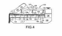
A figura 4 é uma vista esquemática lateral de um sistema em conformidade com a presente invenção;
A figura 5A é uma vista esquemática de um agitador de xisto da técnica anterior;
A figura 5B é uma vista esquemática lateral de um sistema em conformidade com a presente invenção;
A figura 6 é uma vista esquemática lateral de um sistema em conformidade com a presente invenção;
A figura 7 é uma vista esquemática lateral de conjuntos de peneira em conformidade com a presente invenção;
A figura 8A é uma vista esquemática lateral de um conjunto de peneira em conformidade com a presente invenção;
A figura 8B é uma vista traseira do conjunto de peneira da figura 8A;
A figura 8C é uma vista traseira do conjunto de peneira da figura 8A;
A figura 9 é uma vista traseira de um sistema em conformidade com a presente invenção;
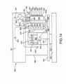
A figura 10A é uma vista lateral de um agitador de xisto em conformidade com a presente invenção;
A figura 10B é uma vista transversal do agitador da Figura 10A;
A figura 10C é uma vista transversal que mostra o agitador da figura 10A com sua cesta inclinada;
A figura 10D é uma vista frontal do agitador da figura 10A;
A figura 10E é um diagrama esquemático de um aparelho de controle para o agitador da Figura 10A;
A figura 10F é uma vista esquemática superior de um separador vibratório em conformidade com a presente invenção;
A figura 11A é uma vista lateral de um agitador de xisto em conformidade com a presente invenção;
A figura 11B é uma vista transversal parcial do agitador de xisto da figura 11A;
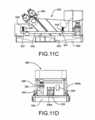
A figura 11C é uma vista transversal parcial do agitador de xisto da figura 11A;
A figura 11D é uma vista traseira do agitador de xisto da figura 11A;
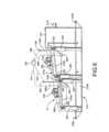
A figura 12A é uma vista lateral do conjunto de balancim do agitador de xisto da figura 11A;
A figura 12B é uma vista superior do conjunto de balancim da figura 12A;
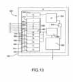
A figura 13 é uma vista esquemática de um sistema de controle em conformidade com a presente invenção para o separador vibratório em conformidade com a presente invenção;
A figura 14 é uma vista esquemática de um sistema em conformidade com a presente invenção;
A figura 15 é uma vista lateral de um agitador de xisto em conformidade com a presente invenção;
A figura 16 é uma vista superior do agitador de xisto da figura 15;
A figura 17 é uma vista traseira do agitador de xisto da figura 15;
A figura 18 é a ilustração do indicador de estado preferido para um sistema de recuperação de petróleo, mostrando o estado de plataformas individuais e estado de pior caso de agregado para áreas geográficas;
A figura 19 é uma ilustração do indicador de estado preferido para um sistema de recuperação de petróleo, mostrando o estado de plataformas individuais e estado de pior caso de agregado para áreas geográficas menores, incluindo a Região Oeste do Canadá;
A figura 20 é a ilustração do indicador de estado preferido para um sistema de recuperação de petróleo mostrando o estado de plataformas individuais e resultados de painel mostrando descrições textuais e estado por código de cores para uma única plataforma de petróleo;
A figura 21A é uma ilustração do indicador de estado preferido para um sistema de recuperação de petróleo e de subestado para uma plataforma individual;
A figura 21B é uma ilustração de um indicador de estado alternativo para um sistema de recuperação de petróleo e indicador de subestado para uma plataforma individual;
A figura 22 é uma ilustração do indicador de estado preferido para um sistema de recuperação de petróleo e indicador de subestado de nível inferior para uma plataforma individual;
A figura 23 é uma ilustração do indicador de estado preferido para um sistema de recuperação de petróleo e indicador de subestado de nível inferior para uma plataforma individual;
A figura 24 é um indicador de estado tabular alternativo para um sistema de recuperação de petróleo;
A figura 25 é um indicador de estado tabular alternativo para um sistema de recuperação de petróleo;
A figura 26 é uma ilustração do sistema de controle de funcionalidade preferido para relatar controles de funcionalidade a partir de uma plataforma de petróleo a um usuário, via satélite;
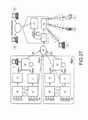
A figura 27 é uma ilustração do sistema de controle de saúde preferido para relatar controles de funcionalidade de múltiplos equipamentos, processos ou sistemas de múltiplas plataformas de petróleo para múltiplos usuários;
A figura 28 é uma ilustração do protocolo preferido para definição de uma estrutura de dados de relatório de eventos para preenchimento e exibição em base de dados;
A figura 29 é um indicador de peneira para um sistema em conformidade com a presente invenção;
A figura 30 é um indicador de peneira para um sistema em conformidade com a presente invenção;
A figura 31 é um indicador de peneira para um sistema em conformidade com a presente invenção;
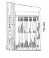
A figura 32A é um indicador de peneira para um sistema em conformidade com a presente invenção; e
A figura 32B é um indicador de peneira para um sistema em conformidade com a presente invenção;[034] Now it will be described how the invention can be put into operation, only by means of examples, with reference to the attached drawings, where:
Figure 1 is a schematic side view of a prior art shale shaker;
Figure 2A is a schematic view of a system in accordance with the present invention;
Figure 2B is a schematic side view of the shale shaking apparatus of the system of Figure 2A;
Figure 3 is a schematic side view of a system in accordance with the present invention;
Figure 4 is a schematic side view of a system in accordance with the present invention;
Figure 5A is a schematic view of a prior art shale shaker;
Figure 5B is a schematic side view of a system in accordance with the present invention;
Figure 6 is a schematic side view of a system in accordance with the present invention;
Figure 7 is a schematic side view of sieve assemblies in accordance with the present invention;
Figure 8A is a schematic side view of a screen assembly in accordance with the present invention;
Figure 8B is a rear view of the screen assembly of Figure 8A;
Figure 8C is a rear view of the screen assembly of Figure 8A;
Figure 9 is a rear view of a system in accordance with the present invention;
Figure 10A is a side view of a shale shaker in accordance with the present invention;
Figure 10B is a cross-sectional view of the agitator in Figure 10A;
Figure 10C is a cross-sectional view showing the agitator of Figure 10A with its basket tilted;
Figure 10D is a front view of the agitator in Figure 10A;
Figure 10E is a schematic diagram of a control apparatus for the agitator in Figure 10A;
Figure 10F is a schematic top view of a vibrating separator in accordance with the present invention;
Figure 11A is a side view of a shale shaker in accordance with the present invention;
Figure 11B is a partial cross-sectional view of the shale shaker of Figure 11A;
Figure 11C is a partial cross-sectional view of the shale shaker of Figure 11A;
Figure 11D is a rear view of the shale shaker in Figure 11A;
Figure 12A is a side view of the shale rocker assembly of Figure 11A;
Figure 12B is a top view of the rocker assembly of Figure 12A;
Figure 13 is a schematic view of a control system in accordance with the present invention for the vibrating separator in accordance with the present invention;
Figure 14 is a schematic view of a system in accordance with the present invention;
Figure 15 is a side view of a shale shaker in accordance with the present invention;
Figure 16 is a top view of the shale shaker in Figure 15;
Figure 17 is a rear view of the shale shaker in Figure 15;
Figure 18 is the illustration of the preferred status indicator for an oil recovery system, showing the status of individual platforms and the worst case state of aggregate for geographic areas;
Figure 19 is an illustration of the preferred status indicator for an oil recovery system, showing the status of individual platforms and the worst case aggregate for smaller geographic areas, including Western Canada;
Figure 20 is the illustration of the preferred status indicator for an oil recovery system showing the status of individual platforms and panel results showing textual descriptions and color-coded status for a single oil platform;
Figure 21A is an illustration of the preferred status indicator for an oil recovery and substation system for an individual platform;
Figure 21B is an illustration of an alternative status indicator for an oil recovery system and substation indicator for an individual platform;
Figure 22 is an illustration of the preferred status indicator for an oil recovery system and a lower level substation indicator for an individual platform;
Figure 23 is an illustration of the preferred status indicator for an oil recovery system and a lower level substation indicator for an individual platform;
Figure 24 is an alternative tabular state indicator for an oil recovery system;
Figure 25 is an alternative tabular state indicator for an oil recovery system;
Figure 26 is an illustration of the preferred functionality control system for reporting functionality controls from an oil platform to a user via satellite;
Figure 27 is an illustration of the preferred health control system for reporting functionality controls for multiple equipment, processes or systems for multiple oil platforms to multiple users;
Figure 28 is an illustration of the preferred protocol for defining an event reporting data structure for filling and displaying in the database;
Figure 29 is a sieve indicator for a system in accordance with the present invention;
Figure 30 is a sieve indicator for a system in accordance with the present invention;
Fig. 31 is a sieve indicator for a system in accordance with the present invention;
Figure 32A is a sieve indicator for a system in accordance with the present invention; and
Fig. 32B is a sieve indicator for a system in accordance with the present invention;
[035] As configurações atualmente preferidas da invenção são mostradas nas figuras acima identificadas e descritas em detalhes abaixo. Diferentes aspectos e características das configurações da invenção são descritas abaixo e algumas são explicadas nas reivindicações dependentes. Qualquer combinação de aspectos e/ou características descritos abaixo ou mostrados nas reivindicações dependentes poderão ser utilizados, exceto onde tais aspectos e/ou características sejam mutuamente exclusivos. Deve ser entendido que os desenhos e descrições aqui apensos são configurações preferidas e não pretendem limitar a invenção ou as reivindicações apensas. Pelo contrário, a intenção é incluir todas as modificações, equivalências e alternativas que venham a cair dentro da essência e escopo da invenção, conforme definido pelas reivindicações apensas. Na exibição e descrição das configurações preferidas, numerais de referência iguais ou idênticos são utilizados para identificar elementos comuns ou similares. As figuras não estão necessariamente em escala, e determinadas características e vistas das figuras poderão ser mostradas de forma exagerada com relação à escala ou à esquemática, no interesse da clareza e concisão.[035] The currently preferred configurations of the invention are shown in the figures identified above and described in detail below. Different aspects and characteristics of the configurations of the invention are described below and some are explained in the dependent claims. Any combination of aspects and / or features described below or shown in the dependent claims may be used, except where those aspects and / or features are mutually exclusive. It should be understood that the drawings and descriptions attached herein are preferred configurations and are not intended to limit the invention or the appended claims. On the contrary, the intention is to include all modifications, equivalences and alternatives that may fall within the essence and scope of the invention, as defined by the attached claims. In displaying and describing preferred configurations, the same or identical reference numerals are used to identify common or similar elements. The figures are not necessarily to scale, and certain characteristics and views of the figures may be shown in an exaggerated way with respect to the scale or schematic, in the interests of clarity and conciseness.
[036] Conforme utilizado aqui e ao longo de todas as diferentes partes (e cabeçalhos) da presente patente, os termos "invenção", "presente invenção” e variações dos mesmos significam uma ou mais configurações, e não pretendem significar a invenção reivindicada de qualquer reivindicação ou reivindicações específicas aqui apensas ou de todas as reivindicações aqui apensas. Da mesma forma, o assunto ou tópico de cada uma destas referências não é automática ou necessariamente uma parte ou um requerimento de qualquer ou quaisquer reivindicações específicas, meramente em função de tal referência. Na medida em que não sejam mutuamente exclusivas ou contraditórias, qualquer aspecto ou característica ou combinação de aspectos ou características de qualquer configuração aqui divulgada poderão ser utilizados em qualquer outra configuração aqui divulgada.[036] As used here and throughout all the different parts (and headings) of this patent, the terms "invention", "present invention" and variations thereof mean one or more configurations, and are not intended to mean the claimed invention in any way. any specific claim or claims attached herewith or all claims attached herewith, the subject or topic of each of these references is not automatically or necessarily a part or a requirement of any or any specific claims, merely as a result of such Insofar as they are not mutually exclusive or contradictory, any aspect or feature or combination of features or characteristics of any configuration disclosed herein may be used in any other configuration disclosed herein.
[037] Agora com referência às Figuras 2A e 2B, um sistema de perfuração 10 em conformidade com a presente invenção inclui uma broca giratória 12 anexada à extremidade inferior de uma extensão de um tubo para perfuração oco 14 suspenso de uma torre de perfuração (não mostrada).[037] Now with reference to Figures 2A and 2B, a
[038] O tubo para perfuração 14 e a broca de perfuração anexa 12 são girados para corte da formação de subsuperfície 16 para formar um furo de poço 18. O tubo para perfuração 14 passa através de um conjunto de cabeça de poço 20 localizado na superfície. O conjunto de cabeça de poço 20 controla o fluxo de fluido de perfuração para dentro do poço. Durante a perfuração do poço, o fluido de perfuração 22 comumente denominado lama de perfuração é bombeado para o interior do tubo para perfuração oco 14. A lama de perfuração sai de esguichos, tal como o esguicho 24 da broca de perfuração 12 e ocupa o fundo 26 do furo do poço 18. O fluido de perfuração que sai dos esguichos 24 empurra da base 26 do furo do poço 18 os detritos ou partículas geradas enquanto a broca de perfuração 12 penetra a formação de terra 16. Um fluxo de lama de perfuração 22 carrega então os detritos e partículas para cima, através do corpo anular do poço 28 (setas 29) para a cabeça de poço 20. A lama de perfuração 22 com as partículas e detritos sendo carregados ou suspensos com ela, deixa a cabeça de poço 20 na saída 31 e passa através de um duto 30 para o sistema agitador em conformidade com a presente invenção, que inclui um agitador de xisto 32.[038] The drill pipe 14 and the attached
[039] No agitador 32, a lama de perfuração e as partículas são depositadas sobre uma ou mais peneiras, que são vibradas de forma que as partículas maiores sejam peneiradas para fora da lama de perfuração e levadas para o topo da(s) peneira(s).[039] In the
[040] Uma parte líquida da lama de perfuração juntamente com as partículas em suspensão muito finas saem por uma primeira saída do agitador 34 e são recebidas na fossa de lama 36.[040] A liquid part of the drilling mud together with the very fine suspended particles come out through a first exit from the
[041] As partículas maiores 44 que são peneiradas para fora do fluxo de lama de perfuração saem por uma segunda saída ou calha do agitador 38 e são transportadas em um transportador ou separador 40 para depósito em uma fossa de reserva 42 ou para tanques de armazenagem para transporte para outro local. A lama de perfuração é bombeada a partir da fossa de lama 36 através de um tubo 46 por uma bomba de lama 50. A bomba de lama 50 então bombeia a lama através de um tubo de descarga 52 que a devolve para o furo interno do tubo para perfuração 14.[041] Larger particles 44 which are sieved out of the drilling mud stream exit via a second outlet or chute of the agitator 38 and are transported on a conveyor or
[042] Como mostrado nas Figuras 2A e 2B, o agitador de xisto 32 possui um aparelho para detecção de nível de fluido 60 que está em comunicação com o aparelho de controle 70. O aparelho de detecção 60 detecta a distância até a superfície superior da lama de perfuração 22 em uma peneira 33 do agitador 32, sendo isto um indicativo da profundidade da lama. Por meio de uma linha de transmissão de sinal 62 (ou múltiplas linhas, se necessário) o aparelho de detecção envia um sinal indicativo desta distância para o aparelho de computador 70. O aparelho 70 controla o aparelho de detecção 60 por meio de uma linha 63 (ou múltiplas linhas, caso necessário).[042] As shown in Figures 2A and 2B, the
[043] O agitador de xisto 32 (ou uma respectiva cesta de suporte de peneira) é suportada por um primeiro suporte 37 que possui uma conexão articulável 39 e por um segundo suporte 51 que possui uma conexão articulável 52 e um poste móvel 53 que é seletivamente movível para cima e para baixo, por um aparelho de movimentação 54, de forma a articular o agitador de xisto 32 (ou apenas sua cesta) na conexão articulável 39, de forma a afetar o ângulo do agitador ou da cesta 32, a profundidade do fluido de perfuração sob o aparelho de detecção 60, e a extensão da área de margem na peneira 33. Por meio de um cabo 65 o aparelho de computador 70 controla um aparelho de controle 72 que opera seletivamente o aparelho de movimentação 54 (que poderá ser alimentado pneumática, hidráulica ou eletricamente, conforme possa ser cada dispositivo ou aparelho de ajuste de altura de qualquer sistema em conformidade com a presente invenção).[043] The shale shaker 32 (or a respective sieve support basket) is supported by a
[044] O aparelho de detecção 60 poderá ser (e como poderá ser o caso para qualquer sensor de qualquer sistema aqui divulgado) qualquer aparelho de detecção de nível e/ou distância conhecido e adequado, incluindo, sem limitação, os seguintes tipos: elétrico, óptico, eletromagnético, ultrassônico, acústico e pulso-eco, e poderá ser como os sistemas de detecção de nível divulgado nas Patentes estadunidenses 6,691,025 B2; 5,793,705; 5,319,972; 6,484,088 B1; 6,062,070; e 5,131,271 (todas as referidas patentes plenamente incorporadas aqui, para todos os fins) e os sistemas referenciados, referidos ou mencionados nestas patentes. O aparelho 70 poderá ser (assim como poderá ser o caso para qualquer sistema aqui divulgado) qualquer computador, computadores, sistema de computador, sistema com base em microprocessador e/ou controlador lógico programável.[044] The detection apparatus 60 may be (and as may be the case for any sensor in any system disclosed herein) any detection apparatus of known and appropriate level and / or distance, including, without limitation, the following types: electrical , optical, electromagnetic, ultrasonic, acoustic and pulse-echo, and may be like the level detection systems disclosed in US Patents 6,691,025 B2; 5,793,705; 5,319,972; 6,484,088 B1; 6,062,070; and 5,131,271 (all said patents fully incorporated herein, for all purposes) and the systems referenced, referred to or mentioned in these patents.
[045] A Figura 3 mostra um agitador de xisto 100 em conformidade com a presente invenção que possui uma cesta 101 vibrada por um aparelho de vibração interconectado 107. A cesta 101 suporta três peneiras 102, 103, 104 para tratamento de material introduzido na peneira 104 a partir de um tanque 106. Um sensor de nível ultrassônico 110 é conectado à cesta 101 e detecta seletivamente a distância até, e, desta forma, o nível do material 114 (tal como fluido de perfuração com sólidos entranhados) em um local 116 acima da peneira 103. Um aparelho de controle 111 controla o sensor 110 por meio de um cabo 118 e também por meio do cabo 118 o sensor 110 envia sinais para o aparelho de controle 111 indicativos da medição de nível no local 116. Em um aspecto, o aparelho de controle 111 inclui aparelhos adequados (tal como o aparelho 70 descrito acima) que calcula a profundidade do local 116 e, com base numa programação adequada em meio de programação adequado no aparelho de controle 111, ajusta a inclinação da cesta 101 utilizando um aparelho de ajuste 112, de forma que a profundidade do local 116 seja mantida no nível desejado.[045] Figure 3 shows a
[046] Em um aspecto a cesta 101 é articuladamente conectada a um suporte 113 no ponto de articulação 115. O suporte 113 é fixado a uma base 105, assim como o tanque 106 e o aparelho de ajuste 112. O material fluido ou sólido que flui através das peneiras 102 - 104 escorre para um receptáculo 117. O material separado 108 flui para a extremidade de saída da última peneira 102.[046] In one aspect the
[047] A Figura 4 mostra um agitador de xisto 120 em conformidade com a presente invenção, similar ao agitador de xisto 100, da Figura 3 (e números similares indicam peças similares); mas o agitador de xisto 120 possui mecanismos de inclinação individuais 131, 132, 133 (cada qual com o respectivo ponto de articulação 131a, 132a, 133a) cada um abaixo da respectiva peneira 121, 122, 123. Os níveis de fluido de perfuração 128 nos diferentes locais das peneiras 121 - 123 podem ser ajustados por meio de alteração seletiva da inclinação das peneiras 121 - 123. Aparelhos de controle 134-136 correspondem, respectivamente, aos mecanismos 131 - 133. Um sistema de controle 127 com um adequado aparelho de controle (tal como o aparelho 70, Fig. 2B) comunica-se com os aparelhos de controle 131 - 133 e também com os sensores de nível individuais 124, 125 e 126. Cada sensor 124-126 detecta o nível de fluido de perfuração 128 nos respectivos locais 137, 138 e 139. O aparelho de controle, em um aspecto, é pré-programado para manter os níveis de fluido de perfuração, nos locais 137 - 139 dentro dos níveis predeterminados, monitorando os níveis com os sensores 124 - 126 e ajustando as profundidades de tais locais por meio de articulação das peneiras 121 – 123, articulando os mecanismos de inclinação individuais 131 - 133. Cada um ou cada dois dos sensores 124 - 126 pode ser excluído e o(s) correspondente(s) mecanismo(s) de inclinação e controle(s) associado(s) pode(m) também ser excluído(s).[047] Figure 4 shows a
[048] A Figura 5A mostra um agitador de xisto da técnica anterior com um ponto de articulação no ponto médio da cesta do agitador ou próximo a este ("cesta de peneiração fina”). A Figura 5B mostra um agitador de xisto 150 em conformidade com a presente invenção que possui um ponto de articulação de cesta 161 em ou próximo a uma das extremidades da cesta 160. O agitador 150 possui um tanque traseiro 151 do qual o material a ser tratado flui para uma cesta de classificação 170 que remove peças e partículas maciças e/ou grossas e através da qual o material flui então para as peneiras 153 - 156. Um aparelho de ajuste de altura 158 (controlado como qualquer aparelho de ajuste aqui divulgado) articula seletivamente a cesta 160 sobre o ponto 161. O aparelho de vibração 157 vibra a cesta 160. O material que passa através das peneiras flui para um receptáculo 159 sobre uma plataforma 165.[048] Figure 5A shows a prior art shale shaker with a pivot point at or near the mid point of the shaker basket ("fine sieve basket"). Figure 5B shows a
[049] Em um aspecto, a presente invenção provê um separador como aquele divulgado na Patente estadunidense 4,082,657 (aqui plenamente incorporado para todos os fins); mas com aprimoramentos em conformidade com a presente invenção. Como mostrado na Figura 6, um dispositivo separador D em conformidade com a presente invenção para separar material particulado de uma corrente líquida inclui uma estrutura 210 que traz montado sobre si um tanque de entrada 211 para recebimento do fluido a ser filtrado ou limpo. Unidades de peneira 214a e 214b são montadas em cascata sobre a estrutura 10 por meio de um suporte vibratório geralmente designado como 215a e 215b, cada um deles incluindo um meio vibratório 216 montado sobre si, para vibração simultânea das unidades de peneira 214a e 214b.[049] In one aspect, the present invention provides a separator such as that disclosed in U.S. Patent 4,082,657 (here fully incorporated for all purposes); but with improvements in accordance with the present invention. As shown in Figure 6, a separator device D in accordance with the present invention for separating particulate material from a liquid stream includes a
[050] A estrutura 210 inclui um primeiro e um segundo membro lateral 210a (apenas um é ilustrado) que são conectados juntos por meio de uma biela frontal 210b e uma biela traseira 210c. As bielas frontal e traseira 210b e 210c cooperam com os membros laterais, tal como 210a, de forma a prover uma forma geralmente retangular, apresentando uma abertura ao longo de si, através da qual a corrente de fluido limpo poderá passar para uma área de recuperação posicionada abaixo. Os membros laterais da estrutura, tal como 210a, podem ser vigas em I ou outros membros adequados para suporte da estrutura aqui divulgada.[050]
[051] O tanque de entrada 211 possui uma linha de entrada conectada 211b para receber os fluidos a serem limpos. Em um aspecto, a unidade de peneira 214a e 214b inclui uma estrutura de metal contendo material de peneiramento.[051] The
[052] As unidades de peneira são montadas de forma removível sobre os suportes de montagem de unidade de peneira 222 e 222a.[052] The sieve units are removably mounted on the sieve
[053] Cada unidade de peneira é suportada por quatro postes ajustáveis 235 (dois deles mostrados em cada lado de cada peneira; tal como, por exemplo, descrito na Patente estadunidense 4,082,657). Opcionalmente, interpostos entre os suportes das unidades de peneira 222, 222a encontram-se mecanismos de mola 233 e 234. Aparelhos vibratórios 216 vibram as unidades de peneira.[053] Each sieve unit is supported by four adjustable posts 235 (two of which are shown on each side of each sieve; as, for example, described in U.S. Patent 4,082,657). Optionally, interposed between the supports of the
[054] Um sensor 240 sobre um suporte 240a detecta a profundidade do fluido na unidade de peneira 214a e um sensor 242 sobre um suporte 242a detecta a profundidade de fluido na unidade de peneira 214b. Um aparelho de controle 250 (similar a qualquer um aqui divulgado) mantém comunicação por sinal com os sensores 240, 242 por meio de cabos 243, 244. O aparelho de controle 250 também está em comunicação via cabos 247, 248 com os aparelhos de controle 245, 246 que controlam os postes de altura ajustável 235. Os aparelhos de controle 250, 245, 246 podem ser similares a qualquer aparelho de controle e/ou aparelho de computador descrito acima.[054] A
[055] A figura 7 mostra três conjuntos de peneira 261, 262, 263 em conformidade com a presente invenção, que podem ser utilizados em qualquer sistema em conformidade com a presente invenção, no qual os conjuntos de peneira, peneiras, ou suportes de peneira individuais sejam inclinados ou movidos para ajuste da profundidade de fluido em um local de um conjunto de peneiras ou de uma peneira. Cada conjunto de peneiras 261 - 263 possui um membro expansível 264 (tal como, sem limitação, um fole extensível ou uma vedação extensível) que assegure que um contato de vedação seja mantido entre conjuntos de peneira adjacentes (ou entre a extremidade de um conjunto de peneiras e um membro numa cesta, contra a qual a extremidade do conjunto de peneiras se apóia). Em um aspecto, como mostrado, os membros extensíveis 264 são vedantes de fole; mas está dentro do escopo da presente invenção o uso de qualquer vedação ou material vedante que possa se expandir e contrair o suficiente para manter uma adequada vedação entre peneiras adjacentes.[055] Figure 7 shows three
[056] As Figuras 8A-8C ilustram um conjunto de peneiras 265 em conformidade com a presente invenção que possui uma vedação frontal flexível 266 que é aplicada contra a extremidade de uma peneira adjacente 267. A vedação 266 é suficientemente ampla para vedar a extremidade do conjunto de peneiras 267 quando a inclinação do conjunto de peneiras 267 for mudada (e/ou quando a inclinação do conjunto de peneiras 265 for mudada (como, por exemplo, em resposta a um sinal procedente de um sensor de nível de fluido sobre cada um ou ambos os conjuntos de peneira 265, 267)). Opcionalmente, o conjunto de peneiras 267 poderá também possuir uma vedação frontal 264.[056] Figures 8A-8C illustrate a set of
[057] A Figura 9 mostra um separador vibratório 270 em conformidade com a presente invenção com paredes 274 e um conjunto de peneiras 271 em configuração adornada com o fluido 272 a ser tratado. Um sensor de nível de fluido 273 conectado a uma parede 274 do separador 270 com um conector 275 detecta o nível de fluido próximo ao ponto central do conjunto de peneiras 271 (como visto na Fig. 9). Um sensor de nível de fluido 276 detecta o nível de fluido próximo à parede 274. Está dentro do escopo da presente invenção situar um ou mais sensores de fluido em qualquer ponto sobre um conjunto de peneiras em um separador vibratório ou agitador. Opcionalmente, qualquer um dos sensores 273 ou 276 poderá ser excluído.[057] Figure 9 shows a vibrating
[058] As Figuras 10A-10D mostra um agitador de xisto 300 em conformidade com a presente invenção que é similar a um "Agitador de xisto King Cobra" comercialmente disponível pela Varco International, Inc., mas possuindo aprimoramentos em conformidade com a presente invenção. O agitador de xisto 300 possui uma plataforma ou base 302 sobre a qual uma cesta 306 é vibrada por meio de um aparelho de vibração 304. A partir de um tanque vertedor 308, o fluido, tal como o fluido de perfuração contendo detritos e resíduos flui para uma primeira peneira 310 que é suportada por um suporte de peneira 310a conectado à cesta 306. Parte do fluido então flui para uma segunda peneira 311 suportada por um suporte de peneira 311a conectado à cesta 306, e depois parte do fluido flui para uma última peneira 312 suportada por um suporte de peneira 312a conectado à cesta 306. Parte do fluido flui através de uma extremidade de saída 312b da peneira 312 para uma peneira opcional mais baixa 313 que é suportada por um suporte de peneira 313a conectado à cesta 306. Os suportes de peneira 310a, 311b e 311c podem ser fixados às suas respectivas peneiras 310, 311, 312 por meio de dispositivos de fixação adequados, tal como um ou mais aparelhos de fixação eletromagnéticos 314, ou outros dispositivos de fixação adequados. O aparelho de fixação eletromagnético 314 pode ser do tipo que é energizado e/ou desenergizado por meio de um pulso elétrico transiente simples. Ou seja, um aparelho de fixação desmagnetizado pode ser colocado em estado magnetizado e permanecer em estado magnetizado por meio de um sinal de pulso elétrico transiente procedente de algum tipo de dispositivo de controle ou de outra fonte adequada. Outro pulso da mesma fonte ou de uma fonte poderá então recolocálo no estado desmagnetizado e o fixador permanecerá naquele estado, indefinidamente, até o mesmo ser energizado novamente. Para ajudar a compensar a massa adicional destes fixadores magnéticos, um controlador de força 'G' constante (não mostrado) poderá ser incluído no sistema de controle do controlador para assegurar que as acelerações vibratórias sejam mantidas dentro dos limites aceitáveis. O sinal de pulso transiente poderá proceder de qualquer dispositivo de controle adequado ou de qualquer outro meio de entrada adequado.[058] Figures 10A-10D shows a
[059] O fluido forma uma poça 315 acima das peneiras 310-312. Dependendo do fluido, viscosidade ou conteúdo sólido, taxa de vazão do referido, e do tempo de saída das peneiras, uma margem 316 é criada na extremidade de saída 312b da peneira 312. Será desejável otimizar a extensão desta margem 316 e, em determinados aspectos, é preferido que esta margem, tal como pode ser vista na Fig. 10B, seja suficientemente grande para que nenhum fluido não tratado possa escapar da última peneira 312.[059] The fluid forms a
[060] Um aparelho de medição sensor transdutor ultrassônico 320 é conectado à cesta 306 (tal como, por exemplo, a um tubo de motor 309 e/ou conectando o aparelho sensor 320b a um tanque vertedor 308) sendo, opcionalmente, posicionado acima da poça 315, como, por exemplo, sobre a extremidade de entrada 310b da peneira 310 ou sobre a extremidade de entrada 312c da peneira 312. Tais locais, para o aparelho 320 fornecerão medições de locais que oferecem o maior alcance de profundidade da poça, e sendo assim, o maior alcance para ajuste da extensão da margem; ou seja, estes locais garantem que os aparelhos 320a e/ou 320b terão uma distância entre o sensor e a superfície da poça adequada para medir, visto que na maioria dos casos existirá fluido em alguma profundidade, neste ponto, abaixo do aparelho ou dos aparelhos 320. Os aparelhos 320a e/ou 320b estão em comunicação com o aparelho de controle 330. Os aparelhos sensores geram um sinal indicativo da distância do sensor à poça que indica a profundidade da poça 315 debaixo do(s) aparelho(s) sensor(es). Opcionalmente, tanto o sensor 320a quanto o sensor 320b podem ser excluídos.[060] An ultrasonic transducer
[061] O aparelho de controle 330 (tal como, por exemplo, um computador, PLC, controlador PID, ou outro dispositivo com meios programáveis) controla seletivamente uma válvula de controle 336 que permite que o fluido hidráulico sob pressão de um reservatório 338, bombeado por uma bomba hidráulica 337 possa se mover em direção e para longe de dois aparelhos de cilindro hidráulico (um deles mostrado na Fig. 10A) posicionados em lados opostos do agitador 300. Uma válvula de controle de fluxo 332 controla o fluxo de fluido para dentro e para fora dos pistões e ajusta a taxa de curso dos aparelhos de cilindro 333, 334 e uma válvula de controle de fluxo 335 limita o fluxo do fluido para dentro e para fora dos pistões, e ajusta a taxa de curso dos aparelhos de cilindro 333, 334. Um aparelho de cilindro hidráulico 350 possui um pistão extensível 351 conectado de forma articulada a uma placa de articulação 353 em um ponto de articulação 365. A placa 353 é articuladamente conectada a um ponto de articulação 357 da cesta 306. Um alojamento 350 do aparelho 334 é preso a um suporte 359 que é articuladamente conectado à cesta 306. Uma conexão 355 é articuladamente conectada à placa 353 em um ponto de articulação 366 e a conexão 355 é conectada a uma conexão 356 que é articuladamente conectada a um ponto de articulação 354 do suporte da cesta 340. O suporte da cesta 340 é suportado pelos aparelhos de cilindro hidráulico e pelas bases 341. Os eixos 367 dos suportes da cesta 340 são montados de forma articulável nas bases 341. Uma régua graduada 339 indica o ângulo horizontal do suporte 340 (ou seja, presumindo que a plataforma ou a base 302 estejam niveladas). O suporte 340 é conectado a molas 346, 343 que suportam os suportes da cesta 345 e 342, respectivamente; e molas e suportes semelhantes são encontrados no outro lado da cesta.[061] Control device 330 (such as, for example, a computer, PLC, PID controller, or other device with programmable means) selectively controls a control valve 336 that allows hydraulic fluid under pressure from a
[062] Em outro aspecto, a placa 365 é excluída e os aparelhos de cilindro hidráulico são orientados quase que verticalmente, e os pistões dos aparelhos de cilindro hidráulico 351 são articuladamente conectados ao suporte da cesta 340 para serem seletivamente elevados e abaixados, de forma a ajustar a extensão da margem.[062] In another aspect, the
[063] A Figura 10C mostra a cesta 306 inclinada, em comparação à cesta 306, conforme mostrada na Figura 10A.[063] Figure 10C shows
[064] Em um aspecto, um separador vibratório ou agitador de xisto em conformidade com a presente invenção pode empregar um sensor de fluxo de material que produz um sinal indicativo da presença ou ausência de material fluindo para o aparelho de peneira; tal como, sem limitação, fluido de perfuração com sólidos escavados fluindo para o aparelho de peneira de um agitador de xisto. Tal indicação é valiosa para assegurar que, durante o recomeço do fluxo após a cessação de um fluxo de material, o que é comum quando a perfuração é interrompida, nenhuma peneira ou cesta esteja inclinada a um ângulo que possibilite a formação de uma poça de profundidade relativamente baixa, em resultado da perda de fluido de perfuração não tratado, fluindo através da extremidade de saída da peneira. Ao ajustar o ângulo da peneira ou da cesta de forma que o reinício do fluxo seja acomodado, será formada uma poça de suficiente profundidade e extensão, de forma que a grande maioria do material seja tratado e uma quantidade opcional de fluido de perfuração flua através da peneira e seja recuperada.[064] In one aspect, a vibrating separator or shale shaker in accordance with the present invention can employ a material flow sensor that produces a signal indicative of the presence or absence of material flowing into the sieve apparatus; such as, without limitation, drilling fluid with excavated solids flowing into the sieve apparatus of a shale shaker. Such indication is valuable to ensure that, during the restart of the flow after the cessation of a flow of material, which is common when the drilling is interrupted, no sieve or basket is tilted at an angle that allows the formation of a deep puddle relatively low, as a result of the loss of untreated drilling fluid flowing through the sieve outlet end. By adjusting the angle of the sieve or basket so that the restart of the flow is accommodated, a puddle of sufficient depth and length will be formed, so that the vast majority of the material is treated and an optional amount of drilling fluid flows through the sieve and be recovered.
[065] Opcionalmente, um agitador 300, conforme mostrado nas Figuras 10A e 10B (com ou sem um sensor ou sensores como o sensor 320a e/ou 320b) possui um dispositivo de comutação de fluxo de material 307 conectado ao separador vibratório adjacente a um tanque de entrada de material, como o tanque 308, para detecção enquanto o material está fluindo. O dispositivo 307 poderá ser qualquer aparelho sensor de fluxo conhecido adequado, incluindo, sem limitação, sistemas de chave controladora, incluindo, sem limitação, as chaves limitadoras da Série FS-550 da Gems Sensors Co.[065] Optionally, an
[066] O dispositivo 307 está em comunicação e é controlado pelo controlador 330 e, em um aspecto, sinais do dispositivo 307 sobrepõem-se a sinais de sensores, como os sensores 320a e 320b, de forma que o controlador 330 sabe que o fluxo de material foi interrompido (ao invés da indicação dos sensores 320a, 320b de que a poça está muito rasa). Em resposta aos sinais do dispositivo 307, o controlador 330 pode ativar o aparelho para ajuste do ângulo da cesta.[066]
[067] Uma vez que o fluxo de material na cesta seja retomado novamente, o controlador 330 (atuando frente a sinais do sensor 320a e/ou do sensor 320b) ajusta o ângulo da cesta para manter a extensão de margem desejada. Embora um sensor de fluxo específico tenha sido mencionado, deve ser entendido que qualquer dispositivo ou sistema sensor de fluxo poderá ser utilizado, incluindo, sem limitação, sistemas transdutores ultrassônicos.[067] Once the material flow in the basket is resumed again, controller 330 (acting on signals from
[068] O controlador 330 poderá ser qualquer aparelho controlador adequado conhecido, comercialmente disponível, incluindo, sem limitação, sistemas computadorizados, sistemas processadores de sinal digital, sistemas de controlador lógico programável e/ou sistemas de microprocessador. Um aparelho sensor e um sistema de controle associado adequados são os modelos XPS-10 e Hydro Ranger 200 da Siemens.[068]
[069] A Figura 10F mostra esquematicamente um separador vibratório ou agitador de xisto 400 em conformidade com a presente invenção que possui uma cesta de suporte de peneira 402 com membros articulados 414 montados de forma articulada em suportes 404 sobre uma plataforma ou base 406. Aparelhos de ajuste 408, 410 a cada lado da cesta 402 (como qualquer aparelho de ajuste aqui descrito) erguem e abaixam uma extremidade 412 da cesta 402, articulando-a ao redor dos membros articulados 414. Em um aspecto, a linha traseira 416 da área de margem 420 de uma peneira 430 suportada em uma cesta 402 coincide com a linha entre os membros articulados 414.[069] Figure 10F schematically shows a vibrating separator or
[070] Um sensor 418 (como qualquer sensor aqui divulgado, incluindo, sem limitação, aqueles das Figuras 1- 10A) é posicionado acima da extremidade de entrada de fluido da peneira 430, sobre um membro de conexão 422 conectado à cesta 402. Um sensor 451 (como qualquer sensor aqui descrito) é posicionado acima da extremidade de entrada de fluido da peneira 434, podendo ser convenientemente conectado a uma barra ou viga conectada ao tanque 450 e/ou à cesta 402. O material flui da peneira 432 para a peneira 430 e da peneira 434 para a peneira 432. Qualquer tanque adequado 452 e/ou aparelho de introdução de fluido poderá ser utilizado. O aparelho de vibração 440 vibra a cesta 402.[070] A sensor 418 (like any sensor disclosed herein, including, without limitation, those in Figures 1-10A) is positioned above the fluid inlet end of the
[071] Um aparelho de força 441 conectado ao agitador 400 energiza os aparelhos de ajuste 408, 410 e pode ser posicionado em qualquer local adequado no agitador 400, incluindo, sem limitação, na cesta 402 ou sobre a plataforma 406. Opcionalmente o aparelho de força 441 poderá ser qualquer aparelho ou sistema aqui divulgado. Em um aspecto, o aparelho de força 441 inclui uma bomba hidráulica em comunicação com um reservatório de fluido hidráulico, 440 através de uma tubulação 444 e os aparelhos 408, 410 são aparelhos hidraulicamente energizados em comunicação fluida com a bomba através de tubulações 442, 443. O aparelho de controle 450 (como qualquer um dos aqui divulgados) controla o aparelho 441, o sensor 418, um sensor 460, um controlador 456, e/ou o sensor 451. Opcionalmente, um sensor de fluxo de material 460 conectado ao tanque 452 (ou a qualquer outro local adequado do separador 400), que é similar ao sensor 307, da Figura 10A, detecta a presença ou ausência do material fluindo a partir do tanque 452 para a peneira 434. O sensor 460 está em comunicação com o aparelho de controle 450 e, em resposta a sinais procedentes do sensor 460, o aparelho de controle 450 ajusta o ângulo da cesta de forma a acomodar o fluxo de material e ajusta para o reinício de fluxo, após uma interrupção de fluxo. Opcionalmente, um controlador de taxa de vazão 456 controla a quantidade de fluido introduzida na peneira 434 a partir do tanque vertedor 452 e uma chave de controle 455 do controlador 456 fica em comunicação com o aparelho de controle 450.[071] A
[072] Está dentro do escopo da presente invenção a localização dos aparelhos 408, 410 em qualquer local efetivo desejável, com respeito à cesta, como pode ser o caso com qualquer aparelho de ajuste aqui divulgado.[072] It is within the scope of the present invention to locate
[073] A presente invenção, desta forma, em algumas e não necessariamente em todas as configurações, provê um separador vibratório possuindo um suporte de peneira ou cesta para suportar o aparelho de peneira para tratamento do material introduzido no separador vibratório, a cesta em uma base e articulável com relação a esta base, aparelho vibratório conectado à cesta para vibração da cesta, aparelho de peneira suportado pela cesta, o material formando uma poça no aparelho de peneira, e uma margem no aparelho de peneira adjacente à poça; aparelho sensor de medição conectado ao separador vibratório e posicionado acima do aparelho de peneira para medir a distância desde o aparelho sensor de medição até a superfície superior da poça, o aparelho sensor de medição incluindo uma seção de produção de sinais para produção de sinais indicativos de tal distância e para transmissão destes sinais, um sistema de controle para controlar e se comunicar com o aparelho sensor de medição para recepção de sinais procedentes do aparelho sensor de medição indicativos de tal distância e para processamento destes sinais para calcular a profundidade de poça correspondente a tal distância, e aparelho de ajuste de ângulo conectado à cesta e controlado pelo sistema de controle para ajuste do ângulo da cesta, ajustando, desta forma, a extensão da margem. Tal separador vibratório poderá ser caracterizado por um ou alguns, em qualquer combinação possível, dos seguintes fatos em que: o separador vibratório é um agitador de xisto e o material é um fluido de perfuração contendo detritos escavados; o equipamento de peneira inclui pelo menos uma peneira de saída com uma extremidade de saída, através da qual o material separado pelo equipamento de peneira flui do equipamento de peneira para descarga do separador vibratório, a cesta permanece em um ângulo tal em que a margem é formada adjacente a uma borda da poça adjacente a tal extremidade de saída, e o sistema de controle controla a extensão da margem; o sistema de controle controla a extensão da margem de forma a manter a margem na peneira de saída; o equipamento de peneira é uma pluralidade de peneiras posicionadas adjacentes umas às outras na cesta, cada peneira com um suporte de peneira associado conectado à cesta; o equipamento de ajuste de ângulo inclui um suporte da cesta montado de forma articulável à base e ao equipamento de movimentação para movimentação seletiva da cesta, para cima e para baixo; a cesta possui uma extremidade para entrada de fluido e uma extremidade para saída de fluido e a cesta é montada de forma articulável adjacente à extremidade para saída de fluido, e o equipamento de ajuste de ângulo move a extremidade da cesta para a entrada de fluido; o equipamento de movimentação inclui dispositivo de cilindro hidráulico para movimentação da cesta; o dispositivo de cilindro hidráulico inclui dois dispositivos de pistão alimentados hidraulicamente, cada um de um lado da cesta para movimentação da cesta; cada dispositivo de pistão alimentado hidraulicamente é interconectado de forma articulável com o correspondente equipamento de conexão, o equipamento de conexão sendo conectado de forma articulável ao suporte da cesta adjacente à extremidade para entrada de fluido da cesta; o equipamento sensor de medição é um equipamento ultrassônico; o equipamento ultrassônico é pelo menos um equipamento ultrassônico; o equipamento sensor de medição é uma pluralidade de equipamentos sensores de distância; a pluralidade de equipamentos sensores inclui um primeiro equipamento sensor ultrassônico espaçado de um segundo equipamento sensor ultrassônico, o primeiro equipamento sensor ultrassônico acima de um lado do equipamento de peneira e o segundo equipamento sensor ultrassônico acima do lado oposto do equipamento de peneira; o equipamento sensor de medição pertence ao grupo consistindo de equipamentos elétricos, ópticos, eletromagnéticos, ultrassônicos, acústicos e de pulso-eco; o limite traseiro da margem acompanha a linha de margem traseira e a cesta é conectada de forma articulável à base abaixo da linha de margem traseira; e/ou o equipamento de ajuste de ângulo é alimentado pelo equipamento de força.[073] The present invention, therefore, in some and not necessarily in all configurations, provides a vibrating separator having a sieve holder or basket to support the sieve apparatus for treating the material introduced in the vibrating separator, the basket in a base and articulated with respect to this base, vibrating apparatus connected to the basket for basket vibration, sieve apparatus supported by the basket, the material forming a puddle in the sieve apparatus, and a margin in the sieve apparatus adjacent to the puddle; measuring sensor device connected to the vibrating separator and positioned above the sieve device to measure the distance from the measuring sensor device to the upper surface of the puddle, the measuring sensor device including a signal production section for producing indicative signals of such distance and for transmission of these signals, a control system to control and communicate with the measuring sensor apparatus for receiving signals from the measuring sensor apparatus indicative of such distance and for processing these signals to calculate the puddle depth corresponding to such distance, and angle adjustment device connected to the basket and controlled by the control system to adjust the angle of the basket, thus adjusting the extent of the margin. Such a vibratory separator may be characterized by one or some, in any possible combination, of the following facts in which: the vibratory separator is a shale shaker and the material is a drilling fluid containing excavated debris; the sieve equipment includes at least one outlet sieve with an outlet end, through which the material separated by the sieve equipment flows from the sieve equipment to discharge the vibrating separator, the basket remains at an angle such that the margin is formed adjacent to an edge of the puddle adjacent to such an outlet end, and the control system controls the extent of the margin; the control system controls the extension of the margin in order to maintain the margin on the exit screen; the sieve equipment is a plurality of sieves positioned adjacent to each other in the basket, each sieve with an associated sieve holder connected to the basket; the angle adjustment equipment includes a basket support articulated to the base and the handling equipment for selective movement of the basket, up and down; the basket has an end for fluid inlet and an end for fluid outlet and the basket is pivotally mounted adjacent to the end for fluid outlet, and the angle adjustment equipment moves the end of the basket to the fluid inlet; the handling equipment includes a hydraulic cylinder device for moving the basket; the hydraulic cylinder device includes two hydraulically powered piston devices, each on one side of the basket for moving the basket; each hydraulically powered piston device is interconnected articulatively with the corresponding connection equipment, the connection equipment being articulated to the basket support adjacent to the end of the basket's fluid inlet; the measuring sensor equipment is an ultrasonic equipment; ultrasonic equipment is at least ultrasonic equipment; the measurement sensor equipment is a plurality of distance sensor equipment; the plurality of sensor equipment includes a first ultrasonic sensor equipment spaced from a second ultrasonic sensor equipment, the first ultrasonic sensor equipment above one side of the sieve equipment and the second ultrasonic sensor equipment above the opposite side of the sieve equipment; the measuring sensor equipment belongs to the group consisting of electrical, optical, electromagnetic, ultrasonic, acoustic and pulse-echo equipment; the rear margin of the margin follows the rear margin line and the basket is articulably connected to the base below the rear margin line; and / or the angle adjustment equipment is powered by the power equipment.
[074] As Figuras 11A-11D mostram o agitador de xisto 500 em conformidade com a presente invenção, que é semelhante ao Agitador de Xisto King Cobra comercialmente disponível por meio da Varco International, Inc., mas contendo aprimoramentos em conformidade com a presente invenção. O agitador de xisto 500 possui uma plataforma ou base 502 sobre a qual fica a cesta 506 que é vibrada pelo equipamento de vibração 504. A partir de um tanque 508 o fluido, tal como, por exemplo, fluido de perfuração contendo detritos e resíduos escavados, flui para uma primeira peneira 510 que é suportada por um suporte de peneira 510a conectado à cesta 506. Parte do fluido flui então para uma segunda peneira 511 suportada pelo suporte de peneira 511a conectado à cesta 506 e então parte do fluido flui para uma última peneira 512 suportada por um suporte de peneira 512a conectado à cesta 506. Parte do fluido flui através da extremidade de saída 512b da peneira 512 para uma peneira mais baixa, opcional 513 que é suportada por um suporte de peneira 513a conectado à cesta 506. O fluido flui para um tanque ou receptáculo 503 posicionado mais abaixo.[074] Figures 11A-11D show the
[075] O fluido forma uma poça 515 sobre as peneiras 510-512. Uma margem 516 se forma na extremidade de saída 512b da peneira 512. Será desejável controlar e/ou otimizar a extensão desta margem 516 e, em determinados aspectos, é preferível que a margem, conforme visto na Fig. 11B, seja suficientemente grande para que nenhum fluido sem tratamento flua para fora da última peneira 512.[075] The fluid forms a 515 puddle on the 510-512 sieves. A margin 516 is formed at the outlet end 512b of the
[076] Um equipamento de medição sensor transdutor ultrassônico 520 é conectado ao agitador de xisto, tal como, por exemplo, a uma plataforma, base, tanque ou, como mostrado, à cesta 506 e é, opcionalmente, posicionado acima da poça 515, tal como, por exemplo, sobre uma extremidade de entrada 510b da peneira 510. O equipamento 520 fica em comunicação com um equipamento de controle 530 (tal como, sem limitação, um computador). O equipamento sensor gera um sinal indicativo da distância do sensor à poça, que indica a profundidade da poça 515 debaixo do(s) equipamento(s) sensor(es).[076] An ultrasonic transducer
[077] O equipamento de controle 530 controla seletivamente um dispositivo tipo bexiga 536 que levanta e abaixa seletivamente o conjunto de balancim 540 que, por sua vez, levanta e abaixa a cesta 506 à qual o conjunto de balancim 540 é conectado. Opcionalmente o ângulo do conjunto de balancim é seletivamente ajustado horizontalmente por um mecanismo mecânico, tal como, por exemplo, qualquer mecanismo mecânico adequado conhecido para movimentação do conjunto de balancim para cima e para baixo, tal como, sem limitação, um mecanismo de parafuso ou um dispositivo de pistão hidráulico ou pneumático.[077] The
[078] Uma parte superior 536a do dispositivo tipo bexiga 536 contata a superfície inferior 541a de uma placa 541 do conjunto de balancim 540. O dispositivo tipo bexiga 536 infla para elevar o conjunto de balancim 540 e desinfla par abaixá-lo. Um gás, tal como ar, por exemplo, um líquido, tal como uma mistura de água e glicol, por exemplo, podem ser utilizados para inflar o dispositivo tipo bexiga 536. O equipamento de controle 530 controla o dispositivo tipo bexiga 536. Em vez de usar o dispositivo tipo bexiga de ar 536 para mover o conjunto de balancim para cima e para baixo, está dentro do escopo da presente invenção o uso de: um dispositivo atuador linear ou outro dispositivo eletronicamente operado; um dispositivo hidraulicamente operado, tal como, por exemplo, um sistema de cilindro hidráulico; ou um equipamento hidráulico acionado por ar, tal como, por exemplo, um sistema com tanque cheio de líquido com pressão a ar. Em uma configuração específica, o dispositivo tipo bexiga de ar 536 é um Modelo 20-2 comercialmente disponível pela Firestone Company. Embora apenas um dispositivo tipo bexiga de ar 536 seja mostrado, está dentro do escopo da presente invenção o uso de dois de tais equipamentos, um a cada lado da cesta 506.[078] An upper part 536a of the bladder-
[079] O conjunto de balancim 540 possui eixos de articulação 542 que giram nos correspondentes recessos 543 dos suportes 544 na plataforma 502. O conjunto de balancim 540 possui duas travessas laterais 545 interconectadas com uma travessa frontal 546. Suportes de mola 54, soldados à cesta 506, suportam as molas 548 conectadas aos suportes 549.[079] The
[080] Um equipamento sensor ultrassônico opcional 522, em comunicação com o equipamento de controle 530, verifica se há ou não fluxo de fluido procedente do tanque 508 para a poça 515. Caso um sinal de “nenhum fluxo” seja gerado pelo equipamento 522 e enviado ao equipamento de controle 530, então a cesta será inclinada ao seu ângulo máximo ascendente, em antecipação da próxima carga de lama. Um equipamento sensor ultrassônico opcional 524 detecta a localização (altura) da placa 541 e produz um sinal indicativo de tal localização, sinal este cujo valor corresponderá ao ângulo do conjunto de balancim 540 e, desta forma, ao ângulo da cesta 506 (e que será correlacionado aos valores de sinal do equipamento 522). Em um aspecto, o equipamento de controle 530 computa o ângulo da cesta com base no sinal procedente do equipamento sensor ultrassônico 524 e correlaciona este ângulo computado com o valor de profundidade de poça, com base no sinal procedente do equipamento sensor ultrassônico 520. Se estes dois valores forem correspondentes, isto indicará que o sistema está operando corretamente. Caso exista discrepância entre os valores (dos sensores ultrassônicos) (tal como, por exemplo, discrepância causada por fluxo alto, orientação da cesta para baixo ou baixo nível de fluido) isto indicará um problema de medição e o equipamento de controle 530 então ajustará a cesta a um ângulo máximo ascendente até que não haja tal discrepância.[080] An optional
[081] Opcionalmente, o agitador de xisto 500 inclui um conversor de frequência 550 (opcionalmente em um invólucro taxado para área de risco Classe 1, Divisão 1, ou Zona 1) cujas funções incluem a variação de RPM do equipamento de vibração 504 e, assim, a variação das forçasG (aceleração) transmitidas à cesta 506 pelo equipamento de vibração 504; e alteração da direção de rotação do equipamento de vibração 504, alterando, desta forma, o movimento da cesta 506, tal como, por exemplo, de movimento linear para movimento elíptico. Em um aspecto particular o equipamento de vibração 504 inclui um vibrador Modelo VMX 18-8300-80 ou Modelo VMX 18-8300-110 da Martin Engineering, equipado com motores de movimento duplo com capacidade de alterar um desequilíbrio de pesos com base na direção da rotação, para alterar o movimento, tal como, por exemplo, de linear para elíptico (ou vice versa). O equipamento de controle 530, e/ou o equipamento sensor ultrassônico 524 e/ou o dispositivo 550 podem ficar localizados em qualquer local conveniente do agitador de xisto 500. Como mostrado na Figura 11A os referidos são protegidos por um invólucro 554 formado por partes do tanque, feitas de material resiliente, tal como, por exemplo, metal ou composto. Alternativamente, o acionador 550 fica localizado em um compartimento separado 554a (mostrado pelas linhas pontilhadas). O equipamento 552 provê um canal 553 para fluido no tanque 508 para desviar das peneiras 510-512 e fluir diretamente no receptáculo 503.[081] Optionally, the
[082] A Figura 13 mostra um computador 560 que pode ser utilizado, em um aspecto, para o equipamento de controle 530. Opcionalmente, o computador 560 é posicionado dentro de um compartimento 561 adequado para instalação em uma zona de risco Classe 1, Divisão 1 ou Zona 1. Uma Força CA é aplicada a um transformador CA para CC 562 que fornece energia para uma fonte de alimentação 579 e para uma fonte de alimentação 563 (que, em troca, fornece energia para dispositivos de barreira 564, 565, e 566). A fonte de alimentação 563 fornece energia, tal como, por exemplo, 24 VDC, para a fonte de alimentação 567 de um dispositivo de Entrada/Saída 568. A fonte de alimentação 579 fornece energia (tal como, por exemplo, 5 VDC) para um computador de placa única 569 que roda um programa de controle e lê o Dispositivo de entrada/saída, e envia sinais de controle para válvulas eletricamente atuadas (tal como, por exemplo, 670, 671, da Fig. 14) para controlar o ângulo da cesta do agitador. Os dispositivos de barreira de força 564 - 566 fornecem energia, tal como, por exemplo, 24 VDC, a vários dispositivos intrinsecamente seguros ("IS"), tal como, por exemplo, equipamentos sensores ultrassônicos. O computador 569 pode ser programado para prover um “reset” [reconfiguração] de ângulo da cesta, para reconfigurar um valor de medição dos equipamentos sensores ultrassônicos numa posição “home” [início] da cesta (tal como, por exemplo, o ângulo máximo ascendente).[082] Figure 13 shows a
[083] Dispositivos de barreira analógicos 571 e 572 limitam a energia dos sinais nos dispositivos analógicos, ou seja, os sensores ultrassônicos. A alimentação 567 fornece energia para os dispositivos 573 - 576. Uma placa de entrada digital 573 recebe sinais de entrada digitais de outros dispositivos, tal como, por exemplo, o conversor de frequência e botões de pressão do usuário. Uma placa de saída digital 574 envia sinais digitais para outros dispositivos, tal como, por exemplo, ao conversor de frequência. Uma placa de relé 575 fornece aberturas e fechamentos de interruptor para envio de sinais de controle para outros dispositivos, tal como, por exemplo, válvulas de controle. Uma placa de saída analógica 576 recebe sinais analógicos de outros dispositivos, tal como, por exemplo, dos equipamentos sensores ultrassônicos.[083]
[084] Opcionalmente, o dispositivo de Entrada/Saída 568 poderá ter uma chave ou conexão 578 para comunicação com um sistema (tal como, por exemplo, um computador ou sistema de computador) separado e/ou remotamente posicionado com relação ao agitador de xisto ou separador vibratório, tal como, por exemplo, sem limitação, a um Controlador de Entrada/Saída Ethernet que, por sua vez, proverá a conexão a outros sistemas, tal como, por exemplo, a Internet.[084] Optionally, the Input /
[085] A Figura 14 ilustra esquematicamente um sistema 600 em conformidade com a presente invenção que é similar aos sistemas mostrados nas Figuras 11A-13. Um agitador 601 (tal como, por exemplo, o agitador 500 ou qualquer agitador aqui revelado ou referido) possui um conjunto de balancim 640 (tal como, por exemplo, o conjunto 540) que pode ser erguido e abaixado por um dispositivo tipo bexiga 636 (tal como, por exemplo, o equipamento 536) que é montado sobre a plataforma 602. Motores vibratórios 604 (tal como, por exemplo, os motores 504) vibram uma cesta 606 (tal como, por exemplo, a cesta 506).[085] Figure 14 schematically illustrates a
[086] Equipamentos sensores ultrassônicos 620, 622, 624 (tal como, por exemplo, os equipamentos 520, 522, 524) fornecem sinais para um sistema de controle 630 (tal como, por exemplo, o equipamento de controle 530) para detecção de parâmetros de sistema, para controlar o conjunto de balancim para ajuste do ângulo da cesta e para controlar os motores 604. O equipamento de controle 630 fica alojado dentro de um compartimento 654 (tal como, por exemplo, o compartimento 554).[086]
[087] Um sistema conversor de frequência opcional ("VFD") 650 (tal como, por exemplo, o sistema 550) em um compartimento 654a (tal como, por exemplo, o compartimento 554a) permanece em comunicação com o sistema 630 e proporciona o controle dos motores 604 (ou seja, o controle das forças G sobre as peneiras e/ou controle do tipo de movimento) e controlam o ângulo da cesta. Em um aspecto particular o sistema 630 possui botões de pressão manualmente operáveis 631 - 634. OS botões 631 - 633 servem para calibração dos equipamentos sensores ultrassônicos 620, 622, 624, respectivamente. O botão 634 é um botão de reconfiguração do sistema. Em um aspecto, os botões são conectados a uma placa de entrada digital no compartimento.[087] An optional frequency converter system ("VFD") 650 (such as, for example, system 550) in a compartment 654a (such as, for example,
[088] O conversor de frequência 650 possui botões de pressão manualmente operáveis 651 - 656 e 658 - 659 que funcionam da seguinte forma:
651 - Liga
652 - Desliga
653 - Altera o movimento do motor entre linear/elíptico
654 - Alimentação do sistema 630
655 - Altera os modos entre manual e automático
656 - Reconfiguração do sistema 650
658 - Move a cesta para cima (aumenta o ângulo da cesta)
659 - Move a cesta para baixo (diminui o ângulo da cesta)[088] The
651 - League
652 - Turn off
653 - Changes the motor movement between linear / elliptical
654 -
655 - Changes the modes between manual and automatic
656 -
658 - Moves the basket up (increases the angle of the basket)
659 - Moves the basket down (decreases the basket angle)
[089] As válvulas 670 e 671 são válvulas eletronicamente operadas. A energia é provida para a válvula 670 por meio de uma linha de energia 681 do sistema 630 e para a válvula 671 por meio de uma linha de energia 684. A cesta é erguida ou abaixada seletivamente por meio de abertura ou fechamento da válvula 670 que permite que o fluido 692 (tal como, por exemplo, uma mistura de água e glicol) flua para ou a partir de um dispositivo tipo bexiga 636 procedente de um reservatório de pressão controlada 691 na tubulação 675 e para ou a partir da válvula 670 na tubulação 677.[089]
[090] A válvula 671 controla o fluxo de ar entre uma entrada de ar 672 e o reservatório 691. O ar sob pressão de uma fonte 692 flui da tubulação 693 até a entrada de ar 672 e então, através das tubulações 678 e 674 para e a partir do reservatório 691 para mover o fluido 692 para erguer e abaixar a cesta, para ajuste do ângulo da cesta.[090]
[091] Um cooler 673, tal como, por exemplo, um equipamento cooler de vórtice em comunicação fluida com a entrada de ar 672 através das tubulações 678 e 685, resfria o interior do compartimento 654a.[091] A 673 cooler, such as, for example, a vortex cooler in fluid communication with the
[092] As Figuras 15-17 mostram um agitador de xisto 70 em conformidade com a presente invenção que possui uma cesta para montagem em peneira 72 e uma ponte 74 na qual são montados dois equipamentos de vibração 75. A cesta 72 possui suportes 76 aos quais são fixadas molas helicoidais 77. Cada mola 77 é presa a um elemento de base 77a. Conforme mostrado na Fig. 17, um alojamento opcional 79 pode ser utilizado nas laterais e sob o agitador de xisto 70. Opcionalmente (e, conforme o caso, com qualquer agitador de xisto daqui revelado em conformidade com a presente invenção ou com qualquer agitador ou separador vibratório de técnica anterior conhecido) um equipamento de rastreamento eletrônico 71 fica no alojamento 79, mas poderá, em conformidade com a presente invenção, ficar dentro de qualquer elemento ou parte apropriada do agitador de xisto; e, opcionalmente, tal equipamento de rastreamento possuirá um contêiner ou um alojamento feito de material composto e/ou será encapsulado em ou revestido com material composto. Qualquer dispositivo, equipamento ou sistema de rastreamento conhecido poderá ser utilizado, incluindo, sem limitação, sistemas de rastreamento por satélite conhecidos.[092] Figures 15-17 show a
[093] A presente invenção, desta forma, provê, em pelo menos certas configurações, um separador vibratório ou agitador de xisto com uma base; uma cesta montada de forma móvel na base para suportar o equipamento de peneira para tratamento do material introduzido no separador vibratório, a cesta na base e articulável em relação a tal base; equipamento vibratório conectado à cesta para vibração da cesta; equipamento de peneira suportado pela cesta, o material fluindo para o equipamento de peneira para tratamento; equipamento de ajuste de ângulo conectado à cesta para ajuste de ângulo da cesta; equipamento sensor, como, por exemplo, ultrassônico, para leitura de parâmetros indicativos de ângulo de cesta e para provisão de um sinal correspondente a tal ângulo de cesta; equipamento de controle para recebimento de sinais do equipamento sensor e para controle de ângulo de cesta com base em tais sinais; o equipamento de ajuste de ângulo incluindo um conjunto de balancim com uma primeira extremidade e uma segunda extremidade, a primeira extremidade montada de forma articulável com relação à base adjacente e debaixo da área de entrada de material do separador vibratório e a segunda extremidade adjacente e embaixo da extremidade de saída de material do separador vibratório; e o equipamento de ajuste de ângulo incluindo um equipamento de movimentação com uma parte do referido em contato com a segunda extremidade do conjunto de balancim para movimentação da segunda extremidade para cima e para baixo para mudança do ângulo da cesta, o equipamento de movimentação sendo controlado pelo equipamento de controle. Tal equipamento poderá ser caracterizado por um, ou alguns, em qualquer combinação possível, dos seguintes fatos em que: o separador vibratório é um agitador de xisto e o material é fluido de perfuração contendo detritos escavados; o equipamento vibratório compreende dois motores para vibração da cesta, os dois motores fornecendo capacidade de dupla movimentação; o equipamento de peneira inclui pelo menos uma peneira de saída com uma extremidade de saída através da qual o material separado pelo equipamento de peneira flui para fora do equipamento de peneira para descarga do separador vibratório, a cesta fica num ângulo tal que uma margem é formada adjacente à margem de uma poça de material, adjacente a tal extremidade de saída, e o sistema de controle controla a extensão da margem; o equipamento sensor é um equipamento sensor ultrassônico; o equipamento sensor ultrassônico é pelo menos um equipamento sensor ultrassônico; o equipamento sensor é uma pluralidade de equipamentos sensores; tal pluralidade de equipamentos sensores inclui um primeiro equipamento sensor ultrassônico espaçado de um segundo equipamento sensor ultrassônico, o primeiro equipamento sensor ultrassônico para leitura do nível de material na cesta e o segundo equipamento sensor ultrassônico para leitura da taxa de vazão de material na cesta; o equipamento sensor de medição é de um grupo consistindo de equipamentos elétricos, ópticos, eletromagnéticos, ultrassônicos, acústicos e de pulso-eco; equipamento sensor de fluxo conectado ao separador vibratório para leitura do fluxo de material no equipamento de peneira, o equipamento sensor de fluxo sendo controlado por e em comunicação com o equipamento de controle, e o equipamento de controle para ajuste de ângulo da cesta, em resposta a sinais procedentes do equipamento sensor de fluxo; tal pluralidade inclui um terceiro equipamento sensor ultrassônico para leitura do ângulo da cesta; o equipamento de ajuste de ângulo é alimentado pelo equipamento de força do grupo consistindo de equipamentos de força pneumáticos, equipamentos de força hidráulicos e equipamentos de força elétricos; e/ou o equipamento de movimentação do equipamento de ajuste de ângulo inclui um dispositivo inflável tipo bexiga que é seletivamente inflado para erguer e abaixar o conjunto de balancim.[093] The present invention thus provides, in at least certain configurations, a vibrating separator or shale shaker with a base; a basket movably mounted on the base to support the sieve equipment for treating the material introduced into the vibrating separator, the basket on the base and articulated in relation to such base; vibrating equipment connected to the basket for basket vibration; sieve equipment supported by the basket, the material flowing to the sieve equipment for treatment; angle adjustment equipment connected to the basket to adjust the angle of the basket; sensor equipment, such as, for example, ultrasonic, to read parameters indicating basket angle and to provide a signal corresponding to such basket angle; control equipment for receiving signals from the sensor equipment and for basket angle control based on such signals; the angle adjustment equipment including a rocker assembly with a first end and a second end, the first end pivotally mounted with respect to the adjacent base and under the material inlet area of the vibrating separator and the second adjacent end and below the material outlet end of the vibrating separator; and the angle adjustment equipment including handling equipment with a portion of the said in contact with the second end of the rocker assembly for moving the second end up and down to change the basket angle, the handling equipment being controlled control equipment. Such equipment may be characterized by one, or some, in any possible combination, of the following facts in which: the vibrating separator is a shale shaker and the material is drilling fluid containing excavated debris; the vibrating equipment comprises two motors for basket vibration, the two motors providing double movement capacity; the sieve equipment includes at least one outlet sieve with an outlet end through which the material separated by the sieve equipment flows out of the sieve equipment to discharge the vibrating separator, the basket is at an angle such that a margin is formed adjacent to the edge of a puddle of material, adjacent to that outlet end, and the control system controls the extent of the edge; the sensor equipment is an ultrasonic sensor equipment; the ultrasonic sensor equipment is at least an ultrasonic sensor equipment; the sensor equipment is a plurality of sensor equipment; such plurality of sensor equipment includes a first ultrasonic sensor equipment spaced from a second ultrasonic sensor equipment, the first ultrasonic sensor equipment for reading the material level in the basket and the second ultrasonic sensor equipment for reading the material flow rate in the basket; the measuring sensor equipment belongs to a group consisting of electrical, optical, electromagnetic, ultrasonic, acoustic and pulse-echo equipment; flow sensor equipment connected to the vibrating separator for reading the material flow in the sieve equipment, the flow sensor equipment being controlled by and in communication with the control equipment, and the control equipment for adjusting the basket angle in response signals from the flow sensing equipment; such plurality includes a third ultrasonic sensor equipment for reading the basket angle; the angle adjustment equipment is powered by the group's power equipment consisting of pneumatic power equipment, hydraulic power equipment and electrical power equipment; and / or the handling equipment of the angle adjustment equipment includes an inflatable bladder-type device that is selectively inflated to raise and lower the rocker assembly.
[094] A presente invenção, desta forma, fornece, pelo menos em determinadas configurações, um separador vibratório ou agitador de xisto com uma base; uma cesta montada de forma móvel na base para suportar o equipamento de peneira para tratamento do material introduzido no separador vibratório, a cesta na base e articulável em relação à referida; equipamento vibratório conectado à cesta para vibração da cesta; equipamento de peneira suportado pela cesta, o material fluindo para o equipamento de peneira para tratamento; equipamento de ajuste de ângulo conectado à cesta para ajuste de ângulo da cesta; equipamento sensor conectado à cesta para leitura de parâmetro indicativo de ângulo de cesta e para provisão de um sinal correspondente a tal ângulo de cesta; equipamento de controle para recebimento de sinais do equipamento sensor e para controle de ângulo de cesta com base em tais sinais; o equipamento de ajuste de ângulo incluindo um conjunto de balancim com uma primeira extremidade e uma segunda extremidade, a primeira extremidade montada de forma articulável com relação à base adjacente e debaixo da área de entrada de material do separador vibratório e a segunda adjacente e abaixo da extremidade de saída de material do separador vibratório; o equipamento de ajuste de ângulo incluindo um equipamento de movimentação com uma parte do mesmo em contato com a segunda extremidade do conjunto de balancim para movimentação da segunda extremidade para cima e para baixo para mudança do ângulo de cesta, o equipamento de movimentação sendo controlado pelo equipamento de controle; o separador vibratório em um aspecto é um agitador de xisto e o material é fluido de perfuração contendo detritos escavados; o equipamento vibratório possui dois motores para vibração da cesta, os dois motores fornecendo uma capacidade de dupla movimentação; o equipamento de peneira inclui pelo menos uma peneira de saída com uma extremidade de saída através da qual o material separado pelo equipamento de peneira flui do equipamento de peneira para descarga do separador vibratório; a cesta está em um ângulo tal que uma margem é formada adjacente à margem de uma poça de material, adjacente a esta extremidade de saída; um sistema de controle controla a extensão da margem; o equipamento sensor é um equipamento sensor ultrassônico; o equipamento sensor é uma pluralidade de equipamentos sensores que incluem um primeiro equipamento sensor ultrassônico, segundo equipamento sensor ultrassônico, e terceiro equipamento sensor ultrassônico para leitura do ângulo da cesta, o primeiro equipamento sensor ultrassônico para leitura do nível de material na cesta e o segundo equipamento sensor ultrassônico para leitura da taxa de fluxo de material na cesta; o equipamento de controle para ajuste do ângulo da cesta em resposta aos sinais procedentes dos equipamentos sensores; e equipamento de correlação para correlação de sinais dos três equipamentos sensores ultrassônicos para verificar o ajuste do sistema.[094] The present invention thus provides, at least in certain configurations, a vibrating separator or shale shaker with a base; a basket movably mounted on the base to support the sieve equipment for treating the material introduced in the vibrating separator, the basket on the base and articulated with respect to said; vibrating equipment connected to the basket for basket vibration; sieve equipment supported by the basket, the material flowing to the sieve equipment for treatment; angle adjustment equipment connected to the basket to adjust the angle of the basket; sensor equipment connected to the basket to read a parameter indicating the basket angle and to provide a signal corresponding to that basket angle; control equipment for receiving signals from the sensor equipment and for basket angle control based on such signals; the angle adjustment equipment including a rocker assembly with a first end and a second end, the first end pivotally mounted with respect to the adjacent base and under the material inlet area of the vibrating separator and the second adjacent and below the material outlet end of the vibrating separator; the angle adjustment equipment including handling equipment with part of it in contact with the second end of the rocker assembly for moving the second end up and down to change the basket angle, the handling equipment being controlled by control equipment; the vibrating separator in one aspect is a shale shaker and the material is drilling fluid containing excavated debris; the vibrating equipment has two motors for basket vibration, the two motors providing a double movement capacity; the sieve equipment includes at least one outlet sieve with an outlet end through which material separated by the sieve equipment flows from the sieve equipment to discharge the vibrating separator; the basket is at such an angle that a margin is formed adjacent to the edge of a puddle of material, adjacent to this outlet end; a control system controls the extent of the margin; the sensor equipment is an ultrasonic sensor equipment; the sensor equipment is a plurality of sensor equipment that includes a first ultrasonic sensor equipment, a second ultrasonic sensor equipment, and a third ultrasonic sensor equipment for reading the basket angle, the first ultrasonic sensor equipment for reading the level of material in the basket and the second ultrasonic sensor equipment for reading the material flow rate in the basket; the control equipment for adjusting the basket angle in response to signals from the sensor equipment; and correlation equipment for signal correlation of the three ultrasonic sensor equipment to verify the system's fit.
[095] A presente invenção, desta forma, provê, pelo menos em determinadas configurações, um separador vibratório com uma base; uma cesta montada de forma móvel na base para suportar o equipamento de peneira para tratamento do material introduzido numa primeira extremidade da cesta do separador vibratório, a cesta na base e a primeira extremidade articulável em relação à referida, a cesta possuindo uma segunda extremidade espaçada da primeira extremidade, o material saindo da cesta pela segunda extremidade; equipamento vibratório conectado à cesta para vibração da cesta; equipamento de peneira suportado pela cesta, o material fluindo para o equipamento de peneira para tratamento; equipamento de ajuste de ângulo conectado à cesta para ajuste de ângulo da cesta por meio de articulação da primeira extremidade da cesta; equipamento sensor para leitura de parâmetro indicativo de ângulo de cesta e para provisão de um sinal correspondente a tal ângulo de cesta; equipamento de controle para recebimento de sinais do equipamento sensor e para controle de ângulo de cesta com base em tais sinais; e equipamento de ajuste de ângulo incluindo equipamento para movimentação da segunda extremidade para cima e para baixo para mudança do ângulo de cesta, o equipamento de movimentação sendo controlado pelo equipamento de controle.[095] The present invention thus provides, at least in certain configurations, a vibrating separator with a base; a basket movably mounted on the base to support the sieve equipment for treating the material introduced in a first end of the basket of the vibrating separator, the basket in the base and the first articulable end in relation to said, the basket having a second end spaced from the first end, the material exiting the basket from the second end; vibrating equipment connected to the basket for basket vibration; sieve equipment supported by the basket, the material flowing to the sieve equipment for treatment; angle adjustment equipment connected to the basket to adjust the angle of the basket by articulating the first end of the basket; sensor equipment for reading the basket angle indicative parameter and for providing a signal corresponding to that basket angle; control equipment for receiving signals from the sensor equipment and for basket angle control based on such signals; and angle adjustment equipment including equipment for moving the second end up and down to change the basket angle, the handling equipment being controlled by the control equipment.
[096] Tal equipamento poderá ser caracterizado por um ou alguns, em qualquer combinação possível, dos seguintes fatos em que: o separador vibratório é um agitador de xisto e o material a ser tratado é fluido de perfuração contendo detritos escavados; tal pluralidade de equipamentos sensores inclui um primeiro equipamento sensor ultrassônico espaçado de um segundo equipamento sensor ultrassônico, o primeiro equipamento sensor ultrassônico para leitura do nível de material na cesta e o segundo equipamento sensor ultrassônico para leitura da taxa de fluxo de material na cesta e onde tal pluralidade de equipamentos sensores inclui um terceiro equipamento sensor ultrassônico para leitura do ângulo da cesta, e equipamento de correlação para correlação de sinais de todos os três equipamentos sensores ultrassônicos para verificar o ajuste do sistema; um conversor de frequência conectado à cesta para controle do equipamento vibratório; equipamento de computador para controlar o separador vibratório; o equipamento de computador executa as funções de um conversor de frequência; e/ou equipamento de botões de pressão auxiliar para mudança manual das forças aplicadas ao equipamento vibratório.[096] Such equipment may be characterized by one or some, in any possible combination, of the following facts in which: the vibrating separator is a shale shaker and the material to be treated is drilling fluid containing excavated debris; such plurality of sensor equipment includes a first ultrasonic sensor equipment spaced from a second ultrasonic sensor equipment, the first ultrasonic sensor equipment for reading the material level in the basket and the second ultrasonic sensor equipment for reading the material flow rate in the basket and where such plurality of sensor equipment includes a third ultrasonic sensor equipment for reading the basket angle, and correlation equipment for signal correlation of all three ultrasonic sensor equipment to verify the system fit; a frequency converter connected to the basket to control the vibrating equipment; computer equipment for controlling the vibrating separator; the computer equipment performs the functions of a frequency converter; and / or auxiliary push-button equipment for manually changing the forces applied to the vibrating equipment.
[097] A presente invenção, desta forma, provê, em pelo menos determinadas configurações, um método para tratamento do material introduzido no separador vibratório, o método incluindo a introdução de material em um separador vibratório, o separador vibratório semelhante a qualquer um em conformidade com a presente invenção, tratamento do material no separador vibratório, e ajuste do ângulo da cesta com um equipamento de ajuste de ângulo. Tal equipamento poderá ser caracterizado por um ou alguns, em qualquer combinação possível, dos seguintes fatos em que: o separador vibratório é um agitador de xisto e o material é fluido de perfuração contendo detritos escavados; e o equipamento vibratório compreende dois motores para vibração da cesta, os dois motores fornecendo capacidade de dupla movimentação, o método ainda incluindo mudança de movimento utilizando os dois motores.[097] The present invention thus provides, in at least certain configurations, a method for treating the material introduced into the vibrating separator, the method including introducing material into a vibrating separator, the vibrating separator similar to any one accordingly. with the present invention, treatment of the material in the vibrating separator, and adjustment of the basket angle with an angle adjustment equipment. Such equipment may be characterized by one or some, in any possible combination, of the following facts in which: the vibrating separator is a shale shaker and the material is drilling fluid containing excavated debris; and the vibrating equipment comprises two motors for basket vibration, the two motors providing double movement capability, the method also including changing the movement using the two motors.
[098] A presente invenção, desta forma, provê, em pelo menos determinadas configurações, equipamento de ajuste de margem para ajuste da extensão de margem na peneira de um separador vibratório, a peneira montada sobre a cesta vibratória do separador vibratório, o equipamento de ajuste de margem incluindo um suporte de cesta com extremidade articulada para suporte da cesta, o suporte de cesta com extremidade articulada articulável na respectiva extremidade articulada, o suporte de cesta com extremidade articulada possuindo uma segunda extremidade afastada da extremidade articulada, a segunda extremidade posicionável próximo à extremidade de saída do separador vibratório; equipamento para articulação do suporte de cesta com extremidade articulada em sua respectiva extremidade articulada; e o equipamento para articulação do suporte de cesta com extremidade articulada incluindo um equipamento de movimentação, contando com uma parte para contato da segunda extremidade do suporte de cesta com extremidade articulada, para facilitar a movimentação articulada do suporte de cesta com extremidade articulada utilizada para erguer e abaixar a segunda extremidade, de forma a ajustar a extensão da margem.[098] The present invention, therefore, provides, in at least certain configurations, margin adjustment equipment for adjusting the margin extension in the sieve of a vibrating separator, the sieve mounted on the vibrating basket of the vibrating separator, the margin adjustment including a hinged end basket support for the basket support, the hinged end basket support at the respective hinged end, the hinged end basket support having a second end away from the hinge end, the second positionable end close to the outlet end of the vibrating separator; equipment for articulating the basket support with an articulated end in its respective articulated end; and the equipment for articulating the basket support with an articulated end including a handling equipment, with a part for contacting the second end of the basket support with an articulated end, to facilitate the articulated movement of the basket support with an articulated end used to lift and lower the second end, in order to adjust the extent of the margin.
[099] Em determinados aspectos, um intensificador automático minimiza a perda de fluido através da extremidade do agitador durante uma situação de inundação. Diversos agitadores padrão da técnica anterior operam com força e frequência de vibração fixa, e um ângulo de cesta manualmente ajustável e vibra a uma taxa de aceleração nominal (força-g) que é medida sem fluido de perfuração. A adição do fluido de perfuração adiciona massa ao sistema, que reduz a aceleração do sistema. Adicionalmente, o ângulo da cesta geralmente é ajustado manualmente, conforme o nível de fluido. O ajuste do ângulo da cesta mantém a extensão de fluido (margem) em um ponto desejado, tal como, por exemplo, em agitadores de peneira tripla, próximo à extremidade da terceira peneira. Contudo, quando a taxa de vazão de fluido muda frequentemente no campo, é frequente que o ângulo da cesta deixe de ser ajustado a sua posição ideal. Se o ângulo da cesta é deixado em sua posição totalmente ascendente, diversas peneiras poderão funcionar a seco, o que pode diminuir a vida útil da peneira. Caso o ângulo da cesta seja deixado em posição descendente para correta extensão da margem, toda a lama poderá ser perdida pela extremidade do agitador quando as taxas de fluxo aumentar.[099] In certain respects, an automatic intensifier minimizes fluid loss through the end of the agitator during a flood situation. Several standard agitators in the prior art operate with fixed vibrating force and frequency, and a manually adjustable basket angle and vibrates at a nominal acceleration rate (g-force) that is measured without drilling fluid. The addition of drilling fluid adds mass to the system, which reduces system acceleration. In addition, the basket angle is usually adjusted manually, depending on the fluid level. Adjusting the basket angle keeps the fluid extent (margin) at a desired point, such as, for example, on triple sieve shakers, near the end of the third sieve. However, when the fluid flow rate changes frequently in the field, it is often the case that the basket angle is no longer adjusted to its ideal position. If the basket angle is left in its fully upward position, several screens can run dry, which can shorten the screen's life. If the basket angle is left in a downward position for the correct extension of the margin, all the mud may be lost at the end of the agitator when the flow rates increase.
[0100] Em determinadas configurações, o agitador, em conformidade com a presente invenção, ajusta automaticamente o ângulo da cesta de acordo com o nível de fluido. Assim, a cesta é inclinada para baixo quando existe pouco fluxo entrando no agitador. Quando o fluxo aumenta, a cesta é automaticamente inclinada para cima, de forma a manter a margem aproximadamente na mesma posição. Se a cesta tiver sido inclinada totalmente para baixo e o nível de fluido estiver medindo alto por um determinado período de tempo (programável no computador e/ou controlador do agitador), então o computador sinalizará automaticamente o conversor de frequência (ou inversor) para que este acione os motores mais rapidamente, isto sendo referido como uma característica de "intensificação automática". Aumentar a velocidade do motor aumentará a força aplicada à cesta e ao sistema de fluido. Isto, em troca, aumentará a aceleração da cesta, que por sua vez aumentará a capacidade de fluxo do agitador. Assim, esta característica de intensificação automática ajuda a evitar inundação e perda de toda a lama do agitador.[0100] In certain configurations, the agitator, in accordance with the present invention, automatically adjusts the basket angle according to the fluid level. Thus, the basket is tilted downwards when there is little flow entering the agitator. When the flow increases, the basket is automatically tilted upwards, in order to keep the margin in approximately the same position. If the basket has been tilted fully down and the fluid level is measuring high for a certain period of time (programmable on the computer and / or agitator controller), then the computer will automatically signal the frequency converter (or inverter) so that it starts the engines more quickly, this being referred to as an "automatic intensification" feature. Increasing the engine speed will increase the force applied to the basket and the fluid system. This, in turn, will increase the acceleration of the basket, which in turn will increase the flow capacity of the agitator. Thus, this automatic intensification feature helps to prevent flooding and loss of all the agitator mud.
[0101] Muitos agitadores tradicionais da técnica anterior operam com um perfil de movimentação fixo. Estes perfis de movimentação podem ser lineares, elípticos ou circulares. Cada movimento tende a ser o mais adequado para uma condição de lama específica. Por exemplo, o movimento circular poderá ter um bom desempenho com argilas pegajosas, o movimento linear terá bom desempenho em condições de alto fluxo e o movimento elíptico poderá oferecer um meio-termo entre o linear e o circular. Alguns agitadores da técnica anterior atuais podem comutar manualmente os perfis, entre linear e elíptico. Tais agitadores incluem o Brandt King Cobra +, Brandt King Cobra II e Swaco Mongoose. Determinados agitadores em conformidade com a presente invenção podem possuir um perfil de movimentação de agitador personalizado, tipo elíptico com variação de relação de aspecto. Um perfil de movimento é a forma de movimento em diferentes pontos do agitador, um movimento transmitido ao material que se move no agitador. Por exemplo, o desempenho geral do agitador pode, em determinados aspectos, ser mais aprimorado por receber uma forma de movimentação diferente na extremidade de descarga do agitador do que na extremidade de alimentação ou no meio do agitador. Em um aspecto, o movimento sintonizado na extremidade do agitador é uma fina elipse (aproximadamente 5% de relação de aspecto), que pode parecer ser linear; a movimentação sintonizada próximo ao centro da cesta é uma elipse média (relação de aspecto de aproximadamente 15%); e a movimentação sintonizada perto da extremidade de descarga do agitador é uma elipse maior (relação de aspecto de aproximadamente 30%). O nível de aceleração e ângulo de ataque permanecem razoavelmente consistentes e uniformes, de frente para trás. Em um aspecto, este perfil de movimento aprimora o desempenho na lama de perfuração com argilas pegajosas. Com esta configuração, a condutividade é aumentada (eliminação mais rápida de líquido da lama) com a fina elipse na extremidade de alimentação do agitador. A condução é aprimorada na extremidade de descarga do agitador pelo movimento elíptico mais articulado. O movimento mais linear na extremidade de alimentação do agitador processa uma taxa máxima de vazão de fluido mais alta, enquanto que o movimento mais elíptico na extremidade de descarga do agitador transporta melhor as argilas pegajosas. A movimentação elíptica é conseguida utilizando-se diferentes pesos nos motores vibratórios, criando uma força diferencial que resulta num movimento perpendicular para a linha de força da cesta, e um desequilíbrio de torque que faz a cesta girar em torno do centro de massa, produzindo um movimento elíptico; e/ou tal movimento é produzido variando-se a posição do motor, em relação ao centro da massa. Em um agitador em conformidade com a presente invenção, um operador pode comutar manualmente o perfil de movimentação do agitador entre movimento linear, elíptico e circular (com adequada localização e/ou espaçamento do motor e/ou com o motor no centro de massa da cesta). Em outro aspecto, um agitador em conformidade com a presente invenção tem a habilidade de produzir todos os três movimentos padrão (linear, elíptico e circular), e um movimento customizado (mudar a forma de frente para trás na cesta), e assim o melhor perfil de movimento pode ser selecionado com base no estado da lama e estado do agitador. Por exemplo, se a taxa de fluxo da lama é muito alta, o perfil de movimento linear poderá ser o melhor. Caso sejam encontradas argilas muito pegajosas, então o movimento circular poderá ser o preferido. Se a lama não contém grande quantidade de argilas pegajosas, e a taxa de vazão não é extremamente alta, então o movimento elíptico poderá ser o melhor. Outras condições poderão apontar para um determinado movimento, como sendo o melhor para a ocasião. Por exemplo, um agitador inteligente em conformidade com a presente invenção poderá selecionar o movimento adequado e ligar e desligar os motores, ou acionar os motores para frente ou em ré para obter a melhor movimentação. Os motores poderão ter freios aplicados para parar a rotação dos pesos do motor, a fim de obter a movimentação desejada.[0101] Many traditional agitators of the prior art operate with a fixed movement profile. These movement profiles can be linear, elliptical or circular. Each movement tends to be the most suitable for a specific mud condition. For example, circular motion may perform well with sticky clays, linear motion will perform well under high flow conditions, and elliptical motion may offer a compromise between linear and circular. Some current prior art stirrers can manually switch profiles between linear and elliptical. Such agitators include the Brandt King Cobra +, Brandt King Cobra II and Swaco Mongoose. Certain agitators in accordance with the present invention may have a custom agitator movement profile, elliptical type with varying aspect ratio. A movement profile is the form of movement at different points on the agitator, a movement transmitted to the material that moves on the agitator. For example, the overall performance of the agitator may, in certain respects, be further improved by receiving a different form of movement at the discharge end of the agitator than at the feed end or in the middle of the agitator. In one aspect, the movement tuned at the end of the stirrer is a thin ellipse (approximately 5% aspect ratio), which can appear to be linear; the movement tuned near the center of the basket is a medium ellipse (aspect ratio of approximately 15%); and the movement tuned near the discharge end of the agitator is a larger ellipse (aspect ratio of approximately 30%). The level of acceleration and angle of attack remain fairly consistent and uniform, from front to back. In one aspect, this movement profile improves performance in drilling mud with sticky clays. With this configuration, the conductivity is increased (faster removal of liquid from the sludge) with the thin ellipse at the feed end of the agitator. Conduction is enhanced at the discharge end of the agitator by the more articulated elliptical movement. The more linear movement at the feed end of the agitator processes a higher maximum flow rate of fluid, while the more elliptical movement at the discharge end of the agitator better conveys the sticky clays. Elliptical movement is achieved using different weights on the vibrating motors, creating a differential force that results in a perpendicular movement to the basket's line of force, and a torque imbalance that makes the basket rotate around the center of mass, producing a elliptical movement; and / or such movement is produced by varying the position of the motor, in relation to the center of mass. In an agitator in accordance with the present invention, an operator can manually switch the agitator's motion profile between linear, elliptical and circular motion (with adequate motor location and / or spacing and / or with the motor in the center of mass of the basket ). In another aspect, a stirrer in accordance with the present invention has the ability to produce all three standard movements (linear, elliptical and circular), and a custom movement (changing the shape from front to back in the basket), and thus the best Motion profile can be selected based on the state of the mud and the state of the agitator. For example, if the mud flow rate is too high, the linear motion profile may be the best. If very sticky clays are found, then circular motion may be preferred. If the mud does not contain a lot of sticky clays, and the flow rate is not extremely high, then the elliptical movement may be the best. Other conditions may point to a particular movement, as being the best for the occasion. For example, an intelligent stirrer in accordance with the present invention may select the appropriate movement and turn the motors on and off, or drive the motors forward or reverse to obtain the best movement. The motors may have brakes applied to stop the rotation of the motor weights, in order to obtain the desired movement.
[0102] Atualmente, muitos agitadores da técnica anterior operam em um estado fixo ou pelo menos com mudanças não frequentes. O estado do agitador pode ser descrito por parâmetros tais como tela de peneira, amplitude de aceleração, perfil de movimento, ângulo da cesta, ângulo de ataque e frequência vibratória. Adicionalmente, muitos agitadores normais operam sem conhecimento do estado da lama de perfuração. Alguns dos parâmetros que contribuem para o estado da lama incluem viscosidade, temperatura, taxa de vazão, nível de fluido no agitador, gravidade específica, teor de sólidos e viscosidade dos sólidos. Normalmente, muitos agitadores da técnica anterior são projetados para operar sob um estado de agitador nominal que funciona razoavelmente bem para uma variedade de estados de lama. Operadores experientes mudam periodicamente o estado do agitador para aumentar o desempenho do atual estado de lama. Sensores de lama da técnica anterior podem ler estes parâmetros. Operadores inexperientes poderão operar o agitador em estado abaixo do ideal para as condições da lama. Mesmo operadores experientes poderão não ter tempo para alterar o estado do agitador de forma a combinar com as condições cambiantes da lama. Um agitador fornecido com informações sobre seu próprio estado e o estado da lama de perfuração pode operar mais perto do ideal, em tais condições. Determinados agitadores em conformidade com a presente invenção avaliam seu próprio desempenho, para ajudar a otimizar a operação.[0102] Currently, many agitators of the prior art operate in a fixed state or at least with infrequent changes. The state of the agitator can be described by parameters such as screen sieve, acceleration amplitude, movement profile, basket angle, angle of attack and vibration frequency. In addition, many normal stirrers operate without knowledge of the status of the drilling mud. Some of the parameters that contribute to the state of the sludge include viscosity, temperature, flow rate, fluid level in the agitator, specific gravity, solids content and viscosity of the solids. Typically, many prior art agitators are designed to operate under a nominal agitator state that works reasonably well for a variety of mud states. Experienced operators periodically change the state of the agitator to increase the performance of the current mud state. Mud sensors from the prior art can read these parameters. Inexperienced operators will be able to operate the agitator in a sub-ideal state for the mud conditions. Even experienced operators may not have time to change the state of the agitator to match changing mud conditions. A stirrer provided with information about its own state and the state of the drilling mud can operate closer to the ideal under such conditions. Certain agitators in accordance with the present invention evaluate their own performance, to help optimize the operation.
[0103] A fim de operar de forma inteligente, um agitador em conformidade com a presente invenção terá um computador ou outro equipamento que seja de alguma forma programável para ler as informações de estado, tomar decisões para otimizar o desempenho e implementar as decisões (tal como, sem limitação, o controlador 330 da Fig. 10E; equipamento de controle 550 da Fig. 11A, computador 560 da Fig. 13; ou o equipamento de controle 630 da Fig. 14). O computador, em um aspecto, é conectado a um dispositivo ou dispositivos E/S (entrada/saída) que lê valores de vários sensores e envia um comando de saída para os atuadores, acionadores de motor, e/ou outros equipamentos. Sensores (tal como, por exemplo, sensores dentro de um agitador, contêiner, tanque e/ou em uma tubulação de fluxo ou conduto; tal como, por exemplo, sensores MS, Figs. 2A e 9) indicam e medem alguns ou todos os parâmetros de estado da lama.[0103] In order to operate intelligently, an agitator in accordance with the present invention will have a computer or other equipment that is in some way programmable to read status information, make decisions to optimize performance and implement decisions (such as such as, without limitation,
[0104] Com informações sobre o estado da lama, o presente estado do agitador, e/ou outras medidas de desempenho, um agitador inteligente em conformidade com a presente invenção controla seu próprio estado para aprimorar e/ou otimizar o desempenho. Estados do agitador capazes de ser controlados (com controles selecionáveis pelo usuário e/ou automaticamente com base em leituras de sensor) incluem ângulo da cesta, magnitude de aceleração, perfil de movimentação (linear, elíptico, ou circular; tal como, por exemplo, detectar material não pegajoso e de livre fluxo e então usar movimento linear flutuante; tal como, por exemplo, detectar argilas pegajosas e mudar para movimento elíptico, ou detectar um baixo fluxo por um longo tempo e então mudar para movimento elíptico), frequência vibratória, ângulo de ataque (ângulo de movimento de cesta relativo à sua posição horizontal; tal como, por exemplo, mudar o centro de massa da cesta e/ou o local do motor).[0104] With information on the state of the mud, the present state of the agitator, and / or other performance measures, an intelligent agitator in accordance with the present invention controls its own state to improve and / or optimize performance. Shaker states capable of being controlled (with controls selectable by the user and / or automatically based on sensor readings) include basket angle, acceleration magnitude, movement profile (linear, elliptical, or circular; such as, for example, detect non-sticky, free flowing material and then use floating linear motion; such as, for example, detecting sticky clays and switching to elliptical motion, or detecting low flow for a long time and then switching to elliptical motion), vibrating frequency, angle of attack (angle of movement of the basket relative to its horizontal position; such as, for example, changing the center of mass of the basket and / or the location of the engine).
[0105] Em determinados aspectos, a característica de intensificador automático é uma instância específica de aceleração controlada. Neste caso, a aceleração do agitador é temporariamente aumentada até um valor predeterminado, tal como, por exemplo, a fim de acomodar um fluxo de lama raramente alto. De forma mais genérica, quando a aceleração do agitador é controlada, esta pode ser então variada sobre uma faixa contínua (tal como, por exemplo, para tal controle, um dispositivo de monitoração monitora um acelerômetro instalado ou conectado à cesta do agitador e o dispositivo de monitoração (tal como, por exemplo, um computador, ou controlador PLC ou PID) envia um sinal para um conversor de frequência). Por exemplo, a aceleração pode ser controlada para ser constante sob fluxo/carga de lama variados. Isto é obtido medindo-se a aceleração da cesta com um acelerômetro localizado na cesta, em um aspecto próximo ao centro de massa, tal como, por exemplo, o acelerômetro AC na Fig. 11C; alimentando o sinal procedente do acelerômetro para um computador agitador (ou Controlador PID, ou a um computador remoto); comparando a aceleração real com o valor desejado; e mudando a frequência do motor ou outra força motriz até que a aceleração real corresponda com a aceleração desejada.[0105] In certain respects, the automatic intensifier feature is a specific instance of controlled acceleration. In this case, the acceleration of the agitator is temporarily increased to a predetermined value, such as, for example, in order to accommodate an unusually high mud flow. More generally, when the agitator's acceleration is controlled, it can then be varied over a continuous range (such as, for example, for such control, a monitoring device monitors an accelerometer installed or connected to the agitator basket and the device monitoring system (such as, for example, a computer, or PLC or PID controller) sends a signal to a frequency converter). For example, acceleration can be controlled to be constant under varying mud flow / load. This is achieved by measuring the acceleration of the basket with an accelerometer located in the basket, in an aspect close to the center of mass, such as, for example, the AC accelerometer in Fig. 11C; feeding the signal from the accelerometer to an agitator computer (or PID Controller, or to a remote computer); comparing the actual acceleration with the desired value; and changing the motor frequency or other driving force until the actual acceleration corresponds to the desired acceleration.
[0106] Caso um valor de aceleração desejado seja mudado de acordo com os estados do agitador e da lama, então o desempenho será aprimorado e/ou otimizado. Por exemplo, o nível de aceleração pode ser ajustado para minimizar o consumo de energia ou para usar a aceleração mínima necessária com base no nível de fluido do agitador. Isto é útil, visto que uma alta aceleração pode levar a diminuição da vida útil da peneira e degradação dos sólidos. Caso o nível de fluido na cesta aumente acima do nível desejado então o ângulo da cesta será reduzido, de forma a inclinar a cesta para cima. Isto só pode ser feito até certo ponto. Uma vez que a cesta esteja inclinada totalmente para baixo, a aceleração será aumentada, o que processará mais fluido e abaixará o nível de fluido na cesta do agitador.[0106] If a desired acceleration value is changed according to the states of the agitator and the mud, then the performance will be improved and / or optimized. For example, the level of acceleration can be adjusted to minimize energy consumption or to use the minimum required acceleration based on the fluid level of the agitator. This is useful, as high acceleration can lead to reduced sieve life and solids degradation. If the fluid level in the basket increases above the desired level then the angle of the basket will be reduced in order to tilt the basket upwards. This can only be done to a certain extent. Once the basket is fully tilted downwards, the acceleration will be increased, which will process more fluid and lower the fluid level in the agitator basket.
[0107] Para uma manutenção com base em condições, o estado da máquina do agitador e/ou o histórico do agitador serão utilizados para estimar quando a manutenção da máquina deverá ser feita. O cronograma de manutenção de um agitador padrão geralmente requer a adição de graxa aos rolamentos do motor do vibrador após um determinado período de tempo. Dependendo de quanto o agitador tenha sido realmente operado ao longo do tempo, isto fará com que o cronograma real de manutenção difira do cronograma estático, documentado. Um engraxamento adequado será especialmente importante para os rolamentos do motor (tal como, por exemplo, o equipamento de rolamento BA mostrado nas linhas pontilhadas da Fig. 11C). Pouca graxa poderá causar um aumento de atrito, aumento da temperatura e falha prematura do rolamento. Graxa demais pode causar um aumento da pressão nos rolamentos, aumento da temperatura e falha prematura do rolamento. Além destes, a temperatura ambiente sob a qual o motor opera irá afetar o cronograma de manutenção. Outros fatores incluem a força do motor.[0107] For condition-based maintenance, the agitator machine status and / or agitator history will be used to estimate when the machine should be serviced. The maintenance schedule for a standard agitator usually requires adding grease to the vibrator motor bearings after a specified period of time. Depending on how much the agitator has actually been operated over time, this will cause the actual maintenance schedule to differ from the static, documented schedule. Proper greasing will be especially important for the motor bearings (such as, for example, the BA bearing equipment shown on the dotted lines in Fig. 11C). Too little grease can cause increased friction, increased temperature and premature bearing failure. Too much grease can cause an increase in bearing pressure, an increase in temperature and premature bearing failure. In addition, the ambient temperature under which the engine operates will affect the maintenance schedule. Other factors include the strength of the engine.
[0108] Um fator que pode ser utilizado para prever quando será necessário adicionar graxa ao rolamento é a temperatura de funcionamento do rolamento. Em conformidade com a presente invenção, a temperatura de funcionamento do rolamento é medida com um sensor (tal como, por exemplo, sensores no motor adjacente aos rolamentos, tal como, por exemplo, o sensor SR da Fig. 11C) e é então enviado a um computador que irá comparar o nível da temperatura ambiente e da temperatura desejada para engraxamento e então o operador poderá ser notificado (tal como, por exemplo, por meio de qualquer controlador aqui descrito) quando for a hora de engraxar os rolamentos do motor. Também, um computador (no agitador, localmente, ou remoto) ou outro dispositivo é utilizado para rastrear o tempo de funcionamento do motor. Quando o tempo de funcionamento atinge o tempo de manutenção desejado, o operador é notificado da necessidade de manutenção. Este tempo de funcionamento pode ser ajustado de acordo com a temperatura ambiente e a atual temperatura do rolamento.[0108] One factor that can be used to predict when grease will need to be added to the bearing is the bearing's operating temperature. In accordance with the present invention, the operating temperature of the bearing is measured with a sensor (such as, for example, sensors on the motor adjacent to the bearings, such as, for example, the SR sensor in Fig. 11C) and is then sent to a computer that will compare the level of the ambient temperature and the desired temperature for greasing and then the operator can be notified (such as, for example, by means of any controller described here) when it is time to grease the motor bearings. Also, a computer (on the agitator, locally, or remote) or another device is used to track the engine's running time. When the operating time reaches the desired maintenance time, the operator is notified of the need for maintenance. This operating time can be adjusted according to the ambient temperature and the current temperature of the bearing.
[0109] Determinados agitadores em conformidade com a presente invenção possuem interfaces e comunicações com controladores locais e remotos, computadores, sistemas, redes, e/ou a Internet. Um agitador automático em conformidade com a presente invenção possui uma interface de web (tal como, por exemplo, Internet) entre o pessoal local presente no local dos agitadores e um pessoal e/ou informações computadorizadas remotas para operações de manutenção e/ou reprogramação. Isto permite que técnicos, durante a configuração, manutenção ou detecção/solução de problemas possam monitorar o estado do agitador, incluindo todos os parâmetros de programa, e ajustar os parâmetros de programa sem interrupção, com o agitador operando e o software rodando. Adicionalmente, os técnicos poderão carregar atualizações do software no agitador. As atualizações de software podem ser feitas através da interface de web ou por troca física de um meio programável, tal como, por exemplo, uma placa Compact Flash removível. Um agitador assim deverá possuir uma rede Ethernet local, no compartimento de computador do agitador. Com um rádio sem fio conectado à rede de computador do agitador, o computador do agitador poderá se comunicar, de forma wireless, por meio do compartimento fechado à prova de explosão, com a Internet e/ou com um laptop (vide, como por exemplo, o laptop LAP mostrado esquematicamente na Fig. 26) com uma conexão de rede sem fio. Em um aspecto, isto funcionará a cerca de 20 pés de distância do agitador, com o agitador funcionando. O alcance poderá ser ampliado com o uso de uma janela no compartimento do computador, ou com o uso de uma antena no compartimento à prova de explosão com uma cúpula de vidro. Adicionalmente, o técnico poderá se conectar a uma rede de computador com um cabo de rede.[0109] Certain agitators in accordance with the present invention have interfaces and communications with local and remote controllers, computers, systems, networks, and / or the Internet. An automatic stirrer in accordance with the present invention has a web interface (such as, for example, the Internet) between local personnel present at the stirrers' location and remote computerized personnel and / or information for maintenance and / or reprogramming operations. This allows technicians, during setup, maintenance or troubleshooting to troubleshoot the agitator status, including all program parameters, and adjust program parameters without interruption, with the agitator operating and the software running. Additionally, technicians will be able to upload software updates to the agitator. Software updates can be made through the web interface or by physically changing a programmable medium, such as, for example, a removable Compact Flash card. Such an agitator should have a local Ethernet network, in the agitator's computer compartment. With a wireless radio connected to the agitator's computer network, the agitator's computer will be able to communicate wirelessly through the closed explosion-proof compartment with the Internet and / or with a laptop (see, for example , the LAP laptop shown schematically in Fig. 26) with a wireless network connection. In one respect, this will work about 20 feet away from the agitator, with the agitator working. The range can be extended with the use of a window in the computer compartment, or with the use of an antenna in the explosion-proof compartment with a glass dome. In addition, the technician can connect to a computer network with a network cable.
[0110] Em determinados aspectos, o agitador em conformidade com a presente invenção se conecta, de forma wireless, à Internet por meio de uma conexão de rede da plataforma de petróleo. Isto permite monitoração remota, detecção e solução de problemas e controle. Por exemplo, se uma plataforma tem um problema, o suporte técnico será contatado e poderá ver o estado do agitador, ver as variáveis de programa, mudar configurações e atualizar o software remotamente, a partir de qualquer parte do mundo, com uma conexão de Internet.[0110] In certain aspects, the agitator in accordance with the present invention wirelessly connects to the Internet via an oil platform network connection. This allows for remote monitoring, troubleshooting and control. For example, if a platform has a problem, technical support will be contacted and will be able to view the status of the agitator, view the program variables, change settings and update the software remotely, from anywhere in the world, with an Internet connection .
[0111] O software no computador do agitador, em determinados aspectos, possui a habilidade de ser atualizado para comunicação com outros Equipamentos de Perfuração (EP) tal como cadeiras de perfuração, Drawworks, rackers, equipamento de controle de lama e top drives. Opcionalmente, interfaces locais e/ou remotas com telas sensíveis ao toque são providas. Isto permitirá que um operador possa ver mais informações sobre o estado do agitador, incluindo alarmes, avisos, verificações de funcionalidade e alterações sugeridas para o agitador. As alterações sugeridas para o agitador podem incluir o aumento ou diminuição da malha da peneira, engraxamento dos rolamentos do motor, substituição de sensores ou verificação dos atuadores de ângulo da cesta.[0111] The software on the agitator's computer, in certain aspects, has the ability to be updated for communication with other Drilling Equipment (EP) such as drilling chairs, Drawworks, rackers, mud control equipment and top drives. Optionally, local and / or remote interfaces with touch screens are provided. This will allow an operator to see more information about the agitator's status, including alarms, warnings, functionality checks and suggested changes to the agitator. Suggested changes to the agitator may include increasing or decreasing the sieve mesh, greasing the motor bearings, replacing sensors or checking the basket angle actuators.
[0112] Em determinadas configurações, (vide, por exemplo, as Figuras 18 - 28) sistemas em conformidade com a presente invenção proporcionam testes, verificações e diagnósticos inteligentes específicos para os cenários operacionais das plataformas de petróleo, para operação do separador vibratório e, em aspectos particulares, para cenários operacionais de peneiras de lama que aprimoram a segurança da plataforma de petróleo e eficiência das operações de perfuração do campo de petróleo, em certos aspectos particulares quando aplicado a um agitador de xisto automaticamente operado por um sistema de controle eletrônico e/ou computadorizado para assegurar uma contínua e adequada disponibilidade de sistema durante as operações de poço. Em determinados sistemas em conformidade com a presente invenção as falhas, degradações de desempenho e/ou falhas previstas são reportadas ao pessoal de manutenção que executará diagnósticos adicionais ou enviará pessoal de campo para substituir ou reparar os sistemas quando necessário.[0112] In certain configurations, (see, for example, Figures 18 - 28) systems in accordance with the present invention provide tests, checks and intelligent diagnostics specific to the operational scenarios of the oil platforms, for operation of the vibrating separator and, in particular aspects, for operational scenarios of mud sieves that improve the safety of the oil platform and efficiency of oil field drilling operations, in certain particular aspects when applied to a shale agitator automatically operated by an electronic control system and / or computerized to ensure continuous and adequate system availability during well operations. In certain systems in accordance with the present invention, failures, performance degradations and / or predicted failures are reported to maintenance personnel who will perform additional diagnostics or send field personnel to replace or repair the systems when necessary.
[0113] A presente invenção provê um método e equipamentos para monitorar remotamente, analisar e notificar afirmativamente o pessoal adequado sobre problemas e eventos associados a um sistema de recuperação de petróleo compreendendo uma ou mais, por exemplo, centenas de plataformas de petróleo sobre uma vasta área geográfica. A presente invenção provê um sistema de monitoração e relatório, referido como Sistema de Controle de Funcionalidade. A presente invenção provê uma variedade de sensores de monitoração de desempenho em cada plataforma de petróleo de um sistema de recuperação de petróleo, e, em determinados aspectos, para cada agitador de xisto de uma plataforma de petróleo. Os resultados dos diagnósticos selecionados rodados em cada plataforma de petróleo e/ou em cada agitador são reportados a um servidor central. O servidor central preenche automaticamente a base de dados do sistema de recuperação de petróleo e exibe um relatório codificado nas cores vermelho/amarelo/verde/cinza para cada plataforma e/ou para todo um sistema de recuperação de petróleo. A presente invenção também alerta afirmativamente o pessoal adequado acerca das ações requeridas para abordar eventos associados a uma plataforma de petróleo de um sistema de recuperação de petróleo. Os diagnósticos feitos em cada plataforma de petróleo são configuráveis em nível de plataforma individual. O servidor central não precisa alterar seu programa de relatório e exibição quando uma verificação de funcionalidade sofre mudanças em uma plataforma de petróleo. A presente invenção provê um protocolo de relatório de estado dinâmico que permite a construção e exibição de uma estrutura em árvore representando todo o estado de um sistema de recuperação de petróleo em uma única tela. Preferivelmente, as informações de nível superior são apresentadas em uma única tela e informações detalhadas são apresentadas quando o usuário se aprofunda em outras telas. Assim, a presente invenção permite rápida confirmação visual da Verificação de Funcionalidade do sistema.[0113] The present invention provides a method and equipment for remotely monitoring, analyzing and affirmatively notifying appropriate personnel of problems and events associated with an oil recovery system comprising one or more, for example, hundreds of oil platforms over a wide range Geographical area. The present invention provides a monitoring and reporting system, referred to as the Functionality Control System. The present invention provides a variety of performance monitoring sensors on each oil platform in an oil recovery system, and, in certain respects, for each shale agitator on an oil platform. The results of the selected diagnoses run on each oil platform and / or on each agitator are reported to a central server. The central server automatically fills in the oil recovery system database and displays a report coded in red / yellow / green / gray for each platform and / or for an entire oil recovery system. The present invention also affirmatively warns appropriate personnel about the actions required to address events associated with an oil recovery system oil rig. The diagnostics made on each oil platform are configurable at the individual platform level. The central server does not need to change its reporting and display program when a functionality check changes on an oil rig. The present invention provides a dynamic state reporting protocol that allows the construction and display of a tree structure representing the entire state of an oil recovery system on a single screen. Preferably, top-level information is presented on a single screen and detailed information is presented when the user delves into other screens. Thus, the present invention allows quick visual confirmation of the Functionality Check of the system.
[0114] Uma Verificação de Funcionalidade é um teste automático em execução na plataforma e que fica monitorando algo, tal como, sem limitação, um ou mais agitadores de xisto, em relação ao desempenho aceitável, indicação de problemas, etc. Estes testes podem ser aplicados a equipamentos, processos de perfuração ou uso por parte do operador de Equipamentos de Perfuração específicos, tais como, sem limitação, agitador(es). Os resultados são então comunicados a um servidor central localizado em um centro de manutenção, por meio de um protocolo único que permite distribuição e exibição automática de informações, e/ou diretamente a partir de um agitador para uma interface de Internet. Um programa de teste em uma plataforma pode ser modificado e tal mudança irá fluir automaticamente por meio de comunicação, armazenagem e exibição dos dados de Resultado de Verificação de Funcionalidade para aquela plataforma.[0114] A Functionality Check is an automatic test running on the platform and monitoring something, such as, without limitation, one or more shale shakers, in relation to acceptable performance, indication of problems, etc. These tests can be applied to equipment, drilling processes or use by the specific Drilling Equipment operator, such as, without limitation, agitator (s). The results are then communicated to a central server located in a maintenance center, using a single protocol that allows automatic distribution and display of information, and / or directly from an agitator to an Internet interface. A test program on a platform can be modified and that change will automatically flow through communication, storage and display of Functionality Check Result data for that platform.
[0115] O servidor de web com base em centro de manutenção permite acesso seguro aos resultados da Verificação de Funcionalidade. Os resultados são apresentados no modo "árvore invertida" com cores vermelha/amarela/verde/cinza. A cor vermelha indica falha de um teste ou sinalização de um evento de interesse, a cor amarela indica que o teste de Funcionalidade encontrou alguma anormalidade que pode precisar de atenção, verde indica conclusão de um teste com êxito e a cor cinza indica impossibilidade de conduzir um teste. O nó inferior da "árvore invertida" contém os resultados da Verificação de Funcionalidade. O resultado de um caso de trabalho é sucessivamente levado para o próximo nível, até atingir o nó superior (que na maioria dos casos é a plataforma de petróleo, grupo de plataformas ou sistema de recuperação de petróleo).[0115] The web server based on maintenance center allows secure access to the results of the Functionality Check. The results are presented in the "inverted tree" mode with red / yellow / green / gray colors. The red color indicates failure of a test or signaling an event of interest, the yellow color indicates that the Functionality test found an abnormality that may need attention, green indicates completion of a successful test, and the gray color indicates an inability to drive. a test. The bottom node of the "inverted tree" contains the results of the Functionality Check. The result of a work case is successively taken to the next level, until it reaches the upper node (which in most cases is the oil rig, group of platforms or oil recovery system).
[0116] Cada Resultado de Verificação de Funcionalidade pode ser configurado para gerar uma mensagem (email, chamada telefônica, PDA, etc.) para alertar uma ou mais pessoas em caso de falha de teste. O protocolo de transferência de dados será definido, de forma que outros grupos de desenvolvimento ou terceiros possam desenvolver facilmente testes de Verificação de Funcionalidade, gerar resultados e alimentar o servidor central com informações. Os resultados de testes são transferidos da plataforma para ao servidor por meio de um novo protocolo de dados que defina dinamicamente a estrutura dos dados, isto é, a estrutura da árvore de nós de dados pela convenção de nomenclatura do protocolo. Assim, os resultados são simplesmente armazenados e exibidos por meio da definição estrutural provida no protocolo de comunicação. Isto permite extrema flexibilidade na definição de novos programas e resultados a serem rodados e reportados nas plataformas de petróleo sem requerer alteração do protocolo de comunicação, funções de notificação ou funções de exibição e armazenagem no servidor central. Os nós mais inferiores da estrutura em árvore contêm resultados de testes. Cada teste entra no servidor central como um registro contendo informações de nó no que diz respeito a onde a informação se encaixa dentro da estrutura em árvore, um identificador para o teste, um resultado de teste (vermelho/amarelo/verde/cinza) e dados intermediários, tais como códigos de erro, dados de entrada do operador e descrição de dados de teste. Assim, nenhuma necessidade de processamento de resultados ocorre no servidor central. O servidor central apenas arquiva e exibe resultados e emite notificações afirmativas (com reconhecimento) e regulares, conforme requerido.[0116] Each Functionality Check Result can be configured to generate a message (email, phone call, PDA, etc.) to alert one or more people in the event of a test failure. The data transfer protocol will be defined, so that other development groups or third parties can easily develop Functionality Check tests, generate results and feed the central server with information. The test results are transferred from the platform to the server using a new data protocol that dynamically defines the data structure, that is, the structure of the data node tree by the protocol naming convention. Thus, the results are simply stored and displayed using the structural definition provided in the communication protocol. This allows for extreme flexibility in defining new programs and results to be run and reported on oil platforms without requiring changes to the communication protocol, notification functions or display and storage functions on the central server. The lowest nodes of the tree structure contain test results. Each test enters the central server as a record containing node information with respect to where the information fits within the tree structure, an identifier for the test, a test result (red / yellow / green / gray) and data intermediates, such as error codes, operator input data, and test data description. Thus, no need for processing results occurs on the central server. The central server only archives and displays results and issues affirmative (acknowledged) and regular notifications as required.
[0117] Eventos ou condições podem ser configurados para notificação, e desta forma, uma vez que o evento ou condição venha a ocorrer, e depois do mesmo ser configurado para notificação, uma notificação é enviada à pessoa designada, reportando o evento de condição. Uma lista de pessoas pode ser associada a cada evento ou condição da plataforma de petróleo. Uma notificação pode ser enviada a um telefone celular, PDA ou outro dispositivo eletrônico. Uma notificação pode compreender uma mensagem de texto, áudio ou vídeo para um usuário. Uma notificação informa o código de cor de estado da plataforma, via texto, áudio ou vídeo. Um usuário pode ligar para o servidor central para verificar o estado de uma plataforma de petróleo ou sistema de recuperação de petróleo. O estado devolvido será uma mensagem de notificação indicando que a plataforma está ok, ou que ocorreu um problema ou condição de interesse. Desta forma as Verificações de Funcionalidade são diferentes de alarmes, embora os alarmes (incluindo os alarmes gerados por sistemas anteriores ou legados) podem ser utilizados como entradas para uma Verificação de Funcionalidade, onde os alarmes serão processados e considerados pela Verificação de Funcionalidade, ao invés de enviar um alarme imediatamente para o pessoal da plataforma de petróleo. Uma Verificação de Funcionalidade poderá indicar qual parte do equipamento está fora de ordem e deve ser substituída num futuro próximo, contudo alarmes cruciais podem ser configurados pelas Verificações de Funcionalidade para gerar uma notificação imediata.[0117] Events or conditions can be configured for notification, and this way, once the event or condition occurs, and after it is configured for notification, a notification is sent to the designated person, reporting the condition event. A list of people can be associated with each event or condition of the oil rig. A notification can be sent to a cell phone, PDA or other electronic device. A notification can comprise a text, audio or video message to a user. A notification informs the platform status color code, via text, audio or video. A user can call the central server to check the status of an oil rig or oil recovery system. The returned status will be a notification message indicating that the platform is ok, or that a problem or condition of interest has occurred. In this way, Functionality Checks are different from alarms, although alarms (including alarms generated by previous or legacy systems) can be used as inputs to a Functionality Check, where alarms will be processed and considered by the Functionality Check, instead to send an alarm immediately to the people on the oil rig. A Functionality Check may indicate which part of the equipment is out of order and should be replaced in the near future, however crucial alarms can be set up by Functionality Checks to generate an immediate notification.
[0118] Em determinados aspectos, a presente invenção (e todas e quaisquer etapas e/ou eventos descritos acima, para qualquer situação) é implementada como um conjunto de instruções em um meio legível por computador, compreendendo ROM, RAM, CD ROM, Flash ou qualquer outro meio legível por computador, atualmente conhecido ou desconhecido, que, quando executado, faça um computador ou sistema similar implementar o método e/ou etapa(s) e/ou eventos de sistemas e métodos em conformidade com a presente invenção, de forma local, remota ou de ambas as formas.[0118] In certain respects, the present invention (and any and all steps and / or events described above, for any situation) is implemented as a set of instructions in a computer-readable medium, comprising ROM, RAM, CD ROM, Flash or any other computer-readable medium, currently known or unknown, which, when performed, causes a computer or similar system to implement the method and / or step (s) and / or events of systems and methods in accordance with the present invention, local, remote or both.
[0119] A presente invenção é aqui descrita pelo seguinte exemplo para uso em plataformas de perfuração, contudo, numerosas outras aplicações são consideradas aproprias para uso em associação com a presente invenção.[0119] The present invention is described herein by the following example for use on drilling rigs, however, numerous other applications are considered suitable for use in association with the present invention.
[0120] A presente invenção fornece uma interface de usuário, que, em um aspecto, é preferencialmente montada na estrutura de piso existente da plataforma e também oferece uma base em pedestal com altura ajustável, para conveniente operação de chokes. Uma versão sem fio também é provida.[0120] The present invention provides a user interface, which, in one aspect, is preferably mounted on the existing floor structure of the platform and also offers a height-adjustable pedestal base for convenient choke operation. A wireless version is also provided.
[0121] A presente invenção suporta comunicação de dados bilateral em tempo real, tal como, por exemplo, com RigSense e DAQ JVM da Varco International, Inc, e com outros sistemas de informação comercialmente disponíveis. Em um aspecto, quaisquer sensores cujos dados sejam utilizados pela presente invenção (para controle e/ou exibição) são diretamente conectados à presente invenção, incluindo, sem limitação, sensores de um agitador de xisto ou de agitadores.[0121] The present invention supports bilateral real-time data communication, such as, for example, with RigSense and DAQ JVM from Varco International, Inc, and with other commercially available information systems. In one aspect, any sensors whose data is used by the present invention (for control and / or display) are directly connected to the present invention, including, without limitation, sensors from a shale shaker or agitators.
[0122] Em um aspecto, quando o sistema RigSense está presente em uma configuração da presente invenção, o sistema RigSense oferece funcionalidades de arquivamento de dados e de exibição de dados expandidos para a presente invenção. A presente invenção provê uma interface de usuário integrada a outros sistemas, tal como o sistema RigSense, DAQ JVM e VICIS; Real-Time Well Control, controle supervisório específico para tarefas de controle de poço; e controle de poço automatizado, que poderão ser todo o processo ou subtarefas selecionadas. Um dos principais impactos percebidos com relação a produtos e serviços onde é feita a integração e/ou implementação da presente invenção é a capacidade de assumir o controle e/ou controlar a operação de choke através de uma intervenção distinta, de forma que o controle seja claramente exercido por usuários de outras estações e por controladores automatizados.[0122] In one aspect, when the RigSense system is present in a configuration of the present invention, the RigSense system offers data archiving and expanded data display functionality for the present invention. The present invention provides a user interface integrated with other systems, such as the RigSense system, DAQ JVM and VICIS; Real-Time Well Control, specific supervisory control for well control tasks; and automated well control, which can be the entire process or subtasks selected. One of the main perceived impacts in relation to products and services where the integration and / or implementation of the present invention is made is the ability to take control and / or control the choke operation through a different intervention, so that the control is clearly exercised by users of other stations and by automated controllers.
[0123] Um fator chave para uso e integração eficiente da presente invenção no ambiente de trabalho do operador é a provisão, pela presente invenção, de controles manuais para as ações do usuário de controle de alta frequência, em vez de consoles de controle com tela sensível ao toque. Uma funcionalidade automatizada adicional é fornecida, tal como controle automático do ajuste de pressão para uso em associação com a tela sensível ao toque, provendo benefícios para a área de controle, especialmente em estações de emergência. Em uma configuração alternativa é provida uma interface de usuário de tela sensível ao toque.[0123] A key factor for the efficient use and integration of the present invention into the operator's work environment is the provision, by the present invention, of manual controls for the user's high-frequency control actions, instead of display control consoles. touch sensitive. Additional automated functionality is provided, such as automatic pressure adjustment control for use in conjunction with the touchscreen, providing benefits to the control area, especially in emergency stations. In an alternative configuration, a touch screen user interface is provided.
[0124] Em outra configuração, a presente invenção é implementada como um conjunto de instruções em um meio legível por computador, compreendendo RAM, CD ROM, Flash ou qualquer outro meio legível por computador, atualmente conhecido ou desconhecido que, quando executado, faça o computador implementar um método da presente invenção.[0124] In another configuration, the present invention is implemented as a set of instructions in a computer-readable medium, comprising RAM, CD ROM, Flash or any other computer-readable medium, currently known or unknown that, when executed, does the computer to implement a method of the present invention.
[0125] A presente invenção provê um método e equipamentos para monitorar, analisar, e notificar afirmativamente o pessoal adequado, de forma remota, sobre problemas e eventos de interesse associado a um sistema de recuperação de petróleo que compreenda uma ou mais, por exemplo, centenas de plataformas de petróleo sobre uma vasta área geográfica ou uma plataforma isolada. A presente invenção fornece um sistema de monitoração e relatório que é referido como um Sistema de Controle de Funcionalidade. A presente invenção provê uma variedade de Verificações de Funcionalidade de desempenhos, processos e equipamentos e sensores de equipamento em cada plataforma de petróleo de um sistema de recuperação de petróleo. A presente invenção provê um protocolo de relatório de estado dinâmico que permite o preenchimento e exibição de uma estrutura de árvore de nós representando a situação de todo um sistema de recuperação de petróleo ou uma plataforma de petróleo simples numa tela simples. Assim, a presente invenção permite rápida afirmação visual ou auditiva de uma Verificação de Funcionalidade do sistema.[0125] The present invention provides a method and equipment to remotely monitor, analyze, and affirm appropriate personnel remotely about problems and events of interest associated with an oil recovery system comprising one or more, for example, hundreds of oil platforms over a vast geographical area or an isolated platform. The present invention provides a monitoring and reporting system that is referred to as a Functionality Control System. The present invention provides a variety of Functionality Checks for performances, processes and equipment and equipment sensors on each oil platform in an oil recovery system. The present invention provides a dynamic state reporting protocol that allows the completion and display of a tree structure of nodes representing the situation of an entire oil recovery system or a simple oil platform on a simple screen. Thus, the present invention allows quick visual or auditory affirmation of a Functionality Check of the system.
[0126] Verificações de Funcionalidade não são o mesmo que alarmes. Um alarme é uma notificação imediata a um operador de que uma condição inaceitável foi detectada, requerendo que o operador fique ciente da referida, e geralmente exigindo alguma ação por parte do operador. Uma Verificação de Funcionalidade pode usar alarmes em sua lógica, mas é, por natureza, diferente de um alarme. Uma verificação de Funcionalidade é mais geral e mais diagnóstica do que um alarme e não requer ação imediata, pelo menos não na plataforma de petróleo. Na presente invenção, um problema é reportado para um servidor central ao pessoal de manutenção, para relatório e diagnóstico. Uma Verificação de Funcionalidade pode se aplicar a qualquer componente ou processo de equipamento, sensores, sistemas de controle, ações de operador ou processos de controle, etc.[0126] Functionality checks are not the same as alarms. An alarm is an immediate notification to an operator that an unacceptable condition has been detected, requiring the operator to be aware of that condition, and generally requiring some action on the part of the operator. A Functionality Check can use alarms in its logic, but it is, by nature, different from an alarm. A Functionality check is more general and more diagnostic than an alarm and does not require immediate action, at least not on the oil rig. In the present invention, a problem is reported to a central server for maintenance personnel, for reporting and diagnosis. A Functionality Check can apply to any component or process of equipment, sensors, control systems, operator actions or control processes, etc.
[0127] O Sistema de Controle de Funcionalidade compreende um software contendo lógica de teste. A lógica é configurável, de forma que inputs, outputs e lógica podem ser selecionados por um usuário para testar e observar qualquer condição ou evento associado a uma plataforma de petróleo ou a um sistema de recuperação de petróleo. O sistema geral, em determinados aspectos, compreende as Verificações de Funcionalidade sendo processadas em tempo real em um computador de uma plataforma de petróleo e uma rede de comunicações conectando a plataforma de petróleo a um servidor central para mover os dados de uma plataforma ou grupo de plataformas para o servidor. O servidor exibe os resultados de forma hierárquica. O servidor envia comandos, programas de aplicação e dados para a plataforma, a partir do servidor.[0127] The Functionality Control System comprises software containing test logic. The logic is configurable, so that inputs, outputs and logic can be selected by a user to test and observe any condition or event associated with an oil platform or an oil recovery system. The general system, in certain respects, comprises Functionality Checks being processed in real time on an oil rig computer and a communications network connecting the oil rig to a central server to move data from a platform or group of platforms for the server. The server displays the results hierarchically. The server sends commands, application programs and data to the platform, from the server.
[0128] O Sistema de Controle de Funcionalidade da presente invenção ainda compreende, em determinados aspectos, uma base de dados central preenchida com estados dinâmicos reportados a partir das plataformas de petróleo, compreendendo um sistema de recuperação de petróleo. A presente invenção ainda compreende um visor de páginas da web para eficiente exibição dos Resultados de Verificação de Funcionalidade associados a um teste, plataforma, área ou sistema de recuperação de petróleo. Os resultados da página da web podem ser exibidos em um computador, telefone celular, assistente de dados pessoal (PDA) ou qualquer outro dispositivo de visor capaz de receber e exibir ou de outra forma alertar (tal como, por exemplo, por notificação sonora) um usuário sobre o estado dos dados. A tela preferida será uma tela colorida que permita a apresentação de resultados em vermelho/verde/amarelo/cinza. Os resultados também poderão ser em áudio, vídeo ou em ícones graficamente codificados para relatórios de severidade, tal como, por exemplo, uma mensagem de áudio que informe uma "situação verde", "situação vermelha" ou "situação amarela" ou uma que exiba um ícone ou animação gráfica ou um vídeo associado ao relatório, para demonstrar um relatório de severidade de Verificação de Funcionalidade. A presente invenção permite aprofundamento (ou seja, atravessar uma árvore de dados com estrutura hierárquica a partir do nó presente, em direção a qualquer nó subordinado ou ramo derivado associado), em uma árvore de nós que represente o estado de diagnóstico, em nível de nó ou ramo, para acesso a informações adicionais relativas a um relatório codificado por cores.[0128] The Functionality Control System of the present invention still comprises, in certain aspects, a central database filled with dynamic states reported from the oil platforms, comprising an oil recovery system. The present invention further comprises a web page viewer for efficient display of the Functionality Check Results associated with an oil recovery test, platform, area or system. The results of the web page can be displayed on a computer, cell phone, personal data assistant (PDA) or any other display device capable of receiving and displaying or otherwise alerting (such as, for example, by sound notification) a user about the state of the data. The preferred screen will be a color screen that allows the presentation of results in red / green / yellow / gray. The results may also be in audio, video or graphically encoded icons for severity reports, such as, for example, an audio message that reports a "green situation", "red situation" or "yellow situation" or one that displays an icon or graphic animation, or a video associated with the report, to demonstrate a Functionality Check severity report. The present invention allows deepening (that is, traversing a hierarchically structured data tree starting from the present node, towards any subordinate node or associated derivative branch), in a node tree that represents the diagnostic state, at the level of node or branch, to access additional information regarding a color-coded report.
[0129] A presente invenção também provê um sistema de notificação para informar imediatamente o pessoal de manutenção sobre problemas conforme necessário, tal como uma mensagem o email para um telefone celular ou Pager, ou uma mensagem pop up de computador. Existe também uma função de confirmação de recebimento, que confirma que uma mensagem de notificação foi recebida e verificada. Segundas e terceiras notificações são enviadas quando um primeiro destinatário não verifica uma afirmação confirmativa dentro de um prazo de tempo configurável. Um relatório de severidade associado a um determinado problema é representado por uma cor intermitente, quando não é reconhecido, e permanece na cor intermitente até que o referido problema seja solucionado e volte ao estado verde ou normal. Os relatórios de severidade, uma vez reconhecidos, mudam de cor intermitente para cor sólida. Os relatórios que forem reconhecidos por um usuário poderão ser transferidos ou reatribuídos a outro usuário, mediante permissão administrativa por parte de um supervisor de sistema, ou por meio de solicitação de permissão para transferência para um segundo usuário, e recebimento de permissão por parte do segundo usuário. Um supervisor de sistema poderá também exibir uma lista de usuários e relatórios de severidade manipulados pelo usuário, ou seja, uma lista de relatórios de severidade reconhecidos e em andamento atribuídos a um determinado usuário, para visualização, e também para permitir uma distribuição da carga de trabalho, de forma a facilitar reatribuições para equilíbrio da carga de trabalho.[0129] The present invention also provides a notification system to immediately inform maintenance personnel of problems as needed, such as an email message to a cell phone or pager, or a computer pop up message. There is also a receipt confirmation function, which confirms that a notification message has been received and verified. Second and third notifications are sent when a first recipient does not verify a confirming statement within a configurable period of time. A severity report associated with a given problem is represented by an intermittent color, when it is not recognized, and remains in an intermittent color until the referred problem is solved and returns to the green or normal state. Severity reports, once recognized, change from intermittent to solid color. Reports that are recognized by a user may be transferred or reassigned to another user, either through administrative permission from a system supervisor, or by requesting permission to transfer to a second user, and receiving permission from the second user user. A system supervisor will also be able to display a list of users and severity reports handled by the user, that is, a list of recognized and ongoing severity reports assigned to a particular user, for viewing, and also to allow a distribution of the load of work, in order to facilitate reallocations to balance the workload.
[0130] Uma mensagem pode atribuir uma ordem de trabalho a um grupo específico de relatórios de severidade. Uma vez que a ordem de trabalho seja concluída o sistema checará para ver se os nós associados à ordem de trabalho foram liberados. A ordem de trabalho fornece um método secundário para determinar se os nós associados a uma ordem de trabalho foram liberados após a conclusão do trabalho. O programa de software do administrador do sistema também poderá verificar a ordem de trabalho contra o estado de nó, para verificação do sistema.[0130] A message can assign a work order to a specific group of severity reports. Once the work order is completed the system will check to see if the nodes associated with the work order have been released. The work order provides a secondary method for determining whether the nodes associated with a work order were released after the job was completed. The system administrator's software program will also be able to check the work order against node status for system verification.
[0131] As vantagens oferecidas ao cliente de um Sistema de Controle de Funcionalidade preferido é uma substancial redução de tempo de inatividade, graças à habilidade que a Verificação de Funcionalidade da presente invenção possui de descobrir ou antecipar problemas e corrigir os problemas de forma mais rápida, preferencialmente antes do cliente perceber a ocorrência do problema. A presente invenção garante ao cliente que o Sistema de Controle de Funcionalidade esteja sempre em serviço e monitorando e reportando ao sistema de recuperação de petróleo, vinte e quatro horas por dia, sete dias por semana. Um cliente ou usuário de sistema poderá sempre conectar e confirmar o estado de todo o sistema de recuperação de petróleo ou de uma simples plataforma, com uma simples chamada ao servidor central ou a uma plataforma, e receber um relatório de situação, ou seja, situação vermelha, amarela, verde ou cinza para o sistema de recuperação de petróleo ou para uma plataforma individual, conforme seja solicitado. A presente invenção permite um uso mais eficiente do pessoal de serviço operacional. A presente invenção descobre e relata problemas, problemas em potencial, e alarma eventos de interesse, o que permite rápida resposta e recuperação, em caso de falhas de equipamento ou operador, reais ou potenciais, ou ocorrência de um evento específico. A presente invenção também ajuda a descobrir problemas em seus estágios iniciais, quando os problemas geralmente são mais fáceis de resolver, antes de falhas catastróficas, criando assim menor impacto sobre o sistema de recuperação de petróleo ou plataforma de petróleo individual do cliente. Verificações de Funcionalidade em conformidade com a presente invenção fornecem um método e equipamentos para provisão de um programa de aplicação que atue como um “conjunto de olhos” sempre vigilantes, a vigiar todo o sistema de recuperação de petróleo ou uma plataforma individual, de forma a assegurar que tudo esteja ok, ou seja, em operação.[0131] The advantages offered to the customer of a preferred Functionality Control System is a substantial reduction in downtime, thanks to the ability that the Functionality Check of the present invention has to discover or anticipate problems and correct problems more quickly. , preferably before the customer realizes the problem has occurred. The present invention guarantees to the customer that the Functionality Control System is always in service and monitoring and reporting to the oil recovery system, twenty-four hours a day, seven days a week. A customer or system user will always be able to connect and confirm the status of the entire oil recovery system or of a simple platform, with a simple call to the central server or to a platform, and receive a situation report, that is, situation red, yellow, green or gray for the oil recovery system or for an individual platform, as requested. The present invention allows for more efficient use of operational service personnel. The present invention discovers and reports problems, potential problems, and alarms events of interest, which allows for quick response and recovery in the event of equipment or operator failures, real or potential, or the occurrence of a specific event. The present invention also helps to discover problems in their early stages, when problems are generally easier to solve, before catastrophic failures, thus creating less impact on the customer's oil recovery system or individual oil platform. Functionality Checks in accordance with the present invention provide a method and equipment for the provision of an application program that acts as a “set of eyes” always vigilant, watching over the entire oil recovery system or an individual platform, in order to ensure that everything is ok, that is, in operation.
[0132] Em determinadas configurações, todos os resultados de cada plataforma de petróleo em um sistema de recuperação de petróleo ou plataforma de petróleo ou equipamento individual, tal como, sem limitação, um agitador ou agitadores, são os piores casos combinados, de forma que o relatório de severidades de pior caso vai para o topo da árvore de relatório, e é reportado como o estado de todo o sistema de recuperação de petróleo, plataforma de petróleo(s), evento de interesse, processo, ou equipamento em análise. Como discutido acima, o vermelho é um relatório de severidade de pior caso, seguido pelo relatório de severidade amarelo, e com o verde sendo o relatório de menor severidade. O cinza indica que nenhum dado está disponível. Assim, caso um ou mais testes reportando um estado vermelho forem recebidos de uma plataforma de petróleo, o estado vermelho se sobreporá a todos os relatórios de estado amarelos e verdes e o estado da plataforma e de todo o sistema de recuperação de petróleo onde reside tal plataforma será mostrado como vermelho. Uma vez que o relatório vermelho seja confirmado, os relatórios amarelos, caso haja, aparecerão e o estado do sistema de recuperação de petróleo, plataforma ou equipamento sendo visualizado será mostrado como amarelo, caso um relatório amarelo esteja em uma árvore de nós transmitida a partir de qualquer plataforma de petróleo de um sistema de recuperação de petróleo. O estado de uma única plataforma irá fazer surgir o relatório de pior caso, também, porém localizado na plataforma ou nas plataformas individuais sob investigação, a menos que agrupadas. Quando agrupadas, o estado de pior caso é reportado para todo o grupo. Por exemplo, caso três plataformas estejam reportando, a seguinte situação será possível: A plataforma um reporta em vermelho, a plataforma 2 reporta em amarelo e a plataforma 3 reporta em verde. O estado de um grupo selecionado para incluir as plataformas 1, 2 e 3 será vermelho. O estado de um grupo selecionado para incluir as plataformas 2 e 3 será amarelo. O estado para um grupo selecionado para incluir apenas a plataforma 3 será verde. Subseções dentro de uma plataforma também podem ser selecionadas para um relatório de estado com base em código de cor. Preferivelmente, o cinza é “não atendido”. Geralmente, caso o teste não seja conduzido por qualquer razão, o estado tomará a cor cinza.[0132] In certain configurations, all the results of each oil rig in an oil recovery system or oil rig or individual equipment, such as, without limitation, an agitator or agitators, are the worst cases combined, so that the worst case severity report goes to the top of the report tree, and is reported as the status of the entire oil recovery system, oil platform (s), event of interest, process, or equipment under analysis. As discussed above, red is the worst case severity report, followed by the yellow severity report, with green being the least severity report. Gray indicates that no data is available. Thus, if one or more tests reporting a red state are received from an oil rig, the red state will override all the yellow and green state reports and the state of the platform and the entire oil recovery system where the oil resides. platform will be shown as red. Once the red report is confirmed, the yellow reports, if any, will appear and the status of the oil recovery system, platform or equipment being viewed will be shown as yellow, if a yellow report is in a node tree transmitted from of any oil platform in an oil recovery system. The status of a single platform will give rise to the worst case report, too, but located on the platform or on the individual platforms under investigation, unless grouped together. When grouped, the worst case status is reported for the entire group. For example, if three platforms are reporting, the following situation is possible: Platform one reports in red, platform 2 reports in yellow and
[0133] A presente invenção permite testar nos nós inferiores de uma estrutura em árvore invertida representando um sistema de recuperação de petróleo, uma única plataforma do referido, ou um equipamento de uma plataforma de petróleo, onde os nós carregam os resultados para o topo, para fácil visualização e uso. A presente invenção também provê um protocolo de relatório dinâmico para transferências de dados de uma plataforma de petróleo para um servidor central onde identificadores de nível são providos para transferir dados e sua estrutura em uma transferência de pacote único, permitindo assim o preenchimento de uma base de dados dinâmica e exibição de relatórios de uma plataforma de petróleo. Os resultados são apresentados em uma página da web ou reportados a telefones celulares, computadores, pagers, assistentes de dados pessoais ou afirmativamente reportados de outra forma para o pessoal adequado. Em uma configuração preferida, os relatórios são reconhecidos por um primeiro destinatário ou um segundo destinatário é selecionado para recebimento do relatório quanto o primeiro destinatário não verifica o recebimento e assim por diante, até que um destinatário receba e verifique o relatório. Alternativamente, múltiplos destinatários podem receber simultaneamente a notificação.[0133] The present invention allows testing on the lower nodes of an inverted tree structure representing an oil recovery system, a single platform of the aforementioned, or an equipment of an oil platform, where the nodes carry the results to the top, for easy viewing and use. The present invention also provides a dynamic reporting protocol for data transfers from an oil platform to a central server where level identifiers are provided to transfer data and its structure in a single packet transfer, thus allowing the filling of a database. dynamic data and reporting from an oil rig. The results are presented on a web page or reported to cell phones, computers, pagers, personal data assistants or otherwise reported to the appropriate personnel. In a preferred configuration, reports are recognized by a first recipient or a second recipient is selected to receive the report when the first recipient does not check receipt, and so on, until a recipient receives and checks the report. Alternatively, multiple recipients can receive the notification simultaneously.
[0134] A presente invenção é automaticamente escalável e extensível devido à natureza modular e dinâmica de seu desenho. Testes podem ser facilmente criados, adicionados ou excluídos e parâmetros podem ser adicionados ou modificados em um teste de equipamento de plataforma de petróleo ou em uma Verificação de Funcionalidade, sem reprogramação ou alteração das aplicações de preenchimento da base de dados, relatório de dados e exibição de dados do servidor central. O relatório poderá variar entre cobertura ampla e cobertura específica, ou seja, um relatório de estado pode incluir dados para um sistema de recuperação de petróleo inteiro, compreendendo mais de 100 plataformas de petróleo e/ou relatórios de dados específicos para uma única plataforma de petróleo de interesse, simultaneamente.[0134] The present invention is automatically scalable and extensible due to the modular and dynamic nature of its design. Tests can be easily created, added or deleted and parameters can be added or modified in an oil rig equipment test or in a Functionality Check, without reprogramming or changing the database filling applications, data reporting and display data from the central server. The report can vary between broad coverage and specific coverage, that is, a state report can include data for an entire oil recovery system, comprising more than 100 oil platforms and / or specific data reports for a single oil platform of interest, simultaneously.
[0135] A presente invenção fornece aviso antecipado de falhas potenciais e reais, e também fornece confirmação de desempenho e uso de produto. Um conjunto de Verificações de Funcionalidade e testes de diagnóstico automatizados é selecionado para serem rodados em tempo real em uma plataforma de petróleo. O estado obtido no teste é continuamente reportado por meio de um link de comunicação entre a plataforma de petróleo e o servidor central. A presente invenção provê critério e análise de equipamentos, processo e uso de equipamento em uma plataforma de petróleo. A presente invenção monitora alarmes e limites de parâmetro para avaliar as ações necessárias e notificar de forma afirmativa o pessoal adequado.[0135] The present invention provides early warning of potential and actual failures, and also provides confirmation of performance and product use. A set of Functionality Checks and automated diagnostic tests are selected to be run in real time on an oil rig. The status obtained in the test is continuously reported through a communication link between the oil platform and the central server. The present invention provides criteria and analysis of equipment, process and use of equipment on an oil rig. The present invention monitors alarms and parameter limits to evaluate the necessary actions and notify the appropriate personnel in an affirmative manner.
[0136] A presente invenção provê monitoração em tempo real, com resposta rápida, bem como diagnóstico remoto dos sistemas de automação e controle em operação nas plataformas de petróleo formadoras de conjuntos de plataformas de petróleo ou sistemas de recuperação de petróleo, de forma a obter um máximo desempenho de plataforma, enquanto mantém uma ótima alocação de pessoal. Um centro de manutenção é conectado às plataformas de petróleo por meio de uma rede com base em Internet. Experientes em sistemas tornam os dados em tempo real e dados logados das plataformas de petróleo disponíveis para exame e análise em uma instalação central ou em locais distribuídos. O website da presente invenção provê acesso ao atual estado operacional, assim como aos dados históricos, operacionais e de desempenho de cada uma das plataformas formadoras de um sistema de recuperação de petróleo.[0136] The present invention provides real-time monitoring, with rapid response, as well as remote diagnosis of the automation and control systems in operation in the oil platforms forming sets of oil platforms or oil recovery systems, in order to obtain maximum platform performance, while maintaining optimal staffing. A maintenance center is connected to the oil platforms via an Internet-based network. System savvy makes data in real time and data logged from oil rigs available for examination and analysis at a central facility or in distributed locations. The website of the present invention provides access to the current operational status, as well as historical, operational and performance data for each of the platforms forming an oil recovery system.
[0137] Os testes de Verificação de Funcionalidade são configuráveis, de forma que novos testes possam ser criados, adicionados ou excluídos, e parâmetros possam ser alterados para execução em uma plataforma de petróleo, sem necessidade de programação. Uma interface de usuário simples é provida, na qual um usuário no servidor central ou em uma plataforma de petróleo pode selecionar um teste, a partir de uma biblioteca de testes existentes, ou criar um novo teste utilizando uma linguagem de script. Uma interface de linguagem natural ou pseudolinguagem é provida, gerando inputs e outputs para definição de script e lógica de processamento para testes. O script é compilado e enviado à plataforma para adição às Verificações de Funcionalidade existentes rodando na plataforma. A interface de usuário também permite modificação, adição e exclusão de parâmetros associados a uma Verificação de Funcionalidade ou teste.[0137] The Functionality Check tests are configurable, so that new tests can be created, added or deleted, and parameters can be changed to run on an oil platform, without the need for programming. A simple user interface is provided, in which a user on the central server or on an oil rig can select a test, from an existing test library, or create a new test using a scripting language. A natural language or pseudo-language interface is provided, generating inputs and outputs for script definition and processing logic for tests. The script is compiled and sent to the platform for addition to existing Functionality Checks running on the platform. The user interface also allows modification, addition and deletion of parameters associated with a Functionality Check or test.
[0138] As notificações poderão ser mensagens imediatas, quando um problema é detectado, ou então notificações de aviso. A notificação é enviada para o pessoal de manutenção especializado associado ao servidor central, ou pode ser direcionada para um gerente de manutenção ou o encarregado de manutenção local mais próximo da plataforma que necessita de manutenção. Para cada plataforma e para cada tipo de problema, uma pessoa ou uma categoria de pessoal de manutenção específica é designada, para recebimento de notificações. Pessoal de reserva secundário e terciário é designado como destinatário, para cada notificação. Notificações afirmativas precisam ser verificadas pelo destinatário, para que o problema seja verificada e alguém tenha assumido a responsabilidade pelo problema. Caso uma notificação afirmativa não seja reconhecida dentro de um período de tempo configurável, então um destinatário secundário ou terciário será notificado, até que o problema seja reconhecido. Relatórios de confiabilidade são gerados pela presente invenção, mostrando resumos de desempenho para plataformas de petróleo, compreendendo tempo produtivo, resposta, problemas detectados e soluções providas. Estes relatórios oferecem uma base objetiva para formulação de uma avaliação da eficiência do sistema de Verificação de Funcionalidade.[0138] Notifications can be immediate messages, when a problem is detected, or warning notifications. The notification is sent to the specialized maintenance personnel associated with the central server, or it can be directed to a maintenance manager or the person in charge of local maintenance closest to the platform that needs maintenance. For each platform and for each type of problem, a specific person or category of maintenance personnel is assigned to receive notifications. Secondary and tertiary reserve personnel are designated as the recipient for each notification. Affirmative notifications need to be verified by the recipient, in order for the problem to be verified and someone has taken responsibility for the problem. If an affirmative notification is not recognized within a configurable period of time, then a secondary or tertiary recipient will be notified, until the problem is recognized. Reliability reports are generated by the present invention, showing performance summaries for oil platforms, comprising production time, response, problems detected and solutions provided. These reports provide an objective basis for formulating an assessment of the efficiency of the Functionality Verification system.
[0139] Os resultados de uma plataforma incluem os inputs processados da plataforma. Nenhum processamento é requerido do servidor central, exceto a exibição, armazenagem e alertas ao pessoal adequado. As Verificações de Funcionalidade e testes da plataforma de petróleo são configuráveis, de forma que não seja requerida nenhuma programação para implementação de um novo teste ou mudanças na lógica ou parâmetros de um teste existente. Um engenheiro de campo ou o pessoal do servidor central poderão adicionar novos testes, sem precisar solicitar que um usuário faça mudanças na programação. A presente invenção provê uma interface de usuário local ou remota que oferece uma interface simples para descrição de um teste e lógica. A interface compreende apresentação icônica, pseudolinguagem, script ou uma interface com linguagem natural para descrever input(s), lógica de processamento e output(s) de um teste. A interface de usuário interpreta os inputs do usuário e os converte para uma linguagem de script. A linguagem de script é compilada e enviada à plataforma onde o novo teste ou o teste ampliado deverá ser executado. O novo teste é adicionado a uma biblioteca de testes, de onde poderá ser selecionado por um usuário para aplicação na plataforma. Os módulos de teste poderão ser excluídos, adicionados, ter seus parâmetros mudados e serem atualizados a partir da plataforma de petróleo, do servidor central ou por um usuário remoto, através de um dispositivo eletrônico de acesso remoto.[0139] The results of a platform include the processed inputs of the platform. No processing is required from the central server, except display, storage and alerts to appropriate personnel. The Oil Platform Functionality Checks and tests are configurable, so that no programming is required to implement a new test or changes to the logic or parameters of an existing test. A field engineer or central server staff will be able to add new tests, without having to ask a user to make changes to the schedule. The present invention provides a local or remote user interface that offers a simple interface for describing a test and logic. The interface comprises iconic presentation, pseudo-language, script or a natural language interface to describe input (s), processing logic and output (s) of a test. The user interface interprets user input and converts it to a scripting language. The scripting language is compiled and sent to the platform where the new test or the extended test is to be performed. The new test is added to a test library, from which it can be selected by a user for application on the platform. The test modules can be deleted, added, their parameters changed and updated from the oil platform, the central server or by a remote user, using an electronic remote access device.
[0140] Com referência agora à Figura 18, uma configuração preferida da presente invenção é mostrada, ilustrando uma vista global 200 de todas as plataformas formadoras de um sistema de recuperação de petróleo. Conforme mostrado na Fig. 18, um mapa indica a localização geográfica das plataformas no sistema de interesse. Um display de página web é apresentado em um computador pessoal ou PDA. A página da web gerada pelo servidor central apresenta uma vista geográfica de um sistema de recuperação de petróleo. Na Figura 18, a plataforma número 563 (702) e a plataforma número 569 (707) são mostradas com estado vermelho, indicando que uma condição ou um evento de relatório de interesse ocorreu nas plataformas número 563 e número 569. A plataforma número 569 (706) está no Canadá e a plataforma número 563 (711) está nos Estados Unidos. A plataforma número 571 (709) está em estado amarelo e a plataforma número 567 (708) está em estado cinza. Todas as demais plataformas, conforme mostrado na Figura 18, estão em estado verde. Quando um usuário do sistema clica na plataforma número 569 (707) ou na região canadense, o display da Figura 19 aparece. A Figura 19 mostra a região canadense, que inclui a plataforma número 569. Note que a plataforma número 570, com estado verde, agora é exibida no display mais detalhado da região canadense. O indicador geográfico de estado verde da plataforma número 570 foi suprimido e não é mostrado no display mais amplo da Figura 18, de forma que o estado vermelho, mais severo, da plataforma número 569 torne-se imediatamente visível e evidente no display da Fig. 18.[0140] With reference now to Figure 18, a preferred embodiment of the present invention is shown, illustrating an
[0141] Uma vez que um usuário verifique implicitamente o estado vermelho da plataforma número 569, clicando na plataforma número 569, a presente invenção exibirá o estado menos severo da plataforma número 570. Assim, o estado mais severo da plataforma número 569 sobe no display geográfico e é exibido primeiro, em um nível mais alto, na hierarquia do display geográfico. Note que o indicador de estado verde da plataforma número 570, contudo, é mostrado no painel 704 da Figura 18 e da Figura 19. Assim, a presente invenção apresenta um display híbrido onde todos os Resultados de Verificação de Funcionalidade são disponíveis no painel 704, mas resultados de pior caso são apresentados nos displays geográficos das Figura 18 e Figura 19.[0141] Once a user implicitly checks the red status of
[0142] Com referência agora para a Figura 20, o indicador de estado 724 da Figura 20 para a plataforma número 569 é mostrado quando um usuário clica na plataforma número 569 da Figura 18 ou da Figura 19. A Figura 20 ilustra que o componente da plataforma número 569, "RigSense", apresenta um indicador vermelho. O ícone da Lente de Aumento 722, mostrado adjacente ao indicador vermelho 730 indica que mais informações são disponíveis com relação ao indicador vermelho 730. Note que também existem os displays de painel adicionais 716 e 718, que são configuráveis, desempenhando funções informativas adicionais. Um painel de resumo 720 é exibido para a plataforma número 569. O painel de resumo de estado contém relatórios do operador procedentes da plataforma de petróleo. Estes relatórios do operador são úteis para diagnosticar o estado e formular um plano de ação ou de notificação. Um painel de estado AutoDriller também é exibido. Note que o indicador Weight on Bit (WOB) 717 se encontra vermelho, no painel de estado AutoDriller. Um painel de parâmetros ajustáveis de broca 718 também é exibido.[0142] With reference now to Figure 20, the
[0143] Com referência agora para a Figura 21 A, continuando com a plataforma número 569, um clique no indicador vermelho do estado RigSense na Figura 20 trará o display de estado de painel de sistema RigSense 740, conforme mostrado na Figura 21A. Note que o bloco de mensagens de dispositivo 743 pode conter um número de peça para agilizar o reparo de uma falha, conforme reportada. O número de peça e/ou número de desenho específico necessário para a execução de um determinado reparo associado a um determinado problema ou relatório de severidade pode ser difícil de achar, num vasto estoque de peças, números de peça e desenhos associados a uma determinada falha. De outra forma, o destinatário de um relatório de falha precisaria pesquisar, por meio de palavras-chave, ao longo de um vasto estoque de peças, números de peça e desenhos associados a uma determinada falha. Além disso, o usuário pode não estar familiarizado com o sistema de numeração de um distribuidor específico e assim a provisão do numero de peça é um expediente valioso para a detecção e correção de problemas.[0143] With reference now to Figure 21 A, continuing with
[0144] A Figura 21A mostra que o estado do dispositivo de grupo de sensor 742 é vermelho, com um Ícone de Lente de Aumento 746 indicando que mais informações estão disponíveis para o estado vermelho do indicador do dispositivo de grupo de sensor 742. Em uma configuração alternativa, conforme mostrado na Figura 21B, uma mensagem pop-up 746a aparece junto com a Lente de Aumento, dizendo "Clique na Lente de Aumento para mais detalhes". Um clique na Lente de Aumento 746 do dispositivo de grupo de sensor 746 trará o display 750 da Figura 22, mostrando o estado detalhado do dispositivo de grupo de sensor. Note que existem dois indicadores vermelhos mostrados na Fig. 22 para estados de dispositivo, no grupo de sensor, como segue: "Sensor Pump 3 Stroke Count" [sensor de contagem de bombeadas] 756 e "Hookload Sensor " [Sensor Hookload] 754. Note que o indicador de estado de dispositivo vermelho Pump 3 [bomba] possui um comentário informativo 752 na coluna de operações do display da Figura 22, dizendo "Intermittent Loss of Signal" [Perda de Sinal Intermitente]. O indicador de estado de dispositivo vermelho do Sensor Hookload apresenta um Ícone de Lente de Aumento adjacente 758 com uma mensagem indicando que mais informações serão disponíveis para o estado de dispositivo do Sensor Hookload, ao clicar no Ícone de Lente de Aumento. Um clique no indicador Lente de Aumento 758 do Sensor Hookload Sensor trará o painel do Sensor Hookload 766 da Figura 23, que mostra que o nome de dispositivo "Barrier" [Barreira] 760 possui um indicador de estado de dispositivo vermelho 762. O estado de dispositivo vermelho de Barrier exibe uma mensagem Operacional 764, dizendo, "Excessive ground current" [Corrente de terra excessiva]. Cada indicador colorido e a respectiva mensagem operacional mostrada nos displays preferidos ilustrados nas Figuras 1 8 - 2 3 apareceram em linha com a Verificação de Funcionalidade executada na plataforma de petróleo e enviada ao servidor no protocolo estruturado da presente invenção.[0144] Figure 21A shows that the state of the sensor group 742 device is red, with a
[0145] A Figura 24 ilustra um display de parâmetros de Driller Adjustable [ajuste de brocas] 710 com dois indicadores vermelhos mostrando que Drill Low Set Point [ponto de ajuste de broca inferior] 712 e Upper Set Point [ponto de ajuste superior] 714 estão Outside Range [Fora de Limites]. O painel de parâmetros de Drilling Tuning [adaptação de brocas] 716 também é exibido. Ambos os painéis indicam um valor presente, indicador de “alterado” e indicador de “fora de limites” para cada parâmetro exibido nos respectivos painéis da Figura 24. O display da Figura 24 é um display tabular alternativo para “estado de plataforma” de uma plataforma individual. A Figura 25 ilustra uma configuração ou um painel de estado para parâmetros ajustáveis de broca 810 para as plataformas número 178-189. O display da Figura 25 é um display tabular alternativo para estado de plataforma para uma pluralidade de plataformas, tal como, por exemplo, plataformas 178-189. Com referência agora à Figura 26, um sistema de aquisição de dados 801 é mostrado em um ambiente de plataforma de petróleo conectado a uma pluralidade de sensores legados ou de Verificação de Funcionalidade ("SENSORES") que, em determinados aspectos, inclui os sensores de um agitador ou agitadores, que coletam dados do grupo de sensores que monitora os equipamentos, parâmetros e processos da plataforma. O sistema de aquisição de dados 801 envia os dados adquiridos dos sensores para um computador 804 onde roda a aplicação de Verificação de Funcionalidade preferida da presente invenção. A aplicação da presente invenção executa lógica de Verificações de Funcionalidade nos dados adquiridos e reporta os resultados, no protocolo estruturado, para um usuário, via satélite 806 ou através de alguma outra forma de comunicação eletrônica. Um usuário pode monitorar o estado da verificação de Funcionalidade e receber notificações através de um receptor eletrônico 808, estação de diagnósticos 807, ou móvel, em veículo de manutenção de campo 805. Alternativamente, o(s) agitador(es) podem manter comunicação direta a partir do computador do agitador CPR com o sistema de transmissão de dados.[0145] Figure 24 illustrates a Driller
[0146] A presente invenção também é útil para Monitoração de Processo, ou seja, para determinar se o equipamento está sendo utilizado de forma adequada, para executar um processo designado. Por exemplo, se os operadores da plataforma estiverem fazendo uso de cancelamento ("override") durante um determinado estado de sistema indicativo de um determinado processo que deveria estar rodando automaticamente, ao invés de ser manualmente operado, a presente invenção poderá fazer uma verificação de Funcionalidade para detectar este evento de interesse e reportá-lo ao servidor central. O conhecimento desta ocorrência permitirá que o pessoal do servidor central possa deter e corrigir a ação inadequada dos operadores. Além disso, o teste para detectar o cancelamento inadequado permanece no sistema, de forma que se novos operadores vierem a recriar o problema, ou se operadores treinados voltarem a usar o cancelamento manual de forma inadequada, o pessoal do servidor central será notificado, de forma que o problema possa ser abordado novamente. Desta forma, o Sistema de Controle de Funcionalidade constrói uma base cumulativa de verificações operacionais para assegurar que um processo em uma plataforma ou em um sistema de recuperação de petróleo opere de forma ideal.[0146] The present invention is also useful for Process Monitoring, that is, to determine whether the equipment is being used properly, to perform a designated process. For example, if the platform operators are making use of override during a certain system state indicative of a certain process that should be running automatically, instead of being manually operated, the present invention can perform a verification of Functionality to detect this event of interest and report it to the central server. The knowledge of this occurrence will allow the personnel of the central server to be able to stop and correct the inappropriate action of the operators. In addition, the test to detect inadequate cancellation remains in the system, so that if new operators re-create the problem, or if trained operators reuse manual cancellation inappropriately, central server personnel will be notified that the problem can be addressed again. In this way, the Functionality Control System builds a cumulative basis of operational checks to ensure that a process on a platform or in an oil recovery system operates optimally.
[0147] Com referência agora à Figura 27, a qual é uma ilustração de um Sistema de Controle de Funcionalidade preferido reportando verificações de Funcionalidade de múltiplos equipamentos, processos ou sistemas a partir de múltiplas plataformas de petróleo para múltiplos usuários. Deve ser entendido que qualquer controlador ou equipamento associado de quaisquer equipamentos, dispositivo ou equipamento poderá ser empregado para o sistema, conforme mostrado na Figura 27, mas o item específico mostrado esquematicamente é um controlador e/ou um computador de um agitador. Como mostrado em um aspecto, o controlador e/ou computador do agitador está em comunicação com um Rig Health Commander, um Health Check Engine, e um usuário. Opcionalmente, o controlador e/ou computador do agitador poderá estar em comunicação direta, através de Internet ou rede similar, com outra entidade, dispositivo e/ou usuário.[0147] Referring now to Figure 27, which is an illustration of a preferred Functionality Control System reporting Functionality checks for multiple equipment, processes or systems from multiple oil platforms to multiple users. It should be understood that any controller or equipment associated with any equipment, device or equipment can be employed for the system, as shown in Figure 27, but the specific item shown schematically is a controller and / or a stirrer computer. As shown in one aspect, the controller and / or computer of the agitator is in communication with a Rig Health Commander, a Health Check Engine, and a user. Optionally, the controller and / or computer of the agitator may be in direct communication, through the Internet or similar network, with another entity, device and / or user.
[0148] Com referência agora à Figura 28, os resultados dos testes são reportados ao servidor central em um protocolo especial que contém dados de resultados de verificação de Funcionalidade e descreve a maneira como os dados são construídos de forma a poderem ser inseridos em uma estrutura de dados lógica ou num formato de árvore e então exibidos. Note que o nó raiz 810, que geralmente é uma plataforma de petróleo, possui a designação "00". O primeiro nível de nós 812, 813 etc. abaixo do nó raiz são denominados Aa, Ab, Ac, Ad, etc. Cada camada de nós subsequente é nomeada com o nome do nó “pai,” seguido pela designação do nó atual. Por exemplo, conforme mostrado na Figura 28, para a plataforma número 569, o nó raiz 810 é denominado "00", o primeiro nível de nós “filhos” sob o nó raiz é denominado Aa 812 e Ac 813. Os “filhos” do nó Aa 812 são denominados AaBa 814, AaBd 1116, AaBe 818 e AaBf 820, como mostrado. Os “filhos” do nó “filho” AaBa são denominados AaBaCl 822, AaBaC2 824, AaBaC3 826 e AaBaC4 828. Os “filhos” do nó AaBaC5 830 são denominados AaBaC5Dg 832, AaBaC5Dp 834, AaBaC5Dq 836 e AaBaC5Ds 838. Um novo teste poderia ser adicionado à plataforma número 569 e o estado de Verificação de Funcionalidade poderia ser reportado sob o nó AaBaC5Dx 840.[0148] Referring now to Figure 28, the test results are reported to the central server in a special protocol that contains data from Functionality verification results and describes the way the data is constructed so that it can be inserted into a structure logical data or in a tree format and then displayed. Note that the
[0149] Alterações nas Verificações de Funcionalidade rodando em qualquer uma ou em todas as plataformas não exigem mudanças no display ou no preenchimento da base de dados, pois o protocolo de comunicação preferido define o layout da base de dados e o layout do display. Os nós folhas da estrutura em árvore representam Resultados de Verificação de Funcionalidade. Cada nó contém um identificador de teste, um resultado de teste (vermelho/amarelo/verde/cinza), dados intermediários, dados inseridos pelo usuário e descrição de teste. Comentários para detecção e correção de erros são providos no servidor central com base nos erros reportados. Códigos de erro de teste são incluídos no nó, de forma que as mensagens associadas aos códigos de erro sejam exibidas para o usuário adequado. Alternadamente, informações relativas à detecção e correção de erros e outras informações também podem ser geradas e anexadas aos resultados dos testes, no local da plataforma. Assim, nenhum processamento para determinar um estado de plataforma é feito no servidor central. Notificações são enviadas quando considerado necessário pela aplicação. A lógica de notificação é configurável pelo pessoal de manutenção no servidor central ou na plataforma de petróleo. A lógica de notificação determina o envio de notificações na ocorrência de um evento e que o evento seja selecionado para relatório em forma de notificação para um usuário. A lógica de notificação e uma lista de destinatários de notificações apropriados em ordem de prioridade, ou seja, quem deve ser contatado primeiro, são mantidas no servidor central. O evento pode ser um relatório sobre o estado de um equipamento, execução de um processo ou um item operacional. Um usuário pode acessar o servidor central da presente invenção para obter um relatório em tempo real sobre o estado de uma plataforma de petróleo ou de múltiplas plataformas de petróleo. O usuário solicitante receberá uma mensagem de relatório de severidade indicando o estado da plataforma, tal como, por exemplo, "normal" ou "vermelho/amarelo/verde/cinza".[0149] Changes to Functionality Checks running on any or all platforms do not require changes to the display or database filling, as the preferred communication protocol defines the database layout and the display layout. The leaf nodes in the tree structure represent Functionality Check Results. Each node contains a test identifier, a test result (red / yellow / green / gray), intermediate data, data entered by the user and test description. Comments for error detection and correction are provided on the central server based on the reported errors. Test error codes are added to the node, so that the messages associated with the error codes are displayed to the appropriate user. Alternatively, information related to the detection and correction of errors and other information can also be generated and attached to the test results, at the platform location. Thus, no processing to determine a platform state is done on the central server. Notifications are sent when deemed necessary by the application. The notification logic is configurable by maintenance personnel on the central server or on the oil rig. The notification logic determines the sending of notifications when an event occurs and that the event is selected for reporting in the form of notification to a user. The notification logic and a list of appropriate notification recipients in order of priority, that is, who should be contacted first, are maintained on the central server. The event can be a report on the state of an equipment, the execution of a process or an operational item. A user can access the central server of the present invention to obtain a real-time report on the status of an oil platform or multiple oil platforms. The requesting user will receive a severity report message indicating the status of the platform, such as, for example, "normal" or "red / yellow / green / gray".
[0150] As Figuras 29-32B ilustram displays de tela de computador para uma configuração do sistema de controle para agitadores e métodos para respectivo uso em conformidade com a presente invenção.[0150] Figures 29-32B illustrate computer screen displays for a configuration of the control system for agitators and methods for respective use in accordance with the present invention.
[0151] A Figura 29 mostra uma tela provida por um servidor, tal como, por exemplo, um servidor de web em um computador de um agitador (como, por exemplo, os computadores 530, 630 e o controlador do computador do agitador de xisto da Figura 27). Quando este computador está conectado e em comunicação com um sistema de controle de plataforma, as interfaces com o sistema de controle de plataforma são identificadas como "Alarms & Events" [Alarmes e Eventos], "Diagnostics" [Diagnósticos] e "Documentation" [Documentação]. A partir da coluna "General" (Geral), um operador pode ir para qualquer das cinco opções relacionadas. A seleção de “Debug Monitor" [monitor de erros] levará a uma tela como a das Figuras 32A e 32B que permite que um usuário monitore e modifique variáveis de programa do agitador. A seleção de "Administration" [administração] levará a uma tela como a da Figura 30. "Array Manipulator" [manipulador de exibição] levará a uma tela que exibe o conjunto de canais de entrada/saída. "Software versions" [versões de software] levará a uma tela que exibe a atual versão do software. "Log Manager/Viewer" [visualizador/gerenciador de log] levará a uma tela que permite que o usuário veja e exclua arquivos log do sistema.[0151] Figure 29 shows a screen provided by a server, such as, for example, a web server on a shaker computer (such as, for example, 530, 630 computers and the shale shaker computer controller. of Figure 27). When this computer is connected and communicating with a platform control system, interfaces to the platform control system are identified as "Alarms & Events", "Diagnostics" and "Documentation" [ Documentation]. From the "General" column, an operator can go to any of the five related options. Selecting "Debug Monitor" will take you to a screen like the one in Figures 32A and 32B that allows a user to monitor and modify agitator program variables. Selecting "Administration" will take you to a screen like the one in Figure 30. "Array Manipulator" will take you to a screen that displays the set of input / output channels. "Software versions" will take you to a screen that displays the current software version "Log Manager / Viewer" will take you to a screen that allows the user to view and delete log files from the system.
[0152] A tela da Figura 30 (exibida quando a linha "Debug Monitor" da Figura 29 é clicada) ilustra uma variedade de verificações e tarefas administrativas que podem ser feitas com relação ao computador do agitador. "Restart JVM" [reiniciador JVM] é selecionado para reiniciar o software de sistema operacional do computador, no computador do agitador. O programa de controle do agitador pode ser interrompido pela seleção de "Stop Controller" [parar controlador]. Esta tela permite que um usuário selecione quais parâmetros e variáveis serão visualizados (tal como, por exemplo, em telas como as mostradas nas Figs. 32A e 32B). O estado geral do agitador é exibido através da seleção de "ControlStation" [estação de controle]. A seleção de “Timer" [temporizador] exibirá variáveis e estados de temporizadores. A tela "ai" exibirá variáveis e estados de entradas analógicas, tal como, por exemplo, a distância medida pelos transdutores ultrassônicos até o fluido nas peneiras. Variáveis e estados do Controlador são exibidos através da seleção de "Controller". Variáveis e estados de entradas digitais [como, por exemplo, sinais procedentes do conversor de frequência do agitador] e aquelas atuadas por meio de botões de pressão e teclas do usuário (tal como, por exemplo, as da Figura 14) são exibidas através da seleção de "di." Variáveis de saídas digitais, tal como, por exemplo, sinais de abertura e fechamento de válvula e sinais para um conversor de frequência, para que este entre em operação rápida ou operação normal, são exibidos através da seleção de “dq”. Parâmetros e variáveis do protocolo utilizado para enviar e receber informações serão exibidos através da seleção de "modbus".[0152] The screen in Figure 30 (displayed when the "Debug Monitor" line in Figure 29 is clicked) illustrates a variety of checks and administrative tasks that can be done against the agitator's computer. "Restart JVM" is selected to restart the computer's operating system software on the agitator's computer. The agitator control program can be interrupted by selecting "Stop Controller". This screen allows a user to select which parameters and variables will be displayed (such as, for example, on screens such as those shown in Figs. 32A and 32B). The general state of the agitator is displayed by selecting "ControlStation". The selection of "Timer" will display variables and states of timers. The "ai" screen will display variables and states of analog inputs, such as, for example, the distance measured by ultrasonic transducers to the fluid in the screens. Variables and states of the Controller are displayed by selecting "Controller." Variables and states of digital inputs [such as, for example, signals from the agitator frequency converter] and those actuated by means of push buttons and user keys (such as, for example, those in Figure 14) are displayed by selecting "di." Variables of digital outputs, such as, for example, valve opening and closing signals and signals for a frequency converter, so that it starts operating fast or normal operation, are displayed by selecting “dq.” Parameters and variables of the protocol used to send and receive information will be displayed by selecting “modbus”.
[0153] Na Figura 32A as entradas indicam o seguinte:

[0154] Na Figura 32B, as entradas indicam o seguinte, para cada um dos três sensores diferentes (equipamentos transdutores ultrassônicos):

[0155] A presente invenção, desta forma, em pelo menos algumas, mas não necessariamente todas as configurações, provê um separador vibratório incluindo: uma base; uma cesta montada de forma móvel na base para suportar o equipamento de peneira para tratamento do material introduzido no separador vibratório, a cesta na base e articulável em relação à referida; equipamento de peneira suportado pela cesta, o material fluindo para o equipamento de peneira para tratamento; equipamento de motor vibratório conectado à cesta para vibração da cesta e do equipamento de peneira; equipamento conversor de frequência para levar seletivamente o equipamento de motor vibratório a uma velocidade selecionada; equipamento de ajuste de ângulo conectado à cesta para ajuste de ângulo da cesta; equipamento sensor conectado ao separador vibratório para leitura de parâmetro indicativo de operação do separador vibratório para provisão de um sinal correspondente a tal parâmetro; e equipamento de controle para recebimento de sinais do equipamento sensor, para controlar o separador vibratório com base em tais sinais, e para sinalização automática do equipamento conversor de frequência para mudar a velocidade do equipamento de motor vibratório de forma a mudar a força aplicada à cesta. Tal separador vibratório poderá ser caracterizado por um ou mais (em qualquer combinação possível) dos seguintes fatos, em que: a cesta é inclinada no maior ângulo ascendente possível para cima; o equipamento de controle inclui equipamento temporizador que indica que a cesta foi mantida no maior ângulo ascendente possível por um período de tempo preestabelecido e dispositivo de atuação para atuação do equipamento conversor de frequência para aumentar a velocidade do equipamento de motor vibratório após atingir tal período de tempo preestabelecido; tal atuação é feita para um período de tempo preestabelecido ou até que um fluxo de material predefinido para a extremidade de introdução de material seja detectado pelo equipamento sensor; o separador vibratório é um agitador de xisto e o material é fluido de perfuração contendo detritos escavados; o equipamento vibratório compreende dois motores para vibração da cesta, os dois motores fornecendo capacidade de dupla movimentação; o equipamento sensor compreende uma pluralidade de equipamentos sensores; o equipamento sensor de medição é do grupo consistindo de equipamentos elétricos, ópticos, eletromagnéticos, ultrassônicos, acústicos e de pulso-eco; equipamento sensor de fluxo conectado ao separador vibratório para leitura do fluxo de material no equipamento de peneira, o equipamento sensor de fluxo controlado por e em comunicação com o equipamento de controle, e o equipamento de controle para ajuste da operação do agitador em resposta a sinais procedentes do equipamento sensor de fluxo; o equipamento de motor vibratório conectável à cesta em uma pluralidade de locais, de forma que o perfil de movimentação da cesta seja seletivamente selecionável entre movimento linear, elíptico, e circular; o perfil de movimentação da cesta inclui uma primeira forma na extremidade de introdução de material da cesta e uma segunda forma na extremidade de saída de material da cesta; a cesta possui uma área média entre a extremidade de introdução de material e a extremidade para saída de fluido e o perfil de movimentação da cesta inclui a forma de uma elipse fina na extremidade de introdução de material, uma forma de elipse média na área média e uma forma de elipse mais larga na extremidade de saída de material; o equipamento de motor vibratório incluindo um equipamento de rolamento para aprimorar a operação do equipamento de motor vibratório, o equipamento sensor incluindo equipamento sensor para detecção da temperatura do equipamento de rolamento durante a operação e o equipamento de controle para fornecer uma notificação ao operador do separador vibratório de que o equipamento de rolamento precisa ser engraxado; o equipamento de controle para monitoração do tempo total de operação do separador vibratório e para provisão de uma notificação de tal tempo de operação total; o equipamento de controle incluindo uma equipamento de interface de web para interface entre o pessoal local, no local do separador vibratório, e uma entidade remota com relação a este; o separador vibratório em uma plataforma de petróleo, o equipamento de controle para monitoração e análise de uma pluralidade de sinais procedentes do equipamento sensor e para transmissão de sinais indicativos das informações relacionadas à operação do separador vibratório para um processador na plataforma de petróleo, o processador incluindo um conjunto de regras de verificação de Funcionalidade para a execução de verificações de Funcionalidade, compreendendo regras lógicas, inputs e outputs para definição de eventos associados ao estado do separador vibratório, processador para determinação do código de segurança para cada evento e para relatório dos eventos e códigos de segurança ao servidor central, os eventos sendo reportados pelo processador para o servidor central em um protocolo definindo a estrutura de dados, a estrutura de dados compreendendo uma estrutura em árvore de nós hierárquicos, onde os resultados da aplicação das regras de verificação de Funcionalidade são os nós inferiores da estrutura em árvore, e exibindo os códigos de severidade de evento em uma tela; processador para prover ao servidor central os resultados em forma de registro contendo informações de nó relativas a um local apropriado para os resultados dentro da estrutura de nós de árvore; e/ou equipamento de controle rodando as verificações de Funcionalidade em tempo real para prover resultados relativos ao estado contínuo do separador vibratório, para indicação de falha potencial do separador vibratório.[0155] The present invention, therefore, in at least some, but not necessarily all configurations, provides a vibrating separator including: a base; a basket movably mounted on the base to support the sieve equipment for treating the material introduced in the vibrating separator, the basket on the base and articulated with respect to said; sieve equipment supported by the basket, the material flowing to the sieve equipment for treatment; vibrating motor equipment connected to the basket for vibrating the basket and the sieve equipment; frequency converter equipment to selectively bring the vibrating motor equipment to a selected speed; angle adjustment equipment connected to the basket to adjust the angle of the basket; sensor equipment connected to the vibrating separator for reading a parameter indicating the operation of the vibrating separator to provide a signal corresponding to that parameter; and control equipment for receiving signals from the sensor equipment, for controlling the vibratory separator based on such signals, and for automatic signaling of the frequency converter equipment to change the speed of the vibrating motor equipment in order to change the force applied to the basket . Such a vibrating separator may be characterized by one or more (in any possible combination) of the following facts, in which: the basket is tilted at the greatest possible upward angle; the control equipment includes timer equipment which indicates that the basket has been kept at the highest possible upward angle for a pre-established period of time and actuation device for actuation of the frequency converter equipment to increase the speed of the vibrating motor equipment after reaching such a period of time. pre-established time; such actuation is made for a pre-established period of time or until a predefined material flow to the material introduction end is detected by the sensor equipment; the vibrating separator is a shale shaker and the material is drilling fluid containing excavated debris; the vibrating equipment comprises two motors for basket vibration, the two motors providing double movement capacity; the sensor equipment comprises a plurality of sensor equipment; the measuring sensor equipment belongs to the group consisting of electrical, optical, electromagnetic, ultrasonic, acoustic and pulse-echo equipment; flow sensor equipment connected to the vibrating separator for reading the material flow in the sieve equipment, the flow sensor equipment controlled by and in communication with the control equipment, and the control equipment for adjusting the agitator operation in response to signals coming from the flow sensor equipment; the vibrating motor equipment that can be connected to the basket in a plurality of locations, so that the movement profile of the basket is selectively selectable between linear, elliptical, and circular movement; the movement profile of the basket includes a first shape at the material end of the basket and a second shape at the material end of the basket; the basket has a medium area between the material introduction end and the fluid outlet end and the basket movement profile includes the shape of a thin ellipse at the material introduction end, a medium ellipse shape in the middle area and a wider ellipse shape at the material outlet end; vibrating motor equipment including rolling equipment to enhance the operation of vibrating motor equipment, sensor equipment including sensor equipment for sensing the temperature of rolling equipment during operation and control equipment to provide notification to the separator operator vibratory that the rolling equipment needs to be greased; control equipment for monitoring the total operating time of the vibrating separator and for providing notification of such total operating time; control equipment including web interface equipment for interfacing between local personnel, at the location of the vibrating separator, and a remote entity with respect to this; the vibrating separator on an oil platform, the control equipment for monitoring and analyzing a plurality of signals from the sensor equipment and for transmitting signals indicative of information related to the operation of the vibrating separator to a processor on the oil platform, the processor including a set of Functionality verification rules for performing Functionality checks, comprising logical rules, inputs and outputs for defining events associated with the state of the vibrating separator, processor for determining the security code for each event and for reporting the events and security codes to the central server, the events being reported by the processor to the central server in a protocol defining the data structure, the data structure comprising a tree structure of hierarchical nodes, where the results of the application of the verification rules of Functionality is the nodes in bottom of the tree structure, and displaying event severity codes on a screen; processor to provide the central server with results in the form of a record containing node information relating to an appropriate location for the results within the tree node structure; and / or control equipment running Functionality checks in real time to provide results regarding the continuous state of the vibrating separator, to indicate the potential failure of the vibrating separator.
[0156] A presente invenção, desta forma, em pelo menos alguns, mas não necessariamente em todas as configurações, provê um separador vibratório incluindo: uma base; uma cesta montada de forma móvel na base para suportar o equipamento de peneira para tratamento do material introduzido no separador vibratório, a cesta na base e articulável em relação à mesma; equipamento de peneira suportado pela cesta, o material fluindo para o equipamento de peneira para tratamento; equipamento de motor vibratório conectado à cesta para vibração da cesta e do equipamento de peneira; equipamento sensor conectado ao separador vibratório para leitura de parâmetro indicativo de operação do separador vibratório para provisão de um sinal correspondente a tal parâmetro; equipamento de controle para recebimento de sinais do equipamento sensor, para controlar o separador vibratório com base em tais sinais; onde o separador vibratório é um agitador de xisto e o material é fluido de perfuração contendo detritos escavados; onde o equipamento sensor compreende uma pluralidade de equipamentos sensores; e o equipamento de motor vibratório conectável à cesta em uma pluralidade de locais, de forma que um perfil de movimentação da cesta seja seletivamente selecionável entre movimento linear, elíptico e circular.[0156] The present invention, therefore, in at least some, but not necessarily in all configurations, provides a vibrating separator including: a base; a basket movably mounted on the base to support the sieve equipment for treating the material introduced into the vibrating separator, the basket on the base and articulated in relation to it; sieve equipment supported by the basket, the material flowing to the sieve equipment for treatment; vibrating motor equipment connected to the basket for vibrating the basket and the sieve equipment; sensor equipment connected to the vibrating separator for reading a parameter indicating the operation of the vibrating separator to provide a signal corresponding to that parameter; control equipment for receiving signals from the sensor equipment, to control the vibrating separator based on such signals; where the vibrating separator is a shale shaker and the material is drilling fluid containing excavated debris; where the sensor equipment comprises a plurality of sensor equipment; and the vibrating motor equipment connectable to the basket in a plurality of locations, so that a basket movement profile is selectively selectable between linear, elliptical and circular movement.
[0157] A presente invenção, desta forma, em pelo menos algumas, mas não necessariamente todas as configurações, provê um método para tratamento do material introduzido no separador vibratório, o método incluindo a introdução de material em um separador vibratório em conformidade com a presente invenção, tratando o material no separador vibratório, e ajustando o ângulo da cesta, seu perfil de movimentação, e/ou a velocidade do seu motor.[0157] The present invention, therefore, in at least some, but not necessarily all configurations, provides a method for treating material introduced into the vibrating separator, the method including introducing material into a vibrating separator in accordance with the present invention, treating the material in the vibrating separator, and adjusting the basket angle, its movement profile, and / or the speed of its motor.
[0158] Em conclusão, desta forma, é visto que a presente invenção e as configurações aqui reveladas e aquelas inclusas pelas reivindicações apensas são bem adaptadas para desempenhar os objetivos e atingir as finalidades estabelecidas. Determinadas alterações podem ser feitas ao objeto sem se afastar da essência e do escopo desta invenção. Pode ser percebido que mudanças podem ser feitas dentro do escopo da presente invenção e é também pretendido que cada elemento ou cada etapa descrita em qualquer das reivindicações abaixo seja entendida como referente àquela etapa, literalmente, e/ou a todos os elementos e/ou etapas equivalentes. As reivindicações abaixo se destinam a incluir a invenção tão amplamente quanto seja legalmente possível, em qualquer forma em que a mesma possa ser utilizada. A invenção aqui reivindicada é nova e inovadora, em conformidade com o título 35 do U.S.C. § 102 e satisfaz as condições de patenteabilidade do § 102. A invenção aqui reivindicada não é óbvia em conformidade com o Título 35 do U.S.C. § 103 e satisfaz as condições de patenteabilidade do § 103. Estas especificações e as reivindicações que se seguem estão em conformidade com todos os requerimentos do título 35 do U.S.C. § 112. Os inventores poderão se amparar na Doutrina dos Equivalentes para determinar e avaliar o escopo de sua invenção e das reivindicações que se seguem, visto que as mesmas pertencem a equipamentos que não se afastam materialmente, mas sim são derivados, do escopo literal da invenção, conforme estabelecido nas reivindicações abaixo. Todas as patentes e pedidos de patente identificados são aqui plenamente incorporados para todos os fins. Nas reivindicações, cláusulas tipo “meios mais função” pretendem incluir as estruturas aqui descritas, como executoras da função descrita, e não apenas seus equivalentes estruturais, mas também suas estruturas equivalentes. Desta forma, embora um prego e um parafuso possam não ser equivalentes estruturais, onde um prego emprega uma superfície cilíndrica para prender peças de madeiras e onde um parafuso emprega uma superfície helicoidal para isto, dentro de um ambiente de fixação de peças de madeira um prego e um parafuso podem ser estruturas equivalentes. É intenção expressa do solicitante não invocar o título 35 do U.S.C. § 112, parágrafo 6 para nenhuma limitação de quaisquer das reivindicações anexas, exceto para aqueles em que a reivindicação use expressamente as palavras “meios para” junto com uma função associada.[0158] In conclusion, in this way, it is seen that the present invention and the configurations disclosed herein and those included by the attached claims are well adapted to perform the objectives and achieve the established purposes. Certain changes can be made to the object without departing from the essence and scope of this invention. It can be seen that changes can be made within the scope of the present invention and it is also intended that each element or each step described in any of the claims below is understood to refer to that step, literally, and / or to all elements and / or steps equivalent. The claims below are intended to include the invention as widely as is legally possible, in any form in which it can be used. The invention claimed here is new and innovative, in accordance with Title 35 of USC § 102 and satisfies the conditions of patentability of § 102. The invention claimed here is not obvious in accordance with Title 35 of USC § 103 and satisfies the conditions of patentability of § 103. These specifications and the following claims are in compliance with all requirements of title 35 of USC § 112. Inventors may rely on the Doctrine of Equivalents to determine and assess the scope of their invention and claims which follow, since they belong to equipment that does not materially depart, but is derived, from the literal scope of the invention, as set out in the claims below. All patents and patent applications identified here are fully incorporated for all purposes. In the claims, clauses such as "means plus function" are intended to include the structures described here, as executing the described function, and not only their structural equivalents, but also their equivalent structures. Thus, although a nail and a screw may not be structural equivalents, where a nail uses a cylindrical surface to hold pieces of wood and where a screw uses a helical surface for this, within a setting of wooden pieces a nail and a screw can be equivalent structures. It is the express intention of the claimant not to invoke title 35 of the U.S.C. § 112,
[0159] Sendo que a presente invenção foi descrita em particular relação com os desenhos aqui anexados, deve ser entendido que outras e adicionais modificações, além daquelas aqui mostradas ou sugeridas, podem ser feitas dentro do escopo e essência da presente invenção.
Legendas das Figuras
Figura 5A
A) Tanque traseiro
B) Cesta de Escalpes
C) Sistema Acionador
D) Cesta de Peneiração Fina
E) Receptáculo
F) Peneira
G) Plataforma
Figura 10E
A) Transdutor ultrassônico
B) Válvula de Controle de Fluxo
C) Cilindros Hidráulicos
D) Válvula de Controle Direcional
E) Bomba Hidráulica
F) Reservatório Hidráulico
Figura 13
A) Invólucro à prova de explosão Classe 1, Divisão 1, possivelmente, e Zona 1
B) Entrada de Botão de Pressão Digital, 6-8x
C) Saída Digital para conversor de frequência, 4x
D) Saída de Relé do conversor de frequência 24, 2x
E) Entrada Analógica 10 v, 3x 0
F) Saída de Força do conversor de frequência 24 para dispositivos intrinsecamente seguros, 3x
G) Comutador Ethernet
H) SBC, Cerf Cube da Intrinsyc 255, Linux
I) Controlador entrada/saída Ethernet
J) Entrada digital
K) Saída digital
L) Relé
M) Barreira de Força intrinsecamente segura
N) Alimentação
O) Barreira analógica intrinsecante segura
Figura 26
A) Comutador Ethernet
B) Sensores
C) Cliente RigSense
D) Agitadores
E) NTTrace
F) Manutenção de Campo
G) WeliData Net
H) Estação de Diagnóstico RigSense
I) Usuário de Dados RigSense
Figura 27
A) Motor de Verificação de Funcionalidade RigSense
B) RigSense
C) Usuário
D) Controlador de Funcionalidade de Plataforma
E) Computador Controlador de Agitador de xisto
F) Motor de Verificação de Funcionalidade
G) Aplicativos de web DrVarco
H) Internet
I) Emissor de Alerta
J) Mensagem Eletrônica
K) Manutenção de Campo
L) E-Mail
M) Sensores
N) Programa Traffic Director
Figura 28
A) Plataforma 569
B) Sistema RigSense Aa 2
C) WefDataNef Ac na Plataforma 569
D) Grupo de Sensor AaBb 3
E) AppServer RS AaBb 9
F) NTTracer RS AaBa 13
G) Sensor de pressão de tubo vertical AaBaC1 4
H) Sensor de contagem de bombeadas 3 AaBbC5Dp 7
I) Sistema de Satélite AcBd 102
J) Servidor de Dados AcBK 103
K) Aplicação Web AcB2 104
L) Sensor de contagem de bombeadas 1 AaBaC2 5
M) Sensor de contagem de bombeadas 2 AaBac3 6
N) Sensor HookLoad AaBaC5 8
O) Barreira AaBaC5Dp 18
P) Conversor CA AaBaC5Dq 19
Q) Placa de Circuito AaBaC5Dg 17
R) Teclado AcBdCa 16
S) AaBa50g17 – Placa de Circuito
T) AcBdCb 15 - Acionador de Hard
U) AaBf 14 RS Cliente[0159] Since the present invention has been described in particular in relation to the drawings attached hereto, it should be understood that other and additional modifications, in addition to those shown or suggested here, can be made within the scope and essence of the present invention.
Picture's description
Figure 5A
A) Rear tank
B) Scalp Basket
C) Trigger System
D) Fine Sifting Basket
E) Receptacle
F) Sieve
G) Platform
Figure 10E
A) Ultrasonic transducer
B) Flow Control Valve
C) Hydraulic Cylinders
D) Directional Control Valve
E) Hydraulic Pump
F) Hydraulic Reservoir
Figure 13
A) Explosion-proof enclosure Class 1, Division 1, possibly, and Zone 1
B) Digital Push Button Input, 6-8x
C) Digital output for frequency converter, 4x
D) Relay output of
E) Analog Input 10 v,
F) Power output of
G) Ethernet switch
H) SBC, Cerf Cube by Intrinsyc 255, Linux
I) Ethernet input / output controller
J) Digital input
K) Digital output
L) Relay
M) Intrinsically safe force barrier
N) Food
O) Intrinsically safe analogue barrier
Figure 26
A) Ethernet switch
B) Sensors
C) RigSense client
D) Agitators
E) NTTrace
F) Field Maintenance
G) WeliData Net
H) RigSense Diagnostic Station
I) RigSense Data User
Figure 27
A) RigSense Functionality Verification Engine
B) RigSense
C) User
D) Platform Functionality Controller
E) Shale Shaker Controller Computer
F) Functionality Check Engine
G) DrVarco web apps
H) Internet
I) Alert Issuer
J) Electronic Message
K) Field Maintenance
L) E-Mail
M) Sensors
N) Traffic Director Program
Figure 28
A)
B) RigSense Aa 2 system
C) WefDataNef Ac on
D)
E)
F) NTTracer RS AaBa 13
G) AaBaC1 vertical
H)
I)
J)
K)
L) Pumped count sensor 1 AaBaC2 5
M) Pumped count sensor 2
N) HookLoad Sensor AaBaC5 8
O) Barrier AaBaC5Dp 18
P) AC Converter AaBaC5Dq 19
Q) Circuit Board AaBaC5Dg 17
R) AcBdCa 16 keyboard
S) AaBa50g17 - Circuit Board
T) AcBdCb 15 - Hard Driver
U) AaBf 14 RS Client
Claims (17)
Translated fromPortugueseApplications Claiming Priority (3)
| Application Number | Priority Date | Filing Date | Title |
|---|---|---|---|
| US12/785,735US8312995B2 (en) | 2002-11-06 | 2010-05-24 | Magnetic vibratory screen clamping |
| US12/785,735 | 2010-05-24 | ||
| PCT/GB2011/050975WO2011148169A2 (en) | 2010-05-24 | 2011-05-24 | Magnetic vibratory screen clamping |
Publications (2)
| Publication Number | Publication Date |
|---|---|
| BR112012029713A2 BR112012029713A2 (en) | 2016-12-13 |
| BR112012029713B1true BR112012029713B1 (en) | 2021-01-26 |
Family
ID=44120103
Family Applications (1)
| Application Number | Title | Priority Date | Filing Date |
|---|---|---|---|
| BR112012029713-9ABR112012029713B1 (en) | 2010-05-24 | 2011-05-24 | method for removably fixing a sieve on sieve holders with an electromagnetic fixture in a basket with a vibrating separator and vibrating separator |
Country Status (6)
| Country | Link |
|---|---|
| US (2) | US8312995B2 (en) |
| EP (1) | EP2576085A2 (en) |
| CN (1) | CN103221149B (en) |
| BR (1) | BR112012029713B1 (en) |
| CA (1) | CA2800394C (en) |
| WO (1) | WO2011148169A2 (en) |
Families Citing this family (27)
| Publication number | Priority date | Publication date | Assignee | Title |
|---|---|---|---|---|
| DE102007034512B3 (en)* | 2007-07-24 | 2008-06-26 | ThyssenKrupp Fördertechnik GmbH | Drive device i.e. unbalance drive, for driving sieving body of sieving machine, has bearing units exclusively arranged at horizontal shafts in axis direction of shaft section between unbalance units and supported at crossbar |
| WO2009140316A2 (en)* | 2008-05-16 | 2009-11-19 | M-I L.L.C. | Methods to increase force and change vibratory separator motion |
| US8949416B1 (en)* | 2012-01-17 | 2015-02-03 | Canyon Oak Energy LLC | Master control system with remote monitoring for handling tubulars |
| US9426243B2 (en)* | 2012-12-27 | 2016-08-23 | Schlumberger Technology Corporation | Remote contextual collaboration |
| TWI479166B (en)* | 2013-07-19 | 2015-04-01 | Hon Hai Prec Ind Co Ltd | Detection System for Product Gap and Method Thereof, and Electronic Device Using The Same |
| WO2015071830A1 (en)* | 2013-11-13 | 2015-05-21 | Stempeutics Research Private Limited | A multiple frequency vibratory filtration system |
| MX2017004721A (en)* | 2014-10-08 | 2018-06-06 | Mi Llc | Drill cuttings circular separator. |
| US10240412B2 (en) | 2014-12-23 | 2019-03-26 | Vermeer Manufacturing Company | Drilling fluid processing tank and system |
| US10830627B2 (en)* | 2015-04-15 | 2020-11-10 | Schlumberger Norge As | Method and system for fluid level determination from pressure measurement |
| US10954729B2 (en)* | 2015-08-31 | 2021-03-23 | Helmerich & Payne Technologies, Llc | System and method for estimating cutting volumes on shale shakers |
| US9908148B2 (en)* | 2015-08-31 | 2018-03-06 | Covar Applied Technologies, Inc. | System and method for measuring fluid front position on shale shakers |
| WO2017039656A1 (en) | 2015-09-02 | 2017-03-09 | Halliburton Energy Services, Inc. | Variable frequency drive motor control |
| GB2546747B (en)* | 2016-01-26 | 2021-04-07 | Ev Offshore Ltd | Optical cap |
| US10821379B2 (en)* | 2016-10-25 | 2020-11-03 | Waters Technologies Corporation | Gas liquid separator and associated methods |
| EP3315216A1 (en) | 2016-10-28 | 2018-05-02 | Metso Sweden Ab | Detection system |
| CN107029988A (en)* | 2017-04-26 | 2017-08-11 | 新乡市振英机械设备有限公司 | A kind of vibratory sieve timing feeding device |
| US10921799B2 (en)* | 2017-05-10 | 2021-02-16 | Equipbit, Inc. | Motor driven equipment maintenance monitoring system |
| CN107088517A (en)* | 2017-05-18 | 2017-08-25 | 湖南绿海粮油有限公司 | A kind of new selecting rice grading plant |
| CN107812708B (en)* | 2017-10-16 | 2020-05-08 | 北京科技大学 | Method for adjusting vibration direction angle of self-synchronizing elliptical vibration machine and self-synchronizing elliptical vibration machine |
| ES2814626T3 (en)* | 2018-02-13 | 2021-03-29 | Eurodrill Gmbh | Drilling rig for drilling into earth or rock as well as procedure for retrofitting such a drilling rig |
| GB2571941B (en)* | 2018-03-13 | 2021-01-13 | Weir Minerals Africa Pty Limited | Vibration screen sensing mechanism and monitoring system |
| CN109225827A (en)* | 2018-10-16 | 2019-01-18 | 天地(唐山)矿业科技有限公司 | A kind of multiaxis driving forced vibration flip flop screen |
| US11224831B1 (en)* | 2019-03-01 | 2022-01-18 | Del Corporation | Retractable shaker dam assembly and method |
| DE102019108564A1 (en)* | 2019-04-02 | 2020-10-08 | Endress+Hauser SE+Co. KG | Additional module for a field device |
| CN113677443A (en)* | 2019-04-12 | 2021-11-19 | 株式会社佐竹 | Operation Monitoring System of Screening Plant |
| CN111906580A (en)* | 2020-07-13 | 2020-11-10 | 罗峰 | Leftover material recovery system for metal material processing |
| MX2023005396A (en)* | 2020-11-09 | 2023-07-26 | 7Dynamics Llc | Screen and screen retention system for a shale shaker. |
Family Cites Families (421)
| Publication number | Priority date | Publication date | Assignee | Title |
|---|---|---|---|---|
| US485488A (en) | 1892-11-01 | Grain-scourer | ||
| US1304918A (en) | 1919-05-27 | Exlter medium ob other abticiie of mauufactitbe | ||
| US399616A (en) | 1889-03-12 | Screen for bolting flour | ||
| US683808A (en)* | 1901-06-19 | 1901-10-01 | Sommers N Smith | Screw-propeller blade. |
| US1078380A (en) | 1912-12-23 | 1913-11-11 | Tyler Co W S | Method of forming woven-wire fabrics. |
| US1139469A (en) | 1914-02-20 | 1915-05-11 | Winfield Scott Potter | Woven screen. |
| US1459845A (en) | 1920-09-30 | 1923-06-26 | Benjamin A Mitchell | Screening machine and screen cloth therefor |
| US1830792A (en) | 1928-08-07 | 1931-11-10 | Herrmann Rudolf | Shaker sieve and method for producing the same |
| US1886174A (en) | 1929-01-10 | 1932-11-01 | Traylor Vibrator Co | Apparatus for the wet screening or separation of intermixed materials |
| US1885154A (en) | 1930-08-08 | 1932-11-01 | Laval Separator Co De | Process of producing concentrated and purified rubber latex |
| US2112784A (en) | 1931-04-27 | 1938-03-29 | Willard C Mcnitt | Method of nonaerating cooking and apparatus therefor |
| US1997713A (en) | 1932-08-08 | 1935-04-16 | Tyler Co W S | Screen and method of making same |
| US2082513A (en) | 1934-07-26 | 1937-06-01 | Western States Machine Co | Filter sieve and art of making the same |
| US2089548A (en)* | 1935-03-12 | 1937-08-10 | Colorado Fuel & Iron Corp | Means of filtration |
| US2341169A (en) | 1940-12-30 | 1944-02-08 | Nat Lead Co | Method and apparatus for detecting gas in well drilling fluids |
| US2418529A (en) | 1944-12-04 | 1947-04-08 | Stern Albert | Embrittled silver solder bonded abrasive |
| US2653521A (en) | 1945-11-10 | 1953-09-29 | Ahlfors Sten Eskil Einarsson | Apparatus for wet-treating fibrous matters |
| US2578456A (en) | 1946-07-31 | 1951-12-11 | Centrifuge Mechanical Equipmen | Centrifugal separator |
| US3302720A (en) | 1957-06-17 | 1967-02-07 | Orpha B Brandon | Energy wave fractureing of formations |
| US2750043A (en)* | 1952-03-21 | 1956-06-12 | Thompson Lee Lavere | Vibrator screens for screening rotary drilling mud |
| GB726596A (en) | 1952-05-14 | 1955-03-23 | Separator Ab | Improvements in or relating to centrifuges for separating, sludge containing liquids |
| US2716493A (en)* | 1953-04-13 | 1955-08-30 | Frank E Hutchison | Mud screening device |
| US2895669A (en) | 1954-09-13 | 1959-07-21 | Phillips Petroleum Co | Mechanical treatment of drilling muds |
| US3070291A (en) | 1955-08-01 | 1962-12-25 | Houston Oil Field Maternal Com | Centrifuge system |
| US2961154A (en) | 1955-08-01 | 1960-11-22 | Houston Oil Field Mat Co Inc | Centrifuge system |
| US2928546A (en) | 1955-08-29 | 1960-03-15 | Carroll E Church | Mud separator |
| US3053379A (en)* | 1956-06-21 | 1962-09-11 | Schenck Gmbh Carl | Material handling vibrating machine |
| US2926785A (en) | 1957-01-24 | 1960-03-01 | Hein Lehmann Ag | Sieve texture, especially for the bottoms of harp-shaped sieves |
| US2955753A (en) | 1957-05-03 | 1960-10-11 | American Machine & Metals | Control apparatus |
| US2938393A (en)* | 1957-05-31 | 1960-05-31 | Allis Chalmers Mfg Co | Vibrating apparatus |
| US2942731A (en) | 1957-08-09 | 1960-06-28 | Robert B Soldini | Machine for salvaging waste concrete material |
| US2919898A (en)* | 1957-08-16 | 1960-01-05 | Phillips Petroleum Co | Treatment of well drilling mud |
| US2973865A (en) | 1957-09-17 | 1961-03-07 | John F Cibula | Rocker screen vibrating machine with undulated screen cloth |
| US3064806A (en) | 1958-06-06 | 1962-11-20 | Insinooritoimisto Engineering | Apparatus for wet sizing of solid materials |
| US3012674A (en) | 1958-06-16 | 1961-12-12 | Hoppe Gerhard | Oscillating screen structure |
| US3219107A (en) | 1960-09-14 | 1965-11-23 | Socony Mobil Oil Co Inc | Remote and automatic control of petroleum production |
| US3226989A (en)* | 1961-11-07 | 1966-01-04 | Litton Industries Inc | Vibratory screen systems |
| BE638716A (en) | 1962-10-16 | |||
| US3498393A (en) | 1967-09-26 | 1970-03-03 | W & H Production Drilling Inc | Well control method |
| DE1955772A1 (en)* | 1968-11-09 | 1970-05-27 | Keisha Yaskawa Denki Seisakush | Shaking or vibration device with a number of oscillating drives |
| US3640344A (en) | 1968-12-02 | 1972-02-08 | Orpha Brandon | Fracturing and scavenging formations with fluids containing liquefiable gases and acidizing agents |
| US3605919A (en)* | 1969-05-16 | 1971-09-20 | Automatic Drilling Mach | Drilling rig control |
| US3629859A (en) | 1969-11-14 | 1971-12-21 | Halliburton Co | Oil field production automation and apparatus |
| US3716138A (en) | 1970-05-13 | 1973-02-13 | Hoyt Wire Cloth Co | Screen |
| US3972974A (en) | 1970-09-04 | 1976-08-03 | Pico Francisco A | Manufacture of abrasion-resistant screening apparatus |
| US3726136A (en) | 1970-12-17 | 1973-04-10 | Petro Electronics Inc | Drilling-fluid control-monitoring apparatus |
| US3855380A (en) | 1971-06-09 | 1974-12-17 | Wheeling Stamping Co | Method for manufacturing unitary, seamless, collapsible thermoplastic tubes |
| US3796299A (en)* | 1971-07-08 | 1974-03-12 | Gen Kinematics Corp | Vibratory material handling device with variable force application |
| US3795361A (en) | 1972-09-06 | 1974-03-05 | Pennwalt Corp | Centrifuge apparatus |
| US3874733A (en) | 1973-08-29 | 1975-04-01 | Continental Oil Co | Hydraulic method of mining and conveying coal in substantially vertical seams |
| US3993146A (en) | 1973-08-29 | 1976-11-23 | Continental Oil Company | Apparatus for mining coal using vertical bore hole and fluid |
| US3900393A (en) | 1973-11-05 | 1975-08-19 | Randtron | Rubber grommet array for sizing screens |
| AT329474B (en) | 1974-02-25 | 1976-05-10 | Oesterr Amerikan Magnesit | CLAMPING DEVICE FOR SCREEN BOTTOM |
| US4192743A (en) | 1974-05-08 | 1980-03-11 | Albert Klein Kg | Process of dewatering sludge-type material and installation for carrying out the process |
| US3955411A (en) | 1974-05-10 | 1976-05-11 | Exxon Production Research Company | Method for measuring the vertical height and/or density of drilling fluid columns |
| US4000074A (en) | 1974-09-20 | 1976-12-28 | The United States Of America As Represented By The Secretary Of The Army | Centrifuge having an inner, invertible, funnel-like container |
| US4033865A (en) | 1974-12-09 | 1977-07-05 | Derrick Manufacturing Corporation | Non-clogging screen apparatus |
| AR205952A1 (en) | 1975-01-03 | 1976-06-15 | Pennwalt Corp | A DECANTER CENTRIFUGE |
| US4038152A (en) | 1975-04-11 | 1977-07-26 | Wallace-Atkins Oil Corporation | Process and apparatus for the destructive distillation of waste material |
| DE2551789A1 (en) | 1975-11-18 | 1977-06-02 | Flottweg Werk Bruckmayer | FULLY-SLEEVED SCREW CENTRIFUGE WITH DIFFERENTIAL SPEED-VARIABLE COUPLING BETWEEN SHEATH PART AND SCREW PART |
| US4082657A (en)* | 1976-01-19 | 1978-04-04 | Gage Ernest L | Separator apparatus |
| US4224821A (en) | 1976-07-26 | 1980-09-30 | Lrs Research Ltd. | Apparatus and method for sensing the quality of dewatered sludge |
| US4116288A (en) | 1977-04-18 | 1978-09-26 | The Brandt Company | Method and apparatus for continuously separating lost circulating material from drilling fluid |
| GB1526663A (en) | 1977-04-25 | 1978-09-27 | Derrick Mfg Corp | Vibratory screening apparatus for finely divided material |
| GB1583517A (en) | 1977-05-04 | 1981-01-28 | Jackson J F | Solid bowl decanter centrifuges of the scroll discharge type |
| US4298160A (en) | 1977-05-24 | 1981-11-03 | Thomas Broadbent & Sons Limited | Solid bowl decanter centrifuges |
| SE407163B (en)* | 1977-07-13 | 1979-03-19 | Morgaardshammar Ab | DRIVER FOR THE REPLACEMENT OF AN ELLIPTIC SHAKE MOVEMENT OF A SPRINGING SUSPENSED DEVICE |
| US4297225A (en) | 1977-09-30 | 1981-10-27 | Hartley Bobby G | Recycling centrifuge for the reduction of viscosity and gel strength of drilling fluids |
| DE2842575A1 (en) | 1977-10-04 | 1979-04-12 | Broadbent & Sons Ltd Thomas | FULL CASE DETERMINATION CENTRIFUGE |
| GB1578948A (en) | 1977-10-26 | 1980-11-12 | United Wire Group Ltd | Sifting screens |
| US4222988A (en) | 1978-05-05 | 1980-09-16 | Oil Base Germany G.M.B.H. | Apparatus for removing hydrocarbons from drill cuttings |
| US4208906A (en) | 1978-05-08 | 1980-06-24 | Interstate Electronics Corp. | Mud gas ratio and mud flow velocity sensor |
| GB2030482B (en) | 1978-10-04 | 1982-09-22 | Knezevich M | Reclamation process |
| DK153058C (en) | 1979-02-23 | 1988-11-07 | Alfa Laval Separation As | DECANTER CENTRIFUGGE WITH A MECHANICAL REDUCTION GEAR BETWEEN THE CENTRIFUGUE DRUM AND TRANSPORT SEAL |
| US4233181A (en) | 1979-05-30 | 1980-11-11 | United Technologies Corporation | Automated catalyst processing for cloud electrode fabrication for fuel cells |
| GB2055597B (en) | 1979-08-09 | 1983-02-23 | Pa Management Consult | Vibratory screening apparatus for screening liquids |
| AU538688B2 (en) | 1979-10-20 | 1984-08-23 | Klockner-Humboldt-Deutz Aktiengesellschaft | Discharge control device for centrifuge |
| US4276157A (en)* | 1980-01-28 | 1981-06-30 | Haight Ehrick K | Combination feeder and sifter |
| DE3005658A1 (en) | 1980-02-15 | 1981-10-01 | Klöckner-Humboldt-Deutz AG, 5000 Köln | METHOD AND SYSTEM FOR CONTROLLING THE DIFFERENTIAL SPEED OF TWO COMPONENTS WITH DIFFERENT SPEED, IN PARTICULAR OF CENTRIFUGAL DRUM AND CONVEYOR SCREW OF A SCREW CENTRIFUGE |
| US4298572A (en) | 1980-02-27 | 1981-11-03 | Energy Detection Company | Mud logging system |
| US4319482A (en) | 1980-03-10 | 1982-03-16 | Ferretronics, Inc. | Gas sensor |
| US4380494A (en) | 1980-04-14 | 1983-04-19 | Litton Systems, Inc. | Vibrating screen with self-supporting screen cloth |
| DE3015665C2 (en) | 1980-04-23 | 1982-07-22 | Gebr. Schmidt, 8432 Beilngries | Sorting device |
| DE3027020A1 (en) | 1980-07-17 | 1982-02-04 | Klöckner-Humboldt-Deutz AG, 5000 Köln | FULL-COVERED CENTRIFUGE FOR SUBSTITUTE EXCHANGE BETWEEN LIQUIDS |
| US4350591A (en) | 1980-10-20 | 1982-09-21 | Lee Joseph E | Drilling mud cleaning apparatus |
| US4319991A (en) | 1980-10-24 | 1982-03-16 | Midwestern Industries, Inc. | Material separating machine |
| US4432064A (en) | 1980-10-27 | 1984-02-14 | Halliburton Company | Apparatus for monitoring a plurality of operations |
| US4411074A (en) | 1981-09-04 | 1983-10-25 | Daly Charles L | Process and apparatus for thermally drying oil well cuttings |
| US4459207A (en) | 1982-01-15 | 1984-07-10 | Standard Oil Company | Method and apparatus for cleaning drilling fluids |
| US4526687A (en) | 1982-03-12 | 1985-07-02 | Water & Industrial Waste Laboratories, Inc. | Reserve pit waste treatment system |
| US5066350A (en) | 1982-06-09 | 1991-11-19 | Richland Industrial, Inc. | Method of applying a refractory coating to a conduit |
| US4729548A (en) | 1986-09-04 | 1988-03-08 | Richland Industrial, Inc. | Refractory coating for metal |
| US4495065A (en) | 1983-03-07 | 1985-01-22 | Dresser Industries, Inc. | Vibratory screening apparatus and method |
| US4482459A (en) | 1983-04-27 | 1984-11-13 | Newpark Waste Treatment Systems Inc. | Continuous process for the reclamation of waste drilling fluids |
| US4743226A (en) | 1983-04-29 | 1988-05-10 | Geosource Inc. | High capacity continuous solid bowl centrifuge |
| US4546783A (en)* | 1983-05-02 | 1985-10-15 | Flo Trend Shares, Inc. | Apparatus for washing drill cuttings |
| US4624417A (en) | 1983-06-17 | 1986-11-25 | Newest, Inc. | Process for converting solid waste and sewage sludge into energy sources and separate recyclable by-products |
| US4575336A (en) | 1983-07-25 | 1986-03-11 | Eco Industries, Inc. | Apparatus for treating oil field wastes containing hydrocarbons |
| US4639258A (en) | 1983-10-14 | 1987-01-27 | Leon E. Roy | Single pass mud rejuvenation system and method |
| US4536286A (en) | 1983-10-24 | 1985-08-20 | Water & Industrial Waste Laboratories, Inc. | Mobile waste water and sludge treatment for hazardous and non-hazardous fluids |
| US4573115A (en) | 1983-10-28 | 1986-02-25 | Standard Oil Company (Indiana) | Supervisory control system for remotely monitoring and controlling at least one operational device |
| US4491517A (en) | 1983-12-23 | 1985-01-01 | W. S. Tyler Incorporated | Multi-dimensional screen |
| US4549431A (en)* | 1984-01-04 | 1985-10-29 | Mobil Oil Corporation | Measuring torque and hook load during drilling |
| US4553429A (en)* | 1984-02-09 | 1985-11-19 | Exxon Production Research Co. | Method and apparatus for monitoring fluid flow between a borehole and the surrounding formations in the course of drilling operations |
| US4575421A (en) | 1984-03-08 | 1986-03-11 | Derrick Manufacturing Corporation | Non-clogging wear-reducing screen assembly for vibrating screening machine |
| GB8411361D0 (en)* | 1984-05-03 | 1984-06-06 | Schlumberger Cambridge Researc | Assessment of drilling conditions |
| US4635735A (en) | 1984-07-06 | 1987-01-13 | Schlumberger Technology Corporation | Method and apparatus for the continuous analysis of drilling mud |
| DE3429021A1 (en) | 1984-08-07 | 1986-02-13 | Haver & Boecker, 4740 Oelde | WIRE FABRIC DESIGNED AS FILTER FABRIC |
| US4770711A (en) | 1984-08-24 | 1988-09-13 | Petroleum Fermentations N.V. | Method for cleaning chemical sludge deposits of oil storage tanks |
| US4606415A (en)* | 1984-11-19 | 1986-08-19 | Texaco Inc. | Method and system for detecting and identifying abnormal drilling conditions |
| DE3502252A1 (en) | 1985-01-24 | 1986-07-24 | Klöckner-Humboldt-Deutz AG, 5000 Köln | METHOD AND DEVICE FOR REGULATING THE DIFFERENTIAL SPEED BETWEEN THE CENTRIFUGAL DRUM AND THE CONVEYOR SCREW OF A SCREW CENTRIFUGE |
| US4889737A (en) | 1985-02-12 | 1989-12-26 | Willard Miles J | Fried snack product having dockering holes therein |
| US4650687A (en) | 1985-02-12 | 1987-03-17 | Miles J. Willard | Float-frying and dockering methods for controlling the shape and preventing distortion of single and multi-layer snack products |
| US4889733A (en) | 1985-02-12 | 1989-12-26 | Willard Miles J | Method for controlling puffing of a snack food product |
| US4634535A (en)* | 1985-03-25 | 1987-01-06 | Lott W Gerald | Drilling mud cleaning method and apparatus |
| US4844106A (en) | 1985-05-06 | 1989-07-04 | James W. Hunter | Apparatus and method for cleaning shards for recycling |
| GB8514983D0 (en) | 1985-06-13 | 1985-07-17 | Thule United Ltd | Screen clamping |
| GB8514982D0 (en) | 1985-06-13 | 1985-07-17 | Thule United Ltd | Screen clamping |
| US4832853A (en) | 1985-06-20 | 1989-05-23 | Kitagawa Iron Works Co., Ltd. | Apparatus for improving characteristics of sand |
| US5229018A (en) | 1986-02-24 | 1993-07-20 | Forrest Gabriel T | Completion and workover fluid for oil and gas wells comprising ground peanut hulls |
| US4793421A (en) | 1986-04-08 | 1988-12-27 | Becor Western Inc. | Programmed automatic drill control |
| DE3612063C1 (en) | 1986-04-10 | 1991-09-26 | Westfalia Separator Ag | Device for regulating the concentrate drain of a centrifuge |
| US4896835A (en) | 1988-07-11 | 1990-01-30 | Fahrenholz Harley D | Screening machine |
| US4696353A (en) | 1986-05-16 | 1987-09-29 | W. S. Tyler, Incorporated | Drilling mud cleaning system |
| US4857176A (en) | 1986-08-04 | 1989-08-15 | Derrick Manufacturing Corporation | Reinforced molded polyurethane vibratory screen |
| US4696751A (en) | 1986-08-04 | 1987-09-29 | Dresser Industries, Inc. | Vibratory screening apparatus and method for removing suspended solids from liquid |
| US4783057A (en) | 1986-09-04 | 1988-11-08 | Richland Industrial, Inc. Of Columbia, Sc | Metal refining with refractory coated pipe |
| FR2611559B3 (en) | 1987-03-05 | 1989-04-07 | Arcor Sarl | METHOD FOR SHARPENING KNIVES, SCISSORS AND OTHER CUTTING TOOLS BY DRY WHEELS |
| GB2202048A (en)* | 1987-03-09 | 1988-09-14 | Forex Neptune Sa | Monitoring drilling mud circulation |
| US4791002A (en) | 1987-03-31 | 1988-12-13 | The Quaker Oats Company | Process for making a canned meat with gravy pet food |
| US4895731A (en) | 1987-03-31 | 1990-01-23 | The Quaker Oats Company | Canned meat and gravy pet food and process |
| US4799987A (en) | 1987-04-10 | 1989-01-24 | Richland Industries | Pipe turning apparatus |
| US4795552A (en)* | 1987-04-24 | 1989-01-03 | Telsmith, Inc. | Natural frequency vibrating screen |
| US4751887A (en) | 1987-09-15 | 1988-06-21 | Environmental Pyrogenics Services, Inc. | Treatment of oil field wastes |
| KR890007306A (en) | 1987-10-30 | 1989-06-19 | 제트.엘.더머 | Online valve diagnostic monitoring system |
| US4809791A (en)* | 1988-02-08 | 1989-03-07 | The University Of Southwestern Louisiana | Removal of rock cuttings while drilling utilizing an automatically adjustable shaker system |
| US4882054A (en)* | 1988-08-22 | 1989-11-21 | Derrick Manufacturing Corporation | Vibratory screening machine with tiltable screen frame and adjustable discharge weir |
| FR2636669B3 (en) | 1988-09-19 | 1991-03-29 | Guillaume Jean Paul | MOBILE DRILLING SLUDGE REGENERATOR UNIT |
| US4911834A (en)* | 1988-10-27 | 1990-03-27 | Triton Engineering Services Company | Drilling mud separation system |
| US4940535A (en)* | 1988-11-28 | 1990-07-10 | Amoco Corporation | Solids flow distribution apparatus |
| US5156749A (en)* | 1989-01-12 | 1992-10-20 | Williams Jack R | Dewatering system for sludge removal |
| US4942929A (en) | 1989-03-13 | 1990-07-24 | Atlantic Richfield Company | Disposal and reclamation of drilling wastes |
| US4915452A (en) | 1989-04-17 | 1990-04-10 | Dibble Merton F | Hydraulic borehole mining system and method |
| US4895665A (en) | 1989-04-26 | 1990-01-23 | George D. Smith | Method for treating and reclaiming oil and gas well working fluids and drilling pits |
| US4961722A (en) | 1989-11-30 | 1990-10-09 | Guyan Machinery Co. | Conical screen for a vertical centrifugal separator |
| JPH0713279B2 (en) | 1990-01-12 | 1995-02-15 | 日本油脂株式会社 | High-pressure phase boron nitride sintered body for cutting tool and manufacturing method thereof |
| US5080721A (en) | 1990-02-28 | 1992-01-14 | Conoco Inc. | Process for cleaning particulate solids |
| US5053082A (en) | 1990-02-28 | 1991-10-01 | Conoco Inc. | Process and apparatus for cleaning particulate solids |
| US5107874A (en) | 1990-02-28 | 1992-04-28 | Conoco Inc. | Apparatus for cleaning particulate solids |
| US5131271A (en)* | 1990-04-16 | 1992-07-21 | Magnetrol International, Inc. | Ultrasonic level detector |
| US5010966A (en) | 1990-04-16 | 1991-04-30 | Chalkbus, Inc. | Drilling method |
| US5145256A (en) | 1990-04-30 | 1992-09-08 | Environmental Equipment Corporation | Apparatus for treating effluents |
| US5221008A (en) | 1990-05-11 | 1993-06-22 | Derrick Manufacturing Corporation | Vibratory screening machine and non-clogging wear-reducing screen assembly therefor |
| US5109933A (en) | 1990-08-17 | 1992-05-05 | Atlantic Richfield Company | Drill cuttings disposal method and system |
| US5129469A (en) | 1990-08-17 | 1992-07-14 | Atlantic Richfield Company | Drill cuttings disposal method and system |
| US5203762A (en) | 1990-12-20 | 1993-04-20 | Alfa-Laval Separation, Inc. | Variable frequency centrifuge control |
| US5147277A (en) | 1991-03-19 | 1992-09-15 | Baker Hughes Incorporated | Power-efficient liquid-solid separating centrifuge |
| US5156751A (en) | 1991-03-29 | 1992-10-20 | Miller Neal J | Three stage centrifuge and method for separating water and solids from petroleum products |
| US5227057A (en) | 1991-03-29 | 1993-07-13 | Lundquist Lynn C | Ring centrifuge apparatus for residual liquid waste removal from recyclable container material |
| US5190645A (en)* | 1991-05-03 | 1993-03-02 | Burgess Harry L | Automatically adjusting shale shaker or the like |
| US5226546A (en) | 1991-05-06 | 1993-07-13 | Sweco, Incorporated | Circular vibratory screen separator |
| DE4127929A1 (en) | 1991-08-23 | 1993-02-25 | Bold Joerg | Continuous mfr. of fibre-reinforced plasterboard - from waste paper fibres and gypsum of controlled density and particle size |
| US5181578A (en) | 1991-11-08 | 1993-01-26 | Lawler O Wayne | Wellbore mineral jetting tool |
| DK0618845T3 (en) | 1991-12-31 | 1999-05-31 | Baker Hughes Inc | Device for speeding up a feed comprising an apparatus with a vane blade for speeding |
| US5861362A (en) | 1992-01-06 | 1999-01-19 | Blue Diamond Growers | Almond shell additive and method of inhibiting sticking in wells |
| US5265730A (en)* | 1992-04-06 | 1993-11-30 | Sweco, Incorporated | Vibratory screen separator |
| US5232099A (en)* | 1992-04-15 | 1993-08-03 | Production Engineered Products, Inc. | Classifying apparatus and method |
| US5256291A (en) | 1992-04-16 | 1993-10-26 | Cagle William S | Screen for filtering undesirable particles from a liquid |
| US5278549A (en) | 1992-05-01 | 1994-01-11 | Crawford James R | Wireline cycle life counter |
| US5332101A (en) | 1992-05-06 | 1994-07-26 | Derrick Manufacturing Corporation | Screen aligning, tensioning and sealing structure for vibratory screening machine |
| US5896998A (en)* | 1992-05-19 | 1999-04-27 | Alfa Laval Separation Ab | Vibratory screening apparatus |
| DE4217005C2 (en) | 1992-05-22 | 1994-03-03 | Himont Inc | Process for recovering plastic from painted plastic parts |
| US5378364A (en) | 1992-09-14 | 1995-01-03 | Baker Hughes Incorporated | Conical screen basket centrifuge |
| US5319972A (en)* | 1992-10-19 | 1994-06-14 | Westinghouse Electric Corp. | Ultrasonic liquid level measurement system |
| US5273112A (en) | 1992-12-18 | 1993-12-28 | Halliburton Company | Surface control of well annulus pressure |
| US5330057A (en) | 1993-01-08 | 1994-07-19 | Derrick Manufacturing Corporation | Screen and screen cloth for vibratory machine and method of manufacture thereof |
| US5417858A (en) | 1993-01-13 | 1995-05-23 | Derrick Manufacturing Corporation | Screen assembly for vibrating screening machine |
| US5958236A (en) | 1993-01-13 | 1999-09-28 | Derrick Manufacturing Corporation | Undulating screen for vibratory screening machine and method of fabrication thereof |
| ES2135563T3 (en) | 1993-01-13 | 1999-11-01 | Derrick Mfg Corp | WAVY SCREEN FOR A VIBRATORY SCREENING MACHINE AND MANUFACTURING METHOD THEREOF. |
| US6000556A (en) | 1993-01-13 | 1999-12-14 | Derrick Manufacturing Corporation | Screen assembly for vibratory screening machine |
| US5344570A (en) | 1993-01-14 | 1994-09-06 | James E. McLachlan | Method and apparatus for removing solids from a liquid |
| US5314058A (en)* | 1993-01-21 | 1994-05-24 | Graham S Neal | Vibratory drive unit |
| US5400376A (en)* | 1993-04-02 | 1995-03-21 | Simmonds Precision Products, Inc. | Ultrasonic fuel gauging system using state machine control |
| US5385669A (en) | 1993-04-30 | 1995-01-31 | Environmental Procedures, Inc. | Mining screen device and grid structure therefor |
| US5337966A (en) | 1993-04-13 | 1994-08-16 | Fluid Mills, Inc. | Method and apparatus for the reduction and classification of solids particles |
| CA2094313C (en) | 1993-04-19 | 1999-08-24 | Bobbie Joe Bowden | Automatic drilling system |
| US5593582A (en) | 1993-04-19 | 1997-01-14 | Roff, Jr.; John W. | Two for one shale shaker |
| US5454957A (en) | 1993-04-19 | 1995-10-03 | Roff, Jr.; John W. | Closed loop system and method of processing cuttings |
| US6371301B1 (en)* | 2000-11-17 | 2002-04-16 | Varco I/P, Inc. | Screen basket for shale shakers |
| US6722504B2 (en) | 1993-04-30 | 2004-04-20 | Varco I/P, Inc. | Vibratory separators and screens |
| US5392925A (en) | 1993-08-12 | 1995-02-28 | Environmental Procedures, Inc. | Shale shaker and screen |
| US6607080B2 (en) | 1993-04-30 | 2003-08-19 | Varco I/P, Inc. | Screen assembly for vibratory separators |
| US5971159A (en) | 1993-04-30 | 1999-10-26 | Tuboscope I/P, Inc. | Screen assembly for a vibratory separator |
| US6283302B1 (en) | 1993-08-12 | 2001-09-04 | Tuboscope I/P, Inc. | Unibody screen structure |
| US5971307A (en) | 1998-02-13 | 1999-10-26 | Davenport; Ricky W. | Rotary grinder |
| US5403260A (en) | 1993-06-04 | 1995-04-04 | Hutchinson-Hayes International | Automatic frequency controlled motor backdrive |
| US5370797A (en) | 1993-07-15 | 1994-12-06 | Cagle; William S. | High aspect ratio triple-plus warp wire mesh |
| DE4324662A1 (en) | 1993-07-22 | 1995-01-26 | Voith Gmbh J M | Sieve |
| US5358058A (en)* | 1993-09-27 | 1994-10-25 | Reedrill, Inc. | Drill automation control system |
| US6114399A (en) | 1993-10-27 | 2000-09-05 | North Carolina State University | Methods and apparatus for separating Fischer-Tropsch catalysts from liquid hydrocarbon product |
| JPH09507168A (en) | 1993-12-28 | 1997-07-22 | ミネソタ・マイニング・アンド・マニュファクチュアリング・カンパニー | Alpha-alumina based abrasive with a sintered outer surface |
| CN1141053A (en) | 1993-12-28 | 1997-01-22 | 美国3M公司 | Alpha alumina-based abrasive grain |
| US5489204A (en) | 1993-12-28 | 1996-02-06 | Minnesota Mining And Manufacturing Company | Apparatus for sintering abrasive grain |
| US5964985A (en) | 1994-02-02 | 1999-10-12 | Wootten; William A. | Method and apparatus for converting coal to liquid hydrocarbons |
| US5839521A (en) | 1994-02-17 | 1998-11-24 | Dietzen; Gary H. | Oil and gas well cuttings disposal system |
| GB9404071D0 (en) | 1994-03-03 | 1994-04-20 | United Wire Ltd | Improved sifting screen |
| WO1995023654A1 (en) | 1994-03-03 | 1995-09-08 | Littlefield Don B Jr | Shale shaker apparatus |
| US6436908B1 (en)* | 1995-05-30 | 2002-08-20 | Duke University | Use of exogenous β-adrenergic receptor and β-adrenergic receptor kinase gene constructs to enhance myocardial function |
| US5488104A (en) | 1994-06-30 | 1996-01-30 | The Dow Chemical Company | Process for comminuting cellulose ethers |
| US5534207A (en) | 1994-07-08 | 1996-07-09 | Natural Resource Recovery, Inc. | Method and apparatus for forming an article from recyclable plastic materials |
| US6123656A (en) | 1994-11-09 | 2000-09-26 | Incentra | Decanter centrifuge |
| US5681256A (en) | 1994-11-10 | 1997-10-28 | Nkk Corporation | Screw decanter centrifuge having a speed-torque controller |
| US5706896A (en) | 1995-02-09 | 1998-01-13 | Baker Hughes Incorporated | Method and apparatus for the remote control and monitoring of production wells |
| NO325157B1 (en)* | 1995-02-09 | 2008-02-11 | Baker Hughes Inc | Device for downhole control of well tools in a production well |
| US5732776A (en) | 1995-02-09 | 1998-03-31 | Baker Hughes Incorporated | Downhole production well control system and method |
| US5597042A (en)* | 1995-02-09 | 1997-01-28 | Baker Hughes Incorporated | Method for controlling production wells having permanent downhole formation evaluation sensors |
| US5730219A (en)* | 1995-02-09 | 1998-03-24 | Baker Hughes Incorporated | Production wells having permanent downhole formation evaluation sensors |
| US6220448B1 (en) | 1995-03-29 | 2001-04-24 | Derrick Manufacturing Corporation | Screen assembly for vibratory screening machine |
| US6581455B1 (en)* | 1995-03-31 | 2003-06-24 | Baker Hughes Incorporated | Modified formation testing apparatus with borehole grippers and method of formation testing |
| US5641070A (en) | 1995-04-26 | 1997-06-24 | Environmental Procedures, Inc. | Shale shaker |
| US5636749A (en) | 1995-05-18 | 1997-06-10 | Derrick Manufacturing Corporation | Undulating screen for vibratory screening machine |
| AUPN314095A0 (en) | 1995-05-23 | 1995-06-15 | Commonwealth Scientific And Industrial Research Organisation | A process and apparatus for dewatering of coal and mineral slurries |
| US5695442A (en) | 1995-06-06 | 1997-12-09 | Baker Hughes Incorporated | Decanter centrifuge and associated method for producing cake with reduced moisture content and high throughput |
| US5643169A (en) | 1995-06-06 | 1997-07-01 | Baker Hughes Incorporated | Decanter centrifuge with adjustable gate control |
| USD387534S (en) | 1995-06-14 | 1997-12-09 | Baker Hughes Incorporated | Accelerator vane for a centrifuge |
| USD388583S (en) | 1995-06-27 | 1997-12-30 | Baker Hughes Incorporated | Accelerator vane for a centrifuge |
| USD388924S (en) | 1995-06-27 | 1998-01-06 | Baker Hughes Incorporated | Accelerator vane for a centrifuge |
| USD386874S (en) | 1995-06-27 | 1997-11-25 | Baker Hughes Incorporated | Accelerator vane for a centrifuge |
| US5791494A (en) | 1995-06-28 | 1998-08-11 | F. Kurt Retsch Gmbh & Co. Kg | Screening machine with acceleration-constant control |
| JP3055434B2 (en)* | 1995-07-14 | 2000-06-26 | 株式会社村田製作所 | Plating equipment for chip-type electronic components |
| US5819952A (en) | 1995-08-29 | 1998-10-13 | United Wire Limited | Sifting screen |
| US5816413A (en)* | 1995-09-08 | 1998-10-06 | W.S. Tyler, Canada | Wire screen deck having replaceable modular screen panels |
| US6279471B1 (en) | 1995-09-15 | 2001-08-28 | Jeffrey Reddoch | Drilling fluid recovery defluidization system |
| US5570749A (en)* | 1995-10-05 | 1996-11-05 | Onsite Technology, L.L.C. | Drilling fluid remediation system |
| US6021377A (en)* | 1995-10-23 | 2000-02-01 | Baker Hughes Incorporated | Drilling system utilizing downhole dysfunctions for determining corrective actions and simulating drilling conditions |
| DK0868215T3 (en) | 1995-12-01 | 2002-05-06 | Baker Hughes Inc | Method and apparatus for controlling and monitoring a continuous supply centrifuge |
| US5669941A (en) | 1996-01-05 | 1997-09-23 | Minnesota Mining And Manufacturing Company | Coated abrasive article |
| US5814218A (en) | 1996-01-16 | 1998-09-29 | Cagle; William S. | Distorted rectangular filter cloth screen for vibrating screening machine |
| US5772573A (en) | 1996-02-26 | 1998-06-30 | Baker Hughes Incorporated | Decanter centrifuge and gear box with harmonic drive and associated operating method |
| US6408953B1 (en) | 1996-03-25 | 2002-06-25 | Halliburton Energy Services, Inc. | Method and system for predicting performance of a drilling system for a given formation |
| US7032689B2 (en)* | 1996-03-25 | 2006-04-25 | Halliburton Energy Services, Inc. | Method and system for predicting performance of a drilling system of a given formation |
| US5653674A (en) | 1996-03-27 | 1997-08-05 | Baker Hughes Incorporated | Decanter centrifuge with discharge opening adjustment control and associated method of operating |
| US5857955A (en) | 1996-03-27 | 1999-01-12 | M-I Drilling Fluids L.L.C. | Centrifuge control system |
| DE19618249A1 (en) | 1996-05-07 | 1997-11-13 | Deutz Ag | Screw centrifuge with centrifugal valve |
| US5699918A (en) | 1996-07-26 | 1997-12-23 | Corrosion Engineering, Inc. | Screen for vibrating material sorting apparatus |
| CA2184535C (en) | 1996-08-30 | 2000-04-18 | H. Craig Willis | Apparatus and method for separation of solids from liquid |
| US5793705A (en)* | 1996-09-18 | 1998-08-11 | International Business Machines Corporation | Ultrasonic liquid level gauge for tanks subject to movement and vibration |
| US6155428A (en)* | 1996-10-15 | 2000-12-05 | Rig Technology Limited | Vibratory screening machine |
| US5942130A (en) | 1996-10-18 | 1999-08-24 | Baker Hughes Incorporated | Solid bowl centrifuge with beach having dedicated liquid drainage |
| GB9621871D0 (en)* | 1996-10-21 | 1996-12-11 | Anadrill Int Sa | Alarm system for wellbore site |
| US5951864A (en) | 1996-10-28 | 1999-09-14 | Emerson Electric Co. | Screening system |
| US6062070A (en)* | 1996-10-29 | 2000-05-16 | Drexelbrook Controls, Inc. | Method and apparatus for the sonic measurement of sludge and clarity conditions during the treatment of waste water |
| US5811003A (en) | 1996-11-15 | 1998-09-22 | Phoenix Energy Products, Inc. | Apparatus for engaging a separator screen to a shaker device |
| US5868125A (en) | 1996-11-21 | 1999-02-09 | Norton Company | Crenelated abrasive tool |
| US5919123A (en) | 1997-01-29 | 1999-07-06 | M-I Drilling Fluids L.L.C. | Method for controlling a centrifuge system utilizing stored electrical energy generated by braking the centrifuge bowl |
| US5782896A (en)* | 1997-01-29 | 1998-07-21 | Light Sciences Limited Partnership | Use of a shape memory alloy to modify the disposition of a device within an implantable medical probe |
| US6045070A (en) | 1997-02-19 | 2000-04-04 | Davenport; Ricky W. | Materials size reduction systems and process |
| DE69827046T2 (en) | 1997-03-01 | 2005-03-03 | United Wire Ltd. | Device for repairing or processing a filter screen |
| US5955666A (en)* | 1997-03-12 | 1999-09-21 | Mullins; Augustus Albert | Satellite or other remote site system for well control and operation |
| US5944197A (en) | 1997-04-24 | 1999-08-31 | Southwestern Wire Cloth, Inc. | Rectangular opening woven screen mesh for filtering solid particles |
| US6693553B1 (en) | 1997-06-02 | 2004-02-17 | Schlumberger Technology Corporation | Reservoir management system and method |
| US6173609B1 (en)* | 1997-06-20 | 2001-01-16 | Optical Sensor Consultants, Inc. | Optical level sensor |
| US5899844A (en) | 1997-06-23 | 1999-05-04 | Eberle, Sr.; Louis C. | Method of controlling the density of the solids separated from a feed slurry in a separator |
| US6176323B1 (en)* | 1997-06-27 | 2001-01-23 | Baker Hughes Incorporated | Drilling systems with sensors for determining properties of drilling fluid downhole |
| GB2327442B (en) | 1997-07-17 | 2000-12-13 | Jeffrey Reddoch | Cuttings injection system |
| US6170580B1 (en) | 1997-07-17 | 2001-01-09 | Jeffery Reddoch | Method and apparatus for collecting, defluidizing and disposing of oil and gas well drill cuttings |
| US6063292A (en) | 1997-07-18 | 2000-05-16 | Baker Hughes Incorporated | Method and apparatus for controlling vertical and horizontal basket centrifuges |
| US6110382A (en) | 1997-07-25 | 2000-08-29 | Ultra Fine, Inc. | Automated effluence conditioning and treatment |
| US5958235A (en) | 1997-08-22 | 1999-09-28 | Baker Hughes Incorporated | Continuous-feed filtering- or screening-type centrifuge with reslurrying and dewatering |
| US5948256A (en) | 1997-08-22 | 1999-09-07 | Baker Hughes Incorporated | Centrifuge with cake churning |
| US6012016A (en) | 1997-08-29 | 2000-01-04 | Bj Services Company | Method and apparatus for managing well production and treatment data |
| US6439392B1 (en) | 1997-09-02 | 2002-08-27 | Southwestern Wire Cloth, Inc. | Vibrating screen assembly with tubular frame |
| US5992519A (en) | 1997-09-29 | 1999-11-30 | Schlumberger Technology Corporation | Real time monitoring and control of downhole reservoirs |
| US6223906B1 (en) | 1997-10-03 | 2001-05-01 | J. Terrell Williams | Flow divider box for conducting drilling mud to selected drilling mud separation units |
| US6024228A (en) | 1997-10-09 | 2000-02-15 | Tuboscope Nu-Tec/Gnt | Bypass diverter box for drilling mud separation unit |
| USD448488S1 (en) | 1997-10-21 | 2001-09-25 | Baker Hughes Incorporated | Wear resistant tiles for lining a centrifuge bowl |
| US6192742B1 (en)* | 1997-11-17 | 2001-02-27 | Denso Corporation | More reliable leakage diagnosis for evaporated gas purge system |
| US6640912B2 (en) | 1998-01-20 | 2003-11-04 | Baker Hughes Incorporated | Cuttings injection system and method |
| US6079568A (en) | 1998-02-25 | 2000-06-27 | Deister Machine Company | Dual deck dewatering screen |
| US6237404B1 (en)* | 1998-02-27 | 2001-05-29 | Schlumberger Technology Corporation | Apparatus and method for determining a drilling mode to optimize formation evaluation measurements |
| WO1999054062A1 (en)* | 1998-04-17 | 1999-10-28 | Emerson Electric Co. | Vibratory screen separator |
| CA2237291C (en) | 1998-05-11 | 2006-08-01 | Scc Environmental Group Inc. | Method and apparatus for removing mercury and organic contaminants from soils, sludges and sediments and other inert materials |
| US6378628B1 (en) | 1998-05-26 | 2002-04-30 | Mcguire Louis L. | Monitoring system for drilling operations |
| US6105689A (en)* | 1998-05-26 | 2000-08-22 | Mcguire Fishing & Rental Tools, Inc. | Mud separator monitoring system |
| US6224532B1 (en) | 1998-06-03 | 2001-05-01 | Jeffery N. Beattey | Centrifuge blade design and control mechanism |
| US6109452A (en) | 1998-06-04 | 2000-08-29 | Baker Hughes Incorporated | Centrifuge with partial wear resistant basket |
| US6346813B1 (en)* | 1998-08-13 | 2002-02-12 | Schlumberger Technology Corporation | Magnetic resonance method for characterizing fluid samples withdrawn from subsurface formations |
| US6179128B1 (en)* | 1998-10-02 | 2001-01-30 | Tuboscope I/P, Inc. | Tension clamp and screen system |
| BR9914733A (en)* | 1998-10-21 | 2001-07-03 | Manorex Ltd | Vibrator set |
| US6769550B2 (en)* | 2002-01-16 | 2004-08-03 | Varco I/P, Inc. | Screen assemblies for shale shakers |
| US6662952B2 (en) | 2002-01-16 | 2003-12-16 | Varco I/P, Inc. | Shale shakers and screens for them |
| US6356205B1 (en)* | 1998-11-30 | 2002-03-12 | General Electric | Monitoring, diagnostic, and reporting system and process |
| US6138834A (en) | 1999-01-08 | 2000-10-31 | Sun Drilling Corporation | Recovery apparatus for drilling and excavation application and related methods |
| US6783685B2 (en)* | 1999-01-19 | 2004-08-31 | Fmc Technologies, Inc. | Oil treatment system |
| WO2000043133A1 (en)* | 1999-01-21 | 2000-07-27 | Extec Industries Plc | Screening device |
| WO2000045031A1 (en)* | 1999-01-29 | 2000-08-03 | Schlumberger Technology Corporation | Controlling production |
| US6429653B1 (en)* | 1999-02-09 | 2002-08-06 | Baker Hughes Incorporated | Method and apparatus for protecting a sensor in a drill collar |
| US6165323A (en) | 1999-02-10 | 2000-12-26 | Andritz-Ahlstrom Inc. | Screen plate having a plurality of inclined slots in a digester |
| US6669027B1 (en) | 1999-03-19 | 2003-12-30 | Derrick Manufacturing Corporation | Vibratory screening machine and vibratory screen and screen tensioning structure |
| US6368264B1 (en) | 1999-03-29 | 2002-04-09 | M-I L.L.C. | Centrifuge control system and method with operation monitoring and pump control |
| US6484088B1 (en)* | 1999-05-04 | 2002-11-19 | Ssi Technologies, Inc. | Fuel optimization system with improved fuel level sensor |
| US6575304B2 (en)* | 1999-05-26 | 2003-06-10 | George F. Cudahy | Vibrating screen apparatus |
| US6519568B1 (en) | 1999-06-15 | 2003-02-11 | Schlumberger Technology Corporation | System and method for electronic data delivery |
| WO2001001366A2 (en)* | 1999-06-25 | 2001-01-04 | Telemonitor, Inc. | Smart remote monitoring system and method |
| US6860845B1 (en) | 1999-07-14 | 2005-03-01 | Neal J. Miller | System and process for separating multi phase mixtures using three phase centrifuge and fuzzy logic |
| US6234250B1 (en)* | 1999-07-23 | 2001-05-22 | Halliburton Energy Services, Inc. | Real time wellbore pit volume monitoring system and method |
| US7783507B2 (en) | 1999-08-23 | 2010-08-24 | General Electric Company | System and method for managing a fleet of remote assets |
| US6601709B2 (en) | 1999-09-03 | 2003-08-05 | Tuboscope I/P, Inc. | Screen support and screens for shale shakers |
| US6308787B1 (en) | 1999-09-24 | 2001-10-30 | Vermeer Manufacturing Company | Real-time control system and method for controlling an underground boring machine |
| US6161700A (en) | 1999-09-28 | 2000-12-19 | Derrick Manufacturing Corporation | Vibratory screening screen and method of fabrication thereof |
| US6873267B1 (en)* | 1999-09-29 | 2005-03-29 | Weatherford/Lamb, Inc. | Methods and apparatus for monitoring and controlling oil and gas production wells from a remote location |
| GB2354852B (en)* | 1999-10-01 | 2001-11-28 | Schlumberger Holdings | Method for updating an earth model using measurements gathered during borehole construction |
| US6220449B1 (en) | 1999-10-01 | 2001-04-24 | Tuboscope I/P, Inc. | Flat top cloth support screen |
| US6510947B1 (en) | 1999-11-03 | 2003-01-28 | Varco I/P, Inc. | Screens for vibratory separators |
| US6237780B1 (en) | 1999-11-03 | 2001-05-29 | Tuboscope I/P, Inc. | Vibratory separator screens |
| US7259688B2 (en) | 2000-01-24 | 2007-08-21 | Shell Oil Company | Wireless reservoir production control |
| WO2001069329A2 (en) | 2000-03-10 | 2001-09-20 | Cyrano Sciences, Inc. | Control for an industrial process using one or more multidimensional variables |
| GB2360003B (en) | 2000-03-11 | 2003-05-21 | United Wire Ltd | Filtering screens for vibratory separation equipment |
| US6333700B1 (en) | 2000-03-28 | 2001-12-25 | Schlumberger Technology Corporation | Apparatus and method for downhole well equipment and process management, identification, and actuation |
| US6530482B1 (en) | 2000-04-26 | 2003-03-11 | Michael D. Wiseman | Tandem shale shaker |
| US6290636B1 (en) | 2000-04-28 | 2001-09-18 | Georg Hiller, Jr. | Helix centrifuge with removable heavy phase discharge nozzles |
| FR2808335B1 (en) | 2000-04-28 | 2002-07-12 | Inst Francais Du Petrole | METHOD AND SYSTEM FOR SYNCHRONIZING ELEMENTS OF A SEISMIC DEVICE USING A STANDARD TRANSMISSION NETWORK AND AN EXTERNAL TIME REFERENCE |
| US6801135B2 (en) | 2000-05-26 | 2004-10-05 | Halliburton Energy Services, Inc. | Webserver-based well instrumentation, logging, monitoring and control |
| US6438495B1 (en)* | 2000-05-26 | 2002-08-20 | Schlumberger Technology Corporation | Method for predicting the directional tendency of a drilling assembly in real-time |
| US6393363B1 (en) | 2000-06-28 | 2002-05-21 | Schlumberger Technology Corporation | Method and apparatus for the measurement of the electrical resistivity of geologic formations employing modeling data |
| US6431368B1 (en) | 2000-07-05 | 2002-08-13 | Emerson Electric Co. | Vibratory screen |
| US6517733B1 (en)* | 2000-07-11 | 2003-02-11 | Vermeer Manufacturing Company | Continuous flow liquids/solids slurry cleaning, recycling and mixing system |
| IN188857B (en) | 2000-07-14 | 2002-11-16 | Govind Kane Dr Shantaram | |
| US6605029B1 (en) | 2000-08-31 | 2003-08-12 | Tuboscope I/P, Inc. | Centrifuge with open conveyor and methods of use |
| US6780147B2 (en) | 2000-08-31 | 2004-08-24 | Varco I/P, Inc. | Centrifuge with open conveyor having an accelerating impeller and flow enhancer |
| US6790169B2 (en) | 2000-08-31 | 2004-09-14 | Varco I/P, Inc. | Centrifuge with feed tube adapter |
| US7018326B2 (en) | 2000-08-31 | 2006-03-28 | Varco I/P, Inc. | Centrifuge with impellers and beach feed |
| US6474143B1 (en) | 2000-09-05 | 2002-11-05 | Dynamic Solutions, Inc. | Automatically monitoring density and viscosity of a liquid |
| US20020035551A1 (en) | 2000-09-20 | 2002-03-21 | Sherwin Rodney D. | Method and system for oil and gas production information and management |
| US6896055B2 (en)* | 2003-02-06 | 2005-05-24 | Weatherford/Lamb, Inc. | Method and apparatus for controlling wellbore equipment |
| WO2002027139A1 (en)* | 2000-09-28 | 2002-04-04 | Tubel Paulo S | Method and system for wireless communications for downhole applications |
| US7198156B2 (en) | 2000-11-17 | 2007-04-03 | Varco I/P, Inc. | Dam basket for vibratory separators |
| US7216767B2 (en) | 2000-11-17 | 2007-05-15 | Varco I/P, Inc. | Screen basket and shale shakers |
| US20020112888A1 (en)* | 2000-12-18 | 2002-08-22 | Christian Leuchtenberg | Drilling system and method |
| US20020134709A1 (en) | 2001-01-25 | 2002-09-26 | Riddle Russell Allen | Woven screen mesh for filtering solid articles and method of producing same |
| US6926101B2 (en) | 2001-02-15 | 2005-08-09 | Deboer Luc | System and method for treating drilling mud in oil and gas well drilling applications |
| US6536540B2 (en) | 2001-02-15 | 2003-03-25 | De Boer Luc | Method and apparatus for varying the density of drilling fluids in deep water oil drilling applications |
| US6485640B2 (en) | 2001-04-18 | 2002-11-26 | Gary Fout | Flow diverter and exhaust blower for vibrating screen separator assembly |
| US6513664B1 (en)* | 2001-04-18 | 2003-02-04 | M-I, L.L.C. | Vibrating screen separator |
| US6679385B2 (en)* | 2001-04-18 | 2004-01-20 | M I Llc. | Motor control system for vibrating screen separator |
| US7514011B2 (en) | 2001-05-01 | 2009-04-07 | Del Corporation | System for separating solids from a fluid stream |
| US6506310B2 (en) | 2001-05-01 | 2003-01-14 | Del Corporation | System and method for separating solids from a fluid stream |
| GB0119523D0 (en) | 2001-08-10 | 2001-10-03 | Ever 1529 Ltd | Screen system |
| US20050103689A1 (en) | 2001-10-19 | 2005-05-19 | Schulte David L.Jr. | Sealing screen assemblies and vibratory separators |
| US8308784B2 (en)* | 2006-08-24 | 2012-11-13 | Jackson Streeter | Low level light therapy for enhancement of neurologic function of a patient affected by Parkinson's disease |
| GB0127085D0 (en) | 2001-11-10 | 2002-01-02 | United Wire Ltd | Improved screen for separating solids from liquids |
| WO2003057376A1 (en) | 2002-01-08 | 2003-07-17 | Rcm Plastics Cc | A screening element |
| US20050067327A1 (en) | 2002-01-16 | 2005-03-31 | Adams Thomas C. | Screen assemblies for shale shakers |
| US7306057B2 (en) | 2002-01-18 | 2007-12-11 | Varco I/P, Inc. | Thermal drill cuttings treatment with weir system |
| US7175027B2 (en) | 2002-01-23 | 2007-02-13 | Varco I/P, Inc. | Shaker screen and clamping system |
| US6681874B2 (en) | 2002-01-23 | 2004-01-27 | Drill Cuttings Technology, L.L.C. | Method and apparatus for removing fluids from drill cuttings |
| US6783088B1 (en) | 2002-02-27 | 2004-08-31 | James Murray Gillis | Method of producing glass and of using glass in cutting materials |
| US6600278B1 (en) | 2002-03-08 | 2003-07-29 | Abb Inc. | Clean power common buss variable frequency drive system |
| US6827223B2 (en) | 2002-03-22 | 2004-12-07 | Derrick Corporation | Vibratory screening machine with single motor mounted to produce linear motion |
| US6905452B1 (en) | 2002-04-26 | 2005-06-14 | Derrick Manufacturing Corporation | Apparatus for centrifuging a slurry |
| US20050242003A1 (en)* | 2004-04-29 | 2005-11-03 | Eric Scott | Automatic vibratory separator |
| US6907375B2 (en)* | 2002-11-06 | 2005-06-14 | Varco I/P, Inc. | Method and apparatus for dynamic checking and reporting system health |
| US7387602B1 (en) | 2002-04-26 | 2008-06-17 | Derrick Corporation | Apparatus for centrifuging a slurry |
| US7331469B2 (en)* | 2004-04-29 | 2008-02-19 | Varco I/P, Inc. | Vibratory separator with automatically adjustable beach |
| US6892812B2 (en)* | 2002-05-21 | 2005-05-17 | Noble Drilling Services Inc. | Automated method and system for determining the state of well operations and performing process evaluation |
| US6763605B2 (en) | 2002-05-31 | 2004-07-20 | Baker Hughes Incorporated | Centrifugal drill cuttings drying apparatus |
| US6932169B2 (en) | 2002-07-23 | 2005-08-23 | Halliburton Energy Services, Inc. | System and method for developing and recycling drilling fluids |
| US6820702B2 (en)* | 2002-08-27 | 2004-11-23 | Noble Drilling Services Inc. | Automated method and system for recognizing well control events |
| US20040051650A1 (en)* | 2002-09-16 | 2004-03-18 | Bryan Gonsoulin | Two way data communication with a well logging tool using a TCP-IP system |
| US6793814B2 (en) | 2002-10-08 | 2004-09-21 | M-I L.L.C. | Clarifying tank |
| US6868972B2 (en) | 2002-11-04 | 2005-03-22 | Varco I/P, Inc. | Fluid flow diffusers and vibratory separators |
| US8172740B2 (en) | 2002-11-06 | 2012-05-08 | National Oilwell Varco L.P. | Controlled centrifuge systems |
| US20060105896A1 (en) | 2004-04-29 | 2006-05-18 | Smith George E | Controlled centrifuge systems |
| US7355033B2 (en)* | 2002-11-18 | 2008-04-08 | Health Research, Inc. | Screening for West Nile Virus antiviral therapy |
| CA2414321C (en) | 2002-12-13 | 2004-11-09 | Donald Roy Smith | Shale bin/settling tank/centrifuge combination skid |
| US7373996B1 (en) | 2002-12-17 | 2008-05-20 | Centrifugal Services, Inc. | Method and system for separation of drilling/production fluids and drilled earthen solids |
| US6868920B2 (en)* | 2002-12-31 | 2005-03-22 | Schlumberger Technology Corporation | Methods and systems for averting or mitigating undesirable drilling events |
| US7001324B2 (en) | 2003-01-08 | 2006-02-21 | Hutchison Hayes, L. P. | Method of retrofitting a decanting centrifuge |
| CA2455481A1 (en) | 2003-01-24 | 2004-07-24 | Radix Systems Limited | Method and apparatus for processing articles |
| TWI230653B (en) | 2003-01-27 | 2005-04-11 | Sumitomo Heavy Industries | Molding machine with lubrication mechanism and method for lubricating molding machine |
| GB2414999B (en) | 2003-03-19 | 2006-10-25 | Varco Int | Apparatus and method for moving drilled cuttings |
| US7493969B2 (en) | 2003-03-19 | 2009-02-24 | Varco I/P, Inc. | Drill cuttings conveyance systems and methods |
| USD524825S1 (en) | 2003-04-05 | 2006-07-11 | Varco I/P, Inc. | Centrifuge support |
| US7264125B2 (en) | 2003-04-23 | 2007-09-04 | Derrick Corporation | Undulating molded plastic vibratory screen |
| ATE309049T1 (en) | 2003-05-19 | 2005-11-15 | Andritz Guinard S A S | DRIVE SYSTEM OF A CENTRIFUGE |
| US7740761B2 (en) | 2003-06-12 | 2010-06-22 | Axiom Process Limited | Screening Apparatus |
| US6981940B2 (en) | 2003-06-23 | 2006-01-03 | Abb Inc. | Centrifuge control system with power loss ride through |
| GB2408006B (en)* | 2003-11-13 | 2007-04-25 | Russel Finex | Improvements in screen separators |
| EP1706580A1 (en) | 2003-12-01 | 2006-10-04 | Clean Cut Technologies Inc. | An apparatus and process for removing liquids from drill cuttings |
| EA011527B1 (en)* | 2004-04-30 | 2009-04-28 | СиПиАй УАЙРКЛОС & СКРИНЗ, ИНК. | Tubular screen separator |
| CA2476933A1 (en) | 2004-07-22 | 2006-01-22 | Willie Stalwick | Drilling fluid conditioning tank and centrifuge combination |
| US20060034988A1 (en) | 2004-08-16 | 2006-02-16 | Bresnahan Steven A | Method for sheeting and processing dough |
| WO2006024038A2 (en)* | 2004-08-27 | 2006-03-02 | Codman & Shurtleff | Light-based implant for treating alzheimer’s disease |
| GB0423021D0 (en) | 2004-10-16 | 2004-11-17 | Astleford John | Drilling fluid screening device |
| US7144516B2 (en) | 2004-10-22 | 2006-12-05 | Bos Rentals Limited | Settling tank and method for separating a solids containing material |
| US7548780B2 (en)* | 2005-02-22 | 2009-06-16 | Cardiac Pacemakers, Inc. | Cell therapy and neural stimulation for cardiac repair |
| US8852184B2 (en)* | 2005-09-15 | 2014-10-07 | Cannuflow, Inc. | Arthroscopic surgical temperature control system |
| US7540838B2 (en) | 2005-10-18 | 2009-06-02 | Varco I/P, Inc. | Centrifuge control in response to viscosity and density parameters of drilling fluid |
| US7540837B2 (en) | 2005-10-18 | 2009-06-02 | Varco I/P, Inc. | Systems for centrifuge control in response to viscosity and density parameters of drilling fluids |
| US20070108106A1 (en) | 2005-11-16 | 2007-05-17 | Burnett George A | Shakers with primary and auxiliary vibrators |
| JPWO2007069474A1 (en) | 2005-12-12 | 2009-05-21 | コニカミノルタオプト株式会社 | Manufacturing method of polarizing plate, polarizing plate and liquid crystal display device |
| KR20080076929A (en) | 2005-12-12 | 2008-08-20 | 코니카 미놀타 옵토 인코포레이티드 | Optical film, its manufacturing method, and image display apparatus using this optical film |
| CA2632475C (en) | 2005-12-13 | 2014-07-15 | M-I L.L.C. | Vibratory separator for separating solids from drilling fluids |
| US20070219600A1 (en)* | 2006-03-17 | 2007-09-20 | Michael Gertner | Devices and methods for targeted nasal phototherapy |
| US7848797B2 (en)* | 2006-08-17 | 2010-12-07 | Neurometrix, Inc. | Motor unit number estimation (MUNE) for the assessment of neuromuscular function |
| US7909172B2 (en) | 2006-09-29 | 2011-03-22 | M-I L.L.C. | Composite screen with integral inflatable seal |
| US7922003B2 (en)* | 2006-09-29 | 2011-04-12 | M-I L.L.C. | Magnetic screen clamping |
| US7992719B2 (en) | 2006-09-29 | 2011-08-09 | M-I L.L.C. | Composite hookstrip screen |
| US9149839B2 (en) | 2006-09-29 | 2015-10-06 | M-I L.L.C. | Sealing system for pre-tensioned composite screens |
| US20080156705A1 (en)* | 2006-12-28 | 2008-07-03 | Markman Herbert L | Computer Assisted Manual Sorting of Identification Coded Items |
| US7828084B2 (en) | 2007-01-31 | 2010-11-09 | M-I L.L.C. | Use of cuttings tank for slurrification on drilling rig |
| US8316963B2 (en) | 2007-01-31 | 2012-11-27 | M-I Llc | Cuttings processing system |
| US7770665B2 (en) | 2007-01-31 | 2010-08-10 | M-I Llc | Use of cuttings tank for in-transit slurrification |
| GB2446780A (en) | 2007-02-22 | 2008-08-27 | Glide Pharmaceutical Technolog | An elongate parenteral injection body having an injection point of angle 10 to 40 degrees. |
| US7581569B2 (en) | 2007-03-27 | 2009-09-01 | Lumsden Corporation | Screen for a vibratory separator having wear reduction feature |
| CA2685008A1 (en) | 2007-04-23 | 2008-10-30 | M-I Llc | Rig storage system |
| US9138596B2 (en)* | 2007-08-22 | 2015-09-22 | Cardiac Pacemakers, Inc. | Optical depolarization of cardiac tissue |
| US7938273B2 (en)* | 2007-09-14 | 2011-05-10 | M-I Llc | Magnetic clamping assembly |
| BRPI0818499B1 (en)* | 2007-10-08 | 2019-11-12 | Mi Llc | drilling fluid dispensing apparatus, vibrating screen and solids separation method |
| US8133164B2 (en) | 2008-01-14 | 2012-03-13 | National Oilwell Varco L.P. | Transportable systems for treating drilling fluid |
| US8113356B2 (en) | 2008-10-10 | 2012-02-14 | National Oilwell Varco L.P. | Systems and methods for the recovery of lost circulation and similar material |
- 2010
- 2010-05-24USUS12/785,735patent/US8312995B2/ennot_activeExpired - Fee Related
- 2011
- 2011-05-24CACA2800394Apatent/CA2800394C/enactiveActive
- 2011-05-24WOPCT/GB2011/050975patent/WO2011148169A2/enactiveApplication Filing
- 2011-05-24CNCN201180025518.5Apatent/CN103221149B/enactiveActive
- 2011-05-24EPEP11722155.6Apatent/EP2576085A2/ennot_activeWithdrawn
- 2011-05-24BRBR112012029713-9Apatent/BR112012029713B1/ennot_activeIP Right Cessation
- 2012
- 2012-10-15USUS13/651,745patent/US8695805B2/ennot_activeExpired - Lifetime
Also Published As
| Publication number | Publication date |
|---|---|
| US8695805B2 (en) | 2014-04-15 |
| CN103221149A (en) | 2013-07-24 |
| WO2011148169A3 (en) | 2013-04-04 |
| US20100235002A1 (en) | 2010-09-16 |
| CA2800394A1 (en) | 2011-12-01 |
| CA2800394C (en) | 2015-10-06 |
| US8312995B2 (en) | 2012-11-20 |
| BR112012029713A2 (en) | 2016-12-13 |
| CN103221149B (en) | 2016-08-17 |
| EP2576085A2 (en) | 2013-04-10 |
| WO2011148169A2 (en) | 2011-12-01 |
| US20130043168A1 (en) | 2013-02-21 |
Similar Documents
| Publication | Publication Date | Title |
|---|---|---|
| BR112012029713B1 (en) | method for removably fixing a sieve on sieve holders with an electromagnetic fixture in a basket with a vibrating separator and vibrating separator | |
| CA2546704C (en) | Vibratory separator | |
| US7571817B2 (en) | Automatic separator or shaker with electromagnetic vibrator apparatus | |
| US20060105896A1 (en) | Controlled centrifuge systems | |
| US10493383B2 (en) | Optimized recycling of drilling fluids by coordinating operation of separation units | |
| US7278540B2 (en) | Adjustable basket vibratory separator | |
| US7331469B2 (en) | Vibratory separator with automatically adjustable beach | |
| US20050222772A1 (en) | Oil rig choke control systems and methods |
Legal Events
| Date | Code | Title | Description |
|---|---|---|---|
| B06F | Objections, documents and/or translations needed after an examination request according [chapter 6.6 patent gazette] | ||
| B06U | Preliminary requirement: requests with searches performed by other patent offices: procedure suspended [chapter 6.21 patent gazette] | ||
| B06A | Patent application procedure suspended [chapter 6.1 patent gazette] | ||
| B09A | Decision: intention to grant [chapter 9.1 patent gazette] | ||
| B16A | Patent or certificate of addition of invention granted [chapter 16.1 patent gazette] | Free format text:PRAZO DE VALIDADE: 20 (VINTE) ANOS CONTADOS A PARTIR DE 24/05/2011, OBSERVADAS AS CONDICOES LEGAIS. | |
| B21F | Lapse acc. art. 78, item iv - on non-payment of the annual fees in time | Free format text:REFERENTE A 11A ANUIDADE. | |
| B24J | Lapse because of non-payment of annual fees (definitively: art 78 iv lpi, resolution 113/2013 art. 12) | Free format text:EM VIRTUDE DA EXTINCAO PUBLICADA NA RPI 2672 DE 22-03-2022 E CONSIDERANDO AUSENCIA DE MANIFESTACAO DENTRO DOS PRAZOS LEGAIS, INFORMO QUE CABE SER MANTIDA A EXTINCAO DA PATENTE E SEUS CERTIFICADOS, CONFORME O DISPOSTO NO ARTIGO 12, DA RESOLUCAO 113/2013. |