BR102021016392A2 - LASER MANDRILL FOR REMOVING FLOAT IN PRODUCTION EQUIPMENT - Google Patents
LASER MANDRILL FOR REMOVING FLOAT IN PRODUCTION EQUIPMENTDownload PDFInfo
- Publication number
- BR102021016392A2 BR102021016392A2BR102021016392-5ABR102021016392ABR102021016392A2BR 102021016392 A2BR102021016392 A2BR 102021016392A2BR 102021016392 ABR102021016392 ABR 102021016392ABR 102021016392 A2BR102021016392 A2BR 102021016392A2
- Authority
- BR
- Brazil
- Prior art keywords
- laser
- mandrel
- icvs
- removal
- valves
- Prior art date
Links
- 238000004519manufacturing processMethods0.000titleclaimsabstractdescription29
- 241000282537Mandrillus sphinxSpecies0.000titleclaims2
- 239000000835fiberSubstances0.000claimsabstractdescription9
- 230000015572biosynthetic processEffects0.000abstractdescription11
- 238000000034methodMethods0.000abstractdescription8
- 230000005764inhibitory processEffects0.000abstractdescription3
- 239000000126substanceSubstances0.000abstractdescription3
- 238000000151depositionMethods0.000abstract1
- 230000008021depositionEffects0.000abstract1
- 238000002347injectionMethods0.000abstract1
- 239000007924injectionSubstances0.000abstract1
- 238000005755formation reactionMethods0.000description10
- 239000000463materialSubstances0.000description5
- VTYYLEPIZMXCLO-UHFFFAOYSA-LCalcium carbonateChemical compound[Ca+2].[O-]C([O-])=OVTYYLEPIZMXCLO-UHFFFAOYSA-L0.000description4
- CURLTUGMZLYLDI-UHFFFAOYSA-NCarbon dioxideChemical compoundO=C=OCURLTUGMZLYLDI-UHFFFAOYSA-N0.000description4
- BVKZGUZCCUSVTD-UHFFFAOYSA-LCarbonateChemical compound[O-]C([O-])=OBVKZGUZCCUSVTD-UHFFFAOYSA-L0.000description4
- 230000005855radiationEffects0.000description4
- 238000005516engineering processMethods0.000description3
- 239000003129oil wellSubstances0.000description3
- 230000002265preventionEffects0.000description3
- 239000011435rockSubstances0.000description3
- 230000000638stimulationEffects0.000description3
- 238000011282treatmentMethods0.000description3
- 230000000903blocking effectEffects0.000description2
- 229910000019calcium carbonateInorganic materials0.000description2
- 239000001569carbon dioxideSubstances0.000description2
- 229910002092carbon dioxideInorganic materials0.000description2
- 238000004140cleaningMethods0.000description2
- 239000011248coating agentSubstances0.000description2
- 238000000576coating methodMethods0.000description2
- 230000001427coherent effectEffects0.000description2
- 238000010276constructionMethods0.000description2
- 239000012530fluidSubstances0.000description2
- 238000010438heat treatmentMethods0.000description2
- ODINCKMPIJJUCX-UHFFFAOYSA-NCalcium oxideChemical compound[Ca]=OODINCKMPIJJUCX-UHFFFAOYSA-N0.000description1
- 229910000831SteelInorganic materials0.000description1
- 238000009825accumulationMethods0.000description1
- 230000005540biological transmissionEffects0.000description1
- 239000013000chemical inhibitorSubstances0.000description1
- 238000006243chemical reactionMethods0.000description1
- 230000003749cleanlinessEffects0.000description1
- 238000004090dissolutionMethods0.000description1
- 230000000694effectsEffects0.000description1
- 230000005670electromagnetic radiationEffects0.000description1
- 230000007613environmental effectEffects0.000description1
- 230000001678irradiating effectEffects0.000description1
- 238000009533lab testMethods0.000description1
- 238000012423maintenanceMethods0.000description1
- 239000011148porous materialSubstances0.000description1
- 239000002244precipitateSubstances0.000description1
- 230000001737promoting effectEffects0.000description1
- 238000011084recoveryMethods0.000description1
- 239000010959steelSubstances0.000description1
- XLYOFNOQVPJJNP-UHFFFAOYSA-NwaterSubstancesOXLYOFNOQVPJJNP-UHFFFAOYSA-N0.000description1
Images


Classifications
- B—PERFORMING OPERATIONS; TRANSPORTING
- B23—MACHINE TOOLS; METAL-WORKING NOT OTHERWISE PROVIDED FOR
- B23K—SOLDERING OR UNSOLDERING; WELDING; CLADDING OR PLATING BY SOLDERING OR WELDING; CUTTING BY APPLYING HEAT LOCALLY, e.g. FLAME CUTTING; WORKING BY LASER BEAM
- B23K26/00—Working by laser beam, e.g. welding, cutting or boring
- B23K26/36—Removing material
- B—PERFORMING OPERATIONS; TRANSPORTING
- B08—CLEANING
- B08B—CLEANING IN GENERAL; PREVENTION OF FOULING IN GENERAL
- B08B9/00—Cleaning hollow articles by methods or apparatus specially adapted thereto
- E—FIXED CONSTRUCTIONS
- E21—EARTH OR ROCK DRILLING; MINING
- E21B—EARTH OR ROCK DRILLING; OBTAINING OIL, GAS, WATER, SOLUBLE OR MELTABLE MATERIALS OR A SLURRY OF MINERALS FROM WELLS
- E21B37/00—Methods or apparatus for cleaning boreholes or wells
Landscapes
- Engineering & Computer Science (AREA)
- Geology (AREA)
- Life Sciences & Earth Sciences (AREA)
- Mining & Mineral Resources (AREA)
- Physics & Mathematics (AREA)
- Environmental & Geological Engineering (AREA)
- Fluid Mechanics (AREA)
- General Life Sciences & Earth Sciences (AREA)
- Geochemistry & Mineralogy (AREA)
- Optics & Photonics (AREA)
- Plasma & Fusion (AREA)
- Mechanical Engineering (AREA)
- Lasers (AREA)
- Physical Or Chemical Processes And Apparatus (AREA)
- Optical Couplings Of Light Guides (AREA)
Abstract
Translated fromPortuguese
Description
Translated fromPortuguese[0001] A presente invenção está baseada em um conceito que será utilizado como sistema prevenção e remoção de incrustações em equipamentos de produção de poços de petróleo.[0001] The present invention is based on a concept that will be used as a scale prevention and removal system in oil well production equipment.
[0002] As atividades e processos conhecidos do Estado da Técnica, visando ao gerenciamento de incrustação em poços de petróleo, são realizados basicamente de duas formas: A primeira é a inibição química através de squeeze de inibidor químico no reservatório, o qual é absorvido pela rocha e posteriormente liberado gradativamente na água produzida. A segunda é a remoção da incrustação pelo uso de soluções removedoras nos equipamentos do sistema de produção como colunas, ANM, manifolds, linhas de produção, risers de produção e até equipamentos de superfície da UEP. As dificuldades encontradas nesses processos estão principalmente na necessidade de repetir tais operações em determinados intervalos de tempo. No caso do squeeze, devido à vida útil do tratamento; no caso da remoção, devido ã renovação da incrustação nos equipamentos, após um determinado intervalo de tempo. Os riscos associados a esses métodos estão relacionados a questões operacionais, visto que dependem da disponibilidade de recursos críticos, como sonda e/ou barcos de estimulação, e/ou financeira, face aos custos associados ã perda de produção, devido ã necessidade de parada de produção para efetuar as operações.[0002] The activities and processes known from the State of the Art, aiming at the management of incrustation in oil wells, are carried out basically in two ways: The first is the chemical inhibition through the squeeze of chemical inhibitor in the reservoir, which is absorbed by the rock and subsequently released gradually into the produced water. The second is the removal of incrustation by using removal solutions in production system equipment such as columns, ANM, manifolds, production lines, production risers and even UEP surface equipment. The difficulties encountered in these processes are mainly the need to repeat such operations at certain time intervals. In the case of squeeze, due to the useful life of the treatment; in the case of removal, due to the renewal of the encrustation in the equipment, after a certain period of time. The risks associated with these methods are related to operational issues, since they depend on the availability of critical resources, such as rig and/or stimulation boats, and/or financial, in view of the costs associated with the loss of production, due to the need to stop production. production to carry out the operations.
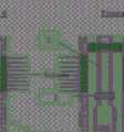
[0003] Um esquema de poço completado em dois intervalos produtores com duas válvulas de completação inteligente ICVs (Inflow Control Valve-válvulas de controle de fluxo) na coluna de produção (CP) é representado na Figura 1. Quando esse tipo de completação é realizada, por exemplo, em poços do Pré-Sal, cujas formações são carbonáticas, pode ocorrer a formação de incrustação de carbonato de cálcio na CP e nos orifícios das ICVs, conforme representado na Figura 2. A incrustação vai crescendo no interior da CP e através dos orifícios das ICVs para o interior da CP, até promover o bloqueio dos orifícios da ICV (Figuras 3 e 4). Caso não seja controlado, o bloqueio total da CP por incrustação pode ocorrer, o que implica perda deste equipamento.[0003] A well scheme completed in two producing intervals with two intelligent completion valves ICVs (Inflow Control Valve) in the production column (CP) is shown in Figure 1. When this type of completion is performed , for example, in Pre-Salt wells, whose formations are carbonate, the formation of calcium carbonate incrustation in the CP and in the holes of the ICVs can occur, as shown in Figure 2. The incrustation grows inside the CP and through from the holes of the ICVs to the interior of the CP, until blocking the holes of the ICV (Figures 3 and 4). If not controlled, the total blockage of the CP by incrustation may occur, which implies loss of this equipment.
[0004] O documento WO2013141810A1 revela um dispositivo de limpeza a laser, compreendendo uma fonte laser, um dispositivo de mão, e um conjunto de sensores acústicos e de temperatura. O dispositivo de mão é acoplado ã fonte laser de fibra, para emitir luz coerente pulsada de forma controlável, enquanto a pluralidade de sensores é conectada ao dispositivo de mão, sendo configurada para determinar uma posição de foco para a luz em uma superfície de aço de uma estrutura marinha, de modo a remover o material depositado nela.[0004] Document WO2013141810A1 discloses a laser cleaning device, comprising a laser source, a handheld device, and a set of acoustic and temperature sensors. The handheld device is coupled to the fiber laser source to emit pulsed coherent light in a controllable manner, while the plurality of sensors are connected to the handheld device and configured to determine a focus position for the light on a steel surface of a marine structure, in order to remove the material deposited on it.
[0005] O documento JP6491173B2 revela uma técnica de remoção de uma película de revestimento na superfície de uma estrutura por irradiação a laser, com aspiração e recuperação da substância removida e, em particular, em uma estrutura fixa, como uma ponte, um edifício, um navio, ou um tubo de grande porte. Um sistema laser é utilizado para remover o filme de revestimento ou depósitos através da irradiação de um feixe laser, usando um módulo laser portátil. O aparelho de irradiação laser inclui um oscilador laser, uma fibra, um módulo laser, uma mangueira de sucção, e uma fonte de sucção, podendo incluir uma fonte de fornecimento de gás e uma mangueira de gás. O módulo laser é um tipo portátil e é conectado ao oscilador laser através da fibra, podendo ser manuseado em um local de trabalho. A saída do laser do oscilador laser é transmitida para o módulo laser através da fibra de transmissão.[0005] Document JP6491173B2 discloses a technique for removing a coating film on the surface of a structure by laser irradiation, with aspiration and recovery of the removed substance and, in particular, on a fixed structure, such as a bridge, a building, a ship, or a large tube. A laser system is used to remove coating film or deposits by irradiating a laser beam using a portable laser module. The laser irradiation apparatus includes a laser oscillator, a fiber, a laser module, a suction hose, and a suction source, and may include a gas supply source and a gas hose. The laser module is a portable type and is connected to the laser oscillator through the fiber, so it can be handled at a work site. The laser output of the laser oscillator is transmitted to the laser module through the transmission fiber.
[0006] O documento WO1983001400A1 revela um método para remoção de materiais depositados nas superfícies de objetos, o qual é realizado direcionando-se a radiação eletromagnética coerente de um laser para o material. A densidade de potência da radiação de impacto é eficaz para remover o material indesejável sem danificar o objeto subjacente. Os princípios da invenção são aplicáveis a numerosas situações de limpeza de superfícies, incluindo a desobstrução das superfícies marinhas. Para a desobstrução do casco de um navio, por exemplo, a radiação laser é conduzida por espelhos e focalizada no casco. Os depósitos são chocados e desalojadas do casco.[0006] Document WO1983001400A1 discloses a method for removing materials deposited on the surfaces of objects, which is performed by directing coherent electromagnetic radiation from a laser to the material. The power density of the impact radiation is effective in removing unwanted material without damaging the underlying object. The principles of the invention are applicable to numerous surface cleaning situations, including clearing marine surfaces. For clearing the hull of a ship, for example, laser radiation is conducted by mirrors and focused on the hull. Deposits are shocked and dislodged from the hull.
[0007] Os documentos citados são silenciosos a respeito da utilização do dispositivo para a remoção de incrustações em colunas de produção de poços de petróleo.[0007] The cited documents are silent regarding the use of the device for the removal of encrustations in oil well production columns.
[0008] Diante das dificuldades presentes no Estado da Técnica, para soluções de remoção e prevenção de incrustações, surge a necessidade de desenvolver uma tecnologia capaz de apresentar um desempenho eficaz e que esteja em acordo com as diretrizes ambientais e de segurança. Os documentos citados não possuem as características únicas desta invenção que serão apresentadas detalhadamente a seguir.[0008] Faced with the difficulties present in the state of the art, for solutions for the removal and prevention of incrustations, the need arises to develop a technology capable of presenting an effective performance and that is in accordance with the environmental and safety guidelines. The cited documents do not have the unique characteristics of this invention that will be presented in detail below.
[0009] É um objetivo da invenção fornecer um dispositivo capaz de controlar a formação de incrustação nas colunas de produção de poços produtores particularmente os que são equipados com completação seletiva, como completação inteligente elétrica.[0009] It is an object of the invention to provide a device capable of controlling the formation of scale in the production columns of producing wells, particularly those equipped with selective completion, such as electrical smart completion.
[0010] É ainda um objetivo da invenção proporcionar a manutenção da produção dos poços equipados com completação inteligente elétrica.[0010] It is also an objective of the invention to provide maintenance for the production of wells equipped with intelligent electrical completion.
[0011] A presente invenção apresenta um mandril a laser capaz de ser instalado na coluna de produção, numa posição abaixo das válvulas ICVs, para ser utilizado num primeiro momento visando à prevenção da formação de incrustação nas válvulas ICVs (2 e 4), e num segundo momento, para a remoção de incrustação na coluna de produção (1).[0011] The present invention presents a laser chuck capable of being installed in the production column, in a position below the ICVs valves, to be used at first aiming at preventing the formation of incrustation in the ICVs valves (2 and 4), and in a second moment, for the removal of encrustation in the production column (1).
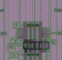
[0012] O mandril laser (9), objeto desta invenção e representado nas Figuras 5 e 6, é dotado de cabo de fibra ótica (5), cabo elétrico (6), colimadores (7), e diodos laser (8).[0012] The laser mandrel (9), object of this invention and represented in Figures 5 and 6, is equipped with a fiber optic cable (5), electrical cable (6), collimators (7), and laser diodes (8).
[0013] A presente invenção será descrita com mais detalhes a seguir, com referência a figuras em anexo que, de uma forma esquemática e não limitativa do escopo inventivo, representam exemplos de sua realização. Nos desenhos, têm-se:
- - A Figura 1 ilustrando um poço equipado com completação inteligente para dois intervalos produtores, onde estão representados: CP (1), ICV superior (2), packer (3), ICV inferior (4);
- - A Figura 2 ilustrando a formação de incrustações no interior da CP e através dos orifícios das ICVs, onde estão representados: CP (1), ICV superior (2), packer (3), ICV inferior (4), vista lateral da formação do anel de incrustação na parte interna da CP (a), vista de topo da formação do anel de incrustação na parte interna da CP (b), detalhe do início da formação de incrustação nos orifícios das válvulas ICVs (c);
- A Figura 3 ilustrando o crescimento da incrustação no interior da CP e através dos orifícios das ICVs, onde estão representados: CP (1), ICV superior (2), packer (3), ICV inferior (4), vista lateral do aumento da espessura do anel de incrustação na parte interna da CP (d), vista de topo do aumento da espessura do anel de incrustação na parte interna da CP (e), detalhe do crescimento da incrustação dos orifícios das válvulas ICVs para o interior da CP (f);
- - A Figura 4 ilustrando o bloqueio gradual por incrustação nas ICVs;
- - A Figura 5 ilustrando o esquema da ferramenta mandril laser, objeto desta invenção, onde estão representados: CP (1), cabo de fibra ótica (5), cabo elétrico (6), colidires (7), diodos laser (8), mandril laser (9).
- - A Figura 6 ilustrando o posicionamento do mandril laser na coluna de produção, onde o equipamento é instalado abaixo das ICVs;
- - A Figura 7 ilustrando o mandril laser em uma primeira opção, para prevenção de incrustação;
- - A Figura 8 ilustrando o mandril laser em uma segunda opção, para remoção de incrustação.
- - Figure 1 illustrating a well equipped with intelligent completion for two producing intervals, where the following are represented: CP (1), upper ICV (2), packer (3), lower ICV (4);
- - Figure 2 illustrating the formation of incrustations inside the CP and through the holes of the ICVs, where the following are represented: CP (1), upper ICV (2), packer (3), lower ICV (4), side view of the formation of the incrustation ring inside the CP (a), top view of the formation of the incrustation ring in the internal part of the CP (b), detail of the beginning of the incrustation formation in the holes of the ICV valves (c);
- Figure 3 illustrating the growth of incrustation inside the CP and through the holes of the ICVs, where the following are represented: CP (1), upper ICV (2), packer (3), lower ICV (4), lateral view of the increase in thickness of the incrustation ring on the inside of the CP (d), top view of the increase in the thickness of the inlay ring on the inside of the CP (e), detail of the incrustation growth from the holes of the ICVs valves to the inside of the CP ( f);
- - Figure 4 illustrating the gradual blocking by encrustation in the ICVs;
- - Figure 5 illustrating the schematic of the laser mandrel tool, object of this invention, where the following are represented: CP (1), fiber optic cable (5), electrical cable (6), collisions (7), laser diodes (8), laser chuck (9).
- - Figure 6 illustrating the positioning of the laser mandrel in the production column, where the equipment is installed below the ICVs;
- - Figure 7 illustrating the laser mandrel in a first option, for incrustation prevention;
- - Figure 8 illustrating the laser mandrel in a second option, for incrustation removal.
[0014] Abaixo segue descrição detalhada de uma concretização preferida da presente invenção, de cunho exemplificativo e de forma nenhuma limitativo. Não obstante, ficará claro para um técnico no assunto, a partir da leitura desta descrição, possíveis concretizações adicionais da presente invenção ainda compreendidas pelas características essenciais e opcionais abaixo.[0014] Below is a detailed description of a preferred embodiment of the present invention, by way of example and in no way limiting. Nevertheless, it will be clear to a person skilled in the art, from reading this description, possible additional embodiments of the present invention still comprised by the essential and optional features below.
[0015] O equipamento da invenção poderá servir como opção prévia para evitar o acúmulo de material incrustante, como carbonato de cálcio, no interior da coluna de produção dos poços, fazendo assim a manutenção da limpeza, evitando a necessidade da aplicação dos processos convencionais, como a operação de squeeze em reservatório, e/ou remoção de incrustação nos equipamentos do sistema de produção.[0015] The equipment of the invention may serve as a prior option to avoid the accumulation of fouling material, such as calcium carbonate, inside the production column of the wells, thus maintaining cleanliness, avoiding the need to apply conventional processes, such as the squeeze operation in the reservoir, and/or removal of encrustation in the equipment of the production system.
[0016] O equipamento pode ser instalado ainda na fase de construção do poço, na etapa de completação. Nas operações de combate à perda de circulação no poço, a invenção possui a vantagem técnica de aproveitar o fluido de completação que o poço irá absorver para realizar uma inibição prévia do reservatório, utilizando assim os espaços porosos da rocha reservatório para reservar fluido de completação inibido, que assim estará disponível dentro do reservatório, quando da produção do poço.[0016] The equipment can be installed even during the construction phase of the well, in the completion stage. In operations to combat loss of circulation in the well, the invention has the technical advantage of taking advantage of the completion fluid that the well will absorb to perform a prior inhibition of the reservoir, thus using the pore spaces of the reservoir rock to reserve inhibited completion fluid , which will thus be available inside the reservoir when the well is produced.
[0017] O mandril laser desta invenção (9) será montado na CP (1) em uma posição logo abaixo das válvulas de completação inteligente elétrica (2 e 4) e será acoplado ao cabo elétrico (6) da completação inteligente. O equipamento (9) será constituído de diodos laser (8), que geram a radiação laser, cabos de fibra ótica (5) para a condução da energia laser, e colimadores (7), que são responsáveis pela projeção do raio laser no interior da coluna (1).[0017] The laser chuck of this invention (9) will be mounted on the CP (1) in a position just below the electrical intelligent completion valves (2 and 4) and will be coupled to the electrical cable (6) of the intelligent completion. The equipment (9) will consist of laser diodes (8), which generate laser radiation, fiber optic cables (5) for conducting laser energy, and collimators (7), which are responsible for projecting the laser beam inside from column (1).
[0018] A tecnologia poderá ser aplicada integralmente no gerenciamento de incrustações nos poços e na garantia de escoamento da produção dos poços. Poderá ainda ser aplicada como parte da tecnologia utilizada na construção de poços na fase de completação.[0018] The technology can be fully applied in the management of incrustations in wells and in guaranteeing the flow of production from wells. It may also be applied as part of the technology used in the construction of wells in the completion phase.
[0019] Ο equipamento será instalado na CP (1) em posição projetada para atingir o objetivo de dissolver as incrustações antes que elas formem grande quantidade de precipitado no seu interior, principalmente nas proximidades das ICVs elétricas (2 e 4).[0019] The equipment will be installed in the CP (1) in a position designed to achieve the objective of dissolving the incrustations before they form a large amount of precipitate inside, mainly in the vicinity of the electrical ICVs (2 and 4).
[0020] Testes realizados em laboratório comprovaram que a aplicação de radiação laser para gerar túneis (canhoneios) em plugs de rochas carbonáticas provocaram a desintegração térmica do carbonato em gás carbônico (CO2) e óxido de cálcio (CaO). Assim, faz-se aplicável o uso do laser para a dissolução térmica do carbonato. Ainda, relatórios de testes de remoção de incrustação, através da aplicação de calor a soluções quelantes, demonstraram um aumento do rendimento da reação e, por conseguinte, da eficiência da remoção de incrustações.[0020] Laboratory tests have shown that the application of laser radiation to generate tunnels (cannons) in carbonate rock plugs caused the thermal disintegration of carbonate into carbon dioxide (CO2) and calcium oxide (CaO). Thus, the use of laser for thermal dissolution of carbonate is applicable. Also, reports of scale removal tests, through the application of heat to chelating solutions, demonstrated an increase in the reaction yield and, therefore, the scale removal efficiency.
[0021] O mandril a laser desta invenção deverá ser instalado na CP (1), numa posição abaixo das válvulas ICVs (2 e 4), para ser utilizado num primeiro momento visando à prevenção da formação de incrustação nas válvulas ICVs (2 e 4), e num segundo momento, para a remoção de incrustação na CP (1).[0021] The laser chuck of this invention must be installed in the CP (1), in a position below the ICVs valves (2 and 4), to be used at first in order to prevent the formation of incrustation in the ICVs valves (2 and 4 ), and in a second moment, for the removal of encrustation in the CP (1).
[0022] Para a prevenção da formação de incrustação nos orifícios das válvulas (2 e 4), o mandril (9) deverá ser acionado periodicamente, promovendo o aquecimento do óleo produzido pelo poço, de modo a criar uma maior turbulência no interior das válvulas, dentro da coluna, auxiliando no processo de desagregação da incrustação. O laser do mandril (9) deverá ser acionado na direção da incrustação, dentro da coluna de produção e abaixo das ICVs. Essa opção é demonstrada na Figura 7.[0022] To prevent the formation of incrustation in the holes of the valves (2 and 4), the mandrel (9) must be activated periodically, promoting the heating of the oil produced by the well, in order to create greater turbulence inside the valves , inside the column, helping in the process of disaggregation of the encrustation. The mandrel laser (9) must be activated in the direction of the encrustation, inside the production column and below the ICVs. This option is shown in Figure 7.
[0023] Para a remoção da incrustação formada nas válvulas (2 e 4), o mandril (9) deverá ser acionado para aquecer as soluções removedoras. O mandril laser (9) poderá ajudar no aumento da eficiência dos tratamentos remotos, pois será capaz de aquecer as soluções removedoras que serão bombeadas pela UEP e/ou barco de estimulação para dentro da CP (1) e posicionadas em frente às ICVs (2 e 4), dentro da CP (1). Nesse caso, o laser do mandril (9) deverá ser acionado na direção da incrustação, dentro da coluna de produção e abaixo das ICVs (2 e 4), passando através da solução removedora de quelantes. Essa opção é demonstrada na Figura 8.[0023] To remove the incrustation formed in the valves (2 and 4), the mandrel (9) must be activated to heat the removing solutions. The laser mandrel (9) can help increase the efficiency of remote treatments, as it will be able to heat the removal solutions that will be pumped by the UEP and/or stimulation boat into the CP (1) and positioned in front of the ICVs (2 and 4), within the CP (1). In this case, the laser of the mandrel (9) must be activated in the direction of the incrustation, inside the production column and below the ICVs (2 and 4), passing through the chelating remover solution. This option is shown in Figure 8.
[0024] Já para a remoção da incrustação na CP (1) em pontos acima das ICVs (2 e 4), o mandril laser (9) também poderá ajudar no aumento da eficiência dos tratamentos remotos, aquecendo as soluções removedoras que serão bombeadas pela UEP e/ou barco de estimulação para dentro da CP (1), na região onde a incrustação estiver posicionada.[0024] As for the removal of encrustation on the CP (1) at points above the ICVs (2 and 4), the laser mandrel (9) can also help to increase the efficiency of remote treatments, heating the removing solutions that will be pumped by the UEP and/or stimulation boat into the CP (1), in the region where the inlay is positioned.
Claims (4)
Translated fromPortuguesePriority Applications (2)
| Application Number | Priority Date | Filing Date | Title |
|---|---|---|---|
| BR102021016392-5ABR102021016392A2 (en) | 2021-08-18 | 2021-08-18 | LASER MANDRILL FOR REMOVING FLOAT IN PRODUCTION EQUIPMENT |
| US17/890,345US11982156B2 (en) | 2021-08-18 | 2022-08-18 | Laser mandrel for removal of scale in production equipment |
Applications Claiming Priority (1)
| Application Number | Priority Date | Filing Date | Title |
|---|---|---|---|
| BR102021016392-5ABR102021016392A2 (en) | 2021-08-18 | 2021-08-18 | LASER MANDRILL FOR REMOVING FLOAT IN PRODUCTION EQUIPMENT |
Publications (1)
| Publication Number | Publication Date |
|---|---|
| BR102021016392A2true BR102021016392A2 (en) | 2023-02-28 |
Family
ID=85229404
Family Applications (1)
| Application Number | Title | Priority Date | Filing Date |
|---|---|---|---|
| BR102021016392-5ABR102021016392A2 (en) | 2021-08-18 | 2021-08-18 | LASER MANDRILL FOR REMOVING FLOAT IN PRODUCTION EQUIPMENT |
Country Status (2)
| Country | Link |
|---|---|
| US (1) | US11982156B2 (en) |
| BR (1) | BR102021016392A2 (en) |
Family Cites Families (15)
| Publication number | Priority date | Publication date | Assignee | Title |
|---|---|---|---|---|
| WO1983001400A1 (en) | 1981-10-22 | 1983-04-28 | First Of Chelsea Corp | Laser removal of materials from surfaces |
| US6880646B2 (en)* | 2003-04-16 | 2005-04-19 | Gas Technology Institute | Laser wellbore completion apparatus and method |
| US6888097B2 (en)* | 2003-06-23 | 2005-05-03 | Gas Technology Institute | Fiber optics laser perforation tool |
| US7490664B2 (en)* | 2004-11-12 | 2009-02-17 | Halliburton Energy Services, Inc. | Drilling, perforating and formation analysis |
| WO2009101125A1 (en)* | 2008-02-15 | 2009-08-20 | Shell Internationale Research Maatschappij B.V. | Method of producing hydrocarbons through a smart well |
| US20090205675A1 (en)* | 2008-02-18 | 2009-08-20 | Diptabhas Sarkar | Methods and Systems for Using a Laser to Clean Hydrocarbon Transfer Conduits |
| AU2010273790B2 (en)* | 2009-06-29 | 2015-04-02 | Halliburton Energy Services, Inc. | Wellbore laser operations |
| EP2599849A1 (en)* | 2011-11-30 | 2013-06-05 | Welltec A/S | Method of inhibiting corrosion of a downhole casing |
| WO2013133415A1 (en) | 2012-03-09 | 2013-09-12 | 株式会社トヨコー | Laser irradiation device, laser irradiation system, and method for removing coating or adhering matter |
| SG11201405364UA (en) | 2012-03-21 | 2014-10-30 | Ngee Ann Polytechnic | A laser cleaning apparatus and method |
| RU2509882C1 (en)* | 2012-09-04 | 2014-03-20 | Александр Петрович Линецкий | Development method of oil and gas deposits using high-power laser radiation for their maximum extraction |
| US9903171B2 (en)* | 2012-09-04 | 2018-02-27 | Alexander Petrovich Linetskiy | Method for developing oil and gas fields using high-power laser radiation for more complete oil and gas extraction |
| US10323460B2 (en)* | 2015-12-11 | 2019-06-18 | Foro Energy, Inc. | Visible diode laser systems, apparatus and methods of use |
| US10239157B2 (en)* | 2016-04-06 | 2019-03-26 | General Electric Company | Additive machine utilizing rotational build surface |
| US11090765B2 (en)* | 2018-09-25 | 2021-08-17 | Saudi Arabian Oil Company | Laser tool for removing scaling |
- 2021
- 2021-08-18BRBR102021016392-5Apatent/BR102021016392A2/enunknown
- 2022
- 2022-08-18USUS17/890,345patent/US11982156B2/enactiveActive
Also Published As
| Publication number | Publication date |
|---|---|
| US20230059801A1 (en) | 2023-02-23 |
| US11982156B2 (en) | 2024-05-14 |
Similar Documents
| Publication | Publication Date | Title |
|---|---|---|
| US11060378B2 (en) | High power laser flow assurance systems, tools and methods | |
| US11072997B2 (en) | Shock waves for oil separation | |
| BRPI0714578A2 (en) | Method for removing oilfield mineral crust from pipes and piping | |
| CN103790515A (en) | New method for radial well drilling by means of laser | |
| BR102021016392A2 (en) | LASER MANDRILL FOR REMOVING FLOAT IN PRODUCTION EQUIPMENT | |
| BR102020016720A2 (en) | Autonomous method of scale removal and inhibition | |
| BR112019027385A2 (en) | high power optical slip ring laser drilling system and method | |
| EP3966423B1 (en) | Laser array drilling tool and related methods | |
| WO2021168524A1 (en) | Laser jetter pipe tool | |
| WO2014144887A2 (en) | High power laser flow assurance systems, tools and methods | |
| Hegdal | Subsea Water Treatment and Injection to Optimize Production and to Reduce Cost | |
| US20250196201A1 (en) | Method of laser stimulation of barium and/or strontium complexion by dtpa | |
| US20250270709A1 (en) | Hybrid tool assembly for pipeline descaling | |
| BR102019026153A2 (en) | PIG LASER FOR REMOVAL OF FLUID IN SUBSEA SYSTEMS | |
| BR102020003955B1 (en) | LASER BLASTING TUBE TOOL | |
| KR102782286B1 (en) | Glycol regeneration apparatus using selective removal of sulfide | |
| BR112019027409A2 (en) | perforation methods and application of laser beam firing patterns | |
| BR102018011841B1 (en) | DEVICE FOR HYDRATE REMOVAL IN SUBSEA EQUIPMENT | |
| ES3034863A2 (en) | SYSTEM AND PROCEDURE FOR REMOVING SCALE FROM INSIDE PIPES | |
| BR102018016130A2 (en) | AUTOMATED CHEMICAL BATHROOM EQUIPMENT ASSISTED BY HIGH POWER ULTRASOUND FOR DE-SCALING BARIUM SULPHATE AND AGGREGATES IN HYDROCYCLONES | |
| BR102018073768B1 (en) | PROCESS FOR STIMULATING OIL WELLS | |
| BR112019027371A2 (en) | methods and systems for laser kerfing drilling | |
| BR112019027373A2 (en) | laser drilling kerfing bit | |
| KR20190060397A (en) | MEG regeneration system having selective sulfide removal process |
Legal Events
| Date | Code | Title | Description |
|---|---|---|---|
| B03A | Publication of a patent application or of a certificate of addition of invention [chapter 3.1 patent gazette] |