BR102017024072B1 - CRYOSPROBE - Google Patents
CRYOSPROBEDownload PDFInfo
- Publication number
- BR102017024072B1 BR102017024072B1BR102017024072-0ABR102017024072ABR102017024072B1BR 102017024072 B1BR102017024072 B1BR 102017024072B1BR 102017024072 ABR102017024072 ABR 102017024072ABR 102017024072 B1BR102017024072 B1BR 102017024072B1
- Authority
- BR
- Brazil
- Prior art keywords
- sleeve
- tube
- channel
- cryoprobe
- nozzle
- Prior art date
Links
Images

Classifications
- B—PERFORMING OPERATIONS; TRANSPORTING
- B23—MACHINE TOOLS; METAL-WORKING NOT OTHERWISE PROVIDED FOR
- B23P—METAL-WORKING NOT OTHERWISE PROVIDED FOR; COMBINED OPERATIONS; UNIVERSAL MACHINE TOOLS
- B23P19/00—Machines for simply fitting together or separating metal parts or objects, or metal and non-metal parts, whether or not involving some deformation; Tools or devices therefor so far as not provided for in other classes
- B23P19/02—Machines for simply fitting together or separating metal parts or objects, or metal and non-metal parts, whether or not involving some deformation; Tools or devices therefor so far as not provided for in other classes for connecting objects by press fit or for detaching same
- A—HUMAN NECESSITIES
- A61—MEDICAL OR VETERINARY SCIENCE; HYGIENE
- A61B—DIAGNOSIS; SURGERY; IDENTIFICATION
- A61B10/00—Instruments for taking body samples for diagnostic purposes; Other methods or instruments for diagnosis, e.g. for vaccination diagnosis, sex determination or ovulation-period determination; Throat striking implements
- A61B10/02—Instruments for taking cell samples or for biopsy
- A—HUMAN NECESSITIES
- A61—MEDICAL OR VETERINARY SCIENCE; HYGIENE
- A61B—DIAGNOSIS; SURGERY; IDENTIFICATION
- A61B18/00—Surgical instruments, devices or methods for transferring non-mechanical forms of energy to or from the body
- A61B18/02—Surgical instruments, devices or methods for transferring non-mechanical forms of energy to or from the body by cooling, e.g. cryogenic techniques
- A—HUMAN NECESSITIES
- A61—MEDICAL OR VETERINARY SCIENCE; HYGIENE
- A61B—DIAGNOSIS; SURGERY; IDENTIFICATION
- A61B17/00—Surgical instruments, devices or methods
- A61B2017/00526—Methods of manufacturing
- A—HUMAN NECESSITIES
- A61—MEDICAL OR VETERINARY SCIENCE; HYGIENE
- A61B—DIAGNOSIS; SURGERY; IDENTIFICATION
- A61B18/00—Surgical instruments, devices or methods for transferring non-mechanical forms of energy to or from the body
- A61B2018/00053—Mechanical features of the instrument of device
- A61B2018/00166—Multiple lumina
- A—HUMAN NECESSITIES
- A61—MEDICAL OR VETERINARY SCIENCE; HYGIENE
- A61B—DIAGNOSIS; SURGERY; IDENTIFICATION
- A61B18/00—Surgical instruments, devices or methods for transferring non-mechanical forms of energy to or from the body
- A61B2018/00315—Surgical instruments, devices or methods for transferring non-mechanical forms of energy to or from the body for treatment of particular body parts
- A61B2018/00541—Lung or bronchi
- A—HUMAN NECESSITIES
- A61—MEDICAL OR VETERINARY SCIENCE; HYGIENE
- A61B—DIAGNOSIS; SURGERY; IDENTIFICATION
- A61B18/00—Surgical instruments, devices or methods for transferring non-mechanical forms of energy to or from the body
- A61B2018/00964—Features of probes
- A—HUMAN NECESSITIES
- A61—MEDICAL OR VETERINARY SCIENCE; HYGIENE
- A61B—DIAGNOSIS; SURGERY; IDENTIFICATION
- A61B18/00—Surgical instruments, devices or methods for transferring non-mechanical forms of energy to or from the body
- A61B18/02—Surgical instruments, devices or methods for transferring non-mechanical forms of energy to or from the body by cooling, e.g. cryogenic techniques
- A61B2018/0212—Surgical instruments, devices or methods for transferring non-mechanical forms of energy to or from the body by cooling, e.g. cryogenic techniques using an instrument inserted into a body lumen, e.g. catheter
- A—HUMAN NECESSITIES
- A61—MEDICAL OR VETERINARY SCIENCE; HYGIENE
- A61B—DIAGNOSIS; SURGERY; IDENTIFICATION
- A61B18/00—Surgical instruments, devices or methods for transferring non-mechanical forms of energy to or from the body
- A61B18/02—Surgical instruments, devices or methods for transferring non-mechanical forms of energy to or from the body by cooling, e.g. cryogenic techniques
- A61B2018/0231—Characteristics of handpieces or probes
- A61B2018/0262—Characteristics of handpieces or probes using a circulating cryogenic fluid
- A61B2018/0268—Characteristics of handpieces or probes using a circulating cryogenic fluid with restriction of flow
Landscapes
- Health & Medical Sciences (AREA)
- Surgery (AREA)
- Life Sciences & Earth Sciences (AREA)
- Nuclear Medicine, Radiotherapy & Molecular Imaging (AREA)
- Engineering & Computer Science (AREA)
- Public Health (AREA)
- Biomedical Technology (AREA)
- Heart & Thoracic Surgery (AREA)
- Medical Informatics (AREA)
- Molecular Biology (AREA)
- Animal Behavior & Ethology (AREA)
- General Health & Medical Sciences (AREA)
- Veterinary Medicine (AREA)
- Otolaryngology (AREA)
- Pathology (AREA)
- Mechanical Engineering (AREA)
- Surgical Instruments (AREA)
- Endoscopes (AREA)
- Lining Or Joining Of Plastics Or The Like (AREA)
- Prostheses (AREA)
- Quick-Acting Or Multi-Walled Pipe Joints (AREA)
- Joints Allowing Movement (AREA)
- Compressors, Vaccum Pumps And Other Relevant Systems (AREA)
- Pistons, Piston Rings, And Cylinders (AREA)
Abstract
Translated fromPortugueseDescription
Translated fromPortuguese[0001] A presente invenção refere-se a um método de fabricação de uma criossonda, assim como uma criossonda.[0001] The present invention relates to a method of manufacturing a cryoprobe, as well as a cryoprobe.
[0002] Na medicina, as criossondas são dispostas para agir por meio de frio em tecido biológico. Tal criossonda pode ser inferida a partir da publicação DE 10 2009 018 291 A1. Essa criossonda compreende um tubo flexível que tem, em sua extremidade distal, uma cabeça metálica que é especialmente configurada para a aplicação respectivamente específica, cuja cabeça pode ser internamente resfriada por meio de um refrigerante. Ao fazer isso, pode-se obter esse tecido biológico que congelará até a cabeça e será separado e removido do tecido circundante para fins de biópsia, por exemplo.[0002] In medicine, cryoprobes are arranged to act by means of cold on biological tissue. Such a cryoprobe can be inferred from publication DE 10 2009 018 291 A1. This cryoprobe comprises a flexible tube that has, at its distal end, a metallic head that is specially configured for the respectively specific application, whose head can be internally cooled by means of a coolant. By doing this, you can get this biological tissue that will freeze down to the head and be separated and removed from the surrounding tissue for biopsy purposes, for example.
[0003] A conexão entre a cabeça fornecida distalmente e o tubo flexível deve ser a prova de fluido e deve exibir resistência à tração. Além disso, as criossondas frequentemente com um diâmetro extremamente pequeno são desejadas a fim de ter capacidade de também avançar a sonda em lúmens justos de um paciente e em vasos.[0003] The connection between the distally supplied head and the flexible tube must be fluid-proof and must exhibit tensile strength. Furthermore, cryoprobes often with an extremely small diameter are desired in order to be able to also advance the probe into a patient's tight lumens and into vessels.
[0004] Ademais, é frequentemente desejável por parte do fabricante fornecer criossondas na forma estéril, para que a criossonda possa ser usada no paciente sem tratamento de esterilização adicional. O objetivo é fornecer, de modo rentável, tais instrumentos como produtos descartáveis.[0004] Furthermore, it is often desirable on the part of the manufacturer to supply cryoprobes in sterile form, so that the cryoprobe can be used on the patient without further sterilization treatment. The aim is to cost-effectively supply such instruments as disposable products.
[0005] Considerando isso, o objetivo da invenção é definir um método de fornecimento de criossondas, sendo que o dito método permite a simples fabricação das mesmas com confiabilidade de processo. Ademais, é o objetivo da invenção fornecer uma criossonda que pode ser produzida com o método de acordo com a invenção e satisfaça pelo menos algumas exigências anteriormente mencionadas de outro modo.[0005] Considering this, the objective of the invention is to define a method of supplying cryoprobes, and said method allows the simple manufacture of the same with process reliability. Furthermore, it is the object of the invention to provide a cryoprobe which can be produced with the method according to the invention and satisfies at least some of the previously mentioned requirements otherwise.
[0006] A parte do objetivo relacionada ao método de fabricação é obtida com um método.[0006] The part of the objective related to the manufacturing method is achieved with a method.
[0007] De acordo com a invenção, o método estabelece que a fabricação de uma criossonda se baseia em um dispositivo de tubo que tem pelo menos dois canais, em que a bocal na forma de um componente separado, de preferência, pré-fabricado, é inserido em um dos canais e a extremidade de tubo é dotada de uma luva no lado de fora de tal maneira que a luva acomode a extremidade de tubo e se projete distalmente além da extremidade de tubo, em particular, além de seu lado de face, de preferência, face de extremidade plana. Depois disso, a luva é deformada para dentro durante um processo de formação de tal maneira que a mesma seja fixada na extremidade de tubo por meio de uma conexão de compressão. Alternativamente, a luva pode ter - mesmo antes da montagem - um diâmetro interno que é menor que o diâmetro externo da extremidade de tubo que é, então, axialmente pressionada nessa luva. Em ambos os casos, a luva tem um diâmetro interno - no máximo, em estado completamente montado - que é menor que o diâmetro externo do dispositivo de tubo. Consequentemente, um encaixe por pressão da luva na extremidade de tubo é garantido.[0007] According to the invention, the method establishes that the manufacture of a cryoprobe is based on a tube device that has at least two channels, in which the nozzle in the form of a separate component, preferably prefabricated, is inserted into one of the channels and the tube end is provided with a sleeve on the outside in such a way that the sleeve accommodates the tube end and projects distally beyond the tube end, in particular beyond its facing side , preferably flat end face. Thereafter, the sleeve is deformed inwards during a forming process in such a way that it is fixed to the pipe end by means of a compression fitting. Alternatively, the sleeve can have - even before assembly - an inside diameter which is smaller than the outside diameter of the pipe end which is then axially pressed into this sleeve. In both cases, the sleeve has an inside diameter - at most in fully assembled state - which is smaller than the outside diameter of the tube device. Consequently, a press fit of the sleeve to the pipe end is ensured.
[0008] Em princípio, a luva pode ser fechada, ou pode ser subsequentemente fechada, em sua extremidade distal. Isso pode ser obtido com uma tampa de extremidade que é conectada à luva de uma maneira vedante para o fechamento distal da luva por meio de uma conexão de vedação anular, por exemplo, uma junção de solda. De preferência, a junção de solda é fornecida após a luva ter sido aplicada à extremidade de tubo. Alternativamente, a extremidade também pode ser conectada à luva antes de aplicar a luva de acordo com um dos métodos mencionados anteriormente, por exemplo, por meio de uma junção de solda anular. Também é possível configurar a luva e a tampa de extremidade em uma peça, isto é, sem junções e em uma peça, e do mesmo material.[0008] In principle, the glove can be closed, or can be subsequently closed, at its distal end. This can be achieved with an end cap which is connected to the sleeve in a sealing manner to the distal closure of the sleeve via an annular sealing connection, for example a solder joint. Preferably, the solder joint is provided after the sleeve has been applied to the pipe end. Alternatively, the end can also be connected to the sleeve before applying the sleeve according to one of the previously mentioned methods, for example by means of an annular solder joint. It is also possible to configure the sleeve and end cap in one piece, ie without joints and in one piece, and of the same material.
[0009] Como uma alternativa para a luva de crimpagem de metal, também é possível usar uma ponta de sonda de um material plástico termicamente condutor e um revestimento plástico. A estanqueidade a vazamentos e resistência à compressão são, então, obtidas, por exemplo, por meio de soldagem ultrassônica.[0009] As an alternative to the metal crimping sleeve, it is also possible to use a probe tip of a thermally conductive plastic material and a plastic coating. Leak tightness and compressive strength are then achieved, for example, by means of ultrasonic welding.
[0010] A fabricação da criossonda por meio do dito método é preferencial com uma luva que é aberta em ambos os lados. Então, a luva pode ser recebida por um pino de montagem que tem uma superfície de apoio para a luva em que a luva entra em contiguidade de lado de face firme e é disposta para posicionar axialmente a luva na extremidade de tubo durante a montagem. O pino de montagem pode ter uma projeção nessa superfície de apoio anular, sendo que a dita projeção é disposta para o apoio de lado de face da extremidade de tubo, para que a distância desejada da superfície de extremidade da luva a partir da superfície de face da extremidade de tubo seja garantida. Dessa maneira, pode-se garantir durante um simples processo de junção que a luva exiba uma sobreposição desejada em relação à extremidade de tubo.[0010] The manufacture of the cryoprobe by means of said method is preferred with a sleeve that is open on both sides. Then, the sleeve can be received by a mounting pin having a sleeve bearing surface where the sleeve abuts hard-faced side and is arranged to axially position the sleeve on the pipe end during assembly. The mounting pin may have a projection on this annular bearing surface, said projection being arranged for the facing side bearing of the pipe end, so that the desired distance of the end surface of the sleeve from the face surface of the pipe end is guaranteed. In this way, it can be ensured during a simple joining process that the sleeve exhibits a desired overlap with the pipe end.
[0011] Também, durante essa etapa de processo, a inserção do bocal na extremidade de tubo pode correr com o auxílio do pino de montagem. Um bocal que foi aceito pelo pino ou foi anteriormente colocado com uma extremidade na extremidade de tubo pode ser inserido, durante o processo de junção da luva e do tubo por uma superfície de apoio de bocal do pino de montagem, na extremidade de tubo, para que o bocal se projete sobre a extremidade de tubo de uma maneira axialmente precisa por uma medição desejada, isto é, em particular, uma sobreposição axial precisa sobre a face de extremidade da extremidade de tubo. Devido a esse processo de junção por meio do pino de montagem que tem três superfícies de apoio separadas (para a luva, a extremidade de tubo e o bocal) obtém que a luva, o bocal, assim como a superfície de face da extremidade de tubo são posicionadas precisamente na relação dimensional desejada uma em relação à outra. Consequentemente, após fechar a luva por meio da tampa, as condições de fluxo definidas pela tampa são geradas na câmara de expansão assim fornecida, para que seja possível - de uma maneira simples - garantir a função térmica correta da criossonda. Em particular, pode-se garantir que a criossonda resfrie uniformemente ou com uma distribuição de frio desejada e, então, produz o efeito cirúrgico desejado durante o uso subsequente.[0011] Also, during this process step, the insertion of the nozzle at the end of the pipe can be performed with the aid of the assembly pin. A nozzle that has been accepted by the pin or was previously placed with one end on the pipe end may be inserted, during the sleeve and pipe joining process, through a nozzle bearing surface of the mounting pin, on the pipe end, to that the nozzle projects over the tube end in an axially accurate manner by a desired measurement, i.e., in particular, a precise axial overlap over the end face of the tube end. Due to this joining process by means of the mounting pin which has three separate bearing surfaces (for the sleeve, the pipe end and the nozzle) it is obtained that the sleeve, the nozzle, as well as the face surface of the pipe end are positioned precisely in the desired dimensional relationship to each other. Consequently, after closing the sleeve by means of the lid, the flow conditions defined by the lid are generated in the expansion chamber thus provided, so that it is possible - in a simple way - to guarantee the correct thermal function of the cryoprobe. In particular, it can be ensured that the cryoprobe cools evenly or with a desired cold distribution and then produces the desired surgical effect during subsequent use.
[0012] Se desejado, a criossonda que deve ser fabricada dessa maneira pode ser produzida com o uso de adesivos. A vedação entre a câmara de expansão e o tubo é obtida pelo material plástico do próprio tubo - até o ponto em que, como tal, age como uma vedação. A vedação entre a tampa e a luva é obtida pela junção de solda, por exemplo. A vedação entre o bocal e a parede interna do canal do tubo é fornecida pelo próprio material do tubo, sendo que o dito material também age como uma vedação até esse ponto.[0012] If desired, the cryoprobe that is to be manufactured in this way can be produced using adhesives. The seal between the expansion chamber and the tube is achieved by the plastic material of the tube itself - to the point where, as such, it acts as a seal. The seal between the cover and the sleeve is obtained by soldering the joint, for example. The seal between the mouthpiece and the inner wall of the tube channel is provided by the tube material itself, said material also acting as a seal to that extent.
[0013] Se desejado, o método de fabricação pode ser usado sem vedação de líquido e materiais adesivos durante a produção e é adequado para uso em salas limpas. Isso facilita a fabricação como um produto estéril e reduz as despesas para isso.[0013] If desired, the manufacturing method can be used without sealing liquid and adhesive materials during production and is suitable for use in clean rooms. This facilitates manufacture as a sterile product and reduces the expense for doing so.
[0014] O dispositivo de tubo da criossonda pode ser configurado como um único tubo que tem dois ou mais canais. No entanto, também é possível fornecer dois ou mais tubos que são conectados entre si. Para obter isso, por exemplo, os mesmos são mantidos na extremidade de tubo em um corpo plástico que é disposto para acomodar a luva. Os tipos de modalidade restantes explicados no presente documento acima ou doravante são fornecidos em tal dispositivo de tubo conforme estão em um tubo de uma peça que tem dois ou mais canais.[0014] The cryoprobe tube device can be configured as a single tube that has two or more channels. However, it is also possible to supply two or more tubes that are connected together. To achieve this, for example, they are held at the end of a tube in a plastic body which is arranged to accommodate the sleeve. The remaining modality types explained herein above or hereinafter are provided in such a tube device as they are in a one-piece tube having two or more channels.
[0015] O bocal é um componente separado e pode ser fornecido, especialmente em sua superfície de outro modo externa circunfe- rencial cilíndrica, com uma estrutura de ancoramento para o engate na extremidade de tubo. Por exemplo, a estrutura de ancoramento pode ser fornecida na extensão local ou periférica, por exemplo anular de nervuras, que, por exemplo, têm uma seção transversal triangular. A estrutura de ancoramento também pode consistir em microrreen- trâncias ou elevações, isto é, uma região ou saliência áspera que é fornecida em toda a superfície externa circunferencial ou em zonas das mesmas.[0015] The nozzle is a separate component and can be provided, especially on its otherwise external circumferential cylindrical surface, with an anchoring structure for engagement at the end of the pipe. For example, the anchoring structure can be provided in local or peripheral extension, for example annular ribs, which, for example, have a triangular cross-section. The anchoring structure may also consist of micro recesses or elevations, i.e. a rough region or protrusion that is provided across the circumferential outer surface or in zones thereof.
[0016] Em particular, na região em que a luva foi deformada para dentro, isto é, na zona de formação em que a mesma exerce uma força direcionada radialmente para dentro, a mesma pode ser dotada de uma estrutura de suporte. Essa estrutura de suporte pode ser formada pelo próprio bocal. Como resultado disso, o bocal é mantido firmemente no canal e, caso presente, por sua estrutura de ancoramento. Devido à deformação direcionada para dentro da luva, a) as luvas se tornam axialmente não deslizáveis no tubo com a tampa de extremidade aplicada por último e b) o bocal é preso axialmente de modo não deslizável no canal do tubo.[0016] In particular, in the region where the glove has been deformed inwards, that is, in the formation zone where it exerts a force directed radially inwards, it can be provided with a support structure. This support structure can be formed by the mouthpiece itself. As a result, the mouthpiece is held securely in the canal and, if present, by its anchoring structure. Due to the inwardly directed deformation of the sleeve, a) the sleeves become axially non-slidable in the tube with the end cap applied last and b) the nozzle is axially non-slidably secured in the channel of the tube.
[0017] Ademais, as estruturas de suporte podem ser dispostas nos canais livres, isto é, os canais que não acomodam o bocal. As estruturas de suporte adequadas são, por exemplo, seções de cano de metal, estruturas de arame, por exemplo, na veia de uma mola helicoidal, ou também um forro plástico do canal em questão com um material plástico que exibe uma dureza que é maior que a dureza do material de tubo restante. Em particular, no caso do forro plástico duro, a estrutura de suporte pode se estender ao longo de todo o comprimento do tubo. Tal tubo de único canal ou de múltiplos canais pode ser fornecido, por exemplo, como um coextrudado.[0017] Furthermore, the support structures can be arranged in the free channels, that is, the channels that do not accommodate the mouthpiece. Suitable support structures are, for example, metal pipe sections, wire structures, for example in the vein of a coil spring, or also a plastic lining of the channel in question with a plastic material that exhibits a hardness that is greater than the hardness of the remaining pipe material. In particular, in the case of the hard plastic liner, the support structure can extend along the entire length of the tube. Such single-channel or multi-channel pipe can be provided, for example, as a coextrudate.
[0018] A deformação direcionada radialmente para dentro da luva pode ser obtida por meio de ferramentas de formação que compreendem duas ou mais garras de aperto dispostas ao redor da circunferência da luva, sendo que as ditas garras de aperto deformam a luva durante um processo de compressão de tal maneira que o diâmetro interno da dita luva diminua e a extremidade de tubo seja presa no lugar. A deformação também pode obtida por meio de rolamento, por exemplo, por meio de um ou mais rolos que circulam ao longo da circunferência da luva. Alternativamente, a deformação pode ser feita de uma maneira sem contato por meio de formação eletromagnética. Para fazer isso, a luva pode ser colocada em uma bobina magnética para a qual um pulso de corrente é aplicado que induz as correntes de vórtice na luva. A corrente de vórtice interage, alternativamente, com a corrente do carretel devido à força de Lorentz e deforma a luva radialmente para dentro pelo menos em uma zona anular.[0018] The deformation directed radially towards the inside of the glove can be obtained by means of forming tools comprising two or more clamping jaws arranged around the circumference of the glove, said clamping jaws deforming the glove during a process of compression in such a way that the internal diameter of said sleeve decreases and the tube end is clamped in place. Deformation can also be achieved by means of rolling, for example by means of one or more rollers circulating along the circumference of the sleeve. Alternatively, deformation can be done in a non-contact manner by means of electromagnetic forming. To do this, the glove can be placed on a magnetic coil to which a current pulse is applied which induces vortex currents in the glove. The vortex current alternatively interacts with the spool current due to the Lorentz force and deforms the sleeve radially inwards at least in an annular zone.
[0019] Alternativamente, a luva pode ser fabricada de um material de memória de formato, em particular, um metal de memória de formato, por exemplo, uma liga de titânio e níquel (nitinol). Então, por exemplo, a luva é fornecida em uma condição ampliada a frio que tem um diâmetro interno que é maior que o diâmetro externo do tubo, em que a dita luva - quando aquecida - retorna novamente para seu formato original em que o diâmetro interno é menor que o diâmetro externo do tubo.[0019] Alternatively, the glove may be manufactured from a shape memory material, in particular a shape memory metal, for example a titanium nickel (nitinol) alloy. So, for example, the sleeve is supplied in a cold enlarged condition which has an inside diameter which is larger than the outside diameter of the tube, whereby said sleeve - when heated - reverts back to its original shape where the inside diameter is smaller than the outside diameter of the tube.
[0020] Os detalhes adicionais de modalidades vantajosas são a matéria das concretizações ou da descrição dos desenhos. Os mesmos mostram na[0020] Further details of advantageous embodiments are the subject of the embodiments or the description of the drawings. The same show in
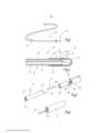
[0021] Figura 1 um diagrama esquemático da criossonda de acordo com a invenção;[0021] Figure 1 is a schematic diagram of the cryoprobe according to the invention;
[0022] Figura 2 uma ilustração longitudinal de uma seção da criossonda de acordo com a Figura 1;[0022] Figure 2 a longitudinal illustration of a section of the cryoprobe according to Figure 1;
[0023] Figura 3 uma vista explodida de uma etapa de processo do processo de fabricação para fornecer a criossonda de acordo com as Figuras 1 e 2, com o uso de um pino de montagem;[0023] Figure 3 is an exploded view of a process step of the manufacturing process to provide the cryoprobe according to Figures 1 and 2, using a mounting pin;
[0024] Figura 4 uma modalidade alternativa de um pino de montagem para realizar o método;[0024] Figure 4 is an alternative embodiment of a mounting pin to carry out the method;
[0025] Figura 5 a criossonda de acordo com a Figura 2 durante a fabricação com um pino de montagem de acordo com a Figura 3 e um tubo com suporte interno inerente;[0025] Figure 5 the cryoprobe according to Figure 2 during manufacture with a mounting pin according to Figure 3 and a tube with inherent internal support;
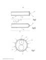
[0026] Figura 6 uma vista lateral do pino de montagem de acordo com a Figura 4;[0026] Figure 6 is a side view of the mounting pin according to Figure 4;
[0027] Figuras 7 e 8 uma ilustração em perspectiva de várias modalidades dos dispositivos de tubo para fornecer a criossonda;[0027] Figures 7 and 8 are a perspective illustration of various embodiments of tube devices for delivering the cryoprobe;
[0028] Figuras 9 e 10 seções longitudinais de várias modalidades de bocais para a criossonda; e[0028] Figures 9 and 10 longitudinal sections of various types of nozzles for the cryoprobe; It is
[0029] Figura 11 uma vista frontal da criossonda sem a tampa de extremidade para ilustrar o processo de montagem de luva.[0029] Figure 11 is a front view of the cryoprobe without the end cap to illustrate the sleeve assembly process.
[0030] A Figura 1 mostra uma criossonda 12 que pode ser usada, por exemplo, para o tratamento criogênico de tecido biológico. Por exemplo, a criossonda 12 pode ser usada em um bronquioscópio para a remoção de uma amostra de tecido. Para fazer isso, a criossonda 12 é inserida, por exemplo, por meio de um bronquioscópio flexível no pulmão, por exemplo, até a pleura, em que a cabeça 13 é, então, colocada em contato com o tecido biológico. Com o uso de uma expansão ou evaporação, isto é, criofluido gasoso ou líquido como, por exemplo, N2 ou CO2, pelo menos uma seção da cabeça 13 é resfriada até um ponto em que o tecido biológico em contato com a mesma congela e, se a remoção de tecido for desejada, se adere à cabeça 13 e pode ser removida, juntamente com a cabeça, a partir da pleura.[0030] Figure 1 shows a
[0031] A Figura 2 mostra um projeto exemplificativo da criossonda 12. A criossonda 12 compreende um dispositivo de tubo 14 que, na presente modalidade exemplificativa, é formada por um tubo plástico flexível 15 que tem um primeiro canal 16, assim como um segundo canal 17. Os dois canais 16, 17 podem ter diferentes diâmetros. De preferência, a seção transversal do segundo canal 17 é 1,1 a 2,5 vezes maior que a seção transversal do primeiro canal 16. Ambos os canais 16, 17 se estendem, de preferência, paralelos entre si e em uma distância próximos entre si através de todo o comprimento do tubo plástico 15 e ambos terminam na superfície de face distal 18, de preferência plana, do dito tubo.[0031] Figure 2 shows an exemplary design of the
[0032] O tubo plástico 15 tem uma extremidade de tubo 19 que suporta a cabeça 13 da criossonda 12. A cabeça 13 compreende uma luva 20 que é mantida na extremidade de tubo 19 e se estende além da superfície de face 18. A luva 20 suporta uma tampa de extremidade 21 que é conectada à luva de uma maneira impermeável a fluidos. Para obter isso, a tampa de extremidade 21 é, de preferência, soldada, na extremidade distal da luva 20, à dita luva, por exemplo, por meio de uma junção de solda a laser anular ou uma outra junção de solda. Desse modo, a tampa de extremidade 21 delimita distalmente uma câmara de expansão 23 para o criofluido que é fornecido por meio do primeiro canal 16 e injetado por meio do bocal 24 na câmara de expansão 23. O bocal é um componente que pode consistir em metal, cerâmica ou também de um material plástico, em cujo caso o material plástico de preferência é um material plástico que é diferente do material do tubo plástico.[0032] The
[0033] O eixo de bocal 24a do bocal 24 é mantido, por exemplo, preso, à seção de extremidade do primeiro canal 16 contígua à superfície de face distal 18. No lado da extremidade, o bocal 24 pode terminar com a superfície de face distal 18 ou, conforme é preferencial e mostrado na Figura 2, se projetar ligeiramente a partir do 16 para a câmara de expansão 23. Ao fazer isso, a posição axial do bocal afeta as condições de fluxo na câmara de expansão 23 e é, então, essencial para a função correta.[0033] The
[0034] De preferência, o bocal 24 tem um orifício de bocal essencialmente redondo que é centralmente disposto no bocal 24 e, então, centralmente em relação ao canal em que o bocal é mantido. Isso simplifica a fabricação devido ao fato de que um alinhamento do bocal não é necessário antes de sua inserção no canal 16. No entanto, uma disposição assimétrica também é possível, beneficiando potencialmente a disposição de resfriamento.[0034] Preferably, the
[0035] A fabricação da criossonda 12 descrita até então é mostrada, pelo menos em parte, pela Figura 3. Para fazer isso, o tubo plástico 15 é, primeiro, dotado do bocal 24 que é inserido no canal 16 pelo menos distante o suficiente de modo a manter pelo menos temporariamente o dito bocal no dito tubo. Ademais, a luva 20 é assentada em um pino de montagem 25 que compreende um receptáculo de luva 26 com essa finalidade. A última compreende uma superfície de compressão anular, de preferência plana27, que se estende ao redor de uma projeção 28. Por exemplo, essa projeção 28 tem uma superfície circunferencial cilíndrica que tem um diâmetro externo que corresponde ao diâmetro interno da luva 20, para que a luva 20 possa ser plugada na projeção 28 para ser, então, mantida na dita projeção. Juntamente, a projeção e a superfície de compressão 27 formam uma sede para a luva 20.[0035] The fabrication of the
[0036] A projeção 28 é, de preferência, dotada de um deslocamento em seu lado de face. A dita projeção compreende uma primeira superfície de apoio 29 para o bocal 24 e uma segunda superfície de apoio 30 que deve entrar em contato com a superfície de face distal 18 do tubo plástico 15 na região do segundo canal 17.[0036] The
[0037] A fixação da luva 20 e do bocal 24 à extremidade de tubo 19 do tubo plástico 15 pode ser inferida a partir da Figura 5. O tubo plástico 15 no qual o eixo de bocal 24a do bocal 24 é parcialmente inserido e o pino de montagem 25 que é dotado da luva 20 são axialmente movidos uma em direção a outra de tal maneira que, primeiro, a extremidade de tubo 19 se mova para a luva 20 e a primeira superfície de apoio 29 entre em contato com a superfície de extremidade do bocal 24. Então, o movimento axial é continuado até que a segunda superfície de apoio 30 da projeção 28 entre em contato com a superfície de face distal 18 do tubo plástico 15. Nesse estado, a luva 20 e o bocal 24 exibem posições axiais bem definidas em relação à superfície de face distal 18, fornecendo, desse modo, uma base essencial para a função correta posterior da criossonda 12.[0037] The attachment of the
[0038] O processo de junção descrito até então pode ser empregado em uma primeira modalidade em que a luva 20 tem um diâmetro menor que o diâmetro externo do tubo plástico 15, assim como em uma segunda modalidade, em que o diâmetro interno da luva 20 é pelo menos tão grande quanto o diâmetro externo do tubo plástico 15.[0038] The joining process described so far can be used in a first embodiment in which the
[0039] Com referência à primeira modalidade mencionada, a luva 20 pode ter, em sua extremidade proximal, um chanfro de inserção não especificamente ilustrado. Alternativa ou adicionalmente, a superfície de face distal 18 do tubo plástico 15 pode transitar - em sua borda radialmente externa - para uma superfície cônica que forma um chanfro de inserção de lado de tubo. Como resultado disso, é possível prender a luva 20 por meio de encaixe por pressão na extremidade de tubo 19 e por meio de encaixe por pressão ao bocal 24 na extremidade de tubo 19. Com referência à segunda, e já mencionada anteriormente modalidade, a luva 20 é deformada radialmente para dentro - pelo menos em partes - seguindo sua aplicação à extremidade de tubo 19 e, então, é restrita. A Figura 2 mostra tal luva 20 com duas zonas de compressão axialmente distanciadas, respectivamente anulares, 31,32 que se estendem sobre toda a circunferência da luva 20 e foram obtidas por meio de deformação plástica da dita luva. A deformação plástica pode ser obtida por meio de duas ou mais garras de aperto que são movidas radialmente para dentro durante o processo de compressão que acomoda a luva 20 entre as mesmas, por meio de uma ferramenta de rolamento que compreende um rolo, ou diversos tais rolos, que circulam ao redor da circunferência da luva de compressão 20 uma ou mais vezes. Ademais, a luva pode ser construída - em partes ou por completo - por meio de formação eletromagnética com o uso de um campo magnético pulsado, isto é, deformada radialmente para dentro. Ao fazer isso, como uma questão de princípio, nenhum contato mecânico em relação à peça de trabalho é necessário, para que as contaminações da superfície da luva possam ser excluídas. O método pode ser usado sob condições ambientes limpas.[0039] With reference to the first mentioned embodiment, the
[0040] Adicionalmente ou alternativamente, é possível, no caso de todas as modalidades mencionadas anteriormente, prender a luva 20 com um meio de conexão adequado, por exemplo, um adesivo à extremidade de tubo 19. Esse pode ser um adesivo de dois componentes (adesivo de poliuretano ou adesivo de epóxi), cianoacrilato altamente elástico, um adesivo curável por UV, um adesivo aerobicamente curável, um adesivo anaerobicamente curável ou um adesivo contendo solvente. Para promover a adesão, a extremidade de tubo 19 pode ser pré-condicionada. Isso pode ser obtido, por exemplo, por meio de encrespamento, ativação de plasma ou por meio de um iniciador. De preferência, no entanto, um adesivo será dispensado.[0040] Additionally or alternatively, it is possible, in the case of all the aforementioned embodiments, to attach the
[0041] O bocal 24 (isto é, em particular, o eixo de bocal 24a) é, de preferência, também mantido por encaixe por pressão. Para obter isso, o bocal 24 pode ter um diâmetro externo ligeiramente maior que o primeiro lúmen 16 em que o dito bocal é mantido. Adicionalmente ou alternativamente, o encaixe por pressão também pode ocorrer ao restringir o lúmen 16 por meio de compressão - pelo menos em algumas zonas, sendo que tal compressão é aplicada a partir da luva 20 radialmente para dentro em direção à extremidade de tubo 19.[0041] The nozzle 24 (i.e., in particular, the
[0042] Após fixar o bocal 24 e a luva 20 à extremidade de tubo 19, a tampa de extremidade 21 é montada. A fim de facilitar o posicionamento, a dita tampa de extremidade pode ter uma extensão anular ou diversas, por exemplo, três extensões em formato de lingueta, ou extensões no formato de abas, que se estendem sobre a parte da luva 20 que se projeta sobre a superfície de face distal 18. A extensão também pode ser configurada como uma extensão anular que exibe uma ou mais descontinuidades. A tampa de extremidade 21 inicialmente fixa pode, então, ser unida, por meio de um processo de junção ou soldagem adequada, por exemplo, soldagem a laser, à luva 20 de uma maneira à prova de fluidos.[0042] After attaching the
[0043] A Figura 11 ilustra a formação da zona de compressão 32 em linhas tracejadas. Conforme é óbvio, a profundidade da zona de compressão 32 pode variar em torno da circunferência da luva 20. Por exemplo, a profundidade da zona de compressão 32 nas redondezas imediatas dos canais 16, 17 pode ser reduzida a fim de manter uma deformação, em particular, uma restrição, dos canais, 16, 17, dentro dos limites. Também é possível reduzir a profundidade da zona de compressão 32 apenas na região do segundo canal 17 a fim de impedir que o segundo canal 17 se retraia enquanto a ação compressiva no primeiro canal 16 promove o encaixe seguro do bocal 24 no primeiro canal 16.[0043] Figure 11 illustrates the formation of the
[0044] Ademais, é possível prender adicionalmente, o bocal 24 na direção axial no canal 16. A Figura 9 mostra um bocal 24 que tem uma seção de cano 33 com uma parede lisa, sendo que a dita seção de cano é fechada em uma extremidade por uma pequena placa de bocal 34 que tem pelo menos um orifício de bocal 36. A placa de bocal 34 pode ser soldada à seção de cano 33, por exemplo, por meio de soldagem a laser. No entanto, também é possível restringir a extremidade distal da seção de cano 33 durante um processo de formação em vez de usar a pequena placa de bocal 34 a fim de, então, formar um orifício de bocal restrito 35. A restrição em relação à seção de cano 33 pode ser coaxial ou também assimétrica, por exemplo, excêntrica, ou pode se estender ao longo de um eixo geométrico orientado de modo oblíquo em relação à direção axial da seção de cano 33.[0044] Furthermore, it is possible to additionally secure the
[0045] Em ambos os casos, as estruturas para prender axialmente o bocal no lúmen 16 podem ser configuradas, por exemplo, como nervuras denticuladas anulares 36, 37, 38, por uma ou mais nervuras do tipo hélice, nós, estruturas irregulares como áreas ásperas ou saliência.[0045] In both cases, the structures for axially holding the mouthpiece in the
[0046] O primeiro canal 16 é disposto para o fluxo de fluidos, isto é, o fornecimento do bocal 24 com líquido ou criofluido gasoso. O segundo canal 17 é disposto para a remoção do criofluido a partir da câmara de expansão 23. A fim de minimizar ou impedir uma restrição do segundo canal 17, em particular na região da luva, é possível fornecer uma estrutura de suporte 39 na extremidade de tubo 19 ou ao longo de todo o canal 17. A Figura 5 é uma ilustração esquemática de uma tal estrutura. Nessa, a estrutura de suporte 39 consiste em um forro de material plástico do segundo canal 17, conforme pode ser inferido a partir da Figura 7. Embora o tubo plástico 15 possa consistir, em geral, de polia- midas, poliolefinas, Pebax, poliuretano, PEEK, PI, materiais compósitos ou outros materiais plásticos, a estrutura de suporte 39 pode consistir em um material plástico comparativamente mais rígido ou em um trançamento metálico. Se a estrutura de suporte for restrita à extremidade de tubo 19, a dita estrutura também pode consistir em um cano de metal.[0046] The
[0047] Conforme mostrado na Figura 8, o dispositivo de tubo 14 também pode ser feito de diversos, por exemplo, dois tubos plásticos 15, 15b que têm diâmetros iguais ou diferentes e são embutidos na cabeça de um corpo, de preferência, um corpo plástico 40. Esse, então, forma a extremidade de tubo 19, enquanto - outro além desse - a descrição no presente documento acima se aplica consequentemente.[0047] As shown in Figure 8, the
[0048] A fabricação, em particular a junção da extremidade de tubo 19 ao bocal 24 e a luva 20, pode, em uma modalidade mais definida, ocorrer também alternativamente com o uso de um pino de montagem 41 de acordo com as Figuras 4 e 6. Nesse caso, um pino de suporte 42 é disposto na segunda superfície de apoio 30, sendo que o dito pino de suporte tem um diâmetro externo que corresponde substancialmente ao diâmetro interno do segundo canal 17 ou é ligeiramente menor que o mesmo. Com referência a essa montagem, o pino de suporte 41 move para o segundo canal 17 e se mantém no canal 17, em particular também durante a deformação radialmente para dentro da luva 20 no canal 17. Ao fazer isso, o pino de suporte 42 impede que o canal 17 se retraia ou seja muito restrito como resultado da deformação direcionada para dentro da luva 40.[0048] The manufacture, in particular the joining of the
[0049] Os métodos de fabricação descritos até então podem ser adicionalmente modificados.[0049] The manufacturing methods described so far can be further modified.
[0050] O pino de suporte 42 pode ser disposto para a acomodação de um pequeno tubo com paredes finas que entra em contiguidade com o apoio do lado de face na segunda superfície de apoio 30 e é inserido no segundo canal 17 durante o processo de junção a fim de, no mesmo, impedir que o segundo canal 17 se retraia durante a deformação direcionada radialmente para dentro da luva 20. Ademais, é possível configurar a projeção 28 sem deslocamento, em cujo caso, a superfície de apoio 29 é fornecida em uma reentrância da superfície de apoio 30. A reentrância, cujo fundo é a superfície de apoio 29, é, então, disposta para a acomodação da extremidade distal do bocal 24 que é, então, inserida no primeiro lúmen 16 durante o processo de junção. A profundidade da reentrância, por sua vez, determina a sobreposição do bocal 24 além da superfície de face distal 18 no estado totalmente montado. Essa modalidade pode ser implantada no pino de montagem 25 de acordo com a Figura 3, assim como no pino de montagem 41 de acordo com as Figuras 4 e 6. A reentrância pode ser redonda a fim de acomodar bocais cilíndricos de simétricos em rotação. Se os bocais não tiverem simétricos em rotação devido ao fato de que - talvez - o orifício de bocal é configurado de modo a ser excêntrico ou se estender em uma orientação oblíqua, o bocal pode ter uma estrutura de proteção torcida e, pode se encaixar entre os mesmos, por exemplo, uma alça ou reentrância, ou não ser redonda de uma outra maneira adequada. Então, a reentrância tem uma forma não redonda correspondente.[0050] The
[0051] O método de fabricação inventivo de uma criossonda usa um pino de montagem 25 para receber uma luva 20 que é para formar uma parte da cabeça 13 da criossonda e compreende três superfícies de apoio 27, 29, 30 que são axialmente deslocadas uma em relação à outra, sendo que as ditas superfícies de apoio garantem, seguindo a fixação da luva 20 e do bocal 24 à extremidade de tubo 19, o posicionamento axial correto do bocal 24 e da luva 20, em particular, em relação à superfície de extremidade distal 18 da extremidade de tubo 19. Consequentemente, a posição do bocal 24 na câmara de expansão 23 que se formou após a luva 20 ter sido fechada e, então, a função da criossonda foi garantida. LISTA DE REFERÊNCIAS NUMÉRICAS:

Claims (8)
Translated fromPortugueseApplications Claiming Priority (2)
| Application Number | Priority Date | Filing Date | Title |
|---|---|---|---|
| EP16199575.8 | 2016-11-18 | ||
| EP16199575.8AEP3323366B1 (en) | 2016-11-18 | 2016-11-18 | Cryoprobe and method for producing same |
Publications (2)
| Publication Number | Publication Date |
|---|---|
| BR102017024072A2 BR102017024072A2 (en) | 2018-06-12 |
| BR102017024072B1true BR102017024072B1 (en) | 2023-04-11 |
Family
ID=57354217
Family Applications (1)
| Application Number | Title | Priority Date | Filing Date |
|---|---|---|---|
| BR102017024072-0ABR102017024072B1 (en) | 2016-11-18 | 2017-11-09 | CRYOSPROBE |
Country Status (8)
| Country | Link |
|---|---|
| US (1) | US11076905B2 (en) |
| EP (1) | EP3323366B1 (en) |
| JP (1) | JP7016242B2 (en) |
| KR (1) | KR102409530B1 (en) |
| CN (1) | CN108066002B (en) |
| BR (1) | BR102017024072B1 (en) |
| PL (1) | PL3323366T3 (en) |
| RU (1) | RU2749868C2 (en) |
Families Citing this family (6)
| Publication number | Priority date | Publication date | Assignee | Title |
|---|---|---|---|---|
| EP3597112A1 (en)* | 2018-07-17 | 2020-01-22 | Erbe Elektromedizin GmbH | Biopsy material recovery device |
| EP3769706A1 (en)* | 2019-07-23 | 2021-01-27 | Erbe Elektromedizin GmbH | Cryoprobe |
| CN111388081B (en)* | 2020-04-17 | 2024-07-09 | 上海导向医疗系统有限公司 | Locking device of cryoprobe structure and cryotherapy equipment |
| EP4349288A1 (en) | 2022-10-07 | 2024-04-10 | Erbe Elektromedizin GmbH | Ablation probe with internal cooling |
| WO2024259414A1 (en)* | 2023-06-16 | 2024-12-19 | Atricure, Inc. | Cryogenic surgical instrument with right angle end effector |
| KR102660309B1 (en)* | 2023-10-16 | 2024-04-23 | 박성덕 | Method of manufacturing a double tube inserted into the body for a polyp removal device |
Family Cites Families (12)
| Publication number | Priority date | Publication date | Assignee | Title |
|---|---|---|---|---|
| US5857997A (en)* | 1994-11-14 | 1999-01-12 | Heart Rhythm Technologies, Inc. | Catheter for electrophysiological procedures |
| US5573532A (en)* | 1995-01-13 | 1996-11-12 | Cryomedical Sciences, Inc. | Cryogenic surgical instrument and method of manufacturing the same |
| US7220257B1 (en)* | 2000-07-25 | 2007-05-22 | Scimed Life Systems, Inc. | Cryotreatment device and method |
| US6241722B1 (en)* | 1998-06-17 | 2001-06-05 | Cryogen, Inc. | Cryogenic device, system and method of using same |
| US20070055326A1 (en)* | 2005-07-21 | 2007-03-08 | Farley Brian E | Method of treating a hollow anatomical structure with a thermal catheter |
| DE102008026635B4 (en)* | 2007-06-26 | 2010-10-28 | Erbe Elektromedizin Gmbh | Kryobiopsiesonde |
| EP2291132B1 (en)* | 2008-05-15 | 2015-09-23 | Boston Scientific Scimed, Inc. | Apparatus for cryogenically ablating tissue and adjusting cryogenic ablation regions |
| DE102009018291A1 (en) | 2009-04-21 | 2010-10-28 | Erbe Elektromedizin Gmbh | Cryosurgical instrument |
| DE102009052208A1 (en)* | 2009-09-24 | 2011-04-07 | Erbe Elektromedizin Gmbh | Tubing connector for a high-frequency surgical device, handle for electrosurgical unit and method for connecting hoses for an electrosurgical unit with such a hose connector |
| DE102010016291A1 (en)* | 2010-04-01 | 2011-10-06 | Erbe Elektromedizin Gmbh | Surgical instrument, in particular electrosurgical instrument |
| CN103118613A (en)* | 2010-08-26 | 2013-05-22 | 克莱米迪克斯有限责任公司 | Cryoablation balloon catheter and related method |
| US9095320B2 (en)* | 2010-09-27 | 2015-08-04 | CyroMedix, LLC | Cryo-induced renal neuromodulation devices and methods |
- 2016
- 2016-11-18PLPL16199575Tpatent/PL3323366T3/enunknown
- 2016-11-18EPEP16199575.8Apatent/EP3323366B1/enactiveActive
- 2017
- 2017-11-09BRBR102017024072-0Apatent/BR102017024072B1/enactiveIP Right Grant
- 2017-11-10KRKR1020170149784Apatent/KR102409530B1/enactiveActive
- 2017-11-14JPJP2017218935Apatent/JP7016242B2/enactiveActive
- 2017-11-17RURU2017140077Apatent/RU2749868C2/enactive
- 2017-11-17CNCN201711146249.3Apatent/CN108066002B/enactiveActive
- 2017-11-17USUS15/816,720patent/US11076905B2/enactiveActive
Also Published As
| Publication number | Publication date |
|---|---|
| JP7016242B2 (en) | 2022-02-04 |
| KR20180056379A (en) | 2018-05-28 |
| RU2017140077A3 (en) | 2020-09-08 |
| CN108066002A (en) | 2018-05-25 |
| RU2749868C2 (en) | 2021-06-17 |
| US11076905B2 (en) | 2021-08-03 |
| KR102409530B1 (en) | 2022-06-17 |
| BR102017024072A2 (en) | 2018-06-12 |
| CN108066002B (en) | 2021-07-06 |
| US20180140342A1 (en) | 2018-05-24 |
| EP3323366B1 (en) | 2020-09-30 |
| PL3323366T3 (en) | 2021-01-25 |
| RU2017140077A (en) | 2019-05-17 |
| EP3323366A1 (en) | 2018-05-23 |
| JP2018108347A (en) | 2018-07-12 |
Similar Documents
| Publication | Publication Date | Title |
|---|---|---|
| BR102017024072B1 (en) | CRYOSPROBE | |
| KR20040051491A (en) | Guidance system for a cryocatheter | |
| JP2019532761A (en) | Steering tool | |
| US20110275153A1 (en) | Cryogenic storage device | |
| JP5248659B2 (en) | Dilator device for ventricular puncture | |
| US8771225B2 (en) | Balloon catheter | |
| WO2010143044A1 (en) | An adapter for connecting a first percutaneous introducer | |
| RU2573797C2 (en) | Systems for reducing fluid leakage and backflow accompanying endoscopic medical procedures | |
| JP5011137B2 (en) | Endoscope injection needle and inner tube with a needle fixed to the tip | |
| KR101498794B1 (en) | Steerable catheter and Catheter device having the same | |
| JP5903875B2 (en) | Endoscopic needle | |
| JP4790611B2 (en) | Auxiliary device for percutaneous positioning of nephroscopic conduits in kidney surgery. | |
| WO2014049790A1 (en) | Puncture needle for injecting bone cement and method for producing same | |
| US20120109117A1 (en) | Cryogenic probe with swivel | |
| KR20210049299A (en) | Fixtures for tube connections with different diameters | |
| US20210113814A1 (en) | Flexible elongated structure having a steerable end | |
| EP4249397A1 (en) | Nozzles, heads and aerosol dispersers | |
| CN114269408B (en) | Medical needle and method for manufacturing medical needle | |
| US9743917B2 (en) | Devices for applying surgical sealants | |
| JPS6327688Y2 (en) | ||
| KR101196730B1 (en) | Balloon catheter | |
| JP2006087747A (en) | Pressurizing and dwelling device and medical catheter | |
| JP2018029876A (en) | Catheter deformation device and catheter deformation device kit | |
| JP2006055279A (en) | Pressurizing and pressure retaining tool | |
| WO2014020666A1 (en) | Medical heat-treatment tool |
Legal Events
| Date | Code | Title | Description |
|---|---|---|---|
| B03A | Publication of a patent application or of a certificate of addition of invention [chapter 3.1 patent gazette] | ||
| B06W | Patent application suspended after preliminary examination (for patents with searches from other patent authorities) chapter 6.23 patent gazette] | ||
| B09A | Decision: intention to grant [chapter 9.1 patent gazette] | ||
| B16A | Patent or certificate of addition of invention granted [chapter 16.1 patent gazette] | Free format text:PRAZO DE VALIDADE: 20 (VINTE) ANOS CONTADOS A PARTIR DE 09/11/2017, OBSERVADAS AS CONDICOES LEGAIS |