BR102014006192B1 - ROD ASSEMBLY FIXABLE TO A SURGICAL INSTRUMENT AND SURGICAL INSTRUMENT HANDLE - Google Patents
ROD ASSEMBLY FIXABLE TO A SURGICAL INSTRUMENT AND SURGICAL INSTRUMENT HANDLEDownload PDFInfo
- Publication number
- BR102014006192B1 BR102014006192B1BR102014006192-4ABR102014006192ABR102014006192B1BR 102014006192 B1BR102014006192 B1BR 102014006192B1BR 102014006192 ABR102014006192 ABR 102014006192ABR 102014006192 B1BR102014006192 B1BR 102014006192B1
- Authority
- BR
- Brazil
- Prior art keywords
- locking
- pivot
- distal
- lock
- actuator
- Prior art date
Links
- 230000033001locomotionEffects0.000claimsabstractdescription169
- 206010061258Joint lockDiseases0.000claimsabstractdescription25
- 238000010304firingMethods0.000claimsdescription72
- 230000004044responseEffects0.000description59
- 238000005520cutting processMethods0.000description53
- 238000000034methodMethods0.000description49
- 230000006870functionEffects0.000description46
- 230000015654memoryEffects0.000description39
- 210000001519tissueAnatomy0.000description39
- 230000000712assemblyEffects0.000description27
- 238000000429assemblyMethods0.000description27
- 238000004891communicationMethods0.000description24
- 238000010168coupling processMethods0.000description23
- 238000012512characterization methodMethods0.000description20
- 230000000694effectsEffects0.000description20
- 230000036961partial effectEffects0.000description20
- 238000010586diagramMethods0.000description18
- 238000006073displacement reactionMethods0.000description18
- 239000000463materialSubstances0.000description18
- 230000008878couplingEffects0.000description16
- 238000005859coupling reactionMethods0.000description16
- 230000010355oscillationEffects0.000description16
- 230000007935neutral effectEffects0.000description15
- 230000005355Hall effectEffects0.000description14
- 230000004888barrier functionEffects0.000description12
- 238000010894electron beam technologyMethods0.000description12
- 230000008569processEffects0.000description12
- 230000009471actionEffects0.000description11
- 238000009434installationMethods0.000description11
- 230000000670limiting effectEffects0.000description11
- 238000007373indentationMethods0.000description10
- 238000005259measurementMethods0.000description10
- 238000003825pressingMethods0.000description10
- 230000002829reductive effectEffects0.000description10
- 238000004422calculation algorithmMethods0.000description9
- 230000007423decreaseEffects0.000description9
- 230000005540biological transmissionEffects0.000description8
- 230000006835compressionEffects0.000description8
- 238000007906compressionMethods0.000description8
- 238000012986modificationMethods0.000description8
- 230000004048modificationEffects0.000description8
- 238000001356surgical procedureMethods0.000description8
- 230000001960triggered effectEffects0.000description8
- 239000003638chemical reducing agentSubstances0.000description7
- 230000013011matingEffects0.000description7
- 230000003213activating effectEffects0.000description6
- 230000007246mechanismEffects0.000description6
- 230000002441reversible effectEffects0.000description6
- 239000000853adhesiveSubstances0.000description5
- 230000001070adhesive effectEffects0.000description5
- 239000004020conductorSubstances0.000description5
- 238000001514detection methodMethods0.000description5
- 230000003993interactionEffects0.000description5
- 238000013519translationMethods0.000description5
- 230000008859changeEffects0.000description4
- 238000004590computer programMethods0.000description4
- 230000000994depressogenic effectEffects0.000description4
- 238000013461designMethods0.000description4
- 239000012636effectorSubstances0.000description4
- 239000004744fabricSubstances0.000description4
- 230000000977initiatory effectEffects0.000description4
- 230000009467reductionEffects0.000description4
- 230000008054signal transmissionEffects0.000description4
- 230000001360synchronised effectEffects0.000description4
- 238000004140cleaningMethods0.000description3
- 230000001965increasing effectEffects0.000description3
- 238000003780insertionMethods0.000description3
- 230000037431insertionEffects0.000description3
- 238000005304joiningMethods0.000description3
- 229910001416lithium ionInorganic materials0.000description3
- 238000004519manufacturing processMethods0.000description3
- 238000012545processingMethods0.000description3
- 230000005855radiationEffects0.000description3
- 239000004065semiconductorSubstances0.000description3
- 230000001953sensory effectEffects0.000description3
- 238000000926separation methodMethods0.000description3
- 238000012935AveragingMethods0.000description2
- 241000238366CephalopodaSpecies0.000description2
- 230000003044adaptive effectEffects0.000description2
- 238000003491arrayMethods0.000description2
- 230000006399behaviorEffects0.000description2
- 238000005452bendingMethods0.000description2
- 230000008901benefitEffects0.000description2
- 239000003990capacitorSubstances0.000description2
- 230000000295complement effectEffects0.000description2
- 150000001875compoundsChemical class0.000description2
- 238000010276constructionMethods0.000description2
- 239000003814drugSubstances0.000description2
- 229940079593drugDrugs0.000description2
- 238000002651drug therapyMethods0.000description2
- 238000005516engineering processMethods0.000description2
- 230000002349favourable effectEffects0.000description2
- 230000005669field effectEffects0.000description2
- 238000001415gene therapyMethods0.000description2
- 239000002648laminated materialSubstances0.000description2
- 230000003287optical effectEffects0.000description2
- 239000013307optical fiberSubstances0.000description2
- 230000000704physical effectEffects0.000description2
- 238000005086pumpingMethods0.000description2
- 230000000717retained effectEffects0.000description2
- 238000005070samplingMethods0.000description2
- 229920006395saturated elastomerPolymers0.000description2
- 230000011664signalingEffects0.000description2
- 238000004088simulationMethods0.000description2
- 230000008093supporting effectEffects0.000description2
- 238000002604ultrasonographyMethods0.000description2
- 241000894006BacteriaSpecies0.000description1
- UOZODPSAJZTQNH-UHFFFAOYSA-NParomomycin IINatural productsNC1C(O)C(O)C(CN)OC1OC1C(O)C(OC2C(C(N)CC(N)C2O)OC2C(C(O)C(O)C(CO)O2)N)OC1COUOZODPSAJZTQNH-UHFFFAOYSA-N0.000description1
- 229910000831SteelInorganic materials0.000description1
- 239000004775TyvekSubstances0.000description1
- 229920000690TyvekPolymers0.000description1
- 230000001133accelerationEffects0.000description1
- 230000004913activationEffects0.000description1
- 230000001154acute effectEffects0.000description1
- 238000004026adhesive bondingMethods0.000description1
- 230000004075alterationEffects0.000description1
- 210000000988bone and boneAnatomy0.000description1
- 238000004364calculation methodMethods0.000description1
- 239000002800charge carrierSubstances0.000description1
- 239000003795chemical substances by applicationSubstances0.000description1
- ALEXXDVDDISNDU-JZYPGELDSA-Ncortisol 21-acetateChemical compoundC1CC2=CC(=O)CC[C@]2(C)[C@@H]2[C@@H]1[C@@H]1CC[C@@](C(=O)COC(=O)C)(O)[C@@]1(C)C[C@@H]2OALEXXDVDDISNDU-JZYPGELDSA-N0.000description1
- 230000003247decreasing effectEffects0.000description1
- 230000000881depressing effectEffects0.000description1
- 238000009826distributionMethods0.000description1
- 230000005684electric fieldEffects0.000description1
- 238000011156evaluationMethods0.000description1
- 239000000835fiberSubstances0.000description1
- 230000002439hemostatic effectEffects0.000description1
- 230000006872improvementEffects0.000description1
- 230000001939inductive effectEffects0.000description1
- 238000012830laparoscopic surgical procedureMethods0.000description1
- 238000007726management methodMethods0.000description1
- 238000007620mathematical functionMethods0.000description1
- 239000002184metalSubstances0.000description1
- 238000004377microelectronicMethods0.000description1
- 238000012978minimally invasive surgical procedureMethods0.000description1
- 238000012544monitoring processMethods0.000description1
- 238000002355open surgical procedureMethods0.000description1
- 230000037361pathwayEffects0.000description1
- 230000002093peripheral effectEffects0.000description1
- 238000002360preparation methodMethods0.000description1
- 230000008707rearrangementEffects0.000description1
- 238000009419refurbishmentMethods0.000description1
- 238000004353relayed correlation spectroscopyMethods0.000description1
- 230000003252repetitive effectEffects0.000description1
- 210000004872soft tissueAnatomy0.000description1
- 238000005476solderingMethods0.000description1
- 239000007787solidSubstances0.000description1
- 229910001220stainless steelInorganic materials0.000description1
- 239000010935stainless steelSubstances0.000description1
- 230000003068static effectEffects0.000description1
- 239000010959steelSubstances0.000description1
- 230000001954sterilising effectEffects0.000description1
- 238000004659sterilization and disinfectionMethods0.000description1
- 230000000638stimulationEffects0.000description1
- 238000003860storageMethods0.000description1
- 239000000126substanceSubstances0.000description1
- 238000006467substitution reactionMethods0.000description1
- 239000000758substrateSubstances0.000description1
- 230000002459sustained effectEffects0.000description1
- 238000012546transferMethods0.000description1
Images


Classifications
- A—HUMAN NECESSITIES
- A61—MEDICAL OR VETERINARY SCIENCE; HYGIENE
- A61B—DIAGNOSIS; SURGERY; IDENTIFICATION
- A61B18/00—Surgical instruments, devices or methods for transferring non-mechanical forms of energy to or from the body
- A61B18/04—Surgical instruments, devices or methods for transferring non-mechanical forms of energy to or from the body by heating
- A61B18/12—Surgical instruments, devices or methods for transferring non-mechanical forms of energy to or from the body by heating by passing a current through the tissue to be heated, e.g. high-frequency current
- A61B18/14—Probes or electrodes therefor
- A61B18/1442—Probes having pivoting end effectors, e.g. forceps
- A61B18/1445—Probes having pivoting end effectors, e.g. forceps at the distal end of a shaft, e.g. forceps or scissors at the end of a rigid rod
- A—HUMAN NECESSITIES
- A61—MEDICAL OR VETERINARY SCIENCE; HYGIENE
- A61B—DIAGNOSIS; SURGERY; IDENTIFICATION
- A61B17/00—Surgical instruments, devices or methods
- A61B17/10—Surgical instruments, devices or methods for applying or removing wound clamps, e.g. containing only one clamp or staple; Wound clamp magazines
- A61B17/105—Wound clamp magazines
- A—HUMAN NECESSITIES
- A61—MEDICAL OR VETERINARY SCIENCE; HYGIENE
- A61B—DIAGNOSIS; SURGERY; IDENTIFICATION
- A61B17/00—Surgical instruments, devices or methods
- A61B17/068—Surgical staplers, e.g. containing multiple staples or clamps
- A—HUMAN NECESSITIES
- A61—MEDICAL OR VETERINARY SCIENCE; HYGIENE
- A61B—DIAGNOSIS; SURGERY; IDENTIFICATION
- A61B17/00—Surgical instruments, devices or methods
- A61B17/068—Surgical staplers, e.g. containing multiple staples or clamps
- A61B17/072—Surgical staplers, e.g. containing multiple staples or clamps for applying a row of staples in a single action, e.g. the staples being applied simultaneously
- A61B17/07207—Surgical staplers, e.g. containing multiple staples or clamps for applying a row of staples in a single action, e.g. the staples being applied simultaneously the staples being applied sequentially
- A—HUMAN NECESSITIES
- A61—MEDICAL OR VETERINARY SCIENCE; HYGIENE
- A61B—DIAGNOSIS; SURGERY; IDENTIFICATION
- A61B17/00—Surgical instruments, devices or methods
- A61B17/28—Surgical forceps
- A61B17/29—Forceps for use in minimally invasive surgery
- A—HUMAN NECESSITIES
- A61—MEDICAL OR VETERINARY SCIENCE; HYGIENE
- A61B—DIAGNOSIS; SURGERY; IDENTIFICATION
- A61B17/00—Surgical instruments, devices or methods
- A61B17/32—Surgical cutting instruments
- A—HUMAN NECESSITIES
- A61—MEDICAL OR VETERINARY SCIENCE; HYGIENE
- A61B—DIAGNOSIS; SURGERY; IDENTIFICATION
- A61B34/00—Computer-aided surgery; Manipulators or robots specially adapted for use in surgery
- A—HUMAN NECESSITIES
- A61—MEDICAL OR VETERINARY SCIENCE; HYGIENE
- A61B—DIAGNOSIS; SURGERY; IDENTIFICATION
- A61B34/00—Computer-aided surgery; Manipulators or robots specially adapted for use in surgery
- A61B34/30—Surgical robots
- A—HUMAN NECESSITIES
- A61—MEDICAL OR VETERINARY SCIENCE; HYGIENE
- A61B—DIAGNOSIS; SURGERY; IDENTIFICATION
- A61B34/00—Computer-aided surgery; Manipulators or robots specially adapted for use in surgery
- A61B34/70—Manipulators specially adapted for use in surgery
- A61B34/76—Manipulators having means for providing feel, e.g. force or tactile feedback
- A—HUMAN NECESSITIES
- A61—MEDICAL OR VETERINARY SCIENCE; HYGIENE
- A61B—DIAGNOSIS; SURGERY; IDENTIFICATION
- A61B17/00—Surgical instruments, devices or methods
- A61B17/064—Surgical staples, i.e. penetrating the tissue
- A—HUMAN NECESSITIES
- A61—MEDICAL OR VETERINARY SCIENCE; HYGIENE
- A61B—DIAGNOSIS; SURGERY; IDENTIFICATION
- A61B17/00—Surgical instruments, devices or methods
- A61B17/068—Surgical staplers, e.g. containing multiple staples or clamps
- A61B17/0682—Surgical staplers, e.g. containing multiple staples or clamps for applying U-shaped staples or clamps, e.g. without a forming anvil
- A61B17/0686—Surgical staplers, e.g. containing multiple staples or clamps for applying U-shaped staples or clamps, e.g. without a forming anvil having a forming anvil staying below the tissue during stapling
- A—HUMAN NECESSITIES
- A61—MEDICAL OR VETERINARY SCIENCE; HYGIENE
- A61B—DIAGNOSIS; SURGERY; IDENTIFICATION
- A61B17/00—Surgical instruments, devices or methods
- A61B2017/00017—Electrical control of surgical instruments
- A—HUMAN NECESSITIES
- A61—MEDICAL OR VETERINARY SCIENCE; HYGIENE
- A61B—DIAGNOSIS; SURGERY; IDENTIFICATION
- A61B17/00—Surgical instruments, devices or methods
- A61B2017/00017—Electrical control of surgical instruments
- A61B2017/00115—Electrical control of surgical instruments with audible or visual output
- A61B2017/00119—Electrical control of surgical instruments with audible or visual output alarm; indicating an abnormal situation
- A61B2017/00123—Electrical control of surgical instruments with audible or visual output alarm; indicating an abnormal situation and automatic shutdown
- A—HUMAN NECESSITIES
- A61—MEDICAL OR VETERINARY SCIENCE; HYGIENE
- A61B—DIAGNOSIS; SURGERY; IDENTIFICATION
- A61B17/00—Surgical instruments, devices or methods
- A61B2017/00367—Details of actuation of instruments, e.g. relations between pushing buttons, or the like, and activation of the tool, working tip, or the like
- A61B2017/00389—Button or wheel for performing multiple functions, e.g. rotation of shaft and end effector
- A61B2017/00393—Button or wheel for performing multiple functions, e.g. rotation of shaft and end effector with means for switching between functions
- A—HUMAN NECESSITIES
- A61—MEDICAL OR VETERINARY SCIENCE; HYGIENE
- A61B—DIAGNOSIS; SURGERY; IDENTIFICATION
- A61B17/00—Surgical instruments, devices or methods
- A61B2017/00367—Details of actuation of instruments, e.g. relations between pushing buttons, or the like, and activation of the tool, working tip, or the like
- A61B2017/00398—Details of actuation of instruments, e.g. relations between pushing buttons, or the like, and activation of the tool, working tip, or the like using powered actuators, e.g. stepper motors, solenoids
- A—HUMAN NECESSITIES
- A61—MEDICAL OR VETERINARY SCIENCE; HYGIENE
- A61B—DIAGNOSIS; SURGERY; IDENTIFICATION
- A61B17/00—Surgical instruments, devices or methods
- A61B2017/0046—Surgical instruments, devices or methods with a releasable handle; with handle and operating part separable
- A—HUMAN NECESSITIES
- A61—MEDICAL OR VETERINARY SCIENCE; HYGIENE
- A61B—DIAGNOSIS; SURGERY; IDENTIFICATION
- A61B17/00—Surgical instruments, devices or methods
- A61B2017/0046—Surgical instruments, devices or methods with a releasable handle; with handle and operating part separable
- A61B2017/00464—Surgical instruments, devices or methods with a releasable handle; with handle and operating part separable for use with different instruments
- A—HUMAN NECESSITIES
- A61—MEDICAL OR VETERINARY SCIENCE; HYGIENE
- A61B—DIAGNOSIS; SURGERY; IDENTIFICATION
- A61B17/00—Surgical instruments, devices or methods
- A61B2017/0046—Surgical instruments, devices or methods with a releasable handle; with handle and operating part separable
- A61B2017/00473—Distal part, e.g. tip or head
- A—HUMAN NECESSITIES
- A61—MEDICAL OR VETERINARY SCIENCE; HYGIENE
- A61B—DIAGNOSIS; SURGERY; IDENTIFICATION
- A61B17/00—Surgical instruments, devices or methods
- A61B2017/00477—Coupling
- A—HUMAN NECESSITIES
- A61—MEDICAL OR VETERINARY SCIENCE; HYGIENE
- A61B—DIAGNOSIS; SURGERY; IDENTIFICATION
- A61B17/00—Surgical instruments, devices or methods
- A61B2017/00681—Aspects not otherwise provided for
- A61B2017/00707—Dummies, phantoms; Devices simulating patient or parts of patient
- A61B2017/00716—Dummies, phantoms; Devices simulating patient or parts of patient simulating physical properties
- A—HUMAN NECESSITIES
- A61—MEDICAL OR VETERINARY SCIENCE; HYGIENE
- A61B—DIAGNOSIS; SURGERY; IDENTIFICATION
- A61B17/00—Surgical instruments, devices or methods
- A61B2017/00681—Aspects not otherwise provided for
- A61B2017/00734—Aspects not otherwise provided for battery operated
- A—HUMAN NECESSITIES
- A61—MEDICAL OR VETERINARY SCIENCE; HYGIENE
- A61B—DIAGNOSIS; SURGERY; IDENTIFICATION
- A61B17/00—Surgical instruments, devices or methods
- A61B17/068—Surgical staplers, e.g. containing multiple staples or clamps
- A61B17/072—Surgical staplers, e.g. containing multiple staples or clamps for applying a row of staples in a single action, e.g. the staples being applied simultaneously
- A61B2017/07214—Stapler heads
- A61B2017/07271—Stapler heads characterised by its cartridge
- A—HUMAN NECESSITIES
- A61—MEDICAL OR VETERINARY SCIENCE; HYGIENE
- A61B—DIAGNOSIS; SURGERY; IDENTIFICATION
- A61B17/00—Surgical instruments, devices or methods
- A61B17/068—Surgical staplers, e.g. containing multiple staples or clamps
- A61B17/072—Surgical staplers, e.g. containing multiple staples or clamps for applying a row of staples in a single action, e.g. the staples being applied simultaneously
- A61B2017/07214—Stapler heads
- A61B2017/07278—Stapler heads characterised by its sled or its staple holder
- A—HUMAN NECESSITIES
- A61—MEDICAL OR VETERINARY SCIENCE; HYGIENE
- A61B—DIAGNOSIS; SURGERY; IDENTIFICATION
- A61B17/00—Surgical instruments, devices or methods
- A61B17/28—Surgical forceps
- A61B17/29—Forceps for use in minimally invasive surgery
- A61B2017/2901—Details of shaft
- A61B2017/2902—Details of shaft characterized by features of the actuating rod
- A61B2017/2903—Details of shaft characterized by features of the actuating rod transferring rotary motion
- A—HUMAN NECESSITIES
- A61—MEDICAL OR VETERINARY SCIENCE; HYGIENE
- A61B—DIAGNOSIS; SURGERY; IDENTIFICATION
- A61B17/00—Surgical instruments, devices or methods
- A61B17/28—Surgical forceps
- A61B17/29—Forceps for use in minimally invasive surgery
- A61B17/2909—Handles
- A61B2017/2912—Handles transmission of forces to actuating rod or piston
- A61B2017/2913—Handles transmission of forces to actuating rod or piston cams or guiding means
- A—HUMAN NECESSITIES
- A61—MEDICAL OR VETERINARY SCIENCE; HYGIENE
- A61B—DIAGNOSIS; SURGERY; IDENTIFICATION
- A61B17/00—Surgical instruments, devices or methods
- A61B17/28—Surgical forceps
- A61B17/29—Forceps for use in minimally invasive surgery
- A61B17/2909—Handles
- A61B2017/2912—Handles transmission of forces to actuating rod or piston
- A61B2017/2923—Toothed members, e.g. rack and pinion
- A—HUMAN NECESSITIES
- A61—MEDICAL OR VETERINARY SCIENCE; HYGIENE
- A61B—DIAGNOSIS; SURGERY; IDENTIFICATION
- A61B17/00—Surgical instruments, devices or methods
- A61B17/28—Surgical forceps
- A61B17/29—Forceps for use in minimally invasive surgery
- A61B17/2909—Handles
- A61B2017/2925—Pistol grips
- A—HUMAN NECESSITIES
- A61—MEDICAL OR VETERINARY SCIENCE; HYGIENE
- A61B—DIAGNOSIS; SURGERY; IDENTIFICATION
- A61B17/00—Surgical instruments, devices or methods
- A61B17/28—Surgical forceps
- A61B17/29—Forceps for use in minimally invasive surgery
- A61B2017/2926—Details of heads or jaws
- A61B2017/2927—Details of heads or jaws the angular position of the head being adjustable with respect to the shaft
- A—HUMAN NECESSITIES
- A61—MEDICAL OR VETERINARY SCIENCE; HYGIENE
- A61B—DIAGNOSIS; SURGERY; IDENTIFICATION
- A61B17/00—Surgical instruments, devices or methods
- A61B17/28—Surgical forceps
- A61B17/29—Forceps for use in minimally invasive surgery
- A61B2017/2926—Details of heads or jaws
- A61B2017/2931—Details of heads or jaws with releasable head
- A—HUMAN NECESSITIES
- A61—MEDICAL OR VETERINARY SCIENCE; HYGIENE
- A61B—DIAGNOSIS; SURGERY; IDENTIFICATION
- A61B17/00—Surgical instruments, devices or methods
- A61B17/28—Surgical forceps
- A61B17/29—Forceps for use in minimally invasive surgery
- A61B2017/2926—Details of heads or jaws
- A61B2017/2932—Transmission of forces to jaw members
- A61B2017/2943—Toothed members, e.g. rack and pinion
- A—HUMAN NECESSITIES
- A61—MEDICAL OR VETERINARY SCIENCE; HYGIENE
- A61B—DIAGNOSIS; SURGERY; IDENTIFICATION
- A61B18/00—Surgical instruments, devices or methods for transferring non-mechanical forms of energy to or from the body
- A61B2018/00053—Mechanical features of the instrument of device
- A61B2018/00172—Connectors and adapters therefor
- A—HUMAN NECESSITIES
- A61—MEDICAL OR VETERINARY SCIENCE; HYGIENE
- A61B—DIAGNOSIS; SURGERY; IDENTIFICATION
- A61B18/00—Surgical instruments, devices or methods for transferring non-mechanical forms of energy to or from the body
- A61B2018/00053—Mechanical features of the instrument of device
- A61B2018/00297—Means for providing haptic feedback
- A61B2018/00303—Means for providing haptic feedback active, e.g. with a motor creating vibrations
- A—HUMAN NECESSITIES
- A61—MEDICAL OR VETERINARY SCIENCE; HYGIENE
- A61B—DIAGNOSIS; SURGERY; IDENTIFICATION
- A61B18/00—Surgical instruments, devices or methods for transferring non-mechanical forms of energy to or from the body
- A61B18/04—Surgical instruments, devices or methods for transferring non-mechanical forms of energy to or from the body by heating
- A61B18/12—Surgical instruments, devices or methods for transferring non-mechanical forms of energy to or from the body by heating by passing a current through the tissue to be heated, e.g. high-frequency current
- A61B18/14—Probes or electrodes therefor
- A61B18/1442—Probes having pivoting end effectors, e.g. forceps
- A61B2018/1452—Probes having pivoting end effectors, e.g. forceps including means for cutting
- A61B2018/1455—Probes having pivoting end effectors, e.g. forceps including means for cutting having a moving blade for cutting tissue grasped by the jaws
- A—HUMAN NECESSITIES
- A61—MEDICAL OR VETERINARY SCIENCE; HYGIENE
- A61B—DIAGNOSIS; SURGERY; IDENTIFICATION
- A61B34/00—Computer-aided surgery; Manipulators or robots specially adapted for use in surgery
- A61B34/20—Surgical navigation systems; Devices for tracking or guiding surgical instruments, e.g. for frameless stereotaxis
- A61B2034/2046—Tracking techniques
- A61B2034/2059—Mechanical position encoders
- A—HUMAN NECESSITIES
- A61—MEDICAL OR VETERINARY SCIENCE; HYGIENE
- A61B—DIAGNOSIS; SURGERY; IDENTIFICATION
- A61B90/00—Instruments, implements or accessories specially adapted for surgery or diagnosis and not covered by any of the groups A61B1/00 - A61B50/00, e.g. for luxation treatment or for protecting wound edges
- A61B90/06—Measuring instruments not otherwise provided for
- A61B2090/064—Measuring instruments not otherwise provided for for measuring force, pressure or mechanical tension
- A—HUMAN NECESSITIES
- A61—MEDICAL OR VETERINARY SCIENCE; HYGIENE
- A61B—DIAGNOSIS; SURGERY; IDENTIFICATION
- A61B90/00—Instruments, implements or accessories specially adapted for surgery or diagnosis and not covered by any of the groups A61B1/00 - A61B50/00, e.g. for luxation treatment or for protecting wound edges
- A61B90/06—Measuring instruments not otherwise provided for
- A61B2090/067—Measuring instruments not otherwise provided for for measuring angles
- A—HUMAN NECESSITIES
- A61—MEDICAL OR VETERINARY SCIENCE; HYGIENE
- A61B—DIAGNOSIS; SURGERY; IDENTIFICATION
- A61B90/00—Instruments, implements or accessories specially adapted for surgery or diagnosis and not covered by any of the groups A61B1/00 - A61B50/00, e.g. for luxation treatment or for protecting wound edges
- A61B90/08—Accessories or related features not otherwise provided for
- A61B2090/0807—Indication means
- A61B2090/0808—Indication means for indicating correct assembly of components, e.g. of the surgical apparatus
- A—HUMAN NECESSITIES
- A61—MEDICAL OR VETERINARY SCIENCE; HYGIENE
- A61B—DIAGNOSIS; SURGERY; IDENTIFICATION
- A61B90/00—Instruments, implements or accessories specially adapted for surgery or diagnosis and not covered by any of the groups A61B1/00 - A61B50/00, e.g. for luxation treatment or for protecting wound edges
- A61B90/08—Accessories or related features not otherwise provided for
- A61B2090/0807—Indication means
- A61B2090/0811—Indication means for the position of a particular part of an instrument with respect to the rest of the instrument, e.g. position of the anvil of a stapling instrument
- A—HUMAN NECESSITIES
- A61—MEDICAL OR VETERINARY SCIENCE; HYGIENE
- A61B—DIAGNOSIS; SURGERY; IDENTIFICATION
- A61B90/00—Instruments, implements or accessories specially adapted for surgery or diagnosis and not covered by any of the groups A61B1/00 - A61B50/00, e.g. for luxation treatment or for protecting wound edges
- A61B90/08—Accessories or related features not otherwise provided for
- A61B2090/0814—Preventing re-use
- G—PHYSICS
- G01—MEASURING; TESTING
- G01D—MEASURING NOT SPECIALLY ADAPTED FOR A SPECIFIC VARIABLE; ARRANGEMENTS FOR MEASURING TWO OR MORE VARIABLES NOT COVERED IN A SINGLE OTHER SUBCLASS; TARIFF METERING APPARATUS; MEASURING OR TESTING NOT OTHERWISE PROVIDED FOR
- G01D5/00—Mechanical means for transferring the output of a sensing member; Means for converting the output of a sensing member to another variable where the form or nature of the sensing member does not constrain the means for converting; Transducers not specially adapted for a specific variable
- G01D5/12—Mechanical means for transferring the output of a sensing member; Means for converting the output of a sensing member to another variable where the form or nature of the sensing member does not constrain the means for converting; Transducers not specially adapted for a specific variable using electric or magnetic means
- G01D5/14—Mechanical means for transferring the output of a sensing member; Means for converting the output of a sensing member to another variable where the form or nature of the sensing member does not constrain the means for converting; Transducers not specially adapted for a specific variable using electric or magnetic means influencing the magnitude of a current or voltage
- G01D5/142—Mechanical means for transferring the output of a sensing member; Means for converting the output of a sensing member to another variable where the form or nature of the sensing member does not constrain the means for converting; Transducers not specially adapted for a specific variable using electric or magnetic means influencing the magnitude of a current or voltage using Hall-effect devices
- G01D5/145—Mechanical means for transferring the output of a sensing member; Means for converting the output of a sensing member to another variable where the form or nature of the sensing member does not constrain the means for converting; Transducers not specially adapted for a specific variable using electric or magnetic means influencing the magnitude of a current or voltage using Hall-effect devices influenced by the relative movement between the Hall device and magnetic fields
Landscapes
- Health & Medical Sciences (AREA)
- Surgery (AREA)
- Life Sciences & Earth Sciences (AREA)
- Engineering & Computer Science (AREA)
- Heart & Thoracic Surgery (AREA)
- Biomedical Technology (AREA)
- Nuclear Medicine, Radiotherapy & Molecular Imaging (AREA)
- Medical Informatics (AREA)
- Molecular Biology (AREA)
- Animal Behavior & Ethology (AREA)
- General Health & Medical Sciences (AREA)
- Public Health (AREA)
- Veterinary Medicine (AREA)
- Robotics (AREA)
- Ophthalmology & Optometry (AREA)
- Plasma & Fusion (AREA)
- Otolaryngology (AREA)
- Physics & Mathematics (AREA)
- Surgical Instruments (AREA)
- User Interface Of Digital Computer (AREA)
- Manipulator (AREA)
- Control Of Position Or Direction (AREA)
- Dental Tools And Instruments Or Auxiliary Dental Instruments (AREA)
- Control Of Position, Course, Altitude, Or Attitude Of Moving Bodies (AREA)
- Dicing (AREA)
- Microwave Tubes (AREA)
- Measurement Of Length, Angles, Or The Like Using Electric Or Magnetic Means (AREA)
- Transmission And Conversion Of Sensor Element Output (AREA)
Abstract
Translated fromPortugueseDescription
Translated fromPortuguese[001] A presente invenção refere-se a instrumentos cirúrgicos e,em várias modalidades, a instrumentos cirúrgicos de corte e grampeamento, e cartuchos de grampos para os mesmos, que são projetados para cortar e grampear tecidos.[001] The present invention relates to surgical instruments and, in various embodiments, surgical cutting and stapling instruments, and staple cartridges therefor, which are designed to cut and staple tissue.
[002] Os recursos e vantagens desta invenção, e a maneira deobtê-los, se tornarão mais aparentes, e a invenção em si será melhor compreendida, por meio da referência à descrição a seguir de modalidades da invenção, consideradas em conjunto com os desenhos anexos, em que:[002] The features and advantages of this invention, and the manner of obtaining them, will become more apparent, and the invention itself will be better understood, by means of reference to the following description of embodiments of the invention, considered in conjunction with the drawings. attachments, where:
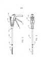
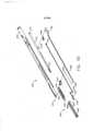
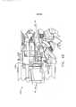
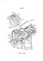
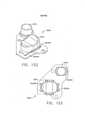
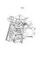
[003] A Figura 1 é uma vista em perspectiva de um instrumentocirúrgico que compreende um cabo, uma haste e um atuador de extremidade articulável;[003] Figure 1 is a perspective view of a surgical instrument comprising a handle, a rod and a pivotable end actuator;
[004] A Figura 2 é uma vista em elevação de um instrumentocirúrgico da Figura 1;[004] Figure 2 is an elevation view of a surgical instrument of Figure 1;
[005] A Figura 3 é uma vista em planta do instrumento cirúrgicoda Figura 1;[005] Figure 3 is a plan view of the surgical instrument of Figure 1;
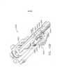
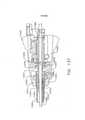
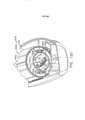
[006] A Figura 4 é uma vista em seção transversal do atuador deextremidade e da haste do instrumento cirúrgico da Figura 1;[006] Figure 4 is a cross-sectional view of the end actuator and the stem of the surgical instrument of Figure 1;
[007] A Figura 5 é uma vista em detalhe de uma junta dearticulação que se conecta de modo giratório à haste e ao atuador de extremidade da Figura 1 e ilustra o atuador de extremidade em uma posição neutra ou centralizada;[007] Figure 5 is a detail view of a swivel joint that pivotally connects to the stem and end actuator of Figure 1 and illustrates the end actuator in a neutral or centered position;
[008] A Figura 6 uma vista em seção transversal de um controlede articulação do instrumento cirúrgico da Figura 1 em uma posição neutra, ou centralizada;[008] Figure 6 is a cross-sectional view of a joint control of the surgical instrument of Figure 1 in a neutral, or centered position;
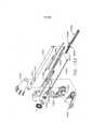
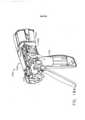
[009] A Figura 7 é uma vista explodida do atuador deextremidade, da haste alongada e da junta de articulação do instrumento cirúrgico da Figura 1;[009] Figure 7 is an exploded view of the end actuator, the elongated rod and the joint joint of the surgical instrument of Figure 1;
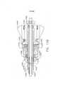
[0010] A Figura 8 é uma vista em seção transversal do atuador deextremidade, da haste alongada e da junta de articulação do instrumento cirúrgico da Figura 1;[0010] Figure 8 is a cross-sectional view of the end actuator, the elongated rod and the articulation joint of the surgical instrument of Figure 1;
[0011] A Figura 9 é uma vista em perspectiva do atuador deextremidade, da haste alongada e da junta de articulação do instrumento cirúrgico da Figura 1;[0011] Figure 9 is a perspective view of the end actuator, elongated rod and pivot joint of the surgical instrument of Figure 1;
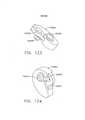
[0012] A Figura 10 representa o atuador de extremidade doinstrumento cirúrgico da Figura 1 articulado em torno da junta de articulação;[0012] Figure 10 represents the end actuator of the surgical instrument of Figure 1 articulated around the articulation joint;
[0013] A Figura 11 é uma vista em seção transversal do controlede articulação da Figura 6 ativado de forma a mover o atuador de extremidade conforme mostrado na Figura 12;[0013] Figure 11 is a cross-sectional view of the pivot control of Figure 6 activated to move the end actuator as shown in Figure 12;
[0014] A Figura 12 é uma vista em perspectiva de um instrumentocirúrgico compreendendo um cabo, uma haste e um atuador de extremidade articulável;[0014] Figure 12 is a perspective view of a surgical instrument comprising a handle, a rod and a pivotable end actuator;
[0015] A Figura 13 é uma vista lateral do instrumento cirúrgico daFigura 12;[0015] Figure 13 is a side view of the surgical instrument of Figure 12;
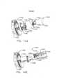
[0016] A Figura 14 é uma vista em perspectiva de um elemento dedisparo e uma engrenagem de pinhão posicionados no interior do cabo da Figura 12;[0016] Figure 14 is a perspective view of a trigger element and a pinion gear positioned inside the handle of Figure 12;
[0017] A Figura 15 é uma vista em perspectiva do elemento dedisparo e da engrenagem de pinhão da Figura 14 e de um conjunto redutor de engrenagens engatado de modo operável à engrenagem de pinhão;[0017] Figure 15 is a perspective view of the trigger element and pinion gear of Figure 14 and a gear reducer assembly operably engaged with the pinion gear;
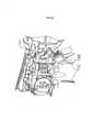
[0018] A Figura 16 é uma vista em perspectiva do cabo da Figura12, com porções do mesmo removidas para ilustrar o elemento de disparo e a engrenagem de pinhão da Figura 14, do conjunto redutor de engrenagens da Figura 15 e de um motor elétrico configurado para acionar o elemento de disparo de maneira distal e/ou proximal, dependendo da direção em que o motor elétrico égirado;[0018] Figure 16 is a perspective view of the cable of Figure 12, with portions thereof removed to illustrate the trigger element and pinion gear of Figure 14, the gear reducer assembly of Figure 15 and a configured electric motor to drive the triggering element distally and/or proximally, depending on the direction in which the electric motor is rotated;
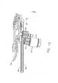
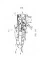
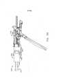
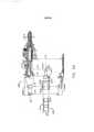
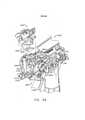
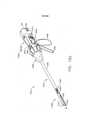
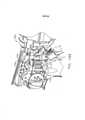
[0019] A Figura 17 é uma vista em perspectiva de um instrumentocirúrgico que compreende um cabo, uma haste, um atuador de extremidade e uma junta de articulação conectando o atuador de extremidade à haste ilustrada, com porções do cabo removidas para fins de ilustração;[0019] Figure 17 is a perspective view of a surgical instrument comprising a handle, a stem, an end actuator and a pivot joint connecting the end actuator to the illustrated stem, with portions of the handle removed for purposes of illustration;
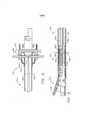
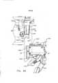
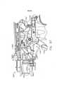
[0020] A Figura 18 é uma vista em seção transversal doinstrumento cirúrgico da Figura 17;[0020] Figure 18 is a cross-sectional view of the surgical instrument of Figure 17;
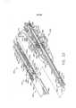
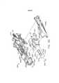
[0021] A Figura 19 é uma vista explodida do instrumento cirúrgicoda Figura 17;[0021] Figure 19 is an exploded view of the surgical instrument of Figure 17;
[0022] A Figura 20 é uma vista em seção transversal em detalhedo instrumento cirúrgico da Figura 17, ilustrado com o atuador de extremidade em uma configuração aberta, a junta de articulação em uma configuração destravada, e um atuador de trava de articulação do cabo de instrumento cirúrgico ilustrado em uma configuração destravada;[0022] Figure 20 is a detailed cross-sectional view of the surgical instrument of Figure 17, illustrated with the end actuator in an open configuration, the pivot joint in an unlocked configuration, and a cable pivot lock actuator. surgical instrument illustrated in an unlocked configuration;
[0023] A Figura 21 é uma vista em seção transversal em detalhedo instrumento cirúrgico da Figura 17, ilustrando o atuador de extremidade em uma configuração aberta e articulada, a junta de articulação em uma configuração destravada, e um acionador de articulação engatado a um elemento de disparo do instrumento cirúrgico da Figura 17, em que o movimento do elemento de disparo pode acionar o acionador de articulação e articular o atuador de extremidade;[0023] Figure 21 is a detailed cross-sectional view of the surgical instrument of Figure 17, illustrating the end actuator in an open and hinged configuration, the hinge joint in an unlocked configuration, and a hinge driver engaged with an element. triggering the surgical instrument of Figure 17, wherein movement of the triggering element can drive the linkage driver and pivot the end actuator;
[0024] A Figura 22 é uma vista em seção transversal em detalhedo instrumento cirúrgico da Figura 17, ilustrando o atuador de extremidade em uma configuração fechada, a junta de articulação em uma configuração destravada, e um acionamento de fechamento de atuador de extremidade sendo ativado para fechar o atuador de extremidade e mover o atuador de trava de articulação para uma configuração travada;[0024] Figure 22 is a detailed cross-sectional view of the surgical instrument of Figure 17, illustrating the end actuator in a closed configuration, the pivot joint in an unlocked configuration, and an end actuator closing drive being activated. to close the end actuator and move the pivot lock actuator to a locked configuration;
[0025] A Figura 22A é uma vista em seção transversal em detalhedo cabo do instrumento cirúrgico da Figura 17, ilustrado na configuração descrita com respeito à Figura 22;[0025] Figure 22A is a detailed cross-sectional view of the handle of the surgical instrument of Figure 17, illustrated in the configuration described with respect to Figure 22;
[0026] A Figura 23 é uma vista em seção transversal em detalhedo instrumento cirúrgico da Figura 17, ilustrando o atuador de extremidade em uma configuração fechada e a junta de articulação em uma configuração travada, em que o acionamento de fechamento ativado impede que o atuador de trava de articulação seja movido para sua configuração destravada ilustrada nas Figuras 20 a 22;[0026] Figure 23 is a detailed cross-sectional view of the surgical instrument of Figure 17, illustrating the end actuator in a closed configuration and the pivot joint in a locked configuration, where the activated closing drive prevents the actuator from pivot lock is moved to its unlocked configuration illustrated in Figures 20 to 22;
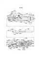
[0027] A Figura 24A é uma vista em planta da junta de articulaçãodo instrumento cirúrgico da Figura 17, ilustrado em uma configuração travada;[0027] Figure 24A is a plan view of the articulation joint of the surgical instrument of Figure 17, illustrated in a locked configuration;
[0028] A Figura 24B é uma vista em planta da junta de articulaçãodo instrumento cirúrgico da Figura 17, ilustrada em uma configuração destravada;[0028] Figure 24B is a plan view of the articulation joint of the surgical instrument of Figure 17, illustrated in an unlocked configuration;
[0029] A Figura 25 é uma vista em seção transversal em detalhedo cabo do instrumento cirúrgico da Figura 17, ilustrando o acionador de articulação desconectado do elemento de disparo pelo acionamento de fechamento;[0029] Figure 25 is a cross-sectional view in detail of the handle of the surgical instrument of Figure 17, illustrating the articulation driver disconnected from the triggering element by the closing drive;
[0030] A Figura 26 é uma vista em detalhe em seção transversaldo instrumento cirúrgico da Figura 17, ilustrando o elemento de disparo em uma posição pelo menos parcialmente disparada, e o acionador de articulação desconectado do elemento de disparo pelo acionamento de fechamento;[0030] Figure 26 is a detailed cross-sectional view of the surgical instrument of Figure 17, illustrating the triggering element in an at least partially triggered position, and the hinge driver disconnected from the triggering element by the closing trigger;
[0031] A Figura 27 é uma vista em seção transversal em detalhedo instrumento cirúrgico da Figura 17, ilustrando o atuador de extremidade em uma configuração fechada, a junta de articulação e o atuador de junta de articulação em uma configuração travada, e o elemento de disparo em uma posição recolhida;[0031] Figure 27 is a detailed cross-sectional view of the surgical instrument of Figure 17, illustrating the end actuator in a closed configuration, the pivot joint and the pivot joint actuator in a locked configuration, and the firing in a stowed position;
[0032] A Figura 28 é uma vista em seção transversal em detalhedo instrumento cirúrgico da Figura 17, ilustrando o atuador de extremidade em uma configuração aberta, o acionamento de fechamento de atuador de extremidade em uma posição recolhida, e a junta de articulação em uma configuração travada;[0032] Figure 28 is a detailed cross-sectional view of the surgical instrument of Figure 17, illustrating the end actuator in an open configuration, the end actuator closing drive in a stowed position, and the pivot joint in an open position. locked configuration;
[0033] A Figura 29 é uma vista em seção transversal em detalhedo instrumento cirúrgico da Figura 17, ilustrando o atuador de extremidade em uma configuração aberta e a junta de articulação e o atuador de junta de articulação em uma configuração destravada, em que o acionador de articulação pode ser reconectado ao acionamento de disparo e usado para articular o atuador de extremidade novamente;[0033] Figure 29 is a detailed cross-sectional view of the surgical instrument of Figure 17, illustrating the end actuator in an open configuration and the pivot joint and pivot joint actuator in an unlocked configuration, where the actuator linkage can be reconnected to the trigger trigger and used to link the end actuator again;
[0034] A Figura 30 é uma vista explodida de uma haste e de umatuador de extremidade de um instrumento cirúrgico, incluindo uma disposição de trava de articulação alternativa;[0034] Figure 30 is an exploded view of a stem and end actuator of a surgical instrument, including an alternative pivot latch arrangement;
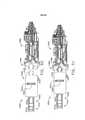
[0035] A Figura 31 é uma vista em elevação em seção transversaldo atuador de extremidade e da haste do instrumento cirúrgico da Figura 30, ilustrando o atuador de extremidade em uma configuração destravada;[0035] Figure 31 is a cross-sectional elevation view of the end actuator and the stem of the surgical instrument of Figure 30, illustrating the end actuator in an unlocked configuration;
[0036] A Figura 32 é uma vista em elevação em seção transversaldo atuador de extremidade e da haste do instrumento cirúrgico da Figura 30, ilustrando o atuador de extremidade em uma configuração travada;[0036] Figure 32 is a cross-sectional elevation view of the end actuator and the stem of the surgical instrument of Figure 30, illustrating the end actuator in a locked configuration;
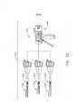
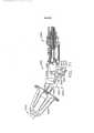
[0037] A Figura 33 é uma vista de conjunto de uma forma desistema cirúrgico, incluindo um instrumento cirúrgico e uma pluralidade de conjuntos de hastes intercambiáveis;[0037] Figure 33 is an assembly view of a form of surgical system, including a surgical instrument and a plurality of interchangeable rod assemblies;
[0038] A Figura 34 é uma vista em perspectiva de um cabo deinstrumento cirúrgico acoplado a um conjunto de haste intercambiável;[0038] Figure 34 is a perspective view of a surgical instrument handle coupled to an interchangeable stem assembly;
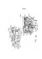
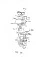
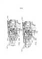
[0039] A Figura 35 é uma vista em perspectiva explodida do cabode instrumento cirúrgico da Figura 34;[0039] Figure 35 is an exploded perspective view of the surgical instrument handle of Figure 34;
[0040] A Figura 36 é uma vista em elevação lateral do cabo daFigura 35 com uma porção do compartimento de cabo removida;[0040] Figure 36 is a side elevation view of the cable of Figure 35 with a portion of the cable compartment removed;
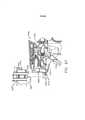
[0041] A Figura 37 é uma vista em perspectiva explodida de umconjunto de haste intercambiável;[0041] Figure 37 is an exploded perspective view of an interchangeable rod assembly;
[0042] A Figura 38 é uma vista de conjunto em elevação lateral deuma porção do cabo e do conjunto de haste intercambiável da Figura 34, ilustrando o alinhamento desses componentes antes de serem acoplados, e com porções dos mesmos omitidas para maior clareza;[0042] Figure 38 is an assembly view in side elevation of a portion of the handle and interchangeable rod assembly of Figure 34, illustrating the alignment of these components before they are coupled, and with portions thereof omitted for clarity;
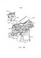
[0043] A Figura 39 é uma vista em perspectiva de uma porção deum conjunto de haste intercambiável antes da fixação a um cabo de um instrumento cirúrgico;[0043] Figure 39 is a perspective view of a portion of an interchangeable stem assembly prior to attachment to a handle of a surgical instrument;
[0044] A Figura 40 é uma vista lateral de uma porção de umconjunto de haste intercambiável acoplada a um cabo com a garra de travamento em uma posição travada ou engatada, com uma porção do módulo de fixação de estrutura do cabo;[0044] Figure 40 is a side view of a portion of an interchangeable rod assembly coupled to a cable with the locking jaw in a locked or engaged position, with a portion of the cable frame attachment module;
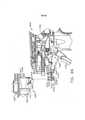
[0045] A Figura 41 é outra vista lateral do conjunto de hasteintercambiável e do cabo da Figura 40, com a garra de travamento na posição desengatada ou destravada;[0045] Figure 41 is another side view of the interchangeable rod and handle assembly of Figure 40, with the locking jaw in the disengaged or unlocked position;
[0046] A Figura 42 é uma vista superior de uma porção de umconjunto de haste intercambiável e do cabo antes de serem acoplados;[0046] Figure 42 is a top view of a portion of an interchangeable rod and cable assembly before being coupled together;
[0047] A Figura 43 é outra vista superior do conjunto de hasteintercambiável e do cabo da Figura 42 acoplados;[0047] Figure 43 is another top view of the interchangeable rod and cable assembly of Figure 42 coupled together;
[0048] A Figura 44 é uma vista em elevação lateral de um conjuntode haste intercambiável alinhado com um cabo de instrumento cirúrgico antes de serem acoplados;[0048] Figure 44 is a side elevation view of an interchangeable rod assembly aligned with a surgical instrument handle before being coupled;
[0049] A Figura 45 é uma vista em perspectiva frontal do conjuntode haste intercambiável e do cabo do instrumento cirúrgico da Figura 44, com porções dos mesmos removidas para maior clareza;[0049] Figure 45 is a front perspective view of the interchangeable stem and handle assembly of the surgical instrument of Figure 44, with portions thereof removed for clarity;
[0050] A Figura 46 é uma vista lateral de uma porção de umconjunto de haste intercambiável alinhada com uma porção de um cabo de instrumento cirúrgico antes de serem acoplados e com porções dos mesmos omitidas para maior clareza;[0050] Figure 46 is a side view of a portion of an interchangeable stem assembly aligned with a portion of a surgical instrument handle before being coupled and with portions thereof omitted for clarity;
[0051] A Figura 47 é outra vista em elevação lateral do conjunto dehaste intercambiável e do cabo da Figura 46, em que o conjunto de haste está em engate de acoplamento parcial com o cabo;[0051] Figure 47 is another side elevation view of the interchangeable rod and cable assembly of Figure 46, where the rod assembly is in partial coupling engagement with the cable;
[0052] A Figura 48 é outra vista em elevação lateral do conjunto dehaste intercambiável e do cabo das Figuras 46 e 47 depois de serem acoplados;[0052] Figure 48 is another side elevation view of the interchangeable rod and cable assembly of Figures 46 and 47 after being coupled;
[0053] A Figura 49 é outra vista em elevação lateral de umaporção de um conjunto de haste intercambiável alinhada com uma porção do cabo antes de começar o processo de acoplamento;[0053] Figure 49 is another side elevational view of a portion of an interchangeable rod assembly aligned with a portion of the handle before beginning the mating process;
[0054] A Figura 50 é uma vista superior de uma porção de outroconjunto de haste intercambiável e de uma porção de outra disposição de estrutura de instrumento cirúrgico;[0054] Figure 50 is a top view of a portion of another interchangeable stem assembly and a portion of another surgical instrument frame arrangement;
[0055] A Figura 51 é outra vista superior do conjunto de hasteintercambiável e da porção de estrutura da Figura 50 depois de serem acoplados;[0055] Figure 51 is another top view of the interchangeable rod assembly and frame portion of Figure 50 after being coupled together;
[0056] A Figura 52 é uma vista em perspectiva explodida doconjunto de haste intercambiável e da porção de estrutura da Figura 50;[0056] Figure 52 is an exploded perspective view of the interchangeable rod assembly and frame portion of Figure 50;
[0057] A Figura 53 é outra vista em perspectiva explodida doconjunto de haste intercambiável e da porção de estrutura da Figura 52, com o módulo de fixação de haste do conjunto de haste em alinhamento com o módulo de fixação de estrutura da porção de estrutura antes do acoplamento;[0057] Figure 53 is another exploded perspective view of the interchangeable stem assembly and frame portion of Figure 52, with the stem attachment module of the stem assembly in alignment with the frame attachment module of the frame portion before of the coupling;
[0058] A Figura 54 é uma vista em elevação lateral do conjunto dehaste intercambiável e da porção de estrutura da Figura 52;[0058] Figure 54 is a side elevation view of the interchangeable rod assembly and frame portion of Figure 52;
[0059] A Figura 55 é uma vista em perspectiva do conjunto de haste intercambiável e da porção de estrutura das Figuras 53 e 54 depois de serem acoplados;[0059] Figure 55 is a perspective view of the interchangeable rod assembly and frame portion of Figures 53 and 54 after being coupled together;
[0060] A Figura 56 é uma vista em elevação lateral do conjunto dehaste intercambiável e da porção de estrutura da Figura 55;[0060] Figure 56 is a side elevation view of the interchangeable rod assembly and frame portion of Figure 55;
[0061] A Figura 57 é outra vista em perspectiva do conjunto dehaste intercambiável e da porção de estrutura das Figuras 55 e 56, com porções dos mesmos omitidas para maior clareza;[0061] Figure 57 is another perspective view of the interchangeable rod assembly and frame portion of Figures 55 and 56, with portions thereof omitted for clarity;
[0062] A Figura 58 é uma vista superior de uma porção de outroconjunto de haste intercambiável e uma porção de estrutura de um instrumento cirúrgico antes de serem acopladas;[0062] Figure 58 is a top view of a portion of another interchangeable stem assembly and a frame portion of a surgical instrument before being coupled together;
[0063] A Figura 59 é outra vista superior do conjunto de hasteintercambiável e da porção de estrutura da Figura 58 depois de serem acoplados;[0063] Figure 59 is another top view of the interchangeable rod assembly and frame portion of Figure 58 after being coupled together;
[0064] A Figura 60 é uma vista em perspectiva do conjunto dehaste intercambiável e da estrutura das Figuras 58 e 59 antes de serem acoplados;[0064] Figure 60 is a perspective view of the interchangeable rod assembly and structure of Figures 58 and 59 before being coupled;
[0065] A Figura 61 é outra vista em perspectiva do conjunto dehaste intercambiável e da porção de estrutura das Figuras 58 a 60 depois de serem acoplados;[0065] Figure 61 is another perspective view of the interchangeable rod assembly and frame portion of Figures 58 to 60 after being coupled together;
[0066] A Figura 62 é outra vista em perspectiva do conjunto dehaste intercambiável e da porção de estrutura das Figuras 58 a 60 depois de serem acoplados, com porções do conjunto de haste mostradas em seção transversal;[0066] Figure 62 is another perspective view of the interchangeable rod assembly and frame portion of Figures 58 to 60 after being coupled, with portions of the rod assembly shown in cross section;
[0067] A Figura 63 é uma vista de conjunto em perspectivaexplodida de outro conjunto de haste de atuador de extremidade e da porção de estrutura de um instrumento cirúrgico;[0067] Figure 63 is an exploded perspective assembly view of another end actuator stem assembly and frame portion of a surgical instrument;
[0068] A Figura 64 é uma vista de conjunto superior explodida doconjunto de haste de atuador de extremidade e da porção de estrutura da Figura 63;[0068] Figure 64 is an exploded top assembly view of the end actuator stem assembly and frame portion of Figure 63;
[0069] A Figura 65 é outra vista de conjunto em perspectiva explodida do conjunto de haste de atuador de extremidade e da porção de estrutura das Figuras 63 e 64;[0069] Figure 65 is another exploded perspective assembly view of the end actuator stem assembly and frame portion of Figures 63 and 64;
[0070] A Figura 66 é uma vista em perspectiva do conjunto dehaste de atuador de extremidade e da porção de estrutura das Figuras 63 a 65 depois de serem acoplados;[0070] Figure 66 is a perspective view of the end actuator rod assembly and frame portion of Figures 63 to 65 after being coupled;
[0071] A Figura 67 é uma vista em elevação lateral do conjunto dehaste de atuador de extremidade e da porção de estrutura da Figura 66, com porções dos mesmos omitidas para maior clareza;[0071] Figure 67 is a side elevation view of the end actuator rod assembly and frame portion of Figure 66, with portions thereof omitted for clarity;
[0072] A Figura 68 é uma vista de conjunto superior explodida deoutro conjunto de haste de atuador de extremidade e da porção de estrutura de outro instrumento cirúrgico;[0072] Figure 68 is an exploded top assembly view of another end actuator stem assembly and frame portion of another surgical instrument;
[0073] A Figura 69 é uma vista de conjunto em perspectivaexplodida do conjunto de haste de atuador de extremidade e da porção de estrutura da Figura 68;[0073] Figure 69 is an exploded perspective assembly view of the end actuator stem assembly and frame portion of Figure 68;
[0074] A Figura 70 é outra vista de conjunto em perspectiva doconjunto de haste de atuador de extremidade e da porção de estrutura das Figuras 68 e 69, com o conjunto de haste de atuador de extremidade antes de ser travado em engate acoplado com a porção de estrutura;[0074] Figure 70 is another perspective assembly view of the end actuator stem assembly and frame portion of Figures 68 and 69, with the end actuator stem assembly before being locked into engagement coupled with the portion of structure;
[0075] A Figura 71 é uma vista superior do conjunto de haste deatuador de extremidade e da porção de estrutura da Figura 70;[0075] Figure 71 is a top view of the end actuator rod assembly and frame portion of Figure 70;
[0076] A Figura 72 é uma vista superior do conjunto de haste deatuador de extremidade e da porção de estrutura das Figuras 68 a 71 depois de serem acoplados;[0076] Figure 72 is a top view of the end actuator rod assembly and frame portion of Figures 68 to 71 after being coupled;
[0077] A Figura 73 é uma vista em elevação lateral do conjunto dehaste de atuador de extremidade e da porção de estrutura da Figura 72;[0077] Figure 73 is a side elevation view of the end actuator rod assembly and frame portion of Figure 72;
[0078] A Figura 74 é uma vista em perspectiva do conjunto dehaste de atuador de extremidade e da porção de estrutura das Figuras 72 e 73;[0078] Figure 74 is a perspective view of the end actuator rod assembly and frame portion of Figures 72 and 73;
[0079] A Figura 75 é uma vista de conjunto explodida de umconjunto de haste intercambiável e do cabo correspondente, com alguns componentes dos mesmos mostrados em seção transversal;[0079] Figure 75 is an exploded assembly view of an interchangeable rod assembly and corresponding handle, with some components thereof shown in cross-section;
[0080] A Figura 76 é uma vista em perspectiva em seçãotransversal parcial de porções do conjunto de haste de atuador de extremidade e do cabo da Figura 75;[0080] Figure 76 is a perspective view in partial cross-section of portions of the end actuator stem and cable assembly of Figure 75;
[0081] A Figura 77 é uma vista em perspectiva parcial do conjuntode haste de atuador de extremidade e do cabo das Figuras 75 e 76 acoplados, com vários componentes omitidos para maior clareza;[0081] Figure 77 is a partial perspective view of the end actuator stem and cable assembly of Figures 75 and 76 coupled together, with various components omitted for clarity;
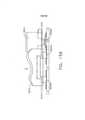
[0082] A Figura 78 é uma vista em elevação lateral do conjunto dehaste de atuador de extremidade e do cabo da Figura 77;[0082] Figure 78 is a side elevation view of the end actuator rod and cable assembly of Figure 77;
[0083] A Figura 79 é uma vista em elevação lateral do conjunto dehaste de atuador de extremidade e do cabo das Figuras 75 a 78 acoplados, com o acionamento de fechamento em uma posição não ativada, e com alguns componentes mostrados em seção transversal;[0083] Figure 79 is a side elevation view of the end actuator rod and cable assembly of Figures 75 to 78 coupled, with the closing drive in a non-activated position, and with some components shown in cross section;
[0084] A Figura 80 é outra vista em elevação lateral do conjunto dehaste de atuador de extremidade e do cabo da Figura 79, com o acionamento de fechamento em uma posição totalmente ativada;[0084] Figure 80 is another side elevation view of the end actuator rod and cable assembly of Figure 79, with the closing drive in a fully activated position;
[0085] A Figura 81 é uma vista de conjunto explodida de umconjunto de haste intercambiável e do cabo correspondente, com alguns componentes dos mesmos omitidos para maior clareza, e em que o sistema de acionamento de fechamento está em orientação travada;[0085] Figure 81 is an exploded assembly view of an interchangeable rod assembly and corresponding cable, with some components thereof omitted for clarity, and in which the closing drive system is in locked orientation;
[0086] A Figura 82 é uma vista lateral do conjunto de haste deatuador de extremidade e do cabo da Figura 81 acoplados, com vários componentes omitidos para maior clareza, e em que o sistema de acionamento de fechamento está em uma posição destravada e não ativada;[0086] Figure 82 is a side view of the end actuator stem and cable assembly of Figure 81 coupled together, with several components omitted for clarity, and in which the closing drive system is in an unlocked, non-activated position ;
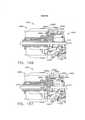
[0087] A Figura 83 é uma vista lateral do conjunto de haste deatuador de extremidade e do cabo da Figura 82, com vários componentes mostrados em seção transversal para maior clareza;[0087] Figure 83 is a side view of the end actuator rod and cable assembly of Figure 82, with various components shown in cross section for clarity;
[0088] A Figura 84 é uma vista lateral do conjunto de haste deatuador de extremidade e do cabo das Figuras 81 a 83 acoplados, com vários componentes omitidos para maior clareza, e em que o sistema de acionamento de fechamento está em uma posição ativada;[0088] Figure 84 is a side view of the end actuator stem and cable assembly of Figures 81 to 83 coupled together, with various components omitted for clarity, and in which the closing drive system is in an activated position;
[0089] A Figura 85 é uma vista lateral do conjunto de haste deatuador de extremidade e do cabo da Figura 84, com vários componentes mostrados em seção transversal para maior clareza;[0089] Figure 85 is a side view of the end actuator rod and cable assembly of Figure 84, with various components shown in cross-section for clarity;
[0090] A Figura 86 é uma vista de conjunto em perspectivaexplodida de uma porção de um conjunto de haste intercambiável e uma porção de cabo de um cabo de instrumento cirúrgico;[0090] Figure 86 is an exploded perspective assembly view of a portion of an interchangeable stem assembly and a handle portion of a surgical instrument handle;
[0091] A Figura 87 é uma vista em elevação lateral das porções doconjunto de haste intercambiável e do cabo da Figura 86;[0091] Figure 87 is a side elevation view of the interchangeable rod and handle portions of Figure 86;
[0092] A Figura 88 é outra vista de conjunto em perspectivaexplodida de porções do conjunto de haste intercambiável e do cabo das Figuras 86 e 87, com porções do conjunto de haste intercambiável mostradas em seção transversal para maior clareza;[0092] Figure 88 is another exploded perspective assembly view of portions of the interchangeable rod assembly and handle of Figures 86 and 87, with portions of the interchangeable rod assembly shown in cross section for clarity;
[0093] A Figura 89 é outra vista em elevação lateral de porções doconjunto de haste intercambiável e do cabo das Figuras 86 a 88, com porções dos mesmos mostradas em seção transversal para maior clareza;[0093] Figure 89 is another side elevation view of portions of the interchangeable rod and handle assembly of Figures 86 to 88, with portions thereof shown in cross section for clarity;
[0094] A Figura 90 é uma vista em elevação lateral das porções doconjunto de haste intercambiável e do cabo das Figuras 86 a 89 depois de o conjunto de haste intercambiável ter sido acoplado de modo operável ao cabo, e com porções dos mesmos mostradas em seção transversal para maior clareza;[0094] Figure 90 is a side elevation view of portions of the interchangeable rod assembly and handle of Figures 86 to 89 after the interchangeable rod assembly has been operably coupled to the handle, and with portions thereof shown in section crosswise for clarity;
[0095] A Figura 91 é outra vista em elevação lateral de porções doconjunto de haste intercambiável e do cabo acoplado ao mesmo, com o sistema de acionamento de fechamento em uma posição totalmente ativada;[0095] Figure 91 is another side elevation view of portions of the interchangeable rod assembly and the cable attached thereto, with the closing drive system in a fully activated position;
[0096] A Figura 92 é uma vista de conjunto em perspectivaexplodida de uma porção de outro conjunto de haste intercambiável e uma porção de cabo de outro instrumento cirúrgico;[0096] Figure 92 is an exploded perspective assembly view of a portion of another interchangeable stem assembly and a handle portion of another surgical instrument;
[0097] A Figura 93 é uma vista em elevação lateral de porções doconjunto de haste intercambiável e do cabo da Figura 92 em alinhamento antes de serem acoplados;[0097] Figure 93 is a side elevation view of portions of the interchangeable rod and handle assembly of Figure 92 in alignment before being coupled;
[0098] A Figura 94 é outra vista em perspectiva explodida doconjunto de haste intercambiável e do cabo das Figuras 92 e 93, com algumas porções dos mesmos mostradas em seção transversal;[0098] Figure 94 is another exploded perspective view of the interchangeable rod and handle assembly of Figures 92 and 93, with some portions thereof shown in cross section;
[0099] A Figura 95 é outra vista em perspectiva do conjunto dehaste intercambiável e do cabo das Figuras 92 a 94 acoplados em engate operável;[0099] Figure 95 is another perspective view of the interchangeable rod and cable assembly of Figures 92 to 94 coupled in operable engagement;
[00100] A Figura 96 é uma vista em elevação lateral do conjunto de haste intercambiável e do cabo da Figura 95;[00100] Figure 96 is a side elevation view of the interchangeable rod and handle assembly of Figure 95;
[00101] A Figura 97 é outra vista em elevação lateral do conjunto de haste intercambiável e do cabo da Figura 96, com alguns componentes dos mesmos mostrados em seção transversal;[00101] Figure 97 is another side elevation view of the interchangeable rod and handle assembly of Figure 96, with some components thereof shown in cross-section;
[00102] A Figura 98 é outra vista em elevação lateral do conjunto de haste intercambiável e do cabo das Figuras 92 a 96, com o gatilho de fechamento em uma posição totalmente ativada;[00102] Figure 98 is another side elevation view of the interchangeable rod and handle assembly of Figures 92 through 96, with the closing trigger in a fully activated position;
[00103] A Figura 99 é uma vista em perspectiva de uma porção de outro conjunto de haste intercambiável que inclui uma disposição com conjunto de travamento de haste;[00103] Figure 99 is a perspective view of a portion of another interchangeable rod assembly that includes a rod locking assembly arrangement;
[00104] A Figura 100 é uma vista em perspectiva da disposição com o conjunto de travamento de haste representado na Figura 99 em uma posição travada, com a porção intermediária da haste de disparo do elemento de disparo de um conjunto de haste intercambiável;[00104] Figure 100 is a perspective view of the arrangement with the locking rod assembly shown in Figure 99 in a locked position, with the firing rod intermediate portion of the firing element of an interchangeable rod assembly;
[00105] A Figura 101 é outra vista em perspectiva do conjunto de travamento de haste e da porção intermediária do elemento de disparo, com o conjunto de travamento da haste em uma posição destravada;[00105] Figure 101 is another perspective view of the rod lock assembly and the intermediate portion of the trigger element, with the rod lock assembly in an unlocked position;
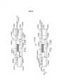
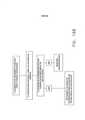
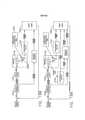
[00106] A Figura 102 é um esquema ilustrando, um, um conjunto de embreagem para conectar de modo operável um acionamento de articulação a um acionamento de disparo de um instrumento cirúrgico, e, dois, uma trava de articulação configurada para reter de modo liberável o acionador de articulação e um atuador de extremidade do instrumento cirúrgicoem posição, em que a Figura 102 ilustra o conjunto de embreagem em uma posição engatada e a trava de articulação em uma condição travada;[00106] Figure 102 is a schematic illustrating, one, a clutch assembly for operably connecting a linkage drive to a triggering drive of a surgical instrument, and, two, a linkage lock configured to releasably retain the linkage driver and a surgical instrument end actuator in position, wherein Figure 102 illustrates the clutch assembly in an engaged position and the linkage latch in a locked condition;
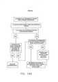
[00107] A Figura 103 é um esquema ilustrando o conjunto deembreagem da Figura 102 em sua posição engatada e a trava de articulação da Figura 102 em uma primeira condição destravada, o que permite a articulação do atuador de extremidade da Figura 102 em uma primeira direção;[00107] Figure 103 is a schematic illustrating the clutch assembly of Figure 102 in its engaged position and the pivot lock of Figure 102 in a first unlocked condition, which allows the end actuator of Figure 102 to pivot in a first direction ;
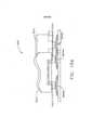
[00108] A Figura 104 é um esquema ilustrando o conjunto de embreagem da Figura 102 em sua posição engatada e a trava de articulação da Figura 102 em uma segunda condição destravada, o que permite a articulação do atuador de extremidade da Figura 102 em uma segunda direção;[00108] Figure 104 is a schematic illustrating the clutch assembly of Figure 102 in its engaged position and the pivot lock of Figure 102 in a second unlocked condition, which allows the end actuator of Figure 102 to pivot in a second condition. direction;
[00109] A Figura 104A é uma vista explodida do conjunto deembreagem e a trava de articulação da Figura 102;[00109] Figure 104A is an exploded view of the clutch assembly and pivot lock of Figure 102;
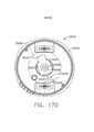
[00110] A Figura 105 é uma vista em perspectiva parcial de umconjunto de haste incluindo o conjunto de embreagem da Figura 102 em sua posição engatada, com porções do conjunto de haste removidas para propósitos de ilustração;[00110] Figure 105 is a partial perspective view of a rod assembly including the clutch assembly of Figure 102 in its engaged position, with portions of the rod assembly removed for purposes of illustration;
[00111] A Figura 106 é uma vista em planta superior parcial do conjunto de haste da Figura 105, ilustrando o conjunto de embreagem da Figura 102 em sua posição engatada;[00111] Figure 106 is a partial top plan view of the rod assembly of Figure 105 illustrating the clutch assembly of Figure 102 in its engaged position;
[00112] A Figura 107 é uma vista em planta inferior parcial do conjunto de haste da Figura 105, ilustrando o conjunto de embreagem da Figura 102 em sua posição engatada;[00112] Figure 107 is a partial bottom plan view of the rod assembly of Figure 105 illustrating the clutch assembly of Figure 102 in its engaged position;
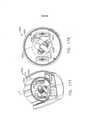
[00113] Figura 108 é uma vista em perspectiva parcial de um conjunto de haste da Figura 105, ilustrando o conjunto de embreagem da Figura 102 em sua posição engatada, com porções adicionais removidas para propósitos de ilustração;[00113] Figure 108 is a partial perspective view of the rod assembly of Figure 105 illustrating the clutch assembly of Figure 102 in its engaged position, with additional portions removed for illustration purposes;
[00114] A Figura 109 é uma vista em perspectiva parcial de um conjunto de haste da Figura 105, ilustrando o conjunto de embreagem da Figura 102 em sua posição desengatada, com porções adicionais removidas para propósitos de ilustração;[00114] Figure 109 is a partial perspective view of the rod assembly of Figure 105 illustrating the clutch assembly of Figure 102 in its disengaged position, with additional portions removed for purposes of illustration;
[00115] A Figura 110 é uma vista em perspectiva parcial do conjunto de haste da Figura 105, ilustrando o conjunto de embreagem da Figura 102 movido a sua posição desengatada por um acionamento de fechamento do conjunto de haste;[00115] Figure 110 is a partial perspective view of the rod assembly of Figure 105, illustrating the clutch assembly of Figure 102 moved to its disengaged position by a closing actuation of the rod assembly;
[00116] A Figura 111 é uma vista em planta parcial de um conjunto de haste da Figura 105, ilustrando o conjunto de embreagem da Figura 102 em sua posição engatada, com porções adicionais removidas para propósitos de ilustração;[00116] Figure 111 is a partial plan view of the rod assembly of Figure 105 illustrating the clutch assembly of Figure 102 in its engaged position, with additional portions removed for illustration purposes;
[00117] A Figura 112 é uma vista em planta parcial de um conjunto de haste da Figura 105, ilustrando o conjunto de embreagem da Figura 102 em sua posição desengatada, com porções adicionais removidas para propósitos de ilustração;[00117] Figure 112 is a partial plan view of the rod assembly of Figure 105 illustrating the clutch assembly of Figure 102 in its disengaged position, with additional portions removed for illustration purposes;
[00118] A Figura 113 é uma vista em planta de uma modalidade alternativa de uma trava de articulação ilustrada em uma condição travada;[00118] Figure 113 is a plan view of an alternative embodiment of a toggle lock illustrated in a locked condition;
[00119] A Figura 114 é uma vista explodida da trava de articulação da Figura 113;[00119] Figure 114 is an exploded view of the pivot latch of Figure 113;
[00120] A Figura 115 uma vista em seção transversal de outra modalidade alternativa de uma trava de articulação ilustrada na condição travada;[00120] Figure 115 is a cross-sectional view of another alternative embodiment of a hinge lock illustrated in the locked condition;
[00121] A Figura 116 é uma vista explodida da trava de articulação da Figura 114;[00121] Figure 116 is an exploded view of the pivot latch of Figure 114;
[00122] A Figura 117 é uma vista em perspectiva de outra modalidade alternativa de uma trava de articulação ilustrada na condição travada;[00122] Figure 117 is a perspective view of another alternative embodiment of a hinge lock illustrated in the locked condition;
[00123] A Figura 118 é uma vista explodida da trava de articulação da Figura 117;[00123] Figure 118 is an exploded view of the pivot latch of Figure 117;
[00124] A Figura 119 é uma vista em elevação da trava de articulação da Figura 117, ilustrando a trava de articulação ilustrada em condição travada;[00124] Figure 119 is an elevation view of the pivot lock of Figure 117, illustrating the pivot lock illustrated in locked condition;
[00125] A Figura 120 é uma vista em elevação da trava dearticulação da Figura 117, ilustrando a trava de articulação em uma primeira condição destravada para articular um atuador deextremidade em uma primeira direção;[00125] Figure 120 is an elevation view of the pivot lock of Figure 117 illustrating the pivot lock in a first unlocked condition for pivoting an end actuator in a first direction;
[00126] A Figura 121 é uma vista em elevação da trava dearticulação da Figura 117, ilustrando a trava de articulação em uma segunda condição destravada para articular um atuador deextremidade em uma segunda direção;[00126] Figure 121 is an elevation view of the pivot lock of Figure 117, illustrating the pivot lock in a second unlocked condition to pivot an end actuator in a second direction;
[00127] A Figura 122 é uma vista explodida da trava de articulação da Figura 117;[00127] Figure 122 is an exploded view of the pivot latch of Figure 117;
[00128] A Figura 123 é uma vista em perspectiva de um primeirocame de travamento da trava de articulação da Figura 117;[00128] Figure 123 is a perspective view of a first locking cam of the pivot lock of Figure 117;
[00129] A Figura 124 é uma vista em perspectiva de um segundocame de travamento da trava de articulação da Figura 117;[00129] Figure 124 is a perspective view of a second locking cam of the pivot lock of Figure 117;
[00130] A Figura 125 é uma vista em perspectiva de outramodalidade alternativa de uma trava de articulação ilustrada na condição travada;[00130] Figure 125 is a perspective view of another alternative embodiment of a hinge lock illustrated in the locked condition;
[00131] A Figura 126 é uma vista explodida da trava de articulação da Figura 125;[00131] Figure 126 is an exploded view of the pivot latch of Figure 125;
[00132] A Figura 127 é uma vista em elevação em seção transversal da trava de articulação da Figura 125, ilustrando a trava de articulação em uma primeira condição destravada para articular um atuador de extremidade em uma primeira direção;[00132] Figure 127 is a cross-sectional elevation view of the pivot lock of Figure 125 illustrating the pivot lock in a first unlocked condition for pivoting an end actuator in a first direction;
[00133] A Figura 128 é uma vista em elevação em seção transversal da trava de articulação da Figura 125, ilustrando a trava de articulação em condição travada;[00133] Figure 128 is a cross-sectional elevation view of the pivot lock of Figure 125, illustrating the pivot lock in locked condition;
[00134] A Figura 129 é uma vista em elevação em seção transversal da trava de articulação da Figura 125, ilustrando a trava de articulação em uma segunda condição destravada para articular um atuador de extremidade em uma segunda direção;[00134] Figure 129 is a cross-sectional elevation view of the pivot lock of Figure 125 illustrating the pivot lock in a second unlocked condition for pivoting an end actuator in a second direction;
[00135] A Figura 130 é uma vista em elevação em seção transversal da trava de articulação da Figura 125, ilustrando a trava de articulação em condição travada;[00135] Figure 130 is a cross-sectional elevation view of the pivot lock of Figure 125, illustrating the pivot lock in locked condition;
[00136] A Figura 131 é uma vista em perspectiva de um conjunto de haste;[00136] Figure 131 is a perspective view of a rod assembly;
[00137] A Figura 132 é uma vista explodida do conjunto de haste da Figura 131, ilustrando uma modalidade alternativa de um conjunto de embreagem para conectar de modo operável um acionamento de articulação com o acionamento de disparo do conjunto de haste;[00137] Figure 132 is an exploded view of the rod assembly of Figure 131 illustrating an alternative embodiment of a clutch assembly for operably connecting a linkage drive with the firing drive of the rod assembly;
[00138] A Figura 133 é outra vista explodida do conjunto de haste da Figura 131;[00138] Figure 133 is another exploded view of the rod assembly of Figure 131;
[00139] A Figura 134 é uma vista explodida parcial do conjunto de haste da Figura 131, ilustrada com porções removidas para propósitos de ilustração;[00139] Figure 134 is a partial exploded view of the rod assembly of Figure 131, illustrated with portions removed for illustration purposes;
[00140] A Figura 135 é uma vista terminal do conjunto de haste da Figura 131, ilustrada com porções removidas para propósitos de ilustração;[00140] Figure 135 is an end view of the rod assembly of Figure 131, illustrated with portions removed for purposes of illustration;
[00141] A Figura 136 é outra vista terminal do conjunto de haste da Figura 131, ilustrada com porções removidas para propósitos de ilustração;[00141] Figure 136 is another end view of the rod assembly of Figure 131, illustrated with portions removed for purposes of illustration;
[00142] A Figura 137 é uma vista em elevação em seção transversal do conjunto de haste da Figura 131;[00142] Figure 137 is a cross-sectional elevation view of the rod assembly of Figure 131;
[00143] A Figura 138 é uma vista em perspectiva em seção transversal parcial do conjunto de haste da Figura 131;[00143] Figure 138 is a perspective view in partial cross-section of the rod assembly of Figure 131;
[00144] A Figura 139 é outra vista em seção transversal parcial do conjunto de haste da Figura 131;[00144] Figure 139 is another partial cross-sectional view of the rod assembly of Figure 131;
[00145] A Figura 140 é uma vista em perspectiva do conjunto de haste da Figura 131, ilustrando o conjunto de embreagem em uma posição engatada, e ilustrada com porções removidas para maior clareza; especificamente, está ilustrado um atuador de embreagem, ao passo que uma luva de embreagem, um interruptor de tambor, um acionador de articulação proximal e um tubo de fechamento não estão ilustrados;[00145] Figure 140 is a perspective view of the rod assembly of Figure 131, illustrating the clutch assembly in an engaged position, and illustrated with portions removed for clarity; specifically, a clutch actuator is illustrated, whereas a clutch sleeve, a drum switch, a proximal linkage driver, and a closure tube are not illustrated;
[00146] A Figura 141 é uma vista em perspectiva do conjunto de haste da Figura 131, ilustrando o conjunto de embreagem em uma posição engatada, e ilustrada com porções removidas para maior clareza; especificamente, estão ilustrados o atuador de embreagem e a luva de embreagem, ao passo que o interruptor de tambor, o acionador de articulação proximal e o tubo de fechamento não estão ilustrados;[00146] Figure 141 is a perspective view of the rod assembly of Figure 131, illustrating the clutch assembly in an engaged position, and illustrated with portions removed for clarity; specifically, the clutch actuator and clutch sleeve are illustrated, while the drum switch, proximal linkage driver, and closing tube are not illustrated;
[00147] A Figura 142 é uma vista em perspectiva do conjunto de haste da Figura 131, ilustrando o conjunto de embreagem em uma posição desengatada, e ilustrada com porções removidas para maior clareza; especificamente, estão ilustrados o atuador de embreagem e a luva de embreagem, ao passo que o interruptor de tambor, o acionador de articulação proximal e o tubo de fechamento não estão ilustrados;[00147] Figure 142 is a perspective view of the rod assembly of Figure 131, illustrating the clutch assembly in a disengaged position, and illustrated with portions removed for clarity; specifically, the clutch actuator and clutch sleeve are illustrated, while the drum switch, proximal linkage driver, and closing tube are not illustrated;
[00148] A Figura 143 é uma vista em perspectiva do conjunto de haste da Figura 131, ilustrando o conjunto de embreagem em uma posição desengatada, e ilustrada com porções removidas para maior clareza; especificamente, estão ilustrados o atuador de embreagem, a luva de embreagem e o tubo de fechamento, ao passo que o interruptor de tambor e o acionador de articulação proximal não estão ilustrados;[00148] Figure 143 is a perspective view of the rod assembly of Figure 131, illustrating the clutch assembly in a disengaged position, and illustrated with portions removed for clarity; specifically, the clutch actuator, clutch sleeve, and closing tube are illustrated, while the drum switch and proximal linkage driver are not illustrated;
[00149] A Figura 144 é uma vista em perspectiva do conjunto de haste da Figura 131, ilustrando o conjunto de embreagem em uma posição desengatada; o atuador de embreagem, a luva de embreagem, o tubo de fechamento, o interruptor de tambor e o acionador de articulação proximal estão ilustrados;[00149] Figure 144 is a perspective view of the rod assembly of Figure 131, illustrating the clutch assembly in a disengaged position; clutch actuator, clutch sleeve, closing tube, drum switch, and proximal linkage driver are illustrated;
[00150] A Figura 145 é uma vista em perspectiva do conjunto de haste da Figura 131, ilustrando o conjunto de embreagem em uma posição engatada, e ilustrada com porções removidas para maior clareza; especificamente, estão ilustrados o atuador de embreagem, a luva de embreagem e o acionador de articulação proximal, ao passo que o interruptor de tambor e o tubo de fechamento não estão ilustrados;[00150] Figure 145 is a perspective view of the rod assembly of Figure 131, illustrating the clutch assembly in an engaged position, and illustrated with portions removed for clarity; specifically, the clutch actuator, clutch sleeve, and proximal linkage driver are illustrated, while the drum switch and closing tube are not illustrated;
[00151] A Figura 146 é uma vista em perspectiva do conjunto de haste da Figura 131, ilustrando o conjunto de embreagem em uma posição engatada, e ilustrada com porções removidas para maior clareza; especificamente, estão ilustrados o atuador de embreagem, a luva de embreagem, o acionador de articulação proximal e o tubo de fechamento estão ilustrados, ao passo que o interruptor de tambor não está ilustrado; além disso, o sistema de acionamento de articulação do conjunto de haste está ilustrado em uma condição centralizada, ou não articulada;[00151] Figure 146 is a perspective view of the rod assembly of Figure 131, illustrating the clutch assembly in an engaged position, and illustrated with portions removed for clarity; specifically, the clutch actuator, clutch sleeve, proximal linkage driver and closure tube are illustrated, while the drum switch is not illustrated; further, the pivot drive system of the rod assembly is illustrated in a centered, or non-hinged, condition;
[00152] A Figura 147 é uma vista em perspectiva do conjunto de haste da Figura 131, ilustrando o conjunto de embreagem em uma posição engatada, e ilustrada com porções removidas para maior clareza; especificamente, estão ilustrados o atuador de embreagem, a luva de embreagem e o acionador de articulação proximal, ao passo que o interruptor de tambor e o tubo de fechamento não estão ilustrados; além disso, o sistema de acionamento de articulação do conjunto de haste está ilustrado em uma condição em que um atuador de extremidade do conjunto de haste seria articulado para a esquerda de um eixo longitudinal do conjunto de haste;[00152] Figure 147 is a perspective view of the rod assembly of Figure 131, illustrating the clutch assembly in an engaged position, and illustrated with portions removed for clarity; specifically, the clutch actuator, clutch sleeve, and proximal linkage driver are illustrated, while the drum switch and closing tube are not illustrated; further, the rod assembly pivot drive system is illustrated in a condition where an end actuator of the rod assembly would pivot to the left of a longitudinal axis of the rod assembly;
[00153] A Figura 148 é uma vista em perspectiva do conjunto de haste da Figura 131, ilustrando o conjunto de embreagem em uma posição engatada, e ilustrada com porções removidas para maior clareza; especificamente, estão ilustrados o atuador de embreagem, a luva de embreagem e o acionador de articulação proximal, ao passo que o interruptor de tambor e o tubo de fechamento não estão ilustrados; além disso, o sistema de acionamento de articulação do conjunto de haste está ilustrado em uma condição em que um atuador de extremidade do conjunto de haste seria articulado para a direita de um eixo longitudinal do conjunto de haste;[00153] Figure 148 is a perspective view of the rod assembly of Figure 131, illustrating the clutch assembly in an engaged position, and illustrated with portions removed for clarity; specifically, the clutch actuator, clutch sleeve, and proximal linkage driver are illustrated, while the drum switch and closing tube are not illustrated; further, the rod assembly pivot drive system is illustrated in a condition where an end actuator of the rod assembly would pivot to the right of a longitudinal axis of the rod assembly;
[00154] A Figura 149 é uma vista em perspectiva do conjunto de haste da Figura 131, ilustrando o conjunto de embreagem em uma posição engatada, e ilustrada com porções removidas para maior clareza; especificamente, estão ilustrados o atuador de embreagem, a luva de embreagem, o tubo de fechamento e o acionador de articulação proximal, ao passo que o interruptor de tambor não está ilustrado;[00154] Figure 149 is a perspective view of the rod assembly of Figure 131, illustrating the clutch assembly in an engaged position, and illustrated with portions removed for clarity; specifically, the clutch actuator, clutch sleeve, closing tube, and proximal linkage driver are illustrated, while the drum switch is not illustrated;
[00155] A Figura 150 é uma vista em perspectiva de um instrumento cirúrgico de acordo com certas modalidades descritas na presente invenção;[00155] Figure 150 is a perspective view of a surgical instrument according to certain embodiments described in the present invention;
[00156] A Figura 151 é um diagrama de blocos esquemático de um sistema de controle de um instrumento cirúrgico de acordo com certas modalidades descritas na presente invenção;[00156] Figure 151 is a schematic block diagram of a surgical instrument control system in accordance with certain embodiments described in the present invention;
[00157] A Figura 152 é uma vista em perspectiva da interface de um instrumento cirúrgico de acordo com certas modalidades descritas na presente invenção;[00157] Figure 152 is a perspective view of the interface of a surgical instrument according to certain embodiments described in the present invention;
[00158] A Figura 153 é uma vista superior da interface da Figura 152;[00158] Figure 153 is a top view of the interface of Figure 152;
[00159] A Figura 154 uma vista em seção transversal da interface da Figura 152 em uma configuração inativa, ou neutra, de acordo com certas modalidades descritas na presente invenção;[00159] Figure 154 is a cross-sectional view of the interface of Figure 152 in an idle, or neutral, configuration, according to certain embodiments described in the present invention;
[00160] A Figura 155 é uma vista em seção transversal da interface da Figura 152 ativada para articular um atuador de extremidade de acordo com certas modalidades descritas na presente invenção;[00160] Figure 155 is a cross-sectional view of the interface of Figure 152 activated to pivot an end actuator in accordance with certain embodiments described in the present invention;
[00161] A Figura 156 é uma vista em seção transversal da interface da Figura 152, ativada para retornar um atuador de extremidade para a posição do estado inicial da articulação, de acordo com certas modalidades descritas na presente invenção;[00161] Figure 156 is a cross-sectional view of the interface of Figure 152, activated to return an end actuator to the initial state position of the joint, in accordance with certain embodiments described in the present invention;
[00162] A Figura 157 é uma vista em seção transversal de uma interface similar à interface da Figura 152 em uma configuração inativa, ou neutra, de acordo com certas modalidades descritas na presente invenção;[00162] Figure 157 is a cross-sectional view of an interface similar to the interface of Figure 152 in an idle, or neutral, configuration, in accordance with certain embodiments described in the present invention;
[00163] A Figura 158 é uma vista em seção transversal da interface da Figura 152, ativada para articular um atuador de extremidade de acordo com certas modalidades descritas na presente invenção;[00163] Figure 158 is a cross-sectional view of the interface of Figure 152, activated to pivot an end actuator in accordance with certain embodiments described in the present invention;
[00164] A Figura 159 é uma vista em seção transversal da interface da Figura 152 ativada para retornar o atuador de extremidade para a posição do estado inicial da articulação, de acordo com certas modalidades descritas na presente invenção;[00164] Figure 159 is a cross-sectional view of the interface of Figure 152 activated to return the end actuator to the initial state position of the joint, in accordance with certain embodiments described in the present invention;
[00165] A Figura 160 é um diagrama de blocos esquemático descrevendo uma resposta de um controlador do instrumento cirúrgico da Figura 150 a um sinal de entrada de reinício, de acordo com certas modalidades descritas na presente invenção;[00165] Figure 160 is a schematic block diagram depicting a response of a controller of the surgical instrument of Figure 150 to a reset input signal, in accordance with certain embodiments described in the present invention;
[00166] A Figura 161 é um diagrama de blocos esquemático descrevendo a resposta de um controlador do instrumento cirúrgico da Figura 150 a um sinal de entrada de estado inicial, de acordo com certas modalidades descritas na presente invenção;[00166] Figure 161 is a schematic block diagram depicting the response of a controller of the surgical instrument of Figure 150 to an initial state input signal, in accordance with certain embodiments described in the present invention;
[00167] A Figura 162 é um diagrama de blocos esquemático descrevendo a resposta de um controlador do instrumento cirúrgico da Figura 150 a um sinal de entrada de estado inicial, de acordo com certas modalidades descritas na presente invenção;[00167] Figure 162 is a schematic block diagram depicting the response of a controller of the surgical instrument of Figure 150 to an initial state input signal, in accordance with certain embodiments described in the present invention;
[00168] A Figura 163 é um diagrama de blocos esquemático descrevendo a resposta de um controlador do instrumento cirúrgico da Figura 150 a um sinal de entrada de estado inicial de disparo, de acordo com certas modalidades descritas na presente invenção;[00168] Figure 163 is a schematic block diagram depicting the response of a controller of the surgical instrument of Figure 150 to an initial trigger state input signal, in accordance with certain embodiments described in the present invention;
[00169] A Figura 164 é vista em elevação lateral de um instrumento cirúrgico, incluindo um cabo separado de uma haste, de acordo com várias modalidades descritas na presente invenção;[00169] Figure 164 is a side elevation view of a surgical instrument, including a handle separated from a shaft, in accordance with various embodiments described in the present invention;
[00170] A Figura 165 é uma vista em elevação lateral de uma porção de cabo incluindo um interruptor de travamento e uma porção de haste incluindo um elemento de travamento, de acordo com várias modalidades descritas na presente invenção;[00170] Figure 165 is a side elevational view of a cable portion including a locking switch and a stem portion including a locking member, in accordance with various embodiments described in the present invention;
[00171] A Figura 166 é uma vista em seção transversal parcial do instrumento cirúrgico na Figura 150, ilustrando um elemento de travamento na configuração travada e um interruptor aberto, de acordo com várias modalidades descritas na presente invenção;[00171] Figure 166 is a partial cross-sectional view of the surgical instrument in Figure 150, illustrating a locking element in the locked configuration and an open switch, in accordance with various embodiments described in the present invention;
[00172] A Figura 167 é uma vista em seção transversal parcial do instrumento cirúrgico na Figura 150, ilustrando um elemento de travamento na configuração destravada e um interruptor fechado, pressionado pelo elemento de travamento, de acordo com várias modalidades descritas na presente invenção;[00172] Figure 167 is a partial cross-sectional view of the surgical instrument in Figure 150, illustrating a locking element in the unlocked configuration and a closed switch pressed by the locking element, in accordance with various embodiments described in the present invention;
[00173] A Figura 167A é uma vista em seção transversal parcial do instrumento cirúrgico na Figura 150 ilustrando um acionamento de disparo avançado, de acordo com várias modalidades descritas na presente invenção;[00173] Figure 167A is a partial cross-sectional view of the surgical instrument in Figure 150 illustrating an advanced trigger actuation, in accordance with various embodiments described in the present invention;
[00174] A Figura 167B é uma vista em seção transversal parcial do instrumento cirúrgico na Figura 150 ilustrando um acionamento de disparo em posição recolhida ou original, de acordo com várias modalidades descritas na presente invenção;[00174] Figure 167B is a partial cross-sectional view of the surgical instrument in Figure 150 illustrating a retracted or original trigger actuation, according to various embodiments described in the present invention;
[00175] A Figura 168 é um diagrama de blocos esquemático descrevendo uma resposta de um controlador do instrumento cirúrgico da Figura 150 a um sinal de entrada, de acordo com certas modalidades descritas na presente invenção;[00175] Figure 168 is a schematic block diagram depicting a response of a controller of the surgical instrument of Figure 150 to an input signal, in accordance with certain embodiments described in the present invention;
[00176] A Figura 169 é um diagrama de blocos esquemático descrevendo uma resposta de um controlador do instrumento cirúrgico da Figura 150 a um sinal de entrada, de acordo com certas modalidades descritas na presente invenção;[00176] Figure 169 is a schematic block diagram depicting a response of a controller of the surgical instrument of Figure 150 to an input signal, in accordance with certain embodiments described in the present invention;
[00177] A Figura 170 é uma vista inferior de um motor elétrico e um ressonador, de acordo com várias modalidades da presente descrição;[00177] Figure 170 is a bottom view of an electric motor and a resonator, in accordance with various embodiments of the present description;
[00178] A Figura 171 é uma vista em perspectiva do ressonador da Figura 170;[00178] Figure 171 is a perspective view of the resonator of Figure 170;
[00179] A Figura 172 é uma vista inferior do ressonador da Figura 170;[00179] Figure 172 is a bottom view of the resonator of Figure 170;
[00180] A Figura 173 é uma vista em perspectiva parcial de um cabo de um instrumento cirúrgico, representando o motor elétrico da Figura 170 e um ressonador, posicionados no interior do cabo, de acordo com várias modalidades da presente descrição;[00180] Figure 173 is a partial perspective view of a surgical instrument handle, illustrating the electric motor of Figure 170 and a resonator, positioned within the handle, in accordance with various embodiments of the present description;
[00181] A Figura 174 é uma vista inferior do motor elétrico e do ressonador da Figura 173;[00181] Figure 174 is a bottom view of the electric motor and resonator of Figure 173;
[00182] A Figura 175 é uma vista em perspectiva do ressonador da Figura 173;[00182] Figure 175 is a perspective view of the resonator of Figure 173;
[00183] A Figura 176 é uma vista inferior do ressonador da Figura 173;[00183] Figure 176 is a bottom view of the resonator of Figure 173;
[00184] A Figura 177 é uma vista em perspectiva parcial do cabo da Figura 173, representando o motor elétrico da Figura 170 e um ressonador posicionados no interior do cabo, de acordo com várias modalidades da presente descrição;[00184] Figure 177 is a partial perspective view of the cable of Figure 173, depicting the electric motor of Figure 170 and a resonator positioned within the cable, in accordance with various embodiments of the present description;
[00185] A Figura 178 é uma vista inferior do motor elétrico e do ressonador da Figura 177;[00185] Figure 178 is a bottom view of the electric motor and resonator of Figure 177;
[00186] A Figura 179 é uma primeira vista em perspectiva doressonador da Figura 177;[00186] Figure 179 is a first perspective view of the resonator of Figure 177;
[00187] A Figura 180 é uma segunda vista em perspectiva doressonador da Figura 177;[00187] Figure 180 is a second perspective view of the resonator of Figure 177;
[00188] A Figura 181 é uma vista em perspectiva do cabo da Figura 173, representando o motor elétrico da Figura 170, um ressonador e um anel retentor posicionados no interior do cabo, de acordo com várias modalidades da presente descrição;[00188] Figure 181 is a perspective view of the cable of Figure 173, depicting the electric motor of Figure 170, a resonator and a retaining ring positioned within the cable, in accordance with various embodiments of the present description;
[00189] A Figura 182 é um fluxograma da operação de um instrumento cirúrgico durante um procedimento cirúrgico, de acordo com várias modalidades da presente descrição;[00189] Figure 182 is a flowchart of the operation of a surgical instrument during a surgical procedure, in accordance with various embodiments of the present disclosure;
[00190] A Figura 183 é uma vista em perspectiva explodida do cabo do instrumento cirúrgico da Figura 34, mostrando uma porção de uma disposição de sensor para um sistema de posicionamento absoluto, de acordo com uma modalidade;[00190] Figure 183 is an exploded perspective view of the handle of the surgical instrument of Figure 34, showing a portion of a sensor arrangement for an absolute positioning system, according to an embodiment;
[00191] A Figura 184 é uma vista em elevação lateral do cabo das Figuras 34 e 183 com uma porção do compartimento de cabo removida, mostrando uma porção de uma disposição de sensor para um sistema de posicionamento absoluto, de acordo com uma modalidade;[00191] Figure 184 is a side elevation view of the cable of Figures 34 and 183 with a portion of the cable compartment removed, showing a portion of a sensor arrangement for an absolute positioning system, according to an embodiment;
[00192] A Figura 185 é um diagrama esquemático de um sistema de posicionamento absoluto que compreende uma disposição de circuitos de acionamento de um motor controlado por microcontrolador, compreendendo uma disposição de sensor, de acordo com uma modalidade;[00192] Figure 185 is a schematic diagram of an absolute positioning system comprising a microcontroller-controlled motor drive circuit arrangement, comprising a sensor arrangement, according to an embodiment;
[00193] A Figura 186 é uma vista em perspectiva em detalhe de uma disposição de sensor para um sistema de posicionamento absoluto, de acordo com uma modalidade;[00193] Fig. 186 is a perspective view in detail of a sensor arrangement for an absolute positioning system, according to an embodiment;
[00194] A Figura 187 é uma vista em perspectiva explodida da disposição de sensor para um sistema de posicionamento absoluto, mostrando um conjunto de placa de circuito de controle e o alinhamento relativo dos elementos da disposição de sensor, de acordo com uma modalidade;[00194] Fig. 187 is an exploded perspective view of the sensor arrangement for an absolute positioning system, showing a control circuit board assembly and the relative alignment of elements of the sensor arrangement, according to an embodiment;
[00195] A Figura 188 é uma vista em perspectiva lateral da disposição de sensor para um sistema de posicionamento absoluto, mostrando um conjunto de placa de circuito de controle, de acordo com uma modalidade;[00195] Fig. 188 is a side perspective view of the sensor arrangement for an absolute positioning system, showing a control circuit board assembly, according to an embodiment;
[00196] A Figura 189 é uma vista em perspectiva lateral da disposição de sensor para um sistema de posicionamento absoluto com o conjunto de placa de circuito de controle removido para mostrar o conjunto de suporte de elemento sensor, de acordo com uma modalidade;[00196] Fig. 189 is a side perspective view of the sensor arrangement for an absolute positioning system with the control circuit board assembly removed to show the sensor element support assembly, according to one embodiment;
[00197] A Figura 190 é uma vista em perspectiva lateral da disposição de sensor para um sistema de posicionamento absoluto com a placa de circuito de controle e os conjuntos de suporte dos sensores removidos para mostrar o elemento sensor, de acordo com uma modalidade;[00197] Figure 190 is a side perspective view of the sensor arrangement for an absolute positioning system with the control circuit board and sensor support assemblies removed to show the sensor element, according to one embodiment;
[00198] A Figura 191 é uma vista superior da disposição de sensor para um sistema de posicionamento absoluto mostrada com a placa de circuito de controle removida, mas com os componentes eletrônicos ainda visíveis, para mostrar a posição relativa entre o sensor de posição e os componentes do circuito, de acordo com uma modalidade;[00198] Figure 191 is a top view of the sensor array for an absolute positioning system shown with the control circuit board removed but the electronics still visible to show the relative position between the position sensor and the circuit components, according to one embodiment;
[00199] A Figura 192 é um diagrama esquemático de uma modalidade de um sensor de posição para um sistema de posicionamento absoluto que compreende um sistema de posicionamento absoluto magnético giratório, de acordo com uma modalidade;[00199] Fig. 192 is a schematic diagram of an embodiment of a position sensor for an absolute positioning system comprising a rotating magnetic absolute positioning system, according to one embodiment;
[00200] A Figura 193 ilustra uma junta de articulação em posição reta, ou seja, em ângulo zero em relação à direção longitudinal, de acordo com uma modalidade;[00200] Figure 193 illustrates an articulation joint in a straight position, that is, at zero angle with respect to the longitudinal direction, according to an embodiment;
[00201] A Figura 194 ilustra a junta de articulação da Figura 193 articulada em uma direção em um primeiro ângulo, definido entre um eixo longitudinal L-A e um eixo de articulação A-A, de acordo com uma modalidade;[00201] Figure 194 illustrates the pivot joint of Figure 193 pivoted in one direction at a first angle defined between a longitudinal axis L-A and a pivot axis A-A, according to an embodiment;
[00202] A Figura 195 ilustra junta de articulação da Figura 193, articulada em outra direção em um segundo ângulo, definida entre um eixo longitudinal L-A e um eixo de articulação A'-A, de acordo com uma modalidade;[00202] Figure 195 illustrates the hinge joint of Figure 193, hinged in the other direction at a second angle, defined between a longitudinal axis L-A and a hinge axis A'-A, according to an embodiment;
[00203] A Figura 196 ilustra uma modalidade de um diagrama lógico para um método de compensação do efeito de biselamento das bandas de bisturis flexíveis no comprimento transeção;[00203] Figure 196 illustrates one embodiment of a logic diagram for a method of compensating for the beveling effect of flexible scalpel bands at transection length;
[00204] A Figura 197 é um esquema de um sistema para desenergizar um conector elétrico de um cabo de instrumento cirúrgico quando um conjunto de haste não estiver acoplado ao mesmo;[00204] Figure 197 is a schematic of a system for de-energizing an electrical connector of a surgical instrument cable when a stem assembly is not coupled thereto;
[00205] A Figura 198 é um esquema ilustrando um sistema para controlar a velocidade de um motor e/ou a velocidade de um elemento acionável de um instrumento cirúrgico descrito na presente invenção; e[00205] Figure 198 is a schematic illustrating a system for controlling the speed of a motor and/or the speed of an actuatable element of a surgical instrument described in the present invention; and
[00206] A Figura 199 é um esquema ilustrando outro sistema para controlar a velocidade de um motor e/ou a velocidade de um elemento acionável de um instrumento cirúrgico apresentado na presente invenção.[00206] Figure 199 is a schematic illustrating another system for controlling the speed of a motor and/or the speed of an actuatable element of a surgical instrument disclosed in the present invention.
[00207] Caracteres de referência correspondentes indicam partes correspondentes em todas as diversas vistas. As exemplificações descritas na presente invenção ilustram certas modalidades da invenção, em uma forma, e tais exemplificações não devem ser consideradas como limitadoras do escopo da invenção de nenhuma maneira.[00207] Matching reference characters indicate matching parts in all different views. The exemplifications described in the present invention illustrate certain embodiments of the invention, in one form, and such exemplifications should not be considered as limiting the scope of the invention in any way.
[00208] A requerente do presente pedido também é a autora dos seguintes pedidos de patente que foram depositados em 01 de março de 2013 e que estão, todos, incorporados em sua totalidade à presente invenção por meio da referência:- Pedido de patente US n° de série 13/782.295, intitulado ARTICULATABLE SURGICAL INSTRUMENTS WITH CONDUCTIVE PATHWAYS FOR SIGNAL COMMUNICATION;- Pedido de patente US n° de série 13/782.323, intitulado ROTARY POWERED ARTICULATION JOINTS FOR SURGICALINSTRUMENTS;Pedido de patente US n° de série 13/782.338, intitulado THUMBWHEEL SWITCH ARRANGEMENTS FOR SURGICAL INSTRUMENTS;- Pedido de patente US n° de série 13/782.499, intitulado ELECTROMECHANICAL SURGICAL DEVICE WITH SIGNAL RELAY ARRANGEMENT;- Pedido de patente US n° de série 13/782.460, intitulado MULTIPLE PROCESSOR MOTOR CONTROL FOR MODULAR SURGICAL INSTRUMENTS;Pedido de patente US n° de série 13/782.358, intitulado JOYSTICK SWITCH ASSEMBLIES FOR SURGICAL INSTRUMENTS;- Pedido de patente US n° de série 13/782.481, intitulado SENSOR STRAIGHTENED END EFFECTOR DURING REMOVAL THROUGH TROCAR;- Pedido de patente US n° de série 13/782.518, intitulado CONTROL METHODS FOR SURGICAL INSTRUMENTS WITH REMOVABLE IMPLEMENT PORTIONS;- Pedido de patente US n° de série 13/782.375, intitulado ROTARY POWERED SURGICAL INSTRUMENTS WITH MULTIPLE DEGREES OF FREEDOM; e- Pedido patente US n° de série 13/782.536, intitulado SURGICAL INSTRUMENT SOFT STOP estão incorporados em sua totalidade à presente invenção por meio da referência.[00208] The applicant of the present application is also the author of the following patent applications that were filed on March 1, 2013 and which are all incorporated in their entirety to the present invention by way of reference:- US patent application no. Serial No. 13/782,295 entitled ARTICULATABLE SURGICAL INSTRUMENTS WITH CONDUCTIVE PATHWAYS FOR SIGNAL COMMUNICATION;- US Patent Application Serial No. 13/782,323 entitled ROTARY POWERED ARTICULATION JOINTS FOR SURGICALINSTRUMENTS; US Patent Application Serial No. 13/782,338 , entitled THUMBWHEEL SWITCH ARRANGEMENTS FOR SURGICAL INSTRUMENTS;- US Patent Application Serial No. 13/782,499, entitled ELECTROMECHANICAL SURGICAL DEVICE WITH SIGNAL RELAY ARRANGEMENT;- US Patent Application Serial No. 13/782,460, entitled MULTIPLE PROCESSOR MOTOR CONTROL FOR MODULAR SURGICAL INSTRUMENTS; US Patent Application Serial No. 13/782,358 entitled JOYSTICK SWITCH ASSEMBLIES FOR SURGICAL INSTRUMENTS;- US Patent Application Serial No. 13/782.48 1, entitled SENSOR STRAIGHTENED END EFFECTOR DURING REMOVAL THROUGH TROCAR;- US Patent Application Serial No. 13/782,518, entitled CONTROL METHODS FOR SURGICAL INSTRUMENTS WITH REMOVABLE IMPLEMENT PORTIONS;- US Patent Application Serial No. 13/782,375, entitled ROTARY POWERED SURGICAL INSTRUMENTS WITH MULTIPLE DEGREES OF FREEDOM; e- US Patent Application Serial No. 13/782,536 entitled SURGICAL INSTRUMENT SOFT STOP are incorporated in their entirety into the present invention by reference.
[00209] A requerente do presente pedido também é a autora dos seguintes pedidos de patente que foram depositados na mesma data do presente pedido e que estão, todos, incorporados em sua totalidade à presente invenção por meio da referência:- Pedido de patente US intitulado CONTROL ARRANGEMENTS FOR A DRIVE MEMBER OF A SURGICAL INSTRUMENT, n° do documento do procurador END7261USNP/130029;- Pedido de patente US intitulado INTERCHANGEABLE SHAFT ASSEMBLIES FOR USE WITH A SURGICAL INSTRUMENT, n° do documento do procurador END7259USNP/130030;- Pedido de patente US intitulado SENSOR ARRANGEMENTS FOR ABSOLUTE POSITIONING SYSTEM FOR SURGICALINSTRUMENTS, n° do documento do procuradorEND7262USNP/130032;- Pedido de patente US intitulado MULTI-FUNCTION MOTOR FOR A SURGICAL INSTRUMENT, n° do documento do procurador END7257USNP/130033;- Pedido de patente US intitulado DRIVE SYSTEM LOCKOUT ARRANGEMENTS FOR MODULAR SURGICAL INSTRUMENTS, n° do documento do procurador END7254USNP/130034;- Pedido de patente US intitulado ARTICULATION CONTROL SYSTEM FOR ARTICULATABLE SURGICAL INSTRUMENTS, n° do documento do procurador END7258USNP/130035;- Pedido de patente US intitulado DRIVE TRAIN CONTROL ARRANGEMENTS FOR MODULAR SURGICAL INSTRUMENTS, n° do documento do procurador END7255USNP/130036;- Pedido de patente US intitulado METHOD AND SYSTEM FOR OPERATING A SURGICAL INSTRUMENT, n° do documento do procurador END7256USNP/130037; e- Pedido de patente US intitulado ARTICULATABLE SURGICAL INSTRUMENT COMPRISING A FIRING DRIVE, n° do documento do procurador END7263USNP/130079.[00209] The applicant of the present application is also the author of the following patent applications which were filed on the same date as the present application and which are all incorporated in their entirety to the present invention by reference:- US patent application entitled CONTROL ARRANGEMENTS FOR A DRIVE MEMBER OF A SURGICAL INSTRUMENT, attorney's document no. END7261USNP/130029;- US patent application entitled INTERCHANGEABLE SHAFT ASSEMBLIES FOR USE WITH A SURGICAL INSTRUMENT, attorney's document no. END7259USNP/130030;- US patent titled SENSOR ARRANGEMENTS FOR ABSOLUTE POSITIONING SYSTEM FOR SURGICALINSTRUMENTS, attorney document no. END7262USNP/130032;- US patent application titled MULTI-FUNCTION MOTOR FOR A SURGICAL INSTRUMENT, attorney document no. END7257USNP/130033;- Patent application US entitled DRIVE SYSTEM LOCKOUT ARRANGEMENTS FOR MODULAR SURGICAL INSTRUMENTS, attorney's document no. END7254USNP/130034;- Patent application and US titled ARTICULATION CONTROL SYSTEM FOR ARTICULATABLE SURGICAL INSTRUMENTS, attorney document no. END7258USNP/130035;- US patent application titled DRIVE TRAIN CONTROL ARRANGEMENTS FOR MODULAR SURGICAL INSTRUMENTS, attorney document no. END7255USNP/130036;- Patent application US entitled METHOD AND SYSTEM FOR OPERATING A SURGICAL INSTRUMENT, attorney's document no. END7256USNP/130037; e- US patent application entitled ARTICULATABLE SURGICAL INSTRUMENT COMPRISING A FIRING DRIVE, attorney's document no. END7263USNP/130079.
[00210] Certas modalidades exemplificadoras serão agora descritas para fornecer o entendimento geral dos princípios da estrutura, função, fabricação e uso dos dispositivos e métodos descritos na presente invenção. Um ou mais exemplos dessas modalidades são ilustrados nos desenhos anexos. Os elementos versados na técnica entenderão que os dispositivos e os métodos especificamente descritos na presente invenção e ilustrados nos desenhos anexos são modalidades exemplificadoras e não limitadoras, e que o escopo das várias modalidades da presente invenção é definido somente pelas reivindicações. Os recursos ilustrados ou descritos em conjunto com uma modalidade exemplificadora podem ser combinados com os recursos de outras modalidades. Tais modificações e variações são concebidas para serem incluídas dentro do escopo da presente invenção.[00210] Certain exemplary embodiments will now be described to provide a general understanding of the principles of structure, function, fabrication and use of the devices and methods described in the present invention. One or more examples of such embodiments are illustrated in the accompanying drawings. Those skilled in the art will understand that the devices and methods specifically described in the present invention and illustrated in the accompanying drawings are exemplary and not limiting embodiments, and that the scope of the various embodiments of the present invention is defined solely by the claims. Features illustrated or described in conjunction with one exemplary embodiment may be combined with features of other embodiments. Such modifications and variations are intended to be included within the scope of the present invention.
[00211] Ao longo de todo este relatório descritivo, os termos "várias modalidades", "algumas modalidades", "uma modalidade" ou "a modalidade", ou similares, significam que um recurso, uma estrutura ou uma característica em particular descrito(a) em conjunto com a modalidade é incluído(a) em pelo menos uma modalidade. Portanto, o surgimento das frases "em várias modalidades", "em algumas modalidades", "em uma modalidade" ou "na modalidade", ou similares, em lugares ao longo de todo o relatório descritivo não estão necessariamente se referindo à mesma modalidade. Além disso, os recursos, estruturas ou características em particular podem ser combinado(a)s de qualquer maneira adequada em uma ou mais modalidades. Portanto, os recursos, as estruturas ou as características em particular ilustrado(a)s ou descrito(a)s em conjunto com uma modalidade podem ser combinado(a)s, no todo ou em parte, com as estruturas dos recursos ou das características de uma ou mais outras modalidades, sem limitação. Tais modificações e variações são concebidas para serem incluídas dentro do escopo da presente invenção.[00211] Throughout this specification, the terms "several modalities", "some modalities", "one modality" or "the modality", or the like, mean that a particular feature, structure or feature is described( a) together with the modality is included in at least one modality. Therefore, the appearance of the phrases "in various modalities", "in some modalities", "in one modality" or "in the modality", or similar, in places throughout the descriptive report are not necessarily referring to the same modality. In addition, particular features, structures or features may be combined in any suitable manner in one or more modalities. Therefore, the particular features, structures or features illustrated or described in conjunction with a modality may be combined, in whole or in part, with the features or feature structures. one or more other modalities, without limitation. Such modifications and variations are intended to be included within the scope of the present invention.
[00212] Os termos "proximal" e "distal" são usados na presente invenção com referência à manipulação que um médico faz da porção de cabo do instrumento cirúrgico. O termo "proximal" refere-se à porção mais próxima ao médico, e o termo "distal" refere-se à porção situada mais distante do médico. Será também entendido que, por uma questão de conveniência e clareza, termos espaciais como "vertical", "horizontal", "para cima" e "para baixo" podem ser usados na presente invenção com relação aos desenhos. Entretanto, instrumentos cirúrgicos podem ser usados em muitas orientações e posições, e não se pretende que esses termos sejam limitadores e/ou absolutos.[00212] The terms "proximal" and "distal" are used in the present invention with reference to a physician's manipulation of the handle portion of the surgical instrument. The term "proximal" refers to the portion closest to the physician, and the term "distal" refers to the portion located furthest from the physician. It will also be understood that, for the sake of convenience and clarity, spatial terms such as "vertical", "horizontal", "upward" and "downward" may be used in the present invention in connection with the drawings. However, surgical instruments can be used in many orientations and positions, and these terms are not intended to be limiting and/or absolute.
[00213] São fornecidos vários dispositivos e métodos exemplificadores para a realização de procedimentos cirúrgicos laparoscópicos e minimamente invasivos. Entretanto, aqueles de habilidade comum na técnica entenderão prontamente que os vários métodos e dispositivos aqui descritos podem ser usados em inúmeros procedimentos cirúrgicos e aplicações incluindo, por exemplo, aqueles em conjunto com procedimentos cirúrgicos abertos. À medida que a presente Descrição Detalhada avança, aqueles de habilidade comum na técnica entenderão adicionalmente que os vários instrumentos apresentados na presente invenção podem ser inseridos em um corpo de qualquer maneira, como através de um orifício natural, através de uma incisão ou perfuração formada no tecido, etc. As porções funcionais ou porções de atuador de extremidade dos instrumentos podem ser inseridas diretamente no corpo de um paciente ou podem ser inseridas por meio de um dispositivo de acesso que tenha um canal de trabalho através do qual o atuador de extremidade e a haste alongada de um instrumento cirúrgico podem ser avançados.[00213] Various exemplary devices and methods are provided for performing laparoscopic and minimally invasive surgical procedures. However, those of ordinary skill in the art will readily understand that the various methods and devices described herein can be used in numerous surgical procedures and applications including, for example, those in conjunction with open surgical procedures. As the present Detailed Description progresses, those of ordinary skill in the art will further understand that the various instruments disclosed in the present invention can be inserted into a body in any manner, such as through a natural orifice, through an incision or perforation formed in the fabric, etc. The functional portions or end actuator portions of instruments may be inserted directly into a patient's body or may be inserted through an access device that has a working channel through which the end actuator and elongated stem of a surgical instrument can be advanced.
[00214] A Figuras 1 a 3 ilustram um instrumento cirúrgico exemplificador 100 que pode incluir um cabo 103, uma haste 104 e um atuador de extremidade articulado 102, conectado de forma articulada à haste 104 na junta de articulação 110. Um controle de articulação 112 é fornecido para efetuar a rotação do atuador de extremidade 102 em torno da junta de articulação 110. O atuador de extremidade 102 é mostrado como configurado para funcionar como um endocortador para pinçar, separar e grampear tecidos, entretanto, será entendido que várias modalidades podem incluir atuadores de extremidade configurados para funcionar como outros dispositivos cirúrgicos incluindo, por exemplo, pinças, cortadores, grampeadores, aplicadores de presilhas, dispositivos de acesso, dispositivos de aplicação de terapia farmacológica/genética, ultrassonografia, RF e/ou dispositivos de energia de laser, etc. O cabo 103 do instrumento 100 pode incluir um gatilho de fechamento 114 e um gatilho de disparo 116 para ativar o atuador de extremidade 102. Será entendido que os instrumentos que têm atuadores de extremidade direcionados a diferentes tarefas cirúrgicas podem ter números ou tipos diferentes de gatilhos, ou de outros controles adequados, para operar um atuador de extremidade. O atuador de extremidade 102 é conectado ao cabo 103 pela haste 104. Um médico pode articular o atuador de extremidade 102 em relação à haste 104 usando o controle de articulação 112, conforme descrito em mais detalhes logo abaixo.[00214] Figures 1 to 3 illustrate an exemplary
[00215] Deve ser entendido que termos espaciais, como vertical, horizontal, direita, esquerda, etc. são usados na presente invenção com referência às figuras, presumindo-se que o eixo longitudinal do instrumento cirúrgico 100 seja coaxial ao eixo central da haste 104, aos gatilhos 114, 116, estendendo-se para baixo em um ângulo agudo a partir da parte inferior do cabo 103. Na prática real, contudo, o instrumento cirúrgico 100 pode ser orientado em vários ângulos, e, como tal, esses termos espaciais são usados em relação ao próprio instrumento cirúrgico 100. Adicionalmente, proximal é usado para denotar uma perspectiva de um médico que esteja atrás do cabo 103 e posicione o atuador de extremidade 102 distalmente ou distante de si. Como usado na presente invenção, a expressão "substancialmente transversal ao eixo longitudinal", em que "o eixo longitudinal" é o eixo da haste, refere-se a uma direção que é quase perpendicular ao eixo longitudinal. Será entendido, entretanto, que as direções que se desviam ligeiramente da perpendicular do eixo longitudinal, também são substancialmente transversais ao eixo longitudinal.[00215] It should be understood that spatial terms such as vertical, horizontal, right, left, etc. are used in the present invention with reference to the figures, assuming that the longitudinal axis of the
[00216] Várias modalidades apresentadas na presente invenção são dirigidas a instrumentos que têm uma junta de articulação acionada por cabos de flexão ou bandas. A Figuras 4 e 5 mostram uma vista superior em seção transversal da haste alongada 104 e do atuador de extremidade 102, incluindo uma banda 205 que é acoplada mecanicamente a uma saliência 206, estendendo-se a partir do atuador de extremidade 102. A banda 205 pode incluir porções de banda 202 e 204 estendendo-se de maneira proximal a partir da saliência 206, ao longo da haste alongada 104 e até o controle de articulação 112. A banda 205 e as porções de banda 202, 204 podem ter um comprimento fixo. A banda 205 pode ser mecanicamente acoplada à saliência 206, conforme mostrado, com o uso de qualquer método de fixação adequado, incluindo, por exemplo, cola, soldagem, etc. Em várias modalidades, cada porção de banda 202, 204 pode ser fornecida como uma banda separada, com cada banda separada tendo uma extremidade acoplada mecanicamente à saliência 206 e outra extremidade estendendo-se até a haste 104 e o controlador de articulação 112. As bandas separadas podem ser mecanicamente acopladas à saliência 206, conforme descrito acima.[00216] Several embodiments presented in the present invention are directed to instruments that have an articulation joint actuated by bending cables or bands. Figures 4 and 5 show a cross-sectional top view of the
[00217] Além do que foi dito, as porções de banda 202, 204 podem estender-se a partir da saliência 206 até a junta de articulação 110, e ao longo da haste 104 até o controle de articulação 112, mostrado na Figura 6. O controle de articulação 112 pode incluir uma corrediça de articulação 208, uma estrutura 212 e um invólucro 218. As porções de banda 202, 204 podem passar pela corrediça de articulação 208 por meio de uma fenda 210 ou outra abertura, embora seja entendido que as porções de banda 202, 204 podem ser acopladas à corrediça 208 por quaisquer meios adequados. A corrediça de articulação 208 pode ter uma peça, conforme mostrado na Figura 6, ou pode incluir duas peças, com a interface entre as duas peças definindo a fenda 210. Em uma modalidade não limitadora, a corrediça de articulação 208 pode incluir múltiplas fendas, por exemplo, com cada fenda configurada para receber uma das porções de banda 202, 204. O invólucro 218 pode cobrir os vários componentes do controle de articulação 112 de forma a impedir a entrada de detritos no controle de articulação 112.[00217] In addition to the foregoing,
[00218] Novamente com referência à Figura 6, as porções de banda 202, 204 podem ser ancoradas à estrutura 212 em pontos de conexão 214 e 216, respectivamente, que estão situados em posição proximal à fenda 210. Será entendido que as porções de banda 202, 204 podem ser ancoradas em qualquer local no instrumento 10, situadas de maneira proximal à fenda 210, incluindo no cabo 103. A modalidade não limitadora da Figura 6 mostra que as porções de banda 202, 204 podem compreender uma configuração curvada entre os pontos de conexão 214 e 216 e a fenda 210, localizada perto do eixo longitudinal da haste 104. São concebidas outras modalidades em que as porções de banda 202, 204 são retas.[00218] Again with reference to Figure 6, the
[00219] As Figuras 7 a 9 mostram vistas do atuador de extremidade 102 e da haste alongada 104 do instrumento 100, incluindo a junta de articulação 110 mostrada na Figura 5. A Figura 7 mostra uma vista explodida do atuador de extremidade 102 e a haste alongada 104, incluindo vários componentes internos. Em pelo menos uma modalidade, uma estrutura de atuador de extremidade 150 e estrutura de haste 154 são configuradas para que estejam unidas na junta de articulação 110. A saliência 206 pode ser integrante da estrutura de atuador de extremidade 150, com a banda 205 contatando a saliência 206, conforme mostrado. A estrutura da haste 154 pode incluir uma aba em orientação distal 302, definindo uma abertura 304. A abertura 304 pode ser posicionada em contato com um pino de articulação (não mostrado) incluído na estrutura de atuador de extremidade 150, permitindo que a estrutura de atuador de extremidade 150 se revolva em relação à estrutura da haste 154 e, consequentemente, que o atuador de extremidade 102 se revolva em relação à haste 104. Quando dispostos em conjunto, os vários componentes podem revolver-se ao redor da junta de articulação 110 em um eixo de articulação 306 mostrados nas Figuras 9 e 10.[00219] Figures 7 to 9 show views of the
[00220] A Figura 7 também mostra uma bigorna 120. Em sua modalidade não limitadora, a bigorna 120 está acoplada a um canaleta alongada 198. Por exemplo, aberturas 199 podem ser definidas na canaleta alongada 198, as quais podem receber pinos 152 estendendo-se a partir da bigorna 120 e permitir que a bigorna 120 se revolva de uma posição aberta a uma posição fechada em relação à canaleta alongada 198 e o cartucho de grampos 118. Além disso, a Figura 7 mostra uma barra de disparo 172, configurada para transladar longitudinalmente ao longo da estrutura da haste 154 até o fechamento flexível e a junta de articulação de estrutura pivotante 110 e através de uma fenda de disparo 176 na estrutura distal 150 para o interior do atuador de extremidade 102. A barra de disparo 172 pode ser construída em uma seção sólida ou, em várias modalidades, pode incluir um material laminado compreendendo, por exemplo, uma pilha de placas de aço. Será entendido que uma barra de disparo 172 produzida a partir de um material laminado pode diminuir a força necessária para articular o atuador de extremidade 102. Em várias modalidades, uma presilha com mola 158 pode ser montada na estrutura de atuador de extremidade 150 para tracionar a barra de disparo 172 para baixo. As aberturas quadradas distal e proximal 164 e 168 formadas no topo da estrutura de atuador de extremidade 150 podem definir entre as mesmas uma barra de presilha 170, a qual recebe um braço superior 162 de uma presilha com mola 158, cujo braço inferior distalmente estendido 160 confere uma força descendente a uma porção elevada 174 da barra de disparo 172, conforme discutido abaixo.[00220] Figure 7 also shows an
[00221] Uma extremidade da barra de disparo em projeção distal 172 pode ser fixada a um feixe eletrônico 178 que pode, dentre outras coisas, auxiliar no espaçamento da bigorna 120 a partir de um cartucho de grampos 118 posicionado na canaleta alongada 198 quando a bigorna 120 estiver em posição fechada. O feixe eletrônico 178 também pode incluir um gume cortante afiado 182, que pode ser usado para separar tecido, conforme o feixe eletrônico 178 é avançado distalmente pela barra de disparo 172. Em funcionamento, o feixe eletrônico 178 também pode ativar, ou disparar, o cartucho de grampos 118. O cartucho de grampo 118 pode incluir um corpo de cartucho moldado 194 que suporta uma pluralidade de grampos 191, os quais repousam sobre os acionadores de grampo 192 dentro de respectivas aberturas de grampo abertas em sentido ascendente 195. Uma prancha em cunha 190 é acionada distalmente pelo feixe eletrônico 178, deslizando sobre uma bandeja de cartuchos 196 que mantém unidos os vários componentes do cartucho de grampos substituível 118. A prancha em cunha 190 desloca para cima, por came, os atuadores de grampo 192, para expulsar os grampos 191 em contato de deformação com a bigorna 120, enquanto uma superfície de corte 182 do feixe eletrônico 178 separa o tecido pinçado.[00221] One end of the distally projecting firing
[00222] Além do que foi dito acima, o feixe eletrônico 178 pode incluir pinos superiores 180 que se prendem à bigorna 120 durante o disparo. O feixe eletrônico 178 pode incluir ainda pinos médios 184 e uma base 186, que podem engatar-se a várias porções do corpo do cartucho 194, da bandeja de cartucho 196 e da canaleta alongada 198. Quando um cartucho de grampos 118 está posicionado no interior da canaleta alongada 198, uma fenda 193 definida no corpo do cartucho 194 pode ser alinhada com uma fenda 197 definida na bandeja de cartucho 196 e com uma fenda 189 definida na canaleta alongada 198. Em uso, o feixe eletrônico 178 pode correr através das fendas alinhadas 193, 197 e 189, em que, como indicado na Figura 7, a base 186 do feixe eletrônico 178 pode engatar um sulco posicionado ao longo da superfície inferior da canaleta 198 ao longo do comprimento da fenda 189, os pinos médios 184 podem engatar-se às superfícies superiores da bandeja de cartucho 196 ao longo do comprimento da fenda longitudinal 197, e os pinos superiores 180 podem engatar-se à bigorna 120. Nessas circunstâncias, o feixe eletrônico 178 pode espaçar ou limitar o movimento relativo entre a bigorna 120 e o cartucho de grampos 118, enquanto a barra de disparo 172 é movida distalmente de forma a disparar os grampos do cartucho de grampos 118 e/ou fazer uma incisão no tecido capturado entre a bigorna 120 e o cartucho de grampos 118. Depois disso, a barra de disparo 172 e o feixe eletrônico 178 podem ser recolhidos de maneira proximal, permitindo que a bigorna 120 seja aberta para liberar duas porções de tecido grampeadas e separadas (não mostradas).[00222] In addition to the above, the
[00223] As Figuras 7 a 9 mostram, também, um conjunto de luva de fechamento com dupla articulação 121, de acordo com várias modalidades. Com referência especificamente à Figura 7, o conjunto de luva de fechamento com dupla articulação 121 inclui uma seção de tubo de fechamento da haste 128, tendo abas superior e inferior em projeção distal 146 e 148. Uma seção de tubo de fechamento de atuador de extremidade 126 inclui uma abertura em formato de ferradura 124 e uma orelha 123 para engatar a orelha de abertura 122 na bigorna 120. A abertura em formato de ferradura 124 e a orelha 123 engatam-se à orelha 122 quando a bigorna 120 está aberta. É mostrada a seção de tubo de fechamento 126, com abas superiores 144 e inferiores (não visíveis) em projeção proximal. Uma conexão superior articulada dupla 130 inclui pinos pivotantes distal e proximal que se projetam para cima 134, 136, que se engatam,respectivamente, a um furo de pino superior distal 138 na aba superior de projeção proximal 144 e a um furo de pino superior proximal 140 na aba superior de projeção distal 146. Uma conexão inferior com dupla articulação 132 inclui pinos pivotantes distal e proximal que se projetam para baixo (não mostrados na Figura 7, mas vistos na Figura 8), que se engatam, respectivamente, a um furo de pino inferior distal na aba inferior em projeção proximal e a um furo de pino inferior proximal 142 na aba inferior em projeção distal 148.[00223] Figures 7 to 9 also show a set of double-hinged
[00224] Em uso, o conjunto da luva de fechamento 121 é transladado distalmente para fechar a bigorna 120, por exemplo, em resposta à atuação do gatilho de fechamento 114. A bigorna 120 é fechada transladando distalmente a seção do tubo de fechamento 126 e, dessa forma, o conjunto da luva 121, fazendo com que encontre uma superfície proximal na bigorna 120, localizada, na Figura 9A, à esquerda da orelha 122. Conforme mostrado mais claramente nas Figuras 8 e 9, a bigorna 120 é aberta transladando-se proximalmente a seção de tubo 126 e o conjunto de luva 121, fazendo com que a orelha 123 e a abertura em formato de ferradura 124 se encontrem e pressionem a orelha 122 de forma a levantar a bigorna 120. Na posição bigorna aberta, o conjunto de luva de fechamento com dupla articulação 121 é movido para sua posição proximal.[00224] In use, the closing
[00225] Em funcionamento, o médico pode articular o atuador de extremidade 102 do instrumento 100 em relação à haste 104 em torno da articulação 110, empurrando o controle 112 lateralmente. Da posição neutra, o médico pode articular o atuador de extremidade 102 para a esquerda em relação à haste 104, aplicando uma força lateral ao lado esquerdo do controle 112. Em resposta à força, a corrediça de articulação 208 pode ser empurrada pelo menos parcialmente para o interior da estrutura 212. Conforme a corrediça 208 é empurrada para o interior da estrutura 212, a fenda 210 e a porção de banda 204 podem ser transladadas ao longo da haste alongada 104 em direção transversal, por exemplo, uma direção substancialmente transversal, ou perpendicular, ao eixo longitudinal dahaste 104. Consequentemente, uma força é aplicada à porção de banda 204, fazendo com que se dobre resilientemente e/ou desloque-se de sua posição inicial antes de ser dobrada em direção ao lado oposto da haste 104. Concomitantemente, a porção de banda 202 é liberada de sua posição inicial antes de ser dobrada. Esse movimento da porção de banda 204, associado ao endireitamento da porção de banda 202, pode aplicar uma força rotacional em sentido anti-horário na saliência 206, o que, por sua vez, faz com que a saliência 206 e o atuador de extremidade 102 revolvam-se para a esquerda em torno do pivô de articulação 110, em um ângulo desejado em relação ao eixo de haste 104, conforme mostrado na Figura 12. A liberação da porção de banda 202 diminui a tensão na porção de banda, permitindo que a porção de banda 204 articule o atuador de extremidade 102 sem interferência substancial da porção de faixa 202. Será entendido que o médico também pode articular o atuador de extremidade 102 para a direita em relação à haste 104 aplicando uma força lateral no lado direito do controle 112. O que dobra a porção de cabo 202, causando que uma força rotacional em sentido horário na saliência 206, o que, por sua vez, faz com que a saliência 206 e o atuador de extremidade se revolvam para a direita em torno do pivô de articulação 110. De modo semelhante ao exposto acima, a porção de faixa 204 pode ser liberada concomitantemente para permitir esse movimento.[00225] In operation, the clinician can pivot
[00226] As Figuras 12 e 13 representam um instrumento cirúrgico de corte e fixação acionado por motor 310. A modalidade ilustrada representa um instrumento endoscópico e, em geral, o instrumento 310 está descrito na presente invenção como um instrumento cirúrgico endoscópico de corte e fixação; entretanto, é preciso observar que a invenção não é por ele limitada e que, de acordo com outras modalidades, qualquer instrumento apresentado na presente invenção pode compreender um instrumento cirúrgico não endoscópico para corte e fixação. O instrumento cirúrgico 310 representado nas Figuras 12 e 13 compreende um cabo 306, uma haste 308 e um atuador de extremidade 312, conectado à haste 308. Em várias modalidades, o atuador de extremidade 312 pode ser articulado em relação à haste 308 em torno da junta de articulação 314. Vários meios para articular o atuador de extremidade 312 e/ou meios para permitir que o atuador de extremidade 312 se articule em relação à haste 308 são revelados na patente US n° 7.753.245, intitulada SURGICAL STAPLING INSTRUMENTS, que foi concedida em 13 de julho de 2010, e na patente US n° 7.670.334, intitulada SURGICAL INSTRUMENT HAVING AN ARTICULATING END EFFECTOR, que foi concedida em 02 de março de 2010, cujas descrições estão incorporadas em sua totalidade à presente invenção por meio da referência. Vários outros meios para articular o atuador de extremidade 312 são discutidos em mais detalhes abaixo. De modo semelhante ao exposto acima, o atuador de extremidade 312 é configurado para agir como um endocortador para pinçar, separar e/ou grampear tecidos, embora, em outras modalidades, diferentes tipos de atuadores de extremidade possam ser usados, como atuadores de extremidade para outros tipos de dispositivos cirúrgicos, como pinças, cortadores, grampeadores, aplicadores de presilhas, dispositivos de acesso, dispositivos de aplicação de terapia farmacológica/genética, ultrassonografia, RF e/ou dispositivos de energia de laser, etc. Diversos dispositivos de RF podem ser encontrados na patente U.S. n° 5.403.312, intitulada ELECTROSURGICAL HEMOSTATIC DEVICE, que foi concedida em 04 de abril de 1995, e no pedido de patente U.S. n° de série 12/031.573, intitulado SURGICAL CUTTING AND FASTENING INSTRUMENT HAVING RF ELECTRODES, depositado em 14 de fevereiro de 2008, cujas descrições estão incorporadas em sua totalidade à presente invenção por meio da referência.[00226] Figures 12 and 13 represent a motor-driven cutting and fixation
[00227] Será entendido que os termos "proximal" e "distal" são usados na presente invenção com referência a um médico segurando o cabo 306 do instrumento 310. Assim, o atuador de extremidade 312 é distal em relação ao cabo, que é mais proximal 306. Deve-se reconhecer adicionalmente que, por uma questão de conveniência e clareza, termos espaciais como "vertical" e "horizontal" são usados na presente invenção em relação aos desenhos. Entretanto, instrumentos cirúrgicos podem ser usados em muitas orientações e posições, e não se pretende que esses termos sejam limitadores e absolutos.[00227] It will be understood that the terms "proximal" and "distal" are used in the present invention with reference to a physician holding the
[00228] O atuador de extremidade 312 pode incluir, dentre outras coisas, uma canaleta de grampos 322 e um elemento pinçante articuladamente transladável, como uma bigorna 324, por exemplo. O cabo 306 do instrumento 310 pode incluir um gatilho de fechamento 318 e um gatilho de disparo 320 para acionar o atuador de extremidade 312. Será entendido que os instrumentos que têm atuadores de extremidade direcionados a diferentes tarefas cirúrgicas podem ter números ou tipos de gatilhos diferentes, ou outros controles adequados, para a operação do atuador de extremidade 312. O cabo 306 pode incluir uma empunhadura que se estende para baixo 326, contra a qual um gatilho de fechamento 318 é pressionado de forma articulada pelo médico para causar o pinçamento ou o fechamento da bigorna 324 contra a canaleta de grampos 322 do atuador de extremidade 312 e, desse modo, pinçar o tecido posicionado entre a bigorna 324 e a canaleta 322. Em outras modalidades, diferentes tipos de elementos pinçantes, além da bigorna 324, ou em seu lugar, poderiam ser usados. O cabo 306 pode incluir ainda uma trava que pode ser configurada para reter de modo liberável o gatilho de fechamento 318 em sua posição fechada. Mais detalhes sobre as modalidades de um sistema de fechamento exemplificador para o fechamento (ou pinçamento) da bigorna 324 do atuador de extremidade 312 pela retração do gatilho de fechamento 318 são fornecidos na patente US n° 7.000.818, intitulada SURGICAL STAPLING INSTRUMENT HAVING SEPARATE DISTINCT CLOSING AND FIRING SYSTEMS, que foi concedida em 21 de fevereiro de 2006, na patente US n° 7.422.139, intitulada MOTOR-DRIVEN SURGICAL CUTTING AND FASTENING INSTRUMENT WITH TACTILE POSITION FEEDBACK, que foi concedida em 09 de setembro de 2008 e na patente US n° 7.464.849, intitulada ELECTROMECHANICAL SURGICAL INSTRUMENT WITH CLOSURE SYSTEM AND ANVIL ALIGNMENT COMPONENTS, que foi concedida em 16 de dezembro de 2008, cujas descrições estão incorporadas em sua totalidade à presente invenção por meio da referência.[00228] The
[00229] Quando estiver satisfeito com o posicionamento do atuador de extremidade 312, o médico pode pressionar o gatilho de fechamento 318 para a posição completamente fechada e travada, próximo à empunhadura 326. O gatilho de disparo 320 pode, então, ser acionado, ou disparado. Em pelo menos uma dessas modalidades, o gatilho de disparo 320 pode estar mais distante que o gatilho de fechamento 318, em que o fechamento do gatilho de fechamento 318 pode mover, ou girar, o gatilho de disparo 320 no sentido da empunhadura 326, de forma que o gatilho de disparo 320 possa ser alcançado pelo operador com o uso de uma mão em várias circunstâncias. Então o operador pode pressionar o gatilho de disparo 320 de forma articulada em direção à empunhadura 312 para causar o grampeamento e a separação do tecido pinçado no atuador de extremidade 312. Depois disso, o gatilho de disparo 320 pode ser recolocado em sua posição não acionada, ou não disparada (mostrada nas Figuras 1 e 2), após o médico aliviar ou liberar a força aplicada ao gatilho de disparo 320. Um botão de liberação no cabo 306, quando pressionado, pode liberar o gatilho de fechamento 318 travado. O botão de liberação pode ser implementado em várias formas como, por exemplo, as descritas na publicação do pedido de patente US n° 2007/0175955, intitulada SURGICAL CUTTING AND FASTENING INSTRUMENT WITH CLOSURE TRIGGER LOCKING MECHANISM, que foi depositado em 31 de janeiro de 2006 e cuja descrição está incorporada em sua totalidade à presente invenção por meio da referência.[00229] When satisfied with the placement of the
[00230] Além do que foi dito, o atuador de extremidade 312 podeincluir um instrumento de corte, como por exemplo, um bisturi, para cortar o tecido pinçado no atuador de extremidade 312 quando o gatilho de disparo 320 for recolhido por um usuário. E além disso, o atuador de extremidade 312 pode compreender também meios para fixar o tecido secionado pelo instrumento de corte, como grampos, eletrodos RF e/ou adesivos, por exemplo. Uma haste de acionamento móvel longitudinalmente, localizada no interior da haste 308 do instrumento 310, pode acionar/ativar o instrumento de corte e os meios de fixação no atuador de extremidade 312. Um motor elétrico, localizado no cabo 306 do instrumento 310, pode ser usado para acionar a haste de acionamento, conforme descrito mais adiante na presente invenção. Em várias modalidades, o motor pode ser um motor de acionamento escovado de corrente contínua com uma rotação máxima de, aproximadamente, 25.000 rpm, por exemplo. Em outras modalidades, o motor pode incluir um motor sem escovas, um motor sem fio, um motor síncrono, um motor de passo ou qualquer outro motor elétrico adequado. Uma bateria (ou "fonte de alimentação" ou "conjunto de baterias"), como a bateria de íons de Li, por exemplo, pode ser incorporada na porção da empunhadura 26 do cabo 6, em posição adjacente ao motor, em que a bateria possa fornecer energia elétrica ao motor por meio de um circuito de controle do motor. De acordo com várias modalidades, podem ser usadas várias bateria conectadas em série como a fonte de energia para energizar o motor. Além disso, a fonte de alimentação pode ser substituível e/ou recarregável.[00230] In addition to the foregoing, the
[00231] Como descrito acima, o motor elétrico no cabo 306 do instrumento 310 pode ser engatado de modo operável com o elemento de acionamento móvel longitudinalmente posicionado no interior da haste 308. Agora com referência às Figuras 14 a 16, um motor elétrico 342 pode ser montado na porção da empunhadura 326 do cabo 306 e posicionado em seu interior. O motor elétrico 342 pode incluir uma haste giratória acoplada de modo operável a um conjunto redutor de engrenagens 370, em que o conjunto redutor de engrenagens 370 pode incluir, dentre outras coisas, um compartimento 374 e uma engrenagem de pinhão de saída 372. Em certas modalidades, a engrenagem de pinhão de saída 372 pode ser diretamente endentada de modo operável com um elemento de acionamento móvel longitudinalmente 382 ou, alternativamente, engatada de modo operável com o elemento de acionamento 382 por intermédio de uma ou mais engrenagens intermediárias 386. A engrenagem intermediária 386, em pelo menos uma dessas modalidades, pode ser endentada com um conjunto, ou cremalheira, de dentes de acionamento 384 definidos no elemento de acionamento 382. Em uso, o motor elétrico 342 pode acionar o elemento de acionamento em sentido distal, como indicado pela seta D (Figura 15), e/ou em sentido proximal, indicado por uma seta D (Figura 16), dependendo da direção em que o motor elétrico 342 girar a engrenagem intermediária 386. Em uso, uma polaridade de tensão fornecida pela bateria é capaz de operar o motor elétrico 342 em sentido horário, em que a polaridade de tensão aplicada ao motor elétrico pela bateria pode ser invertida de forma a operar o motor elétrico 342 em sentido anti-horário. O cabo 306 pode incluir um interruptor que pode ser configurado para inverter apolaridade aplicada ao motor elétrico 342 pela bateria. O cabo 306 também pode incluir um sensor 330 configurado para detectar aposição do elemento de acionamento 382 e/ou a direção em que o elemento de acionamento 382 está sendo movido.[00231] As described above, the electric motor in the
[00232] Como indicado acima, o instrumento cirúrgico 310 pode incluir uma junta de articulação 314 em torno da qual o atuador de extremidade 312 pode ser articulado. O instrumento 310 pode incluir ainda uma trava de articulação, que pode ser configurada e operada para travar seletivamente o atuador de extremidade 312 na posição. Em pelo menos uma dessas modalidades, a trava de articulação pode estender-se da extremidade proximal da haste 308 à extremidade distal da haste 308, em que uma extremidade distal da trava de articulação pode engatar no atuador de extremidade 312 para travar o atuador de extremidade 312 em posição. Referindo-se novamente às Figuras 12 e 13, o instrumento 310 pode incluir, ainda, um controle de articulação 316, que pode ser engatado a uma extremidade proximal da trava de articulação e pode ser configurado para operar a trava de articulação entre um estado travado e um estado destravado. Em uso, o controle de articulação 316 pode ser puxado proximalmente para destravar o atuador de extremidade 312 e permitir que o atuador de extremidade 312 gire em torno da junta de articulação 314. Depois que o atuador de extremidade 312 tiver sido adequadamente articulado, o controle de articulação 316 pode ser movido distalmente para travar novamente o atuador de extremidade 312 em posição. Em pelo menos uma dessas modalidades, o cabo 306 pode ainda incluir uma mola e/ou outro elemento de tração adequado, configurado para tracionar o controle de articulação 316 distalmente e para tracionar a trava de articulação em uma configuração travada com o atuador de extremidade 312. Se o médico desejar, pode, novamente, puxar o controle de articulação 316 de volta, ou de maneira proximal, para destravar o atuador de extremidade 312, articular o atuador de extremidade 312 e, então, mover o controle de articulação 316 de volta para seu estado travado. Nesse estado travado, o atuador de extremidade 312 pode não se articular em relação à haste 308.[00232] As indicated above, the
[00233] Como descrito acima, o instrumento cirúrgico 310 pode incluir uma trava de articulação configurada para reter o atuador de extremidade 312 em posição em relação à haste 308. Também como descrito acima, o atuador de extremidade 312 pode ser girado, ou articulado em relação à haste 308 quando a trava de articulação estiver em seu estado destravado. Em tal estado destravado, o atuador de extremidade 312 pode ser posicionado e forçado contra o tecido mole e/ou osso, por exemplo, que circunda o sítio cirúrgico no paciente de forma a fazer com que o atuador de extremidade 312 se articule em relação à haste 308. Em certas modalidades, o controle de articulação 316 pode compreender um interruptor de articulação, ou pode ser configurado para operar um interruptor de articulação, que possa permitir ou impedir, de maneira seletiva, que o gatilho de disparo 320 opere o motor elétrico 342. Por exemplo, esse interruptor de articulação pode ser colocado em série com o motor elétrico 342 e um interruptor de disparo associado de modo operável ao gatilho de disparo 320, em que o interruptor de articulação pode estar em estado fechado quando o controle de articulação 316 estiver em estado travado. Quando o controle de articulação 316 é movido ao estado destravado, o controle de articulação 316 pode abrir o interruptor de articulação, desacoplando eletricamente a operação do gatilho de disparo 320 e a operação do motor elétrico 342. Em tais circunstâncias, o acionamento de disparo do instrumento 310 não pode ser disparado enquanto o atuador de extremidade 312 estiver em estado destravado, e ele é articulável em relação à haste 308. Quando o controle de articulação 316 for retornado a seu estado travado, o controle de articulação 316 pode fechar novamente o interruptor de articulação, que pode acoplar eletricamente a operação do gatilho de disparo 320 ao motor elétrico 342. Vários detalhes de um ou mais instrumentos de grampeamento cirúrgico são descritos no pedido de patente U.S. n° de série 12/647.100, intitulado MOTOR-DRIVEN SURGICAL CUTTING INSTRUMENT WITH ELECTRIC ACTUATOR DIRECTIONAL CONTROL ASSEMBLY, que foi depositado em 24 de dezembro de 2009 e que foi publicado em 30 de junho de 2011, como publicação de pedido de patente US n° 2011/0155785, cuja descrição está incorporada em sua totalidade à presente invenção por meio da referência.[00233] As described above, the
[00234] Voltando agora às Figuras 17 a 29, um instrumento cirúrgico 400 pode compreender um cabo 403, uma haste 404 estendendo-se a partir do cabo 403 e um atuador de extremidade 402 estendendo-se a partir da haste 404. Como o leitor observará, porções do cabo 403 foram removidas para fins de ilustração; entretanto, o cabo 403 pode incluir um gatilho de fechamento e um gatilho de disparo similares ao gatilho de fechamento 114 e ao gatilho de disparo 116 representados na Figura 1, por exemplo. Conforme será descrito com mais detalhes abaixo, o gatilho de disparo 116 pode ser acoplado de modo operável a um acionamento de disparo, incluindo um elemento de disparo 470, estendendo-se ao longo da haste 404, em que a operação do gatilho de disparo 116 pode avançar o elemento de disparo 470 distalmente em direção ao atuador de extremidade 402. Como também será descrito com mais detalhes abaixo, o instrumento cirúrgico 400 pode ainda incluir um acionador de articulação, que pode ser acoplado de modo seletivo ao elemento de disparo 470 de modo que, quando o elemento de disparo 470 for movimentado pelo gatilho de disparo 116 e/ou por um gatilho e/ou botão de articulação separado, por exemplo, o acionador de articulação pode ser acionado pelo elemento de disparo 470, e o acionador de articulação pode, por sua vez, articular o atuador de extremidade 402 em torno de uma junta de articulação 410.[00234] Turning now to Figures 17 to 29, a
[00235] Voltando agora à Figura 17, o leitor observará que o atuador de extremidade 402 do instrumento cirúrgico 400 está ilustrado em uma configuração aberta. Mais particularmente, uma primeira mandíbula do atuador de extremidade 402, que compreende uma bigorna 420, está ilustrada em posição aberta em relação à canaleta 498 de uma segunda mandíbula do atuador de extremidade 402. De maneira semelhante à exposta acima, a canaleta 498 pode ser configurada para receber e reter um cartucho de grampos em seu interior. Voltando agora à Figura 20, que também ilustra o atuador de extremidade 420 em uma configuração aberta, o cabo 403 do instrumento cirúrgico 400 pode incluir um atuador de trava de articulação 409, que pode ser movido entre uma posição distal, ou travada, em que o atuador de extremidade 402 está travado em posição em relação à haste 404, e uma posição proximal, ou destravada, em que o atuador de extremidade 402 pode ser articulado em relação à haste 404 em torno da junta de articulação 410. Embora o atuador de extremidade 402 e a haste 404 estejam ilustrados na Figura 20 como alinhados em uma configuração reta, o atuador de trava de articulação 409 está ilustrado em sua posição recolhida, destravada, e, como resultado, o atuador de extremidade 402 pode ser articulado em relação à haste 404. Com respeito às Figuras 19, 24A e 24B, o atuador de trava de articulação 409 (Figura 21) pode ser acoplado de modo operável com uma trava de articulação 443, em que o atuador de trava de articulação 409 pode mover a trava de articulação 443 entre uma posição distal (Figura 24A), em que a trava de articulação 443 está engatada a um elemento de travamento proximal 407 do atuador de extremidade 402, e uma posição proximal (Figura 24B), em que a trava de articulação 443 está desengatada do atuador de extremidade 402. Como o leitor entenderá, a posição distal, travada, do atuador de trava de articulação 409 corresponde à posição distal da trava de articulação 443, e a posição proximal, destravada, do atuador de trava de articulação 409 corresponde à posição proximal da trava de articulação 443. Voltando agora à Figura 19, a trava de articulação 443 está acoplada ao atuador de trava de articulação 409 por uma barra de travamento de articulação 440, que compreende uma extremidade distal 442, engatada à trava de articulação 443, como é possível ver melhor na Figura 24A, e uma extremidade proximal 441, engatada ao atuador de trava de articulação 409, como é possível ver melhor Figura 22. Como ilustrado nas Figuras 24A e 24B, a trava de articulação 443 pode compreender um ou mais dentes 445, que podem ser configurados para serem endentados com um ou mais dentes 446 definidos ao longo do perímetro do elemento de travamento proximal 407, por exemplo. Com referência principalmente à Figura 19, a haste 404 pode compreender adicionalmente um elemento de tração, como uma mola 444, por exemplo, que pode ser configurado para tracionar os dentes 445 da trava de articulação 443 ao engate com os dentes 446 do elemento de travamento proximal 407 do atuador de extremidade 402. De modo similar, o cabo 403 pode compreender adicionalmente um elemento de tração posicionado no interior da cavidade 488 (Figura 23), definida entre o atuador de trava de articulação 409 e a estrutura 480, de modo que o elemento de tração possa empurrar o atuador de trava de articulação 409 em direção a sua posição distal, travada.[00235] Returning now to Figure 17, the reader will observe that the
[00236] Como ilustrado na Figura 17, o atuador de trava de articulação 409 pode ser compreendido por duas metades, ou porções, de bocal 411a e 411b, em que, como o leitor observará, a porção do bocal 411b foi removida das Figuras 18 a 27 para fins de ilustração. Também como ilustrado na Figura 17, o atuador de trava de articulação 409 pode compreender uma pluralidade de ganchos 413 que o cirurgião, ou outro médico, pode puxar com o dedo para recolher o atuador de trava de articulação 409 em sua configuração proximal, destravada. O atuador de trava de articulação 409, novamente com referência à Figura 20, pode incluir, ainda, um conjunto de detentor 452, que pode ser configurado para tracionar um elemento detentor 457 contra a estrutura da haste 404 ou a estrutura do cabo 403. Mais particularmente, a haste 404 pode compreender uma estrutura de haste 454 estendendo-se a partir de uma estrutura de cabo 480, em que o conjunto do detentor 452 pode ser configurado para tracionar o elemento detentor 457 contra a estrutura da haste 454. Com referência à Figura 19, a estrutura da haste 454 pode incluir uma canaleta do detentor 453, definida no interior dele, que pode estar alinhada com o elemento detentor 457, de modo que, conforme o atuador de trava de articulação 409 seja deslizado entre suas posições travada e destravada descritas acima, o elemento detentor 457 possa correr no interior da canaleta do detentor 453. O conjunto do detentor 452, novamente com referência à Figura 20, pode incluir uma porção de estrutura estacionária 458, que pode definir uma abertura rosqueada, configurada para receber um elemento rosqueado ajustável 459. O elemento rosqueado ajustável 459 pode incluir uma abertura interna em que pelo menos uma porção do elemento detentor 457 possa ser posicionada no interior da abertura interna e em que o elemento detentor 457 possa ser tracionado no sentido da extremidade da abertura interna por uma mola, por exemplo, posicionada a meio caminho entre o elemento detentor 457 e uma extremidade fechada da abertura interna, por exemplo. Como ilustrado na Figura 19, a extremidade proximal da canaleta do detentor 453 pode compreender um assento do detentor 455, que pode ser configurado para receber de modo removível o elemento detentor 457 quando o atuador de trava de articulação 409 tiver alcançado sua posição proximal, destravada. Em várias circunstâncias, o elemento detentor 457, o assento do detentor 455 e a mola de tração posicionada no elemento rosqueado ajustável 459 podem ser dimensionados e configurados de modo que o conjunto do detentor 452 possa reter de modo liberável o atuador de trava de articulação 409 em sua posição proximal, destravada. Conforme descrito em mais detalhes abaixo, o atuador de trava de articulação 409 pode ser retido em sua posição proximal, destravada até que atuador de extremidade 402 tenha sido articulado adequadamente. Nesse ponto, o atuador de trava de articulação 409 pode ser empurrado para desconectar o elemento detentor 457 do assento do detentor 455. Como o leitor entenderá, com referência principalmente à Figura 20, o elemento rosqueado ajustável 459 pode ser girado para baixo em direção à estrutura da haste 454, de modo a aumentar a força necessária para desencaixar o elemento detentor 457 do assento do detentor 455, enquanto o elemento rosqueado ajustável 459 pode ser girado para cima, na direção contrária à estrutura da haste 454, de modo a diminuir a força necessária para desencaixar o elemento detentor 457 do assento do detentor 455. Também como ilustrado na Figura 20, o atuador de trava de articulação 409 pode compreender uma porta de acesso 418, que pode ser usada para acessar e girar o elemento rosqueado 459.[00236] As illustrated in Figure 17, the
[00237] Como discutido acima, o atuador de trava de articulação 409 está em posição recolhida, destravada na Figura 20, e o atuador de extremidade 402 está em uma configuração destravada, como ilustrado na Figura 24B. Agora com referência às Figuras 19 e 20, o instrumento cirúrgico 400 compreende adicionalmente um acionador de articulação 460, que pode ser empurrado em sentido distal, para girar o atuador de extremidade 402 em torno da junta de articulação 410 em uma primeira direção, e puxado em sentido proximal, para girar o atuador de extremidade 402 em torno da junta de articulação em uma segunda direção, ou direção oposta, como ilustrado na Figura 21. Comparando as Figuras 20 e 21, o leitor observará que o acionador de articulação 460 foi empurrada em sentido proximal pelo elemento de disparo 470. Mais especificamente, uma porção intermediária 475 do elemento de disparo 470 pode compreender um entalhe, ou fenda, 476 nela definida, a qual pode ser configurada para receber uma extremidade proximal 461 do acionador de articulação 460, de modo que, quando o elemento de disparo 470 é puxado em sentido proximal, o elemento de disparo 470 também pode puxar o acionador de articulação 460 em sentido proximal. De modo similar, quando o elemento de disparo 470 é empurrado em sentido distal, o elemento de disparo 470 pode empurrar o acionador de articulação 460 em sentido distal. Ainda conforme ilustrado nas Figuras 20 e 21, o acionador de articulação 460 pode compreender uma extremidade distal 462 engatada a uma saliência 414 estendendo-se a partir do elemento de travamento proximal 407, por exemplo, a qual pode ser configurada para transmitir os movimentos proximal e distal de articulação do acionador de articulação 460 para o atuador de extremidade 102. Referindo-se principalmente às Figuras 18 a 20, o cabo 404 pode compreender adicionalmente uma porção proximal do elemento de disparo 482 do elemento de disparo 470, incluindo uma extremidade distal 481 engatada a uma extremidade proximal 477 da porção intermediária 475 do elemento de disparo 470. De modo semelhante ao exposto acima, o cabo 403 pode incluir um motor elétrico que compreende uma haste de saída e uma engrenagem engatada de modo operável com a haste de saída, em que a engrenagem pode ser engatada de modo operável a um conjunto dentado longitudinal 484 definido na superfície da porção do elemento de disparo 482. Em uso, além do exposto acima, o motor elétrico pode ser operado em uma primeira direção para avançar o elemento de disparo 470 em sentido distal e em uma segunda direção, ou direção oposta, para recolher o elemento de disparo 470 no sentido proximal. Embora não esteja ilustrado, o cabo 403 pode compreender adicionalmente um interruptor, que pode ser posicionado em uma primeira condição para operar o motor elétrico em sua primeira direção, em uma segunda condição para operar o motor elétrico em sua segunda direção e/ou em uma condição neutra em que o motor elétrico não é operado em nenhuma direção. Em pelo menos uma dessas modalidades, o interruptor pode incluir pelo menos um elemento de tração, como uma mola, por exemplo, que pode ser configurado para tracionar o interruptor em sua condição neutral, por exemplo. Adicionalmente, em pelo menos uma dessas modalidades, a primeira condição do interruptor de articulação pode compreender uma primeira posição de um retentor de interruptor em um primeiro lado de uma posição neutra, e a segunda condição do interruptor de articulação pode compreender uma segunda posição do retentor de interruptor em um segundo lado, ou lado oposto, da posição neutra, por exemplo.[00237] As discussed above, the
[00238] Em várias circunstâncias, além do exposto acima, o interruptor de articulação pode ser usado para fazer pequenos ajustes na posição do atuador de extremidade 402. Por exemplo, o cirurgião pode mover o interruptor de articulação em uma primeira direção, para girar o atuador de extremidade 402 em torno da junta de articulação em uma primeira direção e, então, inverter o movimento do atuador de extremidade 402, movendo o interruptor de articulação na segunda direção, e/ou quaisquer outras combinações adequadas de movimentos na primeira e na segunda direções, até que o atuador de extremidade 402 esteja posicionado em uma posição desejada. Referindo-se principalmente às Figuras 19, 24A e 24B, a junta de articulação 410 pode incluir um pino pivotante 405 que se estende a partir do elemento de estrutura de haste 451 e, além disso, uma abertura 408 definida no elemento de travamento proximal 407, que é configurado para receber de maneira justa o pino pivotante 405 em seu interior, de forma que a rotação do atuador de extremidade 402 seja restrita à rotação em torno do eixo de articulação 406, por exemplo. Referindo-se principalmente à Figura 19, a extremidade distal da estrutura da haste 454 pode incluir um recesso 456, configurado para receber o elemento de estrutura de haste 451 em seu interior. Conforme será descrito com mais detalhes abaixo, a haste 404 pode incluir uma luva externa que pode ser deslizada em relação à estrutura da haste 454 de forma a fechar a bigorna 420. Referindo- se principalmente às Figuras 19 a 21, a luva externa da haste 410 pode compreender uma porção proximal 428 e uma porção distal 426, que podem estar conectadas entre si pelas ligações de articulação 430 e 432. Quando a luva externa é deslizada em relação à junta de articulação 410, as ligações de articulação 430 podem acomodar o movimento angulado relativo entre a porção distal 426 e a porção proximal 428 da luva externa, quando o atuador de extremidade 402 tiver sido articulado, como ilustrado na Figura 21. Em várias circunstâncias, as ligações de articulação 430 e 432 podem proporcionar dois ou mais graus de liberdade na junta de articulação 410 de forma a acomodar a articulação do atuador de extremidade 402. O leitor também observará que a junta de articulação 410 pode incluir, ainda, uma guia 401, que pode ser configurada para receber uma porção de corte distal 472 do elemento de disparo 470 em seu interior e guiar a porção de corte distal 472 à medida que é avançada distalmente e/ou recolhida proximalmente no interior e/ou em relação à junta de articulação 410.[00238] In various circumstances, in addition to the above, the pivot switch can be used to make minor adjustments to the position of the
[00239] Como descrito acima, o elemento de disparo 470 pode ser avançado distalmente de modo a avançar o acionador de articulação 460 distalmente e, como resultado, girar o atuador de extremidade 402 em uma primeira direção, e, de modo similar, o elemento de disparo 470 pode ser recolhido proximalmente de modo a recolher o acionador de articulação 460 proximalmente e, como resultado, girar o atuador de extremidade 402 na direção oposta. Em algumas circunstâncias, entretanto, pode não ser desejado mover, ou pelo menos não mover substancialmente, a porção de corte distal 472 do elemento de disparo 470 quando o elemento de disparo 470 estiver sendo usado para articular o atuador de extremidade 402. Voltando agora às Figuras 19 a 21, a porção intermediária 475 do elemento de disparo 470 pode compreender uma fenda longitudinal 474 definida em sua extremidade distal, a qual pode ser configurada para receber a extremidade proximal 473 da porção de corte distal 472. A fenda longitudinal 474 e a extremidade proximal 473 podem ser dimensionadas e configuradas para permitir o movimento relativo entre as mesmas e podem compreender uma junta deslizante 471. A junta deslizante 471 pode permitir que a porção intermediária 475 do acionamento de disparo 470 seja movida para articular o atuador de extremidade 402 sem mover, ou pelo menos não mover substancialmente, a porção de corte distal 472. Quando o atuador de extremidade 402 tiver sido adequadamente orientado, a porção intermediária 475 pode ser avançada distalmente até que uma parede lateral proximal da fenda longitudinal 474 entre em contato com a extremidade proximal 473, de modo a avançar a porção de corte distal 472 e disparar o cartucho de grampos posicionado no interior da canaleta 498, conforme descrito em mais detalhes logo abaixo. Referindo-se principalmente à Figura 19, a estrutura da haste 454 pode compreender uma fenda longitudinal 469 definida em seu interior, que pode ser configurada para receber de maneira deslizante o acionador de articulação 460 e, de modo similar, a porção proximal 428 da luva externa da haste pode compreender uma abertura longitudinal 425, configurada para acomodar o movimento relativo entre o acionador de articulação 460 e a luva externa da haste 404 descrita acima.[00239] As described above, the
[00240] Além do que foi dito acima, o atuador de trava de articulação 409 pode ser configurado para tracionar a porção proximal 461 do acionador de articulação 460 no sentido do elemento de acionamento 470 quando o atuador de trava de articulação 409 está em sua posição proximal, destravada. Mais particularmente, em pelo menos uma dessas modalidades, a superfície interna do atuador de trava de articulação 409 pode compreender um came que pode engatar um lado lateral 466 da porção proximal 461 e tracionar a porção proximal 461 de forma a engatá-la com a fenda 476 definida na porção intermediária 475 do elemento de acionamento 470. Quando o atuador de trava de articulação 409 é movido de volta para sua posição distal, travada, o atuador de trava de articulação 409 não pode mais tracionar a porção proximal 461 internamente, no sentido do elemento de acionamento 470. Em pelo menos uma dessas modalidades, o cabo 403 e/ou a haste 404 podem compreender um elemento resiliente, como uma mola, por exemplo, que pode ser configurado para tracionar a porção proximal 461 externamente, no sentido oposto ao elemento de disparo 470, de forma que a porção proximal 461 não seja engatada de modo operável à fenda 476, a não ser que a força de tração do elemento resiliente seja superada pelo atuador de trava de articulação 409 quando o atuador de trava de articulação 409 é movido de maneira proximal para sua posição destravada, conforme descrito acima. Em várias circunstâncias, a porção proximal 461 e a fenda 476 podem compreender uma embreagem limitadora da força.[00240] In addition to the above, the
[00241] Com o atuador de extremidade 402 articulado na orientação desejada, além do que foi dito, o gatilho de fechamento 114 pode ser ativado para mover a bigorna 420 em direção a sua posição fechada, como ilustrado na Figura 22. Mais particularmente, o gatilho de fechamento 114 pode avançar a luva externa da haste 410 distalmente, de modo que a porção distal 426 da luva externa possa empurrar a bigorna 420 em sentido distal e descendente, por exemplo. A bigorna 420 pode compreender projeções 497 estendendo-se a partir de lados opostos da bigorna 420, as quais podem ser configuradas para correr e girar em fendas alongadas 499 definidas na canaleta do cartucho 498. A bigorna 420 pode compreender adicionalmente uma saliência 496 estendendo-se ascendentemente a partir de si, a qual pode ser posicionada no interior de uma abertura 495 definida na porção distal 426 da luva externa, em que uma parede lateral da abertura 495 pode entrar em contato com a saliência 496 conforme a porção distal 426 é avançada em sentido distal para mover a bigorna 420 em direção à canaleta do cartucho 498. A atuação do acionamento de fechamento, além do que foi dito, também pode mover o atuador de trava de articulação 409 de sua posição proximal, destravada (Figuras 20 a 22) a sua posição distal, travada (Figura 23). Mais especificamente, o acionamento de fechamento pode ser configurado para avançar um carro de acionamento de fechamento 415 distalmente, o qual pode entrar em contato com um colar 450 montado no interior do atuador da articulação 409, como ilustrado na Figura 22. Como ilustrado nas Figuras 19 e 22, o colar 450 pode compreender porções ou metades opostas, que podem ser dispostas em conjunto de forma que essas porções opostas do colar 450 envolvam a haste 404. O colar 450 também pode sustentar o conjunto do detentor 452, o que é discutido acima, e pode incluir uma porção de montagem engatada à extremidade proximal 441 da barra da trava de articulação 440, que também é discutida acima. Em qualquer evento, o carro de acionamento de fechamento 415 pode entrar em contato com o colar 450 e deslizar o atuador de trava de articulação 409 em sentido distal e, além do que foi dito acima, deslocar o elemento detentor 457 a partir do assento do detentor 455, com referência à Figura 19, na canaleta do detentor 453, de forma que o atuador de trava de articulação 409 possa ser empurrado à sua posição travada, e a trava de articulação 443 possa ser movida ao engate com a porção proximal da trava 407, para travar o atuador de extremidade 402 em posição, como ilustrado na Figura 23. Nesse ponto, o carro de acionamento de fechamento 415 pode impedir que o atuador de extremidade 402 seja destravado e articulado até que o acionamento de fechamento e a bigorna 420 sejam abertos novamente, e o carro de acionamento de fechamento 415 seja movido de maneira proximal, conforme descrito em mais detalhes mais abaixo.[00241] With the
[00242] Agora com referência à Figura 25, a atuação do acionamento de fechamento pelo atuador de acionamento de fechamento 114 e o avanço distal da luva externa 428 da haste 410 também podem desengatar de modo operável o acionador de articulação 460 do acionamento de disparo 470. Observando novamente as Figuras 20 e 21, o leitor perceberá que a luva externa 428 inclui uma janela 424 nela definida, em que um elemento de came giratório 465 pode ser posicionado. O elemento de came 465 pode compreender uma primeira extremidade fixada ou acoplada de modo giratório à estrutura da haste 454 e uma segunda extremidade configurada para girar em relação à extremidade fixa do elemento de came 465, ao passo que, em outras modalidades, o elemento de came 465 pode compreender qualquer formato adequado. Quando a luva externa 428 está em sua posição proximal, e a bigorna 420 está em sua configuração aberta, o elemento de came 465 pode estar em uma primeira posição que permite que a extremidade proximal 461 do acionador de articulação 460 seja engatada à fenda 476 definida no elemento de disparo 470; entretanto, quando a luva externa 428 é avançada em sentido distal, uma parede lateral da janela 424 pode engatar o elemento de came 465 e levantar a segunda extremidade do elemento de came 465 em sentido oposto à estrutura da haste 454 para uma segunda posição. Nessa segunda posição, o elemento de came 465 pode mover a extremidade proximal 461 do acionador de articulação 460 no sentido oposto do acionamento de disparo 470, de modo que a extremidade proximal 461 não esteja mais posicionada no interior da fenda 476 definida no acionamento de disparo 470. Assim, quando o acionamento de fechamento tiver sido ativado para fechar a bigorna 420, o acionamento de fechamento pode empurrar o atuador de trava de articulação 409 em sua configuração distal, travada, o atuador de trava de articulação 409 pode empurrar a trava de articulação 445 em uma configuração travada com o atuador de extremidade 402 e, além disso, o acionamento de fechamento pode desconectar de modo operável o acionador de articulação 460 do acionamento de disparo 470. Nesse ponto, na operação do instrumento cirúrgico 400, a atuação do acionamento de disparo 470 não articulará o atuador de extremidade 402, e o acionamento de disparo 470 pode mover-se independentemente do acionador de articulação 460.[00242] Now with reference to Figure 25, actuation of the close drive by the
[00243] Voltando agora à Figura 26, como mencionado acima, o acionamento de disparo 470 pode ser avançado distalmente de forma a ejetar grampos de um cartucho de grampos posicionado no interior da canaleta 498 do atuador de extremidade 402 e deformar os grampos contra a bigorna 420. Como descrito acima, o acionamento de disparo 470 pode compreender adicionalmente um elemento de corte que pode ser configurado para secionar o tecido capturado nos limites do atuador de extremidade 402. Como também foi mencionado acima, o motor elétrico no interior do cabo 403 pode ser operado pelo atuador de disparo 116 de forma a avançar o elemento de disparo 470 distalmente, em que, em várias circunstâncias, o motor elétrico pode ser operado até que a porção de corte distal 472 do elemento de disparo 470 alcance a extremidade distal do cartucho de grampos e/ou qualquer outra posição adequada no interior do cartucho de grampos. Em qualquer evento, a rotação do motor elétrico pode ser invertida para recolher o elemento de disparo 470 em sentido proximal, como ilustrado na Figura 27. Em várias circunstâncias, o motor elétrico pode recolher a porção de acionamento proximal 482 e a porção intermediária 475 até que a parede lateral distal da fenda longitudinal 474 definida na porção intermediária 475 entre em contato com a extremidade proximal 473 do elemento de corte distal 472. Nesse ponto, o recolhimento adicional da porção de acionamento proximal 482 e da porção intermediária 475 recolherá o elemento de corte distal 472 em sentido proximal. Em várias circunstâncias, o motor elétrico pode ser operado até que a fenda 476 definida na porção intermediária 475 do elemento de disparo 470 esteja realinhada com a porção proximal 461 do acionador de articulação 460; entretanto, como a luva de fechamento 428 ainda está na posição avançada distalmente, o elemento de came 465 ainda pode estar tracionando o acionador de articulação 460 no sentido oposto ao engate com o elemento de disparo 470. De forma a permitir que o acionador de articulação 460 seja engatado novamente ao elemento de disparo 470, nessas circunstâncias, o acionamento de fechamento precisaria ser reaberto para levar a janela 424 definida na porção da luva externa 428 ao alinhamento com o elemento de came 465, de modo que o elemento de came 465 possa ser articulado para dentro, no sentido da estrutura da haste 454, para sua primeira posição. Em várias circunstâncias, o acionador de articulação 460 pode ser flexionado resilientemente no sentido oposto ao engate com o elemento de disparo 470, de modo que, quando o elemento de came 465 puder retornar à sua primeira posição, o acionador de articulação 460 possa flexionar-se resilientemente para dentro, no sentido da estrutura da haste 454, para engatar-se novamente à porção proximal 461 do acionador de articulação 460, com a fenda 476 definida na porção intermediária 475 do elemento de acionamento 470. Em várias modalidades, o instrumento cirúrgico 400 pode compreender adicionalmente um elemento de tração que pode ser configurado para tracionar a porção proximal 461 de volta ao engate com a porção intermediária 475.[00243] Returning now to Figure 26, as mentioned above, the trigger drive 470 can be advanced distally so as to eject staples from a staple cartridge positioned within the
[00244] O leitor observará que a porção intermediária 475 do elemento de disparo 470 foi recolhida em sentido proximal na Figura 27, de modo que a fenda 476 definida na porção intermediária 475 está posicionada proximalmente com respeito à porção proximal 461 do acionador de articulação 460. Nessas circunstâncias, como resultado, a porção proximal 461 não pode ser reconectada de modo operável ao elemento de disparo 470 até que a porção intermediária 475 seja avançada distalmente para alinhar a fenda 476 à porção proximal 461. Essas circunstâncias podem surgir como resultado de um jogo entre a porção intermediária 475 e a porção do elemento de corte 472 do elemento de disparo 470 criado pela articulação deslizante 471, o qual pode ser resolvido reativando momentaneamente o motor elétrico na primeira direção, por exemplo.[00244] The reader will note that the
[00245] Novamente com referência à Figura 27, o elemento de disparo 470 pode estar em posição recolhida ou reiniciada, entretanto, o acionamento de fechamento ainda está em uma configuração ativada ou fechada, o que pode impedir que a bigorna 420 seja reaberta e que o atuador de extremidade 402 seja rearticulado. Quando o acionamento de fechamento é liberado, agora com referência à Figura 28, o carro de acionamento de fechamento 415 pode ser recolhido a uma posição proximal em que as porções que incluem a luva de fechamento, 426 e 428, também estejam proximalmente recolhidas. Novamente com referência à Figura 19, a porção proximal da luva 428 pode incluir uma extremidade proximal 417, que pode ser engatada ao carro de acionamento de fechamento 415 de modo que a porção proximal da luva 428 e o carro de acionamento de fechamento 415 se movam em conjunto na direção distal e/ou na direção proximal. Em qualquer evento, além do que foi dito acima, o movimento proximal da porção distal da luva 426 pode fazer com que a parede lateral distal da abertura 495 se engate à projeção 496 que se estende a partir da bigorna 420 de forma a articular a bigorna 420 em sua posição aberta, como ilustrado na Figura 29. Além disso, o movimento proximal do carro de acionamento de fechamento 415 pode destravar o atuador de trava de articulação 409 de modo que o atuador de trava de articulação 409 possa ser movido a sua posição proximal, destravada, o que pode, como resultado, puxar a trava de articulação 443 em sentido proximal até que comprima a mola 444 e destrave o atuador de extremidade 402. Conforme descrito acima, o atuador de extremidade 402 pode ser então articulado em torno da junta de articulação 410, e a operação do instrumento cirúrgico 400 descrita acima pode ser repetida. Com referência principalmente às Figuras 18 a 20, o cabo 404 pode compreender adicionalmente um interruptor 408 montado à estrutura do cabo 480, o qual pode ser configurado para detectar se o atuador de trava de articulação 409 está em sua posição proximal, destravada. Em algumas modalidades, o interruptor 408 pode ser acoplado de modo operável a um indicador no cabo 404, como uma luz, por exemplo, que pode indicar ao operador do instrumento cirúrgico 400 que o atuador de extremidade 402 está em condição destravada e que o operador pode usar o interruptor de articulação para articular o atuador de extremidade 402, por exemplo.[00245] Again with reference to Figure 27, the
[00246] Como descrito acima com relação à modalidade da Figura 17, o instrumento cirúrgico 400 pode compreender um sistema de trava de articulação, configurado para travar e destravar o atuador de extremidade 402, e um acionamento de fechamento, configurado para abrir e fechar a bigorna 420 do atuador de extremidade 402. Embora esses dois sistemas do instrumento cirúrgico 400 interajam em diversos aspectos, que são descritos acima, os sistemas podem ser atuados independentemente um do outro e outros aspectos. Por exemplo, o atuador de trava de articulação 409 e a trava do atuador de extremidade 443 podem ser atuados sem fechar a bigorna 420. Nessa modalidade do instrumento cirúrgico 400, o acionamento de fechamento é operado independentemente para fechar a bigorna 420. Voltando agora às Figuras 30 a 32, o instrumento cirúrgico 400 pode incluir uma disposição alternativa em que o acionamento de fechamento seja acionado para, um, fechar a bigorna 420, e, dois, travar o atuador de extremidade 402 em posição. Com referência principalmente às Figuras 31 e 32, a haste 404 pode compreender uma barra da trava de articulação 540, que pode ser movida entre uma posição proximal, destravada, (Figura 31) em que o atuador de extremidade 402 pode ser articulado ao redor da junta de articulação 410, e uma posição distal, travada (Figura 32) em que o atuador de extremidade 402 pode ser travado em posição. Assim como a barra da trava de articulação 440, a barra da trava de articulação 540 pode incluir uma extremidade distal 542 que é engatada de modo operável à trava de articulação 443, de modo que, quando a barra da trava de articulação 540 é puxada em sentido proximal, a trava de articulação 443 pode ser puxada em sentido proximal. De modo similar, quando a barra da trava de articulação 540 é empurrada em sentido distal, a trava de articulação 443 também pode ser empurrada em sentido distal. Em contraste com a barra da trava de articulação 440, que é empurrada distalmente e puxada proximalmente pelo atuador de trava de articulação 409, conforme descrito acima, a barra da trava de articulação 540 pode ser empurrada distalmente e puxada proximalmente pela luva de fechamento 428. Mais particularmente, a extremidade proximal 541 da barra da trava de articulação 540 pode compreender um gancho 547 que, quando a luva de fechamento 428 é puxada em sentido proximal, pode prender-se a uma porção da luva de fechamento 428 e ser puxado em sentido proximal com a luva de fechamento 428. Nessas circunstâncias, a luva 428 pode puxar a barra da trava de articulação 540 para a condição destravada. Como o leitor observará, a luva de fechamento 428 pode incluir uma janela 549 em cujo interior a extremidade proximal 541 da barra da trava de articulação 540 pode estar posicionada. Quando a luva de fechamento 428 é empurrada em sentido distal, além do que foi dito acima, uma parede lateral proximal 548 da janela 549 pode entrar em contato com a extremidade proximal 541 e empurrar a barra da trava de articulação 540 e a trava de articulação 443 em sentido distal, de forma a travar o atuador de extremidade 402 em posição.[00246] As described above with respect to the embodiment of Figure 17, the
[00247] Conforme descrito na presente invenção, pode ser desejável empregar sistemas e dispositivos cirúrgicos que incluam porções reutilizáveis, configuradas para serem usadas com componentes cirúrgicos intercambiáveis. Com referência à Figura 33, por exemplo, é mostrado um sistema cirúrgico, de modo geral designado por 1000, que, em pelo menos uma forma, compreende um instrumento cirúrgico 1010, que pode ser reutilizado ou não. O instrumento cirúrgico 1010 pode ser empregado com uma pluralidade de conjuntos de hastes intercambiáveis 1200, 1200’, 1200”. Osconjuntos de hastes intercambiáveis 1200, 1200’, 1200” podem ter um atuador de extremidade cirúrgico 1300, 1300’, 1300”, acoplado demodo operável a elas, que esteja configurado para executar uma ou mais tarefas ou procedimentos cirúrgicos. Por exemplo, cada um dos atuadores de extremidade cirúrgicos 1300, 1300’, 1300” podecompreender um dispositivo cirúrgico de corte e fixação que esteja configurado para sustentar de modo operável um cartucho de grampos cirúrgicos em seu interior. Cada um dos conjuntos de hastes pode empregar atuadores de extremidade que sejam adaptados para suportar tamanhos e tipos de cartuchos de grampos diferentes, tendo comprimentos, tamanhos, tipos diferentes de hastes, etc. Embora as presentes figuras ilustrem atuadores de extremidade configurados para cortar a grampear tecidos, vários aspectos do sistema cirúrgico 1000 também pode ser empregados efetivamente com instrumentos cirúrgicos configurados para aplicar outros movimentos e formas de energia, como, por exemplo, energia de radiofrequência (RF), energia ultrassônica, e/ou movimento, nas disposições dos atuadores de extremidade montados em hastes intercambiáveis que são usadas em várias aplicações e procedimentos cirúrgicos. Além disso, o atuador de extremidades, os conjuntos de hastes, os cabos, os instrumentos cirúrgicos e/ou os sistemas de instrumentos cirúrgicos podem usar quaisquer dispositivos de grampeamento adequados para grampear os tecidos. Por exemplo, um cartucho de grampos que compreenda uma pluralidade de grampos armazenada de modo removível em seu interior pode ser inserido e/ou fixado de modo removível ao atuador de extremidades de um conjunto de haste. Em várias circunstâncias, pode ser selecionado um conjunto de haste para ser fixado a um cabo de um instrumento cirúrgico, e pode ser selecionado um cartucho de grampos para ser fixado ao conjunto de haste.[00247] As described in the present invention, it may be desirable to employ surgical systems and devices that include reusable portions configured to be used with interchangeable surgical components. Referring to Figure 33, for example, there is shown a surgical system, generally designated 1000, which, in at least one form, comprises a
[00248] O instrumento cirúrgico 1010, representado na Figura 33 compreende um compartimento 1040, que consiste em um cabo 1042, configurado para ser seguro, manipulado e ativado pelo médico. À medida que avança a presente Descrição Detalhada, contudo, será compreendido que as várias disposições únicas e inovadoras das várias formas dos conjuntos de hastes intercambiáveis revelados na presente invenção também podem ser efetivamente empregadas em conjunto com sistemas cirúrgicos controlados por robô. Dessa forma, o termo "compartimento" também pode abranger um compartimento ou porção similar de um sistema robótico que aloja ou sustenta de qualquer modo pelo menos um sistema de acionamento configurado para gerar e aplicar pelo menos um movimento de controle que possa ser usado para acionar os conjuntos de hastes intercambiáveis descritos na presente invenção e seus respectivos equivalentes. O termo "estrutura" pode referir-se a uma porção de instrumento cirúrgico manual. O termo "estrutura" também pode representar uma porção de um instrumento cirúrgico controlado por robô e/ou uma porção do sistema robótico que podem ser usadas para controlar de modo operável o instrumento cirúrgico. Por exemplo, os conjuntos de hastes intercambiáveis descritos na presente invenção podem ser empregados com vários sistemas robóticos, instrumentos, componentes e métodos revelados na publicação de pedido de patente US n° US 2012/0298719. O pedido patente US n° de série 13/118.241, intitulado SURGICAL STAPLING INSTRUMENTS WITH ROTATABLE STAPLE DEPLOYMENT ARRANGEMENTS, agora publicação de pedido de patente US n° 2012/0298719, está incorporado em sua totalidade à presente invenção por meio da referência.[00248] The
[00249] A Figura 34 ilustra o instrumento cirúrgico 1010 com um conjunto de haste intercambiável 1200 acoplado de modo operável ao mesmo. Na forma ilustrada, o instrumento cirúrgico inclui um cabo 1042. Em pelo menos uma forma, o cabo 1042 pode compreender um par de segmentos de compartimento interconectáveis, 1044 e 1046, que podem ser interconectados por parafusos, recursos de encaixe por pressão, adesivo, etc. Consulte a Figura 35. Na disposição ilustrada, os segmentos de compartimento de cabo 1044 e 1046 cooperam para formar uma porção de empunhadura de pistola 1048, que pode ser segurada e manipulada pelo médico. Como será discutido em mais detalhes abaixo, o cabo 1042 sustenta de modo operável em seu interior uma pluralidade de sistemas de acionamento, que são configurados para gerar e aplicar vários movimentos de controle às porções correspondentes do conjunto de haste intercambiável que está fixado de modo operável ao mesmo.[00249] Figure 34 illustrates the
[00250] O cabo 1042 pode incluir, também, uma estrutura 1080 que, de modo operável, sustenta uma pluralidade de sistemas de acionamento. Por exemplo, a estrutura 1080 pode sustentar de modo operável um primeiro sistema ou sistema de acionamento de fechamento, designado, de modo geral, como 1050, o qual pode ser empregado para aplicar movimentos de fechamento e abertura ao conjunto de haste intercambiável 1200, que está fixado ou acoplado de modo operável ao mesmo. Em pelo menos uma forma, o sistema de acionamento de fechamento 1050 pode incluir um atuador sob a forma de um gatilho de fechamento 1052, sustentado de forma articulada pela estrutura 1080. Mais especificamente, como ilustrado na Figura 35, o gatilho de fechamento 1052 pode ser sustentado de forma articulada pela estrutura 1080, de modo que, quando o médico pegue a empunhadura 1048 do cabo 1042, o gatilho de fechamento 1052 seja facilmente articulado de uma posição inicial, ou desativado, para uma posição ativada, e, mais particularmente, para uma posição completamente pressionada, ou posição completamente ativada. O gatilho de fechamento 1052 pode tracionado à posição desativada por uma mola ou outra disposição de tração (não mostrada). Sob várias formas, o sistema de acionamento de fechamento 1050 inclui adicionalmente um sistema articulado de fechamento 1060, que é acoplado de forma articulada ao gatilho de fechamento 1052. Como pode ser visto na Figura 35, o sistema articulado de fechamento 1060 pode incluir um gatilho de fechamento 1052, acoplado de forma articulada a uma articulação de fechamento 1064, que tem um par de patilhas ou porções de fixação lateralmente estendidas 1066 que se projetam a partir da mesma. A articulação de fechamento 1064 também pode ser chamada de "elemento de fixação" na presente invenção.[00250] The
[00251] Ainda com referência à Figura 35, é possível observar que o gatilho de fechamento 1052 pode conter uma parede de travamento 1068 nele, configurada para cooperar com um conjunto de liberação do fechamento 1070, acoplado de forma articulada à estrutura 1080. Em pelo menos uma forma, o conjunto de liberação do fechamento 1070 pode compreender um conjunto de botão de liberação 1072, que possui um braço seguidor de came em projeção distal 1074 formado no mesmo. O conjunto do botão de liberação 1072 pode ser articulado em sentido anti-horário por uma mola de liberação 1076. Conforme o médico pressiona o gatilho de fechamento 1052 de sua posição desativada em direção à porção da empunhadura 1048 do cabo 1042, a articulação de fechamento 1062 revolver-se para cima, até um ponto em que o braço seguidor de came 1072 entra em engate de retenção com a parede de travamento 1068 na articulação de fechamento 1062, impedindo, assim, que o gatilho de fechamento 1052 retorne à posição desativada. Desse modo, o conjunto de liberação de fechamento 1070 serve para travar o gatilho de fechamento 1052 na posição completamente ativado. Quando o médico deseja destravar o gatilho de fechamento 1052 de forma a permitir que seja tracionado à posição desativada, basta articular o conjunto do botão de liberação do fechamento 1072 de modo que o braço seguidor de came 1074 seja liberado do engate com a parede de travamento 1068 no gatilho de fechamento 1052. Quando o braço seguidor de came 1074 tiver sido liberado do engate com o gatilho de fechamento 1052, o gatilho de fechamento 1052 pode revolver-se de volta à posição desativada. Outras disposições para travamento e liberação do gatilho de fechamento também podem ser empregadas.[00251] Still referring to Figure 35, it is possible to observe that the
[00252] Em pelo menos uma forma, o cabo 1042 e a estrutura 1080 podem sustentar de modo operável outro sistema de acionamento, chamado, na presente invenção, de sistema de acionamento de disparo 1100, que é configurado para aplicar movimentos de disparo às porções correspondentes do conjunto de haste intercambiável fixadas ao mesmo. O sistema de acionamento de disparo também pode ser chamado, na presente invenção, de "segundo sistema de acionamento". O sistema de acionamento de disparo 1100 pode empregar um motor elétrico 1102, localizado na porção de empunhadura 1048 do cabo 1042. Em várias formas, o motor 1102 pode ser um motor de acionamento escovado de corrente contínua, com uma rotação máxima de, aproximadamente, 25.000 RPM, por exemplo. Em outras disposições, o motor pode incluir um motor sem escovas, um motor sem fio, um motor síncrono, um motor de passo ou qualquer outro motor elétrico adequado. Uma bateria 1104 (ou "fonte de alimentação" ou "conjunto de baterias"), como uma bateria de íons de Li, por exemplo, pode ser acoplada ao cabo 1042 para fornecer energia, a um conjunto de placa de circuito de controle 1106 e, por fim, ao motor 1102. A Figura 34 ilustra um compartimento de conjunto de baterias 1104, que é configurado para ser montado de modo liberável no cabo 1042, de modo a fornecer energia de controle ao instrumento cirúrgico 1010. Várias baterias conectadas em série podem ser usadas como a fonte de alimentação para alimentar o motor. Além disso, a fonte de alimentação pode ser substituível e/ou recarregável.[00252] In at least one form, the
[00253] Como descrito acima com respeito a outras várias formas, o motor elétrico 1102 pode incluir um eixo giratório (não mostrado), que, de modo operável, se comunica com um conjunto redutor de engrenagem 1108, que está montado em endentação com um conjunto, ou cremalheira, de dentes de acionamento 1112 em um elemento de acionamento móvel longitudinalmente 1110. Em uso, uma polaridade de tensão fornecida pela bateria é capaz de operar o motor elétrico 1102 em sentido horário, em que a polaridade de tensão aplicada ao motor elétrico pela bateria pode ser invertida de forma a operar o motor elétrico 1102 em sentido anti-horário. Quando o motor elétrico 1102 é girado em uma direção, o elemento de acionamento 1110 será acionado axialmente na direção distal "D". Quando o motor 1102 é acionado no sentido giratório inverso, o elemento de acionamento 1110 será acionado axialmente em uma direção proximal "P". Consulte, por exemplo, a Figura 35. O cabo 1042 pode incluir um interruptor que pode ser configurado para inverter a polaridade aplicada ao motor elétrico 1102 pela bateria. Assim como com as outras formas descritas na presente invenção, o cabo 1042 também pode incluir um sensor configurado para detectar a posição do elemento de acionamento 1110 e/ou a direção em que o elemento de acionamento 1110 está sendo movido.[00253] As described above with respect to other various forms, the
[00254] A atuação do motor 1102 pode ser controlada por um gatilho de disparo 1120, sustentado de forma articulada pelo cabo 1042. O gatilho de disparo 1120 pode ser articulado entre uma posição desativada e uma posição ativada. O gatilho de disparo 1120 pode ser tracionado à posição desativada por uma mola (não mostrada) ou outra disposição de tração, de forma que, quando o médico libera o gatilho de disparo 1120, este pode ser articulado ou de qualquer modo retorne à posição desativada pela mola ou disposição de tração. Em pelo menos uma forma, o gatilho de disparo 1120 pode ser posicionado "distante" do gatilho de fechamento 1052, como discutido acima. Em pelo menos uma forma, um botão de segurança do gatilho de disparo 1122 pode ser montado de maneira articulada no gatilho de fechamento 1052. Como pode ser visto nas Figuras 35 e 36, por exemplo, o botão de segurança 1122 pode estar posicionado entre o gatilho de disparo 1120 e o gatilho de fechamento 1052 e ter um braço articulado 1124 se projetando dali. Conforme mostrado na Figura 38, quando o gatilho de fechamento 1052 está na posição desativada, o botão de segurança 1122 está contido no compartimento de cabo, onde o médico não pode prontamente acessá-lo, nem movê-lo da posição de segurança, o que impede a atuação do gatilho de disparo 1120, para a posição de disparo, em que o gatilho de disparo 1120 pode ser disparado. Conforme o médico pressiona o gatilho de fechamento 1052, o botão de segurança 1122 e o gatilho de disparo 1120 articulam-se para baixo, numa posição em que podem ser manipulados pelo médico.[00254] Actuation of
[00255] Como indicado acima, em pelo menos uma forma, o elemento de acionamento móvel longitudinalmente 1110 tem uma cremalheira de dentes 1112 formados na mesma para a endentação com a engrenagem de acionamento correspondente 1114 do conjunto do redutor de engrenagem 1108. pelo menos uma forma também pode incluir um conjunto de "ejeção" de acionamento manual 1130, configurado para permitir que o médico recolha manualmente o elemento de acionamento móvel longitudinalmente 1110 caso o motor fique desabilitado. O conjunto de ejeção 1130 pode incluir um conjunto de cabo de ejeção ou alavanca 1132, configurado para ser articulado manualmente de forma a engatar-se por catraca nos dentes 1112 no elemento de acionamento 1110. Dessa forma, o médico pode recolher manualmente o elemento de acionamento 1110, usando o conjunto do cabo de ejeção 1132 para mover o elemento de acionamento na direção proximal "P" por meio da catraca. Publicação de pedido de patente US n° US 2010/0089970 descreve disposições de ejeção e outros componentes, disposições e sistemas que também podem ser empregados nos vários instrumentos descritos na presente invenção. Pedido de patente US n° de série 12/249.117, intitulado POWERED SURGICAL CUTTING AND STAPLING APPARATUS WITH MANUALLY RETRACTABLE FIRING SYSTEM, agora publicação de pedido de patente US n° 2010/0089970, está incorporado em sua totalidade por meio da referência.[00255] As indicated above, in at least one form, the longitudinally
[00256] As Figuras 34 e 37 ilustram uma forma de conjunto de haste intercambiável 1200 que tem, por exemplo, um atuador de extremidade cirúrgico 1300 fixado de modo operável ao mesmo. O atuador de extremidade 1300, como ilustrado nessas Figuras pode ser configurado para cortar e grampear tecidos nas várias maneiras apresentadas na presente invenção. Por exemplo, o atuador de extremidade 1300 pode incluir um canaleta 1302 configurada para sustentar um cartucho de grampos cirúrgicos 1304. O cartucho de grampos 1304 pode compreender um cartucho de grampos removível 1304, de modo que possa ser substituído quando aplicados. Entretanto, o cartucho de grampos em outras disposições pode ser configurado de modo que, uma vez instalado no interior da canaleta 1302, não possa ser mais retirado dela. Uma canaleta 1032 e o cartucho de grampos 1304 podem ser coletivamente chamados de uma "primeira porção de mandíbula" do atuador de extremidade 1300. Sob várias formas, o atuador de extremidade 1300 pode ter uma "segunda porção de mandíbula" sob a forma de uma bigorna 1310, que é móvel ou sustentada de forma articulada na canaleta 1302 nas várias maneiras discutidas na presente invenção.[00256] Figures 34 and 37 illustrate a form of
[00257] O conjunto de haste intercambiável 1200 pode incluir, também, uma haste 1210 que inclui uma estrutura de haste 1212 acoplada a um módulo de fixação de haste ou uma porção de fixação de haste 1220. Em pelo menos uma forma, uma extremidade proximal 1214 da estrutura de haste 1212 pode se estender através de uma porção cilíndrica oca 1222 formada no módulo de fixação de haste 1220 e ser fixada de modo giratório à mesma. Por exemplo, um sulco anular 1216 pode ser fornecido na extremidade proximal 1214 da estrutura da haste 1212 para engate com um retentor em formato de U 1226 que se estenda através de uma fenda 1224 no módulo de fixação de haste 1220. Essa disposição permite que a estrutura da haste 1212 seja girada em relação ao módulo de fixação de haste 1220.[00257] The
[00258] O conjunto de haste 1200 pode compreender adicionalmente uma luva externa ou um tubo de fechamento ocos 1250, através dos quais a estrutura da haste 1212 se estende. A luva externa 1250 pode também ser chamada, na presente invenção, de "primeira haste" e/ou "primeiro conjunto de haste". A luva externa 1250 tem uma extremidade proximal 1252 que é adaptada para ser acoplada de modo giratório a uma garra de fixação de tubo de fechamento 1260. Como pode ser visto na Figura 37, a extremidade proximal 1252 da luva externa 1250 é configurada para ser recebida no interior de um berço 1262 na garra de fixação de tubo de fechamento 1260. Um conector em formato de U 1266 estende-se através de uma fenda 1264 na garra de fixação de tubo de fechamento 1260 para ser recebido em um sulco anular 1254 na extremidade proximal 1252 da luva externa 1250. Essa disposição serve para acoplar de modo giratório a luva externa 1250 à garra de fixação de tubo de fechamento 1260, de modo que a luva externa 1250 possa girar em relação à mesma.[00258] The
[00259] Como pode ser visto nas Figuras 38 e 39, a extremidade proximal 1214 da estrutura da haste 1214 projeta-se em sentido proximal da extremidade proximal 1252 da luva externa 1250, e é acoplada de modo giratório ao módulo de fixação de haste 1220 pelo retentor em formato de U 1226 (mostrado na Figura 38). A garra de fixação de tubo de fechamento 1260 é configurada para ser recebida de modo deslizante no interior de uma passagem 1268 no módulo de fixação de haste 1220. Essa disposição permite que a luva externa 1250 seja movimentada axialmente na direção proximal "P" e na direção distal "D" na estrutura da haste 1212 em relação ao módulo de fixação de haste 1220, como será discutido em mais detalhes abaixo.[00259] As can be seen in Figures 38 and 39, the
[00260] Em pelo menos uma forma, o conjunto de haste intercambiável 1200 pode incluir, também, uma junta de articulação 1350. Outros conjuntos de hastes intercambiáveis, entretanto, podem não ser capazes de articular-se. Como pode ser visto na Figura 37, por exemplo, a junta de articulação 1350 inclui um conjunto de luva de fechamento com dupla articulação 1352. De acordo com várias formas, o conjunto de luva de fechamento com dupla articulação 1352 inclui um conjunto de luva de fechamento da haste 1354, tendo abas superior e inferior em projeção distal 1356, 1358. Um conjunto de luva de fechamento de atuador de extremidade 1354 inclui uma abertura em formato de ferradura 1360 e uma orelha 1362 para interconectar a orelha de abertura e a bigorna 1310 da maneira acima descrita. Conforme descrito acima, a abertura em formato de ferradura 1360 e a orelha 1362 interconectam-se com a orelha da bigorna quando a bigorna 1310 é aberta. Uma conexão superior com dupla articulação 1364 inclui pinos pivotantes distal e proximal que se projetam para cima e se engatam, respectivamente, a um furo de pino superior distal na aba superior de projeção proximal 1356 e a um furo de pino superior proximal na aba superior de projeção distal 1256 na luva externa 1250. Uma conexão inferior com dupla articulação 1366 inclui pinos pivotantes distal e proximal que se projetam para baixo e que se engatam, respectivamente, a um furo de pino inferior distal na aba inferior de projeção proximal 1358 e a um furo de pino inferior proximal na aba inferior de projeção distal 1258.[00260] In at least one form, the
[00261] Em uso, o conjunto de luva de fechamento 1354 é transladado distalmente (direção "D") para fechar a bigorna 1310, por exemplo, em resposta à atuação do gatilho de fechamento 1052. A bigorna 1310 é fechada transladando-se distalmente a luva externa 1250 e, dessa forma, o conjunto de luva de fechamento da haste 1354, fazendo com que encontre uma superfície proximal na bigorna 1310 da maneira acima descrita. Também como descrito acima, a bigorna 1310 é aberta transladando-se proximalmente a luva externa 1250 e o conjunto de luva de fechamento da haste 1354, fazendo com que a orelha 1362 e a abertura em formato de ferradura 1360 se encontrem e pressionem a orelha da bigorna de forma a levantar a bigorna 1310. Na posição bigorna aberta, o conjunto de luva de fechamento da haste 1352 é movido para sua posição proximal.[00261] In use,
[00262] Em pelo menos uma forma, o conjunto de haste intercambiável 1200 inclui adicionalmente um elemento de disparo 1270 que é sustentado na estrutura da haste para realizar um deslocamento axial 1212. O elemento de disparo 1270 inclui uma porção intermediária de haste de disparo 1272, que é configurada para se encaixar em uma porção de corte distal 1280. O elemento de disparo 1270 podem também ser chamado de "segunda haste" e/ou "segundo conjunto de haste" na presente invenção. Como pode ser visto na Figura 37, a porção intermediária da haste de disparo 1272 pode incluir uma fenda longitudinal 1274 em sua extremidade distal, a qual pode ser configurada para receber a extremidade proximal 1282 da porção de corte distal 1280. A fenda longitudinal 1274 e a extremidade proximal 1282 podem ser dimensionadas e configuradas para permitir o movimento relativo entre as mesmas e podem compreender uma junta deslizante 1276. A junta deslizante 1276 pode permitir que uma porção intermediária de haste de disparo 1272 do acionamento de disparo 1270 seja movida para articular o atuador de extremidade 1300 sem mover, ou pelo menos sem mover substancialmente, a porção de corte distal 1280. Quando o atuador de extremidade 1300 tiver sido adequadamente orientado, a porção intermediária da haste de disparo 1272 pode ser avançada distalmente até que uma parede lateral proximal da fenda longitudinal 1272 entre em contato com a extremidade proximal 1282 de modo a avançar a porção de corte distal 1280 e disparar o cartucho de grampos posicionado no interior da canaleta 1302, conforme descrito na presente invenção. Conforme pode ser adicionalmente visto na Figura 37, a estrutura da haste 1212 tem em si uma abertura alongada ou janela 1213 para facilitar a disposição em conjunto e a inserção da porção intermediária da haste de disparo 1272 na estrutura da haste 1212. Quando a porção intermediária da haste de disparo 1272 tiver sido inserida nela, um segmento superior da estrutura 1215 pode ser engatado na estrutura da haste 1212 para encerrar em si a porção intermediária da haste de disparo 1272 e a porção de corte distal 1280. O leitor também observará que a junta de articulação 1350 pode incluir, ainda, uma guia 1368, que pode ser configurada para receber a porção de corte distal 1280 do elemento de disparo 1270 em seu interior e orientar a porção de corte distal 1280 à medida que é avançada distalmente e/ou recolhida proximalmente no interior e/ou em relação à junta de articulação 1350.[00262] In at least one form, the
[00263] Como pode ser visto na Figura 37, o módulo de fixação de haste 1220 pode incluir, também, um conjunto de atuador de trava 1230, que pode ser fixado ao módulo de fixação de haste por parafusos não passantes (não mostrados) ou outros fixadores apropriados. O conjunto de atuador de trava 1230 é configurado para cooperar com uma garra de travamento 1240 acoplada de forma articulada ao módulo de fixação haste 1220 para proporcionar um deslocamento pivotante em relação ao módulo. Consulte a Figura 41. Com referência à Figura 39, a garra de travamento 1240 pode incluir duas patilhas de travamento que se projetam de maneira proximal 1242 (Figura 37), configuradas para engate liberável com os detentores ou sulcos de travamento correspondentes 1086 formados em uma porção do módulo de fixação de estrutura 1084 da estrutura 1080, como será discutido em mais detalhes abaixo. A garra de travamento 1240 tem formato substancialmente em U e é instalada no conjunto de atuador de trava 1230, depois que o conjunto de atuador de trava 1230 é acoplado ao módulo de fixação de haste 1220. O conjunto de atuador de trava 1230 pode ter uma parte do corpo arqueada 1234 que forneça folga suficiente para que a garra de travamento 1240 se revolva em relação à mesma entre as posições travada e não travada.[00263] As can be seen in Figure 37, the
[00264] Sob várias formas, a garra de travamento 1240 é tracionada na direção proximal pela mola ou elemento de tração (não mostrado). Dito de outra forma, a garra de travamento 1240 é tracionada à posição travada (Figura 40) e pode ser revolvida para a posição destravado (Figura 41) por um botão de trava 1236 sustentado de modo móvel pelo conjunto de atuador de trava 1230. Em pelo menos uma disposição, por exemplo, o botão de trava 1236 é retido de maneira deslizante no interior de uma porção de compartimento de trava 1235 e é tracionado na direção proximal "P" por uma mola de trava ou elemento de tração (não mostrado). Como será discutido em mais detalhes abaixo, o botão de trava 1236 tem uma patilha de liberação que se projeta distalmente 1237, projetada para engatar-se na garra de travamento 1240 e revolvê-lo da posição travada para a posição destravada, mostrada na Figura 41, mediante atuação do botão de trava 1236.[00264] In various forms, the
[00265] O conjunto de haste intercambiável 1200 pode incluir, também, um conjunto de bocal 1290, sustentado de modo giratório no módulo de fixação de haste 1220. Em pelo menos uma forma, por exemplo, o conjunto de bocal 1290 pode ser composto por duas metades ou porções de bocal 1292, 1294, que podem serinterconectadas por parafusos, recursos de encaixe por pressão, adesivo, etc. Quando montado no módulo de fixação de haste 1220, o conjunto de bocal 1290 pode comunicar-se com a luva externa 1250 e a estrutura da haste 1212 para permitir que o médico gire seletivamente a haste 1210 em relação ao módulo de fixação de haste 1220 em torno do eixo de haste SA-SA, que pode ser definido, por exemplo, como o eixo do conjunto do elemento de disparo 1270. Em particular, uma porção do conjunto de bocal 1290 pode estender-se através de uma janela 1253 na luva externa para engatar-se a um entalhe 1218 na estrutura da haste 1212. Vide a Figura 37. Dessa forma, a rotação do conjunto de bocal 1290 resultará na rotação da estrutura da haste 1212 e da luva externa 1250 em torno do eixo A-A em relação ao módulo de fixação de haste 1220.[00265] The
[00266] Agora com referência às Figuras 42 e 43, o leitor observará que a porção do módulo de fixação de estrutura 1084 da estrutura 1080 é formada por duas fendas receptoras do tipo rabo de andorinha voltadas para dentro 1088. Todas as fendas receptoras do tipo rabo de andorinha 1088 podem ser afuniladas ou, dito de outra forma, ter o formato semelhante a um V. Veja, por exemplo, as Figuras 36 e 38 (apenas uma das fendas 1088 é mostrada). As fendas receptoras do tipo rabo de andorinha 1088 são configuradas para receber de modo liberável as porções de patilha ou de fixação afuniladas correspondentes 1229 de uma porção de conector que se estende em sentido proximal 1228 do módulo de fixação de haste 1220. Conforme também pode ser visto nas Figuras 37 a 39, uma patilha de fixação de haste 1278 é formada na extremidade proximal 1277 da haste de disparo intermediária 1272. Como será discutido em mais detalhes abaixo, quando o conjunto de haste intercambiável 1200 é acoplado ao cabo 1042, a patilha de fixação de haste 1278 é recebida em um berço de fixação de haste de disparo 1113, formado na extremidade distal 1111 do elemento de acionamento longitudinal 1110. Ainda, a garra de fixação de tubo de fechamento 1260 inclui uma porção de garra estendida proximalmente 1265, que inclui duas fendas de captura 1267 que se abrem para baixo para capturar as patilhas de fixação 1066 na barra de fixação de fechamento 1064.[00266] Now with reference to Figures 42 and 43, the reader will note that the frame
[00267] A fixação do conjunto de haste intercambiável 1220 no cabo 1042 será descrita, agora, com referência às Figuras 44 a 48. Sob várias formas, a estrutura 1080, ou pelo menos um dos sistemas de acionamento, definem um eixo de atuação AA-AA. Por exemplo, o eixo de atuação AA-AA pode ser definido pelo eixo do elemento de acionamento móvel longitudinalmente 1110. Dessa forma, quando a haste de disparo intermediária 1272 é acoplada de modo operável ao elemento de acionamento móvel longitudinalmente 1110, o eixo de atuação AA-AA é coaxial ao eixo de haste SA-SA, conforme mostrado na Figura 48.[00267] The attachment of the
[00268] Para iniciar o processo de acoplamento, o médico pode posicionar o módulo de fixação de haste 1220 do conjunto de haste intercambiável 1200 acima ou ao lado da porção do módulo de fixação de estrutura 1084 da estrutura 1080, de modo que as patilhas de fixação 1229 formadas na porção de conector 1228 do módulo de fixação de haste 1220 estejam alinhadas com as fendas do tipo rabo de andorinha 1088 na porção do módulo de fixação 1084, conforme mostrado na Figura 45. O médico pode, então, mover o módulo de fixação de haste 1220 ao longo de um eixo de instalação IA-IA substancialmente transversal ao eixo de atuação AA-AA. Dito de outro modo, o módulo de fixação de haste 1220 é movido em uma direção de instalação "ID" substancialmente transversal ao eixo de atuação AA-AA até as patilhas de fixação 1229 da porção de conector 1228 serem assentadas em "engate operacional" com as fendas receptoras do tipo rabo de andorinha correspondentes 1088. Veja as Figuras 44 e 46. A Figura 47 ilustra a posição do módulo de fixação de haste 1220 antes de a patilha de fixação de haste 1278 na haste de disparo intermediária 1272 entrar no berço 1113 no elemento de acionamento móvel longitudinalmente 1110 e as patilhas de fixação 1066 na barra de fixação do fechamento 1064 entrarem nas fendas correspondentes 1267 na porção de garra 1265 da garra de fixação de tubo de fechamento 1260. A Figura 48 ilustra a posição do módulo de fixação da haste 1220 depois de o processo de fixação ter sido concluído. Conforme pode ser visto nessa figura, as patilhas 1066 (apenas uma é mostrada) estão assentadas em engate operável em suas respectivas fendas 1267 na porção de garra 1265 da garra de fixação de tubo de fechamento 1260. Como usado na presente invenção, o termo "engate operável" em referência a dois componentes significa que os dois componentes estão engatados entre si de tal modo que, mediante aplicação de um movimento de atuação a eles, os componentes podem realizar a ação, função e/ou procedimento pretendidos.[00268] To begin the coupling process, the clinician may position the
[00269] Como discutido acima, em referência uma vez mais às Figuras 44 a 49, pelo menos cinco sistemas do conjunto de haste intercambiável 1200 podem ser acoplados de modo operável a pelo menos cinco sistemas correspondentes do cabo 1042. Um primeiro sistema pode compreender um sistema de estrutura que se acopla e/ou alinha a estrutura do conjunto de haste 1200 com a estrutura do cabo 1042. Como descrito acima, a porção de conector 1228 do conjunto de haste 1200 pode ser engatada à porção do módulo de fixação 1084 da estrutura do cabo 1080. Um segundo sistema pode compreender um sistema de acionamento de fechamento, que se pode conectar de modo operável ao gatilho de fechamento 1052 do cabo 1042 e ao tubo de fechamento 1250 e à bigorna 1310 do conjunto de haste 1200. Como descrito acima, a garra de fixação de tubo de fechamento 1260 do conjunto de haste 1200 pode ser engatada às patilhas de fixação 1066 do cabo 1042. Um terceiro sistema pode compreender um sistema de acionamento de disparo, que pode conectar-se de modo operável ao gatilho de disparo 1120 do cabo 1042, com a haste de disparo intermediária 1272 do conjunto de haste 1200. Como descrito acima, a patilha de fixação de haste 1278 pode ser conectada de modo operável ao berço 1113 do elemento de acionamento longitudinal 1110. Um quarto sistema pode compreender um sistema elétrico que pode, um, enviar um sinal a um controlador no cabo 1042, como um microcontrolador 7004, por exemplo, de que um conjunto de haste, como o conjunto de haste 1200, por exemplo, foi engatado de modo operável ao cabo 1042, e/ou, dois, conduzir energia e/ou sinais de comunicação entre o conjunto de haste 1200 e o cabo 1042. Por exemplo, o conjunto de haste 1200 pode incluir seis contatos elétricos, e o conector elétrico 4000 também pode incluir seis contatos elétricos, em que cada contato elétrico no conjunto de haste 1200 pode ser emparelhado e encaixado em um contato elétrico no conector elétrico 4000 quando o conjunto de haste 1200 é disposto em conjunto no cabo 1042. O conjunto de haste 1200 também pode incluir uma trava 1236, que pode fazer parte de um quinto sistema, como um sistema de travamento, que pode travar de modo liberável o conjunto de haste 1200 ao cabo 1042. Em várias circunstâncias, a trava 1236 pode fechar um circuito no cabo 1042, por exemplo, quando a trava 1236 é engatada ao cabo 1042.[00269] As discussed above, with reference again to Figures 44 to 49, at least five systems of
[00270] Além do que foi dito acima, o sistema de estrutura, o sistema de acionamento de fechamento, o sistema de acionamento de disparo e o sistema elétrico do conjunto de haste 1200 podem ser dispostos em conjunto nos sistemas correspondentes do cabo 1042 em direção transversal, ou seja, ao longo o eixo IA-IA, por exemplo. Em várias circunstâncias, o sistema de estrutura, o sistema de acionamento de fechamento e o sistema de acionamento de disparo do conjunto de haste 1200 podem ser acoplados simultaneamente aos sistemas correspondentes do cabo 1042. Em determinadas circunstâncias, dois dentre o sistema da estrutura, o sistema de acionamento de fechamento e o sistema de acionamento de disparo do conjunto de haste 1200 podem ser acoplados simultaneamente aos sistemas correspondentes do cabo 1042. Em pelo menos uma circunstância, o sistema de estrutura pode ser, pelo menos inicialmente, acoplado antes de o sistema de acionamento de fechamento e do sistema de acionamento de disparo serem acoplados. Nessas circunstâncias, o sistema de estrutura pode ser configurado para alinhar os componentes correspondentes do sistema de acionamento de fechamento e o sistema de acionamento de disparo antes que sejam acoplados como descrito acima. Em várias circunstâncias, as porções do sistema elétrico no conjunto de compartimento 1200 e do cabo 1042 podem ser configuradas para serem acopladas no mesmo momento em que o sistema de estrutura, o sistema de acionamento de fechamento e/ou o sistema de acionamento de disparo forem completa ou totalmente assentados. Em certas circunstâncias, as porções de sistema elétrico do conjunto de compartimento 1200 e do cabo 1042 podem ser configuradas para serem acopladas antes de o sistema de estrutura, o sistema de acionamento de fechamento e/ou o sistema de acionamento de disparo serem completa ou totalmente assentados. Em algumas circunstâncias, as porções de sistema elétrico do conjunto de compartimento 1200 e do cabo 1042 podem ser configuradas para serem acopladas depois de o sistema de estrutura ter sido pelo menos parcialmente acoplado, mas antes de o sistema de acionamento de fechamento e/ou o sistema de acionamento de disparo serem acoplados. Em várias circunstâncias, o sistema de travamento pode ser configurado de modo que seja o último sistema a ser engatado, ou seja, depois de o sistema de estrutura, o sistema de acionamento de fechamento, o sistema de acionamento de disparo e o sistema elétrico estarem todos engatados.[00270] In addition to the above, the frame system, the closing drive system, the triggering system and the electrical system of the
[00271] Como descrito acima, novamente com referência às Figuras 44 a 49, o conector elétrico 4000 do cabo 1042 pode compreender uma pluralidade de contatos elétricos. Voltando agora à Figura 197, o conector elétrico 4000 pode compreender um primeiro contato 4001a, um segundo contato 4001b, um terceiro contato 4001c, um quarto contato 4001d, um quinto contato 4001e e um sexto contato 4001f, por exemplo. Embora a modalidade ilustrada use seis contatos, são concebidas outras modalidades que usem mais de seis contatos ou menos de seis contatos. Como ilustrado na Figura 197, o primeiro contato 4001a pode estar em comunicação elétrica com um transistor 4008, os contatos 4001b a 4001e podem estar em comunicação elétrica com um microcontrolador 7004, e o sexto contato 4001f pode estar em comunicação elétrica com um terra. O microcontrolador 7004 é discutido em mais detalhes mais abaixo. Em determinadas circunstâncias, um ou mais dos contatos elétricos 4001b a 4001e podem estar em comunicação elétrica com um ou mais canais de saída do microcontrolador 7004 e podem ser energizados ou ter uma diferença de potencial aplicada a eles quando o cabo 1042 está em estado energizado. Em algumas circunstâncias, um ou mais dos contatos elétricos 4001b a 4001e pode estar em comunicação elétrica com um ou mais canais de entrada do microcontrolador 7004 e, quando o cabo 1042 está em estado energizado, o microcontrolador 7004 pode ser configurado para detectar quando é aplicada uma diferença de potencial a esses contatos elétricos. Quando um conjunto de haste, como o conjunto de haste 1200, por exemplo, é disposto em conjunto no cabo 1042, os contatos elétricos 4001a a 4001f não podem se comunicar. Quando um conjunto de haste não está disposto em conjunto no cabo 1042, contudo, os contatos elétricos 4001a a 4001f do conector elétrico 4000 podem estar expostos e, em algumas circunstâncias, um ou mais dos contatos 4001a a 4001f podem ser acidentalmente colocados em comunicação elétrica. Essas circunstâncias podem surgir quando um ou mais dos contatos 4001a a 4001f entrarem em contato com um material condutor de eletricidade, por exemplo. Quando isso ocorre, o microcontrolador 7004 podereceber uma entrada errada e/ou o conjunto de haste 1200 podereceber uma saída errada, por exemplo. Para lidar com esseproblema, em várias circunstâncias, o cabo 1042 pode serdesenergizado quando um conjunto de haste, como o conjunto de haste 1200, por exemplo, não está fixado ao cabo 1042. Em outras circunstâncias, o cabo 1042 pode ser energizado quando um conjunto de haste, como o conjunto de haste 1200, por exemplo, não está fixado ao mesmo. Nessas circunstâncias, o microcontrolador 7004 pode ser configurado para ignorar entradas ou diferenças de potenciais aplicadas aos contatos em comunicação elétrica com o microcontrolador 7004, ou seja, contatos 4001b a 4001e, por exemplo, até que um conjunto de haste seja fixado ao cabo 1042. Mesmo sendo possível alimentar o microcontrolador 7004 para operar outras funcionalidades do cabo 1042, nessas circunstâncias, o cabo pode estar em estado desenergizado 1042. De certo modo, o conector elétrico 4000 pode estar em estado desenergizado, pois as diferenças de potencial aplicadas aos contatos elétricos 4001b a 4001e não conseguem afetar a operação do cabo 1042. O leitor entenderá que, embora os contatos 4001b a 4001e possam estar em estado desenergizado, os contatos elétricos 4001a e 4001f, que não estão em comunicação elétrica com o microcontrolador 7004, podem estar ou não em estado desenergizado. Por exemplo, o sexto contato 4001f pode permanecer em comunicação elétrica com um terra, independentemente de o cabo 1042 estar em estado energizado ou desenergizado. Ademais, o transistor 4008, e/ou qualquer outra disposição adequada de transistores, como o transistor 4010, por exemplo, e/ou interruptores, pode ser configurado para controlar o fornecimento de energia de uma fonte de alimentação 4004, como uma bateria 1104, dentro do cabo 1042, por exemplo, para o primeiro contato elétrico 4001a, independentemente de o cabo 1042 estar em estado energizado ou desenergizado, conforme descrito acima. Em várias circunstâncias, a trava 1236 do conjunto de haste 1200, por exemplo, pode ser configurada para alterar o estado do transistor 4008 quando a trava 1236 é engatada ao cabo 1042. Em várias circunstâncias, conforme descrito em outras passagens da presente invenção, a trava 1236 pode ser configurada para fechar um circuito quando se engata ao cabo 1042 e, como resultado, afetar o estado do transistor 4008. Em determinadas circunstâncias, além do que é mencionado abaixo, um sensor de efeito Hall 4002 pode ser configurado para comutar o estado do transistor 4010, o que, como resultado, pode comutar o estado do transistor 4008 e, por fim, fornecer a energia provinda da fonte de alimentação 4004 ao primeiro contato 4001a. Desse modo, além do que foi dito acima, tanto os circuitos de energia como os circuitos de sinais para o conector 4000 podem ser desenergizados quando um conjunto de haste não está instalado no cabo 1042 e energizados quando um conjunto de haste está instalado no cabo 1042.[00271] As described above, again with reference to Figures 44 to 49,
[00272] Em várias circunstâncias, novamente com referência à Figura 197, o cabo 1042 pode incluir o sensor de efeito Hall 4002, por exemplo, que pode ser configurado para detectar um elemento detectável, como um elemento magnético, por exemplo, em um conjunto de haste, como o conjunto de haste 1200, por exemplo, quando o conjunto de haste estiver acoplado ao cabo 1042. O sensor de efeito Hall 4002 pode ser energizado por uma fonte de alimentação 4006, como uma bateria, por exemplo, que pode, na verdade, amplificar o sinal de detecção do sensor de efeito Hall 4002 e comunicar-se com um canal de entrada do microcontrolador 7004 por meio do circuito ilustrado na Figura 197. Quando o microcontrolador 7004 tiver recebido uma entrada indicando que um conjunto de haste foi pelo menos parcialmente acoplado ao cabo 1042 e que, como resultado, os contatos elétricos 4001a a 4001f não estão mais expostos, o microcontrolador 7004 pode entrar em seu estado normal, ou energizado. Em tal estado operacional, o microcontrolador 7004 avaliará os sinais transmitidos a um ou mais dos contatos 4001b a 4001e a partir do conjunto de haste e/ou transmitirá sinais para o conjunto de haste por meio de um ou mais dos contatos 4001b a 4001e em seu uso normal. Em várias circunstâncias, o conjunto de haste 1200 pode precisar ser assentado completamente antes que o sensor de efeito Hall 4002 possa detectar o elemento magnético. Embora um sensor de efeito Hall 4002 possa ser usado para detectar a presença do conjunto de haste 1200, qualquer sistema adequado de sensores e/ou interruptores pode ser usado para detectar se um conjunto de haste foi disposto em conjunto no cabo 1042, por exemplo. Desse modo, além do que foi dito acima, tanto os circuitos de energia como os circuitos de sinais para o conector 4000 podem ser desenergizados quando um conjunto de haste não está instalado no cabo 1042 e energizados quando um conjunto de haste está instalado no cabo 1042.[00272] In various circumstances, again with reference to Figure 197, the
[00273] Em várias modalidades, qualquer número de elementos de detecção magnética podem ser empregados para detectar se um conjunto de haste foi disposto em conjunto no cabo 1042, por exemplo. Por exemplo, as tecnologias usadas para a detecção de campo magnético incluem fluxômetro, fluxo saturado, bombeamento óptico, precessão nuclear, SQUID, efeito Hall, magnetorresistência anisotrópica, magnetorresistência gigante, junções túnel magnética, magnetoimpedância gigante, compostos magnetostritivos/piesoelétricos, magnetodiodo, transistor magnético, fibra óptica, magneto-óptica e sensores magnéticos baseados em sistemas microeletromecânicos, dentre outros.[00273] In various embodiments, any number of magnetic detection elements may be employed to detect whether a rod assembly has been arranged together in the
[00274] Depois que o conjunto de haste intercambiável 1200 tiver sido acoplado de modo operável ao cabo 1042, a atuação do gatilho de fechamento 1052 resultará no avanço distal axial da luva externa 1250 e do conjunto de luva de fechamento de haste 1354 acoplado à mesma para acionar a bigorna 1310 nas várias maneirasapresentadas na presente invenção. Também como pode ser visto na Figura 48, o elemento de disparo 1270 no conjunto de hasteintercambiável 1200 está acoplado ao elemento de acionamento móvel longitudinalmente 1110 no cabo 1042. Mais especificamente, a patilha de fixação de haste 1278 formada na extremidade proximal 1277 da haste de disparo intermediária 1272 é recebida no interior do berço de fixação da haste de disparo 1113 formado na extremidade distal 1111 do elemento de acionamento longitudinalmente móvel 1110. Dessa forma, a atuação do gatilho de disparo 1120, que resulta na energização do motor 1102 para que avance o elemento de acionamento móvel longitudinalmente 1110, também fará com que o elemento de disparo 1270 se mova axialmente no interior da estrutura da haste 1212. Essa ação causará o avanço da porção de corte distal 1280 através do tecido pinçado no atuador de extremidade 1300 nas várias maneiras apresentadas na presente invenção. Embora não seja observado na Figura 48, os elementos versados na técnica também compreenderão que, quando estiver na posição acoplada representada nessa figura, as porções de patilha de fixação 1229 do módulo de fixação de haste 1220 estão assentadas no interior das suas respectivas fendas receptoras do tipo rabo de andorinha 1088 na porção do módulo de fixação 1084 da estrutura 1080. Dessa forma, o módulo de fixação de haste 1220 é acoplado à estrutura 1080. Além disso, embora não seja mostrado na Figura 48 (mas é possível ver na Figura 40), quando o módulo de fixação de haste 1220 tiver sido acoplado à estrutura 1080, as patilhas de travamento 1242 na garra de travamento 1240 estão assentadas em seus respectivos sulcos de travamento 1086 (apenas um é mostrado na Figura 40) na porção do módulo de fixação 1084 da estrutura 1080 para reter de modo liberável o módulo de fixação de haste 1220 em engate operável acoplado com a estrutura 1080.[00274] After the
[00275] Para desengatar o conjunto de haste intercambiável 1220 da estrutura 1080, o médico aperta o botão de trava 1236 na direção distal "D" para fazer com que a garra de travamento 1240 se revolva como mostrado na Figura 41. Esse movimento de revolução da garra de tratamento 1240 faz com que suas patilhas de travamento 1242 movam-se de modo a se liberarem do engate com os sulcos de travamento 1086. O médico pode então afastar o módulo de fixação de haste 1220 do cabo na direção da desconexão "DD", conforme mostrado na Figura 49.[00275] To disengage the
[00276] Os elementos versados na técnica compreenderão que o módulo de fixação de haste 1220 também pode ser mantido estacionário, e que o cabo 1042 pode ser movido ao longo do eixo de instalação IA-IA, que é substancialmente transversal ao eixo de haste SA-SA, para levar as patilhas 1229 na porção de conector 1228 ao engate de assentamento com as fendas do tipo rabo de andorinha 1088. Será ainda compreendido que o módulo de fixação de haste 1220 e o cabo 1042 podem ser simultaneamente movidos um em direção ao outro ao longo do eixo de instalação IA-IA, que é substancialmente transversal ao eixo de haste SA-SA e ao eixo de atuação AA-AA.[00276] Those skilled in the art will understand that the
[00277] Como usada na presente invenção, a expressão, "substancialmente transversal ao e eixo de atuação e/ou ao eixo de haste" refere-se a uma direção que é praticamente perpendicular ao eixo de atuação e/ou ao eixo de haste. Será entendido, entretanto, que direções que desviem um pouco da perpendicular ao eixo de atuação e/ou ao eixo de haste também são praticamente transversais a esses eixos.[00277] As used in the present invention, the expression, "substantially transverse to the actuation axis and/or rod axis" refers to a direction that is substantially perpendicular to the actuation axis and/or rod axis. It will be understood, however, that directions that deviate slightly from the perpendicular to the actuation axis and/or the rod axis are also practically transverse to these axes.
[00278] As Figuras 50 a 57 ilustram outra disposição para acoplamento de um conjunto de haste intercambiável 1600 em uma estrutura 1480 de um cabo (não mostrado) que, de resto, funciona como o cabo 1042 discutido em detalhes na presente invenção. Dessa forma, apenas os detalhes necessários para compreender os recursos de acoplamento exclusivos e inovadores do conjunto de haste 1600 serão discutidos em mais detalhes. Os elementos versados na técnica compreenderão, entretanto, que a estrutura pode ser suportada no interior de um compartimento de um sistema robótico que ainda suporte ou aloje, de modo operável, uma pluralidade de sistemas de acionamento. Em outras disposições, a estrutura pode compreender uma porção de um sistema robótico para afixar de modo operável os conjuntos de hastes intercambiáveis à mesma.[00278] Figures 50 to 57 illustrate another arrangement for coupling an
[00279] Em pelo menos uma forma, o conjunto de haste 1600 inclui uma haste 1610 que pode incluir todos os outros componentes de haste 1210 descritos acima e pode ter um atuador de extremidade (não mostrado) do tipo descrito acima fixado de modo operável à mesma. Voltando à Figura 57, na disposição ilustrada, o conjunto de haste 1600 inclui uma garra de fixação de tubo de fechamento 1660, que pode ser acoplada de modo giratório a uma luva externa 1650, na maneira que o conjunto da garra do tubo de fechamento 1260 foi acoplada de modo giratório à luva externa 1250.[00279] In at least one form, the
[00280] Sob várias formas, o conjunto de haste 1600 inclui um módulo de fixação de haste ou porção de fixação de haste 1620 que tem um fundo aberto 1621. A haste 1610 é acoplada ao módulo de fixação de haste 1620 pela inserção da extremidade proximal da haste 1610 através de uma abertura 1622 no módulo de fixação de haste 1620. A garra de fixação de tubo de fechamento 1660 pode ser inserida no módulo de fixação de haste 1620 através da porção do fundo aberta 1621, de modo que a extremidade proximal 1652 da luva externa 1650 é recebida no berço 1662 na garra de fixação de tubo de fechamento 1660. Da maneira discutida acima, um conector em formato de U 1666 é passado através de uma fenda 1624 no módulo de fixação de haste 1620 para engatar-se a um sulco anular 1654 na extremidade proximal 1652 da luva externa 1250, e das fendas 1664 na garra de fixação de tubo de fechamento 1660 para afixar a luva externa 1650 à garra de fixação de tubo de fechamento 1660. Como discutimos acima, essa disposição permite que a luva externa 1650 gire em relação ao módulo de fixação de haste 1620.[00280] In various forms, the
[00281] Em pelo menos uma forma, a garra de fixação de tubo de fechamento 1660 é configurada para ser sustentada no interior do módulo de fixação de haste 1620, de forma que a garra de fixação de tubo de fechamento 1660 se mova axialmente em seu interior nas direções distal e proximal. Em pelo menos uma forma, uma mola de fechamento 1625 é fornecida no interior do módulo de fixação de haste para tracionar o conjunto da garra do tubo de fechamento 1660 na direção proximal "P". Consulte a Figura 57. Assim como com o conjunto de haste 1210 descrito acima, a extremidade proximal 1614 da estrutura da haste 1612 projeta-se em sentido proximal a partir da extremidade proximal 1652 da luva externa 1650. Como pode ser visto na Figura 57, um anel retentor 1617 pode ser formado na extremidade proximal 1614 da estrutura da haste 1612. Um elemento retentor em formato de U 1627 é inserido através de uma fenda lateral 1633 no módulo de fixação de haste 1620 para reter a extremidade proximal 1652 da luva externa na posição axial, ao mesmo tempo que permite que a luva externa 1650 gire em relação ao módulo de fixação de haste 1620. Essa disposição permite que o médico gire a haste 1610 em torno do eixo de haste SA-SA em relação ao módulo de fixação de haste 1620. Os elementos versados na técnica entenderão que a haste 1610 pode ser girada pela mesma disposição de bocal descrita acima ou por disposição semelhante. Por exemplo, as porções de bocal (não mostradas) podem ser dispostas em conjunto ao redor da luva externa 1650 e engatar-se no entalhe 1618 na estrutura da haste 1612 através da janela 1653 na luva externa 1650. Consulte a Figura 53.[00281] In at least one form, the closing
[00282] Em pelo menos uma forma, a estrutura 1480 tem um módulo de fixação de estrutura ou uma porção de fixação da estrutura 1484 formado(a) na mesma ou fixado(a) à mesma. O módulo de fixação de estrutura 1484 pode ser formado com fendas receptoras do tipo rabo de andorinha opostas 1488. Cada fenda receptora do tipo rabo de andorinha 1488 pode ser afunilada ou, dito de outra forma, ter o formato semelhante a um V. As fendas 1488 são configuradas para receber de modo liberável a porção correspondente de um conector do tipo rabo de andorinha 1629 que se projeta de uma extremidade proximal do módulo de fixação de haste 1620. Como pode ser visto na Figura 52, a extremidade proximal 1677 da haste de disparo intermediária 1672 projeta-se proximalmente a partir do módulo de fixação de haste 1620 e tem uma patilha de fixação de haste 1678 formada na mesma. Uma extremidade proximal 1677 da haste de disparo intermediária 1672 pode estender-se através do espaço entre as paredes da extremidade 1485 do módulo de fixação de estrutura 1484 para permitir que a patilha de fixação da haste 1678 formada na mesma seja recebida em um berço de fixação de haste disparo 1513 formado na extremidade distal 1511 do elemento de acionamento móvel longitudinalmente 1510. Consulte a Figura 57. Quando o conjunto de haste intercambiável 1600 é acoplado ao cabo, ou ao compartimento, ou à estrutura do instrumento cirúrgico, dispositivo, sistema robótico, etc., a patilha de fixação de haste 1678 é recebida em um berço de fixação da haste de disparo 1513 formado na extremidade distal 1511 do elemento de acionamento móvel longitudinalmente 1510.[00282] In at least one form, the
[00283] Como também pode ser visto nas Figuras 52 a 55, o módulo de fixação de estrutura 1484 pode ter um elemento inferior que se projeta em sentido distal 1490 e é adaptado para encerrar pelo menos uma porção do fundo aberto 1621 do módulo de fixação de haste 1620 quando o módulo de fixação da 1620 é acoplado de modo operável ao módulo de fixação de estrutura 1484. Em uma forma, a garra de fixação de tubo de fechamento 1660 tem um par de braços de garra espaçados que se estendem em sentido proximal 1661, projetando-se a partir da mesma. Um pino transversal de fixação de garra 1663 pode estender-se entre os mesmos. Consulte a Figura 57. Quando o módulo de fixação de haste 1620 for colocado em engate operável com o módulo de fixação de estrutura 1484, o pino de fixação da garra 1663 é configurado para ser enganchado por um gancho 1469 formado em uma articulação de fechamento 1467 do sistema de acionamento de fechamento 1450. O sistema de acionamento de fechamento 1450 pode ser similar ao sistema de acionamento de fechamento 1050 descrito acima e incluir um gatilho de fechamento 1452 e um sistema articulado de fechamento 1460. O sistema articulado de fechamento 1460 pode incluir uma articulação de fechamento 1462, acoplada de modo articulado à barra de fixação de fechamento 1464. A barra de fixação do fechamento 1464 é acoplada de modo articulado à articulação de fechamento 1467. Consulte a Figura 54.[00283] As can also be seen in Figures 52 to 55, the
[00284] Um método para acoplar o conjunto de haste 1600 à estrutura 1480 pode ser compreendido por meio da referência às Figuras 53 e 54. Assim como com outras disposições apresentadas na presente invenção, o conjunto de haste 1600 pode definir um eixo de haste SA-SA, e a estrutura 1480 pode definir um eixo de atuação AA- AA. Por exemplo, o eixo de haste SA-SA pode ser definido pelo elemento de disparo 1670, e o eixo de atuação AA-AA pode ser definido pelo elemento de acionamento móvel longitudinalmente 1510. Para iniciar o processo de acoplamento, o médico pode posicionar o módulo de fixação de haste 1620 do conjunto de haste intercambiável 1600 acima ou ao lado do módulo de fixação de estrutura 1484 da estrutura 1480, de modo que o conector do tipo rabo de andorinha 1629 do módulo de fixação de haste 1620 esteja alinhado com as fendas do tipo rabo de andorinha 1488 no módulo de fixação do módulo de fixação de estrutura 1484, conforme mostrado na Figura 53. O médico pode, então, mover o módulo de fixação de haste 1620 ao longo de um eixo de instalação IA-IA substancialmente transversal ao eixo de atuação AA-AA. Dito de outro modo, o módulo de fixação de haste 1620 é movido em uma direção de instalação "ID" substancialmente transversal ao eixo de atuação AA-AA, até que o conector do tipo rabo de andorinha 1629 esteja assentado nas fendas do tipo rabo de andorinha 1488 no módulo da estrutura 1484. Veja as Figuras 55 a 57. Quando o módulo de fixação de haste 1620 tiver sido engatado de modo operável ao módulo de fixação de estrutura 1484, a garra de fixação de tubo de fechamento 1665 será engatada de modo operável ao sistema de acionamento de fechamento 1450, e a atuação do gatilho de fechamento 1452 resultará no avanço axial distal da luva externa 1650 e na atuação da bigorna pelo conjunto de tubo de fechamento da haste a ela acoplado, nas várias maneiras apresentadas na presente invenção. De modo semelhante, o elemento de disparo 1270 será engatado de modo operável ao elemento de acionamento móvel longitudinalmente 1510. Consulte a Figura 57. Dessa forma, a atuação do motor (não mostrado) do sistema de acionamento de disparo 1500 resultará no avanço axial do elemento de acionamento móvel longitudinalmente 1510, assim como no avanço do elemento de disparo 1670. Essa ação causará o avanço da porção de corte distal do elemento de disparo (não mostrado) através do tecido pinçado no atuador de extremidade nas várias maneiras apresentadas na presente invenção.[00284] A method for coupling the
[00285] As Figuras 58 a 62 ilustram outra disposição para acoplamento de um conjunto de haste intercambiável 1900 em uma estrutura 1780 de um cabo (não mostrado) que, de resto, funciona como o cabo 1042 discutido em detalhes na presente invenção. Dessa forma, apenas os detalhes necessários para compreender os recursos de acoplamento exclusivos e inovadores do conjunto de haste 1900 serão discutidos em mais detalhes. Os elementos versados na técnica compreenderão, entretanto, que a estrutura pode ser suportada no interior de um compartimento ou de outra porção de um sistema robótico que ainda suporte ou aloje, de modo operável, uma pluralidade de sistemas de acionamento. Em outras disposições, a estrutura pode compreender uma porção de um sistema robótico para afixar de modo operável os conjuntos de hastes intercambiáveis à mesma.[00285] Figures 58 to 62 illustrate another arrangement for coupling an
[00286] Em pelo menos uma forma, o conjunto de haste 1900 inclui uma haste 1910 que pode incluir todos os outros componentes de haste 1210 descritos acima e pode ter um atuador de extremidade do tipo descrito acima, por exemplo, (não mostrado) fixado de modo operável à mesma. Voltando à Figura 62, na disposição ilustrada, o conjunto de haste 1900 inclui uma garra de fixação de tubo de fechamento 1960, que pode ser acoplada de modo giratório a uma luva externa 1950 da maneira que o conjunto da garra do tubo de fechamento 1260 foi acoplado de modo giratório à luva externa 1250.[00286] In at least one form, the
[00287] Sob várias formas, o conjunto de haste 1900 pode incluir um módulo de fixação de haste ou porção de fixação de haste 1920 que tem um fundo aberto 1921. A haste 1910 é acoplada ao módulo de fixação de haste 1920 pela inserção da extremidade proximal da haste 1910 através de uma abertura 1922 no módulo de fixação de haste 1920. A garra de fixação de tubo de fechamento 1960 pode ser inserida no módulo de fixação de haste 1920 através da poção do fundo aberto 1921, de modo que a extremidade proximal 1952 da luva externa 1950 seja recebida no berço 1962 na garra de fixação de tubo de fechamento 1660. Da maneira discutida acima, um conector em formato de U 1966 engata-se a um sulco anular (não mostrado) na extremidade proximal 1952 da luva externa 1950 e às fendas 1964 na garra de fixação de tubo de fechamento 1960 para afixar a luva externa 1950 à garra de fixação de tubo de fechamento 1960. Como discutido acima, essa disposição permite que a luva externa 1950 gire em relação ao módulo de fixação de haste 1920.[00287] In various forms, the
[00288] Em pelo menos uma forma, a garra de fixação de tubo de fechamento 1960 é configurada para ser sustentada no interior do módulo de fixação de haste 1920, de forma que o conjunto da garra do tubo de fechamento 1960 se mova axialmente em seu interior nas direções distal ("D") e proximal ("P"). Assim como com o conjunto de haste 1210 descrita acima, a extremidade proximal da estrutura da haste projeta-se em sentido proximal a partir da extremidade proximal 1952 da luva externa 1950. Como pode ser visto na Figura 62, um anel retentor 1917 pode ser formado na extremidade proximal da estrutura da haste. Um elemento retentor em formato de U 1927 pode ser empregado para reter a extremidade proximal da estrutura haste na posição axial, ao mesmo tempo que permite que a estrutura da haste gire em relação ao módulo de fixação de haste 1920. Essa disposição permite que o médico gire a haste 1910 em torno do eixo de haste SA- SA em relação ao módulo de fixação de haste 1920. Um conjunto de bocal 1990 pode ser empregado de várias maneiras discutidas na presente invenção para facilitar a rotação da haste 1910 em relação ao módulo de fixação de haste 1920.[00288] In at least one form, the closing
[00289] O conjunto de haste intercambiável 1900 pode incluir, também, um conjunto de bocal 1990 sustentado de modo giratório no módulo de fixação de haste 1920. Em pelo menos uma forma, por exemplo, o conjunto de bocal 1990 pode ser composto por duas metades ou porções de bocal, que podem ser interconectadas por parafusos, recursos de encaixe por pressão, adesivo, etc. Quando montado no módulo de fixação de haste 1920, o conjunto de bocal 1990 pode comunicar-se com um adaptador de rotação da haste 1995, configurado para engatar-se à luva externa 1950 e à estrutura da haste 1912, para permitir que o médico gire seletivamente a haste 1910 em relação ao módulo de fixação de haste 1920 em torno do eixo de haste SA-SA, o qual pode ser definido, por exemplo, como o eixo do conjunto do elemento de disparo. Dessa forma, a rotação do conjunto de bocal 1990 resultará na rotação da estrutura da haste e da luva externa 1950 em torno do eixo A-A em relação ao módulo de fixação de haste 1920.[00289] The
[00290] Em pelo menos uma forma, a estrutura 1780 tem um módulo de fixação de estrutura ou uma porção de fixação da estrutura 1784 formado(a) na mesma ou fixado(a) à mesma. O módulo de fixação de estrutura 1784 pode ser formado com fendas receptoras do tipo rabo de andorinha voltadas para fora 1788. Cada fenda receptora do tipo rabo de andorinha 1788 pode ser afunilada ou, dito de outra forma, ter o formato semelhante a um V. Consulte a Figura 60. As fendas 1788 são configuradas para engatar-se de modo liberável e de modo operável às porções de conector do tipo rabo de andorinha voltadas para dentro 1929 que são formadas no módulo de fixação de haste 1920. Como pode ser visto na Figura 60, uma extremidade proximal 1977 da haste de disparo intermediária 1972 projeta-se proximalmente a partir do módulo de fixação de haste 1920 e tem uma patilha de fixação da haste 1978 formada na mesma. A patilha de fixação de haste 1978 é configurada para ser recebida em um berço de fixação da haste de disparo 1813 formado na extremidade distal 1811 do elemento de acionamento móvel longitudinalmente 1810. Consulte a Figura 62. Quando o conjunto de haste intercambiável 1900 está em engate operável com a estrutura ou o compartimento do instrumento cirúrgico, dispositivo, sistema robótico, etc., a patilha de fixação de haste 1978 é recebida em engate operável em um berço de fixação da haste de disparo 1813 formado na extremidade distal 1811 do elemento de acionamento longitudinalmente 1810.[00290] In at least one form, the
[00291] Em pelo menos uma forma, a garra de fixação de tubo de fechamento 1960 tem um braço de garra em extensão proximal 1961 que dela se projeta e tem um gancho com abertura voltada para baixo 1963 formado em si para engatar uma patilha de fixação 1766 formada na barra de fixação de fechamento 1764 do sistema de acionamento de fechamento 1750. Consulte a Figura 62. Quando o módulo de fixação de haste 1920 é colocado em engate acoplado com o módulo de fixação de estrutura 1784, a patilha de fixação 1766 é enganchada pelo gancho 1963 formado no braço de garra de tubo de fechamento 1961. O sistema de acionamento de fechamento 1750 pode ser similar ao sistema de acionamento de fechamento 1050 descrito acima e incluir um gatilho de fechamento 1752 e um sistema articulado de fechamento 1760. O sistema articulado de fechamento 1760 pode incluir uma articulação de fechamento 1762 acoplada de modo articulado à barra de fixação de fechamento 1764. Consulte a Figura 62. A atuação do gatilho de fechamento 1752 resultará no movimento axial da barra de fixação do fechamento 1764 na direção distal "D".[00291] In at least one form, the closing
[00292] Assim como com outras disposições apresentadas na presente invenção, o conjunto de haste 1900 pode definir um eixo de haste SA-SA, e a estrutura 1780 pode definir um eixo de atuação AA- AA. Por exemplo, o eixo de haste SA-SA pode ser definido pelo elemento de disparo 1970, e o eixo de atuação AA-AA pode ser definido pelo elemento de acionamento móvel longitudinalmente 1810 sustentado de modo operacional pela estrutura 1780. Para iniciar o processo de acoplamento, o médico pode posicionar o módulo de fixação de haste 1920 do conjunto de haste intercambiável 1900 acima ou ao lado do módulo de fixação de estrutura 1784 da estrutura 1780, de modo que as porções de conector do tipo rabo de andorinha 1929 do módulo de fixação de haste 1920 estejam todas alinhadas a suas fendas do tipo rabo de andorinha 1788 correspondentes no módulo de fixação de estrutura 1784. O médico pode, então, mover o módulo de fixação de haste 1920 ao longo de um eixo de instalação substancialmente transversal ao eixo de atuação AA-AA. Dito de outro modo, o módulo de fixação de haste 1920 é movido em uma direção de instalação substancialmente transversal ao eixo de atuação AA-AA, até que os conectores do tipo rabo de andorinha 1929 estejamassentados em suas fendas do tipo rabo de andorinhacorrespondentes 1788 no módulo da estrutura 1784. Quando o módulo de fixação de haste 1920 tiver sido fixado ao módulo de fixação de estrutura 1784, a garra de fixação de tubo de fechamento 1960 será engatada de modo operável ao sistema de acionamento de fechamento 1750, e a atuação do gatilho de fechamento 1752 resultará no avanço axial distal da luva externa 1950 e na atuação da bigorna pelo conjunto de tubo de fechamento da haste a ela acoplado, nas várias maneiras apresentadas na presente invenção. De modo semelhante, o elemento de disparo será acoplado em engate operável ao elemento de acionamento móvel longitudinalmente 1810. Consulte a Figura 62. Dessa forma, a atuação do motor (não mostrado) do sistema de acionamento de disparo 1800 resultará no avanço axial do elemento de acionamento móvel longitudinalmente 1810, assim como no avanço do elemento de disparo 1970. Essa ação causará o avanço da porção de corte distal do elemento de disparo (não mostrado) através do tecido pinçado no atuador de extremidade nas várias maneiras apresentadas na presente invenção.[00292] As with other arrangements presented in the present invention, the
[00293] As Figuras 63 a 66 ilustram outra disposição para acoplamento de um conjunto de haste intercambiável 2200 em uma estrutura 2080 de um cabo (não mostrado), que pode funcionar como o cabo 1042 discutido em detalhes na presente invenção. Dessa forma, apenas os detalhes necessários para compreender os recursos de acoplamento exclusivos e inovadores do conjunto de haste 2200 serão discutidos em mais detalhes. Os elementos versados na técnica compreenderão, entretanto, que a estrutura pode ser suportada no interior de um compartimento ou de outra porção de um sistema robótico que ainda suporte ou aloje, de modo operável, uma pluralidade de sistemas de acionamento. Em outras disposições, a estrutura pode compreender uma porção de um sistema robótico para afixar de modo operável os conjuntos de hastes intercambiáveis à mesma.[00293] Figures 63 to 66 illustrate another arrangement for coupling an
[00294] Em pelo menos uma forma, o conjunto de haste 2200 inclui uma haste 2210 que pode incluir todos os outros componentes de haste 1210 descritos acima e pode ter um atuador de extremidade (não mostrado) do tipo descrito acima fixado de modo operável à mesma. As várias construções e operações desses recursos são descritas acima. Na disposição ilustrada, o conjunto de haste 2200 inclui um garra de fixação de tubo de fechamento 2260, que pode ser acoplada de modo giratório a uma luva externa 2250, da maneira que a garra de fixação da garra do tubo de fechamento 1260 foi acoplada de modo giratório à luva externa 1250. O conjunto de haste 2200, entretanto, não inclui um módulo de fixação de haste como o descrito acima.[00294] In at least one form, the
[00295] Como pode ser visto nas Figuras 63 a 65, a estrutura 2080 pode ser formada por uma primeira parte da estrutura 2080A e uma segunda parte da estrutura 2080B. Nas aplicações em que a estrutura 2080 é empregada com um cabo, a primeira e a segunda parte da estrutura, 2080A e 2080B, podem, ambas, estarem associadas a uma porção de compartimento de cabo. Dessa forma, quando o médico desejar fixar um conjunto de haste 2200 diferente, este pode precisar desencaixar as porções de compartimento de cabo de ambas. Nessas disposições, por exemplo, as porções de compartimento podem ser unidas por fixadores removíveis, ou por outras disposições que facilitem o desencaixe fácil das porções de compartimento. Em outras modalidades, o conjunto de haste 2200 pode ser configurado para uso único. Na disposição ilustrada, a primeira parte da estrutura 2080A pode sustentar de modo operável vários sistemas de acionamento em seu interior, e a segunda parte de estrutura 2080B pode compreender uma porção de estrutura que retenha os vários componentes do conjunto de haste 2200 em engate operável com seus componentes correspondentes do sistema de acionamento, que são sustentados pela primeira parte 2080A.[00295] As can be seen from Figures 63 to 65, the
[00296] Em pelo menos uma forma, a garra de fixação de tubo de fechamento 2260 é configurada para ser sustentada no interior de uma passagem 2081 na estrutura 2080, de forma que a garra de fixação de tubo de fechamento 2260 mova-se axialmente em seu interior, nas direções distal e proximal. Assim como com o conjunto de haste 1210 descrito acima, a extremidade proximal 2214 da estrutura da haste 2212 projeta-se em sentido proximal a partir da extremidade proximal 2252 da luva externa 2250. Como pode ser visto na Figura 63, um anel retentor 2217 pode ser formado na extremidade proximal 2214 da estrutura da haste 2212. O anel retentor 2217 pode ser adaptado para ser recebido de modo giratório em um sulco anular 2083 formado na estrutura 2080. Essa disposição serve para acoplar de modo operável a estrutura da haste 2212 à estrutura 2080, de forma a impedir qualquer movimento axial relativo entre esses componentes e, ao mesmo tempo, permitir que a estrutura da haste 2212 gire em relação à estrutura 2080. Essa disposição permite ainda que o médico gire a haste 2210 em torno do eixo de haste SA-SA em relação à estrutura. Os elementos versados na técnica entenderão que uma disposição de bocal que foi descrita acima pode ser empregada para girar a haste 2210 em torno do eixo de haste SA-SA em relação à estrutura 2080. Por exemplo, as porções de bocal (não mostradas) podem ser dispostas em conjunto ao redor da luva externa 2250 e engatar-se no entalhe 2218 na estrutura da haste 2212 através da janela 2253 na luva externa 2250. Consulte a Figura 64.[00296] In at least one form, the closing
[00297] Como pode ser visto também na Figura 64, a extremidade proximal 2277 da haste de disparo intermediária 2272 projeta-se proximalmente a partir da extremidade proximal 2214 da estrutura da haste 2212 e tem uma patilha de fixação da haste 2278 formada na mesma. O berço de fixação da haste de disparo 2113, formado na extremidade distal 2111 do elemento de acionamento móvel longitudinalmente 2110, é formado para permitir que a patilha de fixação da haste de disparo 2278 seja carregada lateralmente. Em um esforço para auxiliar o médico no alinhamento dos componentes do conjunto de haste 2220 com a primeira e a segunda porções de estrutura 2080A e 2080B durante a disposição em conjunto, a segunda porção de estrutura 2080B pode ser dotada de patilhas 2090, que são configuradas para serem recebidas nos orifícios ou bolsos 2091 correspondentes formados na primeira porção de estrutura 2080A e vice-versa. Nas aplicações para uso único, em que não é desejável a possibilidade de desencaixar o conjunto de haste 2200 da estrutura 2080, os bolsos 2090 podem ser configurados para prender ou engatar permanentemente as patilhas 2090 inseridas nos mesmos.[00297] As can also be seen in Figure 64, the proximal end 2277 of the
[00298] A primeira porção de estrutura 2080A e/ou o elemento de acionamento móvel longitudinalmente 2110, que é sustentado de modo móvel pela primeira porção de estrutura 2080A, podem definir um eixo de atuação A-A, e o conjunto de haste 2200 define o eixo de haste SA-SA. Como pode ser visto na Figura 64, para iniciar o processo de acoplamento, o conjunto de haste 2200 e a primeira porção de estrutura 2080A podem ser reciprocamente orientados de forma que o eixo de haste SA-SA fique praticamente paralelo ao eixo de atuação AA-AA, e de modo que o anel 2217 esteja alinhado lateralmente ao longo do eixo de instalação IA, que é substancialmente transversal ao eixo de atuação, com o sulco anular 2083, e a patilha de fixação de haste 2278 esteja alinhada lateralmente ao longo de outro eixo de instalação IA-IA, que também é substancialmente transversal ao eixo de atuação AA-AA. O conjunto de haste 2200 é então movido em uma direção de instalação "ID", que é substancialmente transversal ao eixo de atuação AA-AA, até que a garra de fixação de tubo de fechamento 2260 esteja assentada na porção da passagem 2081 formada na primeira porção de estrutura 2080A, o anel 2217 esteja assentado no interior da porção do sulco anular 2083 formado na primeira porção de estrutura 2080A, e a patilha de fixação de haste 2278 esteja assentada no berço de fixação da haste 2113 formado no elemento de acionamento móvel longitudinalmente 2110. Em uma outra disposição, o conjunto de haste 2200 e a primeira porção de estrutura 2080A podem ser unidos de maneira semelhante segurando firme o conjunto de haste 2200 e movendo a primeira porção de estrutura 2080A no sentido do conjunto do cabo 2200, até que as porções de componentes acima mencionadas estejam assentadas de modo operável, ou o conjunto do cabo 2200 e a primeira porção de estrutura 2080A possam ser levadas uma de encontro a outra até que estejam unidas. Quando o conjunto do cabo 2200 estiver assentado de modo operável no interior da primeira porção de estrutura 2080A, conforme mostrado na Figura 63, a segunda porção de estrutura 2080B pode ser unida à primeira porção de estrutura 2080A alinhando as cavilhas 2090 com seus orifícios ou bolsos 2091 correspondentes e unindo os componentes. A primeira e a segunda porções de estrutura 2080A e 2080B podem ser mantidas unidas por fixadores (por exemplo, parafusos, cavilhas, etc.), adesivo e/ou recursos de encaixe por pressão. Ainda em outras disposições, a primeira porção de estrutura 2080A e a segunda porção de estrutura 2080B podem ser mantidas unidas em engate acoplado após seus respectivos segmentos de compartimento serem unidos.[00298] The
[00299] Uma vez unidas a primeira e a segunda porções de estrutura 2080A, 2080b, conforme mostrado nas Figuras 65 e 66, o médico pode, então, acoplar o sistema de acionamento de fechamento 2050 à garra de fixação de tubo de fechamento 2260. O sistema de acionamento de fechamento 2050 pode ser similar ao sistema de acionamento de fechamento 1050 descrito acima e incluir um gatilho de fechamento 2052 e um sistema articulado de fechamento 2060. O sistema articulado de fechamento pode incluir uma articulação de fechamento 2062 acoplada de modo articulado à barra de fixação de fechamento 2064. Além disso, outra articulação de fechamento 2067 é acoplada de forma articulada à barra de fixação do fechamento 2064. A articulação de fechamento 2067 pode ser configurada para a fixação pivotante aos braços 2261 da garra de fixação de tubo de fechamento 2260 por meio de um pino 2269. Consulte a Figura 66.[00299] Once the first and
[00300] As Figuras 68 a 74 ilustram outra disposição para acoplamento de um conjunto de haste intercambiável 2500 a uma estrutura 2380. A estrutura 2380 pode ser empregada com cabo conforme descrito aqui, ou pode ser empregada em conjunto com um sistema robótico. Em pelo menos uma forma, o conjunto de haste 2500 inclui uma haste 2510 que pode incluir todos os outros componentes de haste 1210 descritos acima e pode ter um atuador de extremidade (não mostrado) do tipo descrito acima fixado de modo operável à mesma. As várias construções e operações desses recursos são descritas acima. Como pode ser visto nas Figuras 68 a 74, o conjunto de haste 2500 inclui um módulo de fixação de haste ou uma porção de fixação de haste 2520 que é configurada para engatar- se de forma articulada a uma porção de módulo de fixação de estrutura 2384 da estrutura 2380, como será discutido em mais detalhes abaixo. O módulo de fixação de haste 2520, por exemplo, pode ter uma porção de anel 2522 através da qual a extremidade proximal da haste 2510 se estende. O módulo de fixação de haste 2520 coopera com uma porção de módulo de fixação de estrutura 2384 da estrutura 2380 para formar nele uma passagem 2581 em que será sustentado de modo móvel uma garra de fixação de tubo de fechamento 2560. O conjunto da garra de fixação de tubo de fechamento 2560 pode ser sustentado em uma porção do módulo de fixação de haste 2520 e é configurado para ser sustentado no interior da passagem 2581 de forma que o conjunto da garra do tubo de fechamento 2560 possa se mover axialmente em seu interior nas direções distal e proximal. Assim como com os conjuntos de hastes descritos acima, a extremidade proximal da estrutura da haste 2512 é acoplada de modo giratório ao módulo de fixação de haste 2520 de forma que possa girar em relação ao mesmo. A extremidade proximal da luva externa 2550 é acoplada de modo giratório à garra de fixação de tubo de fechamento 2560 das maneiras acima descritas, de modo que possa girar em relação a ele. Sob várias formas, pode ser empregado um bocal 2590, das maneiras descritas acima, para girar a haste 2510 em torno do eixo de haste SA-SA em relação ao módulo de fixação de haste da estrutura 2520.[00300] Figures 68 to 74 illustrate another arrangement for coupling an
[00301] Como pode ser visto também nas Figuras 68 a 70, aextremidade proximal 2577 da haste de disparo intermediária 2572 projeta-se proximalmente a partir da garra de fixação de tubo de fechamento 2560 e tem uma patilha de fixação de haste 2578 formada na mesma. O berço de fixação da haste de disparo 2413, formado na extremidade distal 2411 do elemento de acionamento móvel longitudinalmente 2410, é formado para permitir que a patilha de fixação de haste de disparo 2578 seja carregada lateralmente de maneira articulada.[00301] As can also be seen in Figures 68 to 70, the
[00302] Como pode ser visto na Figura 69, a porção de módulo de fixação de estrutura 2384 tem um par de berços pivotantes 2385 formados nela, os quais são adaptados para receber as patilhas pivotantes correspondentes 2529 formadas no módulo de fixação de haste 2520. Quando as patilhas 2529 estão apoiadas no interior dos berços pivotantes 2385, o módulo de fixação de haste 2520 pode ser revolvido em engate operável com o módulo de fixação de estrutura 2384, como ilustrado na Figura 70. Em particular, as patilhas 2529 podem definir um eixo pivotante PA-PA que seja substancialmente transversal ao eixo de atuação AA-AA. Consulte a Figura 73. O módulo de fixação de haste 2520 pode ter pinos de trava em projeção lateral 2591, configurados para engatar em travamento os bolsos de travamento correspondentes 2387 no módulo de fixação de estrutura 2384. Para iniciar o processo de acoplamento, a haste de disparo intermediária 2572 é colocada em engate operável com o elemento de acionamento móvel longitudinalmente, em uma direção substancialmente transversal ao eixo de atuação AA-AA.[00302] As can be seen in Figure 69, the frame
[00303] Uma vez que o módulo de fixação de haste 2520 tenha sido travado no módulo de fixação de estrutura 2384, conforme mostrado nas Figuras 72 e 73, o médico pode, então, acoplar o sistema de acionamento de fechamento (que pode ser similar aos sistemas de acionamento de fechamento descritos na presente invenção) à garra de fixação de tubo de fechamento 2560.[00303] Once the
[00304] As várias disposições de hastes intercambiáveis descritas na presente invenção representam vastos aprimoramentos com respeito às disposições anteriores de instrumentos cirúrgicos que empregam hastes dedicadas. Por exemplo, uma disposição de haste pode ser usada em múltiplas disposições de cabo e/ou com sistemas cirúrgicos controlados roboticamente. Os métodos de acoplamento das disposições de haste também diferem das disposições de haste anteriores que empregam conexões do tipo baioneta, e de outras estruturas que exigem a aplicação de um movimento giratório à haste e/ou ao cabo ou compartimento durante o processo de acoplamento. As várias descrições exemplificadoras dos processos de acoplamento empregados pelos conjuntos de hastes apresentados na presente invenção incluem a união de uma porção do conjunto de haste intercambiável em engate de acoplamento com uma porção correspondente de um compartimento, um cabo e/ou uma estrutura, em uma direção ou orientação substancialmente transversal a um eixo de atuação. Esses processos de acoplamento pretendem abranger o movimento isolado ou combinado do conjunto de haste e do compartimento, do cabo e/ou da estrutura durante o processo de acoplamento. Por exemplo, um método pode envolver reter com firmeza o cabo, o compartimento e/ou a estrutura e mover o conjunto de haste em engate de acoplamento com os mesmos. Outro método pode envolver reter com firmeza o conjunto de haste e mover o cabo, o compartimento e/ou a estrutura em engate de acoplamento com o mesmo. Outro método pode envolver mover simultaneamente o conjunto de haste e o cabo, o compartimento e/ou a estrutura juntos em engate de acoplamento. Será compreendido que os procedimentos de acoplamento empregados para acoplar as várias disposições de conjuntos de hastes descritos na presente invenção podem envolver uma ou mais (inclusive todas) dessas variações.[00304] The various interchangeable stem arrangements described in the present invention represent vast improvements over previous arrangements of surgical instruments that employ dedicated stems. For example, a rod arrangement may be used in multiple cable arrangements and/or with robotically controlled surgical systems. The methods of coupling rod arrangements also differ from previous rod arrangements that employ bayonet-type connections, and from other structures that require the application of a rotating motion to the rod and/or the handle or housing during the coupling process. The various exemplifying descriptions of the coupling processes employed by the rod assemblies presented in the present invention include joining a portion of the interchangeable rod assembly in coupling engagement with a corresponding portion of a housing, a cable and/or a structure, in a direction or orientation substantially transverse to an axis of action. Such coupling processes are intended to encompass the isolated or combined movement of the rod assembly and housing, cable and/or frame during the coupling process. For example, one method may involve securely retaining the handle, housing and/or frame and moving the rod assembly into mating engagement therewith. Another method may involve securely retaining the rod assembly and moving the cable, housing and/or frame into mating engagement therewith. Another method may involve simultaneously moving the rod assembly and cable, housing and/or frame together in mating engagement. It will be understood that the coupling procedures employed to couple the various arrangements of rod assemblies described in the present invention may involve one or more (including all) of these variations.
[00305] Com referência às Figuras 75 a 80, elas mostram umcabo2642 que pode ser substancialmente idêntico ao cabo 1042 descrito acima, exceto que o módulo de fixação de estrutura ou a porção de fixação da estrutura 2684 da estrutura 2680 inclui um conjunto de travamento 2690 para impedir a atuação inadvertida do sistema de acionamento de fechamento 1750. Como pode ser visto nas Figuras 75 e 76, por exemplo, um segmento de fenda de travamento proximal 2692 é formado no módulo de fixação de estrutura 2684, de modo que, antes da fixação do conjunto de haste intercambiável 1900’ no mesmo, a patilha de fixação correspondente 1066 na barra de fixação do fechamento 1764 é recebida de modo deslizante em seu interior. Dessa forma, quando a barra de fixação de fechamento 1764 está nessa posição, o médico não consegue acionar o sistema de acionamento de fechamento. Dito de outro modo, quando a patilha de atuação 1766 é recebida no segmento de fenda de travamento proximal 2692, o médico não é capaz de acionar o gatilho de fechamento 1752. Sob várias formas, pode ser empregado apenas um segmento de fenda de travamento proximal 2692. Em outras formas, são fornecidos dois segmentos de fendas de travamento proximais 2692, de modo que cada patilha de fixação 1766 seja recebida em um segmento de fenda de travamento proximal 2692 correspondente. Sob várias formas, uma mola de travamento 2695 pode ser empregada para tracionar o sistema articulado 1760, de modo que, quando o gatilho de fechamento 1752 estiver na posição desativada, a barra de fixação do fechamento 1764 seja tracionada a uma posição em que pelo menos uma das patilhas de fixação 1766 seja recebida no segmento de fenda de travamento proximal 2692.[00305] Referring to Figures 75 to 80, they show a
[00306] Como pode ser visto nas Figuras 77 e 78, o conjunto de travamento 2690 pode incluir, também, uma fenda de patilha distal 2694, formada no módulo de fixação de haste 1920’ e localizada de modo que, quando o módulo de fixação de haste 1920’ tiver sido completamente fixado à estrutura 2680, a fenda de patilha distal 2694 se abra no segmento de fenda de travamento proximal 2692, conforme mostrado nas Figuras 77 e 78.[00306] As can be seen in Figures 77 and 78, the locking
[00307] A operação do conjunto de travamento do fechamento 2690 pode ser compreendida a partir da referência às Figuras 76 a 80. A Figura 76 ilustra a posição da barra de fixação de fechamento 1764 quando o gatilho de fechamento 1752 não está ativado. Conforme pode ser visto nessa Figura, quando está nessa posição, a patilha de fixação 1766 é recebida no interior do segmento de fenda de travamento proximal 2692. Dessa forma, se o médico tentar acionar o gatilho de fechamento 1752 quando estiver nessa posição (ou seja, antes de fixar de modo operável o conjunto de haste intercambiável 1900’ na estrutura 2680 em engate operável), ele não será capaz de ativar o sistema de acionamento de fechamento 1750. Depois que o médico tiver fixado o conjunto de haste intercambiável 1900’ à estrutura 2684 de modo que o mesmo fique totalmente assentado e completamente fixado em engate operável, o segmento de fenda de travamento distal 2694 no módulo de fixação de haste 1920” se abrirá no segmento de fenda de travamento proximal 2692, conforme mostrado nas Figuras 77 e 78. À medida que o módulo de fixação de haste 1920’ é inserido em engate operável com o módulo de fixação de estrutura 2684, o braço de garra 1961, que se projeta em sentido proximal a partir da garra de fixação de tubo de fechamento 1960, capturará a patilha de fixação 1766 na fenda que se abre para baixo 1963 e o acionará para o fundo da fenda de travamento proximal 2692, conforme mostrado na Figura 79. Depois disso, quando o médico desejar acionar o sistema de acionamento de fechamento 1750 atuando o gatilho de fechamento 1752, o sistema articulado de fechamento 1760 será acionado na direção distal "D". Conforme a barra de fixação do fechamento 1764 é avançada distalmente, a patilha de fixação 1766 pode avançar distalmente para o interior da fenda de travamento distal 2694 pela distância necessária, por exemplo, para causar o fechamento da bigorna ou a aplicação de um movimento de atuação correspondente ao atuador de extremidade acoplado de modo operável ao conjunto de haste de atuador de extremidade 1900’. A Figura 80 ilustra a posição da barra de fixação de fechamento 1764, com o sistema de acionamento de fechamento 1750 completamente ativado, por exemplo, quando o gatilho de fechamento 1752 é totalmente pressionado.[00307] The operation of the 2690 lock lock assembly can be understood from the reference to Figures 76 to 80. Figure 76 illustrates the position of the
[00308] As Figuras 81 a 85 ilustram outro conjunto de travamento 2690’ para impedir a atuação inadvertida do sistema de acionamento de fechamento 1750 até que o conjunto de haste intercambiável 1900’ tenha sido acoplado em engate operável com a estrutura 2680. Em pelo menos uma forma, um ombro de travamento 2696 é formado no módulo de fixação de estrutura ou na porção de fixação da estrutura 2684’, de modo que, quando o conjunto de haste intercambiável 1900’ não tiver sido acoplado em engate operável com a estrutura 2680, a barra de fixação de fechamento 1764 é impedida de se mover na direção distal "D" pelo ombro 2696. Consulte a Figura 81. À medida que o módulo de fixação de haste 1920’ é inserido em engate operável com o módulo de fixação de estrutura 2684, o braço de garra 1961 que se projeta em sentido proximal a partir da garra de fixação de tubo de fechamento 1960 capturará a patilha de fixação 1766 na barra de fixação de fechamento 1764 e moverá a barra de fixação de fechamento 1764 para a posição "destravada" mostrada nas Figuras 82 e 83. Conforme pode ser visto particularmente na Figura 82, quando na posição destravada, a barra de fixação do fechamento 1764 está localizada abaixo do ombro 2696 no módulo de fixação de estrutura 2684’. Quando a barra de fixação do fechamento está na posição destravada, ela pode ser avançada distalmente quando o sistema de acionamento de fechamento 1750 é ativado pressionando o gatilho de atuação 1752.[00308] Figures 81 to 85 illustrate another locking assembly 2690' to prevent inadvertent actuation of the
[00309] As Figuras 86 a 91 ilustram outro conjunto de haste intercambiável 1900” e cabo 2642 que empregam um conjunto de travamento 2700 para impedir a atuação inadvertida do sistema de acionamento de fechamento 1750”. Como pode ser visto nas Figuras 88 e 89, uma forma de conjunto de travamento 2700 inclui um elemento deslizante atuador 2720, que é encaixado de modo deslizante em uma base de travamento que se estende em sentido distal 2710, formada no módulo de fixação de estrutura ou na porção de fixação da estrutura 2684”. Em particular, em pelo menos uma forma, o elemento deslizante atuador 2720 tem duas orelhas deslizantes que se projetam lateralmente 2722 e são recebidas nas fendas correspondentes 2712, formadas na base de travamento 2710. Consulte a Figura 86. O elemento deslizante atuador 2720 é acoplado de modo pivotante à barra de fixação de fechamento 1764” do sistema de acionamento de fechamento 1750” e tem um bolso de atuador 2724 formado no mesmo que é adaptado para receber uma orelha de atuador em projeção descendente 2702 na garra de fixação de tubo de fechamento 1960’. Assim como com a garra de fixação de tubo de fechamento 1960 descrita acima, a garra de fechamento de fixação do tubo de fechamento 1960’ é afixada giratoriamente à luva externa 1950, nas várias maneiras descritas na presente invenção, e é móvel axialmente no interior do módulo de fixação de haste 1920’.[00309] Figures 86 to 91 illustrate another 1900” interchangeable rod and 2642 cable assembly that employ a 2700 locking assembly to prevent inadvertent actuation of the 1750” closing drive system. As can be seen in Figures 88 and 89, one form of locking
[00310] Como pode ser visto nas Figuras 88 a 89, o conjunto de travamento 2700 pode incluir, também, um elemento de travamento móvel 2730, recebido em uma cavidade 2714 formada na base de travamento 2710. O elemento de travamento 2730 tem uma porção de travamento 2732 dimensionada para se estender até o interior do bolso de atuador 2724, de mondo que quando estiver na posição "travado", o elemento de travamento 2730 impeça o movimento distal do atuador elemento deslizante 2720 em relação à base de travamento 2710. Como pode ser visto mais particularmente Figura 89, é fornecida uma mola de travamento 2734 na cavidade 2714 para tracionar o elemento de travamento 2730 à posição travado.[00310] As can be seen in Figures 88 to 89, the locking
[00311] A Figura 89 ilustra o conjunto de travamento 2700 na posição travado. Quando está nessa posição, a porção de travamento 2732 está localizada no bolso de atuador 2724 e, assim, impede o movimento distal do elemento deslizante atuador 2720. Dessa forma, se o médico tentar acionar o sistema de acionamento de fechamento 1750” pressionando o gatilho de fechamento 1752, a porção de travamento 2732 impedirá o avanço do elemento deslizante 2720. A Figura 90 ilustra a posição do elemento de travamento 2730 depois de a orelha de atuador 2702 na garra do tubo de fechamento 1960’ ter sido inserida no bolso de atuador 2724 e ter tracionado o elemento de travamento 2370 para a posição "destravada" no fundo da cavidade 2714 em que o elemento deslizante atuador 2720 pode ser avançado em sentido distal. A Figura 91 ilustra a posição do elemento deslizante atuador 2720 depois de o gatilho de fechamento 1752 ser completamente pressionado para, assim, avançar axialmente a garra de fixação de tubo de fechamento 1960’ e a luva externa 1950 fixada à mesma.[00311] Figure 89 illustrates the 2700 lock assembly in the locked position. When in this position, the locking
[00312] As Figuras 92 a 98 ilustram outro conjunto de haste intercambiável 1900” e cabo 2642” que emprega um conjunto de travamento 2800 para impedir a atuação inadvertida do sistema de acionamento de fechamento 1750”. O sistema de acionamento de fechamento 1750” pode ser similar aos sistemas de acionamento de fechamento 1050 e 1750 descritos acima e inclui um gatilho de fechamento 1752 e um sistema articulado de fechamento 1760’. O sistema articulado de fechamento 1760' pode incluir uma articulação de fechamento 1762' acoplada de modo articulado à barra de fixação de fechamento 1764. Além disso, um elemento deslizante atuador 2720 pode ser fixado de modo pivotante à barra de fixação do fechamento 1764 e também ser encaixado de modo deslizante a uma base de travamento em extensão distal 2710’, formada no módulo de fixação de estrutura 2684”. Em particular, em pelo menos uma forma, o elemento deslizante atuador 2720 tem duas orelhas deslizantes, que se projetam lateralmente 2722 e são recebidas nas fendas correspondentes 2712 formadas na base de travamento 2710. Consulte a Figura 92. O elemento deslizante atuador 2720 é acoplado de modo pivotante à barra de fixação de fechamento 1764 do sistema de acionamento de fechamento 1750” e tem um bolso de atuador 2724 formado no mesmo que é adaptado para receber uma orelha de atuador em projeção descendente 2702 na garra de fixação de tubo de fechamento 1960’. Assim como com a garra de fixação de tubo de fechamento 1960 descrita acima, a garra de fechamento de fixação do tubo de fechamento 1960’ é afixada giratoriamente à luva externa 1950, nas várias maneiras descritas na presente invenção, e é móvel axialmente no interior do módulo de fixação de haste 1920”.[00312] Figures 92 to 98 illustrate another 1900” interchangeable rod and 2642” cable assembly that employs a 2800 locking assembly to prevent inadvertent actuation of the 1750” closing drive system. The 1750" lock drive system may be similar to the 1050 and 1750 lock drive systems described above and includes a
[00313] Sob várias formas, o conjunto travamento 2800 pode incluir, também, uma barra de travamento móvel ou elemento de travamento 2802 fixado de modo pivotante ao módulo de fixação de estrutura 2684”. Por exemplo, a barra de travamento 2802 pode ser montada de maneira pivotante em um pino que se projeta lateralmente 2804 no módulo de fixação de estrutura 2684”. A barra de travamento 2802 pode, ainda, ter um pino de travamento 2806 que se projeta de uma porção proximal dela e é configurado para estender-se ao interior de uma fenda de travamento 2808, fornecida na articulação de fechamento 1762’, quando o sistema de acionamento de fechamento 1750” não está ativado. Consulte a Figura 94. O pino de travamento 2806 pode estender-se através de uma fenda de travamento 2812 que é fornecida em uma placa lateral 2810 fixada à estrutura 2680’. A fenda de travamento 2812 pode servir para orientar o pino de travamento 2806 entre as posições (Figuras 92 a 94) travado e destravado (Figuras 95 a 98).[00313] In various forms, the locking
[00314] Quando o conjunto travamento está na posição travado, o pino de travamento 2806 é recebido na fenda de travamento em 2808 na articulação de fechamento 1762’. Quando está nessa posição, o pino de travamento impede o movimento do sistema articulado de fechamento 1760’. Dessa forma, se o médico tentar acionar o sistema de acionamento de fechamento 1750” pressionado o gatilho de fechamento 1752, o pino de travamento 2806 impedirá o movimento da articulação de fechamento 1762 e, por fim, impedirá o avanço do elemento deslizante 2720. As Figuras 95 a 98 ilustram a posição da barra de travamento 2602 depois que o módulo de fixação de haste 1920” foi acoplado em engate operável com o módulo de fixação de estrutura 2684”. Quando está nessa posição, uma porção de liberação da trava 2820 no módulo de fixação de estrutura 2684” entra em contato com a barra de travamento 2802 e faz com que se revolva para, assim, mover o pino de travamento 2806 para fora da fenda de travamento 2808 na articulação de fechamento 1762’. Também como pode ser visto nas Figuras 97 e 98, quando o módulo de fixação de haste 1920” tiver sido acoplado em engate operável com o módulo de fixação de estrutura 2684”, a orelha de atuador 2702 na garra do tubo de fechamento 1960’ está assentada no bolso de atuador 2724 no elemento deslizante do atuador 2720. A Figura 98 ilustra a posição do elemento deslizante do atuador 2720 depois de o gatilho de fechamento 1752 ser completamente pressionado para, assim, avançar axialmente a garra de fixação de tubo de fechamento 1960’ e a luva externa 1950 fixada à mesma em direção distal "D".[00314] When the locking assembly is in the locked position, the
[00315] Agora com referência às Figuras 99 a 101, é mostrado um conjunto de travamento da haste 2900 que é configurado para impedir o movimento axial do elemento de disparo 1270, exceto se o conjunto de haste intercambiável tiver sido acoplado em engate operável com o instrumento cirúrgico. Mais particularmente, o conjunto de travamento da haste 2900 pode impedir o movimento axial do elemento de disparo 1270, exceto se o elemento de disparo tiver sido acoplado em engate operável com o elemento de acionamento móvel longitudinalmente 1110 (o elemento de acionamento móvel longitudinalmente 1110 pode ser visto na Figura 88). Em pelo menos uma forma, o conjunto de travamento da haste 2900 pode compreender um elemento de travamento ou uma placa de travamento de haste 2902 que tenha um furo de folga de haste 2904 em seu meio e seja sustentado por uma porção de estrutura ou do módulo de fixação de haste 1920”, permitindo o deslocamento deslizante nas direções "LD" praticamente transversais ao eixo de haste SA-SA. Consulte a Figura 99. A placa de travamento de haste 2902 pode, por exemplo, mover-se desde uma posição travada mostrada na Figura 100, em que a placa de travamento de haste 2902 se estende ao interior da área rebaixada 1279 entre a patilha de fixação 1278 e a extremidade proximal 1277 da porção intermediária da haste de disparo 1272. Quando em posição travada, a placa de travamento de haste 2902 impede qualquer movimento axial da porção intermediária da haste de disparo 1272. A placa de travamento de haste 2902 pode ser tracionada na posição travada por uma mola de travamento 2906 ou outra disposição de tração. Observe que a Figura 99 ilustra a placa de travamento 2902 em uma configuração destravada para fins de clareza. Quando o conjunto de haste intercambiável não está fixado a um instrumento cirúrgico, a placa de travamento 2902 é tracionada para a posição travada conforme mostrado na Figura 100. Será entendido que essa disposição impede o movimento axial inadvertido do elemento de disparo 1270 quando o conjunto de haste intercambiável não estiver fixado de modo operável ao instrumento cirúrgico (por exemplo, instrumento manual, sistema robótico, etc.).[00315] Now with reference to Figures 99 through 101, a
[00316] Como discutido em detalhes acima, durante o acoplamento do conjunto de haste intercambiável ao instrumento cirúrgico, a patilha de fixação 1278 na extremidade da porção intermediária da haste de disparo 1272 entra em um berço 1113 na extremidade distal do elemento de acionamento móvel longitudinalmente 1110. Consulte a Figura 88. À medida que a patilha de fixação 1278 entra no berço 1113, a extremidade distal do elemento de acionamento móvel longitudinalmente 1110 entra em contato com a placa de travamento de haste 2902 e move-a para a posição destravada (Figura 101), em que a extremidade distal do elemento de acionamento móvel longitudinalmente 1110 e a extremidade proximal 1277 da porção intermediária da haste de disparo 1272 podem mover-se axialmente no interior do furo de folga de haste 2904 em resposta aos movimentos de atuação aplicados ao elemento de acionamento móvel longitudinalmente 1110.[00316] As discussed in detail above, during coupling of the interchangeable rod assembly to the surgical instrument, the
[00317] Voltando às Figuras 102 a 112, um instrumento cirúrgico, como o instrumento cirúrgico 10000 e/ou qualquer outro instrumento cirúrgico, como o sistema de instrumento cirúrgico 1000, por exemplo, pode compreender uma haste 10010 e um atuador de extremidade 10020, em que o atuador de extremidade 10020 pode ser articulado em relação à haste 10010. Além do que foi dito, o instrumento cirúrgico 10000 pode compreender um conjunto de haste que compreende a haste 10010 e o atuador de extremidade 10020, em que o conjunto de haste pode ser fixado de modo removível a um cabo do instrumento cirúrgico 10000. Com referência às Figuras 102 a 104 principalmente, a haste 10010 pode compreender uma estrutura de haste 10012, e o atuador de extremidade 10020 pode compreender uma estrutura de atuador de extremidade 10022, em que a estrutura de atuador de extremidade 10022 pode ser acoplada à estrutura da haste 10012 de modo giratório em torno de uma junta de articulação 10090. Com respeito à junta de articulação 10090, em pelo menos um exemplo, a estrutura da haste 10012 pode compreender um pino pivotante 10014 que pode ser recebido no interior de uma abertura pivotante 10024, definida na estrutura de atuador de extremidade 10022. A estrutura de atuador de extremidade 10022 pode compreender adicionalmente um pino de acionamento 10021, que se estende a partir dela e pode ser engatado de modo operável com um acionador de articulação. O pino de acionamento 10021 pode ser configurado para receber uma força aplicada a ele e, dependendo da direção em que a força é aplicada no pino de direção 10021, girar o atuador de extremidade 10020 em uma primeira direção ou uma segunda direção oposta. Mais particularmente, quando uma força é aplicada ao pino de acionamento 10021 na direção distal pelo acionador de articulação, o acionador de articulação pode empurrar o pino de acionamento 10021 em torno do pino pivotante 10014 e, de modo similar, quando uma força é aplicada ao pino de acionamento 10021 na direção proximal pelo acionador de articulação, o acionador de articulação pode puxar o pino de acionamento 10021 em torno do pino pivotante 10014 na direção oposta, por exemplo. Na medida em que o pino de acionamento 10021 deveria ser colocado no lado oposto da junta de articulação 10090, por exemplo, os movimentos distal e proximal do acionador de articulação produziriam um efeito oposto no atuador de extremidade 10020.[00317] Returning to Figures 102 to 112, a surgical instrument, such as the
[00318] Além do que foi dito, novamente com referência às Figuras 102 a 104, o instrumento cirúrgico 10000 pode compreender um sistema acionador de articulação, incluindo um acionador de articulação proximal 10030 e um acionador de articulação distal 10040. Quando uma força motriz é transmitida para o acionador de articulação proximal 10030, seja na direção proximal, seja na direção distal, a força motriz pode ser transmitida para o acionador de articulação distal 10040 por meio de uma trava de articulação 10050, conforme descrito em mais detalhes logo abaixo. Em várias circunstâncias, além do que foi dito acima, um elemento de disparo 10060 do instrumento cirúrgico 10000 pode ser usado para conferir essa força motriz ao acionador de articulação proximal 10040. Por exemplo, com referência principalmente às Figuras 102 a 112, o instrumento cirúrgico 10000 pode compreender um sistema de embreagem 10070, que pode ser configurado para conectar seletivamente o acionador de articulação proximal 10030 ao elemento de disparo 10060, de modo que o movimento do elemento de disparo 10060 possa ser transmitido ao acionador de articulação proximal 10030. Em uso, o sistema de embreagem 10070 pode ser móvel entre um estado engatado (Figuras 102 a 108 e 111), em que o acionador de articulação proximal 10030 está engatado de modo operável com o elemento de disparo 10060, e um estado desengatado, (Figuras 109, 110 e 112), em que oacionador de articulação proximal 10030 não está engatado de modo operável ao elemento de disparo 10060. Em várias circunstâncias, o sistema de embreagem 10070 pode compreender um elemento de engate 10072, que pode ser configurado para conectar diretamente acionador de articulação proximal 10030 ao elemento de disparo 10060. O elemento de engate 10072 pode compreender pelo menos um dente de acionamento 10073 que pode ser recebido em uma reentrância de acionamento 10062 definida no elemento de disparo 10060 quando o sistema de embreagem 10070 está em estado engatado. Em determinadas circunstâncias, com referência principalmente às Figuras 28 e 31, o elemento de engate 10072 pode compreender um primeiro dente de acionamento 10073, que se estende para um lado do acionador de articulação proximal 10030, e um segundo dente de acionamento 10073, que se estende para o outro lado do acionador de articulação proximal 10030, de forma a engatar a reentrância de acionamento 10062 definida no elemento de disparo 10060.[00318] In addition to the foregoing, again with reference to Figures 102 to 104, the
[00319] Além do que foi dito, com referência novamente às Figuras 102 a 112, o sistema de embreagem 10070 pode compreender adicionalmente um membro atuador 10074, que pode ser configurado para girar ou revolver o elemento de engate 10072 em torno de um pino pivotante 10071 montado em uma extremidade proximal 10039 (Figura 104A) do acionador de articulação proximal 10030. O elemento atuador 10074 pode compreender uma primeira saliência, ou saliência externa, 10076 e uma segunda saliência, ou saliência interna, 10077 entre as quais pode estar definida uma reentrância 10078, configurada para receber um braço de controle 10079 definido no elemento de engate 10072. Quando o elemento atuador 10074 é girado para fora do elemento de disparo 10060, ou seja, na direção contrária do eixo longitudinal da haste 10010, a saliência interna 10077 pode entrar em contato com o braço de controle 10079 do elemento de engate 10072 e girar o elemento de engate 10072 no sentido oposto do elemento de disparo 10060, de forma a mover o dente de acionamento 10073 para fora do entalhe de acionamento 10062 e, como resultado, desengatar o elemento de engate 10072 do elemento de disparo 10060. Concomitantemente, o elemento de engate 10072 também pode ser desengatado do acionador de articulação proximal 10030. Em pelo menos uma circunstância, o acionador de articulação proximal 10030 pode compreender um entalhe de acionamento 10035 definido nele, o qual também pode ser configurado para receber uma porção dos dentes de acionamento 10073 quando o elemento de engate 10072 estiver em uma posição engatada, de modo similar ao que foi dito acima, os dentes de articulação 10073 podem ser removidos do entalhe de acionamento quando o 10035 elemento de engate 10072 for movido para a posição desengatada. Em outras determinadas circunstâncias, com referência à Figura 108 principalmente, os dentes de acionamento 10073 podem definir uma reentrância 10083 entre os mesmos, a qual pode ser recebida no entalhe de acionamento 10035. Em ambos os casos, de certo modo, o elemento de engate 10072 pode ser configurado para, um, engatar simultaneamente o entalhe de acionamento 10035 no acionador de articulação proximal 10030 e o entalhe de acionamento 10062 no elemento de disparo 10060, quando o elemento de engate 10072 está em sua posição engatada e, dois, ser simultaneamente desengatado do entalhe de acionamento 10035 e do entalhe de acionamento 10062, quando o elemento de engate 10072 for movido para sua posição desengatada. Continuando a fazer referência às Figuras 102 a 104, o elemento atuador 10074 pode ser montado de modo giratório ou articulado em um compartimento que circunde pelo menos parcialmente a haste 10010 por meio de um pino pivotante 10075. Em algumas circunstâncias, o pino pivotante 10075 pode ser montado na estrutura de um cabo 10001, e/ou um compartimento de cabo circundando a estrutura de cabo 10001, como um compartimento de cabo incluindo as porções 11002 e 11003, como ilustrado na Figura 131, por exemplo. O instrumento cirúrgico 10000 pode compreender adicionalmente uma mola de torção 10080 que circunde pelo menos parcialmente o dito pino pivotante 10075, a qual pode ser configurada para aplicar uma tração giratória ao elemento atuador 10074 de forma a tracionar o atuador 10074 e o elemento de engate 10072 em direção ao elemento de disparo 10060 e tracionar o elemento de engate 10072 à sua posição engatada. Para essa finalidade, a saliência externa 10076 do elemento atuador 10074 pode entrar em contato com o braço de controle 10079 do elemento de engate 10072 e revolver o elemento de engate 10072 para dentro em torno do pino pivotante 10071.[00319] In addition to the foregoing, with reference again to Figures 102 to 112, the
[00320] Comparando as Figuras 108 e 109, além do que foi dito acima, o leitor observará que o sistema de embreagem 10070 foi removido entre seu estado engatado (Figura 108) e seu estado desengatado (Figura 109). Uma comparação semelhante pode ser feita entre as Figuras 111 e 112, mediante a qual o leitor entenderá que um tubo de fechamento 10015 da haste 10010 foi avançado a partir de uma posição proximal (Figura 111) até uma posição distal (Figura 112) para mover um sistema de embreagem 10070 entre seu estado engatado (Figura 111) e seu estado desengatado (Figura 112). Mais particularmente, o elemento atuador 10074 pode incluir uma porção de seguidor de came 10081, que pode estar em contato com o tubo de fechamento 10015, e ser deslocado para sua posição desengatada quando o tubo de fechamento 10015 é avançado distalmente para fechar a bigorna, por exemplo, do atuador de extremidade 10020. A interação de um tubo de fechamento com uma bigorna é discutida em outra parte do presente pedido e não é repetida agora por motivos de brevidade. Em várias circunstâncias, com referência principalmente à Figura 107, a porção de seguidor de came 10081 do elemento atuador 10074 pode ser posicionada no interior de uma janela 10016 definida no tubo de fechamento 10015. Quando o sistema de embreagem 10070 está em estado engatado, a borda, ou parede lateral, 10017 da janela 10016 pode entrar em contato com a porção de seguidor de came 10081 e revolver o elemento atuador 10074 em torno do pino pivotante 10075. Com efeito, a parede lateral 10017 da janela 10016 pode atuar como um came conforme o tubo de fechamento 10015 é movido para sua posição distal ou fechada. Em pelo menos uma circunstância, o elemento atuador 10074 pode compreender um batente que se estende a partir dele, o qual pode ser configurado para engatar um compartimento do cabo, por exemplo, e limitar o deslocamento do elemento atuador 10074. Em determinadas circunstâncias, o conjunto de haste pode incluir uma mola posicionada a meio caminho do compartimento do conjunto de haste e uma saliência 10082 que se estende a partir do elemento atuador 10074, a qual pode ser configurada para tracionar o elemento atuador 10074 para sua posição engatada. Na posição distal, fechada do tubo de fechamento 10015, discutida acima, o tubo de fechamento 10015 pode permanecer posicionado abaixo da porção de seguidor de came 10081 para sustentar o sistema de embreagem 10070 em seu estado desengatado. Em tal estado desengatado, o movimento do elemento de disparo 10060 não é transferido para o acionador de articulação proximal 10030 e/ou nenhuma outra porção do sistema de acionador de articulação. Quando o tubo de fechamento 10015 está recolhido em sua posição proximal ou aberta, o tubo de fechamento 10015 pode ser removido da parte inferior à porção de seguidor de came 10081 do membro atuador 10074, de modo que a mola 10080 possa tracionar o elemento atuador 10074 de volta para o interior da janela 10016 e permitir que o sistema de embreagem 10070 entre novamente em seu estado engatado.[00320] Comparing Figures 108 and 109, in addition to the above, the reader will notice that the 10070 clutch system has been pulled between its engaged state (Figure 108) and its disengaged state (Figure 109). A similar comparison can be made between Figures 111 and 112, whereby the reader will understand that a
[00321] Quando o acionador de articulação proximal 10030 está engatado de modo operável com o elemento de disparo 10060 por meio do sistema de embreagem 10070, além do que foi dito, o elemento de disparo 10060 pode mover o acionador de articulação proximal 10030 em sentido proximal e/ou distal. Por exemplo, o movimento proximal do elemento de disparo 10060 pode mover o acionador de articulação proximal 10030 em sentido proximal e, de modo similar, o movimento distal do elemento de disparo 10060 pode mover o acionador de articulação proximal 10030 em sentido distal. Com referência principalmente às Figuras 102 a 104, o movimento do acionador de articulação proximal 10030, seja proximal, seja distal, pode destravar a trava de articulação 10050, conforme descrito em mais detalhes logo abaixo. Com referência principalmente à Figura 102, a trava de articulação 10050 pode compreender uma estrutura coextensiva com uma estrutura 10042 do acionador de articulação distal 10040. Coletivamente, a estrutura da trava de articulação 10050 e a estrutura 10042 podem ser chamadas em conjunto de estrutura na presente invenção 10042. A estrutura 10042 pode compreender uma primeira cavidade, ou cavidade distal, de travamento 10044 e uma segunda cavidade, ou cavidade proximal, de travamento 10046 nela definidas, em que a primeira cavidade de travamento 10044 e a segunda cavidade de travamento 10046 podem ser separadas por um elemento de estrutura intermediário 10045. A trava de articulação 10050 pode ainda incluir pelo menos um primeiro elemento de travamento 10054 posicionado pelo menos parcialmente no interior da primeira cavidade de travamento 10044, o qual pode ser configurado para inibir ou impedir o movimento proximal do acionador de articulação distal 10040. Com respeito à modalidade particular ilustrada nas Figuras 102 a 104, há três primeiros elementos de travamento 10054 posicionados no interior da primeira cavidade de travamento 10044, os quais podem todos agir de maneira semelhante, paralelamente, e podem agir em cooperação como um único elemento de travamento. São concebidas outras modalidades que podem usar mais de três ou menos de três primeiros elementos de travamento 10054. De modo similar, a trava de articulação 10050 pode incluem, ainda, pelo menos um segundo elemento de travamento 10056 pelo menos parcialmente posicionado no interior de uma segunda cavidade de travamento 10046, o qual pode ser configurado para inibir ou impedir o movimento distal do acionador de articulação distal 10040. Com respeito à modalidade particular ilustrada nas Figuras 102 a 104, há três segundos elementos de travamento 10056 posicionados no interior da segunda cavidade de travamento 10046, os quais podem todos agir de maneira semelhante, paralelamente, e podem agir em cooperação como um único elemento de travamento. São concebidas outras modalidades que podem usar mais de três ou menos de três segundos elementos de travamento 10056.[00321] When the
[00322] Além do que foi dito, com referência principalmente à Figura 104A, cada primeiro elemento de travamento 10054 pode compreender uma abertura de travamento 10052 e uma aba de travamento 10053. A aba de travamento 10053 pode estar disposta no interior da primeira cavidade de travamento 10044, e a abertura de travamento 10052 pode ser engatada de modo deslizante em um trilho da estrutura 10011, montado na estrutura da haste 10012. Novamente com referência à Figura 102, o trilho da estrutura 10011 estende-se através das aberturas 10052 nos primeiros elementos de travamento 10054. Como o leitor observará, ainda com referência à Figura 102, os primeiros elementos de travamento 10054 não estão orientados em uma disposição perpendicular ao trilho da estrutura 10011; em vez disso, os primeiros elementos de travamento 10054 estão dispostos e alinhados em um ângulo não perpendicular com respeito ao trilho da estrutura 10011, de modo que as bordas ou paredes laterais das aberturas de travamento 10052 estão engatadas no trilho da estrutura 10011. Além disso, a interação entre as paredes laterais das aberturas de travamento 10052 e o trilho de estrutura 10011 pode criar uma força de resistência ou atrito entre os mesmos, a qual pode inibir o movimento relativo entre os primeiros elementos de travamento 10054 e o trilho de estrutura 10011 e, como resultado, opor-se a uma força de compressão proximal P aplicada ao acionador de articulação distal 10040. Dito de outra forma, os primeiros elementos de travamento 10054 podem impedir ou pelo menos inibir a rotação do atuador de extremidade 10020 na direção indicada pela seta 10002. Se for aplicado um torque no atuador de extremidade 10020 na direção na direção da seta 10002, será transmitida uma força de compressão proximal P a partir do pino de acionamento 10021 que se estende da estrutura 10022 do atuador de extremidade 10024 para a estrutura 10042 do acionador de articulação distal 10040. Em várias circunstâncias, o pino de acionamento 10021 pode ser recebido sem folga em uma fenda de pino 10043 definida na extremidade distal 10041 do acionador de articulação distal 10040, de modo que o pino de acionamento 10021 possa apoiar-se contra uma parede lateral proximal da fenda de pino 10043 e transmitir a força de compressão proximal P para o acionador de articulação distal 10040. Além do que foi dito, entretanto, a força de tração proximal P servirá apenas para amortecer o engate de travamento entre os primeiros elementos de travamento 10054 e o trilho da estrutura 10011. Mais particularmente, a força de compressão proximal P pode ser transmitida para as abas 10053 dos primeiros elementos de travamento 10054, o que pode fazer com que os primeiros elementos de travamento 10054 girem e diminuam o ângulo definido entre os primeiros elementos de travamento 10054 e o trilho da estrutura 10011 e, como resultado, aumente o aperto entre as paredes laterais das aberturas de travamento 10052 e o trilho da estrutura 10011. Por fim, então, os primeiros elementos de travamento 10054 podem travar o movimento do acionador de articulação distal 10040 em uma direção.[00322] In addition to the foregoing, with reference primarily to Figure 104A, each first locking
[00323] De forma a liberar os primeiros elementos de travamento 10054 e permitir que o atuador de extremidade 10020 seja girado na direção indicada pela seta 10002, agora com referência à Figura 103, o acionador de articulação proximal 10030 pode ser puxado em sentido proximal para endireitar, ou pelo menos endireitar substancialmente, os primeiros elementos de travamento 10054 em posição perpendicular, ou pelo menos praticamente perpendicular. Nessa posição, o aperto, ou força de resistência, entre as paredes laterais das aberturas de travamento 10052 e o trilho da estrutura 10011 pode ser reduzido suficientemente, ou eliminado, de modo que o acionador de articulação distal 10040 possa ser movido proximalmente. De forma endireitar os primeiros elementos de travamento 10054 na posição ilustrada Figura 103, o acionador de articulação proximal 10030 pode ser puxado proximalmente de modo que um braço distal 10034 do acionador de articulação proximal 10030 entre em contato com os primeiros elementos de travamento 10054 para puxar e girar os primeiros elementos de travamento 10054 para sua posição endireitada. Em várias circunstâncias, o acionador de articulação proximal 10030 pode continuar a ser puxado proximalmente até que um braço proximal 10036, que se estende a partir do mesmo, entre em contato, ou fique contíguo a uma parede de acionamento proximal 10052 da estrutura 10042 e puxe a estrutura 10042 proximalmente para articular o atuador de extremidade 10002. Essencialmente, uma força de tração proximal pode ser aplicada do acionador de articulação proximal 10030 para o acionador de articulação distal 10040, por meio da interação entre o braço proximal 10036 e a parede de acionamento proximal 10052, em que tal força de tração pode ser transmitida, por intermédio da estrutura 10042, para o pino de acionamento 10021, para articular o atuador de extremidade 10020 na direção indicada pela seta 10002. Depois de o atuador de extremidade 10020 ter sido adequadamente articulado na direção da seta 10002, o acionador de articulação proximal 10040 pode ser liberado, em várias circunstâncias, para permitir que a trava de articulação 10050 trave novamente o elemento de articulação distal 10040 e o atuador de extremidade 10020 em posição. Em várias circunstâncias, a trava de articulação 10050 pode compreender uma mola 10055 posicionada a meio caminho entre o grupo dos primeiros elementos de travamento 10054 e o grupo dos segundos elementos de travamento 10056, que pode ser comprimida quando os primeiros elementos de travamento 10054 forem endireitados para destravar o movimento proximal do acionador de articulação distal 10040, como discutido acima. Quando o acionador de articulação proximal 10030 é liberado, a mola 10055 pode expandir-se resilientemente para pressionar os primeiros elementos de travamento 10054 para suas posições oblíquas, ilustradas na Figura 102.[00323] In order to release the
[00324] Simultaneamente ao que foi dito acima, novamente com referência às Figuras 102 e 103, os segundos elementos de travamento 10056 podem permanecer em posição oblíqua enquanto os primeiros elementos de travamento 10054 são travados e destravados conforme descrito acima. O leitor entenderá que, embora os segundos elementos de travamento 10056 estejam dispostos e alinhados em posição oblíqua com respeito ao trilho de haste 10011, os segundos elementos de travamento 10056 não são configurados de forma a impedir, nem a impedir pelo menos em grande parte, o movimento proximal do acionador de articulação distal 10040. Quando o acionador de articulação distal 10040 e a trava de articulação 10050 são deslizados proximalmente, como descrito acima, os segundos elementos de travamento 10056 pode correr distalmente ao longo do trilho da estrutura 10011 sem, em várias circunstâncias, alterar, ou pelo menos sem alterar substancialmente, seu alinhamento oblíquo com respeito ao trilho da estrutura 10011. Embora os segundos elementos de travamento 10056 permitam o movimento proximal do acionador de articulação distal 10040 e da trava de articulação 10050, os segundos elementos de travamento 10056 podem ser configurados para impedir, ou pelo menos inibir, seletivamente o movimento distal do acionador de articulação distal 10040, conforme discutido em mais detalhes logo abaixo.[00324] Simultaneously with the above, again with reference to Figures 102 and 103, the
[00325] Semelhantemente ao que foi dito acima, com referência principalmente à Figura 104A, cada segundo elemento de travamento 10056 pode compreender uma abertura de travamento 10057 e uma aba de travamento 10058. A aba de travamento 10058 pode estar disposta no interior da segunda cavidade de travamento 10046, e a abertura de travamento 10057 pode ser engatada de modo deslizante no trilho da estrutura 10011 montado na estrutura da haste 10012. Novamente com referência à Figura 102, o trilho da estrutura 10011 estende-se através das aberturas 10057 nos segundos elementos de travamento 10056. Como o leitor observará, ainda com referência à Figura 102, os segundos elementos de travamento 10056 não estão orientados em uma disposição perpendicular com o trilho da estrutura 10011; em vez disso, os segundos elementos de travamento 10056 estão dispostos e alinhados em um ângulo não perpendicular com respeito ao trilho da estrutura 10011, de modo que as bordas ou paredes laterais das aberturas de travamento 10057 estão engatadas no trilho da estrutura 10011. Além disso, a interação entre as paredes laterais das aberturas de travamento 10057 e o trilho de estrutura 10011 pode criar uma força de resistência ou atrito os mesmos, a qual pode inibir o movimento relativo entre os segundos elementos de travamento 10056 e o trilho de estrutura 10011 e, como resultado, resistir a uma força distal D aplicada ao acionador de articulação distal 10040. Dito de outra forma, os segundos elementos de travamento 10056 podem impedir, ou pelo menos inibir, a rotação do atuador de extremidade 10020 na direção indicada pela seta 10003. Se for aplicado um torque no atuador de extremidade 10020 na direção na direção da seta 10003, será transmitida uma força de tração distal D a partir pino de acionamento 10021, que se estende da estrutura 10022 do atuador de extremidade 10024 à estrutura 10042 do acionador de articulação distal 10040. Em várias circunstâncias, o pino de acionamento 10021 pode ser recebido sem folga em uma fenda de pino 10043 definida na extremidade distal 10041 do acionador de articulação distal 10040, de modo que o pino de acionamento 10021 possa apoiar-se contra uma parede lateral distal da fenda de pino 10043 e transmitir a força de tração distal D ao acionador de articulação distal 10040. Além do que foi dito, entretanto, a força de tração distal D servirá apenas para amortecer o engate de travamento entre os segundos elementos de travamento 10056 e o trilho da estrutura 10011. Mais particularmente, a força de tração distal D pode ser transmitida para as abas 10058 dos segundos elementos de travamento 10056, o que pode fazer com que os segundos elementos de travamento 10056 girem e diminuam o ângulo definido entre os segundos elementos de travamento 10056 e o trilho da estrutura 10011 e, como resultado, aumente o aperto entre as paredes laterais das aberturas de travamento 10057 e o trilho da estrutura 10011. Por fim, então, os segundos elementos de travamento 10056 podem travar o movimento do acionador de articulação distal 10040 em uma direção.[00325] Similar to the above, with reference primarily to Figure 104A, each
[00326] De forma a liberar os segundos elementos de travamento 10056 e permitir que o atuador de extremidade 10020 seja girado na direção indicada pela seta 10003, agora com referência à Figura 104, o acionador de articulação proximal 10030 pode ser tracionado em sentido distal para endireitar, ou pelo menos endireitar substancialmente, os segundos elementos de travamento 10056 em posição perpendicular, ou pelo menos praticamente perpendicular. Nessa posição, o aperto, ou força de resistência, entre as paredes laterais das aberturas de travamento 10057 e o trilho da estrutura 10011 pode ser reduzido suficientemente, ou eliminado, de modo que o acionador de articulação distal 10040 possa ser movido distalmente. De forma endireitar os segundos elementos de travamento 10056 na posição ilustrada Figura 104, o acionador de articulação proximal 10030 pode ser empurrado distalmente de modo que o braço proximal 10036 do acionador de articulação proximal 10030 entre em contato com os segundos elementos de travamento 10056 empurrar e girar os segundos elementos de travamento 10056 em sua posição endireitada. Em várias circunstâncias, o acionador de articulação proximal 10030 pode continuar a ser puxado proximalmente até que um braço proximal 10034 que se estende a partir do mesmo entre em contato, ou fique contíguo a uma parede de acionamento distal 10051 da estrutura 10042 e puxe a estrutura 10042 proximalmente para articular o atuador de extremidade 10020. Essencialmente, uma força de compressão distal pode ser aplicada, a partir do acionador de articulação proximal 10030, ao acionador de articulação distal 10040, por meio da interação entre o braço distal 10034 e a parede de acionamento distal 10051, em que tal força de compressão pode ser transmitida, por intermédio da estrutura 10042, ao pino de acionamento 10021, para articular o atuador de extremidade 10020 na direção indicada pela seta 10003. Depois de o atuador de extremidade 10020 ter sido adequadamente articulado na direção da seta 10003, o acionador de articulação proximal 10040 pode ser liberado, em várias circunstâncias, para permitir que a trava de articulação 10050 trave novamente o elemento de articulação distal 10040 e o atuador de extremidade 10020 em posição. Em várias circunstâncias, de modo semelhante ao exposto acima, a mola 10055 posicionada a meio caminho entre o grupo dos primeiros elementos de travamento 10054 e o grupo dos segundos elementos de travamento 10056 pode ser comprimida quando os segundos elementos de travamento 10056 são endireitados para destravar o movimento distal do acionador de articulação distal 10040, como discutido acima. Quando o acionador de articulação proximal 10040 é liberado, a mola 10055 pode expandir- se resilientemente para pressionar os segundos elementos de travamento 10056 a suas posições oblíquas, ilustrado na Figura 102.[00326] In order to release the
[00327] Simultaneamente ao que foi dito acima, uma vez mais com referência às Figuras 102 e 104, os primeiros elementos de travamento 10054 podem permanecer em posição oblíqua enquanto os segundos elementos de travamento 10056 são travados e destravados conforme descrito acima. O leitor entenderá que, embora os primeiros elementos de travamento 10054 estejam dispostos e alinhados em posição oblíqua com respeito ao trilho de haste 10011, os primeiros elementos de travamento 10054 não são configurados de forma a impedir, nem a impedir pelo menos em grande parte, o movimento distal do acionador de articulação distal 10040. Quando o acionador de articulação distal 10040 e a trava de articulação 10050 são deslizados distalmente, como descrito acima, os primeiros elementos de travamento 10054 pode correr distalmente ao longo do trilho da estrutura 10011 sem, em várias circunstâncias, alterar, ou pelo menos sem alterar substancialmente, seu alinhamento oblíquo com respeito ao trilho da estrutura 10011. Embora os primeiros elementos de travamento 10054 permitam o movimento distal do acionador de articulação distal 10040 e da trava de articulação 10050, os primeiros elementos de travamento are 10054 são configurados para impedir, ou pelo menos inibir, seletivamente o movimento proximal do acionador de articulação distal 10040, conforme discutido abaixo.[00327] Simultaneously with the above, again with reference to Figures 102 and 104, the
[00328] Tendo isso em vista, a trava de articulação 10050, em condição travada, pode ser configurada para opor-se aos movimentos proximal e distal do acionador de articulação distal 10040. Em termos de resistência, a trava de articulação 10050 pode ser configurada para impedir, ou impedir pelo menos praticamente, os movimentos proximal e distal do acionador de articulação distal 10040. Coletivamente, o movimento proximal do acionador de articulação distal 10040 é bloqueado pelos primeiros elementos de travamento 10054, quando os primeiros elementos de travamento 10054 estão em sua orientação travada, e o movimento distal do acionador de articulação distal 10040 é bloqueado pelos segundos elementos de travamento 10056, quando os segundos elementos de travamento 10056 estão em sua orientação travada, conforme descrito acima. Dito de outro modo, os primeiros elementos de travamento 10054 compreendem uma primeira trava unidirecional, e os segundos elementos de travamento 10056 compreendem uma segunda trava unidirecional, as quais travam em direções opostas.[00328] With this in mind, the
[00329] Quando os primeiros elementos de travamento 10054 estão em uma configuração travada, novamente com referência à Figura 102 e como discutido acima, uma tentativa de mover o acionador de articulação distal 10040 proximalmente pode servir apenas para diminuir mais o ângulo entre os primeiros elementos de travamento 10054 e o trilho da estrutura 10011. Em várias circunstâncias, os primeiros elementos de travamento 10054 podem flexionar-se, em pelo menos algumas circunstâncias, os primeiros elementos de travamento 10054 pode estar em posição contígua a um ombro distal 10047 definido na primeira cavidade de travamento 10044. Mais precisamente, o primeiro elemento de travamento mais externo 10054 pode estar em posição contígua ao ombro distal 10047, ao passo que os outros primeiros elementos de travamento 10054 podem estar em posição contígua a um primeiro elemento de travamento adjacente 10054. Em algumas circunstâncias, o ombro distal 10047 pode parar o movimento dos primeiros elementos de travamento 10054. Em determinadas circunstâncias, o ombro distal 10047 pode proporcionar alívio de esforço. Por exemplo, com o ombro distal 10047 em contato com os primeiros elementos de travamento 10054, o ombro distal 10047 pode sustentar os primeiros elementos de travamento 10054 em um local adjacente ao trilho de travamento 10011, ou pelo menos substancialmente adjacente ao mesmo, de modo que apenas um pequeno braço de alavanca, ou braço de torque, separe as forças opostas transmitidas aos primeiros elementos de travamento 10054 em seus diferentes locais. Nessas circunstâncias, com efeito, as forças transmitidas pelas abas 10053 dos primeiros elementos de travamento 10054 pode ser reduzida ou eliminada.[00329] When the
[00330] De modo semelhante ao exposto acima, quando os segundos elementos de travamento 10056 estão em uma configuração travada, novamente com referência à Figura 102 e como discutido acima, uma tentativa de mover o acionador de articulação distal 10040 distalmente pode servir apenas para diminuir mais o ângulo entre os segundos elementos de travamento 10056 e o trilho da estrutura 10011. Em várias circunstâncias, os segundos elementos de travamento 10056 podem flexionar-se, em pelo menos algumas circunstâncias, os segundos elementos de travamento 10056 podem estar em posição contígua a um ombro proximal 10048 definido na segunda cavidade de travamento 10046. Mais precisamente, o segundo elemento de travamento mais externo 10056 pode estar em posição contígua ao ombro proximal 10048, ao passo que os outros segundos elementos de travamento 10056 podem estar em posição contígua a um segundo elemento de travamento adjacente 10056. Em algumas circunstâncias, o ombro proximal 10048 pode parar o movimento dos segundos elementos de travamento 10056. Em determinadas circunstâncias, o ombro proximal 10048 pode proporcionar alívio de esforço. Por exemplo, com o ombro proximal 10048 em contato com os segundos elementos de travamento 10056, o ombro proximal 10048 pode sustentar os segundos elementos de travamento 10056 em um local adjacente ao trilho de travamento 10011, ou pelo menos substancialmente adjacente ao mesmo, de modo que apenas um pequeno braço de alavanca, ou braço de torque, separe as forças opostas transmitidas por meio dos segundos elementos de travamento 10056 em seus diferentes locais. Nessas circunstâncias, com efeito, a força transmitidas pelas abas 10058 dos segundos elementos de travamento 10056 podem ser reduzidas ou eliminadas.[00330] Similar to the above, when the
[00331] Discutido em conjunto com a modalidade exemplificadora ilustrada nas Figuras 102 a 112, um movimento proximal inicial do acionador de articulação proximal 10030 pode destravar o movimento proximal do acionador de articulação distal 10040 e a trava de articulação 10050, ao passo que um movimento proximal adicional do acionador de articulação proximal 10030 pode acionar o acionador de articulação distal 10040 e a trava de articulação 10050 em sentido proximal. De modo semelhante, um movimento distal inicial do acionador de articulação proximal 10030 pode destravar o movimento distal do acionador de articulação distal 10040 e a trava de articulação 10050, ao passo que um movimento distal adicional do acionador de articulação proximal 10030 pode acionar o acionador de articulação distal 10040 e a trava de articulação 10050 em sentido distal. Tal conceito geral é discutido em conjunto com diversas modalidades exemplificadoras apresentadas abaixo. Na medida em que essa discussão é repetitiva, ou em geral acumulativa, com referência à discussão fornecida em conjunto com a modalidade exemplificadora apresentada nas Figuras 102 a 112, a mesma não é reproduzida por motivos de brevidade.[00331] Discussed in conjunction with the exemplary embodiment illustrated in Figures 102 to 112, an initial proximal movement of the proximal
[00332] Voltando agora às Figuras 113 e 114, um instrumento cirúrgico, como o instrumento cirúrgico 10000, e/ou qualquer outro sistema de instrumentos cirúrgico, por exemplo, pode compreender um acionador de articulação proximal 10130, um acionador de articulação distal 10140 e uma trava de articulação 10150. A trava de articulação 10150 pode compreender uma estrutura 10152 que inclui uma fenda ou canaleta de travamento 10151 na mesma configurada para receber pelo menos uma porção do acionador de articulação proximal 10130 e pelo menos uma porção do acionador de articulação distal 10140. A trava de articulação 10150 pode compreender adicionalmente um primeiro elemento de travamento 10154, posicionado no interior de uma primeira cavidade, ou cavidade distal, de travamento 10144, e um segundo elemento de travamento 10155, posicionado no interior de uma segunda cavidade, ou cavidade proximal, de travamento 10146. De modo semelhante ao exposto acima, o primeiro elemento de travamento 10154 pode ser configurado para bloquear uma força de compressão proximal P transmitida por meio do acionador de articulação distal 10140. Para esta finalidade, o acionador de articulação distal 10140 pode incluir uma reentrância de travamento 10145 nele definida, a qual pode incluir uma ou mais superfícies de travamento configuradas para engatar o primeiro elemento de travamento 10154 e impedir o movimento do acionador de articulação distal 10140 em relação à estrutura de travamento 10152. Mais especificamente, uma parede lateral da reentrância de travamento 10145 pode compreender uma primeira superfície, ou superfície distal, de travamento 10141, que pode ser configurada para acunhar o primeiro elemento de travamento 10154 contra a parede lateral, ou parede de travamento, 10153 da canaleta de travamento 10151 e, graças a essa relação de acunhamento, o acionador de articulação distal 10140 não é capaz de passar entre o primeiro elemento de travamento 10154 e a parede lateral oposta 10157 da canaleta de travamento 10151. O leitor entenderá que a reentrância de travamento 10145 é desenhada de modo que diminua gradualmente de profundidade no sentido da extremidade distal da reentrância de travamento 10145, ao passo que, de modo correspondente, o acionador de articulação distal 10140 aumenta gradualmente de espessura no sentido da extremidade distal da reentrância de travamento 10145. Como resultado, uma força de compressão P proximal aplicada ao acionador de articulação distal 10140 pode servir apenas para aumentar mais a resistência, ou força de acunhamento, segurando o acionador de articulação distal 10140 em posição.[00332] Turning now to Figures 113 and 114, a surgical instrument, such as the
[00333] De forma a puxar o acionador de articulação distal 10140 em sentido proximal, o acionador de articulação proximal 10130 pode ser configurado para, um, deslocar o elemento de travamento distal 10154 em sentido proximal para destravar a trava de articulação 10150 na direção proximal e, dois, engatar diretamente o acionador de articulação distal 10140 e aplicar uma força de tração proximal a ele. Mais especificamente, além do que foi exposto acima, o acionador de articulação proximal 10130 pode compreender um braço distal 10134, configurado para engatar inicialmente o primeiro elemento de travamento 10154, e um braço proximal 10136, que pode ser configurado para, depois, engatar uma parede de acionamento proximal 10147 definida na extremidade proximal da reentrância de travamento 10145 e puxar o acionador de articulação distal 10140 em sentido proximal. De modo semelhante ao exposto acima, o movimento proximal do acionador de articulação distal 10140 pode ser configurado para articular o atuador de extremidade do instrumento cirúrgico. Quando o atuador de extremidade tiver sido adequadamente articulado, o acionador de articulação proximal 10130 pode ser liberado, em várias circunstâncias, para permitir que uma mola 10155, posicionada entre o primeiro elemento de travamento 10154 e o segundo elemento de travamento 10156, expanda e reposicione de modo suficiente, o primeiro elemento de travamento 10154 em relação à primeira superfície de travamento 10141 e trave novamente o acionador de articulação distal 10140 e o atuador de extremidade em posição.[00333] In order to pull the distal
[00334] Simultaneamente ao que foi dito acima, o segundo elemento de travamento 10156 pode não bloquear, ou pelo menos não bloquear substancialmente, o movimento proximal do acionador de articulação distal 10140. Quando a trava de articulação 10150 está na condição travada, o segundo elemento de travamento 10156 pode ser posicionado entre uma segunda superfície, ou superfície proximal, de travamento 10143 da reentrância de travamento 10145 e a parede de travamento 10153 da canaleta de travamento 10151. Conforme o acionador de articulação distal 10140 é puxado em sentido proximal pelo acionador de articulação proximal 10130, além do que foi dito acima, uma porção de recuo 10142 da reentrância de travamento 10145 pode mover-se acima do segundo elemento de travamento 10156. Em várias circunstâncias, a porção de recuo 10142 da reentrância de travamento 10145 pode compreender a porção mais profunda da reentrância 10145, o que pode, como resultado, permitir um movimento deslizante relativo entre o acionador de articulação distal 10140 e o segundo elemento de travamento 10156, a medida que o acionador de articulação distal 10140 é puxado proximalmente. Em algumas circunstâncias, o segundo elemento de travamento 10156 pode ser configurado para rolar no interior da porção de recuo 10142 reduzindo, assim, a força de resistência entre o acionador de articulação distal 10140 e o segundo elemento de travamento 10156. Como o leitor entenderá, o segundo elemento de travamento 10156 pode permitir o movimento proximal do acionador de articulação distal 10140, mas pode ser configurado para bloquear seletivamente o movimento distal do acionador de articulação distal 10140, como discutido em mais detalhes logo abaixo.[00334] Simultaneously with the above, the
[00335] De modo semelhante ao dito acima, o segundo elemento de travamento 10156 pode ser configurado para bloquear uma força de tração distal D transmitida por meio do elemento de articulação distal 10140. Com essa finalidade, a segunda superfície de travamento 10143 da reentrância de travamento 10145 pode ser configurada para acunhar o segundo elemento de travamento 10156 contra a parede de travamento 10153 da canaleta de travamento 10151 e, graças a essa relação de acunhamento, o acionador de articulação distal 10140 não pode passar entre o segundo elemento de travamento 10156 e parede lateral oposta 10157 da canaleta de travamento 10151. O leitor entenderá que a reentrância de travamento 10145 é desenhada de modo que diminua gradualmente de profundidade no sentido proximal da extremidade da reentrância de travamento 10145, ao passo que, de modo correspondente, o acionador de articulação distal 10140 aumenta gradualmente de espessura no sentido da extremidade proximal da reentrância de travamento 10145. Como resultado, uma força de compressão distal D aplicada ao acionador de articulação distal 10140 pode servir apenas para aumentar mais a resistência, ou força de acunhamento, segurando o acionador de articulação distal 10140 em posição.[00335] In a similar manner to the above, the
[00336] De forma a puxar o acionador de articulação distal 10140 em sentido distal, o acionador de articulação proximal 10130 pode ser configurado para, um, deslocar o segundo elemento de travamento 10156 em sentido distal para destravar a trava de articulação 10150 na direção distal e, dois, engatar diretamente o acionador de articulação distal 10140 e aplicar uma força de tração proximal a ele. Mais especificamente, além do que foi exposto acima, o braço proximal 10136 do acionador de articulação proximal 10130 por ser configurado para engatar inicialmente o segundo elemento de travamento 10156, em que o braço distal 10134, pode, então, engatar uma parede de acionamento distal 10148 definida na extremidade distal da reentrância de travamento 10145 e empurrar o acionador de articulação distal 10140 em sentido distal. De modo semelhante ao exposto acima, o movimento distal do acionador de articulação distal 10140 pode ser configurado para articular o atuador de extremidade do instrumento cirúrgico. Quando o atuador de extremidade tiver sido adequadamente articulado, o acionador de articulação proximal 10130 pode ser liberado, em várias circunstâncias, para permitir que uma mola 10155, expanda e reposicione de modo suficiente, o segundo elemento de travamento 10156 em relação à segunda superfície de travamento 10143 de forma a travar novamente o acionador de articulação distal 10140 e o atuador de extremidade em posição.[00336] In order to pull the distal
[00337] Simultaneamente ao que foi dito acima, o primeiro elemento de travamento 10154 pode não bloquear, ou pelo menos não bloquear substancialmente, o movimento distal do acionador de articulação distal 10140. Quando a trava de articulação 10150 está na condição travada, o primeiro elemento de travamento 10154 pode ser posicionado entre a primeira superfície de travamento 10141 da reentrância de travamento 10145 e a parede de travamento 10153 da canaleta de travamento 10151, como discutido acima. Conforme o acionador de articulação distal 10140 é puxado em sentido distal pelo acionador de articulação proximal 10130, além do que foi dito acima, a porção de recuo 10142 da reentrância de travamento 10145 pode mover-se acima do primeiro elemento de travamento 10154. Em várias circunstâncias, a porção de recuo 10142 pode permitir um movimento deslizante relativo entre o acionador de articulação distal 10140 e o primeiro elemento de travamento 10154, conforme o acionador de articulação distal 10140 é empurrado em sentido distal. Em algumas circunstâncias, o primeiro elemento de travamento 10154 pode ser configurado para rolar no interior da porção de recuo 10142 reduzindo, assim, a força de resistência entre o acionador de articulação distal 10140 e o primeiro elemento de travamento 10154. Como o leitor entenderá, o primeiro elemento de travamento 10154 pode permitir o movimento distal do acionador de articulação distal 10140, mas pode bloquear seletivamente o movimento proximal do acionador de articulação distal 10140, como discutido acima.[00337] Simultaneously with the above, the
[00338] Além do que foi dito acima, a primeira superfície de travamento 10141, a parte plana 10142 e a segunda superfície de travamento 10143 da reentrância de travamento 10145 pode definir um desenho adequado. Esse desenho pode ser definido por uma primeira, uma segunda e uma terceira superfície plana, as quais compreendem a primeira superfície de travamento 10141, o recuo 10142 e a segunda superfície de travamento 10143, respectivamente. Nessas circunstâncias, podem ser identificadas separações delimitadoras entre a primeira superfície de travamento 10141, o recuo 10142 e a segunda superfície de travamento 10143. Em várias circunstâncias, a primeira superfície de travamento 10141, o recuo 10142 e a segunda superfície de travamento 10143 podem compreender uma superfície contínua, como uma superfície arqueada, por exemplo, em que pode não haver separações delimitadoras entre a primeira superfície de travamento 10141, o recuo 10142 e a segunda superfície de travamento 10143.[00338] In addition to the above, the
[00339] Voltando agora às Figuras 115 e 116, um instrumento cirúrgico, como o instrumento cirúrgico 10000 e/ou qualquer outro sistema de instrumento cirúrgico, por exemplo, pode compreender uma haste 10210, um sistema de acionador de articulação, que compreende um acionador de articulação proximal 10230, um acionador de articulação distal 10240 e uma trava de articulação 10250, configurada para reter de modo liberável o acionador de articulação distal 10240 em posição. A operação geral do sistema de acionador de articulação é igual, ou pelo menos substancialmente igual, ao sistema de acionador de articulação discutido em conjunto com a modalidade apresentada nas Figuras 113 e 114 e, como resultado, essa discussão não é repetida na presente invenção por motivos de brevidade. Como o leitor entenderá, com referência às Figuras 115 e 116, a trava de articulação 10250 pode compreender um primeiro elemento de travamento 10254, que pode fornecer uma trava unidirecional, configurada para impedir de modo liberável o movimento proximal do acionador de articulação distal 10240, e um segundo elemento de travamento 10256, que pode fornecer uma segunda trava unidirecional, configurada para impedir de modo liberável o movimento distal do acionador de articulação distal 10240. De modo semelhante ao exposto acima, o primeiro elemento de travamento 10254 e o segundo elemento de travamento 10256 podem ser posicionados no interior de uma reentrância de travamento 10245 definida no acionador de articulação distal 10240 e podem ser tracionados em condição travada por um elemento de tração ou mola 10255, por exemplo. Para destravar o primeiro elemento de travamento 10254, de modo semelhante ao exposto acima, o acionador de articulação proximal 10230 pode ser empurrado em sentido proximal de modo que um gancho distal 10234 entre em contato com o primeiro elemento de travamento 10254 e puxe o primeiro elemento de travamento 10254 em sentido proximal. Depois disso, o acionador de articulação proximal 10230 pode continuar a ser puxado em sentido proximal até que o gancho distal 10234 entre em contato com a estrutura do acionador de articulação distal 10242, puxe o acionador de articulação distal 10240 em sentido proximal e articule o atuador de extremidade 10020, de modo semelhante às modalidades descritas acima. De forma a destravar o segundo elemento de travamento 10256, de modo semelhante ao exposto acima, o acionador de articulação proximal 10230 pode ser empurrado em sentido distal, de modo que um gancho proximal 10236 entre em contato com o segundo elemento de travamento 10256 e empurre o segundo elemento de travamento 10256 em sentido distal. Depois disso, o acionador de articulação proximal 10230 pode continuar a ser empurrado em sentido distal até que o gancho proximal 10236 entre em contato com a estrutura do acionador de articulação distal 10242, empurre o acionador de articulação distal 10240 em sentido distal e articule o atuador de extremidade 10020 em direção oposta, de modo semelhante às modalidades descritas acima. Em várias circunstâncias, o primeiro elemento de travamento 10254 e o segundo elemento de travamento 10256 podem, ambos, compreender um elemento esférico giratório ou rolamento, por exemplo, que pode ser configurado para reduzir o atrito deslizante entre os elementos de travamento 10254, 10256, aestrutura da haste 10212, o acionador de articulação proximal 10230 e/ou o acionador de articulação distal 10240.[00339] Turning now to Figures 115 and 116, a surgical instrument, such as the
[00340] Voltando agora às Figuras 125 e 130, um instrumento cirúrgico, como o instrumento cirúrgico 10000 e/ou qualquer outro sistema de instrumento cirúrgico, por exemplo, pode compreender um sistema de acionador de articulação, que compreende um acionador de articulação proximal 10330, um acionador de articulação distal 10340 e uma trava de articulação 10350, configurada para reter de modo liberável o acionador de articulação distal 10340 em posição. Em muitos aspectos, a operação geral do sistema de acionador de articulação é igual, ou pelo menos substancialmente igual, à do sistema de acionador de articulação discutido em conjunto com as modalidades apresentadas acima e, como resultado, esses aspectos não são repetidos na presente invenção por motivos de brevidade. Como o leitor entenderá, com referência principalmente às Figuras 125 e 126, a trava de articulação 10350 pode compreender um primeiro elemento de travamento 10354, que pode fornecer uma trava unidirecional, configurada para impedir de modo liberável o movimento proximal do acionador de articulação distal 10340, e um segundo elemento de travamento 10356, que pode fornecer uma segunda trava unidirecional, configurada para impedir de modo liberável o movimento distal do acionador de articulação distal 10340. De modo semelhante ao exposto acima, o primeiro elemento de travamento 10354 pode ser posicionado no interior de uma primeira reentrância, ou reentrância distal, de travamento 10344, e o segundo elemento de travamento 10356 pode ser posicionado no interior de uma segunda reentrância, ou reentrância proximal, de travamento 10346, definidas no acionador de articulação distal 10340; eles podem ser tracionados à condição travada por um elemento de tração ou mola 10355, por exemplo. Para destravar o primeiro elemento de travamento 10354, de com referência de modo geral à Figura 129, o acionador de articulação proximal 10330 pode ser empurrado em sentido proximal de modo que um gancho distal 10334 entre em contato com o primeiro elemento de travamento 10354 e puxe o primeiro elemento de travamento 10354 em sentido proximal. Depois disso, como ilustrado na Figura 129, o acionador de articulação proximal 10330 pode continuar a ser empurrado em sentido proximal até que o primeiro elemento de travamento 10354 entre em contato com um ombro intermediário 10345 que se estende a partir de uma estrutura 10342 da estrutura do acionador de articulação 10340 e empurra o acionador de articulação distal 10340 em sentido proximal para articular o atuador de extremidade, de modo semelhante às modalidades descritas acima. Quando o atuador de extremidade tiver sido suficientemente articulado, o acionador de articulação proximal 10330 pode ser liberado, o que pode permitir que a mola de tração 10355 afaste os elementos de travamento 10354 e 10356 e assente os elementos de travamento 10354 e 10356 na condição travada, como ilustrado na Figura 130. De forma a destravar o segundo elemento de travamento 10356, com referência de modo geral à Figura 127, o acionador de articulação proximal 10330 pode ser empurrado em sentido distal, de modo que um gancho proximal 10336 entre em contato com o segundo elemento de travamento 10356 e empurre o segundo elemento de travamento 10356 em sentido distal. Depois disso, o acionador de articulação 10330 pode continuar a ser empurrado em sentido distal até que o segundo elemento de travamento 10356 entre em contato o ombro intermediário 10345 da estrutura do acionador de articulação distal 10342 e empurre o acionador de articulação distal 10340 em sentido distal para articular o atuador de extremidade em direção oposta, de modo semelhante às modalidades descritas acima. Quando o atuador de extremidade tiver sido suficientemente articulado, de modo semelhante ao exposto acima, o acionador de articulação proximal 10330 pode ser liberado, o que pode permitir que a mola de tração 10355 afaste os elementos de travamento 10354 e 10356 e assente os elementos de travamento 10354 e 10356 na condição travada, como ilustrado na Figura 128.[00340] Turning now to Figures 125 and 130, a surgical instrument, such as the
[00341] Em várias circunstâncias, além das expostas acima, o primeiro elemento de travamento 10354 e o segundo elemento de travamento 10356 podem compreender, ambos, uma cunha, por exemplo, que pode ser configurada para travar o acionador de articulação distal 10340 em posição. Novamente com referência principalmente às Figuras 125 e 126, a trava de articulação 10350 pode compreender uma estrutura 10352 que inclui uma canaleta de travamento 10351 definida nela, a qual pode ser configurada para receber pelo menos uma porção do acionador de articulação proximal 10330 e pelo menos uma porção do acionador de articulação distal 10340. A primeira cavidade de travamento 10344, além do exposto acima, pode ser definida entre o acionador de articulação distal 10340 e uma parede de travamento 10353 da canaleta de travamento 10351. Quando uma carga proximal P é transmitida ao acionador de articulação distal 10340 a partir do atuador de extremidade, o acionador de articulação distal 10340 pode engatar uma porção de cunha 10358 do primeiro elemento de travamento 10354 e tracionar o primeiro elemento de travamento 10354 contra a parede de travamento 10353. Em tais circunstâncias, a carga proximal P é capaz apenas de aumentar a força de acunhamento que sustenta o primeiro elemento de travamento 10354 em posição. Com efeito, o primeiro elemento de travamento 10354 pode compreender uma trava unidirecional que pode impedir o movimento proximal do acionador de articulação distal 10340 até que o primeiro elemento de travamento 10354 esteja destravado, conforme descrito acima. Quando o primeiro elemento de travamento 10354 está destravado, e o acionador de articulação distal 10340 está sendo movido em sentido proximal, o segundo elemento de travamento 10356 não pode bloquear, ou pelo menos não bloquear substancialmente, o movimento proximal do acionador de articulação distal 10340. De modo semelhante ao exposto, a segunda cavidade de travamento 10346, além do exposto acima, pode ser definida entre o acionador de articulação distal 10340 e a parede de travamento 10353. Quando uma carga D é transmitida ao acionador de articulação distal 10340 a partir do atuador de extremidade, o acionador de articulação distal 10340 pode engatar uma porção de cunha 10359 do segundo elemento de travamento 10356 e tracionar o segundo elemento de travamento 10356 contra a parede de travamento 10353. Em tais circunstâncias, a carga distal D é capaz apenas de aumentar a força de acunhamento que sustenta o segundo elemento de travamento 10356 em posição. Com efeito, o segundo elemento de travamento 10356 pode compreender uma trava unidirecional que pode impedir o movimento do acionador de articulação distal 10340 até que o segundo elemento de travamento 10356 esteja destravado, conforme descrito acima. Quando o segundo elemento de travamento 10356 está destravado, e o acionador de articulação distal 10340 está sendo movido em sentido distal, o primeiro elemento de travamento 10354 não pode bloquear, ou pelo menos não bloquear substancialmente, o movimento distal do acionador de articulação distal 10340.[00341] In various circumstances, in addition to those set out above, the
[00342] Voltando agora às Figuras 117 e 124, um instrumento cirúrgico, como o instrumento cirúrgico 10000 e/ou qualquer outro sistema de instrumento cirúrgico, por exemplo, pode compreender um sistema de acionador de articulação, que compreende um acionador de articulação proximal 10430, um acionador de articulação distal 10440 e uma trava de articulação 10450, configurada para reter de modo liberável o acionador de articulação distal 10440 em posição. Como o leitor entenderá, com referência principalmente às Figuras 117 e 118, a trava de articulação 10450 pode compreender um primeiro came de travamento 10454, que pode fornecer uma trava unidirecional, configurada para impedir de modo liberável o movimento distal do acionador de articulação distal 10440, e um segundo came de travamento 10456, que pode fornecer uma segunda trava unidirecional, configurada para impedir de modo liberável o movimento proximal do acionador de articulação distal 10440. O primeiro came de travamento 10454 pode ser montado de modo giratório ao acionador de articulação distal 10440 e pode incluir uma saliência 10457 posicionada de modo giratório no interior de uma abertura pivotante 10447 definida no acionador de articulação distal 10440. De modo semelhante, o segundo came de travamento 10456 pode ser montado de modo giratório ao acionador de articulação distal 10440 e pode incluir uma saliência 10458 posicionada de modo giratório no interior de uma abertura pivotante 10448 também ela definida no acionador de articulação distal 10440. A trava de articulação 10450 pode compreender ainda uma estrutura 10452 que inclui uma canaleta de travamento 10451 definida nela, a qual pode ser configurada para receber pelo menos uma porção do acionador de articulação proximal 10430 e pelo menos uma porção do acionador de articulação distal 10440, o primeiro came de travamento 10454 e o segundo came de travamento 10456. A canaleta de travamento 10451 pode compreender uma primeira parede de travamento 10453 e uma segunda parede de trava 10459 nela; quando a trava de articulação 10450 está no estado travada, o primeiro came de travamento 10454 pode ser tracionado ao engate com a primeira parede de travamento 10453, e o segundo came de travamento 10456 pode ser tracionado ao engate com a segunda parede de travamento 10459. O primeiro came de travamento 10454 pode ser configurado para tracionar o primeiro ponto de rolamento 10445 do acionador de articulação distal 10440 contra a segunda parede de travamento 10459 quando o primeiro came de travamento 10454 está em sua posição travado. De modo semelhante, o segundo came de travamento 10456 pode ser configurado para tracionar um segundo ponto de rolamento 10446 do acionador de articulação distal 10440 contra a primeira parede de travamento 10453 quando o segundo came de travamento 10454 está em sua posição travado. Esse estado travado está ilustrado na Figura 119. Também ilustrado na Figura 119, a trava de articulação 10450 pode ser tracionada em estado travada por uma mola 10455. A mola 10455 pode ser configurada para girar o primeiro came de travamento 10454 em torno de sua projeção 10457, de modo que um ressalto do primeiro came de travamento 10454 engate na primeira parede de travamento 10453 e, de modo similar, para girar o segundo came de travamento 10456 em torno de sua projeção 10458, de modo que um ressalto do segundo came de travamento 10456 engate na segunda parede de travamento 10459. Em várias circunstâncias, o primeiro came de travamento 10454 e o segundo came de travamento 10456 podem, ambos, compreender uma abertura de mola 10449 definida nos mesmos, a qual pode ser configurada para receber uma extremidade da mola 10455, de modo que a mola 10455 possa aplicar as forças de tração discutidas acima.[00342] Turning now to Figures 117 and 124, a surgical instrument, such as the
[00343] De forma a destravar o primeiro came de travamento 10454, com referência em geral à Figura 120, o acionador de articulação proximal 10430 pode ser empurrado em sentido distal de modo que um ombro de acionamento distal 10434 do acionador de articulação proximal 10430 entre em contato com o primeiro came de travamento 10454 e empurre o primeiro came de travamento 10454 em sentido distal. Em várias circunstâncias, o primeiro came de travamento 10454 pode compreender um pino de acionamento 10437 que se estende a partir dele e pode receber o contato do ombro de acionamento distal 10434, de modo que, conforme o acionador de articulação proximal 10430 é empurrado em sentido distal, o primeiro came de travamento 10454 e o acionador de articulação distal 10440 podem ser deslizados em sentido distal em relação à primeira superfície de travamento 10451. Em algumas circunstâncias, o primeiro came de travamento 10454 pode girar em torno de sua projeção 10447 de modo a acomodar tal movimento. Em qualquer caso, de modo semelhante ao exposto acima, o movimento distal do acionador de articulação distal 10440 pode ser configurado para articular o atuador de extremidade. Quando o atuador de extremidade tiver sido suficientemente articulado, o acionador de articulação proximal 10430 pode ser liberado, o que pode permitir que a mola de tração 10455 desloque os cames de travamento 10454 e 10456 ao engate com as superfícies de travamento 10453 e 10459, respectivamente, e coloque a trava de articulação 10450 na sua condição travada, como ilustrado na Figura 119. De modo a destravar o segundo came de travamento 10456, com referência em geral à Figura 121, o acionador de articulação proximal 10430 pode ser empurrado em sentido proximal de modo que um ombro de acionamento proximal 10436 entre em contato com o segundo came de travamento 10456 e puxe o segundo came de travamento 10456 em sentido proximal. Em várias circunstâncias, o segundo came de travamento 10456 pode compreender um pino de acionamento 10438 que se estende a partir dele e pode receber o contato do ombro de acionamento distal 10436, de modo que, conforme o acionador de articulação distal 10430 é empurrado em sentido proximal, o segundo came de travamento 10456 e o acionador de articulação distal 10440 podem ser deslizados em sentido proximal em relação à segunda superfície de travamento 10459. Em algumas circunstâncias, o segundo came de travamento 10456 pode girar em torno de sua projeção 10458 de modo a acomodar tal movimento. Em qualquer caso, de modo semelhante ao exposto acima, o movimento proximal do acionador de articulação distal 10440 pode articular o atuador de extremidade em uma direção oposta. De modo semelhante ao exposto acima, quando o atuador de extremidade tiver sido suficientemente articulado, o acionador de articulação proximal 10430 pode ser liberado, o que pode permitir que a mola de tração 10455 desloque os cames de travamento 10454 e 10456 ao engate com as superfícies de travamento 10453 e 10459, respectivamente, e coloque a trava de articulação 10450 na sua condição travada, como ilustrado na Figura 119.[00343] In order to unlock the
[00344] Além do exposto acima, quando uma carga proximal P é transmitida ao acionador de articulação distal 10440 a partir do atuador de extremidade, com a trava de articulação 10450 em sua condição travada, o segundo came de travamento 10456 ser adicionalmente tracionado ao engate com a parede de travamento 10459. Em tais circunstâncias, a carga proximal P é capaz apenas de aumentar a força de acunhamento que sustenta o segundo elemento de travamento 10456 em posição. Com efeito, o segundo came de travamento 10456 pode compreender uma trava unidirecional que pode impedir o movimento proximal do acionador de articulação distal 10440 até que o segundo came de travamento 10456 esteja destravado, conforme descrito acima. Quando o segundo came de travamento 10456 está destravado, e o acionador de articulação distal 10440 está sendo movido em sentido proximal, o primeiro came de travamento 10454 não pode bloquear, ou pelo menos não bloquear substancialmente, o movimento proximal do acionador de articulação distal 10440. Quando uma carga distal D é transmitida ao acionador de articulação distal 10440 a partir do atuador de extremidade com a trava de articulação 10450 em sua condição travada, o primeiro came de travamento 10454 ser adicionalmente tracionado ao engate com a parede de travamento 10453. Em tais circunstâncias, a carga distal D é capaz apenas de aumentar a força de acunhamento que sustenta o primeiro came de travamento 10454 em posição. Com efeito, o primeiro came de travamento 10454 pode compreender uma trava unidirecional que pode impedir o movimento distal do acionador de articulação distal 10440 até que o primeiro came de travamento 10454 esteja destravado, conforme descrito acima. Quando o primeiro came de travamento 10454 está destravado, e o acionador de articulação distal 10440 está sendo movido em sentido distal, o segundo came de travamento 10454 não pode bloquear, ou pelo menos não bloquear substancialmente, o movimento distal do acionador de articulação distal 10440.[00344] In addition to the above, when a proximal load P is transmitted to the
[00345] Como discutido acima, um instrumento cirúrgico pode compreender um acionamento de disparo para tratar o tecido capturado no atuador de extremidade do instrumento cirúrgico, um acionador de articulação para articular o atuador de extremidade em torno de uma junta de articulação e um conjunto de embreagem, que pode ser usado para engatar seletivamente o acionador de articulação ao acionamento de disparo. Um conjunto de embreagem exemplificador 10070 foi discutido acima, ao passo que outro conjunto de embreagem exemplificador, isto é, conjunto de embreagem 11070, é discutido abaixo. Em várias circunstâncias, os instrumentos cirúrgicos apresentados na presente invenção podem usar qualquer conjunto de embreagem.[00345] As discussed above, a surgical instrument may comprise a trigger drive for treating tissue captured in the end actuator of the surgical instrument, a pivot driver for pivoting the end actuator around a pivot joint, and a set of clutch, which can be used to selectively engage the linkage driver to the trigger drive. An exemplary
[00346] Voltando às Figuras 131 a 149 agora, a instrumento cirúrgico pode usar um conjunto de haste 11010 que pode incluir um atuador de extremidade 10020, uma junta de articulação 10090 e uma trava de articulação 10050, que pode ser configurada para reter de modo liberável o atuador de extremidade 10020 em posição. O leitor entenderá que porções do atuador de extremidade 10020 foram removidas nas Figuras 131 a 133 para fins de ilustração; entretanto, o atuador de extremidade 10020 pode incluir um cartucho de grampos posicionado nele e/ou uma bigorna acoplada de modo giratório a uma canaleta que sustenta o cartucho de grampos. A operação do atuador de extremidade 10020, da junta de articulação 10090 e da trava de articulação 10050 foi discutida acima e não é repetida neste ponto por motivo de brevidade. O conjunto de haste 11010 pode incluir ainda um compartimento proximal composto pelas porções de compartimento 11002 e 11003, por exemplo, que podem conectar o conjunto de haste 11010 ao cabo de um instrumento cirúrgico. O conjunto de haste 11010 pode incluir ainda um tubo de fechamento 11015 que pode ser usado para fechar e/ou abrir a bigorna do atuador de extremidade 10020. Com referência principalmente às Figuras 132 a 134 agora, o conjunto de haste 11010 pode incluir uma coluna 11004, que pode ser configurada sustentar fixamente a porção de estrutura da haste 10012, a qual é discutida acima em conjunto com a trava de articulação 10050. A coluna 11004 pode ser configurada para, um, sustentar de modo deslizante um elemento de disparo 11060 nela, e, dois, sustentar de modo deslizante o tubo de fechamento 11015, que se estende em torno da coluna 11004. A coluna 11004 também pode ser configurada para sustentar de modo deslizante um acionador de articulação proximal 11030. Em várias circunstâncias, a coluna 11004 pode compreender uma extremidade proximal 11009, que é sustentada por uma porção de estrutura 11001, que pode ser configurada para permitir que a coluna 11004 seja girada em torno de seu eixo longitudinal.[00346] Returning to Figures 131 to 149 now, the surgical instrument may use a
[00347] Além do acima exposto, o conjunto de haste 11010 podeincluir um conjunto de embreagem 11070, que pode ser configurado para acoplar de modo seletivo e liberável o acionador de articulação proximal 11030 ao elemento de disparo 11060. O conjunto de embreagem 11070 pode compreender um anel ou luva de travamento 11072 posicionados em torno do elemento de disparo 11060, em que a luva de trava 11072 pode ser girada entre uma posição engatada, em que a luva de travamento 11072 acopla o acionador de articulação proximal 11030 ao elemento de disparo 11060, e uma posição desengatada, em que o acionador de articulação proximal 11030 não está acoplado de modo operável ao elemento de disparo 11060. Quando a luva de travamento 11072 está em sua posição engatada (Figuras 135, 136, 138, 139, 141 e 145 a 149), além do exposto acima, o movimento distal do elemento de disparo 11060 pode mover o acionador de articulação proximal 11030 em sentido distal e, correspondentemente, o movimento proximal do elemento de disparo 11060 pode mover o acionador de articulação proximal 11030 de maneira proximal. Quando a luva de travamento 11072 está em sua posição desengatada (Figuras 142-144), o movimento do elemento de disparo 11060 não é transmitido para o acionador de articulação proximal 11030 e, como resultado, o elemento de disparo 11060 pode mover-se independentemente do acionador de articulação proximal 11030. Em várias circunstâncias, o acionador de articulação proximal 11030 pode ser mantido em posição pela trava de articulação 11050 quando o acionador de articulação proximal 11030 não estiver sendo movido nas direções proximal ou distal pelo elemento de disparo 11060.[00347] In addition to the foregoing, the
[00348] Com referência principalmente à Figura 134, a luva de travamento 11072 pode compreender um corpo cilíndrico, ou pelo menos substancialmente cilíndrico, incluindo uma abertura longitudinal definida nele, configurado para receber o elemento de disparo 11060. A luva 11072 pode compreender um primeiro elemento de travamento voltado para dentro 11073 e um segundo elemento de travamento voltado para fora 11078. O primeiro elemento de travamento 11073 pode ser configurado para ser seletivamente engatado ao elemento de disparo 11060. Mais particularmente, quando a luva de travamento 11072 está em sua posição engatada, o primeiro elemento de travamento 11073 pode ser posicionado em um entalhe de acionamento 11062 definido no elemento de disparo 11060, de modo que uma força de compressão distal e/ou uma força de tração proximal podem ser transmitidas do elemento de disparo 11060 para a luva de travamento 11072. Por um lado, quando a luva de travamento 11072 está em sua posição engatada, o segundo elemento de travamento 11078 pode ser posicionado no interior de um entalhe de acionamento 11035 definido no acionador de articulação proximal 11035, de modo que a força de compressão distal e/ou a força de tração proximal aplicada à luva de travamento 11072 pode ser transmitida ao acionador de articulação proximal 11030. Com efeito, o elemento de disparo 11060, a luva de travamento 11072 e o acionador de articulação proximal 11030 se moverão em conjunto quando a luva de travamento 11072 ainda estiver em sua posição engatada. Por outro lado, quando a luva de travamento 11072 estiver em sua posição desengatada, o primeiro elemento de travamento 11073 não pode ser posicionado no interior do entalhe de acionamento 11062 do elemento de disparo 11060 e, como resultado, uma força de compressão distal e/ou uma força de tração proximal não podem ser transmitidas do elemento de disparo 11060 para a luva de travamento 11072. Correspondentemente, a força de compressão distal e/ou a força de tração proximal não podem ser transmitidas ao acionador de articulação proximal 11030. Nessas circunstâncias, o elemento de disparo 11060 pode ser deslizado em sentido proximal e/ou em sentido distal em relação à luva de travamento 11072 e o acionador de articulação proximal 11030. De modo a acomodar esse movimento relativo, em tais circunstâncias, o elemento de disparo 11060 pode incluir uma fenda ou sulco longitudinal 11061 nele definidos, os quais podem ser configurados para receber o primeiro elemento de travamento 11073 da luva de travamento 11072 quando a luva de travamento 11072 está em sua posição desengatada e, ademais, acomodar o movimento longitudinal do elemento de disparo 11060 em relação à luva de travamento 11072. Em várias circunstâncias, o segundo elemento de travamento 11078 pode permanecer engatado ao entalhe de acionamento 11035 no acionador de articulação proximal 11030, independentemente de a luva de travamento 11072 estar em sua posição engatada ou desengatada.[00348] Referring primarily to Figure 134, the locking
[00349] Além do exposto acima, o conjunto de embreagem 11070 pode compreender adicionalmente um atuador de trava giratório 11074, que pode ser configurado para girar a luva de trava 11072 entre sua posição engatada e desengatada. Em várias circunstâncias, o atuador de trava 11074 pode compreender um anel que pode circundar a luva de travamento 11072, uma abertura longitudinal que se estende através do anel e, com referência principalmente à Figura 135, um elemento de acionamento que se estende para dentro 11077, engatado à luva de travamento 11072. Novamente com referência à Figura 134, a luva de travamento 11072 pode compreender uma fenda longitudinal 11079 definida nela, em que o elemento de acionamento 11077 do atuador de travamento 11074 pode ser recebido. De modo semelhante ao exposto acima, o atuador de travamento 11074 pode ser movido entre uma posição engatada, em que o atuador de travamento 11074 pode posicionar a luva de travamento 11072 em sua posição engatada, e uma posição desengatada, em que o atuador de travamento 11074 pode posicionar a luva de travamento 11072 em sua posição desengatada. De modo a mover a luva de travamento 11072 entre sua posição engatada e sua posição desengatada, o atuador de travamento 11074 pode ser girado em torno de seu eixo longitudinal de modo que o elemento de acionamento 11077 que se estende dele engate uma parede lateral da fenda 11079 para aplicar uma força rotacional à luva de travamento 11072. Em várias circunstâncias, o atuador de travamento 11074 pode ser contido, de modo que não se mova longitudinalmente com a luva de travamento 11072. Em tais circunstâncias, o atuador de travamento 11074 pode girar no interior de uma janela pelo menos parcialmente circunferencial 11089 definida na coluna da haste 11004. De modo a acomodar o movimento longitudinal da luva de travamento 11072, quando a luva de travamento 11072 estiver em sua posição engatada, a luva de travamento 11072 pode ainda incluir uma abertura longitudinal 11079 em que o elemento de acionamento 11077 pode deslocar-se. Em várias circunstâncias, a abertura longitudinal 11079 pode incluir um entalhe central 11076 que pode corresponder à posição não articulada do atuador de extremidade 10020. Em tais circunstâncias, o entalhe central 11076 pode servir como um detentor configurado para reter de modo liberável ou indicar a orientação centralizada do atuador de extremidade 10020, por exemplo.[00349] In addition to the above, the
[00350] Além do exposto acima, com referência principalmente à Figura 134, o atuador de travamento 11074 pode compreender adicionalmente um seguidor de came 11081 estendendo-se para fora dele, o qual pode ser configurado para receber uma força a ele aplicada de forma a girar a luva de travamento 11072 conforme descrito acima. Em várias circunstâncias, o conjunto de haste 11010 pode compreender adicionalmente um interruptor de tambor 11075 que pode ser configurado para aplicar uma força rotacional ao seguidor de came 11081. O interruptor de tambor 11075 pode estender-se em torno do atuador de travamento 11074 e incluir uma fenda longitudinal 11083 definida nele, na qual o seguidor de came 11081 pode estar disposto. Quando o interruptor de tambor 11075 é girado, uma parede lateral da fenda 11083 pode entrar em contato com o seguidor de came 11081 e girar o atuador de trava 11074, como descrito abaixo. O interruptor de tambor 11075 pode compreender adicionalmente aberturas pelo menos parcialmente circunferenciais 11085 nele definidas, as quais, com referência à Figura 137, podem ser configuradas para receber engastes circunferenciais 11007 que se estendem a partir do compartimento de haste, consistem nas metades de compartimento 11002 e 11003 e permitem a rotação relativa, mas não a translação, entre o interruptor de tambor 11075 e o compartimento de haste. Novamente com referência à Figura 134, o interruptor de tambor 11075 pode ser usado para girar o atuador de travamento 11074 e a luva de travamento 11072 entre suas posições engatados e desengatados. Em várias circunstâncias, o conjunto de haste 11010 pode compreender adicionalmente um elemento de tração, como uma mola 11080, por exemplo, que pode ser configurado para tracionar o interruptor de tambor 11075 em uma direção que tracione o atuador de travamento 11074 e a luva de travamento 11072 em suas posições engatados. Assim, em essência, a mola 11080 e o interruptor de tambor 11075 podem ser configurados para tracionar o sistema de acionamento de articulação em engate operável com o sistema de acionamento de disparo. Também como ilustrado na Figura 134, o interruptor de tambor 11075 pode compreender porções de um conjunto de anel coletor 11005, que pode ser configurado para conduzir energia elétrica ao atuador de extremidade 10020 e/ou a partir dele e/ou comunicar sinais ao atuador de extremidade 10020 e/ou a partir dele. O conjunto de anel coletor 11005 pode compreender uma pluralidade de condutores concêntricos 11008, ou pelo menos substancialmente concêntricos, em lados opostos do mesmo, os quais podem ser configurados para permitir a rotação relativa entre as metades do conjunto de anel coletor 11005 e ao mesmo tempo manter os circuitos condutores de eletricidade entre as mesmas. O pedido de patente US n° de série 13/800.067, intitulado STAPLE CARTRIDGE TISSUE THICKNESS SENSOR SYSTEM, depositado em 13 de março de 2013, está incorporado por meio da referência em sua totalidade. O pedido de patente US n° de série 13/800.025, intitulado STAPLE CARTRIDGE TISSUE THICKNESS SENSOR SYSTEM, depositado em 13 de março de 2013, está incorporado por meio da referência em sua totalidade.[00350] In addition to the above, with reference primarily to Figure 134, the
[00351] Em várias circunstâncias, além das expostas acima, o mecanismo de fechamento do conjunto de haste 11010 pode ser configurado para tracionar o conjunto de embreagem 11070 em seu estado desengatado. Por exemplo, com referência principalmente às Figuras 134 e 144 a 147, o tubo de fechamento 11015 pode ser avançado distalmente para fechar a bigorna do atuador de extremidade 10020, como discutido acima, e, ao fazê-lo, levar o atuador de travamento 11074 e, de modo correspondente, a luva de travamento 11072, a suas posições desengatados. Para essa finalidade, o tubo de fechamento 11015 pode compreender uma janela de came 11016 através da qual o seguidor de came 11081 que se estendendo a partir do atuador de travamento 11074 pode estender- se. A janela de came 11016 pode incluir uma parede lateral, ou borda de came, oblíqua, 11017 a qual pode ser configurada para engatar o seguidor de came 11081 conforme o tubo de fechamento 11015 é movido distalmente entre uma posição aberto, ou não fechado, (Figuras 145 a 149) e uma posição fechado (Figuras 142-144) e girar o atuador de trava 11074 de sua posição engatada (Figuras 145-149) para sua posição desengatada (Figuras 142 a 144). Comparando as Figuras 144 e 149, o leitor entenderá que, quando o seguidor de came 11081 e o atuador de travamento 11074 são levados à sua posição desengatada, o seguidor de came 11081 pode girar o interruptor de tambor 11075 e comprimir a mola 11080 entre o interruptor de tambor 11075 e o compartimento de haste. Enquanto o tubo de fechamento 11015 permanecer em sua posição avançada, fechado, o acionador de articulação estará desconectado do acionamento de disparo. De forma a reconectar o acionamento de articulação e o acionamento de disparo, o tubo de fechamento 11015 pode ser recolhido em sua posição não ativado, o que também pode abrir o atuador de extremidade 10020 e, como resultado, pode empurrar a borda de came 11017 em sentido proximal e permitir que a mola 11080 volte a tracionar o atuador de travamento 11074 e a luva de travamento 11072 em suas posições engatados.[00351] In various circumstances, in addition to the above, the 11010 rod assembly closing mechanism may be configured to pull the 11070 clutch assembly in its disengaged state. For example, with reference primarily to Figures 134 and 144 to 147, the closing
[00352] Conforme descrito em mais detalhes em outra seção, o instrumento cirúrgico 1010 pode incluir diversos sistemas operáveis que se estendam, pelo menos parcialmente, através da haste 1210 e estejam em engate operável com o atuador de extremidade 1300. Por exemplo, o instrumento cirúrgico 1010 pode incluir um conjunto de fechamento e possa alternar o atuador de extremidade 1300 entre uma configuração aberta e uma configuração fechada, um conjunto de articulação que pode articular o atuador de extremidade 1300 em relação à haste 1210 e/ou um conjunto de disparo que pode pinçar e/ou cortar o tecido capturado pelo atuador de extremidade 1300. Além disso, o instrumento cirúrgico 1010 pode incluir um compartimento como, por exemplo, o cabo 1042, que pode ser acoplável separadamente à haste 1210 e pode incluir um fechamento complementar, uma articulação e/ou sistemas de acionamento de disparo que podem ser acoplados de modo operável ao fechamento, à articulação e aos conjuntos de disparo, respectivamente, da haste 1210 quando o cabo 1042 está acoplado à haste 1210.[00352] As described in more detail in another section, the
[00353] Em uso, um operador do instrumento cirúrgico 1010 pode desejar reiniciar o instrumento cirúrgico 1010 e retornar um ou mais dos conjuntos do instrumento cirúrgico 1010 a uma posição predefinida. Por exemplo, o operador pode inserir o atuador de extremidade 1300 em um sítio cirúrgico em um paciente através de uma porta de acesso e pode, então, articular e/ou fechar o atuador de extremidade 1300 para capturar o tecido no interior da cavidade. O operador pode então escolher desfazer algumas ou todas as ações anteriores e pode escolher remover o instrumento cirúrgico 1010 da cavidade. O instrumento cirúrgico 1010 pode incluir um ou mais sistemas configurados para facilitar o retorno confiável de um ou mais dos conjuntos descritos acima ao estado inicial com o mínimo de entradas do operador, permitindo, assim, que o operador remova o instrumento cirúrgico da cavidade.[00353] In use, an operator of the
[00354] Com referência à Figura 150, o instrumento cirúrgico 1010 pode incluir um sistema de controle de articulação 3000. Um operador cirúrgico pode usar o sistema de controle de articulação 3000 para articular o atuador de extremidade 1300 em relação à haste 1210 entre a posição de estado inicial de articulação e uma posição articulada. Além disso, o operador cirúrgico pode usar o sistema do controle de articulação 3000 para reiniciar ou retornar o atuador de extremidade articulado 1300 à posição de estado inicial de articulação. O sistema de controle de articulação 3000 pode ser posicionada, pelo menos parcialmente, no cabo 1042. Além disso, como ilustrado no diagrama de blocos esquemático exemplificador na Figura 151, o sistema de controle de articulação 3000 pode compreender um controlador, como, por exemplo, o controlador 3002, que pode ser configurado para receber um sinal de entrada e, em resposta, ativar um motor, como, por exemplo, o motor 1102, para fazer com que o atuador de extremidade 1300 articule-se de acordo com tal sinal de entrada. Exemplos de controladores adequados são descritos em outras seções deste documento e incluem, mas não se limitam a, o microcontrolador 7004 (Consulte a Figura 185).[00354] Referring to Figure 150, the
[00355] Além do exposto acima, o atuador de extremidade 1300 pode ser posicionadoem alinhamento suficiente com a haste 1210 na posição de estado inicial de articulação, também chamado de posição não articulada na presente invenção, de modo que o atuador de extremidade 1300 e pelo menos uma porção da haste 1210 podem ser inseridos ou recolhidos de uma cavidade interna de um paciente através de uma porta de acesso, como, por exemplo, um trocarte posicionado em uma parede da cavidade interna sem danificar a porta axial. Em certas modalidades, o atuador de extremidade 1300 pode ser alinhado, ou pelo menos substancialmente alinhado, com um eixo longitudinal "LL", que passa pela haste 1210 quando o atuador de extremidade 1300 está na posição de estado inicial de articulação, como ilustrado na Figura 150. Em pelo menos uma modalidade, a posição de estado inicial de articulação pode estar inclinada com qualquer ângulo de até 5°, inclusive, por exemplo, com o eixo longitudinal em qualquer lado do eixo longitudinal. Em outra modalidade, a posição de estado inicial de articulação pode estar inclinada com qualquer ângulo de até 3°, inclusive, por exemplo, com o eixo longitudinal em qualquer lado do eixo longitudinal. Ainda em outra modalidade, a posição de estado inicial de articulação pode estar inclinada com qualquer ângulo de até 7°, inclusive, por exemplo, com o eixo longitudinal em qualquer lado do eixo longitudinal.[00355] In addition to the above, the
[00356] O sistema de controle de articulação 3000 pode ser operado para articular o atuador de extremidade 1300 em relação à haste 1210 em um plano que intercepte o eixo longitudinal em uma primeira direção, como, por exemplo, uma direção em sentido horário, e/ou uma segunda direção oposta à primeira direção, como, por exemplo, uma direção em sentido anti-horário. Em pelo menos um exemplo, o sistema de controle de articulação 3000 pode ser operado para articular o atuador de extremidade 1300 na direção em sentido horário a partir da posição de estado inicial de articulação até uma posição articulada em um ângulo de 10° com o eixo longitudinal à direita do eixo longitudinal, por exemplo. Em outro exemplo, o sistema de controle de articulação 3000 pode ser operado para articular o atuador de extremidade 1300 na direção em sentido anti-horário a partir da posição articulada no ângulo de 10° com o eixo longitudinal até a posição de estado inicial de articulação. Ainda em outro exemplo, o sistema de controle de articulação 3000 pode ser operado para articular o atuador de extremidade 1300 em relação à haste 1210 na direção em sentido anti-horário a partir da posição de estado inicial de articulação até a posição articulada em um ângulo de 10° com o eixo longitudinal à esquerda do eixo longitudinal. O leitor entenderá que o atuador de extremidade pode ser articulado em diferentes ângulos na direção em sentido horário e/ou na direção em sentido anti-horário em resposta aos comandos do operador.[00356]
[00357] Com referência à Figura 150, o cabo 1042 do instrumento cirúrgico 1010 pode compreender uma interface 3001 que pode incluir uma pluralidade de entradas que podem ser usadas pelo operador, em parte, para articular o atuador de extremidade 1300 em relação à haste 1210, conforme descrito acima. Em certas modalidades, a interface 3001 pode compreender uma pluralidade de interruptores que podem ser acoplados ao controlador 3002 por meio de circuitos elétricos, por exemplo. Na modalidade ilustrada na Figura 151, a interface 3001 compreende três interruptores 3004A-C, em que cada um dos interruptores 3004A-C é acoplado ao controlador 3002 por meio de um dos três circuitos elétricos 3006A-C, respectivamente. O leitor entenderá que outros combinados de interruptores e circuitos podem ser usados com a interface 3001.[00357] Referring to Figure 150, handle 1042 of
[00358] Além do exposto acima, o controlador 3002 pode compreender um processador 3008 e/ou uma ou mais unidades de memória 3010. Ao executar o código de instrução armazenado na memória 3010, o processador 3008 pode controlar vários componentes do instrumento cirúrgico 1, como o motor 1102 e/ou uma tela de usuário. O controlador 3002 pode ser implementado usando elementos de hardware integrados e/ou discretos, elementos de software e/ou uma combinação de ambas. Exemplos de elementos de hardware integrados podem incluir processadores,microprocessadores, microcontroladores, circuitos integrados, circuitos integrados de aplicação específica (ASIC), dispositivos lógicos programáveis (PLD), processadores de sinal digital (DSP), arranjos de portas programáveis em campo (FPGA), portas lógicas, registradores, dispositivos semicondutores, circuitos integrados, microcircuitos integrados, conjuntos de circuitos integrados, microcontrolador, system-on-chip (SoC) e/ou system-in-package (SIP). Exemplos de elementos de hardware discretos podem incluir circuitos e/ou elementos de circuito (por exemplo, portas lógicas, transistores de efeito de campo, transistores bipolares, resistores, capacitores, indutores, relé e demais). Em outras modalidades, o controlador 3002 pode incluir um circuito híbrido que compreende elementos ou componentes de circuitos integrados e discretos em um ou mais substratos, por exemplo.[00358] In addition to the above,
[00359] Novamente com referência à Figura 151, o instrumento cirúrgico 1010 pode incluir um controlador de motor 3005 em comunicação operável com o controlador 3002. O controlador de motor 3005 pode ser configurado para controlar uma direção de rotação do motor 1102. Por exemplo, o motor 1102 pode ser alimentado por uma bateria, como, por exemplo, a bateria 1104 e o controlador de motor 3002 pode ser configurado para determinar a polaridade da tensão aplicada ao motor 1102 pela bateria 1104 e, por sua vez, a direção de rotação do motor 1102, com base na entrada do controlador 3002. Por exemplo, o motor 1102 pode inverter a direção de sua rotação de uma direção em sentido horário para uma direção em sentido anti-horário quando a polaridade da tensão aplicada ao motor 1102 pela bateria 1104 é invertida pelo controlador de motor 3005 com base na entrada do controlador 3002. Exemplos de controladores de motor adequados são descritos em outras seções deste documento e incluem, mas não se limitam a, o acionador 7010 (Figura 185).[00359] Again with reference to Figure 151, the
[00360] Além disso, conforme descrito em outra seção deste documento em mais detalhes, o motor 1102 pode ser acoplado de modo operável a um acionador de articulação, como, por exemplo, o acionador de articulação proximal 10030 (Figura 37). Em uso, o motor 1102 pode acionar o acionador de articulação proximal 10030 de maneira distal ou proximal, dependendo da direção em que o motor 1102 gira. Além disso, o acionador de articulação proximal 10030 pode ser acoplado de modo operável ao atuador de extremidade 1300, de modo que, por exemplo, a translação axial do acionador de articulação proximal 10030 em sentido proximal pode fazer com que o atuador de extremidade 1300 seja articulado na direção em sentido anti-horário, por exemplo, e/ou a translação axial do acionador de articulação proximal 10030 em sentido distal pode fazer com que o atuador de extremidade 1300 seja articulado na direção em sentido horário, por exemplo.[00360] Additionally, as described in another section of this document in more detail, the
[00361] Além do exposto acima, novamente com referência à Figura 151, a interface 3001 pode ser configurada de modo que a interruptor 3004A pode ser dedicado à articulação em sentido horário do atuador de extremidade 1300 e o interruptor 3004B pode ser dedicado à articulação em sentido anti-horário do atuador de extremidade 1300. Por exemplo, o operador por articular o atuador de extremidade 1300 na direção em sentido horário fechando o interruptor 3004A, o que pode enviar ao controlador o sinal para 3002 fazer o motor 1102 girar na direção em sentido horário, fazendo, assim, como resultado, o acionador de articulação proximal 10030 ser avançado em sentido distal e fazendo com que a o atuador de extremidade 1300 seja articulado na direção em sentido horário. Em outro exemplo, o operador por articular o atuador de extremidade 1300 na direção em sentido anti-horário fechando o interruptor 3004B, o que pode enviar ao controlador o sinal para 3002 fazer o motor 1102 girar na direção em sentido anti-horário, por exemplo, e recolhendo o acionador de articulação proximal 10030 em sentido proximal para articular o atuador de extremidade 1300 na direção em sentido anti-horário.[00361] In addition to the above, again with reference to Figure 151,
[00362] Além do exposto acima, os interruptores 3004A-C podem compreender interruptores de cúpula de arqueada em posição aberta, como ilustrado na Figura 154. Outros tipos de interruptores também podem ser empregados, como, por exemplo, interruptores capacitivos. Na modalidade ilustrado na Figura 154, os interruptores 3004A e 3004B são controlados por um oscilador 3012. Outros meios para controlar os interruptores 3004A e 3004B também são contemplados no escopo da presente da presente descrição. Na posição neutra, ilustrada na Figura 154, ambos os interruptores 3004A e 3004B estão arqueados na posição aberta. O operador, por exemplo, pode articular o atuador de extremidade 1300 na direção em sentido horário inclinando o oscilador para frente, pressionando, dessa forma, o interruptor de cúpula 3004A, como ilustrado na Figura 155. Como resultado, o circuito 3006A (Figura 151) pode ser fechado, sinalizando ao controlador 3002 que ative o motor 1102 para articular o atuador de extremidade 1300 na direção em sentido horário, conforme descrito acima. O motor 1102 pode continuar para articular o atuador de extremidade 1300 até que o operador libere o oscilador 3012, permitindo, assim, que o interruptor de cúpula 3004A volte à posição aberta e o oscilador 3012, para a posição neutra. Em algumas circunstâncias, o controlador 3002 pode ser capaz de identificar quando o atuador de extremidade 1300 alcançou um grau máximo de articulação predeterminado e, nesse ponto, interromper a alimentação do motor 1102, independentemente de o interruptor de cúpula estar pressionado 3004A. Em uma modalidade, o controlador 3002 pode ser configurado para desconsiderar a entrada do operador e parar o motor 1102 quando um grau máximo de articulação segura for alcançado. Alternativamente, o operador pode articular o atuador de extremidade 1300 na direção em sentido anti-horário inclinando o oscilador para trás, pressionando o interruptor de cúpula 3004B, por exemplo. Como resultado, o circuito 3006B pode ser fechado, sinalizando ao controlador 3002 que ative o motor 1102 para articular o atuador de extremidade 1300 na direção em sentido anti-horário, como descrito acima. O motor 1102 pode continuar para articular o atuador de extremidade 1300 até que o operador libere o oscilador 3012, permitindo, assim, que o interruptor de cúpula 3004B volte à posição aberta e o oscilador 3012, para a posição neutra. Em algumas circunstâncias, o controlador 3002 pode ser capaz de identificar quando o atuador de extremidade 1300 alcançou um grau máximo de articulação predeterminado e, nesse ponto, interromper a alimentação do motor 1102, independentemente de o interruptor de 3004B cúpula estar pressionado. Em uma modalidade, o controlador 3002 pode ser configurado para desconsiderar a entrada do operador e parar o motor 1102 quando um grau máximo de articulação segura for alcançado.[00362] In addition to the above, switches 3004A-C may comprise open-position arcuate dome switches, as illustrated in Figure 154. Other types of switches may also be employed, such as capacitive switches. In the embodiment illustrated in Figure 154, switches 3004A and 3004B are controlled by an
[00363] Em certas modalidades, o sistema de controle de articulação 3000 pode incluir um detentor virtual capaz de alertar o operador quando o atuador de extremidade alcançar a posição do estado inicial da articulação. Por exemplo, o operador pode inclinar o oscilador 3012 para articular o atuador de extremidade 1300 de uma posição articulada para a posição do estado inicial da articulação. Alcançada a posição do estado inicial da articulação, o controlador 3002 pode interromper a articulação do atuador de extremidade 1300. De forma a continuar a articulação além do posição do estado inicial da articulação, o operador pode liberar o oscilador 3012 e, então, incliná-lo de novo para reiniciar a articulação. Alternativamente, um detentor mecânico também pode ser usado para fornecer ao operador a realimentação háptica de que o atuador de extremidade alcançou a posição de estado inicial de articulação. Outras formas de realimentação podem ser usadas, como realimentação acústica, por exemplo.[00363] In certain embodiments, the 3000 linkage control system may include a virtual detent capable of alerting the operator when the end actuator reaches the initial state position of the linkage. For example, the operator can tilt
[00364] Além do exposto acima, o sistema de controle de articulação 3000 pode incluir uma entrada de reinício, que pode reiniciar ou retornar o atuador de extremidade 1300 à posição de estado inicial de articulação se o atuador de extremidade 1300 estiver em posição articulada. Por exemplo, como ilustrado na Figura 160, ao receber um sinal de entrada de reinício, o controlador 3002 pode determinar a posição de articulação do atuador de extremidade 1300 e, se o atuador de extremidade 1300 estiver na posição de estado inicial de articulação, o controlador 3002 não fará nada. Entretanto, se o atuador de extremidade 1300 estiver em uma posição articulada quando receber um sinal de entrada de reinício, o controlador pode ativar o motor 1102 para voltar o atuador de extremidade 1300 para a posição de estado inicial de articulação. Como ilustrado na Figura 156, o operador pode pressionar o oscilador 3012 para baixo de forma a fechar os interruptores de cúpula 3004A e 3004B simultaneamente, ou pelo menos com um breve intervalo de tempo entre os mesmos, o que pode transmitir o sinal de entrada de reinício para o controlador 3002 para que reinicie ou retorne o atuador de extremidade 1300 à posição de estado inicial de articulação. O operador pode, então, liberar o oscilador 3012, permitindo, assim, que o oscilador 3012 volte à posição neutra e que os interruptores 3004A e 3004B às posições abertas. Alternativamente, a interface 3001 do sistema de controle de articulação 3000 pode incluir um interruptor de reinício separado, como, por exemplo, outro interruptor de cúpula que possa ser fechado independentemente pelo operador e transmitir o sinal de entrada de reinício para o controlador 3002.[00364] In addition to the above, the
[00365] Com referência às Figuras 157 a 159, em certas modalidades, a interface 3001 do instrumento cirúrgico 1010 pode incluir um oscilador de interface 3012A, o qual pode incluir um elemento de contato 3013 que pode ser configurado para auxiliar o oscilador 3012A em sua posição neutra, como ilustrado na Figura 157. O elemento de contato 3013 pode compreender uma superfície arqueada 3017, que pode ser pressionada contra o compartimento de interface 3011 por um elemento de tração e/ou forças de tração aplicadas à mesma pelos interruptores de cúpula 3004A e 3004B. O elemento de contato 3013 pode ser configurado para oscilar ou girar quando o operador inclina o oscilador 3012A para frente, como ilustrado na Figura 158, ou para trás, de modo a articular o atuador de extremidade 1300 na direção em sentido horário ou na direção em sentido anti-horário, respectivamente. Quando o oscilador 3012A é liberado, a superfície arqueada do oscilador 3012A pode ser girada de volta à sua posição neutra contra o compartimento de interface 3011 pelas forças de tração aplicadas à mesma. Em várias circunstâncias, o elemento de contato 3013 pode ser deslocado no sentido oposto do compartimento de interface 3011 quando o operador pressiona o oscilador 3012A para baixo, como ilustrado na Figura 159, para pressionar os interruptores de cúpula 3004A e 3004B simultaneamente, ou pelo menos com um pequeno intervalo de tempo entre os mesmos, o que pode transmitir o sinal de entrada de reinício para o controlador 3002 para reiniciar ou retornar o atuador de extremidade 1300 à posição de estado inicial de articulação, como discutido acima.[00365] With reference to Figures 157 to 159, in certain embodiments, the
[00366] Conforme descrito acima, o controlador 3002 pode ser configurado para determinar a posição de articulação do atuador de extremidade 1300. O conhecimento da posição de articulação do atuador de extremidade 1300 pode permitir que o controlador 3002 determine se o motor 1102 precisa ser ativado para voltar o atuador de extremidade 1300 para a posição de estado inicial de articulação e, em caso positivo, para determinar a direção de rotação e o número de rotações do motor 1102 necessárias para voltar o atuador de extremidade 1300 para a posição de estado inicial de articulação. Em certas modalidades, o controlador 3002 pode registrar a articulação do atuador de extremidade 1300 e armazenar a posição de articulação do atuador de extremidade 1300, por exemplo, na memória 3010. Por exemplo, o controlador 3002 pode registrar a direção de rotação, a velocidade de rotação e o tempo de rotação do motor 1102 quando o motor 1102 é usado para articular o atuador de extremidade 1300. Em algumas circunstâncias, o controlador 3002 pode ser configurado para avaliar o deslocamento do sistema de disparo quando o sistema de disparo é usado para acionar o sistema de articulação. Mais especificamente, quando o acionador de articulação é acoplado ao acionamento de disparo, o controlador 3002 pode monitorar o acionamento de disparo de forma a determinar o deslocamento do acionador de articulação. O processador 3008 pode calcular a posição de articulação do atuador de extremidade 1300 com base nesses parâmetros e armazenar a distância percorrida pelo acionador de articulação na memória 3010, por exemplo. O leitor entenderá que outros parâmetros podem ser registrados e outros algoritmos podem ser usados pelo processador 3010 para calcular a posição de articulação do atuador de extremidade 1300, estando todos eles contemplados pela presente descrição. A posição de articulação do atuador de extremidade 1300 armazenada pode ser atualizada continuamente conforme o atuador de extremidade 1300 é articulado. Alternativamente, a posição de articulação armazenada pode ser atualizada em pontos distintos, por exemplo, quando o operador libera o interruptor 3004A ou interruptor 3004B de cúpula depois de pressioná-lo para articular o atuador de extremidade 1300.[00366] As described above, the 3002 controller can be configured to determine the pivot position of the 1300 end actuator. Knowing the pivot position of the 1300 end actuator can allow the 3002 controller to determine if the 1102 motor needs to be activated. to return the
[00367] Em qualquer caso, ao receber o sinal de entrada de reinício, o processador 3008 pode acessar a memória 3010 para recuperar a última posição de articulação do atuador de extremidade 1300 armazenada. Se a última posição de articulação armazenada não for a posição de estado inicial de articulação, o processador 3008 pode calcular a direção e o tempo de rotação do motor 1102 necessários para voltar o atuador de extremidade 1300 à posição de estado inicial de articulação com base na última posição de articulação armazenada. Em algumas circunstâncias, o processador 3008 pode calcular a distância e a direção em que o acionamento de disparo precisa ser deslocado de forma a colocar o acionador de articulação em posição do estado inicial. Em qualquer caso, o controlador 3002 pode ativar o motor 1102 para girar do modo necessário para voltar o atuador de extremidade 1300 à posição de estado inicial de articulação. Ademais, o processador 3008 podem também atualização a posição de articulação armazenada para indicar a posição de estado inicial de articulação. Entretanto, se a última posição de articulação armazenada for a posição de estado inicial de articulação, o controlador 3002 não fará nada. Em algumas circunstâncias, o controlador 3002 pode alertar o usuário de que o atuador de extremidade e o sistema de articulação estão em suas posições do estado inicial por meio de alguma forma de realimentação. Por exemplo, o controlador 3002 pode ser configurado para ativar um sinal sonoro e/ou luminoso para alertar o operador de que o atuador de extremidade 1300 está na posição de estado inicial de articulação.[00367] In either case, upon receiving the reset input signal,
[00368] Em certas modalidades, o instrumento cirúrgico 1010 pode incluir um sensor configurado para detectar a posição de articulação do atuador de extremidade 1300 e comunicá-la ao controlador 3002. De modo semelhante ao exposto acima, a posição de articulação do atuador de extremidade 1300 detectada pode ser armazenada na memória 3010 e pode ser atualizada continuamente enquanto o atuador de extremidade 1300 é articulado, ou pode ser atualizada quando o operador libera o interruptor de cúpula 3004A, depois que ele o pressiona para articular o atuador de extremidade 1300, por exemplo.[00368] In certain embodiments, the
[00369] Em certas modalidades, pode ser necessário incluir uma etapa de alerta antes de reiniciar ou retornar o atuador de extremidade 1300 à posição de estado inicial de articulação de forma para oferecer ao operador uma chance de resolver a ativação equivocada do interruptor de reinício. Por exemplo, o controlador 3002 pode ser configurado para reagir a uma primeira transmissão do sinal deentrada de reinício para o controlador 3002 ativando um sinal luminoso e/ou sonoro que alerte o operador de que o oscilador 3012 foipressionado. Além disso, o controlador 3002 também pode ser configurado para reagir a uma segunda transmissão do sinal deentrada de reinício para o controlador 3002 em um período de tempo predeterminado, a contar da primeira transmissão, ativando o motor 1102 para que volte o atuador de extremidade 1300 à posição de estado inicial de articulação. Dito de outro modo, pressionar o oscilador 3012 para baixo pela primeira produzirá um alerta ao operador, pressionar o oscilador 3012 para baixo pela segunda vez em um período de tempo predeterminado, a contar da primeira vez em que o oscilador foi pressionado, fará com que o controlador 3002 ative o motor 1102 para voltar o atuador de extremidade 1300 à posição de estado inicial de articulação.[00369] In certain embodiments, it may be necessary to include an alert step before resetting or returning the 1300 End Actuator to the initial pivot state position in order to give the operator a chance to resolve the reset switch misactivation. For example, the 3002 controller can be configured to react to a first reset input signal transmission to the 3002 controller by activating a light and/or audible signal that alerts the operator that the 3012 oscillator has been pressed. In addition, the 3002 controller may also be configured to react to a second transmission of the reset input signal to the 3002 controller at a predetermined period of time from the first transmission, activating the
[00370] Além do exposto acima, a interface 3001 pode incluir uma tela, que pode ser usada pelo controlador 3002 para comunicar uma mensagem de alerta ao operador em resposta à primeira vez que o oscilador 3012 é pressionado. Por exemplo, em resposta à primeira vez que o oscilador 3012 é pressionado para baixo, o controlador 3002 pode comunicar-se com o operador pela tela para confirmar se o operador deseja voltar o atuador de extremidade 1300 para a posição de estado inicial de articulação. Se o operador responder pressionando o oscilador 3012 uma segunda vez no período de tempo predeterminado, o controlador 3012 pode reagir ativando o motor 1102 para voltar o atuador de extremidade 1300 para a posição de estado inicial de articulação.[00370] In addition to the above, the 3001 interface may include a display, which may be used by the 3002 controller to communicate an alert message to the operator in response to the first time the 3012 oscillator is pressed. For example, in response to the first time the
[00371] Conforme descrito em outras seções em mais detalhes, o atuador de extremidade 1300 do instrumento cirúrgico 1010 pode incluir uma primeira mandíbula que compreende uma bigorna, como, por exemplo, a bigorna 1310, e uma segunda mandíbula que compreende uma canaleta configurada para receber um cartucho de grampos, como, por exemplo, o cartucho de grampos 1304, que pode incluir uma pluralidade de grampos. Além disso, o atuador de extremidade 1300 pode ser movido entre uma configuração aberta e uma configuração fechada. Ademais, o instrumento cirúrgico 1010 pode incluir uma trava de fechamento, e o cabo 1042 pode incluir um elemento de liberação para a trava de fechamento, como, por exemplo, o elemento de liberação 1072, que pode ser pressionado pelo operador para liberar a trava de fechamento, voltando, assim, o atuador de extremidade 1300 à configuração aberta. Além disso, o controlador 3002 pode ser acoplado a um sensor 3014 configurado para detectar a liberação da trava de fechamento pelo elemento de liberação 1272. Ademais, o instrumento cirúrgico 1010 pode incluir um acionamento de disparo, como, por exemplo, o acionamento de disparo 1110, que pode ser acoplado de modo operável a um elemento de disparo, como, por exemplo, o elemento de disparo 10060. O controlador 3002 pode ser acoplado a um sensor 3015 configurado para detectar a posição do acionamento de disparo 1110. O acionamento de disparo 1110 pode ser movido axialmente para avançar o elemento de disparo 10060 da posição do estado inicial de disparo para a posição disparada, de modo a implantar os grampos do cartucho de grampos 1304 e/ou cortar o tecido capturado entre a bigorna 1310 e o cartucho de grampos 1304 quando o atuador de extremidade 1300 está na configuração fechada.[00371] As described in other sections in more detail, the
[00372] Também, como descrito em outra seção em mais detalhes, o acionador de articulação proximal 10030 do instrumento cirúrgico 1010 pode ser acoplado seletivamente ao acionamento de disparo 1110, de modo que, quando o acionamento de disparo 1110 é impulsionado pelo motor 1102, o acionador de articulação proximal 10030 pode ser acionado pelo acionamento de disparo 1110, e o acionador de articulação proximal 10030 pode, por sua vez, articular o atuador de extremidade 1300 em relação à haste 1210, conforme descrito acima. Ademais, o acionamento de disparo 1110 pode ser desacoplado do acionador de articulação proximal 10030 quando o atuador de extremidade 1300 está na configuração fechada. Essa disposição permite que o motor 1102 impulsione o acionamento de disparo 1110 para que mova o elemento de disparo 10060 entre a posição do estado inicial de disparo e a posição disparada, independentemente do acionador de articulação proximal 10030.[00372] Also, as described in another section in more detail, the proximal
[00373] Além do exposto acima, conforme descrito em mais detalhes em outra seção, o instrumento cirúrgico 1010 pode incluir um sistema de embreagem 10070 (Consulte a Figura 37), que pode serengatado, quando o atuador de extremidade 1300 é movido da configuração aberta para a configuração fechada, e desengatado, quando o atuador de extremidade 1300 é movido da configuração fechada para a configuração aberta. Quando engatado, o sistema de embreagem 10070 pode acoplar de modo operável o acionamento de disparo 1110 ao elemento de acionamento proximal 10030, e, quando o elemento de embreagem está desengatado, o acionamento de disparo 1110 pode ser desacoplado do acionamento de articulação proximal. Como o acionamento de disparo 1110 pode ser desacoplado e movido independentemente do acionador de articulação proximal, 10030, o controlador 3002 pode ser configurado para guiar o acionamento de disparo 1110 para que localize o acionador de articulação proximal 10030 e reacople o acionador de articulação proximal 10030 ao acionamento de disparo 1110 novamente. O controlador 3002 pode registrar a direção de rotação, a velocidade de rotação e o tempo de rotação do motor 1102 quando o acionamento de disparo 1110 é acoplado ao acionamento de articulação proximal 10030 para determinar e armazenar a localização do acionador de articulação proximal 10030, por exemplo, na memória 3010. O controlador 3002 pode, conforme descrito em outra seção da presente invenção, monitorar o deslocamento do sistema de disparo usado para acionar o sistema de articulação. Outros parâmetros e algoritmos podem ser usados para determinar a localização do acionador de articulação proximal 10030. Em certas modalidades, o acionamento de disparo 1110 pode incluir um sensor configurado para detectar quando o acionamento de disparo 1110 é acoplado ao acionador de articulação proximal 10030 e comunicar o evento ao controlador 3002 para confirmar o engate de acoplamento entre o acionamento de disparo 1110 e o acionamento de articulação proximal 10030. Em certas modalidades, quando o controlador 3002 não está configurado para armazenar e acessar a posição de articulação do atuador de extremidade 1300, o controlador pode ativar o motor 1102 para impulsionar o acionamento de disparo 1110 para que se desloque ao longo de toda sua amplitude de movimentação até que o acionamento de disparo 1110 entre em disposição acoplada com o acionador de articulação proximal 10030.[00373] In addition to the above, as described in more detail in another section, the
[00374] Além do exposto acima, em certas modalidades, a posição do estado inicial de disparo do elemento de disparo 10060 podem estar situada em uma porção proximal do atuador de extremidade 1300. Alternativamente, a posição do estado inicial de disparo do elemento de disparo 10060 pode estar situada em uma porção distal do atuador de extremidade 1300. Em certas modalidades, a posição do estado inicial de disparo pode estar definida em uma posição em que o elemento de disparo 10060 está recolhido suficientemente em relação ao atuador de extremidade 1300, de modo que o atuador de extremidade 1300 pode ser livremente movido entre a configuração aberta e a configuração fechada. Em outras circunstâncias, a posição do estado inicial de disparo do elemento de disparo 10060 pode ser identificada como a posição do elemento de disparo que posiciona o sistema de acionamento de articulação e o atuador de extremidade em sua posição do estado inicial articulada.[00374] In addition to the foregoing, in certain embodiments, the initial trigger state position of the
[00375] Novamente com referência à Figura 151, a interface 3001 do instrumento cirúrgico 1010 pode incluir uma entrada de estado inicial. O operador pode usar a entrada de estado inicial para transmitir um sinal de entrada de estado inicial para o controlador 3002 para retornar o instrumento cirúrgico 1010 ao estado inicial, o que pode incluir voltar o atuador de extremidade 1300 para a posição de estado inicial de articulação e/ou o elemento de disparo 10060 à posição do estado inicial de disparo. Como ilustrado na Figura 154, a entrada de estado inicial pode incluir um interruptor, por exemplo o interruptor 3004C, que pode ser acoplado ao controlador 3002 por meio de um circuito elétrico 3006C. Como ilustrado nas Figuras 152 e 153, a entrada de estado inicial pode incluir uma capa ou tampa 3014, que pode ser pressionada pelo operador para fechar o interruptor 3004C e transmitir o sinal de entrada de estado inicial através do circuito 3006C ao controlador 3002.[00375] Again with reference to Figure 151, the
[00376] Novamente com referência à Figura 161, o controlador 3002, ao receber o sinal de entrada de estado inicial, pode verificar a posição do acionamento de disparo 1110 por meio do sensor 3015 e pode verificar na memória 3010 a última posição de articulação atualizada. Se o controlador 3002 determinar que o atuador de extremidade 1300 está na posição de estado inicial de articulação e o acionamento de disparo 1110 está posicionado de modo acoplado com o acionamento de articulação proximal 10030, o controlador 3002 não fará nada. Alternativamente, o controlador 3002 pode proporcionar ao operador a realimentação de que o instrumento cirúrgico 1010 está no estado inicial. Por exemplo, o controlador 3002 pode ser configurado para ativar um sinal sonoro e/ou luminoso, ou transmitir uma mensagem por meio da tela para alertar o operador de que o instrumento cirúrgico 1010 está no estado inicial. Entretanto, se o controlador 3002 determinar que o atuador de extremidade 1300 não está na posição de estado inicial de articulação e o acionamento de disparo 1110 está posicionado de modo que esteja acoplado ao acionador de articulação proximal 10030, o controlador 3002 pode ativar o motor 1102 para impulsionar o acionamento de disparo 1110 de modo a mover o acionador de articulação proximal 10030, que pode, por sua vez, articular o atuador de extremidade 1300 em relação a sua haste 1210 de volta para a posição de estado inicial de articulação. Alternativamente, se o controlador 3002 determinar que o atuador de extremidade 1300 está na posição de estado inicial de articulação, mas o acionamento de disparo 1110 não estiver posicionado de modo que esteja acoplado ao acionador de articulação proximal 10030, o controlador 3002 pode ativar o motor 1102 para impulsionar o acionamento de disparo 1110 a uma posição em que o acionamento de disparo 1110 esteja acoplado com o acionamento de articulação 10030. Ao fazê-lo, o motor 1102 pode recolher o elemento de disparo 10060 para a posição do estado inicial de disparo.[00376] Again with reference to Figure 161, the
[00377] Em certas modalidades, com referência à Figura 162, o controlador 3002, ao receber o sinal de entrada de estado inicial, pode verificar se o atuador de extremidade 1300 está na configuração aberta por meio do sensor 3016. Outros meios para determinar se o atuador de extremidade 1300 está na configuração aberta podem ser empregados. Se controlador 3002 determinar que o atuador de extremidade 1300 está na configuração aberta, o controlador 3002 pode agir como descrito acima. Entretanto, se o controlador 3002, ao receber o sinal de entrada de estado inicial, determinar que o atuador de extremidade 1300 está na configuração fechada, o controlador 3002 pode comunicar-se com o operador para confirmar se este deseja retornar o instrumento cirúrgico 1010 ao estado inicial. Essa etapa pode ser uma etapa preventiva para evitar que o operador abra acidentalmente o atuador de extremidade 1300 durante um procedimento cirúrgico, por exemplo. Em certas modalidades, o controlador 3002 pode comunicar-se com o operador exibindo uma mensagem em uma tela acoplado a controlador 3002, por exemplo, pedindo ao operador que volte o atuador de extremidade 1300 à configuração aberta pressionando o elemento de liberação 1072. Se o operador não liberar o atuador de extremidade 1300 para a configuração aberta, o controlador 3002 não fará nada. Em outras modalidades, o controlador 3002 pode alertar o operador exibindo uma mensagem de erro ou ativando um som ou uma luz. Entretanto, se o operador liberar o atuador de extremidade 1300 para a configuração aberta, o controlador 3002 pode reiniciar o instrumento cirúrgico conforme descrito acima.[00377] In certain embodiments, with reference to Figure 162, the
[00378] Com referência à Figura 163, o elemento de disparo 10060 pode compreender uma entrada de reinício de disparo separado, o qual pode incluir um interruptor e um circuito elétrico unindo o interruptor ao controlador 3002, em que o interruptor pode ser configurado para fechar o circuito e transmitir um sinal de entrada de reinício de disparo para o controlador 3002. O controlador 3002, ao receber o sinal de entrada de reinício de disparo pode verificar se o elemento de disparo 10060 está na posição do estado inicial de disparo. Conforme descrito em outra seção em mais detalhes, o elemento de disparo 10060 pode ser acoplado de modo operável ao acionamento de disparo 1110, que pode compreender um sensor, como, por exemplo, o sensor 3015 (veja Figura 151), que pode transmitir a localização do acionamento de disparo 1110 ao controlador 3002. Consequentemente, o controlador 3002 pode determinar a localização do elemento de disparo 10060 monitorando a localização do acionamento de disparo 1110. Por um lado, se o controlador 3002 determinar que o elemento de disparo 10060 está posição do estado inicial de disparo, ou controlador não fará nada, ou alertará o operador de que o elemento de disparo 10060 já está na posição do estado inicial de disparo ativando um som e/ou uma luz. Por outro lado, se o controlador 3002 determinar que o elemento de disparo 10060 não está na posição do estado inicial de disparo, o controlador 3002 pode ativar o motor 1102 para impulsionar o acionamento de disparo 1110 para que retorne o elemento de disparo 10060 à posição do estado inicial de disparo.[00378] Referring to Figure 163, the
[00379] Conforme descrito em mais detalhes em outra seção, o instrumento cirúrgico 1010 pode incluir diversos conjuntos que se estendam, pelo menos parcialmente, através da haste 1210 e estejam em engate operável com o atuador de extremidade 1300. Por exemplo, o instrumento cirúrgico 1010 pode incluir um conjunto de fechamento e possa alternar o atuador de extremidade 1300 entre uma configuração aberta e uma configuração fechada, um conjunto de articulação que pode articular o atuador de extremidade 1300 em relação à haste 1210 e/ou um conjunto de disparo que pode pinçar e/ou cortar o tecido capturado pelo atuador de extremidade 1300. Além disso, o instrumento cirúrgico 1010 pode incluir um compartimento como, por exemplo, o cabo 1042, que pode ser acoplável separadamente à haste 1210 e pode incluir um fechamento complementar, uma articulação e/ou sistemas de acionamento de disparo que podem ser acoplados de modo operável ao fechamento, à articulação e/ou aos conjuntos de disparo, respectivamente, da haste 1210 quando o cabo 1042 está acoplado à haste 1210.[00379] As described in more detail in another section, the
[00380] Em uso, os conjuntos descritos acima e seus sistemas de acionamento correspondentes podem estar conectados de modo operável. Por um lado, tentar separar o cabo 1042 da haste 1210 durante o funcionamento do instrumento cirúrgico 1010 pode romper as conexões entre os conjuntos e seus sistemas de acionamento correspondentes de maneira que faça com que um ou mais desses conjuntos e seus sistemas de acionamento correspondentes fiquem desalinhados. Por outro lado, impedir que o usuário separe o cabo 1042 da haste 1210 durante o funcionamento, sem mais, pode levar a confusões, frustrações e/ou a consideração equivocada de que o instrumento cirúrgico não está funcionando apropriadamente.[00380] In use, the assemblies described above and their corresponding drive systems may be operable connected. On the one hand, attempting to separate the
[00381] O instrumento cirúrgico 1010 pode incluir um sistema de liberação de segurança 3080 que pode ser configurado para voltar um ou mais dos conjuntos e/ou dos sistemas de acionamento correspondentes do instrumento cirúrgico 1010 para um estado inicial, permitindo, assim, que o operador separe o cabo 1042 da haste com segurança 1210. O termo estado inicial, como usado na presente invenção, pode referir-se a um estado predefinido em que um ou mais dos conjuntos e/ou sistemas de acionamento correspondentes do instrumento cirúrgico 1010 sejam encontrados, ou possam ser retornados a sua posição predefinida, como, por exemplo, a posição em que estavam antes do acoplamento do cabo 1042 à haste 1210.[00381] The
[00382] Com referência à Figura 150, o sistema de liberação de segurança 3080 do instrumento cirúrgico 1010 pode incluir um elemento de travamento, como, por exemplo, um elemento de travamento 3082, o qual pode ser movido entre uma configuração travada e uma configuração não travado. Como ilustrado na Figura 164, e conforme descrito em outra seção em mais detalhes, a haste 1210 pode ser alinhada e acoplada ao cabo 1042 do instrumento cirúrgico 1010. Além disso, o elemento de travamento 3082 pode ser movido da configuração travada para a configuração travada de forma a travar o cabo em engate de acoplamento com a haste 1210. O elemento de travamento 3082 pode estar posicionado em uma porção proximal da haste 1210, como ilustrado na Figura 166 e pode incluir um elemento de trava 3083 que pode ser avançado em uma fenda receptora 3085 posicionada no cabo 1042 quando o elemento de travamento 3082 é movido para a configuração travada e o cabo 1042 é acoplado à haste 1210. Além disso, o elemento de trava 3083 pode ser recolhido da fenda receptora 3085 quando o elemento de travamento 3082 e movido para a configuração destravada, permitindo, assim, que o cabo 1042 seja separado da haste 1210, como ilustrado na Figura 167.[00382] Referring to Figure 150, the
[00383] Com referência à Figura 151, o sistema de liberação segura 3080 pode incluir, também, um interruptor de intertravamento 3084, que pode ser acoplado ao controlador 3002 por meio de um circuito elétrico 3086, o qual pode ser configurado para transmitir um sinal de entrada de estado inicial para o controlador 3002. Além disso, o interruptor de intertravamento 3084 pode ser acoplado de modo operável ao elemento de travamento 3082. Por exemplo, um interruptor 3086 pode ser movido de modo a fechar o circuito 3086, quando o elemento de travamento é movido para a configuração destravada, como ilustrado na Figura 167, e pode ser movido para abrir o circuito 3086, quando o elemento de travamento 3082 é movido para a configuração travada, como ilustrado na Figura 166. Neste exemplo, o controlador 3002 pode ser configurado para reconhecer o fechamento do circuito 3086 como uma transmissão do sinal de entrada de estado inicial. Alternativamente, em outro exemplo, o interruptor 3086 pode ser movido de modo a abrir o circuito 3086, quando o elemento de travamento é movido para a configuração destravada, e pode ser movido para fechar o circuito 3086, quando o elemento de travamento 3082 é movido para a configuração travada. Neste exemplo, o controlador 3002 pode ser configurado para reconhecer a abertura do circuito 3086 como uma transmissão do sinal do sinal de entrada de estado inicial.[00383] Referring to Figure 151, the
[00384] Novamente com referência à Figura 166 e à Figura 167, o elemento de travamento 3082 pode incluir uma primeira superfície 3090 e uma segunda superfície 3092, que podem ser separadas por uma rampa 3094, em que o elemento de travamento 3082 pode ser posicionado em relação ao interruptor 3084 de modo que a primeira 3090 e a segunda 3092 superfície sejam móveis de maneira deslizante em relação ao interruptor 3084 quando o cabo 1042 está acoplado à haste 1210. Ademais, como ilustrado na Figura 166, a primeira superfície 3090 pode estender-se em um primeiro plano, e a segunda superfície 3092 pode estender-se em um segundo plano, em que o interruptor 3084 pode estar mais próximo do primeiro plano que do segundo plano. Além disso, como ilustrado na Figura 166, o interruptor 3084 pode ser pressionado pela primeira superfície 3090 quando a elemento de travamento 3082 está na configuração travada e o elemento de trava 3083 é recebido na fenda receptora 3085, fechando, assim, o circuito 3086 (Figura 151) e transmitindo o sinal de entrada de estado inicial para o controlador 3002. Entretanto, à medida que o elemento de travamento 3082 é movido para a configuração destravada e o elemento de trava 3083 é recolhido da fenda receptora 3085, o interruptor 3084 pode deslizar ao longo da rampa 3094 de forma a encontrar a segunda superfície 3092, o que pode fornecer ao interruptor 3084 inclinado o espaço suficiente para ele retornar à posição aberto, como ilustrado na Figura 166.[00384] Again with reference to Figure 166 and Figure 167, the
[00385] Em certas modalidades, como ilustrado nas Figuras 151 e 165, uma primeira extremidade 3084a do interruptor 3084 pode ser posicionada no cabo 1042, por exemplo, em uma porção distal dele, e uma segunda extremidade 3084b do interruptor 3084 pode ser posicionada na haste 1210, por exemplo, em uma porção proximal dela, podendo ser acoplado de modo operável com o elemento de travamento 3082. Nessas modalidades, o interruptor 3084 não pode fechar o circuito 3086 até que o cabo 1042 esteja acoplado à haste 1210 para permitir que o elemento de travamento 3082 coloque a segunda extremidade 3084b do interruptor 3084 em contato com a primeira extremidade 3084a, fechando, assim o circuito 3086 e transmitindo o sinal de entrada de estado inicial para o controlador 3002. Em outras modalidades, o elemento de travamento 3082, a primeira extremidade 3084a e uma segunda extremidade 3084b do interruptor 3084 podem ser colocados no cabo 1042 para permitir o fechamento do circuito 3086 e a transmissão do sinal de entrada de estado inicial para o controlador 3002 antes de acoplar o cabo 1042, por exemplo, para voltar o sistema de acionamento de disparo para sua posição predefinida, de modo a garantir o alinhamento apropriado com o conjunto de disparo quando a haste 1210 está acoplada ao cabo 1042.[00385] In certain embodiments, as illustrated in Figures 151 and 165, a first end 3084a of
[00386] Conforme descrito em outras seções em mais detalhes, o atuador de extremidade 1300 do instrumento cirúrgico 1010 pode incluir uma primeira mandíbula que compreende uma bigorna, como, por exemplo, a bigorna 1310, e uma segunda mandíbula que compreende uma canaleta, configurada para receber um cartucho de grampos, como, por exemplo, o cartucho de grampos 1304, que pode incluir uma pluralidade de grampos. Além disso, o atuador de extremidade 1300 pode ser movido entre uma configuração aberta e uma configuração fechada. Por exemplo, o instrumento cirúrgico 1010 pode incluir uma trava de fechamento para travar o atuador de extremidade 1300 na configuração travada, e o cabo 1042 pode incluir um elemento de liberação para a trava de fechamento, como, por exemplo, o elemento de liberação 1072, que pode ser pressionado pelo operador para liberar a trava de fechamento, voltando, assim, o atuador de extremidade 1300 à configuração aberta. Além disso, o controlador 3002 pode ser acoplado a um sensor 3014 configurado para detectar a liberação da trava de fechamento pelo elemento de liberação 1072. Ademais, o instrumento cirúrgico 1010 pode incluir um acionamento de disparo, como, por exemplo, o acionamento de disparo 1110, que pode ser acoplado de modo operável a um elemento de disparo, como, por exemplo, o elemento de disparo 10060. O controlador 3002 pode ser acoplado a um sensor 3015 configurado para detectar a posição do acionamento de disparo 1110. Além disso, o acionamento de disparo 1110 pode ser avançado axialmente, como ilustrado na Figura 167A, para avançar o elemento de disparo 10060 entre uma posição não disparado e uma posição disparada para implantar os grampos do cartucho de grampos 1304 e/ou cortar o tecido capturado entre a bigorna 1310 e o cartucho de grampos 1304 quando o atuador de extremidade 1300 está na configuração fechada. Ademais, o acionamento de disparo pode ser recolhido pelo motor 1102 da posição avançada, por exemplo, a posição ilustrada na Figura 167A, para uma posição predefinida ou recolhida, como ilustrado na Figura 167B, quando o elemento de travamento 3082 é movido da configuração fechada para a configuração aberta.[00386] As described in other sections in more detail, the
[00387] Além do exposto acima, como descrito em outra seção em mais detalhes, o acionador de articulação proximal 10030 do instrumento cirúrgico 1010 pode ser acoplado seletivamente ao acionamento de disparo 1110, de modo que, quando o acionamento de disparo 1110 é impulsionado pelo motor 5, o acionador de articulação proximal 10030 pode ser acionado pelo acionamento de disparo 1110, e o acionamento de articulação proximal 10030 pode, por sua vez, articular o atuador de extremidade 1300, em relação à haste 1210, entre a posição de estado inicial de articulação e a posição articulada, conforme descrito acima. Ademais, o acionamento de disparo 1110 pode ser desacoplado do acionador de articulação proximal 10030, por exemplo, quando o atuador de extremidade 1300 está na configuração fechada. Essa disposição permite que o motor 1102 impulsione o acionamento de disparo 1110 para que mova o elemento de disparo 10060 entre a posição não disparado e a posição disparada, independentemente do acionador de articulação proximal 10030. Como o acionamento de disparo 1110 pode ser desacoplado do acionamento de articulação proximal 10030 e movido independentemente do mesmo, o controlador 3002 pode ser configurado para guiar o acionamento de disparo 1110 para que localize o acionamento de articulação proximal 10030 e reconecte-se com ele. De certo modo, o controlador 3002 pode lembrar-se de onde deixou o acionador de articulação proximal 10030. Mais particularmente, o controlador 3002 pode, um, avaliar a posição do acionamento de disparo 1110 quando o acionamento de articulação proximal 10030 está desacoplado do acionamento de disparo 1110 e, dois, lembrar-se de onde o acionamento de articulação proximal 10030 está quando o controlador 3002 é instruído a reconectar o acionamento de disparo 1110 com o acionamento de articulação proximal 10030. Em tais circunstâncias, o controlador 3002 pode mover o acionamento de disparo 1110 para uma posição em que o conjunto de embreagem 10070, por exemplo, pode reconectar o acionador de articulação proximal 10030 ao acionamento de disparo 1110. O controlador 3002 pode registrar a direção de rotação, a velocidade de rotação e o tempo de rotação do motor 1102 quando o acionamento de disparo 1110 é acoplado ao acionador de articulação proximal 10030 para determinar e armazenar a localização do acionador de articulação proximal 10030, por exemplo, na memória 3010. Outros parâmetros e algoritmos podem ser usados para determinar a localização do acionador de articulação proximal 10030. Em certas modalidades, o acionamento de disparo 1110 pode incluir um sensor configurado para detectar quando o acionamento de disparo 1110 é acoplado ao acionador de articulação proximal 10030 e comunicar o evento ao controlador 3002 para confirmar o engate de acoplamento entre o acionamento de disparo 1110 e o acionamento de articulação proximal 10030. Em certas modalidades, quando o controlador 3002 não está configurado para armazenar e acessar o acionamento de articulação proximal 10030, o controlador pode ativar o motor 1102 para impulsionar o acionamento de disparo 1110 para que se desloque ao longo de toda sua amplitude de movimentação até que o acionamento de disparo 1110 entre em disposição acoplada com o acionador de articulação proximal 10030.[00387] In addition to the above, as described in another section in more detail, the proximal
[00388] Agora com referência às Figuras 151 e 165, o sistema de liberação segura 3080 pode reagir a uma tentativa do operador de separar o cabo 1042 da haste 1210 retornando o instrumento cirúrgico 1010 ao estado inicial, por exemplo, tão logo o operador mova o elemento de travamento 3082 da configuração travada para a configuração destravada. Conforme descrito acima, o interruptor 3084 pode ser acoplado de modo operável ao elemento de travamento 3082, de modo que, quando o elemento de travamento 3082 é movido da configuração travada para a configuração destravada, o interruptor 3084 pode ser movido para abrir o circuito 3086, transmitindo, assim, o sinal de entrada de estado inicial para o controlador 3002. Alternativamente, a movimentação do interruptor 3084 de sua configuração travada para sua configuração destravada pode permitir que o circuito 3086 feche, transmitindo, assim, o sinal de entrada de estado inicial para o controlador 3002.[00388] Now with reference to Figures 151 and 165, the
[00389] Novamente com referência à Figura 168, o controlador 3002, ao receber o sinal de entrada de estado inicial, pode conferir a posição do acionamento de disparo 1110 por meio do sensor 3015 e pode verificar a memória 3010 quanto à última posição de articulação do atuador de extremidade atualizada e, consequentemente, à última posição do acionamento de articulação proximal 10030. Se o controlador 3002 determinar que o atuador de extremidade 1300 está na posição de estado inicial de articulação e o acionamento de disparo 1110 estiver posicionado de modo que esteja acoplado ao acionamento de articulação proximal 10030, o controlador 3002 não fará nada e o usuário pode remover o conjunto de haste do cabo. alternativamente, o controlador 3002 pode fornecer ao operador realimentação de que o instrumento cirúrgico 1010 está no estado inicial e/ou é seguro separar o cabo 1042 da haste 1210. Por exemplo, o controlador 3002 pode ser configurado para ativar um sinal sonoro e/ou luminoso e/ou transmitir uma mensagem por meio de uma tela (não mostrada) acoplada ao controlador 3002 para alertar o operador de que o instrumento cirúrgico 1010 está no estado inicial e/ou é seguro separar o cabo 1042 da haste 1210. Entretanto, se o controlador 3002 determinar que o atuador de extremidade 1300 não está na posição de estado inicial de articulação e o acionamento de disparo 1110 está posicionado de modo que esteja acoplado ao acionador de articulação proximal 10030, o controlador 3002 pode ativar o motor 1102 para impulsionar o acionamento de disparo 1110 de modo a mover o acionador de articulação proximal 10030, que pode, por sua vez, articular o atuador de extremidade 1300 em relação à sua haste 1210 de volta para a posição de estado inicial de articulação. Alternativamente, se o controlador 3002 determinar que o atuador de extremidade 1300 está na posição de estado inicial de articulação, mas o acionamento de disparo 1110 não estiver posicionado de modo que esteja acoplado ao acionador de articulação proximal 10030, o controlador 3002 pode ativar o motor 1102 para mover o acionamento de disparo 1110 para uma posição em que o acionamento de disparo 1110 é acoplável ao acionamento de articulação 9. Ao fazê-lo, o elemento de disparo 9 pode recolher o elemento de disparo 10060 para a posição do estado inicial de disparo. Conforme descrito acima, o controlador 3002 pode, opcionalmente, fornecer ao operador a realimentação de que o instrumento cirúrgico 1010 está no estado inicial e de que é seguro separar o cabo 1042 da haste 1210.[00389] Again with reference to Figure 168, the
[00390] Em certas modalidades, com referência à Figura 169, o controlador 3002, ao receber o sinal de entrada de estado inicial, pode verificar se o atuador de extremidade 1300 está na configuração aberta por meio do sensor 3016. Outros meios para determinar se o atuador de extremidade 1300 está na configuração aberta podem ser empregados. Se o controlador 3002 determinar que o atuador de extremidade 1300 está na configuração aberta, o controlador 3002 pode prosseguir para reiniciar o instrumento cirúrgico 1010 no estado inicial, conforme descrito acima. Entretanto, se o controlador 3002, ao receber o sinal de entrada de estado inicial, determinar que o atuador de extremidade 1300 está na configuração fechada, o controlador 3002 pode comunicar-se com o operador para confirmar se este deseja separar o cabo 1042 da haste 1210. Essa etapa pode ser uma etapa preventiva para impedir que o instrumento cirúrgico 1010 seja reiniciado se o operador tiver movido acidentalmente o elemento de travamento 3082, transmitindo, assim, equivocadamente, um sinal de entrada de estado inicial para o controlador 3002 com o atuador de extremidade 1300 em uso e pinçando um tecido, por exemplo. Em certas modalidades, o controlador 3002 pode comunicar-se com o operador exibindo uma mensagem em uma tela acoplada ao controlador 3002, por exemplo, pedindo ao operador que retorne o atuador de extremidade 1300 à configuração aberta pressionando o elemento de liberação 1072. Além do elemento de travamento mecânico 3082, o sistema de liberação segura 3080 também pode incluir uma trava eletrônica (não mostrada), que pode ser controlada pelo controlador 3002. A trava eletrônica pode ser configurada para impedir que o operador separe o cabo 1042 da haste 1210 enquanto o operador não pressionar o elemento de liberação 1072. Se o operador não liberar o atuador de extremidade 1300 para a configuração aberta, o controlador 3002 não fará nada. Em outras modalidades, o controlador 3002 pode alertar o operador exibindo uma mensagem de erro ou ativando um sinal sonoro e/ou luminoso. Por outro lado, se o operador liberar o atuador de extremidade 1300 para a configuração aberta, o controlador 3002 pode reiniciar o instrumento cirúrgico 1010 conforme descrito acima. Se for usada uma trava eletrônica, o controlador 3002 pode, então, liberar a trava eletrônica para permitir que o operador separe o cabo 1042 da haste 1210. Além disso, o controlador 3002 pode, então, alertar o operador de que já é seguro remover o cabo 1042 da haste 1210, conforme descrito acima.[00390] In certain embodiments, with reference to Figure 169, the
[00391] Em certas modalidades, pode ser desejável incluir uma etapa de advertência antes de retornar o instrumento cirúrgico 1010 ao estado inicial em resposta a um sinal de entrada de estado inicial para dar ao operador a chance de resolver o destravamento acidental do elemento de travamento 3082. Por exemplo, o controlador 3002 pode ser configurado para reagir à primeira transmissão do sinal de entrada de estado inicial pedindo ao operador que confirme se deseja reiniciar o instrumento cirúrgico 1010, por exemplo, por meio da tela. Em certas modalidades, o operador pode transmitir um segundo sinal de entrada de estado inicial ao controlador 3002 dentro de um período de tempo predeterminado desde o primeiro sinal de entrada de estado inicial travando e destravando o elemento de travamento 3082 uma segunda vez. O controlador 3002 pode ser configurado para reagir à segunda transmissão do sinal de entrada de estado inicial se transmitido dentro do período de tempo predeterminado desde a primeira transmissão retornando o instrumento cirúrgico 1010 ao estado inicial, conforme descrito acima.[00391] In certain embodiments, it may be desirable to include a warning step before returning the
[00392] Um motor elétrico para um instrumento cirúrgico descrito na presente invenção pode realizar múltiplas funções. Por exemplo, um motor elétrico a multifuncional pode avançar a recolher um elemento de predeterminado durante uma sequência de disparo. Para executar múltiplas funções, o motor elétrico multifuncional pode alternar entre diferentes estados operacionais. O motor elétrico pode realizar uma primeira função em um primeiro estado operacional, por exemplo, e pode subsequentemente alternar para um segundo estado operacional para realizar uma segunda função, por exemplo. Em várias circunstâncias, o motor elétrico pode acionar o elemento de disparo distalmente durante o primeiro estado operacional, por exemplo, um estado de avanço, e pode recolher o elemento de disparo proximalmente durante o segundo estado operacional, por exemplo, um estado de recolhimento. Em determinadas circunstâncias, o motor elétrico pode girar em uma primeira direção durante o primeiro estado operacional e pode rodar em uma segunda direção durante o segundo estado operacional. Por exemplo, a rotação do motor elétrico em sentido horário avança o elemento de disparo em sentido distal, e a rotação em sentido anti-horário do motor elétrico pode recolher o elemento de disparo em sentido proximal. O motor elétrico pode ser equilibrado, ou substancialmente equilibrado, durante o primeiro e o segundo estados operacionais, de modo que a realimentação háptica de fundo, ou "ruído", gerado pelo motor elétrico seja minimizado. Embora a realimentação háptica possa ser minimizada durante o primeiro e o segundo estados operacionais, ele pode não ser totalmente eliminado em determinadas circunstâncias. De fato, esse "ruído" pode ser esperado pelo operador durante a operação normal do instrumento cirúrgico e, como tal, não pode consistir em um sinal de realimentação indicativa de uma condição específica do instrumento cirúrgico.[00392] An electric motor for a surgical instrument described in the present invention can perform multiple functions. For example, a multifunctional electric motor may advance to pick up a predetermined element during a firing sequence. To perform multiple functions, the multifunctional electric motor can switch between different operating states. The electric motor may perform a first function in a first operating state, for example, and may subsequently switch to a second operating state to perform a second function, for example. In various circumstances, the electric motor may drive the trigger element distally during the first operating state, for example, a forward state, and may retract the trigger element proximally during the second operating state, e.g., a recoil state. Under certain circumstances, the electric motor may rotate in a first direction during the first operating state and may rotate in a second direction during the second operating state. For example, clockwise rotation of the electric motor advances the trigger element distally, and counterclockwise rotation of the electric motor can retract the trigger element proximally. The electric motor can be balanced, or substantially balanced, during the first and second operating states, so that the background haptic feedback, or "noise", generated by the electric motor is minimized. While haptic feedback can be minimized during the first and second operating states, it may not be completely eliminated under certain circumstances. In fact, this "noise" can be expected by the operator during normal operation of the surgical instrument and, as such, cannot be a feedback signal indicative of a specific condition of the surgical instrument.
[00393] Em várias circunstâncias, o motor elétrico multifuncional pode realizar funções adicionais durante os estados operacionais. Por exemplo, durante um terceiro estado operacional, por exemplo, um estado de realimentação, o motor elétrico pode gerar uma realimentação háptica ou tátil amplificada de forma a comunicar uma condição específica do instrumento cirúrgico a seu operador. Em outras palavras, um motor elétrico multifuncional pode acionar um elemento de disparo em sentido distal e proximal durante uma sequência de disparo, por exemplo, o primeiro estado operacional e o segundo estado operacional, respectivamente, e pode também gerar uma realimentação háptica amplificada para comunicar-se com o operador do instrumento cirúrgico, por exemplo, durante o terceiro estado operacional. A realimentação háptica gerada durante o terceiro estado operacional pode exceder substancialmente a realimentação háptica de fundo, ou "ruído", gerado durante o primeiro e o segundo estados operacionais. Em várias modalidades, a realimentação háptica amplificada gerada durante o terceiro estado operacional pode constitui um sinal de realimentação ao operador que é indicativo de uma condição específica do instrumento cirúrgico. Por exemplo, o motor elétrico pode gerar a realimentação háptica amplificado quando uma força-limite predeterminada é detectada no elemento de disparo. Em tais modalidades, a realimentação háptica amplificada pode constituir um sinal de alerta ao operador como, por exemplo, um alerta de possível sobrecarga. Em outras modalidades, a realimentação háptica amplificada pode comunicar uma atualização de status ao operador, como, por exemplo, um sinal de que o elemento de disparo alcançou a posição distal máxima e/ou concluiu com sucesso um curso de disparo. Em várias modalidades, o motor elétrico pode oscilar entre a rotação em sentido horário e a rotação em sentido anti-horário durante o terceiro estado operacional. Conforme descrito aqui, um ressonador ou amplificador montado no motor elétrico pode oscilar com o motor elétrico para otimizar ou amplificar a realimentação háptica gerada pelo motor elétrico. Embora o ressonador possa amplificar a realimentação háptica durante o terceiro estado operacional, o ressonador pode ser equilibrado em relação a seu eixo de rotação, por exemplo, de modo que a realimentação háptica de fundou, ou "ruído", continue minimizado durante o primeiro e o segundo estados operacionais.[00393] Under various circumstances, the multifunctional electric motor may perform additional functions during operating states. For example, during a third operating state, eg a feedback state, the electric motor can generate amplified haptic or tactile feedback in order to communicate a specific condition of the surgical instrument to its operator. In other words, a multifunctional electric motor can drive a trigger element distally and proximally during a triggering sequence, for example, the first operational state and the second operational state, respectively, and can also generate amplified haptic feedback to communicate with the operator of the surgical instrument, for example, during the third operational state. The haptic feedback generated during the third operating state can substantially exceed the background haptic feedback, or "noise", generated during the first and second operating states. In various embodiments, the amplified haptic feedback generated during the third operating state may constitute a feedback signal to the operator that is indicative of a specific condition of the surgical instrument. For example, the electric motor can generate amplified haptic feedback when a predetermined threshold force is detected in the trigger element. In such modalities, the amplified haptic feedback can constitute an alert signal to the operator, for example, an alert of possible overload. In other embodiments, amplified haptic feedback can communicate a status update to the operator, such as a signal that the trigger has reached the maximum distal position and/or has successfully completed a trigger stroke. In various embodiments, the electric motor can oscillate between clockwise and counterclockwise rotation during the third operating state. As described here, a resonator or amplifier mounted on the electric motor can oscillate with the electric motor to optimize or amplify the haptic feedback generated by the electric motor. Although the resonator can amplify haptic feedback during the third operating state, the resonator can be balanced with respect to its axis of rotation, for example, so that grounded haptic feedback, or "noise", remains minimized during the first and the second operational states.
[00394] Em várias circunstâncias, o motor elétrico multifuncional pode alternar entre diferentes estados operacionais. Por exemplo, o motor elétrico pode alternar do primeiro estado operacional ao segundo estado operacional de forma a recolher o elemento de disparo de uma posição distal em um atuador de extremidade. Ademais, o motor elétrico pode alternar para o terceiro estado operacional para comunicar um sinal indicativo de uma condição específica do instrumento cirúrgico ao operador. Por exemplo, quando uma condição importante do ponto de vista clínico é detectada, o motor elétrico pode alternar do primeiro estado operacional para o terceiro estado operacional de modo a comunicar a condição importante do ponto de vista clínico ao operador. Em certas modalidades, o motor elétrico pode gerar realimentação háptica amplificada para comunicar a condição clinicamente importante ao operador. Quando o motor elétrico alterna para o terceiro estado operacional, o avanço do elemento de disparo pode ser pausado. Em várias modalidades, ao receber a realimentação háptica amplificada, o operador pode decidir entre (A) retomar o primeiro estado operacional, ou (B) iniciar o segundo estado operacional. Por exemplo, quando a condição importante do ponto de vista clínico for uma força alta no elemento de disparo, o que pode ser indicativo de possível sobrecarga do instrumento, o operador pode decidir (A) retomar o avanço do elemento de disparo em sentido distal, ou (B) levar o alerta de possível sobrecarga em consideração e recolher o elemento de disparo proximalmente. Se o operador decidir retomar o primeiro estado operacional apesar da possível sobrecarga do instrumento, o instrumento pode estar em risco de falha. Em várias modalidades, um motor elétrico diferente pode gerar realimentação para comunicar a condição clinicamente importante ao operador. Por exemplo, um segundo motor elétrico pode gerar uma realimentação sensorial, como um sinal sonoro, luminoso e/ou táctil, por exemplo, para comunicar a condição clinicamente importante ao operador.[00394] Under various circumstances, the multifunctional electric motor may switch between different operating states. For example, the electric motor can switch from the first operating state to the second operating state so as to retract the trigger element from a distal position in an end actuator. Furthermore, the electric motor can switch to the third operating state to communicate a signal indicative of a specific condition of the surgical instrument to the operator. For example, when a clinically important condition is detected, the electric motor can switch from the first operating state to the third operating state in order to communicate the clinically important condition to the operator. In certain embodiments, the electric motor can generate amplified haptic feedback to communicate the clinically important condition to the operator. When the electric motor switches to the third operating state, the trigger element advance can be paused. In various embodiments, upon receiving amplified haptic feedback, the operator can decide to either (A) resume the first operational state, or (B) initiate the second operational state. For example, when the clinically important condition is a high force on the triggering element, which may be indicative of possible instrument overload, the operator may decide to (A) resume advancing the triggering element in a distal direction, or (B) take the warning of possible overload into account and retract the trigger element proximally. If the operator decides to resume the first operational state despite possible instrument overload, the instrument may be at risk of failure. In various modalities, a different electric motor can generate feedback to communicate the clinically important condition to the operator. For example, a second electric motor can generate sensory feedback, such as an audible, light and/or tactile signal, for example, to communicate the clinically important condition to the operator.
[00395] Agora com referência à Figura 170, um motor elétrico 5002 para um instrumento cirúrgico (ilustrado em outra seção) pode compreender um compartimento de motor 5004 e uma haste 5006 estendendo-se a partir do compartimento de motor 5004. Embora o motor elétrico 5002 esteja descrito na presente invenção como um exemplo, outros motores elétricos, como o motor 1102, por exemplo, podem incorpora os ensinamentos apresentados na presente invenção. A haste 5006 pode ser fixada a um rotor (não ilustrado) posicionado no interior do compartimento de motor 5004, e a haste 5006 pode girar em conjunto com o rotor. A haste 5006 pode girar em uma direção durante um primeiro estado operacional, por exemplo, e pode girar em uma segunda direção durante o segundo estado operacional, por exemplo. Ademais, a rotação do motor elétrico 5002 em uma direção pode implementar um primeira função cirúrgica, e a rotação do motor elétrico 5002 em outra direção pode implementar uma segunda cirúrgica. Em várias modalidades, o motor elétrico 5002 e/ou sua haste 5006 podem ser acoplados de modo operável a um elemento de disparo (ilustrado em outro lugar), e podem acionar o elemento de disparo durante uma sequência de disparo. Por exemplo, a rotação do motor elétrico 5002 em sentido horário pode acionar o elemento de disparo em sentido distal, e a rotação em sentido anti- horário do motor elétrico 5002 pode acionar o elemento de disparo em sentido proximal. Alternativamente, a rotação do motor elétrico 5002 em sentido anti-horário pode acionar o elemento de disparo em sentido distal, e a rotação em sentido horário do motor elétrico 5002 pode acionar o elemento de disparo em sentido proximal. Em outras palavras, o motor elétrico pode avançar o elemento de disparo durante o primeiro estado operacional e pode recolher o elemento de disparo durante o segundo estado operacional, ou vice-versa. Em outras modalidades, o motor elétrico 5002 pode ser acoplado de modo operável a um mecanismo de articulação (ilustrado em outra seção) e pode articular um atuador de extremidade em relação ao cabo do instrumento cirúrgico. Por exemplo, a rotação do motor elétrico em sentido horário 5002 pode articular o atuador de extremidade em uma primeira direção, e a rotação em sentido anti-horário do motor elétrico 5002 pode articular o atuador de extremidade em uma segunda direção.[00395] Now with reference to Figure 170, an
[00396] Em várias modalidades, um ressonador ou amplificador 5020 pode ser montado na haste 5006 do motor elétrico 5002. Uma arruela 5008 pode prender o ressonador 5020 em relação ao eixo 5006, por exemplo. Ademais, o ressonador 5020 pode ser fixado ao eixo 5006 de modo que o ressonador 5020 gire e/ou mova-se com o eixo 5006. Em várias modalidades, o ressonador 5020 e/ou várias de suas porções podem ser fixados ao eixo 5006 e/ou podem ser integralmente conformados com o mesmo, por exemplo.[00396] In various embodiments, a resonator or
[00397] Agora com referência às Figuras 170 a 172, o ressonador 5020 pode compreender um corpo 5022 que compreende um orifício de montagem 5040 (Figuras 171 e 172) para receber a haste 5006 (Figura 170). Por exemplo, a haste 5006 pode estender-se através do orifício de montagem 5040 quando o ressonador 5020 é preso à haste 5006. O orifício de montagem 5040 e a haste 5006 podem ser coaxiais, por exemplo. Em várias modalidades, o corpo 5022 do ressonador 5020 pode ser equilibrado e/ou simétrico em relação ao orifício de montagem 5040, e o centro de massa do corpo 5022 pode ser posicionado ao longo do eixo central do orifício de montagem 5040, por exemplo. Em tais modalidades, o centro de massa do corpo 5022 pode ser posicionado ao longo do eixo de rotação da haste 5006, e o corpo 5022 pode ser equilibrado em relação à haste 5006, por exemplo.[00397] Now referring to Figures 170 to 172, the
[00398] Em várias circunstâncias, o ressonador 5020 pode compreender adicionalmente um pêndulo 5030 que se estende a partir do corpo 5022. Por exemplo, o pêndulo 5030 pode compreender uma mola ou barra 5032 que se estendem a partir do corpo 5022 e um peso 5034 que se estende a partir da mola 5032. Em determinadas circunstâncias, o ressonador 5020 e/ou o pêndulo 5030 dele podem ser projetados para ter uma frequência natural otimizada. Conforme descrito na presente invenção, uma frequência natural otimizada pode amplificar a realimentação gerada quando o motor elétrico 5002 oscila entre as rotações em sentido horário e em sentido anti-horário, por exemplo, durante o terceiro estado operacional. Em várias circunstâncias, o ressonador 5020 pode compreender adicionalmente um contrapeso 5024 que se estende a partir do corpo 5022. Com referência principalmente à Figura 172, o pêndulo 5030 pode estender- se a partir do corpo 5022 em uma primeira direção X, e o contrapeso 5024 pode estender-se a partir do corpo 5022 em uma segunda direção Y. A segunda direção Y pode ser diferente e/ou oposta à primeira direção X, por exemplo. Em várias modalidades, o contrapeso 5024 pode ser projetado para equilibrar a massa do pêndulo 5030 em relação ao orifício de montagem 5040 (Figuras 171 e 172) através do corpo 5022. Por exemplo, o formato e o material do contrapeso 5024 podem ser selecionados de forma que o centro de massa 5028 (Figura 172) de todo o ressonador 5020 esteja posicionado ao longo do eixo central do orifício de montagem 5040 do corpo 5022 e, dessa forma, ao longo do eixo de rotação do ressonador 5020 e da haste 5006 (Figura 170).[00398] In various circumstances, the
[00399] O centro de massa 5028 do ressonador 5020 CMR pode ser determinado a partir da seguinte relação:

[00400] Em várias circunstâncias, quando o centro de massa 5028 do ressonador 5020 está centralizado ao longo do eixo central do furo de montagem 5040 e, dessa forma, ao longo do eixo de rotação da haste 5006 (Figura 170), o ressonador 5020 pode ser equilibrado em relação a seu eixo de rotação. Em tais modalidades, uma vez que o ressonador 5020 está equilibrado, a realimentação háptica de fundo pode ser minimizada durante o primeiro e o segundo estados operacionais. Em várias circunstâncias, o ressonador 5020 pode incluir mais ou menos componentes. Os vários componentes do ressonador 5020 podem ser equilibrados de modo que o centro de massa 5028 de todo o ressonador 5020 esteja equilibrado em relação ao eixo de rotação do ressonador 5020. Adicionalmente, em algumas modalidades, o material e/ou a densidade de vários componentes do ressonador 5020 podem ser diferentes de vários outros componentes do ressonador 5020. O material e/ou a densidade dos vários componentes podem ser selecionados para equilibrar a massa do ressonador 5020 em relação ao eixo de rotação e/ou otimizar a frequência natural do ressonador 5020 e/ou seu pêndulo 5030, conforme descrito aqui.[00400] In various circumstances, when the center of
[00401] Ainda com referência às Figuras 170 a 172, a mola 5032 do pêndulo 5030 pode ser defletível e/ou deformável. Por exemplo, a rotação do ressonador 5020 pode fazer com que a mola 5032 do pêndulo 5030 defletir. A mola 5032 pode defletir com a rotação inicial do ressonador 5020 e pode permanecer defletida enquanto o ressonador 5020 continuar a girar na mesma direção e na mesma velocidade de rotação. Como a deflexão da mola 5032 continua pelo menos substancialmente constante durante a rotação contínua e substancialmente constante do ressonador 5020 em uma direção, a realimentação háptica de fundo pode ser minimizada durante o primeiro e o segundo estados operacionais. Quando a direção de rotação do ressonador 5020 muda, a mola 5032 pode defletir em uma direção diferente. Por exemplo, a mola 5032 pode defletir em uma primeira direção quando o ressonador 5020 gira em sentido horário e pode defletir em uma segunda direção quando o ressonador 5020 gira em sentido anti-horário. A segunda direção pode ser oposta à primeira direção, por exemplo. Em outras palavras, conforme o motor elétrico 5020 oscila entre a rotação em sentido horário e rotação em sentido anti-horário, a mola 5032 pode defletir repetidamente em direções diferentes em resposta às alterações na direção de rotação. Deflexões repetidas da mola 5032 em direções opostas, ou seja, oscilações defletivas, podem gerar uma realimentação háptica amplificada. Por exemplo, a realimentação háptica gerada pelo ressonador oscilante 5020, que é acionado pelo motor oscilante 5002 (Figura 170), pode ser suficiente amplificada de forma que emita um sinal ao operador indicando uma condição específica do instrumento cirúrgico. A realimentação háptica gerada pelo ressonador oscilante 5020 e o motor 5002 pode ser substancialmente maior que a realimentação háptica de fundo gerada durante a rotação sustentada do ressonador 5020 e do motor 5002 na mesma direção.[00401] Still referring to Figures 170 to 172, the
[00402] Em uso, a rotação do pêndulo 5030 pode gerar uma força centrífuga no peso 5034, e a mola 5032 do pêndulo 5030 pode alongar-se em resposta à força centrífuga. Em várias modalidades, o ressonador 5020 e/ou o motor 5002 podem compreender um retentor para limitar o alongamento radial da mola 5032. Esse retentor pode reter o pêndulo 5030 dentro de um limite radial predefinido 5050 (Figura 170). Em várias circunstâncias, a força centrífuga exercida no peso 5034 durante o terceiro estado operacional pode ser insuficiente para alongar o pêndulo 5030 além do limite radial predefinido 5050.[00402] In use, the rotation of the
[00403] Em várias circunstâncias, o ressonador 5020 pode ser projetado para amplificar a realimentação háptica gerada pelo motor elétrico 5002 (Figura 170) durante o terceiro estado operacional. Em outras palavras, o ressonador 5020 pode ser projetado de modo que a frequência natural do ressonador 5020 seja otimizada, e o motor elétrico 5002 possa oscilar em uma frequência que acione o ressonador 5020 para que oscile em sua frequência natural otimizada. Em várias modalidades, a frequência natural otimizada do ressonador 5020 pode estar relacionada à frequência de oscilações do motor elétrico 5002. A frequência natural otimizada do ressonador 5020 pode coincidir com e/ou corresponder à frequência de oscilação do motor elétrico 5002, por exemplo. Em certas modalidades, a frequência natural otimizada do ressonador 5020 pode ser compensada da frequência de oscilação do motor elétrico 5002, por exemplo.[00403] In various circumstances, the 5020 resonator can be designed to amplify the haptic feedback generated by the 5002 electric motor (Figure 170) during the third operating state. In other words, the 5020 resonator can be designed so that the 5020 resonator's natural frequency is optimized, and the 5002 electric motor can oscillate at a frequency that drives the 5020 resonator to oscillate at its optimized natural frequency. In various embodiments, the optimized natural frequency of the 5020 resonator can be related to the oscillation frequency of the 5002 electric motor. The optimized natural frequency of the 5020 resonator can coincide with and/or match the oscillation frequency of the 5002 electric motor, for example. In certain embodiments, the optimized natural frequency of the
[00404] Em certas modalidades, a frequência natural do ressonador 5020 pode ser aproximada pela frequência natural do pêndulo 5030. Por exemplo, componentes substancialmente não oscilantes podem ser ignorados na aproximação da frequência natural. Em certas modalidades, o corpo 5022 e o contrapeso 5024 podem ser considerados componentes substancialmente não oscilantes do ressonador 5020 e, dessa forma, pode ser assumido que tenham efeito desprezível ou sem consequências na frequência natural do ressonador 5020. Consequentemente, o componente oscilante do ressonador 5020, por exemplo, o pêndulo 5030, pode ser projetado para amplificar a realimentação háptica gerada pelo motor elétrico 5002 (Figura 170) durante o terceiro estado operacional. Quando a massa da mola 5032 é substancialmente menor que a massa do peso 5034, a frequência natural do pêndulo 5030 (fp) pode ser aproximada pela seguinte relação:

[00405] Ainda com referência às Figuras 170 a 172, a frequência natural do ressonador 5020 e/ou o pêndulo 5030 dele podem ser otimizados para uma frequência que forneça uma realimentação háptica ideal ao operador. Por exemplo, a frequência natural do ressonador 5020 pode ser otimizada para entre aproximadamente 50 Hz e aproximadamente 300 Hz de modo a melhorar a realimentação recebida pelo operador. Em algumas modalidades, a frequência natural do ressonador 5020 pode ser otimizada para uma frequência inferior a aproximadamente 50 Hz, por exemplo, e, em outras modalidades, o ressonador 5020 pode ser otimizado para uma frequência maior que aproximadamente 300 Hz, por exemplo. Ademais, o motor elétrico 5002 (Figura 170) pode oscilar em uma frequência que acione o ressonador 5020 para que oscile em uma frequência igual ou próxima a sua. Em certas modalidades, o motor elétrico 5002 pode acionar o ressonador 5020 para oscilar dentro de um intervalo de frequências amplificadoras, incluindo a frequência natural do ressonador 5020.[00405] Still referring to Figures 170 to 172, the natural frequency of the
[00406] Em várias modalidades, a frequência de oscilação do motor elétrico 5002 pode coincidir com e/ou corresponder à frequência natural do ressonador 5020 de forma a acionar o ressonador 5020 em sua frequência natural ou próximo a ela. Em certas modalidades, a frequência de oscilação do motor elétrico 5002 pode ser próxima ou igual à frequência natural do ressonador 5020 e, em outras modalidades, a frequência de oscilação do motor elétrico 5002 pode ser compensada a partir da frequência natural do ressonador 5020. Em várias modalidades, a frequência de oscilação do motor elétrico 5002 pode ser otimizada para coincidir com a frequência natural do ressonador 5020. Além disso, em certas modalidades, a frequência de oscilação do motor elétrico 5002 e a frequência natural do ressonador 5020 podem ser escolhidas, projetadas e/ou otimizadas de modo cooperativo, para amplificar a realimentação háptica gerada pelo motor elétrico 5002 durante o terceiro estado operacional.[00406] In various embodiments, the oscillation frequency of the
[00407] Com referência principalmente à Figura 170, o motor elétrico 5002 pode gerar a realimentação háptica amplificada quando o motor elétrico 5002 oscila entre a direção em sentido horário e a direção em sentido anti-horário durante o terceiro estado operacional. Adicionalmente, a rotação do motor elétrico 5002 durante o primeiro e o segundo estados operacionais pode acionar o elemento de disparo (ilustrado em outra seção) durante um curso de disparo. Por exemplo, a rotação do motor elétrico 5002 em sentido horário pode avançar o elemento de disparo em sentido distal, e a rotação em sentido anti- horário do motor elétrico 5002 pode recolher o elemento de disparo em sentido proximal. Consequentemente, quando o motor elétrico 5002 oscila entre a direção em sentido horário e a direção em sentido anti- horário, a extremidade distal do elemento de disparo pode mover-se entre uma posição ligeiramente mais distal e uma posição ligeiramente mais proximal. Entretanto, o motor elétrico 5002 pode ter a marcha significativamente reduzida de modo que as oscilações do motor elétrico 5002 durante o terceiro estado operacional movam a extremidade distal do elemento de disparo por uma distância não significativa e/ou imperceptível. Em várias modalidades, a relação das engrenagens pode ser de aproximadamente 200:1 a aproximadamente 800:1, por exemplo. Em certas modalidades, o elemento de disparo pode permanecer estacionário durante o terceiro estado operacional. Por exemplo, uma folga entre o motor 5002 e a extremidade distal do elemento de disparo pode absorver as oscilações do motor elétrico 5002. Por exemplo, com referência às Figuras 102 a 104, pode haver tal folga entre o elemento de disparo 10060 e a barra de bisturi 10066. Em várias circunstâncias, a barra de bisturi 10066 pode compreender uma aba-guia 10065 que se estende em uma fenda de acionamento 10064, definida no elemento de disparo 10060, em que a extensão da fenda de acionamento 10064 entre a extremidade distal 10067 e a extremidade proximal 10069 dele pode ser mais longa que a aba-guia 10065. Em uso, deve ocorrer deslocamento suficiente do elemento de disparo 10060 antes que a extremidade distal 10067 ou a extremidade proximal 10069 entrem em contato com a aba-guia 10065.[00407] Referring primarily to Figure 170, the
[00408] Agora com referência às Figuras 173 a 176, o motor elétrico 5002 (Figuras 173 e 174) pode ser posicionado no interior de um cabo 5101 (Figura 173) de um instrumento cirúrgico 5100 (Figura 173). Em várias modalidades, um ressonador ou amplificador 5120 pode ser montado na haste 5006 do motor elétrico 5002. A haste 5006 pode ser fixada ao rotor (não ilustrado) posicionado no interior do compartimento de motor 5004, e a haste 5006 pode girar em conjunto com o rotor. A arruela 5008 pode prender o ressonador 5120 em relação à haste 5006, por exemplo. Ademais, o ressonador 5120 pode ser fixado à haste 5006 de modo que o ressonador 5120 gire e/ou mova-se com a haste 5006. Em algumas circunstâncias, pode ser usado um interruptor para transmitir o movimento rotacional da haste 5006 ao ressonador 5120, por exemplo. Em várias modalidades, o ressonador 5120 e/ou várias de suas porções podem ser fixados à haste 5006 e/ou podem ser integralmente conformados com a mesma, por exemplo.[00408] Now referring to Figures 173 to 176, the electric motor 5002 (Figures 173 and 174) can be positioned within a handle 5101 (Figure 173) of a surgical instrument 5100 (Figure 173). In various embodiments, a resonator or
[00409] Com referência principalmente às Figuras 175 e 176, de modo semelhante ao ressonador 5020, o ressonador 5120 pode compreender um corpo 5122 que compreende um orifício de montagem 5140 para receber a haste 5006 (Figuras 173 e 174) do motor elétrico 5002 (Figuras 173 e174). Por exemplo, a haste 5006 pode estender-se através do orifício de montagem 5140 quando o ressonador 5120 é preso à haste 5006. Em várias modalidades, o corpo 5122 do ressonador 5120 pode ser equilibrado e simétrico em relação ao orifício de montagem 5140, e o centro de massa do corpo 5122 pode ser posicionado ao longo do eixo central do orifício de montagem 5140, por exemplo. Além disso, o centro de massa do corpo 5122 pode ser posicionado ao longo do eixo de rotação do ressonador 5120 e da haste 5006, de modo que o corpo 5122 seja equilibrado em relação à haste 5006, por exemplo.[00409] Referring primarily to Figures 175 and 176, similarly to the
[00410] Em várias modalidades, o ressonador 5120 pode compreender adicionalmente um pêndulo 5130 que se estende a partir do corpo 5122. Por exemplo, o pêndulo 5130 pode compreender uma mola ou barra 5132, que se estendem a partir do corpo 5122, e um peso 5134, que se estende a partir da mola 5132. Em certas modalidades, a mola 5132 pode estender-se ao longo de um eixo que define pelo menos um contorno entre o corpo 5122 e o peso 5134. A mola 5132 pode enrolar-se, dobrar-se, torcer-se, desviar-se, entrecruzar-se e/ou ziguezaguear, por exemplo. O formato da mola 5132 pode afetar sua constante de elasticidade, por exemplo. Em pelo menos uma modalidade, a mola 5132 pode formar um primeiro laço 5137 em um primeiro flanco lateral do ressonador 5120 e um segundo laço 5138 em um segundo flanco lateral do ressonador 5120. Uma porção intermediária 5139 da mola 5132 pode atravessar do primeiro para o segundo laço 5137, 5138, por exemplo. De modo semelhante à mola 5032, a mola 5132 pode ser defletível, e pode defletir-se em resposta às rotações e/ou oscilações do ressonador 5120. Ademais, em certas modalidades, o peso 5134 pode incluir um pino 5136, que pode fornecer massa adicional ao peso 5134, por exemplo. Conforme descrito na presente invenção, a massa do peso 5134, além do formato e das propriedades da mola 5132 podem ser selecionados para otimizar a frequência natural do pêndulo 5130 e dessa forma, frequência natural de todo o ressonador 5120, por exemplo.[00410] In various embodiments, the
[00411] Ainda com referência às Figuras 175 e 176, o ressonador 5120 pode compreender adicionalmente um contrapeso 5124 estendendo-se a partir do corpo 5122. Em certas modalidades, um pino 5126 pode estender-se do contrapeso 5124 e pode fornecer massa adicional ao contrapeso 5124, por exemplo. O pêndulo 5130 pode estender-se a partir do corpo 5122 em uma primeira direção X, e o contrapeso 5124 pode estender-se a partir do corpo 5122 em uma segunda direção Y. A segunda direção Y pode ser diferente e/ou oposta à primeira direção X, por exemplo. Em várias modalidades, o contrapeso 5124 pode ser projetado para equilibrar a massa do pêndulo 5130 em relação ao orifício de montagem 5140 através do corpo 5120. Por exemplo, o formato e o material do contrapeso 5124 podem ser escolhidos de modo que o centro de massa 5128 do ressonador 5120 esteja posicionado ao longo do eixo central do orifício de montagem 5140 do corpo 5122, e dessa forma, ao longo do eixo de rotação A (Figura 173) do ressonador 5120.[00411] Still referring to Figures 175 and 176, the
[00412] De modo semelhante ao ressonador 5020, o ressonador 5120 pode ser projetado para amplificar a realimentação háptica gerada pelo motor elétrico 5002 (Figuras 173 e 174) durante o terceiro estado operacional. Em outras palavras, o ressonador 5120 pode ser projetado de modo que a frequência natural do ressonador 5120 seja otimizada, e o motor elétrico 5002 possa oscilar em uma frequência que acione o ressonador 5120 para que oscile em sua frequência natural otimizada ou próximo a ela. Por exemplo, o motor elétrico 5002 pode acionar o ressonador 5120 para oscilar dentro de um intervalo de frequências amplificadoras, incluindo a frequência natural do ressonador 5120. Em certas modalidades, a frequência natural do ressonador 5120 pode ser aproximada pela frequência natural do pêndulo 5130. Em tais modalidades, o pêndulo 5130 pode ser projetado para amplificar a realimentação háptica gerada pelo motor elétrico 5002 durante o terceiro estado operacional. Por exemplo, o pêndulo 5130 pode ser projetado para ter uma frequência natural otimizada, e o motor elétrico 5002 pode acionar o ressonador 5120 para que oscile na frequência natural otimizada do pêndulo 5130, ou próximo a ela, de modo a amplificar a realimentação háptica gerada durante o terceiro estado operacional.[00412] Similar to the 5020 resonator, the 5120 resonator can be designed to amplify the haptic feedback generated by the 5002 electric motor (Figures 173 and 174) during the third operating state. In other words, the 5120 resonator can be designed so that the 5120 resonator's natural frequency is optimized, and the 5002 electric motor can oscillate at a frequency that drives the 5120 resonator to oscillate at or near its optimized natural frequency. For example,
[00413] Agora com referência às Figuras 177 a 180, o motor elétrico 5002 (Figuras 177 e 178) pode ser posicionado no interior do cabo 5101 (Figura 177) do instrumento cirúrgico 5100 (Figura 177). Em várias modalidades, um ressonador ou amplificador 5220 pode ser montado na haste 5006 (Figura 170) do motor elétrico 5002. A haste 5006 pode ser fixada ao rotor (não ilustrado) posicionado no interior do compartimento 5004, e a haste 5006 pode girar em conjunto com o rotor. A arruela 5008 (Figura 170) pode prender o ressonador 5220 em relação à haste 5006, por exemplo. Ademais, o ressonador 5220 pode ser preso à haste 5006 de modo que o ressonador 5220 gire e/ou mova-se com a haste 5006. Em várias modalidades, o ressonador 5220 e/ou várias de suas porções podem ser fixados à haste 5006 e/ou podem ser integralmente conformados com a mesma, por exemplo.[00413] Now referring to Figures 177 to 180, the electric motor 5002 (Figures 177 and 178) can be positioned inside the handle 5101 (Figure 177) of the surgical instrument 5100 (Figure 177). In various embodiments, a resonator or
[00414] Com referência principalmente às Figuras 179 e 180, de modo semelhante aos ressonadores 5020, 5120, o ressonador 5220 pode compreender um corpo 5222 que compreende um orifício de montagem 5240 para receber a haste 5006 (Figuras 176 e 177) do motor elétrico 5002 (Figuras 176 e 177). Por exemplo, a haste 5006 pode estender-se através do orifício de montagem 5240 quando o ressonador 5220 é preso à haste 5006. Em várias modalidades, o corpo 5222 do ressonador 5220 pode ser equilibrado e simétrico em relação ao orifício de montagem 5240, e o centro de massa do corpo 5222 pode ser posicionado ao longo do eixo central do orifício de montagem 5240, por exemplo. Além disso, o centro de massa do corpo 5222 pode ser posicionado ao longo do eixo de rotação da haste 5006, de modo que o corpo 5222 seja equilibrado em relação à haste 5006, por exemplo.[00414] Referring mainly to Figures 179 and 180, similarly to the
[00415] Em várias modalidades, o ressonador 5220 pode compreender adicionalmente um pêndulo 5230 que se estende a partir do corpo 5222. Por exemplo, o pêndulo 5230 pode compreender uma mola ou barra 5232, que se estendem a partir do corpo 5222, e um peso 5234, que se estende a partir da mola 5232. Em várias modalidades, a mola 5232 pode curvar-se, enrolar-se, dobrar-se, torcer-se, desviar-se, entrecruzar e/ou ziguezaguear entre o corpo 5222 e o peso 5234. Ademais, em certas modalidades, o peso 5234 pode incluir um pino 5236, que pode fornecer massa adicional ao peso 5234, por exemplo. Conforme descrito na presente invenção, a massa do peso 5234, além do formato e das propriedades da mola 5232 podem ser selecionados para otimizar a frequência natural do pêndulo 5230 e, dessa forma, a frequência natural de todo o ressonador 5220, por exemplo.[00415] In various embodiments, the
[00416] Em várias modalidades, um retentor pode limitar ou reter o alongamento radial da mola 5232 e/ou do pêndulo 5230 durante a rotação e/ou oscilação. Por exemplo, um retentor pode compreender uma barreira ou parede de retenção em torno de pelo menos uma porção do pêndulo 5230. Durante o primeiro e o segundo estados operacionais, por exemplo, a mola 5232 pode deformar-se e estender o peso 5234 em direção à barreira, o que pode impedir ulterior alongamento da mola 5232. Por exemplo, com referência principalmente às Figuras 179 e 180, o ressonador 5220 pode compreender um retentor 5244. O retentor 5244 pode compreender uma primeira perna 5246, que pode ser presa ao corpo 5222 e/ou a um contrapeso 5224 do ressonador 5220. A primeira perna 5246 pode ser fixada ao ressonador 5220 e pode ser conformada como uma peça integral com ele e/ou fixada a ele, por exemplo. O retentor 5244 pode compreender adicionalmente uma segunda perna ou perna de barreira 5248, que pode estender-se além do peso 5234 do pêndulo 5230 quando a mola 5232 não está deformada. A perna de barreira 5248 pode definir o limite radial 5050 além do qual o pêndulo 5230 não pode estender-se. Em outras palavras, a perna de barreira 5248 pode bloquear a extensão radial do pêndulo 5230. Por exemplo, a perna de barreira 5248 pode ficar fora de contato com o pêndulo 5230 quando a mola 5232 não está deformada uma vez que o pêndulo 5230 pode estar posicionado no interior do limite radial 5050. Em outras palavras, um vão 5249 (Figura 180) pode ser definido entre o peso 5234 e a perna de barreira 5248 quando a mola 5234 não está deformada. Adicionalmente, a perna de barreira 5248 pode ficar fora de contato com o pêndulo 5230 na oscilação do ressonador 5220 durante o terceiro estado operacional. Por exemplo, a força centrífuga no pêndulo oscilante 5230 durante o terceiro estado operacional pode ser insuficiente para estender o peso 5234 do pêndulo 5230 além do limite radial predefinido 5050 do motor 5002. Embora o vão 5249 possa ser reduzido durante o terceiro estado operacional, o peso 5234 pode permanecer fora de contato com a perna de barreira 5248, por exemplo. Em tais modalidades, a frequência natural do pêndulo 5230 pode permanecer substancialmente não afetada pelo retentor 5244 durante o terceiro estado operacional.[00416] In various embodiments, a retainer may limit or retain the radial elongation of
[00417] Em várias modalidades, quando o ressonador 5220 gira durante o primeiro e o segundo estados operacionais, a mola 5232 do pêndulo 5230 pode ser substancialmente deformada e/ou alongada. Por exemplo, a rotação do ressonador 5220 pode gerar uma força centrífuga a mola 5232, e a mola 5232 pode alongar-se em resposta à força centrífuga. Em certas modalidades, o peso 5234 do pêndulo 5230 pode mover-se no sentido de um contato contíguo à perna de barreira 5248 do retentor 5244. Em tais modalidades, a barreira 5248 pode limitar ou reter o alongamento radial adicional da mola 5232 durante o primeiro e o segundo estados operacionais.[00417] In various embodiments, when the
[00418] Em várias modalidades, o retentor 5244 pode ser substancialmente rígido, de modo que o retentor 5244 resista à deformação e/ou alongamento. Em certas modalidades, o retentor 5244 pode ser integralmente conformado com o ressonador 5220 e/ou preso em relação a ele. Em algumas modalidades, o retentor 5244 pode ser preso ao motor 5002 (Figuras 177 e 178). Por exemplo, o retentor 5244 pode ser fixo em relação ao rotor e/ou à haste 5006 (Figuras 177 e 178) do motor 5002 e pode girar e/ou mover-se com ele. Em tais modalidades, o retentor 5244 pode girar com o ressonador 5220, por exemplo. Em várias modalidades, o retentor 5244 pode ser fixado ao motor 5002 e/ou pode ser integralmente conformado com o mesmo, por exemplo. Em certas modalidades, o retentor 5244 pode permanecer estacionário em relação à haste giratória 5008 e/ou ao ressonador 5220, por exemplo.[00418] In various embodiments,
[00419] Ainda com referência às Figuras 179 e 180, o ressonador 5220 pode compreender adicionalmente um contrapeso 5224 estendendo-se partir do corpo 5222. Em certas modalidades, um pino 5226 pode estender-se do contrapeso 5224 e pode fornecer massa adicional ao contrapeso 5224, por exemplo. O pêndulo 5230 pode estender-se do corpo 5222 em uma primeira direção, e o contrapeso 5224 pode estender-se a partir do corpo 5222 em uma segunda direção. A segunda direção pode ser diferente e/ou oposta à primeira direção do pêndulo 5230, por exemplo. Em várias modalidades, o contrapeso 5224 pode ser projetado para equilibrar a massa do pêndulo 5230 e do retentor 5244 em relação ao orifício de montagem 5240 através do corpo 5220 do ressonador 5220. Por exemplo, o formato e o material do contrapeso 5224 podem ser escolhidos de modo que o centro de massa 5228 do ressonador 5220 esteja posicionado ao longo do eixo central do orifício de montagem 5240 do corpo 5222, e, dessa forma, ao longo do eixo de rotação A (Figura 177) da haste 5008 (Figuras 177 e 178) e do ressonador 5220.[00419] Still referring to Figures 179 and 180, the
[00420] De modo semelhante aos ressonadores 5020, 5120, oressonador 5220 pode ser projetado para amplificar a realimentação háptica gerada pelo motor elétrico 5002 durante o terceiro estado operacional. Em outras palavras, o ressonador 5220 pode ser projetado de modo que a frequência natural do ressonador 5220 seja otimizada, e o motor elétrico 5002 possa oscilar em uma frequência que acione o ressonador 5220 para que oscile em sua frequência natural otimizada ou próximo a ela. Por exemplo, o motor elétrico 5002 pode acionar o ressonador 5220 para oscilar dentro de um intervalo de frequências amplificadoras, incluindo a frequência natural do ressonador 5220. Em certas modalidades, a frequência natural do ressonador 5220 pode ser aproximada pela frequência natural do pêndulo 5230. Em tais modalidades, o pêndulo 5230 pode ser projetado para amplificar a realimentação háptica gerada pelo motor elétrico 5002 durante o terceiro estado operacional. Por exemplo, o pêndulo 5230 pode ser projetado para ter uma frequência natural otimizada, e o motor elétrico 5002 pode acionar o ressonador 5220 para que oscile na frequência natural otimizada do pêndulo 5230, ou próximo a ela, de modo a amplificar a realimentação háptica gerada durante o terceiro estado operacional.[00420] Similar to the 5020, 5120 resonators, the 5220 resonator can be designed to amplify the haptic feedback generated by the 5002 electric motor during the third operating state. In other words, the 5220 resonator can be designed so that the 5220 resonator's natural frequency is optimized, and the 5002 electric motor can oscillate at a frequency that drives the 5220 resonator to oscillate at or close to its optimized natural frequency. For example,
[00421] Agora com referência à Figura 181, o motor elétrico 5002 pode ser posicionado no interior do cabo 5101 do instrumento cirúrgico 5100. Em várias modalidades, um ressonador ou amplificador 5320, similar ao ressonador 5220, por exemplo, pode ser montado na haste 5006 (Figura 170) do motor elétrico 5002. O ressonador 5320 pode compreender um corpo 5322, que compreende um orifício de montagem 5340, por exemplo, um pêndulo 5330, que compreende uma mola 5332, um peso 5334 e um pino 5336, por exemplo, e um contrapeso 5324, que compreende um pino 5326, por exemplo. Em várias modalidades, o centro de massa do ressonador 5320 pode residir ao longo do eixo de rotação A, e o formato e o material do ressonador 5230 podem ser escolhidos para otimizar a frequência natural dele.[00421] Now referring to Figure 181, the
[00422] Em várias modalidades, um anel retentor 5344, similar ao retentor 5244, pode limitar ou reter o alongamento radial da mola 5332 e/ou o pêndulo 5230 durante a rotação e/ou oscilação. Em várias modalidades, o anel retentor 5344 pode compreender uma barreira ou parede de retenção em volta de pelo menos uma porção do pêndulo 5330. Em certas modalidades, o anel retentor 5344 pode compreender um anel em torno do ressonador 5320, por exemplo. Em várias modalidades, o anel retentor 5344 pode ser fixado ao motor elétrico 5002, como ao compartimento de motor 5004, por exemplo. Em outras modalidades, o anel retentor 5344 pode ser fixado ao cabo 5101 do instrumento cirúrgico 5100, por exemplo. Ainda em outras modalidades, o anel retentor 5344 pode ser fixado ao rotor e/ou à haste 5006 (Figura 170) do motor elétrico 5002, de modo que o anel retentor 5344 gire com a haste 5006 e/ou o ressonador 5320, por exemplo. Em várias modalidades, o anel retentor 5344 pode ser substancialmente rígido, de modo que resista à deformação e/ou alongamento.[00422] In various embodiments, a
[00423] O anel retentor 5344 pode definir o limite radial além do qual o pêndulo 5330 não pode estender-se. Por exemplo, o pêndulo 5330 pode ficar fora de contato com o anel de retenção 5344 quando a mola 5332 não estiver deformada. Em outras palavras, um vão pode ser definido entre o peso 5334 do pêndulo 5330 e o anel retentor 5344 quando a mola 5334 não está deformada. Adicionalmente, o pêndulo 5330 pode ficar fora de contato com o anel retentor 5344 na oscilação do ressonador 5320 durante o terceiro estado operacional. Por exemplo, a força centrífuga no pêndulo oscilante 5330 durante o terceiro estado operacional pode ser insuficiente para estender o peso 5334 do pêndulo 5330 além do limite radial predefinido. Embora o vão definido entre o peso 5334 e o anel retentor 5344 possa ser reduzido durante o terceiro estado operacional, o peso 5334 pode continuar fora de contato com o anel retentor 5344, por exemplo. Em tais modalidades, a frequência natural do pêndulo 5330 pode permanecer substancialmente não afetada pelo retentor 5344 durante o terceiro estado operacional.[00423]
[00424] Em várias modalidades, quando o ressonador 5320 gira durante o primeiro e o segundo estados operacionais, a mola 5332 do pêndulo 5330 pode ser substancialmente deformada e/ou alongada. Por exemplo, a rotação do ressonador 5320 pode gerar uma força centrífuga na mola 5332, e a mola 5332 pode alongar-se em resposta à força centrífuga. Em certas modalidades, o peso 5334 do pêndulo 5330 pode mover-se no sentido de um contato contíguo ao anel retentor 5344. Em tais modalidades, o anel retentor 5344 pode limitar ou reter o alongamento radial adicional da mola 5332 durante o primeiro e o segundo estados operacionais.[00424] In various embodiments, when the
[00425] Em várias modalidades, o instrumento cirúrgico 5100 (Figura 177) pode compreender um sistema de controle (não mostrado), que pode controlar o motor elétrico 5002. Em várias modalidades, o sistema de controle pode compreender um ou mais computadores, processadores, microprocessadores, circuitos, elementos de circuito (por exemplo, transistores, resistores, capacitores, indutores e congêneres), circuitos integrados, circuitos integrados de aplicação específica (ASIC), dispositivos lógicos programáveis (PLD), processadores de sinal digital (DSP), arranjo de portas programáveis em campo (FPGA), portas lógicas, registradores, dispositivo semicondutor, circuitos integrados, microcircuitos integrados e/ou conjuntos de circuitos integrados, por exemplo. O sistema de controle pode iniciar, pausar, retomar e/ou interromper vários estados operacionais do motor elétrico 5002. Por exemplo, o motor elétrico 5002 pode realizar uma primeira função, por exemplo, avançando o elemento de disparo distalmente, durante o primeiro estado operacional, e pode, subsequentemente, alternar para o segundo estado operacional para realizar uma segunda função, por exemplo, recolhendo o elemento de disparo em sentido proximal. O elemento de disparo pode ser avançado em sentido distal para secionar uma extensão predefinida de tecido, e/ou para ejetar e/ou formar um número predefinido de grampos (ilustrados em outra seção), por exemplo. Em várias modalidades, quando a extensão de tecido predefinida tiver sido secionada e/ou o número predefinido de grampos tiver sido ejetado e/ou formado, o sistema de controle pode controlar o motor elétrico 5002 para alternar para o segundo estado operacional. O elemento e disparo pode ser recolhido em sentido proximal durante o segundo estado operacional para prepará-lo para um curso de disparo subsequente, por exemplo. Em certas modalidades, o motor elétrico 5002 pode alternar ao terceiro estado operacional antes que o elemento de disparo complete o comprimento transeção predefinido e/ou a ejeção e/ou formação do número de grampos predefinido. Por exemplo, o motor elétrico 5002 lata alternar prematuramente do primeiro estado operacional para o terceiro estado operacional para comunicar um sinal indicativo de uma condição do instrumento cirúrgico ao operador. Em várias modalidades, o motor elétrico 5002 pode alternar para o terceiro estado operacional para comunicar um alerta de possível sobrecarga ao operador. Em outras modalidades, a realimentação háptica amplificada pode comunicar uma atualização de status ao operador, como, por exemplo, um sinal de que o elemento de disparo alcançou a posição distal máxima e/ou concluiu com sucesso um curso de disparo.[00425] In various embodiments, the surgical instrument 5100 (Figure 177) may comprise a control system (not shown) which may control the
[00426] Em várias modalidades, o instrumento cirúrgico 5100 pode ser projetado para superar uma força-limite máxima de modo a secionar o tecido. Quando a força aplicada ao elemento de disparo exceder a força-limite máxima, o instrumento cirúrgico 5100 pode não funcionar como desejado. Por exemplo, quando o elemento de disparo tenta secionar tecido mais espesso e/ou resistente, o tecido mais espesso e/ou resistente pode exercer no elemento de disparo uma força que exceda a força-limite máxima. Consequentemente, o elemento de disparo pode não ser capaz de secionar o tecido mais espesso e/ou resistente. Em tais modalidades, o motor elétrico 5002 pode alternar a um terceiro estado operacional de forma a alertar ao operador a possibilidade de sobrecarga e/ou falha do instrumento cirúrgico 5100. Em várias modalidades, o instrumento cirúrgico 5100 pode compreender um sensor (não mostrado). O sensor pode ser posicionado no atuador de extremidade (ilustrado em outra seção), por exemplo, e pode ser configurado para detectar a força aplicada ao elemento de disparo durante a sequência de disparo. Em certas modalidades, o sensor e o sistema de controle podem estar em comunicação de sinais. Em tais modalidades, quando a força detectada pelo sensor excede a força-limite máxima, o sistema de controle pode alternar motor elétrico 5002 para o terceiro estado operacional. No terceiro estado operacional, conforme descrito aqui, o avanço do elemento de disparo pode ser pausado e o motor elétrico pode gerar uma realimentação háptica amplificada para comunicar o alerta de possível sobrecarga ao operador.[00426] In various embodiments, the
[00427] Em resposta à realimentação háptica amplificada, o operador pode decidir entre retomar o primeiro estado operacional ou iniciar o segundo estado operacional. Por exemplo, o operador pode retomar o avanço do elemento de disparo em sentido distal, ou seja, operar o instrumento cirúrgico no estado operacional com alerta, ou levar o alerta de possível sobrecarga em consideração e recolher o elemento de disparo em sentido proximal, ou seja, operar o instrumento cirúrgico em um estado operacional modificado. Se operador decidir operar o instrumento cirúrgico no estado operacional com alerta, o instrumento cirúrgico 5100 pode estar em risco de falha. Em várias modalidades, o instrumento cirúrgico 5100 pode compreender uma chave de entrada (não mostrada), como uma pluralidade de alavanca(s) e/ou botões(s), por exemplo. Em várias modalidades, a chave de entrada pode estar em comunicação de sinais com o sistema de controle. O operador pode controlar o instrumento cirúrgico executando entradas por meio da chave de entrada. Por exemplo, o operador pode selecionar um primeiro botão da chave de entrada para retomar o avanço do elemento de disparo, ou seja, entrar no estado operacional com alerta, ou selecionar um segundo botão da chave de entrada para recolher o elemento de disparo, ou seja, entre no estado operacional modificado. Em várias modalidades, o operador pode selecionar um botão e/ou alavanca adicional para selecionar ainda um estado operacional diferente.[00427] In response to amplified haptic feedback, the operator can decide between resuming the first operational state or starting the second operational state. For example, the operator can resume the advance of the trigger element in the distal direction, that is, operate the surgical instrument in the operational state with alert, or take the alert of possible overload into account and retract the trigger element in the proximal direction, or that is, operating the surgical instrument in a modified operating state. If operator decides to operate the surgical instrument in the alert operating state, the 5100 surgical instrument may be at risk of failure. In various embodiments,
[00428] Embora o instrumento cirúrgico 5100 possa falhar quando operado no estado operacional com alerta, o operador do instrumento cirúrgico 5100 pode decidir que o risco de falha é menos importante que a necessidade e/ou urgência da função cirúrgica. Por exemplo, quando o tempo for essencial, o operador pode decidir que o risco de falha do instrumento é menos importante que a necessidade crítica de concluir sem demora (ou tentar concluir) uma transeção e/ou grampeamento cirúrgicos. Além disso, ao permitir que o operador determine a conduta adotada, o conhecimento holístico do operador pode ser aplicado ao procedimento cirúrgico, e terá menos probabilidade de o operador ficar confuso e/ou frustrado com o instrumento cirúrgico 5100.[00428] Although the 5100 surgical instrument may fail when operated in the alert operating state, the 5100 surgical instrument operator may decide that the risk of failure is less important than the need and/or urgency of the surgical function. For example, when time is of the essence, the operator may decide that the risk of instrument failure is less important than the critical need to promptly complete (or attempt to complete) a surgical transection and/or stapling. Additionally, by allowing the operator to determine the course of action, the operator's holistic knowledge can be applied to the surgical procedure, and the operator is less likely to be confused and/or frustrated with the 5100 surgical instrument.
[00429] Em várias modalidades, um motor diferente pode gerar realimentação para comunicar-se com o operador. Por exemplo, um primeiro motor pode acionar o elemento de disparo durante uma sequência de disparo, e um segundo motor pode gerar a realimentação. Em várias modalidades, o segundo mecanismo pode gerar realimentação sensorial, como, por exemplo, um sinal sonoro, luminoso e/ou táctil para comunicar-se com o operador. Ademais, em certas modalidades, o sistema de controle pode controlar os múltiplos motores do instrumento cirúrgico.[00429] In various modes, a different motor can generate feedback to communicate with the operator. For example, a first motor can drive the trigger element during a triggering sequence, and a second motor can generate feedback. In various embodiments, the second mechanism may generate sensory feedback, such as an audible, light and/or tactile signal to communicate with the operator. Furthermore, in certain embodiments, the control system can control the multiple motors of the surgical instrument.
[00430] Com referência principalmente à Figura 180, um método de operar um sistema cirúrgico ou instrumento cirúrgico pode incluir uma pluralidade de estados operacionais do instrumento cirúrgico. Por exemplo, o instrumento cirúrgico pode operar primeiro em um estado operacional inicial 5402, e pode, subsequentemente, operar em um dos estados operacionais secundários 5412 ou 5414. O estado operacional secundário pode ser um estado operacional com alerta 5412, por exemplo, ou um estado operacional modificado 5414, por exemplo. Quando o instrumento cirúrgico opera no estado operacional inicial 5402, uma função cirúrgica inicial pode ser iniciada na etapa 5404. A função cirúrgica inicial pode ser um ou mais das várias funções do instrumento cirúrgico, como, pinçar o tecido entre as mandíbulas de um atuador de extremidade, articular o atuador de extremidade, avançar o elemento de disparo, recolher o elemento de disparo, abrir as mandíbulas do atuador de extremidade e/ou repetir e/ou combinar várias função(ões), por exemplo. Depois de iniciar a função cirúrgica inicial, o instrumento cirúrgico pode detectar uma do instrumento cirúrgico na etapa 5406. Por exemplo, quando a função cirúrgica inicial é o avanço do elemento de disparo, um sensor pode detectar uma condição clinicamente importante, como uma força no elemento de disparo avançado que excede a força-limite, por exemplo.[00430] Referring primarily to Figure 180, a method of operating a surgical system or surgical instrument may include a plurality of operating states of the surgical instrument. For example, the surgical instrument may first operate in an
[00431] Ainda com referência à Figura 180, em resposta a uma condição detectada, o instrumento cirúrgico pode pausar a função cirúrgica inicial na etapa 5408. Adicionalmente, na etapa 5410 o instrumento cirúrgico pode fornecer realimentação ao operador do instrumento cirúrgico. A realimentação pode ser uma realimentação, como um sinal sonoro, luminoso e/ou táctil, por exemplo. Em certas modalidades, um primeiro motor pode pausar a função cirúrgica inicial e um segundo motor pode gerar a realimentação sensorial. Alternativamente, conforme descrito aqui, um motor elétrico multifuncional, como o motor elétrico 5002, por exemplo, pode alternar do primeiro estado operacional, ou estado de avanço, para o terceiro estado operacional, ou estado de realimentação, em que o motor elétrico oscila para gerar a realimentação háptica amplificada. Quando o motor elétrico multifuncional oscila para gerar a realimentação háptica amplificada, o avanço e/ou recolhimento do elemento de disparo podem ser pausados e/ou reduzidos para uma quantidade insignificante e/ou imperceptível devido à alta relação das engrenagens entre o motor elétrico e o elemento de disparo. Em tais modalidades, em que o motor multifuncional alterna do primeiro estado operacional para o terceiro estado operacional, a pausa da função cirúrgica inicial na etapa 5408 e o fornecimento de realimentação ao operador na etapa 5410 podem ocorrer simultaneamente ou praticamente simultaneamente, por exemplo.[00431] Still referring to Figure 180, in response to a detected condition, the surgical instrument may pause the initial surgical function at
[00432] Em certas modalidades, depois de o instrumento cirúrgico comunicar a realimentação indicativa de uma condição específica ao operador, o operador pode determinar como prosseguir. Por exemplo, o operador pode decidir entre uma pluralidade de possíveis estados operacionais. Em várias modalidades, o operador pode decidir entrar em um estado operacional com alerta 5412 ou em um estado operacional modificado 5414. Por exemplo, ainda com referência à Figura 180, o operador pode selecionar a função cirúrgica inicial na etapa 5416, ou pode selecionar uma função cirúrgica modificada na etapa 5418. Em várias modalidades, o operador pode usar uma chave, botão e/ou alavanca, por exemplo, para selecionar um dos estados operacionais secundários. Se o operador selecionar a função cirúrgica inicial na etapa 5416, o instrumento cirúrgico pode retomar a função cirúrgica inicial na etapa 5418. Se o operador selecionar a função cirúrgica modificada na etapa 5420, o instrumento cirúrgico pode iniciar a função cirúrgica modificada na etapa 5422.[00432] In certain embodiments, after the surgical instrument communicates feedback indicative of a specific condition to the operator, the operator can determine how to proceed. For example, the operator can decide between a plurality of possible operational states. In various embodiments, the operator may decide to enter an operating state with alert 5412 or a modified
[00433] As Figuras 183 a 192 ilustram várias modalidades de um aparelho, sistema e método para detecção de posição absoluta em um endocortador de acionamento giratório ou linear. Endocortadores controlados por microcontroladores exigem valores de posição e velocidade para que possam controlar apropriadamente a articulação, o disparo e as outras funções cirúrgicas. No passado, os valores eram obtidos por meio do uso de codificadores giratórios fixados aos motores de acionamento, o que pode permitir que o microcontrolador infira a posição contando o número passos progressivos e regressivos dados pelo motor. É preferido, em várias circunstâncias, substituir esse sistema por uma disposição compacta que forneça um sinal de posição único ao microcontrolador para cada localização possível da barra de acionamento ou bisturi. Várias implementações exemplificadoras dessas disposições de sensores de posição absolutos para endocortadores giratórios ou lineares serão, agora, descritas, em conjunto particularmente com as Figuras 183 a 192.[00433] Figures 183 to 192 illustrate various embodiments of an apparatus, system and method for absolute position detection in a rotary or linear drive endocutter. Microcontroller-controlled endocutters require position and velocity values so that they can properly control articulation, firing, and other surgical functions. In the past, values were obtained through the use of rotary encoders attached to the drive motors, which can allow the microcontroller to infer the position by counting the number of forward and backward steps taken by the motor. It is preferred, in many circumstances, to replace such a system with a compact arrangement that provides a unique position signal to the microcontroller for each possible location of the drive bar or scalpel. Various exemplary implementations of such absolute position sensor arrangements for rotary or linear endocutters will now be described, in conjunction particularly with Figures 183 to 192.
[00434] A Figura 183 é uma vista em perspectiva explodida de um cabo de instrumento cirúrgico 1042 da Figura 34, mostrando uma porção de uma disposição de sensor 7002 para um sistema de posicionamento absoluto 7000, de acordo com uma modalidade. O cabo do instrumento cirúrgico 1042 de Figura 34 foi descrito em detalhes em conjunto com a Figura 34. Consequentemente, para maiores concisão e clareza desta apresentação, além da descrição dos elementos associados à disposição do sensor 7002 para um sistema de posicionamento absoluto 7000, essa descrição detalhada do cabo do instrumento cirúrgico 1042 da Figura 34 não será aqui repetida. Consequentemente, conforme mostrado na Figura 183, o cabo de instrumento cirúrgico 1042 do compartimento 1040 sustenta de modo operável um sistema de acionamento de disparo 1100 que está configurado para aplicar um movimento de disparos às porções correspondentes do conjunto de haste intercambiável. O sistema de acionamento de disparo 1100 pode empregar um motor elétrico 1102. Em várias formas, o motor 1102 pode ser um motor de acionamento escovado de corrente contínua, com uma rotação máxima de, aproximadamente, 25.000 RPM, por exemplo. Em outras disposições, o motor pode incluir um motor sem escovas, um motor sem fio, um motor síncrono, um motor de passo ou qualquer outro motor elétrico adequado. Uma bateria 1104 (ou "fonte de alimentação" ou "conjunto de baterias"), como uma bateria de íons de Li, por exemplo, pode ser acoplada ao cabo 1042 para fornecer energia, a um conjunto de placa de circuito de controle 1106 e, por fim, ao motor 1102. O compartimento de conjunto de baterias 1104 pode ser configurado para ser montado de modo liberável no cabo 1042, de modo a fornecer energia de controle ao instrumento cirúrgico 1010 (Figura 33). Várias células de baterias conectadas em série podem ser usadas como a fonte de alimentação para alimentar o motor. Além disso, a fonte de alimentação pode ser substituível e/ou recarregável.[00434] Figure 183 is an exploded perspective view of a surgical instrument handle 1042 of Figure 34, showing a portion of a
[00435] Como descrito acima com respeito a outras várias formas, o motor elétrico 1102 pode incluir uma haste giratória (não mostrada), que, de modo operável, se comunica com um conjunto redutor de engrenagem 1108, que está montado em endentação com um conjunto, ou cremalheira, de dentes de acionamento 1112 em um elemento de acionamento móvel longitudinalmente 1110. Em uso, uma polaridade de tensão fornecida pela bateria é capaz de operar o motor elétrico 1102 em sentido horário, em que a polaridade de tensão aplicada ao motor elétrico pela bateria pode ser invertida de forma a operar o motor elétrico 1102 em sentido anti-horário. Quando o motor elétrico 1102 é girado em uma direção, o elemento de acionamento 1110 será acionado axialmente na direção distal "D". Quando o motor 1102 é levado à rotação no sentido oposto, o elemento de acionamento 1110 será acionado axialmente na direção proximal "P". O cabo 1042 pode incluir um interruptor que pode ser configurado para inverter a polaridade aplicada ao motor elétrico 1102 pela bateria. Assim como com as outras formas descritas na presente invenção, o cabo 1042 também pode incluir um sensor configurado para detectar a posição do elemento de acionamento 1110 e/ou a direção em que o elemento de acionamento 1110 está sendo movido.[00435] As described above with respect to other various forms, the
[00436] A Figura 184 é uma vista em elevação lateral do cabo da Figura 183 com uma porção do compartimento de cabo removida, mostrando uma porção de uma disposição de sensor 7002 para um sistema de posicionamento absoluto 7000, de acordo com uma modalidade. O compartimento 1040 do cabo 1042 sustenta o conjunto de placa de circuito de controle 1106, que compreende a lógica e os outros componentes de circuito necessários para implementar o sistema de posicionamento absoluto 7000.[00436] Figure 184 is a side elevation view of the cable of Figure 183 with a portion of the cable compartment removed, showing a portion of a
[00437] A Figura 185 é um diagrama esquemático de um sistema de posicionamento absoluto 7000 que compreende uma disposição de circuito de controle de motor controlado por microcontrolador 7004, compreendendo uma disposição de sensor 7002, de acordo com uma modalidade. Os elementos do circuito elétrico e eletrônico associados ao sistema de posicionamento absoluto 7000 e/ou a disposição de sensor 7002 são suportados pelo conjunto da placa de circuitos de controle 1106. O microcontrolador 7004 compreende, geralmente, uma memória 7006 e um microprocessador 7008 ("processador") acoplados operacionalmente. O processador 7008 controla um circuito de controle de motor 7010 para controlar a posição e a velocidade do motor 1102. O motor 1102 é acoplado de modo operacional a uma disposição de sensor 7002 e a uma disposição de sensor de posicionamento absoluto 7012 para fornecer ao microcontrolador 7004 um sinal de posição único para cada localização possível de uma barra de acionamento ou bisturi do instrumento cirúrgico 1010 (Figura 33). O sinal de posição único é fornecido ao microcontrolador 7004 por meio de um elemento de realimentação 7024. Será entendido que um sinal de posição único pode ser um sinal analógico ou um valor digital com base na interface entre o sensor de posição 7012 e o microcontrolador 7004. Em uma modalidade descrita logo abaixo, a interface entre o sensor de posição 7012 e o microcontrolador 7004 é a interface periférica serial padrão (SPI), e o sinal de posição único é um valor digital representando a posição de um elemento sensor 7026 durante uma revolução. O valor representativo da posição absoluta do elemento sensor 7026 durante uma revolução pode ser armazenado na memória 7006. O valor de realimentação da posição absoluta do elemento sensor 7026 corresponde à posição dos elementos de articulação e bisturi. Portanto, o valor de realimentação da posição absoluta do elemento sensor 7026 fornece o controle da realimentação da posição dos elementos de articulação e bisturi.[00437] Fig. 185 is a schematic diagram of an
[00438] A bateria 1104, ou outra fonte de energia, fornece energia para o sistema de posicionamento absoluto 7000. Além disso, outro(s) sensor(es) 7018 pode(m) ser fornecido(s) para medirem outros parâmetros associados ao sistema de posicionamento absoluto 7000. Um ou mais indicadores de tela 7020, que podem incluir um componente sonoro, também podem ser fornecidos.[00438] The 1104 battery, or other power source, supplies power to the 7000 absolute positioning system. In addition, other 7018 sensor(s) may be provided to measure other parameters associated with the 7018.
[00439] Conforme mostrado na Figura 185, uma disposição de sensor 7002 fornece um sinal de posição único correspondente à localização do elemento de acionamento móvel longitudinalmente 1110. O motor elétrico 1102 pode incluir uma haste giratória 7016 que se comunique de modo operável com um conjunto de engrenagens 7014 montadas em endentação com um conjunto, ou cremalheira, de dentes de acionamento 1112 (Figura 183) no elemento de acionamento móvel longitudinalmente 1110. O elemento sensor 7026 pode ser acoplado de modo operável ao conjunto de engrenagens 7104, de modo que uma única revolução do elemento sensor 7026 corresponda a alguma translação longitudinal linear do elemento de acionamento móvel longitudinalmente 1110, conforme descrito em mais detalhes logo abaixo. Em uma modalidade, uma disposição de engrenagens e sensores pode ser conectada ao atuador linear por meio de uma disposição de cremalheira e pinhão, ou de um atuador giratório, com uma roda dentada ou outra conexão. Para as modalidades que compreendem uma configuração com fuso giratório em que um número maior de voltas seja necessário, pode ser empregada uma disposição de engrenagens com redução alta entre o elemento de acionamento e o sensor, como um parafuso sem fim e uma roda.[00439] As shown in Figure 185, a
[00440] De acordo com uma modalidade da presente descrição, a disposição de sensor 7002 para o sistema de posicionamento absoluto 7000 proporciona um sensor de posição mais robusto 7012 para uso com dispositivos cirúrgicos. Ao fornecer um valor ou sinal de posição único para cada posição possível do atuador, tal disposição elimina a necessidade de uma etapa para zerar ou calibrar e reduz a possibilidade de impactos negativos do desenho nos casos em que condições com ruídos ou interrupção da alimentação criam erros no sensor, como ocorre nas configurações de codificadores giratórios convencionais.[00440] In accordance with one embodiment of the present description,
[00441] Em uma modalidade, a disposição de sensor 7002 para o sistema de posicionamento absoluto 7000 substitui os codificadores giratórios convencionais tipicamente fixados ao rotor do motor e substitui-os por um sensor de posição 7012, que gera um sinal de posição único para cada posição rotacional em uma mesma revolução de um elemento sensor associado ao sensor de posição 7012. Dessa forma, cada revolução do elemento sensor associada ao sensor de posição 7012 é equivalente á um deslocamento linear longitudinal d1 do elemento de acionamento móvel longitudinalmente 1110. Em outras palavras, d1 é a distância linear longitudinal pela qual o elemento de acionamento móvel longitudinalmente 1110 se move do ponto a ao ponto b depois de uma única revolução de um elemento sensor acoplado ao elemento de acionamento móvel longitudinalmente 1110. A disposição de sensor 7002 pode ser conectada por meio de uma redução de engrenagens que faça com que o sensor de posição 7012 complete apenas uma única volta para o curso completo do elemento de acionamento móvel longitudinalmente 1110. Com uma relação de engrenagens adequada, o curso completo do elemento de acionamento móvel longitudinalmente 1110 pode ser representado em uma revolução do sensor de posição 7012.[00441] In one embodiment, the 7002 sensor array for the 7000 absolute positioning system replaces conventional rotary encoders typically attached to the motor rotor and replaces them with a 7012 position sensor, which generates a unique position signal for each rotational position in the same revolution of a sensing element associated with position sensor 7012. Thus, each revolution of the sensing element associated with position sensor 7012 is equivalent to a longitudinal linear displacement d1 of the longitudinally
[00442] Uma série de interruptores 7022a a 7022n, em que n é um número inteiro maior que um, pode ser empregada isoladamente ou em combinação com uma redução de engrenagens de forma a fornecer um sinal de posição único para mais de uma revolução do sensor de posição 7012. O estado dos interruptores 7022a a 7022n é informado ao microcontrolador 7004, que aplica a lógica para determinar o sinal de posição único, que é correspondente ao deslocamento longitudinal linear dl + d2 + ... dn do elemento de acionamento móvel longitudinalmente 1110.[00442] A series of switches 7022a to 7022n, where n is an integer greater than one, can be employed alone or in combination with a gear reduction to provide a single position signal for more than one sensor revolution 7012. The status of switches 7022a to 7022n is reported to the
[00443] Dessa forma, o sistema de posicionamento absoluto 7000 fornece a posição absoluta do elemento de acionamento móvel longitudinalmente 1110 com a energização do instrumento sem que seja preciso recolher ou avançar o elemento de acionamento móvel longitudinalmente 1110 para a posição de reinício (zero ou inicial), como pode ser o caso de codificadores convencionais giratórios, que meramente contam o número de passos progressivos e regressivos que o motor percorreu para inferir a posição de um atuador de dispositivo, barra de acionamento, bisturi, e congêneres.[00443] In this way, the
[00444] Em várias modalidades, o sensor de posição 7012 da disposição de sensor 7002 pode compreender um ou mais sensores magnéticos, sensores giratórios analógicos, como um potenciômetro, arranjo de elementos de efeito Hall analógicos, que emitem uma combinação única de sinais ou valores, dentre outros, por exemplo.[00444] In various embodiments, position sensor 7012 of
[00445] Em várias modalidades, o microcontrolador 7004 pode ser programado para realizar várias funções, como o controle preciso da velocidade e da posição dos sistemas de articulação e bisturi. Com o uso das propriedades físicas conhecidas, o microcontrolador 7004 pode ser projetado para simular a resposta do sistema real no software do controlador 7004. A resposta simulada é comparada à resposta medida (com ruído e discreta) do sistema real para se obter uma resposta "observada", que é usada para as decisões efetivas baseadas na realimentação. A resposta observada é um valor favorável e ajustado, que equilibra a natureza uniforme e contínua da resposta simulada com a resposta medida, o que pode detectar influências externas no sistema.[00445] In various embodiments, the 7004 microcontroller can be programmed to perform various functions, such as precise control of the speed and position of joint and scalpel systems. Using known physical properties, the 7004 microcontroller can be designed to simulate the response of the real system in the 7004 controller software. The simulated response is compared to the measured response (noisy and discrete) of the real system to obtain a "response" observed", which is used for effective decisions based on feedback. The observed response is a favorable, adjusted value that balances the uniform and continuous nature of the simulated response with the measured response, which can detect external influences on the system.
[00446] Em várias modalidades, o sistema de posicionamentoabsoluto 7000 pode compreender, adicionalmente, e/ou ser programado para implementar, as seguintes funcionalidades. Um controlador de realimentação, que pode ser qualquer controlador de realimentação, incluindo, mas não se limitando a: PID, realimentação de estado e adaptativo. Uma fonte de energia converte o sinal do controlador de realimentação em uma entrada física para o sistema, neste caso, tensão. Outros exemplos incluem, mas não se limitam a, tensão modulada por largura de pulso (PWMed), corrente e força. O motor 1102 pode ser um motor de corrente contínua escovado com uma caixa de câmbio e conexões mecânicas com um sistema de articulação ou bisturi. Além da posição medida pelo sensor de posição 7012, podem ser fornecidos outro(s) sensor(es) 7018 para medir os parâmetros físicos do sistema físico. Como se trata de um sinal digital (ou conectado a um sistema de aquisição de dados digitais), sua saída terá resolução e frequência de amostragem finitas. Um circuito de comparação e combinação pode ser fornecido para combinar a resposta simulada com a resposta medida usando algoritmos, como, sem limitação, média ponderada e laço de controle teórico, que acionem a resposta simulada no sentido da resposta medida. A simulação do sistema físico leva em conta as propriedades como massa, inércia, atrito viscoso, resistência à indutância, etc., para prever quais serão os estados e saídas do sistema físico pelo conhecimento da entrada.[00446] In various embodiments, the
[00447] Em uma modalidade, o microcontrolador 7004 pode ser um LM 4F230H5QR, disponível junto à Texas Instruments, por exemplo. Em uma modalidade, o LM4F230H5QR da Texas Instruments é um núcleo de processamento ARM Cortex-M4F que compreende uma memória embutida 7006, memória flash de ciclo único de 256 KB, ou outra memória não volátil, de até 40 MHz, uma pré-busca em armazenamento temporário para otimizar o desempenho acima de 40 MHz, uma memória de acesso aleatório em série de 32 KB e ciclo único (SRAM), memória só de leitura interna (ROM), carregada com software StellarisWare, memória só de leitura programável apagável eletricamente (EEPROM) de 2 KB, dois módulos de modulação da largura de pulso (PWM), com um total de 16 saídas PWM avançadas para aplicações em movimento e energia, duas entradas de codificadores de quadratura (QEI) analógicos, dois conversores analógico-digital (ADC) de 12 bits com 12 canais de entrada analógicos, dentre outros recursos que estão prontamente disponíveis para a ficha técnica do produto. Outros microcontroladores pode ser imediatamente substituídos para uso no sistema de posicionamento absoluto 7000. Consequentemente, a presente apresentação não deve ser limitada nesse contexto.[00447] In one embodiment, the 7004 microcontroller can be an LM 4F230H5QR, available from Texas Instruments, for example. In one embodiment, the Texas Instruments LM4F230H5QR is an ARM Cortex-M4F processing core comprising an on-
[00448] Em uma modalidade, o acionador 7010 pode ser um A3941, disponível junto à Allegro Microsystems, Inc. O acionador A3941 7010 é um controlador de ponte inteira para uso comtransistores de efeito de campo metal-óxido-semicondutor (MOSFET) de potência, externo, de canal N, projetados para cargas indutivas, como motores de corrente contínua escovados. O acionador 7010 compreende um regulador de bomba de carga único, fornece acionamento de porta completo (>10 V) para baterias com tensão até 7 V e permite que o A3941 opere com um acionamento de porta reduzido, até 5,5 V. Um capacitor de comando de entrada pode ser empregado para fornecer a tensão excedente à fornecida pela bateria necessária para os MOSFETs de canal N. Uma bomba de carga interna para o acionamento do lado de cima permite a operação em corrente contínua (100% ciclo de trabalho). A ponte inteira pode ser acionada nos modos de queda rápida ou lenta usando diodos ou retificação sincronizada. No modo de queda lenta, a recirculação da corrente pode se dar por meio de FET do lado de cima ou do lado de baixo. Os FET de potência são protegidos do efeito shoot-through por meio de resistores com tempo morto programável. O diagnóstico integrado fornece indicação de subtensão, sobretemperatura e falhas na ponte de energia, podendo ser configurado para proteger os MOSFETs de potência na maioria das condições de curto-circuito. Outros controladores de motor podem ser imediatamente substituídos para uso no sistema de posicionamento absoluto 7000. Consequentemente, a presente apresentação não deve ser limitada nesse contexto.[00448] In one embodiment, the 7010 trigger can be an A3941, available from Allegro Microsystems, Inc. The
[00449] Tendo descrito uma arquitetura geral para a implementação de várias modalidades de um sistema de posicionamento absoluto 7000 para uma disposição de sensor 7002, a descrição volta-se, agora, às Figuras 186 a 192 para uma descrição de uma modalidade de uma disposição de sensor para o sistema de posicionamento absoluto 7000. Na modalidade ilustrada na Figura 186, a disposição de sensor 7002 compreende um sensor de posição magnético 7100, um elemento sensor de ímã bipolar 7102, um suporte de ímã 7104, que dá uma volta a cada curso completo do elemento de acionamento móvel longitudinalmente 1110 (Figuras 183 a 185) e um conjunto de engrenagens 7106, para proporcionar uma redução de engrenagens. Um elemento estrutural, como um bráquete 7116, é fornecido para sustentar o conjunto de engrenagens 7106, o suporte de ímã 7104 e o ímã 7102. O sensor de posição magnético 7100 compreende um ou mais elemento magnético de detecção, como elementos de Hall, e está posicionado próximo ao ímã 7102. Consequentemente, conforme o ímã 7102 gira, os elementos magnéticos de detecção do sensor de posição magnético 7100 determinam a posição angular absoluta do elemento magnético 7102 durante uma revolução.[00449] Having described a general architecture for implementing various embodiments of an
[00450] Em várias modalidades, qualquer número de elementos magnéticos de detecção pode ser empregado no sistema de posicionamento absoluto 7000, como, por exemplo, sensores magnéticos classificados de acordo com sua capacidade de medir o campo magnético total ou os componentes vetoriais do campo magnético. As técnicas usadas para produzir ambos os tipos de sensores magnéticos abrangem muitos aspectos da física e da eletrônica. As tecnologias usadas para a detecção de campo magnético incluem fluxômetro, fluxo saturado, bombeamento óptico, precessão nuclear, SQUID, efeito Hall, magnetorresistência anisotrópica, magnetorresistência gigante, junções túnel magnéticas, magnetoimpedância gigante, compostosmagnetostritivos/piesoelétricos, magnetodiodo, transistor magnético, fibra óptica, magneto-óptica e sensores magnéticos baseados em sistemas microeletromecânicos, dentre outros.[00450] In various embodiments, any number of magnetic sensing elements may be employed in the 7000 absolute positioning system, such as magnetic sensors classified according to their ability to measure the total magnetic field or the vector components of the magnetic field. . The techniques used to produce both types of magnetic sensors cover many aspects of physics and electronics. Technologies used for magnetic field detection include flowmeter, saturated flow, optical pumping, nuclear precession, SQUID, Hall effect, anisotropic magnetoresistance, giant magnetoresistance, magnetic tunnel junctions, giant magnetoimpedance, magnetostrictive/piesoelectric compounds, magnetodiode, magnetic transistor, optical fiber , magneto-optics and magnetic sensors based on microelectromechanical systems, among others.
[00451] Na modalidade ilustrada, o conjunto de engrenagens 7106 compreende uma primeira engrenagem gear 7108 e uma segunda engrenagem 7110 em endentação, para proporcionar uma conexão com relação de engrenagens de 3:1. Uma terceira engrenagem 7112 gira em torno da haste 7114. A terceira engrenagem está em endentação com o elemento de acionamento móvel longitudinalmente 1110, e gira em uma primeira direção conforme o elemento de acionamento móvel longitudinalmente 1110 avança em direção distal D (Figura 183), e gira em uma segunda direção conforme o elemento de acionamento móvel longitudinalmente 1110 se recolhe em direção proximal P (Figura 183). A segunda engrenagem 7110 gira em torno da mesma haste 7114 e, portanto, a rotação da segunda engrenagem 7110 em torno da haste 7114 corresponde à translação longitudinal do elemento de acionamento móvel longitudinalmente 1110. Assim, um curso completo do elemento de acionamento móvel longitudinalmente 1110, seja na direção distal, seja na proximal, D, P, corresponde a três rotações da segunda engrenagem 7110 e a uma única rotação da primeira engrenagem 7108. Como o suporte de ímã 7104 está acoplado à primeira engrenagem 7108, o suporte de ímã 7104 completa uma rotação com cada curso completo do elemento de acionamento móvel longitudinalmente 1110.[00451] In the illustrated embodiment, the
[00452] A Figura 187 é uma vista em perspectiva explodida da disposição de sensor 7002 para o sistema de posicionamento absoluto 7000, mostrando um conjunto de placa de circuito de controle 1106 e o alinhamento relativo dos elementos da disposição de sensor 7002, de acordo com uma modalidade. O sensor de posição 7100 (não mostrado nessa vista) é sustentado por um suporte de sensor de posição 7118, definindo uma abertura 7120 adequada para conter o sensor de posição 7100 em alinhamento preciso com um ímã giratório 7102 abaixo dele. O acessório 7120 é acoplado ao bráquete 7116 e ao conjunto de placa de circuito de controle 1106 e permanece estacionário conforme o ímã 7102 gira com o suporte de ímã 7104. É fornecido um ponto central 7122 que se acopla ao conjunto de primeira engrenagem 7108/suporte de ímã 7104.[00452] Figure 187 is an exploded perspective view of
[00453] As Figuras 188 a 190 apresentam vistas adicionais da disposição de sensor 7002, de acordo com uma modalidade. Em particular, a Figura 188 mostra toda a disposição de sensor 7002 posicionada em modo operacional. O suporte de sensor de posição 7118 está situado abaixo do conjunto de placa de circuito de controle 1106 e encapsula o suporte de ímã 7104 e o ímã 7102. A Figura 189 mostra o ímã 7102 localizado abaixo da abertura 7120 definida no suporte de sensor de posição 7118. O sensor de posição 7100 e o conjunto de placa de circuito de controle 1106 não são mostrados para maior clareza. A Figura 190 mostra a disposição de sensor 7002 com o conjunto de placa de circuito de controle 1106, o suporte de sensor de posição 7118, o sensor de posição 7100 e o ímã 7102 removidos para mostrar a abertura 7124 que recebe o ímã 7102.[00453] Figures 188 to 190 show additional views of
[00454] A Figura 191 é uma vista superior da disposição de sensor 7002 mostrada com a placa de circuito de controle 1106 removida, mas com os componentes eletrônicos ainda visíveis, para mostrar a posição relativa entre o sensor de posição 7100 e os componentes do circuito 7126, de acordo com uma modalidade. Na modalidade ilustrada em conjunto com as Figuras 186 a 191, o conjunto de engrenagens 7106 composto da primeira engrenagem 7108 e da segunda engrenagem 7110 tem uma relação de engrenagens de 3:1, de modo que três rotações da segunda engrenagem 7110 proporcionam uma única rotação da primeira engrenagem 7108 e, também, do suporte de ímã 7104. Como anteriormente discutido, o sensor de posição 7100 permanece estacionário enquanto o conjunto suporte de ímã 7104-ímã 7102 gira.[00454] Figure 191 is a top view of the 7002 sensor array shown with the 1106 control circuit board removed, but with the electronics still visible, to show the relative position between the 7100 position sensor and the
[00455] Como discutido acima, um conjunto de engrenagens pode ser usado para acionar o suporte de ímã 7104 e o ímã 7102. Um conjunto de engrenagens pode ser útil em várias circunstâncias, uma vez que a rotação relativa entre uma engrenagem no conjunto de engrenagens e outra engrenagem no conjunto de engrenagens pode ser prevista com segurança. Em várias outras circunstâncias, qualquer meio de acionamento apropriado pode ser usado para acionar o suporte 7104 e o ímã 7102, contanto que a relação entre a potência do motor e a rotação do ímã 7102 possa ser prevista com segurança. Esse meio pode incluir, por exemplo, um conjunto de rodas, incluindo pelo menos duas rodas em contato, como rodas plásticas e/ou rodas elastoméricas, por exemplo, que podem transmitir movimento entre si. Esse meio também pode incluir, por exemplo, um conjunto de roda e correia.[00455] As discussed above, a gear set can be used to drive the
[00456] A Figura 192 é um diagrama esquemático de uma modalidade de um sensor de posição 7100 para um sistema de posicionamento absoluto 7000, que compreende um sistema de posicionamento absoluto magnético giratório, de acordo com uma modalidade. Em uma modalidade, o sensor de posição 7100 pode ser implementado como um um sensor de posição giratório, magnético, de chip único, AS5055EQFT, disponível junto à austriamicrosystems, AG. O sensor de posição 7100 está em interface com o microcontrolador 7004 para fornecer um sistema de posicionamento absoluto 7000. O sensor de posição 7100 é um componente de baixa tensão e baixa potência e inclui quatro elementos de efeito Hall integrados 7128A, 7128B, 7128C, 7128D em uma área 7130 do sensor de posição 7100 localizada acima do ímã 7104 (Figuras 186 a 187). Um ADC de alta resolução 7132 e um controlador inteligente de gerenciamento de potência 7138 são apresentados, também, no circuito integrado. Um processador CORDIC 7136 (de COordinate Rotation DIgital Computer), também conhecido como método dígito por dígito e algoritmo de Volder, é fornecido para implementar um algoritmo simples e eficiente para calcular funções hiperbólicas e trigonométricas que exigem apenas operações de adição, subtração, deslocamento de bits e tabela de pesquisa. As informações de posição angular, bits de alarme e campo magnético são transmitidas por meio de uma interface SPI padrão 7134 para o processador hospedeiro, o microcontrolador 7004. O sensor de posição 7100 fornece 12 ou 14 bits de resolução. Na modalidade ilustrada na Figura 191, o sensor de posição 7100 é um circuito integrado AS5055, fornecido em um pacote pequeno QFN de 16 pinos com 4x4x0,85 mm.[00456] Fig. 192 is a schematic diagram of an embodiment of a
[00457] Os elementos de efeito Hall 7128A, 7128B, 7128C, 7128D estão localizados diretamente acima do ímã giratório. O efeito Hall é um efeito bem conhecido e não será descrito em detalhes na presente invenção por motivo de concisão e clareza da descrição. De modo geral, o efeito Hall é a produção de diferença de potencial (tensão Hall) através de um condutor elétrico, transversal a uma corrente elétrica no condutor, e um campo magnético perpendicular à corrente. Foi descoberto por Edwin Hall em 1879. O coeficiente de Hall é definido como a razão entre o campo elétrico induzido e o produto da densidade de corrente pelo campo magnético aplicado. É uma característica do material a partir do qual o condutor é feito, pois seu valor depende do tipo, do número e das propriedades dos portadores de carga que constituem a corrente. No sensor de posição AS5055 7100, os elementos do efeito Hall 7128A, 7128B, 7128C, 7128D são capazes de produzir um sinal de tensão indicativo da posição absoluta do ímã 7104 (Figuras 186, 187), em termos do ângulo, durante uma única revolução do ímã 7104. Esse valor do ângulo, que é um sinal de posição único, é calculado pelo processador CORDIC 7136 e armazenado integrado no sensor de posição AS5055 7100 em um registro ou memória. O valor do ângulo que é indicativo da posição do ímã 7104 durante uma revolução é fornecido ao processador hospedeiro 7004 em uma variedade de técnicas, por exemplo, ao energizar ou mediante demanda do processador hospedeiro 7004.[00457]
[00458] O sensor de posição AS5055 7100 exige apenas alguns componentes externos para operar quando conectado ao microcontrolador hospedeiro 7004. Seis fios são necessários para uma aplicação simples usando uma única fonte de alimentação: dois fios para energia e quatro fios 7140 para a interface de comunicação em série SPI serial 7134 com o microcontrolador hospedeiro 7004. Uma sétima conexão pode ser adicionada de forma a enviar um sinal de interrupção ao microcontrolador hospedeiro 7004 informando que um novo ângulo válido pode ser lido.[00458] The
[00459] Com a energização, o sensor de posição AS5055 7100 realizar uma sequência completa de energização, incluindo uma medição de ângulo. A conclusão desse ciclo é indicada como uma solicitação INT no pino de saída 7142, e o valor do ângulo é armazenado em um registro interno. Uma vez configurada essa saída, o sensor de posição AS5055 7100 suspende entre no modo suspenso. O microcontrolador externo 7004 pode responder a solicitação INT em 7142 lendo o valor do ângulo a partir do sensor de posição AS5055 7100 por intermédio da interface SPI 7134. Uma vez lido o valor de ângulo pelo microcontrolador 7004, a saída INT 7142 é limpa novamente. Enviar um comando "ler ângulo" pela interface SPI 7134 por meio do microcontrolador 7004 ao sensor de posição 7100 também energiza automaticamente o circuito integrado e inicia outra medição de ângulo. Assim que o microcontrolador 7004 conclui a leitura do valor do ângulo, a saída INT 7142 é limpa e um novo resultado é armazenado no registro de ângulos. A conclusão dessa medição de ângulo é indicada novamente pela determinação da saída INT 7142 e pela identificação correspondente no registro de estados.[00459] Upon power-up, the
[00460] Devido ao princípio de medição do sensor de posição AS5055 7100, apenas uma única medição de ângulo é realizada em tempo muito curto (~600 μs) depois de cada sequência deenergização. Assim que a medição de um ângulo é concluída, o sensor de posição AS5055 7100 entra no estado desenergizado. Não há filtro do valor do ângulo por média digital implementado, pois isso exigiria mais de uma medição de ângulo e, consequentemente, um tempo de energização mais longo, o que não é desejado em aplicações de baixa potência. A variação de ângulo pode ser reduzida fazendo-se a média de várias amostras de ângulo no microcontrolador externo 7004. Por exemplo, uma média de quatro amostras reduz a variação em 6 dB (50%).[00460] Due to the measurement principle of the
[00461] Como discutido acima, o motor 1102 posicionado no interior do cabo 1042 do sistema de instrumento cirúrgico 1000 pode ser usado para avançar e/ou recolher o sistema de disparo do conjunto de haste 1200, incluindo os elementos de disparo 1272 e 1280, por exemplo, em relação ao atuador de extremidade 1300 do conjunto de haste 1200 de forma a grampear e/ou incindir o tecido capturado no interior do atuador de extremidade 1300. Em várias circunstâncias pode ser desejável avançar os elementos de disparo 1272 e 1280 com uma velocidade desejada ou dentro de uma faixa de velocidades desejadas. Da mesma forma, pode ser desejável recolher os elementos de disparo 1272 e 1280 com uma velocidade desejada ou dentro de uma faixa de velocidades desejadas. Em várias circunstâncias, o microcontrolador 7004 do cabo 1042, por exemplo, e/ou qualquer outro controlador adequado, pode ser configurado para controlar a velocidade dos elementos de disparo 1272 e 1280. Em algumas circunstâncias, o controlador pode ser configurado para prever a velocidade dos elementos de disparo 1272 e 1280 com base em vários parâmetros da energia fornecida ao motor 1102, como tensão e/ou corrente, por exemplo, e/ou outros parâmetros operacionais do motor 1102. O controlador também pode ser configurado para prever a velocidade atual dos elementos de disparo 1272 e 1280 com base nos valores anteriores da corrente e/ou da tensão fornecidas ao motor 1102, e/ou os estados anteriores do sistema, como velocidade, aceleração e/ou posição. Ademais, o controlador também pode ser configurado para detectar a velocidade dos elementos de disparo 1272 e 1280 usando o sistema de sensores de posicionamento descrito acima, por exemplo. Em várias circunstâncias, o controlador pode ser configurado para comparar a velocidade prevista dos elementos de disparo 1272 e 1280 e a velocidade detectada dos elementos de disparo 1272 e 1280 para determinar se a energia do motor 1102 deve ser aumentada de forma a aumentar a velocidade dos elementos de disparo 1272 e 1280 e/ou diminuída de forma a diminuir a velocidade dos elementos de disparo 1272 e 1280. O pedido de patente US n° de série 12/235.782, intitulado MOTOR-DRIVEN SURGICAL CUTTING INSTRUMENT, agora patente US n° 8.210.411, está incorporado em sua totalidade por meio da referência. O pedido de patente US n° de série 11/343.803, intitulado SURGICAL INSTRUMENT HAVING RECORDING CAPABILITIES, está incorporado em sua totalidade por meio da referência.[00461] As discussed above, the
[00462] Com o uso das propriedades físicas dos instrumentos apresentados na presente invenção, voltando agora às Figuras 198 e 199, um controlador, como um microcontrolador 7004, por exemplo, pode ser projetado para simular uma resposta do sistema real do instrumento no software do controlador. A resposta simulada é comparada à resposta medida (com ruído e discreta) do sistema real para se obter uma resposta "observada", que é usada para as decisões efetivas baseadas na realimentação. A resposta observada é um valor favorável e ajustado, que equilibra a natureza uniforme e contínua da resposta simulada com a resposta medida, o que pode detectar influências externas no sistema. Com respeito às Figuras 198 e 199, um elemento de disparo, ou elemento de corte, no atuador de extremidade 1300 do conjunto de haste 1200 pode ser movido com uma velocidade desejada, ou próximo a esta. Os sistemas apresentados nas Figuras 198 e 199 podem ser usados para mover o elemento de corte na velocidade desejada. Os sistemas podem incluir um controlador de realimentação 4200, que pode ser qualquer controlador de realimentação, incluindo, mas não se limitando a PID, State Feedback, LQR e/ou um controlador adaptativo, por exemplo. Os sistemas podem incluir ainda uma fonte de alimentação. A fonte de alimentação pode converter o sinal do controlador de realimentação 4200 em uma entrada física para o sistema, nesse caso a tensão, por exemplo. Outros exemplos incluem, mas não se limitam a, tensão modulada por largura de pulso (PWM), tensão modulada por frequência, corrente, torque e/ou força, por exemplo.[00462] Using the physical properties of the instruments presented in the present invention, turning now to Figures 198 and 199, a controller, such as a 7004 microcontroller, for example, can be designed to simulate a real system response of the instrument in the software of the instrument. controller. The simulated response is compared to the measured (noisy and discrete) response of the real system to obtain an "observed" response, which is used for effective feedback-based decisions. The observed response is a favorable, adjusted value that balances the uniform and continuous nature of the simulated response with the measured response, which can detect external influences on the system. With respect to Figures 198 and 199, a triggering element, or cutting element, on
[00463] Continuando a referência às Figuras 198 e 199, o sistema físico apresentado nelas é o sistema de acionamento real do instrumento configurado para acionar o elemento de disparo ou o elemento de corte. Um exemplo é um motor de corrente contínua escovado, com caixa de câmbio e conexões mecânicas a um sistema de articulação e/ou bisturi. Outro exemplo é o motor 1102, apresentado na presente invenção, que opera o elemento de disparo 10060 e o acionador de articulação 10030, por exemplo, de um conjunto de haste intercambiável. A influência externa 4201 apresentada nas Figuras 198 e 199 é a influência não medida e imprevisível de coisas como o tecido, os corpos circundantes e o atrito, por exemplo, no sistema físico. Essa influência externa pode ser chamada de arrasto e pode ser representada por um motor 4202, que age em oposição ao motor 1102, por exemplo. Em várias circunstâncias, a influência externa, como o arrasto, é a principal causa para a diferença entre a simulação do sistema físico e o sistema físico real. Os sistemas representados nas Figuras 198 e 199 e discutidos adicionalmente abaixo podem abordar as diferenças entre o comportamento previsto para o elemento de disparo ou elemento de corte e o comportamento real do elemento de disparo ou do elemento de corte.[00463] Continuing with the reference to Figures 198 and 199, the physical system shown in them is the actual drive system of the instrument configured to drive the trigger element or the cutting element. An example is a brushed DC motor, with gearbox and mechanical connections to a linkage system and/or scalpel. Another example is the
[00464] Continuando a referência às Figuras 198 e 199, o sensor discreto nelas citado mede os parâmetros físicos do sistema físico real. Uma modalidade de tal sensor discreto pode incluir o sensor de posicionamento absoluto 7102 e o sistema aqui descrito. Como a saída de tal sensor discreto pode ser um sinal digital (ou estar conectado a um sistema de aquisição de dados digitais), a saída dele pode ter resolução e frequência de amostragem finitas. A saída do sensor discreto pode ser fornecida a um microcontrolador, como o microcontrolador 7004, por exemplo. Em várias circunstâncias, o microcontrolador pode combinar a resposta simulada, ou estimada, com a resposta medida. Em determinadas circunstâncias, pode ser útil usar resposta medida o suficiente para garantir que a influência externa seja levada em conta sem tornar a resposta observada tão ruidosa que não seja possível usá-la. Exemplos de algoritmos que o fazem incluem uma média ponderada e/ou um laço de controle teórico que aciona a resposta simulada no sentido da resposta medida, por exemplo. Por fim, além do exposto acima, a estimulação do sistema físico leva em conta as propriedades como a massa, a inércia, o atrito viscoso e/ou a resistência à indutância, por exemplo, para prever quais serão os estados e as saídas do sistema físico conhecendo a entrada. A Figura 199 mostra uma adição da avaliação e da medição da corrente fornecida para operar o sistema real, o que é ainda outro parâmetro que pode ser avaliado para controlar a velocidade do elemento de corte ou do elemento de disparo do conjunto de haste 1200, por exemplo. Mediante a medição da corrente em adição a ou em lugar da medição da tensão, em determinadas circunstâncias, o sistema físico pode tornar-se mais preciso. Não obstante, as ideias apresentadas na presente invenção podem ser estendidas à medição de outros parâmetros de estado de outros sistemas físicos.[00464] Continuing the reference to Figures 198 and 199, the discrete sensor mentioned in them measures the physical parameters of the real physical system. One embodiment of such a discrete sensor may include the
[00465] Tendo descrito várias modalidades de um sistema de posicionamento absoluto 7000 para determinar um sinal/valor de posição absoluta de um elemento sensor correspondente a uma posição absoluta única dos elementos associados à articulação e ao disparo, a apresentação volta-se agora para uma descrição das diversas técnicas para empregar a posição/valor absoluto em um sistema de realimentação da posição para controlar a posição da articulação e do bisturi para compensar o biselamento da banda do bisturi em um instrumento cirúrgico articulado motorizado 1010 (Figura 33). O sistema de posicionamento absoluto 7000 fornece aomicrocontrolador um sinal/valor de posição único para cadalocalização possível da barra de acionamento ou bisturi ao longo da extensão do cartucho de grampos.[00465] Having described various modalities of an
[00466] A operação da junta de articulação 1350 foi descrita em conjunto com a Figura 37 e não será repetida em detalhes nesta seção por motivos de concisão e clareza da descrição. A operação da junta de articulação 10090 foi descrita em conjunto com a Figura 102 e não será repetida em detalhes nesta seção por motivos de concisão e clareza da descrição. A Figura 193 ilustra uma junta de articulação 8000 em posição reta, isto é, em ângulo zero θ0 em relação à direção longitudinal, representada como o eixo longitudinal L-A, de acordo com uma modalidade. A Figura 195 ilustra junta de articulação 8000 da Figura 193 articulada em uma direção com um primeiro ângulo θ1, definido entre o eixo longitudinal L-A e um eixo de articulação A-A, de acordo com uma modalidade. A Figura 195 ilustra junta de articulação 8000 da Figura 194 articulada em outra direção com um segundo ângulo θ2, definido entre o eixo longitudinal L-A e o eixo de articulação A'-A, de acordo com uma modalidade.[00466] The operation of the pivot joint 1350 has been described in conjunction with Figure 37 and will not be repeated in detail in this section for the sake of brevity and clarity of description. The operation of the 10090 pivot joint has been described in conjunction with Figure 102 and will not be repeated in detail in this section for the sake of brevity and clarity of description. Figure 193 illustrates a pivot joint 8000 in a straight position, i.e., at zero angle θ0 with respect to the longitudinal direction, represented as the longitudinal axis L-A, according to one embodiment. Figure 195 illustrates pivot joint 8000 of Figure 193 pivoted in one direction with a first angle θ1 defined between longitudinal axis L-A and pivot axis A-A, according to one embodiment. Figure 195 illustrates pivot joint 8000 of Figure 194 pivoted in the other direction with a second angle θ2 defined between longitudinal axis L-A and pivot axis A'-A, according to one embodiment.
[00467] O instrumento cirúrgico de acordo com a presente descrição usa múltiplas bandas de bisturis flexíveis 8002 para transferir força de compressão a um elemento de corte conversor no cartucho (não mostrado) do atuador de extremidade 1300 (Figura 37). As bandas de bisturis flexíveis 8002 permitem que o atuador de extremidade 1300 (Figura 33) se articule em uma variedade de ângulos θ. O ato de articular-se, contudo, faz com que as bandas de bisturis flexíveis 8002 se afunilem. O biselamento das bandas de bisturis flexíveis 8002 altera o comprimento transeção efetivo Tl na direção longitudinal. Dessa forma, fica difícil determinar a posição exata do bisturi além da junta de articulação 8000 quando as bandas de bisturis flexíveis 8002 são articuladas além de um ângulo de θ = 0. Como anteriormente discutido, a posição dos elementos de articulação e de corte pode ser determinada diretamente com o uso do sinal/valor de realimentação da posição absoluta emitido pelo sistema de posicionamento absoluto 7000 quando o ângulo de articulação é igual a zero θ0, conforme mostrado na Figura 194. Entretanto, quando as bandas de bisturis flexíveis 8002 desviam-se do ângulo zero θ0 do eixo longitudinal L-A, a posição absoluta no interior do cartucho não pode ser determinada com precisão com base no sinal/valor de posição absoluta fornecido pelo sistema de posicionamento absoluto 7000 ao microcontrolador 7004 sem o conhecimento do ângulo de articulação θ.[00467] The surgical instrument according to the present description uses multiple
[00468] Em uma modalidade, o ângulo de articulação θ pode ser determinado de modo bastante preciso com base no acionamento de disparo do instrumento cirúrgico. Como descrito acima, o movimento do elemento de disparo 10060 pode ser rastreado por um sistema de posicionamento absoluto 7000, em que, quando o acionador de articulação é acoplado de modo operável ao elemento de disparo 10060 pelo sistema de embreagem 10070, por exemplo, o sistema de posicionamento absoluto 7000 pode, com efeito, rastrear o movimento do sistema de articulação por meio do elemento de disparo 10060. Como resultado do rastreamento do movimento do sistema de articulação, o controlador do instrumento cirúrgico pode rastrear o ângulo de articulação θ do atuador de extremidade, como o atuador de extremidade 10020, por exemplo. Em várias circunstâncias, como resultado, o ângulo de articulação θ pode ser determinado como uma função do deslocamento longitudinal DL das bandas de bisturis flexíveis 8002. Como o deslocamento longitudinal DL das bandas de bisturis flexíveis 8002 pode ser determinado precisamente com base no sinal/valor de posição absoluta fornecido pelo sistema deposicionamento absoluto 7000, um algoritmo pode ser empregado para compensar o erro no deslocamento do bisturi emacompanhamento à junta de articulação 8000.[00468] In one embodiment, the joint angle θ can be determined quite accurately based on the triggering of the surgical instrument. As described above, the movement of the
[00469] Em outra modalidade, o ângulo de articulação θ pode ser determinado por sensores de localização nas bandas de bisturis flexíveis 8002 distais D à junta de articulação 8000. Os sensores podem ser configurados para detectar a dimensão da tensão ou compressão nas bandas de bisturis flexíveis articuladas 8002. Os resultados de tensão ou compressão medidos são fornecidos ao microcontrolador 7004 para calcular o ângulo de articulação θ com base na dimensão da tensão ou compressão medida nas bandas de bisturis 8002. Sensores adequados, como dispositivos de sistemas mecânicos microeletrônicos (MEMS) e medidores de deformação podem ser prontamente adaptados para fazer essas medições. Outras técnicas incluem o posicionamento de sensor de inclinação, clinômetro, acelerômetro, ou qualquer dispositivo adequado para medir ângulos, na junta de articulação 8000 para medir o ângulo de articulação θ.[00469] In another embodiment, the articulation angle θ can be determined by location sensors on the
[00470] Em várias modalidades, várias técnicas para compensar o biselamento das bandas de bisturis flexíveis 8002 em um instrumento cirúrgico articulável motorizado 1010 (Figura 33) são descritas mais abaixo na presente invenção no contexto de um instrumento cirúrgico motorizado 1010 que compreende um sistema de posicionamento absoluto 7000 e um microcontrolador 7004 com capacidade de armazenamento de dados, como uma memória 7006.[00470] In various embodiments, various techniques for compensating for the beveling of
[00471] A Figura 196 ilustra uma modalidade de um diagrama lógico 8100 para um método de compensação do efeito de biselamento das bandas de bisturis flexíveis 8002 no comprimento transeção Tl. O método será descrito em conjunto com as Figuras 185 e 192 a 196. Dessa forma, em uma modalidade de um método 8100 de compensação do efeito de biselamento em bandas de bisturis flexíveis 8002 no comprimento transeção Tl, a relação entre o ângulo da articulação θ do atuador de extremidade 1300 (Figura 37), ou do atuador de extremidade 10020 (Figura 102), por exemplo, e o comprimento transeção efetivo Tl distalmente a partir da junta de articulação 8000 é inicialmente caracterizada, e os dados da caracterização são armazenados na memória 7006 do instrumento cirúrgico 1010 (Figura 33). Em uma modalidade, a memória 7006 é uma memória não volátil, como uma memória flash, EEPROM, e similares. A porção de processador 7008 do microcontrolador 7004 acessa 8102 os dados da caracterização armazenados na memória 7006. O processador 7008 rastreia 8104 o ângulo de articulação do atuador de extremidade 1300 durante o uso do instrumento cirúrgico 1010. O processador 7008 ajusta 8106 o comprimento transeção desejado Tl pelo instrumento cirúrgico 1010 com base no ângulo de articulação conhecido θM e nos dados de caracterização armazenados, representativos da relação entre o ângulo de articulação θS e o comprimento transeção Tl.[00471] Fig. 196 illustrates an embodiment of a logic diagram 8100 for a method of compensating the beveling effect of
[00472] Em várias modalidades, os dados da caracterização representativos da relação entre o ângulo de articulação θ do atuador de extremidade 1300 (Figura 37) e o comprimento transeção efetivo Tl podem ser completados para a haste do instrumento cirúrgico 1010 (Figura 33) durante a fabricação. Em uma modalidade, a saída do processo de caracterização 8102 é uma tabela de pesquisa implementada na memória 7006. Consequentemente, em uma modalidade, o processador 7008 acessa os dados de caracterização da tabela de pesquisa implementada na memória 7006. Em um aspecto, a tabela de pesquisa compreende um arranjo que substitui a computação de tempo de execução por uma operação de indexação de arranjos mais simples. A economia em termos de tempo de processamento pode ser significativa, pois recuperar da memória 7006 um valor por meio do processador 7008 é em geral mais rápido que realizar uma computação "custosa" ou uma operação deentrada/saída. A tabela de pesquisa pode ser pré-calculada earmazenada em um armazenamento de programas estático, calculada (ou "pré-buscada") como parte de uma fase de inicialização de um programa (memorização), ou mesmo armazenada em hardware em plataformas de aplicação específica. Na aplicação instantânea, a tabela de pesquisa armazena valores de saída da caracterização da relação entre o ângulo de articulação do atuador de extremidade 1300 (Figura 37) e o comprimento transeção efetivo. A tabela de pesquisa armazena esses valores de saída em um arranjo e, em algumas linguagens de programação, pode incluir funções. Dessa forma, para cada valor único de deslocamento linear DL há um ângulo de articulação correspondente θ. O ângulo de articulação θ é usado para calcular um deslocamento Tl de comprimento transeçãocorrespondente, distalmente à junta de articulação 8000, à junta de articulação 1350 ou à junta de articulação 10090, por exemplo. O deslocamento Tl do comprimento transeção correspondente é armazenado na tabela de pesquisa e é usado pelo microcontrolador 7004 para determinar a posição do bisturi além da junta de articulação. Outras técnicas de tabela de pesquisa estão contempladas no escopo da presente descrição.[00472] In various embodiments, characterization data representative of the relationship between the pivot angle θ of the end actuator 1300 (Figure 37) and the effective transection length Tl can be completed for the stem of the surgical instrument 1010 (Figure 33) during the manufacturing. In one embodiment, the output of the
[00473] Em uma modalidade, a saída do processo de caracterização 8102 é uma fórmula do melhor ajuste de curva, linear ou não linear. Dessa forma, em uma modalidade o processador 7008 é operacional para executar instruções legíveis por um computador de forma a implementar a fórmula do melhor ajuste de curva com base nos dados de caracterização. Ajuste de curva é o processo de construção de uma curva ou função matemática que tem o melhor ajuste em uma série de pontos de dados, possivelmente sujeito a limitações. O ajuste de curva pode envolver até a interpolação, quando um ajuste exato dos dados for necessário. Na presente descrição, a curva representa o deslocamento do comprimento transeção Tl das bandas de bisturis flexíveis 8002 distalmente D a partir da junta de articulação 8000 de articulação (Figura 37) com base no ângulo de articulação θ, o qual depende do deslocamento linear DL das bandas de bisturis flexíveis 8002 proximalmente P à junta de articulação 1350. Os pontos de dados como deslocamento linear DL das bandas de bisturis flexíveis 8002 proximalmente à junta de articulação 1350, do deslocamento Tl das bandas de bisturis flexíveis 8002 distalmente à junta de articulação de articulação 1350 e ângulo de articulação θ podem ser medidos e usados para gerar uma curva de melhor ajuste na forma de um polinômio da na ordem (usualmente um polinômio de 3a ordem forneceria um ajuste de curva adequado para ajustar-se aos dados medidos). O microcontrolador 7004 pode ser programado para implementar o polinômio de na ordem. Em uso, a entrada do polinômio de na ordem é o deslocamento linear das bandas de bisturis flexíveis 8002 derivadas do sinal/valor único de posição absoluta fornecido pelo sistema de posicionamento absoluto 7000.[00473] In one embodiment, the output of the 8102 characterization process is a formula for the best curve fit, linear or non-linear. Thus, in one embodiment the 7008 processor is operational to execute computer-readable instructions in order to implement the best curve-fit formula based on the characterization data. Curve fitting is the process of constructing a curve or mathematical function that has the best fit over a series of data points, possibly subject to limitations. Curve fitting can even involve interpolation, when an exact fit of the data is required. In the present description, the curve represents the displacement of the transection length Tl of the
[00474] Em uma modalidade, o processo de caracterização 8102determina o ângulo de articulação θ e a força de compressão nasbandas de bisturis 8002.[00474] In one embodiment, the
[00475] Em uma modalidade, o comprimento transeção efetivo éuma distância entre a superfície mais distal da lâmina do bisturi em relação a uma referência predeterminada no cabo dos instrumentoscirúrgicos 1010.[00475] In one embodiment, the effective transection length is a distance between the most distal surface of the scalpel blade relative to a predetermined reference on the handle of the 1010 surgical instruments.
[00476] Em várias modalidades, a memória 7006 para armazenar a caracterização pode ser uma memória não volátil localizada na haste, no cabo, ou ambos, do instrumento cirúrgico 1010 (Figura 33).[00476] In various embodiments, the
[00477] Em várias modalidades, o ângulo de articulação θ pode ser rastreado por um sensor localizado na haste do instrumento cirúrgico 1010 (Figura 33). Em outras modalidades, o ângulo de articulação θ pode ser rastreado por um sensor no cabo do instrumento cirúrgico 1010, ou ângulo de articulação θ pode ser rastreado por variáveis no software de controle para o instrumento cirúrgico 1010.[00477] In various embodiments, the joint angle θ can be tracked by a sensor located on the stem of the surgical instrument 1010 (Figure 33). In other embodiments, the joint angle θ can be tracked by a sensor on the handle of the
[00478] Em uma modalidade, a caracterização é usada pelo software de controle do microcontrolador 7004 que se comunica à memória não volátil 7006 para obter acesso à caracterização.[00478] In one embodiment, characterization is used by the 7004 microcontroller control software that communicates to the 7006 non-volatile memory to gain access to the characterization.
[00479] Várias modalidades descritas na presente invenção são descritas no contexto de grampos armazenados de modo removível no interior de cartucho de grampos para uso com instrumentos cirúrgicos de grampeamento. Em algumas circunstâncias, os grampos podem incluir arames que são deformados quando entram em contato com uma bigorna do grampeador cirúrgico. Esses arames podem ser compostos em metal, como aço inoxidável, por exemplo, e/ou qualquer outro material adequado. Essas modalidades, e seus ensinamentos, podem ser aplicadas a modalidades que incluem fixadores armazenados de modo removível em cartuchos de fixadores para uso com qualquer instrução de fixação adequado.[00479] Various embodiments described in the present invention are described in the context of staples releasably stored within a staple cartridge for use with surgical stapling instruments. In some circumstances, staples may include wires that are deformed when they come into contact with a surgical stapler anvil. Such wires may be composed of metal, such as stainless steel, for example, and/or any other suitable material. These embodiments, and their teachings, can be applied to embodiments that include fasteners removable stored in fastener cartridges for use with any suitable fastening instruction.
[00480] Várias modalidades descritas na presente invenção são descritas no contexto do atuador de extremidades linear e/ou cartuchos de fixadores lineares. Essas modalidades, e os ensinamentos delas, podem ser aplicados a atuadores de extremidade não lineares e/ou cartuchos de fixadores não lineares, como, por exemplo, atuadores de extremidade circulares e/ou outros formatos. Por exemplo, vários atuadores de extremidade, incluindo atuadores de extremidade não lineares, são apresentados no pedido de patente US n° de série 13/036.647, depositado em 28 de fevereiro de 2011, intitulado SURGICAL STAPLING INSTRUMENT, agora publicação de pedido de patente US n° 2011/0226837, a qual está incorporada em sua totalidade à presente invenção por meio da referência. Adicionalmente, pedido de patente US n° de série 12/893.461, depositado em 29 de setembro de 2012, intitulado STAPLE CARTRIDGE, agora publicação de pedido de patente US n° 2012/0074198, a qual está incorporada em sua totalidade à presente invenção por meio da referência. pedido de patente US n° de série 12/031.873, depositado em 15 de fevereiro de 2008, intitulado END EFFECTORS FOR A SURGICAL CUTTING AND STAPLING INSTRUMENT, agora patente US n° 7.980.443, também está incorporada em sua totalidade à presente invenção por meio da referência. Patente US n° 8.393.514, intitulada SELECTIVELY ORIENTABLE IMPLANTABLE FASTENER CARTRIDGE, que foi concedida em 12 de março de 2013, também está incorporada em sua totalidade à presente invenção por meio da referência.[00480] Various embodiments described in the present invention are described in the context of linear end actuator and/or linear fastener cartridges. These embodiments, and the teachings thereof, can be applied to non-linear end actuators and/or non-linear fastener cartridges, such as, for example, circular end actuators and/or other shapes. For example, several end actuators, including non-linear end actuators, are disclosed in U.S. Patent Application Serial No. 13/036,647, filed February 28, 2011, titled SURGICAL STAPLING INSTRUMENT, now U.S. Patent Application Publication No. 2011/0226837, which is incorporated in its entirety into the present invention by reference. Additionally, US Patent Application Serial No. 12/893,461, filed on September 29, 2012, entitled STAPLE CARTRIDGE, now US Patent Application Publication No. 2012/0074198, which is incorporated in its entirety into the present invention by through the reference. US Patent Application Serial No. 12/031,873, filed on February 15, 2008, entitled END EFFECTORS FOR A SURGICAL CUTTING AND STAPLING INSTRUMENT, now US Patent No. 7,980,443, is also incorporated in its entirety into the present invention by through the reference. US Patent No. 8,393,514 entitled SELECTIVELY ORIENTABLE IMPLANTABLE FASTENER CARTRIDGE, which was issued March 12, 2013, is also incorporated in its entirety by the present invention by reference.
[00481] Um instrumento cirúrgico para tratamento de tecidos pode compreender um cabo, que inclui um gatilho, uma haste estendendo- se a partir do cabo, um atuador de extremidade e uma junta de articulação, em que o atuador de extremidade está acoplado rotacionalmente à haste pela junta de articulação. O instrumento cirúrgico pode compreender adicionalmente um elemento de disparo acoplado de modo operável ao gatilho, em que a operação do gatilho é configurada para avançar o elemento de disparo em direção ao atuador de extremidade, e um elemento de articulação acoplado de modo operável ao atuador de extremidade. O elemento de articulação pode ser engatado seletivamente ao elemento de disparo, de modo que o elemento de articulação esteja engatado de modo operável com o elemento de disparo em uma configuração engatada e de modo que o elemento de articulação esteja desengatado de modo operável do elemento de disparo em uma configuração desengatada, em que o elemento de disparo é configurado para avançar o elemento de articulação em direção ao atuador de extremidade para girar o atuador de extremidade em torno da junta de articulação quando o elemento de articulação e o elemento de disparo estão na configuração engatada. O instrumento cirúrgico pode incluir, ainda, um elemento de tração, como uma mola, por exemplo, que pode ser configurado para recentralizar o atuador de extremidade e realinhar o atuador de extremidade com a haste ao longo de um eixo longitudinal depois de o atuador de extremidade ter sido articulado.[00481] A surgical instrument for treating tissue may comprise a handle, which includes a trigger, a rod extending from the handle, an end actuator and a pivot joint, wherein the end actuator is rotationally coupled to the handle. rod through the joint joint. The surgical instrument may further comprise a trigger element operably coupled to the trigger, wherein operation of the trigger is configured to advance the trigger element toward the end actuator, and a pivot element operably coupled to the trigger actuator. far end. The linkage element may be selectively engaged with the trigger element such that the linkage element is operably engaged with the triggering element in an engaged configuration and such that the linkage element is operably disengaged from the triggering element. triggering in a disengaged configuration, wherein the triggering element is configured to advance the linkage element toward the end actuator to rotate the end actuator around the linkage joint when the linkage element and triggering element are in engaged configuration. The surgical instrument may further include a pulling element, such as a spring, for example, which may be configured to re-center the end actuator and realign the end actuator with the stem along a longitudinal axis after the end actuator has end has been articulated.
[00482] Um instrumento cirúrgico para tratamento de tecidos pode compreender um cabo, que inclui um gatilho, uma haste estendendo- se a partir do cabo, um atuador de extremidade e uma junta de articulação, em que o atuador de extremidade está acoplado rotacionalmente à haste pela junta de articulação. O instrumento cirúrgico pode compreender adicionalmente um acionamento de disparo que pode ser engatado de modo operável ao motor elétrico, em que o acionamento de disparo é configurado para ser avançado em direção ao atuador de extremidade e recolhido do atuador de extremidade pelo motor elétrico. O instrumento cirúrgico pode compreender ainda um acionador de articulação acoplado de modo operável ao atuador de extremidade, em que o acionador de articulação é configurado para girar o atuador de extremidade em uma primeira direção quando o acionador de articulação é empurradodistalmente em direção ao atuador de extremidade, em que oacionador de articulação é configurado para girar o atuador deextremidade em uma segunda direção quando o acionador dearticulação é puxado proximalmente no sentido oposto ao atuador de extremidade, em que o acionamento de disparo pode ser seletivamente engatado ao acionador de articulação e é configurado para realizar pelo menos uma função dentre empurrar o acionador de articulação distalmente em direção ao atuador de extremidade e puxar o acionador de articulação no sentido oposto ao atuador de extremidade quando o acionamento de disparo está engatado de modo operável ao acionador de articulação e em que o acionamento de disparo pode operar independentemente do acionador de articulação quando o acionamento de disparo está desengatado de modo operável do acionador de articulação.[00482] A surgical instrument for tissue treatment may comprise a handle, which includes a trigger, a rod extending from the handle, an end actuator and a pivot joint, wherein the end actuator is rotationally coupled to the handle. rod through the joint joint. The surgical instrument may further comprise a trigger drive operably engageable with the electric motor, wherein the trigger drive is configured to be advanced toward the end actuator and retracted from the end actuator by the electric motor. The surgical instrument may further comprise a articulation driver operably coupled to the end actuator, wherein the articulation driver is configured to rotate the end actuator in a first direction when the articulation driver is pushed distally towards the end actuator. , where the linkage driver is configured to rotate the end actuator in a second direction when the linkage driver is pulled proximally in the opposite direction to the end actuator, where the triggering trigger can be selectively engaged with the linkage driver and is configured to perform at least one function of pushing the linkage driver distally toward the end actuator and pulling the linkage driver away from the end actuator when the triggering trigger is operably engaged with the linkage driver and wherein the triggering trigger can operate independently linkage driver when the triggering trigger is operably disengaged from the linkage driver.
[00483] Um instrumento cirúrgico para tratamento de tecidos pode compreender uma haste, um atuador de extremidade acoplado rotacionalmente à haste e um elemento de disparo configurado para ser movido em relação ao atuador de extremidade. O instrumento cirúrgico pode compreender adicionalmente um elemento de articulação acoplado operacionalmente ao atuador de extremidade, em que o elemento de articulação está engatado de modo operável com o elemento de disparo em uma configuração engatada, e de modo que o elemento de articulação está desengatado de modo operável do elemento de disparo em uma configuração desengatada, e em que o elemento de disparo é configurado para mover o elemento de articulação em relação ao atuador de extremidade para girar o atuador de extremidade quando o elemento de articulação e o elemento de disparo estão na configuração engatada. O instrumento cirúrgico pode compreender adicionalmente uma trava do atuador de extremidade, configurável em uma configuração travada e uma configuração destravada, em que a trava do atuador de extremidade é configurada para engatar de modo operável o elemento de articulação ao elemento de disparo quando a trava do atuador de extremidade está na configuração destravada.[00483] A surgical instrument for tissue treatment may comprise a stem, an end actuator rotationally coupled to the stem and a trigger element configured to be moved relative to the end actuator. The surgical instrument may further comprise a hinge element operatively coupled to the end actuator, wherein the hinge element is operably engaged with the trigger element in an engaged configuration, and such that the hinge element is operably disengaged. operable of the trigger element in a disengaged configuration, and wherein the trigger element is configured to move the linkage element relative to the end actuator to rotate the end actuator when the linkage element and trigger element are in the configuration engaged. The surgical instrument may further comprise an end actuator latch, configurable in a latched configuration and an unlocked configuration, wherein the end actuator latch is configured to operably engage the pivot element with the trigger element when the end actuator latch is configured to operably engage the pivot element with the trigger element. End actuator is in the unlocked configuration.
[00484] Um instrumento cirúrgico que pode incluir pelo menos um sistema de acionamento configurado para gerar movimentos de controle e que defina um eixo de atuação. O instrumento cirúrgico pode compreender, adicionalmente, pelo menos um conjunto de haste intercambiável configurado para ser acoplado de modo removível ao pelo menos um sistema de acionamento em uma direção que seja substancialmente transversal ao eixo de atuação e transmitir os movimentos de controle do pelo menos um sistema de acionamento a um atuador de extremidade cirúrgico acoplado de modo operável ao conjunto de haste intercambiável. Além disso, o instrumento cirúrgico pode incluir, também, um conjunto de travamento que em interface com pelo menos um sistema de acionamento para impedir a atuação do sistema de acionamento, a menos que pelo menos um conjunto de haste intercambiável tenha sido acoplado de modo operável ao pelo menos um sistema de acionamento.[00484] A surgical instrument that may include at least one drive system configured to generate control movements and that define an actuation axis. The surgical instrument may additionally comprise at least one interchangeable rod assembly configured to be removably coupled to the at least one drive system in a direction that is substantially transverse to the axis of actuation and transmit the control movements of the at least one drive system to a surgical end actuator operably coupled to the interchangeable stem assembly. In addition, the surgical instrument may also include a locking assembly that interfaces with at least one actuation system to prevent actuation of the actuation system, unless at least one interchangeable stem assembly has been operably coupled. at least one drive system.
[00485] Um instrumento cirúrgico que compreende um conjunto de haste que inclui um atuador de extremidade. O atuador de extremidade pode compreender um cartucho de grampos cirúrgicos e uma bigorna que sustentada de modo móvel em relação ao cartucho de grampos cirúrgicos. O conjunto de haste pode compreender adicionalmente um conjunto de haste de fechamento móvel configurado para aplicar movimentos de abertura e fechamento à bigorna. Uma estrutura de fixação da haste pode sustentar de modo operável em si uma porção do conjunto de haste de fechamento móvel. O instrumento cirúrgico pode compreender adicionalmente um elemento de estrutura que seja configurado para o engate operável e removível com a estrutura de fixação da haste e um sistema de acionamento de fechamento, que seja sustentado de modo operável pelo elemento de estrutura e defina um eixo de atuação. O sistema de acionamento de fechamento pode ser configurado para o engate operável com o conjunto de haste de fechamento, em uma direção que seja substancialmente transversal ao eixo de atuação, quando a estrutura de fixação da haste está em engate operável com o elemento de estrutura. Um conjunto de travamento pode estar em comunicação com o sistema de acionamento de fechamento para impedir a atuação do sistema de acionamento de fechamento, a menos que o conjunto de haste de fechamento esteja em engate operável com o sistema de acionamento de fechamento.[00485] A surgical instrument comprising a stem assembly that includes an end actuator. The end actuator may comprise a surgical staple cartridge and an anvil that is movably supported relative to the surgical staple cartridge. The rod assembly may further comprise a movable closing rod assembly configured to apply opening and closing movements to the anvil. A rod attachment structure may operably support a portion of the movable closing rod assembly thereon. The surgical instrument may further comprise a frame element that is configured for operable and removable engagement with the nail attachment frame and a closure drive system that is operably supported by the frame element and defines an actuation axis. . The closing drive system may be configured for operable engagement with the closing rod assembly in a direction that is substantially transverse to the axis of actuation when the rod attachment structure is in operable engagement with the structure member. A locking assembly may be in communication with the closing actuation system to prevent actuation of the closing actuation system, unless the closing rod assembly is in operable engagement with the closing actuation system.
[00486] Um sistema cirúrgico que pode compreender uma estrutura que sustenta de modo operável pelo menos um sistema de acionamento para gerar movimentos de controle mediante à atuação do atuador de controle. pelo menos um dentre os sistemas de acionamento define um eixo de atuação. O sistema cirúrgico pode compreender, adicionalmente, uma pluralidade de conjuntos de hastes intercambiáveis, em que cada conjunto de haste intercambiável pode compreender uma estrutura de fixação da haste configurada para engatar-se de modo operável e removível a uma porção de estrutura em uma direção que seja substancialmente transversal ao eixo de atuação. Um primeiro conjunto de haste pode ser sustentado de modo operável pela estrutura de fixação da haste e ser configurada para o engate operável com pelo menos um sistema de acionamento correspondente em direção substancialmente transversal ao eixo de atuação. Um conjunto de travamento pode engatar mecanicamente uma porção de pelo menos um sistema de acionamento correspondente e cooperar com o atuador de controle para impedir a ativação do atuador de controle até que a estrutura de fixação da haste esteja em engate operável com a porção de estrutura, e o primeiro conjunto de haste esteja em engate operável com pelo menos um dos sistemas de acionamento.[00486] A surgical system that may comprise a structure that operably supports at least one drive system to generate control movements upon actuation of the control actuator. at least one of the drive systems defines an actuation axis. The surgical system may further comprise a plurality of interchangeable stem assemblies, wherein each interchangeable stem assembly may comprise a stem attachment structure configured to operably and removably engage a portion of the structure in a direction that is substantially transverse to the axis of action. A first rod assembly may be operably supported by the rod attachment structure and configured for operable engagement with at least one corresponding drive system in a direction substantially transverse to the actuation axis. A locking assembly may mechanically engage a portion of at least one corresponding drive system and cooperate with the control actuator to prevent activation of the control actuator until the rod attachment structure is in operable engagement with the frame portion, and the first rod assembly is in operable engagement with at least one of the drive systems.
[00487] Um conjunto de haste intercambiável pode ser usado com um instrumento cirúrgico. Em pelo menos uma forma, o instrumento cirúrgico inclui uma estrutura que sustenta de modo operável uma pluralidade de sistemas de acionamento e define um eixo de atuação. Em uma forma, o conjunto de haste compreende uma primeira haste que é configurada para aplicar primeiros movimentos de atuação a um atuador de extremidade cirúrgico acoplado de modo operável a ela, em que uma extremidade proximal da primeira haste é configurada para ser acoplada de modo operável e de modo liberável a um primeiro sistema de acionamento dentre os sistemas de acionamento sustentados pela estrutura em uma direção que é substancialmente transversal ao eixo de atuação.[00487] An interchangeable stem assembly can be used with a surgical instrument. In at least one form, the surgical instrument includes a frame that operably supports a plurality of drive systems and defines an actuation axis. In one form, the stem assembly comprises a first stem which is configured to apply first actuation movements to a surgical end actuator operably coupled thereto, wherein a proximal end of the first stem is configured to be operably coupled thereto. and releasably to a first drive system among drive systems supported by the frame in a direction that is substantially transverse to the axis of actuation.
[00488] Um conjunto de haste intercambiável pode ser usado com um instrumento cirúrgico. Em pelo menos uma forma, o instrumento cirúrgico pode incluir uma estrutura que define um eixo de atuação e sustenta de modo operável uma pluralidade de sistemas de acionamento. Várias formas do conjunto de haste podem compreender uma estrutura de haste que tenha um módulo de fixação de haste fixado a uma extremidade proximal sua e seja configurada para ser acoplada modo liberável a uma porção de estrutura em uma direção substancialmente transversal ao eixo de atuação. O conjunto de haste pode compreender, adicionalmente, um atuador de extremidade que seja acoplado de modo operável a uma extremidade distal da estrutura de haste. Em pelo menos uma forma, o atuador de extremidade compreende um cartucho de grampos cirúrgicos e uma bigorna que é sustentada de modo móvel em relação ao cartucho de grampos cirúrgico. O conjunto de haste pode compreender, adicionalmente, um conjunto de haste externo que inclua uma extremidade distal que seja configurada para aplicar movimentos de controle à bigorna. O conjunto de haste externo pode incluir uma extremidade proximal que seja configurada para ser acoplada de modo operável e de modo liberável a um primeiro sistema de acionamento dentre os sistemas de acionamento sustentados pela estrutura em uma direção que seja substancialmente transversal ao eixo de atuação. O conjunto de haste pode compreender também um conjunto de haste de disparo que inclua uma porção de corte distal que seja configurada para mover-se entre uma posição inicial e uma posição final no interior do atuador de extremidade. O conjunto de haste de disparo pode incluir uma extremidade proximal que seja configurada para ser acoplada de modo operável e de modo liberável em um sistema de acionamento de disparo sustentado pela estrutura em uma direção que seja substancialmente transversal ao eixo de atuação.[00488] An interchangeable stem assembly can be used with a surgical instrument. In at least one form, the surgical instrument may include a structure that defines an actuation axis and operably supports a plurality of drive systems. Various shapes of the stem assembly may comprise a stem structure that has a stem attachment module attached to a proximal end thereof and is configured to be releasably coupled to a portion of the structure in a direction substantially transverse to the axis of actuation. The stem assembly may additionally comprise an end actuator that is operably coupled to a distal end of the stem structure. In at least one form, the end actuator comprises a surgical staple cartridge and an anvil that is movably supported relative to the surgical staple cartridge. The stem assembly may further comprise an outer stem assembly that includes a distal end that is configured to apply control movements to the anvil. The outer rod assembly may include a proximal end that is configured to be operably and releasably coupled to a first drive system among the drive systems supported by the frame in a direction that is substantially transverse to the axis of actuation. The rod assembly may also comprise a trigger rod assembly that includes a distal cutting portion that is configured to move between a start position and an end position within the end actuator. The firing rod assembly may include a proximal end that is configured to be operably and releasably coupled to a frame-supported firing drive system in a direction that is substantially transverse to the axis of actuation.
[00489] Um sistema cirúrgico pode compreender uma estrutura que sustente uma pluralidade de sistemas de acionamento e defina um eixo de atuação. O sistema pode compreender, adicionalmente, uma pluralidade de conjuntos de hastes intercambiáveis. Cada conjunto de haste intercambiável pode compreender uma haste alongada que seja configurada para aplicar primeiros movimentos de atuação a um atuador de extremidade cirúrgico acoplado de modo operável a ela, em que uma extremidade proximal da haste alongada seja configurada para ser acoplada de modo operável e de modo liberável a um primeiro sistema de acionamento dentre os sistemas de acionamento sustentados pela estrutura em uma direção que seja substancialmente transversal ao eixo de atuação. Cada conjunto de haste intercambiável pode compreender adicionalmente um conjunto de haste de controle que seja sustentado de modo operável no interior de uma haste alongada e seja configurado para aplicar movimentos de controle ao atuador de extremidade, em que uma extremidade proximal do conjunto de haste de controle seja configurada para estar acoplada de modo operável e de modo liberável a um segundo dentre os sistemas de acionamento sustentados pela estrutura na direção que é substancialmente transversal ao eixo de atuação e em que pelo menos um dos atuadores de extremidade cirúrgicos seja diferente de outro dentre os atuadores de extremidade cirúrgicos.[00489] A surgical system may comprise a structure that supports a plurality of drive systems and defines an actuation axis. The system may additionally comprise a plurality of sets of interchangeable rods. Each interchangeable stem assembly may comprise an elongate stem that is configured to apply first actuation strokes to a surgical end actuator operably coupled thereto, wherein a proximal end of the elongated stem is configured to be operably and reliably coupled. releasably to a first drive system among drive systems supported by the frame in a direction that is substantially transverse to the axis of actuation. Each interchangeable rod assembly may further comprise a control rod assembly that is operably supported within an elongated rod and is configured to apply control movements to the end actuator, wherein a proximal end of the control rod assembly is configured to be operably and releasably coupled to a second of the frame-supported drive systems in the direction that is substantially transverse to the axis of actuation and wherein at least one of the surgical end actuators is different from another of the surgical end actuators.
[00490] Elementos versados na técnica compreenderão que as várias disposições de instrumentos cirúrgico apresentadas na presente invenção incluem uma variedade de mecanismos e estruturas para o alinhamento positivo e o travamento e o destravamento positivos dos conjuntos de hastes intercambiáveis na(s) porção(ões) correspondente(s) de um instrumento cirúrgico, seja este um instrumento manual ou um instrumento controlado roboticamente. Por exemplo, pode ser desejável que o instrumento seja configurado para impedir a atuação de um ou mais (incluindo todos) os sistemas de acionamento em momentos incorretos durante a preparação do instrumento ou durante seu uso em um procedimento cirúrgico.[00490] Those of skill in the art will understand that the various arrangements of surgical instruments presented in the present invention include a variety of mechanisms and structures for positive alignment and positive locking and unlocking of interchangeable stem assemblies in the portion(s) corresponding instrument(s) of a surgical instrument, whether it is a manual instrument or a robotically controlled instrument. For example, it may be desirable for the instrument to be configured to prevent actuation of one or more (including all) actuation systems at incorrect times during instrument preparation or during use in a surgical procedure.
[00491] Um compartimento para uso com um instrumento cirúrgico que inclua uma haste e um atuador de extremidade, em que o instrumento cirúrgico inclua um conjunto de articulação configurado para mover o atuador de extremidade em relação à haste. O compartimento compreende um motor sustentado de modo operável pelo compartimento, um acionador de articulação configurado para transmitir pelo menos um movimento de articulação ao conjunto de articulação para mover o atuador de extremidade entre a posição de estado inicial de articulação e uma posição articulada, um controlador em comunicação com o motor, uma primeira entrada configurada para transmitir um primeiro sinal de entrada para o controlador, em que o controlador é configurado para ativar o motor para que gere pelo menos um movimento de articulação para mover o atuador de extremidade para a posição articulada em resposta ao primeiro sinal de entrada, e uma entrada de reinício configurada para transmitir um sinal de entrada de reinício para o controlador, em que o controlador é configurado para ativar o motor para que gere pelo menos um movimento de reinício para mover o atuador de extremidade para a posição de estado inicial de articulação em resposta ao sinal de entrada de reinício.[00491] A housing for use with a surgical instrument that includes a stem and an end actuator, wherein the surgical instrument includes a pivot assembly configured to move the end actuator relative to the stem. The housing comprises a motor operably supported by the housing, a pivot driver configured to transmit at least one pivot motion to the pivot assembly to move the end actuator between the pivot initial state position and a pivot position, a controller in communication with the motor, a first input configured to transmit a first input signal to the controller, wherein the controller is configured to activate the motor so that it generates at least one pivot movement to move the end actuator to the pivot position in response to the first input signal, and a reset input configured to transmit a reset input signal to the controller, where the controller is configured to activate the motor so that it generates at least one reset motion to move the actuator from end to the initial joint state position in response to the input signal from restart.
[00492] Um instrumento cirúrgico compreende uma haste, um atuador de extremidade estendendo-se distalmente a partir da haste, o atuador de extremidade é móvel em relação à haste, entre a posição de estado inicial de articulação e uma posição articulada. O atuador de extremidade compreende um cartucho de grampos, incluindo uma pluralidade de grampos, e um elemento de disparo, configurado para disparar uma pluralidade de grampos, em que o elemento de disparo é móvel entre a posição do estado inicial de disparo e uma posição disparada. Além disso, o instrumento cirúrgico compreende um compartimento estendendo-se proximalmente da haste. O compartimento compreende um motor sustentado de modo operável pelo compartimento, um controlador em comunicação com o motor e uma entrada de estado inicial configurada para transmitir um sinal de entrada de estado inicial para o controlador, em que o controlador é configurado para ativar o motor em resposta ao sinal de entrada de estado inicial para que efetue o retorno do atuador de extremidade para a posição de estado inicial de articulação e o retorno do elemento de disparo para a posição de estado inicial de disparo.[00492] A surgical instrument comprises a stem, an end actuator extending distally from the stem, the end actuator is movable with respect to the stem, between the initial state of articulation position and an articulated position. The end actuator comprises a staple cartridge, including a plurality of staples, and a firing element configured to fire a plurality of staples, wherein the firing element is movable between a firing initial state position and a fired position. . Furthermore, the surgical instrument comprises a compartment extending proximally from the shaft. The compartment comprises a motor held operable by the compartment, a controller communicating with the motor, and an initial state input configured to transmit an initial state input signal to the controller, wherein the controller is configured to activate the motor in response to the initial state input signal to return the end actuator to the initial joint state position and return the trigger element to the initial trigger state position.
[00493] Um instrumento cirúrgico compreende um atuador de extremidade, uma haste que se estende proximalmente a partir do atuador de extremidade, um conjunto de articulação configurado para mover o atuador de extremidade em relação à haste, entre uma posição não articulada, uma primeira posição articulada em um primeiro lado da posição não articulada e uma segunda posição articulada em um segundo lado da posição não articulada, sendo o primeiro lado oposto ao segundo lado. Além disso, o instrumento cirúrgico compreende adicionalmente um motor, um controlador em comunicação com o motor, uma primeira entrada configurado para transmitir um primeiro sinal de entrada para o controlador, em que o controlador é configurado para ativar o motor para que mova o atuador de extremidade para a primeira posição articulada em resposta ao primeiro sinal de entrada, uma segunda entrada configurada para transmitir um segundo sinal de entrada para o controlador, em que o controlador é configurado para ativar o motor para que mova o atuador de extremidade para a segunda posição articulada em resposta ao segundo sinal de entrada, e uma entrada de reinício configurada para transmitir um sinal de entrada de reinício para o controlador, em que o controlador é configurado para ativar o motor para que mova o atuador de extremidade para a posição não articulada em resposta ao sinal de entrada de reinício.[00493] A surgical instrument comprises an end actuator, a rod extending proximally from the end actuator, a pivot assembly configured to move the end actuator relative to the rod between a non-hinged position, a first position hinged on a first side of the non-hinged position and a second hinged position on a second side of the non-hinged position, the first side being opposite the second side. Furthermore, the surgical instrument additionally comprises a motor, a controller communicating with the motor, a first input configured to transmit a first input signal to the controller, wherein the controller is configured to activate the motor to move the actuator from end to the first pivoted position in response to the first input signal, a second input configured to transmit a second input signal to the controller, wherein the controller is configured to activate the motor so that it moves the end actuator to the second position pivoted in response to the second input signal, and a reset input configured to transmit a reset input signal to the controller, where the controller is configured to activate the motor so that it moves the end actuator to the non-hinged position in response to the reset input signal.
[00494] Um instrumento cirúrgico compreende um atuador de extremidade, uma haste estendendo-se proximalmente a partir do atuador de extremidade, um conjunto de disparo configurado para disparar uma pluralidade de grampos, um conjunto de articulação configurado para articular o atuador de extremidade em relação à haste, um elemento de travamento móvel entre uma configuração travada e uma configuração destravada, e um compartimento estendendo-se proximalmente a partir da haste, em que o revestimento é acoplável de modo removível à haste quando o elemento de travamento está na configuração destravada. O compartimento compreende um motor configurado para acionar pelo menos um dos conjuntos de disparo e o conjunto de articulação, e um controlador em comunicação com o motor, em que o controlador é configurado para ativar o motor para que reinicie pelo menos um dentre o conjunto de disparo e o conjunto de articulação no estado inicial quando o membro de travamento for movido entre a configuração travada e a configuração destravada.[00494] A surgical instrument comprises an end actuator, a rod extending proximally from the end actuator, a trigger assembly configured to trigger a plurality of clamps, a pivot assembly configured to pivot the end actuator with respect to to the shank, a locking element movable between a locked configuration and an unlocked configuration, and a housing extending proximally from the shank, wherein the casing is removably attachable to the shank when the locking member is in the unlocked configuration. The compartment comprises an engine configured to drive at least one of the trigger assemblies and the linkage assembly, and a controller communicating with the engine, wherein the controller is configured to activate the engine so that it resets at least one of the trigger and the linkage assembly in the initial state when the locking member is moved between the locked configuration and the unlocked configuration.
[00495] Um instrumento cirúrgico compreende um atuador de extremidade, uma haste estendendo-se proximalmente a partir do atuador de extremidade, um conjunto de disparo configurado para disparar uma pluralidade de grampos, um conjunto de articulação configurado para articular o atuador de extremidade em relação à haste, um elemento de travamento móvel entre uma configuração travada e uma configuração destravada, e um compartimento estendendo-se proximalmente a partir da haste, em que o compartimento é acoplável de modo removível à haste quando o elemento de travamento está na configuração destravada. O compartimento compreende um motor configurado para acionar pelo menos dentre o conjunto de disparo e o conjunto de articulação, um controlador em comunicação com o motor, e uma entrada de estado inicial acoplada de modo operável ao elemento de travamento, em que a entrada de estado inicial é configurada para transmitir um sinal de entrada de estado inicial para o controlador, e em que o controlador é configurado para ativar o motor para que reinicie pelo menos um dentre o conjunto de disparo e o conjunto de articulação em uma posição de estado inicial em resposta ao sinal de entrada de estado inicial.[00495] A surgical instrument comprises an end actuator, a rod extending proximally from the end actuator, a trigger assembly configured to trigger a plurality of clamps, a pivot assembly configured to pivot the end actuator with respect to to the shank, a locking member movable between a locked configuration and an unlocked configuration, and a housing extending proximally from the shank, wherein the housing is removably attachable to the shank when the locking member is in the unlocked configuration. The housing comprises a motor configured to drive at least one of the trigger assembly and linkage assembly, a controller in communication with the motor, and an initial state input operably coupled to the latching element, wherein the state input initial state is configured to transmit an initial state input signal to the controller, and wherein the controller is configured to activate the motor so that it resets at least one of the trigger assembly and linkage assembly to an initial state position in response to the initial state input signal.
[00496] Um instrumento cirúrgico compreende um atuador de extremidade, uma haste estendendo-se proximalmente a partir do atuador de extremidade, um conjunto de articulação configurado para articular o atuador de extremidade em relação à haste entre a posição do estado inicial e uma posição articulada, um elemento de travamento móvel entre uma configuração travada e uma configuração destravada, e um compartimento estendendo-se proximalmente a partir da haste, em que o compartimento é acoplável de modo removível à haste quando o elemento de travamento está na configuração destravada. O compartimento compreende um motor configurado para acionar o conjunto de articulação, e um controlador em comunicação com o motor, em que o controlador é configurado para ativar o motor para que efetue o retorno do atuador de extremidade para a posição do estado inicial quando o elemento de travamento for movido entre a configuração travada e a configuração destravada.[00496] A surgical instrument comprises an end actuator, a rod extending proximally from the end actuator, a pivot assembly configured to pivot the end actuator relative to the rod between the initial state position and a pivot position , a locking member movable between a locked configuration and an unlocked configuration, and a housing extending proximally from the rod, wherein the housing is removably attachable to the rod when the locking member is in the unlocked configuration. The housing comprises a motor configured to drive the linkage assembly, and a controller communicating with the motor, where the controller is configured to activate the motor to return the end actuator to the initial state position when the element lock is moved between the locked configuration and the unlocked configuration.
[00497] Um sistema de sensores de posicionamento absoluto para o instrumento cirúrgico pode compreender, um, um elemento sensor, acoplada de modo operacional a um elemento de acionamento móvel do instrumento cirúrgico, e, dois, um sensor de posição, acoplado de modo operável ao elemento sensor, estando o sensor de posição configurado para detectar a posição absoluta do elemento sensor.[00497] An absolute positioning sensor system for the surgical instrument may comprise, one, a sensor element, operably coupled to a movable drive element of the surgical instrument, and, two, a position sensor, operably coupled to the sensing element, the position sensor being configured to detect the absolute position of the sensing element.
[00498] Um instrumento cirúrgico pode compreender, um, um sistema de sensores de posicionamento absoluto compreendendo um elemento sensor acoplado de modo operacional a um elemento de acionamento móvel do instrumento cirúrgico e um sensor de posição acoplado de modo operável ao elemento sensor, e, dois, um motor acoplado de modo operável ao elemento de acionamento.[00498] A surgical instrument may comprise, a, an absolute positioning sensor system comprising a sensor element operably coupled to a movable actuation element of the surgical instrument and a position sensor operably coupled to the sensing element, and, two, a motor operably coupled to the drive element.
[00499] Um sistema de sensores de posição absoluta para um instrumento cirúrgico pode compreender, um, um elemento sensor acoplado de modo operacional a um elemento de acionamento móvel do instrumento cirúrgico, dois, um suporte para sustentar o elemento sensor, estando o suporte e o elemento sensor acoplados de forma giratória, e, três, um sensor de posição acoplado de modo operável ao elemento sensor, estando o sensor de posição configurado para detectar a posição absoluta do elemento sensor, estando o sensor de posição fixo em relação à rotação do suporte e do elemento sensor.[00499] An absolute position sensor system for a surgical instrument may comprise, one, a sensor element operatively coupled to a movable actuation element of the surgical instrument, two, a support for holding the sensor element, the support and the sensing element rotatably coupled, and, three, a position sensor operably coupled to the sensing element, the position sensor being configured to sense the absolute position of the sensing element, the position sensor being fixed with respect to the rotation of the sensor. support and the sensor element.
[00500] Um método de compensação do efeito de biselamento das bandas de bisturis flexíveis no comprimento transeção de um instrumento cirúrgico que compreende um processador e uma memória, em que o instrumento cirúrgico envolve, armazenados na memória, dados de caracterização representativos de uma relação entre o ângulo de articulação de um atuador de extremidade e um comprimento transeção efetivo, distalmente a partir de uma junta de articulação, compreendendo as etapas de, um, acesso, pelo processador, dos dados de caracterização da memória do instrumento cirúrgico, dois, rastreamento, pelo processador, do ângulo de articulação do atuador de extremidade durante o uso do instrumento cirúrgico e, três, ajuste, pelo processador, do comprimento transeção desejado pelo instrumento cirúrgico com base no ângulo de articulação rastreado e nos dados de caracterização armazenados.[00500] A method of compensating for the beveling effect of flexible scalpel bands on the transection length of a surgical instrument comprising a processor and a memory, wherein the surgical instrument involves, stored in the memory, characterization data representative of a relationship between the articulation angle of an end actuator and an effective transection length, distally from an articulation joint, comprising the steps of, one, access by the processor to the characterization data from the surgical instrument memory, two, tracking, by the processor, the articulation angle of the end actuator during use of the surgical instrument and, three, adjustment, by the processor, of the transection length desired by the surgical instrument based on the articulation angle tracked and the characterization data stored.
[00501] Um instrumento cirúrgico pode compreender um microcontrolador que compreenda um processador, configurado para executar instruções legíveis por um computador, e uma memória, acoplada ao microcontrolador, sendo o processador operacional para, um, acessar, na memória, os dados de caracterização representativos de uma relação entre o ângulo de articulação de um atuador de extremidade e o comprimento transeção efetivo, distalmente a partir de uma junta de articulação, dois, rastrear o ângulo de articulação do atuador de extremidade durante o uso do instrumento cirúrgico e, três, ajustar o comprimento transeção desejado com base no ângulo de articulação rastreado e nos dados de caracterização armazenados.[00501] A surgical instrument may comprise a microcontroller that comprises a processor, configured to execute instructions readable by a computer, and a memory, coupled to the microcontroller, the processor being operational to, one, access, in memory, the representative characterization data a relationship between the articulation angle of an end actuator and the effective transection length, distally from an articulation joint, two, tracking the articulation angle of the end actuator during use of the surgical instrument, and, three, adjusting the desired transection length based on the tracked hinge angle and stored characterization data.
[00502] Um instrumento cirúrgico pode compreender um atuador de extremidade que compreenda uma junta de articulação, bandas de bisturis flexíveis, configuradas para transladar-se de uma posição proximal da junta de articulação a uma posição distal da junta de articulação, um microcontrolador, que compreende um processador operacional para executar instruções legíveis por um computador, e uma memória, acoplada ao microcontrolador. O processador é operacional para, um, acessar, na memória, os dados de caracterização representativos de uma relação entre o ângulo de articulação de um atuador de extremidade e o comprimento transeção efetivo, distalmente a partir de uma junta de articulação, dois, rastrear o ângulo de articulação do atuador de extremidade durante o uso do instrumento cirúrgico e, três, ajustar o comprimento transeção desejado com base no ângulo de articulação conhecido e nos dados de caracterização armazenados.[00502] A surgical instrument may comprise an end actuator comprising a joint joint, flexible scalpel bands configured to translate from a proximal position of the joint joint to a position distal of the joint joint, a microcontroller, which comprises an operational processor to execute instructions readable by a computer, and a memory, coupled to the microcontroller. The processor is operational to, one, access, in memory, characterization data representative of a relationship between the articulation angle of an end actuator and the effective transection length, distally from an articulation joint, two, track the end actuator pivot angle while using the surgical instrument and, three, adjust the desired transection length based on the known pivot angle and stored characterization data.
[00503] Um conjunto de haste para uso com um instrumento cirúrgico pode compreender uma haste, um atuador de extremidade, uma junta de articulação conectando o atuador de extremidade à haste, um acionador de disparo, móvel em relação ao atuador de extremidade, um acionador de articulação, configurado para articular o atuador de extremidade em torno da junta de articulação, e um colar de embreagem, configurado para engatar seletivamente o acionador de articulação ao acionador de disparo para conferir o movimento do acionador de disparo ao acionador de articulação.[00503] A stem assembly for use with a surgical instrument may comprise a stem, an end actuator, a pivot joint connecting the end actuator to the stem, a trigger actuator, movable with respect to the end actuator, an actuator linkage, configured to pivot the end actuator about the pivot joint, and a clutch collar, configured to selectively engage the linkage driver with the trigger driver to impart movement of the trigger driver to the linkage driver.
[00504] Um instrumento cirúrgico pode compreender um cabo, um motor elétrico posicionado no cabo, uma haste fixável ao cabo, um atuador de extremidade, uma junta de articulação, conectando o atuador de extremidade à haste, um acionador de disparo, móvel em direção ao atuador de extremidade, estando o motor elétrico configurado para conferir um movimento de disparo ao acionador de disparo, um acionador de articulação configurado para articular o atuador de extremidade em torno da junta de articulação e uma embreagem giratória configurada para engatar seletivamente o acionador de articulação ao acionador de disparo, de modo a conferir o movimento de disparo ao acionador de articulação.[00504] A surgical instrument may comprise a handle, an electric motor positioned on the handle, a rod attachable to the handle, an end actuator, an articulation joint connecting the end actuator to the rod, a triggering trigger, movable towards to the end actuator, the electric motor being configured to give a triggering motion to the trigger actuator, a linkage driver configured to pivot the end actuator around the linkage joint, and a swivel clutch configured to selectively engage the linkage driver trigger to give the trigger movement to the linkage trigger.
[00505] Um conjunto de haste para uso com um instrumento cirúrgico pode compreender uma haste, um atuador de extremidade, uma junta de articulação, conectando o atuador de extremidade à haste, um acionador de disparo móvel em relação ao atuador de extremidade, um acionador de articulação configurado para articular o atuador de extremidade em torno da junta de articulação, e uma embreagem longitudinal configurada para engatar seletivamente o acionador de articulação ao acionador de disparo para conferir o movimento do acionador de disparo ao acionador de articulação.[00505] A stem assembly for use with a surgical instrument may comprise a stem, an end actuator, a pivot joint connecting the end actuator to the stem, a trigger movable with respect to the end actuator, an actuator linkage configured to pivot the end actuator about the pivot joint, and a longitudinal clutch configured to selectively engage the linkage driver with the trigger driver to impart movement of the trigger driver to the linkage driver.
[00506] Um conjunto de haste fixável ao cabo de um instrumento cirúrgico, o conjunto de haste que compreende uma haste, que compreende uma porção de conector configurada para conectar de modo operável a haste ao cabo, um atuador de extremidade, uma junta de articulação conectando o atuador de extremidade à haste, um acionador de disparo móvel em relação ao atuador de extremidade quando um movimento de disparo é aplicado ao acionador de disparo, um acionador de articulação configurado para articular o atuador de extremidade em torno da junta de articulação quando um movimento de articulação é aplicado ao acionador de articulação, e uma trava de articulação configurada para reter de modo liberável o acionador de articulação em posição, sendo o movimento de articulação configurado para destravar a trava de articulação.[00506] A stem assembly attachable to the handle of a surgical instrument, the stem assembly comprising a stem, comprising a connector portion configured to operably connect the stem to the handle, an end actuator, a pivot joint connecting the end actuator to the stem, a trigger actuator movable relative to the end actuator when a trigger motion is applied to the trigger trigger, a linkage driver configured to pivot the end actuator around the linkage joint when a Pivot movement is applied to the Pivot Driver, and a Pivot Lock configured to releasably hold the Pivot Driver in position, the Pivot Motion being configured to unlock the Pivot Lock.
[00507] Um conjunto de haste fixável ao cabo de um instrumento cirúrgico, o conjunto de haste compreendendo uma haste que inclui, um, uma porção de conector configurada para conectar de modo operável a haste ao cabo e, dois, uma extremidade proximal, um atuador de extremidade, que compreende uma extremidade distal, uma junta de articulação conectando o atuador de extremidade à haste, um acionador de disparo móvel em relação ao atuador de extremidade por meio de um movimento de disparo, um acionador de articulação configurado para articular o atuador de extremidade em torno da junta de articulação quando um movimento de articulação é aplicado ao acionador de articulação, e uma trava de articulação que compreende, um, uma primeira trava unidirecional configurada para resistir de modo liberável ao movimento proximal do acionador de articulação e, dois, uma segunda trava unidirecional, configurada para resistir de modo liberável ao movimento distal do acionador de articulação.[00507] A stem assembly attachable to the handle of a surgical instrument, the stem assembly comprising a stem that includes, one, a connector portion configured to operably connect the stem to the handle, and, two, a proximal end, a end actuator, comprising a distal end, a pivot joint connecting the end actuator to the stem, a trigger actuator movable with respect to the end actuator by means of a triggering motion, a pivot actuator configured to pivot the actuator around the hinge joint when a hinge motion is applied to the hinge driver, and a hinge lock comprising, one, a first unidirectional lock configured to releasably resist proximal movement of the hinge driver, and, two , a second unidirectional latch configured to releasably resist distal movement of the joint driver.
[00508] Um conjunto de haste fixável ao cabo de um instrumento cirúrgico, que compreende uma haste, incluindo, um, uma porção de conector configurada para conectar de modo operável a haste ao cabo e, dois, uma extremidade proximal, um atuador de extremidade, que compreende uma extremidade distal, um junta de articulação conectando o atuador de extremidade à haste, um acionador de disparo móvel em relação ao atuador de extremidade por meio de um movimento de disparo, um sistema acionador de articulação que compreende, um, um acionador de articulação proximal e, dois, um acionador de articulação distal engatados de modo operacional com o atuador de extremidade, e uma trava de articulação configurada para sustentar de modo liberável o acionador de articulação proximal em posição, sendo o movimento do acionador de articulação proximal configurado para destravar a trava de articulação e acionar o acionador de articulação distal.[00508] A stem assembly attachable to the handle of a surgical instrument, comprising a stem, including, one, a connector portion configured to operably connect the stem to the handle, and, two, a proximal end, an end actuator , which comprises a distal end, a articulation joint connecting the end actuator to the stem, a trigger actuator movable with respect to the end actuator by means of a triggering movement, a articulation actuator system comprising, a, an actuator and, two, a distal joint driver operatively engaged with the end actuator, and a joint lock configured to releasably hold the proximal joint driver in position, movement of the proximal joint driver being configured to unlock the joint lock and trigger the distal joint driver.
[00509] Um conjunto de haste fixável ao cabo de um instrumento cirúrgico, compreendendo uma haste que inclui, um, uma porção de conector, configurada para conectar de modo operável a haste ao cabo e, dois, uma extremidade proximal, um atuador de extremidade que compreende uma extremidade distal, uma junta de articulação conectando o atuador de extremidade à haste, um acionador de disparo móvel em relação ao atuador de extremidade por meio de um movimento de disparo, e um sistema acionador de articulação que compreende, um, um primeiro acionador de articulação e, dois, um segundo acionador de articulação engatados de modo operável ao atuador de extremidade, e uma trava de articulação configurada para sustentar de modo liberável o segundo acionador de articulação em posição, sendo o movimento inicial do primeiro acionador de articulação configurado para destravar o segundo acionador de articulação, e estando um movimento subsequente do primeiro acionador de articulação configurado para acionar o segundo acionador de articulação.[00509] A stem assembly attachable to the handle of a surgical instrument, comprising a stem that includes, one, a connector portion configured to operably connect the stem to the handle, and, two, a proximal end, an end actuator comprising a distal end, a articulation joint connecting the end actuator to the stem, a trigger actuator movable with respect to the end actuator by means of a triggering motion, and a linkage actuator system comprising, a, a first pivot driver and, two, a second articulation driver operably engaged with the end actuator, and a articulation lock configured to releasably hold the second articulation driver in position, the initial movement of the configured first articulation driver being to unlock the second linkage driver, and a subsequent movement of the first linkage driver being configured to the trigger the second linkage trigger.
[00510] Um grampeador cirúrgico pode compreender um cabo, um elemento de disparo e um motor elétrico. O motor elétrico pode avançar o elemento de disparo durante um primeiro estado operacional, recolher o elemento de disparo durante um segundo estado operacional e transmitir realimentação ao cabo durante um terceiro estado operacional. Além disso, o motor elétrico pode compreender uma haste e um ressonador montado na haste. O ressonador pode compreender um corpo, que pode compreender um furo de montagem. O furo de montagem e a haste podem ser coaxiais ao eixo central do ressonador, e o centro de massa do ressonador pode ser posicionado ao longo do eixo central. O ressonador também pode compreender uma mola estendendo-se a partir do corpo, um peso estendendo-se a partir da mola e um contrapeso estendendo-se a partir do corpo.[00510] A surgical stapler may comprise a cable, a trigger element and an electric motor. The electric motor may advance the trigger element during a first operational state, retract the trigger element during a second operational state, and transmit feedback to the cable during a third operational state. Furthermore, the electric motor may comprise a rod and a resonator mounted on the rod. The resonator may comprise a body, which may comprise a mounting hole. The mounting hole and rod can be coaxial with the resonator's central axis, and the resonator's center of mass can be positioned along the central axis. The resonator may also comprise a spring extending from the body, a weight extending from the spring and a counterweight extending from the body.
[00511] Um instrumento cirúrgico para cortar e grampear tecido pode compreender um cabo, um elemento de disparo estendendo-se a partir do cabo, um motor elétrico posicionado no cabo e um amplificador que compreende um centro de massa. O motor elétrico pode ser configurado para operar em uma pluralidade de estados e pode compreender uma haste de motor. Ademais, o amplificador pode ser montado na haste de motor no centro de massa. O amplificador pode girar em uma primeira direção quando o motor elétrico está no estado de disparo, e o amplificador pode oscilar entre a primeira direção e a segunda direção quando o motor elétrico está no estado de realimentação.[00511] A surgical instrument for cutting and stapling tissue may comprise a handle, a triggering element extending from the handle, an electric motor positioned on the handle, and an amplifier comprising a center of mass. The electric motor may be configured to operate in a plurality of states and may comprise a motor rod. Furthermore, the amplifier can be mounted on the motor shaft at the center of mass. The amplifier can rotate in a first direction when the electric motor is in the trigger state, and the amplifier can oscillate between the first direction and the second direction when the electric motor is in the feedback state.
[00512] Um instrumento cirúrgico para cortar e grampear tecido pode compreender um meio de sustentação para sustentar o instrumento cirúrgico, um elemento de disparo e um meio motor para operar em uma pluralidade de estados operacionais. A pluralidade de estados operacionais pode compreender um estado de disparo e um estado de realimentação. O meio motor pode girar em uma primeira direção durante o estado de disparo e pode oscilar entre uma primeira direção e uma segunda direção durante o estado de realimentação. O instrumento cirúrgico pode compreender adicionalmente meios geradores de realimentação para a geração da realimentação háptica. O meio gerador de realimentação pode ser montado no meio motor.[00512] A surgical instrument for cutting and stapling tissue may comprise a holding means for holding the surgical instrument, a triggering element and a motor means for operating in a plurality of operational states. The plurality of operational states may comprise a triggering state and a feedback state. The motor means can rotate in a first direction during the trigger state and can oscillate between a first direction and a second direction during the feedback state. The surgical instrument may further comprise feedback generating means for generating haptic feedback. The feedback generating means can be mounted on the motor means.
[00513] Um instrumento cirúrgico para cortar e grampear tecidopode compreender um cabo, um elemento de disparo estendendo-se partir do cabo e um motor elétrico posicionado no cabo. O motor elétrico pode ser configurado para operar em uma pluralidade de estados e o motor elétrico pode compreender uma haste de motor. O instrumento cirúrgico pode compreender adicionalmente um ressonador que compreenda um centro de massa. O ressonador pode ser montado na haste de motor no centro de massa. Ademais, o ressonador pode ser equilibrado quando o motor elétrico está em estado de avanço, e o ressonador pode ser desequilibrado quando o motor elétrico está em estado de realimentação.[00513] A surgical instrument for cutting and stapling tissue may comprise a handle, a triggering element extending from the handle and an electric motor positioned on the handle. The electric motor may be configured to operate in a plurality of states and the electric motor may comprise a motor rod. The surgical instrument may further comprise a resonator comprising a center of mass. The resonator can be mounted on the engine rod at the center of mass. Furthermore, the resonator can be balanced when the electric motor is in a forward state, and the resonator can be unbalanced when the electric motor is in a feedback state.
[00514] Um método para operar um grampeador cirúrgico pode compreender iniciar um estado operacional inicial. Um elemento de corte pode ser acionado distalmente durante o estado operacional inicial. O método pode compreender ainda a detecção de uma condição-limite no elemento de corte, comunicando a condição-limite ao operador do grampeador cirúrgico e recebendo uma dentre uma pluralidade de entradas do operador. A pluralidade de entradas pode compreender uma primeira entrada e uma segunda entrada. O método pode compreender também iniciar um segundo estado operacional em resposta à entrada do operador. O elemento de corte pode ser acionado distalmente em resposta à primeira entrada e pode ser recolhido proximalmente em resposta à segunda entrada.[00514] A method of operating a surgical stapler may comprise initiating an initial operational state. A cutting element can be actuated distally during the initial operating state. The method may further comprise detecting a boundary condition in the cutting element, communicating the boundary condition to the operator of the surgical stapler and receiving one of a plurality of inputs from the operator. The plurality of inlets may comprise a first inlet and a second inlet. The method may also comprise initiating a second operational state in response to operator input. The cutting element may be actuated distally in response to the first input and may be retracted proximally in response to the second input.
[00515] Um método para operar um instrumento cirúrgico pode compreender iniciar uma função cirúrgica inicial, detectar uma condição clinicamente importante, comunicar a condição clinicamente importante ao operador do instrumento cirúrgico, aceitar uma entrada do operador e realizar uma função cirúrgica secundária com base na entrada do operador. A função cirúrgica secundária pode compreender continuar a função cirúrgica inicial ou iniciar uma função cirúrgica modificada.[00515] A method of operating a surgical instrument may comprise initiating an initial surgical function, detecting a clinically important condition, communicating the clinically important condition to the operator of the surgical instrument, accepting input from the operator, and performing a secondary surgical function based on the input. of the operator. The secondary surgical function may comprise continuing the initial surgical function or initiating a modified surgical function.
[00516] Um sistema para controlar um instrumento cirúrgico pode compreender um motor, e o motor pode acionar um elemento de disparo durante um curso de disparo. O sistema também pode compreender um controlador para controlar o motor, e o controlador pode ser configurado para operar em uma pluralidade de estados operacionais durante o primeiro curso. A pluralidade de estados operacionais pode compreender um estado de avanço e um estado de recolhimento. O sistema também pode compreender um sensor configurado para detectar uma força no elemento de disparo, em que o sensor e o controlador podem estar em comunicação de sinais. O controlador pode pausar o curso do disparo quando o sensor detecta uma força no elemento de disparo que excede uma força-limite. O sistema também pode compreender uma pluralidade de chaves de entrada, em que as chaves de entrada e o controlador podem estar em comunicação de sinais. O controlador pode retomar o estado de avanço quando uma primeira chave de entrada é ativada, e o controlador pode iniciar o estado de recolhimento quando uma segunda chave de entrada é ativada.[00516] A system for controlling a surgical instrument may comprise a motor, and the motor may drive a trigger element during a trigger stroke. The system may also comprise a controller for controlling the motor, and the controller may be configured to operate in a plurality of operating states during the first stroke. The plurality of operational states may comprise an advance state and a rollback state. The system may also comprise a sensor configured to detect a force on the trigger element, where the sensor and controller may be in signal communication. The controller can pause the trigger stroke when the sensor detects a force on the trigger element that exceeds a threshold force. The system may also comprise a plurality of input switches, where the input switches and the controller may be in signal communication. The controller can resume the forward state when a first input switch is activated, and the controller can start the collapse state when a second input switch is activated.
[00517] Um instrumento cirúrgico pode compreender um elemento de disparo, um motor configurado para acionar o elemento de disparo e um controlador para controlar o motor. O controlador pode ser configurado par operador o instrumento cirúrgico em uma pluralidade de estados operacionais, e uma pluralidade de estados operacionais pode compreender um estado de disparo para acionar o elemento de disparo e um estado de disparo com alerta para o acionamento do elemento de disparo. O instrumento cirúrgico também pode compreender meios para operar o instrumento cirúrgico no estado de disparo com alerta.[00517] A surgical instrument may comprise a trigger element, a motor configured to drive the trigger element and a controller to control the motor. The controller may be configured to operate the surgical instrument in a plurality of operating states, and a plurality of operating states may comprise a triggering state for triggering the triggering element and a triggering state with alerting for triggering the triggering element. The surgical instrument may also comprise means for operating the surgical instrument in the alert triggering state.
[00518] Um instrumento cirúrgico pode compreender um cabo, uma haste que se estende a partir do cabo, um atuador de extremidade e uma junta de articulação conectando o atuador de extremidade à haste. O instrumento cirúrgico pode compreender adicionalmente um acionador de disparo móvel em relação o atuador de extremidade quando um movimento de disparo é aplicado ao acionador de disparo, um acionador de articulação configurado para articular o atuador de extremidade em torno da junta de articulação quando um movimento de articulação é aplicado ao acionador de articulação, e uma trava de articulação configurada para reter de modo liberável o acionador de articulação em posição, em que o movimento de articulação é configurado para destravar a trava de articulação.[00518] A surgical instrument may comprise a handle, a stem extending from the handle, an end actuator and a pivot joint connecting the end actuator to the stem. The surgical instrument may further comprise a trigger actuator movable with respect to the end actuator when a trigger motion is applied to the trigger actuator, a pivot actuator configured to pivot the end actuator about the hinge joint when a trigger movement is linkage is applied to the linkage driver, and a linkage lock configured to releasably hold the linkage driver in position, wherein the linkage movement is configured to unlock the linkage lock.
[00519] Um instrumento cirúrgico pode compreender pelo menos um sistema de acionamento configurado para gerar movimentos de controle mediante a sua atuação e definindo um eixo de atuação, pelo menos um conjunto de haste intercambiável configurado para ser acoplado de modo removível a pelo menos um sistema de acionamento em uma direção substancialmente transversal ao eixo de atuação e transmitir os movimentos de controle de pelo menos um sistema de acionamento a um atuador de extremidade cirúrgico acoplado de modo operável ao dito conjunto de haste intercambiável, e um conjunto de travamento que compreende meios de interface para a interface com pelo menos um sistema de acionamento e para impedir a atuação do sistema de acionamento, a não ser que pelo menos um conjunto de haste intercambiável tenha sido acoplado de modo operável a pelo menos um sistema de acionamento.[00519] A surgical instrument may comprise at least one drive system configured to generate control movements upon its actuation and defining an actuation axis, at least one interchangeable rod assembly configured to be detachably coupled to at least one system drive in a direction substantially transverse to the axis of actuation and transmit the control movements of at least one drive system to a surgical end actuator operably coupled to said interchangeable rod assembly, and a locking assembly comprising locking means interface to interface with at least one drive system and to prevent actuation of the drive system, unless at least one interchangeable rod assembly has been operably coupled to at least one drive system.
[00520] Um instrumento cirúrgico incluindo um conjunto de haste pode compreender um atuador de extremidade que compreende a cartucho de grampos cirúrgicos e uma bigorna, em que ou a bigorna, ou o cartucho de grampos cirúrgicos é móvel em relação a ou a bigorna, ou o cartucho de grampos cirúrgicos mediante aplicação de um movimento de abertura e um movimento de fechamento. O instrumento cirúrgico pode compreender adicionalmente um conjunto de haste de fechamento móvel configurado para aplicar um movimento de abertura e um movimento de fechamento, uma estrutura de fixação da haste que sustente de modo operável uma porção do conjunto de haste de fechamento móvel em si, um elemento de estrutura, configurado para o engate removível e operável com a estrutura de fixação da haste, um sistema de acionamento de fechamento sustentado de modo operável pelo elemento de estrutura e definindo um eixo de atuação, o sistema de acionamento de fechamento estando configurado para o engate operável com o conjunto de haste de fechamento em uma direção que seja substancialmente transversal ao eixo de atuação quando a estrutura de fixação da haste está em engate operável com o elemento de estrutura, e um conjunto de travamento em interface com o sistema de acionamento de fechamento para impedir a atuação do sistema de acionamento de fechamento sem que o conjunto de haste de fechamento esteja em engate operável com o sistema de acionamento de fechamento.[00520] A surgical instrument including a stem assembly may comprise an end actuator comprising the surgical staple cartridge and an anvil, wherein either the anvil or the surgical staple cartridge is movable relative to either the anvil, or the surgical staple cartridge by applying an opening movement and a closing movement. The surgical instrument may further comprise a movable closing rod assembly configured to apply an opening movement and a closing movement, a rod attachment structure operably holding a portion of the movable closing rod assembly therein, a frame element, configured for removable and operable engagement with the rod attachment frame, a closure drive system operablely supported by the frame element and defining an actuation axis, the closure drive system being configured for the operable engagement with the closing rod assembly in a direction that is substantially transverse to the actuation axis when the rod attachment structure is in operable engagement with the structure member, and a locking assembly interfacing with the rod actuation system closure to prevent actuation of the closure drive system without the locking rod assembly closure is in operable engagement with the closure drive system.
[00521] Um instrumento cirúrgico pode compreender um atuador de extremidade, uma haste que se estende proximalmente a partir do atuador de extremidade e um conjunto de articulação, configurado para mover o atuador de extremidade em relação à haste, entre uma posição não articulada, uma primeira faixa de posições articuladas em um primeiro lado da posição não articulada, e uma segunda faixa de posições articuladas, em um segundo lado da posição não articulada, sendo o primeiro lado oposto ao segundo lado. O instrumento cirúrgico pode compreender adicionalmente um motor, um controlador em comunicação com o motor, uma primeira entrada configurada para transmitir um primeiro sinal de entrada para o controlador, em que o controlador é configurado para ativar o motor para que mova o atuador de extremidade para uma posição não articulada na primeira faixa de posições articuladas em resposta ao primeiro sinal de entrada, uma segunda entrada configurada para ativar o motor para que mova o atuador de extremidade para uma posição articulada na segunda faixa de posições articuladas em resposta ao segundo sinal de entrada, e uma entrada de reinício configurada para transmitir um sinal de entrada de reinício para o controlador, em que o controlador é configurado para ativar o motor para que mova o atuador de extremidade para a posição não articulada em resposta ao sinal de entrada de reinício.[00521] A surgical instrument may comprise an end actuator, a rod extending proximally from the end actuator, and a pivot assembly configured to move the end actuator relative to the rod between a non-hinged position, a first range of hinged positions on a first side of the non-hinged position, and a second range of hinged positions on a second side of the non-hinged position, the first side being opposite the second side. The surgical instrument may further comprise a motor, a controller communicating with the motor, a first input configured to transmit a first input signal to the controller, wherein the controller is configured to activate the motor so that it moves the end actuator to an unhinged position in the first range of hinged positions in response to the first input signal, a second input configured to activate the motor to move the end actuator to a hinged position in the second range of hinged positions in response to the second input signal , and a reset input configured to transmit a reset input signal to the controller, where the controller is configured to activate the motor to move the end actuator to the non-hinged position in response to the reset input signal.
[00522] Embora vários detalhes tenham sido estipulados na descrição precedente, as várias modalidades podem ser postas em prática sem esses detalhes específicos. Por exemplo, por concisão e clareza, aspectos selecionados foram mostrados em diagramas de blocos em vez de em detalhes. Algumas porções das descrições detalhadas fornecidas na presente invenção podem ser apresentadas em termos de instruções que operam com base em dados armazenados em uma memória de computador. Essas descrições e representações são usadas pelos elementos versados na técnica para descrever e representar a substância de seu trabalho a outros elementos versados na técnica. Em geral, um algoritmo refere-se à sequência autoconsistente de etapas que levam ao resultado desejado, em que uma "etapa" refere-se à manipulação de quantidades físicas que podem, embora não necessariamente precisem, assumir a forma de sinais elétricos ou magnéticos que possam ser armazenados, transferidos, combinados, comparados e manipulados de qualquer outra forma. É uso comum chamar esses sinais de bits, valores, elementos, símbolos, caracteres, termos, números ou congêneres. Esses termos e termos semelhantes podem ser associados às grandezas físicas apropriadas e são identificações meramente convenientes aplicadas a essas grandezas.[00522] Although several details have been stipulated in the preceding description, the various modalities can be put into practice without these specific details. For example, for brevity and clarity, selected aspects have been shown in block diagrams rather than in detail. Some portions of the detailed descriptions provided in the present invention may be presented in terms of instructions that operate based on data stored in a computer memory. These descriptions and representations are used by those skilled in the art to describe and represent the substance of their work to other persons skilled in the art. In general, an algorithm refers to the self-consistent sequence of steps that lead to the desired result, where a "step" refers to the manipulation of physical quantities that can, although not necessarily have to, take the form of electrical or magnetic signals that can be stored, transferred, combined, compared and otherwise manipulated. It is common usage to call these signs bits, values, elements, symbols, characters, terms, numbers, or the like. These terms and similar terms may be associated with the appropriate physical quantities and are merely convenient identifications applied to those quantities.
[00523] Salvo afirmação expressa em contrário, como fica patente com a discussão precedente, é entendido que, ao longo da descrição precedente, as discussões que usam termos como "processamento", ou "computação", ou "cálculo", ou "determinação", ou "exibição", ou similares, referem-se à ação e aos processos de um computador, ou dispositivo de computação eletrônica semelhante, que manipule e transforme os dados representados na forma de grandezas físicas (eletrônicas) nos registros e nas memórias do computador em outros dados representados de modo semelhante na forma de grandezas físicas nas memórias ou registro do computador, ou outros dispositivos de armazenamento, transmissão ou exibição de informações congêneres.[00523] Unless expressly stated to the contrary, as is apparent from the preceding discussion, it is understood that throughout the preceding description, discussions that use terms such as "processing", or "computation", or "calculation", or "determination ", or "display", or the like, refers to the action and processes of a computer, or similar electronic computing device, that manipulates and transforms data represented in the form of physical (electronic) quantities in the records and memories of the computer on other data similarly represented in the form of physical quantities in the computer's memories or register, or other devices for storing, transmitting, or displaying similar information.
[00524] Em um sentido geral, os elementos versados na técnica reconhecerão que os vários aspectos descritos não presente invenção e que podem ser implementados, individual e/ou coletivamente, por uma ampla gama of hardware, software, firmware, ou qualquer combinação deles, podem ser vistos como compostos de vários tipos de "circuitos elétricos". Consequentemente, como usado na presente invenção "circuito elétrico" inclui, mas não se limita a, aos circuitos elétricos que tenham pelo menos um circuito elétrico discreto, circuitos elétricos que tenham pelo menos um circuito integrado, circuitos elétricos que tenham pelo menos um circuito integrado para aplicação específica, circuitos elétricos que formem um dispositivo de computação de finalidades gerais configurado por um programa de computador (por exemplo, um computador para finalidades gerais configurado por um programa de computador que realize pelo menos parcialmente processos e/ou dispositivos descritos na presente invenção, ou um microprocessador configurado por um programa de computador que possa realizar pelo menos parcialmente os processos e/ou dispositivos descritos na presente invenção), circuitos elétricos que formem um dispositivo de memória (por exemplo, formas de memória de acesso aleatório), e/ou circuitos elétricos que formem dispositivos de comunicações (por exemplo, um modem, roteadores ou equipamento óptico-elétrico). Os versados na técnica reconhecerão que o assunto descrito na presente invenção pode ser implementado de modo analógico ou digital, ou em alguma combinação deles.[00524] In a general sense, those skilled in the art will recognize that the various aspects described in the present invention may be implemented, individually and/or collectively, by a wide range of hardware, software, firmware, or any combination thereof, can be seen as composed of various types of "electrical circuits". Accordingly, as used in the present invention "electrical circuit" includes, but is not limited to, electrical circuits having at least one discrete electrical circuit, electrical circuits having at least one integrated circuit, electrical circuits having at least one integrated circuit for specific application, electrical circuits that form a general-purpose computing device configured by a computer program (e.g., a general-purpose computer configured by a computer program that at least partially realizes processes and/or devices described in the present invention , or a microprocessor configured by a computer program that can at least partially carry out the processes and/or devices described in the present invention), electrical circuitry that forms a memory device (e.g., forms of random access memory), and/or or electrical circuits that form communications devices (by and example, a modem, routers, or optical-electrical equipment). Those skilled in the art will recognize that the subject matter described in the present invention may be implemented in an analog or digital fashion, or in some combination thereof.
[00525] A descrição detalhada precedente estipulou várias modalidades dos dispositivos e/ou processos por meio do uso de diagramas de bloco, fluxogramas e/ou exemplos. Embora esses diagramas de bloco, fluxogramas e/ou exemplos contenham uma ou mais funções e/ou operações, será compreendido pelos versados na técnica que cada função e/ou operação em tais diagramas de bloco, fluxogramas ou exemplos pode ser implementada, individualmente e/ou coletivamente, por uma ampla gama de hardware, software, firmware ou praticamente qualquer combinação deles. Em uma modalidade, várias porções do assunto descrito na presente invenção podem ser implementadas por meio de circuitos integrados de aplicação específica (ASICs), arranjos de portas programáveis em campo (FPGAs), processadores de sinal digital (DSPs) ou outros formatos integrados. Entretanto, os versados na técnica reconhecerão que alguns aspectos das modalidades descritas na presente invenção, no todo ou em parte, podem ser implementados de modo equivalente em circuitos integrados, na forma de um ou mais programas de computador em execução em um ou mais computadores (por exemplo, na forma de um ou mais programas em execução em um ou mais sistemas de computadores), na forma de um ou mais programas em execução em um ou mais processadores (por exemplo, na forma de um ou mais programas em execução em um ou mais microprocessadores), na forma de firmware ou na forma de praticamente qualquer combinação deles, e o desenho dos circuitos e/ou a escrita do código do software e ou firmware estaria satisfatoriamente no âmbito da prática de um elemento versado na técnica à luz desta descrição. Além disso, os versados na técnica entenderão que os mecanismos do assunto descrito na presente invenção são capazes de ser distribuídos na forma de um produto de programa em uma variedade de formas, e que uma modalidade ilustrativa do assunto descrito na presente invenção é aplicável independentemente do tipo específico de meio de transmissão de sinais usado para efetivamente realizar a distribuição. Exemplos de um meio de transmissão de sinais incluem, mas não se limitam aos seguintes: meios graváveis, como disco removível, um drive de disco rígido, um Compact Disc (CD), um Digital Video Disk (DVD), uma fita digital, uma memória de computador, etc.; e um meio de transmissão, como um meio de comunicação digital e/ou analógico (por exemplo, um cabo de fibra óptica, um guia de onda, uma ligação de comunicação com fio, uma ligação de comunicação sem fio (por exemplo, transmissor, receptor, lógica de transmissão, lógica de recepção, etc.), etc.).[00525] The preceding detailed description has stipulated various modes of devices and/or processes through the use of block diagrams, flowcharts and/or examples. Although such block diagrams, flowcharts and/or examples contain one or more functions and/or operations, it will be understood by those skilled in the art that each function and/or operation in such block diagrams, flowcharts or examples may be implemented, individually and/or or collectively, by a wide range of hardware, software, firmware, or virtually any combination thereof. In one embodiment, various portions of the subject matter described in the present invention may be implemented via application-specific integrated circuits (ASICs), field-programmable gate arrays (FPGAs), digital signal processors (DSPs), or other integrated formats. However, those skilled in the art will recognize that some aspects of the embodiments described in the present invention, in whole or in part, may be equivalently implemented on integrated circuits, in the form of one or more computer programs running on one or more computers ( e.g. in the form of one or more programs running on one or more computer systems), in the form of one or more programs running on one or more processors (e.g. in the form of one or more programs running on a or more microprocessors), in the form of firmware or in the form of virtually any combination thereof, and the circuit design and/or the writing of the software and/or firmware code would be satisfactorily within the scope of practice of a person skilled in the art in light of this description. Furthermore, those skilled in the art will understand that the mechanisms of the subject matter described in the present invention are capable of being delivered in the form of a program product in a variety of ways, and that an illustrative embodiment of the subject matter described in the present invention is applicable irrespective of the specific type of signal transmission medium used to effectively carry out distribution. Examples of a signal transmission medium include, but are not limited to, the following: recordable media, such as a removable disk, a hard disk drive, a Compact Disc (CD), a Digital Video Disk (DVD), a digital tape, a computer memory, etc.; and a transmission medium, such as a digital and/or analog communication medium (e.g. a fiber optic cable, a waveguide, a wired communication link, a wireless communication link (e.g. a transmitter, receiver, transmit logic, receive logic, etc.), etc.).
[00526] Os versados na técnica reconhecerão que os componentes, dispositivos, objetivos descritos na presente invenção (por exemplo, operações) e a discussão que os acompanha são usados como exemplos tendo em vista a clareza conceitual, sendo contempladas várias modificações de configuração. Consequentemente, como usado na presente invenção, os exemplares específicos apresentados e a discussão que os acompanha pretendem ser representativos de suas classes mais gerais. Em geral, o uso de qualquer exemplar específico pretende ser representativo de sua classe, e a não inclusão de componentes, dispositivos e objetos específicos (por exemplo, operações) não deve ser considerada limitadora.[00526] Those skilled in the art will recognize that the components, devices, objects described in the present invention (eg, operations) and the accompanying discussion are used as examples for conceptual clarity, various configuration modifications being contemplated. Accordingly, as used in the present invention, the specific exemplars shown and the accompanying discussion are intended to be representative of their more general classes. In general, the use of any particular instance is intended to be representative of its class, and the non-inclusion of specific components, devices, and objects (eg, operations) should not be considered limiting.
[00527] Com respeito ao uso de substancialmente quaisquer termos plurais e/ou singulares na presente invenção, os versados na técnica podem mudar do plural para o singular e/ou do singular para o plural conforme seja adequado ao contexto e/ou aplicação. As várias permutações singular/plural não estão expressamente apresentadas na presente invenção por motivos de clareza.[00527] With respect to the use of substantially any plural and/or singular terms in the present invention, those skilled in the art may change from plural to singular and/or singular to plural as appropriate to the context and/or application. The various singular/plural permutations are not expressly shown in the present invention for the sake of clarity.
[00528] O assunto descrito na presente invenção ilustra por vezes componentes distintos contidos em outros componentes distintos, ou a eles relacionados. É necessário compreender que essas arquiteturas representadas são meramente exemplificadoras, e que, de fato, podem ser implementadas muitas outras arquiteturas que alcancem a mesma funcionalidade. No sentido conceitual, qualquer disposição de componentes para alcançar a mesma funcionalidade está efetivamente "associada" se a funcionalidade desejada é alcançada. Assim, quaisquer dois componentes mencionados na presente invenção que sejam combinados para alcançar uma funcionalidade específica podem ser vistos como "associados" um ao outro se a funcionalidade desejada é alcançada, independentemente das arquiteturas ou dos componentes intermediários. De modo semelhante, quaisquer desses dois componentes assim associados também podem ser vistos como estando "conectados de modo operável" ou "acoplados de modo operável" um ao outro para alcançar a funcionalidade desejada, e quaisquer desses dois componentes capazes de serem associados dessa forma podem ser vistos como sendo "acopláveis de modo operável" um ao outro para alcançar a funcionalidade desejada. Exemplos específicos de componentes acopláveis de modo operável incluem, mas não se limitam a, componentes fisicamente encaixáveis e/ou em interação física, e/ou os que podem interagir por conexão sem fio, e/ou que interajam por lógica, e/ou podem interagir por lógica.[00528] The subject described in the present invention sometimes illustrates distinct components contained in other distinct components, or related to them. It is necessary to understand that these represented architectures are merely examples, and that, in fact, many other architectures can be implemented that achieve the same functionality. In a conceptual sense, any arrangement of components to achieve the same functionality is effectively "linked" if the desired functionality is achieved. Thus, any two components mentioned in the present invention that are combined to achieve a specific functionality can be seen as "associated" with each other if the desired functionality is achieved, regardless of architectures or intermediate components. Similarly, any of these two components thus associated can also be seen as being "operablely linked" or "operablely coupled" to each other to achieve the desired functionality, and any of these two components capable of being associated in this way may be seen as being "operately dockable" to each other to achieve the desired functionality. Specific examples of operable dockable components include, but are not limited to, physically dockable and/or physically interacting components, and/or those that can interact wirelessly, and/or that interact logically, and/or can interact logically.
[00529] Em alguns casos, um ou mais componentes podem ser chamados na presente invenção de "configurado para", "configurável para", "operável/operacional para", "adaptado/adaptável para", "capaz de", "conformável/conformado para", etc. Os versados na técnica reconhecerão que "configurado para" pode de modo geral abranger componentes em estado ativo, e/ou componentes em estado inativo, e/ou componentes em estado de espera, salvo exigência diversa do contexto.[00529] In some cases, one or more components may be referred to in the present invention as "configured for", "configurable for", "operable/operational for", "adapted/adaptable for", "capable of", "conformable/ conformed to", etc. Those skilled in the art will recognize that "configured for" can generally encompass active-state components, and/or idle-state components, and/or standby-state components, unless the context dictates otherwise.
[00530] Com respeito às reivindicações anexas, os versados na técnica entenderão que as operações referidas nas mesmas podem de modo geral ser realizadas em qualquer ordem. Ainda, embora vários fluxos operacionais sejam apresentados em alguma(s) sequência(s), deve-se compreender que as várias operações podem ser realizadas em outras ordens diferentes das ilustradas, ou podem ser feitas concomitantemente. Exemplos de tais ordenações alternativas podem incluir ordenações sobrepostas, intercaladas, interrompidas, reordenadas, incrementais, preparatórias, suplementares, simultâneas, inversas ou outras ordenações variadas, salvo determinação diversa do contexto. Ademais, termos como "responsivo a", "relacionado a" ou outros particípios adjetivos não pretendem de modo geral excluir essas variantes, salvo determinação distinta do contexto.[00530] With respect to the appended claims, those skilled in the art will understand that the operations referred to therein can generally be carried out in any order. Also, although several operational flows are presented in some sequence(s), it should be understood that the various operations may be performed in orders other than those illustrated, or may be performed concurrently. Examples of such alternative sorts may include overlapping, interleaved, interrupted, reordered, incremental, preparatory, supplementary, simultaneous, inverse, or other miscellaneous sorts unless the context dictates otherwise. Furthermore, terms such as "responsive to", "related to" or other adjectival participles are not generally intended to exclude these variants, unless otherwise determined by the context.
[00531] Embora várias modalidades tenham sido descritas na presente invenção, muitas modificações, variações, substituições, alterações e equivalentes a essas modalidades podem ser implementadas e irão ocorrer aos versados na técnica. Também, quando os materiais são apresentados para determinados componentes, outros materiais podem ser usados. Deve-se compreender, portanto, que a descrição precedente e as reivindicações anexas pretendem cobrir todas essas modificações e variações abrangidas pelo escopo das modalidades apresentadas. As reivindicações a seguir pretendem englobar todas essas modificações e variações.[00531] While various embodiments have been described in the present invention, many modifications, variations, substitutions, alterations, and equivalents of such embodiments can be implemented and will occur to those skilled in the art. Also, when materials are presented for certain components, other materials may be used. It should therefore be understood that the foregoing description and the appended claims are intended to cover all such modifications and variations within the scope of the disclosed embodiments. The following claims are intended to encompass all such modifications and variations.
[00532] A descrição da publicação de pedido de patente US n° 2010/0264194, intitulada SURGICAL STAPLING INSTRUMENT WITH AN ARTICULATABLE END EFFECTOR, depositada em 22 de abril de 2010, está incorporada à presente invenção em sua totalidade por meio da referência. A descrição do pedido de patente US n° de série 13/524.049, intitulado ARTICULATABLE SURGICAL INSTRUMENT COMPRISING A FIRING DRIVE, depositado em 15 de junho de 2012, está incorporada à presente invenção em sua totalidade por meio da referência.[00532] The description of US patent application publication No. 2010/0264194, entitled SURGICAL STAPLING INSTRUMENT WITH AN ARTICULATABLE END EFFECTOR, filed April 22, 2010, is incorporated into the present invention in its entirety by reference. The disclosure of US Patent Application Serial No. 13/524,049, entitled ARTICULATABLE SURGICAL INSTRUMENT COMPRISING A FIRING DRIVE, filed June 15, 2012, is hereby incorporated in its entirety by reference.
[00533] Os dispositivos aqui descritos podem ser projetados para descarte após um único uso, ou os mesmos podem ser projetados para uso múltiplas vezes. Em qualquer um dos casos, entretanto, o dispositivo pode ser recondicionado para reuso após pelo menos um uso. O recondicionamento pode incluir qualquer combinação das etapas de remoção da disposição em conjunto do dispositivo, seguido de limpeza ou substituição de peças particulares, e redisposição em conjunto subsequente. Em particular, o dispositivo pode ser removido da disposição em conjunto, e qualquer número de peças ou partes particulares do dispositivo podem ser seletivamente trocadas ou removidas, em qualquer combinação. Na limpeza e/ou substituição de partes específicas, o dispositivo pode ser redisposto em conjunto para uso subsequente na instalação de recondicionamento, ou por uma equipe cirúrgica imediatamente antes de um procedimento cirúrgico. Os versados na técnica apreciarão que o recondicionamento de um dispositivo pode usar uma variedade de técnicas para remoção da disposição em conjunto, limpeza/troca e redisposição em conjunto. O uso de tais técnicas e o dispositivo recondicionado resultante estão dentro do escopo do presente pedido.[00533] The devices described here may be designed for disposal after a single use, or they may be designed for multiple use. In either case, however, the device may be refurbished for reuse after at least one use. Refurbishing may include any combination of the steps of removing the device from the assembly, followed by cleaning or replacing particular parts, and subsequent reassembly. In particular, the device may be removed from the arrangement together, and any number of particular parts or parts of the device may be selectively exchanged or removed, in any combination. When cleaning and/or replacing specific parts, the device can be reassembled together for subsequent use at the refurbishment facility, or by a surgical team immediately prior to a surgical procedure. Those skilled in the art will appreciate that refurbishing a device can use a variety of techniques for joint removal, joint cleaning/exchange and joint rearrangement. The use of such techniques and the resulting refurbished device are within the scope of this application.
[00534] De preferência, a invenção descrita aqui será processada antes da cirurgia. Primeiro, um instrumento novo ou usado é obtido e, se necessário, limpo. O instrumento pode ser então esterilizado. Em uma técnica de esterilização, o instrumento é disposto em um recipiente fechado e selado, tal como um saco plástico ou de TYVEK. O recipiente e o instrumento são então colocados em um campo de radiação que pode penetrar no recipiente, tal como radiação gama, raios X ou elétrons de alta energia. A radiação extermina bactérias no instrumento e no recipiente. O instrumento esterilizado pode ser, então, armazenado em um recipiente estéril. O recipiente vedado mantém o instrumento estéril até que este seja aberto na instalação médica.[00534] Preferably, the invention described herein will be processed prior to surgery. First, a new or used instrument is obtained and, if necessary, cleaned. The instrument can then be sterilized. In a sterilization technique, the instrument is placed in a closed and sealed container, such as a plastic or TYVEK bag. The container and instrument are then placed in a field of radiation that can penetrate the container, such as gamma radiation, X-rays or high-energy electrons. Radiation kills bacteria on the instrument and container. The sterilized instrument can then be stored in a sterile container. The sealed container keeps the instrument sterile until it is opened in the medical facility.
[00535] Qualquer patente, publicação ou outro material de descrição, no todo ou em parte, que diz-se ser incorporado à presente invenção a título de referência, é incorporado à presente invenção somente até o ponto em que os materiais incorporados não entrem em conflito com definições, declarações ou outro material de descrição existentes apresentados nesta descrição. Desse modo, e até onde for necessário, a descrição como explicitamente aqui determinada substitui qualquer material conflitante incorporado aqui a título de referência. Qualquer material, ou porção do mesmo, tido como incorporado a título de referência na presente invenção, mas que entra em conflito com definições, declarações ou outros materiais da descrição apresentados aqui, serão aqui incorporados apenas até o ponto em que não surja nenhum conflito entre o material incorporado e o material da descrição existente.[00535] Any patent, publication, or other descriptive material, in whole or in part, which is said to be incorporated by reference into the present invention is incorporated into the present invention only to the extent that the incorporated materials do not come into conflict with existing definitions, statements or other descriptive material presented in this description. Accordingly, and to the extent necessary, the description as explicitly set forth herein supersedes any conflicting material incorporated herein by reference. Any material, or portion thereof, which is incorporated by reference into the present invention, but which conflicts with definitions, statements, or other disclosure materials set forth herein, will be incorporated herein only to the extent that no conflict arises between the embedded material and the existing description material.
[00536] Em resumo, inúmeros benefícios foram descritos, os quais resultam do emprego dos conceitos descritos no presente documento. A descrição anteriormente mencionada de uma ou mais modalidades foi apresentada para propósitos ilustrativos e descrição. Esta descrição não pretende ser exaustiva ou limitar a invenção à forma precisa apresentada. Modificações e variações óbvias são possíveis à luz dos ensinamentos acima. Uma ou mais modalidades foram escolhidas e descritas com a finalidade de ilustrar os princípios e a aplicação prática, para permitir, assim, que o versado na técnica utilize as diversas modalidades e com as inúmeras modificações, conforme seja convenientes ao uso particular contemplado. Pretende-se que as reivindicações apresentadas anexas definam o escopo global.[00536] In summary, numerous benefits have been described, which result from the use of the concepts described in this document. The aforementioned description of one or more embodiments has been presented for purposes of illustration and description. This description is not intended to be exhaustive or to limit the invention to the precise form presented. Obvious modifications and variations are possible in light of the above teachings. One or more modalities have been chosen and described for the purpose of illustrating the principles and practical application, thus enabling the person skilled in the art to use the various modalities and with the numerous modifications, as appropriate for the particular use contemplated. The appended claims are intended to define the overall scope.
Claims (10)
Translated fromPortugueseApplications Claiming Priority (11)
| Application Number | Priority Date | Filing Date | Title |
|---|---|---|---|
| US13/803,148US10470762B2 (en) | 2013-03-14 | 2013-03-14 | Multi-function motor for a surgical instrument |
| US13/803,086 | 2013-03-14 | ||
| US13/803,053US9883860B2 (en) | 2013-03-14 | 2013-03-14 | Interchangeable shaft assemblies for use with a surgical instrument |
| US13/803,086US20140263541A1 (en) | 2013-03-14 | 2013-03-14 | Articulatable surgical instrument comprising an articulation lock |
| US13/803,210US9808244B2 (en) | 2013-03-14 | 2013-03-14 | Sensor arrangements for absolute positioning system for surgical instruments |
| US13/803,159US9888919B2 (en) | 2013-03-14 | 2013-03-14 | Method and system for operating a surgical instrument |
| US13/803,066US9629623B2 (en) | 2013-03-14 | 2013-03-14 | Drive system lockout arrangements for modular surgical instruments |
| US13/803,193US9332987B2 (en) | 2013-03-14 | 2013-03-14 | Control arrangements for a drive member of a surgical instrument |
| US13/803,130US9351727B2 (en) | 2013-03-14 | 2013-03-14 | Drive train control arrangements for modular surgical instruments |
| US13/803,117US9351726B2 (en) | 2013-03-14 | 2013-03-14 | Articulation control system for articulatable surgical instruments |
| US13/803,097US9687230B2 (en) | 2013-03-14 | 2013-03-14 | Articulatable surgical instrument comprising a firing drive |
Publications (2)
| Publication Number | Publication Date |
|---|---|
| BR102014006192A2 BR102014006192A2 (en) | 2016-05-24 |
| BR102014006192B1true BR102014006192B1 (en) | 2021-12-21 |
Family
ID=74557387
Family Applications (3)
| Application Number | Title | Priority Date | Filing Date |
|---|---|---|---|
| BR112015022883-6ABR112015022883B1 (en) | 2013-03-14 | 2014-03-05 | ABSOLUTE POSITIONING SENSOR SYSTEM FOR A SURGICAL INSTRUMENT AND SURGICAL INSTRUMENT |
| BR102014006192-4ABR102014006192B1 (en) | 2013-03-14 | 2014-03-14 | ROD ASSEMBLY FIXABLE TO A SURGICAL INSTRUMENT AND SURGICAL INSTRUMENT HANDLE |
| BR102014006190ABR102014006190B8 (en) | 2013-03-14 | 2014-03-14 | ROD ASSEMBLY FOR USE WITH SURGICAL INSTRUMENT AND SURGICAL INSTRUMENT |
Family Applications Before (1)
| Application Number | Title | Priority Date | Filing Date |
|---|---|---|---|
| BR112015022883-6ABR112015022883B1 (en) | 2013-03-14 | 2014-03-05 | ABSOLUTE POSITIONING SENSOR SYSTEM FOR A SURGICAL INSTRUMENT AND SURGICAL INSTRUMENT |
Family Applications After (1)
| Application Number | Title | Priority Date | Filing Date |
|---|---|---|---|
| BR102014006190ABR102014006190B8 (en) | 2013-03-14 | 2014-03-14 | ROD ASSEMBLY FOR USE WITH SURGICAL INSTRUMENT AND SURGICAL INSTRUMENT |
Country Status (12)
| Country | Link |
|---|---|
| US (12) | US9808244B2 (en) |
| EP (15) | EP2777537B1 (en) |
| JP (9) | JP6682425B2 (en) |
| CN (10) | CN105142541B (en) |
| AU (2) | AU2014242023B2 (en) |
| BR (3) | BR112015022883B1 (en) |
| CA (2) | CA2905698C (en) |
| IN (5) | IN2014DE00763A (en) |
| MX (9) | MX361800B (en) |
| PL (6) | PL2786714T3 (en) |
| RU (9) | RU2684021C2 (en) |
| WO (2) | WO2014158636A1 (en) |
Families Citing this family (1347)
| Publication number | Priority date | Publication date | Assignee | Title |
|---|---|---|---|---|
| US5865361A (en)* | 1997-09-23 | 1999-02-02 | United States Surgical Corporation | Surgical stapling apparatus |
| US11229472B2 (en)* | 2001-06-12 | 2022-01-25 | Cilag Gmbh International | Modular battery powered handheld surgical instrument with multiple magnetic position sensors |
| US20070084897A1 (en) | 2003-05-20 | 2007-04-19 | Shelton Frederick E Iv | Articulating surgical stapling instrument incorporating a two-piece e-beam firing mechanism |
| US9060770B2 (en) | 2003-05-20 | 2015-06-23 | Ethicon Endo-Surgery, Inc. | Robotically-driven surgical instrument with E-beam driver |
| US10041822B2 (en) | 2007-10-05 | 2018-08-07 | Covidien Lp | Methods to shorten calibration times for powered devices |
| US11890012B2 (en) | 2004-07-28 | 2024-02-06 | Cilag Gmbh International | Staple cartridge comprising cartridge body and attached support |
| US8215531B2 (en) | 2004-07-28 | 2012-07-10 | Ethicon Endo-Surgery, Inc. | Surgical stapling instrument having a medical substance dispenser |
| US9072535B2 (en) | 2011-05-27 | 2015-07-07 | Ethicon Endo-Surgery, Inc. | Surgical stapling instruments with rotatable staple deployment arrangements |
| US11998198B2 (en) | 2004-07-28 | 2024-06-04 | Cilag Gmbh International | Surgical stapling instrument incorporating a two-piece E-beam firing mechanism |
| CA2809110A1 (en) | 2004-10-08 | 2006-04-20 | Tyco Healthcare Group Lp | Apparatus for applying surgical clips |
| EP2641548B1 (en) | 2004-10-08 | 2015-08-19 | Covidien LP | Endoscopic surgical clip applier |
| US11291443B2 (en)* | 2005-06-03 | 2022-04-05 | Covidien Lp | Surgical stapler with timer and feedback display |
| US10159482B2 (en) | 2005-08-31 | 2018-12-25 | Ethicon Llc | Fastener cartridge assembly comprising a fixed anvil and different staple heights |
| US7934630B2 (en) | 2005-08-31 | 2011-05-03 | Ethicon Endo-Surgery, Inc. | Staple cartridges for forming staples having differing formed staple heights |
| US7673781B2 (en) | 2005-08-31 | 2010-03-09 | Ethicon Endo-Surgery, Inc. | Surgical stapling device with staple driver that supports multiple wire diameter staples |
| US7669746B2 (en) | 2005-08-31 | 2010-03-02 | Ethicon Endo-Surgery, Inc. | Staple cartridges for forming staples having differing formed staple heights |
| US11484312B2 (en) | 2005-08-31 | 2022-11-01 | Cilag Gmbh International | Staple cartridge comprising a staple driver arrangement |
| US11246590B2 (en) | 2005-08-31 | 2022-02-15 | Cilag Gmbh International | Staple cartridge including staple drivers having different unfired heights |
| US9237891B2 (en) | 2005-08-31 | 2016-01-19 | Ethicon Endo-Surgery, Inc. | Robotically-controlled surgical stapling devices that produce formed staples having different lengths |
| US20070106317A1 (en) | 2005-11-09 | 2007-05-10 | Shelton Frederick E Iv | Hydraulically and electrically actuated articulation joints for surgical instruments |
| US11278279B2 (en) | 2006-01-31 | 2022-03-22 | Cilag Gmbh International | Surgical instrument assembly |
| US8186555B2 (en) | 2006-01-31 | 2012-05-29 | Ethicon Endo-Surgery, Inc. | Motor-driven surgical cutting and fastening instrument with mechanical closure system |
| US20110024477A1 (en) | 2009-02-06 | 2011-02-03 | Hall Steven G | Driven Surgical Stapler Improvements |
| US20120292367A1 (en) | 2006-01-31 | 2012-11-22 | Ethicon Endo-Surgery, Inc. | Robotically-controlled end effector |
| US8708213B2 (en) | 2006-01-31 | 2014-04-29 | Ethicon Endo-Surgery, Inc. | Surgical instrument having a feedback system |
| US11793518B2 (en) | 2006-01-31 | 2023-10-24 | Cilag Gmbh International | Powered surgical instruments with firing system lockout arrangements |
| US7845537B2 (en) | 2006-01-31 | 2010-12-07 | Ethicon Endo-Surgery, Inc. | Surgical instrument having recording capabilities |
| US9861359B2 (en) | 2006-01-31 | 2018-01-09 | Ethicon Llc | Powered surgical instruments with firing system lockout arrangements |
| US8820603B2 (en) | 2006-01-31 | 2014-09-02 | Ethicon Endo-Surgery, Inc. | Accessing data stored in a memory of a surgical instrument |
| US11224427B2 (en) | 2006-01-31 | 2022-01-18 | Cilag Gmbh International | Surgical stapling system including a console and retraction assembly |
| US7753904B2 (en) | 2006-01-31 | 2010-07-13 | Ethicon Endo-Surgery, Inc. | Endoscopic surgical instrument with a handle that can articulate with respect to the shaft |
| US20110295295A1 (en) | 2006-01-31 | 2011-12-01 | Ethicon Endo-Surgery, Inc. | Robotically-controlled surgical instrument having recording capabilities |
| US8236010B2 (en) | 2006-03-23 | 2012-08-07 | Ethicon Endo-Surgery, Inc. | Surgical fastener and cutter with mimicking end effector |
| US8992422B2 (en) | 2006-03-23 | 2015-03-31 | Ethicon Endo-Surgery, Inc. | Robotically-controlled endoscopic accessory channel |
| EP2018248B1 (en) | 2006-05-19 | 2015-11-04 | Applied Medical Resources Corporation | Surgical stapler |
| US8322455B2 (en) | 2006-06-27 | 2012-12-04 | Ethicon Endo-Surgery, Inc. | Manually driven surgical cutting and fastening instrument |
| US10568652B2 (en) | 2006-09-29 | 2020-02-25 | Ethicon Llc | Surgical staples having attached drivers of different heights and stapling instruments for deploying the same |
| US7506791B2 (en) | 2006-09-29 | 2009-03-24 | Ethicon Endo-Surgery, Inc. | Surgical stapling instrument with mechanical mechanism for limiting maximum tissue compression |
| US10130359B2 (en) | 2006-09-29 | 2018-11-20 | Ethicon Llc | Method for forming a staple |
| US11980366B2 (en) | 2006-10-03 | 2024-05-14 | Cilag Gmbh International | Surgical instrument |
| CA2605135C (en) | 2006-10-17 | 2014-12-30 | Tyco Healthcare Group Lp | Apparatus for applying surgical clips |
| US11291441B2 (en) | 2007-01-10 | 2022-04-05 | Cilag Gmbh International | Surgical instrument with wireless communication between control unit and remote sensor |
| US8684253B2 (en) | 2007-01-10 | 2014-04-01 | Ethicon Endo-Surgery, Inc. | Surgical instrument with wireless communication between a control unit of a robotic system and remote sensor |
| US8632535B2 (en) | 2007-01-10 | 2014-01-21 | Ethicon Endo-Surgery, Inc. | Interlock and surgical instrument including same |
| US8652120B2 (en) | 2007-01-10 | 2014-02-18 | Ethicon Endo-Surgery, Inc. | Surgical instrument with wireless communication between control unit and sensor transponders |
| US11039836B2 (en) | 2007-01-11 | 2021-06-22 | Cilag Gmbh International | Staple cartridge for use with a surgical stapling instrument |
| US20080169333A1 (en) | 2007-01-11 | 2008-07-17 | Shelton Frederick E | Surgical stapler end effector with tapered distal end |
| US7673782B2 (en) | 2007-03-15 | 2010-03-09 | Ethicon Endo-Surgery, Inc. | Surgical stapling instrument having a releasable buttress material |
| EP2157920B1 (en) | 2007-03-26 | 2017-09-27 | Covidien LP | Endoscopic surgical clip applier |
| US8893946B2 (en) | 2007-03-28 | 2014-11-25 | Ethicon Endo-Surgery, Inc. | Laparoscopic tissue thickness and clamp load measuring devices |
| CN102327136B (en) | 2007-04-11 | 2014-04-23 | 柯惠Lp公司 | Surgical clip applier |
| US11564682B2 (en) | 2007-06-04 | 2023-01-31 | Cilag Gmbh International | Surgical stapler device |
| US8931682B2 (en) | 2007-06-04 | 2015-01-13 | Ethicon Endo-Surgery, Inc. | Robotically-controlled shaft based rotary drive systems for surgical instruments |
| US7753245B2 (en) | 2007-06-22 | 2010-07-13 | Ethicon Endo-Surgery, Inc. | Surgical stapling instruments |
| US8408439B2 (en) | 2007-06-22 | 2013-04-02 | Ethicon Endo-Surgery, Inc. | Surgical stapling instrument with an articulatable end effector |
| US11849941B2 (en) | 2007-06-29 | 2023-12-26 | Cilag Gmbh International | Staple cartridge having staple cavities extending at a transverse angle relative to a longitudinal cartridge axis |
| US8012170B2 (en)* | 2009-04-27 | 2011-09-06 | Tyco Healthcare Group Lp | Device and method for controlling compression of tissue |
| US10271844B2 (en) | 2009-04-27 | 2019-04-30 | Covidien Lp | Surgical stapling apparatus employing a predictive stapling algorithm |
| US8561870B2 (en) | 2008-02-13 | 2013-10-22 | Ethicon Endo-Surgery, Inc. | Surgical stapling instrument |
| US8636736B2 (en) | 2008-02-14 | 2014-01-28 | Ethicon Endo-Surgery, Inc. | Motorized surgical cutting and fastening instrument |
| US7819298B2 (en) | 2008-02-14 | 2010-10-26 | Ethicon Endo-Surgery, Inc. | Surgical stapling apparatus with control features operable with one hand |
| US9179912B2 (en) | 2008-02-14 | 2015-11-10 | Ethicon Endo-Surgery, Inc. | Robotically-controlled motorized surgical cutting and fastening instrument |
| JP5410110B2 (en) | 2008-02-14 | 2014-02-05 | エシコン・エンド−サージェリィ・インコーポレイテッド | Surgical cutting / fixing instrument with RF electrode |
| US8573465B2 (en) | 2008-02-14 | 2013-11-05 | Ethicon Endo-Surgery, Inc. | Robotically-controlled surgical end effector system with rotary actuated closure systems |
| US8758391B2 (en) | 2008-02-14 | 2014-06-24 | Ethicon Endo-Surgery, Inc. | Interchangeable tools for surgical instruments |
| US7866527B2 (en) | 2008-02-14 | 2011-01-11 | Ethicon Endo-Surgery, Inc. | Surgical stapling apparatus with interlockable firing system |
| US11986183B2 (en) | 2008-02-14 | 2024-05-21 | Cilag Gmbh International | Surgical cutting and fastening instrument comprising a plurality of sensors to measure an electrical parameter |
| US8657174B2 (en) | 2008-02-14 | 2014-02-25 | Ethicon Endo-Surgery, Inc. | Motorized surgical cutting and fastening instrument having handle based power source |
| US11272927B2 (en) | 2008-02-15 | 2022-03-15 | Cilag Gmbh International | Layer arrangements for surgical staple cartridges |
| US9585657B2 (en) | 2008-02-15 | 2017-03-07 | Ethicon Endo-Surgery, Llc | Actuator for releasing a layer of material from a surgical end effector |
| US20090206131A1 (en) | 2008-02-15 | 2009-08-20 | Ethicon Endo-Surgery, Inc. | End effector coupling arrangements for a surgical cutting and stapling instrument |
| US9089360B2 (en) | 2008-08-06 | 2015-07-28 | Ethicon Endo-Surgery, Inc. | Devices and techniques for cutting and coagulating tissue |
| US8465502B2 (en) | 2008-08-25 | 2013-06-18 | Covidien Lp | Surgical clip applier and method of assembly |
| US8409223B2 (en) | 2008-08-29 | 2013-04-02 | Covidien Lp | Endoscopic surgical clip applier with clip retention |
| US8267944B2 (en) | 2008-08-29 | 2012-09-18 | Tyco Healthcare Group Lp | Endoscopic surgical clip applier with lock out |
| US9358015B2 (en) | 2008-08-29 | 2016-06-07 | Covidien Lp | Endoscopic surgical clip applier with wedge plate |
| US7954686B2 (en) | 2008-09-19 | 2011-06-07 | Ethicon Endo-Surgery, Inc. | Surgical stapler with apparatus for adjusting staple height |
| PL3476312T3 (en) | 2008-09-19 | 2024-03-11 | Ethicon Llc | Surgical stapler with apparatus for adjusting staple height |
| US9386983B2 (en) | 2008-09-23 | 2016-07-12 | Ethicon Endo-Surgery, Llc | Robotically-controlled motorized surgical instrument |
| US11648005B2 (en) | 2008-09-23 | 2023-05-16 | Cilag Gmbh International | Robotically-controlled motorized surgical instrument with an end effector |
| US9005230B2 (en) | 2008-09-23 | 2015-04-14 | Ethicon Endo-Surgery, Inc. | Motorized surgical instrument |
| US8210411B2 (en) | 2008-09-23 | 2012-07-03 | Ethicon Endo-Surgery, Inc. | Motor-driven surgical cutting instrument |
| US8608045B2 (en) | 2008-10-10 | 2013-12-17 | Ethicon Endo-Sugery, Inc. | Powered surgical cutting and stapling apparatus with manually retractable firing system |
| US20100114081A1 (en) | 2008-11-05 | 2010-05-06 | Spectranetics | Biasing laser catheter: monorail design |
| US8702773B2 (en) | 2008-12-17 | 2014-04-22 | The Spectranetics Corporation | Eccentric balloon laser catheter |
| US8517239B2 (en) | 2009-02-05 | 2013-08-27 | Ethicon Endo-Surgery, Inc. | Surgical stapling instrument comprising a magnetic element driver |
| RU2525225C2 (en) | 2009-02-06 | 2014-08-10 | Этикон Эндо-Серджери, Инк. | Improvement of drive surgical suturing instrument |
| US8453907B2 (en) | 2009-02-06 | 2013-06-04 | Ethicon Endo-Surgery, Inc. | Motor driven surgical fastener device with cutting member reversing mechanism |
| US8444036B2 (en) | 2009-02-06 | 2013-05-21 | Ethicon Endo-Surgery, Inc. | Motor driven surgical fastener device with mechanisms for adjusting a tissue gap within the end effector |
| US8663220B2 (en) | 2009-07-15 | 2014-03-04 | Ethicon Endo-Surgery, Inc. | Ultrasonic surgical instruments |
| US20110022331A1 (en) | 2009-07-27 | 2011-01-27 | Meso Scale Technologies, Llc | Assay Information Management Methods and Devices |
| US8733612B2 (en)* | 2009-08-17 | 2014-05-27 | Covidien Lp | Safety method for powered surgical instruments |
| US9050093B2 (en) | 2009-10-09 | 2015-06-09 | Ethicon Endo-Surgery, Inc. | Surgical generator for ultrasonic and electrosurgical devices |
| US11090104B2 (en) | 2009-10-09 | 2021-08-17 | Cilag Gmbh International | Surgical generator for ultrasonic and electrosurgical devices |
| US10441345B2 (en) | 2009-10-09 | 2019-10-15 | Ethicon Llc | Surgical generator for ultrasonic and electrosurgical devices |
| CA2994889C (en) | 2009-12-07 | 2019-01-22 | Meso Scale Technologies, Llc | Assay cartridges and methods of using the same |
| US8545486B2 (en) | 2009-12-15 | 2013-10-01 | Covidien Lp | Surgical clip applier |
| US8220688B2 (en) | 2009-12-24 | 2012-07-17 | Ethicon Endo-Surgery, Inc. | Motor-driven surgical cutting instrument with electric actuator directional control assembly |
| US8851354B2 (en) | 2009-12-24 | 2014-10-07 | Ethicon Endo-Surgery, Inc. | Surgical cutting instrument that analyzes tissue thickness |
| US8608046B2 (en) | 2010-01-07 | 2013-12-17 | Ethicon Endo-Surgery, Inc. | Test device for a surgical tool |
| US8469981B2 (en) | 2010-02-11 | 2013-06-25 | Ethicon Endo-Surgery, Inc. | Rotatable cutting implement arrangements for ultrasonic surgical instruments |
| US8403945B2 (en) | 2010-02-25 | 2013-03-26 | Covidien Lp | Articulating endoscopic surgical clip applier |
| GB2480498A (en) | 2010-05-21 | 2011-11-23 | Ethicon Endo Surgery Inc | Medical device comprising RF circuitry |
| US8795327B2 (en) | 2010-07-22 | 2014-08-05 | Ethicon Endo-Surgery, Inc. | Electrosurgical instrument with separate closure and cutting members |
| US9192431B2 (en) | 2010-07-23 | 2015-11-24 | Ethicon Endo-Surgery, Inc. | Electrosurgical cutting and sealing instrument |
| US8968337B2 (en) | 2010-07-28 | 2015-03-03 | Covidien Lp | Articulating clip applier |
| US8783543B2 (en) | 2010-07-30 | 2014-07-22 | Ethicon Endo-Surgery, Inc. | Tissue acquisition arrangements and methods for surgical stapling devices |
| US8360296B2 (en) | 2010-09-09 | 2013-01-29 | Ethicon Endo-Surgery, Inc. | Surgical stapling head assembly with firing lockout for a surgical stapler |
| US8632525B2 (en) | 2010-09-17 | 2014-01-21 | Ethicon Endo-Surgery, Inc. | Power control arrangements for surgical instruments and batteries |
| US9289212B2 (en) | 2010-09-17 | 2016-03-22 | Ethicon Endo-Surgery, Inc. | Surgical instruments and batteries for surgical instruments |
| US8733613B2 (en) | 2010-09-29 | 2014-05-27 | Ethicon Endo-Surgery, Inc. | Staple cartridge |
| US9629814B2 (en) | 2010-09-30 | 2017-04-25 | Ethicon Endo-Surgery, Llc | Tissue thickness compensator configured to redistribute compressive forces |
| US9301752B2 (en) | 2010-09-30 | 2016-04-05 | Ethicon Endo-Surgery, Llc | Tissue thickness compensator comprising a plurality of capsules |
| US9232941B2 (en) | 2010-09-30 | 2016-01-12 | Ethicon Endo-Surgery, Inc. | Tissue thickness compensator comprising a reservoir |
| US9788834B2 (en) | 2010-09-30 | 2017-10-17 | Ethicon Llc | Layer comprising deployable attachment members |
| US11298125B2 (en) | 2010-09-30 | 2022-04-12 | Cilag Gmbh International | Tissue stapler having a thickness compensator |
| US12213666B2 (en) | 2010-09-30 | 2025-02-04 | Cilag Gmbh International | Tissue thickness compensator comprising layers |
| RU2013119928A (en) | 2010-09-30 | 2014-11-10 | Этикон Эндо-Серджери, Инк. | A STAPLING SYSTEM CONTAINING A RETAINING MATRIX AND A LEVELING MATRIX |
| US9307989B2 (en) | 2012-03-28 | 2016-04-12 | Ethicon Endo-Surgery, Llc | Tissue stapler having a thickness compensator incorportating a hydrophobic agent |
| US9386988B2 (en) | 2010-09-30 | 2016-07-12 | Ethicon End-Surgery, LLC | Retainer assembly including a tissue thickness compensator |
| US9016542B2 (en) | 2010-09-30 | 2015-04-28 | Ethicon Endo-Surgery, Inc. | Staple cartridge comprising compressible distortion resistant components |
| US9301753B2 (en) | 2010-09-30 | 2016-04-05 | Ethicon Endo-Surgery, Llc | Expandable tissue thickness compensator |
| US9220501B2 (en) | 2010-09-30 | 2015-12-29 | Ethicon Endo-Surgery, Inc. | Tissue thickness compensators |
| US11925354B2 (en) | 2010-09-30 | 2024-03-12 | Cilag Gmbh International | Staple cartridge comprising staples positioned within a compressible portion thereof |
| US11812965B2 (en) | 2010-09-30 | 2023-11-14 | Cilag Gmbh International | Layer of material for a surgical end effector |
| US9364233B2 (en) | 2010-09-30 | 2016-06-14 | Ethicon Endo-Surgery, Llc | Tissue thickness compensators for circular surgical staplers |
| US9314246B2 (en) | 2010-09-30 | 2016-04-19 | Ethicon Endo-Surgery, Llc | Tissue stapler having a thickness compensator incorporating an anti-inflammatory agent |
| US9351730B2 (en) | 2011-04-29 | 2016-05-31 | Ethicon Endo-Surgery, Llc | Tissue thickness compensator comprising channels |
| US10945731B2 (en) | 2010-09-30 | 2021-03-16 | Ethicon Llc | Tissue thickness compensator comprising controlled release and expansion |
| US9332974B2 (en) | 2010-09-30 | 2016-05-10 | Ethicon Endo-Surgery, Llc | Layered tissue thickness compensator |
| US9055941B2 (en) | 2011-09-23 | 2015-06-16 | Ethicon Endo-Surgery, Inc. | Staple cartridge including collapsible deck |
| US9277919B2 (en) | 2010-09-30 | 2016-03-08 | Ethicon Endo-Surgery, Llc | Tissue thickness compensator comprising fibers to produce a resilient load |
| EP2622594B1 (en) | 2010-10-01 | 2018-08-22 | Applied Medical Resources Corporation | Portable laparoscopic trainer |
| US8695866B2 (en) | 2010-10-01 | 2014-04-15 | Ethicon Endo-Surgery, Inc. | Surgical instrument having a power control circuit |
| US12402960B2 (en) | 2010-10-11 | 2025-09-02 | Ecole Polytechnique Federale De Lausanne (Epfl) | Mechanical manipulator for surgical instruments |
| WO2013014621A2 (en) | 2011-07-27 | 2013-01-31 | Ecole Polytechnique Federale De Lausanne (Epfl) | Mechanical teleoperated device for remote manipulation |
| EP2627278B1 (en) | 2010-10-11 | 2015-03-25 | Ecole Polytechnique Fédérale de Lausanne (EPFL) | Mechanical manipulator for surgical instruments |
| US9186153B2 (en) | 2011-01-31 | 2015-11-17 | Covidien Lp | Locking cam driver and jaw assembly for clip applier |
| US9211122B2 (en) | 2011-03-14 | 2015-12-15 | Ethicon Endo-Surgery, Inc. | Surgical access devices with anvil introduction and specimen retrieval structures |
| AU2012250197B2 (en) | 2011-04-29 | 2017-08-10 | Ethicon Endo-Surgery, Inc. | Staple cartridge comprising staples positioned within a compressible portion thereof |
| US11207064B2 (en) | 2011-05-27 | 2021-12-28 | Cilag Gmbh International | Automated end effector component reloading system for use with a robotic system |
| US9259265B2 (en) | 2011-07-22 | 2016-02-16 | Ethicon Endo-Surgery, Llc | Surgical instruments for tensioning tissue |
| US9050084B2 (en) | 2011-09-23 | 2015-06-09 | Ethicon Endo-Surgery, Inc. | Staple cartridge including collapsible deck arrangement |
| US9218753B2 (en) | 2011-10-21 | 2015-12-22 | Applied Medical Resources Corporation | Simulated tissue structure for surgical training |
| US9333025B2 (en) | 2011-10-24 | 2016-05-10 | Ethicon Endo-Surgery, Llc | Battery initialization clip |
| US20130131697A1 (en) | 2011-11-21 | 2013-05-23 | Covidien Lp | Surgical clip applier |
| KR101953187B1 (en) | 2011-12-20 | 2019-02-28 | 어플라이드 메디컬 리소시스 코포레이션 | Advanced surgical simulation |
| US9364216B2 (en) | 2011-12-29 | 2016-06-14 | Covidien Lp | Surgical clip applier with integrated clip counter |
| WO2013119545A1 (en) | 2012-02-10 | 2013-08-15 | Ethicon-Endo Surgery, Inc. | Robotically controlled surgical instrument |
| US9044230B2 (en) | 2012-02-13 | 2015-06-02 | Ethicon Endo-Surgery, Inc. | Surgical cutting and fastening instrument with apparatus for determining cartridge and firing motion status |
| US9078653B2 (en) | 2012-03-26 | 2015-07-14 | Ethicon Endo-Surgery, Inc. | Surgical stapling device with lockout system for preventing actuation in the absence of an installed staple cartridge |
| BR112014024098B1 (en) | 2012-03-28 | 2021-05-25 | Ethicon Endo-Surgery, Inc. | staple cartridge |
| MX358135B (en) | 2012-03-28 | 2018-08-06 | Ethicon Endo Surgery Inc | Tissue thickness compensator comprising a plurality of layers. |
| US9198662B2 (en) | 2012-03-28 | 2015-12-01 | Ethicon Endo-Surgery, Inc. | Tissue thickness compensator having improved visibility |
| JP6224070B2 (en) | 2012-03-28 | 2017-11-01 | エシコン・エンド−サージェリィ・インコーポレイテッドEthicon Endo−Surgery,Inc. | Retainer assembly including tissue thickness compensator |
| US9439668B2 (en) | 2012-04-09 | 2016-09-13 | Ethicon Endo-Surgery, Llc | Switch arrangements for ultrasonic surgical instruments |
| US9408610B2 (en) | 2012-05-04 | 2016-08-09 | Covidien Lp | Surgical clip applier with dissector |
| US11871901B2 (en) | 2012-05-20 | 2024-01-16 | Cilag Gmbh International | Method for situational awareness for surgical network or surgical network connected device capable of adjusting function based on a sensed situation or usage |
| US9532787B2 (en) | 2012-05-31 | 2017-01-03 | Covidien Lp | Endoscopic clip applier |
| US9101358B2 (en) | 2012-06-15 | 2015-08-11 | Ethicon Endo-Surgery, Inc. | Articulatable surgical instrument comprising a firing drive |
| US20140005718A1 (en) | 2012-06-28 | 2014-01-02 | Ethicon Endo-Surgery, Inc. | Multi-functional powered surgical device with external dissection features |
| JP6290201B2 (en) | 2012-06-28 | 2018-03-07 | エシコン・エンド−サージェリィ・インコーポレイテッドEthicon Endo−Surgery,Inc. | Lockout for empty clip cartridge |
| US9028494B2 (en) | 2012-06-28 | 2015-05-12 | Ethicon Endo-Surgery, Inc. | Interchangeable end effector coupling arrangement |
| US9125662B2 (en) | 2012-06-28 | 2015-09-08 | Ethicon Endo-Surgery, Inc. | Multi-axis articulating and rotating surgical tools |
| US20140001231A1 (en) | 2012-06-28 | 2014-01-02 | Ethicon Endo-Surgery, Inc. | Firing system lockout arrangements for surgical instruments |
| US9561038B2 (en) | 2012-06-28 | 2017-02-07 | Ethicon Endo-Surgery, Llc | Interchangeable clip applier |
| US9282974B2 (en) | 2012-06-28 | 2016-03-15 | Ethicon Endo-Surgery, Llc | Empty clip cartridge lockout |
| US9101385B2 (en) | 2012-06-28 | 2015-08-11 | Ethicon Endo-Surgery, Inc. | Electrode connections for rotary driven surgical tools |
| US9408606B2 (en) | 2012-06-28 | 2016-08-09 | Ethicon Endo-Surgery, Llc | Robotically powered surgical device with manually-actuatable reversing system |
| US12383267B2 (en) | 2012-06-28 | 2025-08-12 | Cilag Gmbh International | Robotically powered surgical device with manually-actuatable reversing system |
| US11278284B2 (en) | 2012-06-28 | 2022-03-22 | Cilag Gmbh International | Rotary drive arrangements for surgical instruments |
| BR112014032776B1 (en) | 2012-06-28 | 2021-09-08 | Ethicon Endo-Surgery, Inc | SURGICAL INSTRUMENT SYSTEM AND SURGICAL KIT FOR USE WITH A SURGICAL INSTRUMENT SYSTEM |
| US9289256B2 (en) | 2012-06-28 | 2016-03-22 | Ethicon Endo-Surgery, Llc | Surgical end effectors having angled tissue-contacting surfaces |
| US9072536B2 (en) | 2012-06-28 | 2015-07-07 | Ethicon Endo-Surgery, Inc. | Differential locking arrangements for rotary powered surgical instruments |
| US9119657B2 (en) | 2012-06-28 | 2015-09-01 | Ethicon Endo-Surgery, Inc. | Rotary actuatable closure arrangement for surgical end effector |
| US20140005705A1 (en) | 2012-06-29 | 2014-01-02 | Ethicon Endo-Surgery, Inc. | Surgical instruments with articulating shafts |
| US20140005702A1 (en) | 2012-06-29 | 2014-01-02 | Ethicon Endo-Surgery, Inc. | Ultrasonic surgical instruments with distally positioned transducers |
| US9408622B2 (en) | 2012-06-29 | 2016-08-09 | Ethicon Endo-Surgery, Llc | Surgical instruments with articulating shafts |
| US9226767B2 (en) | 2012-06-29 | 2016-01-05 | Ethicon Endo-Surgery, Inc. | Closed feedback control for electrosurgical device |
| US9198714B2 (en) | 2012-06-29 | 2015-12-01 | Ethicon Endo-Surgery, Inc. | Haptic feedback devices for surgical robot |
| US9393037B2 (en) | 2012-06-29 | 2016-07-19 | Ethicon Endo-Surgery, Llc | Surgical instruments with articulating shafts |
| US9351754B2 (en) | 2012-06-29 | 2016-05-31 | Ethicon Endo-Surgery, Llc | Ultrasonic surgical instruments with distally positioned jaw assemblies |
| US9326788B2 (en) | 2012-06-29 | 2016-05-03 | Ethicon Endo-Surgery, Llc | Lockout mechanism for use with robotic electrosurgical device |
| CA2880277A1 (en) | 2012-08-03 | 2014-02-06 | Applied Medical Resources Corporation | Simulated stapling and energy based ligation for surgical training |
| JP2015532450A (en) | 2012-09-26 | 2015-11-09 | アプライド メディカル リソーシーズ コーポレイション | Surgical training model for laparoscopic procedures |
| US9959786B2 (en) | 2012-09-27 | 2018-05-01 | Applied Medical Resources Corporation | Surgical training model for laparoscopic procedures |
| US10679520B2 (en) | 2012-09-27 | 2020-06-09 | Applied Medical Resources Corporation | Surgical training model for laparoscopic procedures |
| WO2014052612A1 (en) | 2012-09-27 | 2014-04-03 | Applied Medical Resources Corporation | Surgical training model for laparoscopic procedures |
| CA2885314C (en) | 2012-09-28 | 2021-01-19 | Applied Medical Resources Corporation | Surgical training model for transluminal laparoscopic procedures |
| EP2901439A1 (en) | 2012-09-28 | 2015-08-05 | Applied Medical Resources Corporation | Surgical training model for laparoscopic procedures |
| EP2900158B1 (en) | 2012-09-28 | 2020-04-15 | Ethicon LLC | Multi-function bi-polar forceps |
| US9386985B2 (en) | 2012-10-15 | 2016-07-12 | Ethicon Endo-Surgery, Llc | Surgical cutting instrument |
| US9095367B2 (en) | 2012-10-22 | 2015-08-04 | Ethicon Endo-Surgery, Inc. | Flexible harmonic waveguides/blades for surgical instruments |
| US20140135804A1 (en) | 2012-11-15 | 2014-05-15 | Ethicon Endo-Surgery, Inc. | Ultrasonic and electrosurgical devices |
| US9113892B2 (en) | 2013-01-08 | 2015-08-25 | Covidien Lp | Surgical clip applier |
| US9750500B2 (en) | 2013-01-18 | 2017-09-05 | Covidien Lp | Surgical clip applier |
| US9386984B2 (en) | 2013-02-08 | 2016-07-12 | Ethicon Endo-Surgery, Llc | Staple cartridge comprising a releasable cover |
| US9468438B2 (en) | 2013-03-01 | 2016-10-18 | Eticon Endo-Surgery, LLC | Sensor straightened end effector during removal through trocar |
| BR112015021082B1 (en) | 2013-03-01 | 2022-05-10 | Ethicon Endo-Surgery, Inc | surgical instrument |
| RU2672520C2 (en) | 2013-03-01 | 2018-11-15 | Этикон Эндо-Серджери, Инк. | Hingedly turnable surgical instruments with conducting ways for signal transfer |
| AU2014224004B2 (en) | 2013-03-01 | 2018-04-05 | Applied Medical Resources Corporation | Advanced surgical simulation constructions and methods |
| US9345481B2 (en) | 2013-03-13 | 2016-05-24 | Ethicon Endo-Surgery, Llc | Staple cartridge tissue thickness sensor system |
| US9808244B2 (en) | 2013-03-14 | 2017-11-07 | Ethicon Llc | Sensor arrangements for absolute positioning system for surgical instruments |
| EP2967564B1 (en) | 2013-03-14 | 2018-09-12 | Applied Medical Resources Corporation | Surgical stapler with partial pockets |
| US9629629B2 (en) | 2013-03-14 | 2017-04-25 | Ethicon Endo-Surgey, LLC | Control systems for surgical instruments |
| US9820742B2 (en) | 2013-03-15 | 2017-11-21 | Applied Medical Resources Corporation | Surgical stapler with expandable jaw |
| KR102526549B1 (en) | 2013-03-15 | 2023-04-27 | 어플라이드 메디컬 리소시스 코포레이션 | Surgical stapler having actuation mechanism with rotatable shaft |
| US9795384B2 (en) | 2013-03-27 | 2017-10-24 | Ethicon Llc | Fastener cartridge comprising a tissue thickness compensator and a gap setting element |
| US9332984B2 (en) | 2013-03-27 | 2016-05-10 | Ethicon Endo-Surgery, Llc | Fastener cartridge assemblies |
| US9572577B2 (en) | 2013-03-27 | 2017-02-21 | Ethicon Endo-Surgery, Llc | Fastener cartridge comprising a tissue thickness compensator including openings therein |
| US9826976B2 (en) | 2013-04-16 | 2017-11-28 | Ethicon Llc | Motor driven surgical instruments with lockable dual drive shafts |
| BR112015026109B1 (en) | 2013-04-16 | 2022-02-22 | Ethicon Endo-Surgery, Inc | surgical instrument |
| CA3139494A1 (en) | 2013-05-15 | 2014-11-20 | Applied Medical Resources Corporation | Hernia model |
| US9574644B2 (en) | 2013-05-30 | 2017-02-21 | Ethicon Endo-Surgery, Llc | Power module for use with a surgical instrument |
| KR102607634B1 (en) | 2013-06-18 | 2023-11-29 | 어플라이드 메디컬 리소시스 코포레이션 | Gallbladder model for teaching and practicing surgical procedures |
| US10117654B2 (en)* | 2013-06-18 | 2018-11-06 | Covidien Lp | Method of emergency retraction for electro-mechanical surgical devices and systems |
| US20140367445A1 (en)* | 2013-06-18 | 2014-12-18 | Covidien Lp | Emergency retraction for electro-mechanical surgical devices and systems |
| US10085746B2 (en)* | 2013-06-28 | 2018-10-02 | Covidien Lp | Surgical instrument including rotating end effector and rotation-limiting structure |
| AU2014293036B2 (en) | 2013-07-24 | 2017-12-21 | Applied Medical Resources Corporation | First entry model |
| US10198966B2 (en) | 2013-07-24 | 2019-02-05 | Applied Medical Resources Corporation | Advanced first entry model for surgical simulation |
| JP6120715B2 (en)* | 2013-07-26 | 2017-04-26 | オリンパス株式会社 | Medical system |
| JP6091370B2 (en)* | 2013-07-26 | 2017-03-08 | オリンパス株式会社 | Medical system and medical instrument control method |
| MX369362B (en) | 2013-08-23 | 2019-11-06 | Ethicon Endo Surgery Llc | Firing member retraction devices for powered surgical instruments. |
| BR112016003391B1 (en) | 2013-08-23 | 2021-12-28 | Ethicon Endo-Surgery, Llc | SURGICAL STAPLER |
| US9775609B2 (en) | 2013-08-23 | 2017-10-03 | Ethicon Llc | Tamper proof circuit for surgical instrument battery pack |
| US9775624B2 (en) | 2013-08-27 | 2017-10-03 | Covidien Lp | Surgical clip applier |
| US9814514B2 (en) | 2013-09-13 | 2017-11-14 | Ethicon Llc | Electrosurgical (RF) medical instruments for cutting and coagulating tissue |
| JP6366708B2 (en) | 2013-11-04 | 2018-08-01 | コヴィディエン リミテッド パートナーシップ | Surgical fastener application device |
| CN105682567B (en) | 2013-11-04 | 2021-09-10 | 柯惠Lp公司 | Surgical fastener applying apparatus |
| CN105682568B (en) | 2013-11-04 | 2018-10-23 | 柯惠Lp公司 | Surgical fasteners bringing device |
| US9265926B2 (en) | 2013-11-08 | 2016-02-23 | Ethicon Endo-Surgery, Llc | Electrosurgical devices |
| US10368892B2 (en)* | 2013-11-22 | 2019-08-06 | Ethicon Llc | Features for coupling surgical instrument shaft assembly with instrument body |
| ES2755485T3 (en)* | 2013-12-09 | 2020-04-22 | Covidien Lp | Adapter assembly for the interconnection of electromechanical surgical devices and surgical load units, and surgical systems thereof |
| US9918713B2 (en)* | 2013-12-09 | 2018-03-20 | Covidien Lp | Adapter assembly for interconnecting electromechanical surgical devices and surgical loading units, and surgical systems thereof |
| GB2521228A (en) | 2013-12-16 | 2015-06-17 | Ethicon Endo Surgery Inc | Medical device |
| US20150173749A1 (en) | 2013-12-23 | 2015-06-25 | Ethicon Endo-Surgery, Inc. | Surgical staples and staple cartridges |
| US9681870B2 (en) | 2013-12-23 | 2017-06-20 | Ethicon Llc | Articulatable surgical instruments with separate and distinct closing and firing systems |
| US9724092B2 (en) | 2013-12-23 | 2017-08-08 | Ethicon Llc | Modular surgical instruments |
| US20150173756A1 (en) | 2013-12-23 | 2015-06-25 | Ethicon Endo-Surgery, Inc. | Surgical cutting and stapling methods |
| US9642620B2 (en) | 2013-12-23 | 2017-05-09 | Ethicon Endo-Surgery, Llc | Surgical cutting and stapling instruments with articulatable end effectors |
| US9839428B2 (en) | 2013-12-23 | 2017-12-12 | Ethicon Llc | Surgical cutting and stapling instruments with independent jaw control features |
| US9795436B2 (en) | 2014-01-07 | 2017-10-24 | Ethicon Llc | Harvesting energy from a surgical generator |
| CN106659540B (en) | 2014-02-03 | 2019-03-05 | 迪斯塔莫申股份公司 | Mechanical teleoperated devices including interchangeable distal instruments |
| US9962161B2 (en) | 2014-02-12 | 2018-05-08 | Ethicon Llc | Deliverable surgical instrument |
| JP6462004B2 (en) | 2014-02-24 | 2019-01-30 | エシコン エルエルシー | Fastening system with launcher lockout |
| US20140166724A1 (en) | 2014-02-24 | 2014-06-19 | Ethicon Endo-Surgery, Inc. | Staple cartridge including a barbed staple |
| US9554854B2 (en) | 2014-03-18 | 2017-01-31 | Ethicon Endo-Surgery, Llc | Detecting short circuits in electrosurgical medical devices |
| US20180132850A1 (en) | 2014-03-26 | 2018-05-17 | Ethicon Llc | Surgical instrument comprising a sensor system |
| US10013049B2 (en) | 2014-03-26 | 2018-07-03 | Ethicon Llc | Power management through sleep options of segmented circuit and wake up control |
| BR112016021815B1 (en)* | 2014-03-26 | 2022-07-19 | Ethicon Endo-Surgery, Llc. | METHOD TO CONTROL A SURGICAL INSTRUMENT |
| BR112016021943B1 (en) | 2014-03-26 | 2022-06-14 | Ethicon Endo-Surgery, Llc | SURGICAL INSTRUMENT FOR USE BY AN OPERATOR IN A SURGICAL PROCEDURE |
| US10004497B2 (en) | 2014-03-26 | 2018-06-26 | Ethicon Llc | Interface systems for use with surgical instruments |
| US12232723B2 (en) | 2014-03-26 | 2025-02-25 | Cilag Gmbh International | Systems and methods for controlling a segmented circuit |
| US9913642B2 (en) | 2014-03-26 | 2018-03-13 | Ethicon Llc | Surgical instrument comprising a sensor system |
| ES2891756T3 (en) | 2014-03-26 | 2022-01-31 | Applied Med Resources | Simulated dissectable tissue |
| US20150272580A1 (en) | 2014-03-26 | 2015-10-01 | Ethicon Endo-Surgery, Inc. | Verification of number of battery exchanges/procedure count |
| US10092310B2 (en) | 2014-03-27 | 2018-10-09 | Ethicon Llc | Electrosurgical devices |
| US10463421B2 (en) | 2014-03-27 | 2019-11-05 | Ethicon Llc | Two stage trigger, clamp and cut bipolar vessel sealer |
| US9737355B2 (en) | 2014-03-31 | 2017-08-22 | Ethicon Llc | Controlling impedance rise in electrosurgical medical devices |
| US9913680B2 (en) | 2014-04-15 | 2018-03-13 | Ethicon Llc | Software algorithms for electrosurgical instruments |
| CN106456159B (en) | 2014-04-16 | 2019-03-08 | 伊西康内外科有限责任公司 | Fastener Cartridge Assembly and Nail Retainer Cover Arrangement |
| BR112016023825B1 (en) | 2014-04-16 | 2022-08-02 | Ethicon Endo-Surgery, Llc | STAPLE CARTRIDGE FOR USE WITH A SURGICAL STAPLER AND STAPLE CARTRIDGE FOR USE WITH A SURGICAL INSTRUMENT |
| US10470768B2 (en) | 2014-04-16 | 2019-11-12 | Ethicon Llc | Fastener cartridge including a layer attached thereto |
| CN106456176B (en) | 2014-04-16 | 2019-06-28 | 伊西康内外科有限责任公司 | Fastener Cartridge Including Extensions With Different Configurations |
| US10327764B2 (en) | 2014-09-26 | 2019-06-25 | Ethicon Llc | Method for creating a flexible staple line |
| US20150297225A1 (en) | 2014-04-16 | 2015-10-22 | Ethicon Endo-Surgery, Inc. | Fastener cartridges including extensions having different configurations |
| EP3142569B1 (en) | 2014-05-15 | 2023-12-27 | Covidien LP | Surgical fastener applying apparatus |
| ES2861258T3 (en) | 2014-06-11 | 2021-10-06 | Applied Med Resources | Circumferential Shot Surgical Stapler |
| US10045781B2 (en) | 2014-06-13 | 2018-08-14 | Ethicon Llc | Closure lockout systems for surgical instruments |
| US20150374372A1 (en)* | 2014-06-26 | 2015-12-31 | Covidien Lp | Hand held surgical handle assembly, surgical adapters for use between surgical handle assembly and surgical end effectors, and methods of use |
| US9730694B2 (en)* | 2014-07-01 | 2017-08-15 | Covidien Lp | Loading unit including shipping assembly |
| US10285724B2 (en) | 2014-07-31 | 2019-05-14 | Ethicon Llc | Actuation mechanisms and load adjustment assemblies for surgical instruments |
| EP3185808B1 (en) | 2014-08-27 | 2022-02-23 | DistalMotion SA | Surgical system for microsurgical techniques |
| US11311294B2 (en) | 2014-09-05 | 2022-04-26 | Cilag Gmbh International | Powered medical device including measurement of closure state of jaws |
| BR112017004361B1 (en) | 2014-09-05 | 2023-04-11 | Ethicon Llc | ELECTRONIC SYSTEM FOR A SURGICAL INSTRUMENT |
| US10135242B2 (en) | 2014-09-05 | 2018-11-20 | Ethicon Llc | Smart cartridge wake up operation and data retention |
| KR102773368B1 (en) | 2014-09-15 | 2025-02-27 | 어플라이드 메디컬 리소시스 코포레이션 | Surgical stapler with self-adjusting staple height |
| US10105142B2 (en) | 2014-09-18 | 2018-10-23 | Ethicon Llc | Surgical stapler with plurality of cutting elements |
| CN107155297B (en)* | 2014-09-25 | 2019-11-05 | 柯惠有限合伙公司 | Surgical instrument to assist in disposable component replacement and/or sterilization of reusable components |
| US11207127B2 (en) | 2014-09-25 | 2021-12-28 | Covidien Lp | Surgical instruments facilitating replacement of disposable components and/or sterilization of reusable components |
| US11523821B2 (en) | 2014-09-26 | 2022-12-13 | Cilag Gmbh International | Method for creating a flexible staple line |
| CN107427300B (en) | 2014-09-26 | 2020-12-04 | 伊西康有限责任公司 | Surgical suture buttresses and auxiliary materials |
| US10076325B2 (en) | 2014-10-13 | 2018-09-18 | Ethicon Llc | Surgical stapling apparatus comprising a tissue stop |
| US9974539B2 (en) | 2014-10-15 | 2018-05-22 | Ethicon Llc | Surgical instrument battery pack with voltage polling |
| EP3010080B1 (en) | 2014-10-15 | 2022-02-23 | Ethicon Endo-Surgery, Inc. | Surgical instrument battery pack with voltage polling |
| US9924944B2 (en) | 2014-10-16 | 2018-03-27 | Ethicon Llc | Staple cartridge comprising an adjunct material |
| US10517594B2 (en) | 2014-10-29 | 2019-12-31 | Ethicon Llc | Cartridge assemblies for surgical staplers |
| WO2016069754A1 (en) | 2014-10-29 | 2016-05-06 | The Spectranetics Corporation | Laser energy delivery devices including laser transmission detection systems and methods |
| US10136938B2 (en)* | 2014-10-29 | 2018-11-27 | Ethicon Llc | Electrosurgical instrument with sensor |
| US11141153B2 (en) | 2014-10-29 | 2021-10-12 | Cilag Gmbh International | Staple cartridges comprising driver arrangements |
| US10492863B2 (en) | 2014-10-29 | 2019-12-03 | The Spectranetics Corporation | Laser energy delivery devices including laser transmission detection systems and methods |
| US11504192B2 (en) | 2014-10-30 | 2022-11-22 | Cilag Gmbh International | Method of hub communication with surgical instrument systems |
| US9844376B2 (en) | 2014-11-06 | 2017-12-19 | Ethicon Llc | Staple cartridge comprising a releasable adjunct material |
| AU2015347077B2 (en) | 2014-11-13 | 2021-08-12 | Applied Medical Resources Corporation | Simulated tissue models and methods |
| WO2016086028A1 (en)* | 2014-11-24 | 2016-06-02 | The Board Of Regents Of The University Of Oklahoma | Surgical cleaning tool, system, and method |
| US10702278B2 (en) | 2014-12-02 | 2020-07-07 | Covidien Lp | Laparoscopic surgical ligation clip applier |
| US10639092B2 (en) | 2014-12-08 | 2020-05-05 | Ethicon Llc | Electrode configurations for surgical instruments |
| CN104367352B (en)* | 2014-12-09 | 2016-07-06 | 郭学奎 | Adjustable Surgical Cannula Pusher |
| US10736636B2 (en) | 2014-12-10 | 2020-08-11 | Ethicon Llc | Articulatable surgical instrument system |
| US10188385B2 (en)* | 2014-12-18 | 2019-01-29 | Ethicon Llc | Surgical instrument system comprising lockable systems |
| US10085748B2 (en) | 2014-12-18 | 2018-10-02 | Ethicon Llc | Locking arrangements for detachable shaft assemblies with articulatable surgical end effectors |
| US10117649B2 (en)* | 2014-12-18 | 2018-11-06 | Ethicon Llc | Surgical instrument assembly comprising a lockable articulation system |
| MX389118B (en) | 2014-12-18 | 2025-03-20 | Ethicon Llc | SURGICAL INSTRUMENT WITH AN ANVIL THAT CAN BE SELECTIVELY MOVED ON A DISCRETE, NON-MOBILE AXIS RELATIVE TO A STAPLE CARTRIDGE. |
| US9844374B2 (en)* | 2014-12-18 | 2017-12-19 | Ethicon Llc | Surgical instrument systems comprising an articulatable end effector and means for adjusting the firing stroke of a firing member |
| US9844375B2 (en)* | 2014-12-18 | 2017-12-19 | Ethicon Llc | Drive arrangements for articulatable surgical instruments |
| US9943309B2 (en) | 2014-12-18 | 2018-04-17 | Ethicon Llc | Surgical instruments with articulatable end effectors and movable firing beam support arrangements |
| US9987000B2 (en) | 2014-12-18 | 2018-06-05 | Ethicon Llc | Surgical instrument assembly comprising a flexible articulation system |
| EP3653145B1 (en) | 2014-12-19 | 2024-01-24 | DistalMotion SA | Reusable surgical instrument for minimally invasive procedures |
| WO2016097873A2 (en) | 2014-12-19 | 2016-06-23 | Distalmotion Sa | Articulated handle for mechanical telemanipulator |
| EP3232951B1 (en) | 2014-12-19 | 2023-10-25 | DistalMotion SA | Surgical instrument with articulated end-effector |
| WO2016097871A1 (en) | 2014-12-19 | 2016-06-23 | Distalmotion Sa | Docking system for mechanical telemanipulator |
| WO2016097861A1 (en) | 2014-12-19 | 2016-06-23 | Distalmotion Sa | Sterile interface for articulated surgical instruments |
| US10159524B2 (en) | 2014-12-22 | 2018-12-25 | Ethicon Llc | High power battery powered RF amplifier topology |
| US9931124B2 (en) | 2015-01-07 | 2018-04-03 | Covidien Lp | Reposable clip applier |
| CN107205747B (en) | 2015-01-15 | 2020-09-08 | 柯惠有限合伙公司 | Reusable endoscopic surgical clip applier |
| US10292712B2 (en) | 2015-01-28 | 2019-05-21 | Covidien Lp | Surgical clip applier with integrated cutter |
| US10245095B2 (en) | 2015-02-06 | 2019-04-02 | Ethicon Llc | Electrosurgical instrument with rotation and articulation mechanisms |
| KR102586607B1 (en) | 2015-02-19 | 2023-10-10 | 어플라이드 메디컬 리소시스 코포레이션 | Simulated tissue structures and methods |
| US10039545B2 (en) | 2015-02-23 | 2018-08-07 | Covidien Lp | Double fire stapling |
| US10285698B2 (en) | 2015-02-26 | 2019-05-14 | Covidien Lp | Surgical apparatus |
| US10085749B2 (en) | 2015-02-26 | 2018-10-02 | Covidien Lp | Surgical apparatus with conductor strain relief |
| US10180463B2 (en) | 2015-02-27 | 2019-01-15 | Ethicon Llc | Surgical apparatus configured to assess whether a performance parameter of the surgical apparatus is within an acceptable performance band |
| US10159483B2 (en) | 2015-02-27 | 2018-12-25 | Ethicon Llc | Surgical apparatus configured to track an end-of-life parameter |
| US11154301B2 (en) | 2015-02-27 | 2021-10-26 | Cilag Gmbh International | Modular stapling assembly |
| US9993258B2 (en) | 2015-02-27 | 2018-06-12 | Ethicon Llc | Adaptable surgical instrument handle |
| US9901342B2 (en) | 2015-03-06 | 2018-02-27 | Ethicon Endo-Surgery, Llc | Signal and power communication system positioned on a rotatable shaft |
| US10548504B2 (en) | 2015-03-06 | 2020-02-04 | Ethicon Llc | Overlaid multi sensor radio frequency (RF) electrode system to measure tissue compression |
| JP2020121162A (en) | 2015-03-06 | 2020-08-13 | エシコン エルエルシーEthicon LLC | Time dependent evaluation of sensor data to determine stability element, creep element and viscoelastic element of measurement |
| US10245033B2 (en) | 2015-03-06 | 2019-04-02 | Ethicon Llc | Surgical instrument comprising a lockable battery housing |
| US9895148B2 (en)* | 2015-03-06 | 2018-02-20 | Ethicon Endo-Surgery, Llc | Monitoring speed control and precision incrementing of motor for powered surgical instruments |
| US9808246B2 (en) | 2015-03-06 | 2017-11-07 | Ethicon Endo-Surgery, Llc | Method of operating a powered surgical instrument |
| US9993248B2 (en) | 2015-03-06 | 2018-06-12 | Ethicon Endo-Surgery, Llc | Smart sensors with local signal processing |
| US10687806B2 (en) | 2015-03-06 | 2020-06-23 | Ethicon Llc | Adaptive tissue compression techniques to adjust closure rates for multiple tissue types |
| US10441279B2 (en) | 2015-03-06 | 2019-10-15 | Ethicon Llc | Multiple level thresholds to modify operation of powered surgical instruments |
| US10045776B2 (en) | 2015-03-06 | 2018-08-14 | Ethicon Llc | Control techniques and sub-processor contained within modular shaft with select control processing from handle |
| US9924961B2 (en) | 2015-03-06 | 2018-03-27 | Ethicon Endo-Surgery, Llc | Interactive feedback system for powered surgical instruments |
| US10617412B2 (en) | 2015-03-06 | 2020-04-14 | Ethicon Llc | System for detecting the mis-insertion of a staple cartridge into a surgical stapler |
| CN104758020B (en)* | 2015-03-09 | 2017-03-22 | 盈甲医疗器械制造(天津)有限公司 | Rotatable stapling device capable of being operated with one hand |
| CN104739470B (en)* | 2015-03-09 | 2017-03-08 | 天津万和医疗器械有限公司 | A kind of hysteroscope Endo-GIA of one-hand operation |
| US10159491B2 (en) | 2015-03-10 | 2018-12-25 | Covidien Lp | Endoscopic reposable surgical clip applier |
| US10190888B2 (en)* | 2015-03-11 | 2019-01-29 | Covidien Lp | Surgical stapling instruments with linear position assembly |
| US10321950B2 (en) | 2015-03-17 | 2019-06-18 | Ethicon Llc | Managing tissue treatment |
| US10342602B2 (en) | 2015-03-17 | 2019-07-09 | Ethicon Llc | Managing tissue treatment |
| US10595929B2 (en) | 2015-03-24 | 2020-03-24 | Ethicon Llc | Surgical instruments with firing system overload protection mechanisms |
| AU2016243292B2 (en) | 2015-03-27 | 2020-12-24 | Sonitrack Systems, Inc. | Rapidly repositionable powered support arm |
| US10433844B2 (en) | 2015-03-31 | 2019-10-08 | Ethicon Llc | Surgical instrument with selectively disengageable threaded drive systems |
| CA2980685A1 (en)* | 2015-04-01 | 2016-10-06 | Artack Medical (2013) Ltd. | Articulating medical device |
| EP3280337B1 (en) | 2015-04-09 | 2019-11-13 | DistalMotion SA | Articulated hand-held instrument |
| US10568709B2 (en) | 2015-04-09 | 2020-02-25 | Distalmotion Sa | Mechanical teleoperated device for remote manipulation |
| US10463368B2 (en) | 2015-04-10 | 2019-11-05 | Covidien Lp | Endoscopic stapler |
| US10881408B2 (en)* | 2015-04-22 | 2021-01-05 | Covidien Lp | Interlock assembly for replaceable loading units |
| US10159471B2 (en)* | 2015-05-13 | 2018-12-25 | C.R. Bard, Inc. | Actuation lockout for a surgical instrument |
| ES2716924T3 (en) | 2015-05-14 | 2019-06-18 | Applied Med Resources | Synthetic tissue structures for training and electrosurgical stimulation |
| CN111803215B (en)* | 2015-05-15 | 2025-01-24 | 直观外科手术操作公司 | System and method for reducing blade exposure |
| CN107635481B (en) | 2015-05-25 | 2021-01-05 | 柯惠有限合伙公司 | Minor diameter surgical suturing device |
| US10349941B2 (en) | 2015-05-27 | 2019-07-16 | Covidien Lp | Multi-fire lead screw stapling device |
| US10172615B2 (en) | 2015-05-27 | 2019-01-08 | Covidien Lp | Multi-fire push rod stapling device |
| AU2016276771B2 (en) | 2015-06-09 | 2022-02-03 | Applied Medical Resources Corporation | Hysterectomy model |
| CN107771060B (en) | 2015-06-18 | 2021-06-04 | 伊西康有限责任公司 | Dual-articulation drive system structure for articulating surgical instruments |
| CN107750142B (en)* | 2015-06-18 | 2021-04-16 | 伊西康有限责任公司 | Composite firing beam structure articulatable surgical instrument having a central firing support member for articulation support |
| JP6862364B2 (en)* | 2015-06-18 | 2021-04-21 | エシコン エルエルシーEthicon LLC | Push / pull joint motion drive system for joint motion surgical instruments |
| US10154841B2 (en) | 2015-06-18 | 2018-12-18 | Ethicon Llc | Surgical stapling instruments with lockout arrangements for preventing firing system actuation when a cartridge is spent or missing |
| JP6697487B2 (en)* | 2015-06-19 | 2020-05-20 | コヴィディエン リミテッド パートナーシップ | Robotic surgery assembly |
| US10265066B2 (en)* | 2015-06-26 | 2019-04-23 | Ethicon Llc | Surgical stapler with incomplete firing indicator |
| US10456134B2 (en)* | 2015-06-26 | 2019-10-29 | Ethicon Llc | Surgical stapler with reversible motor |
| US10226253B2 (en)* | 2015-06-26 | 2019-03-12 | Ethicon Llc | Firing assembly for circular stapler |
| US10517602B2 (en) | 2015-06-26 | 2019-12-31 | Ethicon Llc | Surgical stapler with reversible polarity |
| US10034704B2 (en) | 2015-06-30 | 2018-07-31 | Ethicon Llc | Surgical instrument with user adaptable algorithms |
| US11129669B2 (en) | 2015-06-30 | 2021-09-28 | Cilag Gmbh International | Surgical system with user adaptable techniques based on tissue type |
| US10898256B2 (en) | 2015-06-30 | 2021-01-26 | Ethicon Llc | Surgical system with user adaptable techniques based on tissue impedance |
| US11051873B2 (en) | 2015-06-30 | 2021-07-06 | Cilag Gmbh International | Surgical system with user adaptable techniques employing multiple energy modalities based on tissue parameters |
| US11141213B2 (en) | 2015-06-30 | 2021-10-12 | Cilag Gmbh International | Surgical instrument with user adaptable techniques |
| US10001531B2 (en)* | 2015-07-15 | 2018-06-19 | Indian Oil Corporation Limited | Giant magneto-impedance (GMI) based sensing device for the detection of carburization in austenitic stainless steel |
| KR102697097B1 (en) | 2015-07-16 | 2024-08-21 | 어플라이드 메디컬 리소시스 코포레이션 | Simulated exciseable tissue |
| WO2017015438A1 (en) | 2015-07-22 | 2017-01-26 | Applied Medical Resources Corporation | Appendectomy model |
| US10064622B2 (en) | 2015-07-29 | 2018-09-04 | Covidien Lp | Surgical stapling loading unit with stroke counter and lockout |
| US11154300B2 (en) | 2015-07-30 | 2021-10-26 | Cilag Gmbh International | Surgical instrument comprising separate tissue securing and tissue cutting systems |
| US10194913B2 (en)* | 2015-07-30 | 2019-02-05 | Ethicon Llc | Surgical instrument comprising systems for assuring the proper sequential operation of the surgical instrument |
| US10045782B2 (en) | 2015-07-30 | 2018-08-14 | Covidien Lp | Surgical stapling loading unit with stroke counter and lockout |
| EP3331455B1 (en) | 2015-08-06 | 2019-10-09 | Applied Medical Resources Corporation | Surgical stapler having locking articulation joint |
| JP6885923B2 (en)* | 2015-08-12 | 2021-06-16 | ヴェサテック エルエルシー | Systems and methods for operating long medical devices |
| US10835249B2 (en) | 2015-08-17 | 2020-11-17 | Ethicon Llc | Implantable layers for a surgical instrument |
| EP3147631B1 (en)* | 2015-08-25 | 2019-10-23 | IDT Europe GmbH | 360° magnetic rotary position sensor system and method for calculating high precision 360-degrees absolute angle of a rotating body |
| MX2022009705A (en) | 2015-08-26 | 2022-11-07 | Ethicon Llc | Surgical staples comprising hardness variations for improved fastening of tissue. |
| US10980538B2 (en) | 2015-08-26 | 2021-04-20 | Ethicon Llc | Surgical stapling configurations for curved and circular stapling instruments |
| RU2725081C2 (en) | 2015-08-26 | 2020-06-29 | ЭТИКОН ЭлЭлСи | Strips with surgical staples allowing the presence of staples with variable properties and providing simple loading of the cartridge |
| MX2018002392A (en) | 2015-08-26 | 2018-08-01 | Ethicon Llc | Staple cartridge assembly comprising various tissue compression gaps and staple forming gaps. |
| WO2017037532A1 (en) | 2015-08-28 | 2017-03-09 | Distalmotion Sa | Surgical instrument with increased actuation force |
| US10238390B2 (en) | 2015-09-02 | 2019-03-26 | Ethicon Llc | Surgical staple cartridges with driver arrangements for establishing herringbone staple patterns |
| MX2022006189A (en) | 2015-09-02 | 2022-06-16 | Ethicon Llc | Surgical staple configurations with camming surfaces located between portions supporting surgical staples. |
| US10363036B2 (en) | 2015-09-23 | 2019-07-30 | Ethicon Llc | Surgical stapler having force-based motor control |
| US10076326B2 (en) | 2015-09-23 | 2018-09-18 | Ethicon Llc | Surgical stapler having current mirror-based motor control |
| US10238386B2 (en) | 2015-09-23 | 2019-03-26 | Ethicon Llc | Surgical stapler having motor control based on an electrical parameter related to a motor current |
| US10327769B2 (en) | 2015-09-23 | 2019-06-25 | Ethicon Llc | Surgical stapler having motor control based on a drive system component |
| US10085751B2 (en) | 2015-09-23 | 2018-10-02 | Ethicon Llc | Surgical stapler having temperature-based motor control |
| US10105139B2 (en) | 2015-09-23 | 2018-10-23 | Ethicon Llc | Surgical stapler having downstream current-based motor control |
| US20170079642A1 (en) | 2015-09-23 | 2017-03-23 | Ethicon Endo-Surgery, Llc | Surgical stapler having magnetic field-based motor control |
| AU2016326371B2 (en) | 2015-09-25 | 2020-07-23 | Covidien Lp | Robotic surgical assemblies and instrument drive connectors thereof |
| US10299878B2 (en) | 2015-09-25 | 2019-05-28 | Ethicon Llc | Implantable adjunct systems for determining adjunct skew |
| US10182813B2 (en)* | 2015-09-29 | 2019-01-22 | Ethicon Llc | Surgical stapling instrument with shaft release, powered firing, and powered articulation |
| US10314578B2 (en) | 2015-09-29 | 2019-06-11 | Ethicon Llc | Battery drain circuit for surgical instrument |
| US10478188B2 (en) | 2015-09-30 | 2019-11-19 | Ethicon Llc | Implantable layer comprising a constricted configuration |
| US10433846B2 (en) | 2015-09-30 | 2019-10-08 | Ethicon Llc | Compressible adjunct with crossing spacer fibers |
| US10194973B2 (en) | 2015-09-30 | 2019-02-05 | Ethicon Llc | Generator for digitally generating electrical signal waveforms for electrosurgical and ultrasonic surgical instruments |
| US10980539B2 (en) | 2015-09-30 | 2021-04-20 | Ethicon Llc | Implantable adjunct comprising bonded layers |
| US11890015B2 (en) | 2015-09-30 | 2024-02-06 | Cilag Gmbh International | Compressible adjunct with crossing spacer fibers |
| KR20250099424A (en) | 2015-10-02 | 2025-07-01 | 어플라이드 메디컬 리소시스 코포레이션 | Hysterectomy Model |
| US10213204B2 (en) | 2015-10-02 | 2019-02-26 | Covidien Lp | Micro surgical instrument and loading unit for use therewith |
| US10660652B2 (en) | 2015-10-10 | 2020-05-26 | Covidien Lp | Endoscopic surgical clip applier |
| US10595930B2 (en) | 2015-10-16 | 2020-03-24 | Ethicon Llc | Electrode wiping surgical device |
| US10959771B2 (en) | 2015-10-16 | 2021-03-30 | Ethicon Llc | Suction and irrigation sealing grasper |
| US10548655B2 (en) | 2015-10-16 | 2020-02-04 | Ethicon Llc | Control and electrical connections for electrode endocutter device |
| DE102015013923A1 (en)* | 2015-10-21 | 2017-04-27 | Karl Storz Gmbh & Co. Kg | Microsurgical instrument, handle and motor block for a microsurgical instrument |
| US10772632B2 (en) | 2015-10-28 | 2020-09-15 | Covidien Lp | Surgical stapling device with triple leg staples |
| CN108348259B (en) | 2015-11-03 | 2020-12-11 | 柯惠有限合伙公司 | Endoscopic Surgical Fixture Applicator |
| US10390831B2 (en) | 2015-11-10 | 2019-08-27 | Covidien Lp | Endoscopic reposable surgical clip applier |
| US10905425B2 (en) | 2015-11-10 | 2021-02-02 | Covidien Lp | Endoscopic reposable surgical clip applier |
| JP6886975B2 (en) | 2015-11-20 | 2021-06-16 | アプライド メディカル リソーシーズ コーポレイション | Simulated incisable tissue |
| US10595864B2 (en) | 2015-11-24 | 2020-03-24 | Covidien Lp | Adapter assembly for interconnecting electromechanical surgical devices and surgical loading units, and surgical systems thereof |
| US10111660B2 (en) | 2015-12-03 | 2018-10-30 | Covidien Lp | Surgical stapler flexible distal tip |
| US10292704B2 (en) | 2015-12-30 | 2019-05-21 | Ethicon Llc | Mechanisms for compensating for battery pack failure in powered surgical instruments |
| US10959806B2 (en)* | 2015-12-30 | 2021-03-30 | Ethicon Llc | Energized medical device with reusable handle |
| US10368865B2 (en) | 2015-12-30 | 2019-08-06 | Ethicon Llc | Mechanisms for compensating for drivetrain failure in powered surgical instruments |
| US10265068B2 (en) | 2015-12-30 | 2019-04-23 | Ethicon Llc | Surgical instruments with separable motors and motor control circuits |
| US10179022B2 (en) | 2015-12-30 | 2019-01-15 | Ethicon Llc | Jaw position impedance limiter for electrosurgical instrument |
| US10575892B2 (en) | 2015-12-31 | 2020-03-03 | Ethicon Llc | Adapter for electrical surgical instruments |
| US10966717B2 (en) | 2016-01-07 | 2021-04-06 | Covidien Lp | Surgical fastener apparatus |
| CN108472044B (en) | 2016-01-11 | 2021-04-16 | 柯惠有限合伙公司 | endoscope-reserved surgical clip applier |
| JP7590072B2 (en)* | 2016-01-12 | 2024-11-26 | インテュイティブ サージカル オペレーションズ, インコーポレイテッド | Gradual force-feedback transitions between control states |
| US12193698B2 (en) | 2016-01-15 | 2025-01-14 | Cilag Gmbh International | Method for self-diagnosing operation of a control switch in a surgical instrument system |
| US11129670B2 (en) | 2016-01-15 | 2021-09-28 | Cilag Gmbh International | Modular battery powered handheld surgical instrument with selective application of energy based on button displacement, intensity, or local tissue characterization |
| US10660623B2 (en) | 2016-01-15 | 2020-05-26 | Covidien Lp | Centering mechanism for articulation joint |
| US10716615B2 (en) | 2016-01-15 | 2020-07-21 | Ethicon Llc | Modular battery powered handheld surgical instrument with curved end effectors having asymmetric engagement between jaw and blade |
| US20170202595A1 (en) | 2016-01-15 | 2017-07-20 | Ethicon Endo-Surgery, Llc | Modular battery powered handheld surgical instrument with a plurality of control programs |
| US11051840B2 (en) | 2016-01-15 | 2021-07-06 | Ethicon Llc | Modular battery powered handheld surgical instrument with reusable asymmetric handle housing |
| US11229471B2 (en) | 2016-01-15 | 2022-01-25 | Cilag Gmbh International | Modular battery powered handheld surgical instrument with selective application of energy based on tissue characterization |
| AU2016388454A1 (en) | 2016-01-18 | 2018-07-19 | Covidien Lp | Endoscopic surgical clip applier |
| US10413291B2 (en) | 2016-02-09 | 2019-09-17 | Ethicon Llc | Surgical instrument articulation mechanism with slotted secondary constraint |
| BR112018016098B1 (en) | 2016-02-09 | 2023-02-23 | Ethicon Llc | SURGICAL INSTRUMENT |
| US11213293B2 (en) | 2016-02-09 | 2022-01-04 | Cilag Gmbh International | Articulatable surgical instruments with single articulation link arrangements |
| US10349937B2 (en) | 2016-02-10 | 2019-07-16 | Covidien Lp | Surgical stapler with articulation locking mechanism |
| US10420559B2 (en)* | 2016-02-11 | 2019-09-24 | Covidien Lp | Surgical stapler with small diameter endoscopic portion |
| US10258331B2 (en) | 2016-02-12 | 2019-04-16 | Ethicon Llc | Mechanisms for compensating for drivetrain failure in powered surgical instruments |
| US10448948B2 (en)* | 2016-02-12 | 2019-10-22 | Ethicon Llc | Mechanisms for compensating for drivetrain failure in powered surgical instruments |
| US11224426B2 (en) | 2016-02-12 | 2022-01-18 | Cilag Gmbh International | Mechanisms for compensating for drivetrain failure in powered surgical instruments |
| US10555769B2 (en) | 2016-02-22 | 2020-02-11 | Ethicon Llc | Flexible circuits for electrosurgical instrument |
| CA2958160A1 (en) | 2016-02-24 | 2017-08-24 | Covidien Lp | Endoscopic reposable surgical clip applier |
| US10118696B1 (en) | 2016-03-31 | 2018-11-06 | Steven M. Hoffberg | Steerable rotating projectile |
| US10413297B2 (en) | 2016-04-01 | 2019-09-17 | Ethicon Llc | Surgical stapling system configured to apply annular rows of staples having different heights |
| US10617413B2 (en) | 2016-04-01 | 2020-04-14 | Ethicon Llc | Closure system arrangements for surgical cutting and stapling devices with separate and distinct firing shafts |
| JP6942720B2 (en)* | 2016-04-01 | 2021-09-29 | エシコン エルエルシーEthicon LLC | Replaceable surgical tool assembly with surgical end effectors that can selectively rotate around the shaft axis |
| CN109310435B (en)* | 2016-04-01 | 2021-07-13 | 伊西康有限责任公司 | Surgical stapling system including tissue compression lockout |
| US10531874B2 (en) | 2016-04-01 | 2020-01-14 | Ethicon Llc | Surgical cutting and stapling end effector with anvil concentric drive member |
| US11284890B2 (en) | 2016-04-01 | 2022-03-29 | Cilag Gmbh International | Circular stapling system comprising an incisable tissue support |
| US10420552B2 (en) | 2016-04-01 | 2019-09-24 | Ethicon Llc | Surgical stapling system configured to provide selective cutting of tissue |
| JP7010838B2 (en) | 2016-04-01 | 2022-01-26 | エシコン エルエルシー | Surgical staple fasteners |
| CN109219405B (en)* | 2016-04-01 | 2022-05-24 | 伊西康有限责任公司 | Surgical Suture System |
| US10405876B2 (en)* | 2016-04-05 | 2019-09-10 | Ethicon Llc | Articulation joint for surgical instrument |
| AU2017250206B2 (en)* | 2016-04-12 | 2022-03-24 | Applied Medical Resources Corporation | Surgical stapler having a powered handle |
| WO2017180706A1 (en) | 2016-04-12 | 2017-10-19 | Applied Medical Resources Corporation | Surgical stapler having articulation mechanism |
| KR102388183B1 (en)* | 2016-04-12 | 2022-04-19 | 어플라이드 메디컬 리소시스 코포레이션 | Reload Shaft Assembly for Surgical Stapler |
| US11179150B2 (en) | 2016-04-15 | 2021-11-23 | Cilag Gmbh International | Systems and methods for controlling a surgical stapling and cutting instrument |
| US10456137B2 (en) | 2016-04-15 | 2019-10-29 | Ethicon Llc | Staple formation detection mechanisms |
| US10357247B2 (en) | 2016-04-15 | 2019-07-23 | Ethicon Llc | Surgical instrument with multiple program responses during a firing motion |
| US10492783B2 (en) | 2016-04-15 | 2019-12-03 | Ethicon, Llc | Surgical instrument with improved stop/start control during a firing motion |
| US11607239B2 (en) | 2016-04-15 | 2023-03-21 | Cilag Gmbh International | Systems and methods for controlling a surgical stapling and cutting instrument |
| US10426467B2 (en) | 2016-04-15 | 2019-10-01 | Ethicon Llc | Surgical instrument with detection sensors |
| US10405859B2 (en) | 2016-04-15 | 2019-09-10 | Ethicon Llc | Surgical instrument with adjustable stop/start control during a firing motion |
| US10828028B2 (en) | 2016-04-15 | 2020-11-10 | Ethicon Llc | Surgical instrument with multiple program responses during a firing motion |
| US10335145B2 (en) | 2016-04-15 | 2019-07-02 | Ethicon Llc | Modular surgical instrument with configurable operating mode |
| US10363037B2 (en) | 2016-04-18 | 2019-07-30 | Ethicon Llc | Surgical instrument system comprising a magnetic lockout |
| US11317917B2 (en) | 2016-04-18 | 2022-05-03 | Cilag Gmbh International | Surgical stapling system comprising a lockable firing assembly |
| US20170296173A1 (en) | 2016-04-18 | 2017-10-19 | Ethicon Endo-Surgery, Llc | Method for operating a surgical instrument |
| US10987156B2 (en) | 2016-04-29 | 2021-04-27 | Ethicon Llc | Electrosurgical instrument with electrically conductive gap setting member and electrically insulative tissue engaging members |
| US10702329B2 (en) | 2016-04-29 | 2020-07-07 | Ethicon Llc | Jaw structure with distal post for electrosurgical instruments |
| US10485607B2 (en) | 2016-04-29 | 2019-11-26 | Ethicon Llc | Jaw structure with distal closure for electrosurgical instruments |
| US10646269B2 (en) | 2016-04-29 | 2020-05-12 | Ethicon Llc | Non-linear jaw gap for electrosurgical instruments |
| US10856934B2 (en) | 2016-04-29 | 2020-12-08 | Ethicon Llc | Electrosurgical instrument with electrically conductive gap setting and tissue engaging members |
| US10456193B2 (en) | 2016-05-03 | 2019-10-29 | Ethicon Llc | Medical device with a bilateral jaw configuration for nerve stimulation |
| US10561419B2 (en) | 2016-05-04 | 2020-02-18 | Covidien Lp | Powered end effector assembly with pivotable channel |
| CN109069172B (en)* | 2016-05-05 | 2021-09-24 | 柯惠有限合伙公司 | Surgical forceps for treating and cutting tissue |
| US11065022B2 (en) | 2016-05-17 | 2021-07-20 | Covidien Lp | Cutting member for a surgical instrument |
| US20170340325A1 (en)* | 2016-05-31 | 2017-11-30 | Covidien Lp | Endoscopic reposable surgical clip applier |
| CN106073840B (en)* | 2016-06-08 | 2019-02-19 | 宁波维尔凯迪医疗器械有限公司 | A kind of hysteroscope stapler |
| CN105919641B (en)* | 2016-06-08 | 2019-07-12 | 宁波维尔凯迪医疗器械有限公司 | A kind of electronic hysteroscope stapler |
| CN105816214B (en)* | 2016-06-08 | 2019-04-09 | 宁波维尔凯迪医疗器械有限公司 | A kind of insurance system and the stapler with the insurance system |
| JP6957532B2 (en) | 2016-06-24 | 2021-11-02 | エシコン エルエルシーEthicon LLC | Staple cartridges including wire staples and punched staples |
| JP6980705B2 (en) | 2016-06-24 | 2021-12-15 | エシコン エルエルシーEthicon LLC | Stapling system for use with wire staples and punched staples |
| USD847989S1 (en) | 2016-06-24 | 2019-05-07 | Ethicon Llc | Surgical fastener cartridge |
| US10893863B2 (en) | 2016-06-24 | 2021-01-19 | Ethicon Llc | Staple cartridge comprising offset longitudinal staple rows |
| USD850617S1 (en) | 2016-06-24 | 2019-06-04 | Ethicon Llc | Surgical fastener cartridge |
| USD826405S1 (en) | 2016-06-24 | 2018-08-21 | Ethicon Llc | Surgical fastener |
| USD822206S1 (en) | 2016-06-24 | 2018-07-03 | Ethicon Llc | Surgical fastener |
| ES2946810T3 (en) | 2016-06-27 | 2023-07-26 | Applied Med Resources | simulated abdominal wall |
| DK3488031T3 (en) | 2016-07-22 | 2024-09-16 | Meso Scale Technologies Llc | INTEGRATED CONSUMABLE DATA MANAGEMENT SYSTEM AND PLATFORM |
| GB201615616D0 (en)* | 2016-09-14 | 2016-10-26 | Cambridge Medical Robotics Ltd | Interfacing a surgical robotic arm and instrument |
| US10376305B2 (en) | 2016-08-05 | 2019-08-13 | Ethicon Llc | Methods and systems for advanced harmonic energy |
| WO2018027788A1 (en) | 2016-08-11 | 2018-02-15 | Covidien Lp | Endoscopic surgical clip applier and clip applying systems |
| US10500000B2 (en) | 2016-08-16 | 2019-12-10 | Ethicon Llc | Surgical tool with manual control of end effector jaws |
| CN109640844B (en)* | 2016-08-25 | 2021-08-06 | 柯惠Lp公司 | Endoscopic Surgical Clip Appliers and Applicator Systems |
| CN106264673A (en)* | 2016-08-30 | 2017-01-04 | 苏州品诺维新医疗科技有限公司 | A kind of method monitoring power output and a kind of processor |
| US10751117B2 (en) | 2016-09-23 | 2020-08-25 | Ethicon Llc | Electrosurgical instrument with fluid diverter |
| US10639044B2 (en) | 2016-10-31 | 2020-05-05 | Covidien Lp | Ligation clip module and clip applier |
| US10660651B2 (en)* | 2016-10-31 | 2020-05-26 | Covidien Lp | Endoscopic reposable surgical clip applier |
| US10492795B2 (en) | 2016-11-01 | 2019-12-03 | Covidien Lp | Endoscopic surgical clip applier |
| US10426489B2 (en) | 2016-11-01 | 2019-10-01 | Covidien Lp | Endoscopic reposable surgical clip applier |
| US10610236B2 (en) | 2016-11-01 | 2020-04-07 | Covidien Lp | Endoscopic reposable surgical clip applier |
| US11642126B2 (en) | 2016-11-04 | 2023-05-09 | Covidien Lp | Surgical stapling apparatus with tissue pockets |
| US10631857B2 (en) | 2016-11-04 | 2020-04-28 | Covidien Lp | Loading unit for surgical instruments with low profile pushers |
| US10492784B2 (en) | 2016-11-08 | 2019-12-03 | Covidien Lp | Surgical tool assembly with compact firing assembly |
| US10463371B2 (en) | 2016-11-29 | 2019-11-05 | Covidien Lp | Reload assembly with spent reload indicator |
| US11266430B2 (en) | 2016-11-29 | 2022-03-08 | Cilag Gmbh International | End effector control and calibration |
| US10398460B2 (en) | 2016-12-20 | 2019-09-03 | Ethicon Llc | Robotic endocutter drivetrain with bailout and manual opening |
| US10987177B2 (en)* | 2016-12-20 | 2021-04-27 | Ethicon Llc | Robotic endocutter drivetrain with bailout and manual opening |
| US10485543B2 (en) | 2016-12-21 | 2019-11-26 | Ethicon Llc | Anvil having a knife slot width |
| US10898186B2 (en) | 2016-12-21 | 2021-01-26 | Ethicon Llc | Staple forming pocket arrangements comprising primary sidewalls and pocket sidewalls |
| US10993715B2 (en) | 2016-12-21 | 2021-05-04 | Ethicon Llc | Staple cartridge comprising staples with different clamping breadths |
| US20180168648A1 (en) | 2016-12-21 | 2018-06-21 | Ethicon Endo-Surgery, Llc | Durability features for end effectors and firing assemblies of surgical stapling instruments |
| JP7062662B2 (en)* | 2016-12-21 | 2022-05-06 | エシコン エルエルシー | Surgical tool assembly with clutch configuration for shifting between a closure system with a closure stroke reduction mechanism and a joint motion and launch system |
| US10426471B2 (en) | 2016-12-21 | 2019-10-01 | Ethicon Llc | Surgical instrument with multiple failure response modes |
| JP7080890B2 (en)* | 2016-12-21 | 2022-06-06 | エシコン エルエルシー | Launch assembly with multiple fault condition fuses |
| US10980536B2 (en) | 2016-12-21 | 2021-04-20 | Ethicon Llc | No-cartridge and spent cartridge lockout arrangements for surgical staplers |
| JP7010956B2 (en) | 2016-12-21 | 2022-01-26 | エシコン エルエルシー | How to staple tissue |
| JP2020501815A (en) | 2016-12-21 | 2020-01-23 | エシコン エルエルシーEthicon LLC | Surgical stapling system |
| CN110099638B (en) | 2016-12-21 | 2022-08-02 | 爱惜康有限责任公司 | Firing member pin configuration |
| US10945727B2 (en) | 2016-12-21 | 2021-03-16 | Ethicon Llc | Staple cartridge with deformable driver retention features |
| US10758229B2 (en) | 2016-12-21 | 2020-09-01 | Ethicon Llc | Surgical instrument comprising improved jaw control |
| US20180168615A1 (en) | 2016-12-21 | 2018-06-21 | Ethicon Endo-Surgery, Llc | Method of deforming staples from two different types of staple cartridges with the same surgical stapling instrument |
| CN110099631B (en) | 2016-12-21 | 2022-08-26 | 爱惜康有限责任公司 | Articulatable surgical end effector with asymmetric shaft arrangement |
| US10542982B2 (en) | 2016-12-21 | 2020-01-28 | Ethicon Llc | Shaft assembly comprising first and second articulation lockouts |
| JP6983893B2 (en) | 2016-12-21 | 2021-12-17 | エシコン エルエルシーEthicon LLC | Lockout configuration for surgical end effectors and replaceable tool assemblies |
| CN110099644B (en)* | 2016-12-21 | 2022-08-09 | 爱惜康有限责任公司 | Articulation locking arrangement for locking an end effector in an articulated position in response to actuation of a jaw closure system |
| MX2019007424A (en)* | 2016-12-21 | 2019-11-18 | Ethicon Llc | Laterally actuatable articulation lock arrangements for locking an end effector of a surgical instrument in an articulated configuration. |
| JP7098620B2 (en)* | 2016-12-21 | 2022-07-11 | エシコン エルエルシー | Range of motion surgical instrument with range of motion stroke amplification mechanism |
| JP6968886B2 (en)* | 2016-12-21 | 2021-11-17 | エシコン エルエルシーEthicon LLC | Surgical system with rotatable launcher in articulated state for articulation to the end effector of the surgical system |
| CN110087565A (en) | 2016-12-21 | 2019-08-02 | 爱惜康有限责任公司 | Surgical stapling system |
| US11419606B2 (en) | 2016-12-21 | 2022-08-23 | Cilag Gmbh International | Shaft assembly comprising a clutch configured to adapt the output of a rotary firing member to two different systems |
| US11090048B2 (en) | 2016-12-21 | 2021-08-17 | Cilag Gmbh International | Method for resetting a fuse of a surgical instrument shaft |
| JP7010957B2 (en) | 2016-12-21 | 2022-01-26 | エシコン エルエルシー | Shaft assembly with lockout |
| US10695055B2 (en) | 2016-12-21 | 2020-06-30 | Ethicon Llc | Firing assembly comprising a lockout |
| US20180168625A1 (en) | 2016-12-21 | 2018-06-21 | Ethicon Endo-Surgery, Llc | Surgical stapling instruments with smart staple cartridges |
| MX2019007299A (en)* | 2016-12-21 | 2019-10-15 | Ethicon Llc | Method for attaching a shaft assembly to a surgical instrument and, alternatively, to a surgical robot. |
| US10568625B2 (en) | 2016-12-21 | 2020-02-25 | Ethicon Llc | Staple cartridges and arrangements of staples and staple cavities therein |
| US10813638B2 (en) | 2016-12-21 | 2020-10-27 | Ethicon Llc | Surgical end effectors with expandable tissue stop arrangements |
| US11684367B2 (en) | 2016-12-21 | 2023-06-27 | Cilag Gmbh International | Stepped assembly having and end-of-life indicator |
| MX2019007295A (en) | 2016-12-21 | 2019-10-15 | Ethicon Llc | Surgical instrument system comprising an end effector lockout and a firing assembly lockout. |
| US11134942B2 (en) | 2016-12-21 | 2021-10-05 | Cilag Gmbh International | Surgical stapling instruments and staple-forming anvils |
| US10973516B2 (en) | 2016-12-21 | 2021-04-13 | Ethicon Llc | Surgical end effectors and adaptable firing members therefor |
| US10582928B2 (en) | 2016-12-21 | 2020-03-10 | Ethicon Llc | Articulation lock arrangements for locking an end effector in an articulated position in response to actuation of a jaw closure system |
| US10687810B2 (en) | 2016-12-21 | 2020-06-23 | Ethicon Llc | Stepped staple cartridge with tissue retention and gap setting features |
| CN106725680B (en)* | 2016-12-29 | 2019-01-22 | 江苏风和医疗器材股份有限公司 | Shaft member and surgical instruments for surgical instruments |
| US10709901B2 (en) | 2017-01-05 | 2020-07-14 | Covidien Lp | Implantable fasteners, applicators, and methods for brachytherapy |
| DE102017101093A1 (en)* | 2017-01-20 | 2018-07-26 | Karl Storz Se & Co. Kg | Surgical instrument, in particular for neurosurgery |
| US10357270B2 (en)* | 2017-02-02 | 2019-07-23 | Ethicon Llc | Resisting torque in articulating surgical tools |
| US10709455B2 (en) | 2017-02-02 | 2020-07-14 | Covidien Lp | Endoscopic surgical clip applier |
| US10758244B2 (en) | 2017-02-06 | 2020-09-01 | Covidien Lp | Endoscopic surgical clip applier |
| US11116514B2 (en) | 2017-02-06 | 2021-09-14 | Covidien Lp | Surgical clip applier with user feedback feature |
| US10952767B2 (en) | 2017-02-06 | 2021-03-23 | Covidien Lp | Connector clip for securing an introducer to a surgical fastener applying apparatus |
| US10660725B2 (en) | 2017-02-14 | 2020-05-26 | Covidien Lp | Endoscopic surgical clip applier including counter assembly |
| ES3004046T3 (en) | 2017-02-14 | 2025-03-11 | Applied Med Resources | Laparoscopic training system |
| US11033325B2 (en) | 2017-02-16 | 2021-06-15 | Cilag Gmbh International | Electrosurgical instrument with telescoping suction port and debris cleaner |
| US20180235618A1 (en) | 2017-02-22 | 2018-08-23 | Covidien Lp | Loading unit for surgical instruments with low profile pushers |
| US10603038B2 (en) | 2017-02-22 | 2020-03-31 | Covidien Lp | Surgical clip applier including inserts for jaw assembly |
| US11350915B2 (en) | 2017-02-23 | 2022-06-07 | Covidien Lp | Surgical stapler with small diameter endoscopic portion |
| US11583291B2 (en) | 2017-02-23 | 2023-02-21 | Covidien Lp | Endoscopic surgical clip applier |
| US10849621B2 (en) | 2017-02-23 | 2020-12-01 | Covidien Lp | Surgical stapler with small diameter endoscopic portion |
| US10548602B2 (en) | 2017-02-23 | 2020-02-04 | Covidien Lp | Endoscopic surgical clip applier |
| US10847057B2 (en) | 2017-02-23 | 2020-11-24 | Applied Medical Resources Corporation | Synthetic tissue structures for electrosurgical training and simulation |
| US10299790B2 (en) | 2017-03-03 | 2019-05-28 | Covidien Lp | Adapter with centering mechanism for articulation joint |
| US10799284B2 (en) | 2017-03-15 | 2020-10-13 | Ethicon Llc | Electrosurgical instrument with textured jaws |
| US10660641B2 (en) | 2017-03-16 | 2020-05-26 | Covidien Lp | Adapter with centering mechanism for articulation joint |
| US11207092B2 (en)* | 2017-03-27 | 2021-12-28 | RELIGN Corporation | Arthroscopic devices and methods |
| US11497546B2 (en) | 2017-03-31 | 2022-11-15 | Cilag Gmbh International | Area ratios of patterned coatings on RF electrodes to reduce sticking |
| US10433842B2 (en) | 2017-04-07 | 2019-10-08 | Lexington Medical, Inc. | Surgical handle assembly |
| US10932845B2 (en)* | 2017-04-27 | 2021-03-02 | Ethicon Llc | Detent feature for articulation control in surgical instrument |
| US11324502B2 (en) | 2017-05-02 | 2022-05-10 | Covidien Lp | Surgical loading unit including an articulating end effector |
| US10603035B2 (en) | 2017-05-02 | 2020-03-31 | Covidien Lp | Surgical loading unit including an articulating end effector |
| EP4018946A1 (en)* | 2017-05-03 | 2022-06-29 | Medtronic Vascular, Inc. | Tissue-removing catheter |
| AU2018202813A1 (en)* | 2017-05-03 | 2018-11-22 | Covidien Lp | Surgical stapling apparatus employing a predictive stapling algorithm |
| US10524784B2 (en) | 2017-05-05 | 2020-01-07 | Covidien Lp | Surgical staples with expandable backspan |
| US10390826B2 (en) | 2017-05-08 | 2019-08-27 | Covidien Lp | Surgical stapling device with elongated tool assembly and methods of use |
| US11058503B2 (en) | 2017-05-11 | 2021-07-13 | Distalmotion Sa | Translational instrument interface for surgical robot and surgical robot systems comprising the same |
| US10420551B2 (en) | 2017-05-30 | 2019-09-24 | Covidien Lp | Authentication and information system for reusable surgical instruments |
| US10478185B2 (en) | 2017-06-02 | 2019-11-19 | Covidien Lp | Tool assembly with minimal dead space |
| US10813639B2 (en) | 2017-06-20 | 2020-10-27 | Ethicon Llc | Closed loop feedback control of motor velocity of a surgical stapling and cutting instrument based on system conditions |
| US11090046B2 (en) | 2017-06-20 | 2021-08-17 | Cilag Gmbh International | Systems and methods for controlling displacement member motion of a surgical stapling and cutting instrument |
| US20180360456A1 (en)* | 2017-06-20 | 2018-12-20 | Ethicon Llc | Surgical instrument having controllable articulation velocity |
| US11517325B2 (en)* | 2017-06-20 | 2022-12-06 | Cilag Gmbh International | Closed loop feedback control of motor velocity of a surgical stapling and cutting instrument based on measured displacement distance traveled over a specified time interval |
| US10368864B2 (en) | 2017-06-20 | 2019-08-06 | Ethicon Llc | Systems and methods for controlling displaying motor velocity for a surgical instrument |
| US10624633B2 (en) | 2017-06-20 | 2020-04-21 | Ethicon Llc | Systems and methods for controlling motor velocity of a surgical stapling and cutting instrument |
| US10307170B2 (en) | 2017-06-20 | 2019-06-04 | Ethicon Llc | Method for closed loop control of motor velocity of a surgical stapling and cutting instrument |
| US11071554B2 (en)* | 2017-06-20 | 2021-07-27 | Cilag Gmbh International | Closed loop feedback control of motor velocity of a surgical stapling and cutting instrument based on magnitude of velocity error measurements |
| US10779820B2 (en) | 2017-06-20 | 2020-09-22 | Ethicon Llc | Systems and methods for controlling motor speed according to user input for a surgical instrument |
| USD890784S1 (en) | 2017-06-20 | 2020-07-21 | Ethicon Llc | Display panel with changeable graphical user interface |
| US11653914B2 (en) | 2017-06-20 | 2023-05-23 | Cilag Gmbh International | Systems and methods for controlling motor velocity of a surgical stapling and cutting instrument according to articulation angle of end effector |
| USD879809S1 (en) | 2017-06-20 | 2020-03-31 | Ethicon Llc | Display panel with changeable graphical user interface |
| US10888321B2 (en) | 2017-06-20 | 2021-01-12 | Ethicon Llc | Systems and methods for controlling velocity of a displacement member of a surgical stapling and cutting instrument |
| US10881396B2 (en) | 2017-06-20 | 2021-01-05 | Ethicon Llc | Surgical instrument with variable duration trigger arrangement |
| US10980537B2 (en) | 2017-06-20 | 2021-04-20 | Ethicon Llc | Closed loop feedback control of motor velocity of a surgical stapling and cutting instrument based on measured time over a specified number of shaft rotations |
| US10646220B2 (en) | 2017-06-20 | 2020-05-12 | Ethicon Llc | Systems and methods for controlling displacement member velocity for a surgical instrument |
| US10881399B2 (en) | 2017-06-20 | 2021-01-05 | Ethicon Llc | Techniques for adaptive control of motor velocity of a surgical stapling and cutting instrument |
| US10327767B2 (en) | 2017-06-20 | 2019-06-25 | Ethicon Llc | Control of motor velocity of a surgical stapling and cutting instrument based on angle of articulation |
| USD879808S1 (en) | 2017-06-20 | 2020-03-31 | Ethicon Llc | Display panel with graphical user interface |
| US10390841B2 (en) | 2017-06-20 | 2019-08-27 | Ethicon Llc | Control of motor velocity of a surgical stapling and cutting instrument based on angle of articulation |
| US11382638B2 (en) | 2017-06-20 | 2022-07-12 | Cilag Gmbh International | Closed loop feedback control of motor velocity of a surgical stapling and cutting instrument based on measured time over a specified displacement distance |
| US10835218B2 (en) | 2017-06-27 | 2020-11-17 | Ethicon Llc | Apparatus and method to determine end of life of battery powered surgical instrument |
| US10090616B1 (en) | 2017-06-27 | 2018-10-02 | Ethicon Llc | Surgical instrument handle assembly with feature to clean electrical contacts at modular shaft interface |
| US11090049B2 (en) | 2017-06-27 | 2021-08-17 | Cilag Gmbh International | Staple forming pocket arrangements |
| US10667812B2 (en)* | 2017-06-27 | 2020-06-02 | Ethicon Llc | Modular powered electrical connection for surgical instrument with features to prevent electrical discharge |
| US10856869B2 (en) | 2017-06-27 | 2020-12-08 | Ethicon Llc | Surgical anvil arrangements |
| US11071548B2 (en) | 2017-06-27 | 2021-07-27 | Cilag Gmbh International | Powered circular stapler with reciprocating drive member to provide independent stapling and cutting of tissue |
| US10639018B2 (en) | 2017-06-27 | 2020-05-05 | Ethicon Llc | Battery pack with integrated circuit providing sleep mode to battery pack and associated surgical instrument |
| US10163309B1 (en) | 2017-06-27 | 2018-12-25 | Ethicon Llc | Surgical instrument with integrated and independently powered displays |
| US10888324B2 (en)* | 2017-06-27 | 2021-01-12 | Ethicon Llc | Powered surgical instrument with independent selectively applied rotary and linear drivetrains |
| WO2019003031A1 (en) | 2017-06-27 | 2019-01-03 | Ethicon Llc | Surgical anvil arrangements |
| US10828029B2 (en) | 2017-06-27 | 2020-11-10 | Ethicon Llc | Surgical stapler with independently actuated drivers to provide varying staple heights |
| US10511065B2 (en) | 2017-06-27 | 2019-12-17 | Ethicon Llc | Battery powered surgical instrument with dual power utilization circuits for dual modes |
| US11266405B2 (en) | 2017-06-27 | 2022-03-08 | Cilag Gmbh International | Surgical anvil manufacturing methods |
| US10772629B2 (en) | 2017-06-27 | 2020-09-15 | Ethicon Llc | Surgical anvil arrangements |
| US11324503B2 (en) | 2017-06-27 | 2022-05-10 | Cilag Gmbh International | Surgical firing member arrangements |
| US10987103B2 (en) | 2017-06-27 | 2021-04-27 | Ethicon Llc | Powered surgical instrument with latching feature preventing removal of battery pack |
| US10993716B2 (en) | 2017-06-27 | 2021-05-04 | Ethicon Llc | Surgical anvil arrangements |
| US10888369B2 (en) | 2017-06-28 | 2021-01-12 | Ethicon Llc | Systems and methods for controlling control circuits for independent energy delivery over segmented sections |
| US10813640B2 (en) | 2017-06-28 | 2020-10-27 | Ethicon Llc | Method of coating slip rings |
| JP7196115B2 (en)* | 2017-06-28 | 2022-12-26 | エシコン エルエルシー | Surgical instrument with openable and closable jaws and an axially movable firing member initially positioned adjacent the jaws prior to firing |
| US10765427B2 (en) | 2017-06-28 | 2020-09-08 | Ethicon Llc | Method for articulating a surgical instrument |
| US10603117B2 (en) | 2017-06-28 | 2020-03-31 | Ethicon Llc | Articulation state detection mechanisms |
| CN110831517B (en)* | 2017-06-28 | 2023-04-25 | 爱惜康有限责任公司 | Surgical instrument including articulation system lockable by closure system |
| US11129666B2 (en) | 2017-06-28 | 2021-09-28 | Cilag Gmbh International | Shaft module circuitry arrangements |
| US11103301B2 (en) | 2017-06-28 | 2021-08-31 | Cilag Gmbh International | Surgical system coupleable with staple cartridge and radio frequency cartridge, and having a plurality of radio-frequency energy return paths |
| US11272976B2 (en) | 2017-06-28 | 2022-03-15 | Cilag Gmbh International | Surgical end effector for applying electrosurgical energy to different electrodes on different time periods |
| US11160604B2 (en) | 2017-06-28 | 2021-11-02 | Cilag Gmbh International | Surgical end effector to adjust jaw compression |
| US10716614B2 (en) | 2017-06-28 | 2020-07-21 | Ethicon Llc | Surgical shaft assemblies with slip ring assemblies with increased contact pressure |
| USD869655S1 (en) | 2017-06-28 | 2019-12-10 | Ethicon Llc | Surgical fastener cartridge |
| US10265120B2 (en) | 2017-06-28 | 2019-04-23 | Ethicon Llc | Systems and methods for controlling control circuits for an independent energy delivery over segmented sections |
| US11065048B2 (en) | 2017-06-28 | 2021-07-20 | Cilag Gmbh International | Flexible circuit arrangement for surgical fastening instruments |
| US11013552B2 (en) | 2017-06-28 | 2021-05-25 | Cilag Gmbh International | Electrosurgical cartridge for use in thin profile surgical cutting and stapling instrument |
| US11246592B2 (en) | 2017-06-28 | 2022-02-15 | Cilag Gmbh International | Surgical instrument comprising an articulation system lockable to a frame |
| US10903685B2 (en) | 2017-06-28 | 2021-01-26 | Ethicon Llc | Surgical shaft assemblies with slip ring assemblies forming capacitive channels |
| US10888325B2 (en) | 2017-06-28 | 2021-01-12 | Ethicon Llc | Cartridge arrangements for surgical cutting and fastening instruments with lockout disablement features |
| CN110868943B (en)* | 2017-06-28 | 2022-11-25 | 爱惜康有限责任公司 | Surgical Instruments with Articulation System Ratio |
| US11298128B2 (en) | 2017-06-28 | 2022-04-12 | Cilag Gmbh International | Surgical system couplable with staple cartridge and radio frequency cartridge, and method of using same |
| USD851762S1 (en) | 2017-06-28 | 2019-06-18 | Ethicon Llc | Anvil |
| US11564686B2 (en)* | 2017-06-28 | 2023-01-31 | Cilag Gmbh International | Surgical shaft assemblies with flexible interfaces |
| USD893717S1 (en) | 2017-06-28 | 2020-08-18 | Ethicon Llc | Staple cartridge for surgical instrument |
| USD908216S1 (en) | 2017-06-28 | 2021-01-19 | Ethicon Llc | Surgical instrument |
| US11259805B2 (en)* | 2017-06-28 | 2022-03-01 | Cilag Gmbh International | Surgical instrument comprising firing member supports |
| US10758232B2 (en) | 2017-06-28 | 2020-09-01 | Ethicon Llc | Surgical instrument with positive jaw opening features |
| US11058477B2 (en) | 2017-06-28 | 2021-07-13 | Cilag Gmbh International | Surgical cutting and fastening instruments with dual power sources |
| USD854151S1 (en) | 2017-06-28 | 2019-07-16 | Ethicon Llc | Surgical instrument shaft |
| US11278346B2 (en) | 2017-06-28 | 2022-03-22 | Cilag Gmbh International | Systems and methods of displaying surgical instrument status |
| USD906355S1 (en) | 2017-06-28 | 2020-12-29 | Ethicon Llc | Display screen or portion thereof with a graphical user interface for a surgical instrument |
| US10211586B2 (en) | 2017-06-28 | 2019-02-19 | Ethicon Llc | Surgical shaft assemblies with watertight housings |
| EP3420947B1 (en) | 2017-06-28 | 2022-05-25 | Cilag GmbH International | Surgical instrument comprising selectively actuatable rotatable couplers |
| US11484310B2 (en) | 2017-06-28 | 2022-11-01 | Cilag Gmbh International | Surgical instrument comprising a shaft including a closure tube profile |
| USD865175S1 (en) | 2017-06-28 | 2019-10-29 | Ethicon Llc | Staple cartridge for surgical instrument |
| US10258418B2 (en) | 2017-06-29 | 2019-04-16 | Ethicon Llc | System for controlling articulation forces |
| US10932772B2 (en) | 2017-06-29 | 2021-03-02 | Ethicon Llc | Methods for closed loop velocity control for robotic surgical instrument |
| US10398434B2 (en) | 2017-06-29 | 2019-09-03 | Ethicon Llc | Closed loop velocity control of closure member for robotic surgical instrument |
| US11007022B2 (en) | 2017-06-29 | 2021-05-18 | Ethicon Llc | Closed loop velocity control techniques based on sensed tissue parameters for robotic surgical instrument |
| US10898183B2 (en) | 2017-06-29 | 2021-01-26 | Ethicon Llc | Robotic surgical instrument with closed loop feedback techniques for advancement of closure member during firing |
| US11304695B2 (en) | 2017-08-03 | 2022-04-19 | Cilag Gmbh International | Surgical system shaft interconnection |
| US11974742B2 (en) | 2017-08-03 | 2024-05-07 | Cilag Gmbh International | Surgical system comprising an articulation bailout |
| US11944300B2 (en) | 2017-08-03 | 2024-04-02 | Cilag Gmbh International | Method for operating a surgical system bailout |
| US11471155B2 (en)* | 2017-08-03 | 2022-10-18 | Cilag Gmbh International | Surgical system bailout |
| US10675112B2 (en) | 2017-08-07 | 2020-06-09 | Covidien Lp | Endoscopic surgical clip applier including counter assembly |
| US10932790B2 (en) | 2017-08-08 | 2021-03-02 | Covidien Lp | Geared actuation mechanism and surgical clip applier including the same |
| US10786262B2 (en) | 2017-08-09 | 2020-09-29 | Covidien Lp | Endoscopic reposable surgical clip applier |
| US10786263B2 (en) | 2017-08-15 | 2020-09-29 | Covidien Lp | Endoscopic reposable surgical clip applier |
| US10695073B2 (en)* | 2017-08-22 | 2020-06-30 | Arthrex, Inc. | Control system for retrograde drill medical device |
| US10624636B2 (en) | 2017-08-23 | 2020-04-21 | Covidien Lp | Surgical stapling device with floating staple cartridge |
| US10806452B2 (en) | 2017-08-24 | 2020-10-20 | Covidien Lp | Loading unit for a surgical stapling instrument |
| US10772677B2 (en) | 2017-08-29 | 2020-09-15 | Ethicon Llc | Electrically-powered surgical systems |
| US10898219B2 (en) | 2017-08-29 | 2021-01-26 | Ethicon Llc | Electrically-powered surgical systems for cutting and welding solid organs |
| US10905417B2 (en) | 2017-08-29 | 2021-02-02 | Ethicon Llc | Circular stapler |
| WO2019043507A1 (en) | 2017-08-29 | 2019-03-07 | Ethicon Llc | Circular stapler |
| US10675082B2 (en) | 2017-08-29 | 2020-06-09 | Ethicon Llc | Control of surgical field irrigation by electrosurgical tool |
| US10881403B2 (en) | 2017-08-29 | 2021-01-05 | Ethicon Llc | Endocutter control system |
| US11160602B2 (en) | 2017-08-29 | 2021-11-02 | Cilag Gmbh International | Control of surgical field irrigation |
| US11504126B2 (en) | 2017-08-29 | 2022-11-22 | Cilag Gmbh International | Control system for clip applier |
| US10912567B2 (en) | 2017-08-29 | 2021-02-09 | Ethicon Llc | Circular stapler |
| US10925602B2 (en) | 2017-08-29 | 2021-02-23 | Ethicon Llc | Endocutter control system |
| US10925682B2 (en) | 2017-08-29 | 2021-02-23 | Ethicon Llc | Electrically-powered surgical systems employing variable compression during treatment |
| US10912581B2 (en) | 2017-08-29 | 2021-02-09 | Ethicon Llc | Electrically-powered surgical systems with articulation-compensated ultrasonic energy delivery |
| US10888370B2 (en) | 2017-08-29 | 2021-01-12 | Ethicon Llc | Methods, systems, and devices for controlling electrosurgical tools |
| US10905421B2 (en) | 2017-08-29 | 2021-02-02 | Ethicon Llc | Electrically-powered surgical box staplers |
| US10470758B2 (en) | 2017-08-29 | 2019-11-12 | Ethicon Llc | Suturing device |
| US10548601B2 (en) | 2017-08-29 | 2020-02-04 | Ethicon Llc | Control system for clip applier |
| US10856928B2 (en) | 2017-08-29 | 2020-12-08 | Ethicon Llc | Electrically-powered surgical systems |
| US11013528B2 (en) | 2017-08-29 | 2021-05-25 | Ethicon Llc | Electrically-powered surgical systems providing fine clamping control during energy delivery |
| WO2019043508A2 (en)* | 2017-08-29 | 2019-03-07 | Ethicon Llc | Endocutter control system |
| US10485527B2 (en) | 2017-08-29 | 2019-11-26 | Ethicon Llc | Control system for clip applier |
| US10905493B2 (en) | 2017-08-29 | 2021-02-02 | Ethicon Llc | Methods, systems, and devices for controlling electrosurgical tools |
| US10932808B2 (en) | 2017-08-29 | 2021-03-02 | Ethicon Llc | Methods, systems, and devices for controlling electrosurgical tools |
| US10695060B2 (en) | 2017-09-01 | 2020-06-30 | RevMedica, Inc. | Loadable power pack for surgical instruments |
| US10966720B2 (en) | 2017-09-01 | 2021-04-06 | RevMedica, Inc. | Surgical stapler with removable power pack |
| US11331099B2 (en) | 2017-09-01 | 2022-05-17 | Rev Medica, Inc. | Surgical stapler with removable power pack and interchangeable battery pack |
| US10835341B2 (en) | 2017-09-12 | 2020-11-17 | Covidien Lp | Endoscopic surgical clip applier and handle assemblies for use therewith |
| US10758245B2 (en) | 2017-09-13 | 2020-09-01 | Covidien Lp | Clip counting mechanism for surgical clip applier |
| US10835260B2 (en) | 2017-09-13 | 2020-11-17 | Covidien Lp | Endoscopic surgical clip applier and handle assemblies for use therewith |
| US10653429B2 (en) | 2017-09-13 | 2020-05-19 | Covidien Lp | Endoscopic surgical clip applier |
| USD917500S1 (en) | 2017-09-29 | 2021-04-27 | Ethicon Llc | Display screen or portion thereof with graphical user interface |
| US10729501B2 (en) | 2017-09-29 | 2020-08-04 | Ethicon Llc | Systems and methods for language selection of a surgical instrument |
| USD907647S1 (en) | 2017-09-29 | 2021-01-12 | Ethicon Llc | Display screen or portion thereof with animated graphical user interface |
| US11484358B2 (en) | 2017-09-29 | 2022-11-01 | Cilag Gmbh International | Flexible electrosurgical instrument |
| US10743872B2 (en) | 2017-09-29 | 2020-08-18 | Ethicon Llc | System and methods for controlling a display of a surgical instrument |
| US10796471B2 (en) | 2017-09-29 | 2020-10-06 | Ethicon Llc | Systems and methods of displaying a knife position for a surgical instrument |
| US11399829B2 (en) | 2017-09-29 | 2022-08-02 | Cilag Gmbh International | Systems and methods of initiating a power shutdown mode for a surgical instrument |
| US11490951B2 (en) | 2017-09-29 | 2022-11-08 | Cilag Gmbh International | Saline contact with electrodes |
| US11033323B2 (en) | 2017-09-29 | 2021-06-15 | Cilag Gmbh International | Systems and methods for managing fluid and suction in electrosurgical systems |
| USD907648S1 (en) | 2017-09-29 | 2021-01-12 | Ethicon Llc | Display screen or portion thereof with animated graphical user interface |
| US10765429B2 (en) | 2017-09-29 | 2020-09-08 | Ethicon Llc | Systems and methods for providing alerts according to the operational state of a surgical instrument |
| GB2567435B (en)* | 2017-10-10 | 2021-11-03 | Gyrus Medical Ltd | Bipolar surgical instruments |
| CN107550526B (en)* | 2017-10-16 | 2020-07-03 | 吉林大学 | Handheld minimally invasive surgical instrument with self-locking property |
| CN107693068B (en)* | 2017-10-25 | 2020-09-08 | 宁波维尔凯迪医疗器械有限公司 | Angle changing mechanism and anastomat with same |
| US11801098B2 (en) | 2017-10-30 | 2023-10-31 | Cilag Gmbh International | Method of hub communication with surgical instrument systems |
| US10736616B2 (en) | 2017-10-30 | 2020-08-11 | Ethicon Llc | Surgical instrument with remote release |
| US11564756B2 (en) | 2017-10-30 | 2023-01-31 | Cilag Gmbh International | Method of hub communication with surgical instrument systems |
| WO2019089305A1 (en)* | 2017-10-30 | 2019-05-09 | Ethicon Llc | Surgical suturing instrument configured to manipulate tissue using mechanical and electrical power |
| US11026687B2 (en) | 2017-10-30 | 2021-06-08 | Cilag Gmbh International | Clip applier comprising clip advancing systems |
| US11317919B2 (en) | 2017-10-30 | 2022-05-03 | Cilag Gmbh International | Clip applier comprising a clip crimping system |
| US11134944B2 (en) | 2017-10-30 | 2021-10-05 | Cilag Gmbh International | Surgical stapler knife motion controls |
| US11911045B2 (en) | 2017-10-30 | 2024-02-27 | Cllag GmbH International | Method for operating a powered articulating multi-clip applier |
| US11291510B2 (en) | 2017-10-30 | 2022-04-05 | Cilag Gmbh International | Method of hub communication with surgical instrument systems |
| US11229436B2 (en) | 2017-10-30 | 2022-01-25 | Cilag Gmbh International | Surgical system comprising a surgical tool and a surgical hub |
| US11129634B2 (en) | 2017-10-30 | 2021-09-28 | Cilag Gmbh International | Surgical instrument with rotary drive selectively actuating multiple end effector functions |
| US10932804B2 (en) | 2017-10-30 | 2021-03-02 | Ethicon Llc | Surgical instrument with sensor and/or control systems |
| US11925373B2 (en) | 2017-10-30 | 2024-03-12 | Cilag Gmbh International | Surgical suturing instrument comprising a non-circular needle |
| US11311342B2 (en) | 2017-10-30 | 2022-04-26 | Cilag Gmbh International | Method for communicating with surgical instrument systems |
| US11090075B2 (en) | 2017-10-30 | 2021-08-17 | Cilag Gmbh International | Articulation features for surgical end effector |
| US11510741B2 (en) | 2017-10-30 | 2022-11-29 | Cilag Gmbh International | Method for producing a surgical instrument comprising a smart electrical system |
| US10842490B2 (en) | 2017-10-31 | 2020-11-24 | Ethicon Llc | Cartridge body design with force reduction based on firing completion |
| US10779903B2 (en) | 2017-10-31 | 2020-09-22 | Ethicon Llc | Positive shaft rotation lock activated by jaw closure |
| EP3703602A4 (en) | 2017-11-02 | 2021-01-13 | Intuitive Surgical Operations, Inc. | SYSTEMS AND PROCEDURES FOR CORRECTING THE SET POINT OF AN ENDEFFECTOR POSITION |
| US10945734B2 (en) | 2017-11-03 | 2021-03-16 | Covidien Lp | Rotation knob assemblies and surgical instruments including the same |
| US11376015B2 (en) | 2017-11-03 | 2022-07-05 | Covidien Lp | Endoscopic surgical clip applier and handle assemblies for use therewith |
| US10828036B2 (en) | 2017-11-03 | 2020-11-10 | Covidien Lp | Endoscopic surgical clip applier and handle assemblies for use therewith |
| US10932791B2 (en) | 2017-11-03 | 2021-03-02 | Covidien Lp | Reposable multi-fire surgical clip applier |
| US11116513B2 (en) | 2017-11-03 | 2021-09-14 | Covidien Lp | Modular surgical clip cartridge |
| US10925603B2 (en) | 2017-11-14 | 2021-02-23 | Covidien Lp | Reload with articulation stabilization system |
| US10863987B2 (en) | 2017-11-16 | 2020-12-15 | Covidien Lp | Surgical instrument with imaging device |
| CN107951521B (en)* | 2017-11-30 | 2023-08-29 | 北京派尔特医疗科技股份有限公司 | An electric endoscopic stapler and its clutch safety device |
| US10987175B2 (en) | 2017-12-06 | 2021-04-27 | Medtech S.A. | Robotic shoulder repair and reconstruction |
| US10722236B2 (en) | 2017-12-12 | 2020-07-28 | Covidien Lp | Endoscopic reposable surgical clip applier |
| US10959737B2 (en) | 2017-12-13 | 2021-03-30 | Covidien Lp | Reposable multi-fire surgical clip applier |
| US10743887B2 (en) | 2017-12-13 | 2020-08-18 | Covidien Lp | Reposable multi-fire surgical clip applier |
| US10849630B2 (en) | 2017-12-13 | 2020-12-01 | Covidien Lp | Reposable multi-fire surgical clip applier |
| US11071543B2 (en) | 2017-12-15 | 2021-07-27 | Cilag Gmbh International | Surgical end effectors with clamping assemblies configured to increase jaw aperture ranges |
| US10966718B2 (en) | 2017-12-15 | 2021-04-06 | Ethicon Llc | Dynamic clamping assemblies with improved wear characteristics for use in connection with electromechanical surgical instruments |
| US10779826B2 (en) | 2017-12-15 | 2020-09-22 | Ethicon Llc | Methods of operating surgical end effectors |
| US10828033B2 (en) | 2017-12-15 | 2020-11-10 | Ethicon Llc | Handheld electromechanical surgical instruments with improved motor control arrangements for positioning components of an adapter coupled thereto |
| US10743874B2 (en) | 2017-12-15 | 2020-08-18 | Ethicon Llc | Sealed adapters for use with electromechanical surgical instruments |
| US10687813B2 (en) | 2017-12-15 | 2020-06-23 | Ethicon Llc | Adapters with firing stroke sensing arrangements for use in connection with electromechanical surgical instruments |
| US11033267B2 (en) | 2017-12-15 | 2021-06-15 | Ethicon Llc | Systems and methods of controlling a clamping member firing rate of a surgical instrument |
| US11006955B2 (en) | 2017-12-15 | 2021-05-18 | Ethicon Llc | End effectors with positive jaw opening features for use with adapters for electromechanical surgical instruments |
| US10743875B2 (en) | 2017-12-15 | 2020-08-18 | Ethicon Llc | Surgical end effectors with jaw stiffener arrangements configured to permit monitoring of firing member |
| US10869666B2 (en)* | 2017-12-15 | 2020-12-22 | Ethicon Llc | Adapters with control systems for controlling multiple motors of an electromechanical surgical instrument |
| US10779825B2 (en)* | 2017-12-15 | 2020-09-22 | Ethicon Llc | Adapters with end effector position sensing and control arrangements for use in connection with electromechanical surgical instruments |
| US11197670B2 (en) | 2017-12-15 | 2021-12-14 | Cilag Gmbh International | Surgical end effectors with pivotal jaws configured to touch at their respective distal ends when fully closed |
| US10716565B2 (en) | 2017-12-19 | 2020-07-21 | Ethicon Llc | Surgical instruments with dual articulation drivers |
| US10729509B2 (en) | 2017-12-19 | 2020-08-04 | Ethicon Llc | Surgical instrument comprising closure and firing locking mechanism |
| US11045270B2 (en) | 2017-12-19 | 2021-06-29 | Cilag Gmbh International | Robotic attachment comprising exterior drive actuator |
| US10835330B2 (en) | 2017-12-19 | 2020-11-17 | Ethicon Llc | Method for determining the position of a rotatable jaw of a surgical instrument attachment assembly |
| USD910847S1 (en) | 2017-12-19 | 2021-02-16 | Ethicon Llc | Surgical instrument assembly |
| US11020112B2 (en)* | 2017-12-19 | 2021-06-01 | Ethicon Llc | Surgical tools configured for interchangeable use with different controller interfaces |
| US11076853B2 (en) | 2017-12-21 | 2021-08-03 | Cilag Gmbh International | Systems and methods of displaying a knife position during transection for a surgical instrument |
| US11129680B2 (en) | 2017-12-21 | 2021-09-28 | Cilag Gmbh International | Surgical instrument comprising a projector |
| US12336705B2 (en) | 2017-12-21 | 2025-06-24 | Cilag Gmbh International | Continuous use self-propelled stapling instrument |
| US11311290B2 (en) | 2017-12-21 | 2022-04-26 | Cilag Gmbh International | Surgical instrument comprising an end effector dampener |
| US11179151B2 (en) | 2017-12-21 | 2021-11-23 | Cilag Gmbh International | Surgical instrument comprising a display |
| US11132462B2 (en) | 2017-12-28 | 2021-09-28 | Cilag Gmbh International | Data stripping method to interrogate patient records and create anonymized record |
| JP7322030B2 (en) | 2017-12-28 | 2023-08-07 | エシコン エルエルシー | Variable output cartridge sensor assembly |
| US11998193B2 (en) | 2017-12-28 | 2024-06-04 | Cilag Gmbh International | Method for usage of the shroud as an aspect of sensing or controlling a powered surgical device, and a control algorithm to adjust its default operation |
| US11857152B2 (en) | 2017-12-28 | 2024-01-02 | Cilag Gmbh International | Surgical hub spatial awareness to determine devices in operating theater |
| US10892899B2 (en) | 2017-12-28 | 2021-01-12 | Ethicon Llc | Self describing data packets generated at an issuing instrument |
| US11818052B2 (en) | 2017-12-28 | 2023-11-14 | Cilag Gmbh International | Surgical network determination of prioritization of communication, interaction, or processing based on system or device needs |
| WO2019130083A1 (en) | 2017-12-28 | 2019-07-04 | Ethicon Llc | Controlling a surgical instrument according to sensed closure parameters |
| US11432885B2 (en) | 2017-12-28 | 2022-09-06 | Cilag Gmbh International | Sensing arrangements for robot-assisted surgical platforms |
| US11311306B2 (en) | 2017-12-28 | 2022-04-26 | Cilag Gmbh International | Surgical systems for detecting end effector tissue distribution irregularities |
| US11317937B2 (en) | 2018-03-08 | 2022-05-03 | Cilag Gmbh International | Determining the state of an ultrasonic end effector |
| US11051876B2 (en) | 2017-12-28 | 2021-07-06 | Cilag Gmbh International | Surgical evacuation flow paths |
| US11464559B2 (en) | 2017-12-28 | 2022-10-11 | Cilag Gmbh International | Estimating state of ultrasonic end effector and control system therefor |
| WO2019130085A1 (en) | 2017-12-28 | 2019-07-04 | Ethicon Llc | Safety systems for smart powered surgical stapling |
| US11304763B2 (en) | 2017-12-28 | 2022-04-19 | Cilag Gmbh International | Image capturing of the areas outside the abdomen to improve placement and control of a surgical device in use |
| CN111526816B (en)* | 2017-12-28 | 2024-03-08 | 爱惜康有限责任公司 | Detecting presence of end effector in liquid |
| US11786245B2 (en) | 2017-12-28 | 2023-10-17 | Cilag Gmbh International | Surgical systems with prioritized data transmission capabilities |
| US11696760B2 (en) | 2017-12-28 | 2023-07-11 | Cilag Gmbh International | Safety systems for smart powered surgical stapling |
| US11559307B2 (en) | 2017-12-28 | 2023-01-24 | Cilag Gmbh International | Method of robotic hub communication, detection, and control |
| US11969142B2 (en) | 2017-12-28 | 2024-04-30 | Cilag Gmbh International | Method of compressing tissue within a stapling device and simultaneously displaying the location of the tissue within the jaws |
| US20190200987A1 (en) | 2017-12-28 | 2019-07-04 | Ethicon Llc | Variable output cartridge sensor assembly |
| US11419667B2 (en) | 2017-12-28 | 2022-08-23 | Cilag Gmbh International | Ultrasonic energy device which varies pressure applied by clamp arm to provide threshold control pressure at a cut progression location |
| US10695081B2 (en) | 2017-12-28 | 2020-06-30 | Ethicon Llc | Controlling a surgical instrument according to sensed closure parameters |
| US20190201039A1 (en) | 2017-12-28 | 2019-07-04 | Ethicon Llc | Situational awareness of electrosurgical systems |
| US20190201142A1 (en) | 2017-12-28 | 2019-07-04 | Ethicon Llc | Automatic tool adjustments for robot-assisted surgical platforms |
| US11109866B2 (en) | 2017-12-28 | 2021-09-07 | Cilag Gmbh International | Method for circular stapler control algorithm adjustment based on situational awareness |
| US11147607B2 (en) | 2017-12-28 | 2021-10-19 | Cilag Gmbh International | Bipolar combination device that automatically adjusts pressure based on energy modality |
| US12127729B2 (en) | 2017-12-28 | 2024-10-29 | Cilag Gmbh International | Method for smoke evacuation for surgical hub |
| US20190206569A1 (en) | 2017-12-28 | 2019-07-04 | Ethicon Llc | Method of cloud based data analytics for use with the hub |
| US11937769B2 (en) | 2017-12-28 | 2024-03-26 | Cilag Gmbh International | Method of hub communication, processing, storage and display |
| US11069012B2 (en) | 2017-12-28 | 2021-07-20 | Cilag Gmbh International | Interactive surgical systems with condition handling of devices and data capabilities |
| US10987178B2 (en) | 2017-12-28 | 2021-04-27 | Ethicon Llc | Surgical hub control arrangements |
| US11424027B2 (en) | 2017-12-28 | 2022-08-23 | Cilag Gmbh International | Method for operating surgical instrument systems |
| US11304720B2 (en) | 2017-12-28 | 2022-04-19 | Cilag Gmbh International | Activation of energy devices |
| US12096916B2 (en) | 2017-12-28 | 2024-09-24 | Cilag Gmbh International | Method of sensing particulate from smoke evacuated from a patient, adjusting the pump speed based on the sensed information, and communicating the functional parameters of the system to the hub |
| US11257589B2 (en) | 2017-12-28 | 2022-02-22 | Cilag Gmbh International | Real-time analysis of comprehensive cost of all instrumentation used in surgery utilizing data fluidity to track instruments through stocking and in-house processes |
| US11446052B2 (en) | 2017-12-28 | 2022-09-20 | Cilag Gmbh International | Variation of radio frequency and ultrasonic power level in cooperation with varying clamp arm pressure to achieve predefined heat flux or power applied to tissue |
| JP7263367B2 (en) | 2017-12-28 | 2023-04-24 | エシコン エルエルシー | surgical instrument cartridge sensor assembly |
| US11903601B2 (en) | 2017-12-28 | 2024-02-20 | Cilag Gmbh International | Surgical instrument comprising a plurality of drive systems |
| US11464535B2 (en)* | 2017-12-28 | 2022-10-11 | Cilag Gmbh International | Detection of end effector emersion in liquid |
| US20190201090A1 (en) | 2017-12-28 | 2019-07-04 | Ethicon Llc | Capacitive coupled return path pad with separable array elements |
| US11529187B2 (en) | 2017-12-28 | 2022-12-20 | Cilag Gmbh International | Surgical evacuation sensor arrangements |
| US10892995B2 (en) | 2017-12-28 | 2021-01-12 | Ethicon Llc | Surgical network determination of prioritization of communication, interaction, or processing based on system or device needs |
| US20190201034A1 (en) | 2017-12-28 | 2019-07-04 | Ethicon Llc | Powered stapling device configured to adjust force, advancement speed, and overall stroke of cutting member based on sensed parameter of firing or clamping |
| JP7225249B2 (en) | 2017-12-28 | 2023-02-20 | エシコン エルエルシー | Surgical system for detecting irregularities in end effector tissue distribution |
| CN111787865B (en)* | 2017-12-28 | 2024-12-03 | 爱惜康有限责任公司 | Surgical instrument including push button circuit |
| US11284936B2 (en) | 2017-12-28 | 2022-03-29 | Cilag Gmbh International | Surgical instrument having a flexible electrode |
| US11410259B2 (en) | 2017-12-28 | 2022-08-09 | Cilag Gmbh International | Adaptive control program updates for surgical devices |
| US11179208B2 (en) | 2017-12-28 | 2021-11-23 | Cilag Gmbh International | Cloud-based medical analytics for security and authentication trends and reactive measures |
| US11786251B2 (en) | 2017-12-28 | 2023-10-17 | Cilag Gmbh International | Method for adaptive control schemes for surgical network control and interaction |
| US11266468B2 (en) | 2017-12-28 | 2022-03-08 | Cilag Gmbh International | Cooperative utilization of data derived from secondary sources by intelligent surgical hubs |
| US11376002B2 (en) | 2017-12-28 | 2022-07-05 | Cilag Gmbh International | Surgical instrument cartridge sensor assemblies |
| WO2019130088A1 (en) | 2017-12-28 | 2019-07-04 | Ethicon Llc | Systems for detecting proximity of surgical end effector to cancerous tissue |
| US11179175B2 (en) | 2017-12-28 | 2021-11-23 | Cilag Gmbh International | Controlling an ultrasonic surgical instrument according to tissue location |
| US11633237B2 (en) | 2017-12-28 | 2023-04-25 | Cilag Gmbh International | Usage and technique analysis of surgeon / staff performance against a baseline to optimize device utilization and performance for both current and future procedures |
| JP2021509311A (en) | 2017-12-28 | 2021-03-25 | エシコン エルエルシーEthicon LLC | Surgical instrument with tissue marking assembly |
| US11304745B2 (en) | 2017-12-28 | 2022-04-19 | Cilag Gmbh International | Surgical evacuation sensing and display |
| US11304699B2 (en) | 2017-12-28 | 2022-04-19 | Cilag Gmbh International | Method for adaptive control schemes for surgical network control and interaction |
| US10932872B2 (en) | 2017-12-28 | 2021-03-02 | Ethicon Llc | Cloud-based medical analytics for linking of local usage trends with the resource acquisition behaviors of larger data set |
| US11364075B2 (en) | 2017-12-28 | 2022-06-21 | Cilag Gmbh International | Radio frequency energy device for delivering combined electrical signals |
| US10898622B2 (en) | 2017-12-28 | 2021-01-26 | Ethicon Llc | Surgical evacuation system with a communication circuit for communication between a filter and a smoke evacuation device |
| US11602393B2 (en) | 2017-12-28 | 2023-03-14 | Cilag Gmbh International | Surgical evacuation sensing and generator control |
| US11576677B2 (en) | 2017-12-28 | 2023-02-14 | Cilag Gmbh International | Method of hub communication, processing, display, and cloud analytics |
| US11096693B2 (en) | 2017-12-28 | 2021-08-24 | Cilag Gmbh International | Adjustment of staple height of at least one row of staples based on the sensed tissue thickness or force in closing |
| US11419630B2 (en) | 2017-12-28 | 2022-08-23 | Cilag Gmbh International | Surgical system distributed processing |
| US11324557B2 (en) | 2017-12-28 | 2022-05-10 | Cilag Gmbh International | Surgical instrument with a sensing array |
| US11832899B2 (en) | 2017-12-28 | 2023-12-05 | Cilag Gmbh International | Surgical systems with autonomously adjustable control programs |
| US11540855B2 (en) | 2017-12-28 | 2023-01-03 | Cilag Gmbh International | Controlling activation of an ultrasonic surgical instrument according to the presence of tissue |
| US11291495B2 (en) | 2017-12-28 | 2022-04-05 | Cilag Gmbh International | Interruption of energy due to inadvertent capacitive coupling |
| US10918310B2 (en) | 2018-01-03 | 2021-02-16 | Biosense Webster (Israel) Ltd. | Fast anatomical mapping (FAM) using volume filling |
| US10943454B2 (en) | 2017-12-28 | 2021-03-09 | Ethicon Llc | Detection and escalation of security responses of surgical instruments to increasing severity threats |
| US11612444B2 (en) | 2017-12-28 | 2023-03-28 | Cilag Gmbh International | Adjustment of a surgical device function based on situational awareness |
| US20190201112A1 (en) | 2017-12-28 | 2019-07-04 | Ethicon Llc | Computer implemented interactive surgical systems |
| US11278281B2 (en) | 2017-12-28 | 2022-03-22 | Cilag Gmbh International | Interactive surgical system |
| US11253315B2 (en) | 2017-12-28 | 2022-02-22 | Cilag Gmbh International | Increasing radio frequency to create pad-less monopolar loop |
| US11744604B2 (en) | 2017-12-28 | 2023-09-05 | Cilag Gmbh International | Surgical instrument with a hardware-only control circuit |
| US11166772B2 (en) | 2017-12-28 | 2021-11-09 | Cilag Gmbh International | Surgical hub coordination of control and communication of operating room devices |
| WO2019130116A1 (en) | 2017-12-28 | 2019-07-04 | Ethicon Llc | Surgical systems with prioritized data transmission capabilities |
| US11160605B2 (en) | 2017-12-28 | 2021-11-02 | Cilag Gmbh International | Surgical evacuation sensing and motor control |
| US11100631B2 (en) | 2017-12-28 | 2021-08-24 | Cilag Gmbh International | Use of laser light and red-green-blue coloration to determine properties of back scattered light |
| US10758310B2 (en) | 2017-12-28 | 2020-09-01 | Ethicon Llc | Wireless pairing of a surgical device with another device within a sterile surgical field based on the usage and situational awareness of devices |
| WO2019133144A1 (en) | 2017-12-28 | 2019-07-04 | Ethicon Llc | Detection and escalation of security responses of surgical instruments to increasing severity threats |
| US11571234B2 (en) | 2017-12-28 | 2023-02-07 | Cilag Gmbh International | Temperature control of ultrasonic end effector and control system therefor |
| US12396806B2 (en) | 2017-12-28 | 2025-08-26 | Cilag Gmbh International | Adjustment of a surgical device function based on situational awareness |
| US10755813B2 (en) | 2017-12-28 | 2020-08-25 | Ethicon Llc | Communication of smoke evacuation system parameters to hub or cloud in smoke evacuation module for interactive surgical platform |
| US11896443B2 (en) | 2017-12-28 | 2024-02-13 | Cilag Gmbh International | Control of a surgical system through a surgical barrier |
| US11389164B2 (en) | 2017-12-28 | 2022-07-19 | Cilag Gmbh International | Method of using reinforced flexible circuits with multiple sensors to optimize performance of radio frequency devices |
| US11234756B2 (en) | 2017-12-28 | 2022-02-01 | Cilag Gmbh International | Powered surgical tool with predefined adjustable control algorithm for controlling end effector parameter |
| US12062442B2 (en) | 2017-12-28 | 2024-08-13 | Cilag Gmbh International | Method for operating surgical instrument systems |
| US11559308B2 (en) | 2017-12-28 | 2023-01-24 | Cilag Gmbh International | Method for smart energy device infrastructure |
| US11423007B2 (en) | 2017-12-28 | 2022-08-23 | Cilag Gmbh International | Adjustment of device control programs based on stratified contextual data in addition to the data |
| US11273001B2 (en) | 2017-12-28 | 2022-03-15 | Cilag Gmbh International | Surgical hub and modular device response adjustment based on situational awareness |
| US10944728B2 (en) | 2017-12-28 | 2021-03-09 | Ethicon Llc | Interactive surgical systems with encrypted communication capabilities |
| US11896322B2 (en) | 2017-12-28 | 2024-02-13 | Cilag Gmbh International | Sensing the patient position and contact utilizing the mono-polar return pad electrode to provide situational awareness to the hub |
| US11308075B2 (en) | 2017-12-28 | 2022-04-19 | Cilag Gmbh International | Surgical network, instrument, and cloud responses based on validation of received dataset and authentication of its source and integrity |
| US11659023B2 (en) | 2017-12-28 | 2023-05-23 | Cilag Gmbh International | Method of hub communication |
| US11969216B2 (en) | 2017-12-28 | 2024-04-30 | Cilag Gmbh International | Surgical network recommendations from real time analysis of procedure variables against a baseline highlighting differences from the optimal solution |
| US11832840B2 (en) | 2017-12-28 | 2023-12-05 | Cilag Gmbh International | Surgical instrument having a flexible circuit |
| US11589888B2 (en) | 2017-12-28 | 2023-02-28 | Cilag Gmbh International | Method for controlling smart energy devices |
| US10849697B2 (en) | 2017-12-28 | 2020-12-01 | Ethicon Llc | Cloud interface for coupled surgical devices |
| US10966791B2 (en) | 2017-12-28 | 2021-04-06 | Ethicon Llc | Cloud-based medical analytics for medical facility segmented individualization of instrument function |
| US11013563B2 (en) | 2017-12-28 | 2021-05-25 | Ethicon Llc | Drive arrangements for robot-assisted surgical platforms |
| US11076921B2 (en) | 2017-12-28 | 2021-08-03 | Cilag Gmbh International | Adaptive control program updates for surgical hubs |
| US11026751B2 (en) | 2017-12-28 | 2021-06-08 | Cilag Gmbh International | Display of alignment of staple cartridge to prior linear staple line |
| JP7342004B2 (en) | 2017-12-28 | 2023-09-11 | エシコン エルエルシー | Safety system for smart electric surgical stapling |
| US11056244B2 (en) | 2017-12-28 | 2021-07-06 | Cilag Gmbh International | Automated data scaling, alignment, and organizing based on predefined parameters within surgical networks |
| US11864728B2 (en) | 2017-12-28 | 2024-01-09 | Cilag Gmbh International | Characterization of tissue irregularities through the use of mono-chromatic light refractivity |
| US12376855B2 (en) | 2017-12-28 | 2025-08-05 | Cilag Gmbh International | Safety systems for smart powered surgical stapling |
| US11666331B2 (en) | 2017-12-28 | 2023-06-06 | Cilag Gmbh International | Systems for detecting proximity of surgical end effector to cancerous tissue |
| US11202570B2 (en) | 2017-12-28 | 2021-12-21 | Cilag Gmbh International | Communication hub and storage device for storing parameters and status of a surgical device to be shared with cloud based analytics systems |
| US11678881B2 (en) | 2017-12-28 | 2023-06-20 | Cilag Gmbh International | Spatial awareness of surgical hubs in operating rooms |
| WO2019136127A1 (en)* | 2018-01-05 | 2019-07-11 | Medrobotics Corporation | Introducer for articulatable probe |
| US11134928B2 (en)* | 2018-01-10 | 2021-10-05 | C.R. Bard, Inc. | Articulating surgical instruments |
| US11051827B2 (en) | 2018-01-16 | 2021-07-06 | Covidien Lp | Endoscopic surgical instrument and handle assemblies for use therewith |
| US10945732B2 (en) | 2018-01-17 | 2021-03-16 | Covidien Lp | Surgical stapler with self-returning assembly |
| AU2019218707B2 (en) | 2018-02-07 | 2024-10-24 | Distalmotion Sa | Surgical robot systems comprising robotic telemanipulators and integrated laparoscopy |
| US12376927B2 (en) | 2018-02-07 | 2025-08-05 | Distalmotion Sa | Surgical robot systems comprising robotic telemanipulators and integrated laparoscopy |
| KR20250038836A (en) | 2018-02-27 | 2025-03-19 | 어플라이드 메디컬 리소시스 코포레이션 | Surgical stapler having a powered handle |
| CA3090020A1 (en) | 2018-03-02 | 2019-09-06 | Covidien Lp | Surgical stapling instrument |
| US11259830B2 (en) | 2018-03-08 | 2022-03-01 | Cilag Gmbh International | Methods for controlling temperature in ultrasonic device |
| EP3536255B1 (en) | 2018-03-08 | 2022-10-05 | Ethicon LLC | Adjustment of complex impedance to compensate for lost power in an articulating ultrasonic device |
| US11986233B2 (en) | 2018-03-08 | 2024-05-21 | Cilag Gmbh International | Adjustment of complex impedance to compensate for lost power in an articulating ultrasonic device |
| US11534196B2 (en) | 2018-03-08 | 2022-12-27 | Cilag Gmbh International | Using spectroscopy to determine device use state in combo instrument |
| US12303159B2 (en) | 2018-03-08 | 2025-05-20 | Cilag Gmbh International | Methods for estimating and controlling state of ultrasonic end effector |
| USD878585S1 (en) | 2018-03-12 | 2020-03-17 | Zimmer Biomet CMF and Thoracic, LLC | End effector coupler stem |
| US10687792B2 (en) | 2018-03-12 | 2020-06-23 | Zimmer Biomet CMF and Thoracic, LLC | End effector coupler for surgical arm |
| US10835345B2 (en) | 2018-03-12 | 2020-11-17 | Zimmer Biomet CMF and Thoracic, LLC | End effector coupler for surgical arm |
| EP3764933A1 (en)* | 2018-03-12 | 2021-01-20 | Zimmer Biomet CMF And Thoracic, LLC | End effector coupler for surgical arm |
| US10772704B2 (en) | 2018-03-12 | 2020-09-15 | Zimmer Biomet CMF and Thoracic, LLC | End effector coupler for surgical arm |
| US10631861B2 (en) | 2018-03-23 | 2020-04-28 | Ethicon Llc | Slip ring assembly for surgical instrument |
| US10631860B2 (en) | 2018-03-23 | 2020-04-28 | Ethicon Llc | Surgical instrument with electrical contact under membrane |
| US10799257B2 (en) | 2018-03-23 | 2020-10-13 | Ethicon Llc | Seal for surgical instrument |
| US10779828B2 (en) | 2018-03-23 | 2020-09-22 | Ethicon Llc | Surgical instrument with capacitive electrical interface |
| US11712637B1 (en) | 2018-03-23 | 2023-08-01 | Steven M. Hoffberg | Steerable disk or ball |
| US10639038B2 (en) | 2018-03-23 | 2020-05-05 | Ethicon Llc | Staple cartridge with short circuit prevention features |
| US11026681B2 (en) | 2018-03-23 | 2021-06-08 | Cilag Gmbh International | Surgical instrument with recessed contacts and electrically insulating barriers |
| US10842517B2 (en) | 2018-03-23 | 2020-11-24 | Ethicon Llc | Surgical instrument with compressible electrical connector |
| US11090047B2 (en) | 2018-03-28 | 2021-08-17 | Cilag Gmbh International | Surgical instrument comprising an adaptive control system |
| EP3545862A3 (en) | 2018-03-28 | 2019-12-25 | Ethicon LLC | Method of compressing tissue within a stapling device and simultaneously displaying the location of the tissue within the jaws |
| US11207067B2 (en) | 2018-03-28 | 2021-12-28 | Cilag Gmbh International | Surgical stapling device with separate rotary driven closure and firing systems and firing member that engages both jaws while firing |
| US11471156B2 (en) | 2018-03-28 | 2022-10-18 | Cilag Gmbh International | Surgical stapling devices with improved rotary driven closure systems |
| US11096688B2 (en) | 2018-03-28 | 2021-08-24 | Cilag Gmbh International | Rotary driven firing members with different anvil and channel engagement features |
| US10973520B2 (en) | 2018-03-28 | 2021-04-13 | Ethicon Llc | Surgical staple cartridge with firing member driven camming assembly that has an onboard tissue cutting feature |
| US11219453B2 (en) | 2018-03-28 | 2022-01-11 | Cilag Gmbh International | Surgical stapling devices with cartridge compatible closure and firing lockout arrangements |
| US11213294B2 (en) | 2018-03-28 | 2022-01-04 | Cilag Gmbh International | Surgical instrument comprising co-operating lockout features |
| US20190298353A1 (en) | 2018-03-28 | 2019-10-03 | Ethicon Llc | Surgical stapling devices with asymmetric closure features |
| US11278280B2 (en) | 2018-03-28 | 2022-03-22 | Cilag Gmbh International | Surgical instrument comprising a jaw closure lockout |
| US11589865B2 (en) | 2018-03-28 | 2023-02-28 | Cilag Gmbh International | Methods for controlling a powered surgical stapler that has separate rotary closure and firing systems |
| BR112020019898A2 (en) | 2018-03-30 | 2021-01-05 | Ethicon Llc | METHOD OF COMPRESSING TISSUE INSIDE A STAPLING DEVICE AND SIMULTANEOUSLY DISPLAY THE TISSUE LOCATION INSIDE THE CLAWS |
| US11051841B2 (en)* | 2018-04-12 | 2021-07-06 | Ethicon Llc | Mechanical lockout for ultrasonic surgical instrument |
| US10993721B2 (en) | 2018-04-25 | 2021-05-04 | Covidien Lp | Surgical clip applier |
| EP4595919A3 (en) | 2018-05-15 | 2025-08-13 | The Regents of the University of California | System for automated image-guided robotic intraocular surgery |
| TWI669887B (en)* | 2018-06-01 | 2019-08-21 | 張勛 | Magnetic motor structure |
| US10849622B2 (en) | 2018-06-21 | 2020-12-01 | Covidien Lp | Articulated stapling with fire lock |
| US11497490B2 (en)* | 2018-07-09 | 2022-11-15 | Covidien Lp | Powered surgical devices including predictive motor control |
| US11272948B2 (en) | 2018-07-10 | 2022-03-15 | Covidien Lp | Hand-held surgical instruments |
| US10786273B2 (en) | 2018-07-13 | 2020-09-29 | Covidien Lp | Rotation knob assemblies for handle assemblies |
| US10736631B2 (en) | 2018-08-07 | 2020-08-11 | Covidien Lp | End effector with staple cartridge ejector |
| US11344316B2 (en) | 2018-08-13 | 2022-05-31 | Covidien Lp | Elongated assemblies for surgical clip appliers and surgical clip appliers incorporating the same |
| US11219463B2 (en) | 2018-08-13 | 2022-01-11 | Covidien Lp | Bilateral spring for surgical instruments and surgical instruments including the same |
| US11246601B2 (en) | 2018-08-13 | 2022-02-15 | Covidien Lp | Elongated assemblies for surgical clip appliers and surgical clip appliers incorporating the same |
| US11051828B2 (en) | 2018-08-13 | 2021-07-06 | Covidien Lp | Rotation knob assemblies and surgical instruments including same |
| US11278267B2 (en) | 2018-08-13 | 2022-03-22 | Covidien Lp | Latch assemblies and surgical instruments including the same |
| US11039834B2 (en) | 2018-08-20 | 2021-06-22 | Cilag Gmbh International | Surgical stapler anvils with staple directing protrusions and tissue stability features |
| US20200054321A1 (en) | 2018-08-20 | 2020-02-20 | Ethicon Llc | Surgical instruments with progressive jaw closure arrangements |
| US10856870B2 (en) | 2018-08-20 | 2020-12-08 | Ethicon Llc | Switching arrangements for motor powered articulatable surgical instruments |
| US10912559B2 (en) | 2018-08-20 | 2021-02-09 | Ethicon Llc | Reinforced deformable anvil tip for surgical stapler anvil |
| US11291440B2 (en) | 2018-08-20 | 2022-04-05 | Cilag Gmbh International | Method for operating a powered articulatable surgical instrument |
| US10779821B2 (en) | 2018-08-20 | 2020-09-22 | Ethicon Llc | Surgical stapler anvils with tissue stop features configured to avoid tissue pinch |
| USD914878S1 (en) | 2018-08-20 | 2021-03-30 | Ethicon Llc | Surgical instrument anvil |
| US11045192B2 (en) | 2018-08-20 | 2021-06-29 | Cilag Gmbh International | Fabricating techniques for surgical stapler anvils |
| US11083458B2 (en) | 2018-08-20 | 2021-08-10 | Cilag Gmbh International | Powered surgical instruments with clutching arrangements to convert linear drive motions to rotary drive motions |
| US11324501B2 (en) | 2018-08-20 | 2022-05-10 | Cilag Gmbh International | Surgical stapling devices with improved closure members |
| US10842492B2 (en) | 2018-08-20 | 2020-11-24 | Ethicon Llc | Powered articulatable surgical instruments with clutching and locking arrangements for linking an articulation drive system to a firing drive system |
| US11253256B2 (en) | 2018-08-20 | 2022-02-22 | Cilag Gmbh International | Articulatable motor powered surgical instruments with dedicated articulation motor arrangements |
| US11207065B2 (en) | 2018-08-20 | 2021-12-28 | Cilag Gmbh International | Method for fabricating surgical stapler anvils |
| US10849620B2 (en) | 2018-09-14 | 2020-12-01 | Covidien Lp | Connector mechanisms for surgical stapling instruments |
| US11871924B2 (en) | 2018-09-21 | 2024-01-16 | Covidien Lp | Hand-held surgical instruments |
| US11510669B2 (en) | 2020-09-29 | 2022-11-29 | Covidien Lp | Hand-held surgical instruments |
| US11395655B2 (en) | 2019-12-06 | 2022-07-26 | Covidien Lp | Hand-held surgical instruments |
| CN109124740B (en)* | 2018-09-26 | 2020-07-14 | 上海联影医疗科技有限公司 | Mammary machine and puncture device thereof |
| US11147566B2 (en) | 2018-10-01 | 2021-10-19 | Covidien Lp | Endoscopic surgical clip applier |
| US11090051B2 (en) | 2018-10-23 | 2021-08-17 | Covidien Lp | Surgical stapling device with floating staple cartridge |
| CA3111088A1 (en)* | 2018-10-30 | 2020-05-07 | Covidien Lp | Binding and non-binding articulation limits for robotic surgical systems |
| US11197673B2 (en) | 2018-10-30 | 2021-12-14 | Covidien Lp | Surgical stapling instruments and end effector assemblies thereof |
| US11065005B2 (en)* | 2018-11-07 | 2021-07-20 | Covidien Lp | Reload assembly for a circular stapling device |
| US10912563B2 (en) | 2019-01-02 | 2021-02-09 | Covidien Lp | Stapling device including tool assembly stabilizing member |
| US10856871B2 (en) | 2019-01-16 | 2020-12-08 | Lexington Medical, Inc. | Advancing a toothed rack of a surgical handle assembly |
| US11464511B2 (en) | 2019-02-19 | 2022-10-11 | Cilag Gmbh International | Surgical staple cartridges with movable authentication key arrangements |
| US11369377B2 (en) | 2019-02-19 | 2022-06-28 | Cilag Gmbh International | Surgical stapling assembly with cartridge based retainer configured to unlock a firing lockout |
| US11317915B2 (en) | 2019-02-19 | 2022-05-03 | Cilag Gmbh International | Universal cartridge based key feature that unlocks multiple lockout arrangements in different surgical staplers |
| US11331100B2 (en) | 2019-02-19 | 2022-05-17 | Cilag Gmbh International | Staple cartridge retainer system with authentication keys |
| US11357503B2 (en) | 2019-02-19 | 2022-06-14 | Cilag Gmbh International | Staple cartridge retainers with frangible retention features and methods of using same |
| EP3930588B1 (en) | 2019-02-27 | 2025-09-03 | Applied Medical Resources Corporation | Surgical stapling instrument having a two-position lockout mechanism |
| US11344297B2 (en) | 2019-02-28 | 2022-05-31 | Covidien Lp | Surgical stapling device with independently movable jaws |
| RU192867U1 (en)* | 2019-03-13 | 2019-10-03 | Общество с ограниченной ответственностью Научно-производственная фирма "Сосны" | TV device |
| US11259808B2 (en) | 2019-03-13 | 2022-03-01 | Covidien Lp | Tool assemblies with a gap locking member |
| US11524398B2 (en) | 2019-03-19 | 2022-12-13 | Covidien Lp | Gear drive mechanisms for surgical instruments |
| US11147553B2 (en) | 2019-03-25 | 2021-10-19 | Cilag Gmbh International | Firing drive arrangements for surgical systems |
| US11147551B2 (en) | 2019-03-25 | 2021-10-19 | Cilag Gmbh International | Firing drive arrangements for surgical systems |
| US11696761B2 (en) | 2019-03-25 | 2023-07-11 | Cilag Gmbh International | Firing drive arrangements for surgical systems |
| US11172929B2 (en) | 2019-03-25 | 2021-11-16 | Cilag Gmbh International | Articulation drive arrangements for surgical systems |
| KR102310177B1 (en)* | 2019-03-28 | 2021-10-08 | 가톨릭대학교 산학협력단 | Needle holder apparatus capable of multi-axis controlling |
| KR20210145248A (en) | 2019-03-29 | 2021-12-01 | 어플라이드 메디컬 리소시스 코포레이션 | Reload cover for surgical stapling system |
| US11284892B2 (en) | 2019-04-02 | 2022-03-29 | Covidien Lp | Loading unit and adapter with modified coupling assembly |
| US11284893B2 (en) | 2019-04-02 | 2022-03-29 | Covidien Lp | Stapling device with articulating tool assembly |
| US11241228B2 (en) | 2019-04-05 | 2022-02-08 | Covidien Lp | Surgical instrument including an adapter assembly and an articulating surgical loading unit |
| US20200345359A1 (en) | 2019-04-30 | 2020-11-05 | Ethicon Llc | Tissue stop for a surgical instrument |
| US20200345357A1 (en) | 2019-04-30 | 2020-11-05 | Ethicon Llc | Intelligent firing associated with a surgical instrument |
| US11452528B2 (en) | 2019-04-30 | 2022-09-27 | Cilag Gmbh International | Articulation actuators for a surgical instrument |
| US11903581B2 (en) | 2019-04-30 | 2024-02-20 | Cilag Gmbh International | Methods for stapling tissue using a surgical instrument |
| US11253254B2 (en) | 2019-04-30 | 2022-02-22 | Cilag Gmbh International | Shaft rotation actuator on a surgical instrument |
| US11648009B2 (en) | 2019-04-30 | 2023-05-16 | Cilag Gmbh International | Rotatable jaw tip for a surgical instrument |
| US11432816B2 (en) | 2019-04-30 | 2022-09-06 | Cilag Gmbh International | Articulation pin for a surgical instrument |
| US11426251B2 (en) | 2019-04-30 | 2022-08-30 | Cilag Gmbh International | Articulation directional lights on a surgical instrument |
| US20200345356A1 (en) | 2019-04-30 | 2020-11-05 | Ethicon Llc | Intelligent firing associated with a surgical instrument |
| US11471157B2 (en) | 2019-04-30 | 2022-10-18 | Cilag Gmbh International | Articulation control mapping for a surgical instrument |
| US20200375596A1 (en) | 2019-05-28 | 2020-12-03 | Ethicon Llc | Nozzle Fluid Ingress Prevention Features for Surgical Stapler |
| US11219495B2 (en)* | 2019-05-31 | 2022-01-11 | Ethicon Llc | Disabling surgical tools due to manual bailout |
| US11690624B2 (en)* | 2019-06-21 | 2023-07-04 | Covidien Lp | Reload assembly injection molded strain gauge |
| USD950728S1 (en) | 2019-06-25 | 2022-05-03 | Cilag Gmbh International | Surgical staple cartridge |
| USD952144S1 (en) | 2019-06-25 | 2022-05-17 | Cilag Gmbh International | Surgical staple cartridge retainer with firing system authentication key |
| USD964564S1 (en) | 2019-06-25 | 2022-09-20 | Cilag Gmbh International | Surgical staple cartridge retainer with a closure system authentication key |
| US11259803B2 (en) | 2019-06-28 | 2022-03-01 | Cilag Gmbh International | Surgical stapling system having an information encryption protocol |
| US11627959B2 (en)* | 2019-06-28 | 2023-04-18 | Cilag Gmbh International | Surgical instruments including manual and powered system lockouts |
| US11246678B2 (en) | 2019-06-28 | 2022-02-15 | Cilag Gmbh International | Surgical stapling system having a frangible RFID tag |
| US11298132B2 (en) | 2019-06-28 | 2022-04-12 | Cilag GmbH Inlernational | Staple cartridge including a honeycomb extension |
| US11523822B2 (en) | 2019-06-28 | 2022-12-13 | Cilag Gmbh International | Battery pack including a circuit interrupter |
| US11376098B2 (en) | 2019-06-28 | 2022-07-05 | Cilag Gmbh International | Surgical instrument system comprising an RFID system |
| US20200405306A1 (en)* | 2019-06-28 | 2020-12-31 | Ethicon Llc | Surgical instrument including a firing system bailout |
| US11298127B2 (en) | 2019-06-28 | 2022-04-12 | Cilag GmbH Interational | Surgical stapling system having a lockout mechanism for an incompatible cartridge |
| US11241235B2 (en) | 2019-06-28 | 2022-02-08 | Cilag Gmbh International | Method of using multiple RFID chips with a surgical assembly |
| US20200405307A1 (en)* | 2019-06-28 | 2020-12-31 | Ethicon Llc | Control circuit comprising a coating |
| US11219455B2 (en) | 2019-06-28 | 2022-01-11 | Cilag Gmbh International | Surgical instrument including a lockout key |
| US11660163B2 (en) | 2019-06-28 | 2023-05-30 | Cilag Gmbh International | Surgical system with RFID tags for updating motor assembly parameters |
| US11399837B2 (en) | 2019-06-28 | 2022-08-02 | Cilag Gmbh International | Mechanisms for motor control adjustments of a motorized surgical instrument |
| US11464601B2 (en) | 2019-06-28 | 2022-10-11 | Cilag Gmbh International | Surgical instrument comprising an RFID system for tracking a movable component |
| US11051807B2 (en) | 2019-06-28 | 2021-07-06 | Cilag Gmbh International | Packaging assembly including a particulate trap |
| US11224497B2 (en) | 2019-06-28 | 2022-01-18 | Cilag Gmbh International | Surgical systems with multiple RFID tags |
| US12004740B2 (en) | 2019-06-28 | 2024-06-11 | Cilag Gmbh International | Surgical stapling system having an information decryption protocol |
| US11684434B2 (en) | 2019-06-28 | 2023-06-27 | Cilag Gmbh International | Surgical RFID assemblies for instrument operational setting control |
| US11497492B2 (en) | 2019-06-28 | 2022-11-15 | Cilag Gmbh International | Surgical instrument including an articulation lock |
| US11291451B2 (en) | 2019-06-28 | 2022-04-05 | Cilag Gmbh International | Surgical instrument with battery compatibility verification functionality |
| US11426167B2 (en) | 2019-06-28 | 2022-08-30 | Cilag Gmbh International | Mechanisms for proper anvil attachment surgical stapling head assembly |
| US11553971B2 (en) | 2019-06-28 | 2023-01-17 | Cilag Gmbh International | Surgical RFID assemblies for display and communication |
| US11638587B2 (en) | 2019-06-28 | 2023-05-02 | Cilag Gmbh International | RFID identification systems for surgical instruments |
| US11478241B2 (en) | 2019-06-28 | 2022-10-25 | Cilag Gmbh International | Staple cartridge including projections |
| US11771419B2 (en) | 2019-06-28 | 2023-10-03 | Cilag Gmbh International | Packaging for a replaceable component of a surgical stapling system |
| US11344309B2 (en) | 2019-07-05 | 2022-05-31 | Covidien Lp | Circular stapling instruments |
| AU2020315615A1 (en) | 2019-07-15 | 2022-02-17 | Stryker Corporation | Robotic hand-held surgical instrument systems and methods |
| US12290257B2 (en) | 2019-07-19 | 2025-05-06 | RevMedica, Inc. | Surgical clip applier with removable power pack |
| US12357307B2 (en) | 2022-05-13 | 2025-07-15 | RevMedica, Inc. | Power pack for activating surgical instruments and providing user feedback |
| EP3998960A4 (en) | 2019-07-19 | 2022-12-14 | Revmedica, Inc. | Surgical stapler with removable power pack |
| US12279770B2 (en) | 2019-07-19 | 2025-04-22 | RevMedica, Inc. | Power pack for activating surgical instruments and providing user feedback |
| US12279771B2 (en) | 2019-07-19 | 2025-04-22 | RevMedica, Inc. | Power pack for activating surgical instruments and providing user feedback |
| US11224424B2 (en) | 2019-08-02 | 2022-01-18 | Covidien Lp | Linear stapling device with vertically movable knife |
| CN112401959B (en)* | 2019-08-23 | 2022-11-18 | 江苏风和医疗器材股份有限公司 | End effector driving device for surgical instrument and surgical instrument |
| CN110638498B (en)* | 2019-09-06 | 2021-04-02 | 湖北理工学院 | Circular cutting anastomat |
| US11406385B2 (en) | 2019-10-11 | 2022-08-09 | Covidien Lp | Stapling device with a gap locking member |
| US11123068B2 (en) | 2019-11-08 | 2021-09-21 | Covidien Lp | Surgical staple cartridge |
| US11076850B2 (en) | 2019-11-26 | 2021-08-03 | Covidien Lp | Surgical instrument including an adapter assembly and an articulating surgical loading unit |
| US11974743B2 (en) | 2019-12-02 | 2024-05-07 | Covidien Lp | Linear stapling device with a gap locking member |
| US11707274B2 (en) | 2019-12-06 | 2023-07-25 | Covidien Lp | Articulating mechanism for surgical instrument |
| US11109862B2 (en) | 2019-12-12 | 2021-09-07 | Covidien Lp | Surgical stapling device with flexible shaft |
| US11540827B2 (en) | 2019-12-13 | 2023-01-03 | Covidien Lp | Hand-held electromechanical surgical instruments |
| US12383260B2 (en) | 2019-12-13 | 2025-08-12 | Covidien Lp | Surgical stapler with universal tip reload |
| US11737747B2 (en) | 2019-12-17 | 2023-08-29 | Covidien Lp | Hand-held surgical instruments |
| US11291446B2 (en) | 2019-12-18 | 2022-04-05 | Covidien Lp | Surgical instrument including an adapter assembly and an articulating surgical loading unit |
| US11291447B2 (en) | 2019-12-19 | 2022-04-05 | Cilag Gmbh International | Stapling instrument comprising independent jaw closing and staple firing systems |
| US11234698B2 (en) | 2019-12-19 | 2022-02-01 | Cilag Gmbh International | Stapling system comprising a clamp lockout and a firing lockout |
| US11844520B2 (en) | 2019-12-19 | 2023-12-19 | Cilag Gmbh International | Staple cartridge comprising driver retention members |
| US11931033B2 (en) | 2019-12-19 | 2024-03-19 | Cilag Gmbh International | Staple cartridge comprising a latch lockout |
| US11559304B2 (en) | 2019-12-19 | 2023-01-24 | Cilag Gmbh International | Surgical instrument comprising a rapid closure mechanism |
| US11607219B2 (en) | 2019-12-19 | 2023-03-21 | Cilag Gmbh International | Staple cartridge comprising a detachable tissue cutting knife |
| US11529137B2 (en) | 2019-12-19 | 2022-12-20 | Cilag Gmbh International | Staple cartridge comprising driver retention members |
| US11446029B2 (en) | 2019-12-19 | 2022-09-20 | Cilag Gmbh International | Staple cartridge comprising projections extending from a curved deck surface |
| US12035913B2 (en) | 2019-12-19 | 2024-07-16 | Cilag Gmbh International | Staple cartridge comprising a deployable knife |
| CN110974422B (en)* | 2019-12-19 | 2022-03-25 | 上海钛米机器人股份有限公司 | Puncture abnormality detection method, puncture abnormality detection device, puncture apparatus, and computer storage medium |
| US11304696B2 (en) | 2019-12-19 | 2022-04-19 | Cilag Gmbh International | Surgical instrument comprising a powered articulation system |
| US11911032B2 (en) | 2019-12-19 | 2024-02-27 | Cilag Gmbh International | Staple cartridge comprising a seating cam |
| US11701111B2 (en) | 2019-12-19 | 2023-07-18 | Cilag Gmbh International | Method for operating a surgical stapling instrument |
| US11464512B2 (en) | 2019-12-19 | 2022-10-11 | Cilag Gmbh International | Staple cartridge comprising a curved deck surface |
| US11529139B2 (en) | 2019-12-19 | 2022-12-20 | Cilag Gmbh International | Motor driven surgical instrument |
| US11576672B2 (en) | 2019-12-19 | 2023-02-14 | Cilag Gmbh International | Surgical instrument comprising a closure system including a closure member and an opening member driven by a drive screw |
| US11504122B2 (en) | 2019-12-19 | 2022-11-22 | Cilag Gmbh International | Surgical instrument comprising a nested firing member |
| WO2021128088A1 (en)* | 2019-12-25 | 2021-07-01 | 北京博辉瑞进生物科技有限公司 | Intelligent driven surgical stapler |
| US12262937B2 (en) | 2019-12-30 | 2025-04-01 | Cilag Gmbh International | User interface for surgical instrument with combination energy modality end-effector |
| US11944366B2 (en) | 2019-12-30 | 2024-04-02 | Cilag Gmbh International | Asymmetric segmented ultrasonic support pad for cooperative engagement with a movable RF electrode |
| US11812957B2 (en) | 2019-12-30 | 2023-11-14 | Cilag Gmbh International | Surgical instrument comprising a signal interference resolution system |
| US11950797B2 (en) | 2019-12-30 | 2024-04-09 | Cilag Gmbh International | Deflectable electrode with higher distal bias relative to proximal bias |
| US11937863B2 (en) | 2019-12-30 | 2024-03-26 | Cilag Gmbh International | Deflectable electrode with variable compression bias along the length of the deflectable electrode |
| US11779329B2 (en) | 2019-12-30 | 2023-10-10 | Cilag Gmbh International | Surgical instrument comprising a flex circuit including a sensor system |
| US12076006B2 (en) | 2019-12-30 | 2024-09-03 | Cilag Gmbh International | Surgical instrument comprising an orientation detection system |
| US11696776B2 (en) | 2019-12-30 | 2023-07-11 | Cilag Gmbh International | Articulatable surgical instrument |
| US20210196362A1 (en) | 2019-12-30 | 2021-07-01 | Ethicon Llc | Electrosurgical end effectors with thermally insulative and thermally conductive portions |
| US11779387B2 (en) | 2019-12-30 | 2023-10-10 | Cilag Gmbh International | Clamp arm jaw to minimize tissue sticking and improve tissue control |
| US11684412B2 (en) | 2019-12-30 | 2023-06-27 | Cilag Gmbh International | Surgical instrument with rotatable and articulatable surgical end effector |
| US11937866B2 (en) | 2019-12-30 | 2024-03-26 | Cilag Gmbh International | Method for an electrosurgical procedure |
| US11786291B2 (en) | 2019-12-30 | 2023-10-17 | Cilag Gmbh International | Deflectable support of RF energy electrode with respect to opposing ultrasonic blade |
| US12023086B2 (en) | 2019-12-30 | 2024-07-02 | Cilag Gmbh International | Electrosurgical instrument for delivering blended energy modalities to tissue |
| US12114912B2 (en) | 2019-12-30 | 2024-10-15 | Cilag Gmbh International | Non-biased deflectable electrode to minimize contact between ultrasonic blade and electrode |
| US12336747B2 (en) | 2019-12-30 | 2025-06-24 | Cilag Gmbh International | Method of operating a combination ultrasonic / bipolar RF surgical device with a combination energy modality end-effector |
| US12053224B2 (en) | 2019-12-30 | 2024-08-06 | Cilag Gmbh International | Variation in electrode parameters and deflectable electrode to modify energy density and tissue interaction |
| US12064109B2 (en) | 2019-12-30 | 2024-08-20 | Cilag Gmbh International | Surgical instrument comprising a feedback control circuit |
| US12082808B2 (en) | 2019-12-30 | 2024-09-10 | Cilag Gmbh International | Surgical instrument comprising a control system responsive to software configurations |
| US20210196270A1 (en) | 2019-12-30 | 2021-07-01 | Ethicon Llc | Surgical instrument comprising a flex circuit |
| US11660089B2 (en) | 2019-12-30 | 2023-05-30 | Cilag Gmbh International | Surgical instrument comprising a sensing system |
| US12343063B2 (en) | 2019-12-30 | 2025-07-01 | Cilag Gmbh International | Multi-layer clamp arm pad for enhanced versatility and performance of a surgical device |
| US11986201B2 (en) | 2019-12-30 | 2024-05-21 | Cilag Gmbh International | Method for operating a surgical instrument |
| US11911063B2 (en) | 2019-12-30 | 2024-02-27 | Cilag Gmbh International | Techniques for detecting ultrasonic blade to electrode contact and reducing power to ultrasonic blade |
| US11786294B2 (en) | 2019-12-30 | 2023-10-17 | Cilag Gmbh International | Control program for modular combination energy device |
| US11452525B2 (en) | 2019-12-30 | 2022-09-27 | Cilag Gmbh International | Surgical instrument comprising an adjustment system |
| US20210196357A1 (en) | 2019-12-30 | 2021-07-01 | Ethicon Llc | Electrosurgical instrument with asynchronous energizing electrodes |
| US11963711B2 (en) | 2019-12-31 | 2024-04-23 | Applied Medical Resources Corporation | Electrosurgical system with tissue and maximum current identification |
| US11779340B2 (en) | 2020-01-02 | 2023-10-10 | Covidien Lp | Ligation clip loading device |
| US11723669B2 (en) | 2020-01-08 | 2023-08-15 | Covidien Lp | Clip applier with clip cartridge interface |
| CN111198581B (en)* | 2020-01-17 | 2021-02-12 | 同济大学 | Speed adjusting method and device for virtual passive walking robot and storage medium terminal |
| CN111214266B (en)* | 2020-01-17 | 2020-12-08 | 盈甲医疗科技(北京)有限公司 | Firing and turning switching device for electric stapler and electric stapler |
| US11452524B2 (en) | 2020-01-31 | 2022-09-27 | Covidien Lp | Surgical stapling device with lockout |
| US11278282B2 (en) | 2020-01-31 | 2022-03-22 | Covidien Lp | Stapling device with selective cutting |
| US12156651B2 (en) | 2020-02-03 | 2024-12-03 | Covidien Lp | Surgical stapling device |
| EP3861920A1 (en) | 2020-02-05 | 2021-08-11 | Erbe Elektromedizin GmbH | Surgical instrument with a position detection device |
| CN115103642A (en) | 2020-02-14 | 2022-09-23 | 柯惠有限合伙公司 | surgical stapler |
| JP2023523507A (en) | 2020-02-14 | 2023-06-06 | コヴィディエン リミテッド パートナーシップ | A cartridge holder for surgical staples and having ridges on the peripheral wall for gripping tissue |
| US11344301B2 (en) | 2020-03-02 | 2022-05-31 | Covidien Lp | Surgical stapling device with replaceable reload assembly |
| US11234704B2 (en)* | 2020-03-03 | 2022-02-01 | Covidien Lp | Cable-actuated adapter for surgical stapling instrument |
| US11344302B2 (en) | 2020-03-05 | 2022-05-31 | Covidien Lp | Articulation mechanism for surgical stapling device |
| US11707278B2 (en) | 2020-03-06 | 2023-07-25 | Covidien Lp | Surgical stapler tool assembly to minimize bleeding |
| US11246593B2 (en) | 2020-03-06 | 2022-02-15 | Covidien Lp | Staple cartridge |
| US11317911B2 (en) | 2020-03-10 | 2022-05-03 | Covidien Lp | Tool assembly with replaceable cartridge assembly |
| US11357505B2 (en) | 2020-03-10 | 2022-06-14 | Covidien Lp | Surgical stapling apparatus with firing lockout mechanism |
| US11406383B2 (en) | 2020-03-17 | 2022-08-09 | Covidien Lp | Fire assisted powered EGIA handle |
| US12108953B2 (en) | 2020-03-24 | 2024-10-08 | Covidien Lp | Surgical stapling device with replaceable staple cartridge |
| US12114866B2 (en) | 2020-03-26 | 2024-10-15 | Covidien Lp | Interoperative clip loading device |
| US11331098B2 (en) | 2020-04-01 | 2022-05-17 | Covidien Lp | Sled detection device |
| US11426159B2 (en) | 2020-04-01 | 2022-08-30 | Covidien Lp | Sled detection device |
| US11504117B2 (en) | 2020-04-02 | 2022-11-22 | Covidien Lp | Hand-held surgical instruments |
| GB2593921B (en)* | 2020-04-09 | 2024-08-07 | Gyrus Medical Ltd | Electrosurgical Device |
| JP7476654B2 (en)* | 2020-04-30 | 2024-05-01 | マックス株式会社 | Electric stapler, post-processing device and image forming system |
| CN113440194B (en)* | 2020-05-09 | 2024-01-02 | 麦德莱(苏州)医疗科技有限公司 | Stapler with indication |
| US11937794B2 (en) | 2020-05-11 | 2024-03-26 | Covidien Lp | Powered handle assembly for surgical devices |
| US11191537B1 (en) | 2020-05-12 | 2021-12-07 | Covidien Lp | Stapling device with continuously parallel jaws |
| US11406387B2 (en) | 2020-05-12 | 2022-08-09 | Covidien Lp | Surgical stapling device with replaceable staple cartridge |
| US11534167B2 (en) | 2020-05-28 | 2022-12-27 | Covidien Lp | Electrotaxis-conducive stapling |
| WO2021245763A1 (en)* | 2020-06-01 | 2021-12-09 | オリンパス株式会社 | Treatment instrument |
| USD974560S1 (en) | 2020-06-02 | 2023-01-03 | Cilag Gmbh International | Staple cartridge |
| USD975851S1 (en) | 2020-06-02 | 2023-01-17 | Cilag Gmbh International | Staple cartridge |
| USD975850S1 (en) | 2020-06-02 | 2023-01-17 | Cilag Gmbh International | Staple cartridge |
| USD975278S1 (en) | 2020-06-02 | 2023-01-10 | Cilag Gmbh International | Staple cartridge |
| USD976401S1 (en) | 2020-06-02 | 2023-01-24 | Cilag Gmbh International | Staple cartridge |
| USD967421S1 (en) | 2020-06-02 | 2022-10-18 | Cilag Gmbh International | Staple cartridge |
| USD966512S1 (en) | 2020-06-02 | 2022-10-11 | Cilag Gmbh International | Staple cartridge |
| US11191538B1 (en) | 2020-06-08 | 2021-12-07 | Covidien Lp | Surgical stapling device with parallel jaw closure |
| CN111671479B (en)* | 2020-06-12 | 2022-02-11 | 妙思医疗科技(上海)有限公司 | Rigid segment of endoscopic stapling device for performing fundoplication |
| CN111616753B (en)* | 2020-06-12 | 2025-01-14 | 妙思医疗科技(上海)有限公司 | Endoscopic stapling device with angle deflection tracking guidance and ultrasound positioning function |
| US11844517B2 (en) | 2020-06-25 | 2023-12-19 | Covidien Lp | Linear stapling device with continuously parallel jaws |
| US11324500B2 (en) | 2020-06-30 | 2022-05-10 | Covidien Lp | Surgical stapling device |
| US12023027B2 (en) | 2020-07-02 | 2024-07-02 | Covidien Lp | Surgical stapling device with compressible staple cartridge |
| US11446028B2 (en) | 2020-07-09 | 2022-09-20 | Covidien Lp | Tool assembly with pivotable clamping beam |
| US11517305B2 (en) | 2020-07-09 | 2022-12-06 | Covidien Lp | Contoured staple pusher |
| US12349902B2 (en) | 2020-07-09 | 2025-07-08 | Covidien Lp | Powered handle assembly for surgical devices |
| WO2022006795A1 (en) | 2020-07-09 | 2022-01-13 | Covidien Lp | Powered handle assembly for surgical devices |
| EP4185215A4 (en) | 2020-07-21 | 2024-04-03 | Covidien LP | Shipping cover for staple cartridge |
| US11871925B2 (en) | 2020-07-28 | 2024-01-16 | Cilag Gmbh International | Surgical instruments with dual spherical articulation joint arrangements |
| US11266402B2 (en) | 2020-07-30 | 2022-03-08 | Covidien Lp | Sensing curved tip for surgical stapling instruments |
| US11439392B2 (en) | 2020-08-03 | 2022-09-13 | Covidien Lp | Surgical stapling device and fastener for pathological exam |
| US11395654B2 (en) | 2020-08-07 | 2022-07-26 | Covidien Lp | Surgical stapling device with articulation braking assembly |
| US11602342B2 (en) | 2020-08-27 | 2023-03-14 | Covidien Lp | Surgical stapling device with laser probe |
| CN114176689B (en)* | 2020-09-14 | 2024-04-19 | 苏州英途康医疗科技有限公司 | Positioning method and device for electric anastomat and driving mechanism of electric anastomat and storage medium |
| US11678878B2 (en) | 2020-09-16 | 2023-06-20 | Covidien Lp | Articulation mechanism for surgical stapling device |
| US20220175441A1 (en)* | 2020-09-17 | 2022-06-09 | Flexdex, Inc. | Detachable surgical tool configured as a finite state machine |
| US11660092B2 (en) | 2020-09-29 | 2023-05-30 | Covidien Lp | Adapter for securing loading units to handle assemblies of surgical stapling instruments |
| US11883052B2 (en) | 2020-10-02 | 2024-01-30 | Cilag Gmbh International | End effector updates |
| US11911030B2 (en) | 2020-10-02 | 2024-02-27 | Cilag Gmbh International | Communication capability of a surgical device with component |
| US11963683B2 (en) | 2020-10-02 | 2024-04-23 | Cilag Gmbh International | Method for operating tiered operation modes in a surgical system |
| US11877897B2 (en) | 2020-10-02 | 2024-01-23 | Cilag Gmbh International | Situational awareness of instruments location and individualization of users to control displays |
| US11992372B2 (en) | 2020-10-02 | 2024-05-28 | Cilag Gmbh International | Cooperative surgical displays |
| US11672534B2 (en) | 2020-10-02 | 2023-06-13 | Cilag Gmbh International | Communication capability of a smart stapler |
| US11748924B2 (en) | 2020-10-02 | 2023-09-05 | Cilag Gmbh International | Tiered system display control based on capacity and user operation |
| US12016566B2 (en) | 2020-10-02 | 2024-06-25 | Cilag Gmbh International | Surgical instrument with adaptive function controls |
| US11883022B2 (en) | 2020-10-02 | 2024-01-30 | Cilag Gmbh International | Shared situational awareness of the device actuator activity to prioritize certain aspects of displayed information |
| US11830602B2 (en) | 2020-10-02 | 2023-11-28 | Cilag Gmbh International | Surgical hub having variable interconnectivity capabilities |
| US12064293B2 (en) | 2020-10-02 | 2024-08-20 | Cilag Gmbh International | Field programmable surgical visualization system |
| US12213801B2 (en) | 2020-10-02 | 2025-02-04 | Cilag Gmbh International | Surgical visualization and particle trend analysis system |
| US11877792B2 (en) | 2020-10-02 | 2024-01-23 | Cilag Gmbh International | Smart energy combo control options |
| US11406384B2 (en) | 2020-10-05 | 2022-08-09 | Covidien Lp | Stapling device with drive assembly stop member |
| US11801050B2 (en) | 2020-10-06 | 2023-10-31 | Covidien Lp | Hand-held surgical instruments |
| US11576674B2 (en) | 2020-10-06 | 2023-02-14 | Covidien Lp | Surgical stapling device with articulation lock assembly |
| USD980425S1 (en) | 2020-10-29 | 2023-03-07 | Cilag Gmbh International | Surgical instrument assembly |
| US11452526B2 (en) | 2020-10-29 | 2022-09-27 | Cilag Gmbh International | Surgical instrument comprising a staged voltage regulation start-up system |
| US11896217B2 (en) | 2020-10-29 | 2024-02-13 | Cilag Gmbh International | Surgical instrument comprising an articulation lock |
| USD1013170S1 (en) | 2020-10-29 | 2024-01-30 | Cilag Gmbh International | Surgical instrument assembly |
| US11534259B2 (en) | 2020-10-29 | 2022-12-27 | Cilag Gmbh International | Surgical instrument comprising an articulation indicator |
| US11517390B2 (en)* | 2020-10-29 | 2022-12-06 | Cilag Gmbh International | Surgical instrument comprising a limited travel switch |
| US11730475B2 (en) | 2020-10-29 | 2023-08-22 | Applied Medical Resources Corporation | Surgical stapler having a powered handle |
| US11931025B2 (en) | 2020-10-29 | 2024-03-19 | Cilag Gmbh International | Surgical instrument comprising a releasable closure drive lock |
| US11779330B2 (en) | 2020-10-29 | 2023-10-10 | Cilag Gmbh International | Surgical instrument comprising a jaw alignment system |
| US11617577B2 (en) | 2020-10-29 | 2023-04-04 | Cilag Gmbh International | Surgical instrument comprising a sensor configured to sense whether an articulation drive of the surgical instrument is actuatable |
| KR20230096077A (en) | 2020-10-29 | 2023-06-29 | 어플라이드 메디컬 리소시스 코포레이션 | Working Shaft Retaining Mechanism for Surgical Stapler |
| US11717289B2 (en) | 2020-10-29 | 2023-08-08 | Cilag Gmbh International | Surgical instrument comprising an indicator which indicates that an articulation drive is actuatable |
| US20220133303A1 (en) | 2020-10-29 | 2022-05-05 | Ethicon Llc | Surgical instrument comprising sealable interface |
| EP4236819A1 (en) | 2020-10-29 | 2023-09-06 | Applied Medical Resources Corporation | Material combinations and processing methods for a surgical instrument |
| US11844518B2 (en) | 2020-10-29 | 2023-12-19 | Cilag Gmbh International | Method for operating a surgical instrument |
| US12053175B2 (en) | 2020-10-29 | 2024-08-06 | Cilag Gmbh International | Surgical instrument comprising a stowed closure actuator stop |
| EP4236851A1 (en) | 2020-10-30 | 2023-09-06 | MAKO Surgical Corp. | Robotic surgical system with slingshot prevention |
| US11890007B2 (en) | 2020-11-18 | 2024-02-06 | Covidien Lp | Stapling device with flex cable and tensioning mechanism |
| US11744581B2 (en) | 2020-12-02 | 2023-09-05 | Cilag Gmbh International | Powered surgical instruments with multi-phase tissue treatment |
| US11849943B2 (en) | 2020-12-02 | 2023-12-26 | Cilag Gmbh International | Surgical instrument with cartridge release mechanisms |
| US11627960B2 (en) | 2020-12-02 | 2023-04-18 | Cilag Gmbh International | Powered surgical instruments with smart reload with separately attachable exteriorly mounted wiring connections |
| US11653920B2 (en) | 2020-12-02 | 2023-05-23 | Cilag Gmbh International | Powered surgical instruments with communication interfaces through sterile barrier |
| US11890010B2 (en) | 2020-12-02 | 2024-02-06 | Cllag GmbH International | Dual-sided reinforced reload for surgical instruments |
| US11678882B2 (en) | 2020-12-02 | 2023-06-20 | Cilag Gmbh International | Surgical instruments with interactive features to remedy incidental sled movements |
| US11737751B2 (en) | 2020-12-02 | 2023-08-29 | Cilag Gmbh International | Devices and methods of managing energy dissipated within sterile barriers of surgical instrument housings |
| US11944296B2 (en) | 2020-12-02 | 2024-04-02 | Cilag Gmbh International | Powered surgical instruments with external connectors |
| US11653915B2 (en) | 2020-12-02 | 2023-05-23 | Cilag Gmbh International | Surgical instruments with sled location detection and adjustment features |
| US11737774B2 (en) | 2020-12-04 | 2023-08-29 | Covidien Lp | Surgical instrument with articulation assembly |
| US11819200B2 (en) | 2020-12-15 | 2023-11-21 | Covidien Lp | Surgical instrument with articulation assembly |
| US11553914B2 (en) | 2020-12-22 | 2023-01-17 | Covidien Lp | Surgical stapling device with parallel jaw closure |
| WO2022140080A1 (en) | 2020-12-23 | 2022-06-30 | Covidien Lp | Surgical instrument including a decoupling mechanism |
| US12070287B2 (en)* | 2020-12-30 | 2024-08-27 | Cilag Gmbh International | Robotic surgical tools having dual articulation drives |
| US11744582B2 (en) | 2021-01-05 | 2023-09-05 | Covidien Lp | Surgical stapling device with firing lockout mechanism |
| US11759206B2 (en) | 2021-01-05 | 2023-09-19 | Covidien Lp | Surgical stapling device with firing lockout mechanism |
| CN116669636A (en)* | 2021-01-08 | 2023-08-29 | 直观外科手术操作公司 | Surgical stapling instrument |
| US12279767B2 (en) | 2021-01-14 | 2025-04-22 | Applied Medical Resources Corporation | Surgical stapler having shaft recognition mechanism |
| US20220233253A1 (en) | 2021-01-22 | 2022-07-28 | Ethicon Llc | Situation adaptable surgical instrument control |
| US11694533B2 (en) | 2021-01-22 | 2023-07-04 | Cilag Gmbh International | Predictive based system adjustments based on biomarker trending |
| US12100496B2 (en) | 2021-01-22 | 2024-09-24 | Cilag Gmbh International | Patient biomarker monitoring with outcomes to monitor overall healthcare delivery |
| US12011163B2 (en) | 2021-01-22 | 2024-06-18 | Cilag Gmbh International | Prediction of tissue irregularities based on biomarker monitoring |
| US20220233241A1 (en) | 2021-01-22 | 2022-07-28 | Ethicon Llc | Surgical procedure monitoring |
| US11682487B2 (en) | 2021-01-22 | 2023-06-20 | Cilag Gmbh International | Active recognition and pairing sensing systems |
| US12239407B2 (en) | 2021-01-22 | 2025-03-04 | Cilag Gmbh International | Adaptable surgical instrument control |
| US11517313B2 (en) | 2021-01-27 | 2022-12-06 | Covidien Lp | Surgical stapling device with laminated drive member |
| US11759207B2 (en) | 2021-01-27 | 2023-09-19 | Covidien Lp | Surgical stapling apparatus with adjustable height clamping member |
| CN112947293B (en)* | 2021-02-22 | 2022-07-01 | 中国矿业大学 | Sliding mode-based safe trajectory tracking control method for manipulators |
| US11925349B2 (en) | 2021-02-26 | 2024-03-12 | Cilag Gmbh International | Adjustment to transfer parameters to improve available power |
| US11980362B2 (en) | 2021-02-26 | 2024-05-14 | Cilag Gmbh International | Surgical instrument system comprising a power transfer coil |
| US11793514B2 (en) | 2021-02-26 | 2023-10-24 | Cilag Gmbh International | Staple cartridge comprising sensor array which may be embedded in cartridge body |
| US11950779B2 (en) | 2021-02-26 | 2024-04-09 | Cilag Gmbh International | Method of powering and communicating with a staple cartridge |
| US11696757B2 (en) | 2021-02-26 | 2023-07-11 | Cilag Gmbh International | Monitoring of internal systems to detect and track cartridge motion status |
| US11950777B2 (en) | 2021-02-26 | 2024-04-09 | Cilag Gmbh International | Staple cartridge comprising an information access control system |
| US11723657B2 (en) | 2021-02-26 | 2023-08-15 | Cilag Gmbh International | Adjustable communication based on available bandwidth and power capacity |
| US11744583B2 (en) | 2021-02-26 | 2023-09-05 | Cilag Gmbh International | Distal communication array to tune frequency of RF systems |
| US11749877B2 (en) | 2021-02-26 | 2023-09-05 | Cilag Gmbh International | Stapling instrument comprising a signal antenna |
| US11751869B2 (en) | 2021-02-26 | 2023-09-12 | Cilag Gmbh International | Monitoring of multiple sensors over time to detect moving characteristics of tissue |
| US11812964B2 (en) | 2021-02-26 | 2023-11-14 | Cilag Gmbh International | Staple cartridge comprising a power management circuit |
| US11701113B2 (en) | 2021-02-26 | 2023-07-18 | Cilag Gmbh International | Stapling instrument comprising a separate power antenna and a data transfer antenna |
| US12108951B2 (en) | 2021-02-26 | 2024-10-08 | Cilag Gmbh International | Staple cartridge comprising a sensing array and a temperature control system |
| US11730473B2 (en) | 2021-02-26 | 2023-08-22 | Cilag Gmbh International | Monitoring of manufacturing life-cycle |
| US12324580B2 (en) | 2021-02-26 | 2025-06-10 | Cilag Gmbh International | Method of powering and communicating with a staple cartridge |
| US12178535B2 (en) | 2021-03-01 | 2024-12-31 | RevMedica, Inc. | Power pack for activating surgical instruments |
| US11717300B2 (en) | 2021-03-11 | 2023-08-08 | Covidien Lp | Surgical stapling apparatus with integrated visualization |
| US12415273B2 (en) | 2021-03-12 | 2025-09-16 | University Of South Florida | Control of robotic arms through hybrid inverse kinematics and intuitive reference frame |
| US11826042B2 (en) | 2021-03-22 | 2023-11-28 | Cilag Gmbh International | Surgical instrument comprising a firing drive including a selectable leverage mechanism |
| US11717291B2 (en) | 2021-03-22 | 2023-08-08 | Cilag Gmbh International | Staple cartridge comprising staples configured to apply different tissue compression |
| US11737749B2 (en) | 2021-03-22 | 2023-08-29 | Cilag Gmbh International | Surgical stapling instrument comprising a retraction system |
| US11826012B2 (en) | 2021-03-22 | 2023-11-28 | Cilag Gmbh International | Stapling instrument comprising a pulsed motor-driven firing rack |
| US11723658B2 (en) | 2021-03-22 | 2023-08-15 | Cilag Gmbh International | Staple cartridge comprising a firing lockout |
| US11759202B2 (en) | 2021-03-22 | 2023-09-19 | Cilag Gmbh International | Staple cartridge comprising an implantable layer |
| US11806011B2 (en) | 2021-03-22 | 2023-11-07 | Cilag Gmbh International | Stapling instrument comprising tissue compression systems |
| US11857183B2 (en) | 2021-03-24 | 2024-01-02 | Cilag Gmbh International | Stapling assembly components having metal substrates and plastic bodies |
| US11793516B2 (en) | 2021-03-24 | 2023-10-24 | Cilag Gmbh International | Surgical staple cartridge comprising longitudinal support beam |
| US11849944B2 (en) | 2021-03-24 | 2023-12-26 | Cilag Gmbh International | Drivers for fastener cartridge assemblies having rotary drive screws |
| US11786239B2 (en) | 2021-03-24 | 2023-10-17 | Cilag Gmbh International | Surgical instrument articulation joint arrangements comprising multiple moving linkage features |
| US11896218B2 (en) | 2021-03-24 | 2024-02-13 | Cilag Gmbh International | Method of using a powered stapling device |
| US11896219B2 (en) | 2021-03-24 | 2024-02-13 | Cilag Gmbh International | Mating features between drivers and underside of a cartridge deck |
| US11944336B2 (en) | 2021-03-24 | 2024-04-02 | Cilag Gmbh International | Joint arrangements for multi-planar alignment and support of operational drive shafts in articulatable surgical instruments |
| US11832816B2 (en) | 2021-03-24 | 2023-12-05 | Cilag Gmbh International | Surgical stapling assembly comprising nonplanar staples and planar staples |
| US11903582B2 (en) | 2021-03-24 | 2024-02-20 | Cilag Gmbh International | Leveraging surfaces for cartridge installation |
| US12102323B2 (en) | 2021-03-24 | 2024-10-01 | Cilag Gmbh International | Rotary-driven surgical stapling assembly comprising a floatable component |
| US11849945B2 (en) | 2021-03-24 | 2023-12-26 | Cilag Gmbh International | Rotary-driven surgical stapling assembly comprising eccentrically driven firing member |
| US11786243B2 (en) | 2021-03-24 | 2023-10-17 | Cilag Gmbh International | Firing members having flexible portions for adapting to a load during a surgical firing stroke |
| US11744603B2 (en) | 2021-03-24 | 2023-09-05 | Cilag Gmbh International | Multi-axis pivot joints for surgical instruments and methods for manufacturing same |
| US11974750B2 (en) | 2021-03-26 | 2024-05-07 | Covidien Lp | Surgical staple cartridge |
| US11497495B2 (en) | 2021-03-31 | 2022-11-15 | Covidien Lp | Continuous stapler strip for use with a surgical stapling device |
| US11666330B2 (en) | 2021-04-05 | 2023-06-06 | Covidien Lp | Surgical stapling device with lockout mechanism |
| US20220346860A1 (en) | 2021-04-30 | 2022-11-03 | Cilag Gmbh International | Surgical systems configured to control therapeutic energy application to tissue based on cartridge and tissue parameters |
| US20220346784A1 (en) | 2021-04-30 | 2022-11-03 | Cilag Gmbh International | Surgical instrument comprising a closure bar and a firing bar |
| US20220346859A1 (en) | 2021-04-30 | 2022-11-03 | Cilag Gmbh International | Surgical instrument comprising independently activatable segmented electrodes |
| US20220346786A1 (en) | 2021-04-30 | 2022-11-03 | Cilag Gmbh International | Shaft system for surgical instrument |
| US11944295B2 (en) | 2021-04-30 | 2024-04-02 | Cilag Gmbh International | Surgical instrument comprising end effector with longitudinal sealing step |
| US11826043B2 (en) | 2021-04-30 | 2023-11-28 | Cilag Gmbh International | Staple cartridge comprising formation support features |
| US20220346785A1 (en) | 2021-04-30 | 2022-11-03 | Cilag Gmbh International | Surgical instrument comprising end effector with energy sensitive resistance elements |
| US20220346773A1 (en) | 2021-04-30 | 2022-11-03 | Cilag Gmbh International | Surgical staple for use with combination electrosurgical instruments |
| US20220346787A1 (en) | 2021-04-30 | 2022-11-03 | Cilag Gmbh International | Interchangeable end effector reloads |
| US12232796B2 (en) | 2021-04-30 | 2025-02-25 | Cilag Gmbh International | Electrosurgical techniques for sealing, short circuit detection, and system determination of power level |
| US20220346861A1 (en) | 2021-04-30 | 2022-11-03 | Cilag Gmbh International | Surgical systems configured to cooperatively control end effector function and application of therapeutic energy |
| US11857184B2 (en) | 2021-04-30 | 2024-01-02 | Cilag Gmbh International | Surgical instrument comprising a rotation-driven and translation-driven tissue cutting knife |
| US20220346781A1 (en) | 2021-04-30 | 2022-11-03 | Cilag Gmbh International | Staple cartridge comprising staple drivers and stability supports |
| US11931035B2 (en) | 2021-04-30 | 2024-03-19 | Cilag Gmbh International | Articulation system for surgical instrument |
| US11918275B2 (en) | 2021-04-30 | 2024-03-05 | Cilag Gmbh International | Electrosurgical adaptation techniques of energy modality for combination electrosurgical instruments based on shorting or tissue impedance irregularity |
| WO2022235625A1 (en) | 2021-05-03 | 2022-11-10 | Covidien Lp | Motor position control and methods for robotic assisted sealing instrument |
| US11576670B2 (en) | 2021-05-06 | 2023-02-14 | Covidien Lp | Surgical stapling device with optimized drive assembly |
| US20220354487A1 (en) | 2021-05-10 | 2022-11-10 | Cilag Gmbh International | Method for implementing a staple system |
| US20220370065A1 (en) | 2021-05-10 | 2022-11-24 | Cilag Gmbh International | Dissimilar staple cartridges with different bioabsorbable components |
| BR112023023389A2 (en) | 2021-05-10 | 2024-01-23 | Cilag Gmbh Int | ABSORBABLE SURGICAL CLIP COMPRISING A COATING |
| WO2022238841A2 (en) | 2021-05-10 | 2022-11-17 | Cilag Gmbh International | Packaging assemblies for surgical staple cartridges containing bioabsorbable staples |
| EP4178458A1 (en) | 2021-05-10 | 2023-05-17 | Cilag GmbH International | System of surgical staple cartridges comprising absorbable staples |
| EP4188238A1 (en) | 2021-05-10 | 2023-06-07 | Cilag GmbH International | Bioabsorbable staple comprising mechanisms for slowing the absorption of the staple |
| US11812956B2 (en) | 2021-05-18 | 2023-11-14 | Covidien Lp | Dual firing radial stapling device |
| US11696755B2 (en) | 2021-05-19 | 2023-07-11 | Covidien Lp | Surgical stapling device with reload assembly removal lockout |
| CN117337154A (en) | 2021-05-21 | 2024-01-02 | 柯惠有限合伙公司 | Articulated assemblies for surgical devices |
| US11771423B2 (en) | 2021-05-25 | 2023-10-03 | Covidien Lp | Powered stapling device with manual retraction |
| US11510673B1 (en) | 2021-05-25 | 2022-11-29 | Covidien Lp | Powered stapling device with manual retraction |
| US11701119B2 (en) | 2021-05-26 | 2023-07-18 | Covidien Lp | Powered stapling device with rack release |
| WO2022249088A1 (en) | 2021-05-28 | 2022-12-01 | Cilag Gmbh International | Stapling instrument comprising a staple cartridge insertion stop |
| BR112023023286A2 (en) | 2021-05-28 | 2024-01-30 | Cilag Gmbh Int | CLIPPING INSTRUMENT COMPRISING A MOUNTED DRIVE AXIS ORIENTATION SENSOR |
| JP2024520515A (en) | 2021-05-28 | 2024-05-24 | シラグ・ゲーエムベーハー・インターナショナル | Stapling instrument with articulation control display - Patents.com |
| US11826047B2 (en) | 2021-05-28 | 2023-11-28 | Cilag Gmbh International | Stapling instrument comprising jaw mounts |
| BR112023022500A2 (en) | 2021-05-28 | 2024-01-16 | Cilag Gmbh Int | CLIPPING INSTRUMENT COMPRISING A SHOT LOCK |
| WO2022249094A1 (en) | 2021-05-28 | 2022-12-01 | Cilag Gmbh International | Stapling instrument comprising a control system that controls a firiing stroke length |
| EP4167872A1 (en) | 2021-05-28 | 2023-04-26 | Cilag GmbH International | Stapling instrument comprising jaw mounts |
| US11576675B2 (en) | 2021-06-07 | 2023-02-14 | Covidien Lp | Staple cartridge with knife |
| US12343009B2 (en)* | 2021-06-07 | 2025-07-01 | Lexington Medical, Inc. | Motorized surgical handle assembly |
| US11707275B2 (en) | 2021-06-29 | 2023-07-25 | Covidien Lp | Asymmetrical surgical stapling device |
| US11617579B2 (en) | 2021-06-29 | 2023-04-04 | Covidien Lp | Ultra low profile surgical stapling instrument for tissue resections |
| US11602344B2 (en) | 2021-06-30 | 2023-03-14 | Covidien Lp | Surgical stapling apparatus with firing lockout assembly |
| CN113418637B (en)* | 2021-07-22 | 2023-05-12 | 珠海市钧兴机电有限公司 | Torsion sensor for electric power-assisted vehicle |
| USD1044829S1 (en) | 2021-07-29 | 2024-10-01 | Mako Surgical Corp. | Display screen or portion thereof with graphical user interface |
| US11540831B1 (en) | 2021-08-12 | 2023-01-03 | Covidien Lp | Staple cartridge with actuation sled detection |
| US11779332B2 (en)* | 2021-08-16 | 2023-10-10 | Cilag Gmbh International | Powered surgical stapler having independently operable closure and firing systems |
| US11779334B2 (en) | 2021-08-19 | 2023-10-10 | Covidien Lp | Surgical stapling device including a manual retraction assembly |
| US12023028B2 (en) | 2021-08-20 | 2024-07-02 | Covidien Lp | Articulating surgical stapling apparatus with pivotable knife bar guide assembly |
| US11707277B2 (en) | 2021-08-20 | 2023-07-25 | Covidien Lp | Articulating surgical stapling apparatus with pivotable knife bar guide assembly |
| US11576671B1 (en) | 2021-08-20 | 2023-02-14 | Covidien Lp | Small diameter linear surgical stapling apparatus |
| WO2023037273A1 (en) | 2021-09-13 | 2023-03-16 | Distalmotion Sa | Instruments for surgical robotic system and interfaces for the same |
| CN114533268A (en)* | 2021-09-13 | 2022-05-27 | 广西大学 | Sterile adapter and power output part |
| US11864761B2 (en) | 2021-09-14 | 2024-01-09 | Covidien Lp | Surgical instrument with illumination mechanism |
| US11660094B2 (en) | 2021-09-29 | 2023-05-30 | Covidien Lp | Surgical fastening instrument with two-part surgical fasteners |
| US11653922B2 (en) | 2021-09-29 | 2023-05-23 | Covidien Lp | Surgical stapling device with firing lockout mechanism |
| US11849949B2 (en) | 2021-09-30 | 2023-12-26 | Covidien Lp | Surgical stapling device with firing lockout member |
| US12035909B2 (en) | 2021-10-13 | 2024-07-16 | Covidien Lp | Surgical stapling device with firing lockout mechanism |
| US11877745B2 (en) | 2021-10-18 | 2024-01-23 | Cilag Gmbh International | Surgical stapling assembly having longitudinally-repeating staple leg clusters |
| US12279845B2 (en) | 2021-10-18 | 2025-04-22 | Cilag Gmbh International | Cable-driven actuation system for robotic surgical tool attachment |
| US11957337B2 (en) | 2021-10-18 | 2024-04-16 | Cilag Gmbh International | Surgical stapling assembly with offset ramped drive surfaces |
| US11980363B2 (en) | 2021-10-18 | 2024-05-14 | Cilag Gmbh International | Row-to-row staple array variations |
| US12239317B2 (en) | 2021-10-18 | 2025-03-04 | Cilag Gmbh International | Anvil comprising an arrangement of forming pockets proximal to tissue stop |
| US12251105B2 (en) | 2021-10-20 | 2025-03-18 | Cilag Gmbh International | Lockout arrangements for surgical instruments |
| US12089841B2 (en) | 2021-10-28 | 2024-09-17 | Cilag CmbH International | Staple cartridge identification systems |
| US12432790B2 (en) | 2021-10-28 | 2025-09-30 | Cilag Gmbh International | Method and device for transmitting UART communications over a security short range wireless communication |
| US20230134883A1 (en) | 2021-10-28 | 2023-05-04 | Cilag Gmbh International | Alternate means to establish resistive load force |
| US11937816B2 (en) | 2021-10-28 | 2024-03-26 | Cilag Gmbh International | Electrical lead arrangements for surgical instruments |
| US20230138314A1 (en) | 2021-10-28 | 2023-05-04 | Cilag Gmbh International | Surgical device with internal communication that combines multiple signals per wire |
| US20230135811A1 (en) | 2021-10-28 | 2023-05-04 | Cilag Gmbh International | Surgical instrument cartridge with unique resistor for surgical instrument identification |
| US11957342B2 (en) | 2021-11-01 | 2024-04-16 | Cilag Gmbh International | Devices, systems, and methods for detecting tissue and foreign objects during a surgical operation |
| US12268389B2 (en) | 2021-11-12 | 2025-04-08 | Covidien Lp | Surgical stapling device with firing lockout |
| CN113940716B (en)* | 2021-11-29 | 2023-04-11 | 苏州法兰克曼医疗器械有限公司 | Electric endoscope anastomat convenient to adjust bending state |
| US12137905B2 (en) | 2022-05-16 | 2024-11-12 | Covidien Lp | Gas-powered continuous feed surgical fastening device |
| US12193666B2 (en) | 2022-05-27 | 2025-01-14 | Covidien Lp | Replaceable staple cartridge with retractable knife |
| DE102022116372B4 (en)* | 2022-06-30 | 2024-10-31 | Karl Storz Se & Co. Kg | SURGICAL INSTRUMENT AND METHOD FOR DISASSEMBLY THEREOF |
| US12419648B2 (en) | 2022-09-26 | 2025-09-23 | Covidien Lp | Two-part fasteners for surgical clip appliers and surgical clip appliers for deploying the same |
| WO2024069565A1 (en) | 2022-09-29 | 2024-04-04 | Cilag Gmbh International | Surgical algorithms with incremental sensory actions |
| WO2024069557A1 (en) | 2022-09-29 | 2024-04-04 | Cilag Gmbh International | Monitoring one drive system to adapt the motor driven aspect of a second drive system |
| WO2024069567A1 (en) | 2022-09-29 | 2024-04-04 | Cilag Gmbh International | Surgical system with motor relative capacity interrogations |
| EP4453953A1 (en) | 2022-09-29 | 2024-10-30 | Cilag GmbH International | Surgical systems with synchronized distributed processing capabilities |
| CN120265218A (en) | 2022-09-29 | 2025-07-04 | 西拉格国际有限公司 | Utilizing local firing parameters to enable motor control regulation in surgical systems |
| WO2024069560A1 (en) | 2022-09-29 | 2024-04-04 | Cilag Gmbh International | Surgical systems with dynamic force to fire adjustments |
| US12239319B2 (en) | 2022-09-29 | 2025-03-04 | Cilag Gmbh International | Adjustment of a motor control command signal to adapt to system changes |
| EP4398812A1 (en) | 2022-09-29 | 2024-07-17 | Cilag GmbH International | Adapting tissue treatment motion parameters based on situational parameters |
| CN120187363A (en) | 2022-09-29 | 2025-06-20 | 西拉格国际有限公司 | Adaptation of independent firing and closing electric suturing system |
| WO2024069568A1 (en) | 2022-09-29 | 2024-04-04 | Cilag Gmbh International | Motor control of surgical instrument systems |
| WO2024069556A1 (en) | 2022-09-29 | 2024-04-04 | Cilag Gmbh International | Motor adjustments in absence of motor drive signal |
| EP4452094A1 (en)* | 2022-09-29 | 2024-10-30 | Cilag GmbH International | Adjustment of a motor control command signal to adapt to system changes |
| EP4447821A2 (en) | 2022-09-29 | 2024-10-23 | Cilag GmbH International | Systems and methods for adjustment of the motor control program based on detection of individual device drive train properties |
| CN120265216A (en) | 2022-09-29 | 2025-07-04 | 西拉格国际有限公司 | Surgical system with amplitude and pulse width modulation regulation |
| WO2024069571A1 (en) | 2022-09-29 | 2024-04-04 | Cilag Gmbh International | Adaptive firing control algorithm based on mechanical actuation of user controls |
| CN115337069B (en)* | 2022-10-18 | 2023-01-10 | 苏州英途康医疗科技有限公司 | Clamping mechanism and clamping device thereof |
| US12254977B2 (en) | 2022-12-30 | 2025-03-18 | Cilag Gmbh International | Detection of knock-off or counterfeit surgical devices |
| US12315617B2 (en) | 2022-12-30 | 2025-05-27 | Cilag Gmbh International | Surgical data processing associated with multiple system hierarchy levels |
| US11844585B1 (en)* | 2023-02-10 | 2023-12-19 | Distalmotion Sa | Surgical robotics systems and devices having a sterile restart, and methods thereof |
| CN116549041A (en)* | 2023-04-13 | 2023-08-08 | 江苏风和医疗器材股份有限公司 | Surgical instrument |
| CN116172637B (en)* | 2023-04-18 | 2023-12-01 | 弘福瑞昇(苏州)微创医疗科技有限公司 | Linear type cutting anastomat and anastomosis system for endoscope |
| WO2024238529A1 (en)* | 2023-05-15 | 2024-11-21 | American Sterilizer Company | Surgical table with integrated absolute sensors |
| US20250025169A1 (en)* | 2023-07-21 | 2025-01-23 | Cilag Gmbh International | Robotic stapling and cutting systems and methods |
| US12433589B2 (en)* | 2023-10-13 | 2025-10-07 | Cilag Gmbh International | Learned triggers for adaptive control of surgical stapling systems |
| US20250196373A1 (en) | 2023-12-15 | 2025-06-19 | Cilag Gmbh International | Immersible and corrosion resistant shaft assemblies |
| CN117694952B (en)* | 2024-02-01 | 2024-04-16 | 以诺康医疗科技(苏州)有限公司 | Emergency switching device, electric stapler and medical equipment |
| CN118121252B (en)* | 2024-03-06 | 2025-04-29 | 北京德益达美医疗科技有限公司 | Meniscus stitching instrument |
| CN119856982B (en)* | 2025-03-25 | 2025-09-09 | 哈尔滨思哲睿智能医疗设备股份有限公司 | Surgical robot, slide control device and storage medium |
Family Cites Families (5239)
| Publication number | Priority date | Publication date | Assignee | Title |
|---|---|---|---|---|
| US1306107A (en) | 1919-06-10 | Assigotob to amebxcak | ||
| US1314601A (en) | 1919-09-02 | Flexible shaft | ||
| US60052A (en) | 1866-11-27 | Dewey phillips | ||
| DE273689C (en) | 1913-08-07 | 1914-05-08 | ||
| US66052A (en) | 1867-06-25 | smith | ||
| US662587A (en) | 1900-05-18 | 1900-11-27 | Charles Chandler Blake | Insulated support for electric conductors. |
| US670748A (en) | 1900-10-25 | 1901-03-26 | Paul Weddeler | Flexible shafting. |
| US719487A (en) | 1901-09-16 | 1903-02-03 | William E Minor | Dilator. |
| US804229A (en) | 1904-07-27 | 1905-11-14 | Thomas C Hutchinson | Forceps and the like. |
| US951393A (en) | 1909-04-06 | 1910-03-08 | John N Hahn | Staple. |
| FR459743A (en) | 1912-09-14 | 1913-11-12 | Bariquant Et Marre Des Atel | Flexible transmission |
| US1188721A (en) | 1915-05-05 | 1916-06-27 | Frank Bittner | Pipe-wrench. |
| US1677337A (en) | 1924-09-27 | 1928-07-17 | Thomas E Grove | Antrum drill |
| US1849427A (en) | 1927-10-17 | 1932-03-15 | Westminster Tool And Electric | Handle of tools driven by flexible shafts |
| US1794907A (en) | 1929-07-19 | 1931-03-03 | Joseph N Kelly | Worm and gear |
| US1944116A (en) | 1930-05-26 | 1934-01-16 | Edward A Stratman | Lever locking device |
| US1954048A (en) | 1931-01-06 | 1934-04-10 | Jeffrey Mfg Co | Tool holder |
| US2037727A (en) | 1934-12-27 | 1936-04-21 | United Shoe Machinery Corp | Fastening |
| US2132295A (en) | 1937-05-05 | 1938-10-04 | Hawkins Earl | Stapling device |
| US2113246A (en)* | 1937-05-17 | 1938-04-05 | Wappler Frederick Charles | Endoscopic forceps |
| US2211117A (en) | 1937-09-06 | 1940-08-13 | Rieter Joh Jacob & Cie Ag | Device for drawing rovings in speeders and spinning machines |
| US2161632A (en) | 1937-12-20 | 1939-06-06 | Martin L Nattenheimer | Fastening device |
| US2214870A (en) | 1938-08-10 | 1940-09-17 | William J West | Siding cutter |
| US2224882A (en) | 1939-08-01 | 1940-12-17 | Herbert G Peck | Umbrella |
| US2329440A (en) | 1941-04-02 | 1943-09-14 | Bocjl Corp | Fastener |
| US2318379A (en) | 1941-04-17 | 1943-05-04 | Walter S Davis | Suture package |
| US2406389A (en) | 1942-11-30 | 1946-08-27 | Lee Engineering Res Corp | Electric motor |
| US2377581A (en) | 1944-03-09 | 1945-06-05 | Matthew J Shaffrey | Divided nut construction |
| US2441096A (en) | 1944-09-04 | 1948-05-04 | Singer Mfg Co | Control means for portable electric tools |
| US2448741A (en) | 1945-04-25 | 1948-09-07 | American Cystoscope Makers Inc | Endoscopic surgical instrument |
| US2578686A (en) | 1945-04-27 | 1951-12-18 | Tubing Appliance Co Inc | Open-sided-socket ratchet wrench |
| US2450527A (en) | 1945-10-27 | 1948-10-05 | P & V Quicklocking Co | Semiautomatic coupling |
| US2507872A (en) | 1946-01-18 | 1950-05-16 | Unsinger Ap Corp | Implement or toolholder |
| US2526902A (en) | 1947-07-31 | 1950-10-24 | Norman C Rublee | Insulating staple |
| US2527256A (en) | 1947-11-07 | 1950-10-24 | Earle R Jackson | Connector for brushes, brooms, and the like |
| FR999646A (en) | 1949-11-16 | 1952-02-04 | Cable clamp device | |
| US2742955A (en) | 1951-01-13 | 1956-04-24 | Richard A Dominguez | Collapsible seat structure |
| US2638901A (en) | 1951-07-30 | 1953-05-19 | Everett D Sugarbaker | Surgical clamp |
| US2701489A (en) | 1951-09-12 | 1955-02-08 | Leonard C Osborn | Cam-actuated slidable jaw wrench |
| US2674149A (en) | 1952-03-01 | 1954-04-06 | Jerry S Benson | Multiple pronged fastener device with spreading means |
| US2711461A (en) | 1953-12-24 | 1955-06-21 | Singer Mfg Co | Portable electric tool handle assemblies |
| US2804848A (en) | 1954-09-30 | 1957-09-03 | Chicago Pneumatic Tool Co | Drilling apparatus |
| FR1112936A (en) | 1954-10-20 | 1956-03-20 | Electric motor and three-speed control enclosed in a sheath | |
| US2887004A (en) | 1954-11-04 | 1959-05-19 | William H Stewart | Staple having flat depressed head with reinforcing ridge |
| US2808482A (en) | 1956-04-12 | 1957-10-01 | Miniature Switch Corp | Toggle switch construction |
| US2853074A (en) | 1956-06-15 | 1958-09-23 | Edward A Olson | Stapling instrument for surgical purposes |
| US2856192A (en) | 1956-10-29 | 1958-10-14 | Hi Shear Rivet Tool Company | Collet with spring jaws |
| US3060972A (en) | 1957-08-22 | 1962-10-30 | Bausch & Lomb | Flexible tube structures |
| US3972734A (en) | 1957-12-27 | 1976-08-03 | Catalyst Research Corporation | Thermal deferred action battery |
| US2959974A (en) | 1958-05-28 | 1960-11-15 | Melvin H Emrick | Forward and reverse friction drive tapping attachment |
| DE1775926U (en) | 1958-06-11 | 1958-10-16 | Rudolf W Dipl Ing Ihmig | BALLPOINT REFILL. |
| US2957353A (en) | 1958-08-26 | 1960-10-25 | Teleflex Inc | Connector |
| US3032769A (en) | 1959-08-18 | 1962-05-08 | John R Palmer | Method of making a bracket |
| US3078465A (en) | 1959-09-09 | 1963-02-26 | Bobrov Boris Sergueevitch | Instrument for stitching gastric stump |
| US3080564A (en) | 1959-09-10 | 1963-03-12 | Strekopitov Alexey Alexeevich | Instrument for stitching hollow organs |
| GB939929A (en) | 1959-10-30 | 1963-10-16 | Vasilii Fedotovich Goodov | Instrument for stitching blood vessels, intestines, bronchi and other soft tissues |
| US3079606A (en) | 1960-01-04 | 1963-03-05 | Bobrov Boris Sergeevich | Instrument for placing lateral gastrointestinal anastomoses |
| US3075062A (en) | 1960-02-02 | 1963-01-22 | J B T Instr Inc | Toggle switch |
| US4034143A (en) | 1960-02-24 | 1977-07-05 | Catalyst Research Corporation | Thermal deferred action battery with interconnecting, foldable electrodes |
| SU143738A1 (en) | 1960-06-15 | 1960-11-30 | А.А. Стрекопытов | Method of suturing lung tissue by double-sided immersion sutures |
| US3204731A (en) | 1961-05-26 | 1965-09-07 | Gardner Denver Co | Positive engaging jaw clutch or brake |
| US3187308A (en) | 1961-07-03 | 1965-06-01 | Gen Electric | Information storage system for microwave computer |
| US3157308A (en) | 1961-09-05 | 1964-11-17 | Clark Mfg Co J L | Canister type container and method of making the same |
| US3196869A (en) | 1962-06-13 | 1965-07-27 | William M Scholl | Buttress pad and method of making the same |
| US3166072A (en) | 1962-10-22 | 1965-01-19 | Jr John T Sullivan | Barbed clips |
| US3180236A (en) | 1962-12-20 | 1965-04-27 | Beckett Harcum Co | Fluid motor construction |
| US3266494A (en) | 1963-08-26 | 1966-08-16 | Possis Machine Corp | Powered forceps |
| US3317105A (en) | 1964-03-25 | 1967-05-02 | Niiex Khirurgicheskoi Apparatu | Instrument for placing lateral intestinal anastomoses |
| US3269630A (en) | 1964-04-30 | 1966-08-30 | Fleischer Harry | Stapling instrument |
| US3269631A (en) | 1964-06-19 | 1966-08-30 | Takaro Timothy | Surgical stapler |
| US3359978A (en) | 1964-10-26 | 1967-12-26 | Jr Raymond M Smith | Guide needle for flexible catheters |
| US3317103A (en) | 1965-05-03 | 1967-05-02 | Cullen | Apparatus for handling hose or similar elongate members |
| US3275211A (en) | 1965-05-10 | 1966-09-27 | United States Surgical Corp | Surgical stapler with replaceable cartridge |
| US3357296A (en) | 1965-05-14 | 1967-12-12 | Keuneth W Lefever | Staple fastener |
| US3726755A (en) | 1966-09-29 | 1973-04-10 | Owens Corning Fiberglass Corp | High-strength foam material |
| US3509629A (en) | 1966-10-01 | 1970-05-05 | Mitsubishi Electric Corp | Portable and adjustable contra-angle dental instrument |
| US3490675A (en) | 1966-10-10 | 1970-01-20 | United States Surgical Corp | Instrument for placing lateral gastrointestinal anastomoses |
| US3494533A (en) | 1966-10-10 | 1970-02-10 | United States Surgical Corp | Surgical stapler for stitching body organs |
| GB1210522A (en) | 1966-10-10 | 1970-10-28 | United States Surgical Corp | Instrument for placing lateral gastro-intestinal anastomoses |
| US3377893A (en) | 1967-03-06 | 1968-04-16 | John A. Shorb | Wrench having pivoted jaws adjustable by a lockable exterior camming sleeve |
| US3499591A (en) | 1967-06-23 | 1970-03-10 | United States Surgical Corp | Instrument for placing lateral gastro-intestinal anastomoses |
| US3480193A (en) | 1967-09-15 | 1969-11-25 | Robert E Ralston | Power-operable fastener applying device |
| DE1791114B1 (en) | 1967-09-19 | 1971-12-02 | Vnii Chirurgitscheskoj Apparat | Surgical device for stapling tissues |
| US3503396A (en) | 1967-09-21 | 1970-03-31 | American Hospital Supply Corp | Atraumatic surgical clamp |
| GB1217159A (en) | 1967-12-05 | 1970-12-31 | Coventry Gauge & Tool Co Ltd | Torque limiting device |
| US3583393A (en) | 1967-12-26 | 1971-06-08 | Olympus Optical Co | Bendable tube assembly |
| JPS4711908Y1 (en) | 1968-01-18 | 1972-05-02 | ||
| DE1775926A1 (en) | 1968-08-28 | 1972-01-27 | Ver Deutsche Metallwerke Ag | Verfaerkungen for plastic Bowden cable guide hoses without wire reinforcement |
| US3568675A (en) | 1968-08-30 | 1971-03-09 | Clyde B Harvey | Fistula and penetrating wound dressing |
| US3551987A (en) | 1968-09-12 | 1971-01-05 | Jack E Wilkinson | Stapling clamp for gastrointestinal surgery |
| US4369013A (en) | 1969-02-13 | 1983-01-18 | Velo-Bind, Inc. | Bookbinding strips |
| US3640317A (en) | 1969-03-21 | 1972-02-08 | Jack Panfili | Clip for closing fragile stuffed casings |
| US3572159A (en) | 1969-06-12 | 1971-03-23 | Teleflex Inc | Motion transmitting remote control assembly |
| US3643851A (en) | 1969-08-25 | 1972-02-22 | United States Surgical Corp | Skin stapler |
| US3688966A (en) | 1969-11-10 | 1972-09-05 | Spotnails | Magazine and feed assembly for a fastener-driving tool |
| US3709221A (en) | 1969-11-21 | 1973-01-09 | Pall Corp | Microporous nonadherent surgical dressing |
| US3598943A (en) | 1969-12-01 | 1971-08-10 | Illinois Tool Works | Actuator assembly for toggle switch |
| US3744495A (en) | 1970-01-02 | 1973-07-10 | M Johnson | Method of securing prolapsed vagina in cattle |
| US3608549A (en) | 1970-01-15 | 1971-09-28 | Merrill Edward Wilson | Method of administering drugs and capsule therefor |
| US3662939A (en) | 1970-02-26 | 1972-05-16 | United States Surgical Corp | Surgical stapler for skin and fascia |
| FR2084475A5 (en) | 1970-03-16 | 1971-12-17 | Brumlik George | |
| US3618842A (en) | 1970-03-20 | 1971-11-09 | United States Surgical Corp | Surgical stapling cartridge with cylindrical driving cams |
| US3902247A (en) | 1970-05-15 | 1975-09-02 | Siemens Ag | Device for operating dental hand pieces |
| US3638652A (en) | 1970-06-01 | 1972-02-01 | James L Kelley | Surgical instrument for intraluminal anastomosis |
| US3695646A (en) | 1970-06-18 | 1972-10-03 | Metal Matic Inc | Ball and socket pipe joint with clip spring |
| US3661666A (en) | 1970-08-06 | 1972-05-09 | Philip Morris Inc | Method for making swab applicators |
| US3650453A (en) | 1970-08-13 | 1972-03-21 | United States Surgical Corp | Staple cartridge with drive belt |
| US3740994A (en) | 1970-10-13 | 1973-06-26 | Surgical Corp | Three stage medical instrument |
| US3717294A (en) | 1970-12-14 | 1973-02-20 | Surgical Corp | Cartridge and powering instrument for stapling skin and fascia |
| US3837555A (en) | 1970-12-14 | 1974-09-24 | Surgical Corp | Powering instrument for stapling skin and fascia |
| US3799151A (en) | 1970-12-21 | 1974-03-26 | Olympus Optical Co | Controllably bendable tube of an endoscope |
| US3727904A (en) | 1971-03-12 | 1973-04-17 | E Gabbey | Concentricity coil for screw threads |
| US3746002A (en) | 1971-04-29 | 1973-07-17 | J Haller | Atraumatic surgical clamp |
| US3836171A (en) | 1971-07-07 | 1974-09-17 | Tokai Rika Co Ltd | Safety belt locking device |
| CA960189A (en) | 1971-07-12 | 1974-12-31 | Hilti Aktiengesellschaft | Nail holder assembly |
| US3752161A (en) | 1971-08-02 | 1973-08-14 | Minnesota Mining & Mfg | Fluid operated surgical tool |
| US3747692A (en) | 1971-08-30 | 1973-07-24 | Parrott Bell Seltzer Park & Gi | Stonesetter{40 s hand tool |
| US3851196A (en) | 1971-09-08 | 1974-11-26 | Xynetics Inc | Plural axis linear motor structure |
| US3747603A (en) | 1971-11-03 | 1973-07-24 | B Adler | Cervical dilators |
| US3883624A (en) | 1971-11-18 | 1975-05-13 | Grandview Ind Limited | Recovery and utilization of scrap in production of foamed thermoplastic polymeric products |
| US3734207A (en) | 1971-12-27 | 1973-05-22 | M Fishbein | Battery powered orthopedic cutting tool |
| US3940844A (en) | 1972-02-22 | 1976-03-02 | Pci Group, Inc. | Method of installing an insulating sleeve on a staple |
| US3751902A (en) | 1972-02-22 | 1973-08-14 | Emhart Corp | Apparatus for installing insulation on a staple |
| US4198734A (en) | 1972-04-04 | 1980-04-22 | Brumlik George C | Self-gripping devices with flexible self-gripping means and method |
| GB1339394A (en) | 1972-04-06 | 1973-12-05 | Vnii Khirurgicheskoi Apparatur | Dies for surgical stapling instruments |
| USRE28932E (en) | 1972-09-29 | 1976-08-17 | United States Surgical Corporation | Surgical stapling instrument |
| US3819100A (en) | 1972-09-29 | 1974-06-25 | United States Surgical Corp | Surgical stapling instrument |
| US3892228A (en) | 1972-10-06 | 1975-07-01 | Olympus Optical Co | Apparatus for adjusting the flexing of the bending section of an endoscope |
| US3821919A (en) | 1972-11-10 | 1974-07-02 | Illinois Tool Works | Staple |
| US3959879A (en) | 1973-02-26 | 1976-06-01 | Rockwell International Corporation | Electrically powered grass trimmer |
| US3944163A (en) | 1973-03-24 | 1976-03-16 | Kabushiki Kaisha Tokai Rika Denki Seisakusho | Seat belt retractor |
| US3826978A (en) | 1973-04-03 | 1974-07-30 | Dynalysis Of Princeton | Waveguide refractometer |
| US3863940A (en) | 1973-04-04 | 1975-02-04 | Philip T Cummings | Wide opening collet |
| US3808452A (en) | 1973-06-04 | 1974-04-30 | Gte Automatic Electric Lab Inc | Power supply system having redundant d. c. power supplies |
| SU511939A1 (en) | 1973-07-13 | 1976-04-30 | Центральная Научно-Исследовательская Лаборатория При 4-М Главном Управлении | Apparatus for imposing arcuate suture on the greater curvature of the stomach |
| JPS5033988U (en) | 1973-07-21 | 1975-04-11 | ||
| US3885491A (en) | 1973-12-21 | 1975-05-27 | Illinois Tool Works | Locking staple |
| JPS552966Y2 (en) | 1974-02-08 | 1980-01-24 | ||
| JPS543B2 (en) | 1974-02-28 | 1979-01-05 | ||
| US3952747A (en) | 1974-03-28 | 1976-04-27 | Kimmell Jr Garman O | Filter and filter insertion instrument |
| US3863639A (en) | 1974-04-04 | 1975-02-04 | Richard N Kleaveland | Disposable visceral retainer |
| CA1015829A (en) | 1974-05-23 | 1977-08-16 | Kurt Pokrandt | Current sensing circuitry |
| US4459519A (en) | 1974-06-24 | 1984-07-10 | General Electric Company | Electronically commutated motor systems and control therefor |
| US4169990A (en) | 1974-06-24 | 1979-10-02 | General Electric Company | Electronically commutated motor |
| US3894174A (en) | 1974-07-03 | 1975-07-08 | Emhart Corp | Insulated staple and method of making the same |
| DE2442260A1 (en) | 1974-09-04 | 1976-03-18 | Bosch Gmbh Robert | CRAFT MACHINE |
| US3955581A (en) | 1974-10-18 | 1976-05-11 | United States Surgical Corporation | Three-stage surgical instrument |
| DE2530261C2 (en) | 1974-10-22 | 1986-10-23 | Asea S.p.A., Mailand/Milano | Programming device for a manipulator |
| US4129059A (en) | 1974-11-07 | 1978-12-12 | Eck William F Van | Staple-type fastener |
| US3950686A (en) | 1974-12-11 | 1976-04-13 | Trw Inc. | Series redundant drive system |
| GB1491083A (en) | 1975-03-19 | 1977-11-09 | Newage Kitchens Ltd | Joint assemblies |
| US4108211A (en) | 1975-04-28 | 1978-08-22 | Fuji Photo Optical Co., Ltd. | Articulated, four-way bendable tube structure |
| SU566574A1 (en) | 1975-05-04 | 1977-07-30 | Всесоюзный научно-исследовательский и испытательный институт медицинской техники | Apparatus for applying linear agraffe suture on organs and tissue |
| US4185701A (en) | 1975-05-19 | 1980-01-29 | Sps Technologies, Inc. | Tightening apparatus |
| US4060089A (en) | 1975-09-03 | 1977-11-29 | United States Surgical Corporation | Surgical fastening method and device therefor |
| US4027746A (en) | 1975-09-05 | 1977-06-07 | Shimano Industrial Company, Limited | Center-pull type caliper brake for a bicycle |
| US4085337A (en) | 1975-10-07 | 1978-04-18 | Moeller Wolfgang W | Electric drill multi-functional apparatus |
| DE2628508A1 (en) | 1976-06-25 | 1977-12-29 | Hilti Ag | SWIVEL NUT WITH TWO U-SHAPED DISCS |
| US4054108A (en) | 1976-08-02 | 1977-10-18 | General Motors Corporation | Internal combustion engine |
| US4100820A (en) | 1976-09-13 | 1978-07-18 | Joel Evett | Shift lever and integral handbrake apparatus |
| AU518664B2 (en) | 1976-10-08 | 1981-10-15 | K. Jarvik Robert | Surgical' clip applicator |
| US4226242A (en) | 1977-09-13 | 1980-10-07 | United States Surgical Corporation | Repeating hemostatic clip applying instruments and multi-clip cartridges therefor |
| US4127227A (en) | 1976-10-08 | 1978-11-28 | United States Surgical Corporation | Wide fascia staple cartridge |
| SU674747A1 (en) | 1976-11-24 | 1979-07-25 | Всесоюзный научно-исследовательский и испытательный институт медицинской техники | Apparatus for mechanical suturing of tissues |
| FR2446509A1 (en) | 1977-04-29 | 1980-08-08 | Garret Roger | PROGRAMMER |
| SU728848A1 (en) | 1977-05-24 | 1980-04-25 | Всесоюзный научно-исследовательский и испытательный институт медицинской техники | Surgical suturing arrangement |
| US4304236A (en) | 1977-05-26 | 1981-12-08 | United States Surgical Corporation | Stapling instrument having an anvil-carrying part of particular geometric shape |
| US4573468A (en) | 1977-05-26 | 1986-03-04 | United States Surgical Corporation | Hollow body organ stapling instrument and disposable cartridge employing relief vents |
| SU733670A1 (en)* | 1977-05-27 | 1980-05-15 | За витель | Surgical tool |
| US4135517A (en) | 1977-07-21 | 1979-01-23 | Minnesota Mining And Manufacturing Company | Femoral prosthesis trial fitting device |
| CA1124605A (en) | 1977-08-05 | 1982-06-01 | Charles H. Klieman | Surgical stapler |
| US4452376A (en) | 1977-08-05 | 1984-06-05 | Charles H. Klieman | Hemostatic clip applicator |
| USD261356S (en) | 1977-09-07 | 1981-10-20 | Ofrex Group Limited | Strip of insulated cable clips |
| US5133727A (en) | 1990-05-10 | 1992-07-28 | Symbiosis Corporation | Radial jaw biopsy forceps |
| US6264617B1 (en) | 1977-09-12 | 2001-07-24 | Symbiosis Corporation | Radial jaw biopsy forceps |
| US4154122A (en) | 1977-09-16 | 1979-05-15 | Severin Hubert J | Hand-powered tool |
| US4106620A (en) | 1977-10-03 | 1978-08-15 | Brimmer Frances M | Surgical blade dispenser |
| JPS6060024B2 (en) | 1977-10-19 | 1985-12-27 | 株式会社日立製作所 | Engine control method |
| US4241861A (en) | 1977-12-20 | 1980-12-30 | Fleischer Harry N | Scissor-type surgical stapler |
| US4900303A (en) | 1978-03-10 | 1990-02-13 | Lemelson Jerome H | Dispensing catheter and method |
| US4190042A (en) | 1978-03-16 | 1980-02-26 | Manfred Sinnreich | Surgical retractor for endoscopes |
| US4207898A (en) | 1978-03-27 | 1980-06-17 | Senco Products, Inc. | Intralumenal anastomosis surgical stapling instrument |
| US4321002A (en) | 1978-03-27 | 1982-03-23 | Minnesota Mining And Manufacturing Company | Medical stapling device |
| US4274304A (en) | 1978-03-29 | 1981-06-23 | Cooper Industries, Inc. | In-line reversing mechanism |
| SU1036324A1 (en) | 1978-03-31 | 1983-08-23 | Всесоюзный научно-исследовательский и испытательный институт медицинской техники | Surgical suturing device |
| US4198982A (en) | 1978-03-31 | 1980-04-22 | Memorial Hospital For Cancer And Allied Diseases | Surgical stapling instrument and method |
| GB2024012B (en) | 1978-04-10 | 1982-07-28 | Johnson & Johnson | Oxygen-generating surgical dressing |
| US4180285A (en) | 1978-05-11 | 1979-12-25 | Reneau Bobby J | Articulated ball connector for use with pipeline |
| DE2839990C2 (en) | 1978-09-14 | 1980-05-14 | Audi Nsu Auto Union Ag, 7107 Neckarsulm | Method for remelt hardening the surface of a workpiece rotating about its axis of rotation, which surface is at a different distance from the axis of rotation |
| US4321746A (en) | 1978-11-01 | 1982-03-30 | White Consolidated Industries, Inc. | Tool changer for vertical boring machine |
| SU886897A1 (en) | 1978-12-25 | 1981-12-07 | Всесоюзный Научно-Исследовательский Институт Медицинской Техники | Surgical apparatus for applying side gastroenterostomy |
| SE419421B (en) | 1979-03-16 | 1981-08-03 | Ove Larson | RESIDENTIAL ARM IN SPECIAL ROBOT ARM |
| US4340331A (en) | 1979-03-26 | 1982-07-20 | Savino Dominick J | Staple and anviless stapling apparatus therefor |
| SU886900A1 (en) | 1979-03-26 | 1981-12-07 | Всесоюзный научно-исследовательский и испытательный институт медицинской техники | Surgical apparatus for applying line sutures |
| JPS55138634A (en) | 1979-04-16 | 1980-10-29 | Kansai Electric Power Co Inc:The | Fault diagnosis apparatus of apparatus |
| US4512038A (en) | 1979-04-27 | 1985-04-23 | University Of Medicine And Dentistry Of New Jersey | Bio-absorbable composite tissue scaffold |
| US4274398A (en) | 1979-05-14 | 1981-06-23 | Scott Jr Frank B | Surgical retractor utilizing elastic tubes frictionally held in spaced notches |
| US4261244A (en) | 1979-05-14 | 1981-04-14 | Senco Products, Inc. | Surgical staple |
| US4289131A (en) | 1979-05-17 | 1981-09-15 | Ergo Instruments, Inc. | Surgical power tool |
| US4272662A (en) | 1979-05-21 | 1981-06-09 | C & K Components, Inc. | Toggle switch with shaped wire spring contact |
| US4275813A (en) | 1979-06-04 | 1981-06-30 | United States Surgical Corporation | Coherent surgical staple array |
| US4272002A (en) | 1979-07-23 | 1981-06-09 | Lawrence M. Smith | Internal surgical stapler |
| US4296654A (en) | 1979-08-20 | 1981-10-27 | Mercer Albert E | Adjustable angled socket wrench extension |
| US4250436A (en) | 1979-09-24 | 1981-02-10 | The Singer Company | Motor braking arrangement and method |
| US4357940A (en) | 1979-12-13 | 1982-11-09 | Detroit Neurosurgical Foundation | Tissue pneumatic separator structure |
| SU1022703A1 (en) | 1979-12-20 | 1983-06-15 | Всесоюзный научно-исследовательский и испытательный институт медицинской техники | Device for correcting and fixing vertebral column of patients ill with scoliosis surgical apparatus for applying compression sutures |
| US4278091A (en) | 1980-02-01 | 1981-07-14 | Howmedica, Inc. | Soft tissue retainer for use with bone implants, especially bone staples |
| CA1205525A (en) | 1980-02-01 | 1986-06-03 | Russell H. Taggart | Current detector |
| US4429695A (en) | 1980-02-05 | 1984-02-07 | United States Surgical Corporation | Surgical instruments |
| AU534210B2 (en) | 1980-02-05 | 1984-01-12 | United States Surgical Corporation | Surgical staples |
| US4376380A (en) | 1980-02-05 | 1983-03-15 | John D. Brush & Co., Inc. | Combination lock |
| JPS56112235A (en) | 1980-02-07 | 1981-09-04 | Vnii Ispytatel Med Tech | Surgical suturing implement for suturing staple |
| SU1042742A1 (en)* | 1980-02-08 | 1983-09-23 | Всесоюзный Научно-Исследовательский Институт Клинической И Экспериментальной Хирургии | Surgical suturing apparatus for application of linear suture |
| US4368731A (en) | 1980-02-12 | 1983-01-18 | Schramm Heinrich W | Pistol-type syringe |
| US4396139A (en) | 1980-02-15 | 1983-08-02 | Technalytics, Inc. | Surgical stapling system, apparatus and staple |
| US4317451A (en) | 1980-02-19 | 1982-03-02 | Ethicon, Inc. | Plastic surgical staple |
| US4312363A (en) | 1980-02-26 | 1982-01-26 | Senco Products, Inc. | Surgical tissue thickness measuring instrument |
| US4319576A (en) | 1980-02-26 | 1982-03-16 | Senco Products, Inc. | Intralumenal anastomosis surgical stapling instrument |
| US4361057A (en) | 1980-02-28 | 1982-11-30 | John Sigan | Handlebar adjusting device |
| US4289133A (en) | 1980-02-28 | 1981-09-15 | Senco Products, Inc. | Cut-through backup washer for the scalpel of an intraluminal surgical stapling instrument |
| US4296881A (en) | 1980-04-03 | 1981-10-27 | Sukoo Lee | Surgical stapler using cartridge |
| US4428376A (en) | 1980-05-02 | 1984-01-31 | Ethicon Inc. | Plastic surgical staple |
| US4331277A (en) | 1980-05-23 | 1982-05-25 | United States Surgical Corporation | Self-contained gas powered surgical stapler |
| US5445604A (en) | 1980-05-22 | 1995-08-29 | Smith & Nephew Associated Companies, Ltd. | Wound dressing with conformable elastomeric wound contact layer |
| US4293604A (en) | 1980-07-11 | 1981-10-06 | Minnesota Mining And Manufacturing Company | Flocked three-dimensional network mat |
| US4380312A (en) | 1980-07-17 | 1983-04-19 | Minnesota Mining And Manufacturing Company | Stapling tool |
| US4606343A (en) | 1980-08-18 | 1986-08-19 | United States Surgical Corporation | Self-powered surgical fastening instrument |
| US4328839A (en) | 1980-09-19 | 1982-05-11 | Drilling Development, Inc. | Flexible drill pipe |
| US4353371A (en) | 1980-09-24 | 1982-10-12 | Cosman Eric R | Longitudinally, side-biting, bipolar coagulating, surgical instrument |
| DE3036217C2 (en) | 1980-09-25 | 1986-12-18 | Siemens AG, 1000 Berlin und 8000 München | Remote-controlled medical device |
| US4349028A (en) | 1980-10-03 | 1982-09-14 | United States Surgical Corporation | Surgical stapling apparatus having self-contained pneumatic system for completing manually initiated motion sequence |
| AU542936B2 (en) | 1980-10-17 | 1985-03-28 | United States Surgical Corporation | Self centering staple |
| JPS5778844A (en) | 1980-11-04 | 1982-05-17 | Kogyo Gijutsuin | Lasre knife |
| US4430997A (en) | 1980-11-19 | 1984-02-14 | Ethicon, Inc. | Multiple clip applier |
| US4500024A (en) | 1980-11-19 | 1985-02-19 | Ethicon, Inc. | Multiple clip applier |
| US4347450A (en) | 1980-12-10 | 1982-08-31 | Colligan Wallace M | Portable power tool |
| SU1235495A1 (en) | 1980-12-29 | 1986-06-07 | Всесоюзный научно-исследовательский и испытательный институт медицинской техники | Apparatus for placing compression anastomoses |
| US4451743A (en) | 1980-12-29 | 1984-05-29 | Citizen Watch Company Limited | DC-to-DC Voltage converter |
| US4394613A (en) | 1981-01-19 | 1983-07-19 | California Institute Of Technology | Full-charge indicator for battery chargers |
| US4409057A (en) | 1981-01-19 | 1983-10-11 | Minnesota Mining & Manufacturing Company | Staple supporting and removing strip |
| US4382326A (en) | 1981-01-19 | 1983-05-10 | Minnesota Mining & Manufacturing Company | Staple supporting and staple removing strip |
| US4348603A (en) | 1981-01-29 | 1982-09-07 | Black & Decker Inc. | Printed-circuit board and trigger-switch arrangement for a portable electric tool |
| FR2499395A1 (en) | 1981-02-10 | 1982-08-13 | Amphoux Andre | DEFORMABLE CONDUIT SUCH AS GAS FLUID SUCTION ARM |
| FR2499782A1 (en) | 1981-02-11 | 1982-08-13 | Faiveley Sa | METHOD FOR ADJUSTING THE POWER SUPPLY OF A DC MOTOR AND DEVICE FOR IMPLEMENTING SAID METHOD |
| US4379457A (en) | 1981-02-17 | 1983-04-12 | United States Surgical Corporation | Indicator for surgical stapler |
| US4350151A (en) | 1981-03-12 | 1982-09-21 | Lone Star Medical Products, Inc. | Expanding dilator |
| SU1009439A1 (en) | 1981-03-24 | 1983-04-07 | Предприятие П/Я Р-6094 | Surgical suturing device for application of anastomosis on digestive tract |
| US4526174A (en) | 1981-03-27 | 1985-07-02 | Minnesota Mining And Manufacturing Company | Staple and cartridge for use in a tissue stapling device and a tissue closing method |
| SU982676A1 (en) | 1981-04-07 | 1982-12-23 | Всесоюзный научно-исследовательский и испытательный институт медицинской техники | Surgical cramp |
| DE3115192C2 (en) | 1981-04-15 | 1983-05-19 | Christian Prof. Dr.med. 2400 Lübeck Krüger | Medical instrument |
| JPS57171207A (en)* | 1981-04-15 | 1982-10-21 | Mitsubishi Heavy Ind Ltd | Position detector |
| US4406621A (en) | 1981-05-04 | 1983-09-27 | Young Dental Manufacturing Company, Inc. | Coupling ensemble for dental handpiece |
| US4383634A (en) | 1981-05-26 | 1983-05-17 | United States Surgical Corporation | Surgical stapler apparatus with pivotally mounted actuator assemblies |
| JPS57211361A (en) | 1981-06-23 | 1982-12-25 | Terumo Corp | Liquid injecting apparatus |
| US4485816A (en) | 1981-06-25 | 1984-12-04 | Alchemia | Shape-memory surgical staple apparatus and method for use in surgical suturing |
| FR2509490B1 (en) | 1981-07-09 | 1985-02-22 | Tractel Sa | RELEASE MECHANISM FOR TRACTION EQUIPMENT ACTING ON A CABLE THROUGH IT |
| US4486928A (en) | 1981-07-09 | 1984-12-11 | Magnavox Government And Industrial Electronics Company | Apparatus for tool storage and selection |
| US4373147A (en) | 1981-07-23 | 1983-02-08 | General Signal Corporation | Torque compensated electric motor |
| US4475679A (en) | 1981-08-07 | 1984-10-09 | Fleury Jr George J | Multi-staple cartridge for surgical staplers |
| US4417890A (en) | 1981-08-17 | 1983-11-29 | Baxter Travenol Laboratories, Inc. | Antibacterial closure |
| US4632290A (en) | 1981-08-17 | 1986-12-30 | United States Surgical Corporation | Surgical stapler apparatus |
| US4576167A (en) | 1981-09-03 | 1986-03-18 | United States Surgical Corporation | Surgical stapler apparatus with curved shaft |
| US4461305A (en) | 1981-09-04 | 1984-07-24 | Cibley Leonard J | Automated biopsy device |
| JPS5844033A (en) | 1981-09-11 | 1983-03-14 | 富士写真光機株式会社 | Adaptor type treating tool introducing apparatus for endoscope |
| US4402445A (en) | 1981-10-09 | 1983-09-06 | United States Surgical Corporation | Surgical fastener and means for applying same |
| JPS5861747A (en) | 1981-10-08 | 1983-04-12 | 馬渕 健一 | Beauty tool |
| EP0077526B1 (en) | 1981-10-15 | 1987-09-16 | Olympus Optical Co., Ltd. | Endoscope system with an electric bending mechanism |
| US4483562A (en) | 1981-10-16 | 1984-11-20 | Arnold Schoolman | Locking flexible shaft device with live distal end attachment |
| US4809695A (en) | 1981-10-21 | 1989-03-07 | Owen M. Gwathmey | Suturing assembly and method |
| US4416276A (en) | 1981-10-26 | 1983-11-22 | Valleylab, Inc. | Adaptive, return electrode monitoring system |
| US4415112A (en) | 1981-10-27 | 1983-11-15 | United States Surgical Corporation | Surgical stapling assembly having resiliently mounted anvil |
| JPS5878639A (en) | 1981-11-04 | 1983-05-12 | オリンパス光学工業株式会社 | Endoscope |
| US4423456A (en) | 1981-11-13 | 1983-12-27 | Medtronic, Inc. | Battery reversal protection |
| JPS5887494U (en) | 1981-12-05 | 1983-06-14 | 株式会社モリタ製作所 | Speed control device for small medical motors |
| US4442964A (en) | 1981-12-07 | 1984-04-17 | Senco Products, Inc. | Pressure sensitive and working-gap controlled surgical stapling instrument |
| US4724840A (en) | 1982-02-03 | 1988-02-16 | Ethicon, Inc. | Surgical fastener applier with rotatable front housing and laterally extending curved needle for guiding a flexible pusher |
| US4471781A (en) | 1982-02-03 | 1984-09-18 | Ethicon, Inc. | Surgical instrument with rotatable front housing and latch mechanism |
| US4586502A (en) | 1982-02-03 | 1986-05-06 | Ethicon, Inc. | Surgical instrument actuator with non-collinear hydraulic pistons |
| US4448194A (en) | 1982-02-03 | 1984-05-15 | Ethicon, Inc. | Full stroke compelling mechanism for surgical instrument with drum drive |
| US4480641A (en) | 1982-02-05 | 1984-11-06 | Ethicon, Inc. | Tip configuration for a ligating clip applier |
| US4478220A (en) | 1982-02-05 | 1984-10-23 | Ethicon, Inc. | Ligating clip cartridge |
| US4471780A (en) | 1982-02-05 | 1984-09-18 | Ethicon, Inc. | Multiple ligating clip applier instrument |
| DE3204532C2 (en) | 1982-02-10 | 1983-12-08 | B. Braun Melsungen Ag, 3508 Melsungen | Surgical skin staple |
| SU1114405A1 (en) | 1982-02-23 | 1984-09-23 | Всесоюзный научно-исследовательский и испытательный институт медицинской техники | Surgical suturing apparatus for placing compression anastomoses on the organs of digestive tract |
| DE3210466A1 (en) | 1982-03-22 | 1983-09-29 | Peter Dipl.-Kfm. Dr. 6230 Frankfurt Gschaider | Method and device for carrying out handling processes |
| USD278081S (en) | 1982-04-02 | 1985-03-19 | United States Surgical Corporation | Linear anastomosis surgical staple cartridge |
| US4408692A (en) | 1982-04-12 | 1983-10-11 | The Kendall Company | Sterile cover for instrument |
| US4664305A (en) | 1982-05-04 | 1987-05-12 | Blake Joseph W Iii | Surgical stapler |
| US4473077A (en) | 1982-05-28 | 1984-09-25 | United States Surgical Corporation | Surgical stapler apparatus with flexible shaft |
| US4485817A (en) | 1982-05-28 | 1984-12-04 | United States Surgical Corporation | Surgical stapler apparatus with flexible shaft |
| US4467805A (en) | 1982-08-25 | 1984-08-28 | Mamoru Fukuda | Skin closure stapling device for surgical procedures |
| US4488523A (en) | 1982-09-24 | 1984-12-18 | United States Surgical Corporation | Flexible, hydraulically actuated device for applying surgical fasteners |
| FR2534801A1 (en) | 1982-10-21 | 1984-04-27 | Claracq Michel | DEVICE FOR PARTIALLY OCCLUDING A VESSEL, PARTICULARLY OF THE CAUDAL CAVE VEIN, AND CONSTITUENT PART THEREOF |
| US4604786A (en) | 1982-11-05 | 1986-08-12 | The Grigoleit Company | Method of making a composite article including a body having a decorative metal plate attached thereto |
| US4790225A (en) | 1982-11-24 | 1988-12-13 | Panduit Corp. | Dispenser of discrete cable ties provided on a continuous ribbon of cable ties |
| US4676245A (en) | 1983-02-09 | 1987-06-30 | Mamoru Fukuda | Interlocking surgical staple assembly |
| JPS59163608A (en) | 1983-03-08 | 1984-09-14 | Hitachi Koki Co Ltd | jigsaw |
| JPS59168848A (en) | 1983-03-11 | 1984-09-22 | エチコン・インコ−ポレ−テツド | Antiseptic surgical apparatus made of nonmetal having affinity to organism |
| US4652820A (en) | 1983-03-23 | 1987-03-24 | North American Philips Corporation | Combined position sensor and magnetic motor or bearing |
| US4506671A (en) | 1983-03-30 | 1985-03-26 | United States Surgical Corporation | Apparatus for applying two-part surgical fasteners |
| US4556058A (en) | 1983-08-17 | 1985-12-03 | United States Surgical Corporation | Apparatus for ligation and division with fixed jaws |
| US4569346A (en) | 1983-03-30 | 1986-02-11 | United States Surgical Corporation | Safety apparatus for surgical occluding and cutting device |
| US4530357A (en) | 1983-04-18 | 1985-07-23 | Pawloski James A | Fluid actuated orthopedic tool |
| GB2138298B (en) | 1983-04-21 | 1986-11-05 | Hundon Forge Ltd | Pellet implanter |
| US4522327A (en) | 1983-05-18 | 1985-06-11 | United States Surgical Corporation | Surgical fastener applying apparatus |
| US4527724A (en) | 1983-06-10 | 1985-07-09 | Senmed, Inc. | Disposable linear surgical stapling instrument |
| US4573469A (en) | 1983-06-20 | 1986-03-04 | Ethicon, Inc. | Two-piece tissue fastener with coinable leg staple and retaining receiver and method and instrument for applying same |
| US4548202A (en) | 1983-06-20 | 1985-10-22 | Ethicon, Inc. | Mesh tissue fasteners |
| US4531522A (en) | 1983-06-20 | 1985-07-30 | Ethicon, Inc. | Two-piece tissue fastener with locking top and method for applying same |
| GR81919B (en) | 1983-06-20 | 1984-12-12 | Ethicon Inc | |
| US4693248A (en) | 1983-06-20 | 1987-09-15 | Ethicon, Inc. | Two-piece tissue fastener with deformable retaining receiver |
| US4532927A (en) | 1983-06-20 | 1985-08-06 | Ethicon, Inc. | Two-piece tissue fastener with non-reentry bent leg staple and retaining receiver |
| JPS607357A (en) | 1983-06-28 | 1985-01-16 | Tokuyama Soda Co Ltd | Membrane for electrodes |
| DE3325282C2 (en) | 1983-07-13 | 1986-09-25 | Howmedica International, Inc., 2301 Schönkirchen | Procedure for charging an accumulator |
| SU1175891A1 (en) | 1983-08-16 | 1985-08-30 | Предприятие П/Я А-7840 | Device for moulding articles |
| US4944443A (en) | 1988-04-22 | 1990-07-31 | Innovative Surgical Devices, Inc. | Surgical suturing instrument and method |
| US4669647A (en) | 1983-08-26 | 1987-06-02 | Technalytics, Inc. | Surgical stapler |
| US4667674A (en) | 1983-10-04 | 1987-05-26 | United States Surgical Corporation | Surgical fastener exhibiting improved hemostasis |
| US4589416A (en) | 1983-10-04 | 1986-05-20 | United States Surgical Corporation | Surgical fastener retainer member assembly |
| US4530453A (en) | 1983-10-04 | 1985-07-23 | United States Surgical Corporation | Surgical fastener applying apparatus |
| US4505414A (en) | 1983-10-12 | 1985-03-19 | Filipi Charles J | Expandable anvil surgical stapler |
| US4610383A (en) | 1983-10-14 | 1986-09-09 | Senmed, Inc. | Disposable linear surgical stapler |
| US4571213A (en) | 1983-11-17 | 1986-02-18 | Nikko Co., Ltd. | Direction-converting device for a toy car |
| JPS60113007A (en) | 1983-11-24 | 1985-06-19 | Nissan Motor Co Ltd | Internal combustion engine intake/exhaust valve control device |
| US4565109A (en) | 1983-12-27 | 1986-01-21 | Tsay Chi Chour | Instantaneous direction changing rotation mechanism |
| US4576165A (en) | 1984-01-23 | 1986-03-18 | United States Surgical Corporation | Surgical ligation and cutting device with safety means |
| US4635638A (en) | 1984-02-07 | 1987-01-13 | Galil Advanced Technologies Ltd. | Power-driven gripping tool particularly useful as a suturing device |
| US4589870A (en) | 1984-02-21 | 1986-05-20 | Indicon, Inc. | Incremental actuator for syringe |
| USD287278S (en) | 1984-02-21 | 1986-12-16 | Senmed, Inc. | Flexible surgical stapler |
| JPS60137406U (en) | 1984-02-24 | 1985-09-11 | シ−アイ化成株式会社 | magnetic sheet |
| US4600037A (en) | 1984-03-19 | 1986-07-15 | Texas Eastern Drilling Systems, Inc. | Flexible drill pipe |
| US4612933A (en) | 1984-03-30 | 1986-09-23 | Senmed, Inc. | Multiple-load cartridge assembly for a linear surgical stapling instrument |
| US4619391A (en) | 1984-04-18 | 1986-10-28 | Acme United Corporation | Surgical stapling instrument |
| US4607638A (en) | 1984-04-20 | 1986-08-26 | Design Standards Corporation | Surgical staples |
| JPS60232124A (en) | 1984-05-04 | 1985-11-18 | 旭光学工業株式会社 | Endoscope bending device |
| US4894051A (en) | 1984-05-14 | 1990-01-16 | Surgical Systems & Instruments, Inc. | Atherectomy system with a biasing sleeve and method of using the same |
| US5002553A (en) | 1984-05-14 | 1991-03-26 | Surgical Systems & Instruments, Inc. | Atherectomy system with a clutch |
| US4628636A (en) | 1984-05-18 | 1986-12-16 | Holmes-Hally Industries, Inc. | Garage door operator mechanism |
| US5464013A (en) | 1984-05-25 | 1995-11-07 | Lemelson; Jerome H. | Medical scanning and treatment system and method |
| US4781186A (en) | 1984-05-30 | 1988-11-01 | Devices For Vascular Intervention, Inc. | Atherectomy device having a flexible housing |
| GB8417562D0 (en) | 1984-07-10 | 1984-08-15 | Surgical Design Services | Fasteners |
| US4605004A (en) | 1984-07-16 | 1986-08-12 | Ethicon, Inc. | Surgical instrument for applying fasteners said instrument including force supporting means (case IV) |
| US4585153A (en) | 1984-07-16 | 1986-04-29 | Ethicon, Inc. | Surgical instrument for applying two-piece fasteners comprising frictionally held U-shaped staples and receivers (Case III) |
| US4741336A (en) | 1984-07-16 | 1988-05-03 | Ethicon, Inc. | Shaped staples and slotted receivers (case VII) |
| IN165375B (en) | 1984-07-16 | 1989-10-07 | Ethicon Inc | |
| US4591085A (en) | 1984-07-16 | 1986-05-27 | Ethicon, Inc. | Surgical instrument for applying fasteners, said instrument having an improved trigger interlocking mechanism (Case VI) |
| US4607636A (en) | 1984-07-16 | 1986-08-26 | Ethicon, Inc. | Surgical instrument for applying fasteners having tissue locking means for maintaining the tissue in the instrument while applying the fasteners (case I) |
| DE3427329A1 (en) | 1984-07-25 | 1986-01-30 | Mannesmann Kienzle GmbH, 7730 Villingen-Schwenningen | METHOD FOR POSITIONING A SWITCH ASSOCIATED WITH A SPEED LIMITER |
| US4655222A (en) | 1984-07-30 | 1987-04-07 | Ethicon, Inc. | Coated surgical staple |
| US4754909A (en) | 1984-08-09 | 1988-07-05 | Barker John M | Flexible stapler |
| US4671445A (en) | 1984-08-09 | 1987-06-09 | Baxter Travenol Laboratories, Inc. | Flexible surgical stapler assembly |
| US4589582A (en) | 1984-08-23 | 1986-05-20 | Senmed, Inc. | Cartridge and driver assembly for a surgical stapling instrument |
| US4560915A (en) | 1984-08-23 | 1985-12-24 | Wen Products, Inc. | Electronic charging circuit for battery operated appliances |
| IL73079A (en) | 1984-09-26 | 1989-01-31 | Porat Michael | Gripper means for medical instruments |
| USD286180S (en) | 1984-10-16 | 1986-10-14 | United States Surgical Corporation | Surgical fastener |
| US4767044A (en) | 1984-10-19 | 1988-08-30 | United States Surgical Corporation | Surgical fastener applying apparatus |
| US4633861A (en) | 1984-10-19 | 1987-01-06 | Senmed, Inc. | Surgical stapling instrument with jaw clamping mechanism |
| US4633874A (en) | 1984-10-19 | 1987-01-06 | Senmed, Inc. | Surgical stapling instrument with jaw latching mechanism and disposable staple cartridge |
| US4608981A (en) | 1984-10-19 | 1986-09-02 | Senmed, Inc. | Surgical stapling instrument with staple height adjusting mechanism |
| US4573622A (en) | 1984-10-19 | 1986-03-04 | United States Surgical Corporation | Surgical fastener applying apparatus with variable fastener arrays |
| US4566620A (en) | 1984-10-19 | 1986-01-28 | United States Surgical Corporation | Articulated surgical fastener applying apparatus |
| US4605001A (en) | 1984-10-19 | 1986-08-12 | Senmed, Inc. | Surgical stapling instrument with dual staple height mechanism |
| US4580712A (en) | 1984-10-19 | 1986-04-08 | United States Surgical Corporation | Surgical fastener applying apparatus with progressive application of fastener |
| IT1180106B (en) | 1984-11-05 | 1987-09-23 | Olivetti & Co Spa | CIRCUIT FOR PILOTING ELECTRIC MOTORS OF TABULATION SELECTION AND INTERLINE OF A ELECTRONIC WRITING MACHINE |
| US4949707A (en) | 1984-11-08 | 1990-08-21 | Minnesota Scientific, Inc. | Retractor apparatus |
| US4787387A (en) | 1984-11-08 | 1988-11-29 | American Cyanamid Company | Surgical closure element |
| DE3543096A1 (en) | 1984-12-05 | 1986-06-05 | Olympus Optical Co., Ltd., Tokio/Tokyo | DEVICE FOR THE CRUSHING OF STONES, LIKE KIDNEY AND GALLET STONES OR THE LIKE |
| US4646722A (en) | 1984-12-10 | 1987-03-03 | Opielab, Inc. | Protective endoscope sheath and method of installing same |
| SU1271497A1 (en) | 1985-01-07 | 1986-11-23 | Научно-производственное объединение "Мединструмент" | Apparatus for bringing together the wound edges |
| US4828542A (en) | 1986-08-29 | 1989-05-09 | Twin Rivers Engineering | Foam substrate and micropackaged active ingredient particle composite dispensing materials |
| US4671278A (en) | 1985-01-14 | 1987-06-09 | Thomas J. Fogarty | Scalp hemostatic clip and dispenser therefor |
| US4705038A (en) | 1985-01-23 | 1987-11-10 | Dyonics, Inc. | Surgical system for powered instruments |
| US4641076A (en) | 1985-01-23 | 1987-02-03 | Hall Surgical-Division Of Zimmer, Inc. | Method and apparatus for sterilizing and charging batteries |
| US4643173A (en) | 1985-01-29 | 1987-02-17 | Bell John H | Heated traction belt |
| JPS61129692U (en) | 1985-02-02 | 1986-08-14 | ||
| US4651734A (en) | 1985-02-08 | 1987-03-24 | The United States Of America As Represented By The United States Department Of Energy | Electrosurgical device for both mechanical cutting and coagulation of bleeding |
| US4569469A (en) | 1985-02-15 | 1986-02-11 | Minnesota Mining And Manufacturing Company | Bone stapler cartridge |
| JPS61209647A (en) | 1985-03-14 | 1986-09-17 | 須广 久善 | Incision opening retractor for connecting blood vessel |
| JPS635697Y2 (en) | 1985-04-04 | 1988-02-17 | ||
| JPS61235446A (en) | 1985-04-11 | 1986-10-20 | Karupu Kogyo Kk | Jacket tube for industrial robot |
| JPH0339685Y2 (en) | 1985-04-11 | 1991-08-21 | ||
| SU1377052A1 (en) | 1985-04-17 | 1988-02-28 | Всесоюзный онкологический научный центр | Arrangement for connecting hollow organs |
| US4833937A (en) | 1985-04-22 | 1989-05-30 | Shimano Industrial Company Limited | Adjusting device for a control cable for a bicycle |
| US4807628A (en) | 1985-04-26 | 1989-02-28 | Edward Weck & Company, Inc. | Method and apparatus for storing, dispensing, and applying surgical staples |
| DE3515659C1 (en) | 1985-05-02 | 1986-08-28 | Goetze Ag, 5093 Burscheid | Piston ring |
| US4671280A (en) | 1985-05-13 | 1987-06-09 | Ethicon, Inc. | Surgical fastening device and method for manufacture |
| US4642618A (en) | 1985-07-23 | 1987-02-10 | Ibm Corporation | Tool failure detector |
| US5012411A (en) | 1985-07-23 | 1991-04-30 | Charles J. Policastro | Apparatus for monitoring, storing and transmitting detected physiological information |
| US4665916A (en) | 1985-08-09 | 1987-05-19 | United States Surgical Corporation | Surgical stapler apparatus |
| US4643731A (en) | 1985-08-16 | 1987-02-17 | Alza Corporation | Means for providing instant agent from agent dispensing system |
| US4750902A (en) | 1985-08-28 | 1988-06-14 | Sonomed Technology, Inc. | Endoscopic ultrasonic aspirators |
| US4750488A (en) | 1986-05-19 | 1988-06-14 | Sonomed Technology, Inc. | Vibration apparatus preferably for endoscopic ultrasonic aspirator |
| US4728020A (en) | 1985-08-30 | 1988-03-01 | United States Surgical Corporation | Articulated surgical fastener applying apparatus |
| CH670753A5 (en) | 1985-09-10 | 1989-07-14 | Vnii Ispytatel Med Tech | |
| SU1377053A1 (en) | 1985-10-02 | 1988-02-28 | В. Г. Сахаутдинов, Р. А. Талипов, Р. М. Халиков и 3. X. Гарифуллин | Surgical suturing apparatus |
| US4610250A (en) | 1985-10-08 | 1986-09-09 | United States Surgical Corporation | Two-part surgical fastener for fascia wound approximation |
| US4715520A (en) | 1985-10-10 | 1987-12-29 | United States Surgical Corporation | Surgical fastener applying apparatus with tissue edge control |
| US4721099A (en) | 1985-10-30 | 1988-01-26 | Kabushiki Kaisha Machida Seisakusho | Operating mechanism for bendable section of endoscope |
| US4729260A (en) | 1985-12-06 | 1988-03-08 | Desoutter Limited | Two speed gearbox |
| SU1333319A2 (en) | 1985-12-10 | 1987-08-30 | Петрозаводский государственный университет им.О.В.Куусинена | Suture appliance for hollow organs |
| US4634419A (en) | 1985-12-13 | 1987-01-06 | Cooper Lasersonics, Inc. | Angulated ultrasonic surgical handpieces and method for their production |
| USD297764S (en) | 1985-12-18 | 1988-09-20 | Ethicon, Inc. | Surgical staple cartridge |
| US4679719A (en) | 1985-12-27 | 1987-07-14 | Senco Products, Inc. | Electronic control for a pneumatic fastener driving tool |
| USD286442S (en) | 1985-12-31 | 1986-10-28 | United States Surgical Corporation | Surgical fastener |
| US4763669A (en) | 1986-01-09 | 1988-08-16 | Jaeger John C | Surgical instrument with adjustable angle of operation |
| US4728876A (en) | 1986-02-19 | 1988-03-01 | Minnesota Mining And Manufacturing Company | Orthopedic drive assembly |
| US4672964A (en) | 1986-02-21 | 1987-06-16 | Dee Robert N | Scalpel with universally adjustable blade |
| US4662555A (en) | 1986-03-11 | 1987-05-05 | Edward Weck & Company, Inc. | Surgical stapler |
| US4675944A (en) | 1986-03-17 | 1987-06-30 | Wells Daryl F | Pneumatic meat saw |
| JPS62221897A (en) | 1986-03-24 | 1987-09-29 | Mitsubishi Electric Corp | Motor control apparatus |
| US4700703A (en) | 1986-03-27 | 1987-10-20 | Semion Resnick | Cartridge assembly for a surgical stapling instrument |
| US4903697A (en) | 1986-03-27 | 1990-02-27 | Semion Resnick | Cartridge assembly for a surgical stapling instrument |
| US4909789A (en) | 1986-03-28 | 1990-03-20 | Olympus Optical Co., Ltd. | Observation assisting forceps |
| US4827911A (en) | 1986-04-02 | 1989-05-09 | Cooper Lasersonics, Inc. | Method and apparatus for ultrasonic surgical fragmentation and removal of tissue |
| US4747820A (en) | 1986-04-09 | 1988-05-31 | Cooper Lasersonics, Inc. | Irrigation/aspiration manifold and fittings for ultrasonic surgical aspiration system |
| US4988334A (en) | 1986-04-09 | 1991-01-29 | Valleylab, Inc. | Ultrasonic surgical system with aspiration tubulation connector |
| JPS62170011U (en) | 1986-04-16 | 1987-10-28 | ||
| US4817847A (en) | 1986-04-21 | 1989-04-04 | Finanzaktiengesellschaft Globe Control | Instrument and a procedure for performing an anastomosis |
| SU1561964A1 (en) | 1986-04-24 | 1990-05-07 | Благовещенский государственный медицинский институт | Surgical suturing apparatus |
| US4691703A (en) | 1986-04-25 | 1987-09-08 | Board Of Regents, University Of Washington | Thermal cautery system |
| US4688555A (en) | 1986-04-25 | 1987-08-25 | Circon Corporation | Endoscope with cable compensating mechanism |
| FR2598905B1 (en) | 1986-05-22 | 1993-08-13 | Chevalier Jean Michel | DEVICE FOR INTERRUPTING THE CIRCULATION OF A FLUID IN A FLEXIBLE WALL CONDUIT, IN PARTICULAR A HOLLOW VISCERE AND CLIP ASSEMBLY COMPRISING THIS DEVICE |
| US4709120A (en) | 1986-06-06 | 1987-11-24 | Pearson Dean C | Underground utility equipment vault |
| USD298967S (en) | 1986-06-09 | 1988-12-13 | Ethicon, Inc. | Surgical staple cartridge |
| US5190544A (en) | 1986-06-23 | 1993-03-02 | Pfizer Hospital Products Group, Inc. | Modular femoral fixation system |
| JPS635976A (en) | 1986-06-27 | 1988-01-11 | Matsushita Electric Ind Co Ltd | Thermal transfer recording device |
| US4744363A (en) | 1986-07-07 | 1988-05-17 | Hasson Harrith M | Intra-abdominal organ stabilizer, retractor and tissue manipulator |
| DE8620714U1 (en) | 1986-08-01 | 1986-11-20 | C. & E. Fein GmbH & Co KG, 70176 Stuttgart | Sterilizable battery |
| US4727308A (en) | 1986-08-28 | 1988-02-23 | International Business Machines Corporation | FET power converter with reduced switching loss |
| US4743214A (en) | 1986-09-03 | 1988-05-10 | Tai Cheng Yang | Steering control for toy electric vehicles |
| US4875486A (en) | 1986-09-04 | 1989-10-24 | Advanced Techtronics, Inc. | Instrument and method for non-invasive in vivo testing for body fluid constituents |
| US4890613A (en) | 1986-09-19 | 1990-01-02 | Ethicon, Inc. | Two piece internal organ fastener |
| US4893622A (en) | 1986-10-17 | 1990-01-16 | United States Surgical Corporation | Method of stapling tubular body organs |
| US4752024A (en) | 1986-10-17 | 1988-06-21 | Green David T | Surgical fastener and surgical stapling apparatus |
| CH674058A5 (en) | 1986-10-22 | 1990-04-30 | Festo Kg | |
| US4933843A (en) | 1986-11-06 | 1990-06-12 | Storz Instrument Company | Control system for ophthalmic surgical instruments |
| US4954960A (en) | 1986-11-07 | 1990-09-04 | Alcon Laboratories | Linear power control for ultrasonic probe with tuned reactance |
| US4970656A (en) | 1986-11-07 | 1990-11-13 | Alcon Laboratories, Inc. | Analog drive for ultrasonic probe with tunable phase angle |
| JPH0418209Y2 (en) | 1986-11-14 | 1992-04-23 | ||
| JPH0755222B2 (en) | 1986-12-12 | 1995-06-14 | オリンパス光学工業株式会社 | Treatment tool |
| SE457680B (en) | 1987-01-15 | 1989-01-16 | Toecksfors Verkstads Ab | ELECTRONIC SWITCH INCLUDING ONE IN A MUCH MOVABLE MANUAL |
| US4832158A (en) | 1987-01-20 | 1989-05-23 | Delaware Capital Formation, Inc. | Elevator system having microprocessor-based door operator |
| US4865030A (en) | 1987-01-21 | 1989-09-12 | American Medical Systems, Inc. | Apparatus for removal of objects from body passages |
| CA1322314C (en) | 1987-02-10 | 1993-09-21 | Paul Mulhauser | Venous cuff applicator |
| US4873977A (en) | 1987-02-11 | 1989-10-17 | Odis L. Avant | Stapling method and apparatus for vesicle-urethral re-anastomosis following retropubic prostatectomy and other tubular anastomosis |
| US4719917A (en) | 1987-02-17 | 1988-01-19 | Minnesota Mining And Manufacturing Company | Surgical staple |
| US5217478A (en) | 1987-02-18 | 1993-06-08 | Linvatec Corporation | Arthroscopic surgical instrument drive system |
| DE3807004A1 (en) | 1987-03-02 | 1988-09-15 | Olympus Optical Co | ULTRASONIC TREATMENT DEVICE |
| DE3709067A1 (en) | 1987-03-19 | 1988-09-29 | Ewald Hensler | Medical, especially surgical, instrument |
| US5001649A (en) | 1987-04-06 | 1991-03-19 | Alcon Laboratories, Inc. | Linear power control for ultrasonic probe with tuned reactance |
| US4777780A (en) | 1987-04-21 | 1988-10-18 | United States Surgical Corporation | Method for forming a sealed sterile package |
| US4730726A (en) | 1987-04-21 | 1988-03-15 | United States Surgical Corporation | Sealed sterile package |
| SU1443874A1 (en) | 1987-04-23 | 1988-12-15 | Всесоюзный научно-исследовательский и испытательный институт медицинской техники | Surgical apparatus for applying compression anastomoses |
| JPS63270040A (en) | 1987-04-28 | 1988-11-08 | Haruo Takase | Suturing method and device in surgical operation |
| US4941623A (en) | 1987-05-12 | 1990-07-17 | United States Surgical Corporation | Stapling process and device for use on the mesentery of the abdomen |
| US5542949A (en) | 1987-05-14 | 1996-08-06 | Yoon; Inbae | Multifunctional clip applier instrument |
| US4928699A (en) | 1987-05-18 | 1990-05-29 | Olympus Optical Co., Ltd. | Ultrasonic diagnosis device |
| US4838859A (en) | 1987-05-19 | 1989-06-13 | Steve Strassmann | Steerable catheter |
| US5285944A (en) | 1987-05-26 | 1994-02-15 | United States Surgical Corporation | Surgical stapler apparatus |
| US5158222A (en) | 1987-05-26 | 1992-10-27 | United States Surgical Corp. | Surgical stapler apparatus |
| USD309350S (en) | 1987-06-01 | 1990-07-17 | Pfizer Hospital Products Group, Inc. | Surgical sternotomy band tightening instrument |
| US4844068A (en) | 1987-06-05 | 1989-07-04 | Ethicon, Inc. | Bariatric surgical instrument |
| US4761326A (en) | 1987-06-09 | 1988-08-02 | Precision Fabrics Group, Inc. | Foam coated CSR/surgical instrument wrap fabric |
| SU1475611A1 (en) | 1987-06-10 | 1989-04-30 | Предприятие П/Я А-3697 | Device for joining tubular organs |
| US5027834A (en) | 1987-06-11 | 1991-07-02 | United States Surgical Corporation | Stapling process for use on the mesenteries of the abdomen |
| US4848637A (en) | 1987-06-11 | 1989-07-18 | Pruitt J Crayton | Staple device for use on the mesenteries of the abdomen |
| US4930503A (en) | 1987-06-11 | 1990-06-05 | Pruitt J Crayton | Stapling process and device for use on the mesenteries of the abdomen |
| US4773420A (en) | 1987-06-22 | 1988-09-27 | U.S. Surgical Corporation | Purse string applicator |
| DE3723310A1 (en) | 1987-07-15 | 1989-01-26 | John Urquhart | PHARMACEUTICAL PREPARATION AND METHOD FOR THE PRODUCTION THEREOF |
| US4817643A (en) | 1987-07-30 | 1989-04-04 | Olson Mary Lou C | Chinese finger cuff dental floss |
| US4821939A (en) | 1987-09-02 | 1989-04-18 | United States Surgical Corporation | Staple cartridge and an anvilless surgical stapler |
| US5158567A (en) | 1987-09-02 | 1992-10-27 | United States Surgical Corporation | One-piece surgical staple |
| SU1509051A1 (en) | 1987-09-14 | 1989-09-23 | Институт прикладной физики АН СССР | Appliance for suturing organs |
| GB2209673B (en) | 1987-09-15 | 1991-06-12 | Wallace Ltd H G | Catheter and cannula assembly |
| US5025559A (en) | 1987-09-29 | 1991-06-25 | Food Industry Equipment International, Inc. | Pneumatic control system for meat trimming knife |
| US4931047A (en) | 1987-09-30 | 1990-06-05 | Cavitron, Inc. | Method and apparatus for providing enhanced tissue fragmentation and/or hemostasis |
| US5015227A (en) | 1987-09-30 | 1991-05-14 | Valleylab Inc. | Apparatus for providing enhanced tissue fragmentation and/or hemostasis |
| US4921479A (en) | 1987-10-02 | 1990-05-01 | Joseph Grayzel | Catheter sheath with longitudinal seam |
| US4805617A (en) | 1987-11-05 | 1989-02-21 | Ethicon, Inc. | Surgical fastening systems made from polymeric materials |
| US4830855A (en) | 1987-11-13 | 1989-05-16 | Landec Labs, Inc. | Temperature-controlled active agent dispenser |
| FR2622429A1 (en) | 1987-11-16 | 1989-05-05 | Blagoveschensky G | SURGICAL SUTURE APPARATUS |
| US5106627A (en) | 1987-11-17 | 1992-04-21 | Brown University Research Foundation | Neurological therapy devices |
| US5018515A (en) | 1987-12-14 | 1991-05-28 | The Kendall Company | See through absorbent dressing |
| US5062491A (en) | 1987-12-23 | 1991-11-05 | Honda Giken Kogyo Kabushiki Kaisha | Apparatus for controlling nut runner |
| US4834720A (en) | 1987-12-24 | 1989-05-30 | Becton, Dickinson And Company | Implantable port septum |
| US4951860A (en) | 1987-12-28 | 1990-08-28 | Edward Weck & Co. | Method and apparatus for storing, dispensing and applying surgical staples |
| US4819853A (en) | 1987-12-31 | 1989-04-11 | United States Surgical Corporation | Surgical fastener cartridge |
| US5100420A (en) | 1989-07-18 | 1992-03-31 | United States Surgical Corporation | Apparatus and method for applying surgical clips in laparoscopic or endoscopic procedures |
| US5084057A (en) | 1989-07-18 | 1992-01-28 | United States Surgical Corporation | Apparatus and method for applying surgical clips in laparoscopic or endoscopic procedures |
| US5030226A (en) | 1988-01-15 | 1991-07-09 | United States Surgical Corporation | Surgical clip applicator |
| GB8800909D0 (en) | 1988-01-15 | 1988-02-17 | Ethicon Inc | Gas powered surgical stapler |
| US5383881A (en) | 1989-07-18 | 1995-01-24 | United States Surgical Corporation | Safety device for use with endoscopic instrumentation |
| US5197970A (en) | 1988-01-15 | 1993-03-30 | United States Surgical Corporation | Surgical clip applicator |
| JPH01182196A (en) | 1988-01-18 | 1989-07-20 | Sanshin Ind Co Ltd | Auxiliary shift device |
| DE3805179A1 (en) | 1988-02-19 | 1989-08-31 | Wolf Gmbh Richard | DEVICE WITH A ROTATING DRIVEN SURGICAL INSTRUMENT |
| US5060658A (en) | 1988-02-23 | 1991-10-29 | Vance Products Incorporated | Fine-needle aspiration cell sampling apparatus |
| US4860644A (en) | 1988-02-29 | 1989-08-29 | Donaldson Company, Inc. | Articulatable fume exhauster trunk |
| US4862891A (en) | 1988-03-14 | 1989-09-05 | Canyon Medical Products | Device for sequential percutaneous dilation |
| FR2628488B1 (en) | 1988-03-14 | 1990-12-28 | Ecia Equip Composants Ind Auto | QUICK ATTACHMENT OF THE IMPROVED BAYONET TYPE |
| US4790314A (en) | 1988-03-16 | 1988-12-13 | Kenneth Weaver | Orifice dilator |
| US4805823A (en) | 1988-03-18 | 1989-02-21 | Ethicon, Inc. | Pocket configuration for internal organ staplers |
| US4856078A (en) | 1988-03-23 | 1989-08-08 | Zenith Electronics Corporation | DC fan speed control |
| US4880015A (en) | 1988-06-03 | 1989-11-14 | Nierman David M | Biopsy forceps |
| US4933800A (en) | 1988-06-03 | 1990-06-12 | Yang Tai Her | Motor overload detection with predetermined rotation reversal |
| GB2220919B (en) | 1988-06-10 | 1992-04-08 | Seikosha Kk | Automatic feeder |
| JPH01313783A (en) | 1988-06-14 | 1989-12-19 | Philips Kk | Measuring circuit for capacity of battery |
| US5193731A (en) | 1988-07-01 | 1993-03-16 | United States Surgical Corporation | Anastomosis surgical stapling instrument |
| KR920001244Y1 (en) | 1988-07-06 | 1992-02-20 | 이재희 | Stapler |
| US5185717A (en) | 1988-08-05 | 1993-02-09 | Ryoichi Mori | Tamper resistant module having logical elements arranged in multiple layers on the outer surface of a substrate to protect stored information |
| US5444113A (en) | 1988-08-08 | 1995-08-22 | Ecopol, Llc | End use applications of biodegradable polymers |
| ES2011110A6 (en) | 1988-09-02 | 1989-12-16 | Lopez Hervas Pedro | Hydraulic device with flexible body for surgical anastomosts |
| CA1327424C (en) | 1988-09-16 | 1994-03-08 | James C. Armour | Compact tampon applicator |
| DE3831607A1 (en) | 1988-09-17 | 1990-03-22 | Haubold Kihlberg Gmbh | STRIKE DEVICE OPERATED BY COMPRESSED AIR WITH BLEEDING VALVE FOR THE MAIN VALVE |
| US5024671A (en) | 1988-09-19 | 1991-06-18 | Baxter International Inc. | Microporous vascular graft |
| US5071052A (en) | 1988-09-22 | 1991-12-10 | United States Surgical Corporation | Surgical fastening apparatus with activation lockout |
| US5024652A (en) | 1988-09-23 | 1991-06-18 | Dumenek Vladimir A | Ophthalmological device |
| DE3832528C1 (en) | 1988-09-24 | 1989-11-16 | Fresenius Ag, 6380 Bad Homburg, De | |
| US4869415A (en) | 1988-09-26 | 1989-09-26 | Ethicon, Inc. | Energy storage means for a surgical stapler |
| US4948327A (en) | 1988-09-28 | 1990-08-14 | Crupi Jr Theodore P | Towing apparatus for coupling to towed vehicle undercarriage |
| CA1308782C (en) | 1988-10-13 | 1992-10-13 | Gyrus Medical Limited | Screening and monitoring instrument |
| US4892244A (en) | 1988-11-07 | 1990-01-09 | Ethicon, Inc. | Surgical stapler cartridge lockout device |
| DE68924692T2 (en) | 1988-11-11 | 1996-04-25 | United States Surgical Corp | Surgical instrument. |
| US5197648A (en) | 1988-11-29 | 1993-03-30 | Gingold Bruce S | Surgical stapling apparatus |
| US4915100A (en) | 1988-12-19 | 1990-04-10 | United States Surgical Corporation | Surgical stapler apparatus with tissue shield |
| US4986808A (en) | 1988-12-20 | 1991-01-22 | Valleylab, Inc. | Magnetostrictive transducer |
| US4978333A (en) | 1988-12-20 | 1990-12-18 | Valleylab, Inc. | Resonator for surgical handpiece |
| US5098360A (en) | 1988-12-26 | 1992-03-24 | Tochigifujisangyo Kabushiki Kaisha | Differential gear with limited slip and locking mechanism |
| US5108368A (en) | 1990-01-04 | 1992-04-28 | Pilot Cardiovascular System, Inc. | Steerable medical device |
| US5111987A (en) | 1989-01-23 | 1992-05-12 | Moeinzadeh Manssour H | Semi-disposable surgical stapler |
| US5089606A (en) | 1989-01-24 | 1992-02-18 | Minnesota Mining And Manufacturing Company | Water-insoluble polysaccharide hydrogel foam for medical applications |
| US4919679A (en) | 1989-01-31 | 1990-04-24 | Osteonics Corp. | Femoral stem surgical instrument system |
| US5077506A (en) | 1989-02-03 | 1991-12-31 | Dyonics, Inc. | Microprocessor controlled arthroscopic surgical system |
| US5061269A (en) | 1989-02-07 | 1991-10-29 | Joseph J. Berke | Surgical rongeur power grip structure and method |
| EP0389102B1 (en) | 1989-02-22 | 1995-05-10 | United States Surgical Corporation | Skin fastener |
| US4930674A (en) | 1989-02-24 | 1990-06-05 | Abiomed, Inc. | Surgical stapler |
| US5186711A (en) | 1989-03-07 | 1993-02-16 | Albert Einstein College Of Medicine Of Yeshiva University | Hemostasis apparatus and method |
| US5522817A (en) | 1989-03-31 | 1996-06-04 | United States Surgical Corporation | Absorbable surgical fastener with bone penetrating elements |
| US5062563A (en) | 1989-04-10 | 1991-11-05 | United States Surgical Corporation | Fascia stapler |
| US5104397A (en) | 1989-04-14 | 1992-04-14 | Codman & Shurtleff, Inc. | Multi-position latching mechanism for forceps |
| US5038247A (en) | 1989-04-17 | 1991-08-06 | Delco Electronics Corporation | Method and apparatus for inductive load control with current simulation |
| US5119009A (en) | 1989-04-20 | 1992-06-02 | Motorola, Inc. | Lithium battery deactivator |
| US5009661A (en) | 1989-04-24 | 1991-04-23 | Michelson Gary K | Protective mechanism for surgical rongeurs |
| US6200320B1 (en) | 1989-04-24 | 2001-03-13 | Gary Karlin Michelson | Surgical rongeur |
| JP2722132B2 (en) | 1989-05-03 | 1998-03-04 | 日機装株式会社 | Device and method for alleviating stenosis from the lumen |
| US5222976A (en) | 1989-05-16 | 1993-06-29 | Inbae Yoon | Suture devices particularly useful in endoscopic surgery |
| SU1708312A1 (en) | 1989-05-16 | 1992-01-30 | Всесоюзный научно-исследовательский и испытательный институт медицинской техники | Surgical apparatus for suturing bone tissue |
| US5031814A (en) | 1989-05-26 | 1991-07-16 | United States Surgical Corporation | Locking mechanism for surgical fastening apparatus |
| US5040715B1 (en) | 1989-05-26 | 1994-04-05 | United States Surgical Corp | Apparatus and method for placing staples in laparoscopic or endoscopic procedures |
| US5505363A (en) | 1989-05-26 | 1996-04-09 | United States Surgical Corporation | Surgical staples with plated anvils |
| US5413268A (en) | 1989-05-26 | 1995-05-09 | United States Surgical Corporation | Apparatus and method for placing stables in laparoscopic or endoscopic procedures |
| US4978049A (en) | 1989-05-26 | 1990-12-18 | United States Surgical Corporation | Three staple drive member |
| US4955959A (en) | 1989-05-26 | 1990-09-11 | United States Surgical Corporation | Locking mechanism for a surgical fastening apparatus |
| US5318221A (en) | 1989-05-26 | 1994-06-07 | United States Surgical Corporation | Apparatus and method for placing staples in laparoscopic or endoscopic procedures |
| US5104400A (en) | 1989-05-26 | 1992-04-14 | Impra, Inc. | Blood vessel patch |
| US5106008A (en) | 1989-05-26 | 1992-04-21 | United States Surgical Corporation | Locking mechanism for a surgical fastening apparatus |
| US5035040A (en) | 1989-05-30 | 1991-07-30 | Duo-Fast Corporation | Hog ring fastener, tool and methods |
| JPH034831A (en) | 1989-06-01 | 1991-01-10 | Toshiba Corp | endoscope equipment |
| US4946067A (en) | 1989-06-07 | 1990-08-07 | Wickes Manufacturing Company | Inflation valve with actuating lever interlock |
| US4987049A (en) | 1989-07-21 | 1991-01-22 | Konica Corporation | Image-receiving element for heat transfer type dye image |
| USD327323S (en) | 1989-08-02 | 1992-06-23 | Ethicon,Inc. | Combination skin stapler and rotating head |
| US6004330A (en) | 1989-08-16 | 1999-12-21 | Medtronic, Inc. | Device or apparatus for manipulating matter |
| US4932960A (en) | 1989-09-01 | 1990-06-12 | United States Surgical Corporation | Absorbable surgical fastener |
| DE3929575A1 (en) | 1989-09-06 | 1991-03-07 | Vascomed Kathetertech | DILATATION CATHETER FOR EXTENDING BLOOD VESSELS WITH MOTOR DRIVE |
| US5155941A (en) | 1989-09-18 | 1992-10-20 | Olympus Optical Co., Ltd. | Industrial endoscope system having a rotary treatment member |
| US4965709A (en) | 1989-09-25 | 1990-10-23 | General Electric Company | Switching converter with pseudo-resonant DC link |
| US4984564A (en) | 1989-09-27 | 1991-01-15 | Frank Yuen | Surgical retractor device |
| CH677728A5 (en) | 1989-10-17 | 1991-06-28 | Bieffe Medital Sa | |
| US5264218A (en) | 1989-10-25 | 1993-11-23 | C. R. Bard, Inc. | Modifiable, semi-permeable, wound dressing |
| GB8924806D0 (en) | 1989-11-03 | 1989-12-20 | Neoligaments Ltd | Prosthectic ligament system |
| US5239981A (en) | 1989-11-16 | 1993-08-31 | Effner Biomet Gmbh | Film covering to protect a surgical instrument and an endoscope to be used with the film covering |
| US5176677A (en) | 1989-11-17 | 1993-01-05 | Sonokinetics Group | Endoscopic ultrasonic rotary electro-cauterizing aspirator |
| JPH0737603Y2 (en) | 1989-11-30 | 1995-08-30 | 晴夫 高瀬 | Surgical suture instrument |
| JPH0527929Y2 (en) | 1989-12-19 | 1993-07-16 | ||
| US5098004A (en) | 1989-12-19 | 1992-03-24 | Duo-Fast Corporation | Fastener driving tool |
| US5156609A (en) | 1989-12-26 | 1992-10-20 | Nakao Naomi L | Endoscopic stapling device and method |
| US5109722A (en) | 1990-01-12 | 1992-05-05 | The Toro Company | Self-detenting transmission shift key |
| US5195968A (en) | 1990-02-02 | 1993-03-23 | Ingemar Lundquist | Catheter steering mechanism |
| US6033378A (en) | 1990-02-02 | 2000-03-07 | Ep Technologies, Inc. | Catheter steering mechanism |
| AU7082091A (en) | 1990-02-13 | 1991-08-15 | Ethicon Inc. | Rotating head skin stapler |
| US5100042A (en) | 1990-03-05 | 1992-03-31 | United States Surgical Corporation | Surgical fastener apparatus |
| US5217457A (en) | 1990-03-15 | 1993-06-08 | Valleylab Inc. | Enhanced electrosurgical apparatus |
| US5088997A (en) | 1990-03-15 | 1992-02-18 | Valleylab, Inc. | Gas coagulation device |
| US5244462A (en) | 1990-03-15 | 1993-09-14 | Valleylab Inc. | Electrosurgical apparatus |
| US5014899A (en) | 1990-03-30 | 1991-05-14 | United States Surgical Corporation | Surgical stapling apparatus |
| SU1722476A1 (en) | 1990-04-02 | 1992-03-30 | Свердловский Филиал Научно-Производственного Объединения "Фтизиопульмонология" | Appliance for temporary occlusion of tubular organs |
| US5005754A (en) | 1990-04-04 | 1991-04-09 | Ethicon, Inc. | Bladder and mandrel for use with surgical stapler |
| US5002543A (en) | 1990-04-09 | 1991-03-26 | Bradshaw Anthony J | Steerable intramedullary fracture reduction device |
| US5343391A (en) | 1990-04-10 | 1994-08-30 | Mushabac David R | Device for obtaining three dimensional contour data and for operating on a patient and related method |
| US5124990A (en) | 1990-05-08 | 1992-06-23 | Caterpillar Inc. | Diagnostic hardware for serial datalink |
| US5613499A (en) | 1990-05-10 | 1997-03-25 | Symbiosis Corporation | Endoscopic biopsy forceps jaws and instruments incorporating same |
| US5331971A (en) | 1990-05-10 | 1994-07-26 | Symbiosis Corporation | Endoscopic surgical instruments |
| US5454378A (en) | 1993-02-11 | 1995-10-03 | Symbiosis Corporation | Biopsy forceps having a detachable proximal handle and distal jaws |
| CA2042006C (en) | 1990-05-11 | 1995-08-29 | Morito Idemoto | Surgical ultrasonic horn |
| US5086401A (en) | 1990-05-11 | 1992-02-04 | International Business Machines Corporation | Image-directed robotic system for precise robotic surgery including redundant consistency checking |
| US5290271A (en) | 1990-05-14 | 1994-03-01 | Jernberg Gary R | Surgical implant and method for controlled release of chemotherapeutic agents |
| US5116349A (en) | 1990-05-23 | 1992-05-26 | United States Surgical Corporation | Surgical fastener apparatus |
| US5396635A (en) | 1990-06-01 | 1995-03-07 | Vadem Corporation | Power conservation apparatus having multiple power reduction levels dependent upon the activity of the computer system |
| US5074454A (en) | 1990-06-04 | 1991-12-24 | Peters Ronald L | Surgical stapler |
| US5342395A (en) | 1990-07-06 | 1994-08-30 | American Cyanamid Co. | Absorbable surgical repair devices |
| NL9001564A (en) | 1990-07-09 | 1992-02-03 | Optische Ind De Oude Delft Nv | BODY CONTAINABLE TUBE EQUIPPED WITH A MANIPULATOR. |
| SU1752361A1 (en) | 1990-07-10 | 1992-08-07 | Производственное Объединение "Челябинский Тракторный Завод Им.В.И.Ленина" | Surgical sutural material |
| RU2008830C1 (en) | 1990-07-13 | 1994-03-15 | Константин Алексеевич Додонов | Electrosurgical apparatus |
| US5163598A (en) | 1990-07-23 | 1992-11-17 | Rudolph Peters | Sternum stapling apparatus |
| US5234447A (en) | 1990-08-28 | 1993-08-10 | Robert L. Kaster | Side-to-end vascular anastomotic staple apparatus |
| US5094247A (en) | 1990-08-31 | 1992-03-10 | Cordis Corporation | Biopsy forceps with handle having a flexible coupling |
| US5389102A (en) | 1990-09-13 | 1995-02-14 | United States Surgical Corporation | Apparatus and method for subcuticular stapling of body tissue |
| US5156614A (en) | 1990-09-17 | 1992-10-20 | United States Surgical Corporation | Apparatus for applying two-part surgical fasteners |
| US5156315A (en) | 1990-09-17 | 1992-10-20 | United States Surgical Corporation | Arcuate apparatus for applying two-part surgical fasteners |
| US5653373A (en) | 1990-09-17 | 1997-08-05 | United States Surgical Corporation | Arcuate apparatus for applying two-part surgical fasteners |
| US5253793A (en) | 1990-09-17 | 1993-10-19 | United States Surgical Corporation | Apparatus for applying two-part surgical fasteners |
| US5080556A (en) | 1990-09-28 | 1992-01-14 | General Electric Company | Thermal seal for a gas turbine spacer disc |
| US5104025A (en) | 1990-09-28 | 1992-04-14 | Ethicon, Inc. | Intraluminal anastomotic surgical stapler with detached anvil |
| EP0484677B2 (en) | 1990-10-05 | 2000-07-05 | United States Surgical Corporation | Apparatus for placing staples in laparoscopic or endoscopic procedures |
| US5088979A (en) | 1990-10-11 | 1992-02-18 | Wilson-Cook Medical Inc. | Method for esophageal invagination and devices useful therein |
| US5042707A (en) | 1990-10-16 | 1991-08-27 | Taheri Syde A | Intravascular stapler, and method of operating same |
| USD330699S (en) | 1990-10-19 | 1992-11-03 | W. W. Cross, Inc. | Insulated staple |
| FR2668361A1 (en) | 1990-10-30 | 1992-04-30 | Mai Christian | OSTEOSYNTHESIS CLIP AND PLATE WITH SELF-RETENTIVE DYNAMIC COMPRESSION. |
| US5344454A (en) | 1991-07-24 | 1994-09-06 | Baxter International Inc. | Closed porous chambers for implanting tissue in a host |
| US5658307A (en) | 1990-11-07 | 1997-08-19 | Exconde; Primo D. | Method of using a surgical dissector instrument |
| GB9025131D0 (en) | 1990-11-19 | 1991-01-02 | Ofrex Group Holdings Plc | Improvements in or relating to a stapling machine |
| US5129570A (en) | 1990-11-30 | 1992-07-14 | Ethicon, Inc. | Surgical stapler |
| CA2055943C (en) | 1990-12-06 | 2003-09-23 | Daniel P. Rodak | Surgical fastening apparatus with locking mechanism |
| US5470009A (en) | 1990-12-06 | 1995-11-28 | United States Surgical Corporation | Surgical fastening apparatus with locking mechanism |
| USRE36720E (en) | 1990-12-13 | 2000-05-30 | United States Surgical Corporation | Apparatus and method for applying latchless surgical clips |
| US5209747A (en) | 1990-12-13 | 1993-05-11 | Knoepfler Dennis J | Adjustable angle medical forceps |
| US7384417B2 (en) | 1990-12-14 | 2008-06-10 | Cucin Robert L | Air-powered tissue-aspiration instrument system employing curved bipolar-type electro-cauterizing dual cannula assembly |
| US5122156A (en) | 1990-12-14 | 1992-06-16 | United States Surgical Corporation | Apparatus for securement and attachment of body organs |
| BR9107241A (en) | 1990-12-18 | 1994-02-16 | Minnesota Mining & Mfg | CLAMP CARTRIDGE SET ADAPTED FOR USE IN A SURGICAL STAPLER |
| US5141144A (en) | 1990-12-18 | 1992-08-25 | Minnesota Mining And Manufacturing Company | Stapler and firing device |
| US5083695A (en) | 1990-12-18 | 1992-01-28 | Minnesota Mining And Manufacturing Company | Stapler and firing device |
| CA2055985A1 (en) | 1990-12-20 | 1992-06-21 | Daniel Shichman | Fascia clip |
| US5195505A (en) | 1990-12-27 | 1993-03-23 | United States Surgical Corporation | Surgical retractor |
| EP0566694A1 (en) | 1991-01-09 | 1993-10-27 | EndoMedix Corporation | Method and device for intracorporeal liquidization of tissue and/or intracorporeal fragmentation of calculi during endoscopic surgical procedures |
| US5354303A (en) | 1991-01-09 | 1994-10-11 | Endomedix Corporation | Devices for enclosing, manipulating, debulking and removing tissue through minimal incisions |
| US5222963A (en) | 1991-01-17 | 1993-06-29 | Ethicon, Inc. | Pull-through circular anastomosic intraluminal stapler with absorbable fastener means |
| US5188111A (en) | 1991-01-18 | 1993-02-23 | Catheter Research, Inc. | Device for seeking an area of interest within a body |
| US5425355A (en) | 1991-01-28 | 1995-06-20 | Laserscope | Energy discharging surgical probe and surgical process having distal energy application without concomitant proximal movement |
| US5342385A (en) | 1991-02-05 | 1994-08-30 | Norelli Robert A | Fluid-expandable surgical retractor |
| CA2060635A1 (en) | 1991-02-12 | 1992-08-13 | Keith D'alessio | Bioabsorbable medical implants |
| US5690675A (en) | 1991-02-13 | 1997-11-25 | Fusion Medical Technologies, Inc. | Methods for sealing of staples and other fasteners in tissue |
| US5168605A (en) | 1991-02-15 | 1992-12-08 | Russell Bartlett | Method and apparatus for securing a tarp |
| US5329923A (en) | 1991-02-15 | 1994-07-19 | Lundquist Ingemar H | Torquable catheter |
| DE4104755A1 (en) | 1991-02-15 | 1992-08-20 | Heidmueller Harald | SURGICAL INSTRUMENT |
| US5571285A (en) | 1991-02-19 | 1996-11-05 | Ethicon, Inc. | Surgical staple for insertion into tissue |
| AU1102192A (en) | 1991-02-19 | 1992-08-27 | Ethicon Inc. | Surgical staple for insertion into tissue |
| US5219111A (en) | 1991-03-11 | 1993-06-15 | Ethicon, Inc. | Pneumatically actuated linear stapling device |
| US5445155A (en) | 1991-03-13 | 1995-08-29 | Scimed Life Systems Incorporated | Intravascular imaging apparatus and methods for use and manufacture |
| US5438997A (en) | 1991-03-13 | 1995-08-08 | Sieben; Wayne | Intravascular imaging apparatus and methods for use and manufacture |
| US5336232A (en) | 1991-03-14 | 1994-08-09 | United States Surgical Corporation | Approximating apparatus for surgical jaw structure and method of using the same |
| CA2061885A1 (en) | 1991-03-14 | 1992-09-15 | David T. Green | Approximating apparatus for surgical jaw structure |
| JP2760666B2 (en) | 1991-03-15 | 1998-06-04 | 株式会社東芝 | Method and apparatus for controlling PWM converter |
| US5217453A (en) | 1991-03-18 | 1993-06-08 | Wilk Peter J | Automated surgical system and apparatus |
| US5170925A (en) | 1991-03-18 | 1992-12-15 | Ethicon, Inc. | Laparoscopic stapler with knife means |
| SU1814161A1 (en) | 1991-03-19 | 1993-05-07 | Penzen Nii Elektronno Mekh Pri | Electric motor |
| USD338729S (en) | 1991-03-22 | 1993-08-24 | Ethicon, Inc. | Linear surgical stapler |
| US5171253A (en) | 1991-03-22 | 1992-12-15 | Klieman Charles H | Velcro-like closure system with absorbable suture materials for absorbable hemostatic clips and surgical strips |
| US5065929A (en) | 1991-04-01 | 1991-11-19 | Ethicon, Inc. | Surgical stapler with locking means |
| US5359993A (en) | 1992-12-31 | 1994-11-01 | Symbiosis Corporation | Apparatus for counting the number of times a medical instrument has been used |
| US5171247A (en) | 1991-04-04 | 1992-12-15 | Ethicon, Inc. | Endoscopic multiple ligating clip applier with rotating shaft |
| US5246156A (en) | 1991-09-12 | 1993-09-21 | Ethicon, Inc. | Multiple fire endoscopic stapling mechanism |
| US5171249A (en) | 1991-04-04 | 1992-12-15 | Ethicon, Inc. | Endoscopic multiple ligating clip applier |
| US5470010A (en) | 1991-04-04 | 1995-11-28 | Ethicon, Inc. | Multiple fire endoscopic stapling mechanism |
| JPH05226945A (en) | 1991-04-09 | 1993-09-03 | Olympus Optical Co Ltd | Voltage current conversion circuit and differential amplifier circuit having same circuit |
| JPH05208014A (en) | 1991-04-10 | 1993-08-20 | Olympus Optical Co Ltd | Treating tool |
| US5297714A (en) | 1991-04-17 | 1994-03-29 | Ethicon, Inc. | Surgical staple with modified "B" shaped configuration |
| US5339799A (en) | 1991-04-23 | 1994-08-23 | Olympus Optical Co., Ltd. | Medical system for reproducing a state of contact of the treatment section in the operation unit |
| US5257713A (en) | 1991-05-07 | 1993-11-02 | United States Surgical Corporation | Surgical fastening device |
| US5413267A (en) | 1991-05-14 | 1995-05-09 | United States Surgical Corporation | Surgical stapler with spent cartridge sensing and lockout means |
| AU671685B2 (en) | 1991-05-14 | 1996-09-05 | United States Surgical Corporation | Surgical stapler with spent cartridge sensing and lockout means |
| US5137198A (en) | 1991-05-16 | 1992-08-11 | Ethicon, Inc. | Fast closure device for linear surgical stapling instrument |
| DE4116343A1 (en) | 1991-05-18 | 1992-11-19 | Bosch Gmbh Robert | HAND-MADE ELECTRIC TOOL, ESPECIALLY DRILLING MACHINE |
| US5181514A (en) | 1991-05-21 | 1993-01-26 | Hewlett-Packard Company | Transducer positioning system |
| FI93607C (en) | 1991-05-24 | 1995-05-10 | John Koivukangas | Cutting Remedy |
| JP2581082Y2 (en) | 1991-05-24 | 1998-09-17 | 三洋電機株式会社 | Battery device |
| US5527264A (en) | 1991-05-29 | 1996-06-18 | Origin Medsystem, Inc. | Methods of using endoscopic inflatable retraction devices |
| US5370134A (en) | 1991-05-29 | 1994-12-06 | Orgin Medsystems, Inc. | Method and apparatus for body structure manipulation and dissection |
| US5361752A (en) | 1991-05-29 | 1994-11-08 | Origin Medsystems, Inc. | Retraction apparatus and methods for endoscopic surgery |
| US5258010A (en) | 1991-05-30 | 1993-11-02 | United States Surgical Corporation | Anvilless surgical apparatus for applying surgical fasteners |
| US5190517A (en) | 1991-06-06 | 1993-03-02 | Valleylab Inc. | Electrosurgical and ultrasonic surgical system |
| US5221036A (en) | 1991-06-11 | 1993-06-22 | Haruo Takase | Surgical stapler |
| US5190560A (en) | 1991-06-20 | 1993-03-02 | Woods John B | Instrument for ligation and castration |
| US5262678A (en) | 1991-06-21 | 1993-11-16 | Lutron Electronics Co., Inc. | Wallbox-mountable switch and dimmer |
| US5207697A (en) | 1991-06-27 | 1993-05-04 | Stryker Corporation | Battery powered surgical handpiece |
| US5268622A (en) | 1991-06-27 | 1993-12-07 | Stryker Corporation | DC powered surgical handpiece having a motor control circuit |
| US5735290A (en) | 1993-02-22 | 1998-04-07 | Heartport, Inc. | Methods and systems for performing thoracoscopic coronary bypass and other procedures |
| US5176688A (en) | 1991-07-17 | 1993-01-05 | Perinchery Narayan | Stone extractor and method |
| US5261877A (en) | 1991-07-22 | 1993-11-16 | Dow Corning Wright | Method of performing a thrombectomy procedure |
| US5190657A (en) | 1991-07-22 | 1993-03-02 | Lydall, Inc. | Blood filter and method of filtration |
| US5173133A (en) | 1991-07-23 | 1992-12-22 | United States Surgical Corporation | Method for annealing stapler anvils |
| US5187422A (en) | 1991-07-31 | 1993-02-16 | Stryker Corporation | Charger for batteries of different type |
| US5391180A (en) | 1991-08-05 | 1995-02-21 | United States Surgical Corporation | Articulating endoscopic surgical apparatus |
| US5383888A (en) | 1992-02-12 | 1995-01-24 | United States Surgical Corporation | Articulating endoscopic surgical apparatus |
| US5490819A (en) | 1991-08-05 | 1996-02-13 | United States Surgical Corporation | Articulating endoscopic surgical apparatus |
| AU2063592A (en) | 1991-08-09 | 1993-02-11 | Emerson Electric Co. | Cordless power tool |
| US5282829A (en) | 1991-08-15 | 1994-02-01 | United States Surgical Corporation | Hollow body implants |
| US5333773A (en) | 1991-08-23 | 1994-08-02 | Ethicon, Inc. | Sealing means for endoscopic surgical anastomosis stapling instrument |
| GR920100358A (en) | 1991-08-23 | 1993-06-07 | Ethicon Inc | Surgical anastomosis stapling instrument. |
| US5350104A (en) | 1991-08-23 | 1994-09-27 | Ethicon, Inc. | Sealing means for endoscopic surgical anastomosis stapling instrument |
| US5259835A (en) | 1991-08-29 | 1993-11-09 | Tri-Point Medical L.P. | Wound closure means and method using flowable adhesive |
| US5263973A (en) | 1991-08-30 | 1993-11-23 | Cook Melvin S | Surgical stapling method |
| US5142932A (en) | 1991-09-04 | 1992-09-01 | The United States Of America As Represented By The Administrator Of The National Aeronautics And Space Administration | Flexible robotic arm |
| US5200280A (en) | 1991-09-05 | 1993-04-06 | Black & Decker Inc. | Terminal cover for a battery pack |
| IT1251206B (en) | 1991-09-18 | 1995-05-04 | Magneti Marelli Spa | ELECTRICAL SYSTEM OF A MOTOR VEHICLE, INCLUDING AT LEAST A SUPER CAPACITOR. |
| US5476479A (en) | 1991-09-26 | 1995-12-19 | United States Surgical Corporation | Handle for endoscopic surgical instruments and jaw structure |
| CA2075319C (en) | 1991-09-26 | 1998-06-30 | Ernie Aranyi | Handle for surgical instruments |
| US5431654A (en) | 1991-09-30 | 1995-07-11 | Stryker Corporation | Bone cement injector |
| US5220269A (en) | 1991-10-04 | 1993-06-15 | Innova Electronics Corporation | Power supply unit |
| US5369565A (en) | 1991-10-04 | 1994-11-29 | Innova Electronics Corp. | Modular power supply system |
| JP2817749B2 (en) | 1991-10-07 | 1998-10-30 | 三菱電機株式会社 | Laser processing equipment |
| US5697909A (en) | 1992-01-07 | 1997-12-16 | Arthrocare Corporation | Methods and apparatus for surgical cutting |
| USD347474S (en) | 1991-10-11 | 1994-05-31 | Ethicon, Inc. | Endoscopic stapler |
| USD348930S (en) | 1991-10-11 | 1994-07-19 | Ethicon, Inc. | Endoscopic stapler |
| US5275608A (en) | 1991-10-16 | 1994-01-04 | Implemed, Inc. | Generic endoscopic instrument |
| CA2075141C (en) | 1991-10-17 | 1998-06-30 | Donald A. Morin | Anvil for surgical staplers |
| US5326013A (en) | 1991-10-18 | 1994-07-05 | United States Surgical Corporation | Self contained gas powered surgical apparatus |
| CA2078794C (en) | 1991-10-18 | 1998-10-06 | Frank J. Viola | Locking device for an apparatus for applying surgical fasteners |
| AU660712B2 (en) | 1991-10-18 | 1995-07-06 | United States Surgical Corporation | Apparatus for applying surgical fasteners |
| US5579978A (en) | 1991-10-18 | 1996-12-03 | United States Surgical Corporation | Apparatus for applying surgical fasteners |
| US5366134A (en) | 1991-10-18 | 1994-11-22 | United States Surgical Corporation | Surgical fastening apparatus |
| US5397046A (en) | 1991-10-18 | 1995-03-14 | United States Surgical Corporation | Lockout mechanism for surgical apparatus |
| US5474223A (en) | 1991-10-18 | 1995-12-12 | United States Surgical Corporation | Surgical fastener applying apparatus |
| US5364001A (en) | 1991-10-18 | 1994-11-15 | United States Surgical Corporation | Self contained gas powered surgical apparatus |
| CA2075227C (en) | 1991-10-18 | 2004-02-10 | Robert J. Geiste | Surgical fastening apparatus with shipping interlock |
| US5307976A (en) | 1991-10-18 | 1994-05-03 | Ethicon, Inc. | Linear stapling mechanism with cutting means |
| US5711472A (en) | 1991-10-18 | 1998-01-27 | United States Surgical Corporation | Self contained gas powered surgical apparatus |
| AU657364B2 (en) | 1991-10-18 | 1995-03-09 | United States Surgical Corporation | Self contained gas powered surgical apparatus |
| US5356064A (en) | 1991-10-18 | 1994-10-18 | United States Surgical Corporation | Apparatus and method for applying surgical staples to attach an object to body tissue |
| US5332142A (en) | 1991-10-18 | 1994-07-26 | Ethicon, Inc. | Linear stapling mechanism with cutting means |
| US6250532B1 (en) | 1991-10-18 | 2001-06-26 | United States Surgical Corporation | Surgical stapling apparatus |
| CA2079756A1 (en) | 1991-10-18 | 1993-04-19 | David T. Green | Apparatus for applying surgical fasteners |
| US5497933A (en) | 1991-10-18 | 1996-03-12 | United States Surgical Corporation | Apparatus and method for applying surgical staples to attach an object to body tissue |
| US5289963A (en) | 1991-10-18 | 1994-03-01 | United States Surgical Corporation | Apparatus and method for applying surgical staples to attach an object to body tissue |
| US5431322A (en) | 1991-10-18 | 1995-07-11 | United States Surgical Corporation | Self contained gas powered surgical apparatus |
| US5443198A (en) | 1991-10-18 | 1995-08-22 | United States Surgical Corporation | Surgical fastener applying apparatus |
| US5478003A (en) | 1991-10-18 | 1995-12-26 | United States Surgical Corporation | Surgical apparatus |
| US5312023A (en) | 1991-10-18 | 1994-05-17 | United States Surgical Corporation | Self contained gas powered surgical apparatus |
| US5395312A (en) | 1991-10-18 | 1995-03-07 | Desai; Ashvin | Surgical tool |
| US5308576A (en) | 1991-10-18 | 1994-05-03 | United States Surgical Corporation | Injection molded anvils |
| EP0540461A1 (en) | 1991-10-29 | 1993-05-05 | SULZER Medizinaltechnik AG | Sterile puncturing apparatus for blood vessels with non-sterile ultrasound probe and device for preparing the apparatus |
| US5197649A (en) | 1991-10-29 | 1993-03-30 | The Trustees Of Columbia University In The City Of New York | Gastrointestinal endoscoptic stapler |
| US5240163A (en) | 1991-10-30 | 1993-08-31 | American Cyanamid Company | Linear surgical stapling instrument |
| US5350400A (en) | 1991-10-30 | 1994-09-27 | American Cyanamid Company | Malleable, bioabsorbable, plastic staple; and method and apparatus for deforming such staple |
| EP0541950B1 (en) | 1991-10-30 | 2004-03-10 | Sherwood Services AG | Stapling device comprising malleable, bioabsorbable, plastic staples |
| US5290310A (en) | 1991-10-30 | 1994-03-01 | Howmedica, Inc. | Hemostatic implant introducer |
| US5531744A (en) | 1991-11-01 | 1996-07-02 | Medical Scientific, Inc. | Alternative current pathways for bipolar surgical cutting tool |
| JPH05123325A (en) | 1991-11-01 | 1993-05-21 | Olympus Optical Co Ltd | Treating tool |
| WO1993008754A1 (en)* | 1991-11-01 | 1993-05-13 | Medical Scientific, Inc. | Electrosurgical cutting tool |
| US5713896A (en) | 1991-11-01 | 1998-02-03 | Medical Scientific, Inc. | Impedance feedback electrosurgical system |
| US5665085A (en) | 1991-11-01 | 1997-09-09 | Medical Scientific, Inc. | Electrosurgical cutting tool |
| US5741271A (en) | 1991-11-05 | 1998-04-21 | Nakao; Naomi L. | Surgical retrieval assembly and associated method |
| US5395034A (en) | 1991-11-07 | 1995-03-07 | American Cyanamid Co. | Linear surgical stapling instrument |
| US5383874A (en) | 1991-11-08 | 1995-01-24 | Ep Technologies, Inc. | Systems for identifying catheters and monitoring their use |
| CA2106410C (en) | 1991-11-08 | 2004-07-06 | Stuart D. Edwards | Ablation electrode with insulated temperature sensing elements |
| WO1993009843A1 (en) | 1991-11-15 | 1993-05-27 | Schoendorf Erhard | Electrotherapy apparatus |
| RU2069981C1 (en) | 1991-11-15 | 1996-12-10 | Ялмар Яковлевич Татти | Surgical suture appliance |
| US5242456A (en) | 1991-11-21 | 1993-09-07 | Kensey Nash Corporation | Apparatus and methods for clamping tissue and reflecting the same |
| US5173053A (en) | 1991-11-26 | 1992-12-22 | Caterpillar Inc. | Electrical connector for an electromechanical device |
| US5439467A (en) | 1991-12-03 | 1995-08-08 | Vesica Medical, Inc. | Suture passer |
| US5458579A (en) | 1991-12-31 | 1995-10-17 | Technalytics, Inc. | Mechanical trocar insertion apparatus |
| WO1993013704A1 (en) | 1992-01-09 | 1993-07-22 | Endomedix Corporation | Bi-directional miniscope |
| US5383880A (en) | 1992-01-17 | 1995-01-24 | Ethicon, Inc. | Endoscopic surgical system with sensing means |
| US5433721A (en) | 1992-01-17 | 1995-07-18 | Ethicon, Inc. | Endoscopic instrument having a torsionally stiff drive shaft for applying fasteners to tissue |
| US5631973A (en) | 1994-05-05 | 1997-05-20 | Sri International | Method for telemanipulation with telepresence |
| US6963792B1 (en) | 1992-01-21 | 2005-11-08 | Sri International | Surgical method |
| CA2128606C (en) | 1992-01-21 | 2008-07-22 | Philip S. Green | Teleoperator system and method with telepresence |
| DE9290164U1 (en) | 1992-01-21 | 1994-09-15 | Valleylab, Inc., Boulder, Col. | Electrosurgical control for a trocar |
| US5284128A (en) | 1992-01-24 | 1994-02-08 | Applied Medical Resources Corporation | Surgical manipulator |
| DE9290173U1 (en) | 1992-02-07 | 1994-10-27 | Valleylab, Inc., Boulder, Col. | Ultrasonic surgical device |
| WO1993015648A1 (en) | 1992-02-07 | 1993-08-19 | Wilk Peter J | Endoscope with disposable insertion member |
| US5271543A (en) | 1992-02-07 | 1993-12-21 | Ethicon, Inc. | Surgical anastomosis stapling instrument with flexible support shaft and anvil adjusting mechanism |
| US5348259A (en) | 1992-02-10 | 1994-09-20 | Massachusetts Institute Of Technology | Flexible, articulable column |
| US5514157A (en) | 1992-02-12 | 1996-05-07 | United States Surgical Corporation | Articulating endoscopic surgical apparatus |
| US5626595A (en) | 1992-02-14 | 1997-05-06 | Automated Medical Instruments, Inc. | Automated surgical instrument |
| US5350355A (en) | 1992-02-14 | 1994-09-27 | Automated Medical Instruments, Inc. | Automated surgical instrument |
| AU667877B2 (en) | 1992-02-14 | 1996-04-18 | Board Of Regents, The University Of Texas System | Multi-phase bioerodible implant/carrier and method of manufacturing and using same |
| US5261922A (en) | 1992-02-20 | 1993-11-16 | Hood Larry L | Improved ultrasonic knife |
| US5282806A (en) | 1992-08-21 | 1994-02-01 | Habley Medical Technology Corporation | Endoscopic surgical instrument having a removable, rotatable, end effector assembly |
| CA2089999A1 (en) | 1992-02-24 | 1993-08-25 | H. Jonathan Tovey | Resilient arm mesh deployer |
| US5658238A (en) | 1992-02-25 | 1997-08-19 | Olympus Optical Co., Ltd. | Endoscope apparatus capable of being switched to a mode in which a curvature operating lever is returned and to a mode in which the curvature operating lever is not returned |
| US5352235A (en) | 1992-03-16 | 1994-10-04 | Tibor Koros | Laparoscopic grasper and cutter |
| GR1002537B (en) | 1992-03-30 | 1997-01-27 | Ethicon Inc. | Surgical staple for insertion into tissue. |
| US5484095A (en) | 1992-03-31 | 1996-01-16 | United States Surgical Corporation | Apparatus for endoscopically applying staples individually to body tissue |
| US5281216A (en) | 1992-03-31 | 1994-01-25 | Valleylab, Inc. | Electrosurgical bipolar treating apparatus |
| US5223675A (en) | 1992-04-02 | 1993-06-29 | Taft Anthony W | Cable fastener |
| DE4211230C2 (en) | 1992-04-03 | 1997-06-26 | Ivoclar Ag | Rechargeable light curing device |
| US5314424A (en) | 1992-04-06 | 1994-05-24 | United States Surgical Corporation | Surgical instrument locking mechanism |
| US5411481A (en) | 1992-04-08 | 1995-05-02 | American Cyanamid Co. | Surgical purse string suturing instrument and method |
| US5314466A (en) | 1992-04-13 | 1994-05-24 | Ep Technologies, Inc. | Articulated unidirectional microwave antenna systems for cardiac ablation |
| US5602449A (en) | 1992-04-13 | 1997-02-11 | Smith & Nephew Endoscopy, Inc. | Motor controlled surgical system and method having positional control |
| US5563481A (en) | 1992-04-13 | 1996-10-08 | Smith & Nephew Endoscopy, Inc. | Brushless motor |
| FR2689749B1 (en) | 1992-04-13 | 1994-07-22 | Toledano Haviv | FLEXIBLE SURGICAL STAPLING INSTRUMENT FOR CIRCULAR ANASTOMOSES. |
| US5672945A (en) | 1992-04-13 | 1997-09-30 | Smith & Nephew Endoscopy, Inc. | Motor controlled surgical system and method having self clearing motor control |
| WO1993020886A1 (en) | 1992-04-13 | 1993-10-28 | Ep Technologies, Inc. | Articulated systems for cardiac ablation |
| US5236440A (en) | 1992-04-14 | 1993-08-17 | American Cyanamid Company | Surgical fastener |
| DK50592A (en) | 1992-04-15 | 1993-10-16 | Jane Noeglebaek Christensen | BACENTIAL TRAINING APPARATUS |
| US5355897A (en) | 1992-04-16 | 1994-10-18 | Ethicon, Inc. | Method of performing a pyloroplasty/pylorectomy using a stapler having a shield |
| US5603318A (en) | 1992-04-21 | 1997-02-18 | University Of Utah Research Foundation | Apparatus and method for photogrammetric surgical localization |
| US5417203A (en) | 1992-04-23 | 1995-05-23 | United States Surgical Corporation | Articulating endoscopic surgical apparatus |
| US5261135A (en) | 1992-05-01 | 1993-11-16 | Mitchell Brent R | Screw gun router for drywall installation |
| US5443463A (en) | 1992-05-01 | 1995-08-22 | Vesta Medical, Inc. | Coagulating forceps |
| GR1002336B (en) | 1992-05-06 | 1996-05-21 | Ethicon Inc. | Endoscopic surgical apparatus capable of ligation and division. |
| US5242457A (en) | 1992-05-08 | 1993-09-07 | Ethicon, Inc. | Surgical instrument and staples for applying purse string sutures |
| US5211655A (en) | 1992-05-08 | 1993-05-18 | Hasson Harrith M | Multiple use forceps for endoscopy |
| US5484451A (en) | 1992-05-08 | 1996-01-16 | Ethicon, Inc. | Endoscopic surgical instrument and staples for applying purse string sutures |
| US5258007A (en) | 1992-05-14 | 1993-11-02 | Robert F. Spetzler | Powered surgical instrument |
| US5389098A (en) | 1992-05-19 | 1995-02-14 | Olympus Optical Co., Ltd. | Surgical device for stapling and/or fastening body tissues |
| US5344059A (en) | 1992-05-19 | 1994-09-06 | United States Surgical Corporation | Surgical apparatus and anvil delivery system therefor |
| JPH0630945A (en) | 1992-05-19 | 1994-02-08 | Olympus Optical Co Ltd | Suturing apparatus |
| US5405378A (en) | 1992-05-20 | 1995-04-11 | Strecker; Ernst P. | Device with a prosthesis implantable in the body of a patient |
| US5197966A (en) | 1992-05-22 | 1993-03-30 | Sommerkamp T Greg | Radiodorsal buttress blade plate implant for repairing distal radius fractures |
| US5192288A (en) | 1992-05-26 | 1993-03-09 | Origin Medsystems, Inc. | Surgical clip applier |
| US5906625A (en) | 1992-06-04 | 1999-05-25 | Olympus Optical Co., Ltd. | Tissue-fixing surgical instrument, tissue-fixing device, and method of fixing tissue |
| US5658300A (en) | 1992-06-04 | 1997-08-19 | Olympus Optical Co., Ltd. | Tissue fixing surgical instrument, tissue-fixing device, and method of fixing tissues |
| JPH0647050A (en) | 1992-06-04 | 1994-02-22 | Olympus Optical Co Ltd | Tissue suture and ligature device |
| JP3442423B2 (en) | 1992-06-05 | 2003-09-02 | 積水化学工業株式会社 | Simple corset and simple corset stuck body |
| US5236424A (en) | 1992-06-05 | 1993-08-17 | Cardiac Pathways Corporation | Catheter with retractable cannula for delivering a plurality of chemicals |
| US5361902A (en) | 1992-06-05 | 1994-11-08 | Leonard Bloom | Surgical blade dispenser and disposal system for use during an operating procedure and method thereof |
| US5279416A (en) | 1992-06-05 | 1994-01-18 | Edward Weck Incorporated | Ligating device cartridge with separable retainer |
| US7928281B2 (en) | 1992-06-19 | 2011-04-19 | Arizant Technologies Llc | Wound covering |
| US5263629A (en) | 1992-06-29 | 1993-11-23 | Ethicon, Inc. | Method and apparatus for achieving hemostasis along a staple line |
| US5258009A (en) | 1992-06-30 | 1993-11-02 | American Cyanamid Company | Malleable, bioabsorbable,plastic staple having a knotted configuration; and method and apparatus for deforming such staple |
| US5258012A (en) | 1992-06-30 | 1993-11-02 | Ethicon, Inc. | Surgical fasteners |
| US5221281A (en) | 1992-06-30 | 1993-06-22 | Valleylab Inc. | Electrosurgical tubular trocar |
| US5341807A (en) | 1992-06-30 | 1994-08-30 | American Cardiac Ablation Co., Inc. | Ablation catheter positioning system |
| US5368606A (en) | 1992-07-02 | 1994-11-29 | Marlow Surgical Technologies, Inc. | Endoscopic instrument system |
| JP3217463B2 (en) | 1992-07-07 | 2001-10-09 | 住友大阪セメント株式会社 | Fiber end face interferometer |
| US5222975A (en) | 1992-07-13 | 1993-06-29 | Lawrence Crainich | Surgical staples |
| US5360428A (en) | 1992-07-22 | 1994-11-01 | Hutchinson Jr William B | Laparoscopic instrument with electrical cutting wires |
| US5313967A (en) | 1992-07-24 | 1994-05-24 | Medtronic, Inc. | Helical guidewire |
| US5258008A (en) | 1992-07-29 | 1993-11-02 | Wilk Peter J | Surgical stapling device and associated method |
| US5511564A (en) | 1992-07-29 | 1996-04-30 | Valleylab Inc. | Laparoscopic stretching instrument and associated method |
| US5657429A (en) | 1992-08-10 | 1997-08-12 | Computer Motion, Inc. | Automated endoscope system optimal positioning |
| US5762458A (en) | 1996-02-20 | 1998-06-09 | Computer Motion, Inc. | Method and apparatus for performing minimally invasive cardiac procedures |
| AU675077B2 (en) | 1992-08-14 | 1997-01-23 | British Telecommunications Public Limited Company | Position location system |
| US5375588A (en) | 1992-08-17 | 1994-12-27 | Yoon; Inbae | Method and apparatus for use in endoscopic procedures |
| DE4228909C2 (en) | 1992-08-28 | 1994-06-09 | Ethicon Gmbh | Endoscopic instrument for the application of ligature binders and ligature binders |
| US5630782A (en) | 1992-09-01 | 1997-05-20 | Adair; Edwin L. | Sterilizable endoscope with separable auxiliary assembly |
| JP3421038B2 (en) | 1992-09-01 | 2003-06-30 | エドウィン エル アデアー, | Sterilizable endoscope having a detachable disposable tube assembly |
| CA2104345A1 (en) | 1992-09-02 | 1994-03-03 | David T. Green | Surgical clamp apparatus |
| US5368215A (en) | 1992-09-08 | 1994-11-29 | United States Surgical Corporation | Surgical apparatus and detachable anvil rod therefor |
| US5285381A (en) | 1992-09-09 | 1994-02-08 | Vanderbilt University | Multiple control-point control system and method of use |
| US5772597A (en) | 1992-09-14 | 1998-06-30 | Sextant Medical Corporation | Surgical tool end effector |
| CA2100532C (en) | 1992-09-21 | 2004-04-20 | David T. Green | Device for applying a meniscal staple |
| US5485952A (en) | 1992-09-23 | 1996-01-23 | United States Surgical Corporation | Apparatus for applying surgical fasteners |
| US5465819A (en) | 1992-09-29 | 1995-11-14 | Borg-Warner Automotive, Inc. | Power transmitting assembly |
| US5573169A (en) | 1992-10-02 | 1996-11-12 | United States Surgical Corporation | Apparatus for applying two-part surgical fasteners in laparoscopic or endoscopic procedures |
| US5423471A (en) | 1992-10-02 | 1995-06-13 | United States Surgical Corporation | Apparatus for applying two-part surgical fasteners in laparoscopic or endoscopic procedures |
| US5383460A (en) | 1992-10-05 | 1995-01-24 | Cardiovascular Imaging Systems, Inc. | Method and apparatus for ultrasound imaging and atherectomy |
| US5569161A (en) | 1992-10-08 | 1996-10-29 | Wendell V. Ebling | Endoscope with sterile sleeve |
| US5330502A (en) | 1992-10-09 | 1994-07-19 | Ethicon, Inc. | Rotational endoscopic mechanism with jointed drive mechanism |
| US5601224A (en) | 1992-10-09 | 1997-02-11 | Ethicon, Inc. | Surgical instrument |
| US5431323A (en) | 1992-10-09 | 1995-07-11 | Ethicon, Inc. | Endoscopic surgical instrument with pivotable and rotatable staple cartridge |
| US5286253A (en) | 1992-10-09 | 1994-02-15 | Linvatec Corporation | Angled rotating surgical instrument |
| US5374277A (en) | 1992-10-09 | 1994-12-20 | Ethicon, Inc. | Surgical instrument |
| US5626587A (en) | 1992-10-09 | 1997-05-06 | Ethicon Endo-Surgery, Inc. | Method for operating a surgical instrument |
| US5381943A (en) | 1992-10-09 | 1995-01-17 | Ethicon, Inc. | Endoscopic surgical stapling instrument with pivotable and rotatable staple cartridge |
| US5662662A (en) | 1992-10-09 | 1997-09-02 | Ethicon Endo-Surgery, Inc. | Surgical instrument and method |
| US5222945A (en) | 1992-10-13 | 1993-06-29 | Basnight Robert W | Hypodermic syringe with protective shield |
| US5350391A (en) | 1992-10-19 | 1994-09-27 | Benedetto Iacovelli | Laparoscopic instruments |
| US5718548A (en) | 1992-10-20 | 1998-02-17 | Clipmaster Corporation Pty Ltd | Staple assembly |
| CA2108605A1 (en) | 1992-10-21 | 1994-04-22 | Nagabhushanam Totakura | Bioabsorbable foam pledget |
| US5309927A (en) | 1992-10-22 | 1994-05-10 | Ethicon, Inc. | Circular stapler tissue retention spring method |
| US5578052A (en) | 1992-10-27 | 1996-11-26 | Koros; Tibor | Insulated laparoscopic grasper with removable shaft |
| US5259366A (en) | 1992-11-03 | 1993-11-09 | Boris Reydel | Method of using a catheter-sleeve assembly for an endoscope |
| US5409498A (en) | 1992-11-05 | 1995-04-25 | Ethicon, Inc. | Rotatable articulating endoscopic fastening instrument |
| GB2272159A (en) | 1992-11-10 | 1994-05-11 | Andreas G Constantinides | Surgical/diagnostic aid |
| IL103737A (en) | 1992-11-13 | 1997-02-18 | Technion Res & Dev Foundation | Stapler device particularly useful in medical suturing |
| US5441483A (en) | 1992-11-16 | 1995-08-15 | Avitall; Boaz | Catheter deflection control |
| US5389104A (en) | 1992-11-18 | 1995-02-14 | Symbiosis Corporation | Arthroscopic surgical instruments |
| US5346504A (en) | 1992-11-19 | 1994-09-13 | Ethicon, Inc. | Intraluminal manipulator with a head having articulating links |
| AU672227B2 (en) | 1992-11-30 | 1996-09-26 | Sherwood Services Ag | An ultrasonic surgical handpiece and an energy initiator to maintain the vibration and linear dynamics |
| US5372602A (en) | 1992-11-30 | 1994-12-13 | Device For Vascular Intervention, Inc. | Method of removing plaque using catheter cutter with torque control |
| US5333422A (en) | 1992-12-02 | 1994-08-02 | The United States Of America As Represented By The United States Department Of Energy | Lightweight extendable and retractable pole |
| US5400267A (en) | 1992-12-08 | 1995-03-21 | Hemostatix Corporation | Local in-device memory feature for electrically powered medical equipment |
| US5356006A (en) | 1992-12-16 | 1994-10-18 | Ethicon, Inc. | Sterile package for surgical devices |
| US5330487A (en) | 1992-12-17 | 1994-07-19 | Tfi Acquistion Corp. | Drive mechanism for surgical instruments |
| JP3042816B2 (en) | 1992-12-18 | 2000-05-22 | 矢崎総業株式会社 | Power supply connector |
| US5807393A (en) | 1992-12-22 | 1998-09-15 | Ethicon Endo-Surgery, Inc. | Surgical tissue treating device with locking mechanism |
| US5403312A (en) | 1993-07-22 | 1995-04-04 | Ethicon, Inc. | Electrosurgical hemostatic device |
| US5558671A (en) | 1993-07-22 | 1996-09-24 | Yates; David C. | Impedance feedback monitor for electrosurgical instrument |
| FR2699806B1 (en) | 1992-12-30 | 1995-03-24 | Duthoit Francois | Instrument, intended in particular to allow the extraction of pathological venous sections such as varicose veins. |
| US5313935A (en) | 1992-12-31 | 1994-05-24 | Symbiosis Corporation | Apparatus for counting the number of times a surgical instrument has been used |
| EP0604789A1 (en) | 1992-12-31 | 1994-07-06 | K. Widmann Ag | Surgical clamping element for making a purse string |
| US5236269A (en) | 1993-01-14 | 1993-08-17 | Mattel, Inc. | Battery-powered dispenser for hot melt adhesive |
| US5468253A (en) | 1993-01-21 | 1995-11-21 | Ethicon, Inc. | Elastomeric medical device |
| US5358510A (en) | 1993-01-26 | 1994-10-25 | Ethicon, Inc. | Two part surgical fastener |
| JP2857555B2 (en) | 1993-01-27 | 1999-02-17 | 三菱電機株式会社 | Electric power steering device |
| CA2114282A1 (en) | 1993-01-28 | 1994-07-29 | Lothar Schilder | Multi-layered implant |
| US5336229A (en) | 1993-02-09 | 1994-08-09 | Laparomed Corporation | Dual ligating and dividing apparatus |
| US5304204A (en) | 1993-02-09 | 1994-04-19 | Ethicon, Inc. | Receiverless surgical fasteners |
| US5383895A (en) | 1993-02-10 | 1995-01-24 | Unisurge, Inc. | Endoscopic surgical grasper and method |
| US5342381A (en) | 1993-02-11 | 1994-08-30 | Everest Medical Corporation | Combination bipolar scissors and forceps instrument |
| US5553624A (en) | 1993-02-11 | 1996-09-10 | Symbiosis Corporation | Endoscopic biopsy forceps jaws and instruments incorporating same |
| US5263937A (en) | 1993-02-11 | 1993-11-23 | Shipp John I | Trocar with profile to reduce insertion force |
| JPH06237937A (en) | 1993-02-12 | 1994-08-30 | Olympus Optical Co Ltd | Suturing device for surgery |
| US5403276A (en) | 1993-02-16 | 1995-04-04 | Danek Medical, Inc. | Apparatus for minimally invasive tissue removal |
| US5613937A (en) | 1993-02-22 | 1997-03-25 | Heartport, Inc. | Method of retracting heart tissue in closed-chest heart surgery using endo-scopic retraction |
| JPH08502438A (en) | 1993-02-22 | 1996-03-19 | ヴァリーラブ・インコーポレーテッド | Laparoscopic distraction tension retractor device and method |
| US5643294A (en) | 1993-03-01 | 1997-07-01 | United States Surgical Corporation | Surgical apparatus having an increased range of operability |
| US5749968A (en) | 1993-03-01 | 1998-05-12 | Focal, Inc. | Device for priming for improved adherence of gels to substrates |
| US5342396A (en) | 1993-03-02 | 1994-08-30 | Cook Melvin S | Staples |
| JP2672713B2 (en) | 1993-03-02 | 1997-11-05 | ホロビーム インコーポレイティド | Surgical equipment |
| DE4306786C1 (en) | 1993-03-04 | 1994-02-10 | Wolfgang Daum | Hand-type surgical manipulator for areas hard to reach - has distal components actuated by fingers via Bowden cables |
| US5336130A (en) | 1993-03-04 | 1994-08-09 | Metal-Fab, Inc. | Adjustable exhauster arm assembly |
| US5431676A (en) | 1993-03-05 | 1995-07-11 | Innerdyne Medical, Inc. | Trocar system having expandable port |
| US5397324A (en) | 1993-03-10 | 1995-03-14 | Carroll; Brendan J. | Surgical stapler instrument and method for vascular hemostasis |
| DE4308454A1 (en) | 1993-03-17 | 1994-09-22 | Ferdinand Dr Koeckerling | Surgical suture clip, in particular tobacco pouch suture clip |
| US5360305A (en) | 1993-03-19 | 1994-11-01 | Duo-Fast Corporation | Clinch staples and method of manufacturing and applying clinch staples |
| US5343382A (en) | 1993-04-05 | 1994-08-30 | Delco Electronics Corp. | Adaptive current control |
| US5312329A (en) | 1993-04-07 | 1994-05-17 | Valleylab Inc. | Piezo ultrasonic and electrosurgical handpiece |
| US5456917A (en) | 1993-04-12 | 1995-10-10 | Cambridge Scientific, Inc. | Method for making a bioerodible material for the sustained release of a medicament and the material made from the method |
| US5370645A (en) | 1993-04-19 | 1994-12-06 | Valleylab Inc. | Electrosurgical processor and method of use |
| USD352780S (en) | 1993-04-19 | 1994-11-22 | Valleylab Inc. | Combined suction, irrigation and electrosurgical handle |
| US5540375A (en) | 1993-04-20 | 1996-07-30 | United States Surgical Corporation | Endoscopic stapler |
| DE69406845T2 (en) | 1993-04-20 | 1998-04-09 | United States Surgical Corp | Surgical stapling instrument |
| CA2121861A1 (en) | 1993-04-23 | 1994-10-24 | William D. Fox | Mechanical morcellator |
| US5467911A (en) | 1993-04-27 | 1995-11-21 | Olympus Optical Co., Ltd. | Surgical device for stapling and fastening body tissues |
| DE69403271T2 (en) | 1993-04-27 | 1997-09-18 | American Cyanamid Co | Automatic laparoscopic applicator for ligation clips |
| US5407293A (en) | 1993-04-29 | 1995-04-18 | Crainich; Lawrence | Coupling apparatus for medical instrument |
| US5464300A (en) | 1993-04-29 | 1995-11-07 | Crainich; Lawrence | Medical instrument and coupling apparatus for same |
| US5431668A (en) | 1993-04-29 | 1995-07-11 | Ethicon, Inc. | Ligating clip applier |
| ES2122282T3 (en) | 1993-04-30 | 1998-12-16 | United States Surgical Corp | SURGICAL INSTRUMENT THAT HAS AN ARTICULATED JAW STRUCTURE. |
| US5447265A (en) | 1993-04-30 | 1995-09-05 | Minnesota Mining And Manufacturing Company | Laparoscopic surgical instrument with a mechanism for preventing its entry into the abdominal cavity once it is depleted and removed from the abdominal cavity |
| US6716232B1 (en) | 1993-04-30 | 2004-04-06 | United States Surgical Corporation | Surgical instrument having an articulated jaw structure and a detachable knife |
| GB9309151D0 (en) | 1993-05-04 | 1993-06-16 | Zeneca Ltd | Syringes and syringe pumps |
| GB9309142D0 (en) | 1993-05-04 | 1993-06-16 | Gyrus Medical Ltd | Laparoscopic instrument |
| US5415334A (en) | 1993-05-05 | 1995-05-16 | Ethicon Endo-Surgery | Surgical stapler and staple cartridge |
| US5364003A (en) | 1993-05-05 | 1994-11-15 | Ethicon Endo-Surgery | Staple cartridge for a surgical stapler |
| US5449370A (en) | 1993-05-12 | 1995-09-12 | Ethicon, Inc. | Blunt tipped ultrasonic trocar |
| US5352229A (en) | 1993-05-12 | 1994-10-04 | Marlowe Goble E | Arbor press staple and washer and method for its use |
| EP0699053B1 (en) | 1993-05-14 | 1999-03-17 | Sri International | Surgical apparatus |
| US6406472B1 (en) | 1993-05-14 | 2002-06-18 | Sri International, Inc. | Remote center positioner |
| US5549621A (en) | 1993-05-14 | 1996-08-27 | Byron C. Sutherland | Apparatus and method for performing vertical banded gastroplasty |
| US5791231A (en) | 1993-05-17 | 1998-08-11 | Endorobotics Corporation | Surgical robotic system and hydraulic actuator therefor |
| JPH06327684A (en) | 1993-05-19 | 1994-11-29 | Olympus Optical Co Ltd | Surgical suture instrument |
| CA2124109A1 (en) | 1993-05-24 | 1994-11-25 | Mark T. Byrne | Endoscopic surgical instrument with electromagnetic sensor |
| JP3172977B2 (en) | 1993-05-26 | 2001-06-04 | 富士重工業株式会社 | In-vehicle battery capacity meter |
| US5601604A (en) | 1993-05-27 | 1997-02-11 | Inamed Development Co. | Universal gastric band |
| US5404870A (en) | 1993-05-28 | 1995-04-11 | Ethicon, Inc. | Method of using a transanal inserter |
| US5489290A (en) | 1993-05-28 | 1996-02-06 | Snowden-Pencer, Inc. | Flush port for endoscopic surgical instruments |
| US5381649A (en) | 1993-06-04 | 1995-01-17 | Webb; Stephen A. | Medical staple forming die and punch |
| US5443197A (en) | 1993-06-16 | 1995-08-22 | United States Surgical Corporation | Locking mechanism for a skin stapler cartridge |
| RU2066128C1 (en) | 1993-06-21 | 1996-09-10 | Иван Александрович Корольков | Surgical suture appliance |
| US5409703A (en) | 1993-06-24 | 1995-04-25 | Carrington Laboratories, Inc. | Dried hydrogel from hydrophilic-hygroscopic polymer |
| US5341724A (en) | 1993-06-28 | 1994-08-30 | Bronislav Vatel | Pneumatic telescoping cylinder and method |
| US6063025A (en) | 1993-07-09 | 2000-05-16 | Bioenterics Corporation | Apparatus for holding intestines out of an operative field |
| US5651762A (en) | 1993-07-09 | 1997-07-29 | Bridges; Doye R. | Apparatus for holding intestines out of an operative field |
| GB9314391D0 (en) | 1993-07-12 | 1993-08-25 | Gyrus Medical Ltd | A radio frequency oscillator and an electrosurgical generator incorporating such an oscillator |
| US5478354A (en) | 1993-07-14 | 1995-12-26 | United States Surgical Corporation | Wound closing apparatus and method |
| DE4323585A1 (en) | 1993-07-14 | 1995-01-19 | Delma Elektro Med App | Bipolar high-frequency surgical instrument |
| DE9310601U1 (en) | 1993-07-15 | 1993-09-02 | Siemens AG, 80333 München | Cassette for holding medical, in particular dental, instruments |
| DE4323815C2 (en) | 1993-07-15 | 1997-09-25 | Siemens Ag | Method and device for the hygienic preparation of medical, in particular dental, instruments |
| US5501654A (en) | 1993-07-15 | 1996-03-26 | Ethicon, Inc. | Endoscopic instrument having articulating element |
| US5805140A (en) | 1993-07-16 | 1998-09-08 | Immersion Corporation | High bandwidth force feedback interface using voice coils and flexures |
| ATE209875T1 (en) | 1993-07-21 | 2001-12-15 | Charles H Klieman | SURGICAL INSTRUMENT FOR ENDOSCOPIC AND GENERAL OPERATIONS |
| US5827323A (en) | 1993-07-21 | 1998-10-27 | Charles H. Klieman | Surgical instrument for endoscopic and general surgery |
| US5792165A (en) | 1993-07-21 | 1998-08-11 | Charles H. Klieman | Endoscopic instrument with detachable end effector |
| US5582617A (en) | 1993-07-21 | 1996-12-10 | Charles H. Klieman | Surgical instrument for endoscopic and general surgery |
| US5693051A (en) | 1993-07-22 | 1997-12-02 | Ethicon Endo-Surgery, Inc. | Electrosurgical hemostatic device with adaptive electrodes |
| US5709680A (en) | 1993-07-22 | 1998-01-20 | Ethicon Endo-Surgery, Inc. | Electrosurgical hemostatic device |
| US5688270A (en) | 1993-07-22 | 1997-11-18 | Ethicon Endo-Surgery,Inc. | Electrosurgical hemostatic device with recessed and/or offset electrodes |
| US5810811A (en) | 1993-07-22 | 1998-09-22 | Ethicon Endo-Surgery, Inc. | Electrosurgical hemostatic device |
| GR940100335A (en) | 1993-07-22 | 1996-05-22 | Ethicon Inc. | Electrosurgical device for placing staples. |
| US5817093A (en) | 1993-07-22 | 1998-10-06 | Ethicon Endo-Surgery, Inc. | Impedance feedback monitor with query electrode for electrosurgical instrument |
| US5372596A (en) | 1993-07-27 | 1994-12-13 | Valleylab Inc. | Apparatus for leakage control and method for its use |
| JPH079622U (en) | 1993-07-27 | 1995-02-10 | 和光化成工業株式会社 | Vehicle sun visor holder structure |
| US5441494A (en) | 1993-07-29 | 1995-08-15 | Ethicon, Inc. | Manipulable hand for laparoscopy |
| US5503320A (en) | 1993-08-19 | 1996-04-02 | United States Surgical Corporation | Surgical apparatus with indicator |
| US5447417A (en) | 1993-08-31 | 1995-09-05 | Valleylab Inc. | Self-adjusting pump head and safety manifold cartridge for a peristaltic pump |
| USD357981S (en) | 1993-09-01 | 1995-05-02 | United States Surgical Corporation | Surgical stapler |
| CH689906A5 (en) | 1993-09-16 | 2000-01-14 | Whitaker Corp | Module-like electrical contact arrangement. |
| US5441193A (en) | 1993-09-23 | 1995-08-15 | United States Surgical Corporation | Surgical fastener applying apparatus with resilient film |
| WO1995008354A1 (en) | 1993-09-24 | 1995-03-30 | Takiron Co., Ltd. | Implantation material |
| US5419766A (en) | 1993-09-28 | 1995-05-30 | Critikon, Inc. | Catheter with stick protection |
| US5405344A (en) | 1993-09-30 | 1995-04-11 | Ethicon, Inc. | Articulable socket joint assembly for an endoscopic instrument for surgical fastner track therefor |
| CA2133159A1 (en) | 1993-09-30 | 1995-03-31 | Eric J. Butterfield | Surgical instrument having improved manipulating means |
| DE4333983A1 (en) | 1993-10-05 | 1995-04-06 | Delma Elektro Med App | High frequency electrosurgical instrument |
| US5542594A (en) | 1993-10-06 | 1996-08-06 | United States Surgical Corporation | Surgical stapling apparatus with biocompatible surgical fabric |
| CA2132917C (en) | 1993-10-07 | 2004-12-14 | John Charles Robertson | Circular anastomosis device |
| US5439155A (en) | 1993-10-07 | 1995-08-08 | United States Surgical Corporation | Cartridge for surgical fastener applying apparatus |
| US6210403B1 (en) | 1993-10-07 | 2001-04-03 | Sherwood Services Ag | Automatic control for energy from an electrosurgical generator |
| US5496312A (en) | 1993-10-07 | 1996-03-05 | Valleylab Inc. | Impedance and temperature generator control |
| US5562682A (en) | 1993-10-08 | 1996-10-08 | Richard-Allan Medical Industries, Inc. | Surgical Instrument with adjustable arms |
| US5487499A (en) | 1993-10-08 | 1996-01-30 | United States Surgical Corporation | Surgical apparatus for applying surgical fasteners including a counter |
| US5725554A (en) | 1993-10-08 | 1998-03-10 | Richard-Allan Medical Industries, Inc. | Surgical staple and stapler |
| US5560532A (en) | 1993-10-08 | 1996-10-01 | United States Surgical Corporation | Apparatus and method for applying surgical staples to body tissue |
| RU2098025C1 (en) | 1993-10-11 | 1997-12-10 | Аркадий Вениаминович Дубровский | Rotary device |
| US5556416A (en) | 1993-10-12 | 1996-09-17 | Valleylab, Inc. | Endoscopic instrument |
| US5724025A (en) | 1993-10-21 | 1998-03-03 | Tavori; Itzchak | Portable vital signs monitor |
| US5427298A (en) | 1993-10-28 | 1995-06-27 | Tegtmeier; C. Allen | Method and apparatus for indicating quantity of fasteners in a fastening device |
| US5571100B1 (en) | 1993-11-01 | 1998-01-06 | Gyrus Medical Ltd | Electrosurgical apparatus |
| GB9322464D0 (en) | 1993-11-01 | 1993-12-22 | Gyrus Medical Ltd | Electrosurgical apparatus |
| JP3414455B2 (en) | 1993-11-02 | 2003-06-09 | オリンパス光学工業株式会社 | Suture device |
| US5376095A (en) | 1993-11-04 | 1994-12-27 | Ethicon Endo-Surgery | Endoscopic multi-fire flat stapler with low profile |
| US5531305A (en) | 1993-11-05 | 1996-07-02 | Borg-Warner Automotive, Inc. | Synchronizer clutch assembly for multiple ratio gearing |
| US5658298A (en) | 1993-11-09 | 1997-08-19 | Inamed Development Company | Laparoscopic tool |
| US5503635A (en) | 1993-11-12 | 1996-04-02 | United States Surgical Corporation | Apparatus and method for performing compressional anastomoses |
| US5562690A (en) | 1993-11-12 | 1996-10-08 | United States Surgical Corporation | Apparatus and method for performing compressional anastomoses |
| US5449355A (en) | 1993-11-24 | 1995-09-12 | Valleylab Inc. | Retrograde tissue splitter and method |
| US5633374A (en) | 1993-11-26 | 1997-05-27 | The Upjohn Company | Pyrimidine, cyanoguanidines as K-channel blockers |
| DE4340707C2 (en) | 1993-11-30 | 1997-03-27 | Wolf Gmbh Richard | manipulator |
| US5514129A (en) | 1993-12-03 | 1996-05-07 | Valleylab Inc. | Automatic bipolar control for an electrosurgical generator |
| US5405073A (en) | 1993-12-06 | 1995-04-11 | Ethicon, Inc. | Flexible support shaft assembly |
| US5465894A (en) | 1993-12-06 | 1995-11-14 | Ethicon, Inc. | Surgical stapling instrument with articulated stapling head assembly on rotatable and flexible support shaft |
| US5543695A (en) | 1993-12-15 | 1996-08-06 | Stryker Corporation | Medical instrument with programmable torque control |
| US5743456A (en) | 1993-12-16 | 1998-04-28 | Stryker Corporation | Hand actuable surgical handpiece |
| US5470008A (en) | 1993-12-20 | 1995-11-28 | United States Surgical Corporation | Apparatus for applying surgical fasteners |
| US5422567A (en) | 1993-12-27 | 1995-06-06 | Valleylab Inc. | High frequency power measurement |
| US5643293A (en) | 1993-12-29 | 1997-07-01 | Olympus Optical Co., Ltd. | Suturing instrument |
| US5564658A (en) | 1993-12-29 | 1996-10-15 | B-Line Systems, Inc. | Support system for data transmission lines |
| WO1995017855A1 (en) | 1993-12-30 | 1995-07-06 | Valleylab, Inc. | Bipolar ultrasonic surgery |
| US5441191A (en) | 1993-12-30 | 1995-08-15 | Linden; Gerald E. | Indicating "staples low" in a paper stapler |
| US5782397A (en) | 1994-01-04 | 1998-07-21 | Alpha Surgical Technologies, Inc. | Stapling device |
| US5437681A (en) | 1994-01-13 | 1995-08-01 | Suturtek Inc. | Suturing instrument with thread management |
| US5382247A (en) | 1994-01-21 | 1995-01-17 | Valleylab Inc. | Technique for electrosurgical tips and method of manufacture and use |
| US5452837A (en) | 1994-01-21 | 1995-09-26 | Ethicon Endo-Surgery, Inc. | Surgical stapler with tissue gripping ridge |
| JP2925036B2 (en) | 1994-01-31 | 1999-07-26 | ヴァリーラブ・インコーポレーテッド | Telescopic telescopic bipolar electrode for non-invasive therapy |
| US5597107A (en) | 1994-02-03 | 1997-01-28 | Ethicon Endo-Surgery, Inc. | Surgical stapler instrument |
| US5465895A (en) | 1994-02-03 | 1995-11-14 | Ethicon Endo-Surgery, Inc. | Surgical stapler instrument |
| US5487500A (en) | 1994-02-03 | 1996-01-30 | Ethicon Endo-Surgery, Inc. | Surgical stapler instrument |
| US5452836A (en) | 1994-02-07 | 1995-09-26 | Ethicon Endo-Surgery, Inc. | Surgical stapling instrument with improved jaw closure and staple firing actuator mechanism |
| US5527320A (en) | 1994-02-10 | 1996-06-18 | Pilling Weck Inc. | Surgical clip applying instrument |
| US5503638A (en) | 1994-02-10 | 1996-04-02 | Bio-Vascular, Inc. | Soft tissue stapling buttress |
| US5413107A (en) | 1994-02-16 | 1995-05-09 | Tetrad Corporation | Ultrasonic probe having articulated structure and rotatable transducer head |
| US5507773A (en) | 1994-02-18 | 1996-04-16 | Ethicon Endo-Surgery | Cable-actuated jaw assembly for surgical instruments |
| JPH0833642A (en) | 1994-02-25 | 1996-02-06 | Ethicon Endo Surgery Inc | Improved anvil receiving port for surgical stapler |
| WO1995023557A1 (en) | 1994-03-01 | 1995-09-08 | United States Surgical Corporation | Surgical stapler with anvil sensor and lockout |
| CA2143560C (en) | 1994-03-02 | 2007-01-16 | Mark Fogelberg | Sterile occlusion fasteners and instrument and method for their placement |
| US5445142A (en) | 1994-03-15 | 1995-08-29 | Ethicon Endo-Surgery, Inc. | Surgical trocars having optical tips defining one or more viewing ports |
| CA2144211C (en) | 1994-03-16 | 2005-05-24 | David T. Green | Surgical instruments useful for endoscopic spinal procedures |
| DE9404459U1 (en) | 1994-03-16 | 1994-07-14 | Chr. Renz GmbH & Co, 73540 Heubach | Device for packaging binding elements |
| JP3421117B2 (en) | 1994-03-17 | 2003-06-30 | テルモ株式会社 | Surgical instruments |
| US5484398A (en) | 1994-03-17 | 1996-01-16 | Valleylab Inc. | Methods of making and using ultrasonic handpiece |
| RU2052979C1 (en) | 1994-03-22 | 1996-01-27 | Товарищество с ограниченной ответственностью "Дипы" ЛТД | Apparatus for application of clamping clips and magazine for suturing staples or clamping clips |
| US5561881A (en) | 1994-03-22 | 1996-10-08 | U.S. Philips Corporation | Electric toothbrush |
| US5472442A (en) | 1994-03-23 | 1995-12-05 | Valleylab Inc. | Moveable switchable electrosurgical handpiece |
| US5860581A (en) | 1994-03-24 | 1999-01-19 | United States Surgical Corporation | Anvil for circular stapler |
| US5541376A (en) | 1994-03-28 | 1996-07-30 | Valleylab Inc | Switch and connector |
| CA2145723A1 (en) | 1994-03-30 | 1995-10-01 | Steven W. Hamblin | Surgical stapling instrument with remotely articulated stapling head assembly on rotatable support shaft |
| US5715987A (en) | 1994-04-05 | 1998-02-10 | Tracor Incorporated | Constant width, adjustable grip, staple apparatus and method |
| US5695524A (en) | 1994-04-05 | 1997-12-09 | Tracor Aerospace, Inc. | Constant width, adjustable grip, staple apparatus and method |
| CA2144818C (en) | 1994-04-07 | 2006-07-11 | Henry Bolanos | Graduated anvil for surgical stapling instruments |
| US5415335A (en) | 1994-04-07 | 1995-05-16 | Ethicon Endo-Surgery | Surgical stapler cartridge containing lockout mechanism |
| US5653677A (en) | 1994-04-12 | 1997-08-05 | Fuji Photo Optical Co. Ltd | Electronic endoscope apparatus with imaging unit separable therefrom |
| JPH07285089A (en) | 1994-04-14 | 1995-10-31 | Mitsubishi Heavy Ind Ltd | Pentadactylic hand arm mechanism |
| US5529235A (en) | 1994-04-28 | 1996-06-25 | Ethicon Endo-Surgery, Inc. | Identification device for surgical instrument |
| US5470007A (en) | 1994-05-02 | 1995-11-28 | Minnesota Mining And Manufacturing Company | Laparoscopic stapler with overload sensor and interlock |
| US5489058A (en) | 1994-05-02 | 1996-02-06 | Minnesota Mining And Manufacturing Company | Surgical stapler with mechanisms for reducing the firing force |
| CA2148667A1 (en) | 1994-05-05 | 1995-11-06 | Carlo A. Mililli | Self-contained powered surgical apparatus |
| US5628446A (en) | 1994-05-05 | 1997-05-13 | United States Surgical Corporation | Self-contained powered surgical apparatus |
| US5474566A (en) | 1994-05-05 | 1995-12-12 | United States Surgical Corporation | Self-contained powered surgical apparatus |
| US5498164A (en) | 1994-05-09 | 1996-03-12 | Ward; Mark C. | Automotive steering column electrical connector |
| US5843021A (en) | 1994-05-09 | 1998-12-01 | Somnus Medical Technologies, Inc. | Cell necrosis apparatus |
| US5782749A (en) | 1994-05-10 | 1998-07-21 | Riza; Erol D. | Laparoscopic surgical instrument with adjustable grip |
| US5480409A (en) | 1994-05-10 | 1996-01-02 | Riza; Erol D. | Laparoscopic surgical instrument |
| US6704210B1 (en) | 1994-05-20 | 2004-03-09 | Medtronic, Inc. | Bioprothesis film strip for surgical stapler and method of attaching the same |
| USRE38335E1 (en) | 1994-05-24 | 2003-11-25 | Endius Incorporated | Surgical instrument |
| US5454827A (en) | 1994-05-24 | 1995-10-03 | Aust; Gilbert M. | Surgical instrument |
| ES2135012T3 (en) | 1994-05-30 | 1999-10-16 | Canon Kk | RECHARGEABLE BATTERIES. |
| US5814057A (en) | 1994-06-03 | 1998-09-29 | Gunze Limited | Supporting element for staple region |
| GB9411429D0 (en) | 1994-06-08 | 1994-07-27 | Seton Healthcare Group Plc | Wound dressings |
| US5553675A (en) | 1994-06-10 | 1996-09-10 | Minnesota Mining And Manufacturing Company | Orthopedic surgical device |
| US5522831A (en) | 1994-06-13 | 1996-06-04 | Dennis R. Sleister | Incising trocar and cannula assembly |
| US5473204A (en) | 1994-06-16 | 1995-12-05 | Temple; Thomas D. | Time delay switch |
| US5732872A (en) | 1994-06-17 | 1998-03-31 | Heartport, Inc. | Surgical stapling instrument |
| WO1995035065A1 (en) | 1994-06-17 | 1995-12-28 | Heartport, Inc. | Surgical stapling instrument and method thereof |
| US5807376A (en) | 1994-06-24 | 1998-09-15 | United States Surgical Corporation | Apparatus and method for performing surgical tasks during laparoscopic procedures |
| US5746224A (en) | 1994-06-24 | 1998-05-05 | Somnus Medical Technologies, Inc. | Method for ablating turbinates |
| US5558665A (en) | 1994-06-24 | 1996-09-24 | Archimedes Surgical, Inc. | Surgical instrument and method for intraluminal retraction of an anatomic structure |
| DE19523332C2 (en) | 1994-06-27 | 1998-05-28 | Ricoh Kk | Battery disposal and collection device |
| DE4422621C1 (en) | 1994-06-28 | 1995-08-31 | Aesculap Ag | Surgical instrument for gripping, transporting or fixing objects |
| GB9413070D0 (en) | 1994-06-29 | 1994-08-17 | Gyrus Medical Ltd | Electrosurgical apparatus |
| US5833695A (en) | 1994-07-13 | 1998-11-10 | Yoon; Inbae | Surgical stapling system and method of applying staples from multiple staple cartridges |
| US5551622A (en) | 1994-07-13 | 1996-09-03 | Yoon; Inbae | Surgical stapler |
| US5623582A (en) | 1994-07-14 | 1997-04-22 | Immersion Human Interface Corporation | Computer interface or control input device for laparoscopic surgical instrument and other elongated mechanical objects |
| US5629577A (en) | 1994-07-15 | 1997-05-13 | Micro Medical Devices | Miniature linear motion actuator |
| US5533521A (en) | 1994-07-15 | 1996-07-09 | United States Surgical Corporation | Interchangeable tissue measuring device |
| US5712460A (en) | 1994-07-19 | 1998-01-27 | Linvatec Corporation | Multi-function surgical device control system |
| US5583114A (en) | 1994-07-27 | 1996-12-10 | Minnesota Mining And Manufacturing Company | Adhesive sealant composition |
| US5544802A (en) | 1994-07-27 | 1996-08-13 | Crainich; Lawrence | Surgical staple and stapler device therefor |
| DE9412228U1 (en) | 1994-07-28 | 1994-09-22 | Loctite Europa E.E.I.G. (E.W.I.V.), 85748 Garching | Peristaltic pump for precise dosing of small amounts of liquid |
| US5582907A (en) | 1994-07-28 | 1996-12-10 | Pall Corporation | Melt-blown fibrous web |
| AU694225B2 (en) | 1994-08-02 | 1998-07-16 | Ethicon Endo-Surgery, Inc. | Ultrasonic hemostatic and cutting instrument |
| RU2104671C1 (en) | 1994-08-03 | 1998-02-20 | Виктор Алексеевич Липатов | Surgical suturing device |
| EP0699418A1 (en) | 1994-08-05 | 1996-03-06 | United States Surgical Corporation | Self-contained powered surgical apparatus |
| US5779130A (en) | 1994-08-05 | 1998-07-14 | United States Surgical Corporation | Self-contained powered surgical apparatus |
| US5507426A (en) | 1994-08-05 | 1996-04-16 | United States Surgical Corporation | Apparatus for applying surgical fasteners |
| US5509916A (en) | 1994-08-12 | 1996-04-23 | Valleylab Inc. | Laser-assisted electrosurgery system |
| US5480089A (en) | 1994-08-19 | 1996-01-02 | United States Surgical Corporation | Surgical stapler apparatus with improved staple pockets |
| CA2146508C (en) | 1994-08-25 | 2006-11-14 | Robert H. Schnut | Anvil for circular stapler |
| US6120433A (en) | 1994-09-01 | 2000-09-19 | Olympus Optical Co., Ltd. | Surgical manipulator system |
| JPH08136626A (en) | 1994-09-16 | 1996-05-31 | Seiko Epson Corp | Battery remaining capacity meter and method for calculating battery remaining capacity |
| US5609601A (en) | 1994-09-23 | 1997-03-11 | United States Surgical Corporation | Endoscopic surgical apparatus with rotation lock |
| US5569284A (en) | 1994-09-23 | 1996-10-29 | United States Surgical Corporation | Morcellator |
| DE4434864C2 (en) | 1994-09-29 | 1997-06-19 | United States Surgical Corp | Surgical staple applicator with interchangeable staple magazine |
| US5916225A (en) | 1994-09-29 | 1999-06-29 | Surgical Sense, Inc. | Hernia mesh patch |
| US5571116A (en) | 1994-10-02 | 1996-11-05 | United States Surgical Corporation | Non-invasive treatment of gastroesophageal reflux disease |
| US5685474A (en) | 1994-10-04 | 1997-11-11 | United States Surgical Corporation | Tactile indicator for surgical instrument |
| US5797538A (en) | 1994-10-05 | 1998-08-25 | United States Surgical Corporation | Articulating apparatus for applying surgical fasteners to body tissue |
| US5901895A (en) | 1994-10-05 | 1999-05-11 | United States Surgical Corporation | Articulating apparatus for applying surgical fasteners to body tissue |
| US5540374A (en) | 1994-10-06 | 1996-07-30 | Minnesota Mining And Manufacturing Company | Bone stapler cartridge |
| EP0705571A1 (en) | 1994-10-07 | 1996-04-10 | United States Surgical Corporation | Self-contained powered surgical apparatus |
| CA2157744C (en) | 1994-10-07 | 2005-08-23 | Charles R. Sherts | Endoscopic vascular suturing apparatus |
| US5575805A (en) | 1994-10-07 | 1996-11-19 | Li Medical Technologies, Inc. | Variable tip-pressure surgical grasper |
| US5571090A (en) | 1994-10-07 | 1996-11-05 | United States Surgical Corporation | Vascular suturing apparatus |
| CN1163558A (en) | 1994-10-11 | 1997-10-29 | 查尔斯·H·克利曼 | Endoscopic instrument with detachable end effector |
| US5718714A (en) | 1994-10-11 | 1998-02-17 | Circon Corporation | Surgical instrument with removable shaft assembly |
| US5591170A (en) | 1994-10-14 | 1997-01-07 | Genesis Orthopedics | Intramedullary bone cutting saw |
| AU706434B2 (en) | 1994-10-18 | 1999-06-17 | Ethicon Inc. | Injectable liquid copolymers for soft tissue repair and augmentation |
| US5752973A (en) | 1994-10-18 | 1998-05-19 | Archimedes Surgical, Inc. | Endoscopic surgical gripping instrument with universal joint jaw coupler |
| US5549627A (en) | 1994-10-21 | 1996-08-27 | Kieturakis; Maciej J. | Surgical instruments and method for applying progressive intracorporeal traction |
| US5599852A (en) | 1994-10-18 | 1997-02-04 | Ethicon, Inc. | Injectable microdispersions for soft tissue repair and augmentation |
| US5620454A (en) | 1994-10-25 | 1997-04-15 | Becton, Dickinson And Company | Guarded surgical scalpel |
| USD381077S (en) | 1994-10-25 | 1997-07-15 | Ethicon Endo-Surgery | Multifunctional surgical stapling instrument |
| US5575789A (en) | 1994-10-27 | 1996-11-19 | Valleylab Inc. | Energizable surgical tool safety device and method |
| US5549637A (en) | 1994-11-10 | 1996-08-27 | Crainich; Lawrence | Articulated medical instrument |
| JPH08136628A (en) | 1994-11-11 | 1996-05-31 | Fujitsu Ltd | Battery capacity monitor |
| US5989244A (en) | 1994-11-15 | 1999-11-23 | Gregory; Kenton W. | Method of use of a sheet of elastin or elastin-based material |
| US5891558A (en) | 1994-11-22 | 1999-04-06 | Tissue Engineering, Inc. | Biopolymer foams for use in tissue repair and reconstruction |
| US5709934A (en) | 1994-11-22 | 1998-01-20 | Tissue Engineering, Inc. | Bipolymer foams having extracellular matrix particulates |
| US6206897B1 (en) | 1994-12-02 | 2001-03-27 | Ethicon, Inc. | Enhanced visualization of the latching mechanism of latching surgical devices |
| US7235089B1 (en) | 1994-12-07 | 2007-06-26 | Boston Scientific Corporation | Surgical apparatus and method |
| US5868760A (en) | 1994-12-07 | 1999-02-09 | Mcguckin, Jr.; James F. | Method and apparatus for endolumenally resectioning tissue |
| US5569270A (en) | 1994-12-13 | 1996-10-29 | Weng; Edward E. | Laparoscopic surgical instrument |
| JPH08164141A (en) | 1994-12-13 | 1996-06-25 | Olympus Optical Co Ltd | Treating tool |
| US5988479A (en) | 1994-12-13 | 1999-11-23 | United States Surgical Corporation | Apparatus for applying surgical fasteners |
| US5636779A (en) | 1994-12-13 | 1997-06-10 | United States Surgical Corporation | Apparatus for applying surgical fasteners |
| US5541489A (en) | 1994-12-15 | 1996-07-30 | Intel Corporation | Smart battery power availability feature based on battery-specific characteristics |
| US5704534A (en) | 1994-12-19 | 1998-01-06 | Ethicon Endo-Surgery, Inc. | Articulation assembly for surgical instruments |
| US5632432A (en) | 1994-12-19 | 1997-05-27 | Ethicon Endo-Surgery, Inc. | Surgical instrument |
| US5713505A (en) | 1996-05-13 | 1998-02-03 | Ethicon Endo-Surgery, Inc. | Articulation transmission mechanism for surgical instruments |
| US5492671A (en) | 1994-12-20 | 1996-02-20 | Zimmer, Inc. | Sterilization case and method of sterilization |
| US5628743A (en) | 1994-12-21 | 1997-05-13 | Valleylab Inc. | Dual mode ultrasonic surgical apparatus |
| US5613966A (en) | 1994-12-21 | 1997-03-25 | Valleylab Inc | System and method for accessory rate control |
| GB9425781D0 (en) | 1994-12-21 | 1995-02-22 | Gyrus Medical Ltd | Electrosurgical instrument |
| AU701320B2 (en) | 1994-12-22 | 1999-01-28 | Ethicon Endo-Surgery, Inc. | Impedance feedback monitor with query electrode for electrosurgical instrument |
| US5695494A (en) | 1994-12-22 | 1997-12-09 | Valleylab Inc | Rem output stage topology |
| US5620452A (en) | 1994-12-22 | 1997-04-15 | Yoon; Inbae | Surgical clip with ductile tissue penetrating members |
| US5713895A (en) | 1994-12-30 | 1998-02-03 | Valleylab Inc | Partially coated electrodes |
| US5466020A (en) | 1994-12-30 | 1995-11-14 | Valleylab Inc. | Bayonet connector for surgical handpiece |
| US6430298B1 (en) | 1995-01-13 | 2002-08-06 | Lonnie Joe Kettl | Microphone mounting structure for a sound amplifying respirator and/or bubble suit |
| CA2168404C (en) | 1995-02-01 | 2007-07-10 | Dale Schulze | Surgical instrument with expandable cutting element |
| CA2210517A1 (en) | 1995-02-03 | 1996-08-08 | Valleylab, Inc. | Electrosurgical aspirator combined with a pencil |
| AU4763296A (en) | 1995-02-03 | 1996-08-21 | Inbae Yoon | Cannula with distal end valve |
| USD372086S (en) | 1995-02-03 | 1996-07-23 | Valleylab Inc. | Aspirator attachment for a surgical device |
| EP0726632B1 (en) | 1995-02-10 | 2000-10-25 | The Raymond Corporation | Lift truck with internal temperature monitor and system |
| US5669907A (en) | 1995-02-10 | 1997-09-23 | Valleylab Inc. | Plasma enhanced bipolar electrosurgical system |
| US6409722B1 (en) | 1998-07-07 | 2002-06-25 | Medtronic, Inc. | Apparatus and method for creating, maintaining, and controlling a virtual electrode used for the ablation of tissue |
| US5695504A (en) | 1995-02-24 | 1997-12-09 | Heartport, Inc. | Devices and methods for performing a vascular anastomosis |
| US6110187A (en) | 1995-02-24 | 2000-08-29 | Heartport, Inc. | Device and method for minimizing heart displacements during a beating heart surgical procedure |
| US5669904A (en) | 1995-03-07 | 1997-09-23 | Valleylab Inc. | Surgical gas plasma ignition apparatus and method |
| US5735445A (en) | 1995-03-07 | 1998-04-07 | United States Surgical Corporation | Surgical stapler |
| US6213999B1 (en) | 1995-03-07 | 2001-04-10 | Sherwood Services Ag | Surgical gas plasma ignition apparatus and method |
| US5681341A (en) | 1995-03-14 | 1997-10-28 | Origin Medsystems, Inc. | Flexible lifting apparatus |
| DE19509115C2 (en) | 1995-03-16 | 1997-11-27 | Deutsche Forsch Luft Raumfahrt | Surgical device for preparing an anastomosis using minimally invasive surgical techniques |
| DE19509116C2 (en) | 1995-03-16 | 2000-01-05 | Deutsch Zentr Luft & Raumfahrt | Flexible structure |
| US5575799A (en) | 1995-03-30 | 1996-11-19 | United States Surgical Corporation | Articulating surgical apparatus |
| US5599350A (en) | 1995-04-03 | 1997-02-04 | Ethicon Endo-Surgery, Inc. | Electrosurgical clamping device with coagulation feedback |
| US5618307A (en) | 1995-04-03 | 1997-04-08 | Heartport, Inc. | Clamp assembly and method of use |
| US6056735A (en) | 1996-04-04 | 2000-05-02 | Olympus Optical Co., Ltd. | Ultrasound treatment system |
| US6669690B1 (en) | 1995-04-06 | 2003-12-30 | Olympus Optical Co., Ltd. | Ultrasound treatment system |
| US5619992A (en) | 1995-04-06 | 1997-04-15 | Guthrie; Robert B. | Methods and apparatus for inhibiting contamination of reusable pulse oximetry sensors |
| US5624452A (en) | 1995-04-07 | 1997-04-29 | Ethicon Endo-Surgery, Inc. | Hemostatic surgical cutting or stapling instrument |
| JPH08289895A (en) | 1995-04-21 | 1996-11-05 | Olympus Optical Co Ltd | Suture device |
| JPH10513390A (en) | 1995-04-21 | 1998-12-22 | ダブリュ.エル.ゴア アンド アソシエイツ,インコーポレイティド | Surgical pledget dispensing and feeding system |
| US5553765A (en) | 1995-04-28 | 1996-09-10 | Ethicon Endo-Surgery, Inc. | Surgical stapler with improved operating lever mounting arrangement |
| US5773991A (en) | 1995-05-02 | 1998-06-30 | Texas Instruments Incorporated | Motor current sense circuit using H bridge circuits |
| US5657417A (en) | 1995-05-02 | 1997-08-12 | Burndy Corporation | Control for battery powered tool |
| JP3526487B2 (en) | 1995-05-08 | 2004-05-17 | 株式会社伊垣医療設計 | Medical sutures |
| JP3795100B2 (en) | 1995-05-08 | 2006-07-12 | 株式会社伊垣医療設計 | Medical suture material |
| AU5741296A (en) | 1995-05-12 | 1996-11-29 | Rodney C. Perkins | Translumenal circumferential injector |
| US5540705A (en) | 1995-05-19 | 1996-07-30 | Suturtek, Inc. | Suturing instrument with thread management |
| US6123241A (en) | 1995-05-23 | 2000-09-26 | Applied Tool Development Corporation | Internal combustion powered tool |
| US5678748A (en) | 1995-05-24 | 1997-10-21 | Vir Engineering | Surgical stapler with improved safety mechanism |
| US5630540A (en) | 1995-05-24 | 1997-05-20 | United States Surgical Corporation | Surgical staple and staple drive member |
| JPH10506564A (en) | 1995-06-06 | 1998-06-30 | ヴァリーラブ・インコーポレーテッド | Digital waveform generation for electrosurgical generators |
| WO1996039086A1 (en) | 1995-06-06 | 1996-12-12 | Valleylab Inc. | Power control for an electrosurgical generator |
| US5720744A (en) | 1995-06-06 | 1998-02-24 | Valleylab Inc | Control system for neurosurgery |
| US5628745A (en) | 1995-06-06 | 1997-05-13 | Bek; Robin B. | Exit spark control for an electrosurgical generator |
| US5599344A (en) | 1995-06-06 | 1997-02-04 | Valleylab Inc. | Control apparatus for electrosurgical generator power output |
| US5814038A (en) | 1995-06-07 | 1998-09-29 | Sri International | Surgical manipulator for a telerobotic system |
| US5649956A (en) | 1995-06-07 | 1997-07-22 | Sri International | System and method for releasably holding a surgical instrument |
| US5667864A (en) | 1995-06-07 | 1997-09-16 | Landoll; Leo M. | Absorbant laminates and method of making same |
| US5614887A (en) | 1995-06-07 | 1997-03-25 | Buchbinder; Dale | Patient monitoring system and method thereof |
| US5620326A (en) | 1995-06-09 | 1997-04-15 | Simulab Corporation | Anatomical simulator for videoendoscopic surgical training |
| DE19521257C2 (en) | 1995-06-10 | 1999-01-28 | Winter & Ibe Olympus | Surgical forceps |
| FR2735350B1 (en) | 1995-06-15 | 1997-12-26 | Maurice Lanzoni | DEVICE FOR DEVELOPING EFFORTS OF A CUTTER |
| US5849011A (en) | 1995-06-19 | 1998-12-15 | Vidamed, Inc. | Medical device with trigger actuation assembly |
| GB9600377D0 (en) | 1996-01-09 | 1996-03-13 | Gyrus Medical Ltd | Electrosurgical instrument |
| EP1025807B1 (en) | 1995-06-23 | 2004-12-08 | Gyrus Medical Limited | An electrosurgical instrument |
| US6780180B1 (en) | 1995-06-23 | 2004-08-24 | Gyrus Medical Limited | Electrosurgical instrument |
| US6293942B1 (en) | 1995-06-23 | 2001-09-25 | Gyrus Medical Limited | Electrosurgical generator method |
| GB9604770D0 (en) | 1995-06-23 | 1996-05-08 | Gyrus Medical Ltd | An electrosurgical generator and system |
| US6015406A (en) | 1996-01-09 | 2000-01-18 | Gyrus Medical Limited | Electrosurgical instrument |
| GB9526627D0 (en) | 1995-12-29 | 1996-02-28 | Gyrus Medical Ltd | An electrosurgical instrument and an electrosurgical electrode assembly |
| KR19990028365A (en) | 1995-06-23 | 1999-04-15 | 니겔 마크 고블 | Electrosurgical surgical instruments |
| US6185356B1 (en) | 1995-06-27 | 2001-02-06 | Lumitex, Inc. | Protective cover for a lighting device |
| US6077280A (en) | 1995-06-29 | 2000-06-20 | Thomas Jefferson University | Surgical clamp |
| US5902312A (en) | 1995-07-03 | 1999-05-11 | Frater; Dirk A. | System for mounting bolster material on tissue staplers |
| US5878607A (en) | 1995-07-06 | 1999-03-09 | Johnson & Johnson Professional, Inc. | Surgical cast cutter |
| USRE38708E1 (en) | 1995-07-11 | 2005-03-01 | United States Surgical Corporation | Disposable loading unit for surgical stapler |
| US5752644A (en) | 1995-07-11 | 1998-05-19 | United States Surgical Corporation | Disposable loading unit for surgical stapler |
| US5591187A (en) | 1995-07-14 | 1997-01-07 | Dekel; Moshe | Laparoscopic tissue retrieval device and method |
| US5706998A (en) | 1995-07-17 | 1998-01-13 | United States Surgical Corporation | Surgical stapler with alignment pin locking mechanism |
| AU6499596A (en) | 1995-07-18 | 1997-02-18 | Edwards, Garland U. | Flexible shaft |
| US5749896A (en) | 1995-07-18 | 1998-05-12 | Cook; Melvin S. | Staple overlap |
| US6447518B1 (en) | 1995-07-18 | 2002-09-10 | William R. Krause | Flexible shaft components |
| US5702409A (en) | 1995-07-21 | 1997-12-30 | W. L. Gore & Associates, Inc. | Device and method for reinforcing surgical staples |
| US5810855A (en) | 1995-07-21 | 1998-09-22 | Gore Enterprise Holdings, Inc. | Endoscopic device and method for reinforcing surgical staples |
| US5556020A (en) | 1995-07-21 | 1996-09-17 | Hou; Chang F. | Power staple gun |
| JP3264607B2 (en) | 1995-07-28 | 2002-03-11 | 株式会社モリタ製作所 | Motor control device for dental handpiece |
| US6023638A (en) | 1995-07-28 | 2000-02-08 | Scimed Life Systems, Inc. | System and method for conducting electrophysiological testing using high-voltage energy pulses to stun tissue |
| US5810846A (en) | 1995-08-03 | 1998-09-22 | United States Surgical Corporation | Vascular hole closure |
| RU2110965C1 (en) | 1995-08-03 | 1998-05-20 | Ярослав Петрович Кулик | Apparatus for laparoscopic interventions |
| US5549583A (en) | 1995-08-04 | 1996-08-27 | Adam Spence Corporation | Surgical connector |
| US5611709A (en) | 1995-08-10 | 1997-03-18 | Valleylab Inc | Method and assembly of member and terminal |
| US5715988A (en) | 1995-08-14 | 1998-02-10 | United States Surgical Corporation | Surgical stapler with lockout mechanism |
| US5718359A (en) | 1995-08-14 | 1998-02-17 | United States Of America Surgical Corporation | Surgical stapler with lockout mechanism |
| US5839639A (en) | 1995-08-17 | 1998-11-24 | Lasersurge, Inc. | Collapsible anvil assembly and applicator instrument |
| US5931853A (en) | 1995-08-25 | 1999-08-03 | Mcewen; James A. | Physiologic tourniquet with safety circuit |
| US5782396A (en) | 1995-08-28 | 1998-07-21 | United States Surgical Corporation | Surgical stapler |
| US6032849A (en) | 1995-08-28 | 2000-03-07 | United States Surgical | Surgical stapler |
| US5762256A (en) | 1995-08-28 | 1998-06-09 | United States Surgical Corporation | Surgical stapler |
| US5574431A (en) | 1995-08-29 | 1996-11-12 | Checkpoint Systems, Inc. | Deactivateable security tag |
| US5891094A (en) | 1995-09-07 | 1999-04-06 | Innerdyne, Inc. | System for direct heating of fluid solution in a hollow body organ and methods |
| US5667526A (en) | 1995-09-07 | 1997-09-16 | Levin; John M. | Tissue retaining clamp |
| US6075441A (en) | 1996-09-05 | 2000-06-13 | Key-Trak, Inc. | Inventoriable-object control and tracking system |
| DE19534043A1 (en) | 1995-09-14 | 1997-03-20 | Carisius Christensen Gmbh Dr | Surgical machine with inductively stored electric energy driven electric motor |
| DE19534112A1 (en) | 1995-09-14 | 1997-03-20 | Wolf Gmbh Richard | Endoscopic instrument with steerable distal end |
| US5704087A (en) | 1995-09-19 | 1998-01-06 | Strub; Richard | Dental care apparatus and technique |
| US5776130A (en) | 1995-09-19 | 1998-07-07 | Valleylab, Inc. | Vascular tissue sealing pressure control |
| US5662667A (en) | 1995-09-19 | 1997-09-02 | Ethicon Endo-Surgery, Inc. | Surgical clamping mechanism |
| US5814055A (en) | 1995-09-19 | 1998-09-29 | Ethicon Endo-Surgery, Inc. | Surgical clamping mechanism |
| US5827271A (en) | 1995-09-19 | 1998-10-27 | Valleylab | Energy delivery system for vessel sealing |
| US5797959A (en) | 1995-09-21 | 1998-08-25 | United States Surgical Corporation | Surgical apparatus with articulating jaw structure |
| US5797927A (en) | 1995-09-22 | 1998-08-25 | Yoon; Inbae | Combined tissue clamping and suturing instrument |
| US5772659A (en) | 1995-09-26 | 1998-06-30 | Valleylab Inc. | Electrosurgical generator power control circuit and method |
| US5702387A (en) | 1995-09-27 | 1997-12-30 | Valleylab Inc | Coated electrosurgical electrode |
| US5732821A (en) | 1995-09-28 | 1998-03-31 | Biomet, Inc. | System for sterilizing medical devices |
| US5707392A (en) | 1995-09-29 | 1998-01-13 | Symbiosis Corporation | Hermaphroditic stamped forceps jaw for disposable endoscopic biopsy forceps and method of making the same |
| US5796188A (en) | 1995-10-05 | 1998-08-18 | Xomed Surgical Products, Inc. | Battery-powered medical instrument with power booster |
| US5804726A (en) | 1995-10-16 | 1998-09-08 | Mtd Products Inc. | Acoustic signature analysis for a noisy enviroment |
| US5653721A (en) | 1995-10-19 | 1997-08-05 | Ethicon Endo-Surgery, Inc. | Override mechanism for an actuator on a surgical instrument |
| US5697542A (en) | 1995-10-19 | 1997-12-16 | Ethicon Endo-Surgery, Inc. | Endoscopic surgical stapler with compact profile |
| US5809441A (en) | 1995-10-19 | 1998-09-15 | Case Corporation | Apparatus and method of neutral start control of a power transmission |
| US5700270A (en) | 1995-10-20 | 1997-12-23 | United States Surgical Corporation | Surgical clip applier |
| US5839369A (en) | 1995-10-20 | 1998-11-24 | Eastman Kodak Company | Method of controlled laser imaging of zirconia alloy ceramic lithographic member to provide localized melting in exposed areas |
| US5997552A (en) | 1995-10-20 | 1999-12-07 | United States Surgical Corporation | Meniscal fastener applying device |
| GB9521772D0 (en) | 1995-10-24 | 1996-01-03 | Gyrus Medical Ltd | An electrosurgical instrument |
| US5941442A (en) | 1995-10-27 | 1999-08-24 | United States Surgical | Surgical stapler |
| US5651491A (en) | 1995-10-27 | 1997-07-29 | United States Surgical Corporation | Surgical stapler having interchangeable loading units |
| CA2188738A1 (en) | 1995-10-27 | 1997-04-28 | Lisa W. Heaton | Surgical stapler having interchangeable loading units |
| US5804936A (en) | 1995-10-31 | 1998-09-08 | Smith & Nephew, Inc. | Motor controlled surgical system |
| US5827298A (en) | 1995-11-17 | 1998-10-27 | Innovasive Devices, Inc. | Surgical fastening system and method for using the same |
| US5860953A (en) | 1995-11-21 | 1999-01-19 | Catheter Imaging Systems, Inc. | Steerable catheter having disposable module and sterilizable handle and method of connecting same |
| JPH09149941A (en) | 1995-12-01 | 1997-06-10 | Tokai Rika Co Ltd | Sensor for intra-corporeal medical instrument |
| US5658281A (en) | 1995-12-04 | 1997-08-19 | Valleylab Inc | Bipolar electrosurgical scissors and method of manufacture |
| US5638582A (en) | 1995-12-20 | 1997-06-17 | Flexible Steel Lacing Company | Belt fastener with pre-set staples |
| US5865638A (en) | 1995-12-21 | 1999-02-02 | Alcoa Fujikura Ltd. | Electrical connector |
| US5971916A (en) | 1995-12-27 | 1999-10-26 | Koren; Arie | Video camera cover |
| BR9612395A (en) | 1995-12-29 | 1999-07-13 | Gyrus Medical Ltd | Electrosurgical instrument and an electrosurgical electrode set |
| GB9600354D0 (en) | 1996-01-09 | 1996-03-13 | Gyrus Medical Ltd | Electrosurgical instrument |
| US6013076A (en) | 1996-01-09 | 2000-01-11 | Gyrus Medical Limited | Electrosurgical instrument |
| US6090106A (en) | 1996-01-09 | 2000-07-18 | Gyrus Medical Limited | Electrosurgical instrument |
| US5755717A (en) | 1996-01-16 | 1998-05-26 | Ethicon Endo-Surgery, Inc. | Electrosurgical clamping device with improved coagulation feedback |
| US5738648A (en) | 1996-01-23 | 1998-04-14 | Valleylab Inc | Method and apparatus for a valve and irrigator |
| US6015417A (en) | 1996-01-25 | 2000-01-18 | Reynolds, Jr.; Walker | Surgical fastener |
| DE19603889C2 (en) | 1996-02-03 | 1999-05-06 | Aesculap Ag & Co Kg | Surgical application device |
| US7166117B2 (en) | 1996-02-07 | 2007-01-23 | Hellenkamp Johann F | Automatic surgical device and control assembly for cutting a cornea |
| US20070244496A1 (en) | 1996-02-07 | 2007-10-18 | Hellenkamp Johann F | Automatic surgical device and control assembly for cutting a cornea |
| US5624398A (en) | 1996-02-08 | 1997-04-29 | Symbiosis Corporation | Endoscopic robotic surgical tools and methods |
| GB9602580D0 (en) | 1996-02-08 | 1996-04-10 | Dual Voltage Ltd | Plastics flexible core |
| US5620289A (en) | 1996-02-09 | 1997-04-15 | Curry; Rinda M. | Colored staples |
| US5749889A (en) | 1996-02-13 | 1998-05-12 | Imagyn Medical, Inc. | Method and apparatus for performing biopsy |
| WO1997029680A1 (en) | 1996-02-13 | 1997-08-21 | Imagyn Medical, Inc. | Surgical access device and method of constructing same |
| US5713128A (en) | 1996-02-16 | 1998-02-03 | Valleylab Inc | Electrosurgical pad apparatus and method of manufacture |
| US5725536A (en) | 1996-02-20 | 1998-03-10 | Richard-Allen Medical Industries, Inc. | Articulated surgical instrument with improved articulation control mechanism |
| US5797537A (en) | 1996-02-20 | 1998-08-25 | Richard-Allan Medical Industries, Inc. | Articulated surgical instrument with improved firing mechanism |
| US5855583A (en) | 1996-02-20 | 1999-01-05 | Computer Motion, Inc. | Method and apparatus for performing minimally invasive cardiac procedures |
| US5762255A (en) | 1996-02-20 | 1998-06-09 | Richard-Allan Medical Industries, Inc. | Surgical instrument with improvement safety lockout mechanisms |
| US6699177B1 (en) | 1996-02-20 | 2004-03-02 | Computer Motion, Inc. | Method and apparatus for performing minimally invasive surgical procedures |
| US5894843A (en) | 1996-02-20 | 1999-04-20 | Cardiothoracic Systems, Inc. | Surgical method for stabilizing the beating heart during coronary artery bypass graft surgery |
| CA2197614C (en) | 1996-02-20 | 2002-07-02 | Charles S. Taylor | Surgical instruments and procedures for stabilizing the beating heart during coronary artery bypass graft surgery |
| US6010054A (en) | 1996-02-20 | 2000-01-04 | Imagyn Medical Technologies | Linear stapling instrument with improved staple cartridge |
| US5820009A (en) | 1996-02-20 | 1998-10-13 | Richard-Allan Medical Industries, Inc. | Articulated surgical instrument with improved jaw closure mechanism |
| US6436107B1 (en) | 1996-02-20 | 2002-08-20 | Computer Motion, Inc. | Method and apparatus for performing minimally invasive surgical procedures |
| US6063095A (en) | 1996-02-20 | 2000-05-16 | Computer Motion, Inc. | Method and apparatus for performing minimally invasive surgical procedures |
| US5800379A (en) | 1996-02-23 | 1998-09-01 | Sommus Medical Technologies, Inc. | Method for ablating interior sections of the tongue |
| US5716370A (en) | 1996-02-23 | 1998-02-10 | Williamson, Iv; Warren | Means for replacing a heart valve in a minimally invasive manner |
| US5891160A (en) | 1996-02-23 | 1999-04-06 | Cardiovascular Technologies, Llc | Fastener delivery and deployment mechanism and method for placing the fastener in minimally invasive surgery |
| US6099537A (en) | 1996-02-26 | 2000-08-08 | Olympus Optical Co., Ltd. | Medical treatment instrument |
| DE19607123C2 (en) | 1996-02-26 | 1998-07-16 | Aesculap Ag & Co Kg | Drilling machine for surgical purposes |
| US5951575A (en) | 1996-03-01 | 1999-09-14 | Heartport, Inc. | Apparatus and methods for rotationally deploying needles |
| US5810721A (en) | 1996-03-04 | 1998-09-22 | Heartport, Inc. | Soft tissue retractor and method for providing surgical access |
| US5673842A (en)* | 1996-03-05 | 1997-10-07 | Ethicon Endo-Surgery | Surgical stapler with locking mechanism |
| US5605272A (en) | 1996-03-12 | 1997-02-25 | Ethicon Endo-Surgery, Inc. | Trigger mechanism for surgical instruments |
| US5697543A (en) | 1996-03-12 | 1997-12-16 | Ethicon Endo-Surgery, Inc. | Linear stapler with improved firing stroke |
| US5810240A (en) | 1996-03-15 | 1998-09-22 | United States Surgical Corporation | Surgical fastener applying device |
| IL117607A0 (en) | 1996-03-21 | 1996-07-23 | Dev Of Advanced Medical Produc | Surgical stapler and method of surgical fastening |
| WO1997035533A1 (en) | 1996-03-25 | 1997-10-02 | Enrico Nicolo | Surgical mesh prosthetic material and methods of use |
| US5747953A (en) | 1996-03-29 | 1998-05-05 | Stryker Corporation | Cordless, battery operated surical tool |
| USD416089S (en) | 1996-04-08 | 1999-11-02 | Richard-Allan Medical Industries, Inc. | Endoscopic linear stapling and dividing surgical instrument |
| US5728121A (en) | 1996-04-17 | 1998-03-17 | Teleflex Medical, Inc. | Surgical grasper devices |
| US5785232A (en) | 1996-04-17 | 1998-07-28 | Vir Engineering | Surgical stapler |
| US6149660A (en) | 1996-04-22 | 2000-11-21 | Vnus Medical Technologies, Inc. | Method and apparatus for delivery of an appliance in a vessel |
| US5836503A (en) | 1996-04-22 | 1998-11-17 | United States Surgical Corporation | Insertion device for surgical apparatus |
| JP3791856B2 (en) | 1996-04-26 | 2006-06-28 | オリンパス株式会社 | Medical suture device |
| US6050472A (en) | 1996-04-26 | 2000-04-18 | Olympus Optical Co., Ltd. | Surgical anastomosis stapler |
| US5928137A (en) | 1996-05-03 | 1999-07-27 | Green; Philip S. | System and method for endoscopic imaging and endosurgery |
| US6221007B1 (en) | 1996-05-03 | 2001-04-24 | Philip S. Green | System and method for endoscopic imaging and endosurgery |
| US5741305A (en) | 1996-05-06 | 1998-04-21 | Physio-Control Corporation | Keyed self-latching battery pack for a portable defibrillator |
| DE19618291A1 (en) | 1996-05-07 | 1998-01-29 | Storz Karl Gmbh & Co | Instrument with a bendable handle |
| US5823066A (en) | 1996-05-13 | 1998-10-20 | Ethicon Endo-Surgery, Inc. | Articulation transmission mechanism for surgical instruments |
| US5797900A (en) | 1996-05-20 | 1998-08-25 | Intuitive Surgical, Inc. | Wrist mechanism for surgical instrument for performing minimally invasive surgery with enhanced dexterity and sensitivity |
| US5792135A (en) | 1996-05-20 | 1998-08-11 | Intuitive Surgical, Inc. | Articulated surgical instrument for performing minimally invasive surgery with enhanced dexterity and sensitivity |
| US5772379A (en) | 1996-05-24 | 1998-06-30 | Evensen; Kenneth | Self-filling staple fastener |
| JPH09323068A (en) | 1996-06-07 | 1997-12-16 | Chowa Kogyo Kk | Method for controlling phase difference of eccentric weight for excitation and mechanism for controlling the same phase |
| US6119913A (en) | 1996-06-14 | 2000-09-19 | Boston Scientific Corporation | Endoscopic stapler |
| GB2314274A (en) | 1996-06-20 | 1997-12-24 | Gyrus Medical Ltd | Electrode construction for an electrosurgical instrument |
| US5735874A (en) | 1996-06-21 | 1998-04-07 | Ethicon Endo-Surgery, Inc. | Variable position handle locking mechanism |
| US6911916B1 (en) | 1996-06-24 | 2005-06-28 | The Cleveland Clinic Foundation | Method and apparatus for accessing medical data over a network |
| US5853366A (en) | 1996-07-08 | 1998-12-29 | Kelsey, Inc. | Marker element for interstitial treatment and localizing device and method using same |
| US5782748A (en) | 1996-07-10 | 1998-07-21 | Symbiosis Corporation | Endoscopic surgical instruments having detachable proximal and distal portions |
| US5812188A (en) | 1996-07-12 | 1998-09-22 | Adair; Edwin L. | Sterile encapsulated endoscopic video monitor |
| US5957831A (en) | 1996-07-12 | 1999-09-28 | Adair; Edwin L. | Sterile encapsulated endoscopic video monitor |
| US5765565A (en) | 1996-07-12 | 1998-06-16 | Adair; Edwin L. | Sterile encapsulated operating room video monitor and video monitor support device |
| US5702408A (en) | 1996-07-17 | 1997-12-30 | Ethicon Endo-Surgery, Inc. | Articulating surgical instrument |
| US6440146B2 (en) | 1996-07-23 | 2002-08-27 | United States Surgical Corporation | Anastomosis instrument and method |
| US6024748A (en) | 1996-07-23 | 2000-02-15 | United States Surgical Corporation | Singleshot anastomosis instrument with detachable loading unit and method |
| US6083234A (en) | 1996-07-23 | 2000-07-04 | Surgical Dynamics, Inc. | Anastomosis instrument and method |
| US5855312A (en)* | 1996-07-25 | 1999-01-05 | Toledano; Haviv | Flexible annular stapler for closed surgery of hollow organs |
| US5785647A (en) | 1996-07-31 | 1998-07-28 | United States Surgical Corporation | Surgical instruments useful for spinal surgery |
| US6054142A (en) | 1996-08-01 | 2000-04-25 | Cyto Therapeutics, Inc. | Biocompatible devices with foam scaffolds |
| JP3752737B2 (en) | 1996-08-12 | 2006-03-08 | トヨタ自動車株式会社 | Angular velocity detector |
| US5830598A (en) | 1996-08-15 | 1998-11-03 | Ericsson Inc. | Battery pack incorporating battery pack contact assembly and method |
| US6017354A (en) | 1996-08-15 | 2000-01-25 | Stryker Corporation | Integrated system for powered surgical tools |
| USD393067S (en) | 1996-08-27 | 1998-03-31 | Valleylab Inc. | Electrosurgical pencil |
| US5997528A (en) | 1996-08-29 | 1999-12-07 | Bausch & Lomb Surgical, Inc. | Surgical system providing automatic reconfiguration |
| US5873885A (en) | 1996-08-29 | 1999-02-23 | Storz Instrument Company | Surgical handpiece |
| US6065679A (en) | 1996-09-06 | 2000-05-23 | Ivi Checkmate Inc. | Modular transaction terminal |
| US6364888B1 (en) | 1996-09-09 | 2002-04-02 | Intuitive Surgical, Inc. | Alignment of master and slave in a minimally invasive surgical apparatus |
| US5730758A (en) | 1996-09-12 | 1998-03-24 | Allgeyer; Dean O. | Staple and staple applicator for use in skin fixation of catheters |
| US20050143769A1 (en) | 2002-08-19 | 2005-06-30 | White Jeffrey S. | Ultrasonic dissector |
| US5833696A (en) | 1996-10-03 | 1998-11-10 | United States Surgical Corporation | Apparatus for applying surgical clips |
| US6109500A (en) | 1996-10-04 | 2000-08-29 | United States Surgical Corporation | Lockout mechanism for a surgical stapler |
| US6036667A (en) | 1996-10-04 | 2000-03-14 | United States Surgical Corporation | Ultrasonic dissection and coagulation system |
| US5843132A (en) | 1996-10-07 | 1998-12-01 | Ilvento; Joseph P. | Self-contained, self-powered temporary intravenous pacing catheter assembly |
| US5904647A (en) | 1996-10-08 | 1999-05-18 | Asahi Kogyo Kabushiki Kaisha | Treatment accessories for an endoscope |
| US5851179A (en) | 1996-10-10 | 1998-12-22 | Nellcor Puritan Bennett Incorporated | Pulse oximeter sensor with articulating head |
| JP3091420B2 (en) | 1996-10-18 | 2000-09-25 | 株式会社貝印刃物開発センター | Endoscope treatment tool |
| US5752965A (en) | 1996-10-21 | 1998-05-19 | Bio-Vascular, Inc. | Apparatus and method for producing a reinforced surgical fastener suture line |
| US5769892A (en) | 1996-10-22 | 1998-06-23 | Mitroflow International Inc. | Surgical stapler sleeve for reinforcing staple lines |
| US6043626A (en) | 1996-10-29 | 2000-03-28 | Ericsson Inc. | Auxiliary battery holder with multicharger functionality |
| US6162537A (en) | 1996-11-12 | 2000-12-19 | Solutia Inc. | Implantable fibers and medical articles |
| US6033105A (en) | 1996-11-15 | 2000-03-07 | Barker; Donald | Integrated bone cement mixing and dispensing system |
| US6165184A (en) | 1996-11-18 | 2000-12-26 | Smith & Nephew, Inc. | Systems methods and instruments for minimally invasive surgery |
| BR9714740A (en) | 1996-11-18 | 2002-01-02 | Univ Massachusetts | Systems, methods and instruments for minimized penetration surgery |
| US5993466A (en) | 1997-06-17 | 1999-11-30 | Yoon; Inbae | Suturing instrument with multiple rotatably mounted spreadable needle holders |
| US6159224A (en) | 1996-11-27 | 2000-12-12 | Yoon; Inbae | Multiple needle suturing instrument and method |
| FR2756574B1 (en) | 1996-11-29 | 1999-01-08 | Staubli Lyon | SELECTION DEVICE, THREE POSITION WEAPON MECHANICS AND WEAVING MACHINE EQUIPPED WITH SUCH WEAPON MECHANICS |
| US5899915A (en) | 1996-12-02 | 1999-05-04 | Angiotrax, Inc. | Apparatus and method for intraoperatively performing surgery |
| US6102926A (en) | 1996-12-02 | 2000-08-15 | Angiotrax, Inc. | Apparatus for percutaneously performing myocardial revascularization having means for sensing tissue parameters and methods of use |
| US6165188A (en) | 1996-12-02 | 2000-12-26 | Angiotrax, Inc. | Apparatus for percutaneously performing myocardial revascularization having controlled cutting depth and methods of use |
| US6162211A (en) | 1996-12-05 | 2000-12-19 | Thermolase Corporation | Skin enhancement using laser light |
| CA2224366C (en) | 1996-12-11 | 2006-10-31 | Ethicon, Inc. | Meniscal repair device |
| US9050119B2 (en) | 2005-12-20 | 2015-06-09 | Intuitive Surgical Operations, Inc. | Cable tensioning in a robotic surgical system |
| US6331181B1 (en) | 1998-12-08 | 2001-12-18 | Intuitive Surgical, Inc. | Surgical robotic tools, data architecture, and use |
| US8206406B2 (en) | 1996-12-12 | 2012-06-26 | Intuitive Surgical Operations, Inc. | Disposable sterile surgical adaptor |
| US6132368A (en) | 1996-12-12 | 2000-10-17 | Intuitive Surgical, Inc. | Multi-component telepresence system and method |
| GB9626512D0 (en) | 1996-12-20 | 1997-02-05 | Gyrus Medical Ltd | An improved electrosurgical generator and system |
| US6063098A (en) | 1996-12-23 | 2000-05-16 | Houser; Kevin | Articulable ultrasonic surgical apparatus |
| IL119883A0 (en) | 1996-12-23 | 1997-03-18 | Dev Of Advanced Medical Produc | Connector of rod posts in surgical stapler apparatus |
| US5966126A (en) | 1996-12-23 | 1999-10-12 | Szabo; Andrew J. | Graphic user interface for database system |
| US5849023A (en) | 1996-12-27 | 1998-12-15 | Mericle; Robert William | Disposable remote flexible drive cutting apparatus |
| US6007521A (en) | 1997-01-07 | 1999-12-28 | Bidwell; Robert E. | Drainage catheter system |
| DE19700402C2 (en) | 1997-01-08 | 1999-12-30 | Ferdinand Peer | Instrument to compensate for hand tremors when manipulating fine structures |
| US6074401A (en) | 1997-01-09 | 2000-06-13 | Coalescent Surgical, Inc. | Pinned retainer surgical fasteners, instruments and methods for minimally invasive vascular and endoscopic surgery |
| US5931847A (en) | 1997-01-09 | 1999-08-03 | Ethicon Endo-Surgery, Inc. | Surgical cutting instrument with improved cutting edge |
| JPH10200699A (en) | 1997-01-16 | 1998-07-31 | Ricoh Co Ltd | Servo control device in scanner of image forming apparatus |
| US5769748A (en) | 1997-01-16 | 1998-06-23 | Hughes Electronics Corporation | Gimbal employing differential combination of offset drives |
| US6485667B1 (en) | 1997-01-17 | 2002-11-26 | Rayonier Products And Financial Services Company | Process for making a soft, strong, absorbent material for use in absorbent articles |
| GB2323744B (en) | 1997-01-17 | 1999-03-24 | Connell Anne O | Method of supporting unknown addresses in an interface for data transmission in an asynchronous transfer mode |
| US5784934A (en) | 1997-01-30 | 1998-07-28 | Shinano Pneumatic Industries, Inc. | Ratchet wrench with pivotable head |
| US5908402A (en) | 1997-02-03 | 1999-06-01 | Valleylab | Method and apparatus for detecting tube occlusion in argon electrosurgery system |
| US6545384B1 (en) | 1997-02-07 | 2003-04-08 | Sri International | Electroactive polymer devices |
| US6376971B1 (en) | 1997-02-07 | 2002-04-23 | Sri International | Electroactive polymer electrodes |
| US5899824A (en) | 1997-02-12 | 1999-05-04 | Accudart Corporation | Snap-fit dart and adapter |
| US5797637A (en) | 1997-02-21 | 1998-08-25 | Ervin; Scott P. | Roll mover and method of using |
| DE19707373C1 (en) | 1997-02-25 | 1998-02-05 | Storz Karl Gmbh & Co | Releasable connection of two tube shaft instruments or instrument parts |
| US5907211A (en) | 1997-02-28 | 1999-05-25 | Massachusetts Institute Of Technology | High-efficiency, large stroke electromechanical actuator |
| IT1291164B1 (en) | 1997-03-04 | 1998-12-29 | Coral Spa | UNIVERSAL DUCT FOR THE CONVEYANCE OF HARMFUL SMOKES OR GAS FROM A WORKING PLACE. |
| CA2283392C (en) | 1997-03-05 | 2009-06-30 | The Trustees Of Columbia University In The City Of New York | Electrothermal device for sealing and joining or cutting tissue |
| US5810821A (en) | 1997-03-28 | 1998-09-22 | Biomet Inc. | Bone fixation screw system |
| WO1998043543A1 (en) | 1997-03-31 | 1998-10-08 | Kabushikikaisha Igaki Iryo Sekkei | Suture retaining member for use in medical treatment |
| US6050172A (en) | 1997-04-04 | 2000-04-18 | Emhart Glass S.A. | Pneumatically operated mechanism |
| US5843169A (en) | 1997-04-08 | 1998-12-01 | Taheri; Syde A. | Apparatus and method for stapling graft material to a blood vessel wall while preserving the patency of orifices |
| US5846254A (en) | 1997-04-08 | 1998-12-08 | Ethicon Endo-Surgery, Inc. | Surgical instrument for forming a knot |
| US6033399A (en) | 1997-04-09 | 2000-03-07 | Valleylab, Inc. | Electrosurgical generator with adaptive power control |
| US6270916B1 (en) | 1997-04-10 | 2001-08-07 | Alcatel | Complete discharge device for lithium battery |
| USD462758S1 (en) | 1997-04-14 | 2002-09-10 | Baxter International Inc. | Pistol grip manually operable irrigation surgical instrument |
| RU2144791C1 (en) | 1997-04-14 | 2000-01-27 | Дубровский Аркадий Вениаминович | Gently sloping turning device |
| TW473600B (en) | 1997-04-15 | 2002-01-21 | Swagelok Co | Tube fitting, rear ferrule for a two ferrule tube fitting and ferrule for a tube fitting and a non-flared tube fitting |
| US5919198A (en) | 1997-04-17 | 1999-07-06 | Ethicon Endo-Surgery, Inc. | Disposable cartridge with drivers |
| DE29720616U1 (en) | 1997-04-18 | 1998-08-20 | Kaltenbach & Voigt Gmbh & Co, 88400 Biberach | Handpiece for medical purposes, in particular for a medical or dental treatment facility, preferably for machining a tooth root canal |
| US5893878A (en) | 1997-04-24 | 1999-04-13 | Pierce; Javin | Micro traumatic tissue manipulator apparatus |
| GB9708268D0 (en) | 1997-04-24 | 1997-06-18 | Gyrus Medical Ltd | An electrosurgical instrument |
| JPH10296660A (en) | 1997-04-25 | 1998-11-10 | Hitachi Koki Co Ltd | Battery-powered portable tools |
| US5906577A (en) | 1997-04-30 | 1999-05-25 | University Of Massachusetts | Device, surgical access port, and method of retracting an incision into an opening and providing a channel through the incision |
| US6157169A (en) | 1997-04-30 | 2000-12-05 | Samsung Electronics Co., Ltd. | Monitoring technique for accurately determining residual capacity of a battery |
| US6017358A (en) | 1997-05-01 | 2000-01-25 | Inbae Yoon | Surgical instrument with multiple rotatably mounted offset end effectors |
| US6037724A (en) | 1997-05-01 | 2000-03-14 | Osteomed Corporation | Electronic controlled surgical power tool |
| US6867248B1 (en) | 1997-05-12 | 2005-03-15 | Metabolix, Inc. | Polyhydroxyalkanoate compositions having controlled degradation rates |
| USH2037H1 (en) | 1997-05-14 | 2002-07-02 | David C. Yates | Electrosurgical hemostatic device including an anvil |
| USH1904H (en) | 1997-05-14 | 2000-10-03 | Ethicon Endo-Surgery, Inc. | Electrosurgical hemostatic method and device |
| US7048716B1 (en) | 1997-05-15 | 2006-05-23 | Stanford University | MR-compatible devices |
| US5817091A (en) | 1997-05-20 | 1998-10-06 | Medical Scientific, Inc. | Electrosurgical device having a visible indicator |
| DE19721076A1 (en) | 1997-05-20 | 1998-11-26 | Trw Repa Gmbh | Method for producing a rope section with a fastening element for a vehicle occupant restraint system, and rope section produced with this method |
| US5997952A (en) | 1997-05-23 | 1999-12-07 | The Dow Chemical Company | Fast-setting latex coating and formulations |
| US5899914A (en) | 1997-06-11 | 1999-05-04 | Endius Incorporated | Surgical instrument |
| US5851212A (en) | 1997-06-11 | 1998-12-22 | Endius Incorporated | Surgical instrument |
| US6231565B1 (en) | 1997-06-18 | 2001-05-15 | United States Surgical Corporation | Robotic arm DLUs for performing surgical tasks |
| US5947996A (en) | 1997-06-23 | 1999-09-07 | Medicor Corporation | Yoke for surgical instrument |
| US5849020A (en) | 1997-06-30 | 1998-12-15 | Ethicon Endo-Surgery, Inc. | Inductively coupled electrosurgical instrument |
| US5951552A (en) | 1997-06-30 | 1999-09-14 | Ethicon Endo-Surgery, Inc. | Capacitively coupled cordless electrosurgical instrument |
| US7021878B1 (en) | 1997-07-03 | 2006-04-04 | Trackers Company | Categorizing fasteners and construction connectors using visual identifiers |
| US6049145A (en) | 1997-07-07 | 2000-04-11 | Motorola, Inc. | Tamper proof safety circuit |
| FR2765794B1 (en) | 1997-07-11 | 1999-09-03 | Joel Bardeau | DRAINAGE DEVICE, PARTICULARLY FOR COVERING |
| US6338737B1 (en) | 1997-07-17 | 2002-01-15 | Haviv Toledano | Flexible annular stapler for closed surgery of hollow organs |
| GB9900964D0 (en) | 1999-01-15 | 1999-03-10 | Gyrus Medical Ltd | An electrosurgical system |
| WO1999003409A1 (en) | 1997-07-18 | 1999-01-28 | Gyrus Medical Limited | An electrosurgical instrument |
| GB2327352A (en) | 1997-07-18 | 1999-01-27 | Gyrus Medical Ltd | Electrosurgical instrument |
| WO1999003408A1 (en) | 1997-07-18 | 1999-01-28 | Gyrus Medical Limited | An electrosurgical instrument |
| US5937951A (en) | 1997-07-18 | 1999-08-17 | Ethicon Endo-Surgery, Inc. | Skin stapler with rack and pinion staple feed mechanism |
| AU731398B2 (en) | 1997-07-18 | 2001-03-29 | Gyrus Medical Limited | An electrosurgical instrument |
| US6923803B2 (en) | 1999-01-15 | 2005-08-02 | Gyrus Medical Limited | Electrosurgical system and method |
| US7278994B2 (en) | 1997-07-18 | 2007-10-09 | Gyrus Medical Limited | Electrosurgical instrument |
| CA2297122A1 (en) | 1997-07-24 | 1999-02-04 | James F. Mcguckin, Jr. | Stationary central tunnel dialysis catheter with optional separable sheath |
| US5948030A (en) | 1997-07-25 | 1999-09-07 | General Motors Corporation | Steering angle determaination method and apparatus |
| ES2242289T3 (en) | 1997-07-25 | 2005-11-01 | MINNESOTA INNOVATIVE TECHNOLOGIES & INSTRUMENTS CORPORATION (MITI) | CONTROL DEVICE TO SUPPLY SUPPLEMENTARY OXYGEN FOR BREATHING. |
| AU8586298A (en) | 1997-07-25 | 1999-02-16 | University Of Massachusetts | Designed protein pores as components for biosensors |
| US6371114B1 (en) | 1998-07-24 | 2002-04-16 | Minnesota Innovative Technologies & Instruments Corporation | Control device for supplying supplemental respiratory oxygen |
| US6532958B1 (en) | 1997-07-25 | 2003-03-18 | Minnesota Innovative Technologies & Instruments Corporation | Automated control and conservation of supplemental respiratory oxygen |
| DE69824545T2 (en) | 1997-07-29 | 2005-06-16 | Thomas & Betts International, Inc., Wilmington | DEVICE FOR DISTRIBUTING CABLE TIES |
| JP3811291B2 (en) | 1998-07-02 | 2006-08-16 | オリンパス株式会社 | Endoscope system |
| US5878938A (en) | 1997-08-11 | 1999-03-09 | Ethicon Endo-Surgery, Inc. | Surgical stapler with improved locking mechanism |
| US5904702A (en) | 1997-08-14 | 1999-05-18 | University Of Massachusetts | Instrument for thoracic surgical procedures |
| US6024750A (en) | 1997-08-14 | 2000-02-15 | United States Surgical | Ultrasonic curved blade |
| US6024764A (en) | 1997-08-19 | 2000-02-15 | Intermedics, Inc. | Apparatus for imparting physician-determined shapes to implantable tubular devices |
| US6211626B1 (en) | 1997-08-26 | 2001-04-03 | Color Kinetics, Incorporated | Illumination components |
| US6083223A (en) | 1997-08-28 | 2000-07-04 | Baker; James A. | Methods and apparatus for welding blood vessels |
| AUPO889497A0 (en) | 1997-09-01 | 1997-09-25 | N.J. Phillips Pty. Limited | An applicator |
| US6731976B2 (en) | 1997-09-03 | 2004-05-04 | Medtronic, Inc. | Device and method to measure and communicate body parameters |
| US6762897B1 (en)* | 1997-09-08 | 2004-07-13 | Kabushiki Kaisha Yaskawa Denki | Magnetic encoder apparatus |
| US6267761B1 (en) | 1997-09-09 | 2001-07-31 | Sherwood Services Ag | Apparatus and method for sealing and cutting tissue |
| WO1999012488A1 (en) | 1997-09-10 | 1999-03-18 | Sherwood Services Ag | Bipolar instrument for vessel fusion |
| AU9478498A (en) | 1997-09-11 | 1999-03-29 | Genzyme Corporation | Articulating endoscopic implant rotator surgical apparatus and method for using same |
| EP2362286B1 (en) | 1997-09-19 | 2015-09-02 | Massachusetts Institute Of Technology | Robotic apparatus |
| US6214001B1 (en) | 1997-09-19 | 2001-04-10 | Oratec Interventions, Inc. | Electrocauterizing tool for orthopedic shave devices |
| US6017356A (en) | 1997-09-19 | 2000-01-25 | Ethicon Endo-Surgery Inc. | Method for using a trocar for penetration and skin incision |
| US20040236352A1 (en) | 1997-09-22 | 2004-11-25 | Yulun Wang | Method and apparatus for performing minimally invasive cardiac procedures |
| US5865361A (en) | 1997-09-23 | 1999-02-02 | United States Surgical Corporation | Surgical stapling apparatus |
| US5921956A (en) | 1997-09-24 | 1999-07-13 | Smith & Nephew, Inc. | Surgical instrument |
| US6173074B1 (en) | 1997-09-30 | 2001-01-09 | Lucent Technologies, Inc. | Acoustic signature recognition and identification |
| US6174318B1 (en) | 1998-04-23 | 2001-01-16 | Scimed Life Systems, Inc. | Basket with one or more moveable legs |
| CA2304663C (en) | 1997-10-02 | 2005-08-09 | Boston Scientific Limited | Device and method for delivering fiber into a body |
| GB2329840C (en) | 1997-10-03 | 2007-10-05 | Johnson & Johnson Medical | Biopolymer sponge tubes |
| US5944172A (en) | 1997-10-06 | 1999-08-31 | Allen-Bradley Company, Llc | Biasing assembly for a switching device |
| US7030904B2 (en) | 1997-10-06 | 2006-04-18 | Micro-Medical Devices, Inc. | Reduced area imaging device incorporated within wireless endoscopic devices |
| US5984949A (en) | 1997-10-06 | 1999-11-16 | Levin; John M. | Tissue hooks and tools for applying same |
| US6293941B1 (en) | 1997-10-06 | 2001-09-25 | Somnus Medical Technologies, Inc. | Method and apparatus for impedance measurement in a multi-channel electro-surgical generator |
| EP1674044B1 (en) | 1997-10-09 | 2015-08-19 | Aesculap AG | Systems for organ resection |
| US6206894B1 (en) | 1997-10-09 | 2001-03-27 | Ethicon Endo-Surgery, Inc. | Electrically powered needle holder to assist in suturing |
| US5893835A (en) | 1997-10-10 | 1999-04-13 | Ethicon Endo-Surgery, Inc. | Ultrasonic clamp coagulator apparatus having dual rotational positioning |
| US6171316B1 (en) | 1997-10-10 | 2001-01-09 | Origin Medsystems, Inc. | Endoscopic surgical instrument for rotational manipulation |
| US5947984A (en) | 1997-10-10 | 1999-09-07 | Ethicon Endo-Surger, Inc. | Ultrasonic clamp coagulator apparatus having force limiting clamping mechanism |
| US6241723B1 (en) | 1997-10-15 | 2001-06-05 | Team Medical Llc | Electrosurgical system |
| US6117148A (en) | 1997-10-17 | 2000-09-12 | Ravo; Biagio | Intraluminal anastomotic device |
| US6511468B1 (en) | 1997-10-17 | 2003-01-28 | Micro Therapeutics, Inc. | Device and method for controlling injection of liquid embolic composition |
| US6224617B1 (en) | 1997-10-17 | 2001-05-01 | Angiotrax, Inc. | Methods and apparatus for defibrillating a heart refractory to electrical stimuli |
| US6142149A (en) | 1997-10-23 | 2000-11-07 | Steen; Scot Kenneth | Oximetry device, open oxygen delivery system oximetry device and method of controlling oxygen saturation |
| US5903117A (en) | 1997-10-28 | 1999-05-11 | Xomed Surgical Products, Inc. | Method and adaptor for connecting a powered surgical instrument to a medical console |
| JP4121615B2 (en) | 1997-10-31 | 2008-07-23 | オリンパス株式会社 | Endoscope |
| US6086600A (en) | 1997-11-03 | 2000-07-11 | Symbiosis Corporation | Flexible endoscopic surgical instrument for invagination and fundoplication |
| US7435249B2 (en) | 1997-11-12 | 2008-10-14 | Covidien Ag | Electrosurgical instruments which reduces collateral damage to adjacent tissue |
| US6187003B1 (en) | 1997-11-12 | 2001-02-13 | Sherwood Services Ag | Bipolar electrosurgical instrument for sealing vessels |
| US6050996A (en) | 1997-11-12 | 2000-04-18 | Sherwood Services Ag | Bipolar electrosurgical instrument with replaceable electrodes |
| US5946978A (en) | 1997-11-13 | 1999-09-07 | Shimano Inc. | Cable adjustment device |
| US6228083B1 (en) | 1997-11-14 | 2001-05-08 | Sherwood Services Ag | Laparoscopic bipolar electrosurgical instrument |
| FR2771145B1 (en) | 1997-11-19 | 2000-02-25 | Car X | FLEXIBLE SHEATH WITH BELLOWS FOR ARTICULATED JOINT AND TOOLS FOR PLACING THIS SHEATH |
| US6010513A (en) | 1997-11-26 | 2000-01-04 | Bionx Implants Oy | Device for installing a tissue fastener |
| US6273876B1 (en) | 1997-12-05 | 2001-08-14 | Intratherapeutics, Inc. | Catheter segments having circumferential supports with axial projection |
| US6254642B1 (en) | 1997-12-09 | 2001-07-03 | Thomas V. Taylor | Perorally insertable gastroesophageal anti-reflux valve prosthesis and tool for implantation thereof |
| US6068627A (en) | 1997-12-10 | 2000-05-30 | Valleylab, Inc. | Smart recognition apparatus and method |
| US6171330B1 (en) | 1997-12-15 | 2001-01-09 | Sofradim Production | Pneumatic surgical instrument for the distribution and placement of connecting or fastening means |
| US6472784B2 (en) | 1997-12-16 | 2002-10-29 | Fred N. Miekka | Methods and apparatus for increasing power of permanent magnet motors |
| ES2227877T3 (en) | 1997-12-16 | 2005-04-01 | B. Braun Celsa | MEDICAL SET FOR THE TREATMENT OF AN ANATOMICAL CONDUCT AFFECTION. |
| EP0923907A1 (en) | 1997-12-19 | 1999-06-23 | Gyrus Medical Limited | An electrosurgical instrument |
| US6228089B1 (en) | 1997-12-19 | 2001-05-08 | Depuy International Limited | Device for positioning and guiding a surgical instrument during orthopaedic interventions |
| US6055062A (en) | 1997-12-19 | 2000-04-25 | Hewlett-Packard Company | Electronic printer having wireless power and communications connections to accessory units |
| JPH11178833A (en) | 1997-12-24 | 1999-07-06 | Olympus Optical Co Ltd | Ultrasonic treatment implement |
| US6033427A (en) | 1998-01-07 | 2000-03-07 | Lee; Benjamin I. | Method and device for percutaneous sealing of internal puncture sites |
| US6156056A (en) | 1998-01-09 | 2000-12-05 | Ethicon, Inc. | Suture buttress |
| US6620166B1 (en) | 1998-01-09 | 2003-09-16 | Ethicon, Inc. | Suture buttress system |
| US6245081B1 (en) | 1998-01-09 | 2001-06-12 | Steven M. Bowman | Suture buttress |
| GB2336214A (en) | 1998-01-16 | 1999-10-13 | David William Taylor | Preventionof multiple use of limited use devices |
| US6200311B1 (en) | 1998-01-20 | 2001-03-13 | Eclipse Surgical Technologies, Inc. | Minimally invasive TMR device |
| US6072299A (en) | 1998-01-26 | 2000-06-06 | Medtronic Physio-Control Manufacturing Corp. | Smart battery with maintenance and testing functions |
| US6096074A (en) | 1998-01-27 | 2000-08-01 | United States Surgical | Stapling apparatus and method for heart valve replacement |
| US6228454B1 (en) | 1998-02-02 | 2001-05-08 | Fort James Corporation | Sheet material having weakness zones and a system for dispensing the material |
| US6296640B1 (en) | 1998-02-06 | 2001-10-02 | Ethicon Endo-Surgery, Inc. | RF bipolar end effector for use in electrosurgical instruments |
| US6165175A (en) | 1999-02-02 | 2000-12-26 | Ethicon Endo-Surgery, Inc. | RF bipolar mesentery takedown device including improved bipolar end effector |
| US6457625B1 (en) | 1998-02-17 | 2002-10-01 | Bionx Implants, Oy | Device for installing a tissue fastener |
| US7052499B2 (en) | 1998-02-18 | 2006-05-30 | Walter Lorenz Surgical, Inc. | Method and apparatus for bone fracture fixation |
| US6645201B1 (en) | 1998-02-19 | 2003-11-11 | Curon Medical, Inc. | Systems and methods for treating dysfunctions in the intestines and rectum |
| US7090683B2 (en) | 1998-02-24 | 2006-08-15 | Hansen Medical, Inc. | Flexible instrument |
| US8414598B2 (en) | 1998-02-24 | 2013-04-09 | Hansen Medical, Inc. | Flexible instrument |
| US7713190B2 (en) | 1998-02-24 | 2010-05-11 | Hansen Medical, Inc. | Flexible instrument |
| US7789875B2 (en) | 1998-02-24 | 2010-09-07 | Hansen Medical, Inc. | Surgical instruments |
| US20020128661A1 (en) | 1998-02-24 | 2002-09-12 | Brock David L. | Surgical instrument |
| US20020095175A1 (en) | 1998-02-24 | 2002-07-18 | Brock David L. | Flexible instrument |
| US6949106B2 (en) | 1998-02-24 | 2005-09-27 | Endovia Medical, Inc. | Surgical instrument |
| US20020087048A1 (en) | 1998-02-24 | 2002-07-04 | Brock David L. | Flexible instrument |
| US7775972B2 (en) | 1998-02-24 | 2010-08-17 | Hansen Medical, Inc. | Flexible instrument |
| US6183442B1 (en) | 1998-03-02 | 2001-02-06 | Board Of Regents Of The University Of Texas System | Tissue penetrating device and methods for using same |
| US5909062A (en) | 1998-03-10 | 1999-06-01 | Krietzman; Mark Howard | Secondary power supply for use with handheld illumination devices |
| RU2141279C1 (en) | 1998-03-11 | 1999-11-20 | Кондратюк Георгий Константинович | Multipurpose attachment |
| US6099551A (en) | 1998-03-12 | 2000-08-08 | Shelhigh, Inc. | Pericardial strip and stapler assembly for dividing and sealing visceral tissues and method of use thereof |
| US7491232B2 (en) | 1998-09-18 | 2009-02-17 | Aptus Endosystems, Inc. | Catheter-based fastener implantation apparatus and methods with implantation force resolution |
| US6042601A (en) | 1998-03-18 | 2000-03-28 | United States Surgical Corporation | Apparatus for vascular hole closure |
| US6592538B1 (en) | 1998-03-20 | 2003-07-15 | New York Society For The Ruptured And Crippled Maintaining The Hospital For Special Surgery | Dynamic orthopedic braces |
| US20020025921A1 (en) | 1999-07-26 | 2002-02-28 | Petito George D. | Composition and method for growing, protecting, and healing tissues and cells |
| GB9807303D0 (en) | 1998-04-03 | 1998-06-03 | Gyrus Medical Ltd | An electrode assembly for an electrosurgical instrument |
| AU3157599A (en) | 1998-03-26 | 1999-10-18 | Gyrus Medical Limited | An electrosurgical instrument |
| GB2335858A (en) | 1998-04-03 | 1999-10-06 | Gyrus Medical Ltd | Resectoscope having pivoting electrode assembly |
| US6347241B2 (en) | 1999-02-02 | 2002-02-12 | Senorx, Inc. | Ultrasonic and x-ray detectable biopsy site marker and apparatus for applying it |
| US6482217B1 (en) | 1998-04-10 | 2002-11-19 | Endicor Medical, Inc. | Neuro thrombectomy catheter |
| US6249076B1 (en) | 1998-04-14 | 2001-06-19 | Massachusetts Institute Of Technology | Conducting polymer actuator |
| US6047861A (en) | 1998-04-15 | 2000-04-11 | Vir Engineering, Inc. | Two component fluid dispenser |
| FR2777443B1 (en) | 1998-04-21 | 2000-06-30 | Tornier Sa | ANCILLARY FOR THE PLACEMENT AND REMOVAL OF AN IMPLANT AND MORE PARTICULARLY A SUTURE ANCHOR |
| US6450989B2 (en) | 1998-04-27 | 2002-09-17 | Artemis Medical, Inc. | Dilating and support apparatus with disease inhibitors and methods for use |
| US6023641A (en) | 1998-04-29 | 2000-02-08 | Medtronic, Inc. | Power consumption reduction in medical devices employing multiple digital signal processors |
| US6003517A (en) | 1998-04-30 | 1999-12-21 | Ethicon Endo-Surgery, Inc. | Method for using an electrosurgical device on lung tissue |
| US6030384A (en) | 1998-05-01 | 2000-02-29 | Nezhat; Camran | Bipolar surgical instruments having focused electrical fields |
| US6514252B2 (en) | 1998-05-01 | 2003-02-04 | Perfect Surgical Techniques, Inc. | Bipolar surgical instruments having focused electrical fields |
| US6010520A (en) | 1998-05-01 | 2000-01-04 | Pattison; C. Phillip | Double tapered esophageal dilator |
| US6558378B2 (en) | 1998-05-05 | 2003-05-06 | Cardiac Pacemakers, Inc. | RF ablation system and method having automatic temperature control |
| US6171305B1 (en) | 1998-05-05 | 2001-01-09 | Cardiac Pacemakers, Inc. | RF ablation apparatus and method having high output impedance drivers |
| US6517566B1 (en) | 1998-05-11 | 2003-02-11 | Surgical Connections, Inc. | Devices and methods for treating e.g. urinary stress incontinence |
| US6062360A (en) | 1998-05-13 | 2000-05-16 | Brunswick Corporation | Synchronizer for a gear shift mechanism for a marine propulsion system |
| US6165929A (en) | 1998-05-18 | 2000-12-26 | Phillips Petroleum Company | Compositions that can produce polymers |
| US6261679B1 (en) | 1998-05-22 | 2001-07-17 | Kimberly-Clark Worldwide, Inc. | Fibrous absorbent material and methods of making the same |
| KR20010052459A (en) | 1998-05-29 | 2001-06-25 | 바이-패스, 인크. | Methods and devices for vascular surgery |
| US20050283188A1 (en) | 1998-05-29 | 2005-12-22 | By-Pass, Inc. | Vascular closure device |
| US6309403B1 (en) | 1998-06-01 | 2001-10-30 | Board Of Trustees Operating Michigan State University | Dexterous articulated linkage for surgical applications |
| US6599302B2 (en) | 1998-06-10 | 2003-07-29 | Converge Medical, Inc. | Aortic aneurysm treatment systems |
| JP3331172B2 (en) | 1998-06-12 | 2002-10-07 | 旭光学工業株式会社 | Endoscope foreign matter collection tool |
| JP2000002228A (en) | 1998-06-12 | 2000-01-07 | Chuo Spring Co Ltd | End structure of pull cable |
| US6126058A (en) | 1998-06-19 | 2000-10-03 | Scimed Life Systems, Inc. | Method and device for full thickness resectioning of an organ |
| US6601749B2 (en) | 1998-06-19 | 2003-08-05 | Scimed Life Systems, Inc. | Multi fire full thickness resectioning device |
| US6629630B2 (en) | 1998-06-19 | 2003-10-07 | Scimed Life Systems, Inc. | Non-circular resection device and endoscope |
| US6585144B2 (en) | 1998-06-19 | 2003-07-01 | Acimed Life Systems, Inc. | Integrated surgical staple retainer for a full thickness resectioning device |
| US6478210B2 (en) | 2000-10-25 | 2002-11-12 | Scimed Life Systems, Inc. | Method and device for full thickness resectioning of an organ |
| US6018227A (en) | 1998-06-22 | 2000-01-25 | Stryker Corporation | Battery charger especially useful with sterilizable, rechargeable battery packs |
| US5941890A (en) | 1998-06-26 | 1999-08-24 | Ethicon Endo-Surgery, Inc. | Implantable surgical marker |
| US6309400B2 (en) | 1998-06-29 | 2001-10-30 | Ethicon Endo-Surgery, Inc. | Curved ultrasonic blade having a trapezoidal cross section |
| CA2276316C (en) | 1998-06-29 | 2008-02-12 | Ethicon Endo-Surgery, Inc. | Method of balancing asymmetric ultrasonic surgical blades |
| CA2276313C (en) | 1998-06-29 | 2008-01-29 | Ethicon Endo-Surgery, Inc. | Balanced ultrasonic blade including a plurality of balance asymmetries |
| US6066132A (en) | 1998-06-30 | 2000-05-23 | Ethicon, Inc. | Articulating endometrial ablation device |
| US6228098B1 (en) | 1998-07-10 | 2001-05-08 | General Surgical Innovations, Inc. | Apparatus and method for surgical fastening |
| JP3806518B2 (en) | 1998-07-17 | 2006-08-09 | オリンパス株式会社 | Endoscopic treatment device |
| US6352503B1 (en) | 1998-07-17 | 2002-03-05 | Olympus Optical Co., Ltd. | Endoscopic surgery apparatus |
| US5977746A (en) | 1998-07-21 | 1999-11-02 | Stryker Corporation | Rechargeable battery pack and method for manufacturing same |
| JP2000055752A (en) | 1998-08-03 | 2000-02-25 | Kayaba Ind Co Ltd | Torque detector |
| WO2000007503A1 (en) | 1998-08-04 | 2000-02-17 | Intuitive Surgical, Inc. | Manipulator positioning linkage for robotic surgery |
| US6818018B1 (en) | 1998-08-14 | 2004-11-16 | Incept Llc | In situ polymerizable hydrogels |
| WO2000009179A2 (en) | 1998-08-14 | 2000-02-24 | Verigen Transplantation Service International (Vtsi) Ag | Methods, instruments and materials for chondrocyte cell transplantation |
| DE19836950B4 (en) | 1998-08-17 | 2004-09-02 | Deutsches Zentrum für Luft- und Raumfahrt e.V. | Surgical instrument in the form of a suturing device |
| US6554798B1 (en) | 1998-08-18 | 2003-04-29 | Medtronic Minimed, Inc. | External infusion device with remote programming, bolus estimator and/or vibration alarm capabilities |
| US6050989A (en) | 1998-08-24 | 2000-04-18 | Linvatec Corporation | Angularly adjustable powered surgical handpiece |
| US6458147B1 (en) | 1998-11-06 | 2002-10-01 | Neomend, Inc. | Compositions, systems, and methods for arresting or controlling bleeding or fluid leakage in body tissue |
| USH2086H1 (en) | 1998-08-31 | 2003-10-07 | Kimberly-Clark Worldwide | Fine particle liquid filtration media |
| US6131790A (en) | 1998-09-02 | 2000-10-17 | Piraka; Hadi A. | Surgical stapler and cartridge |
| DE19840163A1 (en) | 1998-09-03 | 2000-03-16 | Webasto Karosseriesysteme | Drive device and method for adjusting a vehicle part |
| US6924781B1 (en) | 1998-09-11 | 2005-08-02 | Visible Tech-Knowledgy, Inc. | Smart electronic label employing electronic ink |
| FR2783429B1 (en) | 1998-09-18 | 2002-04-12 | Imedex Biomateriaux | BICOMPOSITE COLLAGENIC MATERIAL, ITS OBTAINING PROCESS AND ITS THERAPEUTIC APPLICATIONS |
| US6445530B1 (en) | 1998-09-25 | 2002-09-03 | Seagate Technology Llc | Class AB H-bridge using current sensing MOSFETs |
| JP3766552B2 (en) | 1998-10-01 | 2006-04-12 | 富士写真フイルム株式会社 | Film unit with lens with data imprinting device |
| US6262216B1 (en) | 1998-10-13 | 2001-07-17 | Affymetrix, Inc. | Functionalized silicon compounds and methods for their synthesis and use |
| US6245084B1 (en) | 1998-10-20 | 2001-06-12 | Promex, Inc. | System for controlling a motor driven surgical cutting instrument |
| US5951574A (en) | 1998-10-23 | 1999-09-14 | Ethicon Endo-Surgery, Inc. | Multiple clip applier having a split feeding mechanism |
| WO2000024322A1 (en) | 1998-10-23 | 2000-05-04 | Applied Medical Resources Corporation | Surgical grasper with inserts and method of using same |
| US7267677B2 (en) | 1998-10-23 | 2007-09-11 | Sherwood Services Ag | Vessel sealing instrument |
| US6398779B1 (en) | 1998-10-23 | 2002-06-04 | Sherwood Services Ag | Vessel sealing system |
| AU756626B2 (en) | 1998-10-23 | 2003-01-16 | Covidien Ag | Open vessel sealing forceps with disposable electrodes |
| JP4463424B2 (en) | 1998-10-23 | 2010-05-19 | ボストン サイエンティフィック リミテッド | Improved system and method for intraluminal imaging processing |
| JP4164235B2 (en) | 1998-10-23 | 2008-10-15 | コビディエン アクチェンゲゼルシャフト | Endoscopic bipolar electrosurgical forceps |
| US7137980B2 (en) | 1998-10-23 | 2006-11-21 | Sherwood Services Ag | Method and system for controlling output of RF medical generator |
| US6270508B1 (en) | 1998-10-26 | 2001-08-07 | Charles H. Klieman | End effector and instrument for endoscopic and general surgery needle control |
| DE19851291A1 (en) | 1998-11-06 | 2000-01-05 | Siemens Ag | Data input unit suitable for use in operating theatre |
| US6887710B2 (en) | 1998-11-13 | 2005-05-03 | Mesosystems Technology, Inc. | Robust system for screening mail for biological agents |
| US6249105B1 (en) | 1998-11-13 | 2001-06-19 | Neal Andrews | System and method for detecting performance components of a battery pack |
| US6659939B2 (en) | 1998-11-20 | 2003-12-09 | Intuitive Surgical, Inc. | Cooperative minimally invasive telesurgical system |
| US6459926B1 (en) | 1998-11-20 | 2002-10-01 | Intuitive Surgical, Inc. | Repositioning and reorientation of master/slave relationship in minimally invasive telesurgery |
| US6398726B1 (en) | 1998-11-20 | 2002-06-04 | Intuitive Surgical, Inc. | Stabilizer for robotic beating-heart surgery |
| US6142933A (en) | 1998-11-23 | 2000-11-07 | Ethicon Endo-Surgery, Inc. | Anoscope for hemorrhoidal surgery |
| US6200330B1 (en) | 1998-11-23 | 2001-03-13 | Theodore V. Benderev | Systems for securing sutures, grafts and soft tissue to bone and periosteum |
| US6102271A (en) | 1998-11-23 | 2000-08-15 | Ethicon Endo-Surgery, Inc. | Circular stapler for hemorrhoidal surgery |
| US6167185A (en) | 1998-11-24 | 2000-12-26 | Jds Fitel Inc. | Adjustable optical attenuator |
| US6254534B1 (en) | 1999-10-14 | 2001-07-03 | Atropos Limited | Retractor |
| US7537564B2 (en) | 1998-12-01 | 2009-05-26 | Atropos Limited | Wound retractor device |
| US6309397B1 (en) | 1999-12-02 | 2001-10-30 | Sri International | Accessories for minimally invasive robotic surgery and methods |
| JP2000171730A (en) | 1998-12-08 | 2000-06-23 | Olympus Optical Co Ltd | Battery type portable endoscopic device |
| US7125403B2 (en) | 1998-12-08 | 2006-10-24 | Intuitive Surgical | In vivo accessories for minimally invasive robotic surgery |
| JP4233656B2 (en) | 1998-12-11 | 2009-03-04 | ジョンソン・エンド・ジョンソン株式会社 | Automatic anastomosis instrument and guide balloon attachable to the anastomosis instrument |
| US6828902B2 (en) | 1998-12-14 | 2004-12-07 | Soundcraft, Inc. | Wireless data input to RFID reader |
| US6126670A (en) | 1998-12-16 | 2000-10-03 | Medtronic, Inc. | Cordless surgical handpiece with disposable battery; and method |
| DE19858512C1 (en) | 1998-12-18 | 2000-05-25 | Storz Karl Gmbh & Co Kg | Bipolar medical instrument for minimally invasive surgery for endoscopic operations; has mutually insulated leads passing through tubular shaft to conductor elements on linked jaw parts |
| DE19860444C2 (en) | 1998-12-28 | 2001-03-29 | Storz Karl Gmbh & Co Kg | Handle for a medical tubular shaft instrument |
| DE19860611C1 (en) | 1998-12-29 | 2000-03-23 | Fraunhofer Ges Forschung | Particulate polymer foam product molding process for impact resisting cushions, models, prototypes, involving shaping and microwave fusing of foam particles in evacuated bag |
| US6806867B1 (en) | 1998-12-31 | 2004-10-19 | A.T.X. International, Inc. | Palm pad system |
| US6147135A (en) | 1998-12-31 | 2000-11-14 | Ethicon, Inc. | Fabrication of biocompatible polymeric composites |
| US6113618A (en) | 1999-01-13 | 2000-09-05 | Stryker Corporation | Surgical saw with spring-loaded, low-noise cutting blade |
| US20040030333A1 (en) | 1999-01-15 | 2004-02-12 | Gyrus Medical Ltd. | Electrosurgical system and method |
| US7001380B2 (en) | 1999-01-15 | 2006-02-21 | Gyrus Medical Limited | Electrosurgical system and method |
| US6554861B2 (en) | 1999-01-19 | 2003-04-29 | Gyrus Ent L.L.C. | Otologic prosthesis |
| US6273252B1 (en) | 1999-01-20 | 2001-08-14 | Burke H. Mitchell | Protective covering for a hand-held device |
| US6394998B1 (en) | 1999-01-22 | 2002-05-28 | Intuitive Surgical, Inc. | Surgical tools for use in minimally invasive telesurgical applications |
| US8529588B2 (en) | 1999-01-25 | 2013-09-10 | Applied Medical Resources Corporation | Multiple clip applier apparatus and method |
| DE19905085A1 (en) | 1999-01-29 | 2000-08-03 | Black & Decker Inc N D Ges D S | Battery operated, hand-held power tool |
| US6387113B1 (en) | 1999-02-02 | 2002-05-14 | Biomet, Inc. | Method and apparatus for repairing a torn meniscus |
| US6174309B1 (en) | 1999-02-11 | 2001-01-16 | Medical Scientific, Inc. | Seal & cut electrosurgical instrument |
| DE19906191A1 (en) | 1999-02-15 | 2000-08-17 | Ingo F Herrmann | Mouldable endoscope for transmitting light and images with supplementary device has non-round cross section along longitudinal section for inserting in human or animal body opening |
| US6295888B1 (en) | 1999-02-16 | 2001-10-02 | Shimano Inc. | Gear indicator for a bicycle |
| US6083242A (en) | 1999-02-17 | 2000-07-04 | Holobeam, Inc. | Surgical staples with deformation zones of non-uniform cross section |
| US6065919A (en) | 1999-02-18 | 2000-05-23 | Peck; Philip D. | Self-tapping screw with an improved thread design |
| USD429252S (en) | 1999-02-22 | 2000-08-08 | 3Com Corporation | Computer icon for a display screen |
| US6806808B1 (en) | 1999-02-26 | 2004-10-19 | Sri International | Wireless event-recording device with identification codes |
| US6666875B1 (en) | 1999-03-05 | 2003-12-23 | Olympus Optical Co., Ltd. | Surgical apparatus permitting recharge of battery-driven surgical instrument in noncontact state |
| GB9905211D0 (en) | 1999-03-05 | 1999-04-28 | Gyrus Medical Ltd | Electrosurgery system and instrument |
| US6582427B1 (en) | 1999-03-05 | 2003-06-24 | Gyrus Medical Limited | Electrosurgery system |
| US20020022836A1 (en) | 1999-03-05 | 2002-02-21 | Gyrus Medical Limited | Electrosurgery system |
| GB9905209D0 (en) | 1999-03-05 | 1999-04-28 | Gyrus Medical Ltd | Electrosurgery system |
| US6398781B1 (en) | 1999-03-05 | 2002-06-04 | Gyrus Medical Limited | Electrosurgery system |
| GB9905210D0 (en) | 1999-03-05 | 1999-04-28 | Gyrus Medical Ltd | Electrosurgical system |
| US6190386B1 (en) | 1999-03-09 | 2001-02-20 | Everest Medical Corporation | Electrosurgical forceps with needle electrodes |
| US6179776B1 (en) | 1999-03-12 | 2001-01-30 | Scimed Life Systems, Inc. | Controllable endoscopic sheath apparatus and related method of use |
| US6159146A (en) | 1999-03-12 | 2000-12-12 | El Gazayerli; Mohamed Mounir | Method and apparatus for minimally-invasive fundoplication |
| US6512360B1 (en) | 1999-03-15 | 2003-01-28 | Amiteq Co., Ltd | Self-induction-type stroke sensor |
| DE19912038C1 (en) | 1999-03-17 | 2001-01-25 | Storz Karl Gmbh & Co Kg | Handle for a medical instrument |
| JP2000271141A (en) | 1999-03-23 | 2000-10-03 | Olympus Optical Co Ltd | Operation device |
| CA2368470C (en) | 1999-03-25 | 2011-05-17 | Metabolix, Inc. | Medical devices and applications of polyhydroxyalkanoate polymers |
| US6416486B1 (en) | 1999-03-31 | 2002-07-09 | Ethicon Endo-Surgery, Inc. | Ultrasonic surgical device having an embedding surface and a coagulating surface |
| AU4187800A (en) | 1999-03-31 | 2000-10-16 | Peter L. Rosenblatt | Systems and methods for soft tissue reconstruction |
| US6120462A (en) | 1999-03-31 | 2000-09-19 | Ethicon Endo-Surgery, Inc. | Control method for an automated surgical biopsy device |
| US6086544A (en) | 1999-03-31 | 2000-07-11 | Ethicon Endo-Surgery, Inc. | Control apparatus for an automated surgical biopsy device |
| JP2000287987A (en) | 1999-04-01 | 2000-10-17 | Olympus Optical Co Ltd | Chargeable battery type medical treatment apparatus |
| DE19915291A1 (en) | 1999-04-03 | 2000-10-05 | Gardena Kress & Kastner Gmbh | Pipe connector comprises two connecting sections and locking sleeve which can be slid back to undo joint, sleeve and one part of the coupling having stops which fit into sockets on other part to lock connector together |
| US6228084B1 (en) | 1999-04-06 | 2001-05-08 | Kirwan Surgical Products, Inc. | Electro-surgical forceps having recessed irrigation channel |
| US6594552B1 (en) | 1999-04-07 | 2003-07-15 | Intuitive Surgical, Inc. | Grip strength with tactile feedback for robotic surgery |
| US6424885B1 (en) | 1999-04-07 | 2002-07-23 | Intuitive Surgical, Inc. | Camera referenced control in a minimally invasive surgical apparatus |
| US10327743B2 (en) | 1999-04-09 | 2019-06-25 | Evalve, Inc. | Device and methods for endoscopic annuloplasty |
| AU770243B2 (en) | 1999-04-09 | 2004-02-19 | Evalve, Inc. | Methods and apparatus for cardiac valve repair |
| US6182673B1 (en) | 1999-04-12 | 2001-02-06 | Mike Kindermann Marketing/Vertriebs Gmbh | Dump facility for cassette sewage tanks |
| US6308089B1 (en) | 1999-04-14 | 2001-10-23 | O.B. Scientific, Inc. | Limited use medical probe |
| US6689153B1 (en) | 1999-04-16 | 2004-02-10 | Orthopaedic Biosystems Ltd, Inc. | Methods and apparatus for a coated anchoring device and/or suture |
| US6248117B1 (en) | 1999-04-16 | 2001-06-19 | Vital Access Corp | Anastomosis apparatus for use in intraluminally directed vascular anastomosis |
| JP2000304153A (en) | 1999-04-19 | 2000-11-02 | Honda Motor Co Ltd | Electromagnetic actuator drive |
| US6319510B1 (en) | 1999-04-20 | 2001-11-20 | Alayne Yates | Gum pad for delivery of medication to mucosal tissues |
| US20050222665A1 (en) | 1999-04-23 | 2005-10-06 | Ernest Aranyi | Endovascular fastener applicator |
| US6325805B1 (en) | 1999-04-23 | 2001-12-04 | Sdgi Holdings, Inc. | Shape memory alloy staple |
| TNSN00088A1 (en) | 1999-04-26 | 2002-05-30 | Int Paper Co | VARIABLE MOTION SYSTEM AND METHOD |
| US6181105B1 (en) | 1999-04-26 | 2001-01-30 | Exonix Corporation | Self contained transportable power source maintenance and charge |
| US6383201B1 (en) | 1999-05-14 | 2002-05-07 | Tennison S. Dong | Surgical prosthesis for repairing a hernia |
| JP4503725B2 (en) | 1999-05-17 | 2010-07-14 | オリンパス株式会社 | Endoscopic treatment device |
| US6921412B1 (en) | 1999-05-18 | 2005-07-26 | Cryolife, Inc. | Self-supporting, shaped, three-dimensional biopolymeric materials and methods |
| AU5150600A (en) | 1999-05-18 | 2000-12-05 | Vascular Innovations, Inc. | Tissue punch |
| GB9911954D0 (en) | 1999-05-21 | 1999-07-21 | Gyrus Medical Ltd | Electrosurgery system and instrument |
| GB9911956D0 (en) | 1999-05-21 | 1999-07-21 | Gyrus Medical Ltd | Electrosurgery system and method |
| US6547786B1 (en) | 1999-05-21 | 2003-04-15 | Gyrus Medical | Electrosurgery system and instrument |
| US6762339B1 (en) | 1999-05-21 | 2004-07-13 | 3M Innovative Properties Company | Hydrophilic polypropylene fibers having antimicrobial activity |
| US6063020A (en) | 1999-05-21 | 2000-05-16 | Datex-Ohmeda, Inc. | Heater door safety interlock for infant warming apparatus |
| US6454781B1 (en) | 1999-05-26 | 2002-09-24 | Ethicon Endo-Surgery, Inc. | Feedback control in an ultrasonic surgical instrument for improved tissue effects |
| DE19924311A1 (en) | 1999-05-27 | 2000-11-30 | Walter A Rau | Clip cutting device to cut body tissue and place staple on at least one side of cut line; has clamp head with staples and pressure plate part, with collagen and fibrin fleece underlay covering staples |
| GB9912625D0 (en) | 1999-05-28 | 1999-07-28 | Gyrus Medical Ltd | An electrosurgical generator and system |
| US6409724B1 (en) | 1999-05-28 | 2002-06-25 | Gyrus Medical Limited | Electrosurgical instrument |
| GB9912627D0 (en) | 1999-05-28 | 1999-07-28 | Gyrus Medical Ltd | An electrosurgical instrument |
| US6443973B1 (en) | 1999-06-02 | 2002-09-03 | Power Medical Interventions, Inc. | Electromechanical driver device for use with anastomosing, stapling, and resecting instruments |
| US7695485B2 (en) | 2001-11-30 | 2010-04-13 | Power Medical Interventions, Llc | Surgical device |
| US8229549B2 (en) | 2004-07-09 | 2012-07-24 | Tyco Healthcare Group Lp | Surgical imaging device |
| US6716233B1 (en) | 1999-06-02 | 2004-04-06 | Power Medical Interventions, Inc. | Electromechanical driver and remote surgical instrument attachment having computer assisted control capabilities |
| US8025199B2 (en) | 2004-02-23 | 2011-09-27 | Tyco Healthcare Group Lp | Surgical cutting and stapling device |
| US6793652B1 (en) | 1999-06-02 | 2004-09-21 | Power Medical Interventions, Inc. | Electro-mechanical surgical device |
| US7951071B2 (en) | 1999-06-02 | 2011-05-31 | Tyco Healthcare Group Lp | Moisture-detecting shaft for use with an electro-mechanical surgical device |
| US8241322B2 (en) | 2005-07-27 | 2012-08-14 | Tyco Healthcare Group Lp | Surgical device |
| US6315184B1 (en) | 1999-06-02 | 2001-11-13 | Powermed, Inc. | Stapling device for use with an electromechanical driver device for use with anastomosing, stapling, and resecting instruments |
| US6517565B1 (en) | 1999-06-02 | 2003-02-11 | Power Medical Interventions, Inc. | Carriage assembly for controlling a steering wire steering mechanism within a flexible shaft |
| US6264087B1 (en) | 1999-07-12 | 2001-07-24 | Powermed, Inc. | Expanding parallel jaw device for use with an electromechanical driver device |
| US6981941B2 (en) | 1999-06-02 | 2006-01-03 | Power Medical Interventions | Electro-mechanical surgical device |
| US7032798B2 (en) | 1999-06-02 | 2006-04-25 | Power Medical Interventions, Inc. | Electro-mechanical surgical device |
| US6491201B1 (en) | 2000-02-22 | 2002-12-10 | Power Medical Interventions, Inc. | Fluid delivery mechanism for use with anastomosing, stapling, and resecting instruments |
| US6223833B1 (en) | 1999-06-03 | 2001-05-01 | One World Technologies, Inc. | Spindle lock and chipping mechanism for hammer drill |
| EP1058177A1 (en) | 1999-06-04 | 2000-12-06 | Alps Electric Co., Ltd. | Input device for game machine |
| GB9913652D0 (en) | 1999-06-11 | 1999-08-11 | Gyrus Medical Ltd | An electrosurgical generator |
| US6273902B1 (en) | 1999-06-18 | 2001-08-14 | Novare Surgical Systems, Inc. | Surgical clamp having replaceable pad |
| SE519023C2 (en) | 1999-06-21 | 2002-12-23 | Micromuscle Ab | Catheter-borne microsurgical tool kit |
| US6494888B1 (en) | 1999-06-22 | 2002-12-17 | Ndo Surgical, Inc. | Tissue reconfiguration |
| US7637905B2 (en) | 2003-01-15 | 2009-12-29 | Usgi Medical, Inc. | Endoluminal tool deployment system |
| FR2795301B1 (en) | 1999-06-25 | 2001-08-31 | Prec | ENDOSCOPIC SURGERY INSTRUMENT |
| US6257351B1 (en) | 1999-06-29 | 2001-07-10 | Microaire Surgical Instruments, Inc. | Powered surgical instrument having locking systems and a clutch mechanism |
| US6488196B1 (en) | 1999-06-30 | 2002-12-03 | Axya Medical, Inc. | Surgical stapler and method of applying plastic staples to body tissue |
| US6306424B1 (en) | 1999-06-30 | 2001-10-23 | Ethicon, Inc. | Foam composite for the repair or regeneration of tissue |
| US6333029B1 (en) | 1999-06-30 | 2001-12-25 | Ethicon, Inc. | Porous tissue scaffoldings for the repair of regeneration of tissue |
| US6175290B1 (en) | 1999-06-30 | 2001-01-16 | Gt Development Corporation | Contactless stalk mounted control switch |
| US6325810B1 (en) | 1999-06-30 | 2001-12-04 | Ethicon, Inc. | Foam buttress for stapling apparatus |
| US6355699B1 (en) | 1999-06-30 | 2002-03-12 | Ethicon, Inc. | Process for manufacturing biomedical foams |
| US6104304A (en) | 1999-07-06 | 2000-08-15 | Conexant Systems, Inc. | Self-test and status reporting system for microcontroller-controlled devices |
| US6117158A (en) | 1999-07-07 | 2000-09-12 | Ethicon Endo-Surgery, Inc. | Ratchet release mechanism for hand held instruments |
| JP3293802B2 (en) | 1999-07-07 | 2002-06-17 | エスエムシー株式会社 | Chuck with position detection function |
| US6168605B1 (en) | 1999-07-08 | 2001-01-02 | Ethicon Endo-Surgery, Inc. | Curved laparoscopic scissor having arcs of curvature |
| JP2001035827A (en) | 1999-07-16 | 2001-02-09 | Memc Kk | High concentration ozone water, preparation method thereof and cleaning method using the same |
| RU2161450C1 (en) | 1999-07-22 | 2001-01-10 | Каншин Николай Николаевич | Surgical suturing device |
| US6402766B2 (en) | 1999-07-23 | 2002-06-11 | Ethicon, Inc. | Graft fixation device combination |
| US6436110B2 (en) | 1999-07-23 | 2002-08-20 | Ethicon, Inc. | Method of securing a graft using a graft fixation device |
| US7285131B1 (en) | 1999-07-28 | 2007-10-23 | Cardica, Inc. | System for performing anastomosis |
| US7303570B2 (en) | 1999-07-28 | 2007-12-04 | Cardica, Inc. | Anastomosis tool having a connector holder |
| US7766924B1 (en) | 1999-07-28 | 2010-08-03 | Cardica, Inc. | System for performing anastomosis |
| US7063712B2 (en) | 2001-04-27 | 2006-06-20 | Cardica, Inc. | Anastomosis method |
| US7682368B1 (en) | 1999-07-28 | 2010-03-23 | Cardica, Inc. | Anastomosis tool actuated with stored energy |
| US6391038B2 (en) | 1999-07-28 | 2002-05-21 | Cardica, Inc. | Anastomosis system and method for controlling a tissue site |
| DE19935725C2 (en) | 1999-07-29 | 2003-11-13 | Wolf Gmbh Richard | Medical instrument, especially a rectoscope |
| DE19935904C1 (en) | 1999-07-30 | 2001-07-12 | Karlsruhe Forschzent | Applicator tip of a surgical applicator for placing clips / clips for the connection of tissue |
| US20020116063A1 (en) | 1999-08-02 | 2002-08-22 | Bruno Giannetti | Kit for chondrocyte cell transplantation |
| CA2380111A1 (en) | 1999-08-03 | 2001-02-08 | Smith & Nephew, Inc. | Controlled release implantable devices |
| US6788018B1 (en) | 1999-08-03 | 2004-09-07 | Intuitive Surgical, Inc. | Ceiling and floor mounted surgical robot set-up arms |
| US6527785B2 (en) | 1999-08-03 | 2003-03-04 | Onux Medical, Inc. | Surgical suturing instrument and method of use |
| AU6519100A (en) | 1999-08-05 | 2001-03-05 | Biocardia, Inc. | A system and method for delivering thermally sensitive and reverse-thermal gelation matrials |
| IT1307263B1 (en) | 1999-08-05 | 2001-10-30 | Sorin Biomedica Cardio Spa | ANGIOPLASTIC STENT WITH RESTENOSIS ANTAGONIST ACTION, RELATED KIT AND COMPONENTS. |
| EP1206254A1 (en) | 1999-08-06 | 2002-05-22 | The Board Of Regents, The University Of Texas System | Drug releasing biodegradable fiber implant |
| US6358197B1 (en) | 1999-08-13 | 2002-03-19 | Enteric Medical Technologies, Inc. | Apparatus for forming implants in gastrointestinal tract and kit for use therewith |
| US6666860B1 (en) | 1999-08-24 | 2003-12-23 | Olympus Optical Co., Ltd. | Electric treatment system |
| DE19941859C2 (en) | 1999-09-02 | 2002-06-13 | Siemens Audiologische Technik | Digital hearing aid |
| US6237604B1 (en) | 1999-09-07 | 2001-05-29 | Scimed Life Systems, Inc. | Systems and methods for preventing automatic identification of re-used single use devices |
| US6611793B1 (en) | 1999-09-07 | 2003-08-26 | Scimed Life Systems, Inc. | Systems and methods to identify and disable re-use single use devices based on detecting environmental changes |
| US6387092B1 (en) | 1999-09-07 | 2002-05-14 | Scimed Life Systems, Inc. | Systems and methods to identify and disable re-used single use devices based on time elapsed from first therapeutic use |
| DE50014373D1 (en) | 1999-09-09 | 2007-07-12 | Tuebingen Scient Medical Gmbh | SURGICAL INSTRUMENT FOR MINIMALLY INVASIVE INTERVENTIONS |
| US6077290A (en) | 1999-09-10 | 2000-06-20 | Tnco, Incorporated | Endoscopic instrument with removable front end |
| US6104162A (en) | 1999-09-11 | 2000-08-15 | Sainsbury; Simon R. | Method and apparatus for multi-power source for power tools |
| US7662161B2 (en) | 1999-09-13 | 2010-02-16 | Rex Medical, L.P | Vascular hole closure device |
| US7267679B2 (en) | 1999-09-13 | 2007-09-11 | Rex Medical, L.P | Vascular hole closure device |
| US6636412B2 (en) | 1999-09-17 | 2003-10-21 | Taser International, Inc. | Hand-held stun gun for incapacitating a human target |
| US7075770B1 (en) | 1999-09-17 | 2006-07-11 | Taser International, Inc. | Less lethal weapons and methods for halting locomotion |
| US6358224B1 (en) | 1999-09-24 | 2002-03-19 | Tyco Healthcare Group Lp | Irrigation system for endoscopic surgery |
| JP2001087272A (en) | 1999-09-24 | 2001-04-03 | Motoko Iwabuchi | Automatic suturing unit for excising living body tissue |
| US6356072B1 (en) | 1999-09-24 | 2002-03-12 | Jacob Chass | Hall effect sensor of displacement of magnetic core |
| CA2322061A1 (en) | 1999-10-05 | 2001-04-05 | Anil K. Nalagatla | Stapling instrument having two staple forming surfaces |
| US6325811B1 (en) | 1999-10-05 | 2001-12-04 | Ethicon Endo-Surgery, Inc. | Blades with functional balance asymmetries for use with ultrasonic surgical instruments |
| US6458142B1 (en) | 1999-10-05 | 2002-10-01 | Ethicon Endo-Surgery, Inc. | Force limiting mechanism for an ultrasonic surgical instrument |
| US6312435B1 (en) | 1999-10-08 | 2001-11-06 | Intuitive Surgical, Inc. | Surgical instrument with extended reach for use in minimally invasive surgery |
| US6206903B1 (en) | 1999-10-08 | 2001-03-27 | Intuitive Surgical, Inc. | Surgical tool with mechanical advantage |
| US7887535B2 (en) | 1999-10-18 | 2011-02-15 | Covidien Ag | Vessel sealing wave jaw |
| US6320123B1 (en) | 1999-10-20 | 2001-11-20 | Steven S. Reimers | System and method for shielding electrical components from electromagnetic waves |
| US6749560B1 (en) | 1999-10-26 | 2004-06-15 | Circon Corporation | Endoscope shaft with slotted tube |
| US6780151B2 (en) | 1999-10-26 | 2004-08-24 | Acmi Corporation | Flexible ureteropyeloscope |
| US6471659B2 (en) | 1999-12-27 | 2002-10-29 | Neothermia Corporation | Minimally invasive intact recovery of tissue |
| EP1095627A1 (en) | 1999-10-27 | 2001-05-02 | Everest Medical Corporation | Electrosurgical probe for surface treatment |
| DE19951940C2 (en) | 1999-10-28 | 2001-11-29 | Karlsruhe Forschzent | Clamping device that can be used endoscopically |
| SE515391C2 (en) | 1999-11-08 | 2001-07-23 | Tagmaster Ab | Identification tag and reader with interference protection |
| DE19954497C1 (en) | 1999-11-11 | 2001-04-19 | Norbert Lemke | Electrical apparatus operating device for use in sterile area uses magnetic field device within sterile device cooperating with magnetic field sensor outside sterile area |
| US6666846B1 (en) | 1999-11-12 | 2003-12-23 | Edwards Lifesciences Corporation | Medical device introducer and obturator and methods of use |
| DE19955412A1 (en) | 1999-11-18 | 2001-05-23 | Hilti Ag | Drilling and chiseling device |
| GB9927338D0 (en) | 1999-11-18 | 2000-01-12 | Gyrus Medical Ltd | Electrosurgical system |
| US6324339B1 (en) | 1999-11-29 | 2001-11-27 | Eveready Battery Company, Inc. | Battery pack including input and output waveform modification capability |
| US6494896B1 (en) | 1999-11-30 | 2002-12-17 | Closure Medical Corporation | Applicator for laparoscopic or endoscopic surgery |
| US20020022810A1 (en) | 1999-12-07 | 2002-02-21 | Alex Urich | Non-linear flow restrictor for a medical aspiration system |
| US6184655B1 (en) | 1999-12-10 | 2001-02-06 | Stryker Corporation | Battery charging system with internal power manager |
| US6352532B1 (en) | 1999-12-14 | 2002-03-05 | Ethicon Endo-Surgery, Inc. | Active load control of ultrasonic surgical instruments |
| US6736825B2 (en) | 1999-12-14 | 2004-05-18 | Integrated Vascular Interventional Technologies, L C (Ivit Lc) | Paired expandable anastomosis devices and related methods |
| US6432065B1 (en) | 1999-12-17 | 2002-08-13 | Ethicon Endo-Surgery, Inc. | Method for using a surgical biopsy system with remote control for selecting and operational mode |
| TW429637B (en) | 1999-12-17 | 2001-04-11 | Synergy Scientech Corp | Electrical energy storage device |
| US6428487B1 (en) | 1999-12-17 | 2002-08-06 | Ethicon Endo-Surgery, Inc. | Surgical biopsy system with remote control for selecting an operational mode |
| USD535657S1 (en) | 1999-12-20 | 2007-01-23 | Apple Computer, Inc. | User interface for computer display |
| US6254619B1 (en) | 1999-12-28 | 2001-07-03 | Antoine Garabet | Microkeratome |
| US6942674B2 (en) | 2000-01-05 | 2005-09-13 | Integrated Vascular Systems, Inc. | Apparatus and methods for delivering a closure device |
| US6197042B1 (en) | 2000-01-05 | 2001-03-06 | Medical Technology Group, Inc. | Vascular sheath with puncture site closure apparatus and methods of use |
| RU2181566C2 (en) | 2000-01-10 | 2002-04-27 | Дубровский Аркадий Вениаминович | Controllable pivoting mechanism |
| US6361546B1 (en) | 2000-01-13 | 2002-03-26 | Endotex Interventional Systems, Inc. | Deployable recoverable vascular filter and methods for use |
| US6770078B2 (en) | 2000-01-14 | 2004-08-03 | Peter M. Bonutti | Movable knee implant and methods therefor |
| US8221402B2 (en) | 2000-01-19 | 2012-07-17 | Medtronic, Inc. | Method for guiding a medical device |
| US6699214B2 (en) | 2000-01-19 | 2004-03-02 | Scimed Life Systems, Inc. | Shear-sensitive injectable delivery system |
| US20030205029A1 (en) | 2000-01-20 | 2003-11-06 | Chapolini Robert J. | Method and apparatus for introducing a non-sterile component into a sterile device |
| HU225908B1 (en) | 2000-01-24 | 2007-12-28 | Ethicon Endo Surgery Europe | Surgical circular stapling head |
| US6193129B1 (en) | 2000-01-24 | 2001-02-27 | Ethicon Endo-Surgery, Inc. | Cutting blade for a surgical anastomosis stapling instrument |
| DE10003020C2 (en) | 2000-01-25 | 2001-12-06 | Aesculap Ag & Co Kg | Bipolar barrel instrument |
| US6377011B1 (en) | 2000-01-26 | 2002-04-23 | Massachusetts Institute Of Technology | Force feedback user interface for minimally invasive surgical simulator and teleoperator and other similar apparatus |
| US20010034530A1 (en) | 2000-01-27 | 2001-10-25 | Malackowski Donald W. | Surgery system |
| US6429611B1 (en) | 2000-01-28 | 2002-08-06 | Hui Li | Rotary and linear motor |
| DE10004264C2 (en) | 2000-02-01 | 2002-06-13 | Storz Karl Gmbh & Co Kg | Device for the intracorporeal, minimally invasive treatment of a patient |
| KR20020081295A (en) | 2000-02-04 | 2002-10-26 | 이매진 메디칼 테크놀로지즈 캘리포니아, 인코포레이티드. | Surgical clip applier |
| US6758846B2 (en) | 2000-02-08 | 2004-07-06 | Gyrus Medical Limited | Electrosurgical instrument and an electrosurgery system including such an instrument |
| GB0223348D0 (en) | 2002-10-08 | 2002-11-13 | Gyrus Medical Ltd | A surgical instrument |
| US20040181219A1 (en) | 2000-02-08 | 2004-09-16 | Gyrus Medical Limited | Electrosurgical instrument and an electrosugery system including such an instrument |
| GB0002849D0 (en) | 2000-02-08 | 2000-03-29 | Gyrus Medical Ltd | An electrosurgical instrument and an electosurgery system including such an instrument |
| US20040068307A1 (en) | 2000-02-08 | 2004-04-08 | Gyrus Medical Limited | Surgical instrument |
| US7963964B2 (en) | 2000-02-10 | 2011-06-21 | Santilli Albert N | Surgical clamp assembly with electrodes |
| US6756705B2 (en) | 2000-02-10 | 2004-06-29 | Tri-Tech., Inc | Linear stepper motor |
| US6911033B2 (en) | 2001-08-21 | 2005-06-28 | Microline Pentax Inc. | Medical clip applying device |
| US6589164B1 (en) | 2000-02-15 | 2003-07-08 | Transvascular, Inc. | Sterility barriers for insertion of non-sterile apparatus into catheters or other medical devices |
| US6569171B2 (en) | 2001-02-28 | 2003-05-27 | Microline, Inc. | Safety locking mechanism for a medical clip device |
| US6306149B1 (en) | 2000-02-15 | 2001-10-23 | Microline, Inc. | Medical clip device with cyclical pusher mechanism |
| DE10007919C2 (en) | 2000-02-21 | 2003-07-17 | Wolf Gmbh Richard | Forceps for free preparation of tissue in a body cavity |
| JP4447196B2 (en) | 2000-02-22 | 2010-04-07 | パワー メディカル インターベンションズ, エルエルシー | Telesurgical instrument attachment with electromechanical driver and computer control capability |
| US8016855B2 (en) | 2002-01-08 | 2011-09-13 | Tyco Healthcare Group Lp | Surgical device |
| GB0004179D0 (en) | 2000-02-22 | 2000-04-12 | Gyrus Medical Ltd | Tissue resurfacing |
| US7770773B2 (en) | 2005-07-27 | 2010-08-10 | Power Medical Interventions, Llc | Surgical device |
| US6348061B1 (en) | 2000-02-22 | 2002-02-19 | Powermed, Inc. | Vessel and lumen expander attachment for use with an electromechanical driver device |
| US6533157B1 (en) | 2000-02-22 | 2003-03-18 | Power Medical Interventions, Inc. | Tissue stapling attachment for use with an electromechanical driver device |
| US6488197B1 (en) | 2000-02-22 | 2002-12-03 | Power Medical Interventions, Inc. | Fluid delivery device for use with anastomosing resecting and stapling instruments |
| US6629974B2 (en) | 2000-02-22 | 2003-10-07 | Gyrus Medical Limited | Tissue treatment method |
| US6723091B2 (en) | 2000-02-22 | 2004-04-20 | Gyrus Medical Limited | Tissue resurfacing |
| US7335199B2 (en) | 2000-02-22 | 2008-02-26 | Rhytec Limited | Tissue resurfacing |
| US6603050B2 (en) | 2000-02-23 | 2003-08-05 | Uxb International, Inc. | Destruction of energetic materials |
| US6582441B1 (en) | 2000-02-24 | 2003-06-24 | Advanced Bionics Corporation | Surgical insertion tool |
| US20010025183A1 (en) | 2000-02-25 | 2001-09-27 | Ramin Shahidi | Methods and apparatuses for maintaining a trajectory in sterotaxi for tracking a target inside a body |
| US6273897B1 (en) | 2000-02-29 | 2001-08-14 | Ethicon, Inc. | Surgical bettress and surgical stapling apparatus |
| US20030070683A1 (en) | 2000-03-04 | 2003-04-17 | Deem Mark E. | Methods and devices for use in performing pulmonary procedures |
| DE60136862D1 (en) | 2000-03-06 | 2009-01-15 | Tyco Healthcare | DEVICE FOR IMPLEMENTING A BYPASS IN THE DIGESTING SYSTEM |
| US6763307B2 (en) | 2000-03-06 | 2004-07-13 | Bioseek, Inc. | Patient classification |
| US6953461B2 (en) | 2002-05-16 | 2005-10-11 | Tissuelink Medical, Inc. | Fluid-assisted medical devices, systems and methods |
| US6423079B1 (en) | 2000-03-07 | 2002-07-23 | Blake, Iii Joseph W | Repeating multi-clip applier |
| USD455758S1 (en) | 2000-03-08 | 2002-04-16 | Ethicon Endo-Surgery, Inc. | Operational mode icon for a display screen of a control unit for a surgical device |
| US6663623B1 (en) | 2000-03-13 | 2003-12-16 | Olympus Optical Co., Ltd. | Electric surgical operation apparatus |
| US6525499B2 (en) | 2000-03-15 | 2003-02-25 | Keihin Corporation | System for controlling vehicle power sliding door |
| IL139788A (en) | 2000-11-20 | 2006-10-05 | Minelu Zonnenschein | Stapler for endoscopes |
| US6510854B2 (en) | 2000-03-16 | 2003-01-28 | Gyrus Medical Limited | Method of treatment of prostatic adenoma |
| JP4477280B2 (en) | 2000-03-16 | 2010-06-09 | メディガス リミテッド | Gastric fistula wall forming device |
| US7819799B2 (en) | 2000-03-16 | 2010-10-26 | Immersion Medical, Inc. | System and method for controlling force applied to and manipulation of medical instruments |
| US6770070B1 (en) | 2000-03-17 | 2004-08-03 | Rita Medical Systems, Inc. | Lung treatment apparatus and method |
| US9314339B2 (en) | 2000-03-27 | 2016-04-19 | Formae, Inc. | Implants for replacing cartilage, with negatively-charged hydrogel surfaces and flexible matrix reinforcement |
| DE10015398A1 (en) | 2000-03-28 | 2001-10-11 | Bosch Gmbh Robert | Electrical device, especially hand-held tool, has connection point for transfer of information via information link for evaluation in power supply unit |
| JP2001276091A (en) | 2000-03-29 | 2001-10-09 | Toshiba Corp | Medical manipulator |
| US6778846B1 (en) | 2000-03-30 | 2004-08-17 | Medtronic, Inc. | Method of guiding a medical device and system regarding same |
| US6802822B1 (en) | 2000-03-31 | 2004-10-12 | 3M Innovative Properties Company | Dispenser for an adhesive tissue sealant having a flexible link |
| JP4723156B2 (en) | 2000-03-31 | 2011-07-13 | アンジオ ダイナミクス インコーポレイテッド | Tissue biopsy and treatment equipment |
| US6858005B2 (en) | 2000-04-03 | 2005-02-22 | Neo Guide Systems, Inc. | Tendon-driven endoscope and methods of insertion |
| US6837846B2 (en) | 2000-04-03 | 2005-01-04 | Neo Guide Systems, Inc. | Endoscope having a guide tube |
| WO2005018428A2 (en) | 2000-04-03 | 2005-03-03 | Neoguide Systems, Inc. | Activated polymer articulated instruments and methods of insertion |
| US6984203B2 (en) | 2000-04-03 | 2006-01-10 | Neoguide Systems, Inc. | Endoscope with adjacently positioned guiding apparatus |
| US8888688B2 (en) | 2000-04-03 | 2014-11-18 | Intuitive Surgical Operations, Inc. | Connector device for a controllable instrument |
| IL135571A0 (en) | 2000-04-10 | 2001-05-20 | Doron Adler | Minimal invasive surgery imaging system |
| US6517528B1 (en) | 2000-04-13 | 2003-02-11 | Scimed Life Systems, Inc. | Magnetic catheter drive shaft clutch |
| JP4716594B2 (en) | 2000-04-17 | 2011-07-06 | オリンパス株式会社 | Endoscope |
| USD445745S1 (en) | 2000-04-18 | 2001-07-31 | Honda Giken Kogyo Kabushiki Kaisha | Indicator icon for a vehicle display screen |
| US6415542B1 (en) | 2000-04-19 | 2002-07-09 | International Business Machines Corporation | Location-based firearm discharge prevention |
| RU2187249C2 (en) | 2000-04-27 | 2002-08-20 | Общество с ограниченной ответственностью "ЭНДОМЕДИУМ+" | Surgical instrument |
| US6905498B2 (en) | 2000-04-27 | 2005-06-14 | Atricure Inc. | Transmural ablation device with EKG sensor and pacing electrode |
| DE60111517T2 (en) | 2000-04-27 | 2006-05-11 | Medtronic, Inc., Minneapolis | VIBRATION-SENSITIVE ABLATION DEVICE |
| US6387114B2 (en) | 2000-04-28 | 2002-05-14 | Scimed Life Systems, Inc. | Gastrointestinal compression clips |
| US6412639B1 (en) | 2000-04-28 | 2002-07-02 | Closure Medical Corporation | Medical procedure kit having medical adhesive |
| DE10058796A1 (en) | 2000-05-09 | 2001-11-15 | Heidelberger Druckmasch Ag | Saddle stitcher with separate drives |
| FR2808674B1 (en) | 2000-05-12 | 2002-08-02 | Cie Euro Etude Rech Paroscopie | GASTROPLASTY RING WITH GRIPPED LEGS |
| US6305891B1 (en) | 2000-05-15 | 2001-10-23 | Mark S. Burlingame | Fastening device and a spacer, and a method of using the same |
| US7510566B2 (en) | 2000-05-19 | 2009-03-31 | Coapt Systems, Inc. | Multi-point tissue tension distribution device and method, a chin lift variation |
| US7172615B2 (en) | 2000-05-19 | 2007-02-06 | Coapt Systems, Inc. | Remotely anchored tissue fixation device |
| US6485503B2 (en) | 2000-05-19 | 2002-11-26 | Coapt Systems, Inc. | Multi-point tissue tension distribution device, a brow and face lift variation, and a method of tissue approximation using the device |
| US6419695B1 (en) | 2000-05-22 | 2002-07-16 | Shlomo Gabbay | Cardiac prosthesis for helping improve operation of a heart valve |
| DE10026683C2 (en) | 2000-05-30 | 2003-07-10 | Ethicon Endo Surgery Europe | Surgical stapling device |
| US6805273B2 (en) | 2002-11-04 | 2004-10-19 | Federico Bilotti | Surgical stapling instrument |
| US6602262B2 (en) | 2000-06-02 | 2003-08-05 | Scimed Life Systems, Inc. | Medical device having linear to rotation control |
| US6883199B1 (en) | 2000-06-06 | 2005-04-26 | Koninklijke Philips Electronics, N.V. | Short-life power toothbrush for trial use |
| AU2001275511A1 (en) | 2000-06-07 | 2001-12-17 | Stereotaxis, Inc. | Guide for medical devices |
| GB0014059D0 (en) | 2000-06-09 | 2000-08-02 | Chumas Paul D | Method and apparatus |
| US6492785B1 (en) | 2000-06-27 | 2002-12-10 | Deere & Company | Variable current limit control for vehicle electric drive system |
| DE10031436A1 (en) | 2000-06-28 | 2002-01-10 | Alexander Von Fuchs | Anti-slip protection for a housing head of medical instruments |
| US6863694B1 (en) | 2000-07-03 | 2005-03-08 | Osteotech, Inc. | Osteogenic implants derived from bone |
| JP3789733B2 (en) | 2000-07-06 | 2006-06-28 | アルプス電気株式会社 | Compound operation switch |
| DE10033344B4 (en) | 2000-07-08 | 2011-04-07 | Robert Bosch Gmbh | Method and device for evaluating a sensor signal |
| US6660008B1 (en) | 2001-06-07 | 2003-12-09 | Opus Medical, Inc. | Method and apparatus for attaching connective tissues to bone using a suture anchoring device |
| JP3897962B2 (en) | 2000-07-19 | 2007-03-28 | 株式会社モリタ製作所 | Identification-type instrument body, identification-type adapter, identification-type tube, and medical device using these |
| US20100241137A1 (en) | 2000-07-20 | 2010-09-23 | Mark Doyle | Hand-actuated articulating surgical tool |
| EP2005914B1 (en) | 2000-07-20 | 2012-04-04 | CareFusion 2200, Inc. | Hand-actuated articulating surgical tool |
| EP1303222A1 (en) | 2000-07-21 | 2003-04-23 | Atropos Limited | A cannula |
| US6447799B1 (en) | 2000-07-24 | 2002-09-10 | Joseph M. Ullman | Thromboplastic system |
| JP2004520865A (en) | 2000-07-25 | 2004-07-15 | リタ メディカル システムズ インコーポレイテッド | Apparatus for tumor detection and treatment using localized impedance measurements |
| US6494882B1 (en) | 2000-07-25 | 2002-12-17 | Verimetra, Inc. | Cutting instrument having integrated sensors |
| US6392854B1 (en) | 2000-07-27 | 2002-05-21 | Motorola, Inc. | Method and system for testing continuity of a motor and associated drive circuitry |
| US6746443B1 (en) | 2000-07-27 | 2004-06-08 | Intuitive Surgical Inc. | Roll-pitch-roll surgical tool |
| US6902560B1 (en) | 2000-07-27 | 2005-06-07 | Intuitive Surgical, Inc. | Roll-pitch-roll surgical tool |
| US6585664B2 (en) | 2000-08-02 | 2003-07-01 | Ethicon Endo-Surgery, Inc. | Calibration method for an automated surgical biopsy device |
| US8366787B2 (en) | 2000-08-04 | 2013-02-05 | Depuy Products, Inc. | Hybrid biologic-synthetic bioabsorbable scaffolds |
| JP5162782B2 (en) | 2000-08-07 | 2013-03-13 | 株式会社小松製作所 | Work machine display |
| JP2002054903A (en) | 2000-08-10 | 2002-02-20 | Nippon Densan Corp | Displacement detecting device |
| JP2002051974A (en) | 2000-08-14 | 2002-02-19 | Fuji Photo Optical Co Ltd | Endoscope manipulator |
| GB0020461D0 (en) | 2000-08-18 | 2000-10-11 | Oliver Crispin Consulting Ltd | Improvements in and relating to the robotic positioning of a work tool to a sensor |
| US6533723B1 (en) | 2000-08-25 | 2003-03-18 | Ge Marquette Medical Systems, Inc. | Multiple-link cable management apparatus |
| US6876850B2 (en) | 2000-08-30 | 2005-04-05 | Sony Corporation | Communication apparatus and communication method |
| AU2001288462A1 (en) | 2000-08-30 | 2002-03-13 | Cerebral Vascular Applications Inc. | Medical instrument |
| US20040093024A1 (en) | 2000-09-01 | 2004-05-13 | James Lousararian | Advanced wound site management systems and methods |
| US6767356B2 (en) | 2000-09-01 | 2004-07-27 | Angiolink Corporation | Advanced wound site management systems and methods |
| GB0021799D0 (en) | 2000-09-05 | 2000-10-18 | Gyrus Medical Ltd | Electrosurgery system |
| AU2001288945A1 (en) | 2000-09-07 | 2002-03-22 | Eva Arkin | Fluorescent surgical device |
| JP2002078674A (en) | 2000-09-08 | 2002-03-19 | Fuji Photo Optical Co Ltd | Curved surface structure of endoscope |
| DE60144328D1 (en) | 2000-09-08 | 2011-05-12 | Abbott Vascular Inc | Surgical clamp |
| US6712773B1 (en) | 2000-09-11 | 2004-03-30 | Tyco Healthcare Group Lp | Biopsy system |
| JP4297603B2 (en) | 2000-09-19 | 2009-07-15 | 株式会社トップ | Surgical stapler |
| ATE369800T1 (en) | 2000-09-24 | 2007-09-15 | Medtronic Inc | MOTOR CONTROL SYSTEM FOR A SURGICAL HANDPIECE |
| WO2002026143A1 (en) | 2000-09-27 | 2002-04-04 | Applied Medical Resources | Surgical apparatus with detachable handle assembly |
| JP4014792B2 (en) | 2000-09-29 | 2007-11-28 | 株式会社東芝 | manipulator |
| US6755843B2 (en) | 2000-09-29 | 2004-06-29 | Olympus Optical Co., Ltd. | Endoscopic suturing device |
| BR0017336B1 (en) | 2000-10-04 | 2008-11-18 | device for supplying electric power to an electric pen, electric pen for use with such a device as well as device with such an electric pen. | |
| US7007176B2 (en) | 2000-10-10 | 2006-02-28 | Primarion, Inc. | System and method for highly phased power regulation using adaptive compensation control |
| US6817508B1 (en) | 2000-10-13 | 2004-11-16 | Tyco Healthcare Group, Lp | Surgical stapling device |
| US7407076B2 (en) | 2000-10-13 | 2008-08-05 | Tyco Healthcare Group Lp | Surgical stapling device |
| US7334717B2 (en) | 2001-10-05 | 2008-02-26 | Tyco Healthcare Group Lp | Surgical fastener applying apparatus |
| WO2003079909A2 (en) | 2002-03-19 | 2003-10-02 | Tyco Healthcare Group, Lp | Surgical fastener applying apparatus |
| US7055730B2 (en) | 2000-10-13 | 2006-06-06 | Tyco Healthcare Group Lp | Surgical fastener applying apparatus |
| JP5190169B2 (en) | 2000-10-19 | 2013-04-24 | アプライド メディカル リソーシーズ コーポレイション | Surgical access instruments and methods |
| US7485124B2 (en) | 2000-10-19 | 2009-02-03 | Ethicon Endo-Surgery, Inc. | Surgical instrument having a fastener delivery mechanism |
| US6551333B2 (en) | 2000-10-19 | 2003-04-22 | Ethicon Endo-Surgery, Inc. | Method for attaching hernia mesh |
| US6773438B1 (en) | 2000-10-19 | 2004-08-10 | Ethicon Endo-Surgery | Surgical instrument having a rotary lockout mechanism |
| US7273483B2 (en) | 2000-10-20 | 2007-09-25 | Ethicon Endo-Surgery, Inc. | Apparatus and method for alerting generator functions in an ultrasonic surgical system |
| AU2002234140A1 (en) | 2000-10-20 | 2002-05-06 | Onux Medical, Inc. | Surgical suturing instrument and method of use |
| US20040267310A1 (en) | 2000-10-20 | 2004-12-30 | Racenet David C | Directionally biased staple and anvil assembly for forming the staple |
| US6945981B2 (en) | 2000-10-20 | 2005-09-20 | Ethicon-Endo Surgery, Inc. | Finger operated switch for controlling a surgical handpiece |
| US6908472B2 (en) | 2000-10-20 | 2005-06-21 | Ethicon Endo-Surgery, Inc. | Apparatus and method for altering generator functions in an ultrasonic surgical system |
| US6913608B2 (en) | 2000-10-23 | 2005-07-05 | Viacor, Inc. | Automated annular plication for mitral valve repair |
| US7665995B2 (en) | 2000-10-23 | 2010-02-23 | Toly Christopher C | Medical training simulator including contact-less sensors |
| US6500176B1 (en) | 2000-10-23 | 2002-12-31 | Csaba Truckai | Electrosurgical systems and techniques for sealing tissue |
| US6656177B2 (en) | 2000-10-23 | 2003-12-02 | Csaba Truckai | Electrosurgical systems and techniques for sealing tissue |
| US20020188287A1 (en) | 2001-05-21 | 2002-12-12 | Roni Zvuloni | Apparatus and method for cryosurgery within a body cavity |
| US6605090B1 (en) | 2000-10-25 | 2003-08-12 | Sdgi Holdings, Inc. | Non-metallic implant devices and intra-operative methods for assembly and fixation |
| US6793661B2 (en) | 2000-10-30 | 2004-09-21 | Vision Sciences, Inc. | Endoscopic sheath assemblies having longitudinal expansion inhibiting mechanisms |
| GB0026586D0 (en) | 2000-10-31 | 2000-12-13 | Gyrus Medical Ltd | An electrosurgical system |
| US6893435B2 (en) | 2000-10-31 | 2005-05-17 | Gyrus Medical Limited | Electrosurgical system |
| US6843789B2 (en) | 2000-10-31 | 2005-01-18 | Gyrus Medical Limited | Electrosurgical system |
| US20030139741A1 (en) | 2000-10-31 | 2003-07-24 | Gyrus Medical Limited | Surgical instrument |
| FR2815842B1 (en) | 2000-10-31 | 2003-05-09 | Assist Publ Hopitaux De Paris | MECHANICAL STAPLER FOR RECTUM SURGERY |
| JP2002149860A (en) | 2000-11-07 | 2002-05-24 | Japan Institute Of Plant Maintenance | Maintenance management method and maintenance management support system for equipment in manufacturing operations |
| JP2002143078A (en) | 2000-11-08 | 2002-05-21 | Olympus Optical Co Ltd | Outside tube for endoscope |
| US6506197B1 (en) | 2000-11-15 | 2003-01-14 | Ethicon, Inc. | Surgical method for affixing a valve to a heart using a looped suture combination |
| US6749600B1 (en) | 2000-11-15 | 2004-06-15 | Impulse Dynamics N.V. | Braided splittable catheter sheath |
| JP3822433B2 (en) | 2000-11-16 | 2006-09-20 | オリンパス株式会社 | TREATMENT TOOL, TREATMENT TOOL CONTROL DEVICE AND MEDICAL TREATMENT SYSTEM |
| US6498480B1 (en) | 2000-11-22 | 2002-12-24 | Wabash Technologies, Inc. | Magnetic non-contacting rotary transducer |
| US6821282B2 (en) | 2000-11-27 | 2004-11-23 | Scimed Life Systems, Inc. | Full thickness resection device control handle |
| US8286845B2 (en) | 2000-11-27 | 2012-10-16 | Boston Scientific Scimed, Inc. | Full thickness resection device control handle |
| US6520971B1 (en) | 2000-11-27 | 2003-02-18 | Scimed Life Systems, Inc. | Full thickness resection device control handle |
| JP2002159500A (en) | 2000-11-28 | 2002-06-04 | Koseki Ika Kk | Ligament fixing system |
| US7081114B2 (en) | 2000-11-29 | 2006-07-25 | St. Jude Medical, Atrial Fibrillation Division, Inc. | Electrophysiology/ablation catheter having lariat configuration of variable radius |
| US6899915B2 (en) | 2000-11-29 | 2005-05-31 | President And Fellows Of Harvard College | Methods and compositions for culturing a biological tooth |
| JP2002170622A (en) | 2000-11-30 | 2002-06-14 | Sumitomo Wiring Syst Ltd | Connector |
| US6398795B1 (en) | 2000-11-30 | 2002-06-04 | Scimed Life Systems, Inc. | Stapling and cutting in resectioning for full thickness resection devices |
| US6439446B1 (en) | 2000-12-01 | 2002-08-27 | Stephen J. Perry | Safety lockout for actuator shaft |
| US6569085B2 (en) | 2001-08-16 | 2003-05-27 | Syntheon, Llc | Methods and apparatus for delivering a medical instrument over an endoscope while the endoscope is in a body lumen |
| US6588931B2 (en) | 2000-12-07 | 2003-07-08 | Delphi Technologies, Inc. | Temperature sensor with flexible circuit substrate |
| ES2326467T3 (en) | 2000-12-08 | 2009-10-13 | Osteotech, Inc. | IMPLANT FOR ORTHOPEDIC APPLICATIONS. |
| CA2365376C (en) | 2000-12-21 | 2006-03-28 | Ethicon, Inc. | Use of reinforced foam implants with enhanced integrity for soft tissue repair and regeneration |
| US6406440B1 (en) | 2000-12-21 | 2002-06-18 | Ethicon Endo-Surgery, Inc. | Specimen retrieval bag |
| US6852330B2 (en) | 2000-12-21 | 2005-02-08 | Depuy Mitek, Inc. | Reinforced foam implants with enhanced integrity for soft tissue repair and regeneration |
| US20020127265A1 (en) | 2000-12-21 | 2002-09-12 | Bowman Steven M. | Use of reinforced foam implants with enhanced integrity for soft tissue repair and regeneration |
| US6599323B2 (en) | 2000-12-21 | 2003-07-29 | Ethicon, Inc. | Reinforced tissue implants and methods of manufacture and use |
| US20020185514A1 (en) | 2000-12-22 | 2002-12-12 | Shane Adams | Control module for flywheel operated hand tool |
| KR100498302B1 (en) | 2000-12-27 | 2005-07-01 | 엘지전자 주식회사 | Copacity variable motor for linear compressor |
| US6503259B2 (en) | 2000-12-27 | 2003-01-07 | Ethicon, Inc. | Expandable anastomotic device |
| US6840938B1 (en) | 2000-12-29 | 2005-01-11 | Intuitive Surgical, Inc. | Bipolar cauterizing instrument |
| US7041868B2 (en) | 2000-12-29 | 2006-05-09 | Kimberly-Clark Worldwide, Inc. | Bioabsorbable wound dressing |
| US6482200B2 (en) | 2001-01-03 | 2002-11-19 | Ronald D. Shippert | Cautery apparatus and method |
| DE60218814T2 (en) | 2001-01-03 | 2007-12-06 | Santa Fe Science and Technology, Inc., Santa Fe | STABLE, CONJUGATED POLYMER-CONTAINING ELECTROCHROMIC DEVICES WITH IONIC LIQUIDS |
| AU2002251732A1 (en) | 2001-01-04 | 2002-08-28 | Becomm Corporation | Universal media bar for controlling different types of media |
| US20020151770A1 (en) | 2001-01-04 | 2002-10-17 | Noll Austin F. | Implantable medical device with sensor |
| US7037314B2 (en) | 2001-01-09 | 2006-05-02 | Armstrong David N | Multiple band ligator and anoscope system and method for using same |
| US20020133131A1 (en) | 2001-01-09 | 2002-09-19 | Krishnakumar Rangachari | Absorbent material incorporating synthetic fibers and process for making the material |
| IL156876A0 (en) | 2001-01-11 | 2004-02-08 | Given Imaging Ltd | Device and system for in-vivo procedures |
| US6439439B1 (en) | 2001-01-12 | 2002-08-27 | Telios Orthopedic Systems, Inc. | Bone cement delivery apparatus and hand-held fluent material dispensing apparatus |
| US6494885B1 (en) | 2001-01-17 | 2002-12-17 | Avtar S. Dhindsa | Endoscopic stone extraction device with rotatable basket |
| JP4121730B2 (en) | 2001-01-19 | 2008-07-23 | 富士通コンポーネント株式会社 | Pointing device and portable information device |
| US6695774B2 (en) | 2001-01-19 | 2004-02-24 | Endactive, Inc. | Apparatus and method for controlling endoscopic instruments |
| EP1357844B1 (en) | 2001-01-24 | 2008-06-25 | Tyco Healthcare Group Lp | Anastomosis instrument and method for performing same |
| US6620161B2 (en) | 2001-01-24 | 2003-09-16 | Ethicon, Inc. | Electrosurgical instrument with an operational sequencing element |
| US6626834B2 (en) | 2001-01-25 | 2003-09-30 | Shane Dunne | Spiral scanner with electronic control |
| ES2304430T3 (en) | 2001-01-29 | 2008-10-16 | The Acrobot Company Limited | ROBOTS WITH ACTIVE LIMITATION. |
| US20020134811A1 (en) | 2001-01-29 | 2002-09-26 | Senco Products, Inc. | Multi-mode power tool utilizing attachment |
| US6835199B2 (en) | 2001-01-31 | 2004-12-28 | Rex Medical, L.P. | Apparatus and method for resectioning gastro-esophageal tissue |
| US20020103494A1 (en) | 2001-01-31 | 2002-08-01 | Pacey John Allen | Percutaneous cannula delvery system for hernia patch |
| US6997931B2 (en) | 2001-02-02 | 2006-02-14 | Lsi Solutions, Inc. | System for endoscopic suturing |
| US8313496B2 (en) | 2001-02-02 | 2012-11-20 | Lsi Solutions, Inc. | System for endoscopic suturing |
| US9050192B2 (en) | 2001-02-05 | 2015-06-09 | Formae, Inc. | Cartilage repair implant with soft bearing surface and flexible anchoring device |
| JP3939158B2 (en) | 2001-02-06 | 2007-07-04 | オリンパス株式会社 | Endoscope device |
| US6723109B2 (en) | 2001-02-07 | 2004-04-20 | Karl Storz Endoscopy-America, Inc. | Deployable surgical clamp with delivery/retrieval device and actuator |
| US6302743B1 (en) | 2001-02-09 | 2001-10-16 | Pen-Li Chiu | Electric outlet assembly with rotary receptacles |
| EP2298220B1 (en) | 2001-02-15 | 2016-06-08 | Hansen Medical, Inc. | Flexible instrument |
| US7699835B2 (en) | 2001-02-15 | 2010-04-20 | Hansen Medical, Inc. | Robotically controlled surgical instruments |
| US7008433B2 (en) | 2001-02-15 | 2006-03-07 | Depuy Acromed, Inc. | Vertebroplasty injection device |
| US7766894B2 (en) | 2001-02-15 | 2010-08-03 | Hansen Medical, Inc. | Coaxial catheter system |
| AU2002251958A1 (en) | 2001-02-15 | 2002-09-04 | Brock Rogers Surgical, Inc. | Surgical master/slave system |
| US20030135204A1 (en) | 2001-02-15 | 2003-07-17 | Endo Via Medical, Inc. | Robotically controlled medical instrument with a flexible section |
| DE10108732A1 (en) | 2001-02-23 | 2002-09-05 | Philips Corp Intellectual Pty | Device with a magnetic position sensor |
| US6533784B2 (en) | 2001-02-24 | 2003-03-18 | Csaba Truckai | Electrosurgical working end for transecting and sealing tissue |
| WO2002067798A1 (en) | 2001-02-26 | 2002-09-06 | Ntero Surgical, Inc. | System and method for reducing post-surgical complications |
| EP1234587B1 (en) | 2001-02-26 | 2005-11-23 | Ethicon, Inc. | Biocompatible foam composite |
| USD454951S1 (en) | 2001-02-27 | 2002-03-26 | Visionary Biomedical, Inc. | Steerable catheter |
| DE60224990T2 (en) | 2001-02-27 | 2009-02-05 | Tyco Healthcare Group Lp, Norwalk | EXTERNAL MIXING ARRANGEMENT |
| US7139016B2 (en) | 2001-02-28 | 2006-11-21 | Eastman Kodak Company | Intra-oral camera system with chair-mounted display |
| US6682527B2 (en) | 2001-03-13 | 2004-01-27 | Perfect Surgical Techniques, Inc. | Method and system for heating tissue with a bipolar instrument |
| US6582387B2 (en) | 2001-03-20 | 2003-06-24 | Therox, Inc. | System for enriching a bodily fluid with a gas |
| US20020135474A1 (en) | 2001-03-21 | 2002-09-26 | Sylliassen Douglas G. | Method and device for sensor-based power management of a consumer electronic device |
| US6802844B2 (en) | 2001-03-26 | 2004-10-12 | Nuvasive, Inc | Spinal alignment apparatus and methods |
| JP2002282269A (en) | 2001-03-28 | 2002-10-02 | Gc Corp | Pin for fixing dental tissue regenerated membrane |
| US7097644B2 (en) | 2001-03-30 | 2006-08-29 | Ethicon Endo-Surgery, Inc. | Medical device with improved wall construction |
| US6861954B2 (en) | 2001-03-30 | 2005-03-01 | Bruce H. Levin | Tracking medical products with integrated circuits |
| US20030181900A1 (en) | 2002-03-25 | 2003-09-25 | Long Gary L. | Endoscopic ablation system with a plurality of electrodes |
| US6769590B2 (en) | 2001-04-02 | 2004-08-03 | Susan E. Vresh | Luminal anastomotic device and method |
| EP2397080B1 (en) | 2001-04-03 | 2018-08-01 | Covidien LP | Surgical stapling device |
| US6605669B2 (en) | 2001-04-03 | 2003-08-12 | E. I. Du Pont De Nemours And Company | Radiation-curable coating compounds |
| JP2004525707A (en) | 2001-04-05 | 2004-08-26 | ヒースレイ、ジョン、マーティン | General field isolation rubber dam |
| US7101371B2 (en) | 2001-04-06 | 2006-09-05 | Dycus Sean T | Vessel sealer and divider |
| US7090673B2 (en) | 2001-04-06 | 2006-08-15 | Sherwood Services Ag | Vessel sealer and divider |
| ES2262639T3 (en) | 2001-04-06 | 2006-12-01 | Sherwood Services Ag | SHUTTER AND DIVIDER OF GLASSES WITH BUMPER MEMBERS N OCONDUCTIVES. |
| US7101372B2 (en) | 2001-04-06 | 2006-09-05 | Sherwood Sevices Ag | Vessel sealer and divider |
| DE10117597C1 (en) | 2001-04-07 | 2002-11-28 | Itt Mfg Enterprises Inc | Switch |
| US6638285B2 (en) | 2001-04-16 | 2003-10-28 | Shlomo Gabbay | Biological tissue strip and system and method to seal tissue |
| JP2002314298A (en) | 2001-04-18 | 2002-10-25 | Matsushita Electric Ind Co Ltd | Electronic component mounting equipment |
| US7824401B2 (en) | 2004-10-08 | 2010-11-02 | Intuitive Surgical Operations, Inc. | Robotic tool with wristed monopolar electrosurgical end effectors |
| US6994708B2 (en) | 2001-04-19 | 2006-02-07 | Intuitive Surgical | Robotic tool with monopolar electro-surgical scissors |
| US6783524B2 (en) | 2001-04-19 | 2004-08-31 | Intuitive Surgical, Inc. | Robotic surgical tool with ultrasound cauterizing and cutting instrument |
| WO2002085254A1 (en) | 2001-04-20 | 2002-10-31 | The Research Foundation Of State University Of Newyork | Apparatus and method for fixation of vascular grafts |
| US20040110439A1 (en) | 2001-04-20 | 2004-06-10 | Chaikof Elliot L | Native protein mimetic fibers, fiber networks and fabrics for medical use |
| ATE551955T1 (en) | 2001-04-20 | 2012-04-15 | Tyco Healthcare | SURGICAL DEVICE HAVING BIPOLAR OR ULTRASONIC FEATURES |
| US6620111B2 (en) | 2001-04-20 | 2003-09-16 | Ethicon Endo-Surgery, Inc. | Surgical biopsy device having automatic rotation of the probe for taking multiple samples |
| JP4617059B2 (en) | 2001-04-20 | 2011-01-19 | パワー メディカル インターベンションズ, エルエルシー | Imaging device |
| IL158527A0 (en) | 2001-04-26 | 2004-05-12 | Control Delivery Sys Inc | Sustained release drug delivery system containing codrugs |
| US20020188170A1 (en) | 2001-04-27 | 2002-12-12 | Santamore William P. | Prevention of myocardial infarction induced ventricular expansion and remodeling |
| US20020158593A1 (en) | 2001-04-27 | 2002-10-31 | Henderson Jeffery L. | Circuit for controlling dynamic braking of a motor shaft in a power tool |
| US7225959B2 (en) | 2001-04-30 | 2007-06-05 | Black & Decker, Inc. | Portable, battery-powered air compressor for a pneumatic tool system |
| US6586898B2 (en) | 2001-05-01 | 2003-07-01 | Magnon Engineering, Inc. | Systems and methods of electric motor control |
| US6913579B2 (en) | 2001-05-01 | 2005-07-05 | Surgrx, Inc. | Electrosurgical working end and method for obtaining tissue samples for biopsy |
| US6535764B2 (en) | 2001-05-01 | 2003-03-18 | Intrapace, Inc. | Gastric treatment and diagnosis device and method |
| DE10121305A1 (en) | 2001-05-02 | 2002-12-12 | Ethicon Endo Surgery Europe | Surgical instrument |
| DK1389958T3 (en) | 2001-05-06 | 2009-01-12 | Stereotaxis Inc | Catheter delivery system |
| US6656193B2 (en) | 2001-05-07 | 2003-12-02 | Ethicon Endo-Surgery, Inc. | Device for attachment of buttress material to a surgical fastening device |
| US6503257B2 (en) | 2001-05-07 | 2003-01-07 | Ethicon Endo-Surgery, Inc. | Method for releasing buttress material attached to a surgical fastening device |
| US7160296B2 (en) | 2001-05-10 | 2007-01-09 | Rita Medical Systems, Inc. | Tissue ablation apparatus and method |
| US6827725B2 (en) | 2001-05-10 | 2004-12-07 | Gyrus Medical Limited | Surgical instrument |
| US6630047B2 (en) | 2001-05-21 | 2003-10-07 | 3M Innovative Properties Company | Fluoropolymer bonding composition and method |
| US6588277B2 (en) | 2001-05-21 | 2003-07-08 | Ethicon Endo-Surgery | Method for detecting transverse mode vibrations in an ultrasonic hand piece/blade |
| US20050010158A1 (en) | 2001-05-24 | 2005-01-13 | Brugger James M. | Drop-in blood treatment cartridge with filter |
| US6766957B2 (en) | 2001-05-25 | 2004-07-27 | Sony Corporation | Optical device for bar-code reading, method for manufacturing an optical device, and light projection/receiving package |
| US8740987B2 (en) | 2001-06-04 | 2014-06-03 | Warsaw Orthopedic, Inc. | Tissue-derived mesh for orthopedic regeneration |
| DE50214070D1 (en) | 2001-06-07 | 2010-01-21 | Kaltenbach & Voigt | MEDICAL OR DENTAL MEDICINE INSTRUMENT AND / OR SUPPLY APPARATUS AND / OR CARE INSTRUMENT FOR THE MEDICAL OR DENTAL MEDICINE INSTRUMENT |
| IES20010547A2 (en) | 2001-06-07 | 2002-12-11 | Christy Cummins | Surgical Staple |
| US7041068B2 (en) | 2001-06-12 | 2006-05-09 | Pelikan Technologies, Inc. | Sampling module device and method |
| EP2308391B1 (en) | 2001-06-14 | 2016-08-31 | Endoevolution, Llc | Apparatus for surgical suturing with thread management |
| US7371403B2 (en) | 2002-06-14 | 2008-05-13 | Providence Health System-Oregon | Wound dressing and method for controlling severe, life-threatening bleeding |
| DE20121753U1 (en) | 2001-06-15 | 2003-04-17 | BEMA GmbH + Co. KG Endochirurgische Instrumente, 78576 Emmingen-Liptingen | Handle for a surgical instrument comprises a locking device having a sliding element attached to one handle part and axially moving in a clamping housing attached to the other handle part |
| US20030040670A1 (en) | 2001-06-15 | 2003-02-27 | Assaf Govari | Method for measuring temperature and of adjusting for temperature sensitivity with a medical device having a position sensor |
| USD465226S1 (en) | 2001-06-18 | 2002-11-05 | Bellsouth Intellecutal Property Corporation | Display screen with a user interface icon |
| AU2002315397A1 (en) | 2001-06-20 | 2003-01-08 | Power Medical Interventions, Inc. | A method and system for integrated medical tracking |
| CA2814279C (en) | 2001-06-22 | 2015-12-29 | Tyco Healthcare Group Lp | Electro-mechanical surgical device with data memory unit |
| US7000911B2 (en) | 2001-06-22 | 2006-02-21 | Delaware Capital Formation, Inc. | Motor pack for automated machinery |
| US6726706B2 (en) | 2001-06-26 | 2004-04-27 | Steven Dominguez | Suture tape and method for use |
| US20060199999A1 (en) | 2001-06-29 | 2006-09-07 | Intuitive Surgical Inc. | Cardiac tissue ablation instrument with flexible wrist |
| US6817974B2 (en) | 2001-06-29 | 2004-11-16 | Intuitive Surgical, Inc. | Surgical tool having positively positionable tendon-actuated multi-disk wrist joint |
| US20060178556A1 (en) | 2001-06-29 | 2006-08-10 | Intuitive Surgical, Inc. | Articulate and swapable endoscope for a surgical robot |
| AU2002322374B2 (en) | 2001-06-29 | 2006-10-26 | Intuitive Surgical, Inc. | Platform link wrist mechanism |
| US20050182298A1 (en) | 2002-12-06 | 2005-08-18 | Intuitive Surgical Inc. | Cardiac tissue ablation instrument with flexible wrist |
| US7607189B2 (en) | 2004-07-14 | 2009-10-27 | Colgate-Palmolive | Oral care implement |
| US20040243147A1 (en) | 2001-07-03 | 2004-12-02 | Lipow Kenneth I. | Surgical robot and robotic controller |
| JP3646162B2 (en) | 2001-07-04 | 2005-05-11 | 独立行政法人産業技術総合研究所 | Transplant for cartilage tissue regeneration |
| CN2488482Y (en) | 2001-07-05 | 2002-05-01 | 天津市华志计算机应用有限公司 | Joint locking mechanism for mechanical arm |
| US6696814B2 (en) | 2001-07-09 | 2004-02-24 | Tyco Electronics Corporation | Microprocessor for controlling the speed and frequency of a motor shaft in a power tool |
| CA2451102C (en) | 2001-07-09 | 2009-09-15 | Tyco Healthcare Group Lp | Right angle clip applier apparatus and method |
| AU2002313694B2 (en) | 2001-07-16 | 2007-08-30 | Depuy Products, Inc. | Cartilage repair apparatus and method |
| US20050027307A1 (en) | 2001-07-16 | 2005-02-03 | Schwartz Herbert Eugene | Unitary surgical device and method |
| US8025896B2 (en) | 2001-07-16 | 2011-09-27 | Depuy Products, Inc. | Porous extracellular matrix scaffold and method |
| DE50109817D1 (en) | 2001-07-19 | 2006-06-22 | Hilti Ag | Bolt setting tool with setting depth control |
| IL144446A0 (en) | 2001-07-19 | 2002-05-23 | Prochon Biotech Ltd | Plasma protein matrices and methods for their preparation |
| US7510534B2 (en) | 2001-07-20 | 2009-03-31 | Ethicon Endo-Surgery, Inc. | Method for operating biopsy device |
| JP3646163B2 (en) | 2001-07-31 | 2005-05-11 | 国立大学法人 東京大学 | Active forceps |
| DE20112837U1 (en) | 2001-08-02 | 2001-10-04 | Aesculap AG & Co. KG, 78532 Tuttlingen | Forceps or tweezers shaped surgical instrument |
| WO2003013374A1 (en) | 2001-08-06 | 2003-02-20 | Penn State Research Foundation | Multifunctional tool and method for minimally invasive surgery |
| DE60216676T2 (en) | 2001-08-07 | 2007-10-04 | Universitair Medisch Centrum Utrecht | Device for connecting a surgical device with a stable base |
| JP4235105B2 (en) | 2001-08-07 | 2009-03-11 | 並木精密宝石株式会社 | Magnetic microencoder and micromotor |
| EP2314233B1 (en) | 2001-08-08 | 2013-06-12 | Stryker Corporation | A surgical tool system with an intermediate attachment located between the handpiece and an accessory or an implant, the attachment able to transmit energy from the handpiece to the accessory or the implant and the transmission of data signals from the accessory or implant to the handpiece |
| US6592608B2 (en) | 2001-12-07 | 2003-07-15 | Biopsy Sciences, Llc | Bioabsorbable sealant |
| DE10139153A1 (en) | 2001-08-09 | 2003-02-27 | Ingo F Herrmann | Disposable endoscope sheath |
| IES20010748A2 (en) | 2001-08-09 | 2003-02-19 | Christy Cummins | Surgical Stapling Device and Method |
| ATE333094T1 (en) | 2001-08-10 | 2006-08-15 | Hoffmann La Roche | METHOD FOR PRODUCING PROTEIN-LOADED MICROPARTICLES |
| JP3926119B2 (en) | 2001-08-10 | 2007-06-06 | 株式会社東芝 | Medical manipulator |
| US6705503B1 (en) | 2001-08-20 | 2004-03-16 | Tricord Solutions, Inc. | Electrical motor driven nail gun |
| US6692507B2 (en) | 2001-08-23 | 2004-02-17 | Scimed Life Systems, Inc. | Impermanent biocompatible fastener |
| US7563862B2 (en) | 2001-08-24 | 2009-07-21 | Neuren Pharmaceuticals Limited | Neural regeneration peptides and methods for their use in treatment of brain damage |
| US7282048B2 (en) | 2001-08-27 | 2007-10-16 | Gyrus Medical Limited | Electrosurgical generator and system |
| US6929641B2 (en) | 2001-08-27 | 2005-08-16 | Gyrus Medical Limited | Electrosurgical system |
| EP1287788B1 (en) | 2001-08-27 | 2011-04-20 | Gyrus Medical Limited | Electrosurgical system |
| US6966907B2 (en) | 2001-08-27 | 2005-11-22 | Gyrus Medical Limited | Electrosurgical generator and system |
| GB0425051D0 (en) | 2004-11-12 | 2004-12-15 | Gyrus Medical Ltd | Electrosurgical generator and system |
| WO2004078051A2 (en) | 2001-08-27 | 2004-09-16 | Gyrus Medial Limited | Electrosurgical system |
| US7344532B2 (en) | 2001-08-27 | 2008-03-18 | Gyrus Medical Limited | Electrosurgical generator and system |
| US6808525B2 (en) | 2001-08-27 | 2004-10-26 | Gyrus Medical, Inc. | Bipolar electrosurgical hook probe for cutting and coagulating tissue |
| US6629988B2 (en) | 2001-08-28 | 2003-10-07 | Ethicon, Inc. | Composite staple for completing an anastomosis |
| US6755338B2 (en) | 2001-08-29 | 2004-06-29 | Cerebral Vascular Applications, Inc. | Medical instrument |
| US20030045835A1 (en) | 2001-08-30 | 2003-03-06 | Vascular Solutions, Inc. | Method and apparatus for coagulation and closure of pseudoaneurysms |
| NL1018874C2 (en) | 2001-09-03 | 2003-03-05 | Michel Petronella Hub Vleugels | Surgical instrument. |
| JP2003070804A (en) | 2001-09-05 | 2003-03-11 | Olympus Optical Co Ltd | Remote medical support system |
| US6747121B2 (en) | 2001-09-05 | 2004-06-08 | Synthes (Usa) | Poly(L-lactide-co-glycolide) copolymers, methods for making and using same, and devices containing same |
| JP4857504B2 (en) | 2001-09-10 | 2012-01-18 | マックス株式会社 | Electric stapler staple detection mechanism |
| US6802843B2 (en) | 2001-09-13 | 2004-10-12 | Csaba Truckai | Electrosurgical working end with resistive gradient electrodes |
| US6799669B2 (en) | 2001-09-13 | 2004-10-05 | Siemens Vdo Automotive Corporation | Dynamic clutch control |
| US6773409B2 (en) | 2001-09-19 | 2004-08-10 | Surgrx Llc | Surgical system for applying ultrasonic energy to tissue |
| GB2379878B (en) | 2001-09-21 | 2004-11-10 | Gyrus Medical Ltd | Electrosurgical system and method |
| US6587750B2 (en) | 2001-09-25 | 2003-07-01 | Intuitive Surgical, Inc. | Removable infinite roll master grip handle and touch sensor for robotic surgery |
| DE10147145C2 (en) | 2001-09-25 | 2003-12-18 | Kunz Reiner | Multi-function instrument for micro-invasive surgery |
| US6578751B2 (en) | 2001-09-26 | 2003-06-17 | Scimed Life Systems, Inc. | Method of sequentially firing staples using springs and a rotary or linear shutter |
| JP3557186B2 (en) | 2001-09-26 | 2004-08-25 | 三洋電機株式会社 | DC-DC converter |
| JP4450622B2 (en) | 2001-09-28 | 2010-04-14 | アンジオ ダイナミクス インコーポレイテッド | Impedance-controlled tissue peeling device and method |
| US7108701B2 (en) | 2001-09-28 | 2006-09-19 | Ethicon, Inc. | Drug releasing anastomosis devices and methods for treating anastomotic sites |
| SE523684C2 (en) | 2001-10-04 | 2004-05-11 | Isaberg Rapid Ab | Control device for a drive motor in a stapler |
| US6770027B2 (en) | 2001-10-05 | 2004-08-03 | Scimed Life Systems, Inc. | Robotic endoscope with wireless interface |
| US6835173B2 (en) | 2001-10-05 | 2004-12-28 | Scimed Life Systems, Inc. | Robotic endoscope |
| JP4245480B2 (en) | 2001-10-05 | 2009-03-25 | タイコ ヘルスケア グループ エルピー | Surgical stapling apparatus and method |
| CA2462536C (en) | 2001-10-05 | 2010-03-30 | Tyco Healthcare Group Lp | Tilt top anvil for a surgical fastener device |
| EP1434571B1 (en) | 2001-10-05 | 2005-05-11 | SurModics, Inc. | Particle immobilized coatings and uses thereof |
| EP1432358B1 (en) | 2001-10-05 | 2015-08-12 | Covidien LP | Surgical stapling device |
| US7070597B2 (en) | 2001-10-18 | 2006-07-04 | Surgrx, Inc. | Electrosurgical working end for controlled energy delivery |
| US6929644B2 (en) | 2001-10-22 | 2005-08-16 | Surgrx Inc. | Electrosurgical jaw structure for controlled energy delivery |
| US7464847B2 (en) | 2005-06-03 | 2008-12-16 | Tyco Healthcare Group Lp | Surgical stapler with timer and feedback display |
| US10285694B2 (en) | 2001-10-20 | 2019-05-14 | Covidien Lp | Surgical stapler with timer and feedback display |
| US7052454B2 (en) | 2001-10-20 | 2006-05-30 | Applied Medical Resources Corporation | Sealed surgical access device |
| US6770072B1 (en) | 2001-10-22 | 2004-08-03 | Surgrx, Inc. | Electrosurgical jaw structure for controlled energy delivery |
| US6905497B2 (en) | 2001-10-22 | 2005-06-14 | Surgrx, Inc. | Jaw structure for electrosurgical instrument |
| US7083619B2 (en) | 2001-10-22 | 2006-08-01 | Surgrx, Inc. | Electrosurgical instrument and method of use |
| US6926716B2 (en) | 2001-11-09 | 2005-08-09 | Surgrx Inc. | Electrosurgical instrument |
| US7041102B2 (en) | 2001-10-22 | 2006-05-09 | Surgrx, Inc. | Electrosurgical working end with replaceable cartridges |
| US7011657B2 (en) | 2001-10-22 | 2006-03-14 | Surgrx, Inc. | Jaw structure for electrosurgical instrument and method of use |
| US7125409B2 (en) | 2001-10-22 | 2006-10-24 | Surgrx, Inc. | Electrosurgical working end for controlled energy delivery |
| US20030216732A1 (en) | 2002-05-20 | 2003-11-20 | Csaba Truckai | Medical instrument with thermochromic or piezochromic surface indicators |
| WO2003054849A1 (en)* | 2001-10-23 | 2003-07-03 | Immersion Corporation | Method of using tactile feedback to deliver silent status information to a user of an electronic device |
| US6677687B2 (en) | 2001-10-23 | 2004-01-13 | Sun Microsystems, Inc. | System for distributing power in CPCI computer architecture |
| US20060020336A1 (en) | 2001-10-23 | 2006-01-26 | Liddicoat John R | Automated annular plication for mitral valve repair |
| FR2831417B1 (en) | 2001-10-30 | 2004-08-06 | Eurosurgical | SURGICAL INSTRUMENT |
| JP2003135473A (en) | 2001-11-01 | 2003-05-13 | Mizuho Co Ltd | Active forceps for endoscopic surgery |
| AUPR865901A0 (en) | 2001-11-02 | 2002-01-24 | Poly Systems Pty Ltd | Projectile firing device |
| US8089509B2 (en) | 2001-11-09 | 2012-01-03 | Karl Storz Imaging, Inc. | Programmable camera control unit with updatable program |
| US6716223B2 (en) | 2001-11-09 | 2004-04-06 | Micrus Corporation | Reloadable sheath for catheter system for deploying vasoocclusive devices |
| FR2832262A1 (en) | 2001-11-09 | 2003-05-16 | France Telecom | METHOD AND DEVICE FOR SUPPLYING ELECTRICAL ENERGY TO AN APPARATUS |
| US6471106B1 (en) | 2001-11-15 | 2002-10-29 | Intellectual Property Llc | Apparatus and method for restricting the discharge of fasteners from a tool |
| US6993200B2 (en) | 2001-11-20 | 2006-01-31 | Sony Corporation | System and method for effectively rendering high dynamic range images |
| GB2382226A (en) | 2001-11-20 | 2003-05-21 | Black & Decker Inc | Switch mechanism for a power tool |
| US6997935B2 (en) | 2001-11-20 | 2006-02-14 | Advanced Medical Optics, Inc. | Resonant converter tuning for maintaining substantially constant phaco handpiece power under increased load |
| JP2003164066A (en) | 2001-11-21 | 2003-06-06 | Hitachi Koki Co Ltd | Battery pack |
| US6605078B2 (en) | 2001-11-26 | 2003-08-12 | Scimed Life Systems, Inc. | Full thickness resection device |
| DE10158246C1 (en) | 2001-11-28 | 2003-08-21 | Ethicon Endo Surgery Europe | Surgical stapling instrument |
| US6671185B2 (en) | 2001-11-28 | 2003-12-30 | Landon Duval | Intelligent fasteners |
| US20070073389A1 (en) | 2001-11-28 | 2007-03-29 | Aptus Endosystems, Inc. | Endovascular aneurysm devices, systems, and methods |
| DE60238362D1 (en) | 2001-11-29 | 2010-12-30 | Max Co Ltd | Electric stapler |
| US10098640B2 (en) | 2001-12-04 | 2018-10-16 | Atricure, Inc. | Left atrial appendage devices and methods |
| EP1453432B1 (en) | 2001-12-04 | 2012-08-01 | Tyco Healthcare Group LP | System and method for calibrating a surgical instrument |
| US7591818B2 (en) | 2001-12-04 | 2009-09-22 | Endoscopic Technologies, Inc. | Cardiac ablation devices and methods |
| US7542807B2 (en) | 2001-12-04 | 2009-06-02 | Endoscopic Technologies, Inc. | Conduction block verification probe and method of use |
| US7331968B2 (en) | 2004-06-14 | 2008-02-19 | Ethicon Endo-Surgery, Inc. | Endoscopic clip applier with threaded clip |
| US7918867B2 (en) | 2001-12-07 | 2011-04-05 | Abbott Laboratories | Suture trimmer |
| US20030121586A1 (en) | 2001-12-11 | 2003-07-03 | 3M Innovative Properties Company | Tack-on-pressure films for temporary surface protection and surface modification |
| US20030114851A1 (en) | 2001-12-13 | 2003-06-19 | Csaba Truckai | Electrosurgical jaws for controlled application of clamping pressure |
| GB2383006A (en) | 2001-12-13 | 2003-06-18 | Black & Decker Inc | Mechanism for use in a power tool and a power tool including such a mechanism |
| US6723087B2 (en) | 2001-12-14 | 2004-04-20 | Medtronic, Inc. | Apparatus and method for performing surgery on a patient |
| US7122028B2 (en) | 2001-12-19 | 2006-10-17 | Allegiance Corporation | Reconfiguration surgical apparatus |
| US6974462B2 (en) | 2001-12-19 | 2005-12-13 | Boston Scientific Scimed, Inc. | Surgical anchor implantation device |
| US6939358B2 (en) | 2001-12-20 | 2005-09-06 | Gore Enterprise Holdings, Inc. | Apparatus and method for applying reinforcement material to a surgical stapler |
| EP1465555B1 (en) | 2001-12-21 | 2015-05-06 | QuickRing Medical Technologies Ltd. | Implantation system for annuloplasty rings |
| US7729742B2 (en) | 2001-12-21 | 2010-06-01 | Biosense, Inc. | Wireless position sensor |
| RU2225170C2 (en) | 2001-12-25 | 2004-03-10 | Дубровский Аркадий Вениаминович | Instrument having rotation device |
| GB0425842D0 (en) | 2004-11-24 | 2004-12-29 | Gyrus Group Plc | An electrosurgical instrument |
| US6942662B2 (en) | 2001-12-27 | 2005-09-13 | Gyrus Group Plc | Surgical Instrument |
| JP4313205B2 (en) | 2001-12-27 | 2009-08-12 | ジラス メディカル リミティド | Surgical instruments |
| GB0130975D0 (en) | 2001-12-27 | 2002-02-13 | Gyrus Group Plc | A surgical instrument |
| US20060264929A1 (en) | 2001-12-27 | 2006-11-23 | Gyrus Group Plc | Surgical system |
| US6729119B2 (en) | 2001-12-28 | 2004-05-04 | The Schnipke Family Limited Liability Company | Robotic loader for surgical stapling cartridge |
| US6913594B2 (en) | 2001-12-31 | 2005-07-05 | Biosense Webster, Inc. | Dual-function catheter handle |
| US6602252B2 (en) | 2002-01-03 | 2003-08-05 | Starion Instruments Corporation | Combined dissecting, cauterizing, and stapling device |
| US6740030B2 (en) | 2002-01-04 | 2004-05-25 | Vision Sciences, Inc. | Endoscope assemblies having working channels with reduced bending and stretching resistance |
| CA2472207A1 (en) | 2002-01-09 | 2003-07-24 | Neoguide Systems, Inc. | Apparatus and method for endoscopic colectomy |
| DE60335080D1 (en) | 2002-01-16 | 2011-01-05 | Toyota Motor Co Ltd | TESTING PROCEDURE, STORAGE MEDIUM, PROGRAM, DRIVE |
| AU2003205148A1 (en) | 2002-01-16 | 2003-09-02 | Eva Corporation | Catheter hand-piece apparatus and method of using the same |
| US6869435B2 (en) | 2002-01-17 | 2005-03-22 | Blake, Iii John W | Repeating multi-clip applier |
| US6999821B2 (en) | 2002-01-18 | 2006-02-14 | Pacesetter, Inc. | Body implantable lead including one or more conductive polymer electrodes and methods for fabricating same |
| US7091412B2 (en) | 2002-03-04 | 2006-08-15 | Nanoset, Llc | Magnetically shielded assembly |
| US6676660B2 (en) | 2002-01-23 | 2004-01-13 | Ethicon Endo-Surgery, Inc. | Feedback light apparatus and method for use with an electrosurgical instrument |
| DE10203282A1 (en) | 2002-01-29 | 2003-08-21 | Behrens Ag Friedrich Joh | Fasteners and process for its manufacture |
| EP1478263B1 (en) | 2002-01-30 | 2011-03-09 | Tyco Healthcare Group LP | Surgical imaging device |
| US7530985B2 (en) | 2002-01-30 | 2009-05-12 | Olympus Corporation | Endoscopic suturing system |
| US7501198B2 (en) | 2002-02-07 | 2009-03-10 | Linvatec Corporation | Sterile transfer battery container |
| US20030149406A1 (en) | 2002-02-07 | 2003-08-07 | Lucie Martineau | Multi-layer dressing as medical drug delivery system |
| JP2005516714A (en) | 2002-02-13 | 2005-06-09 | アプライド メディカル リソーシーズ コーポレイション | Tissue melting / welding apparatus and method |
| EP1336392A1 (en) | 2002-02-14 | 2003-08-20 | John S. Geis | Body vessel support and catheter system |
| US7494499B2 (en) | 2002-02-15 | 2009-02-24 | Olympus Corporation | Surgical therapeutic instrument |
| US6524180B1 (en) | 2002-02-19 | 2003-02-25 | Maury Simms | Adjustable duct assembly for fume and dust removal |
| US7427607B2 (en) | 2002-02-20 | 2008-09-23 | Next21 K.K. | Drug administration method |
| US7400752B2 (en) | 2002-02-21 | 2008-07-15 | Alcon Manufacturing, Ltd. | Video overlay system for surgical apparatus |
| US6646307B1 (en) | 2002-02-21 | 2003-11-11 | Advanced Micro Devices, Inc. | MOSFET having a double gate |
| US6847190B2 (en) | 2002-02-26 | 2005-01-25 | Linvatec Corporation | Method and apparatus for charging sterilizable rechargeable batteries |
| US6747300B2 (en) | 2002-03-04 | 2004-06-08 | Ternational Rectifier Corporation | H-bridge drive utilizing a pair of high and low side MOSFETs in a common insulation housing |
| TW200304608A (en) | 2002-03-06 | 2003-10-01 | Z Kat Inc | System and method for using a haptic device in combination with a computer-assisted surgery system |
| US8010180B2 (en) | 2002-03-06 | 2011-08-30 | Mako Surgical Corp. | Haptic guidance system and method |
| US7831292B2 (en) | 2002-03-06 | 2010-11-09 | Mako Surgical Corp. | Guidance system and method for surgical procedures with improved feedback |
| USD473239S1 (en) | 2002-03-08 | 2003-04-15 | Dca Design International Limited | Portion of a display panel with a computer icon image |
| US7289139B2 (en) | 2002-03-12 | 2007-10-30 | Karl Storz Imaging, Inc. | Endoscope reader |
| GB0206208D0 (en) | 2002-03-15 | 2002-05-01 | Gyrus Medical Ltd | A surgical instrument |
| US7660988B2 (en) | 2002-03-18 | 2010-02-09 | Cognomina, Inc. | Electronic notary |
| US20040049172A1 (en) | 2002-03-18 | 2004-03-11 | Root Thomas V. | Reusable instruments and related systems and methods |
| US7247161B2 (en) | 2002-03-22 | 2007-07-24 | Gyrus Ent L.L.C. | Powered surgical apparatus, method of manufacturing powered surgical apparatus, and method of using powered surgical apparatus |
| USD484977S1 (en) | 2002-03-22 | 2004-01-06 | Gyrus Ent L.L.C. | Surgical tool blade holder |
| USD484243S1 (en) | 2002-03-22 | 2003-12-23 | Gyrus Ent L.L.C. | Surgical tool blade holder |
| USD484596S1 (en) | 2002-03-22 | 2003-12-30 | Gyrus Ent L.L.C. | Surgical tool blade holder |
| USD484595S1 (en) | 2002-03-22 | 2003-12-30 | Gyrus Ent L.L.C. | Surgical tool blade holder |
| USD478986S1 (en) | 2002-03-22 | 2003-08-26 | Gyrus Ent L.L.C. | Surgical tool |
| USD478665S1 (en) | 2002-03-22 | 2003-08-19 | Gyrus Ent L.L.C. | Disposable trigger |
| JP4071642B2 (en) | 2002-03-25 | 2008-04-02 | 株式会社リコー | Paper processing apparatus and image forming system |
| US7137981B2 (en) | 2002-03-25 | 2006-11-21 | Ethicon Endo-Surgery, Inc. | Endoscopic ablation system with a distally mounted image sensor |
| US7128748B2 (en) | 2002-03-26 | 2006-10-31 | Synovis Life Technologies, Inc. | Circular stapler buttress combination |
| JP4347705B2 (en) | 2002-04-09 | 2009-10-21 | ファン キム,ジェ | Medical intestinal tract manager for stool bypass of patients with bowel surgery |
| JP2003300416A (en) | 2002-04-10 | 2003-10-21 | Kyowa Sangyo Kk | Sun visor for vehicles |
| US7070083B2 (en) | 2002-04-11 | 2006-07-04 | Tyco Healthcare Group Lp | Surgical stapling apparatus including an anvil and cartridge each having cooperating mating surfaces |
| WO2003088854A1 (en) | 2002-04-15 | 2003-10-30 | Tyco Healthcare Group, Lp | Instrument introducer |
| CA2479765C (en) | 2002-04-15 | 2009-01-27 | Cook Biotech Incorporated | Apparatus and method for producing a reinforced surgical staple line |
| EP2298187B1 (en) | 2002-04-16 | 2017-06-07 | Covidien LP | Surgical stapler and method |
| US7547287B2 (en) | 2002-04-19 | 2009-06-16 | Pelikan Technologies, Inc. | Method and apparatus for penetrating tissue |
| JP4347216B2 (en) | 2002-04-22 | 2009-10-21 | マルシオ マルク アブリュー | Biological parameter measuring device |
| US6846811B2 (en) | 2002-04-22 | 2005-01-25 | Wisconsin Alumni Research Foundation | (20S) 1α-hydroxy-2α-methyl and 2β-methyl-19-nor-vitamin D3 and their uses |
| US7141055B2 (en) | 2002-04-24 | 2006-11-28 | Surgical Connections, Inc. | Resection and anastomosis devices and methods |
| US8241308B2 (en) | 2002-04-24 | 2012-08-14 | Boston Scientific Scimed, Inc. | Tissue fastening devices and processes that promote tissue adhesion |
| AU2003234088A1 (en) | 2002-04-25 | 2003-11-10 | Terumo Kabushiki Kaisha | Organism tissue suturing apparatus |
| WO2003090630A2 (en) | 2002-04-25 | 2003-11-06 | Tyco Healthcare Group, Lp | Surgical instruments including micro-electromechanical systems (mems) |
| US7161580B2 (en)* | 2002-04-25 | 2007-01-09 | Immersion Corporation | Haptic feedback using rotary harmonic moving mass |
| US6692692B2 (en) | 2002-04-29 | 2004-02-17 | Eric J. Stetzel | Dental drill sterilization through application of high amperage current |
| US6969385B2 (en) | 2002-05-01 | 2005-11-29 | Manuel Ricardo Moreyra | Wrist with decoupled motion transmission |
| US7101394B2 (en) | 2002-05-02 | 2006-09-05 | Boston Scientific Scimed, Inc. | Energetically-controlled delivery of biologically active material from an implanted medical device |
| US7674270B2 (en) | 2002-05-02 | 2010-03-09 | Laparocision, Inc | Apparatus for positioning a medical instrument |
| CN1457139A (en) | 2002-05-08 | 2003-11-19 | 精工爱普生株式会社 | Stabilized voltage swtich supply with overpressure output protective circuit and electronic device |
| AU2003224567A1 (en) | 2002-05-08 | 2003-11-11 | Radi Medical Systems Ab | Dissolvable medical sealing device |
| US7044350B2 (en) | 2002-05-09 | 2006-05-16 | Toshiyuki Kameyama | Cartridge for stapler and stapler |
| EP2292151B1 (en) | 2002-05-10 | 2014-08-27 | Covidien LP | Surgical stapling apparatus having a wound closure material applicator assembly |
| JP4316491B2 (en) | 2002-05-10 | 2009-08-19 | タイコ ヘルスケア グループ エルピー | Wound closure material applicator and stapler |
| AU2003230359B2 (en) | 2002-05-10 | 2008-11-13 | Covidien Lp | Electrosurgical stapling apparatus |
| US6736854B2 (en) | 2002-05-10 | 2004-05-18 | C. R. Bard, Inc. | Prosthetic repair fabric with erosion resistant edge |
| AU2003234551A1 (en) | 2002-05-13 | 2003-11-11 | Tyco Healthcare Group, Lp | Surgical stapler and disposable loading unit having different size staples |
| TWI237916B (en) | 2002-05-13 | 2005-08-11 | Sun Bridge Corp | Cordless device system |
| US20040158261A1 (en) | 2002-05-15 | 2004-08-12 | Vu Dinh Q. | Endoscopic device for spill-proof laparoscopic ovarian cystectomy |
| US20040254455A1 (en) | 2002-05-15 | 2004-12-16 | Iddan Gavriel J. | Magneic switch for use in a system that includes an in-vivo device, and method of use thereof |
| US7968569B2 (en) | 2002-05-17 | 2011-06-28 | Celgene Corporation | Methods for treatment of multiple myeloma using 3-(4-amino-1-oxo-1,3-dihydro-isoindol-2-yl)-piperidine-2,6-dione |
| US7967839B2 (en) | 2002-05-20 | 2011-06-28 | Rocky Mountain Biosystems, Inc. | Electromagnetic treatment of tissues and cells |
| US8147421B2 (en) | 2003-01-15 | 2012-04-03 | Nuvasive, Inc. | System and methods for determining nerve direction to a surgical instrument |
| US6638297B1 (en) | 2002-05-30 | 2003-10-28 | Ethicon Endo-Surgery, Inc. | Surgical staple |
| US7004174B2 (en) | 2002-05-31 | 2006-02-28 | Neothermia Corporation | Electrosurgery with infiltration anesthesia |
| US6769594B2 (en) | 2002-05-31 | 2004-08-03 | Tyco Healthcare Group, Lp | End-to-end anastomosis instrument and method for performing same |
| US20030225439A1 (en) | 2002-05-31 | 2003-12-04 | Cook Alonzo D. | Implantable product with improved aqueous interface characteristics and method for making and using same |
| US6543456B1 (en) | 2002-05-31 | 2003-04-08 | Ethicon Endo-Surgery, Inc. | Method for minimally invasive surgery in the digestive system |
| US7056330B2 (en) | 2002-05-31 | 2006-06-06 | Ethicon Endo-Surgery, Inc. | Method for applying tissue fastener |
| US6989034B2 (en) | 2002-05-31 | 2006-01-24 | Ethicon, Inc. | Attachment of absorbable tissue scaffolds to fixation devices |
| US6861142B1 (en) | 2002-06-06 | 2005-03-01 | Hills, Inc. | Controlling the dissolution of dissolvable polymer components in plural component fibers |
| ATE392998T1 (en) | 2002-06-07 | 2008-05-15 | Black & Decker Inc | POWER-DRIVEN TOOL WITH LOCKING DEVICE |
| US6790173B2 (en) | 2002-06-13 | 2004-09-14 | Usgi Medical, Inc. | Shape lockable apparatus and method for advancing an instrument through unsupported anatomy |
| US7166133B2 (en) | 2002-06-13 | 2007-01-23 | Kensey Nash Corporation | Devices and methods for treating defects in the tissue of a living being |
| US20050137454A1 (en) | 2002-06-13 | 2005-06-23 | Usgi Medical Corp. | Shape lockable apparatus and method for advancing an instrument through unsupported anatomy |
| US7717873B2 (en) | 2002-06-14 | 2010-05-18 | Mcneil-Ppc, Inc. | Applicator device for suppositories and the like |
| CA2489727C (en) | 2002-06-14 | 2011-04-26 | Power Medical Interventions, Inc. | Surgical device |
| EP1719461B1 (en) | 2002-06-17 | 2009-06-03 | Tyco Healthcare Group Lp | Annular support structures |
| EP1515645B1 (en) | 2002-06-17 | 2006-08-16 | Tyco Healthcare Group Lp | Annular support structures |
| US7063671B2 (en) | 2002-06-21 | 2006-06-20 | Boston Scientific Scimed, Inc. | Electronically activated capture device |
| RU2284160C2 (en) | 2002-06-24 | 2006-09-27 | Аркадий Вениаминович Дубровский | Device for rotating remote control instrument |
| US6635838B1 (en) | 2002-06-24 | 2003-10-21 | Brent A. Kornelson | Switch actuating device and method of mounting same |
| US7112214B2 (en) | 2002-06-25 | 2006-09-26 | Incisive Surgical, Inc. | Dynamic bioabsorbable fastener for use in wound closure |
| GB2390024B (en) | 2002-06-27 | 2005-09-21 | Gyrus Medical Ltd | Electrosurgical system |
| US7699856B2 (en) | 2002-06-27 | 2010-04-20 | Van Wyk Robert A | Method, apparatus, and kit for thermal suture cutting |
| US9126317B2 (en) | 2002-06-27 | 2015-09-08 | Snap-On Incorporated | Tool apparatus system and method of use |
| US7220260B2 (en) | 2002-06-27 | 2007-05-22 | Gyrus Medical Limited | Electrosurgical system |
| US8287561B2 (en) | 2002-06-28 | 2012-10-16 | Boston Scientific Scimed, Inc. | Balloon-type actuator for surgical applications |
| AUPS322702A0 (en) | 2002-06-28 | 2002-07-18 | Cochlear Limited | Cochlear implant electrode array |
| US20040006340A1 (en) | 2002-07-02 | 2004-01-08 | Gyrus Medical, Inc. | Bipolar electrosurgical instrument for cutting, desiccating and sealing tissue |
| US7033356B2 (en) | 2002-07-02 | 2006-04-25 | Gyrus Medical, Inc. | Bipolar electrosurgical instrument for cutting desiccating and sealing tissue |
| EP1646320B1 (en) | 2002-07-03 | 2009-02-25 | Abbott Vascular Inc | Surgical stapling device |
| US6932218B2 (en) | 2002-07-03 | 2005-08-23 | Monica Rich Kosann Photography Llc | Folding photo case |
| US20040006335A1 (en) | 2002-07-08 | 2004-01-08 | Garrison Lawrence L. | Cauterizing surgical saw |
| US7029439B2 (en) | 2002-07-09 | 2006-04-18 | Welch Allyn, Inc. | Medical diagnostic instrument |
| US20060089535A1 (en) | 2002-07-11 | 2006-04-27 | Dan Raz | Piston-actuated endoscopic steering system |
| US7035762B2 (en) | 2002-07-11 | 2006-04-25 | Alcatel Canada Inc. | System and method for tracking utilization data for an electronic device |
| US20040006860A1 (en) | 2002-07-15 | 2004-01-15 | Haytayan Harry M. | Method and apparatus for attaching structural components with fasteners |
| US20040166169A1 (en) | 2002-07-15 | 2004-08-26 | Prasanna Malaviya | Porous extracellular matrix scaffold and method |
| US7769427B2 (en) | 2002-07-16 | 2010-08-03 | Magnetics, Inc. | Apparatus and method for catheter guidance control and imaging |
| US7054696B2 (en) | 2002-07-18 | 2006-05-30 | Black & Decker Inc. | System and method for data retrieval in AC power tools via an AC line cord |
| IL150853A0 (en) | 2002-07-22 | 2003-02-12 | Niti Medical Technologies Ltd | Imppoved intussusception and anastomosis apparatus |
| US7074880B2 (en) | 2002-07-22 | 2006-07-11 | Aspen Aerogels, Inc. | Polyimide aerogels, carbon aerogels, and metal carbide aerogels and methods of making same |
| JP4046569B2 (en) | 2002-07-30 | 2008-02-13 | オリンパス株式会社 | Surgical instrument |
| WO2004011037A2 (en) | 2002-07-31 | 2004-02-05 | Tyco Heathcare Group, Lp | Tool member cover and cover deployment device |
| US8016881B2 (en) | 2002-07-31 | 2011-09-13 | Icon Interventional Systems, Inc. | Sutures and surgical staples for anastamoses, wound closures, and surgical closures |
| US7179223B2 (en) | 2002-08-06 | 2007-02-20 | Olympus Optical Co., Ltd. | Endoscope apparatus having an internal channel |
| JP4142369B2 (en) | 2002-08-07 | 2008-09-03 | オリンパス株式会社 | Endoscopic treatment system |
| US6969395B2 (en) | 2002-08-07 | 2005-11-29 | Boston Scientific Scimed, Inc. | Electroactive polymer actuated medical devices |
| US9271753B2 (en) | 2002-08-08 | 2016-03-01 | Atropos Limited | Surgical device |
| US6720734B2 (en) | 2002-08-08 | 2004-04-13 | Datex-Ohmeda, Inc. | Oximeter with nulled op-amp current feedback |
| AU2003257309A1 (en) | 2002-08-13 | 2004-02-25 | Microbotics Corporation | Microsurgical robot system |
| US6863668B2 (en) | 2002-08-16 | 2005-03-08 | Edwards Lifesciences Corporation | Articulation mechanism for medical devices |
| US20040044295A1 (en) | 2002-08-19 | 2004-03-04 | Orthosoft Inc. | Graphical user interface for computer-assisted surgery |
| US7494460B2 (en) | 2002-08-21 | 2009-02-24 | Medtronic, Inc. | Methods and apparatus providing suction-assisted tissue engagement through a minimally invasive incision |
| EP1531750B1 (en) | 2002-08-28 | 2014-08-27 | Heribert Schmid | Dental treatment system |
| US20040044364A1 (en) | 2002-08-29 | 2004-03-04 | Devries Robert | Tissue fasteners and related deployment systems and methods |
| US6981978B2 (en) | 2002-08-30 | 2006-01-03 | Satiety, Inc. | Methods and devices for maintaining a space occupying device in a relatively fixed location within a stomach |
| US7174636B2 (en) | 2002-09-04 | 2007-02-13 | Scimed Life Systems, Inc. | Method of making an embolic filter |
| US20040049121A1 (en) | 2002-09-06 | 2004-03-11 | Uri Yaron | Positioning system for neurological procedures in the brain |
| US7223230B2 (en) | 2002-09-06 | 2007-05-29 | C. R. Bard, Inc. | External endoscopic accessory control system |
| AU2003270549A1 (en) | 2002-09-09 | 2004-03-29 | Brian Kelleher | Device and method for endoluminal therapy |
| US6925849B2 (en) | 2002-09-10 | 2005-08-09 | Acco Brands, Inc. | Stapler anvil |
| US8298161B2 (en) | 2002-09-12 | 2012-10-30 | Intuitive Surgical Operations, Inc. | Shape-transferring cannula system and method of use |
| US6895176B2 (en) | 2002-09-12 | 2005-05-17 | General Electric Company | Method and apparatus for controlling electronically commutated motor operating characteristics |
| US7096972B2 (en) | 2002-09-17 | 2006-08-29 | Orozco Jr Efrem | Hammer drill attachment |
| JP3680050B2 (en) | 2002-09-18 | 2005-08-10 | 株式会社東芝 | Medical manipulator and control method thereof |
| GB0221707D0 (en) | 2002-09-18 | 2002-10-30 | Gyrus Medical Ltd | Electrical system |
| US7033378B2 (en) | 2002-09-20 | 2006-04-25 | Id, Llc | Surgical fastener, particularly for the endoluminal treatment of gastroesophageal reflux disease (GERD) |
| US8454628B2 (en) | 2002-09-20 | 2013-06-04 | Syntheon, Llc | Surgical fastener aligning instrument particularly for transoral treatment of gastroesophageal reflux disease |
| US7001408B2 (en) | 2002-09-20 | 2006-02-21 | Ethicon Endo-Surgery,Inc. | Surgical device with expandable member |
| US6814154B2 (en) | 2002-09-23 | 2004-11-09 | Wen San Chou | Power tool having automatically selective driving direction |
| US7256695B2 (en) | 2002-09-23 | 2007-08-14 | Microstrain, Inc. | Remotely powered and remotely interrogated wireless digital sensor telemetry system |
| WO2004028402A2 (en) | 2002-09-26 | 2004-04-08 | Bioaccess, Inc. | Orthopedic medical device with unitary components |
| WO2006047598A1 (en) | 2002-09-27 | 2006-05-04 | Surgifile, Inc. | Surgical file system |
| AU2002368279A1 (en) | 2002-09-27 | 2004-05-04 | Aesculap Ag And Co. Kg | Set of instruments for performing a surgical operation |
| WO2004028585A2 (en) | 2002-09-30 | 2004-04-08 | Sightline Technologies Ltd. | Piston-actuated endoscopic tool |
| US7326203B2 (en) | 2002-09-30 | 2008-02-05 | Depuy Acromed, Inc. | Device for advancing a functional element through tissue |
| US7087054B2 (en) | 2002-10-01 | 2006-08-08 | Surgrx, Inc. | Electrosurgical instrument and method of use |
| JP4049217B2 (en) | 2002-10-02 | 2008-02-20 | イーメックス株式会社 | Conductive polymer molded article and apparatus using laminate |
| US20040068224A1 (en) | 2002-10-02 | 2004-04-08 | Couvillon Lucien Alfred | Electroactive polymer actuated medication infusion pumps |
| US20040068161A1 (en) | 2002-10-02 | 2004-04-08 | Couvillon Lucien Alfred | Thrombolysis catheter |
| US6836611B2 (en) | 2002-10-03 | 2004-12-28 | J. W. Speaker Corporation | Light guide and lateral illuminator |
| AU2003279854B2 (en) | 2002-10-04 | 2008-12-18 | Covidien Lp | Tool assembly for a surgical stapling device |
| CA2500785C (en) | 2002-10-04 | 2011-04-26 | Philip C. Roy | Pneumatic powered surgical stapling device |
| US7083626B2 (en) | 2002-10-04 | 2006-08-01 | Applied Medical Resources Corporation | Surgical access device with pendent valve |
| US7276068B2 (en) | 2002-10-04 | 2007-10-02 | Sherwood Services Ag | Vessel sealing instrument with electrical cutting mechanism |
| ES2289334T3 (en) | 2002-10-04 | 2008-02-01 | Tyco Healthcare Group Lp | TOOL ASSEMBLY FOR SURGICAL STAPLING DEVICE. |
| ES2730694T3 (en) | 2002-10-04 | 2019-11-12 | Covidien Lp | Surgical stapler with universal joint and prior tissue support |
| US7135027B2 (en) | 2002-10-04 | 2006-11-14 | Baxter International, Inc. | Devices and methods for mixing and extruding medically useful compositions |
| JP4422027B2 (en) | 2002-10-04 | 2010-02-24 | タイコ ヘルスケア グループ エルピー | Surgical stapling device |
| US7041088B2 (en) | 2002-10-11 | 2006-05-09 | Ethicon, Inc. | Medical devices having durable and lubricious polymeric coating |
| US20040070369A1 (en) | 2002-10-11 | 2004-04-15 | Makita Corporation | Adapters for battery chargers |
| US6958035B2 (en) | 2002-10-15 | 2005-10-25 | Dusa Pharmaceuticals, Inc | Medical device sheath apparatus and method of making and using same |
| US7023159B2 (en) | 2002-10-18 | 2006-04-04 | Black & Decker Inc. | Method and device for braking a motor |
| US8100872B2 (en) | 2002-10-23 | 2012-01-24 | Tyco Healthcare Group Lp | Medical dressing containing antimicrobial agent |
| US20040092992A1 (en) | 2002-10-23 | 2004-05-13 | Kenneth Adams | Disposable battery powered rotary tissue cutting instruments and methods therefor |
| AU2003287204B2 (en) | 2002-10-28 | 2008-12-11 | Covidien Lp | Fast curing compositions |
| JP4086621B2 (en) | 2002-10-28 | 2008-05-14 | 株式会社トップ | Surgical instrument handle structure |
| US6923093B2 (en) | 2002-10-29 | 2005-08-02 | Rizwan Ullah | Tool drive system |
| US20040085180A1 (en) | 2002-10-30 | 2004-05-06 | Cyntec Co., Ltd. | Current sensor, its production substrate, and its production process |
| US7083620B2 (en) | 2002-10-30 | 2006-08-01 | Medtronic, Inc. | Electrosurgical hemostat |
| US7037344B2 (en) | 2002-11-01 | 2006-05-02 | Valentx, Inc. | Apparatus and methods for treatment of morbid obesity |
| US8070743B2 (en) | 2002-11-01 | 2011-12-06 | Valentx, Inc. | Devices and methods for attaching an endolumenal gastrointestinal implant |
| US20090149871A9 (en) | 2002-11-01 | 2009-06-11 | Jonathan Kagan | Devices and methods for treating morbid obesity |
| US8142515B2 (en) | 2002-11-04 | 2012-03-27 | Sofradim Production | Prosthesis for reinforcement of tissue structures |
| US20040218451A1 (en) | 2002-11-05 | 2004-11-04 | Said Joe P. | Accessible user interface and navigation system and method |
| US6884392B2 (en) | 2002-11-12 | 2005-04-26 | Minntech Corporation | Apparatus and method for steam reprocessing flexible endoscopes |
| US6951562B2 (en) | 2002-11-13 | 2005-10-04 | Ralph Fritz Zwirnmann | Adjustable length tap and method for drilling and tapping a bore in bone |
| CA2505743A1 (en) | 2002-11-14 | 2004-06-03 | Ethicon Endo-Surgery, Inc. | Methods and devices for detecting tissue cells |
| DE10253572A1 (en) | 2002-11-15 | 2004-07-29 | Vega Grieshaber Kg | Wireless communication |
| US20050256452A1 (en) | 2002-11-15 | 2005-11-17 | Demarchi Thomas | Steerable vascular sheath |
| US7211092B2 (en) | 2002-11-19 | 2007-05-01 | Pilling Weck Incorporated | Automated-feed surgical clip applier and related methods |
| US7896897B2 (en) | 2002-11-22 | 2011-03-01 | Tyco Healthcare Group Lp | Sheath introduction apparatus and method |
| CN1486667A (en) | 2002-11-22 | 2004-04-07 | Endoscope system with disposable sheath | |
| US20040101822A1 (en) | 2002-11-26 | 2004-05-27 | Ulrich Wiesner | Fluorescent silica-based nanoparticles |
| DE10257760A1 (en) | 2002-11-26 | 2004-06-17 | Stefan Koscher | Surgical instrument |
| US20040102783A1 (en) | 2002-11-27 | 2004-05-27 | Sutterlin Chester E. | Powered Kerrison-like Rongeur system |
| CA2507803C (en) | 2002-11-29 | 2012-12-04 | John R. Liddicoat | Apparatus and method for manipulating tissue |
| US7386365B2 (en) | 2004-05-04 | 2008-06-10 | Intuitive Surgical, Inc. | Tool grip calibration for robotic surgery |
| KR100486596B1 (en) | 2002-12-06 | 2005-05-03 | 엘지전자 주식회사 | Apparatus and control method for driving of reciprocating compressor |
| KR100803798B1 (en) | 2002-12-16 | 2008-02-14 | 군제 가부시키가이샤 | Medical film |
| EP1572009A2 (en) | 2002-12-17 | 2005-09-14 | Applied Medical Resources Corporation | Surgical staple-clip and applier |
| US20040122419A1 (en) | 2002-12-18 | 2004-06-24 | Ceramoptec Industries, Inc. | Medical device recognition system with write-back feature |
| US7119534B2 (en) | 2002-12-18 | 2006-10-10 | Koninklijke Philips Electronics N.V. | Magnetic position sensor |
| US7343920B2 (en) | 2002-12-20 | 2008-03-18 | Toby E Bruce | Connective tissue repair system |
| US7348763B1 (en) | 2002-12-20 | 2008-03-25 | Linvatec Corporation | Method for utilizing temperature to determine a battery state |
| US7682686B2 (en) | 2002-12-20 | 2010-03-23 | The Procter & Gamble Company | Tufted fibrous web |
| US20040147909A1 (en) | 2002-12-20 | 2004-07-29 | Gyrus Ent L.L.C. | Surgical instrument |
| US7249267B2 (en) | 2002-12-21 | 2007-07-24 | Power-One, Inc. | Method and system for communicating filter compensation coefficients for a digital power control system |
| US7131445B2 (en) | 2002-12-23 | 2006-11-07 | Gyrus Medical Limited | Electrosurgical method and apparatus |
| US6931830B2 (en) | 2002-12-23 | 2005-08-23 | Chase Liao | Method of forming a wire package |
| GB0230055D0 (en) | 2002-12-23 | 2003-01-29 | Gyrus Medical Ltd | Electrosurgical method and apparatus |
| US6863924B2 (en) | 2002-12-23 | 2005-03-08 | Kimberly-Clark Worldwide, Inc. | Method of making an absorbent composite |
| US20040119185A1 (en) | 2002-12-23 | 2004-06-24 | Chen Ching Hsi | Method for manufacturing opened-cell plastic foams |
| US20040186349A1 (en) | 2002-12-24 | 2004-09-23 | Usgi Medical Corp. | Apparatus and methods for achieving endoluminal access |
| JP4160381B2 (en) | 2002-12-27 | 2008-10-01 | ローム株式会社 | Electronic device having audio output device |
| JP2004208922A (en) | 2002-12-27 | 2004-07-29 | Olympus Corp | Medical apparatus, medical manipulator and control process for medical apparatus |
| US7455687B2 (en) | 2002-12-30 | 2008-11-25 | Advanced Cardiovascular Systems, Inc. | Polymer link hybrid stent |
| US7914561B2 (en) | 2002-12-31 | 2011-03-29 | Depuy Spine, Inc. | Resilient bone plate and screw system allowing bi-directional assembly |
| JP2004209042A (en) | 2003-01-06 | 2004-07-29 | Olympus Corp | Ultrasonic treatment apparatus |
| CN1323649C (en) | 2003-01-09 | 2007-07-04 | 盖拉斯医疗有限公司 | electrosurgical generator |
| US7195627B2 (en) | 2003-01-09 | 2007-03-27 | Gyrus Medical Limited | Electrosurgical generator |
| GB0426648D0 (en) | 2004-12-03 | 2005-01-05 | Gyrus Medical Ltd | An electrosurgical generator |
| US7287682B1 (en) | 2003-01-20 | 2007-10-30 | Hazem Ezzat | Surgical device and method |
| US20040143297A1 (en) | 2003-01-21 | 2004-07-22 | Maynard Ramsey | Advanced automatic external defibrillator powered by alternative and optionally multiple electrical power sources and a new business method for single use AED distribution and refurbishment |
| TWI225129B (en) | 2003-01-21 | 2004-12-11 | Honda Motor Co Ltd | Transmission |
| US6960220B2 (en) | 2003-01-22 | 2005-11-01 | Cardia, Inc. | Hoop design for occlusion device |
| US6821284B2 (en) | 2003-01-22 | 2004-11-23 | Novare Surgical Systems, Inc. | Surgical clamp inserts with micro-tractive surfaces |
| US6852122B2 (en) | 2003-01-23 | 2005-02-08 | Cordis Corporation | Coated endovascular AAA device |
| US20040225186A1 (en) | 2003-01-29 | 2004-11-11 | Horne Guy E. | Composite flexible endoscope insertion shaft with tubular substructure |
| US7341591B2 (en) | 2003-01-30 | 2008-03-11 | Depuy Spine, Inc. | Anterior buttress staple |
| EP1442720A1 (en) | 2003-01-31 | 2004-08-04 | Tre Esse Progettazione Biomedica S.r.l | Apparatus for the maneuvering of flexible catheters in the human cardiovascular system |
| JP2004229976A (en) | 2003-01-31 | 2004-08-19 | Nippon Zeon Co Ltd | Forceps type electric treatment instrument |
| EP2263833B1 (en) | 2003-02-05 | 2012-01-18 | Makita Corporation | Power tool with a torque limiter using only rotational angle detecting means |
| US20090318557A1 (en) | 2003-12-22 | 2009-12-24 | Stockel Richard F | Dermatological compositions |
| US7067038B2 (en) | 2003-02-06 | 2006-06-27 | The Procter & Gamble Company | Process for making unitary fibrous structure comprising randomly distributed cellulosic fibers and non-randomly distributed synthetic fibers |
| US7041196B2 (en) | 2003-02-06 | 2006-05-09 | The Procter & Gamble Company | Process for making a fibrous structure comprising cellulosic and synthetic fibers |
| EP2196288B1 (en) | 2003-02-07 | 2011-11-23 | MAX Kabushiki Kaisha | Staple Refill, Stapler |
| DE602004015729D1 (en) | 2003-02-11 | 2008-09-25 | Olympus Corp | ABOUT TUBE |
| CN100442622C (en) | 2003-02-18 | 2008-12-10 | 美商波特-凯博公司 | Over current protective amperage control for battery of electric tool |
| US20040167572A1 (en) | 2003-02-20 | 2004-08-26 | Roth Noah M. | Coated medical devices |
| AU2004212990B2 (en) | 2003-02-20 | 2009-12-10 | Covidien Ag | Motion detector for controlling electrosurgical output |
| US7083615B2 (en) | 2003-02-24 | 2006-08-01 | Intuitive Surgical Inc | Surgical tool having electrocautery energy supply conductor with inhibited current leakage |
| JP4231707B2 (en) | 2003-02-25 | 2009-03-04 | オリンパス株式会社 | Capsule medical device |
| ES2570987T3 (en) | 2003-02-25 | 2016-05-23 | Tria Beauty Inc | Dermatological treatment device, based on diode laser and autonomous |
| EP2604216B1 (en) | 2003-02-25 | 2018-08-22 | Tria Beauty, Inc. | Self-contained, diode-laser-based dermatologic treatment apparatus |
| CA2877504C (en) | 2003-02-25 | 2017-07-25 | Bennie Thompson | Biopsy device with variable speed cutter advance |
| JP4754474B2 (en) | 2003-02-25 | 2011-08-24 | エシコン・エンド−サージェリィ・インコーポレイテッド | Biopsy device with variable speed cutter |
| US7476237B2 (en) | 2003-02-27 | 2009-01-13 | Olympus Corporation | Surgical instrument |
| WO2004078236A2 (en) | 2003-03-04 | 2004-09-16 | Norton Healthcare Limited | Medicament dispensing device with a display indicative of the state of an internal medicament reservoir |
| AU2004216886B9 (en) | 2003-03-05 | 2010-02-25 | Gyrus Medical Limited | Electrosurgical generator and system |
| US7368124B2 (en) | 2003-03-07 | 2008-05-06 | Depuy Mitek, Inc. | Method of preparation of bioabsorbable porous reinforced tissue implants and implants thereof |
| US8197837B2 (en) | 2003-03-07 | 2012-06-12 | Depuy Mitek, Inc. | Method of preparation of bioabsorbable porous reinforced tissue implants and implants thereof |
| IL154814A0 (en) | 2003-03-09 | 2003-10-31 | Edward G Shifrin | Sternal closure system, method and apparatus therefor |
| FR2852226B1 (en) | 2003-03-10 | 2005-07-15 | Univ Grenoble 1 | LOCALIZED MEDICAL INSTRUMENT WITH ORIENTABLE SCREEN |
| US7126879B2 (en) | 2003-03-10 | 2006-10-24 | Healthtrac Systems, Inc. | Medication package and method |
| US20060064086A1 (en) | 2003-03-13 | 2006-03-23 | Darren Odom | Bipolar forceps with multiple electrode array end effector assembly |
| EP1603452B1 (en) | 2003-03-17 | 2017-05-17 | Covidien LP | Endoscopic tissue removal apparatus |
| CA2433205A1 (en) | 2003-03-18 | 2004-09-18 | James Alexander Keenan | Drug delivery, bodily fluid drainage, and biopsy device with enhanced ultrasonic visibility |
| US6928902B1 (en) | 2003-03-20 | 2005-08-16 | Luis P. Eyssallenne | Air powered wrench device with pivotable head and method of using |
| US20060041188A1 (en) | 2003-03-25 | 2006-02-23 | Dirusso Carlo A | Flexible endoscope |
| US20040193189A1 (en) | 2003-03-25 | 2004-09-30 | Kortenbach Juergen A. | Passive surgical clip |
| US7559449B2 (en) | 2003-03-26 | 2009-07-14 | Tyco Healthcare Group Lp | Energy stored in spring with controlled release |
| US7014640B2 (en) | 2003-03-28 | 2006-03-21 | Depuy Products, Inc. | Bone graft delivery device and method of use |
| DE10314072B4 (en) | 2003-03-28 | 2009-01-15 | Aesculap Ag | Surgical instrument |
| JP3944108B2 (en) | 2003-03-31 | 2007-07-11 | 株式会社東芝 | Power transmission mechanism and manipulator for medical manipulator |
| US7295893B2 (en) | 2003-03-31 | 2007-11-13 | Kabushiki Kaisha Toshiba | Manipulator and its control apparatus and method |
| US7527632B2 (en) | 2003-03-31 | 2009-05-05 | Cordis Corporation | Modified delivery device for coated medical devices |
| JP3752494B2 (en) | 2003-03-31 | 2006-03-08 | 株式会社東芝 | Master-slave manipulator, control device and control method thereof |
| US7591783B2 (en) | 2003-04-01 | 2009-09-22 | Boston Scientific Scimed, Inc. | Articulation joint for video endoscope |
| DE10324844A1 (en) | 2003-04-01 | 2004-12-23 | Tuebingen Scientific Surgical Products Gmbh | Surgical instrument with instrument handle and zero point adjustment |
| DE10314827B3 (en) | 2003-04-01 | 2004-04-22 | Tuebingen Scientific Surgical Products Gmbh | Surgical instrument used in minimal invasive surgery comprises an effector-operating gear train having a push bar displaceably arranged in a tubular shaft and lying in contact with a push bolt interacting with an engaging element |
| DE10330604A1 (en) | 2003-04-01 | 2004-10-28 | Tuebingen Scientific Surgical Products Gmbh | Surgical instrument |
| US20040197375A1 (en) | 2003-04-02 | 2004-10-07 | Alireza Rezania | Composite scaffolds seeded with mammalian cells |
| US20040199181A1 (en) | 2003-04-02 | 2004-10-07 | Knodel Bryan D. | Surgical device for anastomosis |
| US20040243163A1 (en) | 2003-04-02 | 2004-12-02 | Gyrus Ent L.L.C | Surgical instrument |
| US20070010702A1 (en) | 2003-04-08 | 2007-01-11 | Xingwu Wang | Medical device with low magnetic susceptibility |
| US20040204735A1 (en) | 2003-04-11 | 2004-10-14 | Shiroff Jason Alan | Subcutaneous dissection tool incorporating pharmacological agent delivery |
| US6754959B1 (en) | 2003-04-15 | 2004-06-29 | Guiette, Iii William E. | Hand-held, cartridge-actuated cutter |
| US20050116673A1 (en) | 2003-04-18 | 2005-06-02 | Rensselaer Polytechnic Institute | Methods and systems for controlling the operation of a tool |
| CN100515381C (en) | 2003-04-23 | 2009-07-22 | 株式会社大塚制药工厂 | Plastic ampoule filled with medicinal liquid and its manufacturing method |
| US8377029B2 (en) | 2003-04-23 | 2013-02-19 | Otsuka Pharmaceutical Factory, Inc. | Drug solution filling plastic ampoule and process for producing the same |
| CA2523270A1 (en) | 2003-04-25 | 2004-11-11 | Applied Medical Resources Corporation | Steerable kink-resistant sheath |
| US8714429B2 (en) | 2003-04-29 | 2014-05-06 | Covidien Lp | Dissecting tip for surgical stapler |
| US20040243151A1 (en) | 2003-04-29 | 2004-12-02 | Demmy Todd L. | Surgical stapling device with dissecting tip |
| US9597078B2 (en) | 2003-04-29 | 2017-03-21 | Covidien Lp | Surgical stapling device with dissecting tip |
| TWI231076B (en) | 2003-04-29 | 2005-04-11 | Univ Nat Chiao Tung | Evanescent-field optical amplifiers and lasers |
| RU32984U1 (en) | 2003-04-30 | 2003-10-10 | Институт экспериментальной ветеринарии Сибири и Дальнего Востока СО РАСХН | CUTIMETER |
| US8128624B2 (en) | 2003-05-01 | 2012-03-06 | Covidien Ag | Electrosurgical instrument that directs energy delivery and protects adjacent tissue |
| US7160299B2 (en) | 2003-05-01 | 2007-01-09 | Sherwood Services Ag | Method of fusing biomaterials with radiofrequency energy |
| CA2777958C (en) | 2003-05-06 | 2015-01-20 | Enpath Medical, Inc. | Rotatable lead introducer |
| JP4391762B2 (en) | 2003-05-08 | 2009-12-24 | オリンパス株式会社 | Surgical instrument |
| US6722550B1 (en) | 2003-05-09 | 2004-04-20 | Illinois Tool Works Inc. | Fuel level indicator for combustion tools |
| AU2003243219B2 (en) | 2003-05-09 | 2009-10-29 | Covidien Lp | Anastomotic staple with fluid dispensing capillary |
| US7404449B2 (en) | 2003-05-12 | 2008-07-29 | Bermingham Construction Limited | Pile driving control apparatus and pile driving system |
| US7025775B2 (en) | 2003-05-15 | 2006-04-11 | Applied Medical Resources Corporation | Surgical instrument with removable shaft apparatus and method |
| US7615003B2 (en) | 2005-05-13 | 2009-11-10 | Ethicon Endo-Surgery, Inc. | Track for medical devices |
| US7431694B2 (en) | 2003-05-16 | 2008-10-07 | Ethicon Endo-Surgery, Inc. | Method of guiding medical devices |
| US7815565B2 (en) | 2003-05-16 | 2010-10-19 | Ethicon Endo-Surgery, Inc. | Endcap for use with an endoscope |
| WO2004102824A1 (en) | 2003-05-19 | 2004-11-25 | Telefonaktiebolaget L M Ericsson (Publ) | Determination of a channel estimate of a transmission channel |
| US6988649B2 (en) | 2003-05-20 | 2006-01-24 | Ethicon Endo-Surgery, Inc. | Surgical stapling instrument having a spent cartridge lockout |
| US7380695B2 (en) | 2003-05-20 | 2008-06-03 | Ethicon Endo-Surgery, Inc. | Surgical stapling instrument having a single lockout mechanism for prevention of firing |
| US20070010838A1 (en) | 2003-05-20 | 2007-01-11 | Shelton Frederick E Iv | Surgical stapling instrument having a firing lockout for an unclosed anvil |
| US6978921B2 (en) | 2003-05-20 | 2005-12-27 | Ethicon Endo-Surgery, Inc. | Surgical stapling instrument incorporating an E-beam firing mechanism |
| US7140528B2 (en) | 2003-05-20 | 2006-11-28 | Ethicon Endo-Surgery, Inc. | Surgical stapling instrument having an electroactive polymer actuated single lockout mechanism for prevention of firing |
| US9060770B2 (en) | 2003-05-20 | 2015-06-23 | Ethicon Endo-Surgery, Inc. | Robotically-driven surgical instrument with E-beam driver |
| US7143923B2 (en) | 2003-05-20 | 2006-12-05 | Ethicon Endo-Surgery, Inc. | Surgical stapling instrument having a firing lockout for an unclosed anvil |
| US20070084897A1 (en) | 2003-05-20 | 2007-04-19 | Shelton Frederick E Iv | Articulating surgical stapling instrument incorporating a two-piece e-beam firing mechanism |
| US7044352B2 (en) | 2003-05-20 | 2006-05-16 | Ethicon Endo-Surgery, Inc. | Surgical stapling instrument having a single lockout mechanism for prevention of firing |
| US7380696B2 (en) | 2003-05-20 | 2008-06-03 | Ethicon Endo-Surgery, Inc. | Articulating surgical stapling instrument incorporating a two-piece E-beam firing mechanism |
| US7286850B2 (en) | 2003-05-20 | 2007-10-23 | Agere Systems Inc. | Wireless communication module system and method for performing a wireless communication |
| USD502994S1 (en) | 2003-05-21 | 2005-03-15 | Blake, Iii Joseph W | Repeating multi-clip applier |
| US7410483B2 (en) | 2003-05-23 | 2008-08-12 | Novare Surgical Systems, Inc. | Hand-actuated device for remote manipulation of a grasping tool |
| US7090637B2 (en) | 2003-05-23 | 2006-08-15 | Novare Surgical Systems, Inc. | Articulating mechanism for remote manipulation of a surgical or diagnostic tool |
| US8100824B2 (en) | 2003-05-23 | 2012-01-24 | Intuitive Surgical Operations, Inc. | Tool with articulation lock |
| NL1023532C2 (en) | 2003-05-26 | 2004-11-29 | Innosource B V | Speed control for a brushless DC motor. |
| US6921397B2 (en) | 2003-05-27 | 2005-07-26 | Cardia, Inc. | Flexible delivery device |
| US7413563B2 (en) | 2003-05-27 | 2008-08-19 | Cardia, Inc. | Flexible medical device |
| US7583063B2 (en) | 2003-05-27 | 2009-09-01 | Pratt & Whitney Canada Corp. | Architecture for electric machine |
| US6965183B2 (en) | 2003-05-27 | 2005-11-15 | Pratt & Whitney Canada Corp. | Architecture for electric machine |
| US7430772B2 (en) | 2003-05-28 | 2008-10-07 | Koninklijke Philips Electronics N.V. | Device including moveable support for examining persons |
| DE10325393B3 (en) | 2003-05-28 | 2005-01-05 | Karl Storz Gmbh & Co. Kg | retractor |
| JP3521910B1 (en) | 2003-05-29 | 2004-04-26 | 清輝 司馬 | External forceps channel device for endoscope |
| US7346344B2 (en) | 2003-05-30 | 2008-03-18 | Aol Llc, A Delaware Limited Liability Company | Identity-based wireless device configuration |
| US6796921B1 (en) | 2003-05-30 | 2004-09-28 | One World Technologies Limited | Three speed rotary power tool |
| US20040247415A1 (en) | 2003-06-04 | 2004-12-09 | Mangone Peter G. | Slotted fastener and fastening method |
| US8007511B2 (en) | 2003-06-06 | 2011-08-30 | Hansen Medical, Inc. | Surgical instrument design |
| US7043852B2 (en) | 2003-06-09 | 2006-05-16 | Mitutoyo Corporation | Measuring instrument |
| WO2004110553A1 (en) | 2003-06-09 | 2004-12-23 | The University Of Cincinnati | Actuation mechanisms for a heart actuation device |
| WO2005006939A2 (en) | 2003-06-11 | 2005-01-27 | Pelikan Technologies, Inc. | Method and apparatus for body fluid sampling and analyte sensing |
| DE10326677A1 (en) | 2003-06-13 | 2005-01-20 | Zf Friedrichshafen Ag | planetary gear |
| US7597693B2 (en) | 2003-06-13 | 2009-10-06 | Covidien Ag | Vessel sealer and divider for use with small trocars and cannulas |
| US20060052825A1 (en) | 2003-06-16 | 2006-03-09 | Ransick Mark H | Surgical implant alloy |
| US7862546B2 (en) | 2003-06-16 | 2011-01-04 | Ethicon Endo-Surgery, Inc. | Subcutaneous self attaching injection port with integral moveable retention members |
| US7905902B2 (en) | 2003-06-16 | 2011-03-15 | Ethicon Endo-Surgery, Inc. | Surgical implant with preferential corrosion zone |
| US20040254590A1 (en) | 2003-06-16 | 2004-12-16 | Hoffman Gary H. | Method and instrument for the performance of stapled anastamoses |
| US20060052824A1 (en) | 2003-06-16 | 2006-03-09 | Ransick Mark H | Surgical implant |
| US7494039B2 (en) | 2003-06-17 | 2009-02-24 | Tyco Healthcare Group Lp | Surgical stapling device |
| EP2474272B1 (en) | 2003-06-17 | 2020-11-04 | Covidien LP | Surgical stapling device |
| AU2012200594B2 (en) | 2003-06-17 | 2014-03-27 | Covidien Lp | Surgical stapling device |
| US20040260315A1 (en) | 2003-06-17 | 2004-12-23 | Dell Jeffrey R. | Expandable tissue support member and method of forming the support member |
| EP1635712B1 (en) | 2003-06-20 | 2015-09-30 | Covidien LP | Surgical stapling device |
| JP4665432B2 (en) | 2003-06-20 | 2011-04-06 | 日立工機株式会社 | Combustion power tool |
| WO2004112652A2 (en) | 2003-06-20 | 2004-12-29 | Medtronic Vascular, Inc. | Device, system, and method for contracting tissue in a mammalian body |
| US20060154546A1 (en) | 2003-06-25 | 2006-07-13 | Andover Coated Products, Inc. | Air permeable pressure-sensitive adhesive tapes |
| GB0314863D0 (en) | 2003-06-26 | 2003-07-30 | Univ Dundee | Medical apparatus and method |
| SE526852C2 (en) | 2003-06-26 | 2005-11-08 | Kongsberg Automotive Ab | Method and arrangement for controlling DC motor |
| DE10328934B4 (en) | 2003-06-27 | 2005-06-02 | Christoph Zepf | Motor drive for surgical instruments |
| JP2005013573A (en) | 2003-06-27 | 2005-01-20 | Olympus Corp | Electronic endoscope system |
| US9002518B2 (en) | 2003-06-30 | 2015-04-07 | Intuitive Surgical Operations, Inc. | Maximum torque driving of robotic surgical tools in robotic surgical systems |
| DE102004063606B4 (en) | 2004-02-20 | 2015-10-22 | Carl Zeiss Meditec Ag | Holding device, in particular for a medical-optical instrument, with a device for active vibration damping |
| US6998816B2 (en) | 2003-06-30 | 2006-02-14 | Sony Electronics Inc. | System and method for reducing external battery capacity requirement for a wireless card |
| US8226715B2 (en) | 2003-06-30 | 2012-07-24 | Depuy Mitek, Inc. | Scaffold for connective tissue repair |
| US7126303B2 (en) | 2003-07-08 | 2006-10-24 | Board Of Regents Of The University Of Nebraska | Robot for surgical applications |
| US7042184B2 (en) | 2003-07-08 | 2006-05-09 | Board Of Regents Of The University Of Nebraska | Microrobot for surgical applications |
| US7147648B2 (en) | 2003-07-08 | 2006-12-12 | Board Of Supervisors Of Louisiana State University And Agricultural And Mechanical College | Device for cutting and holding a cornea during a transplant procedure |
| US20050010213A1 (en) | 2003-07-08 | 2005-01-13 | Depuy Spine, Inc. | Attachment mechanism for surgical instrument |
| US7055731B2 (en) | 2003-07-09 | 2006-06-06 | Ethicon Endo-Surgery Inc. | Surgical stapling instrument incorporating a tapered firing bar for increased flexibility around the articulation joint |
| US6964363B2 (en) | 2003-07-09 | 2005-11-15 | Ethicon Endo-Surgery, Inc. | Surgical stapling instrument having articulation joint support plates for supporting a firing bar |
| US7213736B2 (en) | 2003-07-09 | 2007-05-08 | Ethicon Endo-Surgery, Inc. | Surgical stapling instrument incorporating an electroactive polymer actuated firing bar track through an articulation joint |
| US6981628B2 (en) | 2003-07-09 | 2006-01-03 | Ethicon Endo-Surgery, Inc. | Surgical instrument with a lateral-moving articulation control |
| US6786382B1 (en)* | 2003-07-09 | 2004-09-07 | Ethicon Endo-Surgery, Inc. | Surgical stapling instrument incorporating an articulation joint for a firing bar track |
| US7111769B2 (en) | 2003-07-09 | 2006-09-26 | Ethicon Endo-Surgery, Inc. | Surgical instrument incorporating an articulation mechanism having rotation about the longitudinal axis |
| US7931695B2 (en) | 2003-07-15 | 2011-04-26 | Kensey Nash Corporation | Compliant osteosynthesis fixation plate |
| US7066879B2 (en) | 2003-07-15 | 2006-06-27 | The Trustees Of Columbia University In The City Of New York | Insertable device and system for minimal access procedure |
| EP1498077B8 (en) | 2003-07-15 | 2005-12-28 | University Of Dundee | Medical gripping and/or cutting instrument |
| CA2531909C (en) | 2003-07-16 | 2011-02-15 | Tyco Healthcare Group Lp | Surgical stapling device with tissue tensioner |
| WO2005008769A1 (en) | 2003-07-16 | 2005-01-27 | Tokyo Electron Limited | Transportation apparatus and drive mechanism |
| US7183737B2 (en) | 2003-07-17 | 2007-02-27 | Asmo Co., Ltd. | Motor control device and motor control method |
| ATE482656T1 (en) | 2003-07-17 | 2010-10-15 | Gunze Kk | SEAM REINFORCEMENT MATERIAL FOR AN AUTOMATIC SEWING DEVICE |
| JP4124041B2 (en) | 2003-07-18 | 2008-07-23 | 日立工機株式会社 | DC power supply with charging function |
| US7712182B2 (en) | 2003-07-25 | 2010-05-11 | Milwaukee Electric Tool Corporation | Air flow-producing device, such as a vacuum cleaner or a blower |
| US7121773B2 (en) | 2003-08-01 | 2006-10-17 | Nitto Kohki Co., Ltd. | Electric drill apparatus |
| JP4472395B2 (en) | 2003-08-07 | 2010-06-02 | オリンパス株式会社 | Ultrasonic surgery system |
| US20050032511A1 (en) | 2003-08-07 | 2005-02-10 | Cardiac Pacemakers, Inc. | Wireless firmware download to an external device |
| FI120333B (en) | 2003-08-20 | 2009-09-30 | Bioretec Oy | Porous medical agent and process for its manufacture |
| US7313430B2 (en) | 2003-08-28 | 2007-12-25 | Medtronic Navigation, Inc. | Method and apparatus for performing stereotactic surgery |
| JP3853807B2 (en) | 2003-08-28 | 2006-12-06 | 本田技研工業株式会社 | Sound vibration analysis apparatus, sound vibration analysis method, computer-readable recording medium recording sound vibration analysis program, and program for sound vibration analysis |
| US7686201B2 (en) | 2003-09-01 | 2010-03-30 | Tyco Healthcare Group Lp | Circular stapler for hemorrhoid operations |
| JP4190983B2 (en) | 2003-09-04 | 2008-12-03 | ジョンソン・エンド・ジョンソン株式会社 | Staple device |
| CA2439536A1 (en) | 2003-09-04 | 2005-03-04 | Jacek Krzyzanowski | Variations of biopsy jaw and clevis and method of manufacture |
| JP4494742B2 (en)* | 2003-09-12 | 2010-06-30 | ジーイー・メディカル・システムズ・グローバル・テクノロジー・カンパニー・エルエルシー | Magnetic resonance imaging system |
| JP4722849B2 (en) | 2003-09-12 | 2011-07-13 | マイルストーン サイアンティフィック インク | Drug injection device that identifies tissue using pressure sensing |
| US20050058890A1 (en) | 2003-09-15 | 2005-03-17 | Kenneth Brazell | Removable battery pack for a portable electric power tool |
| US7901381B2 (en) | 2003-09-15 | 2011-03-08 | Allergan, Inc. | Implantable device fastening system and methods of use |
| JP4722850B2 (en) | 2003-09-15 | 2011-07-13 | アラーガン、インコーポレイテッド | Implantable device clamping system and method of use |
| US20050059997A1 (en) | 2003-09-17 | 2005-03-17 | Bauman Ann M. | Circular stapler buttress |
| US7547312B2 (en) | 2003-09-17 | 2009-06-16 | Gore Enterprise Holdings, Inc. | Circular stapler buttress |
| US20090325859A1 (en) | 2003-09-19 | 2009-12-31 | Northwestern University | Citric acid polymers |
| US7000819B2 (en) | 2003-09-29 | 2006-02-21 | Ethicon Endo-Surgery, Inc. | Surgical stapling instrument having multistroke firing incorporating a traction-biased ratcheting mechanism |
| US7434715B2 (en) | 2003-09-29 | 2008-10-14 | Ethicon Endo-Surgery, Inc. | Surgical stapling instrument having multistroke firing with opening lockout |
| DE20321118U1 (en) | 2003-09-29 | 2005-12-22 | Robert Bosch Gmbh | Cordless drill/driver, comprising spring supported switch extending across full front of handle |
| US6905057B2 (en) | 2003-09-29 | 2005-06-14 | Ethicon Endo-Surgery, Inc. | Surgical stapling instrument incorporating a firing mechanism having a linked rack transmission |
| US7083075B2 (en) | 2003-09-29 | 2006-08-01 | Ethicon Endo-Surgery, Inc. | Multi-stroke mechanism with automatic end of stroke retraction |
| US7303108B2 (en) | 2003-09-29 | 2007-12-04 | Ethicon Endo-Surgery, Inc. | Surgical stapling instrument incorporating a multi-stroke firing mechanism with a flexible rack |
| US7364061B2 (en) | 2003-09-29 | 2008-04-29 | Ethicon Endo-Surgery, Inc. | Surgical stapling instrument incorporating a multistroke firing position indicator and retraction mechanism |
| US7094202B2 (en) | 2003-09-29 | 2006-08-22 | Ethicon Endo-Surgery, Inc. | Method of operating an endoscopic device with one hand |
| US6959852B2 (en) | 2003-09-29 | 2005-11-01 | Ethicon Endo-Surgery, Inc. | Surgical stapling instrument with multistroke firing incorporating an anti-backup mechanism |
| US20050070929A1 (en) | 2003-09-30 | 2005-03-31 | Dalessandro David A. | Apparatus and method for attaching a surgical buttress to a stapling apparatus |
| US20050075561A1 (en) | 2003-10-01 | 2005-04-07 | Lucent Medical Systems, Inc. | Method and apparatus for indicating an encountered obstacle during insertion of a medical device |
| US7202576B1 (en) | 2003-10-03 | 2007-04-10 | American Power Conversion Corporation | Uninterruptible power supply systems and enclosures |
| US7556647B2 (en) | 2003-10-08 | 2009-07-07 | Arbor Surgical Technologies, Inc. | Attachment device and methods of using the same |
| US7533906B2 (en) | 2003-10-14 | 2009-05-19 | Water Pik, Inc. | Rotatable and pivotable connector |
| US7914543B2 (en) | 2003-10-14 | 2011-03-29 | Satiety, Inc. | Single fold device for tissue fixation |
| US7097650B2 (en) | 2003-10-14 | 2006-08-29 | Satiety, Inc. | System for tissue approximation and fixation |
| US20060161050A1 (en) | 2003-10-15 | 2006-07-20 | John Butler | A surgical sealing device |
| US7029435B2 (en) | 2003-10-16 | 2006-04-18 | Granit Medical Innovation, Llc | Endoscope having multiple working segments |
| US8968276B2 (en) | 2007-09-21 | 2015-03-03 | Covidien Lp | Hand held surgical handle assembly, surgical adapters for use between surgical handle assembly and surgical end effectors, and methods of use |
| US8806973B2 (en) | 2009-12-02 | 2014-08-19 | Covidien Lp | Adapters for use between surgical handle assembly and surgical end effector |
| US9055943B2 (en) | 2007-09-21 | 2015-06-16 | Covidien Lp | Hand held surgical handle assembly, surgical adapters for use between surgical handle assembly and surgical end effectors, and methods of use |
| EP1680028B1 (en) | 2003-10-17 | 2012-01-25 | Tyco Healthcare Group LP | Surgical stapling device |
| US7296722B2 (en) | 2003-10-17 | 2007-11-20 | Tyco Healthcare Group Lp | Surgical fastener applying apparatus with controlled beam deflection |
| USD509589S1 (en) | 2003-10-17 | 2005-09-13 | Tyco Healthcare Group, Lp | Handle for surgical instrument |
| US8770459B2 (en) | 2003-10-17 | 2014-07-08 | Covidien Lp | Surgical stapling device with independent tip rotation |
| US7840253B2 (en) | 2003-10-17 | 2010-11-23 | Medtronic Navigation, Inc. | Method and apparatus for surgical navigation |
| US10105140B2 (en)* | 2009-11-20 | 2018-10-23 | Covidien Lp | Surgical console and hand-held surgical device |
| US9113880B2 (en)* | 2007-10-05 | 2015-08-25 | Covidien Lp | Internal backbone structural chassis for a surgical device |
| US10588629B2 (en) | 2009-11-20 | 2020-03-17 | Covidien Lp | Surgical console and hand-held surgical device |
| US20090090763A1 (en) | 2007-10-05 | 2009-04-09 | Tyco Healthcare Group Lp | Powered surgical stapling device |
| USD509297S1 (en) | 2003-10-17 | 2005-09-06 | Tyco Healthcare Group, Lp | Surgical instrument |
| US10041822B2 (en) | 2007-10-05 | 2018-08-07 | Covidien Lp | Methods to shorten calibration times for powered devices |
| US20050090817A1 (en) | 2003-10-22 | 2005-04-28 | Scimed Life Systems, Inc. | Bendable endoscopic bipolar device |
| US20050214318A1 (en) | 2003-10-23 | 2005-09-29 | Nmk Research, Llc | Immunogenic composition and method of developing a vaccine based on fusion protein |
| CA2542849C (en) | 2003-10-23 | 2013-08-20 | Sherwood Services Ag | Redundant temperature monitoring in electrosurgical systems for safety mitigation |
| WO2005039835A1 (en) | 2003-10-24 | 2005-05-06 | The University Of Western Ontario | Force reflective robotic control system and minimally invasive surgical device |
| US7190147B2 (en) | 2003-10-24 | 2007-03-13 | Eagle-Picher Technologies, Llc | Battery with complete discharge device |
| EP1682297A4 (en) | 2003-10-28 | 2009-11-11 | Ibex Ind Ltd | Powered hand tool |
| US7842028B2 (en) | 2005-04-14 | 2010-11-30 | Cambridge Endoscopic Devices, Inc. | Surgical instrument guide device |
| US7338513B2 (en) | 2003-10-30 | 2008-03-04 | Cambridge Endoscopic Devices, Inc. | Surgical instrument |
| US7147650B2 (en) | 2003-10-30 | 2006-12-12 | Woojin Lee | Surgical instrument |
| DE602004015134D1 (en) | 2003-10-30 | 2008-08-28 | Mcneil Ppc Inc | VACUUM ARTICLES WITH METAL-LOADED NANOTEILES |
| US7686826B2 (en) | 2003-10-30 | 2010-03-30 | Cambridge Endoscopic Devices, Inc. | Surgical instrument |
| JP2005131173A (en) | 2003-10-31 | 2005-05-26 | Olympus Corp | Externally mounted channel for endoscope |
| JP2005131211A (en) | 2003-10-31 | 2005-05-26 | Olympus Corp | Externally mounted channel for endoscope |
| JP2005131164A (en) | 2003-10-31 | 2005-05-26 | Olympus Corp | External channel for endoscope |
| JP2005131212A (en) | 2003-10-31 | 2005-05-26 | Olympus Corp | External channel for endoscope and endoscope device |
| JP2005131163A (en) | 2003-10-31 | 2005-05-26 | Olympus Corp | External channel for endoscope |
| US20050096683A1 (en) | 2003-11-01 | 2005-05-05 | Medtronic, Inc. | Using thinner laminations to reduce operating temperature in a high speed hand-held surgical power tool |
| JP2005137423A (en) | 2003-11-04 | 2005-06-02 | Olympus Corp | External channel for endoscope and branch member for external channel |
| US7397364B2 (en) | 2003-11-11 | 2008-07-08 | Biosense Webster, Inc. | Digital wireless position sensor |
| JP4614965B2 (en) | 2003-11-12 | 2011-01-19 | アプライド メディカル リソーシーズ コーポレイション | Overmold gripping jaw |
| DE10353846A1 (en) | 2003-11-18 | 2005-06-16 | Maquet Gmbh & Co. Kg | Method of preparation of equipment intended for the performance of medical or surgical procedures |
| US8122128B2 (en) | 2003-11-18 | 2012-02-21 | Burke Ii Robert M | System for regulating access to and distributing content in a network |
| US6899593B1 (en) | 2003-11-18 | 2005-05-31 | Dieter Moeller | Grinding apparatus for blending defects on turbine blades and associated method of use |
| JP4594612B2 (en) | 2003-11-27 | 2010-12-08 | オリンパス株式会社 | Insertion aid |
| GB0327904D0 (en) | 2003-12-02 | 2004-01-07 | Qinetiq Ltd | Gear change mechanism |
| US8133500B2 (en) | 2003-12-04 | 2012-03-13 | Kensey Nash Bvf Technology, Llc | Compressed high density fibrous polymers suitable for implant |
| US8257393B2 (en) | 2003-12-04 | 2012-09-04 | Ethicon, Inc. | Active suture for the delivery of therapeutic fluids |
| US8389588B2 (en) | 2003-12-04 | 2013-03-05 | Kensey Nash Corporation | Bi-phasic compressed porous reinforcement materials suitable for implant |
| GB2408936B (en) | 2003-12-09 | 2007-07-18 | Gyrus Group Plc | A surgical instrument |
| US7439354B2 (en) | 2003-12-11 | 2008-10-21 | E.I. Du Pont De Nemours And Company | Process for preparing amide acetals |
| MXPA06006362A (en) | 2003-12-12 | 2006-08-23 | Automated Merchandising System | Adjustable storage rack for a vending machine. |
| US7378817B2 (en) | 2003-12-12 | 2008-05-27 | Microsoft Corporation | Inductive power adapter |
| US7375493B2 (en) | 2003-12-12 | 2008-05-20 | Microsoft Corporation | Inductive battery charger |
| US7604118B2 (en) | 2003-12-15 | 2009-10-20 | Panasonic Corporation | Puncture needle cartridge and lancet for blood collection |
| US20050131457A1 (en) | 2003-12-15 | 2005-06-16 | Ethicon, Inc. | Variable stiffness shaft |
| US7091191B2 (en) | 2003-12-19 | 2006-08-15 | Ethicon, Inc. | Modified hyaluronic acid for use in musculoskeletal tissue repair |
| US8221424B2 (en) | 2004-12-20 | 2012-07-17 | Spinascope, Inc. | Surgical instrument for orthopedic surgery |
| US7742036B2 (en)* | 2003-12-22 | 2010-06-22 | Immersion Corporation | System and method for controlling haptic devices having multiple operational modes |
| JP4552435B2 (en) | 2003-12-22 | 2010-09-29 | 住友化学株式会社 | Oxime production method |
| JP4398716B2 (en) | 2003-12-24 | 2010-01-13 | 呉羽テック株式会社 | Highly stretchable nonwoven fabric provided with a clear embossed pattern and method for producing the same |
| US8590764B2 (en) | 2003-12-24 | 2013-11-26 | Boston Scientific Scimed, Inc. | Circumferential full thickness resectioning device |
| CN1634601A (en) | 2003-12-26 | 2005-07-06 | 吉林省中立实业有限公司 | Method for sterilizing medical appliance |
| US7134587B2 (en) | 2003-12-30 | 2006-11-14 | Ethicon Endo-Surgery, Inc. | Knife retraction arm for a curved cutter stapler |
| US7766207B2 (en) | 2003-12-30 | 2010-08-03 | Ethicon Endo-Surgery, Inc. | Articulating curved cutter stapler |
| US7204404B2 (en) | 2003-12-30 | 2007-04-17 | Ethicon Endo-Surgery, Inc. | Slotted pins guiding knife in a curved cutter stapler |
| US20050143759A1 (en) | 2003-12-30 | 2005-06-30 | Kelly William D. | Curved cutter stapler shaped for male pelvis |
| US7147139B2 (en) | 2003-12-30 | 2006-12-12 | Ethicon Endo-Surgery, Inc | Closure plate lockout for a curved cutter stapler |
| US6988650B2 (en) | 2003-12-30 | 2006-01-24 | Ethicon Endo-Surgery, Inc. | Retaining pin lever advancement mechanism for a curved cutter stapler |
| US7549563B2 (en) | 2003-12-30 | 2009-06-23 | Ethicon Endo-Surgery, Inc. | Rotating curved cutter stapler |
| US7207472B2 (en) | 2003-12-30 | 2007-04-24 | Ethicon Endo-Surgery, Inc. | Cartridge with locking knife for a curved cutter stapler |
| US7147140B2 (en)* | 2003-12-30 | 2006-12-12 | Ethicon Endo - Surgery, Inc. | Cartridge retainer for a curved cutter stapler |
| US20050139636A1 (en) | 2003-12-30 | 2005-06-30 | Schwemberger Richard F. | Replaceable cartridge module for a surgical stapling and cutting instrument |
| US6995729B2 (en) | 2004-01-09 | 2006-02-07 | Biosense Webster, Inc. | Transponder with overlapping coil antennas on a common core |
| TWI228850B (en) | 2004-01-14 | 2005-03-01 | Asia Optical Co Inc | Laser driver circuit for burst mode and making method thereof |
| GB2410161B (en) | 2004-01-16 | 2008-09-03 | Btg Int Ltd | Method and system for calculating and verifying the integrity of data in data transmission system |
| US7146191B2 (en) | 2004-01-16 | 2006-12-05 | United States Thermoelectric Consortium | Wireless communications apparatus and method |
| US7219980B2 (en) | 2004-01-21 | 2007-05-22 | Silverbrook Research Pty Ltd | Printhead assembly with removable cover |
| JP2005204987A (en)* | 2004-01-23 | 2005-08-04 | Kumamoto Technology & Industry Foundation | Automatic bone extending device |
| JP3944172B2 (en)* | 2004-01-27 | 2007-07-11 | オリンパス株式会社 | Surgical instrument |
| JP2005211455A (en) | 2004-01-30 | 2005-08-11 | Olympus Corp | Surgical excision apparatus |
| US20050171522A1 (en) | 2004-01-30 | 2005-08-04 | Christopherson Mark A. | Transurethral needle ablation system with needle position indicator |
| US7204835B2 (en) | 2004-02-02 | 2007-04-17 | Gyrus Medical, Inc. | Surgical instrument |
| DE102004005709A1 (en) | 2004-02-05 | 2005-08-25 | Polydiagnost Gmbh | Endoscope with a flexible probe |
| US20050177176A1 (en) | 2004-02-05 | 2005-08-11 | Craig Gerbi | Single-fold system for tissue approximation and fixation |
| JP4845382B2 (en) | 2004-02-06 | 2011-12-28 | キヤノン株式会社 | Image processing apparatus, control method therefor, computer program, and computer-readable storage medium |
| US11395865B2 (en) | 2004-02-09 | 2022-07-26 | DePuy Synthes Products, Inc. | Scaffolds with viable tissue |
| KR100855957B1 (en) | 2004-02-09 | 2008-09-02 | 삼성전자주식회사 | Solid-state image sensor and its driving method for compensating the brightness of the periphery of the screen |
| AU2005212341B2 (en) | 2004-02-10 | 2011-11-24 | Synecor, Llc. | Intravascular delivery system for therapeutic agents |
| US7979137B2 (en) | 2004-02-11 | 2011-07-12 | Ethicon, Inc. | System and method for nerve stimulation |
| GB0403020D0 (en) | 2004-02-11 | 2004-03-17 | Pa Consulting Services | Portable charging device |
| ATE520440T1 (en) | 2004-02-12 | 2011-09-15 | Ndi Medical Llc | WEARABLE ARRANGEMENTS AND SYSTEMS FOR FUNCTIONAL OR THERAPEUTIC NEUROMUSCULAR STIMULATION |
| ES2285586T3 (en) | 2004-02-17 | 2007-11-16 | Tyco Healthcare Group Lp | SURGICAL ENGRAVING DEVICE WITH LOCKING MECHANISM. |
| US20100191292A1 (en) | 2004-02-17 | 2010-07-29 | Demeo Joseph | Oriented polymer implantable device and process for making same |
| DE602005001328T2 (en) | 2004-02-17 | 2008-02-14 | Tyco Healthcare Group Lp, Norwalk | Surgical stapler |
| US7097089B2 (en) | 2004-02-17 | 2006-08-29 | Tyco Healthcare Group Lp | Surgical stapling apparatus with locking mechanism |
| US7886952B2 (en) | 2004-02-17 | 2011-02-15 | Tyco Healthcare Group Lp | Surgical stapling apparatus with locking mechanism |
| ES2285587T3 (en) | 2004-02-17 | 2007-11-16 | Tyco Healthcare Group Lp | SURGICAL ENGRAVING DEVICE WITH LOCKING MECHANISM. |
| GB2429651C (en) | 2004-02-17 | 2009-03-25 | Cook Biotech Inc | Medical devices and methods useful for applying bolster material |
| US20050182443A1 (en) | 2004-02-18 | 2005-08-18 | Closure Medical Corporation | Adhesive-containing wound closure device and method |
| US6953138B1 (en) | 2004-02-18 | 2005-10-11 | Frank W. Dworak | Surgical stapler anvil with nested staple forming pockets |
| US7086267B2 (en) | 2004-02-18 | 2006-08-08 | Frank W. Dworak | Metal-forming die and method for manufacturing same |
| US20050187545A1 (en) | 2004-02-20 | 2005-08-25 | Hooven Michael D. | Magnetic catheter ablation device and method |
| US8046049B2 (en) | 2004-02-23 | 2011-10-25 | Biosense Webster, Inc. | Robotically guided catheter |
| US20050186240A1 (en) | 2004-02-23 | 2005-08-25 | Ringeisen Timothy A. | Gel suitable for implantation and delivery system |
| GB2411527B (en) | 2004-02-26 | 2006-06-28 | Itt Mfg Enterprises Inc | Electrical connector |
| JP2005279253A (en) | 2004-03-02 | 2005-10-13 | Olympus Corp | Endoscope |
| US20050209614A1 (en) | 2004-03-04 | 2005-09-22 | Fenter Felix W | Anastomosis apparatus and methods with computer-aided, automated features |
| US20060100610A1 (en) | 2004-03-05 | 2006-05-11 | Wallace Daniel T | Methods using a robotic catheter system |
| US8052636B2 (en) | 2004-03-05 | 2011-11-08 | Hansen Medical, Inc. | Robotic catheter system and methods |
| WO2005087128A1 (en) | 2004-03-05 | 2005-09-22 | Hansen Medical, Inc. | Robotic catheter system |
| US8252009B2 (en) | 2004-03-09 | 2012-08-28 | Ethicon Endo-Surgery, Inc. | Devices and methods for placement of partitions within a hollow body organ |
| US8449560B2 (en) | 2004-03-09 | 2013-05-28 | Satiety, Inc. | Devices and methods for placement of partitions within a hollow body organ |
| US9028511B2 (en) | 2004-03-09 | 2015-05-12 | Ethicon Endo-Surgery, Inc. | Devices and methods for placement of partitions within a hollow body organ |
| WO2005084556A1 (en) | 2004-03-10 | 2005-09-15 | Olympus Corporation | Treatment tool for surgery |
| JP4610934B2 (en) | 2004-06-03 | 2011-01-12 | オリンパス株式会社 | Surgical instrument |
| US20080269596A1 (en) | 2004-03-10 | 2008-10-30 | Ian Revie | Orthpaedic Monitoring Systems, Methods, Implants and Instruments |
| US7066944B2 (en) | 2004-03-11 | 2006-06-27 | Laufer Michael D | Surgical fastening system |
| GB2412232A (en) | 2004-03-15 | 2005-09-21 | Ims Nanofabrication Gmbh | Particle-optical projection system |
| US7118528B1 (en) | 2004-03-16 | 2006-10-10 | Gregory Piskun | Hemorrhoids treatment method and associated instrument assembly including anoscope and cofunctioning tissue occlusion device |
| MXPA06010653A (en) | 2004-03-18 | 2007-03-26 | Contipi Ltd | Apparatus for the prevention of urinary incontinence in females. |
| FI20040415A7 (en) | 2004-03-18 | 2005-09-19 | Stora Enso Oyj | Food packaging and its manufacturing method |
| US7093492B2 (en) | 2004-03-19 | 2006-08-22 | Mechworks Systems Inc. | Configurable vibration sensor |
| US8181840B2 (en) | 2004-03-19 | 2012-05-22 | Tyco Healthcare Group Lp | Tissue tensioner assembly and approximation mechanism for surgical stapling device |
| ES2400050T3 (en) | 2004-03-19 | 2013-04-05 | Covidien Lp | Anvil set with improved cutting ring |
| JP2005261827A (en)* | 2004-03-22 | 2005-09-29 | Olympus Corp | Treatment tool for endoscope |
| WO2005092177A1 (en) | 2004-03-22 | 2005-10-06 | Bodymedia, Inc. | Non-invasive temperature monitoring device |
| JP4727158B2 (en) | 2004-03-23 | 2011-07-20 | オリンパス株式会社 | Endoscope system |
| DE102004014011A1 (en) | 2004-03-23 | 2005-10-20 | Airtec Pneumatic Gmbh | Multifunctional therapy device for shock wave or massage therapy comprises a module with a housing containing a rear and a front cylinder head and a cylinder tube, a piston, a control unit, a piston rod, and an adaptable treatment head |
| TWI234339B (en) | 2004-03-25 | 2005-06-11 | Richtek Techohnology Corp | High-efficiency voltage transformer |
| EP1584300A3 (en) | 2004-03-30 | 2006-07-05 | Kabushiki Kaisha Toshiba | Manipulator apparatus |
| DE102004015667B3 (en) | 2004-03-31 | 2006-01-19 | Sutter Medizintechnik Gmbh | Bipolar double jointed instrument |
| US7331403B2 (en) | 2004-04-02 | 2008-02-19 | Black & Decker Inc. | Lock-out for activation arm mechanism in a power tool |
| EP1591208A1 (en) | 2004-04-02 | 2005-11-02 | BLACK & DECKER INC. | Electronic fastening tool |
| US7036680B1 (en) | 2004-04-07 | 2006-05-02 | Avery Dennison Corporation | Device for dispensing plastic fasteners |
| JP2005296412A (en) | 2004-04-13 | 2005-10-27 | Olympus Corp | Endoscopic treatment apparatus |
| WO2006033671A2 (en) | 2004-04-15 | 2006-03-30 | Wilson-Cook Medical Inc. | Endoscopic surgical access devices and methods of articulating an external accessory channel |
| US6960107B1 (en) | 2004-04-16 | 2005-11-01 | Brunswick Corporation | Marine transmission with a cone clutch used for direct transfer of torque |
| WO2005102193A2 (en) | 2004-04-19 | 2005-11-03 | Acumed, Llc | Placement of fasteners into bone |
| US7361168B2 (en) | 2004-04-21 | 2008-04-22 | Acclarent, Inc. | Implantable device and methods for delivering drugs and other substances to treat sinusitis and other disorders |
| US7758612B2 (en) | 2004-04-27 | 2010-07-20 | Tyco Healthcare Group Lp | Surgery delivery device and mesh anchor |
| US7377918B2 (en) | 2004-04-28 | 2008-05-27 | Gyrus Medical Limited | Electrosurgical method and apparatus |
| US7098794B2 (en) | 2004-04-30 | 2006-08-29 | Kimberly-Clark Worldwide, Inc. | Deactivating a data tag for user privacy or tamper-evident packaging |
| CA2562096A1 (en) | 2004-05-03 | 2005-11-24 | Ams Research Corporation | Surgical implants and related methods |
| US7348875B2 (en) | 2004-05-04 | 2008-03-25 | Battelle Memorial Institute | Semi-passive radio frequency identification (RFID) tag with active beacon |
| CA2563426C (en) | 2004-05-05 | 2013-12-24 | Direct Flow Medical, Inc. | Unstented heart valve with formed in place support structure |
| US20050251063A1 (en) | 2004-05-07 | 2005-11-10 | Raghuveer Basude | Safety device for sampling tissue |
| US7736374B2 (en) | 2004-05-07 | 2010-06-15 | Usgi Medical, Inc. | Tissue manipulation and securement system |
| US8333764B2 (en) | 2004-05-12 | 2012-12-18 | Medtronic, Inc. | Device and method for determining tissue thickness and creating cardiac ablation lesions |
| US8251891B2 (en) | 2004-05-14 | 2012-08-28 | Nathan Moskowitz | Totally wireless electronically embedded action-ended endoscope utilizing differential directional illumination with digitally controlled mirrors and/or prisms |
| JP2005328882A (en) | 2004-05-18 | 2005-12-02 | Olympus Corp | Treatment instrument for endoscope, and endoscopic system |
| GB2414185A (en) | 2004-05-20 | 2005-11-23 | Gyrus Medical Ltd | Morcellating device using cutting electrodes on end-face of tube |
| US7260431B2 (en) | 2004-05-20 | 2007-08-21 | Cardiac Pacemakers, Inc. | Combined remodeling control therapy and anti-remodeling therapy by implantable cardiac device |
| JP2005335432A (en) | 2004-05-24 | 2005-12-08 | Nissan Motor Co Ltd | Rear wheel steering control device |
| IES20040368A2 (en) | 2004-05-25 | 2005-11-30 | James E Coleman | Surgical stapler |
| US7450991B2 (en) | 2004-05-28 | 2008-11-11 | Advanced Neuromodulation Systems, Inc. | Systems and methods used to reserve a constant battery capacity |
| US7828808B2 (en)* | 2004-06-07 | 2010-11-09 | Novare Surgical Systems, Inc. | Link systems and articulation mechanisms for remote manipulation of surgical or diagnostic tools |
| DE102004027850A1 (en) | 2004-06-08 | 2006-01-05 | Henke-Sass Wolf Gmbh | Bendable section of an introducer tube of an endoscope and method for its manufacture |
| US7695493B2 (en) | 2004-06-09 | 2010-04-13 | Usgi Medical, Inc. | System for optimizing anchoring force |
| US7446131B1 (en) | 2004-06-10 | 2008-11-04 | The United States Of America As Represented By The Secretary Of Agriculture | Porous polymeric matrices made of natural polymers and synthetic polymers and optionally at least one cation and methods of making |
| US20050283226A1 (en) | 2004-06-18 | 2005-12-22 | Scimed Life Systems, Inc. | Medical devices |
| GB2415140A (en) | 2004-06-18 | 2005-12-21 | Gyrus Medical Ltd | A surgical instrument |
| US8663245B2 (en) | 2004-06-18 | 2014-03-04 | Medtronic, Inc. | Device for occlusion of a left atrial appendage |
| US7331406B2 (en) | 2004-06-21 | 2008-02-19 | Duraspin Products Llc | Apparatus for controlling a fastener driving tool, with user-adjustable torque limiting control |
| USD530339S1 (en) | 2004-06-23 | 2006-10-17 | Cellco Partnership | Animated icon for a cellularly communicative electronic device |
| USD511525S1 (en) | 2004-06-24 | 2005-11-15 | Verizon Wireless | Icon for the display screen of a cellulary communicative electronic device |
| US7059508B2 (en) | 2004-06-30 | 2006-06-13 | Ethicon Endo-Surgery, Inc. | Surgical stapling instrument incorporating an uneven multistroke firing mechanism having a rotary transmission |
| US7229408B2 (en) | 2004-06-30 | 2007-06-12 | Ethicon, Inc. | Low profile surgical retractor |
| US7367485B2 (en) | 2004-06-30 | 2008-05-06 | Ethicon Endo-Surgery, Inc. | Surgical stapling instrument incorporating a multistroke firing mechanism having a rotary transmission |
| EP1614394A3 (en) | 2004-07-02 | 2006-11-02 | Discus Dental Impressions Inc. | Support system for dentistry |
| US7443547B2 (en) | 2004-07-03 | 2008-10-28 | Science Forge, Inc. | Portable electronic faxing, scanning, copying, and printing device |
| US7966236B2 (en) | 2004-07-07 | 2011-06-21 | Ubs Financial Services Inc. | Method and system for real time margin calculation |
| US7485133B2 (en) | 2004-07-14 | 2009-02-03 | Warsaw Orthopedic, Inc. | Force diffusion spinal hook |
| JP4257270B2 (en) | 2004-07-14 | 2009-04-22 | オリンパス株式会社 | Biological tissue suturing method and biological tissue suturing device |
| US20060020258A1 (en) | 2004-07-20 | 2006-01-26 | Medtronic, Inc. | Surgical apparatus with a manually actuatable assembly and a method of operating same |
| US20090078736A1 (en) | 2004-07-26 | 2009-03-26 | Van Lue Stephen J | Surgical stapler with magnetically secured components |
| RU42750U1 (en) | 2004-07-26 | 2004-12-20 | Альбертин Сергей Викторович | DEVICE FOR DOSED SUBMISSION OF SUBSTANCES |
| US8075476B2 (en) | 2004-07-27 | 2011-12-13 | Intuitive Surgical Operations, Inc. | Cannula system and method of use |
| US7410086B2 (en) | 2004-07-28 | 2008-08-12 | Ethicon Endo-Surgery, Inc. | Electroactive polymer-based actuation mechanism for circular stapler |
| US7407074B2 (en) | 2004-07-28 | 2008-08-05 | Ethicon Endo-Surgery, Inc. | Electroactive polymer-based actuation mechanism for multi-fire surgical fastening instrument |
| US7407077B2 (en) | 2004-07-28 | 2008-08-05 | Ethicon Endo-Surgery, Inc. | Electroactive polymer-based actuation mechanism for linear surgical stapler |
| CA2512948C (en) | 2004-07-28 | 2013-10-01 | Ethicon Endo-Surgery, Inc. | Surgical stapling instrument having an electroactive polymer actuated medical substance dispenser |
| US7147138B2 (en) | 2004-07-28 | 2006-12-12 | Ethicon Endo-Surgery, Inc. | Surgical stapling instrument having an electroactive polymer actuated buttress deployment mechanism |
| US8215531B2 (en) | 2004-07-28 | 2012-07-10 | Ethicon Endo-Surgery, Inc. | Surgical stapling instrument having a medical substance dispenser |
| US7354447B2 (en) | 2005-11-10 | 2008-04-08 | Ethicon Endo-Surgery, Inc. | Disposable loading unit and surgical instruments including same |
| US8905977B2 (en) | 2004-07-28 | 2014-12-09 | Ethicon Endo-Surgery, Inc. | Surgical stapling instrument having an electroactive polymer actuated medical substance dispenser |
| US7879070B2 (en) | 2004-07-28 | 2011-02-01 | Ethicon Endo-Surgery, Inc. | Electroactive polymer-based actuation mechanism for grasper |
| US7143926B2 (en) | 2005-02-07 | 2006-12-05 | Ethicon Endo-Surgery, Inc. | Surgical stapling instrument incorporating a multi-stroke firing mechanism with return spring rotary manual retraction system |
| US7857183B2 (en) | 2004-07-28 | 2010-12-28 | Ethicon Endo-Surgery, Inc. | Surgical instrument incorporating an electrically actuated articulation mechanism |
| US9072535B2 (en) | 2011-05-27 | 2015-07-07 | Ethicon Endo-Surgery, Inc. | Surgical stapling instruments with rotatable staple deployment arrangements |
| US11998198B2 (en) | 2004-07-28 | 2024-06-04 | Cilag Gmbh International | Surgical stapling instrument incorporating a two-piece E-beam firing mechanism |
| US7487899B2 (en) | 2004-07-28 | 2009-02-10 | Ethicon Endo-Surgery, Inc. | Surgical instrument incorporating EAP complete firing system lockout mechanism |
| US7143925B2 (en) | 2004-07-28 | 2006-12-05 | Ethicon Endo-Surgery, Inc. | Surgical instrument incorporating EAP blocking lockout mechanism |
| US8057508B2 (en) | 2004-07-28 | 2011-11-15 | Ethicon Endo-Surgery, Inc. | Surgical instrument incorporating an electrically actuated articulation locking mechanism |
| AU2005203215B2 (en) | 2004-07-28 | 2011-06-09 | Ethicon Endo-Surgery, Inc. | Surgical instrument incorporating an electrically actuated pivoting articulation mechanism |
| US7506790B2 (en) | 2004-07-28 | 2009-03-24 | Ethicon Endo-Surgery, Inc. | Surgical instrument incorporating an electrically actuated articulation mechanism |
| US20060025812A1 (en) | 2004-07-28 | 2006-02-02 | Ethicon Endo-Surgery, Inc. | Surgical instrument incorporating an electrically actuated pivoting articulation mechanism |
| US7513408B2 (en) | 2004-07-28 | 2009-04-07 | Ethicon Endo-Surgery, Inc. | Multiple firing stroke surgical instrument incorporating electroactive polymer anti-backup mechanism |
| DE202004012389U1 (en) | 2004-07-30 | 2004-09-30 | Aesculap Ag & Co. Kg | Surgical machine has brushless electric motor with space vector pulse width modulation control using rotor position sensing by reverse EMF during coil disconnection |
| US7210609B2 (en) | 2004-07-30 | 2007-05-01 | Tools For Surgery, Llc | Stapling apparatus having a curved anvil and driver |
| DE102004038415A1 (en) | 2004-07-30 | 2006-03-23 | Aesculap Ag & Co. Kg | Surgical machine and method for controlling and / or regulating a surgical machine |
| DE102004038414A1 (en) | 2004-07-30 | 2006-03-23 | Aesculap Ag & Co. Kg | Surgical machine and method for operating a surgical machine |
| EP1774037B1 (en) | 2004-08-06 | 2011-05-11 | Genentech, Inc. | Assays and methods using biomarkers |
| CN2716900Y (en) | 2004-08-09 | 2005-08-10 | 陈永 | Novel feeling mouse |
| US7779737B2 (en) | 2004-08-12 | 2010-08-24 | The Chisel Works, LLC. | Multi-axis panel saw |
| AU2005277448B2 (en) | 2004-08-17 | 2011-04-21 | Covidien Lp | Stapling support structures |
| EP1778752B1 (en) | 2004-08-19 | 2012-02-15 | Tyco Healthcare Group LP | Water-swellable copolymers and articles and coating made therefrom |
| US7182239B1 (en) | 2004-08-27 | 2007-02-27 | Myers Stephan R | Segmented introducer device for a circular surgical stapler |
| WO2006026520A2 (en) | 2004-08-31 | 2006-03-09 | Surgical Solutions Llc | Medical device with articulating shaft |
| US8657808B2 (en) | 2004-08-31 | 2014-02-25 | Medtronic, Inc. | Surgical apparatus including a hand-activated, cable assembly and method of using same |
| DE102004042886A1 (en) | 2004-09-04 | 2006-03-30 | Roche Diagnostics Gmbh | Lancet device for creating a puncture wound |
| US8066158B2 (en) | 2004-09-05 | 2011-11-29 | Gateway Plastics, Inc. | Closure for a container |
| US7128254B2 (en)* | 2004-09-07 | 2006-10-31 | Ethicon Endo-Surgery, Inc. | Surgical stapling instrument incorporating a multistroke firing mechanism having a rotary slip-clutch transmission |
| CA2579606C (en) | 2004-09-10 | 2012-04-17 | Ethicon Endo-Surgery, Inc. | Surgical stapling instrument |
| KR100646762B1 (en) | 2004-09-10 | 2006-11-23 | 인하대학교 산학협력단 | Surgical staples and surgical anastomosis device having the same |
| US7162758B2 (en) | 2004-09-14 | 2007-01-16 | Skinner Lyle J | Multipurpose gripping tool |
| JP2006081687A (en) | 2004-09-15 | 2006-03-30 | Max Co Ltd | Medical stapler |
| US7726171B2 (en) | 2004-09-15 | 2010-06-01 | Ao Technology Ag | Device and process for calibrating geometrical measurements of surgical tools and orienting the same in space |
| US7391164B2 (en) | 2004-09-15 | 2008-06-24 | Research In Motion Limited | Visual notification methods for candy-bar type cellphones |
| US8123764B2 (en) | 2004-09-20 | 2012-02-28 | Endoevolution, Llc | Apparatus and method for minimally invasive suturing |
| US7540872B2 (en) | 2004-09-21 | 2009-06-02 | Covidien Ag | Articulating bipolar electrosurgical instrument |
| GB0519252D0 (en) | 2005-09-21 | 2005-10-26 | Dezac Ltd | Laser hair removal device |
| US7336184B2 (en) | 2004-09-24 | 2008-02-26 | Intel Corporation | Inertially controlled switch and RFID tag |
| US20070187857A1 (en) | 2004-09-30 | 2007-08-16 | Riley Susan L | Methods for making and using composites, polymer scaffolds, and composite scaffolds |
| US9261172B2 (en) | 2004-09-30 | 2016-02-16 | Intuitive Surgical Operations, Inc. | Multi-ply strap drive trains for surgical robotic arms |
| JP5047797B2 (en) | 2004-09-30 | 2012-10-10 | コヴァロン・テクノロジーズ・インコーポレーテッド | Non-adhesive elastic gelatin matrix |
| US20120016239A1 (en) | 2004-10-06 | 2012-01-19 | Guided Therapy Systems, Llc | Systems for cosmetic treatment |
| USD541418S1 (en) | 2004-10-06 | 2007-04-24 | Sherwood Services Ag | Lung sealing device |
| FR2876020B1 (en) | 2004-10-06 | 2007-03-09 | Sofradim Production Sa | APPARATUS FOR STORAGE, DISTRIBUTION AND INSTALLATION OF SURGICAL ATTACHES |
| US8409222B2 (en) | 2004-10-08 | 2013-04-02 | Covidien Lp | Endoscopic surgical clip applier |
| EP2641548B1 (en) | 2004-10-08 | 2015-08-19 | Covidien LP | Endoscopic surgical clip applier |
| US7819886B2 (en) | 2004-10-08 | 2010-10-26 | Tyco Healthcare Group Lp | Endoscopic surgical clip applier |
| US20060079879A1 (en) | 2004-10-08 | 2006-04-13 | Faller Craig N | Actuation mechanism for use with an ultrasonic surgical instrument |
| CA2809110A1 (en) | 2004-10-08 | 2006-04-20 | Tyco Healthcare Group Lp | Apparatus for applying surgical clips |
| US9763668B2 (en) | 2004-10-08 | 2017-09-19 | Covidien Lp | Endoscopic surgical clip applier |
| WO2006044581A2 (en) | 2004-10-13 | 2006-04-27 | Medtronic, Inc. | Single-use transurethral needle ablation device |
| US8372094B2 (en) | 2004-10-15 | 2013-02-12 | Covidien Lp | Seal element for anastomosis |
| US8257356B2 (en) | 2004-10-15 | 2012-09-04 | Baxano, Inc. | Guidewire exchange systems to treat spinal stenosis |
| US7857813B2 (en) | 2006-08-29 | 2010-12-28 | Baxano, Inc. | Tissue access guidewire system and method |
| US20100331883A1 (en) | 2004-10-15 | 2010-12-30 | Schmitz Gregory P | Access and tissue modification systems and methods |
| US7455682B2 (en) | 2004-10-18 | 2008-11-25 | Tyco Healthcare Group Lp | Structure containing wound treatment material |
| US7938307B2 (en) | 2004-10-18 | 2011-05-10 | Tyco Healthcare Group Lp | Support structures and methods of using the same |
| CN201515238U (en) | 2004-10-18 | 2010-06-23 | 布莱克和戴克公司 | Cordless power tool system and battery pack for cordless power tool system |
| US7845536B2 (en) | 2004-10-18 | 2010-12-07 | Tyco Healthcare Group Lp | Annular adhesive structure |
| US7717313B2 (en) | 2004-10-18 | 2010-05-18 | Tyco Healthcare Group Lp | Surgical apparatus and structure for applying sprayable wound treatment material |
| US7922743B2 (en) | 2004-10-18 | 2011-04-12 | Tyco Healthcare Group Lp | Structure for applying sprayable wound treatment material |
| WO2006044799A2 (en) | 2004-10-18 | 2006-04-27 | Tyco Healthcare Group, Lp | Extraluminal sealant applicator and method |
| CA2583800C (en) | 2004-10-18 | 2013-12-10 | Tyco Healthcare Group Lp | Apparatus for applying wound treatment material using tissue-penetrating needles |
| US7823592B2 (en) | 2004-10-18 | 2010-11-02 | Tyco Healthcare Group Lp | Annular adhesive structure |
| ES2748926T3 (en) | 2004-10-18 | 2020-03-18 | Covidien Lp | Surgical fixings coated with wound treatment materials |
| DE102004052204A1 (en) | 2004-10-19 | 2006-05-04 | Karl Storz Gmbh & Co. Kg | Deflectible endoscopic instrument |
| CN101137402B (en) | 2004-10-20 | 2012-01-11 | 伊西康公司 | Reinforced absorbable multilayered fabric for use in medical devices and its preparation thereof |
| US7582086B2 (en) | 2004-10-20 | 2009-09-01 | Atricure, Inc. | Surgical clamp |
| US8128662B2 (en) | 2004-10-20 | 2012-03-06 | Vertiflex, Inc. | Minimally invasive tooling for delivery of interspinous spacer |
| US20060087746A1 (en) | 2004-10-22 | 2006-04-27 | Kenneth Lipow | Remote augmented motor-sensory interface for surgery |
| US20060086032A1 (en) | 2004-10-27 | 2006-04-27 | Joseph Valencic | Weapon and input device to record information |
| ATE479387T1 (en) | 2004-11-02 | 2010-09-15 | Medtronic Inc | TECHNIQUES FOR USER-ACTIVATED DATA RETENTION IN AN IMPLANTABLE MEDICAL DEVICE |
| US20060097699A1 (en) | 2004-11-05 | 2006-05-11 | Mathews Associates, Inc. | State of charge indicator for battery |
| US20060106369A1 (en) | 2004-11-12 | 2006-05-18 | Desai Jaydev P | Haptic interface for force reflection in manipulation tasks |
| KR20060046933A (en) | 2004-11-12 | 2006-05-18 | 노틸러스효성 주식회사 | Pinpad module protector |
| CN2738962Y (en) | 2004-11-15 | 2005-11-09 | 胡建坤 | Electric shaver and electric shaver with charger |
| US7641671B2 (en) | 2004-11-22 | 2010-01-05 | Design Standards Corporation | Closing assemblies for clamping device |
| EP1838223A2 (en) | 2004-11-23 | 2007-10-03 | Novare Surgical Systems, Inc. | Articulating mechanisms and link systems with torque transmission in remote manipulation of instruments and tools |
| US7182763B2 (en) | 2004-11-23 | 2007-02-27 | Instrasurgical, Llc | Wound closure device |
| US9700334B2 (en) | 2004-11-23 | 2017-07-11 | Intuitive Surgical Operations, Inc. | Articulating mechanisms and link systems with torque transmission in remote manipulation of instruments and tools |
| GB0425843D0 (en) | 2004-11-24 | 2004-12-29 | Gyrus Group Plc | An electrosurgical instrument |
| US7255012B2 (en) | 2004-12-01 | 2007-08-14 | Rosemount Inc. | Process fluid flow device with variable orifice |
| CA2526541C (en) | 2004-12-01 | 2013-09-03 | Tyco Healthcare Group Lp | Novel biomaterial drug delivery and surface modification compositions |
| JP2006158525A (en) | 2004-12-03 | 2006-06-22 | Olympus Medical Systems Corp | Ultrasonic surgical apparatus and driving method of ultrasonic treatment instrument |
| US7328829B2 (en) | 2004-12-13 | 2008-02-12 | Niti Medical Technologies Ltd. | Palm size surgical stapler for single hand operation |
| US7121446B2 (en) | 2004-12-13 | 2006-10-17 | Niti Medical Technologies Ltd. | Palm-size surgical stapler for single hand operation |
| US7568619B2 (en) | 2004-12-15 | 2009-08-04 | Alcon, Inc. | System and method for identifying and controlling ophthalmic surgical devices and components |
| US7384403B2 (en) | 2004-12-17 | 2008-06-10 | Depuy Products, Inc. | Wireless communication system for transmitting information from a medical device |
| US7678121B1 (en) | 2004-12-23 | 2010-03-16 | Cardica, Inc. | Surgical stapling tool |
| US7896869B2 (en) | 2004-12-29 | 2011-03-01 | Depuy Products, Inc. | System and method for ensuring proper medical instrument use in an operating room |
| US7611474B2 (en) | 2004-12-29 | 2009-11-03 | Ethicon Endo-Surgery, Inc. | Core sampling biopsy device with short coupled MRI-compatible driver |
| US20060142772A1 (en) | 2004-12-29 | 2006-06-29 | Ralph James D | Surgical fasteners and related implant devices having bioabsorbable components |
| US7118020B2 (en) | 2005-01-05 | 2006-10-10 | Chung-Heng Lee | Stapler |
| US7419321B2 (en) | 2005-01-05 | 2008-09-02 | Misha Tereschouk | Hand applicator of encapsulated liquids |
| US8182422B2 (en) | 2005-12-13 | 2012-05-22 | Avantis Medical Systems, Inc. | Endoscope having detachable imaging device and method of using |
| JP4681961B2 (en) | 2005-01-14 | 2011-05-11 | オリンパスメディカルシステムズ株式会社 | Surgical instrument |
| US7713542B2 (en) | 2005-01-14 | 2010-05-11 | Ada Foundation | Three dimensional cell protector/pore architecture formation for bone and tissue constructs |
| US7686804B2 (en) | 2005-01-14 | 2010-03-30 | Covidien Ag | Vessel sealer and divider with rotating sealer and cutter |
| US20060161185A1 (en) | 2005-01-14 | 2006-07-20 | Usgi Medical Inc. | Methods and apparatus for transmitting force to an end effector over an elongate member |
| EP1847225B1 (en) | 2005-01-26 | 2011-12-21 | Suzhou Touchstone International Medical Science Co., Ltd. | Surgical stapler having a stapling head with a rotatable cutter |
| US20060167471A1 (en) | 2005-01-27 | 2006-07-27 | Vector Surgical | Surgical marker |
| US20060173470A1 (en) | 2005-01-31 | 2006-08-03 | Oray B N | Surgical fastener buttress material |
| US20060176031A1 (en) | 2005-02-04 | 2006-08-10 | Ess Technology, Inc. | Dual output switching regulator and method of operation |
| US8007440B2 (en) | 2005-02-08 | 2011-08-30 | Volcano Corporation | Apparatus and methods for low-cost intravascular ultrasound imaging and for crossing severe vascular occlusions |
| WO2006085389A1 (en) | 2005-02-09 | 2006-08-17 | Johnson & Johnson Kabushiki Kaisha | Stapling instrument |
| EP1690638A1 (en) | 2005-02-09 | 2006-08-16 | BLACK & DECKER INC. | Power tool gear-train and torque overload clutch therefor |
| JP2006218129A (en) | 2005-02-10 | 2006-08-24 | Olympus Corp | Surgery supporting system |
| CA2597621C (en) | 2005-02-11 | 2012-04-17 | Radatec, Inc. | Microstrip patch antenna for high temperature environments |
| GB2423199B (en) | 2005-02-11 | 2009-05-13 | Pa Consulting Services | Power supply systems for electrical devices |
| JP2006218228A (en) | 2005-02-14 | 2006-08-24 | Olympus Corp | Battery unit, battery device having the same, medical instrument and endoscope |
| US20060180633A1 (en) | 2005-02-17 | 2006-08-17 | Tyco Healthcare Group, Lp | Surgical staple |
| US7780054B2 (en)* | 2005-02-18 | 2010-08-24 | Ethicon Endo-Surgery, Inc. | Surgical instrument with laterally moved shaft actuator coupled to pivoting articulation joint |
| US7559450B2 (en) | 2005-02-18 | 2009-07-14 | Ethicon Endo-Surgery, Inc. | Surgical instrument incorporating a fluid transfer controlled articulation mechanism |
| US20060289602A1 (en) | 2005-06-23 | 2006-12-28 | Ethicon Endo-Surgery, Inc. | Surgical instrument with articulating shaft with double pivot closure and single pivot frame ground |
| US7654431B2 (en) | 2005-02-18 | 2010-02-02 | Ethicon Endo-Surgery, Inc. | Surgical instrument with guided laterally moving articulation member |
| US7784662B2 (en) | 2005-02-18 | 2010-08-31 | Ethicon Endo-Surgery, Inc. | Surgical instrument with articulating shaft with single pivot closure and double pivot frame ground |
| US7559452B2 (en) | 2005-02-18 | 2009-07-14 | Ethicon Endo-Surgery, Inc. | Surgical instrument having fluid actuated opposing jaws |
| GB2423931B (en) | 2005-03-03 | 2009-08-26 | Michael John Radley Young | Ultrasonic cutting tool |
| US7674263B2 (en) | 2005-03-04 | 2010-03-09 | Gyrus Ent, L.L.C. | Surgical instrument and method |
| US7699846B2 (en) | 2005-03-04 | 2010-04-20 | Gyrus Ent L.L.C. | Surgical instrument and method |
| US20060206100A1 (en) | 2005-03-09 | 2006-09-14 | Brasseler Usa Medical Llc | Surgical apparatus and power module for same, and a method of preparing a surgical apparatus |
| US20060217729A1 (en) | 2005-03-09 | 2006-09-28 | Brasseler Usa Medical Llc | Surgical apparatus and tools for same |
| US20060201989A1 (en) | 2005-03-11 | 2006-09-14 | Ojeda Herminio F | Surgical anvil and system for deploying the same |
| US7064509B1 (en) | 2005-03-14 | 2006-06-20 | Visteon Global Technologies, Inc. | Apparatus for DC motor position detection with capacitive ripple current extraction |
| AU2012200178B2 (en) | 2005-03-15 | 2013-07-11 | Covidien Lp | Anastomosis composite gasket |
| US9364229B2 (en) | 2005-03-15 | 2016-06-14 | Covidien Lp | Circular anastomosis structures |
| US20070203510A1 (en) | 2006-02-28 | 2007-08-30 | Bettuchi Michael J | Annular disk for reduction of anastomotic tension and methods of using the same |
| US7942890B2 (en) | 2005-03-15 | 2011-05-17 | Tyco Healthcare Group Lp | Anastomosis composite gasket |
| US7431230B2 (en) | 2005-03-16 | 2008-10-07 | Medtronic Ps Medical, Inc. | Apparatus and method for bone morselization for surgical grafting |
| US7784663B2 (en) | 2005-03-17 | 2010-08-31 | Ethicon Endo-Surgery, Inc. | Surgical stapling instrument having load sensing control circuitry |
| US9504521B2 (en) | 2005-03-17 | 2016-11-29 | Stryker Corporation | Surgical tool arrangement |
| CN2796654Y (en) | 2005-03-21 | 2006-07-19 | 强生(上海)医疗器材有限公司 | Linear cutting and suturing instrument |
| US7116100B1 (en) | 2005-03-21 | 2006-10-03 | Hr Textron, Inc. | Position sensing for moveable mechanical systems and associated methods and apparatus |
| WO2006100658A2 (en) | 2005-03-22 | 2006-09-28 | Atropos Limited | A surgical instrument |
| US20060252993A1 (en) | 2005-03-23 | 2006-11-09 | Freed David I | Medical devices and systems |
| US7918848B2 (en) | 2005-03-25 | 2011-04-05 | Maquet Cardiovascular, Llc | Tissue welding and cutting apparatus and method |
| JP2006271697A (en) | 2005-03-29 | 2006-10-12 | Fujinon Corp | Electronic endoscope |
| ATE543455T1 (en) | 2005-03-29 | 2012-02-15 | Toshiba Kk | MANIPULATOR |
| US8945095B2 (en) | 2005-03-30 | 2015-02-03 | Intuitive Surgical Operations, Inc. | Force and torque sensing for surgical instruments |
| US9138226B2 (en) | 2005-03-30 | 2015-09-22 | Covidien Lp | Cartridge assembly for a surgical stapling device |
| JP4857585B2 (en) | 2005-04-04 | 2012-01-18 | 日立工機株式会社 | Cordless power tool |
| US7780055B2 (en) | 2005-04-06 | 2010-08-24 | Tyco Healthcare Group Lp | Loading unit having drive assembly locking mechanism |
| US7408310B2 (en) | 2005-04-08 | 2008-08-05 | Lg Electronics Inc. | Apparatus for controlling driving of reciprocating compressor and method thereof |
| US7211979B2 (en) | 2005-04-13 | 2007-05-01 | The Broad Of Trustees Of The Leland Stanford Junior University | Torque-position transformer for task control of position controlled robots |
| US8038686B2 (en) | 2005-04-14 | 2011-10-18 | Ethicon Endo-Surgery, Inc. | Clip applier configured to prevent clip fallout |
| US7297149B2 (en) | 2005-04-14 | 2007-11-20 | Ethicon Endo-Surgery, Inc. | Surgical clip applier methods |
| US7731724B2 (en) | 2005-04-14 | 2010-06-08 | Ethicon Endo-Surgery, Inc. | Surgical clip advancement and alignment mechanism |
| US7699860B2 (en) | 2005-04-14 | 2010-04-20 | Ethicon Endo-Surgery, Inc. | Surgical clip |
| US9204830B2 (en) | 2005-04-15 | 2015-12-08 | Surgisense Corporation | Surgical instruments with sensors for detecting tissue properties, and system using such instruments |
| JP4892546B2 (en) | 2005-04-16 | 2012-03-07 | アエスキュラップ アーゲー | Surgical machine and method for controlling and / or adjusting surgical machine |
| EP1874211B1 (en) | 2005-04-21 | 2017-05-31 | Boston Scientific Scimed, Inc. | Control devices for energy delivery |
| US20080206186A1 (en) | 2005-04-26 | 2008-08-28 | Rimon Therapeutics Ltd. | Pro-Angiogenic Polymer Scaffolds |
| WO2006116392A2 (en) | 2005-04-27 | 2006-11-02 | The Regents Of The University Of Michigan | Particle-containing complex porous materials |
| US7837694B2 (en) | 2005-04-28 | 2010-11-23 | Warsaw Orthopedic, Inc. | Method and apparatus for surgical instrument identification |
| US20060244460A1 (en) | 2005-04-29 | 2006-11-02 | Weaver Jeffrey S | System and method for battery management |
| US8084001B2 (en) | 2005-05-02 | 2011-12-27 | Cornell Research Foundation, Inc. | Photoluminescent silica-based sensors and methods of use |
| DE102005020377B4 (en) | 2005-05-02 | 2021-08-12 | Robert Bosch Gmbh | Method for operating an electric machine tool |
| US20100012703A1 (en) | 2005-05-05 | 2010-01-21 | Allison Calabrese | Surgical Gasket |
| US20100100124A1 (en) | 2005-05-05 | 2010-04-22 | Tyco Healthcare Group Lp | Bioabsorbable surgical composition |
| US20090177226A1 (en) | 2005-05-05 | 2009-07-09 | Jon Reinprecht | Bioabsorbable Surgical Compositions |
| US20100016888A1 (en) | 2005-05-05 | 2010-01-21 | Allison Calabrese | Surgical Gasket |
| US7418078B2 (en) | 2005-05-06 | 2008-08-26 | Siemens Medical Solutions Usa, Inc. | Spot-size effect reduction |
| US20060252990A1 (en) | 2005-05-06 | 2006-11-09 | Melissa Kubach | Systems and methods for endoscope integrity testing |
| US7806871B2 (en) | 2005-05-09 | 2010-10-05 | Boston Scientific Scimed, Inc. | Method and device for tissue removal and for delivery of a therapeutic agent or bulking agent |
| JP4339275B2 (en) | 2005-05-12 | 2009-10-07 | 株式会社エスティック | Method and apparatus for controlling impact type screw fastening device |
| US7648457B2 (en) | 2005-05-13 | 2010-01-19 | Ethicon Endo-Surgery, Inc. | Method of positioning a device on an endoscope |
| US20060258904A1 (en) | 2005-05-13 | 2006-11-16 | David Stefanchik | Feeding tube and track |
| US8108072B2 (en) | 2007-09-30 | 2012-01-31 | Intuitive Surgical Operations, Inc. | Methods and systems for robotic instrument tool tracking with adaptive fusion of kinematics information and image information |
| DE102006023187B4 (en) | 2005-05-17 | 2020-02-27 | Milwaukee Electric Tool Corp. | Method for operating a battery charger and a combination comprising a battery and a battery charger |
| SG127831A1 (en) | 2005-05-17 | 2006-12-29 | Ethicon Endo Surgery Inc | Surgical stapler having a plastic closure plate |
| US7415827B2 (en) | 2005-05-18 | 2008-08-26 | United Technologies Corporation | Arrangement for controlling fluid jets injected into a fluid stream |
| DE102005000062A1 (en) | 2005-05-18 | 2006-11-23 | Hilti Ag | Electrically operated tacker |
| US8840876B2 (en) | 2005-05-19 | 2014-09-23 | Ethicon, Inc. | Antimicrobial polymer compositions and the use thereof |
| US7682561B2 (en) | 2005-05-19 | 2010-03-23 | Sage Products, Inc. | Needleless hub disinfection device and method |
| US20060263444A1 (en) | 2005-05-19 | 2006-11-23 | Xintian Ming | Antimicrobial composition |
| US20060265031A1 (en) | 2005-05-20 | 2006-11-23 | Medtronic, Inc. | Operation indicator for a portable therapy delivery device |
| US7758594B2 (en) | 2005-05-20 | 2010-07-20 | Neotract, Inc. | Devices, systems and methods for treating benign prostatic hyperplasia and other conditions |
| US8157815B2 (en) | 2005-05-20 | 2012-04-17 | Neotract, Inc. | Integrated handle assembly for anchor delivery system |
| US20060261763A1 (en) | 2005-05-23 | 2006-11-23 | Masco Corporation | Brushed motor position control based upon back current detection |
| EP1883358B1 (en) | 2005-05-25 | 2009-12-02 | Gyrus Medical, Inc. | A surgical instrument |
| US20060271042A1 (en) | 2005-05-26 | 2006-11-30 | Gyrus Medical, Inc. | Cutting and coagulating electrosurgical forceps having cam controlled jaw closure |
| JP2006334029A (en) | 2005-05-31 | 2006-12-14 | Olympus Medical Systems Corp | Surgical surgical device |
| DE202005009061U1 (en) | 2005-05-31 | 2006-10-12 | Karl Storz Gmbh & Co. Kg | Clip and clip setter for closing blood vessels |
| US20060291981A1 (en) | 2005-06-02 | 2006-12-28 | Viola Frank J | Expandable backspan staple |
| CA2549209C (en) | 2005-06-02 | 2014-03-25 | Tyco Healthcare Group Lp | Multiple coil staple and staple applier |
| AU2006344427B2 (en) | 2005-06-03 | 2012-03-01 | Covidien Lp | Surgical stapler with timer and feedback display |
| CA2609970C (en) | 2005-06-03 | 2014-08-12 | Tyco Healthcare Group Lp | Battery powered surgical instrument |
| US7717312B2 (en) | 2005-06-03 | 2010-05-18 | Tyco Healthcare Group Lp | Surgical instruments employing sensors |
| US7909191B2 (en) | 2005-06-03 | 2011-03-22 | Greatbatch Ltd. | Connectable instrument trays for creating a modular case |
| MX2007015387A (en) | 2005-06-06 | 2008-02-19 | Lutron Electronics Co | Method and apparatus for quiet variable motor speed control. |
| US7824579B2 (en) | 2005-06-07 | 2010-11-02 | E. I. Du Pont De Nemours And Company | Aluminum thick film composition(s), electrode(s), semiconductor device(s) and methods of making thereof |
| TW200642841A (en) | 2005-06-08 | 2006-12-16 | Nanoforce Technologies Corp | After glow lighting film having UV filtering and explosion-proof |
| US7265374B2 (en) | 2005-06-10 | 2007-09-04 | Arima Computer Corporation | Light emitting semiconductor device |
| US7295907B2 (en) | 2005-06-14 | 2007-11-13 | Trw Automotive U.S. Llc | Recovery of calibrated center steering position after loss of battery power |
| EP1736112B1 (en) | 2005-06-20 | 2011-08-17 | Heribert Schmid | Medical device |
| US7655003B2 (en) | 2005-06-22 | 2010-02-02 | Smith & Nephew, Inc. | Electrosurgical power control |
| EP2241270B1 (en) | 2005-06-28 | 2012-10-10 | Stryker Corporation | Control assembly for a motorized surgical tool that contains a sensor that monitors the state of the motor rotor |
| US7898198B2 (en) | 2005-06-29 | 2011-03-01 | Drs Test & Energy Management, Llc | Torque controller in an electric motor |
| KR100846472B1 (en) | 2005-06-29 | 2008-07-17 | 엘지전자 주식회사 | Linear motor |
| US20070005002A1 (en) | 2005-06-30 | 2007-01-04 | Intuitive Surgical Inc. | Robotic surgical instruments for irrigation, aspiration, and blowing |
| USD605201S1 (en) | 2005-07-01 | 2009-12-01 | Roche Diagnostics Operations, Inc. | Image for a risk evaluation system for a portion of a computer screen |
| US20080312686A1 (en) | 2005-07-01 | 2008-12-18 | Abbott Laboratories | Antimicrobial closure element and closure element applier |
| KR100751733B1 (en) | 2005-07-07 | 2007-08-24 | 한국과학기술연구원 | Method of preparing porous polymer scaffold for tissue engineering using gel spinning technique |
| JP4879645B2 (en) | 2005-07-12 | 2012-02-22 | ローム株式会社 | Motor drive device and electric apparatus using the same |
| US7837685B2 (en) | 2005-07-13 | 2010-11-23 | Covidien Ag | Switch mechanisms for safe activation of energy on an electrosurgical instrument |
| US8409175B2 (en) | 2005-07-20 | 2013-04-02 | Woojin Lee | Surgical instrument guide device |
| WO2007014215A2 (en) | 2005-07-22 | 2007-02-01 | Berg Howard K | Ultrasonic scalpel device |
| US7554343B2 (en) | 2005-07-25 | 2009-06-30 | Piezoinnovations | Ultrasonic transducer control method and system |
| US7597699B2 (en) | 2005-07-25 | 2009-10-06 | Rogers William G | Motorized surgical handpiece |
| US9662116B2 (en) | 2006-05-19 | 2017-05-30 | Ethicon, Llc | Electrically self-powered surgical instrument with cryptographic identification of interchangeable part |
| US8679154B2 (en) | 2007-01-12 | 2014-03-25 | Ethicon Endo-Surgery, Inc. | Adjustable compression staple and method for stapling with adjustable compression |
| US8579176B2 (en) | 2005-07-26 | 2013-11-12 | Ethicon Endo-Surgery, Inc. | Surgical stapling and cutting device and method for using the device |
| US8573462B2 (en) | 2006-05-19 | 2013-11-05 | Ethicon Endo-Surgery, Inc. | Electrical surgical instrument with optimized power supply and drive |
| US7479608B2 (en) | 2006-05-19 | 2009-01-20 | Ethicon Endo-Surgery, Inc. | Force switch |
| US7959050B2 (en) | 2005-07-26 | 2011-06-14 | Ethicon Endo-Surgery, Inc | Electrically self-powered surgical instrument with manual release |
| US8627993B2 (en) | 2007-02-12 | 2014-01-14 | Ethicon Endo-Surgery, Inc. | Active braking electrical surgical instrument and method for braking such an instrument |
| US8627995B2 (en) | 2006-05-19 | 2014-01-14 | Ethicon Endo-Sugery, Inc. | Electrically self-powered surgical instrument with cryptographic identification of interchangeable part |
| JP4336386B2 (en) | 2005-07-26 | 2009-09-30 | エシコン エンド−サージェリー,インク. | Surgical stapling and cutting device and method of using the device |
| US8123523B2 (en) | 2005-07-26 | 2012-02-28 | Angstrom Manufacturing, Inc. | Prophy angle and adapter |
| WO2007014354A2 (en) | 2005-07-27 | 2007-02-01 | Power Medical Interventions, Inc. | Staple pocket arrangement for surgical stapler |
| CA2617120C (en) | 2005-07-27 | 2014-10-07 | Power Medical Interventions, Inc. | System and method for forming staple pockets of a surgical stapler |
| CN101495046B (en) | 2005-07-27 | 2012-12-12 | Tyco医疗健康集团 | e.g. shafts for electromechanical surgical equipment |
| CA2616886C (en) | 2005-07-29 | 2011-11-08 | Gore Enterprise Holdings, Inc. | Highly porous self-cohered web materials having haemostatic properties |
| US20070155010A1 (en) | 2005-07-29 | 2007-07-05 | Farnsworth Ted R | Highly porous self-cohered fibrous tissue engineering scaffold |
| US7655584B2 (en) | 2005-07-29 | 2010-02-02 | Gore Enterprise Holdings, Inc. | Highly porous self-cohered web materials |
| US20070027551A1 (en) | 2005-07-29 | 2007-02-01 | Farnsworth Ted R | Composite self-cohered web materials |
| US7655288B2 (en) | 2005-07-29 | 2010-02-02 | Gore Enterprise Holdings, Inc. | Composite self-cohered web materials |
| US20070026039A1 (en) | 2005-07-29 | 2007-02-01 | Drumheller Paul D | Composite self-cohered web materials |
| US20070026040A1 (en) | 2005-07-29 | 2007-02-01 | Crawley Jerald M | Composite self-cohered web materials |
| US7604668B2 (en) | 2005-07-29 | 2009-10-20 | Gore Enterprise Holdings, Inc. | Composite self-cohered web materials |
| US8048503B2 (en) | 2005-07-29 | 2011-11-01 | Gore Enterprise Holdings, Inc. | Highly porous self-cohered web materials |
| BRPI0520473A2 (en) | 2005-08-01 | 2009-05-12 | Miret Lab | preservative systems comprising cationic surfactants |
| US20070027468A1 (en) | 2005-08-01 | 2007-02-01 | Wales Kenneth S | Surgical instrument with an articulating shaft locking mechanism |
| JP4675709B2 (en) | 2005-08-03 | 2011-04-27 | 株式会社リコー | Optical scanning apparatus and image forming apparatus |
| US7641092B2 (en) | 2005-08-05 | 2010-01-05 | Ethicon Endo - Surgery, Inc. | Swing gate for device lockout in a curved cutter stapler |
| US7559937B2 (en) | 2005-08-09 | 2009-07-14 | Towertech Research Group | Surgical fastener apparatus and reinforcing material |
| US7101187B1 (en) | 2005-08-11 | 2006-09-05 | Protex International Corp. | Rotatable electrical connector |
| US8579178B2 (en) | 2005-08-15 | 2013-11-12 | Covidien Lp | Surgical stapling instruments including a cartridge having multiple staples sizes |
| US7401721B2 (en) | 2005-08-15 | 2008-07-22 | Tyco Healthcare Group Lp | Surgical stapling instruments including a cartridge having multiple staple sizes |
| US7407075B2 (en) | 2005-08-15 | 2008-08-05 | Tyco Healthcare Group Lp | Staple cartridge having multiple staple sizes for a surgical stapling instrument |
| US7398908B2 (en) | 2005-08-15 | 2008-07-15 | Tyco Healthcare Group Lp | Surgical stapling instruments including a cartridge having multiple staple sizes |
| US7388484B2 (en) | 2005-08-16 | 2008-06-17 | Honeywell International Inc. | Conductive tamper switch for security devices |
| DE102005038919A1 (en) | 2005-08-17 | 2007-03-15 | BSH Bosch und Siemens Hausgeräte GmbH | Electric motor kitchen appliance with electrical or electronic interlock |
| JP4402629B2 (en) | 2005-08-19 | 2010-01-20 | オリンパスメディカルシステムズ株式会社 | Ultrasonic coagulation and incision device |
| US8657814B2 (en) | 2005-08-22 | 2014-02-25 | Medtronic Ablation Frontiers Llc | User interface for tissue ablation system |
| US7828794B2 (en) | 2005-08-25 | 2010-11-09 | Covidien Ag | Handheld electrosurgical apparatus for controlling operating room equipment |
| US20070049950A1 (en) | 2005-08-25 | 2007-03-01 | Microline Pentax Inc. | Medical clip applying device |
| US20080177392A1 (en) | 2005-08-30 | 2008-07-24 | Williams Michael S | Closed system artificial intervertebral disc |
| US7500979B2 (en) | 2005-08-31 | 2009-03-10 | Ethicon Endo-Surgery, Inc. | Surgical stapling device with multiple stacked actuator wedge cams for driving staple drivers |
| US7934630B2 (en) | 2005-08-31 | 2011-05-03 | Ethicon Endo-Surgery, Inc. | Staple cartridges for forming staples having differing formed staple heights |
| US8800838B2 (en) | 2005-08-31 | 2014-08-12 | Ethicon Endo-Surgery, Inc. | Robotically-controlled cable-based surgical end effectors |
| US7669746B2 (en) | 2005-08-31 | 2010-03-02 | Ethicon Endo-Surgery, Inc. | Staple cartridges for forming staples having differing formed staple heights |
| US11246590B2 (en) | 2005-08-31 | 2022-02-15 | Cilag Gmbh International | Staple cartridge including staple drivers having different unfired heights |
| US9237891B2 (en) | 2005-08-31 | 2016-01-19 | Ethicon Endo-Surgery, Inc. | Robotically-controlled surgical stapling devices that produce formed staples having different lengths |
| US10159482B2 (en) | 2005-08-31 | 2018-12-25 | Ethicon Llc | Fastener cartridge assembly comprising a fixed anvil and different staple heights |
| US7673781B2 (en) | 2005-08-31 | 2010-03-09 | Ethicon Endo-Surgery, Inc. | Surgical stapling device with staple driver that supports multiple wire diameter staples |
| CN2815700Y (en) | 2005-09-01 | 2006-09-13 | 煜日升电子(深圳)有限公司 | Electric book binding machine |
| US20070051375A1 (en) | 2005-09-06 | 2007-03-08 | Milliman Keith L | Instrument introducer |
| US7778004B2 (en) | 2005-09-13 | 2010-08-17 | Taser International, Inc. | Systems and methods for modular electronic weaponry |
| JP2009507617A (en) | 2005-09-14 | 2009-02-26 | ネオガイド システムズ, インコーポレイテッド | Method and apparatus for performing transluminal and other operations |
| US7467740B2 (en) | 2005-09-21 | 2008-12-23 | Ethicon Endo-Surgery, Inc. | Surgical stapling instruments having flexible channel and anvil features for adjustable staple heights |
| CA2520413C (en) | 2005-09-21 | 2016-10-11 | Sherwood Services Ag | Bipolar forceps with multiple electrode array end effector assembly |
| US7407078B2 (en) | 2005-09-21 | 2008-08-05 | Ehthicon Endo-Surgery, Inc. | Surgical stapling instrument having force controlled spacing end effector |
| EP1767163A1 (en) | 2005-09-22 | 2007-03-28 | Sherwood Services AG | Bipolar forceps with multiple electrode array end effector assembly |
| US7772725B2 (en) | 2005-09-22 | 2010-08-10 | Eastman Kodak Company | Apparatus and method for current control in H-Bridge load drivers |
| US7691106B2 (en) | 2005-09-23 | 2010-04-06 | Synvasive Technology, Inc. | Transverse acting surgical saw blade |
| US7451904B2 (en) | 2005-09-26 | 2008-11-18 | Ethicon Endo-Surgery, Inc. | Surgical stapling instrument having end effector gripping surfaces |
| JP4927371B2 (en) | 2005-09-28 | 2012-05-09 | 興和株式会社 | Intraocular lens |
| US8079950B2 (en) | 2005-09-29 | 2011-12-20 | Intuitive Surgical Operations, Inc. | Autofocus and/or autoscaling in telesurgery |
| US7357287B2 (en) | 2005-09-29 | 2008-04-15 | Ethicon Endo-Surgery, Inc. | Surgical stapling instrument having preloaded firing assistance mechanism |
| AU2006222753B2 (en) | 2005-09-30 | 2012-09-27 | Ethicon Endo-Surgery, Inc. | Electroactive polymer-based actuation mechanism for linear surgical stapler |
| DE102005047320A1 (en) | 2005-09-30 | 2007-04-05 | Biotronik Crm Patent Ag | Detector for atrial flicker and flutter |
| US7722607B2 (en) | 2005-09-30 | 2010-05-25 | Covidien Ag | In-line vessel sealer and divider |
| US9055942B2 (en) | 2005-10-03 | 2015-06-16 | Boston Scienctific Scimed, Inc. | Endoscopic plication devices and methods |
| US20080190989A1 (en) | 2005-10-03 | 2008-08-14 | Crews Samuel T | Endoscopic plication device and method |
| US20070078484A1 (en) | 2005-10-03 | 2007-04-05 | Joseph Talarico | Gentle touch surgical instrument and method of using same |
| US7641091B2 (en) | 2005-10-04 | 2010-01-05 | Tyco Healthcare Group Lp | Staple drive assembly |
| US7635074B2 (en) | 2005-10-04 | 2009-12-22 | Tyco Healthcare Group Lp | Staple drive assembly |
| US8096459B2 (en) | 2005-10-11 | 2012-01-17 | Ethicon Endo-Surgery, Inc. | Surgical stapler with an end effector support |
| AU2006228045B2 (en) | 2005-10-14 | 2011-11-24 | Covidien Lp | Apparatus for laparoscopic or endoscopic procedures |
| CA2563147C (en) | 2005-10-14 | 2014-09-23 | Tyco Healthcare Group Lp | Surgical stapling device |
| AU2006304141B2 (en) | 2005-10-14 | 2012-07-05 | Applied Medical Resources Corporation | Gel cap for wound retractor |
| US8266232B2 (en) | 2005-10-15 | 2012-09-11 | International Business Machines Corporation | Hardware processing of commands within virtual client computing environment |
| US20070173870A2 (en) | 2005-10-18 | 2007-07-26 | Jaime Zacharias | Precision Surgical System |
| US7966269B2 (en) | 2005-10-20 | 2011-06-21 | Bauer James D | Intelligent human-machine interface |
| DE602006018510D1 (en) | 2005-10-21 | 2011-01-05 | Stryker Corp | SYSTEM AND METHOD FOR RECHARGING A HARSH ENVIRONMENT EXPOSED BATTERY |
| US20070244471A1 (en) | 2005-10-21 | 2007-10-18 | Don Malackowski | System and method for managing the operation of a battery powered surgical tool and the battery used to power the tool |
| US20070103437A1 (en) | 2005-10-26 | 2007-05-10 | Outland Research, Llc | Haptic metering for minimally invasive medical procedures |
| US8080004B2 (en) | 2005-10-26 | 2011-12-20 | Earl Downey | Laparoscopic surgical instrument |
| US7850623B2 (en) | 2005-10-27 | 2010-12-14 | Boston Scientific Scimed, Inc. | Elongate medical device with continuous reinforcement member |
| EP1780867B1 (en) | 2005-10-28 | 2016-11-30 | Black & Decker Inc. | Battery pack for cordless power tools |
| US7656131B2 (en) | 2005-10-31 | 2010-02-02 | Black & Decker Inc. | Methods of charging battery packs for cordless power tool systems |
| EP2919295B1 (en) | 2005-10-31 | 2018-08-29 | Black & Decker, Inc. | Method of arranging the components of a battery pack |
| CN101030709A (en) | 2005-11-01 | 2007-09-05 | 布莱克和戴克公司 | Recharging battery group and operation system |
| US20070102472A1 (en) | 2005-11-04 | 2007-05-10 | Ethicon Endo-Surgery, Inc. | Electrosurgical stapling instrument with disposable severing / stapling unit |
| US7328828B2 (en) | 2005-11-04 | 2008-02-12 | Ethicon Endo-Surgery, Inc, | Lockout mechanisms and surgical instruments including same |
| US8182444B2 (en) | 2005-11-04 | 2012-05-22 | Medrad, Inc. | Delivery of agents such as cells to tissue |
| US7607557B2 (en) | 2005-11-04 | 2009-10-27 | Ethicon Endo-Surgery, Inc. | Surgical stapling instruments structured for pump-assisted delivery of medical agents |
| US7673783B2 (en) | 2005-11-04 | 2010-03-09 | Ethicon Endo-Surgery, Inc. | Surgical stapling instruments structured for delivery of medical agents |
| US20070106113A1 (en) | 2005-11-07 | 2007-05-10 | Biagio Ravo | Combination endoscopic operative delivery system |
| US7673780B2 (en) | 2005-11-09 | 2010-03-09 | Ethicon Endo-Surgery, Inc. | Articulation joint with improved moment arm extension for articulating an end effector of a surgical instrument |
| US7799039B2 (en) | 2005-11-09 | 2010-09-21 | Ethicon Endo-Surgery, Inc. | Surgical instrument having a hydraulically actuated end effector |
| US20070106317A1 (en) | 2005-11-09 | 2007-05-10 | Shelton Frederick E Iv | Hydraulically and electrically actuated articulation joints for surgical instruments |
| CN2868212Y (en) | 2005-11-11 | 2007-02-14 | 钟李宽 | Random-replaceable laparoscope surgical forceps |
| CN101351236B (en) | 2005-11-15 | 2013-05-29 | 约翰霍普金斯大学 | An active sleeve for biosensing and surgery |
| US7272002B2 (en) | 2005-11-16 | 2007-09-18 | Adc Dsl Systems, Inc. | Auxiliary cooling methods and systems for electrical device housings |
| US7651017B2 (en) | 2005-11-23 | 2010-01-26 | Ethicon Endo-Surgery, Inc. | Surgical stapler with a bendable end effector |
| US7896895B2 (en) | 2005-11-23 | 2011-03-01 | Ethicon Endo-Surgery, Inc. | Surgical clip and applier device and method of use |
| US7246734B2 (en) | 2005-12-05 | 2007-07-24 | Ethicon Endo-Surgery, Inc. | Rotary hydraulic pump actuated multi-stroke surgical instrument |
| CN101336315B (en) | 2005-12-07 | 2012-12-19 | 特拉维夫大学拉莫特有限公司 | Drug-delivering composite structures |
| US8498691B2 (en) | 2005-12-09 | 2013-07-30 | Hansen Medical, Inc. | Robotic catheter system and methods |
| US8190238B2 (en) | 2005-12-09 | 2012-05-29 | Hansen Medical, Inc. | Robotic catheter system and methods |
| CN2868208Y (en) | 2005-12-14 | 2007-02-14 | 苏州天臣国际医疗科技有限公司 | Round Tube Binding Instrument with Automatic Safety Mechanism |
| US20070135686A1 (en) | 2005-12-14 | 2007-06-14 | Pruitt John C Jr | Tools and methods for epicardial access |
| KR101337278B1 (en) | 2005-12-20 | 2013-12-09 | 인튜어티브 서지컬 인코포레이티드 | Instrument interface of a robotic surgical system |
| US8672922B2 (en) | 2005-12-20 | 2014-03-18 | Intuitive Surgical Operations, Inc. | Wireless communication in a robotic surgical system |
| US7464845B2 (en) | 2005-12-22 | 2008-12-16 | Welcome Co., Ltd. | Hand-held staple gun having a safety device |
| RU61114U1 (en) | 2005-12-23 | 2007-02-27 | Мирзакарим Санакулович Норбеков | DEVICE FOR THE DEVELOPMENT OF BRAIN ACTIVITY |
| WO2007074647A1 (en) | 2005-12-26 | 2007-07-05 | Nitto Kohki Co., Ltd. | Portable drilling machine |
| US20100145146A1 (en) | 2005-12-28 | 2010-06-10 | Envisionier Medical Technologies, Inc. | Endoscopic digital recording system with removable screen and storage device |
| WO2007074430A1 (en) | 2005-12-28 | 2007-07-05 | Given Imaging Ltd. | Device, system and method for activation of an in vivo device |
| US7481824B2 (en) | 2005-12-30 | 2009-01-27 | Ethicon Endo-Surgery, Inc. | Surgical instrument with bending articulation controlled articulation pivot joint |
| US7553173B2 (en) | 2005-12-30 | 2009-06-30 | Click, Inc. | Vehicle connector lockout apparatus and method of using same |
| US8628518B2 (en) | 2005-12-30 | 2014-01-14 | Intuitive Surgical Operations, Inc. | Wireless force sensor on a distal portion of a surgical instrument and method |
| US7930065B2 (en) | 2005-12-30 | 2011-04-19 | Intuitive Surgical Operations, Inc. | Robotic surgery system including position sensors using fiber bragg gratings |
| TWI288526B (en) | 2005-12-30 | 2007-10-11 | Yen Sun Technology Corp | Speed transmission control circuit of a brushless DC motor |
| USD552623S1 (en) | 2006-01-04 | 2007-10-09 | Microsoft Corporation | User interface for a portion of a display screen |
| US7955257B2 (en) | 2006-01-05 | 2011-06-07 | Depuy Spine, Inc. | Non-rigid surgical retractor |
| US7835823B2 (en) | 2006-01-05 | 2010-11-16 | Intuitive Surgical Operations, Inc. | Method for tracking and reporting usage events to determine when preventive maintenance is due for a medical robotic system |
| US7670334B2 (en) | 2006-01-10 | 2010-03-02 | Ethicon Endo-Surgery, Inc. | Surgical instrument having an articulating end effector |
| KR100752548B1 (en) | 2006-01-10 | 2007-08-29 | (주)이앤아이 | Control device of hybrid electric motor and control method thereof |
| DE102006001677B3 (en) | 2006-01-12 | 2007-05-03 | Gebr. Brasseler Gmbh & Co. Kg | Surgical connection device e.g. for removable connection of hand piece to surgical instrument, has recess in which coupling part of instrument can be inserted and at wall on inside of recess resting recess is provided |
| US20120064483A1 (en) | 2010-09-13 | 2012-03-15 | Kevin Lint | Hard-wired and wireless system with footswitch for operating a dental or medical treatment apparatus |
| US20070173872A1 (en) | 2006-01-23 | 2007-07-26 | Ethicon Endo-Surgery, Inc. | Surgical instrument for cutting and coagulating patient tissue |
| US8147485B2 (en) | 2006-01-24 | 2012-04-03 | Covidien Ag | System and method for tissue sealing |
| US20070173813A1 (en) | 2006-01-24 | 2007-07-26 | Sherwood Services Ag | System and method for tissue sealing |
| CA2574934C (en) | 2006-01-24 | 2015-12-29 | Sherwood Services Ag | System and method for closed loop monitoring of monopolar electrosurgical apparatus |
| CA2854625C (en) | 2006-01-27 | 2017-01-24 | Suturtek Incorporated | Apparatus and method for tissue closure |
| US20070198039A1 (en) | 2006-01-27 | 2007-08-23 | Wilson-Cook Medical, Inc. | Intragastric device for treating obesity |
| US7705559B2 (en) | 2006-01-27 | 2010-04-27 | Stryker Corporation | Aseptic battery with a removal cell cluster, the cell cluster configured for charging in a socket that receives a sterilizable battery |
| US7770775B2 (en) | 2006-01-31 | 2010-08-10 | Ethicon Endo-Surgery, Inc. | Motor-driven surgical cutting and fastening instrument with adaptive user feedback |
| US20070175955A1 (en) | 2006-01-31 | 2007-08-02 | Shelton Frederick E Iv | Surgical cutting and fastening instrument with closure trigger locking mechanism |
| US7416101B2 (en) | 2006-01-31 | 2008-08-26 | Ethicon Endo-Surgery, Inc. | Motor-driven surgical cutting and fastening instrument with loading force feedback |
| US11278279B2 (en) | 2006-01-31 | 2022-03-22 | Cilag Gmbh International | Surgical instrument assembly |
| US7644848B2 (en) | 2006-01-31 | 2010-01-12 | Ethicon Endo-Surgery, Inc. | Electronic lockouts and surgical instrument including same |
| US8186555B2 (en) | 2006-01-31 | 2012-05-29 | Ethicon Endo-Surgery, Inc. | Motor-driven surgical cutting and fastening instrument with mechanical closure system |
| US20070175951A1 (en) | 2006-01-31 | 2007-08-02 | Shelton Frederick E Iv | Gearing selector for a powered surgical cutting and fastening instrument |
| US8708213B2 (en) | 2006-01-31 | 2014-04-29 | Ethicon Endo-Surgery, Inc. | Surgical instrument having a feedback system |
| US7464846B2 (en) | 2006-01-31 | 2008-12-16 | Ethicon Endo-Surgery, Inc. | Surgical instrument having a removable battery |
| US8161977B2 (en) | 2006-01-31 | 2012-04-24 | Ethicon Endo-Surgery, Inc. | Accessing data stored in a memory of a surgical instrument |
| US8763879B2 (en) | 2006-01-31 | 2014-07-01 | Ethicon Endo-Surgery, Inc. | Accessing data stored in a memory of surgical instrument |
| US7568603B2 (en) | 2006-01-31 | 2009-08-04 | Ethicon Endo-Surgery, Inc. | Motor-driven surgical cutting and fastening instrument with articulatable end effector |
| US9861359B2 (en) | 2006-01-31 | 2018-01-09 | Ethicon Llc | Powered surgical instruments with firing system lockout arrangements |
| US20110295295A1 (en) | 2006-01-31 | 2011-12-01 | Ethicon Endo-Surgery, Inc. | Robotically-controlled surgical instrument having recording capabilities |
| US20070175950A1 (en) | 2006-01-31 | 2007-08-02 | Shelton Frederick E Iv | Disposable staple cartridge having an anvil with tissue locator for use with a surgical cutting and fastening instrument and modular end effector system therefor |
| US7575144B2 (en) | 2006-01-31 | 2009-08-18 | Ethicon Endo-Surgery, Inc. | Surgical fastener and cutter with single cable actuator |
| US8820603B2 (en) | 2006-01-31 | 2014-09-02 | Ethicon Endo-Surgery, Inc. | Accessing data stored in a memory of a surgical instrument |
| US11224427B2 (en) | 2006-01-31 | 2022-01-18 | Cilag Gmbh International | Surgical stapling system including a console and retraction assembly |
| US7766210B2 (en) | 2006-01-31 | 2010-08-03 | Ethicon Endo-Surgery, Inc. | Motor-driven surgical cutting and fastening instrument with user feedback system |
| US7464849B2 (en) | 2006-01-31 | 2008-12-16 | Ethicon Endo-Surgery, Inc. | Electro-mechanical surgical instrument with closure system and anvil alignment components |
| US7422139B2 (en) | 2006-01-31 | 2008-09-09 | Ethicon Endo-Surgery, Inc. | Motor-driven surgical cutting fastening instrument with tactile position feedback |
| US20110024477A1 (en) | 2009-02-06 | 2011-02-03 | Hall Steven G | Driven Surgical Stapler Improvements |
| US7891531B1 (en) | 2006-01-31 | 2011-02-22 | Ward Gary L | Sub-miniature surgical staple cartridge |
| US20120292367A1 (en) | 2006-01-31 | 2012-11-22 | Ethicon Endo-Surgery, Inc. | Robotically-controlled end effector |
| US7753904B2 (en) | 2006-01-31 | 2010-07-13 | Ethicon Endo-Surgery, Inc. | Endoscopic surgical instrument with a handle that can articulate with respect to the shaft |
| US7845537B2 (en) | 2006-01-31 | 2010-12-07 | Ethicon Endo-Surgery, Inc. | Surgical instrument having recording capabilities |
| US7422138B2 (en) | 2006-02-01 | 2008-09-09 | Ethicon Endo-Surgery, Inc. | Elliptical intraluminal surgical stapler for anastomosis |
| US7595642B2 (en) | 2006-02-01 | 2009-09-29 | Qualcomm Incorporated | Battery management system for determining battery charge sufficiency for a task |
| US9629626B2 (en) | 2006-02-02 | 2017-04-25 | Covidien Lp | Mechanically tuned buttress material to assist with proper formation of surgical element in diseased tissue |
| US8062236B2 (en) | 2006-02-02 | 2011-11-22 | Tyco Healthcare Group, Lp | Method and system to determine an optimal tissue compression time to implant a surgical element |
| EP1837041A1 (en) | 2006-03-20 | 2007-09-26 | Tissuemed Limited | Tissue-adhesive materials |
| EP1815950A1 (en) | 2006-02-03 | 2007-08-08 | The European Atomic Energy Community (EURATOM), represented by the European Commission | Robotic surgical system for performing minimally invasive medical procedures |
| GB0602192D0 (en) | 2006-02-03 | 2006-03-15 | Tissuemed Ltd | Tissue-adhesive materials |
| WO2007092852A2 (en) | 2006-02-06 | 2007-08-16 | Mynosys Cellular Devices, Inc. | Microsurgical cutting instruments |
| US20070185545A1 (en) | 2006-02-06 | 2007-08-09 | Medtronic Emergency Response Systems, Inc. | Post-download patient data protection in a medical device |
| DE102006005998B4 (en) | 2006-02-08 | 2008-05-08 | Schnier, Dietmar, Dr. | Nut with at least two parts |
| WO2007095005A1 (en) | 2006-02-10 | 2007-08-23 | Z-Medica Corporation | Agents and devices for providing blood clotting functions to wounds |
| US7854735B2 (en) | 2006-02-16 | 2010-12-21 | Ethicon Endo-Surgery, Inc. | Energy-based medical treatment system and method |
| CN201263101Y (en) | 2006-02-20 | 2009-06-24 | 布莱克和戴克公司 | DC motor with double commutator strip set and selectable series/parallel connection adjacent coil |
| US20070208375A1 (en) | 2006-02-23 | 2007-09-06 | Kouji Nishizawa | Surgical device |
| JP4910423B2 (en) | 2006-02-27 | 2012-04-04 | ソニー株式会社 | Battery pack, electronic device, and battery remaining amount detection method |
| US8500628B2 (en) | 2006-02-28 | 2013-08-06 | Olympus Endo Technology America, Inc. | Rotate-to-advance catheterization system |
| US20070208359A1 (en) | 2006-03-01 | 2007-09-06 | Hoffman Douglas B | Method for stapling tissue |
| US20070207010A1 (en) | 2006-03-03 | 2007-09-06 | Roni Caspi | Split nut with magnetic coupling |
| US8706316B1 (en) | 2006-03-14 | 2014-04-22 | Snap-On Incorporated | Method and system for enhanced scanner user interface |
| US7955380B2 (en) | 2006-03-17 | 2011-06-07 | Medtronic Vascular, Inc. | Prosthesis fixation apparatus and methods |
| US7771396B2 (en) | 2006-03-22 | 2010-08-10 | Ethicon Endo-Surgery, Inc. | Intubation device for enteral feeding |
| US8721630B2 (en) | 2006-03-23 | 2014-05-13 | Ethicon Endo-Surgery, Inc. | Methods and devices for controlling articulation |
| US8992422B2 (en) | 2006-03-23 | 2015-03-31 | Ethicon Endo-Surgery, Inc. | Robotically-controlled endoscopic accessory channel |
| US20110163146A1 (en) | 2006-03-23 | 2011-07-07 | Ortiz Mark S | Surgical Stapling And Cuttting Device |
| US8348959B2 (en) | 2006-03-23 | 2013-01-08 | Symmetry Medical Manufacturing, Inc. | Angled surgical driver |
| US8236010B2 (en) | 2006-03-23 | 2012-08-07 | Ethicon Endo-Surgery, Inc. | Surgical fastener and cutter with mimicking end effector |
| JP4689511B2 (en) | 2006-03-24 | 2011-05-25 | 株式会社エヌ・ティ・ティ・ドコモ | Portable base station equipment |
| US9675375B2 (en) | 2006-03-29 | 2017-06-13 | Ethicon Llc | Ultrasonic surgical system and method |
| US20090020958A1 (en) | 2006-03-31 | 2009-01-22 | Soul David F | Methods and apparatus for operating an internal combustion engine |
| EP2007466A4 (en) | 2006-03-31 | 2012-01-18 | Automated Medical Instr Inc | System and method for advancing, orienting, and immobilizing on internal body tissue a catheter or other therapeutic device |
| US7836400B2 (en) | 2006-03-31 | 2010-11-16 | Research In Motion Limited | Snooze support for event reminders |
| JP4102409B2 (en) | 2006-04-03 | 2008-06-18 | オリンパス株式会社 | Suture and ligature applier |
| US7635922B2 (en) | 2006-04-03 | 2009-12-22 | C.E. Niehoff & Co. | Power control system and method |
| US20100081883A1 (en) | 2008-09-30 | 2010-04-01 | Ethicon Endo-Surgery, Inc. | Methods and devices for performing gastroplasties using a multiple port access device |
| US8926506B2 (en) | 2009-03-06 | 2015-01-06 | Ethicon Endo-Surgery, Inc. | Methods and devices for providing access into a body cavity |
| US8485970B2 (en) | 2008-09-30 | 2013-07-16 | Ethicon Endo-Surgery, Inc. | Surgical access device |
| EP2006185B1 (en) | 2006-04-11 | 2016-07-20 | NSK Ltd. | Electric power steering device and method of assembling the same |
| MX2008012555A (en) | 2006-04-11 | 2008-10-14 | Tyco Healthcare | Wound dressings with anti-microbial and zinc-containing agents. |
| US7741273B2 (en) | 2006-04-13 | 2010-06-22 | Warsaw Orthopedic, Inc. | Drug depot implant designs |
| US20070243227A1 (en) | 2006-04-14 | 2007-10-18 | Michael Gertner | Coatings for surgical staplers |
| US7450010B1 (en) | 2006-04-17 | 2008-11-11 | Tc License Ltd. | RFID mutual authentication verification session |
| US8267849B2 (en) | 2006-04-18 | 2012-09-18 | Wazer David E | Radioactive therapeutic fastening instrument |
| AU2007250136B2 (en) | 2006-04-20 | 2011-05-26 | Illinois Tool Works Inc. | Fastener-driving tool having trigger control mechanism for alternatively permitting bump firing and sequential firing modes of operation |
| US8518024B2 (en) | 2006-04-24 | 2013-08-27 | Transenterix, Inc. | System and method for multi-instrument surgical access using a single access port |
| US20070246505A1 (en) | 2006-04-24 | 2007-10-25 | Medical Ventures Inc. | Surgical buttress assemblies and methods of uses thereof |
| US7650185B2 (en) | 2006-04-25 | 2010-01-19 | Cardiac Pacemakers, Inc. | System and method for walking an implantable medical device from a sleep state |
| US7278563B1 (en) | 2006-04-25 | 2007-10-09 | Green David T | Surgical instrument for progressively stapling and incising tissue |
| JP4566943B2 (en) | 2006-04-26 | 2010-10-20 | 株式会社マキタ | Charger |
| CN101484599A (en) | 2006-04-28 | 2009-07-15 | 生物镁系统有限公司 | Biodegradable magnesium alloys and uses thereof |
| JP2009535161A (en) | 2006-04-29 | 2009-10-01 | ボード・オブ・リージエンツ,ザ・ユニバーシテイ・オブ・テキサス・システム | Device for use in transmural and intraluminal surgery |
| EP2015681B1 (en) | 2006-05-03 | 2018-03-28 | Datascope Corp. | Tissue closure device |
| US20070262592A1 (en) | 2006-05-08 | 2007-11-15 | Shih-Ming Hwang | Mounting plate for lock and lock therewith |
| WO2007129121A1 (en) | 2006-05-08 | 2007-11-15 | Tayside Health Board | Device and method for improved surgical suturing |
| JP4829005B2 (en) | 2006-05-12 | 2011-11-30 | テルモ株式会社 | manipulator |
| WO2007136769A2 (en) | 2006-05-19 | 2007-11-29 | Mako Surgical Corp. | Method and apparatus for controlling a haptic device |
| EP2486862B1 (en) | 2006-05-19 | 2019-03-27 | Ethicon Endo-Surgery, Inc. | Electrical surgical instrument |
| EP3181063B1 (en) | 2006-05-19 | 2019-09-11 | Ethicon Endo-Surgery, Inc. | Surgical device |
| EP2018248B1 (en) | 2006-05-19 | 2015-11-04 | Applied Medical Resources Corporation | Surgical stapler |
| BRPI0722407B8 (en) | 2006-05-19 | 2021-06-22 | Ethicon Endo Surgery Inc | surgical instrument with optimized power and operating period |
| US8105350B2 (en) | 2006-05-23 | 2012-01-31 | Cambridge Endoscopic Devices, Inc. | Surgical instrument |
| US7586289B2 (en) | 2006-05-23 | 2009-09-08 | Ultralife Corporation | Complete discharge device |
| US20070275035A1 (en) | 2006-05-24 | 2007-11-29 | Microchips, Inc. | Minimally Invasive Medical Implant Devices for Controlled Drug Delivery |
| US20080039746A1 (en) | 2006-05-25 | 2008-02-14 | Medtronic, Inc. | Methods of using high intensity focused ultrasound to form an ablated tissue area containing a plurality of lesions |
| US20070276409A1 (en) | 2006-05-25 | 2007-11-29 | Ethicon Endo-Surgery, Inc. | Endoscopic gastric restriction methods and devices |
| WO2007138571A2 (en) | 2006-06-01 | 2007-12-06 | Mor Research Applications Ltd. | Membrane augmentation, such as of for treatment of cardiac valves, and fastening devices for membrane augmentation |
| US7615067B2 (en) | 2006-06-05 | 2009-11-10 | Cambridge Endoscopic Devices, Inc. | Surgical instrument |
| US7530984B2 (en) | 2006-06-05 | 2009-05-12 | Medigus Ltd. | Transgastric method for carrying out a partial fundoplication |
| IL176133A0 (en) | 2006-06-05 | 2006-10-05 | Medigus Ltd | Stapler |
| US9561045B2 (en) | 2006-06-13 | 2017-02-07 | Intuitive Surgical Operations, Inc. | Tool with rotation lock |
| US20070286892A1 (en) | 2006-06-13 | 2007-12-13 | Uri Herzberg | Compositions and methods for preventing or reducing postoperative ileus and gastric stasis in mammals |
| KR101477133B1 (en) | 2006-06-13 | 2014-12-29 | 인튜어티브 서지컬 인코포레이티드 | Minimally invasive surgical system |
| WO2007146984A2 (en) | 2006-06-13 | 2007-12-21 | Intuitive Surgical, Inc. | Control system configured to compensate for non-ideal actuator-to-joint linkage characteristics in a medical robotic system |
| US8551076B2 (en) | 2006-06-13 | 2013-10-08 | Intuitive Surgical Operations, Inc. | Retrograde instrument |
| DE202007003114U1 (en) | 2006-06-13 | 2007-06-21 | Olympus Winter & Ibe Gmbh | Medical forceps has a removable tool that fits into a retaining sleeve that has a snap action element that prevents rotation |
| EP2040635A1 (en) | 2006-06-14 | 2009-04-01 | MacDonald Dettwiler & Associates Inc. | Surgical manipulator with right-angle pulley drive mechanisms |
| WO2007147058A2 (en) | 2006-06-14 | 2007-12-21 | Cornova, Inc. | Method and apparatus for identifying and treating myocardial infarction |
| US8560047B2 (en) | 2006-06-16 | 2013-10-15 | Board Of Regents Of The University Of Nebraska | Method and apparatus for computer aided surgery |
| EP2035723A4 (en) | 2006-06-20 | 2011-11-30 | Aortx Inc | Torque shaft and torque drive |
| DE502006006482C5 (en) | 2006-06-21 | 2017-08-17 | Steffpa Gmbh | DEVICE FOR INTRODUCING AND POSITIONING SURGICAL INSTRUMENTS |
| US9579088B2 (en) | 2007-02-20 | 2017-02-28 | Board Of Regents Of The University Of Nebraska | Methods, systems, and devices for surgical visualization and device manipulation |
| US8974542B2 (en) | 2006-06-27 | 2015-03-10 | University of Pittsburgh—of the Commonwealth System of Higher Education | Biodegradable elastomeric patch for treating cardiac or cardiovascular conditions |
| US8322455B2 (en) | 2006-06-27 | 2012-12-04 | Ethicon Endo-Surgery, Inc. | Manually driven surgical cutting and fastening instrument |
| EP1872729B1 (en) | 2006-06-29 | 2009-10-21 | The University of Dundee | Medical instrument for grasping on object, in particular needle holder |
| US9718190B2 (en) | 2006-06-29 | 2017-08-01 | Intuitive Surgical Operations, Inc. | Tool position and identification indicator displayed in a boundary area of a computer display screen |
| US20080200835A1 (en) | 2006-06-30 | 2008-08-21 | Monson Gavin M | Energy Biopsy Device for Tissue Penetration and Hemostasis |
| US9492192B2 (en) | 2006-06-30 | 2016-11-15 | Atheromed, Inc. | Atherectomy devices, systems, and methods |
| US20080003196A1 (en) | 2006-06-30 | 2008-01-03 | Jonn Jerry Y | Absorbable cyanoacrylate compositions |
| US7391173B2 (en) | 2006-06-30 | 2008-06-24 | Intuitive Surgical, Inc | Mechanically decoupled capstan drive |
| CN101500630B (en) | 2006-07-03 | 2012-05-30 | 诺沃-诺迪斯克有限公司 | Coupling for an injection device |
| JP4157574B2 (en) | 2006-07-04 | 2008-10-01 | オリンパスメディカルシステムズ株式会社 | Surgical instrument |
| WO2008004548A1 (en) | 2006-07-06 | 2008-01-10 | Nippon Oil Corporation | Refrigerator oil, compressor oil composition, hydraulic fluid composition, metalworking fluid composition, heat treatment oil composition, lubricant composition for machine tool and lubricant composition |
| DE602006010845D1 (en) | 2006-07-07 | 2010-01-14 | Ethicon Endo Surgery Inc | Surgical stapling device |
| US7776037B2 (en) | 2006-07-07 | 2010-08-17 | Covidien Ag | System and method for controlling electrode gap during tissue sealing |
| US7993360B2 (en) | 2006-07-11 | 2011-08-09 | Arthrex, Inc. | Rotary shaver with improved connection between flexible and rigid rotatable tubes |
| CA2592221C (en) | 2006-07-11 | 2014-10-07 | Tyco Healthcare Group Lp | Skin staples with thermal properties |
| DE102006031971A1 (en) | 2006-07-11 | 2008-01-17 | Karl Storz Gmbh & Co. Kg | Medical instrument |
| FR2903696B1 (en) | 2006-07-12 | 2011-02-11 | Provence Technologies | PROCESS FOR PURIFYING DIAMINOPHENOTHIAZIUM COMPOUNDS |
| RU61122U1 (en) | 2006-07-14 | 2007-02-27 | Нина Васильевна Гайгерова | SURGICAL STAPER |
| IL176889A0 (en) | 2006-07-16 | 2006-10-31 | Medigus Ltd | Devices and methods for treating morbid obesity |
| DE102007020583B4 (en) | 2006-07-19 | 2012-10-11 | Erbe Elektromedizin Gmbh | Electrode device with an impedance measuring device and method for producing such an electrode device |
| WO2008011351A2 (en) | 2006-07-19 | 2008-01-24 | Boston Scientific Scimed, Inc. | Apparatus for tissue resection |
| US7748632B2 (en) | 2006-07-25 | 2010-07-06 | Hand Held Products, Inc. | Portable data terminal and battery therefor |
| WO2008013863A2 (en) | 2006-07-26 | 2008-01-31 | Cytori Therapeutics, Inc. | Generation of adipose tissue and adipocytes |
| US7740159B2 (en) | 2006-08-02 | 2010-06-22 | Ethicon Endo-Surgery, Inc. | Pneumatically powered surgical cutting and fastening instrument with a variable control of the actuating rate of firing with mechanical power assist |
| US20080029574A1 (en) | 2006-08-02 | 2008-02-07 | Shelton Frederick E | Pneumatically powered surgical cutting and fastening instrument with actuator at distal end |
| US7431189B2 (en) | 2006-08-02 | 2008-10-07 | Ethicon Endo-Surgery, Inc. | Pneumatically powered surgical cutting and fastening instrument with mechanical linkage coupling end effector and trigger motion |
| US20080030170A1 (en) | 2006-08-03 | 2008-02-07 | Bruno Dacquay | Safety charging system for surgical hand piece |
| JP4755047B2 (en) | 2006-08-08 | 2011-08-24 | テルモ株式会社 | Working mechanism and manipulator |
| WO2008021969A2 (en) | 2006-08-09 | 2008-02-21 | Coherex Medical, Inc. | Methods, systems and devices for reducing the size of an internal tissue opening |
| US7708758B2 (en) | 2006-08-16 | 2010-05-04 | Cambridge Endoscopic Devices, Inc. | Surgical instrument |
| US20080042861A1 (en) | 2006-08-16 | 2008-02-21 | Bruno Dacquay | Safety battery meter system for surgical hand piece |
| DE102006038515A1 (en) | 2006-08-17 | 2008-02-21 | Karl Storz Gmbh & Co. Kg | Medical tubular shaft instrument |
| CN200942099Y (en) | 2006-08-17 | 2007-09-05 | 苏州天臣国际医疗科技有限公司 | Stapler Insurance Agency |
| US7674253B2 (en) | 2006-08-18 | 2010-03-09 | Kensey Nash Corporation | Catheter for conducting a procedure within a lumen, duct or organ of a living being |
| US20080051833A1 (en) | 2006-08-25 | 2008-02-28 | Vincent Gramuglia | Suture passer and method of passing suture material |
| US20080196253A1 (en) | 2006-08-28 | 2008-08-21 | Richard Simon Ezra | Precision knife and blade dispenser for the same |
| US20080125749A1 (en) | 2006-08-29 | 2008-05-29 | Boston Scientific Scimed, Inc. | Self-powered medical devices |
| WO2008026319A1 (en) | 2006-08-30 | 2008-03-06 | Rohm Co., Ltd. | Motor drive circuit, drive method, and motor unit and electronic device using the motor unit |
| DE102006041951B4 (en) | 2006-08-30 | 2022-05-05 | Deltatech Controls Usa, Llc | Switch |
| US8323789B2 (en) | 2006-08-31 | 2012-12-04 | Cambridge Enterprise Limited | Nanomaterial polymer compositions and uses thereof |
| US20080071328A1 (en) | 2006-09-06 | 2008-03-20 | Medtronic, Inc. | Initiating medical system communications |
| US8982195B2 (en) | 2006-09-07 | 2015-03-17 | Abbott Medical Optics Inc. | Digital video capture system and method with customizable graphical overlay |
| US8136711B2 (en) | 2006-09-08 | 2012-03-20 | Tyco Healthcare Group Lp | Dissection tip and introducer for surgical instrument |
| US8403196B2 (en) | 2006-09-08 | 2013-03-26 | Covidien Lp | Dissection tip and introducer for surgical instrument |
| US20080065153A1 (en) | 2006-09-08 | 2008-03-13 | Warsaw Orthopedic, Inc. | Surgical staple |
| CN100464715C (en) | 2006-09-11 | 2009-03-04 | 苏州天臣国际医疗科技有限公司 | Surgical binding instrument binding mechanism |
| US8794496B2 (en) | 2006-09-11 | 2014-08-05 | Covidien Lp | Rotating knob locking mechanism for surgical stapling device |
| JP5148092B2 (en) | 2006-09-11 | 2013-02-20 | オリンパスメディカルシステムズ株式会社 | Energy surgical device |
| US7648519B2 (en) | 2006-09-13 | 2010-01-19 | Cambridge Endoscopic Devices, Inc. | Surgical instrument |
| US7780663B2 (en) | 2006-09-22 | 2010-08-24 | Ethicon Endo-Surgery, Inc. | End effector coatings for electrosurgical instruments |
| US7506791B2 (en) | 2006-09-29 | 2009-03-24 | Ethicon Endo-Surgery, Inc. | Surgical stapling instrument with mechanical mechanism for limiting maximum tissue compression |
| US20100133317A1 (en) | 2006-09-29 | 2010-06-03 | Shelton Iv Frederick E | Motor-Driven Surgical Cutting And Fastening Instrument with Tactile Position Feedback |
| US10130359B2 (en) | 2006-09-29 | 2018-11-20 | Ethicon Llc | Method for forming a staple |
| US20080082114A1 (en) | 2006-09-29 | 2008-04-03 | Mckenna Robert H | Adhesive Mechanical Fastener for Lumen Creation Utilizing Tissue Necrosing Means |
| US10568652B2 (en) | 2006-09-29 | 2020-02-25 | Ethicon Llc | Surgical staples having attached drivers of different heights and stapling instruments for deploying the same |
| US20110087276A1 (en) | 2009-10-09 | 2011-04-14 | Ethicon Endo-Surgery, Inc. | Method for forming a staple |
| US20190269402A1 (en) | 2006-09-29 | 2019-09-05 | Ethicon Llc | Surgical staple having a deformable member with a non-circular cross-sectional geometry |
| US20200038018A1 (en) | 2006-09-29 | 2020-02-06 | Ethicon Llc | End effector for use with a surgical fastening instrument |
| DE102006047204B4 (en) | 2006-10-05 | 2015-04-23 | Erbe Elektromedizin Gmbh | Tubular shaft instrument |
| US8708210B2 (en) | 2006-10-05 | 2014-04-29 | Covidien Lp | Method and force-limiting handle mechanism for a surgical instrument |
| JP5481194B2 (en) | 2006-10-05 | 2014-04-23 | コヴィディエン リミテッド パートナーシップ | Flexible endoscopic suturing device |
| US7866525B2 (en) | 2006-10-06 | 2011-01-11 | Tyco Healthcare Group Lp | Surgical instrument having a plastic surface |
| EP1908422B1 (en) | 2006-10-06 | 2009-07-08 | Ethicon Endo-Surgery, Inc. | Improvements relating to an anastomotic ring applier |
| US8733614B2 (en) | 2006-10-06 | 2014-05-27 | Covidien Lp | End effector identification by mechanical features |
| US8475453B2 (en) | 2006-10-06 | 2013-07-02 | Covidien Lp | Endoscopic vessel sealer and divider having a flexible articulating shaft |
| US20080085296A1 (en) | 2006-10-06 | 2008-04-10 | Powell Darrel M | Methods for reduction of post operative ileus. |
| JP5225996B2 (en) | 2006-10-06 | 2013-07-03 | タイコ ヘルスケア グループ リミテッド パートナーシップ | Endoscopic vessel sealer and divider with flexible articulation shaft |
| US7967178B2 (en) | 2006-10-06 | 2011-06-28 | Tyco Healthcare Group Lp | Grasping jaw mechanism |
| US7481348B2 (en) | 2006-10-06 | 2009-01-27 | Tyco Healthcare Group Lp | Surgical instrument with articulating tool assembly |
| US8807414B2 (en) | 2006-10-06 | 2014-08-19 | Covidien Lp | System and method for non-contact electronic articulation sensing |
| US20080086078A1 (en) | 2006-10-06 | 2008-04-10 | Powell Darrel M | Devices for reduction of post operative ileus |
| US8584921B2 (en) | 2006-10-06 | 2013-11-19 | Covidien Lp | Surgical instrument with articulating tool assembly |
| DE102006047882B3 (en) | 2006-10-10 | 2007-08-02 | Rasmussen Gmbh | Pluggable connection arrangement for hose and pipe or tube, uses leaf-spring ring for latching into annular groove |
| US7736254B2 (en) | 2006-10-12 | 2010-06-15 | Intuitive Surgical Operations, Inc. | Compact cable tension tender device |
| ATE470399T1 (en) | 2006-10-13 | 2010-06-15 | Terumo Corp | MANIPULATOR |
| CA2605135C (en) | 2006-10-17 | 2014-12-30 | Tyco Healthcare Group Lp | Apparatus for applying surgical clips |
| US7862502B2 (en) | 2006-10-20 | 2011-01-04 | Ellipse Technologies, Inc. | Method and apparatus for adjusting a gastrointestinal restriction device |
| US8226635B2 (en) | 2006-10-23 | 2012-07-24 | Boston Scientific Scimed, Inc. | Device for circulating heated fluid |
| US8157793B2 (en) | 2006-10-25 | 2012-04-17 | Terumo Kabushiki Kaisha | Manipulator for medical use |
| JP5198014B2 (en) | 2006-10-25 | 2013-05-15 | テルモ株式会社 | Medical manipulator |
| JP5085996B2 (en) | 2006-10-25 | 2012-11-28 | テルモ株式会社 | Manipulator system |
| EP1915963A1 (en) | 2006-10-25 | 2008-04-30 | The European Atomic Energy Community (EURATOM), represented by the European Commission | Force estimation for a minimally invasive robotic surgery system |
| US8028883B2 (en) | 2006-10-26 | 2011-10-04 | Tyco Healthcare Group Lp | Methods of using shape memory alloys for buttress attachment |
| US7845533B2 (en) | 2007-06-22 | 2010-12-07 | Tyco Healthcare Group Lp | Detachable buttress material retention systems for use with a surgical stapling device |
| US7828854B2 (en) | 2006-10-31 | 2010-11-09 | Ethicon, Inc. | Implantable repair device |
| US20080129253A1 (en) | 2006-11-03 | 2008-06-05 | Advanced Desalination Inc. | Battery energy reclamation apparatus and method thereby |
| EP2091463B1 (en) | 2006-11-03 | 2018-03-07 | Koninklijke Philips N.V. | System for maintaining performance of battery-operated toothbrushes |
| US8822934B2 (en) | 2006-11-03 | 2014-09-02 | Accuray Incorporated | Collimator changer |
| JP2008114339A (en) | 2006-11-06 | 2008-05-22 | Terumo Corp | manipulator |
| US7946453B2 (en) | 2006-11-09 | 2011-05-24 | Ethicon Endo-Surgery, Inc. | Surgical band fluid media dispenser |
| US7780685B2 (en) | 2006-11-09 | 2010-08-24 | Ethicon Endo-Surgery, Inc. | Adhesive and mechanical fastener |
| US7708180B2 (en) | 2006-11-09 | 2010-05-04 | Ethicon Endo-Surgery, Inc. | Surgical fastening device with initiator impregnation of a matrix or buttress to improve adhesive application |
| US20080114250A1 (en) | 2006-11-10 | 2008-05-15 | Penrith Corporation | Transducer array imaging system |
| US7721930B2 (en) | 2006-11-10 | 2010-05-25 | Thicon Endo-Surgery, Inc. | Disposable cartridge with adhesive for use with a stapling device |
| US8834498B2 (en) | 2006-11-10 | 2014-09-16 | Ethicon Endo-Surgery, Inc. | Method and device for effecting anastomosis of hollow organ structures using adhesive and fasteners |
| US7935130B2 (en) | 2006-11-16 | 2011-05-03 | Intuitive Surgical Operations, Inc. | Two-piece end-effectors for robotic surgical tools |
| US9011439B2 (en) | 2006-11-20 | 2015-04-21 | Poly-Med, Inc. | Selectively absorbable/biodegradable, fibrous composite constructs and applications thereof |
| WO2008061566A1 (en) | 2006-11-23 | 2008-05-29 | Tte Germany Gmbh | Power failure detection circuit |
| CN200984209Y (en) | 2006-11-24 | 2007-12-05 | 苏州天臣国际医疗科技有限公司 | Nail anvil molding groove of the chirurgery binding instrument |
| US8114100B2 (en) | 2006-12-06 | 2012-02-14 | Ethicon Endo-Surgery, Inc. | Safety fastener for tissue apposition |
| US20080140159A1 (en) | 2006-12-06 | 2008-06-12 | Transoma Medical, Inc. | Implantable device for monitoring biological signals |
| WO2008073362A2 (en) | 2006-12-08 | 2008-06-19 | Bovie Medical | Forceps for performing endoscopic surgery |
| US7871440B2 (en) | 2006-12-11 | 2011-01-18 | Depuy Products, Inc. | Unitary surgical device and method |
| US8062306B2 (en) | 2006-12-14 | 2011-11-22 | Ethicon Endo-Surgery, Inc. | Manually articulating devices |
| CN200991269Y (en) | 2006-12-20 | 2007-12-19 | 张红 | Reload-unit structure of alimentary tract stapler |
| US7434716B2 (en) | 2006-12-21 | 2008-10-14 | Tyco Healthcare Group Lp | Staple driver for articulating surgical stapler |
| PL2094173T3 (en) | 2006-12-21 | 2016-09-30 | Disposable vitrectomy handpiece | |
| US8292801B2 (en) | 2006-12-22 | 2012-10-23 | Olympus Medical Systems Corp. | Surgical treatment apparatus |
| CN201001747Y (en) | 2006-12-25 | 2008-01-09 | 苏州天臣国际医疗科技有限公司 | Illuminated round tube surgical stapler |
| CN201029899Y (en) | 2007-01-05 | 2008-03-05 | 苏州天臣国际医疗科技有限公司 | Minimally Invasive Surgery Side-to-Side Binding Instruments |
| US7900805B2 (en) | 2007-01-10 | 2011-03-08 | Ethicon Endo-Surgery, Inc. | Surgical instrument with enhanced battery performance |
| US8684253B2 (en) | 2007-01-10 | 2014-04-01 | Ethicon Endo-Surgery, Inc. | Surgical instrument with wireless communication between a control unit of a robotic system and remote sensor |
| US7738971B2 (en) | 2007-01-10 | 2010-06-15 | Ethicon Endo-Surgery, Inc. | Post-sterilization programming of surgical instruments |
| US7721936B2 (en)* | 2007-01-10 | 2010-05-25 | Ethicon Endo-Surgery, Inc. | Interlock and surgical instrument including same |
| US7721931B2 (en) | 2007-01-10 | 2010-05-25 | Ethicon Endo-Surgery, Inc. | Prevention of cartridge reuse in a surgical instrument |
| US8652120B2 (en) | 2007-01-10 | 2014-02-18 | Ethicon Endo-Surgery, Inc. | Surgical instrument with wireless communication between control unit and sensor transponders |
| US7954682B2 (en) | 2007-01-10 | 2011-06-07 | Ethicon Endo-Surgery, Inc. | Surgical instrument with elements to communicate between control unit and end effector |
| US8459520B2 (en) | 2007-01-10 | 2013-06-11 | Ethicon Endo-Surgery, Inc. | Surgical instrument with wireless communication between control unit and remote sensor |
| US8632535B2 (en) | 2007-01-10 | 2014-01-21 | Ethicon Endo-Surgery, Inc. | Interlock and surgical instrument including same |
| US20110174861A1 (en) | 2007-01-10 | 2011-07-21 | Shelton Iv Frederick E | Surgical Instrument With Wireless Communication Between Control Unit and Remote Sensor |
| US11291441B2 (en) | 2007-01-10 | 2022-04-05 | Cilag Gmbh International | Surgical instrument with wireless communication between control unit and remote sensor |
| US20080169333A1 (en) | 2007-01-11 | 2008-07-17 | Shelton Frederick E | Surgical stapler end effector with tapered distal end |
| US20080169328A1 (en) | 2007-01-11 | 2008-07-17 | Shelton Frederick E | Buttress material for use with a surgical stapler |
| US11039836B2 (en) | 2007-01-11 | 2021-06-22 | Cilag Gmbh International | Staple cartridge for use with a surgical stapling instrument |
| AU2011218702B2 (en) | 2007-01-12 | 2013-06-06 | Ethicon Endo-Surgery, Inc | Adjustable compression staple and method for stapling with adjustable compression |
| WO2008089404A2 (en) | 2007-01-19 | 2008-07-24 | Synovis Life Technologies, Inc. | Circular stapler anvil introducer |
| WO2008092056A1 (en) | 2007-01-25 | 2008-07-31 | Eveready Battery Company, Inc. | Portable power supply |
| US7753246B2 (en) | 2007-01-31 | 2010-07-13 | Tyco Healthcare Group Lp | Surgical instrument with replaceable loading unit |
| US20110125149A1 (en) | 2007-02-06 | 2011-05-26 | Rizk El-Galley | Universal surgical function control system |
| US7789883B2 (en) | 2007-02-14 | 2010-09-07 | Olympus Medical Systems Corp. | Curative treatment system, curative treatment device, and treatment method for living tissue using energy |
| US20080200911A1 (en) | 2007-02-15 | 2008-08-21 | Long Gary L | Electrical ablation apparatus, system, and method |
| US20080200933A1 (en) | 2007-02-15 | 2008-08-21 | Bakos Gregory J | Surgical devices and methods for forming an anastomosis between organs by gaining access thereto through a natural orifice in the body |
| US20080200934A1 (en) | 2007-02-15 | 2008-08-21 | Fox William D | Surgical devices and methods using magnetic force to form an anastomosis |
| US7655004B2 (en) | 2007-02-15 | 2010-02-02 | Ethicon Endo-Surgery, Inc. | Electroporation ablation apparatus, system, and method |
| US20080249536A1 (en) | 2007-02-15 | 2008-10-09 | Hansen Medical, Inc. | Interface assembly for controlling orientation of robotically controlled medical instrument |
| US20080200755A1 (en) | 2007-02-15 | 2008-08-21 | Bakos Gregory J | Method and device for retrieving suture tags |
| US20080200762A1 (en) | 2007-02-16 | 2008-08-21 | Stokes Michael J | Flexible endoscope shapelock |
| US7430675B2 (en) | 2007-02-16 | 2008-09-30 | Apple Inc. | Anticipatory power management for battery-powered electronic device |
| CA2621045A1 (en) | 2007-02-16 | 2008-08-16 | Serge Dube | Build-up monitoring system for refrigerated enclosures |
| EP1961433A1 (en) | 2007-02-20 | 2008-08-27 | National University of Ireland Galway | Porous substrates for implantation |
| US9265559B2 (en) | 2007-02-25 | 2016-02-23 | Avent, Inc. | Electrosurgical method |
| US7682367B2 (en) | 2007-02-28 | 2010-03-23 | Tyco Healthcare Group Lp | Surgical stapling apparatus |
| JP5096020B2 (en) | 2007-03-02 | 2012-12-12 | オリエンタルモーター株式会社 | Inductance load control device |
| EP1983312B1 (en) | 2007-03-05 | 2018-02-28 | LG Electronics Inc. | Automatic Liquid Dispenser And Refrigerator With The Same |
| EP3087929B1 (en) | 2007-03-06 | 2020-04-29 | Covidien LP | Surgical stapling apparatus |
| US8011550B2 (en) | 2009-03-31 | 2011-09-06 | Tyco Healthcare Group Lp | Surgical stapling apparatus |
| US9888924B2 (en) | 2007-03-06 | 2018-02-13 | Covidien Lp | Wound closure material |
| US20100076489A1 (en) | 2007-03-06 | 2010-03-25 | Joshua Stopek | Wound closure material |
| CA2678889A1 (en) | 2007-03-06 | 2008-09-12 | Tyco Healthcare Group Lp | Wound closure material |
| US8011555B2 (en) | 2007-03-06 | 2011-09-06 | Tyco Healthcare Group Lp | Surgical stapling apparatus |
| US7533790B1 (en) | 2007-03-08 | 2009-05-19 | Cardica, Inc. | Surgical stapler |
| US7815662B2 (en) | 2007-03-08 | 2010-10-19 | Ethicon Endo-Surgery, Inc. | Surgical suture anchors and deployment device |
| US20100318085A1 (en) | 2007-03-13 | 2010-12-16 | Smith & Nephew, Inc. | Internal fixation devices |
| US20150127021A1 (en) | 2007-03-13 | 2015-05-07 | Longevity Surgical, Inc. | Devices for reconfiguring a portion of the gastrointestinal tract |
| US20110016960A1 (en) | 2007-03-13 | 2011-01-27 | Franck Debrailly | Device For Detecting Angular Position, Electric Motor, Steering Column And Reduction Gear |
| EP2338325B1 (en) | 2007-03-14 | 2018-05-16 | Robert Bosch GmbH | Cutting tools |
| US7673782B2 (en) | 2007-03-15 | 2010-03-09 | Ethicon Endo-Surgery, Inc. | Surgical stapling instrument having a releasable buttress material |
| US7422136B1 (en) | 2007-03-15 | 2008-09-09 | Tyco Healthcare Group Lp | Powered surgical stapling device |
| US7431188B1 (en) | 2007-03-15 | 2008-10-07 | Tyco Healthcare Group Lp | Surgical stapling apparatus with powered articulation |
| US20110052660A1 (en) | 2007-03-16 | 2011-03-03 | Board Of Regents Of The University Of Texas System | Ceramic scaffolds for bone repair |
| US7776065B2 (en) | 2007-03-20 | 2010-08-17 | Symmetry Medical New Bedford Inc | End effector mechanism for a surgical instrument |
| US8308725B2 (en) | 2007-03-20 | 2012-11-13 | Minos Medical | Reverse sealing and dissection instrument |
| US8142461B2 (en) | 2007-03-22 | 2012-03-27 | Ethicon Endo-Surgery, Inc. | Surgical instruments |
| CA2681186C (en) | 2007-03-22 | 2015-07-21 | Tyco Healthcare Group Lp | Apparatus for forming variable height surgical fasteners |
| US8226675B2 (en) | 2007-03-22 | 2012-07-24 | Ethicon Endo-Surgery, Inc. | Surgical instruments |
| US20080234709A1 (en) | 2007-03-22 | 2008-09-25 | Houser Kevin L | Ultrasonic surgical instrument and cartilage and bone shaping blades therefor |
| US8911460B2 (en) | 2007-03-22 | 2014-12-16 | Ethicon Endo-Surgery, Inc. | Ultrasonic surgical instruments |
| US8608745B2 (en) | 2007-03-26 | 2013-12-17 | DePuy Synthes Products, LLC | System, apparatus, and method for cutting bone during an orthopaedic surgical procedure |
| EP2157920B1 (en) | 2007-03-26 | 2017-09-27 | Covidien LP | Endoscopic surgical clip applier |
| US8142200B2 (en) | 2007-03-26 | 2012-03-27 | Liposonix, Inc. | Slip ring spacer and method for its use |
| US7490749B2 (en) | 2007-03-28 | 2009-02-17 | Ethicon Endo-Surgery, Inc. | Surgical stapling and cutting instrument with manually retractable firing member |
| US8056787B2 (en) | 2007-03-28 | 2011-11-15 | Ethicon Endo-Surgery, Inc. | Surgical stapling and cutting instrument with travel-indicating retraction member |
| US8893946B2 (en) | 2007-03-28 | 2014-11-25 | Ethicon Endo-Surgery, Inc. | Laparoscopic tissue thickness and clamp load measuring devices |
| US8496153B2 (en) | 2007-03-29 | 2013-07-30 | Covidien Lp | Anvil-mounted dissecting tip for surgical stapling device |
| US7630841B2 (en) | 2007-03-30 | 2009-12-08 | Texas Instruments Incorporated | Supervising and sequencing commonly driven power supplies with digital information |
| US8377044B2 (en) | 2007-03-30 | 2013-02-19 | Ethicon Endo-Surgery, Inc. | Detachable end effectors |
| AU2008233166B2 (en) | 2007-03-30 | 2013-05-16 | Covidien Lp | Laparoscopic port assembly |
| US7923144B2 (en) | 2007-03-31 | 2011-04-12 | Tesla Motors, Inc. | Tunable frangible battery pack system |
| USD570868S1 (en) | 2007-04-02 | 2008-06-10 | Tokyo Electron Limited | Computer generated image for a display panel or screen |
| US20080242939A1 (en) | 2007-04-02 | 2008-10-02 | William Johnston | Retractor system for internal in-situ assembly during laparoscopic surgery |
| JP5006093B2 (en) | 2007-04-03 | 2012-08-22 | テルモ株式会社 | Manipulator system and control device |
| JP5090045B2 (en) | 2007-04-03 | 2012-12-05 | テルモ株式会社 | Manipulator and control method thereof |
| US20080249608A1 (en) | 2007-04-04 | 2008-10-09 | Vipul Dave | Bioabsorbable Polymer, Bioabsorbable Composite Stents |
| JP4728996B2 (en) | 2007-04-04 | 2011-07-20 | 三菱電機株式会社 | Particle beam therapy apparatus and particle beam irradiation dose calculation method |
| FR2914554B1 (en) | 2007-04-05 | 2009-07-17 | Germitec Soc Par Actions Simpl | METHOD OF MONITORING THE USE OF A MEDICAL DEVICE. |
| US8951274B2 (en) | 2007-04-06 | 2015-02-10 | Hologic, Inc. | Methods of high rate, low profile tissue removal |
| EP2144660A4 (en) | 2007-04-09 | 2016-05-04 | Creative Surgical Llc | FRAME DEVICE |
| US8006885B2 (en) | 2007-04-09 | 2011-08-30 | Tyco Healthcare Group Lp | Surgical stapling apparatus with powered retraction |
| CN102327136B (en) | 2007-04-11 | 2014-04-23 | 柯惠Lp公司 | Surgical clip applier |
| US7950560B2 (en) | 2007-04-13 | 2011-05-31 | Tyco Healthcare Group Lp | Powered surgical instrument |
| US20080255413A1 (en) | 2007-04-13 | 2008-10-16 | Michael Zemlok | Powered surgical instrument |
| US20080255663A1 (en) | 2007-04-13 | 2008-10-16 | Akpek Esen K | Artificial Cornea and Method of Making Same |
| US8800837B2 (en) | 2007-04-13 | 2014-08-12 | Covidien Lp | Powered surgical instrument |
| USD582934S1 (en) | 2007-04-13 | 2008-12-16 | Samsung Electronics Co., Ltd. | Transitional video image display for portable phone |
| US9050123B2 (en) | 2007-04-16 | 2015-06-09 | Smith & Nephew, Inc. | Powered surgical system |
| US7708182B2 (en) | 2007-04-17 | 2010-05-04 | Tyco Healthcare Group Lp | Flexible endoluminal surgical instrument |
| US7839109B2 (en) | 2007-04-17 | 2010-11-23 | Lutron Electronics Co., Inc. | Method of controlling a motorized window treatment |
| CN101765414B (en) | 2007-04-20 | 2013-09-25 | 多汉尼眼科研究所 | Independent surgical center |
| US8323271B2 (en) | 2007-04-20 | 2012-12-04 | Doheny Eye Institute | Sterile surgical tray |
| DE102007019409B3 (en) | 2007-04-23 | 2008-11-13 | Lösomat Schraubtechnik Neef Gmbh | power wrench |
| JP4668946B2 (en) | 2007-04-25 | 2011-04-13 | 株式会社デンソー | On-vehicle air conditioner operation unit and on-vehicle air conditioner control apparatus using the same |
| EP1986123A1 (en) | 2007-04-27 | 2008-10-29 | Italdata Ingegneria Dell'Idea S.p.A. | Data survey device, integrated with an anti-tamper system |
| US7823760B2 (en) | 2007-05-01 | 2010-11-02 | Tyco Healthcare Group Lp | Powered surgical stapling device platform |
| US8028882B2 (en) | 2007-05-01 | 2011-10-04 | Tyco Healthcare Group | Anvil position detector for a surgical stapler |
| JP2007289715A (en) | 2007-05-07 | 2007-11-08 | Olympus Corp | Ultrasonic diagnostic and therapeutic system |
| US9636111B2 (en) | 2007-05-07 | 2017-05-02 | Covidien Lp | Method of stapling tissues with a staple assembly |
| US20080281171A1 (en) | 2007-05-08 | 2008-11-13 | Abbott Diabetes Care, Inc. | Analyte monitoring system and methods |
| US7931660B2 (en) | 2007-05-10 | 2011-04-26 | Tyco Healthcare Group Lp | Powered tacker instrument |
| JP4348714B2 (en) | 2007-05-10 | 2009-10-21 | シャープ株式会社 | Data transmission system and data transmission method |
| CA2691269C (en) | 2007-05-12 | 2016-04-12 | Barosense, Inc. | Devices and methods for stomach partitioning |
| US7810691B2 (en) | 2007-05-16 | 2010-10-12 | The Invention Science Fund I, Llc | Gentle touch surgical stapler |
| US7832611B2 (en) | 2007-05-16 | 2010-11-16 | The Invention Science Fund I, Llc | Steerable surgical stapler |
| US7823761B2 (en) | 2007-05-16 | 2010-11-02 | The Invention Science Fund I, Llc | Maneuverable surgical stapler |
| US8910846B2 (en) | 2007-05-17 | 2014-12-16 | Covidien Lp | Gear driven knife drive mechanism |
| US9545258B2 (en) | 2007-05-17 | 2017-01-17 | Boston Scientific Scimed, Inc. | Tissue aperture securing and sealing apparatuses and related methods of use |
| US7981102B2 (en) | 2007-05-21 | 2011-07-19 | Asante Solutions, Inc. | Removable controller for an infusion pump |
| US20080293910A1 (en) | 2007-05-24 | 2008-11-27 | Tyco Healthcare Group Lp | Adhesive formulatiions |
| US8038045B2 (en) | 2007-05-25 | 2011-10-18 | Tyco Healthcare Group Lp | Staple buttress retention system |
| US7810693B2 (en) | 2007-05-30 | 2010-10-12 | Ethicon Endo-Surgery, Inc. | Surgical stapling and cutting instrument with articulatable end effector |
| US7549564B2 (en) | 2007-06-22 | 2009-06-23 | Ethicon Endo-Surgery, Inc. | Surgical stapling instrument with an articulating end effector |
| US20080297287A1 (en) | 2007-05-30 | 2008-12-04 | Magnetecs, Inc. | Magnetic linear actuator for deployable catheter tools |
| US7798386B2 (en) | 2007-05-30 | 2010-09-21 | Ethicon Endo-Surgery, Inc. | Surgical instrument articulation joint cover |
| US8157145B2 (en) | 2007-05-31 | 2012-04-17 | Ethicon Endo-Surgery, Inc. | Pneumatically powered surgical cutting and fastening instrument with electrical feedback |
| US20080296346A1 (en) | 2007-05-31 | 2008-12-04 | Shelton Iv Frederick E | Pneumatically powered surgical cutting and fastening instrument with electrical control and recording mechanisms |
| US8931682B2 (en) | 2007-06-04 | 2015-01-13 | Ethicon Endo-Surgery, Inc. | Robotically-controlled shaft based rotary drive systems for surgical instruments |
| US8534528B2 (en) | 2007-06-04 | 2013-09-17 | Ethicon Endo-Surgery, Inc. | Surgical instrument having a multiple rate directional switching mechanism |
| KR101349639B1 (en) | 2007-06-04 | 2014-01-09 | 타이코 일렉트로닉스 저팬 지.케이. | A memory card and a SIM card mounting socket having a sensing switch |
| US7832408B2 (en) | 2007-06-04 | 2010-11-16 | Ethicon Endo-Surgery, Inc. | Surgical instrument having a directional switching mechanism |
| US7819299B2 (en) | 2007-06-04 | 2010-10-26 | Ethicon Endo-Surgery, Inc. | Surgical instrument having a common trigger for actuating an end effector closing system and a staple firing system |
| US7905380B2 (en) | 2007-06-04 | 2011-03-15 | Ethicon Endo-Surgery, Inc. | Surgical instrument having a multiple rate directional switching mechanism |
| US7780309B2 (en) | 2007-06-05 | 2010-08-24 | Eveready Battery Company, Inc. | Preparedness flashlight |
| US8016841B2 (en) | 2007-06-11 | 2011-09-13 | Novus Scientific Pte. Ltd. | Mesh implant with an interlocking knitted structure |
| US8899460B2 (en) | 2007-06-12 | 2014-12-02 | Black & Decker Inc. | Magazine assembly for nailer |
| JP2008307383A (en) | 2007-06-12 | 2008-12-25 | Tyco Healthcare Group Lp | Surgical fastener |
| US9096033B2 (en) | 2007-06-13 | 2015-08-04 | Intuitive Surgical Operations, Inc. | Surgical system instrument sterile adapter |
| US7950561B2 (en) | 2007-06-18 | 2011-05-31 | Tyco Healthcare Group Lp | Structure for attachment of buttress material to anvils and cartridges of surgical staplers |
| US7665646B2 (en) | 2007-06-18 | 2010-02-23 | Tyco Healthcare Group Lp | Interlocking buttress material retention system |
| US7731072B2 (en) | 2007-06-18 | 2010-06-08 | Ethicon Endo-Surgery, Inc. | Surgical stapling and cutting instrument with improved anvil opening features |
| USD578644S1 (en) | 2007-06-20 | 2008-10-14 | Abbott Laboratories | Medical device delivery handle |
| US7604150B2 (en) | 2007-06-22 | 2009-10-20 | Ethicon Endo-Surgery, Inc. | Surgical stapling instrument with an anti-back up mechanism |
| US7658311B2 (en) | 2007-06-22 | 2010-02-09 | Ethicon Endo-Surgery, Inc. | Surgical stapling instrument with a geared return mechanism |
| US8408439B2 (en) | 2007-06-22 | 2013-04-02 | Ethicon Endo-Surgery, Inc. | Surgical stapling instrument with an articulatable end effector |
| US7753245B2 (en)* | 2007-06-22 | 2010-07-13 | Ethicon Endo-Surgery, Inc. | Surgical stapling instruments |
| US7441685B1 (en) | 2007-06-22 | 2008-10-28 | Ethicon Endo-Surgery, Inc. | Surgical stapling instrument with a return mechanism |
| US7597229B2 (en) | 2007-06-22 | 2009-10-06 | Ethicon Endo-Surgery, Inc. | End effector closure system for a surgical stapling instrument |
| ES2677323T3 (en) | 2007-06-22 | 2018-08-01 | Medical Components, Inc. | Bushing for removable sheath assembly with hemostatic valve |
| US20090004455A1 (en) | 2007-06-27 | 2009-01-01 | Philippe Gravagna | Reinforced composite implant |
| US8062330B2 (en) | 2007-06-27 | 2011-11-22 | Tyco Healthcare Group Lp | Buttress and surgical stapling apparatus |
| US10219832B2 (en) | 2007-06-29 | 2019-03-05 | Actuated Medical, Inc. | Device and method for less forceful tissue puncture |
| CA2698728C (en) | 2007-06-29 | 2016-08-02 | Ethicon Endo-Surgery, Inc. | Washer for use with a surgical stapling instrument |
| CN101873834B (en) | 2007-06-29 | 2012-12-05 | 伊西康内外科公司 | Washer for use with a surgical stapling instrument |
| US8093572B2 (en) | 2007-06-29 | 2012-01-10 | Accuray Incorporated | Integrated variable-aperture collimator and fixed-aperture collimator |
| DE102007031008A1 (en) | 2007-07-04 | 2009-01-08 | Braun Gmbh | Device with electrical device and charging station |
| US7600663B2 (en) | 2007-07-05 | 2009-10-13 | Green David T | Apparatus for stapling and incising tissue |
| US8758366B2 (en) | 2007-07-09 | 2014-06-24 | Neotract, Inc. | Multi-actuating trigger anchor delivery system |
| US9492278B2 (en) | 2007-07-10 | 2016-11-15 | Warsaw Orthopedic, Inc. | Delivery system |
| US8348972B2 (en) | 2007-07-11 | 2013-01-08 | Covidien Lp | Surgical staple with augmented compression area |
| US7967791B2 (en) | 2007-07-23 | 2011-06-28 | Ethicon Endo-Surgery, Inc. | Surgical access device |
| JP2009028157A (en) | 2007-07-25 | 2009-02-12 | Terumo Corp | Medical manipulator system |
| KR101540920B1 (en) | 2007-07-26 | 2015-08-03 | 사노피 파스퇴르 리미티드 | Antigen-adjuvant compositions and methods |
| US8808319B2 (en) | 2007-07-27 | 2014-08-19 | Ethicon Endo-Surgery, Inc. | Surgical instruments |
| JP5042738B2 (en) | 2007-07-30 | 2012-10-03 | テルモ株式会社 | Working mechanism and cleaning method of medical manipulator |
| US9044261B2 (en) | 2007-07-31 | 2015-06-02 | Ethicon Endo-Surgery, Inc. | Temperature controlled ultrasonic surgical instruments |
| US8430898B2 (en) | 2007-07-31 | 2013-04-30 | Ethicon Endo-Surgery, Inc. | Ultrasonic surgical instruments |
| US7747146B2 (en) | 2007-08-08 | 2010-06-29 | Allegro Microsystems, Inc. | Motor controller having a multifunction port |
| US7787256B2 (en) | 2007-08-10 | 2010-08-31 | Gore Enterprise Holdings, Inc. | Tamper respondent system |
| EP2626030A3 (en) | 2007-08-14 | 2017-03-08 | Koninklijke Philips N.V. | Robotic instrument systems and methods utilizing optical fiber sensors |
| WO2009023745A1 (en) | 2007-08-14 | 2009-02-19 | The Regents Of The University Of California | Mesocellular oxide foams as hemostatic compositions and methods of use |
| US20090048589A1 (en) | 2007-08-14 | 2009-02-19 | Tomoyuki Takashino | Treatment device and treatment method for living tissue |
| US7556185B2 (en) | 2007-08-15 | 2009-07-07 | Tyco Healthcare Group Lp | Surgical instrument with flexible drive mechanism |
| CA2695619C (en) | 2007-08-15 | 2015-11-24 | Board Of Regents Of The University Of Nebraska | Modular and cooperative medical devices and related systems and methods |
| US7714334B2 (en) | 2007-08-16 | 2010-05-11 | Lin Peter P W | Polarless surface mounting light emitting diode |
| JP2009050288A (en) | 2007-08-23 | 2009-03-12 | Terumo Corp | Work mechanism of medical manipulator |
| US9005238B2 (en) | 2007-08-23 | 2015-04-14 | Covidien Lp | Endoscopic surgical devices |
| US7967181B2 (en) | 2007-08-29 | 2011-06-28 | Tyco Healthcare Group Lp | Rotary knife cutting systems |
| US8465515B2 (en) | 2007-08-29 | 2013-06-18 | Ethicon Endo-Surgery, Inc. | Tissue retractors |
| KR101387404B1 (en) | 2007-08-30 | 2014-04-21 | 삼성전자주식회사 | Apparatus of controlling digital image processing apparatus and method thereof |
| US7624902B2 (en) | 2007-08-31 | 2009-12-01 | Tyco Healthcare Group Lp | Surgical stapling apparatus |
| US8579897B2 (en) | 2007-11-21 | 2013-11-12 | Ethicon Endo-Surgery, Inc. | Bipolar forceps |
| US8262655B2 (en) | 2007-11-21 | 2012-09-11 | Ethicon Endo-Surgery, Inc. | Bipolar forceps |
| JP2009056164A (en) | 2007-08-31 | 2009-03-19 | Terumo Corp | Medical manipulator system |
| US8061576B2 (en) | 2007-08-31 | 2011-11-22 | Tyco Healthcare Group Lp | Surgical instrument |
| US7988026B2 (en) | 2007-09-06 | 2011-08-02 | Cardica, Inc. | Endocutter with staple feed |
| US9168039B1 (en) | 2007-09-06 | 2015-10-27 | Cardica, Inc. | Surgical stapler with staples of different sizes |
| FR2920683B1 (en) | 2007-09-06 | 2010-02-12 | Pellenc Sa | MULTIPURPOSE ELECTROPORTATIVE DEVICES. |
| US8257386B2 (en) | 2007-09-11 | 2012-09-04 | Cambridge Endoscopic Devices, Inc. | Surgical instrument |
| US8556151B2 (en) | 2007-09-11 | 2013-10-15 | Covidien Lp | Articulating joint for surgical instruments |
| US8317790B2 (en) | 2007-09-14 | 2012-11-27 | W. L. Gore & Associates, Inc. | Surgical staple line reinforcements |
| EP2039302A3 (en) | 2007-09-18 | 2009-06-10 | Ethicon Endo-Surgery, Inc. | Devices for reduction of post operative ileus |
| US20090076506A1 (en) | 2007-09-18 | 2009-03-19 | Surgrx, Inc. | Electrosurgical instrument and method |
| US7513407B1 (en) | 2007-09-20 | 2009-04-07 | Acuman Power Tools Corp. | Counterforce-counteracting device for a nailer |
| CN102793571B (en) | 2007-09-21 | 2014-12-17 | 柯惠Lp公司 | Surgical device |
| AU2008302043B2 (en) | 2007-09-21 | 2013-06-27 | Covidien Lp | Surgical device |
| US9023014B2 (en) | 2007-09-21 | 2015-05-05 | Covidien Lp | Quick connect assembly for use between surgical handle assembly and surgical accessories |
| US8678263B2 (en) | 2007-09-24 | 2014-03-25 | Covidien Lp | Materials delivery system for stapling device |
| US9597080B2 (en) | 2007-09-24 | 2017-03-21 | Covidien Lp | Insertion shroud for surgical instrument |
| US8721666B2 (en) | 2007-09-26 | 2014-05-13 | Ethicon, Inc. | Method of facial reconstructive surgery using a self-anchoring tissue lifting device |
| US20090088659A1 (en) | 2007-09-27 | 2009-04-02 | Immersion Corporation | Biological Sensing With Haptic Feedback |
| US20090132400A1 (en) | 2007-09-28 | 2009-05-21 | Verizon Services Organization Inc. | Data metering |
| US7703653B2 (en)* | 2007-09-28 | 2010-04-27 | Tyco Healthcare Group Lp | Articulation mechanism for surgical instrument |
| US9050120B2 (en) | 2007-09-30 | 2015-06-09 | Intuitive Surgical Operations, Inc. | Apparatus and method of user interface with alternate tool mode for robotic surgical tools |
| US8084969B2 (en) | 2007-10-01 | 2011-12-27 | Allegro Microsystems, Inc. | Hall-effect based linear motor controller |
| US9707003B2 (en) | 2007-10-02 | 2017-07-18 | Covidien Lp | Articulating surgical instrument |
| US7945798B2 (en) | 2007-10-03 | 2011-05-17 | Lenovo (Singapore) Pte. Ltd. | Battery pack for portable computer |
| US8285367B2 (en) | 2007-10-05 | 2012-10-09 | The Invention Science Fund I, Llc | Vasculature and lymphatic system imaging and ablation associated with a reservoir |
| US20130214025A1 (en) | 2007-10-05 | 2013-08-22 | Covidien Lp | Powered surgical stapling device |
| EP2044888B1 (en) | 2007-10-05 | 2016-12-07 | Covidien LP | Articulation mechanism for a surgical instrument |
| US10498269B2 (en) | 2007-10-05 | 2019-12-03 | Covidien Lp | Powered surgical stapling device |
| US8517241B2 (en) | 2010-04-16 | 2013-08-27 | Covidien Lp | Hand-held surgical devices |
| US8967443B2 (en) | 2007-10-05 | 2015-03-03 | Covidien Lp | Method and apparatus for determining parameters of linear motion in a surgical instrument |
| US8960520B2 (en) | 2007-10-05 | 2015-02-24 | Covidien Lp | Method and apparatus for determining parameters of linear motion in a surgical instrument |
| US10500309B2 (en) | 2007-10-05 | 2019-12-10 | Cook Biotech Incorporated | Absorbable adhesives and their formulation for use in medical applications |
| US8012170B2 (en) | 2009-04-27 | 2011-09-06 | Tyco Healthcare Group Lp | Device and method for controlling compression of tissue |
| US10779818B2 (en) | 2007-10-05 | 2020-09-22 | Covidien Lp | Powered surgical stapling device |
| US20110022032A1 (en) | 2007-10-05 | 2011-01-27 | Tyco Healthcare Group Lp | Battery ejection design for a surgical device |
| US10271844B2 (en) | 2009-04-27 | 2019-04-30 | Covidien Lp | Surgical stapling apparatus employing a predictive stapling algorithm |
| US20120289979A1 (en) | 2007-10-08 | 2012-11-15 | Sherif Eskaros | Apparatus for Supplying Surgical Staple Line Reinforcement |
| AU2008311321B2 (en) | 2007-10-08 | 2012-11-08 | W. L. Gore & Associates, Inc. | Apparatus for supplying surgical staple line reinforcement |
| US8044536B2 (en) | 2007-10-10 | 2011-10-25 | Ams Research Corporation | Powering devices having low and high voltage circuits |
| US8992409B2 (en) | 2007-10-11 | 2015-03-31 | Peter Forsell | Method for controlling flow in a bodily organ |
| US20090099579A1 (en) | 2007-10-16 | 2009-04-16 | Tyco Healthcare Group Lp | Self-adherent implants and methods of preparation |
| EP2995276B1 (en) | 2007-10-17 | 2017-07-05 | Davol, Inc. | Fixating means between a mesh and mesh deployment means especially useful for hernia repair surgeries |
| US7945792B2 (en) | 2007-10-17 | 2011-05-17 | Spansion Llc | Tamper reactive memory device to secure data from tamper attacks |
| US8142425B2 (en) | 2007-10-30 | 2012-03-27 | Hemostatix Medical Techs, LLC | Hemostatic surgical blade, system and method of blade manufacture |
| AU2008318560B2 (en) | 2007-10-31 | 2014-12-04 | Cardinal Health 529, Llc | Method of making a vascular closure device |
| US7922063B2 (en) | 2007-10-31 | 2011-04-12 | Tyco Healthcare Group, Lp | Powered surgical instrument |
| JP5364255B2 (en) | 2007-10-31 | 2013-12-11 | テルモ株式会社 | Medical manipulator |
| US20090118762A1 (en) | 2007-10-31 | 2009-05-07 | Lawrence Crainch | Disposable cartridge for use in a gastric volume reduction procedure |
| US20090112234A1 (en) | 2007-10-31 | 2009-04-30 | Lawrence Crainich | Reloadable laparoscopic fastener deploying device for use in a gastric volume reduction procedure |
| US7954687B2 (en) | 2007-11-06 | 2011-06-07 | Tyco Healthcare Group Lp | Coated surgical staples and an illuminated staple cartridge for a surgical stapling instrument |
| US7954685B2 (en) | 2007-11-06 | 2011-06-07 | Tyco Healthcare Group Lp | Articulation and firing force mechanisms |
| JP2009115640A (en) | 2007-11-07 | 2009-05-28 | Honda Motor Co Ltd | Navigation device |
| RU2010123052A (en) | 2007-11-08 | 2011-12-20 | Сеапро Инк. (Ca) | AVENANTRAMID COMPOSITIONS |
| US8425600B2 (en) | 2007-11-14 | 2013-04-23 | G. Patrick Maxwell | Interfaced medical implant assembly |
| US8125168B2 (en) | 2007-11-19 | 2012-02-28 | Honeywell International Inc. | Motor having controllable torque |
| US20090131819A1 (en) | 2007-11-20 | 2009-05-21 | Ritchie Paul G | User Interface On Biopsy Device |
| GB0722820D0 (en) | 2007-11-21 | 2008-01-02 | Smith & Nephew | Vacuum assisted wound dressing |
| ES2715605T3 (en) | 2007-11-21 | 2019-06-05 | Smith & Nephew | Wound dressing |
| WO2009067649A2 (en) | 2007-11-21 | 2009-05-28 | Ethicon Endo-Surgery, Inc. | Bipolar forceps having a cutting element |
| EP2214612B1 (en) | 2007-11-21 | 2019-05-01 | Smith & Nephew PLC | Wound dressing |
| US8457757B2 (en) | 2007-11-26 | 2013-06-04 | Micro Transponder, Inc. | Implantable transponder systems and methods |
| DE102007057033A1 (en) | 2007-11-27 | 2009-05-28 | Robert Bosch Gmbh | Electrically drivable hand tool machine |
| JP5283209B2 (en) | 2007-11-29 | 2013-09-04 | マニー株式会社 | Medical staples |
| US20090143855A1 (en) | 2007-11-29 | 2009-06-04 | Boston Scientific Scimed, Inc. | Medical Device Including Drug-Loaded Fibers |
| JP5377944B2 (en) | 2007-11-30 | 2013-12-25 | 住友ベークライト株式会社 | Gastrostomy sheath, sheathed dilator, gastrostomy sheath with insertion aid, gastrostomy catheter kit |
| US20090143800A1 (en) | 2007-12-03 | 2009-06-04 | Derek Dee Deville | Cordless Hand-Held Ultrasonic Cautery Cutting Device |
| US8061014B2 (en) | 2007-12-03 | 2011-11-22 | Covidien Ag | Method of assembling a cordless hand-held ultrasonic cautery cutting device |
| US7772720B2 (en) | 2007-12-03 | 2010-08-10 | Spx Corporation | Supercapacitor and charger for secondary power |
| US9017355B2 (en) | 2007-12-03 | 2015-04-28 | Covidien Ag | Battery-powered hand-held ultrasonic surgical cautery cutting device |
| US9107690B2 (en) | 2007-12-03 | 2015-08-18 | Covidien Ag | Battery-powered hand-held ultrasonic surgical cautery cutting device |
| US8663262B2 (en) | 2007-12-03 | 2014-03-04 | Covidien Ag | Battery assembly for battery-powered surgical instruments |
| US8425545B2 (en) | 2007-12-03 | 2013-04-23 | Covidien Ag | Cordless hand-held ultrasonic cautery cutting device and method |
| US8334468B2 (en) | 2008-11-06 | 2012-12-18 | Covidien Ag | Method of switching a cordless hand-held ultrasonic cautery cutting device |
| US9314261B2 (en) | 2007-12-03 | 2016-04-19 | Covidien Ag | Battery-powered hand-held ultrasonic surgical cautery cutting device |
| WO2009073815A1 (en) | 2007-12-06 | 2009-06-11 | Cpair, Inc. | Cpr system with feed back instruction |
| JP5235394B2 (en) | 2007-12-06 | 2013-07-10 | 株式会社ハーモニック・エイディ | Switchable rotary drive |
| US8319002B2 (en) | 2007-12-06 | 2012-11-27 | Nanosys, Inc. | Nanostructure-enhanced platelet binding and hemostatic structures |
| US8180458B2 (en) | 2007-12-17 | 2012-05-15 | Thermage, Inc. | Method and apparatus for digital signal processing for radio frequency surgery measurements |
| US8352004B2 (en) | 2007-12-21 | 2013-01-08 | Covidien Lp | Medical sensor and technique for using the same |
| AU2008345557B2 (en) | 2007-12-21 | 2014-11-27 | Smith & Nephew, Inc. | Surgical drilling aimer |
| CN201150555Y (en)* | 2007-12-28 | 2008-11-19 | 苏州天臣国际医疗科技有限公司 | Sensing type surgery bookbinding appliance |
| US20090171147A1 (en) | 2007-12-31 | 2009-07-02 | Woojin Lee | Surgical instrument |
| TWI348086B (en) | 2008-01-02 | 2011-09-01 | Mstar Semiconductor Inc | Dc power converter and mode-switching method |
| US8727199B2 (en) | 2008-01-03 | 2014-05-20 | Covidien Lp | Surgical stapler |
| JP5116490B2 (en) | 2008-01-08 | 2013-01-09 | 株式会社マキタ | Motor control device and electric tool using the same |
| EP2240083B8 (en) | 2008-01-10 | 2015-08-19 | Covidien LP | Imaging system for a surgical device |
| US8647258B2 (en) | 2008-01-10 | 2014-02-11 | Covidien Lp | Apparatus for endoscopic procedures |
| US8031069B2 (en) | 2008-01-14 | 2011-10-04 | Oded Yair Cohn | Electronic security seal and system |
| US20090181290A1 (en) | 2008-01-14 | 2009-07-16 | Travis Baldwin | System and Method for an Automated Battery Arrangement |
| US8490851B2 (en) | 2008-01-15 | 2013-07-23 | Covidien Lp | Surgical stapling apparatus |
| WO2009091497A2 (en) | 2008-01-16 | 2009-07-23 | John Hyoung Kim | Minimally invasive surgical instrument |
| US20110287082A1 (en) | 2008-01-25 | 2011-11-24 | Jennifer Margaret Smith | Multilayer Scaffold |
| US8192350B2 (en) | 2008-01-28 | 2012-06-05 | Ethicon Endo-Surgery, Inc. | Methods and devices for measuring impedance in a gastric restriction system |
| US8814836B2 (en) | 2008-01-29 | 2014-08-26 | Edge Systems Llc | Devices, systems and methods for treating the skin using time-release substances |
| US20090192534A1 (en) | 2008-01-29 | 2009-07-30 | Ethicon Endo-Surgery, Inc. | Sensor trigger |
| WO2009097468A2 (en) | 2008-01-29 | 2009-08-06 | Kliman Gilbert H | Drug delivery devices, kits and methods therefor |
| US8006365B2 (en) | 2008-01-30 | 2011-08-30 | Easylap Ltd. | Device and method for applying rotary tacks |
| CN101219648B (en) | 2008-01-31 | 2010-12-08 | 北京经纬恒润科技有限公司 | Car lamp steering driving mechanism |
| US20100249947A1 (en) | 2009-03-27 | 2010-09-30 | Evera Medical, Inc. | Porous implant with effective extensibility and methods of forming an implant |
| US20090198272A1 (en) | 2008-02-06 | 2009-08-06 | Lawrence Kerver | Method and apparatus for articulating the wrist of a laparoscopic grasping instrument |
| US8870867B2 (en) | 2008-02-06 | 2014-10-28 | Aesculap Ag | Articulable electrosurgical instrument with a stabilizable articulation actuator |
| US7766209B2 (en) | 2008-02-13 | 2010-08-03 | Ethicon Endo-Surgery, Inc. | Surgical stapling instrument with improved firing trigger arrangement |
| US8561870B2 (en) | 2008-02-13 | 2013-10-22 | Ethicon Endo-Surgery, Inc. | Surgical stapling instrument |
| US8453908B2 (en) | 2008-02-13 | 2013-06-04 | Ethicon Endo-Surgery, Inc. | Surgical stapling instrument with improved firing trigger arrangement |
| US8540133B2 (en) | 2008-09-19 | 2013-09-24 | Ethicon Endo-Surgery, Inc. | Staple cartridge |
| JP5496520B2 (en) | 2008-02-14 | 2014-05-21 | エシコン・エンド−サージェリィ・インコーポレイテッド | Motorized cutting and fastening device with control circuit to optimize battery use |
| US7819297B2 (en) | 2008-02-14 | 2010-10-26 | Ethicon Endo-Surgery, Inc. | Surgical stapling apparatus with reprocessible handle assembly |
| US8584919B2 (en) | 2008-02-14 | 2013-11-19 | Ethicon Endo-Sugery, Inc. | Surgical stapling apparatus with load-sensitive firing mechanism |
| US20090206133A1 (en) | 2008-02-14 | 2009-08-20 | Ethicon Endo-Surgery, Inc. | Articulatable loading units for surgical stapling and cutting instruments |
| US7810692B2 (en) | 2008-02-14 | 2010-10-12 | Ethicon Endo-Surgery, Inc. | Disposable loading unit with firing indicator |
| US8622274B2 (en) | 2008-02-14 | 2014-01-07 | Ethicon Endo-Surgery, Inc. | Motorized cutting and fastening instrument having control circuit for optimizing battery usage |
| US8636736B2 (en) | 2008-02-14 | 2014-01-28 | Ethicon Endo-Surgery, Inc. | Motorized surgical cutting and fastening instrument |
| US8459525B2 (en) | 2008-02-14 | 2013-06-11 | Ethicon Endo-Sugery, Inc. | Motorized surgical cutting and fastening instrument having a magnetic drive train torque limiting device |
| US7857185B2 (en) | 2008-02-14 | 2010-12-28 | Ethicon Endo-Surgery, Inc. | Disposable loading unit for surgical stapling apparatus |
| US7793812B2 (en) | 2008-02-14 | 2010-09-14 | Ethicon Endo-Surgery, Inc. | Disposable motor-driven loading unit for use with a surgical cutting and stapling apparatus |
| US8573465B2 (en) | 2008-02-14 | 2013-11-05 | Ethicon Endo-Surgery, Inc. | Robotically-controlled surgical end effector system with rotary actuated closure systems |
| JP5410110B2 (en) | 2008-02-14 | 2014-02-05 | エシコン・エンド−サージェリィ・インコーポレイテッド | Surgical cutting / fixing instrument with RF electrode |
| US7819296B2 (en) | 2008-02-14 | 2010-10-26 | Ethicon Endo-Surgery, Inc. | Surgical stapling apparatus with retractable firing systems |
| US9179912B2 (en) | 2008-02-14 | 2015-11-10 | Ethicon Endo-Surgery, Inc. | Robotically-controlled motorized surgical cutting and fastening instrument |
| US8758391B2 (en) | 2008-02-14 | 2014-06-24 | Ethicon Endo-Surgery, Inc. | Interchangeable tools for surgical instruments |
| US8752749B2 (en) | 2008-02-14 | 2014-06-17 | Ethicon Endo-Surgery, Inc. | Robotically-controlled disposable motor-driven loading unit |
| US7819298B2 (en) | 2008-02-14 | 2010-10-26 | Ethicon Endo-Surgery, Inc. | Surgical stapling apparatus with control features operable with one hand |
| US7913891B2 (en) | 2008-02-14 | 2011-03-29 | Ethicon Endo-Surgery, Inc. | Disposable loading unit with user feedback features and surgical instrument for use therewith |
| US8657174B2 (en) | 2008-02-14 | 2014-02-25 | Ethicon Endo-Surgery, Inc. | Motorized surgical cutting and fastening instrument having handle based power source |
| US7861906B2 (en)* | 2008-02-14 | 2011-01-04 | Ethicon Endo-Surgery, Inc. | Surgical stapling apparatus with articulatable components |
| US7866527B2 (en) | 2008-02-14 | 2011-01-11 | Ethicon Endo-Surgery, Inc. | Surgical stapling apparatus with interlockable firing system |
| JP5507093B2 (en) | 2008-02-15 | 2014-05-28 | エシコン・エンド−サージェリィ・インコーポレイテッド | Surgical end effector with support retention feature |
| US8608044B2 (en) | 2008-02-15 | 2013-12-17 | Ethicon Endo-Surgery, Inc. | Feedback and lockout mechanism for surgical instrument |
| US20090206137A1 (en) | 2008-02-15 | 2009-08-20 | Ethicon Endo-Surgery, Inc. | Disposable loading units for a surgical cutting and stapling instrument |
| US9585657B2 (en) | 2008-02-15 | 2017-03-07 | Ethicon Endo-Surgery, Llc | Actuator for releasing a layer of material from a surgical end effector |
| US7959051B2 (en) | 2008-02-15 | 2011-06-14 | Ethicon Endo-Surgery, Inc. | Closure systems for a surgical cutting and stapling instrument |
| US8047100B2 (en) | 2008-02-15 | 2011-11-01 | Black & Decker Inc. | Tool assembly having telescoping fastener support |
| US20090206131A1 (en) | 2008-02-15 | 2009-08-20 | Ethicon Endo-Surgery, Inc. | End effector coupling arrangements for a surgical cutting and stapling instrument |
| US7980443B2 (en) | 2008-02-15 | 2011-07-19 | Ethicon Endo-Surgery, Inc. | End effectors for a surgical cutting and stapling instrument |
| US11272927B2 (en) | 2008-02-15 | 2022-03-15 | Cilag Gmbh International | Layer arrangements for surgical staple cartridges |
| US20090206141A1 (en) | 2008-02-15 | 2009-08-20 | Ethicon Endo-Surgery, Inc. | Buttress material having an activatable adhesive |
| US8398673B2 (en) | 2008-02-15 | 2013-03-19 | Surgical Innovations V.O.F. | Surgical instrument for grasping and cutting tissue |
| EP2252222B1 (en) | 2008-02-18 | 2014-03-26 | Texas Scottish Rite Hospital For Children | Tool for external fixation strut adjustment |
| JP5377991B2 (en) | 2008-02-26 | 2013-12-25 | テルモ株式会社 | manipulator |
| JP2009207260A (en) | 2008-02-27 | 2009-09-10 | Denso Corp | Motor controller |
| US8733611B2 (en) | 2008-03-12 | 2014-05-27 | Covidien Lp | Ratcheting mechanism for surgical stapling device |
| US8118206B2 (en) | 2008-03-15 | 2012-02-21 | Surgisense Corporation | Sensing adjunct for surgical staplers |
| US20090234273A1 (en) | 2008-03-17 | 2009-09-17 | Alfred Intoccia | Surgical trocar with feedback |
| US8020741B2 (en) | 2008-03-18 | 2011-09-20 | Barosense, Inc. | Endoscopic stapling devices and methods |
| US8491581B2 (en) | 2008-03-19 | 2013-07-23 | Covidien Ag | Method for powering a surgical instrument |
| US8328802B2 (en) | 2008-03-19 | 2012-12-11 | Covidien Ag | Cordless medical cauterization and cutting device |
| US8197501B2 (en) | 2008-03-20 | 2012-06-12 | Medtronic Xomed, Inc. | Control for a powered surgical instrument |
| JP2009226028A (en) | 2008-03-24 | 2009-10-08 | Terumo Corp | Manipulator |
| US8136713B2 (en) | 2008-03-25 | 2012-03-20 | Tyco Healthcare Group Lp | Surgical stapling instrument having transducer effecting vibrations |
| US20090247901A1 (en) | 2008-03-25 | 2009-10-01 | Brian Zimmer | Latching side removal spacer |
| US8639936B2 (en) | 2008-03-25 | 2014-01-28 | Alcatel Lucent | Methods and entities using IPSec ESP to support security functionality for UDP-based traffic |
| US20090242610A1 (en) | 2008-03-26 | 2009-10-01 | Shelton Iv Frederick E | Disposable loading unit and surgical instruments including same |
| US8317744B2 (en) | 2008-03-27 | 2012-11-27 | St. Jude Medical, Atrial Fibrillation Division, Inc. | Robotic catheter manipulator assembly |
| US8684962B2 (en) | 2008-03-27 | 2014-04-01 | St. Jude Medical, Atrial Fibrillation Division, Inc. | Robotic catheter device cartridge |
| US8808164B2 (en) | 2008-03-28 | 2014-08-19 | Intuitive Surgical Operations, Inc. | Controlling a robotic surgical tool with a display monitor |
| US20090248100A1 (en) | 2008-03-28 | 2009-10-01 | Defibtech, Llc | System and Method for Conditioning a Lithium Battery in an Automatic External Defibrillator |
| US9895813B2 (en) | 2008-03-31 | 2018-02-20 | Intuitive Surgical Operations, Inc. | Force and torque sensing in a surgical robot setup arm |
| ES2442241T3 (en) | 2008-03-31 | 2014-02-10 | Applied Medical Resources Corporation | Electrosurgical system with a switching mechanism |
| US7886743B2 (en) | 2008-03-31 | 2011-02-15 | Intuitive Surgical Operations, Inc. | Sterile drape interface for robotic surgical instrument |
| US7843158B2 (en) | 2008-03-31 | 2010-11-30 | Intuitive Surgical Operations, Inc. | Medical robotic system adapted to inhibit motions resulting in excessive end effector forces |
| JP2009240605A (en) | 2008-03-31 | 2009-10-22 | Gc Corp | Cell engineering support and its manufacturing method |
| US20090247368A1 (en) | 2008-03-31 | 2009-10-01 | Boson Technology Co., Ltd. | Sports health care apparatus with physiological monitoring function |
| US10368838B2 (en) | 2008-03-31 | 2019-08-06 | Intuitive Surgical Operations, Inc. | Surgical tools for laser marking and laser cutting |
| US8534527B2 (en) | 2008-04-03 | 2013-09-17 | Black & Decker Inc. | Cordless framing nailer |
| JP5301867B2 (en) | 2008-04-07 | 2013-09-25 | オリンパスメディカルシステムズ株式会社 | Medical manipulator system |
| JP5145103B2 (en) | 2008-04-08 | 2013-02-13 | ローム株式会社 | Inverter, control circuit thereof, control method, and liquid crystal display device using the same |
| DE102008018158A1 (en) | 2008-04-10 | 2009-10-15 | Aesculap Ag | Ligature clip magazine and bearing body for use in this |
| US8231041B2 (en) | 2008-04-14 | 2012-07-31 | Tyco Healthcare Group Lp | Variable compression surgical fastener cartridge |
| US8231040B2 (en) | 2008-04-14 | 2012-07-31 | Tyco Healthcare Group Lp | Variable compression surgical fastener cartridge |
| US8100310B2 (en) | 2008-04-14 | 2012-01-24 | Tyco Healthcare Group Lp | Variable compression surgical fastener apparatus |
| US7926691B2 (en) | 2008-04-14 | 2011-04-19 | Tyco Healthcare Group, L.P. | Variable compression surgical fastener cartridge |
| US20090255974A1 (en) | 2008-04-14 | 2009-10-15 | Tyco Healthcare Group Lp | Single loop surgical fastener apparatus for applying variable compression |
| US8170241B2 (en) | 2008-04-17 | 2012-05-01 | Intouch Technologies, Inc. | Mobile tele-presence system with a microphone system |
| US20090261141A1 (en) | 2008-04-18 | 2009-10-22 | Stratton Lawrence D | Ergonomic stapler and method for setting staples |
| US20090262078A1 (en) | 2008-04-21 | 2009-10-22 | David Pizzi | Cellular phone with special sensor functions |
| US8021375B2 (en) | 2008-04-21 | 2011-09-20 | Conmed Corporation | Surgical clip applicator |
| US8028884B2 (en) | 2008-04-22 | 2011-10-04 | Tyco Healthcare Group Lp | Cartridge for applying varying amounts of tissue compression |
| US8357158B2 (en) | 2008-04-22 | 2013-01-22 | Covidien Lp | Jaw closure detection system |
| CA2665017A1 (en) | 2008-05-05 | 2009-11-05 | Tyco Healthcare Group Lp | Surgical instrument with sequential clamping and cutting |
| EP2502595B1 (en) | 2008-05-05 | 2014-10-01 | Stryker Corporation | Control console for a surgical tool, the console capable of reading data from a memory integral with the tool from the console terminals over which power is sourced to the tool |
| US7997468B2 (en) | 2008-05-05 | 2011-08-16 | Tyco Healthcare Group Lp | Surgical instrument with clamp |
| DE102008001664B4 (en) | 2008-05-08 | 2015-07-30 | Deutsches Zentrum für Luft- und Raumfahrt e.V. | Medical robot and method for meeting the performance requirement of a medical robot |
| US8795308B2 (en) | 2008-05-09 | 2014-08-05 | Elmer Valin | Laparoscopic gastric and intestinal trocar |
| JP5145113B2 (en) | 2008-05-09 | 2013-02-13 | Hoya株式会社 | Endoscope operation part |
| US8186556B2 (en) | 2008-05-09 | 2012-05-29 | Tyco Healthcare Group Lp | Variable compression surgical fastener apparatus |
| US8091756B2 (en) | 2008-05-09 | 2012-01-10 | Tyco Healthcare Group Lp | Varying tissue compression using take-up component |
| US8967446B2 (en) | 2008-05-09 | 2015-03-03 | Covidien Lp | Variable compression surgical fastener cartridge |
| US8308659B2 (en) | 2008-05-09 | 2012-11-13 | Greatbatch Ltd. | Bi-directional sheath deflection mechanism |
| US9016541B2 (en) | 2008-05-09 | 2015-04-28 | Covidien Lp | Varying tissue compression with an anvil configuration |
| US8464922B2 (en) | 2008-05-09 | 2013-06-18 | Covidien Lp | Variable compression surgical fastener cartridge |
| US8409079B2 (en) | 2008-05-14 | 2013-04-02 | Olympus Medical Systems Corp. | Electric bending operation device and medical treatment system including electric bending operation device |
| US8273404B2 (en) | 2008-05-19 | 2012-09-25 | Cordis Corporation | Extraction of solvents from drug containing polymer reservoirs |
| US20090290016A1 (en) | 2008-05-20 | 2009-11-26 | Hoya Corporation | Endoscope system |
| US7922061B2 (en)* | 2008-05-21 | 2011-04-12 | Ethicon Endo-Surgery, Inc. | Surgical instrument with automatically reconfigurable articulating end effector |
| DE112009001239T5 (en) | 2008-05-21 | 2011-04-07 | Cook Biotech, Inc., West Lafayette | Apparatus and methods for attaching reinforcing materials to surgical fasteners |
| US8179705B2 (en) | 2008-05-27 | 2012-05-15 | Power-One, Inc. | Apparatus and method of optimizing power system efficiency using a power loss model |
| US9402679B2 (en) | 2008-05-27 | 2016-08-02 | Maquet Cardiovascular Llc | Surgical instrument and method |
| MX2010012963A (en) | 2008-05-30 | 2011-04-05 | Xbiotech Inc | Il-1î± abs and methods of use. |
| US8771260B2 (en) | 2008-05-30 | 2014-07-08 | Ethicon Endo-Surgery, Inc. | Actuating and articulating surgical device |
| US8016176B2 (en) | 2008-06-04 | 2011-09-13 | Tyco Healthcare Group, Lp | Surgical stapling instrument with independent sequential firing |
| US8403926B2 (en) | 2008-06-05 | 2013-03-26 | Ethicon Endo-Surgery, Inc. | Manually articulating devices |
| US8701959B2 (en) | 2008-06-06 | 2014-04-22 | Covidien Lp | Mechanically pivoting cartridge channel for surgical instrument |
| US7942303B2 (en) | 2008-06-06 | 2011-05-17 | Tyco Healthcare Group Lp | Knife lockout mechanisms for surgical instrument |
| US20090306639A1 (en) | 2008-06-06 | 2009-12-10 | Galil Medical Ltd. | Cryoprobe incorporating electronic module, and system utilizing same |
| US7789283B2 (en) | 2008-06-06 | 2010-09-07 | Tyco Healthcare Group Lp | Knife/firing rod connection for surgical instrument |
| WO2009151064A1 (en) | 2008-06-10 | 2009-12-17 | 株式会社マキタ | Circular saw |
| US8267951B2 (en) | 2008-06-12 | 2012-09-18 | Ncontact Surgical, Inc. | Dissecting cannula and methods of use thereof |
| US8007513B2 (en) | 2008-06-12 | 2011-08-30 | Ethicon Endo-Surgery, Inc. | Partially reusable surgical stapler |
| BRPI0915375B8 (en) | 2008-06-12 | 2021-06-22 | Ethicon Endo Surgery Inc | surgical stapler for installing staples in fabrics |
| EP2303353B1 (en) | 2008-06-12 | 2018-01-10 | Ramot at Tel-Aviv University Ltd. | Drug-eluting medical devices |
| US8628545B2 (en) | 2008-06-13 | 2014-01-14 | Covidien Lp | Endoscopic stitching devices |
| US9396669B2 (en) | 2008-06-16 | 2016-07-19 | Microsoft Technology Licensing, Llc | Surgical procedure capture, modelling, and editing interactive playback |
| US20140100558A1 (en) | 2012-10-05 | 2014-04-10 | Gregory P. Schmitz | Micro-articulated surgical instruments using micro gear actuation |
| US7543730B1 (en) | 2008-06-24 | 2009-06-09 | Tyco Healthcare Group Lp | Segmented drive member for surgical instruments |
| DE102008002641A1 (en) | 2008-06-25 | 2009-12-31 | Biotronik Vi Patent Ag | Fiber strand and implantable support body with a fiber strand |
| EP3649969A1 (en)* | 2008-06-26 | 2020-05-13 | Smart Medical Devices, Inc. | Depth controllable and measurable medical driver devices |
| US8414469B2 (en) | 2008-06-27 | 2013-04-09 | Intuitive Surgical Operations, Inc. | Medical robotic system having entry guide controller with instrument tip velocity limiting |
| US8011551B2 (en) | 2008-07-01 | 2011-09-06 | Tyco Healthcare Group Lp | Retraction mechanism with clutch-less drive for use with a surgical apparatus |
| DE102008040061A1 (en) | 2008-07-02 | 2010-01-07 | Robert Bosch Gmbh | Power tool |
| US20100005035A1 (en) | 2008-07-02 | 2010-01-07 | Cake Financial Corporation | Systems and Methods for a Cross-Linked Investment Trading Platform |
| JP2011527611A (en) | 2008-07-08 | 2011-11-04 | パワー メディカル インターベンションズ, エルエルシー | Surgical attachment for use with robotic surgical systems |
| US8888792B2 (en) | 2008-07-14 | 2014-11-18 | Ethicon Endo-Surgery, Inc. | Tissue apposition clip application devices and methods |
| US8487487B2 (en) | 2008-07-15 | 2013-07-16 | Ethicon Endo-Surgery, Inc. | Magnetostrictive actuator of a medical ultrasound transducer assembly, and a medical ultrasound handpiece and a medical ultrasound system having such actuator |
| US8834465B2 (en) | 2008-07-15 | 2014-09-16 | Immersion Corporation | Modular tool with signal feedback |
| US9204923B2 (en) | 2008-07-16 | 2015-12-08 | Intuitive Surgical Operations, Inc. | Medical instrument electronically energized using drive cables |
| US9186221B2 (en) | 2008-07-16 | 2015-11-17 | Intuitive Surgical Operations Inc. | Backend mechanism for four-cable wrist |
| US8074858B2 (en) | 2008-07-17 | 2011-12-13 | Tyco Healthcare Group Lp | Surgical retraction mechanism |
| US20110101794A1 (en) | 2008-07-21 | 2011-05-05 | Kirk Schroeder | Portable Power Supply Device |
| WO2010011661A1 (en) | 2008-07-21 | 2010-01-28 | Atricure, Inc. | Apparatus and methods for occluding an anatomical structure |
| US20100022824A1 (en) | 2008-07-22 | 2010-01-28 | Cybulski James S | Tissue modification devices and methods of using the same |
| US20110088921A1 (en) | 2008-07-25 | 2011-04-21 | Sylvain Forgues | Pneumatic hand tool rotational speed control method and portable apparatus |
| US9061392B2 (en) | 2008-07-25 | 2015-06-23 | Sylvain Forgues | Controlled electro-pneumatic power tools and interactive consumable |
| US20100023024A1 (en) | 2008-07-25 | 2010-01-28 | Zeiner Mark S | Reloadable laparoscopic fastener deploying device with disposable cartridge for use in a gastric volume reduction procedure |
| US8317437B2 (en) | 2008-08-01 | 2012-11-27 | The Boeing Company | Adaptive positive feed drilling system |
| US8968355B2 (en) | 2008-08-04 | 2015-03-03 | Covidien Lp | Articulating surgical device |
| US8801752B2 (en) | 2008-08-04 | 2014-08-12 | Covidien Lp | Articulating surgical device |
| US8058771B2 (en) | 2008-08-06 | 2011-11-15 | Ethicon Endo-Surgery, Inc. | Ultrasonic device for cutting and coagulating with stepped output |
| US9089360B2 (en) | 2008-08-06 | 2015-07-28 | Ethicon Endo-Surgery, Inc. | Devices and techniques for cutting and coagulating tissue |
| US20100036370A1 (en) | 2008-08-07 | 2010-02-11 | Al Mirel | Electrosurgical instrument jaw structure with cutting tip |
| US8109426B2 (en) | 2008-08-12 | 2012-02-07 | Tyco Healthcare Group Lp | Surgical tilt anvil assembly |
| US8413661B2 (en) | 2008-08-14 | 2013-04-09 | Ethicon, Inc. | Methods and devices for treatment of obstructive sleep apnea |
| US8211125B2 (en) | 2008-08-15 | 2012-07-03 | Ethicon Endo-Surgery, Inc. | Sterile appliance delivery device for endoscopic procedures |
| US8465475B2 (en)* | 2008-08-18 | 2013-06-18 | Intuitive Surgical Operations, Inc. | Instrument with multiple articulation locks |
| US8532747B2 (en) | 2008-08-22 | 2013-09-10 | Devicor Medical Products, Inc. | Biopsy marker delivery device |
| WO2010022329A1 (en) | 2008-08-22 | 2010-02-25 | Zevex, Inc. | Removable adapter for phacoemulsification handpiece having irrigation and aspiration fluid paths |
| US8465502B2 (en) | 2008-08-25 | 2013-06-18 | Covidien Lp | Surgical clip applier and method of assembly |
| JP2010054718A (en) | 2008-08-27 | 2010-03-11 | Sony Corp | Display device |
| US9358015B2 (en) | 2008-08-29 | 2016-06-07 | Covidien Lp | Endoscopic surgical clip applier with wedge plate |
| US8409223B2 (en) | 2008-08-29 | 2013-04-02 | Covidien Lp | Endoscopic surgical clip applier with clip retention |
| US8834353B2 (en) | 2008-09-02 | 2014-09-16 | Olympus Medical Systems Corp. | Medical manipulator, treatment system, and treatment method |
| US20100051668A1 (en) | 2008-09-03 | 2010-03-04 | Milliman Keith L | Surgical instrument with indicator |
| US20100057118A1 (en) | 2008-09-03 | 2010-03-04 | Dietz Timothy G | Ultrasonic surgical blade |
| US8113405B2 (en) | 2008-09-03 | 2012-02-14 | Tyco Healthcare Group, Lp | Surgical instrument with indicator |
| WO2010028332A2 (en) | 2008-09-08 | 2010-03-11 | Mayo Foundation For Medical Education And Research | Devices, kits and methods for surgical fastening |
| US8808294B2 (en) | 2008-09-09 | 2014-08-19 | William Casey Fox | Method and apparatus for a multiple transition temperature implant |
| WO2010028701A1 (en) | 2008-09-09 | 2010-03-18 | , Olympus Winter & Ibe Gmbh | Laparoscope having adjustable shaft |
| CN101669833A (en) | 2008-09-11 | 2010-03-17 | 苏州天臣国际医疗科技有限公司 | Automatic purse-string device |
| WO2010030850A2 (en) | 2008-09-12 | 2010-03-18 | Ethicon Endo-Surgery, Inc. | Ultrasonic device for fingertip control |
| US8047236B2 (en) | 2008-09-12 | 2011-11-01 | Boston Scientific Scimed, Inc. | Flexible conduit with locking element |
| EP2163209A1 (en) | 2008-09-15 | 2010-03-17 | Zhiqiang Weng | Lockout mechanism for a surgical stapler |
| US8290883B2 (en) | 2008-09-18 | 2012-10-16 | Honda Motor Co., Ltd. | Learning system and learning method comprising an event list database |
| US7837080B2 (en) | 2008-09-18 | 2010-11-23 | Ethicon Endo-Surgery, Inc. | Surgical stapling instrument with device for indicating when the instrument has cut through tissue |
| US8083120B2 (en) | 2008-09-18 | 2011-12-27 | Ethicon Endo-Surgery, Inc. | End effector for use with a surgical cutting and stapling instrument |
| US20100069942A1 (en) | 2008-09-18 | 2010-03-18 | Ethicon Endo-Surgery, Inc. | Surgical instrument with apparatus for measuring elapsed time between actions |
| BRPI0904975B1 (en) | 2008-09-19 | 2019-09-10 | Ethicon Endo Surgery Inc | surgical stapler |
| US7954686B2 (en) | 2008-09-19 | 2011-06-07 | Ethicon Endo-Surgery, Inc. | Surgical stapler with apparatus for adjusting staple height |
| BRPI0903919B8 (en) | 2008-09-19 | 2021-06-22 | Ethicon Endo Surgery Inc | staple cartridge and surgical stapler |
| US8215532B2 (en) | 2008-09-23 | 2012-07-10 | Tyco Healthcare Group Lp | Tissue stop for surgical instrument |
| US9386983B2 (en) | 2008-09-23 | 2016-07-12 | Ethicon Endo-Surgery, Llc | Robotically-controlled motorized surgical instrument |
| US8360298B2 (en) | 2008-09-23 | 2013-01-29 | Covidien Lp | Surgical instrument and loading unit for use therewith |
| US9327061B2 (en) | 2008-09-23 | 2016-05-03 | Senorx, Inc. | Porous bioabsorbable implant |
| US9050083B2 (en) | 2008-09-23 | 2015-06-09 | Ethicon Endo-Surgery, Inc. | Motorized surgical instrument |
| US9005230B2 (en) | 2008-09-23 | 2015-04-14 | Ethicon Endo-Surgery, Inc. | Motorized surgical instrument |
| US8210411B2 (en) | 2008-09-23 | 2012-07-03 | Ethicon Endo-Surgery, Inc. | Motor-driven surgical cutting instrument |
| US7988028B2 (en) | 2008-09-23 | 2011-08-02 | Tyco Healthcare Group Lp | Surgical instrument having an asymmetric dynamic clamping member |
| US8628544B2 (en) | 2008-09-23 | 2014-01-14 | Covidien Lp | Knife bar for surgical instrument |
| US7896214B2 (en) | 2008-09-23 | 2011-03-01 | Tyco Healthcare Group Lp | Tissue stop for surgical instrument |
| JP2010075242A (en) | 2008-09-24 | 2010-04-08 | Terumo Corp | Medical manipulator |
| US9259274B2 (en) | 2008-09-30 | 2016-02-16 | Intuitive Surgical Operations, Inc. | Passive preload and capstan drive for surgical instruments |
| JP5475262B2 (en) | 2008-10-01 | 2014-04-16 | テルモ株式会社 | Medical manipulator |
| US8608045B2 (en) | 2008-10-10 | 2013-12-17 | Ethicon Endo-Sugery, Inc. | Powered surgical cutting and stapling apparatus with manually retractable firing system |
| US8808308B2 (en) | 2008-10-13 | 2014-08-19 | Alcon Research, Ltd. | Automated intraocular lens injector device |
| US20100094340A1 (en) | 2008-10-15 | 2010-04-15 | Tyco Healthcare Group Lp | Coating compositions |
| US8020743B2 (en) | 2008-10-15 | 2011-09-20 | Ethicon Endo-Surgery, Inc. | Powered articulatable surgical cutting and fastening instrument with flexible drive member |
| US8287487B2 (en) | 2008-10-15 | 2012-10-16 | Asante Solutions, Inc. | Infusion pump system and methods |
| US7918377B2 (en) | 2008-10-16 | 2011-04-05 | Ethicon Endo-Surgery, Inc. | Surgical stapling instrument with apparatus for providing anvil position feedback |
| JP2010098844A (en) | 2008-10-16 | 2010-04-30 | Toyota Motor Corp | Power supply system of vehicle |
| US20100100123A1 (en) | 2008-10-17 | 2010-04-22 | Confluent Surgical, Inc. | Hemostatic implant |
| US9889230B2 (en) | 2008-10-17 | 2018-02-13 | Covidien Lp | Hemostatic implant |
| US8063619B2 (en) | 2008-10-20 | 2011-11-22 | Dell Products L.P. | System and method for powering an information handling system in multiple power states |
| US8996165B2 (en)* | 2008-10-21 | 2015-03-31 | Intouch Technologies, Inc. | Telepresence robot with a camera boom |
| US9370341B2 (en) | 2008-10-23 | 2016-06-21 | Covidien Lp | Surgical retrieval apparatus |
| CN101721236A (en) | 2008-10-29 | 2010-06-09 | 苏州天臣国际医疗科技有限公司 | Surgical cutting and binding apparatus |
| US8561617B2 (en) | 2008-10-30 | 2013-10-22 | Ethicon, Inc. | Implant systems and methods for treating obstructive sleep apnea |
| KR101075363B1 (en) | 2008-10-31 | 2011-10-19 | 정창욱 | Surgical Robot System Having Tool for Minimally Invasive Surgery |
| MX2011004313A (en) | 2008-10-31 | 2011-06-16 | Dsm Ip Assets Bv | Improved composition for making a dairy product. |
| US8231042B2 (en) | 2008-11-06 | 2012-07-31 | Tyco Healthcare Group Lp | Surgical stapler |
| US9119898B2 (en) | 2008-11-07 | 2015-09-01 | Sofradim Production | Medical implant including a 3D mesh of oxidized cellulose and a collagen sponge |
| US7934631B2 (en) | 2008-11-10 | 2011-05-03 | Barosense, Inc. | Multi-fire stapling systems and methods for delivering arrays of staples |
| EP2355720A4 (en) | 2008-11-14 | 2015-11-11 | Cole Isolation Tech Llc | Follicular dissection device and method |
| US8657821B2 (en) | 2008-11-14 | 2014-02-25 | Revascular Therapeutics Inc. | Method and system for reversibly controlled drilling of luminal occlusions |
| JP5212039B2 (en) | 2008-11-18 | 2013-06-19 | 宇部興産株式会社 | Fiber mixed papermaking board and manufacturing method thereof |
| TWI414713B (en) | 2008-11-24 | 2013-11-11 | Everlight Electronics Co Ltd | Led lamp device manufacturing method |
| US7886951B2 (en) | 2008-11-24 | 2011-02-15 | Tyco Healthcare Group Lp | Pouch used to deliver medication when ruptured |
| US8539866B2 (en) | 2008-12-01 | 2013-09-24 | Castrax, L.L.C. | Method and apparatus to remove cast from an individual |
| USD600712S1 (en) | 2008-12-02 | 2009-09-22 | Microsoft Corporation | Icon for a display screen |
| GB0822110D0 (en) | 2008-12-03 | 2009-01-07 | Angiomed Ag | Catheter sheath for implant delivery |
| GB2466180B (en) | 2008-12-05 | 2013-07-10 | Surgical Innovations Ltd | Surgical instrument, handle for a surgical instrument and surgical instrument system |
| US8348837B2 (en) | 2008-12-09 | 2013-01-08 | Covidien Lp | Anoscope |
| US8034363B2 (en) | 2008-12-11 | 2011-10-11 | Advanced Technologies And Regenerative Medicine, Llc. | Sustained release systems of ascorbic acid phosphate |
| US20100331856A1 (en) | 2008-12-12 | 2010-12-30 | Hansen Medical Inc. | Multiple flexible and steerable elongate instruments for minimally invasive operations |
| USD607010S1 (en) | 2008-12-12 | 2009-12-29 | Microsoft Corporation | Icon for a portion of a display screen |
| US8060250B2 (en) | 2008-12-15 | 2011-11-15 | GM Global Technology Operations LLC | Joint-space impedance control for tendon-driven manipulators |
| US20100147921A1 (en) | 2008-12-16 | 2010-06-17 | Lee Olson | Surgical Apparatus Including Surgical Buttress |
| US8770460B2 (en) | 2008-12-23 | 2014-07-08 | George E. Belzer | Shield for surgical stapler and method of use |
| US8245594B2 (en) | 2008-12-23 | 2012-08-21 | Intuitive Surgical Operations, Inc. | Roll joint and method for a surgical apparatus |
| US8374723B2 (en) | 2008-12-31 | 2013-02-12 | Intuitive Surgical Operations, Inc. | Obtaining force information in a minimally invasive surgical procedure |
| US8281974B2 (en) | 2009-01-14 | 2012-10-09 | Tyco Healthcare, Group LP | Surgical stapler with suture locator |
| US8632539B2 (en) | 2009-01-14 | 2014-01-21 | Covidien Lp | Vessel sealer and divider |
| WO2010083110A1 (en) | 2009-01-16 | 2010-07-22 | Rhaphis Medical, Inc. | Surgical suturing latch |
| US20100180711A1 (en) | 2009-01-19 | 2010-07-22 | Comau, Inc. | Robotic end effector system and method |
| US8833219B2 (en) | 2009-01-26 | 2014-09-16 | Illinois Tool Works Inc. | Wire saw |
| US20120330329A1 (en) | 2011-06-21 | 2012-12-27 | Harris Jason L | Methods of forming a laparoscopic greater curvature plication using a surgical stapler |
| US20100191262A1 (en) | 2009-01-26 | 2010-07-29 | Harris Jason L | Surgical stapler for applying a large staple through small delivery port and a method of using the stapler to secure a tissue fold |
| US9713468B2 (en) | 2009-01-26 | 2017-07-25 | Ethicon Endo-Surgery, Inc. | Surgical stapler for applying a large staple through a small delivery port and a method of using the stapler to secure a tissue fold |
| US20110278343A1 (en) | 2009-01-29 | 2011-11-17 | Cardica, Inc. | Clamping of Hybrid Surgical Instrument |
| US8228048B2 (en) | 2009-01-30 | 2012-07-24 | Hewlett-Packard Development Company, L.P. | Method and system of regulating voltages |
| US8037591B2 (en) | 2009-02-02 | 2011-10-18 | Ethicon Endo-Surgery, Inc. | Surgical scissors |
| US8523900B2 (en) | 2009-02-03 | 2013-09-03 | Terumo Kabushiki Kaisha | Medical manipulator |
| US8517239B2 (en)* | 2009-02-05 | 2013-08-27 | Ethicon Endo-Surgery, Inc. | Surgical stapling instrument comprising a magnetic element driver |
| US8397971B2 (en) | 2009-02-05 | 2013-03-19 | Ethicon Endo-Surgery, Inc. | Sterilizable surgical instrument |
| US8414577B2 (en) | 2009-02-05 | 2013-04-09 | Ethicon Endo-Surgery, Inc. | Surgical instruments and components for use in sterile environments |
| US20100193566A1 (en) | 2009-02-05 | 2010-08-05 | Ethicon Endo-Surgery, Inc. | Surgical stapling instrument |
| US8485413B2 (en) | 2009-02-05 | 2013-07-16 | Ethicon Endo-Surgery, Inc. | Surgical stapling instrument comprising an articulation joint |
| US8453907B2 (en) | 2009-02-06 | 2013-06-04 | Ethicon Endo-Surgery, Inc. | Motor driven surgical fastener device with cutting member reversing mechanism |
| RU2525225C2 (en) | 2009-02-06 | 2014-08-10 | Этикон Эндо-Серджери, Инк. | Improvement of drive surgical suturing instrument |
| US20120007442A1 (en) | 2009-02-06 | 2012-01-12 | Mark Rhodes | Rotary data and power transfer system |
| US20110024478A1 (en) | 2009-02-06 | 2011-02-03 | Shelton Iv Frederick E | Driven Surgical Stapler Improvements |
| US8245899B2 (en) | 2009-02-06 | 2012-08-21 | Ethicon Endo-Surgery, Inc. | Driven surgical stapler improvements |
| US8444036B2 (en) | 2009-02-06 | 2013-05-21 | Ethicon Endo-Surgery, Inc. | Motor driven surgical fastener device with mechanisms for adjusting a tissue gap within the end effector |
| USD622286S1 (en) | 2009-02-11 | 2010-08-24 | Ricoh Company, Ltd. | Portion of liquid crystal panel with icon image |
| EP2395941B1 (en) | 2009-02-11 | 2017-01-11 | Nanyang Technological University | Multi-layered surgical prosthesis |
| US20100204717A1 (en) | 2009-02-12 | 2010-08-12 | Cardica, Inc. | Surgical Device for Multiple Clip Application |
| US8708211B2 (en) | 2009-02-12 | 2014-04-29 | Covidien Lp | Powered surgical instrument with secondary circuit board |
| WO2010093955A1 (en) | 2009-02-12 | 2010-08-19 | Osteotech,Inc. | Segmented delivery system |
| US8349987B2 (en) | 2009-02-19 | 2013-01-08 | Covidien Lp | Adhesive formulations |
| US20100298636A1 (en) | 2009-02-19 | 2010-11-25 | Salvatore Castro | Flexible rigidizing instruments |
| JP2010193994A (en) | 2009-02-24 | 2010-09-09 | Fujifilm Corp | Clip package, multiple clip system, and mechanism for preventing mismatch of the multiple clip system |
| US8393516B2 (en) | 2009-02-26 | 2013-03-12 | Covidien Lp | Surgical stapling apparatus with curved cartridge and anvil assemblies |
| US20130066304A1 (en) | 2009-02-27 | 2013-03-14 | Modular Surgical, Inc. | Apparatus and methods for hybrid endoscopic and laparoscopic surgery |
| US9030169B2 (en) | 2009-03-03 | 2015-05-12 | Robert Bosch Gmbh | Battery system and method for system state of charge determination |
| JP5431749B2 (en) | 2009-03-04 | 2014-03-05 | テルモ株式会社 | Medical manipulator |
| US20100228250A1 (en) | 2009-03-05 | 2010-09-09 | Intuitive Surgical Operations, Inc. | Cut and seal instrument |
| US8418073B2 (en) | 2009-03-09 | 2013-04-09 | Intuitive Surgical Operations, Inc. | User interfaces for electrosurgical tools in robotic surgical systems |
| US8397973B1 (en) | 2009-03-09 | 2013-03-19 | Cardica, Inc. | Wide handle for true multi-fire surgical stapler |
| US8423182B2 (en) | 2009-03-09 | 2013-04-16 | Intuitive Surgical Operations, Inc. | Adaptable integrated energy control system for electrosurgical tools in robotic surgical systems |
| US7918376B1 (en) | 2009-03-09 | 2011-04-05 | Cardica, Inc. | Articulated surgical instrument |
| US8317071B1 (en) | 2009-03-09 | 2012-11-27 | Cardica, Inc. | Endocutter with auto-feed buttress |
| US8356740B1 (en) | 2009-03-09 | 2013-01-22 | Cardica, Inc. | Controlling compression applied to tissue by surgical tool |
| US8120301B2 (en) | 2009-03-09 | 2012-02-21 | Intuitive Surgical Operations, Inc. | Ergonomic surgeon control console in robotic surgical systems |
| US8007370B2 (en) | 2009-03-10 | 2011-08-30 | Cobra Golf, Inc. | Metal injection molded putter |
| JP5177683B2 (en) | 2009-03-12 | 2013-04-03 | 株式会社リコー | Image reading apparatus and copying machine |
| JP4875117B2 (en) | 2009-03-13 | 2012-02-15 | 株式会社東芝 | Image processing device |
| DE102009013034B4 (en) | 2009-03-16 | 2015-11-19 | Olympus Winter & Ibe Gmbh | Autoclavable charging device for an energy store of a surgical instrument and method for charging a rechargeable energy store in an autoclaved surgical instrument or for an autoclaved surgical instrument |
| US8366719B2 (en) | 2009-03-18 | 2013-02-05 | Integrated Spinal Concepts, Inc. | Image-guided minimal-step placement of screw into bone |
| US8066167B2 (en) | 2009-03-23 | 2011-11-29 | Ethicon Endo-Surgery, Inc. | Circular surgical stapling instrument with anvil locking system |
| JP5292155B2 (en) | 2009-03-27 | 2013-09-18 | Tdkラムダ株式会社 | Power supply control device, power supply device, and power supply control method |
| US20100249497A1 (en) | 2009-03-30 | 2010-09-30 | Peine William J | Surgical instrument |
| US8092443B2 (en) | 2009-03-30 | 2012-01-10 | Medtronic, Inc. | Element for implantation with medical device |
| US8110208B1 (en) | 2009-03-30 | 2012-02-07 | Biolife, L.L.C. | Hemostatic compositions for arresting blood flow from an open wound or surgical site |
| US7967179B2 (en) | 2009-03-31 | 2011-06-28 | Tyco Healthcare Group Lp | Center cinch and release of buttress material |
| JP2010239817A (en) | 2009-03-31 | 2010-10-21 | Brother Ind Ltd | Information display device |
| US8365972B2 (en) | 2009-03-31 | 2013-02-05 | Covidien Lp | Surgical stapling apparatus |
| US8016178B2 (en) | 2009-03-31 | 2011-09-13 | Tyco Healthcare Group Lp | Surgical stapling apparatus |
| US7988027B2 (en) | 2009-03-31 | 2011-08-02 | Tyco Healthcare Group Lp | Crimp and release of suture holding buttress material |
| US8348126B2 (en) | 2009-03-31 | 2013-01-08 | Covidien Lp | Crimp and release of suture holding buttress material |
| US20100249520A1 (en) | 2009-03-31 | 2010-09-30 | Shelton Iv Frederick E | Method Of Surgical Access |
| US9277969B2 (en) | 2009-04-01 | 2016-03-08 | Covidien Lp | Microwave ablation system with user-controlled ablation size and method of use |
| US8945163B2 (en) | 2009-04-01 | 2015-02-03 | Ethicon Endo-Surgery, Inc. | Methods and devices for cutting and fastening tissue |
| KR101132659B1 (en) | 2009-04-02 | 2012-04-02 | 한국과학기술원 | A Laparoscopic Surgical Instrument with 4 Degree of Freedom |
| US9050176B2 (en) | 2009-04-03 | 2015-06-09 | Biomerix Corporation | At least partially resorbable reticulated elastomeric matrix elements and methods of making same |
| EP2413838A4 (en) | 2009-04-03 | 2012-09-19 | Biomerix Corp | At least partially resorbable reticulated elastomeric matrix elements and methods of making same |
| US20100256675A1 (en) | 2009-04-03 | 2010-10-07 | Romans Matthew L | Absorbable surgical staple |
| AU2010232921B2 (en) | 2009-04-03 | 2016-04-28 | The Board Of Trustees Of The Leland Stanford Junior University | Surgical device and method |
| US8257251B2 (en) | 2009-04-08 | 2012-09-04 | Ethicon Endo-Surgery, Inc. | Methods and devices for providing access into a body cavity |
| US8419635B2 (en) | 2009-04-08 | 2013-04-16 | Ethicon Endo-Surgery, Inc. | Surgical access device having removable and replaceable components |
| US8444549B2 (en) | 2009-04-16 | 2013-05-21 | Covidien Lp | Self-steering endoscopic device |
| US9730749B2 (en) | 2009-04-17 | 2017-08-15 | Domain Surgical, Inc. | Surgical scalpel with inductively heated regions |
| US9131977B2 (en) | 2009-04-17 | 2015-09-15 | Domain Surgical, Inc. | Layered ferromagnetic coated conductor thermal surgical tool |
| US20100274160A1 (en) | 2009-04-22 | 2010-10-28 | Chie Yachi | Switching structure and surgical equipment |
| WO2010121356A1 (en) | 2009-04-24 | 2010-10-28 | Storefront.Com Online Inc. | Automated battery and data delivery system |
| EP2424448A4 (en) | 2009-04-27 | 2015-03-04 | Intersect Ent Inc | Devices and methods for treating pain associated with tonsillectomies |
| JP5886043B2 (en) | 2009-04-30 | 2016-03-16 | カール シュトルツ ゲゼルシャフト ミット ベシュレンクテル ハフツング ウント コンパニー コマンディートゲゼルシャフト | Medical manipulator |
| US9192430B2 (en) | 2009-05-01 | 2015-11-24 | Covidien Lp | Electrosurgical instrument with time limit circuit |
| US8631992B1 (en) | 2009-05-03 | 2014-01-21 | Cardica, Inc. | Feeder belt with padded staples for true multi-fire surgical stapler |
| US8167898B1 (en) | 2009-05-05 | 2012-05-01 | Cardica, Inc. | Flexible cutter for surgical stapler |
| US9038881B1 (en) | 2009-05-05 | 2015-05-26 | Cardica, Inc. | Feeder belt actuation mechanism for true multi-fire surgical stapler |
| US8365975B1 (en) | 2009-05-05 | 2013-02-05 | Cardica, Inc. | Cam-controlled knife for surgical instrument |
| US8328064B2 (en) | 2009-05-06 | 2012-12-11 | Covidien Lp | Pin locking mechanism for a surgical instrument |
| US8523881B2 (en) | 2010-07-26 | 2013-09-03 | Valtech Cardio, Ltd. | Multiple anchor delivery tool |
| US8127976B2 (en) | 2009-05-08 | 2012-03-06 | Tyco Healthcare Group Lp | Stapler cartridge and channel interlock |
| US8324585B2 (en) | 2009-05-11 | 2012-12-04 | General Electric Company | Digital image detector |
| US20100292540A1 (en) | 2009-05-12 | 2010-11-18 | Hess Christopher J | Surgical retractor and method |
| US8728099B2 (en) | 2009-05-12 | 2014-05-20 | Ethicon, Inc. | Surgical fasteners, applicator instruments, and methods for deploying surgical fasteners |
| JP5428515B2 (en) | 2009-05-15 | 2014-02-26 | マックス株式会社 | Electric stapler and motor driving method of electric stapler |
| US9023069B2 (en) | 2009-05-18 | 2015-05-05 | Covidien Lp | Attachable clamp for use with surgical instruments |
| US8308043B2 (en) | 2009-05-19 | 2012-11-13 | Covidien Lp | Recognition of interchangeable component of a device |
| WO2010134913A1 (en) | 2009-05-20 | 2010-11-25 | California Institute Of Technology | Endoscope and system and method of operation thereof |
| US9004339B1 (en) | 2009-05-26 | 2015-04-14 | Cardica, Inc. | Cartridgizable feeder belt for surgical stapler |
| CN102448389B (en) | 2009-05-26 | 2014-10-15 | 捷迈公司 | Handheld tool for driving a bone pin into a fractured bone |
| US8070034B1 (en) | 2009-05-29 | 2011-12-06 | Cardica, Inc. | Surgical stapler with angled staple bays |
| US8418909B2 (en) | 2009-06-02 | 2013-04-16 | Covidien Lp | Surgical instrument and method for performing a resection |
| US9383881B2 (en) | 2009-06-03 | 2016-07-05 | Synaptics Incorporated | Input device and method with pressure-sensitive layer |
| US8056789B1 (en) | 2009-06-03 | 2011-11-15 | Cardica, Inc. | Staple and feeder belt configurations for surgical stapler |
| US8132706B2 (en) | 2009-06-05 | 2012-03-13 | Tyco Healthcare Group Lp | Surgical stapling apparatus having articulation mechanism |
| US9086875B2 (en) | 2009-06-05 | 2015-07-21 | Qualcomm Incorporated | Controlling power consumption of a mobile device based on gesture recognition |
| US20100310623A1 (en) | 2009-06-05 | 2010-12-09 | Laurencin Cato T | Synergetic functionalized spiral-in-tubular bone scaffolds |
| US8821514B2 (en) | 2009-06-08 | 2014-09-02 | Covidien Lp | Powered tack applier |
| CH701320B1 (en) | 2009-06-16 | 2013-10-15 | Frii S A | A device for resection treatments / endoscopic tissue removal. |
| US8827134B2 (en) | 2009-06-19 | 2014-09-09 | Covidien Lp | Flexible surgical stapler with motor in the head |
| US8701960B1 (en) | 2009-06-22 | 2014-04-22 | Cardica, Inc. | Surgical stapler with reduced clamp gap for insertion |
| US8087562B1 (en) | 2009-06-22 | 2012-01-03 | Cardica, Inc. | Anvil for surgical instrument |
| USD604325S1 (en) | 2009-06-26 | 2009-11-17 | Microsoft Corporation | Animated image for a portion of a display screen |
| US9463260B2 (en) | 2009-06-29 | 2016-10-11 | Covidien Lp | Self-sealing compositions |
| US8784404B2 (en) | 2009-06-29 | 2014-07-22 | Carefusion 2200, Inc. | Flexible wrist-type element and methods of manufacture and use thereof |
| KR101042597B1 (en) | 2009-07-01 | 2011-06-20 | 경남정보대학산학협력단 | Production method of gompi, lettuce, and turmeric added castella and castella with improved shelf life and palatability |
| KR101180665B1 (en) | 2009-07-03 | 2012-09-07 | 주식회사 이턴 | Hybrid surgical robot system and control method thereof |
| US9030166B2 (en) | 2009-07-03 | 2015-05-12 | Nikon Corporation | Electronic device, and method controlling electronic power supply |
| CN101940844A (en) | 2009-07-03 | 2011-01-12 | 林翠琼 | Analog dog tail oscillator |
| US8146790B2 (en) | 2009-07-11 | 2012-04-03 | Tyco Healthcare Group Lp | Surgical instrument with safety mechanism |
| US8276802B2 (en) | 2009-07-11 | 2012-10-02 | Tyco Healthcare Group Lp | Surgical instrument with double cartridge and anvil assemblies |
| US8343150B2 (en) | 2009-07-15 | 2013-01-01 | Covidien Lp | Mechanical cycling of seal pressure coupled with energy for tissue fusion |
| CN102497827B (en) | 2009-07-15 | 2016-06-01 | 伊西康内外科公司 | Electrosurgical generator for ultrasonic surgical instrument |
| US20110011916A1 (en) | 2009-07-16 | 2011-01-20 | New York University | Anastomosis device |
| USD606992S1 (en) | 2009-07-21 | 2009-12-29 | Micro-Star Int'l Co., Ltd. | Laptop computer |
| US8328062B2 (en) | 2009-07-21 | 2012-12-11 | Covidien Lp | Surgical instrument with curvilinear tissue-contacting surfaces |
| US8143520B2 (en) | 2009-07-22 | 2012-03-27 | Paul Cutler | Universal wall plate thermometer |
| US8205779B2 (en) | 2009-07-23 | 2012-06-26 | Tyco Healthcare Group Lp | Surgical stapler with tactile feedback system |
| US20110021871A1 (en) | 2009-07-27 | 2011-01-27 | Gerry Berkelaar | Laparoscopic surgical instrument |
| US20110025311A1 (en) | 2009-07-29 | 2011-02-03 | Logitech Europe S.A. | Magnetic rotary system for input devices |
| MX2012001210A (en) | 2009-07-29 | 2012-03-26 | Hitachi Koki Kk | Impact tool. |
| JP5440766B2 (en) | 2009-07-29 | 2014-03-12 | 日立工機株式会社 | Impact tools |
| FR2948594B1 (en) | 2009-07-31 | 2012-07-20 | Dexterite Surgical | ERGONOMIC AND SEMI-AUTOMATIC MANIPULATOR AND INSTRUMENT APPLICATIONS FOR MINI-INVASIVE SURGERY |
| EP2281506B1 (en) | 2009-08-03 | 2013-01-16 | Fico Mirrors, S.A. | Method and system for determining an individual's state of attention |
| US8172004B2 (en) | 2009-08-05 | 2012-05-08 | Techtronic Power Tools Technology Limited | Automatic transmission for a power tool |
| US8968358B2 (en) | 2009-08-05 | 2015-03-03 | Covidien Lp | Blunt tissue dissection surgical instrument jaw designs |
| US10383629B2 (en)* | 2009-08-10 | 2019-08-20 | Covidien Lp | System and method for preventing reprocessing of a powered surgical instrument |
| DE202009011312U1 (en) | 2009-08-11 | 2010-12-23 | C. & E. Fein Gmbh | Hand tool with an oscillation drive |
| US8955732B2 (en) | 2009-08-11 | 2015-02-17 | Covidien Lp | Surgical stapling apparatus |
| US8276801B2 (en)* | 2011-02-01 | 2012-10-02 | Tyco Healthcare Group Lp | Surgical stapling apparatus |
| US20110036891A1 (en) | 2009-08-11 | 2011-02-17 | Tyco Healthcare Group Lp | Surgical stapler with visual positional indicator |
| US8360299B2 (en) | 2009-08-11 | 2013-01-29 | Covidien Lp | Surgical stapling apparatus |
| US8459524B2 (en) | 2009-08-14 | 2013-06-11 | Covidien Lp | Tissue fastening system for a medical device |
| US8733612B2 (en) | 2009-08-17 | 2014-05-27 | Covidien Lp | Safety method for powered surgical instruments |
| US20110046667A1 (en) | 2009-08-17 | 2011-02-24 | Patrick John Culligan | Apparatus for housing a plurality of needles and method of use therefor |
| US8342378B2 (en) | 2009-08-17 | 2013-01-01 | Covidien Lp | One handed stapler |
| US9271718B2 (en) | 2009-08-18 | 2016-03-01 | Karl Storz Gmbh & Co. Kg | Suturing and ligating method |
| US9265500B2 (en) | 2009-08-19 | 2016-02-23 | Covidien Lp | Surgical staple |
| US8387848B2 (en) | 2009-08-20 | 2013-03-05 | Covidien Lp | Surgical staple |
| US8162965B2 (en) | 2009-09-09 | 2012-04-24 | Tyco Healthcare Group Lp | Low profile cutting assembly with a return spring |
| US8258745B2 (en) | 2009-09-10 | 2012-09-04 | Syntheon, Llc | Surgical sterilizer with integrated battery charging device |
| JP2011079510A (en) | 2009-09-10 | 2011-04-21 | Makita Corp | Electric vehicle |
| TWI394362B (en) | 2009-09-11 | 2013-04-21 | Anpec Electronics Corp | Method of driving dc motor and related circuit for avoiding reverse current |
| US8974932B2 (en) | 2009-09-14 | 2015-03-10 | Warsaw Orthopedic, Inc. | Battery powered surgical tool with guide wire |
| US20110066156A1 (en) | 2009-09-14 | 2011-03-17 | Warsaw Orthopedic, Inc. | Surgical Tool |
| US9168144B2 (en) | 2009-09-14 | 2015-10-27 | Evgeny Rivin | Prosthesis for replacement of cartilage |
| DE102009041329A1 (en) | 2009-09-15 | 2011-03-24 | Celon Ag Medical Instruments | Combined Ultrasonic and HF Surgical System |
| DE102009042411A1 (en) | 2009-09-21 | 2011-03-31 | Richard Wolf Gmbh | Medical instrument |
| EP2485079B1 (en) | 2009-09-29 | 2016-12-21 | Olympus Corporation | Endoscope system |
| WO2011041488A2 (en) | 2009-09-30 | 2011-04-07 | Mayo Foundation For Medical Education And Research | Tissue capture and occlusion systems and methods |
| JP2011072574A (en) | 2009-09-30 | 2011-04-14 | Terumo Corp | Medical manipulator |
| WO2011041571A2 (en) | 2009-10-01 | 2011-04-07 | Kardium Inc. | Medical device, kit and method for constricting tissue or a bodily orifice, for example, a mitral valve |
| US8470355B2 (en) | 2009-10-01 | 2013-06-25 | Covidien Lp | Mesh implant |
| US8970507B2 (en) | 2009-10-02 | 2015-03-03 | Blackberry Limited | Method of waking up and a portable electronic device configured to perform the same |
| US8430892B2 (en) | 2009-10-06 | 2013-04-30 | Covidien Lp | Surgical clip applier having a wireless clip counter |
| US8236011B2 (en) | 2009-10-06 | 2012-08-07 | Ethicon Endo-Surgery, Inc. | Method for deploying fasteners for use in a gastric volume reduction procedure |
| US8257634B2 (en) | 2009-10-06 | 2012-09-04 | Tyco Healthcare Group Lp | Actuation sled having a curved guide member and method |
| US10194904B2 (en) | 2009-10-08 | 2019-02-05 | Covidien Lp | Surgical staple and method of use |
| US8496154B2 (en) | 2009-10-08 | 2013-07-30 | Covidien Lp | Pair of double staple pusher in triple row stapler |
| US9474540B2 (en) | 2009-10-08 | 2016-10-25 | Ethicon-Endo-Surgery, Inc. | Laparoscopic device with compound angulation |
| US9168054B2 (en) | 2009-10-09 | 2015-10-27 | Ethicon Endo-Surgery, Inc. | Surgical generator for ultrasonic and electrosurgical devices |
| WO2011044343A2 (en) | 2009-10-09 | 2011-04-14 | Ethicon Endo-Surgery, Inc. | Surgical instrument |
| US10441345B2 (en) | 2009-10-09 | 2019-10-15 | Ethicon Llc | Surgical generator for ultrasonic and electrosurgical devices |
| US9050093B2 (en) | 2009-10-09 | 2015-06-09 | Ethicon Endo-Surgery, Inc. | Surgical generator for ultrasonic and electrosurgical devices |
| US8152041B2 (en) | 2009-10-14 | 2012-04-10 | Tyco Healthcare Group Lp | Varying tissue compression aided by elastic members |
| US20150231409A1 (en) | 2009-10-15 | 2015-08-20 | Covidien Lp | Buttress brachytherapy and integrated staple line markers for margin identification |
| US10293553B2 (en) | 2009-10-15 | 2019-05-21 | Covidien Lp | Buttress brachytherapy and integrated staple line markers for margin identification |
| US9610080B2 (en) | 2009-10-15 | 2017-04-04 | Covidien Lp | Staple line reinforcement for anvil and cartridge |
| US8157151B2 (en) | 2009-10-15 | 2012-04-17 | Tyco Healthcare Group Lp | Staple line reinforcement for anvil and cartridge |
| US9693772B2 (en) | 2009-10-15 | 2017-07-04 | Covidien Lp | Staple line reinforcement for anvil and cartridge |
| US8523042B2 (en) | 2009-10-21 | 2013-09-03 | The General Hospital Corporation | Apparatus and method for preserving a tissue margin |
| US8038693B2 (en) | 2009-10-21 | 2011-10-18 | Tyco Healthcare Group Ip | Methods for ultrasonic tissue sensing and feedback |
| US20110095064A1 (en) | 2009-10-22 | 2011-04-28 | Taylor Walter J | Fuel level monitoring system for combustion-powered tools |
| JP4704520B1 (en) | 2009-10-28 | 2011-06-15 | オリンパスメディカルシステムズ株式会社 | High-frequency surgical apparatus and medical device operating method |
| US8430292B2 (en) | 2009-10-28 | 2013-04-30 | Covidien Lp | Surgical fastening apparatus |
| US8322590B2 (en) | 2009-10-28 | 2012-12-04 | Covidien Lp | Surgical stapling instrument |
| JPWO2011052391A1 (en) | 2009-10-28 | 2013-03-21 | オリンパスメディカルシステムズ株式会社 | Medical device |
| US8413872B2 (en) | 2009-10-28 | 2013-04-09 | Covidien Lp | Surgical fastening apparatus |
| MX2012004919A (en) | 2009-10-29 | 2012-08-15 | Prosidyan Inc | Bone graft material. |
| US8657175B2 (en) | 2009-10-29 | 2014-02-25 | Medigus Ltd. | Medical device comprising alignment systems for bringing two portions into alignment |
| US8225979B2 (en) | 2009-10-30 | 2012-07-24 | Tyco Healthcare Group Lp | Locking shipping wedge |
| US8398633B2 (en) | 2009-10-30 | 2013-03-19 | Covidien Lp | Jaw roll joint |
| US8357161B2 (en) | 2009-10-30 | 2013-01-22 | Covidien Lp | Coaxial drive |
| US8418907B2 (en) | 2009-11-05 | 2013-04-16 | Covidien Lp | Surgical stapler having cartridge with adjustable cam mechanism |
| US20110112530A1 (en) | 2009-11-06 | 2011-05-12 | Keller Craig A | Battery Powered Electrosurgery |
| US20110112517A1 (en) | 2009-11-06 | 2011-05-12 | Peine Willliam J | Surgical instrument |
| US8162138B2 (en) | 2009-11-09 | 2012-04-24 | Containmed, Inc. | Universal surgical fastener sterilization caddy |
| US8186558B2 (en) | 2009-11-10 | 2012-05-29 | Tyco Healthcare Group Lp | Locking mechanism for use with loading units |
| US20110118708A1 (en) | 2009-11-13 | 2011-05-19 | Intuitive Surgical Operations, Inc. | Double universal joint |
| EP2467065B1 (en) | 2009-11-13 | 2020-01-08 | Intuitive Surgical Operations, Inc. | End effector with redundant closing mechanisms |
| EP2498710B1 (en) | 2009-11-13 | 2018-05-16 | Intuitive Surgical Operations, Inc. | Motor interface for parallel drive shafts within an independently rotating member |
| KR102152042B1 (en) | 2009-11-13 | 2020-09-04 | 인튜어티브 서지컬 오퍼레이션즈 인코포레이티드 | Surgical tool with a compact wrist |
| US20110114697A1 (en) | 2009-11-19 | 2011-05-19 | Ethicon Endo-Surgery, Inc. | Circular stapler introducer with multi-lumen sheath |
| US8235272B2 (en) | 2009-11-20 | 2012-08-07 | Tyco Healthcare Group Lp | Surgical stapling device with captive anvil |
| JP5211022B2 (en) | 2009-11-30 | 2013-06-12 | 株式会社日立製作所 | Lithium ion secondary battery |
| JP5073733B2 (en) | 2009-11-30 | 2012-11-14 | シャープ株式会社 | Storage battery forced discharge mechanism and safety switch device |
| US8167622B2 (en) | 2009-12-02 | 2012-05-01 | Mig Technology Inc. | Power plug with a freely rotatable delivery point |
| US8136712B2 (en) | 2009-12-10 | 2012-03-20 | Ethicon Endo-Surgery, Inc. | Surgical stapler with discrete staple height adjustment and tactile feedback |
| FR2953752B1 (en) | 2009-12-11 | 2012-01-20 | Prospection & Inventions | INTERNAL COMBUSTION ENGINE FIXING TOOL WITH SINGLE CHAMBER OPENING AND CLOSING |
| GB2476461A (en) | 2009-12-22 | 2011-06-29 | Neosurgical Ltd | Laparoscopic surgical device with jaws biased closed |
| US8220688B2 (en) | 2009-12-24 | 2012-07-17 | Ethicon Endo-Surgery, Inc. | Motor-driven surgical cutting instrument with electric actuator directional control assembly |
| US8851354B2 (en) | 2009-12-24 | 2014-10-07 | Ethicon Endo-Surgery, Inc. | Surgical cutting instrument that analyzes tissue thickness |
| US8267300B2 (en) | 2009-12-30 | 2012-09-18 | Ethicon Endo-Surgery, Inc. | Dampening device for endoscopic surgical stapler |
| US8714430B2 (en) | 2009-12-31 | 2014-05-06 | Covidien Lp | Indicator for surgical stapler |
| US8561871B2 (en) | 2009-12-31 | 2013-10-22 | Covidien Lp | Indicators for surgical staplers |
| US8261958B1 (en) | 2010-01-06 | 2012-09-11 | Cardica, Inc. | Stapler cartridge with staples frangibly affixed thereto |
| US9475180B2 (en) | 2010-01-07 | 2016-10-25 | Black & Decker Inc. | Power tool having rotary input control |
| CN102753782B (en) | 2010-01-07 | 2015-09-30 | 布莱克和戴克公司 | There is the electric screw driver rotating input control |
| US8608046B2 (en) | 2010-01-07 | 2013-12-17 | Ethicon Endo-Surgery, Inc. | Test device for a surgical tool |
| US8313509B2 (en) | 2010-01-19 | 2012-11-20 | Covidien Lp | Suture and retainer assembly and SULU |
| AU2011341678B2 (en) | 2010-01-21 | 2014-12-11 | OrthAlign, Inc. | Systems and methods for joint replacement |
| US10911515B2 (en) | 2012-05-24 | 2021-02-02 | Deka Products Limited Partnership | System, method, and apparatus for electronic patient care |
| CN102811675B (en) | 2010-01-22 | 2016-01-20 | 奥林巴斯株式会社 | Treatment instrument for treatment, treatment device for treatment, and treatment method for treatment |
| US8469254B2 (en) | 2010-01-22 | 2013-06-25 | Covidien Lp | Surgical instrument having a drive assembly |
| ES2662543T3 (en) | 2010-01-26 | 2018-04-06 | Artack Medical (2013) Ltd. | Articulated medical instrument |
| US8322901B2 (en) | 2010-01-28 | 2012-12-04 | Michelotti William M | Illuminated vehicle wheel with bearing seal slip ring assembly |
| US9510925B2 (en) | 2010-02-02 | 2016-12-06 | Covidien Lp | Surgical meshes |
| US8328061B2 (en) | 2010-02-02 | 2012-12-11 | Covidien Lp | Surgical instrument for joining tissue |
| WO2011097634A1 (en) | 2010-02-08 | 2011-08-11 | On Demand Therapeutics, Inc. | Low-permeability, laser-activated drug delivery device |
| JP5432761B2 (en) | 2010-02-12 | 2014-03-05 | 株式会社マキタ | Electric tool powered by multiple battery packs |
| US20110199225A1 (en) | 2010-02-15 | 2011-08-18 | Honeywell International Inc. | Use of token switch to indicate unauthorized manipulation of a protected device |
| CN101779977B (en) | 2010-02-25 | 2011-12-14 | 上海创亿医疗器械技术有限公司 | Nail bin for surgical linear cut stapler |
| JP2011172787A (en)* | 2010-02-25 | 2011-09-08 | Olympus Corp | Trocar |
| US8403945B2 (en) | 2010-02-25 | 2013-03-26 | Covidien Lp | Articulating endoscopic surgical clip applier |
| US8403832B2 (en) | 2010-02-26 | 2013-03-26 | Covidien Lp | Drive mechanism for articulation of a surgical instrument |
| EP2538841A2 (en) | 2010-02-26 | 2013-01-02 | Myskin, Inc. | Analytic methods of tissue evaluation |
| US20110218400A1 (en) | 2010-03-05 | 2011-09-08 | Tyco Healthcare Group Lp | Surgical instrument with integrated wireless camera |
| US20110218550A1 (en) | 2010-03-08 | 2011-09-08 | Tyco Healthcare Group Lp | System and method for determining and adjusting positioning and orientation of a surgical device |
| AU2011200961B2 (en) | 2010-03-12 | 2014-05-29 | Covidien Lp | Method and apparatus for determining parameters of linear motion in a surgical instrument |
| JP5875973B2 (en) | 2010-03-15 | 2016-03-02 | カール シュトルツ ゲゼルシャフト ミット ベシュレンクテル ハフツング ウント コンパニー コマンディートゲゼルシャフト | Medical manipulator |
| US8575880B2 (en) | 2010-03-17 | 2013-11-05 | Alan Lyndon Grantz | Direct current motor with independently driven and switchable stators |
| US8288984B2 (en) | 2010-03-17 | 2012-10-16 | Tai-Her Yang | DC brushless motor drive circuit with speed variable-voltage |
| US8696665B2 (en) | 2010-03-26 | 2014-04-15 | Ethicon Endo-Surgery, Inc. | Surgical cutting and sealing instrument with reduced firing force |
| US20110172495A1 (en) | 2010-03-26 | 2011-07-14 | Armstrong David N | Surgical retractor |
| DE102010013150A1 (en) | 2010-03-27 | 2011-09-29 | Volkswagen Ag | Device for thermal insulation of e.g. lead acid battery utilized in engine component of hybrid car, has battery arranged at distance from inner surfaces of base part, side panel and upper part of housing |
| US20110241597A1 (en) | 2010-03-30 | 2011-10-06 | Lin Engineering | H-bridge drive circuit for step motor control |
| CN102834064B (en) | 2010-03-30 | 2016-01-27 | 卡尔·施托尔茨两合公司 | Medical manipulator system |
| US8894654B2 (en) | 2010-03-31 | 2014-11-25 | Smart Medical Devices, Inc. | Depth controllable and measurable medical driver devices and methods of use |
| US8074859B2 (en) | 2010-03-31 | 2011-12-13 | Tyco Healthcare Group Lp | Surgical instrument |
| CN201719298U (en) | 2010-04-01 | 2011-01-26 | 江苏瑞安贝医疗器械有限公司 | Free handle anti-dropping mechanism for straight line cutting anastomat |
| USD667018S1 (en) | 2010-04-02 | 2012-09-11 | Kewaunee Scientific Corporation | Display screen of a biological safety cabinet with graphical user interface |
| US20120265220A1 (en) | 2010-04-06 | 2012-10-18 | Pavel Menn | Articulating Steerable Clip Applier for Laparoscopic Procedures |
| US8348127B2 (en) | 2010-04-07 | 2013-01-08 | Covidien Lp | Surgical fastener applying apparatus |
| US9722334B2 (en) | 2010-04-07 | 2017-08-01 | Black & Decker Inc. | Power tool with light unit |
| US8662370B2 (en) | 2010-04-08 | 2014-03-04 | Hidehisa Thomas Takei | Introducer system and assembly for surgical staplers |
| US8961504B2 (en) | 2010-04-09 | 2015-02-24 | Covidien Lp | Optical hydrology arrays and system and method for monitoring water displacement during treatment of patient tissue |
| US8834518B2 (en) | 2010-04-12 | 2014-09-16 | Ethicon Endo-Surgery, Inc. | Electrosurgical cutting and sealing instruments with cam-actuated jaws |
| EP2377477B1 (en) | 2010-04-14 | 2012-05-30 | Tuebingen Scientific Medical GmbH | Surgical instrument with elastically moveable instrument head |
| US8734831B2 (en) | 2010-04-16 | 2014-05-27 | Snu R&Db Foundation | Method for manufacturing a porous ceramic scaffold having an organic/inorganic hybrid coating layer containing a bioactive factor |
| US9451938B2 (en) | 2010-04-27 | 2016-09-27 | DePuy Synthes Products, Inc. | Insertion instrument for anchor assembly |
| CA2797582C (en) | 2010-04-29 | 2018-04-10 | Ethicon, Llc | High-density self-retaining sutures, manufacturing equipment and methods |
| US20110271186A1 (en) | 2010-04-30 | 2011-11-03 | John Colin Owens | Visual audio mixing system and method thereof |
| US20110276083A1 (en) | 2010-05-07 | 2011-11-10 | Ethicon Endo-Surgery, Inc. | Bendable shaft for handle positioning |
| US20110275901A1 (en) | 2010-05-07 | 2011-11-10 | Ethicon Endo-Surgery, Inc. | Laparoscopic devices with articulating end effectors |
| US8562592B2 (en) | 2010-05-07 | 2013-10-22 | Ethicon Endo-Surgery, Inc. | Compound angle laparoscopic methods and devices |
| US8646674B2 (en) | 2010-05-11 | 2014-02-11 | Ethicon Endo-Surgery, Inc. | Methods and apparatus for delivering tissue treatment compositions to stapled tissue |
| US8464925B2 (en) | 2010-05-11 | 2013-06-18 | Ethicon Endo-Surgery, Inc. | Methods and apparatus for delivering tissue treatment compositions to stapled tissue |
| CN101828940A (en) | 2010-05-12 | 2010-09-15 | 苏州天臣国际医疗科技有限公司 | Flexural linear closed cutter |
| US8603077B2 (en) | 2010-05-14 | 2013-12-10 | Intuitive Surgical Operations, Inc. | Force transmission for robotic surgical instrument |
| US8685020B2 (en) | 2010-05-17 | 2014-04-01 | Ethicon Endo-Surgery, Inc. | Surgical instruments and end effectors therefor |
| US8958860B2 (en) | 2010-05-17 | 2015-02-17 | Covidien Lp | Optical sensors for intraoperative procedures |
| DE102010029100A1 (en) | 2010-05-19 | 2011-11-24 | Osram Gesellschaft mit beschränkter Haftung | Circuit arrangement for operating at least one discharge lamp and at least one LED |
| JP5534327B2 (en) | 2010-05-19 | 2014-06-25 | 日立工機株式会社 | Electric tool |
| JP5085684B2 (en) | 2010-05-19 | 2012-11-28 | オリンパスメディカルシステムズ株式会社 | Treatment instrument system and manipulator system |
| US20110293690A1 (en) | 2010-05-27 | 2011-12-01 | Tyco Healthcare Group Lp | Biodegradable Polymer Encapsulated Microsphere Particulate Film and Method of Making Thereof |
| US9091588B2 (en) | 2010-05-28 | 2015-07-28 | Prognost Systems Gmbh | System and method of mechanical fault detection based on signature detection |
| USD666209S1 (en) | 2010-06-05 | 2012-08-28 | Apple Inc. | Display screen or portion thereof with graphical user interface |
| KR101095099B1 (en) | 2010-06-07 | 2011-12-16 | 삼성전기주식회사 | Flat vibration motor |
| US9144455B2 (en) | 2010-06-07 | 2015-09-29 | Just Right Surgical, Llc | Low power tissue sealing device and method |
| US8795276B2 (en) | 2010-06-09 | 2014-08-05 | Ethicon Endo-Surgery, Inc. | Electrosurgical instrument employing a plurality of electrodes |
| FR2961087B1 (en) | 2010-06-09 | 2013-06-28 | Allflex Europ | TOOL FOR SAMPLING AN ANIMAL TISSUE SAMPLE. |
| WO2011156776A2 (en) | 2010-06-10 | 2011-12-15 | The Regents Of The University Of California | Smart electric vehicle (ev) charging and grid integration apparatus and methods |
| US8825164B2 (en) | 2010-06-11 | 2014-09-02 | Enteromedics Inc. | Neural modulation devices and methods |
| US20120130217A1 (en) | 2010-11-23 | 2012-05-24 | Kauphusman James V | Medical devices having electrodes mounted thereon and methods of manufacturing therefor |
| US20110313894A1 (en) | 2010-06-18 | 2011-12-22 | Dye Alan W | System and Method for Surgical Pack Manufacture, Monitoring, and Tracking |
| US8596515B2 (en) | 2010-06-18 | 2013-12-03 | Covidien Lp | Staple position sensor system |
| US8302323B2 (en) | 2010-06-21 | 2012-11-06 | Confluent Surgical, Inc. | Hemostatic patch |
| KR20110139127A (en) | 2010-06-21 | 2011-12-28 | 엔비전 에너지 (덴마크) 에이피에스 | Wind turbines and shafts for wind turbines |
| US9226799B2 (en) | 2010-06-23 | 2016-01-05 | Mako Surgical Corp. | Inertially tracked objects |
| US9028495B2 (en) | 2010-06-23 | 2015-05-12 | Covidien Lp | Surgical instrument with a separable coaxial joint |
| US8366559B2 (en) | 2010-06-23 | 2013-02-05 | Lenkbar, Llc | Cannulated flexible drive shaft |
| USD650789S1 (en) | 2010-06-25 | 2011-12-20 | Microsoft Corporation | Display screen with in-process indicator |
| US20110315413A1 (en) | 2010-06-25 | 2011-12-29 | Mako Surgical Corp. | Kit-Of Parts for Multi-Functional Tool, Drive Unit, and Operating Members |
| DE102010030801A1 (en)* | 2010-07-01 | 2012-01-05 | Vs Sensorik Gmbh | Rotary transducer e.g. multi-turn rotary transducer, for determination of absolute rotational position of rotatable shaft, has signal transmitter and signal receiver for detecting position of gear element |
| US20120004636A1 (en) | 2010-07-02 | 2012-01-05 | Denny Lo | Hemostatic fibrous material |
| KR101143469B1 (en) | 2010-07-02 | 2012-05-08 | 에스케이하이닉스 주식회사 | Output enable signal generation circuit of semiconductor memory |
| EP2405439B1 (en) | 2010-07-07 | 2013-01-23 | Crocus Technology S.A. | Magnetic device with optimized heat confinement |
| WO2012006306A2 (en) | 2010-07-08 | 2012-01-12 | Ethicon Endo-Surgery, Inc. | Surgical instrument comprising an articulatable end effector |
| US9149324B2 (en) | 2010-07-08 | 2015-10-06 | Ethicon Endo-Surgery, Inc. | Surgical instrument comprising an articulatable end effector |
| WO2012149480A2 (en) | 2011-04-29 | 2012-11-01 | University Of Southern California | Systems and methods for in vitro and in vivo imaging of cells on a substrate |
| JP2012023847A (en) | 2010-07-14 | 2012-02-02 | Panasonic Electric Works Co Ltd | Rechargeable electrical apparatus |
| US20120016413A1 (en) | 2010-07-14 | 2012-01-19 | Ethicon Endo-Surgery, Inc. | Surgical fastening devices comprising rivets |
| US8453906B2 (en) | 2010-07-14 | 2013-06-04 | Ethicon Endo-Surgery, Inc. | Surgical instruments with electrodes |
| US8439246B1 (en) | 2010-07-20 | 2013-05-14 | Cardica, Inc. | Surgical stapler with cartridge-adjustable clamp gap |
| US8663270B2 (en) | 2010-07-23 | 2014-03-04 | Conmed Corporation | Jaw movement mechanism and method for a surgical tool |
| US8840609B2 (en) | 2010-07-23 | 2014-09-23 | Conmed Corporation | Tissue fusion system and method of performing a functional verification test |
| US8979843B2 (en) | 2010-07-23 | 2015-03-17 | Ethicon Endo-Surgery, Inc. | Electrosurgical cutting and sealing instrument |
| US9011437B2 (en) | 2010-07-23 | 2015-04-21 | Ethicon Endo-Surgery, Inc. | Electrosurgical cutting and sealing instrument |
| WO2012013577A1 (en) | 2010-07-26 | 2012-02-02 | Laboratorios Miret, S.A. | Composition for coating medical devices containing lae and a polycationic amphoteric polymer |
| US8403946B2 (en) | 2010-07-28 | 2013-03-26 | Covidien Lp | Articulating clip applier cartridge |
| US8968337B2 (en) | 2010-07-28 | 2015-03-03 | Covidien Lp | Articulating clip applier |
| WO2012016016A2 (en) | 2010-07-29 | 2012-02-02 | Homax Products, Inc. | Microemulsion liquid cleaning compositions |
| US8801734B2 (en) | 2010-07-30 | 2014-08-12 | Ethicon Endo-Surgery, Inc. | Circular stapling instruments with secondary cutting arrangements and methods of using same |
| US8789740B2 (en) | 2010-07-30 | 2014-07-29 | Ethicon Endo-Surgery, Inc. | Linear cutting and stapling device with selectively disengageable cutting member |
| JP5686236B2 (en) | 2010-07-30 | 2015-03-18 | 日立工機株式会社 | Electric tools and electric tools for screw tightening |
| US8783543B2 (en) | 2010-07-30 | 2014-07-22 | Ethicon Endo-Surgery, Inc. | Tissue acquisition arrangements and methods for surgical stapling devices |
| US8900267B2 (en) | 2010-08-05 | 2014-12-02 | Microline Surgical, Inc. | Articulable surgical instrument |
| US8852199B2 (en) | 2010-08-06 | 2014-10-07 | Abyrx, Inc. | Method and device for handling bone adhesives |
| CN102378503A (en) | 2010-08-06 | 2012-03-14 | 鸿富锦精密工业(深圳)有限公司 | Electronic device combination |
| US8675820B2 (en) | 2010-08-10 | 2014-03-18 | Varian Medical Systems, Inc. | Electronic conical collimator verification |
| EP2417925B1 (en) | 2010-08-12 | 2016-12-07 | Immersion Corporation | Electrosurgical tool having tactile feedback |
| CN101912284B (en) | 2010-08-13 | 2012-07-18 | 李东瑞 | Arc-shaped cutting anastomat |
| US8298233B2 (en) | 2010-08-20 | 2012-10-30 | Tyco Healthcare Group Lp | Surgical instrument configured for use with interchangeable hand grips |
| JP2013126430A (en) | 2010-08-25 | 2013-06-27 | Kevin W Smith | Battery-powered hand-held ultrasonic surgical cautery cutting device |
| WO2012033860A1 (en) | 2010-09-07 | 2012-03-15 | Boston Scientific Scimed, Inc. | Self-powered ablation catheter for renal denervation |
| US8360296B2 (en) | 2010-09-09 | 2013-01-29 | Ethicon Endo-Surgery, Inc. | Surgical stapling head assembly with firing lockout for a surgical stapler |
| US8632525B2 (en) | 2010-09-17 | 2014-01-21 | Ethicon Endo-Surgery, Inc. | Power control arrangements for surgical instruments and batteries |
| US9289212B2 (en) | 2010-09-17 | 2016-03-22 | Ethicon Endo-Surgery, Inc. | Surgical instruments and batteries for surgical instruments |
| US9545253B2 (en) | 2010-09-24 | 2017-01-17 | Ethicon Endo-Surgery, Llc | Surgical instrument with contained dual helix actuator assembly |
| US20120078244A1 (en) | 2010-09-24 | 2012-03-29 | Worrell Barry C | Control features for articulating surgical device |
| US20130131651A1 (en) | 2010-09-24 | 2013-05-23 | Ethicon Endo-Surgery, Inc. | Features providing linear actuation through articulation joint in surgical instrument |
| US9220559B2 (en) | 2010-09-24 | 2015-12-29 | Ethicon Endo-Surgery, Inc. | Articulation joint features for articulating surgical device |
| DK2621339T3 (en) | 2010-09-29 | 2020-02-24 | Dexcom Inc | ADVANCED SYSTEM FOR CONTINUOUS ANALYTICAL MONITORING |
| US8733613B2 (en) | 2010-09-29 | 2014-05-27 | Ethicon Endo-Surgery, Inc. | Staple cartridge |
| US9055941B2 (en) | 2011-09-23 | 2015-06-16 | Ethicon Endo-Surgery, Inc. | Staple cartridge including collapsible deck |
| US9301752B2 (en) | 2010-09-30 | 2016-04-05 | Ethicon Endo-Surgery, Llc | Tissue thickness compensator comprising a plurality of capsules |
| US9232941B2 (en) | 2010-09-30 | 2016-01-12 | Ethicon Endo-Surgery, Inc. | Tissue thickness compensator comprising a reservoir |
| US9016542B2 (en) | 2010-09-30 | 2015-04-28 | Ethicon Endo-Surgery, Inc. | Staple cartridge comprising compressible distortion resistant components |
| US9332974B2 (en) | 2010-09-30 | 2016-05-10 | Ethicon Endo-Surgery, Llc | Layered tissue thickness compensator |
| US9314246B2 (en) | 2010-09-30 | 2016-04-19 | Ethicon Endo-Surgery, Llc | Tissue stapler having a thickness compensator incorporating an anti-inflammatory agent |
| US8893949B2 (en) | 2010-09-30 | 2014-11-25 | Ethicon Endo-Surgery, Inc. | Surgical stapler with floating anvil |
| US9629814B2 (en) | 2010-09-30 | 2017-04-25 | Ethicon Endo-Surgery, Llc | Tissue thickness compensator configured to redistribute compressive forces |
| US9220501B2 (en) | 2010-09-30 | 2015-12-29 | Ethicon Endo-Surgery, Inc. | Tissue thickness compensators |
| US9788834B2 (en) | 2010-09-30 | 2017-10-17 | Ethicon Llc | Layer comprising deployable attachment members |
| US20120248169A1 (en) | 2010-09-30 | 2012-10-04 | Ethicon Endo-Surgery, Inc. | Methods for forming tissue thickness compensator arrangements for surgical staplers |
| US9301753B2 (en) | 2010-09-30 | 2016-04-05 | Ethicon Endo-Surgery, Llc | Expandable tissue thickness compensator |
| RU2013119928A (en) | 2010-09-30 | 2014-11-10 | Этикон Эндо-Серджери, Инк. | A STAPLING SYSTEM CONTAINING A RETAINING MATRIX AND A LEVELING MATRIX |
| US9277919B2 (en) | 2010-09-30 | 2016-03-08 | Ethicon Endo-Surgery, Llc | Tissue thickness compensator comprising fibers to produce a resilient load |
| RU2586246C2 (en) | 2010-09-30 | 2016-06-10 | Этикон Эндо-Серджери, Инк. | Compressible fastener cartridge |
| US9351730B2 (en) | 2011-04-29 | 2016-05-31 | Ethicon Endo-Surgery, Llc | Tissue thickness compensator comprising channels |
| US11812965B2 (en) | 2010-09-30 | 2023-11-14 | Cilag Gmbh International | Layer of material for a surgical end effector |
| US9307989B2 (en) | 2012-03-28 | 2016-04-12 | Ethicon Endo-Surgery, Llc | Tissue stapler having a thickness compensator incorportating a hydrophobic agent |
| US9364233B2 (en) | 2010-09-30 | 2016-06-14 | Ethicon Endo-Surgery, Llc | Tissue thickness compensators for circular surgical staplers |
| CN102440813B (en) | 2010-09-30 | 2013-05-08 | 上海创亿医疗器械技术有限公司 | Endoscopic surgical cutting anastomat with chain joints |
| US9386988B2 (en) | 2010-09-30 | 2016-07-12 | Ethicon End-Surgery, LLC | Retainer assembly including a tissue thickness compensator |
| US10945731B2 (en) | 2010-09-30 | 2021-03-16 | Ethicon Llc | Tissue thickness compensator comprising controlled release and expansion |
| US9113862B2 (en) | 2010-09-30 | 2015-08-25 | Ethicon Endo-Surgery, Inc. | Surgical stapling instrument with a variable staple forming system |
| EP3120781B1 (en) | 2010-09-30 | 2018-03-21 | Ethicon LLC | Surgical stapling instrument with interchangeable staple cartridge arrangements |
| US8998061B2 (en) | 2010-10-01 | 2015-04-07 | Covidien Lp | Surgical fastener applying apparatus |
| US8695866B2 (en) | 2010-10-01 | 2014-04-15 | Ethicon Endo-Surgery, Inc. | Surgical instrument having a power control circuit |
| USD650074S1 (en) | 2010-10-01 | 2011-12-06 | Ethicon Endo-Surgery, Inc. | Surgical instrument |
| US8979890B2 (en) | 2010-10-01 | 2015-03-17 | Ethicon Endo-Surgery, Inc. | Surgical instrument with jaw member |
| US9750502B2 (en) | 2010-10-01 | 2017-09-05 | Covidien Lp | Surgical stapling device for performing circular anastomosis and surgical staples for use therewith |
| US8888809B2 (en) | 2010-10-01 | 2014-11-18 | Ethicon Endo-Surgery, Inc. | Surgical instrument with jaw member |
| US8899461B2 (en) | 2010-10-01 | 2014-12-02 | Covidien Lp | Tissue stop for surgical instrument |
| EP2621390A2 (en) | 2010-10-01 | 2013-08-07 | Ethicon Endo-Surgery, Inc. | Surgical instrument with jaw member |
| JP5636247B2 (en) | 2010-10-06 | 2014-12-03 | Hoya株式会社 | Electronic endoscope processor and electronic endoscope apparatus |
| GB2500478A (en) | 2010-10-12 | 2013-09-25 | Hewlett Packard Development Co | Supplying power to an electronic device using multiple power sources |
| US20110225105A1 (en) | 2010-10-21 | 2011-09-15 | Ford Global Technologies, Llc | Method and system for monitoring an energy storage system for a vehicle for trip planning |
| US9039694B2 (en) | 2010-10-22 | 2015-05-26 | Just Right Surgical, Llc | RF generator system for surgical vessel sealing |
| US20120109186A1 (en) | 2010-10-29 | 2012-05-03 | Parrott David A | Articulating laparoscopic surgical instruments |
| US8568425B2 (en) | 2010-11-01 | 2013-10-29 | Covidien Lp | Wire spool for passing of wire through a rotational coupling |
| US8292150B2 (en) | 2010-11-02 | 2012-10-23 | Tyco Healthcare Group Lp | Adapter for powered surgical devices |
| US9526921B2 (en) | 2010-11-05 | 2016-12-27 | Ethicon Endo-Surgery, Llc | User feedback through end effector of surgical instrument |
| US9597143B2 (en) | 2010-11-05 | 2017-03-21 | Ethicon Endo-Surgery, Llc | Sterile medical instrument charging device |
| US9381058B2 (en) | 2010-11-05 | 2016-07-05 | Ethicon Endo-Surgery, Llc | Recharge system for medical devices |
| US9011471B2 (en) | 2010-11-05 | 2015-04-21 | Ethicon Endo-Surgery, Inc. | Surgical instrument with pivoting coupling to modular shaft and end effector |
| US9039720B2 (en) | 2010-11-05 | 2015-05-26 | Ethicon Endo-Surgery, Inc. | Surgical instrument with ratcheting rotatable shaft |
| US9782214B2 (en) | 2010-11-05 | 2017-10-10 | Ethicon Llc | Surgical instrument with sensor and powered control |
| US9421062B2 (en) | 2010-11-05 | 2016-08-23 | Ethicon Endo-Surgery, Llc | Surgical instrument shaft with resiliently biased coupling to handpiece |
| US9161803B2 (en) | 2010-11-05 | 2015-10-20 | Ethicon Endo-Surgery, Inc. | Motor driven electrosurgical device with mechanical and electrical feedback |
| US9000720B2 (en) | 2010-11-05 | 2015-04-07 | Ethicon Endo-Surgery, Inc. | Medical device packaging with charging interface |
| US9375255B2 (en) | 2010-11-05 | 2016-06-28 | Ethicon Endo-Surgery, Llc | Surgical instrument handpiece with resiliently biased coupling to modular shaft and end effector |
| US20120116265A1 (en) | 2010-11-05 | 2012-05-10 | Houser Kevin L | Surgical instrument with charging devices |
| US9510895B2 (en) | 2010-11-05 | 2016-12-06 | Ethicon Endo-Surgery, Llc | Surgical instrument with modular shaft and end effector |
| US20120116261A1 (en) | 2010-11-05 | 2012-05-10 | Mumaw Daniel J | Surgical instrument with slip ring assembly to power ultrasonic transducer |
| US9072523B2 (en) | 2010-11-05 | 2015-07-07 | Ethicon Endo-Surgery, Inc. | Medical device with feature for sterile acceptance of non-sterile reusable component |
| US20120116381A1 (en) | 2010-11-05 | 2012-05-10 | Houser Kevin L | Surgical instrument with charging station and wireless communication |
| US8308041B2 (en) | 2010-11-10 | 2012-11-13 | Tyco Healthcare Group Lp | Staple formed over the wire wound closure procedure |
| US20120123463A1 (en) | 2010-11-11 | 2012-05-17 | Moises Jacobs | Mechanically-guided transoral bougie |
| EP2640301B1 (en) | 2010-11-15 | 2016-03-30 | Intuitive Surgical Operations, Inc. | Decoupling instrument shaft roll and end effector actuation in a surgical instrument |
| US8480703B2 (en) | 2010-11-19 | 2013-07-09 | Covidien Lp | Surgical device |
| US20120175398A1 (en) | 2010-11-22 | 2012-07-12 | Mayo Foundation For Medical Education And Research | Stapling apparatus and methods of assembling or operating the same |
| US8679093B2 (en) | 2010-11-23 | 2014-03-25 | Microchips, Inc. | Multi-dose drug delivery device and method |
| KR20120059105A (en) | 2010-11-30 | 2012-06-08 | 현대자동차주식회사 | Water drain apparatus of mounting high voltage battery pack in vehicle |
| WO2012072133A1 (en) | 2010-12-01 | 2012-06-07 | Ethicon Endo-Surgery, Inc. | A surgical stapling device and a method for anchoring a liner to a hollow organ |
| US9731410B2 (en) | 2010-12-02 | 2017-08-15 | Makita Corporation | Power tool |
| JP5530911B2 (en) | 2010-12-02 | 2014-06-25 | Hoya株式会社 | Zoom electronic endoscope |
| CN102038532A (en) | 2010-12-07 | 2011-05-04 | 苏州天臣国际医疗科技有限公司 | Nail bin assembly |
| US8801710B2 (en) | 2010-12-07 | 2014-08-12 | Immersion Corporation | Electrosurgical sealing tool having haptic feedback |
| US8523043B2 (en) | 2010-12-07 | 2013-09-03 | Immersion Corporation | Surgical stapler having haptic feedback |
| DE102010053811A1 (en) | 2010-12-08 | 2012-06-14 | Moog Gmbh | Fault-proof actuation system |
| US20120239068A1 (en) | 2010-12-10 | 2012-09-20 | Morris James R | Surgical instrument |
| CN201949071U (en) | 2010-12-10 | 2011-08-31 | 苏州天臣国际医疗科技有限公司 | Linear type cutting suturing device |
| CN101991452B (en) | 2010-12-10 | 2012-07-04 | 苏州天臣国际医疗科技有限公司 | Linear type surgical stapling apparatus |
| US8714352B2 (en) | 2010-12-10 | 2014-05-06 | Covidien Lp | Cartridge shipping aid |
| CN101991453B (en) | 2010-12-10 | 2012-07-18 | 苏州天臣国际医疗科技有限公司 | Linear type cutting seaming device |
| US8348130B2 (en) | 2010-12-10 | 2013-01-08 | Covidien Lp | Surgical apparatus including surgical buttress |
| FR2968564B1 (en) | 2010-12-13 | 2013-06-21 | Perouse Medical | MEDICAL DEVICE FOR INPUT IN CONTACT WITH TISSUE OF A PATIENT AND ASSOCIATED MANUFACTURING METHOD. |
| US8736212B2 (en) | 2010-12-16 | 2014-05-27 | St. Jude Medical, Atrial Fibrillation Division, Inc. | System and method of automatic detection and prevention of motor runaway |
| US8540735B2 (en) | 2010-12-16 | 2013-09-24 | Apollo Endosurgery, Inc. | Endoscopic suture cinch system |
| CN201879759U (en) | 2010-12-21 | 2011-06-29 | 南京迈迪欣医疗器械有限公司 | Cartridge device of disposable rotary cutting anastomat capable of controlling tissue thickness |
| WO2012083468A1 (en) | 2010-12-24 | 2012-06-28 | Ao Technology Ag | Surgical instrument |
| US9124097B2 (en) | 2010-12-29 | 2015-09-01 | International Safety And Development, Inc. | Polarity correcting device |
| CN102228387B (en)* | 2010-12-29 | 2012-11-07 | 北京中法派尔特医疗设备有限公司 | Numerically controlled surgical stapling apparatus |
| US8936614B2 (en) | 2010-12-30 | 2015-01-20 | Covidien Lp | Combined unilateral/bilateral jaws on a surgical instrument |
| DE102011002404A1 (en) | 2011-01-03 | 2012-07-05 | Robert Bosch Gmbh | Hand machine tool power supply unit |
| JP2012143283A (en) | 2011-01-07 | 2012-08-02 | Tomato Inc:Kk | Optical beauty instrument and handpiece used for it |
| DE102012100086A1 (en) | 2011-01-07 | 2012-08-02 | Z-Medical Gmbh & Co. Kg | Surgical instrument |
| WO2012097342A1 (en) | 2011-01-14 | 2012-07-19 | Transenterix, Inc. | Surgical stapling device and method |
| US8603089B2 (en) | 2011-01-19 | 2013-12-10 | Covidien Lp | Surgical instrument including inductively coupled accessory |
| JPWO2012101728A1 (en) | 2011-01-25 | 2014-06-30 | パナソニック株式会社 | Battery module and assembled battery used therefor |
| US9084602B2 (en) | 2011-01-26 | 2015-07-21 | Covidien Lp | Buttress film with hemostatic action for surgical stapling apparatus |
| EP3964146B1 (en) | 2011-01-31 | 2023-10-18 | Boston Scientific Scimed Inc. | Medical devices having releasable coupling |
| US9730717B2 (en) | 2011-02-03 | 2017-08-15 | Karl Storz Gmbh & Co. Kg | Medical manipulator system |
| US8336754B2 (en) | 2011-02-04 | 2012-12-25 | Covidien Lp | Locking articulation mechanism for surgical stapler |
| US8348124B2 (en) | 2011-02-08 | 2013-01-08 | Covidien Lp | Knife bar with geared overdrive |
| WO2012112251A1 (en) | 2011-02-15 | 2012-08-23 | Intuitive Surgical Operations, Inc. | Systems for indicating a clamping prediction |
| KR102143818B1 (en) | 2011-02-15 | 2020-08-13 | 인튜어티브 서지컬 오퍼레이션즈 인코포레이티드 | Indicator for knife location in a stapling or vessel sealing instrument |
| US9393017B2 (en) | 2011-02-15 | 2016-07-19 | Intuitive Surgical Operations, Inc. | Methods and systems for detecting staple cartridge misfire or failure |
| WO2012110119A1 (en) | 2011-02-15 | 2012-08-23 | Zimmer Surgical Sa | Battery housing for powered surgical tool |
| KR102359695B1 (en) | 2011-02-15 | 2022-02-09 | 인튜어티브 서지컬 오퍼레이션즈 인코포레이티드 | Systems for detecting clamping or firing failure |
| US9216062B2 (en) | 2011-02-15 | 2015-12-22 | Intuitive Surgical Operations, Inc. | Seals and sealing methods for a surgical instrument having an articulated end effector actuated by a drive shaft |
| BR112013021042B1 (en) | 2011-02-18 | 2021-08-17 | DePuy Synthes Products, LLC | MANUAL TOOL |
| JP6518403B2 (en) | 2011-02-18 | 2019-05-22 | インテュイティブ サージカル オペレーションズ, インコーポレイテッド | Fusion and cutting surgical instruments and related methods |
| US8968340B2 (en) | 2011-02-23 | 2015-03-03 | Covidien Lp | Single actuating jaw flexible endolumenal stitching device |
| US20120211542A1 (en) | 2011-02-23 | 2012-08-23 | Tyco Healthcare Group I.P | Controlled tissue compression systems and methods |
| US9585672B2 (en) | 2011-02-25 | 2017-03-07 | Thd S.P.A. | Device for implanting a prosthesis in a tissue |
| US8479968B2 (en) | 2011-03-10 | 2013-07-09 | Covidien Lp | Surgical instrument buttress attachment |
| CN106217295B (en) | 2011-03-11 | 2019-07-12 | S·D·温纳德 | Hand-held drive device |
| US9211122B2 (en) | 2011-03-14 | 2015-12-15 | Ethicon Endo-Surgery, Inc. | Surgical access devices with anvil introduction and specimen retrieval structures |
| US8556935B1 (en) | 2011-03-15 | 2013-10-15 | Cardica, Inc. | Method of manufacturing surgical staples |
| US9044229B2 (en) | 2011-03-15 | 2015-06-02 | Ethicon Endo-Surgery, Inc. | Surgical fastener instruments |
| US8857693B2 (en)* | 2011-03-15 | 2014-10-14 | Ethicon Endo-Surgery, Inc. | Surgical instruments with lockable articulating end effector |
| US8800841B2 (en) | 2011-03-15 | 2014-08-12 | Ethicon Endo-Surgery, Inc. | Surgical staple cartridges |
| US8926598B2 (en) | 2011-03-15 | 2015-01-06 | Ethicon Endo-Surgery, Inc. | Surgical instruments with articulatable and rotatable end effector |
| US8540131B2 (en) | 2011-03-15 | 2013-09-24 | Ethicon Endo-Surgery, Inc. | Surgical staple cartridges with tissue tethers for manipulating divided tissue and methods of using same |
| US20120234895A1 (en) | 2011-03-15 | 2012-09-20 | Ethicon Endo-Surgery, Inc. | Surgical staple cartridges and end effectors with vessel measurement arrangements |
| WO2012127462A1 (en) | 2011-03-22 | 2012-09-27 | Human Extensions Ltd. | Motorized surgical instruments |
| US8575895B2 (en) | 2011-03-29 | 2013-11-05 | Rally Manufacturing, Inc. | Method and device for voltage detection and charging of electric battery |
| WO2012135721A1 (en) | 2011-03-30 | 2012-10-04 | Tyco Healthcare Group Lp | Ultrasonic surgical instruments |
| US10729458B2 (en) | 2011-03-30 | 2020-08-04 | Covidien Lp | Ultrasonic surgical instruments |
| US20120253328A1 (en) | 2011-03-30 | 2012-10-04 | Tyco Healthcare Group Lp | Combined presentation unit for reposable battery operated surgical system |
| US20120251861A1 (en) | 2011-03-31 | 2012-10-04 | De Poan Pneumatic Corp. | Shock proof structure of battery pack for receiving battery cell |
| US20140330579A1 (en) | 2011-03-31 | 2014-11-06 | Healthspot, Inc. | Medical Kiosk and Method of Use |
| US9370362B2 (en) | 2011-04-07 | 2016-06-21 | Wake Forest University Health Sciences | Surgical staplers with tissue protection and related methods |
| DE102011007121A1 (en) | 2011-04-11 | 2012-10-11 | Karl Storz Gmbh & Co. Kg | Handling device for a micro-invasive-surgical instrument |
| WO2012141679A1 (en) | 2011-04-11 | 2012-10-18 | Hassan Chandra | Surgical technique(s) and/or device(s) |
| CA2774751C (en) | 2011-04-15 | 2018-11-06 | Covidien Ag | Battery powered hand-held ultrasonic surgical cautery cutting device |
| US9131950B2 (en) | 2011-04-15 | 2015-09-15 | Endoplus, Inc. | Laparoscopic instrument |
| JP5703497B2 (en) | 2011-04-18 | 2015-04-22 | ▲華▼▲為▼▲終▼端有限公司 | Battery, battery assembly, and user equipment |
| US9021684B2 (en) | 2011-04-19 | 2015-05-05 | Tyco Electronics Corporation | Method of fabricating a slip ring component |
| US9655615B2 (en) | 2011-04-19 | 2017-05-23 | Dextera Surgical Inc. | Active wedge and I-beam for surgical stapler |
| US20140039549A1 (en) | 2011-04-21 | 2014-02-06 | Novogate Medical Ltd | Tissue closure device and method of deliver and uses thereof |
| JP5839828B2 (en) | 2011-04-25 | 2016-01-06 | キヤノン株式会社 | Image forming apparatus, image forming apparatus control method, and program |
| US8631990B1 (en) | 2011-04-25 | 2014-01-21 | Cardica, Inc. | Staple trap for surgical stapler |
| US8789737B2 (en) | 2011-04-27 | 2014-07-29 | Covidien Lp | Circular stapler and staple line reinforcement material |
| CN103797681B (en) | 2011-04-28 | 2018-05-11 | 佐尔循环公司 | The system and method for tracking and achieving battery performance |
| US9337668B2 (en) | 2011-04-28 | 2016-05-10 | Zoll Circulation, Inc. | Viral distribution of battery management parameters |
| JP2014513512A (en) | 2011-04-28 | 2014-05-29 | ゾール サーキュレイション インコーポレイテッド | Battery management system for control of lithium power cell |
| US9901412B2 (en) | 2011-04-29 | 2018-02-27 | Vanderbilt University | Dexterous surgical manipulator and method of use |
| AU2012250197B2 (en) | 2011-04-29 | 2017-08-10 | Ethicon Endo-Surgery, Inc. | Staple cartridge comprising staples positioned within a compressible portion thereof |
| BR112013027777B1 (en) | 2011-04-29 | 2020-11-24 | Ethicon Endo-Surgery, Inc. | staple cartridge |
| AU2012201645B2 (en) | 2011-04-29 | 2015-04-16 | Covidien Lp | Surgical stapling apparatus |
| CA3182519A1 (en) | 2011-04-29 | 2012-11-01 | Selecta Biosciences, Inc. | Tolerogenic synthetic nanocarriers for antigen-specific deletion of t effector cells |
| CN102125450B (en) | 2011-04-29 | 2012-07-25 | 常州市康迪医用吻合器有限公司 | Cutter stapler for surgery |
| HK1198738A1 (en) | 2011-05-03 | 2015-06-05 | Endosee股份有限公司 | Method and apparatus for hysteroscopy and endometrial biopsy |
| US9820741B2 (en) | 2011-05-12 | 2017-11-21 | Covidien Lp | Replaceable staple cartridge |
| JP5816457B2 (en) | 2011-05-12 | 2015-11-18 | オリンパス株式会社 | Surgical device |
| US20120289811A1 (en) | 2011-05-13 | 2012-11-15 | Tyco Healthcare Group Lp | Mask on monitor hernia locator |
| FR2975534B1 (en) | 2011-05-19 | 2013-06-28 | Electricite De France | METAL-AIR ACCUMULATOR WITH PROTECTION DEVICE FOR THE AIR ELECTRODE |
| US8852185B2 (en) | 2011-05-19 | 2014-10-07 | Covidien Lp | Apparatus for performing an electrosurgical procedure |
| US20120296342A1 (en) | 2011-05-22 | 2012-11-22 | Kathleen Haglund Wendelschafer | Electric hand-held grooming tool |
| US9161807B2 (en) | 2011-05-23 | 2015-10-20 | Covidien Lp | Apparatus for performing an electrosurgical procedure |
| WO2012160163A1 (en) | 2011-05-25 | 2012-11-29 | Sanofi-Aventis Deutschland Gmbh | Medicament delivery device with cap |
| US10542978B2 (en) | 2011-05-27 | 2020-01-28 | Covidien Lp | Method of internally potting or sealing a handheld medical device |
| US11207064B2 (en) | 2011-05-27 | 2021-12-28 | Cilag Gmbh International | Automated end effector component reloading system for use with a robotic system |
| WO2012166817A2 (en) | 2011-05-31 | 2012-12-06 | Intuitive Surgical Operations, Inc. | Surgical instrument with single drive input for two end effector mechanisms |
| US9913694B2 (en) | 2011-05-31 | 2018-03-13 | Intuitive Surgical Operations, Inc. | Grip force control in a robotic surgical instrument |
| KR102109615B1 (en) | 2011-05-31 | 2020-05-12 | 인튜어티브 서지컬 오퍼레이션즈 인코포레이티드 | Positive control of robotic surgical instrument end effector |
| CN102217963A (en) | 2011-06-08 | 2011-10-19 | 刘忠臣 | Sandwiched stapler type alimentary tract anastomosis dissecting sealer |
| US9289209B2 (en) | 2011-06-09 | 2016-03-22 | Covidien Lp | Surgical fastener applying apparatus |
| WO2012171423A1 (en) | 2011-06-14 | 2012-12-20 | 常州市康迪医用吻合器有限公司 | Kidney-shaped surgical stapler nail and shaping groove therefor |
| US8715302B2 (en) | 2011-06-17 | 2014-05-06 | Estech, Inc. (Endoscopic Technologies, Inc.) | Left atrial appendage treatment systems and methods |
| CN102835977A (en) | 2011-06-21 | 2012-12-26 | 达华国际股份有限公司 | Minimally invasive medical device |
| US8963714B2 (en) | 2011-06-24 | 2015-02-24 | Abbvie Inc. | Tamper-evident packaging |
| CN103764061B (en) | 2011-06-27 | 2017-03-08 | 内布拉斯加大学评议会 | On Tool Tracking System and Computer Assisted Surgery Method |
| US9498231B2 (en) | 2011-06-27 | 2016-11-22 | Board Of Regents Of The University Of Nebraska | On-board tool tracking system and methods of computer assisted surgery |
| US8763876B2 (en) | 2011-06-30 | 2014-07-01 | Covidien Lp | Surgical instrument and cartridge for use therewith |
| US20130012983A1 (en) | 2011-07-08 | 2013-01-10 | Tyco Healthcare Group Lp | Surgical Instrument with Flexible Shaft |
| EP2734121A2 (en) | 2011-07-11 | 2014-05-28 | Agile Endosurgery, Inc. | Articulated surgical tool |
| WO2013009252A2 (en) | 2011-07-11 | 2013-01-17 | Medical Vision Research & Development Ab | Status control for electrically powered surgical tool systems |
| US8758235B2 (en) | 2011-07-13 | 2014-06-24 | Cook Medical Technologies Llc | Foldable surgical retractor |
| WO2013010107A2 (en) | 2011-07-13 | 2013-01-17 | Cook Medical Technologies Llc | Surgical retractor device |
| US8960521B2 (en) | 2011-07-15 | 2015-02-24 | Covidien Lp | Loose staples removal system |
| ES2951258T3 (en) | 2011-07-20 | 2023-10-19 | Int Paper Co | Substrate for board joint tape and process for its manufacture |
| US8603135B2 (en) | 2011-07-20 | 2013-12-10 | Covidien Lp | Articulating surgical apparatus |
| US8574263B2 (en) | 2011-07-20 | 2013-11-05 | Covidien Lp | Coaxial coil lock |
| US20130023910A1 (en) | 2011-07-21 | 2013-01-24 | Solomon Clifford T | Tissue-identifying surgical instrument |
| US9259265B2 (en) | 2011-07-22 | 2016-02-16 | Ethicon Endo-Surgery, Llc | Surgical instruments for tensioning tissue |
| TWI485572B (en) | 2011-07-26 | 2015-05-21 | 睿能創意公司 | Apparatus, method and article for physical preservation of power storage devices in vehicles |
| CN103891089B (en) | 2011-07-26 | 2016-10-12 | 睿能创意公司 | Apparatus, method and article for authentication, security and control of electric power storage devices such as batteries |
| US10512459B2 (en) | 2011-07-27 | 2019-12-24 | William Casey Fox | Bone staple, instrument and method of use and manufacturing |
| US8998059B2 (en) | 2011-08-01 | 2015-04-07 | Ethicon Endo-Surgery, Inc. | Adjunct therapy device having driver with cavity for hemostatic agent |
| JP5841451B2 (en) | 2011-08-04 | 2016-01-13 | オリンパス株式会社 | Surgical instrument and control method thereof |
| US9724095B2 (en) | 2011-08-08 | 2017-08-08 | Covidien Lp | Surgical fastener applying apparatus |
| US20130041292A1 (en) | 2011-08-09 | 2013-02-14 | Tyco Healthcare Group Lp | Customizable Haptic Assisted Robot Procedure System with Catalog of Specialized Diagnostic Tips |
| US9492170B2 (en) | 2011-08-10 | 2016-11-15 | Ethicon Endo-Surgery, Inc. | Device for applying adjunct in endoscopic procedure |
| KR20130017624A (en) | 2011-08-11 | 2013-02-20 | 주식회사 모바수 | Apparatus for holding articulative structure |
| WO2013027202A2 (en) | 2011-08-21 | 2013-02-28 | M.S.T. Medical Surgery Technologies Ltd. | Device and method for asissting laparoscopic surgery - rule based approach |
| JP5859650B2 (en) | 2011-08-25 | 2016-02-10 | アンドコントロルEndocontrol | Surgical instrument with disengageable handle |
| US8956342B1 (en) | 2011-09-01 | 2015-02-17 | Microaire Surgical Instruments Llc | Method and device for ergonomically and ambidextrously operable surgical device |
| US9707043B2 (en) | 2011-09-02 | 2017-07-18 | Stryker Corporation | Surgical instrument including housing, a cutting accessory that extends from the housing and actuators that establish the position of the cutting accessory relative to the housing |
| US8833632B2 (en) | 2011-09-06 | 2014-09-16 | Ethicon Endo-Surgery, Inc. | Firing member displacement system for a stapling instrument |
| US9099863B2 (en) | 2011-09-09 | 2015-08-04 | Covidien Lp | Surgical generator and related method for mitigating overcurrent conditions |
| USD677273S1 (en) | 2011-09-12 | 2013-03-05 | Microsoft Corporation | Display screen with icon |
| US8679098B2 (en) | 2011-09-13 | 2014-03-25 | Covidien Lp | Rotation knobs for surgical instruments |
| US8998060B2 (en) | 2011-09-13 | 2015-04-07 | Ethicon Endo-Surgery, Inc. | Resistive heated surgical staple cartridge with phase change sealant |
| EP2755549A1 (en) | 2011-09-13 | 2014-07-23 | Dose Medical Corporation | Intraocular physiological sensor |
| DE102011113126B4 (en) | 2011-09-14 | 2015-05-13 | Olaf Storz | Power unit and medical hand-held device |
| US9999408B2 (en) | 2011-09-14 | 2018-06-19 | Ethicon Endo-Surgery, Inc. | Surgical instrument with fluid fillable buttress |
| DE102011113127B4 (en) | 2011-09-14 | 2015-05-13 | Olaf Storz | Medical handset and power unit |
| US8814025B2 (en) | 2011-09-15 | 2014-08-26 | Ethicon Endo-Surgery, Inc. | Fibrin pad matrix with suspended heat activated beads of adhesive |
| US20130068816A1 (en) | 2011-09-15 | 2013-03-21 | Venkataramanan Mandakolathur Vasudevan | Surgical instrument and buttress material |
| WO2013042118A1 (en) | 2011-09-20 | 2013-03-28 | A.A. Cash Technology Ltd | Methods and devices for occluding blood flow to an organ |
| US9393018B2 (en) | 2011-09-22 | 2016-07-19 | Ethicon Endo-Surgery, Inc. | Surgical staple assembly with hemostatic feature |
| US9198644B2 (en) | 2011-09-22 | 2015-12-01 | Ethicon Endo-Surgery, Inc. | Anvil cartridge for surgical fastening device |
| US8985429B2 (en) | 2011-09-23 | 2015-03-24 | Ethicon Endo-Surgery, Inc. | Surgical stapling device with adjunct material application feature |
| US8911448B2 (en) | 2011-09-23 | 2014-12-16 | Orthosensor, Inc | Device and method for enabling an orthopedic tool for parameter measurement |
| USD680646S1 (en) | 2011-09-23 | 2013-04-23 | Ethicon Endo-Surgery, Inc. | Circular stapler |
| US9050084B2 (en) | 2011-09-23 | 2015-06-09 | Ethicon Endo-Surgery, Inc. | Staple cartridge including collapsible deck arrangement |
| JP2014528796A (en) | 2011-09-30 | 2014-10-30 | コヴィディエン リミテッド パートナーシップ | Implantable device having a swellable gripping member |
| US8899464B2 (en) | 2011-10-03 | 2014-12-02 | Ethicon Endo-Surgery, Inc. | Attachment of surgical staple buttress to cartridge |
| US9089326B2 (en) | 2011-10-07 | 2015-07-28 | Ethicon Endo-Surgery, Inc. | Dual staple cartridge for surgical stapler |
| US9629652B2 (en) | 2011-10-10 | 2017-04-25 | Ethicon Endo-Surgery, Llc | Surgical instrument with clutching slip ring assembly to power ultrasonic transducer |
| US8585721B2 (en) | 2011-10-12 | 2013-11-19 | Covidien Lp | Mesh fixation system |
| DE102011084499A1 (en) | 2011-10-14 | 2013-04-18 | Robert Bosch Gmbh | tool attachment |
| US9153994B2 (en) | 2011-10-14 | 2015-10-06 | Welch Allyn, Inc. | Motion sensitive and capacitor powered handheld device |
| US8931679B2 (en) | 2011-10-17 | 2015-01-13 | Covidien Lp | Surgical stapling apparatus |
| US9060794B2 (en) | 2011-10-18 | 2015-06-23 | Mako Surgical Corp. | System and method for robotic surgery |
| US20130096568A1 (en) | 2011-10-18 | 2013-04-18 | Warsaw Orthopedic, Inc. | Modular tool apparatus and method |
| EP2768418B1 (en) | 2011-10-19 | 2017-07-19 | Ethicon Endo-Surgery, Inc. | Clip applier adapted for use with a surgical robot |
| US8968308B2 (en) | 2011-10-20 | 2015-03-03 | Covidien Lp | Multi-circuit seal plates |
| US9333025B2 (en) | 2011-10-24 | 2016-05-10 | Ethicon Endo-Surgery, Llc | Battery initialization clip |
| US9492146B2 (en) | 2011-10-25 | 2016-11-15 | Covidien Lp | Apparatus for endoscopic procedures |
| US9480492B2 (en) | 2011-10-25 | 2016-11-01 | Covidien Lp | Apparatus for endoscopic procedures |
| US8657177B2 (en) | 2011-10-25 | 2014-02-25 | Covidien Lp | Surgical apparatus and method for endoscopic surgery |
| US8899462B2 (en) | 2011-10-25 | 2014-12-02 | Covidien Lp | Apparatus for endoscopic procedures |
| US20130098970A1 (en) | 2011-10-25 | 2013-04-25 | David Racenet | Surgical Apparatus and Method for Endoluminal Surgery |
| US8672206B2 (en) | 2011-10-25 | 2014-03-18 | Covidien Lp | Apparatus for endoscopic procedures |
| US9016539B2 (en) | 2011-10-25 | 2015-04-28 | Covidien Lp | Multi-use loading unit |
| EP2770937B1 (en) | 2011-10-26 | 2016-10-05 | Intuitive Surgical Operations, Inc. | Cartridge status and presence detection |
| US8418908B1 (en) | 2011-10-26 | 2013-04-16 | Covidien Lp | Staple feeding and forming apparatus |
| US8912746B2 (en) | 2011-10-26 | 2014-12-16 | Intuitive Surgical Operations, Inc. | Surgical instrument motor pack latch |
| US9675351B2 (en) | 2011-10-26 | 2017-06-13 | Covidien Lp | Buttress release from surgical stapler by knife pushing |
| KR102019754B1 (en) | 2011-10-26 | 2019-09-10 | 인튜어티브 서지컬 오퍼레이션즈 인코포레이티드 | Surgical instrument with integral knife blade |
| US9364231B2 (en) | 2011-10-27 | 2016-06-14 | Covidien Lp | System and method of using simulation reload to optimize staple formation |
| JP2013099120A (en) | 2011-10-31 | 2013-05-20 | Sanyo Electric Co Ltd | Charger, battery pack attachment unit, and battery pack unit |
| JP5855423B2 (en) | 2011-11-01 | 2016-02-09 | オリンパス株式会社 | Surgery support device |
| US8584920B2 (en) | 2011-11-04 | 2013-11-19 | Covidien Lp | Surgical stapling apparatus including releasable buttress |
| WO2013063674A1 (en) | 2011-11-04 | 2013-05-10 | Titan Medical Inc. | Apparatus and method for controlling an end-effector assembly |
| CN202313537U (en) | 2011-11-07 | 2012-07-11 | 苏州天臣国际医疗科技有限公司 | Staple cartridge component for linear stapling and cutting device |
| US20130123816A1 (en) | 2011-11-10 | 2013-05-16 | Gerald Hodgkinson | Hydrophilic medical devices |
| US8992042B2 (en) | 2011-11-14 | 2015-03-31 | Halma Holdings, Inc. | Illumination devices using natural light LEDs |
| US9486213B2 (en) | 2011-11-14 | 2016-11-08 | Thd Lap Ltd. | Drive mechanism for articulating tacker |
| WO2013074694A1 (en) | 2011-11-15 | 2013-05-23 | Oneeros, Inc. | Pulse oximetry system |
| CN111281457B (en) | 2011-11-15 | 2023-10-20 | 直观外科手术操作公司 | Surgical instrument with retracting blade |
| US8968312B2 (en) | 2011-11-16 | 2015-03-03 | Covidien Lp | Surgical device with powered articulation wrist rotation |
| EP2781195B1 (en) | 2011-11-16 | 2016-10-26 | Olympus Corporation | Medical instrument |
| DE102011086826A1 (en) | 2011-11-22 | 2013-05-23 | Robert Bosch Gmbh | System with a hand tool battery and at least one hand tool battery charger |
| US9486186B2 (en) | 2011-12-05 | 2016-11-08 | Devicor Medical Products, Inc. | Biopsy device with slide-in probe |
| WO2013087092A1 (en) | 2011-12-13 | 2013-06-20 | Ethicon Endo-Surgery, Inc. | An applier and a method for anchoring a lining to a hollow organ |
| US9113885B2 (en) | 2011-12-14 | 2015-08-25 | Covidien Lp | Buttress assembly for use with surgical stapling device |
| US9351731B2 (en) | 2011-12-14 | 2016-05-31 | Covidien Lp | Surgical stapling apparatus including releasable surgical buttress |
| US9351732B2 (en) | 2011-12-14 | 2016-05-31 | Covidien Lp | Buttress attachment to degradable polymer zones |
| US9010608B2 (en) | 2011-12-14 | 2015-04-21 | Covidien Lp | Releasable buttress retention on a surgical stapler |
| US8967448B2 (en) | 2011-12-14 | 2015-03-03 | Covidien Lp | Surgical stapling apparatus including buttress attachment via tabs |
| US9237892B2 (en) | 2011-12-14 | 2016-01-19 | Covidien Lp | Buttress attachment to the cartridge surface |
| US9113868B2 (en) | 2011-12-15 | 2015-08-25 | Ethicon Endo-Surgery, Inc. | Devices and methods for endoluminal plication |
| US9173657B2 (en) | 2011-12-15 | 2015-11-03 | Ethicon Endo-Surgery, Inc. | Devices and methods for endoluminal plication |
| US9603599B2 (en) | 2011-12-16 | 2017-03-28 | Ethicon Endo-Surgery, Llc | Feature to reengage safety switch of tissue stapler |
| CN103169493A (en) | 2011-12-20 | 2013-06-26 | 通用电气公司 | Device and method for guiding ultraphonic probe and ultraphonic system |
| CN202568350U (en) | 2011-12-21 | 2012-12-05 | 常州市康迪医用吻合器有限公司 | Clamping thickness adjustment mechanism for surgical linear cut stapler |
| CN202426586U (en) | 2011-12-22 | 2012-09-12 | 苏州天臣国际医疗科技有限公司 | Nail cabinet for surgical suture cutter |
| USD701238S1 (en) | 2011-12-23 | 2014-03-18 | Citrix Systems, Inc. | Display screen with animated graphical user interface |
| CA2796525A1 (en) | 2011-12-23 | 2013-06-23 | Covidien Lp | Apparatus for endoscopic procedures |
| JP5361983B2 (en) | 2011-12-27 | 2013-12-04 | 株式会社東芝 | Information processing apparatus and control method |
| US9220502B2 (en) | 2011-12-28 | 2015-12-29 | Covidien Lp | Staple formation recognition for a surgical device |
| WO2013101485A1 (en) | 2011-12-29 | 2013-07-04 | Boston Scientific Scimed, Inc. | Device and methods for renal nerve modulation monitoring |
| CN202397539U (en) | 2011-12-29 | 2012-08-29 | 瑞奇外科器械(中国)有限公司 | Surgical suturing machine and suturing nail drive thereof |
| CN202489990U (en) | 2011-12-30 | 2012-10-17 | 苏州天臣国际医疗科技有限公司 | Linear sewing and cutting device for surgery |
| US9186148B2 (en) | 2012-01-05 | 2015-11-17 | Ethicon Endo-Surgery, Inc. | Tissue stapler anvil feature to prevent premature jaw opening |
| US9168042B2 (en) | 2012-01-12 | 2015-10-27 | Covidien Lp | Circular stapling instruments |
| US8894647B2 (en) | 2012-01-13 | 2014-11-25 | Covidien Lp | System and method for performing surgical procedures with a reusable instrument module |
| USD736792S1 (en) | 2012-01-13 | 2015-08-18 | Htc Corporation | Display screen with graphical user interface |
| US8864010B2 (en) | 2012-01-20 | 2014-10-21 | Covidien Lp | Curved guide member for articulating instruments |
| US20130211244A1 (en) | 2012-01-25 | 2013-08-15 | Surgix Ltd. | Methods, Devices, Systems, Circuits and Associated Computer Executable Code for Detecting and Predicting the Position, Orientation and Trajectory of Surgical Tools |
| US9326812B2 (en) | 2012-01-25 | 2016-05-03 | Covidien Lp | Portable surgical instrument |
| WO2013116869A1 (en) | 2012-02-02 | 2013-08-08 | Transenterix, Inc. | Mechanized multi-instrument surgical system |
| WO2013119545A1 (en) | 2012-02-10 | 2013-08-15 | Ethicon-Endo Surgery, Inc. | Robotically controlled surgical instrument |
| US9931116B2 (en) | 2012-02-10 | 2018-04-03 | Covidien Lp | Buttress composition |
| US9044230B2 (en) | 2012-02-13 | 2015-06-02 | Ethicon Endo-Surgery, Inc. | Surgical cutting and fastening instrument with apparatus for determining cartridge and firing motion status |
| USD686244S1 (en) | 2012-02-23 | 2013-07-16 | JVC Kenwood Corporation | Display screen with an animated dial for a wireless communication device |
| US8820606B2 (en) | 2012-02-24 | 2014-09-02 | Covidien Lp | Buttress retention system for linear endostaplers |
| USD725674S1 (en) | 2012-02-24 | 2015-03-31 | Samsung Electronics Co., Ltd. | Display screen or portion thereof with transitional graphical user interface |
| US20130231661A1 (en) | 2012-03-01 | 2013-09-05 | Hasan M. Sh. Sh. Alshemari | Electrosurgical midline clamping scissors |
| ES2422332B1 (en) | 2012-03-05 | 2014-07-01 | Iv�n Jes�s ARTEAGA GONZ�LEZ | Surgical device |
| KR101965892B1 (en) | 2012-03-05 | 2019-04-08 | 삼성디스플레이 주식회사 | DC-DC Converter and Organic Light Emitting Display Device Using the same |
| US20150066000A1 (en) | 2012-03-06 | 2015-03-05 | Briteseed Llc | Surgical Tool With Integrated Sensor |
| US8752264B2 (en) | 2012-03-06 | 2014-06-17 | Covidien Lp | Surgical tissue sealer |
| JP2013188812A (en) | 2012-03-13 | 2013-09-26 | Hitachi Koki Co Ltd | Impact tool |
| EP2825105B1 (en) | 2012-03-13 | 2022-05-04 | Medtronic Xomed, Inc. | Surgical system including powered rotary-type handpiece |
| US9113881B2 (en) | 2012-03-16 | 2015-08-25 | Covidien Lp | Travel clip for surgical staple cartridge |
| US20130253480A1 (en) | 2012-03-22 | 2013-09-26 | Cory G. Kimball | Surgical instrument usage data management |
| US9078653B2 (en) | 2012-03-26 | 2015-07-14 | Ethicon Endo-Surgery, Inc. | Surgical stapling device with lockout system for preventing actuation in the absence of an installed staple cartridge |
| US20130256373A1 (en) | 2012-03-28 | 2013-10-03 | Ethicon Endo-Surgery, Inc. | Devices and methods for attaching tissue thickness compensating materials to surgical stapling instruments |
| JP6224070B2 (en) | 2012-03-28 | 2017-11-01 | エシコン・エンド−サージェリィ・インコーポレイテッドEthicon Endo−Surgery,Inc. | Retainer assembly including tissue thickness compensator |
| MX358135B (en) | 2012-03-28 | 2018-08-06 | Ethicon Endo Surgery Inc | Tissue thickness compensator comprising a plurality of layers. |
| BR112014024098B1 (en) | 2012-03-28 | 2021-05-25 | Ethicon Endo-Surgery, Inc. | staple cartridge |
| US9198662B2 (en) | 2012-03-28 | 2015-12-01 | Ethicon Endo-Surgery, Inc. | Tissue thickness compensator having improved visibility |
| EP3275378B1 (en) | 2012-03-28 | 2019-07-17 | Ethicon LLC | Tissue thickness compensator comprising a plurality of capsules |
| EP2833802A4 (en) | 2012-04-04 | 2015-11-18 | Cardica Inc | Surgical staple cartridge with bendable tip |
| US9526563B2 (en) | 2012-04-06 | 2016-12-27 | Covidien Lp | Spindle assembly with mechanical fuse for surgical instruments |
| US9237921B2 (en) | 2012-04-09 | 2016-01-19 | Ethicon Endo-Surgery, Inc. | Devices and techniques for cutting and coagulating tissue |
| US9724118B2 (en) | 2012-04-09 | 2017-08-08 | Ethicon Endo-Surgery, Llc | Techniques for cutting and coagulating tissue for ultrasonic surgical instruments |
| CA2809613C (en) | 2012-04-09 | 2019-11-12 | Covidien Lp | Surgical fastener applying apparatus |
| US9241731B2 (en) | 2012-04-09 | 2016-01-26 | Ethicon Endo-Surgery, Inc. | Rotatable electrical connection for ultrasonic surgical instruments |
| EP2836123B1 (en) | 2012-04-09 | 2017-05-10 | Facet Technologies, LLC | Push-to-charge lancing device |
| US9439668B2 (en) | 2012-04-09 | 2016-09-13 | Ethicon Endo-Surgery, Llc | Switch arrangements for ultrasonic surgical instruments |
| WO2013152452A1 (en) | 2012-04-09 | 2013-10-17 | Intel Corporation | Parallel processing image data having top-left dependent pixels |
| US9113887B2 (en) | 2012-04-10 | 2015-08-25 | Covidien Lp | Electrosurgical generator |
| AU2013201994B2 (en) | 2012-04-11 | 2017-09-07 | Covidien Lp | Apparatus for endoscopic procedures |
| JP5997365B2 (en) | 2012-04-18 | 2016-09-28 | カーディカ インコーポレイテッド | Safety lockout for surgical staplers |
| US9788851B2 (en) | 2012-04-18 | 2017-10-17 | Ethicon Llc | Surgical instrument with tissue density sensing |
| US9539726B2 (en) | 2012-04-20 | 2017-01-10 | Vanderbilt University | Systems and methods for safe compliant insertion and hybrid force/motion telemanipulation of continuum robots |
| US8818523B2 (en) | 2012-04-25 | 2014-08-26 | Medtronic, Inc. | Recharge of an implantable device in the presence of other conductive objects |
| KR101635698B1 (en)* | 2012-04-27 | 2016-07-08 | 쿠카 레보라토리즈 게엠베하 | Robotic surgery system and surgical instrument |
| US9331721B2 (en) | 2012-04-30 | 2016-05-03 | The Trustees Of Columbia University In The City Of New York | Systems, devices, and methods for continuous time signal processing |
| KR101800189B1 (en) | 2012-04-30 | 2017-11-23 | 삼성전자주식회사 | Apparatus and method for controlling power of surgical robot |
| US9668807B2 (en) | 2012-05-01 | 2017-06-06 | Covidien Lp | Simplified spring load mechanism for delivering shaft force of a surgical instrument |
| EP2846710B1 (en) | 2012-05-09 | 2016-07-13 | Boston Scientific Scimed, Inc. | Bushing arm deformation mechanism |
| DE102012207707A1 (en) | 2012-05-09 | 2013-11-28 | Deutsches Zentrum für Luft- und Raumfahrt e.V. | Minimally invasive instrument for robotic surgery |
| CA2873076A1 (en) | 2012-05-10 | 2013-11-14 | The Trustees Of The Stevens Institute Of Technology | Biphasic osteochondral scaffold for reconstruction of articular cartilage |
| EP2852336B1 (en) | 2012-05-23 | 2021-06-23 | Stryker Corporation | Battery and control module for a powered surgical tool, the module including a switch and sensors for both the surgical tool and the switch |
| US8973805B2 (en) | 2012-05-25 | 2015-03-10 | Covidien Lp | Surgical fastener applying apparatus including a knife guard |
| AU2013203675B2 (en) | 2012-05-31 | 2014-11-27 | Covidien Lp | Hand held surgical handle assembly, surgical adapters for use between surgical handle assembly and surgical end effectors, and methods of use |
| US9572592B2 (en) | 2012-05-31 | 2017-02-21 | Ethicon Endo-Surgery, Llc | Surgical instrument with orientation sensing |
| US9681884B2 (en) | 2012-05-31 | 2017-06-20 | Ethicon Endo-Surgery, Llc | Surgical instrument with stress sensor |
| US9868198B2 (en) | 2012-06-01 | 2018-01-16 | Covidien Lp | Hand held surgical handle assembly, surgical adapters for use between surgical handle assembly and surgical loading units, and methods of use |
| US9597104B2 (en) | 2012-06-01 | 2017-03-21 | Covidien Lp | Handheld surgical handle assembly, surgical adapters for use between surgical handle assembly and surgical end effectors, and methods of use |
| US20130327552A1 (en) | 2012-06-08 | 2013-12-12 | Black & Decker Inc. | Power tool having multiple operating modes |
| US10039440B2 (en) | 2012-06-11 | 2018-08-07 | Intuitive Surgical Operations, Inc. | Systems and methods for cleaning a minimally invasive instrument |
| US20130334280A1 (en) | 2012-06-14 | 2013-12-19 | Covidien Lp | Sliding Anvil/Retracting Cartridge Reload |
| US9101358B2 (en) | 2012-06-15 | 2015-08-11 | Ethicon Endo-Surgery, Inc. | Articulatable surgical instrument comprising a firing drive |
| US9364220B2 (en) | 2012-06-19 | 2016-06-14 | Covidien Lp | Apparatus for endoscopic procedures |
| US11589771B2 (en) | 2012-06-21 | 2023-02-28 | Globus Medical Inc. | Method for recording probe movement and determining an extent of matter removed |
| USD692916S1 (en) | 2012-06-22 | 2013-11-05 | Mako Surgical Corp. | Display device or portion thereof with graphical user interface |
| US9641122B2 (en) | 2012-06-26 | 2017-05-02 | Johnson Controls Technology Company | HVAC actuator with automatic end stop recalibration |
| US20140001231A1 (en) | 2012-06-28 | 2014-01-02 | Ethicon Endo-Surgery, Inc. | Firing system lockout arrangements for surgical instruments |
| US9119657B2 (en) | 2012-06-28 | 2015-09-01 | Ethicon Endo-Surgery, Inc. | Rotary actuatable closure arrangement for surgical end effector |
| US9561038B2 (en) | 2012-06-28 | 2017-02-07 | Ethicon Endo-Surgery, Llc | Interchangeable clip applier |
| US9125662B2 (en) | 2012-06-28 | 2015-09-08 | Ethicon Endo-Surgery, Inc. | Multi-axis articulating and rotating surgical tools |
| JP6290201B2 (en) | 2012-06-28 | 2018-03-07 | エシコン・エンド−サージェリィ・インコーポレイテッドEthicon Endo−Surgery,Inc. | Lockout for empty clip cartridge |
| US9289256B2 (en) | 2012-06-28 | 2016-03-22 | Ethicon Endo-Surgery, Llc | Surgical end effectors having angled tissue-contacting surfaces |
| US20140005640A1 (en) | 2012-06-28 | 2014-01-02 | Ethicon Endo-Surgery, Inc. | Surgical end effector jaw and electrode configurations |
| RU2686954C2 (en) | 2012-06-28 | 2019-05-06 | Конинклейке Филипс Н.В. | Navigation by optical fiber sensor for visualization and monitoring of vessels |
| US9101385B2 (en) | 2012-06-28 | 2015-08-11 | Ethicon Endo-Surgery, Inc. | Electrode connections for rotary driven surgical tools |
| US9408606B2 (en) | 2012-06-28 | 2016-08-09 | Ethicon Endo-Surgery, Llc | Robotically powered surgical device with manually-actuatable reversing system |
| US8747238B2 (en) | 2012-06-28 | 2014-06-10 | Ethicon Endo-Surgery, Inc. | Rotary drive shaft assemblies for surgical instruments with articulatable end effectors |
| US11278284B2 (en) | 2012-06-28 | 2022-03-22 | Cilag Gmbh International | Rotary drive arrangements for surgical instruments |
| US20140005718A1 (en) | 2012-06-28 | 2014-01-02 | Ethicon Endo-Surgery, Inc. | Multi-functional powered surgical device with external dissection features |
| US9072536B2 (en) | 2012-06-28 | 2015-07-07 | Ethicon Endo-Surgery, Inc. | Differential locking arrangements for rotary powered surgical instruments |
| US9282974B2 (en) | 2012-06-28 | 2016-03-15 | Ethicon Endo-Surgery, Llc | Empty clip cartridge lockout |
| US9028494B2 (en) | 2012-06-28 | 2015-05-12 | Ethicon Endo-Surgery, Inc. | Interchangeable end effector coupling arrangement |
| US20140005702A1 (en) | 2012-06-29 | 2014-01-02 | Ethicon Endo-Surgery, Inc. | Ultrasonic surgical instruments with distally positioned transducers |
| US9226767B2 (en) | 2012-06-29 | 2016-01-05 | Ethicon Endo-Surgery, Inc. | Closed feedback control for electrosurgical device |
| US9220570B2 (en) | 2012-06-29 | 2015-12-29 | Children's National Medical Center | Automated surgical and interventional procedures |
| US9283045B2 (en) | 2012-06-29 | 2016-03-15 | Ethicon Endo-Surgery, Llc | Surgical instruments with fluid management system |
| US9039691B2 (en) | 2012-06-29 | 2015-05-26 | Covidien Lp | Surgical forceps |
| EP2693954B1 (en) | 2012-06-29 | 2022-03-02 | Gyrus ACMI, Inc. | Blade retention mechanism for surgical instrument |
| US9326788B2 (en) | 2012-06-29 | 2016-05-03 | Ethicon Endo-Surgery, Llc | Lockout mechanism for use with robotic electrosurgical device |
| US9408622B2 (en) | 2012-06-29 | 2016-08-09 | Ethicon Endo-Surgery, Llc | Surgical instruments with articulating shafts |
| US9820768B2 (en) | 2012-06-29 | 2017-11-21 | Ethicon Llc | Ultrasonic surgical instruments with control mechanisms |
| JP6235008B2 (en) | 2012-07-02 | 2017-11-22 | ボストン サイエンティフィック サイムド,インコーポレイテッドBoston Scientific Scimed,Inc. | Stapling apparatus and staple cartridge assembly |
| EP2883511B1 (en) | 2012-07-03 | 2018-08-22 | KUKA Deutschland GmbH | Surgical instrument arrangement |
| US9839480B2 (en) | 2012-07-09 | 2017-12-12 | Covidien Lp | Surgical adapter assemblies for use between surgical handle assembly and surgical end effectors |
| US10492814B2 (en) | 2012-07-09 | 2019-12-03 | Covidien Lp | Apparatus for endoscopic procedures |
| US9955965B2 (en) | 2012-07-09 | 2018-05-01 | Covidien Lp | Switch block control assembly of a medical device |
| WO2014010998A1 (en) | 2012-07-13 | 2014-01-16 | Samsung Electronics Co., Ltd. | Method for transmitting and receiving data between memo layer and application and electronic device using the same |
| WO2014014965A1 (en) | 2012-07-16 | 2014-01-23 | Mirabilis Medica, Inc. | Human interface and device for ultrasound guided treatment |
| US8939975B2 (en) | 2012-07-17 | 2015-01-27 | Covidien Lp | Gap control via overmold teeth and hard stops |
| AU2013206807A1 (en) | 2012-07-18 | 2014-02-06 | Covidien Lp | Apparatus for endoscopic procedures |
| US10194907B2 (en) | 2012-07-18 | 2019-02-05 | Covidien Lp | Multi-fire stapler with electronic counter, lockout, and visual indicator |
| US9572576B2 (en) | 2012-07-18 | 2017-02-21 | Covidien Lp | Surgical apparatus including surgical buttress |
| US9554796B2 (en) | 2012-07-18 | 2017-01-31 | Covidien Lp | Multi-fire surgical stapling apparatus including safety lockout and visual indicator |
| US9402604B2 (en) | 2012-07-20 | 2016-08-02 | Covidien Lp | Apparatus for endoscopic procedures |
| US10058317B2 (en) | 2012-07-26 | 2018-08-28 | Smith & Nephew, Inc. | Knotless anchor for instability repair |
| US9161769B2 (en) | 2012-07-30 | 2015-10-20 | Covidien Lp | Endoscopic instrument |
| US9468447B2 (en) | 2012-08-14 | 2016-10-18 | Insurgical, LLC | Limited-use tool system and method of reprocessing |
| KR101359053B1 (en) | 2012-08-14 | 2014-02-06 | 정창욱 | Apparatus for holding articulative structure |
| AU2013206804B2 (en) | 2012-08-15 | 2017-12-07 | Covidien Lp | Buttress attachment to degradable polymer zones |
| US9277957B2 (en) | 2012-08-15 | 2016-03-08 | Ethicon Endo-Surgery, Inc. | Electrosurgical devices and methods |
| US8690893B2 (en) | 2012-08-16 | 2014-04-08 | Coloplast A/S | Vaginal manipulator head with tissue index and head extender |
| CN102783741B (en) | 2012-08-16 | 2014-10-15 | 东华大学 | Multistage-spreading heat-dissipation fire-proof heat-insulation composite fabric, preparation method and application |
| US20140048580A1 (en) | 2012-08-20 | 2014-02-20 | Covidien Lp | Buttress attachment features for surgical stapling apparatus |
| US9610068B2 (en) | 2012-08-29 | 2017-04-04 | Boston Scientific Scimed, Inc. | Articulation joint with bending member |
| US9131957B2 (en) | 2012-09-12 | 2015-09-15 | Gyrus Acmi, Inc. | Automatic tool marking |
| US9713474B2 (en) | 2012-09-17 | 2017-07-25 | The Cleveland Clinic Foundation | Endoscopic stapler |
| CN102885641B (en) | 2012-09-18 | 2015-04-01 | 上海逸思医疗科技有限公司 | Improved performer for surgical instruments |
| JP6082553B2 (en) | 2012-09-26 | 2017-02-15 | カール シュトルツ ゲゼルシャフト ミット ベシュレンクテル ハフツング ウント コンパニー コマンディートゲゼルシャフト | Brake release mechanism and medical manipulator having the same |
| JP2014069252A (en) | 2012-09-28 | 2014-04-21 | Hitachi Koki Co Ltd | Power tool |
| US20140094681A1 (en) | 2012-10-02 | 2014-04-03 | Covidien Lp | System for navigating surgical instruments adjacent tissue of interest |
| US9526564B2 (en) | 2012-10-08 | 2016-12-27 | Covidien Lp | Electric stapler device |
| US10842357B2 (en) | 2012-10-10 | 2020-11-24 | Moskowitz Family Llc | Endoscopic surgical system |
| US9161753B2 (en) | 2012-10-10 | 2015-10-20 | Covidien Lp | Buttress fixation for a circular stapler |
| US9386985B2 (en) | 2012-10-15 | 2016-07-12 | Ethicon Endo-Surgery, Llc | Surgical cutting instrument |
| US9364217B2 (en) | 2012-10-16 | 2016-06-14 | Covidien Lp | In-situ loaded stapler |
| US10478182B2 (en) | 2012-10-18 | 2019-11-19 | Covidien Lp | Surgical device identification |
| US9421014B2 (en) | 2012-10-18 | 2016-08-23 | Covidien Lp | Loading unit velocity and position feedback |
| US9044281B2 (en) | 2012-10-18 | 2015-06-02 | Ellipse Technologies, Inc. | Intramedullary implants for replacing lost bone |
| US20140115229A1 (en) | 2012-10-19 | 2014-04-24 | Lsi Corporation | Method and system to reduce system boot loader download time for spi based flash memories |
| US9095367B2 (en) | 2012-10-22 | 2015-08-04 | Ethicon Endo-Surgery, Inc. | Flexible harmonic waveguides/blades for surgical instruments |
| US10201365B2 (en) | 2012-10-22 | 2019-02-12 | Ethicon Llc | Surgeon feedback sensing and display methods |
| US9265585B2 (en) | 2012-10-23 | 2016-02-23 | Covidien Lp | Surgical instrument with rapid post event detection |
| USD686240S1 (en) | 2012-10-25 | 2013-07-16 | Advanced Mediwatch Co., Ltd. | Display screen with graphical user interface for a sports device |
| JP6304661B2 (en) | 2012-10-26 | 2018-04-04 | 勝行 戸津 | Automatic screw tightening control method and apparatus |
| WO2014070831A1 (en) | 2012-10-30 | 2014-05-08 | Board Of Trustees Of The University Of Alabama | Distributed battery power electronics architecture and control |
| JP5154710B1 (en) | 2012-11-01 | 2013-02-27 | 株式会社テクノプロジェクト | Medical image exchange system, image relay server, medical image transmission system, and medical image reception system |
| CN104755041B (en) | 2012-11-02 | 2018-11-13 | 直观外科手术操作公司 | Self-antagonistic drive for medical instruments |
| US20140131418A1 (en) | 2012-11-09 | 2014-05-15 | Covidien Lp | Surgical Stapling Apparatus Including Buttress Attachment |
| US9192384B2 (en) | 2012-11-09 | 2015-11-24 | Covidien Lp | Recessed groove for better suture retention |
| WO2014080862A1 (en) | 2012-11-20 | 2014-05-30 | オリンパスメディカルシステムズ株式会社 | Tissue ablation apparatus |
| USD748668S1 (en) | 2012-11-23 | 2016-02-02 | Samsung Electronics Co., Ltd. | Display screen or portion thereof with transitional graphical user interface |
| CN103829981A (en) | 2012-11-26 | 2014-06-04 | 天津瑞贝精密机械技术研发有限公司 | Electric endoscope anastomat |
| CN103841802B (en) | 2012-11-27 | 2017-04-05 | 华硕电脑股份有限公司 | electronic device |
| US9289207B2 (en) | 2012-11-29 | 2016-03-22 | Ethicon Endo-Surgery, Llc | Surgical staple with integral pledget for tip deflection |
| USD729274S1 (en) | 2012-11-30 | 2015-05-12 | Google Inc. | Portion of a display screen with icon |
| US9295466B2 (en) | 2012-11-30 | 2016-03-29 | Covidien Lp | Surgical apparatus including surgical buttress |
| US9566062B2 (en) | 2012-12-03 | 2017-02-14 | Ethicon Endo-Surgery, Llc | Surgical instrument with secondary jaw closure feature |
| KR102076233B1 (en) | 2012-12-05 | 2020-02-11 | 가부시키가이샤 아이피솔루션즈 | Facility-management-system control interface |
| US20140158747A1 (en) | 2012-12-06 | 2014-06-12 | Ethicon Endo-Surgery, Inc. | Surgical stapler with varying staple widths along different circumferences |
| US9050100B2 (en) | 2012-12-10 | 2015-06-09 | Ethicon Endo-Surgery, Inc. | Surgical instrument with feedback at end effector |
| US9445808B2 (en) | 2012-12-11 | 2016-09-20 | Ethicon Endo-Surgery, Llc | Electrosurgical end effector with tissue tacking features |
| US8815594B2 (en) | 2012-12-12 | 2014-08-26 | Southwest Research Institute | Hybrid tissue scaffold for tissue engineering |
| CN102973300B (en) | 2012-12-13 | 2014-10-15 | 常州市新能源吻合器总厂有限公司 | Tissue clamping piece of linear cutting anastomat and nail bin seat thereof |
| US9402627B2 (en) | 2012-12-13 | 2016-08-02 | Covidien Lp | Folded buttress for use with a surgical apparatus |
| KR101484208B1 (en) | 2012-12-14 | 2015-01-21 | 현대자동차 주식회사 | The motor velocity compensating device of the fuel cell vehicle and sensor, the motor velocity compensating method thereof |
| US9445816B2 (en) | 2012-12-17 | 2016-09-20 | Ethicon Endo-Surgery, Llc | Circular stapler with selectable motorized and manual control |
| JP6154483B2 (en) | 2012-12-17 | 2017-06-28 | コーニンクレッカ フィリップス エヌ ヴェKoninklijke Philips N.V. | Apparatus and method for preparing extrudable food |
| CN103860225B (en) | 2012-12-18 | 2016-03-09 | 苏州天臣国际医疗科技有限公司 | Linear seam cutting device |
| USD741895S1 (en) | 2012-12-18 | 2015-10-27 | 2236008 Ontario Inc. | Display screen or portion thereof with graphical user interface |
| US9470297B2 (en) | 2012-12-19 | 2016-10-18 | Covidien Lp | Lower anterior resection 90 degree instrument |
| AU2013266989A1 (en) | 2012-12-19 | 2014-07-03 | Covidien Lp | Buttress attachment to the cartridge surface |
| US9566065B2 (en) | 2012-12-21 | 2017-02-14 | Cardica, Inc. | Apparatus and methods for surgical stapler clamping and deployment |
| JP6024446B2 (en) | 2012-12-22 | 2016-11-16 | 日立工機株式会社 | Impact tools |
| DE102012025393A1 (en) | 2012-12-24 | 2014-06-26 | Festool Group Gmbh & Co. Kg | Electric device in the form of a hand-held machine tool or a suction device |
| US20140181710A1 (en) | 2012-12-26 | 2014-06-26 | Harman International Industries, Incorporated | Proximity location system |
| US9614258B2 (en) | 2012-12-28 | 2017-04-04 | Semiconductor Energy Laboratory Co., Ltd. | Power storage device and power storage system |
| CN103908313A (en) | 2012-12-29 | 2014-07-09 | 苏州天臣国际医疗科技有限公司 | Surgical operating instrument |
| GB2509523A (en) | 2013-01-07 | 2014-07-09 | Anish Kumar Mampetta | Surgical instrument with flexible members and a motor |
| USD750129S1 (en) | 2013-01-09 | 2016-02-23 | Samsung Electronics Co., Ltd. | Display screen or portion thereof with graphical user interface |
| US9204881B2 (en) | 2013-01-11 | 2015-12-08 | Covidien Lp | Buttress retainer for EEA anvil |
| US9522003B2 (en) | 2013-01-14 | 2016-12-20 | Intuitive Surgical Operations, Inc. | Clamping instrument |
| US9675354B2 (en) | 2013-01-14 | 2017-06-13 | Intuitive Surgical Operations, Inc. | Torque compensation |
| US10265090B2 (en) | 2013-01-16 | 2019-04-23 | Covidien Lp | Hand held electromechanical surgical system including battery compartment diagnostic display |
| PL2945549T3 (en) | 2013-01-18 | 2019-01-31 | Ethicon Llc | Motorized surgical instrument |
| US9345480B2 (en) | 2013-01-18 | 2016-05-24 | Covidien Lp | Surgical instrument and cartridge members for use therewith |
| US9433420B2 (en) | 2013-01-23 | 2016-09-06 | Covidien Lp | Surgical apparatus including surgical buttress |
| US20140207124A1 (en) | 2013-01-23 | 2014-07-24 | Ethicon Endo-Surgery, Inc. | Surgical instrument with selectable integral or external power source |
| EP2948274A1 (en) | 2013-01-24 | 2015-12-02 | Hitachi Koki Co., Ltd. | Power tool |
| US10918364B2 (en) | 2013-01-24 | 2021-02-16 | Covidien Lp | Intelligent adapter assembly for use with an electromechanical surgical system |
| US9149325B2 (en) | 2013-01-25 | 2015-10-06 | Ethicon Endo-Surgery, Inc. | End effector with compliant clamping jaw |
| US20140209658A1 (en) | 2013-01-25 | 2014-07-31 | Covidien Lp | Foam application to stapling device |
| US9028510B2 (en) | 2013-02-01 | 2015-05-12 | Olympus Medical Systems Corp. | Tissue excision method |
| US20140224857A1 (en) | 2013-02-08 | 2014-08-14 | Ethicon Endo-Surgery, Inc. | Staple cartridge comprising a compressible portion |
| US9386984B2 (en) | 2013-02-08 | 2016-07-12 | Ethicon Endo-Surgery, Llc | Staple cartridge comprising a releasable cover |
| BR112015018699B1 (en) | 2013-02-08 | 2022-01-11 | Ethicon Endo-Surgery, Inc | END ACTUATOR ASSEMBLY FOR USE WITH A SURGICAL INSTRUMENT |
| CN105120771B (en) | 2013-02-08 | 2018-07-24 | 伊西康内外科公司 | Multi-thickness for surgical stapling device can plant layer |
| JP5733332B2 (en) | 2013-02-13 | 2015-06-10 | 株式会社豊田自動織機 | Battery module |
| USD759063S1 (en) | 2013-02-14 | 2016-06-14 | Healthmate International, LLC | Display screen with graphical user interface for an electrotherapy device |
| US9216013B2 (en) | 2013-02-18 | 2015-12-22 | Covidien Lp | Apparatus for endoscopic procedures |
| US9421003B2 (en) | 2013-02-18 | 2016-08-23 | Covidien Lp | Apparatus for endoscopic procedures |
| US9867615B2 (en) | 2013-02-28 | 2018-01-16 | Ethicon Llc | Surgical instrument with articulation lock having a detenting binary spring |
| US9622746B2 (en) | 2013-02-28 | 2017-04-18 | Ethicon Endo-Surgery, Llc | Distal tip features for end effector of surgical instrument |
| US20140239047A1 (en) | 2013-02-28 | 2014-08-28 | Covidien Lp | Adherence concepts for non-woven absorbable felt buttresses |
| US10092292B2 (en) | 2013-02-28 | 2018-10-09 | Ethicon Llc | Staple forming features for surgical stapling instrument |
| US9186142B2 (en) | 2013-02-28 | 2015-11-17 | Ethicon Endo-Surgery, Inc. | Surgical instrument end effector articulation drive with pinion and opposing racks |
| US9795379B2 (en) | 2013-02-28 | 2017-10-24 | Ethicon Llc | Surgical instrument with multi-diameter shaft |
| US9808248B2 (en) | 2013-02-28 | 2017-11-07 | Ethicon Llc | Installation features for surgical instrument end effector cartridge |
| US9839421B2 (en) | 2013-02-28 | 2017-12-12 | Ethicon Llc | Jaw closure feature for end effector of surgical instrument |
| US9717497B2 (en) | 2013-02-28 | 2017-08-01 | Ethicon Llc | Lockout feature for movable cutting member of surgical instrument |
| BR112015021082B1 (en) | 2013-03-01 | 2022-05-10 | Ethicon Endo-Surgery, Inc | surgical instrument |
| JP2014194211A (en) | 2013-03-01 | 2014-10-09 | Aisan Ind Co Ltd | Electric vacuum pump |
| US9468438B2 (en) | 2013-03-01 | 2016-10-18 | Eticon Endo-Surgery, LLC | Sensor straightened end effector during removal through trocar |
| MX373144B (en) | 2013-03-01 | 2020-05-26 | Ethicon Endo Surgery Inc | ROTATIONALLY FED SURGICAL INSTRUMENTS WITH MULTIPLE DEGREES OF FREEDOM. |
| RU2672520C2 (en) | 2013-03-01 | 2018-11-15 | Этикон Эндо-Серджери, Инк. | Hingedly turnable surgical instruments with conducting ways for signal transfer |
| US9483095B2 (en) | 2013-03-04 | 2016-11-01 | Abbott Medical Optics Inc. | Apparatus and method for providing a modular power supply with multiple adjustable output voltages |
| US10561432B2 (en) | 2013-03-05 | 2020-02-18 | Covidien Lp | Pivoting screw for use with a pair of jaw members of a surgical instrument |
| AU2014200501B2 (en) | 2013-03-07 | 2017-08-24 | Covidien Lp | Powered surgical stapling device |
| US9706993B2 (en) | 2013-03-08 | 2017-07-18 | Covidien Lp | Staple cartridge with shipping wedge |
| CN104042267A (en) | 2013-03-12 | 2014-09-17 | 伊西康内外科公司 | Powered Surgical Instruments With Firing System Lockout Arrangements |
| US9936951B2 (en) | 2013-03-12 | 2018-04-10 | Covidien Lp | Interchangeable tip reload |
| USD711905S1 (en) | 2013-03-12 | 2014-08-26 | Arthrocare Corporation | Display screen for electrosurgical controller with graphical user interface |
| EP3135225B1 (en) | 2013-03-13 | 2019-08-14 | Covidien LP | Surgical stapling apparatus |
| US9629628B2 (en) | 2013-03-13 | 2017-04-25 | Covidien Lp | Surgical stapling apparatus |
| US9717498B2 (en) | 2013-03-13 | 2017-08-01 | Covidien Lp | Surgical stapling apparatus |
| US9668729B2 (en) | 2013-03-13 | 2017-06-06 | Covidien Lp | Surgical stapling apparatus |
| US9814463B2 (en) | 2013-03-13 | 2017-11-14 | Covidien Lp | Surgical stapling apparatus |
| US9254170B2 (en) | 2013-03-13 | 2016-02-09 | Ethicon Endo-Surgery, Inc. | Electrosurgical device with disposable shaft having modular subassembly |
| US9345481B2 (en) | 2013-03-13 | 2016-05-24 | Ethicon Endo-Surgery, Llc | Staple cartridge tissue thickness sensor system |
| US9492189B2 (en) | 2013-03-13 | 2016-11-15 | Covidien Lp | Apparatus for endoscopic procedures |
| EP2967564B1 (en) | 2013-03-14 | 2018-09-12 | Applied Medical Resources Corporation | Surgical stapler with partial pockets |
| US9867620B2 (en) | 2013-03-14 | 2018-01-16 | Covidien Lp | Articulation joint for apparatus for endoscopic procedures |
| US9808244B2 (en) | 2013-03-14 | 2017-11-07 | Ethicon Llc | Sensor arrangements for absolute positioning system for surgical instruments |
| JP6114583B2 (en) | 2013-03-14 | 2017-04-12 | カール シュトルツ ゲゼルシャフト ミット ベシュレンクテル ハフツング ウント コンパニー コマンディートゲゼルシャフト | Medical manipulator |
| US20140276730A1 (en) | 2013-03-14 | 2014-09-18 | Ethicon Endo-Surgery, Inc. | Surgical instrument with reinforced articulation section |
| US9629629B2 (en) | 2013-03-14 | 2017-04-25 | Ethicon Endo-Surgey, LLC | Control systems for surgical instruments |
| US9655613B2 (en) | 2013-03-14 | 2017-05-23 | Dextera Surgical Inc. | Beltless staple chain for cartridge and cartridgeless surgical staplers |
| US9592056B2 (en) | 2013-03-14 | 2017-03-14 | Covidien Lp | Powered stapling apparatus |
| US10314559B2 (en) | 2013-03-14 | 2019-06-11 | Inneroptic Technology, Inc. | Medical device guidance |
| US9722236B2 (en) | 2013-03-15 | 2017-08-01 | General Atomics | Apparatus and method for use in storing energy |
| US9283028B2 (en) | 2013-03-15 | 2016-03-15 | Covidien Lp | Crest-factor control of phase-shifted inverter |
| KR102526549B1 (en) | 2013-03-15 | 2023-04-27 | 어플라이드 메디컬 리소시스 코포레이션 | Surgical stapler having actuation mechanism with rotatable shaft |
| US20140263558A1 (en) | 2013-03-15 | 2014-09-18 | Cardica, Inc. | Extended curved tip for surgical apparatus |
| JP6396987B2 (en) | 2013-03-15 | 2018-09-26 | エスアールアイ インターナショナルSRI International | Super elaborate surgical system |
| US8961191B2 (en) | 2013-03-15 | 2015-02-24 | Garmin Switzerland Gmbh | Electrical connector for pedal spindle |
| US9420967B2 (en) | 2013-03-19 | 2016-08-23 | Surgisense Corporation | Apparatus, systems and methods for determining tissue oxygenation |
| FR3003660B1 (en) | 2013-03-22 | 2016-06-24 | Schneider Electric Ind Sas | MAN-MACHINE DIALOGUE SYSTEM |
| US9510827B2 (en) | 2013-03-25 | 2016-12-06 | Covidien Lp | Micro surgical instrument and loading unit for use therewith |
| US9572577B2 (en) | 2013-03-27 | 2017-02-21 | Ethicon Endo-Surgery, Llc | Fastener cartridge comprising a tissue thickness compensator including openings therein |
| US20140291379A1 (en) | 2013-03-27 | 2014-10-02 | Ethicon Endo-Surgery, Inc. | Tissue thickness compensator comprising a cutting member path |
| US9795384B2 (en) | 2013-03-27 | 2017-10-24 | Ethicon Llc | Fastener cartridge comprising a tissue thickness compensator and a gap setting element |
| US9332984B2 (en) | 2013-03-27 | 2016-05-10 | Ethicon Endo-Surgery, Llc | Fastener cartridge assemblies |
| US20140303660A1 (en) | 2013-04-04 | 2014-10-09 | Elwha Llc | Active tremor control in surgical instruments |
| US9700318B2 (en) | 2013-04-09 | 2017-07-11 | Covidien Lp | Apparatus for endoscopic procedures |
| US9775610B2 (en) | 2013-04-09 | 2017-10-03 | Covidien Lp | Apparatus for endoscopic procedures |
| US9826976B2 (en) | 2013-04-16 | 2017-11-28 | Ethicon Llc | Motor driven surgical instruments with lockable dual drive shafts |
| WO2014172589A1 (en) | 2013-04-17 | 2014-10-23 | Sp Surgical Inc. | Method and apparatus for passing suture |
| US10542908B2 (en) | 2013-04-25 | 2020-01-28 | Intuitive Surgical Operations, Inc. | Surgical equipment control input visualization field |
| USD741882S1 (en) | 2013-05-01 | 2015-10-27 | Viber Media S.A.R.L. | Display screen or a portion thereof with graphical user interface |
| US20140330298A1 (en) | 2013-05-03 | 2014-11-06 | Ethicon Endo-Surgery, Inc. | Clamp arm features for ultrasonic surgical instrument |
| US9687233B2 (en) | 2013-05-09 | 2017-06-27 | Dextera Surgical Inc. | Surgical stapling and cutting apparatus—deployment mechanisms, systems and methods |
| US9237900B2 (en) | 2013-05-10 | 2016-01-19 | Ethicon Endo-Surgery, Inc. | Surgical instrument with split jaw |
| ES2799580T3 (en) | 2013-05-15 | 2020-12-18 | Aesculap Ag | Stapling and cutting surgical apparatus |
| US9574644B2 (en) | 2013-05-30 | 2017-02-21 | Ethicon Endo-Surgery, Llc | Power module for use with a surgical instrument |
| US9240740B2 (en) | 2013-05-30 | 2016-01-19 | The Boeing Company | Active voltage controller for an electric motor |
| US10722292B2 (en) | 2013-05-31 | 2020-07-28 | Covidien Lp | Surgical device with an end-effector assembly and system for monitoring of tissue during a surgical procedure |
| USD742893S1 (en) | 2013-06-09 | 2015-11-10 | Apple Inc. | Display screen or portion thereof with graphical user interface |
| USD740851S1 (en) | 2013-06-10 | 2015-10-13 | Apple Inc. | Display screen or portion thereof with icon |
| USD742894S1 (en) | 2013-06-10 | 2015-11-10 | Apple Inc. | Display screen or portion thereof with graphical user interface |
| DE102013106277A1 (en) | 2013-06-17 | 2014-12-18 | Aesculap Ag | Surgical clip applicator |
| US10117654B2 (en) | 2013-06-18 | 2018-11-06 | Covidien Lp | Method of emergency retraction for electro-mechanical surgical devices and systems |
| US20140367445A1 (en) | 2013-06-18 | 2014-12-18 | Covidien Lp | Emergency retraction for electro-mechanical surgical devices and systems |
| TWM473838U (en) | 2013-06-19 | 2014-03-11 | Mouldex Co Ltd | Rotary medical connector |
| US9797486B2 (en) | 2013-06-20 | 2017-10-24 | Covidien Lp | Adapter direct drive with manual retraction, lockout and connection mechanisms |
| US10085746B2 (en) | 2013-06-28 | 2018-10-02 | Covidien Lp | Surgical instrument including rotating end effector and rotation-limiting structure |
| US9351728B2 (en) | 2013-06-28 | 2016-05-31 | Covidien Lp | Articulating apparatus for endoscopic procedures |
| US9757129B2 (en) | 2013-07-08 | 2017-09-12 | Covidien Lp | Coupling member configured for use with surgical devices |
| KR101550600B1 (en) | 2013-07-10 | 2015-09-07 | 현대자동차 주식회사 | Hydraulic circuit for automatic transmission |
| JP6157258B2 (en) | 2013-07-26 | 2017-07-05 | オリンパス株式会社 | Manipulator and manipulator system |
| USD757028S1 (en) | 2013-08-01 | 2016-05-24 | Palantir Technologies Inc. | Display screen or portion thereof with graphical user interface |
| US10828089B2 (en) | 2013-08-02 | 2020-11-10 | Biosense Webster (Israel) Ltd. | Catheter with improved irrigated tip electrode having two-piece construction, and method of manufacturing therefor |
| USD749623S1 (en) | 2013-08-07 | 2016-02-16 | Robert Bosch Gmbh | Display screen with an animated graphical user interface |
| CN104337556B (en) | 2013-08-09 | 2016-07-13 | 瑞奇外科器械(中国)有限公司 | Curved rotation control apparatus and surgical operating instrument |
| JP6090576B2 (en) | 2013-08-19 | 2017-03-08 | 日立工機株式会社 | Electric tool |
| MX369362B (en) | 2013-08-23 | 2019-11-06 | Ethicon Endo Surgery Llc | Firing member retraction devices for powered surgical instruments. |
| WO2015025493A1 (en) | 2013-08-23 | 2015-02-26 | 日本電産コパル電子株式会社 | Damping mechanism |
| US9775609B2 (en) | 2013-08-23 | 2017-10-03 | Ethicon Llc | Tamper proof circuit for surgical instrument battery pack |
| US9295514B2 (en) | 2013-08-30 | 2016-03-29 | Ethicon Endo-Surgery, Llc | Surgical devices with close quarter articulation features |
| US9662108B2 (en) | 2013-08-30 | 2017-05-30 | Covidien Lp | Surgical stapling apparatus |
| WO2015032797A1 (en) | 2013-09-03 | 2015-03-12 | Frank Wenger | Intraluminal stapler |
| US9220508B2 (en) | 2013-09-06 | 2015-12-29 | Ethicon Endo-Surgery, Inc. | Surgical clip applier with articulation section |
| EP3041427B1 (en) | 2013-09-06 | 2024-11-06 | Brigham and Women's Hospital, Inc. | System for a tissue resection margin measurement device |
| US20140018832A1 (en) | 2013-09-13 | 2014-01-16 | Ethicon Endo-Surgery, Inc. | Method For Applying A Surgical Clip Having A Compliant Portion |
| USD751082S1 (en) | 2013-09-13 | 2016-03-08 | Airwatch Llc | Display screen with a graphical user interface for an email application |
| US20140014704A1 (en) | 2013-09-16 | 2014-01-16 | Ethicon Endo-Surgery, Inc. | Medical Device Having An Improved Coating |
| US20140014707A1 (en) | 2013-09-16 | 2014-01-16 | Ethicon Endo-Surgery, Inc. | Surgical Stapling Instrument Having An Improved Coating |
| US10172636B2 (en) | 2013-09-17 | 2019-01-08 | Ethicon Llc | Articulation features for ultrasonic surgical instrument |
| US9955966B2 (en) | 2013-09-17 | 2018-05-01 | Covidien Lp | Adapter direct drive with manual retraction, lockout, and connection mechanisms for improper use prevention |
| US9962157B2 (en) | 2013-09-18 | 2018-05-08 | Covidien Lp | Apparatus and method for differentiating between tissue and mechanical obstruction in a surgical instrument |
| USD768152S1 (en) | 2013-09-20 | 2016-10-04 | ACCO Brands Corporation | Display screen including a graphical user interface |
| US20150088547A1 (en) | 2013-09-22 | 2015-03-26 | Ricoh Company, Ltd. | Mobile Information Gateway for Home Healthcare |
| US9936949B2 (en) | 2013-09-23 | 2018-04-10 | Ethicon Llc | Surgical stapling instrument with drive assembly having toggle features |
| US10478189B2 (en) | 2015-06-26 | 2019-11-19 | Ethicon Llc | Method of applying an annular array of staples to tissue |
| US20180132849A1 (en) | 2016-11-14 | 2018-05-17 | Ethicon Endo-Surgery, Llc | Staple forming pocket configurations for circular surgical stapler anvil |
| CN203564285U (en) | 2013-09-23 | 2014-04-30 | 瑞奇外科器械(中国)有限公司 | End effector, surgical operating instrument and purse-string clamp |
| CN203564287U (en) | 2013-09-23 | 2014-04-30 | 瑞奇外科器械(中国)有限公司 | End effector, surgical operating instrument and purse-string forceps |
| WO2015046349A1 (en) | 2013-09-27 | 2015-04-02 | オリンパスメディカルシステムズ株式会社 | Treatment tool and treatment system |
| US20140175150A1 (en) | 2013-10-01 | 2014-06-26 | Ethicon Endo-Surgery, Inc. | Providing Near Real Time Feedback To A User of A Surgical Instrument |
| USD749128S1 (en) | 2013-10-04 | 2016-02-09 | Microsoft Corporation | Display screen with icon |
| CN104580654B (en) | 2013-10-09 | 2019-05-10 | 中兴通讯股份有限公司 | A kind of method of terminal and electronics waterproof |
| EP3441023B1 (en) | 2013-10-10 | 2021-04-07 | Gyrus ACMI, Inc. (D.B.A. Olympus Surgical Technologies America) | Laparoscopic forceps assembly |
| US9295565B2 (en) | 2013-10-18 | 2016-03-29 | Spine Wave, Inc. | Method of expanding an intradiscal space and providing an osteoconductive path during expansion |
| CN203597997U (en) | 2013-10-31 | 2014-05-21 | 山东威瑞外科医用制品有限公司 | Nail bin of anastomat and anastomat |
| US11504346B2 (en) | 2013-11-03 | 2022-11-22 | Arizona Board Of Regents On Behalf Of The University Of Arizona | Redox-activated pro-chelators |
| US9295522B2 (en) | 2013-11-08 | 2016-03-29 | Covidien Lp | Medical device adapter with wrist mechanism |
| US20150134077A1 (en) | 2013-11-08 | 2015-05-14 | Ethicon Endo-Surgery, Inc. | Sealing materials for use in surgical stapling |
| US9936950B2 (en) | 2013-11-08 | 2018-04-10 | Ethicon Llc | Hybrid adjunct materials for use in surgical stapling |
| US9907600B2 (en) | 2013-11-15 | 2018-03-06 | Ethicon Llc | Ultrasonic anastomosis instrument with piezoelectric sealing head |
| JP6007357B2 (en) | 2013-11-18 | 2016-10-12 | 日信工業株式会社 | Electronic control device and vehicle brake fluid pressure control device |
| US10368892B2 (en) | 2013-11-22 | 2019-08-06 | Ethicon Llc | Features for coupling surgical instrument shaft assembly with instrument body |
| USD750122S1 (en) | 2013-12-04 | 2016-02-23 | Medtronic, Inc. | Display screen or portion thereof with graphical user interface |
| USD746854S1 (en) | 2013-12-04 | 2016-01-05 | Medtronic, Inc. | Display screen or portion thereof with graphical user interface |
| ES2755485T3 (en) | 2013-12-09 | 2020-04-22 | Covidien Lp | Adapter assembly for the interconnection of electromechanical surgical devices and surgical load units, and surgical systems thereof |
| CN105813582B (en) | 2013-12-11 | 2019-05-28 | 柯惠Lp公司 | Wrist and jaw assemblies for robotic surgical systems |
| US9782193B2 (en) | 2013-12-11 | 2017-10-10 | Medos International Sàrl | Tissue shaving device having a fluid removal path |
| CN110448377A (en) | 2013-12-12 | 2019-11-15 | 柯惠Lp公司 | Gear train for robotic surgical system |
| MX369672B (en) | 2013-12-17 | 2019-11-15 | Standard Bariatrics Inc | Resection line guide for a medical procedure and method of using same. |
| USD744528S1 (en) | 2013-12-18 | 2015-12-01 | Aliphcom | Display screen or portion thereof with animated graphical user interface |
| USD769930S1 (en) | 2013-12-18 | 2016-10-25 | Aliphcom | Display screen or portion thereof with animated graphical user interface |
| US9642620B2 (en) | 2013-12-23 | 2017-05-09 | Ethicon Endo-Surgery, Llc | Surgical cutting and stapling instruments with articulatable end effectors |
| US20150173749A1 (en) | 2013-12-23 | 2015-06-25 | Ethicon Endo-Surgery, Inc. | Surgical staples and staple cartridges |
| USD775336S1 (en) | 2013-12-23 | 2016-12-27 | Ethicon Endo-Surgery, Llc | Surgical fastener |
| US9724092B2 (en) | 2013-12-23 | 2017-08-08 | Ethicon Llc | Modular surgical instruments |
| US20150173789A1 (en) | 2013-12-23 | 2015-06-25 | Ethicon Endo-Surgery, Inc. | Surgical instruments with articulatable shaft arrangements |
| US9681870B2 (en) | 2013-12-23 | 2017-06-20 | Ethicon Llc | Articulatable surgical instruments with separate and distinct closing and firing systems |
| US9839428B2 (en) | 2013-12-23 | 2017-12-12 | Ethicon Llc | Surgical cutting and stapling instruments with independent jaw control features |
| US20150173756A1 (en) | 2013-12-23 | 2015-06-25 | Ethicon Endo-Surgery, Inc. | Surgical cutting and stapling methods |
| EP3087928A4 (en) | 2013-12-27 | 2017-11-08 | Olympus Corporation | Treatment tool handle and treatment tool |
| CN203736251U (en) | 2013-12-30 | 2014-07-30 | 瑞奇外科器械(中国)有限公司 | Support of flexible driving element, end effector and surgical operating instrument |
| CN103750872B (en) | 2013-12-31 | 2016-05-11 | 苏州天臣国际医疗科技有限公司 | Straight line stitching instrument cutter sweep |
| CN103690212B (en) | 2013-12-31 | 2015-08-12 | 上海创亿医疗器械技术有限公司 | There is the surgical linear anastomat from changing cutter function |
| US20150201918A1 (en) | 2014-01-02 | 2015-07-23 | Osseodyne Surgical Solutions, Llc | Surgical Handpiece |
| CN203693685U (en) | 2014-01-09 | 2014-07-09 | 杨宗德 | High-speed automatic stop vertebral plate drill |
| US9655616B2 (en) | 2014-01-22 | 2017-05-23 | Covidien Lp | Apparatus for endoscopic procedures |
| US9700312B2 (en) | 2014-01-28 | 2017-07-11 | Covidien Lp | Surgical apparatus |
| US9802033B2 (en) | 2014-01-28 | 2017-10-31 | Ethicon Llc | Surgical devices having controlled tissue cutting and sealing |
| US9629627B2 (en) | 2014-01-28 | 2017-04-25 | Coviden Lp | Surgical apparatus |
| CN203815517U (en) | 2014-01-29 | 2014-09-10 | 上海创亿医疗器械技术有限公司 | Surgical anastomotic nail forming groove with nail bending groove |
| USD787548S1 (en) | 2014-02-10 | 2017-05-23 | What Watch Ag | Display screen or portion thereof with animated graphical user interface |
| USD758433S1 (en) | 2014-02-11 | 2016-06-07 | Samsung Electronics Co., Ltd. | Display screen or portion thereof with graphical user interface |
| US11090109B2 (en) | 2014-02-11 | 2021-08-17 | Covidien Lp | Temperature-sensing electrically-conductive tissue-contacting plate configured for use in an electrosurgical jaw member, electrosurgical system including same, and methods of controlling vessel sealing using same |
| US9962161B2 (en) | 2014-02-12 | 2018-05-08 | Ethicon Llc | Deliverable surgical instrument |
| US9707005B2 (en) | 2014-02-14 | 2017-07-18 | Ethicon Llc | Lockout mechanisms for surgical devices |
| US9974541B2 (en) | 2014-02-14 | 2018-05-22 | Covidien Lp | End stop detection |
| USD756373S1 (en) | 2014-02-21 | 2016-05-17 | Aliphcom | Display screen or portion thereof with graphical user interface |
| US9301691B2 (en) | 2014-02-21 | 2016-04-05 | Covidien Lp | Instrument for optically detecting tissue attributes |
| US11033182B2 (en) | 2014-02-21 | 2021-06-15 | 3Dintegrated Aps | Set comprising a surgical instrument |
| RU2703827C2 (en) | 2014-02-24 | 2019-10-22 | ЭТИКОН ЭНДО-СЕРДЖЕРИ, ЭлЭлСи. | Implantable layers containing compressed area |
| USD755196S1 (en) | 2014-02-24 | 2016-05-03 | Kennedy-Wilson, Inc. | Display screen or portion thereof with graphical user interface |
| JP6462004B2 (en) | 2014-02-24 | 2019-01-30 | エシコン エルエルシー | Fastening system with launcher lockout |
| US20140166724A1 (en) | 2014-02-24 | 2014-06-19 | Ethicon Endo-Surgery, Inc. | Staple cartridge including a barbed staple |
| US20150238118A1 (en) | 2014-02-27 | 2015-08-27 | Biorasis, Inc. | Detection of the spatial location of an implantable biosensing platform and method thereof |
| WO2015134755A2 (en) | 2014-03-07 | 2015-09-11 | Ubiquiti Networks, Inc. | Devices and methods for networked living and work spaces |
| CN103829983A (en) | 2014-03-07 | 2014-06-04 | 常州威克医疗器械有限公司 | Anti-skid cartridge with different staple heights |
| US10342623B2 (en) | 2014-03-12 | 2019-07-09 | Proximed, Llc | Surgical guidance systems, devices, and methods |
| WO2015138760A1 (en) | 2014-03-12 | 2015-09-17 | Conextions, Inc. | Soft tissue repair devices, systems, and methods |
| US9861261B2 (en) | 2014-03-14 | 2018-01-09 | Hrayr Karnig Shahinian | Endoscope system and method of operation thereof |
| JP6204858B2 (en) | 2014-03-25 | 2017-09-27 | 富士フイルム株式会社 | Touch panel module and electronic device |
| US9913642B2 (en) | 2014-03-26 | 2018-03-13 | Ethicon Llc | Surgical instrument comprising a sensor system |
| US10004497B2 (en) | 2014-03-26 | 2018-06-26 | Ethicon Llc | Interface systems for use with surgical instruments |
| US10013049B2 (en) | 2014-03-26 | 2018-07-03 | Ethicon Llc | Power management through sleep options of segmented circuit and wake up control |
| US20180132850A1 (en) | 2014-03-26 | 2018-05-17 | Ethicon Llc | Surgical instrument comprising a sensor system |
| US20150272580A1 (en) | 2014-03-26 | 2015-10-01 | Ethicon Endo-Surgery, Inc. | Verification of number of battery exchanges/procedure count |
| CN106456267B (en) | 2014-03-28 | 2020-04-03 | 直观外科手术操作公司 | Quantitative 3D visualization of instruments in the field of view |
| AU2015241193B2 (en) | 2014-03-29 | 2020-01-02 | Standard Bariatrics, Inc. | End effectors surgical stapling devices, and methods of using same |
| WO2015153324A1 (en) | 2014-03-29 | 2015-10-08 | Standard Bariatrics, Inc. | End effectors, surgical stapling devices, and methods of using same |
| US10420577B2 (en) | 2014-03-31 | 2019-09-24 | Covidien Lp | Apparatus and method for tissue thickness sensing |
| CN106163445B (en) | 2014-03-31 | 2019-11-29 | 直观外科手术操作公司 | Surgical instruments with switchable drives |
| US9757126B2 (en) | 2014-03-31 | 2017-09-12 | Covidien Lp | Surgical stapling apparatus with firing lockout mechanism |
| US11116383B2 (en) | 2014-04-02 | 2021-09-14 | Asensus Surgical Europe S.à.R.L. | Articulated structured light based-laparoscope |
| US9918730B2 (en) | 2014-04-08 | 2018-03-20 | Ethicon Llc | Methods and devices for controlling motorized surgical devices |
| US9675405B2 (en) | 2014-04-08 | 2017-06-13 | Ethicon Llc | Methods and devices for controlling motorized surgical devices |
| US9980769B2 (en) | 2014-04-08 | 2018-05-29 | Ethicon Llc | Methods and devices for controlling motorized surgical devices |
| US10470768B2 (en) | 2014-04-16 | 2019-11-12 | Ethicon Llc | Fastener cartridge including a layer attached thereto |
| US10636104B2 (en) | 2014-04-16 | 2020-04-28 | Vios Medical, Inc. | Patient care and health information management systems and methods |
| BR112016023825B1 (en) | 2014-04-16 | 2022-08-02 | Ethicon Endo-Surgery, Llc | STAPLE CARTRIDGE FOR USE WITH A SURGICAL STAPLER AND STAPLE CARTRIDGE FOR USE WITH A SURGICAL INSTRUMENT |
| US10327764B2 (en) | 2014-09-26 | 2019-06-25 | Ethicon Llc | Method for creating a flexible staple line |
| CN106456176B (en) | 2014-04-16 | 2019-06-28 | 伊西康内外科有限责任公司 | Fastener Cartridge Including Extensions With Different Configurations |
| US20150297225A1 (en) | 2014-04-16 | 2015-10-22 | Ethicon Endo-Surgery, Inc. | Fastener cartridges including extensions having different configurations |
| US20150297200A1 (en) | 2014-04-17 | 2015-10-22 | Covidien Lp | End of life transmission system for surgical instruments |
| USD756377S1 (en) | 2014-04-17 | 2016-05-17 | Google Inc. | Portion of a display panel with an animated computer icon |
| DE102015201574A1 (en) | 2014-04-17 | 2015-10-22 | Robert Bosch Gmbh | battery device |
| US9668733B2 (en) | 2014-04-21 | 2017-06-06 | Covidien Lp | Stapling device with features to prevent inadvertent firing of staples |
| US10133248B2 (en) | 2014-04-28 | 2018-11-20 | Covidien Lp | Systems and methods for determining an end of life state for surgical devices |
| CA2947530A1 (en) | 2014-04-30 | 2015-11-05 | Vanderbilt Universtiy | Surgical grasper |
| USD786280S1 (en) | 2014-05-01 | 2017-05-09 | Beijing Qihoo Technology Company Limited | Display screen with a graphical user interface |
| US9872722B2 (en) | 2014-05-05 | 2018-01-23 | Covidien Lp | Wake-up system and method for powered surgical instruments |
| US10175127B2 (en) | 2014-05-05 | 2019-01-08 | Covidien Lp | End-effector force measurement drive circuit |
| US9861366B2 (en) | 2014-05-06 | 2018-01-09 | Covidien Lp | Ejecting assembly for a surgical stapler |
| US20150324317A1 (en) | 2014-05-07 | 2015-11-12 | Covidien Lp | Authentication and information system for reusable surgical instruments |
| USD754679S1 (en) | 2014-05-08 | 2016-04-26 | Express Scripts, Inc. | Display screen with a graphical user interface |
| CN103981635B (en) | 2014-05-09 | 2017-01-11 | 浙江省纺织测试研究院 | Preparation method of porous fiber non-woven fabric |
| EP3142569B1 (en) | 2014-05-15 | 2023-12-27 | Covidien LP | Surgical fastener applying apparatus |
| JP2015217112A (en) | 2014-05-16 | 2015-12-07 | キヤノン株式会社 | Mobile radiography apparatus and mobile radiation generation apparatus |
| US9901341B2 (en) | 2014-05-16 | 2018-02-27 | Covidien Lp | Surgical instrument |
| US9668734B2 (en) | 2014-05-16 | 2017-06-06 | Covidien Lp | In-situ loaded stapler |
| JP1517663S (en) | 2014-05-30 | 2015-02-16 | ||
| USD771112S1 (en) | 2014-06-01 | 2016-11-08 | Apple Inc. | Display screen or portion thereof with graphical user interface |
| WO2015187107A1 (en) | 2014-06-05 | 2015-12-10 | Eae Elektri̇k Asansör Endüstri̇si̇ İnşaat Sanayi̇ Ve Ti̇caret Anoni̇m Şi̇rketi̇ | Rotary connection mechanism carrying cable in the wind turbines |
| US10251725B2 (en) | 2014-06-09 | 2019-04-09 | Covidien Lp | Authentication and information system for reusable surgical instruments |
| US9848871B2 (en) | 2014-06-10 | 2017-12-26 | Ethicon Llc | Woven and fibrous materials for reinforcing a staple line |
| US10172611B2 (en) | 2014-06-10 | 2019-01-08 | Ethicon Llc | Adjunct materials and methods of using same in surgical methods for tissue sealing |
| US9936954B2 (en) | 2014-06-10 | 2018-04-10 | Ethicon Llc | Devices and methods for sealing staples in tissue |
| ES2861258T3 (en) | 2014-06-11 | 2021-10-06 | Applied Med Resources | Circumferential Shot Surgical Stapler |
| US10045781B2 (en) | 2014-06-13 | 2018-08-14 | Ethicon Llc | Closure lockout systems for surgical instruments |
| US9918714B2 (en) | 2014-06-13 | 2018-03-20 | Cook Medical Technologies Llc | Stapling device and method |
| US9987099B2 (en) | 2014-06-18 | 2018-06-05 | Covidien Lp | Disposable housings for encasing handle assemblies |
| US20150366585A1 (en) | 2014-06-18 | 2015-12-24 | Matthieu Olivier Lemay | Tension-limiting temporary epicardial pacing wire extraction device |
| US9471969B2 (en) | 2014-06-23 | 2016-10-18 | Exxonmobil Upstream Research Company | Methods for differential image quality enhancement for a multiple detector system, systems and use thereof |
| US10335147B2 (en) | 2014-06-25 | 2019-07-02 | Ethicon Llc | Method of using lockout features for surgical stapler cartridge |
| US10064620B2 (en) | 2014-06-25 | 2018-09-04 | Ethicon Llc | Method of unlocking articulation joint in surgical stapler |
| US10314577B2 (en) | 2014-06-25 | 2019-06-11 | Ethicon Llc | Lockout engagement features for surgical stapler |
| US10456132B2 (en) | 2014-06-25 | 2019-10-29 | Ethicon Llc | Jaw opening feature for surgical stapler |
| US9693774B2 (en) | 2014-06-25 | 2017-07-04 | Ethicon Llc | Pivotable articulation joint unlocking feature for surgical stapler |
| US9999423B2 (en) | 2014-06-25 | 2018-06-19 | Ethicon Llc | Translatable articulation joint unlocking feature for surgical stapler |
| US20150374372A1 (en) | 2014-06-26 | 2015-12-31 | Covidien Lp | Hand held surgical handle assembly, surgical adapters for use between surgical handle assembly and surgical end effectors, and methods of use |
| US10561418B2 (en) | 2014-06-26 | 2020-02-18 | Covidien Lp | Adapter assemblies for interconnecting surgical loading units and handle assemblies |
| US9987095B2 (en) | 2014-06-26 | 2018-06-05 | Covidien Lp | Adapter assemblies for interconnecting electromechanical handle assemblies and surgical loading units |
| US10163589B2 (en) | 2014-06-26 | 2018-12-25 | Covidien Lp | Adapter assemblies for interconnecting surgical loading units and handle assemblies |
| USD753167S1 (en) | 2014-06-27 | 2016-04-05 | Opower, Inc. | Display screen of a communications terminal with graphical user interface |
| DE102014009893B4 (en) | 2014-07-04 | 2016-04-28 | gomtec GmbH | End effector for an instrument |
| US10064649B2 (en) | 2014-07-07 | 2018-09-04 | Covidien Lp | Pleated seal for surgical hand or instrument access |
| US10717179B2 (en) | 2014-07-28 | 2020-07-21 | Black & Decker Inc. | Sound damping for power tools |
| JP6265859B2 (en) | 2014-07-28 | 2018-01-24 | オリンパス株式会社 | Treatment instrument drive |
| US10058395B2 (en) | 2014-08-01 | 2018-08-28 | Intuitive Surgical Operations, Inc. | Active and semi-active damping in a telesurgical system |
| EP3178411B1 (en) | 2014-08-04 | 2023-12-20 | Olympus Corporation | Surgical instrument |
| US9913733B2 (en) | 2014-08-20 | 2018-03-13 | Synaptive Medical (Barbados) Inc. | Intra-operative determination of dimensions for fabrication of artificial bone flap |
| US20160051316A1 (en) | 2014-08-25 | 2016-02-25 | Ethicon Endo-Surgery, Inc. | Electrosurgical electrode mechanism |
| US10194976B2 (en) | 2014-08-25 | 2019-02-05 | Ethicon Llc | Lockout disabling mechanism |
| US9877776B2 (en) | 2014-08-25 | 2018-01-30 | Ethicon Llc | Simultaneous I-beam and spring driven cam jaw closure mechanism |
| US9700320B2 (en) | 2014-09-02 | 2017-07-11 | Ethicon Llc | Devices and methods for removably coupling a cartridge to an end effector of a surgical device |
| US10004500B2 (en) | 2014-09-02 | 2018-06-26 | Ethicon Llc | Devices and methods for manually retracting a drive shaft, drive beam, and associated components of a surgical fastening device |
| US9943312B2 (en) | 2014-09-02 | 2018-04-17 | Ethicon Llc | Methods and devices for locking a surgical device based on loading of a fastener cartridge in the surgical device |
| US9788835B2 (en) | 2014-09-02 | 2017-10-17 | Ethicon Llc | Devices and methods for facilitating ejection of surgical fasteners from cartridges |
| US9795380B2 (en) | 2014-09-02 | 2017-10-24 | Ethicon Llc | Devices and methods for facilitating closing and clamping of an end effector of a surgical device |
| USD762659S1 (en) | 2014-09-02 | 2016-08-02 | Apple Inc. | Display screen or portion thereof with graphical user interface |
| US9848877B2 (en) | 2014-09-02 | 2017-12-26 | Ethicon Llc | Methods and devices for adjusting a tissue gap of an end effector of a surgical device |
| US9413128B2 (en) | 2014-09-04 | 2016-08-09 | Htc Corporation | Connector module having a rotating element disposed within and rotatable relative to a case |
| BR112017004361B1 (en) | 2014-09-05 | 2023-04-11 | Ethicon Llc | ELECTRONIC SYSTEM FOR A SURGICAL INSTRUMENT |
| CN204092074U (en) | 2014-09-05 | 2015-01-14 | 瑞奇外科器械(中国)有限公司 | The driving device of surgical operating instrument and surgical operating instrument |
| US11311294B2 (en) | 2014-09-05 | 2022-04-26 | Cilag Gmbh International | Powered medical device including measurement of closure state of jaws |
| US10135242B2 (en) | 2014-09-05 | 2018-11-20 | Ethicon Llc | Smart cartridge wake up operation and data retention |
| US20160069449A1 (en) | 2014-09-08 | 2016-03-10 | Nidec Copal Electronics Corporation | Thin-type gear motor and muscle force assisting device using thin-type gear motor |
| WO2016037529A1 (en) | 2014-09-12 | 2016-03-17 | 瑞奇外科器械(中国)有限公司 | End effector and staple magazine assembly thereof, and surgical operation instrument |
| KR102773368B1 (en) | 2014-09-15 | 2025-02-27 | 어플라이드 메디컬 리소시스 코포레이션 | Surgical stapler with self-adjusting staple height |
| US10820939B2 (en) | 2014-09-15 | 2020-11-03 | Covidien Lp | Vessel-sealing device including force-balance interface and electrosurgical system including same |
| US10105142B2 (en) | 2014-09-18 | 2018-10-23 | Ethicon Llc | Surgical stapler with plurality of cutting elements |
| CN204158441U (en) | 2014-09-26 | 2015-02-18 | 重庆康美唯外科器械有限公司 | Pin chamber of straight anastomat structure |
| US11523821B2 (en) | 2014-09-26 | 2022-12-13 | Cilag Gmbh International | Method for creating a flexible staple line |
| CN204158440U (en) | 2014-09-26 | 2015-02-18 | 重庆康美唯外科器械有限公司 | Linear anastomat suturing nail chamber structure |
| US9901406B2 (en) | 2014-10-02 | 2018-02-27 | Inneroptic Technology, Inc. | Affected region display associated with a medical device |
| US10603128B2 (en) | 2014-10-07 | 2020-03-31 | Covidien Lp | Handheld electromechanical surgical system |
| USD766261S1 (en) | 2014-10-10 | 2016-09-13 | Salesforce.Com, Inc. | Display screen or portion thereof with animated graphical user interface |
| US10076325B2 (en) | 2014-10-13 | 2018-09-18 | Ethicon Llc | Surgical stapling apparatus comprising a tissue stop |
| US9974539B2 (en) | 2014-10-15 | 2018-05-22 | Ethicon Llc | Surgical instrument battery pack with voltage polling |
| US9924944B2 (en) | 2014-10-16 | 2018-03-27 | Ethicon Llc | Staple cartridge comprising an adjunct material |
| USD780803S1 (en) | 2014-10-16 | 2017-03-07 | Orange Research, Inc. | Display panel portion with icon |
| USD761309S1 (en) | 2014-10-17 | 2016-07-12 | Samsung Electronics Co., Ltd. | Display screen or portion thereof with animated graphical user interface |
| JP5945653B1 (en) | 2014-10-20 | 2016-07-05 | オリンパス株式会社 | Solid-state imaging device and electronic endoscope provided with the solid-state imaging device |
| US10729443B2 (en) | 2014-10-21 | 2020-08-04 | Covidien Lp | Adapter, extension, and connector assemblies for surgical devices |
| US10085750B2 (en) | 2014-10-22 | 2018-10-02 | Covidien Lp | Adapter with fire rod J-hook lockout |
| US11141153B2 (en) | 2014-10-29 | 2021-10-12 | Cilag Gmbh International | Staple cartridges comprising driver arrangements |
| US10517594B2 (en) | 2014-10-29 | 2019-12-31 | Ethicon Llc | Cartridge assemblies for surgical staplers |
| US9844376B2 (en) | 2014-11-06 | 2017-12-19 | Ethicon Llc | Staple cartridge comprising a releasable adjunct material |
| WO2016076100A1 (en) | 2014-11-11 | 2016-05-19 | オリンパス株式会社 | Treatment instrument and treatment system |
| USD772905S1 (en) | 2014-11-14 | 2016-11-29 | Volvo Car Corporation | Display screen with graphical user interface |
| EP3229703B1 (en) | 2014-12-10 | 2024-08-28 | Edwards Lifesciences AG | Multiple-firing securing device |
| US10736636B2 (en) | 2014-12-10 | 2020-08-11 | Ethicon Llc | Articulatable surgical instrument system |
| USD777773S1 (en) | 2014-12-11 | 2017-01-31 | Lenovo (Beijing) Co., Ltd. | Display screen or portion thereof with graphical user interface |
| JP6518766B2 (en) | 2014-12-17 | 2019-05-22 | コヴィディエン リミテッド パートナーシップ | Surgical stapling device with firing indicator |
| WO2016100682A1 (en) | 2014-12-17 | 2016-06-23 | Maquet Cardiovascular Llc | Surgical device |
| US9943309B2 (en) | 2014-12-18 | 2018-04-17 | Ethicon Llc | Surgical instruments with articulatable end effectors and movable firing beam support arrangements |
| US9844374B2 (en) | 2014-12-18 | 2017-12-19 | Ethicon Llc | Surgical instrument systems comprising an articulatable end effector and means for adjusting the firing stroke of a firing member |
| US9987000B2 (en) | 2014-12-18 | 2018-06-05 | Ethicon Llc | Surgical instrument assembly comprising a flexible articulation system |
| US10085748B2 (en) | 2014-12-18 | 2018-10-02 | Ethicon Llc | Locking arrangements for detachable shaft assemblies with articulatable surgical end effectors |
| US9844375B2 (en) | 2014-12-18 | 2017-12-19 | Ethicon Llc | Drive arrangements for articulatable surgical instruments |
| US10188385B2 (en) | 2014-12-18 | 2019-01-29 | Ethicon Llc | Surgical instrument system comprising lockable systems |
| US10117649B2 (en) | 2014-12-18 | 2018-11-06 | Ethicon Llc | Surgical instrument assembly comprising a lockable articulation system |
| ES2971142T3 (en) | 2014-12-30 | 2024-06-03 | Touchstone International Medical Science Co Ltd | Stapling head and suturing and cutting apparatus set for endoscopic surgery |
| WO2016107585A1 (en) | 2014-12-30 | 2016-07-07 | 苏州天臣国际医疗科技有限公司 | Nail head assembly and suturing and cutting apparatus for endoscopic surgery |
| US9775611B2 (en) | 2015-01-06 | 2017-10-03 | Covidien Lp | Clam shell surgical stapling loading unit |
| AU2016200084B2 (en) | 2015-01-16 | 2020-01-16 | Covidien Lp | Powered surgical stapling device |
| WO2016118616A1 (en) | 2015-01-20 | 2016-07-28 | Talon Medical, LLC | Tissue engagement devices, systems, and methods |
| USD798319S1 (en) | 2015-02-02 | 2017-09-26 | Scanmaskin Sverige Ab | Portion of an electronic display panel with changeable computer-generated screens and icons |
| US10470767B2 (en) | 2015-02-10 | 2019-11-12 | Covidien Lp | Surgical stapling instrument having ultrasonic energy delivery |
| US10034668B2 (en) | 2015-02-19 | 2018-07-31 | Covidien Lp | Circular knife blade for linear staplers |
| USD791784S1 (en) | 2015-02-20 | 2017-07-11 | Google Inc. | Portion of a display panel with a graphical user interface with icons |
| US10039545B2 (en) | 2015-02-23 | 2018-08-07 | Covidien Lp | Double fire stapling |
| US10085749B2 (en) | 2015-02-26 | 2018-10-02 | Covidien Lp | Surgical apparatus with conductor strain relief |
| US10285698B2 (en) | 2015-02-26 | 2019-05-14 | Covidien Lp | Surgical apparatus |
| WO2016138443A2 (en) | 2015-02-26 | 2016-09-01 | Stryker Corporation | Surgical instrument with articulation region |
| USD767624S1 (en) | 2015-02-26 | 2016-09-27 | Samsung Electronics Co., Ltd. | Display screen or portion thereof with animated graphical user interface |
| US10159483B2 (en) | 2015-02-27 | 2018-12-25 | Ethicon Llc | Surgical apparatus configured to track an end-of-life parameter |
| US10180463B2 (en) | 2015-02-27 | 2019-01-15 | Ethicon Llc | Surgical apparatus configured to assess whether a performance parameter of the surgical apparatus is within an acceptable performance band |
| US11154301B2 (en) | 2015-02-27 | 2021-10-26 | Cilag Gmbh International | Modular stapling assembly |
| USD770515S1 (en) | 2015-02-27 | 2016-11-01 | Samsung Electronics Co., Ltd. | Display screen or portion thereof with graphical user interface |
| JP6762952B2 (en) | 2015-02-27 | 2020-09-30 | エシコン エルエルシーEthicon LLC | Surgical instrument system with inspection station |
| US9993258B2 (en) | 2015-02-27 | 2018-06-12 | Ethicon Llc | Adaptable surgical instrument handle |
| US9855040B2 (en) | 2015-03-04 | 2018-01-02 | Covidien Lp | Surgical stapling loading unit having articulating jaws |
| US20160256159A1 (en) | 2015-03-05 | 2016-09-08 | Covidien Lp | Jaw members and methods of manufacture |
| US10441279B2 (en) | 2015-03-06 | 2019-10-15 | Ethicon Llc | Multiple level thresholds to modify operation of powered surgical instruments |
| US10617412B2 (en) | 2015-03-06 | 2020-04-14 | Ethicon Llc | System for detecting the mis-insertion of a staple cartridge into a surgical stapler |
| US9993248B2 (en) | 2015-03-06 | 2018-06-12 | Ethicon Endo-Surgery, Llc | Smart sensors with local signal processing |
| US9808246B2 (en) | 2015-03-06 | 2017-11-07 | Ethicon Endo-Surgery, Llc | Method of operating a powered surgical instrument |
| US9901342B2 (en) | 2015-03-06 | 2018-02-27 | Ethicon Endo-Surgery, Llc | Signal and power communication system positioned on a rotatable shaft |
| US9924961B2 (en) | 2015-03-06 | 2018-03-27 | Ethicon Endo-Surgery, Llc | Interactive feedback system for powered surgical instruments |
| US10548504B2 (en) | 2015-03-06 | 2020-02-04 | Ethicon Llc | Overlaid multi sensor radio frequency (RF) electrode system to measure tissue compression |
| US10045776B2 (en) | 2015-03-06 | 2018-08-14 | Ethicon Llc | Control techniques and sub-processor contained within modular shaft with select control processing from handle |
| US10245033B2 (en) | 2015-03-06 | 2019-04-02 | Ethicon Llc | Surgical instrument comprising a lockable battery housing |
| US10687806B2 (en) | 2015-03-06 | 2020-06-23 | Ethicon Llc | Adaptive tissue compression techniques to adjust closure rates for multiple tissue types |
| US9895148B2 (en) | 2015-03-06 | 2018-02-20 | Ethicon Endo-Surgery, Llc | Monitoring speed control and precision incrementing of motor for powered surgical instruments |
| CN204636451U (en) | 2015-03-12 | 2015-09-16 | 葛益飞 | Arteriovenous is cut and stapling apparatus |
| US10159506B2 (en) | 2015-03-16 | 2018-12-25 | Ethicon Llc | Methods and devices for actuating surgical instruments |
| US10092290B2 (en) | 2015-03-17 | 2018-10-09 | Covidien Lp | Surgical instrument, loading unit for use therewith and related methods |
| US9918717B2 (en) | 2015-03-18 | 2018-03-20 | Covidien Lp | Pivot mechanism for surgical device |
| US9883843B2 (en) | 2015-03-19 | 2018-02-06 | Medtronic Navigation, Inc. | Apparatus and method of counterbalancing axes and maintaining a user selected position of a X-Ray scanner gantry |
| US10595929B2 (en) | 2015-03-24 | 2020-03-24 | Ethicon Llc | Surgical instruments with firing system overload protection mechanisms |
| US10863984B2 (en) | 2015-03-25 | 2020-12-15 | Ethicon Llc | Low inherent viscosity bioabsorbable polymer adhesive for releasably attaching a staple buttress to a surgical stapler |
| US10349939B2 (en) | 2015-03-25 | 2019-07-16 | Ethicon Llc | Method of applying a buttress to a surgical stapler |
| US10136891B2 (en) | 2015-03-25 | 2018-11-27 | Ethicon Llc | Naturally derived bioabsorbable polymer gel adhesive for releasably attaching a staple buttress to a surgical stapler |
| US10568621B2 (en) | 2015-03-25 | 2020-02-25 | Ethicon Llc | Surgical staple buttress with integral adhesive for releasably attaching to a surgical stapler |
| US10172617B2 (en) | 2015-03-25 | 2019-01-08 | Ethicon Llc | Malleable bioabsorbable polymer adhesive for releasably attaching a staple buttress to a surgical stapler |
| USD832301S1 (en) | 2015-03-30 | 2018-10-30 | Creed Smith | Display screen or portion thereof with animated graphical user interface |
| US10433844B2 (en) | 2015-03-31 | 2019-10-08 | Ethicon Llc | Surgical instrument with selectively disengageable threaded drive systems |
| US20160287279A1 (en) | 2015-04-01 | 2016-10-06 | Auris Surgical Robotics, Inc. | Microsurgical tool for robotic applications |
| AU2016243992B2 (en) | 2015-04-03 | 2019-02-21 | Conmed Corporation | Autoclave tolerant battery powered motorized surgical hand piece tool and motor control method |
| US10016656B2 (en) | 2015-04-07 | 2018-07-10 | Ohio State Innovation Foundation | Automatically adjustable treadmill control system |
| USD768167S1 (en) | 2015-04-08 | 2016-10-04 | Anthony M Jones | Display screen with icon |
| US10226239B2 (en) | 2015-04-10 | 2019-03-12 | Covidien Lp | Adapter assembly with gimbal for interconnecting electromechanical surgical devices and surgical loading units, and surgical systems thereof |
| US10111698B2 (en) | 2015-04-16 | 2018-10-30 | Ethicon Llc | Surgical instrument with rotatable shaft having plurality of locking positions |
| US10226274B2 (en) | 2015-04-16 | 2019-03-12 | Ethicon Llc | Ultrasonic surgical instrument with articulation joint having plurality of locking positions |
| US10029125B2 (en) | 2015-04-16 | 2018-07-24 | Ethicon Llc | Ultrasonic surgical instrument with articulation joint having integral stiffening members |
| JP6344674B2 (en) | 2015-04-20 | 2018-06-20 | メディ チューリップ カンパニー,リミテッド | Surgical linear stapling device |
| EP3741309A1 (en) | 2015-04-22 | 2020-11-25 | Covidien LP | Handheld electromechanical surgical system |
| US20160314712A1 (en) | 2015-04-27 | 2016-10-27 | KindHeart, Inc. | Telerobotic surgery system for remote surgeon training using robotic surgery station and remote surgeon station and associated methods |
| US10117650B2 (en) | 2015-05-05 | 2018-11-06 | Covidien Lp | Adapter assembly and loading units for surgical stapling devices |
| US10299789B2 (en) | 2015-05-05 | 2019-05-28 | Covidie LP | Adapter assembly for surgical stapling devices |
| US10039532B2 (en) | 2015-05-06 | 2018-08-07 | Covidien Lp | Surgical instrument with articulation assembly |
| EP4245227A3 (en) | 2015-05-08 | 2024-01-17 | Bolder Surgical, LLC | Surgical stapler |
| CA3029355A1 (en) | 2015-05-22 | 2016-11-22 | Covidien Lp | Surgical instruments and methods for performing tonsillectomy, adenoidectomy, and other surgical procedures |
| US10172615B2 (en) | 2015-05-27 | 2019-01-08 | Covidien Lp | Multi-fire push rod stapling device |
| US10349941B2 (en) | 2015-05-27 | 2019-07-16 | Covidien Lp | Multi-fire lead screw stapling device |
| US10722293B2 (en) | 2015-05-29 | 2020-07-28 | Covidien Lp | Surgical device with an end effector assembly and system for monitoring of tissue before and after a surgical procedure |
| USD772269S1 (en) | 2015-06-05 | 2016-11-22 | Apple Inc. | Display screen or portion thereof with graphical user interface |
| USD764498S1 (en) | 2015-06-07 | 2016-08-23 | Apple Inc. | Display screen or portion thereof with graphical user interface |
| US10201381B2 (en) | 2015-06-11 | 2019-02-12 | Conmed Corporation | Hand instruments with shaped shafts for use in laparoscopic surgery |
| KR101719208B1 (en) | 2015-06-17 | 2017-03-23 | 주식회사 하이딥 | Touch pressure detectable touch input device including display module |
| US10154841B2 (en) | 2015-06-18 | 2018-12-18 | Ethicon Llc | Surgical stapling instruments with lockout arrangements for preventing firing system actuation when a cartridge is spent or missing |
| USD769315S1 (en) | 2015-07-09 | 2016-10-18 | Monthly Gift Inc. | Display screen or portion thereof with graphical user interface |
| CN108024806B (en) | 2015-07-21 | 2022-07-01 | 3D集成公司 | Cannula assembly kit, trocar assembly kit, sleeve assembly, minimally invasive surgical system and method thereof |
| US10201348B2 (en) | 2015-07-28 | 2019-02-12 | Ethicon Llc | Surgical stapler cartridge with compression features at staple driver edges |
| US10194913B2 (en) | 2015-07-30 | 2019-02-05 | Ethicon Llc | Surgical instrument comprising systems for assuring the proper sequential operation of the surgical instrument |
| US11154300B2 (en) | 2015-07-30 | 2021-10-26 | Cilag Gmbh International | Surgical instrument comprising separate tissue securing and tissue cutting systems |
| US10045782B2 (en) | 2015-07-30 | 2018-08-14 | Covidien Lp | Surgical stapling loading unit with stroke counter and lockout |
| USD768709S1 (en) | 2015-07-31 | 2016-10-11 | Gen-Probe Incorporated | Display screen or portion thereof with animated graphical user interface |
| USD763277S1 (en) | 2015-08-06 | 2016-08-09 | Fore Support Services, Llc | Display screen with an insurance authorization/preauthorization dashboard graphical user interface |
| US10835249B2 (en) | 2015-08-17 | 2020-11-17 | Ethicon Llc | Implantable layers for a surgical instrument |
| USD803234S1 (en) | 2015-08-26 | 2017-11-21 | General Electric Company | Display screen or portion thereof with graphical user interface |
| US10980538B2 (en) | 2015-08-26 | 2021-04-20 | Ethicon Llc | Surgical stapling configurations for curved and circular stapling instruments |
| USD770476S1 (en) | 2015-08-27 | 2016-11-01 | Google Inc. | Display screen with animated graphical user interface |
| US10245034B2 (en) | 2015-08-31 | 2019-04-02 | Ethicon Llc | Inducing tissue adhesions using surgical adjuncts and medicants |
| US9829698B2 (en) | 2015-08-31 | 2017-11-28 | Panasonic Corporation | Endoscope |
| US10130738B2 (en) | 2015-08-31 | 2018-11-20 | Ethicon Llc | Adjunct material to promote tissue growth |
| US10569071B2 (en) | 2015-08-31 | 2020-02-25 | Ethicon Llc | Medicant eluting adjuncts and methods of using medicant eluting adjuncts |
| US10238390B2 (en) | 2015-09-02 | 2019-03-26 | Ethicon Llc | Surgical staple cartridges with driver arrangements for establishing herringbone staple patterns |
| CN108348264B (en) | 2015-09-03 | 2021-04-30 | 史赛克公司 | Powered surgical drill with integrated depth gauge including probe sliding on drill bit |
| HRP20240478T1 (en) | 2015-09-15 | 2024-07-05 | Ilc Therapeutics Ltd | Compositions and methods relating to the treatment of diseases |
| US10105139B2 (en) | 2015-09-23 | 2018-10-23 | Ethicon Llc | Surgical stapler having downstream current-based motor control |
| US10085751B2 (en) | 2015-09-23 | 2018-10-02 | Ethicon Llc | Surgical stapler having temperature-based motor control |
| US10363036B2 (en) | 2015-09-23 | 2019-07-30 | Ethicon Llc | Surgical stapler having force-based motor control |
| US20170079642A1 (en) | 2015-09-23 | 2017-03-23 | Ethicon Endo-Surgery, Llc | Surgical stapler having magnetic field-based motor control |
| US10327769B2 (en) | 2015-09-23 | 2019-06-25 | Ethicon Llc | Surgical stapler having motor control based on a drive system component |
| US10076326B2 (en) | 2015-09-23 | 2018-09-18 | Ethicon Llc | Surgical stapler having current mirror-based motor control |
| US10238386B2 (en) | 2015-09-23 | 2019-03-26 | Ethicon Llc | Surgical stapler having motor control based on an electrical parameter related to a motor current |
| US10299878B2 (en) | 2015-09-25 | 2019-05-28 | Ethicon Llc | Implantable adjunct systems for determining adjunct skew |
| US10182813B2 (en) | 2015-09-29 | 2019-01-22 | Ethicon Llc | Surgical stapling instrument with shaft release, powered firing, and powered articulation |
| US10433846B2 (en) | 2015-09-30 | 2019-10-08 | Ethicon Llc | Compressible adjunct with crossing spacer fibers |
| US10478188B2 (en) | 2015-09-30 | 2019-11-19 | Ethicon Llc | Implantable layer comprising a constricted configuration |
| US10980539B2 (en) | 2015-09-30 | 2021-04-20 | Ethicon Llc | Implantable adjunct comprising bonded layers |
| US10052164B2 (en) | 2015-10-02 | 2018-08-21 | Ethicon Llc | System and method of converting user input into motion of a surgical instrument via a robotic surgical system |
| US10226251B2 (en) | 2015-10-15 | 2019-03-12 | Ethicon Llc | Surgical staple actuating sled with actuation stroke having minimized distance relative to distal staple |
| US10342535B2 (en) | 2015-10-15 | 2019-07-09 | Ethicon Llc | Method of applying staples to liver and other organs |
| US10265073B2 (en) | 2015-10-15 | 2019-04-23 | Ethicon Llc | Surgical stapler with terminal staple orientation crossing center line |
| US11141159B2 (en) | 2015-10-15 | 2021-10-12 | Cilag Gmbh International | Surgical stapler end effector with multi-staple driver crossing center line |
| USD788140S1 (en) | 2015-10-16 | 2017-05-30 | Nasdaq, Inc. | Display screen or portion thereof with animated graphical user interface |
| USD788123S1 (en) | 2015-10-20 | 2017-05-30 | 23Andme, Inc. | Display screen or portion thereof with a graphical user interface for conveying genetic information |
| USD788792S1 (en) | 2015-10-28 | 2017-06-06 | Technogym S.P.A. | Portion of a display screen with a graphical user interface |
| US10772632B2 (en) | 2015-10-28 | 2020-09-15 | Covidien Lp | Surgical stapling device with triple leg staples |
| US10314588B2 (en) | 2015-10-29 | 2019-06-11 | Ethicon Llc | Fluid penetrable buttress assembly for a surgical stapler |
| US10499918B2 (en) | 2015-10-29 | 2019-12-10 | Ethicon Llc | Surgical stapler buttress assembly with features to interact with movable end effector components |
| US10441286B2 (en) | 2015-10-29 | 2019-10-15 | Ethicon Llc | Multi-layer surgical stapler buttress assembly |
| US10433839B2 (en) | 2015-10-29 | 2019-10-08 | Ethicon Llc | Surgical stapler buttress assembly with gel adhesive retainer |
| US10517592B2 (en) | 2015-10-29 | 2019-12-31 | Ethicon Llc | Surgical stapler buttress assembly with adhesion to wet end effector |
| US10251649B2 (en) | 2015-10-29 | 2019-04-09 | Ethicon Llc | Surgical stapler buttress applicator with data communication |
| US10357248B2 (en) | 2015-10-29 | 2019-07-23 | Ethicon Llc | Extensible buttress assembly for surgical stapler |
| WO2017079044A1 (en) | 2015-11-06 | 2017-05-11 | Intuitive Surgical Operations, Inc. | Knife with mechanical fuse |
| DE102015221998B4 (en) | 2015-11-09 | 2019-01-17 | Siemens Healthcare Gmbh | A method of assisting a finder in locating a target structure in a breast, apparatus and computer program |
| EP3373838B1 (en) | 2015-11-11 | 2020-10-28 | Intuitive Surgical Operations Inc. | Reconfigurable end effector architecture |
| WO2017083129A1 (en) | 2015-11-13 | 2017-05-18 | Intuitive Surgical Operations, Inc. | Stapler anvil with compliant tip |
| WO2017083989A1 (en) | 2015-11-16 | 2017-05-26 | Ao Technology Ag | Surgical power drill including a measuring unit suitable for bone screw length determination |
| US10617411B2 (en) | 2015-12-01 | 2020-04-14 | Covidien Lp | Adapter assembly for surgical device |
| JP6682627B2 (en) | 2015-12-03 | 2020-04-15 | ボストン サイエンティフィック サイムド,インコーポレイテッドBoston Scientific Scimed,Inc. | Electrocautery hemostatic clip |
| US10111660B2 (en) | 2015-12-03 | 2018-10-30 | Covidien Lp | Surgical stapler flexible distal tip |
| USD803235S1 (en) | 2015-12-04 | 2017-11-21 | Capital One Services, Llc | Display screen with a graphical user interface |
| USD789384S1 (en) | 2015-12-09 | 2017-06-13 | Facebook, Inc. | Display screen with animated graphical user interface |
| GB201521812D0 (en) | 2015-12-10 | 2016-01-27 | Cambridge Medical Robotics Ltd | Driving a surgical instrument articulation |
| USD800766S1 (en) | 2015-12-11 | 2017-10-24 | Samsung Electronics Co., Ltd. | Display screen or portion thereof with graphical user interface |
| USD795919S1 (en) | 2015-12-17 | 2017-08-29 | The Procter & Gamble Company | Display screen with icon |
| US10624616B2 (en) | 2015-12-18 | 2020-04-21 | Covidien Lp | Surgical instruments including sensors |
| USD864388S1 (en) | 2015-12-21 | 2019-10-22 | avateramedical GmBH | Instrument unit |
| US10420554B2 (en) | 2015-12-22 | 2019-09-24 | Covidien Lp | Personalization of powered surgical devices |
| US10368865B2 (en) | 2015-12-30 | 2019-08-06 | Ethicon Llc | Mechanisms for compensating for drivetrain failure in powered surgical instruments |
| US10292704B2 (en) | 2015-12-30 | 2019-05-21 | Ethicon Llc | Mechanisms for compensating for battery pack failure in powered surgical instruments |
| US10265068B2 (en) | 2015-12-30 | 2019-04-23 | Ethicon Llc | Surgical instruments with separable motors and motor control circuits |
| US10561474B2 (en) | 2015-12-31 | 2020-02-18 | Ethicon Llc | Surgical stapler with end of stroke indicator |
| US10966717B2 (en) | 2016-01-07 | 2021-04-06 | Covidien Lp | Surgical fastener apparatus |
| CN108430350B (en) | 2016-01-11 | 2021-06-08 | 捷锐士阿希迈公司(以奥林巴斯美国外科技术名义) | Clamps with Tissue Stops |
| US10786248B2 (en) | 2016-01-11 | 2020-09-29 | Ethicon. Inc. | Intra dermal tissue fixation device |
| GB201600546D0 (en) | 2016-01-12 | 2016-02-24 | Gyrus Medical Ltd | Electrosurgical device |
| EP3192491B1 (en) | 2016-01-15 | 2020-01-08 | Evonik Operations GmbH | Composition comprising polyglycerol esters and hydroxy-alkyl modified guar |
| US11051840B2 (en) | 2016-01-15 | 2021-07-06 | Ethicon Llc | Modular battery powered handheld surgical instrument with reusable asymmetric handle housing |
| US10695123B2 (en) | 2016-01-29 | 2020-06-30 | Covidien Lp | Surgical instrument with sensor |
| KR102760033B1 (en) | 2016-01-29 | 2025-02-03 | 인튜어티브 서지컬 오퍼레이션즈 인코포레이티드 | Systems and methods for variable speed surgical devices |
| USD782530S1 (en) | 2016-02-01 | 2017-03-28 | Microsoft Corporation | Display screen with animated graphical user interface |
| EP3410957B1 (en) | 2016-02-04 | 2020-06-03 | Covidien LP | Circular stapler with visual indicator mechanism |
| US10413291B2 (en) | 2016-02-09 | 2019-09-17 | Ethicon Llc | Surgical instrument articulation mechanism with slotted secondary constraint |
| US11213293B2 (en) | 2016-02-09 | 2022-01-04 | Cilag Gmbh International | Articulatable surgical instruments with single articulation link arrangements |
| US10420559B2 (en) | 2016-02-11 | 2019-09-24 | Covidien Lp | Surgical stapler with small diameter endoscopic portion |
| US10258331B2 (en) | 2016-02-12 | 2019-04-16 | Ethicon Llc | Mechanisms for compensating for drivetrain failure in powered surgical instruments |
| US20170231628A1 (en) | 2016-02-12 | 2017-08-17 | Ethicon Endo-Surgery, Llc | Mechanisms for compensating for drivetrain failure in powered surgical instruments |
| US11224426B2 (en) | 2016-02-12 | 2022-01-18 | Cilag Gmbh International | Mechanisms for compensating for drivetrain failure in powered surgical instruments |
| US10448948B2 (en) | 2016-02-12 | 2019-10-22 | Ethicon Llc | Mechanisms for compensating for drivetrain failure in powered surgical instruments |
| US10315566B2 (en) | 2016-03-07 | 2019-06-11 | Lg Electronics Inc. | Vehicle control device mounted on vehicle and method for controlling the vehicle |
| USD800904S1 (en) | 2016-03-09 | 2017-10-24 | Ethicon Endo-Surgery, Llc | Surgical stapling instrument |
| CN111329553B (en) | 2016-03-12 | 2021-05-04 | P·K·朗 | Devices and methods for surgery |
| US10350016B2 (en) | 2016-03-17 | 2019-07-16 | Intuitive Surgical Operations, Inc. | Stapler with cable-driven advanceable clamping element and dual distal pulleys |
| US10278703B2 (en) | 2016-03-21 | 2019-05-07 | Ethicon, Inc. | Temporary fixation tools for use with circular anastomotic staplers |
| USD800742S1 (en) | 2016-03-25 | 2017-10-24 | Illumina, Inc. | Display screen or portion thereof with graphical user interface |
| US10420552B2 (en) | 2016-04-01 | 2019-09-24 | Ethicon Llc | Surgical stapling system configured to provide selective cutting of tissue |
| US10531874B2 (en) | 2016-04-01 | 2020-01-14 | Ethicon Llc | Surgical cutting and stapling end effector with anvil concentric drive member |
| US10617413B2 (en) | 2016-04-01 | 2020-04-14 | Ethicon Llc | Closure system arrangements for surgical cutting and stapling devices with separate and distinct firing shafts |
| US11284890B2 (en) | 2016-04-01 | 2022-03-29 | Cilag Gmbh International | Circular stapling system comprising an incisable tissue support |
| US10413297B2 (en) | 2016-04-01 | 2019-09-17 | Ethicon Llc | Surgical stapling system configured to apply annular rows of staples having different heights |
| US10722233B2 (en) | 2016-04-07 | 2020-07-28 | Intuitive Surgical Operations, Inc. | Stapling cartridge |
| KR102388183B1 (en) | 2016-04-12 | 2022-04-19 | 어플라이드 메디컬 리소시스 코포레이션 | Reload Shaft Assembly for Surgical Stapler |
| US10492783B2 (en) | 2016-04-15 | 2019-12-03 | Ethicon, Llc | Surgical instrument with improved stop/start control during a firing motion |
| US11179150B2 (en) | 2016-04-15 | 2021-11-23 | Cilag Gmbh International | Systems and methods for controlling a surgical stapling and cutting instrument |
| US10828028B2 (en) | 2016-04-15 | 2020-11-10 | Ethicon Llc | Surgical instrument with multiple program responses during a firing motion |
| US10426467B2 (en) | 2016-04-15 | 2019-10-01 | Ethicon Llc | Surgical instrument with detection sensors |
| US10405859B2 (en) | 2016-04-15 | 2019-09-10 | Ethicon Llc | Surgical instrument with adjustable stop/start control during a firing motion |
| US10456137B2 (en) | 2016-04-15 | 2019-10-29 | Ethicon Llc | Staple formation detection mechanisms |
| US10357247B2 (en) | 2016-04-15 | 2019-07-23 | Ethicon Llc | Surgical instrument with multiple program responses during a firing motion |
| US11607239B2 (en) | 2016-04-15 | 2023-03-21 | Cilag Gmbh International | Systems and methods for controlling a surgical stapling and cutting instrument |
| US10335145B2 (en) | 2016-04-15 | 2019-07-02 | Ethicon Llc | Modular surgical instrument with configurable operating mode |
| US20170296173A1 (en) | 2016-04-18 | 2017-10-19 | Ethicon Endo-Surgery, Llc | Method for operating a surgical instrument |
| US11317917B2 (en) | 2016-04-18 | 2022-05-03 | Cilag Gmbh International | Surgical stapling system comprising a lockable firing assembly |
| US10363037B2 (en) | 2016-04-18 | 2019-07-30 | Ethicon Llc | Surgical instrument system comprising a magnetic lockout |
| USD786896S1 (en) | 2016-04-29 | 2017-05-16 | Salesforce.Com, Inc. | Display screen or portion thereof with animated graphical user interface |
| US11076908B2 (en) | 2016-06-02 | 2021-08-03 | Gyrus Acmi, Inc. | Two-stage electrosurgical device for vessel sealing |
| US20170348010A1 (en) | 2016-06-03 | 2017-12-07 | Orion Biotech Inc. | Surgical drill and method of controlling the automatic stop thereof |
| USD790575S1 (en) | 2016-06-12 | 2017-06-27 | Apple Inc. | Display screen or portion thereof with graphical user interface |
| US10349963B2 (en) | 2016-06-14 | 2019-07-16 | Gyrus Acmi, Inc. | Surgical apparatus with jaw force limiter |
| US10959731B2 (en) | 2016-06-14 | 2021-03-30 | Covidien Lp | Buttress attachment for surgical stapling instrument |
| US20170360441A1 (en) | 2016-06-15 | 2017-12-21 | Covidien Lp | Tool assembly for leak resistant tissue dissection |
| WO2017214928A1 (en) | 2016-06-16 | 2017-12-21 | 深圳市汇顶科技股份有限公司 | Touch sensor, touch detection apparatus and detection method, and touch control device |
| US10893863B2 (en) | 2016-06-24 | 2021-01-19 | Ethicon Llc | Staple cartridge comprising offset longitudinal staple rows |
| USD850617S1 (en) | 2016-06-24 | 2019-06-04 | Ethicon Llc | Surgical fastener cartridge |
| USD822206S1 (en) | 2016-06-24 | 2018-07-03 | Ethicon Llc | Surgical fastener |
| USD826405S1 (en) | 2016-06-24 | 2018-08-21 | Ethicon Llc | Surgical fastener |
| USD847989S1 (en) | 2016-06-24 | 2019-05-07 | Ethicon Llc | Surgical fastener cartridge |
| USD819682S1 (en) | 2016-06-29 | 2018-06-05 | Rockwell Collins, Inc. | Ground system display screen portion with transitional graphical user interface |
| USD813899S1 (en) | 2016-07-20 | 2018-03-27 | Facebook, Inc. | Display screen with animated graphical user interface |
| USD844666S1 (en) | 2016-08-02 | 2019-04-02 | Smule, Inc. | Display screen or portion thereof with graphical user interface |
| USD844667S1 (en) | 2016-08-02 | 2019-04-02 | Smule, Inc. | Display screen or portion thereof with graphical user interface |
| USD845342S1 (en) | 2016-08-02 | 2019-04-09 | Smule, Inc. | Display screen or portion thereof with graphical user interface |
| US10500000B2 (en) | 2016-08-16 | 2019-12-10 | Ethicon Llc | Surgical tool with manual control of end effector jaws |
| US10413373B2 (en) | 2016-08-16 | 2019-09-17 | Ethicon, Llc | Robotic visualization and collision avoidance |
| US10687904B2 (en) | 2016-08-16 | 2020-06-23 | Ethicon Llc | Robotics tool exchange |
| US9943377B2 (en) | 2016-08-16 | 2018-04-17 | Ethicon Endo-Surgery, Llc | Methods, systems, and devices for causing end effector motion with a robotic surgical system |
| US10952759B2 (en) | 2016-08-25 | 2021-03-23 | Ethicon Llc | Tissue loading of a surgical instrument |
| US10125586B2 (en) | 2016-09-02 | 2018-11-13 | Saudi Arabian Oil Company | Controlling hydrocarbon production |
| USD806108S1 (en) | 2016-10-07 | 2017-12-26 | General Electric Company | Display screen portion with graphical user interface for a healthcare command center computing system |
| CN107967874B (en) | 2016-10-19 | 2020-04-28 | 元太科技工业股份有限公司 | pixel structure |
| MY197572A (en) | 2016-10-26 | 2023-06-26 | Virginia Flavin Pribanic | System and method for synthetic interaction with user and devices |
| US10631857B2 (en) | 2016-11-04 | 2020-04-28 | Covidien Lp | Loading unit for surgical instruments with low profile pushers |
| USD819684S1 (en) | 2016-11-04 | 2018-06-05 | Microsoft Corporation | Display screen with graphical user interface |
| US11642126B2 (en) | 2016-11-04 | 2023-05-09 | Covidien Lp | Surgical stapling apparatus with tissue pockets |
| US11116594B2 (en) | 2016-11-08 | 2021-09-14 | Covidien Lp | Surgical systems including adapter assemblies for interconnecting electromechanical surgical devices and end effectors |
| USD820307S1 (en) | 2016-11-16 | 2018-06-12 | Airbnb, Inc. | Display screen with graphical user interface for a video pagination indicator |
| US11602364B2 (en) | 2016-11-16 | 2023-03-14 | Cilag Gmbh International | Surgical instrument with removable end effector components |
| USD810099S1 (en) | 2016-11-17 | 2018-02-13 | Nasdaq, Inc. | Display screen or portion thereof with graphical user interface |
| US10337148B2 (en) | 2016-11-23 | 2019-07-02 | Kimberly-Clark Worldwide, Inc. | Hesperaloe tissue having improved cross-machine direction properties |
| USD841667S1 (en) | 2016-12-19 | 2019-02-26 | Coren Intellect LLC | Display screen with employee survey graphical user interface |
| US10881446B2 (en) | 2016-12-19 | 2021-01-05 | Ethicon Llc | Visual displays of electrical pathways |
| US10987177B2 (en) | 2016-12-20 | 2021-04-27 | Ethicon Llc | Robotic endocutter drivetrain with bailout and manual opening |
| USD808989S1 (en) | 2016-12-20 | 2018-01-30 | Abbott Laboratories | Display screen with graphical user interface |
| USD831676S1 (en) | 2016-12-20 | 2018-10-23 | Hancom, Inc. | Display screen or portion thereof with icon |
| US10426471B2 (en) | 2016-12-21 | 2019-10-01 | Ethicon Llc | Surgical instrument with multiple failure response modes |
| CN110087565A (en) | 2016-12-21 | 2019-08-02 | 爱惜康有限责任公司 | Surgical stapling system |
| US20180168615A1 (en) | 2016-12-21 | 2018-06-21 | Ethicon Endo-Surgery, Llc | Method of deforming staples from two different types of staple cartridges with the same surgical stapling instrument |
| US10687810B2 (en) | 2016-12-21 | 2020-06-23 | Ethicon Llc | Stepped staple cartridge with tissue retention and gap setting features |
| US10980536B2 (en) | 2016-12-21 | 2021-04-20 | Ethicon Llc | No-cartridge and spent cartridge lockout arrangements for surgical staplers |
| US10898186B2 (en) | 2016-12-21 | 2021-01-26 | Ethicon Llc | Staple forming pocket arrangements comprising primary sidewalls and pocket sidewalls |
| US10568625B2 (en) | 2016-12-21 | 2020-02-25 | Ethicon Llc | Staple cartridges and arrangements of staples and staple cavities therein |
| US10993715B2 (en) | 2016-12-21 | 2021-05-04 | Ethicon Llc | Staple cartridge comprising staples with different clamping breadths |
| US11419606B2 (en) | 2016-12-21 | 2022-08-23 | Cilag Gmbh International | Shaft assembly comprising a clutch configured to adapt the output of a rotary firing member to two different systems |
| JP6983893B2 (en) | 2016-12-21 | 2021-12-17 | エシコン エルエルシーEthicon LLC | Lockout configuration for surgical end effectors and replaceable tool assemblies |
| US10695055B2 (en) | 2016-12-21 | 2020-06-30 | Ethicon Llc | Firing assembly comprising a lockout |
| US10813638B2 (en) | 2016-12-21 | 2020-10-27 | Ethicon Llc | Surgical end effectors with expandable tissue stop arrangements |
| US20180168648A1 (en) | 2016-12-21 | 2018-06-21 | Ethicon Endo-Surgery, Llc | Durability features for end effectors and firing assemblies of surgical stapling instruments |
| US10973516B2 (en) | 2016-12-21 | 2021-04-13 | Ethicon Llc | Surgical end effectors and adaptable firing members therefor |
| US10945727B2 (en) | 2016-12-21 | 2021-03-16 | Ethicon Llc | Staple cartridge with deformable driver retention features |
| US10485543B2 (en) | 2016-12-21 | 2019-11-26 | Ethicon Llc | Anvil having a knife slot width |
| US11090048B2 (en) | 2016-12-21 | 2021-08-17 | Cilag Gmbh International | Method for resetting a fuse of a surgical instrument shaft |
| US20180168625A1 (en) | 2016-12-21 | 2018-06-21 | Ethicon Endo-Surgery, Llc | Surgical stapling instruments with smart staple cartridges |
| US11134942B2 (en) | 2016-12-21 | 2021-10-05 | Cilag Gmbh International | Surgical stapling instruments and staple-forming anvils |
| US10582928B2 (en) | 2016-12-21 | 2020-03-10 | Ethicon Llc | Articulation lock arrangements for locking an end effector in an articulated position in response to actuation of a jaw closure system |
| US10758229B2 (en) | 2016-12-21 | 2020-09-01 | Ethicon Llc | Surgical instrument comprising improved jaw control |
| US10542982B2 (en) | 2016-12-21 | 2020-01-28 | Ethicon Llc | Shaft assembly comprising first and second articulation lockouts |
| USD820867S1 (en) | 2016-12-30 | 2018-06-19 | Facebook, Inc. | Display screen with animated graphical user interface |
| US10952767B2 (en) | 2017-02-06 | 2021-03-23 | Covidien Lp | Connector clip for securing an introducer to a surgical fastener applying apparatus |
| US10758231B2 (en) | 2017-02-17 | 2020-09-01 | Ethicon Llc | Surgical stapler with bent anvil tip, angled staple cartridge tip, and tissue gripping features |
| US10813710B2 (en) | 2017-03-02 | 2020-10-27 | KindHeart, Inc. | Telerobotic surgery system using minimally invasive surgical tool with variable force scaling and feedback and relayed communications between remote surgeon and surgery station |
| USD854032S1 (en) | 2017-03-03 | 2019-07-16 | Deere & Company | Display screen with a graphical user interface |
| US10299790B2 (en) | 2017-03-03 | 2019-05-28 | Covidien Lp | Adapter with centering mechanism for articulation joint |
| US11078945B2 (en) | 2017-03-26 | 2021-08-03 | Verb Surgical Inc. | Coupler to attach robotic arm to surgical table |
| USD837244S1 (en) | 2017-03-27 | 2019-01-01 | Vudu, Inc. | Display screen or portion thereof with interactive graphical user interface |
| USD837245S1 (en) | 2017-03-27 | 2019-01-01 | Vudu, Inc. | Display screen or portion thereof with graphical user interface |
| USD819072S1 (en) | 2017-03-30 | 2018-05-29 | Facebook, Inc. | Display panel of a programmed computer system with a graphical user interface |
| JP6557274B2 (en) | 2017-03-31 | 2019-08-07 | ファナック株式会社 | Component mounting position guidance device, component mounting position guidance system, and component mounting position guidance method |
| US10765442B2 (en) | 2017-04-14 | 2020-09-08 | Ethicon Llc | Surgical devices and methods for biasing an end effector to a closed configuration |
| US10524784B2 (en) | 2017-05-05 | 2020-01-07 | Covidien Lp | Surgical staples with expandable backspan |
| JP1601498S (en) | 2017-06-05 | 2018-04-09 | ||
| USD836124S1 (en) | 2017-06-19 | 2018-12-18 | Abishkking Ltd. | Display screen or portion thereof with a graphical user interface |
| US10779820B2 (en) | 2017-06-20 | 2020-09-22 | Ethicon Llc | Systems and methods for controlling motor speed according to user input for a surgical instrument |
| US11071554B2 (en) | 2017-06-20 | 2021-07-27 | Cilag Gmbh International | Closed loop feedback control of motor velocity of a surgical stapling and cutting instrument based on magnitude of velocity error measurements |
| US11382638B2 (en) | 2017-06-20 | 2022-07-12 | Cilag Gmbh International | Closed loop feedback control of motor velocity of a surgical stapling and cutting instrument based on measured time over a specified displacement distance |
| USD879809S1 (en) | 2017-06-20 | 2020-03-31 | Ethicon Llc | Display panel with changeable graphical user interface |
| US10390841B2 (en) | 2017-06-20 | 2019-08-27 | Ethicon Llc | Control of motor velocity of a surgical stapling and cutting instrument based on angle of articulation |
| US10327767B2 (en) | 2017-06-20 | 2019-06-25 | Ethicon Llc | Control of motor velocity of a surgical stapling and cutting instrument based on angle of articulation |
| US10646220B2 (en) | 2017-06-20 | 2020-05-12 | Ethicon Llc | Systems and methods for controlling displacement member velocity for a surgical instrument |
| US10888321B2 (en) | 2017-06-20 | 2021-01-12 | Ethicon Llc | Systems and methods for controlling velocity of a displacement member of a surgical stapling and cutting instrument |
| US10980537B2 (en) | 2017-06-20 | 2021-04-20 | Ethicon Llc | Closed loop feedback control of motor velocity of a surgical stapling and cutting instrument based on measured time over a specified number of shaft rotations |
| US10881396B2 (en) | 2017-06-20 | 2021-01-05 | Ethicon Llc | Surgical instrument with variable duration trigger arrangement |
| US11517325B2 (en) | 2017-06-20 | 2022-12-06 | Cilag Gmbh International | Closed loop feedback control of motor velocity of a surgical stapling and cutting instrument based on measured displacement distance traveled over a specified time interval |
| US10368864B2 (en) | 2017-06-20 | 2019-08-06 | Ethicon Llc | Systems and methods for controlling displaying motor velocity for a surgical instrument |
| US11090046B2 (en) | 2017-06-20 | 2021-08-17 | Cilag Gmbh International | Systems and methods for controlling displacement member motion of a surgical stapling and cutting instrument |
| US10307170B2 (en) | 2017-06-20 | 2019-06-04 | Ethicon Llc | Method for closed loop control of motor velocity of a surgical stapling and cutting instrument |
| US10813639B2 (en) | 2017-06-20 | 2020-10-27 | Ethicon Llc | Closed loop feedback control of motor velocity of a surgical stapling and cutting instrument based on system conditions |
| USD879808S1 (en) | 2017-06-20 | 2020-03-31 | Ethicon Llc | Display panel with graphical user interface |
| US10881399B2 (en) | 2017-06-20 | 2021-01-05 | Ethicon Llc | Techniques for adaptive control of motor velocity of a surgical stapling and cutting instrument |
| US20180360456A1 (en) | 2017-06-20 | 2018-12-20 | Ethicon Llc | Surgical instrument having controllable articulation velocity |
| US11653914B2 (en) | 2017-06-20 | 2023-05-23 | Cilag Gmbh International | Systems and methods for controlling motor velocity of a surgical stapling and cutting instrument according to articulation angle of end effector |
| US10624633B2 (en) | 2017-06-20 | 2020-04-21 | Ethicon Llc | Systems and methods for controlling motor velocity of a surgical stapling and cutting instrument |
| US10993716B2 (en) | 2017-06-27 | 2021-05-04 | Ethicon Llc | Surgical anvil arrangements |
| US10639018B2 (en) | 2017-06-27 | 2020-05-05 | Ethicon Llc | Battery pack with integrated circuit providing sleep mode to battery pack and associated surgical instrument |
| US10772629B2 (en) | 2017-06-27 | 2020-09-15 | Ethicon Llc | Surgical anvil arrangements |
| US10856869B2 (en) | 2017-06-27 | 2020-12-08 | Ethicon Llc | Surgical anvil arrangements |
| US11324503B2 (en) | 2017-06-27 | 2022-05-10 | Cilag Gmbh International | Surgical firing member arrangements |
| US11090049B2 (en) | 2017-06-27 | 2021-08-17 | Cilag Gmbh International | Staple forming pocket arrangements |
| US11266405B2 (en) | 2017-06-27 | 2022-03-08 | Cilag Gmbh International | Surgical anvil manufacturing methods |
| US11484310B2 (en) | 2017-06-28 | 2022-11-01 | Cilag Gmbh International | Surgical instrument comprising a shaft including a closure tube profile |
| US10888325B2 (en) | 2017-06-28 | 2021-01-12 | Ethicon Llc | Cartridge arrangements for surgical cutting and fastening instruments with lockout disablement features |
| US10765427B2 (en) | 2017-06-28 | 2020-09-08 | Ethicon Llc | Method for articulating a surgical instrument |
| US10888369B2 (en) | 2017-06-28 | 2021-01-12 | Ethicon Llc | Systems and methods for controlling control circuits for independent energy delivery over segmented sections |
| US11129666B2 (en) | 2017-06-28 | 2021-09-28 | Cilag Gmbh International | Shaft module circuitry arrangements |
| USD869655S1 (en) | 2017-06-28 | 2019-12-10 | Ethicon Llc | Surgical fastener cartridge |
| US11013552B2 (en) | 2017-06-28 | 2021-05-25 | Cilag Gmbh International | Electrosurgical cartridge for use in thin profile surgical cutting and stapling instrument |
| USD854151S1 (en) | 2017-06-28 | 2019-07-16 | Ethicon Llc | Surgical instrument shaft |
| US10603117B2 (en) | 2017-06-28 | 2020-03-31 | Ethicon Llc | Articulation state detection mechanisms |
| US10211586B2 (en) | 2017-06-28 | 2019-02-19 | Ethicon Llc | Surgical shaft assemblies with watertight housings |
| US10758232B2 (en) | 2017-06-28 | 2020-09-01 | Ethicon Llc | Surgical instrument with positive jaw opening features |
| US11246592B2 (en) | 2017-06-28 | 2022-02-15 | Cilag Gmbh International | Surgical instrument comprising an articulation system lockable to a frame |
| US10903685B2 (en) | 2017-06-28 | 2021-01-26 | Ethicon Llc | Surgical shaft assemblies with slip ring assemblies forming capacitive channels |
| US11065048B2 (en) | 2017-06-28 | 2021-07-20 | Cilag Gmbh International | Flexible circuit arrangement for surgical fastening instruments |
| US10716614B2 (en) | 2017-06-28 | 2020-07-21 | Ethicon Llc | Surgical shaft assemblies with slip ring assemblies with increased contact pressure |
| US11564686B2 (en) | 2017-06-28 | 2023-01-31 | Cilag Gmbh International | Surgical shaft assemblies with flexible interfaces |
| US11259805B2 (en) | 2017-06-28 | 2022-03-01 | Cilag Gmbh International | Surgical instrument comprising firing member supports |
| US11298128B2 (en) | 2017-06-28 | 2022-04-12 | Cilag Gmbh International | Surgical system couplable with staple cartridge and radio frequency cartridge, and method of using same |
| US10813640B2 (en) | 2017-06-28 | 2020-10-27 | Ethicon Llc | Method of coating slip rings |
| USD851762S1 (en) | 2017-06-28 | 2019-06-18 | Ethicon Llc | Anvil |
| US10258418B2 (en) | 2017-06-29 | 2019-04-16 | Ethicon Llc | System for controlling articulation forces |
| US11007022B2 (en) | 2017-06-29 | 2021-05-18 | Ethicon Llc | Closed loop velocity control techniques based on sensed tissue parameters for robotic surgical instrument |
| US10398434B2 (en) | 2017-06-29 | 2019-09-03 | Ethicon Llc | Closed loop velocity control of closure member for robotic surgical instrument |
| US10898183B2 (en) | 2017-06-29 | 2021-01-26 | Ethicon Llc | Robotic surgical instrument with closed loop feedback techniques for advancement of closure member during firing |
| US10932772B2 (en) | 2017-06-29 | 2021-03-02 | Ethicon Llc | Methods for closed loop velocity control for robotic surgical instrument |
| USD865796S1 (en) | 2017-07-19 | 2019-11-05 | Lenovo (Beijing) Co., Ltd. | Smart glasses with graphical user interface |
| US11304695B2 (en) | 2017-08-03 | 2022-04-19 | Cilag Gmbh International | Surgical system shaft interconnection |
| US11471155B2 (en) | 2017-08-03 | 2022-10-18 | Cilag Gmbh International | Surgical system bailout |
| US11944300B2 (en) | 2017-08-03 | 2024-04-02 | Cilag Gmbh International | Method for operating a surgical system bailout |
| US11974742B2 (en) | 2017-08-03 | 2024-05-07 | Cilag Gmbh International | Surgical system comprising an articulation bailout |
| USD855634S1 (en) | 2017-08-17 | 2019-08-06 | Samsung Electronics Co., Ltd. | Display screen or portion thereof with transitional graphical user interface |
| USD831209S1 (en) | 2017-09-14 | 2018-10-16 | Ethicon Llc | Surgical stapler cartridge |
| USD863343S1 (en) | 2017-09-27 | 2019-10-15 | Bigfoot Biomedical, Inc. | Display screen or portion thereof with graphical user interface associated with insulin delivery |
| US10743872B2 (en) | 2017-09-29 | 2020-08-18 | Ethicon Llc | System and methods for controlling a display of a surgical instrument |
| US10765429B2 (en) | 2017-09-29 | 2020-09-08 | Ethicon Llc | Systems and methods for providing alerts according to the operational state of a surgical instrument |
| US10796471B2 (en) | 2017-09-29 | 2020-10-06 | Ethicon Llc | Systems and methods of displaying a knife position for a surgical instrument |
| US10729501B2 (en) | 2017-09-29 | 2020-08-04 | Ethicon Llc | Systems and methods for language selection of a surgical instrument |
| US11399829B2 (en) | 2017-09-29 | 2022-08-02 | Cilag Gmbh International | Systems and methods of initiating a power shutdown mode for a surgical instrument |
| USD847199S1 (en) | 2017-10-16 | 2019-04-30 | Caterpillar Inc. | Display screen with animated graphical user interface |
| US11090075B2 (en) | 2017-10-30 | 2021-08-17 | Cilag Gmbh International | Articulation features for surgical end effector |
| US11134944B2 (en) | 2017-10-30 | 2021-10-05 | Cilag Gmbh International | Surgical stapler knife motion controls |
| US10842490B2 (en) | 2017-10-31 | 2020-11-24 | Ethicon Llc | Cartridge body design with force reduction based on firing completion |
| US10779903B2 (en) | 2017-10-31 | 2020-09-22 | Ethicon Llc | Positive shaft rotation lock activated by jaw closure |
| USD848473S1 (en) | 2017-11-01 | 2019-05-14 | General Electric Company | Display screen with transitional graphical user interface |
| USD839900S1 (en) | 2017-11-06 | 2019-02-05 | Shenzhen Valuelink E-Commerce Co., Ltd. | Display screen with graphical user interface |
| JP1630005S (en) | 2017-11-21 | 2019-04-22 | ||
| AU201812807S (en) | 2017-11-24 | 2018-06-14 | Dyson Technology Ltd | Display screen with graphical user interface |
| US10779826B2 (en) | 2017-12-15 | 2020-09-22 | Ethicon Llc | Methods of operating surgical end effectors |
| US10869666B2 (en) | 2017-12-15 | 2020-12-22 | Ethicon Llc | Adapters with control systems for controlling multiple motors of an electromechanical surgical instrument |
| US10687813B2 (en) | 2017-12-15 | 2020-06-23 | Ethicon Llc | Adapters with firing stroke sensing arrangements for use in connection with electromechanical surgical instruments |
| US10966718B2 (en) | 2017-12-15 | 2021-04-06 | Ethicon Llc | Dynamic clamping assemblies with improved wear characteristics for use in connection with electromechanical surgical instruments |
| US11197670B2 (en) | 2017-12-15 | 2021-12-14 | Cilag Gmbh International | Surgical end effectors with pivotal jaws configured to touch at their respective distal ends when fully closed |
| US11033267B2 (en) | 2017-12-15 | 2021-06-15 | Ethicon Llc | Systems and methods of controlling a clamping member firing rate of a surgical instrument |
| US11006955B2 (en) | 2017-12-15 | 2021-05-18 | Ethicon Llc | End effectors with positive jaw opening features for use with adapters for electromechanical surgical instruments |
| US11071543B2 (en) | 2017-12-15 | 2021-07-27 | Cilag Gmbh International | Surgical end effectors with clamping assemblies configured to increase jaw aperture ranges |
| US10743875B2 (en) | 2017-12-15 | 2020-08-18 | Ethicon Llc | Surgical end effectors with jaw stiffener arrangements configured to permit monitoring of firing member |
| US10779825B2 (en) | 2017-12-15 | 2020-09-22 | Ethicon Llc | Adapters with end effector position sensing and control arrangements for use in connection with electromechanical surgical instruments |
| US10828033B2 (en) | 2017-12-15 | 2020-11-10 | Ethicon Llc | Handheld electromechanical surgical instruments with improved motor control arrangements for positioning components of an adapter coupled thereto |
| US10743874B2 (en) | 2017-12-15 | 2020-08-18 | Ethicon Llc | Sealed adapters for use with electromechanical surgical instruments |
| US20190183502A1 (en) | 2017-12-15 | 2019-06-20 | Ethicon Llc | Systems and methods of controlling a clamping member |
| US11020112B2 (en) | 2017-12-19 | 2021-06-01 | Ethicon Llc | Surgical tools configured for interchangeable use with different controller interfaces |
| US11045270B2 (en) | 2017-12-19 | 2021-06-29 | Cilag Gmbh International | Robotic attachment comprising exterior drive actuator |
| US10716565B2 (en) | 2017-12-19 | 2020-07-21 | Ethicon Llc | Surgical instruments with dual articulation drivers |
| US10729509B2 (en) | 2017-12-19 | 2020-08-04 | Ethicon Llc | Surgical instrument comprising closure and firing locking mechanism |
| US10835330B2 (en) | 2017-12-19 | 2020-11-17 | Ethicon Llc | Method for determining the position of a rotatable jaw of a surgical instrument attachment assembly |
| US11076853B2 (en) | 2017-12-21 | 2021-08-03 | Cilag Gmbh International | Systems and methods of displaying a knife position during transection for a surgical instrument |
| US11179151B2 (en) | 2017-12-21 | 2021-11-23 | Cilag Gmbh International | Surgical instrument comprising a display |
| US11129680B2 (en) | 2017-12-21 | 2021-09-28 | Cilag Gmbh International | Surgical instrument comprising a projector |
| US11311290B2 (en) | 2017-12-21 | 2022-04-26 | Cilag Gmbh International | Surgical instrument comprising an end effector dampener |
| US11576677B2 (en) | 2017-12-28 | 2023-02-14 | Cilag Gmbh International | Method of hub communication, processing, display, and cloud analytics |
| US11026751B2 (en) | 2017-12-28 | 2021-06-08 | Cilag Gmbh International | Display of alignment of staple cartridge to prior linear staple line |
| USD870742S1 (en) | 2018-01-26 | 2019-12-24 | Facebook, Inc. | Display screen or portion thereof with animated user interface |
| US10210244B1 (en) | 2018-02-12 | 2019-02-19 | Asapp, Inc. | Updating natural language interfaces by processing usage data |
| KR20250038836A (en) | 2018-02-27 | 2025-03-19 | 어플라이드 메디컬 리소시스 코포레이션 | Surgical stapler having a powered handle |
| USD861035S1 (en) | 2018-03-01 | 2019-09-24 | Google Llc | Display screen with animated icon |
| USD856359S1 (en) | 2018-05-30 | 2019-08-13 | Mindtronic Ai Co., Ltd. | Vehicle display screen or portion thereof with an animated graphical user interface |
| US10973515B2 (en) | 2018-07-16 | 2021-04-13 | Ethicon Llc | Permanent attachment means for curved tip of component of surgical stapling instrument |
| US10779821B2 (en) | 2018-08-20 | 2020-09-22 | Ethicon Llc | Surgical stapler anvils with tissue stop features configured to avoid tissue pinch |
| US11253256B2 (en) | 2018-08-20 | 2022-02-22 | Cilag Gmbh International | Articulatable motor powered surgical instruments with dedicated articulation motor arrangements |
| US10856870B2 (en) | 2018-08-20 | 2020-12-08 | Ethicon Llc | Switching arrangements for motor powered articulatable surgical instruments |
| US11083458B2 (en) | 2018-08-20 | 2021-08-10 | Cilag Gmbh International | Powered surgical instruments with clutching arrangements to convert linear drive motions to rotary drive motions |
| US11291440B2 (en) | 2018-08-20 | 2022-04-05 | Cilag Gmbh International | Method for operating a powered articulatable surgical instrument |
| US11045192B2 (en) | 2018-08-20 | 2021-06-29 | Cilag Gmbh International | Fabricating techniques for surgical stapler anvils |
| US10842492B2 (en) | 2018-08-20 | 2020-11-24 | Ethicon Llc | Powered articulatable surgical instruments with clutching and locking arrangements for linking an articulation drive system to a firing drive system |
| US11324501B2 (en) | 2018-08-20 | 2022-05-10 | Cilag Gmbh International | Surgical stapling devices with improved closure members |
| US11039834B2 (en) | 2018-08-20 | 2021-06-22 | Cilag Gmbh International | Surgical stapler anvils with staple directing protrusions and tissue stability features |
| US20200054321A1 (en) | 2018-08-20 | 2020-02-20 | Ethicon Llc | Surgical instruments with progressive jaw closure arrangements |
| US10912559B2 (en) | 2018-08-20 | 2021-02-09 | Ethicon Llc | Reinforced deformable anvil tip for surgical stapler anvil |
| US11207065B2 (en) | 2018-08-20 | 2021-12-28 | Cilag Gmbh International | Method for fabricating surgical stapler anvils |
- 2013
- 2013-03-14USUS13/803,210patent/US9808244B2/enactiveActive
- 2013-03-14USUS13/803,066patent/US9629623B2/enactiveActive
- 2013-03-14USUS13/803,193patent/US9332987B2/enactiveActive
- 2013-03-14USUS13/803,097patent/US9687230B2/enactiveActive
- 2013-03-14USUS13/803,148patent/US10470762B2/enactiveActive
- 2013-03-14USUS13/803,130patent/US9351727B2/enactiveActive
- 2013-03-14USUS13/803,117patent/US9351726B2/enactiveActive
- 2013-03-14USUS13/803,086patent/US20140263541A1/ennot_activeAbandoned
- 2013-03-14USUS13/803,159patent/US9888919B2/enactiveActive
- 2013-03-14USUS13/803,053patent/US9883860B2/enactiveActive
- 2014
- 2014-02-27CNCN201480014894.8Apatent/CN105142541B/enactiveActive
- 2014-02-27WOPCT/US2014/018951patent/WO2014158636A1/enactiveApplication Filing
- 2014-02-27AUAU2014242023Apatent/AU2014242023B2/ennot_activeCeased
- 2014-02-27CACA2905698Apatent/CA2905698C/enactiveActive
- 2014-03-05WOPCT/US2014/020652patent/WO2014158882A2/enactiveApplication Filing
- 2014-03-05BRBR112015022883-6Apatent/BR112015022883B1/enactiveIP Right Grant
- 2014-03-05CNCN201480015407.XApatent/CN105188591B/enactiveActive
- 2014-03-05JPJP2016500648Apatent/JP6682425B2/enactiveActive
- 2014-03-05RURU2015143673Apatent/RU2684021C2/ennot_activeIP Right Cessation
- 2014-03-05CACA2905818Apatent/CA2905818C/enactiveActive
- 2014-03-05MXMX2015012108Apatent/MX361800B/enactiveIP Right Grant
- 2014-03-05AUAU2014241823Apatent/AU2014241823B2/ennot_activeCeased
- 2014-03-13RURU2014109797Apatent/RU2661139C2/ennot_activeIP Right Cessation
- 2014-03-13RURU2014109746Apatent/RU2665020C2/ennot_activeIP Right Cessation
- 2014-03-13RURU2014109794Apatent/RU2662877C2/ennot_activeIP Right Cessation
- 2014-03-13JPJP2014050137Apatent/JP6452945B2/enactiveActive
- 2014-03-13CNCN201410093084.8Apatent/CN104042269A/enactivePending
- 2014-03-13RURU2014109798Apatent/RU2675960C2/ennot_activeIP Right Cessation
- 2014-03-13RURU2014109799Apatent/RU2662855C2/ennot_activeIP Right Cessation
- 2014-03-13RURU2014109768Apatent/RU2664172C2/ennot_activeIP Right Cessation
- 2014-03-14MXMX2014003109Apatent/MX340915B/enactiveIP Right Grant
- 2014-03-14MXMX2014003098Apatent/MX364133B/enactiveIP Right Grant
- 2014-03-14CNCN201410096535.3Apatent/CN104042279B/enactiveActive
- 2014-03-14EPEP14159863.1Apatent/EP2777537B1/enactiveActive
- 2014-03-14MXMX2014003117Apatent/MX351076B/enactiveIP Right Grant
- 2014-03-14EPEP17177998.6Apatent/EP3251611B1/enactiveActive
- 2014-03-14ININ763DE2014patent/IN2014DE00763A/enunknown
- 2014-03-14MXMX2014003105Apatent/MX344602B/enactiveIP Right Grant
- 2014-03-14CNCN201410097684.1Apatent/CN104042284B/enactiveActive
- 2014-03-14PLPL14159847Tpatent/PL2786714T3/enunknown
- 2014-03-14JPJP2014051432Apatent/JP6411039B2/enactiveActive
- 2014-03-14CNCN201410097776.XApatent/CN104042285B/ennot_activeExpired - Fee Related
- 2014-03-14CNCN201410096593.6Apatent/CN104042280B/enactiveActive
- 2014-03-14RURU2014109974Apatent/RU2666116C2/ennot_activeIP Right Cessation
- 2014-03-14EPEP14160045.2Apatent/EP2777539B1/enactiveActive
- 2014-03-14BRBR102014006192-4Apatent/BR102014006192B1/enactiveIP Right Grant
- 2014-03-14EPEP19167691.5Apatent/EP3524173B1/enactiveActive
- 2014-03-14ININ770DE2014patent/IN2014DE00770A/enunknown
- 2014-03-14JPJP2014051399Apatent/JP6452946B2/enactiveActive
- 2014-03-14EPEP14160125.2Apatent/EP2777522B8/enactiveActive
- 2014-03-14JPJP2014051425Apatent/JP6362888B2/ennot_activeExpired - Fee Related
- 2014-03-14CNCN201410096603.6Apatent/CN104042281B/enactiveActive
- 2014-03-14MXMX2014003101Apatent/MX352432B/enactiveIP Right Grant
- 2014-03-14JPJP2014051392Apatent/JP6444603B2/enactiveActive
- 2014-03-14PLPL14160011Tpatent/PL2777520T3/enunknown
- 2014-03-14MXMX2014003100Apatent/MX356567B/enactiveIP Right Grant
- 2014-03-14MXMX2014003113Apatent/MX356566B/enactiveIP Right Grant
- 2014-03-14PLPL14160127Tpatent/PL2801327T3/enunknown
- 2014-03-14CNCN201410096451.XApatent/CN104042278B/enactiveActive
- 2014-03-14PLPL14160125Tpatent/PL2777522T3/enunknown
- 2014-03-14EPEP14160154.2Apatent/EP2777540B1/enactiveActive
- 2014-03-14CNCN201410097934.1Apatent/CN104042286B/enactiveActive
- 2014-03-14EPEP14160011.4Apatent/EP2777520B1/enactiveActive
- 2014-03-14PLPL14159863Tpatent/PL2777537T3/enunknown
- 2014-03-14JPJP2014051408Apatent/JP6370569B2/enactiveActive
- 2014-03-14EPEP14159847.4Apatent/EP2786714B1/enactiveActive
- 2014-03-14JPJP2014051421Apatent/JP6396048B2/enactiveActive
- 2014-03-14EPEP18164730.6Apatent/EP3378410B1/enactiveActive
- 2014-03-14MXMX2014003099Apatent/MX356207B/enactiveIP Right Grant
- 2014-03-14EPEP14159829.2Apatent/EP2777536B1/enactiveActive
- 2014-03-14PLPL14160143Tpatent/PL2799018T3/enunknown
- 2014-03-14RURU2014110025Apatent/RU2670669C9/ennot_activeIP Right Cessation
- 2014-03-14EPEP17175819.6Apatent/EP3248551B1/enactiveActive
- 2014-03-14ININ767DE2014patent/IN2014DE00767A/enunknown
- 2014-03-14JPJP2014051389Apatent/JP6419443B2/ennot_activeExpired - Fee Related
- 2014-03-14BRBR102014006190Apatent/BR102014006190B8/enactiveIP Right Grant
- 2014-03-14EPEP18174955.7Apatent/EP3388001B1/ennot_activeNot-in-force
- 2014-03-14ININ774DE2014patent/IN2014DE00774A/enunknown
- 2014-03-14EPEP14160127.8Apatent/EP2801327B1/ennot_activeNot-in-force
- 2014-03-14EPEP14160022.1Apatent/EP2777521B1/enactiveActive
- 2014-03-14ININ768DE2014patent/IN2014DE00768A/enunknown
- 2014-03-14EPEP14160143.5Apatent/EP2799018B1/ennot_activeNot-in-force
- 2016
- 2016-03-17USUS15/072,649patent/US10238391B2/enactiveActive
- 2018
- 2018-10-03USUS16/150,413patent/US10893867B2/enactiveActive
Also Published As
Similar Documents
| Publication | Publication Date | Title |
|---|---|---|
| BR102014006192B1 (en) | ROD ASSEMBLY FIXABLE TO A SURGICAL INSTRUMENT AND SURGICAL INSTRUMENT HANDLE | |
| US12193671B2 (en) | Control systems for surgical instruments | |
| BR102014006199B1 (en) | SURGICAL INSTRUMENT | |
| BR102014006189B1 (en) | Interchangeable stem set and surgical system | |
| BR102014006183B1 (en) | surgical instrument | |
| BR102014006142B1 (en) | Compartment for use with a surgical instrument, and surgical instrument | |
| BR112015022670B1 (en) | Surgical instrument to perform a transection | |
| BR102014006209B1 (en) | SYSTEM FOR OPERATING A SURGICAL INSTRUMENT | |
| BR102014006113A2 (en) | MULTI-FUNCTION MOTOR FOR A SURGICAL INSTRUMENT |
Legal Events
| Date | Code | Title | Description |
|---|---|---|---|
| B03A | Publication of a patent application or of a certificate of addition of invention [chapter 3.1 patent gazette] | ||
| B06F | Objections, documents and/or translations needed after an examination request according [chapter 6.6 patent gazette] | ||
| B06U | Preliminary requirement: requests with searches performed by other patent offices: procedure suspended [chapter 6.21 patent gazette] | ||
| B09A | Decision: intention to grant [chapter 9.1 patent gazette] | ||
| B16A | Patent or certificate of addition of invention granted [chapter 16.1 patent gazette] | Free format text:PRAZO DE VALIDADE: 20 (VINTE) ANOS CONTADOS A PARTIR DE 14/03/2014, OBSERVADAS AS CONDICOES LEGAIS. |