Adafruit Trinket M0
CircuitPython or Arduino IDE on this tiny little microcontroller board

CircuitPython UART Serial
In addition to the USB-serial connection you use for the REPL, there is also ahardware UART you can use. This is handy to talk to UART devices like GPSs, some sensors, or other microcontrollers!
This quick-start example shows how you can create a UART device for communicating with hardware serial devices.
To use this example, you'll need something to generate the UART data. We've used a GPS! Note that the GPS will give you UART data without getting a fix on your location. You can use this example right from your desk! You'll have data to read, it simply won't include your actual location.

In the example below, click theDownload Project Bundle button below to download the necessary libraries and thecode.py file in a zip file. Extract the contents of the zip file, open the directoryCircuitPython_Essentials/CircuitPython_UART/ and then click on the directory that matches the version of CircuitPython you're using and copy the contents of that directory to yourCIRCUITPY drive.
YourCIRCUITPY drive should now look similar to the following image:

# SPDX-FileCopyrightText: 2018 Kattni Rembor for Adafruit Industries## SPDX-License-Identifier: MIT"""CircuitPython Essentials UART Serial example"""import boardimport busioimport digitalio# For most CircuitPython boards:led = digitalio.DigitalInOut(board.LED)# For QT Py M0:# led = digitalio.DigitalInOut(board.SCK)led.direction = digitalio.Direction.OUTPUTuart = busio.UART(board.TX, board.RX, baudrate=9600)while True: data = uart.read(32) # read up to 32 bytes # print(data) # this is a bytearray type if data is not None: led.value = True # convert bytearray to string data_string = ''.join([chr(b) for b in data]) print(data_string, end="") led.value = False
# SPDX-FileCopyrightText: 2018 Kattni Rembor for Adafruit Industries## SPDX-License-Identifier: MIT"""CircuitPython Essentials UART Serial example"""import boardimport busioimport digitalio# For most CircuitPython boards:led = digitalio.DigitalInOut(board.LED)# For QT Py M0:# led = digitalio.DigitalInOut(board.SCK)led.direction = digitalio.Direction.OUTPUTuart = busio.UART(board.TX, board.RX, baudrate=9600)while True: data = uart.read(32) # read up to 32 bytes # print(data) # this is a bytearray type if data is not None: led.value = True # convert bytearray to string data_string = ''.join([chr(b) for b in data]) print(data_string, end="") led.value = False
ForQT Py M0, you'll need to comment outled = DigitalInOut(board.LED) and uncommentled = DigitalInOut(board.SCK). The UART code remains the same.
The Code
First we create the UART object. We provide the pins we'd like to use,board.TX andboard.RX, and we set thebaudrate=9600. While these pins are labeled on most of the boards, be aware that RX and TX are not labeled on Gemma, and are labeled on the bottom of Trinket. See the diagrams below for help with finding the correct pins on your board.
Once the object is created you read data in withread(numbytes) where you can specify the max number of bytes. It will return a byte array type object if anything was received already. Note it will always return immediately because there is an internal buffer! So read as much data as you can 'digest'.
If there is no data available,read() will returnNone, so check for that before continuing.
The data that is returned is in a byte array, if you want to convert it to a string, you can use this handy line of code which will runchr() on each byte:
datastr = ''.join([chr(b) for b in data]) # convert bytearray to string
Your results will look something like this:

Wire It Up
You'll need a couple of things to connect the GPS to your board.
For Gemma M0 and Circuit Playground Express, you can use use alligator clips to connect to the Flora Ultimate GPS Module.
For Trinket M0, Feather M0 Express, Metro M0 Express and ItsyBitsy M0 Express, you'll need a breadboard and jumper wires to connect to the Ultimate GPS Breakout.
We've included diagrams show you how to connect the GPS to your board. In these diagrams, the wire colors match the same pins on each board.
- Theblack wire connects between theground pins.
- Theredwire connects between thepower pins on the GPS and your board.
- Theblue wire connects from TXon the GPS toRX on your board.
- Thewhitewire connects fromRXon the GPS toTX on your board.
Check out the list below for a diagram of your specific board!

Circuit Playground Express and Circuit Playground Bluefruit
- Connect3.3v on your CPX to3.3v on your GPS.
- ConnectGND on your CPX toGND on your GPS.
- ConnectRX/A6 on your CPX toTX on your GPS.
- ConnectTX/A7 on your CPX toRX on your GPS.

Trinket M0
- ConnectUSB on the Trinket toVIN on the GPS.
- ConnectGnd on the Trinket toGND on the GPS.
- ConnectD3 on the Trinket toTX on the GPS.
- ConnectD4 on the Trinket toRX on the GPS.

Gemma M0
- Connect3vo on the Gemma to3.3v on the GPS.
- ConnectGND on the Gemma toGND on the GPS.
- ConnectA1/D2 on the Gemma toTX on the GPS.
- ConnectA2/D0 on the Gemma toRX on the GPS.

QT Py M0
- Connect3V on the QT Py toVIN on the GPS.
- ConnectGND on the QT Py toGND on the GPS.
- ConnectRX on the QT Py toTX on the GPS.
- ConnectTX on the QT Py toRX on the GPS.

Feather M0 Express and Feather M4 Express
- ConnectUSB on the Feather toVIN on the GPS.
- ConnectGND on the Feather toGND on the GPS.
- ConnectRX on the Feather toTX on the GPS.
- ConnectTX on the Feather toRX on the GPS.
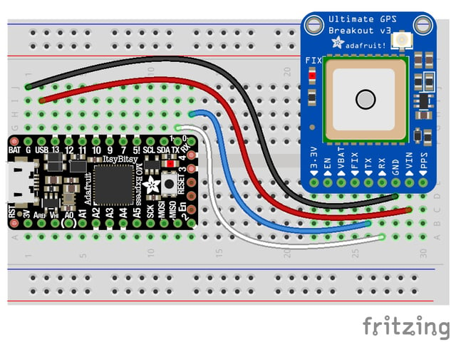
ItsyBitsy M0 Express and ItsyBitsy M4 Express
- ConnectUSB on the ItsyBitsy toVIN on the GPS
- ConnectG on the ItsyBitsy toGND on the GPS.
- ConnectRX/0 on the ItsyBitsy toTX on the GPS.
- ConnectTX/1 on the ItsyBitsy toRX on the GPS.

Metro M0 Express and Metro M4 Express
- Connect5V on the Metro toVIN on the GPS.
- ConnectGND on the Metro toGND on the GPS.
- ConnectRX/D0 on the Metro toTX on the GPS.
- ConnectTX/D1 on the Metro toRX on the GPS.
Where's my UART?
On the SAMD21, we have the flexibility of using a wide range of pins for UART. Compare this to some chips like the ESP8266 withfixed UART pins. The good news is you can use many but notallpins. Given the large number of SAMD boards we have, its impossible to guarantee anything other than the labeled 'TX' and 'RX'. So, if you want some other setup, or multiple UARTs, how will you find those pins? Easy! We've written a handy script.
These are the results from a Trinket M0, your output may vary and it might be very long.For more details about UARTs and SERCOMs check out our detailed guide here

In the example below, click theDownload Project Bundle button below to download the necessary libraries and thecode.py file in a zip file. Extract the contents of the zip file, open the directoryCircuitPython_Essentials/UART_Test_Script/ and then click on the directory that matches the version of CircuitPython you're using and copy the contents of that directory to yourCIRCUITPY drive.
YourCIRCUITPY drive should now look similar to the following image:

# SPDX-FileCopyrightText: 2018 Kattni Rembor for Adafruit Industries## SPDX-License-Identifier: MIT"""CircuitPython Essentials UART possible pin-pair identifying script"""import boardimport busiofrom microcontroller import Pindef is_hardware_uart(tx, rx): try: p = busio.UART(tx, rx) p.deinit() return True except ValueError: return Falsedef get_unique_pins(): exclude = ['NEOPIXEL', 'APA102_MOSI', 'APA102_SCK'] pins = [pin for pin in [ getattr(board, p) for p in dir(board) if p not in exclude] if isinstance(pin, Pin)] unique = [] for p in pins: if p not in unique: unique.append(p) return uniquefor tx_pin in get_unique_pins(): for rx_pin in get_unique_pins(): if rx_pin is tx_pin: continue if is_hardware_uart(tx_pin, rx_pin): print("RX pin:", rx_pin, "\t TX pin:", tx_pin)# SPDX-FileCopyrightText: 2018 Kattni Rembor for Adafruit Industries## SPDX-License-Identifier: MIT"""CircuitPython Essentials UART possible pin-pair identifying script"""import boardimport busiofrom microcontroller import Pindef is_hardware_uart(tx, rx): try: p = busio.UART(tx, rx) p.deinit() return True except ValueError: return Falsedef get_unique_pins(): exclude = ['NEOPIXEL', 'APA102_MOSI', 'APA102_SCK'] pins = [pin for pin in [ getattr(board, p) for p in dir(board) if p not in exclude] if isinstance(pin, Pin)] unique = [] for p in pins: if p not in unique: unique.append(p) return uniquefor tx_pin in get_unique_pins(): for rx_pin in get_unique_pins(): if rx_pin is tx_pin: continue if is_hardware_uart(tx_pin, rx_pin): print("RX pin:", rx_pin, "\t TX pin:", tx_pin)Trinket M0: Create UART before I2C
On the Trinket M0 (only), if you are using both UART and I2C, you must create the UART object first, e.g.:
>>> import board>>> uart = board.UART() # Uses pins 4 and 3 for TX and RX, baudrate 9600.>>> i2c = board.I2C() # Uses pins 2 and 0 for SCL and SDA.# or alternatively,
>>> import board>>> uart = board.UART() # Uses pins 4 and 3 for TX and RX, baudrate 9600.>>> i2c = board.I2C() # Uses pins 2 and 0 for SCL and SDA.# or alternatively,
Creating the I2C object first does not work:
>>> import board>>> i2c = board.I2C() # Uses pins 2 and 0 for SCL and SDA.>>> uart = board.UART() # Uses pins 4 and 3 for TX and RX, baudrate 9600.Traceback (most recent call last):File "", line 1, in ValueError: Invalid pins
>>> import board>>> i2c = board.I2C() # Uses pins 2 and 0 for SCL and SDA.>>> uart = board.UART() # Uses pins 4 and 3 for TX and RX, baudrate 9600.Traceback (most recent call last):File "", line 1, in ValueError: Invalid pins
Page last edited January 22, 2025
Text editor powered bytinymce.


