Adafruit Trinket M0
CircuitPython or Arduino IDE on this tiny little microcontroller board

CircuitPython PWM
Your board haspwmio support, which means you can PWM LEDs, control servos, beep piezos, and manage "pulse train" type devices like DHT22 and Infrared.
Nearly every pin has PWM support! For example, all ATSAMD21 board have anA0 pin which is 'true' analog out anddoes not have PWM support.
PWM with Fixed Frequency
This example will show you how to use PWM to fade the little red LED on your board.
The following illustrates how to connect an external LED to a QT Py M0.

In the example below, click theDownload Project Bundle button below to download the necessary libraries and thecode.py file in a zip file. Extract the contents of the zip file, open the directoryCircuitPython_Essentials/CircuitPython_PWM/ and then click on the directory that matches the version of CircuitPython you're using and copy the contents of that directory to yourCIRCUITPY drive.
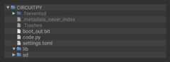
YourCIRCUITPY drive should now look similar to the following image:

# SPDX-FileCopyrightText: 2018 Kattni Rembor for Adafruit Industries## SPDX-License-Identifier: MIT"""CircuitPython Essentials: PWM with Fixed Frequency example."""import timeimport boardimport pwmio# LED setup for most CircuitPython boards:led = pwmio.PWMOut(board.LED, frequency=5000, duty_cycle=0)# LED setup for QT Py M0:# led = pwmio.PWMOut(board.SCK, frequency=5000, duty_cycle=0)while True: for i in range(100): # PWM LED up and down if i < 50: led.duty_cycle = int(i * 2 * 65535 / 100) # Up else: led.duty_cycle = 65535 - int((i - 50) * 2 * 65535 / 100) # Down time.sleep(0.01)
# SPDX-FileCopyrightText: 2018 Kattni Rembor for Adafruit Industries## SPDX-License-Identifier: MIT"""CircuitPython Essentials: PWM with Fixed Frequency example."""import timeimport boardimport pwmio# LED setup for most CircuitPython boards:led = pwmio.PWMOut(board.LED, frequency=5000, duty_cycle=0)# LED setup for QT Py M0:# led = pwmio.PWMOut(board.SCK, frequency=5000, duty_cycle=0)while True: for i in range(100): # PWM LED up and down if i < 50: led.duty_cycle = int(i * 2 * 65535 / 100) # Up else: led.duty_cycle = 65535 - int((i - 50) * 2 * 65535 / 100) # Down time.sleep(0.01)
To use with QT Py M0,you must comment outled = pwmio.PWMOut(board.LED, frequency=5000, duty_cycle=0) and uncommentled = pwmio.PWMOut(board.SCK, frequency=5000, duty_cycle=0). Your setup lines should look like this for the example to work with QT Py M0:
# LED setup for most CircuitPython boards:# led = pwmio.PWMOut(board.LED, frequency=5000, duty_cycle=0)# LED setup for QT Py M0:led = pwmio.PWMOut(board.SCK, frequency=5000, duty_cycle=0)
# LED setup for most CircuitPython boards:# led = pwmio.PWMOut(board.LED, frequency=5000, duty_cycle=0)# LED setup for QT Py M0:led = pwmio.PWMOut(board.SCK, frequency=5000, duty_cycle=0)
Create a PWM Output
led= pwmio.PWMOut(board.LED,frequency=5000,duty_cycle=0)
Since we're using the onboard LED, we'll call the objectled, usepwmio.PWMOut to create the output and pass in theD13 LED pin to use.
Main Loop
The main loop usesrange() to cycle through the loop. When the range is below 50, it PWMs the LED brightness up, and when the range is above 50, it PWMs the brightness down. This is how it fades the LED brighter and dimmer!
Thetime.sleep() is needed to allow the PWM process to occur over a period of time. Otherwise it happens too quickly for you to see!
Fixed frequency outputs are great for pulsing LEDs or controlling servos. But if you want to make some beeps with a piezo, you'll need to vary the frequency.
The following example usespwmio to make a series of tones on a piezo.
To use with any of the M0 boards, no changes to the following code are needed.
In the example below, click theDownload Project Bundle button below to download the necessary libraries and thecode.py file in a zip file. Extract the contents of the zip file, open the directoryCircuitPython_Essentials/CircuitPython_PWM_Piezo/ and then click on the directory that matches the version of CircuitPython you're using and copy the contents of that directory to yourCIRCUITPY drive.
YourCIRCUITPY drive should now look similar to the following image:

To use with the Metro M4 Express, ItsyBitsy M4 Express or the Feather M4 Express, you must comment out thepiezo = pwmio.PWMOut(board.A2, duty_cycle=0, frequency=440, variable_frequency=True)line and uncomment thepiezo = pwmio.PWMOut(board.A1, duty_cycle=0, frequency=440, variable_frequency=True) line. A2 is not a supported PWM pin on the M4 boards!
# SPDX-FileCopyrightText: 2018 Kattni Rembor for Adafruit Industries## SPDX-License-Identifier: MIT"""CircuitPython Essentials PWM with variable frequency piezo example"""import timeimport boardimport pwmio# For the M0 boards:piezo = pwmio.PWMOut(board.A2, duty_cycle=0, frequency=440, variable_frequency=True)# For the M4 boards:# piezo = pwmio.PWMOut(board.A1, duty_cycle=0, frequency=440, variable_frequency=True)while True: for f in (262, 294, 330, 349, 392, 440, 494, 523): piezo.frequency = f piezo.duty_cycle = 65535 // 2 # On 50% time.sleep(0.25) # On for 1/4 second piezo.duty_cycle = 0 # Off time.sleep(0.05) # Pause between notes time.sleep(0.5)
# SPDX-FileCopyrightText: 2018 Kattni Rembor for Adafruit Industries## SPDX-License-Identifier: MIT"""CircuitPython Essentials PWM with variable frequency piezo example"""import timeimport boardimport pwmio# For the M0 boards:piezo = pwmio.PWMOut(board.A2, duty_cycle=0, frequency=440, variable_frequency=True)# For the M4 boards:# piezo = pwmio.PWMOut(board.A1, duty_cycle=0, frequency=440, variable_frequency=True)while True: for f in (262, 294, 330, 349, 392, 440, 494, 523): piezo.frequency = f piezo.duty_cycle = 65535 // 2 # On 50% time.sleep(0.25) # On for 1/4 second piezo.duty_cycle = 0 # Off time.sleep(0.05) # Pause between notes time.sleep(0.5)
The following example uses a nice little helper in thesimpleio library that makes a tone for you on a piezo with a single command.
To use with any of the M0 boards, no changes to the following code are needed.
To use with the Metro M4 Express, ItsyBitsy M4 Express or the Feather M4 Express, you must comment out thesimpleio.tone(board.A2, f, 0.25)line and uncomment thesimpleio.tone(board.A1, f, 0.25) line. A2 is not a supported PWM pin on the M4 boards!
Installing Project Code
To use with CircuitPython, you need to first install a few libraries, into the lib folder on yourCIRCUITPY drive. Then you need to updatecode.py with the example script.
Thankfully, we can do this in one go. In the example below, click theDownload Project Bundle button below to download the necessary libraries and thecode.py file in a zip file. Extract the contents of the zip file, open the directoryCircuitPython_Essentials/CircuitPython_PWM_Piezo_simpleio/ and then click on the directory that matches the version of CircuitPython you're using and copy the contents of that directory to yourCIRCUITPY drive.
YourCIRCUITPY drive should now look similar to the following image:

# SPDX-FileCopyrightText: 2017 Limor Fried for Adafruit Industries## SPDX-License-Identifier: MIT"""CircuitPython Essentials PWM piezo simpleio example"""import timeimport boardimport simpleiowhile True: for f in (262, 294, 330, 349, 392, 440, 494, 523): # For the M0 boards: simpleio.tone(board.A2, f, 0.25) # on for 1/4 second # For the M4 boards: # simpleio.tone(board.A1, f, 0.25) # on for 1/4 second time.sleep(0.05) # pause between notes time.sleep(0.5)
# SPDX-FileCopyrightText: 2017 Limor Fried for Adafruit Industries## SPDX-License-Identifier: MIT"""CircuitPython Essentials PWM piezo simpleio example"""import timeimport boardimport simpleiowhile True: for f in (262, 294, 330, 349, 392, 440, 494, 523): # For the M0 boards: simpleio.tone(board.A2, f, 0.25) # on for 1/4 second # For the M4 boards: # simpleio.tone(board.A1, f, 0.25) # on for 1/4 second time.sleep(0.05) # pause between notes time.sleep(0.5)
As you can see, it's much simpler!
Wire it up
Use the diagrams below to help you wire up your piezo. Attach one leg of the piezo to pinA2 on the M0 boards or A1 on the M4 boards, and the other leg toground. It doesn't matter which leg is connected to which pin. They're interchangeable!
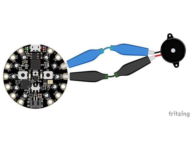
Circuit Playground Express
Use alligator clips to attachA2 and any one of theGND to different legs of the piezo.
CPX has PWM on the following pins:A1, A2, A3, A6, RX, LIGHT, A8, TEMPERATURE, A9, BUTTON_B, D5, SLIDE_SWITCH, D7, D13, REMOTEIN, IR_RX, REMOTEOUT, IR_TX, IR_PROXIMITY, MICROPHONE_CLOCK, MICROPHONE_DATA, ACCELEROMETER_INTERRUPT, ACCELEROMETER_SDA, ACCELEROMETER_SCL, SPEAKER_ENABLE.
There is NO PWM on:A0, SPEAKER, A4, SCL, A5, SDA, A7, TX, BUTTON_A, D4, NEOPIXEL, D8, SCK, MOSI, MISO, FLASH_CS.

Trinket M0
Note: A2 on Trinket is also labeled Digital "0"!
Use jumper wires to connectGND andD0 to different legs of the piezo.
Trinket has PWM available on the following pins:D0, A2, SDA, D2, A1, SCL, MISO, D4, A4, TX, MOSI, D3, A3, RX, SCK, D13, APA102_MOSI, APA102_SCK.
There is NO PWM on: A0, D1.

Gemma M0
Use alligator clips to attachA2andGND to different legs on the piezo.
Gemma has PWM available on the following pins: A1, D2, RX, SCL, A2, D0, TX, SDA, L, D13, APA102_MOSI, APA102_SCK.
There is NO PWM on: A0, D1.

QT Py M0
Use jumper wires to attachA2 andGND to different legs of the piezo.
The QT Py M0 has PWM on the following pins: A2, A3, A6, A7, A8, A9, A10, D2, D3, D4, D5, D6, D7, D8, D9, D10, SCK, MISO, MOSI, NEOPIXEL, RX, TX, SCL, SDA.
There is NO A0, A1, D0, D1, NEOPIXEL_POWER.

Feather M0 Express
Use jumper wires to attachA2and one of the twoGND to different legs of the piezo.
Feather M0 Express has PWM on the following pins:A2, A3, A4, SCK, MOSI, MISO, D0, RX, D1, TX, SDA, SCL, D5, D6, D9, D10, D11, D12, D13, NEOPIXEL.
There is NO PWM on: A0, A1, A5.

Feather M4 Express
Use jumper wires to attachA1and one of the twoGND to different legs of the piezo.
To use A1, comment out the current pin setup line, and uncomment the line labeled for the M4 boards. See the details above!
Feather M4 Express has PWM on the following pins: A1, A3, SCK, D0, RX, D1, TX, SDA, SCL, D4, D5, D6, D9, D10, D11, D12, D13.
There is NO PWM on: A0, A2, A4, A5, MOSI, MISO.

ItsyBitsy M0 Express
Use jumper wires to attachA2 andG to different legs of the piezo.
ItsyBitsy M0 Express has PWM on the following pins:D0, RX, D1, TX, D2, D3, D4, D5, D6, D7, D8, D9, D10, D11, D12, D13, L, A2, A3, A4, MOSI, MISO, SCK, SCL, SDA, APA102_MOSI, APA102_SCK.
There is NO PWM on: A0, A1, A5.

ItsyBitsy M4 Express
Use jumper wires to attachA1 andG to different legs of the piezo.
To use A1, comment out the current pin setup line, and uncomment the line labeled for the M4 boards. See the details above!
ItsyBitsy M4 Express has PWM on the following pins: A1, D0, RX, D1, TX, D2, D4, D5, D7, D9, D10, D11, D12, D13, SDA, SCL.
There is NO PWM on: A2, A3, A4, A5, D3, SCK, MOSI, MISO.

Metro M0 Express
Use jumper wires to connectA2 and any one of theGND to different legs on the piezo.
Metro M0 Express has PWM on the following pins:A2, A3, A4, D0, RX, D1, TX, D2, D3, D4, D5, D6, D7, D8, D9, D10, D11, D12, D13, SDA, SCL, NEOPIXEL, SCK, MOSI, MISO.
There is NO PWM on: A0, A1, A5, FLASH_CS.

Metro M4 Express
Use jumper wires to connectA1 and any one of theGND to different legs on the piezo.
To use A1, comment out the current pin setup line, and uncomment the line labeled for the M4 boards. See the details above!
Metro M4 Express has PWM on: A1, A5, D0, RX, D1, TX, D2, D3, D4, D5, D6, D7, D8, D9, D10, D11, D12, D13, SDA, SCK, MOSI, MISO
There is No PWM on: A0, A2, A3, A4, SCL, AREF, NEOPIXEL, LED_RX, LED_TX.
Where's My PWM?
Want to check to see which pins have PWM yourself? We've written this handy script! It attempts to setup PWM on every pin available, and lets you know which ones work and which ones don't. Check it out!
In the example below, click theDownload Project Bundle button below to download the necessary libraries and thecode.py file in a zip file. Extract the contents of the zip file, open the directoryCircuitPython_Essentials/PWM_Test_Script/ and then click on the directory that matches the version of CircuitPython you're using and copy the contents of that directory to yourCIRCUITPY drive.
YourCIRCUITPY drive should now look similar to the following image:
# SPDX-FileCopyrightText: 2018 Kattni Rembor for Adafruit Industries## SPDX-License-Identifier: MIT"""CircuitPython Essentials PWM pin identifying script"""import boardimport pwmiofor pin_name in dir(board): pin = getattr(board, pin_name) try: p = pwmio.PWMOut(pin) p.deinit() print("PWM on:", pin_name) # Prints the valid, PWM-capable pins! except ValueError: # This is the error returned when the pin is invalid. print("No PWM on:", pin_name) # Prints the invalid pins. except RuntimeError: # Timer conflict error. print("Timers in use:", pin_name) # Prints the timer conflict pins. except TypeError: # Error returned when checking a non-pin object in dir(board). pass # Passes over non-pin objects in dir(board).# SPDX-FileCopyrightText: 2018 Kattni Rembor for Adafruit Industries## SPDX-License-Identifier: MIT"""CircuitPython Essentials PWM pin identifying script"""import boardimport pwmiofor pin_name in dir(board): pin = getattr(board, pin_name) try: p = pwmio.PWMOut(pin) p.deinit() print("PWM on:", pin_name) # Prints the valid, PWM-capable pins! except ValueError: # This is the error returned when the pin is invalid. print("No PWM on:", pin_name) # Prints the invalid pins. except RuntimeError: # Timer conflict error. print("Timers in use:", pin_name) # Prints the timer conflict pins. except TypeError: # Error returned when checking a non-pin object in dir(board). pass # Passes over non-pin objects in dir(board).Page last edited January 22, 2025
Text editor powered bytinymce.


