Using VisualShaders
VisualShaders are the visual alternative for creating shaders.
As shaders are inherently linked to visuals, the graph-based approach withpreviews of textures, materials, etc. offers a lot of additional conveniencecompared to purely script-based shaders. On the other hand, VisualShaders do notexpose all features of the shader script and using both in parallel might benecessary for specific effects.
Note
If you are not familiar with shaders, start by readingIntroduction to shaders.
Creating a VisualShader
VisualShaders can be created in anyShaderMaterial. To begin usingVisualShaders, create a newShaderMaterial in an object of your choice.

Then assign aShader resource to theShader property.

Click on the newShader resource and the Create Shader dialog willopen automatically. Change the Type option toVisualShaderin the dropdown, then give it a name.

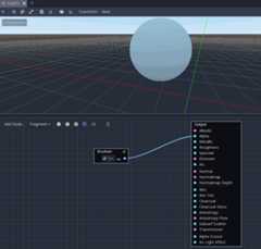
Click on the visual shader you just created to open the Shader Editor.The layout of the Shader Editor comprises four parts, a file list onthe right, the upper toolbar, the graph itself, and a material previewon the right that can be toggled off

From left to right in the toolbar:
The
AddNodebutton displays a popup menu to let you add nodes to theshader graph.The drop-down menu is the shader type: Vertex, Fragment and Light. Like forscript shaders, it defines what built-in nodes will be available.
The following buttons and number input control the zooming level, gridsnapping and distance between grid lines (in pixels).
The toggle controls if the graph minimap in the bottom right of the editoris visible or not.
The automatically arrange selected nodes button will try to organize anynodes you have selected as efficiently and cleanly as possible.
The Manage Varyings button opens a dropdown that lets you add or remove avarying.
The show generated code button shows shader code corresponding to your graph.
The last icon toggles the material preview on or off.
Note
Although VisualShaders do not require coding, they share the same logic withscript shaders. It is advised to learn the basics of both to have a goodunderstanding of the shading pipeline.
The visual shader graph is converted to a script shader behind the scene,and you can see this code by pressing the last button in the toolbar. Thiscan be convenient to understand what a given node does and how to reproduceit in scripts.
Using the Visual Shader Editor
By default, every newVisualShader will have an output node. Every nodeconnection ends at one of the output node's sockets. A node is the basic unit tocreate your shader. To add a new node, click on theAddNode button on theupper left corner or right click on any empty location in the graph, and a menuwill pop up.

This popup has the following properties:
If you right-click on the graph, this menu will be called at the cursorposition and the created node, in that case, will also be placed under thatposition; otherwise, it will be created at the graph's center.
It can be resized horizontally and vertically allowing more content to beshown. Size transform and tree content position are saved between the calls,so if you suddenly closed the popup you can easily restore its previous state.
The
ExpandAllandCollapseAlloptions in the drop-down option menucan be used to easily list the available nodes.You can also drag and drop nodes from the popup onto the graph.
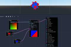
While the popup has nodes sorted in categories, it can seem overwhelming atfirst. Try to add some of the nodes, plug them in the output socket and observewhat happens.
When connecting anyscalar output to avector input, all components ofthe vector will take the value of the scalar.
When connecting anyvector output to ascalar input, the value of thescalar will be the average of the vector's components.
Visual Shader node interface
Visual shader nodes have input and output ports. The input ports are located on the left side of the node, and output ports are located on the right side of the node.

These ports are colored to differentiate type of port:
Type | Color | Description | Example |
|---|---|---|---|
Scalar | Gray | Scalar is a single value. |
|
Vector | Purple | Vector is a set of values. |
|
Boolean | Green | On or off, true or false. |
|
Transform | Pink | A matrix, usually used to transform vertices. |
|
Sampler | Orange | A texture sampler. It can be used to sample textures. |
|


All of the types are used in the calculations of vertices, fragments, and lights in the shader. For example: matrix multiplication,vector addition, or scalar division.
There are other types but these are the main ones.
Visual Shader nodes
Below are some special nodes that are worth knowing about. The list is notexhaustive and might be expanded with more nodes and examples.
Expression node
TheExpression node allows you to write Godot Shading Language (GLSL-like)expressions inside your visual shaders. The node has buttons to add any amountof required input and output ports and can be resized. You can also set up thename and type of each port. The expression you have entered will applyimmediately to the material (once the focus leaves the expression text box). Anyparsing or compilation errors will be printed to the Output tab. The outputs areinitialized to their zero value by default. The node is located under theSpecial tab and can be used in all shader modes.
The possibilities of this node are almost limitless – you can write complexprocedures, and use all the power of text-based shaders, such as loops, thediscard keyword, extended types, etc. For example:

Reroute node
TheReroute node is used purely for organizational purposes. In a complicatedshader with many nodes you may find that the paths between nodes can makethings hard to read. Reroute, as its name suggests, allows you to adjust the pathbetween nodes to make things easier to read. You can even have multiple reroutenodes for a single path, which can be used to make right angles.

To move a reroute node move your mouse cursor above it, and grab the handle thatappears.

Fresnel node
TheFresnel node is designed to accept normal and view vectors and producesa scalar which is the saturated dot product between them. Additionally, you cansetup the inversion and the power of equation. TheFresnel node is great foradding a rim-like lighting effect to objects.

Boolean node
TheBoolean node can be converted toScalar orVector to represent0 or1 and(0,0,0) or(1,1,1) respectively. This propertycan be used to enable or disable some effect parts with one click.
If node
TheIf node allows you to setup a vector which will be returned the resultof the comparison betweena andb. There are three vectors which can bereturned:a==b (in that case the tolerance parameter is provided as acomparison threshold – by default it is equal to the minimal value, i.e.0.00001),a>b anda<b.
Switch node
TheSwitch node returns a vector if the boolean condition istrue orfalse.Boolean was introduced above. If you want to convert a vectorto a true boolean, all components of the vector should be non-zero.

Mesh Emitter
TheMeshEmitter node is used for emitting particles from mesh vertices. This isonly available for shaders that are inParticles mode.
Keep in mind that not all 3D objects are mesh files. a glTF file can't be draggedand dropped into the graph. However, you can create an inherited scene from it,save the mesh in that scene as it's own file, and use that.

You can also drag and drop obj files into the graph editor to add the nodefor that specific mesh, other mesh files will not work for this.