

Running Windows Server Failover Clustering
You can create a failover cluster using Windows Server on Google Cloud Platform(GCP). A group of servers works together to provide higher availability (HA) foryour Windows applications. If onecluster node fails, another node can takeover running the software. You can configure the failover to happenautomatically, which is the usual configuration, or you can manually trigger afailover.
This tutorial assumes you are familiar with failover clustering, ActiveDirectory (AD), and administration of Windows Server.
For a brief overview of networking in GCP, seeGCP for Data Center Pros: Networking.
Architecture
This tutorial walks you through how to create an example failover cluster onCompute Engine. The example system contains the following two servers:
- A primary Compute Engine VM instance running Windows Server 2016 in zone
a. - A second instance, configured to match the primary instance in zone
b.
Additionally, you deploy an AD domain contoller, which, for this tutorial,serves the following purposes:
- Provides a Windows domain.
- Resolves hostnames to IP addresses.
- Hosts thefile share witness that acts as a third "vote" toachieve therequired quorum for the cluster.
You can create the domain controller in any zone. This tutorial uses zonec.In a production system, you can host the file share witness elsewhere, and youdon't need a separate AD system only to support your failover cluster. SeeWhat's next for links to articles about using AD on GCP.
The two servers that you will use to deploy the failover cluster are located indifferent zones to ensure that each serveris on a different physical machine and to protect against the unlikelypossibility of a zonal failure.
The following diagram describes the architecture you deploy by following thistutorial.

Shared storage options
This tutorial does not cover setting up a file server for high-availabilityshared storage.
Google Cloud supports multiple shared storage solutions that you canuse with Windows Server Failover Clustering, including:
For information about other possible shared storage solutions, see:
Understanding the network routing
When the cluster fails over, requests must go to the newly active node. Theclustering technology normally handles routing by usingaddress resolution protocol (ARP), which associates IP addresses with MAC addresses. In GCP, the VirtualPrivate Cloud (VPC) system usessoftware-defined networking,which doesn't leverage MAC addresses. This means the changes broadcast by ARPdon't affect routing at all. To make routing work, the cluster requires somesoftware-level help from theInternal Load Balancer.
Usually, internal load balancing distributes incoming network traffic amongmultiple backend instances that are internal to your VPC, to share the load.For failover clustering, you instead use internal load balancing to route alltraffic to just one instance: the currently active cluster node. Here's howinternal load balancing detects the correct node:
- Each VM instance runs a Compute Engine agent instance that providessupport for Windows failover clustering. The agent keeps track of the IPaddresses for the VM instance.
- The load balancer's frontend provides the IP address for incoming trafficto the application.
- The load balancer's backend provides a health check. The health checkprocess periodically pings the agent on each cluster node by using thefixed IP address of the VM instance through a particular port. The defaultport is 59998.
- The health check includes the application's IP address as a payload inthe request.
- The agent compares the IP address in the request to the list of IPaddresses for the host VM. If the agent finds a match, it responds with avalue of 1. Otherwise, it responds with 0.
- The load balancer marks any VM that passes the health check ashealthy.At any moment, only one VM ever passes the health check because only one VMhas the IP address for the workload.
What happens during a failover
When a failover happens in the cluster, the following changes take place:
- Windows failover clustering changes the status of the active node to indicatethat it has failed.
- Failover clustering moves any cluster resources and roles from the failingnode to the best node, as defined by the quorum. This action includes moving theassociated IP addresses.
- Failover clustering broadcasts ARP packets to notify hardware-based networkrouters that the IP addresses have moved. For this scenario, GCP networkingignores these packets.
- After the move, the Compute Engine agent on the VM for the failing nodechanges its response to the health check from 1 to 0, because the VM no longerhosts the IP address specified in the request.
- The Compute Engine agent on the VM for the newly active node likewise changesits response to the health check from 0 to 1.
- The internal load balancer stops routing traffic to the failing node andinstead routes traffic to the newly active node.
Putting it together
Now that you've reviewed some of the concepts, here are some details to noticeabout the architecture diagram:
- The Compute Engine agent for the VM named
wsfc-2is responding tothe health check with the value 1, indicating it is the active clusternode. Forwsfc-1, the response is 0. - The load balancer is routing requests to
wsfc-2, as indicated by the arrow. - The load balancer and
wsfc-2both have the IP address10.0.0.9. Forthe load balancer, this is the specified frontend IP address. For the VM,it's the IP address of the application. The failover cluster sets this IPaddress on the currently active node. - The failover cluster and
wsfc-2both have the IP address10.0.0.8.The VM has this IP address because it currently hosts the cluster resources.
Advice for following this tutorial
This tutorial has a lot of steps. Sometimes, you are asked to follow steps inexternal documents, such as Microsoft documentation. Don't miss the notesin this document providing specifics for following the external steps.
This tutorial uses Cloud Shell in the Google Cloud console. Though it's possibleto use the Google Cloud console user interface or the gcloud CLI to set upfailover clustering, this tutorial mainly uses Cloud Shell to make it easy foryou. This approach helps you to complete the tutorial faster. When moreappropriate, some steps use the Google Cloud console instead.

It's a good idea totake snapshots of yourCompute Engine persistent disks along the way. If something goes wrong, you can use a snapshot to avoidstarting over from the beginning. This tutorial suggests good times to take thesnapshots.
If you find that things aren't working as you expect, there might beinstructions in the section you're reading. Otherwise, refer to theTroubleshooting section.
Objectives
- Create a network.
- Install Windows Server 2016 on two Compute Engine VMs.
- Install and configure Active Directory on a third instance ofWindows Server.
- Set up the failover cluster, including a file share witness forthe quorum and a role for the workload.
- Set up the internal load balancer.
- Test the failover operation to verify that the cluster is working.
Costs
This tutorial uses Compute Engine images that include Windows Serverlicenses. This means the cost to run this tutorial can be significant if youleave VMs running. It's a good idea to stop the VMs when you're not using them.
See thePricing Calculator for an estimate of the costs to complete this tutorial.
Before you begin
- Sign in to your Google Cloud account. If you're new to Google Cloud, create an account to evaluate how our products perform in real-world scenarios. New customers also get $300 in free credits to run, test, and deploy workloads.
In the Google Cloud console, on the project selector page, select or create a Google Cloud project.
Roles required to select or create a project
- Select a project: Selecting a project doesn't require a specific IAM role—you can select any project that you've been granted a role on.
- Create a project: To create a project, you need the Project Creator role (
roles/resourcemanager.projectCreator), which contains theresourcemanager.projects.createpermission.Learn how to grant roles.
Verify that billing is enabled for your Google Cloud project.
Enable the Compute Engine API.
Roles required to enable APIs
To enable APIs, you need the Service Usage Admin IAM role (
roles/serviceusage.serviceUsageAdmin), which contains theserviceusage.services.enablepermission.Learn how to grant roles.In the Google Cloud console, on the project selector page, select or create a Google Cloud project.
Roles required to select or create a project
- Select a project: Selecting a project doesn't require a specific IAM role—you can select any project that you've been granted a role on.
- Create a project: To create a project, you need the Project Creator role (
roles/resourcemanager.projectCreator), which contains theresourcemanager.projects.createpermission.Learn how to grant roles.
Verify that billing is enabled for your Google Cloud project.
Enable the Compute Engine API.
Roles required to enable APIs
To enable APIs, you need the Service Usage Admin IAM role (
roles/serviceusage.serviceUsageAdmin), which contains theserviceusage.services.enablepermission.Learn how to grant roles.- Start an instance of Cloud Shell.
Go to Cloud Shell
Creating the network
Your cluster requires a custom network. Use VPC to create a custom network andone subnetwork by runninggcloud commands in Cloud Shell.
Create the network:
gcloud compute networks create wsfcnet --subnet-mode customThe name of the network you created is
wsfcnet.Create a subnetwork. Replace
[YOUR_REGION]with a nearby GCP region:gcloudcomputenetworkssubnetscreatewsfcnetsub1--network wsfcnet --region [YOUR_REGION] --range 10.0.0.0/16The name of the subnetwork you created is
wsfcnetsub1.
Notice that theCIDR range for IP addresses in this subnetwork is10.0.0.0/16. This is an examplerange used for this tutorial. In production systems, work with your networkadministrators to allocate appropriate ranges for IP addresses for yoursystems.
Create firewall rules
By default, your network is closed to external traffic. You must open ports inthe firewall to enable remote connections to the servers. Usegcloud commandsin Cloud Shell to create the rules.
For this tutorial, open port 3389 on the main network toenable RDP connections. In the following command, replace
[YOUR_IPv4_ADDRESS]with the IP address of the computer you use toconnect to your VM instances. In a production system,you can provide an IP address range or a series of addresses.gcloudcomputefirewall-rulescreateallow-rdp--network wsfcnet --allow tcp:3389 --source-ranges [YOUR_IPv4_ADDRESS]On the subnetwork, allow all protocols on all ports to enable theservers to communicate with each other. In production systems, consideropening only specific ports, as needed.
gcloud compute firewall-rules create allow-all-subnet --network wsfcnet --allow all --source-ranges 10.0.0.0/16Notice that the
source-rangesvalue matches the CIDR range you used to createthe subnetwork.View your firewall rules:
gcloud compute firewall-rules listYou should see output similar to the following:
NAME NETWORK DIRECTION PRIORITY ALLOW DENY DISABLEDallow-all-subnet wsfcnet INGRESS 1000 all Falseallow-rdp wsfcnet INGRESS 1000 tcp:3389 False
Enabling failover clustering in Compute Engine
To enable failover clustering in the Compute Engine agent,you need to add the flagenable-wsfc=true to your VM definitions either byspecifying it as custom metadata for the VM or by creating aconfiguration file on each VM, as described in theCompute Enginedocumentation.
This tutorial defines the flag as custom metadata when the VMs are created, asdescribed in the next section. The tutorial also relies on the defaultbehavior forwsfc-addrs andwsfc-agent-port, so you don't need to setthese values.
Creating the servers
Next, create the 3 servers. Use thegcloud command in Cloud Shell.
Create the first cluster-node server
Create a new Compute Engine instance. Configure the instance as follows:
- Name the instance
wsfc-1. - Set the
--zoneflag to a convenient zone near you. For example,us-central1-a. - Set the
--machine-typeflag ton1-standard-2. - Set the
--image-projectflag towindows-cloud. - Set the
--image-familyflag towindows-2016. - Set the
--scopesflag tohttps://www.googleapis.com/auth/compute. - Set the
--can-ip-forwardflag to enable IP forwarding. - Set the
--private-network-ipflag to10.0.0.4. - Set the network to
wsfcnetand the subnetwork towsfcnetsub1. - Use the
--metadataparameter to setenable-wsfc=true.
Run the following command, replacing[YOUR_ZONE_1] with the nameof your first zone:
gcloudcomputeinstancescreatewsfc-1--zone [YOUR_ZONE_1] --machine-type n1-standard-2 --image-project windows-cloud --image-family windows-2016 --scopes https://www.googleapis.com/auth/compute --can-ip-forward --private-network-ip 10.0.0.4 --network wsfcnet --subnet wsfcnetsub1 --metadata enable-wsfc=trueCreate the second cluster-node server
For the second server, follow the same steps, except:
- Set the instance name to:
wsfc-2. - Set the
--zoneflag to a different zone than the zone that you usedfor the first server. For example,us-central1-b. - Set the
--private-network-ipflag to10.0.0.5.
Replace[YOUR_ZONE_2] with the name of your second zone:
gcloudcomputeinstancescreatewsfc-2--zone [YOUR_ZONE_2] --machine-type n1-standard-2 --image-project windows-cloud --image-family windows-2016 --scopes https://www.googleapis.com/auth/compute --can-ip-forward --private-network-ip 10.0.0.5 --network wsfcnet --subnet wsfcnetsub1 --metadata enable-wsfc=trueCreate the third server for Active Directory
For the domain controller, follow the same steps, except:
- Set the instance name to:
wsfc-dc. - Set the
--zoneflag to a different zone than the zones that you usedfor the other servers. For example,us-central1-c. - Set the
--private-network-ipflag to10.0.0.6. - Omit
--metadata enable-wsfc=true.
Replace[YOUR_ZONE_3] with the name of your zone:
gcloudcomputeinstancescreatewsfc-dc--zone [YOUR_ZONE_3] --machine-type n1-standard-2 --image-project windows-cloud --image-family windows-2016 --scopes https://www.googleapis.com/auth/compute --can-ip-forward --private-network-ip 10.0.0.6 --network wsfcnet --subnet wsfcnetsub1View your instances
You can see the details about the instances you created.
gcloud compute instances listYou will see output similar to the following:
NAME ZONE MACHINE_TYPE PREEMPTIBLE INTERNAL_IP EXTERNAL_IP STATUSwsfc-1 us-central1-a n1-standard-2 10.0.0.4 35.203.131.133 RUNNINGwsfc-2 us-central1-b n1-standard-2 10.0.0.5 35.203.130.194 RUNNINGwsfc-dc us-central1-c n1-standard-2 10.0.0.6 35.197.27.2 RUNNING
Connecting to your VMs
To connect to a Windows-based VM, you must first generate a password for the VM.You can then connect to the VM using RDP.
Generating passwords
In the Google Cloud console, go to theVM instances page.
Click the name of the VM instance for which you need a new password.
On the instance details page, click theSet Windows Passwordbutton. A password is generated for you. Copy the password and store it in asecure place.
Connecting through RDP
The Compute Engine documentation provides details about how to connect to yourWindows VM instances by using RDP. You can either:
- Use an existing client.
- Add a Chrome RDP plugin to your browser and thenconnect through theGoogle Cloud console.
Whenever this tutorial tells you to connect to a Windows instance, use yourpreferred RDP connection.
Configuring Windows networking
The internal IP addresses that you assigned when you created the VMs arestatic. To ensure that Windows treats the IP addresses as static, you need toadd them, along with the IP addresses of the default gateway and the DNSserver, to the Windows Server networking configuration.
Use RDP to connect towsfc-1,wsfc-2, andwsfc-dc,and repeat the following steps for each instance:
- In Server Manager, in the left pane, selectLocal Server.
- In theEthernet entry of theProperties pane, clickIPv4 address assigned by DHCP, IPv6 enabled.
- Right-clickEthernet and selectProperties.
- Double-clickInternet Protocol Version 4 (TCP/IPv4).
- SelectUse the following IP address.
Enter the internal IP address that you assigned to the VM when youcreated it.
- For
wsfc-1, enter "10.0.0.4". - For
wsfc-2enter "10.0.0.5". - For
wsfc-dcenter "10.0.0.6".
- For
ForSubnet mask, enter "255.255.0.0".
ForDefault gateway, enter
10.0.0.1, the IP address that wasautomatically reserved for the default gateway when you created the subnetwsfcnetsub1.The IP address for the default gateway is always the secondaddress in the primary IP range for a subnet. SeeUnusable addresses in IPv4 subnet ranges.
For
wsfc-1andwsfc-2only:ClickUse the following DNS server addresses.
ForPreferred DNS server, enter "10.0.0.6".
Close all the dialog boxes.
You lose RDP connectivity because these changes reset the virtual networkadapter for the VM instance.
Close the RDP session and then reconnect to the instance.If a dialog box from the previous step is still open, close it.
In the properties section for the local server, verify that theEthernet setting reflects the local server IP address (
10.0.0.4,10.0.0.5,or10.0.0.6). If it doesn't, re-open theInternetProtocol Version 4 (TCP/IPv4) dialog box and update the setting.
This is a good time to take snapshots ofwsfc-1 andwsfc-2.
Setting up Active Directory
Now, set up the domain controller.
- Use RDP to connect to the server named
wsfc-dc. - Using the Windows Computer Management desktop app, set a password for thelocal Administrator account.
- Enable the local Administrator account.
Follow the steps in the Microsoft instructions below to set up the domaincontroller, with these additional notes. You can use default values for mostsettings.
- Select the DNS Server role check box. This step is not specified in theinstructions.
- Select theRestart the destination server automatically ifrequired check box.
- Promote the file server to a domain controller.
- During theAdd a new forest step, name your domain "WSFC.TEST".
- Set the NetBIOS domain name to "WSFC" (the default).
This is a good time to take a snapshot ofwsfc-dc.
Create the domain user account
It can take some time forwsfc-dc to restart. Before joining servers to thedomain, use RDP to sign in towsfc-dc to validate that the domain controlleris running.
You need a domain user that has administrator privileges for the clusterservers. Follow these steps:
- On the domain controller (
wsfc-dc) clickStart, and then typedsa to find and open the Active Directory Users and Computers app. - Right-clickWSFC.TEST, point toNew, and then clickUser.
- For theFull name and theUser logon name, enter
cluster-admin. - ClickNext.
- Enter and confirm a password for the user. Select password options in thedialog box. For example, you can set the password to never expire.
- Confirm the settings and then clickFinish.
Make
cluster-adminan administrator onwsfc-dc:- Right-click
cluster-adminand selectAdd to a group. - TypeAdministrators, and clickOK.
- Right-click
This tutorial uses theWSFC.TEST\cluster-admin account as an administratoraccount wherever such an account is required. In a production system, followyour usual security practices for allocating accounts and permissions. For moreinformation, seeOverview of Active Directory accounts needed by a failover cluster.
Join the servers to the domain
Add the two cluster-node servers to theWSFC.TEST domain. Perform thefollowing steps on each cluster-node server (wsfc-1 andwsfc-2):
- InServer Manager >Local Server, in theProperties pane, clickWORKGROUP.
- ClickChange.
- SelectDomain and then enter "WSFC.TEST".
- ClickOK.
- Provide the credentials for
WSFC.TEST\cluster-adminto join the domain. - ClickOK.
- Close the dialog boxes and follow the prompts to restart the server.
InServer Manager, make
cluster-adminan administrator onwsfc-1andwsfc-2. Alternatively, you can manage administrative privileges byusing a group policy.- On theTools menu, selectComputer Management >Local Usersand Groups >Groups >Administrators, and then clickAdd.
- Enter "cluster-admin" and the clickCheck names.
- ClickOK.
This is a good point to take snapshots of all three VMs.
Setting up failover clustering
Reserve an IP address for the cluster in Compute Engine
When you create the failover cluster, you assign an IP address to create an administrative access point. In a production environment, you mightuse an IP address from a separate subnet.However, in this tutorial you reserve an IP address from the subnet youalready created. Reserving the IP address prevents conflicts with other IPassignments.
Open a terminal on a host VM or open Cloud Shell.
Reserve an IP address. For this tutorial, use
10.0.0.8:gcloud compute addresses create cluster-access-point --region [YOUR_REGION] --subnet wsfcnetsub1 --addresses 10.0.0.8
To confirm the reservation of the IP address:
gcloud compute addresses list
Create the cluster
To create and configure the failover cluster:
- Use RDP to connect
wsfc-1andwsfc-2. Follow the steps in the Microsoft instructions below, with these additional notes:
- Install the Failover Clustering feature on
wsfc-1andwsfc-2. Don't install the Failover Clustering feature onwsfc-dc. - Run the Failover Cluster Manager app as the domain user
WSFC.TEST\cluster-admin. Otherwise, you might encounter permissionsissues.It's a good idea to always run Failover Cluster Manager this way or toconnect to a server ascluster-adminto ensure you have the requiredpermissions. - Add
wsfc-1andwsfc-2to the cluster as nodes. When validating the configuration:
- On theTesting Options page, selectRun only tests Iselect, and then clickNext.
On theTest Selection page, clearStorage because theStorage option will fail when running on Compute Engine (as itwould for separate standalone physical servers).
Common issues you might encounter during cluster validation include:
- Only one network interface between replicas. You canignore this one, because it doesn't apply in a cloud-based setup.
- Windows Updates not the same on both replicas. If youconfigured your Windows instances to apply updatesautomatically, one of the nodes mighthave applied updates that the other hasn't downloaded yet. You shouldkeep the servers in identical configurations.
- Pending reboot. You've made changes to one of the servers,and it needs a reboot to apply. Don't ignore this one.
- The servers do not all have the same domain role. You canignore this one.
- The servers are not all in the same Organizational Unit (OU).This tutorial doesn't use an OU at all, but in a production systemconsider putting your cluster in its own OU. The Microsoftinstructions describe this best practice.
- Unsigned drivers were found. You can ignore this one.
On theSummary page, you can selectCreate the cluster now usingthe validated nodes to continue on to create the cluster, rather thanclosing the wizard and reopening it.
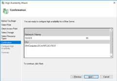
In the Create Cluster Wizard, on theAccess point page:
- Name your cluster "testcluster".
- In theAddress field, enter the IP address that you reserved earlier,
10.0.0.8.
- Install the Failover Clustering feature on
Add the cluster administrator
Adding a domain account as an administrator for the cluster enables you toperform actions on the cluster from tools such as Windows PowerShell. Add thecluster-admin domain account as a cluster admin.
- On the cluster node that hosts the cluster resources, in Failover ClusterManager, select your cluster in the left pane and then clickPropertiesin the right pane.
- Select theCluster Permissions tab.
- ClickAdd and then add
cluster-admin. - With
cluster-adminselected in theGroup or user names list, selectFull Control in thePermissions pane. - ClickApply andOK.
This is a good point to take snapshots.
Creating the file share witness
You have a two-node failover cluster, but the cluster uses a voting mechanism todecide which node should be active. To achieve a quorum, you can add afile share witness.
This tutorial simply adds a shared folder to the domain controller server.If this server were to go offline at the same time one of the cluster nodes isrestarting, the entire cluster could stop working because the remaining servercan't vote by itself. For this tutorial, the assumption is that the GCPinfrastructure features, such asLive Migration andautomatic restart,provide enough reliability to keep the shared folder alive.
If you want to create a more-highly-available file share witness, you have theseoptions:
- Use a cluster of Windows Servers to provide the share by usingStorage Spaces Direct.This Windows Server 2016 feature can provide a highly available share forthe quorum witness. For example, you could create a cluster for your ActiveDirectory domain controller to provide both highly available domainservices and provide the file share witness at the same time.
- Use data replication software, such as SIOS Datakeeper, with WindowsFailover Server Clustering for synchronous or asynchronous replication.
Follow these steps to create the file share for the witness:
- Connect to
wsfc-dc. This server hosts the file share. - In Explorer, browse to the
Cdrive. - In the title bar, click theNew Folder button.
- Name the new folder
shares. - Double-click the
sharesfolder to open it. - Add a new folder and name it
clusterwitness-testcluster.
Configure sharing for the file share witness
You must set permissions on the file share witness folder to enable the clusterto use it.
- From Explorer, right-click the
clusterwitness-testclusterfolder andselectProperties. - On theSharing tab, clickAdvanced Sharing.
- SelectShare this folder.
- ClickPermissions and then clickAdd.
- ClickObject Types, selectComputers, and then clickOK.
- Add the machine account
testcluster$. - GiveFull Control permissions to
testcluster$. - ClickApply and then close all the dialog boxes.
Add the file share witness to the failover cluster
Now, configure the failover cluster to use the file share witness as a quorumvote.
- On the computer that hosts the cluster resources (
wsfc-1), openthe Failover Cluster Manager. - In the left pane, right-click the name of the cluster(testcluster.WSFC.TEST) then point toMore Actions, and then clickConfigure Cluster Quorum Settings.
- On theSelect Quorum Configuration Option panel, chooseSelect the quorum witness.
- On theSelect Quorum Witness panel, chooseConfigure a file share witness.
- For theFile Share Path, enter the path to the shared folder, such as
\\wsfc-dc\clusterwitness-testcluster. - Confirm the settings and then clickFinish.
Testing the failover cluster
Your Windows Server failover cluster should now be working. You can testmanually moving cluster resources between your instances. You're not done yet,but this is a good checkpoint to validate that everything you've done so far isworking.
- On
wsfc-1, note the name of theCurrent Host Server in FailoverCluster Manager. - Run Windows PowerShell as
cluster-admin. In PowerShell, run the following command to change the current host server:
Move-ClusterGroup -Name "Cluster Group"
You should see the name of the current host server change to the other VM.
If this didn't work, review the previous steps and see if you missed anything.The most common issue is a missing firewall rule that isblocking access on the network. Refer to theTroubleshooting section for more issues to check.
Otherwise, you can now move on to setting up the internal load balancer, whichis required in order to route network traffic to the current host server in thecluster.
This is a good time to take snapshots.
Adding a role to the failover cluster
In Windows failover clustering,roles host clustered workloads. You can use arole to specify in the cluster the IP address that your application uses. Forthis tutorial, you add a role for the test workload, which is the InternetInformation Services (IIS) web server, and assign an IP address to the role.
Reserve an IP address for the role in Compute Engine
To prevent IP addressing conflicts within your subnet in Compute Engine, reserve the IP address for the role.
Open a terminal on a host VM or open Cloud Shell.
Reserve an IP address. For this tutorial, use
10.0.0.9:gcloud compute addresses create load-balancer-ip --region [YOUR_REGION] --subnet wsfcnetsub1 --addresses 10.0.0.9
To confirm the reservation of the IP address:
gcloud compute addresses list
Add the role
Follow these steps:
- In Failover Cluster Manager, in theActions pane, selectConfigure Role.
- In theSelect Role page, selectOther Server.
- In theClient Access Point page, enter the name
IIS. - Set the address to
10.0.0.9. - SkipSelect Storage andSelect Resource Types.
- Confirm the settings and then clickFinish.
Creating the internal load balancer
Create and configure the internal load balancer, which is required in orderto route network traffic to the active cluster host node. You will use theGoogle Cloud console, because the user interface gives you a good view intohow internal load balancing is organized.
You will also create a Compute Engine instance group for each zonein the cluster, which the load balancer uses to manage the cluster nodes.
Create the instance groups
Create an instance group in each zone that containsa cluster node and then add each node to the instance group in its zone.Don't add the domain controllerwsfc-dc to an instance group.
Create an instance group for each zone in the cluster, replacing
[ZONE_1]with the name of your first zone and[ZONE_2]with the name of your second:gcloud compute instance-groups unmanaged create wsfc-group-1 --zone=[ZONE_1]
gcloud compute instance-groups unmanaged create wsfc-group-2 --zone=[ZONE_2]
Add the server in each zone to the instance group for that zone:
gcloud compute instance-groups unmanaged add-instances wsfc-group-1 --instances wsfc-1 --zone [ZONE_1]
gcloud compute instance-groups unmanaged add-instances wsfc-group-2 --instances wsfc-2 --zone [ZONE_2]
Confirm that your instance groups were created and that each groupcontains one instance:
gcloud compute instance-groups unmanaged list
NAME ZONE NETWORK NETWORK_PROJECT MANAGED INSTANCES wsfc-group-1 us-central1-a wsfcnet exampleproject No 1 wsfc-group-2 us-central1-b wsfcnet exampleproject No 1
Create the load balancer
Start your configuration
In the Google Cloud console, go to theLoad balancing page.
- ClickCreate load balancer.
- ForType of load balancer, selectNetwork Load Balancer (TCP/UDP/SSL) and clickNext.
- ForProxy or passthrough, selectPassthrough load balancer and clickNext.
- ForPublic facing or internal, selectInternal and clickNext.
- ClickConfigure.
Basic configuration
- ForName, enter "wsfc-lb".
- Select your current region.
- Select
wsfcnetforNetwork.
Configure the backend
Recall that the GCP internal load balancer uses a periodic health check todetermine the active node. The health check pings the Compute Engine clusterhost agent that is running on the active cluster node. The health check payloadis the IP address of the application, which is represented by the clusteredrole. The agent responds with a value of 1 if the node is active or 0 if it isnot.
- ClickBackend configuration.
- UnderBackends, add each instance group that you created by selectingits name and clickingDone.
Create a health check.
- ForName, enter "wsfc-hc".
- Accept the defaultProtocol setting ofTCP and change thePort to "59998" for cluster host agent responses.
- ForRequest, enter "10.0.0.9".
- ForResponse, enter "1".
- ForCheck interval, enter "2".
- ForTimeout enter "1".
- ClickSave and continue.
Configure the frontend
The frontend configuration creates a forwarding rule that defines how the loadbalancer handles incoming requests. For this tutorial, to keep it simple, youwill test the system by making requests between the VMs in the subnetwork.
In your production system, you probably want to open the system up to externaltraffic, such as Internet traffic. To do this, you cancreate a bastion host that accepts external traffic and forwards it to your internal network. Using abastion host is not covered in this tutorial.
- In the center pane, clickFrontend configuration.
- ForName, enter "wsfc-lb-fe".
- Select your subnetwork (
wsfcnetsub1). - ForInternal IP, selectload-balancer-ip (10.0.0.9). This is the sameIP address that you set for the role.
- ForPorts, enter "80".
- ClickDone.
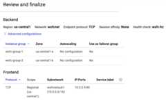
Review and finalize
- To see a summary of the internal load balancer settings, in the centerpane, clickReview and finalize. The summary appears in the right pane.
ClickCreate. It takes a moment to create the load balancer.
Create firewall rules for the health check
You might have noticed that the Google Cloud console notified you that thehealth-check system would require a firewall rule to enable the health checks toreach their targets. In this section, you set up the firewall rule.
Note: The documentation aboutsetting up an internal load balancer instructs you to create a firewall rule for the load balancer itself. For thistutorial, this is not needed because you alreadycreated a rulethat allows all traffic between nodes on the subnet, and the load balancer isoperating within this CIDR range and using only allowed ports.In the Google Cloud console, go to theCloud Shell.
Run the following command to create the firewall rule:
gcloud compute firewall-rules create allow-health-check --network wsfcnet --source-ranges 130.211.0.0/22,35.191.0.0/16 --allow tcp:59998
Open the Windows Firewall
On each cluster node,wsfc-1 andwsfc-2, create a firewall rule in theWindows firewall to allow the load balancer to access each Windows system.
Open the Windows Firewall with Advanced Security app.
In the left navigation pane, selectInbound Rules.
In the right navigation pane, selectNew Rule.
On theRule Type panel, selectCustom as the rule type and clickNext.
On theProgram panel, accept the default and clickNext.
On theProtocol and Ports panel:
- In theProtocol type: field, selectTCP.
- In theLocal port: field, selectSpecific Ports and enter
59998.
On theScope panel, underWhich remote IP addresses does this ruleapply to:
- SelectThese IP addresses:.
Add each of the following IP address to theThis IP address or subnetfield by clickingAdd:
130.211.0.0/2235.191.0.0/16
ClickNext.
On theAction panel, acceptAllow the connection and clickNext.
On theProfile panel, accept the defaults and clickNext.
Specify a name for the firewall rule and clickFinish.
Validating the load balancer
After your internal load balancer is running, you can inspect its status tovalidate that it can find a healthy instance, and then test failover again.
In the Google Cloud console, go to theLoad balancing page.
Click the name of the load balancer (
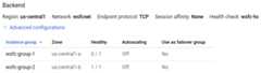
wsfc-lb).In theBackend section of the summary, you should see the instancegroups listed.
In the following image from the details page of the
wsfc-lbload balancer,instance groupwsfc-group-1contains the activenode, as indicated by1 / 1 in theHealthy column. Instance groupwsfc-group-2contains the inactive node, as indicated by0 / 1.
If both instance groups show0 / 1, the load balancer might still besyncing with the nodes. Sometimes, you need to do at least one failoveraction to get the load balancer to find the IP address.
In Failover Cluster Manager, expand the cluster name and click onRoles.In theOwner Node column, note the server name for theIIS role.
Start a failover by right-clicking theIIS role and selectingMove >Best Possible Node. This action moves therole to the other node, as shown in theOwner Node column.

Wait until theStatus showsRunning.
Return to theLoad balancer details page, clickRefresh, and verifythat the1 / 1 and0 / 1 values in theHealthy columnhave switched instance groups.
[REGION] is your region:gcloud compute backend-services get-health wsfc-lb --region=[REGION]
The output looks like the following:
backend: https://compute.googleapis.com/compute/v1/projects/exampleproject/zones/us-central1-a/instanceGroups/wsfc-group-1status: healthStatus: - healthState: HEALTHY instance: https://compute.googleapis.com/compute/v1/projects/exampleproject/zones/us-central1-a/instances/wsfc-1 ipAddress: 10.0.0.4 port: 80 kind: compute#backendServiceGroupHealth---backend: https://compute.googleapis.com/compute/v1/projects/exampleproject/zones/us-central1-b/instanceGroups/wsfc-group-2status: healthStatus: - healthState: UNHEALTHY instance: https://compute.googleapis.com/compute/v1/projects/exampleproject/zones/us-central1-b/instances/wsfc-2 ipAddress: 10.0.0.5 port: 80 kind: compute#backendServiceGroupHealth
Installing your application
Now that you have a cluster, you can set up yourapplication on each node and configure it for running in a clusteredenvironment.
For this tutorial, you need to set up something that can demonstrate thatthe cluster is really working with the internal load balancer. Set up IIS oneach VM to serve a simple web page.
You're not setting up IIS for HA in the cluster. You are creating separateIIS instances that each serve a different web page. After a failover, the webserver serves its own content, not shared content.
Setting up your application or IIS for HA is beyond the scope of thistutorial.
Set up IIS
On each cluster node,install IIS.
- On theSelect role services page, be sure thatDefault Documentis selected underCommon HTTP Features.
- On theConfirmation page, select the checkbox that enablesautomatic restarting of the destination server.
Validate that each web server is working.
- Use RDP to connect to the VM named
wsfc-dc. - In Server Manager, clickLocal Server in the navigation pane on theleft side of the window.
- in theProperties section at the top, turn offIE Enhanced Security Configuration.
- Open Internet Explorer.
Browse to the IP address of each server:
http://10.0.0.4/
http://10.0.0.5/
- Use RDP to connect to the VM named
In each case, you see theWelcome page, which is the default IIS webpage.
Edit the default web pages
Change each default web page so you can easily see which server is currentlyserving the page.
- Use RDP to connect to the VM named
wsfc-1. - Run Notepad as administrator.
- Open
C:\inetpub\wwwroot\iisstart.htmin Notepad. Remember to browse forAll Files, not just text files. In the
<title>element, change the text to the name of the currentserver. For example:<title>wsfc-1</title>Save the HTML file.
Repeat these steps for
wsfc-2, setting the<title>element towsfc-2.
Now, when you view a web page served from one of these servers, the name of theserver appears as the title in the Internet Explorer tab.
Test the failover
- Use RDP to connect to the VM named
wsfc-dc. - Open Internet Explorer.
Browse to the IP address of the load balancer role:
http://10.0.0.9/You see theWelcome page with the name of the current serverdisplayed in the tab title.
Stop the current server to simulate a failure. In Cloud Shell, run thefollowing command, replacing
[INSTANCE_NAME]with the name of the current server you saw in the previousstep, such aswsfc-1:gcloudcomputeinstancesstop[INSTANCE_NAME]--zone=[ACTIVE_ZONE]Switch to your RDP connection to
wsfc-dc.It can take a few moments for the load balancer to detect the move andreroute the traffic.
After 30 seconds or so, refresh the page in Internet Explorer.
You should now see the name of the new active node displayed in the tab title.For example, if you started with
wsfc-1active, you now seewsfc-2inthe title. If you don't see the change right away or see a page-not-found error,refresh the browser again.
Congratulations! You now have a working Windows Server 2016 failover clusterrunning on GCP.
Troubleshooting
Here are some common issues you can check if things aren't working.
GCP firewall rules blocks health check
If the health check isn't working, double-check that you have a firewall rule toenable incoming traffic from the IP addresses that the health check system uses:130.211.0.0/22and35.191.0.0/16.
Windows Firewall blocks health check
Make sure port 59998 is open in Windows Firewall on each cluster node. SeeOpen the Windows Firewall.
Cluster nodes using DHCP
It's important that each VM in the cluster has a static IP address. If a VM isconfigured to use DHCP in Windows, change the networking settings in Windows tomake the IPv4 address match the IP address of the VM as shown in the Google Cloud console. Also set the gateway IP address to match the address of thesubnetwork gateway in the GCP VPC.
GCP network tags in firewall rules
If you use network tags in your firewall rules, be sure the correct tags are seton every VM instance. This tutorial doesn't use tags, but if you've set them forsome other reason, they must be used consistently.
Clean up
To avoid incurring charges to your Google Cloud account for the resources used in this tutorial, either delete the project that contains the resources, or keep the project and delete the individual resources.
After you finish the tutorial, you can clean up the resources that you created so that they stop using quota and incurring charges. The following sections describe how to delete or turn off these resources.
Deleting the project
The easiest way to eliminate billing is to delete the project that you created for the tutorial.
To delete the project:
Cleaning up resources without deleting the project
If you need to keep your project, you can clean up the tutorial resourcesby deleting them individually.
Deleting instances
To delete a Compute Engine instance:
- In the Google Cloud console, go to theVM instances page.
- Select the checkbox for the instance that you want to delete.
- To delete the instance, clickMore actions, clickDelete, and then follow the instructions.
Deleting instance groups
- In the Google Cloud console, go to theInstance groups page.
- Select the checkbox for the instance group that you want to delete.
- To delete the instance group, clickDelete.
Deleting a load balancer
To delete a load balancer:
In the Google Cloud console, go to theLoad balancing page.
Select the checkbox next to the name of the load balancer you want todelete.
Click theDelete button at the top of the page.
Deleting a VPC network
To delete a VPC network:
In the Google Cloud console, go to theVPC networks page.
Click the name of the network you want to delete.
Click theDELETE VPC NETWORK button at the top of the page.
Release reserved IP addresses
Use Cloud Shell to release the reserved IP addresses:
In the Google Cloud console, go to theCloud Shell.
Release the reserved IP addresses:
gcloud compute addresses delete cluster-access-point load-balancer-ip
Deleting persistent disks
To delete a persistent disk:
In the Google Cloud console, go to theDisks page.
Select the checkbox next to the name of the disk you want todelete.
Click theDelete button at the top of the page.
What's next
- Tutorials about Active Directory.
- Explore reference architectures, diagrams, and best practices about Google Cloud.Take a look at ourCloud Architecture Center.
Except as otherwise noted, the content of this page is licensed under theCreative Commons Attribution 4.0 License, and code samples are licensed under theApache 2.0 License. For details, see theGoogle Developers Site Policies. Java is a registered trademark of Oracle and/or its affiliates.
Last updated 2025-12-09 UTC.